JP7076808B2 - Pachinko machine - Google Patents
Pachinko machine Download PDFInfo
- Publication number
- JP7076808B2 JP7076808B2 JP2019167807A JP2019167807A JP7076808B2 JP 7076808 B2 JP7076808 B2 JP 7076808B2 JP 2019167807 A JP2019167807 A JP 2019167807A JP 2019167807 A JP2019167807 A JP 2019167807A JP 7076808 B2 JP7076808 B2 JP 7076808B2
- Authority
- JP
- Japan
- Prior art keywords
- effect
- display
- icon
- game
- symbol
- Prior art date
- Legal status (The legal status is an assumption and is not a legal conclusion. Google has not performed a legal analysis and makes no representation as to the accuracy of the status listed.)
- Active
Links
Images


Classifications
-
- Y—GENERAL TAGGING OF NEW TECHNOLOGICAL DEVELOPMENTS; GENERAL TAGGING OF CROSS-SECTIONAL TECHNOLOGIES SPANNING OVER SEVERAL SECTIONS OF THE IPC; TECHNICAL SUBJECTS COVERED BY FORMER USPC CROSS-REFERENCE ART COLLECTIONS [XRACs] AND DIGESTS
- Y02—TECHNOLOGIES OR APPLICATIONS FOR MITIGATION OR ADAPTATION AGAINST CLIMATE CHANGE
- Y02E—REDUCTION OF GREENHOUSE GAS [GHG] EMISSIONS, RELATED TO ENERGY GENERATION, TRANSMISSION OR DISTRIBUTION
- Y02E60/00—Enabling technologies; Technologies with a potential or indirect contribution to GHG emissions mitigation
- Y02E60/10—Energy storage using batteries
Description
本発明は、遊技機に関する。 The present invention relates to a gaming machine.
従来の遊技機では、取得条件の成立によって取得された判定情報に基づいて遊技者に有利な特別遊技を実行するか否かを判定し、該判定結果に基づいて演出図柄の変動演出を画像表示装置で実行するものが一般的である。 In the conventional gaming machine, it is determined whether or not to execute a special game advantageous to the player based on the determination information acquired by the establishment of the acquisition condition, and the variation effect of the effect pattern is displayed as an image based on the determination result. It is common to run on a device.
このような遊技機では、演出図柄の変動演出の変動パターンが複数種類あり、判定結果に基づいて複数種類ある変動パターンの中から選択して、選択した変動パターンでの演出図柄の変動演出を画像表示装置で表示するものであった(例えば、特許文献1参照)。 In such a gaming machine, there are a plurality of types of variation patterns of the staging pattern, and a variation pattern of the staging symbol is imaged by selecting from a plurality of types of variation patterns based on the determination result. It was displayed on a display device (see, for example, Patent Document 1).
しかしながら、上記特許文献1に記載の遊技機では、演出図柄の変動演出の態様において、改善の余地があり、遊技の興趣の低下を招くおそれがあった。
However, in the gaming machine described in
本発明は、上記した問題点に鑑みてなされたものであり、遊技の興趣を向上することができる遊技機の提供を目的とする。 The present invention has been made in view of the above-mentioned problems, and an object of the present invention is to provide a gaming machine capable of improving the interest of gaming.
[適用例1]
上記課題を解決するため、本願の適用例1の遊技機は、始動条件の成立に基づき図柄(第1特別図柄表示器60、第2特別図柄表示器61)を変動表示し、前記図柄が予め定められた特定図柄で停止表示すると、遊技者に有利な特別遊技を実行可能な遊技機において、遊技の進行を制御することが可能な主制御手段(主制御基板110)と、前記始動条件の成立によって取得された判定情報を記憶することが可能な記憶手段(主制御基板110)と、前記判定情報に基づいて、前記特別遊技を実行するか否かを判定することが可能な判定手段(主制御基板110)と、前記判定手段による判定前に前記判定情報を事前判定することが可能な事前判定手段(主制御基板110)と、電力供給の開始後に遊技の制御状態を初期化させる初期化処理を実行可能な初期化処理手段(主制御基板110)と、電力供給の開始後に前記初期化処理が行われない場合に電力供給の停止前の遊技の制御状態に復旧させる復旧処理を実行可能な復旧処理手段(主制御基板110)と、前記主制御手段からの信号に応じた演出を制御することが可能な演出制御手段(演出制御基板130)と、遊技の演出音を出力することが可能な音出力手段(音声出力装置9)と、前記始動条件の成立に基づき記憶される保留記憶を第1態様により表示する第1保留表示手段(第1保留数表示領域70E、第2保留数表示領域70F)と、前記保留記憶を前記第1態様とは異なる第2態様により表示する第2保留表示手段(第1保留アイコン表示領域70B、当該アイコン表示領域70C、第2保留アイコン表示領域70D)と、を備え、前記演出制御手段は、前記判定手段の判定結果に応じて、前記図柄の変動表示中に、表示手段に演出図柄(演出図柄70a)の変動演出を表示制御可能であり、前記図柄の変動開始により複数列の全てにおいて前記演出図柄が認識可能であり、且つ、前記演出図柄が変動表示中であることを認識可能な認識可能表示態様(図44(b)~(d)、変動開始時の仮停止)を実行可能な第1時間として開始演出を実行可能であり、前記第1時間とは異なる期間であって、複数列の全てにおいて前記演出図柄が認識可能であり、且つ、前記演出図柄が変動表示中であることを認識可能な認識可能表示態様(変動終了示唆演出、図51-1、図51-2、変動終了前の仮停止)を実行可能な第2時間と、複数列の全てにおいて前記演出図柄が停止表示される停止表示態様(第2表示態様)を実行可能な第3時間と、により停止演出を実行可能であり、前記停止表示態様は、第1表示態様(変動パターン1A~1Cの非リーチハズレ)と、第2表示態様(変動パターン4A~5Cの大当たり)と、があり、前記演出制御手段は、前記停止表示態様が前記第2表示態様の場合は、前記第1表示態様の場合に比べて、前記第2時間の実行時間を長くするとともに、前記認識可能表示態様の実行前に期待度を向上させる所定の演出(擬似連演出)が実行され易く、前記第2表示態様となる前記第2時間においては、前記演出図柄が仮停止表示される態様の第1演出(変動終了示唆演出、図51-1の演出図柄70aの振動等)と、前記第1演出とは異なる態様の第2演出(変動終了示唆演出、図51-2の演出図柄70aの煌き等)と、を実行可能であり、前記音出力手段から所定の報知音(電源投入報知音、電源復旧報知音)を出力することが可能であり、遊技が進行していない待機状態において客待ち演出を実行することが可能であり、前記客待ち演出の実行中に前記演出制御手段が受信したコマンドが所定信号(電源投入指定コマンド、電源復旧指定コマンド等)である場合、前記所定の報知音を出力可能であり、前記図柄の変動により前記保留記憶が1つ減少することで前記第1時間が開始された場合、前記第2保留表示手段が実行情報への変化表示(保留アイコン表示領域から当該アイコン表示領域の中心への移動)を完了することになるタイミングよりも、前記第1保留表示手段が表示する前記保留記憶が第1記憶数から第2記憶数へ減少表示(1減算された保留数字への更新)を完了することになるタイミングの方が早く、前記判定が行われて前記図柄の変動が実行されたことを示す前記実行情報又は前記判定が未実行であって前記事前判定が行われた前記第2態様の前記保留記憶である識別情報(当該アイコン、保留アイコン)を表示することが可能であり、前記識別情報の表示態様を段階的に変化させることで前記特別遊技が実行される期待度を示唆する特定演出(例えば、アイコン変化演出)を実行することが可能であり、前記識別情報の表示態様には、第1段階態様(例えば、CDアイコン)と、第2段階態様(例えば、青キャラアイコン)と、第3段階態様(例えば、赤キャラアイコン)とを含み、前記特定演出によって前記第3段階態様まで変化することになる前記識別情報の前記第2段階態様での表示中に停止した電力供給が再開して遊技の制御状態が復旧される場合、前記第2段階態様で表示されていた前記識別情報を前記第1段階態様で表示可能であり、前記遊技の制御状態が復旧したことによって前記第1段階態様で表示された前記識別情報に対応する前記判定情報の前記判定が行われた後は、前記識別情報を前記第1段階態様から前記第2段階態様又は前記第3段階態様に変化可能であることを要旨とする。
[Application Example 1]
In order to solve the above problem, the gaming machine of the application example 1 of the present application variablely displays the symbols (first
本発明によれば、遊技の興趣を向上することができる遊技機を提供することが可能となる。 According to the present invention, it is possible to provide a gaming machine capable of improving the interest of gaming.
(第1実施形態)
以下、本発明の第1実施形態について図面を参照しながら具体的に説明する。
(First Embodiment)
Hereinafter, the first embodiment of the present invention will be specifically described with reference to the drawings.
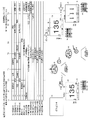
(遊技機の構成)
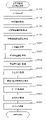
まず、図1を用いて、遊技機1の構成について説明する。図1は本実施の形態における遊技機1の正面図の一例である。
(Composition of gaming machine)
First, the configuration of the
遊技機1は、外枠2と、外枠2に対して回動可能に支持される遊技盤取付枠3と、遊技盤取付枠3に対して回動可能に支持されるガラス枠4と、遊技球が流下する遊技領域5aが形成された遊技盤5が設けられている。
The
外枠2は、中央部分が前後方向に開口する矩形状のベースフレーム2aの下部前面に飾り板2bが取り付けられており、遊技店の島設備に対して固着部材(例えば、釘や止め具など)を介して固定される。
The
遊技盤取付枠3は、水平方向の一端側において第1ヒンジ機構部6を介して外枠2に対して脱着可能に連結されており、第1ヒンジ機構部6を支点として回動可能に支持されている。そのため、遊技盤取付枠3を外枠2に対して扉のように回動すると、遊技盤取付枠3の裏面側が前方に露出するので、遊技盤取付枠3の裏面側に設けられた各種装置のメンテナンスなどを行うことが可能となる。
The game
ガラス枠4は、水平方向の一端側において第2ヒンジ機構部7を介して遊技盤取付枠3に脱着自在に連結されており、第2ヒンジ機構部7を支点として回動可能に支持されている。そのため、ガラス枠4を遊技盤取付枠3に対して扉のように回動すると、遊技盤5の遊技領域5a、及び、遊技盤取付枠3の前面部分を開閉することができる。
The
ガラス枠4の上部寄りの略中央部分には、前後方向に開口する開口部8(窓部)が形成され、該開口部8を後方から塞ぐように透明部材8a(ガラス板やアクリル板など)が取り付けられており、この開口部8、及び、透明部材8aを介して遊技領域5aを視認可能としている。
An opening 8 (window portion) that opens in the front-rear direction is formed in a substantially central portion near the upper part of the
ガラス枠4の開口部8の周囲には、スピーカからなる音声出力装置9と、複数の装飾ランプ(LED)を有する枠用照明装置10と、後述する遊技球払出装置100から払い出された遊技球などの複数の遊技球を貯留するための上受け皿11と、上受け皿11に入りきらずに後述する溢れ球流路に流入した遊技球を受け入れて貯留するための下受け皿12と、遊技球を発射させるための操作が可能な発射操作装置13とが設けられている。
Around the
音声出力装置9は、ガラス枠4の上部2箇所に間隔を空けて設けられ、BGM(バックグラウンドミュージック)、SE(サウンドエフェクト)等を出力することでサウンド(音楽、音声)による演出を行うようになっている。また、枠用照明装置10は、開口部8の周囲に複数設けられ、各ランプ(LED)の光の照射方向や発光色を変更することで照明による演出を行う。また、枠用照明装置10は、ガラス枠4の開放や後述する払出異常が発生した場合に点灯/点滅するように制御される報知LED10a(図示省略)を備えている。
The
上受け皿11は、遊技球の貯留部11aの底面が発射操作装置13の方向側(右方向)に向けて下り傾斜しており、下り傾斜の端部には球送りソレノイド11bが設けられている。上受け皿11の貯留部11aに貯留された遊技球が流下して球送りソレノイド11bに到達すると、球送りソレノイド11bの動作によって遊技球が1個ずつ遊技盤取付枠3側に向けて送り出される。
In the
また、上受け皿11の中央手前側の部分には、後述する種々の演出に係る決定操作や選択操作を行うための入力装置として機能する演出ボタン装置16と選択ボタン装置18(図1参照)が左右に並べて設けられている。
Further, in the portion on the front side of the center of the
演出ボタン装置16は、決定操作など(操作入力)を行うことが可能な演出ボタン17(図示省略)と、演出ボタン17に対する操作を検出する演出ボタン検出スイッチ17a(図2参照)と、演出ボタン17を上下方向に移動させるためのボタン駆動モータを有するボタン駆動装置17b(図2参照)が設けられており、遊技者が遊技機1へ所定の情報を入力可能となっている。
The
選択ボタン装置18は、選択操作などの操作を行うことが可能な十字キー19(図示省略)と、十字キー19に接続されて、十字キー19に対する操作を検出するための十字キー検出スイッチ19a(図2参照)が設けられており、遊技者が遊技機1へ所定の情報を入力可能となっている。
The
また、上受け皿11の右寄りの部分には、遊技球の貸出操作や残金を記憶したカードなどの記憶媒体の返却操作を行うことが可能な貸出返却操作部20が設けられている。貸出返却操作部20の貸出ボタン(図示省略)が操作されると遊技機1に併設される球貸機(図示省略)が受け付けている記憶媒体に記憶された残金を減算して遊技球の貸し出しが行われ、貸出返却操作部20の返却ボタン(図示省略)が操作されると球貸機(図示省略)から記憶媒体が返却されるようになっている。
Further, a lending / returning
上受け皿11と下受け皿12との間には、上受け皿11に入りきらない遊技球を受け入れて下受け皿12に案内するための溢れ球流路(図示省略)が形成されている。また、溢れ球流路の途中には下受け皿12に遊技球が満杯となったことを検出する受け皿満杯検出スイッチ32a(図2参照)が設けられ、受け皿満杯検出スイッチ32aによって下受け皿12の満杯が検出されている間は後述する遊技球払出装置100による遊技球の払い出しが停止される。
An overflow ball flow path (not shown) for receiving a game ball that does not fit in the
発射操作装置13は、ガラス枠4に固定された基体14と、基体14に回動可能に設けられた発射ハンドル15と、発射ハンドル15に遊技者の手が触れていることを検出するタッチセンサ15a(図2参照)と、発射ハンドル15の回動角度によって抵抗値が変化する可変抵抗器からなる発射ボリューム15b(図2参照)と、発射ハンドル15を所定の態様で発光させるためのハンドル発光装置15cが設けられている。タッチセンサ15aによって遊技者の手が発射ハンドル15に触れていることを検出すると、球送りソレノイド11bが作動して遊技球が1個ずつ送り出される。
The
ハンドル発光装置15cは、発射ハンドル15の前側部分を構成すると共に前方に向けて膨出するドーム状に形成され、光を透過可能なレンズ部材によって画成される内部空間に複数のLEDが配設されている。このLEDが発光することで発射ハンドル15を所定の態様で発光させる発光演出を実行することが可能となっている。また、ハンドル発光装置15cの前端部には、後述する送風装置21から送り出される風(空気)の吹き出し口となる送風口15dが開設されている。
The handle
ガラス枠4の裏面側には、発射操作装置13に対応する位置に所定の態様で風(空気)を送り出すための送風装置21が設けられている。送風装置21は、風(空気)を送り出すための送風部(図示省略)と、この送風部を作動させるための送風モータ(図示省略)とを備えており、送風部によって送り出された風(空気)が発射操作装置13の基体14、及び、ハンドル発光装置15cの内部を通って送風口15dから遊技者の手に向けて送出される。この送風装置21が作動することで発射ハンドル15を操作している遊技者の手に向けて所定の態様で風(空気)を送出する送風演出を実行することが可能となっている。
On the back surface side of the
なお、送風装置21を発射操作装置13に対応する位置に設けるのではなく、外枠2の飾り板2b部分やガラス枠4の透明部材8aの周囲等に設け、遊技者に向けて風(空気)を送り出すようにしてもよい。また、送風装置21を複数設けてもよい。
The
遊技盤取付枠3には、遊技盤5を取り付けるための遊技盤取付部25と、遊技球を遊技領域5aに向けて発射するための遊技球発射装置26と、遊技盤取付枠3、及び、ガラス枠4を閉鎖状態にロックするためのロック機構27と、ガラス枠4の開放(開閉)を検出するための開放検出スイッチ31aが設けられている。
The game
遊技盤取付部25は、遊技盤取付枠3の上部寄りの略中央に前方が開口する凹室状に形成され、遊技盤5を前方から収納可能となっている。遊技盤取付部25の凹室の奥部には、前後方向に開放する開口が設けられており、この開口を介して遊技盤5の裏面側に設けられる各種装置などが遊技機1の後方に臨む。
The game
遊技球発射装置26は、遊技球を発射するための打出部材28と、打出部材28を駆動するための発射用ソレノイド28b(図2参照)と、打出部材28から遊技盤の左下端部に向けて上り傾斜する発射レール29と、発射レール29の傾斜下端部となる発射位置に遊技球Aを停留させるストッパー30が設けられている。そして、球送りソレノイド11bによって送り出された遊技球が発射位置に受け入れられると、この遊技球Aを打出部材28の動作によって遊技領域5aに向けて打ち出す。
The game
ロック機構27は、遊技盤取付部25の右側方に設けられ、鍵穴が形成されるシリンダーの前端部がガラス枠4の前面側に露出するようになっている。そして、シリンダーの鍵穴に専用の鍵を挿入して一方向に回動させると遊技盤取付枠3のロックが解除されて遊技盤取付枠3が開閉可能となり、他方向に回動させるとガラス枠4のロックが解除されてガラス枠4が開閉可能となる。
The
遊技盤5の外縁寄りの位置には、湾曲形状の内側レール35と、内側レール35の外側に位置する湾曲形状の外側レール36と、遊技球を遊技領域5aの中央に向けて誘導する誘導部材37が設けられている。そして、内側レール35と外側レール36との間に遊技球発射装置26により発射された遊技球を遊技領域5aの上流部に案内する発射球案内路38が形成されている。また、遊技領域5aの最下流部には、流下してきた遊技球を遊技領域外(遊技盤取付枠3の回収部)に導くためのアウト口39が形成されている。
At positions near the outer edge of the
遊技領域5aの略中央には、所謂センターケースと呼ばれる内部への遊技球の進入を規制する枠状の飾り枠40が設けられ、飾り枠40の内部に演出空間40aが形成されている。また、飾り枠40の側部には、遊技領域5aを流下する遊技球を飾り枠40の内部に導入するワープ装置41が設けられ、飾り枠40の下部には、ワープ装置41により飾り枠40の内部に導入された遊技球を転動させて飾り枠40の下方に流下させるステージ部42が設けられている。
At the substantially center of the
遊技領域5aの下部には、遊技球が常時入賞(入球)可能な複数(本実施の形態では4つ)の一般入賞口43が間隔を空けた状態で設けられており、この一般入賞口43に入賞(入球)した遊技球が一般入賞口検出スイッチ43a(図2参照)によって検出されると、所定個数(例えば10個)の遊技球が遊技球払出装置100(図示省略)から賞球として上受け皿11に払い出される。
At the bottom of the
遊技領域5aの両側方(左側領域、右側領域)には、遊技球が通過可能な普図ゲート44(普図始動領域)がそれぞれ設けられており、この普図ゲート44を通過した遊技球がゲート検出スイッチ44a(図2参照)で検出されると、普通図柄の当たり抽選(補助遊技判定)が行われる。なお、普通図柄の当たり抽選については後述する。
On both sides (left side area, right side area) of the
遊技領域5aの下部であってステージ部42の直下には、遊技球が常時入賞(入球)可能な第1始動口45(特図始動領域)が設けられており、この第1始動口45に入賞(入球)した遊技球が第1始動口検出スイッチ45a(図2参照)で検出されると、所定個数の遊技球(例えば3個)が遊技球払出装置100から賞球として上受け皿11に払い出されるようになっている。また、賞球の払い出しの他に、後述する第1特別図柄(識別情報)の大当たり抽選(特別遊技判定)が行われる。
A first starting port 45 (special drawing starting area) is provided below the
第1始動口45の直下には、所定条件の成立(普通図柄の当たり抽選に当選したこと)に基づき遊技球の入賞(入球)が不可能もしくは困難な閉状態(基本態様)から遊技球の入賞(入球)が可能もしくは容易な開状態(特別態様)に変換される可変始動部46が設けられている。
Immediately below the
可変始動部46には、遊技球が入賞(入球)可能な第2始動口47(特図始動領域)と、第2始動口47への遊技球の入賞(入球)を検出する第2始動口検出スイッチ47a(図2参照)と、第2始動口47を閉状態と開状態とに変換(可変)する可動部材48と、可動部材48を開閉変換するための第2始動口開閉ソレノイド48b(図2参照)とが設けられている。そして、第2始動口47が閉状態となっている場合には、遊技球の入賞が不可能もしくは困難となり、第2始動口47が開状態となっている場合には、遊技球の入賞(入球)が可能もしくは容易となる。
The
また、第2始動口47に入賞(入球)した遊技球が第2始動口検出スイッチ47aで検出されると、所定個数の遊技球(例えば3個)が遊技球払出装置100から賞球として上受け皿11に払い出されるようになっている。また、賞球の払い出しの他に、後述する第2特別図柄(識別情報)の大当たり抽選(特別遊技判定)が行われる。
Further, when a game ball winning (winning) in the
誘導部材37の上方であって右側の普図ゲート44の下流には、所定条件の成立(特別図柄の大当たり抽選に当選したこと)に基づき遊技球の入賞(入球)が不可能な閉状態(基本態様)から遊技球の入賞(入球)が可能な開状態(特別態様)に変換される可変入賞部49が設けられている。
Above the
可変入賞部49には、遊技球が入賞(入球)可能な大入賞口50と、大入賞口50への遊技球の入賞(入球)を検出するための大入賞口検出スイッチ50a(図2参照)と、大入賞口50を閉状態と開状態とに変換(可変)する開閉部材51と、開閉部材51を開閉変換するための大入賞口開閉ソレノイド51bとが設けられている。そして、大入賞口50が閉状態となっている場合には、遊技球の入賞が不可能もしくは困難となり、大入賞口50が開状態となっている場合には、遊技球の入賞(入球)が可能もしくは容易となる。
The variable winning
また、大入賞口50に入賞(入球)した遊技球が大入賞口検出スイッチ50aで検出されると、所定個数の遊技球(例えば15個)が遊技球払出装置100から賞球として上受け皿11に払い出される。
Further, when the game balls that have won (winned) in the
遊技盤5の裏側には、一般入賞口43、第1始動口45、第2始動口47、及び、大入賞口50に入賞して一般入賞口検出スイッチ43a、第1始動口検出スイッチ45a、第2始動口検出スイッチ47a、及び、大入賞口検出スイッチ50aに検出された遊技球を受け入れて集合させながら流下させる入賞球流路52(図示省略)が設けられる。
On the back side of the
また、入賞球流路52の下流部分には、各種検出スイッチに検出された後に入賞球流路52を流下してきた遊技球を検出する入賞確認検出スイッチ52a(図2参照)が設けられる。この入賞確認検出スイッチ52aは、一般入賞口検出スイッチ43a、第1始動口検出スイッチ45a、第2始動口検出スイッチ47a、大入賞口検出スイッチ50aにより検出された後の遊技球を再度検出することで、適正な入賞(入球)であったか異常な入賞(入球)であったかを判定するために用いられる。
Further, in the downstream portion of the winning ball flow path 52, a winning
遊技領域5aの外側には、第1特別図柄表示器60、第2特別図柄表示器61、及び、普通図柄表示器62からなる図柄表示装置と、第1特別図柄保留表示器63、第2特別図柄保留表示器64、及び。普通図柄保留表示器65からなる保留表示装置と、後述する大当たり状態(特別遊技状態)が発生した場合のラウンド数を表示するラウンド数表示器66(図2参照)と、後述する大当たり遊技(特別遊技状態)中や時短遊技状態中に遊技領域5aの右側領域に向けて遊技球を発射することを促す右打ち表示器67(図2参照)が設けられている。
On the outside of the
第1特別図柄表示器60は、第1始動口45に遊技球が入賞(入球)することを条件に行われる第1特別図柄の大当たり抽選の結果を表示(報知)するための可変表示器であり、第2特別図柄表示器61は、第2始動口47に遊技球が入賞(入球)することを条件に行われる第2特別図柄の大当たり抽選の結果を表示(報知)するための可変表示器であり、普通図柄表示器62は、普図ゲート44に遊技球が入賞(入球)することを条件に行われる普通図柄の当たり抽選の結果を表示(報知)するための可変表示器である。
The first
第1特別図柄の大当たり抽選とは、第1始動口45に遊技球が入賞(入球)したときに大当たり判定用乱数値等(判定情報)を取得し、取得した大当たり判定用乱数値と大当たり判定値とを比較して「大当たり」であるか否かを判定することに該当する。なお、第1特別図柄の大当たり抽選が行われると、第1特別図柄表示器60で第1特別図柄の変動表示が行われ、所定時間経過後に抽選結果を示す第1特別図柄の停止表示が行われる。すなわち、第1特別図柄の停止表示は、当該抽選結果の報知となる。
The jackpot lottery of the first special symbol is a jackpot determination random value and a jackpot that are acquired by acquiring a jackpot determination random number value (judgment information) when a game ball wins (wins) in the
第2特別図柄の大当たり抽選とは、第2始動口47に遊技球が入賞(入球)したときに大当たり判定用乱数値等(判定情報)を取得し、取得した大当たり判定用乱数値と大当たり判定値とを比較して「大当たり」であるか否かを判定することに該当する。なお、第2特別図柄の大当たり抽選が行われると、第2特別図柄表示器61で第2特別図柄の変動表示が行われ、所定時間経過後に抽選結果を示す第2特別図柄の停止表示が行われる。すなわち、第2特別図柄の停止表示は、当該抽選結果の報知となる。
The big hit lottery of the second special symbol is the big hit judgment random value and the big hit by acquiring the big hit judgment random value etc. (judgment information) when the game ball wins (wins) in the
なお、第1特別図柄表示器60、及び、第2特別図柄表示器61は、それぞれ複数のLEDによって構成され、各特別図柄の変動表示において対応する表示器のLEDが所定の間隔もしくは順序で点滅する。そして、特別図柄を停止表示する場合には、各大当たり抽選の結果を示す態様(大当たり態様、ハズレ態様)でLEDが点灯する。
The first
なお、本実施の形態において「大当たり」というのは、第1特別図柄の大当たり抽選(特別遊技判定)、又は、第2特別図柄の大当たり抽選(特別遊技判定)において、大当たり遊技(特別遊技状態)を実行する権利を獲得した状態のことを言う。「大当たり遊技(特別遊技状態)」というのは、大入賞口50が所定態様で開放されるラウンド遊技を所定回数(例えば、4回や15回)行う遊技状態のことを言う。
In addition, in this embodiment, "big hit" means a big hit game (special game state) in the big hit lottery of the first special symbol (special game judgment) or the big hit lottery of the second special symbol (special game judgment). It refers to the state in which the right to execute is acquired. The "big hit game (special game state)" refers to a game state in which a round game in which the big winning
なお、各ラウンド遊技における大入賞口50の最大開放回数や最大開放時間は予め定められているが、最大開放回数や最大開放時間に達する前であっても大入賞口50に所定個数の遊技球(例えば9個)が入賞(入球)すると1回のラウンド遊技が終了する。つまり、「大当たり遊技(特別遊技状態)」は、遊技者が賞球を獲得し易い遊技者にとって有利な遊技状態となっている。なお、本実施の形態では、遊技者に有利な度合いが異なる複数種類の大当たり遊技(特別遊技状態)の何れかを発生可能となっているが、詳しくは後述する。
Although the maximum number of open times and the maximum opening time of the large winning
普通図柄の当たり抽選とは、普図ゲート44を遊技球が通過したときに当たり判定用乱数値を取得し、取得した当たり判定用乱数値と当たり判定値とを比較して「当たり」であるか否かを判定することに該当する。なお、普通図柄の当たり抽選が行われると、普通図柄表示器62で普通図柄の変動表示が行われ、所定時間経過後に抽選結果を示す普通図柄の停止表示が行われる。すなわち、普通図柄の停止表示は、当該抽選結果の報知となる。
In the winning lottery of the normal symbol, when the game ball passes through the
なお、普通図柄表示器62は、1、又は、複数のLEDによって構成され、普通図柄の変動表示においてLEDが所定の間隔もしくは順序で点滅する。そして、普通図柄を停止表示する場合には、当たり抽選の結果を示す態様(当たり態様、又は、ハズレ態様)でLEDが点灯する。
The
なお、本実施の形態において「当たり」というのは、普通図柄の当たり抽選において、当たり状態(補助遊技)を実行する権利を獲得した状態のことを言う。「当たり遊技(補助遊技)」というのは、第2始動口47が所定態様で開放される遊技状態のことを言う。
In addition, in this embodiment, "hit" means a state in which the right to execute a winning state (auxiliary game) is acquired in a winning lottery of ordinary symbols. The "hit game (auxiliary game)" refers to a game state in which the
なお、当たり遊技(補助遊技)における第2始動口47の最大開放回数や最大開放時間は予め定められているが、最大開放回数や最大開放時間に達する前であっても第2始動口47に所定個数の遊技球(例えば9個)が入賞(入球)すると当たり遊技(補助遊技)が終了する。つまり、「当たり遊技(補助遊技)」は、第2特別図柄の変動表示が実行され易い(変動表示の開始条件が成立し易い)遊技状態となっている。なお、本実施の形態では、遊技者に有利な度合いが異なる複数種類の当たり遊技(補助遊技)が設けられているが、詳しくは後述する。
Although the maximum number of times of opening and the maximum opening time of the
第1特別図柄保留表示器63は、複数のLEDによって構成され、第1始動口45に遊技球が入賞(入球)した場合に記憶される第1特別図柄の大当たり抽選(第1特別図柄の変動表示)を行うための権利(第1保留記憶)の個数を表示するためのものであり、第1保留記憶の個数を示す態様で点灯、又は、点滅する。なお、第1保留記憶は最大で4個まで記憶されるようになっているが、4個よりも少なくてもよいし多くてもよい。
The first special
第2特別図柄保留表示器64は、複数のLEDによって構成され、第2始動口47に遊技球が入賞(入球)した場合に記憶される第2特別図柄の大当たり抽選(第2特別図柄の変動表示)を行うための権利(第2保留記憶)の個数を表示するためのものであり、第2保留記憶の個数を示す態様で点灯、又は、点滅する。なお、第2保留記憶は最大で4個まで記憶されるようになっているが、4個よりも少なくてもよいし多くてもよい。
The second special symbol hold
普通図柄保留表示器65は、複数のLEDによって構成され、普図ゲート44に遊技球が入賞(通過)した場合に記憶される普通図柄の当たり抽選(普通図柄の変動表示)を行うための権利(普図保留記憶)の個数を表示するためのものであり、普図保留記憶の個数を示す態様で点灯、又は、点滅する。なお、普図保留記憶は最大で4個まで記憶されるようになっているが、4個よりも少なくてもよいし多くてもよい。
The normal
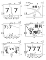
なお、第1特別図柄表示器60及び/又は第2特別図柄表示器61は、7セグメントのLEDによっても構成することができる。例えば、特別図柄の大当たり抽選に当選した場合には、「7」を停止表示し、ハズレであった場合には「-」を停止表示するようにし、変動表示中にあっては消灯と「-」とを繰り返すようにするとよい。なお、特別図柄の変動表示の開始前は前回の変動表示の停止結果がLEDの点灯によって表示された状態となっているので、変動表示の開始時はLEDの消灯からスタートさせることで変動表示が開始されたことが把握し易くなる。
The first
演出空間40aの奥部には、液晶表示ディスプレイからなる第1画像表示装置70(メイン液晶)が設けられ、演出空間40aの下部であって第1画像表示装置70(メイン液晶)の前方には、第1画像表示装置70(メイン液晶)よりも表示領域が小さく形成された液晶表示ディスプレイからなる第2画像表示装置71(サブ液晶)が設けられ、演出空間40aの上部には、キャラクタの顔を模した可動演出部材73Zが設けられている。
なお、本実施の形態では、「第1画像表示装置70(メイン液晶)」と「第2画像表示装置71(サブ液晶)」とをまとめて「画像表示装置」と総称する場合がある。
A first image display device 70 (main liquid crystal) composed of a liquid crystal display is provided in the back of the effect space 40a, and is below the effect space 40a and in front of the first image display device 70 (main liquid crystal). A second image display device 71 (sub liquid crystal) composed of a liquid crystal display having a display area smaller than that of the first image display device 70 (main liquid crystal) is provided, and a character's face is above the effect space 40a. A movable effect member 73Z imitating the above is provided.
In the present embodiment, the "first image display device 70 (main liquid crystal display)" and the "second image display device 71 (sub liquid crystal display)" may be collectively referred to as an "image display device".
第1画像表示装置70(メイン液晶)、及び、第2画像表示装置71(サブ液晶)では、遊技の進行に応じて様々な演出表示を行う。演出表示としては、特別図柄の変動表示が行われていない場合に実行される客待ちデモ演出や特別図柄の変動表示が行われている場合に実行される演出図柄70aの変動表示やキャラクタによる予告演出等がある。
The first image display device 70 (main liquid crystal) and the second image display device 71 (sub liquid crystal) display various effects according to the progress of the game. As the effect display, a customer waiting demo effect executed when the special symbol variation display is not performed, a variation display of the
また、第2画像表示装置71(サブ液晶)は、第1画像表示装置70(メイン液晶)で実行される演出図柄70aの変動表示の実行中に、ソレノイドやモータ等によって構成される盤用駆動装置75(図2参照)によって移動することで移動演出を行うことが可能となっている。
Further, the second image display device 71 (sub liquid crystal) is driven by a solenoid, a motor, or the like during execution of the variable display of the
具体的には、第1画像表示装置70(メイン液晶)の端部寄り(下方)に位置する待機位置(第1位置)と、第1画像表示装置70(メイン液晶)の中央寄り(上方)に位置する演出位置(第2位置)との間で上下方向に移動(上昇、下降)することで移動演出を行うようになっている。なお、第2画像表示装置71(サブ液晶)の移動方向を左右方向や前後方向としてもよいし、演出ボタン17の操作によって移動演出を行うように構成してもよい。
Specifically, the standby position (first position) located near the end (lower) of the first image display device 70 (main liquid crystal) and the center side (upper) of the first image display device 70 (main liquid crystal). The movement effect is performed by moving (raising, descending) in the vertical direction to and from the effect position (second position) located at. The movement direction of the second image display device 71 (sub liquid crystal display) may be the left-right direction or the front-back direction, or the movement effect may be performed by operating the
また、第1画像表示装置70(メイン液晶)の表示部(有効表示領域)には、左側領域、中央領域、右側領域といった3列の変動表示領域が形成されており、各々の変動表示領域に表示される演出図柄70aを縦方向(本実施の形態では上から下)にスクロールさせることで演出図柄70aの変動表示が行われる。
Further, in the display unit (effective display area) of the first image display device 70 (main liquid crystal display), three rows of variable display areas such as a left side area, a central area, and a right side area are formed, and each variable display area has three columns of variable display areas. By scrolling the displayed
なお、演出図柄70aは、例えば、「1」から「9」までの数字を示す図柄により構成され、第1特別図柄表示器60や第2特別図柄表示器61で実行される特別図柄の変動表示に対応(同期)して演出図柄70aの変動表示が行われる。すなわち、特別図柄の変動表示の開始に対応して演出図柄70aの変動表示を開始し、特別図柄の変動表示の停止に対応して演出図柄70aの変動表示を停止するようになっている。なお、演出図柄70aとして、数字を示す図柄の他に「A」から「F」といったアルファベットを示す図柄を設けてもよい。
The
演出図柄70aの停止表示では、演出図柄70aが大当たり抽選の結果を示す所定の態様(ハズレ態様、大当たり態様等)で所定時間停止するようになっている。大当たり態様(特別結果態様)は、「777」などのように同一の演出図柄の組み合わせや「357」などのように規則性を持った演出図柄の組み合わせであり、ハズレ態様はそれ以外の態様である。なお、演出図柄70aの変動表示の態様はこれに限られず、左右方向にスクロールするものであってもよいし、その場で回転(自転)するようなものであってもよい。
In the stop display of the
また、演出図柄70aの変動表示中には、大当たり抽選の結果に応じて、リーチ演出や背景画像、キャラクタ等の様々な演出画像やムービー等が第1画像表示装置70(メイン液晶)や第2画像表示装置71(サブ液晶)に表示されることで、遊技者の大当たり(特別遊技状態)発生への期待度(以下、「大当たり当選期待度」と言う)を高めるようになっている。
Further, during the variable display of the
ここで、リーチ演出とは、大当たりを報知する演出図柄70aの組合せの一部が仮停止して、他の演出図柄70aが変動を行うような、遊技者に大当たり当選への期待感を付与する変動態様を意味する。例えば、大当たりを報知する演出図柄70aの組合せ(大当たり結果態様)として「777」の3桁の演出図柄70aの組み合わせが設定されている場合に、左側領域と右側領域に2つの演出図柄70aが「7」で仮停止して、中央領域で残りの演出図柄70aが変動を行っている態様を言う。
Here, the reach effect gives the player a sense of expectation for winning the jackpot, such that a part of the combination of the
なお、「仮停止」とは、演出図柄70aが小さく揺れ動いたり、演出図柄70aが小さく変形したりして、遊技者に演出図柄70aが停止しているかのようにみせている(完全に停止していない)態様を言う。
The "temporary stop" means that the
また、リーチ演出の種類は、本実施の形態においては、「ノーマルリーチ演出」、「SPリーチ演出」、「SPSPリーチ演出」及び「全回転リーチ演出」の5種類がある。 Further, in the present embodiment, there are five types of reach effects: "normal reach effect", "SP reach effect", "SPSP reach effect", and "full rotation reach effect".
「ノーマルリーチ演出」とは、当該ノーマルリーチ演出となる以前の背景画像が表示されている状態で、左側領域と右側領域に2つの演出図柄70aが仮停止し、中央領域で残り1つの演出図柄70aが変動するリーチ演出のことである。
In the "normal reach effect", two
「SPリーチ演出」とは、左側領域と右側領域に2つの演出図柄70aが仮停止し、中央領域で残り1つの演出図柄70aが変動したまま、ノーマルリーチ演出に係るムービーより長い時間のムービー(動画、アニメーション等)が流れるリーチ演出のことである。
"SP reach effect" is a movie (movie) for a longer time than the movie related to the normal reach effect, with two
「SPSPリーチ演出」とは、左側領域と右側領域に2つの演出図柄70aが仮停止し、中央領域で残り1つの演出図柄70aが変動したまま、SPリーチ演出に係るムービーより長い時間(長編)のムービー(動画、アニメーション等)が流れるリーチ演出のことである。
"SPSP reach effect" is a longer time (feature) than the movie related to SP reach effect, with two
「全回転リーチ演出」とは、大当たりを報知する複数の演出図柄70aの組合せが全て揃った状態で低速に変動するリーチ演出である。本実施の形態においては、大当たり抽選において当選したときにのみ実行されるリーチ演出である。
The "full rotation reach effect" is a reach effect that fluctuates at a low speed with all combinations of a plurality of
本実施の形態では、リーチ演出に係る大当たり当選期待度としては、ノーマルリーチ演出<SPリーチ演出<SPSPリーチ演出<全回転リーチ演出(大当たり確定)の順で高くなっている。 In the present embodiment, the expectation of winning a big hit related to the reach effect is higher in the order of normal reach effect <SP reach effect <SPSP reach effect <full rotation reach effect (big hit confirmed).
また、第1画像表示装置70(メイン液晶)の表示部には、現在の第1保留記憶の個数である第1特別図柄保留数(U1)に対応する数の第1保留アイコンを表示するための第1保留アイコン表示領域70Bと、現在の第2保留記憶の個数である第2特別図柄保留数(U2)に対応する数の第2保留アイコンを表示するための第2保留アイコン表示領域70Dと、実行中の特別図柄(演出図柄70a)の変動表示に対応する(関連した)当該アイコンを表示するための当該アイコン表示領域70Cが形成されている。
Further, in order to display the number of first hold icons corresponding to the first special symbol hold number (U1), which is the current number of first hold storages, on the display unit of the first image display device 70 (main liquid crystal). 1st hold
第1保留アイコン表示領域70Bは、当該アイコン表示領域70Cに近い側から第1表示部70B1、第2表示部70B2、第3表示部70B3、第4表示部70B4といった形で区画されており、各表示部70B1~70B4には、第1特別図柄保留数(U1)に対応した数の第1保留アイコンが表示される。つまり、第1特別図柄保留数(U1)の増減に対応して第1保留アイコンの個数も増減するようになっている。
The first hold
具体的には、第1表示部70B1には、最初に第1特別図柄の変動表示が実行される第1保留記憶を示す第1保留アイコンH11が表示され、第2表示部70B2には、2番目に第1特別図柄の変動表示が実行される第1保留記憶を示す第1保留アイコンH12が表示され、第3表示部70B3には、3番目に第1特別図柄の変動表示が実行される第1保留記憶を示す第1保留アイコンH13が表示され、第4表示部70B4には、4番目に第1特別図柄の変動表示が実行される第1保留記憶を示す第1保留アイコンH14が表示される。 Specifically, the first display unit 70B1 displays the first hold icon H11 indicating the first hold storage in which the variable display of the first special symbol is executed first, and the second display unit 70B2 displays 2 First, the first hold icon H12 indicating the first hold memory on which the variation display of the first special symbol is executed is displayed, and the variation display of the first special symbol is executed third on the third display unit 70B3. The first hold icon H13 indicating the first hold memory is displayed, and the first hold icon H14 showing the first hold memory on which the variable display of the first special symbol is executed is displayed on the fourth display unit 70B4. Will be done.
第2保留アイコン表示領域70Dは、当該アイコン表示領域70Cに近い側から第1表示部70D1、第2表示部70D2、第3表示部70D3、第4表示部70D4といった形で区画されており、各表示部70D1~70D4には、第2特別図柄保留数(U2)に対応した数の第2保留アイコンが表示される。つまり、第2特別図柄保留数(U2)の増減に対応して第2保留アイコンの個数も増減するようになっている。
The second hold icon display area 70D is partitioned from the side closer to the
具体的には、第1表示部70D1には、最初に第2特別図柄の変動表示が実行される第2保留記憶を示す第2保留アイコンH21が表示され、第2表示部70D2には、2番目に第2特別図柄の変動表示が実行される第2保留記憶を示す第2保留アイコンH22が表示され、第3表示部70D3には、3番目に第2特別図柄の変動表示が実行される第2保留記憶を示す第2保留アイコンH23が表示され、第4表示部70D4には、4番目に第2特別図柄の変動表示が実行される第2保留記憶を示す第2保留アイコンH24が表示される。なお、本実施の形態では、「第1特別図柄保留数」を「第1保留数」と「第2特別図柄保留数」を「第2保留数」と称する場合がある。 Specifically, the first display unit 70D1 displays the second hold icon H21 indicating the second hold storage in which the variation display of the second special symbol is executed first, and the second display unit 70D2 displays 2 Second, the second hold icon H22 indicating the second hold memory on which the variation display of the second special symbol is executed is displayed, and the variation display of the second special symbol is executed third on the third display unit 70D3. The second hold icon H23 indicating the second hold memory is displayed, and the second hold icon H24 indicating the second hold memory on which the variation display of the second special symbol is executed is displayed on the fourth display unit 70D4. Will be done. In the present embodiment, the "first special symbol hold number" may be referred to as the "first hold number" and the "second special symbol hold number" may be referred to as the "second hold number".
当該アイコン表示領域70Cは、特別図柄(演出図柄70a)の変動表示の開始に対応して第1保留アイコン表示領域70Bの第1表示部70B1に表示されていた第1保留アイコン、又は、第2保留アイコン表示領域70Dの第1表示部70D1に表示されていた第2保留アイコンが移動(シフト)してくることで当該アイコンTHが表示され、特別図柄(演出図柄70a)の変動表示の終了時に当該アイコンTHが消滅(消去)する。なお、特別図柄(演出図柄70a)の変動表示の途中で当該アイコンを消滅させてもよい。なお、本実施の形態では、「第1保留アイコン」と「第2保留アイコン」と「当該アイコン」とをまとめて「アイコン」と総称する場合がある。
The
可動演出部材73Zは、第1画像表示装置70(メイン液晶)で実行される演出図柄70aの変動表示の実行中に、複数のランプ(LED等)を有する盤用照明装置76によって発光することで発光演出を行うことが可能となっており、ソレノイドやモータ等によって構成される盤用駆動装置75(図2参照)によって移動することで移動演出を行うことが可能となっている。
The movable effect member 73Z emits light by a
具体的には、演出図柄70aの変動表示の進行状態に合わせて複数のランプ(LED等)を所定の発光色で発光することで発光演出を行うようになっている。また、第1画像表示装置70(メイン液晶)の端部寄り(上方)に位置する待機位置(第1位置)と、第1画像表示装置70(メイン液晶)の中央寄り(下方)に位置する演出位置(第2位置)との間で上下方向に移動(上昇、下降)することで移動演出を行うようになっている。なお、演出ボタン17の操作によって発光演出や移動演出を行うように構成してもよい。
Specifically, a light emitting effect is performed by emitting light from a plurality of lamps (LEDs and the like) with a predetermined light emitting color according to the progress state of the variable display of the
遊技盤取付枠3、及び、遊技盤5の裏側には、予め定めた払出条件(賞球、球貸)の成立に基づいて遊技球を払い出すための遊技球払出装置100、島設備などから供給される遊技球を貯留して遊技球払出装置100に供給する遊技球貯留部101(図示省略)、遊技の進行を統括的に制御する主制御基板110を内蔵した主制御装置110A(図示省略)と、主制御基板110からの払出制御コマンドに応じて遊技球払出装置100の制御を行う払出制御基板120を内蔵した払出制御装置120A(図示省略)と、主制御基板110からの演出制御コマンドに応じて演出の制御を行う演出制御基板130を内蔵した演出制御装置130A(図示省略)と、各種制御装置に対して電源電圧の供給を行う電源基板160を内蔵した電源装置160A(図示省略)、遊技機の外部に遊技情報(遊技信号)を出力するための遊技情報出力端子板90(図2参照)が設けられている。
On the back side of the game
(遊技機1の制御構成)
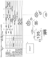
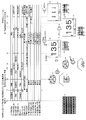
次に、図2を用いて遊技機1の制御構成について具体的に説明する。図2は、本実施の形態における遊技機1の全体のブロック図である。
(Control configuration of gaming machine 1)
Next, the control configuration of the
主制御基板110は、遊技の進行(基本動作)を統括的に制御する。主制御基板110は、演算処理を行うメインCPU110a、遊技制御プログラム等が格納されたメインROM110b、及び、演算処理時のワークエリアとなるメインRAM110c(揮発性記憶手段に相当)を備えた主制御ワンチップマイコン110mと、主制御用の入力ポート、及び、出力ポート等を備えている。メインCPU110aは、水晶発振器からの動作クロックを受けてメインROM110bに記憶されたプログラムを読み出し、メインRAM110cをワークエリアとして活用しながら遊技に関する演算処理を行うことで、被制御装置(各種ソレノイドや各種表示器)を制御したり、演算処理の結果に基づく所定のコマンドを払出制御基板120や演出制御基板130等に送信したりする。
The main control board 110 comprehensively controls the progress (basic operation) of the game. The main control board 110 is a main control one equipped with a
ここで、主制御基板110と払出制御基板120との通信は、双方向にコマンド(データ)を通信可能に構成されており、主制御基板110と演出制御基板130との通信は、主制御基板110から演出制御基板130への一方向のみにコマンド(データ)を通信可能に構成されている。
Here, the communication between the main control board 110 and the
主制御基板110の入力ポートには、一般入賞口検出スイッチ43a、ゲート検出スイッチ44a、第1始動口検出スイッチ45a、第2始動口検出スイッチ47a、大入賞口検出スイッチ50a、入賞確認検出スイッチ52a、磁気検出センサ53a、電波検出センサ54a、RAMクリアスイッチ55a、及び、払出制御基板120等が接続されている。入力ポートを介して、各種検出スイッチや各種検出センサからの検出信号等が主制御基板110に入力されると、検出信号に応じた制御処理が行われる。
The input port of the main control board 110 has a general winning opening detection switch 43a, a gate detection switch 44a, a first starting opening
主制御基板110の出力ポートには、第2始動口開閉ソレノイド48b、大入賞口開閉ソレノイド51b、第1特別図柄表示器60、第2特別図柄表示器61、普通図柄表示器62、第1特別図柄保留表示器63、第2特別図柄保留表示器64、普通図柄保留表示器65、ラウンド数表示器66、右打ち表示器67、遊技情報出力端子板90、及び、演出制御基板130等が接続されている。出力ポートを介して、各種ソレノイドを制御するための駆動制御信号、各種表示器を制御するための表示制御信号、及び、遊技情報出力端子板から遊技機の外部(ホールコンピュータ等)に通知する遊技情報等が出力される。
The output port of the main control board 110 has a second starting port opening / closing solenoid 48b, a winning opening opening / closing solenoid 51b, a first
払出制御基板120は、主制御基板110からの払出コマンドの受信に基づき遊技球の払い出しを制御すると共に、遊技球の発射を制御する従制御基板となっている。払出制御基板120は、遊技球払出装置100を駆動して遊技球の払い出しを制御する払出制御部121と遊技球発射装置26を駆動して遊技球の発射を制御する発射制御部122を備える。
The
払出制御部121は、演算処理を行う払出CPU121a、払出プログラム等が格納された払出ROM121b、演算処理時のワークエリアとなる払出RAM121c、払出制御用の入力ポート、及び、出力ポート等を備えている。払出CPU121aは、図示しない水晶発振器からの動作クロックを受けて払出ROM121bに記憶された払出制御プログラムを読み出し、払出RAM121cをワークエリアとして活用しながら遊技球の払い出しに関する演算処理を行い、遊技球払出装置100を制御したり、演算処理の結果に基づく所定のコマンドを主制御基板110や演出制御基板130等に送信したりする。
The
払出制御部121の入力ポートには、開放検出スイッチ31a、受け皿満杯検出スイッチ32a、遊技球払出装置100に設けられる払出球検出スイッチ100a、及び、遊技球貯留部101に設けられる球有り検出スイッチ101aなどが接続されており、払出制御部121の出力ポートには、遊技球払出装置100に設けられる払出モータ100bが接続されている。
The input port of the
払出制御部121では、主制御基板110から払出コマンドを受信すると、遊技球払出装置100に設けられる払出モータ100bを駆動させて所定個数の遊技球を払い出す制御を行い、払出球検出スイッチ100aによって所定個数の遊技球の払い出しが検出されると遊技球を払い出す制御を終了するようになっている。
When the
発射制御部122は、図示しない制御回路、入力ポート、及び、出力ポート等を備えている。発射制御部122の入力ポートには、タッチセンサ15a、及び、発射ボリューム15bが接続されており、発射制御部122の出力ポートには、球送りソレノイド11b、及び、発射用ソレノイド28bなどが接続されている。
The
発射制御部122では、タッチセンサ15aから入力されるタッチ信号によって遊技者の手が発射ハンドル15に触れていることを検出すると、球送りソレノイド11b、及び、発射用ソレノイド28bへの通電を許容し、発射ボリューム15bからの検出信号によって発射ハンドル15の回動角度が変化したことを検出すると、球送りソレノイド11bを駆動させると共に、発射ハンドル15の回動角度に応じた発射強度となるように発射用ソレノイド28bを駆動させて遊技球を発射させるようになっている。
When the
発射用ソレノイド28bは、ロータリーソレノイドから構成され、回動軸に打出部材28が直結されており、回動軸が回転することで打出部材28が回転して遊技球Aを打ち出すようになっている。なお、発射用ソレノイド28bの動作は、発射制御部122に設けられた水晶発振器の出力周期に基づく周波数から約99.9(回/分)に設定されているため、1分間における遊技球の発射数は約99.9(個/分)となっている。すなわち、遊技球は約0.6秒毎に発射されることになる。
The launching
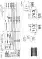
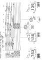
演出制御基板130は、主制御基板110からの演出コマンドの受信に基づき遊技に関する(遊技機1で行われる)演出を制御する従制御基板(従制御手段)となっている。演出制御基板130は、演算処理を行うサブCPU130a、演出制御プログラムが格納されたサブROM130b、演算処理時のワークエリアとなるサブRAM130cを備えた演出制御部130mと、第1画像表示装置70(メイン液晶)や第2画像表示装置71(サブ液晶)や音声出力装置9(スピーカ)等を制御する表示/音声制御部140、枠用照明装置10やハンドル発光装置15cやボタン駆動装置17bや送風装置21や盤用照明装置76や盤用駆動装置75等を制御するランプ/駆動制御部150と、演出制御用の入力ポートや出力ポート等を備えている。
The effect control board 130 is a slave control board (sub-control means) that controls the effect (performed by the game machine 1) related to the game based on the reception of the effect command from the main control board 110. The effect control board 130 includes a
サブCPU130aは、水晶発振器からの動作クロックを受けてサブROM130bに記憶された遊技プログラムを読み出し、サブRAM130cをワークエリアとして活用しながら演出に関する演算処理を行うことで、主制御基板110から受信したコマンドや演出ボタン検出スイッチ17aや十字キー検出スイッチ19aからの入力信号に応じて、各種制御部(表示/音声制御部140、ランプ/駆動制御部150)に各種の演出を実行させるため制御を行う(データやコマンドを出力する)。
The
演出制御基板130の入力ポートには、演出ボタン検出スイッチ17aや十字キー検出スイッチ19aなどが接続されている。演出制御基板130では、演出ボタン検出スイッチ17aから演出ボタン17が操作されたことを示す演出ボタン検出信号が入力されたり、十字キー検出スイッチ19aから十字キー19が操作されたことを示す十字キー検出信号(上ボタン検出信号、左ボタン検出信号、下ボタン検出信号、右ボタン検出信号)が入力されたりすると、検出信号に応じた演出を実行するための処理を行う。
An effect
表示/音声制御部140は、演出制御部130mからのコマンドを受けて、第1画像表示装置70(メイン液晶)、及び、第2画像表示装置71(サブ液晶)に所定の画像を表示させる制御を行ったり、音声出力装置9に所定の音声を出力させる制御を行ったりする。
The display / voice control unit 140 is controlled to display a predetermined image on the first image display device 70 (main liquid crystal) and the second image display device 71 (sub liquid crystal) in response to a command from the
表示/音声制御部140は、演算処理を行う統括CPU142、統括制御プログラムが格納された統括ROM143、演算処理時のワークエリアとなる統括RAM144を備えた統括制御部141と、画像プロセッサとしてのVDP(Video Display Processor)からなる画像制御部145と、画像データ等が格納されたCGROM146と、画像制御部145の内部に設けられ、画像データから生成される描画データを一時的に記憶するフレームバッファ等を有するVRAM147と、音声プロセッサとしての音声制御部148と、音声データ等が格納された音声ROM149、及び、入出力ポート等を備えている。
The display / audio control unit 140 includes a
統括CPU142は、水晶発振器からの動作クロックを受けて統括ROM143に記憶された表示制御プログラムを読み出し、統括RAM144をワークエリアとして活用しながら演出に関する演算処理を行うことで、演出制御部130mから受信した演出指示コマンド等に応じて、画像制御部145や音声制御部148に各種の演出を実行させるための制御を行う(データやコマンドを出力する)。
The
統括ROM143は、マスクROM等で構成されており、画像表示を行うための表示制御プログラム、描画制御コマンド群から構成されるディスプレイリストを生成するためのディスプレイリスト生成プログラム、演出パターンのアニメーションを表示するためのアニメパターン、アニメシーン情報などが記憶されている。
The
このアニメパターンは、画像による演出の具体的な内容を構成するアニメーションを表示するにあたり参照され、アニメパターンにはアニメシーン情報や各アニメシーンの表示順序等に関連付けられている。なお、アニメシーン情報には、ウェイトフレーム(表示時間)、対象データ(スプライトの識別番号、転送元アドレス等)、描画のためのパラメータ(スプライトの表示位置、表示倍率、透過率等)、描画方法、第1画像表示装置70(メイン液晶)、及び、第2画像表示装置71(サブ液晶)の輝度のパラメータとなるデューティー比等の各種情報が含まれている。 This animation pattern is referred to when displaying an animation constituting a specific content of an image effect, and the animation pattern is associated with animation scene information, a display order of each animation scene, and the like. The animation scene information includes weight frames (display time), target data (sprite identification number, transfer source address, etc.), drawing parameters (sprite display position, display magnification, transparency, etc.), drawing method. , The duty ratio which is a parameter of the brightness of the first image display device 70 (main liquid crystal) and the second image display device 71 (sub liquid crystal) is included.
画像制御部145(VDP)は、各種の画像データが記憶されているCGROM146が接続されており、統括制御部141(統括CPU142)からのコマンド(ディスプレイリスト、描画指令等)とCGROM146に記憶された画像データに基づいて映像信号(RGB信号等)の元となる描画データを生成する。画像データは、第1画像表示装置70(メイン液晶)、及び、第2画像表示装置71(サブ液晶)に表示させる画像(フレーム)、例えば、演出図柄画像、演出図柄の背景を構成する背景画像、キャラクタ画像、及び、セリフ画像などの個々の画像を表す素材的なデータである。一方、描画データは、個々の画像が複合されて(重ね合わされて)構成されるフレーム全体の画像を表す合成的なデータである。
The image control unit 145 (VDP) is connected to a CGROM 146 that stores various image data, and is stored in the
CGROM146は、フラッシュメモリ、EEPROM、EPROM、マスクROM等から構成され、所定範囲の画素(例えば、32×32ピクセル)における画素情報の集まりからなる画像データ(スプライト、ムービー)等を圧縮して記憶している。なお、画素情報は、それぞれの画素毎に色番号を指定する色番号情報と画像の透明度を示すα値とから構成されている。このCGROM146は、画像制御部145(VDP)によって画像データ単位で読み出しが行われ、このフレームの画像データ単位で画像処理が行われる。
The
また、CGROM146は、色番号を指定する色番号情報と実際に色を表示するための表示色情報とが対応づけられたパレットデータを圧縮せずに記憶している。なお、CGROM146は、全ての画像データを圧縮せずとも、一部のみ圧縮している構成でもよい。また、ムービーの圧縮方式としては、MPEG4等の公知の種々の圧縮方式を用いることができる。
Further, the
VRAM147は、画像データの書き込み、又は、読み出しが高速なSRAMで構成されている。このVRAM143は、統括制御部141(統括CPU142)から出力されたディスプレイリストを一時的に記憶するディスプレイリスト記憶領域、第1画像表示装置70(メイン液晶)、及び、第2画像表示装置71(サブ液晶)に対応するフレームバッファ領域等を有している。
The
このフレームバッファ領域は、画像を描画、又は、表示するための記憶領域であり、第1フレームバッファ領域と第2フレームバッファ領域とを更に有している。そして、第1フレームバッファ領域と第2フレームバッファ領域とは、描画の開始毎に「描画用フレームバッファ」と「表示用フレームバッファ」とに交互に切り替わるものである。 This frame buffer area is a storage area for drawing or displaying an image, and further has a first frame buffer area and a second frame buffer area. The first frame buffer area and the second frame buffer area are alternately switched between the "drawing frame buffer" and the "display frame buffer" at each start of drawing.
そのため、画像制御部145(VDP)は、統括制御部141(統括CPU142)からの指示(ディスプレイリスト)に基づいて、CGROM146に記憶された描画データをVRAM147のフレームバッファ領域の「描画用フレームバッファ」に描画し、フレームバッファ領域の「表示用フレームバッファ」から描画データを読み出し、読み出した描画データに基づいて映像信号(RGB信号等)を生成して、第1画像表示装置70(メイン液晶)、及び、第2画像表示装置71(サブ液晶)に出力して種々の画像を表示させる。
Therefore, the image control unit 145 (VDP) uses the drawing data stored in the
なお、画像制御部145(VDP)には、水晶発振器から動作クロックが供給されており、この動作クロックを分周することで、第1画像表示装置70(メイン液晶)、及び、第2画像表示装置71(サブ液晶)と同期を図るための同期信号(水平同期信号・垂直同期信号)を生成し、第1画像表示装置70(メイン液晶)、及び、第2画像表示装置71(サブ液晶)に出力する。本実施の形態では、画像制御部145(VDP)のフレームレートは1秒間に30回の描画(画像の表示)が行われるように30fps(1/30秒=約33ms)となっているが、1秒間に60回の描画(画像の表示)が行われるように60fps(1/60秒=約16.6ms)としてもよい。 An operating clock is supplied to the image control unit 145 (VDP) from the crystal oscillator, and by dividing the operating clock, the first image display device 70 (main liquid crystal display) and the second image display are displayed. A synchronization signal (horizontal synchronization signal / vertical synchronization signal) for synchronizing with the device 71 (sub liquid crystal) is generated, and the first image display device 70 (main liquid crystal) and the second image display device 71 (sub liquid crystal) Output to. In the present embodiment, the frame rate of the image control unit 145 (VDP) is 30 fps (1/30 second = about 33 ms) so that drawing (image display) is performed 30 times per second. It may be set to 60 fps (1/60 second = about 16.6 ms) so that drawing (image display) is performed 60 times per second.
また、画像制御部145と第1画像表示装置70(メイン液晶)、及び、第2画像表示装置71(サブ液晶)との間には、画像データを所定の画像形式に変換して出力する汎用基板72が接続されている。汎用基板72は、画像データを表示する第1画像表示装置70(メイン液晶)、及び、第2画像表示装置71(サブ液晶)の性能に対応する画像形式に変換するブリッジ機能を有しており、例えば、SXGA(1280ドット×1080ドット)の19インチの液晶表示装置を接続したときと、XGA(1024ドット×768ドット)の17インチの液晶表示装置を接続したときとの解像度の違いなどを吸収する。
Further, a general-purpose image data is converted into a predetermined image format and output between the
音声制御部148は、音声出力装置9と接続しており、演出制御部130mから送信された各種の演出データ(コマンド含む)に基づいて、第1画像表示装置70(メイン液晶)、及び、第2画像表示装置71(サブ液晶)の表示に合わせて音声データや楽曲データ(BGM、SE)等を音声出力装置9から出力させる制御を行う。
The
ランプ/駆動制御部150は、演算処理を行うランプCPU150aと、ランプ・駆動制御プログラムが格納されたランプROM150b、演算処理時のワークエリアとなるランプRAM150c、及び、入出力ポート等を備えている。
The lamp / drive control unit 150 includes a
ランプCPU150aは、水晶発振器からの動作クロックを受けてランプROM150bに記憶されたランプ・駆動制御プログラムを読み出し、ランプRAM150cをワークエリアとして活用しながら演出に関する演算処理を行うことで、演出制御部130mから受信した演出指示コマンド等に応じて、各種照明装置や各種駆動装置などの被制御装置に所定の演出を行わせるための制御を行う(データやコマンドを出力する)。
The
ランプ/駆動制御部の入出力ポートには、枠用照明装置10、ハンドル発光装置15c、ボタン駆動装置17b、送風装置21、盤用照明装置76が接続されており、演出制御部130m(サブCPU130a)から送信された各種の演出データ(コマンド含む)に基づいて、枠用照明装置10、ハンドル発光装置15c、及び、盤用照明装置76の各種LEDの点灯制御を行うことで発光演出等を行ったり、ボタン駆動装置17b、送風装置21、及び、盤用駆動装置75のモータやソレノイドといった駆動源の駆動制御を行うことで動作演出(前述した移動演出)等を行ったりする。
A
電源基板160は、遊技機の外部から供給される電源から遊技機の動作に必要なメイン電源(動作電源)を生成し、該メイン電源を遊技機1(主制御基板110、払出制御基板120、演出制御基板130や各種電子部品)に供給する。電源基板160には、電源断(停電)が発生したか否かを検出すると共に、電源断(停電)の発生に基づき電断検出信号を主制御基板110に出力する電断検出回路162と、電源断(停電)時に主制御基板110に対してバックアップ電源を供給するためのバックアップ電源回路163を備える。
The
また、電源基板160は、遊技機1(主制御基板110、払出制御基板120、演出制御基板130や各種電子部品)へのメイン電源の供給を行うON状態と停止するOFF状態とに切り替えるための電源スイッチを遊技店の店員によって操作可能なように備えており、電源スイッチをON状態にするとメイン電源の供給が開始されて遊技機1の動作が開始する。なお、電源スイッチがOFF状態であっても主制御基板110へのバックアップ電源の供給は維持される。
Further, the
電断検出回路162は、遊技機1に供給される電源電圧を監視し、電源電圧が所定値以下となったときに、電断検出信号を主制御基板110に出力する。より具体的には、電断検出信号がハイレベルになるメインCPU110aは動作可能状態となり、電断検出信号がローレベルになるとメインCPU110aは動作停止状態になる。
The power
バックアップ電源回路163は、遊技機への通電時に蓄電するコンデンサを備えており、電源断(停電)が発生するとコンデンサに蓄えられていたバックアップ用の電源電圧を主制御基板110のメインRAM110cに対して供給する。これにより、電源断(停電)時においてもメインRAM110cや払出RAM121cの記憶内容が保持されることになり、電源断(停電)からの復旧後に遊技の制御状態を電源断(停電)前の状態に復旧させることができる。なお、払出制御基板120や演出制御基板130にバックアップ電源を供給するようにしてもよい。
The backup
(遊技状態の説明)
次に、遊技が進行する際の遊技状態について説明する。本実施の形態においては、特別図柄の大当たり抽選に関する状態として「低確率遊技状態」と「高確率遊技状態」とを有し、第2始動口47が有する可動部材48に関する状態として「非時短遊技状態」と「時短遊技状態」とを有する。
(Explanation of game status)
Next, the game state when the game progresses will be described. In the present embodiment, the state relating to the jackpot lottery of the special symbol has a "low probability gaming state" and the "high probability gaming state", and the state relating to the
本実施の形態では、以下の3つの遊技状態が設けられている。
(1)「低確率遊技状態」且つ「非時短遊技状態」である低確非時短遊技状態
(2)「低確率遊技状態」且つ「時短遊技状態」である低確時短遊技状態
(3)「高確率遊技状態」且つ「時短遊技状態」である高確時短遊技状態
In this embodiment, the following three gaming states are provided.
(1) Low-probability non-time-saving gaming state that is "low-probability gaming state" and "non-time-saving gaming state" (2) Low-probability time-saving gaming state that is "low-probability gaming state" and "time-saving gaming state" (3) " High-probability time-saving game state that is both "high-probability game state" and "time-saving game state"
なお、遊技を開始したときの遊技状態、すなわち遊技機1の初期の遊技状態は、「低確非時短遊技状態」に設定されており、この遊技状態を本実施の形態においては「通常遊技状態」と称することにする。なお、本実施の形態においては「低確時短遊技状態」及び「高確時短遊技状態」は通常遊技状態よりも遊技者に有利な遊技状態であることから「特定遊技状態」と称する場合がある。
The gaming state when the game is started, that is, the initial gaming state of the
本実施の形態において「低確率遊技状態」というのは、第1始動口45、又は、第2始動口47に遊技球が入球したことを条件として行われる特別図柄の大当たり抽選において、大当たりの当選確率が、例えば1/299と低く設定された遊技状態を言う。これに対して「高確率遊技状態」というのは、低確率遊技状態と比べて大当たりの当選確率が向上し、大当たりの当選確率が、例えば1/59.8と高く設定された遊技状態を言う。したがって、「高確率遊技状態」では、「低確率遊技状態」よりも、大当たりに当選しやすいことになる。なお、低確率遊技状態から高確率遊技状態に変更するのは、後述する大当たり遊技を終了した後である。 In the present embodiment, the "low-probability gaming state" is a big hit in the big hit lottery of the special symbol performed on the condition that the game ball enters the first starting opening 45 or the second starting opening 47. It refers to a gaming state in which the winning probability is set as low as 1/299, for example. On the other hand, the "high probability gaming state" refers to a gaming state in which the jackpot winning probability is improved as compared with the low probability gaming state, and the jackpot winning probability is set as high as, for example, 1 / 59.8. .. Therefore, in the "high-probability gaming state", it is easier to win the jackpot than in the "low-probability gaming state". It should be noted that the change from the low-probability gaming state to the high-probability gaming state is performed after the jackpot game described later is completed.
本実施の形態では、高確率遊技状態への移行の契機となる大当たりを「確変大当たり」と言う。また、低確率遊技状態への移行の契機となる大当たりを「通常大当たり」と言う。 In the present embodiment, the jackpot that triggers the transition to the high-probability gaming state is referred to as "probability variation jackpot". In addition, the jackpot that triggers the transition to the low-probability gaming state is called "normal jackpot".
本実施の形態において「非時短遊技状態」というのは、普図ゲート44を遊技球が通過したことを条件として行われる普通図柄の当たり抽選において、その抽選結果に対応する普通図柄の平均の変動時間が「時短遊技状態」よりも長く設定され、かつ、当たりに当選した際の第2始動口47の開放時間が短く設定されやすい遊技状態を言う。例えば、普図ゲート44を遊技球が通過すると、普通図柄の当たり抽選が行われて、普通図柄表示器62において普通図柄の変動表示が行われるが、普通図柄は変動表示が開始されてから、例えば30秒後に停止表示する。そして、抽選結果が当たりであった場合には、普通図柄の停止表示後に、第2始動口47が例えば0.2秒間、開放態様に制御される。
In the present embodiment, the "non-time saving game state" is a change in the average of the normal symbols corresponding to the lottery result in the winning lottery of the normal symbols performed on the condition that the game ball passes through the
これに対して「時短遊技状態」というのは、普図ゲート44を遊技球が通過したことを条件として行われる普通図柄の当たり抽選において、その抽選結果に対応する普通図柄の平均の変動時間が「非時短遊技状態」よりも短く設定され、かつ、当たりに当選した際の第2始動口47の開放時間が例えば2.5秒と、「非時短遊技状態」よりも長く設定された遊技状態を言う。さらに、「非時短遊技状態」においては普通図柄の当たり抽選において当たりに当選する確率が例えば1/128と低く設定され、「時短遊技状態」においては普通図柄抽選において当たりに当選する確率が例えば127/128と高く設定される。したがって、「時短遊技状態」においては、「非時短遊技状態」よりも、普図ゲート44を遊技球が通過すると、第2始動口47が開放態様に制御されやすくなる。これにより、「時短遊技状態」では、遊技者は遊技球を消費せずに遊技を有利に進行することが可能となる。
On the other hand, the "time saving game state" is the average fluctuation time of the normal symbol corresponding to the lottery result in the winning lottery of the normal symbol performed on the condition that the game ball passes through the
なお、実施形態において、「時短遊技状態」は、「非時短遊技状態」と比べて、普通図柄の変動時間、第2始動口47の開放時間、及び、普通図柄抽選の当選確率が有利になるよう設定されている。しかしながら、「時短遊技状態」は、普通図柄の変動時間、第2始動口47の開放時間、及び、普通図柄抽選の当選確率のいずれか1つのみが有利になるように設定されていてもよい。また、非時短遊技状態では、普通図柄の当たり抽選において当たりに当選する確率が例えば0/128となるようにしてもよい。
In the embodiment, the "time-saving game state" has more advantages than the "non-time-saving game state" in terms of the fluctuation time of the normal symbol, the opening time of the
(大当たりの種類)
次に、大当たりの種類について説明する。
(Type of jackpot)
Next, the types of jackpots will be described.
本実施の形態においては、第1始動口45への遊技球の入賞に基づく、大当たり抽選において当選し得る大当たりの種類として、「第1大当たり」、「第2大当たり」及び「第3大当たり」を有し、第2始動口47への遊技球の入賞に基づく、大当たり抽選において当選し得る大当たりの種類として、「第1大当たり」及び「第2大当たり」を有している。
In the present embodiment, "first jackpot", "second jackpot", and "third jackpot" are selected as the types of jackpots that can be won in the jackpot lottery based on the winning of the game ball to the
「第1大当たり」とは、大入賞口50を最大29.5秒まで開放させた後に大入賞口50を2秒間に亘って閉鎖させるラウンド遊技を10回まで実行する第1大当たり遊技を実行する大当たりである。なお、ラウンド遊技では、開放時間の経過前でも規定個数(例えば、10個)の遊技球が大入賞口50に入賞すると1つのラウンド遊技が終了する。
The "first big hit" is to execute the first big hit game in which the big winning
第1大当たり遊技の終了後は、特別図柄(第1特別図柄、第2特別図柄)の変動表示が10000回行われるまで高確時短遊技状態に設定される。そのため、高確率遊技状態の大当たり当選確率からすると、実質的に次回の大当たりが確定する。 After the end of the first big hit game, the high-accuracy time-saving game state is set until the variable display of the special symbols (first special symbol, second special symbol) is performed 10,000 times. Therefore, from the jackpot winning probability in the high probability gaming state, the next jackpot is substantially determined.
「第2大当たり」とは、ラウンド遊技を10回まで実行する第2大当たり遊技を実行する大当たりである。第2大当たり遊技の終了後は、特別図柄(第1特別図柄、第2特別図柄)の変動表示が100回行われるまで低確時短遊技状態に設定される。 The "second jackpot" is a jackpot that executes a second jackpot game in which a round game is executed up to 10 times. After the end of the second big hit game, the game is set to the low-probability short-time game state until the variable display of the special symbols (first special symbol, second special symbol) is performed 100 times.
「第3大当たり」とは、ラウンド遊技を4回まで実行する第3大当たり遊技を実行する大当たりである。第3大当たり遊技の終了後は、特別図柄(第1特別図柄、第2特別図柄)の変動表示が10000回行われるまで高確時短遊技状態に設定される。そのため、高確率遊技状態の大当たり当選確率からすると、実質的に次回の大当たりが確定する。 The "third jackpot" is a jackpot that executes a third jackpot game in which a round game is executed up to four times. After the end of the third big hit game, the high-accuracy time-saving game state is set until the variable display of the special symbols (first special symbol, second special symbol) is performed 10,000 times. Therefore, from the jackpot winning probability in the high probability gaming state, the next jackpot is substantially determined.
なお、大当たり遊技後に設定される特定遊技状態(高確時短遊技状態、低確時短遊技状態)の変動表示回数(本実施の形態では、上述の100回や10000回)のことを、「高確率回数」や「時短回数」と表現する場合がある。 It should be noted that the number of variable display times (in this embodiment, the above-mentioned 100 times or 10000 times) of the specific game state (high-probability short-time game state, low-probability short-time game state) set after the big hit game is referred to as "high probability". It may be expressed as "number of times" or "time reduction number of times".
なお、本実施の形態では、大当たりの種類を3種類としているが、3種類に限られず、3種類よりも少なくてもよいし、多くてもよい。また、開閉部材51の開放時間を何れの大当たり(第1大当たり~第3大当たり)であっても29.5秒としているが、開放時間は29.5秒ではなくてもよいし、ラウンド遊技によって異なる開放時間としてもよい。
In the present embodiment, the number of types of jackpots is three, but the number is not limited to three, and may be less than or more than three. Further, the opening time of the opening / closing
(当たりの種類)
次に、当たりの種類について説明する。
(Type of hit)
Next, the types of hits will be described.
本実施の形態においては、普図ゲート44への遊技球の通過に基づく、当たり抽選において当選し得る当たりの種類として、「第1当たり」及び「第2当たり」を有し、当たり抽選が実行される際の遊技状態が非時短遊技状態であれば、「第1当たり」となり、当たり抽選が実行される際の遊技状態が時短遊技状態であれば、「第2当たり」となる。
In the present embodiment, there are "first hit" and "second hit" as the types of hits that can be won in the winning lottery based on the passage of the game ball to the
「第1当たり」とは、第2始動口47を最大0.2秒まで開放させる第1当たり遊技を実行する当たりである。つまり、可動部材48を1回開放させる当たり遊技である。
The "first hit" is a hit in which the first hit game in which the
「第2当たり」とは、第2始動口47を、2.6秒まで開放させた後に1.5秒まで閉鎖させ、再び2.6秒まで開放させる第2当たり遊技を実行する当たりである。つまり、可動部材48を2回開放させる当たり遊技である。
The "second hit" is a hit in which the second start opening 47 is opened for 2.6 seconds, then closed for 1.5 seconds, and then opened again for 2.6 seconds. .. That is, it is a hit game in which the
なお、第1当たり遊技及び第2当たり遊技では、開放時間の経過前でも規定個数(例えば、10個)の遊技球が大入賞口50に入賞すると当たり遊技が終了する。
In the first hit game and the second hit game, the hit game ends when a specified number (for example, 10) of game balls wins in the large winning
このように、「時短遊技状態」では、第2始動口47に遊技球が入賞し易くなっており、「非時短遊技状態」よりも、遊技者は遊技球を消費せずに遊技を有利に進行することが可能となっている。
In this way, in the "short-time game state", the game ball is easily won in the
次に、遊技機1における遊技の進行について、フローチャートを用いて説明する。
Next, the progress of the game in the
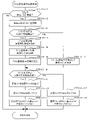
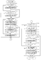
(主制御基板のメイン処理)
図3を用いて、主制御基板110のメイン処理を説明する。図3は、主制御基板110のメイン処理を示すフローチャートである。
(Main processing of main control board)
The main process of the main control board 110 will be described with reference to FIG. FIG. 3 is a flowchart showing the main processing of the main control board 110.
電源基板160から電源電圧が供給されると、メインCPU110aにシステムリセットが発生し、メインCPU110aは以下のメイン処理を行う。
When the power supply voltage is supplied from the
まず、メインCPU110aは、ステップS10において、初期化処理を行う。具体的には、電源投入に応じてメインROM110bから起動プログラムを読み込むと共に、メインRAM110cに記憶されるフラグなどを初期化する処理を行う。
First, the
メインCPU110aは、ステップS20において、特別図柄の変動態様(変動時間)を決定するためのリーチ判定用乱数値、及び、特別図柄決定用乱数値を更新する処理を行い、ステップS30において、大当たり判定用初期値乱数値、特別図柄決定用初期値乱数値、当たり判定用初期値乱数値、及び、普通図柄決定用初期値乱数値の更新を行う初期値乱数値更新処理を行う。
In step S20, the
次に、メインCPU110aは、ステップS40において電源断(停電)が発生したか否かの判定を行う。具体的には、電源基板160の電断検出回路から電断検出信号が入力されたか否かを判定し、電断検出信号が入力されていない場合には、ステップS20に移行し、電断検出信号が入力された場合には、ステップS41に移行する。
Next, the
メインCPU110aは、ステップS41において、タイマ割込を禁止する割込禁止を設定し、ステップS42において、出力ポートをクリアする処理を行い、ステップS43において、メインRAM110cのチェックサムを算出して所定の記憶領域に記憶させる処理を行い、ステップS44において、電断からの復旧時に参照するバックアップフラグをONする処理を行い、ステップS45において、RAMアクセスを禁止する処理を行い、電源電圧の供給が完全に断たれるまで待機する。
The
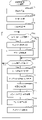
(主制御基板のタイマ割込処理)
図4を用いて、主制御基板110のタイマ割込処理を説明する。図4は、主制御基板110において所定の周期(4ミリ秒)毎に実行されるタイマ割込処理を示すフローチャートである。
(Timer interrupt processing on the main control board)
The timer interrupt processing of the main control board 110 will be described with reference to FIG. FIG. 4 is a flowchart showing a timer interrupt process executed at a predetermined cycle (4 milliseconds) on the main control board 110.
まず、メインCPU110aは、ステップS100において、レジスタに格納されている情報をスタック領域に退避させ、ステップS110において、特別図柄時間カウンタの更新処理、特別電動役物の開放時間等などの特別遊技タイマカウンタの更新処理、普通図柄時間カウンタの更新処理、可動部材48の開閉時間の更新処理等の各種タイマカウンタを更新する時間制御処理を行う。具体的には、特別図柄時間カウンタ、特別遊技タイマカウンタ、普通図柄時間カウンタ、始動口開放タイマカウンタ、始動口閉鎖タイマカウンタなどのカウンタから1を減算する処理を行う。
First, in step S100, the
メインCPU110aは、ステップS120において、大当たり判定用乱数値、特別図柄決定用乱数値、特図変動パターン決定用乱数値、当たり判定用乱数値、普通図柄決定用乱数値、及び、普図変動パターン決定用乱数値の更新を行う特定乱数更新処理を行う。具体的には、それぞれの乱数値、及び、乱数カウンタを+1加算して更新する。なお、加算した乱数カウンタが乱数範囲の最大値を超えた場合(乱数カウンタが1周した場合)には、乱数カウンタを0に戻し、乱数カウンタが周回の初期値まで戻った場合には、対応する初期値乱数値を新たな周回初期値として設定して乱数値を新たに更新する。
In step S120, the
メインCPU110aは、ステップS130において、ステップS30と同様に、大当たり判定用初期値乱数値、特別図柄決定用初期値乱数値、当たり判定用初期値乱数値、及び、普通図柄決定用初期値乱数値を更新する初期値乱数値更新処理を行う。
In step S130, the
メインCPU110aは、ステップS200において、一般入賞口検出スイッチ43a、大入賞口検出スイッチ50a、第1始動口検出スイッチ45a、第2始動口検出スイッチ47a、ゲート検出スイッチ44a、入賞確認検出スイッチ52a等の各種スイッチに入力があったか否かを判定し、入力があった場合に所定のデータをセットする入力制御処理を行う。詳しくは、図5を用いて後述する。
In step S200, the
メインCPU110aは、ステップS300において、特別図柄記憶判定(大当たり判定など)、特別図柄の表示制御、大入賞口50(開閉部材51)の開閉制御、遊技状態の制御等を行うための特図特電制御処理を行う。詳しくは、図7を用いて後述する。
In step S300, the
メインCPU110aは、ステップS400において、普通図柄記憶判定(当たり判定など)、普通図柄の表示制御、第2始動口47(可動部材48)の開閉制御等を行うための普図普電制御処理を行う。
In step S400, the
次に、メインCPU110aは、ステップS500において、払出制御基板120の払出状態を確認するための払出状態確認指定コマンドを払出制御基板120に送信したり、後述する賞球カウンタ(3個賞球カウンタ、10個賞球カウンタ、15個賞球カウンタ)を参照し、各種入賞口に対応する払出数指定コマンドを払出制御基板120に送信したりするための払出制御処理を行う。これにより払出制御基板120が遊技球払出装置100から賞球を払い出すための制御を実行する。
Next, in step S500, the
メインCPU110aは、ステップS600において、磁気検出センサ53a、及び、電波検出センサ54aからの入力信号に基づいて、磁気異常や電波異常の発生を判定し、磁気異常用エラー指定コマンドや電波異常用エラー指定コマンドを演出制御基板130に送信するための磁気・電波異常判定処理を行う。なお、演出制御基板130では、磁気異常用エラー指定コマンドや電波異常用エラー指定コマンドを受信すると、磁気異常エラー報知や電波異常エラー報知を行うための制御を行う。
In step S600, the
メインCPU110aは、ステップS700において、遊技情報出力端子板90から出力する外部情報データ(遊技情報)、第2始動口開閉ソレノイド48bに出力する始動口開閉データ、大入賞口開閉ソレノイド51bに出力する大入賞口開閉データ、第1特別図柄表示器60及び第2特別図柄表示器61に出力する特別図柄表示データ、普通図柄表示器62に出力する普通図柄表示データ、第1特別図柄保留表示器63及び第2特別図柄保留表示器64に出力する特別図柄保留表示データ、及び、普通図柄保留表示器65に出力する普通図柄保留表示データ等のデータを作成するデータ作成処理を行う。
In step S700, the
メインCPU110aは、ステップS800において、上記ステップS700で作成した外部情報データ、始動口開閉データ、及び、大入賞口開閉データ等の信号を出力させるポート出力処理や、特別図柄表示データ、普通図柄表示データ、特別図柄保留表示データ、普通図柄保留表示データ等の信号を出力させる表示出力処理や、メインRAM110cの払出用伝送データ格納領域にセットされているコマンドを払出制御基板120に送信する払出コマンド送信処理や、メインRAM110cの演出用伝送データ格納領域にセットされているコマンドを演出制御基板130に送信する演出コマンド送信処理を実行する出力制御処理を行う。
In step S800, the
なお、主制御基板110から演出制御基板130に送信されるコマンドの種類については、図8、及び、図9を用いて後述する。 The types of commands transmitted from the main control board 110 to the staging control board 130 will be described later with reference to FIGS. 8 and 9.
メインCPU110aは、ステップS900において、ステップS100で退避した情報をメインCPU110aのレジスタに復帰させ、今回のタイマ割込処理を終了する。
In step S900, the
(主制御基板の入力制御処理)
図5を用いて、主制御基板110の入力制御処理を説明する。図5は、主制御基板110における入力制御処理を示すフローチャートである。
(Input control processing of the main control board)
The input control process of the main control board 110 will be described with reference to FIG. FIG. 5 is a flowchart showing an input control process on the main control board 110.
メインCPU110aは、ステップS210において、一般入賞口検出スイッチ入力処理を行う。この一般入賞口検出スイッチ入力処理では、一般入賞口検出スイッチ43aから検出信号を入力したか、すなわち、遊技球が一般入賞口43に入賞したか否かの判定を行う。一般入賞口検出スイッチ43aから検出信号の入力がなければ、ステップS220に処理を移す。
In step S210, the
一般入賞口検出スイッチ43aから検出信号を入力した場合には、賞球のために用いる一般入賞口用の賞球カウンタ(10個賞球カウンタ)に10個賞球を示すデータを加算して更新し、入賞口に入球した遊技球の数を示す入賞球カウンタ(D)に「1」を加算して更新(D←D+1)した後、一般入賞口検出スイッチ入力処理を終了する。 When the detection signal is input from the general prize opening detection switch 43a, the data indicating 10 prize balls is added to the prize ball counter (10 prize ball counter) for the general winning opening used for the prize balls and updated. Then, "1" is added to the winning ball counter (D) indicating the number of game balls entered in the winning opening to update (D ← D + 1), and then the general winning opening detection switch input process is terminated.
メインCPU110aは、ステップS220において、大入賞口検出スイッチ入力処理を行う。この大入賞口検出スイッチ入力処理では、大入賞口検出スイッチ50aから検出信号を入力したか、すなわち、遊技球が大入賞口50に入賞したか否かの判定を行う。大入賞口検出スイッチ50aから検出信号の入力がなければ、ステップS230に処理を移す。
In step S220, the
大入賞口検出スイッチ50aからの検出信号を入力した場合には、賞球のために用いる大入賞口用の賞球カウンタ(15個賞球カウンタ)に15個賞球を示すデータを加算して更新し、入賞口に入球した遊技球の数を示す入賞球カウンタ(D)に「1」を加算して更新(D←D+1)し、現在の遊技状態が特別遊技状態中であるか否かを判定する。現在の遊技状態が特別遊技状態中である場合には、大入賞口50に入賞した遊技球を計数するためのラウンド入賞カウンタ(C)に「1」を加算して更新(C←C+1)し、大入賞口検出スイッチ入力処理を終了する。
When the detection signal from the large prize opening detection switch 50a is input, the data indicating 15 prize balls is added to the prize ball counter (15 prize ball counters) for the large prize opening used for the prize balls. Update and update (D ← D + 1) by adding "1" to the prize ball counter (D) indicating the number of game balls that have entered the prize opening, and whether or not the current game state is in the special game state. Is determined. When the current game state is in the special game state, "1" is added to the round prize counter (C) for counting the game balls won in the
現在の遊技状態が特別遊技状態中でない場合には、入賞可能期間外に特定入賞口(第2始動口47、大入賞口50)に入賞(入球)した遊技球の個数を示す不正入賞球カウンタ(E)に「1」を加算して更新(E←E+1)し、不正入賞球カウンタ(E)の値が規定個数(例えば10個)よりも多いか否かの判定を行い、不正入賞球カウンタ(E)の値が規定個数以下の場合には、大入賞口検出スイッチ入力処理を終了する。
If the current game state is not in the special game state, an illegal winning ball indicating the number of game balls that have won (winned) in the specific winning opening (second starting
不正入賞球カウンタ(E)の値が規定個数よりも多い場合には、入賞可能期間外に遊技球が入賞(入球)する不正入賞(不正入球)が発生したものとして不正入賞用エラー指定コマンドを演出用伝送データ格納領域にセットする。これにより、不正入賞用エラー指定コマンドが演出制御基板130に送信され、演出制御基板130が不正入賞エラー報知を行うことで不正入賞が発生した旨が報知される。 If the value of the illegal winning ball counter (E) is larger than the specified number, it is assumed that an illegal winning (illegal winning) has occurred in which the game ball wins (winning) outside the winning period, and an error for illegal winning is specified. Set the command in the transmission data storage area for production. As a result, an error designation command for illegal winning is transmitted to the staging control board 130, and the staging control board 130 notifies that the illegal winning error has occurred to notify that the illegal winning has occurred.
そして、遊技情報出力端子板90から不正入賞信号を出力するための外部情報データ(出力データ)をメインRAM110cの所定の領域にセットし、不正入賞球カウンタ(E)をクリアして大入賞口検出スイッチ入力処理を終了する。これにより、不正入賞信号が遊技情報出力端子板90から出力され、外部の装置では不正入賞が発生したことを把握(特定)することが可能となる。
Then, external information data (output data) for outputting an illegal winning signal from the game information
メインCPU110aは、ステップS230において、第1始動口検出スイッチ入力処理を行う。この第1始動口検出スイッチ入力処理では、第1始動口検出スイッチ45aからの検出信号を入力したか、すなわち、遊技球が第1始動口45に入賞したか否かの判定を行う。詳しくは、図6を用いて後述する。
The
メインCPU110aは、ステップS240において、第2始動口検出スイッチ入力処理を行う。この第2始動口検出スイッチ入力処理では、後述する図6に示す第1始動口検出スイッチ入力処理と略同様の処理を行う。
The
メインCPU110aは、ステップS250において、ゲート検出スイッチ入力処理を行う。このゲート検出スイッチ入力処理では、ゲート検出スイッチ44aからの検出信号を入力したか、すなわち、遊技球が普図ゲート44を通過したか否かの判定を行う。ゲート検出スイッチ44aから検出信号を入力していない場合には、ゲート検出スイッチ入力処理を終了する。
The
ゲート検出スイッチ44aから検出信号を入力した場合には、普通図柄保留記憶領域に記憶されている普図保留記憶の個数である普図保留数が4未満であるか否かを判定する。普図保留数が4未満でない場合には、ゲート検出スイッチ入力処理を終了する。 When the detection signal is input from the gate detection switch 44a, it is determined whether or not the number of normal map reservations, which is the number of normal symbol hold storages stored in the normal symbol hold storage area, is less than four. If the number of reserved figures is not less than 4, the gate detection switch input process is terminated.
普図保留数が4未満である場合には、普図保留数に「1」を加算して更新し、当たり判定用乱数値、普通図柄決定用乱数値、普図変動パターン決定用乱数値を取得し、普通図柄保留記憶領域にある第1記憶部から順に空いている記憶部を検索していき、空いている記憶部に取得した乱数値を記憶し、ゲート検出スイッチ入力処理を終了する。 If the number of holdings of the normal figure is less than 4, "1" is added to the number of holdings of the normal figure and updated, and the random value for hit judgment, the random value for determining the normal symbol, and the random value for determining the normal symbol fluctuation pattern are added. Acquired, the vacant storage unit is searched in order from the first storage unit in the normal symbol reservation storage area, the acquired random number value is stored in the vacant storage unit, and the gate detection switch input process is terminated.
メインCPU110aは、ステップS260において、入賞確認検出スイッチ入力処理を行う。この入賞確認検出スイッチ入力処理では、入賞確認検出スイッチ52aからの検出信号を入力したか、すなわち、遊技球が入賞球流路52を通過したか否かの判定を行う。入賞確認検出スイッチ52aから検出信号を入力していない場合には、入力制御処理を終了する。
In step S260, the
入賞確認検出スイッチ52aから検出信号を入力した場合には、入賞球カウンタ(D)を「1」減算して更新(D←D-1)し、入賞球カウンタ(D)の値が上限値(例えば20)と下限値(例えば-10)との範囲に収まっているか否かを判定する。
When the detection signal is input from the winning
入賞球カウンタ(D)の値が上限値と下限値との範囲に収まっていない場合には、異常入賞(入球)が発生したものとして異常入賞用エラー指定コマンドを演出用伝送データ格納領域にセットし、遊技情報出力端子板90から異常入賞信号を出力するための外部情報データ(出力データ)をメインRAM110cの所定の領域にセットし、入賞球カウンタ(D)をクリアして入賞確認検出スイッチ入力処理を終了する。なお、異常入賞用エラー指定コマンドを受信した演出制御基板130のサブCPU130aは、異常入賞エラー報知を行って異常入賞が発生した旨を報知する。
If the value of the winning ball counter (D) does not fall within the range between the upper limit value and the lower limit value, it is assumed that an abnormal winning (winning ball) has occurred and an error designation command for abnormal winning is sent to the transmission data storage area for production. Set, set the external information data (output data) for outputting the abnormal winning signal from the game information
(主制御基板の第1始動口検出スイッチ入力処理)
図6を用いて、主制御基板110の第1始動口検出スイッチ入力処理を説明する。図6は、主制御基板110における第1始動口検出スイッチ入力処理を示すフローチャートである。
(First start port detection switch input process on the main control board)
The first start port detection switch input process of the main control board 110 will be described with reference to FIG. FIG. 6 is a flowchart showing a first start port detection switch input process on the main control board 110.
まず、メインCPU110aは、ステップS230-1において、第1始動口検出スイッチ45aからの検出信号を入力したか否かを判定する。第1始動口検出スイッチ45aからの検出信号を入力した場合には、ステップS230-2に処理を移し、第1始動口検出スイッチ45aからの検出信号を入力しなかった場合には、今回の第1始動口検出スイッチ入力処理を終了する。
First, the
メインCPU110aは、ステップS230-2において、賞球のために用いる3個賞球カウンタに3個賞球を示すデータを加算して更新する処理を行い、ステップS230-3において、入賞口に入賞(入球)した遊技球の個数を示す入賞球カウンタ(D)に「1」を加算して更新(D←D+1)する。
In step S230-2, the
メインCPU110aは、ステップS230-4において、第1特別図柄保留記憶領域に記憶されている第1保留記憶の個数である第1特別図柄保留数(U1)が4未満であるか否かを判定する。第1特別図柄保留数(U1)が4未満であった場合には、ステップS230-5に処理を移し、第1特別図柄保留数(U1)が4未満でない場合には、今回の第1始動口検出スイッチ入力処理を終了する。
In step S230-4, the
メインCPU110aは、ステップS230-5において、第1特別図柄保留数(U1)に「1」を加算して更新(U1←U1+1)する処理を行い、ステップS230-6において、更新後の第1特別図柄保留数(U1)に対応する第1特別図柄記憶指定コマンドを演出用伝送データ格納領域にセットする。
In step S230-5, the
メインCPU110aは、ステップS230-7において、特図判定情報(大当たり判定用乱数値、特別図柄決定用乱数値、リーチ判定用乱数値、特図変動パターン決定用乱数値)を取得し、第1特別図柄保留記憶領域にある第1記憶部から順に空いている記憶部を検索していき、空いている記憶部に取得した特図判定情報を記憶する。
In step S230-7, the
以上により、第1特別図柄保留記憶領域の所定の記憶部には、特図判定情報(大当たり判定用乱数値、特別図柄決定用乱数値、リーチ判定用乱数値、及び、特図変動パターン決定用乱数値等)からなる第1保留記憶が記憶されることになる。 As described above, the special symbol determination information (big hit determination random value, special symbol determination random value, reach determination random value, and special symbol variation pattern determination) is stored in the predetermined storage unit of the first special symbol reservation storage area. The first hold storage consisting of random values, etc.) will be stored.
メインCPU110aは、ステップS230-8において、第1事前判定処理を行う。この第1事前判定処理では、事前判定テーブル(図示省略)を参照し、今回取得した特図判定情報(第1保留記憶)を当該判定情報に基づく特別図柄の変動表示が行われるよりも以前に判定し、実行される予定の変動パターンである予定変動パターンを決定する。
The
メインCPU110aは、ステップS230-9において、上記ステップS230-8の第1事前判定処理で決定された予定変動パターンに対応する第1始動口入賞指定コマンドを演出用伝送データ格納領域にセットし、今回の第1始動口検出スイッチ入力処理を終了する。
In step S230-9, the
これにより、予定変動パターンを第1始動口入賞指定コマンドとして演出制御基板130へ送信することができ、第1始動口入賞指定コマンドを受信した演出制御基板130のサブCPU130aは、第1始動口入賞指定コマンドを解析し、当該第1始動口入賞指定コマンドに対応する特別図柄の変動表示が開始される前から、それ以前に実行される1、又は、複数の変動表示に亘って所定の予告演出を実行する先読み予告演出を実行することができる。なお、先読み予告演出は、画像表示装置、音声出力装置9、枠用照明装置10、可動演出部材73Z、及び、盤用照明装置76のうちの1つ、又は、複数を用いて行われる。
As a result, the scheduled variation pattern can be transmitted to the effect control board 130 as the first start port prize designation command, and the
なお、第2始動口検出スイッチ入力処理については、第1始動口検出スイッチ45a、第1特別図柄保留記憶領域、第1保留記憶、第1特別図柄保留数(U1)、第1特別図柄記憶指定コマンド、第1事前判定処理、第1始動口入賞指定コマンドを、それぞれ第2始動口検出スイッチ47a、第2特別図柄保留記憶領域、第2保留記憶、第2特別図柄保留数(U2)、第2特別図柄記憶指定コマンド、第2事前判定処理、第2始動口入賞指定コマンドに読み替えればよい。
Regarding the second start port detection switch input process, the first start
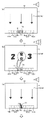
(主制御基板の特図特電制御処理)
図7を用いて、主制御基板110の特図特電制御処理を説明する。図7は、主制御基板110における特図特電制御処理を示すフローチャートである。
(Special figure special electric control processing of main control board)
The special figure special electric control process of the main control board 110 will be described with reference to FIG. 7. FIG. 7 is a flowchart showing a special figure special electric control process in the main control board 110.
まず、メインCPU110aは、ステップS301において、特図特電処理データをロードし、ステップS302においてロードした特図特電処理データから分岐先アドレスを参照し、特図特電処理データ=0であれば特別図柄記憶判定処理(ステップS310)に処理を移し、特図特電処理データ=1であれば特別図柄変動処理(ステップS320)に処理を移し、特図特電処理データ=2であれば特別図柄停止処理(ステップS330)に処理を移し、特図特電処理データ=3であれば大当たり遊技処理(ステップS340)に処理を移し、特図特電処理データ=4であれば大当たり遊技終了処理(ステップS350)に処理を移す。
First, the
この「特図特電処理データ」は、後述するように特図特電制御処理の各サブルーチンの中で必要に応じてセットされていくので、その遊技において必要なサブルーチンが適宜処理されていくことになる。 This "special figure special electric processing data" is set as necessary in each subroutine of the special figure special electric control processing as described later, so that the subroutine necessary for the game is appropriately processed. ..
メインCPU110aは、ステップS310において、大当たりの判定、停止表示する特別図柄の種類を決定する処理、特別図柄の変動時間を決定する処理を行う特別図柄記憶判定処理を行う。
In step S310, the
具体的には、まず、メインCPU110aは、第2特別図柄保留数(U2)が「1」以上であるか否かを判定し、第2特別図柄保留数(U2)が「1」以上でない場合には、第1特別図柄保留数(U1)が「1」以上であるか否かを判定し、第1特別図柄保留数(U1)が「1」以上でない(「0」である)場合には、特別図柄の変動表示及び大当たり遊技が実行されていない客待ち状態の開始であるか否かを判定するための客待ち状態判定フラグが「0」であるか否かを判定する。
Specifically, first, the
客待ち状態判定フラグが「0」の場合には、客待ち状態が開始しているものとして客待ち状態指定コマンドを演出用伝送データ格納領域にセットし、特図特電処理データ=0を維持したまま、今回の特別図柄記憶判定処理を終了し、客待ち状態判定フラグが「0」でない場合には、既に客待ち状態が開始しているものとして特図特電処理データ=0を維持したまま、今回の特別図柄記憶判定処理を終了する。 When the customer waiting state determination flag is "0", the customer waiting state specification command is set in the production transmission data storage area assuming that the customer waiting state has started, and the special figure special electric processing data = 0 is maintained. If the customer waiting status determination flag is not "0" after the current special symbol memory determination processing is completed, it is assumed that the customer waiting status has already started, and the special symbol special electric processing data = 0 is maintained. This special symbol memory determination process is terminated.
第2特別図柄保留数(U2)が「1」以上である場合には、第2特別図柄保留記憶領域に記憶されている値から「1」を減算した後、第2特別図柄保留記憶領域にある第1記憶部~第4記憶部に記憶された各種乱数値(特図判定情報)を1つ前の記憶部にシフトさせ、減算後の第2特別図柄保留数(U2)に対応する第2特別図柄記憶指定コマンドを演出用伝送データ格納領域にセットする。 When the number of second special symbol reservations (U2) is "1" or more, "1" is subtracted from the value stored in the second special symbol reservation storage area, and then the second special symbol reservation storage area is stored. Various random value values (special figure determination information) stored in a certain first storage unit to the fourth storage unit are shifted to the previous storage unit, and the number corresponding to the second special symbol hold number (U2) after subtraction is obtained. 2 Set the special symbol storage specification command in the transmission data storage area for production.
そして、メインCPU110aは、大当たり遊技を実行するか否かを決定するための大当たり判定を行う。具体的には、第2特別図柄保留記憶領域の第1記憶部から第0記憶部にシフトされた各種乱数値(特図判定情報)のうちの特別図柄決定用乱数値、及び、現在の確率遊技状態(低確率遊技状態、高確率遊技状態)に基づいて、大当たり遊技を実行することになる「大当たり」であるか「ハズレ」であるかの判定を行う。
Then, the
一方、第2特別図柄保留数(U2)が「1」以上でない場合であって、第1特別図柄保留数(U1)が「1」以上である場合には、第1特別図柄保留記憶領域に記憶されている値から「1」を減算した後、第1特別図柄保留記憶領域にある第1記憶部~第4記憶部に記憶された各種乱数値を1つ前の記憶部にシフトさせ、減算後の第1特別図柄保留数(U1)に対応する第1特別図柄記憶指定コマンドを演出用伝送データ格納領域にセットする。 On the other hand, when the second special symbol hold number (U2) is not "1" or more and the first special symbol hold number (U1) is "1" or more, the first special symbol hold storage area is stored. After subtracting "1" from the stored value, various random value stored in the first to fourth storage units in the first special symbol reservation storage area is shifted to the previous storage unit. The first special symbol storage designation command corresponding to the number of reserved first special symbols (U1) after subtraction is set in the transmission data storage area for effect.
そして、メインCPU110aは、大当たり遊技を実行するか否かを決定するための大当たり判定を行う。具体的には、第1特別図柄保留記憶領域の第1記憶部から第0記憶部にシフトされた各種乱数値(特図判定情報)のうちの特別図柄決定用乱数値、及び、現在の確率遊技状態(低確率遊技状態、高確率遊技状態)に基づいて、大当たり遊技を実行することになる「大当たり」であるか「ハズレ」であるかの判定を行う。
Then, the
そして、メインCPU110aは、停止表示する特別図柄の種類を決定するための特別図柄決定処理を行う。具体的には、第2特別図柄保留記憶領域の第0記憶部に記憶されている特別図柄決定用乱数値に基づいて大当たり判定を行った場合には、この第0記憶部に記憶されている大当たり図柄用乱数値に基づいて、大当たり特別図柄、又は、ハズレ特別図柄を決定し、決定した特別図柄に対応する演出図柄指定コマンドを演出用伝送データ格納領域にセットする。
Then, the
また、第1特別図柄保留記憶領域の第0記憶部に記憶されている特別図柄決定用乱数値に基づいて大当たり判定を行った場合には、この第0記憶部に記憶されている大当たり図柄用乱数値に基づいて特別図柄(大当たり特別図柄、ハズレ特別図柄)を決定し、決定した特別図柄に対応する演出図柄指定コマンドを演出用伝送データ格納領域にセットする。 Further, when the jackpot determination is performed based on the random value for determining the special symbol stored in the 0th storage unit of the 1st special symbol reservation storage area, the jackpot symbol stored in the 0th storage unit is used. A special symbol (big hit special symbol, loss special symbol) is determined based on the random number value, and the effect symbol designation command corresponding to the determined special symbol is set in the effect transmission data storage area.
次に、メインCPU110aは、特別図柄の変動パターン(変動時間)を決定するための特図変動パターン決定処理を行う。具体的には、第2特別図柄保留記憶領域の第0記憶部に記憶されている特別図柄決定用乱数値に基づいて大当たり判定を行った場合には、この第0記憶部に記憶されているリーチ判定用乱数値、及び、特図変動用乱数値に基づいて、特別図柄の変動パターンを決定し、決定した変動パターンに対応する変動時間を特別図柄時間カウンタにセットし、決定した変動パターンに対応する変動パターン指定コマンドを演出用伝送データ格納領域にセットする。
Next, the
また、第1特別図柄保留記憶領域の第0記憶部に記憶されている特別図柄決定用乱数値に基づいて大当たり判定を行った場合には、この第0記憶部に記憶されているリーチ判定用乱数値、及び、特図変動用乱数値に基づいて特別図柄の変動パターンを決定し、決定した変動パターンに対応する変動時間を特別図柄時間カウンタにセットし、決定した変動パターンに対応する変動パターン指定コマンドを演出用伝送データ格納領域にセットする。 Further, when the jackpot determination is performed based on the random value for determining the special symbol stored in the 0th storage unit of the 1st special symbol reservation storage area, the reach determination is stored in the 0th storage unit. The fluctuation pattern of the special symbol is determined based on the random value and the random value for special symbol fluctuation, the fluctuation time corresponding to the determined fluctuation pattern is set in the special symbol time counter, and the fluctuation pattern corresponding to the determined fluctuation pattern is set. Set the specified command in the transmission data storage area for production.
そして、メインCPU110aは、第1特別図柄表示器60、又は、第2特別図柄表示器61に特別図柄の変動表示(LEDの点滅)を行わせるための変動表示データを所定の処理領域にセットする。
Then, the
これにより、所定の処理領域に変動表示データがセットされていると、上記ステップS600でLEDの点灯、又は、消灯のデータが適宜作成され、作成されたデータがステップS700において出力されることで、第1特別図柄表示器60、又は、第2特別図柄表示器61の変動表示が行われる。
As a result, when the variable display data is set in the predetermined processing area, the data for turning on or off the LED is appropriately created in step S600, and the created data is output in step S700. The variable display of the first
そして、特図特電処理データ=0から特図特電処理データ=1にセットして、特別図柄変動処理のサブルーチンに移す準備を行い、今回の特別図柄記憶判定処理を終了する。 Then, the special symbol special electric processing data = 0 is set to the special symbol special electric processing data = 1, and preparations are made to move to the subroutine of the special symbol variation processing, and the current special symbol storage determination processing is completed.
メインCPU110aは、ステップS320において、特別図柄の変動時間が経過したか否かを判定する特別図柄変動処理を行う。具体的には、上記ステップS310でセットされた特別図柄の変動時間が経過した(特別図柄時間カウンタ=0)か否かを判定する。変動時間が経過していない場合には、特図特電処理データ=1を維持したまま、今回の特別図柄変動処理を終了する。
In step S320, the
変動時間が経過した場合には、上記ステップS310で決定された特別図柄を第1特別図柄表示器60、又は、第2特別図柄表示器61に大当たり特別図柄、又は、ハズレ特別図柄を停止表示させ、予め定められた特別図柄の停止時間(0.5秒)を特別図柄時間カウンタにセットする。これにより、遊技者に大当たり判定の判定結果が報知されることとなる。
When the fluctuation time has elapsed, the special symbol determined in step S310 is displayed on the first
そして、特図特電処理データ=1から特図特電処理データ=2にセットして、特別図柄停止処理のサブルーチンに移す準備を行い、今回の特別図柄変動処理を終了する。 Then, the special symbol special electric processing data = 1 is set to the special symbol special electric processing data = 2, preparations are made to move to the subroutine of the special symbol stop processing, and the special symbol change processing this time is completed.
ステップS330において、メインCPU110aは、特別図柄の停止時間(0.5秒)が経過したか否かを判定する特別図柄停止処理を行う。具体的には、上記ステップS320でセットされた特別図柄の停止時間が経過した(特別図柄時間カウンタ=0)か否かを判定する。停止時間が経過していない場合には、特図特電処理データ=2を維持したまま、今回の特別図柄停止処理を終了する。
In step S330, the
停止時間が経過した場合には、時短回数>0のときには時短回数カウンタから1を減算して更新し、時短回数=0となれば、時短遊技フラグをクリアし、高確率回数>0のときには高確率回数カウンタから1を減算して更新し、高確率回数=0となれば、高確率遊技フラグをクリアする。 When the stop time has elapsed, 1 is subtracted from the time reduction count counter to update when the time reduction count> 0, and when the time reduction count = 0, the time reduction game flag is cleared, and when the high probability number> 0, it is high. It is updated by subtracting 1 from the probability count counter, and when the high probability count = 0, the high probability game flag is cleared.
そして、メインCPU110aは、停止表示された特別図柄が大当たり特別図柄であるか否かを判定する。大当たり特別図柄である場合には、時短遊技フラグ、高確率遊技フラグ、時短回数カウンタ、及び、高確率回数カウンタをクリアすると共に、特図特電処理データ=2から特図特電処理データ=3にセットして、大当たり遊技処理のサブルーチンに移す準備を行い、今回の特別図柄停止処理を終了する。
Then, the
一方、ハズレ特別図柄である場合には、特図特電処理データ=2から特図特電処理データ=0にセットして、特別図柄記憶判定処理のサブルーチンに移す準備を行い、今回の特別図柄停止処理を終了する。 On the other hand, in the case of a lost special symbol, the special symbol special electric processing data = 2 is set to the special symbol special electric processing data = 0, and preparations are made to move to the subroutine of the special symbol storage determination processing, and this special symbol stop processing is performed. To finish.
メインCPU110aは、ステップS340において、上記ステップS310でセットされた大当たり特別図柄の種類(停止図柄データ)に基づいて、第1大当たり遊技、第2大当たり遊技、又は、第3大当たり遊技を実行するための大当たり遊技処理を行う。
In step S340, the
具体的には、大当たり遊技の種類に応じた開閉部材51の開放時間を特別遊技タイマカウンタにセットすると共に、大入賞口開閉ソレノイド51bの駆動データを出力して開閉部材51を開放させる。このとき、ラウンド遊技回数(R)記憶領域に1を加算する。
Specifically, the opening time of the opening / closing
この開放中に規定個数の遊技球が入賞(入球)するか、大入賞口の開放時間が経過すると(ラウンド入賞カウンタ(C)=10、又は、特別遊技タイマカウンタ=0である)、大入賞口開閉ソレノイド51bの駆動データの出力を停止して開閉部材51を閉鎖させる。これにより、1回のラウンド遊技が終了する。また、ラウンド入賞カウンタ(C)のカウンタ値をクリアする。
When a specified number of game balls win (win) during this opening, or when the opening time of the large winning opening elapses (round winning counter (C) = 10 or special game timer counter = 0), the size is large. The output of the drive data of the winning opening opening / closing solenoid 51b is stopped to close the opening / closing
所定回数(本実施の形態では、4回、又は、16回)のラウンド遊技が終了すると、ラウンド遊技回数(R)記憶領域に記憶されているデータをクリアすると共に、特図特電処理データ=3から特図特電処理データ=4にセットして、大当たり遊技終了処理のサブルーチンに移す準備を行い、今回の大当たり遊技処理を終了する。 When the predetermined number of round games (4 times or 16 times in the present embodiment) is completed, the data stored in the round game number (R) storage area is cleared, and the special figure special electric processing data = 3 To special figure special electric processing data = 4, prepare to move to the subroutine of big hit game end processing, and end this big hit game processing.
メインCPU110aは、ステップS350において、高確率遊技状態、又は、低確率遊技状態の何れかの確率遊技状態を決定すると共に、時短遊技状態、又は、非時短遊技状態の何れかの遊技状態を決定する大当たり遊技終了処理を行う。
In step S350, the
具体的には、上記ステップS310でセットされた大当たり特別図柄の種類(停止図柄データ)に基づいて、高確率遊技フラグの設定、高確率回数の設定、時短遊技フラグの設定、時短回数の設定が行い、特図特電処理データ=4から特図特電処理データ=0にセットして、特別図柄記憶判定処理のサブルーチンに移す準備を行い、今回の大当たり遊技終了処理を終了する。 Specifically, based on the type of jackpot special symbol (stop symbol data) set in step S310, the setting of the high probability game flag, the setting of the high probability number of times, the setting of the time saving game flag, and the setting of the time saving number of times are performed. Then, the special figure special electric processing data = 4 is set to the special figure special electric processing data = 0, preparations are made to move to the subroutine of the special symbol storage determination processing, and the current jackpot game end processing is completed.
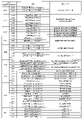
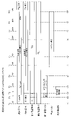
(演出制御基板に関与するコマンドの説明)
図8、及び、図9を用いて、主制御基板110から演出制御基板130に送信されるコマンドの種別について説明する。図8、及び、図9は、主制御基板110から演出制御基板130に送信されるコマンドの種別を示す図である。
(Explanation of commands related to the staging control board)
8 and 9 will be used to describe the types of commands transmitted from the main control board 110 to the staging control board 130. 8 and 9 are diagrams showing the types of commands transmitted from the main control board 110 to the staging control board 130.
「第1特別図柄記憶指定コマンド」は、第1特別図柄保留数(U1)記憶領域に記憶されている保留記憶数を示すものであり、「MODE」が「E0H」で設定され、保留記憶数に合わせてDATAの情報が設定されている。 The "first special symbol storage designation command" indicates the number of reserved storages stored in the first special symbol reserved number (U1) storage area, "MODE" is set to "E0H", and the number of reserved storages is set. DATA information is set according to.
この第1特別図柄記憶指定コマンドは、第1特別図柄保留数(U1)記憶領域に記憶されている値が増減したときに、上記ステップS230-11、又は、上記ステップS310において増減後の保留記憶数に対応する第1特別図柄記憶指定コマンドがメインRAM110cの演出用伝送データ格納領域にセットされ、ステップS800の出力制御処理において演出制御基板130に送信されることになる。 When the value stored in the first special symbol reservation number (U1) storage area increases or decreases, this first special symbol storage designation command waits for storage after the increase or decrease in step S230-11 or step S310. The first special symbol storage designation command corresponding to the number is set in the effect transmission data storage area of the main RAM 110c, and is transmitted to the effect control board 130 in the output control process of step S800.
「第2特別図柄記憶指定コマンド」は、第2特別図柄保留数(U2)記憶領域に記憶されている保留記憶数を示すものであり、「MODE」が「E0H」で設定され、保留記憶数に合わせてDATAの情報が設定されている。 The "second special symbol storage designation command" indicates the number of reserved storages stored in the second special symbol holding number (U2) storage area, "MODE" is set to "E0H", and the number of reserved storages is set. DATA information is set according to.
この第2特別図柄記憶指定コマンドは、第2特別図柄保留数(U2)記憶領域に記憶されている値が増減したときに、上記ステップS240、又は、上記ステップS310において増減後の保留記憶数に対応する第2特別図柄記憶指定コマンドがメインRAM110cの演出用伝送データ格納領域にセットされ、ステップS800の出力制御処理において演出制御基板130に送信されることになる。 When the value stored in the second special symbol storage number (U2) storage area is increased or decreased, the second special symbol storage designation command is used to change the reserved storage number after the increase or decrease in step S240 or step S310. The corresponding second special symbol storage designation command is set in the effect transmission data storage area of the main RAM 110c, and is transmitted to the effect control board 130 in the output control process of step S800.
なお、本実施の形態では、「第1特別図柄記憶指定コマンド」と「第2特別図柄記憶指定コマンド」とをまとめて「特別図柄記憶指定コマンド」と総称する場合がある。 In this embodiment, the "first special symbol storage designation command" and the "second special symbol storage designation command" may be collectively referred to as a "special symbol storage designation command".
「演出図柄指定コマンド」は、停止表示される特別図柄の種別(種類)を示すものであり、第1特別図柄ならば「MODE」が「E1H」で設定され、第2特別図柄ならば「MODE」が「E2H」で設定され、特別図柄の種別に合わせてDATAの情報が設定されている。なお、特別図柄の種別が結果的に大当たりの種別や大当たり終了後の遊技状態を決定するものであるから、演出図柄指定コマンドは、大当たりの種別や、大当たり終了後の遊技状態を示すものともいえる。 The "staging symbol designation command" indicates the type (type) of the special symbol that is stopped and displayed. If it is the first special symbol, "MODE" is set to "E1H", and if it is the second special symbol, "MODE". Is set in "E2H", and DATA information is set according to the type of the special symbol. Since the type of the special symbol eventually determines the type of the jackpot and the game state after the jackpot ends, the effect symbol designation command can be said to indicate the type of the jackpot and the game state after the jackpot ends. ..
この演出図柄指定コマンドは、各種の特別図柄が決定され、特別図柄の変動表示が開始されるときに、上記ステップS310において特別図柄に対応する演出図柄指定コマンドがメインRAM110cの演出用伝送データ格納領域にセットされ、上記ステップS800の出力制御処理において演出制御基板130に送信されることになる。 In this effect symbol designation command, when various special symbols are determined and the variable display of the special symbol is started, the effect symbol designation command corresponding to the special symbol in the step S310 is the effect transmission data storage area of the main RAM 110c. Is set to, and is transmitted to the staging control board 130 in the output control process of step S800.
「第1特別図柄用変動パターン指定コマンド」は、第1特別図柄表示器60における特別図柄の変動時間(変動態様)を示すものであり、「MODE」が「E3H」で設定され、各種の変動パターンに合わせてDATAの情報が設定されている。
The "first special symbol variation pattern designation command" indicates the variation time (variation mode) of the special symbol on the first
この第1特別図柄用変動パターン指定コマンドは、第1特別図柄表示器60の特別図柄の変動表示が開始されるときに、上記ステップS310において特別図柄の変動パターンに対応する第1特別図柄用変動パターン指定コマンドがメインRAM110cの演出用伝送データ格納領域にセットされ、ステップS800の出力制御処理において演出制御基板130に送信されることになる。
This first special symbol variation pattern designation command is a first special symbol variation corresponding to the special symbol variation pattern in step S310 when the variation display of the special symbol of the first
「第2特別図柄用変動パターン指定コマンド」は、第2特別図柄表示器61における特別図柄の変動時間(変動態様)を示すものであり、「MODE」が「E4H」で設定され、各種の変動パターンに合わせてDATAの情報が設定されている。
The "second special symbol variation pattern designation command" indicates the variation time (variation mode) of the special symbol on the second
この第2特別図柄用変動パターン指定コマンドは、第2特別図柄表示器61の特別図柄の変動表示が開始されるときに、上記ステップS310において特別図柄の変動パターンに対応する第2特別図柄用変動パターン指定コマンドがメインRAM110cの演出用伝送データ格納領域にセットされ、ステップS800の出力制御処理において演出制御基板130に送信されることになる。
This second special symbol variation pattern designation command is a second special symbol variation corresponding to the special symbol variation pattern in step S310 when the variation display of the special symbol of the second
なお、本実施の形態では、「第1特別図柄用変動パターン指定コマンド」と「第2特別図柄用変動パターン指定コマンド」とをまとめて、「変動パターン指定コマンド」と総称する場合がある。 In the present embodiment, the "first special symbol variation pattern designation command" and the "second special symbol variation pattern designation command" may be collectively referred to as a "variation pattern designation command".
「特別図柄確定コマンド」は、特別図柄が停止表示されていることを示すものであり、「MODE」が「E5H」で設定され、「DATA」が「00H」に設定されている。 The "special symbol confirmation command" indicates that the special symbol is stopped and displayed, and "MODE" is set to "E5H" and "DATA" is set to "00H".
この特別図柄確定コマンドは、特別図柄を第1特別図柄表示器60、又は、第2特別図柄表示器61に停止表示させるときに、上記ステップS320において特別図柄確定コマンドがメインRAM110cの演出用伝送データ格納領域にセットされ、ステップS800の出力制御処理において演出制御基板130に送信されることになる。
In this special symbol confirmation command, when the special symbol is stopped and displayed on the first
「普通図柄確定コマンド」は、普通図柄が停止表示されていることを示すものであり、「MODE」が「E5H」で設定され、「DATA」が「01H」に設定されている。 The "normal symbol confirmation command" indicates that the normal symbol is stopped and displayed, "MODE" is set to "E5H", and "DATA" is set to "01H".
この普通図柄確定コマンドは、普通図柄を普通図柄表示器62に停止表示させるときに、普通図柄が停止表示されるときに、上記ステップS400において普通図柄確定コマンドがメインRAM110cの演出用伝送データ格納領域にセットされ、ステップS800の出力制御処理において演出制御基板130に送信されることになる。
In this normal symbol confirmation command, when the normal symbol is stopped and displayed on the
「始動口入賞指定コマンド」は、大当たり判定(抽選)の結果を事前に演出制御基板130に通知するための情報であり、第1始動口45への遊技球の入賞に基づくものならば「MODE」が「E6H」で設定され、第2始動口47への遊技球の入賞に基づくものならば「MODE」が「E7H」で設定され、各種の入賞情報に合わせてDATAの情報が設定されている。
The "starting opening winning designation command" is information for notifying the effect control board 130 of the result of the jackpot determination (lottery) in advance, and if it is based on the winning of the game ball to the first starting
この始動口入賞指定コマンドは、第1始動口45、又は、第2始動口47に遊技球が入賞したときに、上記ステップS230-10、又は、S240において始動入賞情報に対応する始動口入賞指定コマンドがメインRAM110cの演出用伝送データ格納領域にセットされ、ステップS800の出力制御処理において演出制御基板130に送信されることになる。 This start opening winning designation command is a starting opening winning designation corresponding to the starting winning information in steps S230-10 or S240 when the game ball wins in the first starting opening 45 or the second starting opening 47. The command is set in the effect transmission data storage area of the main RAM 110c, and is transmitted to the effect control board 130 in the output control process of step S800.
「大当たり用オープニング指定コマンド」は、各種の大当たり遊技(特別遊技状態)が開始することを示すものであり、「MODE」が「E8H」で設定され、大当たり遊技の種別に合わせてDATAの情報が設定されている。 The "big hit opening designation command" indicates that various big hit games (special game states) are started, "MODE" is set to "E8H", and DATA information is set according to the type of big hit game. It is set.
この大当たり用オープニング指定コマンドは、各種の大当たり遊技が開始するときに、上記ステップS330において大当たり遊技の種別に対応する大当たり用オープニング指定コマンドがメインRAM110cの演出用伝送データ格納領域にセットされ、ステップS800の出力制御処理において演出制御基板130に送信されることになる。 In this jackpot opening designation command, when various jackpot games are started, the jackpot opening designation command corresponding to the type of jackpot game is set in the effect transmission data storage area of the main RAM 110c in step S330, and step S800. It will be transmitted to the staging control board 130 in the output control process of.
「ラウンド指定コマンド」は、大当たり遊技のラウンド数を示すものであり、「MODE」が「E9H」で設定され、大当たり遊技のラウンド数に合わせてDATAの情報が設定されている。 The "round designation command" indicates the number of rounds of the jackpot game, "MODE" is set by "E9H", and DATA information is set according to the number of rounds of the jackpot game.
このラウンド指定コマンドは、大当たり遊技のラウンド遊技が開始されるときに、上記ステップS340においてラウンド数に対応するラウンド指定コマンドがメインRAM110cの演出用伝送データ格納領域にセットされ、ステップS800の出力制御処理において演出制御基板130に送信されることになる。 In this round designation command, when the round game of the jackpot game is started, the round designation command corresponding to the number of rounds is set in the effect transmission data storage area of the main RAM 110c in step S340, and the output control process of step S800 is performed. Will be transmitted to the staging control board 130.
「大当たり用エンディング指定コマンド」は、各種の大当たり遊技が終了したことを示すものであり、「MODE」が「EAH」で設定され、大当たり遊技の種別に合わせてDATAの情報が設定されている。 The "big hit ending designation command" indicates that various big hit games have been completed, "MODE" is set to "EAH", and DATA information is set according to the type of big hit game.
この大当たり用エンディング指定コマンドは、各種の大当たり遊技が終了するときに、上記ステップS340において大当たり遊技の種別に対応する大当たり用エンディング指定コマンドがメインRAM110cの演出用伝送データ格納領域にセットされ、ステップS800の出力制御処理において演出制御基板130に送信されることになる。 In this jackpot ending designation command, when various jackpot games are completed, the jackpot ending designation command corresponding to the type of jackpot game is set in the effect transmission data storage area of the main RAM 110c in step S340, and step S800. It will be transmitted to the staging control board 130 in the output control process of.
「普通図柄記憶指定コマンド」は、普通図柄保留数(G1)記憶領域に記憶されている保留記憶数を示すものであり、「MODE」が「ECH」で設定され、保留記憶数に合わせてDATAの情報が設定されている。 The "normal symbol storage designation command" indicates the number of reserved storages stored in the normal symbol holding number (G1) storage area, "MODE" is set to "ECH", and DATA is set according to the number of reserved storages. Information is set.
この普通図柄記憶指定コマンドは、普通図柄保留数(G1)記憶領域に記憶されている値が増減したときに、上記ステップS250、又は、上記ステップS400において増減後の保留記憶数に対応する普通図柄記憶指定コマンドがメインRAM110cの演出用伝送データ格納領域にセットされ、ステップS800の出力制御処理において演出制御基板130に送信されることになる。 When the value stored in the normal symbol storage number (G1) storage area increases or decreases, this normal symbol storage designation command corresponds to the normal symbol storage number after the increase or decrease in step S250 or step S400. The storage designation command is set in the effect transmission data storage area of the main RAM 110c, and is transmitted to the effect control board 130 in the output control process of step S800.
「普図指定コマンド」は、普通図柄表示器62に停止表示される普通図柄の種別を示すものであり、「MODE」が「EDH」で設定され、普通図柄の種別に合わせてDATAの情報が設定されている。
The "normal symbol designation command" indicates the type of the normal symbol that is stopped and displayed on the
この普図指定コマンドは、各種の普通図柄が決定され、普通図柄の変動表示が開始されるときに、上記ステップS400において普通図柄に対応する普図指定コマンドがメインRAM110cの演出用伝送データ格納領域にセットされ、上記ステップS800の出力制御処理において演出制御基板130に送信されることになる。 In this normal symbol designation command, when various normal symbols are determined and the variation display of the normal symbol is started, the normal symbol designation command corresponding to the normal symbol in the above step S400 is the transmission data storage area for the effect of the main RAM 110c. Is set to, and is transmitted to the staging control board 130 in the output control process of step S800.
「普図変動指定コマンド」は、普通図柄表示器62における普通図柄の変動時間を示すものであり、「MODE」が「EEH」で設定され、各種の普通図柄の変動時間に合わせてDATAの情報が設定されている。
The "normal symbol fluctuation designation command" indicates the fluctuation time of the normal symbol on the
この普図変動指定コマンドは、普通図柄の変動表示が開始されるときに、上記ステップS400において普通図柄の変動時間に対応する普図変動指定コマンドがメインRAM110cの演出用伝送データ格納領域にセットされ、ステップS800の出力制御処理において演出制御基板130に送信されることになる。 In this normal symbol fluctuation designation command, when the fluctuation display of the normal symbol is started, the normal symbol fluctuation designation command corresponding to the fluctuation time of the normal symbol is set in the effect transmission data storage area of the main RAM 110c in step S400. , Will be transmitted to the staging control board 130 in the output control process of step S800.
「当たり用オープニング指定コマンド」は、各種の補助遊技が開始することを示すものであり、「MODE」が「EFH」で設定され、補助遊技の種別に合わせてDATAの情報が設定されている。 The "hit opening designation command" indicates that various auxiliary games are started, "MODE" is set in "EFH", and DATA information is set according to the type of auxiliary game.
この当たり用オープニング指定コマンドは、補助遊技が開始されるときに、上記ステップS400において補助遊技の種類に対応する当たり用オープニング指定コマンドがメインRAM110cの演出用伝送データ格納領域にセットされ、ステップS800の出力制御処理において演出制御基板130に送信されることになる。 In this hit opening designation command, when the auxiliary game is started, the hit opening designation command corresponding to the type of the auxiliary game is set in the effect transmission data storage area of the main RAM 110c in step S400, and in step S800. It will be transmitted to the staging control board 130 in the output control process.
「当たり用エンディング指定コマンド」は、各種の補助遊技が終了したことを示すものであり、「MODE」が「EFH」で設定され、補助遊技の種別に合わせてDATAの情報が設定されている。 The "hit ending designation command" indicates that various auxiliary games have been completed, "MODE" is set to "EFH", and DATA information is set according to the type of auxiliary game.
この当たり用エンディング指定コマンドは、各種の補助遊技が終了するときに、上記ステップS400おいて補助遊技の種別に対応する当たり用エンディング指定コマンドがメインRAM110cの演出用伝送データ格納領域にセットされ、ステップS800の出力制御処理において演出制御基板130に送信されることになる。 In this hit ending designation command, when various auxiliary games are completed, the hit ending designation command corresponding to the type of the auxiliary game is set in the effect transmission data storage area of the main RAM 110c in step S400, and the step It will be transmitted to the staging control board 130 in the output control process of S800.
「遊技状態指定コマンド」は、時短遊技状態であるか否か、高確率遊技状態であるか否かを示すものであり、「MODE」が「F0H」で設定され、各遊技状態に合わせて「DATA」が設定されている。 The "game state designation command" indicates whether or not the game is in a time-saving game state and whether or not the game is in a high-probability game state. "DATA" is set.
この遊技状態指定コマンドは、特別図柄の変動開始時、特別図柄の変動終了時(大当たり遊技の開始時)、及び、大当たりの終了時に、上記ステップS310、上記ステップS330、上記ステップS350において遊技状態に対応する遊技状態指定コマンドがメインRAM110cの演出用伝送データ格納領域にセットされ、ステップS800の出力制御処理において演出制御基板130に送信されることになる。 This game state designation command is set to the game state in step S310, step S330, and step S350 at the start of the change of the special symbol, at the end of the change of the special symbol (at the start of the jackpot game), and at the end of the jackpot. The corresponding game state designation command is set in the effect transmission data storage area of the main RAM 110c, and is transmitted to the effect control board 130 in the output control process of step S800.
「電源投入指定コマンド」及び「電源復旧指定コマンド」は、遊技機1への電源投入がメインRAM110cの初期化を伴うものであるか否かを示すものであり、「MODE」が「F1H」で設定され、メインRAM110cの初期化を伴う場合には「DATA」が「00H」に設定され、メインRAM110cの初期化を伴わない場合には「DATA」が「01H~03H」に設定される。
The "power-on designation command" and the "power recovery designation command" indicate whether or not the power-on to the
この電源投入指定コマンド、及び、電源復旧指定コマンドは、遊技機1に電源が投入されたときに、上記ステップS10においてメインRAM110cの初期化の有無、及び、遊技状態に対応する電源投入指定コマンド、又は、電源復旧指定コマンドが演出制御基板130に送信される。
The power-on designation command and the power-on recovery command are the power-on designation commands corresponding to the presence / absence of initialization of the main RAM 110c and the gaming state in step S10 when the power is turned on to the
「客待ち状態指定コマンド」は、特別図柄の変動表示が行われない客待ち状態となったことを示すものであり、「MODE」が「F1H」で設定され、DATAが「04H」で設定されている。 The "customer waiting state specification command" indicates that the customer waiting state in which the change display of the special symbol is not performed is set, "MODE" is set to "F1H", and DATA is set to "04H". ing.
この客待ち状態指定コマンドは、特別図柄の変動表示が行われない客待ち状態となったときに、上記ステップS310においてメインRAM110cの演出用伝送データ格納領域にセットされ、ステップS800の出力制御処理において演出制御基板130に送信されることになる。 This customer waiting state designation command is set in the effect transmission data storage area of the main RAM 110c in step S310 when the customer waiting state in which the change display of the special symbol is not performed is performed, and is set in the output control process of step S800. It will be transmitted to the staging control board 130.
「エラー指定コマンド」は、遊技機1に発生したエラーを示すものであり、「MODE」が「F2H」で設定され、エラーの種別に合わせて「DATA」の情報が設定されている。
The "error designation command" indicates an error that has occurred in the
このエラー指定コマンドは、上記ステップS600の磁気・電波異常判定処理において磁気異常や電波異常の発生が判定されたとき、上記ステップS260の入賞確認検出スイッチ入力処理において異常入賞の発生が判定されたとき、上記ステップS220の大入賞口検出スイッチ入力処理、又は、上記ステップS240の第2始動口検出スイッチ入力処理において不正入賞の発生が判定されたとき、エラーの種別に対応するエラー指定コマンドがメインRAM110cの演出用伝送データ格納領域にセットされ、ステップS800の出力制御処理において演出制御基板130に送信されることになる。 This error specification command is used when the occurrence of a magnetic abnormality or radio wave abnormality is determined in the magnetic / radio wave abnormality determination process of step S600, or when the occurrence of an abnormal prize is determined in the prize confirmation detection switch input process of step S260. When the occurrence of an illegal winning is determined in the large winning opening detection switch input processing in step S220 or the second starting opening detection switch input processing in step S240, the error designation command corresponding to the error type is the main RAM 110c. It is set in the effect transmission data storage area of the above, and is transmitted to the effect control board 130 in the output control process of step S800.
また、払出制御基板120において遊技盤取付枠3やガラス枠4の開放、下受け皿12の満杯、払出異常が検出されたときに、エラーの種別に対応するエラー指定コマンドが払出RAM121cの演出用伝送データ格納領域にセットされ、払出制御基板120の出力制御処理において演出制御基板130に送信されることになる。
Further, when the game
「エラー解除指定コマンド」は、遊技機1に発生したエラーが解消されたことを示すものであり、「MODE」が「F2H」で設定され、解消したエラーの種別に合わせて「DATA」の情報が設定されている。
The "error cancellation designation command" indicates that the error generated in the
このエラー解除指定コマンドは、払出制御基板120において遊技盤取付枠3やガラス枠4の閉鎖、下受け皿12の満杯の解消、払出異常の解消が検出されたときに、解消されたエラーの種別に対応するエラー解除指定コマンドがメインRAM110cの演出用伝送データ格納領域にセットされ、払出制御基板120の出力制御処理において演出制御基板130に送信されることになる。
This error cancellation designation command is used as the type of error resolved when it is detected in the
(演出制御部130mのメイン処理)
次に、図10を用いて、演出制御部130mのメイン処理を説明する。図10は、演出制御部130mのメイン処理を示すフローチャートである。
(Main processing of
Next, the main process of the
電源基板160から電源電圧が供給されると、サブCPU130aにシステムリセットが発生し、サブCPU130aは以下のメイン処理を行う。
When the power supply voltage is supplied from the
サブCPU130aは、ステップE10において、タイマ割込を禁止する割込禁止を設定し、ステップE20において、初期化処理を行う。具体的には、電源投入に応じて、サブROM130bからメイン処理プログラムを読み込むと共に、サブRAM130cに記憶されるフラグ等を初期化し、初期設定等の処理を行う。
The
サブCPU130aは、ステップE30において、タイマ割込を許可する割込許可を設定し、ステップE40において、サブ乱数更新処理を行う。具体的には、サブRAM130cに記憶される各種乱数値を更新する処理を行う。以降は、所定の割込処理が行われるまで、上記ステップE40の処理を繰り返し行う。
In step E30, the
(演出制御部130mのタイマ割込処理)
図11を用いて、演出制御部130mのタイマ割込処理を説明する。図11は、演出制御部130mにおいて所定の周期(4ミリ秒)毎に実行されるタイマ割込処理を示すフローチャートである。
(Timer interrupt processing of
The timer interrupt processing of the
サブCPU130aは、ステップE100において、サブCPU130aのレジスタに格納されている情報をスタック領域に退避させ、ステップE120において、タイマ更新処理を行う。このタイマ更新処理において、サブCPU130aは、各種のタイマを更新する処理を行う。
In step E100, the
サブCPU130aは、ステップE130において、入力制御処理を行う。具体的には、演出ボタン検出スイッチ17aや十字キー検出スイッチ19a等の各種スイッチに入力があったか否かを判定し、入力があった場合に所定のデータをセットする処理を行う。
The
サブCPU130aは、ステップE150において、コマンド解析処理を行う。具体的には、主制御基板110から各種のコマンドが送信されてきているか否かを判定し、各種のコマンドが送信されてきている場合に受信したコマンドをサブRAM130cの受信バッファに格納する処理を行う。
The
サブCPU130aは、ステップE200において、電源投入処理を行う。具体的には、サブRAM130cの受信バッファを参照して電源投入指定コマンドを受信しているか否かを判定し、受信している場合に電源投入報知を行うための処理を行う。詳述すると、表示/音声制御部140に電源投入報知コマンドを送信して、第1画像表示装置70(メイン液晶)や第2画像表示装置71(サブ液晶)に電源投入画面を表示させたり、音声出力装置9から電源投入音を出力させたりする。
The
サブCPU130aは、ステップE250において、停電復旧処理を行う。具体的には、サブRAM130cの受信バッファを参照して電源復旧指定コマンドを受信しているか否かを判定し、受信している場合に停電復旧報知を行うための処理を行う。詳述すると、表示/音声制御部140に電源復旧報知コマンドを送信して、第1画像表示装置70(メイン液晶)や第2画像表示装置71(サブ液晶)に電源復旧画面を表示させたり、音声出力装置9から電源復旧音を出力させたりする。
The
サブCPU130aは、ステップE300において、客待ち演出処理を行う。具体的には、サブRAM130cの受信バッファを参照して客待ち状態指定コマンドを受信しているか否かを判定し、受信している場合に所定時間経過後(例えば20秒)に客待ち演出を行うための処理を行う。詳述すると、表示/音声制御部140に客待ち演出コマンドを送信して、第1画像表示装置70(メイン液晶)や第2画像表示装置71(サブ液晶)に客待ちデモ画面を表示させたり、音声出力装置9から客待ちデモ音を出力させたりする。
The
サブCPU130aは、ステップE350において、遊技状態更新処理を行う。具体的には、サブRAM130cの受信バッファを参照して遊技状態指定コマンドを受信しているか否かを判定し、受信している場合にサブRAM130cに記憶している遊技状態情報を更新する処理を行う。
The
サブCPU130aは、ステップE400において、保留情報更新処理を行う。具体的には、サブRAM130cの受信バッファを参照して特別図柄記憶指定コマンドや普通図柄記憶指定コマンドを受信しているか否かを判定し、受信している場合にサブRAM130cに記憶している第1特別図柄保留数、第2特別図柄保留数、普通図柄保留数等を更新する処理を行う。
The
サブCPU130aは、ステップE500において、アイコン変化演出処理を行う。具体的には、サブRAM130cの受信バッファを参照して始動口入賞指定コマンドや変動パターン指定コマンドを受信しているか否かを判定し、受信している場合にはアイコン変化演出に関する処理を行う。
The
アイコン変化演出とは、保留アイコン、及び、当該アイコンの表示態様を変化させる先読み予告演出の一種であり、詳細は後述するが、変化させるタイミングや変化態様(ノーマル変化、図柄作用変化、及び、キャラ作用変化)は複数種類設定されている。詳しくは、図12を用いて後述する。 The icon change effect is a kind of hold icon and a look-ahead notice effect that changes the display mode of the icon. The details will be described later, but the timing and change mode (normal change, symbol action change, and character) are changed. Multiple types of action change) are set. Details will be described later with reference to FIG.
なお、本実施の形態では、保留アイコンに対するアイコン変化演出を「保留アイコン変化演出」と当該アイコンに対するアイコン変化演出を「当該アイコン変化演出」と称する場合がある。 In the present embodiment, the icon change effect for the hold icon may be referred to as "hold icon change effect" and the icon change effect for the icon may be referred to as "the icon change effect".
サブCPU130aは、ステップE600において、特図特電演出処理を行う。具体的には、サブRAM130cの受信バッファを参照して演出図柄指定コマンド、特別図柄用変動パターン指定コマンド、特別図柄確定コマンド、大当たり用オープニング指定コマンド、ラウンド指定コマンド、及び、大当たり用エンディング指定コマンド等を受信しているか否かを判定し、受信している場合に受信したコマンドに対応する演出を実行するための処理を行う。
The
サブCPU130aは、ステップE800において、普図普電演出処理を行う。具体的には、サブRAM130cの受信バッファを参照して普図指定コマンド、普図変動指定コマンド、普通図柄確定コマンド、当たり用オープニング指定コマンド、及び、当たり用エンディング指定コマンド等を受信しているか否かを判定し、受信している場合に受信したコマンドに対応する演出を実行するための処理を行う。
In step E800, the
サブCPU130aは、ステップE850において、エラー報知処理を行う。具体的には、サブRAM130cの受信バッファを参照してエラー指定コマンドやエラー解除指定コマンドを受信しているか否かを判定し、受信している場合に受信したエラー指定コマンドに対応するエラー報知演出を実行するための処理を行ったり、受信したエラー解除指定コマンドに対応するエラー報知演出を終了したりするための処理を行う。
The
サブCPU130aは、ステップE900において、出力制御処理を行う。具体的には、所定のデータ等の信号を出力したり、サブRAM130cの送信バッファに格納された各種のコマンドを表示/音声制御部140やランプ/駆動制御部150に送信したりする処理を行う。
The
サブCPU130aは、ステップE950において、ステップE100で退避した情報をサブCPU130aのレジスタに復帰させ、今回のタイマ割込処理を終了する。
In step E950, the
(演出制御部130mのアイコン変化演出処理)
図12を用いて、演出制御部130mのアイコン変化演出決定処理を説明する。図12は、演出制御部130mにおけるアイコン変化演出決定処理を示すフローチャートである。
(Icon change effect processing of the
The icon change effect determination process of the
サブCPU130aは、ステップE510において、アイコン変化演出を実行するか否か等を決定するアイコン変化演出決定処理を行う。詳しくは、図13を用いて後述する。
In step E510, the
サブCPU130aは、ステップE520において、既に表示されているアイコン(保留アイコン、及び、当該アイコン)の表示態様を更新(変化)させるためのアイコン表示態様更新処理を行い、今回のアイコン変化演出処理を終了する。詳しくは、図16を用いて後述する。
In step E520, the
(演出制御部130mのアイコン変化演出決定処理)
図13を用いて、演出制御部130mのアイコン変化演出決定処理を説明する。図13は、演出制御部130mにおけるアイコン変化演出決定処理を示すフローチャートである。
(Icon change effect determination process of
The icon change effect determination process of the
サブCPU130aは、ステップE510-1において、始動口入賞指定コマンドを受信したか否かを判定する。始動口入賞指定コマンドを受信した場合には、ステップE510-2に処理を移し、始動口入賞指定コマンドを受信していない場合には、今回のアイコン変化演出決定処理を終了する。
In step E510-1, the
サブCPU130aは、ステップE510-2において、受信した始動口入賞指定コマンドを参照し、大当たりであるか否か、大当たり遊技の種別、及び、演出内容(予定変動パターン)を把握する。
In step E510-2, the
サブCPU130aは、ステップE510-3において、現在がアイコン変化演出の実行可能期間であるか否かを判定する。アイコン変化演出の実行可能期間である場合には、ステップE510-4に処理を移し、アイコン変化演出の実行可能期間でない場合には、今回のアイコン変化演出決定処理を終了する。
In step E510-3, the
アイコン変化演出の実行可能期間とは、大当たり遊技の実行中でないことや、アイコン変化演出の実行中でないことや、アイコン変化演出が実行予定でない場合となっている。
なお、上記3つの条件の何れか1つの条件、又は、2つの条件だけを設けるようにしてもよい。また、上記3つの条件とは異なる条件としてもよい。
The feasible period of the icon change effect is when the jackpot game is not being executed, the icon change effect is not being executed, or the icon change effect is not scheduled to be executed.
It should be noted that one of the above three conditions or only two conditions may be provided. Further, the conditions may be different from the above three conditions.
サブCPU130aは、ステップE510-4において、先行保留(先に受信した始動口入賞指定コマンドに対応する保留記憶)の事前判定結果が全てノーマルリーチ以下、つまり、先行保留の事前判定結果が全て通常変動、短縮変動、又は、ノーマルリーチか否かを判定する。全てノーマルリーチ以下である場合には、ステップE510-5に処理を移し、全てノーマルリーチ以下でない場合には、ステップE510-8に処理を移す。
In step E510-4, the
サブCPU130aは、ステップE510-5において、第1画像表示装置70(メイン液晶)に表示されるアイコンの最終表示態様を決定するためのアイコン表示態様決定用乱数値を取得し、ステップE510-6において、アイコンの最終表示態様を決定するためのアイコン最終表示態様決定テーブル(図14参照)を選択する。なお、アイコン最終表示態様決定テーブルの詳細は後述する。
In step E510-5, the
サブCPU130aは、ステップE510-7において、アイコン最終表示態様を決定する。具体的には、サブCPU130aは、図14に示すアイコン最終表示態様決定テーブルを参照し、始動口入賞指定コマンド、及び、アイコン表示態様決定用乱数値に基づいて、複数のアイコン最終表示態様の中から1つのアイコン最終表示態様を決定する。
The
サブCPU130aは、ステップE510-8において、アイコン最終表示態様として、通常表示態様である通常アイコン(CDアイコン)を決定する。
In step E510-8, the
サブCPU130aは、ステップE510-9において、決定されたアイコン最終表示態様がアイコン変化演出を実行する表示態様(特別アイコン)であるか否かを判定する。アイコン変化演出を実行する表示態様である場合には、ステップE510-10に処理を移し、アイコン変化演出を実行する表示態様でない場合には、ステップE510-13に処理を移す。
The
サブCPU130aは、ステップE510-10において、アイコン変化演出の変化シナリオを決定するための変化シナリオ決定テーブル(図15参照)を選択する。なお、変化シナリオ決定テーブルの詳細は後述する。この変化シナリオとは、保留アイコンが出現してから消滅するまでの表示態様の推移を示すものである。
In step E510-10, the
サブCPU130aは、ステップE510-11において、変化シナリオを決定してサブRAM130cの保留記憶数カウンタに対応する先読み情報記憶領域にセットする。具体的には、図15に示す変化シナリオ決定テーブルを参照し、アイコン最終表示態様、及び、選択率に基づいて、複数の変化シナリオの中から1つの変化シナリオを決定する。
In step E510-11, the
サブCPU130aは、ステップE510-12において、決定された変化シナリオから第1画像表示装置70(メイン液晶)に最初に表示されるアイコン表示態様である入賞時アイコンを特定し、当該入賞時アイコンのアイコン表示コマンドを送信バッファにセットし、今回のアイコン変化演出決定処理を終了する。これにより、上記ステップE900の出力制御処理でアイコン表示コマンドが表示/音声制御部140やランプ/駆動制御部150に送信され、入賞時アイコンのアイコン表示コマンドに対応する表示態様の保留アイコンが第1画像表示装置70(メイン液晶)に表示されたり、所定の効果音が出力されたりすることになる。
In step E510-12, the
サブCPU130aは、ステップE510-13において、アイコン変化演出が実行されない非変化シナリオを決定してサブRAM130cの保留記憶数カウンタに対応する先読み情報記憶領域にセットする。
In step E510-13, the
サブCPU130aは、ステップE510-14において、通常アイコンのアイコン表示コマンドを送信バッファにセットし、今回のアイコン変化演出決定処理を終了する。これにより、上記ステップE900の出力制御処理で表示データが表示/音声制御部140やランプ/駆動制御部150に送信され、通常アイコンのアイコン表示コマンドに対応する表示態様の保留アイコンが第1画像表示装置70(メイン液晶)に表示されたり、所定の効果音が出力されたりすることになる。
In step E510-14, the
なお、本実施の形態のアイコン変化演出決定処理では、先行保留の事前判定結果が全てノーマルリーチ以下である場合にアイコン変化演出(保留アイコン変化演出、当該アイコン変化演出)が実行されるようにしたが、先行保留の事前判定結果がリーチ演出を行わないものである場合にアイコン変化演出が実行されるようにし、リーチ演出を行うものである場合にアイコン変化演出が実行されないようにしてもよい。このようにすると、リーチ演出が実行される先行保留に対応する変動演出中には保留アイコンの表示態様の変化が発生せずに、リーチ演出が実行されない先行保留に対応する変動演出中に保留アイコンの表示態様の変化が発生するようになり、アイコン変化演出によってリーチ演出を阻害することがなくなり、遊技の興趣を向上させることが可能となる。 In the icon change effect determination process of the present embodiment, the icon change effect (hold icon change effect, the icon change effect) is executed when all the prior determination results of the advance hold are equal to or less than the normal reach. , The icon change effect may be executed when the advance determination result of the advance hold does not perform the reach effect, and the icon change effect may not be executed when the reach effect is performed. In this way, the display mode of the hold icon does not change during the variable effect corresponding to the advance hold in which the reach effect is executed, and the hold icon is held during the variable effect corresponding to the advance hold in which the reach effect is not executed. The display mode of the icon is changed, the reach effect is not hindered by the icon change effect, and the fun of the game can be improved.
また、先行保留の事前判定結果がリーチ演出を行うものを含む場合であっても、アイコン変化演出が実行されるようにしてもよいが、先行保留の事前判定結果がリーチ演出を行うものを含まない場合の方が、リーチ演出を行うものを含む場合よりもアイコン変化演出が実行され易い(高い割合で実行される)ようにしてもよい。 Further, even if the pre-determination result of the advance hold includes the one that performs the reach effect, the icon change effect may be executed, but the pre-determination result of the advance hold includes the one that performs the reach effect. If there is no icon change effect, the icon change effect may be more easily executed (executed at a higher rate) than if the reach effect is included.
(アイコン最終表示態様決定テーブル)
図14は、アイコン最終表示態様を決定する場合に参照されるアイコン最終表示態様決定テーブルを示す図である。
(Icon final display mode determination table)
FIG. 14 is a diagram showing an icon final display mode determination table referred to when determining the icon final display mode.
アイコン最終表示態様決定テーブルには、始動口入賞指定コマンドの種類、アイコン表示態様決定用乱数値、及び、選択されるアイコン最終表示態様が対応付けられており、図14に示す選択率(%)となるように、アイコン表示態様決定用乱数値が割り振られている。 The icon final display mode determination table is associated with the type of the start opening winning designation command, the random value for determining the icon display mode, and the selected icon final display mode, and the selection rate (%) shown in FIG. A random number value for determining the icon display mode is assigned so as to be.
アイコン最終表示態様には、通常アイコンとしてのCDアイコンと、大当たりとなる(大当たり遊技が実行される)可能性があることを示唆する特別アイコンとしての青キャラアイコン、赤キャラアイコン、及び、虹キャラアイコンが設定されている。 The final display mode of the icon includes a CD icon as a normal icon, a blue character icon as a special icon suggesting that there is a possibility of a big hit (a big hit game is executed), a red character icon, and a rainbow character. The icon is set.
特別アイコンに係る大当たり当選期待度は、(CDアイコン<)青キャラアイコン<赤キャラアイコン<虹キャラアイコンの順で高くなっており、虹キャラアイコンは大当たりとなることが確定するアイコンとなっている。 The expectation of winning a big hit related to a special icon is higher in the order of (CD icon <) blue character icon <red character icon <rainbow character icon, and the rainbow character icon is an icon that confirms that it will be a big hit. ..
ここで、図14に示すアイコン最終表示態様決定テーブルの主たる特徴として、演出内容に応じて、アイコン最終表示態様の選択率を異ならせている。具体的には、本実施の形態では、演出内容がSPリーチやSPSPリーチであることを示す特定の始動入賞情報である場合、演出内容がリーチにならない通常変動や短縮変動やノーマルリーチであることを示す通常の始動入賞情報である場合よりも、キャラアイコンが高い割合で選択されるようなっている。 Here, as a main feature of the icon final display mode determination table shown in FIG. 14, the selection rate of the icon final display mode is different depending on the effect content. Specifically, in the present embodiment, when the effect content is specific start winning information indicating that the effect content is SP reach or SPSP reach, the effect content is normal variation, shortened variation, or normal reach that does not reach reach. The character icon is selected at a higher rate than in the case of the normal start winning information shown.
なお、図14に示すアイコン最終表示態様決定テーブルでは、大当たりとなる場合は、アイコン最終表示態様としてCDアイコンは選択されないようになっているが、選択されるようにしてもよい。 In the icon final display mode determination table shown in FIG. 14, the CD icon is not selected as the icon final display mode in the case of a big hit, but it may be selected.
(変化シナリオ決定テーブル)
図15は、変化シナリオを決定する場合に参照される変化シナリオ決定テーブルを示す図である。
(Change scenario determination table)
FIG. 15 is a diagram showing a change scenario determination table referred to when determining a change scenario.
変化シナリオ決定テーブルには、アイコン最終表示態様、始動口入賞指定コマンドに対応する特別図柄の保留数、各シナリオの選択率(%)、及び、選択される変化シナリオの種類が対応付けられており、参考として各変化シナリオにおける事前変動、及び、当該変動における更新態様が記載されている。 In the change scenario determination table, the icon final display mode, the number of holdings of the special symbol corresponding to the start opening prize designation command, the selection rate (%) of each scenario, and the type of the selected change scenario are associated. For reference, the preliminary fluctuations in each change scenario and the update mode in the fluctuations are described.
ここで、「事前変動」とは、新たに受信した始動口入賞指定コマンドに対応する特図判定情報よりも以前に記憶された特図判定情報に基づいて実行される変動表示(変動演出)のことであり、「当該変動」とは、新たに受信した始動口入賞指定コマンドに対応する特図判定情報に基づいて実行される変動表示(変動演出)のことである。 Here, the "preliminary variation" is a variation display (variation effect) executed based on the special figure determination information stored before the special figure determination information corresponding to the newly received start opening winning designation command. That is, the "variation" is a variation display (variation effect) executed based on the special figure determination information corresponding to the newly received start opening winning designation command.
変化シナリオには、アイコンの表示態様が事前変動の実行中には変化せず(保留アイコン変化演出が実行されず)に当該変動の実行中には変化する(当該アイコン変化演出が実行される)シナリオ(例えば、シナリオ01等)や、アイコンの表示態様が事前変動の実行中には変化する(保留アイコン変化演出が実行される)が当該変動の実行中には変化しない(当該アイコン変化演出が実行されない)シナリオ(例えば、シナリオ02等)や、アイコンの表示態様が事前変動の実行中、及び、当該変動の実行中に変化する(保留アイコン変化演出、及び、当該アイコン変化演出が実行される)シナリオ(例えば、シナリオ15等)が設定されている。
In the change scenario, the display mode of the icon does not change during the execution of the prior change (the hold icon change effect is not executed), but changes during the execution of the change (the icon change effect is executed). The scenario (for example,
なお、本実施の形態の変化シナリオ決定テーブルでは、事前変動においてリーチ演出(ノーマルリーチ以外のリーチであってもよい)が実行されるか否かに拘らずにアイコンの表示態様を変化させるシナリオを決定するようになっているが、事前変動において大当たり遊技が実行される可能性があることを示唆するリーチ演出が実行されるか否かを判定要素とした変化シナリオ決定テーブルによってアイコンの表示態様を変化させるシナリオを決定するようにしてもよい。このような変化シナリオ決定テーブルを用いる場合には、リーチ演出が実行される事前変動の実行中にアイコンの表示態様の変化が発生せずに、リーチ演出が実行されない事前変動の実行中にアイコンの表示態様の変化が発生するように各種のシナリオを設定しておくとよい。また、リーチ演出が実行される事前変動、及び、リーチ演出が実行されない事前変動の実行中にアイコンの表示態様の変化が発生するが、リーチ演出が実行される事前変動の実行中よりもリーチ演出が実行されない事前変動の実行中の方が高い割合でアイコンの表示態様の変化が発生するように各種のシナリオを設定しておいてもよい。 In the change scenario determination table of the present embodiment, a scenario for changing the display mode of the icon is determined regardless of whether or not the reach effect (which may be a reach other than the normal reach) is executed in the prior variation. However, the display mode of the icon is changed by the change scenario determination table with the judgment factor as to whether or not the reach effect that suggests that the jackpot game may be executed in the advance fluctuation is executed. You may decide the scenario to let you do. When such a change scenario determination table is used, the display mode of the icon does not change during the execution of the pre-variation in which the reach effect is executed, and the reach effect is not executed. It is advisable to set various scenarios so that the display mode changes. In addition, the icon display mode changes during the execution of the pre-variation in which the reach effect is executed and the pre-variation in which the reach effect is not executed. Various scenarios may be set so that the display mode of the icon changes at a higher rate during the execution of the pre-variation in which is not executed.
(演出制御部130mのアイコン表示態様更新処理)
図16を用いて、演出制御部130mのアイコン表示態様更新処理を説明する。図16は、演出制御部130mにおけるアイコン表示態様更新処理を示すフローチャートである。
(Icon display mode update process for staging
The icon display mode update process of the
サブCPU130aは、ステップE520-1において、変動パターン指定コマンドを受信したか否かを判定する。変動パターン指定コマンドを受信した場合には、ステップE520-2に処理を移し、変動パターン指定コマンドを受信していない場合には、今回のアイコン表示態様更新処理を終了する。
The
サブCPU130aは、ステップE520-2において、サブRAM130cの先読み情報記憶領域に記憶されているアイコンの変化シナリオを参照し、ステップE520-3において、表示態様を変化(更新)させる保留アイコンがあるか否かを判定する。表示態様を変化させる保留アイコンがある場合には、ステップE520-4に処理を移し、表示態様を変化させる保留アイコンがない場合には、ステップE520-7に処理を移す。
In step E520-2, the
サブCPU130aは、ステップE520-4において、変化対象となる保留アイコンの表示態様の変化パターン(変化態様)を決定するための保留アイコン用の変化パターン決定テーブル(図17参照)を選択する。なお、保留アイコン用の変化パターン決定テーブルの詳細は後述する。
In step E520-4, the
サブCPU130aは、ステップE520-5において、保留アイコン変化パターンを決定する。具体的には、図17に示す保留アイコン用の変化パターン決定テーブルを参照し、今回の変動演出における保留アイコン変化の態様と、選択率(%)に基づいて、複数の保留アイコン変化パターンの中から1つの保留アイコン変化パターンを決定する。
The
サブCPU130aは、ステップE520-6において、決定した保留アイコン変化パターンに応じた変化演出コマンドを送信バッファにセットする。これにより、上記ステップE900の出力制御処理で表示データが表示/音声制御部140やランプ/駆動制御部150に送信され、保留アイコン変化パターンに応じた変化タイミング、及び、変化タイミングにおける変化段階に応じて第1画像表示装置70(メイン液晶)に表示されている保留アイコンの表示態様が変化したり、所定の効果音が出力されたりすることになる。
In step E520-6, the
サブCPU130aは、ステップE520-7において、表示態様を変化(更新)させる当該アイコンがあるか否かを判定する。表示態様を変化させる当該アイコンがある場合には、ステップE520-8に処理を移し、表示態様を変化させる当該アイコンがない場合には、今回のアイコン表示態様更新処理を終了する。
In step E520-7, the
サブCPU130aは、ステップE520-8において、変化対象となる当該アイコンの表示態様の変化パターン(変化態様)を決定するための複数の当該アイコン用の変化パターン決定テーブルの中から、今回の変動演出で当該アイコンが変化する変化段階に応じた当該アイコン用の変化パターン決定テーブル(図18、図19参照)を選択する。なお、変化段階に応じた当該アイコン用の変化パターン決定テーブルの詳細は後述する。
In step E520-8, the
サブCPU130aは、ステップE520-9において、当該アイコン変化パターンを決定する。具体的には、図18、又は、図19に示す当該アイコン用の変化パターン決定テーブルを参照し、今回の変動演出における当該アイコン変化の態様と、選択率(%)に基づいて、複数の当該アイコン変化パターンの中から1つの当該アイコン変化パターンを決定する。
The
サブCPU130aは、ステップE520-10において、決定した当該アイコン変化パターンに応じた変化演出コマンドを送信バッファにセットし、今回のアイコン表示態様更新処理を終了する。これにより、上記ステップE900の出力制御処理で表示データが表示/音声制御部140やランプ/駆動制御部150に送信され、当該アイコン変化パターンに応じた変化タイミング、及び、変化タイミングにおける変化段階に応じて第1画像表示装置70(メイン液晶)に表示されている当該アイコンの表示態様が変化したり、所定の効果音が出力されたりすることになる。
In step E520-10, the
(保留アイコン用の変化パターン決定テーブル)
図17は、保留アイコン用の変化パターンを決定する場合に参照される保留アイコン用の変化パターン決定テーブルを示す図である。
(Change pattern determination table for hold icon)
FIG. 17 is a diagram showing a change pattern determination table for a hold icon that is referred to when determining a change pattern for a hold icon.
保留アイコン用の変化パターン決定テーブルには、今回の変動演出における保留アイコン変化の態様、各保留アイコン変化パターンの選択率(%)、及び、選択される保留アイコン変化パターンの種類が対応付けられており、参考として各保留アイコン変化パターンにおける保留アイコンの変化演出発生タイミング、及び、変化段階が記載されている。 In the change pattern determination table for the hold icon, the mode of the hold icon change in this variation effect, the selection rate (%) of each hold icon change pattern, and the type of the selected hold icon change pattern are associated with each other. As a reference, the timing of occurrence of the change effect of the hold icon in each hold icon change pattern and the change stage are described.
保留アイコン変化パターンには、当該アイコンが消滅したことに応じて、保留アイコンがシフト表示される際に(変動開始時に)効果音の出力を伴って保留アイコンの表示態様が変化するノーマル変化パターン01や、効果音の出力を伴って変動中に保留アイコンの表示態様が変化するノーマル変化パターン02や、キャラクタが出現すると共にキャラクタを起点として当該アイコンに作用する作用演出が行われて当該アイコンの表示態様が変化するキャラ作用変化パターン01や、変動演出の結果としてアイコンの表示態様が変化することを示す変化報知図柄(特殊図柄)が仮停止表示されると共に変化報知図柄を起点として保留アイコンに作用する作用演出が行われて保留アイコンの表示態様が変化する図柄作用変化パターン01が設定されている。
The hold icon change pattern is a
保留アイコンの変化演出発生タイミングは、変動演出の進行状態に関連して分類されており、変動演出が開始されるとき(変動開始時)と、変動演出の実行中(変動中)と、演出図柄70aが仮停止するとき((仮)停止中)とがある。 The timing of the change effect generation of the hold icon is classified in relation to the progress state of the change effect, and the effect symbol is when the change effect is started (at the time of the change start) and when the change effect is being executed (during change). There is a time when the 70a is temporarily stopped ((temporarily) stopped).
保留アイコンの変化段階には、大当たり当選期待度が1段階上の表示態様に変化させる1UP(例えば、CDアイコンから青キャラアイコンへの変化、青キャラアイコンから赤キャラアイコンへの変化)と、大当たり当選期待度が2段階上の表示態様に変化させる2UP(例えば、CDアイコンから赤キャラアイコンへの変化)が設定されている。 At the change stage of the hold icon, 1UP (for example, change from CD icon to blue character icon, change from blue character icon to red character icon) that changes the jackpot winning expectation to the display mode one step higher, and jackpot A 2UP (for example, a change from a CD icon to a red character icon) is set to change the winning expectation to a display mode that is two levels higher.
なお、保留アイコンの変化演出発生タイミングは、上記3つのタイミングとしていたが、これらタイミングに限られず、他のタイミングを設けてもよい。例えば、リーチが成立するまでの変動演出の実行中(変動中)、ノーマルリーチの実行中やSP(SPSP)リーチの実行中等を設けてもよい。 Although the timing for generating the change effect of the hold icon is the above three timings, the timing is not limited to these timings, and other timings may be provided. For example, it may be provided that the variable effect is being executed (during fluctuation) until the reach is established, the normal reach is being executed, the SP (SPSP) reach is being executed, and the like.
(当該アイコン用の変化パターン決定テーブル)
図18、及び、図19は、当該アイコンの変化パターンを決定する場合に参照される当該アイコン用の変化パターン決定テーブルを示す図であり、図18は、当該アイコンの表示態様を1段階変化させる場合に参照されるテーブルであり、図19は、当該アイコンの表示態様を2段階変化させる場合に参照されるテーブルである。
(Change pattern determination table for the icon)
18 and 19 are diagrams showing a change pattern determination table for the icon referred to when determining the change pattern of the icon, and FIG. 18 shows the display mode of the icon being changed by one step. It is a table referred to in the case, and FIG. 19 is a table referred to when the display mode of the icon is changed in two steps.
当該アイコン用の変化パターン決定テーブルには、今回の変動演出における当該アイコン変化の態様、各当該アイコン変化パターンの選択率(%)、及び、選択される当該アイコン変化パターンの種類が対応付けられており、参考として各当該アイコン変化パターンにおける当該アイコンの変化演出発生タイミング、及び、変化段階が記載されている。 The change pattern determination table for the icon is associated with the mode of the icon change in the current variation effect, the selection rate (%) of each icon change pattern, and the type of the selected icon change pattern. As a reference, the timing of occurrence of the change effect of the icon in each icon change pattern and the change stage are described.
当該アイコン変化パターンには、効果音の出力を伴って変動開始時に保留アイコンの表示態様が変化するノーマル変化パターン01や、効果音の出力を伴って変動中に保留アイコンの表示態様が変化するノーマル変化パターン02や、キャラクタが出現すると共にキャラクタを起点として当該アイコンに作用する作用演出が行われて当該アイコンの表示態様が変化するキャラ作用変化パターン01が設定されている。
The icon change pattern includes a
当該アイコンの変化演出発生タイミングは、変動演出の進行状態に関連して分類されており、変動演出が開始されるとき(変動開始時)と、変動演出の実行中(変動中)と、演出図柄70aが仮停止するとき((仮)停止中)とがある。 The timing of occurrence of the change effect of the icon is classified in relation to the progress state of the change effect, and the effect symbol is when the change effect is started (at the time of the change start) and when the change effect is being executed (during change). There is a time when the 70a is temporarily stopped ((temporarily) stopped).
当該アイコンの変化段階には、大当たり当選期待度が1段階上の表示態様に変化させる1UP(例えば、CDアイコンから青キャラアイコンへの変化、青キャラアイコンから赤キャラアイコンへの変化)と、大当たり当選期待度が2段階上の表示態様に変化させる2UP(例えば、CDアイコンから赤キャラアイコンへの変化、青キャラアイコンから虹キャラアイコンへの変化)が設定されている。 At the change stage of the icon, 1UP (for example, change from CD icon to blue character icon, change from blue character icon to red character icon) that changes the jackpot winning expectation to the display mode one step higher, and jackpot 2UP (for example, change from CD icon to red character icon, change from blue character icon to rainbow character icon) is set to change the winning expectation to a display mode two levels higher.
なお、本実施の形態の当該アイコン用の変化パターン決定テーブルでは、図柄作用変化パターン01が選択されないようになっていたが、選択され得るようにしてもよい。例えば、擬似連演出を行う変動演出において、擬似変動が行われる前の演出図柄70aの仮停止表示が行われるときに変化報知図柄を仮停止表示されるようにすればよい。
In the change pattern determination table for the icon of the present embodiment, the symbol
擬似連演出とは、1回の始動口(第1始動口45、第2始動口47)への入賞(入球)に基づく大当たり判定に対して、あたかも複数回の演出図柄の変動表示が実行されたかのように見せるために、1回の始動口(第1始動口45、第2始動口47)への入賞(入球)に対して決定された特図変動時間内にて、全部の演出図柄70aが仮停止した後に再度変動を開始する再変動表示を1回又は複数回実行する特殊な態様の演出図柄の変動表示のことである。
Pseudo-continuous production means that the jackpot judgment based on winning (ball winning) to one start port (
なお、当該アイコンの変化演出発生タイミングは、上記2つのタイミングとしていたが、これらタイミングに限られず、他のタイミングを設けてもよい。例えば、リーチが成立するまでの変動演出の実行中(変動中)、ノーマルリーチの実行中やSP(SPSP)リーチの実行中等を設けてもよい。 The timing of occurrence of the change effect of the icon is limited to the above two timings, but the timing is not limited to these timings, and other timings may be provided. For example, it may be provided that the variable effect is being executed (during fluctuation) until the reach is established, the normal reach is being executed, the SP (SPSP) reach is being executed, and the like.
(保留アイコン表示態様と変化演出発生タイミングとの変化演出発生頻度の関係性)
図20(a)は、保留アイコン表示態様と変化演出発生タイミングとの発生頻度の関係性を示す図である。
(Relationship between the display mode of the hold icon and the timing of the change effect occurrence)
FIG. 20A is a diagram showing the relationship between the holding icon display mode and the occurrence frequency of the change effect occurrence timing.
保留アイコンの表示態様が青キャラアイコンに変化する場合、所定のコマンドの受信に応じたフレーム更新タイミングの方が変動パターン指定コマンド受信後の所定のフレーム更新タイミングよりも変化演出の発生頻度が高くなっている。 When the display mode of the hold icon changes to the blue character icon, the frame update timing corresponding to the reception of the predetermined command has a higher frequency of occurrence of the change effect than the predetermined frame update timing after receiving the variation pattern specification command. ing.
また、保留アイコンの表示態様が青キャラアイコンに変化する場合、変動パターン指定コマンド受信後の所定のフレーム更新タイミングの方が所定のコマンドの受信に応じたフレーム更新タイミングよりも変化演出の発生頻度が低くなっている。 In addition, when the display mode of the hold icon changes to the blue character icon, the frequency of occurrence of the change effect is higher in the predetermined frame update timing after receiving the fluctuation pattern specification command than in the frame update timing in response to the reception of the predetermined command. It's getting low.
つまり、変動パターン指定コマンド受信後の所定のフレーム更新タイミングにアイコン変化演出が実行される場合よりも所定のコマンドの受信に応じたフレーム更新タイミングにアイコン変化演出が実行される場合の方が保留アイコンの表示態様が青キャラアイコンに変化し易くなっているといえる。 That is, the hold icon is executed when the icon change effect is executed at the frame update timing corresponding to the reception of the predetermined command than when the icon change effect is executed at the predetermined frame update timing after receiving the variation pattern specification command. It can be said that the display mode of is easily changed to a blue character icon.
一方、保留アイコンの表示態様が赤キャラアイコンに変化する場合、変動パターン指定コマンド受信後の所定のフレーム更新タイミングの方が所定のコマンドの受信に応じたフレーム更新タイミングよりも変化演出の発生頻度が高くなっている。 On the other hand, when the display mode of the hold icon changes to the red character icon, the frequency of occurrence of the change effect is higher in the predetermined frame update timing after receiving the fluctuation pattern specification command than in the frame update timing in response to the reception of the predetermined command. It's getting higher.
また、保留アイコンの表示態様が赤キャラアイコンに変化する場合、所定のコマンドの受信に応じたフレーム更新タイミングの方が変動パターン指定コマンド受信後の所定のフレーム更新タイミングよりも変化演出の発生頻度が低くなっている。 In addition, when the display mode of the hold icon changes to the red character icon, the frequency of occurrence of the change effect is higher in the frame update timing according to the reception of the predetermined command than in the predetermined frame update timing after receiving the variation pattern specification command. It's getting low.
つまり、所定のコマンドの受信に応じたフレーム更新タイミングにアイコン変化演出が実行される場合よりも変動パターン指定コマンド受信後の所定のフレーム更新タイミングにアイコン変化演出が実行される場合の方が保留アイコンの表示態様が赤キャラアイコンに変化し易くなっているといえる。なお、この所定のコマンドとは、始動口入賞指定コマンドや変動パターン指定コマンドのことである。 In other words, the hold icon is more when the icon change effect is executed at the predetermined frame update timing after receiving the variation pattern specification command than when the icon change effect is executed at the frame update timing corresponding to the reception of the predetermined command. It can be said that the display mode of is easily changed to a red character icon. It should be noted that this predetermined command is a start opening winning designation command or a variation pattern designation command.
具体的には、所定のコマンドの受信に応じたフレーム更新タイミングにおいて発生する変化演出とは、始動口(第1始動口45、第2始動口47)に遊技球が入賞して保留アイコンが表示されるタイミングで保留アイコンを特別アイコンで表示する変化演出(入賞時変化演出)、及び、ノーマル変化パターン01のことである。
また、変動パターン指定コマンド受信後の所定のフレーム更新タイミングにおいて発生する変化演出とは、ノーマル変化パターン02、キャラ作用変化パターン01、及び、図柄作用変化パターン01のことである。
Specifically, the change effect that occurs at the frame update timing in response to the reception of a predetermined command is that the game ball wins a prize at the start port (
Further, the change effect that occurs at a predetermined frame update timing after receiving the variation pattern designation command is a
保留アイコン表示態様と変化演出発生タイミングとの変化演出発生頻度の関係性が以上のような関係性になっていることから、変動パターン指定コマンド受信後の所定のフレーム更新タイミングの方が所定のコマンドの受信に応じたフレーム更新タイミングよりも大当たり当選期待度が高い赤キャラアイコンに変化する変化演出の発生頻度が高いので、遊技者に変化演出発生タイミングに注目させることができ、遊技の興趣を向上させることが可能となる。 Since the relationship between the hold icon display mode and the change effect occurrence frequency is as described above, the predetermined frame update timing after receiving the variation pattern specification command is the predetermined command. Since the frequency of the change effect that changes to the red character icon, which has a higher expectation of winning a big hit than the frame update timing according to the reception of, is high, the player can pay attention to the change effect occurrence timing and improve the interest of the game. It is possible to make it.
また、所定のコマンドの受信に応じたフレーム更新タイミングの方が変動パターン指定コマンド受信後の所定のフレーム更新タイミングよりも青キャラアイコンに変化する変化演出の発生頻度が高いので、変動演出の早い時期に、大当たり当選期待度が高い赤キャラアイコンには変化し難いものの、青キャラアイコンには変化し易いので、遊技者にその後の変動演出に注目させることができ、遊技の興趣を向上させることが可能となる。 In addition, since the frame update timing corresponding to the reception of the predetermined command occurs more frequently than the predetermined frame update timing after receiving the variation pattern specification command, the change effect that changes to the blue character icon occurs, so that the variation effect is early. In addition, although it is difficult to change to a red character icon with a high expectation of winning a big hit, it is easy to change to a blue character icon, so it is possible to draw the player's attention to the subsequent fluctuation production and improve the interest of the game. It will be possible.
(変化演出種別と変化演出発生タイミングとの変化演出発生頻度の関係性1)
図20(b)は、変化演出種別と変化演出発生タイミングとの変化演出発生頻度の関係性1を示す図である。
(Relationship between change effect type and change effect occurrence timing 1)
FIG. 20B is a diagram showing the
所定のコマンドの受信に応じたフレーム更新タイミングにおいて変化演出が発生する場合、保留アイコン変化演出の方が当該アイコン変化演出よりも変化演出発生頻度が高くなっている。 When the change effect occurs at the frame update timing corresponding to the reception of a predetermined command, the change effect occurs more frequently in the hold icon change effect than in the icon change effect.
また、所定のコマンドの受信に応じたフレーム更新タイミングにおいて変化演出が発生する場合、当該アイコン変化演出の方が保留アイコン変化演出よりも変化演出発生頻度が低くなっている。 Further, when the change effect occurs at the frame update timing corresponding to the reception of a predetermined command, the change effect occurs less frequently in the icon change effect than in the hold icon change effect.
変化演出種別と変化演出発生タイミングとの変化演出発生頻度の関係性が以上のような関係性となっていることから、保留アイコンは、変動演出の早い時期に変化し易くなっているので、遊技者の大当たり遊技への期待感を長期間に亘って引っ張ることができ、遊技の興趣を向上させることが可能となる。なお、この所定のコマンドとは、始動口入賞指定コマンドや変動パターン指定コマンドのことである。 Since the relationship between the change effect type and the change effect occurrence frequency is as described above, the hold icon is likely to change at an early stage of the change effect. It is possible to pull the expectation of the jackpot game of the person for a long period of time, and it is possible to improve the interest of the game. It should be noted that this predetermined command is a start opening winning designation command or a variation pattern designation command.
(変化演出種別と変化演出発生タイミングとの変化演出発生頻度の関係性2)
図20(c)は、変化演出種別と変化演出発生タイミングとの変化演出発生頻度の関係性2を示す図である。
(Relationship between change effect type and change effect occurrence timing 2)
FIG. 20C is a diagram showing the
変動パターン指定コマンド受信後の所定のフレーム更新タイミングにおいて変化演出が発生する場合、当該アイコン変化演出の方が保留アイコン変化演出よりも変化演出発生頻度が高くなっている。 When the change effect occurs at a predetermined frame update timing after receiving the variation pattern designation command, the change effect occurs more frequently in the icon change effect than in the hold icon change effect.
また、変動パターン指定コマンド受信後の所定のフレーム更新タイミングにおいて変化演出が発生する場合、保留アイコン変化演出の方が当該アイコン変化演出よりも変化演出発生頻度が低くなっている。 Further, when the change effect occurs at a predetermined frame update timing after receiving the variation pattern designation command, the hold icon change effect has a lower frequency of occurrence of the change effect than the icon change effect.
変化演出種別と変化演出発生タイミングとの変化演出発生頻度の関係性が以上のような関係性となっていることから、当該アイコンは、変動演出の遅い時期に変化し易くなっているので、遊技者の大当たり遊技への期待感を変動演出の遅い時期まで引っ張ることで遊技の興趣を向上させることが可能となる。 Since the relationship between the change effect type and the change effect occurrence frequency is as described above, the icon is likely to change at a later time of the change effect. It is possible to improve the interest of the game by pulling the expectation of the jackpot game of the person until the late period of the variable production.
(アイコン表示態様とアイコン発生(変化)時の報知音との関係性)
図20(d)は、アイコン表示態様とアイコン発生(変化)時の報知音との関係性を示す図である。
(Relationship between icon display mode and notification sound when icon is generated (changed))
FIG. 20D is a diagram showing the relationship between the icon display mode and the notification sound when the icon is generated (changed).
保留アイコンとしてCDアイコンが発生した時は、アイコン発生時の報知音として第1発生報知音が出力され、保留アイコン、及び、当該アイコンとして青キャラアイコンが発生した時(に変化した時)は、アイコン発生(変化)時の報知音として第2発生報知音(変化報知音)が出力され、保留アイコン、及び、当該アイコンとして赤キャラアイコンが発生した時(に変化した時)は、アイコン発生(変化)時の報知音として第3発生報知音(変化報知音)が出力され、当該アイコンとして虹キャラアイコンに変化した時は、アイコン変化時の報知音として第4発生報知音(変化報知音)が出力されるように設定されている。 When the CD icon is generated as the hold icon, the first generation notification sound is output as the notification sound when the icon is generated, and when the hold icon and the blue character icon are generated as the icon (when changed to), When the second generation notification sound (change notification sound) is output as the notification sound when the icon is generated (change), and the hold icon and the red character icon are generated (changed to) as the icon, the icon is generated (when it changes to). When the third generation notification sound (change notification sound) is output as the notification sound at the time of change) and the icon changes to the rainbow character icon, the fourth generation notification sound (change notification sound) is output as the notification sound when the icon changes. Is set to be output.
なお、本実施の形態では、複数のアイコン表示態様に対して、それぞれ異なる報知音が設定されていたが(4種類)、CDアイコンが発生した時の発生報知音と青キャラアイコン、赤キャラアイコン、及び、虹キャラアイコンに変化した時の変化報知音との2種類としてもよいし、CDアイコンが発生した時には報知音を出力させず、アイコンが何れかの態様に変化した時のみ報知音を出力するようにしてもよい。また、大当たりとなることが確定する虹キャラアイコンについては、専用の変化報知音を設けて3種類としてもよい。 In the present embodiment, different notification sounds are set for each of the plurality of icon display modes (4 types), but the generated notification sound when the CD icon is generated, the blue character icon, and the red character icon. , And a change notification sound when the icon changes to a rainbow character icon, or when a CD icon is generated, the notification sound is not output, and only when the icon changes to any mode, the notification sound is output. It may be output. Further, for the rainbow character icon that is confirmed to be a big hit, a dedicated change notification sound may be provided to make three types.
(統括制御部141のメイン処理)
図21を用いて統括制御部141のメイン処理を説明する。図21は、統括制御部141のメイン処理を示すフローチャートである。
(Main processing of the overall control unit 141)
The main process of the
電源基板160から電源電圧が供給されると、統括CPU142にシステムリセットが発生し、統括CPU142は以下のメイン処理を行う。
When the power supply voltage is supplied from the
まず、統括CPU142は、ステップT1において、タイマ割込を禁止する割込禁止を設定し、ステップT2において、初期化処理を行う。具体的には、統括ROM143からメイン処理プログラムを読み込むと共に、統括RAM144に記憶されるフラグ等を初期化し、初期設定などの処理を行う。
First, the
統括CPU142は、ステップT3において、タイマ割込を許可する割込許可を設定し、ステップT4において、統括RAM144の受信バッファを参照して演出制御部130mから演出指示コマンドを受信しているか否かを判定し、受信していない場合には、ステップT7に処理を移し、受信している場合には、ステップT5において、受信した演出指示コマンドに対応する種類のアニメグループからアニメパターンを決定して設定するアニメパターン設定処理を行う。
In step T3, the
なお、演出指示コマンドとは、客待ち演出コマンド、アイコン表示コマンド、変化演出コマンド、変動演出パターンコマンド、図柄停止パターンコマンド、オープニング演出パターンコマンド、ラウンド演出パターンコマンド、エンディング演出パターンコマンド等が挙げられる。 Examples of the effect instruction command include a customer waiting effect command, an icon display command, a change effect command, a variable effect pattern command, a symbol stop pattern command, an opening effect pattern command, a round effect pattern command, and an ending effect pattern command.
また、アニメグループとは、演出画像を構成するオブジェクトの種類、その演出画像の表示を行うシーン(タイミング)やウェイトフレーム(表示時間)、対象データ(スプライト画像の識別番号、転送元アドレス等)、パラメータ(スプライト画像の表示位置、転送先アドレス等)、描画方法、演出画像を表示する画像表示装置を指定した情報などが規定(指定)された情報であるアニメパターンが1、又は、複数、束ねられることによって形成されたグループである。 The animation group is the type of object that constitutes the production image, the scene (timing) and wait frame (display time) at which the production image is displayed, the target data (sprite image identification number, transfer source address, etc.), One or more animation patterns that are information that specifies (designates) parameters (display position of sprite image, transfer destination address, etc.), drawing method, information that specifies the image display device that displays the production image, etc. are bundled. It is a group formed by being.
アニメグループの種類には、例えば、演出図柄70aのアニメーションを表示するための演出図柄グループ、保留アイコンや当該アイコンのアニメーションを表示するためのアイコングループ、背景やキャラクタといった変動演出のアニメーションを表示するための変動演出グループ、予告等のアニメーションを表示するための予告演出グループ、特別遊技演出のアニメーションを表示するための特別遊技演出グループなどが挙げられる。
The types of animation groups include, for example, an effect symbol group for displaying the animation of the
統括CPU142は、ステップT6において、受信した演出指示コマンドに対応する種類のサウンドグループからサウンドパターンを決定して設定するサウンド設定処理を行い、ステップT7において、画像表示装置に表示させる演出画像を更新する(新たな演出画像の描画を行う)フレーム更新タイミングであることを示すフレーム切替フラグがあるか否かを判定し、フレーム切替フラグがない場合には、ステップT4に処理を移し、フレーム切替フラグがある場合には、ステップT8において、フレーム切替フラグをクリアする。
In step T6, the
統括CPU142は、ステップT9において、描画制御コマンド群から構成されるディスプレイリストを生成し、生成したディスプレイリストを画像制御部145(VDP)に出力するディスプレイリスト生成・出力処理を行う。
In step T9, the
ここで、ディスプレイリストとは、第1画像表示装置70(メイン液晶)、及び、第2画像表示装置71(サブ液晶)に表示する演出画像を成型するための画像整形情報であり、1単位、又は、複数単位のフレーム毎(フレーム更新タイミング)に生成されるものであり、本実施の形態ではディスプレイリストを1フレーム毎に生成するようになっている。 Here, the display list is image shaping information for molding an effect image to be displayed on the first image display device 70 (main liquid crystal) and the second image display device 71 (sub liquid crystal), and is one unit. Alternatively, it is generated for each frame of a plurality of units (frame update timing), and in the present embodiment, the display list is generated for each frame.
具体的には、後述するアニメーション制御処理で設定済みのアニメパターン毎にアニメシーン情報(アドレス)が更新されるため、設定済みのアニメパターン毎にアニメシーン情報の内容に従った描画制御コマンドを設定していく現在のフレーム数に対応した1フレーム分のディスプレイリストが生成される。なお、描画制御コマンドは、各アニメパターンが属するアニメグループに設定される優先順位(描画順位)に従って最も低い優先順位のアニメグループのアニメパターンから最も高い優先順位のアニメグループのアニメパターンまで順次設定されるようになっているが、その逆でもよい。 Specifically, since the animation scene information (address) is updated for each animation pattern set in the animation control process described later, a drawing control command is set for each set animation pattern according to the contents of the animation scene information. A display list for one frame corresponding to the current number of frames is generated. The drawing control commands are sequentially set from the animation pattern of the animation group having the lowest priority to the animation pattern of the animation group having the highest priority according to the priority (drawing order) set to the animation group to which each animation pattern belongs. However, the reverse is also possible.
統括CPU142は、ステップT10において、画像制御部145(VDP)に対して出力したディスプレイリストに基づく演出画像の描画を指示する描画指令処理を行う。この描画指令処理が行われることで、画像制御部145(VDP)ではディスプレイリストに基づく演出画像を描画用フレームバッファに描画し、表示用フレームバッファに描画されていた演出画像を第1画像表示装置70(メイン液晶)、及び、第2画像表示装置71(サブ液晶)に表示させる処理を行う。
In step T10, the
統括CPU142は、ステップT11において、サウンド制御コマンド群から構成されるサウンドリストを生成し、生成したサウンドリストを音声制御部148に出力するサウンドリスト生成・出力処理を行う。
In step T11, the
ここで、サウンドリストとは、音声出力装置9から出力させる音声データや楽曲データ等のサウンド(BGM、サウンドエフェクト等)を指定するための音声出力情報であり、新たなサウンドの出力を行う場合に描画フレームを基準として生成されるものである。
Here, the sound list is audio output information for designating sounds (BGM, sound effects, etc.) such as audio data and music data to be output from the
統括CPU142は、ステップT12において、音声制御部148に対して出力したサウンドリストに基づくサウンドの出力を指示する音出力指令処理を行う。この音出力指令処理が行われることで、音声制御部148ではサウンドリストに基づくサウンドを音声出力装置9から出力させる。
In step T12, the
そのため、各種のサウンドは、画像制御部145(VDP)によるフレーム更新タイミングと同期(同調)するように音声出力装置9からの出力を開始され、また、フレーム更新タイミングと同期(同調)するように音声出力装置9からの出力を終了される。
Therefore, various sounds are started to be output from the
なお、フレーム更新タイミングと同期(同調)するように音声出力装置9から各種のサウンドの出力が開始されるが、フレーム更新タイミングと同期(同調)しないように音声出力装置9から各種のサウンドの出力が停止されるようにしてもよく、その逆となるようにしてもよい。
The
統括CPU142は、ステップT13において、次のフレームのディスプレイリストを作成するための準備として、設定済みのアニメパターン毎にアニメシーン情報(アドレス)を更新するアニメーション制御処理を行ってからステップT4に処理を移し、以降はステップT4~ステップT13までの処理をループするように繰り返し行う。
In step T13, the
(統括制御部141のコマンド受信割込処理)
図22を用いて統括制御部141のコマンド受信割込処理を説明する。図22は、統括制御部141のコマンド受信割込処理を示すフローチャートであり、コマンド受信割込処理は、演出制御部130mから送信された演出指示コマンドを受信することで実行される。
(Command reception interrupt processing of the overall control unit 141)
The command reception interrupt process of the
統括CPU142は、ステップT20において、演出制御部130mから送信された演出指示コマンドを受信するコマンド受信処理を行う。具体的には、演出制御部130mから送信された演出指示コマンドを統括RAM144の受信バッファに格納する処理を行い、今回のコマンド受信割込処理を終了する。
In step T20, the
(統括制御部141のVブランク割込処理)
図23を用いて、統括制御部141のVブランク割込処理を説明する。図23は、統括制御部141のVブランク割込処理を示すフローチャートであり、Vブランク割込処理は、画像制御部145(VDP)から1フレーム分の演出画像の表示が終了する(1/30秒=約33ms)毎に送信されるVブランク信号を受信する(1/30秒=約33ms)毎に実行される。
(V blank interrupt processing of the overall control unit 141)
The V blank interrupt process of the
統括CPU142は、ステップT30において、各種カウンタ(シーン切替カウンタ、ウェイトフレームカウンタ、フレームカウンタ等)を所定数更新(例えば「1」加算)するカウンタ更新処理を行い、ステップT31において、画像制御部145(VDP)に対してVRAM147の第1フレームバッファ領域と第2フレームバッファ領域とを切り替える指示を行うフレームバッファ切替指令処理を行う。
In step T30, the
これにより、1/30秒(約33ms)毎のVブランク割込処理が実行される毎に第1フレームバッファ領域と第2フレームバッファ領域とが「描画用フレームバッファ」と「表示用フレームバッファ」とに交互に切り替わることになる。 As a result, each time the V blank interrupt process is executed every 1/30 second (about 33 ms), the first frame buffer area and the second frame buffer area become a "drawing frame buffer" and a "display frame buffer". It will be switched alternately with.
統括CPU142は、ステップT32において、描画(表示)フレームが切り替わったことを示すフレーム切替フラグをセットし、今回のVブランク割込処理を終了する。このフレーム切替フラグは、上記ステップT7において参照されるため、上記ステップT8~T13の処理は、Vブランク割込処理が実行される(フレーム更新タイミング)毎に実行されることになる。
In step T32, the
(入賞時変化演出のタイミングチャート)
図24、及び、図25は、第1始動口45への遊技球の入賞時に第1保留アイコンの表示態様を青キャラアイコンで表示(に変化)する場合の各種タイミングを示すタイミングチャートである。
(Timing chart of change effect at the time of winning)
24 and 25 are timing charts showing various timings when the display mode of the first hold icon is displayed (changed to) by the blue character icon when the game ball is won in the
T1のタイミングは、変動演出が開始されてから280フレーム目となるタイミングであって演出図柄70aの通常変動が行われる通常変動期間の途中のフレーム更新タイミングである。このタイミングにおいて、第1フレームバッファへの画像データb(背景画像、各種変動演出画像、各種図柄画像、各種アイコン画像等)の描画が開始され、第2フレームバッファに描画されていた画像データaの画像表示装置への表示が開始され、画像表示装置には通常変動演出表示画面aが表示された状態となる。
The timing of T1 is the timing of the 280th frame after the start of the variation effect, and is the frame update timing in the middle of the normal variation period in which the normal variation of the
T2のタイミングは、変動演出が開始されてから280フレーム目の途中のタイミングである。このタイミングにおいて、第1始動口45に遊技球が入賞したことに基づいて主制御基板110から始動口入賞指定コマンドが演出制御部130mに送信される。
The timing of T2 is the timing in the middle of the 280th frame after the variation effect is started. At this timing, a start opening winning designation command is transmitted from the main control board 110 to the
T3のタイミングは、変動演出が開始されてから281フレーム目となるタイミングであって通常変動期間の途中のフレーム更新タイミングである。このタイミングにおいて、入賞時に第1保留アイコンの表示態様を青キャラアイコンで表示することが決定しているが画像表示装置に青キャラアイコンの表示はされず、音声出力装置9から第2発生報知音の出力も開始されない。
The timing of T3 is the timing of the 281st frame after the start of the variation effect, and is the frame update timing in the middle of the normal variation period. At this timing, it is decided to display the display mode of the first hold icon with the blue character icon at the time of winning, but the blue character icon is not displayed on the image display device, and the second generation notification sound from the
また、T3のタイミングにおいて、第2フレームバッファへの画像データc(背景画像、各種変動演出画像、各種図柄画像、各種アイコン画像等)の描画が開始され、第1フレームバッファに描画されていた画像データbの画像表示装置への表示が開始され、画像表示装置には通常変動演出表示画面bが表示された状態となる。 Further, at the timing of T3, drawing of image data c (background image, various variation effect images, various symbol images, various icon images, etc.) in the second frame buffer is started, and the image drawn in the first frame buffer is started. The display of the data b on the image display device is started, and the normal variation effect display screen b is displayed on the image display device.
T4のタイミングは、変動演出が開始されてから282フレーム目となるタイミングであって通常変動期間の途中のフレーム更新タイミングである。このタイミングにおいて、第1フレームバッファへの画像データd(背景画像、各種変動演出画像、各種図柄画像、各種アイコン画像等)の描画が開始され、第2フレームバッファに描画されていた画像データcの画像表示装置への表示が開始され、画像表示装置には通常変動演出表示画面c(青キャラアイコン表示)が表示された状態となり、音声出力装置9から第2発生報知音の出力が開始される。このT4のタイミングが所定コマンドの受信に応じたフレーム更新タイミングに相当する。
The timing of T4 is the timing of the 282nd frame after the start of the variation effect, and is the frame update timing in the middle of the normal variation period. At this timing, drawing of the image data d (background image, various variation effect images, various symbol images, various icon images, etc.) in the first frame buffer is started, and the image data c drawn in the second frame buffer is started. The display on the image display device is started, the normal variation effect display screen c (blue character icon display) is displayed on the image display device, and the output of the second generation notification sound is started from the
T5のタイミングは、変動演出が開始されてから283フレーム目となるタイミングであって通常変動期間の途中のフレーム更新タイミングである。このタイミングにおいて、第2フレームバッファへの画像データe(背景画像、各種変動演出画像、各種図柄画像、各種アイコン画像等)の描画が開始され、第1フレームバッファに描画されていた画像データdの画像表示装置への表示が開始され、画像表示装置には通常変動演出表示画面d(青キャラアイコン表示)が表示された状態となり、音声出力装置9からの第2発生報知音の出力が継続される。
The timing of T5 is the timing of the 283rd frame after the start of the variation effect, and is the frame update timing in the middle of the normal variation period. At this timing, drawing of image data e (background image, various variation effect images, various symbol images, various icon images, etc.) in the second frame buffer is started, and the image data d drawn in the first frame buffer is The display on the image display device is started, the normal variation effect display screen d (blue character icon display) is displayed on the image display device, and the output of the second generation notification sound from the
T6のタイミングは、変動演出が開始されてから284フレーム目となるタイミングであって通常変動期間の途中のフレーム更新タイミングである。このタイミングにおいて、第1フレームバッファへの画像データf(背景画像、各種変動演出画像、各種図柄画像、各種アイコン画像等)の描画が開始され、第2フレームバッファに描画されていた画像データeの画像表示装置への表示が開始され、画像表示装置には通常変動演出表示画面d(青キャラアイコン表示)が表示された状態となり、音声出力装置9からの第2発生報知音の出力が継続される。
The timing of T6 is the timing of the 284th frame after the start of the variation effect, and is the frame update timing in the middle of the normal variation period. At this timing, drawing of the image data f (background image, various variation effect images, various symbol images, various icon images, etc.) in the first frame buffer is started, and the image data e drawn in the second frame buffer is started. The display on the image display device is started, the normal variation effect display screen d (blue character icon display) is displayed on the image display device, and the output of the second generation notification sound from the
T7のタイミングは、変動演出が開始されてから296フレーム目となるタイミングであって通常変動期間の途中のフレーム更新タイミングである。このタイミングにおいて、第1フレームバッファへの画像データh(背景画像、変動演出画像、各種図柄画像、各種アイコン画像等)の描画が開始され、第2フレームバッファに描画されていた画像データgの画像表示装置への表示が開始され、画像表示装置には通常変動演出表示画面g(青キャラアイコン表示)が表示された状態となり、音声出力装置9の第2発生報知音の出力が継続される。
The timing of T7 is the timing of the 296th frame after the start of the variation effect, and is the frame update timing in the middle of the normal variation period. At this timing, drawing of the image data h (background image, variation effect image, various symbol images, various icon images, etc.) in the first frame buffer is started, and the image of the image data g drawn in the second frame buffer is started. The display on the display device is started, the normal variation effect display screen g (blue character icon display) is displayed on the image display device, and the output of the second generation notification sound of the
T8のタイミングは、変動演出が開始されてから297フレーム目となるタイミングであって通常変動期間の途中のタイミングとなっている。このタイミングにおいて、約0.5秒間(15フレーム)に亘って出力していた第2発生報知音の出力が停止される。また、第2フレームバッファへの画像データi(背景画像、変動演出画像、各種図柄画像、各種アイコン画像等)の描画が開始され、第1フレームバッファに描画されていた画像データhの画像表示装置への表示が開始され、画像表示装置には通常変動演出表示画面h(青キャラアイコン表示)が表示された状態となる。 The timing of T8 is the timing of the 297th frame after the start of the fluctuation effect, which is the timing in the middle of the normal fluctuation period. At this timing, the output of the second generation notification sound that had been output for about 0.5 seconds (15 frames) is stopped. Further, the drawing of the image data i (background image, variation effect image, various symbol images, various icon images, etc.) in the second frame buffer is started, and the image display device of the image data h drawn in the first frame buffer is started. The display on the image is started, and the normal variation effect display screen h (blue character icon display) is displayed on the image display device.
T9のタイミングは、変動演出が開始されてから298フレーム目となるタイミングであって通常変動期間の途中のタイミングとなっている。このタイミングにおいて、第1フレームバッファへの画像データj(背景画像、変動演出画像、各種図柄画像、各種アイコン画像等)の描画が開始され第2フレームバッファに描画されていた画像データiの画像表示装置への表示が開始され、画像表示装置には通常変動演出表示画面i(青キャラアイコン表示)が表示された状態となる。 The timing of T9 is the timing of the 298th frame after the start of the fluctuation effect, which is the timing in the middle of the normal fluctuation period. At this timing, the drawing of the image data j (background image, variation effect image, various symbol images, various icon images, etc.) in the first frame buffer is started, and the image display of the image data i drawn in the second frame buffer is started. The display on the device is started, and the normal variation effect display screen i (blue character icon display) is displayed on the image display device.
このように、第1画像表示装置70(メイン液晶)に青キャラアイコンが表示されるフレーム更新タイミングに合わせて(同期して)、音声出力装置9から第2発生報知音の出力が開始するため、青キャラアイコンの表示と第2発生報知音の出力とのフレーム更新タイミングがズレた状態で開始する場合と比べて、遊技者が違和感を覚えることを軽減することができ、遊技の興趣を向上させることが可能となる。
In this way, the
また、青キャラアイコンが表示されるフレーム更新タイミングに合わせて(同期して)第2発生報知音の出力を開始していたのに対して、青キャラアイコンの消去と第2発生報知音の出力の停止とは異なるフレーム更新タイミングで行っているため、青キャラアイコンを消去させるタイミングに制約を受けずに第2発生報知音の出力を停止させることができ、遊技の興趣を向上させることが可能となる。 In addition, while the output of the second generation notification sound was started in accordance with the frame update timing when the blue character icon is displayed (synchronously), the blue character icon is deleted and the second generation notification sound is output. Since it is performed at a frame update timing different from the stop of, it is possible to stop the output of the second occurrence notification sound without being restricted by the timing to erase the blue character icon, and it is possible to improve the fun of the game. It becomes.
(入賞時変化演出の演出例)
図26は、第1始動口45への遊技球の入賞時に第1保留アイコンの表示態様を青キャラアイコンで表示(に変化)する場合の演出例を示す図である。
(Example of staging change at the time of winning)
FIG. 26 is a diagram showing an example of an effect in which the display mode of the first hold icon is displayed (changed to) by the blue character icon when the game ball is won in the
図26(a)に示すように、第1保留アイコン、及び、第2保留アイコンが表示されていない状態、すなわち、保留記憶が1個も記憶されていない状態で、演出図柄70aを変動表示させる通常変動演出が実行されている。
As shown in FIG. 26A, the
ここで、第1始動口45に遊技球が入賞したことに基づいて主制御基板110から始動口入賞指定コマンドが演出制御部130mに送信され、アイコン変化演出決定処理が実行されて、変化シナリオとして「シナリオ02」(入賞時に第1保留アイコンの表示態様を青キャラアイコンで表示)が決定されたとする。
Here, based on the fact that the game ball has won a prize in the
このとき、図26(b)に示すように、第1始動口45に遊技球が入賞したことに応じて、第1保留アイコン表示領域70Bの第1表示部70B1に第1保留アイコン(青キャラアイコン)H11が表示されると共に、音声出力装置9から第2発生報知音が0.5秒間出力される。
At this time, as shown in FIG. 26B, the first holding icon (blue character) is displayed on the first display unit 70B1 of the first holding
そして、図26(c)に示すように、変動表示されていた演出図柄70aがハズレであることを示す組合せ(ここでは、「234」)で停止表示が行われ、当該アイコン表示領域70Cに表示されていた当該アイコン(CDアイコン)THが消去される。
Then, as shown in FIG. 26 (c), stop display is performed in a combination (here, “234”) indicating that the
次に、図26(d)に示すように、演出図柄70aの変動表示が開始されると共に、第1表示部70B1の第1保留アイコン(青キャラアイコン)H11が当該アイコン表示領域70Cにシフト表示される。
Next, as shown in FIG. 26 (d), the variable display of the
その後、図26(e)に示すように、変動表示していた演出図柄70aの左右の変動表示領域に「2」の演出図柄70aを停止表示(仮停止表示)しつつ、中央の変動表示領域で演出図柄70aを変動表示させるリーチ演出が実行される。
After that, as shown in FIG. 26 (e), the
そして、図26(f)に示すように、中央の変動表示領域に「3」の演出図柄70aが停止表示することで、リーチ演出が終了すると共に、変動表示が終了する。ここで、変動表示が終了したので、当該アイコン表示領域70Cに表示されていた当該アイコン(青キャラアイコン)THが消去される。
Then, as shown in FIG. 26 (f), the
なお、図示は省略しているが、変動演出中は音声出力装置9からBGMや効果音等が出力されている。また、以降の図29、図32、図33、図36、及び、図37についても同様である。
Although not shown, BGM, sound effects, and the like are output from the
(ノーマル変化パターン01のタイミングチャート)
図27、及び、図28は、アイコン表示態様更新処理において、保留アイコン変化パターンとしてノーマル変化パターン01が決定され、第1保留アイコンの表示態様を青キャラアイコンに変化させる場合の各種タイミングを示すタイミングチャートである。
(Timing chart of normal change pattern 01)
27 and 28 show timings showing various timings when the
T1のタイミングは、変動演出が開始されてから600フレーム目となるタイミングであって演出図柄70aの停止表示が行われる図柄停止期間の途中のフレーム更新タイミングである。このタイミングにおいて、第1フレームバッファへの画像データb(背景画像、各種停止演出画像、各種図柄画像、各種アイコン画像等)の描画が開始され、第2フレームバッファに描画されていた画像データaの画像表示装置への表示が開始され、画像表示装置には停止演出表示画面aが表示された状態となる。
The timing of T1 is the timing of the 600th frame after the start of the variation effect, and is the frame update timing in the middle of the symbol stop period in which the stop display of the
T2のタイミングは、変動演出が開始されてから600フレーム目の途中のタイミングである。このタイミングにおいて、主制御基板110から変動パターン指定コマンドが演出制御部130mに送信される。
The timing of T2 is the timing in the middle of the 600th frame after the variation effect is started. At this timing, the fluctuation pattern designation command is transmitted from the main control board 110 to the
T3のタイミングは、変動演出が開始されてから601フレーム目となるタイミングであって図柄停止期間の途中のフレーム更新タイミングである。このタイミングにおいて、第1保留アイコンを青キャラアイコンに変化させるノーマル変化パターン01を実行することが決定しているが画像表示装置に青キャラアイコンの表示はされず、音声出力装置9から第2発生報知音の出力も開始されない。
The timing of T3 is the timing of the 601st frame after the start of the variation effect, and is the frame update timing in the middle of the symbol stop period. At this timing, it is decided to execute the
また、T3のタイミングにおいて、第2フレームバッファへの画像データc(背景画像、各種変動演出画像、各種図柄画像、各種アイコン画像等)の描画が開始され、第1フレームバッファに描画されていた画像データbの画像表示装置への表示が開始され、画像表示装置には停止演出表示画面bが表示された状態となる。 Further, at the timing of T3, drawing of image data c (background image, various variation effect images, various symbol images, various icon images, etc.) in the second frame buffer is started, and the image drawn in the first frame buffer is started. The display of the data b on the image display device is started, and the stop effect display screen b is displayed on the image display device.
T4のタイミングは、次の変動演出が開始されてから1フレーム目となるタイミング(変動演出が開始されるタイミング)である。このタイミングにおいて、第1フレームバッファへの画像データd(背景画像、各種変動演出画像、各種図柄画像、各種アイコン画像等)の描画が開始され、第2フレームバッファに描画されていた画像データcの画像表示装置への表示が開始され、画像表示装置には通常変動演出表示画面c(青キャラアイコン表示)が表示された状態となり、音声出力装置9から第2発生報知音の出力が開始される。このT4のタイミングが所定コマンドの受信に応じたフレーム更新タイミングに相当する。
The timing of T4 is the timing (the timing at which the variation effect is started), which is the first frame after the start of the next variation effect. At this timing, drawing of the image data d (background image, various variation effect images, various symbol images, various icon images, etc.) in the first frame buffer is started, and the image data c drawn in the second frame buffer is started. The display on the image display device is started, the normal variation effect display screen c (blue character icon display) is displayed on the image display device, and the output of the second generation notification sound is started from the
T5のタイミングは、変動演出が開始されてから2フレーム目となるタイミングであって通常変動期間の途中のフレーム更新タイミングである。このタイミングにおいて、第2フレームバッファへの画像データe(背景画像、各種変動演出画像、各種図柄画像、各種アイコン画像等)の描画が開始され、第1フレームバッファに描画されていた画像データdの画像表示装置への表示が開始され、画像表示装置には通常変動演出表示画面d(青キャラアイコン表示)が表示された状態となり、音声出力装置9の第2発生報知音の出力が継続される。
The timing of T5 is the timing of the second frame after the start of the variation effect, and is the frame update timing in the middle of the normal variation period. At this timing, drawing of image data e (background image, various variation effect images, various symbol images, various icon images, etc.) in the second frame buffer is started, and the image data d drawn in the first frame buffer is The display on the image display device is started, the normal variation effect display screen d (blue character icon display) is displayed on the image display device, and the output of the second generation notification sound of the
T6のタイミングは、変動演出が開始されてから3フレーム目となるタイミングであって通常変動期間の途中のフレーム更新タイミングである。このタイミングにおいて、第1フレームバッファへの画像データf(背景画像、各種変動演出画像、各種図柄画像、各種アイコン画像等)の描画が開始され、第2フレームバッファに描画されていた画像データeの画像表示装置への表示が開始され、画像表示装置には通常変動演出表示画面d(青キャラアイコン表示)が表示された状態となり、音声出力装置9の第2発生報知音の出力が継続される。
The timing of T6 is the timing of the third frame after the start of the variation effect, and is the frame update timing in the middle of the normal variation period. At this timing, drawing of the image data f (background image, various variation effect images, various symbol images, various icon images, etc.) in the first frame buffer is started, and the image data e drawn in the second frame buffer is started. The display on the image display device is started, the normal variation effect display screen d (blue character icon display) is displayed on the image display device, and the output of the second generation notification sound of the
T7のタイミングは、変動演出が開始されてから15フレーム目となるタイミングであって通常変動期間の途中のフレーム更新タイミングである。このタイミングにおいて、第1フレームバッファへの画像データh(背景画像、変動演出画像、各種図柄画像、各種アイコン画像等)の描画が開始され、第2フレームバッファに描画されていた画像データgの画像表示装置への表示が開始され、画像表示装置には通常変動演出表示画面g(青キャラアイコン表示)が表示された状態となり、音声出力装置9の第2発生報知音の出力が継続される。
The timing of T7 is the timing of the 15th frame after the start of the variation effect, and is the frame update timing in the middle of the normal variation period. At this timing, drawing of the image data h (background image, variation effect image, various symbol images, various icon images, etc.) in the first frame buffer is started, and the image of the image data g drawn in the second frame buffer is started. The display on the display device is started, the normal variation effect display screen g (blue character icon display) is displayed on the image display device, and the output of the second generation notification sound of the
T8のタイミングは、変動演出が開始されてから16フレーム目となるタイミングであって通常変動期間の途中のタイミングとなっている。このタイミングにおいて、約0.5秒間(15フレーム)に亘って出力していた第2発生報知音の出力が停止され、第2フレームバッファへの画像データi(背景画像、変動演出画像、各種図柄画像、各種アイコン画像等)の描画が開始され、第1フレームバッファに描画されていた画像データhの画像表示装置への表示が開始され、画像表示装置には通常変動演出表示画面h(青キャラアイコン表示)が表示された状態となる。 The timing of T8 is the timing of the 16th frame after the start of the fluctuation effect, which is the timing in the middle of the normal fluctuation period. At this timing, the output of the second generation notification sound that had been output for about 0.5 seconds (15 frames) is stopped, and the image data i (background image, variation effect image, various symbols) to the second frame buffer is stopped. Drawing of images (images, various icon images, etc.) is started, display of the image data h drawn in the first frame buffer on the image display device is started, and the normal variation effect display screen h (blue character) is displayed on the image display device. Icon display) is displayed.
T9のタイミングは、変動演出が開始されてから17フレーム目となるタイミングであって通常変動期間の途中のタイミングとなっている。このタイミングにおいて、第1フレームバッファへの画像データj(背景画像、変動演出画像、各種図柄画像、各種アイコン画像等)の描画が開始され第2フレームバッファに描画されていた画像データiの画像表示装置への表示が開始され、画像表示装置には通常変動演出表示画面i(青キャラアイコン表示)が表示された状態となる。 The timing of T9 is the timing of the 17th frame after the start of the fluctuation effect, and is the timing in the middle of the normal fluctuation period. At this timing, the drawing of the image data j (background image, variation effect image, various symbol images, various icon images, etc.) in the first frame buffer is started, and the image display of the image data i drawn in the second frame buffer is started. The display on the device is started, and the normal variation effect display screen i (blue character icon display) is displayed on the image display device.
このように、第1画像表示装置70(メイン液晶)に青キャラアイコンが表示されるフレーム更新タイミングに合わせて(同期して)、音声出力装置9から第2発生報知音の出力が開始するため、青キャラアイコンの表示と第2発生報知音の出力とのフレーム更新タイミングがズレた状態で開始する場合と比べて、遊技者が違和感を覚えることを軽減することができ、遊技の興趣を向上させることが可能となる。
In this way, the
また、青キャラアイコンが表示されるフレーム更新タイミングに合わせて(同期して)第2発生報知音の出力を開始していたのに対して、青キャラアイコンの消去と第2発生報知音の出力の停止とは異なるフレーム更新タイミングで行っているため、青キャラアイコンを消去させるタイミングに制約を受けずに第2発生報知音の出力を停止させることができ、遊技の興趣を向上させることが可能となる。 In addition, while the output of the second generation notification sound was started in accordance with the frame update timing when the blue character icon is displayed (synchronously), the blue character icon is deleted and the second generation notification sound is output. Since it is performed at a frame update timing different from the stop of, it is possible to stop the output of the second occurrence notification sound without being restricted by the timing to erase the blue character icon, and it is possible to improve the fun of the game. It becomes.
(ノーマル変化パターン01の演出例)
図29は、変動開始時(シフト時)に第1保留アイコンの表示態様を青キャラアイコンに変化する場合(ノーマル変化パターン01)の演出例を示す図である。
(Production example of normal change pattern 01)
FIG. 29 is a diagram showing an example of an effect when the display mode of the first hold icon is changed to the blue character icon (normal change pattern 01) at the start of fluctuation (shift).
図29(a)に示すように、第1保留アイコン表示領域70Bの第1表示部70B1、及び、第2表示部70B2に第1保留アイコン(CDアイコン)H11、H12が表示されているときに、ハズレを示す演出図柄の停止表示が行われたとする。
As shown in FIG. 29 (a), when the first hold icons (CD icons) H11 and H12 are displayed on the first display unit 70B1 and the second display unit 70B2 of the first hold
次に図29(b)に示すように、演出図柄70aの変動表示が開始されると共に、第1表示部70B1、及び、第2表示部70B2に表示されている第1保留アイコン(CDアイコン)H11、H12が当該アイコン表示領域70C、第1表示部70B1にそれぞれシフト表示される。
Next, as shown in FIG. 29 (b), the variable display of the
ここで、第2表示部70B2に表示されていた第1保留アイコン(CDアイコン)H12は、第1表示部70B1にシフト表示される際に、表示態様が青キャラアイコンに変化表示される。また、CDアイコンから青キャラアイコンに変化表示されると共に、音声出力装置9から第2発生報知音が0.5秒間出力される。
Here, when the first hold icon (CD icon) H12 displayed on the second display unit 70B2 is shifted and displayed on the first display unit 70B1, the display mode is changed to a blue character icon. Further, the CD icon is changed to the blue character icon, and the
その後、図29(c)に示すように、変動表示されていた演出図柄70aがハズレであることを示す組合せ(ここでは、「164」)で停止表示が行われ、当該アイコン表示領域70Cに表示されていた当該アイコン(CDアイコン)THが消去される。
After that, as shown in FIG. 29 (c), stop display is performed with a combination (here, “164”) indicating that the
次に、図29(d)に示すように、演出図柄70aの変動表示が開始されると共に、第1表示部70B1の第1保留アイコン(青キャラアイコン)H11が当該アイコン表示領域70Cにシフト表示される。
Next, as shown in FIG. 29 (d), the variable display of the
その後、図29(e)に示すように、変動表示していた演出図柄70aの左右の変動表示領域に「2」の演出図柄70aを停止表示(仮停止表示)しつつ、中央の変動表示領域で演出図柄70aを変動表示させるリーチ演出が実行される。
After that, as shown in FIG. 29 (e), the
そして、図29(f)に示すように、中央の変動表示領域に「3」の演出図柄70aが停止表示することで、リーチ演出が終了すると共に、変動表示が終了する。ここで、変動表示が終了したので、当該アイコン表示領域70Cに表示されていた当該アイコン(青キャラアイコン)THが消去される。
Then, as shown in FIG. 29 (f), the
(キャラ作用変化パターン01のタイミングチャート)
図30、及び、図31は、アイコン表示態様更新処理において、当該アイコン変化パターンとしてキャラ作用変化パターン01が決定され、当該アイコンTHの表示態様を赤キャラアイコンに変化させる場合の各種タイミングを示すタイミングチャートである。
(Timing chart of character action change pattern 01)
30 and 31 show timings showing various timings when the character
T1のタイミングは、変動演出が開始されてから1フレーム目となるタイミング(変動演出が開始されるタイミング)であって演出図柄70aの通常変動が行われる通常変動期間の開始のフレーム更新タイミングである。このタイミングにおいて、第1フレームバッファへの画像データb(背景画像、各種変動演出画像、各種図柄画像、各種アイコン画像等)の描画が開始され、第2フレームバッファに描画されていた画像データaの画像表示装置への表示が開始され、画像表示装置には通常変動演出表示画面aが表示された状態となる。
The timing of T1 is the timing of the first frame after the start of the variation effect (the timing of the start of the variation effect), and is the frame update timing of the start of the normal variation period in which the normal variation of the
T2のタイミングは、変動演出が開始されてから61フレーム目となるタイミングであって通常変動期間の途中のフレーム更新タイミングである。このタイミングにおいて、演出制御部130mは当該アイコンTHの表示態様を赤キャラアイコンに変化させるキャラ作用変化パターン01を実行することが決定しているが画像表示装置にキャラ等の表示はされず、音声出力装置9から第3発生報知音の出力も開始されない。
The timing of T2 is the timing of the 61st frame after the start of the variation effect, and is the frame update timing in the middle of the normal variation period. At this timing, it is determined that the
また、T2のタイミングにおいて、第2フレームバッファへの画像データd(背景画像、各種変動演出画像、各種図柄画像、各種アイコン画像、キャラ画像等)の描画が開始され、第1フレームバッファに描画されていた画像データcの画像表示装置への表示が開始され、画像表示装置には通常変動演出表示画面cが表示された状態となる。 Further, at the timing of T2, drawing of image data d (background image, various variation effect images, various symbol images, various icon images, character images, etc.) in the second frame buffer is started, and is drawn in the first frame buffer. The display of the image data c that has been performed on the image display device is started, and the normal variation effect display screen c is displayed on the image display device.
T3のタイミングは、変動演出が開始されてから62フレーム目となるタイミングであって通常変動期間の途中のフレーム更新タイミングである。このタイミングにおいて、第1フレームバッファへの画像データe(背景画像、各種変動演出画像、各種図柄画像、各種アイコン画像、キャラ画像等)の描画が開始され、第2フレームバッファに描画されていた画像データdの画像表示装置への表示が開始され、画像表示装置には通常変動演出表示画面d(キャラ表示)が表示された状態となるが、音声出力装置9から第3発生報知音の出力は開始されない。
The timing of T3 is the timing of the 62nd frame after the start of the variation effect, and is the frame update timing in the middle of the normal variation period. At this timing, drawing of image data e (background image, various variation effect images, various symbol images, various icon images, character images, etc.) in the first frame buffer is started, and the image drawn in the second frame buffer is started. The display of the data d on the image display device is started, and the normal variation effect display screen d (character display) is displayed on the image display device, but the output of the third generation notification sound from the
T4のタイミングは、変動演出が開始されてから63フレーム目となるタイミングであって通常変動期間の途中のフレーム更新タイミングである。このタイミングにおいて、第2フレームバッファへの画像データf(背景画像、各種変動演出画像、各種図柄画像、各種アイコン画像、キャラ画像等)の描画が開始され、第1フレームバッファに描画されていた画像データeの画像表示装置への表示が開始され、画像表示装置には通常変動演出表示画面e(キャラ表示)が表示された状態となるが、音声出力装置9の第3発生報知音の非出力は継続される。
The timing of T4 is the timing of the 63rd frame after the start of the variation effect, and is the frame update timing in the middle of the normal variation period. At this timing, drawing of image data f (background image, various variation effect images, various symbol images, various icon images, character images, etc.) in the second frame buffer is started, and the image drawn in the first frame buffer is started. The display of the data e on the image display device is started, and the normal variation effect display screen e (character display) is displayed on the image display device, but the third generation notification sound of the
T5のタイミングは、変動演出が開始されてから64フレーム目となるタイミングであって通常変動期間の途中のフレーム更新タイミングである。このタイミングにおいて、第1フレームバッファへの画像データg(背景画像、各種変動演出画像、各種図柄画像、各種アイコン画像、キャラ画像等)の描画が開始され、第2フレームバッファに描画されていた画像データfの画像表示装置への表示が開始され、画像表示装置には通常変動演出表示画面f(キャラ表示)が表示された状態となるが、音声出力装置9の第3発生報知音の非出力は継続される。
The timing of T5 is the timing of the 64th frame after the start of the variation effect, and is the frame update timing in the middle of the normal variation period. At this timing, drawing of image data g (background image, various variation effect images, various symbol images, various icon images, character images, etc.) in the first frame buffer is started, and the image drawn in the second frame buffer is started. The display of the data f on the image display device is started, and the normal variation effect display screen f (character display) is displayed on the image display device, but the third generation notification sound of the
T6のタイミングは、変動演出が開始されてから91フレーム目となるタイミングであって通常変動期間の途中のフレーム更新タイミングである。このタイミングにおいて、第1フレームバッファへの画像データh(背景画像、各種変動演出画像、各種図柄画像、各種アイコン画像等)の描画が開始され、第2フレームバッファに描画されていた画像データgの画像表示装置への表示が開始され、画像表示装置には通常変動演出表示画面g(キャラ表示)が表示された状態となるが、音声出力装置9の第3発生報知音の非出力は継続される。
The timing of T6 is the timing of the 91st frame after the start of the variation effect, and is the frame update timing in the middle of the normal variation period. At this timing, drawing of the image data h (background image, various variation effect images, various symbol images, various icon images, etc.) in the first frame buffer is started, and the image data g drawn in the second frame buffer is The display on the image display device is started, and the normal variation effect display screen g (character display) is displayed on the image display device, but the non-output of the third generation notification sound of the
T7のタイミングは、変動演出が開始されてから92フレーム目となるタイミングであって通常変動期間の途中のフレーム更新タイミングである。このタイミングにおいて、第2フレームバッファへの画像データi(背景画像、各種変動演出画像、各種図柄画像、各種アイコン画像等)の描画が開始され、第1フレームバッファに描画されていた画像データhの画像表示装置への表示が開始され、画像表示装置には通常変動演出表示画面h(赤キャラアイコン表示)が表示された状態となり、音声出力装置9から第3発生報知音の出力が開始される。このT7のタイミングが変動パターン指定コマンド受信後の所定のフレーム更新タイミングに相当する。
The timing of T7 is the timing of the 92nd frame after the start of the variation effect, and is the frame update timing in the middle of the normal variation period. At this timing, drawing of the image data i (background image, various variation effect images, various symbol images, various icon images, etc.) in the second frame buffer is started, and the image data h drawn in the first frame buffer is started. The display on the image display device is started, the normal variation effect display screen h (red character icon display) is displayed on the image display device, and the output of the third generation notification sound is started from the
T8のタイミングは、変動演出が開始されてから106フレーム目となるタイミングであって通常変動期間の途中のフレーム更新タイミングである。このタイミングにおいて、音声出力装置9の第3発生報知音の出力が継続しており、第1フレームバッファへの画像データj(背景画像、変動演出画像、各種図柄画像、各種アイコン画像等)の描画が開始され、第2フレームバッファに描画されていた画像データiの画像表示装置への表示が開始され、画像表示装置には通常変動演出表示画面i(赤キャラアイコン表示)が表示された状態となる。
The timing of T8 is the timing of the 106th frame after the start of the variation effect, and is the frame update timing in the middle of the normal variation period. At this timing, the output of the third generation notification sound of the
T9のタイミングは、変動演出が開始されてから107フレーム目となるタイミングであって通常変動期間の途中のタイミングとなっている。このタイミングにおいて、約0.5秒間(15フレーム)に亘って出力していた第3発生報知音の出力が停止され、第2フレームバッファへの画像データk(背景画像、変動演出画像、各種図柄画像、各種アイコン画像等)の描画が開始され、第1フレームバッファに描画されていた画像データjの画像表示装置への表示が開始され、画像表示装置には通常変動演出表示画面j(赤キャラアイコン表示)が表示された状態となる。 The timing of T9 is the timing of the 107th frame after the start of the fluctuation effect, and is the timing in the middle of the normal fluctuation period. At this timing, the output of the third generation notification sound that had been output for about 0.5 seconds (15 frames) is stopped, and the image data k (background image, variation effect image, various symbols) to the second frame buffer is stopped. Drawing of images (images, various icon images, etc.) is started, display of the image data j drawn in the first frame buffer on the image display device is started, and the normal variation effect display screen j (red character) is displayed on the image display device. Icon display) is displayed.
T10のタイミングは、変動演出が開始されてから108フレーム目となるタイミングであって通常変動期間の途中のタイミングとなっている。このタイミングにおいて、第1フレームバッファへの画像データl(背景画像、変動演出画像、各種図柄画像、各種アイコン画像等)の描画が開始され第2フレームバッファに描画されていた画像データkの画像表示装置への表示が開始され、画像表示装置には通常変動演出表示画面k(赤キャラアイコン表示)が表示された状態となる。 The timing of T10 is the timing of the 108th frame after the start of the fluctuation effect, and is the timing in the middle of the normal fluctuation period. At this timing, drawing of the image data l (background image, variation effect image, various symbol images, various icon images, etc.) in the first frame buffer is started, and the image display of the image data k drawn in the second frame buffer is started. The display on the device is started, and the normal variation effect display screen k (red character icon display) is displayed on the image display device.
このように、第1画像表示装置70(メイン液晶)に赤キャラアイコンが表示されるフレーム更新タイミングに合わせて(同期して)、音声出力装置9から第3発生報知音の出力が開始するため、赤キャラアイコンの表示と第3発生報知音の出力とのフレーム更新タイミングがズレた状態で開始する場合と比べて、遊技者が違和感を覚えることを軽減することができ、遊技の興趣を向上させることが可能となる。
In this way, the
また、赤キャラアイコンが表示されるフレーム更新タイミングに合わせて(同期して)、第3発生報知音の出力を開始していたのに対して、赤キャラアイコンの消去と第3発生報知音の出力の停止とは異なるフレーム更新タイミングで行っているため、赤キャラアイコンを消去させるタイミングに制約を受けずに第3発生報知音の出力を停止させることができ、遊技の興趣を向上させることが可能となる。 In addition, while the output of the third generation notification sound was started according to (synchronously) the frame update timing when the red character icon is displayed, the red character icon is deleted and the third generation notification sound is displayed. Since the frame update timing is different from the output stop, the output of the third occurrence notification sound can be stopped without being restricted by the timing to erase the red character icon, which can improve the fun of the game. It will be possible.
(キャラ作用変化パターン01の演出例)
図32、及び、図33は、変動演出中に当該アイコンTHの表示態様を赤キャラアイコンに変化する場合(キャラ作用変化パターン01)の演出例を示す図である。
(Production example of character action change pattern 01)
32 and 33 are diagrams showing an example of an effect when the display mode of the icon TH is changed to a red character icon (character action change pattern 01) during the variation effect.
図32(a)に示すように、第1保留アイコン、及び、第2保留アイコンが表示されていない状態で、すなわち、保留記憶が1個も記憶されていない状態で、演出図柄70aを変動表示させる通常変動演出が実行されている。
As shown in FIG. 32 (a), the
その後、図32(c)に示すように、キャラC1が表示された後(図32(b)参照)、キャラC1が投げキス動作を行なって、ハートHを当該アイコン(CDアイコン)THに向けて飛ばす演出が行われる。 After that, as shown in FIG. 32 (c), after the character C1 is displayed (see FIG. 32 (b)), the character C1 performs a throwing kiss operation and directs the heart H toward the icon (CD icon) TH. The production of flying is performed.
そして、当該アイコンTHにハートHが命中すると、図32(d)に示すように、当該アイコンTHの表示態様がCDアイコンから赤キャラアイコンに変化すると共に、音声出力装置9から第3発生報知音が0.5秒間出力される。
Then, when the heart H hits the icon TH, as shown in FIG. 32 (d), the display mode of the icon TH changes from the CD icon to the red character icon, and the
その後、図33(a)に示すように、変動表示していた演出図柄70aの左右の変動表示領域に「2」の演出図柄70aを停止表示(仮停止表示)しつつ、中央の変動表示領域で演出図柄70aを変動表示させるリーチ演出が実行される。
After that, as shown in FIG. 33 (a), the
そして、SPリーチに発展すると、図33(b)に示すように、味方キャラC2と敵キャラC3とが対決する演出が開始される。なお、SPリーチに発展すると、演出図柄70aが画面左上に縮小表示され、第1保留アイコン表示領域70B、及び、第2保留アイコン表示領域70Dが消去される。
Then, when the SP reach is developed, as shown in FIG. 33 (b), the production in which the ally character C2 and the enemy character C3 confront each other is started. When the SP reach is developed, the
その後、図33(c)に示すように、味方キャラC2が敵キャラC3に勝利することで、大当たりであることを示唆し、変動表示されていた演出図柄70aが大当たりであることを示す組合せ(ここでは、「222」)で停止表示される。
After that, as shown in FIG. 33 (c), the ally character C2 wins over the enemy character C3, suggesting that it is a big hit, and the combination indicating that the variable
そして、図33(d)に示すように、演出図柄70aが縮小表示から元の大きさに戻って第1画像表示装置70(メイン液晶)の中央で停止表示される。ここで、変動表示が終了したので、当該アイコン表示領域70Cに表示されていた当該アイコン(赤キャラアイコン)THが消去される。
Then, as shown in FIG. 33 (d), the
(図柄作用変化パターン01のタイミングチャート)
図34、及び、図35は、アイコン表示態様更新処理において、保留アイコン変化パターンとして図柄作用変化パターン01が決定され、第1保留アイコンの表示態様を赤キャラアイコンに変化させる場合の各種タイミングを示すタイミングチャートである。
(Timing chart of symbol action change pattern 01)
34 and 35 show various timings when the symbol
T1のタイミングは、変動演出が開始されてから1フレーム目となるタイミング(変動演出が開始されるタイミング)であって演出図柄70aの通常変動が行われる通常変動期間の開始のフレーム更新タイミングである。このタイミングにおいて、第1フレームバッファへの画像データb(背景画像、各種変動演出画像、各種図柄画像、各種アイコン画像等)の描画が開始され、第2フレームバッファに描画されていた画像データaの画像表示装置への表示が開始され、画像表示装置には通常変動演出表示画面aが表示された状態となる。
The timing of T1 is the timing of the first frame after the start of the variation effect (the timing of the start of the variation effect), and is the frame update timing of the start of the normal variation period in which the normal variation of the
T2のタイミングは、変動演出が開始されてから299フレーム目となるタイミングであって通常変動期間の途中のフレーム更新タイミングである。このタイミングにおいて、第1保留アイコンの表示態様を赤キャラアイコンに変化させるキャラ作用変化パターン01を実行することが決定しているが画像表示装置に変化図柄等の表示はされず、音声出力装置9から第3発生報知音の出力も開始されない。
The timing of T2 is the timing of the 299th frame after the start of the variation effect, and is the frame update timing in the middle of the normal variation period. At this timing, it is decided to execute the character
また、T2のタイミングにおいて、第2フレームバッファへの画像データd(背景画像、各種停止演出画像、各種図柄画像、各種アイコン画像、変化図柄画像等)の描画が開始され、第1フレームバッファに描画されていた画像データcの画像表示装置への表示が開始され、画像表示装置には通常変動演出表示画面cが表示された状態となる。 Further, at the timing of T2, drawing of image data d (background image, various stop effect images, various symbol images, various icon images, change symbol images, etc.) in the second frame buffer is started, and drawing is performed in the first frame buffer. The display of the image data c that has been performed is started on the image display device, and the normal variation effect display screen c is displayed on the image display device.
T3のタイミングは、変動演出が開始されてから300フレーム目となるタイミングであって演出図柄70aの仮停止表示が行われる図柄仮停止期間のフレーム更新タイミングである。このタイミングにおいて、第1フレームバッファへの画像データe(背景画像、各種停止演出画像、各種図柄画像、各種アイコン画像、変化図柄画像等)の描画が開始され、第2フレームバッファに描画されていた画像データdの画像表示装置への表示が開始され、画像表示装置には仮停止演出表示画面d(変化図柄表示)が表示された状態となるが、音声出力装置9から第3発生報知音の出力は開始されない。
The timing of T3 is the timing of the 300th frame after the start of the variation effect, and is the frame update timing of the symbol temporary stop period in which the temporary stop display of the
T4のタイミングは、変動演出が開始されてから301フレーム目となるタイミングであって図柄仮停止期間の途中のフレーム更新タイミングである。このタイミングにおいて、第2フレームバッファへの画像データf(背景画像、各種停止演出画像、各種図柄画像、各種アイコン画像、変化図柄画像等)の描画が開始され、第1フレームバッファに描画されていた画像データeの画像表示装置への表示が開始され、画像表示装置には仮停止演出表示画面e(変化図柄表示)が表示された状態となるが、音声出力装置9の第3発生報知音の非出力は継続される。 The timing of T4 is the timing of the 301st frame after the start of the variation effect, and is the frame update timing in the middle of the symbol temporary stop period. At this timing, drawing of image data f (background image, various stop effect images, various symbol images, various icon images, change symbol images, etc.) in the second frame buffer was started and was drawn in the first frame buffer. The display of the image data e on the image display device is started, and the temporary stop effect display screen e (change symbol display) is displayed on the image display device. Non-output continues.
T5のタイミングは、変動演出が開始されてから302フレーム目となるタイミングであって図柄仮停止期間の途中のフレーム更新タイミングである。このタイミングにおいて、第1フレームバッファへの画像データg(背景画像、各種停止演出画像、各種図柄画像、各種アイコン画像、変化図柄画像等)の描画が開始され、第2フレームバッファに描画されていた画像データfの画像表示装置への表示が開始され、画像表示装置には仮停止演出表示画面f(変化図柄表示)が表示された状態となるが、音声出力装置9の第3発生報知音の非出力は継続される。 The timing of T5 is the timing of the 302nd frame after the start of the variation effect, and is the frame update timing in the middle of the symbol temporary stop period. At this timing, drawing of image data g (background image, various stop effect images, various symbol images, various icon images, change symbol images, etc.) in the first frame buffer was started, and was drawn in the second frame buffer. The display of the image data f on the image display device is started, and the temporary stop effect display screen f (change symbol display) is displayed on the image display device. Non-output continues.
T6のタイミングは、変動演出が開始されてから330フレーム目となるタイミングであって図柄仮停止期間の途中のフレーム更新タイミングである。このタイミングにおいて、第1フレームバッファへの画像データh(背景画像、各種停止演出画像、各種図柄画像、各種アイコン画像、変化図柄画像等)の描画が開始され、第2フレームバッファに描画されていた画像データgの画像表示装置への表示が開始され、画像表示装置には仮停止演出表示画面g(変化図柄表示)が表示された状態となるが、音声出力装置9の第3発生報知音の非出力は継続される。 The timing of T6 is the timing of the 330th frame after the start of the variation effect, and is the frame update timing in the middle of the symbol temporary stop period. At this timing, drawing of image data h (background image, various stop effect images, various symbol images, various icon images, change symbol images, etc.) in the first frame buffer was started, and was drawn in the second frame buffer. The display of the image data g on the image display device is started, and the temporary stop effect display screen g (change symbol display) is displayed on the image display device. Non-output continues.
T7のタイミングは、変動演出が開始されてから331フレーム目となるタイミングであって図柄仮停止期間の途中のフレーム更新タイミングである。このタイミングにおいて、第2フレームバッファへの画像データi(背景画像、各種停止演出画像、各種図柄画像、各種アイコン画像、変化図柄画像等)の描画が開始され、第1フレームバッファに描画されていた画像データhの画像表示装置への表示が開始され、画像表示装置には仮停止演出表示画面h(変化図柄&赤キャラアイコン表示)が表示された状態となり、音声出力装置9から第3発生報知音の出力が開始される。このT7のタイミングが変動パターン指定コマンド受信後の所定のフレーム更新タイミングに相当する。
The timing of T7 is the timing of the 331st frame after the start of the variation effect, and is the frame update timing in the middle of the symbol temporary stop period. At this timing, drawing of image data i (background image, various stop effect images, various symbol images, various icon images, change symbol images, etc.) in the second frame buffer was started, and was drawn in the first frame buffer. The display of the image data h on the image display device is started, the temporary stop effect display screen h (change symbol & red character icon display) is displayed on the image display device, and the third occurrence notification is notified from the
T8のタイミングは、変動演出が開始されてから345フレーム目となるタイミングであって図柄仮停止期間の途中のフレーム更新タイミングである。このタイミングにおいて、第1フレームバッファへの画像データj(背景画像、停止演出画像、各種図柄画像、各種アイコン画像、変化図柄画像等)の描画が開始され、第2フレームバッファに描画されていた画像データiの画像表示装置への表示が開始され、画像表示装置には仮停止演出表示画面i(変化図柄&赤キャラアイコン表示)が表示された状態となり、音声出力装置9の第3発生報知音の出力が継続される。
The timing of T8 is the timing of the 345th frame after the start of the variation effect, and is the frame update timing in the middle of the symbol temporary stop period. At this timing, drawing of image data j (background image, stop effect image, various symbol images, various icon images, change symbol image, etc.) in the first frame buffer is started, and the image drawn in the second frame buffer is started. The display of the data i on the image display device is started, the temporary stop effect display screen i (change symbol & red character icon display) is displayed on the image display device, and the third generation notification sound of the
T9のタイミングは、変動演出が開始されてから346フレーム目となるタイミングであって図柄仮停止期間の途中のタイミングとなっている。このタイミングにおいて、約0.5秒間(15フレーム)に亘って出力していた第3発生報知音の出力が停止され、第2フレームバッファへの画像データk(背景画像、停止演出画像、各種図柄画像、各種アイコン画像、変化図柄画像等)の描画が開始され、第1フレームバッファに描画されていた画像データjの画像表示装置への表示が開始され、画像表示装置には仮停止演出表示画面j(変化図柄&赤キャラアイコン表示)が表示された状態となる。 The timing of T9 is the timing of the 346th frame after the start of the variation effect, and is the timing in the middle of the symbol temporary stop period. At this timing, the output of the third generation notification sound that had been output for about 0.5 seconds (15 frames) is stopped, and the image data k (background image, stop effect image, various symbols) to the second frame buffer is stopped. Drawing of images, various icon images, change pattern images, etc.) is started, display of the image data j drawn in the first frame buffer on the image display device is started, and the temporary stop effect display screen is displayed on the image display device. j (change pattern & red character icon display) is displayed.
T10のタイミングは、変動演出が開始されてから347フレーム目となるタイミングであって図柄仮停止期間の途中のタイミングとなっている。このタイミングにおいて、第1フレームバッファへの画像データl(背景画像、変動演出画像、各種図柄画像、各種アイコン画像等)の描画が開始され第2フレームバッファに描画されていた画像データkの画像表示装置への表示が開始され、画像表示装置には仮停止演出表示画面k(変化図柄&赤キャラアイコン表示)が表示された状態となる。 The timing of T10 is the timing of the 347th frame after the start of the variation effect, and is the timing in the middle of the symbol temporary stop period. At this timing, drawing of the image data l (background image, variation effect image, various symbol images, various icon images, etc.) in the first frame buffer is started, and the image display of the image data k drawn in the second frame buffer is started. The display on the device is started, and the temporary stop effect display screen k (change symbol & red character icon display) is displayed on the image display device.
このように、第1画像表示装置70(メイン液晶)に赤キャラアイコンが表示されるフレーム更新タイミングに合わせて(同期して)、音声出力装置9から第3発生報知音の出力が開始するため、赤キャラアイコンの表示と第3発生報知音の出力とのフレーム更新タイミングがズレた状態で開始する場合と比べて、遊技者が違和感を覚えることを軽減することができ、遊技の興趣を向上させることが可能となる。
In this way, the
また、赤キャラアイコンが表示されるフレーム更新タイミングに合わせて(同期して)、第3発生報知音の出力を開始していたのに対して、赤キャラアイコンの消去と第3発生報知音の出力の停止とは異なるフレーム更新タイミングで行っているため、赤キャラアイコンを消去させるタイミングに制約を受けずに第3発生報知音の出力を停止させることができ、遊技の興趣を向上させることが可能となる。 In addition, while the output of the third generation notification sound was started according to (synchronously) the frame update timing when the red character icon is displayed, the red character icon is deleted and the third generation notification sound is displayed. Since the frame update timing is different from the output stop, the output of the third occurrence notification sound can be stopped without being restricted by the timing to erase the red character icon, which can improve the fun of the game. It will be possible.
(図柄作用変化パターン01の演出例)
図36、及び、図37は、演出図柄70aの停止中(仮停止中)に保留アイコンの表示態様を赤キャラアイコンに変化する場合(図柄作用変化パターン01)の演出例を示す図である。
(Example of effect of pattern action change pattern 01)
36 and 37 are diagrams showing an example of the effect when the display mode of the hold icon is changed to the red character icon (design action change pattern 01) while the
図36(a)に示すように、第1保留アイコン表示領域70Bの第1表示部70B1に第1保留アイコン(CDアイコン)H11が表示されている状態で、演出図柄70aを変動表示させる通常変動演出が実行されている。
As shown in FIG. 36 (a), the
その後、図35(b)に示すように、左の変動表示領域に「2」、右の変動表示領域に「3」、中央の変動表示領域に「変化」の演出図柄70aを停止表示(仮停止表示)しつつ、中央の変動表示領域で停止表示(仮停止表示)した変化図柄から稲妻のようなエフェクトが第1表示部70B1の第1保留アイコン(CDアイコン)H11に向けて出現し、命中すると、第1保留アイコンH11の表示態様がCDアイコンから赤キャラアイコンに変化すると共に、音声出力装置9から第3発生報知音が0.5秒間出力される。
After that, as shown in FIG. 35 (b), the
次に、図36(c)に示すように、演出図柄70aの変動表示が開始されると共に、第1表示部70B1の第1保留アイコン(赤キャラアイコン)H11が当該アイコン表示領域70Cにシフト表示される。
Next, as shown in FIG. 36 (c), the variable display of the
その後、図37(a)に示すように、変動表示していた演出図柄70aの左右の変動表示領域に「2」の演出図柄70aを停止表示(仮停止表示)しつつ、中央の変動表示領域で演出図柄70aを変動表示させるリーチ演出が実行される。
After that, as shown in FIG. 37 (a), the
そして、SPリーチに発展すると、図37(b)に示すように、味方キャラC2と敵キャラC3とが対決する演出が開始される。なお、SPリーチに発展すると、演出図柄70aが縮小表示となり、左上に表示され、第1保留アイコン表示領域70B、及び、第2保留アイコン表示領域70Dが消去される。
Then, when the SP reach is developed, as shown in FIG. 37 (b), the production in which the ally character C2 and the enemy character C3 confront each other is started. When the SP reach is developed, the
その後、図37(c)に示すように、味方キャラC2が敵キャラC3に勝利することで、大当たりであることを示唆し、変動表示されていた演出図柄70aが大当たりであることを示す組合せ(ここでは、「222」)で停止表示される。
After that, as shown in FIG. 37 (c), the ally character C2 wins over the enemy character C3, suggesting that it is a big hit, and the combination indicating that the variable
そして、図37(d)に示すように、演出図柄70aが縮小表示から元の大きさに戻って第1画像表示装置70(メイン液晶)の中央で停止表示される。ここで、変動表示が終了したので、当該アイコン表示領域70Cに表示されていた当該アイコン(赤キャラアイコン)THが消去される。
Then, as shown in FIG. 37 (d), the
以上のように、本実施の形態では、演出制御部130mが所定のコマンド(始動口入賞指定コマンドや変動パターン指定コマンド)を受信したことに応じたフレーム更新タイミングで変化演出を実行する場合と、演出制御部130mが変動パターン指定コマンドを受信した後の所定のフレーム更新タイミングで変化演出を実行する場合とがあるので、変化演出のバリエーションが増えることで、遊技の興趣を向上させることが可能となる。
As described above, in the present embodiment, the
なお、本実施の形態では、アイコン変化演出は、始動口入賞指定コマンドを演出制御部130mが受信すると、最終表示態様やシナリオを決定するようにしていたが、このような決定方法に限られない。例えば、アイコン(当該アイコン、保留アイコン)の表示態様を変化し得るタイミングになると、その都度、表示態様を変化させるか否かを決定するようにしてもよい。また、始動口入賞指定コマンドを演出制御部130mが受信した際に最終表示態様のみ決定し、どのように変化していくかは、アイコン(当該アイコン、保留アイコン)の表示態様を変化し得るタイミングになると、その都度、決定するようにしてもよい。
In the present embodiment, the icon change effect determines the final display mode and the scenario when the
また、本実施の形態では、アイコン(当該アイコン、保留アイコン)の表示態様としては、通常アイコンとしてのCDアイコンと、特別アイコンとしての青キャラアイコン、赤キャラアイコン、及び、虹キャラアイコンとの4種類であったが、4種類には限られず、多くてもよいし、少なくてもよい。 Further, in the present embodiment, the display mode of the icon (the icon, the hold icon) is 4 as a CD icon as a normal icon, a blue character icon as a special icon, a red character icon, and a rainbow character icon. Although it was a kind, it is not limited to four kinds, and may be many or few.
例えば、青キャラアイコンよりも大当たり当選期待度が低く、特別アイコンに変化する可能性があることを示唆する特殊アイコン(点滅CDアイコン)を設けるようにしてもよい。このような特殊アイコンを設ける場合は、青キャラアイコンよりも大当たり当選期待度が低いことから、ノーマル変化パターン02、キャラ作用変化パターン01、及び、図柄作用変化パターン01(変動パターン指定コマンド受信後の所定のフレーム更新タイミングにおいて発生する変化演出)では、特殊アイコンに変化しないようにすることが望ましい。このようにすることで、大当たり当選期待度が高い表示態様に変化し易いノーマル変化パターン02、キャラ作用変化パターン01、及び、図柄作用変化パターン01(変動パターン指定コマンド受信後の所定のフレーム更新タイミングにおいて発生する変化演出)で、特殊アイコンに変化してしまうことがなくなるので、遊技者が落胆することを防ぎつつ、アイコンの表示態様のバリエーションを増やすことができ、遊技の興趣を向上させることが可能となる。
For example, a special icon (blinking CD icon) may be provided, which has a lower expectation of winning a big hit than the blue character icon and may change to a special icon. When such a special icon is provided, since the jackpot winning expectation is lower than that of the blue character icon, the
また、本実施の形態の4種類に加えて、上記特殊アイコンと緑キャラアイコンを設けてもよい。このようにした場合の、アイコン(当該アイコン、保留アイコン)に係る大当たり当選期待度は、(CDアイコン<)点滅CDアイコン<青キャラアイコン<緑キャラアイコン<赤キャラアイコン<虹キャラアイコンの順で高くなっているようにすればよい。 Further, in addition to the four types of the present embodiment, the above special icon and the green character icon may be provided. In this case, the jackpot winning expectation for the icon (corresponding icon, hold icon) is (CD icon <) blinking CD icon <blue character icon <green character icon <red character icon <rainbow character icon in this order. You just have to make it higher.
また、本実施の形態では、キャラ作用変化パターン01や図柄作用変化パターン01において、キャラC1や変化図柄が表示されれば、必ず、アイコン(当該アイコン、保留アイコン)の表示態様を変化させていたが、キャラC1や変化図柄が表示されても変化されない場合(所謂ガセ演出)を設けてもよい。このようなガセ演出を設ける場合、ノーマル変化パターン02、キャラ作用変化パターン01、及び、図柄作用変化パターン01(変動パターン指定コマンド受信後の所定のフレーム更新タイミングにおいて発生する変化演出)に対するガセ演出の方が入賞時変化演出、及び、ノーマル変化パターン01(所定のコマンドの受信に応じたフレーム更新タイミングにおいて発生する変化演出)に対するガセ演出より実行割合が高い、又は、ノーマル変化パターン02、キャラ作用変化パターン01、及び、図柄作用変化パターン01(変動パターン指定コマンド受信後の所定のフレーム更新タイミングにおいて発生する変化演出)に対するガセ演出のみ実行可能とするのが望ましい。
Further, in the present embodiment, when the character C1 or the changed symbol is displayed in the character
また、本実施の形態では、アイコン変化演出は、1回の変動演出中に複数回実行されることはなかったが、複数回実行するようにしてもよい。このようにする場合、入賞時変化演出、及び、ノーマル変化パターン01(所定のコマンドの受信に応じたフレーム更新タイミングにおいて発生する変化演出)は変動演出中にタイミングが1度しかないため、ノーマル変化パターン02、キャラ作用変化パターン01、及び、図柄作用変化パターン01(変動パターン指定コマンド受信後の所定のフレーム更新タイミングにおいて発生する変化演出)を複数回実行可能とすればよい。このようにすることで、1回の変動演出において複数回アイコン(当該アイコン、保留アイコン)の表示態様が変化する可能性があるので、遊技の興趣を向上させることが可能となる。
Further, in the present embodiment, the icon change effect is not executed a plurality of times during one variation effect, but may be executed a plurality of times. In this case, the change effect at the time of winning and the normal change pattern 01 (the change effect that occurs at the frame update timing corresponding to the reception of a predetermined command) have only one timing during the change effect, so that the normal change is performed. The
また、本実施の形態では、所定のコマンドの受信に応じたフレーム更新タイミングにおいて発生する変化演出(入賞時変化演出、及び、ノーマル変化パターン01)の実行タイミングは、所定のコマンド(始動口入賞指定コマンドや変動パターン指定コマンド)を受信したフレーム数から2フレーム後となるフレーム更新タイミングとしていたが、2フレーム後に限られず、所定のコマンドを受信してから極端に遅くなければ、1フレーム後でも数フレーム後でもよい。 Further, in the present embodiment, the execution timing of the change effect (change effect at the time of winning and the normal change pattern 01) that occurs at the frame update timing corresponding to the reception of the predetermined command is determined by the predetermined command (starting port winning designation). The frame update timing was set to be 2 frames after the number of frames received (command or variable pattern specification command), but it is not limited to 2 frames, and if it is not extremely late after receiving the specified command, the number even after 1 frame. It may be after the frame.
また、本実施の形態では、当該アイコン変化パターンとしては、図柄作用変化パターン01を設けていなかったが、設けてもよい。
Further, in the present embodiment, the symbol
また、本実施の形態では、「ノーマル変化パターン01」を実行する場合、変動パターン指定コマンドの受信に応じたフレーム更新タイミングにおいて変化演出を実行していたが、このタイミングに限られず、例えば、特別図柄記憶指定コマンドや演出図柄指定コマンドの受信に応じたフレーム更新タイミングにおいて変化演出を実行するようにしてもよい。
Further, in the present embodiment, when the "
また、本実施の形態では、「ノーマル変化パターン02」、「キャラ作用変化パターン01」、及び、「図柄作用変化パターン01」を実行する場合、変動パターン指定コマンド受信後の所定のフレーム更新タイミングにおいて変化演出を実行していたが、このタイミングに限られず、他の所定のコマンド受信後の所定のフレーム更新タイミングにおいて変化演出を実行するようにしてもよい。
Further, in the present embodiment, when the "
また、本実施の形態では、アイコン(当該アイコン、保留アイコン)が変化する際に、アイコン(当該アイコン、保留アイコン)が変化したことを報知する演出として、アイコン発生(変化)報知音を出力していたが、このような演出に限られず、アイコン発生(変化)報知音の出力に加えて、盤用照明装置76及び/又は枠用照明装置10を用いて、変化したアイコン(当該アイコン、保留アイコン)の表示態様の色と同じ色でランプを発光させるようにしてもよい。このようにする場合、アイコン発生(変化)報知音の出力と同じように、第1画像表示装置70(メイン液晶)に変化後のアイコン(当該アイコン、保留アイコン)が表示されるフレーム更新タイミングに合わせて(同期して)、盤用照明装置76及び/又は枠用照明装置10のランプの発光を開始するようにすればよく、ランプの発光を終了するタイミングは、所定時間経過で終了するようにしてもよいし、アイコン(当該アイコン、保留アイコン)を消去させるフレーム更新タイミングに合わせて(同期して)終了させるようにしてもよい。
Further, in the present embodiment, when the icon (the icon, the hold icon) changes, an icon generation (change) notification sound is output as an effect of notifying that the icon (the icon, the hold icon) has changed. However, it is not limited to such an effect, and in addition to the output of the icon generation (change) notification sound, the changed icon (the icon, hold) is used by using the
また、本実施の形態では、当該アイコン、及び、保留アイコンは、第1画像表示装置70(メイン液晶)において表示していたが、第2画像表示装置71(サブ液晶)に表示するようにしてもよい。 Further, in the present embodiment, the icon and the hold icon are displayed on the first image display device 70 (main liquid crystal), but are displayed on the second image display device 71 (sub liquid crystal). May be good.
また、本実施の形態では、遊技状態によってアイコン変化演出の実行を制限していなかったが、遊技状態によってアイコン変化演出の実行を制限するようにしてもよい。例えば、第1特定遊技状態、及び、第2特定遊技状態においては、入賞時変化演出、及び、ノーマル変化パターン01(所定のコマンドの受信に応じたフレーム更新タイミングにおいて発生する変化演出)は実行可能だが、ノーマル変化パターン02、キャラ作用変化パターン01、及び、図柄作用変化パターン01(変動パターン指定コマンド受信後の所定のフレーム更新タイミングにおいて発生する変化演出)は実行不可能としてもよい。このようにすることで、第1特定遊技状態、及び、第2特定遊技状態は、変動時間が短く設定されているため、変動中に実行されるノーマル変化パターン02、キャラ作用変化パターン01、及び、図柄作用変化パターン01(変動パターン指定コマンド受信後の所定のフレーム更新タイミングにおいて発生する変化演出)の実行を制限することで、第1特定遊技状態、及び、第2特定遊技状態の遊技性を損なうことなく、遊技の興趣を向上させることが可能となる。
Further, in the present embodiment, the execution of the icon change effect is not restricted depending on the game state, but the execution of the icon change effect may be restricted depending on the game state. For example, in the first specific game state and the second specific game state, the change effect at the time of winning and the normal change pattern 01 (change effect generated at the frame update timing corresponding to the reception of a predetermined command) can be executed. However, the
また、本実施の形態では、アイコン変化演出は、保留アイコンや当該アイコンそのものの表示態様(形状及び色)を変化させていたが、このような変化に限られず、保留アイコンや当該アイコンそのものの表示態様は変化させずに(CDアイコンのまま)、保留アイコンや当該アイコンの周囲に大当たり当選期待度を示す色のエフェクトを表示するようにしてもよいし、保留アイコンや当該アイコンの周囲(近傍)に大当たり当選期待度を示すキャラクタを表示するようにしてもよいし、保留アイコンや当該アイコンの周囲(近傍)に実行予定の演出を示唆する文字画像(例えば「SP」や「擬似連」など)を表示するようにしてもよい。 Further, in the present embodiment, the icon change effect changes the display mode (shape and color) of the hold icon and the icon itself, but the display is not limited to such a change, and the hold icon and the icon itself are displayed. The mode may not be changed (the CD icon remains), and an effect of a color indicating the jackpot winning expectation may be displayed around the hold icon or the icon, or around (near) the hold icon or the icon. A character indicating the degree of expectation of winning a big hit may be displayed, or a character image suggesting an effect to be executed may be displayed around (near) the hold icon or the icon (for example, "SP" or "pseudo-ren"). May be displayed.
また、本実施の形態では、変化シナリオを決定するときに大当たりの当落に係らず決定していたが、大当たりの当落を参照して決定するようにしてもよい。具体的には、アイコン最終表示態様と、現在の保留数と、大当たりの当落と、選択率(%)に基づいて、複数の変化シナリオの中から1つの変化シナリオを決定するようにすればよい。 Further, in the present embodiment, when the change scenario is determined, it is determined regardless of the winning of the jackpot, but it may be determined by referring to the winning of the jackpot. Specifically, one change scenario may be determined from a plurality of change scenarios based on the icon final display mode, the current number of holds, the winning of the jackpot, and the selection rate (%). ..
このように、大当たりの当落を参照して変化シナリオを決定する場合、大当たりに当選していて赤キャラアイコンに変化する場合は、現在の保留数が「1」や「2」のときよりも「3」や「4」のときの方が、入賞時に赤キャラアイコンに変化する変化シナリオが選択され易い選択率(%)に設定すればよい。
つまり、大当たりに当選していて赤キャラアイコンに変化する場合は、現在の保留数が「3」や「4」のときよりも「1」や「2」のときの方が、入賞時に赤キャラアイコンに変化する変化シナリオが選択され難い選択率(%)ともいえる。
また、大当たりに当選しておらず、すなわち、ハズレであって赤キャラアイコンに変化する場合は、大当たりに当選していて赤キャラアイコンに変化する場合よりも入賞時に赤キャラアイコンに変化する変化シナリオが選択され難い選択率(%)に設定すればよい。
In this way, when deciding the change scenario by referring to the winning of the jackpot, if the jackpot is won and it changes to the red character icon, the current number of reservations is "1" or "2" rather than "1" or "2". In the case of "3" or "4", the selection rate (%) may be set so that the change scenario that changes to the red character icon at the time of winning is more likely to be selected.
In other words, if you win a big hit and change to a red character icon, the red character at the time of winning is better when the current number of holds is "1" or "2" than when it is "3" or "4". It can be said that the selection rate (%) makes it difficult to select a change scenario that changes to an icon.
Also, if you have not won the jackpot, that is, if you are lost and change to the red character icon, the change scenario that changes to the red character icon at the time of winning than if you won the jackpot and change to the red character icon. Can be set to a selection rate (%) that is difficult to select.
また、本実施の形態では、保留アイコン変化パターンを決定するときに現在の保留数や大当たりの当落に係らず決定していたが、現在の保留数や大当たりの当落を参照して決定するようにしてもよい。具体的には、今回の変動演出における保留アイコン変化の態様と、現在の保留数と、大当たりの当落と、選択率(%)に基づいて、複数の保留アイコン変化パターンの中から1つの保留アイコン変化パターンを決定するようにすればよい。 Further, in the present embodiment, when determining the hold icon change pattern, the decision is made regardless of the current number of holds and the winning of the jackpot, but the decision is made by referring to the current number of holdings and the winning of the jackpot. You may. Specifically, one hold icon from a plurality of hold icon change patterns based on the mode of the hold icon change in this variation effect, the current number of holds, the winning of the jackpot, and the selection rate (%). The change pattern may be determined.
このように、現在の保留数や大当たりの当落を参照して保留アイコン変化パターンを決定する場合、大当たりに当選していて赤キャラアイコンに変化する場合は、現在の保留数が「1」や「2」のときよりも「3」や「4」のときの方が、保留アイコン変化パターンとして「ノーマル変化パターン01」が選択され易い選択率(%)に設定すればよい。
つまり、大当たりに当選していて赤キャラアイコンに変化する場合は、現在の保留数が「3」や「4」のときよりも「1」や「2」のときの方が、保留アイコン変化パターンとして「ノーマル変化パターン01」が選択され難い選択率(%)ともいえる。
また、大当たりに当選しておらず、すなわち、ハズレであって赤キャラアイコンに変化する場合は、大当たりに当選していて赤キャラアイコンに変化する場合よりも保留アイコン変化パターンとして「ノーマル変化パターン01」が選択され難い選択率(%)に設定すればよい。
In this way, when determining the hold icon change pattern by referring to the current number of holds and the winning of the jackpot, if the jackpot is won and the red character icon changes, the current number of holds is "1" or ". The selection rate (%) may be set so that "
In other words, if you win a jackpot and change to a red character icon, the hold icon change pattern is better when the current number of holds is "1" or "2" than when it is "3" or "4". It can be said that the selection rate (%) is difficult to select as “
In addition, if the jackpot is not won, that is, if the jackpot is lost and the icon changes to the red character icon, the "
以上のように、入賞時変化演出、及び、ノーマル変化パターン01(所定のコマンドの受信に応じたフレーム更新タイミングにおいて発生する変化演出)において赤キャラアイコンに変化する場合、現在の保留数が「1」や「2」のときよりも「3」や「4」のときの方が、大当たり当選期待度が高くなるので、遊技の興趣を向上させることが可能となる。 As described above, when the change effect at the time of winning and the normal change pattern 01 (change effect that occurs at the frame update timing corresponding to the reception of a predetermined command) change to the red character icon, the current number of holds is "1". "3" or "4" has a higher expectation of winning a big hit than "2", so it is possible to improve the interest of the game.
(第2実施形態)
以下、本発明の第2実施形態について図面を参照しながら具体的に説明する。ここでは第1実施形態と同一の部分については説明を省略し、相違する部分を説明する。
(Second Embodiment)
Hereinafter, the second embodiment of the present invention will be specifically described with reference to the drawings. Here, the same parts as those in the first embodiment will be omitted, and different parts will be described.
第2実施形態では、例えば、図39(a)に示すように、第1画像表示装置70の表示部の右下隅部に、特別図柄の変動表示に対応して変動表示される特殊図柄TZを表示するための特殊図柄表示領域が設けられている点において第1実施形態と相違する。
In the second embodiment, for example, as shown in FIG. 39A, a special symbol TZ that is variablely displayed in correspondence with the variable display of the special symbol is provided in the lower right corner of the display unit of the first
また、第1画像表示装置70の表示部の左端部に、現在の第1特別図柄保留数(U1)を示す第1保留数字を表示するための第1保留数表示領域70Eと、現在の第2特別図柄保留数(U2)を示す第2保留数字を表示するための第2保留数表示領域70Fとが設けられている点においても第1実施形態と相違する。
Further, on the left end of the display unit of the first
なお、第1保留数表示領域70Eに表示される第1保留数字、及び、第2保留数表示領域70Fに表示される第2保留数字が第1保留情報に相当し、第1保留アイコン表示領域70Bに表示される第1保留アイコン、及び、第2保留アイコン表示領域70Dに表示される第2保留アイコンが第2保留情報に相当し、当該アイコン表示領域70Cに表示される当該アイコンが実行情報に相当する。
The first hold number displayed in the first hold
(客待ち状態から変動演出が開始される際の具体例)
図38~40を用いて、客待ち状態から変動演出が開始される際の具体例について説明する。図38は、客待ち状態から変動演出が開始されるタイミングチャートであり、図39(a)~(f)及び図40(g)~(k)は、図38の(a)~(k)に対応する演出例を示す図である。
(Specific example when variable staging starts from waiting for customers)
A specific example when the variation effect is started from the customer waiting state will be described with reference to FIGS. 38 to 40. 38 is a timing chart in which the variation effect is started from the customer waiting state, and FIGS. 39 (a) to (f) and FIGS. 40 (g) to (k) are FIGS. 38 (a) to (k). It is a figure which shows the production example corresponding to.
まず、T0のタイミングは、客待ち状態が開始されてから0フレーム目となるタイミングである。このタイミングにおいて、客待ちデモ演出を開始するための待機時間(30秒)の減算が開始される。 First, the timing of T0 is the timing of the 0th frame after the customer waiting state is started. At this timing, the subtraction of the waiting time (30 seconds) for starting the customer waiting demo production is started.
具体的には、図39(a)に示すように、第1画像表示装置70では、演出図柄70a及び特殊図柄TZが停止表示した状態となっている。また、第1保留数表示領域70E及び第2保留数表示領域70Fには「0」が表示され、保留アイコン及び当該アイコンTHが表示されていない状態となっている。
Specifically, as shown in FIG. 39 (a), in the first
T1のタイミングは、第1特別図柄保留数(U1)が「0」から「1」に増加したタイミング(客待ち状態の開始から4フレーム目)である。このタイミングにおいて、第1保留数字の非アニメーションによる増加表示、及び、第1保留アイコンの非アニメーションによる増加表示(1フレームで完了)が行われ、アイコン発生時の報知音である第1発生報知音の出力が開始される。 The timing of T1 is the timing when the first special symbol hold number (U1) increases from "0" to "1" (fourth frame from the start of the customer waiting state). At this timing, the non-animated increase display of the first hold number and the non-animation increase display of the first hold icon (completed in one frame) are performed, and the first generation notification sound which is the notification sound when the icon is generated is performed. Output starts.
具体的には、図39(b)に示すように、第1画像表示装置70では、第1保留数表示領域70Eに表示されている第1保留数字が「0」から「1」に変化すると共に、第1表示部70B1に第1保留アイコン(CDアイコン)H11が通常サイズで表示される。また、音声出力装置9から第1発生報知音(ピコッ)が出力される。
Specifically, as shown in FIG. 39B, in the first
T2のタイミングは、第1特別図柄保留数(U1)が「1」から「0」に減少して通常変動パターンによる変動演出(特別図柄の変動表示)が開始されるタイミング(客待ち状態の開始から5フレーム目)である。このタイミングにおいて、演出図柄70a及び特殊図柄TZの変動表示、第1保留数字の非アニメーションによる減少表示、及び、第1保留アイコンの当該アイコンへのアニメーションによる変化表示(減少表示)が開始される。
The timing of T2 is the timing when the first special symbol hold number (U1) decreases from "1" to "0" and the variation effect (variation display of the special symbol) by the normal variation pattern is started (start of the customer waiting state). 5th frame from). At this timing, the variation display of the
具体的には、図39(c)に示すように、第1画像表示装置70では、第1保留数表示領域70Eに表示されている第1保留数字が「1」から「0」に変化すると共に、第1表示部70B1に表示されていた第1保留アイコン(CDアイコン)H11が当該アイコン表示領域70Cに向けて移動(シフト)を開始する。また、演出図柄70aがスクロール(他の演出図柄に更新)されない状態での縮小表示を開始すると共に、特殊図柄TZがスクロールを開始する。
Specifically, as shown in FIG. 39 (c), in the first
T3のタイミングは、第1発生報知音の出力が開始されてから10フレーム目となるタイミング(客待ち状態の開始から14フレーム目)である。このタイミングにおいて、第1発生報知音の出力が終了する。 The timing of T3 is the timing of the 10th frame after the output of the first generation notification sound is started (14th frame from the start of the customer waiting state). At this timing, the output of the first generation notification sound ends.
具体的には、図39(d)に示すように、第1画像表示装置70では、第1保留アイコン(CDアイコン)H11の当該アイコン表示領域70Cへの移動(シフト)が継続すると共に、演出図柄70aの縮小表示が継続する。
Specifically, as shown in FIG. 39 (d), in the first
T4のタイミングは、第1保留アイコンの変化表示(減少表示)が開始してから20フレーム目となるタイミング(客待ち状態の開始から25フレーム目)である。このタイミングにおいて、第1保留アイコンの変化表示が終了する。 The timing of T4 is the timing of the 20th frame after the start of the change display (decrease display) of the first hold icon (25th frame from the start of the customer waiting state). At this timing, the change display of the first hold icon ends.
具体的には、図39(e)に示すように、第1画像表示装置70では、第1表示部70B1から移動してきた第1保留アイコンH11が当該アイコン表示領域70Cの中心に位置して当該アイコンTHになると共に、演出図柄70aの縮小表示が停止する。
Specifically, as shown in FIG. 39 (e), in the first
T5のタイミングは、変動演出が開始されてから40フレーム目となるタイミング(客待ち状態の開始から45フレーム目)である。このタイミングにおいて、演出図柄70aの変動表示が継続している。
The timing of T5 is the timing of the 40th frame after the start of the variation effect (45th frame from the start of the customer waiting state). At this timing, the variable display of the
具体的には、図39(f)に示すように、第1画像表示装置70では、左の変動表示領域での演出図柄70aのスクロール(下方向への移動)に続いて、中央の変動表示領域での演出図柄70aのスクロール(下方向への移動)が開始される。
Specifically, as shown in FIG. 39 (f), in the first
T6のタイミングは、変動演出が開始されてから50フレーム目となるタイミング(客待ち状態の開始から55フレーム目)である。このタイミングにおいて、演出図柄70aの変動表示が継続している。
The timing of T6 is the timing of the 50th frame after the start of the variation effect (55th frame from the start of the customer waiting state). At this timing, the variable display of the
具体的には、図40(g)に示すように、第1画像表示装置70では、中央の変動表示領域での演出図柄70aのスクロール(下方向への移動)に続いて、右の変動表示領域での演出図柄70aのスクロール(下方向への移動)が開始され、全ての変動表示領域で演出図柄70aがスクロールしている状態となる。
Specifically, as shown in FIG. 40 (g), in the first
T7のタイミングは、変動演出が開始されてから225フレーム目となるタイミング(客待ち状態の開始から230フレーム目)である。このタイミングにおいて、演出図柄70aの変動表示が継続している。
The timing of T7 is the timing of the 225th frame after the start of the variation effect (230th frame from the start of the customer waiting state). At this timing, the variable display of the
具体的には、図40(h)に示すように、第1画像表示装置70では、左側の変動表示領域で「3」の演出図柄70aが仮停止される(揺れ動いた状態になる)と共に、中央と右側の変動表示領域で演出図柄70aのスクロールが継続する。
Specifically, as shown in FIG. 40 (h), in the first
T8のタイミングは、変動演出が開始されてから255フレーム目となるタイミング(客待ち状態の開始から260フレーム目)である。このタイミングにおいて、演出図柄70aの変動表示が継続している。
The timing of T8 is the timing of the 255th frame from the start of the variation effect (260th frame from the start of the customer waiting state). At this timing, the variable display of the
具体的には、図40(i)に示すように、第1画像表示装置70では、右側の変動表示領域で「5」の演出図柄70aが仮停止される(揺れ動いた状態になる)と共に、中央の変動表示領域で演出図柄70aのスクロールが継続する。
Specifically, as shown in FIG. 40 (i), in the first
T9のタイミングは、変動演出が開始されてから285フレーム目となるタイミング(客待ち状態の開始から290フレーム目)である。このタイミングにおいて、演出図柄70aの変動表示が継続している。
The timing of T9 is the timing of the 285th frame after the start of the variation effect (the 290th frame from the start of the customer waiting state). At this timing, the variable display of the
具体的には、図40(j)に示すように、第1画像表示装置70では、中央の変動表示領域に「6」の演出図柄70aが仮停止され(揺れ動いた状態になり)、ハズレであることを示す演出図柄70aの組み合わせが表示された状態となる。
Specifically, as shown in FIG. 40 (j), in the first
T10のタイミングは、変動演出が開始されてから300フレーム目となるタイミング(客待ち状態の開始から305フレーム目)である。このタイミングにおいて、演出図柄70aの変動表示及び特殊図柄TZの変動表示が終了する。
The timing of T10 is the timing of the 300th frame after the start of the variation effect (the 305th frame from the start of the customer waiting state). At this timing, the variation display of the
具体的には、図40(k)に示すように、第1画像表示装置70では、左中右の変動表示領域で仮停止していた演出図柄70aが停止表示すると共に、特殊図柄TZが演出図柄70aと同じ組み合わせ「365」で停止表示する。また、当該アイコン表示領域70Cに表示されていた当該アイコンTHが消去される。
Specifically, as shown in FIG. 40 (k), in the first
このように、客待ち状態中に特別図柄保留数が増加(「0」から「1」に変化)した場合には、保留数字及び保留アイコンの非アニメーションによる増加表示が最短となる1フレーム分の期間(時間)で終了するため、間延びしないように即座に変動演出(保留数字の減少表示及び保留アイコンの変化表示)に移行させることができ、遊技の興趣を向上させることが可能となる。 In this way, when the number of special symbol hold increases (changes from "0" to "1") while waiting for customers, the increase display by non-animation of the hold number and hold icon is the shortest for one frame. Since it ends in a period (time), it is possible to immediately shift to a variable effect (decrease display of the hold number and change display of the hold icon) so as not to be delayed, and it is possible to improve the interest of the game.
また、保留数字及び保留アイコンの増加表示の開始に同期して出力される発生報知音が、保留数字及び保留アイコンの増加表示が終了する(フレーム更新)タイミングよりも後の(フレーム更新)タイミングまで継続するため、特別図柄保留数が増加したことを遊技者に確実に認識させることができ、遊技の興趣を向上させることが可能となる。 In addition, the occurrence notification sound output in synchronization with the start of the increase display of the hold number and the hold icon is until the timing (frame update) after the end of the increase display of the hold number and the hold icon (frame update). Since it continues, it is possible to make the player surely recognize that the number of special symbols reserved has increased, and it is possible to improve the interest of the game.
また、特別図柄保留数が減少(「1」から「0」に変化)した場合には、保留数字の非アニメーションによる減少表示、及び、保留アイコンの当該アイコンへのアニメーションによる変化表示が実行されるため、特別図柄保留数が減少したことを遊技者に確実に認識させることができ、遊技の興趣を向上させることが可能となる。 In addition, when the number of special symbol reservations is reduced (changes from "1" to "0"), the reduction display of the hold number by non-animation and the change display of the hold icon by animation to the icon are executed. Therefore, it is possible to make the player surely recognize that the number of special symbols reserved has decreased, and it is possible to improve the interest of the game.
また、保留アイコンの当該アイコンへの変化表示が完了することになる(フレーム更新)タイミングよりも、保留数字の減少表示が完了することになる(フレーム更新)タイミングの方が早いため、特別図柄保留数が変化することを演出しつつ、保留数字によって特別図柄保留数が減少したことを遊技者が把握し易くなり、遊技の興趣を向上させることが可能となる。 In addition, since the timing when the decrease display of the hold number is completed (frame update) is earlier than the timing when the change display of the hold icon to the icon is completed (frame update), the special symbol is held. While producing a change in the number, it becomes easier for the player to understand that the number of special symbols held has decreased due to the reserved number, and it becomes possible to improve the interest of the game.
また、保留アイコンの当該アイコンへの変化表示が完了するまでは、演出図柄がスクロールせず(次の演出図柄に更新されず)、保留アイコンの変化表示が完了する(フレーム更新)タイミングで演出図柄のスクロール(次の演出図柄への更新)が開始されるため、保留記憶が減少してから変動演出が開始されるという遊技の進行を把握し易くなり、遊技の興趣を向上させることが可能となる。 In addition, the effect symbol does not scroll (it is not updated to the next effect symbol) until the change display of the hold icon to the icon is completed, and the effect symbol is completed at the timing when the change display of the hold icon is completed (frame update). Since scrolling (update to the next effect symbol) is started, it becomes easier to grasp the progress of the game that the variable effect is started after the hold memory is reduced, and it is possible to improve the interest of the game. Become.
なお、客待ち状態中に特別図柄保留数が増加(「0」から「1」に変化)した場合において、保留アイコンの増加表示を非アニメーションで実行するのではなく、保留数字の増加表示よりも長く継続するように、複数フレーム(例えば5フレーム)に亘るアニメーションで実行するようにしてもよい。このようにすることで、特別図柄保留数の増加を遊技者が把握し易くなり、遊技の興趣を向上させることが可能となる。 In addition, when the number of special symbol hold increases (changes from "0" to "1") while waiting for customers, the increase display of the hold icon is not executed non-animated, but rather than the increase display of the hold number. The animation may be executed over a plurality of frames (for example, 5 frames) so as to continue for a long time. By doing so, it becomes easier for the player to grasp the increase in the number of special symbol reservations, and it becomes possible to improve the interest of the game.
また、保留数字の減少表示と保留アイコンの当該アイコンへの変化表示(減少表示)とを同じ(フレーム更新)タイミングで開始するのではなく、保留数字の減少表示が完了する(フレーム更新)タイミングの方が早いのであれば、どちらを先に開始してもよい。このようにすることで、表示制御の自由度を向上させつつ、特別図柄保留数が減少したことを早い段階で把握させることができ、遊技の興趣を向上させることが可能となる。 Also, instead of starting the decrease display of the hold number and the change display (decrease display) of the hold icon to the icon at the same timing (frame update), the decrease display of the hold number is completed (frame update). If it is faster, you can start either one first. By doing so, it is possible to grasp at an early stage that the number of special symbol reservations has decreased while improving the degree of freedom in display control, and it is possible to improve the interest of the game.
また、保留アイコンの変化表示が完了する(フレーム更新)タイミングで演出図柄のスクロール(次の演出図柄への更新)を開始(通常よりも開始が遅延)するのではなく、保留アイコンの変化表示が完了する少し前の(フレーム更新)タイミングで演出図柄のスクロール(次の演出図柄への更新)を開始させるようにしてもよい。 Also, instead of starting scrolling of the effect symbol (update to the next effect symbol) at the timing when the change display of the hold icon is completed (frame update) (start is delayed than usual), the change display of the hold icon is displayed. The scrolling of the effect symbol (update to the next effect symbol) may be started shortly before the completion (frame update).
(変動演出中に保留数が増加する際の具体例)
図41~42を用いて、変動演出中に保留数が増加する際の具体例について説明する。図41は、変動演出中に保留数が増加するタイミングチャートであり、図42(a)~(c)は、図41の(a)~(c)に対応する演出例を示す図である。
(Specific example when the number of holds increases during variable production)
A specific example will be described with reference to FIGS. 41 to 42 when the number of holds increases during the variation staging. 41 is a timing chart in which the number of holds increases during the variation effect, and FIGS. 42 (a) to 42 (c) are diagrams showing an example of the effect corresponding to FIGS. 41 (a) to 41 (c).
まず、T1のタイミングは、通常変動パターンによる変動演出が開始されてから50フレーム目となるタイミングである。このタイミングにおいて、演出図柄70aの変動表示が継続している。
First, the timing of T1 is the timing that is the 50th frame after the fluctuation effect by the normal fluctuation pattern is started. At this timing, the variable display of the
具体的には、図42(a)に示すように、第1画像表示装置70では、演出図柄70a及び特殊図柄TZのスクロール(下方向への移動)が行われている。また、第1保留数表示領域70E及び第2保留数表示領域70Fには「0」が表示され、当該アイコン(CDアイコン)THが表示されている。
Specifically, as shown in FIG. 42 (a), in the first
T2のタイミングは、第1特別図柄保留数(U1)が「0」から「1」に増加したタイミング(変動演出の開始から60フレーム目)である。このタイミングにおいて、第1保留数字の非アニメーションによる増加表示、及び、第1保留アイコンのアニメーションによる増加表示が開始され、アイコン発生時の報知音である第1発生報知音の出力が開始される。 The timing of T2 is the timing when the number of reserved first special symbols (U1) increases from "0" to "1" (60th frame from the start of the variation effect). At this timing, the non-animated increase display of the first hold number and the increase display by the animation of the first hold icon are started, and the output of the first generation notification sound which is the notification sound when the icon is generated is started.
具体的には、図42(b)に示すように、第1画像表示装置70では、第1保留数表示領域70Eに表示されている第1保留数字が「0」から「1」に変化すると共に、第1表示部70B1に第1保留アイコン(CDアイコン)H11が極小サイズで表示されて拡大表示を開始する。また、音声出力装置9から第1発生報知音(ピコッ)が出力される。
Specifically, as shown in FIG. 42B, in the first
T3のタイミングは、第1保留アイコンの増加表示が開始されてから10フレーム目となるタイミング(変動演出の開始から70フレーム目)である。このタイミングにおいて、第1保留アイコンの増加表示が終了すると共に、第1発生報知音の出力が終了する。 The timing of T3 is the timing of the 10th frame after the start of the increase display of the first hold icon (70th frame from the start of the variation effect). At this timing, the increase display of the first hold icon ends, and the output of the first generation notification sound ends.
具体的には、図42(c)に示すように、第1画像表示装置70では、第1表示部70B1に表示された第1保留アイコン(CDアイコン)の拡大表示が終了して通常サイズで表示される。
Specifically, as shown in FIG. 42 (c), in the first
このように、特別図柄保留数が増加した場合には、保留数字の非アニメーションによる増加表示、及び、保留アイコンのアニメーションによる増加表示が実行されるため、特別図柄保留数が増加したことを遊技者に確実に認識させることができ、遊技の興趣を向上させることが可能となる。 In this way, when the number of special symbol hold increases, the increase display by non-animation of the hold number and the increase display by the animation of the hold icon are executed, so that the player can tell that the number of special symbol hold has increased. It is possible to surely recognize the game and improve the interest of the game.
また、保留アイコンの増加表示が完了することになる(フレーム更新)タイミングよりも、保留数字の増加表示が完了することになる(フレーム更新)タイミングの方が早いため、特別図柄保留数が変化することを演出しつつ、保留数字によって特別図柄保留数が増加したことを遊技者が把握し易くなり、遊技の興趣を向上させることが可能となる。 Also, since the timing when the increase display of the hold number is completed (frame update) is earlier than the timing when the increase display of the hold icon is completed (frame update), the number of special symbol hold changes. While producing this, it becomes easier for the player to understand that the number of special symbols held has increased due to the holding numbers, and it becomes possible to improve the interest of the game.
また、変動演出の実行中に特別図柄保留数が増加した場合には、客待ち状態中に特別図柄保留数が増加した場合に比べて、長い期間に亘って保留アイコンの増加表示が実行されるため、特別図柄保留数が増加したことを遊技者に確実に認識させることができ、遊技の興趣を向上させることが可能となる。 In addition, when the number of special symbol reservations increases during the execution of the variable effect, the increase display of the hold icon is executed for a longer period than when the number of special symbol reservations increases while waiting for customers. Therefore, it is possible to make the player surely recognize that the number of special symbols reserved has increased, and it is possible to improve the interest of the game.
また、保留数字及び保留アイコンの増加表示の開始に同期して出力される発生報知音が、保留アイコンの増加表示が終了する(フレーム更新)タイミングに同期して終了するため、特別図柄保留数が増加したことを効果的に演出することができ、遊技の興趣を向上させることが可能となる。 In addition, since the occurrence notification sound output in synchronization with the start of the increase display of the hold number and the hold icon ends in synchronization with the timing when the increase display of the hold icon ends (frame update), the number of special symbol hold is reduced. It is possible to effectively produce the increased number and improve the interest of the game.
また、保留アイコンの当該アイコンへの変化表示に係る期間(20フレーム)よりも、保留アイコンの増加表示に係る期間(10フレーム)の方が短くなっているので、変動演出が開始されることを強調することができ、遊技の興趣を向上させることが可能となる。 In addition, since the period related to the increase display of the hold icon (10 frames) is shorter than the period related to the change display of the hold icon to the icon (20 frames), the variation effect is started. It can be emphasized and it is possible to improve the interest of the game.
なお、保留数字の増加表示と保留アイコンの増加表示とを同じ(フレーム更新)タイミングで開始するのではなく、保留数字の増加表示が完了する(フレーム更新)タイミングの方が早いのであれば、どちらを先に開始してもよい。このようにすることで、表示制御の自由度を向上させつつ、特別図柄保留数が増加したことを早い段階で把握させることができ、遊技の興趣を向上させることが可能となる。 If the increase display of the hold number and the increase display of the hold icon are not started at the same timing (frame update), but the timing when the increase display of the hold number is completed (frame update) is earlier, whichever? May start first. By doing so, it is possible to grasp at an early stage that the number of special symbol reservations has increased while improving the degree of freedom in display control, and it is possible to improve the interest of the game.
また、保留アイコンの当該アイコンへの変化表示に係る期間よりも、保留アイコンの増加表示に係る期間を短くするのではなく、保留アイコンの増加表示に係る期間が長くなるようにしてもよい。このようにすることで、特別図柄保留数が増加したことを強調することができ、遊技の興趣を向上させることが可能となる。 Further, the period related to the increase display of the hold icon may be longer than the period related to the change display of the hold icon to the icon, instead of shortening the period related to the increase display of the hold icon. By doing so, it is possible to emphasize that the number of special symbol reservations has increased, and it is possible to improve the interest of the game.
また、保留アイコンの当該アイコンへの変化表示に係る期間よりも、保留アイコンの増加表示に係る期間を短くするのではなく、両期間を同じ長さにしてもよい。 Further, instead of shortening the period related to the increase display of the hold icon than the period related to the change display of the hold icon to the icon, both periods may be the same length.
(保留数が減少直後に増加する際の具体例)
図43~44を用いて、保留数が減少直後に増加する際の具体例について説明する。図43は、保留数が減少直後に増加するタイミングチャートであり、図44(a)~(f)は、図43の(a)~(f)に対応する演出例を示す図である。
(Specific example when the number of reservations increases immediately after the decrease)
A specific example will be described with reference to FIGS. 43 to 44 when the number of reservations increases immediately after the decrease. FIG. 43 is a timing chart in which the number of reservations increases immediately after the decrease, and FIGS. 44 (a) to 44 (f) are diagrams showing an example of an effect corresponding to FIGS. 43 (a) to (f).
まず、T0のタイミングは、演出図柄70aが停止表示されてから5フレーム目となるタイミングである。このタイミングにおいて、演出図柄70aの停止表示が継続している。
First, the timing of T0 is the timing of the fifth frame after the
具体的には、図44(a)に示すように、第1画像表示装置70では、ハズレを示す「4」「6」「8」の演出図柄70a及び特殊図柄TZが停止表示した状態となっている。また、第1保留数表示領域70Eに「2」が表示されると共に、第2保留数表示領域70Fに「0」が表示されている。さらに、第1表示部70B1に第1保留アイコン(CDアイコン)H11が表示されると共に、第2表示部70B2に第1保留アイコン(CDアイコン)H12が表示され、当該アイコンTHが表示されていない状態となっている。
Specifically, as shown in FIG. 44 (a), in the first
T1のタイミングは、通常変動パターンによる変動演出(特別図柄の変動表示)が開始されるタイミング(演出図柄70aが停止表示されてから20フレーム目)である。このタイミングにおいて、演出図柄70a及び特殊図柄TZの変動表示、第1保留数字の非アニメーションによる減少表示、第1保留アイコンの当該アイコンへのアニメーションによる変化表示、及び、第1保留アイコンのアニメーションによる減少表示が開始される。
The timing of T1 is the timing at which the variation effect (variation display of the special symbol) by the normal variation pattern is started (20th frame after the
具体的には、図44(b)に示すように、第1画像表示装置70では、第1保留数表示領域70Eに表示されている第1保留数字が「2」から「1」に変化する。また、第1表示部70B1に表示されていた第1保留アイコン(CDアイコン)H11が当該アイコン表示領域70Cに向けて移動(シフト)を開始すると共に、第2表示部70B2に表示されていた第1保留アイコン(CDアイコン)H12が第1表示部70B1に向けて移動(シフト)を開始する。さらに、演出図柄70aがスクロール(他の演出図柄に更新)されない状態での縮小表示を開始すると共に、特殊図柄TZがスクロールを開始する。
Specifically, as shown in FIG. 44 (b), in the first
T2のタイミングは、第1特別図柄保留数(U1)が「1」から「2」に増加したタイミング(演出図柄70aが停止表示されてから30フレーム目)である。このタイミングにおいて、第1保留数字の非アニメーションによる増加表示が開始されるが、第1保留アイコンの変化表示及び減少表示の実行中であるため、第1保留アイコンの増加表示やアイコン発生時の報知音である発生報知音の出力は待機されることになる。
The timing of T2 is the timing when the number of reserved first special symbols (U1) increases from "1" to "2" (30th frame after the
具体的には、図44(c)に示すように、第1画像表示装置70では、第1保留数表示領域70Eに表示されている第1保留数字が「1」から「2」に変化すると共に、演出図柄70aの縮小表示が継続する。
Specifically, as shown in FIG. 44 (c), in the first
T3のタイミングは、第1保留アイコンの変化表示及び減少表示が開始してから20フレーム目となるタイミング(演出図柄70aが停止表示されてから40フレーム目)である。このタイミングにおいて、第1保留アイコンの変化表示及び減少表示が終了する。また、待機していた第1保留アイコンのアニメーションによる増加表示が開始されると共に、アイコン発生時の報知音である第1発生報知音の出力が開始される。
The timing of T3 is the timing of the 20th frame after the change display and the decrease display of the first hold icon are started (40th frame after the
具体的には、図44(d)に示すように、第1画像表示装置70では、第1表示部70B1から移動してきた第1保留アイコンH11が当該アイコン表示領域70Cの中心に位置して当該アイコンTHになると共に、第2表示部70B2から移動してきた第1保留アイコンH12が第1表示部70B1の中心に位置し、演出図柄70aの縮小表示が停止する。また、第2表示部70B2に第1保留アイコン(CDアイコン)H13が極小サイズで表示されて拡大表示を開始すると共に、音声出力装置9からの第1発生報知音(ピコッ)の出力が開始される。
Specifically, as shown in FIG. 44 (d), in the first
T4のタイミングは、第1保留アイコンの増加表示が開始されてから5フレーム目となるタイミング(演出図柄70aが停止表示されてから45フレーム目)である。このタイミングにおいて、第1保留アイコンの増加表示、及び、第1発生報知音の出力が継続している。
The timing of T4 is the timing of the fifth frame after the increase display of the first hold icon is started (the 45th frame after the
具体的には、図44(e)に示すように、第1画像表示装置70では、第2表示部70B2に第1保留アイコン(CDアイコン)H13が小サイズで表示されて拡大表示を継続すると共に、音声出力装置9からの第1発生報知音(ピコッ)の出力が継続している。また、左側の変動表示領域での演出図柄70aのスクロール(下方向への移動)が開始される。
Specifically, as shown in FIG. 44 (e), in the first
T5のタイミングは、第1保留アイコンの増加表示が開始されてから10フレーム目となるタイミング(演出図柄70aが停止表示されてから50フレーム目)である。このタイミングにおいて、第1保留アイコンの増加表示が終了すると共に、第1発生報知音の出力が終了する。
The timing of T5 is the timing of the 10th frame after the increase display of the first hold icon is started (the 50th frame after the
具体的には、図44(f)に示すように、第1画像表示装置70では、第1表示部70B1に表示された第1保留アイコン(CDアイコン)の拡大表示が終了して通常サイズで表示される。また、中央の変動表示領域での演出図柄70aのスクロール(下方向への移動)が開始される。
Specifically, as shown in FIG. 44 (f), in the first
このように、保留アイコンの当該アイコンへの変化表示及び保留アイコンの減少表示の実行中に特別図柄保留数が増加した場合には、この変化表示及び減少表示が完了することになる(フレーム更新)タイミングより前であっても、保留数字の増加表示を開始するため、保留アイコンの変化表示及び減少表示の実行中であっても特別図柄保留数が増加したことを遊技者に認識させることができ、遊技の興趣を向上させることが可能となる。 In this way, if the number of special symbols held increases during the execution of the change display of the hold icon to the icon and the decrease display of the hold icon, the change display and the decrease display are completed (frame update). Since the increase display of the hold number is started even before the timing, the player can be made to recognize that the number of special symbol hold has increased even while the change display and the decrease display of the hold icon are being executed. , It becomes possible to improve the interest of the game.
また、保留アイコンの当該アイコンへの変化表示及び保留アイコンの減少表示の実行中に特別図柄保留数が増加した場合には、保留アイコンの増加表示及び発生報知音の出力を待機(制限)しておき、保留アイコンの変化表示及び減少表示が完了した(フレーム更新)タイミングで、保留アイコンの増加表示及び発生報知音の出力を開始するため、特別図柄保留数の推移が把握し難くなることを防止でき、遊技の興趣を向上させることが可能となる。 In addition, if the number of special symbols held increases during the change display of the hold icon to the icon and the decrease display of the hold icon, the increase display of the hold icon and the output of the occurrence notification sound are waited (restricted). When the change display and decrease display of the hold icon are completed (frame update), the increase display of the hold icon and the output of the occurrence notification sound are started, so that it is difficult to grasp the transition of the number of special symbol hold. It is possible to improve the interest of the game.
なお、保留数字の増加表示よりも後に実行される保留アイコンの増加表示に同期して発生報知音を出力するのではなく、保留数字の増加表示に同期して発生報知音を出力するようにしてもよい。 In addition, instead of outputting the occurrence notification sound in synchronization with the increase display of the hold icon executed after the increase display of the hold number, the occurrence notification sound is output in synchronization with the increase display of the hold number. May be good.
また、保留アイコンの変化表示及び減少表示が完了した(フレーム更新)タイミングで、保留アイコンの増加表示及び発生報知音の出力を開始(通常よりも開始が遅延)するのではなく、保留アイコンの変化表示及び減少表示が完了する少し前の(フレーム更新)タイミングで保留アイコンの増加表示及び発生報知音の出力を開始させるようにしてもよい。このようにすることで、特別図柄保留数の推移が把握し難くなることを抑制でき、遊技の興趣を向上させることが可能となる。 Also, at the timing when the change display and decrease display of the hold icon are completed (frame update), the increase display of the hold icon and the output of the occurrence notification sound are not started (start is delayed than usual), but the change of the hold icon. The increase display of the hold icon and the output of the occurrence notification sound may be started shortly before the display and decrease display are completed (frame update). By doing so, it is possible to prevent it from becoming difficult to grasp the transition of the number of special symbols reserved, and it is possible to improve the interest of the game.
また、保留アイコンの増加表示中に特別図柄保留数が増加した場合であっても、保留アイコンの変化表示や減少表示中と同様に、保留アイコンの増加表示及び発生報知音の出力を待機(制限)する一方、保留数字の増加表示を開始し、保留アイコンの増加表示が完了した(フレーム更新)タイミングで、保留アイコンの増加表示及び発生報知音の出力を開始すればよい。 In addition, even if the number of special symbols held increases during the increase display of the hold icon, the increase display of the hold icon and the output of the occurrence notification sound are waited (restricted) as in the case of the change display or decrease display of the hold icon. On the other hand, the increase display of the hold number may be started, and the increase display of the hold icon and the output of the occurrence notification sound may be started at the timing when the increase display of the hold icon is completed (frame update).
(特定リーチ演出中に保留数が増加する際の具体例)
図45~46を用いて、特定リーチ演出中に保留数が増加する際の具体例について説明する。図45は、特定リーチ演出中に保留数が増加するタイミングチャートであり、図46(a)~(f)は、図45の(a)~(f)に対応する演出例を示す図である。
(Specific example when the number of holds increases during a specific reach production)
A specific example when the number of reservations increases during the specific reach effect will be described with reference to FIGS. 45 to 46. 45 is a timing chart in which the number of holds increases during the specific reach effect, and FIGS. 46 (a) to 46 (f) are diagrams showing an example of the effect corresponding to FIGS. 45 (a) to (f). ..
まず、T1のタイミングは、SPリーチ変動パターンによる変動演出が開始されてから400フレーム目となるタイミングである。このタイミングにおいて、SPリーチ演出の前に実行されるノーマルリーチ演出、及び、特殊図柄TZの変動表示が継続している。 First, the timing of T1 is the timing of the 400th frame after the variation effect by the SP reach variation pattern is started. At this timing, the normal reach effect executed before the SP reach effect and the variable display of the special symbol TZ continue.
具体的には、図46(a)に示すように、第1画像表示装置70では、左右の変動表示領域に「7」の演出図柄70aがそれぞれ仮停止され、中央の変動表示領域では演出図柄70aの変動表示が継続している。また、第1保留数表示領域70Eに「1」が表示されると共に、第2保留数表示領域70Fに「0」が表示されている。さらに、第1表示部70B1に第1保留アイコン(CDアイコン)H11が表示されると共に、当該アイコン(CDアイコン)THが表示されている。
Specifically, as shown in FIG. 46A, in the first
T2のタイミングは、ノーマルリーチ演出の開始から90フレーム目となるタイミング(変動演出が開始されてから430フレーム目)である。このタイミングにおいて、SPリーチ演出に発展するための発展演出が開始される。 The timing of T2 is the 90th frame from the start of the normal reach effect (430th frame after the start of the variable effect). At this timing, the development production for developing the SP reach production is started.
具体的には、第1画像表示装置70では、左右の変動表示領域で仮停止している「7」の演出図柄70a及び中央の変動表示領域でスクロールしている演出図柄70aが、画面左上への移動及び縮小表示を開始する。
Specifically, in the first
T3のタイミングは、発展演出が開始されてから15フレーム目となるタイミング(変動演出が開始されてから445フレーム目)である。このタイミングにおいて、SPリーチ演出に発展するための発展演出が継続している。 The timing of T3 is the timing of the 15th frame after the start of the development effect (the 445th frame after the start of the variation effect). At this timing, the development production for developing into the SP reach production continues.
具体的には、図46(b)に示すように、第1画像表示装置70では、左右の変動表示領域で仮停止している「7」の演出図柄70a及び中央の変動表示領域でスクロールしている演出図柄70aが画面左上に近い位置に表示される共に、通常サイズよりも小さいサイズで表示される。
Specifically, as shown in FIG. 46 (b), in the first
T4のタイミングは、発展演出が開始されてから30フレーム目となるタイミング(変動演出が開始されてから460フレーム目)である。このタイミングにおいて、発展演出が終了する一方、SPリーチ演出が開始される。 The timing of T4 is the timing of the 30th frame after the start of the development effect (the 460th frame after the start of the variation effect). At this timing, while the development production ends, the SP reach production starts.
具体的には、図46(c)に示すように、第1画像表示装置70では、左中右の変動表示領域の演出図柄70aが画面左上に縮小サイズで表示されると共に、画面中央には味方キャラC2と敵キャラC3とが対決する対決演出が開始される。また、当該アイコン表示領域70Cに表示されている当該アイコンTHを残して、保留アイコン表示領域(第1保留アイコン表示領域70B、第2保留アイコン表示領域70D)に表示されている保留アイコン(ここでは第1保留アイコンのみ)が保留アイコン表示領域と一緒に非表示となる。さらに、特殊図柄TZが演出図柄70aと同じ「7」図柄でリーチ状態となる。
Specifically, as shown in FIG. 46 (c), in the first
T5のタイミングは、第1特別図柄保留数(U1)が「1」から「2」に増加したタイミング(変動演出が開始されてから820フレーム目)である。このタイミングにおいて、第1保留数字の非アニメーションによる増加表示が開始されるが、SPリーチ演出(対決演出)の実行中であるため、このタイミングでの第1保留アイコンの増加表示やアイコン発生時の報知音である発生報知音の出力は行われないことになる。 The timing of T5 is the timing when the number of reserved first special symbols (U1) increases from "1" to "2" (the 820th frame after the start of the variable staging). At this timing, the non-animated increase display of the first hold number is started, but since the SP reach effect (confrontation effect) is being executed, the increase display of the first hold icon and the icon generation at this timing are performed. The generation notification sound, which is the notification sound, is not output.
具体的には、図46(d)に示すように、第1画像表示装置70では、第1保留数表示領域70Eに表示されている第1保留数字が「1」から「2」に変化すると共に、対決演出の最終演出(大当たりか否かを報知するための決め演出)が実行されている。
Specifically, as shown in FIG. 46 (d), in the first
T6のタイミングは、SPリーチ演出(対決演出)が開始されてから420フレーム目となるタイミング(変動演出が開始されてから880フレーム目)である。このタイミングにおいて、対決演出の最終演出(決め演出)の結果が導出される。 The timing of T6 is the timing of the 420th frame after the start of the SP reach effect (confrontation effect) (the 880th frame after the start of the variable effect). At this timing, the result of the final production (decision production) of the confrontation production is derived.
具体的には、図46(e)に示すように、第1画像表示装置70では、味方キャラC2が敵キャラC3に勝利する演出が行われると共に、画面左上で縮小表示されている演出図柄70aが大当たりであることを示す組み合わせ(「777」)で仮停止する(揺れ動いた状態になる)。
Specifically, as shown in FIG. 46 (e), in the first
T7のタイミングは、SPリーチ演出(対決演出)が開始されてから450フレーム目となるタイミング(変動演出が開始されてから910フレーム目)である。このタイミングにおいて、SPリーチ演出(対決演出)が終了し、第1保留アイコンの非アニメーションによる復帰表示及び増加表示が行われる。 The timing of T7 is the timing of the 450th frame after the start of the SP reach effect (confrontation effect) (the 910th frame after the start of the variable effect). At this timing, the SP reach effect (confrontation effect) ends, and the return display and the increase display of the first hold icon by non-animation are performed.
具体的には、図46(f)に示すように、第1画像表示装置70では、画面左上に縮小表示されていた演出図柄70aが画面中央に拡大表示されて仮停止される(揺れ動いた状態になる)。また、第1表示部70B1に第1保留アイコン(CDアイコン)H11が再表示されると共に、第2表示部70B2に第1保留アイコン(CDアイコン)H12が通常サイズで表示される。
Specifically, as shown in FIG. 46 (f), in the first
そして、最終的には、左中右の変動表示領域で仮停止していた演出図柄70aが停止表示すると共に、特殊図柄TZが演出図柄70aと同じ組み合わせ「777」で停止表示する。また、当該アイコン表示領域70Cに表示されていた当該アイコンTHが消去される。
Finally, the
このように、特定演出(SPリーチ演出)の実行中に特別図柄保留数が増加した場合には、この特定演出が終了することになる(フレーム更新)タイミングより前であっても、保留数字の増加表示を開始するため、遊技の興趣を向上させることが可能となる。 In this way, if the number of special symbol hold increases during the execution of the specific effect (SP reach effect), the hold number will be changed even before the timing when the specific effect ends (frame update). Since the increase display is started, it is possible to improve the fun of the game.
また、特定演出(SPリーチ演出)の実行中に特別図柄保留数が増加した場合には、保留アイコンの増加表示の実行を待機(制限)しておき、特定演出が終了(縮小表示されていたハズレ演出図柄又は大当たり演出図柄が拡大表示)した(フレーム更新)タイミングで、保留アイコンの増加表示を開始するため、特別図柄保留数の推移が把握し難くなることを防止でき、遊技の興趣を向上させることが可能となる。 In addition, when the number of special symbol hold increases during the execution of the specific effect (SP reach effect), the execution of the increase display of the hold icon is waited (restricted), and the specific effect ends (reduced display). Since the increase display of the hold icon is started at the timing when the loss effect symbol or the jackpot effect symbol is enlarged (displayed) (frame update), it is possible to prevent it from becoming difficult to grasp the transition of the number of special symbol hold, and improve the interest of the game. It is possible to make it.
また、特定演出(SPリーチ演出)が終了したタイミングで保留アイコンの増加表示を開始する場合に、1フレームで完結する非アニメーションによる保留アイコンの増加表示を行うため、特別図柄保留数が増加したタイミングと保留アイコンの増加表示を実行するタイミングとに極端なズレがあったとしても、遊技者の違和感を軽減することができ、遊技の興趣を向上させることが可能となる。 In addition, when the increase display of the hold icon is started at the timing when the specific effect (SP reach effect) is completed, the increase display of the hold icon by non-animation completed in one frame is performed, so that the timing when the number of special symbol hold increases. Even if there is an extreme difference between the timing of executing the increase display of the hold icon and the hold icon, it is possible to reduce the discomfort of the player and improve the interest of the game.
また、特定演出(SPリーチ演出)が終了したタイミングで保留アイコンの増加表示を開始する場合に、発生報知音を出力しないため、発生報知音によって特定演出が終了したタイミングで特別図柄保留数が増加したと勘違いさせ難くなり、遊技の興趣を向上させることが可能となる。 In addition, when the increase display of the hold icon is started at the timing when the specific effect (SP reach effect) ends, the generation notification sound is not output, so the number of special symbol hold increases at the timing when the specific effect ends due to the generation notification sound. It becomes difficult to misunderstand that it was done, and it becomes possible to improve the interest of the game.
なお、特定演出(SPリーチ演出)の実行中に特別図柄保留数が複数増加した場合であっても、保留数字の増加表示を実行する一方で、保留アイコンの増加表示の実行を待機(制限)しておき、特定演出が終了した(フレーム更新)タイミングで増加した分の保留アイコンの増加表示を1フレームでまとめて実行するようにするとよい。 Even if the number of special symbols held increases more than once during the execution of the specific effect (SP reach effect), the increase display of the hold number is executed while the increase display of the hold icon is waited (restricted). However, it is advisable to collectively execute the increase display of the hold icon corresponding to the increase at the timing when the specific effect is completed (frame update) in one frame.
また、特定演出(SPリーチ演出)の実行中に特別図柄保留数が増加した場合には、発生報知音を出力しないのではなく、保留数字の増加表示に同期して発生報知音を出力してもよい。 In addition, when the number of special symbol hold increases during the execution of the specific effect (SP reach effect), the generation notification sound is output in synchronization with the increase display of the hold number instead of not outputting the generation notification sound. May be good.
また、特定演出としてSPリーチ演出を例示したが、特定演出にSPSPリーチ演出を含めてもよいし、全回転リーチ演出を含めてもよい。 Further, although the SP reach effect is exemplified as the specific effect, the SPSP reach effect may be included in the specific effect, or the full rotation reach effect may be included in the specific effect.
(特定遊技状態の終了前後に保留数が増減する際の具体例)
図47~49を用いて、特定遊技状態の終了前後に保留数が増減する際の具体例について説明する。図47は、特定遊技状態の終了前後に保留数が増減するタイミングチャートであり、図48(a)~(f)及び図49(g)~(i)は、図47の(a)~(i)に対応する演出例を示す図である。
(Specific example when the number of holds increases or decreases before and after the end of the specific game state)
With reference to FIGS. 47 to 49, a specific example when the number of reservations increases or decreases before and after the end of the specific gaming state will be described. 47 is a timing chart in which the number of reservations increases / decreases before and after the end of the specific gaming state, and FIGS. 48 (a) to (f) and FIGS. 49 (g) to (i) are FIGS. 47 (a) to (i). It is a figure which shows the production example corresponding to i).
まず、T1のタイミングは、特定遊技状態における最後(100回目)の変動演出が開始されてから400フレーム目となるタイミングである。このタイミングにおいて、演出図柄70a及び特殊図柄TZの変動表示が継続している。
First, the timing of T1 is the timing of the 400th frame after the last (100th) variation effect in the specific gaming state is started. At this timing, the variable display of the
具体的には、図48(a)に示すように、第1保留数表示領域70Eに「1」が表示されると共に、第2保留数表示領域70Fに「4」が表示されている。また、第1保留アイコン表示領域70Bが消去されていると共に、第2保留アイコン表示領域70Dの第1表示部70D1~第4表示部70D4にそれぞれ第2保留アイコン(CDアイコン)H21~H24が表示され、当該アイコンTHが表示された状態となっている。さらに、画面上部には、特定遊技状態で実行可能な変動演出の回数(ここでは「残り0回」)が表示されると共に、画面右上には、遊技領域5aの右側領域に向けて遊技球を発射することを促す右打ち画像MUが表示されている。
Specifically, as shown in FIG. 48A, "1" is displayed in the first reserved
T2のタイミングは、第1特別図柄保留数(U1)が「1」から「2」に増加したタイミング(変動演出が開始されてから415フレーム目)である。このタイミングにおいて、第1保留数字の非アニメーションによる増加表示が開始されるが、第1保留アイコン表示領域70Bが消去されているため、第1保留アイコンの増加表示やアイコン発生時の報知音である発生報知音の出力は行われないことになる。
The timing of T2 is the timing at which the number of reserved first special symbols (U1) increases from "1" to "2" (the 415th frame after the start of the variable staging). At this timing, the increase display of the first hold number by non-animation is started, but since the first hold
具体的には、図48(b)に示すように、第1画像表示装置70では、第1保留数表示領域70Eに表示されている第1保留数字が「1」から「2」に変化すると共に、演出図柄70aのスクロールが継続する。
Specifically, as shown in FIG. 48 (b), in the first
T3のタイミングは、変動演出が開始されてから430フレーム目となるタイミングである。このタイミングにおいて、左中右の変動表示領域で変動表示していた演出図柄70aが同時に仮停止する。
The timing of T3 is the timing of the 430th frame after the start of the variable staging. At this timing, the
具体的には、図48(c)に示すように、第1画像表示装置70では、左中右の変動表示領域に「285」の演出図柄70aが仮停止され(揺れ動いた状態になり)、ハズレであることを示す演出図柄70aの組み合わせが表示された状態となる。
Specifically, as shown in FIG. 48 (c), in the first
T4のタイミングは、演出図柄70aが仮停止してから15フレーム目となるタイミング(変動演出が開始されてから445フレーム目)である。このタイミングにおいて、所定の有利期間(大当たり遊技と特定遊技状態が継続している間)における遊技の結果を示すリザルト表示が開始される。
The timing of T4 is the timing of the 15th frame after the
具体的には、図48(d)に示すように、第1画像表示装置70では、背景画像HGが暗転すると共に、特定遊技状態の終了を示す「スペシャルタイム終了」及び所定の有利期間中に実行された大当たり遊技の回数「大当たり×1」の文字が表示される。また、仮停止している演出図柄70aが画面左上に縮小表示される。
Specifically, as shown in FIG. 48 (d), in the first
T5のタイミングは、リザルト表示が開始されてから15フレーム目となるタイミング(変動演出が開始されてから460フレーム目)である。このタイミングにおいて、リザルト表示が継続している。 The timing of T5 is the timing of the 15th frame after the start of the result display (the 460th frame after the start of the variation staging). At this timing, the result display continues.
具体的には、図48(e)に示すように、第1画像表示装置70では、所定の有利期間中に獲得した(払い出された)遊技球の数を示す「TOTAL 1200pt」の文字が追加表示される。
Specifically, as shown in FIG. 48 (e), in the first
T6のタイミングは、リザルト表示が開始されてから30フレーム目となるタイミング(変動演出の開始から475フレーム目)である。このタイミングにおいて、演出図柄70aの変動表示及び特殊図柄TZの変動表示が終了する。
The timing of T6 is the timing of the 30th frame after the start of the result display (the 475th frame from the start of the variation effect). At this timing, the variation display of the
具体的には、図48(f)に示すように、第1画像表示装置70では、画面左上で仮停止していた演出図柄70aが画面中央に移動して停止表示すると共に、特殊図柄TZが演出図柄70aと同じ組み合わせ「285」で停止表示する。また、当該アイコン表示領域70Cに表示されていた当該アイコンTHが消去される。
Specifically, as shown in FIG. 48 (f), in the first
T7のタイミングは、特定遊技状態における最後(100回目)の変動演出が終了して通常遊技状態における1回目の変動演出が開始されるタイミング(変動演出の開始から490フレーム目)である。このタイミングにおいて、演出図柄70a及び特殊図柄TZの変動表示、第2保留数字の非アニメーションによる減少表示、第2保留アイコンの当該アイコンへのアニメーションによる変化表示、第2保留アイコンのアニメーションによる減少表示、第1保留アイコンの非アニメーションによる復帰表示、及び、第1保留アイコンの非アニメーションによる増加表示が開始される。
The timing of T7 is the timing (490th frame from the start of the variation effect) when the last (100th) variation effect in the specific gaming state ends and the first variation effect in the normal game state starts. At this timing, variable display of the
具体的には、図49(g)に示すように、第1画像表示装置70では、第2保留数表示領域70Fに表示されている第2保留数字が「4」から「3」に変化すると共に、第1表示部70D1に表示されていた第2保留アイコン(CDアイコン)H21が当該アイコン表示領域70Cに向けて移動(シフト)を開始すると共に、第2表示部70D2~第4表示部70D4に表示されていた第2保留アイコン(CDアイコン)H22~H24が1つ隣りの表示部に向けて移動(シフト)を開始する。
Specifically, as shown in FIG. 49 (g), in the first
また、第1保留アイコン表示領域が復帰して第1表示部70B1に第1保留アイコン(CDアイコン)H11が復帰表示されると共に、第2表示部70B2に第1保留アイコン(CDアイコン)H12が通常サイズで表示される。さらに、演出図柄70aがスクロール(他の演出図柄に更新)されない状態での縮小表示を開始すると共に、特殊図柄TZがスクロールを開始する。また、画面左上には、遊技領域5aの左側領域に向けて遊技球を発射することを促す左打ち画像HUが表示される。
Further, the first hold icon display area is restored, the first hold icon (CD icon) H11 is returned and displayed on the first display unit 70B1, and the first hold icon (CD icon) H12 is displayed on the second display unit 70B2. It is displayed in normal size. Further, the reduced display is started in a state where the
T8のタイミングは、第2保留アイコンの変化表示及び減少表示が開始してから20フレーム目となるタイミング(前回の変動演出の開始から510フレーム目)である。このタイミングにおいて、第2保留アイコンの変化表示及び減少表示が終了する。 The timing of T8 is the timing of the 20th frame after the start of the change display and the decrease display of the second hold icon (510th frame from the start of the previous variation effect). At this timing, the change display and the decrease display of the second hold icon end.
具体的には、図49(h)に示すように、第1画像表示装置70では、第1表示部70D1から移動してきた第2保留アイコンH21が当該アイコン表示領域70Cの中心に位置して当該アイコンTHになると共に、第2表示部70D2~第4表示部70D4から移動してきた第2保留アイコンH22~H24が隣の表示部の中心に位置し、演出図柄70aの縮小表示が停止する。
Specifically, as shown in FIG. 49 (h), in the first
T9のタイミングは、第2保留アイコンの変化表示及び減少表示が終了してから10フレーム目となるタイミング(前回の変動演出の開始から520フレーム目)である。このタイミングにおいて、演出図柄70aのスクロール(下方向への移動)が継続する。
The timing of T9 is the timing of the 10th frame after the change display and the decrease display of the second hold icon are completed (520th frame from the start of the previous variation effect). At this timing, scrolling (moving downward) of the
具体的には、図49(i)に示すように、第1画像表示装置70では、左側の変動表示領域での演出図柄70aのスクロールに続いて、中央の変動表示領域での演出図柄70aのスクロール(下方向への移動)が開始される。
Specifically, as shown in FIG. 49 (i), in the first
このように、特定遊技状態中に第1特別図柄保留数(U1)が増加した場合には、第1保留アイコンの増加表示を待機(制限)する一方、第1保留数字の増加表示を開始するため、特定演出の実行中であっても特別図柄保留数が増加したことを遊技者に認識させることができ、遊技の興趣を向上させることが可能となる。 In this way, when the first special symbol hold number (U1) increases during the specific game state, the increase display of the first hold icon is waited (restricted), while the increase display of the first hold number is started. Therefore, it is possible to make the player recognize that the number of special symbol reservations has increased even during the execution of the specific effect, and it is possible to improve the interest of the game.
また、特定遊技状態中に第1特別図柄保留数(U1)が増加した場合には、特定遊技状態(における最後の変動演出)が終了した(フレーム更新)タイミングで、第1保留アイコンの増加表示を開始するため、それ以前に実行された第1保留数字の増加表示を見逃した場合であっても、第1特別図柄保留数が増加したことを認識することができ、遊技の興趣を向上させることが可能となる。 In addition, when the number of first special symbol hold (U1) increases during the specific game state, the increase display of the first hold icon is performed at the timing when the specific game state (last variation effect in) ends (frame update). Therefore, even if the increase display of the first reserved number executed before that is overlooked, it is possible to recognize that the number of the first special symbol reserved has increased, and the interest of the game is improved. It becomes possible.
また、特定遊技状態(における最後の変動演出)が終了したタイミングで第1保留アイコンの増加表示を開始する場合に、1フレームで完結する非アニメーションによる保留アイコンの増加表示を行うため、特別図柄保留数が増加したタイミングと保留アイコンの増加表示を実行するタイミングとに極端なズレがあったとしても、遊技者の違和感を軽減することができ、遊技の興趣を向上させることが可能となる。 In addition, when the increase display of the first hold icon is started at the timing when the specific game state (the last variation effect in) ends, the increase display of the hold icon by non-animation completed in one frame is performed, so that the special symbol is held. Even if there is an extreme difference between the timing when the number increases and the timing when the increase display of the hold icon is executed, it is possible to reduce the discomfort of the player and improve the interest of the game.
また、特定遊技状態(における最後の変動演出)が終了したタイミングで保留アイコンの増加表示を開始する場合に、発生報知音を出力しないので、発生報知音によって特定遊技状態が終了したタイミングで特別図柄保留数が増加したと勘違いさせ難くなり、遊技の興趣を向上させることが可能となる。 In addition, when the increase display of the hold icon is started at the timing when the specific game state (the last variation effect in) ends, the generation notification sound is not output, so the special symbol is displayed at the timing when the generation notification sound ends the specific game state. It becomes difficult to misunderstand that the number of holdings has increased, and it becomes possible to improve the interest of the game.
また、保留アイコンの当該アイコンへの変化表示が完了するまでは、演出図柄がスクロールせず(次の演出図柄に更新されず)、保留アイコンの変化表示が完了する(フレーム更新)タイミングで演出図柄のスクロール(次の演出図柄への更新)が開始されるため、変動演出中の演出の進行を把握し易くなり、遊技の興趣を向上させることが可能となる。 In addition, the effect symbol does not scroll (it is not updated to the next effect symbol) until the change display of the hold icon to the icon is completed, and the effect symbol is completed at the timing when the change display of the hold icon is completed (frame update). Since scrolling (update to the next effect symbol) is started, it becomes easier to grasp the progress of the effect during the variable effect, and it becomes possible to improve the interest of the game.
なお、特定遊技状態中に第1特別図柄保留数が複数増加した場合であっても、保留数字の増加表示を実行する一方で、保留アイコンの増加表示の実行を待機(制限)しておき、特定遊技状態(における最後の変動演出)が終了した(フレーム更新)タイミングで増加した分の保留アイコンの増加表示を1フレームでまとめて実行すればよい。 Even if the number of 1st special symbol hold increases by a plurality during the specific game state, the hold icon increase display is waited (restricted) while the hold number increase display is executed. It suffices to collectively execute the increase display of the hold icon by the amount increased at the timing when the specific game state (the last variation effect in) ends (frame update) in one frame.
また、特定遊技状態中に第1特別図柄保留数が増加した場合には、発生報知音を出力しないのではなく、保留数字の増加表示に同期して発生報知音を出力してもよい。 Further, when the number of first special symbol reservations increases during the specific game state, the generation notification sound may be output in synchronization with the increase display of the reservation number instead of not outputting the generation notification sound.
なお、本実施の形態では、通常遊技状態においては第1保留アイコン表示領域70B及び第2保留アイコン表示領域70Dが設定(表示)されていたが、第2保留アイコン表示領域70Dを設定(表示)せずに第1保留アイコン表示領域70Bだけを設定(表示)するようにしてもよい。
In the present embodiment, the first hold
また、本実施の形態では、変動演出中に特定演出(SPリーチ演出、SPSPリーチ演出、全回転リーチ演出)が実行されているか否かに拘らず当該アイコン表示領域70Cが設定(表示)されていたが、特定演出の実行中において当該アイコン表示領域70Cを設定(表示)せずに当該アイコンを非表示としてもよいし、特定演出の実行途中から当該アイコン表示領域70Cを設定(表示)せずに当該アイコンを非表示としてもよい。
Further, in the present embodiment, the
また、本実施の形態では、第1保留数表示領域70Eと第2保留数表示領域70Fとを第1画像表示装置70に設定(表示)していたが、第2画像表示装置71に設定(表示)してもよいし、画像表示装置とは異なる専用の表示器(例えば、7セグメントLED、ドットマトリックス、専用のLED等)に設定(表示)してもよい。そして、専用のLEDに設定する場合には、LEDの点灯色や点灯/点滅態様によって特別図柄保留数を表示するとよい。
Further, in the present embodiment, the first reserved
(第3実施形態)
以下、本発明の第3実施形態について図50-1~図56-2を参照しながら具体的に説明する。ここでは第2実施形態と同一の部分については説明を省略し、相違する部分を説明する。
(Third Embodiment)
Hereinafter, the third embodiment of the present invention will be specifically described with reference to FIGS. 50-1 to 56-2. Here, the same parts as those of the second embodiment will be omitted, and different parts will be described.
[第1表示態様から第2表示態様への変移の説明]
図50-1~図50-3を用いて、まずは、第3実施形態において、第1画像表示装置70で表示される演出図柄70a及び特殊図柄TZの表示態様の変移を説明する。図50-1は、第1表示態様においてノーマルリーチの態様で表示された場合の表示態様の変移を説明する図である。図50-2は、SPリーチ演出が実行される場合の表示態様の変移を説明する図である。図50-3は、第1表示態様において非リーチの態様で表示された場合の表示態様の変移を説明する図である。
[Explanation of the transition from the first display mode to the second display mode]
First, in the third embodiment, the transition of the display mode of the
これら図50-1~図50-3に示すように、第3実施形態における演出図柄70a及び特殊図柄TZの表示態様は、第1表示態様から第2表示態様に変移する。第1表示態様とは、3つの演出図柄列で構成された演出図柄70aのうち少なくとも2つの演出図柄列が停止して、停止していない1つの演出図柄列が変動表示しているとともに、3つの図柄列で構成された特殊図柄TZのうち少なくとも2つの図柄列が停止して、停止していない1つの図柄列が変動表示しているような表示の態様である。したがって、第1表示態様では、演出図柄70aにおいて、3つの演出図柄列のうち少なくとも1つにおいて演出図柄が視認不可能、つまり、認識不可能な表示の態様である。また、特殊図柄TZにおいて、3つの図柄列のうち少なくとも1つにおいて図柄列が認識不可能な表示の態様である。一方、第2表示態様とは、演出図柄70aの3つの演出図柄列の全てが停止するとともに、特殊図柄TZの3つの図柄列の全ても停止し、全ての演出図柄列及び図柄列が視認可能、つまり、認識可能な表示の態様である。
As shown in FIGS. 50-1 to 50-3, the display mode of the
図50-1(a)に示すように、第1表示態様としてノーマルリーチの態様で表示された場合では、例えば、演出図柄70aの2つの演出図柄列が「7」といった同じ演出図柄で停止表示し、1つの演出図柄列が変動表示するとともに、特殊図柄TZの2つの図柄列も停止表示している演出図柄「7」に対応した図柄「7」で停止表示し、1つの図柄列が変動表示している。次に、ノーマルリーチの態様で表示された後の第2表示態様の一つの態様としては、図50-1(b)に示すように、例えば、演出図柄70aにおいて、第1表示態様で変動表示していた1つの演出図柄列が「3」といったように、第1表示態様で停止表示していた演出図柄列の演出図柄とは異なる演出図柄で停止表示したリーチハズレ示唆態様で表示されるとともに、特殊図柄TZにおいても停止表示している演出図柄70aに対応した図柄からなるリーチハズレ示唆態様で停止表示するものがある。また、ノーマルリーチの態様で表示された後の第2表示態様の別の態様としては、図50-1(c)に示すように、例えば、演出図柄70aにおいて、第1表示態様で変動表示していた1つの演出図柄列が「7」といったように、第1表示態様で停止表示していた演出図柄列の演出図柄と同じ演出図柄で停止表示した大当たり示唆態様で表示されるとともに、特殊図柄TZにおいても停止表示している演出図柄70aに対応した図柄からなる大当たり示唆態様で停止表示するものがある。
As shown in FIG. 50-1 (a), when the first display mode is the normal reach mode, for example, the two staging symbol rows of the
図50-2(a)に示すように、SPリーチ演出が実行されるときの第1表示態様では、例えば、演出図柄70aの2つの演出図柄列が「7」といった同じ演出図柄で停止表示し、1つの演出図柄列が変動表示するとともに、特殊図柄TZの2つの図柄列も停止表示している演出図柄「7」に対応した図柄「7」で停止表示し、1つの図柄列が変動表示している。次に、図50-2(b)に示すように、味方キャラC2と敵キャラC3とが対決するSPリーチ演出であるバトル演出が開始されるとともに、演出図柄70aが画面左上に縮小表示される。そして、図50-2(c)に示すように、バトル演出で味方キャラC2が敗退した場合には、第2表示態様の一つの態様として、図50-2(d)に示すように、例えば、演出図柄70aにおいては元の大きさに戻ったうえでのリーチハズレ示唆態様で停止表示するとともに、特殊図柄TZにおいてもリーチハズレ示唆態様で停止表示するものがある。また、図50-2(e)に示すように、バトル演出で味方キャラC2が勝利した場合には、第2表示態様の別の態様として、例えば、図50-2(f)に示すように、演出図柄70aにおいては元の大きさに戻ったうえでの大当たり示唆態様で停止表示するとともに、特殊図柄TZにおいても大当たり示唆態様で停止表示するものがある。なお、図50-2(c)、図50-2(e)では、演出図柄70aにおける3つの演出図柄列が停止表示されて全ての演出図柄が認識可能であるものの、特殊図柄TZの少なくとも1つの図柄列が変動表示された表示態様である。また、本実施形態において、図50-2(c)の表示時間は2秒であり、図50-2(e)の表示時間は3秒であるものとする。
As shown in FIG. 50-2 (a), in the first display mode when the SP reach effect is executed, for example, the two effect symbol rows of the
図50-3(a)に示すように、第1表示態様として非リーチの態様で表示された場合には、演出図柄70aの2つの演出図柄列が「7」と「1」いった互いに異なる演出図柄で停止表示し、1つの演出図柄列が変動表示するとともに、特殊図柄TZの2つの図柄列も停止表示している演出図柄「7」と「1」に対応した図柄で停止表示し、1つの図柄列が変動表示している。そして、第1表示態様において非リーチの態様で表示された後の第2表示態様の一つの態様としては、例えば、図50-3(b)に示すように、第1表示態様において変動表示していた1つの演出図柄列が「2」といったように、第1表示態様で停止表示されていた演出図柄列の2つの演出図柄とは異なる演出図柄で停止表示した非リーチハズレ示唆態様で表示されるとともに、特殊図柄TZにおいても非リーチハズレ示唆態様で停止表示するものがある。
As shown in FIG. 50-3 (a), when displayed in a non-reach mode as the first display mode, the two staging symbol rows of the
[変動終了示唆演出の説明]
図51-1、図51-2を用いて、次に、変動終了示唆演出について説明する。図51-1は、変動終了示唆演出の一例を説明する図であり、図51-2は、変動終了示唆演出の別の一例を説明する図である。変動終了示唆演出とは、第1表示態様と第2表示態様との間の所定のタイミングで実行される演出であり、特に、演出図柄70aおよび特殊図柄TZの変動終了となる第2表示態様の直前に実行されることによって、この変動終了を示唆することとなる演出である。この変動終了示唆演出では、演出図柄70aにおいては3つの演出図柄列が停止表示しているため全ての演出図柄が認識可能であるものの、特殊図柄TZにおいては少なくとも1つの図柄列が変動表示している。なお、変動終了示唆演出は、第1表示態様と第2表示態様との間で必ず実行されるものではなく、第1表示態様の後に実行されないで第2表示態様に変移してもよい。
[Explanation of fluctuation end suggestion effect]
Next, the variation end suggestion effect will be described with reference to FIGS. 51-1 and 51-2. FIG. 51-1 is a diagram for explaining an example of the variation end suggestion effect, and FIG. 51-2 is a diagram for explaining another example of the variation end suggestion effect. The variation end suggestion effect is an effect executed at a predetermined timing between the first display mode and the second display mode, and in particular, the second display mode in which the
図51-1に示すように、変動終了示唆演出の一つの具体例としては、例えば、停止表示している演出図柄70aの演出図柄の各々自体が振動するような所定の挙動を実行するような態様のものがある。図51-1(a)に示す変動表示示唆演出は、第1表示態様においてノーマルリーチの態様で表示された場合やSPリーチ演出が実行された場合であって、第2表示態様でリーチハズレ示唆態様となるときに実行されるものであり、例えば、図50-1(a)→図51-1(a)→図50-1(b)のように変移したり、図50-2(c)→図51-1(a)→図50-2(d)のように変移したりする場合に実行されるようにすることができる。また、図51-1(b)に示す変動表示示唆演出は、第1表示態様においてノーマルリーチの態様で表示された場合やSPリーチ演出が実行された場合であって、第2表示態様で大当たり示唆態様となるときに実行されるものであり、例えば、図50-1(a)→図51-1(b)→図50-1(c)のように変移したり、図50-2(e)→図51-1(b)→図50-2(f)のように変移したりする場合に実行されるようにすることができる。さらに、図51-1(c)に示す変動表示示唆演出は、第1表示態様において非リーチの態様であって第2表示態様で非リーチハズレ示唆態様となるときに表示される場合に実行されるものであり、例えば、図50-3(a)→図51-1(c)→図50-3(b)のように変移したりする場合に実行されるようにすることができる。
As shown in FIG. 51-1 as one specific example of the variation end suggestion effect, for example, a predetermined behavior such that each of the effect symbols of the
図51-2に示すように、変動終了示唆演出の別の具体例としては、例えば、停止表示している演出図柄70aの周囲近傍に、背景画像HGとして演出図柄の各々が煌めくような変動終了示唆表示が表示されるような態様のものがある。図51-2(a)に示す変動表示示唆演出は、第1表示態様においてノーマルリーチの態様で表示された場合やSPリーチ演出が実行された場合であって、第2表示態様でリーチハズレ示唆態様となるときに実行されるものであり、例えば、図50-1(a)→図51-2(a)→図50-1(b)のように変移したり、図50-2(c)→図51-2(a)→図50-2(d)のように変移したりする場合に実行されるようにすることができる。また、図51-2(b)に示す変動表示示唆演出は、第1表示態様においてノーマルリーチの態様で表示された場合やSPリーチ演出が実行された場合であって、第2表示態様で大当たり示唆態様となるときに実行されるものであり、例えば、図50-1(a)→図51-2(b)→図50-1(c)のように変移したり、図50-2(e)→図51-2(b)→図50-2(f)のように変移したりする場合に実行されるようにすることができる。さらに、図51-2(c)に示す変動表示示唆演出態様は、第1表示態様において非リーチの態様であって第2表示態様で非リーチハズレ示唆態様となるときに実行されるものであり、例えば、図50-3(a)→図51-2(c)→図50-3(b)のように変移したりする場合に実行されるようにすることができる。
As shown in FIG. 51-2, as another specific example of the variation end suggestion effect, for example, the variation end in which each of the effect symbols glitters as a background image HG in the vicinity of the periphery of the
なお、本実施形態において、例えば、図50-1(c)および図50-2(f)の表示時間に比べて、図50-1(b)および図50-2(d)の表示時間は短く、図50-3(b)の表示時間は更に短いものとする。つまり、第2表示態様が表示される時間は、大当たり示唆態様、リーチハズレ示唆態様、非リーチハズレ示唆態様、といった順で長くなるように設定されている。また、例えば、図51-1(b)および図51-2(b)の表示時間は3秒であり、図51-1(a)および図51-2(a)の表示時間は1.5秒であり、図51-1(c)および図51-2(c)の表示時間は0.5秒であるものとする。つまり、変動終了示唆演出の実行時間は、大当たりとなる可能性が高い順に長くなるように設定されている。 In this embodiment, for example, the display time of FIGS. 50-1 (b) and 50-2 (d) is higher than the display time of FIGS. 50-1 (c) and 50-2 (f). It is short, and the display time in FIG. 50-3 (b) is further shortened. That is, the time during which the second display mode is displayed is set to be longer in the order of the jackpot suggestion mode, the reach loss suggestion mode, and the non-reach loss suggestion mode. Further, for example, the display time of FIGS. 51-1 (b) and 51-2 (b) is 3 seconds, and the display time of FIGS. 51-1 (a) and 51-2 (a) is 1.5. It is assumed that the display time in FIGS. 51-1 (c) and 51-2 (c) is 0.5 seconds. That is, the execution time of the variation end suggestion effect is set to be longer in the order of high possibility of becoming a big hit.
[擬似連演出の説明]
図52-1、図52-2を用いて、次に、擬似連演出について説明する。図52-1は、第1表示態様においてノーマルリーチの態様で表示された場合の擬似連演出の一例を説明する図であり、図52-2は、第1表示態様において非リーチの態様で表示された場合の擬似連演出の一例を説明する図である。ここで擬似連演出とは、第1表示態様と第2表示態様との間の所定のタイミングで実行される演出であって、特に、変動終了示唆演出が実行される場合には、第1表示態様と変動終了示唆演出との間で実行される演出である。例えば、第1表示態様においてノーマルリーチ又は非リーチの態様で表示された後に、擬似連演出が実行されることを示唆して擬似連演出として実行される態様のものである。
[Explanation of pseudo-ream production]
Next, the pseudo-continuous staging will be described with reference to FIGS. 52-1 and 52-2. FIG. 52-1 is a diagram illustrating an example of a pseudo-continuous effect when displayed in the normal reach mode in the first display mode, and FIG. 52-2 is displayed in the non-reach mode in the first display mode. It is a figure explaining an example of the pseudo-continuous production in the case of. Here, the pseudo-continuous effect is an effect executed at a predetermined timing between the first display mode and the second display mode, and particularly when the variation end suggestion effect is executed, the first display is performed. It is an effect executed between the aspect and the variation end suggestion effect. For example, in the first display mode, after being displayed in the normal reach or non-reach mode, it is suggested that the pseudo continuous effect is executed and the pseudo continuous effect is executed.
図52-1(a)に示すように、第1表示態様においてノーマルリーチの態様で表示された場合の擬似連演出では、まず、第1表示態様におけるノーマルリーチの態様の演出図柄70aの1つの演出図柄列が変動表示していた領域に、「チャンス」といった擬似連表示が表示される。次に、図52-1(b)に示すように、演出図柄70aの全ての図柄列が再度変動表示される。次に、再度の変動表示の後に、図52-1(c)に示すように、再び演出図柄70aの2つの図柄列が「7」といった同じ図柄で停止表示され、1つの図柄列が変動表示される。そして、図52-1(d)に示すように、演出図柄70aにおける3つの演出図柄列が停止表示されて全ての演出図柄が認識可能であるものの、特殊図柄TZの少なくとも1つの図柄列が変動表示された表示態様となる。
As shown in FIG. 52-1 (a), in the pseudo-continuous effect when displayed in the normal reach mode in the first display mode, first, one effect symbol of the
図52-2(a)に示すように、第1表示態様において非リーチの態様で表示された場合の擬似連演出では、まず、第1表示態様における非リーチの態様の演出図柄70aの1つの図柄列が変動表示していた領域に、「チャンス」といった擬似連表示が表示される。次に、図52-2(b)に示すように、演出図柄70aの全ての図柄列が再度変動表示される。そして、再度の変動表示の後に、図52-2(c)に示すように、演出図柄70aの2つの図柄列が「7」といった同じ図柄で停止表示され、1つの図柄列が変動表示される。そして、図52-2(d)に示すように、演出図柄70aにおける3つの演出図柄列が停止表示されて全ての演出図柄が認識可能であるものの、特殊図柄TZの少なくとも1つの図柄列が変動表示された表示態様となる。
As shown in FIG. 52-2 (a), in the pseudo-continuous effect when displayed in the non-reach mode in the first display mode, first, one of the
なお、上述の擬似連演出では、単に第1表示態様においてノーマルリーチ又は非リーチの態様で表示された場合のものを説明したが、演出態様の変化を示唆する、所謂、複数の変動に亘ったチャンス目で演出図柄70aが停止表示される演出と組合わせた態様のものとしてもよい。例えば、演出図柄70aがチャンス目で仮停止した後に、擬似連演出を実行するようにしてもよい。また、演出図柄70aがチャンス目で仮停止した後に、SPリーチ演出を実行するようにしてもよい。また、上述の擬似連演出において、図52-1(d)の表示時間は2秒であるものとする。さらに、第2表示態様においてリーチハズレ示唆態様となる場合に、特殊図柄TZが変動表示されているものの演出図柄70aでリーチハズレの態様で認識可能となっている表示をしてもよく、この表示時間を1秒としてもよい。
In the above-mentioned pseudo-continuous effect, the case where the staging is displayed in the normal reach or non-reach mode is simply described in the first display mode, but there is a chance over a so-called multiple variation that suggests a change in the staging mode. The
また、上述の擬似連演出では、図52-1(a)および図52-2(a)の仮停止の状態の表示から図52-1(d)および図52-2(d)を表示するまでの1回の擬似連演出が実行されている態様であるが、2~3回の擬似連演出を実行する態様としてもよい。具体的には、図52-1又は図52-2において、(a)→(b)→(c)→(a)→…といった態様であったり、(a)→(b)→(a)→…といった態様であったりする擬似連演出を複数回実行してもよく、図52-1と図52-2とを組合わせた態様のものとしてもよい。さらに、図52-1又は図52-2における(a)→(b)→(c)→(a)→…といった態様を含めた擬似連演出を実行するときの大当たりに対する期待度が、(a)→(b)→(a)→…といった態様を含めた擬似連演出を実行するときの大当たりに対する期待度に比べて高いものとなるように設定されていてもよい。そして、上述の擬似連演出においては、図52-1(a)の表示時間が2秒であるのに対して、図52-2(a)の表示時間は1秒とする。なお、図52-1(d)の表示時間が図52-1(a)の仮停止の表示時間よりも長いものとしたり、図52-2(d)の表示時間が図52-2(a)の仮停止の表示時間よりも長いものとしたりしてもよい。 Further, in the above-mentioned pseudo-continuous effect, FIGS. 52-1 (d) and 52-2 (d) are displayed from the display of the temporary stop state in FIGS. 52-1 (a) and 52-2 (a). Although it is an embodiment in which the pseudo-continuous production up to once is executed, it may be an embodiment in which the pseudo-continuous production is executed two or three times. Specifically, in FIG. 52-1 or FIG. 52-2, the mode may be (a) → (b) → (c) → (a) → ..., or (a) → (b) → (a). A pseudo-continuous effect such as →… may be executed a plurality of times, or may be a combination of FIGS. 52-1 and 52-2. Further, the degree of expectation for the jackpot when executing the pseudo-continuous effect including the mode (a) → (b) → (c) → (a) → ... In FIG. 52-1 or FIG. 52-2 is (a). ) → (b) → (a) → ... It may be set to be higher than the degree of expectation for a big hit when executing a pseudo-continuous effect. In the above-mentioned pseudo-continuous production, the display time in FIG. 52-1 (a) is 2 seconds, whereas the display time in FIG. 52-2 (a) is 1 second. The display time of FIG. 52-1 (d) may be longer than the display time of the temporary stop of FIG. 52-1 (a), or the display time of FIG. 52-2 (d) may be longer than the display time of FIG. 52-2 (a). ) May be longer than the display time of the temporary stop.
[復活演出の説明]
図53を用いて、次に、復活演出について説明する。図53は、SPリーチ演出が実行された場合の復活演出の一例を説明する図である。ここで、復活演出とは、第1表示態様と第2表示態様との間の所定のタイミングで実行される演出であって、特に、変動終了示唆演出が実行される場合には、第1表示態様と変動終了示唆演出との間で実行される演出である。例えば、図50-2で説明した第1表示態様の後のSPリーチ演出の味方キャラC2と敵キャラC3とが対決するバトル演出において、味方キャラC2が敗北して、一旦は、バトル演出が終了した後に、再度バトル演出を実行する態様のものである。具体的には、図53(a)に示すように、バトル演出において味方キャラC2が敗北したことを示す表示であって、バトル演出を終了させることを示唆する表示態様が表示される。このとき、演出図柄70aは画面左上に縮小表示されるとともに、特殊図柄TZは全てが変動表示されており、このような演出図柄70aおよび特殊図柄TZの表示態様は復活演出の実行中には維持された状態となる。次に、図53(b)に示すように、味方キャラC2と敵キャラC3とが対決する演出が表示されていた領域に、「復活」といった復活示唆表示が表示される。そして、図53(c)に示すように、味方キャラC2を敗北前に比べて大きくするとともに敵キャラC3を勝利前に比べて小さくしたような態様で、再び味方キャラC2と敵キャラC3とが対決する演出が表示される。そして、図53(d)に示すように、味方キャラC2と敵キャラC3とが対決する演出が表示されていた領域に、「勝利」といった文字が表示される。そして、図53(e)に示すように、バトル演出において味方キャラC2が勝利してバトル演出を終了させることを示唆する表示であって、演出図柄70aにおける3つの演出図柄列が停止表示されて全ての演出図柄が認識可能であるものの、特殊図柄TZの少なくとも1つの図柄列が変動表示された表示態様となる。なお、上述の復活演出において、図53(e)の表示時間は1秒であるものとする。
[Explanation of revival production]
Next, the revival effect will be described with reference to FIG. 53. FIG. 53 is a diagram illustrating an example of a revival effect when the SP reach effect is executed. Here, the revival effect is an effect executed at a predetermined timing between the first display mode and the second display mode, and particularly when the variation end suggestion effect is executed, the first display. It is an effect executed between the aspect and the variation end suggestion effect. For example, in the battle production in which the ally character C2 and the enemy character C3 of the SP reach effect after the first display mode described in FIG. 50-2 confront each other, the ally character C2 is defeated and the battle effect ends once. After that, the battle effect is executed again. Specifically, as shown in FIG. 53A, a display mode indicating that the ally character C2 has been defeated in the battle effect and suggesting that the battle effect is terminated is displayed. At this time, the
上述の復活演出において、味方キャラC2の勝利を示したバトル演出を終了させることを示唆する表示態様を表示する前に、「勝利」といった文字が表示されるものとしたが、このような表示態様のものでなくてもよい。例えば、図53(f)に示すように、特殊図柄TZは変動表示されているものの、背景画像HGの全体が黒く暗転するような暗転演出を実行してもよい。つまり、図53(c)→図53(f)→図53(e)といったような態様の復活演出を実行してもよい。また、上述の復活演出においては、復活後のバトル演出で勝利して、第2表示態様の大当たり示唆態様に変移する態様について説明したが、復活後のバトル演出で敗退して、第2表示態様のリーチハズレ示唆態様に変移するような態様であってもよい。このような敗退する場合の復活演出においては、例えば、図53(c)→図53(f)→図50-2(c)というように変移する態様であってもよい。 In the above-mentioned resurrection effect, characters such as "victory" are displayed before displaying the display mode suggesting that the battle effect indicating the victory of the ally character C2 is terminated. It doesn't have to be. For example, as shown in FIG. 53 (f), although the special symbol TZ is variablely displayed, a darkening effect may be performed such that the entire background image HG is darkened black. That is, the revival effect of the mode such as FIG. 53 (c) → FIG. 53 (f) → FIG. 53 (e) may be executed. Further, in the above-mentioned resurrection effect, a mode in which the player wins in the battle effect after the resurrection and shifts to the jackpot suggestion mode of the second display mode has been described. It may be an aspect that shifts to the aspect of suggesting reach loss. In the revival effect in the case of such a defeat, for example, the mode may be changed as shown in FIG. 53 (c) → FIG. 53 (f) → FIG. 50-2 (c).
上述のバトル演出、復活演出、擬似連演出は、所謂、第2表示態様の前に大当たり示唆態様となる期待度を向上させる演出であるものといえる。また、当該演出は、演出の実行時間の経過とともに段々と期待度を向上させるような態様で実行するものであるため、段階的に期待度を向上させる演出であるものともいえる。また、当該演出は、特殊図柄TZの一変動中に演出図柄の認識可能な状態が複数回実行されるようにすることもできる。 It can be said that the above-mentioned battle effect, revival effect, and pseudo-continuous effect are effects that improve the degree of expectation that is the jackpot suggestion mode before the so-called second display mode. Further, since the effect is executed in such a manner that the degree of expectation is gradually improved with the lapse of the execution time of the effect, it can be said that the effect is an effect of gradually improving the degree of expectation. Further, the effect can be such that the recognizable state of the effect symbol is executed a plurality of times during one variation of the special symbol TZ.
[その他の実施形態の説明]
図54-1~図54-8を用いて、次に、変動終了示唆演出のその他の例について説明する。図54-1~図54-6、図54-8の各々は、変動終了示唆演出のその他の例であって、一例を説明する図であり、図54-7は、演出図柄5470aにおける変動終了示唆演出の一例を説明する図である。
[Explanation of Other Embodiments]
Next, another example of the variation end suggestion effect will be described with reference to FIGS. 54-1 to 54-8. Each of FIGS. 54-1 to 54-6 and 54-8 is another example of the variation end suggestion effect and is a diagram illustrating an example, and FIG. 54-7 is a diagram showing the variation end in the
図54-1に示した変動終了示唆演出は、停止表示している演出図柄70aの演出図柄の各々自体が移動して位置が変化するような所定の挙動を実行するような態様のものである。具体的には、図54-1(a)に示すように、停止表示していた「7」の演出図柄が上方に移動するものの、変動表示している演出図柄70aの一つの演出図柄列の位置は変化しないように表示される。次に、図54-1(b)に示すように、移動した演出図柄は位置をそのまま維持した状態で、変動表示していた演出図柄列が停止表示される。そして、図54-1(c)に示すように、上方に移動していた演出図柄の位置が変化して、元の演出図柄70aが表示されていた位置に戻り、全ての演出図柄70aが停止表示される。
The variation end suggestion effect shown in FIG. 54-1 is such that each of the effect symbols of the
図54-2に示した変動終了示唆演出は、一つの演出図柄列が変動表示している演出図柄70aの周囲近傍に、背景画像HGとしてシャッター扉のような形態の変動終了示唆表示が表示される態様のものである。具体的には、図54-2(a)に示すように、一つの演出図柄列が変動表示している演出図柄70aが認識可能な状態で、演出図柄70aの両側に開いているシャッター扉のような変動終了示唆表示が表示される。次に、図54-2(b)に示すように、シャッター扉が閉まるように変動終了示唆表示が変化して、全ての演出図柄70aが視認不可能となる。そして、図54-2(c)に示すように、閉まっていたシャッター扉が開くように変動終了示唆表示が変化して、全ての演出図柄70aが認識可能となる。
In the variation end suggestion effect shown in FIG. 54-2, the variation end suggestion display in the form of a shutter door is displayed as the background image HG in the vicinity of the periphery of the
図54-3(a)に示した変動終了示唆演出は、停止表示している演出図柄70aの演出図柄の各々自体が振動するような所定の挙動を実行するような態様のものである。この図54-3(a)に示した振動の態様は、図51-1に示したような態様とは異なるものである。具体的には、図51-1に示した演出図柄70aの振動は上下左右の方向に小刻みに振動する態様であるのに対して、図54-3(a)に示した演出図柄70aの振動は左右の方向に大きく振動する態様である。次に、図54-3(b)に示した変動終了示唆演出は、停止表示している演出図柄70aの演出図柄の各々が輝くような所定の挙動を実行するような態様のものである。この図54-3(b)に示した輝く態様は、図51-2に示したような態様とは異なるものである。具体的には、図51-2に示した演出図柄70aでは、背景画像HGが演出図柄の各々の周囲近傍が煌めくような態様であるのに対して、図54-3(a)に示した演出図柄70aの輝く態様は停止表示している演出図柄70aの演出図柄の各々自体が輝くような態様のものである。これら図54-3に示した変動終了示唆演出は、例えば、第2表示態様において大当たり示唆態様となる変動パターンにおいて実行されるものとして、第2表示態様において非リーチハズレ示唆態様およびリーチハズレ示唆態様となる変動パターンにおいては図51-1又は図51-2に示した変動終了示唆演出が実行されるようにしてもよい。つまり、第2表示態様において大当たり示唆態様となる変動パターンにおいては、振動や輝き等といった非リーチハズレ示唆態様およびリーチハズレ示唆態様における変動終了示唆演出と類似した態様の変動終了示唆演出であるものの、特有の態様のものとすることができる。
The variation end suggestion effect shown in FIG. 54-3 (a) is such that each of the effect symbols of the
図54-4に示した変動終了示唆演出は、停止表示している演出図柄70aの演出図柄の各々自体が大きく拡大するような所定の挙動を実行するような態様のものである。具体的には、図54-4(a)に示した通常の大きさの演出図柄70aの演出図柄が、図54-4(b)に示した通常の大きさの演出図柄に比べて拡大して大きくなった演出図柄となるように、演出図柄70aの演出図柄の各々自体が拡大変化して強調される態様である。この図54-4に示した変動終了示唆演出は、例えば、第2表示態様において大当たり示唆態様となる変動パターンにおいて実行されるものとしてもよい。つまり、第2表示態様において大当たり示唆態様となる変動パターンにおいては、非リーチハズレ示唆態様およびリーチハズレ示唆態様における変動終了示唆演出として実行されない特有の態様の変動終了示唆演出が実行されるものとすることができる。
The variation end suggestion effect shown in FIG. 54-4 is such that each of the
図54-5に示した変動終了示唆演出は、停止表示している演出図柄70aの演出図柄の各々自体が小さく縮小するような所定の挙動を実行するような態様のものである。具体的には、図54-5(a)に示した通常よりも大きい演出図柄70aで演出図柄列のうちの少なくとも1つが変動しており、図54-5(b)に示した通常よりも大きい演出図柄70aで演出図柄列の全てが停止表示し、図54-5(c)に示した通常の大きさの演出図柄に比べて縮小して小さくなった演出図柄となるように、演出図柄70aの演出図柄の各々自体が縮小変化する態様である。この図54-5に示した変動終了示唆演出は、例えば、第2表示態様において非リーチハズレ示唆態様又はリーチハズレ示唆態様となる変動パターンにおいて実行されるものとしてもよい。つまり、第2表示態様において非リーチハズレ示唆態様又はリーチハズレ示唆態様となる変動パターンにおいては、大当たり示唆態様における変動終了示唆演出として実行されない特有の態様の変動終了示唆演出が実行されるものとすることができる。
The variation end suggestion effect shown in FIG. 54-5 is an embodiment in which each of the effect symbols of the
図54-6に示した変動終了示唆演出は、停止表示している演出図柄70aの演出図柄自体が回転するような所定の挙動を実行するような態様のものである。具体的には、図54-6(a)に示すように、演出図柄70aの演出図柄の各々自体が同じ方向に同じ速度で回転したり、図54-6(b)に示すように、演出図柄70aの3つの演出図柄が一体となって回転したりする態様である。この図54-6に示した変動終了示唆演出は、例えば、第2表示態様において大当たり示唆態様となる変動パターンにおいて実行されるものとしてもよい。つまり、第2表示態様において大当たり示唆態様となる変動パターンにおいては、非リーチハズレ示唆態様およびリーチハズレ示唆態様における変動終了示唆演出として実行されない特有の態様の変動終了示唆演出が実行されるものとすることができる。
The variation end suggestion effect shown in FIG. 54-6 is an embodiment in which a predetermined behavior such that the effect symbol itself of the
図54-7に示した変動終了示唆演出は、数字を主要な構成要素とした数字部5470bと、数字部5470bの数字毎に異なる所定のキャラクタを模したキャラ部5470cと、から構成された演出図柄5470aによって実行される態様のものである。具体的には、図54-7(a)に示すように、キャラ部5470cのみが振動したり所定の動作をしたりするような態様であったり、キャラ部5470cのみが輝いたりするような態様である。また、キャラ部5470cのみではなく、数字部5470bにおいても種々の演出が実行されてもよい。例えば、数字部5470bが、図54-7(a)に示したキャラ部5470cとは異なるような態様の振動をするようにしたりしてもよい。さらに、図54-7では、第2表示態様にてリーチハズレ示唆態様となるような場合について図示していたが、非リーチハズレ示唆態様又は大当たり示唆態様となるような変動パターンで図54-7に示すような態様の変動終了示唆演出が実行されてもよい。
The variation end suggestion effect shown in FIG. 54-7 is composed of a
図54-8に示した変動終了示唆演出は、例えば、SPリーチ演出の実行中において、一つの演出図柄列が変動表示している状態の演出図柄に対して、全ての演出図柄を一時的に隠すようにシャッター扉のような形態の扉画像TGである変動終了示唆表示が表示される態様のものである。具体的には、まず、図54-8(a)に示すように、二つの演出図柄5470aと一つの演出図柄70aとで構成されており、全ての演出図柄列が認識可能な状態で表示される。次に、図54-8(b)に示すように、三つの演出図柄の態様が変化して、二つの演出図柄70aが縮小すると共に第1画像表示装置70の上隅に移動した状態となり、残り一つの演出図柄列が変動する。次に、図54-8(c)に示すように、変動していた演出図柄列が停止表示(例えば、リーチハズレを示唆するような停止表示)する。次に、図54-8(d)に示すように、認識可能な状態で停止表示していた全ての演出図柄70a及び第1保留アイコン表示領域70Bや当該アイコン表示領域70Cや第2保留アイコン表示領域70Dの全てを覆うように扉画像TGを第1画像表示装置70の全面に亘るように表示する。つまり、扉画像TGが表示される態様の演出は、全ての演出図柄70aが認識可能であり、演出図柄が変動表示中であることを認識可能な状態で実行される演出である。そして、図54-8(e)に示すように、扉画像TGが開いて消えることによって覆われていた全ての演出図柄70aを停止表示された第2表示態様(例えば、演出図柄5470aを利用した大当たり示唆態様)として表示する。
In the variation end suggestion effect shown in FIG. 54-8, for example, during the execution of the SP reach effect, all the effect symbols are temporarily displayed for the effect symbol in which one effect symbol sequence is variablely displayed. The variation end suggestion display, which is a door image TG in the form of a shutter door so as to be hidden, is displayed. Specifically, first, as shown in FIG. 54-8 (a), it is composed of two
ここで、上述した図54-8に示した変動終了示唆演出は、第1表示態様でSPリーチ(ハズレ/大当たり)のときに実行されるものであり、非リーチ(ハズレ)やノーマルリーチ(ハズレ/大当たり)のときには実行されないものであってもよく、また、第1表示態様において、SPリーチ(ハズレ)の場合と、SPリーチ(大当たり)の場合とでは、実行される割合が異なり、具体的には、SPリーチ(大当たり)の場合の方が、実行される割合が高いものとしてもよい。さらに、図54-8に示した変動終了示唆演出においては、(a)、(c)~(e)の状態が、全ての演出図柄列が認識可能であり、特殊図柄TZが変動中であることより演出図柄70aが変動表示中であることを認識可能な状態であり、一方で、(b)の状態が、全ての演出図柄が認識可能でないものの、演出図柄70aが変動表示中であることは認識可能な状態である、といえる。つまり、図54-8に示した変動終了示唆演出においては、全ての演出図柄列が認識可能であり、演出図柄70aが変動表示中であることを認識可能な状態の期間は、不連続であるものの、(a)、(c)、(e)の状態の全てを合算したものである、ともいえる。さらに、図54-8に示した変動終了示唆演出の(a)~(c)、(e)においては、第1保留アイコン表示領域70Bや当該アイコン表示領域70Cや第2保留アイコン表示領域70Dが表示されていたが、全ての状態において表示されていなくてもよい。そして、図54-8に示した変動終了示唆演出の(d)においては、全ての演出図柄列を覆うように表示される画像の形態をシャッター扉のような扉画像TGとしたが、全ての演出図柄列を覆って隠すような形態であればよいため、例えば、キャラクタの大きな画像であってもよい。
Here, the variation end suggestion effect shown in FIG. 54-8 described above is executed at the time of SP reach (loss / big hit) in the first display mode, and is non-reach (loss) or normal reach (loss / loss /). It may not be executed at the time of (big hit), and in the first display mode, the ratio of execution is different between the case of SP reach (loss) and the case of SP reach (big hit), and specifically. May be executed at a higher rate in the case of SP reach (big hit). Further, in the variation end suggestion effect shown in FIG. 54-8, all the effect symbol sequences can be recognized in the states (a), (c) to (e), and the special symbol TZ is changing. Therefore, it is possible to recognize that the
なお、上述した変動終了示唆演出は、各々が単独で実行されるだけでなく、複数の変動終了示唆演出が組合さった態様で実行されてもよい。具体的には、例えば、図51-1に示した変動終了示唆演出に対して、図51-2に示した変動終了示唆演出を組合わせて、振動している演出図柄70aが煌めくような態様の変動終了示唆演出を実行することができる。また、例えば、図54-1に示した変動終了示唆演出であれば、全ての演出図柄70aが認識可能な(b)、(c)の状態のときに、図51-1、図51-2、図54-3に示した変動終了示唆演出を組合わせて、演出図柄70aが煌めいたり振動したりするようにしてもよい。さらに、図54-2に示した変動終了示唆演出であれば、(c)の状態のときに、図51-1、図51-2、図54-3に示した変動終了示唆演出を組合わせるようにしてもよい。そして、図54-3に示した変動終了示唆演出であれば、(a)の状態のときに、図51-2に示した変動終了示唆演出を組合わせるようにしたり、(b)の状態のときに、図51-1に示した変動終了示唆演出を組合わせたりしてもよい。またさらに、図54-4に示した変動終了示唆演出であれば、(a)、(b)の状態のときに、図51-1、図51-2、図54-3に示した変動終了示唆演出を組合わせるようにしてもよい。またそして、図54-5に示した変動終了示唆演出であれば、(b)、(c)の状態のときに、図51-1、図51-2、図54-3に示した変動終了示唆演出を組合わせるようにしてもよい。さらにまた、図54-6に示した変動終了示唆演出であれば、(a)又は(b)の状態のときに、図51-1、図51-2、図54-3に示した変動終了示唆演出を組合わせるようにしてもよい。さらにそして、図54-8に示した変動終了示唆演出であれば、(c)の状態のときに、図51-1、図51-2、図54-3に示した変動終了示唆演出を組合わせるようにしてもよい。そしてまた、図54-1~図54-6に示した各変動終了示唆演出において、全ての演出図柄列が認識可能であり、演出図柄70aが変動表示中であることを認識可能な状態で、図54-8(d)に示した扉画像TZが表示されるように組合された態様で実行してもよい。このように異なる態様の変動終了示唆演出が組合さって実行されることで、一つの態様の変動終了示唆演出が実行される場合に比べて、遊技者における大当たりに対する期待度を高めるような様々な態様の演出を実行でき、遊技の興趣を向上させることができる。
It should be noted that the above-mentioned variation end suggestion effect is not only executed independently, but may be executed in a mode in which a plurality of variation end suggestion effects are combined. Specifically, for example, a mode in which the vibrating
また、上述したように、変動終了示唆演出は、図51-1等で例示した複数種類の態様の変動終了示唆演出のうちで複数が組合さった態様でなく、一つの態様の変動終了示唆演出とその他の演出が組合さった態様であってもよい。例えば、演出図柄が所定の挙動をするとともに、周囲近傍に背景画像HGによる変動終了示唆表示が表示されるような態様のものであってもよい。具体的には、図51-1等に示した停止表示している演出図柄70aにおいて、演出図柄の各々自体が振動するような所定の挙動と、周囲近傍に背景画像HGとしての演出図柄の各々が煌めくような表示と、が組合さった態様のものであってもよい。また、図50-1~図54-6においては、数字を主要な構成要素とした演出図柄70aにて説明されているが、演出図柄70aの代わりに演出図柄5470aを利用した種々の演出を実行するものとしてもよいし、所定のタイミングで演出図柄70aの代わりに演出図柄5470aに変更するような態様の種々の演出を実行してもよい。
Further, as described above, the variation end suggestion effect is not a combination of a plurality of the variation end suggestion effects of the plurality of types illustrated in FIG. 51-1 and the like, but a variation end suggestion effect of one aspect. Other effects may be combined. For example, the staging symbol may behave in a predetermined manner, and the variation end suggestion display by the background image HG may be displayed in the vicinity of the surroundings. Specifically, in the
また、上述した実施形態において、第1表示態様から第2表示態様に至る間の特殊図柄TZの表示は、少なくとも1つの図柄列が変動表示される態様であったが、全ての図柄列が変動表示されていてもよい。例えば、図50-1~図50-3における第1表示態様における特殊図柄TZは、全ての図柄列が変動表示されていてもよい。また、図52-1、および図52-2に示した擬似連演出の演出表示における特殊図柄TZは、一連の演出表示の実行中又は一部の演出表示の実行中に、全ての図柄列が変動表示されていてもよい。さらに、図53に示した復活演出の演出表示における特殊図柄TZは、一連の演出表示の実行中又は一部の演出表示の実行中に、全ての図柄列が変動表示されていてもよい。 Further, in the above-described embodiment, the display of the special symbol TZ between the first display mode and the second display mode is such that at least one symbol sequence is variablely displayed, but all the symbol sequences are variable. It may be displayed. For example, in the special symbol TZ in the first display mode in FIGS. 50-1 to 50-3, all the symbol sequences may be displayed in a variable manner. Further, in the special symbol TZ in the effect display of the pseudo-continuous effect shown in FIGS. 52-1 and 52-2, all the symbol strings are displayed during the execution of a series of effect displays or the execution of a part of the effect display. It may be displayed in a variable manner. Further, as for the special symbol TZ in the effect display of the revival effect shown in FIG. 53, all the symbol strings may be variablely displayed during the execution of a series of effect displays or the execution of a part of the effect display.
さらに、上述の実施形態においては、SPリーチ演出が実行される場合の表示態様の変移を説明したが、SPリーチ演出とは異なる態様のSPSPリーチ演出が実行される場合にも同様の表示態様の変移が実行されるようにしてもよい。そして、上述の実施形態においては、第2表示態様の直前に演出図柄自体が所定の挙動を実行するような態様の変動終了示唆演出を実行するものとしたが、第2表示態様の後に演出図柄における所定の演出を実行するようにしてもよい。例えば、リーチハズレ示唆態様又は非リーチハズレ示唆態様の第2表示態様後に演出図柄が、変動終了示唆演出とは異なる所定の挙動を実行するような態様の演出を実行し、演出図柄70aの全ての演出図柄列が変動表示するような態様の演出を実行するようにしてもよい。
Further, in the above-described embodiment, the transition of the display mode when the SP reach effect is executed has been described, but the same display mode is also described when the SPSP reach effect different from the SP reach effect is executed. The transition may be performed. Then, in the above-described embodiment, the variation end suggestion effect of the mode in which the staging symbol itself executes a predetermined behavior is executed immediately before the second display mode, but the staging symbol is executed after the second display mode. You may try to perform a predetermined effect in. For example, after the second display mode of the reach loss suggestion mode or the non-reach loss suggestion mode, the effect symbol performs an effect of a mode in which the effect symbol executes a predetermined behavior different from the variation end suggestion effect, and all the effect symbols of the
[低確/高確の変動パターンの説明]
図55-1、図55-2を用いて、次に、上述した種々の演出である付加演出を組合わせた変動パターンの選択率について説明する。図55-1は、低確率遊技状態における変動パターンテーブルである低確変動パターンテーブルを例示した図であり、図55-2は、高確率遊技状態における変動パターンテーブルである高確変動パターンテーブルを例示した図である。図55-1、図55-2に示すように、低確変動パターンテーブルおよび高確変動パターンテーブルの各々では、変動パターン1A~変動パターン5Cまでの15の変動パターンを有している。これらの変動パターン1A~5Cについて説明する。なお、低確変動パターンテーブルおよび高確変動パターンテーブルにおいて、「変動パターン」+「数字」+「アルファベット」で表される変動パターンがあるが、「変動パターン」+「数字」が同じである場合には、第1表示態様および第2表示態様が同様の変動パターンとなる。例えば、変動パターン2Aと変動パターン2Bとは、第1表示態様がノーマルリーチで同様であり、第2表示態様がリーチハズレ示唆態様で同様である。また、付加演出とは、上述した復活演出、擬似連演出、変動終了示唆演出のうちのいずれかの演出、およびこれらの演出を組合わせた態様の演出のことをいうものとする。
[Explanation of low / high accuracy fluctuation patterns]
Next, with reference to FIGS. 55-1 and 55-2, the selectivity of the variation pattern in which the additional effects, which are the above-mentioned various effects, are combined will be described. FIG. 55-1 is a diagram illustrating a low probability fluctuation pattern table which is a fluctuation pattern table in a low probability gaming state, and FIG. 55-2 shows a high probability fluctuation pattern table which is a fluctuation pattern table in a high probability gaming state. It is an exemplary figure. As shown in FIGS. 55-1 and 55-2, each of the low probability fluctuation pattern table and the high probability fluctuation pattern table has 15 fluctuation patterns from the fluctuation pattern 1A to the fluctuation pattern 5C. These fluctuation patterns 1A to 5C will be described. In the low probability fluctuation pattern table and the high probability fluctuation pattern table, there is a fluctuation pattern represented by "variation pattern" + "number" + "alphabet", but when the "variation pattern" + "number" is the same. The first display mode and the second display mode have similar fluctuation patterns. For example, the variation pattern 2A and the variation pattern 2B have the same first display mode in the normal reach mode and the second display mode in the reach loss suggestion mode. Further, the additional effect refers to any of the above-mentioned revival effect, pseudo-continuous effect, and variation end suggestion effect, and an effect in which these effects are combined.
変動パターン1は、第1表示態様として非リーチの態様で表示され、第2表示態様として非リーチハズレ示唆態様となる場合の変動パターンである。このうち、変動パターン1Aは、付加演出を実行しないパターンであり、低確遊技状態では85%、高確遊技状態では87%の確率で選択される。変動パターン1Bは、付加演出として変動終了示唆演出のみを実行するパターンであり、低確遊技状態では5%、高確遊技状態では3%の確率で選択される。変動パターン1Cは、付加演出として擬似連演出のみを実行するパターンであり、低確遊技状態では10%、高確遊技状態では10%の確率で選択される。
The
変動パターン2は、第1表示態様としてノーマルリーチの態様で表示され、第2表示態様としてリーチハズレ示唆態様となる場合の変動パターンである。このうち、変動パターン2Aは、付加演出として変動終了示唆演出のみを実行するパターンであり、低確遊技状態では70%、高確遊技状態では65%の確率で選択される。変動パターン2Bは、付加演出として擬似連演出と変動終了示唆演出とを実行するパターンであり、低確遊技状態では5%、高確遊技状態では5%の確率で選択される。変動パターン2Cは、付加演出として擬似連演出のみを実行するパターンであり、低確遊技状態では25%、高確遊技状態では30%の確率で選択される。
The
変動パターン3は、第1表示態様としてSPリーチ演出が実行され、第2表示態様としてリーチハズレ示唆態様となる場合の変動パターンである。このうち、変動パターン3Aは、付加演出として変動終了示唆演出のみを実行するパターンであり、低確遊技状態では60%、高確遊技状態では60%の確率で選択される。変動パターン3Bは、付加演出として復活演出と変動終了示唆演出とを実行するパターンであり、低確遊技状態では10%、高確遊技状態では5%の確率で選択される。変動パターン3Cは、付加演出として復活演出のみを実行するパターンであり、低確遊技状態では30%、高確遊技状態では35%の確率で選択される。
The
変動パターン4は、第1表示態様としてノーマルリーチの態様で表示され、第2表示態様として大当たり示唆態様となる場合の変動パターンである。このうち、変動パターン4Aは、付加演出として変動終了示唆演出のみを実行するパターンであり、低確遊技状態では15%、高確遊技状態では15%の確率で選択される。変動パターン4Bは、付加演出として擬似連演出と変動終了示唆演出とを実行するパターンであり、低確遊技状態では65%、高確遊技状態では60%の確率で選択される。変動パターン4Cは、付加演出として擬似連演出のみを実行するパターンであり、低確遊技状態では20%、高確遊技状態では25%の確率で選択される。
The
変動パターン5は、第1表示態様としてSPリーチ演出が実行され、第2表示態様として大当たり示唆態様となる場合の変動パターンである。このうち、変動パターン5Aは、付加演出として変動終了示唆演出のみを実行するパターンであり、低確遊技状態では20%、高確遊技状態では15%の確率で選択される。変動パターン5Bは、付加演出として復活演出と変動終了示唆演出とを実行するパターンであり、低確遊技状態では65%、高確遊技状態では65%の確率で選択される。変動パターン5Cは、付加演出として復活演出のみを実行するパターンであり、低確遊技状態では15%、高確遊技状態では20%の確率で選択される。
The
なお、低確遊技状態又は高確遊技状態において、変動パターン1~5毎に異なる態様の変動終了示唆演出が実行されるものとする。例えば、低確遊技状態において、変動パターン1では、図51-1に示したような態様であり、変動パターン2では、図51-2に示したような態様であり、変動パターン3では、図54-3(a)に示したような態様であり、変動パターン4では、図54-3(b)に示したような態様であり、変動パターン5では、図54-4に示したような態様であるものとする。また、低確遊技状態と高確遊技状態の各々において、同じ変動パターンであるものの、異なる態様の変動終了示唆演出が実行されるものとする。例えば、低確遊技状態では上述の通りであって、高確遊技状態において、変動パターン1では、図51-2に示したような態様であり、変動パターン2では、図51-1に示したような態様であり、変動パターン3では、図54-3(b)に示したような態様であり、変動パターン4では、図54-3(a)に示したような態様であり、変動パターン5では、図54-6に示したような態様であるものとする。
In addition, in the low probability gaming state or the high probability gaming state, it is assumed that the variation end suggestion effect of a different mode is executed for each
さらに、上述した各変動終了示唆演出は、低確遊技状態の場合と、高確遊技状態の場合とで、実行される割合が異なっていてもよい。例えば、第1表示態様でSPリーチ(大当たり)となる変動パターン5Aにおいて、図51-1等に示した変動終了示唆演出を実行する割合が、低確遊技状態の場合に比べて、高確遊技状態の場合には低くなるように設定されていてもよい。つまり、上述した図51-1、図51-2、図54-1~図54-8に示した変動終了示唆演出を実行する割合が、低確遊技状態の場合に比べて、高確遊技状態の場合には低くなるように設定されていてもよい。また、上述したように、異なる態様の変動終了示唆演出が組合された態様で実行される場合についても、低確遊技状態の場合と、高確遊技状態の場合とで、実行する割合が異なっていてもよい。例えば、第1表示態様でSPリーチ(大当たり)となる変動パターン5Aにおいて、低確遊技状態では、図54-8に示した変動終了示唆演出のみが実行される割合よりも、図54-8に示した変動終了示唆演出に図51-1等に示した変動終了示唆演出を組合わせた態様の演出が実行される割合が高いものの、高確遊技状態では、図54-8に示した変動終了示唆演出に図51-1等に示した変動終了示唆演出を組合わせた態様の演出が実行される割合よりも、図54-8に示した変動終了示唆演出のみが実行される割合の方を高くなるように設定されていてもよい。つまり、上述した図51-1、図51-2、図54-1~図54-8に示した変動終了示唆演出のうち複数種類が組合された態様の演出が実行される割合が、低確遊技状態の場合に比べて、高確遊技状態の場合には低くなるように設定されていてもよい。特に、図54-8(d)に示した扉画像TZが表示される態様については、低確遊技状態の場合と、高確遊技状態の場合とで、実行する割合が異なっていてもよい。 Further, each of the above-mentioned variation end suggestion effects may be executed at a different ratio depending on the case of the low probability gaming state and the case of the high probability gaming state. For example, in the variation pattern 5A which is SP reach (big hit) in the first display mode, the ratio of executing the variation end suggestion effect shown in FIG. 51-1 or the like is higher than in the case of the low probability gaming state. In the case of a state, it may be set to be low. That is, the ratio of executing the variation end suggestion effect shown in FIGS. 51-1, 51-2, and 54-1 to 54-8 described above is higher than that in the low probability gaming state. In the case of, it may be set to be low. Further, as described above, even when the variation end suggestion effect of different modes is executed in the combined mode, the ratio of execution is different between the case of the low probability gaming state and the case of the high probability gaming state. You may. For example, in the variation pattern 5A in which the SP reach (big hit) is obtained in the first display mode, in the low probability gaming state, the rate at which only the variation end suggestion effect shown in FIG. 54-8 is executed is shown in FIG. 54-8. Although there is a high percentage of the effect of combining the variation end suggestion effect shown in FIG. 51-1 with the variation end suggestion effect shown in FIG. 51-1 and the like, the variation end shown in FIG. The rate at which only the variation end suggestion effect shown in FIG. 54-8 is executed is higher than the rate at which the effect in which the variation end suggestion effect shown in FIG. 51-1 is combined with the suggestion effect is executed. It may be set to be high. That is, among the above-mentioned variation end suggestion effects shown in FIGS. 51-1, 51-2, and 54-1 to 54-8, the ratio of performing the effect in which a plurality of types are combined is low. It may be set to be lower in the high-accuracy gaming state than in the gaming state. In particular, regarding the mode in which the door image TZ shown in FIG. 54-8 (d) is displayed, the execution ratio may be different between the case of the low probability gaming state and the case of the high probability gaming state.
[保留数の多寡に応じた変動パターンの説明]
図56-1、図56-2を用いて、次に、上述した種々の演出である付加演出を組合わせた変動パターンについて、第1特別保留数および第2特別保留数の多寡に応じた選択率について説明する。図56-1は、保留数が少ない場合(例えば、保留数が1~2の場合)の変動パターンテーブルである少保留変動パターンテーブルを例示した図であり、図56-2は、保留数が多い場合(例えば、保留数が3~4の場合)の変動パターンテーブルである多保留変動パターンテーブルを例示した図である。図56-1、図56-2に示すように、少保留変動パターンテーブルおよび多保留変動パターンテーブルの各々では、上述した低確変動パターンテーブルおよび高確変動パターンテーブルと同様の変動パターンであって、変動パターン1A~変動パターン5Cまでの15の変動パターンを有している。
[Explanation of fluctuation patterns according to the number of pending numbers]
Using FIGS. 56-1 and 56-2, next, the variation pattern in which the additional effects, which are the above-mentioned various effects, are combined, is selected according to the number of the first special hold number and the second special hold number. Explain the rate. FIG. 56-1 is a diagram illustrating a small hold fluctuation pattern table which is a fluctuation pattern table when the number of holds is small (for example, when the number of holds is 1 to 2), and FIG. 56-2 shows a diagram in which the number of holds is large. It is a figure exemplifying the multi-hold fluctuation pattern table which is the fluctuation pattern table in the case of a large number (for example, when the number of holds is 3 to 4). As shown in FIGS. 56-1 and 56-2, each of the low-holding fluctuation pattern table and the high-holding fluctuation pattern table has the same fluctuation patterns as the low-probability fluctuation pattern table and the high-probability fluctuation pattern table described above. , It has 15 fluctuation patterns from the fluctuation pattern 1A to the fluctuation pattern 5C.
図56-1、図56-2に示すように、保留数の比較的多い少保留変動パターンテーブルの方が、保留数の比較的少ない多保留変動パターンテーブルに比べて、付加演出として実行される演出の少ない変動パターンの選択率が高くなっている。つまり、本実施形態においては、保留数の多い場合には、保留の消化を促進するために、当該保留に対する変動演出の実行時間が短くなるような変動パターンが選択されやすく、保留数の少ない場合には、保留が全て消化され変動演出の実行が途切れて遊技者の興趣を損なうことを防ぐために、当該保留に対する変動演出の実行時間が長くなるような変動パターンが選択されやすいように設定されていることとなる。また、演出図柄70aの全ての演出図柄列が停止表示されて演出図柄が認識可能となる時間に関して、少保留変動パターンテーブルに比べて多保留変動パターンテーブルの方が、変動終了示唆演出が実行される変動パターンの選択率を高くしている。つまり、特殊図柄TZが変動表示中であるものの演出図柄70aの全ての演出図柄列が停止表示されて演出図柄が認識可能となる時間は、保留数が多ければ多いほど長くなるように設定されていることとなる。
As shown in FIGS. 56-1 and 56-2, the low-holding variation pattern table having a relatively large number of holds is executed as an additional effect as compared with the multi-hold variation pattern table having a relatively small number of holds. The selection rate of fluctuation patterns with little effect is high. That is, in the present embodiment, when the number of holds is large, it is easy to select a variation pattern that shortens the execution time of the variation effect for the hold in order to promote the digestion of the hold, and the number of holds is small. Is set so that it is easy to select a variation pattern that lengthens the execution time of the variation effect for the hold in order to prevent the player from losing the interest of the player due to the interruption of the execution of the variation effect due to all the hold being exhausted. Will be there. Further, regarding the time when all the effect symbol rows of the
[停電復旧処理における変動演出の説明]
ここで、遊技機1における電断から復旧するときの停電復旧処理であって、図11のE250においては、上述したように、表示/音声制御部140に電源復旧報知コマンドを送信して、第1画像表示装置70や第2画像表示装置71に電源復旧画面を表示させたり、音声出力装置9から電源復旧音を出力させたりするものとしたが、さらに、電源復旧画面を表示させた後の変動演出を所定の態様にするものとしてもよい。具体的には、例えば、第2表示態様にて非リーチハズレ表示態様やリーチハズレ表示態様である変動パターンにおいて、演出図柄列および特殊図柄TZが変動中に電断から復旧するときには、第1画像表示装置70に電源復旧画面を表示させた後に、必ず特定の変動パターンである「515」といった演出図柄にて停止表示させるとともに、付加演出を実行させる時間も特定のものとして特定の付加演出(例えば、図51-2に示した変動終了示唆演出のみ)を実行するようにしてもよい。また、このような演出図柄列および特殊図柄TZが変動中に電断から復旧するときの演出図柄の変動表示および停止表示の特定の態様は、低確時および高確時のいずれの場合であっても適用されてもよいし、保留数の多寡に依らないで適用されるものとしてもよい。
[Explanation of fluctuation effect in power failure recovery processing]
Here, it is a power failure recovery process when recovering from a power failure in the
[各変動演出のタイミングの説明]
図57を用いて、上述の変動演出のタイミングについて説明する。図57は、各変動演出のタイミングチャートであり、(a)は、変動演出パターン1A,1Bのタイミングチャートであり、(b)は、変動演出パターン2Aのタイミングチャートであり、(c)は、変動演出パターン3Aのタイミングチャートであり、(d)は、変動演出パターン5B,5Cのタイミングチャートである。ここで、図57において、「通常変動」とは、複数の演出図柄70aがバラバラに高速で変動して、リーチとならずに停止することを意味しており、変動時間が12秒に設定されているものとする。また、図柄仮停止の実行時間(複数回の図柄仮停止がある場合には最後の図柄仮停止の実行時間)は、上述の変動終了示唆演出が実行される期間であり、図柄本停止の実行時間は、上述の第2表示態様が表示される期間であるものとする。
[Explanation of the timing of each variation effect]
The timing of the above-mentioned fluctuation effect will be described with reference to FIG. 57. 57 is a timing chart of each variation effect, FIG. 57A is a timing chart of variation effect patterns 1A and 1B, FIG. 57B is a timing chart of variation effect pattern 2A, and FIG. 57C is a timing chart of variation effect pattern 2A. It is the timing chart of the variation effect pattern 3A, and (d) is the timing chart of the variation effect pattern 5B, 5C. Here, in FIG. 57, "normal fluctuation" means that a plurality of staging
図57(a)に示すように、まず、変動演出パターン1A等では、T00のタイミングにおいて演出図柄70aの変動表示を開始する。そして、t1秒間変動表示した後のタイミングT01で全ての演出図柄70aを仮停止表示し、仮停止表示してからt2秒経過後のタイミングT02で演出図柄70aを本停止表示し(t3秒間)、変動演出が終了する。
As shown in FIG. 57 (a), first, in the variation effect pattern 1A and the like, the variation display of the
図57(b)に示すように、次に、変動演出パターン2Aでは、T10のタイミングにおいて演出図柄70aの変動表示を開始する。そして、t4秒間変動表示した後のタイミングT11でノーマルリーチを開始し、ノーマルリーチが開始してからt5秒経過後のタイミングT12で全ての演出図柄70aを仮停止表示し、仮停止表示してからt6秒経過後のタイミングT13で演出図柄70aを本停止表示し(t7秒間)、変動演出が終了する。
As shown in FIG. 57 (b), next, in the variation effect pattern 2A, the variation display of the
図57(c)に示すように、次に、変動演出パターン3Aでは、T20のタイミングにおいて演出図柄70aの変動表示を開始する。そして、t8秒間変動表示した後のタイミングT21でノーマルリーチを開始し、ノーマルリーチが開始してからt9秒経過後のタイミングT22でノーマルリーチからSPリーチに発展し、SPリーチを開始する。その後、タイミングT23で全ての演出図柄70aを仮停止表示し、仮停止表示してからt11秒経過後のタイミングT24で演出図柄70aを本停止表示し(t12秒間)、変動演出が終了する。
As shown in FIG. 57 (c), next, in the variation effect pattern 3A, the variation display of the
図57(d)に示すように、そして、変動演出パターン5B等では、T30のタイミングにおいて演出図柄70aの変動表示を開始する。そして、t13秒間変動表示した後のタイミングT31でノーマルリーチを開始し、ノーマルリーチが開始してからt14秒経過後のタイミングT32でノーマルリーチからSPリーチに発展し、SPリーチを開始する。その後、タイミングT33で全ての演出図柄70aを仮停止表示するが、仮停止表示してからt16秒経過後のタイミングT34で復活演出を開始する。なお、復活演出が開始されると、中央の演出図柄70aが再び、変動表示を開始する。そして、タイミングT35で再度、全ての演出図柄70aを仮停止表示し、仮停止表示してからt18秒経過後のタイミングT36で演出図柄70aを本停止表示し(t19秒間)、変動演出が終了する。
As shown in FIG. 57 (d), and in the variation effect pattern 5B and the like, the variation display of the
なお、図57に示す各変動演出のタイミングチャートにおいて、演出図柄70aの本停止表示前の仮停止表示の実行時間(t2、t6、t11、t18)と演出図柄70aの本停止表示の実行時間(t3、t7、t12、t19)とについて具体的な数値は示していないが、演出図柄70aの本停止表示前の仮停止表示の実行時間は、t2(変動演出パターン1A等の仮停止表示)<t6(変動演出パターン2Aの仮停止表示)<t11(変動演出パターン3Aの仮停止表示)、t18(変動演出パターン5B等の仮停止表示)の順で実行時間が長くなっており、演出図柄70aの本停止表示の実行時間は、t3(変動演出パターン1A等の本停止表示)=t7(変動演出パターン2Aの本停止表示)=t12(変動演出パターン3Aの本停止表示)=t19(変動演出パターン5B等の本停止表示)となっているものとする。また、t11とt16とt18とは同じ実行時間としても良いし、それぞれ異なる実行時間としても良いが、少なくとも、t2やt6よりもt11やt16t、18の方が、実行時間が長くなっていれば良い。
In the timing chart of each variation effect shown in FIG. 57, the execution time (t2, t6, t11, t18) of the temporary stop display before the main stop display of the
また、上述の実施形態において、保留数の多い場合(図56-2の多保留変動パターンテーブル)の各変動パターンと保留数の少ない場合(図56-1の少保留変動パターンテーブル)の各変動パターンとの両方については、略同様のタイミングチャートであるものとすることができるが、異なるタイミングチャートの変動パターンとするようにしてもよい。例えば、保留数の少ない場合に比べて、保留数の多い場合には特別図柄の平均変動時間が短くなるようにしてもよい。具体的には、少保留変動パターンテーブルの変動パターン1A,1Bにおける演出図柄70aの変動表示は通常変動であることに対して、多保留変動パターンテーブルの変動パターン1A,1Bにおける演出図柄70aの変動表示は短縮変動であるようにしてもよい。ここで、「短縮変動」とは、複数の演出図柄70aがバラバラに高速で変動して、リーチとならずに停止することを意味しており、変動時間が通常変動に比べて短い3秒に設定されているものとする。なお、特別図柄の保留数としては最大球数の「4」が記憶されることはあるものの、特別図柄の変動パターンは、特別図柄の保留数から1を減算した後に決定されるものであることから、保留数として「4」は参照されないことになる。
Further, in the above-described embodiment, each variation pattern when the number of holds is large (multi-hold variation pattern table in FIG. 56-2) and each variation when the number of holds is small (small hold variation pattern table in FIG. 56-1). Both of the patterns and the timing charts may be substantially the same timing charts, but the fluctuation patterns of different timing charts may be used. For example, the average fluctuation time of the special symbol may be shorter when the number of holdings is large than when the number of holdings is small. Specifically, the variation display of the
また、短縮変動演出、SPSPリーチ演出、復活煽り演出、及び、再抽選演出等が実行される変動演出パターンのタイミングチャートは説明していないが、短縮変動演出が実行される変動演出パターンでの演出図柄70aの本停止表示前の仮停止表示の実行時間は、通常変動演出が実行される変動演出パターンでの演出図柄70aの本停止表示前の仮停止表示の実行時間よりも短い時間となっており、SPSPリーチ演出が実行される変動演出パターンでの演出図柄70aの本停止表示前の仮停止表示の実行時間は、SPリーチ演出が実行される変動演出パターンでの演出図柄70aの本停止表示前の仮停止表示の実行時間と同一の時間となっており、復活煽り演出、再抽選演出が実行される変動演出パターンでの演出図柄70aの本停止表示前の仮停止表示の実行時間は、復活演出が実行される変動演出パターンでの演出図柄70aの本停止表示前の仮停止表示の実行時間と同一の時間となっているものとする。
Further, although the timing chart of the variable effect pattern in which the shortened variable effect, the SPSP reach effect, the resurrection fanning effect, the re-lottery effect, etc. is executed is not explained, the effect in the variable effect pattern in which the shortened variable effect is executed is not described. The execution time of the temporary stop display before the main stop display of the
つまり、本実施の形態における変動演出パターンの種別による演出図柄70aの本停止表示前の仮停止表示の実行時間は、変動演出パターン2(短縮変動演出)<変動演出パターン1(通常変動演出)<変動演出パターン3(ノーマルリーチ演出)<変動演出パターン4~13(SPリーチ演出、SPSPリーチ演出、復活演出、復活煽り演出、再抽選演出)の順で長くなっている。このようにすることで、遊技の興趣を向上させることが可能となる。
That is, the execution time of the temporary stop display before the main stop display of the
つまり、上述の実施形態における変動演出パターンの種別による演出図柄70aの本停止表示前の仮停止表示の実行時間は、変動演出パターン1A等(短縮変動演出)<変動演出パターン1A等(通常変動演出)<変動演出パターン2A(ノーマルリーチ演出)<変動演出パターン3A,5B,5C等(SPリーチ演出、SPSPリーチ演出、復活演出、復活煽り演出、再抽選演出)の順で長くなっている。このようにすることで、遊技の興趣を向上させることが可能となる。
That is, the execution time of the temporary stop display before the main stop display of the
また、上述の実施形態における演出図柄70aの本停止表示の実行時間は、何れの変動演出パターンであっても同一の時間となっている。また、演出図柄70aが本停止表示となると共に、特殊図柄TZも停止表示となるため、特殊図柄TZの停止表示の実行時間も、何れの変動演出パターンであっても同一の時間となっている。このようにすることで、変動演出パターンによって、演出図柄70aの本停止表示の仮停止表示の実行時間が異なっていても、少なくとも、一定の時間以上において演出図柄70aを停止表示できるので、大当たり判定の結果である演出図柄70aの停止表示が視認し難くなることを防止することが可能となる。また、何れの変動演出パターンであっても特殊図柄TZの停止表示の実行時間が同一であるので、遊技者は特殊図柄TZを確認することで、変動演出の実行状況を把握し易く、遊技者が混乱してしまうことを防止することができる。
Further, the execution time of the main stop display of the
また、上述の実施形態では、リーチとならない場合であって保留数が1又は2のときは通常変動の変動パターンを実行し、保留数が3又は4のときは短縮変動の変動パターンを実行するようにしていたが、保留数に係らず、通常変動の変動パターン、及び、短縮変動の変動パターンを実行可能としても良い。このようにする場合でも、保留数が1又は2のときは短縮変動の変動パターンよりも通常変動の変動パターンを実行し易いようにし、保留数が3又は4のときは通常変動の変動パターンよりも短縮変動の変動パターンを実行し易いようにすれば良い。つまり、保留数が1又は2のときは、演出図柄70aは仮停止表示を行い、仮停止表示の実行時間が経過すると、演出図柄70aが光ったようなアクション(動作、表示)を行った後、本停止表示を実行するが、保留数が3又は4のときは、演出図柄70aは仮停止表示、及び、演出図柄70aが光ったようなアクション(動作、表示)を行わずに、本停止表示を実行するとも言える。
Further, in the above-described embodiment, when the number of holdings is 1 or 2, the fluctuation pattern of the normal fluctuation is executed, and when the number of holdings is 3 or 4, the fluctuation pattern of the shortened fluctuation is executed. However, regardless of the number of holdings, the fluctuation pattern of normal fluctuation and the fluctuation pattern of shortened fluctuation may be feasible. Even in this case, when the number of holdings is 1 or 2, it is easier to execute the fluctuation pattern of normal fluctuation than the fluctuation pattern of shortened fluctuation, and when the number of holdings is 3 or 4, it is better than the fluctuation pattern of normal fluctuation. However, it suffices to make it easier to execute the fluctuation pattern of shortened fluctuations. That is, when the number of holdings is 1 or 2, the
また、保留数によって短縮変動の変動パターンを実行するか否かを決定するのではなく、遊技状態によって短縮変動の変動パターンを実行するか否かを決定するようにしても良い。例えば、時短遊技状態であれば、保留数が1又は2のときは短縮変動の変動パターンを実行し、保留数が3又は4のときは短縮変動よりも変動時間が短い超短縮変動の変動パターンを実行するようにしても良いし、時短遊技状態であれば、保留数に係らず、リーチとならない場合であれば、短縮変動の変動パターンを実行するようにしても良い。 Further, instead of determining whether or not to execute the variation pattern of the shortened variation depending on the number of holdings, it may be determined whether or not to execute the variation pattern of the shortened variation depending on the gaming state. For example, in the time-saving game state, when the number of holdings is 1 or 2, the fluctuation pattern of the shortened fluctuation is executed, and when the number of holdings is 3 or 4, the fluctuation pattern of the ultra-shortening fluctuation is shorter than the shortened fluctuation. In the short game state, regardless of the number of holdings, if the reach is not reached, the fluctuation pattern of the shortened fluctuation may be executed.
また、上述の実施形態の種々の変動パターンでは、演出図柄における所定の態様の演出が実行されるものとしたが、種々のタイミングで第1可動部材73、第2可動部材74、演出ボタン17等の各種役物が所定の態様の演出を実行するように制御してもよい。このように各種役物が所定の態様の演出を実行するタイミングとしては、例えば、複数回の変動に亘って実行する連続演出における各変動の期間の前半としてもよい。より具体的には、3回の変動に亘った連続演出において、各変動の開始直後に可動役物が同じ態様又は異なる態様で作動するようにしてもよい。なお、この連続演出における各種役物が作動するときの各タイミングにおいて、同色又は同じモチーフ等の演出図柄70aを停止表示(所謂、チャンス目)するようにしたり、第1画像表示装置70等で同色、関連性のあるものの異なる色、同じモチーフ等の背景を表示したり、盤用照明装置76等で同じ態様の発光演出を実行したりしてもよい。また、擬似連演出の複数回の仮停止時に各種役物が作動してもよく、この擬似連演出のときも上述と同様に、第1画像表示装置70等による演出を組合わせてもよい。
Further, in the various variation patterns of the above-described embodiment, it is assumed that the effect of a predetermined mode in the effect symbol is executed, but the first
また、各種役物が所定の態様の演出を実行するタイミングとしては、その他に、発展演出を実行するときであってもよく、発展演出の実行中に各種役物が所定の態様の演出を実行し、その後にSPリーチ演出を実行するような態様であってもよい。また、例えば、種々の態様の発展演出が設定されている場合には、実行する発展演出の態様に応じて各種役物による所定の態様の演出の実行割合が異なるようにしてもよい。特に、発展演出の態様の一つとして、第1画像表示装置70等に演出ボタン17の操作を促す画像が出力されるような態様である場合は、当該画像を出力しない態様の発展演出を実行する場合に比べて、各種役物による所定の態様の実行割合が高くなるようにしてもよい。さらに、その他のタイミングとしては、仮停止した大当たり演出図柄が遊技者にとってより価値の高い大当たり演出図柄に昇格するか否かの昇格演出を実行するときであってもよく、昇格演出を開始するときや昇格演出を終了するときに各種役物が所定の態様の演出を実行し、その後に全ての演出図柄70aが停止表示されるような態様であってもよい。そして、その他のタイミングとしては、図柄の変動中に大当たりとなることが非常に高いことを示唆する演出(所謂、確定演出)を実行するときであってもよく、当該演出の実行中に各種役物が所定の態様の演出を実行し、その後に全ての演出図柄70aが停止表示されるような態様であってもよい。またさらに、その他のタイミングとしては、全ての演出図柄70aが第2表示態様にて大当たり示唆態様で表示されるときの演出を実行するときであってもよく、当該演出の実行中に各種役物が所定の態様の演出を実行し、その後に全ての演出図柄70aが大当たり示唆態様で停止表示されるような態様であってもよい。
In addition, the timing at which the various characters execute the effect of the predetermined mode may be the time when the development effect is executed, and the various characters execute the effect of the predetermined mode during the execution of the development effect. Then, the mode may be such that the SP reach effect is executed after that. Further, for example, when various aspects of the development effect are set, the execution ratio of the effect of the predetermined aspect by the various accessories may be different depending on the aspect of the development effect to be executed. In particular, as one of the modes of the development effect, when an image prompting the operation of the
また、上述のように、第1可動部材73、第2可動部材74、演出ボタン17等の各種役物が種々のタイミングで所定の態様の演出を実行するように制御してもよいとしたが、音声出力装置9による演出音や盤用照明装置76等による発光演出が、上述と同様の種々のタイミングで所定の態様で実行するようにしてもよい。特に、音声出力装置9については、遊技が進行していない待機状態(所謂、客待ち状態)に所定の演出音を出力してもよく、例えば、待機状態中において発射ハンドル15に遊技者の手が所定時間触れていたり、遊技球が発射されたりしたときに、音出力装置9が所定の演出音を出力するようにしてもよい。さらに、例えば、図44等に示すように、特殊図柄TZの変動開始により全ての演出図柄が認識可能であり、且つ、演出図柄が変動表示中であることを認識可能な認識可能表示態様の実行中に各種役物や音声出力装置9が所定の態様の演出を実行するようにしてもよい。これらのような遊技機であれば、種々のタイミングで各種役物等による所定の態様の演出が実行されるため、当該演出が実行されたときには、第2表示態様で大当たり示唆態様となることに対する遊技者の期待感を高めることができる。なお、上述の実施形態においては、認識可能表示態様において、演出図柄70aが変動表示中か否かを判別するときに、第1特別図柄表示器60及び第2特別図柄表示器61の特別図柄の変動表示に対応する特殊図柄TZの状態で判別したが、第1特別図柄表示器60及び第2特別図柄表示器61の特別図柄が変動表示中か否かで判別するものとしてもよい。
Further, as described above, various accessories such as the first
さらに、上述の実施形態において、通常遊技状態のときに第1始動口45に遊技球が入球した場合は、先読み予告演出(画像表示装置、音声出力装置9、枠用照明装置10、可動演出部材73Z、及び、盤用照明装置76のうちの1つ、又は、複数を用いて行われる所定の態様の演出)が実行されていたが、時短遊技状態(第2始動口47が開状態となっている状態)のときに第1始動口45に入球した場合は、先読み予告演出を実行しないように制御されていてもよい。但し、時短遊技状態のときに第1始動口45に入球した場合は、第1特別図柄保留表示器63や第1特図保留数表示領域70Eにおいて、保留数が増加したことを示唆する増加表示を実行するように制御されている。このように制御されている遊技機であれば、時短遊技状態のときの大当たりか否かの判定に直接的な関係のない第1始動口45への入球に対して、先読み予告演出が実行されないため、時短遊技状態における遊技の興趣を低下させることがないだけでなく、第1特別図柄保留表示器63等では増加表示されるため、遊技者が第1始動口45への入球を容易且つ確実に認識することができる。
Further, in the above-described embodiment, when the game ball enters the
そして、上述の実施形態において、第1保留アイコン表示領域70Bは、第1始動口45に遊技球が入球したときに保留アイコンを表示する領域であり、通常遊技状態のときには表示されるものの、時短遊技状態のとき(図48を参照。)や特定演出(SPリーチ演出)の実行中(図46を参照。)には表示されないものである。ここで、図48および図49に示すように、時短遊技状態から通常遊技状態に移行した場合には、第1保留アイコン表示領域70Bが表示されるとともに、時短遊技状態中の第1始動口45への入球に基づく保留アイコンが表示される。このとき、時短遊技状態から通常遊技状態に移行したときの第1保留アイコン表示領域70Bにおける保留アイコンの表示が完了する時間が、通常遊技状態のときの第1始動口45への入球に基づく保留アイコンの表示が完了する(図44を参照。)時間に比べて短くなるように制御してもよい。また、図46に示すように、特定演出(SPリーチ演出)の終了とともに画像が切替った場合には、第1保留アイコン表示領域70Bが表示されるとともに、特定演出(SPリーチ演出)実行中の第1始動口45への入球に基づく保留アイコンが表示される(特に、図46(f)を参照。)。このとき、特定演出(SPリーチ演出)が終了したときの第1保留アイコン表示領域70Bにおける保留アイコンの表示が完了する時間が、通常遊技状態のときの第1始動口45への入球に基づく保留アイコンの表示が完了する(図44を参照。)時間に比べて短くなるように制御してもよい。このように制御されている遊技機であれば、時短遊技状態中や特定演出(SPリーチ演出)中の第1始動口45への入球について、遊技者は時短遊技状態や特定演出(SPリーチ演出)の終了後に即時且つ確実に認識することができる。
Further, in the above-described embodiment, the first hold
またさらに、上述の実施形態では、音声出力装置9は、第1始動口45への入球に基づく第1保留アイコン表示領域70Bでの保留アイコンの増加表示が実行される場合に、発生報知音を出力するように制御されている。このように制御されている遊技機においては、図38に示すように、客待ち状態中において、第1保留アイコン表示領域70Bでの保留アイコンの増加表示が実行される場合に、保留アイコンの増加表示の実行期間(1又は5フレーム)よりも、音声出力装置9における発生報知音の出力期間(10フレーム)の方が長くなるようにすることができる。このように制御されている遊技機であれば、第1保留アイコン表示領域70Bにおける保留アイコンの増加表示の実行期間が短いとしても、音声出力装置9による発生報知音によって、保留記憶の数が増加したことを遊技者に確実に認識させることができる。
Further, in the above-described embodiment, the
[第3実施形態の特徴]
本実施形態によれば、第2表示態様において演出図柄70aの全ての演出図柄列の演出図柄がそれぞれ異なるとともに大当たり示唆態様とは異なる非リーチハズレ示唆態様で停止表示される変動パターン1A~1Cと、第2表示態様において演出図柄70aの3つの演出図柄列の演出図柄のうち少なくとも2つの演出図柄が共通するとともに大当たり示唆態様とは異なるリーチハズレ示唆態様で停止表示される変動パターン2A~3Cと、では、特殊図柄TZが変動表示中であるものの演出図柄70aの全ての演出図柄が認識可能な時間が異なるようにすることができる。具体的には、変動パターン1A~1Cの全ての演出図柄の認識可能な時間は、擬似連演出における図52-2(d)の表示時間、変動終了示唆演出の実行時間を組合わせたものとなり、0~1秒である。一方、変動パターン2A~3Cの全ての演出図柄の認識可能な時間は、バトル演出又は復活演出における図50-2(c)の表示時間、擬似連演出における図52-2(d)の表示時間、変動終了示唆演出の実行時間を組合わせたものとなり、1.5~5.5秒である。また、変動パターン1A~1Cと変動パターン2A~3Cとでは、上述のように、変動終了示唆演出の態様を異なるようにして、特殊図柄TZが変動表示中であるものの演出図柄70aの全ての演出図柄が認識可能な時間中の演出図柄における演出の態様が異なるようにすることもできる。このような本実施形態であれば、第1表示態様において非リーチである場合とリーチである場合とでは、演出図柄70aの全ての演出図柄の認識可能な時間が異なるとともに当該時間中の演出の態様が異なるため、大当たりか否かの結果が示唆される第2表示態様となるまでの遊技者における大当たりに対する期待感を損なわせることを防ぐことができ、興趣を向上させることができる。
[Characteristics of the third embodiment]
According to the present embodiment, the variation patterns 1A to 1C in which the staging symbols of all the staging symbol rows of the
本実施形態によれば、演出図柄70aの少なくとも1つの演出図柄列が変動表示中で演出図柄が視認不可能な状態で第1表示態様としてノーマルリーチである変動パターン2A~2Cと、演出図柄70aの少なくとも1つの演出図柄列が変動表示中で演出図柄が視認不可能な状態で第1表示態様としてSPリーチ演出を実行する変動パターン3A~3Cと、では、特殊図柄TZが変動表示中であるものの演出図柄70aの全ての演出図柄が認識可能な時間が異なるようにすることができる。具体的には、変動パターン2A~2Cの全ての演出図柄の認識可能な時間は、擬似連演出における図52-2(d)の表示時間、変動終了示唆演出の実行時間を組合わせたものとなり、1.5~2.5秒である。一方、変動パターン3A~3Cの全ての演出図柄の認識可能な時間は、バトル演出又は復活演出における図50-2(c)の表示時間、変動終了示唆演出の実行時間を組合わせたものとなり、3~5.5秒である。また、変動パターン2A~2Cと変動パターン3A~3Cとでは、上述のように、変動終了示唆演出の態様を異なるようにして、特殊図柄TZが変動表示中であるものの演出図柄70aの全ての演出図柄が認識可能な時間中の演出図柄における演出の態様が異なるようにすることもできる。このような本実施形態であれば、第1表示態様においてノーマルリーチである場合とSPリーチ演出を実行する場合とでは、演出図柄70aの全ての演出図柄の認識可能な時間が異なるとともに当該時間中の演出の態様が異なるため、大当たりか否かの結果が示唆される第2表示態様となるまでの遊技者における大当たりに対する期待感を損なわせることを防ぐことができ、興趣を向上させることができる。
According to the present embodiment, the variation patterns 2A to 2C, which are normal reach as the first display mode in a state where at least one effect symbol row of the
本実施形態によれば、特殊図柄TZが変動表示中に段階的に期待度を向上させる演出であるバトル演出、復活演出、擬似連演出のうち少なくともいずれかが実行される変動パターン2B,2C,3A~3C,4B,4C,5A~5Cと、特殊図柄TZが変動表示中にSPリーチ演出、復活演出、擬似連演出のいずれも実行されない変動パターン2A,4Aと、では、特殊図柄TZが変動表示中であるものの演出図柄70aの全ての演出図柄が認識可能な時間が異なるようにすることができる。具体的には、変動パターン2B,2C,3A~3C,4B,4C,5A~5Cの全ての演出図柄の認識可能な時間は、擬似連演出における図52-1(d)又は図52-2(d)の表示時間、バトル演出における図50-2(c),(e)の表示時間、復活演出における図53(e)の表示時間、変動終了示唆演出の実行時間を組合わせたものとなり、3.5~7秒である。一方、変動パターン2A,4Aの全ての演出図柄の認識可能な時間は、変動終了示唆演出の実行時間を含むか否かであるものとなり、1.5~3秒である。また、変動パターン2B,2C,3A~3C,4B,4C,5A~5Cと変動パターン2A,4Aとでは、上述のように、上述のように、変動終了示唆演出の態様を異なるようにして、特殊図柄TZが変動表示中であるものの演出図柄70aの全ての演出図柄が認識可能な時間中の演出図柄における演出の態様が異なるようにすることもできる。このような本実施形態であれば、特殊図柄TZが変動表示中にSPリーチ演出、復活演出、擬似連演出を実行するか否かでは、演出図柄70aの全ての演出図柄の認識可能な時間が異なるとともに当該時間中の演出の態様が異なるため、大当たりか否かの結果が示唆される第2表示態様となるまでの遊技者における大当たりに対する期待感を損なわせることを防ぐことができ、興趣を向上させることができる。
According to the present embodiment, the variation patterns 2B, 2C, in which at least one of the battle effect, the resurrection effect, and the pseudo-continuous effect, which is the effect of gradually improving the expectation while the special symbol TZ is variable display, is executed, In 3A to 3C, 4B, 4C, 5A to 5C, and in the fluctuation patterns 2A and 4A in which none of the SP reach effect, the revival effect, and the pseudo-continuous effect is executed during the variable display of the special symbol TZ, the special symbol TZ varies. It is possible to make the recognizable times of all the
本実施形態によれば、特殊図柄TZが変動表示中に、特殊図柄TZの一変動中に演出図柄の認識可能な態様が複数回実行される復活演出、擬似連演出のうち少なくともいずれかが実行される変動パターンの方が、特殊図柄TZが変動表示中に復活演出、擬似連演出のうち少なくともいずれもが実行されない変動パターンに比べて、図55-1、図55-2に示したように、特殊図柄TZが変動表示中であるものの演出図柄70aの全ての演出図柄が認識可能な時間が長いとともに、第2表示態様で大当たり示唆態様となる確率が高くなるようにすることができる。具体的には、復活演出、擬似連演出のうち少なくともいずれかと変動終了示唆演出とが実行される変動パターンにおける全ての演出図柄の認識可能な時間は、擬似連演出における図52-1(d)の表示時間又は復活演出における図53(e)の表示時間に変動終了示唆演出の実行時間を合わせたものとなるため、復活演出、擬似連演出のうち少なくともいずれかと変動終了示唆演出とが実行されない変動パターンに比べて変動終了示唆演出の実行時間分長いものとなる。このような本実施形態であれば、特殊図柄TZが変動表示中に復活演出、擬似連演出のうち少なくともいずれかと変動終了示唆演出とを実行するか否かでは、演出図柄70aの全ての演出図柄の認識可能な時間が異なるとともに大当たりとなる確率が異なるため、復活演出、擬似連演出のうち少なくともいずれかと変動終了示唆演出とが実行されたときの遊技者における大当たりに対する期待感を損なわせることを防ぐことができ、興趣を向上させることができる。
According to the present embodiment, while the special symbol TZ is variablely displayed, at least one of the revival effect and the pseudo-continuous effect in which the recognizable mode of the effect symbol is executed a plurality of times during one change of the special symbol TZ is executed. As shown in FIGS. 55-1 and 55-2, the fluctuation pattern to be performed is compared with the fluctuation pattern in which at least one of the revival effect and the pseudo-continuous effect is not executed during the variation display of the special symbol TZ. Although the special symbol TZ is being displayed in a variable manner, all the
本実施形態によれば、第2表示態様において演出図柄70aの全ての演出図柄列の演出図柄がそれぞれ異なるとともに大当たり示唆態様とは異なる非リーチハズレ示唆態様で停止表示される変動パターン1A~1Cに比べて、第2表示態様において演出図柄70aの3つの演出図柄列の演出図柄のうち少なくとも2つの演出図柄が共通するとともに大当たり示唆態様とは異なるリーチハズレ示唆態様で停止表示される変動パターン2A~3Cの方が、図55-1、図55-2に示したように、特殊図柄TZが変動表示中であるものの演出図柄70aの全ての演出図柄が認識可能な時間が長いとともに、第2表示態様となる前の期待度を向上させるバトル演出、復活演出、擬似連演出のうち少なくともいずれかを実行する確率が高くなるようにすることができる。具体的には、変動パターン1A~1Cの全ての演出図柄の認識可能な時間は、擬似連演出における図52-2(d)の表示時間、変動終了示唆演出の実行時間を組合わせたものとなり、0~1秒である。一方、変動パターン2A~3Cの全ての演出図柄の認識可能な時間は、バトル演出又は復活演出における図50-2(c)の表示時間、擬似連演出における図52-2(d)の表示時間、変動終了示唆演出の実行時間を組合わせたものとなり、1.5~5.5秒である。このような本実施形態であれば、第1表示態様において非リーチである場合とリーチである場合とでは、演出図柄70aの全ての演出図柄の認識可能な時間が異なるとともにバトル演出、復活演出、擬似連演出のうち少なくともいずれかを実行する確率が異なるため、大当たりか否かの結果が示唆される第2表示態様となるまでの遊技者における大当たりに対する期待感を損なわせることを防ぐことができ、興趣を向上させることができる。
According to the present embodiment, in the second display mode, the staging symbols of all the staging symbol rows of the
本実施形態によれば、第2表示態様において演出図柄70aの全ての演出図柄列の演出図柄がそれぞれ異なるとともに大当たり示唆態様とは異なる非リーチハズレ示唆態様で停止表示される変動パターン1A~1Cに比べて、第2表示態様において大当たり示唆態様となる変動パターン4A~5Cの方が、図55-1、図55-2に示したように、特殊図柄TZが変動表示中であるものの演出図柄70aの全ての演出図柄が認識可能な時間が長いとともに、第2表示態様となる前の期待度を向上させるバトル演出、復活演出、擬似連演出のうち少なくともいずれかを実行する確率が高くなるようにすることができる。具体的には、変動パターン1A~1Cの全ての演出図柄の認識可能な時間は、擬似連演出における図52-1(d)の表示時間、変動終了示唆演出の実行時間を組合わせたものとなり、0~1秒である。一方、変動パターン4A~5Cの全ての演出図柄の認識可能な時間は、バトル演出における図50-2(e)の表示時間、擬似連演出における図52-1(d)の表示時間、復活演出における図53(e)の表示時間、変動終了示唆演出の実行時間を組合わせたものとなり、3~7秒である。このような本実施形態であれば、第2表示態様において非リーチハズレとなる場合と大当たりとなる場合とでは、演出図柄70aの全ての演出図柄の認識可能な時間が異なるとともにバトル演出、復活演出、擬似連演出のうち少なくともいずれかを実行する確率が異なるため、大当たりか否かの結果が示唆される第2表示態様となるまでの遊技者における大当たりに対する期待感を損なわせることを防ぐことができ、興趣を向上させることができる。
According to the present embodiment, in the second display mode, the staging symbols of all the staging symbol rows of the
本実施形態によれば、第2表示態様において演出図柄70aの全ての演出図柄列の演出図柄がそれぞれ異なるとともに大当たり示唆態様とは異なる非リーチハズレ示唆態様で停止表示される変動パターン1A~1Cに比べて、第2表示態様において演出図柄70aの3つの演出図柄列の演出図柄のうち少なくとも2つの演出図柄が共通するとともに大当たり示唆態様とは異なるリーチハズレ示唆態様で停止表示される変動パターン2A~3Cの方が、図55-1、図55-2に示したように、種々の変動終了示唆演出を実行する確率が高くなるようにすることができる。このような本実施形態であれば、第2表示態様において非リーチハズレとなる場合とリーチハズレとなる場合とでは、変動終了示唆演出を実行する確率が異なるため、大当たりか否かの結果が示唆される第2表示態様となるまでの遊技者における大当たりに対する期待感を損なわせることを防ぐことができ、興趣を向上させることができる。
According to the present embodiment, in the second display mode, the staging symbols of all the staging symbol rows of the
本実施形態によれば、第2表示態様において演出図柄70aが大当たり示唆態様とは異なる非リーチハズレ示唆態様又はリーチハズレ示唆態様で停止表示される変動パターン1A~3Cに比べて、第2表示態様において大当たり示唆態様となる変動パターン4A~5Cの方が、図55-1、図55-2に示したように、種々の変動終了示唆演出を実行する確率が高くなるようにすることができる。このような本実施形態であれば、第2表示態様においてハズレ示唆態様となる場合と大当たり示唆態様となる場合とでは、変動終了示唆演出を実行する確率が異なるため、大当たりか否かの結果が示唆される第2表示態様となるまでの遊技者における大当たりに対する期待感を損なわせることを防ぐことができ、興趣を向上させることができる。
According to the present embodiment, the jackpot in the second display mode is compared with the variation patterns 1A to 3C in which the
本実施形態によれば、第2表示態様において演出図柄70aの全ての演出図柄列の演出図柄がそれぞれ異なるとともに大当たり示唆態様とは異なる非リーチハズレ示唆態様で停止表示される変動パターン1A~1Cに比べて、第2表示態様において大当たり示唆態様となる変動パターン4A~5Cの方が、図55-1、図55-2に示したように、種々の変動終了示唆演出を実行する確率が高くなる、つまり、第2表示態様において大当たり示唆態様となる場合に比べて非リーチハズレ示唆態様となる場合の方が種々の変動終了示唆演出が実行される確率が低くなるようにすることができる。このような本実施形態であれば、第2表示態様において非リーチハズレ示唆態様となる場合と大当たり示唆態様となる場合とでは、変動終了示唆演出を実行する確率が異なるため、大当たりか否かの結果が示唆される第2表示態様となるまでの遊技者における大当たりに対する期待感を損なわせることを防ぐことができ、興趣を向上させることができる。
According to the present embodiment, in the second display mode, the staging symbols of all the staging symbol rows of the
本実施形態によれば、図55-1、図55-2に示したように、高確率遊技状態のときと低確率遊技状態のときとでは、異なる態様の変動終了示唆演出が実行されるようにすることができる。つまり、高確率遊技状態のときと低確率遊技状態のときとでは、変動終了示唆演出の態様を異なるようにして、特殊図柄TZが変動表示中であるものの演出図柄70aの全ての演出図柄が認識可能な時間中の演出図柄における演出の態様が異なるようにすることもできる。このような本実施形態であれば、高確率遊技状態のときと低確率遊技状態のときとでは変動終了示唆演出の態様が異なるため、遊技者は現時点の遊技状態が高確又は低確のいずれかであるかを判別し易く、遊技の興趣を損なうことなく遊技をすることができる。
According to the present embodiment, as shown in FIGS. 55-1 and 55-2, different aspects of the variation end suggestion effect are executed between the high-probability gaming state and the low-probability gaming state. Can be. That is, in the high-probability gaming state and the low-probability gaming state, the mode of the variation end suggestion effect is different, and all the effect symbols of the
なお、本実施形態において、保留アイコンにおけるアイコン変化演出もさらに組合わせてもよい。例えば、ノーマルリーチ演出、バトル演出、復活演出、および擬似連演出の第1表示態様が表示されているときに、アイコン変化演出が実行される、といった態様であってもよい。また、このようにアイコン変化演出が実行されるか否かによって、第2表示態様にて大当たり示唆態様となる可能性が変化するように設定されていてもよく、例えば、アイコン変化演出が実行される場合は、実行されない場合に比べて、大当たり示唆態様となる可能性が高い、といったように設定されていてもよい。さらに、このようなアイコン変化演出は、第2表示態様の前に大当たり示唆態様となる期待度を向上させる演出であるものといえる。そして、アイコン変化演出は、複数の態様で段階的に変化させるように実行可能であるため、段階的に期待度を向上させる演出であるものともいえ、特殊図柄TZの一変動中に段階的に変化させる場合には、特殊図柄TZの一変動中に演出図柄の認識可能な状態が複数回実行される演出であるものともいえる。 In addition, in this embodiment, the icon change effect in the hold icon may be further combined. For example, the icon change effect may be executed when the first display modes of the normal reach effect, the battle effect, the revival effect, and the pseudo-continuous effect are displayed. Further, the possibility of becoming a jackpot suggestion mode may be changed in the second display mode depending on whether or not the icon change effect is executed in this way. For example, the icon change effect is executed. In that case, it may be set to be more likely to be a jackpot suggestion mode than in the case where it is not executed. Further, it can be said that such an icon change effect is an effect of improving the degree of expectation which is a jackpot suggestion mode before the second display mode. Since the icon change effect can be executed so as to change stepwise in a plurality of modes, it can be said that the icon change effect is an effect of gradually improving the degree of expectation, and it can be said that the icon change effect is stepwise during one change of the special symbol TZ. When changing, it can be said that the recognizable state of the effect symbol is executed a plurality of times during one change of the special symbol TZ.
(第4実施形態)
以下に本発明の実施形態の一例である第4実施形態について、図58~図73を参照して説明する。まず、図58~図66を参照し、遊技機1P(パチンコ機)について説明する。
(Fourth Embodiment)
The fourth embodiment, which is an example of the embodiment of the present invention, will be described below with reference to FIGS. 58 to 73. First, the
以下の説明において、図58に示す遊技盤ユニット12Pの一方側であって、遊技場内に設置された島の内側に向かう方向を、遊技機1Pの後方向とする。また、遊技盤ユニット12Pの他方側であって遊技者に向かう方向を、遊技機1Pの前方向とする。また、図59に示す遊技盤ユニット12Pの背面図における紙面右方向、左方向、上方向、下方向を、夫々、遊技機1Pの右方向、左方向、上方向、下方向とする。
In the following description, the direction toward the inside of the island installed in the game field on one side of the
図58に示すように、本実施形態の遊技機1Pは、外枠10Zと、遊技盤ユニット12Pと、内枠14Pとを備えている。外枠10Zは、遊技場内に設置された島に直接取り付けられる。外枠10Zは上下方向が左右方向より長い略長方形状に形成されている。遊技盤ユニット12Pと内枠14Pは、外枠10Zの一方の縦辺の近傍で外枠10Zに対して回動可能に支持されている。
As shown in FIG. 58, the
図58~図60に示すように、遊技盤ユニット12Pは、主に、ベース枠体221と、遊技盤222と、画像表示装置123と、図示しないランプ中継基板と、背面カバー124とを備えている。
As shown in FIGS. 58 to 60, the
遊技盤ユニット12Pは、ベース枠体221が外枠10Zに対して回動可能に取り付けられることによって、外枠10Zに回動可能に取り付けられている。遊技盤ユニット12Pは、ベース枠体221に、遊技盤222、画像表示装置123、ランプ中継基板、背面カバー124などが組み付けられることによって構成されている。
The
具体的には、ベース枠体221の前側に、遊技盤222が取り付けられ、ベース枠体221の後側に、画像表示装置123、ランプ中継基板、背面カバー124などが組み付けられている。
Specifically, the
ベース枠体221及び遊技盤222には、画像表示装置123を後側に取り付けたとき、画像表示装置123が備える図示しない液晶画面が、前側から見えるようにするため、図示しない開口部が形成されている。
When the
遊技盤222には、遊技球が流下する遊技領域が形成されている。遊技盤222は、遊技領域が表面側を向くようにベース枠体221に取り付けられる。
The
図59及び図60に示すように、画像表示装置123は、ベース枠体221の後側に取り付けられる。画像表示装置123は、ベース枠体221の開口部を塞ぐように配置される。また、ランプ中継基板は、ベース枠体221の後側に取り付けられる。背面カバー124は、画像表示装置123やランプ中継基板を含む画像表示ユニットの背面の一部を覆っている。
As shown in FIGS. 59 and 60, the
遊技盤ユニット12Pの後側には、後述する組立体2Pが組み付けられる。組立体2Pは、画像表示ユニットが背面カバー124で覆われる部分の下方で、ベース枠体221に対し組み付けられる。
An
図58に示すように、内枠14Pには、ガラス板を嵌め込む嵌込空間241が形成されている。このため、遊技機1Pを組み立てると、嵌込空間241に嵌め込まれたガラス板を介して、遊技盤ユニット12Pの遊技盤上に設定された遊技領域を前側から見ることができる。また、内枠14Pの前側には、操作ハンドル142や電飾ランプ143等が設けられている。
As shown in FIG. 58, the
組立体2Pについて説明する。図60~図62に示すように、組立体2Pは、台座20Pと、基板ケース3Pと、保護カバー23とを備えている。台座20Pは、遊技盤ユニット12P(図60参照)の後側に基板ケース3Pを取り付けるために用いられる部品である。図62に示すように、台座20Pは、左右方向に沿った2辺が上下方向に沿った2辺より長尺な略長方形状に形成されており、下辺の左右両端近傍に一対の軸部21Pを備え、上辺の左右方向中央に板状フック22を備えている。軸部21Pは、軸方向が左右方向に一致するものである。
The
基板ケース3Pには、各軸部21Pに係合させる一対のフック部49Pが設けられている。一対のフック部49Pは、後述する外ケース45Pの下辺に設けられている。フック部49Pは、前側に向かって凸なU字状に形成されている。
The
図63に示すように、基板ケース3Pを台座20Pに取り付けるときは、フック部49Pが背面側に向かって凸となる状態に、基板ケース3Pを配置する。するとフック部49Pが軸部21Pに係合可能な状態となるので、基板ケース3Pを台座20Pに近づけて、各フック部49Pを各軸部21Pに係合させる。
As shown in FIG. 63, when the
そして、フック部49Pが軸部21Pに係合したら、基板ケース3Pを、軸部21Pを中心に左側面視反時計回り(図63中の符号ハの矢印の方向)に回転させ、基板ケース3Pを台座20Pに重ね合わせる。図61に示すように、このとき、台座20Pの上辺に備えられている板状フック22が基板ケース3Pの上辺に設けられた窪み3aに引っ掛かる。そのため、基板ケース3Pは、フック部49Pと軸部21Pとの係合と、板状フック22と基板ケース3Pとの係合とにより、台座20Pに固定される。
Then, when the
図61及び図62に示すように、その後、保護カバー23を基板ケース3Pに取り付ける。保護カバー23は、フック部49Pを含む基板ケース3Pの下部部分を覆う。このようにして組立体2Pは組み立てられるとともに遊技盤ユニット12Pの後側に添設される。
As shown in FIGS. 61 and 62, the
制御基板501及び基板ケース3Pについて説明する。図62に示すように、遊技を制御する制御基板501は、基板ケース3P内に収納される。制御基板501には、ROM502が装着されている。また、制御基板501には、ROM502とは異なる複数の電子部品595が実装されている。複数の電子部品595は、IC、抵抗、コネクタ、コンデンサ、及びコイル等の種々の電子部品を含む。また、図64(b)に示すように、制御基板501には、複数のコネクタ771,772,773,774,775,776が実装されている。なお、複数のコネクタ771~776は、図64(b)に記載しており、その他の図においては図示を省略している場合がある。
The
ROM502は、遊技の制御に使用される記憶内容(データ)を格納している。また、ROM502は、遊技の結果に影響を与える記憶内容(データ)を格納している。複数のコネクタ771~776は、制御基板501の下部において、左から右側に向けて順に並んでいる。複数のコネクタ771~776は、基板ケース3Pの外ケース45Pの下部に設けられた6個の開口部779の内側に配置されている。
The
複数のコネクタ771~776のうち、複数のコネクタ774,775を、検出信号コネクタ774,775という。検出信号コネクタ774,775には、遊技球が入賞したことを検出する一般入賞口検出スイッチ、第1始動口検出スイッチ、第2始動口検出スイッチ、大入賞口検出スイッチのうちの少なくとも一部からの信号が入力される。本実施形態では、検出信号コネクタ774,775には、遊技球が入賞したことを検出する一般入賞口検出スイッチ、第1始動口検出スイッチ、第2始動口検出スイッチ、大入賞口検出スイッチ1の全ての信号が入力されるとする。検出信号コネクタ774,775は、他のコネクタ771,772,773,776とは異なる色である。本実施形態では、検出信号コネクタ774,775は、蛍光色であり、その他のコネクタ771,772,773,776は、蛍光色とは異なる色である。
Of the plurality of
ROM502は、上下左右に延びる板状の本体部580と複数の第一信号ピン582とを備えている。第一信号ピン582は、ROM502と制御基板501との間の信号を伝達する信号ピンである。第一信号ピン582は、基板ケース3Pを介して視認可能に配置されている。詳細には、第一信号ピン582は、ROM502の本体部580の上方及び下方に延び、制御基板501と電気的に接続されている。このため、第一信号ピン582は、基板ケース3Pを介して前方から視認可能である。
The
複数の電子部品595の夫々に設けられた信号ピンを第二信号ピン583(図62参照)という。第二信号ピン583は、複数の電子部品595の夫々と、制御基板501との間の信号を伝達する。なお、信号は、デジタル信号に限らず、アナログ信号も含む。基板ケース3Pを介して視認可能に配置されている。詳細には、第二信号ピン583は、各電子部品から上方、下方、左方、右方、又は前方に延び、制御基板501と電気的に接続されている。このため、第二信号ピン583は、基板ケース3Pを介して視認可能である。
The signal pin provided in each of the plurality of
図62に示すように、基板ケース3Pは、制御基板501及びROM502を視認可能で且つ接触困難に収納する箱形のケースである。また、基板ケース3Pは、制御基板501に実装された複数のコネクタ771~776(図64(b)参照)を視認可能に制御基板501を内包する。基板ケース3Pは、例えば、透明なプラスチック等の光透過性を有する部材で形成されている。
As shown in FIG. 62, the
基板ケース3Pは、制御基板501を内包する複数の部材511、及び封印シール7Pを切断する切断部材6Pを備えている。複数の部材511は、内ケース40P、外ケース45P、及びキャップ8Pを含む。内ケース40Pは、外ケース45Pと組み合わされることで、制御基板501を内包する内包部581を形成する。外ケース45Pは、基板ケース3Pにおいて、ROM502側である後側に設けられている。内ケース40Pは、基板ケース3Pにおいて、ROM502側とは反対側である前側に設けられている。尚、図61(c)においては、透明な基板ケース3Pに内包された制御基板501に設けられた電気部品のうち、ROM502のみを図示しており、他の電気部品は図示を省略している(図66(a)等も同様)。
The
図65に示すように、各ケース40P,45Pは、制御基板501(図62参照)を収納する制御基板収納部41P,46Pと、後述する封止基礎部5P(図66参照)を構成する封止部51P,56とを備えている。制御基板収納部41P,46Pは、略長方形状に形成された板部42P,47Pと、これら板部42P,47Pの周囲縁部から突設され、各板部42P,47Pの一方側の面を囲うフランジ部43P,48Pとを有する形状に形成されている。
As shown in FIG. 65, each of the
また、図62に示すように、内ケース40Pの板部42Pの左部には、制御基板501側である後方に向かって延びる円筒部565が設けられている。円筒部565には、前後方向に延びる孔部566が形成されている。孔部566の内側には、ねじ山が形成されている。制御基板501において、円筒部565に対向する位置には、孔部567が設けられている。
Further, as shown in FIG. 62, a
制御基板501は、内ケース40Pに固定される。より詳細には、内ケース40Pの円筒部565の後方に、制御基板501の孔部567が配置される。ビス769(図64参照)の軸部が、制御基板501の後側から、孔部567を介して、円筒部565の孔部566に挿入される。円筒部565の孔部567に形成されたねじ山に、ビス769(図64(b)参照)の軸部に設けられたねじ山が、組み合わせられる。これによって、ビス769の頭部と円筒部565の後面との間に制御基板501が挟まれ、制御基板501が内ケース40Pに固定された状態となる。すなわち、制御基板501は、内ケース40P側にビス止めされる。
The
図65に示すように、制御基板収納部41Pのフランジ部43Pのうち、板部42Pの長尺な2辺に沿って板部42Pから突設されている部分(以下「雄部」という)には、L字状に形成された引掛溝430がそれぞれ3つずつ形成されている。
As shown in FIG. 65, of the
一方、制御基板収納部46Pのフランジ部48Pのうち、板部47Pの長尺な2辺に沿って板部47Pから突設されている部分は(以下「雌部」という)、二重壁状に形成されており、二重壁を形成する壁と壁との間に、制御基板収納部41Pの雄部を挿入可能な挿入溝部480が設けられている。また、各挿入溝部480には、引掛片481が形成されている。
On the other hand, of the
制御基板501がビス769によってビス止めされた内ケース40Pと、外ケース45Pとが組み合わせられる場合、フランジ部43Pの雄部がフランジ部48Pの雌部に挿入される。そして、制御基板収納部41P,46Pが、左右方向に沿った図65中の矢印αの方向に互いにスライドされる。すると、雄部に設けられた引掛溝430が引掛片481に係合するので、内ケース40Pと外ケース45Pとは、矢印αとは逆方向に互いに移動しない限り、外れないように組み合わされる。
When the
このように組み合わされると、制御基板収納部41P,46Pは、内部に外部から遮蔽された箱形の内包部581を形成する。内包部581には、制御基板501(図62参照)が収納された状態となる。このため、制御基板501及びROM502等が不正に交換等される可能性を抑制できる。
When combined in this way, the control
制御基板501は、制御基板収納部41P,46Pが組み合わされる前に、制御基板収納部46Pの内側に取り付けられる。このとき制御基板501上に実装されているICなどが、制御基板収納部46Pの板部47Pに対向するように取り付けられる。これは、板部47Pも透明なプラスチックで形成されているので、制御基板501が基板ケース3P内に収納されても、制御基板501上に実装されたROM502等の電子部品が不正に交換されていないか、板部47Pを介して外部から確認できるようにするためである。図59に示すように、本実施形態では、基板ケース3Pを備える組立体2Pを遊技盤ユニット12Pに取り付けると、遊技機1Pの背面側から外ケース45Pを通して、基板ケース3P内の制御基板501に実装された電子部品を視認することができる。
The
図65に示すように、各ケース40P,45Pの右端部には、封止部51P,56が設けられている。図66に示すように、ケース40P,45Pには、封止部51P,56の上方に、第一ネジ止片91、第二ネジ止片96が設けられている。
As shown in FIG. 65, sealing
制御基板収納部41P,46Pをスライドさせて組み合わせると、これらを組み合わせた封止体4Pの長手方向の端部に封止部51P,56によって封止基礎部5Pが形成される。
When the control
図64に示すように、封止基礎部5Pにかぶせて封止体4Pにキャップ8Pを取り付けると、封止体4Pの長手方向の端部には、第一ネジ止片91、第二ネジ止片96に加えて、キャップ8Pが備える第三ネジ止片98が重なり、ネジ止め用のネジ止部9Pを構成する。
As shown in FIG. 64, when the
図65に示すように、封止部51P,56は、制御基板収納部41P,46Pの右端部から右方に突設されている。封止部51P,56は、左右方向に沿った高さが同じ高さであり、上下方向の幅が同じ幅に形成されている。
As shown in FIG. 65, the sealing
各封止部51P,56には、左右方向に沿って長尺な溝部512,562が形成されている。封止部56には、左右方向に沿って平行な2つの溝部562が、所定間隔離して形成され、封止部51Pには、左右方向に沿って、1つの溝部512が形成されている。
図66に示すように、上記のようにケース40P,45Pが組み合わされると、封止部51P,56は、組み合わされた制御基板収納部41P,46Pの右部に、封止基礎部5Pを形成する。
As shown in FIG. 66, when the
封止基礎部5Pにおいては、封止部51P,56が一定間隔を開けて平行に配置され、封止部51P,56が互いに対向する面の間に挿抜空間5ap(図66参照)が形成される。
In the
図65に示すように、封印シール7Pは、基板ケース3Pを封印する手段として用いられるものであり、認証資格を有した組織等によって発行された真正品であることを証明するものである。
As shown in FIG. 65, the sealing
封印シール7Pは、切断性を考慮し、紙などの切断し易い材料の一方の面に接着面が設けられたものであり、複数の切目が形成されている。図示しないが、封印シール7Pには、例えば、ホログラム及びQRコード(登録商標)等が印刷されている。また、封印シール7Pには、「開封禁止」の文字も印刷されている。
The sealing
切断部材6Pは、基礎部60Pと、一対の摘部61Pと、切断部64Pとを有する形状に形成されている。切断部材6Pの基礎となる基礎部60Pは、略長方形状に形成されている。基礎部60Pの長尺な2辺のうち、一方には、切断部64Pが形成されている。切断部64Pは、基礎部60Pの先端が刃状に形成された部位である。摘部61Pは、基礎部60Pの長手方向両端に設けられ、全体に「く」の字に折り曲げられた形状に形成されている。摘部61Pの左端部を、遊端部61aという。
The cutting
キャップ8Pは、封止基礎部5Pにかぶせて封止基礎部5P全体を覆うことができる大きさに形成されており、封止基礎部5Pに対して着脱可能に形成されている。
The
キャップ8Pは、封止基礎部5Pを覆う椀状に形成された箱部80と、箱部80の長手方向の一端側に形成された第三ネジ止片98とを備えている。箱部80の内側面には、キャップ8Pを封止基礎部5Pに取り付けたときに、挿抜空間5apに挿入された切断部材6Pの摘部61Pの遊端部61aが引っ掛かる位置に、突起82が設けられている。また、箱部80の内側面には、溝部86が形成されている。
The
切断部材6Pは、封止基礎部5Pの挿抜空間5ap(図66参照)に挿入される。その後、封印シール7Pが貼り付けられる。さらに、キャップ8Pを封止基礎部5Pにかぶせると、溝部86が、挿抜空間5apに挿入された切断部材6Pの一部に嵌る。また、突起82が切断部材6Pの摘部61Pの遊端部61aと係合する。
The
図64に示すように、上述したように、キャップ8Pを封止基礎部5Pにかぶせると、第三ネジ止片98が、内ケース40Pの第一ネジ止片91と,外ケース45Pの第二ネジ止片96とが組み合わされたものに重なり、ネジ止め用のネジ止部9Pを構成する。ネジ止部9Pにカシメ部材30Pを打ち込まれると、内ケース40P、外ケース45P、キャップ8Pが互いに固定される。
As shown in FIG. 64, as described above, when the
基板ケース3Pの封印を解くときは、カシメ部材30Pが取り外されるとともに、キャップ8Pが封止基礎部5Pから取り外される。基板ケース3Pの封印が不正に解かれる時も同様である。
When the
切断部材6Pとキャップ8Pとは一体化している。このため、キャップ8Pを封止基礎部5Pから取り外されると、同時に切断部材6Pも封止基礎部5Pから取り外される。すると、切断部64P等により、封印シール7Pには回復不能な傷が付けられる。
The
識別表示520について説明する。図62に示すように、識別表示520は、制御基板501、ROM502、内ケース40P、外ケース45P、及びキャップ8Pに付されている。識別表示520は、遊技機1Pに関する情報が含まれる表示である。以下の説明においては、制御基板501に設けられた識別表示520を、識別表示521といい、ROM502に設けられた識別表示520を、識別表示522という。外ケース45Pに設けられた識別表示520を、識別表示523といい、内ケース40Pに設けられた識別表示520を、識別表示524という。キャップ8Pに設けられた識別表示520を、識別表示525という。
The
図62に示すように、識別表示521は、制御基板501の背面の上部に、シルク印刷によって表示されている。識別表示521は、特定の情報を表示するための情報識別部である。識別表示522は、ROM502に、刻印によって添付されている。識別表示522は、特定の情報を表示するための情報識別部である。基板ケース3Pに付された識別表示523、524,525は、特定の情報を表示するための情報識別部である。識別表示524は、内ケース40Pの前面の右上部に、内ケース40Pを製造する金型による刻印によって形成されている(図66参照)。識別表示525は、キャップ8Pの背面に、キャップ8Pを製造する金型による刻印によって形成されている。識別表示523の表示態様及び情報識別部との関係については後述する。
As shown in FIG. 62, the
識別表示521~525は互いに関連しており、少なくとも同じ内容を示唆する識別表示529を含む。本実施形態では、一例として、識別表示521は、「ABCD01」の文字列であり、識別表示522は、「ABCD02」の文字列である。識別表示523は、「ABCD03」の文字列であり、識別表示524は、「ABCD04」の文字列である。識別表示525は、「ABCD05」の文字列である。識別表示521~525において同じ内容を示唆する識別表示529は、「ABCD」である。識別表示529は、例えば、メーカ名及び機種名等に対応した表示である。本実施形態では、一例として、「ABCD」のうち、「AB」はメーカ名を表し、「CD」は機種名を表すとする。
The
なお、識別表示521~525において、メーカ名を「ABCD」に含まれる「AB」で表示するのではなく、図72の識別表示1595,1596における「AA社」のように、メーカ名そのものを表示してもよい。また、機種名を「ABCD」に含まれる「CD」で表示するではなく、図72の識別表示1595,1596における「CRあいう」のように、機種名そのものを表示してもよい。また、識別表示521~525に、図72の識別表示1595,1596における型式「GH101」のように、型式が表示されてもよい。この場合、識別表示521~525において同じ内容を示唆する識別表示は、機種名「CRあいう」、型式「GH101」、及びメーカ名「AA社」となる。
In the
以下の説明では、外ケース45Pにおいて、基板ケース3Pの内側を形成する面を内面532という。外ケース45Pにおいて、基板ケース3Pの外側を形成する面を外面531という。図61(c)、図64(c)、及び図66に示すように、外面531には、位置表示部541が設けられている。位置表示部541は、識別表示523を付与する位置を表示する部位である。位置表示部541は、基板ケース3Pにおいて、ROM502に重なる部位とは異なる部位に設けられている。より詳細には、位置表示部541は、後側から見た場合に矩形状であり、外ケース45Pの右下部に設けられている。ROM502は、後側から見た場合に、位置表示部541より左側に設けられている。位置表示部541は、前側に向かって凹んだ凹部である。
In the following description, in the
図64(b)に示すように、位置表示部541には、光透過性を有する素材で形成されたシール部542が貼り付けられている。本実施形態ではシール部542は、一例として透明であるとする。シール部542には、印刷部797が印刷されている。本実施形態では、一例として、印刷部797は、識別表示523である。シール部542に、識別表示523が印刷されていることによって、位置表示部541に識別表示523が付された状態となる。シール部542は、基板ケース3Pにおいて複数の電子部品595の少なくとも一部を跨いで配置されている。言い換えると、シール部542は、後方から見た場合に、基板ケース3Pにおいて複数の電子部品595に重なる状態で配置されている。なお、図64(b)には、複数の電子部品595のうちの一部を図示しており、実際には、他の電子部品(図62参照)も存在する。外ケース45Pの識別表示523は、ROM502の装着箇所が視認できる角度を有するように表示されている。本実施形態では、外ケース45Pに付された識別表示523によりROM502の装着箇所が視認性を阻害されない。なお、後述する変形例におけるシール部1561(図73参照)の場合と同様に、基板ケース3Pが所定の角度にある場合に、識別表示523が、ROM502の装着箇所と重なってもよい。
As shown in FIG. 64 (b), a
このように、印刷等によって識別表示が付されたシール部等が貼り付けられて、対象物に識別表示が付された状態となる場合、識別表示を含んだシール部等を情報識別部と呼ぶこととする。本実施形態では識別表示523を含んだシール部542は、情報識別部である。なお、識別表示520は、制御基板501、ROM502、内ケース40P、外ケース45P、及びキャップ8Pに付されているが、それぞれに一つ付されているわけではなく、二つ以上付されていることもある。例えば、ROM502に二つの識別表示が付されることもあり、同様に情報識別部が二つある場合もある。
In this way, when a sticker or the like with an identification mark is attached by printing or the like and the object is in a state where the identification mark is attached, the sticker part or the like including the identification mark is called an information identification unit. I will do it. In the present embodiment, the
以上のように、本実施形態における遊技機1Pが形成される。本実施形態では、制御基板501を内包する基板ケース3Pが設けられている。図61、図62、図64、及び図66に示すように、基板ケース3Pには、識別表示523を付与する位置を表示する部位である位置表示部541が設けられている。このため、位置表示部541が設けられていない場合に比べ、検査者は、基板ケース3Pに付された識別表示523を容易に確認することができる。よって、不正行為の発生を抑制することができる。故に、遊技者が安心して遊技することができ、遊技者の興趣が向上する。
As described above, the
また、遊技機1Pの製造時においては、位置表示部541が設けられていない場合に比べて、製造者が、識別表示520を付与する位置を把握し易い。このため、例えばシール部542が使用され、製造者によって識別表示523が付与される場合に、複数の遊技機1Pの間で、異なる位置に識別表示523が付与される可能性を低減できる。このため、位置表示部541が設けられていない場合に比べて、検査者は、基板ケース3Pに付された識別表示523を容易に確認することができる。よって、不正行為の発生を抑制することができる。故に、遊技者が安心して遊技することができ、遊技者の興趣が向上する。
Further, at the time of manufacturing the
また、位置表示部541は、基板ケース3Pの外面531に形成され、識別表示520を位置決めするため凹部である。凹部である位置表示部541が設けられているので、例えば、基板ケース3Pの平面に印刷等によって位置表示部541が表示される場合に比べて、検査者が位置表示部541の位置を、把握し易い。よって、検査者は、基板ケース3Pに付された識別表示523を容易に確認することができる。故に、不正行為の発生を抑制することができる。このため、遊技者が安心して遊技することができ、遊技者の興趣が向上する。
Further, the
また、製造者は、凹部である位置表示部541に沿って識別表示520を位置決めすることができる。このため、製造者は、遊技機1Pを量産する場合において、複数の遊技機1P間で同じ位置に識別表示520を付することができる。複数の遊技機1P間で同じ位置に識別表示520が付されるので、検査者は、識別表示520を容易に確認することができる。故に、不正行為の発生を抑制することができる。このため、遊技者が安心して遊技することができ、遊技者の興趣が向上する。
In addition, the manufacturer can position the
また、位置表示部541は、基板ケース3PにおいてROM502に重なる部位とは異なる部位に設けられている。この場合、位置表示部541に付される識別表示523とROM502が重なる可能性を低減できる。このため、検査者が、識別表示523とROM502との両方を同時に確認することができる。よって、例えば、不正行為によってROM502が入れ替えられたことを容易に発見することができる。このため、遊技者が安心して遊技することができ、遊技者の興趣が向上する。
Further, the
また、位置表示部541は、基板ケース3Pの外面531に形成され、識別表示520(523)を位置決めするための凹部である。凹部である位置表示部541が設けられているので、例えば、手が触れた場合などに、基板ケース3Pの平面にシール部542が貼り付けられる場合に比べて、シールの剥がれを防止することができる。シールの一部が剥がれると、検査者はそれが不正によるものか確認しなければならず、検査に時間がかかってしまう。しかし、このような位置表示部541であれば、シール部が保護されるため、検査者は、基板ケース3Pに付された識別表示523を容易に確認することができる。故に、不正行為の発生を抑制することができる。このため、遊技者が安心して遊技することができ、遊技者の興趣が向上する。
Further, the
また、基板ケース3Pに添付された情報識別部である、識別表示523を含んだシール部542と、ROM502に添付された情報識別部である識別表示522とは、少なくとも同じ内容を示唆する識別表示529を含む。また、外ケース45Pに付された識別表示523は、ROM502の装着箇所が視認できる角度を有するように表示されている。また、本実施形態では、外ケース45Pに付された識別表示523によってROM502の装着箇所の視認性を阻害されることはない。外ケース45Pに付された識別表示523は、ROM502の装着箇所が視認できる角度を有するように表示されているので、検査者は、同じ識別表示529が付されたROM502と、基板ケース3Pとを確認し、不正行為が行われていないことを容易に確認することができる。また、不正行為によって、例えば、ROM502が、他のROMに入れ替えられた場合でも、ROM502と基板ケース3Pに付された識別表示529が同じであるか否かを判断することで、検査者は、容易に不正行為が行われたことを確認できる。このため、不正行為の発生を抑制することができる。よって、遊技者が安心して遊技することができ、遊技者の興趣が向上する。
Further, the
また、基板ケース3Pに添付された情報識別部である、識別表示523を含んだシール部542と、ROM502に添付された情報識別部である識別表示522と、制御基板501に表示された情報識別部である識別表示521とは、少なくとも同じ内容を示唆する識別表示529(本実施形態では「ABCD」の文字列)を含む。このため、検査者は、同じ内容を示唆する識別表示529が付された制御基板501、ROM502、及び基板ケース3Pを確認し、不正行為が行われていないことを容易に確認することができる。また、不正行為によって、制御基板501及びROM502の少なくとも一方が、他の制御基板501及びROM502に入れ替えられた場合でも、制御基板501、ROM502、及び基板ケース3Pに付された識別表示529が同じであるか否かを判断することで、検査者は、容易に不正行為が行われたことを確認できる。このため、不正行為の発生を抑制することができる。よって、遊技者が安心して遊技することができ、遊技者の興趣が向上する。
Further, the
基板ケース3Pは、複数のコネクタ771~776を視認可能に、制御基板501を内包する。複数のコネクタ771~776が視認可能であるので、例えば、制御基板501とは異なる機器がコネクタ771~776に接続される不正が行われているか否かを容易に判断できる。よって、不正が行われる可能性を低減でき、遊技者が安心して遊技できる。よって、遊技者の興趣が向上する。
The
また、検出信号コネクタ774,775が蛍光色であるので、蛍光色でない場合に比べて、検査者が視認しやすくなる。このため、例えば、制御基板501とは異なる機器が検出信号コネクタ774,775に接続される不正が行われているか否かを容易に判断できる。よって、不正が行われる可能性を低減でき、遊技者が安心して遊技できる。故に、遊技者の興趣が向上する。
Further, since the
また、検出信号コネクタ774,775は、複数設けられている。このため、検出信号コネクタが1つである場合に比べて、検出信号コネクタ774,775を検査者が確認しやすい。このため、例えば、制御基板501とは異なる機器が検出信号コネクタ774,775に接続される不正が行われているか否かを容易に判断できる。よって、不正が行われる可能性を低減でき、遊技者が安心して遊技できる。故に、遊技者の興趣が向上する。
Further, a plurality of
また、ROM502が備える第一信号ピン582は基板ケース3Pを介して視認可能に配置されている。第一信号ピン582が視認可能であるので、例えば、制御基板501とは異なる機器が第一信号ピン582に対して接続される不正が行われているか否かを容易に判断できる。このため、不正が行われる可能性を低減でき、遊技者が安心して遊技できる。よって、遊技者の興趣が向上する。
Further, the
また、複数の電子部品595が備える第二信号ピン583は、基板ケース3Pを介して視認可能に配置されている。第二信号ピン583が視認可能であるので、例えば、制御基板501とは異なる機器が第二信号ピン583に対して接続される不正が行われているか否かを容易に判断できる。このため、不正が行われる可能性を低減でき、遊技者が安心して遊技できる。よって、遊技者の興趣が向上する。
Further, the
また、制御基板501は、内ケース40P側に、ビス769(図64(b)参照)によってビス止めされている。このため、ビス止めされていない場合に比べて、制御基板501を不正に交換し難い。よって、不正が行われる可能性を低減でき、遊技者が安心して遊技できる。故に、遊技者の興趣が向上する。
Further, the
また、外ケース45Pと内ケース40Pとは、互いにスライドされて組み合わせられる。このため、不正行為をしようとする者が、外ケース45Pと内ケース40Pとを分離するために、単に外ケース45Pと内ケース40Pとを引き離そうとしても、外ケース45Pと内ケース40Pが分離され難い。よって、制御基板501を不正に交換し難い。よって、不正が行われる可能性を低減でき、遊技者が安心して遊技できる。故に、遊技者の興趣が向上する。
Further, the
尚、本発明は上記実施形態に限定されることなく、種々の変更が可能である。以下の各変形例において、上記実施形態の構成に対応する構成は、同じ符号で示し、詳細な説明は省略する。 The present invention is not limited to the above embodiment, and various modifications can be made. In each of the following modifications, the configurations corresponding to the configurations of the above embodiments are indicated by the same reference numerals, and detailed description thereof will be omitted.
位置表示部541が凹部であったが、これに限定されない。例えば、位置表示部541が凸部であってもよい。図67は、基板ケース3Pの変形例に係る基板ケース1003の外ケース45Pにおいて、図64に示すA-A線の位置における矢方向断面を示している。図67に示すように、基板ケース1003の位置表示部541は、外ケース45Pの外面531に形成された凸部であり、後側に突出している。位置表示部541には、シール部542によって識別表示523が付されている。
The
また、位置表示部541は、外面531に設けられていたが、これに限定されない。例えば、位置表示部541が、内面532に設けられてもよい。図68は、基板ケース3Pの変形例に係る基板ケース1103の外ケース45Pにおいて、図64に示すA-A線の位置における矢方向断面を示している。図68に示すように、基板ケース1103の位置表示部541は、基板ケース1103の内面532に形成された凹部であり、後側に凹んでいる。位置表示部541には、シール部542によって識別表示523が付されている。尚、識別表示523は、シール部542の後側に印刷されている。このため、検査者は、基板ケース1103の後側から、透明な外ケース45Pを介して、識別表示523を確認することができる。
Further, the
図69は、基板ケース3Pの変形例に係る基板ケース1203の外ケース45Pにおいて、図64に示すA-A線の位置における矢方向断面を示している。図69に示すように、基板ケース1203の位置表示部541は、基板ケース1203の内面532に形成された凸部であり、前側に突出している。位置表示部541には、シール部542によって識別表示523が付されている。尚、識別表示523は、シール部542の後側に印刷されている。このため、検査者は、基板ケース1203の後側から、透明な外ケース45Pを介して、識別表示523を確認することができる。
FIG. 69 shows a cross section in the arrow direction at the position of the line AA shown in FIG. 64 in the
以上のように、位置表示部541は、基板ケース3Pの内面532又は外面531に形成され、識別表示520を位置決めするための凸部又は凹部である。凸部又は凹部である位置表示部541が設けられているので、例えば、基板ケース3Pの平面に印刷等によって位置表示部541が表示される場合に比べて、検査者が識別表示520の位置を、把握し易い。よって、検査者は、基板ケース3Pに付された識別表示520を容易に確認することができる。故に、不正行為の発生を抑制することができる。よって、遊技者が安心して遊技することができ、遊技者の興趣が向上する。
As described above, the
また、製造者は、凸部又は凹部である位置表示部541に沿って識別表示520を位置決めすることができる。このため、製造者は、遊技機1Pを量産する場合において、複数の遊技機1P間で同じ位置に識別表示520を付することができる。複数の遊技機1P間で同じ位置に識別表示520が付されるので、検査者は、識別表示520を容易に確認することができる。故に、不正行為の発生を抑制することができる。このため、遊技者が安心して遊技することができ、遊技者の興趣が向上する。
In addition, the manufacturer can position the
また、制御基板501を内包する複数の部材511は、外ケース45P、内ケース40P、及びキャップ8Pのうち、一部を含まなくてもよい。また、複数の部材511は、外ケース45P、内ケース40P、及びキャップ8Pとは異なる部材をさらに含んでいてもよい。
Further, the plurality of
また、制御基板501、ROM502、及び複数の部材511に識別表示520が付されていたが、これに限定されない。例えば、制御基板501と複数の部材511とのうち、少なくとも2つに、関連した識別表示520が付されてもよい。例えば、複数の部材511に含まれるキャップ8Pに識別表示525が付されなくてもよい。また、複数の部材511に含まれる内ケース40Pに識別表示524が付されなくてもよい。また、複数の部材511に含まれる外ケース45Pに識別表示523が付されなくてもよい。検査者は、制御基板501と複数の部材511とのうち、少なくとも2つに付された識別表示520を確認し、不正行為が行われか否かを容易に確認することができる。例えば、不正行為によって、制御基板501が、他の制御基板に入れ替えられた場合でも、制御基板501と複数の部材511とのうち、少なくとも2つに付された識別表示520が関連しているか否かを判断することで、検査者は、容易に不正行為が行われたことを確認できる。このため、不正行為の発生を抑制することができる。よって、遊技者が安心して遊技することができ、遊技者の興趣が向上する。
Further, the
また、識別表示520は、制御基板501、外ケース45P、及び内ケース40Pのうち、少なくとも2つに付されてもよい。この場合、検査者は、制御基板501、外ケース45P、及び内ケース40Pのうち、少なくとも2つに付された識別表示520を確認し、不正行為が行われか否かを容易に確認することができる。例えば、不正行為によって、制御基板501が他の制御基板に入れ替えられた場合でも、制御基板501、外ケース45P、及び内ケース40Pのうちのうち、少なくとも2つに付された識別表示520が関連しているか否かを判断することで、検査者は、容易に不正行為が行われたことを確認できる。このため、不正行為の発生を抑制することができる。よって、遊技者が安心して遊技することができ、遊技者の興趣が向上する。
Further, the
また、識別表示520は、少なくとも外ケース45PとROM502とに付されてもよい。この場合、検査者は、少なくとも外ケース45PとROM502に付された識別表示520を確認し、不正行為が行われか否かを容易に確認することができる。例えば、不正行為によって、ROM502が他のROMに入れ替えられた場合でも、少なくとも外ケース45PとROM502に付された識別表示520が関連しているか否かを判断することで、検査者は、容易に不正行為が行われたことを確認できる。このため、不正行為の発生を抑制することができる。よって、遊技者が安心して遊技することができ、遊技者の興趣が向上する。
Further, the
また、識別表示520は、互いに関連していればよい。例えば、識別表示520は、全て同じ識別表示(例えば、全て「ABCD01」等)でもよい。また、識別表示520が夫々異なる表示でもよく、同じ識別表示529が含まれなくてもよい。検査者が確認できる態様であれば、識別表示520の記載内容は限定されない。また、識別表示520は文字列でなくてもよい。例えば、識別表示520は、種々のマークであってもよい。また、識別表示520が付される態様は限定されない。例えば、識別表示521だけでなく、識別表示521~525が全てシール部に印刷されて付与されてもよい。また、該シール部は透明でなくてもよい。また、識別表示523~525が全て基板ケース3Pを製造する金型によって刻印されてもよい。
Further, the
また、識別表示520は、基板ケース3Pの素材の内部に形成されていてもよい。以下、図70及び図71を参照し、該変形例について説明する。図70及び図71に示す基板ケース1303は、基板ケース3Pの変形例である。基板ケース1303において、識別表示523が表示された部位を識別表示部1390という。また、識別表示部1390より外側の部位を、外側部位1391という。図71に示すように、識別表示部1390は、外側部位1391より後側に突出している。このため、識別表示部1390の厚みL1は、外側部位1391の厚みL2よりも大きい。
Further, the
識別表示523は、識別表示部1390を形成する部材(本実施形態では、外ケース45Pの素材)の内部に形成されている。識別表示523は、識別表示部1390において厚み方向(前後方向)の複数(本実施形態では4つ)の階層1381,1382,1383,1384に分割されて設けられている。
The
識別表示523の「A」の文字1371は、階層1381に形成されている。「B」の文字1372は、階層1382に形成されている。「C」の文字1373は、階層1383に形成されている。「D」の文字1374は、階層1384に形成されている。「0」の文字1375は、階層1382に形成されている。「3」の文字1376は、階層1383に形成されている。
The
尚、識別表示523を、識別表示部1390を形成する部材の内部に形成する方法は限定されない。例えば、3Dレーザ彫刻によって、識別表示523が形成されてもよい。3Dレーザ彫刻とは、レーザを集光させ、基板ケース3Pの素材の内部に、例えば100ミクロンの微細なクラックを、例えば0.08mm~0.016mmの間隔で形成する技術である。該クラックを複数形成することで、基板ケース3Pの内部に識別表示523が形成される。
The method of forming the
本実施形態では、識別表示523は、識別表示部1390を形成する部材の内部に形成されている。このため、例えば、識別表示523の全体が基板ケース3Pの外面531又は内面532に形成されている場合に比べて、識別表示523が除去され難い。よって、不正行為の発生が抑制できる。故に、遊技者が安心して遊技することができ、遊技者の興趣が向上する。また、不正によって識別表示523が除去された場合には、基板ケース1303に傷が形成される。このため、検査者が容易に不正行為を発見できる。よって、遊技者が安心して遊技することができ、遊技者の興趣が向上する。
In the present embodiment, the
また、識別表示523は、識別表示部1390において厚み方向の複数の階層1381~1384に分割されて設けられている。このため、一層のみに識別表示523が形成されている場合に比べて、識別表示523が除去され難い。よって、不正行為の発生を抑制することができる。故に、遊技者が安心して遊技することができ、遊技者の興趣が向上する。
Further, the
また、基板ケース1303において、識別表示部1390の厚みL1は、外側部位1391の厚みL2より大きい。この場合、L1がL2以下の場合に比べて、不正者が識別表示520を除去しようとした場合に、基板ケース3Pをより深く削る必要がある。このため、基板ケース1303に傷が生じやすい。このため、検査者が容易に不正行為を発見できる。よって、遊技者が安心して遊技することができ、遊技者の興趣が向上する。
Further, in the
尚、識別表示523が、識別表示部1390において厚み方向の複数の階層1381~1384に分割されていなくてもよい。例えば、一層のみに識別表示523が形成されてもよい。また、識別表示部1390の厚みL1は、外側部位1391の厚みL2以下でもよい。また、識別表示523について説明したが、識別表示524,525等、基板ケース1303に設けられる識別表示520についても同様に、基板ケース1303の内部に形成されてもよい。
The
上記実施形態において、基板ケース1303は、本発明の「ケース部」の一例である。
In the above embodiment, the
また、基板ケース3Pには、シール部542等以外にも種々のシールが添付されてもよい。また、シール部542等の種々のシールに設けられる印刷部(例えば、印刷部797)に表示される内容は限定されない。例えば、図72に示す変形例に係る基板ケース1551には、シール部542に加え、シール部1560及びシール部1561が貼り付けられている。なお、図72において、上記実施形態と同様の構成の部材は、同じ符号で示し、詳細な説明は省略する。
Further, various stickers may be attached to the
シール部1560は、基板ケース1551の外ケース45Pの左右方向中央部の上部に貼り付けられている。シール部1561は、基板ケース3Pの外ケース45Pの左上部に貼り付けられている。シール部1560,1561は、光透過性を有する素材で形成されている。シール部1560,1561は、夫々、複数の電子部品595(図62参照)を跨いで配置されている。なお、図72においては、シール部1560,1561の前側に位置する複数の電子部品595(図62参照)等、種々の電子部品の図示は省略している。
The
シール部1560には、印刷部1571が印刷されている。印刷部1571は、複数の領域1575を備えている。印刷部1571は、有色であり、本実施形態では、一例として白色の下地を有する。複数の領域1575は、コード部1572、情報表示部1573、及び記載領域1570を含む。シール部1560は、印刷部1571、コード部1572、情報表示部1573、及び記載領域1570が、ROM502と重ならない位置となるように、設けられている。
A
コード部1572は、シール部1560の左上部に設けられている。コード部1572は、所定の情報を含む。コード部1572は、他の機器によって情報が読み取られる部位であり、例えば、矩形状の有色(本実施形態では白色)の領域に、QRコード(登録商標)、バーコード等が黒色で印刷されている。本実施形態では、一例として、コード部1572は、QRコード(登録商標)を含む。
The
コード部1572は、例えば、遊技機1Pとは異なる機器(以下、「他機器」という。)に記憶された、制御基板501の納入先を示す情報と紐付けられている。例えば、情報携帯端末等に備えられたカメラによってコード部1572に含まれる情報であるURL(Uniform Resource Locator)が読み取られる。情報携帯端末は
、該URLを使用し、ネットワークを介して他機器にアクセスする。他機器にアクセスした結果、情報携帯端末に表示される情報には、制御基板501の納入先(例えば、遊技機1Pが納入された店舗名)、及び、遊技機1Pが廃棄されたか否か等の情報が含まれている。これによって検査者は、制御基板501の納入先を示す情報、及び遊技機1Pが廃棄されたか否か等の情報を容易に確認することができる。
The
情報表示部1573には、種々の情報が含まれる。情報表示部1573は、例えば、識別表示529と同様の情報が含まれてもよい。本実施形態では、一例として、情報表示部1573には、矩形状の有色(本実施形態では白色)の領域に、「EF001」の文字列が印刷されている。該文字列は、一例として、制御基板501の管理番号である。該管理番号によって、検査者は、メーカが保有している管理番号に紐づいた情報から、遊技機1Pの納入先、遊技機1Pが廃棄されたか否か等の情報を調べることができる。なお、情報表示部1573の文字列は、メーカ名、機種名、型式等に対応する情報を含んでもよい。また、情報表示部1573が有する矩形状の領域と、コード部1572が有する矩形状の流域とは、左右方向において繋がっている。
The
記載領域1570は、一例として、上下方向に3行、左右方向に2列の計6個設けられている。記載領域1570は、矩形状の有色(本実施形態では白色)の下地によって印刷されている。左上の記載領域1570の上方には、「開封者」と黒色で印刷されている。右上の記載領域1570の上方には、「開封年月日」と黒色で印刷されている。左上の記載領域1570の左方には、丸1と印刷されている。左側の上下方向中央の記載領域1570の左方には、丸2と印刷されている。左下の記載領域1570の左方には、丸3と印刷されている。
As an example, the
例えば、検査者は、基板ケース3Pを開封した場合に、検査者の名前を左側の記載領域1570に記載し、基板ケース3Pを開封した年月日を、右側の記載領域1570に記載する。なお、検査者は、記載領域1570に、制御基板501に不正が行われたか否かを確認した年月日等を記載してもよい。
For example, when the
シール部1560は、電子部品798を覗くための覗き部1574を備えている。覗き部1574は、複数の領域1575同士の間に設けられている。覗き部1574は、光透過性を有する。本実施形態では、覗き部1574は、シール部1560における印刷されていない部分によって形成されており、透明である。本実施形態においては、上下方向3行の記載領域1570の間に、左右方向に延びる覗き部1574が設けられている。また、左右に並んだコード部1572及び情報表示部1573と、上側の2つ記載領域1570との間に、左右方向に延びる覗き部1574が設けられている。左右方向2列の記載領域1570の間に、上下方向に延びる覗き部1574が設けられている。
The
また、シール部1561は、特定の情報を表示するための情報識別部である。例えば、特定の情報としてとして、機種名、型式、メーカ名のうちの少なくとも1つが印刷される。本実施形態では、一例として、機種名「CRあいう」、型式「GH101」、及びメーカ名「AA社」が印刷されている。本実施形態では、これらの情報が印刷された部位を印刷部1563ともいう。また、シール部1561に表示される特定の情報を識別表示1595という。本実施形態では、識別表示1595は、機種名「CRあいう」、型式「GH101」、及びメーカ名「AA社」である。
Further, the
また、ROM502には、シール部1562が貼り付けられている。シール部1562は、ROM502の識別表示522「ABCD02」の左側に貼り付けられている。シール部1562は、特定の情報を表示するための情報識別部である。例えば、特定の情報としてとして、機種名、型式、メーカ名のうちの少なくとも1つが印刷される。本実施形態では、一例として、シール部1562には、所定の情報として、機種名「CRあいう」、型式「GH101」、及びメーカ名「AA社」が印刷されている。また、シール部1562に表示される特定の情報を識別表示1596という。本実施形態では、識別表示1596は、機種名「CRあいう」、型式「GH101」、及びメーカ名「AA社」である。なお、ROM502の識別表示522も情報識別部であり、すなわち、本実施形態では、ROM502には、情報識別部が二つ設けられている。
Further, a
また、シール部1561とシール部1562は、少なくとも同じ内容を示唆する識別表示1595,1596を含んで表示される。本実施形態においては、識別表示1595,1596における種名「CRあいう」、型式「GH101」、及びメーカ名「AA社」が全て同じであるが、一部が同じであればよい。
Further, the
なお、識別表示1595,1596は、基板ケース3PとROM502に付されている
が、他の部材に付されてもよい。例えば、制御基板501に、識別表示1595,159
6と同じ識別表示を含んで表示されてもよい。
Although the identification displays 1595 and 1596 are attached to the
It may be displayed including the same identification display as in 6.
以上のように、本変形例に係る基板ケース1551及び制御基板501等が形成される。本実施形態では、シール部542,1560,1561が複数の電子部品595(図6
1参照)の少なくとも一部を跨いで配置されるので、例えば、シール部542,1560
,1561と電子部品595との位置関係を確認することで、検査者は、制御基板501に不正が行われたか否かを判断できる。このため、不正が行われる可能性を低減でき、遊技者が安心して遊技できる。よって、遊技者の興趣が向上する。
As described above, the
Since it is arranged so as to straddle at least a part of (see 1), for example, the
By confirming the positional relationship between the 1561 and the
また、領域1575が設けられているので、検査者は、領域1575(より詳細には、記載領域1570)に、検査者の名前、及び、基板ケース3Pを開封した年月日を記載することができる。また、検査者は、制御基板501に不正が行われたか否かを確認した日付等を、領域1575に記載することもできる。また、領域1575の間に覗き部1574が設けられているので、領域1575のみが設けられている場合に比べて、領域1575が目立ちやすい。このため、領域1575に記載された文字等を検査者が確認し易くなる。よって、不正が行われる可能性を低減でき、遊技者が安心して遊技できる。故に、遊技者の興趣が向上する。
Further, since the
また、覗き部1574が設けられているので、検査者は、覗き部1574を介して、電子部品798を確認することができる。よって、覗き部1574が設けられていない場合に比べて、検査者は、電子部品798に対して不正が行われたか否かを容易に確認できる。よって、不正が行われる可能性を低減でき、遊技者が安心して遊技できる。故に、遊技者の興趣が向上する。
Further, since the
また、コード部1572がROM502と重ならない位置に設けられている。このため、検査者はROM502を容易に確認することができる。このため、検査者は、ROM502を確認し、不正が行われているか否かを容易に判断できる。よって、遊技者が安心して遊技できる。故に、遊技者の興趣が向上する。
Further, the
また、コード部1572は、遊技機1Pとは異なる機器に記憶された、制御基板501の納入先を示す情報と紐付けられている。これによって、検査者は、コード部1572を使用して、制御基板501の納入先を示す情報を容易に確認することができる。このため、検査者は、納入先の情報を確認し、納入先の異なる制御基板501が装着される不正が行われたか否かを容易に判断できる。よって、遊技者が安心して遊技できる。故に、遊技者の興趣が向上する。
Further, the
また、ROM502にシール部1562が貼り付けられ、シール部1562に所定の情報が表示されている。このため、検査者は、シール部1562を確認することで、ROM502が入れ替えられる不正を容易に確認することができる。よって、不正が行われる可能性を低減でき、遊技者が安心して遊技できる。故に、遊技者の興趣が向上する。
Further, a
また、シール部1561に、機種名、型式、メーカ名のうちの少なくとも1つが印刷されているので、検査者は、容易に、機種名、型式、メーカ名のうちの少なくとも1つを把握することができる。よって、検査者は、機種名、型式、メーカ名のうちの少なくとも1つを確認し、不正が行われているか否かを容易に判断できる。故に、遊技者が安心して遊技できる。故に、遊技者の興趣が向上する。
Further, since at least one of the model name, model, and manufacturer name is printed on the
なお、ROM502の形状は限定されない。上記実施形態におけるROM502は、図64に示すように、上下左右に延びる板状の本体部580を有している。しかし、本体部580が、前後左右に延びてもよい。この場合、第一信号ピンは、前方に延び、制御基板501と電気的に接続されてもよい。また、本体部580が前後左右に延びる場合、シール部1591に表示された所定の情報は、本体部580の上面又は下面に表示されてもよい。
The shape of the
また、シール部542,1560,1561に表示される各種の情報は、ROM502の装着箇所が視認できる角度を有するように表示されればよい。例えば、図73は、シール部1561及びROM502を、後斜め上方から見た図である。図73においては、シール部1561及びROM502以外の部材の図示は省略している。この場合、シール部1561に表示される情報が、ROM502の装着箇所に重なっている。すなわち、図73は、シール部1561に表示される情報が、ROM502の装着箇所を視認し難くなる角度から見た図である。しかし、図72に示すように、後側から見た場合には、ROM502の装着箇所を視認できる。すなわち、図72は、シール部1561に表示される情報が、ROM502の装着箇所を視認できる角度から見た図である。このように、シール部1561に表示される情報は、ROM502の装着箇所が視認できる角度を有するように表示される。なお、シール部1561を例にして説明したが、他のシール部542,1560に表示される各種情報(例えば、識別表示523の情報)が、ROM502の装着箇所が視認できる角度を有するように表示されればよい。
Further, various information displayed on the
(第5実施形態)
次に、図74-1~図74-6を参照して、本発明の実施形態の一例である第5実施形態について説明する。なお、以下に説明する第5実施形態において、第4実施形態と同じ構成のものは、第4実施形態と同じ符号を使用して詳細な説明を省略する。
(Fifth Embodiment)
Next, a fifth embodiment, which is an example of the embodiment of the present invention, will be described with reference to FIGS. 74-1 to 74-6. In the fifth embodiment described below, the same configuration as that of the fourth embodiment uses the same reference numerals as those of the fourth embodiment, and detailed description thereof will be omitted.
まず、図74-1~図74-4を参照して、第5実施形態に係る基板ケース1700及び制御基板1705の構成の概要について説明する。図74-1は、第5実施形態に係る制御基板1705が収納された基板ケース1700の背面図である。図74-2(a)は、シール部1710の構成を説明する概略図であり、図74-2(b)は、デートマーク部1720の構成を説明する概略図である。図74-3(a)は、開封禁止シール部1730の構成を説明する概略図であり、図74-3(b)は、開封禁止シール部1730が基板ケース1700に貼付された状態を説明する概略図である。図74-4は、情報表示器1750の表示の構成を説明する概略図である。
First, with reference to FIGS. 74-1 to 74-4, an outline of the configuration of the
図74-1に示すように、第5実施形態の遊技機1Pにおいては、制御基板1705と、制御基板1705を収納する基板ケース1700と、を備える。基板ケース1700は、第4実施形態の変形例である基板ケース1551と略同様の構成であるが、後述するシール部1710、デートマーク部1720、開封禁止シール1730、RAMクリア操作部1785、を備えている。制御基板1705は、第4実施形態の変形例である制御基板501と略同様の構成であるが、後述する情報表示器1750、操作キー部1780、RAMクリアボタン、を備えている。
As shown in FIG. 74-1, the
シール部1710は、光透過性を有する素材で形成されており、基板ケース1700の外ケース45Pの左右方向中央部の上部に貼り付けられている。なお、シール部1710は、夫々、複数の電子部品595(図示を省略)等を跨いで配置されている。デートマーク部1720は、基板ケース1700の外ケース45Pの左右方向中央部の下部に、外ケース45Pの正面側において外ケース45Pから凸形状となるように形成されている。開封禁止シール部1730は、基板ケース1700における左右方向右端部に形成されたシール貼付部1701に貼付されている。なお、シール貼付部1701は、キャップ8Pによって覆われる部分である。RAMクリア操作部1785は、基板ケース1700の外ケース45Pの左右方向右部の下部に形成されており、制御基板1705のRAMクリアボタンを操作可能に構成されている。操作キー部1780は、特定の鍵を差込み回転操作が可能な構造のものであり、特定の鍵を差込み口が基板ケース1700の外ケース45Pから露出していることで、制御基板1705が基板ケース1700に収納された状態で操作可能に設けられている。なお、操作キー部1780は、遊技機1Pの遊技を制御するメインCPUに対して、操作キー部1780が操作されたか否かの信号が送信可能に接続されている。
The
情報表示器1750は、制御基板1705の左右方向右部の上角隅部に設けられており、制御基板501を覆う透明な樹脂からなる基板ケース1700の内部に配置される。また、情報表示器1750は、制御基板501に設けられているメインCPU、メインROM、メインRAMが設けられている位置とは異なる位置であって、基板ケース1700に設けられているRAMクリア操作部1785やシール部1710などによって視認が阻害されない位置に設けられる。また、情報表示器1750の周囲および近傍には、電子部品595等の制御基板1705上に設けられる複数の電子部品のいずれも設けられていない。このような情報表示器1750は、基板ケース1700に収納された制御基板1705上に設けられているにもかかわらず、目立つため、表示される情報の視認が容易となっている。
The
ここで、情報表示器1750と図示しないアウト球検出スイッチとについて説明する。アウト球検出スイッチは、遊技領域に発射された全ての遊技球(本実施形態では、「アウト球」と称する。)を検知し、検知結果のデータを主制御基板300へ送信可能に接続ケーブルにて接続されている。情報表示器1750は、アウト球検出スイッチでの検知結果に基づきメインCPUにて算出された数値(後述する計算式による算出値である。)によって、遊技機1Pの種々の性能を表示するものである。なお、この情報表示器1750において表示される数値が、所定の範囲内であるか否かによって、遊技機1Pの性能が維持されているか否かを判断可能となる。
Here, the
図74-2(a)に示すように、シール部1710は、シール部1560と略同様の構成であり、印刷部1711、コード部1712、情報表示部1713、記載領域1570、および覗き部1574を備えている。また、コード部1712のQRコード(登録商標)を所定の端末機にて読み取ることによって、所定の端末機に表示される情報には、情報表示部1713に記載された文字列が含まれている。つまり、特定の情報を含む所定の情報が、コード部1712のQRコード(登録商標)と情報表示部1713の文字列といったように、異なる態様にて表示されていることとなる。ここで、コード部1712と情報表示部1713の構成が、シール部1560のコード部1572と情報表示部1573の構成と異なる。具体的には、コード部1712の有色領域と情報表示部1713の有色領域とに跨って「EF001」の文字列が印刷された構成となっている。このような構成のシール部1710であれば、コード部1712の有色領域と情報表示部1713の有色領域とのうちのいずれかを削り取って不正に情報を変更したりすると、シール部1560に比べて変更した痕跡が明確になり易く、不正な情報の変更を抑止することができる。さらに、前述した通り、シール部1560によって覆われた位置に設けられた電子部品798は覗き部1574から視認可能となっているが、これは電子部品798の少なくとも一部又は全体が制御基板に対して垂直をなす方向から覗き部1574を介して視認可能であるだけでなく、制御基板に対して垂直ではなく所定の角度をなす方向から覗き部1574を介して視認可能であることも意味するものである。具体的には、シール部1560によって覆われた位置に設けられた電子部品であって、制御基板1705に対して垂直をなす方向からは有色領域1575によって視認困難となっているものは、シール部1560に対して垂直ではなく所定の角度をなす方向から覗き部1574を介して視認可能となっていることである。
As shown in FIG. 74-2 (a), the
図74-2(b)に示すように、デートマーク部1720は、基板ケース1700を製造した年月日を表示する部分であり、日付表示部1721と年月表示部1726とから構成されている。日付表示部1721は、円形状の外縁に1~31までの目盛りが形成されており、円中心から延びる矢印によって製造された日付が示される形態となっている。年月表示部1726は、円形状の外縁に1~12までの目盛りが形成されており、円中心から延びる矢印によって製造された月が示されるとともに、円中心に形成された数字によって製造された年が示される形態となっている。つまり、図74-2(b)に示されたデートマーク部1720においては、「2014年12月1日」に基板ケース1700が製造されたことが示されることとなる。なお、図74-2(b)に示されたデートマーク部1720は、外ケース45Pを遊技機1Pの正面側から視認した場合のものであり、基板ケース1700を遊技機1Pの背面側から視認した場合には反転して示される(例えば、図74-1を参照。)こととなる。
As shown in FIG. 74-2 (b), the
図74-3(a)に示すように、開封禁止シール部1730は、所定の文字列が印字される情報表示部1731、QRコード(登録商標)等が印刷されるコード部1732、偽造困難なホログラムが形成されているホログラム表示部1735、を備えている。なお、コード部1732のQRコード(登録商標)を所定の端末機にて読み取ることによって、所定の端末機に表示される情報には、情報表示部1731に記載された文字列が含まれていてもよい。つまり、特定の情報を含む所定の情報が、コード部1732のQRコード(登録商標)と情報表示部1731の文字列といったように、異なる態様にて表示されていてもよい。
As shown in FIG. 74-3 (a), the opening
図74-3(b)に示すように、また、開封禁止シール部1730がシール貼付部1701に貼付されると、基板ケース1700の内ケース40Pと外ケース45Pに跨って貼付されるように、内ケース40Pと外ケース45Pとが組合さったときの境界部1738の一部を覆うように貼付されることとなる。つまり、基板ケース1700に収納されている制御基板1705に接触するため、内ケース40Pと外ケース45Pとを分解すると、開封禁止シール部1730が破断されることとなる。つまり、開封禁止シール部1730は、シール部1705等といった種々の識別情報が付された識別表示部とは異なり、基板ケース1700を分解すると形状が変化する識別表示部である。また、開封禁止シール部1730の情報表示部1731およびコード部1732は、シール貼付部1701における遊技機1Pの背面側に全体が視認可能となるように開封禁止シール部1730が貼付されている。さらに、開封禁止シール部1730の情報表示部1731およびコード部1732は、基板ケース1700における基板ケース1700の厚み方向の天面に対して、基板ケース1700の厚み方向に一段低くなるような位置に設けられる。つまり、基板ケース1700におけるシール部1710と開封禁止シール部1730とでは、制御基板1705を制御基板1705の厚み方向に対して垂直をなす方向に延伸させた仮想面からの距離が異なるように構成されている。
As shown in FIG. 74-3 (b), and when the opening
図74-4に示すように、情報表示器1750は、図示しない制御部と、横一列になるように構成された4つの7セグ表示部1770a~1770dと、各7セグ表示部の右下に形成された4つのドット表示部1775a~1775dから構成されている。また、情報表示器1750は、アウト球検出スイッチ302aによって検知された結果を受信した主制御基板300にて、その検知結果に基づき計測されたデータが出力されるように主制御基板300からのデータ出力を可能に接続されている。さらに、情報表示器1750は、遊技機1Pの電源がON状態のときには、常時点灯している。そして、情報表示器1750においては、正面から視認した場合に左側に位置する2つの7セグ表示部1770a、1770bおよび2つのドット表示部1775a、1775bを識別表示部1780aとし、右側に位置する2つの7セグ表示部1770c、1770dおよび2つのドット表示部1775c、1775dを比率表示部1780bとする。なお、4つの7セグ表示部1770a~1770dと、4つのドット表示部1775a~1775dとは回路が結線されているものとする。
As shown in FIG. 74-4, the
[情報表示器1750における表示態様の説明]
次に、図74-5および図74-6を参照して、情報表示器1750における具体的な表示態様について説明する。図74-5は、遊技機1Pの性能表示に関して情報表示器1750に表示される内容および表示形態を説明する表であり、図74-6は、遊技機1Pの設定表示に関して情報表示器1750に表示される内容および表示形態を説明する表である。
[Explanation of display mode in information display 1750]
Next, a specific display mode in the
図74-5に示すように、情報表示器1750において遊技機1Pの性能を表示する場合には、比率表示部1780bで、主制御基板300にて計算された数値が表示される。具体的には、初回電源投入時から所定区間(初回電源投入から総アウト球数が300個となってから総アウト球数が60000個となる毎)における遊技状態が低確状態のときの遊技球の払出球数と低確状態のとき(例えば、低確状態で時短遊技でないとき)の遊技球のアウト球数との比率が出力され、計算式としては、「(低確状態時の払出球数)÷(低確状態時のアウト球数)×100」であって、小数点以下第一位を四捨五入した値が出力される。なお、出力する数値が100以上である場合は、比率表示部に「99.」が表示される。また、RAMクリアおよび電源再投入をした場合であっても、RAM異常時でない限り、今までの計測が引き継がれるように設定されている。
As shown in FIG. 74-5, when the performance of the
識別表示部1780aにおいては、比率表示部1780bにおいて表示されている数値の種類について識別可能な情報が表示される。具体的には、現時点での現区間の計測値を表示している場合には「bL.」と表示され、前区間~前々々区間における計算値を表示している場合には「b1.」~「b3.」と表示される。なお、図74-5における点滅周期は、点灯0.3秒、消灯0.3秒とし、「bL.」~「b3.」の表示切換のタイミングは、各表示において5.0秒表示を繰り返すものとする。
In the
ここで、本実施形態の遊技機1Pにおける計測の流れについて説明する。まず、遊技機1Pにおいて初回電源投入されて遊技が開始されると、アウト球検出スイッチによって、低確状態のときにアウト球排出口から排出される遊技球の検出が開始される。ここで、アウト球排出口から排出される遊技球は、遊技領域における全てのアウト口からのものであるため、アウト球検出スイッチでの検出結果に基づく遊技球数が総アウト球数となる。そして、総アウト球数が300個となってからは、低確状態における所定区間毎の払出球計測スイッチ(賞球として払出された遊技球数を検出するスイッチであって、図示しない。)およびアウト球検出スイッチでの検出結果に基づき、メインCPUにて計算された計算値が情報表示器1750において出力される。
Here, the flow of measurement in the
また、遊技機1Pは、大当たり確率の設定を変更できるようなものであって、設定キー1780およびRAMクリア操作部1785のRAMクリアボタンの操作により大当たり確率の設定を変更可能である。具体的には、遊技機1Pの電源がONであって、設定キー部1780「ON」でRAMクリアボタン「ON」とすると、RAMクリアボタンの押圧回数に応じて、大当たり確率の設定を変更することができ、変更したい設定としたときに設定キー部1780「OFF」にすると設定を確定することができる。また、遊技機1Pの電源がONであって、設定キー1780「ON」でRAMクリアボタンを操作しないと、後述するように情報表示器1750に現在の遊技機1Pの大当たり確率の設定が表示され、設定の確認をすることができる。なお、遊技機1Pの出荷時、復旧情報の破損時、設定の変更中の電源の入り切り等で復旧エラー状態のときには、上述と同様に電源がONであって設定キー部1780「ON」でRAMクリアボタン「ON」とすると、設定変更が可能であるが、電源がONであって設定キー1780「ON」でRAMクリアボタンを操作しないと、遊技停止の状態となる。
Further, the
図74-6に示すように、具体的には、本実施形態の遊技機1Pでは、大当たり確率を第1設定(低確率:300分の1)~第6設定(高確率:250分の1)の6段階に設定可能である。この設定変更および設定確認において、情報表示部1750の右側に位置する7セグ表示部1770dでは、変更しようとする設定値または現在設定されている設定値に応じて、「1」~「6」が点灯される。さらに、設定変更をした場合に、設定変更の終了から5秒間は全ての7セグ表示部1770a~1770dとドット表示部1775a~1775dとが点滅する。そして、5秒間の点滅の後に識別表示部1780a、比率表示部1780bにて前述した遊技機1Pの性能の表示が開始される。また、設定変更および設定確認において、設定変更中/設定確認中には「設定変更中です。」、「設定確認中です。」といった現在の状態を示す音声と警告サイレンとが出力されるとともにメイン液晶にて「設定変更中/設定確認中」といった表示がされる。なお、このような遊技機においては、大当たり確率の設定の種類によらず、大当たりのときの特定の演出(図74-6では、「第1演出」とする。)の選択率、およびハズレのときの特定の演出の選択率は一定のものとする。
As shown in FIG. 74-6, specifically, in the
ここで、図74-6の表中に使用している語句について説明する。「(大当たりのとき/ハズレのとき」第1演出選択率」とは、「大当たり」又は「ハズレ」と判定されたときに実行される演出において、「第1演出」が選択(実行)される確率のことである。この「第1演出選択率」が、上述の通り、第1設定~第6設定の各設定の大当たり確率に依らず一定である。「(大当たりのとき/ハズレのとき)第1演出出現率」とは、第1始動装置又は第2始動装置への入球に基づき実行される演出において、「第1演出」が実行される確率のことである。「大当たり」のときの「第1演出出現率」は、各設定における「大当たり確率」に「第1演出選択率」を乗じることで算出できる数値である。また、「ハズレ」のときの「第1演出出現率」は、各設定における「ハズレ確率」に「第1演出選択率」を乗じることで算出できる数値である。「ハズレ確率」とは、非確変遊技状態の場合に第1始動装置又は第2始動装置への入球に基づく判定において、「ハズレ」と判定される確率のことであり、「1」から「大当たり確率」を減じることで算出できる数値である。「総合第1演出出現率」とは、非確変遊技状態の場合の第1始動装置又は第2始動装置への入球に基づく判定と共に選択(実行)される演出において、「第1演出」が実行される確率のことである。この「総合第1演出出現率」は、各設定における「大当たりのときの第1演出出現率」と「ハズレのときの第1演出出現率」との和となる数値である。また、「第1演出信頼度」とは、非確変遊技状態の場合の第1始動装置又は第2始動装置への入球に基づく判定に伴い「第1演出」が実行されたときに、実行された「第1演出」が「大当たり」との判定と共に実行された「第1演出」であることの確率である。この「第1演出信頼度」は、「第1演出出現率」を「総合第1演出出現率」で割ることで算出できる数値である。 Here, the terms and phrases used in the table of FIG. 74-6 will be described. "(At the time of big hit / at the time of loss" first effect selection rate "means that" first effect "is selected (executed) in the effect to be executed when it is determined to be" big hit "or" lost ". It is a probability. As described above, this "first effect selection rate" is constant regardless of the jackpot probability of each setting of the first setting to the sixth setting. "(When a jackpot / loss) The "first effect appearance rate" is the probability that the "first effect" is executed in the effect executed based on the entry into the first starting device or the second starting device. When the "big hit" is used. The "first effect appearance rate" is a numerical value that can be calculated by multiplying the "big hit probability" in each setting by the "first effect selection rate". In addition, the "first effect appearance rate" at the time of "loss". Is a numerical value that can be calculated by multiplying the "loss probability" in each setting by the "first effect selection rate". The "loss probability" is the first starting device or the second starting device in the case of a non-probability variable gaming state. It is the probability of being judged as "missing" in the judgment based on the entry into the ball, and is a numerical value that can be calculated by subtracting the "big hit probability" from "1". , This is the probability that the "first effect" is executed in the effect selected (executed) together with the determination based on the entry into the first starting device or the second starting device in the case of the non-probability variable gaming state. The "comprehensive first effect appearance rate" is a numerical value that is the sum of the "first effect appearance rate at the time of a big hit" and the "first effect appearance rate at the time of loss" in each setting. The "staging reliability" is the "first effect" executed when the "first effect" is executed in accordance with the determination based on the entry into the first starting device or the second starting device in the non-probability variable gaming state. It is the probability that the "directing" is the "first staging" executed together with the judgment of "big hit". This "first staging reliability" changes the "first staging appearance rate" to the "comprehensive first staging appearance". It is a numerical value that can be calculated by dividing by "rate".
[第5実施形態の作用効果]
本実施形態のようなシール部1720を有する組立体2Pを備える遊技機1Pであれば、シール部1720に覗き部1574が設けられているので、検査者は、覗き部1574を介して、基板ケース1700に収納されている制御基板1705を視認して、制御基板1705に対する不正が行われたか否かを確認することができる。したがって、覗き部1574のようなものが設けられていないような基板ケースを備えた遊技機に比べて、検査者は、制御基板1705に対して不正が行われたか否かを容易に確認できるため、不正の行われる可能性の低減に繋げることができる。また、このようなシール部1720においては、複数の有色領域である記載領域1570に所定の文字を記載することができるため、光透過性を低下させたような有色領域がなく透明な部分に所定の文字が記載されるようなシールに比べて、検査者が文字による情報の内容を確認し易いものでもある。さらに、このようなシール部においては、透明な覗き部1574が複数の有色領域である記載領域1570、コード部1712、情報表示部1713の間に設けられているため、複数の有色領域のみが並べて設けられているようなものに比べて、有色領域が目立つこととなり、記載領域1570、コード部1712、情報表示部1713に記載された文字等を検査者が確認し易い。
[Action and effect of the fifth embodiment]
In the case of the
また、本実施形態のようなシール部1720とデートマーク部1720とを有する組立体2Pを備える遊技機1Pによれば、シール部1720の記載領域1570に記載される開封年月日と、デートマーク部1720に表示された製造年月日と、は、異なる情報であるものの、所定の時系列の関係を有している。具体的には、シール部1720の記載領域1570に記載される開封年月日は、デートマーク部1720に表示された製造年月日に比べて、必ず新しい年月日となっている。したがって、検査者は、シール部1720の記載領域1570の開封年月日と、デートマーク部1720の製造年月日と、の整合性を確認することによって、不正な制御基板の交換といった不正行為を容易に確認することができる。
Further, according to the
さらに、本実施形態のようなシール部1720と開封禁止シール部1730とを有する組立体2Pを備える遊技機1Pによれば、シール部1720のコード部1712と情報表示部1713に表示されている情報は、開封禁止シール部1730に表示されている情報と紐付けされている。したがって、検査者は、シール部1720の情報と開封禁止シール部1730の情報との整合性を確認することで、不正な制御基板の交換といった不正行為を容易に確認することができる。また、開封禁止シール部1730のコード部1732は、基板ケース1700の厚み方向において、制御基板1705を当該厚み方向に対して垂直をなす方向に延伸させた仮想面からの距離が、当該仮想面からシール部1720のコード部1712及び情報表示部1713までの距離とは異なるように設けられている。したがって、検査者は、開封禁止シール部1730のコード部1732とシール部1720のコード部1712及び情報表示部1713とが同じ高さで同一の平面上に設けられているようなものに比べて、開封禁止シール部1730のコード部1732とシール部1720のコード部1712及び情報表示部1713との情報を視認し易く、不正な制御基板の交換といった不正行為を容易に確認することができる。
Further, according to the
そして、本実施形態のような識別表示523における文字1371と文字1372とを有する組立体2Pを備える遊技機1Pによれば、文字1371と文字1372とは、識別表示部1390の厚さ方向における異なる階層となるように形成されているため、階層1381の文字1371と階層1382の文字1372とは、基板ケース1700の天面からの距離が異なるように形成されている。このような識別表示523は、ケース部1700を形成する部材の内部に形成されているため、例えば、識別表示523の全体がケース部の外面又は内面に形成されている場合に比べて、除去され難いものである。また、識別表示523は、基板ケース1700の厚さ方向における天面からの距離が異なる位置、つまり、厚さ方向の複数の階層に分割されて設けられることとなるため、一層のみに形成されている場合に比べて除去され難いものとなっている。このような識別表示523であれば、もし、不正によって除去等された場合には、研磨されたり削られたりすることで基板ケース1700に目立つ損傷が形成されるため、検査者による不正行為の発見が容易であるとともに不正行為の発生を抑制できるものであるといえる。さらに、識別表示523における文字1371と文字1372とは、平面視において、重複する部分がないとともに離間しているため、組立体2Pに対して遊技機の背面側から視認したときに、文字1371と文字1372とを共に俯瞰可能であり、制御基板1705等に対する不正行為等の有無を容易に確認することもできる。
Then, according to the
またさらに、本実施形態のような識別表示523における文字1371と文字1372とを有する組立体2Pを備える遊技機1Pによれば、文字1371と文字1372とは、識別表示部1390の厚さ方向における異なる階層となるように形成されているため、階層1381の文字1371と階層1382の文字1372とは、制御基板1705の所定の面(例えば、制御基板1705を厚み方向に対して垂直をなす方向に延伸させた仮想面)からの距離が異なるように形成されている。このような識別表示523は、ケース部1700を形成する部材の内部に形成されているため、例えば、識別表示523の全体がケース部の外面又は内面に形成されている場合に比べて、除去され難いものである。また、識別表示523は、制御基板1705の所定の面からの距離が異なる位置、つまり、厚さ方向の複数の階層に分割されて設けられることとなるため、一層のみに形成されている場合に比べて除去され難いものとなっている。このような識別表示523であれば、もし、不正によって除去等された場合には、研磨されたり削られたりすることで基板ケース1700に目立つ損傷が形成されるため、検査者による不正行為の発見が容易であるとともに不正行為の発生を抑制できるものであるといえる。さらに、識別表示523における文字1371と文字1372とは、平面視において、重複する部分がないとともに離間しているため、組立体2Pに対して遊技機の背面側から視認したときに、文字1371と文字1372とを共に俯瞰可能であり、制御基板1705等に対する不正行為等の有無を容易に確認することもできる。
Furthermore, according to the
またそして、本実施形態のようなシール部1720を有する組立体2Pを備える遊技機1Pであれば、コード部1712のQRコード(登録商標)と情報表示部1713の文字列と、いったように互いに紐付けされるとともに同じ特定の情報を含む情報が異なる態様で表示されている。したがって、コード部1712に対する不正は難しく、情報表示部1713の情報が不正に改竄されていたとしても、検査者が、コード部1712との整合性を確認することで、不正行為等の有無を容易に確認することができるとともに、不正行為を抑止することができる。また、シール部1720においては、コード部1712及び情報表示部1713と、記載領域1570との間に、覗き部1574が形成されているため、上述と同様に、制御基板1705に対して不正が行われたか否かを容易に確認できるため、不正の行われる可能性の低減に繋げることができる。
Further, in the case of the
さらにまた、本実施形態のようなシール部1710と情報表示器1750とを有する組立体2Pを備える遊技機1Pによれば、例えば、情報表示器1750等といった一部の電子部品は覗き部1574を介さずとも視認可能である。したがって、即座且つ容易に視認が必要な一部の電子部品は、視認が容易であるため、不正行為の確認が容易である。また、覗き部1574を介さずとも視認可能な一部の電子部品は、覗き部1574を介して視認可能な電子部品に比べて、制御基板1705上で目立つため、覗き部1574を介さずとも視認可能な一部の電子部品に対する不正行為を抑止することができる。特に、情報表示器1750は、遊技機1Pの遊技盤ユニット12を開放して容易な視認を必要とする部材であるため、上述のような効果を奏することが必要とされる。
Furthermore, according to the
[第5実施形態のその他の形態]
上述の実施形態においては、詳細な説明を省略したが、シール部542,1561,1562、識別表示521,522,523、コネクタ771~776も有する。これらのうちシール部542,1561,1562および識別表示521,522,523は、識別可能な所定の情報が表示されているため、所謂、識別表示であるとしてもよい。また、識別可能な所定の情報が表示されているものとしては、シール部1710、デートマーク部1720、開封禁止シール部1730、遊技機の性能表示や設定表示を表示する情報表示器1750も識別表示に含まれるとしてもよい。さらに、図示していないが、制御基板1705において設けられた種々の電子部品のうち、リード抵抗に表示されたカラーコード、ネットワーク抵抗に表示された識別コード、ICやコンデンサやトランジスタに表示された型番コード等も、識別可能な所定の情報が表示されているため、識別表示であるとしてもよい。そして、上述の実施形態におけるコネクタ771~776については、各々で開口部の形状やピン数が異なるため、コネクタ771~776の各々の開口部の形状やピン数は識別可能な情報であり、識別表示に含まれるものとしてもよい。なお、図示していないが、コネクタ771~776の各々の近傍には、制御基板1705上にコネクタ番号が表示されており、このコネクタ番号も識別可能な情報であり、識別表示に含まれるものとしてもよい。
[Other embodiments of the fifth embodiment]
In the above-described embodiment, although detailed description is omitted, the
また、上述の実施形態においては、シール部1710の覗き部1574において、覗き部1574から制御基板1705の電子部品が視認可能であるものとしたが、当該電子部品が視認可能な領域はこれに限定されず、制御基板1705の電子部品が基板ケース1705を介しても視認可能な領域であれば、種々の態様のものであってもよく、同様の効果を奏する。例えば、複数の有色領域で視認困難な領域が設けられ、複数の視認困難な領域の間で当該有色領域に比べて光透過性の高い領域から制御基板を視認可能であれば、当該領域も同様の効果を奏する。また、これらの視認可能な領域は、制御基板の電子部品が視認可能であるだけでなく、制御基板自体、制御基板の配線パターン、電子部品の足等も視認可能であり、同様の効果を奏する。また、これらの視認可能な領域においては、後述するROMの透明ソケット(コネクタ)も視認でき、ROMだけでなくIC、トランジスタ、種々の抵抗等の様々な電子部品に対しても透明ソケット(コネクタ)が設けられている場合には、それらの透明ソケット(コネクタ)を視認できる。このような視認可能な領域が設けられていると、電子部品に対する不正行為を抑止できる、といった同様の効果を奏する。
Further, in the above-described embodiment, it is assumed that the electronic component of the
さらに、上述の実施形態においては、識別表示523はシール部542に印字されているものとしたが、図70及び図71において説明したように、基板ケース1700を形成する部材の内部に形成された識別表示523を備えていてもよい。このような識別表示523としては、上述のように文字1371~1376から構成されていてもよいが、これに限定されず種々の構成のものであってもよい。例えば、複数の識別可能な所定の情報で構成、所謂、複数の識別表示で構成されているものであってもよい。つまり、複数の識別表示が複数の階層に分かれて形成されているものであってもよい。例えば、図74-7に示すような構成のものであってもよい。図74-7は、基板ケースを形成する部材の内部に形成された識別表示の変形例を説明する図であり、(a)は、変形例に係る基板ケース1790の識別表示部1791の断面図であり、(b)は、変形例に係る基板ケース1795の識別表示部1796の断面図である。なお、図74-7の識別表示1794,1799は、図70及び図71の識別表示523と同様に、例えば、識別表示部1791,1796の内部において、3Dレーザ彫刻によって形成されているものとする。また、識別表示1794,1799及び識別表示523(図70及び図71を参照。)は、基板ケースが金型によって成型されることによって形成されたものであってもよい。
Further, in the above-described embodiment, the
図74-7(a)に示すように、変形例に係る基板ケース1790における識別表示1794は、「A」、「B」、「C」、「0」、「3」の5つの識別表示で構成されており、識別表示部1791を形成する部材(外ケースの素材)の内部に形成されている。また、識別表示1794は、識別表示部1791において厚み方向の3つの階層1793a~1793cに分かれて設けられている。識別表示1794において、「A」の識別表示1792bは、階層1793aに形成されており、「B」の識別表示1792cは、階層1793bに形成されており、「C」の識別表示1792aと「0」の識別表示1792dと「3」の識別表示1792eは、階層1793cにて上下方向(図74-1の上下方向)に重ならないように形成されている。そして、このような構成の識別表示部1791を左側(図74-1の左右方向の左から右に向かう方向)から視認した場合に、「A」、「B」、「C03」の各々が異なる階層となるように視認できるとともに、「C」、「0」、「3」が重ならないような構成の識別表示1794を視認できる。
As shown in FIG. 74-7 (a), the
図74-7(b)に示すように、変形例に係る基板ケース1795における識別表示1799は、識別表示1794と同様に、「A」、「B」、「C」、「0」、「3」の5つの識別表示で構成されており、識別表示部1796を形成する部材(外ケースの素材)の内部に形成されている。また、識別表示1794は、識別表示部1791において厚み方向の4つの階層1793a~1793dに分けられて設けられている。識別表示1799において、「A」の識別表示1797bは、階層1798aに形成されており、「B」の識別表示1797dと「0」の識別表示1797cは、階層1798bに形成されており、「3」の識別表示1797aは、階層1798cに形成されており、「C」の識別表示1797eは、階層1798dに形成されている。そして、識別表示部1796を遊技機1Pの背面側から視認した場合に、「A」、「B」、「C」が左右方向(図74-1の左右方向)に重ならないように視認でき、識別表示部1796を左側(図74-1の左右方向の左から右に向かう方向)から視認した場合に、「0」、「3」の各々が異なる階層で重ならないような構成の識別表示1799を視認することができる。
As shown in FIG. 74-7 (b), the
このような構成の識別表示1794,1799及び識別表示523(図70及び図71を参照。)によれば、基板ケースの天面から特定の識別表示までの距離が異なったり、基板ケースに収納されている制御基板1705から特定の識別表示までの距離が異なったりするように構成することができる。具体的には、例えば、識別表示1794において、識別表示1792bは、識別表示1792aに比べて、基板ケース1790の天面からの距離が小さいものの、制御基板1705からの距離が大きいものとなるように形成されている。また、識別表示1792cは、基板ケース1790の天面からの距離について、識別表示1792aに比べて小さいものの、識別表示1792bに比べて大きいものとなるように形成されている。一方で、識別表示1792cは、制御基板1705からの距離について、識別表示1792aに比べて大きいものの、識別表示1792bに比べて小さいものとなるように形成されている。
According to the
また、このような構成の識別表示1794,1799及び識別表示523(図70及び図71を参照。)によれば、識別表示部の厚みを構成する面(図74-1の左右方向の側面を形成する面)から特定の識別表示までの距離も異なるように構成することができる。また、このような構成の識別表示1794,1799及び識別表示523(図70及び図71を参照。)によれば、基板ケースの天面、制御基板1705、および識別表示部の厚みを構成する面のいずれかから特定の識別表示の距離が略同じとなるように構成することもできる。以上のように識別表示部を形成する部材の内部に複数の階層に分かれて形成された識別表示であれば、上述と同様に、各識別表示を除去され難いとともに、削られて除去された場合には除去の痕跡が残るため、不正行為の発生が抑制できる。なお、上記において、制御基板1705から各識別表示までの距離とは、制御基板1705における配線パターンが形成されている面から各識別表示までの距離のことをいうものとする。
Further, according to the
また、このような構成の識別表示1799によれば、各識別表示に対して視認可能な方向および角度が異なるように構成することができる。具体的には、上述のように、識別表示1799における識別表示1797aと識別表示1797bとでは、異なる方向および角度から視認可能となるように構成されている。したがって、このように形成された識別表示であれば、検査者が視認容易な方向や角度に対して識別表示を形成することができ、不正行為の抑制に繋げることができる。また、識別表示部の近傍において、識別表示の視認を阻害するような部材がある場合(例えば、識別表示部の厚みよりも厚みが大きい部材)には、当該部材によって視認性が阻害されない位置に各識別表示を形成することもできる。一方で、識別表示部の近傍において、識別表示の視認を阻害するような部材を設けないようにしてもよい。
Further, according to the
さらに、上述の識別表示1794,1799においては、個々に独立した識別表示1792a~1792e,1797a~1797eで構成されているものとしたが、複数の識別表示のうちの一部の識別表示で一つの識別表示を構成するようなものであってもよい。
具体的には、識別表示1794においては、2つの識別表示1792b,1792cで識別可能な所定の情報を構成するとともに、3つの識別表示1792a,1792d,1792eで識別可能な所定の情報を構成するものとしてもよい。識別表示1799においては、2つの識別表示1797a,1797cで識別可能な所定の情報を構成するとともに、3つの識別表示1797b,1797d,1797eで識別可能な所定の情報を構成する、といったように視認可能な方向や角度に応じて異なる識別表示を構成するものとしてもよい。そして、識別表示1794,1799においては、図70及び図71で説明した識別表示523と同様に、各々の5つの識別表示で一つの識別可能な所定の情報を構成するものとしてもよい。このように5つの識別表示で一つの識別可能な所定の情報を構成するものとして、具体的には、「製」「造」「番」「号」「NО.」といった組合せのものがある。より具体的には、例えば、識別表示部1791において、階層1793aに識別表示として「製」、「造」が表示され、階層1793bに識別表示として「番」、「号」が表示され、階層1793cに識別表示として「NО.」、「1234」が表示される、といったものであってもよい。また、識別表示部1390(図70及び図71を参照。)において、階層1381の識別表示1371の位置に識別表示として「製」が表示され、階層1382の識別表示1372の位置に識別表示として「造」が表示され、階層1383の識別番号1373の位置に識別表示として「番」が表示され、階層1384の識別番号1374の位置に識別表示として「号」が表示され、階層1382の識別表示1375の位置に識別表示として「NО.」が表示され、階層1383の識別番号1376の位置に識別表示として「1234」が表示される、といったものであってもよい。
Further, in the above-mentioned
Specifically, in the
そして、上述の識別表示1794,1799及び識別表示523(図70及び図71を参照。)によれば、識別表示を「A」、「B」、「C」、「0」、「3」の5つの識別表示で構成されているものとしたが、これに限定されず、種々の態様の識別表示が表示されているものであってもよい。具体的には、識別表示部1791において、階層1793aに識別表示として「メーカ名称」が表示され、階層1793bに識別表示として「機種名称」が表示され、階層1793cに識別表示として「製造場所」、「製造年月日」、「制御基板の素材名称」が表示されるものであってもよい。また、識別表示部1791におけるその他の具体例としては、階層1793aに識別表示として「QRコード(登録商標)」が表示され、階層1793bに識別表示として「機種名称」が表示され、階層1793cに識別表示として「メーカ名称」が表示される、といったものであってもよい。さらに、識別表示部1791において、階層1793aに識別表示として「製」、「造」が表示され、階層1793bに識別表示として「番」、「号」が表示され、階層1793cに識別表示として「NО.」、「1234」が表示される、といったものであってもよい。
Then, according to the above-mentioned
またそして、識別表示部1390(図70及び図71を参照。)において、階層1381に識別表示として「メーカ名称」が表示され、階層1382に識別表示として「機種名称」が表示され、階層1383に識別表示として「製造場所」、「製造年月日」が表示され、階層1384に識別表示として「制御基板の素材名称」が表示される、といったものであってもよい。また、識別表示部1390におけるその他の具体例としては、階層1381に識別表示として「QRコード(登録商標)」が表示され、階層1382に識別表示として「機種名称」が表示され、階層1383に識別表示として「メーカ名称」が表示され、階層1384に識別表示として「制御基板の素材名称」が表示される、といったものであってもよい。さらに、識別表示部1390において、階層1381に識別表示として「製」、「造」が表示され、階層1382に識別表示として「番」、「号」が表示され、階層1383に識別表示として「NО.」が表示され、階層1384に識別表示として「1234」が表示され、各々の識別表示が遊技機1Pの背面側から視認可能なように重ならないように表示される、といったものであってもよい。
Further, in the identification display unit 1390 (see FIGS. 70 and 71), the "manufacturer name" is displayed as the identification display in the
さらにそして、上述の実施形態では、基板ケースの識別表示部に形成された識別表示について詳細に説明したが、識別可能な所定の情報は制御基板に表示されていてもよい。例えば、制御基板と基板ケースを有する制御手段における基板ケースの厚み方向における異なる位置に種々の識別表示が表示されているものがある。具体的には、基板ケースの天面に最も近い位置に識別表示として「QRコード(登録商標)」が表示され、識別表示としての「QRコード(登録商標)」に比べて制御基板に近い位置に識別表示として「機種名称」が表示され、制御基板に最も近い位置又は制御基板自体に「メーカ名称」が表示されているものがある。 Furthermore, in the above-described embodiment, the identification display formed on the identification display unit of the board case has been described in detail, but predetermined identifiable information may be displayed on the control board. For example, in a control means having a control board and a board case, various identification indications are displayed at different positions in the thickness direction of the board case. Specifically, the "QR code (registered trademark)" is displayed as an identification display at the position closest to the top surface of the board case, and the position closer to the control board than the "QR code (registered trademark)" as the identification display. In some cases, the "model name" is displayed as an identification display, and the "manufacturer name" is displayed at the position closest to the control board or on the control board itself.
(第6実施形態)
次に、図75-1~図75-9を参照して、上述した本発明の第4実施形態の変形例の一つである第6実施形態について説明する。図75-1は第6実施形態に係る制御基板501が収納された基板ケース1803の背面図である。図75-2はシール部1560及びシール部1561を介して斜め上方から電子部品595を見た状態を示す図である。図75-3は透明ソケット1801の(a)平面図、(b)側面図である。図75-4は基板ケース1805~1808における図75-1のC-C線に相当する位置の矢視方向断面図(a)~(d)である。図75-5は基板ケース1809、1810における、図75-1のC-C線に相当する位置の矢視方向断面図(a)、(b)である。図75-6は特殊な位置表示部541を示す説明図である。図75-7はシール部1560の光透過性を低下させる一方法の説明図である。図75-8は賞球基板1811を収納したケース部1813の模式的な背面図である。図75-9は演出基板1821を収納したケース部1823の模式的な背面図である。なお、以下に説明する第6実施形態において、第4実施形態と同じ構成のものは、第4実施形態と同じ符号を使用して詳細な説明を省略する。
(Sixth Embodiment)
Next, a sixth embodiment, which is one of the modifications of the fourth embodiment of the present invention described above, will be described with reference to FIGS. 75-1 to 75-9. FIG. 75-1 is a rear view of the
図75-1に示すように、第6実施形態の遊技機1Pは、主に制御基板501、制御基板501に搭載されたROM502、制御基板501に実装された複数の電子基板595、これらを収納するケース部1803、ケース部1803に貼り付けられたシール部1560及びシール部1561、ROM502に貼り付けられたシール部1562、ケース部1803に設けられた識別表示部1390で構成される。ケース部1803以外は、既に説明済みのものである。ケース部1803についても、位置表示部541がシール部1560に設けられていること以外は、ケース部1551とほぼ同様の内容である。
As shown in FIG. 75-1, the
なお、前述のとおり、情報識別部は、識別表示が付されたシール部のことを指すが、第6実施形態の説明中、識別表示が付されていないシール部が登場することはない。このため、第6実施形態の説明では、シール部を情報識別部と呼ぶこととする。具体的には、シール部1560を第1シール部と呼ぶ場合があり、第1情報識別部と呼ぶ場合がある。シール部1561を第2シール部と呼ぶ場合があり、第2情報識別部と呼ぶ場合がある。シール部1562を第3情報識別部と呼ぶ場合がある。また、シール部全体を一つの情報識別部と捉えるのではなく、複数の情報識別部の集合体と捉えることも可能である。このため、例えばシール部1561にメーカ名、機種名、型番が表示されている場合、3つの情報識別部が含まれるとして説明する場合がある。
As described above, the information identification unit refers to a sticker unit with an identification display, but in the description of the sixth embodiment, the seal unit without the identification display does not appear. Therefore, in the description of the sixth embodiment, the seal unit is referred to as an information identification unit. Specifically, the
[ROM502の装着部分]
本実施形態では、図75-3に示すように、ROM502は、透明ソケット(コネクタ)1801を介し、取り外し可能に制御基板501に装着されている。図75-3(a)は、透明ソケットにROMが装着された状態の平面図であり、図75-3(b)は、透明ソケットにROMが装着された状態の側面図である。なお、両図とも制御基板501は、省略してある。透明ソケット1801は、通常のソケットと機能は同じであるが、高さがありソケットの樹脂部分が透明体で形成されている。すなわち、ソケットの内部においても、ROM502の第一信号ピン582に不正な配線等が接続されていないか、目視できるようになっている。これにより、いわゆるぶら下がり基板等の不正行為の発生を抑制することができる。さらにいえば、透明ソケット1801が制御基板501に実装された状態で、透明ソケット1801のピン1802aが目視できるようになっている。これにより、ピン1802aに不正な配線等が接続されるのを抑止できる。故に、遊技者が安心して遊技することができ、遊技者の興趣が向上する。
[Mounting part of ROM 502]
In this embodiment, as shown in FIG. 75-3, the
[位置表示部541]
本実施形態では、図75-4(d)に示すように、位置表示部541は線状の凹部となっている。図75-4(d)は、ケース部1803において、図75-1のC-C線に相当する位置の矢方向断面を示している。図75-4(d)に示すように、ケース部1803の位置表示部541は、シール部1560の外縁よりも一回り大きく、ケース部1803の内面532に形成された線状の凹部であり、後側に向かって凹んだ凹部である。ケース部1803の外面531には、印刷部1571が印刷されたシール部1560が貼り付けられている。
[Position display unit 541]
In the present embodiment, as shown in FIG. 75-4 (d), the
また、本実施形態の変形例として、図68及び図69に示すように、位置表示部541がケース部1103,1203の内面532に形成されており、それを目印としてシール部1560を外面531に貼り付けるようにしてもよい(図示せず)。また、別の変形例として、図75-4(c)に示すように、位置表示部541を線状の凸部としてもよい。図75-4(c)は、ケース部1803の変形であるケース部1807において、図75-1のC-C線に相当する位置の矢方向断面を示している。図75-4(c)に示すように、ケース部1807の位置表示部541は、シール部1560の外縁よりも一回り大きく、ケース部1807の内面532に形成された線状の凸部であり、前側に突出している。ケース部1807の外面531には、印刷部1571が印刷されたシール部1560が貼り付けられている。すなわち、本段落と前段落に記載された位置表示部541は、内面532に凹、又は/及び、凸により形成されている。
Further, as a modification of the present embodiment, as shown in FIGS. 68 and 69, the
このように、凹、又は/及び、凸状の位置表示部を内面532に形成し、シール部1560を外面531に貼り付ける場合、どこにシール部を貼っても位置表示部541がシール部1560と干渉することが無いので貼付を阻害しない。シールの一部が剥がれると、検査者はそれが不正によるものか確認しなければならず、検査に時間がかかってしまう。しかし、このような位置表示部541であれば、検査者は、シール部1560に印刷された印刷部1571を容易に確認することができる。故に、不正行為の発生を抑制することができる。このため、遊技者が安心して遊技することができ、遊技者の興趣が向上する。
In this way, when a concave or / or convex position display portion is formed on the
また、外面531にシール部を貼付し、内面532に位置表示部541を設ける場合、位置表示部541は、外面531に貼付されたシール部1560の外縁、又は/及び、シール部1560の内縁、又は/及び、シール部1560の内外を交差するように形成することができる。これについて簡単に説明する。図75-6における、ケース部1820に設けられた位置表示部541aは、シール部1560の内縁に形成されたものであり、位置表示部541bの図中左右方向に延びる部分は、シール部1560の内外を交差するよう形成されたものである。位置表示部541の図中上下方向に延びる部分は、シール部1560の外縁上であるが、これも内外を交差するように形成されたといえる。
Further, when the seal portion is attached to the
また、本実施形態の変形例として、図75-2(a)に示すように、シール部1560をケース部1805の外面531に貼付し、位置表示部541を線状の凸部として外面531に設けてもよい。図75-2(a)は、ケース部1803の変形であるケース部1805において、図75-1に示すC-C線に相当する位置の矢方向断面を示している。図75-2(a)に示すように、ケース部1805の位置表示部541は、シール部1560の外縁よりも一回り大きく、外面531に形成された線状の凸部であり、後側に突出している。位置表示部541の内側には、印刷部1571が印刷されたシール部1560が貼り付けられている。
Further, as a modification of the present embodiment, as shown in FIG. 75-2 (a), the
線状の凸部である位置表示部541が設けられているので、例えば、手が触れた場合などに、平面状のケース部にシール部1560が貼り付けられる場合に比べて、シール部1560の剥がれを防止することができる。すなわち、シール部1560を貼付する目印とすると共に、貼付後はシール部1560の剥がれを防止することが出来る。シール部1560の一部が剥がれると、検査者はそれが不正によるものか確認しなければならず、検査に時間がかかってしまう。しかし、このような位置表示部541であれば、シール部1560が保護されるため、検査者は、シール部1560に印刷された印刷部1571を容易に確認することができる。故に、不正行為の発生を抑制することができる。このため、遊技者が安心して遊技することができ、遊技者の興趣が向上する。
Since the
また、別の変形例として、図75-2(b)に示すように、シール部1560をケース部1806の外面531に貼付し、位置表示部541を外面531に設けるものとして、位置表示部541を線状の凹部としてもよい。図75-2(b)は、ケース部1803の変形であるケース部1806おいて、図75-1に示すC-C線に相当する位置の矢方向断面を示している。図75-2(b)に示すように、ケース部1806の位置表示部541は、シール部1560の外縁よりも一回り大きく、外面531に形成された線状の凹部であり、前側に向かって凹んだ凹部である。位置表示部541の内側には、印刷部1571が印刷されたシール部1560が貼り付けられている。
Further, as another modification, as shown in FIG. 75-2 (b), the
また、別の変形例として、図75-5(a)に示すように、シール部1560をケース部1809の外面531に貼付し、位置表示部541を外面531に設けるものとして、位置表示部541を内面532にも設けてもよい。図75-5(a)は、ケース部1803の変形であるケース部1809おいて、図75-1に示すC-C線に相当する位置の矢方向断面を示している。外面531の位置表示部541によって、シール部1560が保護されると共に、内面532の位置表示部541により、より正確な位置にシール部1560を張り付けることができる。
Further, as another modification, as shown in FIG. 75-5 (a), the
また、別の変形例として、図75-5(b)に示すように、シール部1560をケース部1810の外面531に貼付し、位置表示部541を外面531に設けるものとして、位置表示部541を凸部と凹部としてもよい。図75-5(b)は、ケース部183の変形であるケース部1810おいて、図75-1に示すC-C線に相当する位置の矢方向断面を示している。シール部1560をより保護することができる。
Further, as another modification, as shown in FIG. 75-5 (b), the
上記の位置表示部541は、凸部又は/及び凹部であるが、シール部1560を貼付する位置を表示することができれば、凸部又は/及び凹部でなくてもよい。位置表示部541は、後述の覗き部1574を避けた位置に形成されている。なお、「形成され」とは、一体的に形成されているものに限らず、シール等により取付けられるものも含む意である。また、位置表示部541は、シール部1560の一部(角部)の位置を表示するL字状のものでもよい。また、ケース部1803の第1面531の裏の所定位置とは、ケース部1803の内面532を指すだけではない。基板501が無い状態でシール部1560を貼付することを想定していれば、内ケース40P上に位置表示部541を設けてもよく、基板501を内包した状態でシール部1560を貼付することを想定していれば、基板上に位置表示部541を設けてもよい。
The
[シール部1560]
本実施形態では、図75-1に示すように、印刷部1571が印刷されたシール部1560は、ケース部1803やシール部1561の光透過性よりも低く、且つ、電子部品595を透視可能な所定の光透過性を有している。シール部1560の光透過性は、一様である必要はない。例えば、模様のようなものを印刷することで光透過性を低下させてもよい。この場合、部分で光透過性が異なっていたとしても、全体としてケース部1803やシール部1561よりも光透過性が低くなっていればよい。本実施形態でも、図中斜線部分に薄い線の模様が印刷されており光透過性を低下させている。模様によって光透過性が異なることを図75-7を用いて簡単に説明する。図75-7(a)は、シール部1560の背景が波のような模様になっており、図75-7(b)は、シール部1560aの背景が格子状になっている。両社とも電子部品595を透視することはできるが、図75-7(a)のほうが光透過性が低いことがわかる。
[Seal part 1560]
In the present embodiment, as shown in FIG. 75-1, the
なお、ケース部1803は、最も高い所定の光透過性を有し、シール部1561は、ケース部1803の光透過性よりも若干低い所定の光透過性を有している。これにより、ROM502は、ケース部1803の光透過性で視認可能、電子部品595は、シール部1561又はシール部1560の光透過性で視認可能となっている。シール部1561の光透過性をケース部1803やシール部1561の光透過性よりも低くする方法としては、シール部1561の素材の光透過性を低下させてもいいし、印刷部1571によって、光透過性を低下させてもいい。
The
シール部1560の光透過性と、ケース部1551やシール部1561の光透過性とが同等の場合より、シール部1560の偽造が困難になり、不正行為の発生を抑制できる。また、模様によって光透過性を低くしている場合は、一見すると模様によって光透過性を下げていることがわからないため、よりシール部1560の偽造が困難になり、不正行為の発生を抑制できる。故に、遊技者が安心して遊技することができ、遊技者の興趣が向上する。
When the light transmission of the
また、本実施形態では、図75-1に示すように、シール部1560の有色領域1575でなく所定の文字が付されていない部分に、所定の角度から見たときにのみ識別可能となる固有情報1804(本実施形態ではK)が表示されている。なお、本実施形態では、文字であるが、記号でも図でもよい。また、模様により固有情報が形成される第1の領域1814と、文字等と模様により固有情報が形成される第2の領域1815の境界で、模様の連続性が変化するようになっている。これによれば、シール部1560の偽造が一層困難になるため、不正行為の発生をより抑制できる。故に、遊技者が安心して遊技することができ、遊技者の興趣が向上する。なお、シール部1560は、特定の情報を表示するための情報識別部である。
Further, in the present embodiment, as shown in FIG. 75-1, the unique portion of the
また、図75-2に示すように、シール部1561を通して視認できる範囲とシール部1560を通して視認できる範囲には、異なる電子部品595が少なくとも1つ以上取付けられている。電子部品595の種類に応じた光透過性を有するシール部を貼り付けることで不正を発見しやすく、且つ、不正を行い難くすることができる。故に、遊技者が安心して遊技することができ、遊技者の興趣が向上する。
Further, as shown in FIG. 75-2, at least one or more different
なお、シール部1561に記載される情報としては、機種名、型式記号、外部端子情報、メーカ名、QRコード(登録商標)、定格電圧、消費電力、注意事項等が想定される。また、シール部1561とシール部1560は、ROM502の装着箇所が視認できる角度を有する位置に貼付けられる。
As the information described in the
[第1表示、第2表示]
また、本実施形態では、制御基板501と、ROM502と、電子部品595とを含むケース部1803を制御手段と呼び、制御手段のうち異なる所定箇所に第1表示1371と第2表示1372とを設けている。第1表示1371と第2表示1372とは、制御基板501のROM502が搭載される側の面501aから第1表示1371,第2表示1372が表示されるまでの距離がそれぞれ異なっている。なお、第1表示1371及び第2表示1372は、識別表示部1390だけを指すのではなく、図75-6に示すように、制御手段に設けられ、制御基板501のROMが搭載される側の面501aからの距離が異なるものであればこれも含まれる。制御基板501の外ケース45P側の面501a、その反対面、内ケース40Pの刻印、外ケース45Pの刻印、シール各種等が想定される。
[1st display, 2nd display]
Further, in the present embodiment, the
ただし、情報識別部と表示とが同一の情報を表すことはないものとする。なお、シール部と情報識別部は同義ではなく、一つのシール部の中に複数の情報識別部が存在する場合があるものとする。例えば、シール部1561に、メーカ名、機種名、型番が表示されていた場合、情報識別部は3つ存在するということである。情報識別部と表示の関係について、事例を挙げて説明する。例えば、第1情報識別部をメーカ名とすると、第1表示はメーカ名ではないため、例えば、シール部に表示された機種名となる。また、第2表示は、例えば、基板501の内ケース40P側の面に表示された機種名となる。なお、第2情報識別部は、例えば、シール部1560の開封者情報であり、第3情報識別部は、例えば、シール部1562のメーカ名である。制御基板からの距離が異なるという複雑な第1表示と第2表示が制御手段に設けられているため、基板501やケース部1803の偽造を防止することができる。
However, the information identification unit and the display do not represent the same information. It should be noted that the seal unit and the information identification unit are not synonymous with each other, and it is assumed that a plurality of information identification units may exist in one seal unit. For example, when the manufacturer name, model name, and model number are displayed on the
[賞球基板1811]
また、本実施形態では、賞球基板1811とそのケース部1813が発明の構成に含まれる。図75-8に示すように、制御基板501と双方向通信可能な賞球基板1811は、光透過性を有するケース部1813内に収納される。賞球基板1811には、ROM1812が装着されている。また、賞球基板1811には、ROM1812とは異なる複数の電子部品595(図示せず)が実装されている。ROM1812は、賞球の制御に使用されるデータを格納している。
[Prize ball board 1811]
Further, in the present embodiment, the
ケース部1813には、光透過性を有する素材で形成されたシール部1816が貼付されている。シール部1816は、光透過性を低下させた領域である複数の有色領域1817が印刷されている。また、シール部1816は、有色領域1817同士の間で、所定の文字が付されていない部分に、電子部品595を覗くことが可能な覗き部1819を有している。シール部1560とシール部1816は、電子部品595が透視可能な光透過性であると共に、シール部1560とシール部1816とは光透過性が異なっている。本実施形態では、シール部1560のほうがシール部1816よりも光透過性が低くなっている。例えば、シール部1560を図75-7(a)に示すような波のような模様とし、シール部1816を図75-7(b)に示すような格子模様としてもよい。
A
シール部1560とシール部1816との光透過性が異なっているため、シール部1560,1816の偽造が困難となり、ケース部1551,1813ごと不正な基板501,1811と入れ替えるという不正行為困難にすることができる。故に、遊技者が安心して遊技することができ、遊技者の興趣が向上する。
Since the light transmission between the
なお、本実施形態では設けられていないが、賞球基板1811と、ROM1812と、電子部品595とを含むケース部1813を賞球手段とし、賞球手段のうち異なる所定箇所に第1,2表示(1371,1372)のように第3表示と第4表示とを設けてもよい。
Although not provided in the present embodiment, the
[演出基板1821]
また、本実施形態では、演出基板1821とそのケース部1823が発明の構成に含まれる。図75-9に示すように、制御基板501又は賞球基板1811からの一方向通信により演出制御可能な演出基板1821は、光透過性を有するケース部1823内に収納される。演出基板1821には、ROM1822が装着されている。また、演出基板1821には、ROM1822とは異なる複数の電子部品595(図示せず)が実装されている。ROM1822は、演出の制御に使用される記憶内容を格納している。なお、制御基板501及び賞球基板1811は、図75-6に示すように足差しタイプの基板であり、演出基板1821は表面実装タイプの基板である。表面実装の例として、両面が表面実装、片面が表面実装、全面が表面実装、一部表面実装がある。
[Direction board 1821]
Further, in the present embodiment, the
ケース部1823には、シール部1560のように光透過性を有する素材で形成されると共に、光透過性を低下させた領域である複数の有色領域が印刷され、有色領域同士の間で、所定の文字が付されていない部分に、電子部品595を覗くことが可能な覗き部を有するシール部が、貼付されていない。有色領域及び覗き部を有するシール部をケース部1823には貼付せずに、ケース部1803のみに貼付している。このようにシール部の扱いが異なっているため、シール部1560とケース部1803の偽造が困難になり、故に、遊技者が安心して遊技することができ、遊技者の興趣が向上する。
The
図76に示すように、制御基板501には、第1領域1900aと、該第1領域1900aと異なる態様の第2領域1900bがあってもよい。ここで、異なる態様とは、視覚的に区別を認識できる違いをいい、例えば、第1領域1900aと第2領域1900bとの間で色が異なったり、色の濃淡が異なったりなどの色による態様や、第1領域1900aおよび第2領域1900bが線や模様などで囲まれているなど枠による態様や、第1領域1900aおよび第2領域1900bとが段差になっているなど形状による態様等、これらの1つまたは組み合わせを用いることができる。例えば、制御基板501の表面に塗布されるレジストを、第2領域1900bが第1領域1900aよりも濃いまたは薄い緑色にすることが挙げられる。また、第1領域1900aは、制御基板501においてROM502およびROM502以外の電子部品595が配置される範囲に対応して設定することが好ましい。これに対して、第2領域1900bは、制御基板501においてROM502、ROM502以外の電子部品595およびコネクタ771~776などの基板実装部品が配置されていない範囲に対応して設定することが好ましく、例えば、制御基板501の縁部に設定するとよい。なお、第1領域1900aおよび第2領域1900b自体の中で、前述した色等の態様を異ならしてもよく、例えば、制御基板501においてROM502の配置範囲とROM502以外の電子部品595の配置範囲とで異なる態様としてもよい。第1領域1900aおよび第2領域1900bは、制御基板501の実装面(後面)または遊技盤ユニット12Pの背面に面する前面の何れかまたは両方に設けることができる。また、制御基板501の後面または前面の一方に第1領域1900aを設け、制御基板501の後面または前面の他方に第2領域1900bを設けてもよい。
As shown in FIG. 76, the
図76に示すように、制御基板501には、第2領域1900bに、特定の情報を表示するための情報識別部1902を設けてもよい。そして、情報識別部1902には、前述した識別表示529と同様の情報が含まれている識別表示521を含んでいてもよい。このように、第1領域1900aと態様が異なる第2領域1900bに情報識別部1902を設けることで、情報識別部1902で表示される情報を、見易くすることができる。従って、検査者は、制御基板501に不正が行われたか否かを判断し易くなり、管理を容易にすることができる。そして、不正が行われる可能性を低減でき、遊技者が安心して遊技できる。よって、遊技者の興趣が向上する。
As shown in FIG. 76, the
制御基板501について、特に区別する場合、実装された電子部品502,595等の基板実装部品を除く板体を「基板」ということがあり、「基板」に基板実装部品が実装されたものを「制御部」ということがある。第1領域1900aおよび第2領域1900bは基板に設けることが好ましいが、基板実装部品に異なる態様の領域を設けてもよい。
When the
前述した識別表示523が、識別表示部1390において厚み方向(前後方向)の複数の階層1381,1382,1383,1384に分割されて設けられている構成を、外ケース45Pに設けられる識別表示523だけでなく、内ケース40Pに設けられる識別表示524や、キャップ8Pに設けられる識別表示525や、制御基板501に設けられる識別表示521や、ROM502に設けられる識別表示522など、制御部に付される識別表示520に適用することができる。階層1381,1382,1383,1384に分割される対象は、文字1371~1376に限られず、図形や模様やコードや、文字の組み合わせなどの複数の識別子からなる表示であってもよい。例えば、識別表示520同士の関係が、前述したような階層1381,1382,1383,1384に分かれていてもよい。
The above-mentioned
階層1381,1382,1383,1384の位置を、識別表示523が設けられた対象(識別表示部1390の厚み方向)で説明しているが、外ケース45Pに設けられた識別表示523であれば、外ケース45Pの厚み方向に位置が異なり、内ケース40Pに設けられた識別表示524であれば、内ケース40Pの厚み方向に位置が異なり、制御基板501または基板実装部品に設けられた識別表示521,522であれば、基板の厚み方
向に位置が異なる。そして、基板に付された識別表示521とROM502に付された識別表示522とは、基板の厚み方向において異なる位置にあるといえ、基板の実装面(後面)に付された識別表示と基板の前面に付された識別表示とは、基板の厚み方向において異なる位置にあるといえる。また、基板実装部品が実装された面を構成する外ケース45Pは、基板実装部品の設置スペースを確保するために内ケース40Pよりも基板から離れており、外ケース45Pに付された識別表示523と内ケース40Pに付された識別表示524とは、基板の厚み方向において異なる位置にあるといえる。
The positions of the
互いに関連付けられた識別表示とは、製造者などが視認により関係が直接的に認識できる態様に限らず、管理者などが保有する情報と照合したり、管理者が保有する機器により変換したりなどすることで関連性が把握可能な関係であってもよい。例えば、基板ケース3Pに付された識別表示523~525が、制御基板501に付された識別表示521,
522と一致する識別子を含んでいなくても、管理者が保有する情報を参照することで、両識別表示520が共通する情報を含んでいることなどを挙げられる。換言すると、互いに関連付けられた識別表示は、視認により認識できる情報から関連性を直接的に把握できる態様と、視認により認識できる情報から関連性を直接的に把握できない態様とを含んでいてもよい。このように、識別表示同士の関連性が一見判らない態様であることで、製造者や管理者以外の書き換えが難しくなり、不正が行われる可能性を低減でき、遊技者が安心して遊技できる。よって、遊技者の興趣が向上する。
The identification display associated with each other is not limited to a mode in which the relationship can be directly recognized by the manufacturer or the like, but can be collated with the information held by the administrator or converted by the device owned by the administrator. By doing so, the relationship may be such that the relationship can be grasped. For example, the
Even if the identifier that matches 522 is not included, by referring to the information held by the administrator, it can be mentioned that both identification displays 520 include common information. In other words, the identification display associated with each other may include a mode in which the relevance can be directly grasped from the information that can be visually recognized, and a mode in which the relevance cannot be directly grasped from the information that can be visually recognized. .. In this way, since the relationship between the identification displays is not apparent at first glance, rewriting by anyone other than the manufacturer or the administrator becomes difficult, the possibility of fraud can be reduced, and the player can play with peace of mind. Therefore, the interest of the player is improved.
なお、本件における「第1表示」、「第2表示」、「第3表示」、「第4表示」、「第1情報表示」、「第2情報表示」、「第1情報識別部」、「第2情報識別部」、「第3情報識別部」、「第4情報識別部」は、上記実施形態に記載のものに限られず、シール、シールに印字されたコード情報や文字、ケース上の刻印や、機種名、製造者名、基板の管理情報、ケースの管理情報など、基板上や基板ケース上の遊技機に関する情報の表示方法や表示内容全般を採用することが可能である。 In this case, "first display", "second display", "third display", "fourth display", "first information display", "second information display", "first information identification unit", The "second information identification unit", "third information identification unit", and "fourth information identification unit" are not limited to those described in the above embodiments, but are not limited to those described in the above embodiments, but are limited to the stickers, code information and characters printed on the stickers, and on the case. It is possible to adopt the display method and general display contents of information related to the gaming machine on the board and the board case, such as the stamp, the model name, the manufacturer name, the board management information, and the case management information.
(第7実施形態)
以下、本発明の第7実施形態について図面を参照しながら具体的に説明する。
(7th Embodiment)
Hereinafter, the seventh embodiment of the present invention will be specifically described with reference to the drawings.
(遊技機の構成)
まず、図1を用いて、遊技機1の構成について説明する。図1は本実施形態における遊技機1の正面図の一例である。
(Composition of gaming machine)
First, the configuration of the
遊技機1は、外枠2と、外枠2に対して回動可能に支持される遊技盤取付枠3と、遊技盤取付枠3に対して回動可能に支持されるガラス枠4と、遊技球が流下する遊技領域5aが形成された遊技盤5が設けられている。
The
外枠2は、中央部分が前後方向に開口する矩形状のベースフレーム2aの下部前面に飾り板2bが取り付けられており、遊技店の島設備に対して固着部材(例えば、釘や止め具など)を介して固定される。
The
遊技盤取付枠3は、水平方向の一端側において第1ヒンジ機構部6を介して外枠2に対して脱着可能に連結されており、第1ヒンジ機構部6を支点として回動可能に支持されている。そのため、遊技盤取付枠3を外枠2に対して扉のように回動すると、遊技盤取付枠3の裏面側が前方に露出するので、遊技盤取付枠3の裏面側に設けられた各種装置のメンテナンスなどを行うことが可能となる。
The game
ガラス枠4は、水平方向の一端側において第2ヒンジ機構部7を介して遊技盤取付枠3に脱着自在に連結されており、第2ヒンジ機構部7を支点として回動可能に支持されている。そのため、ガラス枠4を遊技盤取付枠3に対して扉のように回動すると、遊技盤5の遊技領域5a、及び、遊技盤取付枠3の前面部分を開閉することができる。
The
ガラス枠4の上部寄りの略中央部分には、前後方向に開口する開口部8(窓部)が形成され、該開口部8を後方から塞ぐように透明部材8a(ガラス板やアクリル板など)が取り付けられており、この開口部8、及び、透明部材8aを介して遊技領域5aを視認可能としている。
An opening 8 (window portion) that opens in the front-rear direction is formed in a substantially central portion near the upper part of the
ガラス枠4の開口部8の周囲には、スピーカからなる音声出力装置9と、複数の装飾ランプ(LED)を有する枠用照明装置10と、後述する払出装置100から払い出された遊技球などの複数の遊技球を貯留するための上皿11と、上皿11に入りきらずに後述する溢れ球流路に流入した遊技球を受け入れて貯留するための下皿12と、遊技球の発射操作を行うための発射操作装置13とが設けられている。
Around the
音声出力装置9は、ガラス枠4の上部2箇所に間隔を空けて設けられ、BGM(バックグラウンドミュージック)、SE(サウンドエフェクト)等を出力することでサウンド(音楽、音声)による演出を行うようになっている。また、枠用照明装置10は、開口部8の周囲に複数設けられ、各ランプ(LED)の光の照射方向や発光色を変更することで照明による演出を行う。また、枠用照明装置10は、ガラス枠4の開放や後述する払出異常が発生した場合に点灯/点滅するように制御される報知LED10aを備えている。
The
上皿11は、遊技球の貯留部11aの底面が発射操作装置13の方向側(右方向)に向けて下り傾斜しており、下り傾斜の端部には球送りソレノイド11bが設けられている。上皿11の貯留部11aに貯留された遊技球が流下して球送りソレノイド11bに到達すると、球送りソレノイド11bの動作によって遊技球が1個ずつ遊技盤取付枠3側に向けて送り出される。
In the
また、上皿11の中央手前側の部分には、後述する種々の演出に係る決定操作や選択操作を行うための入力装置として機能する演出ボタン装置16と選択ボタン装置18(図1参照)が左右に並べて設けられている。
Further, in the portion on the front side of the center of the
演出ボタン装置16は、決定操作など(操作入力)を行うことが可能な演出ボタン17(図示省略)と、演出ボタン17に対する操作を検出する演出ボタン検出スイッチ17a(図2参照)と、演出ボタン17を駆動するためのボタン駆動装置17b(図2参照)が設けられており、遊技者が遊技機1へ所定の情報を入力可能となっている。
The
演出ボタン17は、枠用照明装置10(図2参照)の一部である演出ボタンLED(フルカラー)を所定の発光態様で点灯することで演出発光を行うことが可能となっており、ボタン駆動装置17bの一部であるボタン駆動モータの駆動力によって下方に位置する待機位置(原点位置)と上方に位置する演出位置との間で上下方向に移動すること、及び/又は、ボタン駆動装置17bの一部であるボタン振動モータの駆動力によって所定の振動態様で振動することで演出動作を行うことが可能となっており、ボタン位置検出センサ(図示省略)によって原点位置にあることが検出される。
The
選択ボタン装置18は、選択操作などの操作を行うことが可能な十字キー19(図示省略)と、十字キー19に接続されて、十字キー19に対する操作を検出するための十字キー検出スイッチ19a(図2参照)が設けられており、遊技者が遊技機1へ所定の情報を入力可能となっている。
The
また、上皿11の右寄りの部分には、遊技球の貸出操作や残金を記憶したカードなどの記憶媒体の返却操作を行うことが可能な貸出返却操作部20が設けられている。貸出返却操作部20の貸出ボタン(図示省略)が操作されると遊技機1に併設される球貸機(図示省略)が受け付けている記憶媒体に記憶された残金を減算して遊技球の貸し出しが行われ、貸出返却操作部20の返却ボタン(図示省略)が操作されると球貸機(図示省略)から記憶媒体が返却されるようになっている。
Further, on the right side portion of the
上皿11と下皿12との間には、上皿11に入りきらない遊技球を受け入れて下皿12に案内するための溢れ球流路(図示省略)が形成されている。また、溢れ球流路の途中には下皿12に遊技球が満杯となったことを検出する受け皿満杯検出スイッチ32a(図2参照)が設けられ、受け皿満杯検出スイッチ32aによって下皿12の満杯が検出されている間は後述する払出装置100による遊技球の払い出しが停止される。
An overflow ball flow path (not shown) for accepting a game ball that does not fit in the
発射操作装置13は、ガラス枠4に固定された基体14と、基体14に回動可能に設けられた発射ハンドル15と、発射ハンドル15に遊技者の手が触れていることを検出するタッチセンサ15a(図2参照)と、発射ハンドル15の回動角度によって抵抗値が変化する可変抵抗器からなる発射ボリューム15b(図2参照)と、発射ハンドル15を所定の態様で発光させるためのハンドル発光装置15cが設けられている。タッチセンサ15aによって遊技者の手が発射ハンドル15に触れていることを検出すると、球送りソレノイド11bが作動して遊技球が1個ずつ送り出される。
The
ハンドル発光装置15cは、発射ハンドル15の前側部分を構成すると共に前方に向けて膨出するドーム状に形成され、光を透過可能なレンズ部材によって画成される内部空間に複数のLEDが配設されている。このLEDが発光することで発射ハンドル15を所定の態様で発光させる発光演出を実行することが可能となっている。
The handle
遊技盤取付枠3には、遊技盤5を取り付けるための遊技盤取付部25と、遊技球を遊技領域5aに向けて発射するための発射装置26と、遊技盤取付枠3、及び、ガラス枠4を閉鎖状態にロックするためのロック機構27と、ガラス枠4の開放(開閉)を検出するための開放検出スイッチ31aが設けられている。
The game
遊技盤取付部25は、遊技盤取付枠3の上部寄りの略中央に前方が開口する凹室状に形成され、遊技盤5を前方から収納可能となっている。遊技盤取付部25の凹室の奥部には、前後方向に開放する開口が設けられており、この開口を介して遊技盤5の裏面側に設けられる各種装置などが遊技機1の後方に臨む。
The game
発射装置26は、遊技球を発射するための打出部材28と、打出部材28を駆動するための発射用ソレノイド28b(図2参照)と、打出部材28から遊技盤の左下端部に向けて上り傾斜する発射レール29と、発射レール29の傾斜下端部となる発射位置に遊技球Aを停留させるストッパー30が設けられている。そして、球送りソレノイド11bによって送り出された遊技球が発射位置に受け入れられると、この遊技球Aを打出部材28の動作によって遊技領域5aに向けて打ち出す。
The launching
ロック機構27は、遊技盤取付部25の右側方に設けられ、鍵穴が形成されるシリンダーの前端部がガラス枠4の前面側に露出するようになっている。そして、シリンダーの鍵穴に専用の鍵を挿入して一方向に回動させると遊技盤取付枠3のロックが解除されて遊技盤取付枠3が開閉可能となり、他方向に回動させるとガラス枠4のロックが解除されてガラス枠4が開閉可能となる。
The
遊技盤5の外縁寄りの位置には、湾曲形状の内側レール35と、内側レール35の外側に位置する湾曲形状の外側レール36と、遊技球を遊技領域5aの中央に向けて誘導する誘導部材37が設けられている。そして、内側レール35と外側レール36との間に発射装置26により発射された遊技球を遊技領域5aの上流部に案内する発射球案内路38が形成されている。また、遊技領域5aの最下流部には、流下してきた遊技球を遊技領域外(遊技盤取付枠3の回収部)に導くためのアウト口39が形成されている。
At positions near the outer edge of the
遊技領域5aの略中央には、所謂センターケースと呼ばれる内部への遊技球の進入を規制する枠状の飾り枠40が設けられ、飾り枠40の内部に演出空間40aが形成されている。また、飾り枠40の側部には、遊技領域5aを流下する遊技球を飾り枠40の内部に導入するワープ装置41が設けられ、飾り枠40の下部には、ワープ装置41により飾り枠40の内部に導入された遊技球を転動させて飾り枠40の下方に流下させるステージ部42が設けられている。
At the substantially center of the
遊技領域5aの下部には、遊技球が常時入賞(入球)可能な複数(本実施形態では4つ)の一般入賞口43が間隔を空けた状態で設けられており、この一般入賞口43に入賞(入球)した遊技球が一般入賞口検出スイッチ43a(図2参照)によって検出されると、所定個数(例えば10個)の遊技球が払出装置100(図示省略)から賞球として上皿11に払い出される。
At the lower part of the
遊技領域5aの両側方(左側領域、右側領域)には、遊技球が通過可能な普図ゲート44(普図始動領域)がそれぞれ設けられており、この普図ゲート44を通過した遊技球がゲート検出スイッチ44a(図2参照)で検出されると、普通図柄の当たり抽選(補助遊技判定)が行われる。なお、普通図柄の当たり抽選については後述する。
On both sides (left side area, right side area) of the
遊技領域5aの下部であってステージ部42の直下には、遊技球が常時入賞(入球)可能な第1始動口45(特図始動領域)が設けられており、この第1始動口45に入賞(入球)した遊技球が第1始動口検出スイッチ45a(図2参照)で検出されると、所定個数の遊技球(例えば3個)が払出装置100から賞球として上皿11に払い出されるようになっている。また、賞球の払い出しの他に、後述する第1特別図柄(識別情報)の大当たり判定(特別遊技判定)が行われる。
A first starting port 45 (special drawing starting area) is provided below the
第1始動口45の下方には、所定条件の成立(普通図柄の当たり抽選に当選したこと)に基づき遊技球の入賞(入球)が不可能もしくは困難な閉状態(基本態様)から遊技球の入賞(入球)が可能もしくは容易な開状態(特別態様)に変換される可変始動部46が設けられている。
Below the
可変始動部46には、遊技球が入賞(入球)可能な第2始動口47(特図始動領域)と、第2始動口47への遊技球の入賞(入球)を検出する第2始動口検出スイッチ47a(図2参照)と、第2始動口47を閉状態と開状態とに変換(可変)する可動部材48と、可動部材48を開閉変換するための第2始動口開閉ソレノイド48b(図2参照)とが設けられている。そして、第2始動口47が閉状態となっている場合には、遊技球の入賞が不可能もしくは困難となり、第2始動口47が開状態となっている場合には、遊技球の入賞(入球)が可能もしくは容易となる。
The
また、第2始動口47に入賞(入球)した遊技球が第2始動口検出スイッチ47aで検出されると、所定個数の遊技球(例えば3個)が払出装置100から賞球として上皿11に払い出されるようになっている。また、賞球の払い出しの他に、後述する第2特別図柄(識別情報)の大当たり判定(特別遊技判定)が行われる。
Further, when a game ball winning (winning) in the
第1始動口45と可変始動部46との間には、第1始動口45、及び、可変始動部46の周辺を所定の態様で発光させるための入賞口ランプNR(図示省略)が設けられており、複数のランプ(フルカラーLED等)を有する盤用照明装置76によって発光することで発光演出を行うことが可能となっている。
A winning port lamp NR (not shown) for causing the periphery of the
誘導部材37の上方であって右側の普図ゲート44の下流には、所定条件の成立(特別図柄の大当たり判定に当選したこと)に基づき遊技球の入賞(入球)が不可能な閉状態(基本態様)から遊技球の入賞(入球)が可能な開状態(特別態様)に変換される可変入賞部49が設けられている。
Above the
可変入賞部49には、遊技球が入賞(入球)可能な大入賞口50と、大入賞口50への遊技球の入賞(入球)を検出するための大入賞口検出スイッチ50a(図2参照)と、大入賞口50を閉状態と開状態とに変換(可変)する開閉部材51と、開閉部材51を開閉変換するための大入賞口開閉ソレノイド51bとが設けられている。そして、大入賞口50が閉状態となっている場合には、遊技球の入賞が不可能もしくは困難となり、大入賞口50が開状態となっている場合には、遊技球の入賞(入球)が可能もしくは容易となる。
The variable winning
また、大入賞口50に入賞(入球)した遊技球が大入賞口検出スイッチ50aで検出されると、所定個数の遊技球(例えば15個)が払出装置100から賞球として上皿11に払い出される。
Further, when the game balls that have won (winned) in the large winning
遊技盤5の裏側には、一般入賞口43、第1始動口45、第2始動口47、及び、大入賞口50に入賞して一般入賞口検出スイッチ43a、第1始動口検出スイッチ45a、第2始動口検出スイッチ47a、及び、大入賞口検出スイッチ50aに検出された遊技球、及び、アウト口39に流入した遊技球を受け入れて集合させながら流下させるアウト球流路が設けられ、アウト球流路の最下流部にはアウト球検出スイッチ52aが設けられている。このアウト球流路を流下してきてアウト球検出スイッチ52aで検出された遊技球は遊技機1の裏面側の排出口から遊技機1の外部(島設備)に排出されることになる。
On the back side of the
遊技領域5aの外側には、第1特別図柄表示器60、第2特別図柄表示器61、及び、普通図柄表示器62、第1あ器63、第2特別図柄保留表示器64、及び。普通図柄保留表示器65、後述する大当たり遊技(特別遊態)が実行される場合のラウンド数を表示するラウンド数表示器66(図2参照)と、大当たり遊技(特別遊技)中や時短遊技状態中に遊技領域5aの右側領域に向けて遊技球を発射することを促す右打ち表示器67(図2参照)、後述する設定変更モードや設定確認モードに設定されていることを示す状態確認表示器68(図2参照)からなるメイン情報表示装置59が設けられている。
On the outside of the
また、メイン情報表示装置59の近傍には、当選確率表示シールが貼付されている(図示省略)。この当選確率表示シールには、本実施形態の遊技機1の大当たりの当選確率(1/285~1/300)や設定値(4~1)が印字されている。なお、この当選確率表示シール200の貼付位置は一例であり、メイン情報表示装置59の近傍に限られず、遊技機1の正面(表面)であれば良い。
Further, a winning probability display sticker is affixed in the vicinity of the main information display device 59 (not shown). On the winning probability display sticker, the winning probability (1/285 to 1/300) and the set value (4-1) of the jackpot of the
第1特別図柄表示器60は、第1始動口45に遊技球が入賞(入球)することを条件に行われる第1特別図柄の大当たり判定の結果を表示(報知)するための可変表示器であり、第2特別図柄表示器61は、第2始動口47に遊技球が入賞(入球)することを条件に行われる第2特別図柄の大当たり判定の結果を表示(報知)するための可変表示器であり、普通図柄表示器62は、普図ゲート44に遊技球が入賞(入球)することを条件に行われる普通図柄の当たり抽選の結果を表示(報知)するための可変表示器である。
The first
第1特別図柄の大当たり判定とは、第1始動口45に遊技球が入賞(入球)したときに大当たり判定用乱数値等(第1特図判定情報)を取得し、取得した大当たり判定用乱数値と大当たり判定値とを比較して「大当たり」であるか否かを判定することに該当する。なお、第1特別図柄の大当たり判定が行われると、第1特別図柄表示器60で第1特別図柄の変動表示が行われ、所定時間経過後に抽選結果を示す第1特別図柄の停止表示が行われる。すなわち、第1特別図柄の停止表示は、当該抽選結果の報知となる。
The jackpot determination of the first special symbol is for jackpot determination by acquiring a random value for jackpot determination (first special symbol determination information) when a game ball wins (wins) in the
第2特別図柄の大当たり判定とは、第2始動口47に遊技球が入賞(入球)したときに大当たり判定用乱数値等(第2特図判定情報)を取得し、取得した大当たり判定用乱数値と大当たり判定値とを比較して「大当たり」であるか否かを判定することに該当する。なお、第2特別図柄の大当たり判定が行われると、第2特別図柄表示器61で第2特別図柄の変動表示が行われ、所定時間経過後に抽選結果を示す第2特別図柄の停止表示が行われる。すなわち、第2特別図柄の停止表示は、当該抽選結果の報知となる。
The jackpot determination of the second special symbol is for jackpot determination by acquiring a random value for jackpot determination (second special symbol determination information) when a game ball wins (wins) in the
なお、第1特別図柄表示器60、及び、第2特別図柄表示器61は、それぞれ複数のLEDによって構成され、各特別図柄の変動表示において対応する表示器のLEDが所定の間隔もしくは順序で点滅する。そして、特別図柄を停止表示する場合には、各大当たり判定の結果を示す態様(大当たり態様、ハズレ態様)でLEDが点灯する。
The first
なお、本実施形態において「大当たり」というのは、第1特別図柄の大当たり判定(特別遊技判定)、又は、第2特別図柄の大当たり判定(特別遊技判定)において、大当たり遊技(特別遊技)を実行する権利を獲得した状態のことを言う。「大当たり遊技」というのは、大入賞口50が所定態様で開放されるラウンド遊技を所定回数(例えば、4回や15回)行う遊技状態のことを言う。
In the present embodiment, the "big hit" means that the jackpot game (special game) is executed in the jackpot determination (special game determination) of the first special symbol or the jackpot determination (special game determination) of the second special symbol. It refers to the state in which you have acquired the right to do so. The "big hit game" refers to a game state in which a round game in which the big winning
なお、各ラウンド遊技における大入賞口50の最大開放回数や最大開放時間は予め定められているが、最大開放回数や最大開放時間に達する前であっても大入賞口50に所定個数の遊技球(例えば9個)が入賞(入球)すると1回のラウンド遊技が終了する。つまり、「大当たり遊技(特別遊技)」は、遊技者が賞球を獲得し易い遊技者にとって有利な遊技状態となっている。なお、本実施形態では、遊技者に有利な度合いが異なる複数種類の大当たり遊技の何れかを発生可能となっているが、詳しくは後述する。
Although the maximum number of open times and the maximum opening time of the large winning
普通図柄の当たり抽選とは、普図ゲート44を遊技球が通過したときに当たり判定用乱数値を取得し、取得した当たり判定用乱数値と当たり判定値とを比較して「当たり」であるか否かを判定することに該当する。なお、普通図柄の当たり抽選が行われると、普通図柄表示器62で普通図柄の変動表示が行われ、所定時間経過後に抽選結果を示す普通図柄の停止表示が行われる。すなわち、普通図柄の停止表示は、当該抽選結果の報知となる。
In the winning lottery of the normal symbol, when the game ball passes through the
なお、普通図柄表示器62は、1、又は、複数のLEDによって構成され、普通図柄の変動表示においてLEDが所定の間隔もしくは順序で点滅する。そして、普通図柄を停止表示する場合には、当たり抽選の結果を示す態様(当たり態様、又は、ハズレ態様)でLEDが点灯する。
The
なお、本実施形態において「当たり」というのは、普通図柄の当たり抽選において、当たり状態(補助遊技)を実行する権利を獲得した状態のことを言う。「当たり遊技(補助遊技)」というのは、第2始動口47が所定態様で開放される遊技状態のことを言う。
In addition, in this embodiment, "hit" means a state in which the right to execute a winning state (auxiliary game) is acquired in a winning lottery of ordinary symbols. The "hit game (auxiliary game)" refers to a game state in which the
なお、当たり遊技(補助遊技)における第2始動口47の最大開放回数や最大開放時間は予め定められているが、最大開放回数や最大開放時間に達する前であっても第2始動口47に所定個数の遊技球(例えば9個)が入賞(入球)すると当たり遊技(補助遊技)が終了する。つまり、「当たり遊技(補助遊技)」は、第2特別図柄の変動表示が実行され易い(変動表示の開始条件が成立し易い)遊技状態となっている。なお、本実施形態では、遊技者に有利な度合いが異なる複数種類の当たり遊技(補助遊技)が設けられているが、詳しくは後述する。
Although the maximum number of times of opening and the maximum opening time of the
第1特別図柄保留表示器63は、複数のLEDによって構成され、第1始動口45に遊技球が入賞(入球)した場合に記憶される第1特別図柄の大当たり判定(第1特別図柄の変動表示)を行うための権利(第1保留記憶)の個数を表示するためのものであり、第1保留記憶の個数を示す態様で点灯、又は、点滅する。なお、第1保留記憶は最大で4個まで記憶されるようになっているが、4個よりも少なくてもよいし多くてもよい。
The first special symbol hold
第2特別図柄保留表示器64は、複数のLEDによって構成され、第2始動口47に遊技球が入賞(入球)した場合に記憶される第2特別図柄の大当たり判定(第2特別図柄の変動表示)を行うための権利(第2保留記憶)の個数を表示するためのものであり、第2保留記憶の個数を示す態様で点灯、又は、点滅する。なお、第2保留記憶は最大で4個まで記憶されるようになっているが、4個よりも少なくてもよいし多くてもよい。
The second special symbol hold
普通図柄保留表示器65は、複数のLEDによって構成され、普図ゲート44に遊技球が入賞(通過)した場合に記憶される普通図柄の当たり抽選(普通図柄の変動表示)を行うための権利(普図保留記憶)の個数を表示するためのものであり、普図保留記憶の個数を示す態様で点灯、又は、点滅する。なお、普図保留記憶は最大で4個まで記憶されるようになっているが、4個よりも少なくてもよいし多くてもよい。
The normal
なお、第1特別図柄表示器60及び/又は第2特別図柄表示器61は、7セグメントのLEDによっても構成することができる。例えば、特別図柄の大当たり判定に当選した場合には、「7」を停止表示し、ハズレであった場合には「-」を停止表示するようにし、変動表示中にあっては消灯と「-」とを繰り返すようにするとよい。なお、特別図柄の変動表示の開始前は前回の変動表示の停止結果がLEDの点灯によって表示された状態となっているので、変動表示の開始時はLEDの消灯からスタートさせることで変動表示が開始されたことが把握し易くなる。
The first
ラウンド数表示器66は、複数のLEDによって構成され、大当たり状態(特別遊技状態)が発生した場合のラウンド数を表示するためのものであり、大当たり遊技開始時にラウンド数を示す所定の態様でLEDの点灯を開始し、大当たり遊技中はLEDの点灯を継続し、大当たり遊技の終了時にLEDを消灯する。例えば、ラウンド数が2回の大当たり遊技であれば、左から4番目のLEDのみが点灯し、ラウンド数が16回の大当たり遊技であれば、全てのLEDが点灯する。 The round number display 66 is composed of a plurality of LEDs and is for displaying the number of rounds when a jackpot state (special game state) occurs, and is an LED in a predetermined mode indicating the number of rounds at the start of the jackpot game. Starts lighting, continues lighting the LED during the jackpot game, and turns off the LED at the end of the jackpot game. For example, if the number of rounds is 2 jackpot games, only the fourth LED from the left is lit, and if the number of rounds is 16 jackpot games, all the LEDs are lit.
右打ち表示器67は、1つのLEDで構成され、大当たり状態(特別遊技状態)中、及び、時短遊技状態中において右側遊技領域に向けて遊技球を発射すること(所謂右打ち)を促す右打ち表示を表示するためのものであり、大当たり状態(特別遊技状態)中、及び、時短遊技状態中にLEDが点灯する。
The right-handed
状態確認表示器68は、1つのLEDで構成され、後述する設定変更モード、又は、後述する設定確認モードに設定されていることを示すためのものであり、設定変更モード、又は、設定確認モードに移行すると、LEDの点灯を開始し、設定変更モード、又は、設定確認モードが終了すると、LEDを消灯する。このように、設定変更モード、又は、設定確認モードに設定されていることを示す状態確認表示器68が遊技機の正面(表面)に設けられているので、設定変更モード、又は、設定確認モードに設定されているか否かを容易に確認することが可能となっている。 The status confirmation display 68 is composed of one LED and is for indicating that the setting change mode described later or the setting confirmation mode described later is set, and is set to the setting change mode or the setting confirmation mode. When the mode shifts to, the LED starts to light up, and when the setting change mode or the setting confirmation mode ends, the LED turns off. As described above, since the state confirmation indicator 68 indicating that the setting change mode or the setting confirmation mode is set is provided on the front surface (front surface) of the gaming machine, the setting change mode or the setting confirmation mode is provided. It is possible to easily check whether or not it is set to.
なお、状態確認表示器68の設置位置は一例であり、本実施形態の設置位置に限られず、遊技機1の正面(表面)であれば良い。
The installation position of the status confirmation display 68 is an example, and is not limited to the installation position of the present embodiment, and may be the front surface (front surface) of the
また、本実施形態では、設定変更モードと、設定確認モードとの何れに設定されていても同じ表示態様(点灯表示)で表示していたが、何れに設定されているのかを認識可能に表示しても良い。例えば、設定変更モードに設定されているときは、状態確認表示器68を点灯表示するようにし、設定確認モードに設定されているときは、状態確認表示器68を点滅表示するようにしても良いし、設定変更モードに設定されているときは、状態確認表示器68と第2遊技情報表示装置69の何れかの表示器とを点灯表示し、設定確認モードに設定されているときは、状態確認表示器68のみを点灯表示するようにしても良い。
Further, in the present embodiment, the display mode (lighting display) is the same regardless of whether the setting change mode or the setting confirmation mode is set, but it is possible to recognize which setting is set. You may. For example, when the setting change mode is set, the status confirmation display 68 may be lit and displayed, and when the setting confirmation mode is set, the status confirmation display 68 may be blinked. However, when the setting change mode is set, either the status confirmation display 68 or the second game
また、本実施形態では、設定変更モード、又は、設定確認モードに設定されていることを示すために専用の表示器として状態確認表示器68を設けているが、他の表示器と兼用としても良い。例えば、設定変更モード、及び、設定確認モードにおいては、メイン情報表示装置59や後述する第2遊技情報表示装置69は消灯しているので、これら表示装置を用いても良い。具体的には、メイン情報表示装置59や第2遊技情報表示装置69の何れかの表示器の1つのLEDを点灯させても良いし、メイン情報表示装置59や第2遊技情報表示装置69の全てのLEDを点灯させても良い。
Further, in the present embodiment, the status confirmation display 68 is provided as a dedicated display to indicate that the setting change mode or the setting confirmation mode is set, but it can also be used as another display. good. For example, in the setting change mode and the setting confirmation mode, the main
遊技領域5aの内側の右下部には、サブ第1変動表示器81、サブ第2変動表示器82Z、サブ第1保留表示器83、サブ第2保留表示器84Z、サブ普図変動表示器85、サブ普図保留表示器86Z、遊技領域5aの右側領域に向けて遊技球を発射すること(所謂右打ち)を促すサブ右打ち表示器87からなるサブ情報表示装置80Zが設けられている。なお、サブ情報表示装置80Zには、上述した状態確認表示器68のような後述する設定変更モードや設定確認モードに設定されていることを示す表示器は設けられていない。
In the lower right inside the
サブ第1変動表示器81は、第1特別図柄の大当たり判定の結果を表示(報知)するためのものであり、サブ第2変動表示器82Zは、第2特別図柄の大当たり判定の結果を表示(報知)するためのものであり、それぞれ1つのLEDによって構成されている。そして、対応する特別図柄の変動表示が開始されるとLEDが所定の間隔で点滅(第1ランプ図柄LZ又は第2ランプ図柄LZが変動表示)し、対応する特別図柄が停止表示されると大当たり判定の結果(大当たりの場合には点灯、ハズレの場合には消灯)が停止表示される。
The sub
なお、サブ第1変動表示器81、及び、サブ第2変動表示器82Zにおいて、特別図柄の変動表示中であるか否かのみが把握できるように、特別図柄の変動表示中に点滅し、停止表示されると点灯又は消灯するようにしてもよい。
In addition, in the sub
サブ第1保留表示器83は、第1保留記憶の個数(保留数)を表示するためのものであり、サブ第2保留表示器84Zは、第2保留記憶の個数(保留数)を表示するためのものであり、それぞれ左右2つのLEDによって構成されている。そして、保留数が「0」のときに左右のLEDが消灯し、保留数が「1」のときに左側のLEDが点灯すると共に右側のLEDが消灯し、保留数が「2」のときに左右のLEDが点灯し、保留数が「3」のときに左側のLEDが点滅すると共に右側のLEDが点灯し、保留数が「4」のときに左右のLEDが点滅する。
The sub
サブ普図変動表示器85は、当り抽選の結果を表示(報知)するためのものであり、1つのLEDによって構成されている。そして、普通図柄の変動表示が開始されるとLEDが所定の間隔で点滅(変動表示)する。そして、普通図柄が停止表示されると当り抽選の結果を示す態様(当たりの場合には点灯、ハズレの場合には消灯)が停止表示される。
The sub-normal
なお、サブ普図変動表示器85において、普通図柄の変動表示中であるか否かのみが把握できるように、普通図柄の変動表示中に点滅し、停止表示されると点灯又は消灯するようにしてもよい。
In addition, in the sub-normal
サブ普図保留表示器86Zは、普図保留記憶の個数(保留数)を表示するためのものであり、左右に並ぶ2つのLEDによって構成されている。そして、普図保留数が「0」のときに左右のLEDが消灯し、普図保留数が「1」のときに左側のLEDが点灯すると共に右側のLEDが消灯し、普図保留数が「2」のときに左側のLEDが点滅すると共に右側のLEDが点灯し、普図保留数が「4」のときに左右のLEDが点滅する。
The sub-normal
演出空間40aの奥部には、液晶表示ディスプレイからなる第1画像表示装置70(メイン液晶)が設けられ、演出空間40aの下部であって第1画像表示装置70(メイン液晶)の前方には、第1画像表示装置70(メイン液晶)よりも表示領域が小さく形成された液晶表示ディスプレイからなる第2画像表示装置71(サブ液晶)が設けられ、演出空間40aの上部には、キャラクタの顔を模した第1可動部材73が設けられ、演出空間40aの右部には、円形の第2可動部材74が設けられている。
A first image display device 70 (main liquid crystal) composed of a liquid crystal display is provided in the back of the effect space 40a, and is below the effect space 40a and in front of the first image display device 70 (main liquid crystal). A second image display device 71 (sub liquid crystal) composed of a liquid crystal display having a display area smaller than that of the first image display device 70 (main liquid crystal) is provided, and a character's face is above the effect space 40a. A first
第1画像表示装置70(メイン液晶)、及び、第2画像表示装置71(サブ液晶)からなる画像表示装置では、遊技の進行に応じて様々な演出表示を行う。演出表示としては、特別図柄の変動表示が行われていない客待ち状態(遊技が進行していない待機状態)中に実行される客待ちデモ演出、特別図柄の変動表示中に実行される演出図柄70aの変動表示を伴う変動演出等がある。 The image display device including the first image display device 70 (main liquid crystal) and the second image display device 71 (sub liquid crystal) displays various effects according to the progress of the game. As the effect display, the customer waiting demo effect executed during the customer waiting state (waiting state in which the game is not progressing) in which the special symbol variation display is not performed, and the effect symbol executed during the customer waiting state in which the special symbol variation display is not performed. There is a variation effect accompanied by a variation display of 70a.
第1画像表示装置70(メイン液晶)の表示部(有効表示領域)には、左側領域、中央領域、右側領域といった3列の変動表示領域が形成されており、各々の変動表示領域に表示される演出図柄70aを縦方向(本実施形態では上から下)にスクロールさせることで演出図柄70aの変動表示が行われる。
The display unit (effective display area) of the first image display device 70 (main liquid crystal display) is formed with three columns of variable display areas such as a left side area, a central area, and a right side area, and is displayed in each variable display area. By scrolling the
なお、演出図柄70aは、例えば、「1」から「9」までの数字を示す図柄により構成され、第1特別図柄表示器60や第2特別図柄表示器61で実行される特別図柄の変動表示に対応(同期)して演出図柄70aの変動表示が行われる。すなわち、特別図柄の変動表示の開始に対応して演出図柄70aの変動表示を開始し、特別図柄の変動表示の停止前に演出図柄70aを仮停止表示(揺動表示)し、特別図柄の変動表示の停止表示に対応して演出図柄70aの変動表示を停止表示(静止表示)するようになっている。なお、演出図柄70aとして、数字を示す図柄の他に「A」から「F」といったアルファベットを示す図柄を設けてもよい。
The
なお、「仮停止表示」とは、演出図柄70aが小さく揺れ動いたり、演出図柄70aが小さく変形したりして、遊技者に演出図柄70aが停止しているかのようにみせている(完全に停止していない)態様を言う。
The "temporary stop display" means that the
演出図柄70aの停止表示では、演出図柄70aが大当たり判定の結果を示す所定の態様(ハズレ態様、大当たり態様等)で所定時間(例えば、0.5秒)停止するようになっている。大当たり態様(特別結果態様)は、「777」などのように同一の演出図柄の組み合わせや「357」などのように規則性を持った演出図柄の組み合わせであり、ハズレ態様はそれ以外の態様である。なお、演出図柄70aの変動表示の態様はこれに限られず、左右方向にスクロールするものであってもよいし、その場で回転(自転)するようなものであってもよい。
In the stop display of the
また、演出図柄70aの変動表示中には、大当たり判定の結果に応じて、リーチ演出や背景画像、キャラクタ等の様々な演出画像やムービー等が第1画像表示装置70(メイン液晶)や第2画像表示装置71(サブ液晶)に表示されることで、大当たり(特別遊技)が実行されることへの遊技者の期待感(以下、「大当たり当選期待度」と言う)を高めるようになっている。
Further, during the variable display of the
ここで、「リーチ演出」とは、大当たりを報知する演出図柄70aの組合せの一部が仮停止して、他の演出図柄70aが変動を行うような、遊技者に対して大当たり遊技が実行されることを期待させる変動態様を意味する。例えば、大当たりを報知する演出図柄70aの組合せ(大当たり結果態様)として「777」の3桁の演出図柄70aの組み合わせが設定されている場合に、左側領域と右側領域に2つの演出図柄70aが「7」で仮停止して、中央領域で残りの演出図柄70aが変動を行っている態様を言う。
Here, the "reach effect" means that a jackpot game is executed for a player in which a part of the combination of the
また、リーチ演出の種類は、本実施形態においては、「ノーマルリーチ演出」、「SPリーチ演出」、「SPSPリーチ演出」及び「全回転リーチ演出」の5種類がある。 Further, in the present embodiment, there are five types of reach effects: "normal reach effect", "SP reach effect", "SPSP reach effect", and "full rotation reach effect".
「ノーマルリーチ演出」とは、当該ノーマルリーチ演出となる以前の背景画像が表示されている状態で、左側領域と右側領域に2つの演出図柄70aが仮停止し、中央領域で残り1つの演出図柄70aが変動するリーチ状態を形成した状態で実行されるリーチ演出のことである。
In the "normal reach effect", two
「SPリーチ演出」とは、ノーマルリーチ演出の後に実行され、リーチ状態を形成した状態の演出図柄70aが画面隅部に縮小表示され、ノーマルリーチ演出よりも演出効果が高い(大当たりとなる期待感が高い)ムービー(動画、アニメーション等)が流れるリーチ演出のことである。
The "SP reach effect" is executed after the normal reach effect, and the
「SPSPリーチ演出」とは、ノーマルリーチ演出又はSPリーチ演出の後に実行され、ノーマルリーチ演出又はSPリーチ演出よりも演出効果(大当たりとなる期待感が高い)が高いムービー(動画、アニメーション等)が流れるリーチ演出のことである。 "SPSP reach effect" is a reach that is executed after the normal reach effect or SP reach effect, and a movie (movie, animation, etc.) with a higher effect (high expectation to be a big hit) is played than the normal reach effect or SP reach effect. It is a production.
「全回転リーチ演出」とは、大当たりを報知する複数の演出図柄70aの組合せが全て揃った状態で低速に変動するリーチ演出である。本実施形態においては、大当たり判定において当選したときにのみ実行されるリーチ演出である。
The "full rotation reach effect" is a reach effect that fluctuates at a low speed with all combinations of a plurality of
本実施形態では、リーチ演出に係る大当たり当選期待度としては、ノーマルリーチ演出<SPリーチ演出<SPSPリーチ演出<全回転リーチ演出(大当たり確定)の順で高くなっている。 In the present embodiment, the expectation of winning a big hit related to the reach effect is higher in the order of normal reach effect <SP reach effect <SPSP reach effect <full rotation reach effect (big hit confirmed).
また、第1画像表示装置70(メイン液晶)の表示部には、現在の第1保留記憶の個数である第1特図保留数(U1)に対応する数の第1保留アイコンを表示するための第1保留アイコン表示領域70Bと、現在の第2保留記憶の個数である第2特図保留数(U2)に対応する数の第2保留アイコンを表示するための第2保留アイコン表示領域70Dと、実行中の特別図柄(演出図柄70a)の変動表示に対応する(関連した)当該アイコンを表示するための当該アイコン表示領域70Cが形成されている。
Further, in order to display the number of first hold icons corresponding to the first special figure hold number (U1), which is the current number of first hold storages, on the display unit of the first image display device 70 (main liquid crystal). 1st hold
第1保留アイコン表示領域70Bは、当該アイコン表示領域70Cに近い側から第1表示部70B1、第2表示部70B2、第3表示部70B3、第4表示部70B4といった形で区画されており、各表示部70B1~70B4には、第1特図保留数(U1)に対応した数の第1保留アイコンが表示される。つまり、第1特図保留数(U1)の増減に対応して第1保留アイコンの個数も増減するようになっている。
The first hold
具体的には、第1表示部70B1には、最初に第1特別図柄の変動表示が実行される第1保留記憶を示す第1保留アイコンH11が表示され、第2表示部70B2には、2番目に第1特別図柄の変動表示が実行される第1保留記憶を示す第1保留アイコンH12が表示され、第3表示部70B3には、3番目に第1特別図柄の変動表示が実行される第1保留記憶を示す第1保留アイコンH13が表示され、第4表示部70B4には、4番目に第1特別図柄の変動表示が実行される第1保留記憶を示す第1保留アイコンH14が表示される。 Specifically, the first display unit 70B1 displays the first hold icon H11 indicating the first hold storage in which the variable display of the first special symbol is executed first, and the second display unit 70B2 displays 2 First, the first hold icon H12 indicating the first hold memory on which the variation display of the first special symbol is executed is displayed, and the variation display of the first special symbol is executed third on the third display unit 70B3. The first hold icon H13 indicating the first hold memory is displayed, and the first hold icon H14 showing the first hold memory on which the variable display of the first special symbol is executed is displayed on the fourth display unit 70B4. Will be done.
第2保留アイコン表示領域70Dは、当該アイコン表示領域70Cに近い側から第1表示部70D1、第2表示部70D2、第3表示部70D3、第4表示部70D4といった形で区画されており、各表示部70D1~70D4には、第2特図保留数(U2)に対応した数の第2保留アイコンが表示される。つまり、第2特図保留数(U2)の増減に対応して第2保留アイコンの個数も増減するようになっている。
The second hold icon display area 70D is partitioned from the side closer to the
具体的には、第1表示部70D1には、最初に第2特別図柄の変動表示が実行される第2保留記憶を示す第2保留アイコンH21が表示され、第2表示部70D2には、2番目に第2特別図柄の変動表示が実行される第2保留記憶を示す第2保留アイコンH22が表示され、第3表示部70D3には、3番目に第2特別図柄の変動表示が実行される第2保留記憶を示す第2保留アイコンH23が表示され、第4表示部70D4には、4番目に第2特別図柄の変動表示が実行される第2保留記憶を示す第2保留アイコンH24が表示される。なお、本実施形態では、「第1特図保留数」を「第1特図保留数」と「第2特図保留数」を「第2保留数」と称する場合がある。 Specifically, the first display unit 70D1 displays the second hold icon H21 indicating the second hold storage in which the variation display of the second special symbol is executed first, and the second display unit 70D2 displays 2 Second, the second hold icon H22 indicating the second hold memory on which the variation display of the second special symbol is executed is displayed, and the variation display of the second special symbol is executed third on the third display unit 70D3. The second hold icon H23 indicating the second hold memory is displayed, and the second hold icon H24 indicating the second hold memory on which the variation display of the second special symbol is executed is displayed on the fourth display unit 70D4. Will be done. In the present embodiment, the "first special figure hold number" may be referred to as the "first special figure hold number" and the "second special figure hold number" may be referred to as the "second hold number".
当該アイコン表示領域70Cは、特別図柄(演出図柄70a)の変動表示の開始に対応して第1保留アイコン表示領域70Bの第1表示部70B1に表示されていた第1保留アイコン、又は、第2保留アイコン表示領域70Dの第1表示部70D1に表示されていた第2保留アイコンが移動(シフト)してくることで当該アイコンTHが表示され、特別図柄(演出図柄70a)の変動表示の終了時に当該アイコンTHが消滅(消去)する。なお、特別図柄(演出図柄70a)の変動表示の途中で当該アイコンを消滅させてもよい。なお、本実施形態では、「第1保留アイコン」と「第2保留アイコン」と「当該アイコン」とをまとめて「アイコン」と総称する場合がある。
The
第1可動部材73は、盤用照明装置76(図2参照)の一部である第1可動部材LED(フルカラー)を所定の発光態様で点灯することで演出発光を行うことが可能となっており、盤用駆動装置75(図2参照)の一部である第1可動部材駆動モータの駆動力によって上方に位置する待機位置(原点位置)と下方に位置する演出位置との間で上下方向に移動することで演出動作を行うことが可能となっており、第1位置検出センサ(図示省略)によって原点位置にあることが検出される。
The first
第2可動部材74は、盤用照明装置76(図2参照)の一部である第2可動部材LED(フルカラー)を所定の発光態様で点灯させることで演出発光を行うことが可能となっており、盤用駆動装置75(図2参照)の一部である第2可動部材駆動モータの駆動力によって右上方に位置する待機位置(原点位置)と左下方に位置する演出位置との間で斜め上下方向に移動することで演出動作を行うことが可能となっており、第2位置検出センサ(図示省略)によって原点位置にあることが検出される。
The second
第1可動部材73、及び、第2可動部材74は、互いの演出位置が一部重複するようになっているため、基本的には第1可動部材73と第2可動部材74とが同時に動作しないことで互いに衝突しないようになっている。
Since the first
なお、第1可動部材73、及び、第2可動部材74が互いに衝突しないのであれば、一方の可動部材が演出位置まで移動した後に他方の可動部材の演出位置と重複しない位置まで復帰した段階で他方の可動部材を演出位置に移動するようにしてもよい。
If the first
遊技盤取付枠3、及び、遊技盤5の裏側には、予め定めた払出条件(賞球、球貸)の成立に基づいて遊技球を払い出すための払出装置100、島設備などから供給される遊技球を貯留して払出装置100に供給する遊技球貯留部(図示省略)、遊技の進行を統括的に制御する主制御基板110を内蔵した主制御装置110A(図示省略)と、主制御基板110からの払出制御コマンドに応じて払出装置100の制御を行う払出制御基板120を内蔵した払出制御装置120A(図示省略)と、主制御基板110からの演出制御コマンドに応じて演出の制御を行う演出制御基板130を内蔵した演出制御装置130A(図示省略)と、各種制御装置に対して電源電圧の供給を行う電源基板160を内蔵した電源装置160A(図示省略)、遊技機の外部に遊技情報(遊技信号)を出力するための遊技情報出力端子板90(図2参照)が設けられている。
The game
主制御装置110Aは、各種の電子部品が表面に実装される主制御基板110と、主制御基板110を内部に収容するための透明樹脂製の基板ケースと、基板ケースの開放を規制するための封印シール104と、封印シール104を覆うように基板ケースに取り付けられる透明樹脂性のシールカバー部材105を備えている。 The main control device 110A includes a main control board 110 on which various electronic components are mounted on the surface, a transparent resin board case for accommodating the main control board 110 inside, and a board case for restricting the opening of the board case. It includes a sealing seal 104 and a transparent resin-based seal cover member 105 attached to a substrate case so as to cover the sealing seal 104.
主制御基板110の表面側には、遊技を制御するためのワンチップマイコンからなる主制御部110m、主制御部110mのメインRAM110cの記憶内容をクリア又は遊技の有利度合いの段階である(遊技の有利度を異ならせる)設定値を更新するための信号を入力するRWMクリアスイッチ111a、設定キーを用いた操作によって設定値を変更可能な状態又は設定値を確認可能な状態に移行させるための信号を入力する設定キースイッチ112a、遊技機1の実性能を把握可能とする性能情報や設定値を表示するための情報表示器113等が実装されている。
On the front surface side of the main control board 110, the stored contents of the main control unit 110m composed of a one-chip microcomputer for controlling the game and the main RAM 110c of the main control unit 110m are cleared or the game is at the stage of the advantage of the game (game). (Different advantages) RWM
情報表示器113は、設定値や性能情報(後述する通常ベース値)を表示するためのものであり、デシマルポイントDPを有する4つの7セグメント表示器(113a~113d)が横並び状態で配置されることで構成されている。そして、上位2桁に相当する2つの7セグメント表示器に性能情報の種類(データ種別)を示す識別情報を表示するための識別セグが構成され、下位2桁に相当する2つの7セグメント表示器によって設定値や性能情報の数値を示す数値情報を表示するための数値セグが構成されている。
The
基板ケースは、主制御基板110の裏面側と対向する部分が開放する凹室状の下ケース部材と、主制御基板110の表面側と対向する部分が開放する凹室状の上ケース部材を備えており、下ケース部材と上ケース部材とを閉止状態となることで主制御基板110を収容するための収容空間を形成するようになっている。 The board case includes a concave chamber-shaped lower case member in which the portion facing the back surface side of the main control board 110 is open, and a concave chamber-shaped upper case member in which the portion facing the front surface side of the main control board 110 is opened. By closing the lower case member and the upper case member, a storage space for accommodating the main control board 110 is formed.
上ケース部材の上面には、情報表示器113と前後に重ならないように遊技機1の型式名(機種名)が印字された型式名シールと、主制御基板110の管理番号が印字された管理番号シールとが左右に並んだ状態で貼付される。また、RWMクリアスイッチ111aに対応する位置には、RWMクリアスイッチ111aのアクチュエーターを押圧(ON)するための操作部材108が遊嵌されている。そして、操作部材108を押圧操作するとRWMクリアスイッチ111aがONすることになる。
On the upper surface of the upper case member, a model name sticker on which the model name (model name) of the
また、設定キースイッチ112aに対応する位置には、設定キーを設定キースイッチ112aの鍵穴に挿入するための挿入部(図示省略)が形成されている。この挿入部は、設定キースイッチ112aの鍵穴を外部に露出させるための開口部と、設定キースイッチ112aの周囲を覆うように開口部の開口縁から後方に延設される筒状部とを有している。そして、開口部を介して設定キーを設定キースイッチ112aの鍵穴に挿入し、初期位置から右側に回すと設定キースイッチ112aがONして設定キーが鍵穴から抜けない状態になり、左側に回して初期位置に戻すと設定キースイッチ112aがOFFして設定キーが鍵穴から抜ける状態になる。
Further, at a position corresponding to the setting
管理番号シールは、無色透明なベースシールの表面に、主制御基板110の開封者名を記入するための開封者記入部と、主制御基板110の開封日を記入するための開封日記入部とが左右に並んで設けられている。 The control number sticker has an opener entry section for entering the name of the opener of the main control board 110 and an opening date entry section for entering the opening date of the main control board 110 on the surface of the colorless and transparent base seal. It is installed side by side on the left and right.
開封者記入部は、縦方向に間隔を空けて並ぶ4つの有色(白色)の記入領域(第1~第4記入領域)が設けられると共に、各記入領域の間に主制御基板110の表面に実装された電子部品を視認(目視確認)させるための透明な窓部領域が設けられている。 The opener entry section is provided with four colored (white) entry areas (first to fourth entry areas) arranged at intervals in the vertical direction, and is provided on the surface of the main control board 110 between the entry areas. A transparent window area is provided for visually recognizing (visually confirming) the mounted electronic components.
開封日記入部は、縦方向に間隔を空けて並ぶ4つの有色(白色)の記入領域(第1~第4記入領域)が設けられると共に、各記入領域の間に主制御基板110の表面に実装された電子部品を視認(目視確認)させるための透明な窓部領域が設けられている。 The opening date entry section is provided with four colored (white) entry areas (first to fourth entry areas) arranged at intervals in the vertical direction, and is mounted on the surface of the main control board 110 between the entry areas. A transparent window area is provided for visually recognizing (visually confirming) the electronic components.
そして、開封者記入部の第1~第4記入領域は、開封日記入部の第1~第4記入領域とそれぞれ間隔を空けて隣り合っており、各記入領域の間に主制御基板110の表面に実装された電子部品を視認(目視確認)させるための透明な窓部領域が設けられている。 The first to fourth entry areas of the opener entry section are adjacent to the first to fourth entry areas of the opening date entry section at intervals, and the surface of the main control board 110 is located between the entry areas. A transparent window area is provided for visually recognizing (visually confirming) the electronic components mounted on the.
なお、情報表示器113として4つの7セグメント表示器と基板からなる回路部をユニット化した性能表示ユニットを主制御基板上に搭載してもよい。その場合であっても、型式名シール及び管理番号シールによって視認が規制(遮蔽)されないように前後に重ならないようにずらして配置するのが望ましい。
As the
また、主制御基板110にRWMクリアスイッチ111a、設定キースイッチ112a、情報表示器113を実装するのではなく、専用基板にRWMクリアスイッチ111a、設定キースイッチ112a、情報表示器113の少なくとも1つを実装し、主制御基板110の基板ケースに内包されるように主制御基板110にボードtoボード接続するようにしてもよい。
Further, instead of mounting the RWM
また、RWMクリアスイッチ111aについては、主制御基板110や主制御基板110の基板ケースに内包される専用基板に実装するのではなく、遊技者が操作できない位置であれば電源基板160に設けたり、遊技盤取付枠3の裏面側に設けたり、ガラス枠4の裏面側に設けたりしてもよい。この場合であってもRWMクリアスイッチ111aからの信号が主制御部110mに入力されるようにするとよい。
Further, the RWM
また、RWMクリアスイッチ111aの操作によってメインRAM110cの記憶内容をクリア又は設定値を更新するための信号が入力されるようにするのではなく、RWMクリアスイッチ111aとは別個に設定値を更新するための信号を入力する専用の設定スイッチを設けてもよい。この場合には、RWMクリアスイッチ111a及び設定スイッチを主制御基板110や主制御基板110の基板ケースに内包される専用基板に実装するようにしてもよいし、遊技者が操作できない位置として電源基板160に設けたり、遊技盤取付枠3の裏面側に設けたり、ガラス枠4の裏面側に設けたりしてもよい。
Further, instead of inputting a signal for clearing the stored contents of the main RAM 110c or updating the set value by operating the RWM
また、情報表示器113に性能情報と設定値の両方を表示するのではなく、もう1つの表示器を主制御基板110又は主制御基板110の基板ケースに内包される専用基板に実行し、何れか一方の表示器に性能情報を表示し、何れか他方の表示器に設定値を表示するようにしてもよい。
Further, instead of displaying both the performance information and the set value on the
(遊技機1の制御構成)
次に、図2を用いて遊技機1の制御構成について具体的に説明する。図2は、本実施形態における遊技機1の全体のブロック図である。
(Control configuration of gaming machine 1)
Next, the control configuration of the
主制御基板110は、遊技の進行(基本動作)を統括的に制御する。主制御基板110は、演算処理を行うメインCPU110a、遊技制御プログラム等が格納されたメインROM110b、及び、演算処理時のワークエリアとなるメインRAM110c(揮発性記憶手段に相当)を備えたワンチップマイコンとしての主制御部110mと、主制御用の入力ポート、及び、出力ポート等を備えている。メインCPU110aは、水晶発振器からの動作クロックを受けてメインROM110bに記憶されたプログラムを読み出し、メインRAM110cをワークエリアとして活用しながら遊技に関する演算処理を行うことで、被制御装置(各種ソレノイドや各種表示器)を制御したり、演算処理の結果に基づく所定のコマンドを払出制御基板120や演出制御基板130等に送信したりする。
The main control board 110 comprehensively controls the progress (basic operation) of the game. The main control board 110 is a one-chip microcomputer provided with a
ここで、主制御基板110と払出制御基板120との通信は、双方向にコマンド(データ)を通信可能に構成されており、主制御基板110と演出制御基板130との通信は、主制御基板110から演出制御基板130への一方向のみにコマンド(データ)を通信可能に構成されている。
Here, the communication between the main control board 110 and the
主制御基板110の入力ポートには、一般入賞口検出スイッチ43a、ゲート検出スイッチ44a、第1始動口検出スイッチ45a、第2始動口検出スイッチ47a、大入賞口検出スイッチ50a、アウト球検出スイッチ52a、磁気検出センサ53a、電波検出センサ54a、RWMクリアスイッチ111a、設定キースイッチ112a、情報表示器113、及び、払出制御基板120等が接続されている。入力ポートを介して、各種検出スイッチや各種検出センサからの検出信号等が主制御基板110に入力されると、検出信号に応じた制御処理が行われる。
The input port of the main control board 110 has a general winning opening detection switch 43a, a gate detection switch 44a, a first starting opening
主制御基板110の出力ポートには、第2始動口開閉ソレノイド48b、大入賞口開閉ソレノイド51b、第1特別図柄表示器60、第2特別図柄表示器61、メイン情報表示装置59、遊技情報出力端子板90、払出制御基板120、及び、演出制御基板130等が接続されている。出力ポートを介して、各種ソレノイドを制御するための駆動制御信号、各種表示器を制御するための表示制御信号、及び、遊技情報出力端子板から遊技機の外部(ホールコンピュータ等)に通知する遊技情報等が出力される。
The output port of the main control board 110 has a second start opening opening / closing solenoid 48b, a winning opening opening / closing solenoid 51b, a first
主制御部110mのメモリ領域は、メインROM110bに割り当てられたメモリ領域と、メインRAM110cに割り当てられたメモリ領域とを備えている。
The memory area of the main control unit 110m includes a memory area allocated to the
メインROM110bのメモリ領域は、遊技の進行に係るプログラムやデータが格納される遊技用ROM領域と、遊技機の性能表示に係るプログラムやデータが格納される情報用ROM領域と、アクセスが禁止されると共に「0」が格納される16バイト以上の未使用領域と、プログラムのタイトルやバージョン等のデータが格納されるROMコメント領域と、後述するタイマ割込処理の先頭アドレスなどが設定されるベクタテーブル領域と、アクセス禁止領域の開始アドレスや最終アドレス等のパラメータが設定されるHWパラメータ領域が順に配置されている。
Access to the memory area of the
遊技用ROM領域は、遊技の進行に係るプログラムが格納される遊技用プログラム領域と、アクセスが禁止されると共に「0」が格納される第1の未使用領域と、遊技の進行に係るデータが格納される遊技用データ領域と、アクセスが禁止されると共に「0」が格納される第2の未使用領域が順に配置されている。 The game ROM area contains a game program area in which a program related to the progress of the game is stored, a first unused area in which access is prohibited and "0" is stored, and data related to the progress of the game. A game data area to be stored and a second unused area in which access is prohibited and "0" is stored are arranged in order.
情報用ROM領域は、遊技機の性能表示に係るプログラムが格納される情報用プログラム領域と、アクセスが禁止されると共に「0」が格納される未使用領域と、遊技機の性能表示に係るデータが格納される情報用データ領域が順に配置されている。 The information ROM area includes an information program area in which a program related to the performance display of the gaming machine is stored, an unused area in which access is prohibited and "0" is stored, and data related to the performance display of the gaming machine. The information data areas in which are stored are arranged in order.
メインRAM110cのメモリ領域は、遊技用プログラムの実行に際してワーク(作業領域)として用いられる遊技用RWM領域と、情報用プログラムの実行に際してワーク(作業領域)として用いられる情報用RWM領域が順に配置されている。 In the memory area of the main RAM 110c, a game RWM area used as a work (work area) when executing a game program and an information RWM area used as a work (work area) when executing an information program are arranged in order. There is.
遊技用RWM領域は、遊技用プログラムがワークとして用いる遊技用ワーク領域と、アクセスが禁止されると共に「0」が格納される第1の未使用領域と、遊技用プログラムが処理中のデータを一時的に退避させるための遊技用スタック領域と、アクセスが禁止されると共に「0」が格納される第2の未使用領域が順に配置されている。 The game RWM area temporarily stores the game work area used as the work by the game program, the first unused area in which access is prohibited and "0" is stored, and the data being processed by the game program. A game stack area for temporarily evacuating and a second unused area in which access is prohibited and "0" is stored are arranged in order.
遊技用ワーク領域には、設定値を格納するための設定値領域、RWM領域の異常を判定するための判定情報(後述するチェックサム)を格納するための判定情報領域、遊技の進行によって変化する遊技データを格納するための遊技用データ領域が順に配置されている。 The game work area changes depending on the progress of the game, the set value area for storing the set value, the judgment information area for storing the judgment information (checksum described later) for judging an abnormality in the RWM area, and the game progress. Game data areas for storing game data are arranged in order.
情報用RWM領域は、情報用プログラムがワークとして用いる情報用ワーク領域と、アクセスが禁止されると共に「0」が格納される未使用領域と、情報用プログラムが処理中のデータを一時的に退避させるための情報用スタック領域が順に配置されている。 The information RWM area temporarily saves the information work area used as the work by the information program, the unused area in which access is prohibited and "0" is stored, and the data being processed by the information program. Information stack areas are arranged in order.
情報用ワーク領域には、遊技機1の性能に係る情報を格納するための性能情報領域、各種のエラー判定に係る情報を格納するためのエラー情報領域が順に配置されている。
In the information work area, a performance information area for storing information related to the performance of the
以下、遊技用プログラムに基づく処理を行う遊技用領域(遊技用ROM領域、遊技用RWM領域)と、情報用プログラムに基づく処理を行う情報用領域(情報用ROM領域、情報用RWM領域)との関係について説明する。 Hereinafter, a game area (game ROM area, game RWM area) for processing based on the game program and an information area (information ROM area, information RWM area) for processing based on the information program Explain the relationship.
メインCPU110aが遊技用プログラムに基づく処理を行う場合、基本的には遊技用データ領域を参照すると共に、遊技用RWM領域をワークとして使用しながら遊技用RWM領域の内容を参照及び更新するようになっている。また、情報用プログラムに基づく処理を行う場合に、基本的には情報用データ領域を参照すると共に、情報用RWM領域をワークとして使用しながら情報用RWM領域の内容を参照及び更新するようになっている。
When the
ただし、遊技用プログラムに基づく処理では、情報用RWM領域の内容を更新することはできないが、参照することは可能となっている。また、情報用プログラムに基づく処理では、遊技用RWM領域の内容を更新することはできないが、参照することは可能となっている。 However, in the process based on the game program, the content of the information RWM area cannot be updated, but it can be referred to. Further, in the process based on the information program, the contents of the game RWM area cannot be updated, but can be referred to.
そして、情報用プログラムに基づく処理を行う場合には、遊技用プログラムに基づく処理においてフラグレジスタを遊技用RWM領域に退避した後に情報用プログラムを呼び出して情報用プログラムに基づく処理を実行し、情報用プログラムに基づく処理が終了して遊技用プログラムに復帰した直後にフラグレジスタを遊技用RWM領域から復帰するようになっている。 Then, when performing processing based on the information program, in the processing based on the game program, after saving the flag register in the game RWM area, the information program is called to execute the processing based on the information program, and the information is used. Immediately after the processing based on the program is completed and the program returns to the game program, the flag register is returned from the game RWM area.
また、情報用プログラムの開始直後に遊技用スタック領域のスタックポインタを情報用RWM領域に退避した後に情報用スタック領域のスタックポインタを設定し、遊技用プログラムで用いていた全レジスタを情報用RWM領域に退避し、情報用プログラムの終了直前に遊技用プログラムで用いていた全レジスタを情報用RWM領域から復帰して遊技用スタック領域のスタックポインタを復帰するようになっている。 Immediately after the start of the information program, the stack pointer of the game stack area is saved in the information RWM area, and then the stack pointer of the information stack area is set, and all the registers used in the game program are used in the information RWM area. All the registers used in the game program are returned from the information RWM area immediately before the end of the information program, and the stack pointer in the game stack area is returned.
このようにすることで、情報用プログラムに基づく処理を行う場合に遊技用プログラムが使用していたデータを保護することができ、情報用プログラムから遊技用プログラムに復帰した際に、不都合が発生することがなくなる。 By doing so, it is possible to protect the data used by the game program when performing processing based on the information program, and inconvenience occurs when the information program returns to the game program. There will be no such thing.
払出制御基板120は、主制御基板110からの払出コマンドの受信に基づき遊技球の払い出しを制御すると共に、遊技球の発射を制御する従制御基板となっている。払出制御基板120は、払出装置100を駆動して遊技球の払い出しを制御する払出制御部121と発射装置26を駆動して遊技球の発射を制御する発射制御部122を備える。
The
払出制御部121は、演算処理を行う払出CPU121a、払出プログラム等が格納された払出ROM121b、演算処理時のワークエリアとなる払出RAM121c、払出制御用の入力ポート、及び、出力ポート等を備えている。払出CPU121aは、図示しない水晶発振器からの動作クロックを受けて払出ROM121bに記憶された払出制御プログラムを読み出し、払出RAM121cをワークエリアとして活用しながら遊技球の払い出しに関する演算処理を行い、払出装置100を制御したり、演算処理の結果に基づく所定のコマンドを主制御基板110や演出制御基板130等に送信したりする。
The
払出制御部121の入力ポートには、開放検出スイッチ31a、受け皿満杯検出スイッチ32a、払出装置100に設けられる払出球検出スイッチ100a、及び、遊技球貯留部に設けられる球有り検出スイッチ101aなどが接続されており、払出制御部121の出力ポートには、払出装置100に設けられる払出モータ100bが接続されている。
An open detection switch 31a, a saucer full detection switch 32a, a payout ball detection switch 100a provided in the
払出制御部121では、主制御基板110から払出コマンドを受信すると、払出装置100に設けられる払出モータ100bを駆動させて所定個数の遊技球を払い出す制御を行い、払出球検出スイッチ100aによって所定個数の遊技球の払い出しが検出されると遊技球を払い出す制御を終了するようになっている。
When the
発射制御部122は、図示しない制御回路、入力ポート、及び、出力ポート等を備えている。発射制御部122の入力ポートには、タッチセンサ15a、及び、発射ボリューム15bが接続されており、発射制御部122の出力ポートには、球送りソレノイド11b、及び、発射用ソレノイド28bなどが接続されている。
The
発射制御部122では、タッチセンサ15aから入力されるタッチ信号によって遊技者の手が発射ハンドル15に触れていることを検出すると、球送りソレノイド11b、及び、発射用ソレノイド28bへの通電を許容し、発射ボリューム15bからの検出信号によって発射ハンドル15の回動角度が変化したことを検出すると、球送りソレノイド11bを駆動させると共に、発射ハンドル15の回動角度に応じた発射強度となるように発射用ソレノイド28bを駆動させて遊技球を発射させるようになっている。
When the
発射用ソレノイド28bは、ロータリーソレノイドから構成され、回動軸に打出部材28が直結されており、回動軸が回転することで打出部材28が回転して遊技球Aを打ち出すようになっている。なお、発射用ソレノイド28bの動作は、発射制御部122に設けられた水晶発振器の出力周期に基づく周波数から約99.9(回/分)に設定されているため、1分間における遊技球の発射数は約99.9(個/分)となっている。すなわち、遊技球は約0.6秒毎に発射されることになる。
The launching
演出制御基板130は、主制御基板110からの演出コマンドの受信に基づき遊技に関する(遊技機1で行われる)演出を制御する従制御基板(従制御手段)となっている。演出制御基板130は、演算処理を行うサブCPU130a、演出制御プログラムが格納されたサブROM130b、演算処理時のワークエリアとなるサブRAM130cを備えた演出制御部130mと、第1画像表示装置70(メイン液晶)や第2画像表示装置71(サブ液晶)や音声出力装置9(スピーカ)等を制御する表示/音声制御部140、枠用照明装置10やハンドル発光装置15cやボタン駆動装置17bや盤用照明装置76や盤用駆動装置75等を制御するランプ/駆動制御部150と、演出制御用の入力ポートや出力ポート等を備えている。
The effect control board 130 is a slave control board (sub-control means) that controls the effect (performed by the game machine 1) related to the game based on the reception of the effect command from the main control board 110. The effect control board 130 includes a
サブCPU130aは、水晶発振器からの動作クロックを受けてサブROM130bに記憶された遊技プログラムを読み出し、サブRAM130cをワークエリアとして活用しながら演出に関する演算処理を行うことで、主制御基板110から受信したコマンドや演出ボタン検出スイッチ17aや十字キー検出スイッチ19aからの入力信号に応じて、各種制御部(表示/音声制御部140、ランプ/駆動制御部150)に各種の演出を実行させるため制御を行う(データやコマンドを出力する)。
The
演出制御基板130の入力ポートには、演出ボタン検出スイッチ17a、十字キー検出スイッチ19a、及び、ボタン位置検出センサ(図示省略)などが接続されている。演出制御基板130では、演出ボタン検出スイッチ17aから演出ボタン17が操作されたことを示す演出ボタン検出信号が入力されたり、十字キー検出スイッチ19aから十字キー19が操作されたことを示す十字キー検出信号(上ボタン検出信号、左ボタン検出信号、下ボタン検出信号、右ボタン検出信号)が入力されたりすると、検出信号に応じた演出を実行するための処理を行う。
An effect
表示/音声制御部140は、演出制御部130mからのコマンドを受けて、第1画像表示装置70(メイン液晶)、及び、第2画像表示装置71(サブ液晶)に所定の画像を表示させる制御を行ったり、音声出力装置9に所定の音声を出力させる制御を行ったりする。
The display / voice control unit 140 is controlled to display a predetermined image on the first image display device 70 (main liquid crystal) and the second image display device 71 (sub liquid crystal) in response to a command from the
表示/音声制御部140は、演算処理を行う統括CPU142Z、統括制御プログラムが格納された統括ROM143Z、演算処理時のワークエリアとなる統括RAM144Zを備えた統括制御部141と、画像プロセッサとしてのVDP(Video Display Processor)からなる画像制御部145と、画像データ等が格納されたCGROM146と、画像制御部145の内部に設けられ、画像データから生成される描画データを一時的に記憶するフレームバッファ等を有するVRAM147と、音声プロセッサとしての音声制御部148と、音声データ等が格納された音声ROM149、及び、入出力ポート等を備えている。
The display / voice control unit 140 includes a
統括CPU142Zは、水晶発振器からの動作クロックを受けて統括ROM143Zに記憶された表示制御プログラムを読み出し、統括RAM144Zをワークエリアとして活用しながら演出に関する演算処理を行うことで、演出制御部130mから受信した演出指示コマンド等に応じて、画像制御部145や音声制御部148に各種の演出を実行させるための制御を行う(データやコマンドを出力する)。
The
統括ROM143Zは、マスクROM等で構成されており、画像表示を行うための表示制御プログラム、描画制御コマンド群から構成されるディスプレイリストを生成するためのディスプレイリスト生成プログラム、演出パターンのアニメーションを表示するためのアニメパターン、アニメシーン情報などが記憶されている。
The
このアニメパターンは、画像による演出の具体的な内容を構成するアニメーションを表示するにあたり参照され、アニメパターンにはアニメシーン情報や各アニメシーンの表示順序等に関連付けられている。なお、アニメシーン情報には、ウェイトフレーム(表示時間)、対象データ(スプライトの識別番号、転送元アドレス等)、描画のためのパラメータ(スプライトの表示位置、表示倍率、透過率等)、描画方法、第1画像表示装置70(メイン液晶)、及び、第2画像表示装置71(サブ液晶)の輝度のパラメータとなるデューティー比等の各種情報が含まれている。 This animation pattern is referred to when displaying an animation constituting a specific content of an image effect, and the animation pattern is associated with animation scene information, a display order of each animation scene, and the like. The animation scene information includes weight frames (display time), target data (sprite identification number, transfer source address, etc.), drawing parameters (sprite display position, display magnification, transparency, etc.), drawing method. , The duty ratio which is a parameter of the brightness of the first image display device 70 (main liquid crystal) and the second image display device 71 (sub liquid crystal) is included.
画像制御部145(VDP)は、各種の画像データが記憶されているCGROM146が接続されており、統括制御部141(統括CPU142Z)からのコマンド(ディスプレイリスト、描画指令等)とCGROM146に記憶された画像データに基づいて映像信号(RGB信号等)の元となる描画データを生成する。画像データは、第1画像表示装置70(メイン液晶)、及び、第2画像表示装置71(サブ液晶)に表示させる画像(フレーム)、例えば、演出図柄画像、演出図柄の背景を構成する背景画像、キャラクタ画像、及び、セリフ画像などの個々の画像を表す素材的なデータである。一方、描画データは、個々の画像が複合されて(重ね合わされて)構成されるフレーム全体の画像を表す合成的なデータである。
The image control unit 145 (VDP) is connected to a CGROM 146 that stores various image data, and is stored in the
CGROM146は、フラッシュメモリ、EEPROM、EPROM、マスクROM等から構成され、所定範囲の画素(例えば、32×32ピクセル)における画素情報の集まりからなる画像データ(スプライト、ムービー)等を圧縮して記憶している。なお、画素情報は、それぞれの画素毎に色番号を指定する色番号情報と画像の透明度を示すα値とから構成されている。このCGROM146は、画像制御部145(VDP)によって画像データ単位で読み出しが行われ、このフレームの画像データ単位で画像処理が行われる。
The
また、CGROM146は、色番号を指定する色番号情報と実際に色を表示するための表示色情報とが対応づけられたパレットデータを圧縮せずに記憶している。なお、CGROM146は、全ての画像データを圧縮せずとも、一部のみ圧縮している構成でもよい。また、ムービーの圧縮方式としては、MPEG4等の公知の種々の圧縮方式を用いることができる。
Further, the
VRAM147は、画像データの書き込み、又は、読み出しが高速なSRAMで構成されている。このVRAM143は、統括制御部141(統括CPU142Z)から出力されたディスプレイリストを一時的に記憶するディスプレイリスト記憶領域、第1画像表示装置70(メイン液晶)、及び、第2画像表示装置71(サブ液晶)に対応するフレームバッファ領域等を有している。
The
このフレームバッファ領域は、画像を描画、又は、表示するための記憶領域であり、第1フレームバッファ領域と第2フレームバッファ領域とを更に有している。そして、第1フレームバッファ領域と第2フレームバッファ領域とは、描画の開始毎に「描画用フレームバッファ」と「表示用フレームバッファ」とに交互に切り替わるものである。 This frame buffer area is a storage area for drawing or displaying an image, and further has a first frame buffer area and a second frame buffer area. The first frame buffer area and the second frame buffer area are alternately switched between the "drawing frame buffer" and the "display frame buffer" at each start of drawing.
そのため、画像制御部145(VDP)は、統括制御部141(統括CPU142Z)からの指示(ディスプレイリスト)に基づいて、CGROM146に記憶された描画データをVRAM147のフレームバッファ領域の「描画用フレームバッファ」に描画し、フレームバッファ領域の「表示用フレームバッファ」から描画データを読み出し、読み出した描画データに基づいて映像信号(RGB信号等)を生成して、第1画像表示装置70(メイン液晶)、及び、第2画像表示装置71(サブ液晶)に出力して種々の画像を表示させる。
Therefore, the image control unit 145 (VDP) uses the drawing data stored in the
なお、画像制御部145(VDP)には、水晶発振器から動作クロックが供給されており、この動作クロックを分周することで、第1画像表示装置70(メイン液晶)、及び、第2画像表示装置71(サブ液晶)と同期を図るための同期信号(水平同期信号・垂直同期信号)を生成し、第1画像表示装置70(メイン液晶)、及び、第2画像表示装置71(サブ液晶)に出力する。本実施形態では、画像制御部145(VDP)のフレームレートは1秒間に30回の描画(画像の表示)が行われるように30fps(1/30秒=約33ms)となっているが、1秒間に60回の描画(画像の表示)が行われるように60fps(1/60秒=約16.6ms)としてもよい。 An operating clock is supplied to the image control unit 145 (VDP) from the crystal oscillator, and by dividing the operating clock, the first image display device 70 (main liquid crystal display) and the second image display are displayed. A synchronization signal (horizontal synchronization signal / vertical synchronization signal) for synchronizing with the device 71 (sub liquid crystal) is generated, and the first image display device 70 (main liquid crystal) and the second image display device 71 (sub liquid crystal) Output to. In the present embodiment, the frame rate of the image control unit 145 (VDP) is 30 fps (1/30 second = about 33 ms) so that drawing (image display) is performed 30 times per second. It may be set to 60 fps (1/60 second = about 16.6 ms) so that drawing (displaying an image) is performed 60 times per second.
また、画像制御部145と第1画像表示装置70(メイン液晶)、及び、第2画像表示装置71(サブ液晶)との間には、画像データを所定の画像形式に変換して出力する汎用基板72が接続されている。汎用基板72は、画像データを表示する第1画像表示装置70(メイン液晶)、及び、第2画像表示装置71(サブ液晶)の性能に対応する画像形式に変換するブリッジ機能を有しており、例えば、SXGA(1280ドット×1080ドット)の19インチの液晶表示装置を接続したときと、XGA(1024ドット×768ドット)の17インチの液晶表示装置を接続したときとの解像度の違いなどを吸収する。
Further, a general-purpose image data is converted into a predetermined image format and output between the
音声制御部148は、音声出力装置9と接続しており、演出制御部130mから送信された各種の演出データ(コマンド含む)に基づいて、第1画像表示装置70(メイン液晶)、及び、第2画像表示装置71(サブ液晶)の表示に合わせて音声データや楽曲データ(BGM、SE)等を音声出力装置9から出力させる制御を行う。
The
ランプ/駆動制御部150は、演算処理を行うランプCPU150aと、ランプ・駆動制御プログラムが格納されたランプROM150b、演算処理時のワークエリアとなるランプRAM150c、及び、入出力ポート等を備えている。
The lamp / drive control unit 150 includes a
ランプCPU150aは、水晶発振器からの動作クロックを受けてランプROM150bに記憶されたランプ・駆動制御プログラムを読み出し、ランプRAM150cをワークエリアとして活用しながら演出に関する演算処理を行うことで、演出制御部130mから受信した演出指示コマンド等に応じて、各種照明装置や各種駆動装置などの被制御装置に所定の演出を行わせるための制御を行う(データやコマンドを出力する)。
The
ランプ/駆動制御部の入出力ポートには、枠用照明装置10、ハンドル発光装置15c、ボタン駆動装置17b、盤用照明装置76、及び、サブ情報表示装置80Zが接続されており、演出制御部130m(サブCPU130a)から送信された各種の演出データ(コマンド含む)に基づいて、枠用照明装置10、ハンドル発光装置15c、盤用照明装置76、及び、サブ情報表示装置80Zの各種LEDの点灯制御を行ったり、ボタン駆動装置17b、及び、盤用駆動装置75のモータやソレノイドといった駆動源の駆動制御を行ったりする。
A
電源基板160は、遊技機の外部から供給される電源から遊技機の動作に必要なメイン電源(動作電源)を生成し、該メイン電源を遊技機1(主制御基板110、払出制御基板120、演出制御基板130や各種電子部品)に供給する。電源基板160には、電源断(停電)が発生したか否かを検出すると共に、電源断(停電)の発生に基づき電断検出信号を主制御基板110に出力する電断検出回路162と、電源断(停電)時に主制御基板110に対してバックアップ電源を供給するためのバックアップ電源回路163を備える。
The
また、電源基板160は、遊技機1(主制御基板110、払出制御基板120、演出制御基板130や各種電子部品)へのメイン電源の供給を行うON状態と停止するOFF状態とに切り替えるための電源スイッチを遊技店の店員によって操作可能なように備えており、電源スイッチをON状態にするとメイン電源の供給が開始されて遊技機1の動作が開始する。なお、電源スイッチがOFF状態であっても主制御基板110へのバックアップ電源の供給は維持される。
Further, the
電断検出回路162は、遊技機1に供給される電源電圧を監視し、電源電圧が所定値以下となったときに、電断検出信号を主制御基板110に出力する。より具体的には、電断検出信号がハイレベルになるメインCPU110aは動作可能状態となり、電断検出信号がローレベルになるとメインCPU110aは動作停止状態になる。
The power
バックアップ電源回路163は、遊技機への通電時に蓄電するコンデンサを備えており、電源断(停電)が発生するとコンデンサに蓄えられていたバックアップ用の電源電圧を主制御基板110のメインRAM110cに対して供給する。これにより、電源断(停電)時においてもメインRAM110cや払出RAM121cの記憶内容が保持されることになり、電源断(停電)からの復旧後に遊技の制御状態を電源断(停電)前の状態に復旧させることができる。なお、払出制御基板120や演出制御基板130にバックアップ電源を供給するようにしてもよい。
The backup
(遊技状態の説明)
次に、遊技が進行する際の遊技状態について説明する。本実施形態においては、特別図柄の大当たり判定に関する状態として「低確率遊技状態」と「高確率遊技状態」とを有し、第2始動口47が有する可動部材48に関する状態として「非時短遊技状態」と「時短遊技状態」とを有する。
(Explanation of game status)
Next, the game state when the game progresses will be described. In the present embodiment, the state relating to the jackpot determination of the special symbol has a "low probability gaming state" and a "high probability gaming state", and the state relating to the
本実施形態では、以下の3つの遊技状態が設けられている。
(1)「低確率遊技状態」且つ「非時短遊技状態」である低確非時短遊技状態
(2)「低確率遊技状態」且つ「時短遊技状態」である低確時短遊技状態
(3)「高確率遊技状態」且つ「時短遊技状態」である高確時短遊技状態
In this embodiment, the following three gaming states are provided.
(1) Low-probability non-time-saving gaming state that is "low-probability gaming state" and "non-time-saving gaming state" (2) Low-probability time-saving gaming state that is "low-probability gaming state" and "time-saving gaming state" (3) " High-probability time-saving game state that is both "high-probability game state" and "time-saving game state"
なお、遊技を開始したときの遊技状態、すなわち遊技機1の初期の遊技状態は、「低確非時短遊技状態」に設定されており、この遊技状態を本実施形態においては「通常遊技状態」と称することにする。なお、本実施形態においては「低確時短遊技状態」及び「高確時短遊技状態」は通常遊技状態よりも遊技者に有利な遊技状態であることから「特定遊技状態」と称する場合がある。
The game state when the game is started, that is, the initial game state of the
本実施形態において「低確率遊技状態」というのは、例えば、遊技の有利度合いの段階である(大当たり判定における大当たり確率の)設定値が「1」の場合において、第1始動口45、又は、第2始動口47に遊技球が入球したことを条件として行われる特別図柄の大当たり判定において、大当たりの当選確率が約1/300と低く設定された遊技状態を言う。これに対して「高確率遊技状態」というのは、低確率遊技状態と比べて大当たりの当選確率が向上し、設定値が「1」の場合において、大当たりの当選確率が約1/60と高く設定された遊技状態を言う。
In the present embodiment, the "low probability gaming state" is, for example, the
具体的には、設定値は「1」~「4」の4種類となっており、設定値が「1」の場合、低確率遊技状態での大当たりの当選確率は約1/300となり、高確率遊技状態での大当たりの当選確率は約1/60となり、設定値が「2」の場合、低確率遊技状態での大当たりの当選確率は約1/295となり、高確率遊技状態での大当たりの当選確率は約1/59となり、設定値が「3」の場合、低確率遊技状態での大当たりの当選確率は約1/290となり、高確率遊技状態での大当たりの当選確率は約1/58となり、設定値が「4」の場合、低確率遊技状態での大当たりの当選確率は約1/285となり、高確率遊技状態での大当たりの当選確率は約1/57となっている。 Specifically, there are four types of set values, "1" to "4", and when the set value is "1", the winning probability of the jackpot in the low probability gaming state is about 1/300, which is high. The winning probability of the jackpot in the probability gaming state is about 1/60, and when the set value is "2", the winning probability of the jackpot in the low probability gaming state is about 1/295, and the jackpot in the high probability gaming state. The winning probability is about 1/59, and when the set value is "3", the winning probability of the jackpot in the low probability gaming state is about 1/290, and the winning probability of the jackpot in the high probability gaming state is about 1/58. When the set value is "4", the winning probability of the jackpot in the low-probability gaming state is about 1/285, and the winning probability of the jackpot in the high-probability gaming state is about 1/57.
したがって、「高確率遊技状態」では、「低確率遊技状態」よりも、大当たりに当選しやすいことになる。また、低確率遊技状態から高確率遊技状態に変更するのは、後述する大当たり遊技を終了した後である。そのため、本実施形態では、高確率遊技状態への移行の契機となる大当たりを「確変大当たり」と言う。また、低確率遊技状態への移行の契機となる大当たりを「通常大当たり」と言う。 Therefore, in the "high-probability gaming state", it is easier to win the jackpot than in the "low-probability gaming state". Further, the change from the low-probability gaming state to the high-probability gaming state is performed after the jackpot game described later is completed. Therefore, in the present embodiment, the jackpot that triggers the transition to the high-probability gaming state is referred to as "probability variation jackpot". In addition, the jackpot that triggers the transition to the low-probability gaming state is called "normal jackpot".
本実施形態において「非時短遊技状態」というのは、普図ゲート44を遊技球が通過したことを条件として行われる普通図柄の当たり抽選において、その抽選結果に対応する普通図柄の平均の変動時間が「時短遊技状態」よりも長く設定され、かつ、当たりに当選した際の第2始動口47の開放時間が短く設定されやすい遊技状態を言う。例えば、普図ゲート44を遊技球が通過すると、普通図柄の当たり抽選が行われて、普通図柄表示器62において普通図柄の変動表示が行われるが、普通図柄は変動表示が開始されてから、例えば30秒後に停止表示する。そして、抽選結果が当たりであった場合には、普通図柄の停止表示後に、第2始動口47が例えば0.2秒間、開放態様に制御される。
In the present embodiment, the "non-time saving game state" is the average fluctuation time of the normal symbol corresponding to the lottery result in the winning lottery of the normal symbol performed on the condition that the game ball passes through the
これに対して「時短遊技状態」というのは、普図ゲート44を遊技球が通過したことを条件として行われる普通図柄の当たり抽選において、その抽選結果に対応する普通図柄の平均の変動時間が「非時短遊技状態」よりも短く設定され、かつ、当たりに当選した際の第2始動口47の開放時間が例えば2.5秒と、「非時短遊技状態」よりも長く設定された遊技状態を言う。さらに、「非時短遊技状態」においては普通図柄の当たり抽選において当たりに当選する確率が例えば1/128と低く設定され、「時短遊技状態」においては普通図柄抽選において当たりに当選する確率が例えば127/128と高く設定される。したがって、「時短遊技状態」においては、「非時短遊技状態」よりも、普図ゲート44を遊技球が通過すると、第2始動口47が開放態様に制御されやすくなる。これにより、「時短遊技状態」では、遊技者は遊技球を消費せずに遊技を有利に進行することが可能となる。
On the other hand, the "time saving game state" is the average fluctuation time of the normal symbol corresponding to the lottery result in the winning lottery of the normal symbol performed on the condition that the game ball passes through the
なお、実施形態において、「時短遊技状態」は、「非時短遊技状態」と比べて、普通図柄の変動時間、第2始動口47の開放時間、及び、普通図柄抽選の当選確率が有利になるよう設定されている。しかしながら、「時短遊技状態」は、普通図柄の変動時間、第2始動口47の開放時間、及び、普通図柄抽選の当選確率のいずれか1つのみが有利になるように設定されていてもよい。また、非時短遊技状態では、普通図柄の当たり抽選において当たりに当選する確率が例えば0/128となるようにしてもよい。
In the embodiment, the "time-saving game state" has more advantages than the "non-time-saving game state" in terms of the fluctuation time of the normal symbol, the opening time of the
なお、本実施形態では、高確率遊技状態のときに大当たりに当選する確率が、低確率遊技状態のときに大当たりに当選する確率の5倍(設定値に拘らず共通)となっている大当たりと判定される確率は5倍に限られず、10倍以下の値であれば3倍や8倍といった任意の値に設定してもよい。 In this embodiment, the probability of winning a jackpot in a high-probability gaming state is five times the probability of winning a jackpot in a low-probability gaming state (common regardless of the set value). The probability of determination is not limited to 5 times, and any value such as 3 times or 8 times may be set as long as the value is 10 times or less.
また、本実施形態では、大当たり判定において大当たりよりも有利者に有利な度合いが低い小当たりに当選しないようになっているが、例えば、約1/100の確率で小当たりに当選するようにしてもよい。この場合には、設定値が「1」~「4」の何れであるかに拘らず小当たり確率が同一となるようにするとよい。 Further, in the present embodiment, in the big hit determination, the small hit that is less advantageous to the advantager than the big hit is not won, but for example, the small hit is won with a probability of about 1/100. May be good. In this case, it is preferable that the small hit probabilities are the same regardless of whether the set value is "1" to "4".
また、設定値が大きくなるほど遊技者に有利となる(大当たり確率が高くなる)ようになっているが、それとは逆に設定値が小さくなるほど遊技者に有利となる(大当たり確率が高くなる)ようにしてもよい。 In addition, the larger the set value, the more advantageous to the player (higher jackpot probability), but conversely, the smaller the set value, the more advantageous to the player (higher jackpot probability). You may do it.
また、全ての設定値(1~4)において低確率遊技状態及び/又は高確率遊技状態で大当たりと判定される確率が同一となるようにしてもよいし、例えば2つ又は3つの設定値(1及び2、1~3等)において低確率遊技状態及び/又は高確率遊技状態で大当たりと判定される確率が同一となるようにしてもよい。 Further, the probability of being determined as a big hit in the low probability gaming state and / or the high probability gaming state may be the same in all the set values (1 to 4), for example, two or three set values (2 or 3 set values). In 1 and 2, 1 to 3 etc.), the probability of being determined as a big hit in the low probability gaming state and / or the high probability gaming state may be the same.
また、本実施形態の設定値は、1~4の4段階となっているが、4段階に限られず、4段階よりも多くても良いし、少なくても良い。 Further, the set value of the present embodiment is 4 steps from 1 to 4, but the setting value is not limited to 4 steps, and may be more or less than 4 steps.
(大当たり遊技の種類)
次に、大当たり遊技の種類について説明する。
(Type of jackpot game)
Next, the types of jackpot games will be described.
本実施形態においては、第1始動口45への遊技球の入賞に基づく大当たり判定の結果として実行され得る大当たり遊技の種類として、「第1大当たり遊技」、「第2大当たり遊技」、及び、「第3大当たり遊技」を有し、第2始動口47への遊技球の入賞に基づく大当たり判定の結果として実行され得る大当たり遊技の種類として、「第1大当たり遊技」、及び、「第2大当たり遊技」を有している。
In the present embodiment, as the types of jackpot games that can be executed as a result of the jackpot determination based on the winning of the game ball to the
「第1大当たり遊技」では、大入賞口50を最大29.5秒まで開放させた後に大入賞口50を2秒間に亘って閉鎖させるラウンド遊技を10回まで実行する。なお、ラウンド遊技では、開放時間の経過前でも規定個数(例えば、10個)の遊技球が大入賞口50に入賞すると1つのラウンド遊技が終了する。
In the "first big hit game", a round game is executed up to 10 times in which the big winning
第1大当たり遊技の終了後は、特別図柄(第1特別図柄、第2特別図柄)の変動表示が10000回行われるまで高確時短遊技状態に設定される。そのため、高確率遊技状態の大当たり当選確率からすると、実質的に次回の大当たりが確定する。 After the end of the first big hit game, the high-accuracy time-saving game state is set until the variable display of the special symbols (first special symbol, second special symbol) is performed 10,000 times. Therefore, from the jackpot winning probability in the high probability gaming state, the next jackpot is substantially determined.
「第2大当たり遊技」とは、ラウンド遊技を10回まで実行する。第2大当たり遊技の終了後は、特別図柄(第1特別図柄、第2特別図柄)の変動表示が100回行われるまで低確時短遊技状態に設定される。 The "second big hit game" is to execute a round game up to 10 times. After the end of the second big hit game, the game is set to the low-probability short-time game state until the variable display of the special symbols (first special symbol, second special symbol) is performed 100 times.
「第3大当たり」とは、ラウンド遊技を4回まで実行する。第3大当たり遊技の終了後は、特別図柄(第1特別図柄、第2特別図柄)の変動表示が10000回行われるまで高確時短遊技状態に設定される。そのため、高確率遊技状態の大当たり当選確率からすると、実質的に次回の大当たりが確定する。 The "third big hit" means that a round game is executed up to four times. After the end of the third big hit game, the high-accuracy time-saving game state is set until the variable display of the special symbols (first special symbol, second special symbol) is performed 10,000 times. Therefore, from the jackpot winning probability in the high probability gaming state, the next jackpot is substantially determined.
なお、大当たり遊技後に設定される特定遊技状態(高確時短遊技状態、低確時短遊技状態)の変動表示回数(本実施形態では、上述の100回や10000回)のことを、「高確率回数」や「時短回数」と表現する場合がある。 In addition, the variable display number of the specific game state (high probability time short game state, low probability time short game state) set after the big hit game (in this embodiment, the above-mentioned 100 times or 10000 times) is referred to as "high probability number of times". "And" the number of time reductions "may be expressed.
なお、本実施形態では、大当たり遊技の種類を3種類としているが、3種類に限られず、3種類よりも少なくてもよいし、多くてもよい。また、開閉部材51の開放時間を何れの大当たり遊技(第1大当たり遊技~第3大当たり遊技)であっても29.5秒としているが、開放時間は29.5秒ではなくてもよいし、ラウンド遊技によって異なる開放時間としてもよい。
In the present embodiment, the types of jackpot games are three types, but the types are not limited to three types, and may be less than or more than three types. Further, the opening time of the opening / closing
(当たり遊技の種類)
次に、当たりの種類について説明する。
(Type of winning game)
Next, the types of hits will be described.
本実施形態においては、普図ゲート44への遊技球の通過に基づく当たり抽選において当選し得る当たり遊技の種類として、「第1当たり遊技」、及び、「第2当たり遊技」を有し、当たり抽選が実行されるときに非時短遊技状態であれば、「第1当たり遊技」となり、当たり抽選が実行されるときに時短遊技状態であれば、「第2当たり遊技」となる。
In the present embodiment, as the types of winning games that can be won in the winning lottery based on the passage of the game ball to the
「第1当たり遊技」とは、第2始動口47を最大0.2秒まで開放させる。つまり、可動部材48を1回開放させる当たり遊技である。
The "first hit game" means that the
「第2当たり遊技」とは、第2始動口47を、2.6秒まで開放させた後に1.5秒まで閉鎖させ、再び2.6秒まで開放させる。つまり、可動部材48を2回開放させる当たり遊技である。
The "second hit game" means that the
なお、第1当たり遊技、及び、第2当たり遊技では、開放時間の経過前でも規定個数(例えば、10個)の遊技球が大入賞口50に入賞すると当たり遊技が終了する。
In the first hit game and the second hit game, the hit game ends when a specified number (for example, 10) of game balls wins in the large winning
このように、「時短遊技状態」では、第2始動口47に遊技球が入賞し易くなっており、「非時短遊技状態」よりも、遊技者は遊技球を消費せずに遊技を有利に進行することが可能となっている。
In this way, in the "short-time game state", the game ball is easily won in the
次に、遊技機1における遊技の進行について、フローチャートを用いて説明する。
Next, the progress of the game in the
(主制御基板のメイン処理)
図77を用いて、主制御基板110のメイン処理を説明する。図77は、主制御基板110のメイン処理を示すフローチャートである。このメイン処理は、電源基板160から電源電圧が供給されることで発生するシステムリセットがメインCPU110aに入力されることで行われる。
(Main processing of main control board)
The main process of the main control board 110 will be described with reference to FIG. 77. FIG. 77 is a flowchart showing the main processing of the main control board 110. This main process is performed by inputting a system reset generated by supplying a power supply voltage from the
まず、メインCPU110aは、ステップSZ1において、全割込を禁止し、ステップSZ2において、内蔵レジスタの設定などのCPUの初期設定を行い、ステップSZ3において、他の基板の起動待ち処理を行う。具体的には、主制御基板110からのコマンドの取りこぼしが無いように、払出制御基板120や演出制御基板130が起動するのを1秒間に亘って待機する。
First, the
メインCPU110aは、ステップSZ4において、メインRAM110cのRWM領域へのアクセスを許可し、ステップSZ5において、発射許可指定コマンドを払出制御基板120に送信する。これにより、払出制御部121によって発射装置26による遊技球の発射を許可するための処理が行われることになる。
The
メインCPU110aは、ステップSZ6において、メインRAM110cの遊技用RWM領域に電源復旧であることを示すバックアップフラグがセーブされているか否かを判定する。バックアップフラグがセーブされている場合には、電源復旧であるものとしてステップSZ7に処理を移し、バックアップフラグがセーブされていない場合には、初回の電源投入であるものとしてステップSZ8に処理を移す。
In step SZ6, the
メインCPU110aは、ステップSZ7において、メインRAM110cの遊技用RWM領域(設定値領域を除く)のチェックサム(異常判定データ)を算出する。
In step SZ7, the
メインCPU110aは、ステップSZ8において、設定変更操作があったか否かを判定する。具体的には、設定キースイッチ112a、及び、RWMクリアスイッチ111aがON状態であるか否かを判定する。設定変更操作があった場合には、設定変更モードに移行するものとしてステップSZ9に処理を移し、設定変更操作がなかった場合には、ステップSZ10に処理を移す。
The
メインCPU110aは、ステップSZ9において、設定変更処理を行う。具体的には、状態確認表示器68に設定変更中又は設定確認中であることを示す状態確認表示を表示すると共に、情報表示器113の1つの7セグメントLEDに遊技用RWM領域の設定値領域にセーブされている現在の設定値を表示し、設定変更指定コマンドを演出制御基板130に送信する。
The
さらに、RWMクリアスイッチ111aの操作がある毎に設定値を「1」~「4」の範囲で変更(更新)すると共に、7セグメントLEDに更新後の設定値を表示し、設定キースイッチ112aがON状態からOFF状態になる設定確定操作があると、設定値を確定させるものとして変更(更新)後の設定値を設定値領域にセーブし、情報表示器113での設定値の表示を終了すると共に、状態確認表示器68での状態確認表示を終了し、設定変更モードを終了させるための処理を行う。
Further, every time the RWM
なお、設定変更指定コマンドを受信した演出制御基板130では、設定値の変更中であることを報知するための設定変更報知を実行するための処理が行われることになる。具体的には、画像表示装置70、71に設定値の変更中であることを示す設定変更中画面を表示したり、枠用照明装置10や盤用照明装置76を設定変更中に亘って所定の発光色(例えば白色)で全点灯させたりする。なお、音声出力装置9から設定変更中であることを示す設定変更報知音(「設定変更中です」)が出力されるようにしてもよい。
In addition, the staging control board 130 that has received the setting change designation command performs a process for executing the setting change notification for notifying that the setting value is being changed. Specifically, the
メインCPU110aは、ステップ0において、チェックサムが正常であるか否かを判定する。具体的には、遊技用RWM領域にセーブされているチェックサムと、ステップSZ7で算出したチェックサムが一致するか否かを判定する。チェックサムが正常である(遊技用RWM領域のデータに異常がない)場合には、ステップSZ11に処理を移し、チェックサムが正常でない(遊技用RWM領域のデータに異常がある)場合には、電源断前の制御状態に正常に復帰できないものとして、ステップSZ12に処理を移す。
In
なお、バックアップフラグがセーブされていない場合、つまり、初回の電源投入の場合には、チェックサムが異常であると判定されるようになっている。 When the backup flag is not saved, that is, when the power is turned on for the first time, it is determined that the checksum is abnormal.
メインCPU110aは、ステップSZ11において、設定値領域の設定値は適正範囲(ここでは、1~4)であるか否かを判定する。設定値領域の設定値が適正範囲であると判定された場合には、ステップSZ13に処理を移し、設定値領域の設定値が適正範囲ではないと判定された場合には、ステップSZ12に処理を移す。
In step SZ11, the
メインCPU110aは、ステップSZ12において、復帰不可能エラー処理を行う。具体的には、情報表示器113に復帰不可能エラーを示すエラー情報「E」を表示し、演出制御基板130に復帰不可能エラーが発生したことを示す復帰不可能エラー指定コマンドを送信した後に、タイマ割込を禁止する割込禁止を設定し、出力ポートをクリアした後に遊技情報出力端子板90のセキュリティ信号端子から復帰不可能エラーの発生を示す復帰不可能エラー信号(セキュリティ信号)を出力し、電源供給が完全に断たれるまで待機する処理を行う。これにより、演出制御基板130では、復帰不可能エラー報知を実行するための処理が行われることになる。
The
「復帰不可能エラー」とは、遊技の制御が行われなくなる(遊技の制御に移行しなくなる)エラー状態となっており、設定変更処理が実行されないと解除されないようになっている。そのため、復帰不可能エラーが発生した場合には、電源基板160に設けられる電源スイッチをOFFにした後に、設定変更操作を伴わずに電源スイッチをONにしたとしても解除されることがなく、設定変更操作を伴って電源スイッチをONにしなければならなくなっている。なお、復帰不可能エラー中にあっては、各種入力装置(各種スイッチ、各種センサ)からの信号入力の有無を一切監視しないようになっている。
The "unrecoverable error" is an error state in which the game is not controlled (it does not shift to the game control), and is not cleared unless the setting change process is executed. Therefore, when an unrecoverable error occurs, even if the power switch provided on the
なお、「復帰不可能エラー」は、設定変更処理が実行されないと解除されないようにしていたが、設定変更処理が伴わないRWMクリアが実行されたときにも解除されるようにしても良い。 It should be noted that the "unrecoverable error" is not canceled unless the setting change process is executed, but it may be canceled even when the RWM clear without the setting change process is executed.
「復帰不可能エラー報知」とは、復帰不可能エラーが発生したことを認識させるための報知であり、画像表示装置70、71に復帰不可能エラー画面(「復帰不可能エラーです。設定変更を行って下さい」)を表示したり、枠用照明装置10や盤用照明装置76を電源断まで所定の発光色(例えば赤)で全点灯させたり、音声出力装置9から復帰不可能エラーが発生したことを示す復帰不可能エラー音(「復帰不可能エラーです」+ブザー音)を電源断まで出力したりすることである。
なお、これら音声出力装置9と、枠用照明装置10と、画像表示装置70、71と、盤用照明装置76とを総称して「演出装置」と記載する場合がある。
"Unrecoverable error notification" is a notification for recognizing that an unrecoverable error has occurred, and is an unrecoverable error screen on the
The
メインCPU110aは、ステップSZ13において、RWMクリア操作があったか否かを判定する。具体的には、RWMクリアスイッチ111aがON状態であるか否かを判定する。RWMクリア操作があった場合には、RWMクリアを実行するものとしてステップSZ14に処理を移し、RWMクリア操作がなかった場合には、ステップSZ16に処理を移す。
The
メインCPU110aは、ステップSZ14において、RWMクリア処理を行う。具体的には、遊技の制御状態を初期化(遊技用RWM領域の設定値領域以外を初期化)するための処理を行う。
The
メインCPU110aは、ステップSZ15において、遊技の制御状態が初期化されたこと及び現在の遊技状態(ここでは通常遊技状態としての低確非時短遊技状態)を示す電源投入指定コマンドを払出制御基板120及び演出制御基板130に送信し、ステップSZ21に処理を移す。これにより、演出制御基板130では、電源投入報知を実行するための処理が行われることになる。
In step SZ15, the
「電源投入報知」とは、遊技の制御状態が初期化されたことを認識させるための報知であり、画像表示装置70、71に電源投入時の初期画面(背景画像と初期演出図柄「135」)を表示したり、枠用照明装置10や盤用照明装置76を所定期間(例えば60秒間)に亘って所定の発光色(例えば赤色)で全点灯させたり、音声出力装置9からRWM領域が初期化されたことを示す電源投入報知音(「RWMがクリアされました」+ブザー音)を所定期間(例えば30秒間)に亘って出力したりすることである。
なお、電源投入報知において、画像表示装置70、71に初期画面を表示するのではなく、画像表示装置70、71にRWMがクリアされたことを報知する表示を表示するようにしても良い。
The "power-on notification" is a notification for recognizing that the control state of the game has been initialized, and the initial screen (background image and initial effect symbol "135") at the time of power-on on the
In the power-on notification, instead of displaying the initial screen on the
メインCPU110aは、ステップSZ16において、設定確認操作があったか否かを判定する。具体的には、設定キースイッチ112aがON状態であるか否かを判定する。設定確認操作があった場合には、設定確認モードに移行するものとしてステップSZ17に処理を移し、設定確認操作がなかった場合には、遊技の制御状態を電源断前の状態に復帰させるためにステップSZ18に処理を移す。
The
メインCPU110aは、ステップSZ17において、設定確認処理を行う。具体的には、状態確認表示器68に設定変更中又は設定確認中であることを示す状態確認表示を表示すると共に、情報表示器113の1つの7セグメントLEDに遊技用RWM領域の設定値領域にセーブされている現在の設定値を表示し、設定確認指定コマンドを演出制御基板130に送信する。
The
さらに、設定キースイッチ112aがON状態からOFF状態になる確認終了操作があると、情報表示器113での設定値の表示を終了すると共に、状態確認表示器68での状態確認表示を終了し、設定確認モードを終了させるための処理を行う。
Further, when there is a confirmation end operation in which the setting
なお、設定確認指定コマンドを受信した演出制御基板130では、設定確認が行われていることを報知するための設定確認報知を実行するための処理が行われることになる。具体的には、画像表示装置70、71に設定確認中であることを示す設定確認中画面を表示したり、枠用照明装置10や盤用照明装置76を設定確認中に亘って所定の発光色(例えば白)で全点灯させたりする。なお、音声出力装置9から設定確認中であることを示す設定確認報知音(「設定値の確認中です」)が出力されるようにしてもよい。
In addition, the staging control board 130 that has received the setting confirmation designation command performs a process for executing the setting confirmation notification for notifying that the setting confirmation has been performed. Specifically, a screen indicating that the settings are being confirmed is displayed on the
メインCPU110aは、ステップSZ18において、遊技用RWM領域にセーブされているバックアップフラグ及びチェックサムをクリア(0クリア)し、電源復旧時の遊技用RWM領域の設定を行う。これにより、遊技の進行状態(制御状態)が電源断前の状態に復帰(復旧)するので、電源断前の状態から遊技を再開することが可能となる。
In step SZ18, the
メインCPU110aは、ステップSZ19において、遊技の制御状態が復旧したこと及び停電発生前の遊技状態を示す電源復旧指定コマンドを演出制御基板130に送信する。これにより、演出制御基板130では、後述する設定確認報知等を終了させて電源復旧報知を実行するための処理が行われることになる。
In step SZ19, the
「電源復旧報知」とは、遊技の制御状態が電源断前の状態に復帰したことを認識させるための報知であり、画像表示装置70、71に電源復旧時の初期画面(背景画像と初期演出図柄「135」)を表示したり、枠用照明装置10や盤用照明装置76を所定期間(例えば60秒間)に亘って所定の発光色(例えば青色)で全点灯させたり、音声出力装置9から電源が(停電から)復旧したことを示す電源復旧報知音(「電源が復旧されました」+ブザー音)を所定期間(例えば30秒間)に亘って出力したりすることである。
なお、電源復旧報知において、画像表示装置70、71に初期画面を表示するのではなく、画像表示装置70、71に電源が復旧されたことを報知する表示を表示するようにしても良い。
The "power restoration notification" is a notification for recognizing that the control state of the game has returned to the state before the power was cut off, and the
In the power recovery notification, instead of displaying the initial screen on the
メインCPU110aは、ステップSZ20において、その他のコマンド(第1特図保留数(U1)、及び、第2特図保留数(U2)を示す特図保留数指定コマンド、普図保留数(G)を示す普図保留数指定コマンド等)を演出制御基板130に送信する。これにより、演出制御基板130では特図保留数や普図保留数を把握することが可能となると共に、第1画像表示装置70に第1保留アイコンや第2保留アイコンを表示させるための処理が行われることになる。
In step SZ20, the
メインCPU110aは、ステップSZ21において、設定値指定コマンドを演出制御基板130に送信する。これにより、演出制御基板130では現在の設定値を把握することが可能となる。なお、この設定値指定コマンドは、電源投入指定コマンドや電源復旧指定コマンドが送信される前に演出制御基板130に送信してもよい。また、設定値指定コマンドを特別図柄の変動表示の開始毎にも送信してもよいし、大当たり遊技の開始毎にも送信してもよい。
In step SZ21, the
メインCPU110aは、ステップSZ22において、タイマ割込(4ミリ秒)を発生させるためのCTC(カウンタタイマサーキット)を起動し、ステップSZ23において、全割込を許可する。
The
メインCPU110aは、ステップSZ24において、特別図柄の変動態様(変動時間)を決定するためのリーチ判定用乱数値、及び、特別図柄決定用乱数値を更新する処理を行い、ステップSZ25において、大当たり判定用初期値乱数値、特別図柄決定用初期値乱数値、当たり判定用初期値乱数値、及び、普通図柄決定用初期値乱数値の更新を行う初期値乱数値更新処理を行う。
In step SZ24, the
次に、メインCPU110aは、ステップSZ26において電源断(停電)が発生したか否かの判定を行う。具体的には、電源基板160の電断検出回路から電断検出信号が入力されたか否かを判定し、電断検出信号が入力されていない場合には、ステップSZ24に移行し、電断検出信号が入力された場合には、ステップSZ27に移行する。
Next, the
メインCPU110aは、ステップSZ27において、タイマ割込を禁止する割込禁止を設定し、ステップSZ28において、出力ポートをクリアする処理を行い、ステップSZ29において、メインRAM110cの遊技用RWM領域(設定値領域を除く)のチェックサム(異常判定データ)を算出して遊技用RWM領域にセーブさせる処理を行い、ステップSZ30において、メインRAM110cの遊技用RWM領域にバックアップフラグをセーブする処理を行い、ステップSZ31において、RAMアクセスを禁止する処理を行い、電源電圧の供給が完全に断たれるまで待機する。
The
このように、設定変更操作については、複数の条件(操作)が設定されていることで、容易に設定変更を行うことができないため、不正行為を抑制することができ、遊技機のセキュリティを向上させることが可能となる。 In this way, since multiple conditions (operations) are set for the setting change operation, it is not possible to easily change the setting, so fraudulent activities can be suppressed and the security of the gaming machine is improved. It is possible to make it.
また、RWMクリア操作や設定確認操作に設定されている条件(操作)よりも、設定変更操作に設定されている条件(操作)の数の方が多くなっていることで、設定変更という最も不正行為が行われ易い事象のセキュリティを高くすることができ、効果的に不正行為を防止することが可能となる。 In addition, the number of conditions (operations) set for the setting change operation is larger than the conditions (operations) set for the RWM clear operation and setting confirmation operation, which is the most illegal setting change. It is possible to increase the security of events in which acts are likely to occur, and it is possible to effectively prevent fraudulent acts.
また、チェックサムが異常の場合に復帰不可能エラー処理を実行して遊技の進行を停止させるようになっていることで、遊技機が不測の動作を行ってしまって遊技店や遊技者に迷惑をかけることがなくなり、遊技機の信頼性を向上させることが可能となる。 In addition, if the checksum is abnormal, the non-recoverable error processing is executed to stop the progress of the game, which causes the gaming machine to perform unexpected movements, which is annoying to the game store and the player. It is possible to improve the reliability of the gaming machine.
また、設定値領域の値が適正範囲でない場合、つまり、前回の電源断が設定変更中に発生した可能性がある場合においては、チェックサムが正常であっても復帰不可能エラー処理を実行して遊技の進行を停止させるようになっていることで、遊技店側が意図していない設定値が設定された状態で遊技が進行することがなくなり、遊技機の信頼性を向上させることが可能となる。 Also, if the value in the set value area is not in the proper range, that is, if the previous power failure may have occurred during the setting change, the unrecoverable error processing is executed even if the checksum is normal. By stopping the progress of the game, it is possible to improve the reliability of the game machine by preventing the game from progressing in a state where the setting value not intended by the game store is set. Become.
また、設定変更中(設定変更モード中)や設定確認中(設定確認モード中)において、遊技機1の正面(表面)では、状態確認表示器68、画像表示装置70、71、枠用照明装置10や盤用照明装置76を確認することで設定変更中であることを認識可能であり、背面(裏面)では、情報表示器113を確認することで設定変更中であることを認識可能となっている。つまり、遊技機1の正面(表面)と背面(裏面)との何れからでも設定変更中であるか否かを把握可能となる。
Further, while the setting is being changed (during the setting change mode) or the setting is being confirmed (during the setting confirmation mode), the state confirmation display 68, the
なお、設定変更操作、RWMクリア操作、及び、設定確認操作について、条件として開放検出スイッチ31aがON状態であることを含めてもよい。このようにすることで、条件が増えるので、不正行為を抑制することができ、遊技機のセキュリティをさらに向上させることが可能となる。 The setting change operation, the RWM clear operation, and the setting confirmation operation may include that the open detection switch 31a is in the ON state as a condition. By doing so, since the conditions are increased, fraudulent activities can be suppressed, and the security of the gaming machine can be further improved.
また、バックアップフラグがないと判定される(初回の電源投入である)と共に、設定変更操作がなかったと判定される場合、その後のステップSZ10でチェックサムが異常と判定されると復帰不可能エラー処理が実行されるようになっているが、バックアップフラグがないと判定された時点で、遊技用プログラムで遊技用RWM領域を初期化(0クリア)して設定値領域に初期値「1」をセーブして、ステップSZ13に処理を移すようにしてもよい。 In addition, if it is determined that there is no backup flag (it is the first power-on) and there is no setting change operation, and if the checksum is determined to be abnormal in the subsequent step SZ10, an unrecoverable error process is performed. However, when it is determined that there is no backup flag, the game program initializes the game RWM area (clears 0) and saves the initial value "1" in the set value area. Then, the process may be transferred to step SZ13.
また、バックアップフラグがあると判定される(電源復旧である)と共に、設定変更操作がなかったと判定される場合、その後のステップSZ10でチェックサムが異常と判定されると復帰不可能エラー処理が実行されるようになっているが、チェックサムが異常と判定された時点で、遊技用プログラムで遊技用RWM領域を初期化(0クリア)して設定値領域に初期値「1」をセーブして、ステップSZ13に処理を移すようにしてもよい。 In addition, if it is determined that there is a backup flag (power recovery) and there is no setting change operation, if the checksum is determined to be abnormal in the subsequent step SZ10, an unrecoverable error process is executed. However, when the checksum is determined to be abnormal, the game program initializes the game RWM area (clears 0) and saves the initial value "1" in the set value area. , The process may be transferred to step SZ13.
また、電源投入指定コマンド及び電源復旧指定コマンドには、現在の遊技状態を示す情報を含めて送信するようにしているが、電源投入指定コマンドや電源復旧指定コマンドを送信した後に、現在の遊技状態を示す遊技状態指定コマンドを送信するようにしてもよい。 In addition, the power-on designation command and power recovery designation command are sent including information indicating the current game status, but after the power-on designation command and power recovery designation command are sent, the current game status is sent. You may send a game state specification command indicating.
また、電源断の発生時や電源の投入時において、遊技用プログラムによってメインRAM110cの遊技用RWM領域(設定値領域除く)のチェックサムを算出するようになっているが、情報用プログラムによってチェックサムを算出するようにしてもよい。この場合には、算出したチェックサムを情報用RWM領域にセーブするようにするとよい。 Further, when the power is turned off or when the power is turned on, the checksum of the game RWM area (excluding the set value area) of the main RAM 110c is calculated by the game program, but the checksum is calculated by the information program. May be calculated. In this case, the calculated checksum may be saved in the information RWM area.
また、電源断の発生時や電源の投入時において、遊技用RWM領域(設定値領域除く)のチェックサムを算出するようになっているが、全RWM領域のチェックサムを算出するようにしても良いし、遊技用RWM領域のチェックサムと情報用RWM領域のチェックサムを別個に算出し、何れか一方のチェックサムが異常である場合に復帰不可能エラー処理に移行させるようにしてもよい。 Further, when the power is turned off or when the power is turned on, the checksum of the game RWM area (excluding the set value area) is calculated, but even if the checksum of the entire RWM area is calculated. Alternatively, the checksum of the game RWM area and the checksum of the information RWM area may be calculated separately, and if one of the checksums is abnormal, the checksum may be shifted to the unrecoverable error processing.
また、設定変更処理の開始時に設定変更指定コマンドを送信し、設定変更処理の終了後に電源投入指定コマンドを送信するようになっているが、設定変更指定コマンドに代えて設定変更開始指定コマンドを送信し、電源投入指定コマンドに代えて設定変更終了指定コマンドを送信するようにしてもよい。この場合には、設定変更終了指定コマンドを設定変更処理の最後に送信してもよいし、設定変更処理の終了後に送信してもよい。 In addition, the setting change specification command is sent at the start of the setting change processing, and the power-on specification command is sent after the setting change processing is completed. However, the setting change start specification command is sent instead of the setting change specification command. Then, instead of the power-on specification command, the setting change end specification command may be sent. In this case, the setting change end specification command may be sent at the end of the setting change process, or may be sent after the setting change process is completed.
また、設定変更が行われる場合、設定変更が行われた後に、RWMクリア処理を行なうようになっていたが、設定変更が行われる前にRWMクリア処理を行っても良い。 Further, when the setting is changed, the RWM clear process is performed after the setting change is performed, but the RWM clear process may be performed before the setting change is performed.
(主制御基板のタイマ割込処理)
図78を用いて、主制御基板110のタイマ割込処理を説明する。図78は、主制御基板110において所定の周期(4ミリ秒)毎に実行されるタイマ割込処理を示すフローチャートである。
(Timer interrupt processing on the main control board)
The timer interrupt process of the main control board 110 will be described with reference to FIG. 78. FIG. 78 is a flowchart showing a timer interrupt process executed at a predetermined cycle (4 milliseconds) on the main control board 110.
まず、メインCPU110aは、ステップSZ100において、レジスタに格納されている情報をスタック領域に退避させ、ステップSZ110において、特別図柄時間カウンタの更新処理、特別電動役物の開放時間等などの特別遊技タイマカウンタの更新処理、普通図柄時間カウンタの更新処理、可動部材48の開閉時間の更新処理等の各種タイマカウンタを更新する時間制御処理を行う。具体的には、特別図柄時間カウンタ、特別遊技タイマカウンタ、普通図柄時間カウンタ、始動口開放タイマカウンタ、始動口閉鎖タイマカウンタなどのカウンタから1を減算する処理を行う。
First, in step SZ100, the
メインCPU110aは、ステップSZ120において、大当たり判定用乱数値、特別図柄決定用乱数値、特図変動パターン決定用乱数値、当たり判定用乱数値、普通図柄決定用乱数値、及び、普図変動パターン決定用乱数値の更新を行う特定乱数更新処理を行う。具体的には、それぞれの乱数値、及び、乱数カウンタを+1加算して更新する。なお、加算した乱数カウンタが乱数範囲の最大値を超えた場合(乱数カウンタが1周した場合)には、乱数カウンタを0に戻し、乱数カウンタが周回の初期値まで戻った場合には、対応する初期値乱数値を新たな周回初期値として設定して乱数値を新たに更新する。
In step SZ120, the
メインCPU110aは、ステップSZ130において、ステップSZ30と同様に、大当たり判定用初期値乱数値、特別図柄決定用初期値乱数値、当たり判定用初期値乱数値、及び、普通図柄決定用初期値乱数値を更新する初期値乱数値更新処理を行う。
In step SZ130, the
メインCPU110aは、ステップSZ200において、一般入賞口検出スイッチ43a、大入賞口検出スイッチ50a、第1始動口検出スイッチ45a、第2始動口検出スイッチ47a、ゲート検出スイッチ44a、アウト球検出スイッチ52a等の各種スイッチに入力があったか否かを判定し、入力があった場合に所定のデータをセットする入力制御処理を行う。詳しくは、図79を用いて後述する。
In step SZ200, the
メインCPU110aは、ステップSZ300において、特図保留数判定(大当たり判定など)、特別図柄の表示制御、大入賞口50(開閉部材51)の開閉制御、遊技状態の制御等を行うための特図特電制御処理を行う。詳しくは、図81を用いて後述する。
In step SZ300, the
メインCPU110aは、ステップSZ400において、普図記憶数判定(当たり判定など)、普通図柄の表示制御、第2始動口47(可動部材48)の開閉制御等を行うための普図普電制御処理を行う。
In step SZ400, the
なお、普図普電制御処理で行われる普図判定情報の判定結果として決定される当たり普通図柄の種類、ハズレ普通図柄の種類については、設定値によって変化せずに同一となっている。このようにすることで、複雑な遊技性となり過ぎず、遊技者が安心して遊技を行うことが可能となる。 It should be noted that the type of the hit normal symbol and the type of the lost normal symbol determined as the judgment result of the normal figure determination information performed by the normal figure and normal electric control process are the same without changing depending on the set value. By doing so, the game playability is not too complicated, and the player can play the game with peace of mind.
また、普図普電制御処理で行われる普図判定情報の判定結果として決定される各種当たり普通図柄の選択割合、各種ハズレ普通図柄の選択割合については、設定値によって変化せずに一定となっている。このようにすることで、遊技者の有利度合いが設定値によって極端に変わってしまうことがなくなり、遊技者が安心して遊技を行うことが可能となる。 In addition, the selection ratio of the normal symbols for each type and the selection ratio of the various lost ordinary symbols, which are determined as the judgment result of the normal symbol judgment information performed by the normal map and electric control process, are constant without changing depending on the set value. ing. By doing so, the degree of advantage of the player does not change drastically depending on the set value, and the player can play the game with peace of mind.
次に、メインCPU110aは、ステップSZ500において、払出制御基板120の払出状態を確認するための払出状態確認指定コマンドを払出制御基板120に送信したり、後述する賞球カウンタ(3個賞球カウンタ、10個賞球カウンタ、15個賞球カウンタ)を参照し、各種入賞口に対応する払出数指定コマンドを払出制御基板120に送信したりするための払出制御処理を行う。これにより払出制御基板120が払出装置100から賞球を払い出すための制御を実行する。
Next, in step SZ500, the
メインCPU110aは、ステップSZ600において、磁気検出センサ53a、及び、電波検出センサ54aからの入力信号に基づいて、磁気異常や電波異常の発生を判定し、磁気異常用エラー指定コマンドや電波異常用エラー指定コマンドを演出制御基板130に送信するための磁気・電波異常判定処理を行う。なお、演出制御基板130では、磁気異常用エラー指定コマンドや電波異常用エラー指定コマンドを受信すると、磁気異常エラー報知や電波異常エラー報知を行うための制御を行う。
In step SZ600, the
メインCPU110aは、ステップSZ700において、遊技情報出力端子板90から出力する外部情報データ(遊技情報)、第2始動口開閉ソレノイド48bに出力する始動口開閉データ、大入賞口開閉ソレノイド51bに出力する大入賞口開閉データ、第1特別図柄表示器60、及び、第2特別図柄表示器61に出力する特別図柄表示データ、普通図柄表示器62に出力する普通図柄表示データ、第1特別図柄保留表示器63、及び、第2特別図柄保留表示器64に出力する特別図柄保留表示データ、及び、普通図柄保留表示器65に出力する普通図柄保留表示データ等のデータを作成するデータ作成処理を行う。
In step SZ700, the
メインCPU110aは、ステップSZ750において、上記ステップSZ700で作成した外部情報データ、始動口開閉データ、及び、大入賞口開閉データ等の信号を出力させるポート出力処理や、特別図柄表示データ、普通図柄表示データ、特別図柄保留表示データ、普通図柄保留表示データ等の信号を出力させる表示出力処理や、メインRAM110cの払出用伝送データ格納領域にセットされているコマンドを払出制御基板120に送信する払出コマンド送信処理や、メインRAM110cの演出用伝送データ格納領域にセットされているコマンドを演出制御基板130に送信する演出コマンド送信処理を実行する出力制御処理を行う。
In step SZ750, the
メインCPU110aは、ステップSZ800において、情報用プログラム呼出時処理を行う。具体的には、割込を禁止した後にフラグレジスタを遊技用RWM領域に退避し、CALL命令によって対象となる情報用プログラムを呼び出すための処理を行う。
The
メインCPU110aは、ステップSZ810において、遊技球計数処理(情報用プログラム)を行う。具体的には、通常遊技状態中における各種入賞口(一般入賞口、大入賞口始動口)への遊技球の入賞に基づく賞球の払出数である通常中払出数、通常遊技状態中におけるアウト球検出スイッチ52aで検出された遊技球数である通常中アウト数、遊技状態に拘らずにアウト球検出スイッチ52aで検出された遊技球数である総アウト数を計数するための処理を行う。
The
なお、総アウト数、通常中払出数、及び、通常中アウト数については、設定値を変化させたとしても影響を受けない(設定値とは無関係な)遊技情報となっているため、これらを計数しておくことで設定値の影響を排除した性能情報(後述する通常ベース値)を算出することが可能となり、遊技機1の性能把握に役立てることが可能となる。
The total number of outs, the number of normal payouts, and the number of normal outs are game information that is not affected even if the set value is changed (irrelevant to the set value). By counting, it becomes possible to calculate performance information (normal base value described later) excluding the influence of the set value, and it becomes possible to use it for grasping the performance of the
メインCPU110aは、ステップSZ830において、性能情報算出処理(情報用プログラム)を行う。具体的には、総アウト数によって区切られる現在の遊技区間における通常ベース値((通常中払出数÷通常中アウト数)×100)を算出すると共に、情報用RWM領域に設定されるベース記憶領域の第1領域に小数点第一位で四捨五入した通常ベース値をセーブする処理を行う。
The
なお、遊技区間は、総アウト数が6万個となる毎に更新されるようになっており、ベース記憶領域は、現在の遊技区間における通常ベース値が記憶される第1領域と、1回前の遊技区間における通常ベース値を記憶するための第2領域と、2回前の遊技区間における通常ベース値を記憶するための第3領域と、3回前の遊技区間における通常ベース値を記憶するための第4領域とが設けられており、現在を含む4つの遊技区間分のベース値がそれぞれの領域にセーブされることになる。 The game section is updated every time the total number of outs reaches 60,000, and the base storage area is once with the first area where the normal base value in the current game section is stored. The second area for storing the normal base value in the previous game section, the third area for storing the normal base value in the game section two times before, and the normal base value in the game section three times before are stored. A fourth area is provided for this purpose, and the base values for the four game sections including the present are saved in each area.
メインCPU110aは、ステップSZ850において、性能表示データ設定処理(情報用プログラム)を行う。具体的には、性能情報算出処理で算出されてベース記憶領域にセーブされている4つの遊技区間分の通常ベース値(性能情報)を5秒毎に切り替えながら情報表示器113に表示させるための性能表示データを設定する処理を行う。
The
メインCPU110aは、ステップSZ870において、試験データ作成処理(情報用プログラム)を行う。具体的には、遊技機1の試験を行う際に使用する試験設備に出力する試験データ(試験情報)を作成する処理を行う。
The
メインCPU110aは、ステップSZ880において、出力制御処理(情報用プログラム)を行う。具体的には、上記ステップSZ850で設定した性能表示データ(性能情報)等の信号を各種表示器に出力させる表示出力処理や、上記ステップSZ870で作成した試験データ等の信号を出力する処理を行う。
The
メインCPU110aは、ステップSZ890において、遊技用プログラム復帰時処理を行う。具体的には、フラグレジスタを遊技用RWM領域から復帰し、割込を許可して遊技用プログラムに復帰するための処理を行う。
The
メインCPU110aは、ステップSZ900において、ステップSZ100で退避した情報をメインCPU110aのレジスタに復帰させ、今回のタイマ割込処理を終了する。
In step SZ900, the
このように、設定変更処理、RWMクリア処理、及び、設定確認処理においてはタイマ割込が実行されることがないため、払出数やアウト数の計数、遊技機の性能情報の算出、遊技機の性能情報の表示が行われないようになっているため、主制御基板110における制御負担を軽減することが可能となる。 In this way, since the timer interrupt is not executed in the setting change processing, the RWM clear processing, and the setting confirmation processing, the number of payouts and outs is counted, the performance information of the gaming machine is calculated, and the gaming machine is used. Since the performance information is not displayed, it is possible to reduce the control load on the main control board 110.
なお、主制御基板110のタイマ割込処理において性能情報算出処理を行なうようにしていたが、主制御基板110のメイン処理において行なうようにしても良い。また、遊技球計数処理についても主制御基板110のメイン処理において行なうようにしても良い。具体的には、ステップSZ25とステップSZ26との間で行うようにすれば良い。 Although the performance information calculation process is performed in the timer interrupt process of the main control board 110, it may be performed in the main process of the main control board 110. Further, the game ball counting process may also be performed in the main process of the main control board 110. Specifically, it may be performed between step SZ25 and step SZ26.
(主制御基板の入力制御処理)
図79を用いて、主制御基板110の入力制御処理を説明する。図79は、主制御基板110における入力制御処理を示すフローチャートである。
(Input control processing of the main control board)
The input control process of the main control board 110 will be described with reference to FIG. 79. FIG. 79 is a flowchart showing an input control process on the main control board 110.
メインCPU110aは、ステップSZ210において、一般入賞口検出スイッチ入力処理を行う。この一般入賞口検出スイッチ入力処理では、一般入賞口検出スイッチ43aから検出信号を入力したか、すなわち、遊技球が一般入賞口43に入賞したか否かの判定を行う。一般入賞口検出スイッチ43aから検出信号の入力がなければ、ステップSZ220に処理を移す。
In step SZ210, the
一般入賞口検出スイッチ43aから検出信号を入力した場合には、賞球のために用いる一般入賞口用の賞球カウンタ(10個賞球カウンタ)に10個賞球を示すデータを加算して更新し、入賞口に入球した遊技球の数を示す入賞球カウンタ(D)に「1」を加算して更新(D←D+1)した後、一般入賞口検出スイッチ入力処理を終了する。 When the detection signal is input from the general prize opening detection switch 43a, the data indicating 10 prize balls is added to the prize ball counter (10 prize ball counter) for the general winning opening used for the prize balls and updated. Then, "1" is added to the winning ball counter (D) indicating the number of game balls entered in the winning opening to update (D ← D + 1), and then the general winning opening detection switch input process is terminated.
メインCPU110aは、ステップSZ220において、大入賞口検出スイッチ入力処理を行う。この大入賞口検出スイッチ入力処理では、大入賞口検出スイッチ50aから検出信号を入力したか、すなわち、遊技球が大入賞口50に入賞したか否かの判定を行う。大入賞口検出スイッチ50aから検出信号の入力がなければ、ステップSZ230に処理を移す。
In step SZ220, the
大入賞口検出スイッチ50aからの検出信号を入力した場合には、賞球のために用いる大入賞口用の賞球カウンタ(15個賞球カウンタ)に15個賞球を示すデータを加算して更新し、入賞口に入球した遊技球の数を示す入賞球カウンタ(D)に「1」を加算して更新(D←D+1)し、現在が大当たり遊技(特別遊技)中であるか否かを判定する。現在が大当たり遊技中である場合には、大入賞口50に入賞した遊技球を計数するためのラウンド入賞カウンタ(C)に「1」を加算して更新(C←C+1)し、大入賞口検出スイッチ入力処理を終了する。
When the detection signal from the large prize opening detection switch 50a is input, the data indicating 15 prize balls is added to the prize ball counter (15 prize ball counters) for the large prize opening used for the prize balls. Update and update (D ← D + 1) by adding "1" to the winning ball counter (D) indicating the number of game balls that have entered the winning opening, and whether or not the game is currently a big hit game (special game). Is determined. If you are currently playing a big hit, add "1" to the round winning counter (C) for counting the game balls that won the big winning
現在の遊技状態が特別遊技状態中でない場合には、入賞可能期間外に特定入賞口(第2始動口47、大入賞口50)に入賞(入球)した遊技球の個数を示す不正入賞球カウンタ(E)に「1」を加算して更新(E←E+1)し、不正入賞球カウンタ(E)の値が規定個数(例えば10個)よりも多いか否かの判定を行い、不正入賞球カウンタ(E)の値が規定個数以下の場合には、大入賞口検出スイッチ入力処理を終了する。
If the current game state is not in the special game state, an illegal winning ball indicating the number of game balls that have won (winned) in the specific winning opening (second starting
不正入賞球カウンタ(E)の値が規定個数よりも多い場合には、入賞可能期間外に遊技球が入賞(入球)する不正入賞(不正入球)が発生したものとして不正入賞用エラー指定コマンドを演出用伝送データ格納領域にセットする。これにより、不正入賞用エラー指定コマンドが演出制御基板130に送信され、演出制御基板130が不正入賞エラー報知を行うことで不正入賞が発生した旨が報知される。 If the value of the illegal winning ball counter (E) is larger than the specified number, it is assumed that an illegal winning (illegal winning) has occurred in which the game ball wins (winning) outside the winning period, and an error for illegal winning is specified. Set the command in the transmission data storage area for production. As a result, an error designation command for illegal winning is transmitted to the staging control board 130, and the staging control board 130 notifies that the illegal winning error has occurred to notify that the illegal winning has occurred.
そして、遊技情報出力端子板90から不正入賞信号を出力するための外部情報データ(出力データ)をメインRAM110cの所定の領域にセットし、不正入賞球カウンタ(E)をクリアして大入賞口検出スイッチ入力処理を終了する。これにより、不正入賞信号が遊技情報出力端子板90から出力され、外部の装置では不正入賞が発生したことを把握(特定)することが可能となる。
Then, external information data (output data) for outputting an illegal winning signal from the game information
メインCPU110aは、ステップSZ230において、第1始動口検出スイッチ入力処理を行う。この第1始動口検出スイッチ入力処理では、第1始動口検出スイッチ45aからの検出信号を入力したか、すなわち、遊技球が第1始動口45に入賞したか否かの判定を行う。詳しくは、図80を用いて後述する。
The
メインCPU110aは、ステップSZ240において、第2始動口検出スイッチ入力処理を行う。この第2始動口検出スイッチ入力処理では、後述する図80に示す第1始動口検出スイッチ入力処理と略同様の処理を行う。
The
メインCPU110aは、ステップSZ250において、ゲート検出スイッチ入力処理を行う。このゲート検出スイッチ入力処理では、ゲート検出スイッチ44aからの検出信号を入力したか、すなわち、遊技球が普図ゲート44を通過したか否かの判定を行う。ゲート検出スイッチ44aから検出信号を入力していない場合には、入力制御処理を終了する。
The
ゲート検出スイッチ44aから検出信号を入力した場合には、普通図柄保留記憶領域に記憶されている普図保留記憶の個数である普図保留数が4未満であるか否かを判定する。普図保留数が4未満でない場合には、入力制御処理を終了する。 When the detection signal is input from the gate detection switch 44a, it is determined whether or not the number of normal map reservations, which is the number of normal symbol hold storages stored in the normal symbol hold storage area, is less than four. If the number of reserved figures is not less than 4, the input control process is terminated.
普図保留数が4未満である場合には、普図保留数に「1」を加算して更新し、普図判定情報(当たり判定用乱数値、普通図柄決定用乱数値、普図変動パターン決定用乱数値)を取得し、普通図柄保留記憶領域にある第1記憶部から順に空いている記憶部を検索していき、空いている記憶部に取得した普図判定情報を記憶し、入力制御処理を終了する。 If the number of holdings of the normal figure is less than 4, "1" is added to the number of holdings of the normal figure to update it, and the normal figure judgment information (random value for hit judgment, random value for normal symbol determination, normal figure fluctuation pattern) is updated. (Random value for determination) is acquired, the vacant storage unit is searched in order from the first storage unit in the normal symbol reservation storage area, and the acquired normal figure judgment information is stored in the vacant storage unit and input. End the control process.
(主制御基板の第1始動口検出スイッチ入力処理)
図80を用いて、主制御基板110の第1始動口検出スイッチ入力処理を説明する。図6は、主制御基板110における第1始動口検出スイッチ入力処理を示すフローチャートである。
(First start port detection switch input process on the main control board)
The first start port detection switch input process of the main control board 110 will be described with reference to FIG. 80. FIG. 6 is a flowchart showing a first start port detection switch input process on the main control board 110.
まず、メインCPU110aは、ステップSZ230-1において、第1始動口検出スイッチ45aからの検出信号を入力(第1始動口45に遊技球が入賞)したか否かを判定する。第1始動口検出スイッチ45aからの検出信号を入力した場合には、ステップSZ230-2に処理を移し、第1始動口検出スイッチ45aからの検出信号を入力しなかった場合には、今回の第1始動口検出スイッチ入力処理を終了する。
First, the
メインCPU110aは、ステップSZ230-2において、賞球のために用いる3個賞球カウンタに3個賞球を示すデータを加算して更新する処理を行い、ステップSZ230-3において、特図判定情報(大当たり判定用乱数値、特別図柄決定用乱数値、リーチ判定用乱数値、特図変動パターン決定用乱数値)を取得する。
In step SZ230-2, the
メインCPU110aは、ステップSZ230-4において、第1特別図柄保留記憶領域に記憶されている第1特図保留数(U1)が4未満であるか否かを判定する。第1特図保留数(U1)が4未満であった場合には、ステップSZ230-5に処理を移し、第1特図保留数(U1)が4未満でない場合には、今回の第1始動口検出スイッチ入力処理を終了する。
In step SZ230-4, the
メインCPU110aは、ステップSZ230-5において、第1特図保留数(U1)に「1」を加算して更新(U1←U1+1)する処理を行い、ステップSZ230-6において、更新後の第1特図保留数(U1)に対応する第1特図保留数指定コマンドを演出用伝送データ格納領域にセットする。これにより、第1特図保留数指定コマンドが演出制御基板130に送信され、演出制御基板130では第1特図保留数を把握することが可能となる。
In step SZ230-5, the
メインCPU110aは、ステップSZ230-7において、第1特別図柄保留記憶領域にある第1記憶部から順に空いている記憶部を検索していき、空いている記憶部に取得済みの特図判定情報を記憶する。
In step SZ230-7, the
以上により、第1特別図柄保留記憶領域の所定の記憶部には、特図判定情報(大当たり判定用乱数値、特別図柄決定用乱数値、リーチ判定用乱数値、及び、特図変動パターン決定用乱数値等)からなる第1保留記憶が記憶されることになる。 As described above, the special symbol determination information (big hit determination random value, special symbol determination random value, reach determination random value, and special symbol variation pattern determination) is stored in the predetermined storage unit of the first special symbol reservation storage area. The first hold storage consisting of random values, etc.) will be stored.
メインCPU110aは、ステップSZ230-8において、現在の遊技状態が非時短遊技状態中であるか否かを判定する。非時短遊技状態中である場合には、ステップSZ230-9に処理を移し、非時短遊技状態中でない場合には、今回の第1始動口検出スイッチ入力処理を終了する。
In step SZ230-8, the
メインCPU110aは、ステップSZ230-9において、第1事前判定処理を行う。この第1事前判定処理では、事前判定テーブル(図示省略)を参照し、今回取得した特図判定情報(第1保留記憶)を当該判定情報に基づく特別図柄の変動表示が行われるよりも以前に判定し、実行される予定の変動パターンである予定変動パターンを判定する。
The
メインCPU110aは、ステップSZ230-10において、上記ステップSZ230-8の第1事前判定処理で決定された予定変動パターンに対応する第1先読み指定コマンドを演出用伝送データ格納領域にセットし、今回の第1始動口検出スイッチ入力処理を終了する。
In step SZ230-10, the
これにより、第1先読み指定コマンドが演出制御基板130へ送信され、演出制御基板130では第1先読み指定コマンドに対応する特別図柄の変動表示が開始される前から、それ以前に実行される1又は複数の変動表示に亘って所定の予告演出を実行する先読み予告演出を実行することができる。なお、先読み予告演出は、画像表示装置、音声出力装置9、枠用照明装置10、第1可動部材73、第2可動部材74、及び、盤用照明装置76のうちの1つ、又は、複数を用いて行われる。
As a result, the first look-ahead designation command is transmitted to the staging control board 130, and the staging control board 130 is executed before or before the variable display of the special symbol corresponding to the first look-ahead designation command is started. It is possible to execute a look-ahead advance notice effect that executes a predetermined advance notice effect over a plurality of variable displays. The look-ahead notice effect is one or more of the image display device, the
なお、第2始動口検出スイッチ入力処理については、第1始動口検出スイッチ45a、第1始動口45、第1特別図柄保留記憶領域、第1保留記憶、第1特図保留数(U1)、第1特図保留数指定コマンド、第1事前判定処理、第1先読み指定コマンドを、それぞれ第2始動口検出スイッチ47a、第2始動口47、第2特別図柄保留記憶領域、第2保留記憶、第2特図保留数(U2)、第2特図保留数指定コマンド、第2事前判定処理、第2先読み指定コマンドに読み替えればよい。
Regarding the second start port detection switch input process, the first start
(主制御基板の特図特電制御処理)
図81を用いて、主制御基板110の特図特電制御処理を説明する。図81は、主制御基板110における特図特電制御処理を示すフローチャートである。
(Special figure special electric control processing of main control board)
The special figure special electric control process of the main control board 110 will be described with reference to FIG. 81. FIG. 81 is a flowchart showing a special figure special electric control process in the main control board 110.
まず、メインCPU110aは、ステップSZ301において、特図特電処理データをロードし、ステップSZ302においてロードした特図特電処理データから分岐先アドレスを参照し、特図特電処理データ=0であれば特図保留数判定処理(ステップSZ310)に処理を移し、特図特電処理データ=1であれば特別図柄変動処理(ステップSZ320)に処理を移し、特図特電処理データ=2であれば特別図柄停止処理(ステップSZ330)に処理を移し、特図特電処理データ=3であれば大当たり遊技処理(ステップSZ340)に処理を移し、特図特電処理データ=4であれば大当たり遊技終了処理(ステップSZ350)に処理を移す。
First, the
この「特図特電処理データ」は、後述するように特図特電制御処理の各サブルーチンの中で必要に応じてセットされていくので、その遊技において必要なサブルーチンが適宜処理されていくことになる。 This "special figure special electric processing data" is set as necessary in each subroutine of the special figure special electric control processing as described later, so that the subroutine necessary for the game is appropriately processed. ..
メインCPU110aは、ステップSZ310において、大当たりの判定、停止表示する特別図柄の種類を決定する処理、特別図柄の変動時間を決定する処理を行う特図保留数判定処理を行う。
In step SZ310, the
具体的には、まず、メインCPU110aは、第2特図保留数(U2)が「1」以上であるか否かを判定し、第2特図保留数(U2)が「1」以上でない場合には、第1特図保留数(U1)が「1」以上であるか否かを判定し、第1特図保留数(U1)が「1」以上でない(「0」である)場合には、特別図柄の変動表示、及び、大当たり遊技が実行されていない客待ち状態(遊技が進行していない待機状態)の開始であるか否かを判定するための客待ち状態判定フラグが「0」であるか否かを判定する。
Specifically, first, the
客待ち状態判定フラグが「0」の場合には、客待ち状態が開始したものとして客待ち状態指定コマンドを演出用伝送データ格納領域にセットし、特図特電処理データ=0を維持したまま、今回の特図保留数判定処理を終了し、客待ち状態判定フラグが「0」でない場合には、既に客待ち状態が開始しているものとして特図特電処理データ=0を維持したまま、今回の特図保留数判定処理を終了する。 When the customer waiting state determination flag is "0", it is assumed that the customer waiting state has started, the customer waiting state specification command is set in the transmission data storage area for production, and the special figure special electric processing data = 0 is maintained. If the customer waiting status determination flag is not "0" after the current special figure hold number determination process is completed, it is assumed that the customer waiting status has already started, and the special figure special electric processing data = 0 is maintained this time. Ends the special figure hold number determination process.
第2特図保留数(U2)が「1」以上である場合には、第2特別図柄保留記憶領域に記憶されている値から「1」を減算した後、第2特別図柄保留記憶領域にある第1記憶部~第4記憶部に記憶された各種乱数値(特図判定情報)を1つ前の記憶部にシフトさせ、減算後の第2特図保留数(U2)に対応する第2特図保留数指定コマンドを演出用伝送データ格納領域にセットする。これにより、第2特図保留数指定コマンドが演出制御基板130に送信され、演出制御基板130では第2特図保留数を把握することが可能となる。 When the second special symbol reservation number (U2) is "1" or more, "1" is subtracted from the value stored in the second special symbol reservation storage area, and then the second special symbol reservation storage area is stored. Various random value values (special figure determination information) stored in a certain first storage unit to the fourth storage unit are shifted to the previous storage unit, and the number corresponding to the second special figure hold number (U2) after subtraction is obtained. 2 Set the special figure hold number specification command in the transmission data storage area for production. As a result, the second special figure hold number designation command is transmitted to the effect control board 130, and the effect control board 130 can grasp the second special figure hold number.
そして、メインCPU110aは、大当たり遊技を実行するか否かを決定するための大当たり判定(開始時判定)を行う。具体的には、第2特別図柄保留記憶領域の第1記憶部から第0記憶部にシフトされた各種乱数値(特図判定情報)のうちの特別図柄決定用乱数値、遊技用RWM領域の設定値領域に記憶してある設定値(ここでは1~4)、及び、現在の確率遊技状態(低確率遊技状態、高確率遊技状態)に基づいて、大当たり遊技を実行することになる「大当たり」であるか「ハズレ」であるかの大当たり判定を行う。
Then, the
一方、第2特図保留数(U2)が「1」以上でない場合であって、第1特図保留数(U1)が「1」以上である場合には、第1特別図柄保留記憶領域に記憶されている値から「1」を減算した後、第1特別図柄保留記憶領域にある第1記憶部~第4記憶部に記憶された各種乱数値を1つ前の記憶部にシフトさせ、減算後の第1特図保留数(U1)に対応する第1特図保留数指定コマンドを演出用伝送データ格納領域にセットする。これにより、第1特図保留数指定コマンドが演出制御基板130に送信され、演出制御基板130では第1特図保留数を把握することが可能となる。 On the other hand, when the second special figure hold number (U2) is not "1" or more and the first special figure hold number (U1) is "1" or more, the first special symbol hold storage area is stored. After subtracting "1" from the stored value, various random value stored in the first to fourth storage units in the first special symbol reservation storage area is shifted to the previous storage unit. The first special figure hold number designation command corresponding to the first special figure hold number (U1) after subtraction is set in the transmission data storage area for effect. As a result, the command for designating the number of reserved first special figures is transmitted to the effect control board 130, and the effect control board 130 can grasp the number of reserved first special figures.
そして、メインCPU110aは、大当たり遊技を実行するか否かを決定するための大当たり判定(開始時判定)を行う。具体的には、第1特別図柄保留記憶領域の第1記憶部から第0記憶部にシフトされた各種乱数値(特図判定情報)のうちの特別図柄決定用乱数値、遊技用RWM領域の設定値領域に記憶してある設定値(ここでは1~4)、及び、現在の確率遊技状態(低確率遊技状態、高確率遊技状態)に基づいて、大当たり遊技を実行することになる「大当たり」であるか「ハズレ」であるかの大当たり判定を行う。
Then, the
そして、メインCPU110aは、停止表示する特別図柄の種類を決定するための特別図柄決定処理を行う。具体的には、第2特別図柄保留記憶領域の第0記憶部に記憶されている特別図柄決定用乱数値に基づいて大当たり判定を行った場合には、この第0記憶部に記憶されている大当たり図柄用乱数値に基づいて、大当たり特別図柄、又は、ハズレ特別図柄を決定し、決定した特別図柄に対応する特別図柄指定コマンドを演出用伝送データ格納領域にセットする。これにより、特別図柄指定コマンドが演出制御基板130に送信され、演出制御基板130では停止表示する特別図柄の種類を把握することが可能となる。
Then, the
また、第1特別図柄保留記憶領域の第0記憶部に記憶されている特別図柄決定用乱数値に基づいて大当たり判定を行った場合には、この第0記憶部に記憶されている大当たり図柄用乱数値に基づいて特別図柄(大当たり特別図柄、ハズレ特別図柄)を決定し、決定した特別図柄に対応する特別図柄指定コマンドを演出用伝送データ格納領域にセットする。これにより、特別図柄指定コマンドが演出制御基板130に送信され、演出制御基板130では停止表示する特別図柄の種類を把握することが可能となる。 Further, when the jackpot determination is performed based on the random value for determining the special symbol stored in the 0th storage unit of the 1st special symbol reservation storage area, the jackpot symbol stored in the 0th storage unit is used. A special symbol (big hit special symbol, loss special symbol) is determined based on the random number value, and a special symbol designation command corresponding to the determined special symbol is set in the transmission data storage area for production. As a result, the special symbol designation command is transmitted to the staging control board 130, and the staging control board 130 can grasp the type of the special symbol to be stopped and displayed.
次に、メインCPU110aは、特別図柄の変動パターン(変動時間)を決定するための特図変動パターン決定処理を行う。具体的には、第2特別図柄保留記憶領域の第0記憶部に記憶されている特別図柄決定用乱数値に基づいて大当たり判定を行った場合には、この第0記憶部に記憶されているリーチ判定用乱数値、及び、特図変動用乱数値に基づいて、特別図柄の変動パターンを決定し、決定した変動パターンに対応する変動時間を特別図柄時間カウンタにセットし、決定した変動パターンに対応する特図変動パターン指定コマンドを演出用伝送データ格納領域にセットする。これにより、特図変動パターン指定コマンドが演出制御基板130に送信され、演出制御基板130では特別図柄の変動パターンを把握することが可能となる。
Next, the
また、第1特別図柄保留記憶領域の第0記憶部に記憶されている特別図柄決定用乱数値に基づいて大当たり判定を行った場合には、この第0記憶部に記憶されているリーチ判定用乱数値、及び、特図変動用乱数値に基づいて特別図柄の変動パターンを決定し、決定した変動パターンに対応する変動時間を特別図柄時間カウンタにセットし、決定した変動パターンに対応する特図変動パターン指定コマンドを演出用伝送データ格納領域にセットする。これにより、特図変動パターン指定コマンドが演出制御基板130に送信され、演出制御基板130では特別図柄の変動パターンを把握することが可能となる。 Further, when the jackpot determination is performed based on the random value for determining the special symbol stored in the 0th storage unit of the 1st special symbol reservation storage area, the reach determination is stored in the 0th storage unit. The fluctuation pattern of the special symbol is determined based on the random value and the random value for special symbol fluctuation, the variation time corresponding to the determined variation pattern is set in the special symbol time counter, and the special diagram corresponding to the determined variation pattern is set. Set the variation pattern specification command in the transmission data storage area for production. As a result, the special symbol variation pattern designation command is transmitted to the staging control board 130, and the staging control board 130 can grasp the variation pattern of the special symbol.
そして、メインCPU110aは、第1特別図柄表示器60、又は、第2特別図柄表示器61に特別図柄の変動表示(LEDの点滅)を行わせるための変動表示データを所定の処理領域にセットする。
Then, the
これにより、所定の処理領域に変動表示データがセットされていると、上記ステップSZ600でLEDの点灯、又は、消灯のデータが適宜作成され、作成されたデータがステップSZ700において出力されることで、第1特別図柄表示器60、又は、第2特別図柄表示器61で特別図柄の変動表示が行われる。
As a result, when the variable display data is set in the predetermined processing area, the data for turning on or off the LED is appropriately created in the step SZ600, and the created data is output in the step SZ700. The first
そして、特図特電処理データ=0から特図特電処理データ=1にセットして、特別図柄変動処理のサブルーチンに移す準備を行い、今回の特図保留数判定処理を終了する。 Then, the special figure special electric processing data = 0 is set to the special figure special electric processing data = 1, preparations are made to move to the subroutine of the special symbol variation processing, and the special figure hold number determination processing this time is completed.
メインCPU110aは、ステップSZ320において、特別図柄の変動時間が経過したか否かを判定する特別図柄変動処理を行う。具体的には、上記ステップSZ310でセットされた特別図柄の変動時間が経過した(特別図柄時間カウンタ=0)か否かを判定する。変動時間が経過していない場合には、特図特電処理データ=1を維持したまま、今回の特別図柄変動処理を終了する。
In step SZ320, the
変動時間が経過した場合には、上記ステップSZ310で決定された大当たり特別図柄、又は、ハズレ特別図柄を第1特別図柄表示器60、又は、第2特別図柄表示器61に停止表示させ、予め定められた特別図柄の停止時間(0.5秒)を特別図柄時間カウンタにセットする。これにより、遊技者に大当たり判定の結果が報知されることになる。
When the fluctuation time has elapsed, the jackpot special symbol or the lost special symbol determined in step SZ310 is stopped and displayed on the first
そして、特図特電処理データ=1から特図特電処理データ=2にセットして、特別図柄停止処理のサブルーチンに移す準備を行い、今回の特別図柄変動処理を終了する。 Then, the special symbol special electric processing data = 1 is set to the special symbol special electric processing data = 2, preparations are made to move to the subroutine of the special symbol stop processing, and the special symbol change processing this time is completed.
ステップSZ330において、メインCPU110aは、特別図柄の停止時間(0.5秒)が経過したか否かを判定する特別図柄停止処理を行う。具体的には、上記ステップSZ320でセットされた特別図柄の停止時間が経過した(特別図柄時間カウンタ=0)か否かを判定する。停止時間が経過していない場合には、特図特電処理データ=2を維持したまま、今回の特別図柄停止処理を終了する。
In step SZ330, the
停止時間が経過した場合には、時短回数>0のときには時短回数カウンタから1を減算して更新し、時短回数=0となれば、時短遊技フラグをクリアし、高確率回数>0のときには高確率回数カウンタから1を減算して更新し、高確率回数=0となれば、高確率遊技フラグをクリアする。 When the stop time has elapsed, 1 is subtracted from the time reduction count counter to update when the time reduction count> 0, and when the time reduction count = 0, the time reduction game flag is cleared, and when the high probability number> 0, it is high. It is updated by subtracting 1 from the probability count counter, and when the high probability count = 0, the high probability game flag is cleared.
そして、メインCPU110aは、停止表示された特別図柄が大当たり特別図柄であるか否かを判定する。大当たり特別図柄である場合には、時短遊技フラグ、高確率遊技フラグ、時短回数カウンタ、及び、高確率回数カウンタをクリアすると共に、特図特電処理データ=2から特図特電処理データ=3にセットして、大当たり遊技処理のサブルーチンに移す準備を行い、今回の特別図柄停止処理を終了する。
Then, the
一方、ハズレ特別図柄である場合には、特図特電処理データ=2から特図特電処理データ=0にセットして、特図保留数判定処理のサブルーチンに移す準備を行い、今回の特別図柄停止処理を終了する。 On the other hand, in the case of a lost special symbol, the special figure special electric processing data = 2 is set to the special figure special electric processing data = 0, preparations are made to move to the subroutine of the special figure hold number determination processing, and the special symbol is stopped this time. End the process.
メインCPU110aは、ステップSZ340において、上記ステップSZ310でセットされた大当たり特別図柄の種類(停止図柄データ)に基づいて、第1大当たり遊技、第2大当たり遊技、又は、第3大当たり遊技を実行するための大当たり遊技処理を行う。
The
具体的には、大当たり遊技の種類に応じた開閉部材51の開放時間を特別遊技タイマカウンタにセットすると共に、大入賞口開閉ソレノイド51bの駆動データを出力して開閉部材51を開放させる。このとき、ラウンド遊技回数(R)記憶領域に1を加算する。
Specifically, the opening time of the opening / closing
この開放中に規定個数の遊技球が入賞(入球)するか、大入賞口の開放時間が経過すると(ラウンド入賞カウンタ(C)=10、又は、特別遊技タイマカウンタ=0である)、大入賞口開閉ソレノイド51bの駆動データの出力を停止して開閉部材51を閉鎖させる。これにより、1回のラウンド遊技が終了する。また、ラウンド入賞カウンタ(C)のカウンタ値をクリアする。
When a specified number of game balls win (win) during this opening, or when the opening time of the large winning opening elapses (round winning counter (C) = 10 or special game timer counter = 0), the size is large. The output of the drive data of the winning opening opening / closing solenoid 51b is stopped to close the opening / closing
所定回数(本実施形態では、4回、又は、16回)のラウンド遊技が終了すると、ラウンド遊技回数(R)記憶領域に記憶されているデータをクリアすると共に、特図特電処理データ=3から特図特電処理データ=4にセットして、大当たり遊技終了処理のサブルーチンに移す準備を行い、今回の大当たり遊技処理を終了する。 When the predetermined number of round games (4 times or 16 times in this embodiment) is completed, the data stored in the round game number (R) storage area is cleared, and the special figure special electric processing data = 3 Set the special figure special electric processing data = 4, prepare to move to the subroutine of the big hit game end processing, and end the big hit game processing this time.
メインCPU110aは、ステップSZ350において、高確率遊技状態、又は、低確率遊技状態の何れかの確率遊技状態を決定すると共に、時短遊技状態、又は、非時短遊技状態の何れかの遊技状態を決定する大当たり遊技終了処理を行う。
In step SZ350, the
具体的には、上記ステップSZ310でセットされた大当たり特別図柄の種類(停止図柄データ)に基づいて、高確率遊技フラグの設定、高確率回数の設定、時短遊技フラグの設定、時短回数の設定が行い、特図特電処理データ=4から特図特電処理データ=0にセットして、特図保留数判定処理のサブルーチンに移す準備を行い、今回の大当たり遊技終了処理を終了する。 Specifically, based on the type of jackpot special symbol (stop symbol data) set in step SZ310, the setting of the high probability game flag, the setting of the high probability number of times, the setting of the time saving game flag, and the setting of the time saving number of times are performed. Then, the special figure special electric processing data = 4 is set to the special figure special electric processing data = 0, preparations are made to move to the subroutine of the special figure hold number determination processing, and the current jackpot game end processing is completed.
(演出制御基板に関与するコマンドの説明)
図82、及び、図83を用いて、主制御基板110から演出制御基板130に送信されるコマンドの種別について説明する。図82、及び、図83は、主制御基板110から演出制御基板130に送信されるコマンドの種別を示す図である。
(Explanation of commands related to the staging control board)
82 and 83 will be used to describe the types of commands transmitted from the main control board 110 to the staging control board 130. 82 and 83 are diagrams showing the types of commands transmitted from the main control board 110 to the staging control board 130.
「第1特図保留数指定コマンド」は、第1特図保留数(U1)を示すものであり、第1特図保留数(U1)が増減したときにメインRAM110cの演出用伝送データ格納領域にセットされ、演出制御基板130に送信される。 The "first special figure hold number designation command" indicates the first special figure hold number (U1), and is the effect transmission data storage area of the main RAM 110c when the first special figure hold number (U1) increases or decreases. It is set to and transmitted to the staging control board 130.
「第2特図保留数指定コマンド」は、第2特図保留数(U2)を示すものであり、第2特図保留数(U2)が増減したときにメインRAM110cの演出用伝送データ格納領域にセットされ、演出制御基板130に送信される。 The "second special figure hold number designation command" indicates the second special figure hold number (U2), and is the effect transmission data storage area of the main RAM 110c when the second special figure hold number (U2) increases or decreases. Is set in, and is transmitted to the staging control board 130.
なお、本実施形態では、「第1特図保留数指定コマンド」と「第2特図保留数指定コマンド」とをまとめて「特図保留数指定コマンド」と総称する場合がある。なお、保留数を示すコマンドではなく、保留数の増加を示すコマンド(第1特図保留増加コマンド、第2特図保留増加コマンド)や保留数の減少を示すコマンド(第1特図保留減少コマンド、第2特図保留減少コマンド)を送信するようにしてもよい。 In this embodiment, the "first special figure hold number designation command" and the "second special figure hold number designation command" may be collectively referred to as a "special figure hold number designation command". Note that this is not a command indicating the number of holds, but a command indicating an increase in the number of holds (1st special figure hold increase command, 2nd special figure hold increase command) and a command indicating a decrease in the number of holds (1st special figure hold decrease command). , The second special figure hold reduction command) may be transmitted.
「特別図柄指定コマンド」は、停止表示される特別図柄の種別(種類)を示すものであり、各種の特別図柄が決定されて特別図柄の変動表示が開始されるときにメインRAM110cの演出用伝送データ格納領域にセットされ、演出制御基板130に送信される。 The "special symbol designation command" indicates the type (type) of the special symbol to be stopped and displayed, and is transmitted for directing the main RAM 110c when various special symbols are determined and the variable display of the special symbol is started. It is set in the data storage area and transmitted to the staging control board 130.
なお、特別図柄の種別が結果的に大当たり遊技の種別や大当たり遊技終了後の遊技状態を決定するものであるから、特別図柄指定コマンドは、大当たりの種別や、大当たり終了後の遊技状態を示すものともいえる。 Since the type of the special symbol eventually determines the type of the jackpot game and the game state after the jackpot game ends, the special symbol designation command indicates the type of the jackpot and the game state after the end of the jackpot game. It can be said that.
「第1特図変動パターン指定コマンド」は、第1特別図柄表示器60での特別図柄の変動時間(変動態様)を示すものであり、第1特別図柄表示器60で特別図柄の変動表示が開始されるときにメインRAM110cの演出用伝送データ格納領域にセットされ、演出制御基板130に送信される。
The "first special symbol variation pattern designation command" indicates the variation time (variation mode) of the special symbol on the first
「第2特図変動パターン指定コマンド」は、第2特別図柄表示器61での特別図柄の変動時間(変動態様)を示すものであり、第2特別図柄表示器61で特別図柄の変動表示が開始されるときにメインRAM110cの演出用伝送データ格納領域にセットされ、演出制御基板130に送信される。
The "second special symbol variation pattern designation command" indicates the variation time (variation mode) of the special symbol on the second
なお、本実施形態では、「第1特図変動パターン指定コマンド」と「第2特図変動パターン指定コマンド」とをまとめて、「特図変動パターン指定コマンド」と総称する場合がある。 In this embodiment, the "first special figure fluctuation pattern designation command" and the "second special figure fluctuation pattern designation command" may be collectively referred to as a "special figure fluctuation pattern designation command".
「特図停止指定コマンド」は、特別図柄が停止表示されたことを示すものであり、第1特別図柄表示器60、又は、第2特別図柄表示器61で特別図柄を停止表示させるときにメインRAM110cの演出用伝送データ格納領域にセットされ、演出制御基板130に送信される。
The "special symbol stop designation command" indicates that the special symbol has been stopped and displayed, and is the main when the special symbol is stopped and displayed on the first
「普図停止指定コマンド」は、普通図柄が停止表示されたことを示すものであり、普通図柄表示器62で普通図柄を停止表示させるときにメインRAM110cの演出用伝送データ格納領域にセットされ、演出制御基板130に送信される。
The "normal symbol stop designation command" indicates that the normal symbol has been stopped and displayed, and is set in the effect transmission data storage area of the main RAM 110c when the normal symbol is stopped and displayed on the
「先読み指定コマンド」は、大当たり判定(特図判定情報の判定)の結果を事前に演出制御基板130に通知するためのものであり、第1始動口45、又は、第2始動口47に遊技球が入賞したときにメインRAM110cの演出用伝送データ格納領域にセットされ、演出制御基板130に送信される。
The "look-ahead designation command" is for notifying the effect control board 130 of the result of the jackpot determination (determination of the special figure determination information) in advance, and the game is played to the
「大当たり用オープニング指定コマンド」は、大当たり遊技(特別遊技)が開始することを示すものであり、各種の大当たり遊技が開始するときにメインRAM110cの演出用伝送データ格納領域にセットされ、演出制御基板130に送信される。 The "big hit opening designation command" indicates that the big hit game (special game) starts, and is set in the effect transmission data storage area of the main RAM 110c when various big hit games start, and is set on the effect control board. It is transmitted to 130.
「ラウンド数指定コマンド」は、大当たり遊技のラウンド数を示すものであり、大当たり遊技のラウンド遊技が開始されるときにメインRAM110cの演出用伝送データ格納領域にセットされ、演出制御基板130に送信される。 The "round number designation command" indicates the number of rounds of the jackpot game, is set in the effect transmission data storage area of the main RAM 110c when the round game of the jackpot game is started, and is transmitted to the effect control board 130. To.
「大当たり用エンディング指定コマンド」は、大当たり遊技が終了することを示すものであり、各種の大当たり遊技が終了するときにメインRAM110cの演出用伝送データ格納領域にセットされ、演出制御基板130に送信される。 The "big hit ending designation command" indicates that the big hit game ends, and when various big hit games end, it is set in the effect transmission data storage area of the main RAM 110c and transmitted to the effect control board 130. To.
「普図保留数指定コマンド」は、普図保留数(G1)を示すものであり、普図保留数(G1)記憶領域に記憶されている値が増減したときにメインRAM110cの演出用伝送データ格納領域にセットされ、演出制御基板130に送信される。 The "normal figure hold number designation command" indicates the normal figure hold number (G1), and is the transmission data for directing the main RAM 110c when the value stored in the normal figure hold number (G1) storage area increases or decreases. It is set in the storage area and transmitted to the effect control board 130.
「普通図柄指定コマンド」は、普通図柄表示器62に停止表示される普通図柄の種別を示すものであり、各種の普通図柄が決定されて普通図柄の変動表示が開始されるときにメインRAM110cの演出用伝送データ格納領域にセットされ、演出制御基板130に送信される。
The "ordinary symbol designation command" indicates the type of the ordinary symbol that is stopped and displayed on the
「普図変動パターン指定コマンド」は、普通図柄表示器62での普通図柄の変動時間を示すものであり、普通図柄の変動表示が開始されるときにメインRAM110cの演出用伝送データ格納領域にセットされ、演出制御基板130に送信される。
The "normal symbol fluctuation pattern designation command" indicates the fluctuation time of the normal symbol on the
「当たり用オープニング指定コマンド」は、当たり遊技(補助遊技)が開始することを示すものであり、当たり遊技が開始されるときにメインRAM110cの演出用伝送データ格納領域にセットされ、演出制御基板130に送信される。 The "hit opening designation command" indicates that the hit game (auxiliary game) starts, and is set in the effect transmission data storage area of the main RAM 110c when the hit game starts, and the effect control board 130. Will be sent to.
「当たり用エンディング指定コマンド」は、各種の補助遊技が終了することを示すものであり、当たり遊技が終了するときにメインRAM110cの演出用伝送データ格納領域にセットされ、演出制御基板130に送信される。 The "hit ending designation command" indicates that various auxiliary games are completed, and when the hit game is completed, it is set in the effect transmission data storage area of the main RAM 110c and transmitted to the effect control board 130. To.
「遊技状態指定コマンド」は、時短遊技状態であるか否か、高確率遊技状態であるか否かを示すものであり、特別図柄の変動開始時、特別図柄の変動終了時(大当たり遊技の開始時)、及び、大当たりの終了時にメインRAM110cの演出用伝送データ格納領域にセットされ、演出制御基板130に送信される。 The "game state designation command" indicates whether or not the game is in a time-saving game state and whether or not the game is in a high-probability game state. Time) and at the end of the jackpot, it is set in the effect transmission data storage area of the main RAM 110c and transmitted to the effect control board 130.
「電源投入指定コマンド」、及び、「電源復旧指定コマンド」は、遊技機1への電源投入がメインRAM110cの初期化を伴うものであるか否かを示すものであり、遊技機1の電源がONされたときにメインRAM110cの初期化の有無、及び、遊技状態に対応する電源投入指定コマンド、又は、電源復旧指定コマンドが演出制御基板130に送信される。
The "power-on designation command" and the "power recovery designation command" indicate whether or not the power-on to the
「客待ち状態指定コマンド」は、特別図柄の変動表示および大当たり遊技が行われない客待ち状態となったことを示すものであり、客待ち状態となったときにメインRAM110cの演出用伝送データ格納領域にセットされ、演出制御基板130に送信される。 The "customer waiting state designation command" indicates that the customer waiting state has been entered in which the variable display of the special symbol and the jackpot game are not performed, and when the customer waiting state is reached, the transmission data for the production of the main RAM 110c is stored. It is set in the area and transmitted to the staging control board 130.
「エラー指定コマンド」は、遊技機1でエラーが発生したこと、及び、エラーの種類を示すものであり、上述した磁気・電波異常判定処理で磁気異常や電波異常の発生が判定されたとき、上述した大入賞口検出スイッチ入力処理、又は、上述した第2始動口検出スイッチ入力処理において不正入賞の発生が判定されたときにメインRAM110cの演出用伝送データ格納領域にセットされ、演出制御基板130に送信される。
The "error designation command" indicates that an error has occurred in the
また、払出制御基板120において遊技盤取付枠3やガラス枠4の開放、下皿12の満杯、払出異常が検出されたときにも払出RAM121cの演出用伝送データ格納領域にセットされ、演出制御基板130に送信される。
Further, even when the game
「エラー解除指定コマンド」は、遊技機1に発生したエラーが解消されたことを示すものであり、各種異常の解消が検出されたときにメインRAM110c又は払出RAM121cの演出用伝送データ格納領域にセットされ、演出制御基板130に送信される。
The "error cancellation designation command" indicates that the error generated in the
「設定値指定コマンド」は、遊技機1に設定されている設定値を示すものであり、遊技機1の電源がONされた後、具体的には、電源投入指定コマンドや電源復旧指定コマンドが送信された後に演出制御基板130に送信される。
The "setting value designation command" indicates the setting value set in the
(演出制御部のメイン処理)
次に、図84を用いて、演出制御部130mのメイン処理を説明する。図84は、演出制御部130mのメイン処理を示すフローチャートである。
(Main processing of the staging control unit)
Next, the main process of the
電源基板160から電源電圧が供給されると、サブCPU130aにシステムリセットが発生し、サブCPU130aは以下のメイン処理を行う。
When the power supply voltage is supplied from the
サブCPU130aは、ステップEZ10において、タイマ割込を禁止する割込禁止を設定し、ステップEZ20において、初期化処理を行う。具体的には、電源投入に応じて、サブROM130bからメイン処理プログラムを読み込むと共に、サブRAM130cに記憶されるフラグ等を初期化し、初期設定等の処理を行う。
The
サブCPU130aは、ステップEZ30において、タイマ割込を許可する割込許可を設定し、ステップEZ40において、サブ乱数更新処理を行う。具体的には、サブRAM130cに記憶される各種乱数値を更新する処理を行う。以降は、所定の割込処理が行われるまで、上記ステップEZ40の処理を繰り返し行う。
The
(演出制御部のタイマ割込処理)
図85を用いて、演出制御部130mのタイマ割込処理を説明する。図85は、演出制御部130mにおいて所定の周期(4ミリ秒)毎に実行されるタイマ割込処理を示すフローチャートである。
(Timer interrupt processing of the staging control unit)
A timer interrupt process of the
サブCPU130aは、ステップEZ100において、サブCPU130aのレジスタに格納されている情報をスタック領域に退避させ、ステップEZ120において、タイマ更新処理を行う。このタイマ更新処理において、サブCPU130aは、各種のタイマを更新する処理を行う。
The
サブCPU130aは、ステップEZ130において、入力制御処理を行う。具体的には、演出ボタン検出スイッチ17aや十字キー検出スイッチ19a等の各種スイッチに入力があったか否かを判定し、入力があった場合に所定のデータをセットする処理を行う。
The
サブCPU130aは、ステップEZ150において、コマンド解析処理を行う。具体的には、主制御基板110から各種のコマンドが送信されてきているか否かを判定し、各種のコマンドが送信されてきている場合に受信したコマンドをサブRAM130cの受信バッファに格納する処理を行う。
The
サブCPU130aは、ステップEZ170において、設定変更/確認処理を行う。具体的には、サブRAM130cの受信バッファを参照して設定変更指定コマンド又は設定確認指定コマンドを受信しているか否かを判定し、設定変更指定コマンドを受信している場合には、上述した設定変更報知を実行するための処理を行い、設定確認指定コマンドを受信している場合には、上述した設定確認報知を実行するための処理を行う。
The
サブCPU130aは、ステップEZ200において、電源投入処理を行う。具体的には、サブRAM130cの受信バッファを参照して電源投入指定コマンドを受信しているか否かを判定し、受信している場合に電源投入報知を実行するための処理を行う。詳述すると、表示/音声制御部140に電源投入報知コマンドを送信して、第1画像表示装置70(メイン液晶)や第2画像表示装置71(サブ液晶)に電源投入画面を表示させたり、音声出力装置9から電源投入音を出力させたりする。
The
サブCPU130aは、ステップEZ250において、停電復旧処理を行う。具体的には、サブRAM130cの受信バッファを参照して電源復旧指定コマンドを受信しているか否かを判定し、受信している場合に停電復旧報知を実行するための処理を行う。詳述すると、表示/音声制御部140に電源復旧報知コマンドを送信して、第1画像表示装置70(メイン液晶)や第2画像表示装置71(サブ液晶)に電源復旧画面を表示させたり、音声出力装置9から電源復旧音を出力させたりする。なお、
The
サブCPU130aは、ステップEZ300において、客待ち演出処理を行う。具体的には、サブRAM130cの受信バッファを参照して客待ち状態指定コマンドを受信しているか否かを判定し、受信している場合に所定時間経過後に客待ちデモ演出を行うための処理を行う。詳述すると、表示/音声制御部140に客待ち演出コマンドを送信して、第1画像表示装置70(メイン液晶)や第2画像表示装置71(サブ液晶)に客待ちデモ画面を表示させたり、音声出力装置9から客待ちデモ音を出力させたりする。詳しくは、図86を用いて後述する。
The
サブCPU130aは、ステップEZ350において、遊技状態更新処理を行う。具体的には、サブRAM130cの受信バッファを参照して遊技状態指定コマンドを受信しているか否かを判定し、受信している場合にサブRAM130cに記憶している遊技状態情報を更新する処理を行う。
The
サブCPU130aは、ステップEZ400において、保留情報更新処理を行う。具体的には、サブRAM130cの受信バッファを参照して特図保留数指定コマンドや普図保留数指定コマンドを受信しているか否かを判定し、受信している場合にサブRAM130cに記憶(把握)している第1特図保留数、第2特図保留数、普図保留数等を更新する処理を行う。
The
サブCPU130aは、ステップEZ500において、先読み系演出処理を行う。具体的には、サブRAM130cの受信バッファを参照して先読み指定コマンドや特図変動パターン指定コマンドを受信しているか否かを判定し、受信している場合には、先読み系演出としてのアイコン変化演出、連続予告演出、ランプ変化演出に関する処理を行う。詳しくは、図88を用いて後述する。
The
「アイコン変化演出」とは、保留アイコン、及び、当該アイコンの表示態様を変化させることで遊技者に対して大当たり遊技が実行されることを期待させる先読み予告演出の一種である。なお、本実施形態では、保留アイコンに対するアイコン変化演出を「保留アイコン変化演出」と当該アイコンに対するアイコン変化演出を「当該アイコン変化演出」と称する場合がある。 The "icon change effect" is a kind of look-ahead advance notice effect that expects the player to execute the jackpot game by changing the hold icon and the display mode of the icon. In the present embodiment, the icon change effect for the hold icon may be referred to as "hold icon change effect" and the icon change effect for the icon may be referred to as "the icon change effect".
「連続予告演出」とは、1又は複数の変動演出にわたって所定演出を実行することで遊技者に対して大当たり遊技が実行されることを期待させる先読み予告演出の一種である。
「ランプ変化演出」とは、1又は複数の変動演出にわたって入賞口ランプの発光態様を変化させることで遊技者に対して大当たり遊技が実行されることを期待させる先読み予告演出の一種である。
The "continuous notice effect" is a kind of look-ahead advance notice effect that makes the player expect the jackpot game to be executed by executing a predetermined effect over one or a plurality of variable effects.
The "ramp change effect" is a kind of look-ahead advance notice effect that expects the player to execute the jackpot game by changing the light emitting mode of the winning opening lamp over one or a plurality of variable effects.
サブCPU130aは、ステップEZ600において、特図特電演出処理を行う。具体的には、サブRAM130cの受信バッファを参照して特別図柄指定コマンド、特図変動パターン指定コマンド、特図停止指定コマンド、大当たり用オープニング指定コマンド、ラウンド数指定コマンド、及び、大当たり用エンディング指定コマンド等を受信しているか否かを判定し、受信している場合に受信したコマンドに対応する演出を実行するための処理を行う。
The
サブCPU130aは、ステップEZ800において、普図普電演出処理を行う。具体的には、サブRAM130cの受信バッファを参照して普通図柄指定コマンド、普図変動パターン指定コマンド、普図停止指定コマンド、当たり用オープニング指定コマンド、及び、当たり用エンディング指定コマンド等を受信しているか否かを判定し、受信している場合に受信したコマンドに対応する演出を実行するための処理を行う。
In step EZ800, the
サブCPU130aは、ステップEZ850において、エラー報知処理を行う。具体的には、サブRAM130cの受信バッファを参照してエラー指定コマンドやエラー解除指定コマンドを受信しているか否かを判定し、受信している場合に受信したエラー指定コマンドに対応するエラー報知演出を実行するための処理を行ったり、受信したエラー解除指定コマンドに対応するエラー報知演出を終了したりするための処理を行う。
The
サブCPU130aは、ステップEZ900において、出力制御処理を行う。具体的には、所定のデータ等の信号を出力したり、サブRAM130cの送信バッファに格納された各種のコマンドを表示/音声制御部140やランプ/駆動制御部150に送信したりする処理を行う。
The
サブCPU130aは、ステップEZ950において、ステップEZ100で退避した情報をサブCPU130aのレジスタに復帰させ、今回のタイマ割込処理を終了する。
In step EZ950, the
(演出制御部の客待ち演出処理)
図86を用いて、演出制御部130mの客待ち演出処理を説明する。図86は、演出制御部130mにおける客待ち演出処理を示すフローチャートである。
(Customer waiting production processing of the production control unit)
With reference to FIG. 86, the customer waiting effect processing of the
サブCPU130aは、ステップEZ300-1において、主制御基板110から客待ち状態指定コマンドを受信しているか否かを判定する。客待ち状態指定コマンドを受信していない場合には、ステップEZ300-4に処理を移し、客待ち状態指定コマンドを受信している場合には、ステップEZ300-2において、客待ちデモ演出の開始までの待機時間を決定するためのデモ待機時間決定テーブル(図87参照)を選択する。なお、デモ待機時間決定テーブルの詳細は後述する。
In step EZ300-1, the
サブCPU130aは、ステップEZ300-3において、デモ待機時間を決定し、デモ待機タイマにセットする。具体的には、図87に示すデモ待機時間決定テーブルを参照し、現在の遊技状態、現在の状態に基づいて、複数のデモ待機時間の中から1つのデモ待機時間を決定する。
The
サブCPU130aは、ステップEZ300-4において、デモ待機中であるか否かを判定する。具体的には、デモ待機タイマがセットされているかを判定する。デモ待機中でない場合には、客待ちデモ演出を実行しないものとして今回の客待ち演出処理を終了し、デモ待機中である場合には、ステップEZ300-5において、デモ待機タイマを-1更新する。
The
サブCPU130aは、ステップEZ300-6において、デモ待機タイマ=0であるか否かを判定する。デモ待機タイマ=0でない場合には、まだ客待ちデモ演出を実行しないものとして今回の客待ち演出処理を終了し、デモ待機タイマ=0の場合には、ステップEZ300-7において、客待ちデモ演出コマンドを送信バッファにセットし、今回の客待ち演出処理を終了する。これにより、客待ちデモ演出コマンドが表示/音声制御部140やランプ/駆動制御部150に送信され、遊技者に対して遊技の実行を訴求する客待ちデモ演出が実行されることになる。
The
(デモ待機時間決定テーブル)
図87は、客待ちデモ演出の開始までの待機時間を決定する場合に参照されるデモ待機時間決定テーブルを示す図である。
(Demo waiting time determination table)
FIG. 87 is a diagram showing a demo waiting time determination table that is referred to when determining the waiting time until the start of the customer waiting demo effect.
図87にデモ待機時間決定テーブルには、遊技状態、現在の状態、及び、選択されるデモ待機時間が対応付けられている。通常遊技状態におけるデモ待機時間には、30秒~70秒の4種類のデモ待機時間が設定されており、特定遊技状態におけるデモ待機時間には、35秒~75秒の4種類のデモ待機時間が設定されている。 In FIG. 87, the demo waiting time determination table is associated with a gaming state, a current state, and a selected demo waiting time. Four types of demo waiting times of 30 seconds to 70 seconds are set for the demo waiting time in the normal game state, and four types of demo waiting times of 35 seconds to 75 seconds are set for the demo waiting time in the specific game state. Is set.
図87に示したデモ待機時間決定テーブルの第1の特徴としては、電源投入直後に画像表示装置に演出図柄が静止表示されてからのデモ待機時間と、電源復旧直後に画像表示装置に演出図柄が静止表示されてからのデモ待機時間と、演出図柄の変動表示が終了(変動時間が経過)して演出図柄が静止表示されてからのデモ待機時間と、客待ちデモ演出の終了後に演出図柄が静止表示されてからのデモ待機時間とが異なる点が挙げられる。そのため、現在の状態に応じた適切な時間で客待ちデモ演出を実行することができ、遊技機の稼働を向上させることが可能となる。 The first feature of the demo standby time determination table shown in FIG. 87 is the demo standby time after the effect symbol is statically displayed on the image display device immediately after the power is turned on, and the effect symbol on the image display device immediately after the power is restored. The demo waiting time after the still display, the demo waiting time after the variable display of the staging symbol ends (variable time elapses) and the staging symbol is statically displayed, and the staging symbol after the customer waiting demo staging ends. There is a difference from the demo waiting time after is displayed still. Therefore, it is possible to execute the customer waiting demonstration effect at an appropriate time according to the current state, and it is possible to improve the operation of the gaming machine.
図87に示したデモ待機時間決定テーブルの第2の特徴としては、電源投入直後に画像表示装置に演出図柄が静止表示されてからのデモ待機時間よりも、演出図柄の変動表示が終了(変動時間が経過)して演出図柄が静止表示されてからのデモ待機時間の方が長い点が挙げられる。そのため、遊技者が遊技している可能性の高低に応じた適切な時間で客待ちデモ演出を実行することができ、遊技機の稼働を向上させることが可能となる。 The second feature of the demo standby time determination table shown in FIG. 87 is that the variation display of the effect symbol ends (varies) rather than the demo standby time after the effect symbol is statically displayed on the image display device immediately after the power is turned on. The point is that the demo waiting time after the staging pattern is statically displayed after (time has passed) is longer. Therefore, it is possible to execute the customer waiting demonstration effect at an appropriate time according to the high or low possibility that the player is playing, and it is possible to improve the operation of the gaming machine.
図87に示したデモ待機時間決定テーブルの第3の特徴としては、演出図柄の変動表示が終了(変動時間が経過)して演出図柄が静止表示されてからのデモ待機時間よりも、電源復旧直後に画像表示装置に演出図柄が静止表示されてからのデモ待機時間の方が長い点が挙げられる。そのため、遊技者が遊技している可能性の高低に応じた適切な時間で客待ちデモ演出を実行することができ、遊技機の稼働を向上させることが可能となる。 The third feature of the demo standby time determination table shown in FIG. 87 is that the power is restored rather than the demo standby time after the variation display of the effect symbol is completed (the variation time has elapsed) and the effect symbol is statically displayed. Immediately after that, the demo waiting time after the staging pattern is statically displayed on the image display device is longer. Therefore, it is possible to execute the customer waiting demonstration effect at an appropriate time according to the high or low possibility that the player is playing, and it is possible to improve the operation of the gaming machine.
図87に示したデモ待機時間決定テーブルの第4の特徴としては、電源投入直後に画像表示装置に演出図柄が静止表示されてからのデモ待機時間よりも、電源復旧直後に画像表示装置に演出図柄が静止表示されてからのデモ待機時間の方が長い点が挙げられる。そのため、遊技者が遊技している可能性の高低に応じた適切な時間で客待ちデモ演出を実行することができ、遊技機の稼働を向上させることが可能となる。 The fourth feature of the demo standby time determination table shown in FIG. 87 is that the effect is displayed on the image display device immediately after the power is restored, rather than the demo standby time after the effect symbol is statically displayed on the image display device immediately after the power is turned on. The point is that the demo waiting time after the symbol is displayed still is longer. Therefore, it is possible to execute the customer waiting demonstration effect at an appropriate time according to the high or low possibility that the player is playing, and it is possible to improve the operation of the gaming machine.
図87に示したデモ待機時間決定テーブルの第5の特徴としては、客待ちデモ演出の終了後に演出図柄が静止表示されてからのデモ待機時間が一番短くなっている点が挙げられる。そのため、遊技者に対する遊技への訴求力を効果的に高めることができ、遊技機の稼働を向上させることが可能となる。 The fifth feature of the demo waiting time determination table shown in FIG. 87 is that the demo waiting time after the effect symbol is statically displayed after the customer waiting demo effect is completed is the shortest. Therefore, the appealing power to the game to the player can be effectively enhanced, and the operation of the gaming machine can be improved.
図87に示したデモ待機時間決定テーブルの第6の特徴としては、通常遊技状態における各デモ待機時間よりも、特定遊技状態(低確時短遊技状態、高確時短遊技状態)における各デモ待機時間の方が長い点が挙げられる。そのため、遊技者が遊技している可能性の高低に応じた適切な時間で客待ちデモ演出を実行することができ、遊技機の稼働を向上させることが可能となる。 The sixth feature of the demo waiting time determination table shown in FIG. 87 is that each demo waiting time in a specific gaming state (low-probability short-time gaming state, high-probability short-time gaming state) is more than each demo waiting time in the normal gaming state. The longer point is mentioned. Therefore, it is possible to execute the customer waiting demonstration effect at an appropriate time according to the high or low possibility that the player is playing, and it is possible to improve the operation of the gaming machine.
(演出制御部の先読み系演出処理)
図88を用いて、演出制御部130mの先読み系演出処理を説明する。図88は、演出制御部130mにおける先読み系演出処理を示すフローチャートである。
(Pre-reading effect processing of the effect control unit)
A look-ahead system effect process of the
サブCPU130aは、ステップEZ510において、アイコン変化演出を実行するか否かやアイコン変化演出の演出態様等を決定するためのアイコン変化演出決定処理を行う。詳しくは、図89を用いて後述する。
In step EZ510, the
サブCPU130aは、ステップEZ520において、アイコン変化演出決定処理で実行することが決定されたアイコン変化演出を実行する(既に表示されている保留アイコンや当該アイコンの表示態様を変化させる)ためのアイコン変化演出実行処理を行う。詳しくは、図92を用いて後述する。
In step EZ520, the
サブCPU130aは、ステップEZ530において、連続予告演出を実行するか否かや連続予告演出の演出態様等を決定するための連続予告演出決定処理を行う。詳しくは、図97を用いて後述する。
In step EZ530, the
サブCPU130aは、ステップEZ540において、連続予告演出決定処理で実行することが決定された連続予告演出を実行するための連続予告演出実行処理を行う。詳しくは、図100を用いて後述する。
In step EZ540, the
サブCPU130aは、ステップEZ550において、ランプ変化演出を実行する(表示態様が変化したアイコンに対応する発光態様となるように入賞口ランプNRを点灯させる)ためのランプ変化演出実行処理を行い、今回の先読み系演出処理を終了する。詳しくは、図102を用いて後述する。
In step EZ550, the
(演出制御部のアイコン変化演出決定処理)
図89を用いて、演出制御部130mのアイコン変化演出決定処理を説明する。図89は、演出制御部130mにおけるアイコン変化演出決定処理を示すフローチャートである。
(Icon change effect determination process of the effect control unit)
The icon change effect determination process of the
サブCPU130aは、ステップEZ510-1において、主制御基板110から先読み指定コマンドを受信したか否かを判定する。先読み指定コマンドを受信した場合には、ステップEZ510-2に処理を移し、先読み指定コマンドを受信していない場合には、今回のアイコン変化演出決定処理を終了する。
The
サブCPU130aは、ステップEZ510-2において、受信した先読み指定コマンドを参照し、大当たりであるか否か、大当たり遊技の種別、及び、演出内容(予定変動パターン)を把握する。
In step EZ510-2, the
サブCPU130aは、ステップEZ510-3において、現在がアイコン変化演出の実行可能期間であるか否かを判定する。アイコン変化演出の実行可能期間である場合には、ステップEZ510-4に処理を移し、アイコン変化演出の実行可能期間でない場合には、ステップEZ510-7に処理を移す。
In step EZ510-3, the
「アイコン変化演出の実行可能期間」とは、大当たり遊技の実行中でないことや、アイコン変化演出の実行中でないことや、アイコン変化演出が実行予定でない場合となっている。なお、上記3つの条件の何れか1つの条件、又は、2つの条件だけを設けるようにしてもよい。また、受信した先読み指定コマンドが第1始動口45への入賞に基づくものである場合には通常遊技状態であること、受信した先読み指定コマンドが第2始動口47への入賞に基づくものである場合には特定遊技状態(低確時短遊技状態、高確時短遊技状態)であること等を設けてもよい。
The "executable period of the icon change effect" is a case where the jackpot game is not being executed, the icon change effect is not being executed, or the icon change effect is not scheduled to be executed. It should be noted that one of the above three conditions or only two conditions may be provided. Further, when the received look-ahead designation command is based on the winning of the
サブCPU130aは、ステップEZ510-4において、第1画像表示装置70(メイン液晶)に追加表示するアイコンの最終表示態様を決定するためのアイコン表示態様決定用乱数値を取得し、ステップEZ510-5において、アイコンの最終表示態様を決定するためのアイコン最終表示態様決定テーブル(図90参照)を選択する。なお、アイコン最終表示態様決定テーブルの詳細は後述する。
In step EZ510-4, the
サブCPU130aは、ステップEZ510-6において、アイコン最終表示態様を決定する。具体的には、サブCPU130aは、図90に示すアイコン最終表示態様決定テーブルを参照し、先読み指定コマンドが示す予定変動パターン、及び、各アイコン最終表示態様の選択率(%)に基づいて、複数のアイコン最終表示態様の中から1つのアイコン最終表示態様を決定する。
The
サブCPU130aは、ステップEZ510-7において、アイコン最終表示態様として、通常表示態様である通常アイコン(CDアイコン)を決定する。
In step EZ510-7, the
サブCPU130aは、ステップEZ510-8において、決定されたアイコン最終表示態様がアイコン変化演出を実行する表示態様(特別アイコン)であるか否かを判定する。アイコン変化演出を実行する表示態様である場合には、ステップEZ510-9に処理を移し、アイコン変化演出を実行する表示態様でない場合には、ステップEZ510-12に処理を移す。
The
サブCPU130aは、ステップEZ510-9において、アイコン変化演出の変化シナリオを決定するための変化シナリオ決定テーブル(図91参照)を選択する。なお、変化シナリオ決定テーブルの詳細は後述する。この変化シナリオとは、保留アイコンが出現してから消滅するまでの表示態様の推移を示すものである。
In step EZ510-9, the
サブCPU130aは、ステップEZ510-10において、変化シナリオを決定してサブRAM130cの保留数カウンタに対応する先読み情報記憶領域にセットする。具体的には、図91に示す変化シナリオ決定テーブルを参照し、アイコン最終表示態様、先読み指定コマンドに対応する特別図柄の保留数、及び、各変化シナリオの選択率(%)に基づいて、複数の変化シナリオの中から1つの変化シナリオを決定する。
In step EZ510-10, the
サブCPU130aは、ステップEZ510-11において、決定された変化シナリオから第1画像表示装置70(メイン液晶)に最初に表示されるアイコン表示態様である入賞時アイコンを特定し、当該入賞時アイコンのアイコン表示コマンドを送信バッファにセットし、今回のアイコン変化演出決定処理を終了する。これにより、アイコン表示コマンドが表示/音声制御部140やランプ/駆動制御部150に送信され、入賞時アイコンのアイコン表示コマンドに対応する表示態様の保留アイコンが第1画像表示装置70(メイン液晶)に表示されたり、所定の効果音(通常アイコンで表示される場合には第1入賞音、特別アイコンで表示される場合には第2入賞音)が出力されたりすることになる。
In step EZ510-11, the
サブCPU130aは、ステップEZ510-12において、アイコン変化演出が実行されない非変化シナリオを決定してサブRAM130cの保留数カウンタに対応する先読み情報記憶領域にセットする。
In step EZ510-12, the
サブCPU130aは、ステップEZ510-13において、通常アイコンのアイコン表示コマンドを送信バッファにセットし、今回のアイコン変化演出決定処理を終了する。これにより、アイコン表示コマンドが表示/音声制御部140やランプ/駆動制御部150に送信され、通常アイコンのアイコン表示コマンドに対応する表示態様の保留アイコンが第1画像表示装置70(メイン液晶)に表示されたり、所定の効果音(第1入賞音)が出力されたりすることになる。
In step EZ510-13, the
(アイコン最終表示態様決定テーブル)
図90は、アイコン最終表示態様を決定する場合に参照されるアイコン最終表示態様決定テーブルを示す図である。
(Icon final display mode determination table)
FIG. 90 is a diagram showing an icon final display mode determination table referred to when determining the icon final display mode.
アイコン最終表示態様決定テーブルには、先読み指定コマンドが示す予定変動パターン、各アイコン最終表示態様の選択率(%)、及び、選択されるアイコン最終表示態様が対応付けられている。 The icon final display mode determination table is associated with the scheduled variation pattern indicated by the look-ahead designation command, the selection rate (%) of each icon final display mode, and the selected icon final display mode.
アイコン最終表示態様には、通常アイコンとしてのCDアイコンと、大当たりとなる(大当たり遊技が実行される)可能性があることを示唆する特別アイコンとしての青キャラアイコン、赤キャラアイコン、及び、虹キャラアイコンが設定されている。 The final display mode of the icon includes a CD icon as a normal icon, a blue character icon as a special icon suggesting that there is a possibility of a big hit (a big hit game is executed), a red character icon, and a rainbow character. The icon is set.
特別アイコンに係る大当たり当選期待度は、(CDアイコン<)青キャラアイコン<赤キャラアイコン<虹キャラアイコンの順で高くなっており、虹キャラアイコンは大当たりとなることが確定するアイコンとなっている。 The expectation of winning a big hit related to a special icon is higher in the order of (CD icon <) blue character icon <red character icon <rainbow character icon, and the rainbow character icon is an icon that confirms that it will be a big hit. ..
ここで、図90に示したアイコン最終表示態様決定テーブルの主たる特徴として、予定変動パターンに応じて、アイコン最終表示態様の選択率を異ならせている。具体的には、本実施形態では、予定変動パターンがSPリーチやSPSPリーチである場合、予定変動パターンがリーチにならない通常変動や短縮変動やノーマルリーチである場合よりも、特別アイコンが高い割合で選択されるようなっている。 Here, as a main feature of the icon final display mode determination table shown in FIG. 90, the selection rate of the icon final display mode is changed according to the planned variation pattern. Specifically, in the present embodiment, when the scheduled fluctuation pattern is SP reach or SPSP reach, the special icon is selected at a higher rate than when the scheduled fluctuation pattern is normal fluctuation, shortened fluctuation, or normal reach where the scheduled fluctuation pattern is not reach. It is supposed to be done.
なお、図90に示したアイコン最終表示態様決定テーブルでは、大当たりとなる場合は、アイコン最終表示態様として通常アイコン(CDアイコン)は選択されないようになっているが、選択されるようにしてもよい。 In the icon final display mode determination table shown in FIG. 90, the normal icon (CD icon) is not selected as the icon final display mode in the case of a big hit, but it may be selected. ..
(変化シナリオ決定テーブル)
図91は、変化シナリオを決定する場合に参照される変化シナリオ決定テーブルを示す図である。
(Change scenario determination table)
FIG. 91 is a diagram showing a change scenario determination table referred to when determining a change scenario.
変化シナリオ決定テーブルには、アイコン最終表示態様、先読み指定コマンドに対応する特別図柄の保留数、各変化シナリオの選択率(%)、及び、選択される変化シナリオが対応付けられており、参考として各変化シナリオにおける事前変動、及び、当該変動におけるアイコンの更新態様が記載されている。 The change scenario determination table is associated with the icon final display mode, the number of reserved special symbols corresponding to the look-ahead designation command, the selection rate (%) of each change scenario, and the selected change scenario, for reference. Preliminary fluctuations in each change scenario and how to update the icon in the fluctuations are described.
「事前変動」とは、新たに受信した先読み指定コマンドに対応する特図判定情報よりも以前に記憶された特図判定情報に基づいて実行される変動表示(変動演出)のことであり、「当該変動」とは、新たに受信した先読み指定コマンドに対応する特図判定情報に基づいて実行される変動表示(変動演出)のことである。 "Preliminary variation" is a variation display (variation effect) executed based on the special figure determination information stored before the special figure determination information corresponding to the newly received look-ahead designation command. The “variation” is a variation display (variation effect) executed based on the special figure determination information corresponding to the newly received look-ahead designation command.
変化シナリオには、アイコンの表示態様が事前変動の実行中には変化せず(保留アイコン変化演出が実行されず)に当該変動の実行中には変化する(当該アイコン変化演出が実行される)シナリオ(例えば、シナリオ01等)や、アイコンの表示態様が事前変動の実行中には変化する(保留アイコン変化演出が実行される)が当該変動の実行中には変化しない(当該アイコン変化演出が実行されない)シナリオ(例えば、シナリオ02等)や、アイコンの表示態様が事前変動の実行中、及び、当該変動の実行中に変化する(保留アイコン変化演出、及び、当該アイコン変化演出が実行される)シナリオ(例えば、シナリオ15等)が設定されている。
In the change scenario, the display mode of the icon does not change during the execution of the prior change (the hold icon change effect is not executed), but changes during the execution of the change (the icon change effect is executed). The scenario (for example,
なお、本実施形態の変化シナリオ決定テーブルでは、事前変動においてリーチ演出(ノーマルリーチ以外のリーチであってもよい)が実行されるか否かに拘らずにアイコンの表示態様を変化させるシナリオを決定するようになっているが、事前変動において大当たり遊技が実行される可能性があることを示唆するリーチ演出が実行されるか否かを判定要素とした変化シナリオ決定テーブルによってアイコンの表示態様を変化させるシナリオを決定するようにしてもよい。このような変化シナリオ決定テーブルを用いる場合には、リーチ演出が実行される事前変動の実行中にアイコンの表示態様の変化が発生せずに、リーチ演出が実行されない事前変動の実行中にアイコンの表示態様の変化が発生するように各種のシナリオを設定しておくとよい。また、リーチ演出が実行される事前変動、及び、リーチ演出が実行されない事前変動の実行中にアイコンの表示態様の変化が発生するが、リーチ演出が実行される事前変動の実行中よりもリーチ演出が実行されない事前変動の実行中の方が高い割合でアイコンの表示態様の変化が発生するように各種のシナリオを設定しておいてもよい。 In the change scenario determination table of the present embodiment, a scenario for changing the display mode of the icon is determined regardless of whether or not the reach effect (which may be a reach other than the normal reach) is executed in the prior variation. However, the display mode of the icon is changed by the change scenario determination table whose judgment factor is whether or not the reach effect suggesting that the jackpot game may be executed in the advance fluctuation is executed. You may decide the scenario. When such a change scenario determination table is used, the display mode of the icon does not change during the execution of the pre-variation in which the reach effect is executed, and the reach effect is not executed. It is advisable to set various scenarios so that the display mode changes. In addition, the icon display mode changes during the execution of the pre-variation in which the reach effect is executed and the pre-variation in which the reach effect is not executed. Various scenarios may be set so that the display mode of the icon changes at a higher rate during the execution of the pre-variation in which is not executed.
(演出制御部のアイコン変化演出実行処理)
図92を用いて、演出制御部130mのアイコン変化演出実行処理を説明する。図92は、演出制御部130mにおけるアイコン変化演出実行処理を示すフローチャートである。
(Icon change effect execution process of the effect control unit)
The icon change effect execution process of the
サブCPU130aは、ステップEZ520-1において、主制御基板110から特図変動パターン指定コマンドを受信したか否かを判定する。特図変動パターン指定コマンドを受信した場合には、ステップEZ520-2に処理を移し、特図変動パターン指定コマンドを受信していない場合には、今回のアイコン変化演出実行処理を終了する。
The
サブCPU130aは、ステップEZ520-2において、サブRAM130cの先読み情報記憶領域に記憶されているアイコンの変化シナリオを参照し、ステップEZ520-3において、今回の変動演出において表示態様を変化(更新)させる保留アイコンがあるか否かを判定する。表示態様を変化させる保留アイコンがある場合には、ステップEZ520-4に処理を移し、表示態様を変化させる保留アイコンがない場合には、ステップEZ520-7に処理を移す。
In step EZ520-2, the
サブCPU130aは、ステップEZ520-4において、変化対象となる保留アイコンの表示態様の変化パターン(変化態様)を決定するための保留アイコン用の変化パターン決定テーブル(図93参照)を選択する。なお、保留アイコン用の変化パターン決定テーブルの詳細は後述する。
In step EZ520-4, the
サブCPU130aは、ステップEZ520-5において、保留アイコン変化パターンを決定する。具体的には、図93に示す保留アイコン用の変化パターン決定テーブルを参照し、今回の変動演出における保留アイコン変化の態様と、選択率(%)に基づいて、複数の保留アイコン変化パターンの中から1つの保留アイコン変化パターンを決定する。
The
サブCPU130aは、ステップEZ520-6において、決定した保留アイコン変化パターンに応じた変化演出コマンドを送信バッファにセットする。これにより、変化演出コマンドが表示/音声制御部140やランプ/駆動制御部150に送信され、保留アイコン変化パターンに応じた変化タイミング、及び、変化タイミングにおける変化段階に応じて第1画像表示装置70に表示されている保留アイコンの表示態様が変化したり、所定の効果音(変化音)が出力されたりすることになる。
In step EZ520-6, the
サブCPU130aは、ステップEZ520-7において、サブRAM130cの先読み情報記憶領域に当該アイコンのシナリオ(変化シナリオ、非変化シナリオ)が記憶されているか否かを判定する。当該アイコンのシナリオが記憶されている場合には、ステップEZ520-8に処理を移し、当該アイコンのシナリオが記憶されていない場合には、先読み情報記憶領域からシナリオがクリアされてしまう電源復旧又は入賞時コマンド(特図保留数指定コマンド、先読み指定コマンド)を正常に受信できないことで先読み情報記憶領域にシナリオが記憶されないコマンド異常が発生したものとしてステップEZ520-11に処理を移す。
In step EZ520-7, the
サブCPU130aは、ステップEZ520-8において、表示態様を変化(更新)させる当該アイコンがあるか否かを判定する。表示態様を変化させる当該アイコンがある場合には、ステップEZ520-9に処理を移し、表示態様を変化させる当該アイコンがない場合には、今回のアイコン変化演出実行処理を終了する。
The
サブCPU130aは、ステップEZ520-9において、変化対象となる当該アイコンの表示態様の変化パターン(変化態様)を決定するための複数の当該アイコン用の変化パターン決定テーブルの中から、今回の変動演出で当該アイコンが変化する変化段階に応じた当該アイコン用の変化パターン決定テーブル(図94参照)を選択する。なお、変化段階に応じた当該アイコン用の変化パターン決定テーブルの詳細は後述する。
In step EZ520-9, the
サブCPU130aは、ステップEZ520-10において、当該アイコン変化パターンを決定する。具体的には、選択した当該アイコン用の変化パターン決定テーブルを参照し、今回の変動演出における当該アイコン変化の態様と、各当該アイコン変化パターンの選択率(%)に基づいて、複数の当該アイコン変化パターンの中から1つの当該アイコン変化パターンを決定する。
The
サブCPU130aは、ステップEZ520-11において、電源復旧又はコマンド異常の発生によって実行されなくなった可能性があるアイコン変化演出の補償としての当該アイコン変化演出を実行するか否かを決定するための異常時用の当該アイコン変化パターン決定テーブル(図95)を選択する。なお、異常時用の当該アイコン変化パターン決定テーブルの詳細は後述する。
At the time of abnormality, the
サブCPU130aは、ステップEZ520-12において、当該アイコン変化パターンを決定する。具体的には、選択した異常時用の当該アイコン変化パターン決定テーブルを参照し、今回の特図変動パターン指定コマンドが示す変動パターンと、各当該アイコン変化パターンの選択率(%)に基づいて、複数の当該アイコン変化パターンの中から1つの当該アイコン変化パターンを決定し、アイコン最終表示態様についても決定する。
The
サブCPU130aは、ステップEZ520-13において、当該アイコン変化パターンが当該アイコンの表示態様を変化させる変化パターンであるか否かを判定する。変化パターンである場合には、ステップEZ520-14に処理を移し、変化パターンでない(非変化パターンである)場合には、今回のアイコン変化演出実行処理を終了する。
In step EZ520-13, the
サブCPU130aは、ステップEZ520-14において、決定した当該アイコン変化パターンに応じた変化演出コマンドを送信バッファにセットし、今回のアイコン変化演出実行処理を終了する。これにより、変化演出コマンドが表示/音声制御部140やランプ/駆動制御部150に送信され、当該アイコン変化パターンに応じた変化タイミング、及び、変化タイミングにおける変化段階に応じて第1画像表示装置70に表示されている当該アイコンの表示態様が変化したり、所定の効果音(変化音)が出力されたりすることになる。
In step EZ520-14, the
このように、図92に示したアイコン変化演出実行処理によれば、電源復旧又はコマンド異常(先読み指定コマンドの取りこぼし等)が発生した場合、新たに開始される変動演出においてアイコン変化演出(当該アイコン変化演出)が再び実行される場合があるようになっている。そのため、電源復旧又はコマンド異常の発生によってアイコン変化演出が実行されなくなることに伴う不満感を軽減することができ、遊技の興趣を向上させることが可能となる。 As described above, according to the icon change effect execution process shown in FIG. 92, when a power recovery or a command abnormality (such as missing a look-ahead designation command) occurs, the icon change effect (the icon) is newly started in the variable effect. The change effect) may be executed again. Therefore, it is possible to reduce the dissatisfaction caused by the icon change effect not being executed due to the power restoration or the occurrence of a command abnormality, and it is possible to improve the interest of the game.
また、図92に示したアイコン変化演出実行処理によれば、電源復旧後に新たに開始される変動演出においてアイコン変化演出を再び実行(保留アイコン変化演出によって特別アイコンとなっていたが電源復旧によって通常アイコンに復帰したアイコンに対して当該アイコン変化演出を実行)する場合であっても、今回の変動パターンに基づいてアイコン変化演出の演出態様を新たに決定することで、電源復旧前の変化シナリオ(電源供給の停止前に示唆していた段階)の続きからは実行しないようになっている。そのため、今回の変動演出の内容に則したアイコン変化演出を実行することができ、遊技の興趣を向上させることが可能となる。 Further, according to the icon change effect execution process shown in FIG. 92, the icon change effect is executed again in the variable effect newly started after the power is restored (although it was a special icon due to the hold icon change effect, it is normal due to the power restoration. Even when the icon change effect is executed for the icon that has returned to the icon), the change scenario before power restoration is performed by newly determining the effect mode of the icon change effect based on the current fluctuation pattern. It is not executed from the continuation of the stage (the stage suggested before the power supply was stopped). Therefore, it is possible to execute the icon change effect according to the content of the variable effect this time, and it is possible to improve the interest of the game.
なお、アイコン変化演出の実行中に電源復旧又はコマンド異常が発生した場合、電源復旧又はコマンド異常の発生後に新たに開始される変動演出において、アイコン変化演出の実行契機となった保留記憶(特図判定情報)よりも前の保留記憶(特図判定情報)に対応する変動演出ではアイコン変化演出を実行せず、アイコン変化演出の実行契機となった保留記憶に対応する変動演出でアイコン変化演出を実行可能としてもよい。 If a power recovery or command error occurs during the execution of the icon change effect, the hold memory (special figure) that triggered the execution of the icon change effect in the variable effect that is newly started after the power recovery or command error occurs. The icon change effect is not executed in the variable effect corresponding to the hold memory (special figure judgment information) before the judgment information), but the icon change effect is performed by the variable effect corresponding to the hold memory that triggered the execution of the icon change effect. It may be feasible.
(保留アイコン用の変化パターン決定テーブル)
図93は、保留アイコン用の変化パターンを決定する場合に参照される保留アイコン用の変化パターン決定テーブルを示す図である。
(Change pattern determination table for hold icon)
FIG. 93 is a diagram showing a change pattern determination table for the hold icon that is referred to when determining the change pattern for the hold icon.
保留アイコン用の変化パターン決定テーブルには、今回の変動演出における保留アイコン変化の態様、各保留アイコン変化パターンの選択率(%)、及び、選択される保留アイコン変化パターンが対応付けられており、参考として各保留アイコン変化パターンにおける保留アイコンの変化演出発生タイミング、及び、変化段階が記載されている。 The change pattern determination table for the hold icon is associated with the mode of the hold icon change in the current variation effect, the selection rate (%) of each hold icon change pattern, and the selected hold icon change pattern. For reference, the timing of occurrence of the change effect of the hold icon in each hold icon change pattern and the change stage are described.
保留アイコン変化パターンには、当該アイコンが消滅したことに応じて、保留アイコンがシフト表示される際に(変動開始時に)効果音の出力を伴って保留アイコンの表示態様が変化するノーマル変化パターン01や、効果音の出力を伴って変動中に保留アイコンの表示態様が変化するノーマル変化パターン02や、キャラクタが出現すると共にキャラクタを起点として当該アイコンに作用する作用演出が行われて当該アイコンの表示態様が変化するキャラ作用変化パターン01や、変動演出の結果としてアイコンの表示態様が変化することを示す変化報知図柄が仮停止表示されると共に、変化報知図柄を起点として保留アイコンに作用する作用演出が行われて保留アイコンの表示態様が変化する図柄作用変化パターン01が設定されている。
The hold icon change pattern is a
保留アイコンの変化演出発生タイミングは、変動演出の進行状態に関連して分類されており、変動演出が開始されるとき(変動開始時)と、変動演出の実行中(変動中)と、演出図柄70aが仮停止するとき((仮)停止中)とがある。 The timing of the change effect generation of the hold icon is classified in relation to the progress state of the change effect, and the effect symbol is when the change effect is started (at the time of the change start) and when the change effect is being executed (during change). There is a time when the 70a is temporarily stopped ((temporarily) stopped).
保留アイコンの変化段階には、大当たり当選期待度が1段階上の表示態様に変化させる1UP(例えば、CDアイコンから青キャラアイコンへの変化、青キャラアイコンから赤キャラアイコンへの変化)と、大当たり当選期待度が2段階上の表示態様に変化させる2UP(例えば、CDアイコンから赤キャラアイコンへの変化)が設定されている。 At the change stage of the hold icon, 1UP (for example, change from CD icon to blue character icon, change from blue character icon to red character icon) that changes the jackpot winning expectation to the display mode one step higher, and jackpot A 2UP (for example, a change from a CD icon to a red character icon) is set to change the winning expectation to a display mode that is two levels higher.
なお、保留アイコンの変化演出発生タイミングは、上記3つのタイミングとしていたが、これらタイミングに限られず、他のタイミングを設けてもよい。例えば、リーチが成立するまでの変動演出の実行中(変動中)、ノーマルリーチの実行中やSP(SPSP)リーチの実行中等を設けてもよい。 Although the timing for generating the change effect of the hold icon is the above three timings, the timing is not limited to these timings, and other timings may be provided. For example, it may be provided that the variable effect is being executed (during fluctuation) until the reach is established, the normal reach is being executed, the SP (SPSP) reach is being executed, and the like.
(当該アイコン用の変化パターン決定テーブル)
図94は、当該アイコンの変化パターンを決定する場合に参照される当該アイコン用の変化パターン決定テーブルを示す図であり、図94(a)は、当該アイコンの表示態様を1段階変化させる場合に参照されるテーブルであり、図94(b)は、当該アイコンの表示態様を2段階変化させる場合に参照されるテーブルである。
(Change pattern determination table for the icon)
FIG. 94 is a diagram showing a change pattern determination table for the icon referred to when determining the change pattern of the icon, and FIG. 94 (a) shows a case where the display mode of the icon is changed by one step. It is a table to be referred to, and FIG. 94 (b) is a table to be referred to when the display mode of the icon is changed in two steps.
当該アイコン用の変化パターン決定テーブルには、今回の変動演出における当該アイコン変化の態様、各当該アイコン変化パターンの選択率(%)、及び、選択される当該アイコン変化パターンが対応付けられており、参考として各当該アイコン変化パターンにおける当該アイコンの変化演出発生タイミング、及び、変化段階が記載されている。 The change pattern determination table for the icon is associated with the mode of the icon change in the current variation effect, the selection rate (%) of each icon change pattern, and the selected icon change pattern. For reference, the timing of occurrence of the change effect of the icon in each icon change pattern and the change stage are described.
当該アイコン変化パターンには、効果音の出力を伴って変動開始時に保留アイコンの表示態様が変化するノーマル変化パターン01や、効果音の出力を伴って変動中に保留アイコンの表示態様が変化するノーマル変化パターン02や、キャラクタが出現すると共にキャラクタを起点として当該アイコンに作用する作用演出が行われて当該アイコンの表示態様が変化するキャラ作用変化パターン01が設定されている。
The icon change pattern includes a
当該アイコンの変化演出発生タイミングは、変動演出の進行状態に関連して分類されており、変動演出が開始されるとき(変動開始時)と、変動演出の実行中(変動中)と、演出図柄70aが仮停止するとき((仮)停止中)とがある。 The timing of occurrence of the change effect of the icon is classified in relation to the progress state of the change effect, and the effect symbol is when the change effect is started (at the time of the change start) and when the change effect is being executed (during change). There is a time when the 70a is temporarily stopped ((temporarily) stopped).
当該アイコンの変化段階には、大当たり当選期待度が1段階上の表示態様に変化させる1UP(例えば、CDアイコンから青キャラアイコンへの変化、青キャラアイコンから赤キャラアイコンへの変化)と、大当たり当選期待度が2段階上の表示態様に変化させる2UP(例えば、CDアイコンから赤キャラアイコンへの変化、青キャラアイコンから虹キャラアイコンへの変化)が設定されている。 At the change stage of the icon, 1UP (for example, change from CD icon to blue character icon, change from blue character icon to red character icon) that changes the jackpot winning expectation to the display mode one step higher, and jackpot 2UP (for example, change from CD icon to red character icon, change from blue character icon to rainbow character icon) is set to change the winning expectation to a display mode two levels higher.
なお、本実施形態の当該アイコン用の変化パターン決定テーブルでは、図柄作用変化パターン01が選択されないようになっていたが、選択され得るようにしてもよい。例えば、擬似連演出を行う変動演出において、擬似変動が行われる前の演出図柄70aの仮停止表示が行われるときに変化報知図柄を仮停止表示されるようにすればよい。
In the change pattern determination table for the icon of the present embodiment, the symbol
「擬似連演出」とは、1回の始動口(第1始動口45、第2始動口47)への入賞(入球)に基づく大当たり判定に対して、あたかも複数回の演出図柄の変動表示が実行されたかのように見せるために、1回の始動口(第1始動口45、第2始動口47)への入賞(入球)に対して決定された特図変動時間内にて、全部の演出図柄70aが仮停止した後に再度変動を開始する再変動表示を1回又は複数回実行する特殊な態様の演出図柄の変動表示のことである。
"Pseudo-continuous effect" is a variable display of the effect pattern multiple times for a jackpot judgment based on winning (ball winning) to one start port (
なお、当該アイコンの変化演出発生タイミングは、上記2つのタイミングとしていたが、これらタイミングに限られず、他のタイミングを設けてもよい。例えば、リーチが成立するまでの変動演出の実行中(変動中)、ノーマルリーチの実行中やSP(SPSP)リーチの実行中等を設けてもよい。 The timing of occurrence of the change effect of the icon is limited to the above two timings, but the timing is not limited to these timings, and other timings may be provided. For example, it may be provided that the variable effect is being executed (during fluctuation) until the reach is established, the normal reach is being executed, the SP (SPSP) reach is being executed, and the like.
(異常時用の当該アイコン変化パターン決定テーブル)
図95は、当該アイコンの変化パターンを決定する場合に参照される異常時用の当該アイコン変化パターン決定テーブルを示す図である。
(The icon change pattern determination table for abnormal situations)
FIG. 95 is a diagram showing the icon change pattern determination table for abnormal times, which is referred to when determining the change pattern of the icon.
異常時用の当該アイコン変化パターン決定テーブルには、特図変動パターン指定コマンドが示す変動パターン、当該アイコン変化パターンの選択率(%)、選択される当該アイコン変化パターン、及び、選択される当該アイコンの最終表示態様が対応付けられており、参考として各当該アイコン変化パターンにおける当該アイコンの変化演出発生タイミング、及び、変化段階が記載されている。 In the icon change pattern determination table for abnormal situations, the fluctuation pattern indicated by the special figure fluctuation pattern specification command, the selection rate (%) of the icon change pattern, the selected icon change pattern, and the selected icon are displayed. The final display mode of the above is associated with the icon, and the timing of occurrence of the change effect of the icon and the change stage in each icon change pattern are described as a reference.
なお、当該アイコン変化パターンには、当該アイコン変化演出が実行されない非変化パターンが含まれるが、他の当該アイコン変化パターン、当該アイコンの変化演出発生タイミング、当該アイコンの変化段階については、上述した当該アイコン用の変化パターン決定テーブルで説明したものと同様であるため、ここでの説明は省略する。 The icon change pattern includes a non-change pattern in which the icon change effect is not executed, but the other icon change patterns, the change effect occurrence timing of the icon, and the change stage of the icon are described above. Since it is the same as that described in the change pattern determination table for icons, the description here is omitted.
(保留アイコン表示態様と変化演出発生タイミングとの変化演出発生頻度の関係性)
図96(a)は、保留アイコン表示態様と変化演出発生タイミングとの発生頻度の関係性を示す図である。
(Relationship between the display mode of the hold icon and the timing of the change effect occurrence)
FIG. 96A is a diagram showing the relationship between the holding icon display mode and the occurrence frequency of the change effect occurrence timing.
保留アイコンの表示態様が青キャラアイコンに変化する場合、所定のコマンドの受信に応じたフレーム更新タイミングの方が特図変動パターン指定コマンド受信後の所定のフレーム更新タイミングよりも変化演出の発生頻度が高くなっている。 When the display mode of the hold icon changes to the blue character icon, the frequency of occurrence of the change effect is higher in the frame update timing according to the reception of the predetermined command than in the predetermined frame update timing after receiving the special figure fluctuation pattern specification command. It's getting higher.
また、保留アイコンの表示態様が青キャラアイコンに変化する場合、特図変動パターン指定コマンド受信後の所定のフレーム更新タイミングの方が所定のコマンドの受信に応じたフレーム更新タイミングよりも変化演出の発生頻度が低くなっている。 In addition, when the display mode of the hold icon changes to the blue character icon, the change effect occurs at the predetermined frame update timing after receiving the special figure fluctuation pattern specification command than at the frame update timing according to the reception of the predetermined command. The frequency is low.
つまり、特図変動パターン指定コマンド受信後の所定のフレーム更新タイミングにアイコン変化演出が実行される場合よりも所定のコマンドの受信に応じたフレーム更新タイミングにアイコン変化演出が実行される場合の方が保留アイコンの表示態様が青キャラアイコンに変化し易くなっているといえる。 That is, it is better when the icon change effect is executed at the frame update timing corresponding to the reception of the predetermined command than when the icon change effect is executed at the predetermined frame update timing after receiving the special figure fluctuation pattern specification command. It can be said that the display mode of the hold icon is likely to change to the blue character icon.
一方、保留アイコンの表示態様が赤キャラアイコンに変化する場合、特図変動パターン指定コマンド受信後の所定のフレーム更新タイミングの方が所定のコマンドの受信に応じたフレーム更新タイミングよりも変化演出の発生頻度が高くなっている。 On the other hand, when the display mode of the hold icon changes to the red character icon, the change effect occurs at the predetermined frame update timing after receiving the special figure fluctuation pattern specification command than at the frame update timing according to the reception of the predetermined command. The frequency is high.
また、保留アイコンの表示態様が赤キャラアイコンに変化する場合、所定のコマンドの受信に応じたフレーム更新タイミングの方が特図変動パターン指定コマンド受信後の所定のフレーム更新タイミングよりも変化演出の発生頻度が低くなっている。 In addition, when the display mode of the hold icon changes to the red character icon, the change effect occurs at the frame update timing corresponding to the reception of the predetermined command than at the predetermined frame update timing after receiving the special figure fluctuation pattern specification command. The frequency is low.
つまり、所定のコマンドの受信に応じたフレーム更新タイミングにアイコン変化演出が実行される場合よりも特図変動パターン指定コマンド受信後の所定のフレーム更新タイミングにアイコン変化演出が実行される場合の方が保留アイコンの表示態様が赤キャラアイコンに変化し易くなっているといえる。なお、この所定のコマンドとは、先読み指定コマンドや特図変動パターン指定コマンドのことである。 That is, it is better when the icon change effect is executed at the predetermined frame update timing after receiving the special figure variation pattern specification command than when the icon change effect is executed at the frame update timing corresponding to the reception of the predetermined command. It can be said that the display mode of the hold icon is likely to change to the red character icon. The predetermined command is a look-ahead designation command or a special figure fluctuation pattern designation command.
具体的には、所定のコマンドの受信に応じたフレーム更新タイミングにおいて発生する変化演出とは、始動口(第1始動口45、第2始動口47)に遊技球が入賞して保留アイコンが表示されるタイミングで保留アイコンを特別アイコンで表示する変化演出(入賞時変化演出)、及び、ノーマル変化パターン01のことである。
また、特図変動パターン指定コマンド受信後の所定のフレーム更新タイミングにおいて発生する変化演出とは、ノーマル変化パターン02、キャラ作用変化パターン01、及び、図柄作用変化パターン01のことである。
Specifically, the change effect that occurs at the frame update timing in response to the reception of a predetermined command is that the game ball wins a prize at the start port (
Further, the change effect that occurs at a predetermined frame update timing after receiving the special figure change pattern designation command is a
保留アイコン表示態様と変化演出発生タイミングとの変化演出発生頻度の関係性が以上のような関係性になっていることから、特図変動パターン指定コマンド受信後の所定のフレーム更新タイミングの方が所定のコマンドの受信に応じたフレーム更新タイミングよりも大当たり当選期待度が高い赤キャラアイコンに変化する変化演出の発生頻度が高いので、遊技者に変化演出発生タイミングに注目させることができ、遊技の興趣を向上させることが可能となる。 Since the relationship between the hold icon display mode and the change effect occurrence frequency between the hold icon display mode and the change effect occurrence frequency is as described above, the predetermined frame update timing after receiving the special figure fluctuation pattern specification command is predetermined. Since the frequency of the change effect that changes to the red character icon, which has a higher expectation of winning a big hit than the frame update timing according to the reception of the command of, is high, the player can pay attention to the change effect occurrence timing, and the interest of the game Can be improved.
また、所定のコマンドの受信に応じたフレーム更新タイミングの方が特図変動パターン指定コマンド受信後の所定のフレーム更新タイミングよりも青キャラアイコンに変化する変化演出の発生頻度が高いので、変動演出の早い時期に、大当たり当選期待度が高い赤キャラアイコンには変化し難いものの、青キャラアイコンには変化し易いので、遊技者にその後の変動演出に注目させることができ、遊技の興趣を向上させることが可能となる。 In addition, since the frame update timing corresponding to the reception of the predetermined command occurs more frequently than the predetermined frame update timing after receiving the special figure fluctuation pattern specification command, the change effect that changes to the blue character icon occurs. Although it is difficult to change to a red character icon with a high expectation of winning a big hit at an early stage, it is easy to change to a blue character icon, so it is possible to draw the player's attention to the subsequent fluctuation production and improve the interest of the game. It becomes possible.
(変化演出種別と変化演出発生タイミングとの変化演出発生頻度の関係性1)
図96(b)は、変化演出種別と変化演出発生タイミングとの変化演出発生頻度の関係性1を示す図である。
(Relationship between change effect type and change effect occurrence timing 1)
FIG. 96B is a diagram showing the
所定のコマンドの受信に応じたフレーム更新タイミングにおいて変化演出が発生する場合、保留アイコン変化演出の方が当該アイコン変化演出よりも変化演出発生頻度が高くなっている。 When the change effect occurs at the frame update timing corresponding to the reception of a predetermined command, the change effect occurs more frequently in the hold icon change effect than in the icon change effect.
また、所定のコマンドの受信に応じたフレーム更新タイミングにおいて変化演出が発生する場合、当該アイコン変化演出の方が保留アイコン変化演出よりも変化演出発生頻度が低くなっている。 Further, when the change effect occurs at the frame update timing corresponding to the reception of a predetermined command, the change effect occurs less frequently in the icon change effect than in the hold icon change effect.
変化演出種別と変化演出発生タイミングとの変化演出発生頻度の関係性が以上のような関係性となっていることから、保留アイコンは、変動演出の早い時期に変化し易くなっているので、遊技者の大当たり遊技への期待感を長期間に亘って引っ張ることができ、遊技の興趣を向上させることが可能となる。なお、この所定のコマンドとは、先読み指定コマンドや特図変動パターン指定コマンドのことである。 Since the relationship between the change effect type and the change effect occurrence frequency is as described above, the hold icon is likely to change at an early stage of the change effect. It is possible to pull the expectation of the jackpot game of the person for a long period of time, and it is possible to improve the interest of the game. The predetermined command is a look-ahead designation command or a special figure fluctuation pattern designation command.
(変化演出種別と変化演出発生タイミングとの変化演出発生頻度の関係性2)
図96(c)は、変化演出種別と変化演出発生タイミングとの変化演出発生頻度の関係性2を示す図である。
(Relationship between change effect type and change effect occurrence timing 2)
FIG. 96C is a diagram showing the
特図変動パターン指定コマンド受信後の所定のフレーム更新タイミングにおいて変化演出が発生する場合、当該アイコン変化演出の方が保留アイコン変化演出よりも変化演出発生頻度が高くなっている。 When the change effect occurs at a predetermined frame update timing after receiving the special figure variation pattern designation command, the change effect occurs more frequently in the icon change effect than in the hold icon change effect.
また、特図変動パターン指定コマンド受信後の所定のフレーム更新タイミングにおいて変化演出が発生する場合、保留アイコン変化演出の方が当該アイコン変化演出よりも変化演出発生頻度が低くなっている。 Further, when the change effect occurs at a predetermined frame update timing after receiving the special figure variation pattern designation command, the hold icon change effect has a lower frequency of occurrence of the change effect than the icon change effect.
変化演出種別と変化演出発生タイミングとの変化演出発生頻度の関係性が以上のような関係性となっていることから、当該アイコンは、変動演出の遅い時期に変化し易くなっているので、遊技者の大当たり遊技への期待感を変動演出の遅い時期まで引っ張ることで遊技の興趣を向上させることが可能となる。 Since the relationship between the change effect type and the change effect occurrence frequency is as described above, the icon is likely to change at a later time of the change effect. It is possible to improve the interest of the game by pulling the expectation of the jackpot game of the person until the late period of the variable production.
(アイコン表示態様とアイコン発生(変化)時の報知音との関係性)
図96(d)は、アイコン表示態様とアイコン発生(変化)時の報知音との関係性を示す図である。
(Relationship between icon display mode and notification sound when icon is generated (changed))
FIG. 96D is a diagram showing the relationship between the icon display mode and the notification sound when the icon is generated (changed).
保留アイコンとしてCDアイコンが発生した時は、アイコン発生時の報知音として第1発生報知音が出力され、保留アイコン、及び、当該アイコンとして青キャラアイコンが発生した時(に変化した時)は、アイコン発生(変化)時の報知音として第2発生報知音(変化報知音)が出力され、保留アイコン、及び、当該アイコンとして赤キャラアイコンが発生した時(に変化した時)は、アイコン発生(変化)時の報知音として第3発生報知音(変化報知音)が出力され、当該アイコンとして虹キャラアイコンに変化した時は、アイコン変化時の報知音として第4発生報知音(変化報知音)が出力されるように設定されている。 When the CD icon is generated as the hold icon, the first generation notification sound is output as the notification sound when the icon is generated, and when the hold icon and the blue character icon are generated as the icon (when changed to), When the second generation notification sound (change notification sound) is output as the notification sound when the icon is generated (change), and the hold icon and the red character icon are generated (changed to) as the icon, the icon is generated (when it changes to). When the third generation notification sound (change notification sound) is output as the notification sound at the time of change) and the icon changes to the rainbow character icon, the fourth generation notification sound (change notification sound) is output as the notification sound when the icon changes. Is set to be output.
なお、本実施形態では、複数のアイコン表示態様に対して、それぞれ異なる報知音が設定されていたが(4種類)、CDアイコンが発生した時の発生報知音と青キャラアイコン、赤キャラアイコン、及び、虹キャラアイコンに変化した時の変化報知音との2種類としてもよいし、CDアイコンが発生した時には報知音を出力させず、アイコンが何れかの態様に変化した時のみ報知音を出力するようにしてもよい。また、大当たりとなることが確定する虹キャラアイコンについては、専用の変化報知音を設けて3種類としてもよい。 In this embodiment, different notification sounds are set for each of the plurality of icon display modes (4 types), but the generation notification sound when the CD icon is generated, the blue character icon, and the red character icon, And, there may be two types of change notification sound when the icon changes to a rainbow character icon. When the CD icon is generated, the notification sound is not output, and the notification sound is output only when the icon changes to any mode. You may try to do it. Further, for the rainbow character icon that is confirmed to be a big hit, a dedicated change notification sound may be provided to make three types.
(演出制御部の連続予告演出決定処理)
図97を用いて、演出制御部130mにおける連続予告演出決定処理を説明する。図97は、演出制御部130mにおける連続予告演出決定処理を示すフローチャートである。
(Continuous notice effect determination process of the effect control unit)
FIG. 97 will be described with reference to the continuous advance notice effect determination process in the
サブCPU130aは、ステップEZ530-1において、主制御基板110から先読み指定コマンドを受信したか否かを判定する。先読み指定コマンドを受信した場合には、ステップEZ530-2に処理を移し、先読み指定コマンドを受信していない場合には、今回の連続予告演出決定処理を終了する。
The
サブCPU130aは、ステップEZ530-2において、受信した先読み指定コマンドを参照し、大当たりであるか否か、大当たり遊技の種別、及び、演出内容(予定変動パターン)を把握する。
In step EZ530-2, the
ステップEZ530-3において、現在が先読みゾーン演出の実行可能期間であるか否かを判定する。先読みゾーン演出の実行可能期間である場合には、ステップEZ530-4に処理を移し、先読みゾーン演出の実行可能期間でない場合には、今回受信した先読み指定コマンドに基づく先読みゾーン演出を実行しないものとしてステップEZ530-6に処理を移す。 In step EZ530-3, it is determined whether or not the present is the feasible period of the look-ahead zone effect. If it is the runnable period of the look-ahead zone effect, the process is moved to step EZ530-4, and if it is not the runnable period of the look-ahead zone effect, the look-ahead zone effect based on the read-ahead designation command received this time is not executed. The process is transferred to step EZ530-6.
「先読みゾーン演出」とは、1又は複数の変動演出中にゾーン中演出(先読みゾーン背景画像の表示、青色のゾーン画像又は赤色の熱ゾーン画像の表示、ゾーンBGM又は熱ゾーンBGMの出力)を行うことで特別遊技が実行される期待度を背景画像や文字情報や色情報(期待値情報)によって継続的に示唆する演出であり、連続予告演出の一種となっている。 The "look-ahead zone effect" is a zone-in-zone effect (display of a look-ahead zone background image, display of a blue zone image or a red thermal zone image, output of a zone BGM or a thermal zone BGM) during one or more variable effects. It is a production that continuously suggests the degree of expectation that a special game will be executed by performing it with a background image, character information, and color information (expected value information), and is a kind of continuous advance notice production.
「先読みゾーン演出の実行可能期間」とは、先行保留に先読みゾーン演出を実行するものがないこと、大当たり遊技の実行中でないこと、第1始動口45への入賞に基づく先読み指定コマンドを受信した場合には通常遊技状態であること、第2始動口47への入賞に基づく先読み指定コマンドを受信した場合には特定遊技状態(低確時短遊技状態、高確時短遊技状態)であること等が挙げられる。
The "executable period of the look-ahead zone effect" means that there is nothing to execute the look-ahead zone effect in the advance hold, that the jackpot game is not being executed, and that the look-ahead designation command based on the winning of the
サブCPU130aは、ステップEZ530-4において、先読みゾーン演出のシナリオを決定するための先読みゾーン演出シナリオ決定テーブル(図98参照)を選択する。なお、先読みゾーン演出シナリオ決定テーブルの詳細は後述する。
In step EZ530-4, the
サブCPU130aは、ステップEZ530-5において、先読みゾーン演出シナリオを決定する。具体的には、図98に示す先読みゾーン演出シナリオ決定テーブルを参照し、先読み指定コマンドに対応する特別図柄の保留数、先読み指定コマンドが示す予定変動パターンの種類、及び、各演出シナリオの選択率(%)に基づいて、複数の先読みゾーン演出シナリオの中から1つの先読みゾーン演出シナリオを決定する。
The
サブCPU130aは、ステップEZ530-6において、先読みゾーン演出を実行しない演出シナリオとして先読みゾーン演出の非実行シナリオを決定する。
In step EZ530-6, the
サブCPU130aは、ステップEZ530-7において、決定された先読みゾーン演出シナリオをサブRAM130cの保留数カウンタに対応する先読み情報記憶領域にセットする。これにより、上述したステップEZ540の連続予告演出実行処理で先読みゾーン演出シナリオが参照され、先読みゾーン演出を実行するための処理が行われることになる。
In step EZ530-7, the
サブCPU130aは、ステップEZ530-8において、現在が先読みエフェクト演出の実行可能期間であるか否かを判定する。先読みエフェクト演出の実行可能期間である場合には、ステップEZ530-9に処理を移し、先読みエフェクト演出の実行可能期間でない場合には、今回受信した先読み指定コマンドに基づく先読みエフェクト演出を実行しないものとしてステップEZ530-11に処理を移す。
In step EZ530-8, the
「先読みエフェクト演出」とは、1又は複数の変動演出における変動開始時に演出図柄70aの周囲に所定色のエフェクト画像(青色、赤色、虹色の何れか)を付加表示することで特別遊技が実行される期待度を色情報(期待値情報)によって断続的に示唆する演出であり、連続予告演出の1種となっている。
"Look-ahead effect effect" is a special game executed by additionally displaying an effect image (either blue, red, or rainbow color) of a predetermined color around the
「先読みエフェクト演出の実行可能期間」とは、先行保留に先読みエフェクト演出を実行するものがないこと、大当たり遊技の実行中でないこと、第1始動口45への入賞に基づく先読み指定コマンドを受信した場合には通常遊技状態であること、第2始動口47への入賞に基づく先読み指定コマンドを受信した場合には特定遊技状態(低確時短遊技状態、高確時短遊技状態)であること等が挙げられる。
The "executable period of the look-ahead effect effect" means that there is nothing to execute the look-ahead effect effect in the advance hold, that the jackpot game is not being executed, and that the look-ahead designation command based on the winning of the
サブCPU130aは、ステップEZ530-9において、先読みエフェクト演出のシナリオを決定するための先読みエフェクト演出シナリオ決定テーブル(図99参照)を選択する。なお、先読みエフェクト演出シナリオ決定テーブルの詳細は後述する。
In step EZ530-9, the
サブCPU130aは、ステップEZ530-10において、先読みエフェクト演出シナリオを決定する。具体的には、図99に示す先読みエフェクト演出シナリオ決定テーブルを参照し、先読み指定コマンドに対応する特別図柄の保留数、先読み指定コマンドが示す予定変動パターンの種類、及び、各演出シナリオの選択率(%)に基づいて、複数の先読みエフェクト演出シナリオの中から1つの先読みエフェクト演出シナリオを決定する。
The
サブCPU130aは、ステップEZ530-11において、先読みエフェクト演出を実行しない演出シナリオとして先読みエフェクト演出の非実行シナリオを決定する。
In step EZ530-11, the
サブCPU130aは、ステップEZ530-12において、決定された先読みエフェクト演出シナリオをサブRAM130cの保留数カウンタに対応する先読み情報記憶領域にセットする。これにより、上述したステップEZ540の連続予告演出実行処理で先読みエフェクト演出シナリオが参照され、先読みエフェクト演出を実行するための処理が行われることになる。本処理を終了すると今回の連続予告演出決定処理を終了する。
The
(先読みゾーン演出シナリオ決定テーブル)
図98は、先読みゾーン演出シナリオを決定する場合に参照される先読みゾーン演出シナリオ決定テーブルを示す図である。
(Look-ahead zone production scenario determination table)
FIG. 98 is a diagram showing a look-ahead zone effect scenario determination table that is referred to when determining a look-ahead zone effect scenario.
先読みゾーン演出シナリオ決定テーブルには、先読み指定コマンドに対応する特別図柄の保留数、先読み指定コマンドが示す予定変動パターン、各先読みゾーン演出の予告シナリオの選択率(%)、及び、選択される先読みゾーン演出の予告シナリオが対応付けられており、参考として各予告シナリオにおける事前変動、及び、当該変動における先読みゾーン演出の演出態様が記載されている。 In the look-ahead zone effect scenario determination table, the number of reserved special symbols corresponding to the look-ahead designation command, the scheduled fluctuation pattern indicated by the look-ahead designation command, the selection rate (%) of the advance notice scenario for each look-ahead zone effect, and the selected look-ahead. The advance notice scenario of the zone effect is associated with it, and as a reference, the pre-variation in each advance notice scenario and the effect mode of the look-ahead zone effect in the change are described.
「事前変動」とは、新たに受信した先読み指定コマンドに対応する特図判定情報よりも以前に記憶された特図判定情報に基づいて実行される変動表示(変動演出)のことであり、「当該変動」とは、新たに受信した先読み指定コマンドに対応する特図判定情報に基づいて実行される変動表示(変動演出)のことである。 "Preliminary variation" is a variation display (variation effect) executed based on the special figure determination information stored before the special figure determination information corresponding to the newly received look-ahead designation command. The “variation” is a variation display (variation effect) executed based on the special figure determination information corresponding to the newly received look-ahead designation command.
「ゾーン」とは、通常のゾーン演出(先読みゾーン背景画像の表示、青色のゾーン画像の表示、ゾーンBGMの出力)が実行されることであり、「熱ゾーン」とは、通常のゾーン演出よりも大当たり期待度が高い熱ゾーン演出(先読みゾーン背景画像の表示、赤色の熱ゾーン画像の表示、熱ゾーンBGMの出力)が実行されることである。 "Zone" means that normal zone effect (display of look-ahead zone background image, display of blue zone image, output of zone BGM) is executed, and "heat zone" is more than normal zone effect. The heat zone effect (display of the look-ahead zone background image, display of the red heat zone image, output of the heat zone BGM) with high expectation of big hit is executed.
先読みゾーン演出シナリオには、先読みゾーン演出が実行されない非実行シナリオ(例えば、シナリオ00)や、事前変動中にはゾーン中演出が実行されずに当該変動中にゾーン中演出が実行されるシナリオ(例えば、シナリオ01)や、事前変動中及び当該変動中にゾーン中演出が実行されるシナリオ(例えば、シナリオ02)が設定されている。 The look-ahead zone effect scenario includes a non-execution scenario in which the look-ahead zone effect is not executed (for example, scenario 00), and a scenario in which the zone-in-zone effect is not executed during the pre-variation and the zone-in-zone effect is executed during the change (for example). For example, a scenario 01) and a scenario (for example, scenario 02) in which the in-zone effect is executed during the pre-variation and the variation are set.
(先読みエフェクト演出シナリオ決定テーブル)
図99は、先読みエフェクト演出シナリオを決定する場合に参照される先読みエフェクト演出シナリオ決定テーブルを示す図である。
(Look-ahead effect production scenario determination table)
FIG. 99 is a diagram showing a look-ahead effect effect scenario determination table that is referred to when determining a look-ahead effect effect effect scenario.
先読みエフェクト演出シナリオ決定テーブルには、先読み指定コマンドに対応する特別図柄の保留数、先読み指定コマンドが示す予定変動パターン、各先読みエフェクト演出の予告シナリオの選択率(%)、及び、選択される先読みエフェクト演出の予告シナリオが対応付けられており、参考として各予告シナリオにおける事前変動、及び、当該変動における先読みエフェクト演出の演出態様が記載されている。 In the look-ahead effect effect scenario determination table, the number of reserved special symbols corresponding to the look-ahead specification command, the scheduled fluctuation pattern indicated by the look-ahead specification command, the selection rate (%) of the advance notice scenario for each look-ahead effect effect, and the selected look-ahead. The advance notice scenario of the effect effect is associated with it, and as a reference, the pre-variation in each advance notice scenario and the effect mode of the look-ahead effect effect in the change are described.
「事前変動」とは、新たに受信した先読み指定コマンドに対応する特図判定情報よりも以前に記憶された特図判定情報に基づいて実行される変動表示(変動演出)のことであり、「当該変動」とは、新たに受信した先読み指定コマンドに対応する特図判定情報に基づいて実行される変動表示(変動演出)のことである。 "Preliminary variation" is a variation display (variation effect) executed based on the special figure determination information stored before the special figure determination information corresponding to the newly received look-ahead designation command. The “variation” is a variation display (variation effect) executed based on the special figure determination information corresponding to the newly received look-ahead designation command.
「青エフェクト」とは、演出図柄70aに青色のエフェクト画像が付加表示されることであり、「赤エフェクト」とは、演出図柄70aに赤色のエフェクト画像が付加表示されることである。なお、エフェクト画像に係る大当たり期待度は、青エフェクト<赤エフェクトの順で高くなっている。
The "blue effect" means that a blue effect image is additionally displayed on the
先読みエフェクト演出シナリオには、先読みエフェクト演出が実行されない非実行シナリオ(例えば、シナリオ00)や、事前変動中には演出図柄70aにエフェクト画像が付加表示されずに当該変動中に演出図柄70aにエフェクト画像が付加表示されるシナリオ(例えば、シナリオ01)や、事前変動中及び当該変動中に演出図柄にエフェクトが付加表示されるシナリオ(例えば、シナリオ02)が設定されている。
The look-ahead effect effect scenario includes a non-execution scenario in which the look-ahead effect effect is not executed (for example, scenario 00), or an effect on the
(演出制御部の連続予告演出実行処理)
図100を用いて、演出制御部130mの連続予告演出実行処理を説明する。図100は、演出制御部130mにおける連続予告演出実行処理を示すフローチャートである。
(Continuous notice effect execution process of the effect control unit)
With reference to FIG. 100, a continuous advance notice effect execution process of the
サブCPU130aは、ステップEZ540-1において、主制御基板110から特図変動パターン指定コマンドを受信したか否かを判定する。特図変動パターン指定コマンドを受信した場合には、ステップEZ540-2に処理を移し、特図変動パターン指定コマンドを受信していない場合には、今回の連続予告演出実行処理を終了する。
The
サブCPU130aは、ステップEZ540-2において、サブRAM130cの先読み情報記憶領域に記憶されている連続予告演出(先読みゾーン演出、先読みエフェクト演出)の予告シナリオを参照し、ステップEZ540-3において、連続予告演出の予告シナリオが記憶されているか否かを判定する。予告シナリオが記憶されている場合には、ステップEZ540-4に処理を移し、予告シナリオが記憶されていない場合には、先読み情報記憶領域からシナリオがクリアされてしまう電源復旧又は入賞時コマンド(特図保留数指定コマンド、先読み指定コマンド)を正常に受信できないことで先読み情報記憶領域にシナリオが記憶されないコマンド異常が発生したものとしてステップEZ540-6に処理をする。
The
サブCPU130aは、ステップEZ540-4において、サブRAM130cの先読み情報記憶領域に先読みゾーン演出を実行する予告シナリオが記憶されているか否かを判定する。先読みゾーン演出を実行する予告シナリオが記憶されている場合には、ステップEZ540-5に処理を移し、先読みゾーン演出を実行する演出シナリオが記憶されていない場合には、今回の変動演出において先読みゾーン演出を実行しないものとしてステップEZ540-7に処理を移す。
In step EZ540-4, the
サブCPU130aは、ステップEZ540-5において、先読みゾーン演出の予告シナリオに応じた先読みゾーン演出パターン(ゾーン、熱ゾーン)を決定し、ステップEZ540-6において、決定した先読みゾーン演出パターンに応じた先読みゾーン演出コマンドを送信バッファにセットする。これにより、先読みゾーン演出コマンドが表示/音声制御部140やランプ/駆動制御部150に送信され、先読みゾーン演出が実行されることになる。
In step EZ540-5, the
サブCPU130aは、ステップEZ540-7において、サブRAM130cの先読み情報記憶領域に先読みエフェクト演出を実行する予告シナリオが記憶されているか否かを判定する。先読みエフェクト演出を実行する予告シナリオが記憶されている場合には、ステップEZ540-8に処理を移し、先読みエフェクト演出を実行する演出シナリオが記憶されていない場合には、今回の変動演出において先読みエフェクト演出を実行しないものとして今回の連続予告演出実行処理を終了する。
In step EZ540-7, the
サブCPU130aは、ステップEZ540-8において、先読みエフェクト演出の予告シナリオに応じた先読みエフェクト演出パターン(青エフェクト、赤エフェクト)を決定し、ステップEZ540-9において、決定した先読みエフェクト演出パターンに応じた先読みエフェクト演出コマンドを送信バッファにセットする。これにより、先読みエフェクト演出コマンドが表示/音声制御部140やランプ/駆動制御部150に送信され、先読みエフェクト演出が実行されることになる。
In step EZ540-8, the
サブCPU130aは、ステップEZ540-10において、電源復旧又はコマンド異常の発生によって実行されなくなった可能性がある連続予告演出の補償としての代替予告演出を実行するか否かを決定するための代替予告パターン決定テーブル(図101参照)を選択し、予告パターンを決定する。具体的には、選択した代替予告パターン決定テーブルを参照し、今回の変動演出パターン、各代替予告パターンの選択率(%)に基づいて、複数の代替予告パターンの中から1つの代替予告パターンを決定する。なお、代替予告パターン決定テーブルの詳細は後述する。
The
「代替予告演出」とは、電源復旧又はコマンド異常の発生によって実行されなくなった可能性がある連続予告演出を補償するための演出であり、画像表示装置に大当たり期待度が異なる複数のミニキャラの何れかを表示することで遊技者に対して大当たり遊技が実行されることを期待させる予告演出の一種である。 The "alternative notice effect" is an effect for compensating for a continuous advance notice effect that may not be executed due to power restoration or the occurrence of a command abnormality, and is any of a plurality of mini characters having different jackpot expectations on the image display device. It is a kind of advance notice effect that makes the player expect the jackpot game to be executed by displaying.
サブCPU130aは、ステップEZ540-11において、決定した代替予告パターンが代替予告演出を実行するものであるか否かを判定する。代替予告演出を実行するものである場合には、ステップEZ540-12に処理を移し、代替予告演出を実行するものでない場合には、今回の連続予告演出実行処理を終了する。
The
サブCPU130aは、ステップEZ540-12において、代替予告パターンに応じた代替予告演出コマンドを送信バッファにセットする。これにより、代替予告演出コマンドが表示/音声制御部140やランプ/駆動制御部150に送信され、代替予告演出が実行されることになる。
In step EZ540-12, the
図100に示した連続予告演出実行処理によれば、電源復旧又はコマンド異常(先読み指定コマンドの取りこぼし等)の発生によって先読み情報記憶領域に連続予告演出の演出シナリオが記憶されていない場合、これから開始される変動演出において連続予告演出を実行せずに、連続予告演出とは異なる代替予告演出を実行することが可能となっている。そのため、電源復旧又はコマンド異常の発生によって連続予告演出が実行されないことに伴う不満感を軽減することができ、遊技の興趣を向上させることが可能となる。 According to the continuous advance notice effect execution process shown in FIG. 100, if the effect scenario of the continuous advance notice effect is not stored in the look-ahead information storage area due to power restoration or a command abnormality (such as missing a look-ahead designation command), the process starts from now on. It is possible to execute an alternative advance notice effect different from the continuous advance notice effect without executing the continuous advance notice effect in the variable effect to be performed. Therefore, it is possible to reduce the dissatisfaction caused by the continuous advance notice effect not being executed due to the restoration of the power supply or the occurrence of a command abnormality, and it is possible to improve the interest of the game.
また、図100に示した連続予告演出実行処理によれば、連続予告演出の実行中に電源復旧(電源断)が発生した場合、電源復旧後に開始される変動演出において連続予告演出を再開させずに、連続予告演出とは異なる代替予告演出を実行することが可能となっている。そのため、電源復旧(電源断)の発生によって連続予告演出が終了することに伴う不満感を軽減することができ、遊技の興趣を向上させることが可能となる。 Further, according to the continuous advance notice effect execution process shown in FIG. 100, when the power supply is restored (power cutoff) during the execution of the continuous advance notice effect, the continuous advance notice effect is not restarted in the variable effect started after the power is restored. In addition, it is possible to execute an alternative notice effect different from the continuous advance notice effect. Therefore, it is possible to reduce the dissatisfaction associated with the end of the continuous advance notice effect due to the occurrence of power restoration (power interruption), and it is possible to improve the interest of the game.
(代替予告パターン決定テーブル)
図101は、代替予告パターンを決定する場合に参照される代替予告パターン決定テーブルを示す図である。
(Alternative notice pattern determination table)
FIG. 101 is a diagram showing an alternative notice pattern determination table referred to when determining an alternative notice pattern.
代替予告パターン決定テーブルには、特図変動パターン指定コマンドが示す変動パターンの種類、各代替予告パターンの選択率(%)、及び、選択される代替予告パターンが対応付けられており、参考として各代替予告パターンにおける演出態様が記載されている。 The alternative notice pattern determination table is associated with the type of variation pattern indicated by the special figure variation pattern specification command, the selection rate (%) of each alternative notice pattern, and the alternative notice pattern to be selected. The production mode in the alternative notice pattern is described.
代替予告パターンには、代替予告演出が実行されないパターン00や、画像表示装置にミニキャラAが表示されるパターン01、画像表示装置にミニキャラBが表示されるパターン02、画像表示装置にミニキャラCが表示されるパターン03、画像表示装置にミニキャラDが表示されるパターン04が設定されている。
The alternative notice pattern includes pattern 00 in which the substitute notice effect is not executed,
ミニキャラに係る大当たり当選期待度は、ミニキャラA<ミニキャラB<ミニキャラC<ミニキャラDの順で高くなっており、ミニキャラDは大当たりとなることが確定するミニキャラとなっている。 The expectation of winning a big hit for a mini character is higher in the order of mini character A <mini character B <mini character C <mini character D, and mini character D is a mini character that is confirmed to be a big hit.
図101に示した代替予告パターン決定テーブルの第1の特徴としては、大当たり当選期待度が低い変動パターンよりも、大当たり当選期待度が高い変動パターンの方が、代替予告演出が実行される代替予告パターンが決定され易い点が挙げられる。そのため、電源復旧又はコマンド異常の発生前に連続予告演出が実行されていた可能性が高い場合ほど代替予告演出が実行されるようになり、連続予告演出が終了することに伴う不満感を軽減することができ、遊技の興趣を向上させることが可能となる。 The first feature of the alternative notice pattern determination table shown in FIG. 101 is that the variation pattern with a high jackpot winning expectation is an alternative notice in which the substitution notice effect is executed, rather than the fluctuation pattern with a low jackpot winning expectation. The point that the pattern is easy to determine is mentioned. Therefore, if there is a high possibility that the continuous advance notice effect was executed before the power was restored or the command abnormality occurred, the alternative advance notice effect will be executed, and the dissatisfaction associated with the end of the continuous advance notice effect will be reduced. It is possible to improve the fun of the game.
図101に示した代替予告パターン決定テーブルの第2の特徴としては、連続予告演出の実行契機となった保留に対応する変動演出が実行される場合の方が、連続予告演出の実行契機となった保留よりも前の連続予告演出の実行契機となっていない保留に対応する変動演出が実行される場合よりも、代替予告演出が実行される代替予告パターンが決定され易くなる点が挙げられる。そのため、電源復旧又はコマンド異常の発生後において、連続予告演出の実行契機となった保留に対応する変動演出がどの変動演出なのかを把握し易くなり、遊技の興趣を向上させることが可能となる。 The second feature of the alternative notice pattern determination table shown in FIG. 101 is that the case where the variable effect corresponding to the hold that triggered the execution of the continuous notice effect is executed is the trigger for executing the continuous notice effect. It is easier to determine the alternative notice pattern in which the alternative notice effect is executed than in the case where the variable effect corresponding to the hold that does not trigger the execution of the continuous notice effect prior to the hold is executed. Therefore, after the power is restored or a command abnormality occurs, it becomes easy to grasp which variable effect corresponds to the hold that triggered the execution of the continuous notice effect, and it becomes possible to improve the interest of the game. ..
なお、電源復旧又はコマンド異常の発生後に実行される変動演出においては、後述する大当たり予告演出(セリフ予告演出、ステップアップ予告演出)を実行するか否かが決定されるようになっているため、大当たり予告演出の実行確率を通常よりも高めるようにすることで代替予告演出を実行しないようにしてもよい。 In addition, in the variable effect executed after the power is restored or the command abnormality occurs, it is decided whether or not to execute the jackpot advance notice effect (line notice effect, step-up advance notice effect) described later. It is possible not to execute the alternative advance notice effect by increasing the execution probability of the jackpot advance notice effect more than usual.
この場合においても、連続予告演出の実行契機となった保留に対応する変動演出が実行される場合の方が、連続予告演出の実行契機となった保留よりも前の連続予告演出の実行契機となっていない保留に対応する変動演出が実行される場合よりも、大当たり予告演出が実行され易くするとよい。このようにすると、電源復旧又はコマンド異常の発生後において、連続予告演出の実行契機となった保留に対応する変動演出がどの変動演出なのかを把握し易くなり、遊技の興趣を向上させることが可能となる。 Even in this case, the case where the variable effect corresponding to the hold that triggered the execution of the continuous notice effect is executed is the trigger for executing the continuous notice effect before the hold that triggered the execution of the continuous notice effect. It is preferable that the jackpot notice effect is easier to execute than when the variable effect corresponding to the hold that has not been set is executed. By doing so, after the power is restored or a command abnormality occurs, it becomes easier to grasp which variable effect corresponds to the hold that triggered the execution of the continuous notice effect, and it is possible to improve the interest of the game. It will be possible.
(演出制御部のランプ変化演出実行処理)
図102を用いて、演出制御部130mのランプ変化演出実行処理を説明する。図102は、演出制御部130mにおけるランプ変化演出実行処理を示すフローチャートである。
(Lamp change effect execution process of the effect control unit)
A lamp change effect execution process of the
サブCPU130aは、ステップEZ550-1において、サブRAM130cの先読み情報記憶領域にアイコンの変化シナリオが記憶されているか否かを判定する。アイコンの変化シナリオが記憶されている場合には、アイコン変化演出が実行されるものとしてステップEZ550-2に処理を移し、アイコンの変化シナリオが記憶されていない場合には、サブRAM130cから変化シナリオがクリアされてしまう電源復旧又は入賞時コマンド(特図保留数指定コマンド、先読み指定コマンド)を正常に受信できないことで先読み情報記憶領域にシナリオが記憶されないコマンド異常が発生したものとしてステップEZ550-6に処理を移す。
In step EZ550-1, the
サブCPU130aは、ステップEZ550-2において、アイコンの変化タイミングであるか否かを判定する。アイコンの変化タイミングである場合には、ステップEZ550-3に処理を移し、アイコンの変化タイミングでない場合には、今回のランプ変化演出実行処理を終了する。
The
サブCPU130aは、ステップEZ550-3において、アイコン変化後の色に応じたランプ演出コマンドを送信バッファにセットする。これにより、ランプ演出コマンドがランプ/駆動制御部150に送信され、アイコンの色変化に対応して入賞口ランプNRの発光態様(発光色、点灯/点滅)が変化することでランプ変化演出が実行されることになる。
In step EZ550-3, the
サブCPU130aは、ステップEZ550-4において、ランプ変化演出が実行されていることを示すランプ変化中フラグがサブRAM130cにセットされているか否かを判定する。ランプ変化中フラグがセットされている場合には、今回のランプ変化演出実行処理を終了し、ランプ変化中フラグがセットされていない場合には、ランプ変化中フラグをセットし、今回のランプ変化演出実行処理を終了する。
In step EZ550-4, the
サブCPU130aは、ステップEZ550-6において、ランプ変化中フラグがサブRAM130cにセットされているか否かを判定する。ランプ変化中フラグがセットされている場合には、ステップEZ550-7に処理を移し、ランプ変化中フラグがセットされてない場合には、今回のランプ変化演出実行処理を終了する。
The
サブCPU130aは、ステップEZ550-7において、サブRAM130cにセットされているランプ変化中フラグをクリアし、ステップEZ550-8において、ランプ演出終了コマンドを送信バッファにセットし、今回のランプ変化演出実行処理を終了する。これにより、ランプ演出コマンドがランプ/駆動制御部150に送信され、実行していたランプ変化演出が終了することになる。
In step EZ550-7, the
このように、図102に示したランプ変化演出実行処理によれば、アイコン変化演出におけるアイコンの変化に対応して入賞口ランプNRの発光態様(発光色、点灯/点滅)を変化させてランプ変化演出を実行するようになっている。そのため、アイコン変化演出との相乗効果によって演出効果を高めることができ、遊技の興趣を向上させることが可能となる。 As described above, according to the lamp change effect execution process shown in FIG. 102, the lamp change by changing the light emission mode (emission color, lighting / blinking) of the winning port lamp NR in response to the change of the icon in the icon change effect. It is designed to perform production. Therefore, the effect of the effect can be enhanced by the synergistic effect with the effect of changing the icon, and the interest of the game can be improved.
また、図102に示したランプ変化演出実行処理によれば、アイコン変化演出や連続予告演出と違ってランプ変化演出の実行中に電源復旧が発生した場合であっても、ランプ変化演出を再び実行したり、代替予告演出を実行したりしないようになっている。そのため、制御負担を軽減しつつランプ変化演出の希少性を担保することができ、遊技の興趣を向上させることが可能となる。 Further, according to the lamp change effect execution process shown in FIG. 102, unlike the icon change effect and the continuous advance notice effect, even if the power supply is restored during the execution of the lamp change effect, the lamp change effect is executed again. It is designed not to do or perform an alternative notice effect. Therefore, it is possible to secure the rarity of the lamp change effect while reducing the control burden, and it is possible to improve the interest of the game.
なお、アイコン変化演出のように電源復旧が発生した場合に、電源復旧後に開始される変動演出においてランプ変化演出を再び実行するようにしてもよい。この場合には、電源復旧後に開始されるアイコン変化演出に対応するようにランプ変化演出を実行するとよい。 When the power supply is restored as in the icon change effect, the lamp change effect may be executed again in the variable effect started after the power supply is restored. In this case, it is advisable to execute the lamp change effect so as to correspond to the icon change effect that is started after the power is restored.
また、アイコン変化演出に対応してランプ変化演出を実行するのではなく、入賞口ランプNRの最終発光態様、事前変動から当該変動までの発光シナリオ等を抽選により決定してランプ変化演出を実行するようにしてもよい。 In addition, instead of executing the lamp change effect in response to the icon change effect, the final light emission mode of the winning opening lamp NR, the light emission scenario from the prior fluctuation to the change, etc. are determined by lottery and the lamp change effect is executed. You may do so.
(演出制御部の大当たり予告演出決定処理)
図103を用いて、演出制御部130mの大当たり予告演出決定処理を説明する。図103は、演出制御部130mにおける大当たり予告演出決定処理を示すフローチャートであり、本処理は、上述した特図特電演出処理における変動演出パターン決定処理(特図変動パターン指定コマンドに基づいて変動演出パターンを決定する処理)の後に実行される。
(Big hit notice production decision processing of the production control unit)
With reference to FIG. 103, the jackpot advance notice effect determination process of the
サブCPU130aは、ステップEZ650‐1において、今回の変動演出で実行される変動演出パターンを参照し、ステップEZ650-2において、大当たり遊技が実行されることを遊技者に期待させる大当たり予告演出の予告パターンを決定するための大当たり予告決定テーブル(図104参照)を選択し、予告パターンを決定する。具体的には、図104に示す大当たり予告決定テーブルを参照し、大当たり判定結果、変動演出パターンの種別、及び、各予告パターンの選択率(%)に基づいて、複数の予告パターン(非予告パターンを含む)の中から1つの予告パターンを決定する。なお、大当たり予告決定テーブルの詳細は後述する。
The
サブCPU130aは、ステップEZ650-3において、セリフ予告演出を実行する予告パターンであるか否かを判定する。セリフ予告演出を実行する予告パターンである場合には、ステップEZ650-4に処理を移し、セリフ予告演出を実行する予告パターンでない場合には、ステップEZ650-6に処理を移す。
The
「セリフ予告演出」とは、変動演出中に発生する有効期間において演出ボタン17が操作されたことに応じて、画像表示装置に大当たり期待度を示唆するセリフ画像が表示されると共に、音声出力装置9からセリフ画像に応じた音声が出力される大当たり予告演出の一種である。具体的には、大当たり遊技が実行されない場合よりも、大当たり遊技が実行される場合の(大当たり期待度が高い)方が、相対的に期待度が高いセリフが表示されるようになっており、相対的に期待度が高いセリフが表示された場合には、例えば1秒間だけ演出ボタン17が振動するようになっている。
"Serif notice effect" means that a dialogue image suggesting a jackpot expectation is displayed on the image display device and an audio output device is displayed in response to the operation of the
サブCPU130aは、ステップEZ650-4において、セリフ予告演出におけるセリフパターンを決定するためのセリフパターン決定テーブル(図示省略)を選択し、セリフパターンを決定する。具体的には、セリフパターン決定テーブルを参照し、大当たり判定結果、変動演出パターンの種別、及び、各セリフパターンの選択率(%)に基づいて、複数のセリフパターンの中から1つのセリフパターンを決定する。
In step EZ650-4, the
サブCPU130aは、ステップEZ650-5において、セリフパターンに応じたセリフ予告演出コマンドを送信バッファにセットする。これにより、セリフ予告演出コマンドが表示/音声制御部140やランプ/駆動制御部150に送信され、セリフパターンに応じたセリフ予告演出が実行されることになり、第1画像表示装置70にセリフ画像が表示されたり、音声出力装置9からセリフ画像に対応する音声が出力されたりする。
In step EZ650-5, the
サブCPU130aは、ステップEZ650-6において、ステップアップ予告演出を実行する予告パターンであるか否かを判定する。ステップアップ予告演出を実行する予告パターンである場合には、ステップEZ650-7に処理を移し、ステップアップ予告演出を実行する予告パターンでない場合には、今回の大当たり予告演出決定処理を終了する。
The
「ステップアップ予告演出」とは、第1ステップ(第1段階)から最終ステップ(最終段階)までの複数のステップ(段階)の何れかとなるまで所定の順序でステップ演出を実行する大当たり予告演出の一種となっている。具体的には、大当たり遊技が実行されない場合よりも大当たり遊技が実行される場合の(大当たり期待度が高い)方が多くのステップ演出が実行され易いようになっている。 The "step-up notice effect" is a jackpot advance notice effect in which step effects are executed in a predetermined order until any of a plurality of steps (stages) from the first step (first stage) to the final step (final stage). It is a kind. Specifically, more step effects are more likely to be executed when the jackpot game is executed (higher expectation of the jackpot) than when the jackpot game is not executed.
サブCPU130aは、ステップEZ650-7において、ステップアップ予告演出におけるステップアップパターンを決定するためのステップアップパターン決定テーブル(図示省略)を選択し、ステップアップパターンを決定する。具体的には、ステップアップパターン決定テーブルを参照し、大当たり判定結果、変動演出パターンの種別、及び、各ステップアップパターンの選択率(%)に基づいて、複数のステップアップパターンの中から1つのステップアップパターンを決定する。
In step EZ650-7, the
サブCPU130aは、ステップEZ650-8において、ステップアップパターンに応じたステップアップ予告演出コマンドを送信バッファにセットし、今回の大当たり予告演出決定処理を終了する。これにより、ステップアップ予告演出コマンドが表示/音声制御部140やランプ/駆動制御部150に送信され、ステップアップパターンに応じたステップアップ予告演出が実行されることになり、第1画像表示装置70にステップ画像が表示されたり、音声出力装置9からステップ画像に応じた効果音が出力されたりする。
In step EZ650-8, the
(大当たり予告パターン決定テーブル)
図104は、大当たり予告演出の予告パターンを決定する場合に参照される大当たり予告演出決定処理を示す図である。
(Big hit notice pattern determination table)
FIG. 104 is a diagram showing a jackpot notice effect determination process referred to when determining a notice pattern for the jackpot notice effect.
大当たり予告決定テーブルには、大当たり判定結果、変動演出パターンの種別、各予告パターンの選択率(%)、及び、選択される予告パターンが対応付けられている。 The jackpot notice determination table is associated with a jackpot determination result, a type of variation effect pattern, a selection rate (%) of each notice pattern, and a notice pattern to be selected.
予告パターンには、予告なしとなる予告パターン、セリフ予告演出が実行される予告パターン、ステップアップ予告演出が実行される予告パターンが設定されており、セリフ予告演出が実行される場合よりも、ステップアップ予告演出が実行される場合の方が、大当たり当選期待度が高くなっている。 The notice pattern includes a notice pattern without a notice, a notice pattern in which the dialogue notice effect is executed, and a notice pattern in which the step-up notice effect is executed. The expectation of winning a big hit is higher when the up notice effect is executed.
(統括制御部のメイン処理)
図105を用いて、統括制御部141のメイン処理を説明する。図105は、統括制御部141のメイン処理を示すフローチャートである。
(Main processing of the overall control unit)
The main process of the
電源基板160から電源電圧が供給されると、統括CPU142Zにシステムリセットが発生し、統括CPU142Zは以下のメイン処理を行う。
When the power supply voltage is supplied from the
まず、統括CPU142Zは、ステップTZ1において、タイマ割込を禁止する割込禁止を設定し、ステップTZ2において、初期化処理を行う。具体的には、統括ROM143Zからメイン処理プログラムを読み込むと共に、統括RAM144Zに記憶されるフラグ等を初期化し、初期設定などの処理を行う。
First, the
統括CPU142Zは、ステップTZ3において、タイマ割込を許可する割込許可を設定し、ステップTZ4において、統括RAM144Zの受信バッファを参照して演出制御部130mから演出指示コマンドを受信しているか否かを判定し、受信していない場合には、ステップTZ7に処理を移し、受信している場合には、ステップTZ5において、受信した演出指示コマンドに対応する種類のアニメグループからアニメパターンを決定して設定するアニメパターン設定処理を行う。
In step TZ3, the
なお、演出指示コマンドとは、客待ち演出コマンド、アイコン表示コマンド、変化演出コマンド、変動演出パターンコマンド、図柄停止パターンコマンド、オープニング演出パターンコマンド、ラウンド演出パターンコマンド、エンディング演出パターンコマンド等が挙げられる。 Examples of the effect instruction command include a customer waiting effect command, an icon display command, a change effect command, a variable effect pattern command, a symbol stop pattern command, an opening effect pattern command, a round effect pattern command, and an ending effect pattern command.
また、アニメグループとは、演出画像を構成するオブジェクトの種類、その演出画像の表示を行うシーン(タイミング)やウェイトフレーム(表示時間)、対象データ(スプライト画像の識別番号、転送元アドレス等)、パラメータ(スプライト画像の表示位置、転送先アドレス等)、描画方法、演出画像を表示する画像表示装置を指定した情報などが規定(指定)された情報であるアニメパターンが1、又は、複数、束ねられることによって形成されたグループである。 The animation group is the type of object that constitutes the production image, the scene (timing) and wait frame (display time) at which the production image is displayed, the target data (sprite image identification number, transfer source address, etc.), One or more animation patterns that are information that specifies (designates) parameters (display position of sprite image, transfer destination address, etc.), drawing method, information that specifies the image display device that displays the production image, etc. are bundled. It is a group formed by being.
アニメグループの種類には、例えば、演出図柄70aのアニメーションを表示するための演出図柄グループ、保留アイコンや当該アイコンのアニメーションを表示するためのアイコングループ、背景やキャラクタといった変動演出のアニメーションを表示するための変動演出グループ、予告等のアニメーションを表示するための予告演出グループ、特別遊技演出のアニメーションを表示するための特別遊技演出グループなどが挙げられる。
The types of animation groups include, for example, an effect symbol group for displaying the animation of the
統括CPU142Zは、ステップTZ6において、受信した演出指示コマンドに対応する種類のサウンドグループからサウンドパターンを決定して設定するサウンド設定処理を行い、ステップTZ7において、画像表示装置に表示させる演出画像を更新する(新たな演出画像の描画を行う)フレーム更新タイミングであることを示すフレーム切替フラグがあるか否かを判定し、フレーム切替フラグがない場合には、ステップTZ4に処理を移し、フレーム切替フラグがある場合には、ステップTZ8において、フレーム切替フラグをクリアする。
In step TZ6, the
統括CPU142Zは、ステップTZ9において、描画制御コマンド群から構成されるディスプレイリストを生成し、生成したディスプレイリストを画像制御部145(VDP)に出力するディスプレイリスト生成・出力処理を行う。
In step TZ9, the
ここで、ディスプレイリストとは、第1画像表示装置70(メイン液晶)、及び、第2画像表示装置71(サブ液晶)に表示する演出画像を成型するための画像整形情報であり、1単位、又は、複数単位のフレーム毎(フレーム更新タイミング)に生成されるものであり、本実施形態ではディスプレイリストを1フレーム毎に生成するようになっている。 Here, the display list is image shaping information for molding an effect image to be displayed on the first image display device 70 (main liquid crystal) and the second image display device 71 (sub liquid crystal), and is one unit. Alternatively, it is generated for each frame of a plurality of units (frame update timing), and in the present embodiment, the display list is generated for each frame.
具体的には、後述するアニメーション制御処理で設定済みのアニメパターン毎にアニメシーン情報(アドレス)が更新されるため、設定済みのアニメパターン毎にアニメシーン情報の内容に従った描画制御コマンドを設定していく現在のフレーム数に対応した1フレーム分のディスプレイリストが生成される。なお、描画制御コマンドは、各アニメパターンが属するアニメグループに設定される優先順位(描画順位)に従って最も低い優先順位のアニメグループのアニメパターンから最も高い優先順位のアニメグループのアニメパターンまで順次設定されるようになっているが、その逆でもよい。 Specifically, since the animation scene information (address) is updated for each animation pattern set in the animation control process described later, a drawing control command is set for each set animation pattern according to the contents of the animation scene information. A display list for one frame corresponding to the current number of frames is generated. The drawing control commands are sequentially set from the animation pattern of the animation group having the lowest priority to the animation pattern of the animation group having the highest priority according to the priority (drawing order) set to the animation group to which each animation pattern belongs. However, the reverse is also possible.
統括CPU142Zは、ステップTZ10において、画像制御部145(VDP)に対して出力したディスプレイリストに基づく演出画像の描画を指示する描画指令処理を行う。この描画指令処理が行われることで、画像制御部145(VDP)ではディスプレイリストに基づく演出画像を描画用フレームバッファに描画し、表示用フレームバッファに描画されていた演出画像を第1画像表示装置70(メイン液晶)、及び、第2画像表示装置71(サブ液晶)に表示させる処理を行う。
In step TZ10, the
統括CPU142Zは、ステップTZ11において、サウンド制御コマンド群から構成されるサウンドリストを生成し、生成したサウンドリストを音声制御部148に出力するサウンドリスト生成・出力処理を行う。
In step TZ11, the
ここで、サウンドリストとは、音声出力装置9から出力させる音声データや楽曲データ等のサウンド(BGM、サウンドエフェクト等)を指定するための音声出力情報であり、新たなサウンドの出力を行う場合に描画フレームを基準として生成されるものである。
Here, the sound list is audio output information for designating sounds (BGM, sound effects, etc.) such as audio data and music data to be output from the
統括CPU142Zは、ステップTZ12において、音声制御部148に対して出力したサウンドリストに基づくサウンドの出力を指示する音出力指令処理を行う。この音出力指令処理が行われることで、音声制御部148ではサウンドリストに基づくサウンドを音声出力装置9から出力させる。
In step TZ12, the
そのため、各種のサウンドは、画像制御部145(VDP)によるフレーム更新タイミングと同期(同調)するように音声出力装置9からの出力を開始され、また、フレーム更新タイミングと同期(同調)するように音声出力装置9からの出力を終了される。
Therefore, various sounds are started to be output from the
なお、フレーム更新タイミングと同期(同調)するように音声出力装置9から各種のサウンドの出力が開始されるが、フレーム更新タイミングと同期(同調)しないように音声出力装置9から各種のサウンドの出力が停止されるようにしてもよく、その逆となるようにしてもよい。
The
統括CPU142Zは、ステップTZ13において、次のフレームのディスプレイリストを作成するための準備として、設定済みのアニメパターン毎にアニメシーン情報(アドレス)を更新するアニメーション制御処理を行ってからステップTZ4に処理を移し、以降はステップTZ4~ステップTZ13までの処理をループするように繰り返し行う。
In step TZ13, the
(統括制御部のコマンド受信割込処理)
図106を用いて統括制御部141のコマンド受信割込処理を説明する。図106は、統括制御部141のコマンド受信割込処理を示すフローチャートであり、本処理は、演出制御部130mから送信された演出指示コマンドを受信することで実行される。
(Command reception interrupt processing of the overall control unit)
The command reception interrupt process of the
統括CPU142Zは、ステップTZ20において、演出制御部130mから送信された演出指示コマンドを受信するコマンド受信処理を行う。具体的には、演出制御部130mから送信された演出指示コマンドを統括RAM144Zの受信バッファに格納する処理を行い、今回のコマンド受信割込処理を終了する。
In step TZ20, the
(統括制御部のVブランク割込処理)
図107を用いて、統括制御部141のVブランク割込処理を説明する。図107は、統括制御部141のVブランク割込処理を示すフローチャートであり、Vブランク割込処理は、画像制御部145(VDP)から1フレーム分の演出画像の表示が終了する(1/30秒=約33ms)毎に送信されるVブランク信号を受信する(1/30秒=約33ms)毎に実行される。
(V blank interrupt processing of the overall control unit)
The V blank interrupt process of the
統括CPU142Zは、ステップTZ30において、各種カウンタ(シーン切替カウンタ、ウェイトフレームカウンタ、フレームカウンタ等)を所定数更新(例えば「1」加算)するカウンタ更新処理を行い、ステップTZ31において、画像制御部145(VDP)に対してVRAM147の第1フレームバッファ領域と第2フレームバッファ領域とを切り替える指示を行うフレームバッファ切替指令処理を行う。
In step TZ30, the
これにより、1/30秒(約33ms)毎のVブランク割込処理が実行される毎に第1フレームバッファ領域と第2フレームバッファ領域とが「描画用フレームバッファ」と「表示用フレームバッファ」とに交互に切り替わることになる。 As a result, each time the V blank interrupt process is executed every 1/30 second (about 33 ms), the first frame buffer area and the second frame buffer area become a "drawing frame buffer" and a "display frame buffer". It will be switched alternately with.
統括CPU142Zは、ステップTZ32において、描画(表示)フレームが切り替わったことを示すフレーム切替フラグをセットし、今回のVブランク割込処理を終了する。このフレーム切替フラグは、上記ステップTZ7において参照されるため、上記ステップTZ8~TZ13の処理は、Vブランク割込処理が実行される(フレーム更新タイミング)毎に実行されることになる。
In step TZ32, the
(入賞時変化演出のタイミングチャート)
図108、及び、図109は、第1始動口45への遊技球の入賞時に第1保留アイコンの表示態様を青キャラアイコンで表示(に変化)する場合の各種タイミングを示すタイミングチャートである。
(Timing chart of change effect at the time of winning)
FIGS. 108 and 109 are timing charts showing various timings when the display mode of the first hold icon is displayed (changed to) by the blue character icon when the game ball is won in the
T1のタイミングは、変動演出が開始されてから280フレーム目となるタイミングであって演出図柄70aの通常変動が行われる通常変動期間の途中のフレーム更新タイミングである。このタイミングにおいて、第1フレームバッファへの画像データb(背景画像、各種変動演出画像、各種図柄画像、各種アイコン画像等)の描画が開始され、第2フレームバッファに描画されていた画像データaの画像表示装置への表示が開始され、画像表示装置には通常変動演出表示画面aが表示された状態となる。
The timing of T1 is the timing of the 280th frame after the start of the variation effect, and is the frame update timing in the middle of the normal variation period in which the normal variation of the
T2のタイミングは、変動演出が開始されてから280フレーム目の途中のタイミングである。このタイミングにおいて、第1始動口45に遊技球が入賞したことに基づいて主制御基板110から先読み指定コマンドが演出制御部130mに送信される。
The timing of T2 is the timing in the middle of the 280th frame after the variation effect is started. At this timing, a look-ahead designation command is transmitted from the main control board 110 to the
T3のタイミングは、変動演出が開始されてから281フレーム目となるタイミングであって通常変動期間の途中のフレーム更新タイミングである。このタイミングにおいて、入賞時に第1保留アイコンの表示態様を青キャラアイコンで表示することが決定しているが画像表示装置に青キャラアイコンの表示はされず、音声出力装置9から第2発生報知音の出力も開始されない。
The timing of T3 is the timing of the 281st frame after the start of the variation effect, and is the frame update timing in the middle of the normal variation period. At this timing, it is decided to display the display mode of the first hold icon with the blue character icon at the time of winning, but the blue character icon is not displayed on the image display device, and the second generation notification sound from the
また、T3のタイミングにおいて、第2フレームバッファへの画像データc(背景画像、各種変動演出画像、各種図柄画像、各種アイコン画像等)の描画が開始され、第1フレームバッファに描画されていた画像データbの画像表示装置への表示が開始され、画像表示装置には通常変動演出表示画面bが表示された状態となる。 Further, at the timing of T3, drawing of image data c (background image, various variation effect images, various symbol images, various icon images, etc.) in the second frame buffer is started, and the image drawn in the first frame buffer is started. The display of the data b on the image display device is started, and the normal variation effect display screen b is displayed on the image display device.
T4のタイミングは、変動演出が開始されてから282フレーム目となるタイミングであって通常変動期間の途中のフレーム更新タイミングである。このタイミングにおいて、第1フレームバッファへの画像データd(背景画像、各種変動演出画像、各種図柄画像、各種アイコン画像等)の描画が開始され、第2フレームバッファに描画されていた画像データcの画像表示装置への表示が開始され、画像表示装置には通常変動演出表示画面c(青キャラアイコン表示)が表示された状態となり、音声出力装置9から第2発生報知音の出力が開始される。このT4のタイミングが所定コマンドの受信に応じたフレーム更新タイミングに相当する。
The timing of T4 is the timing of the 282nd frame after the start of the variation effect, and is the frame update timing in the middle of the normal variation period. At this timing, drawing of the image data d (background image, various variation effect images, various symbol images, various icon images, etc.) in the first frame buffer is started, and the image data c drawn in the second frame buffer is started. The display on the image display device is started, the normal variation effect display screen c (blue character icon display) is displayed on the image display device, and the output of the second generation notification sound is started from the
T5のタイミングは、変動演出が開始されてから283フレーム目となるタイミングであって通常変動期間の途中のフレーム更新タイミングである。このタイミングにおいて、第2フレームバッファへの画像データe(背景画像、各種変動演出画像、各種図柄画像、各種アイコン画像等)の描画が開始され、第1フレームバッファに描画されていた画像データdの画像表示装置への表示が開始され、画像表示装置には通常変動演出表示画面d(青キャラアイコン表示)が表示された状態となり、音声出力装置9からの第2発生報知音の出力が継続される。
The timing of T5 is the timing of the 283rd frame after the start of the variation effect, and is the frame update timing in the middle of the normal variation period. At this timing, drawing of image data e (background image, various variation effect images, various symbol images, various icon images, etc.) in the second frame buffer is started, and the image data d drawn in the first frame buffer is The display on the image display device is started, the normal variation effect display screen d (blue character icon display) is displayed on the image display device, and the output of the second generation notification sound from the
T6のタイミングは、変動演出が開始されてから284フレーム目となるタイミングであって通常変動期間の途中のフレーム更新タイミングである。このタイミングにおいて、第1フレームバッファへの画像データf(背景画像、各種変動演出画像、各種図柄画像、各種アイコン画像等)の描画が開始され、第2フレームバッファに描画されていた画像データeの画像表示装置への表示が開始され、画像表示装置には通常変動演出表示画面d(青キャラアイコン表示)が表示された状態となり、音声出力装置9からの第2発生報知音の出力が継続される。
The timing of T6 is the timing of the 284th frame after the start of the variation effect, and is the frame update timing in the middle of the normal variation period. At this timing, drawing of the image data f (background image, various variation effect images, various symbol images, various icon images, etc.) in the first frame buffer is started, and the image data e drawn in the second frame buffer is started. The display on the image display device is started, the normal variation effect display screen d (blue character icon display) is displayed on the image display device, and the output of the second generation notification sound from the
T7のタイミングは、変動演出が開始されてから296フレーム目となるタイミングであって通常変動期間の途中のフレーム更新タイミングである。このタイミングにおいて、第1フレームバッファへの画像データh(背景画像、変動演出画像、各種図柄画像、各種アイコン画像等)の描画が開始され、第2フレームバッファに描画されていた画像データgの画像表示装置への表示が開始され、画像表示装置には通常変動演出表示画面g(青キャラアイコン表示)が表示された状態となり、音声出力装置9の第2発生報知音の出力が継続される。
The timing of T7 is the timing of the 296th frame after the start of the variation effect, and is the frame update timing in the middle of the normal variation period. At this timing, drawing of the image data h (background image, variation effect image, various symbol images, various icon images, etc.) in the first frame buffer is started, and the image of the image data g drawn in the second frame buffer is started. The display on the display device is started, the normal variation effect display screen g (blue character icon display) is displayed on the image display device, and the output of the second generation notification sound of the
T8のタイミングは、変動演出が開始されてから297フレーム目となるタイミングであって通常変動期間の途中のタイミングとなっている。このタイミングにおいて、約0.5秒間(15フレーム)に亘って出力していた第2発生報知音の出力が停止される。また、第2フレームバッファへの画像データi(背景画像、変動演出画像、各種図柄画像、各種アイコン画像等)の描画が開始され、第1フレームバッファに描画されていた画像データhの画像表示装置への表示が開始され、画像表示装置には通常変動演出表示画面h(青キャラアイコン表示)が表示された状態となる。 The timing of T8 is the timing of the 297th frame after the start of the fluctuation effect, which is the timing in the middle of the normal fluctuation period. At this timing, the output of the second generation notification sound that had been output for about 0.5 seconds (15 frames) is stopped. Further, the drawing of the image data i (background image, variation effect image, various symbol images, various icon images, etc.) in the second frame buffer is started, and the image display device of the image data h drawn in the first frame buffer is started. The display on the image is started, and the normal variation effect display screen h (blue character icon display) is displayed on the image display device.
T9のタイミングは、変動演出が開始されてから298フレーム目となるタイミングであって通常変動期間の途中のタイミングとなっている。このタイミングにおいて、第1フレームバッファへの画像データj(背景画像、変動演出画像、各種図柄画像、各種アイコン画像等)の描画が開始され第2フレームバッファに描画されていた画像データiの画像表示装置への表示が開始され、画像表示装置には通常変動演出表示画面i(青キャラアイコン表示)が表示された状態となる。 The timing of T9 is the timing of the 298th frame after the start of the fluctuation effect, which is the timing in the middle of the normal fluctuation period. At this timing, the drawing of the image data j (background image, variation effect image, various symbol images, various icon images, etc.) in the first frame buffer is started, and the image display of the image data i drawn in the second frame buffer is started. The display on the device is started, and the normal variation effect display screen i (blue character icon display) is displayed on the image display device.
このように、第1画像表示装置70(メイン液晶)に青キャラアイコンが表示されるフレーム更新タイミングに合わせて(同期して)、音声出力装置9から第2発生報知音の出力が開始するため、青キャラアイコンの表示と第2発生報知音の出力とのフレーム更新タイミングがズレた状態で開始する場合と比べて、遊技者が違和感を覚えることを軽減することができ、遊技の興趣を向上させることが可能となる。
In this way, the
また、青キャラアイコンが表示されるフレーム更新タイミングに合わせて(同期して)第2発生報知音の出力を開始していたのに対して、青キャラアイコンの消去と第2発生報知音の出力の停止とは異なるフレーム更新タイミングで行っているため、青キャラアイコンを消去させるタイミングに制約を受けずに第2発生報知音の出力を停止させることができ、遊技の興趣を向上させることが可能となる。 In addition, while the output of the second generation notification sound was started in accordance with the frame update timing when the blue character icon is displayed (synchronously), the blue character icon is deleted and the second generation notification sound is output. Since it is performed at a frame update timing different from the stop of, it is possible to stop the output of the second occurrence notification sound without being restricted by the timing to erase the blue character icon, and it is possible to improve the fun of the game. It becomes.
(入賞時変化演出の演出例)
図110は、第1始動口45への遊技球の入賞時に第1保留アイコンの表示態様を青キャラアイコンで表示(に変化)する場合の演出例を示す図である。
(Example of staging change at the time of winning)
FIG. 110 is a diagram showing an example of an effect in which the display mode of the first hold icon is displayed (changed to) by the blue character icon when the game ball is won in the
図110(a)に示すように、第1保留アイコン、及び、第2保留アイコンが表示されていない状態、すなわち、保留記憶が1個も記憶されていない状態で、演出図柄70aを変動表示させる通常変動演出が実行されている。
As shown in FIG. 110A, the
ここで、第1始動口45に遊技球が入賞したことに基づいて主制御基板110から先読み指定コマンドが演出制御部130mに送信され、アイコン変化演出決定処理が実行されて、変化シナリオとして「シナリオ02」(入賞時に第1保留アイコンの表示態様を青キャラアイコンで表示)が決定されたとする。
Here, a look-ahead designation command is transmitted from the main control board 110 to the
このとき、図110(b)に示すように、第1始動口45に遊技球が入賞したことに応じて、第1保留アイコン表示領域70Bの第1表示部70B1に第1保留アイコン(青キャラアイコン)H11が表示されると共に、音声出力装置9から第2発生報知音が0.5秒間出力される。
At this time, as shown in FIG. 110 (b), the first hold icon (blue character) is displayed on the first display unit 70B1 of the first hold
そして、図110(c)に示すように、変動表示されていた演出図柄70aがハズレであることを示す組合せ(ここでは、「234」)で停止表示が行われ、当該アイコン表示領域70Cに表示されていた当該アイコン(CDアイコン)THが消去される。
Then, as shown in FIG. 110 (c), stop display is performed with a combination (here, “234”) indicating that the
次に、図110(d)に示すように、演出図柄70aの変動表示が開始されると共に、第1表示部70B1の第1保留アイコン(青キャラアイコン)H11が当該アイコン表示領域70Cにシフト表示される。
Next, as shown in FIG. 110 (d), the variable display of the
その後、図110(e)に示すように、変動表示していた演出図柄70aの左右の変動表示領域に「2」の演出図柄70aを停止表示(仮停止表示)しつつ、中央の変動表示領域で演出図柄70aを変動表示させるリーチ演出が実行される。
After that, as shown in FIG. 110 (e), the
そして、図110(f)に示すように、中央の変動表示領域に「3」の演出図柄70aが停止表示することで、リーチ演出が終了すると共に、変動表示が終了する。ここで、変動表示が終了したので、当該アイコン表示領域70Cに表示されていた当該アイコン(青キャラアイコン)THが消去される。
Then, as shown in FIG. 110 (f), the
なお、図示は省略しているが、変動演出中は音声出力装置9からBGMや効果音等が出力されている。また、以降の図113、図116、図117、図120、及び、図121についても同様である。
Although not shown, BGM, sound effects, and the like are output from the
(ノーマル変化パターン01のタイミングチャート)
図111、及び、図112は、アイコン変化演出実行処理において、保留アイコン変化パターンとしてノーマル変化パターン01が決定され、第1保留アイコンの表示態様を青キャラアイコンに変化させる場合の各種タイミングを示すタイミングチャートである。
(Timing chart of normal change pattern 01)
11 and 112 show timings showing various timings when the
T1のタイミングは、変動演出が開始されてから600フレーム目となるタイミングであって演出図柄70aの停止表示が行われる図柄停止期間の途中のフレーム更新タイミングである。このタイミングにおいて、第1フレームバッファへの画像データb(背景画像、各種停止演出画像、各種図柄画像、各種アイコン画像等)の描画が開始され、第2フレームバッファに描画されていた画像データaの画像表示装置への表示が開始され、画像表示装置には停止演出表示画面aが表示された状態となる。
The timing of T1 is the timing of the 600th frame after the start of the variation effect, and is the frame update timing in the middle of the symbol stop period in which the stop display of the
T2のタイミングは、変動演出が開始されてから600フレーム目の途中のタイミングである。このタイミングにおいて、主制御基板110から特図変動パターン指定コマンドが演出制御部130mに送信される。
The timing of T2 is the timing in the middle of the 600th frame after the variation effect is started. At this timing, the special figure fluctuation pattern designation command is transmitted from the main control board 110 to the
T3のタイミングは、変動演出が開始されてから601フレーム目となるタイミングであって図柄停止期間の途中のフレーム更新タイミングである。このタイミングにおいて、第1保留アイコンを青キャラアイコンに変化させるノーマル変化パターン01を実行することが決定しているが画像表示装置に青キャラアイコンの表示はされず、音声出力装置9から第2発生報知音の出力も開始されない。
The timing of T3 is the timing of the 601st frame after the start of the variation effect, and is the frame update timing in the middle of the symbol stop period. At this timing, it is decided to execute the
また、T3のタイミングにおいて、第2フレームバッファへの画像データc(背景画像、各種変動演出画像、各種図柄画像、各種アイコン画像等)の描画が開始され、第1フレームバッファに描画されていた画像データbの画像表示装置への表示が開始され、画像表示装置には停止演出表示画面bが表示された状態となる。 Further, at the timing of T3, drawing of image data c (background image, various variation effect images, various symbol images, various icon images, etc.) in the second frame buffer is started, and the image drawn in the first frame buffer is started. The display of the data b on the image display device is started, and the stop effect display screen b is displayed on the image display device.
T4のタイミングは、次の変動演出が開始されてから1フレーム目となるタイミング(変動演出が開始されるタイミング)である。このタイミングにおいて、第1フレームバッファへの画像データd(背景画像、各種変動演出画像、各種図柄画像、各種アイコン画像等)の描画が開始され、第2フレームバッファに描画されていた画像データcの画像表示装置への表示が開始され、画像表示装置には通常変動演出表示画面c(青キャラアイコン表示)が表示された状態となり、音声出力装置9から第2発生報知音の出力が開始される。このT4のタイミングが所定コマンドの受信に応じたフレーム更新タイミングに相当する。
The timing of T4 is the timing (the timing at which the variation effect is started), which is the first frame after the start of the next variation effect. At this timing, drawing of the image data d (background image, various variation effect images, various symbol images, various icon images, etc.) in the first frame buffer is started, and the image data c drawn in the second frame buffer is started. The display on the image display device is started, the normal variation effect display screen c (blue character icon display) is displayed on the image display device, and the output of the second generation notification sound is started from the
T5のタイミングは、変動演出が開始されてから2フレーム目となるタイミングであって通常変動期間の途中のフレーム更新タイミングである。このタイミングにおいて、第2フレームバッファへの画像データe(背景画像、各種変動演出画像、各種図柄画像、各種アイコン画像等)の描画が開始され、第1フレームバッファに描画されていた画像データdの画像表示装置への表示が開始され、画像表示装置には通常変動演出表示画面d(青キャラアイコン表示)が表示された状態となり、音声出力装置9の第2発生報知音の出力が継続される。
The timing of T5 is the timing of the second frame after the start of the variation effect, and is the frame update timing in the middle of the normal variation period. At this timing, drawing of image data e (background image, various variation effect images, various symbol images, various icon images, etc.) in the second frame buffer is started, and the image data d drawn in the first frame buffer is The display on the image display device is started, the normal variation effect display screen d (blue character icon display) is displayed on the image display device, and the output of the second generation notification sound of the
T6のタイミングは、変動演出が開始されてから3フレーム目となるタイミングであって通常変動期間の途中のフレーム更新タイミングである。このタイミングにおいて、第1フレームバッファへの画像データf(背景画像、各種変動演出画像、各種図柄画像、各種アイコン画像等)の描画が開始され、第2フレームバッファに描画されていた画像データeの画像表示装置への表示が開始され、画像表示装置には通常変動演出表示画面d(青キャラアイコン表示)が表示された状態となり、音声出力装置9の第2発生報知音の出力が継続される。
The timing of T6 is the timing of the third frame after the start of the variation effect, and is the frame update timing in the middle of the normal variation period. At this timing, drawing of the image data f (background image, various variation effect images, various symbol images, various icon images, etc.) in the first frame buffer is started, and the image data e drawn in the second frame buffer is started. The display on the image display device is started, the normal variation effect display screen d (blue character icon display) is displayed on the image display device, and the output of the second generation notification sound of the
T7のタイミングは、変動演出が開始されてから15フレーム目となるタイミングであって通常変動期間の途中のフレーム更新タイミングである。このタイミングにおいて、第1フレームバッファへの画像データh(背景画像、変動演出画像、各種図柄画像、各種アイコン画像等)の描画が開始され、第2フレームバッファに描画されていた画像データgの画像表示装置への表示が開始され、画像表示装置には通常変動演出表示画面g(青キャラアイコン表示)が表示された状態となり、音声出力装置9の第2発生報知音の出力が継続される。
The timing of T7 is the timing of the 15th frame after the start of the variation effect, and is the frame update timing in the middle of the normal variation period. At this timing, drawing of the image data h (background image, variation effect image, various symbol images, various icon images, etc.) in the first frame buffer is started, and the image of the image data g drawn in the second frame buffer is started. The display on the display device is started, the normal variation effect display screen g (blue character icon display) is displayed on the image display device, and the output of the second generation notification sound of the
T8のタイミングは、変動演出が開始されてから16フレーム目となるタイミングであって通常変動期間の途中のタイミングとなっている。このタイミングにおいて、約0.5秒間(15フレーム)に亘って出力していた第2発生報知音の出力が停止され、第2フレームバッファへの画像データi(背景画像、変動演出画像、各種図柄画像、各種アイコン画像等)の描画が開始され、第1フレームバッファに描画されていた画像データhの画像表示装置への表示が開始され、画像表示装置には通常変動演出表示画面h(青キャラアイコン表示)が表示された状態となる。 The timing of T8 is the timing of the 16th frame after the start of the fluctuation effect, which is the timing in the middle of the normal fluctuation period. At this timing, the output of the second generation notification sound that had been output for about 0.5 seconds (15 frames) is stopped, and the image data i (background image, variation effect image, various symbols) to the second frame buffer is stopped. Drawing of images (images, various icon images, etc.) is started, display of the image data h drawn in the first frame buffer on the image display device is started, and the normal variation effect display screen h (blue character) is displayed on the image display device. Icon display) is displayed.
T9のタイミングは、変動演出が開始されてから17フレーム目となるタイミングであって通常変動期間の途中のタイミングとなっている。このタイミングにおいて、第1フレームバッファへの画像データj(背景画像、変動演出画像、各種図柄画像、各種アイコン画像等)の描画が開始され第2フレームバッファに描画されていた画像データiの画像表示装置への表示が開始され、画像表示装置には通常変動演出表示画面i(青キャラアイコン表示)が表示された状態となる。 The timing of T9 is the timing of the 17th frame after the start of the fluctuation effect, and is the timing in the middle of the normal fluctuation period. At this timing, the drawing of the image data j (background image, variation effect image, various symbol images, various icon images, etc.) in the first frame buffer is started, and the image display of the image data i drawn in the second frame buffer is started. The display on the device is started, and the normal variation effect display screen i (blue character icon display) is displayed on the image display device.
このように、第1画像表示装置70(メイン液晶)に青キャラアイコンが表示されるフレーム更新タイミングに合わせて(同期して)、音声出力装置9から第2発生報知音の出力が開始するため、青キャラアイコンの表示と第2発生報知音の出力とのフレーム更新タイミングがズレた状態で開始する場合と比べて、遊技者が違和感を覚えることを軽減することができ、遊技の興趣を向上させることが可能となる。
In this way, the
また、青キャラアイコンが表示されるフレーム更新タイミングに合わせて(同期して)第2発生報知音の出力を開始していたのに対して、青キャラアイコンの消去と第2発生報知音の出力の停止とは異なるフレーム更新タイミングで行っているため、青キャラアイコンを消去させるタイミングに制約を受けずに第2発生報知音の出力を停止させることができ、遊技の興趣を向上させることが可能となる。 In addition, while the output of the second generation notification sound was started in accordance with the frame update timing when the blue character icon is displayed (synchronously), the blue character icon is deleted and the second generation notification sound is output. Since it is performed at a frame update timing different from the stop of, it is possible to stop the output of the second occurrence notification sound without being restricted by the timing to erase the blue character icon, and it is possible to improve the fun of the game. It becomes.
(ノーマル変化パターン01の演出例)
図113は、変動開始時(シフト時)に第1保留アイコンの表示態様を青キャラアイコンに変化する場合(ノーマル変化パターン01)の演出例を示す図である。
(Production example of normal change pattern 01)
FIG. 113 is a diagram showing an example of an effect when the display mode of the first hold icon is changed to the blue character icon (normal change pattern 01) at the start of fluctuation (shift).
図113(a)に示すように、第1保留アイコン表示領域70Bの第1表示部70B1、及び、第2表示部70B2に第1保留アイコン(CDアイコン)H11、H12が表示されているときに、ハズレを示す演出図柄の停止表示が行われたとする。
As shown in FIG. 113A, when the first hold icons (CD icons) H11 and H12 are displayed on the first display unit 70B1 and the second display unit 70B2 of the first hold
次に図113(b)に示すように、演出図柄70aの変動表示が開始されると共に、第1表示部70B1、及び、第2表示部70B2に表示されている第1保留アイコン(CDアイコン)H11、H12が当該アイコン表示領域70C、第1表示部70B1にそれぞれシフト表示される。
Next, as shown in FIG. 113 (b), the variable display of the
ここで、第2表示部70B2に表示されていた第1保留アイコン(CDアイコン)H12は、第1表示部70B1にシフト表示される際に、表示態様が青キャラアイコンに変化表示される。また、CDアイコンから青キャラアイコンに変化表示されると共に、音声出力装置9から第2発生報知音が0.5秒間出力される。
Here, when the first hold icon (CD icon) H12 displayed on the second display unit 70B2 is shifted and displayed on the first display unit 70B1, the display mode is changed to a blue character icon. Further, the CD icon is changed to the blue character icon, and the
その後、図113(c)に示すように、変動表示されていた演出図柄70aがハズレであることを示す組合せ(ここでは、「164」)で停止表示が行われ、当該アイコン表示領域70Cに表示されていた当該アイコン(CDアイコン)THが消去される。
After that, as shown in FIG. 113 (c), stop display is performed with a combination (here, “164”) indicating that the
次に、図113(d)に示すように、演出図柄70aの変動表示が開始されると共に、第1表示部70B1の第1保留アイコン(青キャラアイコン)H11が当該アイコン表示領域70Cにシフト表示される。
Next, as shown in FIG. 113 (d), the variable display of the
その後、図113(e)に示すように、変動表示していた演出図柄70aの左右の変動表示領域に「2」の演出図柄70aを停止表示(仮停止表示)しつつ、中央の変動表示領域で演出図柄70aを変動表示させるリーチ演出が実行される。
After that, as shown in FIG. 113 (e), the
そして、図113(f)に示すように、中央の変動表示領域に「3」の演出図柄70aが停止表示することで、リーチ演出が終了すると共に、変動表示が終了する。ここで、変動表示が終了したので、当該アイコン表示領域70Cに表示されていた当該アイコン(青キャラアイコン)THが消去される。
Then, as shown in FIG. 113 (f), the
(キャラ作用変化パターン01のタイミングチャート)
図114、及び、図115は、アイコン変化演出実行処理において、当該アイコン変化パターンとしてキャラ作用変化パターン01が決定され、当該アイコンTHの表示態様を赤キャラアイコンに変化させる場合の各種タイミングを示すタイミングチャートである。
(Timing chart of character action change pattern 01)
114 and 115 show timings in which the character
T1のタイミングは、変動演出が開始されてから1フレーム目となるタイミング(変動演出が開始されるタイミング)であって演出図柄70aの通常変動が行われる通常変動期間の開始のフレーム更新タイミングである。このタイミングにおいて、第1フレームバッファへの画像データb(背景画像、各種変動演出画像、各種図柄画像、各種アイコン画像等)の描画が開始され、第2フレームバッファに描画されていた画像データaの画像表示装置への表示が開始され、画像表示装置には通常変動演出表示画面aが表示された状態となる。
The timing of T1 is the timing of the first frame after the start of the variation effect (the timing of the start of the variation effect), and is the frame update timing of the start of the normal variation period in which the normal variation of the
T2のタイミングは、変動演出が開始されてから61フレーム目となるタイミングであって通常変動期間の途中のフレーム更新タイミングである。このタイミングにおいて、演出制御部130mは当該アイコンTHの表示態様を赤キャラアイコンに変化させるキャラ作用変化パターン01を実行することが決定しているが画像表示装置にキャラ等の表示はされず、音声出力装置9から第3発生報知音の出力も開始されない。
The timing of T2 is the timing of the 61st frame after the start of the variation effect, and is the frame update timing in the middle of the normal variation period. At this timing, the
また、T2のタイミングにおいて、第2フレームバッファへの画像データd(背景画像、各種変動演出画像、各種図柄画像、各種アイコン画像、キャラ画像等)の描画が開始され、第1フレームバッファに描画されていた画像データcの画像表示装置への表示が開始され、画像表示装置には通常変動演出表示画面cが表示された状態となる。 Further, at the timing of T2, drawing of image data d (background image, various variation effect images, various symbol images, various icon images, character images, etc.) in the second frame buffer is started, and is drawn in the first frame buffer. The display of the image data c that has been performed on the image display device is started, and the normal variation effect display screen c is displayed on the image display device.
T3のタイミングは、変動演出が開始されてから62フレーム目となるタイミングであって通常変動期間の途中のフレーム更新タイミングである。このタイミングにおいて、第1フレームバッファへの画像データe(背景画像、各種変動演出画像、各種図柄画像、各種アイコン画像、キャラ画像等)の描画が開始され、第2フレームバッファに描画されていた画像データdの画像表示装置への表示が開始され、画像表示装置には通常変動演出表示画面d(キャラ表示)が表示された状態となるが、音声出力装置9から第3発生報知音の出力は開始されない。
The timing of T3 is the timing of the 62nd frame after the start of the variation effect, and is the frame update timing in the middle of the normal variation period. At this timing, drawing of image data e (background image, various variation effect images, various symbol images, various icon images, character images, etc.) in the first frame buffer is started, and the image drawn in the second frame buffer is started. The display of the data d on the image display device is started, and the normal variation effect display screen d (character display) is displayed on the image display device, but the output of the third generation notification sound from the
T4のタイミングは、変動演出が開始されてから63フレーム目となるタイミングであって通常変動期間の途中のフレーム更新タイミングである。このタイミングにおいて、第2フレームバッファへの画像データf(背景画像、各種変動演出画像、各種図柄画像、各種アイコン画像、キャラ画像等)の描画が開始され、第1フレームバッファに描画されていた画像データeの画像表示装置への表示が開始され、画像表示装置には通常変動演出表示画面e(キャラ表示)が表示された状態となるが、音声出力装置9の第3発生報知音の非出力は継続される。
The timing of T4 is the timing of the 63rd frame after the start of the variation effect, and is the frame update timing in the middle of the normal variation period. At this timing, drawing of image data f (background image, various variation effect images, various symbol images, various icon images, character images, etc.) in the second frame buffer is started, and the image drawn in the first frame buffer is started. The display of the data e on the image display device is started, and the normal variation effect display screen e (character display) is displayed on the image display device, but the third generation notification sound of the
T5のタイミングは、変動演出が開始されてから64フレーム目となるタイミングであって通常変動期間の途中のフレーム更新タイミングである。このタイミングにおいて、第1フレームバッファへの画像データg(背景画像、各種変動演出画像、各種図柄画像、各種アイコン画像、キャラ画像等)の描画が開始され、第2フレームバッファに描画されていた画像データfの画像表示装置への表示が開始され、画像表示装置には通常変動演出表示画面f(キャラ表示)が表示された状態となるが、音声出力装置9の第3発生報知音の非出力は継続される。
The timing of T5 is the timing of the 64th frame after the start of the variation effect, and is the frame update timing in the middle of the normal variation period. At this timing, drawing of image data g (background image, various variation effect images, various symbol images, various icon images, character images, etc.) in the first frame buffer is started, and the image drawn in the second frame buffer is started. The display of the data f on the image display device is started, and the normal variation effect display screen f (character display) is displayed on the image display device, but the third generation notification sound of the
T6のタイミングは、変動演出が開始されてから91フレーム目となるタイミングであって通常変動期間の途中のフレーム更新タイミングである。このタイミングにおいて、第1フレームバッファへの画像データh(背景画像、各種変動演出画像、各種図柄画像、各種アイコン画像等)の描画が開始され、第2フレームバッファに描画されていた画像データgの画像表示装置への表示が開始され、画像表示装置には通常変動演出表示画面g(キャラ表示)が表示された状態となるが、音声出力装置9の第3発生報知音の非出力は継続される。
The timing of T6 is the timing of the 91st frame after the start of the variation effect, and is the frame update timing in the middle of the normal variation period. At this timing, drawing of the image data h (background image, various variation effect images, various symbol images, various icon images, etc.) in the first frame buffer is started, and the image data g drawn in the second frame buffer is The display on the image display device is started, and the normal variation effect display screen g (character display) is displayed on the image display device, but the non-output of the third generation notification sound of the
T7のタイミングは、変動演出が開始されてから92フレーム目となるタイミングであって通常変動期間の途中のフレーム更新タイミングである。このタイミングにおいて、第2フレームバッファへの画像データi(背景画像、各種変動演出画像、各種図柄画像、各種アイコン画像等)の描画が開始され、第1フレームバッファに描画されていた画像データhの画像表示装置への表示が開始され、画像表示装置には通常変動演出表示画面h(赤キャラアイコン表示)が表示された状態となり、音声出力装置9から第3発生報知音の出力が開始される。このT7のタイミングが特図変動パターン指定コマンド受信後の所定のフレーム更新タイミングに相当する。
The timing of T7 is the timing of the 92nd frame after the start of the variation effect, and is the frame update timing in the middle of the normal variation period. At this timing, drawing of the image data i (background image, various variation effect images, various symbol images, various icon images, etc.) in the second frame buffer is started, and the image data h drawn in the first frame buffer is started. The display on the image display device is started, the normal variation effect display screen h (red character icon display) is displayed on the image display device, and the output of the third generation notification sound is started from the
T8のタイミングは、変動演出が開始されてから106フレーム目となるタイミングであって通常変動期間の途中のフレーム更新タイミングである。このタイミングにおいて、音声出力装置9の第3発生報知音の出力が継続しており、第1フレームバッファへの画像データj(背景画像、変動演出画像、各種図柄画像、各種アイコン画像等)の描画が開始され、第2フレームバッファに描画されていた画像データiの画像表示装置への表示が開始され、画像表示装置には通常変動演出表示画面i(赤キャラアイコン表示)が表示された状態となる。
The timing of T8 is the timing of the 106th frame after the start of the variation effect, and is the frame update timing in the middle of the normal variation period. At this timing, the output of the third generation notification sound of the
T9のタイミングは、変動演出が開始されてから107フレーム目となるタイミングであって通常変動期間の途中のタイミングとなっている。このタイミングにおいて、約0.5秒間(15フレーム)に亘って出力していた第3発生報知音の出力が停止され、第2フレームバッファへの画像データk(背景画像、変動演出画像、各種図柄画像、各種アイコン画像等)の描画が開始され、第1フレームバッファに描画されていた画像データjの画像表示装置への表示が開始され、画像表示装置には通常変動演出表示画面j(赤キャラアイコン表示)が表示された状態となる。 The timing of T9 is the timing of the 107th frame after the start of the fluctuation effect, and is the timing in the middle of the normal fluctuation period. At this timing, the output of the third generation notification sound that had been output for about 0.5 seconds (15 frames) is stopped, and the image data k (background image, variation effect image, various symbols) to the second frame buffer is stopped. Drawing of images (images, various icon images, etc.) is started, display of the image data j drawn in the first frame buffer on the image display device is started, and the normal variation effect display screen j (red character) is displayed on the image display device. Icon display) is displayed.
T10のタイミングは、変動演出が開始されてから108フレーム目となるタイミングであって通常変動期間の途中のタイミングとなっている。このタイミングにおいて、第1フレームバッファへの画像データl(背景画像、変動演出画像、各種図柄画像、各種アイコン画像等)の描画が開始され第2フレームバッファに描画されていた画像データkの画像表示装置への表示が開始され、画像表示装置には通常変動演出表示画面k(赤キャラアイコン表示)が表示された状態となる。 The timing of T10 is the timing of the 108th frame after the start of the fluctuation effect, and is the timing in the middle of the normal fluctuation period. At this timing, drawing of the image data l (background image, variation effect image, various symbol images, various icon images, etc.) in the first frame buffer is started, and the image display of the image data k drawn in the second frame buffer is started. The display on the device is started, and the normal variation effect display screen k (red character icon display) is displayed on the image display device.
このように、第1画像表示装置70(メイン液晶)に赤キャラアイコンが表示されるフレーム更新タイミングに合わせて(同期して)、音声出力装置9から第3発生報知音の出力が開始するため、赤キャラアイコンの表示と第3発生報知音の出力とのフレーム更新タイミングがズレた状態で開始する場合と比べて、遊技者が違和感を覚えることを軽減することができ、遊技の興趣を向上させることが可能となる。
In this way, the
また、赤キャラアイコンが表示されるフレーム更新タイミングに合わせて(同期して)、第3発生報知音の出力を開始していたのに対して、赤キャラアイコンの消去と第3発生報知音の出力の停止とは異なるフレーム更新タイミングで行っているため、赤キャラアイコンを消去させるタイミングに制約を受けずに第3発生報知音の出力を停止させることができ、遊技の興趣を向上させることが可能となる。 In addition, while the output of the third generation notification sound was started according to (synchronously) the frame update timing when the red character icon is displayed, the red character icon is deleted and the third generation notification sound is displayed. Since the frame update timing is different from the output stop, the output of the third occurrence notification sound can be stopped without being restricted by the timing to erase the red character icon, which can improve the fun of the game. It will be possible.
(キャラ作用変化パターン01の演出例)
図116、及び、図117は、変動演出中に当該アイコンTHの表示態様を赤キャラアイコンに変化する場合(キャラ作用変化パターン01)の演出例を示す図である。
(Production example of character action change pattern 01)
FIGS. 116 and 117 are diagrams showing an example of an effect when the display mode of the icon TH is changed to a red character icon (character action change pattern 01) during the variation effect.
図116(a)に示すように、第1保留アイコン、及び、第2保留アイコンが表示されていない状態で、すなわち、保留記憶が1個も記憶されていない状態で、演出図柄70aを変動表示させる通常変動演出が実行されている。
As shown in FIG. 116 (a), the
その後、図116(b)に示すように、キャラC1が表示された後、図116(c)に示すように、キャラC1が投げキス動作を行なって、ハートHを当該アイコン(CDアイコン)THに向けて飛ばす演出が行われる。 After that, as shown in FIG. 116 (b), after the character C1 is displayed, the character C1 performs a throwing kiss operation as shown in FIG. 116 (c), and the heart H is changed to the icon (CD icon) TH. The production of flying towards is performed.
そして、当該アイコンTHにハートHが命中すると、図116(d)に示すように、当該アイコンTHの表示態様がCDアイコンから赤キャラアイコンに変化すると共に、音声出力装置9から第3発生報知音が0.5秒間出力される。
Then, when the heart H hits the icon TH, as shown in FIG. 116 (d), the display mode of the icon TH changes from the CD icon to the red character icon, and the
その後、図117(a)に示すように、変動表示していた演出図柄70aの左右の変動表示領域に「2」の演出図柄70aを停止表示(仮停止表示)しつつ、中央の変動表示領域で演出図柄70aを変動表示させるリーチ演出が実行される。
After that, as shown in FIG. 117 (a), the
そして、SPリーチに発展すると、図117(b)に示すように、味方キャラC2と敵キャラC3とが対決する演出が開始される。なお、SPリーチに発展すると、演出図柄70aが画面左上に縮小表示され、第1保留アイコン表示領域70B、及び、第2保留アイコン表示領域70Dが消去される。
Then, when the SP reach is developed, as shown in FIG. 117 (b), the production in which the ally character C2 and the enemy character C3 confront each other is started. When the SP reach is developed, the
その後、図117(c)に示すように、味方キャラC2が敵キャラC3に勝利することで、大当たりであることを示唆し、変動表示されていた演出図柄70aが大当たりであることを示す組合せ(ここでは、「222」)で停止表示される。
After that, as shown in FIG. 117 (c), the ally character C2 wins over the enemy character C3, suggesting that it is a big hit, and the combination indicating that the variable display of the
そして、図117(d)に示すように、演出図柄70aが縮小表示から元の大きさに戻って第1画像表示装置70(メイン液晶)の中央で停止表示される。ここで、変動表示が終了したので、当該アイコン表示領域70Cに表示されていた当該アイコン(赤キャラアイコン)THが消去される。
Then, as shown in FIG. 117 (d), the
(図柄作用変化パターン01のタイミングチャート)
図118、及び、図119は、アイコン変化演出実行処理において、保留アイコン変化パターンとして図柄作用変化パターン01が決定され、第1保留アイコンの表示態様を赤キャラアイコンに変化させる場合の各種タイミングを示すタイミングチャートである。
(Timing chart of symbol action change pattern 01)
FIGS. 118 and 119 show various timings when the symbol
T1のタイミングは、変動演出が開始されてから1フレーム目となるタイミング(変動演出が開始されるタイミング)であって演出図柄70aの通常変動が行われる通常変動期間の開始のフレーム更新タイミングである。このタイミングにおいて、第1フレームバッファへの画像データb(背景画像、各種変動演出画像、各種図柄画像、各種アイコン画像等)の描画が開始され、第2フレームバッファに描画されていた画像データaの画像表示装置への表示が開始され、画像表示装置には通常変動演出表示画面aが表示された状態となる。
The timing of T1 is the timing of the first frame after the start of the variation effect (the timing of the start of the variation effect), and is the frame update timing of the start of the normal variation period in which the normal variation of the
T2のタイミングは、変動演出が開始されてから299フレーム目となるタイミングであって通常変動期間の途中のフレーム更新タイミングである。このタイミングにおいて、第1保留アイコンの表示態様を赤キャラアイコンに変化させるキャラ作用変化パターン01を実行することが決定しているが画像表示装置に変化図柄等の表示はされず、音声出力装置9から第3発生報知音の出力も開始されない。
The timing of T2 is the timing of the 299th frame after the start of the variation effect, and is the frame update timing in the middle of the normal variation period. At this timing, it is decided to execute the character
また、T2のタイミングにおいて、第2フレームバッファへの画像データd(背景画像、各種停止演出画像、各種図柄画像、各種アイコン画像、変化図柄画像等)の描画が開始され、第1フレームバッファに描画されていた画像データcの画像表示装置への表示が開始され、画像表示装置には通常変動演出表示画面cが表示された状態となる。 Further, at the timing of T2, drawing of image data d (background image, various stop effect images, various symbol images, various icon images, change symbol images, etc.) in the second frame buffer is started, and drawing is performed in the first frame buffer. The display of the image data c that has been performed is started on the image display device, and the normal variation effect display screen c is displayed on the image display device.
T3のタイミングは、変動演出が開始されてから300フレーム目となるタイミングであって演出図柄70aの仮停止表示が行われる図柄仮停止期間のフレーム更新タイミングである。このタイミングにおいて、第1フレームバッファへの画像データe(背景画像、各種停止演出画像、各種図柄画像、各種アイコン画像、変化図柄画像等)の描画が開始され、第2フレームバッファに描画されていた画像データdの画像表示装置への表示が開始され、画像表示装置には仮停止演出表示画面d(変化図柄表示)が表示された状態となるが、音声出力装置9から第3発生報知音の出力は開始されない。
The timing of T3 is the timing of the 300th frame after the start of the variation effect, and is the frame update timing of the symbol temporary stop period in which the temporary stop display of the
T4のタイミングは、変動演出が開始されてから301フレーム目となるタイミングであって図柄仮停止期間の途中のフレーム更新タイミングである。このタイミングにおいて、第2フレームバッファへの画像データf(背景画像、各種停止演出画像、各種図柄画像、各種アイコン画像、変化図柄画像等)の描画が開始され、第1フレームバッファに描画されていた画像データeの画像表示装置への表示が開始され、画像表示装置には仮停止演出表示画面e(変化図柄表示)が表示された状態となるが、音声出力装置9の第3発生報知音の非出力は継続される。 The timing of T4 is the timing of the 301st frame after the start of the variation effect, and is the frame update timing in the middle of the symbol temporary stop period. At this timing, drawing of image data f (background image, various stop effect images, various symbol images, various icon images, change symbol images, etc.) in the second frame buffer was started and was drawn in the first frame buffer. The display of the image data e on the image display device is started, and the temporary stop effect display screen e (change symbol display) is displayed on the image display device. Non-output continues.
T5のタイミングは、変動演出が開始されてから302フレーム目となるタイミングであって図柄仮停止期間の途中のフレーム更新タイミングである。このタイミングにおいて、第1フレームバッファへの画像データg(背景画像、各種停止演出画像、各種図柄画像、各種アイコン画像、変化図柄画像等)の描画が開始され、第2フレームバッファに描画されていた画像データfの画像表示装置への表示が開始され、画像表示装置には仮停止演出表示画面f(変化図柄表示)が表示された状態となるが、音声出力装置9の第3発生報知音の非出力は継続される。 The timing of T5 is the timing of the 302nd frame after the start of the variation effect, and is the frame update timing in the middle of the symbol temporary stop period. At this timing, drawing of image data g (background image, various stop effect images, various symbol images, various icon images, change symbol images, etc.) in the first frame buffer was started, and was drawn in the second frame buffer. The display of the image data f on the image display device is started, and the temporary stop effect display screen f (change symbol display) is displayed on the image display device. Non-output continues.
T6のタイミングは、変動演出が開始されてから330フレーム目となるタイミングであって図柄仮停止期間の途中のフレーム更新タイミングである。このタイミングにおいて、第1フレームバッファへの画像データh(背景画像、各種停止演出画像、各種図柄画像、各種アイコン画像、変化図柄画像等)の描画が開始され、第2フレームバッファに描画されていた画像データgの画像表示装置への表示が開始され、画像表示装置には仮停止演出表示画面g(変化図柄表示)が表示された状態となるが、音声出力装置9の第3発生報知音の非出力は継続される。 The timing of T6 is the timing of the 330th frame after the start of the variation effect, and is the frame update timing in the middle of the symbol temporary stop period. At this timing, drawing of image data h (background image, various stop effect images, various symbol images, various icon images, change symbol images, etc.) in the first frame buffer was started, and was drawn in the second frame buffer. The display of the image data g on the image display device is started, and the temporary stop effect display screen g (change symbol display) is displayed on the image display device. Non-output continues.
T7のタイミングは、変動演出が開始されてから331フレーム目となるタイミングであって図柄仮停止期間の途中のフレーム更新タイミングである。このタイミングにおいて、第2フレームバッファへの画像データi(背景画像、各種停止演出画像、各種図柄画像、各種アイコン画像、変化図柄画像等)の描画が開始され、第1フレームバッファに描画されていた画像データhの画像表示装置への表示が開始され、画像表示装置には仮停止演出表示画面h(変化図柄&赤キャラアイコン表示)が表示された状態となり、音声出力装置9から第3発生報知音の出力が開始される。このT7のタイミングが特図変動パターン指定コマンド受信後の所定のフレーム更新タイミングに相当する。
The timing of T7 is the timing of the 331st frame after the start of the variation effect, and is the frame update timing in the middle of the symbol temporary stop period. At this timing, drawing of image data i (background image, various stop effect images, various symbol images, various icon images, change symbol images, etc.) in the second frame buffer was started, and was drawn in the first frame buffer. The display of the image data h on the image display device is started, the temporary stop effect display screen h (change symbol & red character icon display) is displayed on the image display device, and the third occurrence notification is notified from the
T8のタイミングは、変動演出が開始されてから345フレーム目となるタイミングであって図柄仮停止期間の途中のフレーム更新タイミングである。このタイミングにおいて、第1フレームバッファへの画像データj(背景画像、停止演出画像、各種図柄画像、各種アイコン画像、変化図柄画像等)の描画が開始され、第2フレームバッファに描画されていた画像データiの画像表示装置への表示が開始され、画像表示装置には仮停止演出表示画面i(変化図柄&赤キャラアイコン表示)が表示された状態となり、音声出力装置9の第3発生報知音の出力が継続される。
The timing of T8 is the timing of the 345th frame after the start of the variation effect, and is the frame update timing in the middle of the symbol temporary stop period. At this timing, drawing of image data j (background image, stop effect image, various symbol images, various icon images, change symbol image, etc.) in the first frame buffer is started, and the image drawn in the second frame buffer is started. The display of the data i on the image display device is started, the temporary stop effect display screen i (change symbol & red character icon display) is displayed on the image display device, and the third generation notification sound of the
T9のタイミングは、変動演出が開始されてから346フレーム目となるタイミングであって図柄仮停止期間の途中のタイミングとなっている。このタイミングにおいて、約0.5秒間(15フレーム)に亘って出力していた第3発生報知音の出力が停止され、第2フレームバッファへの画像データk(背景画像、停止演出画像、各種図柄画像、各種アイコン画像、変化図柄画像等)の描画が開始され、第1フレームバッファに描画されていた画像データjの画像表示装置への表示が開始され、画像表示装置には仮停止演出表示画面j(変化図柄&赤キャラアイコン表示)が表示された状態となる。 The timing of T9 is the timing of the 346th frame after the start of the variation effect, and is the timing in the middle of the symbol temporary stop period. At this timing, the output of the third generation notification sound that had been output for about 0.5 seconds (15 frames) is stopped, and the image data k (background image, stop effect image, various symbols) to the second frame buffer is stopped. Drawing of images, various icon images, change pattern images, etc.) is started, display of the image data j drawn in the first frame buffer on the image display device is started, and the temporary stop effect display screen is displayed on the image display device. j (change pattern & red character icon display) is displayed.
T10のタイミングは、変動演出が開始されてから347フレーム目となるタイミングであって図柄仮停止期間の途中のタイミングとなっている。このタイミングにおいて、第1フレームバッファへの画像データl(背景画像、変動演出画像、各種図柄画像、各種アイコン画像等)の描画が開始され第2フレームバッファに描画されていた画像データkの画像表示装置への表示が開始され、画像表示装置には仮停止演出表示画面k(変化図柄&赤キャラアイコン表示)が表示された状態となる。 The timing of T10 is the timing of the 347th frame after the start of the variation effect, and is the timing in the middle of the symbol temporary stop period. At this timing, drawing of the image data l (background image, variation effect image, various symbol images, various icon images, etc.) in the first frame buffer is started, and the image display of the image data k drawn in the second frame buffer is started. The display on the device is started, and the temporary stop effect display screen k (change symbol & red character icon display) is displayed on the image display device.
このように、第1画像表示装置70(メイン液晶)に赤キャラアイコンが表示されるフレーム更新タイミングに合わせて(同期して)、音声出力装置9から第3発生報知音の出力が開始するため、赤キャラアイコンの表示と第3発生報知音の出力とのフレーム更新タイミングがズレた状態で開始する場合と比べて、遊技者が違和感を覚えることを軽減することができ、遊技の興趣を向上させることが可能となる。
In this way, the
また、赤キャラアイコンが表示されるフレーム更新タイミングに合わせて(同期して)、第3発生報知音の出力を開始していたのに対して、赤キャラアイコンの消去と第3発生報知音の出力の停止とは異なるフレーム更新タイミングで行っているため、赤キャラアイコンを消去させるタイミングに制約を受けずに第3発生報知音の出力を停止させることができ、遊技の興趣を向上させることが可能となる。 In addition, while the output of the third generation notification sound was started according to (synchronously) the frame update timing when the red character icon is displayed, the red character icon is deleted and the third generation notification sound is displayed. Since the frame update timing is different from the output stop, the output of the third occurrence notification sound can be stopped without being restricted by the timing to erase the red character icon, which can improve the fun of the game. It will be possible.
(図柄作用変化パターン01の演出例)
図120、及び、図121は、演出図柄70aの停止中(仮停止中)に保留アイコンの表示態様を赤キャラアイコンに変化する場合(図柄作用変化パターン01)の演出例を示す図である。
(Example of effect of pattern action change pattern 01)
FIGS. 120 and 121 are diagrams showing an effect example when the display mode of the hold icon is changed to the red character icon (design action change pattern 01) while the
図120(a)に示すように、第1保留アイコン表示領域70Bの第1表示部70B1に第1保留アイコン(CDアイコン)H11が表示されている状態で、演出図柄70aを変動表示させる通常変動演出が実行されている。
As shown in FIG. 120 (a), the
その後、図120(b)に示すように、左の変動表示領域に「2」、右の変動表示領域に「3」、中央の変動表示領域に「変化」の演出図柄70aを停止表示(仮停止表示)しつつ、中央の変動表示領域で停止表示(仮停止表示)した変化図柄から稲妻のようなエフェクトが第1表示部70B1の第1保留アイコン(CDアイコン)H11に向けて出現し、命中すると、第1保留アイコンH11の表示態様がCDアイコンから赤キャラアイコンに変化すると共に、音声出力装置9から第3発生報知音が0.5秒間出力される。
After that, as shown in FIG. 120 (b), the
次に、図120(c)に示すように、演出図柄70aの変動表示が開始されると共に、第1表示部70B1の第1保留アイコン(赤キャラアイコン)H11が当該アイコン表示領域70Cにシフト表示される。
Next, as shown in FIG. 120 (c), the variable display of the
その後、図121(a)に示すように、変動表示していた演出図柄70aの左右の変動表示領域に「2」の演出図柄70aを停止表示(仮停止表示)しつつ、中央の変動表示領域で演出図柄70aを変動表示させるリーチ演出が実行される。
After that, as shown in FIG. 121 (a), the
そして、SPリーチに発展すると、図121(b)に示すように、味方キャラC2と敵キャラC3とが対決する演出が開始される。なお、SPリーチに発展すると、演出図柄70aが縮小表示となり、左上に表示され、第1保留アイコン表示領域70B、及び、第2保留アイコン表示領域70Dが消去される。
Then, when the SP reach is developed, as shown in FIG. 121 (b), the production in which the ally character C2 and the enemy character C3 confront each other is started. When the SP reach is developed, the
その後、図121(c)に示すように、味方キャラC2が敵キャラC3に勝利することで、大当たりであることを示唆し、変動表示されていた演出図柄70aが大当たりであることを示す組合せ(ここでは、「222」)で停止表示される。
After that, as shown in FIG. 121 (c), the ally character C2 wins over the enemy character C3, suggesting that it is a big hit, and the combination indicating that the variable
そして、図121(d)に示すように、演出図柄70aが縮小表示から元の大きさに戻って第1画像表示装置70(メイン液晶)の中央で停止表示される。ここで、変動表示が終了したので、当該アイコン表示領域70Cに表示されていた当該アイコン(赤キャラアイコン)THが消去される。
Then, as shown in FIG. 121 (d), the
以上のように、本実施形態では、演出制御部130mが所定のコマンド(先読み指定コマンドや特図変動パターン指定コマンド)を受信したことに応じたフレーム更新タイミングで変化演出を実行する場合と、演出制御部130mが特図変動パターン指定コマンドを受信した後の所定のフレーム更新タイミングで変化演出を実行する場合とがあるので、変化演出のバリエーションが増えることで、遊技の興趣を向上させることが可能となる。
As described above, in the present embodiment, the
なお、本実施形態では、アイコン変化演出は、先読み指定コマンドを演出制御部130mが受信すると、最終表示態様やシナリオを決定するようにしていたが、このような決定方法に限られない。例えば、アイコン(当該アイコン、保留アイコン)の表示態様を変化し得るタイミングになると、その都度、表示態様を変化させるか否かを決定するようにしてもよい。また、先読み指定コマンドを演出制御部130mが受信した際に最終表示態様のみ決定し、どのように変化していくかは、アイコン(当該アイコン、保留アイコン)の表示態様を変化し得るタイミングになると、その都度、決定するようにしてもよい。
In the present embodiment, the icon change effect is designed to determine the final display mode and the scenario when the
また、本実施形態では、アイコン(当該アイコン、保留アイコン)の表示態様としては、通常アイコンとしてのCDアイコンと、特別アイコンとしての青キャラアイコン、赤キャラアイコン、及び、虹キャラアイコンとの4種類であったが、4種類には限られず、多くてもよいし、少なくてもよい。 Further, in the present embodiment, there are four types of display modes of the icon (the icon, the hold icon): a CD icon as a normal icon, a blue character icon as a special icon, a red character icon, and a rainbow character icon. However, it is not limited to the four types, and may be many or few.
例えば、青キャラアイコンよりも大当たり当選期待度が低く、特別アイコンに変化する可能性があることを示唆する特殊アイコン(点滅CDアイコン)を設けるようにしてもよい。このような特殊アイコンを設ける場合は、青キャラアイコンよりも大当たり当選期待度が低いことから、ノーマル変化パターン02、キャラ作用変化パターン01、及び、図柄作用変化パターン01(特図変動パターン指定コマンド受信後の所定のフレーム更新タイミングにおいて発生する変化演出)では、特殊アイコンに変化しないようにすることが望ましい。このようにすることで、大当たり当選期待度が高い表示態様に変化し易いノーマル変化パターン02、キャラ作用変化パターン01、及び、図柄作用変化パターン01(特図変動パターン指定コマンド受信後の所定のフレーム更新タイミングにおいて発生する変化演出)で、特殊アイコンに変化してしまうことがなくなるので、遊技者が落胆することを防ぎつつ、アイコンの表示態様のバリエーションを増やすことができ、遊技の興趣を向上させることが可能となる。
For example, a special icon (blinking CD icon) may be provided, which has a lower expectation of winning a big hit than the blue character icon and may change to a special icon. When such a special icon is provided, since the jackpot winning expectation is lower than that of the blue character icon, the
また、本実施形態の4種類に加えて、上記特殊アイコンと緑キャラアイコンを設けてもよい。このようにした場合の、アイコン(当該アイコン、保留アイコン)に係る大当たり当選期待度は、(CDアイコン<)点滅CDアイコン<青キャラアイコン<緑キャラアイコン<赤キャラアイコン<虹キャラアイコンの順で高くなっているようにすればよい。 Further, in addition to the four types of the present embodiment, the above special icon and the green character icon may be provided. In this case, the jackpot winning expectation for the icon (corresponding icon, hold icon) is (CD icon <) blinking CD icon <blue character icon <green character icon <red character icon <rainbow character icon in this order. You just have to make it higher.
また、本実施形態では、キャラ作用変化パターン01や図柄作用変化パターン01において、キャラC1や変化図柄が表示されれば、必ず、アイコン(当該アイコン、保留アイコン)の表示態様を変化させていたが、キャラC1や変化図柄が表示されても変化されない場合(所謂ガセ演出)を設けてもよい。このようなガセ演出を設ける場合、ノーマル変化パターン02、キャラ作用変化パターン01、及び、図柄作用変化パターン01(特図変動パターン指定コマンド受信後の所定のフレーム更新タイミングにおいて発生する変化演出)に対するガセ演出の方が入賞時変化演出、及び、ノーマル変化パターン01(所定のコマンドの受信に応じたフレーム更新タイミングにおいて発生する変化演出)に対するガセ演出より実行割合が高い、又は、ノーマル変化パターン02、キャラ作用変化パターン01、及び、図柄作用変化パターン01(特図変動パターン指定コマンド受信後の所定のフレーム更新タイミングにおいて発生する変化演出)に対するガセ演出のみ実行可能とするのが望ましい。
Further, in the present embodiment, when the character C1 or the changed symbol is displayed in the character
また、本実施形態では、アイコン変化演出は、1回の変動演出中に複数回実行されることはなかったが、複数回実行するようにしてもよい。このようにする場合、入賞時変化演出、及び、ノーマル変化パターン01(所定のコマンドの受信に応じたフレーム更新タイミングにおいて発生する変化演出)は変動演出中にタイミングが1度しかないため、ノーマル変化パターン02、キャラ作用変化パターン01、及び、図柄作用変化パターン01(特図変動パターン指定コマンド受信後の所定のフレーム更新タイミングにおいて発生する変化演出)を複数回実行可能とすればよい。このようにすることで、1回の変動演出において複数回アイコン(当該アイコン、保留アイコン)の表示態様が変化する可能性があるので、遊技の興趣を向上させることが可能となる。
Further, in the present embodiment, the icon change effect is not executed a plurality of times during one variation effect, but may be executed a plurality of times. In this case, the change effect at the time of winning and the normal change pattern 01 (the change effect that occurs at the frame update timing corresponding to the reception of a predetermined command) have only one timing during the change effect, so that the normal change is performed. The
また、本実施形態では、所定のコマンドの受信に応じたフレーム更新タイミングにおいて発生する変化演出(入賞時変化演出、及び、ノーマル変化パターン01)の実行タイミングは、所定のコマンド(先読み指定コマンドや特図変動パターン指定コマンド)を受信したフレーム数から2フレーム後となるフレーム更新タイミングとしていたが、2フレーム後に限られず、所定のコマンドを受信してから極端に遅くなければ、1フレーム後でも数フレーム後でもよい。 Further, in the present embodiment, the execution timing of the change effect (change effect at the time of winning and the normal change pattern 01) that occurs at the frame update timing corresponding to the reception of the predetermined command is determined by the predetermined command (look-ahead designation command or special feature). The frame update timing was set to be two frames after the number of frames received (figure variation pattern specification command), but it is not limited to two frames, and if it is not extremely late after receiving the specified command, several frames even after one frame. It may be later.
また、本実施形態では、当該アイコン変化パターンとしては、図柄作用変化パターン01を設けていなかったが、設けてもよい。
Further, in the present embodiment, the symbol
また、本実施形態では、「ノーマル変化パターン01」を実行する場合、特図変動パターン指定コマンドの受信に応じたフレーム更新タイミングにおいて変化演出を実行していたが、このタイミングに限られず、例えば、特図保留数指定コマンドや特別図柄指定コマンドの受信に応じたフレーム更新タイミングにおいて変化演出を実行するようにしてもよい。
Further, in the present embodiment, when the "
また、本実施形態では、「ノーマル変化パターン02」、「キャラ作用変化パターン01」、及び、「図柄作用変化パターン01」を実行する場合、特図変動パターン指定コマンド受信後の所定のフレーム更新タイミングにおいて変化演出を実行していたが、このタイミングに限られず、他の所定のコマンド受信後の所定のフレーム更新タイミングにおいて変化演出を実行するようにしてもよい。
Further, in the present embodiment, when the "
また、本実施形態では、アイコン(当該アイコン、保留アイコン)が変化する際に、アイコン(当該アイコン、保留アイコン)が変化したことを報知する演出として、アイコン発生(変化)報知音を出力していたが、このような演出に限られず、アイコン発生(変化)報知音の出力に加えて、盤用照明装置76及び/又は枠用照明装置10を用いて、変化したアイコン(当該アイコン、保留アイコン)の表示態様の色と同じ色でランプを発光させるようにしてもよい。このようにする場合、アイコン発生(変化)報知音の出力と同じように、第1画像表示装置70(メイン液晶)に変化後のアイコン(当該アイコン、保留アイコン)が表示されるフレーム更新タイミングに合わせて(同期して)、盤用照明装置76及び/又は枠用照明装置10のランプの発光を開始するようにすればよく、ランプの発光を終了するタイミングは、所定時間経過で終了するようにしてもよいし、アイコン(当該アイコン、保留アイコン)を消去させるフレーム更新タイミングに合わせて(同期して)終了させるようにしてもよい。
Further, in the present embodiment, when the icon (the icon, the hold icon) changes, an icon generation (change) notification sound is output as an effect of notifying that the icon (the icon, the hold icon) has changed. However, it is not limited to such an effect, and in addition to the output of the icon generation (change) notification sound, the changed icon (the icon, the hold icon) is used by using the
また、本実施形態では、当該アイコン、及び、保留アイコンは、第1画像表示装置70(メイン液晶)において表示していたが、第2画像表示装置71(サブ液晶)に表示するようにしてもよい。 Further, in the present embodiment, the icon and the hold icon are displayed on the first image display device 70 (main liquid crystal), but may be displayed on the second image display device 71 (sub liquid crystal). good.
また、本実施形態では、遊技状態によってアイコン変化演出の実行を制限していなかったが、遊技状態によってアイコン変化演出の実行を制限するようにしてもよい。例えば、第1特定遊技状態、及び、第2特定遊技状態においては、入賞時変化演出、及び、ノーマル変化パターン01(所定のコマンドの受信に応じたフレーム更新タイミングにおいて発生する変化演出)は実行可能だが、ノーマル変化パターン02、キャラ作用変化パターン01、及び、図柄作用変化パターン01(特図変動パターン指定コマンド受信後の所定のフレーム更新タイミングにおいて発生する変化演出)は実行不可能としてもよい。このようにすることで、第1特定遊技状態、及び、第2特定遊技状態は、変動時間が短く設定されているため、変動中に実行されるノーマル変化パターン02、キャラ作用変化パターン01、及び、図柄作用変化パターン01(特図変動パターン指定コマンド受信後の所定のフレーム更新タイミングにおいて発生する変化演出)の実行を制限することで、第1特定遊技状態、及び、第2特定遊技状態の遊技性を損なうことなく、遊技の興趣を向上させることが可能となる。
Further, in the present embodiment, the execution of the icon change effect is not restricted depending on the game state, but the execution of the icon change effect may be restricted depending on the game state. For example, in the first specific game state and the second specific game state, the change effect at the time of winning and the normal change pattern 01 (change effect generated at the frame update timing corresponding to the reception of a predetermined command) can be executed. However, the
また、本実施形態では、アイコン変化演出は、保留アイコンや当該アイコンそのものの表示態様(形状及び色)を変化させていたが、このような変化に限られず、保留アイコンや当該アイコンそのものの表示態様は変化させずに(CDアイコンのまま)、保留アイコンや当該アイコンの周囲に大当たり当選期待度を示す色のエフェクトを表示するようにしてもよいし、保留アイコンや当該アイコンの周囲(近傍)に大当たり当選期待度を示すキャラクタを表示するようにしてもよいし、保留アイコンや当該アイコンの周囲(近傍)に実行予定の演出を示唆する文字画像(例えば「SP」や「擬似連」など)を表示するようにしてもよい。 Further, in the present embodiment, the icon change effect changes the display mode (shape and color) of the hold icon and the icon itself, but is not limited to such a change, and the display mode of the hold icon and the icon itself is not limited to such a change. May be displayed around the hold icon or the icon in a color indicating the expectation of winning a jackpot without changing (the CD icon remains), or around (near) the hold icon or the icon. A character indicating the degree of expectation of winning a big hit may be displayed, or a character image (for example, "SP" or "pseudo-ren") suggesting an effect to be executed may be displayed around (near) the hold icon or the icon. It may be displayed.
また、本実施形態では、変化シナリオを決定するときに大当たりの当落に係らず決定していたが、大当たりの当落を参照して決定するようにしてもよい。具体的には、アイコン最終表示態様と、現在の保留数と、大当たりの当落と、選択率(%)に基づいて、複数の変化シナリオの中から1つの変化シナリオを決定するようにすればよい。 Further, in the present embodiment, when the change scenario is determined, it is determined regardless of the winning of the jackpot, but it may be determined by referring to the winning of the jackpot. Specifically, one change scenario may be determined from a plurality of change scenarios based on the icon final display mode, the current number of holds, the winning of the jackpot, and the selection rate (%). ..
このように、大当たりの当落を参照して変化シナリオを決定する場合、大当たりに当選していて赤キャラアイコンに変化する場合は、現在の保留数が「1」や「2」のときよりも「3」や「4」のときの方が、入賞時に赤キャラアイコンに変化する変化シナリオが選択され易い選択率(%)に設定すればよい。
つまり、大当たりに当選していて赤キャラアイコンに変化する場合は、現在の保留数が「3」や「4」のときよりも「1」や「2」のときの方が、入賞時に赤キャラアイコンに変化する変化シナリオが選択され難い選択率(%)ともいえる。
また、大当たりに当選しておらず、すなわち、ハズレであって赤キャラアイコンに変化する場合は、大当たりに当選していて赤キャラアイコンに変化する場合よりも入賞時に赤キャラアイコンに変化する変化シナリオが選択され難い選択率(%)に設定すればよい。
In this way, when deciding the change scenario by referring to the winning of the jackpot, if the jackpot is won and it changes to the red character icon, the current number of reservations is "1" or "2" rather than "1" or "2". In the case of "3" or "4", the selection rate (%) may be set so that the change scenario that changes to the red character icon at the time of winning is more likely to be selected.
In other words, if you win a big hit and change to a red character icon, the red character at the time of winning is better when the current number of holds is "1" or "2" than when it is "3" or "4". It can be said that the selection rate (%) makes it difficult to select a change scenario that changes to an icon.
Also, if you have not won the jackpot, that is, if you are lost and change to the red character icon, the change scenario that changes to the red character icon at the time of winning than if you won the jackpot and change to the red character icon. Can be set to a selection rate (%) that is difficult to select.
また、本実施形態では、保留アイコン変化パターンを決定するときに現在の保留数や大当たりの当落に係らず決定していたが、現在の保留数や大当たりの当落を参照して決定するようにしてもよい。具体的には、今回の変動演出における保留アイコン変化の態様と、現在の保留数と、大当たりの当落と、選択率(%)に基づいて、複数の保留アイコン変化パターンの中から1つの保留アイコン変化パターンを決定するようにすればよい。 Further, in the present embodiment, when determining the hold icon change pattern, the decision is made regardless of the current number of holds and the winning of the jackpot, but the decision is made by referring to the current number of holdings and the winning of the jackpot. May be good. Specifically, one hold icon from a plurality of hold icon change patterns based on the mode of the hold icon change in this variation effect, the current number of holds, the winning of the jackpot, and the selection rate (%). The change pattern may be determined.
このように、現在の保留数や大当たりの当落を参照して保留アイコン変化パターンを決定する場合、大当たりに当選していて赤キャラアイコンに変化する場合は、現在の保留数が「1」や「2」のときよりも「3」や「4」のときの方が、保留アイコン変化パターンとして「ノーマル変化パターン01」が選択され易い選択率(%)に設定すればよい。
つまり、大当たりに当選していて赤キャラアイコンに変化する場合は、現在の保留数が「3」や「4」のときよりも「1」や「2」のときの方が、保留アイコン変化パターンとして「ノーマル変化パターン01」が選択され難い選択率(%)ともいえる。
また、大当たりに当選しておらず、すなわち、ハズレであって赤キャラアイコンに変化する場合は、大当たりに当選していて赤キャラアイコンに変化する場合よりも保留アイコン変化パターンとして「ノーマル変化パターン01」が選択され難い選択率(%)に設定すればよい。
In this way, when determining the hold icon change pattern by referring to the current number of holds and the winning of the jackpot, if the jackpot is won and the red character icon changes, the current number of holds is "1" or ". The selection rate (%) may be set so that "
In other words, if you win a jackpot and change to a red character icon, the hold icon change pattern is better when the current number of holds is "1" or "2" than when it is "3" or "4". It can be said that the selection rate (%) is difficult to select as “
In addition, if the jackpot is not won, that is, if the jackpot is lost and the icon changes to the red character icon, the "
以上のように、入賞時変化演出、及び、ノーマル変化パターン01(所定のコマンドの受信に応じたフレーム更新タイミングにおいて発生する変化演出)において赤キャラアイコンに変化する場合、現在の保留数が「1」や「2」のときよりも「3」や「4」のときの方が、大当たり当選期待度が高くなるので、遊技の興趣を向上させることが可能となる。 As described above, when the change effect at the time of winning and the normal change pattern 01 (change effect that occurs at the frame update timing corresponding to the reception of a predetermined command) change to the red character icon, the current number of holds is "1". "3" or "4" has a higher expectation of winning a big hit than "2", so it is possible to improve the interest of the game.
(第1実施形態の変形例)
以下、第1実施形態の変形例について図面を参照しながら具体的に説明する。
(Variation example of the first embodiment)
Hereinafter, a modification of the first embodiment will be specifically described with reference to the drawings.
第1実施形態の変形例では、例えば、図123(a)に示すように、第1画像表示装置70の表示部の右下隅部に、特別図柄の変動表示に対応して変動表示される特殊図柄TZを表示するための特殊図柄表示領域が設けられている点において第1実施形態と相違する。
In the modified example of the first embodiment, for example, as shown in FIG. 123 (a), a special pattern is variablely displayed in the lower right corner of the display unit of the first
また、第1画像表示装置70の表示部の左端部に、現在の第1特図保留数(U1)を示す第1特図保留数字を表示するための第1特図保留数表示領域と、現在の第2特図保留数(U2)を示す第2保留数字を表示するための第2保留数表示領域70Fとが設けられている点においても第1実施形態と相違する。
Further, at the left end of the display unit of the first
なお、第1特図保留数表示領域70Eに表示される第1特図保留数字、及び、第2保留数表示領域70Fに表示される第2保留数字が第1保留情報に相当し、第1保留アイコン表示領域70Bに表示される第1保留アイコン、及び、第2保留アイコン表示領域70Dに表示される第2保留アイコンが第2保留情報に相当し、当該アイコン表示領域70Cに表示される当該アイコンが実行情報に相当する。
The first special figure hold number displayed in the first special figure hold
(客待ち状態から変動演出が開始される際の具体例)
図122~124を用いて、客待ち状態から変動演出が開始される際の具体例について説明する。図122は、客待ち状態から変動演出が開始されるタイミングチャートであり、図123(a)~(f)及び図124(g)~(k)は、図122の(a)~(k)に対応する演出例を示す図である。
(Specific example when variable staging starts from waiting for customers)
A specific example of when the variation effect is started from the customer waiting state will be described with reference to FIGS. 122 to 124. 122 is a timing chart in which the variation effect is started from the customer waiting state, and FIGS. 123 (a) to (f) and FIGS. 124 (g) to (k) are FIGS. 122 (a) to (k). It is a figure which shows the production example corresponding to.
まず、T0のタイミングは、客待ち状態が開始されてから0フレーム目となるタイミングである。このタイミングにおいて、客待ちデモ演出を開始するための待機時間(30秒)の減算が開始される。 First, the timing of T0 is the timing of the 0th frame after the customer waiting state is started. At this timing, the subtraction of the waiting time (30 seconds) for starting the customer waiting demo production is started.
具体的には、図123(a)に示すように、第1画像表示装置70では、演出図柄70a、及び、特殊図柄TZが停止表示した状態となっている。また、第1特図保留数表示領域70E、及び、第2保留数表示領域70Fには「0」が表示され、保留アイコン、及び、当該アイコンTHが表示されていない状態となっている。
Specifically, as shown in FIG. 123 (a), in the first
T1のタイミングは、第1特図保留数(U1)が「0」から「1」に増加したタイミング(客待ち状態の開始から4フレーム目)である。このタイミングにおいて、第1特図保留数字の非アニメーションによる増加表示、及び、第1保留アイコンの非アニメーションによる増加表示(1フレームで完了)が行われ、アイコン発生時の報知音である第1発生報知音の出力が開始される。 The timing of T1 is the timing when the number of reserved first special figures (U1) increases from "0" to "1" (fourth frame from the start of the customer waiting state). At this timing, the non-animated increase display of the first special figure hold number and the non-animation increase display of the first hold icon (completed in one frame) are performed, and the first generation, which is a notification sound when the icon is generated, is performed. The output of the notification sound is started.
具体的には、図123(b)に示すように、第1画像表示装置70では、第1特図保留数表示領域70Eに表示されている第1特図保留数字が「0」から「1」に変化すると共に、第1表示部70B1に第1保留アイコン(CDアイコン)H11が通常サイズで表示される。また、音声出力装置9から第1発生報知音(ピコッ)が出力される。
Specifically, as shown in FIG. 123 (b), in the first
T2のタイミングは、第1特図保留数(U1)が「1」から「0」に減少して通常変動パターンによる変動演出(特別図柄の変動表示)が開始されるタイミング(客待ち状態の開始から5フレーム目)である。このタイミングにおいて、演出図柄70a、及び、特殊図柄TZの変動表示、第1特図保留数字の非アニメーションによる減少表示、及び、第1保留アイコンの当該アイコンへのアニメーションによる変化表示(減少表示)が開始される。
The timing of T2 is the timing when the first special figure hold number (U1) decreases from "1" to "0" and the fluctuation effect (variation display of the special symbol) by the normal fluctuation pattern is started (start of the customer waiting state). 5th frame from). At this timing, the variation display of the
具体的には、図123(c)に示すように、第1画像表示装置70では、第1特図保留数表示領域70Eに表示されている第1特図保留数字が「1」から「0」に変化すると共に、第1表示部70B1に表示されていた第1保留アイコン(CDアイコン)H11が当該アイコン表示領域70Cに向けて移動(シフト)を開始する。また、演出図柄70aがスクロール(他の演出図柄に更新)されない状態での縮小表示を開始すると共に、特殊図柄TZがスクロールを開始する。
Specifically, as shown in FIG. 123 (c), in the first
T3のタイミングは、第1発生報知音の出力が開始されてから10フレーム目となるタイミング(客待ち状態の開始から14フレーム目)である。このタイミングにおいて、第1発生報知音の出力が終了する。 The timing of T3 is the timing of the 10th frame after the output of the first generation notification sound is started (14th frame from the start of the customer waiting state). At this timing, the output of the first generation notification sound ends.
具体的には、図123(d)に示すように、第1画像表示装置70では、第1保留アイコン(CDアイコン)H11の当該アイコン表示領域70Cへの移動(シフト)が継続すると共に、演出図柄70aの縮小表示が継続する。
Specifically, as shown in FIG. 123 (d), in the first
T4のタイミングは、第1保留アイコンの変化表示(減少表示)が開始してから20フレーム目となるタイミング(客待ち状態の開始から25フレーム目)である。このタイミングにおいて、第1保留アイコンの変化表示が終了する。 The timing of T4 is the timing of the 20th frame after the start of the change display (decrease display) of the first hold icon (25th frame from the start of the customer waiting state). At this timing, the change display of the first hold icon ends.
具体的には、図123(e)に示すように、第1画像表示装置70では、第1表示部70B1から移動してきた第1保留アイコンH11が当該アイコン表示領域70Cの中心に位置して当該アイコンTHになると共に、演出図柄70aの縮小表示が停止する。
Specifically, as shown in FIG. 123 (e), in the first
T5のタイミングは、変動演出が開始されてから40フレーム目となるタイミング(客待ち状態の開始から45フレーム目)である。このタイミングにおいて、演出図柄70aの変動表示が継続している。
The timing of T5 is the timing of the 40th frame after the start of the variation effect (45th frame from the start of the customer waiting state). At this timing, the variable display of the
具体的には、図123(f)に示すように、第1画像表示装置70では、左の変動表示領域での演出図柄70aのスクロール(下方向への移動)に続いて、中央の変動表示領域での演出図柄70aのスクロール(下方向への移動)が開始される。
Specifically, as shown in FIG. 123 (f), in the first
T6のタイミングは、変動演出が開始されてから50フレーム目となるタイミング(客待ち状態の開始から55フレーム目)である。このタイミングにおいて、演出図柄70aの変動表示が継続している。
The timing of T6 is the timing of the 50th frame after the start of the variation effect (55th frame from the start of the customer waiting state). At this timing, the variable display of the
具体的には、図124(g)に示すように、第1画像表示装置70では、中央の変動表示領域での演出図柄70aのスクロール(下方向への移動)に続いて、右の変動表示領域での演出図柄70aのスクロール(下方向への移動)が開始され、全ての変動表示領域で演出図柄70aがスクロールしている状態となる。
Specifically, as shown in FIG. 124 (g), in the first
T7のタイミングは、変動演出が開始されてから225フレーム目となるタイミング(客待ち状態の開始から230フレーム目)である。このタイミングにおいて、演出図柄70aの変動表示が継続している。
The timing of T7 is the timing of the 225th frame after the start of the variation effect (230th frame from the start of the customer waiting state). At this timing, the variable display of the
具体的には、図124(h)に示すように、第1画像表示装置70では、左側の変動表示領域で「3」の演出図柄70aが仮停止される(揺れ動いた状態になる)と共に、中央と右側の変動表示領域で演出図柄70aのスクロールが継続する。
Specifically, as shown in FIG. 124 (h), in the first
T8のタイミングは、変動演出が開始されてから255フレーム目となるタイミング(客待ち状態の開始から260フレーム目)である。このタイミングにおいて、演出図柄70aの変動表示が継続している。
The timing of T8 is the timing of the 255th frame from the start of the variation effect (260th frame from the start of the customer waiting state). At this timing, the variable display of the
具体的には、図124(i)に示すように、第1画像表示装置70では、右側の変動表示領域で「5」の演出図柄70aが仮停止される(揺れ動いた状態になる)と共に、中央の変動表示領域で演出図柄70aのスクロールが継続する。
Specifically, as shown in FIG. 124 (i), in the first
T9のタイミングは、変動演出が開始されてから285フレーム目となるタイミング(客待ち状態の開始から290フレーム目)である。このタイミングにおいて、演出図柄70aの変動表示が継続している。
The timing of T9 is the timing of the 285th frame after the start of the variation effect (the 290th frame from the start of the customer waiting state). At this timing, the variable display of the
具体的には、図124(j)に示すように、第1画像表示装置70では、中央の変動表示領域に「6」の演出図柄70aが仮停止され(揺れ動いた状態になり)、ハズレであることを示す演出図柄70aの組み合わせが表示された状態となる。
Specifically, as shown in FIG. 124 (j), in the first
T10のタイミングは、変動演出が開始されてから300フレーム目となるタイミング(客待ち状態の開始から305フレーム目)である。このタイミングにおいて、演出図柄70aの変動表示、及び、特殊図柄TZの変動表示が終了する。
The timing of T10 is the timing of the 300th frame after the start of the variation effect (the 305th frame from the start of the customer waiting state). At this timing, the variation display of the
具体的には、図124(k)に示すように、第1画像表示装置70では、左中右の変動表示領域で仮停止していた演出図柄70aが停止表示すると共に、特殊図柄TZが演出図柄70aと同じ組み合わせ「365」で停止表示する。また、当該アイコン表示領域70Cに表示されていた当該アイコンTHが消去される。
Specifically, as shown in FIG. 124 (k), in the first
このように、客待ち状態中に特図保留数が増加(「0」から「1」に変化)した場合には、保留数字、及び、保留アイコンの非アニメーションによる増加表示が最短となる1フレーム分の期間(時間)で終了するため、間延びしないように即座に変動演出(保留数字の減少表示、及び、保留アイコンの変化表示)に移行させることができ、遊技の興趣を向上させることが可能となる。 In this way, when the number of special figures held increases (changes from "0" to "1") while waiting for customers, one frame that minimizes the increase display of the hold number and the hold icon by non-animation. Since it ends in a minute period (hours), it is possible to immediately shift to a variable effect (decrease display of the hold number and change display of the hold icon) so that it will not be delayed, and it is possible to improve the interest of the game. It becomes.
また、保留数字、及び、保留アイコンの増加表示の開始に同期して出力される発生報知音が、保留数字、及び、保留アイコンの増加表示が終了する(フレーム更新)タイミングよりも後の(フレーム更新)タイミングまで継続するため、特図保留数が増加したことを遊技者に確実に認識させることができ、遊技の興趣を向上させることが可能となる。 In addition, the occurrence notification sound output in synchronization with the start of the increase display of the hold number and the hold icon is after the timing when the increase display of the hold number and the hold icon ends (frame update) (frame). (Update) Since it continues until the timing, it is possible to make the player surely recognize that the number of special figures held has increased, and it is possible to improve the interest of the game.
また、特図保留数が減少(「1」から「0」に変化)した場合には、保留数字の非アニメーションによる減少表示、及び、保留アイコンの当該アイコンへのアニメーションによる変化表示が実行されるため、特図保留数が減少したことを遊技者に確実に認識させることができ、遊技の興趣を向上させることが可能となる。 In addition, when the number of special figure holdings decreases (changes from "1" to "0"), the holding number is reduced by non-animation and the holding icon is changed by animation to the icon. Therefore, it is possible to make the player surely recognize that the number of reserved special figures has decreased, and it is possible to improve the interest of the game.
また、保留アイコンの当該アイコンへの変化表示が完了することになる(フレーム更新)タイミングよりも、保留数字の減少表示が完了することになる(フレーム更新)タイミングの方が早いため、特図保留数が変化することを演出しつつ、保留数字によって特図保留数が減少したことを遊技者が把握し易くなり、遊技の興趣を向上させることが可能となる。 In addition, since the timing when the decrease display of the hold number is completed (frame update) is earlier than the timing when the change display of the hold icon to the icon is completed (frame update), the special figure is held. While producing a change in the number, it becomes easier for the player to understand that the number of special figures held has decreased due to the holding number, and it becomes possible to improve the interest of the game.
また、保留アイコンの当該アイコンへの変化表示が完了するまでは、演出図柄がスクロールせず(次の演出図柄に更新されず)、保留アイコンの変化表示が完了する(フレーム更新)タイミングで演出図柄のスクロール(次の演出図柄への更新)が開始されるため、保留記憶が減少してから変動演出が開始されるという遊技の進行を把握し易くなり、遊技の興趣を向上させることが可能となる。 In addition, the effect symbol does not scroll (it is not updated to the next effect symbol) until the change display of the hold icon to the icon is completed, and the effect symbol is completed at the timing when the change display of the hold icon is completed (frame update). Since scrolling (update to the next effect symbol) is started, it becomes easier to grasp the progress of the game that the variable effect is started after the hold memory is reduced, and it is possible to improve the interest of the game. Become.
なお、客待ち状態中に特図保留数が増加(「0」から「1」に変化)した場合において、保留アイコンの増加表示を非アニメーションで実行するのではなく、保留数字の増加表示よりも長く継続するように、複数フレーム(例えば5フレーム)に亘るアニメーションで実行するようにしてもよい。このようにすることで、特図保留数の増加を遊技者が把握し易くなり、遊技の興趣を向上させることが可能となる。 In addition, when the number of special figures held increases (changes from "0" to "1") while waiting for customers, the increase display of the hold icon is not executed non-animated, but rather than the increase display of the hold number. The animation may be executed over a plurality of frames (for example, 5 frames) so as to continue for a long time. By doing so, it becomes easier for the player to grasp the increase in the number of reserved special figures, and it becomes possible to improve the interest of the game.
また、保留数字の減少表示と保留アイコンの当該アイコンへの変化表示(減少表示)とを同じ(フレーム更新)タイミングで開始するのではなく、保留数字の減少表示が完了する(フレーム更新)タイミングの方が早いのであれば、どちらを先に開始してもよい。このようにすることで、表示制御の自由度を向上させつつ、特図保留数が減少したことを早い段階で把握させることができ、遊技の興趣を向上させることが可能となる。 Also, instead of starting the decrease display of the hold number and the change display (decrease display) of the hold icon to the icon at the same timing (frame update), the decrease display of the hold number is completed (frame update). If it is faster, you can start either one first. By doing so, it is possible to grasp at an early stage that the number of reserved special figures has decreased while improving the degree of freedom in display control, and it is possible to improve the interest of the game.
また、保留アイコンの変化表示が完了する(フレーム更新)タイミングで演出図柄のスクロール(次の演出図柄への更新)を開始(通常よりも開始が遅延)するのではなく、保留アイコンの変化表示が完了する少し前の(フレーム更新)タイミングで演出図柄のスクロール(次の演出図柄への更新)を開始させるようにしてもよい。 Also, instead of starting scrolling of the effect symbol (update to the next effect symbol) at the timing when the change display of the hold icon is completed (frame update) (start is delayed than usual), the change display of the hold icon is displayed. The scrolling of the effect symbol (update to the next effect symbol) may be started shortly before the completion (frame update).
(変動演出中に保留数が増加する際の具体例)
図125~126を用いて、変動演出中に保留数が増加する際の具体例について説明する。図125は、変動演出中に保留数が増加するタイミングチャートであり、図126(a)~(c)は、図125の(a)~(c)に対応する演出例を示す図である。
(Specific example when the number of holds increases during variable production)
A specific example will be described with reference to FIGS. 125 to 126 when the number of holds increases during the variation staging. FIG. 125 is a timing chart in which the number of holds increases during the variation effect, and FIGS. 126 (a) to 126 (c) are diagrams showing an example of the effect corresponding to FIGS. 125 (a) to (c).
まず、T1のタイミングは、通常変動パターンによる変動演出が開始されてから50フレーム目となるタイミングである。このタイミングにおいて、演出図柄70aの変動表示が継続している。
First, the timing of T1 is the timing that is the 50th frame after the fluctuation effect by the normal fluctuation pattern is started. At this timing, the variable display of the
具体的には、図126(a)に示すように、第1画像表示装置70では、演出図柄70a、及び、特殊図柄TZのスクロール(下方向への移動)が行われている。また、第1特図保留数表示領域70E、及び、第2保留数表示領域70Fには「0」が表示され、当該アイコン(CDアイコン)THが表示されている。
Specifically, as shown in FIG. 126 (a), in the first
T2のタイミングは、第1特図保留数(U1)が「0」から「1」に増加したタイミング(変動演出の開始から60フレーム目)である。このタイミングにおいて、第1特図保留数字の非アニメーションによる増加表示、及び、第1保留アイコンのアニメーションによる増加表示が開始され、アイコン発生時の報知音である第1発生報知音の出力が開始される。 The timing of T2 is the timing when the number of reserved first special figures (U1) increases from "0" to "1" (60th frame from the start of the variation effect). At this timing, the non-animated increase display of the first special figure hold number and the increase display by the animation of the first hold icon are started, and the output of the first generation notification sound which is the notification sound when the icon is generated is started. To.
具体的には、図126(b)に示すように、第1画像表示装置70では、第1特図保留数表示領域70Eに表示されている第1特図保留数字が「0」から「1」に変化すると共に、第1表示部70B1に第1保留アイコン(CDアイコン)H11が極小サイズで表示されて拡大表示を開始する。また、音声出力装置9から第1発生報知音(ピコッ)が出力される。
Specifically, as shown in FIG. 126 (b), in the first
T3のタイミングは、第1保留アイコンの増加表示が開始されてから10フレーム目となるタイミング(変動演出の開始から70フレーム目)である。このタイミングにおいて、第1保留アイコンの増加表示が終了すると共に、第1発生報知音の出力が終了する。 The timing of T3 is the timing of the 10th frame after the start of the increase display of the first hold icon (70th frame from the start of the variation effect). At this timing, the increase display of the first hold icon ends, and the output of the first generation notification sound ends.
具体的には、図126(c)に示すように、第1画像表示装置70では、第1表示部70B1に表示された第1保留アイコン(CDアイコン)の拡大表示が終了して通常サイズで表示される。
Specifically, as shown in FIG. 126 (c), in the first
このように、特図保留数が増加した場合には、保留数字の非アニメーションによる増加表示、及び、保留アイコンのアニメーションによる増加表示が実行されるため、特図保留数が増加したことを遊技者に確実に認識させることができ、遊技の興趣を向上させることが可能となる。 In this way, when the number of special figure reservations increases, the increase display by non-animation of the hold numbers and the increase display by animation of the hold icon are executed, so that the player can tell that the number of special figure reservations has increased. It is possible to surely recognize the game and improve the interest of the game.
また、保留アイコンの増加表示が完了することになる(フレーム更新)タイミングよりも、保留数字の増加表示が完了することになる(フレーム更新)タイミングの方が早いため、特図保留数が変化することを演出しつつ、保留数字によって特図保留数が増加したことを遊技者が把握し易くなり、遊技の興趣を向上させることが可能となる。 Also, since the timing when the increase display of the hold number is completed (frame update) is earlier than the timing when the increase display of the hold icon is completed (frame update), the number of special figure reservations changes. While producing this, it becomes easier for the player to understand that the number of special figure reservations has increased due to the holding number, and it becomes possible to improve the interest of the game.
また、変動演出の実行中に特図保留数が増加した場合には、客待ち状態中に特図保留数が増加した場合に比べて、長い期間に亘って保留アイコンの増加表示が実行されるため、特図保留数が増加したことを遊技者に確実に認識させることができ、遊技の興趣を向上させることが可能となる。 In addition, when the number of special figure reservations increases during the execution of the variation effect, the increase display of the hold icon is executed for a longer period than when the number of special figure reservations increases while waiting for customers. Therefore, it is possible to make the player surely recognize that the number of reserved special figures has increased, and it is possible to improve the interest of the game.
また、保留数字、及び、保留アイコンの増加表示の開始に同期して出力される発生報知音が、保留アイコンの増加表示が終了する(フレーム更新)タイミングに同期して終了するため、特図保留数が増加したことを効果的に演出することができ、遊技の興趣を向上させることが可能となる。 In addition, since the hold number and the occurrence notification sound output in synchronization with the start of the increase display of the hold icon end in synchronization with the timing when the increase display of the hold icon ends (frame update), the special figure is held. It is possible to effectively produce the increase in the number, and it is possible to improve the interest of the game.
また、保留アイコンの当該アイコンへの変化表示に係る期間(20フレーム)よりも、保留アイコンの増加表示に係る期間(10フレーム)の方が短くなっているので、変動演出が開始されることを強調することができ、遊技の興趣を向上させることが可能となる。 In addition, since the period related to the increase display of the hold icon (10 frames) is shorter than the period related to the change display of the hold icon to the icon (20 frames), the variation effect is started. It can be emphasized and it is possible to improve the interest of the game.
なお、保留数字の増加表示と保留アイコンの増加表示とを同じ(フレーム更新)タイミングで開始するのではなく、保留数字の増加表示が完了する(フレーム更新)タイミングの方が早いのであれば、どちらを先に開始してもよい。このようにすることで、表示制御の自由度を向上させつつ、特図保留数が増加したことを早い段階で把握させることができ、遊技の興趣を向上させることが可能となる。 If the increase display of the hold number and the increase display of the hold icon are not started at the same timing (frame update), but the timing when the increase display of the hold number is completed (frame update) is earlier, whichever? May start first. By doing so, it is possible to grasp at an early stage that the number of reserved special figures has increased while improving the degree of freedom in display control, and it is possible to improve the interest of the game.
また、保留アイコンの当該アイコンへの変化表示に係る期間よりも、保留アイコンの増加表示に係る期間を短くするのではなく、保留アイコンの増加表示に係る期間が長くなるようにしてもよい。このようにすることで、特図保留数が増加したことを強調することができ、遊技の興趣を向上させることが可能となる。 Further, the period related to the increase display of the hold icon may be longer than the period related to the change display of the hold icon to the icon, instead of shortening the period related to the increase display of the hold icon. By doing so, it is possible to emphasize that the number of special figures reserved has increased, and it is possible to improve the interest of the game.
また、保留アイコンの当該アイコンへの変化表示に係る期間よりも、保留アイコンの増加表示に係る期間を短くするのではなく、両期間を同じ長さにしてもよい。 Further, instead of shortening the period related to the increase display of the hold icon than the period related to the change display of the hold icon to the icon, both periods may be the same length.
(保留数が減少直後に増加する際の具体例)
図127~128を用いて、保留数が減少直後に増加する際の具体例について説明する。図127は、保留数が減少直後に増加するタイミングチャートであり、図128(a)~(f)は、図127の(a)~(f)に対応する演出例を示す図である。
(Specific example when the number of reservations increases immediately after the decrease)
A specific example will be described with reference to FIGS. 127 to 128 when the number of reservations increases immediately after the decrease. 127 is a timing chart in which the number of reservations increases immediately after the decrease, and FIGS. 128 (a) to 128 (f) are diagrams showing an example of the effect corresponding to FIGS. 127 (a) to 127.
まず、T0のタイミングは、演出図柄70aが停止表示されてから5フレーム目となるタイミングである。このタイミングにおいて、演出図柄70aの停止表示が継続している。
First, the timing of T0 is the timing of the fifth frame after the
具体的には、図128(a)に示すように、第1画像表示装置70では、ハズレを示す「4」「6」「8」の演出図柄70a、及び、特殊図柄TZが停止表示した状態となっている。また、第1特図保留数表示領域70Eに「2」が表示されると共に、第2保留数表示領域70Fに「0」が表示されている。さらに、第1表示部70B1に第1保留アイコン(CDアイコン)H11が表示されると共に、第2表示部70B2に第1保留アイコン(CDアイコン)H12が表示され、当該アイコンTHが表示されていない状態となっている。
Specifically, as shown in FIG. 128 (a), in the first
T1のタイミングは、通常変動パターンによる変動演出(特別図柄の変動表示)が開始されるタイミング(演出図柄70aが停止表示されてから20フレーム目)である。このタイミングにおいて、演出図柄70a、及び、特殊図柄TZの変動表示、第1特図保留数字の非アニメーションによる減少表示、第1保留アイコンの当該アイコンへのアニメーションによる変化表示、及び、第1保留アイコンのアニメーションによる減少表示が開始される。
The timing of T1 is the timing at which the variation effect (variation display of the special symbol) by the normal variation pattern is started (20th frame after the
具体的には、図128(b)に示すように、第1画像表示装置70では、第1特図保留数表示領域70Eに表示されている第1特図保留数字が「2」から「1」に変化する。また、第1表示部70B1に表示されていた第1保留アイコン(CDアイコン)H11が当該アイコン表示領域70Cに向けて移動(シフト)を開始すると共に、第2表示部70B2に表示されていた第1保留アイコン(CDアイコン)H12が第1表示部70B1に向けて移動(シフト)を開始する。さらに、演出図柄70aがスクロール(他の演出図柄に更新)されない状態での縮小表示を開始すると共に、特殊図柄TZがスクロールを開始する。
Specifically, as shown in FIG. 128 (b), in the first
T2のタイミングは、第1特図保留数(U1)が「1」から「2」に増加したタイミング(演出図柄70aが停止表示されてから30フレーム目)である。このタイミングにおいて、第1特図保留数字の非アニメーションによる増加表示が開始されるが、第1保留アイコンの変化表示、及び、減少表示の実行中であるため、第1保留アイコンの増加表示やアイコン発生時の報知音である発生報知音の出力は待機されることになる。
The timing of T2 is the timing when the number of reserved first special figures (U1) increases from "1" to "2" (30th frame after the
具体的には、図128(c)に示すように、第1画像表示装置70では、第1特図保留数表示領域70Eに表示されている第1特図保留数字が「1」から「2」に変化すると共に、演出図柄70aの縮小表示が継続する。
Specifically, as shown in FIG. 128 (c), in the first
T3のタイミングは、第1保留アイコンの変化表示、及び、減少表示が開始してから20フレーム目となるタイミング(演出図柄70aが停止表示されてから40フレーム目)である。このタイミングにおいて、第1保留アイコンの変化表示、及び、減少表示が終了する。また、待機していた第1保留アイコンのアニメーションによる増加表示が開始されると共に、アイコン発生時の報知音である第1発生報知音の出力が開始される。
The timing of T3 is the timing of the 20th frame after the change display and the decrease display of the first hold icon are started (40th frame after the
具体的には、図128(d)に示すように、第1画像表示装置70では、第1表示部70B1から移動してきた第1保留アイコンH11が当該アイコン表示領域70Cの中心に位置して当該アイコンTHになると共に、第2表示部70B2から移動してきた第1保留アイコンH12が第1表示部70B1の中心に位置し、演出図柄70aの縮小表示が停止する。また、第2表示部70B2に第1保留アイコン(CDアイコン)H13が極小サイズで表示されて拡大表示を開始すると共に、音声出力装置9からの第1発生報知音(ピコッ)の出力が開始される。
Specifically, as shown in FIG. 128 (d), in the first
T4のタイミングは、第1保留アイコンの増加表示が開始されてから5フレーム目となるタイミング(演出図柄70aが停止表示されてから45フレーム目)である。このタイミングにおいて、第1保留アイコンの増加表示、及び、第1発生報知音の出力が継続している。
The timing of T4 is the timing of the fifth frame after the increase display of the first hold icon is started (the 45th frame after the
具体的には、図128(e)に示すように、第1画像表示装置70では、第2表示部70B2に第1保留アイコン(CDアイコン)H13が小サイズで表示されて拡大表示を継続すると共に、音声出力装置9からの第1発生報知音(ピコッ)の出力が継続している。また、左側の変動表示領域での演出図柄70aのスクロール(下方向への移動)が開始される。
Specifically, as shown in FIG. 128 (e), in the first
T5のタイミングは、第1保留アイコンの増加表示が開始されてから10フレーム目となるタイミング(演出図柄70aが停止表示されてから50フレーム目)である。このタイミングにおいて、第1保留アイコンの増加表示が終了すると共に、第1発生報知音の出力が終了する。
The timing of T5 is the timing of the 10th frame after the increase display of the first hold icon is started (the 50th frame after the
具体的には、図128(f)に示すように、第1画像表示装置70では、第1表示部70B1に表示された第1保留アイコン(CDアイコン)の拡大表示が終了して通常サイズで表示される。また、中央の変動表示領域での演出図柄70aのスクロール(下方向への移動)が開始される。
Specifically, as shown in FIG. 128 (f), in the first
このように、保留アイコンの当該アイコンへの変化表示、及び、保留アイコンの減少表示の実行中に特図保留数が増加した場合には、この変化表示、及び、減少表示が完了することになる(フレーム更新)タイミングより前であっても、保留数字の増加表示を開始するため、保留アイコンの変化表示、及び、減少表示の実行中であっても特図保留数が増加したことを遊技者に認識させることができ、遊技の興趣を向上させることが可能となる。 In this way, if the number of special figure pending increases during the execution of the change display of the hold icon to the icon and the decrease display of the hold icon, the change display and the decrease display are completed. Since the increase display of the hold number is started even before the (frame update) timing, the player indicates that the special figure hold number has increased even while the change display of the hold icon and the decrease display are being executed. It is possible to improve the interest of the game.
また、保留アイコンの当該アイコンへの変化表示、及び、保留アイコンの減少表示の実行中に特図保留数が増加した場合には、保留アイコンの増加表示、及び、発生報知音の出力を待機(制限)しておき、保留アイコンの変化表示、及び、減少表示が完了した(フレーム更新)タイミングで、保留アイコンの増加表示、及び、発生報知音の出力を開始するため、特図保留数の推移が把握し難くなることを防止でき、遊技の興趣を向上させることが可能となる。 In addition, if the number of special figures held increases during the change display of the hold icon to the icon and the decrease display of the hold icon, the increase display of the hold icon and the output of the occurrence notification sound are waited for ( (Restriction), and when the change display of the hold icon and the decrease display are completed (frame update), the increase display of the hold icon and the output of the occurrence notification sound are started, so the change in the number of special figure hold It is possible to prevent it from becoming difficult to grasp, and it is possible to improve the interest of the game.
なお、保留数字の増加表示よりも後に実行される保留アイコンの増加表示に同期して発生報知音を出力するのではなく、保留数字の増加表示に同期して発生報知音を出力するようにしてもよい。 In addition, instead of outputting the occurrence notification sound in synchronization with the increase display of the hold icon executed after the increase display of the hold number, the occurrence notification sound is output in synchronization with the increase display of the hold number. May be good.
また、保留アイコンの変化表示、及び、減少表示が完了した(フレーム更新)タイミングで、保留アイコンの増加表示、及び、発生報知音の出力を開始(通常よりも開始が遅延)するのではなく、保留アイコンの変化表示、及び、減少表示が完了する少し前の(フレーム更新)タイミングで保留アイコンの増加表示、及び、発生報知音の出力を開始させるようにしてもよい。このようにすることで、特図保留数の推移が把握し難くなることを抑制でき、遊技の興趣を向上させることが可能となる。 Also, when the change display of the hold icon and the decrease display are completed (frame update), the increase display of the hold icon and the output of the occurrence notification sound are not started (start is delayed from normal). The increase display of the hold icon and the output of the generation notification sound may be started at the timing (frame update) shortly before the change display of the hold icon and the decrease display are completed. By doing so, it is possible to suppress the difficulty in grasping the transition of the number of reserved special figures, and it is possible to improve the interest of the game.
また、保留アイコンの増加表示中に特図保留数が増加した場合であっても、保留アイコンの変化表示や減少表示中と同様に、保留アイコンの増加表示、及び、発生報知音の出力を待機(制限)する一方、保留数字の増加表示を開始し、保留アイコンの増加表示が完了した(フレーム更新)タイミングで、保留アイコンの増加表示、及び、発生報知音の出力を開始すればよい。 In addition, even if the number of special figures held increases during the increase display of the hold icon, the increase display of the hold icon and the output of the occurrence notification sound are waited for, as in the case of the change display or decrease display of the hold icon. (Restriction) On the other hand, the increase display of the hold number may be started, and the increase display of the hold icon and the output of the generation notification sound may be started at the timing when the increase display of the hold icon is completed (frame update).
(特定リーチ演出中に保留数が増加する際の具体例)
図129~130を用いて、特定リーチ演出中に保留数が増加する際の具体例について説明する。図129は、特定リーチ演出中に保留数が増加するタイミングチャートであり、図130(a)~(f)は、図129の(a)~(f)に対応する演出例を示す図である。
(Specific example when the number of holds increases during a specific reach production)
A specific example of an increase in the number of holds during a specific reach effect will be described with reference to FIGS. 129 to 130. FIG. 129 is a timing chart in which the number of holds increases during the specific reach effect, and FIGS. 130 (a) to 130 (f) are diagrams showing an example of the effect corresponding to FIGS. 129 (a) to (f). ..
まず、T1のタイミングは、SPリーチ変動パターンによる変動演出が開始されてから400フレーム目となるタイミングである。このタイミングにおいて、SPリーチ演出の前に実行されるノーマルリーチ演出、及び、特殊図柄TZの変動表示が継続している。 First, the timing of T1 is the timing of the 400th frame after the variation effect by the SP reach variation pattern is started. At this timing, the normal reach effect executed before the SP reach effect and the variable display of the special symbol TZ continue.
具体的には、図130(a)に示すように、第1画像表示装置70では、左右の変動表示領域に「7」の演出図柄70aがそれぞれ仮停止され、中央の変動表示領域では演出図柄70aの変動表示が継続している。また、第1特図保留数表示領域70Eに「1」が表示されると共に、第2保留数表示領域70Fに「0」が表示されている。さらに、第1表示部70B1に第1保留アイコン(CDアイコン)H11が表示されると共に、当該アイコン(CDアイコン)THが表示されている。
Specifically, as shown in FIG. 130A, in the first
T2のタイミングは、ノーマルリーチ演出の開始から90フレーム目となるタイミング(変動演出が開始されてから430フレーム目)である。このタイミングにおいて、SPリーチ演出に発展するための発展演出が開始される。 The timing of T2 is the 90th frame from the start of the normal reach effect (430th frame after the start of the variable effect). At this timing, the development production for developing the SP reach production is started.
具体的には、第1画像表示装置70では、左右の変動表示領域で仮停止している「7」の演出図柄70a、及び、中央の変動表示領域でスクロールしている演出図柄70aが、画面左上への移動、及び、縮小表示を開始する。
Specifically, in the first
T3のタイミングは、発展演出が開始されてから15フレーム目となるタイミング(変動演出が開始されてから445フレーム目)である。このタイミングにおいて、SPリーチ演出に発展するための発展演出が継続している。 The timing of T3 is the timing of the 15th frame after the start of the development effect (the 445th frame after the start of the variation effect). At this timing, the development production for developing into the SP reach production continues.
具体的には、図130(b)に示すように、第1画像表示装置70では、左右の変動表示領域で仮停止している「7」の演出図柄70a、及び、中央の変動表示領域でスクロールしている演出図柄70aが画面左上に近い位置に表示される共に、通常サイズよりも小さいサイズで表示される。
Specifically, as shown in FIG. 130 (b), in the first
T4のタイミングは、発展演出が開始されてから30フレーム目となるタイミング(変動演出が開始されてから460フレーム目)である。このタイミングにおいて、発展演出が終了する一方、SPリーチ演出が開始される。 The timing of T4 is the timing of the 30th frame after the start of the development effect (the 460th frame after the start of the variation effect). At this timing, while the development production ends, the SP reach production starts.
具体的には、図130(c)に示すように、第1画像表示装置70では、左中右の変動表示領域の演出図柄70aが画面左上に縮小サイズで表示されると共に、画面中央には味方キャラC2と敵キャラC3とが対決する対決演出が開始される。また、当該アイコン表示領域70Cに表示されている当該アイコンTHを残して、保留アイコン表示領域(第1保留アイコン表示領域70B、第2保留アイコン表示領域70D)に表示されている保留アイコン(ここでは第1保留アイコンのみ)が保留アイコン表示領域と一緒に非表示となる。さらに、特殊図柄TZが演出図柄70aと同じ「7」図柄でリーチ状態となる。
Specifically, as shown in FIG. 130 (c), in the first
T5のタイミングは、第1特図保留数(U1)が「1」から「2」に増加したタイミング(変動演出が開始されてから820フレーム目)である。このタイミングにおいて、第1特図保留数字の非アニメーションによる増加表示が開始されるが、SPリーチ演出(対決演出)の実行中であるため、このタイミングでの第1保留アイコンの増加表示やアイコン発生時の報知音である発生報知音の出力は行われないことになる。 The timing of T5 is the timing when the number of reserved first special figures (U1) increases from "1" to "2" (the 820th frame after the start of the variable staging). At this timing, the non-animated increase display of the first special figure hold number is started, but since the SP reach effect (confrontation effect) is being executed, the increase display of the first hold icon and the icon generation at this timing The generation notification sound, which is the notification sound of the time, is not output.
具体的には、図130(d)に示すように、第1画像表示装置70では、第1特図保留数表示領域70Eに表示されている第1特図保留数字が「1」から「2」に変化すると共に、対決演出の最終演出(大当たりか否かを報知するための決め演出)が実行されている。
Specifically, as shown in FIG. 130 (d), in the first
T6のタイミングは、SPリーチ演出(対決演出)が開始されてから420フレーム目となるタイミング(変動演出が開始されてから880フレーム目)である。このタイミングにおいて、対決演出の最終演出(決め演出)の結果が導出される。 The timing of T6 is the timing of the 420th frame after the start of the SP reach effect (confrontation effect) (the 880th frame after the start of the variable effect). At this timing, the result of the final production (decision production) of the confrontation production is derived.
具体的には、図130(e)に示すように、第1画像表示装置70では、味方キャラC2が敵キャラC3に勝利する演出が行われると共に、画面左上で縮小表示されている演出図柄70aが大当たりであることを示す組み合わせ(「777」)で仮停止する(揺れ動いた状態になる)。
Specifically, as shown in FIG. 130 (e), in the first
T7のタイミングは、SPリーチ演出(対決演出)が開始されてから450フレーム目となるタイミング(変動演出が開始されてから910フレーム目)である。このタイミングにおいて、SPリーチ演出(対決演出)が終了し、第1保留アイコンの非アニメーションによる復帰表示、及び、増加表示が行われる。 The timing of T7 is the timing of the 450th frame after the start of the SP reach effect (confrontation effect) (the 910th frame after the start of the variable effect). At this timing, the SP reach effect (confrontation effect) ends, and the return display and the increase display of the first hold icon by non-animation are performed.
具体的には、図130(f)に示すように、第1画像表示装置70では、画面左上に縮小表示されていた演出図柄70aが画面中央に拡大表示されて仮停止される(揺れ動いた状態になる)。また、第1表示部70B1に第1保留アイコン(CDアイコン)H11が再表示されると共に、第2表示部70B2に第1保留アイコン(CDアイコン)H12が通常サイズで表示される。
Specifically, as shown in FIG. 130 (f), in the first
そして、最終的には、左中右の変動表示領域で仮停止していた演出図柄70aが停止表示すると共に、特殊図柄TZが演出図柄70aと同じ組み合わせ「777」で停止表示する。また、当該アイコン表示領域70Cに表示されていた当該アイコンTHが消去される。
Finally, the
このように、特定演出(SPリーチ演出)の実行中に特図保留数が増加した場合には、この特定演出が終了することになる(フレーム更新)タイミングより前であっても、保留数字の増加表示を開始するため、遊技の興趣を向上させることが可能となる。 In this way, if the number of special figures held increases during the execution of the specific effect (SP reach effect), the hold number will be changed even before the timing when the specific effect ends (frame update). Since the increase display is started, it is possible to improve the fun of the game.
また、特定演出(SPリーチ演出)の実行中に特図保留数が増加した場合には、保留アイコンの増加表示の実行を待機(制限)しておき、特定演出が終了(縮小表示されていたハズレ演出図柄又は大当たり演出図柄が拡大表示)した(フレーム更新)タイミングで、保留アイコンの増加表示を開始するため、特図保留数の推移が把握し難くなることを防止でき、遊技の興趣を向上させることが可能となる。 In addition, when the number of special figure hold increases during the execution of the specific effect (SP reach effect), the execution of the increase display of the hold icon is waited (restricted), and the specific effect ends (reduced display). Since the increase display of the hold icon is started at the timing when the loss effect symbol or the jackpot effect symbol is enlarged (displayed) (frame update), it is possible to prevent it from becoming difficult to grasp the transition of the number of special figure hold, and improve the interest of the game. It is possible to make it.
また、特定演出(SPリーチ演出)が終了したタイミングで保留アイコンの増加表示を開始する場合に、1フレームで完結する非アニメーションによる保留アイコンの増加表示を行うため、特図保留数が増加したタイミングと保留アイコンの増加表示を実行するタイミングとに極端なズレがあったとしても、遊技者の違和感を軽減することができ、遊技の興趣を向上させることが可能となる。 In addition, when the increase display of the hold icon is started at the timing when the specific effect (SP reach effect) is completed, the increase display of the hold icon by non-animation completed in one frame is performed, so that the timing when the number of special figure hold increases. Even if there is an extreme difference between the timing of executing the increase display of the hold icon and the hold icon, it is possible to reduce the discomfort of the player and improve the interest of the game.
また、特定演出(SPリーチ演出)が終了したタイミングで保留アイコンの増加表示を開始する場合に、発生報知音を出力しないため、発生報知音によって特定演出が終了したタイミングで特図保留数が増加したと勘違いさせ難くなり、遊技の興趣を向上させることが可能となる。 In addition, when the increase display of the hold icon is started at the timing when the specific effect (SP reach effect) ends, the generation notification sound is not output, so the number of special figure reservations increases at the timing when the specific effect ends due to the generation notification sound. It becomes difficult to misunderstand that it was done, and it becomes possible to improve the interest of the game.
なお、特定演出(SPリーチ演出)の実行中に特図保留数が複数増加した場合であっても、保留数字の増加表示を実行する一方で、保留アイコンの増加表示の実行を待機(制限)しておき、特定演出が終了した(フレーム更新)タイミングで増加した分の保留アイコンの増加表示を1フレームでまとめて実行するようにするとよい。 Even if the number of special figures held increases more than once during the execution of the specific effect (SP reach effect), the increase display of the hold number is executed while the increase display of the hold icon is waited (restricted). However, it is advisable to collectively execute the increase display of the hold icon corresponding to the increase at the timing when the specific effect is completed (frame update) in one frame.
また、特定演出(SPリーチ演出)の実行中に特図保留数が増加した場合には、発生報知音を出力しないのではなく、保留数字の増加表示に同期して発生報知音を出力してもよい。 In addition, when the number of special figure reservations increases during the execution of the specific effect (SP reach effect), the generation notification sound is output in synchronization with the increase display of the reservation number instead of not outputting the generation notification sound. May be good.
また、特定演出としてSPリーチ演出を例示したが、特定演出にSPSPリーチ演出を含めてもよいし、全回転リーチ演出を含めてもよい。 Further, although the SP reach effect is exemplified as the specific effect, the SPSP reach effect may be included in the specific effect, or the full rotation reach effect may be included in the specific effect.
(特定遊技状態の終了前後に保留数が増減する際の具体例)
図131~133を用いて、特定遊技状態の終了前後に保留数が増減する際の具体例について説明する。図131は、特定遊技状態の終了前後に保留数が増減するタイミングチャートであり、図132(a)~(f)、及び、図133(g)~(i)は、図131の(a)~(i)に対応する演出例を示す図である。
(Specific example when the number of holds increases or decreases before and after the end of the specific game state)
A specific example will be described with reference to FIGS. 131 to 133 when the number of holdings increases or decreases before and after the end of the specific gaming state. 131 is a timing chart in which the number of holdings increases / decreases before and after the end of the specific gaming state, and FIGS. 132 (a) to (f) and FIGS. 133 (g) to (i) are FIGS. 131 (a). It is a figure which shows the production example corresponding to (i).
まず、T1のタイミングは、特定遊技状態における最後(100回目)の変動演出が開始されてから400フレーム目となるタイミングである。このタイミングにおいて、演出図柄70a、及び、特殊図柄TZの変動表示が継続している。
First, the timing of T1 is the timing of the 400th frame after the last (100th) variation effect in the specific gaming state is started. At this timing, the variable display of the
具体的には、図132(a)に示すように、第1特図保留数表示領域70Eに「1」が表示されると共に、第2保留数表示領域70Fに「4」が表示されている。また、第1保留アイコン表示領域70Bが消去されていると共に、第2保留アイコン表示領域70Dの第1表示部70D1~第4表示部70D4にそれぞれ第2保留アイコン(CDアイコン)H21~H24が表示され、当該アイコンTHが表示された状態となっている。さらに、画面上部には、特定遊技状態で実行可能な変動演出の回数(ここでは「残り0回」)が表示されると共に、画面右上には、遊技領域5aの右側領域に向けて遊技球を発射することを促す右打ち画像MUが表示されている。
Specifically, as shown in FIG. 132 (a), "1" is displayed in the first special figure reserved
T2のタイミングは、第1特図保留数(U1)が「1」から「2」に増加したタイミング(変動演出が開始されてから415フレーム目)である。このタイミングにおいて、第1特図保留数字の非アニメーションによる増加表示が開始されるが、第1保留アイコン表示領域70Bが消去されているため、第1保留アイコンの増加表示やアイコン発生時の報知音である発生報知音の出力は行われないことになる。
The timing of T2 is the timing at which the number of reserved first special figures (U1) increases from "1" to "2" (the 415th frame after the variation staging is started). At this timing, the increase display of the first special figure hold number by non-animation is started, but since the first hold
具体的には、図132(b)に示すように、第1画像表示装置70では、第1特図保留数表示領域70Eに表示されている第1特図保留数字が「1」から「2」に変化すると共に、演出図柄70aのスクロールが継続する。
Specifically, as shown in FIG. 132 (b), in the first
T3のタイミングは、変動演出が開始されてから430フレーム目となるタイミングである。このタイミングにおいて、左中右の変動表示領域で変動表示していた演出図柄70aが同時に仮停止する。
The timing of T3 is the timing of the 430th frame after the start of the variable staging. At this timing, the
具体的には、図132(c)に示すように、第1画像表示装置70では、左中右の変動表示領域に「285」の演出図柄70aが仮停止され(揺れ動いた状態になり)、ハズレであることを示す演出図柄70aの組み合わせが表示された状態となる。
Specifically, as shown in FIG. 132 (c), in the first
T4のタイミングは、演出図柄70aが仮停止してから15フレーム目となるタイミング(変動演出が開始されてから445フレーム目)である。このタイミングにおいて、所定の有利期間(大当たり遊技と特定遊技状態が継続している間)における遊技の結果を示すリザルト表示が開始される。
The timing of T4 is the timing of the 15th frame after the
具体的には、図132(d)に示すように、第1画像表示装置70では、背景画像HGが暗転すると共に、特定遊技状態の終了を示す「スペシャルタイム終了」、及び、所定の有利期間中に実行された大当たり遊技の回数「大当たり×1」の文字が表示される。また、仮停止している演出図柄70aが画面左上に縮小表示される。
Specifically, as shown in FIG. 132 (d), in the first
T5のタイミングは、リザルト表示が開始されてから15フレーム目となるタイミング(変動演出が開始されてから460フレーム目)である。このタイミングにおいて、リザルト表示が継続している。 The timing of T5 is the timing of the 15th frame after the start of the result display (the 460th frame after the start of the variation staging). At this timing, the result display continues.
具体的には、図132(e)に示すように、第1画像表示装置70では、所定の有利期間中に獲得した(払い出された)遊技球の数を示す「TOTAL 1200pt」の文字が追加表示される。
Specifically, as shown in FIG. 132 (e), in the first
T6のタイミングは、リザルト表示が開始されてから30フレーム目となるタイミング(変動演出の開始から475フレーム目)である。このタイミングにおいて、演出図柄70aの変動表示、及び、特殊図柄TZの変動表示が終了する。
The timing of T6 is the timing of the 30th frame after the start of the result display (the 475th frame from the start of the variation effect). At this timing, the variation display of the
具体的には、図132(f)に示すように、第1画像表示装置70では、画面左上で仮停止していた演出図柄70aが画面中央に移動して停止表示すると共に、特殊図柄TZが演出図柄70aと同じ組み合わせ「285」で停止表示する。また、当該アイコン表示領域70Cに表示されていた当該アイコンTHが消去される。
Specifically, as shown in FIG. 132 (f), in the first
T7のタイミングは、特定遊技状態における最後(100回目)の変動演出が終了して通常遊技状態における1回目の変動演出が開始されるタイミング(変動演出の開始から490フレーム目)である。このタイミングにおいて、演出図柄70a、及び、特殊図柄TZの変動表示、第2保留数字の非アニメーションによる減少表示、第2保留アイコンの当該アイコンへのアニメーションによる変化表示、第2保留アイコンのアニメーションによる減少表示、第1保留アイコンの非アニメーションによる復帰表示、及び、第1保留アイコンの非アニメーションによる増加表示が開始される。
The timing of T7 is the timing (490th frame from the start of the variation effect) when the last (100th) variation effect in the specific gaming state ends and the first variation effect in the normal game state starts. At this timing, the variation display of the
具体的には、図133(g)に示すように、第1画像表示装置70では、第2保留数表示領域70Fに表示されている第2保留数字が「4」から「3」に変化すると共に、第1表示部70D1に表示されていた第2保留アイコン(CDアイコン)H21が当該アイコン表示領域70Cに向けて移動(シフト)を開始すると共に、第2表示部70D2~第4表示部70D4に表示されていた第2保留アイコン(CDアイコン)H22~H24が1つ隣りの表示部に向けて移動(シフト)を開始する。
Specifically, as shown in FIG. 133 (g), in the first
また、第1保留アイコン表示領域が復帰して第1表示部70B1に第1保留アイコン(CDアイコン)H11が復帰表示されると共に、第2表示部70B2に第1保留アイコン(CDアイコン)H12が通常サイズで表示される。さらに、演出図柄70aがスクロール(他の演出図柄に更新)されない状態での縮小表示を開始すると共に、特殊図柄TZがスクロールを開始する。また、画面左上には、遊技領域5aの左側領域に向けて遊技球を発射することを促す左打ち画像HUが表示される。
Further, the first hold icon display area is restored, the first hold icon (CD icon) H11 is returned and displayed on the first display unit 70B1, and the first hold icon (CD icon) H12 is displayed on the second display unit 70B2. It is displayed in normal size. Further, the reduced display is started in a state where the
T8のタイミングは、第2保留アイコンの変化表示、及び、減少表示が開始してから20フレーム目となるタイミング(前回の変動演出の開始から510フレーム目)である。このタイミングにおいて、第2保留アイコンの変化表示、及び、減少表示が終了する。 The timing of T8 is the timing of the 20th frame after the start of the change display and the decrease display of the second hold icon (510th frame from the start of the previous variation effect). At this timing, the change display and the decrease display of the second hold icon end.
具体的には、図133(h)に示すように、第1画像表示装置70では、第1表示部70D1から移動してきた第2保留アイコンH21が当該アイコン表示領域70Cの中心に位置して当該アイコンTHになると共に、第2表示部70D2~第4表示部70D4から移動してきた第2保留アイコンH22~H24が隣の表示部の中心に位置し、演出図柄70aの縮小表示が停止する。
Specifically, as shown in FIG. 133 (h), in the first
T9のタイミングは、第2保留アイコンの変化表示、及び、減少表示が終了してから10フレーム目となるタイミング(前回の変動演出の開始から520フレーム目)である。このタイミングにおいて、演出図柄70aのスクロール(下方向への移動)が継続する。
The timing of T9 is the timing of the 10th frame after the change display and the decrease display of the second hold icon are completed (520th frame from the start of the previous variation effect). At this timing, scrolling (moving downward) of the
具体的には、図133(i)に示すように、第1画像表示装置70では、左側の変動表示領域での演出図柄70aのスクロールに続いて、中央の変動表示領域での演出図柄70aのスクロール(下方向への移動)が開始される。
Specifically, as shown in FIG. 133 (i), in the first
このように、特定遊技状態中に第1特図保留数(U1)が増加した場合には、第1保留アイコンの増加表示を待機(制限)する一方、第1特図保留数字の増加表示を開始するため、特定演出の実行中であっても特図保留数が増加したことを遊技者に認識させることができ、遊技の興趣を向上させることが可能となる。 In this way, when the first special figure hold number (U1) increases during the specific game state, the increase display of the first special figure hold icon is waited for (restricted), while the increase display of the first special figure hold number is displayed. Since it starts, it is possible to make the player recognize that the number of reserved special figures has increased even while the specific effect is being executed, and it is possible to improve the interest of the game.
また、特定遊技状態中に第1特図保留数(U1)が増加した場合には、特定遊技状態(における最後の変動演出)が終了した(フレーム更新)タイミングで、第1保留アイコンの増加表示を開始するため、それ以前に実行された第1特図保留数字の増加表示を見逃した場合であっても、第1特図保留数が増加したことを認識することができ、遊技の興趣を向上させることが可能となる。 Further, when the number of the first special figure hold (U1) increases during the specific game state, the increase display of the first hold icon is performed at the timing when the specific game state (the last variation effect in) ends (frame update). Even if you miss the increase display of the 1st special figure hold number that was executed before that, you can recognize that the 1st special figure hold number has increased, and you can enjoy the game. It will be possible to improve.
また、特定遊技状態(における最後の変動演出)が終了したタイミングで第1保留アイコンの増加表示を開始する場合に、1フレームで完結する非アニメーションによる保留アイコンの増加表示を行うため、特図保留数が増加したタイミングと保留アイコンの増加表示を実行するタイミングとに極端なズレがあったとしても、遊技者の違和感を軽減することができ、遊技の興趣を向上させることが可能となる。 In addition, when the increase display of the first hold icon is started at the timing when the specific game state (the last variation effect in) ends, the increase display of the hold icon by non-animation completed in one frame is performed, so that the special figure is held. Even if there is an extreme difference between the timing when the number increases and the timing when the increase display of the hold icon is executed, it is possible to reduce the discomfort of the player and improve the interest of the game.
また、特定遊技状態(における最後の変動演出)が終了したタイミングで保留アイコンの増加表示を開始する場合に、発生報知音を出力しないので、発生報知音によって特定遊技状態が終了したタイミングで特図保留数が増加したと勘違いさせ難くなり、遊技の興趣を向上させることが可能となる。 In addition, when the increase display of the hold icon is started at the timing when the specific game state (the last fluctuation effect in) ends, the generation notification sound is not output. It becomes difficult to misunderstand that the number of holdings has increased, and it becomes possible to improve the interest of the game.
また、保留アイコンの当該アイコンへの変化表示が完了するまでは、演出図柄がスクロールせず(次の演出図柄に更新されず)、保留アイコンの変化表示が完了する(フレーム更新)タイミングで演出図柄のスクロール(次の演出図柄への更新)が開始されるため、変動演出中の演出の進行を把握し易くなり、遊技の興趣を向上させることが可能となる。 In addition, the effect symbol does not scroll (it is not updated to the next effect symbol) until the change display of the hold icon to the icon is completed, and the effect symbol is completed at the timing when the change display of the hold icon is completed (frame update). Since scrolling (update to the next effect symbol) is started, it becomes easier to grasp the progress of the effect during the variable effect, and it becomes possible to improve the interest of the game.
なお、特定遊技状態中に第1特図保留数が複数増加した場合であっても、保留数字の増加表示を実行する一方で、保留アイコンの増加表示の実行を待機(制限)しておき、特定遊技状態(における最後の変動演出)が終了した(フレーム更新)タイミングで増加した分の保留アイコンの増加表示を1フレームでまとめて実行すればよい。 Even if the number of hold 1st special figures increases more than once during the specific game state, the increase display of the hold number is executed, while the increase display of the hold icon is waited (restricted). It suffices to collectively execute the increase display of the hold icon by the amount increased at the timing when the specific game state (the last variation effect in) ends (frame update) in one frame.
また、特定遊技状態中に第1特図保留数が増加した場合には、発生報知音を出力しないのではなく、保留数字の増加表示に同期して発生報知音を出力してもよい。 Further, when the number of reserved first special figures increases during the specific game state, the generated notification sound may be output in synchronization with the increase display of the reserved number instead of not outputting the generation notification sound.
なお、本実施形態では、通常遊技状態においては第1保留アイコン表示領域70B、及び、第2保留アイコン表示領域70Dが設定(表示)されていたが、第2保留アイコン表示領域70Dを設定(表示)せずに第1保留アイコン表示領域70Bだけを設定(表示)するようにしてもよい。
In the present embodiment, the first hold
また、本実施形態では、変動演出中に特定演出(SPリーチ演出、SPSPリーチ演出、全回転リーチ演出)が実行されているか否かに拘らず当該アイコン表示領域70Cが設定(表示)されていたが、特定演出の実行中において当該アイコン表示領域70Cを設定(表示)せずに当該アイコンを非表示としてもよいし、特定演出の実行途中から当該アイコン表示領域70Cを設定(表示)せずに当該アイコンを非表示としてもよい。
Further, in the present embodiment, the
また、本実施形態では、第1特図保留数表示領域70Eと第2保留数表示領域70Fとを第1画像表示装置70に設定(表示)していたが、第2画像表示装置71に設定(表示)してもよいし、画像表示装置とは異なる専用の表示器(例えば、7セグメントLED、ドットマトリックス、専用のLED等)に設定(表示)してもよい。そして、専用のLEDに設定する場合には、LEDの点灯色や点灯/点滅態様によって特図保留数を表示するとよい。
Further, in the present embodiment, the first special figure holding
(ランプ/駆動制御部の役物初期処理)
図134を用いて、ランプ/駆動制御部150の役物初期処理を説明する。図134は、ランプ/駆動制御部150の役物初期処理を示すフローチャートであり、本処理は、ランプ/駆動制御部150において所定周期(4ミリ秒)毎に実行されるタイマ割込処理内で実行される。
(Initial processing of lamp / drive control unit)
The initial processing of the accessory of the lamp / drive control unit 150 will be described with reference to FIG. 134. FIG. 134 is a flowchart showing the initial processing of the accessory of the lamp / drive control unit 150, and this processing is performed in the timer interrupt processing executed every predetermined cycle (4 milliseconds) in the lamp / drive control unit 150. Will be executed.
ランプCPU150aは、ステップR101において、主制御基板110から電源ON時コマンド(電源投入指定コマンド、電源復旧指定コマンド)を受信したか否かを判定する。電源ON時コマンドを受信した場合には、ステップR102に処理を移し、電源ON時コマンドを受信していない場合には、ステップR103に処理を移す。
In step R101, the
ランプCPU150aは、ステップR102において、役物初期処理の各処理において更新される初期処理番号に役物(第1可動部材73、第2可動部材74、演出ボタン17)の原点復帰処理を実行するための「1」をセットする。
In step R102, the
ランプCPU150aは、ステップR103において、初期処理番号が「1」であるか否かを判定する。初期処理番号が「1」でない場合には、役物の原点復帰処理を実行しないものとしてステップR105に処理を移し、初期処理番号「1」である場合には、ステップR104において、原点復帰処理を行い、今回の役物初期処理を終了する。具体的には、位置検出センサからの入力信号に基づいて役物(第1可動部材73、第2可動部材74、演出ボタン17)の原点位置への復帰動作を実行したり、初期処理番号を「2」にセットしたりするなどの処理を行う。なお、原点復帰処理の詳細は後述する。
The
ランプCPU150aは、ステップR105において、初期処理番号が「2」であるか否かを判定する。初期処理番号が「2」でない場合には、役物の初期動作処理を実行しないものとして今回の役物初期処理を終了し、初期処理番号「2」である場合には、初期動作処理を行い、今回の役物初期処理を終了する。具体的には、役物が正常に作動するか否かを確認するための初期動作及び初期発光を行わせたり、初期処理番号を「0」にセットしたりするなどの処理を行う。なお、初期動作処理の詳細は後述する。
In step R105, the
このように、図134に示した役物初期処理によれば、各種役物の原点位置への復帰動作を行うための原点復帰処理と、各種役物の初期動作及び初期発光を行うための初期動作処理とが同時に実行しないようになっている。そのため、各種役物の原点位置への復帰動作と、各種役物の初期動作及び初期発光とが混在することがなくなり、復帰動作と初期動作及び初期発光とを切り分けて確認することが可能となる。 As described above, according to the accessory initial process shown in FIG. 134, the origin return process for performing the return operation to the origin position of various accessories, and the initial operation for performing the initial operation and the initial light emission of various accessories are performed. The operation process is not executed at the same time. Therefore, the return operation to the origin position of various accessories and the initial operation and initial light emission of various accessories are not mixed, and the return operation, the initial operation, and the initial light emission can be confirmed separately. ..
また、図134に示した役物初期処理によれば、初期動作処理の前に原点復帰処理を実行するようになっている。そのため、各種役物が原点位置から初期動作することになり、各種役物の動作に異常があるか否かを把握し易くすることが可能となる。 Further, according to the accessory initial processing shown in FIG. 134, the origin return processing is executed before the initial operation processing. Therefore, the various accessories will initially operate from the origin position, and it will be possible to easily grasp whether or not there is an abnormality in the operation of the various accessories.
(ランプ/駆動制御部の原点復帰処理)
図135を用いて、ランプ/駆動制御部150の原点復帰処理を説明する。図135は、ランプ/駆動制御部150における原点復帰処理を示すフローチャートである。
(Lamp / drive control unit home return processing)
The origin return process of the lamp / drive control unit 150 will be described with reference to FIG. 135. FIG. 135 is a flowchart showing the origin return process in the lamp / drive control unit 150.
ランプCPU150aは、ステップR105-1において、盤役物(第1可動部材73、第2可動部材74)の原点復帰状況の推移を示す盤役物処理番号が「0」であるか否かを判定する。盤役物処理番号が「0」でない場合には、ステップR105-3に処理を移し、盤役物処理番号が「0」の場合には、ステップR105-2において、原点復帰させる駆動対象を第1可動部材73に設定し、ステップR105-5に処理を移す。
In step R105-1, the
ランプCPU150aは、ステップR105-3において、盤役物処理番号が「1」であるか否かを判定する。盤役物処理番号が「1」でない場合には、ステップR105-12に処理を移し、盤役物処理番号が「1」である場合には、ステップR105-4において、原点復帰させる駆動対象を第2可動部材74に設定し、ステップR105-5に処理を移す。
In step R105-3, the
ランプCPU150aは、ステップR105-5において、駆動対象の可動部材が原点位置(待機位置)にあるか否かを判定する。具体的には、各可動部材が原点位置にあることを検出する位置検出センサからの入力信号を判定する。駆動対象の可動部材が原点位置にない場合には、ステップR105-6に処理を移し、駆動対象の可動部材が原点位置にある場合には、ステップR105-11に処理を移す。
In step R105-5, the
ランプCPU150aは、ステップR105-6において、駆動対象の可動部材が原点位置に戻るように、駆動対象の可動部材を移動させるための駆動モータを駆動させ、ステップR105-7において、可動部材が所定時間内に原点位置に復帰しない復帰異常の発生を判定するための盤役物異常判定タイマを+1更新する。
The
ランプCPU150aは、ステップR105-8において、更新後の盤役物異常判定タイマが上限値(例えば5秒)であるか否かを判定する。盤役物異常判定タイマが上限値である場合には、駆動対象の可動部材に復帰異常が発生したものとしてステップR105-9に処理を移し、盤役物異常判定タイマが上限値でない場合には、ステップR105-12に処理を移す。
In step R105-8, the
ランプCPU150aは、ステップR105-9において、駆動対象の可動部材に復帰異常が発生したことを示す復帰異常情報(第1可動部材復帰異常情報、第2可動部材復帰異常情報)をランプRAM150cにセットし、ステップR105-10において、盤役物異常判定タイマをクリアする。
In step R105-9, the
ランプCPU150aは、ステップR105-11において、盤役物処理番号を+1更新する。具体的には、盤役物処理番号が「0」であったならば、第2可動部材74を駆動対象とすべく盤役物処理番号を「1」に更新し、盤役物処理番号が「1」であったならば、盤役物(第1可動部材、第2可動部材)を原点復帰させる処理を終了すべく盤役物処理番号を「2」に更新する。
The
ランプCPU150aは、ステップR105-12において、枠役物(演出ボタン17)の原点復帰状況の推移を示す枠役物処理番号が「0」であるか否かを判定する。枠役物処理番号が「0」である場合には、ステップR105-13に処理を移し、盤役物処理番号が「0」でない場合には、ステップR105-20に処理を移す。
In step R105-12, the
ランプCPU150aは、ステップR105-13において、演出ボタン17が原点位置(待機位置)にあるか否かを判定する。具体的には、演出ボタン17が原点位置にあることを検出する位置検出センサからの入力信号を判定する。演出ボタン17が原点位置にない場合には、ステップR105-14に処理を移し、演出ボタン17が原点位置にある場合には、ステップR105-19に処理を移す。
The
ランプCPU150aは、ステップR105-14において、演出ボタン17が原点位置に戻るように、演出ボタン17を移動させるための演出ボタン駆動モータを駆動させ、ステップR105-15において、演出ボタン17が所定時間内に原点位置に復帰しない復帰異常の発生を判定するための枠役物異常判定タイマを+1更新する。
The
ランプCPU150aは、ステップR105-16において、更新後の枠役物異常判定タイマが上限値(例えば5秒)であるか否かを判定する。枠役物異常判定タイマが上限値である場合には、演出ボタン17に復帰異常が発生したものとしてステップR105-17に処理を移し、枠役物異常判定タイマが上限値でない場合には、今回の原点復帰処理を終了する。
In step R105-16, the
ランプCPU150aは、ステップR105-17において、演出ボタン17に復帰異常が発生したことを示す復帰異常情報をランプRAM150cにセットし、ステップR105-18において、枠役物異常判定タイマをクリアする。
The
ランプCPU150aは、ステップR105-19において、枠役物処理番号を+1更新する。具体的には、枠役物処理番号が「0」であったならば、枠役物(演出ボタン17)を原点復帰させる処理を終了すべく盤役物処理番号を「1」に更新する。
The
ランプCPU150aは、ステップR105-20において、盤役物処理番号、及び、枠役物処理番号が終了条件を満たすか否かを判定する。具体的には、盤役物処理番号が「2」であって枠役物処理番号が「1」であるか否かを判定する。終了条件を満たす場合には、ステップR105-21に処理を移し、終了条件を満たさない場合には、今回の原点復帰処理を終了する。
In step R105-20, the
ランプCPU150aは、ステップR105-21において、盤役物処理番号、及び、枠役物処理番号をクリアし、ステップR105-22において、上述した初期処理番号に役物の初期動作処理を実行するための「2」をセットし、今回の原点復帰処理を終了する。
The
このように、図135に示した原点復帰処理によれば、第1可動部材73と、第2可動部材74とを同時(同時期)に原点位置に復帰させずに所定の順序(第1可動部材73→第2可動部材74の順)で原点位置に復帰させるようになっている。そのため、各種の盤役物が原点位置に復帰したか否かを確認し易くすることが可能となる。また、第1可動部材73と第2可動部材74とが離間困難に接触しているような場合に、双方の可動部材が互いに負荷をかけあうことを抑制でき、双方の可動部材が同時に破損するような不都合を抑制することが可能となる。
As described above, according to the origin return processing shown in FIG. 135, the first
また、図135に示した原点復帰処理によれば、盤役物(第1可動部材73、第2可動部材74)の原点位置への復帰動作と、枠役物(演出ボタン17)の原点位置への復帰動作とを同時(同時期)に実行可能となっている。そのため、各種役物の復帰動作にかかる時間を短縮することができ、次に実行される各種役物の初期動作にスムーズに移行することが可能となる。
Further, according to the origin return processing shown in FIG. 135, the return operation of the board accessory (first
また、図135に示した原点復帰処理によれば、各役物の原点位置への復帰動作の時間に上限を設けている。そのため、いつまでも各種役物の復帰動作が終了しないといった不都合を抑制することが可能となる。そのため、変動演出中にも各種役物が復帰動作を行っていて演出動作が行われないといった事態を回避することができ、遊技の興趣が低下することを防止することが可能となる。 Further, according to the origin return processing shown in FIG. 135, an upper limit is set for the time of the return operation to the origin position of each accessory. Therefore, it is possible to suppress the inconvenience that the return operation of various accessories is not completed forever. Therefore, it is possible to avoid a situation in which various characters are performing a return operation and the effect operation is not performed even during the variable effect, and it is possible to prevent a decrease in the interest of the game.
また、図135に示した原点復帰処理によれば、盤役物(第1可動部材73、第2可動部材74)の原点位置への復帰動作と、枠役物(演出ボタン17)の原点位置への復帰動作の両方が終了した場合に、初期動作処理へ移行するための処理が行われるようになっている。そのため、各種役物の原点位置への復帰動作と、各種役物の初期動作とが同時に実行されることがなくなり、各種役物の復帰動作と初期動作とを切り分けて確認することが可能となる。
Further, according to the origin return processing shown in FIG. 135, the return operation of the board accessory (first
なお、第1可動部材73と、第2可動部材74とが所定の順序(第1可動部材73→第2可動部材74の順)で原点位置に復帰するようになっているが、同時に原点位置に復帰する動作を開始するようにしてもよい。このようにすると、第1可動部材73、及び、第2可動部材74の復帰動作にかかる時間を短縮することができ、次に実行される各種役物の初期動作にスムーズに移行することが可能となる。
The first
(ランプ/駆動制御部の初期動作処理)
図136を用いて、ランプ/駆動制御部150の初期動作処理を説明する。図136は、ランプ/駆動制御部150の初期動作処理を示すフローチャートである。
(Initial operation processing of lamp / drive control unit)
The initial operation processing of the lamp / drive control unit 150 will be described with reference to FIG. 136. FIG. 136 is a flowchart showing an initial operation process of the lamp / drive control unit 150.
ランプCPU150aは、ステップR107-1において、盤役物の初期動作状況の推移を示す盤役物処理番号が「0」であるか否かを判定する。盤役物処理番号が「0」である場合には、ステップR107-2に処理を移し、盤役物処理番号が「0」でない場合には、ステップR107-7に処理を移す。
In step R107-1, the
ランプCPU150aは、ステップR107-2において、ランプRAM150cに第1可動部材73、及び、第2可動部材74の復帰異常情報がセットされているか否かを判定する。復帰異常情報がセットされていない場合には、盤役物の初期動作及び初期発光を行うものとしてステップR107-4に処理を移し、復帰異常情報がセットされている場合には、ステップR107-3において、盤役物の初期動作を行わないものとして盤役物処理番号に「2」をセットし、ステップR107-7に処理を移す。
In step R107-2, the
ランプCPU150aは、ステップR107-4において、盤役物の初期動作パターンを決定するための盤役物初期動作パターン決定テーブル(図137参照)を選択する。なお、盤役物初期動作パターン決定テーブルの詳細は後述する。
In step R107-4, the
ランプCPU150aは、ステップR107-5において、盤役物(第1可動部材73、第2可動部材74)の初期動作パターンを決定し、ランプRAM150cにセットする。具体的には、図137に示す盤役物初期動作パターン決定テーブルを参照し、電源ON時コマンドの種類、及び、復帰異常情報の有無に基づいて、複数の初期動作パターンの中から1つの初期動作パターンを決定する。
In step R107-5, the
ランプCPU150aは、ステップR107-6において、盤役物処理番号を+1更新する。具体的には、盤役物処理番号が「0」であったならば、盤役物の初期動作を実行すべく盤役物処理番号を「1」に更新する。
The
ランプCPU150aは、ステップR107-7において、盤役物処理番号が「1」であるか否かを判定する。盤役物処理番号が「1」でない場合には、ステップR107-11に処理を移し、盤役物処理番号が「1」である場合には、ステップR107-8において、ランプRAM150cにセットされている盤役物の初期動作パターンに応じて盤役物の初期動作を実行させる。
In step R107-7, the
ランプCPU150aは、ステップR107-9において、盤役物の初期動作が全工程終了したか否かを判定する。盤役物の初期動作が全工程終了していない場合には、ステップR107-11に処理を移し、盤役物の初期動作が全工程終了した場合には、ステップR107-10において、盤役物処理番号を+1更新する。具体的には、盤役物処理番号が「1」であったならば、盤役物の初期動作させる処理を終了すべく盤役物処理番号を「2」に更新する。
In step R107-9, the
ランプCPU150aは、ステップR107-11において、枠役物(演出ボタン17)の初期動作状況の推移を示す枠役物処理番号が「0」であるか否かを判定する。枠役物処理番号が「0」である場合には、ステップR107-12に処理を移し、枠役物処理番号が「0」でない場合には、ステップR107-17に処理を移す。
In step R107-11, the
ランプCPU150aは、ステップR107-12において、ランプRAM150cに演出ボタン17の復帰異常情報がセットされているか否かを判定する。復帰異常情報がセットされていない場合には、枠役物の初期動作を行うものとしてステップR107-14に処理を移し、復帰異常情報がセットされている場合には、ステップR107-13において、枠役物の初期動作を行わないものとして枠役物処理番号に「2」をセットし、ステップR107-17に処理を移す。
In step R107-12, the
ランプCPU150aは、ステップR107-14において、枠役物の初期動作パターンを決定するための枠役物初期動作パターン決定テーブル(図138参照)を選択する。なお、枠役物初期動作パターン決定テーブルの詳細は後述する。
In step R107-14, the
ランプCPU150aは、ステップR107-15において、枠役物(演出ボタン17)の初期動作パターンを決定し、ランプRAM150cにセットする。具体的には、図138に示す枠役物初期動作パターン決定テーブルを参照し、電源ON時コマンドの種類に基づいて、複数の初期動作パターンの中から1つの初期動作パターンを決定する。
In step R107-15, the
ランプCPU150aは、ステップR107-16において、枠役物処理番号を+1更新する。具体的には、枠役物処理番号が「0」であったならば、枠役物の初期動作を実行すべく枠役物処理番号を「1」に更新する。
In step R107-16, the
ランプCPU150aは、ステップR107-17において、枠役物処理番号が「1」であるか否かを判定する。枠役物処理番号が「1」でない場合には、ステップR107-21に処理を移し、枠役物処理番号が「1」である場合には、ステップR107-18において、ランプRAM150cにセットされている枠役物の初期動作パターンに応じて枠役物の初期動作を実行させる。
In step R107-17, the
ランプCPU150aは、ステップR107-19において、枠役物の初期動作が全工程終了したか否かを判定する。枠役物の初期動作が全工程終了していない場合には、ステップR107-21に処理を移し、枠役物の初期動作が全工程終了した場合には、ステップR107-20において、枠役物処理番号を+1更新する。具体的には、枠役物処理番号が「1」であったならば、枠役物の初期動作させる処理を終了すべく枠役物処理番号を「2」に更新する。
In step R107-19, the
ランプCPU150aは、ステップR107-21において、盤役物処理番号、及び、枠役物処理番号が終了条件を満たすか否かを判定する。具体的には、盤役物処理番号が「2」であって枠役物処理番号が「2」であるかを判定する。終了条件を満たす場合には、ステップR107-22に処理を移し、終了条件を満たさない場合には、今回の初期動作処理を終了する。
In step R107-21, the
ランプCPU150aは、ステップR107-22において、盤役物処理番号、及び、枠役物処理番号をクリアし、ステップR107-23において、上述した初期処理番号をクリアし、今回の初期動作処理を終了する。
The
このように、図136に示した初期動作処理によれば、盤役物(第1可動部材73、第2可動部材74)の初期動作と、枠役物(演出ボタン17)の初期動作とを同時(同時期)に実行可能となっている。そのため、各種役物の初期動作にかかる時間を短縮することができ、遊技中における各種役物の演出動作を阻害することを防止することが可能となる。
As described above, according to the initial operation process shown in FIG. 136, the initial operation of the board accessory (first
また、図136に示した初期動作処理によれば、盤役物を構成する第1可動部材73、及び、第2可動部材74に復帰異常がある場合には、第1可動部材73、及び、第2可動部材74の初期動作を実行しないようになっている。そのため、復帰異常が発生している可動部材を無理やり初期動作させることで可動部材が完全に故障したり、破損したりすることを防止することが可能となる。
Further, according to the initial operation process shown in FIG. 136, if there is a return abnormality in the first
また、図136に示した初期動作処理によれば、枠役物を構成する演出ボタン17に復帰異常がある場合には、演出ボタン17の初期動作を実行しないようになっている。そのため、復帰異常が発生している演出ボタン17を無理やり初期動作させることで演出ボタン17が完全に故障したり、破損したりするような不都合を防止することが可能となる。
Further, according to the initial operation process shown in FIG. 136, when the
また、図136に示した初期動作処理によれば、復帰異常が発生した盤役物の初期動作が実行されない場合でも、復帰異常が発生していない枠役物の初期動作は実行し、復帰異常が発生した枠役物の初期動作が実行されない場合でも、復帰異常が発生していない盤役物の初期動作は実行するようになっている。そのため、復帰異常が発生していない方の役物の動作に異常がないか否かを確認することが可能となる。 Further, according to the initial operation process shown in FIG. 136, even if the initial operation of the board accessory in which the return error has occurred is not executed, the initial operation of the frame accessory in which the return error has not occurred is executed, and the return error is executed. Even if the initial operation of the frame accessory in which the above occurs is not executed, the initial operation of the board accessory in which the return abnormality has not occurred is executed. Therefore, it is possible to confirm whether or not there is an abnormality in the operation of the accessory that does not have a return abnormality.
また、図136に示した初期動作処理によれば、盤役物(第1可動部材73、第2可動部材74)の初期動作と、枠役物(演出ボタン17)の初期動作の両方が終了した場合に初期動作処理が終了するようになっている。そのため、盤役物、及び、枠役物の一方が初期動作を行っているのにも拘らず、他方が演出動作を行うといった初期動作なのか演出動作なのかが不明な状態が発生することがなくなる。
Further, according to the initial operation process shown in FIG. 136, both the initial operation of the board accessory (first
(盤役物初期動作パターン決定テーブル)
図137は、盤役物(第1可動部材73、第2可動部材74)の初期動作パターンを決定する場合に参照される盤役物初期動作パターン決定テーブルを示す図である。
(Table for determining the initial operation pattern of the board)
FIG. 137 is a diagram showing a board accessory initial operation pattern determination table referred to when determining an initial operation pattern of a board accessory (first
盤役物初期動作パターン決定テーブルには、電源ON時コマンドの種類、復帰異常情報の有無、選択される初期動作パターンが対応付けられており、参考として初期動作時の作動態様、及び、初期動作の工程数が記載されている。 The board accessory initial operation pattern determination table is associated with the type of command when the power is turned on, the presence / absence of return abnormality information, and the selected initial operation pattern. For reference, the operation mode at the time of initial operation and the initial operation. The number of steps of is described.
初期動作パターンには、電源投入指定コマンドを受信している場合に決定されるパターン01~03や、客待ち状態中であることを示す第1電源復旧指定コマンドを受信している場合に決定されるパターン04~06や、特別図柄の変動表示中であることを示す第2電源復旧指定コマンド又は大当たり遊技中であることを示す第3電源復旧指定コマンドを受信している場合に決定されるパターン07~09が設定されている。
The initial operation pattern is determined when
「初期動作パターン01」は、第1可動部材73、及び、第2可動部材74に復帰異常がないときに決定され、第1可動部材73が小下降→原点復帰→大下降→原点復帰の順で動作した後に第2可動部材74が移動→原点復帰の順で動作し、その期間において第1可動部材LED、及び、第2可動部材LEDが青と白で点灯(発光)する。
「初期動作パターン02」は、第1可動部材73に復帰異常があるときに決定され、第1可動部材73が動作せずに、第2可動部材74が移動→原点復帰の順で動作し、その期間において第2可動部材LEDが青と白で点灯(発光)する。
「初期動作パターン03」は、第2可動部材74に復帰異常があるときに決定され、第1可動部材73が小下降→原点復帰→大下降→原点復帰の順で動作した後に第2可動部材74が動作せず、その期間において第1可動部材LEDが青と白で点灯(発光)する。
The "
The "
The "
「初期動作パターン04」は、第1可動部材73、及び、第2可動部材74に復帰異常がないときに決定され、第2可動部材LEDが青のみで点灯(発光)する以外は、初期動作パターン01と同じである。
「初期動作パターン05」は、第1可動部材73に復帰異常があるときに決定され、第2可動部材LEDが青のみで点灯(発光)する以外は、初期動作パターン02と同じである。
「初期動作パターン06」は、第2可動部材74に復帰異常があるときに決定され、第2可動部材LEDが青で点灯しないため、結果的に初期動作パターン03と同じである。
The "
The "
The "
「初期動作パターン07」は、第1可動部材73、及び、第2可動部材74に復帰異常がないときに決定され、第1可動部材LED、及び、第2可動部材LEDが消灯する以外は、初期動作パターン01又は初期動作パターン04と同じである。
「初期動作パターン08」は、第1可動部材73に復帰異常があるときに決定され、第2可動部材74が消灯する以外は、初期動作パターン02又は初期動作パターン05と同じである。
「初期動作パターン09」は、第2可動部材74に復帰異常があるときに決定され、第1可動部材73が消灯する以外は、初期動作パターン03又は初期動作パターン06と同じである。
The "
The "
The "
なお、初期動作パターン02、初期動作パターン05、及び、初期動作パターン08において、第1可動部材LEDの点灯色が記載されていないが、この点は第1可動部材73の復帰異常によって第1可動部材LEDが異常報知のために赤点滅となるからである。
In the
また、初期動作パターン03、初期動作パターン06、及び、初期動作パターン09において、第2可動部材LEDの点灯色が記載されていないが、この点は第2可動部材74の復帰異常によって第2可動部材LEDが異常報知のために赤点滅となるからである。
Further, in the
図137に示した盤役物初期動作パターン決定テーブルの第1の特徴としては、メインRAM110の初期化を伴う電源投入時と、メインRAM110cの初期化を伴わない電源復旧時とで、盤役物(第1可動部材、第2可動部材)の初期動作の動作態様(工程数、各工程の動作)が同一となっている点が挙げられる。そのため、電源投入であるか電源復旧であるかに拘らず、盤役物の動作に異常があるか否かを適切に確認することが可能となる。 The first feature of the board accessory initial operation pattern determination table shown in FIG. 137 is that the board accessory is used when the power is turned on with the initialization of the main RAM 110 and when the power is restored without the initialization of the main RAM 110c. It can be mentioned that the operation modes (number of processes, operation of each process) of the initial operation of (the first movable member and the second movable member) are the same. Therefore, it is possible to appropriately confirm whether or not there is an abnormality in the operation of the panel accessory regardless of whether the power is turned on or restored.
なお、初期動作の動作態様が同一とは、少なくとも各工程における盤役物の動きのパターンが同じであればよく、各工程における動作時間が同一であってもよいし、各工程における動作時間が異なっていてもよい。 It should be noted that the operation mode of the initial operation is the same as long as the movement pattern of the board accessory in each process is at least the same, the operation time in each process may be the same, and the operation time in each process is the same. It may be different.
また、電源投入時と電源復旧時とで、第1可動部材73、及び、第2可動部材74の一方の初期動作の動作態様(工程数、各工程の動作)を異ならせてもよいし、第1可動部材73、及び、第2可動部材74の両方の初期動作の動作態様(工程数、各工程の動作)を異ならせてもよい。このようにすると、電源投入による初期動作である(遊技の制御状態が初期化された)のか、電源復旧による初期動作である(遊技の制御状態が復旧した)のかを簡単に把握することが可能となる。
Further, the operation mode (number of processes, operation of each process) of one of the first
また、電源投入時と電源復旧時とで、第1可動部材73、及び/又は、第2可動部材74の初期動作の動作態様(工程数、各工程の動作)を異ならせる場合に、電源投入時の初期動作にはない動作を電源復旧時の初期動作で実行させたり、電源復旧時の初期動作にはない動作を電源投入時の初期動作で実行させたりするようにしてもよい。このようにすると、電源投入による初期動作である(遊技の制御状態が初期化された)のか、電源復旧による初期動作である(遊技の制御状態が復旧した)のかをより簡単に把握することが可能となる。
Further, when the operation mode (number of processes, operation of each process) of the initial operation of the first
図137に示した盤役物初期動作パターン決定テーブルの第2の特徴としては、電源投入時と、客待ち状態に復旧する電源復旧時とで、盤役物(第1可動部材73、第2可動部材74)の初期動作中における初期発光の発光態様が異なる点が挙げられる。そのため、電源投入による初期動作である(遊技の制御状態が初期化された)のか、電源復旧による初期動作である(遊技の制御状態が復旧した)のかを把握することが可能となる。
The second feature of the board accessory initial operation pattern determination table shown in FIG. 137 is that the board accessory (first
図137に示した盤役物初期動作パターン決定テーブルの第3の特徴としては、電源投入時と、客待ち状態に復旧する電源復旧時とで、第1可動部材LEDの初期発光の発光態様が同一である一方、第2可動部材LEDの初期発光の発光態様が異なる点が挙げられる。そのため、電源投入による初期動作である(遊技の制御状態が初期化された)のか、電源復旧による初期動作である(遊技の制御状態が復旧した)のかを把握することが可能となる。 The third feature of the board accessory initial operation pattern determination table shown in FIG. 137 is the light emission mode of the initial light emission of the first movable member LED between the time when the power is turned on and the time when the power is restored to the customer waiting state. While they are the same, there is a difference in the light emission mode of the initial light emission of the second movable member LED. Therefore, it is possible to grasp whether it is the initial operation by turning on the power (the control state of the game is initialized) or the initial operation by restoring the power (the control state of the game is restored).
なお、電源投入時と、客待ち状態に復旧する電源復旧時とで、第1可動部材LEDの初期発光の発光態様が同一である一方、第2可動部材LEDの初期発光の発光態様が異なるようになっているが、それとは逆に、電源投入時と、客待ち状態に復旧する電源復旧時とで、第1可動部材LEDの初期発光の発光態様を異ならせる一方、第2可動部材LEDの初期発光の発光態様を同一にしてもよい。 It should be noted that the initial light emission mode of the first movable member LED is the same, but the light emission mode of the second movable member LED is different between when the power is turned on and when the power is restored to the customer waiting state. However, on the contrary, the light emission mode of the initial light emission of the first movable member LED differs between the time when the power is turned on and the time when the power is restored to the customer waiting state, while the second movable member LED The light emission mode of the initial light emission may be the same.
また、電源投入時と、客待ち状態に復旧する電源復旧時とで、第1可動部材LEDの初期発光の発光態様、及び、第2可動部材LEDの初期発光の発光態様の両方を異ならせてもよい。このようにすると、電源投入による初期動作である(遊技の制御状態が初期化された)のか、電源復旧による初期動作である(遊技の制御状態が復旧した)のかを把握し易くすることが可能となる。 Further, both the light emission mode of the initial light emission of the first movable member LED and the light emission mode of the initial light emission of the second movable member LED are different between when the power is turned on and when the power is restored to the customer waiting state. May be good. By doing so, it is possible to easily grasp whether it is the initial operation by turning on the power (the control state of the game is initialized) or the initial operation by restoring the power (the control state of the game is restored). Will be.
図137に示した盤役物初期動作パターン決定テーブルの第4の特徴としては、電源投入時と、特別図柄の変動表示中、又は、大当たり遊技中に復旧する電源復旧時とで、盤役物(第1可動部材、第2可動部材)の初期動作中における初期発光の発光態様が異なる点が挙げられる。そのため、電源投入による初期動作である(遊技の制御状態が初期化された)のか、電源復旧による初期動作である(遊技の制御状態が復旧した)のかを把握することが可能となる。 The fourth feature of the board accessory initial operation pattern determination table shown in FIG. 137 is that the board accessory is restored when the power is turned on, during the variable display of the special symbol, or during the jackpot game. The light emission mode of the initial light emission during the initial operation of (the first movable member and the second movable member) is different. Therefore, it is possible to grasp whether it is the initial operation by turning on the power (the control state of the game is initialized) or the initial operation by restoring the power (the control state of the game is restored).
図137に示した盤役物初期動作パターン決定テーブルの第5の特徴としては、客待ち状態に復旧する電源復旧時と、特別図柄の変動表示中、又は、大当たり遊技中に復旧する電源復旧時とで、盤役物(第1可動部材、第2可動部材)の初期動作中における初期発光の発光態様が異なる点が挙げられる。そのため、客待ち状態に復旧する電源復旧による初期動作であるのか、特別図柄の変動表示中、又は、大当たり遊技中に復旧する電源復旧による初期動作であるのかを把握することが可能となる。 The fifth feature of the board accessory initial operation pattern determination table shown in FIG. 137 is that when the power is restored to the customer waiting state, and when the power is restored during the variable display of the special symbol or during the jackpot game. The difference in the light emission mode of the initial light emission during the initial operation of the board accessory (first movable member, second movable member) can be mentioned. Therefore, it is possible to grasp whether the initial operation is due to the power restoration that restores the customer waiting state, during the variable display of the special symbol, or during the jackpot game.
なお、特別図柄の変動表示中、又は、大当たり遊技中に復旧する電源復旧時において、第1可動部材LED、及び、第2可動部材LEDの両方が消灯するようになっているが、第1可動部材LED、及び、第2可動部材LEDを客待ち状態に復旧する電源復旧時と同じ発光態様で点灯させるようにしてもよい。 It should be noted that both the first movable member LED and the second movable member LED are turned off when the power is restored during the variable display of the special symbol or during the jackpot game, but the first movable member LED is turned off. The member LED and the second movable member LED may be turned on in the same light emitting mode as at the time of power restoration for restoring the customer waiting state.
図137に示した盤役物初期動作パターン決定テーブルの第6の特徴としては、電源投入時であるか電源復旧時であるかに拘らず、第1可動部材73に復帰異常があって第2可動部材74に復帰異常がない場合には、第1可動部材73の初期動作を行わずに第2可動部材74の初期動作を行い、第1可動部材73に復帰異常がなくて第2可動部材74に復帰異常がある場合には、第1可動部材73の初期動作を行って第2可動部材74の初期動作を行わないようになっている点が挙げられる。このようにすることで、復帰異常の有無に応じて好適な初期動作を行うことが可能となる。
The sixth feature of the board accessory initial operation pattern determination table shown in FIG. 137 is that the first
(枠役物初期動作パターン決定テーブル)
図138は、枠役物(演出ボタン17)の初期動作パターンを決定する場合に参照される枠役物初期動作パターン決定テーブルを示す図である。
(Frame accessory initial operation pattern determination table)
FIG. 138 is a diagram showing a frame accessory initial operation pattern determination table referred to when determining an initial operation pattern of the frame accessory (effect button 17).
枠役物初期動作パターン決定テーブルには、電源ON時コマンドの種類、選択される初期動作パターンが対応付けられており、参考として初期動作時の作動態様、及び、初期動作の工程数が記載されている。 The type of command at power ON and the selected initial operation pattern are associated with the frame accessory initial operation pattern determination table, and the operation mode at the time of initial operation and the number of steps of the initial operation are described for reference. ing.
「初期動作パターン01」は、電源投入指定コマンドを受信している場合に決定され、演出ボタン17が大上昇&連続振動→原点復帰→間欠振動の順で動作し、その期間において演出ボタンLEDが赤→緑→青の順で点灯(発光)する。
「初期動作パターン02」は、客待ち状態中であることを示す第1電源復旧指定コマンドを受信している場合に決定され、演出ボタンが大上昇&連続振動→原点復帰の順で動作し、その期間において演出ボタンが青で点灯(発光)する。
「初期動作パターン03」は、特別図柄の変動表示中であることを示す第2電源復旧指定コマンド又は大当たり遊技中であることを示す第3電源復旧指定コマンドを受信している場合に決定され、演出ボタンが大上昇&連続振動→原点復帰の順で動作し、その期間において演出ボタンLEDが消灯する。
The "
The "
The "
なお、演出ボタン17の連続振動の時間(2秒)、及び、間欠振動の時間(2秒間)については、変動演出の実行中に発生する有効期間において演出ボタン17が操作されることで実行される操作演出中に演出ボタン17が振動する時間(大当たりとなることを期待させる大当たり予告用の有効期間であれば1秒振動、大当たりか否かを報知する決め演出用の有効期間であれば5秒振動)とは異なる時間となっている。
The continuous vibration time (2 seconds) and the intermittent vibration time (2 seconds) of the
図138に示した枠役物初期動作パターン決定テーブルの第1の特徴としては、メインRAM110の初期化を伴う電源投入時と、メインRAM110cの初期化を伴わない電源復旧時とで、枠役物(演出ボタン17)の初期動作の動作態様(工程数、各工程の動作)が異なる点が挙げられる。そのため、電源投入による初期動作である(遊技の制御状態が初期化された)のか、電源復旧による初期動作である(遊技の制御状態が復旧した)のかを簡単に把握することが可能となる。 The first feature of the frame accessory initial operation pattern determination table shown in FIG. 138 is that the frame accessory is used when the power is turned on with the initialization of the main RAM 110 and when the power is restored without the initialization of the main RAM 110c. The operation mode (number of processes, operation of each process) of the initial operation of (effect button 17) is different. Therefore, it is possible to easily grasp whether it is the initial operation by turning on the power (the control state of the game is initialized) or the initial operation by restoring the power (the control state of the game is restored).
図138に示した枠役物初期動作パターン決定テーブルの第2の特徴としては、電源投入時の演出ボタン17の初期動作には、電源復旧時の演出ボタン17の初期動作にはない動作を実行させるようになっている点が挙げられる。そのため、電源投入による初期動作である(遊技の制御状態が初期化された)のか、電源復旧による初期動作である(遊技の制御状態が復旧した)のかをより簡単に把握することが可能となる。
The second feature of the frame accessory initial operation pattern determination table shown in FIG. 138 is that the initial operation of the
なお、電源投入時と電源復旧時とで、演出ボタン17の初期動作の動作態様(工程数、各工程の動作)を同一にしてもよい。このようにすると、電源投入であるか電源復旧であるかに拘らず、枠役物の動作に異常があるか否かを適切に確認することが可能となる。
The operation mode (number of processes, operation of each process) of the initial operation of the
図138に示した枠役物初期動作パターン決定テーブルの第3の特徴としては、電源投入時と、客待ち状態に復旧する電源復旧時とで、枠役物(演出ボタン17)の初期動作中における初期発光の発光態様が異なる点が挙げられる。そのため、電源投入による初期動作である(遊技の制御状態が初期化された)のか、電源復旧による初期動作である(遊技の制御状態が復旧した)のかを把握することが可能となる。 The third feature of the frame accessory initial operation pattern determination table shown in FIG. 138 is that the frame accessory (effect button 17) is in the initial operation during the initial operation of the frame accessory (effect button 17) at the time of turning on the power and at the time of restoring the power to restore the customer waiting state. There is a difference in the light emission mode of the initial light emission in the above. Therefore, it is possible to grasp whether it is the initial operation by turning on the power (the control state of the game is initialized) or the initial operation by restoring the power (the control state of the game is restored).
図138に示した枠役物初期動作パターン決定テーブルの第4の特徴としては、電源投入時と、特別図柄の変動表示中、又は、大当たり遊技中に復旧する電源復旧時とで、盤役物(第1可動部材、第2可動部材)の初期動作中における初期発光の発光態様が異なる点が挙げられる。そのため、電源投入による初期動作である(遊技の制御状態が初期化された)のか、電源復旧による初期動作である(遊技の制御状態が復旧した)のかを把握することが可能となる。 The fourth feature of the frame accessory initial operation pattern determination table shown in FIG. 138 is that the board accessory is restored when the power is turned on, during the variable display of the special symbol, or during the jackpot game. The light emission mode of the initial light emission during the initial operation of (the first movable member and the second movable member) is different. Therefore, it is possible to grasp whether it is the initial operation by turning on the power (the control state of the game is initialized) or the initial operation by restoring the power (the control state of the game is restored).
なお、特別図柄の変動表示中、又は、大当たり遊技中に復旧する電源復旧時において、演出ボタンLEDが消灯するようになっているが、演出ボタンLEDを客待ち状態に復旧する電源復旧時と同じ発光態様で点灯させるようにしてもよい。 The effect button LED is turned off when the power is restored during the variable display of the special symbol or during the jackpot game, but it is the same as when the power is restored to restore the effect button LED to the customer waiting state. It may be turned on in a light emitting mode.
図138に示した枠役物初期動作パターン決定テーブルの第5の特徴としては、電源投入時の演出ボタン17の初期発光における発光色数と、電源復旧時の演出ボタン17の初期発光における発光色数が異なるようになっている点が挙げられる。そのため、電源投入による初期動作である(遊技の制御状態が初期化された)のか、電源復旧による初期動作である(遊技の制御状態が復旧した)のかをより簡単に把握することが可能となる。
The fifth feature of the frame accessory initial operation pattern determination table shown in FIG. 138 is the number of emission colors in the initial emission of the
なお、電源投入時の演出ボタン17の初期発光における発光色数の方が、電源復旧時の演出ボタン17の初期発光における発光色数よりも多くなっているが、それとは逆にしてもよい。
The number of emission colors in the initial emission of the
図138に示した枠役物初期動作パターン決定テーブルの第6の特徴としては、電源投入時の演出ボタン17の初期発光における発光色には、電源復旧時の演出ボタン17の初期発光における発光色にはない発光色が含まれている点が挙げられる。そのため、電源投入による初期動作である(遊技の制御状態が初期化された)のか、電源復旧による初期動作である(遊技の制御状態が復旧した)のかをより簡単に把握することが可能となる。
The sixth feature of the frame accessory initial operation pattern determination table shown in FIG. 138 is that the emission color in the initial emission of the
なお、電源復旧時の演出ボタン17の初期発光における発光色に、電源投入時の演出ボタン17の初期発光における発光色にはない発光色を含ませるようにしてもよい。
The emission color in the initial emission of the
図138に示した枠役物初期動作パターン決定テーブルの第7の特徴としては、電源投入時や電源復旧時において演出ボタン17が振動する時間が、変動演出の実行中に発生する有効期間において演出ボタン17が操作されることで実行される操作演出中に演出ボタン17が振動する時間とは異なる点が挙げられる。そのため、演出ボタン17の初期動作における振動であることを把握することが可能となる。
The seventh feature of the frame accessory initial operation pattern determination table shown in FIG. 138 is that the time during which the
図138に示した枠役物初期動作パターン決定テーブルの第8の特徴としては、原点位置にあるか否かの検出が行われないボタン振動モータの初期振動については、原点位置にあるか否かの検出が行われる演出ボタン17の初期動作に被せて実行するようになっている点が挙げられる。そのため、演出ボタン17の動作確認とボタン振動モータの動作確認を同時に行えることになり、動作確認にかかる時間を短縮することが可能となる。
The eighth feature of the frame accessory initial operation pattern determination table shown in FIG. 138 is whether or not the initial vibration of the button vibration motor, which is not detected whether or not it is at the origin position, is at the origin position. It can be mentioned that the
(電源投入後に各種役物に復帰異常がない場合の具体例)
図139は、メインRAM110cの初期化を伴う電源投入後に各種役物(第1可動部材73、第2可動部材74、演出ボタン17)に復帰異常がない場合の具体例を示す図である。
(Specific example when there is no return abnormality in various accessories after turning on the power)
FIG. 139 is a diagram showing a specific example in the case where there is no return abnormality in the various accessories (first
なお、メインRAM110cの初期化を伴う電源投入には、設定変更処理が行われた後にメインRAM110cが初期化される電源投入と、設定変更処理が行われずにメインRAM110cが初期化される電源投入とがあるが、ここでは設定変更処理が行われずにメインRAM110cが初期化される電源投入である場合について説明する。 The power-on accompanied by the initialization of the main RAM 110c includes a power-on in which the main RAM 110c is initialized after the setting change process and a power-on in which the main RAM 110c is initialized without the setting change process. However, here, a case where the main RAM 110c is initialized without performing the setting change process will be described.
T1のタイミングにおいて、遊技機1の電源スイッチがONされて電源供給が開始されると、画像表示装置の初期動作として「読み込み中」との文字が表示される初期画面が表示される。
At the timing of T1, when the power switch of the
T2のタイミングにおいて、主制御基板110から送信される電源投入指定コマンドを演出制御基板130が受信すると、原点復帰処理が開始されて第1可動部材73、及び、演出ボタン17の原点位置への復帰動作が開始される。
When the effect control board 130 receives the power-on designation command transmitted from the main control board 110 at the timing of T2, the origin return process is started to return the first
このとき、第1可動部材LED、第2可動部材LED、及び、演出ボタンLEDは消灯を維持し、画像表示装置には、電源投入時の初期図柄である「135」の演出図柄70a、及び、特殊図柄TZが停止表示(静止表示)された状態の第1待機画面が表示され、音声出力装置9からは、警報と「RAMクリアです」との音声からなる初期化報知音が出力される。
At this time, the first movable member LED, the second movable member LED, and the effect button LED are kept off, and the image display device has the
また、電源ON時コマンドとしての特図保留数指定コマンド(第1特図保留数、及び、第2保留数=0)を受信すると、画像表示装置の第1特図保留数表示領域70E、及び、第2保留数表示領域70Fのそれぞれに保留数字として「0」が表示される。
Further, when the special figure hold number designation command (first special figure hold number and second hold number = 0) as a command when the power is turned on is received, the first special figure hold
このとき、サブ第1変動表示器81、サブ第2変動表示器82Z、及び、サブ普図変動表示器85は、抽選結果が表示されない非表示態様(ハズレ態様)を継続する。また、サブ第1保留表示器83、サブ第2保留表示器84Z、及び、サブ普図保留表示器86Zは、「0」を示す表示態様となる。
At this time, the
T3のタイミングにおいて、第1可動部材73、及び、演出ボタン17の復帰動作が終了すると、第2可動部材74の復帰動作が開始される。このとき、第1可動部材LED、第2可動部材LED、及び、演出ボタンLEDは消灯した状態を維持する。
At the timing of T3, when the return operation of the first
T4のタイミングにおいて、第2可動部材74の復帰動作が終了すると原点復帰処理が終了し、初期動作処理が開始されて第1可動部材73、及び、演出ボタン17の初期動作が開始される。このとき、第1可動部材LED、及び、第2可動部材LEDは、初期発光として青と白に交互に点灯し、演出ボタンLEDは、初期発光として赤→緑→青の順で点灯する。
At the timing of T4, when the return operation of the second
T5のタイミングにおいて、演出ボタン17の初期動作が終了すると、演出ボタンLEDにおいて初期発光が終了して客待ち中点灯(白点灯)となり、T6のタイミングにおいて、第1可動部材73の初期動作が終了すると、第2可動部材74の初期動作が開始される。
When the initial operation of the
T7のタイミングにおいて、第2可動部材74の初期動作が終了すると初期動作処理が終了し、第1可動部材LED、及び、第2可動部材LEDにおいて初期発光が終了して客待ち中点灯(白点灯)となり、T8のタイミングにおいて、初期化報知音の出力期間(例えば60秒)が経過すると、初期化報知音の出力が停止して無音状態となる。
At the timing of T7, when the initial operation of the second
T9のタイミングにおいて、第1始動口45への遊技球の入賞に基づく第1特図保留数指定コマンド(第1特図保留数=1)を受信すると、第1特図保留数表示領域70Eに表示されている保留数字が「1」になり、第1保留アイコン表示領域70Bに第1保留アイコンが表示されると共に、サブ第1保留表示器83が「1」を示す表示態様となり、音声出力装置9から入賞音「ポン♪」が出力される。
When the first special figure hold number designation command (first special figure hold number = 1) based on the winning of the game ball to the
T10のタイミングにおいて、主制御基板110から変動開始コマンド(特別図柄指定コマンド、特図変動パターン指定コマンド)を受信すると、第1特図保留数表示領域70Eに表示されている保留数字が「0」となって変動演出(演出図柄70a、及び、特殊図柄TZの変動表示、保留アイコンの移動又は当該アイコンへの変化、BGMの出力)が開始される。
When a fluctuation start command (special symbol designation command, special symbol fluctuation pattern designation command) is received from the main control board 110 at the timing of T10, the hold number displayed in the first special figure hold
このとき、サブ第1変動表示器81で変動表示が開始されると共に、第1可動部材LED、第2可動部材LED、及び、演出ボタンLEDが変動中点灯となり、サブ第1保留表示器83は、「0」を示す表示態様となる。
At this time, the sub-first
(電源投入後に第2可動部材に復帰異常がある場合の具体例)
図140は、メインRAM110cの初期化を伴う電源投入後に第2可動部材74に復帰異常がある場合の具体例を示す図である。ここでは設定変更処理が行われずにメインRAM110cが初期化される電源投入である場合について説明する。
(Specific example when there is a return abnormality in the second movable member after the power is turned on)
FIG. 140 is a diagram showing a specific example of a case where the second
T1のタイミングにおいて、遊技機1の電源スイッチがONされて電源供給が開始されると、画像表示装置の初期動作として「読み込み中」との文字が表示される初期画面が表示される。
At the timing of T1, when the power switch of the
T2のタイミングにおいて、主制御基板110から送信される電源投入指定コマンドを演出制御基板130が受信すると、原点復帰処理が開始されて第1可動部材73、及び、演出ボタン17の原点位置への復帰動作が開始される。
When the effect control board 130 receives the power-on designation command transmitted from the main control board 110 at the timing of T2, the origin return process is started to return the first
このとき、第1可動部材LED、第2可動部材LED、及び、演出ボタンLEDは消灯を維持し、画像表示装置には、電源投入時の初期図柄である「135」の演出図柄70a、及び、特殊図柄TZが停止表示(静止表示)された状態の第1待機画面が表示され、音声出力装置9からは、警報と「RAMクリアです」との音声からなる初期化報知音が出力される。
At this time, the first movable member LED, the second movable member LED, and the effect button LED are kept off, and the image display device has the
また、電源ON時コマンドとしての特図保留数指定コマンド(第1特図保留数、及び、第2保留数=0)を受信すると、画像表示装置の第1特図保留数表示領域70E、及び、第2保留数表示領域70Fのそれぞれに保留数字として「0」が表示される。
Further, when the special figure hold number designation command (first special figure hold number and second hold number = 0) as a command when the power is turned on is received, the first special figure hold
このとき、サブ第1変動表示器81、サブ第2変動表示器82Z、及び、サブ普図変動表示器85は、抽選結果が表示されない非表示態様(ハズレ態様)を継続する。また、サブ第1保留表示器83、及び、サブ第2保留表示器84Zは、「0」を示す表示態様となる。
At this time, the
T3のタイミングにおいて、第1可動部材73、及び、演出ボタン17の復帰動作が終了すると、第2可動部材74の復帰動作が開始される。このとき、第1可動部材LED、第2可動部材LED、及び、演出ボタンLEDは消灯した状態を維持する。
At the timing of T3, when the return operation of the first
T4のタイミングにおいて、第2可動部材74に復帰異常が発生した状態で原点復帰処理が終了すると、第2可動部材LEDが復帰異常の発生を報知するために赤点滅(異常報知態様)となり、初期動作処理が開始されて第1可動部材73、及び、演出ボタン17の初期動作が開始される。このとき、第1可動部材LEDは、初期発光として青と白に交互に点灯し、演出ボタンLEDは、初期発光として赤→緑→青の順で点灯する。
At the timing of T4, when the origin return process is completed with the return abnormality occurring in the second
T5のタイミングにおいて、演出ボタン17の初期動作が終了すると、演出ボタンLEDにおいて初期発光が終了して客待ち中点灯(白点灯)となり、T6のタイミングにおいて、第1可動部材73の初期動作が終了すると、第2可動部材74の初期動作が実行されることなく初期動作処理が終了し、第1可動部材LEDの初期発光が終了して客待ち中点灯(白点灯)となる。
When the initial operation of the
T7のタイミングにおいて、初期化報知音の出力期間(例えば60秒)が経過すると、初期化報知音の出力が停止して無音状態となり、T8のタイミングにおいて、第1始動口45への遊技球の入賞に基づく第1特図保留数指定コマンド(第1特図保留数=1)を受信すると、第1特図保留数表示領域70Eに表示されている保留数字が「1」となり、第1保留アイコン表示領域70Bに第1保留アイコンが表示されると共に、サブ第1保留表示器83が「1」を示す表示態様となり、音声出力装置9から入賞音「ポン♪」が出力される。
When the output period of the initialization notification sound (for example, 60 seconds) elapses at the timing of T7, the output of the initialization notification sound is stopped and becomes silent, and at the timing of T8, the game ball to the
T9のタイミングにおいて、主制御基板110から変動開始コマンド(特別図柄指定コマンド、特図変動パターン指定コマンド)を受信すると、第1特図保留数表示領域70Eに表示されている保留数字が「0」となって変動演出(演出図柄70a、及び、特殊図柄TZの変動表示、保留アイコンの移動又は当該アイコンへの変化、BGMの出力)が開始される。
When a fluctuation start command (special symbol designation command, special symbol fluctuation pattern designation command) is received from the main control board 110 at the timing of T9, the hold number displayed in the first special figure hold
このとき、第2可動部材LEDによる異常報知期間が終了し、サブ第1変動表示器81で変動表示が開始されると共に、第1可動部材LED、第2可動部材LED、及び、演出ボタンLEDが変動中点灯となり、サブ第1保留表示器83は、「0」を示す表示態様となる。
At this time, the abnormality notification period by the second movable member LED ends, the fluctuation display is started on the sub
(電源投入後に第1可動部材に復帰異常がある場合の具体例)
図141は、メインRAM110cの初期化を伴う電源投入後に第1可動部材73に復帰異常がある場合の具体例を示す図である。ここでは設定変更処理が行われずにメインRAM110cが初期化される電源投入である場合について説明する。
(Specific example when there is a return abnormality in the first movable member after the power is turned on)
FIG. 141 is a diagram showing a specific example of a case where the first
T1のタイミングにおいて、遊技機1の電源スイッチがONされて電源供給が開始されると、画像表示装置の初期動作として「読み込み中」との文字が表示される初期画面が表示される。
At the timing of T1, when the power switch of the
T2のタイミングにおいて、主制御基板110から送信される電源投入指定コマンドを演出制御基板130が受信すると、原点復帰処理が開始されて第1可動部材73、及び、演出ボタン17の原点位置への復帰動作が開始される。
When the effect control board 130 receives the power-on designation command transmitted from the main control board 110 at the timing of T2, the origin return process is started to return the first
このとき、第1可動部材LED、第2可動部材LED、及び、演出ボタンLEDは消灯を維持し、画像表示装置には、電源投入時の初期図柄である「135」の演出図柄70a、及び、特殊図柄TZが停止表示(静止表示)された状態の第1待機画面が表示され、音声出力装置9からは、警報と「RAMクリアです」との音声からなる初期化報知音が出力される。
At this time, the first movable member LED, the second movable member LED, and the effect button LED are kept off, and the image display device has the
また、電源ON時コマンドとしての特図保留数指定コマンド(第1特図保留数、及び、第2保留数=0)を受信すると、画像表示装置の第1特図保留数表示領域70E、及び、第2保留数表示領域70Fのそれぞれに保留数字として「0」が表示される。
Further, when the special figure hold number designation command (first special figure hold number and second hold number = 0) as a command when the power is turned on is received, the first special figure hold
このとき、サブ第1変動表示器81、サブ第2変動表示器82Z、及び、サブ普図変動表示器85は、抽選結果が表示されない非表示態様(ハズレ態様)を継続する。また、サブ第1保留表示器83、及び、サブ第2保留表示器84Zは、「0」を示す表示態様となる。
At this time, the
T3のタイミングにおいて、第1可動部材73に復帰異常が発生した状態で第1可動部材73、及び、演出ボタン17の復帰動作が終了すると、第1可動部材LEDが復帰異常の発生を報知するために赤点滅(異常報知態様)となり、第2可動部材74の復帰動作が開始される。このとき、第2可動部材LED、及び、演出ボタンLEDは消灯した状態を維持する。
At the timing of T3, when the return operation of the first
T4のタイミングにおいて、第2可動部材74の復帰動作が終了して原点復帰処理が終了すると、初期動作処理が開始されて第2可動部材74、及び、演出ボタン17の初期動作が開始される。このとき、第2可動部材LEDは、初期発光として青と白に交互に点灯し、演出ボタンLEDは、初期発光として赤→緑→青の順で点灯する。
At the timing of T4, when the return operation of the second
T5のタイミングにおいて、演出ボタン17の初期動作が終了すると、演出ボタンLEDにおいて初期発光が終了して客待ち中点灯(白点灯)となり、T6のタイミングにおいて、第2可動部材74の初期動作が終了すると、第1可動部材73の初期動作が実行されることなく初期動作処理が終了し、第2可動部材LEDの初期発光が終了して客待ち中点灯(白点灯)となる。
When the initial operation of the
T7のタイミングにおいて、初期化報知音の出力期間(例えば60秒)が経過すると、初期化報知音の出力が停止して無音状態となり、T8のタイミングにおいて、第1始動口45への遊技球の入賞に基づく第1特図保留数指定コマンド(第1特図保留数=1)を受信すると、第1特図保留数表示領域70Eに表示されている保留数字が「1」となり、第1保留アイコン表示領域70Bに第1保留アイコンが表示されると共に、サブ第1保留表示器83が「1」を示す表示態様となり、音声出力装置9から入賞音「ポン♪」が出力される。
When the output period of the initialization notification sound (for example, 60 seconds) elapses at the timing of T7, the output of the initialization notification sound is stopped and becomes silent, and at the timing of T8, the game ball to the
T9のタイミングにおいて、主制御基板110から変動開始コマンド(特別図柄指定コマンド、特図変動パターン指定コマンド)を受信すると、第1特図保留数表示領域70Eに表示されている保留数字が「0」となって変動演出(演出図柄70a、及び、特殊図柄TZの変動表示、保留アイコンの移動又は当該アイコンへの変化、BGMの出力)が開始される。
When a fluctuation start command (special symbol designation command, special symbol fluctuation pattern designation command) is received from the main control board 110 at the timing of T9, the hold number displayed in the first special figure hold
このとき、第1可動部材LEDによる異常報知期間が終了し、サブ第1変動表示器81で変動表示が開始されると共に、第1可動部材LED、第2可動部材LED、及び、演出ボタンLEDが変動中点灯となり、サブ第1保留表示器83は、「0」を示す表示態様となる。
At this time, the abnormality notification period by the first movable member LED ends, the fluctuation display is started on the sub
(電源投入後に演出ボタンに復帰異常がある場合の具体例)
図142は、メインRAM110cの初期化を伴う電源投入後に演出ボタン17に復帰異常がある場合の具体例を示す図である。
(Specific example when there is a return abnormality in the effect button after the power is turned on)
FIG. 142 is a diagram showing a specific example of a case where the
T1のタイミングにおいて、遊技機1の電源スイッチがONされて電源供給が開始されると、画像表示装置の初期動作として「読み込み中」との文字が表示される初期画面が表示される。
At the timing of T1, when the power switch of the
T2のタイミングにおいて、主制御基板110から送信される電源投入指定コマンドを演出制御基板130が受信すると、原点復帰処理が開始されて第1可動部材73、及び、演出ボタン17の原点位置への復帰動作が開始される。
When the effect control board 130 receives the power-on designation command transmitted from the main control board 110 at the timing of T2, the origin return process is started to return the first
このとき、第1可動部材LED、第2可動部材LED、及び、演出ボタンLEDは消灯を維持し、画像表示装置には、電源投入時の初期図柄である「135」の演出図柄70a、及び、特殊図柄TZが停止表示(静止表示)された状態の第1待機画面が表示され、音声出力装置9からは、警報と「RAMクリアです」との音声からなる初期化報知音が出力される。
At this time, the first movable member LED, the second movable member LED, and the effect button LED are kept off, and the image display device has the
また、電源ON時コマンドとしての特図保留数指定コマンド(第1特図保留数、及び、第2保留数=0)を受信すると、画像表示装置の第1特図保留数表示領域70E、及び、第2保留数表示領域70Fのそれぞれに保留数字として「0」が表示される。
Further, when the special figure hold number designation command (first special figure hold number and second hold number = 0) as a command when the power is turned on is received, the first special figure hold
このとき、サブ第1変動表示器81、サブ第2変動表示器82Z、及び、サブ普図変動表示器85は、抽選結果が表示されない非表示態様(ハズレ態様)を継続する。また、サブ第1保留表示器83、及び、サブ第2保留表示器84Zは、「0」を示す表示態様となる。
At this time, the
T3のタイミングにおいて、演出ボタン17に復帰異常が発生した状態で第1可動部材73、及び、演出ボタン17の復帰動作が終了すると、演出ボタンLEDが復帰異常の発生を報知するために赤点滅(異常報知態様)となり、第2可動部材74の復帰動作が開始される。このとき、第1可動部材LED、及び、第2可動部材LEDは消灯した状態を維持する。
At the timing of T3, when the return operation of the first
T4のタイミングにおいて、第2可動部材74の復帰動作が終了して原点復帰処理が終了すると、初期動作処理が開始されて第1可動部材73の初期動作が開始されるが、演出ボタン17の初期動作が開始されない状態となる。このとき、第1可動部材LED、及び、第2可動部材LEDは、初期発光として青と白で交互に点灯する。
At the timing of T4, when the return operation of the second
T5のタイミングにおいて、第1可動部材73の初期動作が終了すると、第2可動部材74の初期動作が開始され、T6のタイミングにおいて、第2可動部材74の初期動作が終了すると初期動作処理が終了し、第1可動部材LED、及び、第2可動部材LEDにおいて初期発光が終了して客待ち中点灯(白点灯)となり、T7のタイミングにおいて、初期化報知音の出力期間(例えば60秒)が経過すると、初期化報知音の出力が停止して無音状態となる。
When the initial operation of the first
T8のタイミングにおいて、第1始動口45への遊技球の入賞に基づく第1特図保留数指定コマンド(第1特図保留数=1)を受信すると、第1特図保留数表示領域70Eに表示されている保留数字が「1」になり、第1保留アイコン表示領域70Bに第1保留アイコンが表示されると共に、サブ第1保留表示器83が「1」を示す表示態様となり、音声出力装置9から入賞音「ポン♪」が出力される。
When the first special figure hold number designation command (first special figure hold number = 1) based on the winning of the game ball to the
T9のタイミングにおいて、主制御基板110から変動開始コマンド(特別図柄指定コマンド、特図変動パターン指定コマンド)を受信すると、第1特図保留数表示領域70Eに表示されている保留数字が「0」となって変動演出(演出図柄70a、及び、特殊図柄TZの変動表示、保留アイコンの移動又は当該アイコンへの変化、BGMの出力)が開始される。
When a fluctuation start command (special symbol designation command, special symbol fluctuation pattern designation command) is received from the main control board 110 at the timing of T9, the hold number displayed in the first special figure hold
このとき、演出ボタンLEDによる異常報知期間が終了し、サブ第1変動表示器81で変動表示が開始されると共に、第1可動部材LED、第2可動部材LED、及び、演出ボタンLEDが変動中点灯となり、サブ第1保留表示器83は、「0」を示す表示態様となる。
At this time, the abnormality notification period by the effect button LED ends, the variation display is started on the sub
なお、図139~図142に示した具体例では、設定変更処理が行われずにメインRAM110cが初期化される電源投入の場合について説明したが、設定変更が行われた後にメインRAM110cが初期化される電源投入の場合には、初期画面が表示された後に設定変更指定コマンドを演出制御基板130が受信することで設定変更中画面が表示され、その後に電源投入指定コマンドを演出制御基板130が受信することで第1待機画面が表示されて各種役物(第1可動部材73、第2可動部材74、演出ボタン17)の復帰動作や初期動作が開始されるようになっている。なお、設定値指定コマンドを受信することで第1待機画面が表示されるようにしてもよい。
In the specific examples shown in FIGS. 139 to 142, the case where the power is turned on in which the main RAM 110c is initialized without performing the setting change processing has been described, but the main RAM 110c is initialized after the setting change is performed. When the power is turned on, the setting change specification command is received by the effect control board 130 after the initial screen is displayed, so that the setting change screen is displayed, and then the power on control command is received by the effect control board 130. By doing so, the first standby screen is displayed, and the return operation and the initial operation of various accessories (first
(電源復旧後に各種役物に復帰異常がない場合の具体例)
図143は、メインRAM110cの初期化を伴わない電源復旧後に各種役物(第1可動部材73、第2可動部材74、演出ボタン17)に復帰異常がない場合の具体例を示す図である。
(Specific example when there is no return abnormality in various accessories after power restoration)
FIG. 143 is a diagram showing a specific example in the case where there is no return abnormality in various accessories (first
T1のタイミングにおいて、遊技機1の電源スイッチがONされて電源供給が開始されると、画像表示装置の初期動作として「読み込み中」との文字が表示される初期画面が表示される。
At the timing of T1, when the power switch of the
T2のタイミングにおいて、主制御基板110から送信される客待ち中用の電源復旧指定コマンドを演出制御基板130が受信すると、原点復帰処理が開始されて第1可動部材73、及び、演出ボタン17の原点位置への復帰動作が開始される。
When the effect control board 130 receives the power recovery designation command for waiting for customers transmitted from the main control board 110 at the timing of T2, the origin return process is started and the first
このとき、第1可動部材LED、第2可動部材LED、及び、演出ボタンLEDは消灯を維持し、画像表示装置には、電源復旧時の初期図柄である「753」の演出図柄70a、及び、特殊図柄TZが停止表示(静止表示)された状態の第2待機画面が表示され、音声出力装置9は無音を維持する。
At this time, the first movable member LED, the second movable member LED, and the effect button LED are kept off, and the image display device has the
また、電源ON時コマンドとしての特図保留数指定コマンド(第1特図保留数、及び、第2保留数=0)を受信すると、画像表示装置の第1特図保留数表示領域70E、及び、第2保留数表示領域70Fのそれぞれに保留数字として「0」が表示される。
Further, when the special figure hold number designation command (first special figure hold number and second hold number = 0) as a command when the power is turned on is received, the first special figure hold
このとき、サブ第1変動表示器81、サブ第2変動表示器82Z、及び、サブ普図変動表示器85は、抽選結果が表示されない非表示態様(ハズレ態様)を継続する。また、サブ第1保留表示器83、及び、サブ第2保留表示器84Zは、「0」を示す表示態様となる。
At this time, the
T3のタイミングにおいて、第1可動部材73、及び、演出ボタン17の復帰動作が終了すると、第2可動部材74の復帰動作が開始される。このとき、第1可動部材LED、第2可動部材LED、及び、演出ボタンLEDは消灯した状態を維持する。
At the timing of T3, when the return operation of the first
T4のタイミングにおいて、第2可動部材74の復帰動作が終了すると原点復帰処理が終了し、初期動作処理が開始されて第1可動部材73、及び、演出ボタン17の初期動作が開始される。このとき、第1可動部材LEDは、初期発光として青と白に交互に点灯し、第2可動部材LEDは、初期発光として青に点灯し、演出ボタンLEDは、初期発光として青に点灯する。
At the timing of T4, when the return operation of the second
T5のタイミングにおいて、演出ボタン17の初期動作が終了すると、演出ボタンLEDにおいて初期発光が終了して客待ち中点灯(白点灯)となり、T6のタイミングにおいて、第1可動部材73の初期動作が終了すると、第2可動部材74の初期動作が開始される。
When the initial operation of the
T7のタイミングにおいて、第2可動部材74の初期動作が終了すると初期動作処理が終了し、第1可動部材LED、及び、第2可動部材LEDにおいて初期発光が終了して客待ち中点灯(白点灯)となる。
At the timing of T7, when the initial operation of the second
T8のタイミングにおいて、第1始動口45への遊技球の入賞に基づく第1特図保留数指定コマンド(第1特図保留数=1)を受信すると、第1特図保留数表示領域70Eに表示されている保留数字が「1」になり、第1保留アイコン表示領域70Bに第1保留アイコンが表示されると共に、サブ第1保留表示器83が「1」を示す表示態様となり、音声出力装置9から入賞音「ポン♪」が出力される。
When the first special figure hold number designation command (first special figure hold number = 1) based on the winning of the game ball to the
T9のタイミングにおいて、主制御基板110から変動開始コマンド(特別図柄指定コマンド、特図変動パターン指定コマンド)を受信すると、第1特図保留数表示領域70Eに表示されている保留数字が「0」となって変動演出(演出図柄70a、及び、特殊図柄TZの変動表示、保留アイコンの移動又は当該アイコンへの変化、BGMの出力)が開始される。
When a fluctuation start command (special symbol designation command, special symbol fluctuation pattern designation command) is received from the main control board 110 at the timing of T9, the hold number displayed in the first special figure hold
このとき、サブ第1変動表示器81で変動表示が開始されると共に、第1可動部材LED、第2可動部材LED、及び、演出ボタンLEDが変動中点灯となり、サブ第1保留表示器83は、「0」を示す表示態様となる。
At this time, the sub-first
(電源復旧後に第2可動部材に復帰異常がある場合の具体例)
図144は、メインRAM110cの初期化を伴わない電源復旧後に第2可動部材74に復帰異常がある場合の具体例を示す図である。
(Specific example when there is a return abnormality in the second movable member after power restoration)
FIG. 144 is a diagram showing a specific example in the case where the second
T1のタイミングにおいて、遊技機1の電源スイッチがONされて電源供給が開始されると、画像表示装置の初期動作として「読み込み中」との文字が表示される初期画面が表示される。
At the timing of T1, when the power switch of the
T2のタイミングにおいて、主制御基板110から送信される客待ち中用の電源復旧指定コマンドを演出制御基板130が受信すると、原点復帰処理が開始されて第1可動部材73、及び、演出ボタン17の原点位置への復帰動作が開始される。
When the effect control board 130 receives the power recovery designation command for waiting for customers transmitted from the main control board 110 at the timing of T2, the origin return process is started and the first
このとき、第1可動部材LED、第2可動部材LED、及び、演出ボタンLEDは消灯を維持し、画像表示装置には、電源復旧時の初期図柄である「753」の演出図柄70a、及び、特殊図柄TZが停止表示(静止表示)された状態の第2待機画面が表示され、音声出力装置9は無音を維持する。
At this time, the first movable member LED, the second movable member LED, and the effect button LED are kept off, and the image display device has the
また、電源ON時コマンドとしての特図保留数指定コマンド(第1特図保留数、及び、第2保留数=0)を受信すると、画像表示装置の第1特図保留数表示領域70E、及び、第2保留数表示領域70Fのそれぞれに保留数字として「0」が表示される。
Further, when the special figure hold number designation command (first special figure hold number and second hold number = 0) as a command when the power is turned on is received, the first special figure hold
このとき、サブ第1変動表示器81、サブ第2変動表示器82Z、及び、サブ普図変動表示器85は、抽選結果が表示されない非表示態様(ハズレ態様)を継続する。また、サブ第1保留表示器83、及び、サブ第2保留表示器84Zは、「0」を示す表示態様となる。
At this time, the
T3のタイミングにおいて、第1可動部材73、及び、演出ボタン17の復帰動作が終了すると、第2可動部材74の復帰動作が開始される。このとき、第1可動部材LED、第2可動部材LED、及び、演出ボタンLEDは消灯した状態を維持する。
At the timing of T3, when the return operation of the first
T4のタイミングにおいて、第2可動部材74に復帰異常が発生した状態で原点復帰処理が終了すると、第2可動部材LEDが復帰異常の発生を報知するために赤点滅(異常報知態様)となり、初期動作処理が開始されて第1可動部材73、及び、演出ボタン17の初期動作が開始される。このとき、第1可動部材LEDは、初期発光として青と白に交互に点灯し、演出ボタンLEDは、初期発光として青に点灯する。
At the timing of T4, when the origin return process is completed with the return abnormality occurring in the second
T5のタイミングにおいて、演出ボタン17の初期動作が終了すると、演出ボタンLEDにおいて初期発光が終了して客待ち中点灯(白点灯)となり、T6のタイミングにおいて、第1可動部材73の初期動作が終了すると、第2可動部材74の初期動作が実行されることなく初期動作処理が終了し、第1可動部材LEDの初期発光が終了して客待ち中点灯(白点灯)となる。
When the initial operation of the
T7のタイミングにおいて、第1始動口45への遊技球の入賞に基づく第1特図保留数指定コマンド(第1特図保留数=1)を受信すると、第1特図保留数表示領域70Eに表示されている保留数字が「1」となり、第1保留アイコン表示領域70Bに第1保留アイコンが表示されると共に、サブ第1保留表示器83が「1」を示す表示態様となり、音声出力装置9から入賞音「ポン♪」が出力される。
When the first special figure hold number designation command (first special figure hold number = 1) based on the winning of the game ball to the
T8のタイミングにおいて、主制御基板110から変動開始コマンド(特別図柄指定コマンド、特図変動パターン指定コマンド)を受信すると、第1特図保留数表示領域70Eに表示されている保留数字が「0」となって変動演出(演出図柄70a、及び、特殊図柄TZの変動表示、保留アイコンの移動又は当該アイコンへの変化、BGMの出力)が開始される。
When a fluctuation start command (special symbol designation command, special symbol fluctuation pattern designation command) is received from the main control board 110 at the timing of T8, the hold number displayed in the first special figure hold
このとき、第2可動部材LEDによる異常報知期間が終了し、サブ第1変動表示器81で変動表示が開始されると共に、第1可動部材LED、第2可動部材LED、及び、演出ボタンLEDが変動中点灯となり、サブ第1保留表示器83は、「0」を示す表示態様となる。
At this time, the abnormality notification period by the second movable member LED ends, the fluctuation display is started on the sub
(電源復旧後に第1可動部材に復帰異常がある場合の具体例)
図145は、メインRAM110cの初期化を伴わない電源復旧後に第1可動部材73に復帰異常がある場合の具体例を示す図である。
(Specific example when there is a return abnormality in the first movable member after power restoration)
FIG. 145 is a diagram showing a specific example in the case where the first
T1のタイミングにおいて、遊技機1の電源スイッチがONされて電源供給が開始されると、画像表示装置の初期動作として「読み込み中」との文字が表示される初期画面が表示される。
At the timing of T1, when the power switch of the
T2のタイミングにおいて、主制御基板110から送信される客待ち中用の電源復旧指定コマンドを演出制御基板130が受信すると、原点復帰処理が開始されて第1可動部材73、及び、演出ボタン17の原点位置への復帰動作が開始される。
When the effect control board 130 receives the power recovery designation command for waiting for customers transmitted from the main control board 110 at the timing of T2, the origin return process is started and the first
このとき、第1可動部材LED、第2可動部材LED、及び、演出ボタンLEDは消灯を維持し、画像表示装置には、電源復旧時の初期図柄である「753」の演出図柄70a、及び、特殊図柄TZが停止表示(静止表示)された状態の第2待機画面が表示され、音声出力装置9は無音を維持する。
At this time, the first movable member LED, the second movable member LED, and the effect button LED are kept off, and the image display device has the
また、電源ON時コマンドとしての特図保留数指定コマンド(第1特図保留数、及び、第2保留数=0)を受信すると、画像表示装置の第1特図保留数表示領域70E、及び、第2保留数表示領域70Fのそれぞれに保留数字として「0」が表示される。
Further, when the special figure hold number designation command (first special figure hold number and second hold number = 0) as a command when the power is turned on is received, the first special figure hold
このとき、サブ第1変動表示器81、サブ第2変動表示器82Z、及び、サブ普図変動表示器85は、抽選結果が表示されない非表示態様(ハズレ態様)を継続する。また、サブ第1保留表示器83、及び、サブ第2保留表示器84Zは、「0」を示す表示態様となる。
At this time, the
T3のタイミングにおいて、第1可動部材73に復帰異常が発生した状態で第1可動部材73、及び、演出ボタン17の復帰動作が終了すると、第1可動部材LEDが復帰異常の発生を報知するために赤点滅(異常報知態様)となり、第2可動部材74の復帰動作が開始される。このとき、第2可動部材LED、及び、演出ボタンLEDは消灯した状態を維持する。
At the timing of T3, when the return operation of the first
T4のタイミングにおいて、第2可動部材74の復帰動作が終了して原点復帰処理が終了すると、初期動作処理が開始されて第2可動部材74、及び、演出ボタン17の初期動作が開始される。このとき、第2可動部材LED、及び、演出ボタンLEDは、初期発光として青に点灯する。
At the timing of T4, when the return operation of the second
T5のタイミングにおいて、演出ボタン17の初期動作が終了すると、演出ボタンLEDにおいて初期発光が終了して客待ち中点灯(白点灯)となり、T6のタイミングにおいて、第2可動部材74の初期動作が終了すると、第1可動部材73の初期動作が実行されることなく初期動作処理が終了し、第2可動部材LEDの初期発光が終了して客待ち中点灯(白点灯)となる。
When the initial operation of the
T7のタイミングにおいて、第1始動口45への遊技球の入賞に基づく第1特図保留数指定コマンド(第1特図保留数=1)を受信すると、第1特図保留数表示領域70Eに表示されている保留数字が「1」となり、第1保留アイコン表示領域70Bに第1保留アイコンが表示されると共に、サブ第1保留表示器83が「1」を示す表示態様となり、音声出力装置9から入賞音「ポン♪」が出力される。
When the first special figure hold number designation command (first special figure hold number = 1) based on the winning of the game ball to the
T8のタイミングにおいて、主制御基板110から変動開始コマンド(特別図柄指定コマンド、特図変動パターン指定コマンド)を受信すると、第1特図保留数表示領域70Eに表示されている保留数字が「0」となって変動演出(演出図柄70a、及び、特殊図柄TZの変動表示、保留アイコンの移動又は当該アイコンへの変化、BGMの出力)が開始される。
When a fluctuation start command (special symbol designation command, special symbol fluctuation pattern designation command) is received from the main control board 110 at the timing of T8, the hold number displayed in the first special figure hold
このとき、第1可動部材LEDによる異常報知期間が終了し、サブ第1変動表示器81で変動表示が開始されると共に、第1可動部材LED、第2可動部材LED、及び、演出ボタンLEDが変動中点灯となり、サブ第1保留表示器83は、「0」を示す表示態様となる。
At this time, the abnormality notification period by the first movable member LED ends, the fluctuation display is started on the sub
(電源復旧後に演出ボタンに復帰異常がある場合の具体例)
図146は、メインRAM110cの初期化を伴わない電源投入後に演出ボタン17に復帰異常がある場合の具体例を示す図である。
(Specific example when there is a return abnormality in the effect button after power restoration)
FIG. 146 is a diagram showing a specific example of a case where the
T1のタイミングにおいて、遊技機1の電源スイッチがONされて電源供給が開始されると、画像表示装置の初期動作として「読み込み中」との文字が表示される初期画面が表示される。
At the timing of T1, when the power switch of the
T2のタイミングにおいて、主制御基板110から送信される客待ち中用の電源復旧指定コマンドを演出制御基板130が受信すると、原点復帰処理が開始されて第1可動部材73、及び、演出ボタン17の原点位置への復帰動作が開始される。
When the effect control board 130 receives the power recovery designation command for waiting for customers transmitted from the main control board 110 at the timing of T2, the origin return process is started and the first
このとき、第1可動部材LED、第2可動部材LED、及び、演出ボタンLEDは消灯を維持し、画像表示装置には、電源復旧時の初期図柄である「753」の演出図柄70a、及び、特殊図柄TZが停止表示(静止表示)された状態の第2待機画面が表示され、音声出力装置9は無音を維持する。
At this time, the first movable member LED, the second movable member LED, and the effect button LED are kept off, and the image display device has the
また、電源ON時コマンドとしての特図保留数指定コマンド(第1特図保留数、及び、第2保留数=0)を受信すると、画像表示装置の第1特図保留数表示領域70E、及び、第2保留数表示領域70Fのそれぞれに保留数字として「0」が表示される。
Further, when the special figure hold number designation command (first special figure hold number and second hold number = 0) as a command when the power is turned on is received, the first special figure hold
このとき、サブ第1変動表示器81、サブ第2変動表示器82Z、及び、サブ普図変動表示器85は、抽選結果が表示されない非表示態様(ハズレ態様)を継続する。また、サブ第1保留表示器83、及び、サブ第2保留表示器84Zは、「0」を示す表示態様となる。
At this time, the
T3のタイミングにおいて、演出ボタン17に復帰異常が発生した状態で第1可動部材73、及び、演出ボタン17の復帰動作が終了すると、演出ボタンLEDが復帰異常の発生を報知するために赤点滅(異常報知態様)となり、第2可動部材74の復帰動作が開始される。このとき、第1可動部材LED、及び、第2可動部材LEDは消灯した状態を維持する。
At the timing of T3, when the return operation of the first
T4のタイミングにおいて、第2可動部材74の復帰動作が終了して原点復帰処理が終了すると、初期動作処理が開始されて第1可動部材73の初期動作が開始されるが、演出ボタン17の初期動作が開始されない状態となる。このとき、第1可動部材LEDは、初期発光として青と白に交互に点灯し、第2可動部材LEDは、初期発光として青に点灯する。
At the timing of T4, when the return operation of the second
T5のタイミングにおいて、第1可動部材73の初期動作が終了すると、第2可動部材74の初期動作が開始され、T6のタイミングにおいて、第2可動部材74の初期動作が終了すると初期動作処理が終了し、第1可動部材LED、及び、第2可動部材LEDにおいて初期発光が終了して客待ち中点灯(白点灯)となる。
At the timing of T5, when the initial operation of the first
T7のタイミングにおいて、第1始動口45への遊技球の入賞に基づく第1特図保留数指定コマンド(第1特図保留数=1)を受信すると、第1特図保留数表示領域70Eに表示されている保留数字が「1」になり、第1保留アイコン表示領域70Bに第1保留アイコンが表示されると共に、サブ第1保留表示器83が「1」を示す表示態様となり、音声出力装置9から入賞音「ポン♪」が出力される。
When the first special figure hold number designation command (first special figure hold number = 1) based on the winning of the game ball to the
T8のタイミングにおいて、主制御基板110から変動開始コマンド(特別図柄指定コマンド、特図変動パターン指定コマンド)を受信すると、第1特図保留数表示領域70Eに表示されている保留数字が「0」となって変動演出(演出図柄70a、及び、特殊図柄TZの変動表示、保留アイコンの移動又は当該アイコンへの変化、BGMの出力)が開始される。
When a fluctuation start command (special symbol designation command, special symbol fluctuation pattern designation command) is received from the main control board 110 at the timing of T8, the hold number displayed in the first special figure hold
このとき、演出ボタンLEDによる異常報知期間が終了し、サブ第1変動表示器81で変動表示が開始されると共に、第1可動部材LED、第2可動部材LED、及び、演出ボタンLEDが変動中点灯となり、サブ第1保留表示器83は、「0」を示す表示態様となる。
At this time, the abnormality notification period by the effect button LED ends, the variation display is started on the sub
(電源復旧後の状態が特別図柄の変動表示中且つ保留記憶ありの場合の具体例)
図147は、メインRAM110cの初期化を伴わない電源復旧後の状態が特別図柄の変動表示(ハズレ変動表示)中且つ保留記憶ありの場合の具体例を示す図である。
(Specific example when the state after power restoration is displaying the fluctuation of the special symbol and there is hold memory)
FIG. 147 is a diagram showing a specific example in the case where the state after the power supply is restored without the initialization of the main RAM 110c is in the variable display (loss variable display) of the special symbol and has the hold storage.
T1のタイミングにおいて、遊技機1の電源スイッチがONされて電源供給が開始されると、画像表示装置の初期動作として「読み込み中」との文字が表示される初期画面が表示される。
At the timing of T1, when the power switch of the
T2のタイミングにおいて、主制御基板110から送信される特図変動中用の電源復旧指定コマンドを演出制御基板130が受信すると、原点復帰処理が開始されて第1可動部材73、及び、演出ボタン17の原点位置への復帰動作が開始される。
At the timing of T2, when the effect control board 130 receives the power recovery designation command for during special figure fluctuation transmitted from the main control board 110, the origin return process is started and the first
このとき、第1可動部材LED、第2可動部材LED、及び、演出ボタンLEDは消灯を維持し、画像表示装置には、「遊技を再開して下さい」の文字を含む復帰中画面が表示され、音声出力装置9は無音を維持する。
At this time, the first movable member LED, the second movable member LED, and the effect button LED are kept off, and the image display device displays a returning screen including the characters "Please restart the game". , The
また、電源ON時コマンドとしての特図保留数指定コマンド(第1特図保留数=3、第2保留数=0)を受信すると、画像表示装置には復帰中画面が表示されているため第1特図保留数表示領域70Eや第2保留数表示領域70Fに保留数字を表示しない状態を維持する。
Further, when the special figure hold number designation command (first special figure hold number = 3, second hold number = 0) as a command when the power is turned on is received, the image display device displays the returning screen. 1 Maintain a state in which the reserved numbers are not displayed in the reserved
このとき、サブ第1変動表示器81、サブ第2変動表示器82Z、及び、サブ普図変動表示器85は、抽選結果が表示されない非表示態様(ハズレ態様)を継続する。また、サブ第1保留表示器83は、「3」を示す表示態様となり、サブ第2保留表示器84Zは、「0」を示す表示態様となる。
At this time, the
T3のタイミングにおいて、第1可動部材73、及び、演出ボタン17の復帰動作が終了すると、第2可動部材74の復帰動作が開始される。このとき、第1可動部材LED、第2可動部材LED、及び、演出ボタンLEDは消灯した状態を維持する。
At the timing of T3, when the return operation of the first
T4のタイミングにおいて、第2可動部材74の復帰動作が終了すると原点復帰処理が終了し、初期動作処理が開始されて第1可動部材73、及び、演出ボタン17の初期動作が開始される。このとき、第1可動部材LED、第2可動部材LED、及び、演出ボタンLEDは、消灯した状態を維持する。
At the timing of T4, when the return operation of the second
T5のタイミングにおいて、演出ボタン17の初期動作が終了し、T6のタイミングにおいて、第1可動部材73の初期動作が終了すると、第2可動部材74の初期動作が開始され、T7のタイミングにおいて、第2可動部材74の初期動作が終了すると初期動作処理が終了し、第1可動部材LED、第2可動部材LED、及び、演出ボタンLEDは、消灯した状態を維持する。
When the initial operation of the
T8のタイミングにおいて、主制御基板110から特図停止指定コマンドを受信すると、画像表示装置には、電源復旧時の初期図柄である「753」の演出図柄70a、及び、特殊図柄TZが停止表示(静止表示)された状態の停止画面(第2待機画面と同じ)が表示され、音声出力装置9から停止音「ドン♪」が出力される。
When a special figure stop designation command is received from the main control board 110 at the timing of T8, the
このとき、第1保留アイコン表示領域70Bには、3つの第1保留アイコンが表示されるが、当該アイコン表示領域70Cは、その表示領域が背景画像等の演出画像を表示可能な状態で確保(台座画像が表示)されているが当該アイコンが表示されない状態となる。
At this time, three first hold icons are displayed in the first hold
T9のタイミングにおいて、主制御基板110から変動開始コマンド(特別図柄指定コマンド、特図変動パターン指定コマンド)を受信すると、第1特図保留数表示領域70Eに表示されている保留数字が「2」となって変動演出(演出図柄70a、及び、特殊図柄TZの変動表示、保留アイコンの移動又は当該アイコンへの変化、BGMの出力)が開始される。
When a fluctuation start command (special symbol designation command, special symbol fluctuation pattern designation command) is received from the main control board 110 at the timing of T9, the hold number displayed in the first special figure hold
このとき、サブ第1変動表示器81で変動表示が開始されると共に、第1可動部材LED、第2可動部材LED、及び、演出ボタンLEDが変動中点灯となり、サブ第1保留表示器83は、「2」を示す表示態様となる。
At this time, the sub-first
なお、電源復旧後の状態が特別図柄の変動表示(ハズレ変動表示)中且つ保留記憶なしの場合については、T2のタイミングにおいてサブ第1保留表示器83に「0」が表示され、T9のタイミングにおいて客待ち状態指定コマンドを受信して変動演出が開始されない以外は、上述したT1のタイミングからT8のタイミングまでの基本的な動作の流れは同じとなる。
If the state after the power is restored is a special symbol fluctuation display (loss fluctuation display) and there is no hold storage, "0" is displayed on the sub
(電源ON時に電源投入指定コマンドを正常に受信できなかった場合の具体例)
図148は、電源ON時に電源投入指定コマンドを正常に受信できなかった場合の具体例を示す図である。ここでは設定変更処理が行われずにメインRAM110cが初期化される電源投入である場合について説明する。
(Specific example when the power-on specification command cannot be received normally when the power is turned on)
FIG. 148 is a diagram showing a specific example when the power-on designation command cannot be normally received when the power is turned on. Here, a case where the power is turned on in which the main RAM 110c is initialized without performing the setting change process will be described.
電源投入指定コマンドを正常に受信できない場合とは、演出制御基板130には電源が供給されているが、主制御基板110には電源線が断線しているか又は電源線のコネクタが非接続状態(半差し状態を含む)によって電源(メイン電源及びバックアップ電源)が供給されていない第1のケース、主制御基板110から演出制御基板130へのコマンド通信線が断線している第2のケース、コマンド通信線のコネクタが非接続状態(半差し状態を含む)となっている第3のケース等が挙げられるが、ここでは、第1のケースについて説明する。 When the power-on designation command cannot be received normally, the power is supplied to the effect control board 130, but the power line is disconnected from the main control board 110 or the power line connector is not connected (the power line connector is not connected). The first case where the power supply (main power supply and backup power supply) is not supplied by (including the half-inserted state), the second case where the command communication line from the main control board 110 to the effect control board 130 is disconnected, the command A third case or the like in which the connector of the communication line is in a non-connected state (including a half-inserted state) can be mentioned, but here, the first case will be described.
T1のタイミングにおいて、遊技機1の電源スイッチがONされると、主制御基板110には電源供給が行われずに演出制御基板130への電源供給が開始される。このとき、画像表示装置の初期動作として「読み込み中」との文字が表示される初期画面が表示され、その後に所定時間(例えば0.5秒)が経過すると演出制御基板130がコマンドに応じた演出を実行することが可能な制御状態となる。
When the power switch of the
T2のタイミングにおいて、主制御基板110への電源線が接続状態になると遊技の制御状態を初期化させるための処理が行われ、電源投入指定コマンドが送信される。そして、演出制御基板130が電源投入指定コマンドを受信すると、コマンドに応じた演出を実行することが可能な制御状態となっているにも拘らず、原点復帰処理が開始されて第1可動部材73、及び、演出ボタン17の原点位置への復帰動作が開始される。
At the timing of T2, when the power line to the main control board 110 is connected, a process for initializing the control state of the game is performed, and a power-on designation command is transmitted. Then, when the effect control board 130 receives the power-on designation command, the origin return process is started and the first
このとき、第1可動部材LED、第2可動部材LED、及び、演出ボタンLEDは消灯を維持し、画像表示装置には、電源投入時の初期図柄である「135」の演出図柄70a、及び、特殊図柄TZが停止表示(静止表示)された状態の第1待機画面が表示される。また、音声出力装置9からは、警報と「RAMクリアです」との音声からなる初期化報知音が出力される。
At this time, the first movable member LED, the second movable member LED, and the effect button LED are kept off, and the image display device has the
また、電源ON時コマンドとしての特図保留数指定コマンド(第1特図保留数、及び、第2保留数=0)を受信すると、画像表示装置の第1特図保留数表示領域70E、及び、第2保留数表示領域70Fのそれぞれに保留数字として「0」が表示される。
Further, when the special figure hold number designation command (first special figure hold number and second hold number = 0) as a command when the power is turned on is received, the first special figure hold
このとき、サブ第1変動表示器81、サブ第2変動表示器82Z、及び、サブ普図変動表示器85は、抽選結果が表示されない非表示態様(ハズレ態様)を継続する。また、サブ第1保留表示器83、サブ第2保留表示器84Z、及び、サブ普図保留表示器86Zは、「0」を示す表示態様となる。
At this time, the
T3のタイミングにおいて、第1可動部材73、及び、演出ボタン17の復帰動作が終了すると、第2可動部材74の復帰動作が開始される。このとき、第1可動部材LED、第2可動部材LED、及び、演出ボタンLEDは消灯した状態を維持する。
At the timing of T3, when the return operation of the first
T4のタイミングにおいて、第2可動部材74の復帰動作が終了すると原点復帰処理が終了し、初期動作処理が開始されて第1可動部材73、及び、演出ボタン17の初期動作が開始される。このとき、第1可動部材LED、及び、第2可動部材LEDは、初期発光として青と白に交互に点灯し、演出ボタンLEDは、初期発光として赤→緑→青の順で点灯する。
At the timing of T4, when the return operation of the second
T5のタイミングにおいて、演出ボタン17の初期動作が終了すると、演出ボタンLEDにおいて初期発光が終了して客待ち中点灯(白点灯)となり、T6のタイミングにおいて、第1可動部材73の初期動作が終了すると、第2可動部材74の初期動作が開始される。
When the initial operation of the
T7のタイミングにおいて、第2可動部材74の初期動作が終了すると初期動作処理が終了し、第1可動部材LED、及び、第2可動部材LEDにおいて初期発光が終了して客待ち中点灯(白点灯)となる。その後、初期化報知音の出力期間(例えば60秒)が経過すると、初期化報知音の出力が停止して無音状態となる。
At the timing of T7, when the initial operation of the second
なお、演出制御基板130が電源投入指定コマンドを受信したときに第1待機画面を表示していたが、すぐに第1待機画面を表示するのではなく、初期画面の一種としての暗色表示画面を所定期間(例えば0.5秒)表示した後に第1待機画面を表示するようにしてもよい。この場合、初期化報知音については、暗色表示画面の表示開始時から出力するようにしてもよいし、第1待機画面の表示開始時から出力するようにしてもよい。 The first standby screen was displayed when the effect control board 130 received the power-on designation command, but instead of immediately displaying the first standby screen, a dark color display screen as a kind of initial screen was displayed. The first standby screen may be displayed after displaying for a predetermined period (for example, 0.5 seconds). In this case, the initialization notification sound may be output from the start of display on the dark color display screen, or may be output from the start of display on the first standby screen.
(電源ON時に電源復旧指定コマンドを正常に受信できなかった場合の具体例)
図149は、電源ON時に電源復旧指定コマンドを正常に受信できなかった場合の具体例を示す図である。
(Specific example when the power recovery specification command could not be received normally when the power is turned on)
FIG. 149 is a diagram showing a specific example when the power recovery designation command cannot be normally received when the power is turned on.
電源復旧指定コマンドを正常に受信できない場合とは、演出制御基板130には電源が供給されているが、主制御基板110には電源線が断線しているか又は電源線のコネクタが非接続状態(半差し状態を含む)によって電源(メイン電源のみ)が供給されていない第1のケース、主制御基板110から演出制御基板130へのコマンド通信線が断線している第2のケース、コマンド通信線のコネクタが非接続状態(半差し状態を含む)となっている第3のケース等が挙げられるが、ここでは、第1のケースについて説明する。 When the power recovery designation command cannot be received normally, the power is supplied to the effect control board 130, but the power line is disconnected from the main control board 110 or the power line connector is not connected (the power line connector is not connected). The first case where the power supply (main power supply only) is not supplied due to the half-inserted state), the second case where the command communication line from the main control board 110 to the effect control board 130 is disconnected, the command communication line A third case or the like in which the connector of the above is in a non-connected state (including a half-inserted state) can be mentioned, but here, the first case will be described.
T1のタイミングにおいて、遊技機1の電源スイッチがONされると、主制御基板110には電源供給が行われずに演出制御基板130への電源供給が開始される。このとき、画像表示装置の初期動作として「読み込み中」との文字が表示される初期画面が表示され、その後に所定時間(例えば0.5秒)が経過すると、演出制御基板130がコマンドに応じた演出を実行することが可能な制御状態となる。
When the power switch of the
T2のタイミングにおいて、主制御基板110への電源線が接続状態になると遊技の制御状態を復旧させるための処理が行われ、客待ち中用の電源復旧指定コマンドが送信される。そして、演出制御基板130が電源復旧指定コマンドを受信すると、原点復帰処理が開始されて第1可動部材73、及び、演出ボタン17の原点位置への復帰動作が開始される。
At the timing of T2, when the power supply line to the main control board 110 is connected, a process for restoring the control state of the game is performed, and a power restoration designation command for waiting for customers is transmitted. Then, when the effect control board 130 receives the power restoration designation command, the origin return process is started and the return operation of the first
このとき、第1可動部材LED、第2可動部材LED、及び、演出ボタンLEDは消灯を維持し、画像表示装置には、電源復旧時の初期図柄である「753」の演出図柄70a、及び、特殊図柄TZが停止表示(静止表示)された状態の第2待機画面が表示される。また、音声出力装置9は、無音の状態となる。
At this time, the first movable member LED, the second movable member LED, and the effect button LED are kept off, and the image display device has the
また、電源ON時コマンドとしての特図保留数指定コマンド(第1特図保留数、及び、第2保留数=0)を受信すると、画像表示装置の第1特図保留数表示領域70E、及び、第2保留数表示領域70Fのそれぞれに保留数字として「0」が表示される。
Further, when the special figure hold number designation command (first special figure hold number and second hold number = 0) as a command when the power is turned on is received, the first special figure hold
このとき、サブ第1変動表示器81、サブ第2変動表示器82Z、及び、サブ普図変動表示器85は、抽選結果が表示されない非表示態様(ハズレ態様)を継続する。また、サブ第1保留表示器83、サブ第2保留表示器84Z、及び、サブ普図保留表示器86Zは、「0」を示す表示態様となる。
At this time, the
T3のタイミングにおいて、第1可動部材73、及び、演出ボタン17の復帰動作が終了すると、第2可動部材74の復帰動作が開始される。このとき、第1可動部材LED、第2可動部材LED、及び、演出ボタンLEDは消灯した状態を維持する。
At the timing of T3, when the return operation of the first
T4のタイミングにおいて、第2可動部材74の復帰動作が終了すると原点復帰処理が終了し、初期動作処理が開始されて第1可動部材73、及び、演出ボタン17の初期動作が開始される。このとき、第1可動部材LEDは、初期発光として青と白に交互に点灯し、第2可動部材LEDは、初期発光として青に点灯し、演出ボタンLEDは、初期発光として青に点灯する。
At the timing of T4, when the return operation of the second
T5のタイミングにおいて、演出ボタン17の初期動作が終了すると、演出ボタンLEDにおいて初期発光が終了して客待ち中点灯(白点灯)となり、T6のタイミングにおいて、第1可動部材73の初期動作が終了すると、第2可動部材74の初期動作が開始される。
When the initial operation of the
T7のタイミングにおいて、第2可動部材74の初期動作が終了すると初期動作処理が終了し、第1可動部材LED、及び、第2可動部材LEDにおいて初期発光が終了して客待ち中点灯(白点灯)となる。
At the timing of T7, when the initial operation of the second
なお、演出制御基板130が電源復旧指定コマンドを受信したときに第2待機画面を表示していたが、すぐに第2待機画面を表示するのではなく、初期画面の一種としての暗色表示画面を所定期間(例えば0.5秒)表示した後に第2待機画面を表示するようにしてもよい。この場合、初期化報知音については、暗色表示画面の表示開始時から出力するようにしてもよいし、第2待機画面の表示開始時から出力するようにしてもよい。 The second standby screen was displayed when the staging control board 130 received the power recovery designation command, but instead of immediately displaying the second standby screen, a dark color display screen as a kind of initial screen was displayed. The second standby screen may be displayed after displaying for a predetermined period (for example, 0.5 seconds). In this case, the initialization notification sound may be output from the start of display on the dark color display screen, or may be output from the start of display on the second standby screen.
また、電源復旧指定コマンドを受信したときに音声出力装置9が無音の状態となるようにしていたが、電源ONとなったことを示す(把握可能とする)報知音(警報等)を出力するようにしてもよい。この場合、電源投入指定コマンドを受信したときと同じ警報であってもよいし、異なる警報であってもよい。
In addition, the
(電源ON時に電源ON時コマンドを正常に受信できなかった場合の具体例)
図150は、電源ON時に電源ON時コマンド(電源投入指定コマンド、電源復旧指定コマンド)を正常に受信できなかった場合の具体例を示す図である。
(Specific example when the command when the power is turned on cannot be received normally when the power is turned on)
FIG. 150 is a diagram showing a specific example when the power ON command (power ON designation command, power recovery designation command) cannot be normally received when the power is ON.
電源ON時コマンドを正常に受信できない場合とは、演出制御基板130には電源が供給されているが、主制御基板110に電源が供給されていない第1のケース、主制御基板110から演出制御基板130へのコマンド通信線が断線している第2のケース、コマンド通信線のコネクタが非接続状態(半差し状態を含む)となっている第3のケース等が挙げられるが、ここでは第3のケースについて説明する。
When the command when the power is turned on cannot be received normally, the effect control is performed from the first case, the main control board 110, in which the power is supplied to the effect control board 130 but the power is not supplied to the main control board 110. The second case in which the command communication line to the board 130 is disconnected, the third case in which the connector of the command communication line is not connected (including the half-inserted state), and the like can be mentioned.
T1のタイミングにおいて、遊技機1の電源スイッチがONされると、主制御基板110及び演出制御基板130に電源供給が開始される。このとき、画像表示装置の初期動作として「読み込み中」との文字が表示される初期画面が表示される。
When the power switch of the
T2のタイミングにおいて、主制御基板110から送信される電源ON時コマンド(電源投入指定コマンド、電源復旧指定コマンド)を演出制御基板130が受信しないまま、特図保留数指定コマンド(第1特図保留数、及び、第2保留数=0)を受信すると、画像表示装置では初期画面が表示された状態を維持し、第1可動部材LED、第2可動部材LED、及び、演出ボタンLEDは消灯を維持する。 At the timing of T2, the special figure hold number designation command (first special figure hold) is performed without the effect control board 130 receiving the power ON command (power on designation command, power recovery designation command) transmitted from the main control board 110. When the number and the second hold number = 0) are received, the initial screen is maintained in the image display device, and the first movable member LED, the second movable member LED, and the effect button LED are turned off. maintain.
このとき、サブ第1変動表示器81、サブ第2変動表示器82Z、及び、サブ普図変動表示器85は、抽選結果が表示されない非表示態様(ハズレ態様)を継続する。また、サブ第1保留表示器83、及び、サブ第2保留表示器84Zは、「0」を示す表示態様となる。
At this time, the
T3のタイミングにおいて、第1始動口45への遊技球の入賞に基づく第1特図保留数指定コマンド(第1特図保留数=1)を受信すると、画像表示装置には初期画面が表示された状態を維持するが、サブ第1保留表示器83が「1」を示す表示態様となり、音声出力装置9から入賞音「ポン♪」が出力される。
When the first special figure hold number designation command (first special figure hold number = 1) based on the winning of the game ball to the
T4のタイミングにおいて、主制御基板110から変動開始コマンド(特別図柄指定コマンド、特図変動パターン指定コマンド)を受信すると、画像表示装置には電源復旧時の初期図柄である「753」の演出図柄70a、及び、特殊図柄TZが停止表示(静止表示)された状態の第2待機画面が一瞬表示されてから変動演出(演出図柄70a、及び、特殊図柄TZの変動表示、保留アイコンの移動又は当該アイコンへの変化、BGMの出力)が開始される。
When a fluctuation start command (special symbol designation command, special symbol fluctuation pattern designation command) is received from the main control board 110 at the timing of T4, the image display device has the
このとき、サブ第1変動表示器81で変動表示が開始されると共に、第1可動部材LED、第2可動部材LED、及び、演出ボタンLEDが変動中点灯となり、サブ第1保留表示器83は、「0」を示す表示態様となる。
At this time, the sub-first
(主制御基板への電源供給だけが停止した後に再開する場合の具体例1)
図151は、既に原点復帰処理、及び、初期動作処理が終了した後の客待ち状態(主制御基板110、及び、演出制御基板130への電源供給中)において主制御基板110への電源供給だけが停止した後に再開する場合の具体例1を示す図である。
(Specific example 1 when only the power supply to the main control board is stopped and then restarted)
FIG. 151 shows only the power supply to the main control board 110 in the customer waiting state (power is being supplied to the main control board 110 and the staging control board 130) after the origin return process and the initial operation process are completed. It is a figure which shows the specific example 1 in the case of restarting after stopping.
主制御基板への電源供給だけが停止した後に再開する場合とは、電源基板160から主制御基板110への電源線(メイン電源線、バックアップ電源線)が断線した後に外的要因により接触するケース、電源基板160から主制御基板110への電源線(メイン電源線、バックアップ電源線)のコネクタが非接続状態(半差し状態を含む)となった後に、コネクタが接続状態となったケース等が挙げられる。
The case where only the power supply to the main control board is stopped and then restarted is the case where the power supply lines (main power supply line and backup power supply line) from the
ここでは、演出制御基板130がコマンドに応じた演出を実行することが可能な制御状態の1つである客待ち状態(客待ちデモ演出の実行中を含む)中に、主制御基板110への電源供給(メイン電源、バックアップ電源)が停止した後に電源供給(メイン電源、バックアップ電源)が再開する場合について説明する。 Here, during the customer waiting state (including the execution of the customer waiting demo effect), which is one of the control states in which the effect control board 130 can execute the effect according to the command, the main control board 110 is input. A case where the power supply (main power supply, backup power supply) is restarted after the power supply (main power supply, backup power supply) is stopped will be described.
T1のタイミングにおいて、既に各種役物の復帰動作、初期動作、及び、初期化報知音の出力が終了した後の客待ち状態となっており、画像表示装置には、電源復旧時の初期図柄である「753」の演出図柄70a、及び、特殊図柄TZが停止表示(静止表示)された状態の第2待機画面、又は、客待ちデモ演出画面が表示され、第1可動部材LED、第2可動部材LED、及び、演出ボタンLEDは、客待ち中点灯となっている。
At the timing of T1, it is already in the customer waiting state after the return operation, the initial operation, and the output of the initialization notification sound of various accessories are completed, and the image display device has the initial symbol at the time of power restoration. The second standby screen in which the
なお、T1のタイミングが各種役物の復帰動作、初期動作、及び、初期化報知音の出力が終了した後に実行された変動演出の終了後の客待ち状態である場合には、画像表示装置には、ハズレ演出図柄70a、及び、特殊図柄TZが停止表示(静止表示)された状態の待機画面、又は、客待ちデモ演出画面が表示されていることになる。
If the timing of T1 is the return operation of various accessories, the initial operation, and the customer waiting state after the end of the variation effect executed after the output of the initialization notification sound is completed, the image display device is displayed. Is to display the standby screen in which the lost
このとき、サブ第1変動表示器81、サブ第2変動表示器82Z、及び、サブ普図変動表示器85は、抽選結果が表示されない非表示態様(ハズレ態様)を継続する。また、サブ第1保留表示器83、サブ第2保留表示器84Z、及び、サブ普図保留表示器86Zは、「0」を示す表示態様となる。
At this time, the
T2のタイミングにおいて、主制御基板110への電源供給(メイン電源、バックアップ電源)だけが停止すると、画像表示装置では、第2待機画面、又は、客待ちデモ演出画面が表示された状態を維持し、サブ情報表示装置80Z(サブ第1変動表示器81、サブ第2変動表示器82Z、サブ第1保留表示器83、サブ第2保留表示器84Z、サブ普図変動表示器85、サブ普図保留表示器86Z)も表示内容を維持する。
When only the power supply (main power supply, backup power supply) to the main control board 110 is stopped at the timing of T2, the image display device maintains the state in which the second standby screen or the customer waiting demo effect screen is displayed. , Sub
なお、主制御基板110への電源供給(メイン電源、バックアップ電源)だけが停止していても、待機画面の表示中(変動演出の終了後であるか否かに拘らず客待ち状態指定コマンドを受信した後、又は、前回の客待ちデモ演出の終了後)にデモ待機時間が経過した場合には、客待ちデモ演出を開始するようになっている。 Even if only the power supply to the main control board 110 (main power supply, backup power supply) is stopped, the customer waiting state specification command is issued while the standby screen is being displayed (whether or not the fluctuation effect is finished). When the demo waiting time has elapsed after receiving or after the end of the previous customer waiting demo production), the customer waiting demo production is started.
T3のタイミングにおいて、主制御基板110への電源供給(メイン電源)が再開すると、メインRAM110cの初期化が行われて遊技の制御状態が初期化される。このとき、画像表示装置では、第2待機画面又は客待ちデモ演出画面が表示された状態を維持し、サブ情報表示装置80Z(サブ第1変動表示器81、サブ第2変動表示器82Z、サブ第1保留表示器83、サブ第2保留表示器84Z、サブ普図変動表示器85、サブ普図保留表示器86Z)も表示内容を維持する。
When the power supply to the main control board 110 (main power supply) is restarted at the timing of T3, the main RAM 110c is initialized and the control state of the game is initialized. At this time, the image display device maintains the state in which the second standby screen or the customer waiting demo effect screen is displayed, and the sub
T4のタイミングにおいて、主制御基板110から送信される電源投入指定コマンドを演出制御基板130が受信すると、原点復帰処理が開始されて第1可動部材73、及び、演出ボタン17の原点位置への復帰動作が開始される。
When the effect control board 130 receives the power-on designation command transmitted from the main control board 110 at the timing of T4, the origin return process is started to return the first
このとき、第1可動部材LED、第2可動部材LED、及び、演出ボタンLEDは、消灯した状態となり、画像表示装置には、第2待機画面、又は、客待ちデモ演出画面に代えて、電源投入時の初期図柄である「135」の演出図柄70a、及び、特殊図柄TZが停止表示(静止表示)された状態の第1待機画面が表示され、音声出力装置9からは、警報と「RAMクリアです」との音声からなる初期化報知音が出力される。
At this time, the first movable member LED, the second movable member LED, and the effect button LED are turned off, and the image display device is powered by a power source instead of the second standby screen or the customer waiting demo effect screen. The
また、電源ON時コマンドとしての特図保留数指定コマンド(第1特図保留数、及び、第2保留数=0)を受信すると、画像表示装置の第1特図保留数表示領域70E、及び、第2保留数表示領域70Fのそれぞれに保留数字として「0」が表示される。
Further, when the special figure hold number designation command (first special figure hold number and second hold number = 0) as a command when the power is turned on is received, the first special figure hold
このとき、サブ第1変動表示器81、サブ第2変動表示器82Z、及び、サブ普図変動表示器85は、抽選結果が表示されない非表示態様(ハズレ態様)を継続する。また、サブ第1保留表示器83、及び、サブ第2保留表示器84Zは、「0」を示す表示態様となる。
At this time, the
T5のタイミングにおいて、第1可動部材73、及び、演出ボタン17の復帰動作が終了すると、第2可動部材74の復帰動作が開始される。このとき、第1可動部材LED、第2可動部材LED、及び、演出ボタンLEDは消灯した状態を維持する。
At the timing of T5, when the return operation of the first
T6のタイミングにおいて、第2可動部材74の復帰動作が終了すると原点復帰処理が終了し、初期動作処理が開始されて第1可動部材73、及び、演出ボタン17の初期動作が開始される。このとき、第1可動部材LED、及び、第2可動部材LEDは、初期発光として青と白に交互に点灯し、演出ボタンLEDは、初期発光として赤→緑→青の順で点灯する。
At the timing of T6, when the return operation of the second
T7のタイミングにおいて、演出ボタン17の初期動作が終了すると、演出ボタンLEDにおいて初期発光が終了して客待ち中点灯(白点灯)となり、T8のタイミングにおいて、第1可動部材73の初期動作が終了すると、第2可動部材74の初期動作が開始される。
When the initial operation of the
T9のタイミングにおいて、第2可動部材74の初期動作が終了すると初期動作処理が終了し、第1可動部材LED、及び、第2可動部材LEDにおいて初期発光が終了して客待ち中点灯(白点灯)となり、T10のタイミングにおいて、初期化報知音の出力期間(例えば60秒)が経過すると、初期化報知音の出力が停止して無音状態となる。
At the timing of T9, when the initial operation of the second
なお、既に各種役物の復帰動作、初期動作、及び、初期化報知音の出力が終了した後の変動演出(ハズレ変動演出)の実行中や大当たり演出(オープニング演出、ラウンド演出、エンディング演出)の実行中といった演出制御基板がコマンドに応じた演出を実行することが可能な制御状態中に主制御基板110への電源供給(バックアップ電源含む)だけが停止した後に再開する場合についても、T4のタイミングで電源投入指定コマンドを受信するまでに画像表示装置に表示される画面が変動演出画面(ハズレ変動演出画面、大当たり変動演出画面)や大当たり演出画面(オープニング演出画面、ラウンド遊技演出画面、エンディング演出画面)である点以外は、客待ち状態中に主制御基板110への電源供給だけが停止した後に再開する場合と同様となり、各種役物(第1可動部材73、第2可動部材74、演出ボタン17)の復帰動作や初期動作が行われたり、音声出力装置9からの初期化報知音の出力などが行われたりすることになる。
It should be noted that the return operation, the initial operation, and the variation effect (loss variation effect) after the output of the initialization notification sound is already being executed or the jackpot effect (opening effect, round effect, ending effect) of various characters are performed. Even when the power supply to the main control board 110 (including the backup power supply) is stopped and then restarted during the control state in which the effect control board can execute the effect according to the command, such as during execution, the timing of T4 The screen displayed on the image display device by the time the power-on designation command is received is the variable effect screen (loss variable effect screen, big hit variable effect screen) or the big hit effect screen (opening effect screen, round game effect screen, ending effect screen). ), It is the same as the case where only the power supply to the main control board 110 is stopped and then restarted during the customer waiting state, and various accessories (first
また、各種役物に復帰異常がある場合については、図140、図141、又は、図142に示した具体例と同じように各種役物の初期動作や異常報知態様での発光(赤点滅)が行われることになる。 In addition, when there is a return abnormality in various accessories, light emission (blinking red) in the initial operation of various accessories or in the abnormality notification mode as in the specific example shown in FIGS. 140, 141, or 142. Will be done.
(主制御基板への電源供給だけが停止した後に再開する場合の具体例2)
図152は、既に原点復帰処理、及び、初期動作処理が終了した後の客待ち状態(主制御基板110、及び、演出制御基板130への電源供給中)において主制御基板110への電源供給だけが停止した後に再開する場合の具体例2を示す図である。
(Specific example 2 when only the power supply to the main control board is stopped and then restarted)
FIG. 152 shows only the power supply to the main control board 110 in the customer waiting state (power is being supplied to the main control board 110 and the staging control board 130) after the origin return process and the initial operation process are completed. It is a figure which shows the specific example 2 in the case of restarting after stopping.
ここでは、演出制御基板130がコマンドに応じた演出を実行することが可能な制御状態の1つである客待ち状態(客待ちデモ演出の実行中を含む)中に、主制御基板110へのメイン電源の供給が停止してバックアップ電源の供給が継続している状態でメイン電源の供給が再開する場合について説明する。 Here, during the customer waiting state (including the execution of the customer waiting demo effect), which is one of the control states in which the effect control board 130 can execute the effect according to the command, the main control board 110 is input. A case where the main power supply is stopped and the backup power supply is continued and the main power supply is restarted will be described.
T1のタイミングにおいて、既に各種役物の復帰動作、初期動作、及び、初期化報知音の出力が終了した後の客待ち状態となっており、画像表示装置には、電源復旧時の初期図柄である「753」の演出図柄70a、及び、特殊図柄TZが停止表示(静止表示)された状態の第2待機画面、又は、客待ちデモ演出画面が表示され、第1可動部材LED、第2可動部材LED、及び、演出ボタンLEDは客待ち中点灯となっている。
At the timing of T1, it is already in the customer waiting state after the return operation, the initial operation, and the output of the initialization notification sound of various accessories are completed, and the image display device has the initial symbol at the time of power restoration. The second standby screen in which the
なお、各種役物の復帰動作、初期動作、及び、初期化報知音の出力が終了した後に実行された変動演出の終了後の客待ち状態である場合には、画像表示装置には、ハズレを示す演出図柄70a、及び、特殊図柄TZが停止表示(静止表示)された状態の待機画面、又は、客待ちデモ演出画面が表示されていることになる。
In addition, in the case of a customer waiting state after the end of the return operation, the initial operation, and the output of the initialization notification sound of various accessories and the variation effect executed after the end, the image display device may be lost. The standby screen in which the
このとき、サブ第1変動表示器81、サブ第2変動表示器82Z、及び、サブ普図変動表示器85は、抽選結果が表示されない非表示態様(ハズレ態様)を継続する。また、サブ第1保留表示器83、サブ第2保留表示器84Z、及び、サブ普図保留表示器86Zは、「0」を示す表示態様となる。
At this time, the
T2のタイミングにおいて、主制御基板110への電源供給(バックアップ電源除く)だけが停止すると、画像表示装置では、待機画面、又は、客待ちデモ演出画面が表示された状態を維持し、サブ情報表示装置80Z(サブ第1変動表示器81、サブ第2変動表示器82Z、サブ第1保留表示器83、サブ第2保留表示器84Z、サブ普図変動表示器85、サブ普図保留表示器86Z)も表示内容を維持する。
When only the power supply to the main control board 110 (excluding the backup power supply) is stopped at the timing of T2, the image display device maintains the state in which the standby screen or the customer waiting demo effect screen is displayed and displays the sub information.
なお、主制御基板110へのメイン電源の供給が停止していても、待機画面の表示中(変動演出の終了後であるか否かに拘らず客待ち状態指定コマンドを受信した後、又は、前回の客待ちデモ演出の終了後)にデモ待機時間が経過した場合には、客待ちデモ演出を開始するようになっている。 Even if the supply of the main power supply to the main control board 110 is stopped, the standby screen is being displayed (after receiving the customer waiting state specification command regardless of whether or not the fluctuation effect is finished, or. When the demo waiting time has elapsed after the end of the previous customer waiting demo production), the customer waiting demo production is started.
T3のタイミングにおいて、主制御基板110への電源供給(メイン電源)が再開すると、メインRAM110cの初期化が行われずに遊技の制御状態を復旧させるための処理が行われる。このとき、画像表示装置では、待機画面、又は、客待ちデモ演出画面が表示された状態を維持し、サブ情報表示装置80Z(サブ第1変動表示器81、サブ第2変動表示器82Z、サブ第1保留表示器83、サブ第2保留表示器84Z、サブ普図変動表示器85、サブ普図保留表示器86Z)も表示内容を維持する。
When the power supply (main power supply) to the main control board 110 is restarted at the timing of T3, the processing for restoring the control state of the game is performed without initializing the main RAM 110c. At this time, the image display device maintains the state in which the standby screen or the customer waiting demo effect screen is displayed, and the sub
T4のタイミングにおいて、主制御基板110から送信される客待ち中用の電源復旧指定コマンドを演出制御基板130が受信すると、原点復帰処理が開始されて第1可動部材73、及び、演出ボタン17の原点位置への復帰動作が開始される。
When the effect control board 130 receives the power recovery designation command for waiting for customers transmitted from the main control board 110 at the timing of T4, the origin return process is started and the first
このとき、第1可動部材LED、第2可動部材LED、及び、演出ボタンLEDは、消灯した状態となり、画像表示装置には、待機画面、又は、客待ちデモ演出画面に代えて、電源復旧時の初期図柄である「753」の演出図柄70a、及び、特殊図柄TZが停止表示(静止表示)された状態の第2待機画面が表示され、音声出力装置9は無音となる。
At this time, the first movable member LED, the second movable member LED, and the effect button LED are turned off, and the image display device is replaced with the standby screen or the customer waiting demo effect screen when the power is restored. The second standby screen in a state where the
また、電源ON時コマンドとしての特図保留数指定コマンド(第1特図保留数、及び、第2保留数=0)を受信すると、画像表示装置の第1特図保留数表示領域70E、及び、第2保留数表示領域70Fのそれぞれに保留数字として「0」が表示される。
Further, when the special figure hold number designation command (first special figure hold number and second hold number = 0) as a command when the power is turned on is received, the first special figure hold
このとき、サブ第1変動表示器81、サブ第2変動表示器82Z、及び、サブ普図変動表示器85は、抽選結果が表示されない非表示態様(ハズレ態様)を継続する。また、サブ第1保留表示器83、及び、サブ第2保留表示器84Zは、「0」を示す表示態様となる。
At this time, the
T5のタイミングにおいて、第1可動部材73、及び、演出ボタン17の復帰動作が終了すると、第2可動部材74の復帰動作が開始される。このとき、第1可動部材LED、第2可動部材LED、及び、演出ボタンLEDは消灯した状態を維持する。
At the timing of T5, when the return operation of the first
T6のタイミングにおいて、第2可動部材74の復帰動作が終了すると原点復帰処理が終了し、初期動作処理が開始されて第1可動部材73、及び、演出ボタン17の初期動作が開始される。このとき、第1可動部材LEDは、初期発光として青と白に交互に点灯し、第2可動部材LEDは、初期発光として青に点灯し、演出ボタンLEDは、初期発光として青に点灯する。
At the timing of T6, when the return operation of the second
T7のタイミングにおいて、演出ボタン17の初期動作が終了すると、演出ボタンLEDにおいて初期発光が終了して客待ち中点灯(白点灯)となり、T8のタイミングにおいて、第1可動部材73の初期動作が終了すると、第2可動部材74の初期動作が開始される。
When the initial operation of the
T9のタイミングにおいて、第2可動部材74の初期動作が終了すると初期動作処理が終了し、第1可動部材LED、及び、第2可動部材LEDにおいて初期発光が終了して客待ち中点灯(白点灯)となる。
At the timing of T9, when the initial operation of the second
なお、各種役物に復帰異常がある場合については、図144、図145、又は、図146に示した具体例と同じように各種役物の初期動作や異常報知態様での発光(赤点滅)が行われることになる。 In addition, when there is a return abnormality in various accessories, light emission (blinking in red) in the initial operation of various accessories or in the abnormality notification mode as in the specific example shown in FIGS. 144, 145, or 146. Will be done.
(主制御基板への電源供給だけが停止した後に再開する場合の具体例3)
図153は、既に原点復帰処理、及び、初期動作処理が終了した後の変動演出の実行中(主制御基板110、及び、演出制御基板130への電源供給中)において主制御基板110への電源供給だけが停止した後に再開する場合の具体例3を示す図である。
(Specific example 3 when only the power supply to the main control board is stopped and then restarted)
FIG. 153 shows the power supply to the main control board 110 during the execution of the variation effect (while the power is being supplied to the main control board 110 and the effect control board 130) after the origin return process and the initial operation process are completed. It is a figure which shows the specific example 3 in the case where only the supply is stopped and then restarted.
ここでは、演出制御基板130がコマンドに応じた演出を実行することが可能な制御状態の1つである変動演出の実行中に、主制御基板110へのメイン電源の供給が停止してバックアップ電源の供給が継続している状態でメイン電源の供給が再開する場合について説明する。 Here, the supply of the main power supply to the main control board 110 is stopped during the execution of the variable effect, which is one of the control states in which the effect control board 130 can execute the effect according to the command, and the backup power supply is supplied. The case where the main power supply is restarted while the power supply is continued will be described.
T1のタイミングにおいて、変動演出の実行中となっており、画像表示装置には変動演出画面が表示され、音声出力装置9からは変動演出音(BGM、SE等)が出力されている。このとき、第1可動部材LED、第2可動部材LED、及び、演出ボタンLEDが変動中点灯となっている。また、サブ第1変動表示器81で変動表示が行われており、サブ第1保留表示器83に保留数字「1」が表示されている。
At the timing of T1, the variation effect is being executed, the variation effect screen is displayed on the image display device, and the variation effect sound (BGM, SE, etc.) is output from the
T2のタイミングにおいて、主制御基板110への電源供給(バックアップ電源除く)だけが停止すると、画像表示装置では、変動演出画面が表示された状態を維持し、サブ情報表示装置80Z(サブ第1変動表示器81、サブ第2変動表示器82Z、サブ第1保留表示器83、サブ第2保留表示器84Z、サブ普図変動表示器85、サブ普図保留表示器86Z)も表示内容を維持する。
When only the power supply to the main control board 110 (excluding the backup power supply) is stopped at the timing of T2, the image display device maintains the state in which the variation effect screen is displayed, and the sub
T3のタイミングにおいて、主制御基板110への電源供給(メイン電源)が再開すると、メインRAM110cの初期化が行われずに遊技の制御状態を復旧させるための処理が行われる。このとき、画像表示装置では、変動演出画面が表示された状態を維持し、サブ情報表示装置80Z(サブ第1変動表示器81、サブ第2変動表示器82Z、サブ第1保留表示器83、サブ第2保留表示器84Z、サブ普図変動表示器85、サブ普図保留表示器86Z)も表示内容を維持する。
When the power supply (main power supply) to the main control board 110 is restarted at the timing of T3, the processing for restoring the control state of the game is performed without initializing the main RAM 110c. At this time, in the image display device, the state in which the variation effect screen is displayed is maintained, and the sub
T4のタイミングにおいて、主制御基板110から送信される特図変動中用の電源復旧指定コマンドを演出制御基板130が受信すると、原点復帰処理が開始されて第1可動部材73、及び、演出ボタン17の原点位置への復帰動作が開始される。
At the timing of T4, when the effect control board 130 receives the power recovery designation command for during special figure fluctuation transmitted from the main control board 110, the origin return process is started and the first
このとき、第1可動部材LED、第2可動部材LED、及び、演出ボタンLEDは、消灯した状態となり、画像表示装置には、「遊技を再開して下さい」の文字を含む復帰中画面が表示され、音声出力装置9は無音となるが、サブ情報表示装置80Z(サブ第1変動表示器81、サブ第2変動表示器82Z、サブ第1保留表示器83、サブ第2保留表示器84Z、サブ普図変動表示器85、サブ普図保留表示器86Z)は表示内容を維持する。
At this time, the first movable member LED, the second movable member LED, and the effect button LED are turned off, and the image display device displays a returning screen including the characters "Please restart the game". The
T5のタイミングにおいて、第1可動部材73、及び、演出ボタン17の復帰動作が終了すると、第2可動部材74の復帰動作が開始される。このとき、第1可動部材LED、第2可動部材LED、及び、演出ボタンLEDは消灯した状態を維持する。
At the timing of T5, when the return operation of the first
T6のタイミングにおいて、第2可動部材74の復帰動作が終了すると原点復帰処理が終了し、初期動作処理が開始されて第1可動部材73、及び、演出ボタン17の初期動作が開始される。このとき、第1可動部材LEDは、初期発光として青と白に交互に点灯し、第2可動部材LEDは、初期発光として青に点灯し、演出ボタンLEDは、初期発光として青に点灯する。
At the timing of T6, when the return operation of the second
T7のタイミングにおいて、演出ボタン17の初期動作が終了すると、演出ボタンLEDにおいて初期発光が終了して消灯した状態となり、T8のタイミングにおいて、第1可動部材73の初期動作が終了すると、第2可動部材74の初期動作が開始される。
At the timing of T7, when the initial operation of the
T9のタイミングにおいて、第2可動部材74の初期動作が終了すると初期動作処理が終了し、第1可動部材LED、及び、第2可動部材LEDにおいて初期発光が終了して消灯した状態となる。
At the timing of T9, when the initial operation of the second
T10のタイミングにおいて、主制御基板110から送信される特図停止指定コマンドを演出制御基板130が受信すると、変動演出のハズレでの確定表示が行われる。このとき、画像表示装置では、電源復旧時の初期図柄である「753」の演出図柄70a、及び、特殊図柄TZが停止表示(静止表示)された状態の停止画面(第2待機画面と同じ)が表示され、音声出力装置9から停止音「ドン♪」が出力される。また、第1特図保留数表示領域70Eに「1」が表示されると共に、第2保留数表示領域70Fに「0」が表示された状態となる。また、サブ第1変動表示器81では、ハズレであることを示すハズレ表示態様(非表示態様)となる。
When the effect control board 130 receives the special figure stop designation command transmitted from the main control board 110 at the timing of T10, a definite display is performed with a loss of the variation effect. At this time, in the image display device, the stop screen (same as the second standby screen) in which the
なお、今回の変動演出の結果が大当たりとなる場合には、特図停止指定コマンドを演出制御基板130が受信すると、変動演出の大当たりでの確定表示が行われる。このとき、画像表示装置では、大当たり演出図柄である「777」等の演出図柄70a、及び、特殊図柄TZが停止(静止表示)された状態の確定画面が表示され、サブ第1変動表示器81では、大当たりであることを示す大当たり表示態様となる。
When the result of the fluctuation effect of this time is a big hit, when the effect control board 130 receives the special figure stop designation command, the confirmation display of the change effect by the big hit is performed. At this time, the image display device displays an
T11のタイミングにおいて、主制御基板110から送信される変動開始コマンド(特別図柄指定コマンド、特図変動パターン指定コマンド)を受信すると、第1特図保留数表示領域70Eに表示されている保留数字が「0」となって変動演出(演出図柄70a、及び、特殊図柄TZの変動表示、保留アイコンの移動又は当該アイコンへの変化、BGMの出力)が開始される。
When the fluctuation start command (special symbol designation command, special symbol fluctuation pattern designation command) transmitted from the main control board 110 is received at the timing of T11, the hold number displayed in the first special figure hold
このとき、サブ第1変動表示器81で変動表示が開始されると共に、第1可動部材LED、第2可動部材LED、及び、演出ボタンLEDが変動中点灯となり、サブ第1保留表示器83は、「0」を示す表示態様となる。
At this time, the sub-first
なお、T6のタイミングで、第1可動部材LED、第2可動部材LED、及び、演出ボタンLEDが電源復旧時の初期発光態様となるが、消灯又は電源復旧時の初期発光態様とは異なる特殊発光態様とすることで、変動演出中に電源復旧指定コマンドを受信したことが把握可能なようにしてもよい。 At the timing of T6, the first movable member LED, the second movable member LED, and the effect button LED are in the initial light emission mode when the power is restored, but the special light emission is different from the initial light emission mode when the power is turned off or the power is restored. Depending on the mode, it may be possible to grasp that the power restoration designation command has been received during the fluctuation effect.
また、各種役物に復帰異常がある場合については、図144、図145、又は、図146に示した具体例と同じように各種役物の初期動作や異常報知態様での発光(赤点滅)が行われることになる。 In addition, when there is a return abnormality in various accessories, light emission (blinking in red) in the initial operation of various accessories or in the abnormality notification mode as in the specific example shown in FIGS. 144, 145, or 146. Will be done.
また、特図停止指定コマンドを受信するよりも前に演出制御基板130が認識している変動演出の実行時間が経過した場合であっても、演出図柄70aの仮停止表示や停止表示が行われず、サブ第1変動表示器やサブ第2変動表示器での変動表示も終了しないことになる。
Further, even if the execution time of the variation effect recognized by the effect control board 130 elapses before the special figure stop designation command is received, the temporary stop display or stop display of the
(主制御基板への電源供給だけが停止した後に再開する場合の具体例4)
図154は、既に原点復帰処理、及び、初期動作処理が終了した後の大当たり演出の実行中(主制御基板110、及び、演出制御基板130への電源供給中)において主制御基板110への電源供給だけが停止した後に再開する場合の具体例4を示す図である。
(Specific example 4 when only the power supply to the main control board is stopped and then restarted)
FIG. 154 shows the power supply to the main control board 110 during the execution of the jackpot effect (during power supply to the main control board 110 and the effect control board 130) after the origin return process and the initial operation process are completed. It is a figure which shows the specific example 4 in the case where only the supply is stopped and then restarted.
ここでは、演出制御基板130がコマンドに応じた演出を実行することが可能な制御状態の1つである大当たり演出の実行中に、主制御基板110へのメイン電源の供給が停止してバックアップ電源の供給が継続している状態でメイン電源の供給が再開する場合について説明する。 Here, during the execution of the jackpot effect, which is one of the control states in which the effect control board 130 can execute the effect according to the command, the supply of the main power supply to the main control board 110 is stopped and the backup power supply is supplied. The case where the main power supply is restarted while the power supply is continued will be described.
T1のタイミングにおいて、大当たり演出(ここでは第1回目のラウンド演出)の実行中となっており、画像表示装置には、大当たり演出(ラウンド演出)画面が表示され、画面右上には、右打ちを示唆する右打ち表示画像MGが表示されると共に、画面右下には、大当たり特殊図柄TZ(「777」)が停止表示(静止表示)された状態となっている。また、第1特図保留数表示領域70Eに保留数字として「1」が表示されると共に、第2保留数表示領域70Fに保留数字として「0」が表示される。
At the timing of T1, the jackpot effect (here, the first round effect) is being executed, the jackpot effect (round effect) screen is displayed on the image display device, and right-handed is displayed on the upper right of the screen. The suggested right-handed display image MG is displayed, and the jackpot special symbol TZ (“777”) is stopped and displayed (still displayed) at the lower right of the screen. Further, "1" is displayed as a hold number in the first special figure hold
このとき、音声出力装置9からは大当たり演出音(BGM、SE等)が出力され、第1可動部材LED、第2可動部材LED、及び、演出ボタンLEDが大当たり中点灯となっている。また、サブ第1変動表示器81では大当たり表示(点灯)が行われている。
At this time, a jackpot effect sound (BGM, SE, etc.) is output from the
T2のタイミングにおいて、主制御基板110への電源供給(バックアップ電源除く)だけが停止すると、画像表示装置では、大当たり演出画面が表示された状態を維持し、サブ情報表示装置80Z(サブ第1変動表示器81、サブ第2変動表示器82Z、サブ第1保留表示器83、サブ第2保留表示器84Z、サブ普図変動表示器85、サブ普図保留表示器86Z)も表示内容を維持する。
When only the power supply to the main control board 110 (excluding the backup power supply) is stopped at the timing of T2, the image display device maintains the state in which the jackpot effect screen is displayed, and the sub
T3のタイミングにおいて、主制御基板110への電源供給(メイン電源)が再開すると、メインRAM110cの初期化が行われずに遊技の制御状態を復旧させるための処理が行われる。このとき、画像表示装置では、大当たり演出画面が表示された状態を維持し、サブ情報表示装置80Z(サブ第1変動表示器81、サブ第2変動表示器82Z、サブ第1保留表示器83、サブ第2保留表示器84Z、サブ普図変動表示器85、サブ普図保留表示器86Z)も表示内容を維持する。
When the power supply (main power supply) to the main control board 110 is restarted at the timing of T3, the processing for restoring the control state of the game is performed without initializing the main RAM 110c. At this time, in the image display device, the state in which the jackpot effect screen is displayed is maintained, and the sub
T4のタイミングにおいて、主制御基板110から送信される大当たり中用の電源復旧指定コマンドを演出制御基板130が受信すると、原点復帰処理が開始されて第1可動部材73、及び、演出ボタン17の原点位置への復帰動作が開始される。
When the effect control board 130 receives the power recovery designation command for the jackpot medium transmitted from the main control board 110 at the timing of T4, the origin return process is started and the origin of the first
このとき、第1可動部材LED、第2可動部材LED、及び、演出ボタンLEDは、消灯した状態となり、画像表示装置には、「遊技を再開して下さい(大当たり中)」の文字を含む大当たり中用の復帰中画面が表示され、音声出力装置9は無音となるが、サブ情報表示装置80Z(サブ第1変動表示器81、サブ第2変動表示器82Z、サブ第1保留表示器83、サブ第2保留表示器84Z、サブ普図変動表示器85、サブ普図保留表示器86Z)は表示内容を維持する。
At this time, the first movable member LED, the second movable member LED, and the effect button LED are turned off, and the image display device is a big hit including the characters "Please restart the game (big hit)". The intermediate return screen is displayed and the
なお、大当たり中用の復帰中画面を表示するのではなく、図153に示した変動演出中に主制御基板110への電源供給(メイン電源のみ)が停止した場合と同じ復帰中画面を表示するようにしてもよい。 In addition, instead of displaying the returning screen for the jackpot, the same returning screen as when the power supply to the main control board 110 (main power supply only) is stopped during the fluctuation effect shown in FIG. 153 is displayed. You may do so.
T5のタイミングにおいて、第1可動部材73、及び、演出ボタン17の復帰動作が終了すると、第2可動部材74の復帰動作が開始される。このとき、第1可動部材LED、第2可動部材LED、及び、演出ボタンLEDは消灯した状態を維持する。
At the timing of T5, when the return operation of the first
T6のタイミングにおいて、第2可動部材74の復帰動作が終了すると原点復帰処理が終了し、初期動作処理が開始されて第1可動部材73、及び、演出ボタン17の初期動作が開始される。このとき、第1可動部材LEDは、初期発光として青と白に交互に点灯し、第2可動部材LEDは、初期発光として青に点灯し、演出ボタンLEDは、初期発光として青に点灯する。
At the timing of T6, when the return operation of the second
T7のタイミングにおいて、演出ボタン17の初期動作が終了すると、演出ボタンLEDにおいて初期発光が終了して消灯した状態となり、T8のタイミングにおいて、第1可動部材73の初期動作が終了すると、第2可動部材74の初期動作が開始される。
At the timing of T7, when the initial operation of the
T9のタイミングにおいて、第2可動部材74の初期動作が終了すると初期動作処理が終了し、第1可動部材LED、及び、第2可動部材LEDにおいて初期発光が終了して消灯した状態となる。
At the timing of T9, when the initial operation of the second
T10のタイミングにおいて、主制御基板110から送信される開放2回目(第2ラウンド)用のラウンド数指定コマンドを演出制御基板130が受信すると、大当たり演出(ラウンド演出)が再開される。このとき、画像表示装置では、通常の大当たり演出画面ではなく、特殊な大当たり演出(ラウンド演出)画面が表示され、大当たり特殊図柄TZ(「777」)が表示されない状態となっている。 When the effect control board 130 receives the round number designation command for the second opening (second round) transmitted from the main control board 110 at the timing of T10, the jackpot effect (round effect) is restarted. At this time, the image display device displays a special jackpot effect (round effect) screen instead of the normal jackpot effect screen, and the jackpot special symbol TZ (“777”) is not displayed.
また、第1特図保留数表示領域70Eに保留数字として「1」が表示されると共に、第2保留数表示領域70Fに保留数字として「0」が表示される。さらに、音声出力装置9からは大当たり演出音(BGM、SE等)が出力され、第1可動部材LED、第2可動部材LED、及び、演出ボタンLEDが大当たり中点灯となる。
Further, "1" is displayed as a hold number in the first special figure hold
その後、主制御基板110から送信される開放3回目(第3ラウンド)用のラウンド数指定コマンドを演出制御基板130が受信すると、画像表示装置には、特殊な大当たり演出(ラウンド演出)画面に代えて、通常の大当たり演出(ラウンド演出)画面が表示される。 After that, when the effect control board 130 receives the round number designation command for the third opening (third round) transmitted from the main control board 110, the image display device is replaced with a special jackpot effect (round effect) screen. Then, the normal jackpot effect (round effect) screen is displayed.
なお、特殊な大当たり演出画面を表示しているときにラウンド数指定コマンドを演出制御基板130が受信した場合にではなく、エンディング指定コマンドを演出制御基板130が受信した場合には、通常のエンディング演出画面が表示されることになる。 It should be noted that when the effect control board 130 receives the ending specification command, not when the effect control board 130 receives the round number designation command while the special jackpot effect screen is displayed, the normal ending effect is performed. The screen will be displayed.
また、特殊な大当たり演出画面を表示しているときにラウンド数指定コマンドを受信した場合に通常の大当たり演出画面に切り替えるのではなく、エンディング指定コマンドを演出制御基板130が受信するまで特殊な大当たり演出画面を継続してもよいし、大当たり遊技が終了した後に客待ち状態指定コマンドや変動開始コマンドを演出制御基板130が受信するまで特殊な大当たり演出画面を継続してもよい。 Further, instead of switching to the normal jackpot effect screen when the round number designation command is received while the special jackpot effect screen is displayed, the special jackpot effect is performed until the effect control board 130 receives the ending specification command. The screen may be continued, or a special jackpot effect screen may be continued until the effect control board 130 receives a customer waiting state designation command or a fluctuation start command after the jackpot game is completed.
また、T6のタイミングで、第1可動部材LED、及び、第2可動部材LEDが電源復旧時の初期発光態様となるが、消灯又は電源復旧時の初期発光態様とは異なる特殊発光態様とすることで、変動演出中に電源復旧指定コマンドを受信したことを把握可能なようにしてもよい。 Further, at the timing of T6, the first movable member LED and the second movable member LED are set to the initial light emitting mode at the time of power restoration, but are set to a special light emitting mode different from the initial light emitting mode at the time of turning off or restoring the power supply. Then, it may be possible to grasp that the power recovery designation command has been received during the fluctuation effect.
また、各種役物に復帰異常がある場合については、図144、図145、又は、図146に示した具体例と同じように各種役物の初期動作や異常報知態様での発光(赤点滅)が行われることになる。 In addition, when there is a return abnormality in various accessories, light emission (blinking in red) in the initial operation of various accessories or in the abnormality notification mode as in the specific example shown in FIGS. 144, 145, or 146. Will be done.
なお、図151~図154において、電源投入指定コマンド又は電源復旧指定コマンドを受信したときに各種役物(第1可動部材73、第2可動部材74、演出ボタン17)の復帰動作を行っていたが、復帰動作を行わずに各種役物の初期動作を行うようにしてもよい。
In addition, in FIGS. 151 to 154, when the power-on designation command or the power recovery designation command is received, the return operation of various accessories (first
このように、図139~図154に示した具体例によれば、遊技の制御状態が初期化された場合には、複数の演出図柄70aにおける識別文字(数字、アルファベット等)が第1の組み合わせとなる第1初期演出図柄(「135」)を表示し、遊技の制御状態が復旧された場合には、複数の演出図柄70aにおける識別文字が第2の組み合わせとなる第2初期演出図柄(「753」)を表示するようになっている。そのため、遊技の制御状態が初期化されたのか、遊技の制御状態が復旧したのかを把握し易くすることが可能となる。
As described above, according to the specific examples shown in FIGS. 139 to 154, when the control state of the game is initialized, the identification characters (numbers, alphabets, etc.) in the plurality of staging
また、図139~図154に示した具体例によれば、遊技の制御状態が復旧する場合において、画像表示装置に演出図柄70aを表示する前に電源供給の再開を示唆する特定表示を行うことが可能であり、客待ち状態に復旧するときに画像表示装置に表示する特定表示の表示態様(初期画面の表示のみ)と、特別図柄の変動表示中且つ保留記憶なし/保留記憶ありへの復旧後に画像表示装置に表示する特定表示の表示態様(初期画面+復帰中画面の表示)とを異ならせるようになっている。そのため、停止した電源供給が再開して遊技の制御状態が復旧した場合において、遊技の興趣が低下することを抑制することが可能となる。
Further, according to the specific examples shown in FIGS. 139 to 154, when the control state of the game is restored, a specific display suggesting the restart of the power supply is performed before the
また、図139~図154に示した具体例によれば、保留アイコン表示領域(第1保留アイコン表示領域70B、第2保留アイコン表示領域70D)、及び、サブ保留表示器(サブ第1保留表示器83、サブ第2保留表示器84Z)の各々で保留記憶の数を示す保留表示を行うことが可能であり、保留記憶がある状態で停止した電源供給が再開して遊技の制御状態が復旧する場合、画像表示装置で電源供給の再開を示唆する特定表示(復帰中画面の表示)を行っているときに保留アイコン表示領域では保留表示を実行しないが、サブ保留表示器では保留表示を実行可能となっている。そのため、停止した電源供給が再開して遊技の制御状態が復旧した場合において、特定表示の終了前に保留記憶の数を把握することができ、遊技の興趣が低下することを抑制することが可能となる。
Further, according to the specific examples shown in FIGS. 139 to 154, the hold icon display area (first hold
また、図139~図154に示した具体例によれば、客待ちデモ演出中に停止した電源供給が再開して遊技の制御状態が復旧する場合には、客待ちデモ演出画面を再び表示するのではなく、電源復旧時の初期図柄である「753」の演出図柄70aが停止表示(静止表示)された状態の第2待機画面を表示するようになっている。そのため、電源供給が停止する前の状態が客待ちデモ演出中であるか否かを意識しなくて済み、電源供給の再開後に遊技の制御状態を復旧させる場合における表示制御に係る処理負荷を軽減することが可能となる。
Further, according to the specific examples shown in FIGS. 139 to 154, when the power supply stopped during the customer waiting demo effect is resumed and the control state of the game is restored, the customer waiting demo effect screen is displayed again. Instead, the second standby screen is displayed in a state where the
また、図139~図154に示した具体例によれば、サブ変動表示器(サブ第1変動表示器81、サブ第2変動表示器82Z)については、変動演出中に停止した電源供給が再開して遊技の制御状態が復旧する場合には、特別図柄の変動表示が実行(復帰中画面が表示)されている場合であっても、当該特別図柄の変動表示中にあっては変動表示(点滅表示)を行わないようになっている。そのため、電源供給の再開後に遊技の制御状態を復旧させる場合における処理負荷を軽減することが可能となる。
Further, according to the specific examples shown in FIGS. 139 to 154, the power supply stopped during the fluctuation effect is restarted for the sub fluctuation display (sub
なお、遊技の制御状態が復旧したときに特別図柄の変動表示が実行(復帰中画面が表示)されている場合において、サブ変動表示器(サブ第1変動表示器81、サブ第2変動表示器82Z)で変動表示(点滅表示)を行うようにしてもよい。このようにすると、遊技の制御状態が復旧したときに特別図柄の変動表示が実行されていることを把握し易くすることが可能となる。
In addition, when the change display of the special symbol is executed (the screen during return is displayed) when the control state of the game is restored, the sub-variation display (sub
また、図139~図154に示した具体例によれば、サブ保留表示器(サブ第1保留表示器83、サブ第2保留表示器84Z)については、画像表示装置に復帰中画面が表示されているとき(サブ変動表示器で変動表示が行われる前であって特図保留数指定コマンドの受信時)から保留数を示す表示態様になるようになっている。そのため、遊技の制御状態が復旧した後すぐに遊技者に保留数を把握させることができ、遊技の興趣が低下することを抑制することが可能となる。
Further, according to the specific examples shown in FIGS. 139 to 154, the returning screen is displayed on the image display device for the sub-hold display (
なお、画像表示装置に復帰中画面が表示されているときにサブ変動表示器(サブ第1変動表示器81、サブ第2変動表示器82Z)で変動表示(点滅表示)を行う場合にあっては、この変動表示の開始に合わせてサブ保留表示器(サブ第1保留表示器83、サブ第2保留表示器84Z)が保留数を示す表示態様にするようにしてもよい。このようにすると、遊技の制御状態が復旧したときに特別図柄の変動表示が実行されていること、及び、そのときの保留数を把握し易くすることが可能となる。
In addition, when the sub-variation display (sub
また、図139~図154に示した具体例によれば、メインRAM110cの初期化を伴う電源投入が行われる場合には、メインRAM110cの初期化を伴わない客待ち状態への電源復旧が行われる場合と同じタイミング、つまり、画像表示装置に演出図柄70aが表示されたタイミング(初期画面が終了するタイミング)から、各種役物の復帰動作を行うようになっている。そのため、各種役物の復帰動作にかかる制御が複雑にならずに済み、各種役物の復帰動作にかかる処理負荷を軽減することが可能となる。
Further, according to the specific examples shown in FIGS. 139 to 154, when the power is turned on with the initialization of the main RAM 110c, the power is restored to the customer waiting state without the initialization of the main RAM 110c. From the same timing as in the case, that is, from the timing when the
また、図139~図154に示した具体例によれば、メインRAM110cの初期化を伴う電源投入やメインRAM110cの初期化を伴わない電源復旧の場合に、各種役物(第1可動部材73、第2可動部材74、演出ボタン17)の復帰動作中にあっては、各種役物の発光部(第1可動部材LED、第2可動部材LED、演出ボタンLED)が消灯状態となるようになっている。そのため、各種役物の初期動作と区別することができ、復帰動作中であることを把握することが可能となる。
Further, according to the specific examples shown in FIGS. 139 to 154, various accessories (first
また、図139~図154に示した具体例によれば、各種役物の何れかに復帰異常があった場合には、復帰異常があった役物の発光部を赤点滅(異常報知態様)することで異常報知を行うようになっている。そのため、復帰異常があった役物を把握することが可能となる。 Further, according to the specific examples shown in FIGS. 139 to 154, when there is a return abnormality in any of the various accessories, the light emitting portion of the accessory with the return abnormality blinks in red (abnormality notification mode). By doing so, abnormality notification is performed. Therefore, it is possible to grasp the character that has a return abnormality.
また、図139~図154に示した具体例によれば、復帰異常があった役物の発光部を赤点滅することで異常報知を行った場合には、次に変動演出が開始されるまで異常報知が継続するようになっている。そのため、復帰異常があった役物を確実に知らしめることが可能となる。 Further, according to the specific examples shown in FIGS. 139 to 154, when the abnormality notification is performed by blinking the light emitting portion of the accessory having the return abnormality in red, until the next variation effect is started. Abnormality notification is being continued. Therefore, it is possible to reliably notify the character having the return abnormality.
なお、役物に復帰異常があった場合に、次の変動演出が開始されたタイミングで復帰異常があった役物を原点位置に復帰させるための復帰動作を行うようにしてもよい。また、復帰異常があった役物の発光部を赤点滅することで異常報知を行った場合において、演出ボタン17が操作されると異常報知を解除するようにしてもよい。
In addition, when there is a return abnormality in the accessory, a return operation for returning the accessory having the return abnormality to the origin position may be performed at the timing when the next variation effect is started. Further, when the abnormality notification is performed by blinking the light emitting portion of the accessory having the return abnormality in red, the abnormality notification may be canceled when the
また、図139~図154に示した具体例によれば、客待ち状態中に停止した電源供給が再開して遊技の制御状態が復旧する場合には、画像表示装置に演出図柄70aが表示された後のタイミング(復帰動作が即座に完了する場合には、演出図柄70aが表示されるタイミング)から、各種役物(第1可動部材73、第2可動部材74、演出ボタン17)の初期動作を行うが、特別図柄の変動表示中に停止した電源供給が再開して遊技の制御状態が復旧する場合には、画像表示装置に演出図柄70aが表示される前のタイミング(復帰中画面の表示中)から各種役物の初期動作を行うようになっている。そのため、電源供給が発生したときの状態に応じて適切なタイミングで各種役物の初期動作を行うことが可能となる。
Further, according to the specific examples shown in FIGS. 139 to 154, when the power supply stopped during the customer waiting state is resumed and the control state of the game is restored, the
また、図139~図154に示した具体例によれば、盤役物(第1可動部材73、第2可動部材74)については、メインRAM110cの初期化を伴う電源投入やメインRAM110cの初期化を伴わない電源復旧の場合に、画像表示装置に復帰中画面が表示されているとき(特別図柄の変動表示中且つ演出図柄70aの表示前)にサブ保留表示器(サブ第1保留表示器83、サブ第2保留表示器84Z)が保留数を示す表示態様になった後に初期動作を行うようになっている。そのため、遊技者に保留数(今後の遊技の進行)を把握させた後に盤役物の初期動作を行うことができ、遊技の興趣が低下することを抑制することが可能となる。
Further, according to the specific examples shown in FIGS. 139 to 154, for the board accessory (first
また、図139~図154に示した具体例によれば、枠役物(演出ボタン17)については、メインRAM110cの初期化を伴う電源投入やメインRAM110cの初期化を伴わない電源復旧の場合に、画像表示装置に復帰中画面が表示されているとき(特別図柄の変動表示中且つ演出図柄70aの表示前)にサブ保留表示器(サブ第1保留表示器83、サブ第2保留表示器84Z)が保留数を示す表示態様になった後に初期動作を行うようになっている。そのため、遊技者に保留数(今後の遊技の進行)を把握させた後に枠役物の初期動作を行うことができ、遊技の興趣が低下することを抑制することが可能となる。
Further, according to the specific examples shown in FIGS. 139 to 154, regarding the frame accessory (effect button 17), when the power is turned on with the initialization of the main RAM 110c or the power is restored without the initialization of the main RAM 110c. , When the returning screen is displayed on the image display device (during the variable display of the special symbol and before the display of the
また、図139~図154に示した具体例によれば、メインRAM110cの初期化を伴う電源投入が行われた場合には、メインRAM110cの初期化を伴わない客待ち状態への電源復旧が行われた場合と同じタイミング、つまり、画像表示装置に演出図柄70aが表示された後のタイミング(復帰動作が即座に完了する場合には、演出図柄70aが表示されるタイミング)から各種役物の初期動作を行うようになっている。そのため、各種役物の初期動作にかかる制御が複雑にならずに済み、各種役物の初期動作にかかる処理負荷を軽減することが可能となる。
Further, according to the specific examples shown in FIGS. 139 to 154, when the power is turned on with the initialization of the main RAM 110c, the power is restored to the customer waiting state without the initialization of the main RAM 110c. The initial timing of various accessories from the same timing as when the effect is displayed, that is, the timing after the
また、図139~図154に示した具体例によれば、復帰中画面の表示後に停止画面を表示する場合であっても、演出図柄70aの停止音を出力するようになっている。そのため、電源供給が停止した時点で実行されていた変動演出が終了したことを遊技者に把握させ易くすることができ、遊技の興趣が低下することを抑制することが可能となる。
Further, according to the specific examples shown in FIGS. 139 to 154, the stop sound of the
なお、復帰中画面の表示後に停止画面を表示する場合には、演出図柄70aの停止音を出力しないようにしてもよい。
When the stop screen is displayed after the return screen is displayed, the stop sound of the
また、図139~図154に示した具体例によれば、電源ON時コマンド(電源投入指定コマンド、電源復旧指定コマンド)を受信できない場合には、初期画面を表示するだけで各種役物の復帰動作、初期動作、及び、初期発光を実行しないようになっている。そのため、電源ON時コマンドを受信できない異常が発生していることを把握することが可能となる。 Further, according to the specific examples shown in FIGS. 139 to 154, when the power ON time command (power on designation command, power recovery designation command) cannot be received, various accessories can be restored only by displaying the initial screen. The operation, the initial operation, and the initial light emission are not executed. Therefore, it is possible to grasp that an abnormality has occurred in which the command cannot be received when the power is turned on.
また、図139~図154に示した具体例によれば、電源ON時コマンド(電源投入指定コマンド、電源復旧指定コマンド)を受信できないことによって初期画面を表示している場合であっても、演出制御基板130がコマンドに応じた演出を実行することが可能な制御状態であるときに主制御基板110から始動口への遊技球の入賞に基づく特図保留数指定コマンドを受信すると、入賞音を出力するようになっている。そのため、初期画面を表示しているときであっても始動口への遊技球の入賞があったことを的確に報知することが可能となる。 Further, according to the specific examples shown in FIGS. 139 to 154, even if the initial screen is displayed due to the inability to receive the power ON time command (power on designation command, power recovery designation command), the effect is produced. When the control board 130 is in a control state capable of executing an effect according to a command and receives a special figure hold number designation command based on the winning of a game ball from the main control board 110 to the starting port, a winning sound is emitted. It is designed to output. Therefore, even when the initial screen is displayed, it is possible to accurately notify that the game ball has won a prize at the starting opening.
また、図139~図154に示した具体例によれば、電源ON時コマンド(電源投入指定コマンド、電源復旧指定コマンド)を受信できないことによって初期画面を表示している場合であっても、演出制御基板130がコマンドに応じた演出を実行することが可能な制御状態であるときに主制御基板110から変動開始コマンドを受信すると、待機画面を表示せずに変動演出を実行するようになっている。そのため、変動演出の開始が遅れずに実行されることになり、特別図柄の変動時間の範囲内で変動演出を最初から最後まで実行することが可能となる。 Further, according to the specific examples shown in FIGS. 139 to 154, even if the initial screen is displayed due to the inability to receive the power ON time command (power on designation command, power recovery designation command), the effect is produced. When a variation start command is received from the main control board 110 while the control board 130 is in a control state capable of executing an effect according to a command, the variation effect is executed without displaying the standby screen. There is. Therefore, the start of the variable effect is executed without delay, and the variable effect can be executed from the beginning to the end within the range of the variable time of the special symbol.
また、図139~図154に示した具体例によれば、電源ON時コマンド(電源投入指定コマンド、電源復旧指定コマンド)を受信できないことによって初期画面を表示している場合であっても、演出制御基板130がコマンドに応じた演出を実行することが可能な制御状態であるときに主制御基板110から変動開始コマンドを受信すると、各種役物の復帰動作や初期動作を実行せずに変動演出を実行するようになっている。そのため、変動演出の実行中において復帰動作や初期動作によって阻害されずに各種役物を用いた演出を実行することが可能となる。 Further, according to the specific examples shown in FIGS. 139 to 154, even if the initial screen is displayed due to the inability to receive the power ON time command (power on designation command, power recovery designation command), the effect is produced. When a fluctuation start command is received from the main control board 110 while the control board 130 is in a control state capable of executing an effect according to a command, the variation effect is performed without executing the return operation or the initial operation of various accessories. Is supposed to be executed. Therefore, it is possible to perform an effect using various accessories without being hindered by the return operation or the initial operation during the execution of the variable effect.
また、図139~図154に示した具体例によれば、既に各種役物の復帰動作、及び、初期動作(初期発光含む)が終了した後の客待ち状態中といった演出制御基板130がコマンドに応じた演出を実行することが可能な制御状態中であっても、主制御基板110への電源供給だけが停止した後に再開するなどして、主制御基板110から電源投入指定コマンドや電源復旧指定コマンドを再び受信した場合には、再び各種役物の復帰動作、及び、初期動作(初期発光含む)を実行するようになっている。そのため、主制御基板110からのコマンドを無視せずに処理するため、主制御基板110の制御進行と演出制御基板130の制御進行とがズレることになったとしても、そのズレを解消することが可能となり、主制御手段と演出制御手段との連携を円滑に行わせることが可能となる。 Further, according to the specific examples shown in FIGS. 139 to 154, the staging control board 130 such as the return operation of various accessories and the customer waiting state after the initial operation (including the initial light emission) is already commanded. Even in the control state where it is possible to execute the corresponding effect, the power-on designation command or power recovery designation from the main control board 110 is performed by restarting after only the power supply to the main control board 110 is stopped. When the command is received again, the return operation of various accessories and the initial operation (including the initial light emission) are executed again. Therefore, since the command from the main control board 110 is processed without ignoring it, even if the control progress of the main control board 110 and the control progress of the staging control board 130 are different, the difference can be eliminated. This makes it possible to smoothly link the main control means and the staging control means.
また、図139~図154に示した具体例によれば、既に各種役物の復帰動作、及び、初期動作(初期発光含む)が終了した後の変動演出中といった演出制御基板130がコマンドに応じた演出を実行することが可能な制御状態中であっても、主制御基板110への電源供給だけが停止した後に再開するなどして、主制御基板110から電源投入指定コマンドや電源復旧指定コマンドを再び受信した場合には、再び各種役物の復帰動作、及び、初期動作(初期発光含む)を実行するようになっている。そのため、主制御基板110からのコマンドを無視せずに処理するため、主制御基板110の制御進行と演出制御基板130の制御進行とがズレることになったとしても、そのズレを解消することが可能となり、主制御手段と演出制御手段との連携を円滑に行わせることが可能となる。 Further, according to the specific examples shown in FIGS. 139 to 154, the effect control board 130 such as the return operation of various accessories and the variable effect after the initial operation (including the initial light emission) is completed responds to the command. Even during the control state in which the effect can be executed, the power-on designation command or power recovery designation command from the main control board 110 is restarted after only the power supply to the main control board 110 is stopped. Is received again, the return operation of various accessories and the initial operation (including the initial light emission) are executed again. Therefore, since the command from the main control board 110 is processed without ignoring it, even if the control progress of the main control board 110 and the control progress of the staging control board 130 are different, the difference can be eliminated. This makes it possible to smoothly link the main control means and the staging control means.
また、図139~図154に示した具体例によれば、既に各種役物の復帰動作、及び、初期動作(初期発光含む)が終了した後の大当たり遊技中であっても、主制御基板110への電源供給だけが停止した後に再開するなどして、主制御基板110から電源投入指定コマンドや電源復旧指定コマンドを再び受信した場合には、再び各種役物の復帰動作、及び、初期動作(初期発光含む)を実行するようになっている。そのため、主制御基板110からのコマンドを無視せずに処理するため、主制御基板110の制御進行と演出制御基板130の制御進行とがズレることになったとしても、そのズレを解消することが可能となり、主制御手段と演出制御手段との連携を円滑に行わせることが可能となる。 Further, according to the specific examples shown in FIGS. 139 to 154, the main control board 110 is in the jackpot game after the return operation of various accessories and the initial operation (including the initial light emission) have already been completed. When the power-on designation command or the power recovery designation command is received again from the main control board 110 by restarting after only the power supply to the power supply is stopped, the recovery operation and the initial operation of various accessories are performed again. (Including initial emission) is to be executed. Therefore, since the command from the main control board 110 is processed without ignoring it, even if the control progress of the main control board 110 and the control progress of the staging control board 130 are different, the difference can be eliminated. This makes it possible to smoothly link the main control means and the staging control means.
また、図139~図154に示した具体例によれば、既に初期化報知音の出力が終了した後の客待ち状態中といった演出制御基板130がコマンドに応じた演出を実行することが可能な制御状態中であっても、主制御基板110への電源供給だけが停止した後に再開するなどして、主制御基板110から電源投入指定コマンドを受信した場合には、再び初期化報知音を出力するようになっている。そのため、主制御基板110からのコマンドを無視せずに処理するため、主制御基板110の制御進行と演出制御基板130の制御進行とがズレることになったとしても、そのズレを解消することが可能となり、主制御手段と演出制御手段との連携を円滑に行わせることが可能となる。 Further, according to the specific examples shown in FIGS. 139 to 154, it is possible for the effect control board 130 to execute an effect according to a command, such as in a customer waiting state after the output of the initialization notification sound has already been completed. Even during the control state, if the power-on designation command is received from the main control board 110, such as by restarting after only the power supply to the main control board 110 is stopped, the initialization notification sound is output again. It is designed to do. Therefore, since the command from the main control board 110 is processed without ignoring it, even if the control progress of the main control board 110 and the control progress of the staging control board 130 are different, the difference can be eliminated. This makes it possible to smoothly link the main control means and the staging control means.
また、図139~図154に示した具体例によれば、既に初期化報知音の出力が終了した後の変動演出中といった演出制御基板130がコマンドに応じた演出を実行することが可能な制御状態中であっても、主制御基板110への電源供給だけが停止した後に再開するなどして、主制御基板110から電源投入指定コマンドを受信した場合には、再び初期化報知音を出力するようになっている。そのため、主制御基板110からのコマンドを無視せずに処理するため、主制御基板110の制御進行と演出制御基板130の制御進行とがズレることになったとしても、そのズレを解消することが可能となり、主制御手段と演出制御手段との連携を円滑に行わせることが可能となる。 Further, according to the specific examples shown in FIGS. 139 to 154, the control board 130 can execute the effect according to the command, such as during the variable effect after the output of the initialization notification sound is already completed. Even in the state, when the power-on designation command is received from the main control board 110 by restarting after only the power supply to the main control board 110 is stopped, the initialization notification sound is output again. It has become like. Therefore, since the command from the main control board 110 is processed without ignoring it, even if the control progress of the main control board 110 and the control progress of the staging control board 130 are different, the difference can be eliminated. This makes it possible to smoothly link the main control means and the staging control means.
また、図139~図154に示した具体例によれば、既に初期化報知音の出力が終了した後の大当たり遊技(オープニング演出、ラウンド演出、エンディング演出)中といった演出制御基板130がコマンドに応じた演出を実行することが可能な制御状態中であっても、主制御基板110への電源供給だけが停止した後に再開するなどして、主制御基板110から電源投入指定コマンドを再び受信した場合には、再び初期化報知音を出力するようになっている。そのため、主制御基板110からのコマンドを無視せずに処理するため、主制御基板110の制御進行と演出制御基板130の制御進行とがズレることになったとしても、そのズレを解消することが可能となり、主制御手段と演出制御手段との連携を円滑に行わせることが可能となる。 Further, according to the specific examples shown in FIGS. 139 to 154, the effect control board 130 such as during the jackpot game (opening effect, round effect, ending effect) after the output of the initialization notification sound is already completed responds to a command. When the power-on designation command is received again from the main control board 110, for example, when only the power supply to the main control board 110 is stopped and then restarted even during the control state in which the effect can be executed. Is designed to output the initialization notification sound again. Therefore, since the command from the main control board 110 is processed without ignoring it, even if the control progress of the main control board 110 and the control progress of the staging control board 130 are different, the difference can be eliminated. This makes it possible to smoothly link the main control means and the staging control means.
なお、主制御基板110から再び電源投入指定コマンドを受信した場合に、各種役物の復帰動作、及び、初期動作(初期発光含む)を実行するのではなく、音声出力装置9から初期化報知音を出力するだけにしてもよい。
When the power-on designation command is received again from the main control board 110, the
また、図139~図154に示した具体例によれば、既に各種役物の復帰動作、及び、初期動作(初期発光含む)が終了した後の客待ち状態中といった演出制御基板130がコマンドに応じた演出を実行することが可能な制御状態中であっても、主制御基板110への電源供給だけが停止した後に再開するなどして、主制御基板110から電源投入指定コマンドを再び受信した場合には、初期画面を表示せずに第1待機画面を表示し、主制御基板110から再び電源復旧指定コマンドを受信した場合には、初期画面を表示せずに第2待機画面を表示するようになっている。そのため、主制御基板110からのコマンドを無視せずに処理するため、主制御基板110の制御進行と演出制御基板130の制御進行とがズレることになったとしても、そのズレを解消することが可能となり、主制御手段と演出制御手段との連携を円滑に行わせることが可能となる。 Further, according to the specific examples shown in FIGS. 139 to 154, the staging control board 130 such as the return operation of various accessories and the customer waiting state after the initial operation (including the initial light emission) is already commanded. Even during the control state in which the corresponding effect can be executed, the power-on designation command is received again from the main control board 110, such as by restarting after only the power supply to the main control board 110 is stopped. In that case, the first standby screen is displayed without displaying the initial screen, and when the power recovery designation command is received again from the main control board 110, the second standby screen is displayed without displaying the initial screen. It has become like. Therefore, since the command from the main control board 110 is processed without ignoring it, even if the control progress of the main control board 110 and the control progress of the staging control board 130 are different, the difference can be eliminated. This makes it possible to smoothly link the main control means and the staging control means.
なお、既に初期化報知音の出力が終了した後の変動演出中や大当たり遊技中といった演出制御基板130がコマンドに応じた演出を実行することが可能な制御状態中であっても、主制御基板110への電源供給だけが停止した後に再開するなどして、主制御基板110から再び電源投入指定コマンドを受信した場合には、初期画面を表示せずに第1待機画面を表示するようになっている。そのため、主制御基板110からのコマンドを無視せずに処理するため、主制御基板110の制御進行と演出制御基板130の制御進行とがズレることになったとしても、そのズレを解消することが可能となり、主制御手段と演出制御手段との連携を円滑に行わせることが可能となる。 It should be noted that the main control board is in a control state in which the effect control board 130 can execute an effect according to a command, such as during a fluctuation effect or a jackpot game after the output of the initialization notification sound is already completed. When the power-on designation command is received again from the main control board 110, such as when only the power supply to the 110 is stopped and then restarted, the first standby screen is displayed without displaying the initial screen. ing. Therefore, since the command from the main control board 110 is processed without ignoring it, even if the control progress of the main control board 110 and the control progress of the staging control board 130 are different, the difference can be eliminated. This makes it possible to smoothly link the main control means and the staging control means.
また、図139~図154に示した具体例によれば、既に各種役物の復帰動作、及び、初期動作(初期発光含む)が終了した後の変動演出中といった演出制御基板130がコマンドに応じた演出を実行することが可能な制御状態中であっても、主制御基板110への電源供給(メイン電源)だけが停止した後に再開するなどして、主制御基板110から電源復旧指定コマンドを受信した場合には、初期画面を表示せずに復帰中画面を表示するようになっている。そのため、主制御基板110からのコマンドを無視せずに処理するため、主制御基板110の制御進行と演出制御基板130の制御進行とがズレることになったとしても、そのズレを解消することが可能となり、主制御手段と演出制御手段との連携を円滑に行わせることが可能となる。 Further, according to the specific examples shown in FIGS. 139 to 154, the effect control board 130 such as the return operation of various accessories and the variable effect after the initial operation (including the initial light emission) is completed responds to the command. Even in the control state where it is possible to execute the effect, the power recovery designation command is issued from the main control board 110 by restarting after only the power supply (main power supply) to the main control board 110 is stopped. When it is received, the returning screen is displayed without displaying the initial screen. Therefore, since the command from the main control board 110 is processed without ignoring it, even if the control progress of the main control board 110 and the control progress of the staging control board 130 are different, the difference can be eliminated. This makes it possible to smoothly link the main control means and the staging control means.
また、図139~図154に示した具体例によれば、既に各種役物の復帰動作、及び、初期動作(初期発光含む)が終了した後の大当たり演出中といった演出制御基板130がコマンドに応じた演出を実行することが可能な制御状態中であっても、主制御基板110への電源供給(メイン電源)だけが停止した後に再開するなどして、主制御基板110から電源復旧指定コマンドを受信した場合には、初期画面を表示せずに大当たり中用の復帰中画面を表示するようになっている。そのため、主制御基板110からのコマンドを無視せずに処理するため、主制御基板110の制御進行と演出制御基板130の制御進行とがズレることになったとしても、そのズレを解消することが可能となり、主制御手段と演出制御手段との連携を円滑に行わせることが可能となる。 Further, according to the specific examples shown in FIGS. 139 to 154, the effect control board 130 such as the return operation of various accessories and the jackpot effect after the initial operation (including the initial light emission) is completed responds to the command. Even in the control state where it is possible to execute the effect, the power recovery designation command is issued from the main control board 110 by restarting after only the power supply (main power supply) to the main control board 110 is stopped. When it is received, the recovery screen for the jackpot is displayed without displaying the initial screen. Therefore, since the command from the main control board 110 is processed without ignoring it, even if the control progress of the main control board 110 and the control progress of the staging control board 130 are different, the difference can be eliminated. This makes it possible to smoothly link the main control means and the staging control means.
また、図139~図154に示した具体例によれば、既に初期化報知音の出力が終了した後の変動演出中や大当たり遊技中といった演出制御基板130がコマンドに応じた演出を実行することが可能な制御状態中であっても、主制御基板110への電源供給だけが停止した後に再開するなどして、主制御基板110から再び電源投入指定コマンドを受信した場合には、初期画面を表示せずに第1待機画面を表示し、主制御基板110から再び電源復旧指定コマンドを受信した場合には、初期画面を表示させずに第2待機画面を表示するようになっている。そのため、主制御基板110からのコマンドを無視せずに処理するため、主制御基板110の制御進行と演出制御基板130の制御進行とがズレることになったとしても、そのズレを解消することが可能となり、主制御手段と演出制御手段との連携を円滑に行わせることが可能となる。 Further, according to the specific examples shown in FIGS. 139 to 154, the effect control board 130 such as during a variable effect or a jackpot game after the output of the initialization notification sound has already been completed executes an effect according to a command. If the power-on designation command is received again from the main control board 110, for example, after only the power supply to the main control board 110 is stopped and then restarted, the initial screen is displayed even in the control state where The first standby screen is displayed without displaying, and when the power recovery designation command is received again from the main control board 110, the second standby screen is displayed without displaying the initial screen. Therefore, since the command from the main control board 110 is processed without ignoring it, even if the control progress of the main control board 110 and the control progress of the staging control board 130 are different, the difference can be eliminated. This makes it possible to smoothly link the main control means and the staging control means.
また、図139~154に示した具体例によれば、演出制御基板130がコマンドに応じた演出を実行することが可能な制御状態(客待ち状態、変動演出、大当たり演出)中において、演出制御基板130への電源供給が継続した状態で主制御基板130への電源供給が停止した場合であっても、それまでの表示画面を継続して表示可能となっている。そのため、主制御手段への電源供給が停止した際に遊技者に違和感を与えることがなくなり、遊技の興趣が低下することを防止することが可能となる。 Further, according to the specific examples shown in FIGS. 139 to 154, the effect control is performed in the control state (customer waiting state, variable effect, jackpot effect) in which the effect control board 130 can execute the effect according to the command. Even when the power supply to the main control board 130 is stopped while the power supply to the board 130 is continued, the display screen up to that point can be continuously displayed. Therefore, when the power supply to the main control means is stopped, the player does not feel uncomfortable, and it is possible to prevent the game from being less enjoyable.
また、図139~154に示した具体例によれば、演出制御基板130がコマンドに応じた演出を実行することが可能な制御状態(客待ち状態、変動演出、大当たり演出)中において、演出制御基板130への電源供給が継続した状態で主制御基板130への電源供給が停止した後に電源供給が再開した場合であっても、それまでの表示画面を継続して表示可能となっている。そのため、主制御手段への電源供給が再開した際に遊技者に違和感を与えることがなくなり、遊技の興趣が低下することを防止することが可能となる。 Further, according to the specific examples shown in FIGS. 139 to 154, the effect control is performed in the control state (customer waiting state, variable effect, jackpot effect) in which the effect control board 130 can execute the effect according to the command. Even if the power supply to the main control board 130 is stopped and then the power supply is restarted while the power supply to the board 130 is continued, the display screen up to that point can be continuously displayed. Therefore, when the power supply to the main control means is resumed, the player does not feel uncomfortable, and it is possible to prevent the game from being less enjoyable.
(主制御基板への電源供給だけが停止した後に再開する場合の変形例1)
図155は、既に原点復帰処理、及び、初期動作処理が終了した後の客待ち状態(主制御基板110、及び、演出制御基板130への電源供給中)において主制御基板110への電源供給だけが停止した後に再開する場合の変形例1を示す図である。
(Modification example 1 when only the power supply to the main control board is stopped and then restarted)
FIG. 155 shows only the power supply to the main control board 110 in the customer waiting state (power is being supplied to the main control board 110 and the staging control board 130) after the origin return process and the initial operation process are completed. It is a figure which shows the
ここでは、演出制御基板130がコマンドに応じた演出を実行することが可能な制御状態の1つである客待ち状態中に、主制御基板110への電源供給(メイン電源、バックアップ電源)だけが停止した後に主制御基板110への電源供給(メイン電源、バックアップ電源)が再開する場合について説明する。 Here, only the power supply (main power supply, backup power supply) to the main control board 110 is performed during the customer waiting state, which is one of the control states in which the effect control board 130 can execute the effect according to the command. A case where the power supply to the main control board 110 (main power supply, backup power supply) is restarted after the stop is described will be described.
T1のタイミングにおいて、既に各種役物の復帰動作、初期動作、及び、初期化報知音の出力が終了した後の客待ち状態となっており、画像表示装置には、電源復旧時の初期図柄である「753」の演出図柄70a、及び、特殊図柄TZが停止表示(静止表示)された状態の第2待機画面が表示され、第1可動部材LED、第2可動部材LED、及び、演出ボタンLEDは客待ち中点灯となっている。
At the timing of T1, it is already in the customer waiting state after the return operation, the initial operation, and the output of the initialization notification sound of various accessories are completed, and the image display device has the initial symbol at the time of power restoration. The second standby screen in a state where the
なお、T1のタイミングが各種役物の復帰動作、初期動作、及び、初期化報知音の出力が終了した後に実行された変動演出の終了後の客待ち状態である場合には、画像表示装置には、ハズレ演出図柄70a、及び、特殊図柄TZが停止表示(静止表示)された状態の待機画面が表示されていることになる。
If the timing of T1 is the return operation of various accessories, the initial operation, and the customer waiting state after the end of the variation effect executed after the output of the initialization notification sound is completed, the image display device is displayed. Means that the standby screen in which the
このとき、サブ第1変動表示器81、サブ第2変動表示器82Z、及び、サブ普図変動表示器85は、抽選結果が表示されない非表示態様(ハズレ態様)を継続する。また、サブ第1保留表示器83、サブ第2保留表示器84Z、及び、サブ普図保留表示器86Zは、「0」を示す表示態様となる。
At this time, the
T2のタイミングにおいて、主制御基板110への電源供給(バックアップ電源含む)だけが停止すると、画像表示装置では、第2待機画面、又は、客待ちデモ演出画面が表示された状態を維持し、サブ情報表示装置80Z(サブ第1変動表示器81、サブ第2変動表示器82Z、サブ第1保留表示器83、サブ第2保留表示器84Z、サブ普図変動表示器85、サブ普図保留表示器86Z)も表示内容を維持する。
When only the power supply to the main control board 110 (including the backup power supply) is stopped at the timing of T2, the image display device maintains the state in which the second standby screen or the customer waiting demo effect screen is displayed, and the sub
なお、主制御基板110への電源供給だけが停止していても、待機画面の表示中(変動演出の終了後であるか否かに拘らず客待ち状態指定コマンドを受信した後、又は、前回の客待ちデモ演出の終了後)にデモ待機時間が経過した場合には、客待ちデモ演出を開始するようになっている。 Even if only the power supply to the main control board 110 is stopped, the standby screen is being displayed (after receiving the customer waiting state specification command regardless of whether or not the fluctuation effect is finished, or the previous time. When the demo waiting time has elapsed after the end of the customer waiting demo production), the customer waiting demo production is started.
T3のタイミングにおいて、主制御基板110への電源供給が再開すると、メインRAM110cの初期化が行われる。このとき、画像表示装置には、第2待機画面に代えて、「読み込み中」の文字を含む初期画面が表示され、第1可動部材LED、第2可動部材LED、及び、演出ボタンLEDは消灯する。 When the power supply to the main control board 110 is resumed at the timing of T3, the main RAM 110c is initialized. At this time, instead of the second standby screen, the image display device displays an initial screen including the characters "reading", and the first movable member LED, the second movable member LED, and the effect button LED are turned off. do.
このとき、サブ情報表示装置80Z(サブ第1変動表示器81、サブ第2変動表示器82Z、サブ第1保留表示器83、サブ第2保留表示器84Z、サブ普図変動表示器85、サブ普図保留表示器86Z)は非表示となる。
At this time, the sub
T4のタイミングにおいて、主制御基板110から送信される電源投入指定コマンドを演出制御基板130が受信すると、原点復帰処理が開始されて第1可動部材73、及び、演出ボタン17の原点位置への復帰動作が開始される。
When the effect control board 130 receives the power-on designation command transmitted from the main control board 110 at the timing of T4, the origin return process is started to return the first
このとき、第1可動部材LED、第2可動部材LED、及び、演出ボタンLEDは消灯を維持し、画像表示装置には、初期画面に代えて、電源投入時の初期図柄である「135」の演出図柄70a、及び、特殊図柄TZが停止表示(静止表示)された状態の第1待機画面が表示され、音声出力装置9からは、警報と「RAMクリアです」との音声からなる初期化報知音が出力される。
At this time, the first movable member LED, the second movable member LED, and the effect button LED are kept off, and the image display device is replaced with the initial screen of "135" which is the initial design when the power is turned on. The first standby screen in which the
また、電源ON時コマンドとしての特図保留数指定コマンド(第1特図保留数、及び、第2保留数=0)を受信すると、画像表示装置の第1特図保留数表示領域70E、及び、第2保留数表示領域70Fのそれぞれに保留数字として「0」が表示される。
Further, when the special figure hold number designation command (first special figure hold number and second hold number = 0) as a command when the power is turned on is received, the first special figure hold
このとき、サブ第1変動表示器81、サブ第2変動表示器82Z、及び、サブ普図変動表示器85は、抽選結果が表示されない非表示態様(ハズレ態様)を継続する。また、サブ第1保留表示器83、及び、サブ第2保留表示器84Zは、「0」を示す表示態様となる。
At this time, the
T5のタイミングにおいて、第1可動部材73、及び、演出ボタン17の復帰動作が終了すると、第2可動部材74の復帰動作が開始される。このとき、第1可動部材LED、第2可動部材LED、及び、演出ボタンLEDは消灯した状態を維持する。
At the timing of T5, when the return operation of the first
T6のタイミングにおいて、第2可動部材74の復帰動作が終了すると原点復帰処理が終了し、初期動作処理が開始されて第1可動部材73、及び、演出ボタン17の初期動作が開始される。このとき、第1可動部材LED、及び、第2可動部材LEDは、初期発光として青と白で交互に点灯し、演出ボタンLEDは、初期発光として赤→緑→青の順で点灯する。
At the timing of T6, when the return operation of the second
T7のタイミングにおいて、演出ボタン17の初期動作が終了すると、演出ボタンLEDにおいて初期発光が終了して客待ち中点灯(白点灯)となり、T8のタイミングにおいて、第1可動部材73の初期動作が終了すると、第2可動部材74の初期動作が開始される。
When the initial operation of the
T9のタイミングにおいて、第2可動部材74の初期動作が終了すると初期動作処理が終了し、第1可動部材LED、及び、第2可動部材LEDにおいて初期発光が終了して客待ち中点灯(白点灯)となり、T10のタイミングにおいて、初期化報知音の出力期間(例えば60秒)が経過すると、初期化報知音の出力が停止して無音状態となる。
At the timing of T9, when the initial operation of the second
なお、既に各種役物の復帰動作、初期動作、及び、初期化報知音の出力が終了した後の客待ちデモ演出の実行中や変動演出(ハズレ変動演出、大当たり変動演出)の実行中や大当たり演出(オープニング、ラウンド遊技、エンディング)の実行中に主制御基板110への電源供給(バックアップ電源含む)だけが停止した後に再開する場合についても、T3のタイミングで画像表示装置に表示される画面が客待ちデモ演出画面や変動演出画面(ハズレ変動演出画面、大当たり変動演出画面)や大当たり演出画面(オープニング演出画面、ラウンド遊技演出画面、エンディング演出画面)である点以外は、図151に示した例と基本的には同様となる。 It should be noted that the return operation, the initial operation, and the output of the initialization notification sound have already been completed, and the customer waiting demo effect is being executed, the variation effect (loss variation effect, jackpot variation effect) is being executed, or the jackpot is being performed. Even when the power supply to the main control board 110 (including the backup power supply) is stopped and then restarted during the execution of the effect (opening, round game, ending), the screen displayed on the image display device is displayed at the timing of T3. The example shown in FIG. 151 except that it is a customer waiting demo production screen, a fluctuation production screen (loss fluctuation production screen, jackpot fluctuation production screen), and a jackpot production screen (opening production screen, round game production screen, ending production screen). Is basically the same.
(主制御基板への電源供給だけが停止した後に再開する場合の変形例2)
図156は、既に原点復帰処理、及び、初期動作処理が終了した後の客待ち状態(主制御基板110、及び、演出制御基板130への電源供給中)において主制御基板110への電源供給だけが停止した後に再開する場合の変形例2を示す図である。
(
FIG. 156 shows only the power supply to the main control board 110 in the customer waiting state (power is being supplied to the main control board 110 and the staging control board 130) after the origin return process and the initial operation process are completed. It is a figure which shows the
ここでは、演出制御基板130がコマンドに応じた演出を実行することが可能な制御状態の1つである客待ち状態中に、主制御基板110へのメイン電源の供給が停止してバックアップ電源の供給が継続している状態でメイン電源の供給が再開する場合について説明する。 Here, while the effect control board 130 is in the customer waiting state, which is one of the control states capable of executing the effect according to the command, the supply of the main power supply to the main control board 110 is stopped to supply the backup power supply. A case where the main power supply is restarted while the supply is continued will be described.
T1のタイミングにおいて、既に各種役物の復帰動作、初期動作、及び、初期化報知音の出力が終了した後の客待ち状態である場合には、画像表示装置に電源復旧時の初期図柄である「753」の演出図柄70a、及び、特殊図柄TZが停止表示(静止表示)された状態の第2待機画面、又は、客待ちデモ演出画面が表示され、第1可動部材LED、第2可動部材LED、及び、演出ボタンLEDは客待ち中点灯となっている。
At the timing of T1, if the return operation, the initial operation, and the customer waiting state after the output of the initialization notification sound is already completed, the image display device is the initial symbol at the time of power restoration. The second standby screen in which the
なお、各種役物の復帰動作、初期動作、及び、初期化報知音の出力が終了した後に実行された変動演出の終了後の客待ち状態である場合には、画像表示装置には、ハズレを示す演出図柄70a、及び、特殊図柄TZが停止表示(静止表示)された状態の待機画面、又は、客待ちデモ演出画面が表示されていることになる。
In addition, in the case of a customer waiting state after the end of the return operation, the initial operation, and the output of the initialization notification sound of various accessories and the variation effect executed after the end, the image display device may be lost. The standby screen in which the
このとき、サブ第1変動表示器81、サブ第2変動表示器82Z、及び、サブ普図変動表示器85は、抽選結果が表示されない非表示態様(ハズレ態様)を継続する。また、サブ第1保留表示器83、サブ第2保留表示器84Z、及び、サブ普図保留表示器86Zは、「0」を示す表示態様となる。
At this time, the
T2のタイミングにおいて、主制御基板110への電源供給(バックアップ電源除く)だけが停止すると、画像表示装置では、待機画面、又は、客待ちデモ演出画面が表示された状態を維持し、サブ情報表示装置80Z(サブ第1変動表示器81、サブ第2変動表示器82Z、サブ第1保留表示器83、サブ第2保留表示器84Z、サブ普図変動表示器85、サブ普図保留表示器86Z)も表示内容を維持する。
When only the power supply to the main control board 110 (excluding the backup power supply) is stopped at the timing of T2, the image display device maintains the state in which the standby screen or the customer waiting demo effect screen is displayed and displays the sub information.
なお、主制御基板110への電源供給だけが停止していても、待機画面の表示中(変動演出の終了後であるか否かに拘らず客待ち状態指定コマンドを受信した後、又は、前回の客待ちデモ演出の終了後)にデモ待機時間が経過した場合には、客待ちデモ演出を開始するようになっている。 Even if only the power supply to the main control board 110 is stopped, the standby screen is being displayed (after receiving the customer waiting state specification command regardless of whether or not the fluctuation effect is finished, or the previous time. When the demo waiting time has elapsed after the end of the customer waiting demo production), the customer waiting demo production is started.
T3のタイミングにおいて、主制御基板110への電源供給が再開すると、メインRAM110cの初期化が行われずに遊技の制御状態を復旧させるための処理が行われる。このとき、画像表示装置には、「読み込み中」の文字を含む初期画面が表示され、第1可動部材LED、第2可動部材LED、及び、演出ボタンLEDは消灯する。 When the power supply to the main control board 110 is resumed at the timing of T3, the process for restoring the control state of the game is performed without initializing the main RAM 110c. At this time, the initial screen including the characters "reading" is displayed on the image display device, and the first movable member LED, the second movable member LED, and the effect button LED are turned off.
このとき、サブ情報表示装置80Z(サブ第1変動表示器81、サブ第2変動表示器82Z、サブ第1保留表示器83、サブ第2保留表示器84Z、サブ普図変動表示器85、サブ普図保留表示器86Z)は非表示となる。
At this time, the sub
T4のタイミングにおいて、主制御基板110から送信される客待ち中用の電源復旧指定コマンドを演出制御基板130が受信すると、原点復帰処理が開始されて第1可動部材73、及び、演出ボタン17の原点位置への復帰動作が開始される。
When the effect control board 130 receives the power recovery designation command for waiting for customers transmitted from the main control board 110 at the timing of T4, the origin return process is started and the first
このとき、第1可動部材LED、第2可動部材LED、及び、演出ボタンLEDは、消灯を維持し、画像表示装置には、初期画面に代えて、電源復旧時の初期図柄である「753」の演出図柄70a、及び、特殊図柄TZが停止表示(静止表示)された状態の第2待機画面が表示される。
At this time, the first movable member LED, the second movable member LED, and the effect button LED are kept off, and the image display device is replaced with the initial screen by "753" which is an initial symbol at the time of power restoration. The second standby screen in which the
また、電源ON時コマンドとしての特図保留数指定コマンド(第1特図保留数、及び、第2保留数=0)を受信すると、画像表示装置の第1特図保留数表示領域70E、及び、第2保留数表示領域70Fのそれぞれに保留数字として「0」が表示される。
Further, when the special figure hold number designation command (first special figure hold number and second hold number = 0) as a command when the power is turned on is received, the first special figure hold
このとき、サブ第1変動表示器81、サブ第2変動表示器82Z、及び、サブ普図変動表示器85は、抽選結果が表示されない非表示態様(ハズレ態様)を継続する。また、サブ第1保留表示器83、及び、サブ第2保留表示器84Zは、「0」を示す表示態様となる。
At this time, the
T5のタイミングにおいて、第1可動部材73、及び、演出ボタン17の復帰動作が終了すると、第2可動部材74の復帰動作が開始される。このとき、第1可動部材LED、第2可動部材LED、及び、演出ボタンLEDは消灯した状態を維持する。
At the timing of T5, when the return operation of the first
T6のタイミングにおいて、第2可動部材74の復帰動作が終了すると原点復帰処理が終了し、初期動作処理が開始されて第1可動部材73、及び、演出ボタン17の初期動作が開始される。このとき、第1可動部材LEDは、初期発光として青と白に交互に点灯し、第2可動部材LEDは、初期発光として青に点灯し、演出ボタンLEDは、初期発光として青に点灯する。
At the timing of T6, when the return operation of the second
T7のタイミングにおいて、演出ボタン17の初期動作が終了すると、演出ボタンLEDにおいて初期発光が終了して客待ち中点灯(白点灯)となり、T8のタイミングにおいて、第1可動部材73の初期動作が終了すると、第2可動部材74の初期動作が開始される。
When the initial operation of the
T9のタイミングにおいて、第2可動部材74の初期動作が終了すると初期動作処理が終了し、第1可動部材LED、及び、第2可動部材LEDにおいて初期発光が終了して客待ち中点灯(白点灯)となる。
At the timing of T9, when the initial operation of the second
なお、既に各種役物の復帰動作、初期動作、及び、初期化報知音の出力が終了した後の客待ちデモ演出の実行中や変動演出(ハズレ変動演出、大当たり変動演出)の実行中や大当たり演出(オープニング、ラウンド遊技、エンディング)の実行中に主制御基板110への電源供給(バックアップ電源除く)だけが停止した後に再開する場合についても、T3のタイミングで画像表示装置に表示される画面が客待ちデモ演出画面や変動演出画面(ハズレ変動演出画面、大当たり変動演出画面)や大当たり演出画面(オープニング演出画面、ラウンド遊技演出画面、エンディング演出画面)である点以外は、図152~154に示した例と基本的には同様となる。 It should be noted that the return operation, the initial operation, and the output of the initialization notification sound have already been completed, and the customer waiting demo effect is being executed, the variation effect (loss variation effect, jackpot variation effect) is being executed, or the jackpot is being performed. Even when the power supply to the main control board 110 (excluding the backup power supply) is stopped and then restarted during the execution of the effect (opening, round game, ending), the screen displayed on the image display device is displayed at the timing of T3. Figures 152 to 154 show, except for the customer waiting demo production screen, the variable production screen (missing variable production screen, big hit variable production screen), and the big hit production screen (opening production screen, round game production screen, ending production screen). It is basically the same as the above example.
なお、図155~図156において、電源投入指定コマンド又は電源復旧指定コマンドを受信したときに各種役物(第1可動部材73、第2可動部材74、演出ボタン17)の復帰動作を行っていたが、復帰動作を行わずに各種役物の初期動作を行うようにしてもよい。
In addition, in FIGS. 155 to 156, when the power-on designation command or the power recovery designation command is received, the return operation of various accessories (first
このように、図155~図156に示した変形例によれば、主制御基板110への電源供給だけが停止した後に再開した場合、演出図柄70aが表示される待機画面から待機画面とは異なる初期画面に切り替えるようになっている。そのため、主制御基板110への電源供給が停止していた(主制御基板110に異常があった)ことを把握することが可能となる。
As described above, according to the modification shown in FIGS. 155 to 156, when only the power supply to the main control board 110 is stopped and then restarted, the standby screen on which the
また、図155~図156に示した変形例によれば、主制御基板110への電源供給だけが停止した後に再開した場合、初期画面の表示中から第1可動部材LED、第2可動部材LED、及び、演出ボタンLEDを消灯させるようになっている。そのため、主制御基板110への電源供給が停止していた(主制御基板110に異常があった)ことを把握し易くなる。 Further, according to the modification shown in FIGS. 155 to 156, when only the power supply to the main control board 110 is stopped and then restarted, the first movable member LED and the second movable member LED are displayed from the initial screen. , And the effect button LED is turned off. Therefore, it becomes easy to grasp that the power supply to the main control board 110 has been stopped (there was an abnormality in the main control board 110).
なお、初期画面から待機画面に切り替わったタイミングから各種役物の初期動作を開始するのではなく、初期画面に切り替わったタイミング、又は、初期画面から待機画面に切り替わるまでの間のタイミングから各種役物の初期動作を開始するようにしてもよい。 In addition, instead of starting the initial operation of various accessories from the timing when the initial screen is switched to the standby screen, the various accessories are not started from the timing when the initial screen is switched or the timing between the initial screen and the standby screen. The initial operation of may be started.
また、主制御基板110への電源供給が再開した場合に待機画面から初期画面に切り替えるのではなく、電源ON時コマンド(電源投入指定コマンド、電源復旧指定コマンド)を受信した段階で待機画面から初期画面に切り替えるようにしてもよい。この場合、待機画面から初期画面に切り替わったタイミング、又は、初期画面から待機画面に切り替わるまでの間のタイミングから各種役物の初期動作を開始するようにしてもよいし、初期画面から待機画面に切り替わったタイミングで各種役物の初期動作を開始するようにしてもよい。 Also, instead of switching from the standby screen to the initial screen when the power supply to the main control board 110 is resumed, the initial screen is displayed from the standby screen when the power ON command (power-on specification command, power recovery specification command) is received. You may switch to the screen. In this case, the initial operation of various accessories may be started from the timing when the standby screen is switched to the initial screen or the timing between the initial screen and the standby screen, or the initial screen is changed to the standby screen. The initial operation of various accessories may be started at the timing of switching.
また、主制御基板110への電源供給が再開した場合に待機画面から初期画面に切り替えるのではなく、待機画面から非表示状態に切り替えた後に初期画面を表示するようにしてもよい。この場合、非表示状態から初期画面に切り替わったタイミング、又は、初期画面から待機画面に切り替わるまでの間のタイミングから各種役物の初期動作を開始するようにしてもよいし、初期画面から待機画面に切り替わったタイミングで各種役物の初期動作を開始するようにしてもよい。 Further, instead of switching from the standby screen to the initial screen when the power supply to the main control board 110 is resumed, the initial screen may be displayed after switching from the standby screen to the non-display state. In this case, the initial operation of various accessories may be started from the timing of switching from the non-display state to the initial screen or the timing of switching from the initial screen to the standby screen, or the initial screen to the standby screen. The initial operation of various accessories may be started at the timing of switching to.
(電源投入後に第2可動部材に復帰異常がある場合の変形例)
図157は、メインRAM110cの初期化を伴う電源投入後に第2可動部材74に復帰異常がある場合の変形例を示す図である。
(Modification example when the second movable member has a return abnormality after the power is turned on)
FIG. 157 is a diagram showing a modified example in which the second
T1のタイミングにおいて、遊技機1の電源スイッチがONされて電源供給が開始されると、画像表示装置の初期動作として「読み込み中」との文字が表示される初期画面が表示される。
At the timing of T1, when the power switch of the
T2のタイミングにおいて、主制御基板110から送信される電源投入指定コマンドを演出制御基板130が受信すると、原点復帰処理が開始されて第1可動部材73、及び、演出ボタン17の原点位置への復帰動作が開始される。
When the effect control board 130 receives the power-on designation command transmitted from the main control board 110 at the timing of T2, the origin return process is started to return the first
このとき、第1可動部材LED、第2可動部材LED、及び、演出ボタンLEDは消灯を維持し、画像表示装置には、電源投入時の初期図柄である「135」の演出図柄70a、及び、特殊図柄TZが停止表示(静止表示)された状態の第1待機画面が表示され、音声出力装置9からは、警報と「RAMクリアです」との音声からなる初期化報知音が出力される。
At this time, the first movable member LED, the second movable member LED, and the effect button LED are kept off, and the image display device has the
また、電源ON時コマンドとしての特図保留数指定コマンド(第1特図保留数、及び、第2保留数=0)を受信すると、画像表示装置の第1特図保留数表示領域70E、及び、第2保留数表示領域70Fのそれぞれに保留数字として「0」が表示される。
Further, when the special figure hold number designation command (first special figure hold number and second hold number = 0) as a command when the power is turned on is received, the first special figure hold
このとき、サブ第1変動表示器81、サブ第2変動表示器82Z、及び、サブ普図変動表示器85は、抽選結果が表示されない非表示態様(ハズレ態様)を継続する。また、サブ第1保留表示器83、及び、サブ第2保留表示器84Zは、「0」を示す表示態様となる。
At this time, the
T3のタイミングにおいて、第1可動部材73、及び、演出ボタン17の復帰動作が終了すると、第2可動部材74の復帰動作が開始される。このとき、第1可動部材LED、第2可動部材LED、及び、演出ボタンLEDは消灯した状態を維持する。
At the timing of T3, when the return operation of the first
T4のタイミングにおいて、第2可動部材74に復帰異常が発生した状態で原点復帰処理が終了すると、第1可動部材LED、及び、第2可動部材LEDが復帰異常の発生を報知するために赤点滅(異常報知態様)となり、初期動作処理が開始されて演出ボタン17の初期動作が開始される。このとき、演出ボタンLEDは、初期発光として赤→緑→青の順で点灯する。
At the timing of T4, when the origin return process is completed with the return abnormality occurring in the second
T5のタイミングにおいて、演出ボタン17の初期動作が終了すると、演出ボタンLEDにおいて初期発光が終了して客待ち中点灯(白点灯)となり、第1可動部材73、及び、第2可動部材74の初期動作が実行されることなく初期動作処理が終了する。
When the initial operation of the
T6のタイミングにおいて、初期化報知音の出力期間(例えば60秒)が経過すると、初期化報知音の出力が停止して無音状態となり、T7のタイミングにおいて、第1始動口45への遊技球の入賞に基づく第1特図保留数指定コマンド(第1特図保留数=1)を受信すると、第1特図保留数表示領域70Eに表示されている保留数字が「1」となり、第1保留アイコン表示領域70Bに第1保留アイコンが表示されると共に、サブ第1保留表示器83が「1」を示す表示態様となり、音声出力装置9から入賞音「ポン♪」が出力される。
When the output period of the initialization notification sound (for example, 60 seconds) elapses at the timing of T6, the output of the initialization notification sound is stopped and becomes silent, and at the timing of T7, the game ball to the
T8のタイミングにおいて、主制御基板110から変動開始コマンド(特別図柄指定コマンド、特図変動パターン指定コマンド)を受信すると、第1特図保留数表示領域70Eに表示されている保留数字が「0」となって変動演出(演出図柄70a、及び、特殊図柄TZの変動表示、保留アイコンの移動又は当該アイコンへの変化、BGMの出力)が開始される。
When a fluctuation start command (special symbol designation command, special symbol fluctuation pattern designation command) is received from the main control board 110 at the timing of T8, the hold number displayed in the first special figure hold
このとき、第1可動部材LED、及び、第2可動部材LEDによる異常報知期間が終了し、サブ第1変動表示器81で変動表示が開始されると共に、第1可動部材LED、第2可動部材LED、及び、演出ボタンLEDが変動中点灯となり、サブ第1保留表示器83は、「0」を示す表示態様となる。
At this time, the abnormality notification period by the first movable member LED and the second movable member LED ends, the variable display is started by the sub first
なお、電源投入時に第1可動部材73に復帰異常がある場合についても、第1可動部材LED、及び、第2可動部材LEDが復帰異常の発生を報知するために赤点滅(異常報知態様)となり、第1可動部材73、及び、第2可動部材74の初期動作が実行されることなく初期動作処理が終了するようになっている。
Even when the first
また、電源復旧時においても、第1可動部材73、又は、第2可動部材74に復帰異常がある場合には、第1可動部材LED、及び、第2可動部材LEDが復帰異常の発生を報知するために赤点滅(異常報知態様)となり、第1可動部材73、及び、第2可動部材74の初期動作が実行されることなく初期動作処理が終了するようになっている。
Further, even when the power is restored, if the first
このように、図157に示した変形例によれば、第1可動部材73、及び、第2可動部材74の一方に復帰異常がある場合、復帰異常がある可動部材だけでなく、復帰異常がない可動部材についても初期動作が実行されないようになっている。そのため、一方の可動部材が他方の可動部材に衝突して故障してしまうといった不都合を防止することが可能となる。また、遊技(変動演出、大当たり遊技)の実行中に可動部材(特に、復帰異常が発生していない方の可動部材)が動作しなくなることを抑制することができ、遊技の興趣が低下することを防止することが可能となる。
As described above, according to the modification shown in FIG. 157, when one of the first
また、図157に示した変形例によれば、第1可動部材73、及び、第2可動部材74の一方に復帰異常がある場合、第1可動部材LED、及び、第2可動部材LEDの両方が復帰異常を報知するために赤点滅となる。そのため、復帰異常がある一方の可動部材に設けられた可動部材LEDのみを赤点滅とする場合と比べ、可動部材に異常があることを把握し易くすることが可能となる。
Further, according to the modification shown in FIG. 157, when one of the first
また、図157に示した変形例によれば、第1可動部材73、及び、第2可動部材74の一方に復帰異常がある場合であっても、第1可動部材73、及び、第2可動部材74と衝突する虞がない演出ボタン17については初期動作を実行するようになっている。そのため、演出ボタン17の動作を確認することができ、演出ボタン17の異常を把握することが可能となる。
Further, according to the modification shown in FIG. 157, even if one of the first
また、図157に示した変形例によれば、第1可動部材73、及び、第2可動部材74の一方に復帰異常がある場合であっても、演出ボタン17に設けられる演出ボタンLEDが復帰異常を報知するための赤点滅とならずに初期発光を行うようになっている。そのため、演出ボタン17に復帰異常がなかったことを把握し易くすることが可能となる。
Further, according to the modification shown in FIG. 157, even if one of the first
なお、第1可動部材73、又は、第2可動部材74に復帰異常がある場合において、演出ボタン17についても初期動作を実行することなく初期動作処理が終了するようにしてもよい。この場合には、第1可動部材LED、第2可動部材LED、及び、演出ボタンLEDが復帰異常の発生を報知するために赤点滅となるようにしてもよい。
When the first
また、演出ボタン17に復帰異常がある場合において、第1可動部材73、及び、第2可動部材74についても初期動作を実行することなく初期動作処理が終了するようにしてもよい。この場合には、第1可動部材LED、第2可動部材LED、及び、演出ボタンLEDが復帰異常の発生を報知するために赤点滅となるようにしてもよい。
Further, when the
(当該アイコン変化演出、及び、ランプ変化演出の実行中に遊技機への電源供給が停止した後に再開するときの演出例)
図158、及び、図159は、当該アイコン変化演出、及び、ランプ変化演出の実行中に遊技機1への電源供給が停止した後に再開するときの演出例を示す図である。
(Example of effect when the power supply to the gaming machine is stopped and then restarted during the execution of the icon change effect and the lamp change effect)
FIGS. 158 and 159 are diagrams showing an example of an effect when the power supply to the
図158(a)に示すように、第1保留アイコン表示領域70Bの第1表示部70B1、及び、第2表示部70B2に第1保留アイコン(CDアイコン)が表示されているときに、「728」のハズレ演出図柄70aが停止表示されたとする。
As shown in FIG. 158 (a), when the first hold icon (CD icon) is displayed on the first display unit 70B1 and the second display unit 70B2 of the first hold
その後、SPSPリーチ演出が実行される変動演出が開始されると、図158(b)に示すように、演出図柄70aの変動表示が開始されると共に、第1表示部70B1、及び、第2表示部70B2に表示されている第1保留アイコン(CDアイコン)が当該アイコン表示領域70C、第1表示部70B1にそれぞれシフト表示される。
After that, when the variable effect in which the SPSP reach effect is executed is started, as shown in FIG. 158 (b), the variable display of the
ここで、当該アイコン表示領域70Cにシフト表示された当該アイコンの表示態様が赤キャラアイコンに変化表示することで当該アイコン変化演出が開始され、それに伴って入賞口ランプNRが消灯した状態から赤点滅した状態に変化することでランプ変化演出が開始される。
Here, the display mode of the icon shifted and displayed in the
その後、図158(c)に示すように、変動表示していた演出図柄70aの左右の変動表示領域に「3」の演出図柄70aを停止表示(仮停止表示)しつつ、中央の変動表示領域で演出図柄70aを変動表示させるリーチ演出(ノーマルリーチ)が実行される。
After that, as shown in FIG. 158 (c), the
そして、SPリーチに発展すると、図158(d)に示すように、SPリーチ演出が開始されると共に、演出図柄70aが画面左上に縮小表示され、第1保留アイコン表示領域70B、及び、第2保留アイコン表示領域70Dが保留アイコンもろとも消去される。
Then, when the SP reach is developed, as shown in FIG. 158 (d), the SP reach effect is started, and the
その後、SPSPリーチに発展すると、図158(e)に示すように、SPSPリーチ演出が開始され、当該アイコンが表示されている当該アイコン表示領域70Cが当該アイコンもろとも消去される。このとき、当該アイコンの消去に伴って入賞口ランプNRが消灯することはなく、入賞口ランプNRでのランプ変化演出は継続したままとなる。
After that, when the SPSP reach is developed, as shown in FIG. 158 (e), the SPSP reach effect is started, and the
このタイミングで遊技機1への電源供給が停止すると、図158(f)に示すように、画像表示装置が非表示となると共に、入賞口ランプNRが消灯する。
When the power supply to the
その後、遊技機1への電源供給が再開すると、図159(g)に示すように、画像表示装置には「読み込み中」の文字を含む初期画面が表示されるが、入賞口ランプNRは消灯した状態を維持する。
After that, when the power supply to the
そして、主制御基板110から送信される第2電源復旧指定コマンドを演出制御基板130が受信すると、図159(h)に示すように、画像表示装置には「遊技を再開して下さい」の文字を含む復帰中画面がSPSPリーチ演出(仮停止した大当たり演出図柄が遊技者にとってより価値の高い大当たり演出図柄に昇格するか否かの昇格演出の実行期間を含む)の実行期間に亘って表示されるが、ここでも入賞口ランプNRは消灯した状態を維持する。 Then, when the staging control board 130 receives the second power supply restoration designation command transmitted from the main control board 110, the character "Please restart the game" is displayed on the image display device as shown in FIG. 159 (h). The returning screen including is displayed over the execution period of the SPSP reach effect (including the execution period of the promotion effect of whether or not the temporarily stopped jackpot effect symbol is promoted to a higher value jackpot effect symbol for the player). However, even here, the winning opening lamp NR remains off.
その後、ハズレとなるSPSPリーチ演出の実行期間が終了(演出制御基板130がハズレを示す特図停止指定コマンドを受信)すると、図159(i)に示すように、演出図柄70aの仮停止表示(揺れ変動)を行わずに電源復旧時の初期図柄である「753」の演出図柄70a、及び、特殊図柄TZが停止表示(静止表示)された状態の停止画面(第2待機画面)が表示され、ランプ変化演出が再開されることなく変動演出が終了する。
After that, when the execution period of the SPSP reach effect that becomes a loss ends (the effect control board 130 receives the special figure stop designation command indicating the loss), as shown in FIG. 159 (i), the temporary stop display of the
このとき、第1保留アイコン表示領域70Bの第1表示部70B1には、電源供給が停止する前と同じCDアイコンが表示され、当該アイコン表示領域70Cには、当該アイコンが表示されないが、四角形の領域画像が表示されることで当該アイコンの表示スペース(表示領域)が背景画像等の演出画像を表示可能な状態で確保されている状態となる。
At this time, the same CD icon as before the power supply is stopped is displayed on the first display unit 70B1 of the first hold
その後、次の変動演出が開始されると、図159(j)に示すように、演出図柄70aの変動表示が開始されると共に、第1表示部70B1、及び、第2表示部70B2に表示されている第1保留アイコン(CDアイコン)が当該アイコン表示領域70C、第1表示部70B1にそれぞれシフト表示される。
After that, when the next variation effect is started, as shown in FIG. 159 (j), the variation display of the
一方、大当たりとなるSPSPリーチ演出の実行期間が終了(演出制御基板130が大当たりを示す特図停止指定コマンドを受信)すると、図159(k)に示すように、演出図柄70aの仮停止表示(揺れ変動/揺動表示)を行わずに、今回の大当たり遊技(ここでは第1大当たり遊技)の種類を示唆する「777」の大当たり演出図柄70a(電源断前のリーチ状態を形成していた「3↓3」の演出図柄によるリーチ組み合わせとは異なる演出図柄の組み合わせ)、及び、特殊図柄TZが停止表示(静止表示)された状態の停止画面が表示され、入賞口ランプNRでランプ変化演出が再開することなく変動演出が終了する。
On the other hand, when the execution period of the SPSP reach effect that becomes a big hit ends (the effect control board 130 receives the special figure stop designation command indicating the big hit), as shown in FIG. 159 (k), the temporary stop display of the
なお、SPSPリーチ演出が実行される変動演出だけでなく、その他の変動演出(通常変動が実行される変動演出、短縮変動が実行される変動演出、ノーマルリーチ演出が実行される変動演出、SPリーチ演出が実行される変動演出)についても、その実行中に停止した電源供給が再開して演出の実行期間が終了すると、演出図柄70aの仮停止表示(揺れ変動/揺動表示)が行われずに「753」のハズレ演出図柄70a、又は、電源断前のリーチ状態を形成していた演出図柄によるリーチ組み合わせと同じ演出図柄の組み合わせ又は異なる演出図柄の組み合わせとなる大当たり演出図柄が停止表示(静止表示)されることになる。
It should be noted that not only the variable effect in which the SPSP reach effect is executed, but also other variable effects (variable effect in which normal variation is executed, variable effect in which shortened variation is executed, variable effect in which normal reach effect is executed, SP reach effect). As for the variable effect), when the power supply stopped during the execution is resumed and the execution period of the effect ends, the temporary stop display (sway fluctuation / swing display) of the
また、特殊図柄TZについては、遊技の制御状態が初期化されるのか復旧されるのか、その後の状態が通常遊技状態であるのか特定遊技状態(低確時短遊技状態、高確時短遊技状態)であるのかに拘らず、特殊図柄TZについては、同一の表示態様(形状、デザイン)であって演出図柄70aと同じ組み合わせとなる数字で停止表示(静止表示)されることになる。
Further, regarding the special symbol TZ, whether the control state of the game is initialized or restored, and whether the subsequent state is the normal game state or the specific game state (low probability time short game state, high probability time short game state). Regardless of whether or not there is a special symbol TZ, the special symbol TZ is stopped and displayed (still display) with a number having the same display mode (shape, design) and the same combination as the
その後、大当たり遊技のオープニングが開始されると、図159(l)に示すように、画像表示装置には大当たり遊技の種類を示す情報(第1大当たり遊技であることを示す「MAX大当たり」)を含むオープニング演出が開始され、第1保留アイコン表示領域70B、第2保留アイコン表示領域70D、及び、当該アイコン表示領域70Cがアイコンもろとも消去される。
After that, when the opening of the jackpot game is started, as shown in FIG. 159 (l), the image display device is provided with information indicating the type of the jackpot game (“MAX jackpot” indicating that the jackpot game is the first jackpot game). The including opening effect is started, and the first hold
なお、初期画面及び/又は復帰中画面の表示中に入賞口ランプNRが消灯したままとなっているが、ランプ変化演出において用いられない(大当たり当選期待度を示唆しない)点灯態様(例えば白点灯)で入賞口ランプNRを点灯させてもよい。 Although the winning opening lamp NR remains off during the display of the initial screen and / or the returning screen, it is not used in the lamp change effect (does not suggest the jackpot winning expectation). ) May turn on the winning opening lamp NR.
このように、図158~図159に示した演出例によれば、演出図柄70aが仮停止表示(揺れ変動)された後に停止表示される変動演出の実行中に停止した電源供給が再開して遊技の制御状態が復旧した後、特別図柄の変動時間が経過して特図停止指定コマンド(特図停止指定コマンドを取りこぼした場合であってその後に客待ち状態に移行する場合には、客待ち状態指定コマンド)を受信した場合に、演出図柄70aの仮停止表示(揺れ変動/揺動表示)が行われずに演出図柄70aが停止表示(静止表示)されるようになっている。そのため、電源供給が停止した時点で実行されていた変動演出が終了したことを遊技者に把握させることができ、遊技の興趣が低下することを抑制することが可能となる。
As described above, according to the effect example shown in FIGS. 158 to 159, the power supply stopped during the execution of the variation effect in which the
また、図158~図159に示した演出例によれば、ハズレ変動演出の実行中に停止した電源供給が再開して遊技の制御状態が復旧した後において演出図柄70aが停止表示(静止表示)される場合、通常のハズレ演出図柄ではなく、電源復旧時の初期図柄である演出図柄の組み合わせが停止表示(静止表示)されるようになっている。そのため、停止表示(静止表示)する演出図柄を抽選で決定するような煩雑な処理を行わずに済み、遊技の制御状態が復旧する電源復旧であること、及び、電源供給が停止した時点で実行されていた変動演出が終了したことを把握することが可能となる。
Further, according to the effect example shown in FIGS. 158 to 159, the
また、図158~図159に示した演出例によれば、大当たり変動演出の実行中に停止した電源供給が再開して遊技の制御状態が復旧した後において演出図柄が停止表示(静止表示)される場合、大当たり演出図柄の組み合わせを停止表示(静止表示)するようになっている。そのため、遊技の制御状態が復旧する電源復旧であること、及び、電源供給が停止した時点で実行されていた変動演出が大当たり変動演出であったことを把握することが可能となる。 Further, according to the effect example shown in FIGS. 158 to 159, the effect symbol is stopped and displayed (still display) after the power supply stopped during the execution of the jackpot variation effect is restarted and the control state of the game is restored. In that case, the combination of jackpot staging symbols is stopped and displayed (still display). Therefore, it is possible to understand that the power supply is restored so that the control state of the game is restored, and that the variable effect that was executed when the power supply was stopped was the jackpot variable effect.
また、図158~図159に示した演出例によれば、遊技の制御状態が復旧した後において大当たり演出図柄の組み合わせを停止表示(静止表示)する場合、電源供給の停止前にリーチ状態を形成していた演出図柄によるリーチ組み合わせとは異なる大当たり演出図柄の組み合わせを停止表示(静止表示)可能となっている。そのため、電源供給の停止前に停止表示予定だった大当たり演出図柄を意識しなくて済み、電源供給の再開後の表示制御に係る処理負荷を軽減することが可能となる。 Further, according to the effect example shown in FIGS. 158 to 159, when the combination of the jackpot effect symbols is stopped and displayed (still display) after the control state of the game is restored, the reach state is formed before the power supply is stopped. It is possible to stop and display (still display) a combination of jackpot effect symbols that is different from the reach combination of the effect symbols that were used. Therefore, it is not necessary to be aware of the jackpot staging symbol that was scheduled to be stopped and displayed before the power supply is stopped, and it is possible to reduce the processing load related to the display control after the power supply is restarted.
また、図158~図159に示した演出例によれば、電源供給が停止した時点で実行されていた変動演出に上述した昇格演出の実行期間が含まれる場合に、電源供給が再開して制御状態が復旧した後において昇格演出を実行せずに大当たり演出図柄が停止表示(静止表示)されるようになっている。そのため、演出図柄が停止表示(静止表示)されるまでに無駄な演出が行われないため、電源供給が停止した時点で実行されていた変動演出が大当たり変動演出であったことを遊技者に即座に把握することが可能となる。 Further, according to the effect example shown in FIGS. 158 to 159, when the variable effect executed at the time when the power supply is stopped includes the execution period of the promotion effect described above, the power supply is restarted and controlled. After the state is restored, the jackpot effect symbol is stopped and displayed (still display) without executing the promotion effect. Therefore, since no useless effect is performed until the effect symbol is stopped and displayed (still display), the player immediately knows that the variable effect that was being executed when the power supply was stopped was a jackpot variable effect. It becomes possible to grasp.
また、図158~図159に示した演出例によれば、ハズレ変動演出の実行中に停止した電源供給が再開して遊技の制御状態が復旧する場合と、大当たり変動演出の実行中に停止した電源供給が再開して遊技の制御状態が復旧する場合とで、電源供給の再開後の画像表示装置の表示態様(表示画面の種類、表示画面の表示順序)が同一となっている。そのため、ハズレ変動演出の実行中であったのか、大当たり変動演出の実行中であったのかを意識することなくシンプルな表示制御を行うことができ、電源供給の再開後の表示制御に係る処理負荷を軽減することが可能となる。 Further, according to the effect examples shown in FIGS. 158 to 159, the power supply stopped during the execution of the loss variation effect is restarted and the control state of the game is restored, and the game is stopped during the execution of the jackpot variation effect. The display mode (type of display screen, display order of display screens) of the image display device after the restart of power supply is the same as in the case where the power supply is restarted and the control state of the game is restored. Therefore, simple display control can be performed without being aware of whether the loss fluctuation effect is being executed or the jackpot variation effect is being executed, and the processing load related to the display control after the power supply is restarted. Can be reduced.
また、図158~図159に示した演出例によれば、特殊図柄TZについては、電源供給が再開して遊技の制御状態が復旧した後において、電源供給が停止する前と同じ表示態様であって、演出図柄70aと同じ組み合わせとなる数字で停止表示(静止表示)されるようになっている。そのため、電源供給が停止した時点で実行されていた変動演出が終了したことを把握し易くなる。
Further, according to the production example shown in FIGS. 158 to 159, the special symbol TZ has the same display mode as before the power supply is stopped after the power supply is restarted and the control state of the game is restored. Therefore, the stop display (still display) is performed with a number having the same combination as the
また、図158~図159に示した演出例によれば、当該アイコンの表示中に停止した電源供給が再開して遊技の制御状態が復旧した場合、復帰中画面の表示が終了してから次の変動演出(演出図柄70aのスクロール)が開始されるまでの間、当該アイコン表示領域70Cには、四角形の領域画像が表示されることで当該アイコンの表示スペース(表示領域)が背景画像等の演出画像を表示可能な状態で確保されるが、当該アイコンが表示されないようになっている。そのため、電源供給が停止した時点で実行されていた変動演出が終了したことを遊技者に把握させることができ、遊技の興趣が低下することを抑制することが可能となる。
Further, according to the effect example shown in FIGS. 158 to 159, when the power supply stopped during the display of the icon is resumed and the control state of the game is restored, the display of the returning screen is completed and then the next step is performed. Until the variation effect (scrolling of the
また、図158~図159に示した演出例によれば、保留アイコンの表示中に停止した電源供給が再開して遊技の制御状態が復旧した場合、復帰中画面の表示が終了してから次の変動演出が開始されるまでの間、保留アイコン表示領域には、四角形の領域画像が表示されることで保留アイコンの表示スペース(表示領域)が背景画像等の演出画像を表示可能な状態で確保されて、保留アイコンが表示されるようになっている。そのため、電源供給が停止した場合であっても、保留されていた変動演出が消滅していないことを把握することができ、遊技の興趣が低下することを抑制することが可能となる。 Further, according to the effect example shown in FIGS. 158 to 159, when the power supply stopped during the display of the hold icon is resumed and the control state of the game is restored, the display of the returning screen is completed and then the next step. Until the variable effect of is started, a square area image is displayed in the hold icon display area, so that the hold icon display space (display area) can display the effect image such as the background image. It is secured and the hold icon is displayed. Therefore, even when the power supply is stopped, it is possible to grasp that the reserved fluctuation effect has not disappeared, and it is possible to suppress the deterioration of the interest of the game.
また、図158~図159に示した演出例によれば、ランプ変化演出の実行契機となった当該アイコンに対応する変動演出(入賞口ランプNRを大当たり当選期待度が高い点灯色(青、赤、虹)に変化させることになる特図判定情報の記憶)中に停止した電源供給が再開して遊技の制御状態が復旧した場合、ランプ変化演出を再開せずに、入賞口ランプNRを大当たり当選期待度を示唆しない報知態様(消灯又は白点灯)とするようになっている。そのため、電源供給の再開後における制御負荷を軽減しつつ、変動演出が実行されてないにも拘らずランプ変化演出が再開されるといった遊技者が困惑する事態を回避することが可能となる。 Further, according to the effect examples shown in FIGS. 158 to 159, the variation effect corresponding to the icon that triggered the execution of the lamp change effect (the lighting color (blue, red) with high expectation of winning the winning opening lamp NR is high. , Rainbow) If the power supply stopped during the storage of the special figure judgment information) is resumed and the control state of the game is restored, the winning opening lamp NR is a big hit without restarting the lamp change effect. The notification mode (turns off or lights up in white) does not indicate the degree of expectation of winning. Therefore, while reducing the control load after restarting the power supply, it is possible to avoid a situation in which the player is confused, such as restarting the lamp change effect even though the variation effect is not executed.
なお、大当たり変動演出の実行期間が終了した後に、大当たり演出図柄70a、及び、特殊図柄TZが停止表示された状態の停止画面を表示しているが、ハズレのときと同じように電源復旧時の初期図柄である「753」の演出図柄70a、及び、特殊図柄TZが停止表示(静止表示)された状態の第2待機画面を表示してもよい。
After the execution period of the jackpot variation effect is completed, the stop screen in the state where the
また、大当たり変動演出の実行期間が終了した後に、大当たり演出図柄70a、及び、特殊図柄TZが停止表示された状態の停止画面を表示しているが、停止画面を表示せずに大当たり演出図柄70aが表示されない大当たり遊技のオープニング演出を開始してもよい。また、オープニング演出において大当たり遊技の種類を示す情報を表示してもよいし、「777」の大当たり特殊図柄TZを表示してもよいし、電源復旧時の初期図柄である「753」の特殊図柄TZを表示してもよい。
Further, after the execution period of the jackpot variation effect is completed, the stop screen in the state where the
また、ハズレ変動演出の実行期間が終了した後においては、電源復旧時の初期図柄である演出図柄70a、及び、特殊図柄TZを表示し、大当たり変動演出の実行期間が終了した後においては、大当たり演出図柄70a、及び、特殊図柄TZが停止表示された状態の停止画面を表示させずに大当たり遊技のオープニング演出を開始してもよい。
Further, after the execution period of the loss fluctuation effect is completed, the
また、変動演出においてリーチ状態の演出図柄70aが表示されずに大当たり遊技が実行されるか否かを煽る(大当たり遊技が実行されることを期待させる)特定演出を実行可能とした場合、その特定演出の実行中に停止した電源供給が再開して制御状態が復旧した後においては、ハズレであれば電源復旧時の初期図柄である演出図柄70aを停止表示(静止表示)し、大当たりであれば大当たり演出図柄70aを停止表示(静止表示)するようにしてもよい。
In addition, if it is possible to execute a specific effect that encourages whether or not the jackpot game is executed without displaying the
また、遊技の制御状態が復旧した後において大当たり演出図柄の組み合わせを停止表示(静止表示)する場合、その後に実行される大当たり遊技の種類に対応する複数の大当たり演出図柄の組み合わせのうちの1つを停止表示するようにしてもよい。 In addition, when the combination of jackpot effect symbols is stopped and displayed (still display) after the control state of the game is restored, it is one of a plurality of combinations of jackpot effect symbols corresponding to the types of jackpot games executed thereafter. May be stopped and displayed.
この場合、例えば、第1大当たり遊技の実行を示唆する大当たり演出図柄の組み合わせが「333」と「777」であり、第2大当たり遊技の実行を示唆する大当たり演出図柄の組み合わせが「222」と「444」と「666」と「888」であり、第3大当たり遊技の実行を示唆する大当たり演出図柄の組み合わせが「111」と「555」と「999」であるものとする。 In this case, for example, the combination of the jackpot effect symbols suggesting the execution of the first jackpot game is "333" and "777", and the combination of the jackpot effect symbols suggesting the execution of the second jackpot game is "222" and "222". It is assumed that "444", "666", and "888", and the combinations of the jackpot staging symbols suggesting the execution of the third jackpot game are "111", "555", and "999".
そして、電源供給の停止前のリーチ組み合わせが第3大当たり遊技の実行を示唆する大当たり演出図柄の組み合わせの一部を構成する「1↓1」である場合、その後に実行される大当たり遊技が第1大当たり遊技である場合には、「333」と「777」の何れか(リーチ状態を形成していた演出図柄によるリーチ組み合わせとは異なる大当たり演出図柄の組み合わせ)を停止表示し、その後に実行される大当たり遊技が第3大当たり遊技である場合には、「111」と「555」と「999」の何れか(リーチ状態を形成していた演出図柄によるリーチ組み合わせと同じ又は異なる大当たり演出図柄の組み合わせ)を停止表示するようにするとよい。 When the reach combination before the power supply is stopped is "1 ↓ 1" which constitutes a part of the combination of the jackpot effect symbols suggesting the execution of the third jackpot game, the jackpot game executed after that is the first. In the case of a jackpot game, either "333" or "777" (a combination of jackpot effect symbols different from the reach combination by the effect symbols forming the reach state) is stopped and displayed, and then executed. When the jackpot game is the third jackpot game, either "111", "555", or "999" (a combination of the same or different jackpot effect symbols as the reach combination by the effect symbols forming the reach state). It is advisable to stop and display.
また、特殊図柄TZについては、電源供給が再開して制御状態が復旧した後において演出図柄70aと同じ組み合わせとなる数字で停止表示(静止表示)するのではなく、演出図柄70aと異なる組合せとなる数字で停止表示(静止表示)するようにしてもよい。
Further, regarding the special symbol TZ, after the power supply is restarted and the control state is restored, the combination is different from that of the
また、電源供給が再開して制御状態が復旧した後が通常遊技状態且つ客待ち状態である場合には、演出図柄70a、及び、特殊図柄TZを停止表示(静止表示)する一方、電源供給が再開して制御状態が復旧した後が特定遊技状態(低確時短遊技状態、高確時短遊技状態)且つ客待ち状態である場合には、演出図柄70aを停止表示(静止表示)せずに、特殊図柄TZを停止表示(静止表示)するようにしてもよい。
Further, when the normal game state and the customer waiting state are after the power supply is restarted and the control state is restored, the
(連続予告演出、保留アイコン変化演出、及び、ランプ変化演出の実行中に遊技機への電源供給が停止した後に再開するときの演出例)
図160、及び、図161は、連続予告演出、保留アイコン変化演出、及び、ランプ変化演出の実行中に遊技機への電源供給が停止した後に再開するときの演出例を示す図である。
(Example of effect when power supply to the gaming machine is stopped and then restarted during continuous notice effect, hold icon change effect, and lamp change effect)
FIGS. 160 and 161 are diagrams showing an example of an effect when the power supply to the gaming machine is stopped and then restarted during the execution of the continuous advance notice effect, the hold icon change effect, and the lamp change effect.
図160(a)に示すように、第1保留アイコン表示領域70Bの第1表示部70B1、第2表示部70B2、及び、第3表示部70B3に第1保留アイコン(CDアイコン)が表示されているときに、「728」のハズレ演出図柄70aが停止表示されたとする。
As shown in FIG. 160A, the first hold icon (CD icon) is displayed on the first display unit 70B1, the second display unit 70B2, and the third display unit 70B3 of the first hold
その後、事前変動となる変動演出が開始されると、図160(b)に示すように、演出図柄70aの変動表示が開始されると共に、第1表示部70B1、第2表示部70B2、及び、第3表示部70B3に表示されている第1保留アイコン(CDアイコン)が当該アイコン表示領域70C、第1表示部70B1、及び、第2表示部70B2にそれぞれシフト表示される。
After that, when the variation effect that becomes a preliminary variation is started, as shown in FIG. 160 (b), the variation display of the
ここで、変動表示を開始する演出図柄70aの周囲にエフェクト画像EFが表示されることで連続予告演出の1回目の演出が開始され、第2表示部70B2にシフト表示された第1保留アイコン(アイコン最終表示態様=赤キャラアイコン)の表示態様が青キャラアイコンに変化表示することで保留アイコン変化演出が開始され、それに伴って入賞口ランプNRが消灯した状態から青点滅した状態に変化することでランプ変化演出が開始される。
Here, the effect image EF is displayed around the
その後、図160(c)に示すように、演出図柄70aの周囲に表示されていたエフェクト画像EFが消去されると共に、演出図柄70aが高速でのスクロールを開始する。そして、変動時間が経過すると、図160(d)に示すように、ハズレを示す演出図柄70aが仮停止表示した後に、「259」のハズレ演出図柄70a、及び、特殊図柄TZが停止表示される。
After that, as shown in FIG. 160 (c), the effect image EF displayed around the
その後、事前変動となる変動演出が開始されると、図160(e)に示すように、演出図柄70aの変動表示が開始されると共に、第1表示部70B1、及び、第2表示部70B2に表示されている第1保留アイコンが当該アイコン表示領域70C、及び、第1表示部70B1にそれぞれシフト表示される。
After that, when the variation effect that becomes a preliminary variation is started, as shown in FIG. 160 (e), the variation display of the
ここで、変動表示を開始する演出図柄70aの周囲にエフェクト画像EFが表示されることで連続予告演出の2回目の演出が開始され、保留アイコン変化演出、及び、ランプ変化演出は継続したままとなる。
Here, the effect image EF is displayed around the
そして、図160(f)に示すように、演出図柄70aの周囲に表示されていたエフェクト画像EFが消去されると共に、演出図柄70aが高速でのスクロールを開始する。このタイミングで遊技機1への電源供給が停止すると、図160(g)に示すように、画像表示装置が非表示となると共に、入賞口ランプNRが消灯する。
Then, as shown in FIG. 160 (f), the effect image EF displayed around the
その後、遊技機1への電源供給が再開すると、図160(h)に示すように、画像表示装置には「読み込み中」の文字を含む初期画面が表示されるが、入賞口ランプNRではランプ変化演出を再開することなく消灯した状態を維持する。
After that, when the power supply to the
そして、主制御基板110から送信される第2電源復旧指定コマンドを演出制御基板130が受信すると、図161(i)に示すように、画像表示装置には「遊技を再開して下さい」の文字を含む復帰中画面が事前変動の実行期間に亘って表示されるが、ここでも入賞口ランプNRは消灯した状態を維持する。 Then, when the effect control board 130 receives the second power supply restoration designation command transmitted from the main control board 110, the character "Please restart the game" is displayed on the image display device as shown in FIG. 161 (i). The returning screen including the above is displayed over the execution period of the pre-variation, but the winning opening lamp NR remains off again.
その後、事前変動の実行期間が終了(演出制御基板130がハズレを示す特図停止指定コマンドを受信)すると、図161(j)に示すように、演出図柄70aの仮停止表示(揺れ変動)を行わずに電源復旧時の初期図柄である「753」の演出図柄70a、及び、特殊図柄TZが停止表示(静止表示)された状態の停止画面が表示され、ランプ変化演出が再開することなく事前変動が終了する。
After that, when the execution period of the pre-variation ends (the effect control board 130 receives the special figure stop designation command indicating the loss), as shown in FIG. 161 (j), the temporary stop display (sway variation) of the
このとき、第1保留アイコン表示領域70Bの第1表示部70B1には、電源供給が停止する前の青キャラアイコンではないCDアイコンが表示され、当該アイコン表示領域70Cには、当該アイコンが表示されないが、四角形の領域画像が表示されることで当該アイコンの表示スペース(表示領域)が背景画像等の演出画像を表示可能な状態で確保されている状態となる。
At this time, a CD icon that is not the blue character icon before the power supply is stopped is displayed in the first display unit 70B1 of the first hold
その後、SPSPリーチ演出が実行される変動演出が開始されると、図161(k)に示すように、演出図柄70aの変動表示が開始されると共に、第1表示部70B1に表示されている第1保留アイコン(CDアイコン)が当該アイコン表示領域70Cにシフト表示される。
After that, when the variable effect in which the SPSP reach effect is executed is started, as shown in FIG. 161 (k), the variable display of the
ここで、新たに実行された当該アイコン変化演出に関する抽選に当選すると、その結果に応じて当該アイコン表示領域70Cにシフト表示された当該アイコンの表示態様が青キャラアイコンに変化表示することで当該アイコン変化演出が開始される。一方、ランプ変化演出に関する抽選については新たに実行されないため、入賞口ランプNRは消灯した状態を維持してランプ変化演出が再開されることはない。
Here, if the newly executed lottery for the icon change effect is won, the display mode of the icon shifted and displayed in the
また、電源供給が再開したことで行われる代替予告演出に関する抽選に当選すると、その結果に応じて画像表示装置にミニキャラMCBが表示されると共に、ミニキャラMCBがフレームアウトするように移動することで代替予告演出が実行される。 In addition, if the lottery for the alternative notice effect performed when the power supply is resumed is won, the mini character MCB is displayed on the image display device according to the result, and the mini character MCB is moved so as to be framed out. A notice effect is executed.
その後、図161(l)に示すように、画像表示装置に表示されるセリフウィンドウに味方Aが発したセリフが表示されると共に、音声出力装置9からセリフに応じた音声「チャンス到来よ!」が表示されることでセリフ予告演出が実行される。
After that, as shown in FIG. 161 (l), the dialogue issued by the ally A is displayed in the dialogue window displayed on the image display device, and the voice "Chance has arrived!" Corresponding to the dialogue from the
そして、図161(m)に示すように、変動表示していた演出図柄70aの左右の変動表示領域に「3」の演出図柄70aを停止表示(仮停止表示)しつつ、中央の変動表示領域で演出図柄70aを変動表示させるリーチ演出(ノーマルリーチ)が実行される。
Then, as shown in FIG. 161 (m), the
その後、SPリーチに発展すると、図161(n)に示すように、SPリーチ演出が開始されると共に、演出図柄70aが画面左上に縮小表示され、第1保留アイコン表示領域70B、及び、第2保留アイコン表示領域70Dが消去される。
After that, when the SP reach is developed, as shown in FIG. 161 (n), the SP reach effect is started, and the
そして、SPSPリーチに発展すると、図161(o)に示すように、SPSPリーチ演出が開始され、当該アイコン表示領域70Cが当該アイコンもろとも消去される。
Then, when the SPSP reach is developed, as shown in FIG. 161 (o), the SPSP reach effect is started, and the
その後、大当たりとなるSPSPリーチ演出の実行期間が終了(演出制御基板130が大当たりを示す特図停止指定コマンドを受信)すると、図161(p)に示すように、今回の大当たり遊技(ここでは第1大当たり遊技)の種類を示唆する「333」の大当たり演出図柄70a、及び、特殊図柄TZが仮停止表示(揺れ変動)された後に停止表示されて変動演出が終了する。
After that, when the execution period of the SPSP reach effect, which is a big hit, ends (the effect control board 130 receives the special figure stop designation command indicating the big hit), as shown in FIG. 161 (p), this big hit game (here, the first). The
なお、初期画面及び/又は復帰中画面の表示中に入賞口ランプNRが消灯したままとなっているが、ランプ変化演出において用いられない(大当たり当選期待度を示唆しない)点灯態様(例えば白点灯)で入賞口ランプNRを点灯させてもよい。 Although the winning opening lamp NR remains off during the display of the initial screen and / or the returning screen, it is not used in the lamp change effect (does not suggest the jackpot winning expectation). ) May turn on the winning opening lamp NR.
また、変動演出(演出図柄70aの仮停止表示(揺れ変動))中に特図停止指定コマンドを受信できない場合には、仮停止表示(揺れ変動)している演出図柄70aが停止表示することなく、仮停止表示(揺れ変動)を継続することになる。
Further, if the special symbol stop designation command cannot be received during the fluctuation effect (temporary stop display (sway fluctuation) of the
このように、図160~図161に示した演出例によれば、連続予告演出の実行中に停止した電源供給が再開して遊技の制御状態が復旧した場合、復旧時に記憶されていた特図判定情報に対応する変動演出において連続予告演出を再開させずに、連続予告演出とは異なる代替予告演出を実行可能となっている。そのため、電源供給の停止によって連続予告演出が終了することに伴う遊技者の不満感を軽減することができ、遊技の興趣を向上させることが可能となる。 As described above, according to the effect example shown in FIGS. 160 to 161 when the power supply stopped during the execution of the continuous advance notice effect is resumed and the control state of the game is restored, the special figure stored at the time of restoration is stored. It is possible to execute an alternative advance notice effect different from the continuous advance notice effect without restarting the continuous advance notice effect in the variable effect corresponding to the determination information. Therefore, it is possible to reduce the dissatisfaction of the player due to the end of the continuous advance notice effect due to the stop of the power supply, and it is possible to improve the interest of the game.
また、図160~図161に示した演出例によれば、特別アイコンとして表示されている(最終表示態様までは変化していない場合、及び、最終表示態様まで変化している場合を含む)保留アイコンの表示中に停止した電源供給が再開して遊技の制御状態が復旧した場合、特別アイコンとして表示されていた保留アイコンを通常アイコンとして表示するようになっている。そのため、電源供給の停止時の保留アイコンの表示態様を意識しないで済み、電源供給の再開後の表示制御に係る処理負荷を軽減することが可能となる。 Further, according to the effect example shown in FIGS. 160 to 161 which, it is displayed as a special icon (including the case where the final display mode has not changed and the case where the final display mode has changed). When the power supply that was stopped while the icon was displayed is resumed and the control state of the game is restored, the hold icon that was displayed as a special icon is now displayed as a normal icon. Therefore, it is not necessary to be aware of the display mode of the hold icon when the power supply is stopped, and it is possible to reduce the processing load related to the display control after the power supply is restarted.
また、図160~図161に示した演出例によれば、アイコン変化演出の実行中に停止した電源供給が再開して遊技の制御状態が復旧した場合、復旧時に記憶されていた特図判定情報に対応する変動演出において、保留アイコン変化演出は実行しないが当該アイコン変化演出を再び実行可能となっている。そのため、電源供給の停止によってアイコン変化演出が終了することに伴う遊技者の不満感を軽減することができ、遊技の興趣を向上させることが可能となる。 Further, according to the effect example shown in FIGS. 160 to 161 when the power supply stopped during the execution of the icon change effect is resumed and the control state of the game is restored, the special figure determination information stored at the time of restoration is restored. In the variation effect corresponding to, the hold icon change effect is not executed, but the icon change effect can be executed again. Therefore, it is possible to reduce the dissatisfaction of the player due to the end of the icon change effect due to the stop of the power supply, and it is possible to improve the interest of the game.
また、図160~図161に示した演出例によれば、復旧時に記憶されていた特図判定情報に対応する変動演出の実行中において、当該アイコン変化演出を再び実行する場合であっても、電源供給の停止前に示唆していた段階の続きからは実行しないようになっている。そのため、今回の変動演出の内容に則したアイコン変化演出を実行することができ、遊技の興趣を向上させることが可能となる。 Further, according to the effect example shown in FIGS. 160 to 161 even when the icon change effect is executed again during the execution of the variation effect corresponding to the special figure determination information stored at the time of restoration. It is no longer executed from the continuation of the stage suggested before the power supply was stopped. Therefore, it is possible to execute the icon change effect according to the content of the variable effect this time, and it is possible to improve the interest of the game.
また、図160~図161に示した演出例によれば、ランプ変化演出の実行契機となった保留アイコンに対応する変動演出(入賞口ランプNRを大当たり当選期待度が高い点灯色(青、赤、虹)に変化させることになる特図判定情報の記憶)中に停止した電源供給が再開して遊技の制御状態が復旧した場合であっても、ランプ変化演出を再開せずに、入賞口ランプNRを大当たり当選期待度を示唆しない報知態様(消灯又は白点灯)とするようになっている。そのため、電源供給の再開後における制御負荷を軽減しつつ、変動演出が実行されてないにも拘らずランプ変化演出が再開されるといった遊技者が困惑する事態を回避することが可能となる。 Further, according to the effect examples shown in FIGS. 160 to 161, the variable effect corresponding to the hold icon that triggered the execution of the lamp change effect (the lighting color (blue, red) with high expectation of winning the winning opening lamp NR is high. Even if the power supply stopped during the storage of the special figure judgment information that will be changed to (rainbow) is resumed and the control state of the game is restored, the winning opening without restarting the lamp change effect. The lamp NR is set to a notification mode (turned off or turned on in white) that does not indicate the degree of expectation of winning a big hit. Therefore, while reducing the control load after restarting the power supply, it is possible to avoid a situation in which the player is confused, such as restarting the lamp change effect even though the variation effect is not executed.
(各種検出手段の接続状態が変化するときの具体例)
図162(a)、及び、図162(b)は、客待ち状態中において各種検出手段の接続状態が変化するときの具体例を示す図である。
(Specific example when the connection state of various detection means changes)
FIGS. 162 (a) and 162 (b) are diagrams showing specific examples when the connection state of various detection means changes during the customer waiting state.
ここでは、第1始動口検出スイッチ45a、磁気検出センサ53a、及び、電波検出センサ54aからの配線が1つのコネクタにまとめられており、このコネクタが主制御基板110のコネクタに接続されているものとする。
Here, the wiring from the first start
まず、図162(a)について説明する。
図162(a)は、客待ち状態中において第1始動口検出スイッチ45aの接続状態が変化するときの具体例を示す図である。
First, FIG. 162 (a) will be described.
FIG. 162 (a) is a diagram showing a specific example when the connection state of the first start
T1のタイミングにおいて、第1始動口検出スイッチ45a、磁気検出センサ53a、及び、電波検出センサ54aが主制御基板110に正常に接続されているものとする。このとき、画像表示装置には、電源復旧時の初期図柄である「753」の演出図柄70a、及び、特殊図柄TZが停止表示(静止表示)された状態の第1待機画面が表示されている。
At the timing of T1, it is assumed that the first start
T2のタイミングにおいて、例えば、主制御基板110に接続されていたコネクタが半差し状態となって第1始動口検出スイッチ45aだけが未接続状態になると、主制御基板110によって接続エラーの発生が検出され、演出制御基板130によって接続エラー報知が実行される。
At the timing of T2, for example, when the connector connected to the main control board 110 is in a half-inserted state and only the first start
このとき、画像表示装置には、接続エラーが発生したことを示す「接続エラー検出」との文字を含むエラー報知画像EGが表示され、音声出力装置9からは、警報と「接続エラーです」との音声からなる接続エラー報知音が出力される。
At this time, the image display device displays an error notification image EG including the characters "connection error detection" indicating that a connection error has occurred, and the
T3のタイミングにおいて、主制御基板110に接続されていたコネクタの半差しが解除されて第1始動口検出スイッチ45aが接続状態に復帰すると、主制御基板110によって接続エラーが解除されたことが検出されるが、遊技機1の電源がOFFされるまで接続エラー報知が継続した状態となる。
At the timing of T3, when the half-insertion of the connector connected to the main control board 110 is released and the first start
次に、図162(b)について説明する。
図162(b)は、客待ち状態中において第1始動口検出スイッチ45a、磁気検出センサ53a、及び、電波検出センサ54aの接続状態が変化するときの具体例を示す図である。
Next, FIG. 162 (b) will be described.
FIG. 162 (b) is a diagram showing a specific example when the connection state of the first start
T1のタイミングにおいて、第1始動口検出スイッチ45a、磁気検出センサ53a、及び、電波検出センサ54aが主制御基板110に正常に接続されているものとする。このとき、画像表示装置には、電源復旧時の初期図柄である「753」の演出図柄70a、及び、特殊図柄TZが停止表示(静止表示)された状態の第1待機画面が表示されている。
At the timing of T1, it is assumed that the first start
T2のタイミングにおいて、例えば、主制御基板110に接続されていたコネクタが半差し状態となって第1始動口検出スイッチ45a、磁気検出センサ53a、及び、電波検出センサ54aが未接続状態になると、主制御基板110によって磁気エラー、電波エラー、及び、接続エラーの発生が検出され、演出制御基板130によって磁気エラー報知、電波エラー報知、及び、接続エラー報知が実行される。
At the timing of T2, for example, when the connector connected to the main control board 110 is in a half-inserted state and the first start
このとき、画像表示装置には、磁気エラーの発生を示す「磁気エラー検出」との文字、電波エラーの発生を示す「電波エラー検出」との文字、及び、接続エラーの発生を示す「接続エラー検出」との文字を含むエラー報知画像EGが表示され、音声出力装置9からは、警報と「磁気エラーです」との音声からなる磁気エラー報知音が出力される。
At this time, the image display device has the characters "magnetic error detection" indicating the occurrence of a magnetic error, the characters "radio error detection" indicating the occurrence of a radio wave error, and the "connection error" indicating the occurrence of a connection error. An error notification image EG including the characters "detection" is displayed, and a magnetic error notification sound including an alarm and a voice "magnetic error" is output from the
T3のタイミングにおいて、主制御基板110に接続されるコネクタの半差しが解除されて磁気検出センサ53a、電波検出センサ54a、及び、第1始動口検出スイッチ45aが接続状態に復帰すると、主制御基板110によって磁気エラー、電波エラー、及び、接続エラーが解除されたことが検出されるが、遊技機1の電源がOFFされるまで各種のエラー報知が継続した状態となる。
At the timing of T3, when the half-insertion of the connector connected to the main control board 110 is released and the
なお、主制御基板110と払出制御基板120とがコマンド通信を行うための信号線が接続状態から未接続状態になった場合には、主制御基板110によって接続エラーの発生は検出されず、エラー報知が実行されないようになっている。
When the signal line for command communication between the main control board 110 and the
このように、図162に示した具体例によれば、主制御基板110に接続される所定の事象(始動入賞、磁気、電波等)を検出する特定の検出手段(始動口検出スイッチ、磁気検出センサ53a、電波検出センサ54a)が接続状態から非接続状態になるとエラー報知を行うようになっている。そのため、異常(コネクタの半差し、断線、不正行為)の発生を把握させることができ、迅速な対応を行うことが可能となる。
As described above, according to the specific example shown in FIG. 162, specific detection means (starting port detection switch, magnetic detection) for detecting a predetermined event (starting prize, magnetism, radio wave, etc.) connected to the main control board 110. When the
また、図162に示した具体例によれば、所定の事象(始動入賞、磁気、電波等)を検出する特定の検出手段(始動口検出スイッチ、磁気検出センサ53a、電波検出センサ54a)が非接続状態から接続状態に復帰した場合であっても、遊技機1の電源がOFFになるまでは磁気エラーや電波エラーのエラー報知を継続するようになっている。そのため、磁気検出センサ53aや電波検出センサ54aに対する不正行為の発生を抑制することが可能となる。
Further, according to the specific example shown in FIG. 162, the specific detection means (starting port detection switch,
また、図162に示した具体例によれば、払出制御基板120が接続状態から未接続状態になってもエラー報知が行われないようになっている。そのため、不正行為の可能性が低いケースにおいて遊技をそのまま続行させることができ、遊技の興趣が低下することを防止することが可能となる。
Further, according to the specific example shown in FIG. 162, the error notification is not performed even if the
なお、主制御基板110に接続される特定の検出手段(始動口検出スイッチ、磁気検出センサ53a、電波検出センサ54a)が非接続状態のまま遊技機1への電源供給が開始された場合についても、初期画面の表示中から又は初期画面の終了後(第1待機画面や第2待機画面の表示開始時)から、各種のエラー報知(図162と同じ報知態様で接続エラー報知、磁気エラー報知、電波エラー報知)を行うようにしてもよい。
Even when the power supply to the
この場合、磁気検出センサ53aや電波検出センサ54aが未接続状態から接続状態になってもエラー報知(磁気エラー報知、電波エラー報知)が継続したままとするが、第1始動口検出スイッチ45aが未接続状態から接続状態になると接続エラー報知が解除されるようにしてもよい。このようにすると、不正行為の可能性が低いケースにおいて遊技をそのまま続行させることができ、遊技の興趣が低下することを防止することが可能となる。
In this case, even if the
また、磁気エラーよりも優先度(重要度)が低い電波エラーに係る電波エラー報知音や、電波エラーよりも優先度(重要度)が低い接続エラーに係る接続エラー報知音については、磁気エラーと同時に発生した場合には出力されないようになっているが、発生したエラーに係る報知音を順番に出力するようにしてもよい。 In addition, the radio error notification sound related to a radio wave error with a lower priority (importance) than the magnetic error and the connection error notification sound related to a connection error with a lower priority (importance) than the radio wave error are referred to as magnetic errors. If they occur at the same time, they are not output, but the notification sounds related to the errors that have occurred may be output in order.
また、磁気エラー報知、電波エラー報知、及び、接続エラー報知において、エラー報知画像EGを表示せずにエラー報知音を出力するようにしてもよいし、エラー報知画像EGを表示してエラー報知音を出力しないようにしてもよい。 Further, in the magnetic error notification, the radio wave error notification, and the connection error notification, the error notification sound may be output without displaying the error notification image EG, or the error notification image EG may be displayed and the error notification sound may be output. May not be output.
(第8実施形態)
以下、本発明の第8実施形態について図面を参照しながら具体的に説明する。
(8th Embodiment)
Hereinafter, the eighth embodiment of the present invention will be specifically described with reference to the drawings.
(ランプ/駆動制御部の役物初期処理)
図163を用いて、ランプ/駆動制御部150の役物初期処理を説明する。図163は、ランプ/駆動制御部150の役物初期処理を示すフローチャートである。
なお、ここでは第1実施形態の役物初期処理と同じ処理には同一の符号を付して説明を省略し、異なる処理について説明する。
(Initial processing of lamp / drive control unit)
The initial processing of the accessory of the lamp / drive control unit 150 will be described with reference to FIG. 163. FIG. 163 is a flowchart showing the initial processing of the accessory of the lamp / drive control unit 150.
In addition, here, the same processing as the accessory initial processing of the first embodiment is designated by the same reference numeral, and the description thereof will be omitted, and different processing will be described.
ランプCPU150aは、ステップR101Aにおいて、電源供給の開始時にランプRAM150cにセットされる電源ONフラグがあるか否かを判定する。電源ONフラグがない場合には、ステップR102Aに処理を移し、電源ONフラグがある場合には、ステップR101Bにおいて、電源ONフラグをクリアする。
In step R101A, the
ランプCPU150aは、ステップR102Aにおいて、主制御基板110から送信される電源ON時コマンド(電源投入指定コマンド、電源復旧指定コマンド)を受信したか否かを判定する、電源ON時コマンドを受信した場合には、ステップR102Bに処理を移し、電源ON時コマンドを受信していない場合には、ステップR104に処理を移す。
When the
ランプCPU150aは、ステップR102Bにおいて、電源ONから所定時間(例えば60秒)が経過しているか否かを判定する。所定期間(例えば、前回の電源ONから復帰動作、及び、初期動作が完了しているはずの60秒)が経過している場合には、ステップR103に処理を移し、所定時間が経過していない場合には、ステップR104に処理を移す。
In step R102B, the
ランプCPU150aは、ステップR103において、役物初期処理の各処理において更新される初期処理番号に役物(第1可動部材73、第2可動部材74、演出ボタン17)の原点復帰処理を実行するための「1」をセットする。
In step R103, the
このように、図163に示した役物初期化処理の変形例によれば、遊技機1への電源供給が開始されると各種役物の復帰動作、及び、初期動作が開始されるようになっている。そのため、遊技の制御状態が初期化されるのか、遊技の制御状態が復旧されるのかを意識しなくて済み、電源供給の開始後における各種役物の復帰動作、及び、初期動作に係る処理負荷を軽減することが可能となる。
As described above, according to the modified example of the accessory initialization process shown in FIG. 163, when the power supply to the
また、図163に示した役物初期化処理の変形例によれば、遊技機1への電源供給が開始されてから所定期間(例えば60秒)が経過した後に電源ON時コマンド(電源投入指定コマンド、電源復旧指定コマンド)を受信した場合には、再び各種役物の復帰動作、及び、初期動作を行うようになっている。そのため、主制御基板110が正常に起動しておらずに電源ON時コマンドが通常よりも遅れて送信された(電源基板160から主制御基板110への電源線に関する異常が発生している)ことを把握することが可能となる。
Further, according to the modified example of the accessory initialization process shown in FIG. 163, a power ON command (power on designation) occurs after a predetermined period (for example, 60 seconds) has elapsed from the start of power supply to the
なお、電源ON時コマンド(電源投入指定コマンド、電源復旧指定コマンド)を受信した場合に、遊技機1への電源供給が開始されてからの経過期間に拘らず、各種役物の復帰動作、及び、初期動作を行うようにしてもよい。このようにすると、遊技機1への電源供給が開始されてからの経過期間を意識せずに済み、電源ON時コマンドを受信したときの処理を簡素化することが可能となる。
When a power ON command (power on designation command, power recovery designation command) is received, the recovery operation of various accessories and the return operation of various accessories are performed regardless of the elapsed period from the start of power supply to the
(電源投入後に各種役物に復帰異常がない場合の具体例)
図164は、メインRAM110cの初期化を伴う電源投入後に各種役物(第1可動部材73、第2可動部材74、演出ボタン17)に復帰異常がない場合の具体例を示す図である。
(Specific example when there is no return abnormality in various accessories after turning on the power)
FIG. 164 is a diagram showing a specific example when there is no return abnormality in various accessories (first
なお、メインRAM110cの初期化を伴う電源投入には、設定変更処理が行われた後にメインRAM110cが初期化される電源投入と、設定変更処理が行われずにメインRAM110cが初期化される電源投入とがあるが、ここでは設定変更処理が行われずにメインRAM110cが初期化される電源投入である場合について説明する。 The power-on accompanied by the initialization of the main RAM 110c includes a power-on in which the main RAM 110c is initialized after the setting change process and a power-on in which the main RAM 110c is initialized without the setting change process. However, here, a case where the main RAM 110c is initialized without performing the setting change process will be described.
T1のタイミングにおいて、遊技機1の電源スイッチがONされて電源供給が開始されると、原点復帰処理が開始されて第1可動部材73、及び、演出ボタン17の原点位置への復帰動作が開始される。
At the timing of T1, when the power switch of the
このとき、画像表示装置では、初期動作として暗色の初期画面が表示され、第1可動部材LED、第2可動部材LED、及び、演出ボタンLEDは消灯を維持する。また、サブ第1変動表示器81、サブ第2変動表示器82Z、サブ第1保留表示器83、サブ第2保留表示器84Z、及び、サブ普図変動表示器85は、非表示状態となっている。
At this time, in the image display device, a dark initial screen is displayed as an initial operation, and the first movable member LED, the second movable member LED, and the effect button LED are kept off. Further, the sub
T2のタイミングにおいて、第1可動部材73、及び、演出ボタン17の復帰動作が終了すると、第2可動部材74の復帰動作が開始される。このとき、第1可動部材LED、第2可動部材LED、及び、演出ボタンLEDは消灯した状態を維持する。
At the timing of T2, when the return operation of the first
T3のタイミングにおいて、第2可動部材74の復帰動作が終了すると原点復帰処理が終了し、初期動作処理が開始されて第1可動部材73、及び、演出ボタン17の初期動作が開始される。
At the timing of T3, when the return operation of the second
さらに、主制御基板110から送信される電源投入指定コマンドを演出制御基板130が受信すると、第1可動部材LED、及び、第2可動部材LEDの発光態様が変化して赤と白に交互に点灯し、演出ボタンLEDの発光態様が変化して赤→緑→青の順で点灯する。 Further, when the effect control board 130 receives the power-on designation command transmitted from the main control board 110, the light emitting modes of the first movable member LED and the second movable member LED change and light up alternately in red and white. Then, the light emitting mode of the effect button LED changes and lights up in the order of red → green → blue.
このとき、画像表示装置には、電源投入時の初期図柄である「135」の演出図柄70a、及び、特殊図柄TZが停止表示(静止表示)された状態の第1待機画面が表示され、音声出力装置9からは、警報と「RAMクリアです」との音声からなる初期化報知音が出力される。
At this time, the image display device displays the
さらに、電源ON時コマンドとしての特図保留数指定コマンド(第1特図保留数、及び、第2保留数=0)を受信すると、画像表示装置の第1特図保留数表示領域70E、及び、第2保留数表示領域70Fのそれぞれに保留数字として「0」が表示される。
Further, when the special figure hold number designation command (first special figure hold number and second hold number = 0) as a command when the power is turned on is received, the first special figure hold
このとき、サブ第1変動表示器81、サブ第2変動表示器82Z、及び、サブ普図変動表示器85は、抽選結果が表示されない非表示態様(ハズレ態様)を継続する。また、サブ第1保留表示器83、サブ第2保留表示器84Z、及び、サブ普図保留表示器86Zは、「0」を示す表示態様となる。
At this time, the
T4のタイミングにおいて、演出ボタン17の初期動作が終了し、T5のタイミングにおいて、第1可動部材73の初期動作が終了すると、第2可動部材74の初期動作が開始される。
When the initial operation of the
T6のタイミングにおいて、第2可動部材74の初期動作が終了すると初期動作処理が終了し、第1可動部材LED、第2可動部材LED、及び、演出ボタンLEDが客待ち中点灯(白点灯)となる。T7のタイミングにおいて、初期化報知音の出力期間(例えば60秒)が経過すると、初期化報知音の出力が停止して無音状態となる。
At the timing of T6, when the initial operation of the second
T8のタイミングにおいて、第1始動口45への遊技球の入賞に基づく第1特図保留数指定コマンド(第1特図保留数=1)を受信すると、第1特図保留数表示領域70Eに表示されている保留数字が「1」になり、第1保留アイコン表示領域70Bに第1保留アイコンが表示されると共に、サブ第1保留表示器83が「1」を示す表示態様となり、音声出力装置9から入賞音「ポン♪」が出力される。
When the first special figure hold number designation command (first special figure hold number = 1) based on the winning of the game ball to the
T9のタイミングにおいて、主制御基板110から変動開始コマンド(特別図柄指定コマンド、特図変動パターン指定コマンド)を受信すると、第1特図保留数表示領域70Eに表示されている保留数字が「0」となって変動演出(演出図柄70a、及び、特殊図柄TZの変動表示、保留アイコンの移動又は当該アイコンへの変化、BGMの出力)が開始される。
When a fluctuation start command (special symbol designation command, special symbol fluctuation pattern designation command) is received from the main control board 110 at the timing of T9, the hold number displayed in the first special figure hold
このとき、サブ第1変動表示器81で変動表示が開始されると共に、第1可動部材LED、第2可動部材LED、及び、演出ボタンLEDが変動中点灯となり、サブ第1保留表示器83は、「0」を示す表示態様となる。
At this time, the sub-first
(電源投入後に第2可動部材に復帰異常がある場合の具体例)
図165は、メインRAM110cの初期化を伴う電源投入後に第2可動部材74に復帰異常がある場合の具体例を示す図である。ここでは設定変更処理が行われずにメインRAM110cが初期化される電源投入である場合について説明する。
(Specific example when there is a return abnormality in the second movable member after the power is turned on)
FIG. 165 is a diagram showing a specific example of a case where the second
T1のタイミングにおいて、遊技機1の電源スイッチがONされて電源供給が開始されると、原点復帰処理が開始されて第1可動部材73、及び、演出ボタン17の原点位置への復帰動作が開始される。
At the timing of T1, when the power switch of the
このとき、画像表示装置では、初期動作として暗色の初期画面が表示され、第1可動部材LED、第2可動部材LED、及び、演出ボタンLEDは消灯を維持する。また、サブ第1変動表示器81、サブ第2変動表示器82Z、サブ第1保留表示器83、サブ第2保留表示器84Z、及び、サブ普図変動表示器85は、非表示状態を維持する。
At this time, in the image display device, a dark initial screen is displayed as an initial operation, and the first movable member LED, the second movable member LED, and the effect button LED are kept off. Further, the sub
T2のタイミングにおいて、第1可動部材73、及び、演出ボタン17の復帰動作が終了すると、第2可動部材74の復帰動作が開始される。このとき、第1可動部材LED、第2可動部材LED、及び、演出ボタンLEDは消灯した状態を維持する。
At the timing of T2, when the return operation of the first
T3のタイミングにおいて、第2可動部材74に復帰異常が発生した状態で原点復帰処理が終了すると、初期動作処理が開始されて第1可動部材73、及び、演出ボタン17の初期動作が開始される。また、第2可動部材LEDは、復帰異常の発生を報知するための赤点滅(異常報知態様)となる。
At the timing of T3, when the origin return process is completed with the return abnormality occurring in the second
さらに、主制御基板110から送信される電源投入指定コマンドを演出制御基板130が受信すると、第1可動部材LEDの発光態様が変化して赤と白に交互に点灯し、演出ボタンLEDが赤→緑→青の順で点灯する。 Further, when the effect control board 130 receives the power-on designation command transmitted from the main control board 110, the light emitting mode of the first movable member LED changes and lights alternately in red and white, and the effect button LED turns red → Lights in the order of green → blue.
このとき、画像表示装置には、電源投入時の初期図柄である「135」の演出図柄70a、及び、特殊図柄TZが停止表示(静止表示)された状態の第1待機画面が表示され、音声出力装置9からは、警報と「RAMクリアです」との音声からなる初期化報知音が出力される。
At this time, the image display device displays the
さらに、電源ON時コマンドとしての特図保留数指定コマンド(第1特図保留数、及び、第2保留数=0)を受信すると、画像表示装置の第1特図保留数表示領域70E、及び、第2保留数表示領域70Fのそれぞれに保留数字として「0」が表示される。
Further, when the special figure hold number designation command (first special figure hold number and second hold number = 0) as a command when the power is turned on is received, the first special figure hold
このとき、サブ第1変動表示器81、サブ第2変動表示器82Z、及び、サブ普図変動表示器85は、抽選結果が表示されない非表示態様(ハズレ態様)を継続する。また、サブ第1保留表示器83、サブ第2保留表示器84Z、及び、サブ普図保留表示器86Zは、「0」を示す表示態様となる。
At this time, the
T4のタイミングにおいて、演出ボタン17の初期動作が終了し、T5のタイミングにおいて、第1可動部材73の初期動作が終了すると、第2可動部材74の初期動作が実行されることなく初期動作処理が終了する。
When the initial operation of the
T6のタイミングにおいて、初期化報知音の出力期間(例えば60秒)が経過すると、初期化報知音の出力が停止して無音状態となる。 At the timing of T6, when the output period of the initialization notification sound (for example, 60 seconds) elapses, the output of the initialization notification sound is stopped and the state becomes silent.
T7のタイミングにおいて、第1始動口45への遊技球の入賞に基づく第1特図保留数指定コマンド(第1特図保留数=1)を受信すると、第1特図保留数表示領域70Eに表示されている保留数字が「1」になり、第1保留アイコン表示領域70Bに第1保留アイコンが表示されると共に、サブ第1保留表示器83が「1」を示す表示態様となり、音声出力装置9から入賞音「ポン♪」が出力される。
When the first special figure hold number designation command (first special figure hold number = 1) based on the winning of the game ball to the
T8のタイミングにおいて、主制御基板110から変動開始コマンド(特別図柄指定コマンド、特図変動パターン指定コマンド)を受信すると、第1特図保留数表示領域70Eに表示されている保留数字が「0」となって変動演出(演出図柄70a、及び、特殊図柄TZの変動表示、保留アイコンの移動又は当該アイコンへの変化、BGMの出力)が開始される。
When a fluctuation start command (special symbol designation command, special symbol fluctuation pattern designation command) is received from the main control board 110 at the timing of T8, the hold number displayed in the first special figure hold
このとき、第2可動部材LEDによる異常報知期間が終了し、サブ第1変動表示器81で変動表示が開始されると共に、第1可動部材LED、第2可動部材LED、及び、演出ボタンLEDが変動中点灯となり、サブ第1保留表示器83は、「0」を示す表示態様となる。
At this time, the abnormality notification period by the second movable member LED ends, the fluctuation display is started on the sub
(電源投入後に第1可動部材に復帰異常がある場合の具体例)
図166は、メインRAM110cの初期化を伴う電源投入後に第1可動部材73に復帰異常がある場合の具体例を示す図である。ここでは設定変更処理が行われずにメインRAM110cが初期化される電源投入である場合について説明する。
(Specific example when there is a return abnormality in the first movable member after the power is turned on)
FIG. 166 is a diagram showing a specific example in the case where the first
T1のタイミングにおいて、遊技機1の電源スイッチがONされて電源供給が開始されると、原点復帰処理が開始されて第1可動部材73、及び、演出ボタン17の原点位置への復帰動作が開始される。
At the timing of T1, when the power switch of the
このとき、画像表示装置では、初期動作として暗色の初期画面が表示され、第1可動部材LED、第2可動部材LED、及び、演出ボタンLEDは消灯を維持する。また、サブ第1変動表示器81、サブ第2変動表示器82Z、サブ第1保留表示器83、サブ第2保留表示器84Z、及び、サブ普図変動表示器85は、非表示状態を維持する。
At this time, in the image display device, a dark initial screen is displayed as an initial operation, and the first movable member LED, the second movable member LED, and the effect button LED are kept off. Further, the sub
T2のタイミングにおいて、第1可動部材73に復帰異常が発生した状態で第1可動部材73、及び、演出ボタン17の復帰動作が終了すると、第2可動部材74の復帰動作が開始される。このとき、第1可動部材LEDは、復帰異常の発生を報知するための赤点滅(異常報知態様)となる。
At the timing of T2, when the return operation of the first
T3のタイミングにおいて、第2可動部材74の復帰動作が終了して原点復帰処理が終了すると、初期動作処理が開始されて第2可動部材74、及び、演出ボタン17の初期動作が開始される。
At the timing of T3, when the return operation of the second
さらに、主制御基板110から送信される電源ON時のコマンドとしての電源投入指定コマンドを演出制御基板130が受信すると、第2可動部材LEDの発光態様が変化して赤と白に交互に点灯し、演出ボタンLEDの発光態様が変化して赤→緑→青の順で点灯する。 Further, when the effect control board 130 receives the power-on designation command as a command for turning on the power transmitted from the main control board 110, the light emitting mode of the second movable member LED changes and lights up alternately in red and white. , The light emitting mode of the effect button LED changes and lights up in the order of red → green → blue.
このとき、画像表示装置には、電源投入時の初期図柄である「135」の演出図柄70a、及び、特殊図柄TZが停止表示(静止表示)された状態の第1待機画面が表示され、音声出力装置9からは、警報と「RAMクリアです」との音声からなる初期化報知音が出力される。
At this time, the image display device displays the
さらに、電源ON時コマンドとしての特図保留数指定コマンド(第1特図保留数、及び、第2保留数=0)を受信すると、画像表示装置の第1特図保留数表示領域70E、及び、第2保留数表示領域70Fのそれぞれに保留数字として「0」が表示される。
Further, when the special figure hold number designation command (first special figure hold number and second hold number = 0) as a command when the power is turned on is received, the first special figure hold
このとき、サブ第1変動表示器81、サブ第2変動表示器82Z、及び、サブ普図変動表示器85は、抽選結果が表示されない非表示態様(ハズレ態様)を継続する。また、サブ第1保留表示器83、サブ第2保留表示器84Z、及び、サブ普図保留表示器86Zは、「0」を示す表示態様となる。
At this time, the
T4のタイミングにおいて、演出ボタン17の初期動作が終了し、T5のタイミングにおいて、第2可動部材74の初期動作が終了すると、第1可動部材73の初期動作が実行されることなく初期動作処理が終了する。
When the initial operation of the
T7のタイミングにおいて、第1始動口45への遊技球の入賞に基づく第1特図保留数指定コマンド(第1特図保留数=1)を受信すると、第1特図保留数表示領域70Eに表示されている保留数字が「1」になり、第1保留アイコン表示領域70Bに第1保留アイコンが表示されると共に、サブ第1保留表示器83が「1」を示す表示態様となり、音声出力装置9から入賞音「ポン♪」が出力される。
When the first special figure hold number designation command (first special figure hold number = 1) based on the winning of the game ball to the
T8のタイミングにおいて、主制御基板110から変動開始コマンド(特別図柄指定コマンド、特図変動パターン指定コマンド)を受信すると、第1特図保留数表示領域70Eに表示されている保留数字が「0」となって変動演出(演出図柄70a、及び、特殊図柄TZの変動表示、保留アイコンの移動又は当該アイコンへの変化、BGMの出力)が開始される。
When a fluctuation start command (special symbol designation command, special symbol fluctuation pattern designation command) is received from the main control board 110 at the timing of T8, the hold number displayed in the first special figure hold
このとき、第1可動部材LEDによる異常報知期間が終了し、サブ第1変動表示器81で変動表示が開始されると共に、第1可動部材LED、第2可動部材LED、及び、演出ボタンLEDが変動中点灯となり、サブ第1保留表示器83は、「0」を示す表示態様となる。
At this time, the abnormality notification period by the first movable member LED ends, the fluctuation display is started on the sub
(電源投入後に演出ボタンに復帰異常がある場合の具体例)
図167は、メインRAM110cの初期化を伴う電源投入後に演出ボタン17に復帰異常がある場合の具体例を示す図である。ここでは設定変更処理が行われずにメインRAM110cが初期化される電源投入である場合について説明する。
(Specific example when there is a return abnormality in the effect button after the power is turned on)
FIG. 167 is a diagram showing a specific example of a case where the
T1のタイミングにおいて、遊技機1の電源スイッチがONされて電源供給が開始されると、原点復帰処理が開始されて第1可動部材73、及び、演出ボタン17の原点位置への復帰動作が開始される。
At the timing of T1, when the power switch of the
このとき、画像表示装置では、初期動作として暗色の初期画面が表示され、第1可動部材LED、第2可動部材LED、及び、演出ボタンLEDは消灯を維持する。また、サブ第1変動表示器81、サブ第2変動表示器82Z、サブ第1保留表示器83、サブ第2保留表示器84Z、及び、サブ普図変動表示器85は、非表示状態を維持する。
At this time, in the image display device, a dark initial screen is displayed as an initial operation, and the first movable member LED, the second movable member LED, and the effect button LED are kept off. Further, the sub
T2のタイミングにおいて、演出ボタン17に復帰異常が発生した状態で第1可動部材73、及び、演出ボタン17の復帰動作が終了すると、第2可動部材74の復帰動作が開始される。このとき、演出ボタンLEDは、復帰異常の発生を報知するための赤点滅(異常報知態様)となる。
At the timing of T2, when the return operation of the first
T3のタイミングにおいて、第2可動部材74の復帰動作が終了して原点復帰処理が終了すると、初期動作処理が開始されて第1可動部材73の初期動作が開始されるが、演出ボタン17の初期動作が開始されない状態となる。
At the timing of T3, when the return operation of the second
さらに、主制御基板110から送信される電源投入指定コマンドを演出制御基板130が受信すると、第1可動部材LED、及び、第2可動部材LEDの発光態様が変化して赤と白に交互に点灯する。 Further, when the effect control board 130 receives the power-on designation command transmitted from the main control board 110, the light emitting modes of the first movable member LED and the second movable member LED change and light up alternately in red and white. do.
このとき、画像表示装置には、電源投入時の初期図柄である「135」の演出図柄70a、及び、特殊図柄TZが停止表示(静止表示)された状態の第1待機画面が表示され、音声出力装置9からは、警報と「RAMクリアです」との音声からなる初期化報知音が出力される。
At this time, the image display device displays the
さらに、電源ON時コマンドとしての特図保留数指定コマンド(第1特図保留数、及び、第2保留数=0)を受信すると、画像表示装置の第1特図保留数表示領域70E、及び、第2保留数表示領域70Fのそれぞれに保留数字として「0」が表示される。
Further, when the special figure hold number designation command (first special figure hold number and second hold number = 0) as a command when the power is turned on is received, the first special figure hold
このとき、サブ第1変動表示器81、サブ第2変動表示器82Z、及び、サブ普図変動表示器85は、抽選結果が表示されない非表示態様(ハズレ態様)を継続する。また、サブ第1保留表示器83、サブ第2保留表示器84Z、及び、サブ普図保留表示器86Zは、「0」を示す表示態様となる。
At this time, the
T4のタイミングにおいて、第1可動部材73の初期動作が終了すると、第2可動部材74の初期動作が開始される。
When the initial operation of the first
T5のタイミングにおいて、第2可動部材74の初期動作が終了すると初期動作処理が終了し、第1可動部材LED、及び、第2可動部材LEDが客待ち中点灯(白点灯)となる。T6のタイミングにおいて、初期化報知音の出力期間(例えば60秒)が経過すると、初期化報知音の出力が停止して無音状態となる。
At the timing of T5, when the initial operation of the second
T7のタイミングにおいて、第1始動口45への遊技球の入賞に基づく第1特図保留数指定コマンド(第1特図保留数=1)を受信すると、第1特図保留数表示領域70Eに表示されている保留数字が「1」になり、第1保留アイコン表示領域70Bに第1保留アイコンが表示されると共に、サブ第1保留表示器83が「1」を示す表示態様となり、音声出力装置9から入賞音「ポン♪」が出力される。
When the first special figure hold number designation command (first special figure hold number = 1) based on the winning of the game ball to the
T8のタイミングにおいて、主制御基板110から変動開始コマンド(特別図柄指定コマンド、特図変動パターン指定コマンド)を受信すると、第1特図保留数表示領域70Eに表示されている保留数字が「0」となって変動演出(演出図柄70a、及び、特殊図柄TZの変動表示、保留アイコンの移動又は当該アイコンへの変化、BGMの出力)が開始される。
When a fluctuation start command (special symbol designation command, special symbol fluctuation pattern designation command) is received from the main control board 110 at the timing of T8, the hold number displayed in the first special figure hold
このとき、演出ボタンLEDによる異常報知期間が終了し、サブ第1変動表示器81で変動表示が開始されると共に、第1可動部材LED、第2可動部材LED、及び、演出ボタンLEDが変動中点灯となり、サブ第1保留表示器83は、「0」を示す表示態様となる。
At this time, the abnormality notification period by the effect button LED ends, the variation display is started on the sub
なお、図164~図167に示した具体例では、設定変更処理が行われずにメインRAM110cが初期化される電源投入の場合について説明したが、設定変更が行われた後にメインRAM110cが初期化される電源投入の場合には、暗色画面(初期画面)が表示された後に設定変更指定コマンドを演出制御基板130が受信することで設定変更中画面が表示され、その後に電源投入指定コマンドを演出制御基板130が受信することで第1待機画面が表示されて各種役物(第1可動部材73、第2可動部材74、演出ボタン17)の復帰動作や初期動作が開始されるようになっている。なお、設定値指定コマンドを受信することで第1待機画面が表示されるようにしてもよい。
In the specific examples shown in FIGS. 164 to 167, the case where the power is turned on in which the main RAM 110c is initialized without performing the setting change process has been described, but the main RAM 110c is initialized after the setting change is performed. When the power is turned on, the setting change specification command is received by the effect control board 130 after the dark screen (initial screen) is displayed, so that the setting changing screen is displayed, and then the power on specification command is output and controlled. Upon reception by the board 130, the first standby screen is displayed, and the return operation and the initial operation of various accessories (first
(電源復旧後に各種役物に復帰異常がない場合の具体例)
図168は、メインRAM110cの初期化を伴わない電源復旧後に各種役物(第1可動部材73、第2可動部材74、演出ボタン17)に復帰異常がない場合の具体例を示す図である。
(Specific example when there is no return abnormality in various accessories after power restoration)
FIG. 168 is a diagram showing a specific example in the case where there is no return abnormality in various accessories (first
T1のタイミングにおいて、遊技機1の電源スイッチがONされて電源供給が開始されると、原点復帰処理が開始されて第1可動部材73、及び、演出ボタン17の原点位置への復帰動作が開始される。
At the timing of T1, when the power switch of the
このとき、画像表示装置では、初期動作として暗色の初期画面が表示され、第1可動部材LED、第2可動部材LED、及び、演出ボタンLEDは消灯を維持する。また、サブ第1変動表示器81、サブ第2変動表示器82Z、サブ第1保留表示器83、サブ第2保留表示器84Z、及び、サブ普図変動表示器85は、非表示状態となっている。
At this time, in the image display device, a dark initial screen is displayed as an initial operation, and the first movable member LED, the second movable member LED, and the effect button LED are kept off. Further, the sub
T2のタイミングにおいて、第1可動部材73、及び、演出ボタン17の復帰動作が終了すると、第2可動部材74の復帰動作が開始される。このとき、第1可動部材LED、第2可動部材LED、及び、演出ボタンLEDは消灯した状態を維持する。
At the timing of T2, when the return operation of the first
T3のタイミングにおいて、第2可動部材74の復帰動作が終了すると原点復帰処理が終了し、初期動作処理が開始されて第1可動部材73、及び、演出ボタン17の初期動作が開始される。
At the timing of T3, when the return operation of the second
さらに、主制御基板110から送信される電源ON時コマンドとしての第1電源復旧指定コマンドを演出制御基板130が受信すると、第1可動部材LEDの発光態様が変化して青と白に交互に点灯すると共に、第2可動部材LED、及び、演出ボタンLEDの発光態様が変化して青で点灯する。 Further, when the effect control board 130 receives the first power supply restoration designation command as the power ON time command transmitted from the main control board 110, the light emitting mode of the first movable member LED changes and lights up alternately in blue and white. At the same time, the light emitting mode of the second movable member LED and the effect button LED changes and lights up in blue.
このとき、画像表示装置には、電源復旧時の初期図柄である「753」の演出図柄70a、及び、特殊図柄TZが停止表示(静止表示)された状態の第2待機画面が表示される。
At this time, the image display device displays the
さらに、電源ON時コマンドとしての特図保留数指定コマンド(第1特図保留数、及び、第2保留数=0)を受信すると、画像表示装置の第1特図保留数表示領域70E、及び、第2保留数表示領域70Fのそれぞれに保留数字として「0」が表示される。
Further, when the special figure hold number designation command (first special figure hold number and second hold number = 0) as a command when the power is turned on is received, the first special figure hold
このとき、サブ第1変動表示器81、サブ第2変動表示器82Z、及び、サブ普図変動表示器85は、抽選結果が表示されない非表示態様(ハズレ態様)を継続する。また、サブ第1保留表示器83、サブ第2保留表示器84Z、及び、サブ普図保留表示器86Zは、「0」を示す表示態様となる。
At this time, the
T4のタイミングにおいて、演出ボタン17の初期動作が終了し、T5のタイミングにおいて、第1可動部材73の初期動作が終了すると、第2可動部材74の初期動作が開始される。
When the initial operation of the
T6のタイミングにおいて、第2可動部材74の初期動作が終了すると初期動作処理が終了し、第1可動部材LED、第2可動部材LED、及び、演出ボタンLEDが客待ち中点灯(白点灯)となる。
At the timing of T6, when the initial operation of the second
T7のタイミングにおいて、第1始動口45への遊技球の入賞に基づく第1特図保留数指定コマンド(第1特図保留数=1)を受信すると、第1特図保留数表示領域70Eに表示されている保留数字が「1」になり、第1保留アイコン表示領域70Bに第1保留アイコンが表示されると共に、サブ第1保留表示器83が「1」を示す表示態様となり、音声出力装置9から入賞音「ポン♪」が出力される。
When the first special figure hold number designation command (first special figure hold number = 1) based on the winning of the game ball to the
T8のタイミングにおいて、主制御基板110から変動開始コマンド(特別図柄指定コマンド、特図変動パターン指定コマンド)を受信すると、第1特図保留数表示領域70Eに表示されている保留数字が「0」となって変動演出(演出図柄70a、及び、特殊図柄TZの変動表示、保留アイコンの移動又は当該アイコンへの変化、BGMの出力)が開始される。
When a fluctuation start command (special symbol designation command, special symbol fluctuation pattern designation command) is received from the main control board 110 at the timing of T8, the hold number displayed in the first special figure hold
このとき、サブ第1変動表示器81で変動表示が開始されると共に、第1可動部材LED、第2可動部材LED、及び、演出ボタンLEDが変動中点灯となり、サブ第1保留表示器83は、「0」を示す表示態様となる。
At this time, the sub-first
(電源復旧後に第2可動部材に復帰異常がある場合の具体例)
図169は、メインRAM110cの初期化を伴わない電源復旧後に第2可動部材74に復帰異常がある場合の具体例を示す図である。
(Specific example when there is a return abnormality in the second movable member after power restoration)
FIG. 169 is a diagram showing a specific example in the case where the second
T1のタイミングにおいて、遊技機1の電源スイッチがONされて電源供給が開始されると、原点復帰処理が開始されて第1可動部材73、及び、演出ボタン17の原点位置への復帰動作が開始される。
At the timing of T1, when the power switch of the
このとき、画像表示装置では、初期動作として暗色の初期画面が表示され、第1可動部材LED、第2可動部材LED、及び、演出ボタンLEDは消灯を維持する。また、サブ第1変動表示器81、サブ第2変動表示器82Z、サブ第1保留表示器83、サブ第2保留表示器84Z、及び、サブ普図変動表示器85は、非表示状態を維持する。
At this time, in the image display device, a dark initial screen is displayed as an initial operation, and the first movable member LED, the second movable member LED, and the effect button LED are kept off. Further, the sub
T2のタイミングにおいて、第1可動部材73、及び、演出ボタン17の復帰動作が終了すると、第2可動部材74の復帰動作が開始される。このとき、第1可動部材LED、第2可動部材LED、及び、演出ボタンLEDは消灯した状態を維持する。
At the timing of T2, when the return operation of the first
T3のタイミングにおいて、第2可動部材74に復帰異常が発生した状態で原点復帰処理が終了すると、初期動作処理が開始されて第1可動部材73、及び、演出ボタン17の初期動作が開始される。このとき、第2可動部材LEDは、復帰異常の発生を報知するための赤点滅(異常報知態様)となる。
At the timing of T3, when the origin return process is completed with the return abnormality occurring in the second
さらに、主制御基板110から送信される客待ち中用の電源復旧指定コマンドを演出制御基板130が受信すると、第1可動部材LEDの発光態様が変化して青と白に交互に点灯し、演出ボタンLEDの発光態様が変化して青で点灯する。 Further, when the effect control board 130 receives the power restoration designation command for waiting for customers transmitted from the main control board 110, the light emitting mode of the first movable member LED changes and lights up alternately in blue and white, and the effect is produced. The light emitting mode of the button LED changes and lights up in blue.
このとき、画像表示装置には、電源復旧時の初期図柄である「753」の演出図柄70a、及び、特殊図柄TZが停止表示(静止表示)された状態の第2待機画面が表示される。
At this time, the image display device displays the
さらに、電源ON時コマンドとしての特図保留数指定コマンド(第1特図保留数、及び、第2保留数=0)を受信すると、画像表示装置の第1特図保留数表示領域70E、及び、第2保留数表示領域70Fのそれぞれに保留数字として「0」が表示される。
Further, when the special figure hold number designation command (first special figure hold number and second hold number = 0) as a command when the power is turned on is received, the first special figure hold
このとき、サブ第1変動表示器81、サブ第2変動表示器82Z、及び、サブ普図変動表示器85は、抽選結果が表示されない非表示態様(ハズレ態様)を継続する。また、サブ第1保留表示器83、サブ第2保留表示器84Z、及び、サブ普図保留表示器86Zは、「0」を示す表示態様となる。
At this time, the
T4のタイミングにおいて、演出ボタン17の初期動作が終了し、T5のタイミングにおいて、第1可動部材73の初期動作が終了すると、第2可動部材74の初期動作が実行されることなく初期動作処理が終了し、第1可動部材LED、及び、演出ボタンLEDが客待ち中点灯(白点灯)となる。
When the initial operation of the
T6のタイミングにおいて、第1始動口45への遊技球の入賞に基づく第1特図保留数指定コマンド(第1特図保留数=1)を受信すると、第1特図保留数表示領域70Eに表示されている保留数字が「1」になり、第1保留アイコン表示領域70Bに第1保留アイコンが表示されると共に、サブ第1保留表示器83が「1」を示す表示態様となり、音声出力装置9から入賞音「ポン♪」が出力される。
When the first special figure hold number designation command (first special figure hold number = 1) based on the winning of the game ball to the
T7のタイミングにおいて、主制御基板110から変動開始コマンド(特別図柄指定コマンド、特図変動パターン指定コマンド)を受信すると、第1特図保留数表示領域70Eに表示されている保留数字が「0」となって変動演出(演出図柄70a、及び、特殊図柄TZの変動表示、保留アイコンの移動又は当該アイコンへの変化、BGMの出力)が開始される。
When a fluctuation start command (special symbol designation command, special symbol fluctuation pattern designation command) is received from the main control board 110 at the timing of T7, the hold number displayed in the first special figure hold
このとき、第2可動部材LEDによる異常報知期間が終了し、サブ第1変動表示器81で変動表示が開始されると共に、第1可動部材LED、第2可動部材LED、及び、演出ボタンLEDが変動中点灯となり、サブ第1保留表示器83は、「0」を示す表示態様となる。
At this time, the abnormality notification period by the second movable member LED ends, the fluctuation display is started on the sub
(電源復旧後に第1可動部材に復帰異常がある場合の具体例)
図170は、メインRAM110cの初期化を伴わない電源復旧後に第1可動部材73に復帰異常がある場合の具体例を示す図である。
(Specific example when there is a return abnormality in the first movable member after power restoration)
FIG. 170 is a diagram showing a specific example in the case where the first
T1のタイミングにおいて、遊技機1の電源スイッチがONされて電源供給が開始されると、原点復帰処理が開始されて第1可動部材73、及び、演出ボタン17の原点位置への復帰動作が開始される。
At the timing of T1, when the power switch of the
このとき、画像表示装置では、初期動作として暗色の初期画面が表示され、第1可動部材LED、第2可動部材LED、及び、演出ボタンLEDは消灯を維持する。
また、サブ第1変動表示器81、サブ第2変動表示器82Z、サブ第1保留表示器83、サブ第2保留表示器84Z、及び、サブ普図変動表示器85は、非表示状態を維持する。
At this time, in the image display device, a dark initial screen is displayed as an initial operation, and the first movable member LED, the second movable member LED, and the effect button LED are kept off.
Further, the sub
T2のタイミングにおいて、第1可動部材73に復帰異常が発生した状態で第1可動部材73、及び、演出ボタン17の復帰動作が終了すると、第2可動部材74の復帰動作が開始される。このとき、第1可動部材LEDは、復帰異常の発生を報知するための赤点滅(異常報知態様)となり、第2可動部材LED、及び、演出ボタンLEDは消灯した状態を維持する。
At the timing of T2, when the return operation of the first
T3のタイミングにおいて、第2可動部材74の復帰動作が終了して原点復帰処理が終了すると、初期動作処理が開始されて第2可動部材74、及び、演出ボタン17の初期動作が開始される。
At the timing of T3, when the return operation of the second
さらに、主制御基板110から送信される客待ち中用の電源復旧指定コマンドを演出制御基板130が受信すると、第2可動部材LED、及び、演出ボタンLEDの発光態様が変化して青で点灯する。 Further, when the effect control board 130 receives the power recovery designation command for waiting for customers transmitted from the main control board 110, the light emitting modes of the second movable member LED and the effect button LED change and light up in blue. ..
このとき、画像表示装置には、電源復旧時の初期図柄である「753」の演出図柄70a、及び、特殊図柄TZが停止表示(静止表示)された状態の第2待機画面が表示される。
At this time, the image display device displays the
さらに、電源ON時コマンドとしての特図保留数指定コマンド(第1特図保留数、及び、第2保留数=0)を受信すると、画像表示装置の第1特図保留数表示領域70E、及び、第2保留数表示領域70Fのそれぞれに保留数字として「0」が表示される。
Further, when the special figure hold number designation command (first special figure hold number and second hold number = 0) as a command when the power is turned on is received, the first special figure hold
このとき、サブ第1変動表示器81、サブ第2変動表示器82Z、及び、サブ普図変動表示器85は、抽選結果が表示されない非表示態様(ハズレ態様)を継続する。また、サブ第1保留表示器83、サブ第2保留表示器84Z、及び、サブ普図保留表示器86Zは、「0」を示す表示態様となる。
At this time, the
T4のタイミングにおいて、演出ボタン17の初期動作が終了し、T5のタイミングにおいて、第2可動部材74の初期動作が終了すると、第1可動部材73の初期動作が実行されることなく初期動作処理が終了し、第1可動部材LED、及び、演出ボタンLEDが客待ち中点灯(白点灯)となる。
When the initial operation of the
T6のタイミングにおいて、第1始動口45への遊技球の入賞に基づく第1特図保留数指定コマンド(第1特図保留数=1)を受信すると、第1特図保留数表示領域70Eに表示されている保留数字が「1」になり、第1保留アイコン表示領域70Bに第1保留アイコンが表示されると共に、サブ第1保留表示器83が「1」を示す表示態様となり、音声出力装置9から入賞音「ポン♪」が出力される。
When the first special figure hold number designation command (first special figure hold number = 1) based on the winning of the game ball to the
T7のタイミングにおいて、主制御基板110から変動開始コマンド(特別図柄指定コマンド、特図変動パターン指定コマンド)を受信すると、第1特図保留数表示領域70Eに表示されている保留数字が「0」となって変動演出(演出図柄70a、及び、特殊図柄TZの変動表示、保留アイコンの移動又は当該アイコンへの変化、BGMの出力)が開始される。
When a fluctuation start command (special symbol designation command, special symbol fluctuation pattern designation command) is received from the main control board 110 at the timing of T7, the hold number displayed in the first special figure hold
このとき、第1可動部材LEDによる異常報知期間が終了し、サブ第1変動表示器81で変動表示が開始されると共に、第1可動部材LED、第2可動部材LED、及び、演出ボタンLEDが変動中点灯となり、サブ第1保留表示器83は、「0」を示す表示態様となる。
At this time, the abnormality notification period by the first movable member LED ends, the fluctuation display is started on the sub
(電源復旧後に演出ボタンに復帰異常がある場合の具体例)
図171は、メインRAM110cの初期化を伴わない電源復旧後に演出ボタン17に復帰異常がある場合の具体例を示す図である。
(Specific example when there is a return abnormality in the effect button after power restoration)
FIG. 171 is a diagram showing a specific example in the case where the
T1のタイミングにおいて、遊技機1の電源スイッチがONされて電源供給が開始されると、原点復帰処理が開始されて第1可動部材73、及び、演出ボタン17の原点位置への復帰動作が開始される。
At the timing of T1, when the power switch of the
このとき、画像表示装置では、初期動作として暗色の初期画面が表示され、第1可動部材LED、第2可動部材LED、及び、演出ボタンLEDは消灯を維持する。また、サブ第1変動表示器81、サブ第2変動表示器82Z、サブ第1保留表示器83、サブ第2保留表示器84Z、及び、サブ普図変動表示器85は、非表示状態を維持する。
At this time, in the image display device, a dark initial screen is displayed as an initial operation, and the first movable member LED, the second movable member LED, and the effect button LED are kept off. Further, the sub
T2のタイミングにおいて、演出ボタン17に復帰異常が発生した状態で第1可動部材73、及び、演出ボタン17の復帰動作が終了すると、第2可動部材74の復帰動作が開始される。このとき、演出ボタンLEDは、復帰異常の発生を報知するための赤点滅(異常報知態様)となり、第1可動部材LED、及び、第2可動部材LEDは消灯した状態を維持する。
At the timing of T2, when the return operation of the first
T3のタイミングにおいて、第2可動部材74の復帰動作が終了して原点復帰処理が終了すると、初期動作処理が開始されて第1可動部材73の初期動作が開始されるが、演出ボタン17の初期動作が開始されない状態となる。
At the timing of T3, when the return operation of the second
さらに、主制御基板110から送信される客待ち中用の電源復旧指定コマンドを演出制御基板130が受信すると、第1可動部材LEDの発光態様が変化して青と白で交互に点灯し、第2可動部材LEDの発光態様が変化して青で点灯する。 Further, when the effect control board 130 receives the power restoration designation command for waiting for customers transmitted from the main control board 110, the light emitting mode of the first movable member LED changes and lights up alternately in blue and white. 2 The light emitting mode of the movable member LED changes and lights up in blue.
このとき、画像表示装置には、電源復旧時の初期図柄である「753」の演出図柄70a、及び、特殊図柄TZが停止表示(静止表示)された状態の第2待機画面が表示される。
At this time, the image display device displays the
さらに、電源ON時コマンドとしての特図保留数指定コマンド(第1特図保留数、及び、第2保留数=0)を受信すると、画像表示装置の第1特図保留数表示領域70E、及び、第2保留数表示領域70Fのそれぞれに保留数字として「0」が表示される。
Further, when the special figure hold number designation command (first special figure hold number and second hold number = 0) as a command when the power is turned on is received, the first special figure hold
このとき、サブ第1変動表示器81、サブ第2変動表示器82Z、及び、サブ普図変動表示器85は、抽選結果が表示されない非表示態様(ハズレ態様)を継続する。また、サブ第1保留表示器83、サブ第2保留表示器84Z、及び、サブ普図保留表示器86Zは、「0」を示す表示態様となる。
At this time, the
T4のタイミングにおいて、第1可動部材73の初期動作が終了すると、第2可動部材74の初期動作が開始される。
When the initial operation of the first
T5のタイミングにおいて、第2可動部材74の初期動作が終了すると初期動作処理が終了し、第1可動部材LED、及び、第2可動部材LEDが客待ち中点灯(白点灯)となる。
At the timing of T5, when the initial operation of the second
T6のタイミングにおいて、第1始動口45への遊技球の入賞に基づく第1特図保留数指定コマンド(第1特図保留数=1)を受信すると、第1特図保留数表示領域70Eに表示されている保留数字が「1」になり、第1保留アイコン表示領域70Bに第1保留アイコンが表示されると共に、サブ第1保留表示器83が「1」を示す表示態様となり、音声出力装置9から入賞音「ポン♪」が出力される。
When the first special figure hold number designation command (first special figure hold number = 1) based on the winning of the game ball to the
T7のタイミングにおいて、主制御基板110から変動開始コマンド(特別図柄指定コマンド、特図変動パターン指定コマンド)を受信すると、第1特図保留数表示領域70Eに表示されている保留数字が「0」となって変動演出(演出図柄70a、及び、特殊図柄TZの変動表示、保留アイコンの移動又は当該アイコンへの変化、BGMの出力)が開始される。
When a fluctuation start command (special symbol designation command, special symbol fluctuation pattern designation command) is received from the main control board 110 at the timing of T7, the hold number displayed in the first special figure hold
このとき、演出ボタンLEDによる異常報知期間が終了し、サブ第1変動表示器81で変動表示が開始されると共に、第1可動部材LED、第2可動部材LED、及び、演出ボタンLEDが変動中点灯となり、サブ第1保留表示器83は、「0」を示す表示態様となる。
At this time, the abnormality notification period by the effect button LED ends, the variation display is started on the sub
(電源復旧後の状態が特別図柄の変動表示中且つ保留記憶ありの場合の具体例)
図172は、メインRAM110cの初期化を伴わない電源復旧後の状態が特別図柄の変動表示(ハズレ変動表示)中且つ保留記憶ありの場合の具体例を示す図である。
(Specific example when the state after power restoration is displaying the fluctuation of the special symbol and there is hold memory)
FIG. 172 is a diagram showing a specific example in the case where the state after the power supply is restored without the initialization of the main RAM 110c is in the variable display (loss variable display) of the special symbol and has the hold storage.
T1のタイミングにおいて、遊技機1の電源スイッチがONされて電源供給が開始されると、原点復帰処理が開始されて第1可動部材73、及び、演出ボタン17の原点位置への復帰動作が開始される。
At the timing of T1, when the power switch of the
このとき、画像表示装置では、初期動作として暗色の初期画面が表示され、第1可動部材LED、第2可動部材LED、及び、演出ボタンLEDは消灯を維持する。また、サブ第1変動表示器81、サブ第2変動表示器82Z、サブ第1保留表示器83、サブ第2保留表示器84Z、及び、サブ普図変動表示器85は、非表示状態となっている。
At this time, in the image display device, a dark initial screen is displayed as an initial operation, and the first movable member LED, the second movable member LED, and the effect button LED are kept off. Further, the sub
T2のタイミングにおいて、第1可動部材73、及び、演出ボタン17の復帰動作が終了すると、第2可動部材74の復帰動作が開始される。このとき、第1可動部材LED、第2可動部材LED、及び、演出ボタンLEDは消灯した状態を維持する。
At the timing of T2, when the return operation of the first
T3のタイミングにおいて、第2可動部材74の復帰動作が終了すると原点復帰処理が終了し、初期動作処理が開始されて第1可動部材73、及び、演出ボタン17の初期動作が開始される。
At the timing of T3, when the return operation of the second
さらに、主制御基板110から送信される特図変動中用の電源復旧指定コマンドを演出制御基板130が受信すると、第1可動部材LEDの発光態様が変化して青と白に交互に点灯し、第2可動部材LED、及び、演出ボタンLEDの発光態様が変化して青で点灯する。このとき、画像表示装置には、「遊技を再開して下さい」の文字を含む復帰中画面が表示され、音声出力装置9は無音を維持する。
Further, when the effect control board 130 receives the power restoration designation command for during the special figure change transmitted from the main control board 110, the light emitting mode of the first movable member LED changes and lights up alternately in blue and white. The light emitting mode of the second movable member LED and the effect button LED changes and lights up in blue. At this time, the returning screen including the characters "Please restart the game" is displayed on the image display device, and the
また、電源ON時コマンドとしての特図保留数指定コマンド(第1特図保留数=3、第2保留数=0)を受信すると、画像表示装置には復帰中画面が表示されているため第1特図保留数表示領域70Eや第2保留数表示領域70Fに保留数字を表示しない状態を維持する。
Further, when the special figure hold number designation command (first special figure hold number = 3, second hold number = 0) as a command when the power is turned on is received, the image display device displays the returning screen. 1 Maintain a state in which the reserved numbers are not displayed in the reserved
このとき、サブ第1変動表示器81、サブ第2変動表示器82Z、及び、サブ普図変動表示器85は、抽選結果が表示されない非表示態様(ハズレ態様)を継続する。また、サブ第1保留表示器83は、「3」を示す表示態様となり、サブ第2保留表示器84Z、及び、サブ普図保留表示器86Zは、「0」を示す表示態様となる。
At this time, the
T4のタイミングにおいて、演出ボタン17の初期動作が終了し、T5のタイミングにおいて、第1可動部材73の初期動作が終了すると、第2可動部材74の初期動作が開始される。
When the initial operation of the
T6のタイミングにおいて、第2可動部材74の初期動作が終了すると初期動作処理が終了し、第1可動部材LED、第2可動部材LED、及び、演出ボタンLEDが消灯した状態になる。
At the timing of T6, when the initial operation of the second
T7のタイミングにおいて、主制御基板110から特図停止指定コマンドを受信すると、画像表示装置には、電源復旧時の初期図柄である「753」の演出図柄70a、及び、特殊図柄TZが停止表示(静止表示)された状態の停止画面(第2待機画面と同じ)が表示され、音声出力装置9から停止音が出力される。
When a special figure stop designation command is received from the main control board 110 at the timing of T7, the
このとき、第1保留アイコン表示領域70Bには、3つの第1保留アイコンが表示されるが、当該アイコン表示領域70Cは、その表示領域が背景画像等の演出画像を表示可能な状態で確保(台座画像が表示)されているが当該アイコンが表示されない状態となる。
At this time, three first hold icons are displayed in the first hold
T8のタイミングにおいて、主制御基板110から変動開始コマンド(特別図柄指定コマンド、特図変動パターン指定コマンド)を受信すると、第1特図保留数表示領域70Eに表示されている保留数字が「2」となって変動演出(演出図柄70a、及び、特殊図柄TZの変動表示、保留アイコンの移動又は当該アイコンへの変化、BGMの出力)が開始される。
When a fluctuation start command (special symbol designation command, special symbol fluctuation pattern designation command) is received from the main control board 110 at the timing of T8, the hold number displayed in the first special figure hold
このとき、サブ第1変動表示器81で変動表示が開始されると共に、第1可動部材LED、第2可動部材LED、及び、演出ボタンLEDが変動中点灯となり、サブ第1保留表示器83は、「2」を示す表示態様となる。
At this time, the sub-first
(電源ON時に電源投入指定コマンドを正常に受信できなかった場合の具体例)
図173は、電源ON時に電源投入指定コマンドを正常に受信できなかった場合の具体例を示す図である。
(Specific example when the power-on specification command cannot be received normally when the power is turned on)
FIG. 173 is a diagram showing a specific example when the power-on designation command cannot be normally received when the power is turned on.
電源投入指定コマンドを正常に受信できない場合とは、演出制御基板130には電源が供給されているが、主制御基板110には電源線が断線しているか又は電源線のコネクタが非接続状態(半差し状態を含む)によって電源(メイン電源及びバックアップ電源)が供給されていない第1のケース、主制御基板110から演出制御基板130へのコマンド通信線が断線している第2のケース、コマンド通信線のコネクタが非接続状態(半差し状態を含む)となっている第3のケース等が挙げられるが、ここでは、第1のケースについて説明する。 When the power-on designation command cannot be received normally, the power is supplied to the effect control board 130, but the power line is disconnected from the main control board 110 or the power line connector is not connected (the power line connector is not connected). The first case where the power supply (main power supply and backup power supply) is not supplied by (including the half-inserted state), the second case where the command communication line from the main control board 110 to the effect control board 130 is disconnected, the command A third case or the like in which the connector of the communication line is in a non-connected state (including a half-inserted state) can be mentioned, but here, the first case will be described.
T1のタイミングにおいて、遊技機1の電源スイッチがONされると、主制御基板110には電源供給が行われずに電源供給が開始されると、原点復帰処理が開始されて第1可動部材73、及び、演出ボタン17の原点位置への復帰動作が開始される。
When the power switch of the
このとき、画像表示装置では、初期動作として暗色の初期画面が表示され、第1可動部材LED、第2可動部材LED、及び、演出ボタンLEDは消灯を維持する。また、サブ第1変動表示器81、サブ第2変動表示器82Z、サブ第1保留表示器83、サブ第2保留表示器84Z、サブ普図変動表示器85、及び、サブ普図保留表示器86Zは、非表示状態となっている。
At this time, in the image display device, a dark initial screen is displayed as an initial operation, and the first movable member LED, the second movable member LED, and the effect button LED are kept off. Further, the sub
T2のタイミングにおいて、第1可動部材73、及び、演出ボタン17の復帰動作が終了すると、第2可動部材74の復帰動作が開始される。このとき、第1可動部材LED、第2可動部材LED、及び、演出ボタンLEDは消灯した状態を維持する。
At the timing of T2, when the return operation of the first
T3のタイミングにおいて、第2可動部材74の復帰動作が終了すると原点復帰処理が終了し、初期動作処理が開始されて第1可動部材73、及び、演出ボタン17の初期動作が開始され、T4のタイミングにおいて、演出ボタン17の初期動作が終了し、T5のタイミングにおいて、第1可動部材73の初期動作が終了すると、第2可動部材74の初期動作が開始され、T6のタイミングにおいて、第2可動部材74の初期動作が終了すると初期動作処理が終了し、演出制御基板130がコマンドに応じた演出を実行することが可能な制御状態となる。
At the timing of T3, when the return operation of the second
T7のタイミングにおいて、主制御基板110への電源線が接続状態になると、遊技の制御状態を初期化させるための処理が行われて電源投入指定コマンドが送信される。そして、演出制御基板130が電源投入指定コマンドを受信すると、コマンドに応じた演出を実行することが可能な制御状態となっているにも拘らず、原点復帰処理が開始されて第1可動部材73、及び、演出ボタン17の原点位置への復帰動作が開始される。
When the power supply line to the main control board 110 is connected to the main control board 110 at the timing of T7, a process for initializing the control state of the game is performed and a power-on designation command is transmitted. Then, when the effect control board 130 receives the power-on designation command, the origin return process is started and the first
このとき、画像表示装置には、電源投入時の初期図柄である「135」の演出図柄70a、及び、特殊図柄TZが停止表示(静止表示)された状態の第1待機画面が表示され、音声出力装置9からは、警報と「RAMクリアです」との音声からなる初期化報知音が出力される。
At this time, the image display device displays the
その後、第1可動部材73、及び、演出ボタン17の復帰動作が終了すると、第2可動部材74の復帰動作が開始される。このとき、第1可動部材LED、第2可動部材LED、及び、演出ボタンLEDは消灯した状態を維持する。
After that, when the return operation of the first
T8のタイミングにおいて、第2可動部材74の復帰動作が終了すると原点復帰処理が終了し、初期動作処理が開始されて第1可動部材73、及び、演出ボタン17の初期動作が開始される。このとき、第1可動部材LED、及び、第2可動部材LEDは、初期発光として赤と白で交互に点灯し、演出ボタンLEDは、初期発光として赤→緑→青の順で点灯する。
At the timing of T8, when the return operation of the second
T9のタイミングにおいて、演出ボタン17の初期動作が終了し、T10のタイミングにおいて、第1可動部材73の初期動作が終了すると、第2可動部材74の初期動作が開始される。
When the initial operation of the
T11のタイミングにおいて、第2可動部材74の初期動作が終了すると初期動作処理が終了し、第1可動部材LED、第2可動部材LED、及び、演出ボタンLEDの初期発光が終了して客待ち中点灯(白点灯)となり、その後に、初期化報知音の出力期間(例えば60秒)が経過すると、初期化報知音の出力が停止して無音状態となる。
At the timing of T11, when the initial operation of the second
なお、演出制御基板130が電源投入指定コマンドを受信したときに第1待機画面を表示していたが、すぐに第1待機画面を表示するのではなく、初期画面の一種としての暗色表示画面を所定期間(例えば0.5秒)表示した後に第1待機画面を表示するようにしてもよい。この場合、初期化報知音については、暗色表示画面の表示開始時から出力するようにしてもよいし、第1待機画面の表示開始時から出力するようにしてもよい。 The first standby screen was displayed when the effect control board 130 received the power-on designation command, but instead of immediately displaying the first standby screen, a dark color display screen as a kind of initial screen was displayed. The first standby screen may be displayed after displaying for a predetermined period (for example, 0.5 seconds). In this case, the initialization notification sound may be output from the start of display on the dark color display screen, or may be output from the start of display on the first standby screen.
(電源ON時に電源復旧指定コマンドを正常に受信できなかった場合の具体例)
図174は、電源ON時に電源復旧指定コマンドを正常に受信できなかった場合の具体例を示す図である。
(Specific example when the power recovery specification command could not be received normally when the power is turned on)
FIG. 174 is a diagram showing a specific example when the power recovery designation command cannot be normally received when the power is turned on.
電源復旧指定コマンドを正常に受信できない場合とは、演出制御基板130には電源が供給されているが、主制御基板110には電源線が断線しているか又は電源線のコネクタが非接続状態(半差し状態を含む)によって電源(メイン電源のみ)が供給されていない第1のケース、主制御基板110から演出制御基板130へのコマンド通信線が断線している第2のケース、コマンド通信線のコネクタが非接続状態(半差し状態を含む)となっている第3のケース等が挙げられるが、ここでは、第1のケースについて説明する。 When the power recovery designation command cannot be received normally, the power is supplied to the effect control board 130, but the power line is disconnected from the main control board 110 or the power line connector is not connected (the power line connector is not connected). The first case where the power supply (main power supply only) is not supplied due to the half-inserted state), the second case where the command communication line from the main control board 110 to the effect control board 130 is disconnected, the command communication line A third case or the like in which the connector of the above is in a non-connected state (including a half-inserted state) can be mentioned, but here, the first case will be described.
なお、T1からT7までのタイミングについては、図173のT1~T7までのタイミングと同一であるため、ここでの説明は省略し、T7のタイミング以降について説明する。 Since the timing from T1 to T7 is the same as the timing from T1 to T7 in FIG. 173, the description here is omitted, and the timing after T7 will be described.
T7のタイミングにおいて、主制御基板110への電源線が接続状態になると、遊技の制御状態を復旧させるための処理が行われて電源復旧指定コマンドが送信される。そして、演出制御基板130が電源復旧指定コマンドを受信すると、コマンドに応じた演出を実行することが可能な制御状態となっているにも拘らず、原点復帰処理が開始されて第1可動部材73、及び、演出ボタン17の原点位置への復帰動作が開始される。
When the power supply line to the main control board 110 is connected to the main control board 110 at the timing of T7, a process for restoring the control state of the game is performed and a power restoration designation command is transmitted. Then, when the effect control board 130 receives the power recovery designation command, the origin return process is started and the first
このとき、画像表示装置には、電源復旧時の初期図柄である「753」の演出図柄70a、及び、特殊図柄TZが停止表示(静止表示)された状態の第2待機画面が表示され、音声出力装置9は、無音の状態を維持する。
At this time, the image display device displays the
その後、第1可動部材73、及び、演出ボタン17の復帰動作が終了すると、第2可動部材74の復帰動作が開始される。このとき、第1可動部材LED、第2可動部材LED、及び、演出ボタンLEDは消灯した状態を維持する。
After that, when the return operation of the first
T8のタイミングにおいて、第2可動部材74の復帰動作が終了すると原点復帰処理が終了し、初期動作処理が開始されて第1可動部材73、及び、演出ボタン17の初期動作が開始される。このとき、第1可動部材LEDは、初期発光として青と白で交互に点灯し、第2可動部材LED、及び、演出ボタンLEDは、初期発光として青で点灯する。
At the timing of T8, when the return operation of the second
T9のタイミングにおいて、演出ボタン17の初期動作が終了し、T10のタイミングにおいて、第1可動部材73の初期動作が終了すると、第2可動部材74の初期動作が開始される。
When the initial operation of the
T11のタイミングにおいて、第2可動部材74の初期動作が終了すると初期動作処理が終了し、第1可動部材LED、第2可動部材LED、及び、演出ボタンLEDの初期発光が終了して客待ち中点灯(白点灯)となる。
At the timing of T11, when the initial operation of the second
なお、演出制御基板130が電源復旧指定コマンドを受信したときに第2待機画面を表示していたが、すぐに第2待機画面を表示するのではなく、初期画面の一種としての暗色表示画面を所定期間(例えば0.5秒)表示した後に第2待機画面を表示するようにしてもよい。 The second standby screen was displayed when the staging control board 130 received the power recovery designation command, but instead of immediately displaying the second standby screen, a dark color display screen as a kind of initial screen was displayed. The second standby screen may be displayed after displaying for a predetermined period (for example, 0.5 seconds).
また、電源復旧指定コマンドを受信したときに音声出力装置9が無音の状態となるようにしていたが、電源ONとなったことを示す(把握可能とする)報知音(警報等)を所定期間(例えば30秒間)に亘って出力するようにしてもよい。この場合、電源投入指定コマンドを受信したときと同じ警報であってもよいし、異なる警報であってもよい。
In addition, the
なお、図173~図174において、電源投入指定コマンド又は電源復旧指定コマンドを受信したときに各種役物(第1可動部材73、第2可動部材74、演出ボタン17)の復帰動作を行っていたが、復帰動作を行わずに各種役物の初期動作を行うようにしてもよい。
In addition, in FIGS. 173 to 174, when the power-on designation command or the power recovery designation command is received, the return operation of various accessories (first
(電源ON時に電源ON時コマンドを正常に受信できなかった場合の具体例)
図175は、電源ON時に電源ON時コマンド(電源投入指定コマンド、電源復旧指定コマンド)を正常に受信できなった場合の具体例を示す図である。
(Specific example when the command when the power is turned on cannot be received normally when the power is turned on)
FIG. 175 is a diagram showing a specific example when the power-on command (power-on designation command, power recovery designation command) cannot be normally received when the power is turned on.
電源復旧指定コマンドを正常に受信できない場合とは、主制御基板110に電源が供給されていないケース、主制御基板110から演出制御基板130へのコマンド通信線が断線しているケース、コマンド通信線のコネクタが非接続状態(半差し状態を含む)となっているケース等が挙げられる。 When the power recovery designation command cannot be received normally, the power is not supplied to the main control board 110, the command communication line from the main control board 110 to the staging control board 130 is disconnected, and the command communication line. There is a case where the connector of is not connected (including the half-inserted state).
なお、T1からT5までのタイミングについては、図173のT1~T5までのタイミングと同一であるため、ここでの説明は省略し、T5のタイミング以降について説明する。 Since the timing from T1 to T5 is the same as the timing from T1 to T5 in FIG. 173, the description here is omitted, and the timing after T5 will be described.
T5のタイミングにおいて、主制御基板110から送信される電源ON時コマンドとしての第1電源復旧指定コマンドを演出制御基板130が受信しないまま、特図保留数指定コマンド(第1特図保留数、及び、第2保留数=0)を受信すると、画像表示装置では初期画面が表示された状態を維持する。 At the timing of T5, the special figure hold number designation command (the first special figure hold number and the first special figure hold number) without receiving the first power supply restoration designation command as the power ON time command transmitted from the main control board 110 is not received by the staging control board 130. , Second hold number = 0) is received, the image display device maintains the state in which the initial screen is displayed.
このとき、サブ第1変動表示器81、サブ第2変動表示器82Z、及び、サブ普図変動表示器85は、抽選結果が表示されない非表示態様(ハズレ態様)を継続する。また、サブ第1保留表示器83、及び、サブ第2保留表示器84Zは、「0」を示す表示態様となる。
At this time, the
T6のタイミングにおいて、第2可動部材74の初期動作が終了すると初期動作処理が終了し、第1可動部材LED、第2可動部材LED、及び、演出ボタンLEDの表示態様が変化して消灯した状態となる。
At the timing of T6, when the initial operation of the second
T7のタイミングにおいて、第1始動口45への遊技球の入賞に基づく第1特図保留数指定コマンド(第1特図保留数=1)を受信すると、画像表示装置には初期画面が表示されたままとなるが、サブ第1保留表示器83が「1」を示す表示態様となり、音声出力装置9から入賞音「ポン♪」が出力される。
When the first special figure hold number designation command (first special figure hold number = 1) based on the winning of the game ball to the
T8のタイミングにおいて、主制御基板110から変動開始コマンド(特別図柄指定コマンド、特図変動パターン指定コマンド)を受信すると、画像表示装置には電源復旧時の初期図柄である「753」の演出図柄70a、及び、特殊図柄TZが停止表示(静止表示)された状態の第2待機画面が一瞬表示されてから変動演出(演出図柄70a、及び、特殊図柄TZの変動表示、保留アイコンの移動又は当該アイコンへの変化、BGMの出力)が開始される。
When a fluctuation start command (special symbol designation command, special symbol fluctuation pattern designation command) is received from the main control board 110 at the timing of T8, the image display device has the
このとき、サブ第1変動表示器81で変動表示が開始されると共に、第1可動部材LED、第2可動部材LED、及び、演出ボタンLEDが変動中点灯となり、サブ第1保留表示器83は、「0」を示す表示態様となる。
At this time, the sub-first
(主制御基板への電源供給だけが停止した後に再開する場合の具体例1)
図176は、既に原点復帰処理、及び、初期動作処理が終了した後の客待ち状態(主制御基板110、及び、演出制御基板130への電源供給中)において主制御基板110への電源供給だけが停止した後に再開する場合の具体例1を示す図である。
(Specific example 1 when only the power supply to the main control board is stopped and then restarted)
FIG. 176 shows only the power supply to the main control board 110 in the customer waiting state (power is being supplied to the main control board 110 and the staging control board 130) after the origin return process and the initial operation process are completed. It is a figure which shows the specific example 1 in the case of restarting after stopping.
主制御基板への電源供給だけが停止した後に再開する場合とは、電源基板160から主制御基板110への電源線(メイン電源線、バックアップ電源線)が断線した後に外的要因により接触するケース、電源基板160から主制御基板110への電源線(メイン電源線、バックアップ電源線)のコネクタが非接続状態(半差し状態を含む)となった後に、コネクタが接続状態となったケース等が挙げられる。
The case where only the power supply to the main control board is stopped and then restarted is the case where the power supply lines (main power supply line and backup power supply line) from the
ここでは、演出制御基板130がコマンドに応じた演出を実行することが可能な制御状態の1つである客待ち状態(客待ちデモ演出の実行中を含む)中に、主制御基板110への電源供給(メイン電源、バックアップ電源)が停止した後に電源供給(メイン電源、バックアップ電源)が再開する場合について説明する。 Here, during the customer waiting state (including the execution of the customer waiting demo effect), which is one of the control states in which the effect control board 130 can execute the effect according to the command, the main control board 110 is input. A case where the power supply (main power supply, backup power supply) is restarted after the power supply (main power supply, backup power supply) is stopped will be described.
T1のタイミングにおいて、既に各種役物の復帰動作、及び、初期動作が終了した後の客待ち状態となっており、画像表示装置には、電源復旧時の初期図柄である「753」の演出図柄70a、及び、特殊図柄TZが停止表示(静止表示)された状態の第2待機画面、又は、客待ちデモ演出画面が表示され、第1可動部材LED、第2可動部材LED、及び、演出ボタンLEDは、客待ち中点灯となっている。 At the timing of T1, the return operation of various accessories and the customer waiting state after the initial operation is completed are already in the customer waiting state, and the image display device has the effect symbol of "753" which is the initial symbol at the time of power restoration. The second standby screen in which 70a and the special symbol TZ are stopped and displayed (still display) or the customer waiting demo effect screen is displayed, and the first movable member LED, the second movable member LED, and the effect button are displayed. The LED is lit while waiting for customers.
このとき、サブ第1変動表示器81、サブ第2変動表示器82Z、及び、サブ普図変動表示器85は、抽選結果が表示されない非表示態様(ハズレ態様)を継続する。また、サブ第1保留表示器83、サブ第2保留表示器84Z、及び、サブ普図保留表示器86Zは、「0」を示す表示態様となる。
At this time, the
T2のタイミングにおいて、主制御基板110への電源供給だけが停止すると、画像表示装置では、第2待機画面又は客待ちデモ演出画面が表示された状態を維持し、サブ情報表示装置80Z(サブ第1変動表示器81、サブ第2変動表示器82Z、サブ第1保留表示器83、サブ第2保留表示器84Z、サブ普図変動表示器85、サブ普図保留表示器86Z)も表示内容を維持する。
When only the power supply to the main control board 110 is stopped at the timing of T2, the image display device maintains the state in which the second standby screen or the customer waiting demo effect screen is displayed, and the sub
T3のタイミングにおいて、主制御基板110への電源供給が再開すると、メインRAM110cの初期化が行われる。このとき、画像表示装置では、第2待機画面又は客待ちデモ演出画面が表示された状態を維持し、サブ情報表示装置80Z(サブ第1変動表示器81、サブ第2変動表示器82Z、サブ第1保留表示器83、サブ第2保留表示器84Z、サブ普図変動表示器85、サブ普図保留表示器86Z)も表示内容を維持する。
When the power supply to the main control board 110 is resumed at the timing of T3, the main RAM 110c is initialized. At this time, the image display device maintains the state in which the second standby screen or the customer waiting demo effect screen is displayed, and the sub
T4のタイミングにおいて、主制御基板110から送信される電源ON時コマンドとしての電源投入指定コマンドを演出制御基板130が受信すると、原点復帰処理が開始されて第1可動部材73、及び、演出ボタン17の原点位置への復帰動作が開始される。
At the timing of T4, when the effect control board 130 receives the power-on designation command as the power ON command transmitted from the main control board 110, the origin return process is started and the first
このとき、第1可動部材LED、及び、第2可動部材LEDは、初期発光として赤と白に交互に点灯し、演出ボタンLEDは、初期発光として白で点灯し、画像表示装置には、電源投入時の初期図柄である「135」の演出図柄70a、及び、特殊図柄TZが停止表示(静止表示)された状態の第1待機画面が表示され、音声出力装置9からは、警報と「RAMクリアです」との音声からなる初期化報知音が出力される。
At this time, the first movable member LED and the second movable member LED are alternately lit in red and white as the initial light emission, the effect button LED is lit in white as the initial light emission, and the image display device is powered by a power source. The
また、電源ON時コマンドとしての特図保留数指定コマンド(第1特図保留数、及び、第2保留数=0)を受信すると、画像表示装置の第1特図保留数表示領域70E、及び、第2保留数表示領域70Fのそれぞれに保留数字として「0」が表示される。
Further, when the special figure hold number designation command (first special figure hold number and second hold number = 0) as a command when the power is turned on is received, the first special figure hold
このとき、サブ第1変動表示器81、サブ第2変動表示器82Z、及び、サブ普図変動表示器85は、抽選結果が表示されない非表示態様(ハズレ態様)を継続する。また、サブ第1保留表示器83、及び、サブ第2保留表示器84Zは、「0」を示す表示態様となる。
At this time, the
T5のタイミングにおいて、第1可動部材73、及び、演出ボタン17の復帰動作が終了すると、第2可動部材74の復帰動作が開始され、T6のタイミングにおいて、第2可動部材74の復帰動作が終了すると原点復帰処理が終了し、初期動作処理が開始されて第1可動部材73、及び、演出ボタン17の初期動作が開始される。
When the return operation of the first
T7のタイミングにおいて、演出ボタン17の初期動作が終了し、T8のタイミングにおいて、第1可動部材73の初期動作が終了すると、第2可動部材74の初期動作が開始される。
When the initial operation of the
T9のタイミングにおいて、第2可動部材74の初期動作が終了すると初期動作処理が終了し、第1可動部材LED、及び、第2可動部材LEDにおいて初期発光が終了して客待ち中点灯(白点灯)となり、T10のタイミングにおいて、初期化報知音の出力期間(例えば60秒)が経過すると、初期化報知音の出力が停止して無音状態となる。
At the timing of T9, when the initial operation of the second
なお、既に各種役物の復帰動作、初期動作、及び、初期化報知音の出力が終了した後の変動演出(ハズレ変動演出)の実行中や大当たり演出(オープニング演出、ラウンド演出、エンディング演出)の実行中といった演出制御基板がコマンドに応じた演出を実行することが可能な制御状態中に主制御基板110への電源供給(バックアップ電源含む)だけが停止した後に再開する場合についても、T4のタイミングで電源投入指定コマンドを受信するまでに画像表示装置に表示される画面が変動演出画面(ハズレ変動演出画面、大当たり変動演出画面)や大当たり演出画面(オープニング演出画面、ラウンド遊技演出画面、エンディング演出画面)である点以外は、客待ち状態中に主制御基板110への電源供給だけが停止した後に再開する場合と同様となり、各種役物(第1可動部材73、第2可動部材74、演出ボタン17)の復帰動作や初期動作が行われたり、音声出力装置9からの初期化報知音の出力などが行われたりすることになる。
It should be noted that the return operation, the initial operation, and the variation effect (loss variation effect) after the output of the initialization notification sound is already being executed or the jackpot effect (opening effect, round effect, ending effect) of various characters are performed. Even when the power supply to the main control board 110 (including the backup power supply) is stopped and then restarted during the control state in which the effect control board can execute the effect according to the command, such as during execution, the timing of T4 The screen displayed on the image display device by the time the power-on designation command is received is the variable effect screen (loss variable effect screen, big hit variable effect screen) or the big hit effect screen (opening effect screen, round game effect screen, ending effect screen). ), It is the same as the case where only the power supply to the main control board 110 is stopped and then restarted during the customer waiting state, and various accessories (first
また、各種役物に異常がある場合については、図165、図166、又は、図167に示した具体例と同じように各種役物の初期動作や異常報知態様での発光(赤点滅)が行われることになる。 Further, when there is an abnormality in the various accessories, the light emission (blinking in red) in the initial operation of the various accessories or the abnormality notification mode is the same as in the specific example shown in FIGS. 165, 166, or 167. It will be done.
(主制御基板への電源供給だけが停止した後に再開する場合の具体例2)
図177は、既に原点復帰処理、及び、初期動作処理が終了した後の客待ち状態(主制御基板110、及び、演出制御基板130への電源供給中)において主制御基板110への電源供給だけが停止した後に再開する場合の具体例2を示す図である。
(Specific example 2 when only the power supply to the main control board is stopped and then restarted)
FIG. 177 shows only the power supply to the main control board 110 in the customer waiting state (power is being supplied to the main control board 110 and the staging control board 130) after the origin return process and the initial operation process are completed. It is a figure which shows the specific example 2 in the case of restarting after stopping.
ここでは、演出制御基板130がコマンドに応じた演出を実行することが可能な制御状態の1つである客待ち状態(客待ちデモ演出の実行中を含む)中に、主制御基板110へのメイン電源の供給が停止してバックアップ電源の供給が継続している状態でメイン電源の供給が再開する場合について説明する。 Here, during the customer waiting state (including the execution of the customer waiting demo effect), which is one of the control states in which the effect control board 130 can execute the effect according to the command, the main control board 110 is input. A case where the main power supply is stopped and the backup power supply is continued and the main power supply is restarted will be described.
T1のタイミングにおいて、既に各種役物の復帰動作、初期動作、及び、初期化報知音の出力が終了した後の客待ち状態である場合には、画像表示装置に電源復旧時の初期図柄である「753」の演出図柄70a、及び、特殊図柄TZが停止表示(静止表示)された状態の第2待機画面、又は、客待ちデモ演出画面が表示され、第1可動部材LED、第2可動部材LED、及び、演出ボタンLEDは客待ち中点灯となっている。
At the timing of T1, if the return operation, the initial operation, and the customer waiting state after the output of the initialization notification sound is already completed, the image display device is the initial symbol at the time of power restoration. The second standby screen in which the
なお、各種役物の復帰動作、初期動作、及び、初期化報知音の出力が終了した後に実行された変動演出の終了後の客待ち状態である場合には、画像表示装置には、ハズレを示す演出図柄70a、及び、特殊図柄TZが停止表示(静止表示)された状態の待機画面、又は、客待ちデモ演出画面が表示されていることになる。
In addition, in the case of a customer waiting state after the end of the return operation, the initial operation, and the output of the initialization notification sound of various accessories and the variation effect executed after the end, the image display device may be lost. The standby screen in which the
このとき、サブ第1変動表示器81、サブ第2変動表示器82Z、及び、サブ普図変動表示器85は、抽選結果が表示されない非表示態様(ハズレ態様)を継続する。また、サブ第1保留表示器83、サブ第2保留表示器84Z、及び、サブ普図保留表示器86Zは、「0」を示す表示態様となる。
At this time, the
T2のタイミングにおいて、主制御基板110への電源供給(バックアップ電源除く)だけが停止すると、画像表示装置では、待機画面、又は、客待ちデモ演出画面が表示された状態を維持し、サブ情報表示装置80Z(サブ第1変動表示器81、サブ第2変動表示器82Z、サブ第1保留表示器83、サブ第2保留表示器84Z、サブ普図変動表示器85、サブ普図保留表示器86Z)も表示内容を維持する。
When only the power supply to the main control board 110 (excluding the backup power supply) is stopped at the timing of T2, the image display device maintains the state in which the standby screen or the customer waiting demo effect screen is displayed and displays the sub information.
T3のタイミングにおいて、主制御基板110への電源供給が再開すると、遊技の制御状態を復旧させるための処理が行われる。このとき、画像表示装置では、待機画面、又は、客待ちデモ演出画面が表示された状態を維持し、サブ情報表示装置80Z(サブ第1変動表示器81、サブ第2変動表示器82Z、サブ第1保留表示器83、サブ第2保留表示器84Z、サブ普図変動表示器85、サブ普図保留表示器86Z)も表示内容を維持する。
When the power supply to the main control board 110 is resumed at the timing of T3, a process for restoring the control state of the game is performed. At this time, the image display device maintains the state in which the standby screen or the customer waiting demo effect screen is displayed, and the sub
なお、主制御基板110へのメイン電源の供給が停止していても、待機画面の表示中(変動演出の終了後であるか否かに拘らず客待ち状態指定コマンドを受信した後、又は、前回の客待ちデモ演出の終了後)にデモ待機時間が経過した場合には、客待ちデモ演出を開始するようになっている。 Even if the supply of the main power supply to the main control board 110 is stopped, the standby screen is being displayed (after receiving the customer waiting state specification command regardless of whether or not the fluctuation effect is finished, or. When the demo waiting time has elapsed after the end of the previous customer waiting demo production), the customer waiting demo production is started.
T4のタイミングにおいて、主制御基板110から送信される電源ON時コマンドとしての電源復旧指定コマンドを演出制御基板130が受信すると、原点復帰処理が開始されて第1可動部材73、及び、演出ボタン17の原点位置への復帰動作が開始される。
At the timing of T4, when the effect control board 130 receives the power recovery designation command as the power ON command transmitted from the main control board 110, the origin return process is started and the first
このとき、第1可動部材LEDは、初期発光として青と白に交互に点灯し、第2可動部材LEDは、初期発光として青で点灯し、演出ボタンLEDは、初期発光として白で点灯し、画像表示装置には、待機画面、又は、客待ちデモ演出画面に代えて、電源復旧時の初期図柄である「753」の演出図柄70a、及び、特殊図柄TZが停止表示(静止表示)された状態の第2待機画面が表示される。
At this time, the first movable member LED lights up alternately in blue and white as the initial light emission, the second movable member LED lights up in blue as the initial light emission, and the effect button LED lights up in white as the initial light emission. Instead of the standby screen or the customer waiting demo effect screen, the
また、電源ON時コマンドとしての特図保留数指定コマンド(第1特図保留数、及び、第2保留数=0)を受信すると、画像表示装置の第1特図保留数表示領域70E、及び、第2保留数表示領域70Fのそれぞれに保留数字として「0」が表示される。
Further, when the special figure hold number designation command (first special figure hold number and second hold number = 0) as a command when the power is turned on is received, the first special figure hold
このとき、サブ第1変動表示器81、サブ第2変動表示器82Z、及び、サブ普図変動表示器85は、抽選結果が表示されない非表示態様(ハズレ態様)を継続する。また、サブ第1保留表示器83、及び、サブ第2保留表示器84Zは、「0」を示す表示態様となる。
At this time, the
T5のタイミングにおいて、第1可動部材73、及び、演出ボタン17の復帰動作が終了すると、第2可動部材74の復帰動作が開始され、第2可動部材74の復帰動作が終了すると原点復帰処理が終了し、初期動作処理が開始されて第1可動部材73、及び、演出ボタン17の初期動作が開始される。
At the timing of T5, when the return operation of the first
T6のタイミングにおいて、第2可動部材74の復帰動作が終了すると原点復帰処理が終了し、初期動作処理が開始されて第1可動部材73、及び、演出ボタン17の初期動作が開始される。
At the timing of T6, when the return operation of the second
T7のタイミングにおいて、演出ボタン17の初期動作が終了し、T8のタイミングにおいて、第1可動部材73の初期動作が終了すると、第2可動部材74の初期動作が開始される。
When the initial operation of the
T9のタイミングにおいて、第2可動部材74の初期動作が終了すると初期動作処理が終了し、第1可動部材LED、第2可動部材LED、及び、演出ボタンLEDにおいて初期発光が終了して客待ち中点灯(白点灯)となる。
At the timing of T9, when the initial operation of the second
なお、各種役物に復帰異常がある場合については、図169、図170、又は、図171に示した具体例と同じように各種役物の初期動作や初期発光が行われることになる。 When there is a return abnormality in the various accessories, the initial operation and the initial light emission of the various accessories are performed in the same manner as in the specific example shown in FIGS. 169, 170, or 171.
(主制御基板への電源供給だけが停止した後に再開する場合の具体例3)
図178は、既に原点復帰処理、及び、初期動作処理が終了した後の変動演出の実行中(主制御基板110、及び、演出制御基板130への電源供給中)において主制御基板110への電源供給だけが停止した後に再開する場合の具体例3を示す図である。
(Specific example 3 when only the power supply to the main control board is stopped and then restarted)
FIG. 178 shows the power supply to the main control board 110 during the execution of the variation effect (while the power is being supplied to the main control board 110 and the effect control board 130) after the origin return process and the initial operation process are completed. It is a figure which shows the specific example 3 in the case where only the supply is stopped and then restarted.
ここでは、演出制御基板130がコマンドに応じた演出を実行することが可能な制御状態の1つである変動演出の実行中に、主制御基板110へのメイン電源の供給が停止してバックアップ電源の供給が継続している状態でメイン電源の供給が再開する場合について説明する。 Here, the supply of the main power supply to the main control board 110 is stopped during the execution of the variable effect, which is one of the control states in which the effect control board 130 can execute the effect according to the command, and the backup power supply is supplied. The case where the main power supply is restarted while the power supply is continued will be described.
T1のタイミングにおいて、変動演出の実行中となっており、画像表示装置には変動演出画面が表示され、音声出力装置9からは変動演出音(BGM、SE等)が出力されている。このとき、第1可動部材LED、第2可動部材LED、及び、演出ボタンLEDが変動中点灯となっている。また、サブ第1変動表示器81で変動表示が行われており、サブ第1保留表示器83に保留数字「1」が表示されている。
At the timing of T1, the variation effect is being executed, the variation effect screen is displayed on the image display device, and the variation effect sound (BGM, SE, etc.) is output from the
T2のタイミングにおいて、主制御基板110への電源供給(バックアップ電源除く)だけが停止すると、画像表示装置では、変動演出画面が表示された状態を維持し、サブ情報表示装置80Z(サブ第1変動表示器81、サブ第2変動表示器82Z、サブ第1保留表示器83、サブ第2保留表示器84Z、サブ普図変動表示器85、サブ普図保留表示器86Z)も表示内容を維持する。
When only the power supply to the main control board 110 (excluding the backup power supply) is stopped at the timing of T2, the image display device maintains the state in which the variation effect screen is displayed, and the sub
T3のタイミングにおいて、主制御基板110への電源供給(メイン電源)が再開すると、メインRAM110cの初期化が行われずに遊技の制御状態を復旧させるための処理が行われる。このとき、画像表示装置では、変動演出画面が表示された状態を維持し、サブ情報表示装置80Z(サブ第1変動表示器81、サブ第2変動表示器82Z、サブ第1保留表示器83、サブ第2保留表示器84Z、サブ普図変動表示器85、サブ普図保留表示器86Z)も表示内容を維持する。
When the power supply (main power supply) to the main control board 110 is restarted at the timing of T3, the processing for restoring the control state of the game is performed without initializing the main RAM 110c. At this time, in the image display device, the state in which the variation effect screen is displayed is maintained, and the sub
T4のタイミングにおいて、主制御基板110から送信される特図変動中用の電源復旧指定コマンドを演出制御基板130が受信すると、原点復帰処理が開始されて第1可動部材73、及び、演出ボタン17の原点位置への復帰動作が開始される。
At the timing of T4, when the effect control board 130 receives the power recovery designation command for during special figure fluctuation transmitted from the main control board 110, the origin return process is started and the first
このとき、第1可動部材LEDは、初期発光として青と白に交互に点灯し、第2可動部材LEDは、初期発光として青で点灯し、演出ボタンLEDは、初期発光として白で点灯し、画像表示装置には、「遊技を再開して下さい」の文字を含む復帰中画面が表示され、音声出力装置9は無音となるが、サブ情報表示装置80Z(サブ第1変動表示器81、サブ第2変動表示器82Z、サブ第1保留表示器83、サブ第2保留表示器84Z、サブ普図変動表示器85、サブ普図保留表示器86Z)は表示内容を維持する。
At this time, the first movable member LED lights up alternately in blue and white as the initial light emission, the second movable member LED lights up in blue as the initial light emission, and the effect button LED lights up in white as the initial light emission. The image display device displays a returning screen including the characters "Please restart the game", and the
T5のタイミングにおいて、第1可動部材73、及び、演出ボタン17の復帰動作が終了すると、第2可動部材74の復帰動作が開始され、T6のタイミングにおいて、第2可動部材74の復帰動作が終了すると原点復帰処理が終了し、初期動作処理が開始されて第1可動部材73、及び、演出ボタン17の初期動作が開始される。
When the return operation of the first
T7のタイミングにおいて、演出ボタン17の初期動作が終了し、T8のタイミングにおいて、第1可動部材73の初期動作が終了すると、第2可動部材74の初期動作が開始される。
When the initial operation of the
T9のタイミングにおいて、第2可動部材74の初期動作が終了すると初期動作処理が終了し、第1可動部材LED、第2可動部材LED、及び、演出ボタンLEDにおいて初期発光が終了して消灯した状態となる。
At the timing of T9, when the initial operation of the second
T10のタイミングにおいて、主制御基板110から送信される特図停止指定コマンドを演出制御基板130が受信すると、変動演出のハズレでの確定表示が行われる。このとき、画像表示装置では、電源復旧時の初期図柄である「753」の演出図柄70a、及び、特殊図柄TZが停止表示(静止表示)された状態の停止画面が表示され、音声出力装置9から停止音が出力される。また、第1特図保留数表示領域70Eに「1」が表示されると共に、第2保留数表示領域70Fに「0」が表示された状態となる。また、サブ第1変動表示器81では、ハズレであることを示すハズレ表示態様(非表示態様)となる。
When the effect control board 130 receives the special figure stop designation command transmitted from the main control board 110 at the timing of T10, a definite display is performed with a loss of the variation effect. At this time, the image display device displays the
なお、今回の変動演出の結果が大当たりとなる場合には、特図停止指定コマンドを演出制御基板130が受信すると、変動演出の大当たりでの確定表示が行われる。このとき、画像表示装置では、大当たり演出図柄である「777」等の演出図柄70a、及び、特殊図柄TZが停止(静止表示)された状態の停止画面が表示され、サブ第1変動表示器81では、大当たりであることを示す大当たり表示態様となり、音声出力装置9から停止音が出力される。
When the result of the fluctuation effect of this time is a big hit, when the effect control board 130 receives the special figure stop designation command, the confirmation display of the change effect by the big hit is performed. At this time, the image display device displays a stop screen in which the
T11のタイミングにおいて、主制御基板110から送信される変動開始コマンド(特別図柄指定コマンド、特図変動パターン指定コマンド)を受信すると、第1特図保留数表示領域70Eに表示されている保留数字が「0」となって変動演出(演出図柄70a、及び、特殊図柄TZの変動表示、保留アイコンの移動又は当該アイコンへの変化、BGMの出力)が開始される。
When the fluctuation start command (special symbol designation command, special symbol fluctuation pattern designation command) transmitted from the main control board 110 is received at the timing of T11, the hold number displayed in the first special figure hold
このとき、サブ第1変動表示器81で変動表示が開始されると共に、第1可動部材LED、第2可動部材LED、及び、演出ボタンLEDが変動中点灯となり、サブ第1保留表示器83は、「0」を示す表示態様となる。
At this time, the sub-first
なお、T4のタイミングで、第1可動部材LED、及び、第2可動部材LEDが電源復旧時の初期発光態様となるが、消灯又は電源復旧時の初期発光態様とは異なる特殊発光態様とすることで、変動演出中に電源復旧指定コマンドを受信したことを把握可能なようにしてもよい。 At the timing of T4, the first movable member LED and the second movable member LED have the initial light emission mode when the power is restored, but the special light emission mode different from the initial light emission mode when the power is turned off or the power is restored. Then, it may be possible to grasp that the power recovery designation command has been received during the fluctuation effect.
また、各種役物に復帰異常がある場合について、図169、図170、又は、図171に示した具体例と同じように各種役物の初期動作や異常報知態様での発光(赤点滅)が行われることになる。 Further, when there is a return abnormality in the various accessories, the light emission (blinking red) in the initial operation of the various accessories or the abnormality notification mode is the same as in the specific example shown in FIGS. 169, 170, or 171. It will be done.
また、特図停止指定コマンドを受信するよりも前に演出制御基板130が認識している変動演出の実行時間が経過した場合であっても、演出図柄70aの仮停止表示や停止表示が行われず、サブ第1変動表示器やサブ第2変動表示器での変動表示も終了しないことになる。
Further, even if the execution time of the variation effect recognized by the effect control board 130 elapses before the special figure stop designation command is received, the temporary stop display or stop display of the
(主制御基板への電源供給だけが停止した後に再開する場合の具体例4)
図179は、既に原点復帰処理、及び、初期動作処理が終了した後の大当たり演出の実行中(主制御基板110、及び、演出制御基板130への電源供給中)において主制御基板110への電源供給だけが停止した後に再開する場合の具体例4を示す図である。
(Specific example 4 when only the power supply to the main control board is stopped and then restarted)
FIG. 179 shows the power supply to the main control board 110 during the execution of the jackpot effect (during power supply to the main control board 110 and the effect control board 130) after the origin return process and the initial operation process are completed. It is a figure which shows the specific example 4 in the case where only the supply is stopped and then restarted.
ここでは、演出制御基板130がコマンドに応じた演出を実行することが可能な制御状態の1つである大当たり演出の実行中に、主制御基板110へのメイン電源の供給が停止してバックアップ電源の供給が継続している状態でメイン電源の供給が再開する場合について説明する。 Here, during the execution of the jackpot effect, which is one of the control states in which the effect control board 130 can execute the effect according to the command, the supply of the main power supply to the main control board 110 is stopped and the backup power supply is supplied. The case where the main power supply is restarted while the power supply is continued will be described.
T1のタイミングにおいて、大当たり演出(ここでは第1回目のラウンド演出)の実行中となっており、画像表示装置には大当たり演出(ラウンド演出)画面が表示され、大当たり特殊図柄TZ(「777」)が停止表示(静止表示)された状態となっている。また、第1特図保留数表示領域70Eに保留数字として「1」が表示されると共に、第2保留数表示領域70Fに保留数字として「0」が表示される。
At the timing of T1, the jackpot effect (here, the first round effect) is being executed, the jackpot effect (round effect) screen is displayed on the image display device, and the jackpot special symbol TZ (“777”). Is in a stopped display (static display) state. Further, "1" is displayed as a hold number in the first special figure hold
このとき、音声出力装置9からは大当たり演出音(BGM、SE等)が出力され、第1可動部材LED、第2可動部材LED、及び、演出ボタンLEDが大当たり中点灯となっている。また、サブ第1変動表示器81では大当たり表示(点灯)が行われている。
At this time, a jackpot effect sound (BGM, SE, etc.) is output from the
T2のタイミングにおいて、主制御基板110への電源供給(バックアップ電源除く)だけが停止すると、画像表示装置では、大当たり演出画面が表示された状態を維持し、サブ情報表示装置80Z(サブ第1変動表示器81、サブ第2変動表示器82Z、サブ第1保留表示器83、サブ第2保留表示器84Z、サブ普図変動表示器85、サブ普図保留表示器86Z)も表示内容を維持する。
When only the power supply to the main control board 110 (excluding the backup power supply) is stopped at the timing of T2, the image display device maintains the state in which the jackpot effect screen is displayed, and the sub
T3のタイミングにおいて、主制御基板110への電源供給(メイン電源)が再開すると、メインRAM110cの初期化が行われずに遊技の制御状態を復旧させるための処理が行われる。このとき、画像表示装置では、大当たり演出画面が表示された状態を維持し、サブ情報表示装置80Z(サブ第1変動表示器81、サブ第2変動表示器82Z、サブ第1保留表示器83、サブ第2保留表示器84Z、サブ普図変動表示器85、サブ普図保留表示器86Z)も表示内容を維持する。
When the power supply (main power supply) to the main control board 110 is restarted at the timing of T3, the processing for restoring the control state of the game is performed without initializing the main RAM 110c. At this time, in the image display device, the state in which the jackpot effect screen is displayed is maintained, and the sub
T4のタイミングにおいて、主制御基板110から送信される大当たり中用の電源復旧指定コマンドを演出制御基板130が受信すると、原点復帰処理が開始されて第1可動部材73、及び、演出ボタン17の原点位置への復帰動作が開始される。
When the effect control board 130 receives the power recovery designation command for the jackpot medium transmitted from the main control board 110 at the timing of T4, the origin return process is started and the origin of the first
このとき、第1可動部材LEDは、初期発光として青と白に交互に点灯し、第2可動部材LEDは、初期発光として青で点灯し、演出ボタンLEDは、初期発光として白で点灯し、画像表示装置には、「遊技を再開して下さい(大当たり中)」の文字を含む大当たり中用の復帰中画面が表示され、音声出力装置9は無音となる。また、サブ情報表示装置80Z(サブ第1変動表示器81、サブ第2変動表示器82Z、サブ第1保留表示器83、サブ第2保留表示器84Z、サブ普図変動表示器85、サブ普図保留表示器86Z)は表示内容を維持する。
At this time, the first movable member LED lights up alternately in blue and white as the initial light emission, the second movable member LED lights up in blue as the initial light emission, and the effect button LED lights up in white as the initial light emission. The image display device displays the return-to-return screen for the jackpot medium, which includes the characters "Please restart the game (big hit in progress)", and the
なお、大当たり中用の復帰中画面を表示するのではなく、図178に示した変動演出中に主制御基板110への電源供給(メイン電源のみ)が停止した場合と同じ復帰中画面を表示するようにしてもよい。 In addition, instead of displaying the returning screen for the jackpot, the same returning screen as when the power supply to the main control board 110 (main power supply only) is stopped during the fluctuation effect shown in FIG. 178 is displayed. You may do so.
T5のタイミングにおいて、第1可動部材73、及び、演出ボタン17の復帰動作が終了すると、第2可動部材74の復帰動作が開始され、T6のタイミングにおいて、第2可動部材74の復帰動作が終了すると原点復帰処理が終了し、初期動作処理が開始されて第1可動部材73、及び、演出ボタン17の初期動作が開始される。
When the return operation of the first
T7のタイミングにおいて、演出ボタン17の初期動作が終了し、T8のタイミングにおいて、第1可動部材73の初期動作が終了すると、第2可動部材74の初期動作が開始される。
When the initial operation of the
T9のタイミングにおいて、第2可動部材74の初期動作が終了すると初期動作処理が終了し、第1可動部材LED、第2可動部材LED、及び、演出ボタンLEDにおいて初期発光が終了して消灯した状態となる。
At the timing of T9, when the initial operation of the second
T10のタイミングにおいて、主制御基板110から送信される開放2回目(第2ラウンド)用のラウンド数指定コマンドを演出制御基板130が受信すると、大当たり演出(ラウンド演出)が再開される。このとき、画像表示装置では、通常の大当たり演出画面ではなく、特殊な大当たり演出(ラウンド演出)画面が表示され、大当たり特殊図柄TZ(「777」)が表示されない状態となっている。 When the effect control board 130 receives the round number designation command for the second opening (second round) transmitted from the main control board 110 at the timing of T10, the jackpot effect (round effect) is restarted. At this time, the image display device displays a special jackpot effect (round effect) screen instead of the normal jackpot effect screen, and the jackpot special symbol TZ (“777”) is not displayed.
また、第1特図保留数表示領域70Eに保留数字として「1」が表示されると共に、第2保留数表示領域70Fに保留数字として「0」が表示される。さらに、音声出力装置9からは大当たり演出音(BGM、SE等)が出力され、第1可動部材LED、第2可動部材LED、及び、演出ボタンLEDが大当たり中点灯となる。
Further, "1" is displayed as a hold number in the first special figure hold
その後、主制御基板110から送信される開放3回目(第3ラウンド)用のラウンド数指定コマンドを演出制御基板130が受信すると、画像表示装置には、特殊な大当たり演出(ラウンド演出)画面に代えて、通常の大当たり演出(ラウンド演出)画面が表示される。 After that, when the effect control board 130 receives the round number designation command for the third opening (third round) transmitted from the main control board 110, the image display device is replaced with a special jackpot effect (round effect) screen. Then, the normal jackpot effect (round effect) screen is displayed.
なお、特殊な大当たり演出画面を表示しているときにラウンド数指定コマンドを演出制御基板130が受信した場合にではなく、エンディング指定コマンドを演出制御基板130が受信した場合には、通常のエンディング演出画面が表示されることになる。 It should be noted that when the effect control board 130 receives the ending specification command, not when the effect control board 130 receives the round number designation command while the special jackpot effect screen is displayed, the normal ending effect is performed. The screen will be displayed.
また、特殊な大当たり演出画面を表示しているときにラウンド数指定コマンドを受信した場合に通常の大当たり演出画面に切り替えるのではなく、エンディング指定コマンドを演出制御基板130が受信するまで特殊な大当たり演出画面を継続してもよいし、大当たり遊技が終了した後に客待ち状態指定コマンドや変動開始コマンドを演出制御基板130が受信するまで特殊な大当たり演出画面を継続してもよい。 Further, instead of switching to the normal jackpot effect screen when the round number designation command is received while the special jackpot effect screen is displayed, the special jackpot effect is performed until the effect control board 130 receives the ending specification command. The screen may be continued, or a special jackpot effect screen may be continued until the effect control board 130 receives a customer waiting state designation command or a fluctuation start command after the jackpot game is completed.
また、T4のタイミングで、第1可動部材LED、及び、第2可動部材LEDが電源復旧時の初期発光態様となるが、消灯又は電源復旧時の初期発光態様とは異なる特殊発光態様とすることで、変動演出中に電源復旧指定コマンドを受信したことを把握可能なようにしてもよい。 Further, at the timing of T4, the first movable member LED and the second movable member LED are set to the initial light emitting mode at the time of power restoration, but are set to a special light emitting mode different from the initial light emitting mode at the time of turning off or restoring the power supply. Then, it may be possible to grasp that the power recovery designation command has been received during the fluctuation effect.
また、各種役物に復帰異常がある場合について、図169、図170、又は、図171に示した具体例と同じように各種役物の初期動作や異常報知態様での発光(赤点滅)が行われることになる。 Further, when the various accessories have a return abnormality, the light emission (blinking red) in the initial operation of the various accessories or the abnormality notification mode is the same as in the specific example shown in FIGS. 169, 170, or 171. It will be done.
なお、図176~図179において、電源投入指定コマンド又は電源復旧指定コマンドを受信したときに各種役物(第1可動部材73、第2可動部材74、演出ボタン17)の復帰動作を行っていたが、復帰動作を行わずに各種役物の初期動作を行うようにしてもよい。
In addition, in FIGS. 176 to 179, when the power-on designation command or the power recovery designation command is received, the return operation of various accessories (first
このように、図164~図179に示した具体例によれば、遊技の制御状態が初期化された場合には、複数の演出図柄70aにおける識別文字(数字、アルファベット等)が第1の組み合わせとなる第1初期演出図柄(「135」)を表示し、遊技の制御状態が復旧された場合には、複数の演出図柄70aにおける識別文字が第2の組み合わせとなる第2初期演出図柄(「753」)を表示するようになっている。そのため、遊技の制御状態が初期化されたのか、遊技の制御状態が復旧したのかを把握し易くすることが可能となる。
As described above, according to the specific examples shown in FIGS. 164 to 179, when the control state of the game is initialized, the identification characters (numbers, alphabets, etc.) in the plurality of staging
また、図164~図179に示した具体例によれば、遊技の制御状態が復旧する場合において、画像表示装置に演出図柄70aを表示する前に電源供給の再開を示唆する特定表示を行うことが可能であり、客待ち状態に復旧するときに画像表示装置に表示する特定表示の表示態様(初期画面の表示のみ)と、特別図柄の変動表示中且つ保留記憶なし/保留記憶ありへの復旧後に画像表示装置に表示する特定表示の表示態様(初期画面+復帰中画面の表示)とを異ならせるようになっている。そのため、停止した電源供給が再開して遊技の制御状態が復旧した場合において、遊技の興趣が低下することを抑制することが可能となる。
Further, according to the specific examples shown in FIGS. 164 to 179, when the control state of the game is restored, a specific display suggesting the restart of the power supply is performed before the
また、図164~図179に示した具体例によれば、保留アイコン表示領域(第1保留アイコン表示領域70B、第2保留アイコン表示領域70D)、及び、サブ保留表示器(サブ第1保留表示器83、サブ第2保留表示器84Z)の各々で保留記憶の数を示す保留表示を行うことが可能であり、保留記憶がある状態で停止した電源供給が再開して遊技の制御状態が復旧する場合、画像表示装置で電源供給の再開を示唆する特定表示(復帰中画面の表示)を行っているときに保留アイコン表示領域では保留表示を実行しないが、サブ保留表示器では保留表示を実行可能となっている。そのため、停止した電源供給が再開して遊技の制御状態が復旧した場合において、特定表示の終了前に保留記憶の数を把握することができ、遊技の興趣が低下することを抑制することが可能となる。
Further, according to the specific examples shown in FIGS. 164 to 179, the hold icon display area (first hold
また、図164~図179に示した具体例によれば、客待ちデモ演出中に停止した電源供給が再開して遊技の制御状態が復旧する場合には、客待ちデモ演出画面を再び表示するのではなく、電源復旧時の初期図柄である「753」の演出図柄70aが停止表示(静止表示)された状態の第2待機画面を表示するようになっている。そのため、電源供給が停止する前の状態が客待ちデモ演出中であるか否かを意識しなくて済み、電源供給の再開後に遊技の制御状態を復旧させる場合における表示制御に係る処理負荷を軽減することが可能となる。
Further, according to the specific examples shown in FIGS. 164 to 179, when the power supply stopped during the customer waiting demo effect is resumed and the control state of the game is restored, the customer waiting demo effect screen is displayed again. Instead, the second standby screen is displayed in a state where the
また、図164~図179に示した具体例によれば、サブ変動表示器(サブ第1変動表示器81、サブ第2変動表示器82Z)については、変動演出中に停止した電源供給が再開して遊技の制御状態が復旧する場合には、特別図柄の変動表示が実行(復帰中画面が表示)されている場合であっても、当該特別図柄の変動表示中にあっては変動表示(点滅表示)を行わないようになっている。そのため、電源供給の再開後に遊技の制御状態を復旧させる場合における処理負荷を軽減することが可能となる。
Further, according to the specific examples shown in FIGS. 164 to 179, the power supply stopped during the fluctuation effect is restarted for the sub fluctuation display (sub
なお、遊技の制御状態が復旧したときに特別図柄の変動表示が実行(復帰中画面が表示)されている場合において、サブ変動表示器(サブ第1変動表示器81、サブ第2変動表示器82Z)で変動表示(点滅表示)を行うようにしてもよい。このようにすると、遊技の制御状態が復旧したときに特別図柄の変動表示が実行されていることを把握し易くすることが可能となる。
In addition, when the change display of the special symbol is executed (the screen during return is displayed) when the control state of the game is restored, the sub-variation display (sub
また、図164~図179に示した具体例によれば、サブ保留表示器(サブ第1保留表示器83、サブ第2保留表示器84Z)については、画像表示装置に復帰中画面が表示されているとき(サブ変動表示器で変動表示が行われる前であって特図保留数指定コマンドの受信時)から保留数を示す表示態様になるようになっている。そのため、遊技の制御状態が復旧した後すぐに遊技者に保留数を把握させることができ、遊技の興趣が低下することを抑制することが可能となる。
Further, according to the specific examples shown in FIGS. 164 to 179, the returning screen is displayed on the image display device for the sub-hold display (sub
なお、画像表示装置に復帰中画面が表示されているときにサブ変動表示器(サブ第1変動表示器81、サブ第2変動表示器82Z)で変動表示(点滅表示)を行う場合にあっては、この変動表示の開始に合わせてサブ保留表示器(サブ第1保留表示器83、サブ第2保留表示器84Z)が保留数を示す表示態様にするようにしてもよい。このようにすると、遊技の制御状態が復旧したときに特別図柄の変動表示が実行されていること、及び、そのときの保留数を把握し易くすることが可能となる。
In addition, when the sub-variation display (sub
また、図164~図179に示した具体例によれば、メインRAM110cの初期化を伴う電源投入が行われる場合には、メインRAM110cの初期化を伴わない客待ち状態への電源復旧が行われる場合と同じタイミング、つまり、電源ONの直後(初期画面が表示されるタイミング)から、各種役物の復帰動作を行うようになっている。そのため、各種役物の復帰動作にかかる制御が複雑にならずに済み、各種役物の復帰動作にかかる処理負荷を軽減することが可能となる。 Further, according to the specific examples shown in FIGS. 164 to 179, when the power is turned on with the initialization of the main RAM 110c, the power is restored to the customer waiting state without the initialization of the main RAM 110c. From the same timing as in the case, that is, immediately after the power is turned on (the timing when the initial screen is displayed), the return operation of various accessories is performed. Therefore, the control for the return operation of various accessories does not become complicated, and the processing load for the return operation of various accessories can be reduced.
また、図164~図179に示した具体例によれば、メインRAM110cの初期化を伴う電源投入やメインRAM110cの初期化を伴わない電源復旧の場合に、各種役物(第1可動部材73、第2可動部材74、演出ボタン17)の復帰動作中にあっては、各種役物の発光部(第1可動部材LED、第2可動部材LED、演出ボタンLED)が消灯状態となるようになっている。そのため、各種役物の初期動作と区別することができ、復帰動作中であることを把握することが可能となる。
Further, according to the specific examples shown in FIGS. 164 to 179, various accessories (first
また、図164~図179に示した具体例によれば、各種役物の何れかに復帰異常があった場合には、復帰異常があった役物の発光部を赤点滅(異常報知態様)することで異常報知を行うようになっている。そのため、復帰異常があった役物を把握することが可能となる。 Further, according to the specific examples shown in FIGS. 164 to 179, when there is a return abnormality in any of the various accessories, the light emitting portion of the accessory having the return abnormality blinks in red (abnormality notification mode). By doing so, abnormality notification is performed. Therefore, it is possible to grasp the character that has a return abnormality.
また、図164~図179に示した具体例によれば、復帰異常があった役物の発光部を赤点滅することで異常報知を行った場合には、次に変動演出が開始されるまで異常報知が継続するようになっている。そのため、復帰異常があった役物を確実に知らしめることが可能となる。 Further, according to the specific examples shown in FIGS. 164 to 179, when the abnormality notification is performed by blinking the light emitting portion of the accessory having the return abnormality in red, until the next variation effect is started. Abnormality notification is being continued. Therefore, it is possible to reliably notify the character having the return abnormality.
なお、役物に復帰異常があった場合に、次の変動演出が開始されたタイミングで復帰異常があった役物を原点位置に復帰させるための復帰動作を行うようにしてもよい。また、復帰異常があった役物の発光部を赤点滅することで異常報知を行った場合において、演出ボタン17が操作されると異常報知を解除するようにしてもよい。
In addition, when there is a return abnormality in the accessory, a return operation for returning the accessory having the return abnormality to the origin position may be performed at the timing when the next variation effect is started. Further, when the abnormality notification is performed by blinking the light emitting portion of the accessory having the return abnormality in red, the abnormality notification may be canceled when the
また、図164~図179に示した具体例によれば、メインRAM110cの初期化を伴う電源投入が行われる場合には、メインRAM110cの初期化を伴わない客待ち状態への電源復旧が行われる場合と同じタイミング、つまり、電源ONの直後(初期画面が表示されるタイミング)から、各種役物の初期動作を行うようになっている。そのため、各種役物の初期動作にかかる制御が複雑にならずに済み、各種役物の初期動作にかかる処理負荷を軽減することが可能となる。 Further, according to the specific examples shown in FIGS. 164 to 179, when the power is turned on with the initialization of the main RAM 110c, the power is restored to the customer waiting state without the initialization of the main RAM 110c. The initial operation of various accessories is performed at the same timing as in the case, that is, immediately after the power is turned on (the timing at which the initial screen is displayed). Therefore, the control related to the initial operation of various accessories does not become complicated, and the processing load applied to the initial operation of various accessories can be reduced.
また、図164~図179に示した具体例によれば、盤役物(第1可動部材73、第2可動部材74)については、メインRAM110cの初期化を伴う電源投入やメインRAM110cの初期化を伴わない電源復旧の場合に、サブ保留表示器(サブ第1保留表示器83、サブ第2保留表示器84Z)が保留数を示す表示態様になる(画像表示装置に復帰中画面が表示される)前に初期動作を行うようになっている。そのため、盤役物の初期動作によって演出の進行が阻害されるような不都合を回避し易くなり。遊技の興趣が低下することを抑制することが可能となる。
Further, according to the specific examples shown in FIGS. 164 to 179, for the board accessory (first
また、図164~図179に示した具体例によれば、枠役物(演出ボタン17)については、メインRAM110cの初期化を伴う電源投入やメインRAM110cの初期化を伴わない電源復旧の場合に、サブ保留表示器(サブ第1保留表示器83、サブ第2保留表示器84Z)が保留数を示す表示態様になる(画像表示装置に復帰中画面が表示される)前に初期動作を行うようになっている。そのため、枠役物の初期動作によって演出の進行が阻害されるような不都合を回避し易くなり。遊技の興趣が低下することを抑制することが可能となる。
Further, according to the specific examples shown in FIGS. 164 to 179, regarding the frame accessory (effect button 17), when the power is turned on with the initialization of the main RAM 110c or the power is restored without the initialization of the main RAM 110c. , The sub hold indicator (sub 1st hold
また、図164~図179に示した具体例によれば、復帰中画面の表示後に停止画面を表示する場合であっても、演出図柄70aの停止音を出力するようになっている。そのため、電源供給が停止した時点で実行されていた変動演出が終了したことを遊技者に把握させ易くすることができ、遊技の興趣が低下することを抑制することが可能となる。
Further, according to the specific examples shown in FIGS. 164 to 179, the stop sound of the
なお、復帰中画面の表示後に停止画面を表示する場合には、演出図柄70aの停止音を出力しないようにしてもよい。
When the stop screen is displayed after the return screen is displayed, the stop sound of the
また、図164~図179に示した具体例によれば、電源ON時コマンド(電源投入指定コマンド、電源復旧指定コマンド)を受信できない場合であっても、各種役物の復帰動作、初期動作、及び、初期発光を実行すると共に、初期画面の表示を継続するようになっている。そのため、電源ON時コマンドを受信できない異常が発生していることを把握することが可能となる。 Further, according to the specific examples shown in FIGS. 164 to 179, even when the power ON time command (power on designation command, power recovery designation command) cannot be received, the recovery operation, the initial operation, and the operation of various accessories are performed. In addition, the initial light emission is executed and the display of the initial screen is continued. Therefore, it is possible to grasp that an abnormality has occurred in which the command cannot be received when the power is turned on.
また、図164~図179に示した具体例によれば、電源ON時コマンド(電源投入指定コマンド、電源復旧指定コマンド)を受信できないことによって初期画面の表示を継続している場合であっても、演出制御基板130がコマンドに応じた演出を実行することが可能な制御状態であるときに主制御基板110から始動口への遊技球の入賞に基づく特図保留数指定コマンドを受信すると、入賞音を出力するようになっている。そのため、初期画面を表示しているときであっても始動口への遊技球の入賞があったことを的確に報知することが可能となる。 Further, according to the specific examples shown in FIGS. 164 to 179, even when the display of the initial screen is continued due to the failure to receive the power ON command (power on designation command, power recovery designation command). , When the effect control board 130 is in the control state capable of executing the effect according to the command, when the special figure hold number designation command based on the prize of the game ball from the main control board 110 to the start port is received, the prize is won. It is designed to output sound. Therefore, even when the initial screen is displayed, it is possible to accurately notify that the game ball has won a prize at the starting port.
また、図164~図179に示した具体例によれば、電源ON時コマンド(電源投入指定コマンド、電源復旧指定コマンド)を受信できないことによって初期画面を表示している場合であっても、演出制御基板130がコマンドに応じた演出を実行することが可能な制御状態となった後に主制御基板110から変動開始コマンドを受信すると、待機画面を表示せずに変動演出を実行するようになっている。そのため、変動演出の開始が遅れずに実行されることになり、特別図柄の変動時間の範囲内で変動演出を最初から最後まで実行することが可能となる。 Further, according to the specific examples shown in FIGS. 164 to 179, even if the initial screen is displayed due to the inability to receive the power ON command (power on designation command, power recovery designation command), the effect is produced. When the fluctuation start command is received from the main control board 110 after the control board 130 is in the control state capable of executing the effect according to the command, the variation effect is executed without displaying the standby screen. There is. Therefore, the start of the variable effect is executed without delay, and the variable effect can be executed from the beginning to the end within the range of the variable time of the special symbol.
また、図164~図179に示した具体例によれば、既に各種役物の復帰動作、及び、初期動作(初期発光含む)が終了した後の客待ち状態中といった演出制御基板130がコマンドに応じた演出を実行することが可能な制御状態中であっても、主制御基板110への電源供給だけが停止した後に再開するなどして、主制御基板110から電源投入指定コマンドや電源復旧指定コマンドを再び受信した場合には、再び各種役物の復帰動作、及び、初期動作(初期発光)を実行するようになっている。そのため、主制御基板110からのコマンドを無視せずに処理するため、主制御基板110の制御進行と演出制御基板130の制御進行とがズレることになったとしても、そのズレを解消することが可能となる。 Further, according to the specific examples shown in FIGS. 164 to 179, the effect control board 130 such as the return operation of various accessories and the customer waiting state after the initial operation (including the initial light emission) is already commanded. Even in the control state where it is possible to execute the corresponding effect, the power-on designation command or power recovery designation from the main control board 110 is performed by restarting after only the power supply to the main control board 110 is stopped. When the command is received again, the return operation of various accessories and the initial operation (initial light emission) are executed again. Therefore, since the command from the main control board 110 is processed without ignoring it, even if the control progress of the main control board 110 and the control progress of the staging control board 130 are different, the difference can be eliminated. It will be possible.
また、図164~図179に示した具体例によれば、既に各種役物の復帰動作、及び、初期動作(初期発光含む)が終了した後の変動演出中といった演出制御基板130がコマンドに応じた演出を実行することが可能な制御状態中であっても、主制御基板110への電源供給だけが停止した後に再開するなどして、主制御基板110から電源投入指定コマンドや電源復旧指定コマンドを再び受信した場合には、再び各種役物の復帰動作、及び、初期動作(初期発光)を実行するようになっている。そのため、主制御基板110からのコマンドを無視せずに処理するため、主制御基板110の制御進行と演出制御基板130の制御進行とがズレることになったとしても、そのズレを解消することが可能となる。 Further, according to the specific examples shown in FIGS. 164 to 179, the effect control board 130 such as the return operation of various accessories and the variable effect after the initial operation (including the initial light emission) is completed responds to the command. Even during the control state in which the effect can be executed, the power-on designation command or power recovery designation command from the main control board 110 is restarted after only the power supply to the main control board 110 is stopped. Is received again, the return operation of various accessories and the initial operation (initial light emission) are executed again. Therefore, since the command from the main control board 110 is processed without ignoring it, even if the control progress of the main control board 110 and the control progress of the staging control board 130 are different, the difference can be eliminated. It will be possible.
また、図164~図179に示した具体例によれば、既に各種役物の復帰動作、及び、初期動作(初期発光含む)が終了した後の大当たり遊技中といった演出制御基板130がコマンドに応じた演出を実行することが可能な制御状態中であっても、主制御基板110への電源供給だけが停止した後に再開するなどして、主制御基板110から電源投入指定コマンドや電源復旧指定コマンドを再び受信した場合には、再び各種役物の復帰動作、及び、初期動作(初期発光含む)を実行するようになっている。そのため、主制御基板110からのコマンドを無視せずに処理するため、主制御基板110の制御進行と演出制御基板130の制御進行とがズレることになったとしても、そのズレを解消することが可能となる Further, according to the specific examples shown in FIGS. 164 to 179, the staging control board 130 such as during the jackpot game after the return operation of various accessories and the initial operation (including the initial light emission) is completed responds to the command. Even in the control state where it is possible to execute the effect, the power-on designation command or power recovery designation command from the main control board 110 is restarted after only the power supply to the main control board 110 is stopped. Is received again, the return operation of various accessories and the initial operation (including the initial light emission) are executed again. Therefore, since the command from the main control board 110 is processed without ignoring it, even if the control progress of the main control board 110 and the control progress of the staging control board 130 are different, the difference can be eliminated. Will be possible
また、図164~図179に示した具体例によれば、既に初期化報知音の出力が終了した後の客待ち状態中といった演出制御基板130がコマンドに応じた演出を実行することが可能な制御状態中であっても、主制御基板110への電源供給だけが停止した後に再開するなどして、主制御基板110から電源投入指定コマンドを受信した場合には、再び初期化報知音を出力するようになっている。そのため、主制御基板110からのコマンドを無視せずに処理するため、主制御基板110の制御進行と演出制御基板130の制御進行とがズレることになったとしても、そのズレを解消することが可能となる。 Further, according to the specific examples shown in FIGS. 164 to 179, it is possible for the effect control board 130 to execute an effect according to a command, such as in a customer waiting state after the output of the initialization notification sound has already been completed. Even during the control state, if the power-on designation command is received from the main control board 110, such as by restarting after only the power supply to the main control board 110 is stopped, the initialization notification sound is output again. It is designed to do. Therefore, since the command from the main control board 110 is processed without ignoring it, even if the control progress of the main control board 110 and the control progress of the staging control board 130 are different, the difference can be eliminated. It will be possible.
また、図164~図179に示した具体例によれば、既に初期化報知音の出力が終了した後の変動演出中といった演出制御基板130がコマンドに応じた演出を実行することが可能な制御状態中であっても、主制御基板110への電源供給だけが停止した後に再開するなどして、主制御基板110から電源投入指定コマンドを受信した場合には、再び初期化報知音を出力するようになっている。そのため、主制御基板110からのコマンドを無視せずに処理するため、主制御基板110の制御進行と演出制御基板130の制御進行とがズレることになったとしても、そのズレを解消することが可能となる。 Further, according to the specific examples shown in FIGS. 164 to 179, the control board 130 can execute the effect according to the command, such as during the variable effect after the output of the initialization notification sound is already completed. Even in the state, when the power-on designation command is received from the main control board 110 by restarting after only the power supply to the main control board 110 is stopped, the initialization notification sound is output again. It has become like. Therefore, since the command from the main control board 110 is processed without ignoring it, even if the control progress of the main control board 110 and the control progress of the staging control board 130 are different, the difference can be eliminated. It will be possible.
また、図164~図179に示した具体例によれば、既に初期化報知音の出力が終了した後の大当たり遊技中といった演出制御基板130がコマンドに応じた演出を実行することが可能な制御状態中であっても、主制御基板110への電源供給だけが停止した後に再開するなどして、主制御基板110から電源投入指定コマンドを再び受信した場合には、再び初期化報知音を出力するようになっている。そのため、主制御基板110からのコマンドを無視せずに処理するため、主制御基板110の制御進行と演出制御基板130の制御進行とがズレることになったとしても、そのズレを解消することが可能となる。 Further, according to the specific examples shown in FIGS. 164 to 179, the control board 130 can execute the effect according to the command, such as during the jackpot game after the output of the initialization notification sound is already completed. Even in the state, if the power-on designation command is received again from the main control board 110, such as by restarting after only the power supply to the main control board 110 is stopped, the initialization notification sound is output again. It is designed to do. Therefore, since the command from the main control board 110 is processed without ignoring it, even if the control progress of the main control board 110 and the control progress of the staging control board 130 are different, the difference can be eliminated. It will be possible.
なお、主制御基板110から再び電源投入指定コマンドを受信した場合に、各種役物の復帰動作、初期動作、及び、初期発光を実行するのではなく、音声出力装置9から初期化報知音を出力するだけにしてもよい。
When the power-on designation command is received again from the main control board 110, the initialization notification sound is output from the
また、図164~図179に示した具体例によれば、既に各種役物の復帰動作、及び、初期動作(初期発光含む)が終了した後の客待ち状態中といった演出制御基板130がコマンドに応じた演出を実行することが可能な制御状態中であっても、主制御基板110への電源供給だけが停止した後に再開するなどして、主制御基板110から電源投入指定コマンドを再び受信した場合には、初期画面を表示せずに第1待機画面を表示し、主制御基板110から再び電源復旧指定コマンドを受信した場合には、初期画面を表示せずに第2待機画面を表示するようになっている。そのため、主制御基板110からのコマンドを無視せずに処理するため、主制御基板110の制御進行と演出制御基板130の制御進行とがズレることになったとしても、そのズレを解消することが可能となる。 Further, according to the specific examples shown in FIGS. 164 to 179, the effect control board 130 such as the return operation of various accessories and the customer waiting state after the initial operation (including the initial light emission) is already commanded. Even during the control state in which the corresponding effect can be executed, the power-on designation command is received again from the main control board 110, such as by restarting after only the power supply to the main control board 110 is stopped. In that case, the first standby screen is displayed without displaying the initial screen, and when the power recovery designation command is received again from the main control board 110, the second standby screen is displayed without displaying the initial screen. It has become like. Therefore, since the command from the main control board 110 is processed without ignoring it, even if the control progress of the main control board 110 and the control progress of the staging control board 130 are different, the difference can be eliminated. It will be possible.
なお、既に各種役物の復帰動作、及び、初期動作(初期発光含む)が終了した後の変動演出中や大当たり演出中といった演出制御基板130がコマンドに応じた演出を実行することが可能な制御状態中であっても、主制御基板110への電源供給だけが停止した後に再開するなどして、主制御基板110から電源投入指定コマンドを再び受信した場合には、初期画面を表示せずに第1待機画面を表示するようになっている。そのため、主制御基板110からのコマンドを無視せずに処理するため、主制御基板110の制御進行と演出制御基板130の制御進行とがズレることになったとしても、そのズレを解消することが可能となる。 It should be noted that the control board 130 can execute the effect according to the command, such as the return operation of various accessories and the effect during the variable effect or the jackpot effect after the initial operation (including the initial light emission) is completed. Even in the state, if the power-on designation command is received again from the main control board 110, such as by restarting after only the power supply to the main control board 110 is stopped, the initial screen is not displayed. The first standby screen is displayed. Therefore, since the command from the main control board 110 is processed without ignoring it, even if the control progress of the main control board 110 and the control progress of the staging control board 130 are different, the difference can be eliminated. It will be possible.
また、図164~図179に示した具体例によれば、既に各種役物の復帰動作、及び、初期動作(初期発光含む)が終了した後の変動演出中といった演出制御基板130がコマンドに応じた演出を実行することが可能な制御状態中であっても、主制御基板110への電源供給(メイン電源)だけが停止した後に再開するなどして、主制御基板110から電源復旧指定コマンドを受信した場合には、初期画面を表示せずに復帰中画面を表示するようになっている。そのため、主制御基板110からのコマンドを無視せずに処理するため、主制御基板110の制御進行と演出制御基板130の制御進行とがズレることになったとしても、そのズレを解消することが可能となる。 Further, according to the specific examples shown in FIGS. 164 to 179, the effect control board 130 such as the return operation of various accessories and the variable effect after the initial operation (including the initial light emission) is completed responds to the command. Even in the control state where it is possible to execute the effect, the power recovery designation command is issued from the main control board 110 by restarting after only the power supply (main power supply) to the main control board 110 is stopped. When it is received, the returning screen is displayed without displaying the initial screen. Therefore, since the command from the main control board 110 is processed without ignoring it, even if the control progress of the main control board 110 and the control progress of the staging control board 130 are different, the difference can be eliminated. It will be possible.
また、図164~図179に示した具体例によれば、既に各種役物の復帰動作、及び、初期動作(初期発光含む)が終了した後の大当たり演出中といった演出制御基板130がコマンドに応じた演出を実行することが可能な制御状態中であっても、主制御基板110への電源供給(メイン電源)だけが停止した後に再開するなどして、主制御基板110から電源復旧指定コマンドを受信した場合には、初期画面を表示せずに大当たり中用の復帰中画面を表示するようになっている。そのため、主制御基板110からのコマンドを無視せずに処理するため、主制御基板110の制御進行と演出制御基板130の制御進行とがズレることになったとしても、そのズレを解消することが可能となる。 Further, according to the specific examples shown in FIGS. 164 to 179, the effect control board 130 such as the return operation of various accessories and the jackpot effect after the initial operation (including the initial light emission) is completed responds to the command. Even in the control state where it is possible to execute the effect, the power recovery designation command is issued from the main control board 110 by restarting after only the power supply (main power supply) to the main control board 110 is stopped. When it is received, the recovery screen for the jackpot is displayed without displaying the initial screen. Therefore, since the command from the main control board 110 is processed without ignoring it, even if the control progress of the main control board 110 and the control progress of the staging control board 130 are different, the difference can be eliminated. It will be possible.
また、図164~図179に示した具体例によれば、既に初期化報知音の出力が終了した後の変動演出中や大当たり遊技中といった演出制御基板130がコマンドに応じた演出を実行することが可能な制御状態中であっても、主制御基板110への電源供給だけが停止した後に再開するなどして、主制御基板110から再び電源投入指定コマンドを受信した場合には、初期画面を表示せずに第1待機画面を表示し、主制御基板110から再び電源復旧指定コマンドを受信した場合には、初期画面を表示させずに第2待機画面を表示するようになっている。そのため、主制御基板110からのコマンドを無視せずに処理するため、主制御基板110の制御進行と演出制御基板130の制御進行とがズレることになったとしても、そのズレを解消することが可能となる。 Further, according to the specific examples shown in FIGS. 164 to 179, the effect control board 130 such as during a variable effect or a jackpot game after the output of the initialization notification sound has already been completed executes an effect according to a command. If the power-on designation command is received again from the main control board 110, for example, after only the power supply to the main control board 110 is stopped and then restarted, the initial screen is displayed even in the control state where The first standby screen is displayed without displaying, and when the power recovery designation command is received again from the main control board 110, the second standby screen is displayed without displaying the initial screen. Therefore, since the command from the main control board 110 is processed without ignoring it, even if the control progress of the main control board 110 and the control progress of the staging control board 130 are different, the difference can be eliminated. It will be possible.
また、図164~179に示した具体例によれば、演出制御基板130がコマンドに応じた演出を実行することが可能な制御状態(客待ち状態、変動演出、大当たり演出)中において、演出制御基板130への電源供給が継続した状態で主制御基板130への電源供給が停止した場合であっても、それまでの表示画面を継続して表示可能となっている。そのため、主制御手段への電源供給が停止した際に遊技者に違和感を与えることがなくなり、遊技の興趣が低下することを防止することが可能となる。 Further, according to the specific examples shown in FIGS. 164 to 179, the effect control is performed in the control state (customer waiting state, variable effect, jackpot effect) in which the effect control board 130 can execute the effect according to the command. Even when the power supply to the main control board 130 is stopped while the power supply to the board 130 is continued, the display screen up to that point can be continuously displayed. Therefore, when the power supply to the main control means is stopped, the player does not feel uncomfortable, and it is possible to prevent the game from being less enjoyable.
また、図164~179に示した具体例によれば、演出制御基板130がコマンドに応じた演出を実行することが可能な制御状態(客待ち状態、変動演出、大当たり演出)中において、演出制御基板130への電源供給が継続した状態で主制御基板130への電源供給が停止した後に電源供給が再開した場合であっても、それまでの表示画面を継続して表示可能となっている。そのため、主制御手段への電源供給が再開した際に遊技者に違和感を与えることがなくなり、遊技の興趣が低下することを防止することが可能となる。 Further, according to the specific examples shown in FIGS. 164 to 179, the effect control is performed in the control state (customer waiting state, variable effect, jackpot effect) in which the effect control board 130 can execute the effect according to the command. Even if the power supply to the main control board 130 is stopped and then the power supply is restarted while the power supply to the board 130 is continued, the display screen up to that point can be continuously displayed. Therefore, when the power supply to the main control means is resumed, the player does not feel uncomfortable, and it is possible to prevent the game from being less enjoyable.
なお、演出制御基板130がコマンドに応じた演出を実行することが可能な制御状態としては、客待ち状態、変動演出中、大当たり演出中となっているが、起動後の主制御基板110からのコマンド待ちの状態(例えば、初期画面の表示中)についても、演出制御基板130がコマンドに応じた演出を実行することが可能な制御状態に含むようにしてもよい。 The control state in which the effect control board 130 can execute the effect according to the command is a customer waiting state, a variable effect, or a jackpot effect, but the main control board 110 after activation is used. The state of waiting for a command (for example, while the initial screen is being displayed) may be included in the control state in which the effect control board 130 can execute the effect according to the command.
本実施形態では、演出図柄70aを「1」~「9」の数字(識別文字)のみで構成していたが、数字(識別文字)+キャラクタ(装飾部)で構成してもよく、その場合には、「1」とキャラクタA、「2」とキャラクタBといったように、数字毎にキャラクタを異ならせるとよい。また、通常遊技状態において演出図柄70aを数字+キャラクタで表示し、特定遊技状態(低確時短遊技状態、高確時短遊技状態)において演出図柄70aを数字のみ又は数字+通常遊技状態よりも小さいキャラクタで表示してもよい。
In the present embodiment, the
また、通常遊技状態における演出モードをA~Cの3種類設け、演出モード毎に演出図柄70aの数字のデザイン及びキャラクタのデザインの少なくとも一方を異ならせるようにしてもよい。また、高確時短遊技状態における演出モードをD~Eの2種類設け、演出モード毎に演出図柄70aの数字のデザイン及びキャラクタのデザインの少なくとも一方を異ならせるようにしてもよい。さらに、低確時短遊技状態における演出モードをF~Gの2種類設け、演出モード毎に演出図柄70aの数字のデザイン及びキャラクタのデザインの少なくとも一方を異ならせるようにしてもよい。
Further, three types of effect modes A to C may be provided in the normal game state, and at least one of the numerical design of the
この場合、通常遊技状態において演出モードA~Cの何れかであるときに電源供給が停止し、その後に電源供給が再開して遊技の制御状態が復旧されるときは、必ず演出モードAが設定されると共に、初期画面又は復帰中画面の表示終了後において演出モードAに対応する演出図柄70aが揺動表示せずに静止表示されることになる。一方、遊技の制御状態が初期化されるときは、必ず演出モードAが設定されると共に、初期画面の表示終了後において演出モードAに対応する演出図柄70aが揺動表示せずに静止表示されることになる。
In this case, when the power supply is stopped in any of the effect modes A to C in the normal game state, and then the power supply is restarted and the control state of the game is restored, the effect mode A is always set. At the same time, after the display of the initial screen or the returning screen is completed, the
そして、高確時短遊技状態において演出モードD~Eの何れかであるときに電源供給が停止し、その後に電源供給が再開して遊技の制御状態が復旧されるときは、必ず演出モードDが設定されると共に、初期画面又は復帰中画面の表示終了後において演出モードDに対応する演出図柄70aが揺動表示せずに静止表示されることになる。一方、遊技の制御状態が初期化されるときは、必ず演出モードAが設定されると共に、初期画面の表示終了後において演出モードAに対応する演出図柄70aが揺動表示せずに静止表示されることになる。
Then, when the power supply is stopped in any of the effect modes D to E in the high-accuracy time-short game state, and then the power supply is restarted and the control state of the game is restored, the effect mode D is always set. At the same time as being set, the
さらに、低確時短遊技状態において演出モードF~Gの何れかであるときに電源供給が停止し、その後に電源供給が再開して遊技の制御状態が復旧されるときは、必ず演出モードFが設定されると共に、初期画面又は復帰中画面の表示終了後において演出モードFに対応する演出図柄70aが揺動表示せずに静止表示されることになる。一方、遊技の制御状態が初期化されるときは、必ず演出モードAが設定されると共に、初期画面の表示終了後において演出モードAに対応する演出図柄70aが揺動表示せずに静止表示されることになる。
Further, when the power supply is stopped in any of the effect modes F to G in the low accuracy short game state, and then the power supply is restarted and the control state of the game is restored, the effect mode F is always set. At the same time as being set, the
また、通常遊技状態におけるSPリーチ演出やSPSPリーチ演出において演出図柄70aを縮小表示させる場合に、演出図柄70aを数字のみに変更し、SPリーチ演出やSPSPリーチ演出が終了して演出図柄70aが仮停止表示(揺動表示)されるときに、演出図柄70aを数字+キャラクタに復帰させるようにしてもよい。
Further, when the
この場合、通常遊技状態におけるSPリーチ中やSPSPリーチ中、つまり、演出図柄70aが数字のみに変更されているときに電源供給が停止し、その後に電源供給が再開して遊技の制御状態が復旧されるときは、復帰中画面の表示終了後に数字+キャラクタの演出図柄70aが揺動表示せずに静止表示されることになる。一方、遊技の制御状態が初期化されるときは、初期画面の表示終了後に数字+キャラクタの演出図柄70aが揺動表示せずに静止表示されることになる。
In this case, during SP reach or SPSP reach in the normal game state, that is, when the
さらに、特定遊技状態(低確時短遊技状態、高確時短遊技状態)におけるSPリーチ中やSPSPリーチ中、つまり、演出図柄70aが数字のみであるときに電源供給が停止し、その後に電源供給が再開して遊技の制御状態が復旧されるときは、復帰中画面の表示終了後に数字のみの演出図柄70aが揺動表示せずに静止表示されることになる。一方、遊技の制御状態が初期化されるときは、初期画面の表示終了後に数字+キャラクタの演出図柄70aが揺動表示せずに静止表示されることになる。
Further, the power supply is stopped during the SP reach or the SPSP reach in the specific gaming state (low probability short game state, high probability short game state), that is, when the
(演出制御部がコマンドを正常に受信できない場合の具体例1)
図180及び図181を用いて、演出制御部130mがコマンドを正常に受信できない場合の具体例1について説明する。図180は、演出制御部130mがコマンドを正常に受信できない場合のタイミングチャート1であり、図181(a)~(j)は、図180のタイミングチャート1における(a)~(j)に対応する演出例である。
(Specific example 1 when the staging control unit cannot receive commands normally)
A specific example 1 in the case where the
なお、通常遊技状態において第1画像表示装置70に表示される演出図柄70aは、矩形状のベース画像、所定のキャラクタからなるキャラクタ画像CG、キャラクタの一部である触覚画像SGおよびキャラクタの背景を装飾する図柄エフェクト画像ZEからなる装飾部と、六角形状のベース画像および数字部(識別文字)からなる識別部で構成されているものとする。また、特定遊技状態において第1画像表示装置70に表示される演出図柄70aは、数字部(識別文字)からなる識別部のみで構成されているものとする。
The
また、通常遊技状態においては、演出モードA~Cの各々に対応する背景画像が左右にスクロール(往復動作)しているものとする。また、特定遊技状態においては、演出モードD~Eの各々に対応する背景画像が左右にスクロール(往復動作)しているものとする。 Further, in the normal gaming state, it is assumed that the background images corresponding to each of the effect modes A to C are scrolled left and right (reciprocating operation). Further, in the specific gaming state, it is assumed that the background image corresponding to each of the effect modes D to E is scrolled left and right (reciprocating operation).
まず、T0のタイミングにおいて、主制御部110mが記憶(把握)している第1特図保留数が「2」から「1」に減少することに伴って第1特別図柄の変動表示が開始される。このタイミングで主制御部110mから送信される開始時コマンド(第1特図保留数指定コマンド、特別図柄指定コマンド、特図変動パターン指定コマンド)を演出制御部130mが受信すると、演出制御部130mが記憶(把握)している第1特図保留数が「2」から「1」となって変動演出を開始するための処理が行われる。
First, at the timing of T0, the variation display of the first special symbol is started as the number of first special symbol reservations stored (grasped) by the main control unit 110m decreases from "2" to "1". To. When the
このとき、変動中BGMが出力されたままサブ第1保留表示器83及び第1特図保留数表示領域70Eに表示されている第1特図保留数が1フレーム分の非アニメーションで「2」から「1」となり、第1保留アイコン表示領域70Bに表示されている2つの保留アイコンHIが20フレーム分のアニメーションとして当該アイコン表示領域70Cに向けてシフト表示されて最先の1つが当該アイコンTIとして表示される。また、演出図柄70a、特殊図柄TZおよび第1ランプ図柄LZの変動表示が開始されるが、演出図柄70aは拡縮動作(準備動作)を行った後にスクロールを開始する。
At this time, the number of 1st special figure hold displayed in the sub
なお、第1ランプ図柄LZの変動表示は、サブ第1変動表示器81のLEDが点滅することで行われるが、図面では点滅を表現できないことから2重丸によって変動表示していることを表現するものとする。また、サブ第1保留表示器83のLEDについても、2重丸によって点滅していることを表現するものとする。
It should be noted that the fluctuation display of the first lamp symbol LZ is performed by blinking the LED of the sub
次に、T1のタイミングにおいて、第1始動口45に遊技球が入賞することで主制御部110mが記憶(把握)している第1特図保留数が「1」から「2」に増加する。このタイミングで主制御部110mから送信される入賞時コマンド(第1特図保留数指定コマンド、先読み指定コマンド)を演出制御部130mが受信すると、演出制御部130mが記憶(把握)している第1特図保留数が「1」から「2」となる。
Next, at the timing of T1, the number of first special figure reservations stored (grasped) by the main control unit 110m increases from "1" to "2" by winning a prize in the
このとき、サブ第1保留表示器83及び第1特図保留数表示領域70Eに表示されている第1特図保留数が1フレーム分の非アニメーションで「1」から「2」となり、第1保留アイコン表示領域70Bに1つの保留アイコンHIが10フレーム分のアニメーションとして追加表示(極小サイズから徐々に大きくなるように表示)される(図181(a)参照)。
At this time, the number of 1st special figure hold displayed in the sub
その後、T2のタイミングにおいて、変動演出の開始から所定時間が経過すると、左中右の演出図柄70aがハズレ態様(「814」)で仮停止する。このとき、演出図柄70aが予め定められた停止位置を上下するように僅かに揺れ動作(揺動表示)することに加え、演出図柄70aを構成している触覚画像SGおよび図柄エフェクト画像ZEが揺らぎ動作(演出動作)を行う。また、保留アイコンHIおよび当該アイコンTIが回転動作(演出動作)を行っている状態となっている(図181(b)参照)。
After that, at the timing of T2, when a predetermined time elapses from the start of the variation effect, the
そして、T3のタイミングにおいて、特別図柄の変動時間が経過すると、第1特別図柄がハズレ態様で停止表示される。このタイミングで主制御部110mから送信される停止時コマンド(特図停止指定コマンド)を演出制御部130mが受信すると、変動演出を終了させるための処理が行われる。
Then, at the timing of T3, when the fluctuation time of the special symbol elapses, the first special symbol is stopped and displayed in a lost manner. When the
このとき、背景画像のスクロールは継続しているが、当該アイコン表示領域70Cに表示されている当該アイコンTIが10フレーム分のアニメーションとして消去される。また、仮停止していた演出図柄70aが停止位置で本停止すると共に、特殊図柄TZが予め定められたハズレ態様(「248」)で本停止し、第1ランプ図柄LZがハズレ態様(消灯)で本停止する(図181(c)参照)。
At this time, the scrolling of the background image continues, but the icon TI displayed in the
次に、T4のタイミングにおいて、特別図柄の停止時間が経過すると、主制御部110mが記憶(把握)している第1特図保留数が「2」から「1」に減少することに伴って第1特別図柄の変動表示が開始される。このタイミングで主制御部110mから送信される開始時コマンド(第1特図保留数指定コマンド、特別図柄指定コマンド、特図変動パターン指定コマンド)を演出制御部130mが受信すると、演出制御部130mが記憶(把握)している第1特図保留数が「2」から「1」となって変動演出を開始するための処理が行われる。
Next, at the timing of T4, when the stop time of the special symbol elapses, the number of first special symbol reservations stored (grasped) by the main control unit 110m decreases from "2" to "1". The variable display of the first special symbol is started. When the
このとき、サブ第1保留表示器83及び第1特図保留数表示領域70Eに表示されている第1特図保留数が1フレーム分の非アニメーションで「2」から「1」となり、第1保留アイコン表示領域70Bに表示されている2つの保留アイコンHIが20フレーム分のアニメーションとして当該アイコン表示領域70Cに向けてシフト表示されて最先の1つが当該アイコンTIとして表示される。また、演出図柄70a、特殊図柄TZおよび第1ランプ図柄LZの変動表示が開始されるが、演出図柄70aは拡縮動作(準備動作)を行った後にスクロールを開始する(図181(d)参照)。
At this time, the number of 1st special figure holdings displayed in the sub
その後、T5のタイミングにおいて、アイコンのシフト表示が完了してから所定時間が経過すると、背景画像のスクロールが継続した状態で、演出図柄70aが高速でスクロールした状態となる。このとき、演出図柄70aの変動表示が開始されているため、保留アイコン及び当該アイコンが回転動作(演出動作)を行っている状態となっている(図181(e)参照)。
After that, at the timing of T5, when a predetermined time elapses after the shift display of the icon is completed, the
そして、T6のタイミングにおいて、変動演出の開始から所定時間が経過すると、左中右の演出図柄70aがハズレ態様(「531」)で仮停止する。このとき、演出図柄70aが予め定められた停止位置を上下するように僅かに揺れ動作(揺動表示)することに加え、演出図柄70aを構成している触覚画像SGおよび図柄エフェクト画像ZEが揺らぎ動作(演出動作)を行う。また、背景画像のスクロール、保留アイコンHIおよび当該アイコンTIの回転動作(演出動作)が継続している(図181(f)参照)。
Then, at the timing of T6, when a predetermined time elapses from the start of the variation effect, the
次に、T7のタイミングにおいて、特別図柄の変動時間が経過すると、第1特別図柄がハズレ態様で停止表示される。このタイミングで主制御部110mから送信される停止時コマンド(特図停止コマンド)を演出制御部130mが正常に受信できない場合、変動演出を終了させるための処理が行われないことになる。
Next, at the timing of T7, when the fluctuation time of the special symbol elapses, the first special symbol is stopped and displayed in a lost manner. If the
このとき、背景画像のスクロール、保留アイコンHIおよび当該アイコンTIの回転動作が継続している状態で、演出図柄70aの仮停止、特殊図柄TZの変動表示、及び、第1ランプ図柄LZの変動表示の期間が延長され、それに伴って変動中BGMの出力が維持される(図181(f)参照)。
At this time, while the background image is scrolled, the hold icon HI and the icon TI are continuously rotated, the
その後、T8のタイミングにおいて、特別図柄の停止時間が経過すると、主制御部110mが記憶(把握)している第1特図保留数が「1」から「0」に減少することに伴って第1特別図柄の変動表示が開始される。このタイミングで主制御部110mから送信される開始時コマンド(第1特図保留数指定コマンド、特別図柄指定コマンド、特図変動パターン指定コマンド)を演出制御部130mが受信すると、演出制御部130mが記憶(把握)している第1特図保留数が「1」から「0」となって変動演出を開始するための処理が行われる。
After that, at the timing of T8, when the stop time of the special symbol elapses, the number of first special symbol reservations stored (grasped) by the main control unit 110m decreases from "1" to "0". 1 The variable display of the special symbol is started. When the
このとき、サブ第1保留表示器83及び第1特図保留数表示領域70Eに表示されている第1特図保留数が1フレーム分の非アニメーションで「1」から「0」となり、第1保留アイコン表示領域70Bに表示されている1つの保留アイコンHIが20フレーム分のアニメーションとして当該アイコン表示領域70Cに向けてシフト表示されて当該アイコンTIとして表示される。また、停止位置からズレている演出図柄70aを含む全ての演出図柄70aが停止位置に表示(瞬間的に導出表示)される(図181(g)参照)。
At this time, the number of 1st special figure holdings displayed in the sub
そして、特殊図柄TZおよび第1ランプ図柄LZの変動表示が継続したまま演出図柄70aの変動表示が開始され、演出図柄70aは拡縮動作(準備動作)を行った後にスクロールを開始する(図181(g)参照)。
Then, the variable display of the
そして、T9のタイミングにおいて、背景画像のスクロールが継続した状態で、演出図柄70aが高速でスクロールした状態となる。このとき、演出図柄70aの変動表示が開始されているため、当該アイコンが回転動作(演出動作)を行っている状態となっている(図181(h)参照)。
Then, at the timing of T9, the
次に、T10のタイミングにおいて、変動演出の開始から所定時間が経過すると、左中右の演出図柄70aがハズレ態様(「962」)で仮停止する。このとき、演出図柄70aが予め定められた停止位置を上下するように僅かに揺れ動作(揺動表示)することに加え、演出図柄70aを構成している触覚画像SGおよび図柄エフェクト画像ZEが揺らぎ動作(演出動作)を行う。また、当該アイコンTIが回転動作(演出動作)を継続している(図181(i)参照)。
Next, at the timing of T10, when a predetermined time elapses from the start of the variation effect, the
その後、T11のタイミングにおいて、特別図柄の変動時間が経過すると、第1特別図柄がハズレ態様で停止表示される。このタイミングで主制御部110mから送信される停止時コマンド(特図停止コマンド)を演出制御部130mが正常に受信できない場合、変動演出を終了させるための処理が行われないことになる。
After that, at the timing of T11, when the fluctuation time of the special symbol elapses, the first special symbol is stopped and displayed in a lost manner. If the
このとき、背景画像のスクロールおよび当該アイコンTIの回転動作が継続している状態で、演出図柄70aの仮停止、特殊図柄TZの変動表示、及び、第1ランプ図柄LZの変動表示の期間が延長される(図181(i)参照)。
At this time, while the background image scrolling and the icon TI rotation operation continue, the period of temporary stop of the
そして、T12のタイミングにおいて、特別図柄の停止時間が経過すると、主制御部110mが記憶(把握)している第1特図保留数が「0」であるため、客待ち状態(遊技待機状態)に移行する。このタイミングで主制御部110mから送信される客待ち状態指定コマンドを演出制御部130mが受信すると、演出制御部130mで変動演出を終了するための処理が行われる。
Then, at the timing of T12, when the stop time of the special symbol elapses, the number of first special symbol holdes stored (grasped) by the main control unit 110m is "0", so that the customer waiting state (game waiting state). Move to. When the
このとき、背景画像のスクロールは継続しているが、当該アイコン表示領域70Cに表示されている当該アイコンTIが1フレーム分の非アニメーションとして消去される。また、停止位置からズレている演出図柄70aを含む全ての演出図柄70a(過去の変動演出で停止表示される予定だった演出図柄70a)が停止位置に表示(本停止)されると共に、特殊図柄TZが予め定められたハズレ態様(「248」)で本停止し、第1ランプ図柄LZがハズレ態様(消灯)で本停止する(図181(j)参照)。
At this time, the scrolling of the background image continues, but the icon TI displayed in the
なお、T7のタイミングにおいて、主制御部110mから送信されたコマンド(停止時コマンド)を演出制御部130mが正常に受信できたが、このコマンドの受信に基づき演出制御部130mから送信された演出コマンドを表示/音声制御部140及びランプ/駆動制御部150が正常に受信できない場合についても、主制御部110mから送信されたコマンド(停止時コマンド、開始時コマンド)を演出制御部130mが正常に受信できない場合と同様の処理が行われることになる。
At the timing of T7, the
ここでは、通常遊技状態において演出制御部130mがコマンドを正常に受信できない場合の具体例1について説明したが、遊技状態が特定遊技状態(時短遊技状態、確変遊技状態)であっても、基本的な流れは上述した説明と同様となる。
Here, a specific example 1 in which the
具体的には、第1特図保留数、第1特図保留数指定コマンド、第1特別図柄、サブ第1保留表示器83、第1特図保留数表示領域70E、第1保留アイコン表示領域70B、第1ランプ図柄LZ、第1始動口45の各々を、第2特図保留数、第2特図保留数指定コマンド、第2特別図柄、サブ第2保留表示器84Z、第2特図保留数表示領域70F、第2保留アイコン表示領域70D、第2ランプ図柄LZ、第2始動口47に読み替えればよい。
Specifically, the first special figure hold number, the first special figure hold number designation command, the first special symbol, the sub
なお、所定の検出センサ(始動口検出スイッチ、磁気検出センサ53a、電波検出センサ54a等)のコネクタ抜けの場合には、即座に異常報知(エラー報知)を行うようになっていたが、主制御基板110と演出制御基板130との間で通信を行うためのコマンド線のコネクタ抜けによるコマンド異常の場合には、異常報知は行わないようになっている。
When the connector of a predetermined detection sensor (starting port detection switch,
(演出制御部がコマンドを正常に受信できない場合の具体例2)
図182及び図183を用いて、演出制御部130mがコマンドを正常に受信できない場合の具体例2について説明する。図182は、演出制御部130mがコマンドを正常に受信できない場合のタイミングチャート2であり、図183(a)~(i)は、図182のタイミングチャート2における(a)~(i)に対応する演出例1である。
(Specific example 2 when the staging control unit cannot receive the command normally)
A specific example 2 in the case where the
まず、T0のタイミングにおいて、主制御部110mが記憶(把握)している第1特図保留数が「4」から「3」に減少することに伴って第1特別図柄の変動表示が開始される。このタイミングで主制御部110mから送信される開始時コマンド(第1特図保留数指定コマンド、特別図柄指定コマンド、特図変動パターン指定コマンド)を演出制御部130mが受信すると、演出制御部130mが記憶(把握)している第1特図保留数が「4」から「3」となって変動演出を開始するための処理が行われる。
First, at the timing of T0, the variation display of the first special symbol is started as the number of reserved first special symbols stored (grasped) by the main control unit 110m decreases from "4" to "3". To. When the
このとき、サブ第1保留表示器83及び第1特図保留数表示領域70Eに表示されている第1特図保留数が1フレーム分の非アニメーションで「4」から「3」となり、第1保留アイコン表示領域70Bに表示されている4つの保留アイコンHIが20フレーム分のアニメーションとして当該アイコン表示領域70Cに向けてシフト表示されて最先の1つが当該アイコンTIとして表示される。また、演出図柄70a、特殊図柄TZおよび第1ランプ図柄LZの変動表示が開始されるが、演出図柄70aは拡縮動作(準備動作)を行った後にスクロールを開始する。
At this time, the number of 1st special figure hold displayed in the sub
次に、T1のタイミングにおいて、第1始動口45に遊技球が入賞することで主制御部110mが記憶(把握)している第1特図保留数が「3」から「4」に増加する。このタイミングで主制御部110mから送信される入賞時コマンド(第1特図保留数指定コマンド、先読み指定コマンド)を演出制御部130mが受信すると、演出制御部130mが記憶(把握)している第1特図保留数が「3」から「4」となる。
Next, at the timing of T1, the number of first special figure reservations stored (grasped) by the main control unit 110m increases from "3" to "4" by winning a prize in the first starting
このとき、サブ第1保留表示器83及び第1特図保留数表示領域70Eに表示されている第1特図保留数が1フレーム分の非アニメーションで「3」から「4」となり、第1保留アイコン表示領域70Bに1つの保留アイコンHIが10フレーム分のアニメーションとして追加表示(極小サイズから徐々に大きくなるように表示)される(図183(a)参照)。
At this time, the number of 1st special figure hold displayed in the sub
その後、T2のタイミングにおいて、変動演出の開始から所定時間が経過すると、左中右の演出図柄70aがハズレ態様(「814」)で仮停止する。このとき、演出図柄70aが予め定められた停止位置を上下するように僅かに揺れ動作(揺動表示)することに加え、演出図柄70aを構成している触覚画像SGおよび図柄エフェクト画像ZEが揺らぎ動作(演出動作)を行う。また、保留アイコンHIおよび当該アイコンTIが回転動作(演出動作)を行っている状態となっている(図183(b)参照)。
After that, at the timing of T2, when a predetermined time elapses from the start of the variation effect, the
そして、T3のタイミングにおいて、特別図柄の変動時間が経過すると、第1特別図柄がハズレ態様で停止表示される。このタイミングで主制御部110mから送信される停止時コマンド(特図停止指定コマンド)を演出制御部130mが受信すると、変動演出を終了させるための処理が行われる。
Then, at the timing of T3, when the fluctuation time of the special symbol elapses, the first special symbol is stopped and displayed in a lost manner. When the
このとき、背景画像のスクロールは継続しているが、当該アイコン表示領域70Cに表示されている当該アイコンTIが10フレーム分のアニメーションとして消去される。また、仮停止していた演出図柄70aが停止位置で本停止すると共に、特殊図柄TZが予め定められたハズレ態様(「248」)で本停止し、第1ランプ図柄LZがハズレ態様(消灯)で本停止する(図183(c)参照)。
At this time, the scrolling of the background image continues, but the icon TI displayed in the
次に、T4のタイミングにおいて、特別図柄の停止時間が経過すると、主制御部110mが記憶(把握)している第1特図保留数が「4」から「3」に減少することに伴って第1特別図柄の変動表示が開始される。このタイミングで主制御部110mから送信される開始時コマンド(第1特図保留数指定コマンド、特別図柄指定コマンド、特図変動パターン指定コマンド)を演出制御部130mが受信すると、演出制御部130mが記憶(把握)している第1特図保留数が「4」から「3」となって変動演出を開始するための処理が行われる。
Next, at the timing of T4, when the stop time of the special symbol elapses, the number of first special symbol reservations stored (grasped) by the main control unit 110m decreases from "4" to "3". The variable display of the first special symbol is started. When the
このとき、サブ第1保留表示器83及び第1特図保留数表示領域70Eに表示されている第1特図保留数が1フレーム分の非アニメーションで「4」から「3」となり、第1保留アイコン表示領域70Bに表示されている4つの保留アイコンHIが20フレーム分のアニメーションとして当該アイコン表示領域70Cに向けてシフト表示されて最先の1つが当該アイコンTIとして表示される。また、演出図柄70a、特殊図柄TZおよび第1ランプ図柄LZの変動表示が開始され、演出図柄70aは拡縮動作(準備動作)を行った後にスクロールを開始する(図183(d)参照)。
At this time, the number of 1st special figure hold displayed in the sub
その後、T5のタイミングにおいて、アイコンのシフト表示が完了すると先読みゾーン演出(通常のゾーン演出)が開始される。具体的には、背景画像が先読みゾーン背景に変化し、「ZONE」の文字が左右方向にスクロールする青色のゾーン画像が表示されると共に、ゾーンBGMが出力される。このとき、背景画像のスクロールが継続していると共に、演出図柄70aの変動表示が開始されているため、保留アイコン及び当該アイコンが回転動作(演出動作)を行っている状態となっている(図183(e)参照)。
After that, at the timing of T5, when the shift display of the icon is completed, the look-ahead zone effect (normal zone effect) is started. Specifically, the background image changes to the look-ahead zone background, a blue zone image in which the characters "ZONE" scroll in the left-right direction is displayed, and the zone BGM is output. At this time, since the scrolling of the background image is continued and the variable display of the
そして、T6のタイミングにおいて、変動演出の開始から所定時間が経過すると、左中右の演出図柄70aがハズレ態様(「531」)で仮停止する。このとき、演出図柄70aが予め定められた停止位置を上下するように僅かに揺れ動作(揺動表示)することに加え、演出図柄70aを構成している触覚画像SGおよび図柄エフェクト画像ZEが揺らぎ動作(演出動作)を行う。また、背景画像のスクロール、保留アイコンHIおよび当該アイコンTIの回転動作(演出動作)が継続している(図183(f)参照)。
Then, at the timing of T6, when a predetermined time elapses from the start of the variation effect, the
次に、T7のタイミングにおいて、特別図柄の変動時間が経過すると、第1特別図柄がハズレ態様で停止表示される。このタイミングで主制御部110mから送信される停止時コマンド(特図停止コマンド)を演出制御部130mが正常に受信できない場合、変動演出を終了させるための処理が行われないことになる。
Next, at the timing of T7, when the fluctuation time of the special symbol elapses, the first special symbol is stopped and displayed in a lost manner. If the
このとき、背景画像のスクロール、保留アイコンHIおよび当該アイコンTIの回転動作が継続している状態で、演出図柄70aの仮停止、特殊図柄TZの変動表示、及び、第1ランプ図柄LZの変動表示の期間が延長される。また、ゾーン演出(先読みゾーン背景の表示、青色のゾーン画像の表示、ゾーンBGMの出力)が維持されて先読みゾーン演出が継続する(図183(g)参照)。
At this time, while the background image is scrolled, the hold icon HI and the icon TI are continuously rotated, the
その後、T8のタイミングにおいて、特別図柄の停止時間が経過すると、主制御部110mが記憶(把握)している第1特図保留数が「3」から「2」に減少することに伴って第1特別図柄の変動表示が開始される。このタイミングで主制御部110mから送信される開始時コマンド(第1特図保留数指定コマンド、特別図柄指定コマンド、特図変動パターン指定コマンド)を演出制御部130mが正常に受信できない場合、演出制御部130mが記憶(把握)している第1特図保留数が「3」のままとなり、変動演出を開始するための処理が行われないことになる。このとき、図183(g)の状態が維持される。
After that, at the timing of T8, when the stop time of the special symbol elapses, the number of first special symbol reservations stored (grasped) by the main control unit 110m decreases from "3" to "2". 1 The variable display of the special symbol is started. If the
そして、T9のタイミングにおいて、特別図柄の変動時間が経過すると、第1特別図柄がハズレ態様で停止表示される。このタイミングで主制御部110mから送信される停止時コマンド(特図停止コマンド)を演出制御部130mが正常に受信できない場合、変動演出を終了させるための処理が行われないことになる。このとき、図183(g)の状態が維持される。
Then, at the timing of T9, when the fluctuation time of the special symbol elapses, the first special symbol is stopped and displayed in a lost manner. If the
次に、T10のタイミングにおいて、特別図柄の停止時間が経過すると、主制御部110mが記憶(把握)している第1特図保留数が「2」から「1」に減少することに伴って第1特別図柄の変動表示が開始される。このタイミングで主制御部110mから送信される開始時コマンド(第1特図保留数指定コマンド、特別図柄指定コマンド、特図変動パターン指定コマンド)を演出制御部130mが受信すると、演出制御部130mが記憶(把握)している第1特図保留数が「3」から「1」となって変動演出を開始するための処理が行われる。
Next, at the timing of T10, when the stop time of the special symbol elapses, the number of first special symbol reservations stored (grasped) by the main control unit 110m decreases from "2" to "1". The variable display of the first special symbol is started. When the
このとき、サブ第1保留表示器83及び第1特図保留数表示領域70Eに表示されている第1特図保留数が1フレーム分の非アニメーションで「3」から「1」となり、第1保留アイコン表示領域70Bの3番目に表示されている余剰分の保留アイコンHIが1フレーム分の非アニメーションで消去され、停止位置からズレている演出図柄70aを含む全ての演出図柄70a(過去の変動演出で停止表示される予定だった演出図柄70a)が停止位置に表示(瞬間的に導出表示)される(図183(h)参照)。
At this time, the number of 1st special figure hold displayed in the sub
そして、第1保留アイコン表示領域70Bに表示されている必要分の2つの保留アイコンHIが20フレーム分のアニメーションとして当該アイコン表示領域70Cに向けてシフト表示されて最先の1つが当該アイコンTIとして表示される。また、先読みゾーン演出、特殊図柄TZおよび第1ランプ図柄LZの変動表示が継続したまま演出図柄70aの変動表示が開始され、演出図柄70aは拡縮動作(準備動作)を行った後にスクロールを開始する(図183(h)参照)。
Then, the required two hold icon HIs displayed in the first hold
なお、余剰分の保留アイコンを消去して必要分の保留アイコンをシフト表示させるときに、余剰分の保留アイコンをそのまま残存させて必要分の保留アイコンをシフト表示させてもよい。 When the surplus hold icon is deleted and the required hold icon is shifted and displayed, the surplus hold icon may be left as it is and the required hold icon may be shifted and displayed.
その後、T11のタイミングにおいて、アイコンのシフト表示が完了してから所定時間が経過すると、先読みゾーン演出および背景画像のスクロールが継続した状態で、演出図柄70aが高速でスクロールした状態となる。このとき、演出図柄70aの変動表示が開始されているため、保留アイコン及び当該アイコンが回転動作(演出動作)を行っている状態となっている(図183(i)参照)。
After that, at the timing of T11, when a predetermined time elapses after the shift display of the icon is completed, the
その後、主制御部110mからの各種コマンドを演出制御部130mが正常に受信できている場合には、第1特図保留数が「0」になる特別図柄の変動表示中に実行される変動演出(先読みゾーン演出による期待度示唆の対象)においても予告シナリオに沿って通常のゾーン演出(先読みゾーン背景の表示、青色のゾーン画像の表示、ゾーンBGMの出力)が実行され、演出図柄70aが本停止した時点で先読みゾーン演出が終了する。
After that, when the
なお、T7~T9のタイミングにおいて、主制御部110mから送信されたコマンド(停止時コマンド、開始時コマンド)を演出制御部130mが正常に受信できたが、このコマンドの受信に基づき演出制御部130mから送信された演出コマンドを表示/音声制御部140及びランプ/駆動制御部150が正常に受信できない場合についても、主制御部110mから送信されたコマンド(停止時コマンド、開始時コマンド)を演出制御部130mが正常に受信できない場合と同様の処理が行われることになる。
At the timings of T7 to T9, the
ここでは、T10のタイミングにおいて、演出制御部130mが記憶(把握)している第1特図保留数が「3」から「1」となる場合について説明したが、第1特図保留数が「4」から「2」となる場合、及び、第1特図保留数が「2」から「0」になる場合、つまり、主制御部110mが把握している保留数と演出制御部130mが把握している保留数との乖離が「2」であれば、基本的な流れは上述した説明と同様となる。
Here, the case where the number of first special figure reservations stored (grasped) by the
また、ここでは、通常遊技状態において演出制御部130mがコマンドを正常に受信できない場合の具体例2について説明したが、遊技状態が特定遊技状態(時短遊技状態、確変遊技状態)であっても、基本的な流れは上述した説明と同様となる。
Further, although the specific example 2 in which the
具体的には、第1特図保留数、第1特図保留数指定コマンド、第1特別図柄、サブ第1保留表示器83、第1特図保留数表示領域70E、第1保留アイコン表示領域70B、第1ランプ図柄LZ、第1始動口45の各々を、第2特図保留数、第2特図保留数指定コマンド、第2特別図柄、サブ第2保留表示器84Z、第2特図保留数表示領域70F、第2保留アイコン表示領域70D、第2ランプ図柄LZ、第2始動口47に読み替えればよい。
Specifically, the first special figure hold number, the first special figure hold number designation command, the first special symbol, the sub first hold
(演出制御部がコマンドを正常に受信できない場合の具体例3)
図182及び図184を用いて、演出制御部130mがコマンドを正常に受信できない場合の具体例3について説明する。図182は、演出制御部130mがコマンドを正常に受信できない場合のタイミングチャート2であり、図184(a)~(i)は、図182のタイミングチャート2における(a)~(i)に対応する演出例2である。
(Specific example 3 when the staging control unit cannot receive the command normally)
A specific example 3 in the case where the
なお、図183と図184とは、先読み予告演出として先読みゾーン演出に代えて先読みエフェクト演出が実行されると共に、アイコン変化演出が実行される点で異なるため、ここでは共通する部分の説明は省略し、異なる部分についてのみ説明する。 Since FIGS. 183 and 184 differ in that the look-ahead effect effect is executed instead of the look-ahead zone effect and the icon change effect is executed as the look-ahead advance notice effect, the description of the common part is omitted here. However, only the different parts will be explained.
T4のタイミングにおいて、特別図柄の停止時間が経過すると、主制御部110mが記憶(把握)している第1特図保留数が「4」から「3」に減少することに伴って第1特別図柄の変動表示が開始される。このタイミングで主制御部110mから送信される開始時コマンド(第1特図保留数指定コマンド、特別図柄指定コマンド、特図変動パターン指定コマンド)を演出制御部130mが受信すると、演出制御部130mが記憶(把握)している第1特図保留数が「4」から「3」となって変動演出を開始するための処理が行われる。
At the timing of T4, when the stop time of the special symbol elapses, the number of the first special symbol reserved by the main control unit 110m decreases from "4" to "3", and the first special symbol is stored. The variable display of the symbol is started. When the
このとき、サブ第1保留表示器83及び第1特図保留数表示領域70Eに表示されている第1特図保留数が1フレーム分の非アニメーションで「4」から「3」となり、第1保留アイコン表示領域70Bに表示されている4つの保留アイコンHIが20フレーム分のアニメーションとして当該アイコン表示領域70Cに向けてシフト表示されて最先の1つが当該アイコンTIとして表示される(図184(d)参照)。
At this time, the number of 1st special figure holdings displayed in the sub
また、演出図柄70a、特殊図柄TZおよび第1ランプ図柄LZの変動表示が開始されると共に、先読みエフェクト演出が実行される。具体的には、演出図柄70aの背後下部に青色のエフェクト画像EFが表示されると共に、エフェクト効果音が出力される。そして、演出図柄70aは拡縮動作(準備動作)を行った後にスクロールを開始する(図184(d)参照)。
In addition, the variable display of the
その後、T5のタイミングにおいて、アイコンのシフト表示が完了するとエフェクト画像EFが消去されて先読みエフェクト演出が一旦停止し、アイコン変化演出が開始される。具体的には、第1保留アイコン表示領域70Bに表示されている3番目の保留アイコンが青キャラアイコンに変化すると共に、変化音が出力される。このとき、背景画像のスクロールが継続していると共に、演出図柄70aの変動表示が開始されているため、保留アイコン及び当該アイコンが回転動作(演出動作)を行っている状態となっている(図184(e)参照)。
After that, at the timing of T5, when the shift display of the icon is completed, the effect image EF is erased, the look-ahead effect effect is temporarily stopped, and the icon change effect is started. Specifically, the third hold icon displayed in the first hold
そして、T6のタイミングにおいて、変動演出の開始から所定時間が経過すると、左中右の演出図柄70aがハズレ態様(「531」)で仮停止する。このとき、演出図柄70aが予め定められた停止位置を上下するように僅かに揺れ動作(揺動表示)することに加え、演出図柄70aを構成している触覚画像SGおよび図柄エフェクト画像ZEが揺らぎ動作(演出動作)を行う。また、背景画像のスクロール、保留アイコンHIおよび当該アイコンTIの回転動作(演出動作)が継続している(図184(f)参照)。
Then, at the timing of T6, when a predetermined time elapses from the start of the variation effect, the
次に、T7のタイミングにおいて、特別図柄の変動時間が経過すると、第1特別図柄がハズレ態様で停止表示される。このタイミングで主制御部110mから送信される停止時コマンド(特図停止コマンド)を演出制御部130mが正常に受信できない場合、変動演出を終了させるための処理が行われないことになる。
Next, at the timing of T7, when the fluctuation time of the special symbol elapses, the first special symbol is stopped and displayed in a lost manner. If the
このとき、背景画像のスクロール、保留アイコンHIおよび当該アイコンTIの回転動作が継続している状態で、演出図柄70aの仮停止、特殊図柄TZの変動表示、及び、第1ランプ図柄LZの変動表示の期間が延長される。また、青キャラアイコンが維持されてアイコン変化演出が継続する(図184(g)参照)。
At this time, while the background image is scrolled, the hold icon HI and the icon TI are continuously rotated, the
その後、T8のタイミングにおいて、特別図柄の停止時間が経過すると、主制御部110mが記憶(把握)している第1特図保留数が「3」から「2」に減少することに伴って第1特別図柄の変動表示が開始される。このタイミングで主制御部110mから送信される開始時コマンド(第1特図保留数指定コマンド、特別図柄指定コマンド、特図変動パターン指定コマンド)を演出制御部130mが正常に受信できない場合、演出制御部130mが記憶(把握)している第1特図保留数が「3」のままとなり、変動演出を開始するための処理が行われないことになる。そのため、先読みエフェクト演出(エフェクト画像EFの表示、エフェクト効果音の出力)が実行されずに図184(g)の状態が維持される。
After that, at the timing of T8, when the stop time of the special symbol elapses, the number of first special symbol reservations stored (grasped) by the main control unit 110m decreases from "3" to "2". 1 The variable display of the special symbol is started. If the
そして、T9のタイミングにおいて、特別図柄の変動時間が経過すると、第1特別図柄がハズレ態様で停止表示される。このタイミングで主制御部110mから送信される停止時コマンド(特図停止コマンド)を演出制御部130mが正常に受信できない場合、変動演出を終了させるための処理が行われないことになる。そのため、図184(g)の状態が維持される。
Then, at the timing of T9, when the fluctuation time of the special symbol elapses, the first special symbol is stopped and displayed in a lost manner. If the
次に、T10のタイミングにおいて、特別図柄の停止時間が経過すると、主制御部110mが記憶(把握)している第1特図保留数が「2」から「1」に減少することに伴って第1特別図柄の変動表示が開始される。このタイミングで主制御部110mから送信される開始時コマンド(第1特図保留数指定コマンド、特別図柄指定コマンド、特図変動パターン指定コマンド)を演出制御部130mが受信すると、演出制御部130mが記憶(把握)している第1特図保留数が「3」から「1」となって変動演出を開始するための処理が行われる。
Next, at the timing of T10, when the stop time of the special symbol elapses, the number of first special symbol reservations stored (grasped) by the main control unit 110m decreases from "2" to "1". The variable display of the first special symbol is started. When the
このとき、サブ第1保留表示器83及び第1特図保留数表示領域70Eに表示されている第1特図保留数が1フレーム分の非アニメーションで「3」から「1」となり、第1保留アイコン表示領域70Bの2番目に表示されている余剰分の保留アイコンHIが1フレーム分の非アニメーションで消去されると共に、3番目に表示されている保留アイコンHIが1フレーム分の非アニメーションで2番目に表示される。また、停止位置からズレている演出図柄70aを含む全ての演出図柄70a(過去の変動演出で停止表示される予定だった演出図柄70a)が停止位置に表示(瞬間的に導出表示)される(図184(h)参照)。
At this time, the number of 1st special figure hold displayed in the sub
そして、第1保留アイコン表示領域70Bに表示されている必要分の2つの保留アイコンHIが20フレーム分のアニメーションとして当該アイコン表示領域70Cに向けてシフト表示されて最先の1つが当該アイコンTIとして表示される。また、特殊図柄TZおよび第1ランプ図柄LZの変動表示が継続したまま演出図柄70aの変動表示が開始されると共に、先読みエフェクト演出が実行される。具体的には、予告シナリオに沿って演出図柄70aの背後下部に青色のエフェクト画像EFが表示されると共に、エフェクト効果音が出力される。そして、演出図柄70aは拡縮動作(準備動作)を行った後にスクロールを開始する(図184(h)参照)。
Then, the required two hold icon HIs displayed in the first hold
その後、T11のタイミングにおいて、アイコンのシフト表示が完了してから所定時間が経過すると、エフェクト画像EFが消去されて先読みエフェクト演出が一旦停止すると共に、アイコン変化演出が実行され、演出図柄70aが高速でスクロールした状態となる。具体的には、第1保留アイコン表示領域70Bに表示されている1番目の保留アイコンが変化シナリオに沿って赤キャラアイコンに変化すると共に、変化音が出力される。このとき、演出図柄70aの変動表示が開始されているため、保留アイコン及び当該アイコンが回転動作(演出動作)を行っている状態となっている(図184(i)参照)。
After that, at the timing of T11, when a predetermined time elapses after the shift display of the icon is completed, the effect image EF is erased, the look-ahead effect effect is temporarily stopped, the icon change effect is executed, and the
その後、主制御部110mからの各種コマンドを演出制御部130mが正常に受信できる状態である場合には、第1特図保留数が「0」になる特別図柄の変動表示中に実行される変動演出(先読み予告演出による期待度示唆の対象)においても先読みエフェクト演出(エフェクト画像EFの表示、エフェクト効果音の出力)及びアイコン変化演出(当該アイコン変化演出)が実行される。そして、演出図柄70aが高速でスクロールするタイミングで先読みエフェクト演出が終了し、演出図柄70aが停止表示するタイミングで当該アイコンが消去されてアイコン変化演出が終了する。
After that, when the
なお、T7~T9のタイミングにおいて、主制御部110mから送信されたコマンド(停止時コマンド、開始時コマンド)を演出制御部130mが正常に受信できたが、このコマンドの受信に基づき演出制御部130mから送信された演出コマンドを表示/音声制御部140及びランプ/駆動制御部150が正常に受信できない場合についても、主制御部110mから送信されたコマンド(停止時コマンド、開始時コマンド)を演出制御部130mが正常に受信できない場合と同様の処理が行われることになる。
At the timings of T7 to T9, the
ここでは、T10のタイミングにおいて、演出制御部130mが記憶(把握)している第1特図保留数が「3」から「1」となる場合について説明したが、第1特図保留数が「4」から「2」となる場合、及び、第1特図保留数が「2」から「0」になる場合、つまり、主制御部110mが把握している保留数と演出制御部130mが把握している保留数との乖離が「2」であれば、基本的な流れは上述した説明と同様となる。
Here, the case where the number of first special figure reservations stored (grasped) by the
また、ここでは、通常遊技状態において演出制御部130mがコマンドを正常に受信できない場合の具体例3について説明したが、遊技状態が特定遊技状態(時短遊技状態、確変遊技状態)であっても、基本的な流れは上述した説明と同様となる。
Further, although the specific example 3 in the case where the
具体的には、第1特図保留数、第1特図保留数指定コマンド、第1特別図柄、サブ第1保留表示器83、第1特図保留数表示領域70E、第1保留アイコン表示領域70B、第1ランプ図柄LZ、第1始動口45の各々を、第2特図保留数、第2特図保留数指定コマンド、第2特別図柄、サブ第2保留表示器84Z、第2特図保留数表示領域70F、第2保留アイコン表示領域70D、第2ランプ図柄LZ、第2始動口47に読み替えればよい。
Specifically, the first special figure hold number, the first special figure hold number designation command, the first special symbol, the sub first hold
このように、図182~図184に示した具体例によれば、保留アイコン表示領域において、所定数(例えば1つ)よりも2つ多い特定数(例えば3つ)の保留アイコン(第1保留情報)の表示中に、特図保留数が所定数となる変動表示の開始時コマンドを演出制御部130mが受信した場合、特定数の保留アイコンのうちの余剰分の保留アイコン(例えば3番目の保留アイコン)をシフト表示することなく、必要分の保留アイコン(例えば1番目~2番目の保留アイコン)をシフト表示するようになっている。そのため、主制御部110mと演出制御部130mとの連携を円滑に行わせることが可能となる。また、保留数のズレ(齟齬、乖離)を補正する際の違和感を軽減することができ、遊技の興趣が低下することを抑制することが可能となる。
As described above, according to the specific examples shown in FIGS. 182 to 184, in the hold icon display area, a specific number (for example, three) of hold icons (first hold), which is two more than a predetermined number (for example, one). When the
また、図182~図184に示した具体例によれば、保留アイコン表示領域において、所定数(例えば1つ)よりも2つ多い特定数(例えば3つ)の保留アイコン(第1保留情報)の表示中に、特図保留数が所定数となる変動表示の開始時コマンドを演出制御部130mが受信した場合、特定数よりも1つ少ない数の保留アイコンを表示してから所定数の保留アイコンを表示するようになっている。そのため、主制御部110mと演出制御部130mとの連携を円滑に行わせることが可能となる。また、保留数のズレ(齟齬、乖離)を補正する際の違和感を軽減することができ、遊技の興趣が低下することを抑制することが可能となる。
Further, according to the specific examples shown in FIGS. 182 to 184, in the hold icon display area, a specific number (for example, three) of hold icons (first hold information) that is two more than a predetermined number (for example, one). If the
また、図182~図184に示した具体例によれば、サブ第1保留表示器83や第1特図保留数表示領域70Eにおいて、所定数(例えば1つ)よりも2つ多い特定数(例えば3つ)の保留数を表示中に、特図保留数が所定数となる変動表示の開始時コマンドを演出制御部130mが受信した場合、特定数よりも1つ少ない数の保留数を表示することなく所定数の保留数を表示するようになっている。そのため、主制御部110mと演出制御部130mとの連携を円滑に行わせることが可能となる。また、即座に正確な保留数が表示されるため、遊技者に対して迅速に保留数を知らしめることが可能となる。
Further, according to the specific examples shown in FIGS. 182 to 184, in the sub first hold
(演出制御部がコマンドを正常に受信できない場合の具体例4)
図185及び図186を用いて、演出制御部130mがコマンドを正常に受信できない場合の具体例4について説明する。図185は、演出制御部130mがコマンドを正常に受信できない場合のタイミングチャート3であり、図186(a)~(i)は、図185のタイミングチャート3における(a)~(i)に対応する演出例1である。
(Specific example 4 when the staging control unit cannot receive the command normally)
A specific example 4 in the case where the
まず、T0のタイミングにおいて、主制御部110mが記憶(把握)している第1特図保留数が「4」から「3」に減少することに伴って第1特別図柄の変動表示が開始される。このタイミングで主制御部110mから送信される開始時コマンド(第1特図保留数指定コマンド、特別図柄指定コマンド、特図変動パターン指定コマンド)を演出制御部130mが受信すると、演出制御部130mが記憶(把握)している第1特図保留数が「4」から「3」となって変動演出を開始するための処理が行われる。
First, at the timing of T0, the variation display of the first special symbol is started as the number of reserved first special symbols stored (grasped) by the main control unit 110m decreases from "4" to "3". To. When the
このとき、サブ第1保留表示器83及び第1特図保留数表示領域70Eに表示されている第1特図保留数が1フレーム分の非アニメーションで「4」から「3」となり、第1保留アイコン表示領域70Bに表示されている4つの保留アイコンHIが20フレーム分のアニメーションとして当該アイコン表示領域70Cに向けてシフト表示されて最先の1つが当該アイコンTIとして表示される。また、演出図柄70a、特殊図柄TZおよび第1ランプ図柄LZの変動表示が開始されるが、演出図柄70aは拡縮動作(準備動作)を行った後にスクロールを開始する。
At this time, the number of 1st special figure hold displayed in the sub
次に、T1のタイミングにおいて、第1始動口45に遊技球が入賞することで主制御部110mが記憶(把握)している第1特図保留数が「3」から「4」に増加する。このタイミングで主制御部110mから送信される入賞時コマンド(第1特図保留数指定コマンド、先読み指定コマンド)を演出制御部130mが受信すると、演出制御部130mが記憶(把握)している第1特図保留数が「3」から「4」となる。
Next, at the timing of T1, the number of first special figure reservations stored (grasped) by the main control unit 110m increases from "3" to "4" by winning a prize in the
このとき、サブ第1保留表示器83及び第1特図保留数表示領域70Eに表示されている第1特図保留数が1フレーム分の非アニメーションで「3」から「4」となり、第1保留アイコン表示領域70Bに1つの保留アイコンHIが10フレーム分のアニメーションとして追加表示(極小サイズから徐々に大きくなるように表示)される(図186(a)参照)。
At this time, the number of 1st special figure hold displayed in the sub
その後、T2のタイミングにおいて、変動演出の開始から所定時間が経過すると、左中右の演出図柄70aがハズレ態様(「814」)で仮停止する。このとき、演出図柄70aが予め定められた停止位置を上下するように僅かに揺れ動作(揺動表示)することに加え、演出図柄70aを構成している触覚画像SGおよび図柄エフェクト画像ZEが揺らぎ動作(演出動作)を行う。また、保留アイコンHIおよび当該アイコンTIが回転動作(演出動作)を行っている状態となっている(図186(b)参照)。
After that, at the timing of T2, when a predetermined time elapses from the start of the variation effect, the
そして、T3のタイミングにおいて、特別図柄の変動時間が経過すると、第1特別図柄がハズレ態様で停止表示される。このタイミングで主制御部110mから送信される停止時コマンド(特図停止指定コマンド)を演出制御部130mが受信すると、変動演出を終了させるための処理が行われる。
Then, at the timing of T3, when the fluctuation time of the special symbol elapses, the first special symbol is stopped and displayed in a lost manner. When the
このとき、背景画像のスクロールは継続しているが、当該アイコン表示領域70Cに表示されている当該アイコンTIが10フレーム分のアニメーションとして消去される。また、仮停止していた演出図柄70aが停止位置で本停止すると共に、特殊図柄TZが予め定められたハズレ態様(「248」)で本停止し、第1ランプ図柄LZがハズレ態様(消灯)で本停止する(図186(c)参照)。
At this time, the scrolling of the background image continues, but the icon TI displayed in the
次に、T4のタイミングにおいて、特別図柄の停止時間が経過すると、主制御部110mが記憶(把握)している第1特図保留数が「4」から「3」に減少することに伴って第1特別図柄の変動表示が開始される。このタイミングで主制御部110mから送信される開始時コマンド(第1特図保留数指定コマンド、特別図柄指定コマンド、特図変動パターン指定コマンド)を演出制御部130mが受信すると、演出制御部130mが記憶(把握)している第1特図保留数が「4」から「3」となって変動演出を開始するための処理が行われる。
Next, at the timing of T4, when the stop time of the special symbol elapses, the number of first special symbol reservations stored (grasped) by the main control unit 110m decreases from "4" to "3". The variable display of the first special symbol is started. When the
このとき、サブ第1保留表示器83及び第1特図保留数表示領域70Eに表示されている第1特図保留数が1フレーム分の非アニメーションで「4」から「3」となり、第1保留アイコン表示領域70Bに表示されている4つの保留アイコンHIが20フレーム分のアニメーションとして当該アイコン表示領域70Cに向けてシフト表示されて最先の1つが当該アイコンTIとして表示される。また、演出図柄70a、特殊図柄TZおよび第1ランプ図柄LZの変動表示が開始され、演出図柄70aは拡縮動作(準備動作)を行った後にスクロールを開始する(図186(d)参照)。
At this time, the number of 1st special figure hold displayed in the sub
その後、T5のタイミングにおいて、アイコンのシフト表示が完了すると先読みゾーン演出(通常のゾーン演出)が開始される。具体的には、背景画像が先読みゾーン背景に変化し、「ZONE」の文字が左右方向にスクロールする青色のゾーン画像が表示されると共に、ゾーンBGMが出力される。このとき、背景画像のスクロールが継続していると共に、演出図柄70aの変動表示が開始されているため、保留アイコン及び当該アイコンが回転動作(演出動作)を行っている状態となっている(図186(e)参照)。
After that, at the timing of T5, when the shift display of the icon is completed, the look-ahead zone effect (normal zone effect) is started. Specifically, the background image changes to the look-ahead zone background, a blue zone image in which the characters "ZONE" scroll in the left-right direction is displayed, and the zone BGM is output. At this time, since the scrolling of the background image is continued and the variable display of the
そして、T6のタイミングにおいて、変動演出の開始から所定時間が経過すると、左中右の演出図柄70aがハズレ態様(「531」)で仮停止する。このとき、演出図柄70aが予め定められた停止位置を上下するように僅かに揺れ動作(揺動表示)することに加え、演出図柄70aを構成している触覚画像SGおよび図柄エフェクト画像ZEが揺らぎ動作(演出動作)を行う。また、背景画像のスクロール、保留アイコンHIおよび当該アイコンTIの回転動作(演出動作)が継続している(図186(f)参照)。
Then, at the timing of T6, when a predetermined time elapses from the start of the variation effect, the
次に、T7のタイミングにおいて、特別図柄の変動時間が経過すると、第1特別図柄がハズレ態様で停止表示される。このタイミングで主制御部110mから送信される停止時コマンド(特図停止コマンド)を演出制御部130mが正常に受信できない場合、変動演出を終了させるための処理が行われないことになる。
Next, at the timing of T7, when the fluctuation time of the special symbol elapses, the first special symbol is stopped and displayed in a lost manner. If the
このとき、背景画像のスクロール、保留アイコンHIおよび当該アイコンTIの回転動作が継続している状態で、演出図柄70aの仮停止、特殊図柄TZの変動表示、及び、第1ランプ図柄LZの変動表示の期間が延長される。また、ゾーン演出(先読みゾーン背景の表示、青色のゾーン画像の表示、ゾーンBGMの出力)が維持されて先読みゾーン演出が継続する(図186(g)参照)。
At this time, while the background image is scrolled, the hold icon HI and the icon TI are continuously rotated, the
その後、T8のタイミングにおいて、特別図柄の停止時間が経過すると、主制御部110mが記憶(把握)している第1特図保留数が「3」から「2」に減少することに伴って第1特別図柄の変動表示が開始される。このタイミングで主制御部110mから送信される開始時コマンド(第1特図保留数指定コマンド、特別図柄指定コマンド、特図変動パターン指定コマンド)を演出制御部130mが正常に受信できない場合、演出制御部130mが記憶(把握)している第1特図保留数が「3」のままとなり、変動演出を開始するための処理が行われないことになる。このとき、図186(g)の状態が維持される。
After that, at the timing of T8, when the stop time of the special symbol elapses, the number of first special symbol reservations stored (grasped) by the main control unit 110m decreases from "3" to "2". 1 The variable display of the special symbol is started. If the
そして、T9のタイミングにおいて、特別図柄の変動時間が経過すると、第1特別図柄がハズレ態様で停止表示される。このタイミングで主制御部110mから送信される停止時コマンド(特図停止コマンド)を演出制御部130mが正常に受信できない場合、変動演出を終了させるための処理が行われないことになる。このとき、図186(g)の状態が維持される。
Then, at the timing of T9, when the fluctuation time of the special symbol elapses, the first special symbol is stopped and displayed in a lost manner. If the
次に、T10のタイミングにおいて、特別図柄の停止時間が経過すると、主制御部110mが記憶(把握)している第1特図保留数が「2」から「1」に減少することに伴って第1特別図柄の変動表示が開始される。このタイミングで主制御部110mから送信される開始時コマンド(第1特図保留数指定コマンド、特別図柄指定コマンド、特図変動パターン指定コマンド)を演出制御部130mが正常に受信できない場合、演出制御部130mが記憶(把握)している第1特図保留数が「3」のままとなり、変動演出を開始するための処理が行われないことになる。このとき、図186(g)の状態が維持される。
Next, at the timing of T10, when the stop time of the special symbol elapses, the number of first special symbol reservations stored (grasped) by the main control unit 110m decreases from "2" to "1". The variable display of the first special symbol is started. If the
そして、T11のタイミングにおいて、特別図柄の変動時間が経過すると、第1特別図柄がハズレ態様で停止表示される。このタイミングで主制御部110mから送信される停止時コマンド(特図停止コマンド)を演出制御部130mが正常に受信できない場合、変動演出を終了させるための処理が行われないことになる。このとき、図186(g)の状態が維持される。
Then, at the timing of T11, when the fluctuation time of the special symbol elapses, the first special symbol is stopped and displayed in a lost manner. If the
次に、T12のタイミングにおいて、特別図柄の停止時間が経過すると、主制御部110mが記憶(把握)している第1特図保留数が「1」から「0」に減少することに伴って第1特別図柄の変動表示が開始される。このタイミングで主制御部110mから送信される開始時コマンド(第1特図保留数指定コマンド、特別図柄指定コマンド、特図変動パターン指定コマンド)を演出制御部130mが受信すると、演出制御部130mが記憶(把握)している第1特図保留数が「3」から「0」となって変動演出を開始するための処理が行われる。
Next, at the timing of T12, when the stop time of the special symbol elapses, the number of first special symbol reservations stored (grasped) by the main control unit 110m decreases from "1" to "0". The variable display of the first special symbol is started. When the
このとき、サブ第1保留表示器83及び第1特図保留数表示領域70Eに表示されている第1特図保留数が1フレーム分の非アニメーションで「3」から「0」となり、第1保留アイコン表示領域70Bの2番目及び3番目に表示されている余剰分の保留アイコンHIが1フレーム分の非アニメーションで消去され、停止位置からズレている演出図柄70aを含む全ての演出図柄70a(過去の変動演出で停止表示される予定だった演出図柄70a)が停止位置に表示(瞬間的に導出表示)される(図186(h)参照)。
At this time, the number of 1st special figure holdings displayed in the sub
そして、第1保留アイコン表示領域70Bに表示されている必要分の1つの保留アイコンHIが20フレーム分のアニメーションとして当該アイコン表示領域70Cに向けてシフト表示されて当該アイコンTIとして表示される。また、先読みゾーン演出、特殊図柄TZおよび第1ランプ図柄LZの変動表示が継続したまま演出図柄70aの変動表示が開始され、演出図柄70aは拡縮動作(準備動作)を行った後にスクロールを開始する(図186(h)参照)。
Then, one required hold icon HI displayed in the first hold
その後、T13のタイミングにおいて、アイコンのシフト表示が完了してから所定時間が経過すると、先読みゾーン演出および背景画像のスクロールが継続した状態で、演出図柄70aが高速でスクロールした状態となる。このとき、演出図柄70aの変動表示が開始されているため、保留アイコン及び当該アイコンが回転動作(演出動作)を行っている状態となっている(図186(i)参照)。
After that, at the timing of T13, when a predetermined time elapses after the shift display of the icon is completed, the
その後、主制御部110mからの各種コマンドを演出制御部130mが正常に受信できている場合には、演出図柄70aが本停止した時点で先読みゾーン演出が終了する。
After that, when the
なお、T7~T11のタイミングにおいて、主制御部110mから送信されたコマンド(停止時コマンド、開始時コマンド)を演出制御部130mが正常に受信できたが、このコマンドの受信に基づき演出制御部130mから送信された演出コマンドを表示/音声制御部140及びランプ/駆動制御部150が正常に受信できない場合についても、主制御部110mから送信されたコマンド(停止時コマンド、開始時コマンド)を演出制御部130mが正常に受信できない場合と同様の処理が行われることになる。
At the timings of T7 to T11, the
ここでは、T12のタイミングにおいて、演出制御部130mが記憶(把握)している第1特図保留数が「3」から「0」となる場合について説明したが、第1特図保留数が「4」から「1」となる場合、つまり、主制御部110mが把握している保留数と演出制御部130mが把握している保留数との乖離が「3」であれば、基本的な流れは上述した説明と同様となる。
Here, the case where the number of first special figure reservations stored (grasped) by the
また、ここでは、通常遊技状態において演出制御部130mがコマンドを正常に受信できない場合の具体例4について説明したが、遊技状態が特定遊技状態(時短遊技状態、確変遊技状態)であっても、基本的な流れは上述した説明と同様となる。
Further, although the specific example 4 in the case where the
具体的には、第1特図保留数、第1特図保留数指定コマンド、第1特別図柄、サブ第1保留表示器83、第1特図保留数表示領域70E、第1保留アイコン表示領域70B、第1ランプ図柄LZ、第1始動口45の各々を、第2特図保留数、第2特図保留数指定コマンド、第2特別図柄、サブ第2保留表示器84Z、第2特図保留数表示領域70F、第2保留アイコン表示領域70D、第2ランプ図柄LZ、第2始動口47に読み替えればよい。
Specifically, the first special figure hold number, the first special figure hold number designation command, the first special symbol, the sub first hold
(演出制御部がコマンドを正常に受信できない場合の具体例5)
図185及び図187を用いて、演出制御部130mがコマンドを正常に受信できない場合の具体例5について説明する。図185は、演出制御部130mがコマンドを正常に受信できない場合のタイミングチャート3であり、図187(a)~(i)は、図185のタイミングチャート3における(a)~(i)に対応する演出例2である。
(Specific example 5 when the staging control unit cannot receive the command normally)
A specific example 5 in the case where the
なお、図186と図187とは、先読み予告演出として先読みゾーン演出に代えて先読みエフェクト演出が実行されると共に、アイコン変化演出が実行される点で異なるため、ここでは共通する部分の説明は省略し、異なる部分についてのみ説明する。 Since FIGS. 186 and 187 differ in that the look-ahead effect effect is executed instead of the look-ahead zone effect and the icon change effect is executed as the look-ahead advance notice effect, the description of the common part is omitted here. However, only the different parts will be explained.
T4のタイミングにおいて、特別図柄の停止時間が経過すると、主制御部110mが記憶(把握)している第1特図保留数が「4」から「3」に減少することに伴って第1特別図柄の変動表示が開始される。このタイミングで主制御部110mから送信される開始時コマンド(第1特図保留数指定コマンド、特別図柄指定コマンド、特図変動パターン指定コマンド)を演出制御部130mが受信すると、演出制御部130mが記憶(把握)している第1特図保留数が「4」から「3」となって変動演出を開始するための処理が行われる。
At the timing of T4, when the stop time of the special symbol elapses, the number of the first special symbol reserved by the main control unit 110m decreases from "4" to "3", and the first special symbol is stored. The variable display of the symbol is started. When the
このとき、サブ第1保留表示器83及び第1特図保留数表示領域70Eに表示されている第1特図保留数が1フレーム分の非アニメーションで「4」から「3」となり、第1保留アイコン表示領域70Bに表示されている4つの保留アイコンHIが20フレーム分のアニメーションとして当該アイコン表示領域70Cに向けてシフト表示されて最先の1つが当該アイコンTIとして表示される。
At this time, the number of 1st special figure hold displayed in the sub
また、演出図柄70a、特殊図柄TZおよび第1ランプ図柄LZの変動表示が開始されると共に、先読みエフェクト演出が実行される。具体的には、演出図柄70aの背後下部に青色のエフェクト画像EFが表示されると共に、エフェクト効果音が出力される。そして、演出図柄70aは拡縮動作(準備動作)を行った後にスクロールを開始する(図187(d)参照)。
In addition, the variable display of the
その後、T5のタイミングにおいて、アイコンのシフト表示が完了するとエフェクト画像EFが消去されて先読みエフェクト演出が一旦停止し、アイコン変化演出が開始される。具体的には、第1保留アイコン表示領域70Bに表示されている3番目の保留アイコンが青キャラアイコンに変化すると共に、変化音が出力される。このとき、背景画像のスクロールが継続していると共に、演出図柄70aの変動表示が開始されているため、保留アイコン及び当該アイコンが回転動作(演出動作)を行っている状態となっている(図187(e)参照)。
After that, at the timing of T5, when the shift display of the icon is completed, the effect image EF is erased, the look-ahead effect effect is temporarily stopped, and the icon change effect is started. Specifically, the third hold icon displayed in the first hold
そして、T6のタイミングにおいて、変動演出の開始から所定時間が経過すると、左中右の演出図柄70aがハズレ態様(「531」)で仮停止する。このとき、演出図柄70aが予め定められた停止位置を上下するように僅かに揺れ動作(揺動表示)することに加え、演出図柄70aを構成している触覚画像SGおよび図柄エフェクト画像ZEが揺らぎ動作(演出動作)を行う。また、背景画像のスクロール、保留アイコンHIおよび当該アイコンTIの回転動作(演出動作)が継続している(図187(f)参照)。
Then, at the timing of T6, when a predetermined time elapses from the start of the variation effect, the
次に、T7のタイミングにおいて、特別図柄の変動時間が経過すると、第1特別図柄がハズレ態様で停止表示される。このタイミングで主制御部110mから送信される停止時コマンド(特図停止コマンド)を演出制御部130mが正常に受信できない場合、変動演出を終了させるための処理が行われないことになる。
Next, at the timing of T7, when the fluctuation time of the special symbol elapses, the first special symbol is stopped and displayed in a lost manner. If the
このとき、背景画像のスクロール、保留アイコンHIおよび当該アイコンTIの回転動作が継続している状態で、演出図柄70aの仮停止、特殊図柄TZの変動表示、及び、第1ランプ図柄LZの変動表示の期間が延長される。また、青キャラアイコンが維持されてアイコン変化演出が継続する(図187(g)参照)。
At this time, while the background image is scrolled, the hold icon HI and the icon TI are continuously rotated, the
その後、T8のタイミングにおいて、特別図柄の停止時間が経過すると、主制御部110mが記憶(把握)している第1特図保留数が「3」から「2」に減少することに伴って第1特別図柄の変動表示が開始される。このタイミングで主制御部110mから送信される開始時コマンド(第1特図保留数指定コマンド、特別図柄指定コマンド、特図変動パターン指定コマンド)を演出制御部130mが正常に受信できない場合、演出制御部130mが記憶(把握)している第1特図保留数が「3」のままとなり、変動演出を開始するための処理が行われないことになる。そのため、先読みエフェクト演出(エフェクト画像EFの表示、エフェクト効果音の出力)が実行されずに図187(g)の状態が維持される。
After that, at the timing of T8, when the stop time of the special symbol elapses, the number of first special symbol reservations stored (grasped) by the main control unit 110m decreases from "3" to "2". 1 The variable display of the special symbol is started. If the
そして、T9のタイミングにおいて、特別図柄の変動時間が経過すると、第1特別図柄がハズレ態様で停止表示される。このタイミングで主制御部110mから送信される停止時コマンド(特図停止コマンド)を演出制御部130mが正常に受信できない場合、変動演出を終了させるための処理が行われないことになる。そのため、図187(g)の状態が維持される。
Then, at the timing of T9, when the fluctuation time of the special symbol elapses, the first special symbol is stopped and displayed in a lost manner. If the
次に、T10のタイミングにおいて、特別図柄の停止時間が経過すると、主制御部110mが記憶(把握)している第1特図保留数が「2」から「1」に減少することに伴って第1特別図柄の変動表示が開始される。このタイミングで主制御部110mから送信される開始時コマンド(第1特図保留数指定コマンド、特別図柄指定コマンド、特図変動パターン指定コマンド)を演出制御部130mが正常に受信できない場合、演出制御部130mが記憶(把握)している第1特図保留数が「3」のままとなり、変動演出を開始するための処理が行われないことになる。そのため、先読みエフェクト演出(エフェクト画像EFの表示、エフェクト効果音の出力)が実行されずに図187(g)の状態が維持される。
Next, at the timing of T10, when the stop time of the special symbol elapses, the number of first special symbol reservations stored (grasped) by the main control unit 110m decreases from "2" to "1". The variable display of the first special symbol is started. If the
その後、T11のタイミングにおいて、特別図柄の変動時間が経過すると、第1特別図柄がハズレ態様で停止表示される。このタイミングで主制御部110mから送信される停止時コマンド(特図停止コマンド)を演出制御部130mが正常に受信できない場合、変動演出を終了させるための処理が行われないことになる。
After that, at the timing of T11, when the fluctuation time of the special symbol elapses, the first special symbol is stopped and displayed in a lost manner. If the
このとき、背景画像のスクロール、保留アイコンHIおよび当該アイコンTIの回転動作が継続している状態で、演出図柄70aの仮停止、特殊図柄TZの変動表示、及び、第1ランプ図柄LZの変動表示の期間が延長される(図187(g)参照)。
At this time, while the background image is scrolled, the hold icon HI and the icon TI are continuously rotated, the
その後、T12のタイミングにおいて、特別図柄の停止時間が経過すると、主制御部110mが記憶(把握)している第1特図保留数が「1」から「0」に減少することに伴って第1特別図柄の変動表示が開始される。このタイミングで主制御部110mから送信される開始時コマンド(第1特図保留数指定コマンド、特別図柄指定コマンド、特図変動パターン指定コマンド)を演出制御部130mが受信すると、演出制御部130mが記憶(把握)している第1特図保留数が「3」から「0」となって変動演出を開始するための処理が行われる。
After that, at the timing of T12, when the stop time of the special symbol elapses, the number of first special symbol reservations stored (grasped) by the main control unit 110m decreases from "1" to "0". 1 The variable display of the special symbol is started. When the
このとき、サブ第1保留表示器83及び第1特図保留数表示領域70Eに表示されている第1特図保留数が1フレーム分の非アニメーションで「3」から「0」となり、第1保留アイコン表示領域70Bの1番目及び2番目に表示されている余剰分の保留アイコンHIが1フレーム分の非アニメーションで消去されると共に、3番目に表示されている保留アイコンHIが1フレーム分の非アニメーションで1番目に表示される。また、停止位置からズレている演出図柄70aを含む全ての演出図柄70a(過去の変動演出で停止表示される予定だった演出図柄70a)が停止位置に表示(瞬間的に導出表示)される。
At this time, the number of 1st special figure holdings displayed in the sub
そして、第1保留アイコン表示領域70Bに表示されている必要分の1つの保留アイコンHIが20フレーム分のアニメーションとして当該アイコン表示領域70Cに向けてシフト表示されて当該アイコンTIとして表示される。また、特殊図柄TZおよび第1ランプ図柄LZの変動表示が継続したまま演出図柄70aの変動表示が開始されると共に、先読みエフェクト演出が実行される。具体的には、演出図柄70aの背後下部に赤色のエフェクト画像EFが表示されると共に、エフェクト効果音が出力される。そして、演出図柄70aは拡縮動作(準備動作)を行った後にスクロールを開始する(図187(h)参照)。
Then, one required hold icon HI displayed in the first hold
その後、T13のタイミングにおいて、アイコンのシフト表示が完了すると同時にアイコン変化演出が実行されると共に、エフェクト画像EFが消去されて先読みエフェクト演出が終了し、演出図柄70aが高速でスクロールした状態となる。具体的には、当該アイコン表示領域70Cに表示されている当該アイコンが変化シナリオに沿って赤キャラアイコンに変化すると共に、変化音が出力される。このとき、演出図柄70aの変動表示が開始されているため、当該アイコンが回転動作(演出動作)を行っている状態となっている(図187(i)参照)。
After that, at the timing of T13, the icon change effect is executed at the same time as the icon shift display is completed, the effect image EF is erased, the look-ahead effect effect ends, and the
その後、主制御部110mからの各種コマンドを演出制御部130mが正常に受信できる状態である場合には、演出図柄70aが停止表示するタイミングで当該アイコンが消去されてアイコン変化演出が終了する。
After that, when the
なお、T7~T11のタイミングにおいて、主制御部110mから送信されたコマンド(停止時コマンド、開始時コマンド)を演出制御部130mが正常に受信できたが、このコマンドの受信に基づき演出制御部130mから送信された演出コマンドを表示/音声制御部140及びランプ/駆動制御部150が正常に受信できない場合についても、主制御部110mから送信されたコマンド(停止時コマンド、開始時コマンド)を演出制御部130mが正常に受信できない場合と同様の処理が行われることになる。
At the timings of T7 to T11, the
ここでは、T12のタイミングにおいて、演出制御部130mが記憶(把握)している第1特図保留数が「3」から「0」となる場合について説明したが、第1特図保留数が「4」から「1」となる場合、つまり、主制御部110mが把握している保留数と演出制御部130mが把握している保留数との乖離が「3」であれば、基本的な流れは上述した説明と同様となる。
Here, the case where the number of first special figure reservations stored (grasped) by the
また、ここでは、通常遊技状態において演出制御部130mがコマンドを正常に受信できない場合の具体例5について説明したが、遊技状態が特定遊技状態(時短遊技状態、確変遊技状態)であっても、基本的な流れは上述した説明と同様となる。
Further, although the specific example 5 in the case where the
具体的には、第1特図保留数、第1特図保留数指定コマンド、第1特別図柄、サブ第1保留表示器83、第1特図保留数表示領域70E、第1保留アイコン表示領域70B、第1ランプ図柄LZ、第1始動口45の各々を、第2特図保留数、第2特図保留数指定コマンド、第2特別図柄、サブ第2保留表示器84Z、第2特図保留数表示領域70F、第2保留アイコン表示領域70D、第2ランプ図柄LZ、第2始動口47に読み替えればよい。
Specifically, the first special figure hold number, the first special figure hold number designation command, the first special symbol, the sub first hold
このように、図185~図187に示した具体例によれば、保留アイコン表示領域において、所定数(例えば1つ)よりも3つ多い特定数(例えば4つ)の保留アイコン(第1保留情報)の表示中に、特図保留数が所定数となる変動表示の開始時コマンドを演出制御部130mが受信した場合、特定数よりも1つ少ない数の保留アイコンを表示することなく所定数の保留アイコンを表示するようになっている。そのため、主制御部110mと演出制御部130mとの連携を円滑に行わせることが可能となる。また、保留数のズレ(齟齬、乖離)を補正する際の違和感を軽減することができ、遊技の興趣が低下することを抑制することが可能となる。
As described above, according to the specific examples shown in FIGS. 185 to 187, in the hold icon display area, a specific number (for example, four) of hold icons (first hold), which is three more than a predetermined number (for example, one). When the
また、図185~図187に示した具体例によれば、保留アイコン表示領域において、所定数(例えば1つ)よりも3つ多い特定数(例えば4つ)の保留アイコン(第1保留情報)の表示中に、特図保留数が所定数となる変動表示の開始時コマンドを演出制御部130mが受信した場合、特定数よりも1つ少ない数の保留アイコンを表示することなく特定数よりも2つ少ない数の保留アイコンを表示し、その後に所定数の保留アイコンを表示するようになっている。そのため、主制御部110mと演出制御部130mとの連携を円滑に行わせることが可能となる。また、保留数のズレ(齟齬、乖離)を補正する際の違和感を軽減することができ、遊技の興趣が低下することを抑制することが可能となる。
Further, according to the specific examples shown in FIGS. 185 to 187, in the hold icon display area, a specific number (for example, four) of hold icons (first hold information) that is three more than a predetermined number (for example, one). When the
また、図185~図187に示した具体例によれば、サブ第1保留表示器83や第1特図保留数表示領域70Eにおいて、所定数(例えば1つ)よりも3つ多い特定数(例えば4つ)の保留数を表示中に、特図保留数が所定数となる変動表示の開始時コマンドを演出制御部130mが受信した場合、特定数よりも1つ及び2つ少ない数の保留数を表示することなく所定数の保留数を表示するようになっている。そのため、主制御部110mと演出制御部130mとの連携を円滑に行わせることが可能となる。また、即座に正確な保留数が表示されるため、遊技者に対して迅速に保留数を知らしめることが可能となる。
Further, according to the specific examples shown in FIGS. 185 to 187, in the sub
(演出制御部がコマンドを正常に受信できない場合の具体例6)
図188及び図189を用いて、演出制御部130mがコマンドを正常に受信できない場合の具体例6について説明する。図188は、演出制御部130mがコマンドを正常に受信できない場合のタイミングチャート4であり、図189(a)~(h)は、図188のタイミングチャート4における(a)~(h)に対応する演出例である。
(Specific example 6 when the staging control unit cannot receive the command normally)
A specific example 6 in the case where the
まず、T0のタイミングにおいて、主制御部110mが記憶(把握)している第1特図保留数が「4」から「3」に減少することに伴って第1特別図柄の変動表示が開始される。このタイミングで主制御部110mから送信される開始時コマンド(第1特図保留数指定コマンド、特別図柄指定コマンド、特図変動パターン指定コマンド)を演出制御部130mが受信すると、演出制御部130mが記憶(把握)している第1特図保留数が「4」から「3」となって変動演出を開始するための処理が行われる。
First, at the timing of T0, the variation display of the first special symbol is started as the number of reserved first special symbols stored (grasped) by the main control unit 110m decreases from "4" to "3". To. When the
このとき、サブ第1保留表示器83及び第1特図保留数表示領域70Eに表示されている第1特図保留数が1フレーム分の非アニメーションで「4」から「3」となり、第1保留アイコン表示領域70Bに表示されている4つの保留アイコンHIが20フレーム分のアニメーションとして当該アイコン表示領域70Cに向けてシフト表示されて最先の1つが当該アイコンTIとして表示される。また、演出図柄70a、特殊図柄TZおよび第1ランプ図柄LZの変動表示が開始されるが、演出図柄70aは拡縮動作(準備動作)を行った後にスクロールを開始する。
At this time, the number of 1st special figure hold displayed in the sub
次に、T1のタイミングにおいて、第1始動口45に遊技球が入賞することで主制御部110mが記憶(把握)している第1特図保留数が「3」から「4」に増加する。このタイミングで主制御部110mから送信される入賞時コマンド(第1特図保留数指定コマンド、先読み指定コマンド)を演出制御部130mが受信すると、演出制御部130mが記憶(把握)している第1特図保留数が「3」から「4」となる。
Next, at the timing of T1, the number of first special figure reservations stored (grasped) by the main control unit 110m increases from "3" to "4" by winning a prize in the
このとき、サブ第1保留表示器83及び第1特図保留数表示領域70Eに表示されている第1特図保留数が1フレーム分の非アニメーションで「3」から「4」となり、第1保留アイコン表示領域70Bに1つの保留アイコンHIが10フレーム分のアニメーションとして追加表示(極小サイズから徐々に大きくなるように表示)される(図189(a)参照)。
At this time, the number of 1st special figure hold displayed in the sub
その後、T2のタイミングにおいて、変動演出の開始から所定時間が経過すると、左中右の演出図柄70aがハズレ態様(「814」)で仮停止する。このとき、演出図柄70aが予め定められた停止位置を上下するように僅かに揺れ動作(揺動表示)することに加え、演出図柄70aを構成している触覚画像SGおよび図柄エフェクト画像ZEが揺らぎ動作(演出動作)を行う。また、保留アイコンHIおよび当該アイコンTIが回転動作(演出動作)を行っている状態となっている(図189(b)参照)。
After that, at the timing of T2, when a predetermined time elapses from the start of the variation effect, the
そして、T3のタイミングにおいて、特別図柄の変動時間が経過すると、第1特別図柄がハズレ態様で停止表示される。このタイミングで主制御部110mから送信される停止時コマンド(特図停止指定コマンド)を演出制御部130mが受信すると、変動演出を終了させるための処理が行われる。
Then, at the timing of T3, when the fluctuation time of the special symbol elapses, the first special symbol is stopped and displayed in a lost manner. When the
このとき、背景画像のスクロールは継続しているが、当該アイコン表示領域70Cに表示されている当該アイコンTIが10フレーム分のアニメーションとして消去される。また、仮停止していた演出図柄70aが停止位置で本停止すると共に、特殊図柄TZが予め定められたハズレ態様(「248」)で本停止し、第1ランプ図柄LZがハズレ態様(消灯)で本停止する(図189(c)参照)。
At this time, the scrolling of the background image continues, but the icon TI displayed in the
次に、T4のタイミングにおいて、特別図柄の停止時間が経過すると、主制御部110mが記憶(把握)している第1特図保留数が「4」から「3」に減少することに伴って第1特別図柄の変動表示が開始される。このタイミングで主制御部110mから送信される開始時コマンド(第1特図保留数指定コマンド、特別図柄指定コマンド、特図変動パターン指定コマンド)を演出制御部130mが受信すると、演出制御部130mが記憶(把握)している第1特図保留数が「4」から「3」となって変動演出を開始するための処理が行われる。
Next, at the timing of T4, when the stop time of the special symbol elapses, the number of first special symbol reservations stored (grasped) by the main control unit 110m decreases from "4" to "3". The variable display of the first special symbol is started. When the
このとき、サブ第1保留表示器83及び第1特図保留数表示領域70Eに表示されている第1特図保留数が1フレーム分の非アニメーションで「4」から「3」となり、第1保留アイコン表示領域70Bに表示されている4つの保留アイコンHIが20フレーム分のアニメーションとして当該アイコン表示領域70Cに向けてシフト表示されて最先の1つが当該アイコンTIとして表示される。また、演出図柄70a、特殊図柄TZおよび第1ランプ図柄LZの変動表示が開始され、演出図柄70aは拡縮動作(準備動作)を行った後にスクロールを開始する(図189(d)参照)。
At this time, the number of 1st special figure hold displayed in the sub
その後、T5のタイミングにおいて、アイコンのシフト表示が完了すると先読みゾーン演出(通常のゾーン演出)およびアイコン変化演出が開始される。具体的には、背景画像が先読みゾーン背景に変化し、「ZONE」の文字が左右方向にスクロールする青色のゾーン画像が表示されると共に、ゾーンBGMが出力される。また、第1保留アイコン表示領域70Bに表示されている3番目の保留アイコンが青キャラアイコンに変化すると共に、変化音が出力される。このとき、背景画像のスクロールが継続していると共に、演出図柄70aの変動表示が開始されているため、保留アイコン及び当該アイコンが回転動作(演出動作)を行っている状態となっている(図189(e)参照)。
After that, at the timing of T5, when the shift display of the icon is completed, the look-ahead zone effect (normal zone effect) and the icon change effect are started. Specifically, the background image changes to the look-ahead zone background, a blue zone image in which the characters "ZONE" scroll in the left-right direction is displayed, and the zone BGM is output. Further, the third hold icon displayed in the first hold
そして、T6のタイミングにおいて、変動演出の開始から所定時間が経過すると、左中右の演出図柄70aがハズレ態様(「531」)で仮停止する。このとき、演出図柄70aが予め定められた停止位置を上下するように僅かに揺れ動作(揺動表示)することに加え、演出図柄70aを構成している触覚画像SGおよび図柄エフェクト画像ZEが揺らぎ動作(演出動作)を行う。また、背景画像のスクロール、保留アイコンHIおよび当該アイコンTIの回転動作(演出動作)が継続している(図189(f)参照)。
Then, at the timing of T6, when a predetermined time elapses from the start of the variation effect, the
次に、T7のタイミングにおいて、特別図柄の変動時間が経過すると、第1特別図柄がハズレ態様で停止表示される。このタイミングで主制御部110mから送信される停止時コマンド(特図停止コマンド)を演出制御部130mが正常に受信できない場合、変動演出を終了させるための処理が行われないことになる。
Next, at the timing of T7, when the fluctuation time of the special symbol elapses, the first special symbol is stopped and displayed in a lost manner. If the
このとき、背景画像のスクロール、保留アイコンHIおよび当該アイコンTIの回転動作が継続している状態で、演出図柄70aの仮停止、特殊図柄TZの変動表示、及び、第1ランプ図柄LZの変動表示の期間が延長される。また、ゾーン演出(先読みゾーン背景の表示、青色のゾーン画像の表示、ゾーンBGMの出力)が維持されて先読みゾーン演出が継続し、青キャラアイコンが維持されてアイコン変化演出が継続する(図189(g)参照)。
At this time, while the background image is scrolled, the hold icon HI and the icon TI are continuously rotated, the
その後、T8のタイミングにおいて、特別図柄の停止時間が経過すると、主制御部110mが記憶(把握)している第1特図保留数が「3」から「2」に減少することに伴って第1特別図柄の変動表示が開始される。このタイミングで主制御部110mから送信される開始時コマンド(第1特図保留数指定コマンド、特別図柄指定コマンド、特図変動パターン指定コマンド)を演出制御部130mが正常に受信できない場合、演出制御部130mが記憶(把握)している第1特図保留数が「3」のままとなり、変動演出を開始するための処理が行われないことになる。そのため、図189(g)の状態が維持される。
After that, at the timing of T8, when the stop time of the special symbol elapses, the number of first special symbol reservations stored (grasped) by the main control unit 110m decreases from "3" to "2". 1 The variable display of the special symbol is started. If the
そして、T9のタイミングにおいて、特別図柄の変動時間が経過すると、第1特別図柄がハズレ態様で停止表示される。このタイミングで主制御部110mから送信される停止時コマンド(特図停止コマンド)を演出制御部130mが正常に受信できない場合、変動演出を終了させるための処理が行われないことになる。そのため、図189(g)の状態が維持される。
Then, at the timing of T9, when the fluctuation time of the special symbol elapses, the first special symbol is stopped and displayed in a lost manner. If the
次に、T10のタイミングにおいて、特別図柄の停止時間が経過すると、主制御部110mが記憶(把握)している第1特図保留数が「2」から「1」に減少することに伴って第1特別図柄の変動表示が開始される。このタイミングで主制御部110mから送信される開始時コマンド(第1特図保留数指定コマンド、特別図柄指定コマンド、特図変動パターン指定コマンド)を演出制御部130mが正常に受信できない場合、演出制御部130mが記憶(把握)している第1特図保留数が「3」のままとなり、変動演出を開始するための処理が行われないことになる。そのため、図189(g)の状態が維持される。
Next, at the timing of T10, when the stop time of the special symbol elapses, the number of first special symbol reservations stored (grasped) by the main control unit 110m decreases from "2" to "1". The variable display of the first special symbol is started. If the
その後、T11のタイミングにおいて、特別図柄の変動時間が経過すると、第1特別図柄がハズレ態様で停止表示される。このタイミングで主制御部110mから送信される停止時コマンド(特図停止コマンド)を演出制御部130mが正常に受信できない場合、変動演出を終了させるための処理が行われないことになる。そのため、図189(g)の状態が維持される。
After that, at the timing of T11, when the fluctuation time of the special symbol elapses, the first special symbol is stopped and displayed in a lost manner. If the
そして、T12のタイミングにおいて、特別図柄の停止時間が経過すると、主制御部110mが記憶(把握)している第1特図保留数が「1」から「0」に減少することに伴って第1特別図柄の変動表示が開始される。このタイミングで主制御部110mから送信される開始時コマンド(第1特図保留数指定コマンド、特別図柄指定コマンド、特図変動パターン指定コマンド)を演出制御部130mが正常に受信できない場合、演出制御部130mが記憶(把握)している第1特図保留数が「3」のままとなり、変動演出を開始するための処理が行われないことになる。そのため、図189(g)の状態が維持される。
Then, at the timing of T12, when the stop time of the special symbol elapses, the number of first special symbol reservations stored (grasped) by the main control unit 110m decreases from "1" to "0". 1 The variable display of the special symbol is started. If the
次に、T13のタイミングにおいて、特別図柄の変動時間が経過すると、第1特別図柄がハズレ態様で停止表示される。このタイミングで主制御部110mから送信される停止時コマンド(特図停止コマンド)を演出制御部130mが正常に受信できない場合、変動演出を終了させるための処理が行われないことになる。そのため、図189(g)の状態が維持される。
Next, at the timing of T13, when the fluctuation time of the special symbol elapses, the first special symbol is stopped and displayed in a lost manner. If the
その後、T14のタイミングにおいて、特別図柄の停止時間が経過すると、客待ち状態(遊技待機状態)となる。このタイミングで主制御部110mから送信される客待ち状態指定コマンドを演出制御部130mが受信すると、演出制御部130mが記憶(把握)している第1特図保留数が「3」から「0」となって客待ちデモ演出を開始するまでの待機タイマをセットする処理が行われる。
After that, at the timing of T14, when the stop time of the special symbol elapses, the customer waiting state (game waiting state) is set. When the
このとき、サブ第1保留表示器83及び第1特図保留数表示領域70Eに表示されている第1特図保留数が1フレーム分の非アニメーションで「3」から「0」となり、第1保留アイコン表示領域70Bの1番目~3番目に表示されている余剰分の保留アイコンHIおよび当該アイコン表示領域70Cに表示されている当該アイコンが1フレーム分の非アニメーションで消去されてアイコン変化演出および先読みゾーン演出が終了する。また、停止位置からズレている演出図柄70aを含む全ての演出図柄70a(過去の変動演出で停止表示される予定だった演出図柄70a)が停止位置に表示(瞬間的に導出表示)されると共に、特殊図柄TZが予め定められたハズレ態様(「248」)で本停止し、第1ランプ図柄LZがハズレ態様(消灯)で本停止する(図189(h)参照)。
At this time, the number of 1st special figure holdings displayed in the sub
なお、T7~T13のタイミングにおいて、主制御部110mから送信されたコマンド(停止時コマンド、開始時コマンド)を演出制御部130mが正常に受信できたが、このコマンドの受信に基づき演出制御部130mから送信された演出コマンドを表示/音声制御部140及びランプ/駆動制御部150が正常に受信できない場合についても、主制御部110mから送信されたコマンド(停止時コマンド、開始時コマンド)を演出制御部130mが正常に受信できない場合と同様の処理が行われることになる。
At the timings of T7 to T13, the
ここでは、T14のタイミングにおいて、演出制御部130mが記憶(把握)している第1特図保留数が「3」の状態で客待ち状態指定コマンドを受信した場合について説明したが、第1特図保留数が「4」、「2」、「1」の何れかの状態で客待ち状態指定コマンドを受信した場合についても、基本的な流れは上述した説明と同様となる。
Here, at the timing of T14, the case where the customer waiting state designation command is received while the first special figure hold number stored (grasped) by the
また、ここでは、通常遊技状態において演出制御部130mがコマンドを正常に受信できない場合の具体例6について説明したが、遊技状態が特定遊技状態(時短遊技状態、確変遊技状態)であっても、基本的な流れは上述した説明と同様となる。
Further, although the specific example 6 in the case where the
具体的には、第1特図保留数、第1特図保留数指定コマンド、第1特別図柄、サブ第1保留表示器83、第1特図保留数表示領域70E、第1保留アイコン表示領域70B、第1ランプ図柄LZ、第1始動口45の各々を、第2特図保留数、第2特図保留数指定コマンド、第2特別図柄、サブ第2保留表示器84Z、第2特図保留数表示領域70F、第2保留アイコン表示領域70D、第2ランプ図柄LZ、第2始動口47に読み替えればよい。
Specifically, the first special figure hold number, the first special figure hold number designation command, the first special symbol, the sub first hold
このように、図188~図189に示した具体例によれば、演出図柄70aの仮停止期間の延長中に演出制御部130mが客待ち状態指定コマンドを正常に受信した場合には、予め定められている停止位置からズレている演出図柄70aを含む全ての演出図柄70a(過去の変動演出で停止表示される予定だった演出図柄70a)が停止位置に表示(本停止)されるようになっている。そのため、変動演出が終了(客待ち状態に移行)したことを遊技者に知らしめることができ、遊技の興趣を向上させることが可能となる。
As described above, according to the specific examples shown in FIGS. 188 to 189, when the
(演出制御部がコマンドを正常に受信できない場合の具体例7)
図190及び図191を用いて、演出制御部130mがコマンドを正常に受信できない場合の具体例7について説明する。図190は、演出制御部130mがコマンドを正常に受信できない場合のタイミングチャート5であり、図191(a)~(h)は、図190のタイミングチャート5における(a)~(h)に対応する演出例である。
(Specific example 7 when the staging control unit cannot receive the command normally)
A specific example 7 in the case where the
なお、図188と図190とは、T14のタイミングで受信するコマンドが客待ち指定コマンドであるかオープニング指定コマンドであるかの点だけが異なるため、ここでは共通する部分の説明は省略し、異なる部分についてのみ説明する。 Since FIGS. 188 and 190 differ only in whether the command received at the timing of T14 is a customer waiting designation command or an opening designation command, the description of the common part is omitted here and is different. Only the part will be described.
T14のタイミングにおいて、特別図柄の停止時間が経過すると、大当たり遊技(特別遊技)が開始される。このタイミングで主制御部110mから送信されるオープニング指定コマンドを演出制御部130mが受信すると、演出制御部130mが記憶(把握)している第1特図保留数が「3」のままで、大当たり遊技のオープニング演出を開始するための処理が行われる。
At the timing of T14, when the stop time of the special symbol elapses, the jackpot game (special game) is started. When the
このとき、サブ第1保留表示器83及び第1特図保留数表示領域70Eに表示されている第1特図保留数は「3」のままを維持し、演出図柄70a、アイコン表示領域に表示されている保留アイコンHIおよび当該アイコンが消去されてアイコン変化演出および先読みゾーン演出が終了する。また、特殊図柄TZが予め定められたハズレ態様(「248」)で本停止すると共に、第1ランプ図柄LZがハズレ態様(消灯)で本停止し、オープニング演出画像が表示される(図191(h)参照)。
At this time, the number of 1st special figure hold displayed in the sub
その後、大当たり遊技中や大当たり遊技の終了後(時短遊技状態、確変遊技状態)において、主制御部110mからの第1特図保留数指定コマンドを演出制御部130mが正常に受信できた場合には、サブ第1保留表示器83及び第1特図保留数表示領域70Eに表示されている第1特図保留数が1フレーム分の非アニメーションでコマンドに応じた数に更新される。
After that, if the
なお、T7~T13のタイミングにおいて、主制御部110mから送信されたコマンド(停止時コマンド、開始時コマンド)を演出制御部130mが正常に受信できたが、このコマンドの受信に基づき演出制御部130mから送信された演出コマンドを表示/音声制御部140及びランプ/駆動制御部150が正常に受信できない場合についても、主制御部110mから送信されたコマンド(停止時コマンド、開始時コマンド)を演出制御部130mが正常に受信できない場合と同様の処理が行われることになる。
At the timings of T7 to T13, the
ここでは、T14のタイミングにおいて、演出制御部130mが記憶(把握)している第1特図保留数が「3」の状態でオープニング指定コマンドを受信した場合について説明したが、第1特図保留数が「4」、「2」、「1」の何れかの状態でオープニング指定コマンドを受信した場合についても、基本的な流れは上述した説明と同様となる。
Here, at the timing of T14, the case where the opening designation command is received in the state where the first special figure hold number stored (grasped) by the
また、ここでは、通常遊技状態において演出制御部130mがコマンドを正常に受信できない場合の具体例7について説明したが、遊技状態が特定遊技状態(時短遊技状態、確変遊技状態)であっても、基本的な流れは上述した説明と同様となる。
Further, although the specific example 7 in which the
具体的には、第1特図保留数、第1特図保留数指定コマンド、第1特別図柄、サブ第1保留表示器83、第1特図保留数表示領域70E、第1保留アイコン表示領域70B、第1ランプ図柄LZ、第1始動口45の各々を、第2特図保留数、第2特図保留数指定コマンド、第2特別図柄、サブ第2保留表示器84Z、第2特図保留数表示領域70F、第2保留アイコン表示領域70D、第2ランプ図柄LZ、第2始動口47に読み替えればよい。
Specifically, the first special figure hold number, the first special figure hold number designation command, the first special symbol, the sub first hold
このように、図190~図191に示した具体例によれば、演出図柄70aの仮停止期間の延長中に演出制御部130mがオープニング指定コマンドを正常に受信した場合には、予め定められている停止位置からズレている演出図柄70aを含む全ての演出図柄70a(過去の変動演出で停止表示される予定だった演出図柄70a)が停止位置に表示(本停止)することなく、大当たり遊技のオープニング演出画像を表示するようになっている。そのため、演出図柄によってオープニング演出が阻害されることがなくなり、遊技の興趣を向上させることが可能となる。
As described above, according to the specific examples shown in FIGS. 190 to 191, when the
(演出制御部がコマンドを正常に受信できない場合の具体例8)
図192及び図194を用いて、演出制御部130mがコマンドを正常に受信できない場合の具体例8について説明する。図192は、演出制御部130mがコマンドを正常に受信できない場合のタイミングチャート6であり、図194(a)~(j)は、図192のタイミングチャート6における(a)~(j)に対応する演出例である。
(Specific example 8 when the staging control unit cannot normally receive the command)
A specific example 8 in the case where the
まず、T0のタイミングにおいて、主制御部110mが記憶(把握)している第1特図保留数が「2」から「1」に減少することに伴って第1特別図柄の変動表示が開始される。このタイミングで主制御部110mから送信される開始時コマンド(第1特図保留数指定コマンド、特別図柄指定コマンド、特図変動パターン指定コマンド)を演出制御部130mが受信すると、演出制御部130mが記憶(把握)している第1特図保留数が「2」から「1」となって変動演出を開始するための処理が行われる。
First, at the timing of T0, the variation display of the first special symbol is started as the number of first special symbol reservations stored (grasped) by the main control unit 110m decreases from "2" to "1". To. When the
このとき、サブ第1保留表示器83及び第1特図保留数表示領域70Eに表示されている第1特図保留数が1フレーム分の非アニメーションで「2」から「1」となり、第1保留アイコン表示領域70Bに表示されている2つの保留アイコンHIが20フレーム分のアニメーションとして当該アイコン表示領域70Cに向けてシフト表示されて最先の1つが当該アイコンTIとして表示される。また、演出図柄70a、特殊図柄TZおよび第1ランプ図柄LZの変動表示が開始されるが、演出図柄70aは拡縮動作(準備動作)を行った後にスクロールを開始する。
At this time, the number of 1st special figure holdings displayed in the sub
次に、T1のタイミングにおいて、アイコンのシフト表示が完了すると先読みゾーン演出(通常のゾーン演出)およびアイコン変化演出が開始される。具体的には、背景画像が先読みゾーン背景に変化し、「ZONE」の文字が左右方向にスクロールする青色のゾーン画像が表示されると共に、ゾーンBGMが出力される。また、第1保留アイコン表示領域70Bに表示されている1番目の保留アイコンが青キャラアイコンに変化すると共に、変化音が出力される。このとき、背景画像のスクロールが継続していると共に、演出図柄70aの変動表示が開始されているため、保留アイコン及び当該アイコンが回転動作(演出動作)を行っている状態となっている(図194(a)参照)。
Next, at the timing of T1, when the shift display of the icon is completed, the look-ahead zone effect (normal zone effect) and the icon change effect are started. Specifically, the background image changes to the look-ahead zone background, a blue zone image in which the characters "ZONE" scroll in the left-right direction is displayed, and the zone BGM is output. Further, the first hold icon displayed in the first hold
そして、T2のタイミングにおいて、第1始動口45に遊技球が入賞することで主制御部110mが記憶(把握)している第1特図保留数が「1」から「2」に増加する。このタイミングで主制御部110mから送信される入賞時コマンド(第1特図保留数指定コマンド、先読み指定コマンド)を演出制御部130mが正常に受信できない場合、演出制御部130mが記憶(把握)している第1特図保留数を更新するための処理が行われずに「1」のままとなる(図194(b)参照)。
Then, at the timing of T2, when the game ball wins in the
その後、T3のタイミングにおいて、変動演出の開始から所定時間が経過すると、左中右の演出図柄70aがハズレ態様(「814」)で仮停止する。このとき、演出図柄70aが予め定められた停止位置を上下するように僅かに揺れ動作(揺動表示)することに加え、演出図柄70aを構成している触覚画像SGおよび図柄エフェクト画像ZEが揺らぎ動作(演出動作)を行う。また、背景画像のスクロール、保留アイコンHIおよび当該アイコンTIの回転動作(演出動作)が継続している(図194(c)参照)。
After that, at the timing of T3, when a predetermined time elapses from the start of the variation effect, the
次に、T4のタイミングにおいて、特別図柄の変動時間が経過すると、第1特別図柄がハズレ態様で停止表示される。このタイミングで主制御部110mから送信される停止時コマンド(特図停止コマンド)を演出制御部130mが正常に受信できない場合、変動演出を終了させるための処理が行われないことになる。
Next, at the timing of T4, when the fluctuation time of the special symbol elapses, the first special symbol is stopped and displayed in a lost manner. If the
このとき、背景画像のスクロール、保留アイコンHIおよび当該アイコンTIの回転動作が継続している状態で、演出図柄70aの仮停止、特殊図柄TZの変動表示、及び、第1ランプ図柄LZの変動表示の期間が延長される。また、ゾーン演出(先読みゾーン背景の表示、青色のゾーン画像の表示、ゾーンBGMの出力)が維持されて先読みゾーン演出が継続し、青キャラアイコンが維持されてアイコン変化演出が継続する(図194(d)参照)。
At this time, while the background image is scrolled, the hold icon HI and the icon TI are continuously rotated, the
その後、T5のタイミングにおいて、特別図柄の停止時間が経過すると、主制御部110mが記憶(把握)している第1特図保留数が「2」から「1」に減少することに伴って第1特別図柄の変動表示が開始される。このタイミングで主制御部110mから送信される開始時コマンド(第1特図保留数指定コマンド、特別図柄指定コマンド、特図変動パターン指定コマンド)を演出制御部130mが正常に受信すると、演出制御部130mが記憶(把握)している第1特図保留数が「1」から「1」、つまり、第1特図保留数が変化せずに変動演出を開始するための処理が行われる。
After that, at the timing of T5, when the stop time of the special symbol elapses, the number of first special symbol reservations stored (grasped) by the main control unit 110m decreases from "2" to "1". 1 The variable display of the special symbol is started. When the
このとき、サブ第1保留表示器83及び第1特図保留数表示領域70Eに表示されている第1特図保留数が1フレーム分の非アニメーションで「1」から「1」となり、第1保留アイコン表示領域70Bの2番目に保留アイコンHI(CDアイコン)が1フレーム分の非アニメーションで追加表示(最初から通常サイズで表示)される。また、停止位置からズレている演出図柄70aを含む全ての演出図柄70a(過去の変動演出で停止表示される予定だった演出図柄70a)が停止位置に表示(瞬間的に導出表示)される(図194(e)参照)。
At this time, the number of 1st special figure holdings displayed in the sub
そして、第1保留アイコン表示領域70Bに表示されている必要分の2つの保留アイコンHIが20フレーム分のアニメーションとして当該アイコン表示領域70Cに向けてシフト表示されて最先の1つが当該アイコンTIとして表示される。また、特殊図柄TZおよび第1ランプ図柄LZの変動表示が継続したまま演出図柄70aの変動表示が開始され、演出図柄70aは拡縮動作(準備動作)を行った後にスクロールを開始する(図194(e)参照)。
Then, the required two hold icon HIs displayed in the first hold
その後、T6のタイミングにおいて、アイコンのシフト表示が完了するとアイコン変化演出(当該アイコン変化演出)が開始される。具体的には、当該アイコン表示領域70Cに表示されている当該アイコンが赤キャラアイコンに変化すると共に、変化音が出力される。このとき、背景画像のスクロールが継続していると共に、演出図柄70aの変動表示が開始されているため、保留アイコン及び当該アイコンが回転動作(演出動作)を行っている状態となる(図194(f)参照)。
After that, at the timing of T6, when the shift display of the icon is completed, the icon change effect (the icon change effect) is started. Specifically, the icon displayed in the
次に、T7のタイミングにおいて、変動演出の開始から所定時間が経過(SPリーチ演出が終了)すると、左中右の演出図柄70aがリーチハズレ態様(「878」)で仮停止する。このとき、演出図柄70aが予め定められた停止位置を上下するように僅かに揺れ動作(揺動表示)することに加え、演出図柄70aを構成している触覚画像SGおよび図柄エフェクト画像ZEが揺らぎ動作(演出動作)を行う。また、背景画像のスクロール、保留アイコンHIおよび当該アイコンTIの回転動作(演出動作)が継続している(図194(g)参照)。
Next, at the timing of T7, when a predetermined time elapses from the start of the variation effect (the SP reach effect ends), the
そして、T8のタイミングにおいて、特別図柄の変動時間が経過すると、第1特別図柄がハズレ態様で停止表示される。このタイミングで主制御部110mから送信される停止時コマンド(特図停止指定コマンド)を演出制御部130mが受信すると、変動演出を終了させるための処理が行われる。
Then, at the timing of T8, when the fluctuation time of the special symbol elapses, the first special symbol is stopped and displayed in a lost manner. When the
このとき、背景画像のスクロールは継続しているが、当該アイコン表示領域70Cに表示されている当該アイコンTIが10フレーム分のアニメーションとして消去される。また、仮停止していた演出図柄70aが停止位置で本停止すると共に、特殊図柄TZが予め定められたハズレ態様(「248」)で本停止し、第1ランプ図柄LZがハズレ態様(消灯)で本停止する(図194(h)参照)。
At this time, the scrolling of the background image continues, but the icon TI displayed in the
その後、T9のタイミングにおいて、特別図柄の停止時間が経過すると、主制御部110mが記憶(把握)している第1特図保留数が「1」から「0」に減少することに伴って第1特別図柄の変動表示が開始される。このタイミングで主制御部110mから送信される開始時コマンド(第1特図保留数指定コマンド、特別図柄指定コマンド、特図変動パターン指定コマンド)を演出制御部130mが受信すると、演出制御部130mが記憶(把握)している第1特図保留数が「1」から「0」となって変動演出を開始するための処理が行われる。
After that, at the timing of T9, when the stop time of the special symbol elapses, the number of first special symbol reservations stored (grasped) by the main control unit 110m decreases from "1" to "0". 1 The variable display of the special symbol is started. When the
このとき、サブ第1保留表示器83及び第1特図保留数表示領域70Eに表示されている第1特図保留数が1フレーム分の非アニメーションで「1」から「0」となり、第1保留アイコン表示領域70Bに表示されている1つの保留アイコンHIが20フレーム分のアニメーションとして当該アイコン表示領域70Cに向けてシフト表示されて当該アイコンTIとして表示される。また、演出図柄70a、特殊図柄TZおよび第1ランプ図柄LZの変動表示が開始され、演出図柄70aは拡縮動作(準備動作)を行った後にスクロールを開始する(図194(i)参照)。
At this time, the number of 1st special figure holdings displayed in the sub
次に、T10のタイミングにおいて、アイコンのシフト表示が完了するとアイコン変化演出が開始される。具体的には、当該アイコン表示領域70Cに表示されている当該アイコン(演出制御部130mが入賞時コマンドを正常に受信できなかった第1保留記憶に対応するアイコン)が青キャラアイコンに変化すると共に、変化音が出力される。このとき、背景画像のスクロールが継続していると共に、演出図柄70aの変動表示が開始されているため、当該アイコンが回転動作(演出動作)を行っている状態となっている(図194(j)参照)。
Next, at the timing of T10, when the shift display of the icon is completed, the icon change effect is started. Specifically, the icon displayed in the
その後、主制御部110mからの各種コマンドを演出制御部130mが正常に受信できる状態である場合には、演出図柄70aが停止表示するタイミングで当該アイコンが消去されてアイコン変化演出が終了する。
After that, when the
なお、T2~T4のタイミングにおいて、主制御部110mから送信されたコマンド(入賞時コマンド、停止時コマンド)を演出制御部130mが正常に受信できたが、このコマンドの受信に基づき演出制御部130mから送信された演出コマンドを表示/音声制御部140及びランプ/駆動制御部150が正常に受信できない場合についても、主制御部110mから送信されたコマンド(入賞時コマンド、停止時コマンド)を演出制御部130mが正常に受信できない場合と同様の処理が行われることになる。
At the timings of T2 to T4, the
ここでは、T5のタイミングにおいて、演出制御部130mが記憶(把握)している第1特図保留数が「1」から「1」になる場合について説明したが、第1特図保留数が「0」から「0」となる場合、第1特図保留数が「2」から「2」となる場合、第1特図保留数が「3」から「3」となる場合、つまり、主制御部110mが記憶(把握)している保留数と、演出制御部130mが記憶(把握)している保留数とが同一であれば、基本的な流れは上述した説明と同様となる。
Here, the case where the number of first special figure reservations stored (grasped) by the
また、ここでは、通常遊技状態において演出制御部130mがコマンドを正常に受信できない場合の具体例8について説明したが、遊技状態が特定遊技状態(時短遊技状態、確変遊技状態)であっても、基本的な流れは上述した説明と同様となる。
Further, although the specific example 8 in the case where the
具体的には、第1特図保留数、第1特図保留数指定コマンド、第1特別図柄、サブ第1保留表示器83、第1特図保留数表示領域70E、第1保留アイコン表示領域70B、第1ランプ図柄LZ、第1始動口45の各々を、第2特図保留数、第2特図保留数指定コマンド、第2特別図柄、サブ第2保留表示器84Z、第2特図保留数表示領域70F、第2保留アイコン表示領域70D、第2ランプ図柄LZ、第2始動口47に読み替えればよい。
Specifically, the first special figure hold number, the first special figure hold number designation command, the first special symbol, the sub first hold
このように、図192~図194に示した具体例によれば、保留アイコン表示領域において所定数(例えば1つ)の保留アイコン(第1保留情報)の表示中に、特図保留数が所定数となる変動表示の開始時コマンドを演出制御部130mが受信した場合、所定数よりも1つ多い数(例えば2つ)の保留アイコンを表示してから、それらの保留アイコンをシフト表示することで所定数の保留アイコンを表示するようになっている。そのため、主制御部110mと演出制御部130mとの連携を円滑に行わせることが可能となる。また、保留数のズレ(齟齬、乖離)を補正する際の違和感を軽減することができ、遊技の興趣が低下することを抑制することが可能となる。
As described above, according to the specific examples shown in FIGS. 192 to 194, the number of reserved special figures is predetermined while the predetermined number (for example, one) of hold icons (first hold information) is displayed in the hold icon display area. When the
また、図192~図194に示した具体例によれば、サブ第1保留表示器83や第1特図保留数表示領域70Eにおいて所定数(例えば1つ)の保留数を表示中に、特図保留数が所定数となる変動表示の開始時コマンドを演出制御部130mが受信した場合、所定数よりも1つ多い数(例えば2つ)の保留数を表示することなく、所定数の保留数を表示するようになっている。そのため、主制御部110mと演出制御部130mとの連携を円滑に行わせることが可能となる。また、即座に正確な保留数が表示されるため、遊技者に対して迅速に保留数を知らしめることが可能となる。
Further, according to the specific examples shown in FIGS. 192 to 194, while displaying a predetermined number (for example, one) of the reserved number in the sub first reserved
また、図192~図194に示した具体例によれば、保留アイコン表示領域に保留アイコン(第1保留情報)を表示していないが当該アイコンの表示中に、特図保留数が「0」となる変動表示の開始時コマンドを演出制御部130mが受信した場合、「0」よりも1つ多い数(例えば1つ)の保留アイコンを表示してから、その保留アイコンをシフト表示することで保留アイコンが表示されない状態とするようになっている。そのため、主制御部110mと演出制御部130mとの連携を円滑に行わせることが可能となる。また、保留数のズレ(齟齬、乖離)を補正する際の違和感を軽減することができ、遊技の興趣が低下することを抑制することが可能となる。
Further, according to the specific examples shown in FIGS. 192 to 194, the hold icon (first hold information) is not displayed in the hold icon display area, but the number of special figure holds is "0" while the icon is being displayed. When the
また、図192~図194に示した具体例によれば、サブ第1保留表示器83や第1特図保留数表示領域70Eにおいて「0」の保留数を表示中に、特図保留数が「0」となる変動表示の開始時コマンドを演出制御部130mが受信した場合、「0」よりも1つ多い数(例えば1つ)の保留数を表示することなく、「0」の保留数を表示(維持)するようになっている。そのため、主制御部110mと演出制御部130mとの連携を円滑に行わせることが可能となる。また、即座に正確な保留数が表示されるため、遊技者に対して迅速に保留数を知らしめることが可能となる。
Further, according to the specific examples shown in FIGS. 192 to 194, the number of reserved special figures is displayed while the number of reserved figures of "0" is displayed in the sub first hold
(演出制御部がコマンドを正常に受信できない場合の具体例9)
図194及び図195を用いて、演出制御部130mがコマンドを正常に受信できない場合の具体例9について説明する。図194は、演出制御部130mがコマンドを正常に受信できない場合のタイミングチャート7であり、図195(a)~(f)は、図194のタイミングチャート7における(a)~(f)に対応する演出例である。
(Specific example 9 when the staging control unit cannot normally receive the command)
A specific example 9 in the case where the
まず、T0のタイミングにおいて、主制御部110mが記憶(把握)している第1特図保留数が「2」から「1」に減少することに伴って第1特別図柄の変動表示が開始される。このタイミングで主制御部110mから送信される開始時コマンド(第1特図保留数指定コマンド、特別図柄指定コマンド、特図変動パターン指定コマンド)を演出制御部130mが受信すると、演出制御部130mが記憶(把握)している第1特図保留数が「2」から「1」となって変動演出を開始するための処理が行われる。
First, at the timing of T0, the variation display of the first special symbol is started as the number of first special symbol reservations stored (grasped) by the main control unit 110m decreases from "2" to "1". To. When the
このとき、サブ第1保留表示器83及び第1特図保留数表示領域70Eに表示されている第1特図保留数が1フレーム分の非アニメーションで「2」から「1」となり、第1保留アイコン表示領域70Bに表示されている2つの保留アイコンHIが20フレーム分のアニメーションとして当該アイコン表示領域70Cに向けてシフト表示されて最先の1つが当該アイコンTIとして表示される。また、演出図柄70a、特殊図柄TZおよび第1ランプ図柄LZの変動表示が開始されるが、演出図柄70aは拡縮動作(準備動作)を行った後にスクロールを開始する。
At this time, the number of 1st special figure holdings displayed in the sub
次に、T1のタイミングにおいて、アイコンのシフト表示が完了すると先読みゾーン演出(通常のゾーン演出)およびアイコン変化演出が開始される。具体的には、背景画像が先読みゾーン背景に変化し、「ZONE」の文字が左右方向にスクロールする青色のゾーン画像が表示されると共に、ゾーンBGMが出力される。また、第1保留アイコン表示領域70Bに表示されている1番目の保留アイコンが青キャラアイコンに変化すると共に、変化音が出力される。このとき、背景画像のスクロールが継続していると共に、演出図柄70aの変動表示が開始されているため、保留アイコン及び当該アイコンが回転動作(演出動作)を行っている状態となっている(図195(a)参照)。
Next, at the timing of T1, when the shift display of the icon is completed, the look-ahead zone effect (normal zone effect) and the icon change effect are started. Specifically, the background image changes to the look-ahead zone background, a blue zone image in which the characters "ZONE" scroll in the left-right direction is displayed, and the zone BGM is output. Further, the first hold icon displayed in the first hold
そして、T2のタイミングにおいて、第1始動口45に遊技球が入賞することで主制御部110mが記憶(把握)している第1特図保留数が「1」から「2」に増加する。このタイミングで主制御部110mから送信される入賞時コマンド(第1特図保留数指定コマンド、先読み指定コマンド)を演出制御部130mが正常に受信できない場合、演出制御部130mが記憶(把握)している第1特図保留数を更新するための処理が行われずに「1」のままとなる(図195(b)参照)。
Then, at the timing of T2, when the game ball wins in the
その後、T3のタイミングにおいて、第1始動口45に遊技球が入賞することで主制御部110mが記憶(把握)している第1特図保留数が「2」から「3」に増加する。このタイミングで主制御部110mから送信される入賞時コマンド(第1特図保留数指定コマンド、先読み指定コマンド)を演出制御部130mが正常に受信できない場合、演出制御部130mが記憶(把握)している第1特図保留数を更新するための処理が行われずに「1」のままとなる(図195(b)参照)。
After that, at the timing of T3, when the game ball wins in the
次に、T4のタイミングにおいて、第1始動口45に遊技球が入賞することで主制御部110mが記憶(把握)している第1特図保留数が「3」から「4」に増加する。このタイミングで主制御部110mから送信される入賞時コマンド(第1特図保留数指定コマンド、先読み指定コマンド)を演出制御部130mが正常に受信できない場合、演出制御部130mが記憶(把握)している第1特図保留数を更新するための処理が行われずに「1」のままとなる(図195(b)参照)。
Next, at the timing of T4, when the game ball wins in the
そして、T5のタイミングにおいて、変動演出の開始から所定時間が経過すると、左中右の演出図柄70aがハズレ態様(「814」)で仮停止する。このとき、演出図柄70aが予め定められた停止位置を上下するように僅かに揺れ動作(揺動表示)することに加え、演出図柄70aを構成している触覚画像SGおよび図柄エフェクト画像ZEが揺らぎ動作(演出動作)を行う。また、背景画像のスクロール、保留アイコンHIおよび当該アイコンTIの回転動作(演出動作)が継続している(図195(c)参照)。
Then, at the timing of T5, when a predetermined time elapses from the start of the variation effect, the
その後、T6のタイミングにおいて、特別図柄の変動時間が経過すると、第1特別図柄がハズレ態様で停止表示される。このタイミングで主制御部110mから送信される停止時コマンド(特図停止コマンド)を演出制御部130mが正常に受信できない場合、変動演出を終了させるための処理が行われないことになる。
After that, at the timing of T6, when the fluctuation time of the special symbol elapses, the first special symbol is stopped and displayed in a lost manner. If the
このとき、背景画像のスクロール、保留アイコンHIおよび当該アイコンTIの回転動作が継続している状態で、演出図柄70aの仮停止、特殊図柄TZの変動表示、及び、第1ランプ図柄LZの変動表示の期間が延長される。また、ゾーン演出(先読みゾーン背景の表示、青色のゾーン画像の表示、ゾーンBGMの出力)が維持されて先読みゾーン演出が継続し、青キャラアイコンが維持されてアイコン変化演出が継続する(図195(d)参照)。
At this time, while the background image is scrolled, the hold icon HI and the icon TI are continuously rotated, the
その後、T7のタイミングにおいて、特別図柄の停止時間が経過すると、主制御部110mが記憶(把握)している第1特図保留数が「4」から「3」に減少することに伴って第1特別図柄の変動表示が開始される。このタイミングで主制御部110mから送信される開始時コマンド(第1特図保留数指定コマンド、特別図柄指定コマンド、特図変動パターン指定コマンド)を演出制御部130mが正常に受信すると、演出制御部130mが記憶(把握)している第1特図保留数が「1」から「3」となって変動演出を開始するための処理が行われる。
After that, at the timing of T7, when the stop time of the special symbol elapses, the number of first special symbol reservations stored (grasped) by the main control unit 110m decreases from "4" to "3". 1 The variable display of the special symbol is started. When the
このとき、サブ第1保留表示器83及び第1特図保留数表示領域70Eに表示されている第1特図保留数が1フレーム分の非アニメーションで「1」から「3」となり、第1保留アイコン表示領域70Bの2番目~4番目に保留アイコンHI(CDアイコン)が1フレーム分の非アニメーションで追加表示(最初から通常サイズで表示)される。また、停止位置からズレている演出図柄70aを含む全ての演出図柄70a(過去の変動演出で停止表示される予定だった演出図柄70a)が停止位置に表示(瞬間的に導出表示)される(図195(e)参照)。
At this time, the number of 1st special figure hold displayed in the sub
そして、第1保留アイコン表示領域70Bに表示されている必要分の4つの保留アイコンHIが20フレーム分のアニメーションとして当該アイコン表示領域70Cに向けてシフト表示されて最先の1つが当該アイコンTIとして表示される。また、特殊図柄TZおよび第1ランプ図柄LZの変動表示が継続したまま演出図柄70aの変動表示が開始され、演出図柄70aは拡縮動作(準備動作)を行った後にスクロールを開始する(図195(e)参照)。
Then, the required four hold icon HIs displayed in the first hold
その後、T8のタイミングにおいて、アイコンのシフト表示が完了するとアイコン変化演出(当該アイコン変化演出)が開始される。具体的には、当該アイコン表示領域70Cに表示されている当該アイコンが赤キャラアイコンに変化すると共に、変化音が出力される。このとき、背景画像のスクロールが継続していると共に、演出図柄70aの変動表示が開始されているため、保留アイコン及び当該アイコンが回転動作(演出動作)を行っている状態となる(図195(f)参照)。
After that, at the timing of T8, when the shift display of the icon is completed, the icon change effect (the icon change effect) is started. Specifically, the icon displayed in the
その後、主制御部110mからの各種コマンドを演出制御部130mが正常に受信できる状態である場合には、演出図柄70aが停止表示するタイミングで当該アイコンが消去されてアイコン変化演出が終了する。
After that, when the
なお、T2~T6のタイミングにおいて、主制御部110mから送信されたコマンド(入賞時コマンド、停止時コマンド、開始時コマンド)を演出制御部130mが正常に受信できたが、このコマンドの受信に基づき演出制御部130mから送信された演出コマンドを表示/音声制御部140及びランプ/駆動制御部150が正常に受信できない場合についても、主制御部110mから送信されたコマンド(入賞時コマンド、停止時コマンド、開始時コマンド)を演出制御部130mが正常に受信できない場合と同様の処理が行われることになる。
At the timings of T2 to T6, the
ここでは、T7のタイミングにおいて、演出制御部130mが記憶(把握)している第1特図保留数が「1」から「3」となる場合について説明したが、第1特図保留数が「1」から「2」となる場合、第1特図保留数が「0」から「2」となる場合、第1特図保留数が「0」から「1」になる場合、つまり、主制御部110mが記憶(把握)している保留数の方が、演出制御部130mが記憶(把握)している保留数よりも多い場合であれば、基本的な流れは上述した説明と同様となる。
Here, the case where the number of first special figure reservations stored (grasped) by the
また、ここでは、通常遊技状態において演出制御部130mがコマンドを正常に受信できない場合の具体例9について説明したが、遊技状態が特定遊技状態(時短遊技状態、確変遊技状態)であっても、基本的な流れは上述した説明と同様となる。
Further, although the specific example 9 in the case where the
具体的には、第1特図保留数、第1特図保留数指定コマンド、第1特別図柄、サブ第1保留表示器83、第1特図保留数表示領域70E、第1保留アイコン表示領域70B、第1ランプ図柄LZ、第1始動口45の各々を、第2特図保留数、第2特図保留数指定コマンド、第2特別図柄、サブ第2保留表示器84Z、第2特図保留数表示領域70F、第2保留アイコン表示領域70D、第2ランプ図柄LZ、第2始動口47に読み替えればよい。
Specifically, the first special figure hold number, the first special figure hold number designation command, the first special symbol, the sub first hold
このように、図194~図195に示した具体例によれば、保留アイコン表示領域において所定数(例えば1つ)の保留アイコン(第1保留情報)の表示中に、特図保留数が所定数よりも多い特定数(例えば2つ)となる変動表示の開始時コマンドを演出制御部130mが受信した場合、特定数よりも1つ多い数(例えば3つ)の保留アイコンを表示してから、それらの保留アイコンをシフト表示することで特定数の保留アイコンを表示するようになっている。そのため、主制御部110mと演出制御部130mとの連携を円滑に行わせることが可能となる。また、保留数のズレ(齟齬、乖離)を補正する際の違和感を軽減することができ、遊技の興趣が低下することを抑制することが可能となる。
As described above, according to the specific examples shown in FIGS. 194 to 195, the number of special figure reservations is predetermined while the predetermined number (for example, one) of hold icons (first hold information) is displayed in the hold icon display area. When the
また、図194~図195に示した具体例によれば、サブ第1保留表示器83や第1特図保留数表示領域70Eにおいて所定数(例えば1つ)の保留数を表示中に、特図保留数が所定数よりも多い特定数(例えば2つ)となる変動表示の開始時コマンドを演出制御部130mが受信した場合、特定数よりも1つ多い数(例えば3つ)の保留数を表示することなく、特定数の保留数を表示するようになっている。そのため、主制御部110mと演出制御部130mとの連携を円滑に行わせることが可能となる。また、即座に正確な保留数が表示されるため、遊技者に対して迅速に保留数を知らしめることが可能となる。
Further, according to the specific examples shown in FIGS. 194 to 195, while displaying a predetermined number (for example, one) of the reserved number in the sub first reserved
また、図194~図195に示した具体例によれば、保留アイコン表示領域に保留アイコン(第1保留情報)を表示していないが当該アイコンの表示中に、特図保留数が所定数(例えば1つ)となる変動表示の開始時コマンドを演出制御部130mが受信した場合、所定数よりも1つ多い数(例えば2つ)の保留アイコンを表示してから、それらの保留アイコンをシフト表示することで所定数の保留アイコンを表示するようになっている。そのため、主制御部110mと演出制御部130mとの連携を円滑に行わせることが可能となる。また、保留数のズレ(齟齬、乖離)を補正する際の違和感を軽減することができ、遊技の興趣が低下することを抑制することが可能となる。
Further, according to the specific examples shown in FIGS. 194 to 195, the hold icon (first hold information) is not displayed in the hold icon display area, but the number of special figure holds is a predetermined number (while the icon is being displayed). For example, when the
また、図194~図195に示した具体例によれば、サブ第1保留表示器83や第1特図保留数表示領域70Eにおいて「0」の保留数を表示中に、特図保留数が所定数(例えば1つ)となる変動表示の開始時コマンドを演出制御部130mが受信した場合、所定数よりも1つ多い数(例えば2つ)の保留数を表示することなく、所定数の保留数を表示するようになっている。そのため、主制御部110mと演出制御部130mとの連携を円滑に行わせることが可能となる。また、即座に正確な保留数が表示されるため、遊技者に対して迅速に保留数を知らしめることが可能となる。
Further, according to the specific examples shown in FIGS. 194 to 195, the number of reserved special figures is displayed while the number of reserved figures of "0" is displayed in the sub first hold
(図180~図195に示した具体例のまとめ)
上述したように、図180~図195に示した具体例によれば、演出図柄70aの仮停止中に演出制御部130mが停止時コマンドを正常に受信できない場合には、演出図柄70aの仮停止期間、特殊図柄TZおよびランプ図柄LZの変動期間、変動中BGMの出力期間が通常の期間よりも延長(継続)されるようになっている。そのため、何らの演出も実行されていない期間の発生を抑制することができ、遊技の興趣を向上させることが可能となる。
(Summary of specific examples shown in FIGS. 180 to 195)
As described above, according to the specific examples shown in FIGS. 180 to 195, if the
また、図180~図195に示した具体例によれば、演出図柄70aの仮停止期間の延長(継続)中において、背景画像のスクロール、保留アイコンおよび当該アイコンの回転動作が継続するようになっている。そのため、演出図柄70aの仮停止期間の延長(継続)中が極端に動きのない退屈な演出となってしまうことを抑制することができ、遊技の興趣を向上させることが可能となる。
Further, according to the specific examples shown in FIGS. 180 to 195, the scrolling of the background image, the hold icon, and the rotation operation of the icon continue during the extension (continuation) of the temporary stop period of the
また、図180~図195に示した具体例によれば、演出図柄70aの仮停止期間の延長(継続)中においても、先読み予告演出(アイコン変化演出、先読みゾーン演出)を継続(実行)するようになっている。そのため、演出制御部130mがコマンドを正常に受信できないコマンド異常が発生した場合であっても、先読み予告演出が終了することがなくなり、遊技者が不満を募らせるような不都合を回避することで遊技の興趣を向上させることが可能となる。
Further, according to the specific examples shown in FIGS. 180 to 195, the look-ahead advance notice effect (icon change effect, look-ahead zone effect) is continued (executed) even during the extension (continuation) of the temporary stop period of the
また、図180~図195に示した具体例によれば、演出図柄70aの仮停止期間の延長(継続)中において先読み予告演出(アイコン変化演出、先読みゾーン演出)を継続(実行)する場合であっても、演出図柄70aの仮停止期間の延長(継続)中には先読み予告演出の予告態様(アイコンの種類、ゾーン演出の種類)が変化しないようになっている。そのため、先読み予告演出の進行に異常をきたすことがなくなり、遊技者が不満を募らせるような不都合を回避することで遊技の興趣を向上させることが可能となる。
Further, according to the specific examples shown in FIGS. 180 to 195, when the look-ahead advance notice effect (icon change effect, look-ahead zone effect) is continued (executed) during the extension (continuation) of the temporary stop period of the
また、図180~図195に示した具体例によれば、演出図柄70aの仮停止期間の延長中に演出制御部130mが開始時コマンドを正常に受信した場合には、予め定められている停止位置からズレている演出図柄70aを含む全ての演出図柄70a(過去の変動演出で停止表示する予定だった演出図柄70a)が停止位置に表示(瞬間的に導出表示)されてから変動表示を開始するようになっている。そのため、演出図柄70aが停止位置からズレた状態で変動表示を開始する場合よりも、変動演出の開始時の見た目を良くすることができ、遊技の興趣を向上させることが可能となる。
Further, according to the specific examples shown in FIGS. 180 to 195, when the
また、図180~図195に示した具体例によれば、演出図柄70aの仮停止期間の延長中に演出制御部130mが開始時コマンドを正常に受信した場合には、特殊図柄TZおよびランプ図柄LZは停止表示されずに変動表示を継続するようになっている。そのため、特殊図柄TZおよびランプ図柄LZを停止表示させるような煩雑な処理を行わずに済み、制御負荷を軽減することが可能となる。また、演出図柄70aが停止位置に表示(瞬間的に導出表示)されていても、特殊図柄TZおよびランプ図柄LZによって変動演出中となっていること遊技者に知らしめることができ、遊技の興趣を向上させることが可能となる。
Further, according to the specific examples shown in FIGS. 180 to 195, when the
また、図180~図195に示した具体例によれば、演出図柄70aの仮停止期間の延長中に演出制御部130mが開始時コマンドを正常に受信した場合には、当該アイコンが通常の時間(停止時コマンドを受信した場合の10フレーム分のアニメーション)よりも短い時間(1フレーム分の非アニメーション)で消去されるようになっている。そのため、新たに実行される変動演出が当該アイコンの消去によって阻害され難くすることができ、遊技の興趣を向上させることが可能となる。
Further, according to the specific examples shown in FIGS. 180 to 195, when the
また、図180~図195に示した具体例によれば、先読み予告演出(アイコン変化演出、先読みゾーン演出)が継続(実行)される演出図柄70aの仮停止期間の延長中に演出制御部130mが開始時コマンドを正常に受信した場合には、新たに実行する変動演出においても先読み予告演出を実行可能となっている。そのため、演出制御部130mがコマンドを正常に受信できないコマンド異常が発生した場合であっても、先読み予告演出が終了することがなくなり、遊技者が不満を募らせるような不都合を回避することで遊技の興趣を向上させることが可能となる。
Further, according to the specific examples shown in FIGS. 180 to 195, the
また、図180~図195に示した具体例によれば、先読み予告演出(アイコン変化演出、先読みゾーン演出)が継続(実行)される演出図柄70aの仮停止期間の延長中に演出制御部130mが開始時コマンドを正常に受信した場合には、新たに実行する変動演出において、先読み予告演出のシナリオに応じた内容の演出を実行可能となっている。そのため、演出制御部130mがコマンドを正常に受信できないコマンド異常が発生した場合であっても、先読み予告演出の進行に異常をきたすことがなくなり、遊技者が不満を募らせるような不都合を回避することで遊技の興趣を向上させることが可能となる。
Further, according to the specific examples shown in FIGS. 180 to 195, the
(演出制御部がコマンドを正常に受信できない場合の具体例10)
図196及び図197を用いて、演出制御部130mがコマンドを正常に受信できない場合の具体例10について説明する。図196は、演出制御部130mがコマンドを正常に受信できない場合のタイミングチャート8であり、図197(a)~(j)は、図196のタイミングチャート8における(a)~(j)に対応する演出例である。
(Specific example 10 when the staging control unit cannot normally receive the command)
A specific example 10 in the case where the
まず、T0のタイミングにおいて、主制御部110mが記憶(把握)している第1特図保留数が「2」から「1」に減少することに伴って第1特別図柄の変動表示が開始される。このタイミングで主制御部110mから送信される開始時コマンド(第1特図保留数指定コマンド、特別図柄指定コマンド、特図変動パターン指定コマンド)を演出制御部130mが受信すると、演出制御部130mが記憶(把握)している第1特図保留数が「2」から「1」となって変動演出を開始するための処理が行われる。
First, at the timing of T0, the variation display of the first special symbol is started as the number of first special symbol reservations stored (grasped) by the main control unit 110m decreases from "2" to "1". To. When the
このとき、サブ第1保留表示器83及び第1特図保留数表示領域70Eに表示されている第1特図保留数が1フレーム分の非アニメーションで「2」から「1」となり、第1保留アイコン表示領域70Bに表示されている2つの保留アイコンHIが20フレーム分のアニメーションとして当該アイコン表示領域70Cに向けてシフト表示されて最先の1つが当該アイコンTIとして表示される。また、演出図柄70a、特殊図柄TZおよび第1ランプ図柄LZの変動表示が開始されるが、演出図柄70aは拡縮動作(準備動作)を行った後にスクロールを開始する。
At this time, the number of 1st special figure holdings displayed in the sub
次に、T1のタイミングにおいて、アイコンのシフト表示が完了する。このとき、背景画像のスクロールが継続していると共に、演出図柄70aの変動表示が開始されているため、保留アイコン及び当該アイコンが回転動作(演出動作)を行っている状態となっている。
Next, at the timing of T1, the shift display of the icon is completed. At this time, since the scrolling of the background image is continued and the variable display of the
そして、T2のタイミングにおいて、第1始動口45に遊技球が入賞することで主制御部110mが記憶(把握)している第1特図保留数が「1」から「2」に増加する。このタイミングで主制御部110mから送信される入賞時コマンド(第1特図保留数指定コマンド、先読み指定コマンド)を演出制御部130mが正常に受信できない場合、演出制御部130mが記憶(把握)している第1特図保留数を更新するための処理が行われずに「1」のままとなる。
Then, at the timing of T2, when the game ball wins in the
このとき、第1特図保留数が「2」となる入賞時コマンドを受信できていないため、サブ第1保留表示器83及び第1特図保留数表示領域70Eに表示されている第1特図保留数が「1」のままとなり、第1保留アイコン表示領域70Bの第1特図保留数「2」に対応する2番目には保留アイコンHIが表示されないことになる(図197(a)参照)。
At this time, since the winning command in which the first special figure hold number is "2" has not been received, the first special figure displayed in the sub first hold
その後、T3のタイミングにおいて、第1始動口45に遊技球が入賞することで主制御部110mが記憶(把握)している第1特図保留数が「2」から「3」に増加する。このタイミングで主制御部110mから送信される入賞時コマンド(第1特図保留数指定コマンド、先読み指定コマンド)を演出制御部130mが受信すると、演出制御部130mが記憶(把握)している第1特図保留数が「1」から「3」となる。
After that, at the timing of T3, when the game ball wins in the
このとき、サブ第1保留表示器83及び第1特図保留数表示領域70Eに表示されている第1特図保留数が1フレーム分の非アニメーションで「1」から「3」となり、第1保留アイコン表示領域70Bのうちの入賞時コマンドを受信できなかった第1特図保留数の「2」に対応する2番目には保留アイコンHIが表示されずに第1特図保留数の「3」に対応する3番目に1つの保留アイコンHIが10フレーム分のアニメーションとして追加表示(極小サイズから徐々に大きくなるように表示)される(図197(b)参照)。
At this time, the number of 1st special figure hold displayed in the sub
次に、T4のタイミングにおいて、変動演出の開始から所定時間が経過すると、左中右の演出図柄70aがハズレ態様(「814」)で仮停止する。このとき、演出図柄70aが予め定められた停止位置を上下するように僅かに揺れ動作(揺動表示)することに加え、演出図柄70aを構成している触覚画像SGおよび図柄エフェクト画像ZEが揺らぎ動作(演出動作)を行う。また、保留アイコンHIおよび当該アイコンTIが回転動作(演出動作)を行っている状態となっている(図197(c)参照)。
Next, at the timing of T4, when a predetermined time elapses from the start of the variation effect, the
そして、T5のタイミングにおいて、特別図柄の変動時間が経過すると、第1特別図柄がハズレ態様で停止表示される。このタイミングで主制御部110mから送信される停止時コマンド(特図停止指定コマンド)を演出制御部130mが受信すると、変動演出を終了させるための処理が行われる。
Then, at the timing of T5, when the fluctuation time of the special symbol elapses, the first special symbol is stopped and displayed in a lost manner. When the
このとき、背景画像のスクロールは継続しているが、当該アイコン表示領域70Cに表示されている当該アイコンTIが10フレーム分のアニメーションとして消去される。また、仮停止していた演出図柄70aが停止位置で本停止すると共に、特殊図柄TZが予め定められたハズレ態様(「248」)で本停止し、第1ランプ図柄LZがハズレ態様(消灯)で本停止する(図197(d)参照)。
At this time, the scrolling of the background image continues, but the icon TI displayed in the
その後、T6のタイミングにおいて、特別図柄の停止時間が経過すると、主制御部110mが記憶(把握)している第1特図保留数が「3」から「2」に減少することに伴って第1特別図柄の変動表示が開始される。このタイミングで主制御部110mから送信される開始時コマンド(第1特図保留数指定コマンド、特別図柄指定コマンド、特図変動パターン指定コマンド)を演出制御部130mが受信すると、演出制御部130mが記憶(把握)している第1特図保留数が「3」から「2」となって変動演出を開始するための処理が行われる。
After that, at the timing of T6, when the stop time of the special symbol elapses, the number of first special symbol reservations stored (grasped) by the main control unit 110m decreases from "3" to "2". 1 The variable display of the special symbol is started. When the
このとき、サブ第1保留表示器83及び第1特図保留数表示領域70Eに表示されている第1特図保留数が1フレーム分の非アニメーションで「3」から「2」となり、第1保留アイコン表示領域70Bのうちの入賞時コマンドを受信できなかった第1特図保留数「2」に対応する2番目に保留アイコンHIが1フレーム分の非アニメーションとして追加表示(最初から通常サイズで表示)され、表示されている3つの保留アイコンHIが20フレーム分のアニメーションとして当該アイコン表示領域70Cに向けてシフト表示されて最先の1つが当該アイコンTIとして表示される。また、演出図柄70a、特殊図柄TZおよび第1ランプ図柄LZの変動表示が開始され、演出図柄70aは拡縮動作(準備動作)を行った後にスクロールを開始する(図197(e)参照)。
At this time, the number of 1st special figure hold displayed in the sub
その後、T7のタイミングにおいて、アイコンのシフト表示が完了する。このとき、背景画像のスクロールが継続していると共に、演出図柄70aの変動表示が開始されているため、保留アイコン及び当該アイコンが回転動作(演出動作)を行っている状態となっている(図197(f)参照)。
After that, at the timing of T7, the shift display of the icon is completed. At this time, since the scrolling of the background image is continued and the variable display of the
次に、T8のタイミングにおいて、変動演出の開始から所定時間が経過すると、左中右の演出図柄70aがハズレ態様(「225」)で仮停止する。このとき、演出図柄70aが予め定められた停止位置を上下するように僅かに揺れ動作(揺動表示)することに加え、演出図柄70aを構成している触覚画像SGおよび図柄エフェクト画像ZEが揺らぎ動作(演出動作)を行う。また、背景画像のスクロール、保留アイコンHIおよび当該アイコンTIの回転動作(演出動作)が継続している(図197(g)参照)。
Next, at the timing of T8, when a predetermined time elapses from the start of the variation effect, the
そして、T9のタイミングにおいて、特別図柄の変動時間が経過すると、第1特別図柄がハズレ態様で停止表示される。このタイミングで主制御部110mから送信される停止時コマンド(特図停止コマンド)を演出制御部130mが正常に受信すると、変動演出を終了させるための処理が行われる。
Then, at the timing of T9, when the fluctuation time of the special symbol elapses, the first special symbol is stopped and displayed in a lost manner. When the
このとき、背景画像のスクロールは継続しているが、当該アイコン表示領域70Cに表示されている当該アイコンTIが10フレーム分のアニメーションとして消去される。また、仮停止していた演出図柄70aが停止位置で本停止すると共に、特殊図柄TZが予め定められたハズレ態様(「248」)で本停止し、第1ランプ図柄LZがハズレ態様(消灯)で本停止する(図197(h)参照)。
At this time, the scrolling of the background image continues, but the icon TI displayed in the
その後、T10のタイミングにおいて、特別図柄の停止時間が経過すると、主制御部110mが記憶(把握)している第1特図保留数が「2」から「1」に減少することに伴って第1特別図柄の変動表示が開始される。このタイミングで主制御部110mから送信される開始時コマンド(第1特図保留数指定コマンド、特別図柄指定コマンド、特図変動パターン指定コマンド)を演出制御部130mが受信すると、演出制御部130mが記憶(把握)している第1特図保留数が「2」から「1」となって変動演出を開始するための処理が行われる。
After that, at the timing of T10, when the stop time of the special symbol elapses, the number of first special symbol reservations stored (grasped) by the main control unit 110m decreases from "2" to "1". 1 The variable display of the special symbol is started. When the
このとき、サブ第1保留表示器83及び第1特図保留数表示領域70Eに表示されている第1特図保留数が1フレーム分の非アニメーションで「2」から「1」となり、第1保留アイコン表示領域70Bに表示されている2つの保留アイコンHIが20フレーム分のアニメーションとして当該アイコン表示領域70Cに向けてシフト表示されて最先の1つが当該アイコンTIとして表示される。また、演出図柄70a、特殊図柄TZおよび第1ランプ図柄LZの変動表示が開始され、演出図柄70aは拡縮動作(準備動作)を行った後にスクロールを開始する(図197(i)参照)。
At this time, the number of 1st special figure holdings displayed in the sub
次に、T11のタイミングにおいて、アイコンのシフト表示が完了するとアイコン変化演出が開始される。具体的には、当該アイコン表示領域70Cに表示されている当該アイコン(演出制御部130mが入賞時コマンドを正常に受信できなかった第1保留記憶に対応するアイコン)が青キャラアイコンに変化すると共に、変化音が出力される。このとき、背景画像のスクロールが継続していると共に、演出図柄70aの変動表示が開始されているため、当該アイコンが回転動作(演出動作)を行っている状態となっている(図197(j)参照)。
Next, at the timing of T11, when the shift display of the icon is completed, the icon change effect is started. Specifically, the icon displayed in the
その後、主制御部110mからの各種コマンドを演出制御部130mが正常に受信できる状態である場合には、演出図柄70aが停止表示するタイミングで当該アイコンが消去されてアイコン変化演出が終了する。
After that, when the
なお、T2のタイミングにおいて、主制御部110mから送信されたコマンド(入賞時コマンド)を演出制御部130mが正常に受信できたが、このコマンドの受信に基づき演出制御部130mから送信された演出コマンドを表示/音声制御部140及びランプ/駆動制御部150が正常に受信できない場合についても、主制御部110mから送信されたコマンド(入賞時コマンド)を演出制御部130mが正常に受信できない場合と同様の処理が行われることになる。
At the timing of T2, the
ここでは、T3のタイミングにおいて、演出制御部130mが記憶(把握)している第1特図保留数が「1」のときに第1特図保留数が「3」となる入賞時コマンドを受信した場合について説明したが、演出制御部130mが記憶(把握)している第1特図保留数が「1」のときに第1特図保留数が「4」となる入賞時コマンドを受信した場合、演出制御部130mが記憶(把握)している第1特図保留数が「0」のときに第1特図保留数が「2」、「3」、「4」の何れかとなる入賞時コマンドを受信した場合についても、基本的な流れは上述した説明と同様となる。
Here, at the timing of T3, when the number of first special figure reservations stored (grasped) by the
また、ここでは、通常遊技状態において演出制御部130mがコマンドを正常に受信できない場合の具体例10について説明したが、遊技状態が特定遊技状態(時短遊技状態、確変遊技状態)であっても、基本的な流れは上述した説明と同様となる。
Further, although the specific example 10 in which the
具体的には、第1特図保留数、第1特図保留数指定コマンド、第1特別図柄、サブ第1保留表示器83、第1特図保留数表示領域70E、第1保留アイコン表示領域70B、第1ランプ図柄LZ、第1始動口45の各々を、第2特図保留数、第2特図保留数指定コマンド、第2特別図柄、サブ第2保留表示器84Z、第2特図保留数表示領域70F、第2保留アイコン表示領域70D、第2ランプ図柄LZ、第2始動口47に読み替えればよい。
Specifically, the first special figure hold number, the first special figure hold number designation command, the first special symbol, the sub first hold
このように、図196~図197に示した具体例によれば、保留アイコン表示領域のうちの所定数(例えば2つ)に対応する領域(例えば2番目)に保留アイコン(第1保留情報)を表示していないときに、特図保留数が所定数よりも1つ多い特定数(例えば3つ)となる入賞時コマンドを演出制御部130mが受信した場合、保留アイコン表示領域のうちの所定数に対応する領域(例えば2番目)に保留アイコンを表示せずに、保留アイコン表示領域のうちの特定数に対応する領域(例えば3番目)に保留アイコンを表示するようになっている。そのため、主制御部110mと演出制御部130mとの連携を円滑に行わせることが可能となる。また、遊技者に誤った保留数を認識させてしまうといった不都合を回避して遊技の興趣が低下することを抑制することが可能となる。
As described above, according to the specific examples shown in FIGS. 196 to 197, the hold icon (first hold information) is in the area (for example, the second) corresponding to a predetermined number (for example, two) of the hold icon display areas. When the
また、図196~図197に示した具体例によれば、サブ第1保留表示器83や第1特図保留数表示領域70Eにおいて所定数(例えば2つ)よりも1つ少ない数(例えば1つ)の保留数を表示中に、特図保留数が所定数よりも1つ多い特定数(例えば3つ)となる入賞時コマンドを演出制御部130mが受信した場合、所定数の保留数を表示することなく特定数の保留数を表示するようになっている。そのため、主制御部110mと演出制御部130mとの連携を円滑に行わせることが可能となる。また、即座に正確な保留数が表示されるため、遊技者に対して迅速に保留数を知らしめることが可能となる。
Further, according to the specific examples shown in FIGS. 196 to 197, the number (for example, 1) is one less than the predetermined number (for example, two) in the sub first hold
このように、図196~図197に示した具体例によれば、保留アイコン表示領域のうちの所定数(例えば2つ)に対応する領域(例えば2番目)に保留アイコン(第1保留情報)を表示していないときに、特図保留数が所定数よりも複数多い特定数(例えば4つ)となる入賞時コマンドを演出制御部130mが受信した場合、保留アイコン表示領域のうちの所定数に対応する領域(例えば2番目)から特定数よりも1つ少ない数に対応する領域(例えば3番目)に保留アイコンを表示せずに、保留アイコン表示領域のうちの特定数に対応する領域(例えば4番目)に保留アイコンを表示するようになっている。そのため、主制御部110mと演出制御部130mとの連携を円滑に行わせることが可能となる。また、遊技者に誤った保留数を認識させてしまうといった不都合を回避して遊技の興趣が低下することを抑制することが可能となる。
As described above, according to the specific examples shown in FIGS. 196 to 197, the hold icon (first hold information) is in the area (for example, the second) corresponding to a predetermined number (for example, two) of the hold icon display areas. When the
また、図196~図197に示した具体例によれば、サブ第1保留表示器83や第1特図保留数表示領域70Eにおいて所定数(例えば2つ)よりも1つ少ない数(例えば1つ)の保留数を表示中に、特図保留数が所定数よりも複数多い特定数(例えば4つ)となる入賞時コマンドを演出制御部130mが受信した場合、所定数から特定数よりも1つ少ない数の保留数を表示することなく特定数の保留数を表示するようになっている。そのため、主制御部110mと演出制御部130mとの連携を円滑に行わせることが可能となる。また、即座に正確な保留数が表示されるため、遊技者に対して迅速に保留数を知らしめることが可能となる。
Further, according to the specific examples shown in FIGS. 196 to 197, the number (for example, 1) is one less than the predetermined number (for example, two) in the sub first hold
また、図196~図197に示した具体例によれば、保留アイコン表示領域のうちの所定数(例えば2つ)に対応する領域(例えば2番目)に保留アイコンを表示せずに所定数よりも1つ多い特定数(例えば3つ)に対応する領域(例えば3番目)に保留アイコンを表示中に、特図保留数が所定数となる開始時コマンドを演出制御部130mが受信した場合、保留アイコン表示領域のうちの所定数に対応する領域(例えば2番目)に保留アイコンを追加表示して特定数の保留アイコンを表示してから、それらの保留アイコンをシフト表示することで所定数の保留アイコンを表示するようになっている。そのため、主制御部110mと演出制御部130mとの連携を円滑に行わせることが可能となる。また、保留数のズレ(齟齬、乖離)を補正する際の違和感を軽減することができ、遊技の興趣が低下することを抑制することが可能となる。
Further, according to the specific examples shown in FIGS. 196 to 197, the hold icon is not displayed in the area corresponding to the predetermined number (for example, two) of the hold icon display areas (for example, the second), and the hold icon is displayed from the predetermined number. When the
また、図196~図197に示した具体例によれば、保留アイコン表示領域のうちの所定数(例えば2つ)に対応する領域(例えば2番目)および所定数よりも1つ多い数(例えば3つ)に対応する領域に保留アイコンを表示せずに所定数よりも複数多い特定数(例えば4つ)に対応する領域(例えば4番目)に保留アイコンを表示中に、特図保留数が特定数よりも1つ少ない数となる開始時コマンドを演出制御部130mが受信した場合、保留アイコン表示領域のうちの所定数に対応する領域(例えば2番目)および所定数よりも1つ多い数(例えば3つ)に対応する領域に保留アイコンを追加表示して特定数の保留アイコンを表示してから、それらの保留アイコンをシフト表示することで特定数よりも1つ少ない数の保留アイコンを表示するようになっている。そのため、主制御部110mと演出制御部130mとの連携を円滑に行わせることが可能となる。また、保留数のズレ(齟齬、乖離)を補正する際の違和感を軽減することができ、遊技の興趣が低下することを抑制することが可能となる。
Further, according to the specific examples shown in FIGS. 196 to 197, an area (for example, the second) corresponding to a predetermined number (for example, two) of the hold icon display areas and a number one more than the predetermined number (for example). While the hold icon is displayed in the area (for example, 4th) corresponding to a specific number (for example, 4) that is more than a predetermined number without displaying the hold icon in the area corresponding to 3), the special figure hold number is displayed. When the
また、図196~図197に示した具体例によれば、演出制御部130mが入賞時コマンドを正常に受信できなかった第1保留記憶に対応するアイコンについては、保留アイコンとしての表示中にはアイコン変化演出が実行されないが、当該アイコンとしての表示中にはアイコン変化演出を実行可能となっている。そのため、入賞時コマンドを正常に受信できなかったことでアイコン変化演出が実行されなくなるといった不都合を回避することができ、遊技の興趣を向上させることが可能となる。
Further, according to the specific examples shown in FIGS. 196 to 197, the icon corresponding to the first hold storage in which the
(演出制御部がコマンドを正常に受信できない場合の変形例1)
図182及び図198を用いて、図182及び図183で説明した具体例2の変形例(演出制御部130mがコマンドを正常に受信できない場合の変形例1について説明する。図198(a)~(i)は、図182のタイミングチャート2における(a)~(i)に対応する演出例である。
(Modification example 1 when the staging control unit cannot receive commands normally)
182 and 198 are used to describe a modification of the specific example 2 described with reference to FIGS. 182 and 183 (
なお、図183と図198とは、T0~T9のタイミングまで同一であるため、ここでは共通する部分の説明は省略し、異なる部分についてのみ説明する。 Since FIGS. 183 and 198 have the same timing from T0 to T9, the description of common parts will be omitted here, and only the different parts will be described.
T10のタイミングにおいて、特別図柄の停止時間が経過すると、主制御部110mが記憶(把握)している第1特図保留数が「2」から「1」に減少することに伴って第1特別図柄の変動表示が開始される。このタイミングで主制御部110mから送信される開始時コマンド(第1特図保留数指定コマンド、特別図柄指定コマンド、特図変動パターン指定コマンド)を演出制御部130mが受信すると、演出制御部130mが記憶(把握)している第1特図保留数が「3」から「1」となって変動演出を開始するための処理が行われる。
At the timing of T10, when the stop time of the special symbol elapses, the number of the first special symbol reserved by the main control unit 110m decreases from "2" to "1", and the first special symbol is stored. The variable display of the symbol is started. When the
このとき、サブ第1保留表示器83及び第1特図保留数表示領域70Eに表示されている第1特図保留数が1フレーム分の非アニメーションで「3」から「1」となり、主制御部110mから通知された第1特図保留数と演出制御部130mが記憶(把握)している第1特図保留数との間にコマンド異常に起因する不整合(本来であれば1の乖離であるところ2以上の乖離である異常)が生じたため、先読みゾーン演出が終了する。
At this time, the number of 1st special figure hold displayed in the sub
具体的には、先読みゾーン背景から演出モードAに対応する背景画像に切り替わると共に、ゾーン画像の表示、ゾーンBGMの出力が終了して変動中BGMが出力される(図198(h)参照)。 Specifically, the look-ahead zone background is switched to the background image corresponding to the effect mode A, the display of the zone image and the output of the zone BGM are completed, and the changing BGM is output (see FIG. 198 (h)).
また、第1保留アイコン表示領域70Bの2番目に表示されている余剰分の保留アイコンHIが1フレーム分の非アニメーションで消去されると共に、3番目に表示されている保留アイコンHIが1フレーム分の非アニメーションで2番目に表示される。停止位置からズレている演出図柄70aを含む全ての演出図柄70a(過去の変動演出で停止表示される予定だった演出図柄70a)が停止位置に表示(瞬間的に導出表示)される(図198(h)参照)。
In addition, the surplus hold icon HI displayed second in the first hold
そして、第1保留アイコン表示領域70Bに表示されている必要分の2つの保留アイコンHIが20フレーム分のアニメーションとして当該アイコン表示領域70Cに向けてシフト表示されて最先の1つが当該アイコンTIとして表示される。また、特殊図柄TZおよび第1ランプ図柄LZの変動表示が継続したまま演出図柄70aの変動表示が開始される。そして、演出図柄70aは拡縮動作(準備動作)を行った後にスクロールを開始する(図198(h)参照)。
Then, the required two hold icon HIs displayed in the first hold
その後、T11のタイミングにおいて、アイコンのシフト表示が完了してから所定時間が経過すると、背景画像のスクロールが継続した状態で、演出図柄70aが高速でスクロールした状態となる。このとき、演出図柄70aの変動表示が開始されているため、保留アイコン及び当該アイコンが回転動作(演出動作)を行っている状態となっている(図198(i)参照)。
After that, at the timing of T11, when a predetermined time elapses after the shift display of the icon is completed, the
(演出制御部がコマンドを正常に受信できない場合の変形例2)
図182及び図199を用いて、図182及び図184で説明した具体例3の変形例(演出制御部130mがコマンドを正常に受信できない場合の変形例2)について説明する。図199(a)~(i)は、図182のタイミングチャート2における(a)~(i)に対応する演出例である。
(Modification example 2 when the staging control unit cannot receive commands normally)
A modification of the specific example 3 described with reference to FIGS. 182 and 184 (a
なお、図184と図199とは、T0~T9のタイミングまで同一であるため、ここでは共通する部分の説明は省略し、異なる部分についてのみ説明する。 Since FIGS. 184 and 199 have the same timing from T0 to T9, the description of common parts will be omitted here, and only different parts will be described.
T10のタイミングにおいて、特別図柄の停止時間が経過すると、主制御部110mが記憶(把握)している第1特図保留数が「2」から「1」に減少することに伴って第1特別図柄の変動表示が開始される。このタイミングで主制御部110mから送信される開始時コマンド(第1特図保留数指定コマンド、特別図柄指定コマンド、特図変動パターン指定コマンド)を演出制御部130mが受信すると、演出制御部130mが記憶(把握)している第1特図保留数が「3」から「1」となって変動演出を開始するための処理が行われる。
At the timing of T10, when the stop time of the special symbol elapses, the number of the first special symbol reserved by the main control unit 110m decreases from "2" to "1", and the first special symbol is stored. The variable display of the symbol is started. When the
このとき、サブ第1保留表示器83及び第1特図保留数表示領域70Eに表示されている第1特図保留数が1フレーム分の非アニメーションで「3」から「1」となり、主制御部110mから通知された第1特図保留数と演出制御部130mが記憶(把握)している第1特図保留数との間にコマンド異常に起因する不整合(本来であれば1の乖離であるところ2以上の乖離である異常)が生じたため、アイコン変化演出及び先読みエフェクト演出が終了する。
At this time, the number of 1st special figure hold displayed in the sub
具体的には、第1保留アイコン表示領域70Bの3番目に表示されている余剰分の保留アイコンHI(青キャラアイコン)が1フレーム分の非アニメーションで消去される。また、停止位置からズレている演出図柄70aを含む全ての演出図柄70a(過去の変動演出で停止表示される予定だった演出図柄70a)が停止位置に表示(瞬間的に導出表示)される(図199(h)参照)。
Specifically, the surplus hold icon HI (blue character icon) displayed third in the first hold
そして、第1保留アイコン表示領域70Bに表示されている必要分の2つの保留アイコンHIが20フレーム分のアニメーションとして当該アイコン表示領域70Cに向けてシフト表示されて最先の1つが当該アイコンTIとして表示される。また、特殊図柄TZおよび第1ランプ図柄LZの変動表示が継続したまま演出図柄70aの変動表示が開始される。そして、演出図柄70aは拡縮動作(準備動作)を行った後にスクロールを開始する(図199(h)参照)。
Then, the required two hold icon HIs displayed in the first hold
その後、T11のタイミングにおいて、アイコンのシフト表示が完了してから所定時間が経過すると、演出図柄70aが高速でスクロールした状態となる。このとき、演出図柄70aの変動表示が開始されているため、保留アイコン及び当該アイコンが回転動作(演出動作)を行っている状態となっている(図199(i)参照)。
After that, at the timing of T11, when a predetermined time elapses after the shift display of the icon is completed, the
その後、主制御部110mからの各種コマンドを演出制御部130mが正常に受信できる状態である場合には、第1特図保留数が「0」になる特別図柄の変動表示に実行される変動演出(先読み予告演出による期待度示唆の対象)においても先読みエフェクト演出及びアイコン変化演出が実行されないことになる。
After that, when the
このように、図198~図199に示した変形例によれば、主制御部110mから通知された第1特図保留数と演出制御部130mが記憶していた第1特図保留数との間にコマンド異常に起因する不整合(本来であれば減少方向への1の乖離であるところ減少方向への2以上の乖離である異常)が生じた場合には、先読み予告演出(先読みゾーン演出、アイコン変化演出、先読みエフェクト演出)を終了させるようになっている。そのため、本来であれば先読み予告演出の実行対象となっていない変動演出の実行中に先読み予告演出が実行されるといった不都合が発生することを抑制することができ、遊技の興趣が低下することを抑制することが可能となる。
As described above, according to the modification shown in FIGS. 198 to 199, the number of first special figure reservations notified from the main control unit 110m and the number of first special figure reservations stored in the
(演出制御部がコマンドを正常に受信できない場合の変形例3)
図192及び図200を用いて、図182及び図194で説明した具体例8の変形例(演出制御部130mがコマンドを正常に受信できない場合の変形例3)について説明する。図200(a)~(j)は、図192のタイミングチャート6における(a)~(j)に対応する演出例である。
(Modification example 3 when the staging control unit cannot receive commands normally)
A modification of the specific example 8 described with reference to FIGS. 182 and 194 (modification example 3 when the
なお、図194と図200とは、T0~T4のタイミングまで同一であるため、ここでは共通する部分の説明は省略し、異なる部分についてのみ説明する。 Since FIGS. 194 and 200 have the same timing from T0 to T4, the description of common parts will be omitted here, and only the different parts will be described.
T5のタイミングにおいて、特別図柄の停止時間が経過すると、主制御部110mが記憶(把握)している第1特図保留数が「2」から「1」に減少することに伴って第1特別図柄の変動表示が開始される。このタイミングで主制御部110mから送信される開始時コマンド(第1特図保留数指定コマンド、特別図柄指定コマンド、特図変動パターン指定コマンド)を演出制御部130mが正常に受信すると、演出制御部130mが記憶(把握)している第1特図保留数が「1」から「1」、つまり、第1特図保留数が変化せずに変動演出を開始するための処理が行われる。
At the timing of T5, when the stop time of the special symbol elapses, the number of the first special symbol reserved by the main control unit 110m decreases from "2" to "1", and the first special symbol is stored. The variable display of the symbol is started. When the
このとき、サブ第1保留表示器83及び第1特図保留数表示領域70Eに表示されている第1特図保留数が1フレーム分の非アニメーションで「1」から「1」となり、主制御部110mから通知された第1特図保留数と演出制御部130mが記憶していた第1特図保留数との間にコマンド異常に起因する不整合(本来であれば減少方向への1の乖離であるところ同一数である異常)が生じたため、アイコン変化演出及び先読みゾーン演出が終了する。
At this time, the number of 1st special figure hold displayed in the sub
具体的には、先読みゾーン背景から演出モードAに対応する背景画像に切り替わると共に、ゾーン画像の表示、ゾーンBGMの出力が終了して変動中BGMが出力される。また、第1保留アイコン表示領域70Bの1番目の青キャラアイコンが1フレーム分の非アニメーションでCDアイコンに復帰し、2番目に保留アイコンHI(CDアイコン)が1フレーム分の非アニメーションで追加表示(最初から通常サイズで表示)される。また、停止位置からズレている演出図柄70aを含む全ての演出図柄70a(過去の変動演出で停止表示される予定だった演出図柄70a)が停止位置に表示(瞬間的に導出表示)される(図200(e)参照)。
Specifically, the look-ahead zone background is switched to the background image corresponding to the effect mode A, the zone image display and the zone BGM output are completed, and the changing BGM is output. In addition, the first blue character icon in the first hold
そして、第1保留アイコン表示領域70Bに表示されている必要分の2つの保留アイコンHIが20フレーム分のアニメーションとして当該アイコン表示領域70Cに向けてシフト表示されて最先の1つが当該アイコンTIとして表示される。また、特殊図柄TZおよび第1ランプ図柄LZの変動表示が継続したまま演出図柄70aの変動表示が開始され、演出図柄70aは拡縮動作(準備動作)を行った後にスクロールを開始する(図200(e)参照)。
Then, the required two hold icon HIs displayed in the first hold
その後、T6のタイミングにおいて、アイコンのシフト表示が完了する。このとき、背景画像のスクロールが継続していると共に、演出図柄70aの変動表示が開始されているため、保留アイコン及び当該アイコンが回転動作(演出動作)を行っている状態となる(図200(f)参照)。
After that, at the timing of T6, the shift display of the icon is completed. At this time, since the scrolling of the background image is continued and the variable display of the
次に、T7のタイミングにおいて、変動演出の開始から所定時間が経過すると、左中右の演出図柄70aがリーチハズレ態様(「878」)で仮停止する。このとき、演出図柄70aが予め定められた停止位置を上下するように僅かに揺れ動作(揺動表示)することに加え、演出図柄70aを構成している触覚画像SGおよび図柄エフェクト画像ZEが揺らぎ動作(演出動作)を行う。また、背景画像のスクロール、保留アイコンHIおよび当該アイコンTIの回転動作(演出動作)が継続している(図200(g)参照)。
Next, at the timing of T7, when a predetermined time elapses from the start of the variation effect, the
そして、T8のタイミングにおいて、特別図柄の変動時間が経過すると、第1特別図柄がハズレ態様で停止表示される。このタイミングで主制御部110mから送信される停止時コマンド(特図停止指定コマンド)を演出制御部130mが受信すると、変動演出を終了させるための処理が行われる。
Then, at the timing of T8, when the fluctuation time of the special symbol elapses, the first special symbol is stopped and displayed in a lost manner. When the
このとき、背景画像のスクロールは継続しているが、当該アイコン表示領域70Cに表示されている当該アイコンTIが10フレーム分のアニメーションとして消去される。また、仮停止していた演出図柄70aが停止位置で本停止すると共に、特殊図柄TZが予め定められたハズレ態様(「248」)で本停止し、第1ランプ図柄LZがハズレ態様(消灯)で本停止する(図200(h)参照)。
At this time, the scrolling of the background image continues, but the icon TI displayed in the
その後、T9のタイミングにおいて、特別図柄の停止時間が経過すると、主制御部110mが記憶(把握)している第1特図保留数が「1」から「0」に減少することに伴って第1特別図柄の変動表示が開始される。このタイミングで主制御部110mから送信される開始時コマンド(第1特図保留数指定コマンド、特別図柄指定コマンド、特図変動パターン指定コマンド)を演出制御部130mが受信すると、演出制御部130mが記憶(把握)している第1特図保留数が「1」から「0」となって変動演出を開始するための処理が行われる。
After that, at the timing of T9, when the stop time of the special symbol elapses, the number of first special symbol reservations stored (grasped) by the main control unit 110m decreases from "1" to "0". 1 The variable display of the special symbol is started. When the
このとき、サブ第1保留表示器83及び第1特図保留数表示領域70Eに表示されている第1特図保留数が1フレーム分の非アニメーションで「1」から「0」となり、第1保留アイコン表示領域70Bに表示されている1つの保留アイコンHIが20フレーム分のアニメーションとして当該アイコン表示領域70Cに向けてシフト表示されて当該アイコンTIとして表示される。また、演出図柄70a、特殊図柄TZおよび第1ランプ図柄LZの変動表示が開始され、演出図柄70aは拡縮動作(準備動作)を行った後にスクロールを開始する(図200(i)参照)。
At this time, the number of 1st special figure holdings displayed in the sub
次に、T10のタイミングにおいて、アイコンのシフト表示が完了する。このとき、背景画像のスクロールが継続していると共に、演出図柄70aの変動表示が開始されているため、当該アイコンが回転動作(演出動作)を行っている状態となっている(図200(j)参照)。
Next, at the timing of T10, the shift display of the icon is completed. At this time, since the scrolling of the background image is continued and the variable display of the
その後、主制御部110mからの各種コマンドを演出制御部130mが正常に受信できる状態である場合には、演出図柄70aが停止表示するタイミングで当該アイコンが消去される。
After that, when the
このように、図200に示した変形例によれば、主制御部110mから通知された第1特図保留数と演出制御部130mが記憶していた第1特図保留数との間にコマンド異常に起因する不整合(本来であれば1の乖離であるところ同一数である異常)が生じた場合には、先読み予告演出(先読みゾーン演出、アイコン変化演出、先読みエフェクト演出)を終了させるようになっている。そのため、本来であれば先読み予告演出の実行対象となっていない変動演出の実行中に先読み予告演出が実行されるといった不都合が発生することを抑制することができ、遊技の興趣が低下することを抑制することが可能となる。
As described above, according to the modification shown in FIG. 200, a command is given between the number of first special figure reservations notified from the main control unit 110m and the number of first special figure reservations stored in the
(演出制御部がコマンドを正常に受信できない場合の変形例4)
図194及び図201を用いて、図194及び図195で説明した具体例9の変形例(演出制御部130mがコマンドを正常に受信できない場合の変形例4)について説明する。図201(a)~(f)は、図194のタイミングチャート7における(a)~(f)に対応する演出例である。
(Modification example 4 when the staging control unit cannot receive commands normally)
A modification of the specific example 9 described with reference to FIGS. 194 and 195 (a
なお、図195と図201とは、T0~T6のタイミングまで同一であるため、ここでは共通する部分の説明は省略し、異なる部分についてのみ説明する。 Since the timings of FIGS. 195 and 201 are the same from T0 to T6, the description of the common parts will be omitted here, and only the different parts will be described.
T7のタイミングにおいて、特別図柄の停止時間が経過すると、主制御部110mが記憶(把握)している第1特図保留数が「4」から「3」に減少することに伴って第1特別図柄の変動表示が開始される。このタイミングで主制御部110mから送信される開始時コマンド(第1特図保留数指定コマンド、特別図柄指定コマンド、特図変動パターン指定コマンド)を演出制御部130mが正常に受信すると、演出制御部130mが記憶(把握)している第1特図保留数が「1」から「3」となって変動演出を開始するための処理が行われる。
At the timing of T7, when the stop time of the special symbol elapses, the number of the first special symbol reserved by the main control unit 110m decreases from "4" to "3", and the first special symbol is stored. The variable display of the symbol is started. When the
このとき、サブ第1保留表示器83及び第1特図保留数表示領域70Eに表示されている第1特図保留数が1フレーム分の非アニメーションで「1」から「3」となり、主制御部110mから通知された第1特図保留数と演出制御部130mが記憶(把握)している第1特図保留数との間にコマンド異常に起因する不整合(本来であれば減少方向への1の乖離であるところ増加方向への1以上の乖離である異常)が生じたため、アイコン変化演出及び先読みゾーン演出が終了する。
At this time, the number of 1st special figure hold displayed in the sub
具体的には、先読みゾーン背景から演出モードAに対応する背景画像に切り替わると共に、ゾーン画像の表示、ゾーンBGMの出力が終了して変動中BGMが出力される。また、第1保留アイコン表示領域70Bの1番目の青キャラアイコンが1フレーム分の非アニメーションでCDアイコンに復帰し、2番目~4番目に保留アイコンHI(CDアイコン)が1フレーム分の非アニメーションで追加表示(最初から通常サイズで表示)される。また、停止位置からズレている演出図柄70aを含む全ての演出図柄70a(過去の変動演出で停止表示される予定だった演出図柄70a)が停止位置に表示(瞬間的に導出表示)される(図201(e)参照)。
Specifically, the look-ahead zone background is switched to the background image corresponding to the effect mode A, the zone image display and the zone BGM output are completed, and the changing BGM is output. In addition, the first blue character icon in the first hold
そして、第1保留アイコン表示領域70Bに表示されている必要分の4つの保留アイコンHIが20フレーム分のアニメーションとして当該アイコン表示領域70Cに向けてシフト表示されて最先の1つが当該アイコンTIとして表示される。また、特殊図柄TZおよび第1ランプ図柄LZの変動表示が継続したまま演出図柄70aの変動表示が開始され、演出図柄70aは拡縮動作(準備動作)を行った後にスクロールを開始する(図201(e)参照)。
Then, the required four hold icon HIs displayed in the first hold
その後、T8のタイミングにおいて、アイコンのシフト表示が完了する。このとき、背景画像のスクロールが継続していると共に、演出図柄70aの変動表示が開始されているため、保留アイコン及び当該アイコンが回転動作(演出動作)を行っている状態となる(図201(f)参照)。
After that, at the timing of T8, the shift display of the icon is completed. At this time, since the scrolling of the background image is continued and the variable display of the
その後、主制御部110mからの各種コマンドを演出制御部130mが正常に受信できる状態である場合には、演出図柄70aが停止表示するタイミングで当該アイコンが消去される。
After that, when the
このように、図201に示した変形例によれば、主制御部110mから通知された第1特図保留数と演出制御部130mが記憶していた第1特図保留数との間にコマンド異常に起因する不整合(本来であれば減少方向への1の乖離であるところ増加方向への1以上の乖離である異常)が生じた場合には、先読み予告演出(先読みゾーン演出、アイコン変化演出、先読みエフェクト演出)を終了させるようになっている。そのため、本来であれば先読み予告演出の実行対象となっていない変動演出の実行中に先読み予告演出が実行されるといった不都合が発生することを抑制することができ、遊技の興趣が低下することを抑制することが可能となる。
As described above, according to the modification shown in FIG. 201, a command is given between the number of first special figure reservations notified from the main control unit 110m and the number of first special figure reservations stored in the
(演出制御部がコマンドを正常に受信できない場合の変形例5)
図196及び図202を用いて、図196及び図197で説明した具体例10の変形例(演出制御部130mがコマンドを正常に受信できない場合の変形例5)について説明する。図202(a)~(j)は、図182のタイミングチャート8における(a)~(j)に対応する演出例である。
(
A modification of the specific example 10 described with reference to FIGS. 196 and 197 (a
なお、図197と図202とは、T6~T11のタイミングが同一であるため、ここでは共通する部分の説明は省略し、異なる部分についてのみ説明する。 Since the timings of T6 to T11 are the same in FIGS. 197 and 202, the description of the common parts will be omitted here, and only the different parts will be described.
まず、T0のタイミングにおいて、主制御部110mが記憶(把握)している第1特図保留数が「2」から「1」に減少することに伴って第1特別図柄の変動表示が開始される。このタイミングで主制御部110mから送信される開始時コマンド(第1特図保留数指定コマンド、特別図柄指定コマンド、特図変動パターン指定コマンド)を演出制御部130mが受信すると、演出制御部130mが記憶(把握)している第1特図保留数が「2」から「1」となって変動演出を開始するための処理が行われる。
First, at the timing of T0, the variation display of the first special symbol is started as the number of first special symbol reservations stored (grasped) by the main control unit 110m decreases from "2" to "1". To. When the
このとき、サブ第1保留表示器83及び第1特図保留数表示領域70Eに表示されている第1特図保留数が1フレーム分の非アニメーションで「2」から「1」となり、第1保留アイコン表示領域70Bに表示されている2つの保留アイコンHIが20フレーム分のアニメーションとして当該アイコン表示領域70Cに向けてシフト表示されて最先の1つが当該アイコンTIとして表示される。また、演出図柄70a、特殊図柄TZおよび第1ランプ図柄LZの変動表示が開始されるが、演出図柄70aは拡縮動作(準備動作)を行った後にスクロールを開始する。
At this time, the number of 1st special figure holdings displayed in the sub
次に、T1のタイミングにおいて、アイコンのシフト表示が完了する。このとき、背景画像のスクロールが継続していると共に、演出図柄70aの変動表示が開始されているため、保留アイコン及び当該アイコンが回転動作(演出動作)を行っている状態となっている。
Next, at the timing of T1, the shift display of the icon is completed. At this time, since the scrolling of the background image is continued and the variable display of the
そして、T2のタイミングにおいて、第1始動口45に遊技球が入賞することで主制御部110mが記憶(把握)している第1特図保留数が「1」から「2」に増加する。このタイミングで主制御部110mから送信される入賞時コマンド(第1特図保留数指定コマンド、先読み指定コマンド)を演出制御部130mが正常に受信できない場合、演出制御部130mが記憶(把握)している第1特図保留数を更新するための処理が行われずに「1」のままとなる(図202(a)参照)。
Then, at the timing of T2, when the game ball wins in the
その後、T3のタイミングにおいて、第1始動口45に遊技球が入賞することで主制御部110mが記憶(把握)している第1特図保留数が「2」から「3」に増加する。このタイミングで主制御部110mから送信される入賞時コマンド(第1特図保留数指定コマンド、先読み指定コマンド)を演出制御部130mが受信すると、演出制御部130mが記憶(把握)している第1特図保留数が「1」から「3」となる。
After that, at the timing of T3, when the game ball wins in the
このとき、サブ第1保留表示器83及び第1特図保留数表示領域70Eに表示されている第1特図保留数が1フレーム分の非アニメーションで「1」から「3」となり、第1保留アイコン表示領域70Bの2番目に1つの保留アイコンHIが1フレームの非アニメーションとして表示されると共に、3番目に1つの保留アイコンHIが10フレーム分のアニメーションとして追加表示(極小サイズから徐々に大きくなるように表示)される(図202(b)参照)。
At this time, the number of 1st special figure hold displayed in the sub
次に、T4のタイミングにおいて、変動演出の開始から所定時間が経過すると、左中右の演出図柄70aがハズレ態様(「814」)で仮停止する。このとき、演出図柄70aが予め定められた停止位置を上下するように僅かに揺れ動作(揺動表示)することに加え、演出図柄70aを構成している触覚画像SGおよび図柄エフェクト画像ZEが揺らぎ動作(演出動作)を行う。また、保留アイコンHIおよび当該アイコンTIが回転動作(演出動作)を行っている状態となっている(図202(c)参照)。
Next, at the timing of T4, when a predetermined time elapses from the start of the variation effect, the
そして、T5のタイミングにおいて、特別図柄の変動時間が経過すると、第1特別図柄がハズレ態様で停止表示される。このタイミングで主制御部110mから送信される停止時コマンド(特図停止指定コマンド)を演出制御部130mが受信すると、変動演出を終了させるための処理が行われる。
Then, at the timing of T5, when the fluctuation time of the special symbol elapses, the first special symbol is stopped and displayed in a lost manner. When the
このとき、背景画像のスクロールは継続しているが、当該アイコン表示領域70Cに表示されている当該アイコンTIが10フレーム分のアニメーションとして消去される。また、仮停止していた演出図柄70aが停止位置で本停止すると共に、特殊図柄TZが予め定められたハズレ態様(「248」)で本停止し、第1ランプ図柄LZがハズレ態様(消灯)で本停止する(図202(d)参照)。
At this time, the scrolling of the background image continues, but the icon TI displayed in the
このように、図202に示した変形例によれば、保留アイコン表示領域のうちの所定数(例えば2つ)に対応する領域(例えば2番目)に保留アイコン(第1保留情報)を表示していないときに、特図保留数が所定数よりも1つ多い特定数(例えば3つ)となる入賞時コマンドを演出制御部130mが受信した場合、保留アイコン表示領域のうちの所定数に対応する領域(例えば2番目)と特定数に対応する領域(例えば3番目)に保留アイコンを追加表示するようになっている。そのため、主制御部110mと演出制御部130mとの連携を円滑に行わせることが可能となる。また、遊技者に誤った保留数を認識させてしまうといった不都合を回避して遊技の興趣が低下することを抑制することが可能となる。
As described above, according to the modification shown in FIG. 202, the hold icon (first hold information) is displayed in the area (for example, the second) corresponding to a predetermined number (for example, two) of the hold icon display areas. When the
また、図202に示した変形例によれば、サブ第1保留表示器83や第1特図保留数表示領域70Eにおいて所定数(例えば2つ)よりも1つ少ない数(例えば1つ)の保留数を表示中に、特図保留数が所定数よりも1つ多い特定数(例えば3つ)となる入賞時コマンドを演出制御部130mが受信した場合、所定数の保留数を表示することなく特定数の保留数を表示するようになっている。そのため、主制御部110mと演出制御部130mとの連携を円滑に行わせることが可能となる。また、即座に正確な保留数が表示されるため、遊技者に対して迅速に保留数を知らしめることが可能となる。
Further, according to the modification shown in FIG. 202, the number (for example, one) is one less than the predetermined number (for example, two) in the sub first hold
また、図202に示した変形例によれば、保留アイコン表示領域のうちの所定数(例えば2つ)に対応する領域(例えば2番目)に保留アイコン(第1保留情報)を表示していないときに、特図保留数が所定数よりも複数多い特定数(例えば4つ)となる入賞時コマンドを演出制御部130mが受信した場合、保留アイコン表示領域のうちの所定数に対応する領域(例えば2番目)から特定数に対応する領域(例えば4番目)に保留アイコンを追加表示するようになっている。そのため、主制御部110mと演出制御部130mとの連携を円滑に行わせることが可能となる。また、遊技者に誤った保留数を認識させてしまうといった不都合を回避して遊技の興趣が低下することを抑制することが可能となる。
Further, according to the modification shown in FIG. 202, the hold icon (first hold information) is not displayed in the area (for example, the second) corresponding to a predetermined number (for example, two) of the hold icon display areas. Occasionally, when the
また、図202に示した変形例によれば、サブ第1保留表示器83や第1特図保留数表示領域70Eにおいて所定数(例えば2つ)よりも1つ少ない数(例えば1つ)の保留数を表示中に、特図保留数が所定数よりも複数多い特定数(例えば4つ)となる入賞時コマンドを演出制御部130mが受信した場合、所定数から特定数よりも1つ少ない数の保留数を表示することなく特定数の保留数を表示するようになっている。そのため、主制御部110mと演出制御部130mとの連携を円滑に行わせることが可能となる。また、即座に正確な保留数が表示されるため、遊技者に対して迅速に保留数を知らしめることが可能となる。
Further, according to the modification shown in FIG. 202, the number (for example, one) is one less than the predetermined number (for example, two) in the sub first hold
また、図202に示した変形例によれば、演出制御部130mが入賞時コマンドを正常に受信できなかった第1保留記憶に対応するアイコンについては、保留アイコンとしての表示中にはアイコン変化演出が実行されないが、当該アイコンとしての表示中にはアイコン変化演出を実行可能となっている。そのため、入賞時コマンドを正常に受信できなかったことでアイコン変化演出が実行されなくなるといった不都合を回避することができ、遊技の興趣を向上させることが可能となる。
Further, according to the modification shown in FIG. 202, the icon corresponding to the first hold storage in which the
なお、本実施形態では、変動演出の開始から所定時間が経過すると3つの演出図柄70aが全て仮停止(揺れ動作)するようになっているが、左右の演出図柄70aは停止して中央の演出図柄70aだけが仮停止(揺れ動作)するようにしてもよい。このとき、3つの演出図柄70aが全て揺らぎ動作(演出動作)を行ってもよいし、左右の演出図柄70aは揺らぎ動作(演出動作)せずに中央の演出図柄70aだけが揺らぎ動作(演出動作)するようにしてもよい。
In the present embodiment, when a predetermined time elapses from the start of the variable effect, all three
また、本実施形態では、演出図柄70aの仮停止時に装飾部を構成する触覚画像SGおよび図柄エフェクト画像ZEが揺らぎ動作(演出動作)するようになっているが、触覚画像SGと図柄エフェクト画像ZEの何れか一方のみが揺らぎ動作(演出動作)するようにしてもよい。
Further, in the present embodiment, the tactile image SG and the symbol effect image ZE constituting the decorative portion fluctuate (effect operation) when the
また、本実施形態では、演出図柄70aの仮停止時に六角形状のベース画像および数字部(識別文字)からなる識別部が揺らぎ動作(演出動作)を行わないようになっているが、識別部のテクスチャ(表面の模様等)に揺らぎ動作(演出動作)を行わせるようにしてもよいし、識別部に発光エフェクトを加えることで揺らぎ動作(演出動作)を行わせるようにしてもよい。
Further, in the present embodiment, the identification unit consisting of the hexagonal base image and the number portion (identification character) does not perform the fluctuation operation (effect operation) when the
また、本実施形態では、演出図柄70aの仮停止として演出図柄70aが上下に揺れ動作するようになっているが、演出図柄70aが拡縮動作するようにしてもよい。この場合、仮停止中に開始時コマンドを受信すると、演出図柄70aが停止位置よりも縮小する方向にズレている(通常サイズよりも小さい)場合および拡大する方向にズレている(通常サイズよりも大きい)場合は、通常サイズとなって停止位置に表示されるようにするとよい。
Further, in the present embodiment, the
また、本実施形態では、演出図柄70aの仮停止として演出図柄70aが上下に揺れ動作するようになっているが、演出図柄70aは揺れ動作せずに、装飾部や数字部がベース画像からはみ出すように揺らぎ動作するようにしてもよい。この場合、仮停止中に開始時コマンドを受信すると、装飾部や数字部がベース画像からはみ出す方向にズレている場合は、ベース画像内に収まる状態となって停止位置に表示されるようにするとよい。
Further, in the present embodiment, the
また、本実施形態では、特定遊技状態(時短遊技状態、確変遊技状態)において、演出図柄70aが数字部(識別文字)のみで構成されているため、演出図柄70aの仮停止時に装飾部の揺らぎ動作(演出動作)が行われないようになっているが、演出図柄70aを数字部(識別文字)と図柄エフェクト画像からなる装飾部とで構成し、演出図柄70aの仮停止時に図柄エフェクト画像が揺らぎ動作(演出動作)するようにしてもよい。
Further, in the present embodiment, since the
また、本実施形態では、演出図柄70aの仮停止の延長中における枠用照明装置10や盤用照明装置76について言及していなかったが、演出図柄70aの仮停止の延長中において枠用照明装置10を構成する複数の発光部の少なくとも1つを延長前の仮停止中と同じ態様(変動中よりも低輝度となる発光態様、変動中よりも変化や動きの少ない発光態様)としてもよいし、盤用照明装置76を構成する複数の発光部の少なくとも1つを延長前の仮停止中と同じ発光態様(変動中よりも低輝度となる発光態様、変動中よりも変化や動きの少ない発光態様、消灯)としてもよい。この場合、次に開始時コマンドを受信すると枠用照明装置10や盤用照明装置76が変動中に応じた発光態様に変化(切り替わる)ことになる。
Further, in the present embodiment, the
また、本実施形態では、ハズレ態様の演出図柄70aの本停止時に特殊図柄TZが予め定められたハズレ態様(「248」)で本停止するようになっているが、演出図柄70aと同じ数字となるハズレ態様で本停止するようにしてもよい。また、大当たり態様の演出図柄70aの本停止時に特殊図柄TZが予め定められた大当たり態様(「333」)で本停止するようになっているが、演出図柄70aと同じ数字となる大当たり態様で本停止するようにしてもよい。
Further, in the present embodiment, when the
また、本実施形態では、演出図柄70aの仮停止中に主制御部110mから送信された開始時コマンド(特図保留数指定コマンド、特別図柄指定コマンド、特図変動パターン指定コマンド)を演出制御部130mが受信したときに、特殊図柄TZおよびランプ図柄LZの変動表示が継続したままとなっているが、演出図柄70aと同様に瞬間的に導出表示してから変動表示を開始するようにしてもよい。この場合、特殊図柄TZについては、予め定められた停止位置からズレている特殊図柄TZを停止位置に表示するとよい。
Further, in the present embodiment, the staging control unit issues start commands (special symbol hold number designation command, special symbol designation command, special symbol variation pattern designation command) transmitted from the main control unit 110m during the temporary stop of the
また、本実施形態では、当該アイコンTIの表示中に開始時コマンド又は客待ち状態指定コマンドを受信すると、当該アイコンTIが1フレーム分の非アニメーションで消去されるようになっているが、停止時コマンドの受信に基づく当該アイコンTIの消去にかかる10フレーム、保留アイコンHIのシフト表示にかかる20フレームおよび保留アイコンの追加表示にかかる10フレームよりも短ければよく、例えば5フレーム分のアニメーションで消去されるようにしてもよい。 Further, in the present embodiment, when the start time command or the customer waiting state specification command is received while the icon TI is displayed, the icon TI is erased without animation for one frame, but at the time of stop. It may be shorter than 10 frames for erasing the icon TI based on the reception of a command, 20 frames for the shift display of the hold icon HI, and 10 frames for the additional display of the hold icon, for example, it is erased by animation for 5 frames. You may do so.
また、本実施形態では、特図保留数よりも多い数の保留アイコンの表示中に開始時コマンドを受信すると、余剰分の保留アイコンHIを1フレーム分の非アニメーションで消去するようになっているが、停止時コマンドの受信に基づく当該アイコンTIの消去にかかる10フレーム、保留アイコンHIのシフト表示にかかる20フレームおよび保留アイコンの追加表示にかかる10フレームよりも短いフレーム数であればよく、例えば5フレーム分のアニメーションで消去されるようにしてもよい。 Further, in the present embodiment, when a start command is received while the number of hold icons larger than the number of special figure hold icons is displayed, the surplus hold icon HI is deleted by one frame of non-animation. However, the number of frames may be shorter than 10 frames for erasing the icon TI based on the reception of the stop command, 20 frames for the shift display of the hold icon HI, and 10 frames for the additional display of the hold icon, for example. It may be erased by the animation for 5 frames.
また、本実施形態では、特図保留数が所定数となる開始時コマンドを演出制御部130mが受信することで、主制御部110mから通知された特図保留数と演出制御部130mが記憶(把握)していた特図保留数との間にコマンド異常に起因する不整合(同一数である異常、増加方向への乖離がある異常)が生じるような場合には、所定数よりも1つ多い数の保留アイコンを表示した後に所定数の保留アイコンを表示するようになっているが、所定数よりも1つ多い数の保留アイコンを表示せずに所定数の保留アイコンをそのまま表示するようにしてもよい。
Further, in the present embodiment, when the
また、本実施形態では、特図保留数が所定数となる開始時コマンドを演出制御部130mが受信することで、主制御部110mから通知された特図保留数と演出制御部130mが記憶(把握)していた特図保留数との間にコマンド異常に起因する不整合(同一数である異常、増加方向への乖離がある異常)が生じるような場合には、この開始時コマンドの受信に応じて実行される変動演出中に当該アイコンを表示するようになっているが、開始時コマンドの受信に応じて実行される変動演出中に当該アイコンを表示しないようにしてもよい。
Further, in the present embodiment, when the
また、本実施形態では、演出モードの種類に拘らず通常アイコンがCDアイコンとなっているが、演出モードや遊技状態の種類に応じて通常アイコンの形態(形状、色等)を異ならせてもよい。この場合、演出モードの種類に拘らず特別アイコンはキャラアイコンとしてもよいし、演出モードや遊技状態の種類に応じて特別アイコンの形態(形状、色等)を異ならせてもよい。 Further, in the present embodiment, the normal icon is a CD icon regardless of the type of the effect mode, but the form (shape, color, etc.) of the normal icon may be different depending on the effect mode and the type of the gaming state. good. In this case, the special icon may be a character icon regardless of the type of the effect mode, or the form (shape, color, etc.) of the special icon may be different depending on the effect mode and the type of the game state.
また、演出モードや遊技状態の種類に応じて通常アイコンの形態(形状、色等)を異ならせる場合には、通常アイコンの形態によって変動演出中における動作態様(演出動作の態様)を異ならせてもよい。さらに、演出モードや遊技状態の種類に応じて特別アイコンの形態(形状、色等)を異ならせる場合にも、特別アイコンの形態によって変動演出中における動作態様(演出動作の態様)を異ならせてもよい。 In addition, when the form (shape, color, etc.) of the normal icon is different depending on the effect mode and the type of the game state, the operation mode (the mode of the effect operation) during the variable effect is different depending on the form of the normal icon. May be good. Furthermore, even when the form (shape, color, etc.) of the special icon is different depending on the effect mode and the type of the game state, the operation mode (the mode of the effect operation) during the variable effect is different depending on the form of the special icon. May be good.
また、本実施形態では、アイコン変化演出の結果として表示されるものが特別アイコンしかなかったが、特別アイコンへの変化を示唆する(特別アイコンへの変化の過程で表示される)特殊アイコンや特定のリーチ演出(例えば、SPリーチ演出やSPSPリーチ演出)が実行されることを示唆する特定アイコンを設けてもよい。この場合には、特殊アイコンや特定アイコンの形態や演出動作の態様を通常アイコンや特別アイコンの形態や演出動作の態様と異ならせるとよい。 Further, in the present embodiment, only the special icon is displayed as a result of the icon change effect, but the special icon or the specific icon (displayed in the process of changing to the special icon) suggesting the change to the special icon is specified. A specific icon suggesting that the reach effect (for example, SP reach effect or SPSP reach effect) is executed may be provided. In this case, the form of the special icon or the specific icon or the mode of the effect operation may be different from the form of the normal icon or the special icon or the mode of the effect operation.
また、本実施形態では、入賞時コマンドとしての特図保留数指定コマンドの先読み指定コマンドの両方を正常に受信した場合に保留アイコンが表示されるようにしたが、特図保留数指定コマンドを受信して先読み指定コマンドを正常に受信していない場合には保留アイコンを表示する一方、特図保留数指定コマンドを正常に受信せずに先読み指定コマンドを正常に受信した場合には保留アイコンを表示しないようにしてもよいし、その逆としてもよい。なお、特図保留数指定コマンドと先読み指定コマンドの何れか一方だけを受信して保留アイコンを表示する場合には、この保留アイコンに対するアイコン変化演出が実行されないようにしてもよい。 Further, in the present embodiment, the hold icon is displayed when both the look-ahead specification command of the special figure hold number specification command as the winning command is normally received, but the special figure hold number specification command is received. If the look-ahead specification command is not received normally, the hold icon is displayed, while if the look-ahead specification command is received normally without receiving the special figure hold number specification command normally, the hold icon is displayed. It may be avoided or vice versa. When the hold icon is displayed by receiving only one of the special figure hold number designation command and the look-ahead designation command, the icon change effect for this hold icon may not be executed.
また、本実施形態では、遊技者による演出ボタン17の操作によって演出モードを変更することができないようになっていたが、演出ボタン17の操作によって演出モードを変更できるようにしてもよい。この場合には、演出制御部130mがコマンドを正常に受信できないコマンド異常に基づく演出図柄70aの仮停止期間の延長中には、演出モードを変更するための操作を受け付けない、つまり、演出ボタン17の操作に基づく演出モードの変更を規制するようにするとよい。
Further, in the present embodiment, the effect mode cannot be changed by the operation of the
また、本実施形態では、演出ボタン17の操作を行わずに保留アイコン変化演出が実行されるようになっているが、保留アイコンを演出ボタン17の操作を促すボタンアイコンとして表示し、演出ボタン17が有効となるボタンアイコンの表示中に演出ボタン17が操作されたことに応じて、ボタンアイコンを通常アイコン、特別アイコンおよび特定アイコンの何れかに変化させる操作変化演出を実行するようにしてもよい。この場合、操作変化演出では、演出ボタン17を所定の割合で第1操作態様(非振動、待機位置にある非突出状態)から第2操作態様(振動、演出位置にある突出状態)に変化させるようにしてもよい。この場合、操作変化演出において演出ボタン17が第1操作態様から第2操作態様に変化する割合よりも、上述したセリフ予告演出や決め演出において演出ボタン17が第1操作態様から第2操作態様に変化する割合の方が高くなるようにするとよい。
Further, in the present embodiment, the hold icon change effect is executed without operating the
また、本実施形態では、操作演出(セリフ予告演出、決め演出)を行うための操作部が演出ボタン17のみであったが、演出ボタン17とは別個に演出レバー等の操作部を設け、例えばSPリーチ演出中に発生する有効期間において演出ボタン17又は演出レバーの操作を促す操作促進演出を実行し、演出ボタン17又は演出レバーの操作に応じて操作演出(決め演出等)を実行するようにしてもよい。この場合、通常遊技状態でのみ実行可能なSPリーチ演出を実行している場合よりも、特定遊技状態(時短遊技状態、確変遊技状態)でのみ実行可能なSPリーチ演出における決め演出の方が、演出ボタン17の操作を促す操作促進演出を低い割合で実行する(実行され難く)してもよい。
Further, in the present embodiment, the operation unit for performing the operation effect (speech notice effect, decision effect) is only the
また、本実施形態では、リーチ演出の実行期間において、有効となった演出ボタン17の操作に応じて大当たり遊技が実行される期待度を示唆する操作予告演出を実行するようになっていないが、リーチ演出の前半期間(例えばノーマルリーチ中)と後半期間(例えばSPリーチ演出中)において、それぞれ操作予告演出を実行するようにしてもよい。この場合、リーチ演出の前半期間に実行される操作予告演出よりも、リーチ演出の後半期間に実行される操作予告演出の方が、演出ボタン17が第2操作態様(振動、演出位置への移動)となる割合が高くなるようにするとよい。
Further, in the present embodiment, during the execution period of the reach effect, the operation notice effect suggesting the expectation that the jackpot game is executed according to the operation of the
また、本実施形態では、大当たり予告演出における予告の期待度と可動部材の動作とが紐付いていなかったが、大当たり予告演出における予告の期待度と可動部材の動作とを紐付けてもよい。この場合、変動演出の実行中において、大当たり期待度が低い内容の予告演出が実行される場合よりも、大当たり期待度が高い内容の予告演出が実行された場合の方が、可動部材が動作する割合が高くなる(動作し易い)ようにするとよい。 Further, in the present embodiment, the expectation of the notice in the jackpot notice effect and the operation of the movable member are not linked, but the expectation of the notice in the jackpot notice effect and the operation of the movable member may be linked. In this case, during the execution of the variable effect, the movable member operates when the advance notice effect of the content having a high jackpot expectation is executed than when the advance notice effect of the content having a high jackpot expectation is executed. It is better to make the ratio high (easy to operate).
また、上述の実施形態において、第1可動部材73、第2可動部材74、演出ボタン17等の各種役物は、遊技の進行に応じて演出動作を実行している場合(例えば、第1可動部材73等が第1画像表示装置70の中央近傍となる進出位置で作動している場合、演出ボタン17が所定の態様で発光している場合等)に、演出制御基板130が主制御基板110から所定信号(例えば、電源投入指定コマンド、電源復旧指定コマンド等)を受信すると、演出動作を中断し、初期動作を実行するように制御されていてもよい。さらに、各種役物は、初期動作の実行後においては、このときに中断された演出動作を途中から(中断された時点の演出動作の続きの動作)実行しないように制御されていてもよい。また、各種役物が初期動作を実行するときには、第1画像表示装置70等において初期化画像(電源投入されたことを示唆する態様の画像等)を表示するように制御されていたり、盤用照明装置76等において初期化発光(電源投入されたことを示唆する態様の発光等)を実行するように制御されていたりしていてもよい。
Further, in the above-described embodiment, when various accessories such as the first
また、上述の実施形態において、音声出力装置9は、遊技の進行に応じて演出音を出力している場合(例えば、大当たりとなったときの所定の演出音等を出力している場合)に、演出制御基板130が主制御基板110から所定信号(例えば、電源投入指定コマンド、電源復旧指定コマンド等)を受信すると、所定の報知音(例えば、電源投入されたことを示唆する所定の報知音等)を出力するように制御されていてもよい。さらに、音声出力装置9が所定の報知音を出力するときには、第1画像表示装置70等において初期化画像(電源投入されたことを示唆する態様の画像等)を表示するように制御されていたり、盤用照明装置76等において初期化発光(電源投入されたことを示唆する態様の発光等)を実行するように制御されていたりしていてもよい。
Further, in the above-described embodiment, when the
<本実施形態に記載された発明の内容1>
従来の遊技機では、始動条件が成立すると、遊技者に有利な特別遊技を実行するか否かの判定情報を取得し、判定情報を記憶する。そして、判定条件が成立すると記憶されている判定情報を判定すると共に、当該判定の結果に応じた変動演出を実行し、当該変動演出が特別結果になると特別遊技を実行するものがある。このような遊技機の中には、未判定の判定情報に対応する保留画像を表示するものがあった(例えば、特開2015-33530号公報参照)。また、当該遊技機は、通常の保留画像を、変動演出が特別結果になる可能性を示唆する表示態様の保留画像に変化させることによって、遊技の興趣を向上させている。しかしながら、上記遊技機には、遊技の興趣の向上を図るには未だ改善の余地が残されていた。
<Contents of the invention described in this
In the conventional gaming machine, when the starting condition is satisfied, the determination information as to whether or not to execute the special game advantageous to the player is acquired, and the determination information is stored. Then, when the determination condition is satisfied, the stored determination information is determined, a variation effect according to the result of the determination is executed, and a special game is executed when the variation effect becomes a special result. Some such gaming machines display a reserved image corresponding to undetermined determination information (see, for example, Japanese Patent Application Laid-Open No. 2015-33530). In addition, the gaming machine improves the interest of the game by changing the normal reserved image into a reserved image in a display mode suggesting that the variation effect may have a special result. However, there is still room for improvement in the above-mentioned gaming machines in order to improve the interest of the gaming.
◆上記課題を解決するための第1の構成の遊技機は、始動条件の成立に基づき図柄(第1特別図柄表示器60、第2特別図柄表示器61)を変動表示し、前記図柄が予め定められた特定図柄で停止表示すると、遊技者に有利な特別遊技を実行可能な遊技機において、遊技の進行を制御することが可能な主制御手段(主制御基板110)と、前記主制御手段からの信号に応じた演出を制御することが可能な演出制御手段(演出制御基板130)と、所定の態様で作動可能な可動演出手段(第1可動部材73、第2可動部材74、演出ボタン17)と、を備え、前記演出制御手段は、前記図柄の変動表示中に、表示手段に演出図柄(演出図柄70a)を表示制御可能であり、複数列の全てにおいて前記演出図柄が認識可能であり、且つ、前記演出図柄が変動表示中であることを認識可能な認識可能表示態様(変動終了示唆演出、図51-1、図51-2、変動終了前の仮停止)を実行可能な第1時間と、複数列の全てにおいて前記演出図柄が停止表示される停止表示態様(第2表示態様)を実行可能な第2時間と、により停止演出を実行可能であり、前記停止表示態様は、第1表示態様(変動パターン1A~1Cの非リーチハズレ)と、第2表示態様(変動パターン2A~3Cのリーチハズレ)と、第3表示態様(変動パターン4A~5Cの大当たり)と、があり、前記第1表示態様と前記第2表示態様とでは、前記第1時間の実行時間が異なり、前記演出制御手段は、前記第2表示態様となる前記第1時間においては、所定の態様の第1演出(変動終了示唆演出、図51-1の演出図柄70aの振動等)と、前記第1演出とは異なる態様の第2演出(変動終了示唆演出、図51-2の演出図柄70aの煌き等)と、が実行可能であり、前記可動演出手段による初期作動(初期動作、初期発光)と、演出作動(演出動作、演出発光)と、を実行することが可能であり、前記第3表示態様となる場合においては、前記可動演出手段による前記演出作動を実行可能であり、前記第3表示態様となる前記信号に応じた演出の途中であって前記可動演出手段による前記演出作動の実行中に前記演出制御手段が電源コマンド(電源投入指定コマンド、電源復旧指定コマンド等)を受信した場合、前記初期作動を実行可能であることを要旨とする。このような遊技機であれば、遊技の興趣を向上させることができる。
◆ The gaming machine having the first configuration for solving the above-mentioned problems displays the symbols (first
◆上記課題を解決するための第2の構成の遊技機は、始動条件の成立に基づき図柄(第1特別図柄表示器60、第2特別図柄表示器61)を変動表示し、前記図柄が予め定められた特定図柄で停止表示すると、遊技者に有利な特別遊技を実行可能な遊技機において、遊技の進行を制御することが可能な主制御手段(主制御基板110)と、前記主制御手段からの信号に応じた演出を制御することが可能な演出制御手段(演出制御基板130)と、所定の態様で作動可能な可動演出手段(第1可動部材73、第2可動部材74、演出ボタン17)と、前記始動条件の成立に基づき記憶される保留記憶を第1表示態様により表示する第1保留表示手段(第1保留数表示領域70E、第2保留数表示領域70F)と、前記保留記憶を前記第1表示態様とは異なる第2表示態様により表示する第2保留表示手段(第1保留アイコン表示領域70B、当該アイコン表示領域70C、第2保留アイコン表示領域70D)と、を備え、前記演出制御手段は、前記図柄の変動表示中に、表示手段に演出図柄(演出図柄70a)を表示制御可能であり、複数列の全てにおいて前記演出図柄が認識可能であり、且つ、前記演出図柄が変動表示中であることを認識可能な認識可能表示態様(変動終了示唆演出、図51-1、図51-2、変動終了前の仮停止)を実行可能な第1時間と、複数列の全てにおいて前記演出図柄が停止表示される停止表示態様(第2表示態様)を実行可能な第2時間と、により停止演出を実行可能であり、前記図柄の変動表示中に、複数列のうち2つの列において共通する前記演出図柄で表示される共通表示演出(第1表示態様)を実行可能であり、前記共通表示演出は、第1変動演出(変動パターン2A~2Cのノーマルリーチハズレ)と、前記第1変動演出とは異なる第2変動演出(変動パターン3A~3CのSPリーチハズレ)と、があり、前記第1変動演出を実行する場合と前記第2変動演出を実行する場合とでは、前記第1時間の実行時間が異なり、前記演出制御手段は、前記第2変動演出を実行する場合の前記第1時間においては、所定の態様の第1演出(変動終了示唆演出、図51-1の演出図柄70aの振動等)と、前記第1演出とは異なる態様の第2演出(変動終了示唆演出、図51-2の演出図柄70aの煌き等)と、を実行可能であり、前記可動演出手段による初期作動(初期動作、初期発光)と、演出作動(演出動作、演出発光)と、を実行することが可能であり、遊技が進行していない待機状態において客待ち演出を実行することが可能であり、前記客待ち演出の実行中に前記演出制御手段が電源コマンド(電源投入指定コマンド、電源復旧指定コマンド等)を受信した場合、前記初期作動を実行可能であり、前記第2変動演出の実行中に前記保留記憶が増加した場合、前記第1保留表示手段は、第1記憶数から第2記憶数への増加表示(1加算された保留数字への更新)を行うが、前記第2保留表示手段は、前記第1記憶数から前記第2記憶数への増加表示を前記第1時間における所定条件が成立する(第2変動演出が終了、縮小表示されていたハズレ演出図柄又は大当たり演出図柄が拡大表示)まで行わないことを要旨とする。このような遊技機であれば、遊技の興趣を向上させることができる。
◆ The gaming machine having the second configuration for solving the above-mentioned problems displays the symbols (first
◆上記課題を解決するための第3の構成の遊技機は、始動条件の成立に基づき図柄(第1特別図柄表示器60、第2特別図柄表示器61)を変動表示し、前記図柄が予め定められた特定図柄で停止表示すると、遊技者に有利な特別遊技を実行可能な遊技機において、遊技の進行を制御することが可能な主制御手段(主制御基板110)と、前記主制御手段からの信号に応じた演出を制御することが可能な演出制御手段(演出制御基板130)と、所定の態様で作動可能な可動演出手段(第1可動部材73、第2可動部材74、演出ボタン17)と、前記始動条件の成立に基づき記憶される保留記憶を第1表示態様により表示する第1保留表示手段(第1保留数表示領域70E、第2保留数表示領域70F)と、前記保留記憶を前記第1表示態様とは異なる第2表示態様により表示する第2保留表示手段(第1保留アイコン表示領域70B、当該アイコン表示領域70C、第2保留アイコン表示領域70D)と、を備え、前記演出制御手段は、前記図柄の変動表示中に、表示手段に演出図柄(演出図柄70a)を表示制御可能であり、前記図柄の変動開始により複数列の全てにおいて前記演出図柄が認識可能であり、且つ、前記演出図柄が変動表示中であることを認識可能な認識可能表示態様(図44(b)~(d)、変動開始時の仮停止)を実行可能な第1時間として開始演出を実行可能であり、前記第1時間とは異なる期間であって、複数列の全てにおいて前記演出図柄が認識可能であり、且つ、前記演出図柄が変動表示中であることを認識可能な認識可能表示態様(変動終了示唆演出、図51-1、図51-2、変動終了前の仮停止)を実行可能な第2時間と、複数列の全てにおいて前記演出図柄が停止表示される停止表示態様(第2表示態様)を実行可能な第3時間と、により停止演出を実行可能であり、所定の演出(擬似連演出)を、実行する場合と実行しない場合と、があり、実行する場合と実行しない場合とでは前記第2時間の実行時間が異なり、前記所定の演出を実行する場合の前記第2時間においては、所定の態様の第1演出(変動終了示唆演出、図51-1の演出図柄70aの振動等)と、前記第1演出とは異なる態様の第2演出(変動終了示唆演出、図51-2の演出図柄70aの煌き等)と、を実行可能であり、前記可動演出手段による初期作動(初期動作、初期発光)と、演出作動(演出動作、演出発光)と、を実行することが可能であり、前記図柄の変動表示中においては、前記可動演出手段による前記演出作動を実行可能であり、前記図柄の変動表示中であって前記可動演出手段による前記演出作動の実行中に前記演出制御手段が受信したコマンドが電源コマンド(電源投入指定コマンド、電源復旧指定コマンド等)である場合、前記初期作動を実行可能であり、前記図柄の変動開始により前記第1保留表示手段が第1記憶数から第2記憶数へ減少表示(1減算された保留数字への更新)を開始し、前記第2保留表示手段が前記第1記憶数から前記第2記憶数へ減少表示(保留アイコン表示領域における保留アイコンが隣の表示部の中心へ移動すること)を完了する前の前記第1時間においては、前記第1演出および前記第2演出とは異なる態様の第3演出(図44(b)~(d)の演出図柄70aの拡大縮小)を実行可能であることを要旨とする。このような遊技機であれば、遊技の興趣を向上させることができる。
◆ The gaming machine having the third configuration for solving the above-mentioned problems displays the symbols (first
◆上記課題を解決するための第4の構成の遊技機は、始動条件の成立に基づき図柄(第1特別図柄表示器60、第2特別図柄表示器61)を変動表示し、前記図柄が予め定められた特定図柄で停止表示すると、遊技者に有利な特別遊技を実行可能な遊技機において、遊技の進行を制御することが可能な主制御手段(主制御基板110)と、前記主制御手段からの信号に応じた演出を制御することが可能な演出制御手段(演出制御基板130)と、所定の態様で作動可能な可動演出手段(第1可動部材73、第2可動部材74、演出ボタン17)と、前記始動条件の成立に基づき記憶される保留記憶を第1表示態様により表示する第1保留表示手段(第1保留数表示領域70E、第2保留数表示領域70F)と、前記保留記憶を前記第1表示態様とは異なる第2表示態様により表示する第2保留表示手段(第1保留アイコン表示領域70B、当該アイコン表示領域70C、第2保留アイコン表示領域70D)と、を備え、前記演出制御手段は、前記図柄の変動表示中に、表示手段に複数列で演出図柄(演出図柄70a)の変動演出を実行し、且つ、前記図柄が前記特定図柄で停止表示する場合に、前記演出図柄を予め定められた特定演出図柄で停止表示するように制御可能であり、前記図柄の変動開始により複数列の全てにおいて前記演出図柄が認識可能であり、且つ、前記演出図柄が変動表示中であることを認識可能な認識可能表示態様(図44(b)~(d)、変動開始時の仮停止)を実行可能な第1時間として開始演出を実行可能であり、前記第1時間とは異なる期間であって、複数列の全てにおいて前記演出図柄が認識可能であり、且つ、前記演出図柄が変動表示中であることを認識可能な認識可能表示態様(変動終了示唆演出、図51-1、図51-2、変動終了前の仮停止)を実行可能な第2時間と、複数列の全てにおいて前記演出図柄が停止表示される停止表示態様(第2表示態様)を実行可能な第3時間と、により停止演出を実行可能であり、所定の演出(擬似連演出)を、実行する場合と実行しない場合と、があり、実行する場合は実行しない場合に比べて前記第2時間の実行時間を長くするとともに、前記停止表示態様で前記特定演出図柄にて停止表示され易く、前記所定の演出における最後の前記認識可能表示態様が実行される前記第2時間においては、所定の態様の第1演出(変動終了示唆演出、図51-1の演出図柄70aの振動等)と、前記第1演出とは異なる態様の第2演出(変動終了示唆演出、図51-2の演出図柄70aの煌き等)と、を実行可能であり、前記可動演出手段による初期作動(初期動作、初期発光)と、演出作動(演出動作、演出発光)と、を実行することが可能であり、前記特別遊技の実行中に特別遊技演出(大当たり演出、オープニング演出、ラウンド演出、エンディング演出)を実行することが可能であり、前記特別遊技演出の実行中に前記演出制御手段が受信したコマンドが電源コマンド(電源投入指定コマンド、電源復旧指定コマンド等)である場合、前記初期作動を実行可能であり、前記図柄の変動開始により前記第1保留表示手段が第1記憶数から第2記憶数へ減少表示(1減算された保留数字への更新)を開始し、前記変動演出が開始された前記第2保留表示手段の実行情報への変化表示(保留アイコン表示領域から当該アイコン表示領域の中心への移動)を完了する前の前記第1時間においては、前記第1演出および前記第2演出とは異なる態様の第3演出(図44(b)~(d)の演出図柄70aの拡大縮小)を実行可能であることを要旨とする。このような遊技機であれば、遊技の興趣を向上させることができる。
◆ The gaming machine having the fourth configuration for solving the above-mentioned problems displays the symbols (first
◆上記課題を解決するための第5の構成の遊技機は、始動条件の成立に基づき図柄(第1特別図柄表示器60、第2特別図柄表示器61)を変動表示し、前記図柄が予め定められた特定図柄で停止表示すると、遊技者に有利な特別遊技を実行可能な遊技機において、遊技の進行を制御することが可能な主制御手段(主制御基板110)と、前記主制御手段からの信号に応じた演出を制御することが可能な演出制御手段(演出制御基板130)と、遊技の演出音を出力することが可能な音出力手段(音声出力装置9)と、前記始動条件の成立に基づき記憶される保留記憶を第1態様により表示する第1保留表示手段(第1保留数表示領域70E、第2保留数表示領域70F)と、前記保留記憶を前記第1態様とは異なる第2態様により表示する第2保留表示手段(第1保留アイコン表示領域70B、当該アイコン表示領域70C、第2保留アイコン表示領域70D)と、を備え、前記演出制御手段は、前記図柄の変動表示中に、表示手段に演出図柄(演出図柄70a)を表示制御可能であり、前記図柄の変動開始により複数列の全てにおいて前記演出図柄が認識可能であり、且つ、前記演出図柄が変動表示中であることを認識可能な認識可能表示態様(図44(b)~(d)、変動開始時の仮停止)を実行可能な第1時間として開始演出を実行可能であり、前記第1時間とは異なる期間であって、複数列の全てにおいて前記演出図柄が認識可能であり、且つ、前記演出図柄が変動表示中であることを認識可能な認識可能表示態様(変動終了示唆演出、図51-1、図51-2、変動終了前の仮停止)を実行可能な第2時間と、複数列の全てにおいて前記演出図柄が停止表示される停止表示態様(第2表示態様)を実行可能な第3時間と、により停止演出を実行可能であり、前記停止表示態様は、第1表示態様(変動パターン1A~1Cの非リーチハズレ)と、第2表示態様(変動パターン2A~3Cのリーチハズレ)と、第3表示態様(変動パターン4A~5Cの大当たり)と、があり、前記演出制御手段は、前記停止表示態様が前記第2表示態様の場合は、前記第1表示態様の場合に比べて、前記第2時間の実行時間を長くするとともに、前記認識可能表示態様の実行前に期待度を向上させる所定の演出(擬似連演出)が実行され易く、前記第2表示態様となる前記第2時間においては、所定の態様の第1演出(変動終了示唆演出、図51-1の演出図柄70aの振動等)と、前記第1演出とは異なる態様の第2演出(変動終了示唆演出、図51-2の演出図柄70aの煌き等)と、を実行可能であり、前記第3表示態様となる場合においては、前記音出力手段による所定の演出音(BGM、SE等)を出力可能であり、前記音出力手段から所定の報知音(電源投入報知音、電源復旧報知音)を出力することが可能であり、前記第3表示態様となる前記信号に応じた演出の途中であって前記音出力手段による前記所定の演出音の出力中に前記演出制御手段が受信したコマンドが所定信号(電源投入指定コマンド、電源復旧指定コマンド等)である場合、前記所定の報知音を出力可能であり、前記図柄の変動により前記保留記憶が1つ減少することで前記第1時間が開始された場合、前記第2保留表示手段が表示する前記保留記憶が第1記憶数から第2記憶数へ減少表示(保留アイコン表示領域における保留アイコンが隣の表示部の中心へ移動すること)を完了することになるタイミングよりも、前記第1保留表示手段が表示する前記保留記憶が前記第1記憶数から前記第2記憶数へ減少表示(1減算された保留数字への更新)を完了することになるタイミングの方が早いことを要旨とする。このような遊技機であれば、遊技の興趣を向上させることができる。
◆ The gaming machine having the fifth configuration for solving the above problems displays the symbols (first
◇上記課題を解決するための第6の構成の遊技機は、始動条件の成立に基づき図柄(第1特別図柄表示器60、第2特別図柄表示器61)を変動表示し、前記図柄が予め定められた特定図柄で停止表示すると、遊技者に有利な特別遊技を実行可能な遊技機において、遊技の進行を制御することが可能な主制御手段(主制御基板110)と、前記主制御手段からの信号に応じた演出を制御することが可能な演出制御手段(演出制御基板130)と、遊技の演出音を出力することが可能な音出力手段(音声出力装置9)と、前記始動条件の成立に基づき記憶される保留記憶を第1態様により表示する第1保留表示手段(第1保留数表示領域70E、第2保留数表示領域70F)と、前記保留記憶を前記第1態様とは異なる第2態様により表示する第2保留表示手段(第1保留アイコン表示領域70B、当該アイコン表示領域70C、第2保留アイコン表示領域70D)と、を備え、前記演出制御手段は、前記図柄の変動表示中に、表示手段に演出図柄(演出図柄70a)の変動演出を表示制御可能であり、前記図柄の変動開始により複数列の全てにおいて前記演出図柄が認識可能であり、且つ、前記演出図柄が変動表示中であることを認識可能な認識可能表示態様(図44(b)~(d)、変動開始時の仮停止)を実行可能な第1時間として開始演出を実行可能であり、前記第1時間とは異なる期間であって、複数列の全てにおいて前記演出図柄が認識可能であり、且つ、前記演出図柄が変動表示中であることを認識可能な認識可能表示態様(変動終了示唆演出、図51-1、図51-2、変動終了前の仮停止)を実行可能な第2時間と、複数列の全てにおいて前記演出図柄が停止表示される停止表示態様(第2表示態様)を実行可能な第3時間と、により停止演出を実行可能であり、前記停止表示態様は、第1表示態様(変動パターン1A~1Cの非リーチハズレ)と、第2表示態様(変動パターン4A~5Cの大当たり)と、があり、前記演出制御手段は、前記停止表示態様が前記第2表示態様の場合は、前記第1表示態様の場合に比べて、前記第2時間の実行時間を長くするとともに、前記認識可能表示態様の実行前に期待度を向上させる所定の演出(擬似連演出)が実行され易く、前記第2表示態様となる前記第2時間においては、所定の態様の第1演出(変動終了示唆演出、図51-1の演出図柄70aの振動等)と、前記第1演出とは異なる態様の第2演出(変動終了示唆演出、図51-2の演出図柄70aの煌き等)と、を実行可能であり、前記音出力手段から所定の報知音(電源投入報知音、電源復旧報知音)を出力することが可能であり、遊技が進行していない待機状態において客待ち演出を実行することが可能であり、前記客待ち演出の実行中に前記演出制御手段が受信したコマンドが所定信号(電源投入指定コマンド、電源復旧指定コマンド等)である場合、前記所定の報知音を出力可能であり、前記図柄の変動により前記保留記憶が1つ減少することで前記第1時間が開始された場合、前記第2保留表示手段が実行情報への変化表示(保留アイコン表示領域から当該アイコン表示領域の中心への移動)を完了することになるタイミングよりも、前記第1保留表示手段が表示する前記保留記憶が第1記憶数から第2記憶数へ減少表示(1減算された保留数字への更新)を完了することになるタイミングの方が早いことを要旨とする。このような遊技機であれば、遊技の興趣を向上させることができる。
◇ The gaming machine having the sixth configuration for solving the above-mentioned problems displays the symbols (first
◆上記課題を解決するための第7の構成の遊技機は、始動条件の成立に基づき図柄(第1特別図柄表示器60、第2特別図柄表示器61)を変動表示し、前記図柄が予め定められた特定図柄で停止表示すると、遊技者に有利な特別遊技を実行可能な遊技機において、遊技の進行を制御することが可能な主制御手段(主制御基板110)と、前記主制御手段からの信号に応じた演出を制御することが可能な演出制御手段(演出制御基板130)と、遊技の演出音を出力することが可能な音出力手段(音声出力装置9)と、前記始動条件の成立に基づき記憶される保留記憶を第1態様により表示する第1保留表示手段(第1保留数表示領域70E、第2保留数表示領域70F)と、前記保留記憶を前記第1態様とは異なる第2態様により表示する第2保留表示手段(第1保留アイコン表示領域70B、当該アイコン表示領域70C、第2保留アイコン表示領域70D)と、を備え、前記演出制御手段は、前記図柄の変動表示中に、表示手段に演出図柄(演出図柄70a)を表示制御可能であり、前記図柄の変動開始により複数列の全てにおいて前記演出図柄が認識可能であり、且つ、前記演出図柄が変動表示中であることを認識可能な認識可能表示態様(図44(b)~(d)、変動開始時の仮停止)を実行可能な第1時間として開始演出を実行可能であり、前記第1時間とは異なる期間であって、複数列の全てにおいて前記演出図柄が認識可能であり、且つ、前記演出図柄が変動表示中であることを認識可能な認識可能表示態様(変動終了示唆演出、図51-1、図51-2、変動終了前の仮停止)を実行可能な第2時間と、複数列の全てにおいて前記演出図柄が停止表示される停止表示態様(第2表示態様)を実行可能な第3時間と、により停止演出を実行可能であり、前記停止表示態様は、第1表示態様(変動パターン1A~1Cの非リーチハズレ)と、第2表示態様(変動パターン2A~3Cのリーチハズレ)と、第3表示態様(変動パターン4A~5Cの大当たり)と、があり、前記演出制御手段は、前記停止表示態様が前記第2表示態様の場合は、前記第1表示態様の場合に比べて、前記第2時間における前記認識可能表示態様の実行中に、所定の態様の第1演出(変動終了示唆演出、図51-1の演出図柄70aの振動等)と、前記第1演出とは異なる態様の第2演出(変動終了示唆演出、図51-2の演出図柄70aの煌き等)と、が実行され易く、前記音出力手段から所定の報知音(電源投入報知音、電源復旧報知音)を出力することが可能であり、前記停止表示態様が前記第3表示態様となるか否かを報知するための変動演出を実行することが可能であり、前記変動演出の実行中に前記演出制御手段が受信したコマンドが所定信号(電源投入指定コマンド、電源復旧指定コマンド等)である場合、前記所定の報知音を出力可能であり、前記図柄の変動により前記保留記憶が1つ減少することで前記第1時間が開始され、その後前記第2保留表示手段が表示する前記保留記憶が第1記憶数から第2記憶数へ減少表示中に前記保留記憶が増加した場合、前記第2保留表示手段が表示する前記保留記憶が前記第1記憶数から前記第2記憶数へ減少表示(保留アイコン表示領域における保留アイコンが隣の表示部の中心へ移動すること)を完了することになるタイミングより前であっても、前記第1保留表示手段が表示する前記保留記憶が前記前記第2記憶数から前記第1記憶数へ増加表示(1加算された保留数字への更新)を開始することを要旨とする。このような遊技機であれば、遊技の興趣を向上させることができる。
◆ The gaming machine having the seventh configuration for solving the above-mentioned problems displays the symbols (first
◆上記課題を解決するための第8の構成の遊技機は、始動条件の成立に基づき図柄(第1特別図柄表示器60、第2特別図柄表示器61)を変動表示し、前記図柄が予め定められた特定図柄で停止表示すると、遊技者に有利な特別遊技を実行可能な遊技機において、遊技の進行を制御することが可能な主制御手段(主制御基板110)と、前記主制御手段からの信号に応じた演出を制御することが可能な演出制御手段(演出制御基板130)と、遊技の演出音を出力することが可能な音出力手段(音声出力装置9)と、前記始動条件の成立に基づき記憶される保留記憶を第1態様により表示する第1保留表示手段(第1保留数表示領域70E、第2保留数表示領域70F)と、前記保留記憶を前記第1態様とは異なる第2態様により表示する第2保留表示手段(第1保留アイコン表示領域70B、当該アイコン表示領域70C、第2保留アイコン表示領域70D)と、を備え、前記演出制御手段は、前記図柄の変動表示中に、表示手段に演出図柄(演出図柄70a)の変動演出を表示制御可能であり、前記図柄の変動開始により複数列の全てにおいて前記演出図柄が認識可能であり、且つ、前記演出図柄が変動表示中であることを認識可能な認識可能表示態様(図44(b)~(d)、変動開始時の仮停止)を実行可能な第1時間として開始演出を実行可能であり、前記第1時間とは異なる期間であって、複数列の全てにおいて前記演出図柄が認識可能であり、且つ、前記演出図柄が変動表示中であることを認識可能な認識可能表示態様(変動終了示唆演出、図51-1、図51-2、変動終了前の仮停止)を実行可能な第2時間と、複数列の全てにおいて前記演出図柄が停止表示される停止表示態様(第2表示態様)を実行可能な第3時間と、により停止演出を実行可能であり、前記停止表示態様は、第1表示態様(変動パターン1A~1Cの非リーチハズレ)と、第2表示態様(変動パターン4A~5Cの大当たり)と、があり、前記演出制御手段は、前記停止表示態様が前記第2表示態様の場合は、前記第1表示態様の場合に比べて、前記第2時間における前記認識可能表示態様の実行中に、所定の態様の第1演出(変動終了示唆演出、図51-1の演出図柄70aの振動等)と、前記第1演出とは異なる態様の第2演出(変動終了示唆演出、図51-2の演出図柄70aの煌き等)と、が実行され易く、前記音出力手段から所定の報知音を出力することが可能であり、前記停止表示態様が前記第2表示態様となった後であって前記特別遊技の実行中に特別遊技演出(大当たり演出、オープニング演出、ラウンド演出、エンディング演出)を実行することが可能であり、前記特別遊技演出の実行中に前記演出制御手段が受信したコマンドが所定信号(電源投入指定コマンド、電源復旧指定コマンド等)である場合、前記所定の報知音を出力可能であり、前記図柄の変動により前記保留記憶が1つ減少することで前記第1時間が開始され、その後前記第2保留表示手段が実行情報への変化表示(保留アイコン表示領域から当該アイコン表示領域の中心への移動)中に前記保留記憶が増加した場合、前記第2保留表示手段が表示する前記保留記憶が第1記憶数から第2記憶数へ減少表示(保留アイコン表示領域における保留アイコンが隣の表示部の中心へ移動すること)を完了することになるタイミングより前であっても、前記第1保留表示手段が表示する前記保留記憶が前記第2記憶数から前記第1記憶数へ増加表示(1加算された保留数字への更新)を開始することを要旨とする。このような遊技機であれば、遊技の興趣を向上させることができる。
◆ The gaming machine having the eighth configuration for solving the above-mentioned problems displays the symbols (first
◆上記課題を解決するための第9の構成の遊技機は、始動条件の成立に基づき図柄(第1特別図柄表示器60、第2特別図柄表示器61)を変動表示し、前記図柄が予め定められた特定図柄で停止表示すると、遊技者に有利な特別遊技を実行可能な遊技機において、遊技の進行を制御することが可能な主制御手段(主制御基板110)と、前記主制御手段からの信号に応じた演出を制御することが可能な演出制御手段(演出制御基板130)と、前記始動条件の成立に基づき記憶される保留記憶を第1態様により表示する第1保留表示手段(第1保留数表示領域70E、第2保留数表示領域70F)と、前記保留記憶を前記第1態様とは異なる第2態様により表示する第2保留表示手段(第1保留アイコン表示領域70B、当該アイコン表示領域70C、第2保留アイコン表示領域70D)と、を備え、前記演出制御手段は、前記図柄の変動表示中に、表示手段に演出図柄(演出図柄70a)を表示制御可能であり、遊技が進行していない待機状態において前記表示手段に遊技待機画面(演出図柄の静止表示画面)を表示するように制御可能であり、前記図柄の変動開始により複数列の全てにおいて前記演出図柄が認識可能であり、且つ、前記演出図柄が変動表示中であることを認識可能な認識可能表示態様(図44(b)~(d)、変動開始時の仮停止)を実行可能な第1時間として開始演出を実行可能であり、前記第1時間とは異なる期間であって、複数列の全てにおいて前記演出図柄が認識可能であり、且つ、前記演出図柄が変動表示中であることを認識可能な認識可能表示態様(変動終了示唆演出、図51-1、図51-2、変動終了前の仮停止)を実行可能な第2時間と、複数列の全てにおいて前記演出図柄が停止表示される停止表示態様(第2表示態様)を実行可能な第3時間と、により停止演出を実行可能であり、前記停止表示態様は、第1表示態様(変動パターン1A~1Cの非リーチハズレ)と、第2表示態様(変動パターン4A~5Cの大当たり)と、があり、前記演出制御手段は、前記停止表示態様が前記第1表示態様の場合は、前記第2表示態様の場合に比べて、前記第2時間における前記認識可能表示態様の実行中に、所定の態様の第1演出(変動終了示唆演出、図51-1の演出図柄70aの振動等)と、前記第1演出とは異なる態様の第2演出(変動終了示唆演出、図51-2の演出図柄70aの煌き等)と、が実行され難く、前記遊技待機画面の表示中に前記主制御手段への電源供給が停止した場合、前記遊技待機画面の表示を継続することが可能であり、前記図柄の変動により前記保留記憶が1つ減少することで前記第1時間が開始され、その後前記図柄の変動の実行中に前記保留記憶が増加した場合、前記第2保留表示手段が表示する前記保留記憶が第1記憶数から第2記憶数へ増加表示(保留アイコン表示領域に追加表示された保留アイコンの通常サイズへの拡大)を完了することになるタイミングよりも、前記第1保留表示手段が表示する前記保留記憶が前記第1記憶数から前記第2記憶数へ増加表示(1加算された保留数字への更新)を完了することになるタイミングの方が早いことを要旨とする。このような遊技機であれば、遊技の興趣を向上させることができる。
◆ The gaming machine having the ninth configuration for solving the above-mentioned problems displays the symbols (first
◆上記課題を解決するための第10の構成の遊技機は、始動条件の成立に基づき図柄(第1特別図柄表示器60、第2特別図柄表示器61)を変動表示し、前記図柄が予め定められた特定図柄で停止表示すると、遊技者に有利な特別遊技を実行可能であり、第1状態(通常遊技状態、低確遊技状態)と前記第1状態に比べて遊技者に有利な第2状態(特定遊技状態、高確遊技状態)とに制御可能な遊技機において、所定の事象を検出するための検出手段(始動口検出スイッチ45a,47a、磁気検出センサ53a、電波検出センサ54a等)と、前記検出手段からの入力信号に基づき所定の制御を行う制御手段(主制御基板110、演出制御基板130)と、前記始動条件の成立に基づき記憶される保留記憶を第1表示態様により表示する第1保留表示手段(第1保留数表示領域70E、第2保留数表示領域70F)と、前記保留記憶を前記第1表示態様とは異なる第2表示態様により表示する第2保留表示手段(第1保留アイコン表示領域70B、当該アイコン表示領域70C、第2保留アイコン表示領域70D)と、前記始動条件の成立において、第1始動条件の成立(第1始動口45への遊技球の入球)に基づく前記保留記憶を第1保留記憶として記憶し、第2始動条件の成立(第2始動口47への遊技球の入球)に基づく前記保留記憶を第2保留記憶として記憶可能な記憶手段と、を備え、前記制御手段は、前記図柄の変動表示中に、表示手段に演出図柄(演出図柄70a)を表示制御可能であり、複数列の全てにおいて前記演出図柄が認識可能であり、且つ、前記演出図柄が変動表示中であることを認識可能な認識可能表示態様(変動終了示唆演出、図51-1、図51-2、変動終了前の仮停止)を実行する第1時間と、複数列の全てにおいて前記演出図柄が停止表示される停止表示態様(第2表示態様)を実行する第2時間と、により停止演出を実行可能であり、前記第1状態と前記第2状態とでは、前記第1時間中における演出態様が異なるように制御可能であり、前記遊技機への電力供給が開始されたときに前記制御手段と前記検出手段とが非接続状態である場合、所定の異常報知(断線報知、磁気異常報知、電波異常報知等)を実行可能であり、前記第2状態において前記第1保留記憶が増加した場合、前記第1保留表示手段は、第1記憶数から第2記憶数への増加表示(1加算された保留数字への更新)を行うが、前記第2保留表示手段は、前記第1記憶数から前記第2記憶数への増加表示(第1保留記憶に関する保留アイコン表示領域での追加表示)を所定条件が成立(特定遊技状態である第2状態における最後の変動演出が終了、通常遊技状態である第1状態に復帰)するまで行わないようにすることが可能であることを要旨とする。このような遊技機であれば、遊技の興趣を向上させることができる。
◆ The gaming machine having the tenth configuration for solving the above-mentioned problems displays the symbols (first
◆上記課題を解決するための第11の構成の遊技機は、始動条件の成立に基づき図柄(第1特別図柄表示器60、第2特別図柄表示器61)を変動表示し、前記図柄が予め定められた特定図柄で停止表示すると、遊技者に有利な特別遊技を実行可能な遊技機において、所定の事象を検出するための検出手段(始動口検出スイッチ45a,47a、磁気検出センサ53a、電波検出センサ54a等)と、前記検出手段からの入力信号に基づき所定の制御を行う制御手段(主制御基板110、演出制御基板130)と、を備え、前記制御手段は、前記図柄の変動表示中に、表示手段に演出図柄(演出図柄70a)を表示制御可能であり、複数列の全てにおいて前記演出図柄が認識可能であり、且つ、前記演出図柄が変動表示中であることを認識可能な認識可能表示態様(変動終了示唆演出、図51-1、図51-2、変動終了前の仮停止)を実行可能な第1時間と、複数列の全てにおいて前記演出図柄が停止表示される停止表示態様(第2表示態様)を実行可能な第2時間と、により停止演出を実行可能であり、前記停止表示態様は、第1表示態様(変動パターン1A~1Cの非リーチハズレ)と、第2表示態様(変動パターン2A~3Cのリーチハズレ)と、があり、前記第1表示態様と前記第2表示態様とでは、前記第1時間の実行時間が異なり、前記制御手段は、前記第2表示態様となる前記第1時間においては、所定の態様の第1演出(変動終了示唆演出、図51-1の演出図柄70aの振動等)と、前記第1演出とは異なる態様の第2演出(変動終了示唆演出、図51-2の演出図柄70aの煌き等)と、が実行可能であり、前記遊技機への電力供給が開始されたときに前記制御手段と前記検出手段とが非接続状態である場合、所定の異常報知(断線報知、磁気異常報知、電波異常報知等)を実行可能であり、前記所定の異常報知の実行中に前記制御手段と前記検出手段とが接続状態となった場合、所定期間にわたって前記所定の異常報知の実行を継続することを要旨とする。このような遊技機であれば、遊技の興趣を向上させることができる。
◆ The gaming machine having the eleventh configuration for solving the above-mentioned problems displays the symbols (first
◆上記課題を解決するための第12の構成の遊技機は、始動条件の成立に基づき図柄(第1特別図柄表示器60、第2特別図柄表示器61)を変動表示し、前記図柄が予め定められた特定図柄で停止表示すると、遊技者に有利な特別遊技を実行可能な遊技機において、所定の事象を検出するための検出手段(始動口検出スイッチ45a,47a、磁気検出センサ53a、電波検出センサ54a等)と、前記検出手段からの入力信号に基づき所定の制御を行う制御手段(主制御基板110、演出制御基板130)と、前記始動条件の成立に基づき記憶される保留記憶を第1表示態様により表示する第1保留表示手段(第1保留数表示領域70E、第2保留数表示領域70F)と、前記保留記憶を前記第1表示態様とは異なる第2表示態様により表示する第2保留表示手段(第1保留アイコン表示領域70B、当該アイコン表示領域70C、第2保留アイコン表示領域70D)と、を備え、前記制御手段は、前記図柄の変動表示中に、表示手段に演出図柄(演出図柄70a)を表示制御可能であり、複数列の全てにおいて前記演出図柄が認識可能であり、且つ、前記演出図柄が変動表示中であることを認識可能な認識可能表示態様(変動終了示唆演出、図51-1、図51-2、変動終了前の仮停止)を実行可能な第1時間と、複数列の全てにおいて前記演出図柄が停止表示される停止表示態様(第2表示態様)を実行可能な第2時間と、により停止演出を実行可能であり、前記図柄の変動表示中に、複数列のうち2つの列において共通する前記演出図柄で表示される共通表示演出(第1表示態様)を実行可能であり、前記共通表示演出は、第1変動演出(変動パターン2A~2Cのノーマルリーチハズレ)と、前記第1変動演出とは異なる第2変動演出(変動パターン3A~3CのSPリーチハズレ)と、があり、前記第1変動演出を実行する場合と前記第2変動演出を実行する場合とでは、前記第1時間の実行時間が異なり、前記制御手段は、前記第2変動演出を実行する場合の前記第1時間においては、所定の態様の第1演出(変動終了示唆演出、図51-1の演出図柄70aの振動等)と、前記第1演出とは異なる態様の第2演出(変動終了示唆演出、図51-2の演出図柄70aの煌き等)と、を実行可能であり、前記遊技機への電力供給中において前記制御手段と前記検出手段とが非接続状態となった場合、所定の異常報知(断線報知、磁気異常報知、電波異常報知等)を実行可能であり、前記第2変動演出の実行中に前記保留記憶が増加した場合、前記第1保留表示手段は、第1記憶数から第2記憶数への増加表示(1加算された保留数字への更新)を行うが、前記第2保留表示手段は、前記第1記憶数から前記第2記憶数への増加表示を前記第1時間における所定条件が成立する(第2変動演出が終了、縮小表示されていたハズレ演出図柄又は大当たり演出図柄が拡大表示)まで行わないことを要旨とする。このような遊技機であれば、遊技の興趣を向上させることができる。
◆ The gaming machine having the twelfth configuration for solving the above-mentioned problems displays the symbols (first
◆上記課題を解決するための第13の構成の遊技機は、始動条件の成立に基づき図柄(第1特別図柄表示器60、第2特別図柄表示器61)を変動表示し、前記図柄が予め定められた特定図柄で停止表示すると、遊技者に有利な特別遊技を実行可能な遊技機において、所定の事象を検出するための検出手段(始動口検出スイッチ45a,47a、磁気検出センサ53a、電波検出センサ54a等)と、前記検出手段からの入力信号に基づき所定の制御を行う制御手段(主制御基板110、演出制御基板130)と、前記始動条件の成立に基づき記憶される保留記憶を第1表示態様により表示する第1保留表示手段(第1保留数表示領域70E、第2保留数表示領域70F)と、前記保留記憶を前記第1表示態様とは異なる第2表示態様により表示する第2保留表示手段(第1保留アイコン表示領域70B、当該アイコン表示領域70C、第2保留アイコン表示領域70D)と、を備え、前記制御手段は、前記図柄の変動表示中に、表示手段に演出図柄(演出図柄70a)を表示制御可能であり、前記図柄の変動開始により複数列の全てにおいて前記演出図柄が認識可能であり、且つ、前記演出図柄が変動表示中であることを認識可能な認識可能表示態様(図44(b)~(d)、変動開始時の仮停止)を実行可能な第1時間として開始演出を実行可能であり、前記第1時間とは異なる期間であって、複数列の全てにおいて前記演出図柄が認識可能であり、且つ、前記演出図柄が変動表示中であることを認識可能な認識可能表示態様(変動終了示唆演出、図51-1、図51-2、変動終了前の仮停止)を実行可能な第2時間と、複数列の全てにおいて前記演出図柄が停止表示される停止表示態様(第2表示態様)を実行可能な第3時間と、により停止演出を実行可能であり、所定の演出(擬似連演出)を、実行する場合と実行しない場合と、があり、実行する場合と実行しない場合とでは前記第2時間の実行時間が異なり、前記所定の演出を実行する場合の前記第2時間においては、所定の態様の第1演出(変動終了示唆演出、図51-1の演出図柄70aの振動等)と、前記第1演出とは異なる態様の第2演出(変動終了示唆演出、図51-2の演出図柄70aの煌き等)と、を実行可能であり、前記遊技機への電力供給中において前記制御手段と前記検出手段とが非接続状態となった場合、所定の異常報知(断線報知、磁気異常報知、電波異常報知等)を実行可能であり、前記所定の異常報知の実行中に前記制御手段と前記検出手段とが接続状態となった場合、所定期間にわたって前記所定の異常報知の実行を継続可能であり、前記図柄の変動開始により前記第1保留表示手段が第1記憶数から第2記憶数へ減少表示(1減算された保留数字への更新)を開始し、前記第2保留表示手段が前記第1記憶数から前記第2記憶数へ減少表示(保留アイコン表示領域における保留アイコンが隣の表示部の中心へ移動すること)を完了する前の前記第1時間においては、前記第1演出および前記第2演出とは異なる態様の第3演出(図44(b)~(d)の演出図柄70aの拡大縮小)を実行可能であることを要旨とする。このような遊技機であれば、遊技の興趣を向上させることができる。
◆ The gaming machine having the thirteenth configuration for solving the above-mentioned problems displays the symbols (first
◆上記課題を解決するための第14の構成の遊技機は、始動条件の成立に基づき図柄(第1特別図柄表示器60、第2特別図柄表示器61)を変動表示し、前記図柄が予め定められた特定図柄で停止表示すると、遊技者に有利な特別遊技を実行可能な遊技機において、遊技の進行を制御することが可能な主制御手段(主制御基板110)と、前記主制御手段からの信号に応じた演出を制御することが可能な演出制御手段(演出制御基板130)と、前記始動条件の成立に基づき記憶される保留記憶を第1表示態様により表示する第1保留表示手段(第1保留数表示領域70E、第2保留数表示領域70F)と、前記保留記憶を前記第1表示態様とは異なる第2表示態様により表示し、前記保留記憶の増加に応じて前記第2表示態様の表示(保留アイコン)を増加表示すると共に、前記保留記憶の減少に応じて前記第2表示態様の表示の各々をシフト表示させて減少表示することが可能である第2保留表示手段(第1保留アイコン表示領域70B、当該アイコン表示領域70C、第2保留アイコン表示領域70D)と、を備え、前記演出制御手段は、前記図柄の変動表示中に、表示手段に複数列で演出図柄(演出図柄70a)の変動演出を実行し、且つ、前記図柄が前記特定図柄で停止表示する場合に、前記演出図柄を予め定められた特定演出図柄で停止表示するように制御可能であり、前記図柄の変動開始により複数列の全てにおいて前記演出図柄が認識可能であり、且つ、前記演出図柄が変動表示中であることを認識可能な認識可能表示態様(図44(b)~(d)、変動開始時の仮停止)を実行可能な第1時間として開始演出を実行可能であり、前記第1時間とは異なる期間であって、複数列の全てにおいて前記演出図柄が認識可能であり、且つ、前記演出図柄が変動表示中であることを認識可能な認識可能表示態様(変動終了示唆演出、図51-1、図51-2、変動終了前の仮停止)を実行可能な第2時間と、複数列の全てにおいて前記演出図柄が停止表示される停止表示態様(第2表示態様)を実行可能な第3時間と、により停止演出を実行可能であり、前記図柄の一変動中に前記認識可能表示態様が複数回実行される所定の演出(擬似連演出)を、実行する場合と実行しない場合と、があり、実行する場合は実行しない場合に比べて前記第2時間の実行時間を長くするとともに、前記停止表示態様で前記特定演出図柄にて停止表示され易く、前記所定の演出における最後の前記認識可能表示態様が実行される前記第2時間においては、所定の態様の第1演出(変動終了示唆演出、図51-1の演出図柄70aの振動等)と、前記第1演出とは異なる態様の第2演出(変動終了示唆演出、図51-2の演出図柄70aの煌き等)と、を実行可能であり、前記変動演出において前記演出図柄が認識可能であるときに、前記第2保留表示手段の前記第2表示態様の表示を演出動作(揺らぎ、回転等)させることが可能であり、前記図柄の変動開始により前記第1保留表示手段が第1記憶数から第2記憶数へ減少表示(1減算された保留数字への更新)を開始し、前記変動演出が開始された前記第2保留表示手段の実行情報への変化表示(保留アイコン表示領域から当該アイコン表示領域の中心への移動)を完了する前の前記第1時間においては、前記第1演出および前記第2演出とは異なる態様の第3演出(図44(b)~(d)の演出図柄70aの拡大縮小)を実行可能であり、前記第2保留表示手段で前記演出動作を行っており前記演出図柄が認識可能であるときであって所定数(例えば1つ)よりも2つ多い特定数(例えば3つ)の前記第2保留表示手段の表示中に、前記保留記憶が前記所定数となる前記図柄の変動開始の信号(保留数指定コマンド、特別図柄指定コマンド、特図変動パターン指定コマンド)を受信した場合には、前記変動演出を開始し、前記第2保留表示手段は、前記特定数の前記第2保留表示手段のうちの前記特定数に対応する前記第2表示態様の表示(当該アイコン表示領域側から3番目の保留アイコン)のシフト表示を行うことなく、前記所定数に対応する前記第2表示態様の表示(少なくとも当該アイコン表示領域側から1番目の保留アイコン)のシフト表示を行うことが可能であることを要旨とする。このような遊技機であれば、遊技の興趣を向上させることができる。
◆ The gaming machine having the fourteenth configuration for solving the above-mentioned problems displays the symbols (first
◆上記課題を解決するための第15の構成の遊技機は、始動条件の成立に基づき図柄(第1特別図柄表示器60、第2特別図柄表示器61)を変動表示し、前記図柄が予め定められた特定図柄で停止表示すると、遊技者に有利な特別遊技を実行可能な遊技機において、遊技の進行を制御することが可能な主制御手段(主制御基板110)と、前記主制御手段からの信号に応じた演出を制御することが可能な演出制御手段(演出制御基板130)と、前記始動条件の成立に基づき記憶される保留記憶を第1態様により表示する第1保留表示手段(第1保留数表示領域70E、第2保留数表示領域70F)と、前記保留記憶を前記第1態様とは異なる第2態様により表示する第2保留表示手段(第1保留アイコン表示領域70B、当該アイコン表示領域70C、第2保留アイコン表示領域70D)と、を備え、前記演出制御手段は、前記図柄の変動表示中に、表示手段に演出図柄(演出図柄70a)の変動演出を表示制御可能であり、前記図柄の変動開始により複数列の全てにおいて前記演出図柄が認識可能であり、且つ、前記演出図柄が変動表示中であることを認識可能な認識可能表示態様(図44(b)~(d)、変動開始時の仮停止)を実行可能な第1時間として開始演出を実行可能であり、前記第1時間とは異なる期間であって、複数列の全てにおいて前記演出図柄が認識可能であり、且つ、前記演出図柄が変動表示中であることを認識可能な認識可能表示態様(変動終了示唆演出、図51-1、図51-2、変動終了前の仮停止)を実行可能な第2時間と、複数列の全てにおいて前記演出図柄が停止表示される停止表示態様(第2表示態様)を実行可能な第3時間と、により停止演出を実行可能であり、前記停止表示態様は、前記複数列のそれぞれにおいて異なる前記演出図柄で停止表示される第1表示態様(変動パターン1A~1Cの非リーチハズレ)と、前記複数列のうち2つが共通する前記演出図柄で停止表示される第2表示態様(変動パターン2A~3Cのリーチハズレ)と、があり、前記演出制御手段は、前記停止表示態様が前記第2表示態様の場合は、前記第1表示態様の場合に比べて、前記第2時間の実行時間を長くするとともに、前記認識可能表示態様の実行前に期待度を向上させる所定の演出(擬似連演出)が実行され易く、前記第2表示態様となる前記第2時間においては、所定の態様の第1演出(変動終了示唆演出、図51-1の演出図柄70aの振動等)と、前記第1演出とは異なる態様の第2演出(変動終了示唆演出、図51-2の演出図柄70aの煌き等)と、を実行可能であり、前記変動演出において前記演出図柄が認識可能であるときに、前記演出図柄の背景画像を演出動作(スクロール、変化等)させることが可能であり、所定のフレーム更新タイミングとなる毎に表示画像を更新可能であって、前記図柄の変動により前記保留記憶が1つ減少することで前記第1時間が開始された場合、前記第2保留表示手段が表示する前記保留記憶が第1記憶数から第2記憶数へ減少表示(保留アイコン表示領域における保留アイコンが隣の表示部の中心へ移動すること)を完了することになるフレーム更新タイミングよりも、前記第1保留表示手段が表示する前記保留記憶が前記第1記憶数から前記第2記憶数へ減少表示(1減算された保留数字への更新)を完了することになるタイミングの方が早く、前記演出制御手段は、前記背景画像が前記演出動作を行っており前記演出図柄が認識可能であるときであって所定数(例えば1つ)よりも2つ多い特定数(例えば3つ)の前記第2保留表示手段の表示中に、前記保留記憶が前記所定数となる前記図柄の変動開始の信号(保留数指定コマンド、特別図柄指定コマンド、特図変動パターン指定コマンド)を受信した場合、前記変動演出を開始し、前記第2保留表示手段は、前記特定数よりも1つ少ない数(例えば2つ)での表示を行ってから前記所定数での表示を行うことが可能であることを要旨とする。このような遊技機であれば、遊技の興趣を向上させることができる。
◆ The gaming machine having the fifteenth configuration for solving the above-mentioned problems displays the symbols (first
◆上記課題を解決するための第16の構成の遊技機は、始動条件の成立に基づき図柄(第1特別図柄表示器60、第2特別図柄表示器61)を変動表示し、前記図柄が予め定められた特定図柄で停止表示すると、遊技者に有利な特別遊技を実行可能な遊技機において、遊技の進行を制御することが可能な主制御手段(主制御基板110)と、前記主制御手段からの信号に応じた演出を制御することが可能な演出制御手段(演出制御基板130)と、前記始動条件の成立に基づき記憶される保留記憶を第1態様により表示する第1保留表示手段(第1保留数表示領域70E、第2保留数表示領域70F)と、前記保留記憶を前記第1態様とは異なる第2態様により表示する第2保留表示手段(第1保留アイコン表示領域70B、当該アイコン表示領域70C、第2保留アイコン表示領域70D)と、を備え、前記演出制御手段は、前記図柄の変動表示中に、表示手段に複数列で演出図柄(演出図柄70a)の変動演出を実行し、且つ、前記図柄が前記特定図柄で停止表示する場合に、前記演出図柄を予め定められた特定演出図柄で停止表示するように制御可能であり、前記図柄の変動開始により複数列の全てにおいて前記演出図柄が認識可能であり、且つ、前記演出図柄が変動表示中であることを認識可能な認識可能表示態様(図44(b)~(d)、変動開始時の仮停止)を実行可能な第1時間として開始演出を実行可能であり、前記第1時間とは異なる期間であって、複数列の全てにおいて前記演出図柄が認識可能であり、且つ、前記演出図柄が変動表示中であることを認識可能な認識可能表示態様(変動終了示唆演出、図51-1、図51-2、変動終了前の仮停止)を実行可能な第2時間と、複数列の全てにおいて前記演出図柄が停止表示される停止表示態様(第2表示態様)を実行可能な第3時間と、により停止演出を実行可能であり、前記停止表示態様は、前記複数列のそれぞれにおいて異なる前記演出図柄で停止表示される第1表示態様(変動パターン1A~1Cの非リーチハズレ)と、前記特定演出図柄で停止表示される第2表示態様(変動パターン4A~5Cの大当たり)と、があり、前記演出制御手段は、前記停止表示態様が前記第2表示態様の場合は、前記第1表示態様の場合に比べて、前記第2時間の実行時間を長くするとともに、前記認識可能表示態様の実行前に期待度を向上させる所定の演出(擬似連演出)が実行され易く、前記第2表示態様となる前記第2時間においては、所定の態様の第1演出(変動終了示唆演出、図51-1の演出図柄70aの振動等)と、前記第1演出とは異なる態様の第2演出(変動終了示唆演出、図51-2の演出図柄70aの煌き等)と、を実行可能であり、前記変動演出において前記演出図柄が認識可能であるときに、前記演出図柄を構成する所定要素(キャラクタの触覚画像、図柄エフェクト画像)を演出動作させることが可能であり、所定のフレーム更新タイミングとなる毎に表示画像を更新可能であって、前記図柄の変動により前記保留記憶が1つ減少することで前記第1時間が開始された場合、前記第2保留表示手段が実行情報への変化表示(保留アイコン表示領域から当該アイコン表示領域の中心への移動)を完了することになるフレーム更新タイミングよりも、前記第1保留表示手段が表示する前記保留記憶が第1記憶数から第2記憶数へ減少表示(1減算された保留数字への更新)を完了することになるタイミングの方が早く、前記演出制御手段は、前記所定要素が演出動作を行っており前記演出図柄が認識可能であるときであって所定数(例えば1つ)よりも2つ多い特定数(例えば3つ)の前記第2保留表示手段の表示中に、前記保留記憶が前記所定数となる前記図柄の変動開始の信号(保留数指定コマンド、特別図柄指定コマンド、特図変動パターン指定コマンド)を受信した場合、前記変動演出を開始し、前記第1保留表示手段は、前記特定数よりも1つ少ない数(例えば2つ)での表示を行うことなく前記所定数での表示を行う一方、前記第2保留表示手段は、前記特定数よりも1つ少ない数(例えば2つ)での表示を行ってから前記所定数での表示を行うことが可能であることを要旨とする。このような遊技機であれば、遊技の興趣を向上させることができる。
◆ The gaming machine having the sixteenth configuration for solving the above problems displays the symbols (first
◆上記課題を解決するための第17の構成の遊技機は、始動条件の成立に基づき図柄(第1特別図柄表示器60、第2特別図柄表示器61)を変動表示し、前記図柄が予め定められた特定図柄で停止表示すると、遊技者に有利な特別遊技を実行可能な遊技機において、遊技の進行を制御することが可能な主制御手段(主制御基板110)と、前記主制御手段からの信号に応じた演出を制御することが可能な演出制御手段(演出制御基板130)と、前記始動条件の成立に基づき記憶される保留記憶を第1態様により表示する第1保留表示手段(第1保留数表示領域70E、第2保留数表示領域70F)と、前記保留記憶を前記第1態様とは異なる第2態様により表示する第2保留表示手段(第1保留アイコン表示領域70B、当該アイコン表示領域70C、第2保留アイコン表示領域70D)と、を備え、前記演出制御手段は、前記図柄の変動表示中に、表示手段に演出図柄(演出図柄70a)の変動演出を表示制御可能であり、前記図柄の変動開始により複数列の全てにおいて前記演出図柄が認識可能であり、且つ、前記演出図柄が変動表示中であることを認識可能な認識可能表示態様(図44(b)~(d)、変動開始時の仮停止)を実行可能な第1時間として開始演出を実行可能であり、前記第1時間とは異なる期間であって、複数列の全てにおいて前記演出図柄が認識可能であり、且つ、前記演出図柄が変動表示中であることを認識可能な認識可能表示態様(変動終了示唆演出、図51-1、図51-2、変動終了前の仮停止)を実行可能な第2時間と、複数列の全てにおいて前記演出図柄が停止表示される停止表示態様(第2表示態様)を実行可能な第3時間と、により停止演出を実行可能であり、前記停止表示態様は、第1表示態様(変動パターン1A~1Cの非リーチハズレ)と、第2表示態様(変動パターン2A~3Cのリーチハズレ)と、があり、前記演出制御手段は、前記停止表示態様が前記第2表示態様の場合は、前記第1表示態様の場合に比べて、前記第2時間における前記認識可能表示態様の実行中に、所定の態様の第1演出(変動終了示唆演出、図51-1の演出図柄70aの振動等)と、前記第1演出とは異なる態様の第2演出(変動終了示唆演出、図51-2の演出図柄70aの煌き等)と、が実行され易く、前記変動演出において前記演出図柄が認識可能であるときに、前記第2保留表示手段の前記第2態様の表示を演出動作(揺らぎ、回転等)させることが可能であり、所定のフレーム更新タイミングとなる毎に表示画像を更新可能であって、前記図柄の変動により前記保留記憶が1つ減少することで前記第1時間が開始され、その後前記第2保留表示手段が表示する前記保留記憶が第1記憶数から第2記憶数へ減少表示中に前記保留記憶が増加した場合、前記第2保留表示手段が表示する前記保留記憶が前記第1記憶数から前記第2記憶数へ減少表示(保留アイコン表示領域における保留アイコンが隣の表示部の中心へ移動すること)を完了することになるフレーム更新タイミングより前であっても、前記第1保留表示手段が表示する前記保留記憶が前記前記第2記憶数から前記第1記憶数へ増加表示(1加算された保留数字への更新)を開始し、前記演出制御手段は、前記第2保留表示手段で前記演出動作を行っており前記演出図柄が認識可能であるときであって所定数(例えば1つ)よりも3つ多い特定数(例えば4つ)の前記第2保留表示手段の表示中に、前記保留記憶が前記所定数となる前記図柄の変動開始の信号(保留数指定コマンド、特別図柄指定コマンド、特図変動パターン指定コマンド)を受信した場合には、前記変動演出を開始し、前記第2保留表示手段は、前記特定数よりも1つ少ない数(例えば3つ)での表示を行うことなく前記所定数での表示を行うことが可能であることを要旨とする。このような遊技機であれば、遊技の興趣を向上させることができる。
◆ The gaming machine having the 17th configuration for solving the above-mentioned problems displays the symbols (1st
◆上記課題を解決するための第18の構成の遊技機は、始動条件の成立に基づき図柄(第1特別図柄表示器60、第2特別図柄表示器61)を変動表示し、前記図柄が予め定められた特定図柄で停止表示すると、遊技者に有利な特別遊技を実行可能な遊技機において、遊技の進行を制御することが可能な主制御手段(主制御基板110)と、前記主制御手段からの信号に応じた演出を制御することが可能な演出制御手段(演出制御基板130)と、前記始動条件の成立に基づき記憶される保留記憶を第1態様により表示する第1保留表示手段(第1保留数表示領域70E、第2保留数表示領域70F)と、前記保留記憶を前記第1態様とは異なる第2態様により表示する第2保留表示手段(第1保留アイコン表示領域70B、当該アイコン表示領域70C、第2保留アイコン表示領域70D)と、を備え、前記演出制御手段は、前記図柄の変動表示中に、表示手段に複数列で演出図柄(演出図柄70a)の変動演出を実行し、且つ、前記図柄が前記特定図柄で停止表示する場合に、前記演出図柄を予め定められた特定演出図柄で停止表示するように制御可能であり、前記図柄の変動開始により複数列の全てにおいて前記演出図柄が認識可能であり、且つ、前記演出図柄が変動表示中であることを認識可能な認識可能表示態様(図44(b)~(d)、変動開始時の仮停止)を実行可能な第1時間として開始演出を実行可能であり、前記第1時間とは異なる期間であって、複数列の全てにおいて前記演出図柄が認識可能であり、且つ、前記演出図柄が変動表示中であることを認識可能な認識可能表示態様(変動終了示唆演出、図51-1、図51-2、変動終了前の仮停止)を実行可能な第2時間と、複数列の全てにおいて前記演出図柄が停止表示される停止表示態様(第2表示態様)を実行可能な第3時間と、により停止演出を実行可能であり、前記停止表示態様は、前記特定演出図柄とは異なる前記演出図柄で停止表示される第1表示態様(変動パターン1A~1Cの非リーチハズレ)と、前記特定演出図柄で停止表示される第2表示態様(変動パターン4A~5Cの大当たり)と、があり、前記演出制御手段は、前記停止表示態様が前記第2表示態様の場合は、前記第1表示態様の場合に比べて、前記第2時間における前記認識可能表示態様の実行中に、所定の態様の第1演出(変動終了示唆演出、図51-1の演出図柄70aの振動等)と、前記第1演出とは異なる態様の第2演出(変動終了示唆演出、図51-2の演出図柄70aの煌き等)と、が実行され易く、前記変動演出において前記演出図柄が認識可能であるときに、前記演出図柄の背景画像を演出動作(スクロール、変化等)させることが可能であり、所定のフレーム更新タイミングとなる毎に表示画像を更新可能であって、前記図柄の変動により前記保留記憶が1つ減少することで前記第1時間が開始され、その後前記第2保留表示手段が実行情報への変化表示(保留アイコン表示領域から当該アイコン表示領域の中心への移動)中に前記保留記憶が増加した場合、前記第2保留表示手段が表示する前記保留記憶が第1記憶数から第2記憶数へ減少表示(保留アイコン表示領域における保留アイコンが隣の表示部の中心へ移動すること)を完了することになるフレーム更新タイミングより前であっても、前記第1保留表示手段が表示する前記保留記憶が前記第2記憶数から前記第1記憶数へ増加表示(1加算された保留数字への更新)を開始し、前記演出制御手段は、前記背景画像が演出動作を行っており前記演出図柄が認識可能であるときであって所定数(例えば1つ)よりも3つ多い特定数(例えば4つ)の前記第2保留表示手段の表示中に、前記保留記憶が前記所定数となる前記図柄の変動開始の信号(保留数指定コマンド、特別図柄指定コマンド、特図変動パターン指定コマンド)を受信した場合、前記変動演出を開始し、前記第2保留表示手段は、前記特定数よりも1つ少ない数(例えば3つ)での表示を行うことなく前記特定数よりも2つ少ない数(例えば2つ)での表示を行い、その後に前記所定数での表示を行うことが可能であることを要旨とする。このような遊技機であれば、遊技の興趣を向上させることができる。
◆ The gaming machine having the eighteenth configuration for solving the above-mentioned problems displays the symbols (first
◆上記課題を解決するための第19の構成の遊技機は、始動条件の成立に基づき図柄(第1特別図柄表示器60、第2特別図柄表示器61)を変動表示し、前記図柄が予め定められた特定図柄で停止表示すると、遊技者に有利な特別遊技を実行可能な遊技機において、遊技の進行を制御することが可能な主制御手段(主制御基板110)と、前記主制御手段からの信号に応じた演出を制御することが可能な演出制御手段(演出制御基板130)と、前記始動条件の成立に基づき記憶される保留記憶を第1態様により表示する第1保留表示手段(第1保留数表示領域70E、第2保留数表示領域70F)と、前記保留記憶を前記第1態様とは異なる第2態様により表示する第2保留表示手段(第1保留アイコン表示領域70B、当該アイコン表示領域70C、第2保留アイコン表示領域70D)と、を備え、前記演出制御手段は、前記図柄の変動表示中に、表示手段に複数列で演出図柄(演出図柄70a)の変動演出を実行し、且つ、前記図柄が前記特定図柄で停止表示する場合に、前記演出図柄を予め定められた特定演出図柄で停止表示するように制御可能であり、前記図柄の変動開始により複数列の全てにおいて前記演出図柄が認識可能であり、且つ、前記演出図柄が変動表示中であることを認識可能な認識可能表示態様(図44(b)~(d)、変動開始時の仮停止)を実行可能な第1時間として開始演出を実行可能であり、前記第1時間とは異なる期間であって、複数列の全てにおいて前記演出図柄が認識可能であり、且つ、前記演出図柄が変動表示中であることを認識可能な認識可能表示態様(変動終了示唆演出、図51-1、図51-2、変動終了前の仮停止)を実行可能な第2時間と、複数列の全てにおいて前記演出図柄が停止表示される停止表示態様(第2表示態様)を実行可能な第3時間と、により停止演出を実行可能であり、前記停止表示態様は、前記複数列のそれぞれにおいて異なる前記演出図柄で停止表示される第1表示態様(変動パターン1A~1Cの非リーチハズレ)と、前記特定演出図柄で停止表示される第2表示態様(変動パターン4A~5Cの大当たり)と、があり、前記演出制御手段は、前記停止表示態様が前記第1表示態様の場合は、前記第2表示態様の場合に比べて、前記第2時間における前記認識可能表示態様の実行中に、所定の態様の第1演出(変動終了示唆演出、図51-1の演出図柄70aの振動等)と、前記第1演出とは異なる態様の第2演出(変動終了示唆演出、図51-2の演出図柄70aの煌き等)と、が実行され難く、前記変動演出において前記演出図柄が認識可能であるときに、前記演出図柄を構成する所定要素(キャラクタの触覚画像、図柄エフェクト画像)を演出動作させることが可能であり、所定のフレーム更新タイミングとなる毎に表示画像を更新可能であって、前記図柄の変動により前記保留記憶が1つ減少することで前記第1時間が開始され、その後前記図柄の変動の実行中に前記保留記憶が増加した場合、前記第2保留表示手段が表示する前記保留記憶が第1記憶数から第2記憶数へ増加表示(保留アイコン表示領域に追加表示された保留アイコンの通常サイズへの拡大)を完了することになるフレーム更新タイミングよりも、前記第1保留表示手段が表示する前記保留記憶が前記第1記憶数から前記第2記憶数へ増加表示(1加算された保留数字への更新)を完了することになるタイミングの方が早く、前記演出制御手段は、前記所定要素が演出動作を行っており前記演出図柄が認識可能であるときであって所定数(例えば1つ)よりも3つ多い特定数(例えば4つ)の前記第2保留表示手段の表示中に、前記保留記憶が前記所定数となる前記図柄の変動開始の信号(保留数指定コマンド、特別図柄指定コマンド、特図変動パターン指定コマンド)を受信した場合、前記変動演出を開始し、前記第1保留表示手段は、前記特定数よりも2つ少ない数(例えば2つ)での表示を行うことなく前記所定数の数での表示を行う一方、前記第2保留表示手段は、前記特定数よりも1つ少ない数(例えば3つ)での表示を行うことなく前記特定数よりも2つ少ない数(例えば2つ)での表示を行い、その後に前記所定数での表示を行うことが可能であることを要旨とする。このような遊技機であれば、遊技の興趣を向上させることができる。
◆ The gaming machine having the nineteenth configuration for solving the above-mentioned problems displays the symbols (first
◆上記課題を解決するための第20の構成の遊技機は、始動条件の成立に基づき図柄(第1特別図柄表示器60、第2特別図柄表示器61)を変動表示し、前記図柄が予め定められた特定図柄で停止表示すると、遊技者に有利な特別遊技を実行可能であり、第1状態(通常遊技状態、低確遊技状態)と前記第1状態に比べて遊技者に有利な第2状態(特定遊技状態、高確遊技状態)とに制御可能な遊技機において、遊技の進行を制御することが可能な主制御手段(主制御基板110)と、前記主制御手段からの信号に応じた演出を制御することが可能な演出制御手段(演出制御基板130)と、前記始動条件の成立に基づき記憶される保留記憶を第1表示態様により表示する第1保留表示手段(第1保留数表示領域70E、第2保留数表示領域70F)と、前記保留記憶を前記第1表示態様とは異なる第2表示態様により表示する第2保留表示手段(第1保留アイコン表示領域70B、当該アイコン表示領域70C、第2保留アイコン表示領域70D)と、前記始動条件の成立において、第1始動条件の成立(第1始動口45への遊技球の入球)に基づく前記保留記憶を第1保留記憶として記憶し、第2始動条件の成立(第2始動口47への遊技球の入球)に基づく前記保留記憶を第2保留記憶として記憶可能な記憶手段と、を備え、前記演出制御手段は、前記図柄の変動表示中に、表示手段に演出図柄(演出図柄70a)の変動演出を表示制御可能であり、複数列の全てにおいて前記演出図柄が認識可能であり、且つ、前記演出図柄が変動表示中であることを認識可能な認識可能表示態様(変動終了示唆演出、図51-1、図51-2、変動終了前の仮停止)を実行する第1時間と、複数列の全てにおいて前記演出図柄が停止表示される停止表示態様(第2表示態様)を実行する第2時間と、により停止演出を実行可能であり、前記第1状態と前記第2状態とでは、前記第1時間中における演出態様が異なるように制御可能であり、前記変動演出において前記演出図柄が認識可能であるときに、前記演出図柄を構成する所定要素(キャラクタの触覚画像、図柄エフェクト画像)を演出動作させることが可能であり、前記変動演出において前記所定要素が演出動作中であって認識可能な前記演出図柄が所定位置からズレているときに前記図柄の変動開始の信号(保留数指定コマンド、特別図柄指定コマンド、特図変動パターン指定コマンド)を受信した場合、前記変動演出の開始に伴って前記演出図柄を前記所定位置に表示してから変動表示させることが可能であり、前記第2状態において前記第1保留記憶が増加した場合、前記第1保留表示手段は、第1記憶数から第2記憶数への増加表示(1加算された保留数字への更新)を行うが、前記第2保留表示手段は、前記第1記憶数から前記第2記憶数への増加表示(第1保留記憶に関する保留アイコン表示領域での追加表示)を所定条件が成立(特定遊技状態である第2状態における最後の変動演出が終了、通常遊技状態である第1状態に復帰)するまで行わないようにすることが可能であることを要旨とする。このような遊技機であれば、遊技の興趣を向上させることができる。
◆ The gaming machine having the twentieth configuration for solving the above-mentioned problems displays the symbols (first
◆上記課題を解決するための第21の構成の遊技機は、始動条件の成立に基づき図柄(第1特別図柄表示器60、第2特別図柄表示器61)を変動表示し、前記図柄が予め定められた特定図柄で停止表示すると、遊技者に有利な特別遊技を実行可能な遊技機において、遊技の進行を制御することが可能な主制御手段(主制御基板110)と、前記主制御手段からの信号に応じた演出を制御することが可能な演出制御手段(演出制御基板130)と、前記始動条件の成立に基づき記憶される保留記憶を第1態様により表示する第1保留表示手段(第1保留数表示領域70E、第2保留数表示領域70F)と、前記保留記憶を前記第1態様とは異なる第2態様により表示し、前記保留記憶の増加に応じて前記第2態様の表示を増加表示すると共に、前記保留記憶の減少に応じて前記第2態様の表示の各々をシフト表示させて減少表示して1つを実行情報として表示することが可能な第2保留表示手段(第1保留アイコン表示領域70B、当該アイコン表示領域70C、第2保留アイコン表示領域70D)と、を備え、前記演出制御手段は、前記図柄の変動表示中に、表示手段に演出図柄(演出図柄70a)を表示制御可能であり、複数列の全てにおいて前記演出図柄が認識可能であり、且つ、前記演出図柄が変動表示中であることを認識可能な認識可能表示態様(変動終了示唆演出、図51-1、図51-2、変動終了前の仮停止)を実行可能な第1時間と、複数列の全てにおいて前記演出図柄が停止表示される停止表示態様(第2表示態様)を実行可能な第2時間と、により停止演出を実行可能であり、前記停止表示態様は、前記複数列のそれぞれにおいて異なる前記演出図柄で停止表示される第1表示態様(変動パターン1A~1Cの非リーチハズレ)と、前記複数列のうち2つが共通する前記演出図柄で停止表示される第2表示態様(変動パターン2A~3Cのリーチハズレ)と、があり、前記第1表示態様と前記第2表示態様とでは、前記第1時間の実行時間が異なり、前記演出制御手段は、前記第2状態となる前記第1時間においては、所定の態様の第1演出(変動終了示唆演出、図51-1の演出図柄70aの振動等)と、前記第1演出とは異なる態様の第2演出(変動終了示唆演出、図51-2の演出図柄70aの煌き等)と、が実行可能であり、所定数(例えば1つ)よりも2つ多い特定数(例えば3つ)の前記第2保留表示手段の表示中に、前記保留記憶が前記所定数となる前記図柄の変動開始の信号(保留数指定コマンド、特別図柄指定コマンド、特図変動パターン指定コマンド)を受信した場合には、前記実行情報が消去されると共に、変動演出を開始し、前記第2保留表示手段は、前記特定数の前記第2保留表示手段のうちの前記特定数に対応する前記第2態様の表示(当該アイコン表示領域側から3番目の保留アイコン)のシフト表示を行うことなく、前記所定数に対応する前記第2態様の表示(当該アイコン表示領域側から1~2番目の保留アイコン)のシフト表示を行い、シフト表示をしたうちの1つを前記実行情報としての表示を行うことが可能であることを要旨とする。このような遊技機であれば、遊技の興趣を向上させることができる。
◆ The gaming machine having the 21st configuration for solving the above problems displays the symbols (1st
◆上記課題を解決するための第22の構成の遊技機は、始動条件の成立に基づき図柄(第1特別図柄表示器60、第2特別図柄表示器61)を変動表示し、前記図柄が予め定められた特定図柄で停止表示すると、遊技者に有利な特別遊技を実行可能な遊技機において、遊技の進行を制御することが可能な主制御手段(主制御基板110)と、前記主制御手段からの信号に応じた演出を制御することが可能な演出制御手段(演出制御基板130)と、前記始動条件の成立に基づき記憶される保留記憶を第1表示態様により表示する第1保留表示手段(第1保留数表示領域70E、第2保留数表示領域70F)と、前記保留記憶を前記第1表示態様とは異なる第2表示態様により表示すると共に、前記図柄の変動表示が開始された前記第2表示態様の表示を実行情報として表示することが可能な第2保留表示手段(第1保留アイコン表示領域70B、当該アイコン表示領域70C、第2保留アイコン表示領域70D)と、を備え、前記演出制御手段は、前記図柄の変動表示中に、表示手段に演出図柄(演出図柄70a)の変動演出を表示制御可能であり、複数列の全てにおいて前記演出図柄が認識可能であり、且つ、前記演出図柄が変動表示中であることを認識可能な認識可能表示態様(変動終了示唆演出、図51-1、図51-2、変動終了前の仮停止)を実行可能な第1時間と、複数列の全てにおいて前記演出図柄が停止表示される停止表示態様(第2表示態様)を実行可能な第2時間と、により停止演出を実行可能であり、前記図柄の変動表示中に、複数列のうち2つの列において共通する前記演出図柄で表示される共通表示演出(第1表示態様)を実行可能であり、前記共通表示演出は、第1変動演出(変動パターン2A~2Cのノーマルリーチハズレ)と、前記第1変動演出より前記特別遊技の期待度の高い第2変動演出(変動パターン3A~3CのSPリーチハズレ)と、があり、前記第1変動演出を実行する場合と前記第2変動演出を実行する場合とでは、前記第1時間の実行時間が異なり、前記演出制御手段は、前記第2変動演出を実行する場合の前記第1時間においては、所定の態様の第1演出(変動終了示唆演出、図51-1の演出図柄70aの振動等)と、前記第1演出とは異なる態様の第2演出(変動終了示唆演出、図51-2の演出図柄70aの煌き等)と、を実行可能であり、前記第2変動演出の実行中に前記保留記憶が増加した場合、前記第1保留表示手段は、第1記憶数から第2記憶数への増加表示(1加算された保留数字への更新)を行うが、前記第2保留表示手段は、前記第1記憶数から前記第2記憶数への増加表示を前記第1時間における所定条件が成立する(第2変動演出が終了、縮小表示されていたハズレ演出図柄又は大当たり演出図柄が拡大表示)まで行わないことが可能であり、前記演出制御手段は、所定数(例えば1つ)よりも2つ多い特定数(例えば3つ)の前記第2保留表示手段の表示中に、前記保留記憶が前記所定数となる前記図柄の変動開始の信号(保留数指定コマンド、特別図柄指定コマンド、特図変動パターン指定コマンド)を受信した場合、前記実行情報が消去されると共に、前記変動演出を開始し、前記第2保留表示手段は、前記特定数よりも1つ少ない数(例えば2つ)での表示を行ってから前記所定数の前記第2表示態様の表示と前記実行情報との表示を行うことが可能であることを要旨とする。このような遊技機であれば、遊技の興趣を向上させることができる。
◆ The gaming machine having the 22nd configuration for solving the above-mentioned problems displays the symbols (1st
◆上記課題を解決するための第23の構成の遊技機は、始動条件の成立に基づき図柄(第1特別図柄表示器60、第2特別図柄表示器61)を変動表示し、前記図柄が予め定められた特定図柄で停止表示すると、遊技者に有利な特別遊技を実行可能な遊技機において、遊技の進行を制御することが可能な主制御手段(主制御基板110)と、前記主制御手段からの信号に応じた演出を制御することが可能な演出制御手段(演出制御基板130)と、前記始動条件の成立に基づき記憶される保留記憶を第1表示態様により表示する第1保留表示手段(第1保留数表示領域70E、第2保留数表示領域70F)と、前記保留記憶を前記第1表示態様とは異なる第2表示態様により表示すると共に、前記図柄の変動表示が開始された前記第2表示態様の表示を実行情報として表示することが可能な第2保留表示手段(第1保留アイコン表示領域70B、当該アイコン表示領域70C、第2保留アイコン表示領域70D)と、を備え、前記演出制御手段は、前記図柄の変動表示中に、表示手段に演出図柄(演出図柄70a)の変動演出を表示制御可能であり、前記図柄の変動開始により複数列の全てにおいて前記演出図柄が認識可能であり、且つ、前記演出図柄が変動表示中であることを認識可能な認識可能表示態様(図44(b)~(d)、変動開始時の仮停止)を実行可能な第1時間として開始演出を実行可能であり、前記第1時間とは異なる期間であって、複数列の全てにおいて前記演出図柄が認識可能であり、且つ、前記演出図柄が変動表示中であることを認識可能な認識可能表示態様(変動終了示唆演出、図51-1、図51-2、変動終了前の仮停止)を実行可能な第2時間と、複数列の全てにおいて前記演出図柄が停止表示される停止表示態様(第2表示態様)を実行可能な第3時間と、により停止演出を実行可能であり、段階的に期待度を向上させる所定の演出(擬似連演出)を実行する場合と、前記所定の演出を実行しない場合であって、前記複数列のそれぞれにおいて異なる前記演出図柄で停止表示される場合(変動パターン1A,1B)と、があり、前記所定の演出を、実行する場合と実行しない場合とでは、前記第2時間の実行時間が異なり、前記所定の演出を実行する場合の前記第2時間においては、所定の態様の第1演出(変動終了示唆演出、図51-1の演出図柄70aの振動等)と、前記第1演出とは異なる態様の第2演出(変動終了示唆演出、図51-2の演出図柄70aの煌き等)と、を実行可能であり、前記図柄の変動開始により前記第1保留表示手段が第1記憶数から第2記憶数へ減少表示(1減算された保留数字への更新)を開始し、前記第2保留表示手段が前記第1記憶数から前記第2記憶数へ減少表示(保留アイコン表示領域における保留アイコンが隣の表示部の中心へ移動すること)を完了する前の前記第1時間においては、前記第1演出および前記第2演出とは異なる態様の第3演出(図44(b)~(d)の演出図柄70aの拡大縮小)を実行可能であり、所定数(例えば1つ)よりも2つ多い特定数(例えば3つ)の前記第2保留表示手段の表示中に、前記保留記憶が前記所定数となる前記図柄の変動開始の信号(保留数指定コマンド、特別図柄指定コマンド、特図変動パターン指定コマンド)を受信した場合、前記実行情報が消去されると共に、前記変動演出を開始し、前記第2保留表示手段は、前記特定数よりも1つ少ない数(例えば2つ)での表示を行ってから前記所定数の前記第2表示態様の表示と前記実行情報との表示を行うことが可能であることを要旨とする。このような遊技機であれば、遊技の興趣を向上させることができる。
◆ The gaming machine having the 23rd configuration for solving the above problems displays the symbols (1st
◆上記課題を解決するための第24の構成の遊技機は、始動条件の成立に基づき図柄(第1特別図柄表示器60、第2特別図柄表示器61)を変動表示し、前記図柄が予め定められた特定図柄で停止表示すると、遊技者に有利な特別遊技を実行可能な遊技機において、遊技の進行を制御することが可能な主制御手段(主制御基板110)と、前記主制御手段からの信号に応じた演出を制御することが可能な演出制御手段(演出制御基板130)と、前記始動条件の成立に基づき記憶される保留記憶を第1表示態様により表示する第1保留表示手段(第1保留数表示領域70E、第2保留数表示領域70F)と、前記保留記憶を前記第1表示態様とは異なる第2表示態様により表示と共に、前記図柄の変動表示が開始された前記第2表示態様の表示を実行情報として表示することが可能な第2保留表示手段(第1保留アイコン表示領域70B、当該アイコン表示領域70C、第2保留アイコン表示領域70D)と、を備え、前記演出制御手段は、前記図柄の変動表示中に、表示手段に複数列で演出図柄(演出図柄70a)の変動演出を実行し、且つ、前記図柄が前記特定図柄で停止表示する場合に、前記演出図柄を予め定められた特定演出図柄で停止表示するように制御可能であり、前記図柄の変動開始により複数列の全てにおいて前記演出図柄が認識可能であり、且つ、前記演出図柄が変動表示中であることを認識可能な認識可能表示態様(図44(b)~(d)、変動開始時の仮停止)を実行可能な第1時間として開始演出を実行可能であり、前記第1時間とは異なる期間であって、複数列の全てにおいて前記演出図柄が認識可能であり、且つ、前記演出図柄が変動表示中であることを認識可能な認識可能表示態様(変動終了示唆演出、図51-1、図51-2、変動終了前の仮停止)を実行可能な第2時間と、複数列の全てにおいて前記演出図柄が停止表示される停止表示態様(第2表示態様)を実行可能な第3時間と、により停止演出を実行可能であり、前記図柄の一変動中に前記認識可能表示態様が複数回実行される所定の演出(擬似連演出)を、実行する場合と実行しない場合と、があり、実行する場合は実行しない場合に比べて前記第2時間の実行時間を長くするとともに、前記停止表示態様で前記特定演出図柄にて停止表示され易く、前記所定の演出における最後の前記認識可能表示態様が実行される前記第2時間においては、所定の態様の第1演出(変動終了示唆演出、図51-1の演出図柄70aの振動等)と、前記第1演出とは異なる態様の第2演出(変動終了示唆演出、図51-2の演出図柄70aの煌き等)と、を実行可能であり、前記図柄の変動開始により前記第1保留表示手段が第1記憶数から第2記憶数へ減少表示(1減算された保留数字への更新)を開始し、前記変動演出が開始された前記第2保留表示手段の実行情報への変化表示(保留アイコン表示領域から当該アイコン表示領域の中心への移動)を完了する前の前記第1時間においては、前記第1演出および前記第2演出とは異なる態様の第3演出(図44(b)~(d)の演出図柄70aの拡大縮小)を実行可能であり、所定数(例えば1つ)よりも3つ多い特定数(例えば4つ)の前記第2保留表示手段の表示中に、前記保留記憶が前記所定数となる前記図柄の変動開始の信号(保留数指定コマンド、特別図柄指定コマンド、特図変動パターン指定コマンド)を受信した場合、前記実行情報が消去されると共に、前記変動演出を開始し、前記第2保留表示手段は、前記特定数よりも1つ少ない数(例えば3つ)での表示を行うことなく前記所定数の前記第2表示態様の表示と前記実行情報との表示を行うことが可能であることを要旨とする。このような遊技機であれば、遊技の興趣を向上させることができる。
◆ The gaming machine having the 24th configuration for solving the above problems displays the symbols (first
◆上記課題を解決するための第25の構成の遊技機は、始動条件の成立に基づき図柄(第1特別図柄表示器60、第2特別図柄表示器61)を変動表示し、前記図柄が予め定められた特定図柄で停止表示すると、遊技者に有利な特別遊技を実行可能な遊技機において、遊技の進行を制御することが可能な主制御手段(主制御基板110)と、前記主制御手段からの信号に応じた演出を制御することが可能な演出制御手段(演出制御基板130)と、前記始動条件の成立に基づき記憶される保留記憶を第1態様により表示する第1保留表示手段(第1保留数表示領域70E、第2保留数表示領域70F)と、前記保留記憶を前記第1態様とは異なる第2態様により表示すると共に、前記図柄の変動表示が開始された前記第2態様の表示を実行情報として表示することが可能な第2保留表示手段(第1保留アイコン表示領域70B、当該アイコン表示領域70C、第2保留アイコン表示領域70D)と、を備え、前記演出制御手段は、前記図柄の変動表示中に、表示手段に演出図柄(演出図柄70a)の変動演出を表示制御可能であり、前記図柄の変動開始により複数列の全てにおいて前記演出図柄が認識可能であり、且つ、前記演出図柄が変動表示中であることを認識可能な認識可能表示態様(図44(b)~(d)、変動開始時の仮停止)を実行可能な第1時間として開始演出を実行可能であり、前記第1時間とは異なる期間であって、複数列の全てにおいて前記演出図柄が認識可能であり、且つ、前記演出図柄が変動表示中であることを認識可能な認識可能表示態様(変動終了示唆演出、図51-1、図51-2、変動終了前の仮停止)を実行可能な第2時間と、複数列の全てにおいて前記演出図柄が停止表示される停止表示態様(第2表示態様)を実行可能な第3時間と、により停止演出を実行可能であり、前記停止表示態様は、前記複数列のそれぞれにおいて異なる前記演出図柄で停止表示される第1表示態様(変動パターン1A~1Cの非リーチハズレ)と、前記複数列のうち2つが共通する前記演出図柄で停止表示される第2表示態様(変動パターン2A~3Cのリーチハズレ)と、があり、前記演出制御手段は、前記停止表示態様が前記第2表示態様の場合は、前記第1表示態様の場合に比べて、前記第2時間の実行時間を長くするとともに、前記認識可能表示態様の実行前に期待度を向上させる所定の演出(擬似連演出)が実行され易く、前記第2表示態様となる前記第2時間においては、所定の態様の第1演出(変動終了示唆演出、図51-1の演出図柄70aの振動等)と、前記第1演出とは異なる態様の第2演出(変動終了示唆演出、図51-2の演出図柄70aの煌き等)と、を実行可能であり、所定のフレーム更新タイミングとなる毎に表示画像を更新可能であって、前記図柄の変動により前記保留記憶が1つ減少することで前記第1時間が開始された場合、前記第2保留表示手段が表示する前記保留記憶が第1記憶数から第2記憶数へ減少表示(保留アイコン表示領域における保留アイコンが隣の表示部の中心へ移動すること)を完了することになるフレーム更新タイミングよりも、前記第1保留表示手段が表示する前記保留記憶が前記第1記憶数から前記第2記憶数へ減少表示(1減算された保留数字への更新)を完了することになるタイミングの方が早く、前記演出制御手段は、所定数(例えば1つ)よりも3つ多い特定数(例えば4つ)の前記第2保留表示手段の表示中に、前記保留記憶が前記所定数となる前記図柄の変動開始の信号(保留数指定コマンド、特別図柄指定コマンド、特図変動パターン指定コマンド)を受信した場合、前記実行情報が消去されると共に、前記変動演出を開始し、前記第2保留表示手段は、前記特定数よりも1つ少ない数(例えば3つ)での表示を行うことなく前記特定数よりも2つ少ない数(例えば2つ)での表示を行い、その後に前記所定数の前記第2態様の表示と前記実行情報との表示を行うことが可能であることを要旨とする。このような遊技機であれば、遊技の興趣を向上させることができる。
◆ The gaming machine having the 25th configuration for solving the above-mentioned problems displays the symbols (first
◆上記課題を解決するための第26の構成の遊技機は、始動条件の成立に基づき図柄(第1特別図柄表示器60、第2特別図柄表示器61)を変動表示し、前記図柄が予め定められた特定図柄で停止表示すると、遊技者に有利な特別遊技を実行可能な遊技機において、遊技の進行を制御することが可能な主制御手段(主制御基板110)と、前記主制御手段からの信号に応じた演出を制御することが可能な演出制御手段(演出制御基板130)と、前記始動条件の成立に基づき記憶される保留記憶を第1態様により表示する第1保留表示手段(第1保留数表示領域70E、第2保留数表示領域70F)と、前記保留記憶を前記第1態様とは異なる第2態様により表示すると共に、前記図柄の変動表示が開始された前記第2態様の表示を実行情報として表示することが可能な第2保留表示手段(第1保留アイコン表示領域70B、当該アイコン表示領域70C、第2保留アイコン表示領域70D)と、を備え、前記演出制御手段は、前記図柄の変動表示中に、表示手段に複数列で演出図柄(演出図柄70a)の変動演出を実行し、且つ、前記図柄が前記特定図柄で停止表示する場合に、前記演出図柄を予め定められた特定演出図柄で停止表示するように制御可能であり、前記図柄の変動開始により複数列の全てにおいて前記演出図柄が認識可能であり、且つ、前記演出図柄が変動表示中であることを認識可能な認識可能表示態様(図44(b)~(d)、変動開始時の仮停止)を実行可能な第1時間として開始演出を実行可能であり、前記第1時間とは異なる期間であって、複数列の全てにおいて前記演出図柄が認識可能であり、且つ、前記演出図柄が変動表示中であることを認識可能な認識可能表示態様(変動終了示唆演出、図51-1、図51-2、変動終了前の仮停止)を実行可能な第2時間と、複数列の全てにおいて前記演出図柄が停止表示される停止表示態様(第2表示態様)を実行可能な第3時間と、により停止演出を実行可能であり、前記停止表示態様は、前記複数列のそれぞれにおいて異なる前記演出図柄で停止表示される第1表示態様(変動パターン1A~1Cの非リーチハズレ)と、前記特定演出図柄で停止表示される第2表示態様(変動パターン4A~5Cの大当たり)と、があり、前記演出制御手段は、前記停止表示態様が前記第2表示態様の場合は、前記第1表示態様の場合に比べて、前記第2時間の実行時間を長くするとともに、前記認識可能表示態様の実行前に期待度を向上させる所定の演出(擬似連演出)が実行され易く、前記第2表示態様となる前記第2時間においては、所定の態様の第1演出(変動終了示唆演出、図51-1の演出図柄70aの振動等)と、前記第1演出とは異なる態様の第2演出(変動終了示唆演出、図51-2の演出図柄70aの煌き等)と、を実行可能であり、所定のフレーム更新タイミングとなる毎に表示画像を更新可能であって、前記図柄の変動により前記保留記憶が1つ減少することで前記第1時間が開始された場合、前記第2保留表示手段が実行情報への変化表示(保留アイコン表示領域から当該アイコン表示領域の中心への移動)を完了することになるフレーム更新タイミングよりも、前記第1保留表示手段が表示する前記保留記憶が第1記憶数から第2記憶数へ減少表示(1減算された保留数字への更新)を完了することになるタイミングの方が早く、前記演出制御手段は、所定数(例えば1つ)よりも3つ多い特定数(例えば4つ)の前記第2保留表示手段の表示中に、前記保留記憶が前記所定数となる前記図柄の変動開始の信号(保留数指定コマンド、特別図柄指定コマンド、特図変動パターン指定コマンド)を受信した場合、前記実行情報が消去されると共に、前記変動演出を開始し、前記第1保留表示手段は、前記特定数よりも2つ少ない数(例えば2つ)での表示を行うことなく前記所定数の数での表示を行う一方、前記第2保留表示手段は、前記特定数よりも1つ少ない数(例えば3つ)での表示を行うことなく前記特定数よりも2つ少ない数(例えば2つ)での表示を行い、その後に前記所定数の前記第2態様の表示と前記実行情報との表示を行うことが可能であることを要旨とする。このような遊技機であれば、遊技の興趣を向上させることができる。
◆ The gaming machine having the 26th configuration for solving the above-mentioned problems displays the symbols (first
◆上記課題を解決するための第27の構成の遊技機は、始動条件の成立に基づき図柄(第1特別図柄表示器60、第2特別図柄表示器61)を変動表示し、前記図柄が予め定められた特定図柄で停止表示すると、遊技者に有利な特別遊技を実行可能な遊技機において、遊技の進行を制御することが可能な主制御手段(主制御基板110)と、前記主制御手段からの信号に応じた演出を制御することが可能な演出制御手段(演出制御基板130)と、前記始動条件の成立に基づき記憶される保留記憶を第1態様により表示する第1保留表示手段(第1保留数表示領域70E、第2保留数表示領域70F)と、前記保留記憶を前記第1態様とは異なる第2態様により表示する第2保留表示手段(第1保留アイコン表示領域70B、当該アイコン表示領域70C、第2保留アイコン表示領域70D)と、を備え、前記演出制御手段は、前記図柄の変動表示中に、表示手段に演出図柄(演出図柄70a)の変動演出を表示制御可能であり、前記図柄の変動開始により複数列の全てにおいて前記演出図柄が認識可能であり、且つ、前記演出図柄が変動表示中であることを認識可能な認識可能表示態様(図44(b)~(d)、変動開始時の仮停止)を実行可能な第1時間として開始演出を実行可能であり、前記第1時間とは異なる期間であって、複数列の全てにおいて前記演出図柄が認識可能であり、且つ、前記演出図柄が変動表示中であることを認識可能な認識可能表示態様(変動終了示唆演出、図51-1、図51-2、変動終了前の仮停止)を実行可能な第2時間と、複数列の全てにおいて前記演出図柄が停止表示される停止表示態様(第2表示態様)を実行可能な第3時間と、により停止演出を実行可能であり、前記停止表示態様は、第1表示態様(変動パターン1A~1Cの非リーチハズレ)と、第2表示態様(変動パターン2A~3Cのリーチハズレ)と、があり、前記演出制御手段は、前記停止表示態様が前記第2表示態様の場合は、前記第1表示態様の場合に比べて、前記第2時間における前記認識可能表示態様の実行中に、所定の態様の第1演出(変動終了示唆演出、図51-1の演出図柄70aの振動等)と、前記第1演出とは異なる態様の第2演出(変動終了示唆演出、図51-2の演出図柄70aの煌き等)と、が実行され易く、前記変動演出において認識可能な前記演出図柄が所定位置からズレているときに前記図柄の変動開始の信号(保留数指定コマンド、特別図柄指定コマンド、特図変動パターン指定コマンド)を受信した場合、前記変動演出の開始に伴って前記演出図柄を前記所定位置に表示してから変動表示させることが可能であり、所定のフレーム更新タイミングとなる毎に表示画像を更新可能であって、前記図柄の変動により前記保留記憶が1つ減少することで前記第1時間が開始され、その後前記第2保留表示手段が表示する前記保留記憶が第1記憶数から第2記憶数へ減少表示中に前記保留記憶が増加した場合、前記第2保留表示手段が表示する前記保留記憶が前記第1記憶数から前記第2記憶数へ減少表示(保留アイコン表示領域における保留アイコンが隣の表示部の中心へ移動すること)を完了することになるフレーム更新タイミングより前であっても、前記第1保留表示手段が表示する前記保留記憶が前記前記第2記憶数から前記第1記憶数へ増加表示(1加算された保留数字への更新)を開始することを要旨とする。このような遊技機であれば、遊技の興趣を向上させることができる。
◆ The gaming machine having the 27th configuration for solving the above problems displays the symbols (first
◆上記課題を解決するための第28の構成の遊技機は、始動条件の成立に基づき図柄(第1特別図柄表示器60、第2特別図柄表示器61)を変動表示し、前記図柄が予め定められた特定図柄で停止表示すると、遊技者に有利な特別遊技を実行可能な遊技機において、遊技の進行を制御することが可能な主制御手段(主制御基板110)と、前記主制御手段からの信号に応じた演出を制御することが可能な演出制御手段(演出制御基板130)と、前記始動条件の成立に基づき記憶される保留記憶を第1態様により表示する第1保留表示手段(第1保留数表示領域70E、第2保留数表示領域70F)と、前記保留記憶を前記第1態様とは異なる第2態様により表示する第2保留表示手段(第1保留アイコン表示領域70B、当該アイコン表示領域70C、第2保留アイコン表示領域70D)と、を備え、前記演出制御手段は、表示手段の所定の表示領域にて特殊図柄(特殊図柄TZ)の変動表示を実行すると共に、前記特殊図柄を確認可能な状態である確認表示態様を実行可能であり、前記特殊図柄の変動表示中に、前記表示手段の前記所定の表示領域とは異なる領域にて複数列で演出図柄(演出図柄70a)の変動演出を実行し、且つ、前記図柄が前記特定図柄で停止表示する場合に、前記演出図柄を予め定められた特定演出図柄で停止表示するように制御可能であり、前記図柄の変動開始に基づいて複数列の全てにおいて前記演出図柄が認識可能であり、且つ、前記演出図柄が変動表示中であることを認識可能な認識可能表示態様(図44(b)~(d)、変動開始時の仮停止)を実行可能な第1時間として開始演出を実行可能であり、前記第1時間とは異なる期間であって、複数列の全てにおいて前記演出図柄が認識可能であり、且つ、前記演出図柄が変動表示中であることを認識可能な認識可能表示態様(変動終了示唆演出、図51-1、図51-2、変動終了前の仮停止)を実行可能な第2時間と、複数列の全てにおいて前記演出図柄が停止表示される停止表示態様(第2表示態様)を実行可能な第3時間と、により停止演出を実行可能であり、前記停止表示態様は、前記特定演出図柄とは異なる前記演出図柄で停止表示される第1表示態様(変動パターン1A~1Cの非リーチハズレ)と、前記特定演出図柄で停止表示される第2表示態様(変動パターン4A~5Cの大当たり)と、があり、前記演出制御手段は、前記停止表示態様が前記第2表示態様の場合は、前記第1表示態様の場合に比べて、前記第2時間における前記認識可能表示態様の実行中に、所定の態様の第1演出(変動終了示唆演出、図51-1の演出図柄70aの振動等)と、前記第1演出とは異なる態様の第2演出(変動終了示唆演出、図51-2の演出図柄70aの煌き等)と、が実行され易く、前記停止表示態様が前記第1表示態様の場合であって、前記第1保留表示手段において第1記憶数で表示されているときと前記第1記憶数に比べて少ない第2記憶数で表示されているときとで、前記特殊図柄の前記確認表示態様の実行時間が同一であり、前記図柄の変動により前記保留記憶が1つ減少することで前記第1時間が開始され、その後前記第2保留表示手段が実行情報への変化表示(保留アイコン表示領域から当該アイコン表示領域の中心への移動)中に前記保留記憶が増加した場合、前記第2保留表示手段が表示する前記保留記憶が第3記憶数から第4記憶数へ減少表示(保留アイコン表示領域における保留アイコンが隣の表示部の中心へ移動すること)を完了することになるタイミングより前であっても、前記第1保留表示手段が表示する前記保留記憶が前記第4記憶数から前記第3記憶数へ増加表示(1加算された保留数字への更新)を開始することを要旨とする。このような遊技機であれば、遊技の興趣を向上させることができる。
◆ The gaming machine having the 28th configuration for solving the above-mentioned problems displays the symbols (first
◆上記課題を解決するための第29の構成の遊技機は、始動条件の成立に基づき図柄(第1特別図柄表示器60、第2特別図柄表示器61)を変動表示し、前記図柄が予め定められた特定図柄で停止表示すると、遊技者に有利な特別遊技を実行可能な遊技機において、遊技の進行を制御することが可能な主制御手段(主制御基板110)と、前記主制御手段からの信号に応じた演出を制御することが可能な演出制御手段(演出制御基板130)と、前記始動条件の成立に基づき記憶される保留記憶を第1態様により表示する第1保留表示手段(第1保留数表示領域70E、第2保留数表示領域70F)と、前記保留記憶を前記第1態様とは異なる第2態様により表示する第2保留表示手段(第1保留アイコン表示領域70B、当該アイコン表示領域70C、第2保留アイコン表示領域70D)と、を備え、前記演出制御手段は、表示手段の所定の表示領域にて特殊図柄(特殊図柄TZ)の変動表示を実行すると共に、前記特殊図柄を確認可能な状態である確認表示態様を実行可能であり、前記特殊図柄の変動表示中に、前記表示手段の前記所定の表示領域とは異なる領域にて複数列で演出図柄(演出図柄70a)の変動演出を実行し、且つ、前記図柄が前記特定図柄で停止表示する場合に、前記演出図柄を予め定められた特定演出図柄で停止表示するように制御可能であり、前記図柄の変動開始に基づいて複数列の全てにおいて前記演出図柄が認識可能であり、且つ、前記演出図柄が変動表示中であることを認識可能な認識可能表示態様(図44(b)~(d)、変動開始時の仮停止)を実行可能な第1時間として開始演出を実行可能であり、前記第1時間とは異なる期間であって、複数列の全てにおいて前記演出図柄が認識可能であり、且つ、前記演出図柄が変動表示中であることを認識可能な認識可能表示態様(変動終了示唆演出、図51-1、図51-2、変動終了前の仮停止)を実行可能な第2時間と、複数列の全てにおいて前記演出図柄が停止表示される停止表示態様(第2表示態様)を実行可能な第3時間と、により停止演出を実行可能であり、前記停止表示態様は、前記複数列のそれぞれにおいて異なる前記演出図柄で停止表示される第1表示態様(変動パターン1A~1Cの非リーチハズレ)と、前記特定演出図柄で停止表示される第2表示態様(変動パターン4A~5Cの大当たり)と、があり、前記演出制御手段は、前記停止表示態様が前記第1表示態様の場合は、前記第2表示態様の場合に比べて、前記第2時間における前記認識可能表示態様の実行中に、所定の態様の第1演出(変動終了示唆演出、図51-1の演出図柄70aの振動等)と、前記第1演出とは異なる態様の第2演出(変動終了示唆演出、図51-2の演出図柄70aの煌き等)と、が実行され難く、前記停止表示態様が前記第1表示態様の場合であって、前記第1保留表示手段において第1記憶数で表示されているときと前記第1記憶数に比べて多い第2記憶数で表示されているときとで、前記特殊図柄の前記確認表示態様の実行時間が同一であり、前記図柄の変動により前記保留記憶が1つ減少することで前記第1時間が開始され、その後前記図柄の変動の実行中に前記保留記憶が増加した場合、前記第2保留表示手段が表示する前記保留記憶が第3記憶数から第4記憶数へ増加表示(保留アイコン表示領域に追加表示された保留アイコンの通常サイズへの拡大)を完了することになるタイミングよりも、前記第1保留表示手段が表示する前記保留記憶が前記第3記憶数から前記第4記憶数へ増加表示(1加算された保留数字への更新)を完了することになるタイミングの方が早いことを要旨とする。このような遊技機であれば、遊技の興趣を向上させることができる。
◆ The gaming machine having the 29th configuration for solving the above-mentioned problems displays the symbols (first
◆上記課題を解決するための第30の構成の遊技機は、始動条件の成立に基づき図柄(第1特別図柄表示器60、第2特別図柄表示器61)を変動表示し、前記図柄が予め定められた特定図柄で停止表示すると、遊技者に有利な特別遊技を実行可能であり、第1状態(通常遊技状態、低確遊技状態)と前記第1状態に比べて遊技者に有利な第2状態(特定遊技状態、高確遊技状態)とに制御可能な遊技機において、遊技の進行を制御することが可能な主制御手段(主制御基板110)と、前記主制御手段からの信号に応じた演出を制御することが可能な演出制御手段(演出制御基板130)と、前記始動条件の成立に基づき記憶される保留記憶を第1表示態様により表示する第1保留表示手段(第1保留数表示領域70E、第2保留数表示領域70F)と、前記保留記憶を前記第1表示態様とは異なる第2表示態様により表示する第2保留表示手段(第1保留アイコン表示領域70B、当該アイコン表示領域70C、第2保留アイコン表示領域70D)と、前記始動条件の成立において、第1始動条件の成立(第1始動口45への遊技球の入球)に基づく前記保留記憶を第1保留記憶として記憶し、第2始動条件の成立(第2始動口47への遊技球の入球)に基づく前記保留記憶を第2保留記憶として記憶可能な記憶手段と、を備え、前記演出制御手段は、表示手段の所定の表示領域にて特殊図柄(特殊図柄TZ)の変動表示を実行すると共に、前記特殊図柄を確認可能な状態である確認表示態様を実行可能であり、前記特殊図柄の変動表示中に、前記表示手段の前記所定の表示領域とは異なる領域にて複数列で演出図柄(演出図柄70a)の変動演出を実行し、且つ、前記図柄が前記特定図柄で停止表示する場合に、前記演出図柄を予め定められた特定演出図柄で停止表示するように制御可能であり、複数列の全てにおいて前記演出図柄が認識可能であり、且つ、前記演出図柄が変動表示中であることを認識可能な認識可能表示態様(変動終了示唆演出、図51-1、図51-2、変動終了前の仮停止)を実行する第1時間と、複数列の全てにおいて前記演出図柄が停止表示される停止表示態様(第2表示態様)を実行する第2時間と、により停止演出を実行可能であり、前記第1状態と前記第2状態とでは、前記第1時間中における演出態様が異なるように制御可能であり、前記第1状態で前記演出図柄が前記特定演出図柄とは異なる図柄で停止表示される場合であって、前記第1保留表示手段において第1記憶数で表示されているときと前記第1記憶数に比べて多い第2記憶数で表示されているときとで、前記特殊図柄の前記確認表示態様の実行時間が同一であり、前記第2状態において前記第1保留記憶が増加した場合、前記第1保留表示手段は、第3記憶数から第4記憶数への増加表示(1加算された保留数字への更新)を行うが、前記第2保留表示手段は、前記第3記憶数から前記第4記憶数への増加表示(第1保留記憶に関する保留アイコン表示領域での追加表示)を所定条件が成立(特定遊技状態である第2状態における最後の変動演出が終了、通常遊技状態である第1状態に復帰)するまで行わないようにすることが可能であることを要旨とする。このような遊技機であれば、遊技の興趣を向上させることができる。
◆ The gaming machine having the thirtieth configuration for solving the above-mentioned problems displays the symbols (first
<本実施形態に記載された発明の内容2>
従来の遊技機では、始動条件が成立すると、遊技者に有利な特別遊技を実行するか否かの判定情報を取得し、判定情報を記憶する。そして、判定条件が成立すると記憶されている判定情報を判定すると共に、当該判定の結果に応じた変動演出を実行し、当該変動演出が特別結果になると特別遊技を実行するものがある。このような遊技機の中には、未判定の判定情報に対応する保留画像を表示するものがあった(例えば、特開2015-33530号公報参照)。また、当該遊技機は、通常の保留画像を、変動演出が特別結果になる可能性を示唆する表示態様の保留画像に変化させることによって、遊技の興趣を向上させている。しかしながら、上記遊技機には、遊技の興趣の向上を図るには未だ改善の余地が残されていた。
<Contents of the invention described in this
In the conventional gaming machine, when the starting condition is satisfied, the determination information as to whether or not to execute the special game advantageous to the player is acquired, and the determination information is stored. Then, when the determination condition is satisfied, the stored determination information is determined, a variation effect according to the result of the determination is executed, and a special game is executed when the variation effect becomes a special result. Some such gaming machines display a reserved image corresponding to undetermined determination information (see, for example, Japanese Patent Application Laid-Open No. 2015-33530). In addition, the gaming machine improves the interest of the game by changing the normal reserved image into a reserved image in a display mode suggesting that the variation effect may have a special result. However, there is still room for improvement in the above-mentioned gaming machines in order to improve the interest of the gaming.
◆上記課題を解決するための第1の構成として、本実施の形態の遊技機1によれば、遊技の進行を制御する主制御手段(主制御基板110)と、前記主制御手段からのコマンドに基づき遊技の演出を制御する従制御手段(演出制御部130m)と、を備えた遊技機において、前記主制御手段は、遊技者に有利な特別遊技(大当たり遊技)を行うか否かの判定を行う判定手段(メインCPU110a)と、前記判定の権利を保留可能な保留手段(メインRAM110c)と、を備え、前記従制御手段は、保留している前記権利に対応する保留画像(保留アイコン)を表示手段(第1画像表示装置70)に表示する画像表示手段(表示/音声制御部140)と、遊技の進行過程で演出手段(音声出力装置9)に所定の報知演出(アイコン発生(変化)報知音)を実行させる演出実行手段(表示/音声制御部140)と、を備え、前記画像表示手段は、所定のフレーム更新タイミングとなる毎に前記表示手段に表示させる画像を更新するよう構成され、前記保留画像から前記特別遊技を行うか否かの可能性を示す特別保留画像に変化させる変化演出(アイコン変化演出)を行うことが可能であり、前記変化演出は、前記主制御手段から送信された前記権利が発生したことを示すコマンド(始動口入賞指定コマンド)の受信に応じたフレーム更新タイミングで実行する第1変化演出(入賞時変化演出)と、前記主制御手段から送信された前記判定の結果を示すコマンド(変動パターン指定コマンド)の受信後の所定のフレーム更新タイミングで実行する第2変化演出(ノーマル変化パターン02、キャラ作用変化パターン01、及び、図柄作用変化パターン01)とを含み、前記演出実行手段は、前記第1変化演出が開始されるフレーム更新タイミングで前記報知演出を開始し、前記第1変化演出が終了するフレーム更新タイミングとは異なるフレーム更新タイミングで前記報知演出を終了するようにしている。このようにしたことで、遊技の興趣を向上させることが可能となる。
◆ As a first configuration for solving the above problems, according to the
◆上記課題を解決するための第2の構成として、本実施の形態の遊技機1によれば、遊技の進行を制御する主制御手段(主制御基板110)と、前記主制御手段からのコマンドに基づき遊技の演出を制御する従制御手段(演出制御部130m)と、を備えた遊技機において、前記主制御手段は、遊技者に有利な特別遊技(大当たり遊技)を行うか否かの判定を行う判定手段(メインCPU110a)と、前記判定の権利を保留可能な保留手段(メインRAM110c)と、前記判定の結果に基づいて、図柄を変動表示させてから当該図柄を停止表示させる変動制御手段と、を備え、前記従制御手段は、保留している前記権利に対応する保留画像(保留アイコン)を表示手段(第1画像表示装置70)に表示する画像表示手段(表示/音声制御部140)と、遊技の進行過程で演出手段(音声出力装置9)に所定の報知演出(アイコン発生(変化)報知音)を実行させる演出実行手段(表示/音声制御部140)と、を備え、前記画像表示手段は、所定のフレーム更新タイミングとなる毎に前記表示手段に表示させる画像を更新するよう構成され、前記保留画像から前記特別遊技を行うか否かの可能性を示す特別保留画像に変化させる変化演出(アイコン変化演出)を行うことが可能であり、前記変化演出は、前記主制御手段から送信された前記図柄の変動表示が開始することを示すコマンド(変動パターン指定コマンド)の受信に応じたフレーム更新タイミングで実行する第1変化演出(ノーマル変化パターン01)と、前記主制御手段から送信された前記判定の結果を示すコマンド(変動パターン指定コマンド)の受信後の所定のフレーム更新タイミングで実行する第2変化演出(ノーマル変化パターン02、キャラ作用変化パターン01、及び、図柄作用変化パターン01)とを含み、前記演出実行手段は、前記第1変化演出が開始されるフレーム更新タイミングで前記報知演出を開始し、前記第1変化演出が終了するフレーム更新タイミングとは異なるフレーム更新タイミングで前記報知演出を終了するようにしている。このようにしたことで、遊技の興趣を向上させることが可能となる。
◆ As a second configuration for solving the above problems, according to the
◆上記課題を解決するための第3の構成として、本実施の形態の遊技機1によれば、遊技の進行を制御する主制御手段(主制御基板110)と、前記主制御手段からのコマンドに基づき遊技の演出を制御する従制御手段(演出制御部130m)と、を備えた遊技機において、前記主制御手段は、遊技者に有利な特別遊技(大当たり遊技)を行うか否かの判定を行う判定手段(メインCPU110a)と、前記判定の権利を保留可能な保留手段(メインRAM110c)と、前記判定の結果に基づいて、図柄を変動表示させてから当該図柄を停止表示させる変動制御手段(メインCPU110a)と、を備え、前記従制御手段は、保留している前記権利に対応する判定前保留画像(保留アイコン)と、前記権利に対して前記判定が行われてからの当該権利に対応する判定後保留画像(当該アイコン)とを表示手段(第1画像表示装置70)に表示する画像表示手段(表示/音声制御部140)と、遊技の進行過程で演出手段(音声出力装置9)に所定の報知演出(アイコン発生(変化)報知音)を実行させる演出実行手段(表示/音声制御部140)と、を備え、前記画像表示手段は、所定のフレーム更新タイミングとなる毎に前記表示手段に表示させる画像を更新するよう構成され、前記判定前保留画像又は前記判定後保留画像から前記特別遊技を行うか否かの可能性を示す判定前特別保留画像又は判定後特別保留画像に変化させる変化演出(アイコン変化演出)を行うことが可能であり、前記変化演出は、前記図柄の変動表示が開始するときに前記主制御手段から送信されたコマンド(変動パターン指定コマンド)に応じたフレーム更新タイミングで実行する第1変化演出(ノーマル変化パターン01)と、前記主制御手段から送信された前記判定の結果を示すコマンド(変動パターン指定コマンド)の受信後の予め定められた所定のフレーム更新タイミングで実行する第2変化演出(ノーマル変化パターン02、キャラ作用変化パターン01、及び、図柄作用変化パターン01)とを含み、前記演出実行手段は、前記第1変化演出が開始されるフレーム更新タイミングで前記報知演出を開始し、前記第1変化演出が終了するフレーム更新タイミングとは異なるフレーム更新タイミングで前記報知演出を終了し、前記判定前特別保留画像に変化させる場合よりも前記判定後特別保留画像に変化させる場合の方が、前記第2変化演出が実行される割合が高いようにしている。このようにしたことで、遊技の興趣を向上させることが可能となる。
◆ As a third configuration for solving the above problems, according to the
◆上記課題を解決するための第4の構成として、本実施の形態の遊技機1によれば、遊技の進行を制御する主制御手段(主制御基板110)と、前記主制御手段からのコマンドに基づき遊技の演出を制御する従制御手段(演出制御部130m)と、を備えた遊技機において、前記主制御手段は、遊技者に有利な特別遊技(大当たり遊技)を行うか否かの判定を行う判定手段(メインCPU110a)と、前記判定の権利を所定数保留可能な保留手段(メインRAM110c)と、を備え、前記従制御手段は、保留している前記権利に対応する保留画像(保留アイコン)を表示手段(第1画像表示装置70)に表示する画像表示手段(表示/音声制御部140)と、遊技の進行過程で演出手段(音声出力装置9)に所定の報知演出(アイコン発生(変化)報知音)を実行させる演出実行手段(表示/音声制御部140)と、を備え、前記画像表示手段は、所定のフレーム更新タイミングとなる毎に前記表示手段に表示させる画像を更新するよう構成され、前記保留画像から前記特別遊技を行うか否かの可能性を示す特別保留画像に変化させる変化演出(アイコン変化演出)を行うことが可能であり、前記変化演出は、保留している前記権利の数が変化するときに前記主制御手段から送信されたコマンド(始動口入賞指定コマンド、変動パターン指定コマンド、特別図柄記憶指定コマンド)に応じたフレーム更新タイミングで実行する第1変化演出(入賞時変化演出、ノーマル変化パターン01)と、前記主制御手段から送信された前記判定の結果を示すコマンド(変動パターン指定コマンド)の受信後の予め定められた所定のフレーム更新タイミングで実行する第2変化演出(ノーマル変化パターン02、キャラ作用変化パターン01、及び、図柄作用変化パターン01)とを含み、前記特別保留画像の表示態様は、第1表示態様(青キャラアイコン)と、当該第1表示態様よりも前記特別遊技を行う可能性が高い第2表示態様(赤キャラアイコン)とを有し、前記演出実行手段は、前記第1変化演出が開始されるフレーム更新タイミングで前記報知演出を開始し、前記第1変化演出が終了するフレーム更新タイミングとは異なるフレーム更新タイミングで前記報知演出を終了し、前記第1変化演出が実行されたときよりも前記第2変化演出が実行されたときの方が、前記第2表示態様に変化し易く、前記第1変化演出において前記第2表示態様に変化する場合、保留している前記権利の数が第1の数のときよりも当該第1の数よりも多い第2の数のときの方が、前記特別遊技を行う可能性が高いようにしている。このようにしたことで、遊技の興趣を向上させることが可能となる。
◆ As a fourth configuration for solving the above problems, according to the
なお、「特別保留画像」、「判定前特別保留画像」とは、通常の保留アイコンから形状を変化させたもの、色彩を変化させたもの、保留アイコンの周囲に大当たり当選期待度を示す色のエフェクトを表示するもの、保留アイコンの周囲(近傍)に大当たり当選期待度を示すキャラクタを表示するもの、及び、保留アイコンの周囲(近傍)に実行予定の演出を示唆する文字画像(例えば「SP」や「擬似連」など)を表示するもの等を含む。 The "special hold image" and "special hold image before judgment" are those whose shape is changed from the normal hold icon, those whose color is changed, and those whose color indicates the degree of expectation of winning a big hit around the hold icon. An effect is displayed, a character showing the expectation of winning a big hit is displayed around (nearby) the hold icon, and a character image (for example, "SP") suggesting an effect to be executed around (near) the hold icon. , "Pseudo-ren", etc.) are included.
また、「判定後特別保留画像」とは、通常の当該アイコンから形状を変化させたもの、色彩を変化させたもの、当該アイコンの周囲に大当たり当選期待度を示す色のエフェクトを表示するもの、当該アイコンの周囲(近傍)に大当たり当選期待度を示すキャラクタを表示するもの、及び、当該アイコンの周囲(近傍)に実行予定の演出を示唆する文字画像(例えば「SP」や「擬似連」など)を表示するもの等を含む。 In addition, the "special hold image after judgment" is an image in which the shape is changed from the normal icon, a color is changed, and an effect of a color indicating the degree of expectation of winning a big hit is displayed around the icon. A character that displays a character indicating the degree of expectation of a big hit is displayed around (nearby) the icon, and a character image (for example, "SP" or "pseudo-ream") that suggests an effect to be executed is displayed around (near) the icon. ) Is included.
また、「第1表示態様」とは、特殊アイコン(点滅CDアイコン)、青キャラアイコン、及び、緑キャラアイコン等を含む。
また、「第2表示態様」とは、赤キャラアイコン、及び、虹キャラアイコン等を含む。
Further, the "first display mode" includes a special icon (blinking CD icon), a blue character icon, a green character icon, and the like.
Further, the "second display mode" includes a red character icon, a rainbow character icon, and the like.
また、「判定後保留画像」、「判定後特別保留画像」は、変動演出が開始してから終了するまで表示しているもの、変動演出の開始後、所定期間だけ表示するもの、及び、変動演出中の特定期間(SPリーチ、SPSPリーチ等)は表示が消去されるもの等を含む。 Further, the "post-judgment hold image" and the "post-judgment special hold image" are displayed from the start to the end of the variation effect, displayed only for a predetermined period after the start of the variation effect, and the variation. The specific period (SP reach, SPSP reach, etc.) during the production includes those whose display is erased.
<本実施形態に記載された発明の内容3>
従来の遊技機では、取得条件の成立によって取得された判定情報を保留記憶として記憶し、該判定情報に基づいて遊技者に有利な特別遊技を実行するか否かを判定し、該判定結果に基づいて変動演出を実行するものが一般的である。このような遊技機の中には、保留記憶の各々に対応する保留画像の増加表示や減少表示を行ったり、変動演出が実行された保留記憶に対応する実行画像を表示したりすることで、遊技の進行状況を遊技者に把握させるものがあった(例えば、特開2017-018225号公報参照)。しかしながら、上記特許文献1に記載の遊技機では、保留記憶数が変化する際に保留記憶数を即座に把握し難いという問題があった。
<Contents of the invention described in this
In the conventional gaming machine, the determination information acquired when the acquisition condition is satisfied is stored as a hold memory, and based on the determination information, it is determined whether or not to execute a special game advantageous to the player, and the determination result is used. It is common to execute a variable effect based on this. In such a gaming machine, an increase display or a decrease display of the hold image corresponding to each of the hold storage is performed, or an execution image corresponding to the hold storage in which the variation effect is executed is displayed. There was something that made the player grasp the progress of the game (see, for example, Japanese Patent Application Laid-Open No. 2017-018225). However, the gaming machine described in
◆上記課題を解決するための第1の構成として、遊技の進行を制御する主制御手段(主制御基板110)と、前記主制御手段からのコマンドに基づき遊技の演出を制御する従制御手段(演出制御基板130)と、を備えた遊技機において、前記主制御手段は、取得条件の成立(始動口への遊技球の入球)によって取得された判定情報(特図判定情報)に基づいて、遊技者に有利な特別遊技(大当たり遊技)を実行するか否かを判定可能な判定手段と、前記判定が未実行の前記判定情報を保留記憶として記憶可能な記憶手段と、を備え、前記従制御手段は、前記判定の結果に応じた変動演出を画像表示手段(画像表示装置)で実行可能な変動演出実行手段と、前記保留記憶の数を示す第1保留情報(保留数字)と、前記保留記憶の各々に対応する識別子を示す第2保留情報(保留アイコン)とを表示可能な情報表示手段と、を備え、前記画像表示手段は、所定のフレーム更新タイミング(1/30ms)となる毎に表示画像が更新され、前記情報表示手段は、前記保留記憶の数が減少すると、前記第1保留情報の減少表示と、前記第2保留情報の減少表示とを実行可能であり、前記第2保留情報の減少表示(保留アイコン表示領域における隣の表示部の中心への移動)が完了することになるフレーム更新タイミングよりも、前記第1保留情報の減少表示(1減算された保留数字への更新)が完了することになるフレーム更新タイミングの方が早いようになっている。このようにすることで、保留記憶数を把握し易くなる。 ◆ As the first configuration for solving the above problems, a main control means (main control board 110) for controlling the progress of the game and a secondary control means (main control means) for controlling the production of the game based on a command from the main control means. In the game machine provided with the effect control board 130), the main control means is based on the determination information (special figure determination information) acquired by the establishment of the acquisition condition (the entry of the game ball into the starting port). A determination means capable of determining whether or not to execute a special game (big hit game) advantageous to the player, and a storage means capable of storing the determination information for which the determination has not been executed as a hold storage are provided. The slave control means includes a variation effect execution means capable of executing a variation effect according to the result of the determination by the image display means (image display device), a first hold information (holding number) indicating the number of hold storages, and a hold number. The image display means includes an information display means capable of displaying a second hold information (hold icon) indicating an identifier corresponding to each of the hold storages, and the image display means has a predetermined frame update timing (1 / 30 ms). The display image is updated every time, and when the number of the reserved storages decreases, the information display means can execute the reduced display of the first reserved information and the reduced display of the second reserved information, and the first 2 Decrease display of the first hold information (to the subtracted hold number) rather than the frame update timing at which the decrease display of the hold information (movement to the center of the adjacent display unit in the hold icon display area) is completed. The frame update timing when the update) is completed is earlier. By doing so, it becomes easy to grasp the number of reserved storages.
◆上記課題を解決するための第2の構成として、遊技の進行を制御する主制御手段(主制御基板110)と、前記主制御手段からのコマンドに基づき遊技の演出を制御する従制御手段(演出制御基板130)と、を備えた遊技機において、前記主制御手段は、取得条件の成立(始動口への遊技球の入球)によって取得された判定情報(特図判定情報)に基づいて、遊技者に有利な特別遊技(大当たり遊技)を実行するか否かを判定可能な判定手段と、前記判定が未実行の前記判定情報を保留記憶として記憶可能な記憶手段と、を備え、前記従制御手段は、前記判定の結果に応じた変動演出を画像表示手段(画像表示装置)で実行可能な変動演出実行手段と、前記保留記憶の数を示す第1保留情報(保留数字)と、前記保留記憶の各々に対応する識別子を示す第2保留情報(保留アイコン)とを表示可能な情報表示手段と、を備え、前記画像表示手段は、所定のフレーム更新タイミング(1/30ms)となる毎に表示画像が更新され、前記情報表示手段は、前記保留記憶の数が減少すると、前記第1保留情報の減少表示と、前記変動演出が開始された前記第2保留情報を実行情報(当該アイコン)に変化させる変化表示とを実行可能であり、前記第2保留情報の前記実行情報への変化表示(保留アイコン表示領域から当該アイコン表示領域の中心への移動)が完了することになるフレーム更新タイミングよりも、前記第1保留情報の減少表示(1減算された保留数字への更新)が完了することになるフレーム更新タイミングの方が早いようになっている。このようにすることで、保留記憶数を把握し易くなる。 ◆ As a second configuration for solving the above problems, a main control means (main control board 110) for controlling the progress of the game and a secondary control means (main control means) for controlling the production of the game based on a command from the main control means. In the game machine provided with the effect control board 130), the main control means is based on the determination information (special figure determination information) acquired by the establishment of the acquisition condition (the entry of the game ball into the starting port). A determination means capable of determining whether or not to execute a special game (big hit game) advantageous to the player, and a storage means capable of storing the determination information for which the determination has not been executed as a hold storage are provided. The slave control means includes a variation effect execution means capable of executing a variation effect according to the result of the determination by the image display means (image display device), a first hold information (holding number) indicating the number of hold storages, and a hold number. The image display means includes an information display means capable of displaying a second hold information (hold icon) indicating an identifier corresponding to each of the hold storages, and the image display means has a predetermined frame update timing (1 / 30 ms). The display image is updated every time, and when the number of the reserved storages decreases, the information display means executes the reduced display of the first reserved information and the second reserved information from which the variation effect is started (the relevant). A frame in which a change display that changes to an icon) can be executed, and a change display (movement from the hold icon display area to the center of the icon display area) of the second hold information to the execution information is completed. The frame update timing at which the reduction display of the first hold information (update to the hold number subtracted by 1) is completed is earlier than the update timing. By doing so, it becomes easy to grasp the number of reserved storages.
◆上記課題を解決するための第3の構成として、遊技の進行を制御する主制御手段(主制御基板110)と、前記主制御手段からのコマンドに基づき遊技の演出を制御する従制御手段(演出制御基板130)と、を備えた遊技機において、前記主制御手段は、取得条件の成立(始動口への遊技球の入球)によって取得された判定情報(特図判定情報)に基づいて、遊技者に有利な特別遊技(大当たり遊技)を実行するか否かを判定可能な判定手段と、前記判定が未実行の前記判定情報を保留記憶として記憶可能な記憶手段と、を備え、前記従制御手段は、前記判定の結果に応じた変動演出を画像表示手段(画像表示装置)で実行可能な変動演出実行手段と、前記保留記憶の数を示す第1保留情報(保留数字)と、前記保留記憶の各々に対応する識別子を示す第2保留情報(保留アイコン)とを表示可能な情報表示手段と、を備え、前記画像表示手段は、所定のフレーム更新タイミング(1/30ms)となる毎に表示画像が更新され、前記情報表示手段は、前記保留記憶の数が減少すると、前記第1保留情報の減少表示と、前記第2保留情報の減少表示とを実行可能であり、前記保留記憶の数が増加すると、前記第1保留情報の増加表示と、前記第2保留情報の増加表示とを実行可能であり、前記第2保留情報の減少表示中に前記保留記憶の数が増加した場合、当該第2保留情報の減少表示(保留アイコン表示領域における隣の表示部の中心への移動)が完了することになるフレーム更新タイミングより前であっても、前記第1保留情報の増加表示(1加算された保留数字への更新)が開始されるようになっている。このようにすることで、保留記憶数を把握し易くなる。 ◆ As a third configuration for solving the above problems, a main control means (main control board 110) for controlling the progress of the game and a secondary control means (main control means) for controlling the production of the game based on a command from the main control means. In the game machine provided with the effect control board 130), the main control means is based on the determination information (special figure determination information) acquired by the establishment of the acquisition condition (the entry of the game ball into the starting port). A determination means capable of determining whether or not to execute a special game (big hit game) advantageous to the player, and a storage means capable of storing the determination information for which the determination has not been executed as a hold storage are provided. The slave control means includes a variation effect execution means capable of executing a variation effect according to the result of the determination by the image display means (image display device), a first hold information (holding number) indicating the number of hold storages, and a hold number. The image display means includes an information display means capable of displaying a second hold information (hold icon) indicating an identifier corresponding to each of the hold storages, and the image display means has a predetermined frame update timing (1 / 30 ms). The display image is updated every time, and when the number of the reserved storages decreases, the information display means can execute the reduced display of the first reserved information and the reduced display of the second reserved information, and the reserved information can be executed. When the number of memories increases, it is possible to execute the increase display of the first hold information and the increase display of the second hold information, and the number of the hold memories increases during the decrease display of the second hold information. In this case, even before the frame update timing at which the decrease display of the second hold information (movement to the center of the adjacent display unit in the hold icon display area) is completed, the increase display of the first hold information is performed. (Update to the reserved number added by 1) is started. By doing so, it becomes easy to grasp the number of reserved storages.
◆上記課題を解決するための第4の構成として、遊技の進行を制御する主制御手段(主制御基板110)と、前記主制御手段からのコマンドに基づき遊技の演出を制御する従制御手段(演出制御基板130)と、を備えた遊技機において、前記主制御手段は、取得条件の成立(始動口への遊技球の入球)によって取得された判定情報(特図判定情報)に基づいて、遊技者に有利な特別遊技(大当たり遊技)を実行するか否かを判定可能な判定手段と、前記判定が未実行の前記判定情報を保留記憶として記憶可能な記憶手段と、を備え、前記従制御手段は、前記判定の結果に応じた変動演出を画像表示手段(画像表示装置)で実行可能な変動演出実行手段と、前記保留記憶の数を示す第1保留情報(保留数字)と、前記保留記憶の各々に対応する識別子を示す第2保留情報(保留アイコン)とを表示可能な情報表示手段と、を備え、前記画像表示手段は、所定のフレーム更新タイミング(1/30ms)となる毎に表示画像が更新され、前記情報表示手段は、前記保留記憶の数が減少すると、前記第1保留情報の減少表示と、前記変動表示が開始された前記第2保留情報を実行情報(当該アイコン)に変化させる変化表示とを実行可能であり、前記保留記憶の数が増加すると、前記第1保留情報の増加表示と、前記第2保留情報の増加表示とを実行可能であり、前記第2保留情報の変化表示中に前記保留記憶の数が増加した場合、当該第2保留情報の減少表示(保留アイコン表示領域から当該アイコン表示領域の中心への移動)が完了することになるフレーム更新タイミングより前であっても、前記第1保留情報の増加表示(1加算された保留数字への更新)が開始されるようになっている。このようにすることで、保留記憶数を把握し易くなる。 ◆ As a fourth configuration for solving the above problems, a main control means (main control board 110) for controlling the progress of the game and a secondary control means (main control means) for controlling the production of the game based on a command from the main control means. In the game machine provided with the effect control board 130), the main control means is based on the determination information (special figure determination information) acquired by the establishment of the acquisition condition (the entry of the game ball into the starting port). A determination means capable of determining whether or not to execute a special game (big hit game) advantageous to the player, and a storage means capable of storing the determination information for which the determination has not been executed as a hold storage are provided. The slave control means includes a variation effect execution means capable of executing a variation effect according to the result of the determination by the image display means (image display device), a first hold information (holding number) indicating the number of hold storages, and a hold number. The image display means includes an information display means capable of displaying a second hold information (hold icon) indicating an identifier corresponding to each of the hold storages, and the image display means has a predetermined frame update timing (1 / 30 ms). The display image is updated every time, and when the number of the reserved storages decreases, the information display means executes the reduced display of the first reserved information and the second reserved information from which the variable display is started (the relevant). It is possible to execute the change display to be changed to the icon), and when the number of the reserved memories increases, the increased display of the first reserved information and the increased display of the second reserved information can be executed, and the first 2 When the number of reserved memories increases during the change display of the reserved information, the frame update that completes the reduced display of the second reserved information (movement from the reserved icon display area to the center of the icon display area). Even before the timing, the increase display of the first hold information (update to the hold number added by 1) is started. By doing so, it becomes easy to grasp the number of reserved storages.
◆上記課題を解決するための第5の構成として、遊技の進行を制御する主制御手段(主制御基板110)と、前記主制御手段からのコマンドに基づき遊技の演出を制御する従制御手段(演出制御基板130)と、を備えた遊技機において、前記主制御手段は、取得条件の成立(始動口への遊技球の入球)によって取得された判定情報(特図判定情報)に基づいて、遊技者に有利な特別遊技(大当たり遊技)を実行するか否かを判定可能な判定手段と、前記判定が未実行の前記判定情報を保留記憶として記憶可能な記憶手段と、を備え、前記従制御手段は、前記判定の結果に応じた変動演出を画像表示手段(画像表示装置)で実行可能な変動演出実行手段と、前記保留記憶の数を示す第1保留情報(保留数字)と、前記保留記憶の各々に対応する識別子を示す第2保留情報(保留アイコン)とを表示可能な情報表示手段と、を備え、前記画像表示手段は、所定のフレーム更新タイミング(1/30ms)となる毎に表示画像が更新され、前記情報表示手段は、前記保留記憶の数が増加すると、前記第1保留情報の増加表示と、前記第2保留情報の増加表示とを実行可能であり、前記変動演出の実行中に前記保留記憶の数が増加した場合、前記第2保留情報の増加表示(保留アイコン表示領域に追加表示された保留アイコンの通常サイズへの拡大)が完了することになるフレーム更新タイミングよりも、前記第1保留情報の増加表示(1加算された保留数字への更新)が完了することになるフレーム更新タイミングの方が早いようになっている。このようにすることで、保留記憶数を把握し易くなる。 ◆ As a fifth configuration for solving the above problems, a main control means (main control board 110) for controlling the progress of the game and a secondary control means (main control means) for controlling the production of the game based on a command from the main control means. In the game machine provided with the effect control board 130), the main control means is based on the determination information (special figure determination information) acquired by the establishment of the acquisition condition (the entry of the game ball into the starting port). A determination means capable of determining whether or not to execute a special game (big hit game) advantageous to the player, and a storage means capable of storing the determination information for which the determination has not been executed as a hold storage are provided. The slave control means includes a variation effect execution means capable of executing a variation effect according to the result of the determination by the image display means (image display device), a first hold information (holding number) indicating the number of hold storages, and a hold number. The image display means includes an information display means capable of displaying a second hold information (hold icon) indicating an identifier corresponding to each of the hold storages, and the image display means has a predetermined frame update timing (1 / 30 ms). The display image is updated every time, and when the number of the reserved storages increases, the information display means can execute the increased display of the first reserved information and the increased display of the second reserved information, and the variation. If the number of hold memories increases during the execution of the effect, the frame update that completes the increase display of the second hold information (enlargement of the hold icon additionally displayed in the hold icon display area to the normal size). The frame update timing at which the increase display of the first hold information (update to the hold number added by 1) is completed is earlier than the timing. By doing so, it becomes easy to grasp the number of reserved storages.
◆上記課題を解決するための第6の構成として、遊技の進行を制御する主制御手段(主制御基板110)と、前記主制御手段からのコマンドに基づき遊技の演出を制御する従制御手段(演出制御基板130)と、を備えた遊技機において、前記主制御手段は、取得条件の成立(始動口への遊技球の入球)によって取得された判定情報(特図判定情報)に基づいて、遊技者に有利な特別遊技(大当たり遊技)を実行するか否かを判定可能な判定手段と、前記判定が未実行の前記判定情報を保留記憶として記憶可能な記憶手段と、を備え、前記従制御手段は、前記判定の結果に応じた変動演出を画像表示手段(画像表示装置)で実行可能な変動演出実行手段と、前記保留記憶の数を示す第1保留情報(保留数字)と、前記保留記憶の各々に対応する識別子を示す第2保留情報(保留アイコン)とを表示可能な情報表示手段と、を備え、前記変動演出実行手段は、前記変動演出の実行中に前記特別遊技の実行を期待させる特定演出(SPリーチ演出、SPSPリーチ演出、全回転リーチ演出)を実行可能であり、前記情報表示手段は、前記保留記憶の数が増加すると、前記第1保留情報の増加表示と、前記第2保留情報の増加表示とを実行可能であり、前記特定演出の実行中に前記保留記憶の数が増加した場合、前記第1保留情報の増加表示(1加算された保留数字への更新)は実行されるが、前記第2保留情報の増加表示は所定条件が成立(特定演出が終了、縮小表示されていたハズレ演出図柄又は大当たり演出図柄が拡大表示)するまで実行されないようになっている。このようにすることで、保留記憶数を把握し易くなる。 ◆ As a sixth configuration for solving the above problems, a main control means (main control board 110) for controlling the progress of the game and a secondary control means (main control means) for controlling the production of the game based on a command from the main control means. In the game machine provided with the effect control board 130), the main control means is based on the determination information (special figure determination information) acquired by the establishment of the acquisition condition (the entry of the game ball into the starting port). A determination means capable of determining whether or not to execute a special game (big hit game) advantageous to the player, and a storage means capable of storing the determination information for which the determination has not been executed as a hold storage are provided. The slave control means includes a variation effect execution means capable of executing a variation effect according to the result of the determination by the image display means (image display device), a first hold information (holding number) indicating the number of hold storages, and a hold number. An information display means capable of displaying a second hold information (hold icon) indicating an identifier corresponding to each of the hold storages is provided, and the variation effect execution means of the special game during execution of the variation effect. It is possible to execute a specific effect (SP reach effect, SPSP reach effect, full rotation reach effect) that is expected to be executed, and the information display means increases the display of the first hold information when the number of hold memories increases. , The increase display of the second hold information is possible, and when the number of the hold memories increases during the execution of the specific effect, the increase display of the first hold information (to the added hold number by 1). (Update) is executed, but the increase display of the second hold information is not executed until a predetermined condition is satisfied (the specific effect is completed, the lost effect symbol or the jackpot effect symbol that has been reduced and displayed is enlarged and displayed). ing. By doing so, it becomes easy to grasp the number of reserved storages.
◆上記課題を解決するための第7の構成として、遊技の進行を制御する主制御手段(主制御基板110)と、前記主制御手段からのコマンドに基づき遊技の演出を制御する従制御手段(演出制御基板130)と、を備えた遊技機において、前記主制御手段は、取得条件の成立(始動口への遊技球の入球)によって取得された判定情報(特図判定情報)に基づいて、遊技者に有利な特別遊技(大当たり遊技)を実行するか否かを判定可能な判定手段と、前記判定が未実行の前記判定情報を保留記憶として記憶可能な記憶手段と、通常遊技状態と、該通常遊技状態よりも遊技者に有利な特定遊技状態とに制御可能な遊技状態制御手段と、を備え、前記従制御手段は、前記判定の結果に応じた変動演出を画像表示手段(画像表示装置)で実行可能な変動演出実行手段と、前記保留記憶の数を示す第1保留情報(保留数字)と、前記保留記憶の各々に対応する識別子を示す第2保留情報(保留アイコン)とを表示可能な情報表示手段と、を備え、前記情報表示手段は、前記保留記憶の数が増加すると、前記第1保留情報の増加表示と、前記第2保留情報の増加表示とを実行可能であり、前記記憶手段は、第1取得条件の成立(第1始動口への遊技球の入球)に基づく前記判定情報を第1保留記憶として記憶し、第2取得条件の成立(第2始動口への遊技球の入球)に基づく前記判定情報を第2保留記憶として記憶し、前記特定遊技状態において前記第1保留記憶の数が増加した場合、前記第1保留情報の増加表示(1加算された保留数字への更新)は実行されるが、前記第2保留情報の増加表示は所定条件が成立(特定遊技状態における最後の変動演出が終了、通常遊技状態に復帰)するまで実行されないようになっている。このようにすることで、保留記憶数を把握し易くなる。 ◆ As a seventh configuration for solving the above problems, a main control means (main control board 110) for controlling the progress of the game and a secondary control means (main control means) for controlling the production of the game based on a command from the main control means. In the game machine provided with the effect control board 130), the main control means is based on the determination information (special figure determination information) acquired by the establishment of the acquisition condition (the entry of the game ball into the start port). , A determination means capable of determining whether or not to execute a special game (big hit game) advantageous to the player, a storage means capable of storing the determination information for which the determination has not been executed as reserved storage, and a normal game state. A gaming state control means capable of controlling a specific gaming state that is more advantageous to the player than the normal gaming state, and the slave control means displays a variation effect according to the result of the determination as an image display means (image). The variable effect executing means that can be executed by the display device), the first hold information (hold number) indicating the number of the hold storage, and the second hold information (hold icon) indicating the identifier corresponding to each of the hold storage. The information display means can execute an increase display of the first hold information and an increase display of the second hold information when the number of the hold storages increases. Yes, the storage means stores the determination information based on the establishment of the first acquisition condition (entry of the game ball into the first start port) as the first reserved storage, and the establishment of the second acquisition condition (second start). The determination information based on the entry of the game ball into the mouth) is stored as the second hold memory, and when the number of the first hold memories increases in the specific game state, the increase display of the first hold information (1). (Update to the added hold number) is executed, but the increase display of the second hold information is not executed until a predetermined condition is satisfied (the last variation effect in the specific game state is completed and the normal game state is restored). It has become like. By doing so, it becomes easy to grasp the number of reserved storages.
<本実施形態に記載された発明の内容4>
従来の遊技機では、取得条件の成立によって取得された判定情報に基づいて遊技者に有利な特別遊技を実行するか否かを判定し、該判定結果に基づいて演出図柄の変動演出を画像表示装置で実行するものが一般的である。このような遊技機では、演出図柄の変動演出の変動パターンが複数種類あり、判定結果に基づいて複数種類ある変動パターンの中から選択して、選択した変動パターンでの演出図柄の変動演出を画像表示装置で表示するものであった(例えば、特開2017-018225号公報参照)。しかしながら、上記特許文献1に記載の遊技機では、演出図柄の変動演出の態様において、改善の余地があり、遊技の興趣の低下を招くおそれがあった。
<Contents of the invention described in the
In the conventional gaming machine, it is determined whether or not to execute a special game advantageous to the player based on the determination information acquired by the establishment of the acquisition condition, and the variation effect of the effect pattern is displayed as an image based on the determination result. It is common to run on a device. In such a gaming machine, there are a plurality of types of variation patterns of the staging pattern, and a variation pattern of the staging pattern is imaged by selecting from a plurality of types of variation patterns based on the determination result. It was displayed on a display device (see, for example, Japanese Patent Application Laid-Open No. 2017-018225). However, in the gaming machine described in
◆上記課題を解決するための遊技機の第1の構成として、始動条件の成立に基づき図柄(特殊図柄TZ)を変動表示し、前記図柄が予め定められた特定図柄で停止表示すると、遊技者に有利な特別遊技を実行可能な遊技機において、前記図柄の変動表示中に、表示手段(第1画像表示装置70)に複数列で表示させる演出図柄(演出図柄70a)の変動演出を実行し、且つ、前記図柄が前記特定図柄で停止表示する場合に、前記演出図柄を予め定められた特定演出図柄で停止表示するように制御可能な変動演出制御手段(演出制御基板130)、を備え、前記変動演出制御手段は、前記図柄の変動表示中に、複数列の全てにおいて前記演出図柄が認識可能であり、且つ、揺動可能な認識可能表示態様(変動終了示唆演出,図124-2(c),図126-2(d))を実行する第1時間と、複数列の全てにおいて前記演出図柄が停止表示されている態様である停止表示態様(第2表示態様)を実行する第2時間と、により停止演出を実行可能であり、前記停止表示態様は、前記複数列のそれぞれにおいて異なる前記演出図柄で停止表示される第1状態(変動パターン1A~1C)と、前記複数列のうち少なくとも2つが共通する前記演出図柄で停止表示される第2状態(変動パターン2A~3C)と、では、があり、前記第1状態と前記第2状態とでは、前記第1時間の実行時間が異なるとともに、前記第1時間中の前記演出図柄における所定の演出(変動終了示唆演出)の態様が異なるように制御可能である。このようにすることで、遊技の興趣を向上させることができる。
◆ As the first configuration of the gaming machine for solving the above problem, when the symbol (special symbol TZ) is variablely displayed based on the establishment of the starting condition and the symbol is stopped and displayed at a predetermined specific symbol, the player In a gaming machine capable of executing a special game that is advantageous to the user, during the variable display of the symbol, the variable effect of the effect symbol (
◆上記課題を解決するための遊技機の第2の構成として、始動条件の成立に基づき図柄(特殊図柄TZ)を変動表示し、前記図柄が予め定められた特定図柄で停止表示すると、遊技者に有利な特別遊技を実行可能な遊技機において、前記図柄の変動表示中に、表示手段(第1画像表示装置70)に複数列で表示させる演出図柄(演出図柄70a)の変動演出を実行し、且つ、前記図柄が前記特定図柄で停止表示する場合に、前記演出図柄を予め定められた特定演出図柄で停止表示するように制御可能な変動演出制御手段(演出制御基板130)、を備え、前記変動演出制御手段は、前記図柄の変動表示中に、複数列の全てにおいて前記演出図柄が認識可能であり、且つ、揺動可能な認識可能表示態様(変動終了示唆演出,図124-2(c),図126-2(d))を実行する第1時間と、前記図柄の変動表示中に、複数列のうち2つの列において共通する前記演出図柄で停止表示される共通表示態様(第1表示態様)を実行する第2時間と、により停止演出を実行可能であり、前記共通表示態様は、第1変動演出(変動パターン2A~2C)を実行する場合と、前記第1変動演出より前記特別遊技が実行されることに対する期待度の高い第2変動演出(変動パターン3A~3C)を実行した場合と、があり、前記第1変動演出を実行する場合と前記第2変動演出を実行する場合とでは、前記第1時間の実行時間が異なるとともに、前記第1時間中の前記演出図柄における所定の演出(変動終了示唆演出)の態様が異なるように制御可能である。このようにすることで、遊技の興趣を向上させることができる。
◆ As a second configuration of the gaming machine for solving the above problem, when the symbol (special symbol TZ) is variablely displayed based on the establishment of the starting condition and the symbol is stopped and displayed at a predetermined specific symbol, the player In a gaming machine capable of executing a special game advantageous to the above, a variable effect of an effect symbol (
◆上記課題を解決するための遊技機の第3の構成として、始動条件の成立に基づき図柄(特殊図柄TZ)を変動表示し、前記図柄が予め定められた特定図柄で停止表示すると、遊技者に有利な特別遊技を実行可能な遊技機において、前記図柄の変動表示中に、表示手段(第1画像表示装置70)に複数列で表示させる演出図柄(演出図柄70a)の変動演出を実行し、且つ、前記図柄が前記特定図柄で停止表示する場合に、前記演出図柄を予め定められた特定演出図柄で停止表示するように制御可能な変動演出制御手段(演出制御基板130)、を備え、前記図柄の変動表示中に、複数列の全てにおいて前記演出図柄が認識可能であり、且つ、揺動可能な認識可能表示態様(変動終了示唆演出,図124-2(c),(e),図126-1(d),図126-2(d),図127(e))を実行する第1時間により停止演出を実行可能であり、段階的に期待度を向上させる所定の演出(バトル演出,復活演出,擬似連演出)を実行する場合と、前記所定の演出を実行しない場合と、があり、前記所定の演出を実行する場合と前記所定の演出を実行しない場合とでは、前記第1時間の実行時間が異なるとともに、前記第1時間中の前記演出図柄における所定の演出(変動終了示唆演出)の態様が異なるように制御可能である。このようにすることで、遊技の興趣を向上させることができる。
◆ As a third configuration of the gaming machine for solving the above problem, when the symbol (special symbol TZ) is variablely displayed based on the establishment of the starting condition and the symbol is stopped and displayed at a predetermined specific symbol, the player In a gaming machine capable of executing a special game advantageous to the above, a variable effect of an effect symbol (
◆上記課題を解決するための遊技機の第4の構成として、始動条件の成立に基づき図柄(特殊図柄TZ)を変動表示し、前記図柄が予め定められた特定図柄で停止表示すると、遊技者に有利な特別遊技を実行可能な遊技機において、前記図柄の変動表示中に、表示手段(第1画像表示装置70)に複数列で表示させる演出図柄(演出図柄70a)の変動演出を実行し、且つ、前記図柄が前記特定図柄で停止表示する場合に、前記演出図柄を予め定められた特定演出図柄で停止表示するように制御可能な変動演出制御手段(演出制御基板130)、を備え、前記変動演出制御手段は、前記図柄の変動表示中に、複数列の全てにおいて前記演出図柄が認識可能であり、且つ、揺動可能な認識可能表示態様(変動終了示唆演出,図126-1(d),図127(e))を実行する第1時間と、複数列の全てにおいて前記演出図柄が停止表示される停止表示態様(第2表示態様)を実行する第2時間と、により停止演出を実行可能であり、前記図柄の一変動中に前記認識可能表示態様が複数回実行される所定の演出(擬似連演出,復活演出)を実行する場合と、前記所定の演出を実行しない場合と、があり、前記所定の演出を実行する場合は、前記所定の演出を実行しない場合に比べて、前記第1時間の実行時間を長くするとともに、前記停止表示態様で前記特定演出図柄にて停止表示され易くなるように制御可能である。このようにすることで、遊技の興趣を向上させることができる。
◆ As a fourth configuration of the gaming machine for solving the above problem, when the symbol (special symbol TZ) is variablely displayed based on the establishment of the starting condition and the symbol is stopped and displayed at a predetermined specific symbol, the player In a gaming machine capable of executing a special game advantageous to the above, a variable effect of an effect symbol (
◆上記課題を解決するための遊技機の第5の構成として、始動条件の成立に基づき図柄(特殊図柄TZ)を変動表示し、前記図柄が予め定められた特定図柄で停止表示すると、遊技者に有利な特別遊技を実行可能な遊技機において、前記図柄の変動表示中に、表示手段(第1画像表示装置70)に複数列で表示させる演出図柄(演出図柄70a)の変動演出を実行し、且つ、前記図柄が前記特定図柄で停止表示する場合に、前記演出図柄を予め定められた特定演出図柄で停止表示するように制御可能な変動演出制御手段(演出制御基板130)、を備え、前記変動演出制御手段は、前記図柄の変動表示中に、複数列の全てにおいて前記演出図柄が認識可能であり、且つ、揺動可能な認識可能表示態様(変動終了示唆演出,図124-2(c),図126-2(d))を実行する第1時間と、複数列の全てにおいて前記演出図柄が停止表示される停止表示態様(第2表示態様)を実行する第2時間と、により停止演出を実行可能であり、前記停止表示態様は、前記複数列のそれぞれにおいて異なる前記演出図柄で停止表示される第1状態(変動パターン1A~1C)と、前記複数列のうち少なくとも2つが共通する前記演出図柄で停止表示される第2状態(変動パターン2A~3C)と、があり、前記第2状態は、前記第1状態に比べて、前記第1時間の実行時間を長くするとともに、前記認識可能表示態様の実行前に期待度を向上させる所定の演出(バトル演出,復活演出,擬似連演出)が実行され易くなるように制御可能である。このようにすることで、遊技の興趣を向上させることができる。
◆ As a fifth configuration of the gaming machine for solving the above problem, when the symbol (special symbol TZ) is variablely displayed based on the establishment of the starting condition and the symbol is stopped and displayed at a predetermined specific symbol, the player In a gaming machine capable of executing a special game advantageous to the above, a variable effect of an effect symbol (
◆上記課題を解決するための遊技機の第6の構成として、始動条件の成立に基づき図柄(特殊図柄TZ)を変動表示し、前記図柄が予め定められた特定図柄で停止表示すると、遊技者に有利な特別遊技を実行可能な遊技機において、前記図柄の変動表示中に、表示手段(第1画像表示装置70)に複数列で表示させる演出図柄(演出図柄70a)の変動演出を実行し、且つ、前記図柄が前記特定図柄で停止表示する場合に、前記演出図柄を予め定められた特定演出図柄で停止表示するように制御可能な変動演出制御手段(演出制御基板130)、を備え、前記変動演出制御手段は、前記図柄の変動表示中に、複数列の全てにおいて前記演出図柄が認識可能であり、且つ、揺動可能な認識可能表示態様(変動終了示唆演出,図124-2(e),図126-1(d),図127(e))を実行する第1時間と、複数列の全てにおいて前記演出図柄が停止表示される停止表示態様(第2表示態様)を実行する第2時間と、により停止演出を実行可能であり、前記停止表示態様は、前記複数列のそれぞれにおいて異なる前記演出図柄で停止表示される第1状態(変動パターン1A~1C)と、前記特定演出図柄で停止表示される第2状態(変動パターン4A~5C)と、があり、前記第2状態は、前記第1状態に比べて、前記第1時間の実行時間を長くするとともに、前記認識可能表示態様の実行前に期待度を向上させる所定の演出(バトル演出,復活演出,擬似連演出)が実行され易くなるように制御可能である。このようにすることで、遊技の興趣を向上させることができる。
◆ As a sixth configuration of the gaming machine for solving the above problem, when the symbol (special symbol TZ) is variablely displayed based on the establishment of the starting condition and the symbol is stopped and displayed at a predetermined specific symbol, the player In a gaming machine capable of executing a special game advantageous to the above, a variable effect of an effect symbol (
◆上記課題を解決するための遊技機の第7の構成として、始動条件の成立に基づき図柄(特殊図柄TZ)を変動表示し、前記図柄が予め定められた特定図柄で停止表示すると、遊技者に有利な特別遊技を実行可能な遊技機において、前記図柄の変動表示中に、表示手段(第1画像表示装置70)に複数列で表示させる演出図柄(演出図柄70a)の変動演出を実行し、且つ、前記図柄が前記特定図柄で停止表示する場合に、前記演出図柄を予め定められた特定演出図柄で停止表示するように制御可能な変動演出制御手段(演出制御基板130)、を備え、前記変動演出制御手段は、前記図柄の変動表示中に、複数列の全てにおいて前記演出図柄が認識可能であり、且つ、揺動可能な認識可能表示態様(変動終了示唆演出等)を実行する第1時間と、複数列の全てにおいて前記演出図柄が停止表示される停止表示態様(第2表示態様)を実行する第2時間と、により停止演出を実行可能であり、前記停止表示態様は、第1状態(変動パターン1A~1C)と、前記第1状態とは異なる第2状態(変動パターン2A~3C)と、があり、前記第2状態は、前記第1状態に比べて、前記認識可能表示態様の実行中に所定の演出(変動終了示唆演出)が実行され易くなるように制御可能である。このようにすることで、遊技の興趣を向上させることができる。
◆ As the seventh configuration of the gaming machine for solving the above problem, when the symbol (special symbol TZ) is variablely displayed based on the establishment of the starting condition and the symbol is stopped and displayed at a predetermined specific symbol, the player In a gaming machine capable of executing a special game advantageous to the above, a variable effect of an effect symbol (
◆上記課題を解決するための遊技機の第8の構成として、始動条件の成立に基づき図柄(特殊図柄TZ)を変動表示し、前記図柄が予め定められた特定図柄で停止表示すると、遊技者に有利な特別遊技を実行可能な遊技機において、前記図柄の変動表示中に、表示手段(第1画像表示装置70)に複数列で表示させる演出図柄(演出図柄70a)の変動演出を実行し、且つ、前記図柄が前記特定図柄で停止表示する場合に、前記演出図柄を予め定められた特定演出図柄で停止表示するように制御可能な変動演出制御手段(演出制御基板130)、を備え、前記変動演出制御手段は、前記図柄の変動表示中に、複数列の全てにおいて前記演出図柄が認識可能であり、且つ、揺動可能な認識可能表示態様(変動終了示唆演出等)を実行する第1時間と、複数列の全てにおいて前記演出図柄が停止表示される停止表示態様(第2表示態様)を実行する第2時間と、により停止演出を実行可能であり、前記停止表示態様は、前記特定演出図柄とは異なる前記演出図柄で停止表示される第1状態(変動パターン1A~1C)と、前記特定演出図柄で停止表示される第2状態(変動パターン4A~5C)と、があり、前記第2状態は、前記第1状態に比べて、前記認識可能表示態様の実行中に所定の演出(変動終了示唆演出)が実行され易くなるように制御可能である。このようにすることで、遊技の興趣を向上させることができる。
◆ As the eighth configuration of the gaming machine for solving the above problem, when the symbol (special symbol TZ) is variablely displayed based on the establishment of the starting condition and the symbol is stopped and displayed at a predetermined specific symbol, the player In a gaming machine capable of executing a special game advantageous to the above, a variable effect of an effect symbol (
◆上記課題を解決するための遊技機の第9の構成として、始動条件の成立に基づき図柄(特殊図柄TZ)を変動表示し、前記図柄が予め定められた特定図柄で停止表示すると、遊技者に有利な特別遊技を実行可能な遊技機において、前記図柄の変動表示中に、表示手段(第1画像表示装置70)に複数列で表示させる演出図柄(演出図柄70a)の変動演出を実行し、且つ、前記図柄が前記特定図柄で停止表示する場合に、前記演出図柄を予め定められた特定演出図柄で停止表示するように制御可能な変動演出制御手段(演出制御基板130)、を備え、前記変動演出制御手段は、前記図柄の変動表示中に、複数列の全てにおいて前記演出図柄が認識可能であり、且つ、揺動可能な認識可能表示態様(変動終了示唆演出等)を実行する第1時間と、複数列の全てにおいて前記演出図柄が停止表示される停止表示態様(第2表示態様)を実行する第2時間と、により停止演出を実行可能であり、前記停止表示態様は、前記複数列のそれぞれにおいて異なる前記演出図柄で停止表示される第1状態(変動パターン1A~1C)と、前記特定演出図柄で停止表示される第2状態(変動パターン4A~5C)と、があり、前記第1状態は、前記第2状態に比べて、前記認識可能表示態様の実行中に所定の演出(変動終了示唆演出)が実行され難くなるように制御可能である。このようにすることで、遊技の興趣を向上させることができる。
◆ As the ninth configuration of the gaming machine for solving the above problem, when the symbol (special symbol TZ) is variablely displayed based on the establishment of the starting condition and the symbol is stopped and displayed at a predetermined specific symbol, the player In a gaming machine capable of executing a special game advantageous to the above, a variable effect of an effect symbol (
◆上記課題を解決するための遊技機の第10の構成として、始動条件の成立に基づき図柄(特殊図柄TZ)を変動表示し、前記図柄が予め定められた特定図柄で停止表示すると、遊技者に有利な特別遊技を実行可能な遊技機において、前記図柄の変動表示中に、表示手段(第1画像表示装置70)に複数列で表示させる演出図柄(演出図柄70a)の変動演出を実行し、且つ、前記図柄が前記特定図柄で停止表示する場合に、前記演出図柄を予め定められた特定演出図柄で停止表示するように制御可能な変動演出制御手段(演出制御基板130)、を備え、前記変動演出制御手段は、前記図柄の変動表示中に、複数列の全てにおいて前記演出図柄が認識可能であり、且つ、揺動可能な認識可能表示態様(変動終了示唆演出等)を実行する第1時間に停止演出を実行可能であり、高確状態と低確状態とでは、前記第1時間中の前記演出図柄における所定の演出(変動終了示唆演出)の態様が異なるように制御可能である。このようにすることで、遊技の興趣を向上させることができる。
◆ As the tenth configuration of the gaming machine for solving the above problem, when the symbol (special symbol TZ) is variablely displayed based on the establishment of the starting condition and the symbol is stopped and displayed at a predetermined specific symbol, the player In a gaming machine capable of executing a special game advantageous to the above, a variable effect of an effect symbol (
<本実施形態に記載された発明の内容5>
従来、遊技機の制御基板を収納する基板ケースは、ケース部材を2つ組み合わせて構成されている。制御基板は、これらケース部材の制御基板収納部を組み合わせて形成される収納空間内に収納されていた(例えば、特開2010-167124号公報参照)。しかしながら、従来の遊技機では、例えば、制御基板又は基板ケース等に対する不正行為が行われる可能性が残っており、遊技者の興趣が低下する可能性があるという問題があった。
<Contents of the invention described in this
Conventionally, a board case for accommodating a control board of a gaming machine is configured by combining two case members. The control board was housed in a storage space formed by combining the control board storage portions of these case members (see, for example, Japanese Patent Application Laid-Open No. 2010-167124). However, in the conventional gaming machine, for example, there is a possibility that fraudulent acts against the control board or the board case remain, and there is a problem that the interest of the player may be lowered.
◆上記課題を解決するための遊技機の第1の構成として、遊技を制御するための複数の電子部品が実装された制御基板(制御基板1705)と、当該制御基板を収納し光透過性を有する収納部(基板ケース1700)と、を有する制御手段(組立体2P)と、前記収納部に貼付され、光透過性を有する素材で形成されたシール部(シール部1710)と、前記シール部に設けられ、前記制御手段に関する情報を表示するための第1情報表示部(記載領域1570、コード部1712、情報表示部1713)と、前記収納部における前記シール部とは異なる位置に設けられ、前記制御手段に関する情報を表示するための第2情報表示部(デートマーク部1720)と、を備え、前記第1情報表示部は、当該光透過性を低下させた領域である複数の有色領域(印刷部1711、複数の領域1575)と、前記複数の有色領域のうちの第1有色領域と前記第1有色領域とは異なる第2有色領域との間で所定の文字が付されていない部分であって、前記収納部に収納されている前記制御基板を視認可能な視認可能領域(覗き部1574)と、を有することを要旨とする。
◆ As the first configuration of the game machine for solving the above problems, a control board (control board 1705) on which a plurality of electronic components for controlling the game are mounted and the control board are housed to improve light transmission. A storage portion (board case 1700) having a storage portion (board case 1700), a control means (
上記のようなシール部1720とデートマーク部1720とを有する組立体2Pを備える遊技機1Pによれば、シール部1720の記載領域1570に記載される開封年月日と、デートマーク部1720に表示された製造年月日と、は、異なる情報であるものの、所定の時系列の関係を有している。具体的には、シール部1720の記載領域1570に記載される開封年月日は、デートマーク部1720に表示された製造年月日に比べて、必ず新しい年月日となっている。したがって、検査者は、シール部1720の記載領域1570の開封年月日と、デートマーク部1720の製造年月日と、の整合性を確認することによって、不正な制御基板の交換といった不正行為を容易に確認することができる。
According to the
◆上記課題を解決するための遊技機の第2の構成として、遊技を制御するための複数の電子部品が実装された制御基板(制御基板1705)と、当該制御基板を収納し光透過性を有する収納部(基板ケース1700)と、を有する制御手段(組立体2P)と、前記収納部に貼付され、光透過性を有する素材で形成された第1シール部(シール部1710)と、前記第1シール部に設けられ、前記制御手段に関する情報を表示するための第1情報表示部(コード部1712、情報表示部1713)及び第2情報表示部(記載領域1570)と、前記収納部における前記第1シール部とは異なる位置に貼付される第2シール部(開封禁止シール部1730)と、前記第2シール部に設けられ、前記制御手段に関する情報を表示するための第3情報表示部(コード部1732)と、を備え、前記第1情報表示部及び前記第3情報表示部は、端末機により読取可能な所定の態様の識別表示が含まれ、前記第2情報表示部は、当該光透過性を低下させた領域である複数の有色領域(印刷部1711、複数の領域1575)と、前記複数の有色領域のうちの第1有色領域と前記第1有色領域とは異なる第2有色領域との間で所定の文字が付されていない部分であって、前記収納部に収納されている前記制御基板を視認可能な視認可能領域(覗き部1574)と、を有し、前記第3情報表示部は、前記収納部の厚み方向において、前記制御基板を前記収納部の厚み方向に対して垂直をなす方向に延伸させた仮想面からの距離が、当該仮想面から前記第1情報表示部までの距離とは異なるように設けられていることを要旨とする。
◆ As a second configuration of the game machine for solving the above problems, a control board (control board 1705) on which a plurality of electronic components for controlling the game are mounted and the control board are housed to improve light transmission. A control means (
上記のようなシール部1720と開封禁止シール部1730とを有する組立体2Pを備える遊技機1Pによれば、シール部1720のコード部1712と情報表示部1713に表示されている情報は、開封禁止シール部1730に表示されている情報と紐付けされている。したがって、検査者は、シール部1720の情報と開封禁止シール部1730の情報との整合性を確認することで、不正な制御基板の交換といった不正行為を容易に確認することができる。また、開封禁止シール部1730のコード部1732は、基板ケース1700の厚み方向において、制御基板1705を当該厚み方向に対して垂直をなす方向に延伸させた仮想面からの距離が、当該仮想面からシール部1720のコード部1712及び情報表示部1713までの距離とは異なるように設けられている。したがって、検査者は、開封禁止シール部1730のコード部1732とシール部1720のコード部1712及び情報表示部1713とが同じ高さで同一の平面上に設けられているようなものに比べて、開封禁止シール部1730のコード部1732とシール部1720のコード部1712及び情報表示部1713との情報を視認し易く、不正な制御基板の交換といった不正行為を容易に確認することができる。
According to the
◆上記課題を解決するための遊技機の第3の構成として、制御基板(制御基板501,1705)及び当該制御基板を収納する収納部(基板ケース1551,1700)を有する制御手段(組立体2P)と、前記制御手段に設けられた第1情報表示(識別表示523の文字1371)及び第2情報表示(識別表示523の文字1374)と、を備え、前記収納部の厚み方向において、前記収納部の天面から前記第1情報表示までの距離が、前記収納部の天面から前記第2情報表示までの距離とは異なることを要旨とする。
◆ As a third configuration of the gaming machine for solving the above problems, a control means (
上記のような識別表示523における文字1371と文字1372とを有する組立体2Pを備える遊技機1Pによれば、文字1371と文字1372とは、識別表示部1390の厚さ方向における異なる階層となるように形成されているため、階層1381の文字1371と階層1382の文字1372とは、基板ケース1700の天面からの距離が異なるように形成されている。このような識別表示523は、ケース部1700を形成する部材の内部に形成されているため、例えば、識別表示523の全体がケース部の外面又は内面に形成されている場合に比べて、除去され難いものである。また、識別表示523は、基板ケース1700の厚さ方向における天面からの距離が異なる位置、つまり、厚さ方向の複数の階層に分割されて設けられることとなるため、一層のみに形成されている場合に比べて除去され難いものとなっている。このような識別表示523であれば、もし、不正によって除去等された場合には、研磨されたり削られたりすることで基板ケース1700に目立つ損傷が形成されるため、検査者による不正行為の発見が容易であるとともに不正行為の発生を抑制できるものであるといえる。さらに、識別表示523における文字1371と文字1372とは、平面視において、重複する部分がないとともに離間しているため、組立体2Pに対して遊技機の背面側から視認したときに、文字1371と文字1372とを共に俯瞰可能であり、制御基板1705等に対する不正行為等の有無を容易に確認することもできる。
According to the
◆上記課題を解決するための遊技機の第4の構成として、制御基板(制御基板501,1705)及び当該制御基板を収納する収納部(基板ケース1551,1700)を有する制御手段(組立体2P)と、前記制御手段に設けられた第1情報表示(識別表示523の文字1371)及び第2情報表示(識別表示523の文字1374)と、を備え、前記制御基板の厚み方向において、前記制御基板の所定の面から前記第1情報表示までの距離が、前記制御基板の所定の面から前記第2情報表示までの距離とは異なることを要旨とする。
◆ As a fourth configuration of the gaming machine for solving the above problems, a control means (
上記のような識別表示523における文字1371と文字1372とを有する組立体2Pを備える遊技機1Pによれば、文字1371と文字1372とは、識別表示部1390の厚さ方向における異なる階層となるように形成されているため、階層1381の文字1371と階層1382の文字1372とは、制御基板1705の所定の面(例えば、制御基板1705を厚み方向に対して垂直をなす方向に延伸させた仮想面)からの距離が異なるように形成されている。このような識別表示523は、ケース部1700を形成する部材の内部に形成されているため、例えば、識別表示523の全体がケース部の外面又は内面に形成されている場合に比べて、除去され難いものである。また、識別表示523は、制御基板1705の所定の面からの距離が異なる位置、つまり、厚さ方向の複数の階層に分割されて設けられることとなるため、一層のみに形成されている場合に比べて除去され難いものとなっている。このような識別表示523であれば、もし、不正によって除去等された場合には、研磨されたり削られたりすることで基板ケース1700に目立つ損傷が形成されるため、検査者による不正行為の発見が容易であるとともに不正行為の発生を抑制できるものであるといえる。さらに、識別表示523における文字1371と文字1372とは、平面視において、重複する部分がないとともに離間しているため、組立体2Pに対して遊技機の背面側から視認したときに、文字1371と文字1372とを共に俯瞰可能であり、制御基板1705等に対する不正行為等の有無を容易に確認することもできる。
According to the
◆上記課題を解決するための遊技機の第5の構成として、遊技を制御するための複数の電子部品が実装された制御基板(制御基板501,1705)と、前記複数の電子部品を視認可能に前記制御基板を収納し光透過性を有する収納部(基板ケース1551,1700)と、前記収納部に添付され所定の情報を表示するための第1情報表示部(コード部1572,1712、情報表示部1573,1713)及び第2情報表示部(記載領域1570)と、を備え、前記第1情報表示部は、特定の情報を含む第1態様と当該第1態様とは異なる第2態様とで表示され、前記第2情報表示部は、光透過性を有する素材で形成されており、当該光透過性を低下させた領域である複数の有色領域(印刷部1571,1711、複数の領域1575)と、前記複数の有色領域のうちの第1有色領域と前記第1有色領域とは異なる第2有色領域との間であって、前記制御基板を視認可能な領域(覗き部1574)と、を有することを要旨とする。
◆ As a fifth configuration of the gaming machine for solving the above problems, a control board (control
上記のようなシール部1720を有する組立体2Pを備える遊技機1Pであれば、コード部1712のQRコード(登録商標)と情報表示部1713の文字列と、いったように互いに紐付けされるとともに同じ特定の情報を含む情報が異なる態様で表示されている。したがって、コード部1712に対する不正は難しく、情報表示部1713の情報が不正に改竄されていたとしても、検査者が、コード部1712との整合性を確認することで、不正行為等の有無を容易に確認することができるとともに、不正行為を抑止することができる。また、シール部1720においては、コード部1712及び情報表示部1713と、記載領域1570との間に、覗き部1574が形成されているため、上述と同様に、制御基板1705に対して不正が行われたか否かを容易に確認できるため、不正の行われる可能性の低減に繋げることができる。
In the case of the
◆上記課題を解決するための遊技機の第6の構成として、遊技を制御する基板(501)と、前記基板を内包する、第1の光透過性を有するケース部(1803)と、前記基板に設けられ、遊技に使用されるデータを格納する記憶手段(502)と、前記基板に設けられ、前記記憶手段とは異なる複数の電子部品(595)と、前記ケース部に設けられ、光透過性を有する素材で形成されたシール部(1560)と、前記シール部に印刷され、前記シール部における光透過性を低下させた領域である複数の有色領域(1575)と、を備え、前記シール部は、前記第1の光透過性よりも低く、且つ、前記電子部品を視認可能な第2の光透過性を有し、前記複数の有色領域のうちの第1有色領域と前記第1有色領域とは異なる第2有色領域との間で所定の文字が付されていない部分であって、前記ケース部に内包されている前記電子部品を前記第2の光透過性により覗くことが可能な覗き部(1574)を有することを要旨とする。 ◆ As a sixth configuration of the game machine for solving the above-mentioned problems, a substrate (501) for controlling the game, a first case portion (1803) having light transmission, which includes the substrate, and the substrate. A storage means (502) provided in the above-mentioned storage means for storing data used for a game, a plurality of electronic components (595) provided in the substrate and different from the storage means, and a light transmission provided in the case portion. The seal is provided with a seal portion (1560) made of a material having a property and a plurality of colored regions (1575) which are printed on the seal portion and have reduced light transmission in the seal portion. The unit has a second light transmittance that is lower than the first light transmittance and that allows the electronic component to be visually recognized, and has a first colored region and the first colored region among the plurality of colored regions. It is possible to look into the electronic component contained in the case portion by the second light transmission, which is a portion where a predetermined character is not attached between the second colored region different from the region. The gist is to have a peep section (1574).
覗き部が設けられているので、検査者は、覗き部を介して、電子部品を確認することができる。よって、覗き部が設けられていない場合に比べて、電子部品に対して不正が行われたか否かを容易に確認できる。故に、不正が行われる可能性を低減でき、遊技者が安心して遊技できる。故に、遊技者の興趣が向上する。また、有色の複数の領域が設けられているので、例えば、検査者の名前、及び、基板ケースを開封した年月日を記載することができる。また、検査者は、領域に、制御基板に不正が行われたか否かを確認した日付等を記載することもできる。また、領域の間に覗き部が設けられているので、領域のみが設けられている場合に比べて、領域が目立ちやすい。このため、領域に記載された文字等を検査者が確認し易くなる。よって、不正が行われる可能性を低減でき、遊技者が安心して遊技できる。故に、遊技者の興趣が向上する。また、シール部の光透過性がケース部の光透過性より低くなっているため、シール部の偽造が困難となり、ケース部ごと不正な基板と入れ替えるという不正行為困難にすることができる。これにより、遊技者が安心して遊技できる。故に、遊技者の興趣が向上する。 Since the peep section is provided, the inspector can confirm the electronic component through the peep section. Therefore, it is possible to easily confirm whether or not the electronic component has been fraudulent as compared with the case where the viewing portion is not provided. Therefore, the possibility of fraud can be reduced, and the player can play with peace of mind. Therefore, the interest of the player is improved. Further, since a plurality of colored areas are provided, for example, the name of the inspector and the date when the substrate case is opened can be described. In addition, the inspector can also describe in the area the date on which it is confirmed whether or not the control board has been fraudulent. Further, since the peep portion is provided between the areas, the area is more conspicuous than the case where only the area is provided. Therefore, it becomes easy for the inspector to confirm the characters and the like written in the area. Therefore, the possibility of fraud can be reduced, and the player can play with peace of mind. Therefore, the interest of the player is improved. Further, since the light transmission of the seal portion is lower than the light transmission of the case portion, it becomes difficult to forge the seal portion, and it is possible to make it difficult to perform fraudulent acts such as replacing the entire case portion with an illegal substrate. As a result, the player can play with peace of mind. Therefore, the interest of the player is improved.
◆上記課題を解決するための遊技機の第7-1の構成として、遊技を制御する基板(501)と、前記基板を内包する、光透過性を有するケース部(1803)と、前記基板に設けられ、遊技に使用されるデータを格納する記憶手段(502)と、前記基板に設けられ、前記記憶手段とは異なる複数の電子部品(595)と、前記ケース部の第1面に設けられ、光透過性を有する素材で形成されたシール部(1560)と、前記ケース部の前記第1面の裏側に位置する所定位置に形成され、前記シール部を取付ける位置の目印となる位置表示部(541)と、前記シール部に印刷され、前記シール部における光透過性を低下させた領域である複数の有色領域(1575)と、を備え、前記シール部は、前記複数の有色領域のうちの第1有色領域と前記第1有色領域とは異なる第2有色領域との間で所定の文字が付されていない部分であって、前記ケース部に内包されている前記電子部品を覗くことが可能な覗き部(1574)を有することを要旨とする。 ◆ As the 7-1 configuration of the game machine for solving the above-mentioned problems, a substrate (501) for controlling the game, a case portion (1803) having light transmission, which includes the substrate, and the substrate. A storage means (502) provided for storing data used for a game, a plurality of electronic components (595) provided on the substrate and different from the storage means, and provided on the first surface of the case portion. A seal portion (1560) made of a light-transmitting material and a position display portion formed at a predetermined position located on the back side of the first surface of the case portion and serving as a mark for a position to attach the seal portion. (541) and a plurality of colored regions (1575) which are printed on the seal portion and have reduced light transmission in the seal portion, and the seal portion is included in the plurality of colored regions. It is possible to look into the electronic component contained in the case portion, which is a portion where a predetermined character is not attached between the first colored region of the above and the second colored region different from the first colored region. The gist is to have a possible peep section (1574).
この場合、製造者は、位置表示部に沿って識別表示を位置決めすることができる。このため、製造者は、遊技機を量産する場合において、複数の遊技機間で同じ位置に識別表示を付することができる。複数の遊技機間で同じ位置に識別表示が付されるので、検査者は、識別表示を容易に確認することができる。故に、不正行為の発生を抑制することができる。このため、遊技者が安心して遊技することができ、遊技者の興趣が向上する。 In this case, the manufacturer can position the identification display along the position display unit. Therefore, in the case of mass-producing gaming machines, the manufacturer can attach an identification display to the same position among a plurality of gaming machines. Since the identification display is attached to the same position among the plurality of gaming machines, the inspector can easily confirm the identification display. Therefore, the occurrence of fraudulent activity can be suppressed. Therefore, the player can play with peace of mind, and the interest of the player is improved.
また、位置表示部を内面側に形成し、シール部を外面に貼り付けるため、どこにシール部を貼っても位置表示部がシール部と干渉することが無いので貼付を阻害しない。シールの一部が剥がれると、検査者はそれが不正によるものか確認しなければならず、検査に時間がかかってしまう。しかし、このような位置表示部であれば、検査者は、基板ケースに付された識別表示を容易に確認することができる。故に、不正行為の発生を抑制することができる。このため、遊技者が安心して遊技することができ、遊技者の興趣が向上する。 Further, since the position display portion is formed on the inner surface side and the seal portion is attached to the outer surface, the position display portion does not interfere with the seal portion no matter where the seal portion is attached, so that the attachment is not hindered. If a part of the seal is peeled off, the inspector must confirm that it is due to fraud, which takes time to inspect. However, with such a position display unit, the inspector can easily confirm the identification display attached to the substrate case. Therefore, the occurrence of fraudulent activity can be suppressed. Therefore, the player can play with peace of mind, and the interest of the player is improved.
◆上記課題を解決するための遊技機の第7-2の構成として、遊技を制御する基板(501)と、前記基板を内包する、光透過性を有するケース部(1803)と、前記基板に設けられ、遊技に使用されるデータを格納する記憶手段(502)と、前記基板に設けられ、前記記憶手段とは異なる複数の電子部品(595)と、前記ケース部の第1面に設けられ、光透過性を有する素材で形成されたシール部(1560)と、前記ケース部の前記第1面において前記シール部の外縁に形成された凸部、又は/及び、凹部であって、前記シール部を取付ける位置の目印となる位置表示部(541)と、前記シール部に印刷され、前記シール部における光透過性を低下させた領域である複数の有色領域(1575)と、を備え、前記シール部は、前記複数の有色領域のうちの第1有色領域と前記第1有色領域とは異なる第2有色領域との間で所定の文字が付されていない部分であって、前記ケース部に内包されている前記電子部品を覗くことが可能な覗き部(1574)を有することを要旨とする。 ◆ As the configuration of No. 7-2 of the game machine for solving the above-mentioned problems, the substrate (501) for controlling the game, the case portion (1803) having light transmittance containing the substrate, and the substrate A storage means (502) provided for storing data used for a game, a plurality of electronic components (595) provided on the substrate and different from the storage means, and provided on the first surface of the case portion. A seal portion (1560) made of a light-transmitting material, a convex portion formed on the outer edge of the seal portion on the first surface of the case portion, and / or a concave portion, and the seal. A position display portion (541) that serves as a mark of a position for mounting the portion, and a plurality of colored regions (1575) that are printed on the seal portion and have reduced light transmission in the seal portion are provided. The seal portion is a portion in which a predetermined character is not attached between the first colored region of the plurality of colored regions and the second colored region different from the first colored region, and the seal portion is formed on the case portion. The gist is to have a viewing unit (1574) capable of viewing the contained electronic component.
この場合、製造者は、位置表示部に沿って識別表示を位置決めすることができる。このため、製造者は、遊技機を量産する場合において、複数の遊技機間で同じ位置に識別表示を付することができる。複数の遊技機間で同じ位置に識別表示が付されるので、検査者は、識別表示を容易に確認することができる。故に、不正行為の発生を抑制することができる。このため、遊技者が安心して遊技することができ、遊技者の興趣が向上する。 In this case, the manufacturer can position the identification display along the position display unit. Therefore, in the case of mass-producing gaming machines, the manufacturer can attach an identification display to the same position among a plurality of gaming machines. Since the identification display is attached to the same position among the plurality of gaming machines, the inspector can easily confirm the identification display. Therefore, the occurrence of fraudulent activity can be suppressed. Therefore, the player can play with peace of mind, and the interest of the player is improved.
また、シール部を貼付する外面に、シール部の外縁に形成された凸部、又は/及び、凹部である位置表示部が設けられているので、例えば、手が触れた場合などに、基板ケースの平面にシール部が貼り付けられる場合に比べて、シールの剥がれを防止することができる。シールの一部が剥がれると、検査者はそれが不正によるものか確認しなければならず、検査に時間がかかってしまう。しかし、このような位置表示部であれば、シール部が保護されるため、検査者は、基板ケースに付された識別表示を容易に確認することができる。故に、不正行為の発生を抑制することができる。このため、遊技者が安心して遊技することができ、遊技者の興趣が向上する。 Further, since the position display portion which is a convex portion or / or a concave portion formed on the outer edge of the seal portion is provided on the outer surface to which the seal portion is attached, for example, the substrate case may be touched by a hand. It is possible to prevent the seal from peeling off as compared with the case where the seal portion is attached to the flat surface of. If a part of the seal is peeled off, the inspector must confirm that it is due to fraud, which takes time to inspect. However, since the seal portion is protected by such a position display portion, the inspector can easily confirm the identification display attached to the substrate case. Therefore, the occurrence of fraudulent activity can be suppressed. Therefore, the player can play with peace of mind, and the interest of the player is improved.
◆上記課題を解決するための遊技機の第8の構成として、遊技を制御する基板(501)と、前記基板に設けられ、遊技に使用されるデータを格納する記憶手段(502)と、前記基板に設けられ、前記記憶手段とは異なる複数の電子部品(595)と、前記記憶手段及び前記複数の電子部品を視認可能で且つ接触困難に収納する、第1の光透過性を有する収納部(1803)と、前記収納部に設けられ、特定の情報を表示する第1情報識別部(1561,1595)及び第2情報識別部(1560,1572、1573)と、前記記憶手段に設けられ、特定の情報を表示する第3情報識別部(1562,1596)と、を備え、前記第1情報識別部及び前記第3情報識別部は、少なくとも同じ内容を意味する識別表示を含んで表示され、前記第2情報識別部は、前記第1の光透過性よりも光透過性が低く、且つ、前記電子部品を視認可能な第2の光透過性により形成されており、前記第2の光透過性よりも光透過性を低下させた領域である複数の有色領域(1575)と、前記複数の有色領域のうちの第1有色領域と前記第1有色領域とは異なる第2有色領域との間で所定の文字が付されていない部分であって、前記収納部に収納されている前記電子部品を前記第2の光透過性により覗くことが可能な覗き部(1574)と、を有していることを要旨とする。 As the eighth configuration of the gaming machine for solving the above-mentioned problems, a substrate (501) for controlling the game, a storage means (502) provided on the substrate and storing data used for the game, and the above-mentioned A first light-transmitting storage unit provided on a substrate for storing a plurality of electronic components (595) different from the storage means, and the storage means and the plurality of electronic components in a visible and difficult-to-contact manner. (1803), a first information identification unit (1561, 1595) and a second information identification unit (1560, 1572, 1573) provided in the storage unit and displaying specific information, and a storage unit provided. A third information identification unit (1562, 1596) for displaying specific information is provided, and the first information identification unit and the third information identification unit are displayed including an identification display meaning at least the same content. The second information identification unit has a lower light transmittance than the first light transmission and is formed by a second light transmission in which the electronic component can be visually recognized, and the second information transmission unit has the second light transmission. Between a plurality of colored regions (1575), which is a region in which light transmission is lowered rather than sex, and a first colored region among the plurality of colored regions and a second colored region different from the first colored region. It has a peep section (1574) which is a portion to which a predetermined character is not attached and can peep the electronic component housed in the storage section by the second light transmissiveness. The gist is that there is.
この場合、検査者は、同じ識別表示が表示された記憶手段と、収納部とを確認し、不正行為が行われていないことを容易に確認することができる。また、不正行為によって、例えば、記憶手段が、他の記憶手段に入れ替えられた場合でも、記憶手段と収納部に付された識別表示が同じであるか否かを判断することで、検査者は、容易に不正行為が行われたことを確認できる。このため、不正行為の発生を抑制することができる。よって、遊技者が安心して遊技することができ、遊技者の興趣が向上する。 In this case, the inspector can confirm the storage unit on which the same identification display is displayed and the storage unit, and can easily confirm that no fraudulent activity has been performed. Further, even if the storage means is replaced with another storage means due to fraudulent activity, the inspector can determine whether or not the identification display attached to the storage means and the storage unit is the same. , You can easily confirm that the fraudulent activity was committed. Therefore, the occurrence of fraudulent activity can be suppressed. Therefore, the player can play with peace of mind, and the interest of the player is improved.
◆上記課題を解決するための遊技機の第9-1の構成として、遊技を制御する基板(501)と、前記基板に設けられ、遊技に使用されるデータを格納する記憶手段(502)と、前記基板に設けられ、前記記憶手段とは異なる複数の電子部品(595)と、前記記憶手段及び前記複数の電子部品を視認可能で且つ接触困難に収納する、光透過性を有する収納部(1803)と、前記収納部に設けられ、特定の情報を表示する第1情報識別部(1561,1595)と、前記収納部の第1面に設けられ、特定の情報を表示する第2情報識別部(1560,1572,1573)と、前記記憶手段に設けられ、特定の情報を表示する第3情報識別部(1562,1596)と、前記収納部の前記第1面の裏側に位置する所定位置に形成され、前記第2情報識別部を取付ける位置の目印となる位置表示部(541)と、を備え、前記第1情報識別部及び前記第3情報識別部は、少なくとも同じ内容を意味する識別表示を含んで表示され、前記第2情報識別部は、光透過性を有する素材で形成されており、当該光透過性を低下させた領域である複数の有色領域(1575)と、前記複数の有色領域のうちの第1有色領域と前記第1有色領域とは異なる第2有色領域との間で所定の文字が付されていない部分であって、前記収納部に収納されている前記電子部品を覗くことが可能な覗き部(1574)と、を有することを要旨とする。 ◆ As the ninth-1 configuration of the game machine for solving the above-mentioned problems, a board (501) for controlling the game and a storage means (502) provided on the board for storing data used for the game. , A storage unit having light transmission, which is provided on the substrate and stores a plurality of electronic parts (595) different from the storage means, and the storage means and the plurality of electronic parts so as to be visible and difficult to contact. 1803), a first information identification unit (1561, 1595) provided in the storage unit to display specific information, and a second information identification unit provided in the first surface of the storage unit to display specific information. A unit (1560, 1572, 1573), a third information identification unit (1562, 1596) provided in the storage means and displaying specific information, and a predetermined position located on the back side of the first surface of the storage unit. The first information identification unit and the third information identification unit are provided with a position display unit (541) formed in the above and used as a marker for a position to attach the second information identification unit, and the first information identification unit and the third information identification unit are identified to mean at least the same contents. The second information identification unit is displayed including a display, and the second information identification unit is formed of a material having light transmittance, and is a plurality of colored regions (1575) which are regions in which the light transmission is reduced, and the plurality of colored regions (1575). A portion of the colored region in which a predetermined character is not attached between a first colored region and a second colored region different from the first colored region, and the electronic component housed in the storage portion. The gist is to have a peep section (1574) that can peep into.
◆上記課題を解決するための遊技機の第9-2の構成として、遊技を制御する基板(501)と、前記基板に設けられ、遊技に使用されるデータを格納する記憶手段(502)と、前記基板に設けられ、前記記憶手段とは異なる複数の電子部品(595)と、前記記憶手段及び前記複数の電子部品を視認可能で且つ接触困難に収納する、光透過性を有する収納部(1803)と、前記収納部に設けられ、特定の情報を表示する第1情報識別部(1561,1595)と、前記収納部の第1面に設けられ、特定の情報を表示する第2情報識別部(1560,1572,1573)と、前記記憶手段に設けられ、特定の情報を表示する第3情報識別部(1562,1598)と、前記収納部の第1面において前記第2情報識別部の外縁に形成された凸部、又は/及び、凹部であって、前記第2情報識別部を取付ける位置の目印となる位置表示部(541)と、を備え、前記第1情報識別部及び前記第3情報識別部は、少なくとも同じ内容を意味する識別表示を含んで表示され、前記第2情報識別部は、光透過性を有する素材で形成されており、当該光透過性を低下させた領域である複数の有色領域(1575)と、前記複数の有色領域のうちの第1有色領域と前記第1有色領域とは異なる第2有色領域との間で所定の文字が付されていない部分であって、前記収納部に収納されている前記電子部品を覗くことが可能な覗き部(1574)と、を有することを要旨とする。 ◆ As the 9th-2nd configuration of the gaming machine for solving the above problems, a substrate (501) for controlling the game and a storage means (502) provided on the substrate for storing data used for the game. , A storage unit having light transmission, which is provided on the substrate and stores a plurality of electronic parts (595) different from the storage means, and the storage means and the plurality of electronic parts so as to be visible and difficult to contact. 1803), a first information identification unit (1561, 1595) provided in the storage unit to display specific information, and a second information identification unit provided in the first surface of the storage unit to display specific information. A unit (1560, 1572, 1573), a third information identification unit (1562, 1598) provided in the storage means and displaying specific information, and a second information identification unit on the first surface of the storage unit. The first information identification unit and the first information identification unit are provided with a position display unit (541) which is a convex portion and / or a concave portion formed on the outer edge and serves as a mark of a position where the second information identification unit is attached. The 3 information identification unit is displayed including an identification display meaning at least the same content, and the second information identification unit is formed of a material having light transmission, and is a region where the light transmission is reduced. A portion in which a predetermined character is not attached between a plurality of colored regions (1575) and a first colored region of the plurality of colored regions and a second colored region different from the first colored region. The gist is to have a viewing unit (1574) capable of viewing the electronic component stored in the storage unit.
◆上記課題を解決するための遊技機の第10の構成として、遊技を制御する基板(501)と、前記基板を内包する、光透過性を有するケース部(1803)と、前記基板に設けられ、遊技に使用されるデータを格納する記憶手段(502)と、前記基板に設けられ、前記記憶手段とは異なる複数の電子部品(595)と、前記ケース部に設けられると共に、光透過性を有する素材で形成された第1シール部(1561)及び第2シール部(1560)と、を備え、前記第2シール部は、前記第1シール部よりも光透過性が低く、且つ、前記電子部品を視認可能な所定の光透過性により形成されており、前記所定の光透過性よりも光透過性を低下させた領域である複数の有色領域(1575)と、前記複数の有色領域のうちの第1有色領域と前記第1有色領域とは異なる第2有色領域との間で所定の文字が付されていない部分であって、前記ケース部に内包されている前記電子部品を前記所定の光透過性により覗くことが可能な覗き部(1574)と、を有していることを要旨とする。 ◆ As a tenth configuration of the game machine for solving the above problems, a substrate (501) for controlling the game, a case portion (1803) having light transmission, which includes the substrate, and a case portion (1803) provided on the substrate are provided. , A storage means (502) for storing data used for a game, a plurality of electronic components (595) provided on the substrate and different from the storage means, and a case portion provided with light transmission. It includes a first seal portion (1561) and a second seal portion (1560) made of the material to be provided, and the second seal portion has a lower light transmittance than the first seal portion and the electron. A plurality of colored regions (1575) in which the component is formed by a predetermined visible light transmission and the light transmission is lower than the predetermined light transmission, and the plurality of colored regions. A portion in which a predetermined character is not attached between the first colored region of the above and a second colored region different from the first colored region, and the electronic component contained in the case portion is the predetermined electronic component. The gist is that it has a peep section (1574) that can be peeked by light transmission.
本発明によれば、第2シール部の光透過性が第1シール部の光透過性より低くなっているため、第2シール部の偽造が困難となり、ケース部ごと不正な基板と入れ替えるという不正行為困難にすることができる。よって、遊技者が安心して遊技することができ、遊技者の興趣が向上する。 According to the present invention, since the light transmission of the second seal portion is lower than the light transmission of the first seal portion, it becomes difficult to forge the second seal portion, and the case portion is illegally replaced with an illegal substrate. It can be difficult to act. Therefore, the player can play with peace of mind, and the interest of the player is improved.
◆上記課題を解決するための遊技機の第11の構成として、遊技を制御する基板(501)と、前記基板に設けられ、遊技に使用されるデータを格納する記憶手段(502)と、前記基板に設けられ、前記記憶手段とは異なる複数の電子部品(595)と、前記記憶手段及び前記複数の電子部品を視認可能で且つ接触困難に収納する、光透過性を有する収納部(1803)と、前記収納部に設けられると共に、光透過性を有する素材で形成され、特定の情報を表示する第1情報識別部(1561,1595)及び第2情報識別部(1560,1572,1573)と、前記記憶手段に設けられ、特定の情報を表示する第3情報識別部(1562,1596)と、を備え、前記第1情報識別部及び前記第3情報識別部は、少なくとも同じ内容を意味する識別表示を含んで表示され、前記第2情報識別部は、前記第1情報識別部よりも光透過性が低く、且つ、前記電子部品を視認可能な所定の光透過性により形成されており、前記所定の光透過性よりも光透過性を低下させた領域である複数の有色領域(1575)と、前記複数の有色領域のうちの第1有色領域と前記第1有色領域とは異なる第2有色領域との間で所定の文字が付されていない部分であって、前記収納部に収納されている前記電子部品を前記所定の光透過性により覗くことが可能な覗き部(1574)と、を有していることを要旨とする。 As the eleventh configuration of the gaming machine for solving the above-mentioned problems, a substrate (501) for controlling the game, a storage means (502) provided on the substrate and storing data used for the game, and the above-mentioned A light-transmitting storage unit (1803) provided on a substrate for storing a plurality of electronic components (595) different from the storage means, and the storage means and the plurality of electronic components in a visible and difficult-to-contact manner. The first information identification unit (1561, 1595) and the second information identification unit (1560, 1572, 1573), which are provided in the storage unit and are made of a light-transmitting material and display specific information. , The third information identification unit (1562, 1596) provided in the storage means and displaying specific information, and the first information identification unit and the third information identification unit mean at least the same contents. The second information identification unit is displayed including the identification display, and the second information identification unit has a lower light transmittance than the first information identification unit and is formed by a predetermined light transmission that allows the electronic component to be visually recognized. A plurality of colored regions (1575), which are regions whose light transmission is lower than the predetermined light transmittance, and a first colored region among the plurality of colored regions and a second colored region different from the first colored region. A peep section (1574), which is a portion between the colored region and which is not provided with a predetermined character, and which allows the electronic component housed in the storage section to be peeked by the predetermined light transmission. The gist is that you have.
◆上記課題を解決するための遊技機の第12の構成として、基板(501)および該基板(501)に設けられた電子部品(502,595)を含む制御部と、前記制御部を内包する複数の部材(511)を含むケース部(3P,1003,1103,1203,1303,1551)と、を備え、前記ケース部(3P,1003,1103,1203,1303,1551)において前記基板(501)における前記電子部品(502,595)の実装面側を構成する前記部材(45P)には、前記制御部に付された識別表示(521,522)と関連する識別表示(523)として、前記基板(501)の厚み方向において該基板(501)からの距離が異なる第1表示(1371)と第2表示(1372)とが付されていることを要旨とする。 ◆ As a twelfth configuration of a game machine for solving the above problems, a control unit including a substrate (501) and electronic components (502,595) provided on the substrate (501) and the control unit are included. A case portion (3P, 1003,1103,1203,1303,1551) including a plurality of members (511) is provided, and the substrate (501) is provided in the case portion (3P, 1003,1103,1203,1303,1551). The member (45P) constituting the mounting surface side of the electronic component (502,595) in the above is a substrate as an identification display (523) associated with the identification display (521,522) attached to the control unit. The gist is that the first display (1371) and the second display (1372), which are different in distance from the substrate (501) in the thickness direction of (501), are attached.
この場合、基板の識別表示とケース部の識別表示とは関連しているため、もし、基板が不正に交換された場合などに基板の識別表示とケース部の識別表示とが異なるものとなって、検査者による不正行為の発見が容易になる。また、識別表示は、基板の厚さ方向における基板からの距離が異なる位置、つまり、厚さ方向の複数の階層に分割されて設けられることで、識別表示が一層のみに形成されている場合に比べて除去され難くすることができる。このような識別表示であれば、もし、この識別表示が不正によって除去等された場合には、研磨されたり削られたりすることでケース部に目立つ損傷が形成されるため、検査者による不正行為の発見が容易であるとともに不正行為の発生を抑制できる。よって、遊技者が安心して遊技することができ、遊技者の興趣が向上する。 In this case, since the identification display of the board and the identification display of the case part are related, the identification display of the board and the identification display of the case part are different if the board is replaced illegally. , Makes it easier for inspectors to detect fraudulent activity. Further, the identification display is provided at a position where the distance from the substrate in the thickness direction of the substrate is different, that is, the identification display is divided into a plurality of layers in the thickness direction, so that the identification display is formed only on one layer. It can be made more difficult to remove. In the case of such an identification mark, if this identification mark is removed by fraud, it will be polished or scraped to form conspicuous damage to the case part, so that the inspector will cheat. Can be easily found and the occurrence of fraudulent activity can be suppressed. Therefore, the player can play with peace of mind, and the interest of the player is improved.
◆上記課題を解決するための遊技機の第13の構成として、基板(501)および該基板(501)の実装面に設けられた電子部品(502,595)を含む制御部と、前記制御部を内包する複数の部材(511)を含むケース部(3P,1003,1103,1203,1303,1551)とを有する制御手段を備え、前記制御手段に付されて互いに関連付けられた識別表示(520)として、前記基板(501)の厚み方向における前記実装面からの距離が異なるように付された第1表示(1371)および第2表示(1372)を有すると共に、前記基板(501)の厚み方向における前記実装面からの距離が、前記第2表示(1372)と同じになるように付された第3表示(1375)を有していることを要旨とする。 ◆ As a thirteenth configuration of a game machine for solving the above problems, a control unit including a substrate (501) and electronic components (502,595) provided on a mounting surface of the substrate (501), and the control unit. A control means having a case portion (3P, 1003,1103,1203,1303,1551) including a plurality of members (511) including the control means, and an identification display (520) attached to the control means and associated with each other. As described above, the substrate (501) has a first display (1371) and a second display (1372) attached so as to have different distances from the mounting surface in the thickness direction of the substrate (501), and the substrate (501) has a thickness direction of the substrate (501). It is a gist to have a third display (1375) attached so that the distance from the mounting surface is the same as the second display (1372).
この場合、制御手段の識別表示が互いに関連しているため、もし、基板が不正に交換された場合などに基板の識別表示とケース部の識別表示とが異なるものとなって、検査者による不正行為の発見が容易になる。また、識別表示は、基板の厚さ方向における基板からの距離が異なる位置、つまり、厚さ方向の複数の階層に分割されて設けられることで、識別表示が一層のみに形成されている場合に比べて除去され難くすることができる。このような識別表示であれば、もし、この識別表示が不正によって除去等された場合には、研磨されたり削られたりすることでケース部に目立つ損傷が形成されるため、検査者による不正行為の発見が容易であるとともに不正行為の発生を抑制できる。よって、遊技者が安心して遊技することができ、遊技者の興趣が向上する。 In this case, since the identification display of the control means is related to each other, if the board is replaced illegally, the identification display of the board and the identification display of the case portion are different, and the inspector is fraudulent. It makes it easier to discover actions. Further, the identification display is provided at a position where the distance from the substrate in the thickness direction of the substrate is different, that is, the identification display is divided into a plurality of layers in the thickness direction, so that the identification display is formed only on one layer. It can be made more difficult to remove. In the case of such an identification mark, if this identification mark is removed by fraud, it will be polished or scraped to form conspicuous damage to the case part, so that the inspector will cheat. Can be easily found and the occurrence of fraudulent activity can be suppressed. Therefore, the player can play with peace of mind, and the interest of the player is improved.
◆上記課題を解決するための遊技機の第14の構成として、基板(501)および該基板(501)に設けられた電子部品(502,595)を含む制御部と、前記制御部を内包する複数の部材(511)を含むケース部(3P,1003,1103,1203,1303,1551)と、を備え、前記ケース部(3P,1003,1103,1203,1303,1551)には、前記制御部に付された識別表示(521,522)と関連する識別表示(523)として、前記基板(501)の厚み方向における位置が異なるように付された第1表示(1371)と第2表示(1372)とが付され、前記制御部には、前記ケース部(3P,1003,1103,1203,1303,1551)に付された前記識別表示(523)と関連する前記識別表示(520)として、前記基板の厚み方向における位置が異なるように付された第3表示と第4表示とが付されていることを要旨とする。 ◆ As a fourteenth configuration of a game machine for solving the above problems, a control unit including a substrate (501) and electronic components (502,595) provided on the substrate (501) and the control unit are included. A case unit (3P, 1003,1103,1203,1303,1551) including a plurality of members (511) is provided, and the case unit (3P, 1003,1103,1203,1303,1551) includes the control unit. As the identification display (523) related to the identification display (521,522) attached to the above, the first display (1371) and the second display (1372) are attached so that the positions of the substrate (501) in the thickness direction are different. ), And the control unit is designated as the identification display (520) associated with the identification display (523) attached to the case unit (3P, 1003,1103,1203,1303,1551). The gist is that the third and fourth indications are attached so that the positions of the substrates in the thickness direction are different.
この場合、基板の識別表示とケース部の識別表示とは関連しているため、もし、基板が不正に交換された場合などに基板の識別表示とケース部の識別表示とが異なるものとなって、検査者による不正行為の発見が容易になる。また、識別表示は、基板の厚さ方向における基板からの距離が異なる位置、つまり、厚さ方向の複数の階層に分割されて設けられることで、識別表示が一層のみに形成されている場合に比べて除去され難くすることができる。このような識別表示であれば、もし、この識別表示が不正によって除去等された場合には、研磨されたり削られたりすることでケース部に目立つ損傷が形成されるため、検査者による不正行為の発見が容易であるとともに不正行為の発生を抑制できる。よって、遊技者が安心して遊技することができ、遊技者の興趣が向上する。 In this case, since the identification display of the board and the identification display of the case part are related, the identification display of the board and the identification display of the case part are different if the board is replaced illegally. , Makes it easier for inspectors to detect fraudulent activity. Further, the identification display is provided at a position where the distance from the substrate in the thickness direction of the substrate is different, that is, the identification display is divided into a plurality of layers in the thickness direction, so that the identification display is formed only on one layer. It can be made more difficult to remove. In the case of such an identification mark, if this identification mark is removed by fraud, it will be polished or scraped to form conspicuous damage to the case part, so that the inspector will cheat. Can be easily found and the occurrence of fraudulent activity can be suppressed. Therefore, the player can play with peace of mind, and the interest of the player is improved.
◆上記課題を解決するための遊技機の第15の構成として、遊技を制御する制御基板(501)と、前記制御基板(501)に設けられ、遊技の制御に使用される記憶内容を格納する記憶手段(502)と、前記制御基板(501)に設けられ、前記記憶手段(502)とは異なる複数の電子部品(595)と、前記記憶手段(502)および前記複数の電子部品(595)を視認可能で且つ接触困難に収納する光透過性の収納部(3P,1003,1103,1203,1303,1551)と、前記収納部(3P,1003,1103,1203,1303,1551)に設けられ、特定の情報を表示するための第1情報識別部(523,1561)および第2情報識別部(1560)と、前記記憶手段(502)に設けられ、特定の情報を表示するための第3情報識別部(522,1562)と、を備え、前記制御基板(502)には、第1領域(1900a)と、該第1領域(1900a)と異なる態様の第2領域(1900b)があり、前記第2領域(1900b)には、特定の情報を表示するための第4情報識別部(1902)が設けられ、前記第1情報識別部(523,1561)および前記第3情報識別部(522,1562)は、少なくとも同じ識別表示(529,1595,1596)を含んで表示され、前記第1情報識別部は、前記記憶手段の装着箇所が視認できる角度を有するように表示され、前記第2情報識別部は、光透過性を有する素材で形成されており、当該光透過性を低下させた領域である複数の有色領域(1575)と、前記複数の有色領域のうちの第1有色領域(1575)と前記第1有色領域とは異なる第2有色領域(1575)との間で所定の文字が付されていない部分であって、前記収納部に収納されている前記複数の電子部品を覗くための覗き部(1574)と、を有することを要旨とする。 ◆ As a fifteenth configuration of a game machine for solving the above problems, a control board (501) for controlling a game and a storage content provided on the control board (501) and used for controlling the game are stored. The storage means (502), a plurality of electronic components (595) provided on the control board (501) and different from the storage means (502), the storage means (502), and the plurality of electronic components (595). Is provided in a light-transmitting storage unit (3P, 1003,1103,1203,1303,1551) and the storage unit (3P, 1003,1103,1203,1303,1551) for visually recognizing and difficult to contact. , A third information identification unit (523,1561) and a second information identification unit (1560) for displaying specific information, and a third information identification unit (502) provided in the storage means (502) for displaying specific information. The control board (502) includes an information identification unit (522,1562), and has a first region (1900a) and a second region (1900b) having a mode different from that of the first region (1900a). The second region (1900b) is provided with a fourth information identification unit (1902) for displaying specific information, and the first information identification unit (523,1561) and the third information identification unit (522). , 1562) is displayed including at least the same identification display (529, 1595, 1596), and the first information identification unit is displayed so as to have an angle at which the mounting location of the storage means can be visually recognized, and the second information identification unit is displayed. The information identification unit is formed of a material having light transmittance, and is a plurality of colored regions (1575) which are regions in which the light transmittance is reduced, and a first colored region (1575) among the plurality of colored regions. 1575) and the second colored region (1575) different from the first colored region, which is a portion where a predetermined character is not attached, and looks into the plurality of electronic parts stored in the storage portion. The gist is to have a peep section (1574) for the purpose.
この場合、収納部の第1情報識別部および記憶手段の第3情報識別部には少なくとも同じ識別表示が付されているため、検査者は、同じ識別表示が表示された記憶手段と収納部とを確認し、不正行為が行われていないことを容易に確認することができる。また、第1情報識別部は記憶手段の装着箇所が視認できる角度を有するように付されているため、例えば、不正行為によって記憶手段が交換された場合でも、記憶手段と収納部に付された識別表示が同じであるか否かを判断することで、検査者は、容易に不正行為が行われたことを確認できる。さらに、収納部の第2情報識別部には覗き部が設けられているので、検査者は、覗き部を介して、収納部に内包されている複数の電子部品を視認して、これら複数の電子部品に対する不正が行われたか否かを確認することができる。したがって、覗き部のようなものが設けられていないような遊技機に比べて、検査者は、収納部に内包されている複数の電子部品に対して不正が行われたか否かを容易に確認できるため、不正の行われる可能性の低減に繋げることができる。そして、このような第2情報識別部においては、複数の有色領域に所定の文字を記載することができるため、光透過性を低下させたような有色領域がなく透明な部分に所定の文字が記載されるようなものに比べて、検査者が文字による情報の内容を確認し易い。またさらに、このような第2情報識別部においては、透明な覗き部が複数の有色領域の間に設けられているため、複数の有色領域のみが並べて設けられているようなものに比べて、有色領域が目立つこととなり、有色領域に記載された文字等を検査者が確認し易い。このように、検査者による不正行為の発見が容易であるとともに不正行為の発生を抑制できる。よって、遊技者が安心して遊技することができ、遊技者の興趣が向上する。 In this case, since at least the same identification display is attached to the first information identification unit of the storage unit and the third information identification unit of the storage unit, the inspector can use the storage unit and the storage unit displaying the same identification display. It is possible to easily confirm that no fraudulent activity has been carried out. Further, since the first information identification unit is attached so as to have an angle at which the mounting location of the storage means can be visually recognized, the first information identification unit is attached to the storage means and the storage unit even when the storage means is exchanged due to fraudulent activity, for example. By determining whether or not the identification indications are the same, the inspector can easily confirm that the fraudulent activity has been performed. Further, since the second information identification unit of the storage unit is provided with a peep section, the inspector visually recognizes a plurality of electronic components contained in the storage section through the peep section, and these plurality of electronic components are visually recognized. It is possible to confirm whether or not the electronic component has been fraudulent. Therefore, compared to a gaming machine that does not have a peephole, the inspector can easily check whether or not the electronic components contained in the storage section have been tampered with. Therefore, it is possible to reduce the possibility of fraud. Then, in such a second information identification unit, since a predetermined character can be described in a plurality of colored regions, the predetermined character is placed in a transparent portion without a colored region that has reduced light transmission. It is easier for the inspector to confirm the content of the information in characters than the one described. Furthermore, in such a second information identification unit, since a transparent viewing unit is provided between the plurality of colored regions, compared with a unit in which only the plurality of colored regions are provided side by side. The colored area becomes conspicuous, and it is easy for the inspector to confirm the characters and the like written in the colored area. In this way, the inspector can easily detect the fraudulent activity and suppress the occurrence of the fraudulent activity. Therefore, the player can play with peace of mind, and the interest of the player is improved.
◆上記課題を解決するための遊技機の第16の構成として、遊技を制御するための複数の電子部品が実装された制御基板(制御基板1705)と、当該制御基板を収納し光透過性を有する収納部(基板ケース1700)と、を有する制御手段(組立体2P)と、前記収納部に貼付され、光透過性を有する素材で形成されたシール部(シール部1710)と、を備え、前記シール部は、当該光透過性を低下させた領域である複数の有色領域(印刷部1711、複数の領域1575)と、前記複数の有色領域のうちの第1有色領域と前記第1有色領域とは異なる第2有色領域との間で所定の文字が付されていない部分であって、前記収納部に収納されている前記制御基板を視認可能な視認可能領域(覗き部1574)と、を有し、前記制御手段は、前記制御基板における前記複数の電子部品のうちの一部の電子部品(電子部品798)が前記視認可能領域を介して視認できるように実装されており、当該一部の電子部品とは異なる電子部品のうち少なくとも一つの電子部品(情報表示器1750)が前記視認可能領域を介さずとも視認できるように実装されていることを要旨とする。
◆ As the 16th configuration of the game machine for solving the above problems, a control board (control board 1705) on which a plurality of electronic components for controlling the game are mounted and the control board are housed to improve light transmission. It is provided with a storage portion (board case 1700) having a storage portion (board case 1700), a control means (
発明16のようなシール部1710と情報表示器1750とを有する組立体2Pを備える遊技機1Pによれば、例えば、情報表示器1750等といった一部の電子部品は覗き部1574を介さずとも視認可能である。したがって、即座且つ容易に視認が必要な一部の電子部品は、視認が容易であるため、不正行為の確認が容易である。また、覗き部1574を介さずとも視認可能な一部の電子部品は、覗き部1574を介して視認可能な電子部品に比べて、制御基板1705上で目立つため、覗き部1574を介さずとも視認可能な一部の電子部品に対する不正行為を抑止することができる。特に、情報表示器1750は、遊技機1Pの遊技盤ユニット12Pを開放して容易な視認を必要とする部材であるため、上述のような効果を奏することが必要とされる。
According to the
◆上記課題を解決するための遊技機の第17の構成として、遊技を制御するための複数の電子部品が実装された制御基板(制御基板1705)と、当該制御基板を収納し光透過性を有する収納部(基板ケース1700)と、を有する制御手段(組立体2P)と、前記収納部に貼付され、光透過性を有する素材で形成されたシール部(シール部1710)と、前記制御基板に実装され、遊技に係る所定の値情報を表示する所定の情報表示部(情報表示器1750)と、を備え、前記シール部は、当該光透過性を低下させた領域である複数の有色領域(印刷部1711、複数の領域1575)と、前記複数の有色領域のうちの第1有色領域と前記第1有色領域とは異なる第2有色領域との間で所定の文字が付されていない部分であって、前記収納部に収納されている前記制御基板を視認可能な視認可能領域(覗き部1574)と、を有し、前記制御手段は、前記制御基板における前記複数の電子部品のうちの一部の電子部品(電子部品798)が前記視認可能領域を介して視認できるように実装されており、前記所定の情報表示部が前記視認可能領域を介さずとも視認できるように実装されていることを要旨とする。
◆ As the seventeenth configuration of the game machine for solving the above problems, a control board (control board 1705) on which a plurality of electronic components for controlling the game are mounted and the control board are housed to improve light transmission. A control means (
発明17のようなシール部1710と情報表示器1750とを有する組立体2Pを備える遊技機1Pによれば、例えば、情報表示器1750等といった一部の電子部品は覗き部1574を介さずとも視認可能である。したがって、即座且つ容易に視認が必要な一部の電子部品は、視認が容易であるため、不正行為の確認が容易である。また、覗き部1574を介さずとも視認可能な一部の電子部品は、覗き部1574を介して視認可能な電子部品に比べて、制御基板1705上で目立つため、覗き部1574を介さずとも視認可能な一部の電子部品に対する不正行為を抑止することができる。特に、情報表示器1750は、遊技機1Pの遊技盤ユニット12Pを開放して容易な視認を必要とする部材であるため、上述のような効果を奏することが必要とされる。
According to the
◆上記課題を解決するための遊技機の第18の構成として、遊技を制御する基板(501)と、前記基板を内包する、光透過性を有するケース部(1803)と、前記基板に設けられ、遊技に使用されるデータを格納する記憶手段(502)と、前記基板に設けられ、前記記憶手段とは異なる複数の電子部品(595)と、を有する制御手段と、前記制御手段のうち異なる所定箇所に設けられた第1表示(1371)及び第2表示(1372)と、前記制御手段に設けられ、光透過性を有する素材で形成されたシール部(1560)と、前記シール部に印刷され、前記シール部における光透過性を低下させた領域である複数の有色領域(1575)と、を備え、前記第1表示と前記第2表示とは、前記基板の前記記憶手段が搭載される側の面から前記第1,2表示が表示されるまでの距離がそれぞれ異なっており、前記シール部は、前記複数の有色領域のうちの第1有色領域と前記第1有色領域とは異なる第2有色領域との間で所定の文字が付されていない部分であって、前記ケース部に内包されている前記電子部品を覗くことが可能な覗き部(1574)を有することを要旨とする。 ◆ As the eighteenth configuration of the game machine for solving the above-mentioned problems, a substrate (501) for controlling the game, a case portion (1803) having light transmission, which includes the substrate, and the substrate are provided. , A control means having a storage means (502) for storing data used for a game, and a plurality of electronic components (595) provided on the substrate and different from the storage means, and the control means are different. A first display (1371) and a second display (1372) provided at predetermined locations, a seal portion (1560) provided in the control means and made of a light-transmitting material, and printing on the seal portion. The first display and the second display include the storage means of the substrate, which is provided with a plurality of colored regions (1575) which are regions in which the light transmission is reduced in the seal portion. The distances from the side surface to the display of the first and second indications are different, and the seal portion is different from the first colored region and the first colored region among the plurality of colored regions. (2) It is a gist to have a viewing portion (1574) which is a portion between the colored region and which is not designated with a predetermined character and is capable of viewing the electronic component contained in the case portion.
この場合、制御手段の所定箇所に第1表示及び第2表示を設け、基盤の記憶手段搭載面から第1,2表示が表示されるまでの距離がそれぞれ異なっているため、制御手段の偽造が困難となり、制御手段ごと不正な基盤と入れ替えるという不正行為の発生を抑制できる。よって、遊技者が安心して遊技することができ、遊技者の興趣が向上する。 In this case, since the first display and the second display are provided at predetermined positions of the control means and the distances from the storage means mounting surface of the board to the display of the first and second displays are different, the control means can be forged. It becomes difficult, and it is possible to suppress the occurrence of fraudulent acts such as replacing each control means with a fraudulent base. Therefore, the player can play with peace of mind, and the interest of the player is improved.
制御手段には、基板、ケース部、記憶手段、電子部品が含まれる。したがって、例えば、第1表示が基板、第2表示がケース部に設けられるという場合もある。 The control means include a substrate, a case portion, a storage means, and an electronic component. Therefore, for example, the first display may be provided on the substrate and the second display may be provided on the case portion.
◆上記課題を解決するための遊技機の第19の構成として、遊技を制御する基板(501)と、前記基板を内包する、光透過性を有するケース部(1803)と、前記基板に設けられ、遊技に使用されるデータを格納する記憶手段(502)と、前記基板に設けられ、前記記憶手段とは異なる複数の電子部品(595)と、を有する制御手段と、前記制御手段に設けられ、光透過性を有する素材で形成されたシール部(1560)と、前記シール部に印刷され、前記シール部における光透過性を低下させた領域である複数の有色領域(1575)と、を備え、前記記憶手段に設けられた識別表示(1562)と関連する第1,2表示(1371,1372)を前記制御手段のうち異なる所定箇所に表示すると共に、前記基板の前記記憶手段が搭載される側の面から前記第1,2表示が表示されるまでの距離がそれぞれ異なっており、前記シール部は、前記複数の有色領域のうちの第1有色領域と前記第1有色領域とは異なる第2有色領域との間で所定の文字が付されていない部分であって、前記ケース部に内包されている前記電子部品を覗くことが可能な覗き部(1574)を有することを要旨とする。 ◆ As a nineteenth configuration of a game machine for solving the above problems, a substrate (501) for controlling a game, a case portion (1803) having a light transmittance and containing the substrate, and a case portion (1803) provided on the substrate are provided. A control means having a storage means (502) for storing data used for a game, a plurality of electronic components (595) provided on the substrate and different from the storage means, and a control means provided in the control means. A seal portion (1560) formed of a light-transmitting material, and a plurality of colored regions (1575) printed on the seal portion and having reduced light transmission in the seal portion. The first and second displays (1371, 1372) related to the identification display (1562) provided in the storage means are displayed at different predetermined positions of the control means, and the storage means of the substrate is mounted. The distances from the side surface to the display of the first and second displays are different, and the seal portion is different from the first colored region and the first colored region among the plurality of colored regions. (2) It is a gist to have a viewing portion (1574) which is a portion between the colored region and a predetermined character and is capable of viewing the electronic component contained in the case portion.
◆上記課題を解決するための遊技機の第20の構成として、遊技を制御する基板(501)と、前記基板に設けられ、遊技に使用されるデータを格納する記憶手段(502)と、前記基板に設けられ、前記記憶手段とは異なる複数の電子部品(595)と、前記記憶手段及び前記複数の電子部品を視認可能で且つ接触困難に収納する、光透過性の収納部(1803)と、を有する制御手段と、前記制御手段のうち異なる所定箇所に設けられた第1表示(1371)及び第2表示(1372)と、前記収納部に設けられ、特定の情報を表示する第1情報識別部(1561,1595)及び第2情報識別部(1560,1572,1573)と、前記記憶手段に設けられ、特定の情報を表示する第3情報識別部(1562,1596)と、を備え、前記第1表示と前記第2表示とは、前記基板の前記記憶手段が搭載される側の面から前記第1,2表示が表示されるまでの距離がそれぞれ異なっており、前記第1情報識別部及び前記第3情報識別部は、少なくとも同じ内容を意味する識別表示を含んで表示され、前記第2情報識別部は、光透過性を有する素材で形成されており、当該光透過性を低下させた領域である複数の有色領域(1575)と、前記複数の有色領域のうちの第1有色領域と前記第1有色領域とは異なる第2有色領域との間で所定の文字が付されていない部分であって、前記収納部に収納されている前記電子部品を覗くことが可能な覗き部(1574)と、を有することを要旨とする。 ◆ As the twentieth configuration of the gaming machine for solving the above problems, a substrate (501) for controlling the game, a storage means (502) provided on the substrate and storing data used for the game, and the above-mentioned A plurality of electronic components (595) provided on the substrate and different from the storage means, and a light-transmitting storage unit (1803) for storing the storage means and the plurality of electronic components in a visible and difficult-to-contact manner. A control means having It includes an identification unit (1561, 1595), a second information identification unit (1560, 1572, 1573), and a third information identification unit (1562, 1596) provided in the storage means to display specific information. The first display and the second display differ in the distance from the surface of the board on which the storage means is mounted until the first and second displays are displayed, and the first information identification is performed. The unit and the third information identification unit are displayed including an identification display meaning at least the same content, and the second information identification unit is formed of a material having light transmission, and the light transmission is reduced. A predetermined character is attached between the plurality of colored regions (1575) which are the made regions and the first colored region of the plurality of colored regions and the second colored region different from the first colored region. The gist is to have a peep section (1574) that is not a portion and can peek at the electronic parts stored in the storage section.
◆上記課題を解決するための遊技機の第21の構成として、遊技を制御する基板(501)と、前記基板に設けられ、遊技に使用されるデータを格納する記憶手段(502)と、前記基板に設けられ、前記記憶手段とは異なる複数の電子部品(595)と、前記記憶手段及び前記複数の電子部品を視認可能で且つ接触困難に収納する、光透過性を有する収納部(1803)と、を有する制御手段と、前記収納部に設けられ、特定の情報を表示する第1情報識別部(1561,1595)及び第2情報識別部(1560,1572,1573)と、前記記憶手段に設けられ、特定の情報を表示する第3情報識別部(1562,1596)と、を備え、前記第1情報識別部及び前記第3情報識別部は、少なくとも同じ内容を意味する識別表示を含んで表示され、前記第3情報識別部と関連する第1,2表示(1371,1372)を前記制御手段のうち異なる所定箇所に表示すると共に、前記基板の前記記憶手段が搭載される側の面から前記第1,2表示が表示されるまでの距離がそれぞれ異なり、前記第2情報識別部は、光透過性を有する素材で形成されており、当該光透過性を低下させた領域である複数の有色領域(1575)と、前記複数の有色領域のうちの第1有色領域と前記第1有色領域とは異なる第2有色領域との間で所定の文字が付されていない部分であって、前記収納部に収納されている前記電子部品を覗くことが可能な覗き部(1574)と、を有することを要旨とする。 As the 21st configuration of the gaming machine for solving the above-mentioned problems, a substrate (501) for controlling the game, a storage means (502) provided on the substrate and storing data used for the game, and the above-mentioned A light-transmitting storage unit (1803) provided on a substrate for storing a plurality of electronic components (595) different from the storage means, and the storage means and the plurality of electronic components in a visible and difficult-to-contact manner. The first information identification unit (1561, 1595) and the second information identification unit (1560, 1572, 1573) provided in the storage unit and displaying specific information, and the storage unit A third information identification unit (1562, 1596) provided and displaying specific information is provided, and the first information identification unit and the third information identification unit include an identification display meaning at least the same content. The first and second displays (1371, 1372) displayed and related to the third information identification unit are displayed at different predetermined positions of the control means, and from the surface of the substrate on the side on which the storage means is mounted. The distances until the first and second indications are displayed are different from each other, and the second information identification unit is formed of a material having light transmittance, and is a plurality of regions having reduced light transmission. A portion in which a predetermined character is not attached between the colored region (1575) and the first colored region of the plurality of colored regions and the second colored region different from the first colored region. The gist is to have a viewing unit (1574) capable of viewing the electronic component stored in the storage unit.
◆上記課題を解決するための遊技機の第22の構成として、遊技を制御する基板(501)と、前記基板に設けられ、遊技に使用されるデータを格納する記憶手段(502)と、前記基板に設けられ、前記記憶手段とは異なる複数の電子部品(595)と、前記記憶手段及び前記複数の電子部品を視認可能で且つ接触困難に収納する、光透過性を有する収納部(1803)と、前記収納部に設けられ、特定の情報を表示する第1情報識別部(1561,1595)及び第2情報識別部(1560,1572,1573)と、前記記憶手段に設けられ、特定の情報を表示する第3情報識別部(1562,1596)と、を備え、前記第1情報識別部及び前記第3情報識別部は、少なくとも同じ内容を意味する識別表示を含んで表示され、前記第2情報識別部は、前記記憶手段の装着箇所が視認できる角度を有するように表示され、前記第2情報識別部は、光透過性を有する素材で形成されており、当該光透過性を低下させた領域である複数の有色領域(1575)と、前記複数の有色領域のうちの第1有色領域と前記第1有色領域とは異なる第2有色領域との間で所定の文字が付されていない部分であって、前記収納部に収納されている前記電子部品を覗くことが可能な覗き部(1574)と、を有することを要旨とする。 As a 22nd configuration of the gaming machine for solving the above problems, a substrate (501) for controlling the game, a storage means (502) provided on the substrate and storing data used for the game, and the above-mentioned A light-transmitting storage unit (1803) provided on a substrate for storing a plurality of electronic components (595) different from the storage means, and the storage means and the plurality of electronic components in a visible and difficult-to-contact manner. A first information identification unit (1561, 1595) and a second information identification unit (1560, 1572, 1573) provided in the storage unit and displaying specific information, and specific information provided in the storage means. The first information identification unit and the third information identification unit are displayed including an identification display meaning at least the same content, and the second information identification unit (1562, 1596) is provided. The information identification unit is displayed so as to have an angle at which the mounting location of the storage means can be visually recognized, and the second information identification unit is made of a material having light transmission, thereby reducing the light transmission. A portion where a predetermined character is not attached between a plurality of colored regions (1575) which are regions and a first colored region of the plurality of colored regions and a second colored region different from the first colored region. It is a gist to have a viewing unit (1574) capable of viewing the electronic component stored in the storage unit.
この場合、記憶手段の装着箇所が確実に視認可能となるため、制御基板に対する不正を抑止することができる。よって、遊技者が安心して遊技することができ、遊技者の興趣が向上する。 In this case, since the mounting location of the storage means can be reliably visually recognized, it is possible to prevent fraudulent use of the control board. Therefore, the player can play with peace of mind, and the interest of the player is improved.
◆上記課題を解決するための遊技機の第23の構成として、遊技を制御する基板(501)と、前記基板を内包する、光透過性を有する第1ケース部(1803)と、前記基板に設けられ、遊技に使用されるデータを格納する第1記憶手段(502)と、前記基板に設けられ、前記第1記憶手段とは異なる複数の電子部品(595)と、前記第1ケース部に設けられ、光透過性を有する素材で形成された第1シール部(1560)と、前記第1シール部に印刷され、前記第1シール部における光透過性を低下させた領域である複数の第1有色領域(1575)と、前記基板と双方向通信可能な賞球基板(1811)と、前記賞球基板を内包する、光透過性を有する第2ケース部(1813)と、前記賞球基板に設けられ、賞球に使用されるデータを格納する第2記憶手段(1812)と、前記賞球基板に設けられ、前記第2記憶手段とは異なる複数の電子部品(595)と、前記第2ケース部に設けられ、光透過性を有する素材で形成された第2シール部(1816)と、前記第2シール部に印刷され、前記第2シール部における光透過性を低下させた領域である複数の第2有色領域(1817)と、を備え、前記第1シール部は、前記第1有色領域と前記第1有色領域とは異なる第3有色領域との間で所定の文字が付されていない部分であって、前記第1ケース部に内包されている前記電子部品を覗くことが可能な第1覗き部(1574)を有し、前記第2シール部は、前記第2有色領域と前記第2有色領域とは異なる第4有色領域との間で所定の文字が付されていない部分であって、前記第2ケース部に内包されている前記電子部品を覗くことが可能な第2覗き部(1819)を有し、前記第1シール部及び前記第2シール部は、前記電子部品が透視可能な光透過性であると共に、それぞれの光透過性が異なることを要旨とする。 ◆ As the 23rd configuration of the gaming machine for solving the above problems, the substrate (501) for controlling the game, the first case portion (1803) having light transmission including the substrate, and the substrate A first storage means (502) provided and storing data used for a game, a plurality of electronic components (595) provided on the substrate and different from the first storage means, and the first case portion. A first seal portion (1560) provided and formed of a light-transmitting material, and a plurality of regions printed on the first seal portion and having reduced light transmission in the first seal portion. A colored region (1575), a prize ball substrate (1811) capable of bidirectional communication with the substrate, a second case portion (1813) having light transmission, which includes the prize ball substrate, and the prize ball substrate. A second storage means (1812) provided on the prize ball and storing data used for the prize ball, a plurality of electronic components (595) provided on the prize ball substrate and different from the second storage means, and the first. In the second seal portion (1816) provided in the two case portions and made of a material having light transmission, and in the region printed on the second seal portion and having reduced light transmission in the second seal portion. A plurality of second colored regions (1817) are provided, and a predetermined character is attached to the first seal portion between the first colored region and a third colored region different from the first colored region. It has a first peeping portion (1574) that is not a portion and can look into the electronic component contained in the first case portion, and the second sealing portion has a second colored region. A second portion in which a predetermined character is not attached between the second colored region and the fourth colored region, which is different from the second colored region, and the electronic component contained in the second case portion can be seen. The gist is that the first seal portion and the second seal portion have a viewing portion (1819), and the electronic component has a transparent light transmission property and the light transmission property thereof is different from each other.
この場合、制御基板に係る第1シール部と賞球基板に係る第2シール部との光透過性が異なっているため、第1,2シール部の偽造が困難となり、ケース部ごと不正な基板と入れ替えるという不正行為を困難にすることができる。故に、遊技者が安心して遊技することができ、遊技者の興趣が向上する。 In this case, since the light transmission between the first seal portion related to the control board and the second seal portion related to the prize ball board is different, it becomes difficult to forge the first and second seal parts, and the entire case part is an illegal board. It can make the fraudulent act of replacing with. Therefore, the player can play with peace of mind, and the interest of the player is improved.
◆上記課題を解決するための遊技機の第24の構成として、遊技を制御する基板(501)と、前記基板を内包する、光透過性を有する第1ケース部(1803)と、前記基板に設けられ、遊技に使用されるデータを格納する第1記憶手段(502)と、前記基板に設けられ、前記第1記憶手段とは異なると共に、前記基板に対してスルーホール実装される複数の電子部品(595)と、前記基板と一方向通信可能な演出基板(1821)と、前記演出基板を内包する、光透過性を有する第2ケース部(1823)と、前記演出基板に設けられ、演出に使用されるデータを格納する第2記憶手段(1822)と、前記演出基板に設けられ、前記第2記憶手段とは異なると共に、前記基板に対して表面実装される複数の電子部品(595)と、を備え、光透過性を有する素材で形成されたシール部(1560)は、当該光透過性を低下させた領域である複数の有色領域(1575)と、
前記複数の有色領域のうちの第1有色領域と前記第1有色領域とは異なる第2有色領域との間で所定の文字が付されていない部分であって、内包されている前記電子部品を覗くことが可能な覗き部(1574)と、を有し、前記第2ケース部に取付けられることなく、前記第1ケース部に取付けられたことを要旨とする。
◆ As the 24th configuration of the gaming machine for solving the above problems, the substrate (501) for controlling the game, the first case portion (1803) having light transmittance containing the substrate, and the substrate A first storage means (502) provided and storing data used for a game, and a plurality of electrons provided on the substrate and different from the first storage means and mounted through holes on the substrate. A component (595), an effect board (1821) capable of unidirectional communication with the effect board, a second case portion (1823) having light transmissibility including the effect board, and an effect provided on the effect board. A second storage means (1822) for storing the data used in the substrate, and a plurality of electronic components (595) provided on the effect board, which are different from the second storage means and are surface-mounted on the board. The sealing portion (1560) made of a material having light transmittance is provided with a plurality of colored regions (1575) which are regions in which the light transmission is reduced.
A portion of the plurality of colored regions in which a predetermined character is not attached between a first colored region and a second colored region different from the first colored region, and the electronic component contained therein is included. It has a peeping portion (1574) capable of peeping, and the gist is that it is attached to the first case portion without being attached to the second case portion.
この場合、制御基板の第1ケース部と演出基板の第2ケース部とでシール部の扱いが異なっているため、第1,2ケース部とシール部の偽造が困難となり、ケース部ごと不正な基板と入れ替えるという不正行為を困難にすることができる。故に、遊技者が安心して遊技することができ、遊技者の興趣が向上する。 In this case, since the handling of the seal portion is different between the first case portion of the control board and the second case portion of the staging board, it is difficult to forge the first and second case portions and the seal portion, and each case portion is illegal. The fraudulent act of replacing the board can be made difficult. Therefore, the player can play with peace of mind, and the interest of the player is improved.
◆上記課題を解決するための遊技機の第25の構成として、遊技を制御する基板(501)と、前記基板を内包する、光透過性を有する第1ケース部(1803)と、前記基板に設けられ、遊技に使用されるデータを格納する第1記憶手段(502)と、前記基板に設けられ、前記第1記憶手段とは異なる複数の電子部品(595)と、を有する制御手段と、前記基板と双方向通信可能な賞球基板(1811)と、前記賞球基板を内包する、光透過性を有する第2ケース部(1813)と、前記賞球基板に設けられ、賞球に使用されるデータを格納する第2記憶手段(1812)と、前記賞球基板に設けられ、前記第2記憶手段とは異なる複数の電子部品(595)と、を有する賞球手段と、前記制御手段のうち異なる所定箇所に設けられた第1表示(1371)及び第2表示(1372)と、前記第1ケース部に設けられ、光透過性を有する素材で形成された第1シール部(1560)と、前記第1シール部に印刷され、前記第1シール部における光透過性を低下させた領域である複数の第1有色領域(1575)と、前記第2ケース部に設けられ、光透過性を有する素材で形成された第2シール部(1816)と、前記第2シール部に印刷され、前記第2シール部における光透過性を低下させた領域である複数の第2有色領域(1817)と、を備え、前記第1表示と前記第2表示とは、前記基板の前記第1記憶手段が搭載される側の面から前記第1,2表示が表示されるまでの距離がそれぞれ異なっており、前記第1シール部は、前記第1有色領域と前記第1有色領域とは異なる第3有色領域との間で所定の文字が付されていない部分であって、前記第1ケース部に内包されている前記電子部品を覗くことが可能な第1覗き部(1574)を有し、前記第2のシール部は、前記第2有色領域と前記第2有色領域とは異なる第4有色領域との間で所定の文字が付されていない部分であって、前記第2ケース部に内包されている前記電子部品を覗くことが可能な第2覗き部(1819)を有し、前記第1シール部及び前記第2シール部は、前記電子部品が透視可能な光透過性であると共に、それぞれの光透過性が異なることを要旨とする。 ◆ As a 25th configuration of a game machine for solving the above problems, a substrate (501) for controlling a game, a first case portion (1803) having light transmission and containing the substrate, and the substrate A control means having a first storage means (502) provided and storing data used for a game, and a plurality of electronic components (595) provided on the substrate and different from the first storage means. A prize ball substrate (1811) capable of bidirectional communication with the substrate, a second case portion (1813) having light transmission capacity containing the prize ball substrate, and a prize ball substrate provided on the prize ball substrate and used for the prize ball. A prize ball means having a second storage means (1812) for storing the data to be stored, a plurality of electronic components (595) provided on the prize ball substrate and different from the second storage means, and the control means. The first display (1371) and the second display (1372) provided at different predetermined positions, and the first seal portion (1560) provided in the first case portion and made of a light-transmitting material. A plurality of first colored regions (1575), which are printed on the first seal portion and have reduced light transmission in the first seal portion, and a plurality of first colored regions (1575) provided in the second case portion to provide light transmittance. A second sealed portion (1816) formed of a material having a The first display and the second display have different distances from the surface of the substrate on which the first storage means is mounted until the first and second displays are displayed. The first sealed portion is a portion in which a predetermined character is not attached between the first colored region and the third colored region different from the first colored region, and the first case portion has a portion. The second sealing portion has a first peeping portion (1574) capable of peeking into the contained electronic component, and the second sealed portion has a fourth colored region different from the second colored region and the second colored region. It has a second peeping portion (1819) capable of peeking at the electronic component contained in the second case portion, which is a portion to which a predetermined character is not attached, and has the first peeping portion (1819). The gist of the seal portion and the second seal portion is that the electronic component has light transmission that can be seen through and that the light transmission of each is different.
◆上記課題を解決するための遊技機の第26の構成として、遊技を制御する基板(501)と、前記基板を内包する、光透過性を有する第1ケース部(1803)と、前記基板に設けられ、遊技に使用されるデータを格納する第1記憶手段(502)と、前記基板に設けられ、前記第1記憶手段とは異なる複数の電子部品(595)と、を有する制御手段と、前記基板と双方向通信可能な賞球基板(1811)と、前記賞球基板を内包する、光透過性を有する第2ケース部(1813)と、前記賞球基板に設けられ、賞球に使用されるデータを格納する第2記憶手段(1812)と、前記賞球基板に設けられ、前記第2記憶手段とは異なる複数の電子部品(595)と、を有する賞球手段と、前記第1ケース部に設けられ、光透過性を有する素材で形成された第1シール部(1560)と、前記第1シール部に印刷され、前記第1シール部における光透過性を低下させた領域である複数の第1有色領域(1575)と、前記第2ケース部に設けられ、光透過性を有する素材で形成された第2シール部(1816)と、前記第2シール部に印刷され、前記第2シール部における光透過性を低下させた領域である複数の第2有色領域(1817)と、を備え、前記第1記憶手段に設けられた識別表示(1562)と関連する第1,2表示(1371,1372)を前記制御手段のうち異なる所定箇所に表示すると共に、前記基板の前記記憶手段が搭載される側の面から前記第1,2表示が表示されるまでの距離がそれぞれ異なり、前記第1シール部は、前記第1有色領域と前記第1有色領域とは異なる第3有色領域との間で所定の文字が付されていない部分であって、前記第1ケース部に内包されている前記電子部品を覗くことが可能な第1覗き部(1574)を有し、前記第2のシール部は、前記第2有色領域と前記第2有色領域とは異なる第4有色領域との間で所定の文字が付されていない部分であって、前記第2ケース部に内包されている前記電子部品を覗くことが可能な第2覗き部(1819)を有し、前記第1シール部及び前記第2シール部は、前記電子部品が透視可能な光透過性であると共に、それぞれの光透過性が異なることを要旨とする。 ◆ As the 26th configuration of the game machine for solving the above-mentioned problems, a substrate (501) for controlling the game, a first case portion (1803) having light transmittance and containing the substrate, and the substrate are included. A control means having a first storage means (502) provided and storing data used for a game, and a plurality of electronic components (595) provided on the substrate and different from the first storage means. A prize ball substrate (1811) capable of bidirectional communication with the substrate, a second case portion (1813) having light transmission including the prize ball substrate, and a prize ball substrate provided on the prize ball substrate and used for the prize ball. A prize ball means having a second storage means (1812) for storing the data to be stored, a plurality of electronic components (595) provided on the prize ball substrate and different from the second storage means, and the first prize ball means. A first seal portion (1560) provided in the case portion and made of a material having light transmission, and a region printed on the first seal portion to reduce the light transmission in the first seal portion. A plurality of first colored regions (1575), a second seal portion (1816) provided in the second case portion and made of a light-transmitting material, and the second seal portion printed on the second seal portion. A plurality of second colored regions (1817), which are regions in which light transmission is reduced in the two seal portions, are provided, and first and second displays related to the identification display (1562) provided in the first storage means. (1371, 1372) is displayed at different predetermined locations among the control means, and the distances from the surface of the substrate on the side on which the storage means are mounted to the display of the first and second displays are different. The first sealed portion is a portion in which a predetermined character is not attached between the first colored region and the third colored region different from the first colored region, and is included in the first case portion. It has a first peeping portion (1574) capable of peeking at the electronic component, and the second sealing portion has a second colored region and a fourth colored region different from the second colored region. A portion having a predetermined character between them and having a second viewing portion (1819) capable of viewing the electronic component contained in the second case portion, the first sealing portion. The gist of the second seal portion is that the electronic component is transparent and has different light transmission properties.
◆上記課題を解決するための遊技機の第27の構成として、遊技を制御する基板(501)と、前記基板を内包する、光透過性を有する第1ケース部(1803)と、前記基板に設けられ、遊技に使用されるデータを格納する第1記憶手段(502)と、前記基板に設けられ、前記第1記憶手段とは異なると共に、前記基板に対してスルーホール実装される複数の電子部品(595)と、を有する制御手段と、前記基板と一方向通信可能な演出基板(1821)と、前記演出基板を内包する、光透過性を有する第2ケース部(1823)と、前記演出基板に設けられ、演出に使用されるデータを格納する第2記憶手段(1822)と、前記演出基板に設けられ、前記第2記憶手段とは異なると共に、前記演出基板に対して表面実装される複数の電子部品(595)と、を有する演出手段と、前記制御手段のうち異なる所定箇所に設けられた第1表示(1371)及び第2表示(1372)と、を備え、前記第1表示と前記第2表示とは、前記基板の前記第1記憶手段が搭載される側の面から前記第1,2表示が表示されるまでの距離がそれぞれ異なっており、光透過性を有する素材で形成されたシール部(1560)は、当該光透過性を低下させた領域である複数の有色領域(1575)と、前記複数の有色領域のうちの第1有色領域と前記第1有色領域とは異なる第2有色領域との間で所定の文字が付されていない部分であって、内包されている前記電子部品を覗くことが可能な覗き部(1574)と、を有し、前記第2ケース部に取付けられることなく、前記第1ケース部に取付けられたことを要旨とする。 ◆ As the 27th configuration of the game machine for solving the above-mentioned problems, a substrate (501) for controlling the game, a first case portion (1803) having light transmission, which includes the substrate, and the substrate. A first storage means (502) provided and storing data used for a game, and a plurality of electrons provided on the substrate and different from the first storage means and mounted through holes on the substrate. A control means having a component (595), an effect board (1821) capable of unidirectional communication with the substrate, a second case portion (1823) having light transmission including the effect board, and the effect. A second storage means (1822) provided on the substrate and storing data used for the effect, and a second storage means provided on the effect board, which are different from the second storage means and are surface-mounted on the effect board. The effect means having a plurality of electronic components (595), the first display (1371) and the second display (1372) provided at different predetermined positions among the control means, and the first display and the above-mentioned first display. The distance from the surface of the substrate on which the first storage means is mounted to the display of the first and second displays is different from the second display, and the second display is made of a material having light transmission property. The sealed seal portion (1560) is different from the plurality of colored regions (1575), which are regions where the light transmission is reduced, and the first colored region and the first colored region among the plurality of colored regions. The second case portion has a peeping portion (1574) which is a portion between the second colored region and a predetermined character and is capable of peeping at the contained electronic component. The gist is that it was attached to the first case portion without being attached to.
◆上記課題を解決するための遊技機の第28の構成として、遊技を制御する基板(501)と、前記基板を内包する、光透過性を有する第1ケース部(1803)と、前記基板に設けられ、遊技に使用される記憶を格納する第1記憶手段(502)と、前記基板に設けられ、前記第1記憶手段とは異なると共に、前記基板に対してスルーホール実装される複数の電子部品(595)と、を有する制御手段と、前記基板と一方向通信可能な演出基板(1821)と、前記演出基板を内包する、光透過性を有する第2ケース部(1823)と、前記演出基板に設けられ、演出に使用される記憶を格納する第2記憶手段(1822)と、前記演出基板に設けられ、前記第2記憶手段とは異なると共に、前記基板に対して表面実装される複数の電子部品(595)と、を有する演出手段と、を備え、前記第1記憶手段に設けられた識別表示(1562)と関連する第1,2表示(1371,1372)を前記制御手段のうち異なる所定箇所に表示すると共に、前記基板の前記第1記憶手段が搭載される側の面から前記第1,2表示が表示されるまでの距離がそれぞれ異なり、光透過性を有する素材で形成されたシール部(1560)は、当該光透過性を低下させた領域である複数の有色領域(1575)と、前記複数の有色領域のうちの第1有色領域と前記第1有色領域とは異なる第2有色領域との間で所定の文字が付されていない部分であって、内包されている前記電子部品を覗くことが可能な覗き部(1574)と、を有し、前記第2ケース部に取付けられることなく、前記第1ケース部に取付けられたことを要旨とする。 ◆ As the 28th configuration of the game machine for solving the above-mentioned problems, the board (501) for controlling the game, the first case portion (1803) having the light transmittance containing the board, and the board. A first storage means (502) provided and storing storage used for a game, and a plurality of electrons provided on the substrate and different from the first storage means and mounted through holes on the substrate. A control means having a component (595), an effect board (1821) capable of unidirectional communication with the substrate, a second case portion (1823) having light transmission, which includes the effect board, and the effect. A second storage means (1822) provided on the substrate and storing the storage used for the effect, and a plurality of means provided on the effect board, which are different from the second storage means and are surface-mounted on the substrate. Of the control means, the first and second displays (1371, 1372) associated with the identification display (1562) provided in the first storage means are provided with the electronic component (595) and the effect means having the same. It is made of a material having light transmissibility, in which the display is performed at different predetermined locations, and the distances from the surface of the substrate on which the first storage means is mounted to the display of the first and second displays are different. The seal portion (1560) has a plurality of colored regions (1575) which are regions in which the light transmission is reduced, and a first colored region among the plurality of colored regions and a first colored region different from the first colored region. The second case portion has a peeping portion (1574) that is a portion between the two colored regions and a predetermined character is not attached and is capable of peeping at the contained electronic component. The gist is that it was attached to the first case portion without being attached.
<本実施形態に記載された発明の内容6>
従来の遊技機では、取得された判定情報によって遊技者に有利な特別遊技を実行するか否かを判定し、該判定の結果に応じて特別遊技を実行可能な遊技機が一般的である。このような遊技機の中には、電源供給の開始後に遊技の制御状態を初期化させるか、又は、電源供給の停止前の状態に復旧させる遊技機があった(例えば、特開2017-189604号公報参照)。しかしながら、上記特許文献に記載された遊技機では、遊技の制御状態が初期化されたのか、遊技の制御状態が復旧したのかが把握し難いという問題があった。
<Contents of the invention described in this
In a conventional gaming machine, a gaming machine capable of determining whether or not to execute a special game advantageous to the player based on the acquired determination information and executing the special game according to the result of the determination is common. Among such gaming machines, there are gaming machines that initialize the control state of the game after the start of power supply or restore the state before the power supply is stopped (for example, Japanese Patent Application Laid-Open No. 2017-189604). See Gazette). However, in the gaming machine described in the above patent document, there is a problem that it is difficult to grasp whether the control state of the game is initialized or the control state of the game is restored.
◆上記課題を解決するための第1の構成として、遊技を行うことが可能な遊技機において、所定の態様で作動(動作、発光)可能な可動演出手段(第1可動部材73、第2可動部材74、演出ボタン17)と、電源供給の開始後に遊技の制御状態を初期化させるか、又は、電源供給の停止前の状態に復旧させることが可能な初期処理手段(主制御基板110)と、電源供給の開始後に前記可動演出手段の初期作動(初期動作、初期発光)を行い、遊技の実行中に前記可動演出手段の演出作動(演出動作、演出発光)を行うことが可能な演出制御手段(演出制御基板130)と、を備え、前記演出制御手段は、遊技の制御状態が初期化される場合と、遊技の制御状態が復旧される場合とで、前記初期作動の作動態様(動作態様、発光態様等)を異ならせるようになっている。そのため、遊技の制御状態が初期化されたのか、遊技の制御状態が復旧したのかを把握し易くすることが可能となる。
◆ As a first configuration for solving the above problems, a movable staging means (first
◆上記課題を解決するための第2の構成として、遊技を行うことが可能な遊技機において、遊技者が操作可能であると共に所定の態様で発光可能な操作手段(演出ボタン17)と、電源供給の開始後に遊技の制御状態を初期化させるか、又は、電源供給の停止前の状態に復旧させることが可能な初期処理手段(主制御基板110)と、電源供給の開始後に前記操作手段の初期発光を行い、遊技の実行中に前記操作手段の演出発光を行うことが可能な演出制御手段(演出制御基板130)と、を備え、前記演出制御手段は、遊技の制御状態が初期化される場合と、遊技の制御状態が復旧される場合とで、前記初期発光の発光態様(発光態様等)を異ならせるようになっている。そのため、遊技の制御状態が初期化されたのか、遊技の制御状態が復旧したのかを把握し易くすることが可能となる。 ◆ As a second configuration for solving the above problems, in a gaming machine capable of playing a game, an operating means (effect button 17) capable of being operated by the player and capable of emitting light in a predetermined mode, and a power supply. An initial processing means (main control board 110) capable of initializing the control state of the game after the start of supply or restoring the state before the power supply is stopped, and the operating means after the start of power supply. The effect control means (effect control board 130) capable of performing initial light emission and performing effect light emission of the operation means during execution of the game is provided, and the effect control means is initialized to the control state of the game. The light emission mode (light emission mode, etc.) of the initial light emission is different between the case where the game is controlled and the case where the control state of the game is restored. Therefore, it is possible to easily grasp whether the control state of the game has been initialized or the control state of the game has been restored.
◆上記課題を解決するための第3の構成として、遊技を行うことが可能な遊技機において、所定の態様で動作可能であると共に所定の態様で発光可能な可動演出手段(第1可動部材73、第2可動部材74)と、電源供給の開始後に遊技の制御状態を初期化させるか、又は、電源供給の停止前の状態に復旧させることが可能な初期処理手段(主制御基板110)と、電源供給の開始後に前記可動演出手段の初期動作と初期発光とを行い、遊技の実行中に前記可動演出手段の演出動作と演出発光とを行うことが可能な演出制御手段(演出制御基板130)と、を備え、前記演出制御手段は、遊技の制御状態が初期化される場合と、遊技の制御状態が復旧される場合とで、前記可動演出手段の初期動作の動作態様(工程数や各工程の動作等の動作態様等)を同じとするが、前記可動演出手段の初期発光の発光態様(発光態様等)を異ならせるようになっている。そのため、遊技の制御状態が初期化されたのか、遊技の制御状態が復旧したのかを把握し易くすることが可能となる。 ◆ As a third configuration for solving the above problems, in a gaming machine capable of playing a game, a movable effect means (first movable member 73) capable of operating in a predetermined mode and emitting light in a predetermined mode. , The second movable member 74) and the initial processing means (main control board 110) capable of initializing the control state of the game after the start of the power supply or restoring the state before the stop of the power supply. The effect control means (effect control board 130) capable of performing the initial operation and the initial light emission of the movable effect means after the start of power supply, and performing the effect operation and the effect light emission of the movable effect means during the execution of the game. ), And the effect control means is an operation mode (number of steps) of the initial operation of the movable effect means depending on whether the control state of the game is initialized or the control state of the game is restored. The operation mode (light emission mode, etc.) of the operation of each step is the same, but the light emission mode (light emission mode, etc.) of the initial light emission of the movable effect means is different. Therefore, it is possible to easily grasp whether the control state of the game has been initialized or the control state of the game has been restored.
◆上記課題を解決するための第4の構成として、遊技を行うことが可能な遊技機において、所定の態様で動作可能であると共に所定の態様で発光可能な可動演出手段(第1可動部材73、第2可動部材74)と、電源供給の開始後に遊技の制御状態を初期化させるか、又は、電源供給の停止前の状態に復旧させることが可能な初期処理手段(主制御基板110)と、電源供給の開始後に前記可動演出手段の初期発光を行い、遊技の実行中に前記可動演出手段の演出発光を行うことが可能な演出制御手段(演出制御基板130)と、を備え、前記可動演出手段は、第1可動演出手段(第1可動部材73)と、第2可動演出手段(第2可動部材74)とを含み、前記演出制御手段は、遊技の制御状態が初期化される場合と、遊技の制御状態が復旧される場合とで、前記第1可動演出手段における前記初期発光の発光態様の少なくとも一部を同じとするが、前記第2可動演出手段における前記初期発光の発光態様を異ならせるようになっている。そのため、遊技の制御状態が初期化されたのか、遊技の制御状態が復旧したのかを把握し易くすることが可能となる。 ◆ As a fourth configuration for solving the above problems, in a gaming machine capable of playing a game, a movable effect means (first movable member 73) capable of operating in a predetermined mode and emitting light in a predetermined mode. , The second movable member 74) and the initial processing means (main control board 110) capable of initializing the control state of the game after the start of the power supply or restoring the state before the stop of the power supply. The movable effect control means (effect control board 130) capable of performing the initial light emission of the movable effect means after the start of power supply and performing the effect light emission of the movable effect means during the execution of the game. The effect means include a first movable effect means (first movable member 73) and a second movable effect means (second movable member 74), and the effect control means is a case where the control state of the game is initialized. And, in the case where the control state of the game is restored, at least a part of the light emission mode of the initial light emission in the first movable effect means is the same, but the light emission mode of the initial light emission in the second movable effect means. Is designed to be different. Therefore, it is possible to easily grasp whether the control state of the game has been initialized or the control state of the game has been restored.
◆上記課題を解決するための第5の構成として、遊技を行うことが可能な遊技機において、取得条件の成立によって取得された判定情報(特図判定情報)に基づいて、遊技者に有利な特別遊技(大当たり遊技)を実行するか否かを判定することが可能な判定手段(主制御基板110)と、電源供給の開始後に遊技の制御状態を初期化させるか、又は、電源供給の停止前の状態に復旧させることが可能な初期処理手段(主制御基板110)と、前記判定手段の判定結果に応じて、表示手段(画像表示装置)に表示させた複数の演出図柄の変動表示を伴う変動演出を行うことが可能な演出制御手段(演出制御基板130)と、を備え、前記複数の演出図柄には、各々を識別可能とする識別文字(数字、アルファベット等)を含み、前記演出制御手段は、遊技の制御状態が初期化される場合には、前記表示手段に表示される前記複数の演出図柄における前記識別文字を第1の組み合わせ(例えば「135」)とし、遊技の制御状態が復旧される場合には、前記表示手段に表示される前記複数の演出図柄における前記識別文字を第2の組み合わせ(例えば「753」)とするようになっている。そのため、遊技の制御状態が初期化されたのか、遊技の制御状態が復旧したのかを把握し易くすることが可能となる。 ◆ As a fifth configuration for solving the above problem, it is advantageous for the player based on the determination information (special figure determination information) acquired by the establishment of the acquisition condition in the gaming machine capable of playing the game. A determination means (main control board 110) capable of determining whether or not to execute a special game (big hit game), and the control state of the game is initialized after the start of power supply, or the power supply is stopped. The initial processing means (main control board 110) that can be restored to the previous state, and the variable display of a plurality of effect symbols displayed on the display means (image display device) according to the judgment result of the determination means. The staging control means (staging control board 130) capable of performing the accompanying variable staging is provided, and the plurality of staging symbols include identification characters (numbers, alphabets, etc.) that can identify each of the staging symbols. When the control state of the game is initialized, the control means sets the identification characters in the plurality of effect symbols displayed on the display means as the first combination (for example, "135"), and controls the game. Is restored, the identification characters in the plurality of effect symbols displayed on the display means are set to the second combination (for example, "753"). Therefore, it is possible to easily grasp whether the control state of the game has been initialized or the control state of the game has been restored.
<本実施形態に記載された発明の内容7>
従来の遊技機では、電源供給の開始後に遊技の制御状態を初期化させるか、又は、電源供給の停止前の状態に復旧させる遊技機が一般的である。このような遊技機の中には、電源供給の開始後に可動演出手段の初期動作を行わせる遊技機があった(例えば、特開2016-187648号公報参照)。しかしながら、上記特許文献に記載された遊技機では、可動演出手段について好適な初期動作を行えない場合があるという問題があった。
<Contents of the invention described in this
In conventional gaming machines, a gaming machine that initializes the control state of the game after the start of power supply or restores the state before the power supply is stopped is common. Among such gaming machines, there was a gaming machine in which the initial operation of the movable staging means was performed after the start of power supply (see, for example, Japanese Patent Application Laid-Open No. 2016-187648). However, the gaming machine described in the above patent document has a problem that a suitable initial operation may not be performed for the movable staging means.
◆上記課題を解決するための第1の構成として、遊技を行うことが可能な遊技機において、第1位置(原点位置)と第2位置(第1画像表示装置70の中央寄りの位置)との間で動作可能な可動演出手段(第1可動部材73、第2可動部材74)と、電源供給の開始後に遊技の制御状態を初期化させるか、又は、電源供給の停止前の状態に復旧させることが可能な初期処理手段(主制御基板110)と、電源供給の開始後に前記可動演出手段の初期動作を行い、遊技の実行中に前記可動演出手段の演出動作を行うことが可能な演出制御手段(演出制御基板130)と、を備え、前記演出制御手段は、遊技の制御状態が復旧されることになる電源供給の開始(電源復旧)時に前記可動演出手段が前記第2位置にある場合、当該可動演出手段の前記第1位置への復帰動作を行ってから前記初期動作を行うようになっている。そのため、可動演出手段について好適な初期動作を行うことが可能となる。
◆ As the first configuration for solving the above problem, in a gaming machine capable of playing a game, a first position (origin position) and a second position (a position near the center of the first image display device 70) The movable staging means (first
◆上記課題を解決するための第2の構成として、遊技を行うことが可能な遊技機において、第1位置(原点位置)と第2位置(第1画像表示装置70の中央寄りの位置)との間で動作可能な可動演出手段(第1可動部材73、第2可動部材74)と、電源供給の開始後に遊技の制御状態を初期化させるか、又は、電源供給の停止前の状態に復旧させることが可能な初期処理手段(主制御基板110)と、電源供給の開始後に前記可動演出手段の初期動作を行い、遊技の実行中に前記可動演出手段の演出動作を行うことが可能な演出制御手段(演出制御基板130)と、を備え、前記演出制御手段は、遊技の制御状態が復旧されることになる電源供給の開始(電源復旧)時に前記可動演出手段が前記第2位置にある場合、当該可動演出手段の前記第1位置への復帰動作を行い、前記可動演出手段が前記第1位置に復帰した場合には前記初期動作を行うが、前記第1位置に復帰しない場合には前記初期動作を行わないようになっている。そのため、可動演出手段について好適な初期動作を行うことが可能となる。
◆ As a second configuration for solving the above problem, in a gaming machine capable of playing a game, a first position (origin position) and a second position (a position closer to the center of the first image display device 70) The movable staging means (first
◆上記課題を解決するための第3の構成として、遊技を行うことが可能な遊技機において、第1位置(原点位置)と第2位置(第1画像表示装置70の中央寄りの位置)との間で動作可能な可動演出手段(第1可動部材73、第2可動部材74)と、電源供給の開始後に遊技の制御状態を初期化させるか、又は、電源供給の停止前の状態に復旧させることが可能な初期処理手段(主制御基板110)と、電源供給の開始後に前記可動演出手段の初期動作を行い、遊技の実行中に前記可動演出手段の演出動作を行うことが可能な演出制御手段(演出制御基板130)と、を備え、前記可動演出手段は、第1可動演出手段(第1可動部材73)と、第2可動演出手段(第2可動部材74)とを含み、前記演出制御手段は、遊技の制御状態が復旧されることになる電源供給の開始(電源復旧)時に前記第1可動演出手段が前記第2位置にあって前記第2可動演出手段が前記第1位置にある場合、当該第1可動演出手段の前記第1位置への復帰動作を行い、前記第1可動演出手段が前記第1位置に復帰しない場合には、当該第1可動演出手段の初期動作は行わずに、前記第2可動演出手段の前記初期動作を行うようになっている。そのため、可動演出手段について好適な初期動作を行うことが可能となる。
◆ As a third configuration for solving the above problems, in a gaming machine capable of playing a game, a first position (origin position) and a second position (a position closer to the center of the first image display device 70) The movable staging means (first
◆上記課題を解決するための第4の構成として、遊技を行うことが可能な遊技機において、第1位置(原点位置)と第2位置(第1画像表示装置70の中央寄りの位置)との間で動作可能な可動演出手段(第1可動部材73、第2可動部材74)と、電源供給の開始後に遊技の制御状態を初期化させるか、又は、電源供給の停止前の状態に復旧させることが可能な初期処理手段(主制御基板110)と、電源供給の開始後に前記可動演出手段の初期動作を行い、遊技の実行中に前記可動演出手段の演出動作を行うことが可能な演出制御手段(演出制御基板130)と、を備え、前記可動演出手段は、第1可動演出手段(第1可動部材73)と、第2可動演出手段(第2可動部材74)とを含み、前記演出制御手段は、遊技の制御状態が復旧されることになる電源供給の開始(電源復旧)時に前記第1可動演出手段が前記第2位置にあって前記第2可動演出手段が前記第1位置にある場合、当該第1可動演出手段の前記第1位置への復帰動作を行い、前記第1可動演出手段が前記第1位置に復帰しない場合には、前記第2可動演出手段の前記初期動作を行わないようになっている。そのため、可動演出手段について好適な初期動作を行うことが可能となる。
◆ As a fourth configuration for solving the above problems, in a gaming machine capable of playing a game, a first position (origin position) and a second position (a position closer to the center of the first image display device 70) The movable staging means (first
◆上記課題を解決するための第5の構成として、遊技を行うことが可能な遊技機において、第1位置(原点位置)と第2位置(第1画像表示装置70の中央寄りの位置)との間で動作可能な可動演出手段(第1可動部材73、第2可動部材74)と、電源供給の開始後に遊技の制御状態を初期化させるか、又は、電源供給の停止前の状態に復旧させることが可能な初期処理手段(主制御基板110)と、電源供給の開始後に前記可動演出手段の初期動作を行い、遊技の実行中に前記可動演出手段の演出動作を行うことが可能な演出制御手段(演出制御基板130)と、を備え、前記可動演出手段は、第1可動演出手段(第1可動部材73)と、第2可動演出手段(第2可動部材74)とを含み、前記演出制御手段は、遊技の制御状態が初期化されることになる電源供給の開始(電源投入)時に前記第1可動演出手段が前記第2位置にあって前記第2可動演出手段が前記第1位置にある場合、当該第1可動演出手段の前記第1位置への復帰動作を行い、前記第1可動演出手段が前記第1位置に復帰しない場合には、当該第1可動演出手段の初期動作は行わずに、前記第2可動演出手段の前記初期動作を行うようになっている。そのため、可動演出手段について好適な初期動作を行うことが可能となる。
◆ As a fifth configuration for solving the above problems, in a gaming machine capable of playing a game, a first position (origin position) and a second position (a position closer to the center of the first image display device 70) The movable staging means (first
◆上記課題を解決するための第6の構成として、遊技を行うことが可能な遊技機において、第1位置(原点位置)と第2位置(第1画像表示装置70の中央寄りの位置)との間で動作可能な可動演出手段(第1可動部材73、第2可動部材74)と、電源供給の開始後に遊技の制御状態を初期化させるか、又は、電源供給の停止前の状態に復旧させることが可能な初期処理手段(主制御基板110)と、電源供給の開始後に前記可動演出手段の初期動作を行い、遊技の実行中に前記可動演出手段の演出動作を行うことが可能な演出制御手段(演出制御基板130)と、を備え、前記可動演出手段は、第1可動演出手段(第1可動部材73)と、該第1可動演出手段の第2位置と自身の第2位置とに重複する部分がある第2可動演出手段(第2可動部材74)とを含み、前記演出制御手段は、遊技の制御状態が初期化されることになる電源供給の開始(電源投入)時に前記第1可動演出手段が前記第2位置にあって前記第2可動演出手段が前記第1位置にある場合、当該第1可動演出手段の前記第1位置への復帰動作を行い、前記第1可動演出手段が前記第1位置に復帰しない場合には、前記第2可動演出手段の前記初期動作を行わないようになっている。そのため、可動演出手段について好適な初期動作を行うことが可能となる。
◆ As a sixth configuration for solving the above problem, in a gaming machine capable of playing a game, a first position (origin position) and a second position (a position closer to the center of the first image display device 70) The movable staging means (first
<本実施形態に記載された発明の内容8>
従来の遊技機では、取得された判定情報によって遊技者に有利な特別遊技を実行するか否かを判定し、該判定の結果に応じて表示手段に表示させた演出図柄の変動表示を伴う変動演出を実行可能な遊技機が一般的である。このような遊技機の中には、電源供給の開始後に遊技の制御状態を初期化させるか、又は、電源供給の停止前の状態に復旧させる遊技機があった(例えば、特開2017-189604号公報参照)。しかしながら、上記特許文献に記載された遊技機では、変動演出中に停止した電源供給が再開して遊技の制御状態が復旧した場合の表示手段の制御に改善の余地があり、遊技の興趣が低下する可能性があるという問題があった。
<Contents of the invention described in this
In the conventional gaming machine, it is determined whether or not to execute a special game advantageous to the player based on the acquired determination information, and the variation of the effect symbol displayed on the display means according to the result of the determination is accompanied by the variation display. A gaming machine capable of performing a production is common. Among such gaming machines, there are gaming machines that initialize the control state of the game after the start of power supply or restore the state before the power supply is stopped (for example, Japanese Patent Application Laid-Open No. 2017-189604). See Gazette). However, in the gaming machine described in the above patent document, there is room for improvement in the control of the display means when the power supply stopped during the fluctuation effect is resumed and the control state of the gaming is restored, and the interest of the gaming is lowered. There was a problem that it could be done.
◆上記課題を解決するための第1の構成として、遊技を行うことが可能な遊技機において、取得条件の成立によって取得された判定情報(特図判定情報)に基づいて、遊技者に有利な特別遊技(大当たり遊技)を実行するか否かを判定することが可能な判定手段(主制御基板110)と、電源供給の開始後に遊技の制御状態を初期化させるか、又は、電源供給の停止前の状態に復旧させることが可能な初期処理手段(主制御基板110)と、前記判定手段の判定結果に応じて、表示手段(画像表示装置)に表示させた演出図柄の変動表示を伴う変動演出を行うことが可能な演出制御手段(演出制御基板130)と、を備え、前記変動演出では、前記変動表示している前記演出図柄を揺動表示(仮停止表示)してから静止表示(停止表示)することが可能であり、前記演出制御手段は、前記演出図柄を揺動表示する前記変動演出の実行中に停止した電源供給が再開して遊技の制御状態が復旧される場合、所定のタイミング(特図停止指定コマンド受信時、客待ちコマンド受信時)で前記演出図柄を揺動表示させずに前記表示手段に静止表示可能となっている。そのため、電源供給が停止した時点で実行されていた変動演出が終了したことを遊技者に把握させることができ、遊技の興趣が低下することを抑制することが可能となる。 ◆ As the first configuration for solving the above problem, it is advantageous for the player based on the determination information (special figure determination information) acquired by the establishment of the acquisition condition in the gaming machine capable of playing the game. A determination means (main control board 110) capable of determining whether or not to execute a special game (big hit game), and the control state of the game is initialized after the start of power supply, or the power supply is stopped. Variations of the effect symbol displayed on the display means (image display device) according to the determination result of the initial processing means (main control board 110) that can be restored to the previous state and the determination means. It is provided with an effect control means (effect control board 130) capable of performing an effect, and in the variable effect, the effect symbol that is variablely displayed is oscillated (temporarily stopped) and then statically displayed (temporarily stopped). (Stop display) is possible, and the effect control means is predetermined when the power supply stopped during the execution of the variation effect that swings and displays the effect symbol is resumed and the control state of the game is restored. At the timing of (when the special figure stop designation command is received, when the customer waiting command is received), the effect symbol can be statically displayed on the display means without being oscillated. Therefore, it is possible to make the player know that the fluctuation effect that has been executed when the power supply is stopped has ended, and it is possible to suppress the deterioration of the interest of the game.
◆上記課題を解決するための第2の構成として、遊技を行うことが可能な遊技機において、取得条件の成立(始動口への遊技球の入球)によって取得された判定情報(特図判定情報)に基づいて、遊技者に有利な特別遊技(大当たり遊技)を実行するか否かを判定することが可能な判定手段(主制御基板110)と、電源供給の開始後に遊技の制御状態を初期化させるか、又は、電源供給の停止前の状態に復旧させることが可能な初期処理手段(主制御基板110)と、前記判定手段の判定結果に応じて、表示手段(画像表示装置)に表示させた複数の演出図柄の変動表示を伴う変動演出を行うことが可能な演出制御手段(演出制御基板130)と、を備え、前記変動演出には、一部の前記演出図柄によってリーチ状態を形成表示させてリーチ演出を実行するリーチ変動演出を含み、前記演出制御手段は、前記リーチ演出の実行中に停止した電源供給が再開して遊技の制御状態が復旧される場合、所定のタイミング(特図停止指定コマンド受信時、客待ちコマンド受信時)で前記リーチ状態を形成表示していた演出図柄によるリーチ組み合わせとは異なる前記演出図柄の組み合わせを前記表示手段に静止状態で表示可能となっている。そのため、電源供給が停止した時点で実行されていた変動演出が終了したことを遊技者に把握させることができ、遊技の興趣が低下することを抑制することが可能となる。 ◆ As a second configuration for solving the above-mentioned problems, in a gaming machine capable of playing a game, the judgment information (special figure judgment) acquired by the establishment of the acquisition condition (the entry of the game ball into the starting port). Information), the determination means (main control board 110) capable of determining whether or not to execute a special game (big hit game) advantageous to the player, and the control state of the game after the start of power supply. The initial processing means (main control board 110) that can be initialized or restored to the state before the power supply is stopped, and the display means (image display device) according to the determination result of the determination means. It is provided with an effect control means (effect control board 130) capable of performing a variable effect accompanied by a variable display of a plurality of displayed effect symbols, and the variable effect is provided with a reach state by some of the effect symbols. The effect control means includes a reach variation effect of displaying the formation and executing the reach effect, and the effect control means has a predetermined timing (when the power supply stopped during the execution of the reach effect is resumed and the control state of the game is restored. It is now possible to display the combination of the staging symbols different from the reach combination by the staging symbols that formed and displayed the reach state on the display means in the stationary state when the special figure stop designation command is received and the customer waiting command is received). There is. Therefore, it is possible to make the player know that the fluctuation effect that has been executed when the power supply is stopped has ended, and it is possible to suppress the deterioration of the interest of the game.
<本実施形態に記載された発明の内容9>
従来の遊技機では、取得された判定情報によって遊技者に有利な特別遊技を実行するか否かを判定し、該判定の結果に応じて表示手段に表示させた演出図柄の変動表示を伴う変動演出を実行可能な遊技機が一般的である。このような遊技機の中には、電源供給の開始後に遊技の制御状態を初期化させるか、又は、電源供給の停止前の状態に復旧させる遊技機があった(例えば、特開2017-189604号公報参照)。しかしながら、上記特許文献に記載された遊技機では、停止した電源供給が再開して遊技の制御状態が復旧される場合の表示手段の制御に改善の余地があり、遊技の興趣が低下する可能性があるという問題があった。
<Contents of the invention described in this
In the conventional gaming machine, it is determined whether or not to execute a special game advantageous to the player based on the acquired determination information, and the variation of the effect symbol displayed on the display means according to the result of the determination is accompanied by the variation display. A gaming machine capable of performing a production is common. Among such gaming machines, there are gaming machines that initialize the control state of the game after the start of power supply or restore the state before the power supply is stopped (for example, Japanese Patent Application Laid-Open No. 2017-189604). See Gazette). However, in the gaming machine described in the above patent document, there is room for improvement in the control of the display means when the stopped power supply is resumed and the control state of the game is restored, and the interest of the game may be reduced. There was a problem that there was.
◆上記課題を解決するための第1の構成として、遊技を行うことが可能な遊技機において、取得条件の成立(始動口への遊技球の入球)によって取得された判定情報(特図判定情報)を保留記憶として記憶可能な記憶手段(主制御基板110)と、前記判定情報に基づいて、遊技者に有利な特別遊技(大当たり遊技)を実行するか否かを判定可能な判定手段(主制御基板110)と、電源供給の開始後に遊技の制御状態を初期化させるか、又は、電源供給の停止前の状態に復旧させる初期処理手段(主制御基板110)と、前記判定手段の判定結果に応じて、表示手段(画像表示装置)に表示させた演出図柄の変動表示を伴う変動演出を行うことが可能な演出制御手段(演出制御基板130)と、を備え、遊技機の状態には、前記変動演出が実行されない客待ち状態と、前記保留記憶がない状態での前記変動演出の実行期間である第1状態と、前記保留記憶がある状態での前記変動演出の実行期間である第2状態と、を含み、前記演出制御手段は、遊技の制御状態が復旧される場合、前記表示手段に前記演出図柄を表示する前に特定表示(初期画面の表示等)を行うことが可能であり、前記客待ち状態において停止した電源供給が再開して前記客待ち状態に復旧する場合の前記特定表示の態様(初期画面の表示のみ)と、前記第1状態又は前記第2状態において停止した電源供給が再開して前記第1状態又は第2状態に復旧する場合の前記特定表示の表示態様(初期画面+復帰中画面の表示)とを異ならせるようになっている。そのため、停止した電源供給が再開して遊技の制御状態が復旧される場合において、遊技の興趣が低下することを抑制することが可能となる。 ◆ As the first configuration for solving the above problem, the judgment information (special figure judgment) acquired by the establishment of the acquisition condition (the entry of the game ball into the starting port) in the game machine capable of playing the game. A storage means (main control board 110) that can store information) as a hold memory, and a determination means (main control board 110) that can determine whether or not to execute a special game (big hit game) that is advantageous to the player based on the determination information. The main control board 110), the initial processing means (main control board 110) for initializing the control state of the game after the start of the power supply, or the state before the power supply is stopped, and the determination means. The game machine is provided with an effect control means (effect control board 130) capable of performing a variable effect accompanied by a variable display of the effect symbol displayed on the display means (image display device) according to the result. Is a customer waiting state in which the variation effect is not executed, a first state which is an execution period of the variation effect without the hold memory, and an execution period of the variation effect with the hold memory. When the control state of the game is restored, the effect control means can perform a specific display (display of an initial screen, etc.) before displaying the effect symbol on the display means, including the second state. The mode of the specific display (only the display of the initial screen) when the power supply stopped in the customer waiting state is resumed and restored to the customer waiting state, and the operation is stopped in the first state or the second state. The display mode of the specific display (display of the initial screen + the display of the returning screen) is different from the display mode of the specific display when the power supply is restarted and the first state or the second state is restored. Therefore, when the stopped power supply is restarted and the control state of the game is restored, it is possible to suppress the deterioration of the interest of the game.
<本実施形態に記載された発明の内容10>
従来の遊技機では、取得された判定情報によって遊技者に有利な特別遊技を実行するか否かを判定し、該判定の結果に応じて表示手段に表示させた演出図柄の変動表示を伴う変動演出を実行可能な遊技機が一般的である。このような遊技機の中には、遊技者が遊技を行っていない状態になると表示手段で客待ち演出を行うような遊技機があった(例えば、特開2018-064835号公報参照)。しかしながら、上記特許文献に記載された遊技機では、遊技機の状態に応じた適切な時間で客待ち演出を実行しないという問題があった。
<Contents of the invention described in this
In the conventional gaming machine, it is determined whether or not to execute a special game advantageous to the player based on the acquired determination information, and the variation of the effect symbol displayed on the display means according to the result of the determination is accompanied by the variation display. A gaming machine capable of performing a production is common. Among such gaming machines, there is a gaming machine that performs a customer waiting effect by a display means when the player is not playing a game (see, for example, Japanese Patent Application Laid-Open No. 2018-064835). However, the gaming machine described in the above patent document has a problem that the customer waiting effect is not executed at an appropriate time according to the state of the gaming machine.
◆上記課題を解決するための第1の構成として、遊技を行うことが可能な遊技機において、取得条件の成立(始動口への遊技球の入球)によって取得された判定情報(特図判定情報)に基づいて、遊技者に有利な特別遊技(大当たり遊技)を実行するか否かを判定することが可能な判定手段(主制御基板110)と、電源供給の開始後に遊技の制御状態を初期化させるか、又は、電源供給の停止前の状態に復旧させることが可能な初期処理手段(主制御基板110)と、前記判定手段の判定結果に応じて、表示手段(画像表示装置)に表示させた演出図柄の変動表示を伴う変動演出を行うことが可能な演出制御手段(演出制御基板130)と、を備え、前記演出制御手段は、前記表示手段に前記演出図柄を静止表示した後に所定期間が経過すると、前記表示手段で客待ち演出(客待ちデモ演出)を実行することが可能であり、前記変動演出の変動時間の経過後に前記演出図柄を静止表示した場合と、前記制御状態の初期化後又は前記制御状態の復旧後に前記演出図柄を静止表示した場合とで、前記客待ち演出を実行するまでの期間を異ならせることが可能である。そのため、遊技機の状態に応じた適切な時間で客待ち演出を実行することができ、遊技機の稼働を向上させることが可能となる。 ◆ As the first configuration for solving the above-mentioned problems, the judgment information (special figure judgment) acquired by the establishment of the acquisition condition (the entry of the game ball into the starting port) in the game machine capable of playing the game. Information), the determination means (main control board 110) capable of determining whether or not to execute a special game (big hit game) advantageous to the player, and the control state of the game after the start of power supply. The initial processing means (main control board 110) that can be initialized or restored to the state before the power supply is stopped, and the display means (image display device) according to the determination result of the determination means. A staging control means (staging control board 130) capable of performing a fluctuating effect accompanied by a fluctuating display of the displayed staging symbol is provided, and the staging control means statically displays the staging symbol on the display means. After a lapse of a predetermined period, the customer waiting effect (customer waiting demo effect) can be executed by the display means, and the effect symbol is statically displayed after the variation time of the variation effect has elapsed, and the control state. It is possible to make the period until the customer waiting effect is executed different from the case where the effect symbol is statically displayed after the initialization of the above or after the restoration of the control state. Therefore, it is possible to execute the customer waiting effect at an appropriate time according to the state of the gaming machine, and it is possible to improve the operation of the gaming machine.
<本実施形態に記載された発明の内容11>
従来の遊技機では、取得された判定情報によって遊技者に有利な特別遊技を実行するか否かを判定し、該判定の結果に応じて表示手段に表示させた演出図柄の変動表示を伴う変動演出を実行可能な遊技機が一般的である。このような遊技機の中には、変動演出を実行中の判定情報に対応する実行情報を表示手段に表示するような遊技機があった(例えば、特開2018-064835号公報参照)。しかしながら、上記特許文献に記載された遊技機では、停止した電源供給が再開して遊技の制御状態が復旧される場合の表示手段の制御に改善の余地があり、遊技の興趣が低下する可能性があるという問題があった。
<Contents of the invention described in this
In the conventional gaming machine, it is determined whether or not to execute a special game advantageous to the player based on the acquired determination information, and the variation of the effect symbol displayed on the display means according to the result of the determination is accompanied by the variation display. A gaming machine capable of performing a production is common. Among such gaming machines, there is a gaming machine that displays execution information corresponding to the determination information during execution of the variation effect on the display means (see, for example, Japanese Patent Application Laid-Open No. 2018-064835). However, in the gaming machine described in the above patent document, there is room for improvement in the control of the display means when the stopped power supply is resumed and the control state of the game is restored, and the interest of the game may be reduced. There was a problem that there was.
◆上記課題を解決するための第1の構成として、遊技を行うことが可能な遊技機において、取得条件の成立(始動口への遊技球の入球)によって取得された判定情報(特図判定情報)に基づいて、遊技者に有利な特別遊技(大当たり遊技)を実行するか否かを判定することが可能な判定手段(主制御基板110)と、電源供給の開始後に遊技の制御状態を初期化させるか、又は、電源供給の停止前の状態に復旧させる初期処理手段(主制御基板110)と、前記判定手段の判定結果に応じて、表示手段(画像表示装置)に表示させた演出図柄の変動表示を伴う変動演出を行うことが可能な演出制御手段(演出制御基板130)と、を備え、前記演出制御手段は、遊技の制御状態が復旧される場合、前記表示手段に前記演出図柄を表示する前に特定表示(初期画面の表示等)を行うことが可能であり、前記表示手段の所定の表示領域(当該アイコン表示領域70C)に前記変動演出を実行中の前記判定情報に対応する実行情報(当該アイコン)を表示することが可能であり、前記実行情報の表示中に停止した電源供給が再開して遊技の制御状態が復旧される場合、前記特定表示の終了から次の前記変動表示が開始されるまでの間、前記所定の表示領域を予め定められた状態(背景画像等の演出画像を表示可能な状態)で確保するが、当該所定の表示領域に前記実行情報を表示しないようになっている。そのため、電源供給が停止した時点で実行されていた変動演出が終了したことを遊技者に把握させることができ、遊技の興趣が低下することを抑制することが可能となる。
◆ As the first configuration for solving the above-mentioned problem, the judgment information (special figure judgment) acquired by the establishment of the acquisition condition (the entry of the game ball into the starting port) in the game machine capable of playing the game. Based on the information), the determination means (main control board 110) capable of determining whether or not to execute a special game (big hit game) advantageous to the player, and the control state of the game after the start of power supply are determined. An effect displayed on the display means (image display device) according to the determination result of the initial processing means (main control board 110) for initializing or restoring the state before the power supply is stopped and the determination result of the determination means. The effect control means (effect control board 130) capable of performing a variation effect accompanied by a variation display of a symbol is provided, and the effect control means is provided with the effect on the display means when the control state of the game is restored. It is possible to perform a specific display (display of the initial screen, etc.) before displaying the symbol, and to the determination information during the execution of the variation effect in the predetermined display area (the
<本実施形態に記載された発明の内容12>
従来の遊技機では、取得された判定情報によって遊技者に有利な特別遊技を実行するか否かを判定し、該判定の結果に応じて表示手段に表示させた演出図柄の変動表示を伴う変動演出を実行可能な遊技機が一般的である。このような遊技機の中には、判定情報の事前判定結果に基づいて、複数回の変動演出に亘る先読み予告演出を実行するような遊技機があった(例えば、特開2017-143904号公報参照)。しかしながら、上記特許文献に記載された遊技機では、先読み予告演出中に停止した電源供給が再開して遊技の制御状態が復旧される場合において、遊技の興趣が低下する可能性があるという問題があった。
<Contents of the invention described in this
In the conventional gaming machine, it is determined whether or not to execute a special game advantageous to the player based on the acquired determination information, and the variation of the effect symbol displayed on the display means according to the result of the determination is accompanied by the variation display. A gaming machine capable of performing a production is common. Among such gaming machines, there is a gaming machine that executes a look-ahead notice effect over a plurality of variable effects based on the preliminary determination result of the determination information (for example, JP-A-2017-143904). reference). However, in the gaming machine described in the above patent document, there is a problem that the interest of the gaming may be lowered when the power supply stopped during the pre-reading notice production is restarted and the control state of the gaming is restored. there were.
◆上記課題を解決するための第1の構成として、遊技を行うことが可能な遊技機において、取得条件の成立(始動口への遊技球の入球)によって取得された判定情報(特図判定情報)を記憶することが可能な記憶手段(主制御基板110)と、前記判定情報に基づいて、遊技者に有利な特別遊技(大当たり遊技)を実行するか否かを判定することが可能な判定手段(主制御基板110)と、前記判定手段による判定前に前記判定情報を判定することが可能な事前判定手段(主制御基板110)と、電源供給の開始後に遊技の制御状態を初期化させるか、又は、電源供給の停止前の状態に復旧させる初期処理手段(主制御基板110)と、前記判定手段の判定結果に応じて、表示手段(画像表示装置)に表示させた演出図柄の変動表示を伴う変動演出を行うことが可能な演出制御手段(演出制御基板130)と、を備え、前記演出制御手段は、前記事前判定手段の判定結果に基づいて、複数回の前記変動演出にわたる所定の先読み予告演出(連続予告演出)を実行することが可能であり、前記先読み予告演出の実行中に停止した電源供給が再開して遊技の制御状態が復旧される場合、前記先読み予告演出を再開させず、電源供給が停止した前記変動演出の次に実行される前記変動演出において前記先読み予告演出とは異なる予告演出(例えば、代替予告演出)を実行可能となっている。そのため、電源供給の停止によって連続予告演出が終了することに伴う遊技者の不満感を軽減することができ、遊技の興趣を向上させることが可能となる。 ◆ As the first configuration for solving the above-mentioned problem, the judgment information (special figure judgment) acquired by the establishment of the acquisition condition (the entry of the game ball into the starting port) in the game machine capable of playing the game. Based on the storage means (main control board 110) capable of storing information) and the determination information, it is possible to determine whether or not to execute a special game (big hit game) advantageous to the player. The determination means (main control board 110), the pre-determination means (main control board 110) capable of determining the determination information before the determination by the determination means, and the game control state are initialized after the start of power supply. An effect symbol displayed on the display means (image display device) according to the determination result of the initial processing means (main control board 110) and the determination means for causing or restoring the state before the power supply is stopped. The effect control means (effect control board 130) capable of performing a variation effect accompanied by a variation display is provided, and the effect control means has a plurality of times of the variation effect based on the determination result of the prior determination means. It is possible to execute a predetermined look-ahead notice effect (continuous notice effect), and when the power supply stopped during the execution of the look-ahead notice effect is resumed and the control state of the game is restored, the look-ahead notice effect is restored. It is possible to execute a advance notice effect (for example, an alternative advance notice effect) different from the look-ahead advance notice effect in the variation effect executed after the variation effect in which the power supply is stopped without restarting. Therefore, it is possible to reduce the dissatisfaction of the player due to the end of the continuous advance notice effect due to the stop of the power supply, and it is possible to improve the interest of the game.
<本実施形態に記載された発明の内容13>
従来の遊技機では、取得された判定情報によって遊技者に有利な特別遊技を実行するか否かを判定し、該判定の結果に応じて表示手段に表示させた演出図柄の変動表示を伴う変動演出を実行可能な遊技機が一般的である。このような遊技機の中には、複数回の変動演出に亘って特別遊技が実行される期待度を段階的に示唆する特定演出を実行するような遊技機があった(例えば、特開2017-143904号公報参照)。しかしながら、上記特許文献に記載された遊技機では、特定演出中に停止した電源供給が再開して遊技の制御状態が復旧される場合において、遊技の興趣が低下する可能性があるという問題があった。
<Contents of the invention described in this
In the conventional gaming machine, it is determined whether or not to execute a special game advantageous to the player based on the acquired determination information, and the variation of the effect symbol displayed on the display means according to the result of the determination is accompanied by the variation display. A gaming machine capable of performing a production is common. Among such gaming machines, there is a gaming machine that executes a specific effect that indicates the degree of expectation that a special game is executed over a plurality of variable effects in stages (for example, Japanese Patent Application Laid-Open No. 2017). -Refer to Japanese Patent Publication No. 143904). However, the gaming machine described in the above patent document has a problem that the interest of the gaming may be lowered when the power supply stopped during the specific production is restarted and the control state of the gaming is restored. rice field.
◆上記課題を解決するための第1の構成として、遊技を行うことが可能な遊技機において、取得条件の成立(始動口への遊技球の入球)によって取得された判定情報(特図判定情報)を記憶することが可能な記憶手段(主制御基板110)と、前記判定情報に基づいて、遊技者に有利な特別遊技(大当たり遊技)を実行するか否かを判定することが可能な判定手段(主制御基板110)と、前記判定手段による判定前に前記判定情報を判定することが可能な事前判定手段(主制御基板110)と、電源供給の開始後に遊技の制御状態を初期化させるか、又は、電源供給の停止前の状態に復旧させる初期処理手段(主制御基板110)と、前記判定手段の判定結果に応じて、表示手段(画像表示装置)に表示させた演出図柄の変動表示を伴う変動演出を行うことが可能な演出制御手段(演出制御基板130)と、を備え、前記演出制御手段は、複数回の前記変動演出にわたって前記特別遊技が実行される期待度を段階的に示唆する特定演出(例えば、アイコン変化演出)を実行することが可能であり、前記特定演出の実行中に停止した電源供給が再開して遊技の制御状態が復旧される場合、電源供給が停止した前記変動演出の次に実行される前記変動演出において前記特定演出を実行可能であるが、電源供給の停止前に示唆していた段階の続きからは実行しないようになっている。そのため、今回の変動演出の内容に則したアイコン変化演出を実行することができ、遊技の興趣を向上させることが可能となる。 ◆ As the first configuration for solving the above-mentioned problem, the judgment information (special figure judgment) acquired by the establishment of the acquisition condition (the entry of the game ball into the starting port) in the game machine capable of playing the game. Based on the storage means (main control board 110) capable of storing information) and the determination information, it is possible to determine whether or not to execute a special game (big hit game) advantageous to the player. The determination means (main control board 110), the pre-determination means (main control board 110) capable of determining the determination information before the determination by the determination means, and the game control state are initialized after the start of power supply. An effect symbol displayed on the display means (image display device) according to the determination result of the initial processing means (main control board 110) and the determination means for causing or restoring the state before the power supply is stopped. The effect control means (effect control board 130) capable of performing a variation effect accompanied by a variation display is provided, and the effect control means steps the degree of expectation that the special game is executed over a plurality of times of the variation effect. It is possible to execute a specific effect (for example, an icon change effect) that is suggested, and when the power supply stopped during the execution of the specific effect is restarted and the control state of the game is restored, the power supply is turned on. The specific effect can be executed in the variable effect executed after the stopped variable effect, but it is not executed from the continuation of the stage suggested before the power supply is stopped. Therefore, it is possible to execute the icon change effect according to the content of the variable effect this time, and it is possible to improve the interest of the game.
<本実施形態に記載された発明の内容14>
従来の遊技機では、取得された判定情報によって遊技者に有利な特別遊技を実行するか否かを判定し、該判定の結果に応じて表示手段に表示させた演出図柄の変動表示を伴う変動演出を実行可能な遊技機が一般的である。このような遊技機の中には、変動演出の実行が終了していない判定情報の各々に対応して表示される識別情報の表示態様を段階的に変化させる特定演出を実行するような遊技機があった(例えば、特開2018-061728号公報参照)。しかしながら、上記特許文献に記載された遊技機では、変化演出中に停止した電源供給が再開して遊技の制御状態が復旧される場合において、電源供給の再開後の表示制御に係る処理負荷が高くなる虞があった。
<Contents of the invention described in this
In the conventional gaming machine, it is determined whether or not to execute a special game advantageous to the player based on the acquired determination information, and the variation of the effect symbol displayed on the display means according to the result of the determination is accompanied by the variation display. A gaming machine capable of performing a production is common. Among such gaming machines, there is a gaming machine that executes a specific effect that gradually changes the display mode of the identification information displayed corresponding to each of the determination information for which the execution of the variation effect has not been completed. (For example, see Japanese Patent Application Laid-Open No. 2018-06728). However, in the gaming machine described in the above patent document, when the power supply stopped during the change effect is resumed and the control state of the game is restored, the processing load related to the display control after the restart of the power supply is high. There was a risk of becoming.
◆上記課題を解決するための第1の構成として、遊技を行うことが可能な遊技機において、取得条件の成立(始動口への遊技球の入球)によって取得された判定情報(特図判定情報)を記憶することが可能な記憶手段(主制御基板110)と、前記判定情報に基づいて、遊技者に有利な特別遊技(大当たり遊技)を実行するか否かを判定することが可能な判定手段(主制御基板110)と、前記判定手段による判定前に前記判定情報を判定することが可能な事前判定手段(主制御基板110)と、電源供給の開始後に遊技の制御状態を初期化させるか、又は、電源供給の停止前の状態に復旧させる初期処理手段(主制御基板110)と、前記判定手段の判定結果に応じて、表示手段(画像表示装置)に表示させた演出図柄の変動表示を伴う変動演出を行うことが可能な演出制御手段(演出制御基板130)と、を備え、前記演出制御手段は、前記変動演出の実行が終了していない前記判定情報及び前記変動演出が開始されていない前記判定情報の各々に対応する識別情報(当該アイコン、保留アイコン)を表示することが可能であり、前記識別情報の表示態様を段階的に変化させることで前記特別遊技が実行される期待度を示唆する特定演出(例えば、アイコン変化演出)を実行することが可能であり、前記表示態様には、第1段階態様(例えば、CDアイコン)と、第2段階態様(例えば、青キャラアイコン)と、第3段階態様(赤キャラアイコン)とを含み、前記第3段階態様まで変化する前記識別情報の前記第2段階態様での表示中に停止した電源供給が再開して遊技の制御状態が復旧される場合、前記第2段階態様で表示されていた前記識別情報を前記第1段階態様で表示するようになっている。そのため、電源供給の停止時の保留アイコンの表示態様を意識しないで済み、電源供給の再開後の表示制御に係る処理負荷を軽減することが可能となる。 ◆ As the first configuration for solving the above problem, in a gaming machine capable of playing a game, the judgment information (special figure judgment) acquired by the establishment of the acquisition condition (the entry of the game ball into the starting port). Based on the storage means (main control board 110) capable of storing information) and the determination information, it is possible to determine whether or not to execute a special game (big hit game) advantageous to the player. The determination means (main control board 110), the pre-determination means (main control board 110) capable of determining the determination information before the determination by the determination means, and the game control state are initialized after the start of power supply. An effect symbol displayed on the display means (image display device) according to the determination result of the initial processing means (main control board 110) and the determination means for causing or restoring the state before the power supply is stopped. The effect control means is provided with an effect control means (effect control board 130) capable of performing a variation effect accompanied by a variation display, and the effect control means includes the determination information and the variation effect for which the execution of the variation effect has not been completed. It is possible to display the identification information (the icon, the hold icon) corresponding to each of the determination information that has not been started, and the special game is executed by gradually changing the display mode of the identification information. It is possible to execute a specific effect (for example, an icon change effect) that suggests the degree of expectation, and the display mode includes a first stage mode (for example, a CD icon) and a second stage mode (for example, blue). The power supply that was stopped during the display of the identification information that includes the character icon) and the third stage aspect (red character icon) and that changes up to the third stage aspect in the second stage aspect is resumed in the game. When the control state is restored, the identification information displayed in the second stage mode is displayed in the first stage mode. Therefore, it is not necessary to be aware of the display mode of the hold icon when the power supply is stopped, and it is possible to reduce the processing load related to the display control after the power supply is restarted.
<本実施形態に記載された発明の内容15>
従来の遊技機では、取得された判定情報によって遊技者に有利な特別遊技を実行するか否かを判定し、該判定の結果に応じて表示手段に表示させた演出図柄の変動表示を伴う変動演出を実行可能な遊技機が一般的である。このような遊技機の中には、判定が未実行の判定情報である保留記憶の数を表示領域に表示するような遊技機があった(例えば、特開2018-061728号公報参照)。しかしながら、上記特許文献に記載された遊技機では、停止した電源供給が再開して遊技の制御状態が復旧される場合において、保留記憶の数が把握できるまでに時間がかかってしまい、遊技の興趣が低下する可能性があるという問題があった。
<Contents of the invention described in this
In the conventional gaming machine, it is determined whether or not to execute a special game advantageous to the player based on the acquired determination information, and the variation of the effect symbol displayed on the display means according to the result of the determination is accompanied by the variation display. A gaming machine capable of performing a production is common. Among such gaming machines, there is a gaming machine that displays the number of reserved storages, which are determination information for which determination has not been executed, in the display area (see, for example, Japanese Patent Application Laid-Open No. 2018-06728). However, in the gaming machine described in the above patent document, when the stopped power supply is resumed and the control state of the gaming is restored, it takes time to grasp the number of reserved memories, which is a hobby of the gaming. There was a problem that it could decrease.
◆上記課題を解決するための第1の構成として、遊技を行うことが可能な遊技機において、取得条件の成立(始動口への遊技球の入球)によって取得された判定情報(特図判定情報)を保留記憶として記憶可能な記憶手段(主制御基板110)と、前記判定情報に基づいて、遊技者に有利な特別遊技(大当たり遊技)を実行するか否かを判定可能な判定手段(主制御基板110)と、電源供給の開始後に遊技の制御状態を初期化させるか、又は、電源供給の停止前の状態に復旧させる初期処理手段(主制御基板110)と、前記判定手段の判定結果に応じて、表示手段(画像表示装置)に表示させた演出図柄の変動表示を伴う変動演出を行うことが可能な演出制御手段(演出制御基板130)と、を備え、遊技の制御状態が復旧される場合、前記表示手段に前記演出図柄を表示する前に特定表示(初期画面の表示等)を行うことが可能であり、第1表示領域(サブ第1保留表示器83、サブ第2保留表示器84Z)、及び、該第1表示領域とは異なる第2表示領域(第1保留アイコン表示領域70B、第2保留アイコン表示領域70D)の各々で前記保留記憶の数を示す保留表示を行うことが可能であり、前記保留記憶がある状態で停止した電源供給が再開して遊技の制御状態が復旧される場合、前記特定表示の実行中において前記第2表示領域では前記保留表示を実行しないが、前記第1表示領域では前記保留表示を実行可能となっている。そのため、停止した電源供給が再開して遊技の制御状態が復旧される場合において、特定表示の終了前に保留記憶の数を把握することができ、遊技の興趣が低下することを抑制することが可能となる。
◆ As the first configuration for solving the above problem, the judgment information (special figure judgment) acquired by the establishment of the acquisition condition (the entry of the game ball into the starting port) in the game machine capable of playing the game. A storage means (main control board 110) that can store information) as a hold memory, and a determination means (main control board 110) that can determine whether or not to execute a special game (big hit game) that is advantageous to the player based on the determination information. The main control board 110), the initial processing means (main control board 110) for initializing the control state of the game after the start of the power supply, or the state before the power supply is stopped, and the determination means. A game control state is provided with an effect control means (effect control board 130) capable of performing a variable effect accompanied by a variable display of the effect symbol displayed on the display means (image display device) according to the result. When it is restored, it is possible to perform a specific display (display of the initial screen, etc.) before displaying the effect symbol on the display means, and the first display area (sub
<本実施形態に記載された発明の内容16>
従来の遊技機では、取得された判定情報によって遊技者に有利な特別遊技を実行するか否かを判定し、該判定の結果に応じて表示手段に表示させた演出図柄の変動表示を伴う変動演出を実行可能な遊技機が一般的である。このような遊技機の中には、特別遊技が実行される期待度を示唆する演出を実行するような遊技機があった(例えば、特開2017-143904号公報参照)。しかしながら、上記特許文献に記載された遊技機では、特別遊技が実行される期待度を示唆する演出中に停止した電源供給が再開して遊技の制御状態が復旧される場合において、遊技の興趣が低下する可能性があるという問題があった。
<Contents of the invention described in this
In the conventional gaming machine, it is determined whether or not to execute a special game advantageous to the player based on the acquired determination information, and the variation of the effect symbol displayed on the display means according to the result of the determination is accompanied by the variation display. A gaming machine capable of performing a production is common. Among such gaming machines, there are gaming machines that perform an effect suggesting the degree of expectation that a special game will be executed (see, for example, Japanese Patent Application Laid-Open No. 2017-143904). However, in the gaming machine described in the above patent document, the interest of the game is enjoyed when the power supply stopped during the production suggesting the expectation that the special game is executed is restarted and the control state of the game is restored. There was a problem that it could be reduced.
◆上記課題を解決するための第1の構成として、遊技を行うことが可能な遊技機において、取得条件の成立(始動口への遊技球の入球)によって取得された判定情報(特図判定情報)を記憶することが可能な記憶手段(主制御基板110)と、前記判定情報に基づいて、遊技者に有利な特別遊技(大当たり遊技)を実行するか否かを判定することが可能な判定手段(主制御基板110)と、前記判定手段よりも前に前記判定情報を判定することが可能な事前判定手段(主制御基板110)と、電源供給の開始後に遊技の制御状態を初期化させるか、又は、電源供給の停止前の状態に復旧させる初期処理手段(主制御基板110)と、前記判定手段の判定結果に応じて、表示手段(画像表示装置)に表示させた演出図柄の変動表示を伴う変動演出を行うことが可能な演出制御手段(演出制御基板130)と、複数の報知態様の何れかに変化可能な発光手段(入賞口ランプNR)と、を備え、前記演出制御手段は、前記発光手段を特定の報知態様に変化させることで前記特別遊技が実行される期待度を示唆する変化演出(ランプ変化演出)を実行することが可能であり、前記変化演出の実行中に停止した電源供給が再開して遊技の制御状態が復旧される場合、前記発光手段を前記特定の報知態様とは異なる報知態様(白点灯又は消灯)にするようになっている。そのため、電源供給の再開後における制御負荷を軽減しつつ、変動演出が実行されてないにも拘らずランプ変化演出が再開されるといった遊技者が困惑する事態を回避することが可能となり、遊技の興趣が低下することを抑制することが可能となる。 ◆ As the first configuration for solving the above-mentioned problem, the judgment information (special figure judgment) acquired by the establishment of the acquisition condition (the entry of the game ball into the starting port) in the game machine capable of playing the game. Based on the storage means (main control board 110) capable of storing information) and the determination information, it is possible to determine whether or not to execute a special game (big hit game) advantageous to the player. The determination means (main control board 110), the pre-determination means (main control board 110) capable of determining the determination information before the determination means, and the game control state are initialized after the start of power supply. An effect symbol displayed on the display means (image display device) according to the determination result of the initial processing means (main control board 110) and the determination means for causing or restoring the state before the power supply is stopped. The effect control is provided with an effect control means (effect control board 130) capable of performing a variable effect accompanied by a variable display, and a light emitting means (winning port lamp NR) capable of changing to any of a plurality of notification modes. The means can execute a change effect (ramp change effect) suggesting the degree of expectation that the special game will be executed by changing the light emitting means to a specific notification mode, and the change effect is being executed. When the power supply that has been stopped is resumed and the control state of the game is restored, the light emitting means is set to a notification mode (white lighting or extinguishing) different from the specific notification mode. Therefore, while reducing the control load after the power supply is restarted, it is possible to avoid a situation in which the player is confused, such as the lamp change effect being resumed even though the variation effect is not executed. It is possible to prevent the decline in interest.
<本実施形態に記載された発明の内容17>
従来の遊技機では、遊技の進行を制御することが可能な主制御手段と、主制御手段からの信号(コマンド等)に応じた演出を制御することが可能な演出制御手段とを備えたものが一般的である。このような遊技機の中には、所定の態様で作動可能な可動演出手段を備えた遊技機があった(例えば、特開2016-187648号公報参照)。しかしながら、このような遊技機では、主制御手段の制御状態と演出制御手段の制御状態とがズレた場合のことを考慮していなかった。
<Contents of the invention described in this
A conventional gaming machine is provided with a main control means capable of controlling the progress of a game and an effect control means capable of controlling an effect according to a signal (command, etc.) from the main control means. Is common. Among such gaming machines, there was a gaming machine provided with a movable staging means that can be operated in a predetermined manner (see, for example, Japanese Patent Application Laid-Open No. 2016-187648). However, in such a gaming machine, the case where the control state of the main control means and the control state of the staging control means deviate from each other is not taken into consideration.
◆上記課題を解決するための第1の構成として、遊技の進行を制御することが可能な主制御手段(主制御基板110)と、前記主制御手段からの信号(コマンド等)に応じた演出を制御することが可能な演出制御手段(演出制御基板130)とを備えた遊技機において、所定の態様で作動(動作、発光)可能な可動演出手段(第1可動部材73、第2可動部材74、演出ボタン17)を備え、前記演出制御手段は、前記可動演出手段の初期作動(初期動作、初期発光)と、前記可動演出手段の演出作動(演出動作、演出発光)とを実行することが可能であり、前記信号に応じた演出を実行することが可能な制御状態(客待ち状態、変動演出、大当たり演出)中に前記主制御手段から所定信号(電源投入指定コマンド、電源復旧指定コマンド等)を受信した場合、前記初期作動を実行することが可能である。そのため、主制御手段の制御状態と演出制御手段の制御状態とのズレを解消することが可能となり、主制御手段と演出制御手段との連携を円滑に行わせることが可能となる。
◆ As the first configuration for solving the above-mentioned problems, a main control means (main control board 110) capable of controlling the progress of the game and an effect according to a signal (command or the like) from the main control means. In a game machine provided with an effect control means (effect control board 130) capable of controlling the above, movable effect means (first
◆上記課題を解決するための第2の構成として、遊技の進行を制御することが可能な主制御手段(主制御基板110)と、前記主制御手段からの信号(コマンド等)に応じた演出を制御することが可能な演出制御手段(演出制御基板130)とを備えた遊技機において、所定の態様で作動(動作、発光)可能な可動演出手段(第1可動部材73、第2可動部材74、演出ボタン17)を備え、前記演出制御手段は、前記可動演出手段の初期作動(初期動作、初期発光)と、前記可動演出手段の演出作動(演出動作、演出発光)とを実行することが可能であり、遊技が進行していない待機状態(客待ち状態)において客待ち演出を実行することが可能であり、前記客待ち演出の実行中に前記主制御手段から所定信号(電源投入指定コマンド、電源復旧指定コマンド等)を受信した場合、前記初期作動を実行することが可能である。そのため、主制御手段の制御状態と演出制御手段の制御状態とのズレを解消することが可能となり、主制御手段と演出制御手段との連携を円滑に行わせることが可能となる。
◆ As a second configuration for solving the above problems, a main control means (main control board 110) capable of controlling the progress of the game and an effect according to a signal (command, etc.) from the main control means. In a game machine provided with an effect control means (effect control board 130) capable of controlling the above, movable effect means (first
◆上記課題を解決するための第3の構成として、遊技の進行を制御することが可能な主制御手段(主制御基板110)と、前記主制御手段からの信号(コマンド等)に応じた演出を制御することが可能な演出制御手段(演出制御基板130)とを備えた遊技機において、所定の態様で作動(動作、発光)可能な可動演出手段(第1可動部材73、第2可動部材74、演出ボタン17)を備え、前記演出制御手段は、前記可動演出手段の初期作動(初期動作、初期発光)と、前記可動演出手段の演出作動(演出動作、演出発光)とを実行することが可能であり、遊技者に有利な特別遊技(大当たり遊技)を実行するか否かを報知するための変動演出を実行することが可能であり、前記変動演出の実行中に前記主制御手段から所定信号(電源投入指定コマンド、電源復旧指定コマンド等)を受信した場合、前記初期作動を実行することが可能である。そのため、主制御手段の制御状態と演出制御手段の制御状態とのズレを解消することが可能となり、主制御手段と演出制御手段との連携を円滑に行わせることが可能となる。
◆ As a third configuration for solving the above problems, a main control means (main control board 110) capable of controlling the progress of the game and an effect according to a signal (command or the like) from the main control means. In a gaming machine provided with an effect control means (effect control board 130) capable of controlling the above, movable effect means (first
◆上記課題を解決するための第4の構成として、遊技の進行を制御することが可能な主制御手段(主制御基板110)と、前記主制御手段からの信号(コマンド等)に応じた演出を制御することが可能な演出制御手段(演出制御基板130)とを備えた遊技機において、所定の態様で作動(動作、発光)可能な可動演出手段(第1可動部材73、第2可動部材74、演出ボタン17)を備え、前記演出制御手段は、前記可動演出手段の初期作動(初期動作、初期発光)と、前記可動演出手段の演出作動(演出動作、演出発光)とを実行することが可能であり、遊技者に有利な特別遊技(大当たり遊技)の実行中に特別遊技演出(大当たり演出、オープニング演出、ラウンド演出、エンディング演出)を実行することが可能であり、前記特別遊技演出の実行中に前記主制御手段から所定信号(電源投入指定コマンド、電源復旧指定コマンド等)を受信した場合、前記初期作動を実行することが可能である。そのため、主制御手段の制御状態と演出制御手段の制御状態とのズレを解消することが可能となり、主制御手段と演出制御手段との連携を円滑に行わせることが可能となる。
◆ As a fourth configuration for solving the above problems, a main control means (main control board 110) capable of controlling the progress of a game and an effect according to a signal (command or the like) from the main control means. In a gaming machine provided with an effect control means (effect control board 130) capable of controlling the above, movable effect means (first
◆上記課題を解決するための第5の構成として、遊技の進行を制御することが可能な主制御手段(主制御基板110)と、前記主制御手段からの信号(コマンド等)に応じた演出を制御することが可能な演出制御手段(演出制御基板130)とを備えた遊技機において、所定の態様で動作可能であると共に所定の発光態様で発光可能な可動演出手段(第1可動部材73、第2可動部材74)と、電源供給の開始後に遊技の制御状態を初期化させるか、又は、電源供給の停止前の状態に復旧させることが可能な初期処理手段(主制御基板110)と、を備え、前記演出制御手段は、前記可動演出手段の初期動作と初期発光とを実行することが可能であると共に、前記可動演出手段の演出動作と演出発光とを実行することが可能であり、遊技の制御状態が初期化される場合と、遊技の制御状態が復旧される場合とで、前記可動演出手段の初期動作の動作態様(工程数や各工程の動等の動作態様)を同じとするが、前記可動演出手段の初期発光の発光態様(発光色、発光パターン等)を異ならせ、前記信号に応じた演出を実行することが可能な制御状態(客待ち状態、変動演出、大当たり演出)中に前記主制御手段から所定信号(電源投入指定コマンド、電源復旧指定コマンド等)を受信した場合、前記可動演出手段の初期動作を実行することが可能である。そのため、主制御手段の制御状態と演出制御手段の制御状態とのズレを解消することが可能となり、主制御手段と演出制御手段との連携を円滑に行わせることが可能となる。 ◆ As a fifth configuration for solving the above problems, a main control means (main control board 110) capable of controlling the progress of the game and an effect according to a signal (command or the like) from the main control means. In a gaming machine provided with an effect control means (effect control board 130) capable of controlling the above, a movable effect means (first movable member 73) capable of operating in a predetermined mode and emitting light in a predetermined light emission mode. , The second movable member 74) and the initial processing means (main control board 110) capable of initializing the control state of the game after the start of the power supply or restoring the state before the stop of the power supply. , The effect control means can execute the initial operation and the initial light emission of the movable effect means, and can also execute the effect operation and the effect light emission of the movable effect means. , The operation mode of the initial operation of the movable effect means (operation mode such as the number of processes and the motion of each process) is the same depending on whether the control state of the game is initialized or the control state of the game is restored. However, a control state (customer waiting state, variable effect, jackpot) capable of executing an effect according to the signal by differentizing the light emission mode (emission color, light emission pattern, etc.) of the initial light emission of the movable effect means. When a predetermined signal (power-on designation command, power recovery designation command, etc.) is received from the main control means during the effect), the initial operation of the movable effect means can be executed. Therefore, it is possible to eliminate the discrepancy between the control state of the main control means and the control state of the staging control means, and it is possible to smoothly cooperate between the main control means and the staging control means.
◆上記課題を解決するための第6の構成として、遊技の進行を制御することが可能な主制御手段(主制御基板110)と、前記主制御手段からの信号(コマンド等)に応じた演出を制御することが可能な演出制御手段(演出制御基板130)とを備えた遊技機において、所定の態様で作動(動作、発光、音出力、画像表示)可能な演出手段(第1可動部材73、第2可動部材74、演出ボタン17、各種LED、音声出力装置9、画像表示装置)と、取得条件の成立(始動口への遊技球の入賞)によって取得された判定情報(特図判定情報)に基づいて、遊技者に有利な特別遊技(大当たり遊技)を実行するか否かを判定することが可能な判定手段(主制御基板110)と、電源供給の開始後に遊技の制御状態を初期化させるか、又は、電源供給の停止前の状態に復旧させることが可能な初期処理手段(主制御基板110)と、を備え、前記演出制御手段は、前記演出手段の初期作動(初期動作、初期発光、報知音出力、初期画面表示)と、前記可動演出手段の演出作動(演出動作、演出発光、演出音出力、演出画像表示)とを実行することが可能であり、前記判定手段の判定結果に応じて、表示手段(画像表示装置)に表示させた演出図柄の変動表示を伴う変動演出を実行することが可能であり、前記変動演出では、前記変動表示している前記演出図柄を揺動表示(仮停止表示)してから静止表示(停止表示)することが可能であり、前記演出制御手段は、前記演出図柄を揺動表示する前記変動演出の実行中に停止した電源供給が再開して遊技の制御状態が復旧される場合、所定のタイミング(特図停止指定コマンド受信時、客待ちコマンド受信時)で前記演出図柄を揺動表示させずに前記表示手段に静止表示することが可能であり、前記信号に応じた演出を実行することが可能な制御状態(客待ち状態、変動演出、大当たり演出)中に前記主制御手段から所定信号(電源投入指定コマンド、電源復旧指定コマンド等)を受信した場合、前記初期作動を実行することが可能である。そのため、主制御手段の制御状態と演出制御手段の制御状態とのズレを解消することが可能となり、主制御手段と演出制御手段との連携を円滑に行わせることが可能となる。
◆ As a sixth configuration for solving the above problems, a main control means (main control board 110) capable of controlling the progress of the game and an effect according to a signal (command, etc.) from the main control means. In a game machine provided with an effect control means (effect control board 130) capable of controlling the above, the effect means (first movable member 73) capable of operating (operation, light emission, sound output, image display) in a predetermined manner. , 2nd
◆上記課題を解決するための第7の構成として、遊技の進行を制御することが可能な主制御手段(主制御基板110)と、前記主制御手段からの信号(コマンド等)に応じた演出を制御することが可能な演出制御手段(演出制御基板130)とを備えた遊技機において、所定の態様で作動(動作、発光、音出力、画像表示)可能な演出手段(第1可動部材73、第2可動部材74、演出ボタン17、各種LED、音声出力装置9、画像表示装置)と、取得条件の成立(始動口への遊技球の入球)によって取得された判定情報(特図判定情報)を保留記憶として記憶可能な記憶手段(主制御基板110)と、前記判定情報に基づいて、遊技者に有利な特別遊技(大当たり遊技)を実行するか否かを判定可能な判定手段(主制御基板110)と、電源供給の開始後に遊技の制御状態を初期化させるか、又は、電源供給の停止前の状態に復旧させる初期処理手段(主制御基板110)と、を備え、前記演出制御手段は、前記演出手段の初期作動(初期動作、初期発光、報知音出力、初期画面表示)と、前記演出手段の演出作動(演出動作、演出発光、演出音出力、演出画像表示)とを実行することが可能であり、前記判定手段の判定結果に応じて、表示手段(画像表示装置)に表示させた演出図柄の変動表示を伴う変動演出を実行することが可能であり、遊技機の状態には、前記変動演出が実行されない客待ち状態と、前記保留記憶がない状態での前記変動演出の実行期間である第1状態と、前記保留記憶がある状態での前記変動演出の実行期間である第2状態と、を含み、前記演出制御手段は、遊技の制御状態が復旧される場合、前記表示手段に前記演出図柄を表示する前に特定表示(初期画面の表示等)を行うことが可能であり、前記客待ち状態中に停止した電源供給が再開して前記客待ち状態に復旧する場合の前記特定表示の表示態様(初期画面の表示のみ)と、前記第1状態又は前記第2状態中に停止した電源供給が再開して前記第1状態又は第2状態に復旧する場合の前記特定表示の表示態様(初期画面+復帰中画面の表示)とを異ならせ、前記信号に応じた演出を実行することが可能な制御状態(客待ち状態、変動演出、大当たり演出)中に前記主制御手段から所定信号(電源投入指定コマンド、電源復旧指定コマンド等)を受信した場合、前記初期作動を実行することが可能である。そのため、主制御手段の制御状態と演出制御手段の制御状態とのズレを解消することが可能となり、主制御手段と演出制御手段との連携を円滑に行わせることが可能となる。
◆ As a seventh configuration for solving the above problems, a main control means (main control board 110) capable of controlling the progress of a game and an effect according to a signal (command, etc.) from the main control means. In a game machine provided with an effect control means (effect control board 130) capable of controlling the above, the effect means (first movable member 73) capable of operating (operation, light emission, sound output, image display) in a predetermined manner. , 2nd
◆上記課題を解決するための第8の構成として、遊技の進行を制御することが可能な主制御手段(主制御基板110)と、前記主制御手段からの信号(コマンド等)に応じた演出を制御することが可能な演出制御手段(演出制御基板130)とを備えた遊技機において、所定の態様で作動(動作、発光、音出力、画像表示)可能な演出手段(第1可動部材73、第2可動部材74、演出ボタン17、各種LED、音声出力装置9、画像表示装置)と、取得条件の成立(始動口への遊技球の入球)によって取得された判定情報(特図判定情報)を保留記憶として記憶可能な記憶手段(主制御基板110)と、前記判定情報に基づいて、遊技者に有利な特別遊技(大当たり遊技)を実行するか否かを判定可能な判定手段(主制御基板110)と、電源供給の開始後に遊技の制御状態を初期化させるか、又は、電源供給の停止前の状態に復旧させる初期処理手段(主制御基板110)と、を備え、前記演出制御手段は、前記演出手段の初期作動(初期動作、初期発光、報知音出力、初期画面表示)と、前記演出手段の演出作動(演出動作、演出発光、演出音出力、演出画像表示)とを実行することが可能であり、前記判定手段の判定結果に応じて、表示手段(画像表示装置)に表示させた演出図柄の変動表示を伴う変動演出を実行することが可能であり、前記表示手段に前記演出図柄を静止表示した後に所定期間が経過すると、前記表示手段で客待ち演出(客待ちデモ演出)を実行することが可能であり、前記変動演出の変動時間の経過後に前記演出図柄を静止表示した場合と、前記制御状態の初期化後又は前記制御状態の復旧後に前記演出図柄を静止表示した場合とで、前記客待ち演出を実行するまでの期間を異ならせることが可能であり、前記信号に応じた演出を実行することが可能な制御状態(客待ち状態、変動演出、大当たり演出)中に前記主制御手段から所定信号(電源投入指定コマンド、電源復旧指定コマンド等)を受信した場合、前記初期作動を実行することが可能である。そのため、主制御手段の制御状態と演出制御手段の制御状態とのズレを解消することが可能となり、主制御手段と演出制御手段との連携を円滑に行わせることが可能となる。
◆ As an eighth configuration for solving the above problems, a main control means (main control board 110) capable of controlling the progress of the game and an effect according to a signal (command, etc.) from the main control means. In a game machine provided with an effect control means (effect control board 130) capable of controlling the above, the effect means (first movable member 73) capable of operating (operation, light emission, sound output, image display) in a predetermined manner. , 2nd
◆上記課題を解決するための第9の構成として、遊技の進行を制御することが可能な主制御手段(主制御基板110)と、前記主制御手段からの信号(コマンド等)に応じた演出を制御することが可能な演出制御手段(演出制御基板130)とを備えた遊技機において、所定の態様で作動(動作、発光、音出力、画像表示)可能な演出手段(第1可動部材73、第2可動部材74、演出ボタン17、各種LED、音声出力装置9、画像表示装置)と、取得条件の成立(始動口への遊技球の入球)によって取得された判定情報(特図判定情報)を保留記憶として記憶可能な記憶手段(主制御基板110)と、前記判定情報に基づいて、遊技者に有利な特別遊技(大当たり遊技)を実行するか否かを判定可能な判定手段(主制御基板110)と、電源供給の開始後に遊技の制御状態を初期化させるか、又は、電源供給の停止前の状態に復旧させる初期処理手段(主制御基板110)と、を備え、前記演出制御手段は、前記演出手段の初期作動(初期動作、初期発光、報知音出力、初期画面表示)と、前記演出手段の演出作動(演出動作、演出発光、演出音出力、演出画像表示)とを実行することが可能であり、前記判定手段の判定結果に応じて、表示手段(画像表示装置)に表示させた演出図柄の変動表示を伴う変動演出を実行することが可能であり、前記事前判定手段の判定結果に基づいて、複数回の前記変動演出にわたる所定の先読み予告演出(連続予告演出)を実行することが可能であり、前記先読み予告演出の実行中に停止した電源供給が再開して遊技の制御状態が復旧される場合、前記先読み予告演出を再開させず、電源供給が停止した前記変動演出の次に実行される前記変動演出において前記先読み予告演出とは異なる予告演出(例えば、代替予告演出)を実行可能であり、前記信号に応じた演出を実行することが可能な制御状態(客待ち状態、変動演出、大当たり演出)中に前記主制御手段から所定信号(電源投入指定コマンド、電源復旧指定コマンド等)を受信した場合、前記初期作動を実行することが可能である。そのため、主制御手段の制御状態と演出制御手段の制御状態とのズレを解消することが可能となり、主制御手段と演出制御手段との連携を円滑に行わせることが可能となる。
◆ As a ninth configuration for solving the above problems, a main control means (main control board 110) capable of controlling the progress of a game and an effect according to a signal (command, etc.) from the main control means. In a game machine provided with an effect control means (effect control board 130) capable of controlling the above, the effect means (first movable member 73) capable of operating (operation, light emission, sound output, image display) in a predetermined manner. , 2nd
◆上記課題を解決するための第10の構成として、遊技の進行を制御することが可能な主制御手段(主制御基板110)と、前記主制御手段からの信号(コマンド等)に応じた演出を制御することが可能な演出制御手段(演出制御基板130)とを備えた遊技機において、所定の態様で作動(動作、発光、音出力、画像表示)可能な演出手段(第1可動部材73、第2可動部材74、演出ボタン17、各種LED、音声出力装置9、画像表示装置)と、取得条件の成立(始動口への遊技球の入球)によって取得された判定情報(特図判定情報)を保留記憶として記憶可能な記憶手段(主制御基板110)と、前記判定情報に基づいて、遊技者に有利な特別遊技(大当たり遊技)を実行するか否かを判定可能な判定手段(主制御基板110)と、電源供給の開始後に遊技の制御状態を初期化させるか、又は、電源供給の停止前の状態に復旧させる初期処理手段(主制御基板110)と、を備え、前記演出制御手段は、前記演出手段の初期作動(初期動作、初期発光、報知音出力、初期画面表示)と、前記演出手段の演出作動(演出動作、演出発光、演出音出力、演出画像表示)とを実行することが可能であり、前記判定手段の判定結果に応じて、表示手段(画像表示装置)に表示させた演出図柄の変動表示を伴う変動演出を実行することが可能であり、複数回の前記変動演出にわたって前記特別遊技が実行される期待度を段階的に示唆する特定演出(例えば、アイコン変化演出)を実行することが可能であり、前記特定演出の実行中に停止した電源供給が再開して遊技の制御状態が復旧される場合、電源供給が停止した前記変動演出の次に実行される前記変動演出において前記特定演出を実行可能であるが、電源供給の停止前に示唆していた段階の続きからは実行せず、前記信号に応じた演出を実行することが可能な制御状態(客待ち状態、変動演出、大当たり演出)中に前記主制御手段から所定信号(電源投入指定コマンド、電源復旧指定コマンド等)を受信した場合、前記初期作動を実行することが可能である。そのため、主制御手段の制御状態と演出制御手段の制御状態とのズレを解消することが可能となり、主制御手段と演出制御手段との連携を円滑に行わせることが可能となる。
◆ As a tenth configuration for solving the above problems, a main control means (main control board 110) capable of controlling the progress of a game and an effect according to a signal (command, etc.) from the main control means. In a game machine provided with an effect control means (effect control board 130) capable of controlling the above, the effect means (first movable member 73) capable of operating (operation, light emission, sound output, image display) in a predetermined manner. , 2nd
◆上記課題を解決するための第11の構成として、遊技の進行を制御することが可能な主制御手段(主制御基板110)と、前記主制御手段からの信号(コマンド等)に応じた演出を制御することが可能な演出制御手段(演出制御基板130)とを備えた遊技機において、複数の報知態様の何れかに変化可能な発光手段(入賞口ランプNR)と、所定の態様で作動(動作、発光、音出力、画像表示)可能な演出手段(第1可動部材73、第2可動部材74、演出ボタン17、各種LED、音声出力装置9、画像表示装置)と、取得条件の成立(始動口への遊技球の入球)によって取得された判定情報(特図判定情報)を保留記憶として記憶可能な記憶手段(主制御基板110)と、前記判定情報に基づいて、遊技者に有利な特別遊技(大当たり遊技)を実行するか否かを判定可能な判定手段(主制御基板110)と、電源供給の開始後に遊技の制御状態を初期化させるか、又は、電源供給の停止前の状態に復旧させる初期処理手段(主制御基板110)と、を備え、前記演出制御手段は、前記演出手段の初期作動(初期動作、初期発光、報知音出力、初期画面表示)と、前記演出手段の演出作動(演出動作、演出発光、演出音出力、演出画像表示)とを実行することが可能であり、前記発光手段を特定の報知態様に変化させることで前記特別遊技が実行される期待度を示唆する変化演出(ランプ変化演出)を実行することが可能であり、前記変化演出の実行中に停止した電源供給が再開して遊技の制御状態が復旧される場合、前記発光手段を前記特定の報知態様とは異なる報知態様(白点灯又は消灯)に制御し、前記信号に応じた演出を実行することが可能な制御状態(客待ち状態、変動演出、大当たり演出)中に前記主制御手段から所定信号(電源投入指定コマンド、電源復旧指定コマンド等)を受信した場合、前記初期作動を実行することが可能である。そのため、主制御手段の制御状態と演出制御手段の制御状態とのズレを解消することが可能となり、主制御手段と演出制御手段との連携を円滑に行わせることが可能となる。
◆ As an eleventh configuration for solving the above problems, a main control means (main control board 110) capable of controlling the progress of a game and an effect according to a signal (command, etc.) from the main control means. In a gaming machine provided with an effect control means (effect control board 130) capable of controlling the above, a light emitting means (winning port lamp NR) that can be changed to any of a plurality of notification modes and an operation in a predetermined mode. (Operation, light emission, sound output, image display) Possible effect means (first
◆上記課題を解決するための第12の構成として、遊技の進行を制御することが可能な主制御手段(主制御基板110)と、前記主制御手段からの信号(コマンド等)に応じた演出を制御することが可能な演出制御手段(演出制御基板130)とを備えた遊技機において、遊技の演出音(BGM、SE等)を出力することが可能な音出力手段(音声出力装置9)を備え、前記演出制御手段は、前記音出力手段から電源供給の開始を示す所定の報知音(電源投入報知音、電源復旧報知音等)を出力することが可能であり、前記信号に応じた演出を実行することが可能な制御状態(客待ち状態、変動演出、大当たり演出)中に前記主制御手段から所定信号(電源投入指定コマンド、電源復旧指定コマンド等)を受信した場合、前記所定の報知音を出力することが可能である。そのため、主制御手段の制御状態と演出制御手段の制御状態とのズレを解消することが可能となり、主制御手段と演出制御手段との連携を円滑に行わせることが可能となる。 ◆ As a twelfth configuration for solving the above problems, a main control means (main control board 110) capable of controlling the progress of a game and an effect according to a signal (command, etc.) from the main control means. A sound output means (voice output device 9) capable of outputting a game effect sound (BGM, SE, etc.) in a game machine provided with an effect control means (effect control board 130) capable of controlling the above. The effect control means can output a predetermined notification sound (power-on notification sound, power recovery notification sound, etc.) indicating the start of power supply from the sound output means, and responds to the signal. When a predetermined signal (power-on designation command, power recovery designation command, etc.) is received from the main control means during a control state (customer waiting state, fluctuation effect, jackpot effect) in which the effect can be executed, the predetermined signal is received. It is possible to output a notification sound. Therefore, it is possible to eliminate the discrepancy between the control state of the main control means and the control state of the staging control means, and it is possible to smoothly cooperate between the main control means and the staging control means.
◆上記課題を解決するための第13の構成として、遊技の進行を制御することが可能な主制御手段(主制御基板110)と、前記主制御手段からの信号(コマンド等)に応じた演出を制御することが可能な演出制御手段(演出制御基板130)とを備えた遊技機において、遊技の演出音(BGM、SE等)を出力することが可能な音出力手段(音声出力装置9)を備え、前記演出制御手段は、前記音出力手段から電源供給の開始を示す所定の報知音(電源投入報知音、電源復旧報知音等)を出力することが可能であり、遊技が進行していない待機状態(客待ち状態)において客待ち演出を実行することが可能であり、前記客待ち演出の実行中に前記主制御手段から所定信号(電源投入指定コマンド、電源復旧指定コマンド等)を受信した場合、前記所定の報知音を出力することが可能である。そのため、主制御手段の制御状態と演出制御手段の制御状態とのズレを解消することが可能となり、主制御手段と演出制御手段との連携を円滑に行わせることが可能となる。 ◆ As a thirteenth configuration for solving the above problems, a main control means (main control board 110) capable of controlling the progress of a game and an effect according to a signal (command, etc.) from the main control means. A sound output means (voice output device 9) capable of outputting a game effect sound (BGM, SE, etc.) in a game machine provided with an effect control means (effect control board 130) capable of controlling the above. The effect control means can output a predetermined notification sound (power-on notification sound, power recovery notification sound, etc.) indicating the start of power supply from the sound output means, and the game is in progress. It is possible to execute the customer waiting effect in a non-waiting state (customer waiting state), and receive a predetermined signal (power-on designation command, power recovery designation command, etc.) from the main control means during the execution of the customer waiting effect. If so, it is possible to output the predetermined notification sound. Therefore, it is possible to eliminate the discrepancy between the control state of the main control means and the control state of the staging control means, and it is possible to smoothly cooperate between the main control means and the staging control means.
◆上記課題を解決するための第14の構成として、遊技の進行を制御することが可能な主制御手段(主制御基板110)と、前記主制御手段からの信号(コマンド等)に応じた演出を制御することが可能な演出制御手段(演出制御基板130)とを備えた遊技機において、遊技の演出音(BGM、SE等)を出力することが可能な音出力手段(音声出力装置9)を備え、前記演出制御手段は、前記音出力手段から電源供給の開始を示す所定の報知音(電源投入報知音、電源復旧報知音等)を出力することが可能であり、遊技者に有利な特別遊技(大当たり遊技)を実行するか否かを報知するための変動演出を実行することが可能であり、前記変動演出の実行中に前記主制御手段から所定信号(電源投入指定コマンド、電源復旧指定コマンド等)を受信した場合、前記所定の報知音を出力することが可能である。そのため、主制御手段の制御状態と演出制御手段の制御状態とのズレを解消することが可能となり、主制御手段と演出制御手段との連携を円滑に行わせることが可能となる。 ◆ As a fourteenth configuration for solving the above problems, a main control means (main control board 110) capable of controlling the progress of a game and an effect according to a signal (command, etc.) from the main control means. A sound output means (voice output device 9) capable of outputting a game effect sound (BGM, SE, etc.) in a game machine provided with an effect control means (effect control board 130) capable of controlling the above. The effect control means can output a predetermined notification sound (power-on notification sound, power recovery notification sound, etc.) indicating the start of power supply from the sound output means, which is advantageous for the player. It is possible to execute a variable effect for notifying whether or not to execute a special game (big hit game), and during the execution of the variable effect, a predetermined signal (power-on designation command, power recovery) is performed from the main control means. When a designated command or the like) is received, it is possible to output the predetermined notification sound. Therefore, it is possible to eliminate the discrepancy between the control state of the main control means and the control state of the staging control means, and it is possible to smoothly cooperate between the main control means and the staging control means.
◆上記課題を解決するための第15の構成として、遊技の進行を制御することが可能な主制御手段(主制御基板110)と、前記主制御手段からの信号(コマンド等)に応じた演出を制御することが可能な演出制御手段(演出制御基板130)とを備えた遊技機において、遊技の演出音(BGM、SE等)を出力することが可能な音出力手段(音声出力装置9)を備え、前記演出制御手段は、前記音出力手段から電源供給の開始を示す所定の報知音(電源投入報知音、電源復旧報知音等)を出力することが可能であり、遊技者に有利な特別遊技(大当たり遊技)の実行中に特別遊技演出(大当たり演出、オープニング演出、ラウンド演出、エンディング演出)を実行することが可能であり、前記特別遊技演出の実行中に前記主制御手段から所定信号(電源投入指定コマンド、電源復旧指定コマンド等)を受信した場合、前記所定の報知音を出力することが可能である。そのため、主制御手段の制御状態と演出制御手段の制御状態とのズレを解消することが可能となり、主制御手段と演出制御手段との連携を円滑に行わせることが可能となる。 ◆ As a fifteenth configuration for solving the above problems, a main control means (main control board 110) capable of controlling the progress of a game and an effect according to a signal (command, etc.) from the main control means. A sound output means (voice output device 9) capable of outputting a game effect sound (BGM, SE, etc.) in a game machine provided with an effect control means (effect control board 130) capable of controlling the above. The effect control means can output a predetermined notification sound (power-on notification sound, power recovery notification sound, etc.) indicating the start of power supply from the sound output means, which is advantageous for the player. It is possible to execute a special game effect (big hit effect, opening effect, round effect, ending effect) during the execution of the special game (big hit game), and a predetermined signal from the main control means during the execution of the special game effect. When (power-on designation command, power recovery designation command, etc.) is received, the predetermined notification sound can be output. Therefore, it is possible to eliminate the discrepancy between the control state of the main control means and the control state of the staging control means, and it is possible to smoothly cooperate between the main control means and the staging control means.
<本実施形態に記載された発明の内容18>
従来の遊技機では、遊技の進行を制御するための主制御手段と、主制御手段からのコマンドに応じた演出を制御するための演出制御手段とを備えたものが一般的である。このような遊技機の中には、演出画像を表示可能な表示手段を備えた遊技機があった(例えば、特開2016-187648号公報参照)。しかしながら、このような遊技機では、演出制御手段への電源供給が継続しているときに主制御手段への電源供給が停止された場合のことを考慮していなかった。
<Contents of the invention described in this
A conventional gaming machine generally includes a main control means for controlling the progress of a game and an effect control means for controlling an effect according to a command from the main control means. Among such gaming machines, there was a gaming machine provided with a display means capable of displaying an effect image (see, for example, Japanese Patent Application Laid-Open No. 2016-187648). However, in such a gaming machine, the case where the power supply to the main control means is stopped while the power supply to the staging control means is continued is not taken into consideration.
◆上記課題を解決するための第1の構成として、遊技の進行を制御することが可能な主制御手段(主制御基板110)と、前記主制御手段からの信号(コマンド等)に応じた演出を制御することが可能な演出制御手段(演出制御基板130)とを備えた遊技機において、演出画像(変動演出、大当たり演出等)を表示可能な表示手段(画像表示装置70、71)を備え、前記演出制御手段は、遊技が進行していない待機状態(客待ち状態)において前記表示手段に遊技待機画面(演出図柄の静止表示画面)を表示することが可能であり、前記遊技待機画面の表示中に前記主制御手段への電源供給が停止した場合、前記遊技待機画面の表示を継続することが可能である。そのため、主制御手段への電源供給が停止した際に遊技者に違和感を与えることがなくなり、遊技の興趣が低下することを防止することが可能となる。
◆ As the first configuration for solving the above-mentioned problems, a main control means (main control board 110) capable of controlling the progress of the game and an effect according to a signal (command or the like) from the main control means. In a game machine equipped with a staging control means (staging control board 130) capable of controlling, a display means (
<本実施形態に記載された発明の内容19>
従来の遊技機では、遊技の進行を制御するための主制御手段と、主制御手段からのコマンドに応じた演出を制御するための演出制御手段とを備えたものが一般的である。このような遊技機の中には、所定の検出手段からの入力信号に基づいて異常報知を実行するものがあった(例えば、特開2017-113441号公報参照)。しかしながら、上記特許文献に記載された遊技機では、適切に異常報知が行われない可能性があった。
<Contents of the invention described in this
A conventional gaming machine generally includes a main control means for controlling the progress of a game and an effect control means for controlling an effect according to a command from the main control means. Some of such gaming machines execute abnormality notification based on an input signal from a predetermined detection means (see, for example, Japanese Patent Application Laid-Open No. 2017-113441). However, in the gaming machine described in the above patent document, there is a possibility that the abnormality notification is not properly performed.
◆上記課題を解決するための第1の構成として、遊技を行うことが可能な遊技機において、所定の事象(始動入賞、磁気、電波等)を検出するための検出手段(始動口検出スイッチ、磁気検出センサ53a、電波検出センサ54a等)と、前記検出手段からの入力信号に基づき所定の制御(大当たり判定、異常判定等)を行う制御手段(主制御基板110及び/又は演出制御基板130)と、を備え、当該遊技機への電源供給が開始されたときに前記制御手段と前記検出手段とが非接続状態(コネクタ抜け、断線等)である場合、所定の異常報知(断線報知、磁気異常報知、電波異常報知等)を実行可能とした。そのため、適切に異常報知を行うことが可能となる。
◆ As the first configuration for solving the above problems, a detection means (starting port detection switch, etc.) for detecting a predetermined event (starting prize, magnetism, radio wave, etc.) in a gaming machine capable of playing a game
◆上記課題を解決するための第2の構成として、遊技を行うことが可能な遊技機において、所定の事象(始動入賞、磁気、電波等)を検出する検出手段(始動口検出スイッチ、磁気検出センサ53a、電波検出センサ54a等)と、前記検出手段からの入力信号に基づき所定の制御(大当たり判定、異常判定等)を行う制御手段(主制御基板110及び/又は演出制御基板130)と、を備え、当該遊技機への電源供給が開始されたときに前記制御手段と前記検出手段とが非接続状態(コネクタ抜け、断線等)である場合、所定の異常報知(断線報知、磁気異常報知、電波異常報知等)を実行可能であり、前記所定の異常報知の実行中に前記制御手段と前記検出手段とが接続状態となった場合、所定期間(30秒経過、電源OFFまで等)にわたって前記所定の異常報知の実行を継続する。そのため、適切に異常報知を行うことが可能となる。
◆ As a second configuration for solving the above problems, a detection means (starting port detection switch, magnetic detection) for detecting a predetermined event (starting prize, magnetism, radio wave, etc.) in a gaming machine capable of playing a
◆上記課題を解決するための第3の構成として、遊技を行うことが可能な遊技機において、所定の事象(始動入賞、磁気、電波等)を検出する検出手段(始動口検出スイッチ、磁気検出センサ53a、電波検出センサ54a等)と、前記検出手段からの入力信号に基づき所定の制御(大当たり判定、異常判定等)を行う制御手段(主制御基板110及び/又は演出制御基板130)と、を備え、当該遊技機への電源供給中において前記制御手段と前記検出手段とが非接続状態(コネクタ抜け、断線等)となった場合、所定の異常報知(断線報知、磁気異常報知、電波異常報知等)を実行可能とした。そのため、適切に異常報知を行うことが可能となる。
◆ As a third configuration for solving the above problems, a detection means (starting port detection switch, magnetic detection) for detecting a predetermined event (starting prize, magnetism, radio wave, etc.) in a gaming machine capable of playing a
◆上記課題を解決するための第4の構成として、遊技を行うことが可能な遊技機において、所定の事象(始動入賞、磁気、電波等)を検出する検出手段(始動口検出スイッチ、磁気検出センサ53a、電波検出センサ54a等)と、前記検出手段からの入力信号に基づき所定の制御(大当たり判定、異常判定等)を行う制御手段(主制御基板110及び/又は演出制御基板130)と、を備え、当該遊技機への電源供給中において前記制御手段と前記検出手段とが非接続状態(コネクタ抜け、断線等)となった場合、所定の異常報知(断線報知、磁気異常報知、電波異常報知等)を実行可能であり、前記所定の異常報知の実行中に前記制御手段と前記検出手段とが接続状態となった場合、所定期間(30秒経過、電源OFFまで等)にわたって前記所定の異常報知の実行を継続する。そのため、適切に異常報知を行うことが可能となる。
◆ As a fourth configuration for solving the above problems, a detection means (starting port detection switch, magnetic detection) for detecting a predetermined event (starting prize, magnetism, radio wave, etc.) in a gaming machine capable of playing a
<本実施形態に記載された発明の内容20>
従来の遊技機では、始動領域への遊技媒体の入賞に基づき取得した判定情報に基づき、遊技者に有利な大当たり遊技を実行するか否かを判定し、該判定の結果に応じた遊技演出を実行する遊技機が一般的である。このような遊技機の中には、遊技の進行を制御する主制御手段と、主制御手段からのコマンド(信号)に応じた演出を制御する演出制御手段とを備えたものがあった(例えば、特開2017-143904号公報参照)。しかしながら、上記特許文献に記載された遊技機では、主制御手段の制御状態と演出制御手段の制御状態とがズレた場合のことを考慮していなかった。
<Contents of the invention described in this
In the conventional gaming machine, based on the determination information acquired based on the winning of the gaming medium in the starting area, it is determined whether or not to execute the jackpot game advantageous to the player, and the game effect is performed according to the result of the determination. The gaming machine to be executed is common. Some of such gaming machines are provided with a main control means for controlling the progress of the game and an effect control means for controlling an effect according to a command (signal) from the main control means (for example). , JP-A-2017-143904). However, in the gaming machine described in the above patent document, the case where the control state of the main control means and the control state of the staging control means deviate from each other is not taken into consideration.
◆上記課題を解決するための第1の構成として、遊技の進行を制御する主制御手段(主制御基板110)と、前記主制御手段からの信号(コマンド)に応じた演出を制御する演出制御手段(演出制御基板130)とを備えた遊技機において、前記主制御手段は、第1始動条件の成立(第1始動口への入球)により取得した第1判定情報(特図判定情報)又は第2始動条件の成立(第2始動口への入球)により取得した第2判定情報(特図判定情報)に基づき特別遊技(大当たり遊技)を実行するか否かを判定する判定手段と、前記判定手段の判定結果に基づき図柄(特別図柄)の変動表示を実行する変動表示手段と、前記判定が未実行の前記第1判定情報を第1保留記憶として記憶すると共に、前記判定が未実行の前記第2判定情報を第2保留記憶として記憶する記憶手段と、通常遊技状態と遊技者に有利な特定遊技状態(確変遊技状態、時短遊技状態)とに制御する状態制御手段と、を備え、前記演出制御手段は、前記通常遊技状態において、前記第1判定情報の判定結果に基づいて、複数の演出図柄の変動表示を伴う変動演出を実行することが可能であり、前記第1保留記憶の増加に応じて保留情報(第1保留アイコン)を表示領域(画像表示装置70)に追加表示すると共に、前記第1保留記憶の減少に応じて前記保留情報の各々をシフト表示させて減少させることが可能であり、前記変動演出において前記複数の演出図柄が仮停止しているときに、前記保留情報を演出動作(揺らぎ、回転等)させることが可能であり、前記保留情報が演出動作を行っている前記複数の演出図柄の仮停止中であって所定数(例えば1つ)よりも2つ多い特定数(例えば3つ)の前記保留情報の表示中に、前記第1保留記憶が前記所定数となる前記変動表示の開始時信号(保留数指定コマンド、特別図柄指定コマンド、特図変動パターン指定コマンド)を受信した場合、前記変動演出を開始し、前記特定数の前記保留情報うちの前記特定数に対応する前記保留情報(当該アイコン表示領域側から3番目の保留アイコン)をシフト表示することなく、前記所定数に対応する前記保留情報(少なくとも当該アイコン表示領域側から1番目の保留アイコン)をシフト表示する。そのため、主制御手段と演出制御手段との連携を円滑に行わせることが可能となる。 ◆ As a first configuration for solving the above problems, a main control means (main control board 110) for controlling the progress of a game and an effect control for controlling an effect according to a signal (command) from the main control means. In the gaming machine provided with the means (effect control board 130), the main control means is the first determination information (special figure determination information) acquired by the establishment of the first start condition (entry into the first start port). Alternatively, as a determination means for determining whether or not to execute a special game (big hit game) based on the second determination information (special figure determination information) acquired by the establishment of the second start condition (entry into the second start opening). , The variation display means that executes the variation display of the symbol (special symbol) based on the determination result of the determination means, and the first determination information for which the determination has not been executed are stored as the first hold storage, and the determination has not been made. A storage means for storing the second determination information of execution as a second hold storage, and a state control means for controlling a normal game state and a specific game state (probability change game state, time-saving game state) advantageous to the player. In the normal gaming state, the effect control means can execute a variation effect accompanied by a variation display of a plurality of effect symbols based on the determination result of the first determination information, and the first hold. The hold information (first hold icon) is additionally displayed in the display area (image display device 70) according to the increase in the storage, and each of the hold information is shifted and displayed according to the decrease in the first hold storage to decrease. It is possible to make the hold information perform an effect operation (fluctuation, rotation, etc.) when the plurality of effect symbols are temporarily stopped in the variable effect, and the hold information is an effect operation. While the temporary stop of the plurality of effect symbols is being performed and the specified number (for example, 3) of the reserved information is displayed, which is 2 more than the predetermined number (for example, 1), the first reserved memory is stored. When the predetermined number of the variation display start signals (holding number designation command, special symbol designation command, special symbol variation pattern designation command) are received, the variation effect is started, and the specified number of the hold information is included. The hold information (at least the first from the icon display area side) corresponding to the predetermined number without shifting and displaying the hold information (third hold icon from the icon display area side) corresponding to the specific number of the above. Hold icon) is displayed in shift. Therefore, it is possible to smoothly cooperate between the main control means and the staging control means.
◆上記課題を解決するための第2の構成として、遊技の進行を制御する主制御手段(主制御基板110)と、前記主制御手段からの信号(コマンド)に応じた演出を制御する演出制御手段(演出制御基板130)とを備えた遊技機において、前記主制御手段は、第1始動条件の成立(第1始動口への入球)により取得した第1判定情報(特図判定情報)又は第2始動条件の成立(第2始動口への入球)により取得した第2判定情報(特図判定情報)に基づき特別遊技(大当たり遊技)を実行するか否かを判定する判定手段と、前記判定手段の判定結果に基づき図柄(特別図柄)の変動表示を実行する変動表示手段と、前記判定が未実行の前記第1判定情報を第1保留記憶として記憶すると共に、前記判定が未実行の前記第2判定情報を第2保留記憶として記憶する記憶手段と、通常遊技状態と遊技者に有利な特定遊技状態(確変遊技状態、時短遊技状態)とに制御する状態制御手段と、を備え、前記演出制御手段は、前記通常遊技状態において、前記第1判定情報の判定結果に基づいて、背景画像の前面で複数の演出図柄の変動表示を伴う変動演出を実行することが可能であり、前記第1保留記憶の各々に対応する保留情報(第1保留アイコン)を表示領域(画像表示装置70)に表示することが可能であり、前記変動演出において前記複数の演出図柄が仮停止しているときに、前記背景画像を演出動作(スクロール、変化等)させることが可能であり、前記背景画像が演出動作を行っている前記複数の演出図柄の仮停止中であって所定数(例えば1つ)よりも2つ多い特定数(例えば3つ)の前記保留情報の表示中に、前記第1保留記憶が前記所定数となる前記変動表示の開始時信号(保留数指定コマンド、特別図柄指定コマンド、特図変動パターン指定コマンド)を受信した場合、前記変動演出を開始し、前記特定数よりも1つ少ない数(例えば2つ)の前記保留情報を表示してから前記所定数(例えば1つ)の前記保留情報を表示する。そのため、主制御手段と演出制御手段との連携を円滑に行わせることが可能となる。 ◆ As a second configuration for solving the above problems, a main control means (main control board 110) for controlling the progress of the game and an effect control for controlling an effect according to a signal (command) from the main control means. In the gaming machine provided with the means (effect control board 130), the main control means is the first determination information (special figure determination information) acquired by the establishment of the first start condition (entry into the first start port). Alternatively, as a determination means for determining whether or not to execute a special game (big hit game) based on the second determination information (special figure determination information) acquired by the establishment of the second start condition (entry into the second start opening). , The variation display means for executing the variation display of the symbol (special symbol) based on the determination result of the determination means, and the first determination information for which the determination has not been executed are stored as the first hold storage, and the determination has not been performed. A storage means for storing the second determination information of execution as a second hold storage, and a state control means for controlling a normal game state and a specific game state (probability change game state, time-saving game state) advantageous to the player. In the normal gaming state, the effect control means can execute a variation effect accompanied by a variation display of a plurality of effect symbols on the front surface of the background image based on the determination result of the first determination information. It is possible to display the hold information (first hold icon) corresponding to each of the first hold storages in the display area (image display device 70), and the plurality of effect symbols are temporarily stopped in the variable effect. At this time, it is possible to cause the background image to perform an effect operation (scrolling, change, etc.), and a predetermined number (for example,) of the plurality of effect symbols on which the background image is performing the effect operation is temporarily stopped. While displaying a specific number (for example, three) of the reserved information that is two more than one), the start signal (holding number designation command, special symbol) of the variable display in which the first reserved storage becomes the predetermined number. When the designated command (designated command, special figure variation pattern designation command) is received, the variation effect is started, the hold information is displayed in a number one less than the specific number (for example, two), and then the predetermined number (for example, two) is displayed. The above-mentioned hold information of 1) is displayed. Therefore, it is possible to smoothly cooperate between the main control means and the staging control means.
◆上記課題を解決するための第3の構成として、遊技の進行を制御する主制御手段(主制御基板110)と、前記主制御手段からの信号(コマンド)に応じた演出を制御する演出制御手段(演出制御基板130)とを備えた遊技機において、前記主制御手段は、第1始動条件の成立(第1始動口への入球)により取得した第1判定情報(特図判定情報)又は第2始動条件の成立(第2始動口への入球)により取得した第2判定情報(特図判定情報)に基づき特別遊技(大当たり遊技)を実行するか否かを判定する判定手段と、前記判定手段の判定結果に基づき図柄(特別図柄)の変動表示を実行する変動表示手段と、前記判定が未実行の前記第1判定情報を第1保留記憶として記憶すると共に、前記判定が未実行の前記第2判定情報を第2保留記憶として記憶する記憶手段と、通常遊技状態と遊技者に有利な特定遊技状態(確変遊技状態、時短遊技状態)とに制御する状態制御手段と、を備え、前記演出制御手段は、前記通常遊技状態において、前記第1判定情報の判定結果に基づいて、複数の演出図柄の変動表示を伴う変動演出を実行することが可能であり、前記第1保留記憶の数を示す数情報を第1表示領域(サブ第1保留表示器83)に表示することが可能であると共に、前記第1保留記憶の各々に対応する保留情報(第1保留アイコン)を第2表示領域(画像表示装置70)に表示することが可能であり、前記変動演出において前記複数の演出図柄が仮停止しているときに、前記演出図柄を構成する所定要素(キャラクタの触覚画像、図柄エフェクト画像)を演出動作(揺らぎ動作等)させることが可能であり、前記所定要素が演出動作を行っている前記複数の演出図柄の仮停止中であって所定数(例えば1つ)よりも2つ多い特定数(例えば3つ)の前記保留情報の表示中に、前記第1保留記憶が前記所定数となる前記変動表示の開始時信号(保留数指定コマンド、特別図柄指定コマンド、特図変動パターン指定コマンド)を受信した場合、前記変動演出の実行を開始し、前記第1表示領域において前記特定数よりも1つ少ない前記数情報(例えば2つ)を表示することなく前記所定数の前記数情報(例えば1つ)を表示する一方、前記第2表示領域において前記特定数よりも1つ少ない数(例えば2つ)の前記保留情報を表示してから前記所定数(例えば1つ)の前記保留情報を表示する。そのため、主制御手段と演出制御手段との連携を円滑に行わせることが可能となる。 ◆ As a third configuration for solving the above problems, a main control means (main control board 110) for controlling the progress of the game and an effect control for controlling an effect according to a signal (command) from the main control means. In the gaming machine provided with the means (effect control board 130), the main control means is the first determination information (special figure determination information) acquired by the establishment of the first start condition (entry into the first start port). Alternatively, as a determination means for determining whether or not to execute a special game (big hit game) based on the second determination information (special figure determination information) acquired by the establishment of the second start condition (entry into the second start opening). , The variation display means for executing the variation display of the symbol (special symbol) based on the determination result of the determination means, and the first determination information for which the determination has not been executed are stored as the first hold storage, and the determination has not been performed. A storage means for storing the second determination information of execution as a second hold storage, and a state control means for controlling a normal game state and a specific game state (probability change game state, time-saving game state) advantageous to the player. In addition, the effect control means can execute a variation effect accompanied by a variation display of a plurality of effect symbols based on the determination result of the first determination information in the normal gaming state, and the first hold. It is possible to display numerical information indicating the number of memories in the first display area (sub first hold display 83), and hold information (first hold icon) corresponding to each of the first hold storages. It is possible to display in the second display area (image display device 70), and when the plurality of effect symbols are temporarily stopped in the variable effect, a predetermined element (tactile image of the character) constituting the effect symbol , Symbol effect image) can be made to perform an effect operation (fluctuation operation, etc.), and the predetermined number (for example, one) of the plurality of effect symbols on which the predetermined element is performing the effect operation is temporarily stopped. During the display of the hold information of a specific number (for example, three) that is two more than the specified number, the start signal (hold number designation command, special symbol designation command, special symbol) of the variation display in which the first hold storage becomes the predetermined number. When the figure variation pattern designation command) is received, the execution of the variation effect is started, and the predetermined number without displaying the number information (for example, two) which is one less than the specific number in the first display area. While displaying the number information (for example, one) of the above, the predetermined number (for example, one) is displayed after displaying a number (for example, two) of the reserved information that is one less than the specific number (for example, two) in the second display area. ) The hold information is displayed. Therefore, it is possible to smoothly cooperate between the main control means and the staging control means.
◆上記課題を解決するための第4の構成として、遊技の進行を制御する主制御手段(主制御基板110)と、前記主制御手段からの信号(コマンド)に応じた演出を制御する演出制御手段(演出制御基板130)とを備えた遊技機において、前記主制御手段は、第1始動条件の成立(第1始動口への入球)により取得した第1判定情報(特図判定情報)又は第2始動条件の成立(第2始動口への入球)により取得した第2判定情報(特図判定情報)に基づき特別遊技(大当たり遊技)を実行するか否かを判定する判定手段と、前記判定手段の判定結果に基づき図柄(特別図柄)の変動表示を実行する変動表示手段と、前記判定が未実行の前記第1判定情報を第1保留記憶として記憶すると共に、前記判定が未実行の前記第2判定情報を第2保留記憶として記憶する記憶手段と、通常遊技状態と遊技者に有利な特定遊技状態(確変遊技状態、時短遊技状態)とに制御する状態制御手段と、を備え、前記演出制御手段は、前記通常遊技状態において、前記第1判定情報の判定結果に基づいて、複数の演出図柄の変動表示を伴う変動演出を実行することが可能であり、前記第1保留記憶の各々に対応する保留情報(第1保留アイコン)を表示領域(画像表示装置70)に表示することが可能であり、前記変動演出において前記複数の演出図柄が仮停止しているときに、前記保留情報を演出動作(揺らぎ、回転等)させることが可能であり、前記保留情報が演出動作を行っている前記複数の演出図柄の仮停止中であって所定数(例えば1つ)よりも3つ多い特定数(例えば4つ)の前記保留情報の表示中に、前記第1保留記憶が前記所定数となる前記変動表示の開始時信号(保留数指定コマンド、特別図柄指定コマンド、特図変動パターン指定コマンド)を受信した場合、前記変動演出を開始し、前記特定数よりも1つ少ない数(例えば3つ)の前記保留情報を表示することなく前記所定数(例えば1つ)の前記保留情報を表示する。そのため、主制御手段と演出制御手段との連携を円滑に行わせることが可能となる。 ◆ As a fourth configuration for solving the above problems, a main control means (main control board 110) for controlling the progress of a game and an effect control for controlling an effect according to a signal (command) from the main control means. In the gaming machine provided with the means (effect control board 130), the main control means is the first determination information (special figure determination information) acquired by the establishment of the first start condition (entry into the first start port). Alternatively, as a determination means for determining whether or not to execute a special game (big hit game) based on the second determination information (special figure determination information) acquired by the establishment of the second start condition (entry into the second start opening). , The variation display means for executing the variation display of the symbol (special symbol) based on the determination result of the determination means, and the first determination information for which the determination has not been executed are stored as the first hold storage, and the determination has not been performed. A storage means for storing the second determination information of execution as a second hold storage, and a state control means for controlling a normal game state and a specific game state (probability change game state, time-saving game state) advantageous to the player. In the normal gaming state, the effect control means can execute a variation effect accompanied by a variation display of a plurality of effect symbols based on the determination result of the first determination information, and the first hold. It is possible to display the hold information (first hold icon) corresponding to each of the memories in the display area (image display device 70), and when the plurality of effect symbols are temporarily stopped in the variable effect. It is possible to cause the hold information to perform an effect operation (fluctuation, rotation, etc.), and the hold information is temporarily stopped for the plurality of effect symbols performing the effect operation, and is more than a predetermined number (for example, one). During the display of the hold information of three more specific numbers (for example, four), the start signal of the variation display (holding number designation command, special symbol designation command, special figure) in which the first hold storage becomes the predetermined number. When the variation pattern designation command) is received, the variation effect is started, and the predetermined number (for example, one) of the predetermined number (for example, one) is not displayed without displaying the hold information of one less number (for example, three) than the specific number. Display pending information. Therefore, it is possible to smoothly cooperate between the main control means and the staging control means.
◆上記課題を解決するための第5の構成として、遊技の進行を制御する主制御手段(主制御基板110)と、前記主制御手段からの信号(コマンド)に応じた演出を制御する演出制御手段(演出制御基板130)とを備えた遊技機において、前記主制御手段は、第1始動条件の成立(第1始動口への入球)により取得した第1判定情報(特図判定情報)又は第2始動条件の成立(第2始動口への入球)により取得した第2判定情報(特図判定情報)に基づき特別遊技(大当たり遊技)を実行するか否かを判定する判定手段と、前記判定手段の判定結果に基づき図柄(特別図柄)の変動表示を実行する変動表示手段と、前記判定が未実行の前記第1判定情報を第1保留記憶として記憶すると共に、前記判定が未実行の前記第2判定情報を第2保留記憶として記憶する記憶手段と、通常遊技状態と遊技者に有利な特定遊技状態(確変遊技状態、時短遊技状態)とに制御する状態制御手段と、を備え、前記演出制御手段は、前記通常遊技状態において、前記第1判定情報の判定結果に基づいて、背景画像の前面で複数の演出図柄の変動表示を伴う変動演出を実行することが可能であり、前記第1保留記憶の各々に対応する保留情報(第1保留アイコン)を表示領域(画像表示装置70)に表示することが可能であり、前記変動演出において前記複数の演出図柄が仮停止しているときに、前記背景画像を演出動作(スクロール、変化等)させることが可能であり、前記背景画像が演出動作を行っている前記複数の演出図柄の仮停止中であって所定数(例えば1つ)よりも3つ多い特定数(例えば4つ)の前記保留情報の表示中に、前記第1保留記憶が前記所定数となる前記変動表示の開始時信号(保留数指定コマンド、特別図柄指定コマンド、特図変動パターン指定コマンド)を受信した場合、前記変動演出を開始し、前記特定数よりも1つ少ない数(例えば3つ)の前記保留情報を表示することなく前記特定数よりも2つ少ない数(例えば2つ)の前記保留情報を表示し、その後に前記所定数(例えば1つ)の前記保留情報を表示する。そのため、主制御手段と演出制御手段との連携を円滑に行わせることが可能となる。 ◆ As a fifth configuration for solving the above problems, a main control means (main control board 110) for controlling the progress of the game and an effect control for controlling an effect according to a signal (command) from the main control means. In the gaming machine provided with the means (effect control board 130), the main control means is the first determination information (special figure determination information) acquired by the establishment of the first start condition (entry into the first start port). Alternatively, as a determination means for determining whether or not to execute a special game (big hit game) based on the second determination information (special figure determination information) acquired by the establishment of the second start condition (entry into the second start opening). , The variation display means for executing the variation display of the symbol (special symbol) based on the determination result of the determination means, and the first determination information for which the determination has not been executed are stored as the first hold storage, and the determination has not been performed. A storage means for storing the second determination information of execution as a second hold storage, and a state control means for controlling a normal game state and a specific game state (probability change game state, time-saving game state) advantageous to the player. In the normal gaming state, the effect control means can execute a variation effect accompanied by a variation display of a plurality of effect symbols on the front surface of the background image based on the determination result of the first determination information. It is possible to display the hold information (first hold icon) corresponding to each of the first hold storages in the display area (image display device 70), and the plurality of effect symbols are temporarily stopped in the variable effect. At this time, it is possible to cause the background image to perform an effect operation (scrolling, change, etc.), and a predetermined number (for example,) of the plurality of effect symbols on which the background image is performing the effect operation is temporarily stopped. During the display of the hold information of a specific number (for example, four) three more than one), the start signal (hold number designation command, special symbol) of the variation display in which the first hold storage becomes the predetermined number. When the designated command (designated command, special figure fluctuation pattern designation command) is received, the fluctuation effect is started, and the number of hold information one less than the specific number (for example, three) is not displayed and the number is smaller than the specific number. Two smaller numbers (eg, two) of said hold information are displayed, followed by the predetermined number (eg, one) of said hold information. Therefore, it is possible to smoothly cooperate between the main control means and the staging control means.
◆上記課題を解決するための第6の構成として、遊技の進行を制御する主制御手段(主制御基板110)と、前記主制御手段からの信号(コマンド)に応じた演出を制御する演出制御手段(演出制御基板130)とを備えた遊技機において、前記主制御手段は、第1始動条件の成立(第1始動口への入球)により取得した第1判定情報(特図判定情報)又は第2始動条件の成立(第2始動口への入球)により取得した第2判定情報(特図判定情報)に基づき特別遊技(大当たり遊技)を実行するか否かを判定する判定手段と、前記判定手段の判定結果に基づき図柄(特別図柄)の変動表示を実行する変動表示手段と、前記判定が未実行の前記第1判定情報を第1保留記憶として記憶すると共に、前記判定が未実行の前記第2判定情報を第2保留記憶として記憶する記憶手段と、通常遊技状態と遊技者に有利な特定遊技状態(確変遊技状態、時短遊技状態)とに制御する状態制御手段と、を備え、前記演出制御手段は、前記通常遊技状態において、前記第1判定情報の判定結果に基づいて、複数の演出図柄の変動表示を伴う変動演出を実行することが可能であり、前記第1保留記憶の数を示す数情報を第1表示領域(サブ第1保留表示器83)に表示することが可能であると共に、前記第1保留記憶の各々に対応する保留情報(第1保留アイコン)を第2表示領域(画像表示装置70)に表示することが可能であり、前記変動演出において前記複数の演出図柄が仮停止しているときに、前記演出図柄を構成する所定要素(キャラクタの触覚画像、図柄エフェクト画像)を演出動作(揺らぎ動作等)させることが可能であり、前記所定要素が演出動作を行っている前記複数の演出図柄の仮停止中であって所定数(例えば1つ)よりも3つ多い特定数(例えば4つ)の前記保留情報の表示中に、前記第1保留記憶が前記所定数となる前記変動表示の開始時信号(保留数指定コマンド、特別図柄指定コマンド、特図変動パターン指定コマンド)を受信した場合、前記変動演出を開始し、前記第1表示領域において前記特定数よりも2つ少ない前記数情報(例えば2つ)を表示することなく前記所定数の前記数情報(例えば1つ)を表示する一方、前記第2表示領域において前記特定数よりも1つ少ない数(例えば3つ)の前記保留情報を表示することなく前記特定数よりも2つ少ない数(例えば2つ)の前記保留情報を表示し、その後に前記所定数(例えば1つ)の前記保留情報を表示する。そのため、主制御手段と演出制御手段との連携を円滑に行わせることが可能となる。 ◆ As a sixth configuration for solving the above-mentioned problems, a main control means (main control board 110) for controlling the progress of a game and an effect control for controlling an effect according to a signal (command) from the main control means. In the gaming machine provided with the means (effect control board 130), the main control means is the first determination information (special figure determination information) acquired by the establishment of the first start condition (entry into the first start port). Alternatively, as a determination means for determining whether or not to execute a special game (big hit game) based on the second determination information (special figure determination information) acquired by the establishment of the second start condition (entry into the second start opening). , The variation display means for executing the variation display of the symbol (special symbol) based on the determination result of the determination means, and the first determination information for which the determination has not been executed are stored as the first hold storage, and the determination has not been performed. A storage means for storing the second determination information of execution as a second hold storage, and a state control means for controlling a normal game state and a specific game state (probability change game state, time-saving game state) advantageous to the player. In addition, the effect control means can execute a variation effect accompanied by a variation display of a plurality of effect symbols based on the determination result of the first determination information in the normal gaming state, and the first hold. It is possible to display numerical information indicating the number of memories in the first display area (sub first hold display 83), and hold information (first hold icon) corresponding to each of the first hold storages. It is possible to display in the second display area (image display device 70), and when the plurality of effect symbols are temporarily stopped in the variable effect, a predetermined element (tactile image of the character) constituting the effect symbol , Symbol effect image) can be made to perform an effect operation (fluctuation operation, etc.), and the predetermined number (for example, one) of the plurality of effect symbols on which the predetermined element is performing the effect operation is temporarily stopped. During the display of the reserved information of a specific number (for example, four) that is three more than the specified number, the start signal of the variable display (holding number designation command, special symbol designation command, special symbol) in which the first hold storage becomes the predetermined number. When the figure variation pattern designation command) is received, the variation effect is started, and the predetermined number of the predetermined number of information (for example, two) is displayed in the first display area, which is two less than the specific number. While displaying the number information (for example, one), the number two less than the specific number without displaying the reserved information which is one less than the specific number (for example, three) in the second display area. (For example, two) of the above-mentioned pending information is displayed, and the holding information is displayed. Later, the predetermined number (for example, one) of the pending information is displayed. Therefore, it is possible to smoothly cooperate between the main control means and the staging control means.
◆上記課題を解決するための第7の構成として、遊技の進行を制御する主制御手段(主制御基板110)と、前記主制御手段からの信号(コマンド)に応じた演出を制御する演出制御手段(演出制御基板130)とを備えた遊技機において、前記主制御手段は、第1始動条件の成立(第1始動口への入球)により取得した第1判定情報(特図判定情報)又は第2始動条件の成立(第2始動口への入球)により取得した第2判定情報(特図判定情報)に基づき特別遊技(大当たり遊技)を実行するか否かを判定する判定手段と、前記判定手段の判定結果に基づき図柄(特別図柄)の変動表示を実行する変動表示手段と、通常遊技状態と遊技者に有利な特定遊技状態(確変遊技状態、時短遊技状態)とに制御する状態制御手段と、を備え、前記演出制御手段は、前記通常遊技状態において、前記第1判定情報の判定結果に基づいて、複数の演出図柄の変動表示を伴う変動演出を実行することが可能であり、前記変動演出において前記複数の演出図柄が仮停止しているときに、前記演出図柄を構成する所定要素(キャラクタの触覚画像、図柄エフェクト画像)を演出動作(揺らぎ動作等)させることが可能であり、前記変動演出において前記所定要素が演出動作中であって仮停止している前記演出図柄が停止位置からズレているときに前記第1判定情報の判定結果に基づく前記変動表示の開始時信号(保留数指定コマンド、特別図柄指定コマンド、特図変動パターン指定コマンド)を受信した場合、前記変動演出の開始に伴って前記演出図柄を前記停止位置に表示してから変動表示させる。そのため、主制御手段と演出制御手段との連携を円滑に行わせることが可能となる。 ◆ As a seventh configuration for solving the above-mentioned problems, a main control means (main control board 110) for controlling the progress of a game and an effect control for controlling an effect according to a signal (command) from the main control means. In the gaming machine provided with the means (staging control board 130), the main control means is the first determination information (special figure determination information) acquired by the establishment of the first start condition (entry into the first start port). Alternatively, as a determination means for determining whether or not to execute a special game (big hit game) based on the second determination information (special figure determination information) acquired by the establishment of the second start condition (entry into the second start opening). , The variable display means that executes the variable display of the symbol (special symbol) based on the determination result of the determination means, and the normal gaming state and the specific gaming state (probability variable gaming state, time-saving gaming state) that is advantageous to the player are controlled. The effect control means is provided with a state control means, and in the normal gaming state, it is possible to execute a variation effect accompanied by a variation display of a plurality of effect symbols based on the determination result of the first determination information. When the plurality of effect symbols are temporarily stopped in the variable effect, it is possible to cause a predetermined element (tactile image of a character, a symbol effect image) constituting the effect symbol to perform an effect operation (fluctuation operation, etc.). At the start of the variation display based on the determination result of the first determination information when the effect symbol that is temporarily stopped while the predetermined element is in the effect operation in the variation effect is deviated from the stop position. When a signal (holding number designation command, special symbol designation command, special symbol variation pattern designation command) is received, the effect symbol is displayed at the stop position with the start of the variation effect, and then the variation is displayed. Therefore, it is possible to smoothly cooperate between the main control means and the staging control means.
◆上記課題を解決するための第8の構成として、遊技の進行を制御する主制御手段(主制御基板110)と、前記主制御手段からの信号(コマンド)に応じた演出を制御する演出制御手段(演出制御基板130)とを備えた遊技機において、前記主制御手段は、第1始動条件の成立(第1始動口への入球)により取得した第1判定情報(特図判定情報)又は第2始動条件の成立(第2始動口への入球)により取得した第2判定情報(特図判定情報)に基づき特別遊技(大当たり遊技)を実行するか否かを判定する判定手段と、前記判定手段の判定結果に基づき図柄(特別図柄)の変動表示を実行する変動表示手段と、前記判定が未実行の前記第1判定情報を第1保留記憶として記憶すると共に、前記判定が未実行の前記第2判定情報を第2保留記憶として記憶する記憶手段と、通常遊技状態と遊技者に有利な特定遊技状態(確変遊技状態、時短遊技状態)とに制御する状態制御手段と、を備え、前記演出制御手段は、前記特定遊技状態において、前記第2判定情報の判定結果に基づいて、演出図柄の変動表示を伴う変動演出を実行することが可能であり、前記第2保留記憶の増加に応じて保留情報(第2保留アイコン)を表示領域(画像表示装置70)に追加表示すると共に、前記第2保留記憶の減少に応じて前記保留情報をシフト表示させて1つ減少させることが可能であり、所定数(例えば1つ)よりも2つ多い特定数(例えば3つ)の前記保留情報の表示中に、前記第2保留記憶が前記所定数となる前記変動表示の開始時信号(保留数指定コマンド、特別図柄指定コマンド、特図変動パターン指定コマンド)を受信した場合、前記変動演出を開始し、前記特定数の前記保留情報うちの前記特定数に対応する前記保留情報(当該アイコン表示領域側から3番目の保留アイコン)をシフト表示することなく、前記所定数に対応する前記保留情報(少なくとも当該アイコン表示領域側から1番目の保留アイコン)をシフト表示する。そのため、主制御手段と演出制御手段との連携を円滑に行わせることが可能となる。 ◆ As an eighth configuration for solving the above-mentioned problems, a main control means (main control board 110) for controlling the progress of a game and an effect control for controlling an effect according to a signal (command) from the main control means. In the gaming machine provided with the means (effect control board 130), the main control means is the first determination information (special figure determination information) acquired by the establishment of the first start condition (entry into the first start port). Alternatively, as a determination means for determining whether or not to execute a special game (big hit game) based on the second determination information (special figure determination information) acquired by the establishment of the second start condition (entry into the second start opening). , The variation display means for executing the variation display of the symbol (special symbol) based on the determination result of the determination means, and the first determination information for which the determination has not been executed are stored as the first hold storage, and the determination has not been performed. A storage means for storing the second determination information of execution as a second hold storage, and a state control means for controlling a normal game state and a specific game state (probability change game state, time-saving game state) advantageous to the player. The effect control means can execute a variation effect accompanied by a variation display of the effect symbol based on the determination result of the second determination information in the specific gaming state, and is capable of executing the variation effect of the second hold storage. The hold information (second hold icon) is additionally displayed in the display area (image display device 70) according to the increase, and the hold information is shifted and displayed and reduced by one according to the decrease of the second hold storage. At the start of the variation display in which the second hold storage becomes the predetermined number during the display of the specific number (for example, 3) of the hold information, which is two more than the predetermined number (for example, one). When a signal (holding number designation command, special symbol designation command, special figure fluctuation pattern designation command) is received, the variation effect is started, and the hold information corresponding to the specific number of the specific number of the hold information (the hold information). The hold information (at least the first hold icon from the icon display area side) corresponding to the predetermined number is shifted and displayed without shifting the hold icon (third hold icon from the icon display area side). Therefore, it is possible to smoothly cooperate between the main control means and the staging control means.
◆上記課題を解決するための第9の構成として、遊技の進行を制御する主制御手段(主制御基板110)と、前記主制御手段からの信号(コマンド)に応じた演出を制御する演出制御手段(演出制御基板130)とを備えた遊技機において、前記主制御手段は、第1始動条件の成立(第1始動口への入球)により取得した第1判定情報(特図判定情報)又は第2始動条件の成立(第2始動口への入球)により取得した第2判定情報(特図判定情報)に基づき特別遊技(大当たり遊技)を実行するか否かを判定する判定手段と、前記判定手段の判定結果に基づき図柄(特別図柄)の変動表示を実行する変動表示手段と、前記判定が未実行の前記第1判定情報を第1保留記憶として記憶すると共に、前記判定が未実行の前記第2判定情報を第2保留記憶として記憶する記憶手段と、通常遊技状態と遊技者に有利な特定遊技状態(確変遊技状態、時短遊技状態)とに制御する状態制御手段と、を備え、前記演出制御手段は、前記特定遊技状態において、前記第2判定情報の判定結果に基づいて、演出図柄の変動表示を伴う変動演出を実行することが可能であり、前記第2保留記憶の各々に対応する保留情報(第2保留アイコン)を表示領域(画像表示装置70)に表示可能であり、所定数(例えば1つ)よりも2つ多い特定数(例えば3つ)の前記保留情報の表示中に、前記第2保留記憶が前記所定数となる前記変動表示の開始時信号(保留数指定コマンド、特別図柄指定コマンド、特図変動パターン指定コマンド)を受信した場合、前記変動演出を開始し、前記特定数よりも1つ少ない数(例えば2つ)の前記保留情報を表示してから前記所定数(例えば1つ)の前記保留情報を表示する。そのため、主制御手段と演出制御手段との連携を円滑に行わせることが可能となる。 ◆ As a ninth configuration for solving the above problems, a main control means (main control board 110) for controlling the progress of a game and an effect control for controlling an effect according to a signal (command) from the main control means. In the gaming machine provided with the means (effect control board 130), the main control means is the first determination information (special figure determination information) acquired by the establishment of the first start condition (entry into the first start port). Alternatively, as a determination means for determining whether or not to execute a special game (big hit game) based on the second determination information (special figure determination information) acquired by the establishment of the second start condition (entry into the second start opening). , The variation display means for executing the variation display of the symbol (special symbol) based on the determination result of the determination means, and the first determination information for which the determination has not been executed are stored as the first hold storage, and the determination has not been performed. A storage means for storing the second determination information of execution as a second hold storage, and a state control means for controlling a normal game state and a specific game state (probability change game state, time-saving game state) advantageous to the player. The effect control means can execute a variation effect accompanied by a variation display of the effect symbol based on the determination result of the second determination information in the specific gaming state, and is capable of executing the variation effect of the second hold storage. The hold information (second hold icon) corresponding to each can be displayed in the display area (image display device 70), and the hold information of a specific number (for example, three) two more than a predetermined number (for example, one). When the start signal (holding number designation command, special symbol designation command, special symbol fluctuation pattern designation command) of the variation display in which the second hold storage becomes the predetermined number is received during the display of, the variation effect is performed. It starts, displays the reserved information one less than the specific number (for example, two), and then displays the predetermined number (for example, one) of the reserved information. Therefore, it is possible to smoothly cooperate between the main control means and the staging control means.
◆上記課題を解決するための第10の構成として、遊技の進行を制御する主制御手段(主制御基板110)と、前記主制御手段からの信号(コマンド)に応じた演出を制御する演出制御手段(演出制御基板130)とを備えた遊技機において、前記主制御手段は、第1始動条件の成立(第1始動口への入球)により取得した第1判定情報(特図判定情報)又は第2始動条件の成立(第2始動口への入球)により取得した第2判定情報(特図判定情報)に基づき特別遊技(大当たり遊技)を実行するか否かを判定する判定手段と、前記判定手段の判定結果に基づき図柄(特別図柄)の変動表示を実行する変動表示手段と、前記判定が未実行の前記第1判定情報を第1保留記憶として記憶すると共に、前記判定が未実行の前記第2判定情報を第2保留記憶として記憶する記憶手段と、通常遊技状態と遊技者に有利な特定遊技状態(確変遊技状態、時短遊技状態)とに制御する状態制御手段と、を備え、前記演出制御手段は、前記特定遊技状態において、前記第2判定情報の判定結果に基づいて、演出図柄の変動表示を伴う変動演出を実行することが可能であり、前記第2保留記憶の数を示す数情報を第1表示領域(サブ第2保留表示器84Z)に表示することが可能であると共に、前記第2保留記憶の各々に対応する保留情報(第2保留アイコン)を第2表示領域(画像表示装置70)に表示することが可能であり、所定数(例えば1つ)よりも2つ多い特定数(例えば3つ)の前記保留情報の表示中に、前記第2保留記憶が前記所定数となる前記変動表示の開始時信号(保留数指定コマンド、特別図柄指定コマンド、特図変動パターン指定コマンド)を受信した場合、前記変動演出を開始し、前記第1表示領域において前記特定数よりも1つ少ない前記数情報(例えば2つ)を表示することなく前記所定数の前記数情報(例えば1つ)を表示する一方、前記第2表示領域において前記特定数よりも1つ少ない数(例えば2つ)の前記保留情報を表示してから前記所定数(例えば1つ)の前記保留情報を表示する。そのため、主制御手段と演出制御手段との連携を円滑に行わせることが可能となる。
◆ As a tenth configuration for solving the above problems, a main control means (main control board 110) for controlling the progress of a game and an effect control for controlling an effect according to a signal (command) from the main control means. In the gaming machine provided with the means (effect control board 130), the main control means is the first determination information (special figure determination information) acquired by the establishment of the first start condition (entry into the first start port). Alternatively, as a determination means for determining whether or not to execute a special game (big hit game) based on the second determination information (special figure determination information) acquired by the establishment of the second start condition (entry into the second start opening). , The variation display means for executing the variation display of the symbol (special symbol) based on the determination result of the determination means, and the first determination information for which the determination has not been executed are stored as the first hold storage, and the determination has not been performed. A storage means for storing the second determination information of execution as a second hold storage, and a state control means for controlling a normal game state and a specific game state (probability change game state, time-saving game state) advantageous to the player. The effect control means can execute a variation effect accompanied by a variation display of the effect symbol based on the determination result of the second determination information in the specific gaming state, and is capable of executing the variation effect of the second hold storage. It is possible to display the number information indicating the number in the first display area (sub
◆上記課題を解決するための第11の構成として、遊技の進行を制御する主制御手段(主制御基板110)と、前記主制御手段からの信号(コマンド)に応じた演出を制御する演出制御手段(演出制御基板130)とを備えた遊技機において、前記主制御手段は、第1始動条件の成立(第1始動口への入球)により取得した第1判定情報(特図判定情報)又は第2始動条件の成立(第2始動口への入球)により取得した第2判定情報(特図判定情報)に基づき特別遊技(大当たり遊技)を実行するか否かを判定する判定手段と、前記判定手段の判定結果に基づき図柄(特別図柄)の変動表示を実行する変動表示手段と、前記判定が未実行の前記第1判定情報を第1保留記憶として記憶すると共に、前記判定が未実行の前記第2判定情報を第2保留記憶として記憶する記憶手段と、通常遊技状態と遊技者に有利な特定遊技状態(確変遊技状態、時短遊技状態)とに制御する状態制御手段と、を備え、前記演出制御手段は、前記特定遊技状態において、前記第2判定情報の判定結果に基づいて、演出図柄の変動表示を伴う変動演出を実行することが可能であり、前記第2保留記憶の各々に対応する保留情報(第2保留アイコン)を表示領域(画像表示装置70)に表示することが可能であり、所定数(例えば1つ)よりも3つ多い特定数(例えば4つ)の前記保留情報の表示中に、前記第2保留記憶が前記所定数となる前記変動表示の開始時信号(保留数指定コマンド、特別図柄指定コマンド、特図変動パターン指定コマンド)を受信した場合、前記変動演出を開始し、前記特定数よりも1つ少ない数(例えば3つ)の前記保留情報を表示することなく前記所定数(例えば1つ)の前記保留情報を表示する。そのため、主制御手段と演出制御手段との連携を円滑に行わせることが可能となる。 ◆ As an eleventh configuration for solving the above problems, a main control means (main control board 110) for controlling the progress of a game and an effect control for controlling an effect according to a signal (command) from the main control means. In the gaming machine provided with the means (effect control board 130), the main control means is the first determination information (special figure determination information) acquired by the establishment of the first start condition (entry into the first start port). Alternatively, as a determination means for determining whether or not to execute a special game (big hit game) based on the second determination information (special figure determination information) acquired by the establishment of the second start condition (entry into the second start opening). , The variation display means for executing the variation display of the symbol (special symbol) based on the determination result of the determination means, and the first determination information for which the determination has not been executed are stored as the first hold storage, and the determination has not been performed. A storage means for storing the second determination information of execution as a second hold storage, and a state control means for controlling a normal game state and a specific game state (probability change game state, time-saving game state) advantageous to the player. The effect control means can execute a variation effect accompanied by a variation display of the effect symbol based on the determination result of the second determination information in the specific gaming state, and is capable of executing the variation effect of the second hold storage. It is possible to display the hold information (second hold icon) corresponding to each in the display area (image display device 70), and the specific number (for example, four) three more than the predetermined number (for example, one). When the start signal (holding number designation command, special symbol designation command, special figure fluctuation pattern designation command) of the variation display in which the second hold storage becomes the predetermined number is received during the display of the hold information, the said The variation effect is started, and the predetermined number (for example, one) of the hold information is displayed without displaying the number (for example, three) of the hold information one less than the specific number. Therefore, it is possible to smoothly cooperate between the main control means and the staging control means.
◆上記課題を解決するための第12の構成として、遊技の進行を制御する主制御手段(主制御基板110)と、前記主制御手段からの信号(コマンド)に応じた演出を制御する演出制御手段(演出制御基板130)とを備えた遊技機において、前記主制御手段は、第1始動条件の成立(第1始動口への入球)により取得した第1判定情報(特図判定情報)又は第2始動条件の成立(第2始動口への入球)により取得した第2判定情報(特図判定情報)に基づき特別遊技(大当たり遊技)を実行するか否かを判定する判定手段と、前記判定手段の判定結果に基づき図柄(特別図柄)の変動表示を実行する変動表示手段と、前記判定が未実行の前記第1判定情報を第1保留記憶として記憶すると共に、前記判定が未実行の前記第2判定情報を第2保留記憶として記憶する記憶手段と、通常遊技状態と遊技者に有利な特定遊技状態(確変遊技状態、時短遊技状態)とに制御する状態制御手段と、を備え、前記演出制御手段は、前記特定遊技状態において、前記第2判定情報の判定結果に基づいて、演出図柄の変動表示を伴う変動演出を実行することが可能であり、前記第2保留記憶の各々に対応する保留情報(第2保留アイコン)を表示領域(画像表示装置70)に表示することが可能であり、所定数(例えば1つ)よりも3つ多い特定数(例えば4つ)の前記保留情報の表示中に、前記第2保留記憶が前記所定数となる前記変動表示の開始時信号(保留数指定コマンド、特別図柄指定コマンド、特図変動パターン指定コマンド)を受信した場合、前記変動演出を開始し、前記特定数よりも1つ少ない数(例えば3つ)の前記保留情報を表示することなく前記特定数よりも2つ少ない数(例えば2つ)の前記保留情報を表示し、その後に前記所定数(例えば1つ)の前記保留情報を表示する。そのため、主制御手段と演出制御手段との連携を円滑に行わせることが可能となる。 ◆ As a twelfth configuration for solving the above problems, a main control means (main control board 110) for controlling the progress of a game and an effect control for controlling an effect according to a signal (command) from the main control means. In the gaming machine provided with the means (effect control board 130), the main control means is the first determination information (special figure determination information) acquired by the establishment of the first start condition (entry into the first start port). Alternatively, as a determination means for determining whether or not to execute a special game (big hit game) based on the second determination information (special figure determination information) acquired by the establishment of the second start condition (entry into the second start opening). , The variation display means for executing the variation display of the symbol (special symbol) based on the determination result of the determination means, and the first determination information for which the determination has not been executed are stored as the first hold storage, and the determination has not been performed. A storage means for storing the second determination information of execution as a second hold storage, and a state control means for controlling a normal game state and a specific game state (probability change game state, time-saving game state) advantageous to the player. The effect control means can execute a variation effect accompanied by a variation display of the effect symbol based on the determination result of the second determination information in the specific gaming state, and is capable of executing the variation effect of the second hold storage. It is possible to display the hold information (second hold icon) corresponding to each in the display area (image display device 70), and the specific number (for example, four) three more than the predetermined number (for example, one). When the start signal (holding number designation command, special symbol designation command, special figure fluctuation pattern designation command) of the variation display in which the second hold storage becomes the predetermined number is received during the display of the hold information, the said The variation effect is started, and the hold information is displayed in a number two less than the specific number (for example, two) without displaying the hold information one less than the specific number (for example, three). After that, the predetermined number (for example, one) of the reserved information is displayed. Therefore, it is possible to smoothly cooperate between the main control means and the staging control means.
◆上記課題を解決するための第13の構成として、遊技の進行を制御する主制御手段(主制御基板110)と、前記主制御手段からの信号(コマンド)に応じた演出を制御する演出制御手段(演出制御基板130)とを備えた遊技機において、前記主制御手段は、第1始動条件の成立(第1始動口への入球)により取得した第1判定情報(特図判定情報)又は第2始動条件の成立(第2始動口への入球)により取得した第2判定情報(特図判定情報)に基づき特別遊技(大当たり遊技)を実行するか否かを判定する判定手段と、前記判定手段の判定結果に基づき図柄(特別図柄)の変動表示を実行する変動表示手段と、前記判定が未実行の前記第1判定情報を第1保留記憶として記憶すると共に、前記判定が未実行の前記第2判定情報を第2保留記憶として記憶する記憶手段と、通常遊技状態と遊技者に有利な特定遊技状態(確変遊技状態、時短遊技状態)とに制御する状態制御手段と、を備え、前記演出制御手段は、前記特定遊技状態において、前記第2判定情報の判定結果に基づいて、演出図柄の変動表示を伴う変動演出を実行することが可能であり、前記第2保留記憶の数を示す数情報を第1表示領域(サブ第2保留表示器84Z)に表示することが可能であると共に、前記第2保留記憶の各々に対応する保留情報(第2保留アイコン)を第2表示領域(画像表示装置70)に表示することが可能であり、所定数(例えば1つ)よりも3つ多い特定数(例えば4つ)の前記保留情報の表示中に、前記第2保留記憶が前記所定数となる前記変動表示の開始時信号(保留数指定コマンド、特別図柄指定コマンド、特図変動パターン指定コマンド)を受信した場合、前記変動演出を開始し、前記第1表示領域において前記特定数よりも2つ少ない前記数情報(例えば2つ)を表示することなく前記所定数の前記数情報(例えば1つ)を表示する一方、前記第2表示領域において前記特定数よりも1つ少ない数(例えば3つ)の前記保留情報を表示することなく前記特定数よりも2つ少ない数(例えば2つ)の前記保留情報を表示し、その後に前記所定数(例えば1つ)の前記保留情報を表示する。そのため、主制御手段と演出制御手段との連携を円滑に行わせることが可能となる。
◆ As a thirteenth configuration for solving the above-mentioned problems, a main control means (main control board 110) for controlling the progress of a game and an effect control for controlling an effect according to a signal (command) from the main control means. In the gaming machine provided with the means (effect control board 130), the main control means is the first determination information (special figure determination information) acquired by the establishment of the first start condition (entry into the first start port). Alternatively, as a determination means for determining whether or not to execute a special game (big hit game) based on the second determination information (special figure determination information) acquired by the establishment of the second start condition (entry into the second start opening). , The variation display means for executing the variation display of the symbol (special symbol) based on the determination result of the determination means, and the first determination information for which the determination has not been executed are stored as the first hold storage, and the determination has not been performed. A storage means for storing the second determination information of execution as a second hold storage, and a state control means for controlling a normal game state and a specific game state (probability change game state, time-saving game state) advantageous to the player. The effect control means can execute a variation effect accompanied by a variation display of the effect symbol based on the determination result of the second determination information in the specific gaming state, and is capable of executing the variation effect of the second hold storage. It is possible to display the number information indicating the number in the first display area (sub
◆上記課題を解決するための第14の構成として、遊技の進行を制御する主制御手段(主制御基板110)と、前記主制御手段からの信号(コマンド)に応じた演出を制御する演出制御手段(演出制御基板130)とを備えた遊技機において、前記主制御手段は、第1始動条件の成立(第1始動口への入球)により取得した第1判定情報(特図判定情報)又は第2始動条件の成立(第2始動口への入球)により取得した第2判定情報(特図判定情報)に基づき特別遊技(大当たり遊技)を実行するか否かを判定する判定手段と、前記判定手段の判定結果に基づき図柄(特別図柄)の変動表示を実行する変動表示手段と、通常遊技状態と遊技者に有利な特定遊技状態(確変遊技状態、時短遊技状態)とに制御する状態制御手段と、を備え、前記演出制御手段は、前記特定遊技状態において、前記第2判定情報の判定結果に基づいて、演出図柄の変動表示を伴う変動演出を実行することが可能であり、前記変動演出において仮停止している前記演出図柄が停止位置からズレているときに前記第2判定情報の判定結果に基づく前記変動表示の開始時信号(保留数指定コマンド、特別図柄指定コマンド、特図変動パターン指定コマンド)を受信した場合、前記変動演出の開始に伴って前記演出図柄を前記停止位置に表示してから変動表示させる。そのため、主制御手段と演出制御手段との連携を円滑に行わせることが可能となる。 ◆ As a fourteenth configuration for solving the above problems, a main control means (main control board 110) for controlling the progress of a game and an effect control for controlling an effect according to a signal (command) from the main control means. In the gaming machine provided with the means (effect control board 130), the main control means is the first determination information (special figure determination information) acquired by the establishment of the first start condition (entry into the first start port). Alternatively, as a determination means for determining whether or not to execute a special game (big hit game) based on the second determination information (special figure determination information) acquired by the establishment of the second start condition (entry into the second start opening). , The variable display means that executes the variable display of the symbol (special symbol) based on the determination result of the determination means, and the normal gaming state and the specific gaming state (probability variable gaming state, time-saving gaming state) that is advantageous to the player are controlled. The effect control means is provided with a state control means, and in the specific gaming state, it is possible to execute a variation effect accompanied by a variation display of the effect symbol based on the determination result of the second determination information. When the effect symbol that is temporarily stopped in the variation effect is deviated from the stop position, the variation display start signal (holding number designation command, special symbol designation command, special feature) based on the determination result of the second determination information. When the figure variation pattern designation command) is received, the effect symbol is displayed at the stop position with the start of the variation effect, and then the variation is displayed. Therefore, it is possible to smoothly cooperate between the main control means and the staging control means.
◆上記課題を解決するための第15の構成として、遊技の進行を制御する主制御手段(主制御基板110)と、前記主制御手段からの信号に応じた演出を制御する演出制御手段(演出制御基板130)とを備えた遊技機において、前記主制御手段は、始動条件の成立(始動口への入球)により取得した判定情報(特図判定情報)に基づき特別遊技(大当たり遊技)を実行するか否かを判定する判定手段と、前記判定手段の判定結果に基づき図柄(特別図柄)の変動表示を実行する変動表示手段と、前記判定が未実行の前記判定情報を保留記憶として記憶する記憶手段と、を備え、前記演出制御手段は、前記判定情報の判定結果に基づいて、演出図柄の変動表示を伴う変動演出を実行することが可能であり、前記保留記憶の増加に応じて保留情報(保留アイコン)を表示領域(画像表示装置70)に追加表示すると共に、前記保留記憶の減少に応じて前記保留情報をシフト表示させて1つを実行情報(当該アイコン)として表示することが可能であり、所定数(例えば1つ)よりも2つ多い特定数(例えば3つ)の前記保留情報の表示中に、前記保留記憶が前記所定数となる前記変動表示の開始時信号(保留数指定コマンド、特別図柄指定コマンド、特図変動パターン指定コマンド)を受信した場合、前記実行情報を消去すると共に、前記変動演出を開始し、前記特定数の前記保留情報うちの前記特定数に対応する前記保留情報(当該アイコン表示領域側から3番目の保留アイコン)をシフト表示することなく、前記所定数に対応する前記保留情報(当該アイコン表示領域側から1~2番目の保留アイコン)をシフト表示させ、シフト表示させたうちの1つを前記実行情報として表示する。そのため、主制御手段と演出制御手段との連携を円滑に行わせることが可能となる。 ◆ As a fifteenth configuration for solving the above problems, a main control means (main control board 110) for controlling the progress of a game and an effect control means (effect) for controlling an effect according to a signal from the main control means. In the gaming machine provided with the control board 130), the main control means plays a special game (big hit game) based on the determination information (special figure determination information) acquired by the establishment of the starting condition (entry into the starting port). A determination means for determining whether or not to execute, a variation display means for executing variation display of a symbol (special symbol) based on the determination result of the determination means, and the determination information for which the determination has not been executed are stored as reserved storage. The effect control means can execute a variation effect accompanied by a variation display of the effect symbol based on the determination result of the determination information, and responds to the increase in the reserved storage. The hold information (hold icon) is additionally displayed in the display area (image display device 70), and the hold information is shifted and displayed according to the decrease in the hold storage, and one is displayed as the execution information (the icon). Is possible, and during the display of a specific number (for example, three) of the reserved information that is two more than the predetermined number (for example, one), the start signal of the variable display in which the reserved memory becomes the predetermined number (for example, three). When the hold number designation command, the special symbol designation command, the special figure variation pattern designation command) is received, the execution information is deleted and the variation effect is started, and the specified number of the specified number of the hold information is selected. The hold information (the first or second hold icon from the icon display area side) corresponding to the predetermined number is displayed without shifting the corresponding hold information (the third hold icon from the icon display area side). The shift display is performed, and one of the shift displays is displayed as the execution information. Therefore, it is possible to smoothly cooperate between the main control means and the staging control means.
◆上記課題を解決するための第16の構成として、遊技の進行を制御する主制御手段(主制御基板110)と、前記主制御手段からの信号に応じた演出を制御する演出制御手段(演出制御基板130)とを備えた遊技機において、前記主制御手段は、始動条件の成立(始動口への入球)により取得した判定情報(特図判定情報)に基づき特別遊技(大当たり遊技)を実行するか否かを判定する判定手段と、前記判定手段の判定結果に基づき図柄(特別図柄)の変動表示を実行する変動表示手段と、前記判定が未実行の前記判定情報を保留記憶として記憶する記憶手段と、を備え、前記演出制御手段は、前記判定情報の判定結果に基づいて、演出図柄の変動表示を伴う変動演出を実行することが可能であり、前記保留記憶の各々に対応する保留情報(保留アイコン)を表示領域(画像表示装置70)に表示すると共に、前記変動表示が開始された前記保留情報を実行情報(当該アイコン)として表示することが可能であり、所定数(例えば1つ)よりも2つ多い特定数(例えば3つ)の前記保留情報の表示中に、前記保留記憶が前記所定数となる前記変動表示の開始時信号(保留数指定コマンド、特別図柄指定コマンド、特図変動パターン指定コマンド)を受信した場合、前記実行情報を消去すると共に、前記変動演出を開始し、前記特定数よりも1つ少ない数(例えば2つ)の前記保留情報を表示してから前記所定数(例えば1つ)の前記保留情報と前記実行情報とを表示する。そのため、主制御手段と演出制御手段との連携を円滑に行わせることが可能となる。 ◆ As the sixteenth configuration for solving the above-mentioned problems, a main control means (main control board 110) for controlling the progress of a game and an effect control means (effect) for controlling an effect according to a signal from the main control means. In the gaming machine provided with the control board 130), the main control means plays a special game (big hit game) based on the determination information (special figure determination information) acquired by the establishment of the starting condition (entry into the starting port). A determination means for determining whether or not to execute, a variation display means for executing variation display of a symbol (special symbol) based on the determination result of the determination means, and the determination information for which the determination has not been executed are stored as reserved storage. The effect control means can execute a variation effect accompanied by a variation display of the effect symbol based on the determination result of the determination information, and corresponds to each of the reserved storages. The hold information (hold icon) can be displayed in the display area (image display device 70), and the hold information for which the variation display has been started can be displayed as execution information (the icon), and a predetermined number (for example, the icon) can be displayed. While displaying a specific number (for example, three) of the hold information that is two more than one), the start signal (hold number designation command, special symbol designation command) of the variation display in which the hold storage becomes the predetermined number. , Special figure variation pattern designation command) is deleted, the execution information is deleted, the variation effect is started, and the hold information is displayed in a number one less than the specific number (for example, two). Displays the predetermined number (for example, one) of the holding information and the execution information. Therefore, it is possible to smoothly cooperate between the main control means and the staging control means.
◆上記課題を解決するための第17の構成として、遊技の進行を制御する主制御手段(主制御基板110)と、前記主制御手段からの信号に応じた演出を制御する演出制御手段(演出制御基板130)とを備えた遊技機において、前記主制御手段は、始動条件の成立(始動口への入球)により取得した判定情報(特図判定情報)に基づき特別遊技(大当たり遊技)を実行するか否かを判定する判定手段と、前記判定手段の判定結果に基づき図柄(特別図柄)の変動表示を実行する変動表示手段と、前記判定が未実行の前記判定情報を保留記憶として記憶する記憶手段と、を備え、前記演出制御手段は、前記判定情報の判定結果に基づいて、演出図柄の変動表示を伴う変動演出を実行することが可能であり、前記保留記憶の数を示す数情報を第1表示領域(サブ保留表示器83,84、特図保留数表示領域70E,70F)に表示することが可能であり、前記保留記憶の各々に対応する保留情報(保留アイコン)を第2表示領域(保留アイコン表示領域)に表示すると共に、前記変動表示が開始された前記保留情報を実行情報(当該アイコン)として表示することが可能であり、所定数(例えば1つ)よりも2つ多い特定数(例えば3つ)の前記保留情報の表示中に、前記保留記憶が前記所定数となる前記変動表示の開始時信号(保留数指定コマンド、特別図柄指定コマンド、特図変動パターン指定コマンド)を受信した場合、前記実行情報を消去すると共に、前記変動演出を開始し、前記第1表示領域において前記特定数よりも1つ少ない前記数情報(例えば2つ)を表示することなく前記所定数の前記数情報(例えば1つ)を表示する一方、前記第2表示領域において前記特定数よりも1つ少ない数(例えば2つ)の前記保留情報を表示してから前記所定数(例えば1つ)の前記保留情報と前記実行情報とを表示する。そのため、主制御手段と演出制御手段との連携を円滑に行わせることが可能となる。
◆ As a seventeenth configuration for solving the above problems, a main control means (main control board 110) for controlling the progress of a game and an effect control means (effect) for controlling an effect according to a signal from the main control means. In the gaming machine provided with the control board 130), the main control means plays a special game (big hit game) based on the determination information (special figure determination information) acquired by the establishment of the starting condition (entry into the starting port). A determination means for determining whether or not to execute, a variation display means for executing variation display of a symbol (special symbol) based on the determination result of the determination means, and the determination information for which the determination has not been executed are stored as reserved storage. The effect control means can execute a variation effect accompanied by a variation display of the effect symbol based on the determination result of the determination information, and is a number indicating the number of reserved storages. Information can be displayed in the first display area (
◆上記課題を解決するための第18の構成として、遊技の進行を制御する主制御手段(主制御基板110)と、前記主制御手段からの信号に応じた演出を制御する演出制御手段(演出制御基板130)とを備えた遊技機において、前記主制御手段は、始動条件の成立(始動口への入球)により取得した判定情報(特図判定情報)に基づき特別遊技(大当たり遊技)を実行するか否かを判定する判定手段と、前記判定手段の判定結果に基づき図柄(特別図柄)の変動表示を実行する変動表示手段と、前記判定が未実行の前記判定情報を保留記憶として記憶する記憶手段と、を備え、前記演出制御手段は、前記判定情報の判定結果に基づいて、演出図柄の変動表示を伴う変動演出を実行することが可能であり、前記保留記憶の各々に対応する保留情報(保留アイコン)を表示領域(画像表示装置70)に表示すると共に、前記変動表示が開始された前記保留情報を実行情報(当該アイコン)として表示することが可能であり、所定数(例えば1つ)よりも3つ多い特定数(例えば4つ)の前記保留情報の表示中に、前記保留記憶が前記所定数となる前記変動表示の開始時信号(保留数指定コマンド、特別図柄指定コマンド、特図変動パターン指定コマンド)を受信した場合、前記実行情報を消去すると共に、前記変動演出を開始し、前記特定数よりも1つ少ない数(例えば3つ)の前記保留情報を表示することなく前記所定数(例えば1つ)の前記保留情報と前記実行情報とを表示する。そのため、主制御手段と演出制御手段との連携を円滑に行わせることが可能となる。 ◆ As an eighteenth configuration for solving the above problems, a main control means (main control board 110) for controlling the progress of a game and an effect control means (effect) for controlling an effect according to a signal from the main control means. In the gaming machine provided with the control board 130), the main control means plays a special game (big hit game) based on the determination information (special figure determination information) acquired by the establishment of the starting condition (entry into the starting port). A determination means for determining whether or not to execute, a variation display means for executing variation display of a symbol (special symbol) based on the determination result of the determination means, and the determination information for which the determination has not been executed are stored as reserved storage. The effect control means can execute a variation effect accompanied by a variation display of the effect symbol based on the determination result of the determination information, and corresponds to each of the reserved storages. The hold information (hold icon) can be displayed in the display area (image display device 70), and the hold information for which the variation display has been started can be displayed as execution information (the icon), and a predetermined number (for example, the icon) can be displayed. While displaying a specific number (for example, four) of the hold information, which is three more than one), the start signal (hold number designation command, special symbol designation command) of the variation display in which the hold storage becomes the predetermined number. , Special figure variation pattern designation command) is received, the execution information is deleted, the variation effect is started, and the hold information is displayed in a number one less than the specific number (for example, three). Instead, the predetermined number (for example, one) of the hold information and the execution information are displayed. Therefore, it is possible to smoothly cooperate between the main control means and the staging control means.
◆上記課題を解決するための第19の構成として、遊技の進行を制御する主制御手段(主制御基板110)と、前記主制御手段からの信号に応じた演出を制御する演出制御手段(演出制御基板130)とを備えた遊技機において、前記主制御手段は、始動条件の成立(始動口への入球)により取得した判定情報(特図判定情報)に基づき特別遊技(大当たり遊技)を実行するか否かを判定する判定手段と、前記判定手段の判定結果に基づき図柄(特別図柄)の変動表示を実行する変動表示手段と、前記判定が未実行の前記判定情報を保留記憶として記憶する記憶手段と、を備え、前記演出制御手段は、前記判定情報の判定結果に基づいて、演出図柄の変動表示を伴う変動演出を実行することが可能であり、前記保留記憶の各々に対応する保留情報(保留アイコン)を表示領域(画像表示装置70)に表示すると共に、前記変動表示が開始された前記保留情報を実行情報(当該アイコン)として表示することが可能であり、所定数(例えば1つ)よりも3つ多い特定数(例えば4つ)の前記保留情報の表示中に、前記保留記憶が前記所定数となる前記変動表示の開始時信号(保留数指定コマンド、特別図柄指定コマンド、特図変動パターン指定コマンド)を受信した場合、前記実行情報を消去すると共に、前記変動演出を開始し、前記特定数よりも1つ少ない数(例えば3つ)の前記保留情報を表示することなく前記特定数よりも2つ少ない数(例えば2つ)の前記保留情報を表示し、その後に前記所定数(例えば1つ)の前記保留情報と前記実行情報とを表示する。そのため、主制御手段と演出制御手段との連携を円滑に行わせることが可能となる。 ◆ As a nineteenth configuration for solving the above problems, a main control means (main control board 110) for controlling the progress of a game and an effect control means (effect) for controlling an effect according to a signal from the main control means. In the gaming machine provided with the control board 130), the main control means plays a special game (big hit game) based on the determination information (special figure determination information) acquired by the establishment of the starting condition (entry into the starting port). A determination means for determining whether or not to execute, a variation display means for executing variation display of a symbol (special symbol) based on the determination result of the determination means, and the determination information for which the determination has not been executed are stored as reserved storage. The effect control means can execute a variation effect accompanied by a variation display of the effect symbol based on the determination result of the determination information, and corresponds to each of the reserved storages. The hold information (hold icon) can be displayed in the display area (image display device 70), and the hold information for which the variation display has been started can be displayed as execution information (the icon), and a predetermined number (for example, the icon) can be displayed. While displaying a specific number (for example, four) of the hold information, which is three more than one), the start signal (hold number designation command, special symbol designation command) of the variation display in which the hold storage becomes the predetermined number. , Special figure variation pattern designation command) is received, the execution information is deleted, the variation effect is started, and the hold information is displayed in a number one less than the specific number (for example, three). The reserved information is displayed in a number two less than the specific number (for example, two), and then the predetermined number (for example, one) of the reserved information and the execution information are displayed. Therefore, it is possible to smoothly cooperate between the main control means and the staging control means.
◆上記課題を解決するための第20の構成として、遊技の進行を制御する主制御手段(主制御基板110)と、前記主制御手段からの信号に応じた演出を制御する演出制御手段(演出制御基板130)とを備えた遊技機において、前記主制御手段は、始動条件の成立(始動口への入球)により取得した判定情報(特図判定情報)に基づき特別遊技(大当たり遊技)を実行するか否かを判定する判定手段と、前記判定手段の判定結果に基づき図柄(特別図柄)の変動表示を実行する変動表示手段と、前記判定が未実行の前記判定情報を保留記憶として記憶する記憶手段と、を備え、前記演出制御手段は、前記判定情報の判定結果に基づいて、演出図柄の変動表示を伴う変動演出を実行することが可能であり、前記保留記憶の数を示す数情報を第1表示領域(サブ保留表示器83,84、特図保留数表示領域70E,70F)に表示することが可能であり、前記保留記憶の各々に対応する保留情報(保留アイコン)を第2表示領域(保留アイコン表示領域)に表示すると共に、前記変動表示が開始された前記保留情報を実行情報(当該アイコン)として表示することが可能であり、所定数(例えば1つ)よりも3つ多い特定数(例えば4つ)の前記保留情報の表示中に、前記保留記憶が前記所定数となる前記変動表示の開始時信号(保留数指定コマンド、特別図柄指定コマンド、特図変動パターン指定コマンド)を受信した場合、前記実行情報を消去すると共に、前記変動演出を開始し、前記第1表示領域において前記特定数よりも2つ少ない前記数情報(例えば2つ)を表示することなく前記所定数の前記数情報(例えば1つ)を表示する一方、前記第2表示領域において前記特定数よりも1つ少ない数(例えば3つ)の前記保留情報を表示することなく前記特定数よりも2つ少ない数(例えば2つ)の前記保留情報を表示し、その後に前記所定数(例えば1つ)の前記保留情報と前記実行情報とを表示する。そのため、主制御手段と演出制御手段との連携を円滑に行わせることが可能となる。
◆ As a twentieth configuration for solving the above problems, a main control means (main control board 110) for controlling the progress of a game and an effect control means (effect) for controlling an effect according to a signal from the main control means. In the gaming machine provided with the control board 130), the main control means plays a special game (big hit game) based on the determination information (special figure determination information) acquired by the establishment of the starting condition (entry into the starting port). A determination means for determining whether or not to execute, a variation display means for executing variation display of a symbol (special symbol) based on the determination result of the determination means, and the determination information for which the determination has not been executed are stored as reserved storage. The effect control means can execute a variation effect accompanied by a variation display of the effect symbol based on the determination result of the determination information, and is a number indicating the number of reserved storages. Information can be displayed in the first display area (
◆上記課題を解決するための第21の構成として、遊技の進行を制御する主制御手段(主制御基板110)と、前記主制御手段からの信号(コマンド)に応じた演出を制御する演出制御手段(演出制御基板130)とを備えた遊技機において、前記主制御手段は、始動条件の成立(始動口への入球)により取得した判定情報(特図判定情報)に基づき特別遊技(大当たり遊技)を実行するか否かを判定する判定手段と、前記判定手段の判定結果に基づき図柄(特別図柄)の変動表示を実行する変動表示手段と、を備え、前記演出制御手段は、前記判定情報の判定結果に基づいて、演出図柄の変動表示を伴う変動演出を実行することが可能であり、前記変動演出において仮停止している前記演出図柄が停止位置からズレているときに前記変動表示の開始時信号(保留数指定コマンド、特別図柄指定コマンド、特図変動パターン指定コマンド)を受信した場合、前記変動演出の開始に伴って前記演出図柄を前記停止位置に表示してから変動表示させる。そのため、主制御手段と演出制御手段との連携を円滑に行わせることが可能となる。 ◆ As a 21st configuration for solving the above problems, a main control means (main control board 110) for controlling the progress of a game and an effect control for controlling an effect according to a signal (command) from the main control means. In the gaming machine provided with the means (effect control board 130), the main control means is a special game (big hit) based on the judgment information (special figure judgment information) acquired by the establishment of the starting condition (entry into the starting port). The effect control means includes a determination means for determining whether or not to execute a game) and a variation display means for executing a variation display of a symbol (special symbol) based on the determination result of the determination means. Based on the determination result of the information, it is possible to execute the variation effect accompanied by the variation display of the effect symbol, and when the effect symbol temporarily stopped in the variation effect is deviated from the stop position, the variation display is performed. When a signal at the start of (holding number designation command, special symbol designation command, special symbol fluctuation pattern designation command) is received, the effect symbol is displayed at the stop position with the start of the variation effect, and then the variation is displayed. .. Therefore, it is possible to smoothly cooperate between the main control means and the staging control means.
なお、本実施の形態の遊技機1は、パチンコ遊技機に限られるものではなく、回胴式遊技機(いわゆるスロットマシン)にも用いることもできる。さらには、じゃん球遊技機、アレンジボール遊技機に用いることもできる。
The
また、本実施の形態の遊技機1は、全ての大当たり遊技の終了後に所定回数に亘る高確率遊技状態に移行させるものとしたが、大当たり遊技の特定のラウンド遊技において特定領域を遊技球が通過した場合に、大当たり遊技の終了後に所定回数に亘る高確率遊技状態に移行させる遊技機としてもよい。
Further, the
また、全ての大当たり遊技の終了後に高確率遊技状態に移行させ、高確率遊技状態における特別図柄の変動表示の開始時に実行される転落抽選に当選した場合に、高確率遊技状態を終了させて通常遊技状態に復帰させる遊技機としてもよい。 In addition, if the player shifts to the high-probability gaming state after the end of all jackpot games and wins the fall lottery executed at the start of the variable display of the special symbol in the high-probability gaming state, the high-probability gaming state is terminated and the normal game state is normally executed. It may be a gaming machine that returns to the gaming state.
また、大当たり特別図柄の種類が通常図柄である場合には、大当たり遊技の終了後に低確率遊技状態に移行させ、大当たり特別図柄の種類が特定図柄である場合には、大当たり遊技の終了後に次回の大当たり遊技まで継続する高確率遊技状態に移行させる遊技機としてもよい。 If the type of the jackpot special symbol is a normal symbol, the game shifts to the low-probability gaming state after the end of the jackpot game, and if the type of the jackpot special symbol is a specific symbol, the next time after the end of the jackpot game. It may be a gaming machine that shifts to a high-probability gaming state that continues until the jackpot game.
また、本実施の形態の遊技機1は、第1特別図柄の変動表示と第2特別図柄の変動表示とが同時に(並行して)実行されず、第2特別図柄の変動表示が優先して実行されるものとしたが、第1特別図柄の変動表示と第2特別図柄の変動表示とが同時に(並行して)実行される遊技機としてもよい。
Further, in the
また、今回開示された実施の形態はすべての点で例示であって制限的なものではないと考えられるべきである。本発明の範囲は上記した説明ではなくて特許請求の範囲によって示され、特許請求の範囲と均等の意味、及び、範囲内でのすべての変更が含まれることが意図される。 It should also be considered that the embodiments disclosed this time are exemplary in all respects and not restrictive. The scope of the present invention is shown by the scope of claims rather than the above description, and is intended to include the meaning equivalent to the scope of claims and all modifications within the scope.
1…遊技機、9…音声出力装置(音出力手段)、60…第1特別図柄表示器(図柄)、61…第2特別図柄表示器(図柄)、70…第1画像表示装置(表示手段)、70a…演出図柄(演出図柄)、70B…第1保留アイコン表示領域(第2保留表示手段)、70C…当該アイコン表示領域(第2保留表示手段)、70D…第2保留アイコン表示領域(第2保留表示手段)、70E…第1保留数表示領域(第1保留表示手段)、70F…第2保留数表示領域(第1保留表示手段)、110…主制御基板(主制御手段)、130…演出制御基板(演出制御手段)。 1 ... Game machine, 9 ... Audio output device (sound output means), 60 ... 1st special symbol display (design), 61 ... 2nd special symbol display (design), 70 ... 1st image display device (display means) ), 70a ... Effect symbol (effect symbol), 70B ... 1st hold icon display area (second hold display means), 70C ... The icon display area (second hold display means), 70D ... Second hold icon display area ( 2nd hold display means), 70E ... 1st hold number display area (1st hold display means), 70F ... 2nd hold number display area (1st hold display means), 110 ... main control board (main control means), 130 ... Staging control board (staging control means).
Claims (1)
遊技の進行を制御することが可能な主制御手段と、
前記始動条件の成立によって取得された判定情報を記憶することが可能な記憶手段と、
前記判定情報に基づいて、前記特別遊技を実行するか否かを判定することが可能な判定手段と、
前記判定手段による判定前に前記判定情報を事前判定することが可能な事前判定手段と、
電力供給の開始後に遊技の制御状態を初期化させる初期化処理を実行可能な初期化処理手段と、
電力供給の開始後に前記初期化処理が行われない場合に電力供給の停止前の遊技の制御状態に復旧させる復旧処理を実行可能な復旧処理手段と、
前記主制御手段からの信号に応じた演出を制御することが可能な演出制御手段と、
遊技の演出音を出力することが可能な音出力手段と、
前記始動条件の成立に基づき記憶される保留記憶を第1態様により表示する第1保留表示手段と、
前記保留記憶を前記第1態様とは異なる第2態様により表示する第2保留表示手段と、を備え、
前記演出制御手段は、
前記判定手段の判定結果に応じて、前記図柄の変動表示中に、表示手段に演出図柄の変動演出を表示制御可能であり、
前記図柄の変動開始により複数列の全てにおいて前記演出図柄が認識可能であり、且つ、前記演出図柄が変動表示中であることを認識可能な認識可能表示態様を実行可能な第1時間として開始演出を実行可能であり、
前記第1時間とは異なる期間であって、複数列の全てにおいて前記演出図柄が認識可能であり、且つ、前記演出図柄が変動表示中であることを認識可能な認識可能表示態様を実行可能な第2時間と、
複数列の全てにおいて前記演出図柄が停止表示される停止表示態様を実行可能な第3時
間と、により停止演出を実行可能であり、
前記停止表示態様は、
第1表示態様と、第2表示態様と、があり、
前記演出制御手段は、
前記停止表示態様が前記第2表示態様の場合は、前記第1表示態様の場合に比べて、前記第2時間の実行時間を長くするとともに、前記認識可能表示態様の実行前に期待度を向上させる所定の演出が実行され易く、
前記第2表示態様となる前記第2時間においては、前記演出図柄が仮停止表示される態様の第1演出と、前記第1演出とは異なる態様の第2演出と、を実行可能であり、
前記音出力手段から所定の報知音を出力することが可能であり、
遊技が進行していない待機状態において客待ち演出を実行することが可能であり、
前記客待ち演出の実行中に前記演出制御手段が受信したコマンドが所定信号である場合、前記所定の報知音を出力可能であり、
前記図柄の変動により前記保留記憶が1つ減少することで前記第1時間が開始された場合、前記第2保留表示手段が実行情報への変化表示を完了することになるタイミングよりも、前記第1保留表示手段が表示する前記保留記憶が第1記憶数から第2記憶数へ減少表示を完了することになるタイミングの方が早く、
前記判定が行われて前記図柄の変動が実行されたことを示す前記実行情報又は前記判定が未実行であって前記事前判定が行われた前記第2態様の前記保留記憶である識別情報を表示することが可能であり、
前記識別情報の表示態様を段階的に変化させることで前記特別遊技が実行される期待度を示唆する特定演出を実行することが可能であり、
前記識別情報の表示態様には、第1段階態様と、第2段階態様と、第3段階態様とを含み、
前記特定演出によって前記第3段階態様まで変化することになる前記識別情報の前記第2段階態様での表示中に停止した電力供給が再開して遊技の制御状態が復旧される場合、前記第2段階態様で表示されていた前記識別情報を前記第1段階態様で表示可能であり、
前記遊技の制御状態が復旧したことによって前記第1段階態様で表示された前記識別情報に対応する前記判定情報の前記判定が行われた後は、前記識別情報を前記第1段階態様から前記第2段階態様又は前記第3段階態様に変化可能であることを特徴とする遊技機。 In a gaming machine capable of performing a special game advantageous to the player by displaying the symbol in a variable manner based on the establishment of the start condition and stopping and displaying the symbol with a predetermined specific symbol.
The main control means that can control the progress of the game,
A storage means capable of storing the determination information acquired when the start condition is satisfied, and a storage means.
A determination means capable of determining whether or not to execute the special game based on the determination information,
A pre-determination means capable of pre-determining the determination information before the determination by the determination means,
An initialization processing means that can execute an initialization process that initializes the control state of the game after the start of power supply,
A recovery processing means capable of executing a recovery process for restoring the control state of the game before the stop of the power supply when the initialization process is not performed after the start of the power supply.
An effect control means capable of controlling an effect according to a signal from the main control means, and an effect control means.
A sound output means that can output the production sound of the game,
The first hold display means for displaying the hold storage stored based on the establishment of the start condition according to the first aspect, and the hold display means.
A second hold display means for displaying the hold memory in a second aspect different from the first aspect is provided.
The staging control means
According to the determination result of the determination means, it is possible to control the display means to display and control the variation effect of the effect symbol during the variation display of the symbol.
By starting the variation of the symbol, the effectable symbol can be recognized in all of the plurality of rows, and the recognizable display mode in which it can be recognized that the effect symbol is being displayed in the variable display is started as the first time that can be executed. Is feasible and
It is possible to execute a recognizable display mode in which the effect symbol can be recognized in all of the plurality of rows and the effect symbol is being displayed in a variable manner for a period different from the first time. Second time and
The stop effect can be executed by the third time in which the stop display mode in which the effect symbol is stopped and displayed in all of the plurality of columns can be executed.
The stop display mode is
There are a first display mode and a second display mode.
The staging control means
When the stop display mode is the second display mode, the execution time of the second time is longer and the expectation level is improved before the execution of the recognizable display mode as compared with the case of the first display mode. It is easy to execute the prescribed effect to make it
In the second time, which is the second display mode, it is possible to execute the first effect in which the effect symbol is temporarily stopped and displayed , and the second effect in a mode different from the first effect.
It is possible to output a predetermined notification sound from the sound output means.
It is possible to execute the customer waiting effect in the waiting state where the game is not in progress.
When the command received by the effect control means is a predetermined signal during the execution of the customer waiting effect, the predetermined notification sound can be output.
When the first time is started by reducing the hold storage by one due to the fluctuation of the symbol, the second hold display means is more than the timing at which the change display to the execution information is completed. 1 The timing at which the hold storage displayed by the hold display means completes the reduction display from the first memory number to the second memory number is earlier.
The execution information indicating that the determination has been made and the variation of the symbol has been executed, or the identification information which is the reserved storage of the second aspect in which the determination has not been executed and the preliminary determination has been made. It is possible to display,
By changing the display mode of the identification information step by step, it is possible to execute a specific effect suggesting the degree of expectation that the special game will be executed.
The display mode of the identification information includes a first stage mode, a second stage mode, and a third stage mode.
When the power supply stopped during the display of the identification information in the second stage mode, which is changed to the third stage mode by the specific effect, is restarted and the control state of the game is restored, the second stage mode is restored. The identification information displayed in the step mode can be displayed in the first step mode.
After the determination of the determination information corresponding to the identification information displayed in the first stage mode is performed by the restoration of the control state of the game, the identification information is used from the first stage aspect to the first stage. A gaming machine characterized in that it can be changed to a two-stage embodiment or the third-stage embodiment.
Priority Applications (2)
| Application Number | Priority Date | Filing Date | Title |
|---|---|---|---|
| JP2019167807A JP7076808B2 (en) | 2019-09-14 | 2019-09-14 | Pachinko machine |
| JP2022038155A JP7431463B2 (en) | 2019-09-14 | 2022-03-11 | gaming machine |
Applications Claiming Priority (1)
| Application Number | Priority Date | Filing Date | Title |
|---|---|---|---|
| JP2019167807A JP7076808B2 (en) | 2019-09-14 | 2019-09-14 | Pachinko machine |
Related Child Applications (1)
| Application Number | Title | Priority Date | Filing Date |
|---|---|---|---|
| JP2022038155A Division JP7431463B2 (en) | 2019-09-14 | 2022-03-11 | gaming machine |
Publications (2)
| Publication Number | Publication Date |
|---|---|
| JP2021045183A JP2021045183A (en) | 2021-03-25 |
| JP7076808B2 true JP7076808B2 (en) | 2022-05-30 |
Family
ID=74876772
Family Applications (2)
| Application Number | Title | Priority Date | Filing Date |
|---|---|---|---|
| JP2019167807A Active JP7076808B2 (en) | 2019-09-14 | 2019-09-14 | Pachinko machine |
| JP2022038155A Active JP7431463B2 (en) | 2019-09-14 | 2022-03-11 | gaming machine |
Family Applications After (1)
| Application Number | Title | Priority Date | Filing Date |
|---|---|---|---|
| JP2022038155A Active JP7431463B2 (en) | 2019-09-14 | 2022-03-11 | gaming machine |
Country Status (1)
| Country | Link |
|---|---|
| JP (2) | JP7076808B2 (en) |
Citations (9)
| Publication number | Priority date | Publication date | Assignee | Title |
|---|---|---|---|---|
| JP2001190743A (en) | 2000-01-13 | 2001-07-17 | Sophia Co Ltd | Game machine |
| JP2001340605A (en) | 2000-06-05 | 2001-12-11 | Sophia Co Ltd | Game machine |
| JP2002191785A (en) | 2000-12-25 | 2002-07-10 | Sansei R & D:Kk | Game machine |
| JP2008043372A (en) | 2006-08-10 | 2008-02-28 | Taiyo Elec Co Ltd | Game machine |
| JP2017060608A (en) | 2015-09-25 | 2017-03-30 | 株式会社三共 | Game machine |
| JP2018042638A (en) | 2016-09-13 | 2018-03-22 | 株式会社ソフイア | Game machine |
| JP2018047330A (en) | 2017-12-25 | 2018-03-29 | 株式会社サンセイアールアンドディ | Game machine |
| JP2019005210A (en) | 2017-06-23 | 2019-01-17 | 京楽産業.株式会社 | Game machine |
| JP2019005045A (en) | 2017-06-22 | 2019-01-17 | 京楽産業.株式会社 | Game machine |
Family Cites Families (4)
| Publication number | Priority date | Publication date | Assignee | Title |
|---|---|---|---|---|
| JP2000296250A (en) | 1999-04-14 | 2000-10-24 | Takasago Electric Ind Co Ltd | Circuit board box of game machine |
| JP6174204B1 (en) | 2016-06-27 | 2017-08-02 | 京楽産業.株式会社 | Game machine |
| JP6374442B2 (en) | 2016-06-28 | 2018-08-15 | 京楽産業.株式会社 | Game machine |
| JP6473180B2 (en) | 2017-01-19 | 2019-02-20 | 京楽産業.株式会社 | Game machine |
-
2019
- 2019-09-14 JP JP2019167807A patent/JP7076808B2/en active Active
-
2022
- 2022-03-11 JP JP2022038155A patent/JP7431463B2/en active Active
Patent Citations (9)
| Publication number | Priority date | Publication date | Assignee | Title |
|---|---|---|---|---|
| JP2001190743A (en) | 2000-01-13 | 2001-07-17 | Sophia Co Ltd | Game machine |
| JP2001340605A (en) | 2000-06-05 | 2001-12-11 | Sophia Co Ltd | Game machine |
| JP2002191785A (en) | 2000-12-25 | 2002-07-10 | Sansei R & D:Kk | Game machine |
| JP2008043372A (en) | 2006-08-10 | 2008-02-28 | Taiyo Elec Co Ltd | Game machine |
| JP2017060608A (en) | 2015-09-25 | 2017-03-30 | 株式会社三共 | Game machine |
| JP2018042638A (en) | 2016-09-13 | 2018-03-22 | 株式会社ソフイア | Game machine |
| JP2019005045A (en) | 2017-06-22 | 2019-01-17 | 京楽産業.株式会社 | Game machine |
| JP2019005210A (en) | 2017-06-23 | 2019-01-17 | 京楽産業.株式会社 | Game machine |
| JP2018047330A (en) | 2017-12-25 | 2018-03-29 | 株式会社サンセイアールアンドディ | Game machine |
Also Published As
| Publication number | Publication date |
|---|---|
| JP2021045183A (en) | 2021-03-25 |
| JP7431463B2 (en) | 2024-02-15 |
| JP2022066568A (en) | 2022-04-28 |
Similar Documents
| Publication | Publication Date | Title |
|---|---|---|
| JP7056955B2 (en) | Pachinko machine | |
| JP6942370B2 (en) | Pachinko machine | |
| JP6942371B2 (en) | Pachinko machine | |
| JP7076808B2 (en) | Pachinko machine | |
| JP7076807B2 (en) | Pachinko machine | |
| JP7076809B2 (en) | Pachinko machine | |
| JP7076810B2 (en) | Pachinko machine | |
| JP7066199B2 (en) | Pachinko machine | |
| JP7066195B2 (en) | Pachinko machine | |
| JP7066198B2 (en) | Pachinko machine | |
| JP7066196B2 (en) | Pachinko machine | |
| JP7066194B2 (en) | Pachinko machine | |
| JP7066197B2 (en) | Pachinko machine | |
| JP7066193B2 (en) | Pachinko machine | |
| JP7044389B2 (en) | Pachinko machine | |
| JP7056956B2 (en) | Pachinko machine | |
| JP7056957B2 (en) | Pachinko machine | |
| JP7044390B2 (en) | Pachinko machine | |
| JP7044391B2 (en) | Pachinko machine | |
| JP6992997B2 (en) | Pachinko machine | |
| JP7013032B2 (en) | Pachinko machine | |
| JP6942368B2 (en) | Pachinko machine | |
| JP6943471B2 (en) | Pachinko machine | |
| JP6942369B2 (en) | Pachinko machine | |
| JP6942372B2 (en) | Pachinko machine |
Legal Events
| Date | Code | Title | Description |
|---|---|---|---|
| A621 | Written request for application examination |
Free format text: JAPANESE INTERMEDIATE CODE: A621 Effective date: 20200923 |
|
| A977 | Report on retrieval |
Free format text: JAPANESE INTERMEDIATE CODE: A971007 Effective date: 20210716 |
|
| A131 | Notification of reasons for refusal |
Free format text: JAPANESE INTERMEDIATE CODE: A131 Effective date: 20210817 |
|
| A521 | Request for written amendment filed |
Free format text: JAPANESE INTERMEDIATE CODE: A523 Effective date: 20211011 |
|
| A131 | Notification of reasons for refusal |
Free format text: JAPANESE INTERMEDIATE CODE: A131 Effective date: 20220118 |
|
| A521 | Request for written amendment filed |
Free format text: JAPANESE INTERMEDIATE CODE: A523 Effective date: 20220315 |
|
| TRDD | Decision of grant or rejection written | ||
| A01 | Written decision to grant a patent or to grant a registration (utility model) |
Free format text: JAPANESE INTERMEDIATE CODE: A01 Effective date: 20220419 |
|
| A61 | First payment of annual fees (during grant procedure) |
Free format text: JAPANESE INTERMEDIATE CODE: A61 Effective date: 20220511 |
|
| R150 | Certificate of patent or registration of utility model |
Ref document number: 7076808 Country of ref document: JP Free format text: JAPANESE INTERMEDIATE CODE: R150 |