JP7076456B2 - Power connector with resistance sensing - Google Patents
Power connector with resistance sensing Download PDFInfo
- Publication number
- JP7076456B2 JP7076456B2 JP2019536519A JP2019536519A JP7076456B2 JP 7076456 B2 JP7076456 B2 JP 7076456B2 JP 2019536519 A JP2019536519 A JP 2019536519A JP 2019536519 A JP2019536519 A JP 2019536519A JP 7076456 B2 JP7076456 B2 JP 7076456B2
- Authority
- JP
- Japan
- Prior art keywords
- component
- contact
- contacts
- impedance
- electrical
- Prior art date
- Legal status (The legal status is an assumption and is not a legal conclusion. Google has not performed a legal analysis and makes no representation as to the accuracy of the status listed.)
- Active
Links
Images


Classifications
-
- G—PHYSICS
- G08—SIGNALLING
- G08C—TRANSMISSION SYSTEMS FOR MEASURED VALUES, CONTROL OR SIMILAR SIGNALS
- G08C17/00—Arrangements for transmitting signals characterised by the use of a wireless electrical link
-
- H—ELECTRICITY
- H01—ELECTRIC ELEMENTS
- H01R—ELECTRICALLY-CONDUCTIVE CONNECTIONS; STRUCTURAL ASSOCIATIONS OF A PLURALITY OF MUTUALLY-INSULATED ELECTRICAL CONNECTING ELEMENTS; COUPLING DEVICES; CURRENT COLLECTORS
- H01R13/00—Details of coupling devices of the kinds covered by groups H01R12/70 or H01R24/00 - H01R33/00
- H01R13/02—Contact members
- H01R13/22—Contacts for co-operating by abutting
- H01R13/24—Contacts for co-operating by abutting resilient; resiliently-mounted
- H01R13/2407—Contacts for co-operating by abutting resilient; resiliently-mounted characterized by the resilient means
- H01R13/2421—Contacts for co-operating by abutting resilient; resiliently-mounted characterized by the resilient means using coil springs
-
- H—ELECTRICITY
- H01—ELECTRIC ELEMENTS
- H01R—ELECTRICALLY-CONDUCTIVE CONNECTIONS; STRUCTURAL ASSOCIATIONS OF A PLURALITY OF MUTUALLY-INSULATED ELECTRICAL CONNECTING ELEMENTS; COUPLING DEVICES; CURRENT COLLECTORS
- H01R13/00—Details of coupling devices of the kinds covered by groups H01R12/70 or H01R24/00 - H01R33/00
- H01R13/46—Bases; Cases
- H01R13/52—Dustproof, splashproof, drip-proof, waterproof, or flameproof cases
- H01R13/5219—Sealing means between coupling parts, e.g. interfacial seal
-
- H—ELECTRICITY
- H01—ELECTRIC ELEMENTS
- H01R—ELECTRICALLY-CONDUCTIVE CONNECTIONS; STRUCTURAL ASSOCIATIONS OF A PLURALITY OF MUTUALLY-INSULATED ELECTRICAL CONNECTING ELEMENTS; COUPLING DEVICES; CURRENT COLLECTORS
- H01R13/00—Details of coupling devices of the kinds covered by groups H01R12/70 or H01R24/00 - H01R33/00
- H01R13/62—Means for facilitating engagement or disengagement of coupling parts or for holding them in engagement
- H01R13/6205—Two-part coupling devices held in engagement by a magnet
-
- H—ELECTRICITY
- H01—ELECTRIC ELEMENTS
- H01R—ELECTRICALLY-CONDUCTIVE CONNECTIONS; STRUCTURAL ASSOCIATIONS OF A PLURALITY OF MUTUALLY-INSULATED ELECTRICAL CONNECTING ELEMENTS; COUPLING DEVICES; CURRENT COLLECTORS
- H01R13/00—Details of coupling devices of the kinds covered by groups H01R12/70 or H01R24/00 - H01R33/00
- H01R13/66—Structural association with built-in electrical component
- H01R13/6608—Structural association with built-in electrical component with built-in single component
- H01R13/6616—Structural association with built-in electrical component with built-in single component with resistor
-
- H—ELECTRICITY
- H01—ELECTRIC ELEMENTS
- H01R—ELECTRICALLY-CONDUCTIVE CONNECTIONS; STRUCTURAL ASSOCIATIONS OF A PLURALITY OF MUTUALLY-INSULATED ELECTRICAL CONNECTING ELEMENTS; COUPLING DEVICES; CURRENT COLLECTORS
- H01R13/00—Details of coupling devices of the kinds covered by groups H01R12/70 or H01R24/00 - H01R33/00
- H01R13/66—Structural association with built-in electrical component
- H01R13/665—Structural association with built-in electrical component with built-in electronic circuit
- H01R13/6658—Structural association with built-in electrical component with built-in electronic circuit on printed circuit board
-
- H—ELECTRICITY
- H01—ELECTRIC ELEMENTS
- H01R—ELECTRICALLY-CONDUCTIVE CONNECTIONS; STRUCTURAL ASSOCIATIONS OF A PLURALITY OF MUTUALLY-INSULATED ELECTRICAL CONNECTING ELEMENTS; COUPLING DEVICES; CURRENT COLLECTORS
- H01R13/00—Details of coupling devices of the kinds covered by groups H01R12/70 or H01R24/00 - H01R33/00
- H01R13/66—Structural association with built-in electrical component
- H01R13/665—Structural association with built-in electrical component with built-in electronic circuit
- H01R13/6683—Structural association with built-in electrical component with built-in electronic circuit with built-in sensor
-
- H—ELECTRICITY
- H01—ELECTRIC ELEMENTS
- H01R—ELECTRICALLY-CONDUCTIVE CONNECTIONS; STRUCTURAL ASSOCIATIONS OF A PLURALITY OF MUTUALLY-INSULATED ELECTRICAL CONNECTING ELEMENTS; COUPLING DEVICES; CURRENT COLLECTORS
- H01R13/00—Details of coupling devices of the kinds covered by groups H01R12/70 or H01R24/00 - H01R33/00
- H01R13/66—Structural association with built-in electrical component
- H01R13/665—Structural association with built-in electrical component with built-in electronic circuit
- H01R13/6691—Structural association with built-in electrical component with built-in electronic circuit with built-in signalling means
-
- H—ELECTRICITY
- H01—ELECTRIC ELEMENTS
- H01R—ELECTRICALLY-CONDUCTIVE CONNECTIONS; STRUCTURAL ASSOCIATIONS OF A PLURALITY OF MUTUALLY-INSULATED ELECTRICAL CONNECTING ELEMENTS; COUPLING DEVICES; CURRENT COLLECTORS
- H01R13/00—Details of coupling devices of the kinds covered by groups H01R12/70 or H01R24/00 - H01R33/00
- H01R13/66—Structural association with built-in electrical component
- H01R13/70—Structural association with built-in electrical component with built-in switch
- H01R13/703—Structural association with built-in electrical component with built-in switch operated by engagement or disengagement of coupling parts, e.g. dual-continuity coupling part
- H01R13/7036—Structural association with built-in electrical component with built-in switch operated by engagement or disengagement of coupling parts, e.g. dual-continuity coupling part the switch being in series with coupling part, e.g. dead coupling, explosion proof coupling
- H01R13/7037—Structural association with built-in electrical component with built-in switch operated by engagement or disengagement of coupling parts, e.g. dual-continuity coupling part the switch being in series with coupling part, e.g. dead coupling, explosion proof coupling making use of a magnetically operated switch
-
- H—ELECTRICITY
- H01—ELECTRIC ELEMENTS
- H01R—ELECTRICALLY-CONDUCTIVE CONNECTIONS; STRUCTURAL ASSOCIATIONS OF A PLURALITY OF MUTUALLY-INSULATED ELECTRICAL CONNECTING ELEMENTS; COUPLING DEVICES; CURRENT COLLECTORS
- H01R13/00—Details of coupling devices of the kinds covered by groups H01R12/70 or H01R24/00 - H01R33/00
- H01R13/66—Structural association with built-in electrical component
- H01R13/70—Structural association with built-in electrical component with built-in switch
- H01R13/713—Structural association with built-in electrical component with built-in switch the switch being a safety switch
-
- H—ELECTRICITY
- H01—ELECTRIC ELEMENTS
- H01R—ELECTRICALLY-CONDUCTIVE CONNECTIONS; STRUCTURAL ASSOCIATIONS OF A PLURALITY OF MUTUALLY-INSULATED ELECTRICAL CONNECTING ELEMENTS; COUPLING DEVICES; CURRENT COLLECTORS
- H01R24/00—Two-part coupling devices, or either of their cooperating parts, characterised by their overall structure
- H01R24/38—Two-part coupling devices, or either of their cooperating parts, characterised by their overall structure having concentrically or coaxially arranged contacts
-
- H—ELECTRICITY
- H01—ELECTRIC ELEMENTS
- H01R—ELECTRICALLY-CONDUCTIVE CONNECTIONS; STRUCTURAL ASSOCIATIONS OF A PLURALITY OF MUTUALLY-INSULATED ELECTRICAL CONNECTING ELEMENTS; COUPLING DEVICES; CURRENT COLLECTORS
- H01R43/00—Apparatus or processes specially adapted for manufacturing, assembling, maintaining, or repairing of line connectors or current collectors or for joining electric conductors
- H01R43/26—Apparatus or processes specially adapted for manufacturing, assembling, maintaining, or repairing of line connectors or current collectors or for joining electric conductors for engaging or disengaging the two parts of a coupling device
-
- H—ELECTRICITY
- H01—ELECTRIC ELEMENTS
- H01R—ELECTRICALLY-CONDUCTIVE CONNECTIONS; STRUCTURAL ASSOCIATIONS OF A PLURALITY OF MUTUALLY-INSULATED ELECTRICAL CONNECTING ELEMENTS; COUPLING DEVICES; CURRENT COLLECTORS
- H01R2103/00—Two poles
-
- H—ELECTRICITY
- H01—ELECTRIC ELEMENTS
- H01R—ELECTRICALLY-CONDUCTIVE CONNECTIONS; STRUCTURAL ASSOCIATIONS OF A PLURALITY OF MUTUALLY-INSULATED ELECTRICAL CONNECTING ELEMENTS; COUPLING DEVICES; CURRENT COLLECTORS
- H01R2107/00—Four or more poles
-
- H—ELECTRICITY
- H02—GENERATION; CONVERSION OR DISTRIBUTION OF ELECTRIC POWER
- H02M—APPARATUS FOR CONVERSION BETWEEN AC AND AC, BETWEEN AC AND DC, OR BETWEEN DC AND DC, AND FOR USE WITH MAINS OR SIMILAR POWER SUPPLY SYSTEMS; CONVERSION OF DC OR AC INPUT POWER INTO SURGE OUTPUT POWER; CONTROL OR REGULATION THEREOF
- H02M7/00—Conversion of ac power input into dc power output; Conversion of dc power input into ac power output
- H02M7/02—Conversion of ac power input into dc power output without possibility of reversal
Description
関連出願への相互参照
本願は、2017年1月5日に出願された米国仮特許出願第62/442,519号の利益を主張するものであり、この文献の内容は、その全体が参照により本明細書に組み込まれる。
Cross-reference to related applications This application claims the interests of US Provisional Patent Application No. 62 / 442,519 filed on January 5, 2017, and the content of this document is in its entirety by reference. Incorporated herein.
本願は、電力伝送のための電源コネクタに関し、特に、抵抗感知を使用する電源コネクタに関する。 The present application relates to power connectors for power transmission, and in particular to power connectors that use resistance sensing.
従来の電源コネクタは、一般に、プラグから外向きに延びる導電プロングを有する雄型プラグと、雄型プラグ上の導電プロングを受け入れるためのソケットを有する雌型プラグとを含む。雄型部品及び雌型部品は、典型的に、プロングとキャビティの壁との間の摩擦力によって一緒に保持される。接続されると、電源コネクタは、コネクタの一方の側にある電源からコネクタの他方の側にある装置に電力が流れるのを可能にする。 Conventional power connectors generally include a male plug with a conductive prong extending outward from the plug and a female plug with a socket for receiving the conductive prong on the male plug. Male and female parts are typically held together by a frictional force between the prong and the wall of the cavity. Once connected, the power connector allows power to flow from the power supply on one side of the connector to the device on the other side of the connector.
従来型の雄型プラグを従来の雌型プラグの内外に挿入及び取り外しすることは面倒であり得る。時には、雄型端部を取り外すのに必要な引張り力が過大になり得る。例えば、寒い天候では、部品がわずかに収縮し、それによって雄型プロングと雌型ソケットとの間の摩擦力が増大する可能性がある。雄型端部と雌型端部とを分離させるために過度の引張り力をかけると、プラグ及び/又は関連する電子機器を損傷させる可能性がある。 Inserting and removing conventional male plugs into and out of conventional female plugs can be tedious. Occasionally, the pulling force required to remove the male end can be excessive. For example, in cold weather, the component may shrink slightly, which may increase the frictional force between the male prong and the female socket. Excessive tensile force to separate the male and female ends can damage the plug and / or related electronics.
例えば、低温で自動車のエンジンを始動させるのを助けるために世界中でブロックヒータが使用されている。現在のブロックヒータは、NEMA5-15コネクタで終端する標準の14-16 American Wire Gaugeワイヤを使用して、電力幹線に差し込まれる。寒い状況では、プラグの金属製ピン及びプラスチック製ハウジングが収縮する可能性があり、これにより、ブロックヒータへの電源の接続及び切断が益々困難になる。ユーザは、コードを外すために(数十ポンド程度の引張り力の力を加えなければならないことによって)力をそれらに物理的に加える必要があり得る。その結果、コードやプラグの接続部が擦り切れたり、送電線が露出したり、不適切な接触(感電及び/又は感電死の原因となる可能性がある)、ユーザへの怪我、及びブロックヒータの故障が発生する可能性がある。ユーザがブロックヒータを抜くのを忘れて、コンセントから引き離す可能性もある。これにより、接続ワイヤだけでなく、ブロックヒータ及び/又は車両にも損傷を与える可能性がある。ユーザから要求される適度な力で接合し分離させることができる電源コネクタ部品を有することが望ましいであろう。 For example, block heaters are used all over the world to help start a car engine at low temperatures. Current block heaters are plugged into power trunk lines using standard 14-16 American Wire Gauge wires terminating with NEMA 5-15 connectors. In cold conditions, the metal pins and plastic housing of the plug can shrink, which makes it more difficult to connect and disconnect the power supply to the block heater. The user may need to physically apply force to them (by having to apply a tensile force of several tens of pounds) to disconnect the cords. As a result, cord and plug connections are frayed, power lines are exposed, improper contact (which can cause electric shock and / or electrocution), user injury, and block heaters. Failure may occur. It is possible that the user forgets to unplug the block heater and pulls it away from the outlet. This can damage not only the connecting wires, but also the block heater and / or the vehicle. It would be desirable to have a power connector component that can be joined and separated with the appropriate force required by the user.
さらに、従来のプラグは電流の流れに対する制御を提供しない。一旦差し込まれると、従来の電源コネクタは、電流が電源から装置へ流れるのを可能にする。これは、特定の状況、特に電源コネクタが高電圧のAC信号を送信するために使用される場合に安全上のリスクをもたらす可能性がある。上記の困難及び課題に悩まされない電源コネクタを有することが望ましいであろう。 Moreover, conventional plugs do not provide control over current flow. Once plugged in, conventional power connectors allow current to flow from the power supply to the device. This can pose a safety risk in certain situations, especially when the power connector is used to transmit high voltage AC signals. It would be desirable to have a power connector that does not suffer from the above difficulties and challenges.
一態様によれば、電源を装置に電気的に接続するための電源コネクタが提供される。電源コネクタは、
第1のインピーダンスを有する第1の電気抵抗素子を含む第1組の電気接点と、論理ユニットと、その上に配置された第1組の電気接点を有する第1の面と、を含む第1の構成要素と、
第2のインピーダンスを有する第2の電気抵抗素子を含む第2組の電気接点と、その上に配置された第2組の電気接点を有する第2の面と、を含む第2の構成要素と、を有しており、
第1の構成要素を第2の構成要素に結合することにより、第1組の電気接点が第2組の電気接点と電気的接続を形成し、
論理ユニットは、第1のインピーダンス及び第2のインピーダンスに少なくとも部分的に基づいて、第1の構成要素と第2の構成要素との間の電流フローを有効にするように構成される。
According to one aspect, a power connector for electrically connecting a power source to the device is provided. The power connector is
A first set of electrical contacts including a first set of electrical resistance elements having a first impedance, a logic unit, and a first surface having a first set of electrical contacts disposed on it. Components and
A second component including a second set of electrical contacts including a second set of electrical resistance elements having a second impedance and a second set of electrical contacts arranged on the second set of electrical contacts. Has,
By coupling the first component to the second component, the first set of electrical contacts forms an electrical connection with the second set of electrical contacts.
The logic unit is configured to enable current flow between the first component and the second component based at least in part on the first impedance and the second impedance.
別の態様によれば、電源と装置との間の電流フローを有効にする方法が提供される。この方法は、
第1組の接点を第1の面に有する第1の構成要素を提供するステップであって、第1組の接点は、第1のインピーダンスを有する第1の電気抵抗素子を含む、提供するステップと、
第2組の接点を第2の面に有する第2の構成要素を提供するステップであって、第2組の接点は、第2のインピーダンスを有する第2の電気抵抗素子を含む、提供するステップと、
第1組の接点と第2組の接点との間に電気的接続を形成するステップと、
第1のインピーダンス及び第2のインピーダンスに少なくとも部分的に基づいて、第1の構成要素と第2の構成要素との間の電流フローを有効にするステップと、を含む。
According to another aspect, a method of enabling the current flow between the power supply and the device is provided. This method
A step of providing a first component having a first set of contacts on a first surface, wherein the first set of contacts comprises a first electrical resistance element having a first impedance. When,
A step of providing a second component having a second set of contacts on a second surface, wherein the second set of contacts comprises a second electrical resistance element having a second impedance. When,
Steps to form an electrical connection between the first set of contacts and the second set of contacts,
It comprises a step of enabling current flow between the first component and the second component, at least in part based on the first impedance and the second impedance.
図面において、図は例示的な実施形態を示す。
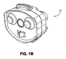
本明細書に記載のシステム及び方法は様々な方法で実施することができる。図1A及び図1Bは、それぞれ、いくつかの実施形態による、電源コネクタ100の能動部品101及び受動部品151の斜視図である。いくつかの実施形態では、能動部品101と受動部品151とを接触させて電気的接続を形成することができる。能動部品及び受動部品は多くの異なる形状を使用して実現できること、及び本明細書に記載の実施形態は非限定的な例として意図されることに留意されたい。
In the drawings, the figure shows an exemplary embodiment.
The systems and methods described herein can be implemented in a variety of ways. 1A and 1B are perspective views of the
いくつかの実施形態では、電源コネクタ100は能動部品101と受動部品151とを含む。能動部品101及び受動部品151はそれぞれ、その上に配置された複数の電気接点を有する。能動部品の面と受動部品の面とが結合されると、能動部品上の電気接点と受動部品上の電気接点とが電気的接続を形成する。いくつかの実施形態では、AC電流が、能動部品及び受動部品上の1つ又は複数の電気接点の間を流れることが許容される。いくつかの実施形態では、制御回路又は論理回路は、AC電流が能動部品と受動部品との間を流れることを許容されるかどうかを支配し得る。様々な実施形態及びそれに関連する特徴は、以下でさらに詳細に議論する。
In some embodiments, the
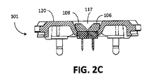
図2Aは、いくつかの実施形態による能動部品101の正面図である。能動部品101は面120を含み、面120は略平面状及び/又は輪郭付けされ得る。面120は、その上に配置された複数の電気接点102、104、106、及び108を含み得る。いくつかの実施形態では、面120は、その上に配置された強磁性要素110をさらに含む。いくつかの実施形態では、強磁性要素110は鋼鉄又は任意の磁性材料でできたプレートであり得る。
FIG. 2A is a front view of the
電気接点102は、ホット用接点(hot contact)とすることができる。電気接点104はニュートラル用接点(neutral
contact)とすることができる。電気接点106は接地用接点(ground contact)とすることができる。電気接点108は、それに関連するインピーダンスを有する抵抗接点とすることができる。
The
contact) can be. The
図2Aの例示的な実施形態が4つの電気接点を示しているが、4つより多い電気接点、又は4つより少ない電気接点を有することができる他の実施形態が企図されることを理解されたい。例えば、特定の国は接地用接点やそれに類するものを必要としないので、いくつかの実施形態は接地用接点を特徴としない場合がある。 Although the exemplary embodiment of FIG. 2A shows four electrical contacts, it is understood that other embodiments that can have more than four electrical contacts or less than four electrical contacts are contemplated. sea bream. For example, some embodiments may not feature grounding contacts, as certain countries do not require grounding contacts or the like.
図2Bは、図2Aに示される能動部品101の断面図(A-A)である。この例示的な実施形態では、能動部品101の面120は、電気接点102及び104がそれぞれ配置される2つの凹部112及び114を含む。いくつかの実施形態では、電気接点102及び104は凹形状を有する。
FIG. 2B is a cross-sectional view (AA) of the
図2Cは、図2Aに示される能動部品101の断面図(B-B)である。能動部品101の面120は、電気接点106及び108が配置される凹部117をさらに含むことが分かる。この例示的な実施形態では、電気接点106及び108は、電気接点106及び108の組合せが楔状の形状を形成するように、略台形の断面形状で成形される。いくつかの実施形態では、凹部17の面120からの深さは、電気接点102及び104を収容する凹部112及び114の深さよりも浅い。
FIG. 2C is a cross-sectional view (BB) of the
図3Aは、いくつかの実施形態による受動部品151の正面図である。受動部品は面170を含み、面170は略平面状及び/又は輪郭付けされ得る。面170は、その上に配置された複数の電気接点152、154、156、及び158を含み得る。いくつかの実施形態では、面170は、その上に配置された磁気要素160をさらに含む。
FIG. 3A is a front view of the
電気接点152は、ホット用接点とすることができる。電気接点154はニュートラル用接点とすることができる。電気接点156は接地用接点とすることができる。電気接点158は、それに関連するインピーダンスを有する抵抗接点とすることができる。能動部品101に関して上述したように、この例では4つの電気接点が示されているが、他の実施形態は4つより多い電気接点を有することができ、他の実施形態は4つより少ない電気接点を有することができることを理解されたい。
The
図3Bは、図3Aに示される受動部品151の断面図(F-F)である。この例示的な実施形態では、面170は、一組の突起部162、164を含み、その上に電気接点152及び154が配置される。いくつかの実施形態では、電気接点152及び154は凸形状を有する。いくつかの実施形態では、電気接点152及び154の形状は、能動部品101上の電気接点102及び104の形状と相補的である。
FIG. 3B is a cross-sectional view (FF) of the
図3Cは、図3Aに示される受動部品151の断面図(E-E)である。面170は、第2組の突起部166、168を含み、その上に電気接点156、158が配置されることが分かる。この例示的な実施形態では、電気接点156及び158は、電気接点156及び158の組合せが略角錐状の構造を形成するように、略三角形の断面形状を有するように成形される。いくつかの実施形態では、電気接点106及び108によって形成された楔形形状と、電気接点156及び158によって形成された角錐構造とは相補的である。
FIG. 3C is a cross-sectional view (EE) of the
図4Aは、いくつかの実施形態による、受動部品151上の第1組の突起部162、164を能動部品101上の第1組の凹部112、114に近接させた状態の図である。図4Bは、受動部品及び能動部品が第2組の突起部166、168及び凹部117で強調して結合される状態の図である。
FIG. 4A is a diagram showing a state in which the first set of
能動部品101と受動部品151とが結合されると、面120と面170とが近接する。いくつかの実施形態では、面120及び面170は物理的に接触しなくてもよく、物理的接触は電気的接触に限定されてもよい。図示されるように、受動面170上の第1組の凸状突起部162、164は、能動面120上の第1組の凹状凹部112、114によって収容される。これにより、電気接点102と電気接点152との接続を形成することができ、電気接点104と電気接点154と接続を形成することができる。いくつかの実施形態では、能動部品101上の凹部112、114は受動部品151上の突起部162、164よりも大きく寸法決めされており、これにより突起部162、164を能動部品101の凹部112、114内で横方向にスライドさせることができる。
When the
いくつかの実施形態では、能動部品及び受動部品上の凹状及び凸状の電気接点は、現在一般的に使用されているような従来のブレードコネクタ、ポール(丸みを帯びた)コネクタ等と比較して高電流の伝達のための追加の表面積を提供し得る。これは、電気接点の小さな表面積を通過する高電流に関連し、次に局所領域の温度を上昇させ、潜在的な火災の危険性を提示するアーク放電の可能性を減らすことができる。伝達のための表面積が増大すると、そのような火災被害の危険性が減少し得る。 In some embodiments, concave and convex electrical contacts on active and passive components are compared to conventional blade connectors, pole (rounded) connectors, etc. as are commonly used today. Can provide additional surface area for high current transfer. This is associated with high currents passing through a small surface area of electrical contacts, which in turn raises the temperature in the local area and can reduce the possibility of arc discharge, which presents a potential fire hazard. Increasing the surface area for transmission can reduce the risk of such fire damage.
能動部品101と受動部品151との結合中に、第2組の突起部166、168及び電気接点156、158(これらは角錐形状を形成する)は、台形状の電気接点106及び108並びに凹部117によって形成された楔形状構造と接触する。いくつかの実施形態では、角錐形状及び楔形状は、楔形状が角錐形状の受容器として作用するように寸法決めされる。
During the coupling of the
いくつかの実施形態では、能動部品101上の楔形構造の面120に対する深さは、電気接点102及び104を収容する凹部112、114の深さよりも浅い。楔構造のより浅い深さは、電気接点152及び154がそれぞれ電気接点102及び104と接触する前に、電気接点156及び158が電気接点106及び108と接触するのを可能にし得る。
In some embodiments, the depth of the wedge structure on the
そのような構成は、地域の規制又は設計上の考慮事項により、特定の接点が結合時に最初に接触すること、結合解除時に最後に分離されること、又はその両方であることが要求される場合に望ましくあり得る。例えば、いくつかの地域では、調整体には、接地用接点が結合時に最初に接触し、結合解除時に最後に分離することが要求され得る。いくつかの実施形態では、この要件は、接地用接点を106と156、又は108と158のいずれかであるように(すなわち、楔形構造及び角錐形構造上の接点のうちの1つとして)選択することによって満たされ得る。 Such configurations are where local regulations or design considerations require that certain contacts first contact at coupling, last at disconnection, or both. May be desirable. For example, in some areas, the coordinator may be required to have the ground contact first contact at coupling and last at disconnection. In some embodiments, this requirement selects the grounding contact to be either 106 and 156, or 108 and 158 (ie, as one of the contacts on a wedge or pyramidal structure). Can be satisfied by doing.
いくつかの実施形態では、能動部品101と受動部品151との結合中に、磁気要素160を強磁性要素110と十分に接近させて、強磁性要素110と磁気要素160との間に磁気吸引力を及ぼす。いくつかの実施形態では、能動部品及び受動部品は、複数の強磁性要素110と磁気要素160とを含み得る。能動部品101と受動部品151とが互いに近づくにつれて、磁気吸引力の大きさが増大する。
In some embodiments, the
いくつかの実施形態では、磁気吸引力の大きさは、能動部品と受動部品とを結合したままにさせるのに十分であるが、能動部品と受動部品とを分離するために、過度の物理力が必要となるほど強くはない。例えば、必要とされる分離力は、電源ケーブル又はその下にある電気装置を損傷させる危険性があるほど強くすべきではない。さらに、磁気吸引力は、偶発的に引っ張られた場合(例えば、人がコードでつまずいた場合)に、能動部品と受動部品とが分離するように調整することができる。いくつかの実施形態では、磁気吸引力は約3~5ポンド(1.36~2.27kg)の力である。しかしながら、この範囲よりも大きい又は小さい引力は、使用される特定の状況及び構成要素に基づいて選択することができる。 In some embodiments, the magnitude of the magnetic attraction is sufficient to keep the active and passive components coupled, but excessive physical force to separate the active and passive components. Is not strong enough to require. For example, the required separation force should not be strong enough to risk damage to the power cable or the electrical equipment beneath it. In addition, the magnetic attraction can be adjusted to separate the active and passive components if accidentally pulled (eg, if a person trips over the cord). In some embodiments, the magnetic attraction is a force of about 3-5 pounds (1.36-2.27 kg). However, gravitational forces greater than or less than this range can be selected based on the particular circumstances and components used.
いくつかの実施形態では、(摩擦力の使用ではなく)能動部品と受動部品とを接続したままにするための磁気吸引力(非摩擦力)の使用は、1つ又は複数の電気接点102、104、106、108、152、154、156、158の寿命を延ばすことができる。
In some embodiments, the use of magnetic attraction (non-friction force) to keep the active and passive components connected (rather than the use of frictional force) is the use of one or more
能動部品及び受動部品に関して多くの異なる構成が企図される。特定の構成が上述されているが、能動部品101上の電気接点が受動部品151上の電気接点と接触することができる他の構成がある。
Many different configurations are contemplated for active and passive components. Although certain configurations are described above, there are other configurations in which the electrical contacts on the
図9Aは、能動部品101の代替実施形態の斜視図である。示されるように、接点は、能動部品上の同心円状の導電性円形又は楕円形のストリップ102、104、106、及び108の形態をとることができる。図9Bは、図9Aに示される能動部品101の実施形態の正面図である。導電リングは、ニュートラル用接点、ホット用接点、接地用接点、及び抵抗接点のそれぞれを電気的に絶縁するように、絶縁リングによって分離することができる。本明細書では導電性ストリップをリングと呼ぶが、特定の形状は必要とされないことを理解されたい。そのため、本明細書に記載の例示的な実施形態は、能動部品又は受動部品上の導電性ストリップに関して可能な構成に限定的な影響を及ぼすと解釈すべきではない。絶縁層は、例えばプラスチックから作製され得る。電気接点があらゆる導電リングと関連付けることができること、及び図9A~9Cに示される構成が単なる例であることを理解すべきである。例えば、接点102は、示されるように、最も外側の導電リングではなく、内側の導電リングのうちの1つと関連付けることができる。
FIG. 9A is a perspective view of an alternative embodiment of the
図9Cは、図9A及び図9Bに示される能動部品101の実施形態の側面図である。能動部品101の側面プロファイルから分かるように、導電リング102、104、106、及び108は、能動部品101の面120上で比較的平坦であり得る。他の実施形態では、導電リングは面120内で様々な深さを有し得る。
9C is a side view of an embodiment of the
図9Dは、受動部品151の例示的な実施形態の斜視図である。示されるように、受動部品151は、面170から延びる複数の突起部を有する。1つ又は複数の電気接点152、154、156、及び158は、面170から延びる突起部と関連付けられ得る。受動部品151の面170上の突起部同士の間の間隔は、能動部品101の例示的な実施形態の導電リング同士の間の間隔に対応してもよく、それによって、電気接点152、154、156、及び158は、それぞれ能動部品101上の電気接点102、104、106、及び108と電気的接続を形成する。
FIG. 9D is a perspective view of an exemplary embodiment of the
図9Eは、図9Dに示される受動部品151の側面図である。示されるように、電気接点152、154、156、及び158は受動部品151の面170から突出している。示される例示的な実施形態では、接地用接点156に対応する突起部は、他の電気接点152、154、及び158に対応する突起部よりも面170からさらに突出しており、これら他の電気接点は、例えば、ホット用接点、ニュートラル用接点、及び抵抗接点の接続に対応し得る。これにより、他の電気的接続が形成される前に、接地用接点156が能動部品101上の接地用接点106と接触することが可能になり得、これはいくつかの地域では望ましいことであり得る。電気コネクタ175a~175dが図9Eにも示されており、これらのコネクタは、能動部品101に接続された電源によって最終的に電力が供給される装置(図示せず)内の下にある電気回路への接続を提供する。
9E is a side view of the
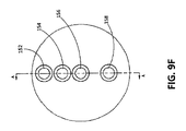
図9Fは、図9Dに示される受動部品151の例示的な実施形態の正面図である。この特定の構成では、接点152、154、156、及び158のそれぞれは、面の直径に沿って置かれており、この例では円形である。しかしながら、受動部品151の形状が全ての実施形態において必ずしも円形である必要はなく、電気接点が直径に沿って配置される必要がないことを理解されたい。例えば、接点152、154、156、及び158のうちの1つ又は複数が、能動部品101上の導電リングと整列するように面の中心から離れている任意の構成は、必要な機能を提供するであろう。
9F is a front view of an exemplary embodiment of the
図9Gは、図9Fに示される軸線A-Aを通る例示的な受動部品151の断面図である。いくつかの実施形態では、突起部のうちの1つ又は複数は、弾性部材902によって面170から外向きに付勢され得る。いくつかの実施形態では、弾性部材はばねであり得る。接点を外向きに付勢することは、能動部品101上の突起部又は受容キャビティの長さの機械加工におけるいかなる不正確さも、突起部が受動部品の面から様々な長さだけ突出するのを可能にすることによって説明され得るという利点を提供し得る。これにより、各電気接点の間の適切な接触を確実に達成できることが保証され得る。
FIG. 9G is a cross-sectional view of an exemplary
図9Hは、図9Dに示される例示的な受動部品151を図9Aに示される例示的な能動部品101と近接させた状態の斜視図である。示されるように、能動部品101上の同心状の導電リングが受動部品151上の突起部と電気的接続を形成する。そのような構成の1つの利点は、能動部品101上の接点のリング構造と組み合わされる受動部品151上の突起部が、接続を確立するために必要とされる角度的なアプローチに関して高い可変性を可能にし得ることである。例えば、電気接点同士の間に物理的接続を確立するために、能動部品と受動部品との特定の向きは必要とされない。これは視覚障害のあるユーザや、届きにくい場所にある電源コンセントに特に役立ち得る。いくつかの実施形態では、導電リングは絶縁リングによって分離される。いくつかの実施形態では、絶縁リングはプラスチック製であり得る。
9H is a perspective view of the exemplary
また、図9Hにおいて受動部品151を能動部品101に接合する場合に、接地用接点156に対応する受動部品151上の突起部が、他の電気接点152、154、及び158よりも面170からさらに突出し得ることを思い出すべきである。こうして、この例示的な実施形態では、接地用接点に対応する導電リング106が、能動部品と受動部品とが接合されているときに、受動部品151と物理的に接触する第1の接点とすることができ、能動部品と受動部品とが分離されているときに、接地用接点156及び106が最後に切断される接点となることも可能にする。
Further, when the
前述の例では、受動部品151は突起部を含み、能動部品101は導電リング及び/又は凹部を含むことにさらに留意されたい。しかしながら、いくつかの実施形態では、能動部品101は代わりに突起部を有してもよく、受動部品151は導電リングを含んでもよい。いくつかの実施形態では、電気接点102、104、106、及び108と、152、154、156、前記158とのうちの1つ又は複数の間に電気的接続を形成可能にするように必要な相補的関係が維持される限り、本明細書は、能動部品及び受動部品上の接点構成を交換可能にすることを企図する。こうして、本明細書に記載の例示的な実施形態は、能動部品101を、受動部品151からの突起部を受け入れるための凹部のみを含むように限定するものと見なすべきではない。能動部品101は、突起部、又は突起部と凹部との組合せを含むことができる。受動部品151はまた、接点同士の間に電気的接続を確立するための凹部、又は凸部と凹部との組合せを含むことができる。
It should be further noted that in the above example, the
ここで別の例示的な実施形態に目を向けると、いくつかの実施形態では、1つ又は複数の接点を能動部品101又は受動部品151上で一緒にまとめてもよい。さらに、1つ又は複数の接点を1つ又は複数の弾性部材1002によって外向きに付勢してもよい。図10Aは、能動部品101の例示的なモジュール1000の斜視図である。モジュール1000では、電気接点106及び108が一緒にまとめられる。示されるように、中央の電気接点106(この例では、接地用接点)は外向きに突出している。いくつかの実施形態では、電気接点106は、(図10Dに示されるように)ばね1002によって外向きに付勢される。いくつかの実施形態では、接地用接点106は、ばね取付け式プランジャ接点であり得る。
Turning to another exemplary embodiment here, in some embodiments, one or more contacts may be grouped together on the
電気接点106は、ゴム又は他の任意の適切な絶縁材料で作製され得る絶縁リング1001によって電気接点108から分離され得る。図10Dに示されるように、絶縁リング1001は、電気接点106を電気接点108から電気的に絶縁するように、モジュール1000の本体全体に亘って延びることができる。図10Bは、図10Aに示されるモジュール1000の正面図である。図10A、図10C、及び図10Dのそれぞれに示されるように、モジュール1000は、電源に接続するための接地ピン1003をさらに含むことができる。
The
図10Eは、モジュール1000と形状が相補的である例示的なモジュール1050の斜視図である。示されるように、モジュール1050は、中心に配置された電気接点156(この例では、接地用接点)を有しており、絶縁リング1051が電気接点156と電気接点158とを分離する。モジュール1050は、装置(図示せず)に接続する接地ピン1053をさらに含む。図10Hに示されるように、絶縁リング1051は、接点156(例えば、接地用接点)を接点158(例えば、抵抗接点)から電気的に絶縁するようにモジュール1050の本体全体に亘って延びることができる。図10F及び図10Gは、モジュール1050の更なる正面図及び側面図を提供する。
FIG. 10E is a perspective view of an
いくつかの実施形態では、能動部品101はモジュール1000を含み、受動部品151はモジュール1050を含む。この例では、受動部品151が能動部品101内に押し込まれるときに、モジュール1000上の接点106が、他の接点よりも先にモジュール1050上の接点156と物理的に接触する。接触がモジュール1000と1050との間で行われると、ばね1002を圧縮して接点106を収容することができるので、接点106をモジュール1000の本体内に押し込むことができる。ばね1002がモジュール1000及び1050を分離させるために動作する力を及ぼすが、受動部品及び能動部品は、ばね1002によってプランジャ接点106に及ぼされる力を克服するのに十分な吸引力を与える1つ又は複数の磁気要素160及び強磁性要素110を含むことができる。
In some embodiments, the
いくつかの実施形態では、モジュール1000は能動部品101内に統合され、モジュール1050は受動部品151内に統合され得ることを理解されたい。他の実施形態では、モジュール1000及び1050は、能動部品101及び受動部品151によってそれぞれ収容されるように適合される別々の部品である。さらに、本明細書に記載の例示的なモジュール1000及び1050が接地用接点及び抵抗接点を収容したが、ホット用接点、ニュートラル用接点、接地用接点、及び抵抗接点のうちの任意の2つがモジュール1000及び1050内に実装される他の実装形態が企図されることを留意されたい。
It should be appreciated that in some embodiments, the
いくつかの実施形態では、受動装置151への電気経路の確立を制御するために回路が能動装置101に設けられる。すなわち、電気接点102、104、106、及び108は、それぞれ電気接点152、154、156、及び158と物理的に接触しているが、いくつかの実施形態によれば、接点同士の間の物理的接続の存在は、以下で説明するように、更なる条件を満足せずに、電力が流れることを可能にするのに十分ではない可能性がある。
In some embodiments, a circuit is provided in the
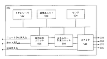
図5は、いくつかの実施形態による、例示的な能動部品101に見られる構成要素のブロック図である。図示されるように、能動部品101は、論理ユニット501、トランシーバ502、センサ504、電力制御ユニット506、エネルギー計量ユニット508、及びコネクタ510を含む。能動部品101は、電源からホット用接続、ニュートラル用接続、及び接地用接続を受け入れるように構成され、特定の条件が満たされる場合に、これらの接続を受動部品151に接続された装置に提供する。いくつかの実施形態では、電源コネクタ100は、1つ又は複数の条件が満たされていない場合に、デフォルトで電力の流れを可能にしないように構成される。これにより、受動部品151が存在し且つ能動部品101に完全に物理的に接続されるまで、能動部品上の電気接点が常にオフであり且つ接触に対して安全であることが保証され得る。これにより、感電及び感電死の可能性が減少され得る。さらに、電源コネクタ100のいくつかの実施形態は、ユーザが誤って又は意図的に能動部品101をいじって装置を起動させるのを防ぐことができる。
FIG. 5 is a block diagram of the components found in the exemplary
論理ユニット501は、能動部品101から受動部品151への電力の流れを制御するように構成される。図5に示されるように、電源からのホット用入力(hot in)接続、ニュートラル用入力(neutral in)接続、及び接地用入力(ground in)接続は、能動部品101の入力として扱われる。いくつかの実施形態では、論理ユニット501は、閉じた状態では、ホット用電流(hot current)、ニュートラル用電流(neutral current)、及び接地用電流(ground current)の通過を可能にし、開いた状態では流れを防止する(スイッチとして機能する)1組の電気リレー(relay)を制御するように構成される。こうして、論理ユニット501によって有効にされると、ホット用電流、ニュートラル用電流、及び接地用電流が能動部品101上のコネクタ510から受動部品151に流れることができる。
The logic unit 501 is configured to control the flow of power from the
図5は論理ユニット501が能動部品101の内部にあるものとして描いているが、いくつかの実施形態では、論理ユニット501は能動部品101の外部にあるか又は能動部品101から分離していることが企図される。論理ユニットが能動部品101の外部にあるか又は能動部品101から分離している実施形態では、ホット用入力、ニュートラル用入力、及び接地用入力からの測定値は、トランシーバ502を介して論理ユニット501に送信され得る。論理ユニット501は、次に、測定値を処理し、トランシーバ502を介して電流フローを可能にするか否かの1つ又は複数の命令をリレーに与えることができる。
FIG. 5 depicts the logic unit 501 as being inside the
図6は、いくつかの実施形態による、能動部品のコネクタ510の簡略ブロック図である。示されるように、例示的なコネクタは電気接点102、104、106、及び108を含む。この例では、電気接点108は、抵抗接点であり、電源からのあらゆるAC電圧を伝えない。電源から電圧を伝えるのではなく、電気接点108に基準電圧(この例示的な実施形態では、基準電圧は+5VDC又は任意の適切なDC基準電圧であり得る)が供給され、Z1のインピーダンスを有する抵抗素子を有する。上述したように、インピーダンスは、実部(例えば、純粋に抵抗性)、虚部(例えば、純粋に反応性)、又はそれらの組合せであり得る。いくつかの実施形態では、DC基準電圧は、AC電源から入力信号の一部を取り出し、その一部をDC信号に変換することによって得られる。いくつかの実施形態では、基準電圧はAC電圧であり得る。
FIG. 6 is a simplified block diagram of an
図7は、受動部品151の簡略ブロック図である。示されるように、電気接点152、154、156、及び158は受動部品151上に存在する。この例では、受動部品151の左側は、受動部品101と相互作用する受動部品151の側面を示している。この例における受動部品151の右側は、受け側の電気装置(図示せず)に供給される出力を示している。能動側の電気接点108と同様に、能動側の電気接点158は、抵抗接点であり、且つAC電流を電源から受け側の電気装置に流すためには使用されない。電気接点158は、代わりに、インピーダンスZ2と関連しており、ニュートラル用接続に接続される。インピーダンスZ2は、純粋に抵抗性、純粋に反応性、又は実インピーダンスと虚インピーダンスとの組合せであり得る。
FIG. 7 is a simplified block diagram of the
図8は、いくつかの実施形態による、物理的に接続された状態の能動部品及び受動部品の簡略ブロック図である。コネクタ510と受動部品151との間の物理的接続の存在は、電力が流れるのにそれ自体では十分ではない可能性があることに留意されたい。図示されるように、各接点102、104、106、108及び152、154、156、158の間に物理的な接続がある(これらは、この例示的な実施形態におけるホット用接続、ニュートラル用接続、及び接地用接続に対応する)。また、接点108と接点158との接続は、Z1及び2で示される2つのインピーダンスの間に接続を形成することにも留意されたい。
FIG. 8 is a simplified block diagram of an active component and a passive component in a physically connected state according to some embodiments. It should be noted that the presence of a physical connection between the
単純化した例として、Z1及びZ2がR1及びR2の抵抗を有する純粋に抵抗接点である場合に、回路理論によれば、この例示的な構成は分圧器を形成する。すなわち、図8のA点で測定された電圧は、入力電圧(この例では、5VDC)とR2/(R1+R2)の比との積に等しい。R1及びR2が等しい場合には、数学的に便利なケースがある。この場合に、点Aで測定された電圧は単に入力電圧の半分になる。 As a simplified example, if Z1 and Z2 are purely resistant contacts with resistances of R1 and R2, according to circuit theory, this exemplary configuration forms a voltage divider. That is, the voltage measured at point A in FIG. 8 is equal to the product of the input voltage (5VDC in this example) and the ratio of R2 / (R1 + R2). When R1 and R2 are equal, there are cases that are mathematically convenient. In this case, the voltage measured at point A is simply half the input voltage.
図5の例に戻ると、いくつかの実施形態では、論理ユニット501は様々な接点の状態を定期的にポーリングすることができる。いくつかの実施形態では、論理ユニット501は、図8の点Aにおける電圧をポーリングするように構成される。これは、例えば、マイクロコントローラのピンを点Aにマッピングすることによって達成することができる。観測された電圧、又は観測された他の特性に基づいて、論理ユニット501は、リレーを閉じて電力が能動部品101と受動部品151との間を流れるのを可能にする信号を送ることができる。いくつかの実施形態では、論理ユニット501は、電流フローを有効にするための必要条件が所定の時間量だけ満たされた後に、電流の流れを遅延させることができる。電流の流れを遅延させることは、例えば、電気接点102、104、106、108がユーザによって保持されている間は電気が流れて(live)おらず、ユーザが接点に触れることができない所定の時間期間後に電気が流れることを確実にすることによって、コネクタ100の安全性を高めることができる。
Returning to the example of FIG. 5, in some embodiments, the logic unit 501 can periodically poll the state of various contacts. In some embodiments, the logic unit 501 is configured to poll the voltage at point A in FIG. This can be achieved, for example, by mapping the pins of the microcontroller to point A. Based on the observed voltage, or other observed characteristics, the logic unit 501 can send a signal that closes the relay and allows power to flow between the
論理ユニット501をトリガしてリレーを閉じ、電力を流すことを可能にするのに適し得る多くの可能な条件がある。いくつかの実施形態では、論理ユニット501が電力の流れを有効にするために、第1のインピーダンスZ1は第2のインピーダンスZ2と略等しくしなければならない。そのような場合に、点Aにおける電圧が入力電圧の約半分である(例えば、入力電圧が5Vの場合に点Aにおいて2.5Vの電圧が観測される)ことを観察することによって決定を行うことができる。いくつかの実施形態では、電力の流れを有効にするために、第1のインピーダンスと第2のインピーダンスとの間の所定の関係又は条件を満たされなければならない。論理ユニット501は、比較器、プロセッサ、マイクロコントローラ、又は本明細書で議論される決定を行うのに適した他の任意のハードウェア及び/又はソフトウェア設計のうちの1つ又は複数を含むことができる。 There are many possible conditions that may be suitable to trigger the logic unit 501 to close the relay and allow power to flow. In some embodiments, the first impedance Z1 must be approximately equal to the second impedance Z2 in order for the logic unit 501 to enable power flow. In such a case, the determination is made by observing that the voltage at point A is about half the input voltage (eg, when the input voltage is 5V, a voltage of 2.5V is observed at point A). be able to. In some embodiments, certain relationships or conditions between the first impedance and the second impedance must be met in order to enable power flow. The logic unit 501 may include a comparator, processor, microcontroller, or any other hardware and / or software design suitable for making the decisions discussed herein. can.
いくつかの実施形態によれば、電源コネクタ100と共に抵抗感知方式を使用することから、いくつかの利点を引き出すことができる。例えば、異なる能動部品101と受動部品151とを特定の基準(例えば、等しいインピーダンス値)を満たす特定のインピーダンス値で製造することができる。正しいインピーダンス値を有する特定の受動部品151のみが特定の能動部品101と共に使用され得るので、これは、電源コネクタ100に対する追加の制御層を可能にするであろう。例えば、幼い子供がいる家庭では、危険な電化製品又はツールは、家の特定の部分に配置された特定の能動部品101のみと互換性がある受動部品151と共に使用することができる。これにより、特定の電気装置の不要な使用を防ぐのに役立つ。
According to some embodiments, some advantages can be derived from using the resistance sensing method with the
図5に戻ると、能動部品101は電力制御ユニット506を含むことができる。電力制御ユニット506は、電源からのホット用入力接続、及びニュートラル用入力接続を受け入れる。いくつかの実施形態では、電力制御ユニット506は、電子制御スイッチとして機能する1つ又は複数の電気式リレーを含む。論理ユニット501は、(電力の流れを防ぐため)リレーを開くべきか又は(ホット用電圧及びニュートラル用電圧が流れるのを可能にするため)閉じるべきかを示す信号を電力制御ユニット506に供給する。リレーが閉じられると、ホット用入力電流及びニュートラル用入力電流がプラグコネクタ510に、そしてオプションでエネルギー計量ユニット508に流れるのが可能になる。
Returning to FIG. 5, the
電力制御ユニット506は、AC/DC変換ユニット560及び送電ユニット562を含み得る。例示的な実施形態の回路図が図11に提供される。図示されるように、AC/DC変換ユニット560は、MOSFET駆動型発振集積回路(IC)を有する様々な抵抗器及びコンデンサを含み得る。図5から分かるように、電力制御ユニット506は、電源からのホット用入力接続及びニュートラル用入力接続を受け入れる。いくつかの実施形態では、ICは、最大360mAの供給電流で、入力電圧を85VAC~265VACの範囲内の電源から12VDCの出力に変換することができる。いくつかの実施形態では、供給電流は360mAを超えてもよい。12VDCの出力は、送電ユニット562内の中継ユニットだけでなく、他の様々な構成要素(例えば、電力の流れが有効になると点灯する1つ又は複数の発光ダイオードを含む)に電力を供給するために、部分的に使用され得る。
The
いくつかの実施形態では、12VDCの出力は、5VDCの出力電圧を供給するDC-DCステップダウンコンバータにさらに送られる。いくつかの実施形態では、5VDCの出力は、論理ユニット501及びそれと通信する構成要素に電力を供給するために使用され得る。5VDCの信号はまた、電気接点108及び158が接続されるときに形成される分圧器のための基準信号としても使用され得る。本明細書に記載の例示的なAC/DC変換ユニット560は、システムレベルの熱過負荷保護、並びに出力短絡及び開回路制御ループ保護を提供し得る。さらに、例示的なAC/DC変換ユニット560は、700Vまでの降伏電圧に関して定格されてもよく、これは、入力電力サージに耐えるのに有用であり得る。
In some embodiments, the output of 12 VDC is further sent to a DC-DC step-down converter that supplies an output voltage of 5 VDC. In some embodiments, the output of the 5 VDC can be used to power the logic unit 501 and the components communicating with it. The 5 VDC signal can also be used as a reference signal for the voltage divider formed when the
いくつかの実施形態では、送電ユニット562は、様々な電力レベルに対して定格が定められ得る1つ又は複数のリレーを含み得る。例えば、そのようなリレーは、最大接触電圧400VACで30アンペアの連続電流を供給することができる可能性がある。リレーは、論理ユニット501からのリレーを閉じるのを有効にする信号がない場合にリレーが導通しないように、論理ユニット501によって制御される。リレーは、例えば光アイソレータによって低電力部品から電気的に絶縁することができる。光アイソレータは、リレーの接点を非活性化するために、論理ユニット501の出力から必要な電流量を低下させることができるソリッドステート・リレーの一種である。 In some embodiments, the power transmission unit 562 may include one or more relays that can be rated for various power levels. For example, such a relay may be able to supply a continuous current of 30 amps with a maximum contact voltage of 400 VAC. The relay is controlled by the logic unit 501 so that the relay does not conduct in the absence of a signal to enable closing the relay from the logic unit 501. Relays can be electrically isolated from low power components, for example by optical isolators. An optical isolator is a type of solid state relay that can reduce the amount of current required from the output of the logic unit 501 to deactivate the contacts of the relay.
能動部品101は、磁場の存在を検出するためのセンサ504も含み得る。いくつかの実施形態では、センサ504は、十分に強い磁場が検出されたときに、電流を発生するホール効果センサ又はスイッチである。受動部品が磁気要素160を含み、能動部品が強磁性要素110を含む実施形態では、磁場の存在を示すセンサ504からの信号は、能動部品と受動部品との間の電流フローを有効にするための前提条件として使用され得る。これにより、電源コネクタ100に追加の制御層及び冗長性が与えられる。
The
例えば、図11に示されるように、ホール効果センサ504は、磁場がない場合に、光アイソレータ1101内のLEDが光アイソレータ1101を起動させるのに十分な光を生成しないように光アイソレータ1101に結合される。局所的な磁場がない場合に、能動部品101上の電気接点は、光アイソレータを起動させるのに十分に強い磁場を発生させるために、磁気要素160を含む受動部品151が能動部品に十分近くなるまで、オフにされ接触しても安全である。
For example, as shown in FIG. 11, the
さらに、これにより、どのコネクタを能動部品101と共に使用することができるかについての追加の制御層が提供される。適切な形状及び正しい電気接点構成を有する偽の受動部品を使用しようとした場合であって、磁気要素を含まない場合に、センサ504からの許可信号がないと、能動部品101内のリレーが閉じるのが防止される。こうして、特に電源コネクタ100が屋外で使用される場合に、能動部品101を使用することにより、許可されていない人が電気装置をユーザのコンセントに接続して電気を盗用することを防止することができる。屋外で見付けられた従来のコンセントは誰でも使用でき、通常は通電するために許可を必要としない。
In addition, this provides an additional layer of control as to which connector can be used with the
いくつかの実施形態では、能動部品101は、エネルギー計量ユニット508を含む。計量ユニット508は、電源又は電力制御ユニット506からホット用入力接続及びニュートラル用入力接続を受け入れる。計量ユニット508は、受動装置151及びそれに接続された任意の装置によるエネルギー消費を測定及び監視するように構成される。いくつかの実施形態では、エネルギー消費データはメモリに記憶され得る。いくつかの実施形態では、エネルギー消費データは、オプションで、リアルタイムでユーザに送信され得る。いくつかの実施形態では、エネルギー計量ユニット508は、エネルギー消費データを論理ユニット501に提供することができる。これにより、論理ユニットが動作上の不一致を検出することができる。例えば、地絡によって引き起こされる漏電は、エネルギー計量ユニット508によって測定することができ、論理ユニット501は、漏電の検出に応答して電力の流れを無効にすることができる。これは、例えば、電源コネクタ100のユーザを感電死又は火災被害から保護するのに有用であり得る。
In some embodiments, the
エネルギー計量ユニット508は、個々の装置のエネルギー使用量を監視することができるという利点も提供することができる。一般に、エネルギー計量装置は、家全体又はアパート単位に関連するエネルギー使用量を監視するために使用される。エネルギー監視ユニットが電源コネクタ100内に収容されているので、個々の装置のエネルギー使用量を監視することができ、それによってユーザは予想よりも大きな量の電力を使用している装置を特定することができる。そのような電力消費データは、異常な電力又はエネルギー消費の読取り値が、機械又は機器に保守が必要であり、機械又は機器が障害点に達するまで問題に気が付かないのではなく、将来を見越して予防的保守が実施されることを可能にする有用な指標となり得る産業用途において特に有用であり得る。これはコストのかかる修理の可能性を減らす可能性がある。
The
いくつかの実施形態では、能動部品101はトランシーバ502を含む。トランシーバ502は、データを送信及び受信することができる無線トランシーバとすることができる。いくつかの実施形態では、トランシーバ502は、例えば統合プロセッサ又はシステムオンチップ設計として論理ユニット501に統合される。いくつかの実施形態では、トランシーバ502は、論理ユニット501とは別個であり、論理ユニット501に光学的に結合される。トランシーバ502は、電源コネクタ100がユーザと連絡するための能力を提供する。いくつかの実施形態では、トランシーバ502は、スマートホームプロトコル(例えば、Zigbee Alliance、Z-wave Alliance等)と通信するように構成される。
In some embodiments, the
通信は、例えば、インターネット又はローカルエリアネットワーク等へのネットワーク接続を確立することによって達成され得る。通信接続が確立されると、トランシーバは、例えば適切な通信プロトコルを使用してコンピュータ又はモバイルコンピュータ装置を介してユーザからコマンドを受け取ることができる。そのようなユーザコマンドは、論理ユニット501に(リレーを開くことによって)電力の流れを無効にさせる、又は(リレーを閉じることによって)電力の流れを有効にさせる、ユーザからのコマンドを含むことができる。 Communication can be achieved, for example, by establishing a network connection to the Internet, a local area network, or the like. Once the communication connection is established, the transceiver can receive commands from the user via a computer or mobile computer device, for example using the appropriate communication protocol. Such user commands may include commands from the user that cause the logical unit 501 to disable power flow (by opening the relay) or enable power flow (by closing the relay). can.
このように、本発明のいくつかの実施形態は、インターネット接続等の通信リンクが利用可能であるという条件で、ユーザが電源コネクタ100を遠隔でオン及びオフに切り替えることを可能にし得る。これは、ユーザが装置の電源を切るのを忘れて既に家を出た場合に有用であり得る。例えば、ユーザがオーブンの電源を入れたままにしておいた場合に、ユーザはコマンドをリモートネットワーク接続装置から電源コネクタ100に送信し、電源コネクタ100をオフにすることができ、それによってエネルギーの無駄を省き、火災の危険性を減らす。
As described above, some embodiments of the present invention may allow the user to remotely switch the
図12は、電源と装置との間の電流フローを有効にする方法1200を示す例示的なフローチャートである。1202において、第1組の電気接点を有する第1の構成要素が提供され、第1組の電気接点は第1のインピーダンスを有する第1の抵抗接点を含む。いくつかの実施形態では、第1の構成要素は能動部品101である。1204において、第2組の電気接点を有する第2の構成要素が提供され、第2組の電気接点は第2のインピーダンスを有する第2の抵抗接点を含む。いくつかの実施形態では、第2の構成要素は受動部品151である。
FIG. 12 is an exemplary flow chart illustrating a
1206において、第1組の接点と第2組の接点との間に電気的接続が形成される。電気的接続は、例えば、能動部品101と受動部品151を物理的に接触させることによって形成することができ、それによって、第1組の電気接点102、104、106、108は、第2組の電気接点152、154、156、158と物理的に接触する。
At 1206, an electrical connection is formed between the first set of contacts and the second set of contacts. Electrical connections can be formed, for example, by physically contacting the
オプションで、いくつかの実施形態では、能動部品と受動部品とが近接している間に磁場が検出され得る。磁場は、例えば、第2の構成要素上の磁気要素によって発生させることができる。いくつかの実施形態では、検出された磁場の大きさは閾値と比較される。閾値の大きさは、例えば、ホール効果センサに特定の電圧又は他の信号を出力させるのに必要な磁場強度であり得る。いくつかの実施形態では、検出された磁場強度が不十分である場合に、電流フロー有効にならない可能性がある。いくつかの実施形態では、磁場強度は、十分に強い磁場の継続的な存在を確実にするためにポーリングされる。 Optionally, in some embodiments, the magnetic field can be detected while the active and passive components are in close proximity. The magnetic field can be generated, for example, by a magnetic element on the second component. In some embodiments, the magnitude of the detected magnetic field is compared to a threshold. The magnitude of the threshold can be, for example, the magnetic field strength required to cause the Hall effect sensor to output a particular voltage or other signal. In some embodiments, current flow may not be effective if the detected magnetic field strength is inadequate. In some embodiments, the magnetic field strength is polled to ensure the continued presence of a sufficiently strong magnetic field.
1207において、第1のインピーダンス及び第2のインピーダンスが論理ユニット501に送信される。いくつかの実施形態では、論理ユニットは第1の構成要素と統合される。論理ユニット501が第1の構成要素と統合される実施形態では、第1及び第2のインピーダンスはシステムバスを介して送信され得る。いくつかの実施形態では、論理ユニットは第1の構成要素の外部にあるか又は第1の構成要素とは別である。論理ユニットが第1の構成要素から分離している実施形態では、第1及び第2のインピーダンスはデータ接続によって送信され得る。データ接続は、無線ネットワーク接続(例えば、802.11無線ローカルエリアネットワーク)、無線WAN、セルラーネットワーク(例えば、4G、LTE(登録商標)、EDGE、GPRS等)、又は有線データ接続(例えば、有線イーサネット(登録商標)、電力ラインデータ接続)を含み得る。いくつかの実施形態では、論理ユニット501は、クラウドベース又はインターネットベースの制御システム或いはスマートホームプロトコル(例えば、Zigbee(登録商標)、Z-wave Alliance等)の一部とすることができる。 At 1207, the first impedance and the second impedance are transmitted to the logic unit 501. In some embodiments, the logical unit is integrated with the first component. In embodiments where the logic unit 501 is integrated with the first component, the first and second impedances may be transmitted via the system bus. In some embodiments, the logical unit is outside or separate from the first component. In embodiments where the logic unit is separated from the first component, the first and second impedances may be transmitted by a data connection. The data connection may be a wireless network connection (eg, 802.11 wireless local area network), a wireless WAN, a cellular network (eg, 4G, LTE®, EDGE, GPRS, etc.), or a wired data connection (eg, wired Ethernet). (Registered trademark), power line data connection) may be included. In some embodiments, the logic unit 501 can be part of a cloud-based or internet-based control system or smart home protocol (eg, Zigbee®, Z-wave Alliance, etc.).
1209において、第1のインピーダンスと第2のインピーダンスとが比較される。第1のインピーダンスが第2のインピーダンスと整合(一致)する場合に、次に1210において、第1の構成要素と第2の構成要素との間の電流フローが有効にされる。いくつかの実施形態では、第1及び第2のインピーダンスは、第1のインピーダンスが第2のインピーダンスと依然として整合することを検証するために定期的に又は連続的に監視される。いくつかの実施形態では、第1のインピーダンスが第2のインピーダンスと整合するかどうかに関する判定は、例えば図8の点Aの電圧をポーリングすることにより、論理ユニット501を使用することによって達成することができる。第1のインピーダンスが第2のインピーダンスと整合しない場合に、次に1212において、能動部品と受動部品との間で電流フローが有効にされない。 At 1209, the first impedance and the second impedance are compared. If the first impedance matches the second impedance, then at 1210, the current flow between the first component and the second component is enabled. In some embodiments, the first and second impedances are monitored regularly or continuously to verify that the first impedance is still consistent with the second impedance. In some embodiments, the determination as to whether the first impedance matches the second impedance is accomplished by using the logic unit 501, eg, by polling the voltage at point A in FIG. Can be done. If the first impedance does not match the second impedance, then at 1212, the current flow between the active and passive components is not enabled.
第1のインピーダンスが第2のインピーダンスと整合する図12の例における要件は、満たさなければならない第1のインピーダンス及び第2のインピーダンスに関する条件の単なる例であることに留意されたい。例えば、第1のインピーダンスと第2のインピーダンスとの間の他の関係を様々な制御システム又はスマートホームプロトコルに従って使用又は構成することができる。 It should be noted that the requirements in the example of FIG. 12 where the first impedance matches the second impedance are merely examples of the conditions relating to the first impedance and the second impedance that must be met. For example, other relationships between the first impedance and the second impedance can be used or configured according to various control systems or smart home protocols.
いくつかの実施形態では、電源は交流(AC)電源である。電源からのAC電圧の一部が、直流(DC)に変換され得る。次に、DC電圧は、能動部品101内の様々な論理素子に電力を供給するため、並びに能動部品及び受動部品が接合されるときに、第1及び第2の抵抗素子によって形成される分圧器に基準DC電圧(例えば、5V)を供給するために使用され得る。いくつかの実施形態では、能動部品及び受動部品は、抵抗素子に加えて、1つ又は複数のホット用接点、ニュートラル用接点、及び接地用接点を有する。電流フローが論理ユニット501及びオプションでセンサ504によって有効にされると、ホット用接点、ニュートラル用接点、及び接地用接点は、AC電圧を能動部品から受動部品に送ることができる。
In some embodiments, the power source is an alternating current (AC) power source. A portion of the AC voltage from the power supply can be converted to direct current (DC). The DC voltage is then a voltage divider formed by the first and second resistance elements to power the various logic elements in the
いくつかの実施形態では、方法1200は、能動部品101の面に強磁性要素を設けることと、受動部品151の面に磁気要素を設けることとをさらに含む。上述したように、強磁性要素110は、磁場を発生する必要はなく、磁場と相互作用する任意の材料(例えば、ニッケル、コバルト、鉄等を含む任意の適切な材料)であり得る。いくつかの実施形態では、磁気要素160は磁場供給源(例えば、棒磁石)である。第1の面と第2の面との間の吸引力は、それら第1及び第2の面が物理的に近接する(又は、所定の距離内になる)ときに誘発され、その吸引力は第1の構成要素と第2の構成要素とを一緒に保持するように作用し得る。検出された磁場の大きさが所定の閾値を超えたときに電流フローを有効にすることができる。いくつかの実施形態では、吸引力は、ホール効果センサ504によって検出され得る。
In some embodiments, the
さらに、いくつかの実施形態では、十分に強い磁場の存在は、電流フローを有効にするための前提条件であり得る。例えば、ホール効果センサ504は、電流フローを有効にする二次イネーブル信号を提供することができる。こうして、磁気要素160を含む第2の構成要素が存在しない場合に、電流フローもまた、第1の構成要素から第2の構成要素へと流れるのを妨げられ得る。
Moreover, in some embodiments, the presence of a sufficiently strong magnetic field can be a prerequisite for enabling current flow. For example, the
いくつかの実施形態では、方法1200は、第1の構成要素と第2の構成要素との間の電流フローを有効又は無効にするためのコマンドを受信すること、及びコマンドの受信に応答して電流フローを有効又は無効にすることをさらに含む。いくつかの実施形態では、トランシーバ502を使用してコマンドを送受信する。いくつかの実施形態では、トランシーバ502は無線トランシーバである。
In some embodiments,
様々な発明の概念を1つ又は複数の方法として具現化することができ、そのうちの複数の例が本明細書で提供されていることに留意されたい。方法の一部として実行される動作は、任意の適切な方法で順序付けされ得る。従って、例示的な実施形態では順次的な動作として示されていても、図示されているのとは異なる順序で動作が実行される(いくつかの動作が同時に実行されることを含み得る)実施形態を構成することができ、又はその逆も可能である。 It should be noted that the concepts of various inventions can be embodied as one or more methods, some of which are provided herein. The actions performed as part of the method can be ordered in any suitable way. Thus, even though shown as sequential actions in an exemplary embodiment, actions are performed in a different order than shown (which may include several actions being performed simultaneously). The morphology can be constructed and vice versa.
本発明の上述した実施形態は、多数の方法のうちの任意の方法で実施することができる。例えば、いくつかの実施形態のいくつかの特徴は、ハードウェア、ソフトウェア、又はそれらの組合せを使用して実施され得る。ソフトウェアで実施されるとき、ソフトウェアコードは、単一のコンピュータに提供されるか又は複数のコンピュータに分散されるかにかかわらず、任意の適切なプロセッサ又はプロセッサの集合(例えば、1つ又は複数のマイクロプロセッサ)上で実行され得る記憶されたプログラム命令として具体化され得る。 The above-described embodiment of the present invention can be carried out by any method among a large number of methods. For example, some features of some embodiments may be implemented using hardware, software, or a combination thereof. When implemented in software, the software code is any suitable processor or set of processors (eg, one or more), whether provided to a single computer or distributed across multiple computers. It can be embodied as a stored program instruction that can be executed on a microprocessor).
コンピュータは、ラックマウント式コンピュータ、デスクトップコンピュータ、ラップトップコンピュータ、又はタブレット型コンピュータ等の多数の形態のうちの任意の形態で具体化できることを理解されたい。さらに、コンピュータは、一般にコンピュータとは見なされないが、携帯情報端末(PDA)、スマートフォン、タブレット、リーダー、若しくは任意の他の適切な携帯型又は固定型の電子装置を含む適切な処理能力を有する装置で具現化され得る。 It should be understood that a computer can be embodied in any form of many forms such as a rack mount computer, a desktop computer, a laptop computer, or a tablet computer. In addition, computers are not generally considered computers, but have the appropriate processing power, including personal digital assistants (PDAs), smartphones, tablets, readers, or any other suitable portable or fixed electronic device. It can be embodied in a device.
また、コンピュータは、1つ又は複数の入出力装置を有することができる。これらの装置は、とりわけ、ユーザインターフェースを提示するために使用され得る。ユーザインターフェースを提供するために使用され得る出力装置の例は、出力の視覚的提示のためのプリンタ又は表示画面、及び出力の可聴的提示のためのスピーカ又は他の音発生装置を含む。ユーザインターフェースに使用され得る入力装置の例には、キーボード、マイクロフォン、並びにマウス、タッチパッド、及びデジタルタブレット等のポインティング装置が含まれる。 Also, the computer can have one or more input / output devices. These devices can be used, among other things, to present a user interface. Examples of output devices that can be used to provide a user interface include a printer or display screen for the visual presentation of the output, and a speaker or other sound generator for the audible presentation of the output. Examples of input devices that can be used for user interfaces include keyboards, microphones, and pointing devices such as mice, touchpads, and digital tablets.
そのようなコンピュータは、企業ネットワーク等のローカルエリアネットワーク(LAN)又は広域ネットワーク(WAN)、インテリジェントネットワーク(IN)、又はインターネット等のネットワークを含む任意の適切な形態の1つ又は複数のネットワークによって相互接続することができる。そのようなネットワークは、任意の適切な技術に基づいてもよく、任意の適切なプロトコルに従って動作してもよく、無線ネットワーク、有線ネットワーク、及び/又は光ファイバネットワークを含んでもよい。 Such computers are connected to each other by any suitable form of network, including local area networks (LANs) such as corporate networks or wide area networks (WANs), intelligent networks (INs), or networks such as the Internet. You can connect. Such networks may be based on any suitable technique, may operate according to any suitable protocol, and may include wireless networks, wired networks, and / or fiber optic networks.
本明細書で概説した様々な方法又はプロセスは、様々なオペレーティングシステム又はプラットフォームのうちの任意の1つを使用する1つ又は複数のプロセッサ上で実行可能なソフトウェアとして符号化することができる。さらに、そのようなソフトウェアは、任意の多数の適切なプログラミング言語及び/又はプログラミング又はスクリプト・ツールを使用して書くことができ、また仮想マシン又は適切なフレームワーク上で実行される実行可能な機械語コード又は中間コードとしてコンパイルすることもできる。 The various methods or processes outlined herein can be encoded as software that can be run on one or more processors using any one of the various operating systems or platforms. In addition, such software can be written using any number of suitable programming languages and / or programming or script tools, and can be run on virtual machines or suitable frameworks. It can also be compiled as a word code or intermediate code.
この点に関して、様々な発明の概念は、1つ又は複数のプログラムで符号化された、少なくとも1つの非一時的な有形のコンピュータ可読記憶媒体物品(例えば、コンピュータメモリ、1つ又は複数のフロッピー(登録商標)ディスク、コンパクトディスク、光ディスク、磁気テープ、フラッシュメモリ、フィールドプログラマブルゲートアレイの回路構成、又は他の半導体装置等)として具現化することができ、そのプログラムが1つ又は複数のコンピュータ又は他のプロセッサ上で実行されたときに、本発明の様々なプロセスの実施形態が実施される。非一時的なコンピュータ可読媒体(複数可)は、可搬性があり、それによってその上に記憶された1つ又は複数のプログラムを任意の適切なコンピュータリソースにロードして、上述したように本発明の様々な態様を実施することができる。 In this regard, the concepts of various inventions are at least one non-temporary tangible computer-readable storage medium article (eg, computer memory, one or more optical disks) encoded by one or more programs. It can be embodied as (registered trademark) disk, compact disk, optical disk, magnetic tape, flash memory, circuit configuration of field programmable gate array, or other semiconductor device, etc., and its program is one or more computers or others. When executed on a computer of the present invention, various embodiments of the process of the present invention are implemented. The non-temporary computer-readable medium (s) are portable, thereby loading one or more programs stored on it into any suitable computer resource and as described above. Various aspects of can be implemented.
本明細書では、「プログラム」又は「ソフトウェア」という用語は、任意のタイプのコンピュータコード又はコンピュータ実行可能命令のセットを指すために総称的な意味で使用され、そのコード又は命令は、コンピュータ又は他のプロセッサをプログラムして本発明の様々な態様の実施形態を上述したように実施するために使用することができる。さらに、一態様によれば、実行時に本発明の方法を実行する1つ又は複数のコンピュータプログラムは、単一のコンピュータ又はプロセッサ上に存在する必要はないが、異なるコンピュータ又はプロセッサの間にモジュール方式で分散して本発明の様々な態様を実施することができる。 As used herein, the term "program" or "software" is used generically to refer to any type of computer code or set of computer-executable instructions, the code or instruction being a computer or other. Computers can be programmed and used to implement embodiments of various aspects of the invention as described above. Further, according to one aspect, one or more computer programs that execute the method of the invention at run time need not be present on a single computer or processor, but in a modular manner between different computers or processors. Various aspects of the present invention can be carried out in a dispersed manner.
コンピュータ実行可能命令は、1つ又は複数のコンピュータ又は他の装置によって実行されるプログラムモジュール等の多くの形態であり得る。一般に、プログラムモジュールは、特定のタスクを実行するか又は特定の抽象データ型式を実装するルーチン、プログラム、アイテム、コンポーネント、データ構造等を含む。典型的に、プログラムモジュールの機能は、様々な実施形態において必要に応じて組み合わせ又は分散させることができる。 Computer-executable instructions can be in many forms, such as program modules, executed by one or more computers or other devices. In general, a program module includes routines, programs, items, components, data structures, etc. that perform a particular task or implement a particular abstract data type. Typically, the functions of the program modules can be combined or distributed as needed in various embodiments.
また、データ構造は、任意の適切な形式で非一時的な有形のコンピュータ可読記憶媒体物品に記憶させることができる。説明を簡単にするために、データ構造は、データ構造内の位置によって関連するフィールドを有するように示され得る。そのような関係は、フィールド同士の間の関係を伝達する非一時的な有形のコンピュータ可読媒体内の位置を用いてフィールドに記憶域を割り当てることによって同様に達成することができる。しかしながら、ポインタ、タグ、又はデータ要素の間の関係を確立する他のメカニズムの使用を含む、データ構造のフィールド内の情報の間の関係を確立するために任意の適切なメカニズムを使用することができる。 The data structure can also be stored in a non-temporary tangible computer-readable storage medium article in any suitable format. For simplicity of explanation, a data structure may be shown to have related fields by position within the data structure. Such a relationship can be similarly achieved by allocating storage to a field using a position in a non-temporary tangible computer-readable medium that conveys the relationship between the fields. However, any suitable mechanism may be used to establish the relationship between the information in the fields of the data structure, including the use of other mechanisms that establish the relationship between pointers, tags, or data elements. can.
本明細書で規定及び使用される全ての規定は、辞書の規定、参照により組み込まれる文書中の規定、及び/又は規定された用語の通常の意味を支配すると理解すべきである。 It should be understood that all provisions and provisions used herein govern the provisions of the dictionary, the provisions in the document incorporated by reference, and / or the usual meanings of the defined terms.
本明細書で使用される不定冠詞「1つの(a, an)」は、そうでないことが明確に示されていない限り、「少なくとも1つ」を意味すると理解すべきである。 As used herein, the indefinite article "one (a, an)" should be understood to mean "at least one" unless explicitly stated otherwise.
本明細書で使用される場合に、1つ又は複数の要素のリストに関する句「少なくとも1つ」は、要素のリスト内の任意の1つ又は複数の要素から選択される少なくとも1つの要素を意味するが、必ずしも要素のリスト内に具体的に列挙されている全ての要素のうちの少なくとも1つを含まず、要素のリスト内の要素のいかなる組合せも除外しないと理解すべきである。この規定はまた、具体的に特定されたこれらの要素に関連するか関係しないかにかかわらず、「少なくとも1つ」という句が指す要素のリスト内で具体的に特定された要素以外の要素がオプションで存在し得ることを可能にする。こうして、非限定的な例として、「A及びBの少なくとも一方」(又は同等に、「A又はBの少なくとも一方」、又は同等に「A及び/又はBの少なくとも一方」)は、一実施形態では、少なくとも1つの、オプションで1つより多いAを含むが、Bが存在しない(及び、オプションでB以外の要素を含む)こと;別の実施形態では、少なくとも1つの、オプションで1つより多いBを含むが、Aが存在しない(及び、オプションでA以外の要素を含む)こと;さらに別の実施形態では、少なくとも1つの、オプションで1つより多いAを含み、少なくとも1つの、オプションで1つより多いBを含む(及び、オプションで他の要素を含む)こと;等を指すことができる。 As used herein, the phrase "at least one" for a list of one or more elements means at least one element selected from any one or more elements in the list of elements. However, it should be understood that it does not necessarily include at least one of all the elements specifically listed in the list of elements and does not exclude any combination of elements in the list of elements. This provision also includes elements other than those specifically identified in the list of elements pointed to by the phrase "at least one", whether related to or not related to these specifically identified elements. Allows it to exist as an option. Thus, as a non-limiting example, "at least one of A and B" (or equivalently, "at least one of A or B", or equivalently "at least one of A and / or B") is an embodiment. In, at least one, optionally more than one A, but B is absent (and optionally, non-B elements are included); in another embodiment, at least one, optionally more than one. Containing more B, but not A (and optionally including non-A elements); in yet another embodiment, including at least one, optionally more than one A, and at least one option. Including more than one B (and optionally other elements); etc.
本明細書で使用される「及び/又は」という句は、そのように結合された要素の「いずれか又は両方」、すなわち、ある場合には結合的に存在し、他の場合には分離的に存在する要素を意味すると理解されたい。「及び/又は」で列挙された複数の要素は、同じように解釈すべきであり、すなわち、そのように結合された要素の「1つ又は複数」である。具体的に特定されたそれらの要素に関連するかどうかにかかわらず、「及び/又は」節によって具体的に特定された要素以外の他の要素がオプションで存在してもよい。こうして、非限定的な例として、「備える、有する、含む(comprising)」等のオープンエンド言語と共に使用されるときの「A及び/又はB」への言及は、一実施形態では、Aのみ(オプションで、B以外の要素を含む);別の実施形態では、Bのみ(オプションで、A以外の要素を含む);さらに別の実施形態では、AとBとの両方(オプションで、他の要素を含む);等を指すことができる。 As used herein, the phrase "and / or" is "either or both" of such combined elements, i.e., in some cases, in a concatenated manner and in other cases, in a separable manner. It should be understood that it means an element that exists in. The elements listed in "and / or" should be interpreted in the same way, i.e., "one or more" of the elements so combined. Other elements than those specifically specified by the "and / or" clause may optionally be present, whether or not they are related to those specifically identified. Thus, as a non-limiting example, reference to "A and / or B" when used with an open-ended language such as "comprising" is A only (in one embodiment). Optionally include elements other than B); in another embodiment B only (optionally includes elements other than A); in yet another embodiment both A and B (optionally other) (Including elements); etc. can be pointed out.
本明細書で使用される場合に、「又は」は、上で規定されたような「及び/又は」と同じ意味を有すると理解すべきである。例えば、リスト内の項目を分離するときに、「又は」又は「及び/又は」は、包括的、すなわち、少なくとも1つの要素を含むが、複数の要素又は要素のリストのうちの複数も含む、また、オプションでリストに含まれていない追加の項目も含むものとして解釈されるものとする。 As used herein, "or" should be understood to have the same meaning as "and / or" as defined above. For example, when separating items in a list, "or" or "and / or" is comprehensive, i.e., includes at least one element, but also a plurality of elements or a plurality of a list of elements. It shall also be construed as optionally including additional items not included in the list.
本明細書で使用されている表現及び用語は説明を目的としており、限定と見なすべきではない。「含む、有する(including)」、「備える、有する、含む(comprising)」、「有する、含む(having)」、「含む(containing)」、「含む(involving)」、及びそれらの変形の使用は、その後に列挙される項目及び追加の項目を包含することを意味する。 The expressions and terms used herein are for illustration purposes only and should not be considered limiting. The use of "including, including", "preparing, having, comprising", "having, having", "containing", "involving", and variants thereof , Means to include the items listed thereafter and additional items.
本発明のいくつかの実施形態について詳細に説明してきたが、様々な修正及び改良が当業者に容易に想起されるであろう。そのような修正及び改良は本発明の精神及び範囲内にあることが意図されている。従って、前述した説明は例示に過ぎず、限定することを意図したものではない。
Although some embodiments of the present invention have been described in detail, various modifications and improvements will be readily recalled to those of skill in the art. Such modifications and improvements are intended to be within the spirit and scope of the invention. Therefore, the above description is merely an example and is not intended to be limited.
Claims (15)
ホット用接点(102)、ニュートラル用接点(104)、及び接地用接点(106)と、第1のインピーダンスを有する第1の電気抵抗素子(108)を含み、基準信号が供給される1つの第1の抵抗接点(108)とを含む第1組の電気接点(102,104,106)と、その上に配置された前記第1組の電気接点を有する第1の面(120)と、を含む第1の構成要素(101)と、
第2のインピーダンスを有する第2の電気抵抗素子(158)を含む1つの第2の抵抗接点(158)を含む第2組の電気接点(152,154,156)と、その上に配置された前記第2組の電気接点を有する第2の面(170)と、を含む第2の構成要素(151)と、を有しており、
前記第1の構成要素(101)を前記第2の構成要素(151)に結合することにより、前記第1組の電気接点(102,104,106,108)が前記第2組の電気接点(152,154,156,158)と電気的接続を形成し、
論理ユニット(501)は、前記第1の構成要素(101)の前記第1の電気抵抗素子(108)の前記第1のインピーダンスと前記第2の構成要素(151)の前記第2の電気抵抗素子(158)の前記第2のインピーダンスとの比が所定の条件を満たすときに、前記第1の構成要素(101)と前記第2の構成要素(151)との間の電流フローを有効にするように構成される、
電源コネクタシステム。 A power connector system for electrically connecting a power source to a device, and the power connector system is
A first contact that includes a hot contact (102), a neutral contact (104), and a ground contact (106), and a first electrical resistance element (108) having a first impedance, to which a reference signal is supplied. A first set of electrical contacts (102, 104, 106) including one resistance contact (108) and a first surface (120) having the first set of electrical contacts arranged on the first set of electrical contacts. The first component (101) including the
A second set of electrical contacts (152,154,156) including one second resistance contact (158) including a second electrical resistance element (158) with a second impedance and located on it. It has a second surface (170) having the second set of electrical contacts and a second component (151) including.
By coupling the first component (101) to the second component (151), the first set of electrical contacts (102, 104, 106 , 108 ) becomes the second set of electrical contacts (102, 104, 106, 108). 152,154,156,158 ) to form an electrical connection,
The logic unit (501) has the first impedance of the first electric resistance element (108) of the first component (101) and the second electric resistance of the second component (151). When the ratio of the element (158) to the second impedance satisfies a predetermined condition, the current flow between the first component (101) and the second component (151) is effectively enabled. Configured to
Power connector system.
第1組の接点(102,104,106)を第1の面(120)に有する第1の構成要素(101)を提供するステップであって、前記第1組の接点(102,104,106)は、ホット用接点(102)、ニュートラル用接点(104)、及び接地用接点(106)と、第1のインピーダンスを有する第1の電気抵抗素子(108)を含み、基準信号が供給される1つの第1の抵抗接点(108)とを含む、提供するステップと、
第2組の接点(152,154,156)を第2の面(170)に有する第2の構成要素(151)を提供するステップであって、前記第2組の接点(152,154,156)は、第2のインピーダンスを有する第2の電気抵抗素子(158)を含む1つの第2の抵抗接点(158)を含む、提供するステップと、
前記第1組の接点(102,104,106,108)と前記第2組の接点(152,154,156,158)との間に電気的接続を形成するステップと、
前記第1の構成要素(101)の前記第1の電気抵抗素子(108)の前記第1のインピーダンスと前記第2の構成要素(151)の前記第2の電気抵抗素子(158)の前記第2のインピーダンスとの比が所定の条件を満たすときに、前記第1の構成要素(101)と前記第2の構成要素(151)との間の電流フローを有効にするステップと、を含む、
方法。 A method of enabling current flow between a power source and a device, the method of which is
A step of providing a first component (101) having a first set of contacts (102, 104, 106) on a first surface (120), the first set of contacts (102, 104, 106). ) Includes a hot contact (102), a neutral contact (104), a ground contact (106), and a first electrical resistance element (108) having a first impedance, to which a reference signal is supplied. A step of providing, including one first resistance contact (108) .
A step of providing a second component (151) having a second set of contacts (152,154,156) on a second surface (170), the second set of contacts (152,154,156). ) Contain a second resistance contact (158) comprising a second electrical resistance element (158) having a second impedance, and the steps provided.
A step of forming an electrical connection between the first set of contacts (102, 104, 106 , 108 ) and the second set of contacts (152, 154, 156 , 158 ).
The first impedance of the first electric resistance element (108) of the first component (101) and the second electric resistance element (158) of the second component (151). A step of enabling a current flow between the first component (101) and the second component (151) when the ratio to the impedance of 2 satisfies a predetermined condition.
Method.
前記第2の構成要素の面に磁気要素を設けるステップであって、該磁気要素は磁場を生成する、設けるステップと、
前記第1の面及び前記第2の面が所定の距離未満だけ離れているときに、前記第1の面と前記第2の面との間に吸引力を誘発させるステップと、
前記磁場の大きさが所定の閾値を超えるときに、前記電流フローを有効にするステップと、をさらに含む、請求項8に記載の方法。 The step of providing a ferromagnetic element on the surface of the first component,
A step of providing a magnetic element on the surface of the second component, wherein the magnetic element generates a magnetic field, and a step of providing the magnetic element.
A step of inducing a suction force between the first surface and the second surface when the first surface and the second surface are separated by a predetermined distance or less.
8. The method of claim 8, further comprising a step of enabling the current flow when the magnitude of the magnetic field exceeds a predetermined threshold.
Applications Claiming Priority (3)
| Application Number | Priority Date | Filing Date | Title |
|---|---|---|---|
| US201762442519P | 2017-01-05 | 2017-01-05 | |
| US62/442,519 | 2017-01-05 | ||
| PCT/CA2018/000006 WO2018126314A1 (en) | 2017-01-05 | 2018-01-05 | Power connector using resistive sensing |
Publications (3)
| Publication Number | Publication Date |
|---|---|
| JP2020504900A JP2020504900A (en) | 2020-02-13 |
| JP2020504900A5 JP2020504900A5 (en) | 2021-02-12 |
| JP7076456B2 true JP7076456B2 (en) | 2022-05-27 |
Family
ID=62788896
Family Applications (1)
| Application Number | Title | Priority Date | Filing Date |
|---|---|---|---|
| JP2019536519A Active JP7076456B2 (en) | 2017-01-05 | 2018-01-05 | Power connector with resistance sensing |
Country Status (8)
| Country | Link |
|---|---|
| US (2) | US11228148B2 (en) |
| EP (1) | EP3566267A4 (en) |
| JP (1) | JP7076456B2 (en) |
| KR (1) | KR102492036B1 (en) |
| CN (1) | CN110168817B (en) |
| AU (1) | AU2018206676B2 (en) |
| CA (1) | CA3049271A1 (en) |
| WO (1) | WO2018126314A1 (en) |
Families Citing this family (8)
| Publication number | Priority date | Publication date | Assignee | Title |
|---|---|---|---|---|
| USD884644S1 (en) * | 2017-11-13 | 2020-05-19 | Pure Watercraft, Inc. | Power connector |
| US11183739B2 (en) | 2017-11-13 | 2021-11-23 | Pure Watercraft, Inc. | Batteries for electric marine propulsion systems, and associated systems and methods |
| DE102018212726A1 (en) * | 2018-07-31 | 2020-02-06 | BSH Hausgeräte GmbH | Updating a home appliance |
| WO2020041375A1 (en) | 2018-08-21 | 2020-02-27 | Richard Theodore Wurden | Batteries for electric marine propulsion systems, and associated systems and methods |
| US11688971B2 (en) * | 2021-03-08 | 2023-06-27 | Bellco S.R.L. | Fluid system connector |
| US20220330393A1 (en) * | 2021-04-08 | 2022-10-13 | Whirlpool Corporation | Temperature probe assembly |
| KR102571289B1 (en) * | 2021-07-22 | 2023-08-28 | 한국자동차연구원 | Apparatus for measuring contact resistance of outlet connector for charging electric vehicle |
| IT202100032096A1 (en) * | 2021-12-22 | 2022-03-22 | Gianluca Pedrazzi | INTELLIGENT HOME ELECTRICAL CONNECTION SYSTEM |
Citations (1)
| Publication number | Priority date | Publication date | Assignee | Title |
|---|---|---|---|---|
| US20160254616A1 (en) | 2013-11-08 | 2016-09-01 | Sps Inc. | Power supply system having magnetic connector |
Family Cites Families (24)
| Publication number | Priority date | Publication date | Assignee | Title |
|---|---|---|---|---|
| US3808577A (en) * | 1973-03-05 | 1974-04-30 | W Mathauser | Magnetic self-aligning quick-disconnect for a telephone or other communications equipment |
| JPS62246276A (en) * | 1986-04-18 | 1987-10-27 | 日本電気エンジニアリング株式会社 | Plug socket |
| PL1810548T3 (en) * | 2005-05-24 | 2009-03-31 | Varibel B V | Connector assembly for connecting an earpiece of a hearing aid to a glasses temple |
| US7311526B2 (en) * | 2005-09-26 | 2007-12-25 | Apple Inc. | Magnetic connector for electronic device |
| US7351066B2 (en) | 2005-09-26 | 2008-04-01 | Apple Computer, Inc. | Electromagnetic connector for electronic device |
| US7833037B2 (en) * | 2007-03-16 | 2010-11-16 | Allied Precision Industries, Inc. | Cordset assembly |
| CN101510672A (en) * | 2007-10-03 | 2009-08-19 | 贝尔金国际股份有限公司 | Apparatus for providing electrical power to electrical device and method of use |
| US9172233B2 (en) * | 2009-02-06 | 2015-10-27 | Early Rescue Solutions, LLC | System and method for monitoring an electrical device |
| TW201005460A (en) * | 2008-07-23 | 2010-02-01 | Kerio Technologies Inc | Safety output device for power converter and power converter having the same |
| DE102010025261A1 (en) | 2010-06-23 | 2011-12-29 | C. & E. Fein Gmbh | electric motor |
| US8529277B2 (en) * | 2011-02-18 | 2013-09-10 | Hi Rel Connectors, Inc | Flex to flex connection device |
| CA2774364C (en) | 2011-04-18 | 2014-01-28 | Norman R. Byrne | Electrical system with circuit limiter |
| US10096938B2 (en) * | 2011-10-04 | 2018-10-09 | Todd Doobrow | Quick-disconnect power adapters |
| US9083110B2 (en) * | 2011-10-04 | 2015-07-14 | Todd Doobrow | Quick-disconnect power adapters |
| CA2775681C (en) * | 2012-04-30 | 2018-09-18 | Arash Janfada | Magnetically actuated ac power connector |
| US9225126B2 (en) * | 2013-04-09 | 2015-12-29 | Magno Plug Products Inc. | Magnetically actuated AC power connector |
| CN103066442B (en) * | 2012-11-30 | 2015-10-21 | 重庆富士特电控有限公司 | The plugs and sockets of employing face contact |
| US20140220806A1 (en) * | 2013-02-04 | 2014-08-07 | Cho-Liang Liang | Portable plug adapter with wireless transceiver module |
| KR101265730B1 (en) * | 2013-02-20 | 2013-05-21 | (주)에스피에스 | Magnetic connector module having a circuit for restricting power supply |
| US9281638B2 (en) | 2013-09-30 | 2016-03-08 | Apple Inc. | Connectors |
| US9660378B2 (en) * | 2015-09-22 | 2017-05-23 | Simple Socket Inc. | Magnetic electrical connector |
| US9858796B2 (en) * | 2016-01-05 | 2018-01-02 | Eaton Corporation | Mountable wall receptacles including current sensing and addressable identification and monitoring functionalities via power-line communication |
| US10468818B2 (en) * | 2017-01-20 | 2019-11-05 | Philip Giampi | Magnetically activated power socket and plug combination |
| US10788543B2 (en) * | 2017-05-26 | 2020-09-29 | Hydril USA Distribution LLC | In situ pressure balanced oil-filled cable connector integrity monitoring |
-
2018
- 2018-01-05 WO PCT/CA2018/000006 patent/WO2018126314A1/en unknown
- 2018-01-05 KR KR1020197023023A patent/KR102492036B1/en active IP Right Grant
- 2018-01-05 JP JP2019536519A patent/JP7076456B2/en active Active
- 2018-01-05 CN CN201880005966.0A patent/CN110168817B/en active Active
- 2018-01-05 EP EP18735896.5A patent/EP3566267A4/en active Pending
- 2018-01-05 AU AU2018206676A patent/AU2018206676B2/en active Active
- 2018-01-05 CA CA3049271A patent/CA3049271A1/en active Pending
- 2018-01-05 US US16/476,093 patent/US11228148B2/en active Active
-
2021
- 2021-12-01 US US17/539,567 patent/US20220115824A1/en active Pending
Patent Citations (1)
| Publication number | Priority date | Publication date | Assignee | Title |
|---|---|---|---|---|
| US20160254616A1 (en) | 2013-11-08 | 2016-09-01 | Sps Inc. | Power supply system having magnetic connector |
Also Published As
| Publication number | Publication date |
|---|---|
| US20190356091A1 (en) | 2019-11-21 |
| AU2018206676B2 (en) | 2022-02-10 |
| EP3566267A4 (en) | 2020-06-24 |
| CN110168817B (en) | 2022-04-05 |
| CN110168817A (en) | 2019-08-23 |
| JP2020504900A (en) | 2020-02-13 |
| US20220115824A1 (en) | 2022-04-14 |
| KR20190097285A (en) | 2019-08-20 |
| EP3566267A1 (en) | 2019-11-13 |
| WO2018126314A1 (en) | 2018-07-12 |
| KR102492036B1 (en) | 2023-01-27 |
| CA3049271A1 (en) | 2018-07-12 |
| AU2018206676A1 (en) | 2019-07-11 |
| US11228148B2 (en) | 2022-01-18 |
Similar Documents
| Publication | Publication Date | Title |
|---|---|---|
| JP7076456B2 (en) | Power connector with resistance sensing | |
| EP2621028A1 (en) | Receptacle and plug | |
| CN206211197U (en) | A kind of anti-open circuit pluggable electric connector | |
| JP2016525272A (en) | Appliance comprising an electrical plug having tamper-proof reading means and electrical assembly comprising such an appliance | |
| CN208656083U (en) | Electric connector | |
| KR101507856B1 (en) | Theft alarm connector for electronic equipment | |
| CN204349123U (en) | Safety socket | |
| TWM501660U (en) | Safety socket | |
| CN205724235U (en) | For at the earth leakage protective socket installed within the walls | |
| US7465174B1 (en) | Coupling for connecting and disconnecting a plug and a socket | |
| CN207612107U (en) | A kind of mobile phone charging head equipment against fire hazard, charger, wall socket and insert row | |
| CN207069185U (en) | CA cable assembly, power supply unit and electric automobile | |
| KR101205016B1 (en) | The power connector | |
| CN106130141A (en) | A kind of charge control method, charging system and electronic equipment | |
| US20130303024A1 (en) | Safety Electrical Interconnect | |
| CN103078205A (en) | Safe power socket | |
| CN205543374U (en) | Power receptacle of many interfaces safety | |
| CN203481528U (en) | Socket | |
| CN203871605U (en) | Plug and plug-socket assembly | |
| EP3675290B1 (en) | Electrical outlet and method | |
| WO2013162351A1 (en) | Safety power socket | |
| CN107979149A (en) | A kind of mobile phone charging head equipment against fire hazard, charger, wall socket and insert row | |
| CN210245893U (en) | Power supply extension line | |
| KR102417869B1 (en) | High-speed connector | |
| CN207853023U (en) | A kind of shatter-resistant socket |
Legal Events
| Date | Code | Title | Description |
|---|---|---|---|
| A521 | Request for written amendment filed |
Free format text: JAPANESE INTERMEDIATE CODE: A523 Effective date: 20201224 |
|
| A621 | Written request for application examination |
Free format text: JAPANESE INTERMEDIATE CODE: A621 Effective date: 20201224 |
|
| A977 | Report on retrieval |
Free format text: JAPANESE INTERMEDIATE CODE: A971007 Effective date: 20211108 |
|
| A131 | Notification of reasons for refusal |
Free format text: JAPANESE INTERMEDIATE CODE: A131 Effective date: 20211207 |
|
| A521 | Request for written amendment filed |
Free format text: JAPANESE INTERMEDIATE CODE: A523 Effective date: 20220217 |
|
| TRDD | Decision of grant or rejection written | ||
| A01 | Written decision to grant a patent or to grant a registration (utility model) |
Free format text: JAPANESE INTERMEDIATE CODE: A01 Effective date: 20220426 |
|
| A61 | First payment of annual fees (during grant procedure) |
Free format text: JAPANESE INTERMEDIATE CODE: A61 Effective date: 20220517 |
|
| R150 | Certificate of patent or registration of utility model |
Ref document number: 7076456 Country of ref document: JP Free format text: JAPANESE INTERMEDIATE CODE: R150 |