JP7075673B2 - Device for preparing bleachate - Google Patents
Device for preparing bleachate Download PDFInfo
- Publication number
- JP7075673B2 JP7075673B2 JP2019552231A JP2019552231A JP7075673B2 JP 7075673 B2 JP7075673 B2 JP 7075673B2 JP 2019552231 A JP2019552231 A JP 2019552231A JP 2019552231 A JP2019552231 A JP 2019552231A JP 7075673 B2 JP7075673 B2 JP 7075673B2
- Authority
- JP
- Japan
- Prior art keywords
- tank
- cover
- leachate
- upper tank
- view
- Prior art date
- Legal status (The legal status is an assumption and is not a legal conclusion. Google has not performed a legal analysis and makes no representation as to the accuracy of the status listed.)
- Active
Links
Images


Classifications
-
- A—HUMAN NECESSITIES
- A47—FURNITURE; DOMESTIC ARTICLES OR APPLIANCES; COFFEE MILLS; SPICE MILLS; SUCTION CLEANERS IN GENERAL
- A47J—KITCHEN EQUIPMENT; COFFEE MILLS; SPICE MILLS; APPARATUS FOR MAKING BEVERAGES
- A47J31/00—Apparatus for making beverages
- A47J31/14—Coffee or tea-making apparatus with filters placed in or behind pouring spouts
-
- A—HUMAN NECESSITIES
- A23—FOODS OR FOODSTUFFS; TREATMENT THEREOF, NOT COVERED BY OTHER CLASSES
- A23F—COFFEE; TEA; THEIR SUBSTITUTES; MANUFACTURE, PREPARATION, OR INFUSION THEREOF
- A23F5/00—Coffee; Coffee substitutes; Preparations thereof
- A23F5/24—Extraction of coffee; Coffee extracts; Making instant coffee
- A23F5/26—Extraction of water soluble constituents
-
- A—HUMAN NECESSITIES
- A47—FURNITURE; DOMESTIC ARTICLES OR APPLIANCES; COFFEE MILLS; SPICE MILLS; SUCTION CLEANERS IN GENERAL
- A47J—KITCHEN EQUIPMENT; COFFEE MILLS; SPICE MILLS; APPARATUS FOR MAKING BEVERAGES
- A47J31/00—Apparatus for making beverages
-
- A—HUMAN NECESSITIES
- A47—FURNITURE; DOMESTIC ARTICLES OR APPLIANCES; COFFEE MILLS; SPICE MILLS; SUCTION CLEANERS IN GENERAL
- A47J—KITCHEN EQUIPMENT; COFFEE MILLS; SPICE MILLS; APPARATUS FOR MAKING BEVERAGES
- A47J31/00—Apparatus for making beverages
- A47J31/06—Filters or strainers for coffee or tea makers ; Holders therefor
-
- A—HUMAN NECESSITIES
- A47—FURNITURE; DOMESTIC ARTICLES OR APPLIANCES; COFFEE MILLS; SPICE MILLS; SUCTION CLEANERS IN GENERAL
- A47J—KITCHEN EQUIPMENT; COFFEE MILLS; SPICE MILLS; APPARATUS FOR MAKING BEVERAGES
- A47J31/00—Apparatus for making beverages
- A47J31/24—Coffee-making apparatus in which hot water is passed through the filter under pressure, i.e. in which the coffee grounds are extracted under pressure
- A47J31/30—Coffee-making apparatus in which hot water is passed through the filter under pressure, i.e. in which the coffee grounds are extracted under pressure with hot water under steam pressure
- A47J31/303—Coffee-making apparatus in which hot water is passed through the filter under pressure, i.e. in which the coffee grounds are extracted under pressure with hot water under steam pressure classical type of espresso apparatus, e.g. to put on a stove, i.e. in which the water is heated in a lower, sealed boiling vessel, raised by the steam pressure through a rising pipe and an extraction chamber and subsequently is collected in a beverage container on top of the water boiling vessel
-
- A—HUMAN NECESSITIES
- A47—FURNITURE; DOMESTIC ARTICLES OR APPLIANCES; COFFEE MILLS; SPICE MILLS; SUCTION CLEANERS IN GENERAL
- A47J—KITCHEN EQUIPMENT; COFFEE MILLS; SPICE MILLS; APPARATUS FOR MAKING BEVERAGES
- A47J31/00—Apparatus for making beverages
- A47J31/44—Parts or details or accessories of beverage-making apparatus
- A47J31/54—Water boiling vessels in beverage making machines
- A47J31/547—Water boiling vessels in beverage making machines using microwave energy for heating the water
-
- A—HUMAN NECESSITIES
- A47—FURNITURE; DOMESTIC ARTICLES OR APPLIANCES; COFFEE MILLS; SPICE MILLS; SUCTION CLEANERS IN GENERAL
- A47J—KITCHEN EQUIPMENT; COFFEE MILLS; SPICE MILLS; APPARATUS FOR MAKING BEVERAGES
- A47J36/00—Parts, details or accessories of cooking-vessels
- A47J36/02—Selection of specific materials, e.g. heavy bottoms with copper inlay or with insulating inlay
- A47J36/027—Cooking- or baking-vessels specially adapted for use in microwave ovens; Accessories therefor
Landscapes
- Engineering & Computer Science (AREA)
- Food Science & Technology (AREA)
- Life Sciences & Earth Sciences (AREA)
- Chemical & Material Sciences (AREA)
- Polymers & Plastics (AREA)
- Apparatus For Making Beverages (AREA)
- Extraction Or Liquid Replacement (AREA)
- Tea And Coffee (AREA)
- Medical Preparation Storing Or Oral Administration Devices (AREA)
- Infusion, Injection, And Reservoir Apparatuses (AREA)
- Constitution Of High-Frequency Heating (AREA)
Description
本発明は、上昇管により浸出液を準備するためのデバイスを述べる。このデバイスは、電磁波を反射するシールドを含むことを特徴とする。本発明で述べるデバイスは、電子レンジ内での浸出液の準備に適している。 The present invention describes a device for preparing bleachate with a riser tube. The device is characterized by including a shield that reflects electromagnetic waves. The device described in the present invention is suitable for preparing a leachate in a microwave oven.
浸出液の準備は、抽出すべき固形物(コーヒー、茶、マテ、カモミール、芳香性ハーブなど)の気液抽出によって行われることが知られている。抽出液流体(液体または蒸気)の流れは、抽出すべき固形物の層を含む抽出領域に浸透し、浸出液を貯蔵する凝縮タンクに流入する。 It is known that the preparation of the leachate is carried out by the gas-liquid extraction of the solid matter to be extracted (coffee, tea, mate, chamomile, aromatic herbs, etc.). A stream of extract fluid (liquid or vapor) permeates the extraction region containing the layer of solid to be extracted and flows into the condensation tank that stores the leachate.
抽出プロセスでは、最大の抽出性能を発揮し、固形物からのすべての化合物、特に浸出液の芳香を司る揮発性化合物を抽出できるように、流体温度が抽出液の沸点に近いことが必要である。一方、流体の圧力が高いほど、揮発性化合物の抽出が良くなる。さらに、揮発性化合物が劣化するので、凝縮タンク内の浸出液の温度が高くないことが必要である。さらに、抽出領域での高温により、抽出すべき物質が炭化される。最後に、一度準備した浸出液は約40℃の温度にすることが推奨される。 The extraction process requires the fluid temperature to be close to the boiling point of the extract so that it can extract all compounds from the solid, especially the volatile compounds that control the aroma of the leachate, for maximum extraction performance. On the other hand, the higher the pressure of the fluid, the better the extraction of volatile compounds. Furthermore, it is necessary that the temperature of the leachate in the condensation tank is not high because the volatile compounds deteriorate. Further, the high temperature in the extraction region carbonizes the substance to be extracted. Finally, it is recommended that the leachate once prepared be at a temperature of about 40 ° C.
従来技術では、浸出液を準備するための様々な方法が述べられている:
-上昇管によるもの。上昇管を通して、抽出すべき固形物が位置される上側容器に高温の抽出流体が取り込まれる。
-圧力下での液体の流れによるもの。この流れは、抽出すべき固形物を含むカプセルを穿孔して通過する。
-抽出すべき固形物を単一の容器内で含浸することによるもの。
Conventional techniques describe various methods for preparing bleachate:
-By rising pipe. Through the riser tube, the hot extraction fluid is taken into the upper container where the solid to be extracted is located.
-Due to the flow of liquid under pressure. This flow perforates and passes through the capsule containing the solid to be extracted.
-By impregnating the solid to be extracted in a single container.
液体の流れによる抽出は、揮発性化合物を抽出するために6~15barの圧力で行われるが、開いた容器内に浸出液が落ち、浸出液が急速に冷却するという欠点がある。浸出液を得るためのこの手順には、カプセルの種類ごとに特定のデバイスが必要である。さらに、抽出すべき固形物の層にチャネルが形成されることを避けるべきである。他方、不十分な洗浄により、シールに真菌及び酵母が成長することがよくある。 Extraction by liquid flow is performed at a pressure of 6 to 15 bar to extract volatile compounds, but has the disadvantage that the leachate falls into an open container and the leachate cools rapidly. This procedure to obtain bleachate requires a specific device for each capsule type. In addition, channels should be avoided from forming in the layer of solids to be extracted. On the other hand, inadequate cleaning often causes fungi and yeast to grow on the seal.
上昇管による抽出に使用されるデバイスは、金属製の下側タンクを有し、下側タンクに、沸騰温度まで加熱した抽出流体が導入される。流体が沸騰温度に達すると、抽出すべき固形物の炭化と揮発性化合物の分解とを防ぐために、エネルギー源を切断しなければならない。しかし、得られた浸出液は急速に冷却され、浸出液を注ぐために補助容器が必要とされる。これらのデバイスは、1~1.2barの圧力下で動作する。準備された浸出液は、60~80℃の温度である。浸出液を、飲めるように冷却しなければならない。 The device used for extraction by the riser tube has a metal lower tank into which the extraction fluid heated to boiling temperature is introduced. When the fluid reaches boiling temperature, the energy source must be cut off to prevent carbonization of the solids to be extracted and decomposition of volatile compounds. However, the resulting leachate cools rapidly and requires an auxiliary container to pour the leachate. These devices operate under pressures of 1-1.2 bar. The prepared leachate has a temperature of 60-80 ° C. The leachate must be cooled so that it can be drunk.
従来技術では、タンクを接続するためのいくつかのフィルタを備えるデバイスが述べられているが、上記フィルタは、圧力を上昇させる。特許文献1には、電磁放射を反射するシールドを備える、浸出液を準備するための装置が述べられているが、作業圧が50~60psi(3.4~4.1bar)である。
Conventional techniques describe devices that include several filters for connecting tanks, the filters increasing the pressure.
本発明に最も近い文献は、電磁放射に対して透明な材料で作られた、電子レンジ内で浸出液を準備するのに適したデバイスを述べているが、得られる浸出液は過熱されて、浸出液の芳香を司る揮発性成分を失い、不快な味がするため、浸出液は低品質である。 The closest literature to the present invention describes a device made of a material that is transparent to electromagnetic radiation and suitable for preparing the leachate in a microwave oven, but the resulting leachate is overheated and of the leachate. The leachate is of poor quality because it loses the volatile components that control the aroma and has an unpleasant taste.
特許文献2には、浸出液を準備するためのデバイスであって:
-弁を有する、電磁放射に対して透明な下側タンク、
-下側タンクにねじ接続される上側タンク、
-タンクを接続する漏斗、及び
-濾過手段を有する、抽出すべき物質を含む抽出領域
を備えるデバイスが述べられている。
-A lower tank that has a valve and is transparent to electromagnetic radiation,
-Upper tank, screwed to the lower tank,
A device with an extraction area containing the substance to be extracted, which has a funnel connecting the tank and a filtration means, is described.
しかし、上記デバイスは、漏斗の表面にある8つの穿孔、及びフィルタを備え、それによって液体が流れるが、上記穿孔は閉塞し得て、圧力、したがって温度を上昇させる。 However, the device comprises eight perforations on the surface of the funnel, and a filter thereby allowing liquid to flow, but the perforations can be blocked, increasing pressure and thus temperature.
本発明によって解決される問題は、揮発性成分の劣化を防ぐ、電子レンジ内で浸出液を準備するための適切なデバイスを見つけることである。すなわち、本発明は、浸出液の風味及び芳香を改善することを可能にする。 The problem solved by the present invention is to find a suitable device for preparing the leachate in the microwave, which prevents the deterioration of the volatile components. That is, the present invention makes it possible to improve the flavor and aroma of the leachate.
本発明者らが発見した解決策は、上側タンクまたは凝縮器の温度及び抽出領域内の温度を上昇させることなく、1.5barを超える抽出流体の圧力を得ることを可能にする漏れ止めデバイスである。本願で記載するデバイスは、抽出領域及び凝縮タンク内の電磁放射を反射するシールドを備え、このようにして、電磁放射のエネルギーは、下側タンクまたはボイラのみに伝達される。 The solution we have found is a leak-proof device that allows the pressure of the extraction fluid to exceed 1.5 bar without increasing the temperature of the upper tank or condenser and the temperature in the extraction region. be. The device described herein comprises a shield that reflects electromagnetic radiation in the extraction region and the condensation tank, thus transmitting the energy of the electromagnetic radiation only to the lower tank or boiler.
本発明によって解決される別の問題は、上側タンクが加熱されないので、別の容器を使用せずに浸出液をデバイスから直接飲むことができることである。 Another problem solved by the present invention is that the upper tank is not heated so that the leachate can be drunk directly from the device without using a separate container.
本願で述べるデバイスは、茶、カモミール、マテ、バニラ、コーヒーなどの任意の固形物を抽出するのに適している。抽出すべき物質は抽出領域内にあり、フィルタまたはカプセル内で調整することができる。 The devices described herein are suitable for extracting any solid matter such as tea, chamomile, mate, vanilla, coffee and the like. The substance to be extracted is in the extraction area and can be adjusted within a filter or capsule.
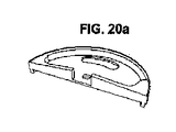
好ましい形態では、デバイスは、カバー、抽出領域、及び上側凝縮タンクに熱シールドを備える。熱シールドは、浸出液の冷却を防止する。 In a preferred embodiment, the device comprises a heat shield on the cover, extraction area, and upper condensation tank. The heat shield prevents the leachate from cooling.
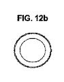
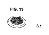
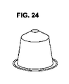
好ましい形態では、本願で述べるデバイスは、カプセル内で調整された固形物を抽出するのに適している。この実施形態では、抽出領域は、下側タンクを封止するシールを備え、シールを通してカプセルが挿入され、抽出領域はさらに、カプセル及び濾過手段をパンチ及びプレスするための手段を備える。 In a preferred embodiment, the devices described herein are suitable for extracting the prepared solids within the capsule. In this embodiment, the extraction area comprises a seal that seals the lower tank, the capsule is inserted through the seal, and the extraction area further comprises means for punching and pressing the capsule and filtration means.
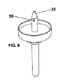
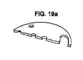
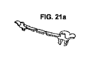
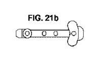
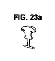
より好ましい形態では、カプセルをパンチ及びプレスするための手段は、タンクと、先端で終端する少なくとも3本の脚を有する円形部片とを接続する漏斗の上部にある針である。この実施形態は、幾何形状及び製造業者に関係なく、市場に出ているほとんどのカプセルに本デバイスを使用することを可能にする。 In a more preferred form, the means for punching and pressing the capsule is a needle at the top of the funnel connecting the tank with a circular piece having at least three legs terminating at the tip. This embodiment makes it possible to use the device for most capsules on the market, regardless of geometry and manufacturer.
別の実施形態では、デバイスは、得られた浸出液量を知ることを可能にする浮きを備えたねじキャップを備える。 In another embodiment, the device comprises a screw cap with a float that allows the amount of leachate obtained to be known.
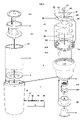
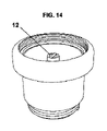
本発明で述べる抽出デバイスは、安全弁(3)を有する、電磁放射(1.4)に対して透明な下側タンク(1)、下側タンク(1)にねじ接続される上側タンク(8)、上側タンクと下側タンクとを接続する漏斗(5)、濾過手段を有する、抽出すべき物質を含む抽出領域、カバー(14)、及びデバイスを漏れ止めするための手段によって形成される。さらに、上側タンク(8)、抽出領域、及びカバー(14)は、電磁放射を反射するシールド1.2及び13を含む。 The extraction device described in the present invention has a safety valve (3), a lower tank (1) transparent to electromagnetic radiation (1.4), and an upper tank (8) screwed to the lower tank (1). It is formed by a funnel (5) connecting the upper tank and the lower tank, an extraction region containing a substance to be extracted having a filtering means, a cover (14), and a means for leak-proofing the device. In addition, the upper tank (8), extraction area, and cover (14) include shields 1.2 and 13 that reflect electromagnetic radiation.
下側タンク(1)は水で満たされ、下側タンク(1)が連通している抽出領域に、抽出すべき物質(37)(コーヒー、紅茶、カモミール、芳香性ハーブなど)が入れられる。デバイスは、液密カバーで閉じられる。デバイスは、浸出液(27)を準備するために電子レンジ(38)内に配置される。 The lower tank (1) is filled with water, and the substance (37) to be extracted (coffee, tea, chamomile, aromatic herbs, etc.) is placed in the extraction region with which the lower tank (1) communicates. The device is closed with a liquidtight cover. The device is placed in a microwave oven (38) to prepare the leachate (27).
図3に示されるように、シールド1.2及び13は、電子レンジによって発生された電磁放射(1.4)を反射する。再び反射された波(1.4)は、ここで電子レンジの内壁で反射され、最終的に、放射を吸収して水を加熱する下側タンク(1)に衝突する。このようにして、水は、抽出領域または上側タンク(8)で加熱を引き起こすことなく、従来技術で引用された文献よりも迅速に加熱する。 As shown in FIG. 3, shields 1.2 and 13 reflect electromagnetic radiation (1.4) generated by the microwave oven. The re-reflected wave (1.4) is then reflected by the inner wall of the microwave oven and finally collides with the lower tank (1), which absorbs the radiation and heats the water. In this way, the water heats faster than the literature cited in the prior art, without causing heating in the extraction region or the upper tank (8).
電磁放射を遮蔽するための手段は、フェライト、鋼、アルミニウムなど、0.2~1ミリメートルの厚さを有する金属シートである。好ましい形態では、シールドは、0.5mmの鋼板である。 The means for shielding electromagnetic radiation is a metal sheet having a thickness of 0.2 to 1 mm, such as ferrite, steel, aluminum, etc. In a preferred embodiment, the shield is a 0.5 mm steel plate.
電磁放射に対する透明な材料は、当業者に知られており、セラミック、ガラス、テフロン(登録商標)、ポリアミドでよい。好ましい形態では、下側タンク(1)は、テフロン(登録商標)で作られる。 Materials that are transparent to electromagnetic radiation are known to those of skill in the art and may be ceramic, glass, Teflon®, polyamide. In a preferred embodiment, the lower tank (1) is made of Teflon®.
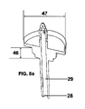
下側タンク(1)内で到達する圧力は、2.4~2.8barである。90~95℃の温度での水蒸気は、抽出領域から固形物を抽出し、漏斗(5)を通過して、上側タンク(8)に貯蔵される。準備される浸出液(27)の温度は40~50℃であり、この温度は、浸出液(27)を直接飲めるようにする。 The pressure reached in the lower tank (1) is 2.4 to 2.8 bar. The steam at a temperature of 90-95 ° C. extracts the solid from the extraction region, passes through the funnel (5) and is stored in the upper tank (8). The temperature of the prepared leachate (27) is 40-50 ° C., which allows the leachate (27) to be drunk directly.
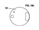
好ましい実施形態では、デバイスは、カバー及び上側タンク(1.1)に熱シールド(12)を含む。熱シールドにより、火傷することなくデバイスを取り、浸出液を約40℃の温度に維持できるようにする。 In a preferred embodiment, the device comprises a heat shield (12) in the cover and upper tank (1.1). A heat shield allows the device to be taken without burns and the leachate to be maintained at a temperature of about 40 ° C.
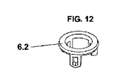
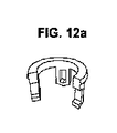
好ましい実施形態では、抽出領域は、シール(33)を備え、シール(33)は上側タンク(8)を封止し、シール(33)を通してカプセル(6)が導入され、抽出領域はさらに、カプセル(6)及びフィルタ(6.1)をパンチ及びプレスするための手段を備える。より好ましい形態では、カプセル(6)をパンチ及びプレスするための手段は、タンクと、先端で終端する少なくとも3本の脚(6.3)を有する円形部片(6.2)とを接続する漏斗の上部にある針(32)である。この実施形態は、幾何形状及び製造業者に関係なく、市場に出ているほとんどのカプセルに本デバイスを使用することを可能にする。 In a preferred embodiment, the extraction region comprises a seal (33), the seal (33) seals the upper tank (8), the capsule (6) is introduced through the seal (33), and the extraction region is further encapsulated. (6) and the means for punching and pressing the filter (6.1) are provided. In a more preferred embodiment, the means for punching and pressing the capsule (6) connects the tank with a circular piece (6.2) having at least three legs (6.3) terminating at the tip. The needle (32) at the top of the funnel. This embodiment makes it possible to use the device for most capsules on the market, regardless of geometry and manufacturer.
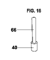
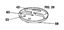
好ましい形態では、カバー(14)は浮き(40)を含み、浮き(40)は、デバイスが動作中の電子レンジ(38)内部にあるとき、準備された浸出液(27)の体積をリアルタイムで検出する。 In a preferred embodiment, the cover (14) comprises a float (40), which detects the volume of prepared leachate (27) in real time when the device is inside a working microwave oven (38). do.
図1~3に本発明を示し、本発明によるデバイスの一実施形態を表す。 The present invention is shown in FIGS. 1 to 3, and one embodiment of the device according to the present invention is shown.
これらの図から理解されるように、本発明は、水(16)の下側タンク(1)を有し、下側タンク(1)内に水(16)が入れられ、この水(16)は電子レンジ(38)によって加熱されなければならず、下側タンク(1)には、使用後にタンクを手及び口で掴んだときに火傷しないように構成された熱シールド(1.1)が設けられ、下側タンク(1)にはさらに、水タンク(1)の内部を電磁波(1.4)から保護するために配置されたシールド(1.2)が設けられ、下側領域(1.3)は保護されずに残り、下側領域(1.3)で電磁波(1.4)が水(16)を加熱し、下側タンク(1)にはさらに、安全弁(3)が設けられ、安全弁(3)は、ステム(17)、ばね(18)、中空ねじ(19)、及びカバー(20)からなり、下側タンク(1)内部の圧力が特定の最大値を超えないように構成され、水(16)のタンク(1)の内部で特定の最大圧を超えた場合、タンク(1)内部の圧力は、弁(3)のばね(18)によって及ぼされる力よりも大きい力をステムヘッド(21)に対して生成し、ステム(17)を安全弁(3)の外方向に移動させ、蒸気がねじ(19)に入り、最後の穴を通って出てカバー(20)に向かって進み、タンク(1)内部の圧力が通常レベルに下がるまでデバイスの外部に圧力を解放し、安全弁(3)のばね力(18)がタンク(1)の内部の圧力よりも大きくなると、ステムヘッド(21)をねじ(19)内に移動させ、蒸気出口を阻止し、水(16)のタンク(1)の圧力を調整し、タンク(1)には浸出液のタンク(8)がねじ接続され、タンク(8)内にはコーヒー浸出液(27)が蓄積される。 As can be understood from these figures, the present invention has a lower tank (1) of water (16), in which the water (16) is placed in the lower tank (1), and the water (16). Must be heated by a microwave oven (38) and the lower tank (1) has a heat shield (1.1) configured to prevent burning when the tank is grasped by hand and mouth after use. The lower tank (1) is further provided with a shield (1.2) arranged to protect the inside of the water tank (1) from the electromagnetic wave (1.4), and the lower region (1) is provided. .3) remains unprotected, electromagnetic waves (1.4) heat water (16) in the lower region (1.3), and a safety valve (3) is further provided in the lower tank (1). The safety valve (3) consists of a stem (17), a spring (18), a hollow screw (19), and a cover (20) so that the pressure inside the lower tank (1) does not exceed a certain maximum value. If a certain maximum pressure is exceeded inside the tank (1) of water (16), the pressure inside the tank (1) is greater than the force exerted by the spring (18) of the valve (3). A force is generated against the stem head (21), moving the stem (17) outwards of the safety valve (3), allowing steam to enter the screw (19) and exit through the last hole to cover (20). When the pressure inside the tank (1) is released to the outside of the device until the pressure inside the tank (1) drops to the normal level, and the spring force (18) of the safety valve (3) becomes larger than the pressure inside the tank (1). , The stem head (21) is moved into the screw (19), the steam outlet is blocked, the pressure of the water (16) tank (1) is adjusted, and the tank (1) has a leachate tank (8). It is screwed and the coffee leachate (27) is accumulated in the tank (8).
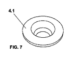
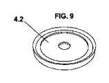
両タンク(1、8)は、漏斗(5)によって分離され、漏斗(5)は、ねじ山(2)の穴の入口部から導入され、ねじ山(2)は、下側タンク(1)にある狭窄部(44)の上部に取り付けられ、狭窄部(44)は凹部(45)を有し、凹部(45)は、凸部(4.3)を有するシール(4)の下部に完全に適合し、凹部(4.4)を有するシール(4)の上部に完全に適合するようにシール(4.1)が下側凸形状(4.1.1)を有し、凹部(4.1.2)を有するシール(4.1)の上部に完全に適合するように漏斗(5)の下部が凸部(46)を有し、漏斗(5)の上部は凹部(47)を有し、凸部(4.2.1)を有するシール(4.2)の下部に完全に適合し、シール(4.2)は、固定及び封止部(41)と共に下側タンク(1)を封止する。 Both tanks (1, 8) are separated by a funnel (5), the funnel (5) is introduced from the entrance of the hole in the thread (2), and the thread (2) is the lower tank (1). Attached to the top of the constriction (44) in, the constriction (44) has a recess (45) and the recess (45) is completely underneath the seal (4) with the convex (4.3). The seal (4.1) has a downward convex shape (4.1.1) and a recess (4) so as to fit perfectly on top of the seal (4) with a recess (4.4). The lower part of the funnel (5) has a convex portion (46) and the upper part of the funnel (5) has a concave portion (47) so as to perfectly fit the upper part of the seal (4.1) having 1.2). It has and is perfectly fitted to the bottom of the seal (4.2) with the convex part (4.2.1), the seal (4.2) is the lower tank (1) along with the fixing and sealing part (41). ) Is sealed.
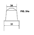
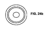
コーヒーポッドまたはカプセル(6)は、浸出液の上側タンク(8)のねじ(9)の内側にあるシール(33)に適合され、上部(4.2.2)を有するシール(4.2)が、下部(33.1)を有するシール(33)と完全に適合し、詳細には、上記シール(33)は、ポッド(6)の測定部と完全に適合し、ポッド(6)の上部(34)をタンク(8)の出口管(35)に向けて適合し、フィルタ(6.1)が針(6.3)と共に作用し、入口部(36)にあるカプセル(6)の下部(31)を、上側タンク(8)のシール(33)内に残す。 The coffee pod or capsule (6) is fitted with a seal (33) inside the screw (9) of the upper tank (8) of the leachate, with a seal (4.2) having an upper part (4.2.2). A perfect fit with the seal (33) having a lower part (33.1), in particular, the seal (33) perfectly fits the measuring part of the pod (6) and the upper part of the pod (6). 34) is fitted towards the outlet tube (35) of the tank (8), the filter (6.1) works with the needle (6.3) and the lower part of the capsule (6) at the inlet (36) (6). 31) is left in the seal (33) of the upper tank (8).
浸出液の上側タンク(8)のねじ(9)をタンク(1)のねじ山(2)とねじ接続することにより、タンク(8)の領域(8.1)の下側領域と漏斗(5)の上側領域(51)との間に力が発生し、穿孔(50)を有する針(32)によって上側領域(51)をカプセル(6)内に導入し、ポッド(6)の下部(31)を封止し、同時に、漏斗(5)のシール(4.2)が、浸出液(27)の上側タンク(8)を封止する凸形下部(36)を有するシール(33)と完全に適合することによって、タンク(1)の内部狭窄部(44)の上側領域(45)と漏斗(5)の上部(51)との間の圧縮が生じる。 By screwing the screw (9) of the upper tank (8) of the leachate to the thread (2) of the tank (1), the lower region of the region (8.1) of the tank (8) and the funnel (5) A force is generated between the upper region (51) and the upper region (51) being introduced into the capsule (6) by a needle (32) having a perforation (50), and the lower portion (31) of the pod (6). At the same time, the funnel (5) seal (4.2) is perfectly compatible with the seal (33) having a convex lower portion (36) that seals the upper tank (8) of the leachate (27). This causes compression between the upper region (45) of the internal constriction (44) of the tank (1) and the upper part (51) of the funnel (5).
漏斗(5)は、開いた下側入口(28)により形成され、下側入口(28)は、タンク(1)の水(16)をダクト(29)に接続し、ダクト(29)は、水(16)を針(32)に伝達し、上記流れが、コーヒーカプセル(6)の内部で、その下部(31)において、穿孔(50)を有する針(32)によって分散され、針(32)は、漏斗の上部(51)の中心点にあり、穿孔(50)を有する針(32)は、水(16)を、部分(31)を通してコーヒーカプセル(6)内部に排出し、コーヒーカプセル(6)の内部に含まれる物質(37)を濡らし、出口管(35)にあるフィルタ(6.1)及び針(6.3)を有するリング(6.2)が、タンク(8)にあるシール(33)に挿入されたカプセル(6)に応じてパンチ、プレス、及び濾過して、内部に浸出液(27)を生成し、上記浸出液(27)が、カプセル(6)の上部(34)を通って出て、貯蔵部(8)の出口管(35)に向かい、浸出液(27)を、端部穴(12)を通してタンク(8)の内部(15)に排出する。 The funnel (5) is formed by an open lower inlet (28), the lower inlet (28) connecting the water (16) of the tank (1) to the duct (29), the duct (29). Water (16) is transmitted to the needle (32) and the flow is dispersed inside the coffee capsule (6) at its lower portion (31) by a needle (32) having a perforation (50) and the needle (32). ) Is located at the center of the upper part (51) of the funnel, and the needle (32) with the perforation (50) drains the water (16) through the portion (31) into the coffee capsule (6). Wetting the substance (37) contained inside (6), a ring (6.2) with a filter (6.1) and a needle (6.3) in the outlet tube (35) is placed in the tank (8). Punches, presses, and filters according to the capsule (6) inserted in a seal (33) to generate a leachate (27) inside, which exudate (27) is the top (34) of the capsule (6). ), Toward the outlet pipe (35) of the storage unit (8), and the exudate (27) is discharged to the inside (15) of the tank (8) through the end hole (12).
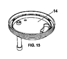
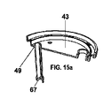
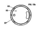
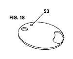
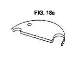
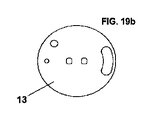
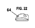
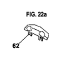
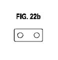
上側タンク(8)は、上部にカバー(14)を有し、カバー(14)は、タンク(8)の上側ねじ山(8.2)とカバー(14)のねじ(14.1)とによって接続され、カバー(14)はスプーン(14.2)を有し、スプーン(14.2)の配置は、カバー(14)の下側領域(49)に位置されて、浸出液(27)を、上側タンク(8)に追加される別の物質と混合し、カバー(14)はさらにボタン(10)を有し、ボタン(10)は浸出液計(39)を起動し、浸出液計(39)は、カバーの下部(49)に配置され、スプーン(14.2)内部にある浮き(40)によって形成され、また、カバー(14)はボタン(11)も有し、ボタン(11)は穴(42)を開放し、穴(42)は、浸出液(27)を外に通して、デバイスから直接飲めるようにする助けとなり、カバー(14)は内部に熱シール(12)を有し、熱シール(12)は、使用後に唇を火傷せずにデバイスから直接飲めるようにし、カバー(14)の内部(43)に位置し、カバー(14)はさらにシールド(13)を有し、シールド(13)は、上側タンク(8)の内部を電磁波から保護し、カバー(14)の内部(43)に位置し、安全キャップ(52)への接続によって接続され、安全キャップ(52)は、直立姿勢で部片に対して横方向に位置し、浸出液のタンクの内部の圧力が高すぎる場合に上方向に上昇し、穴(53)を開けたままにして圧力を解放し、同じ穴(53)に導入されるときにプラグ(52)が再び作動して、固定されて封止される。部分(57)にあるOリング(56)は、閉鎖カバー(58)がクリップ(59)によってカバー(14)の領域(60)内に埋め込まれるとき、カバー(14)を内部から封止し、カバーを固定して水密にする。閉鎖カバー(61)は、穴(63)を用いてクリップ(62)によって埋め込まれ、インジケータ(39)のボタン(10)と飲用ボタン(11)との両方を固定させる。閉鎖カバー(61)の上側陥凹部(64)は、その余剰部(65)によってインジケータ(39)のボタン(10)及び飲用ボタン(11)を保持する助けとなる。 The upper tank (8) has a cover (14) at the top, and the cover (14) is provided by the upper thread (8.2) of the tank (8) and the screw (14.1) of the cover (14). Connected, the cover (14) has a spoon (14.2), and the placement of the spoon (14.2) is located in the lower region (49) of the cover (14), with the exudate (27). Mixing with another substance added to the upper tank (8), the cover (14) further has a button (10), the button (10) activates the leachate meter (39), and the leachate meter (39) , Located at the bottom (49) of the cover, formed by a float (40) inside the spoon (14.2), the cover (14) also has a button (11), the button (11) is a hole (11). 42) is opened and the hole (42) helps allow the exudate (27) to pass out and be drunk directly from the device, the cover (14) has a heat seal (12) inside and the heat seal. (12) is located inside (43) of the cover (14) so that it can be swallowed directly from the device without burning the lips after use, the cover (14) further has a shield (13) and a shield (13). ) Protects the inside of the upper tank (8) from electromagnetic waves, is located inside (43) of the cover (14) and is connected by a connection to the safety cap (52), and the safety cap (52) is in an upright position. Located laterally to the piece, if the pressure inside the leachate tank is too high, it will rise upwards, leaving the hole (53) open to release the pressure and the same hole (53). When introduced into, the plug (52) is activated again to be secured and sealed. The O-ring (56) at the portion (57) seals the cover (14) from the inside when the closing cover (58) is embedded in the area (60) of the cover (14) by the clip (59). Fix the cover to make it watertight. The closing cover (61) is embedded by a clip (62) using a hole (63) to secure both the button (10) and the drinking button (11) of the indicator (39). The upper recess (64) of the closing cover (61) helps hold the button (10) and the drinking button (11) of the indicator (39) by its surplus portion (65).
コーヒーまたは他の物質の浸出液(27)を準備するために、適切な量の水(16)が、上側タンク(8)の領域(54)を超えないように上側タンク(8)内に入り、その量の水(16)を上側領域(55)を通してタンク(1)内部に注ぎ、液位は弁(3)よりも下であり、漏斗(5)が、底部シール(4.1)、上部シール(4.2)、及びシール(4)と共に、水タンク(1)(16)内部に挿入され、上側浸出液タンク(8)のシール(33)にコーヒーカプセル(6)が埋め込まれ、浸出液タンク(8)のねじ(9)がタンク(1)のねじ山(2)にねじ接続され、本発明を封止し、次いで、浸出液レベル(27)のインジケータ(39)のボタン(10)及び飲用ボタン(11)を押し、余剰部(65)をカバー(14)の閉鎖カバー(61)の上部陥凹部(64)に固定し、本発明を電子レンジ(38)内部に入れ、中程度の熱または中高程度の熱を加える。 To prepare the leachate (27) for coffee or other substances, an appropriate amount of water (16) enters the upper tank (8) so that it does not exceed the area (54) of the upper tank (8). That amount of water (16) is poured into the tank (1) through the upper region (55), the liquid level is below the valve (3), the funnel (5) is the bottom seal (4.1), the top. It is inserted inside the water tanks (1) and (16) together with the seal (4.2) and the seal (4), and the coffee capsule (6) is embedded in the seal (33) of the upper leachate tank (8). The screw (9) of (8) is screwed to the thread (2) of the tank (1) to seal the invention, followed by the button (10) of the indicator (39) of the leachate level (27) and drinking. Press the button (11) to secure the surplus portion (65) to the upper recess (64) of the closing cover (61) of the cover (14) and place the invention inside the microwave oven (38) to moderate heat. Or add medium to high heat.
タンク(1)からの水(16)が加熱され、圧力を上昇させ、この圧力が、水(16)の一部をタンク(1)から漏斗(5)の下側入口(28)を通して上方に押し、流れ(16)が内部ダクト(29)に流入し、ダクト(29)は、水(16)を針(32)に向けて方向付け、穿孔(50)を有する針(32)によってコーヒーカプセル(6)内部で水(16)を分散し、最終的に、水(16)は、コーヒー(37)または他の物質と接触して含浸して、カプセル(6)の上部(34)にあるリング(6.2)によって浸出液(27)を抽出し、浸出液(27)をフィルタ(6.1)によって濾過し、上側タンク(8)の出口管(35)に向けて導き、端部穴(12)を通して浸出液タンク(8)の内部(15)に浸出液(27)を導き、浮き(40)のマスト(66)は、スプーン(14.2)の底部にある入口(67)を通して浸出液(27)に入り、生成されている浸出液の量及び質をリアルタイムでタンク(8)内で得ることによって、浸出液(27)の質と量を報告する。 The water (16) from the tank (1) is heated to increase the pressure, which causes a portion of the water (16) to move upward from the tank (1) through the lower inlet (28) of the funnel (5). Push, flow (16) flows into the internal duct (29), the duct (29) directs the water (16) towards the needle (32) and the coffee capsule by the needle (32) with the perforation (50). (6) Disperse the water (16) inside, and finally the water (16) is in contact with and impregnated with the coffee (37) or other substance and is at the top (34) of the capsule (6). The leachate (27) is extracted by the ring (6.2), the leachate (27) is filtered by the filter (6.1), guided towards the outlet tube (35) of the upper tank (8), and the end hole (27). Guide the leachate (27) into the interior (15) of the leachate tank (8) through 12) and the mast (66) of the float (40) through the inlet (67) at the bottom of the spoon (14.2) the leachate (27). ), And the quality and quantity of the leachate (27) is reported by obtaining the quantity and quality of the leachate produced in the tank (8) in real time.
熱の影響により、したがってタンク(1)内部の圧力と温度の上昇により、タンク(1)にある熱シールド(1.1)及びカバー(14)内の熱シールド(12)が示され、一定の時間間隔の後、電子レンジからの本発明の取出しを可能にし、上側タンク(8)のカバー(14)のボタン(11)により、コーヒー浸出液(27)を、電子レンジ(38)による固液蒸気抽出によって直接飲めるようにする。 Due to the effects of heat, and thus the pressure and temperature rise inside the tank (1), the heat shield (1.1) in the tank (1) and the heat shield (12) in the cover (14) are shown and constant. After a time interval, the present invention can be removed from the microwave oven, and the coffee leachate (27) is vaporized by the button (11) of the cover (14) of the upper tank (8). Make it drinkable directly by extraction.
抽出段階では、カプセル(6)内部で生成された浸出液(27)の流れは、カプセル(6)の上部(34)を通して、リング(6.2)を通して濾過され、フィルタ(6.1)によって浸出液(27)を濾過し、浸出液(27)を上側タンク(8)の出口管路(35)に向けて導き、端部穴(12)を通してタンク(8)の内部(15)に浸出液(27)を導く。 In the extraction step, the flow of bleachate (27) produced inside the capsule (6) is filtered through the ring (6.2) through the top (34) of the capsule (6) and by the filter (6.1). (27) is filtered, the leachate (27) is guided toward the outlet conduit (35) of the upper tank (8), and the leachate (27) is introduced into the inside (15) of the tank (8) through the end hole (12). To guide.
このようにして、固液蒸気抽出によって得られた飲料画分が、上記プロセス中に不純物と混合されることが回避され、また、熱シールド1.1及び12ならびにタンク(1)のシールド(1.2)及びカバー(14)のシールド(13)は、本発明の内部を電磁波(1.4)及び高温から保護し、高品質のコーヒーまたは他の物質の浸出液を得て、同じデバイスから飲めるようにする。 In this way, the beverage fraction obtained by solid-liquid steam extraction is prevented from being mixed with impurities during the process, and the thermal shields 1.1 and 12 as well as the shield (1) of the tank (1). .2) and the shield (13) of the cover (14) protect the interior of the invention from electromagnetic waves (1.4) and high temperatures to obtain high quality coffee or brews of other substances that can be drunk from the same device. To do so.
本発明及び実際に実施される方法を十分に述べてきたが、添付図面に示して上述した規定は、その基本原理を変えない限り、詳細に修正を施されることに留意されたい。 Although the present invention and the method actually carried out have been sufficiently described, it should be noted that the above-mentioned provisions shown in the accompanying drawings are modified in detail unless the basic principle is changed.
110mlの水を下側タンクに入れ、出力350Wの電子レンジ内にデバイスを配置した。70秒後、水は漏斗を通って上昇し始めた。下側タンクで到達した圧力は2.67barであり、温度は95℃であった。下側タンクで使用した材料はテフロン(登録商標)であり、電磁放射線に対するシールド材料は、厚さ0.5mmの鋼板であった。 110 ml of water was placed in the lower tank and the device was placed in a microwave oven with an output of 350 W. After 70 seconds, water began to rise through the funnel. The pressure reached in the lower tank was 2.67 bar and the temperature was 95 ° C. The material used in the lower tank was Teflon (registered trademark), and the shield material against electromagnetic radiation was a steel plate with a thickness of 0.5 mm.
以下に詳述される特許請求の範囲に詳述されるすべての実施形態が本明細書の一部である。 All embodiments detailed in the claims detailed below are part of this specification.
Claims (6)
弁(3)を有する、電磁放射(1.4)に対して透明な下側タンク(1)、
前記下側タンク(1)のねじ山(2)とねじ(9)によってねじ接続される上側タンク(8)、
前記上側タンク(8)と下側タンク(1)とを接続する漏斗(5)、
抽出領域であって、
抽出すべき物質を備えるカプセル(6)、
前記上側タンク(8)を封止する上側タンク(8)の底部シール(33)であって、前記カプセル(6)が挿入される前記上側タンク(8)の底部シール(33)、
フィルタ(6.1)、
先端(6.3)で終端する少なくとも3本の脚を有する円形部片(6.2)、
カバー(14)、及び
前記デバイスを漏れ止めするのに適した下側タンク(1)の底部シール(4)、を有する抽出領域
とを備え、
前記抽出領域及び前記上側タンク(8)内の電磁波(1.4)に対するシールド(1.2)、ならびに
前記カバー(14)内に電磁波に対するシールド(13)を含み、
前記漏斗(5)が、
前記上側タンク(8)内部と接する円形形状の上側部分(51)、
前記漏斗(5)の中心に位置し、前記上側部分(51)を通り、前記上側タンク(8)と前記下側タンク(1)と連通するダクト(29)であって、前記下側タンク側に開いた下側入口(28)を有し、前記下側入口(28)から前記下側タンク(1)の水(16)を前記ダクト(29)内に通過させる、前記ダクト(29)、
前記カプセル(6)をパンチ及びプレスするのに適した、前記抽出領域に位置する中空の針(32)であって、前記上側部分(51)側に位置し、前記ダクト(29)と連通し、前記針(32)の先端部は閉じている、前記針(32)、及び、
前記上側部分(51)側に位置する前記ダクト(29)にあり、前記針(32)の閉じた先端部よりも下側に位置する穿孔(50)、
によって形成されることを特徴とするデバイス。 A device for preparing bleachate,
Lower tank (1), transparent to electromagnetic radiation (1.4), with valve (3),
The upper tank (8), which is screwed to the thread (2) of the lower tank (1) by a screw (9) ,
A funnel (5) connecting the upper tank (8) and the lower tank (1) ,
It ’s an extraction area ,
Capsules containing substances to be extracted (6),
The bottom seal (33) of the upper tank (8) for sealing the upper tank (8), wherein the bottom seal (33) of the upper tank (8) into which the capsule (6) is inserted.
Filter (6.1),
A circular piece (6.2) with at least three legs terminating at the tip (6.3),
Extraction area with cover (14) and bottom seal (4) of lower tank (1) suitable for leak-proofing the device.
And with
A shield (1.2) against electromagnetic waves (1.4) in the extraction region and the upper tank (8), and a shield (13) against electromagnetic waves in the cover (14) are included.
The funnel (5)
The circular upper portion (51) in contact with the inside of the upper tank (8 ),
A duct (29) located at the center of the funnel (5), passing through the upper portion (51) and communicating with the upper tank (8) and the lower tank (1), and is on the lower tank side. The duct (29), which has an open lower inlet (28) and allows water (16) from the lower tank (1) to pass through the duct (29) from the lower inlet (28) .
A hollow needle (32) located in the extraction region suitable for punching and pressing the capsule (6), located on the upper portion (51) side and communicating with the duct (29). , The tip of the needle (32) is closed, the needle (32), and
A perforation (50) located in the duct (29) located on the upper side (51) side and below the closed tip of the needle (32) .
A device characterized by being formed by.
Applications Claiming Priority (3)
| Application Number | Priority Date | Filing Date | Title |
|---|---|---|---|
| ESU201730354 | 2017-03-28 | ||
| ES201730354U ES1182359Y (en) | 2017-03-28 | 2017-03-28 | Apparatus for the preparation of infusions |
| PCT/ES2017/070566 WO2018178412A1 (en) | 2017-03-28 | 2017-08-02 | Device for preparing infusions |
Publications (2)
| Publication Number | Publication Date |
|---|---|
| JP2020515317A JP2020515317A (en) | 2020-05-28 |
| JP7075673B2 true JP7075673B2 (en) | 2022-05-26 |
Family
ID=58645418
Family Applications (1)
| Application Number | Title | Priority Date | Filing Date |
|---|---|---|---|
| JP2019552231A Active JP7075673B2 (en) | 2017-03-28 | 2017-08-02 | Device for preparing bleachate |
Country Status (15)
| Country | Link |
|---|---|
| US (1) | US11553816B2 (en) |
| EP (1) | EP3603461B1 (en) |
| JP (1) | JP7075673B2 (en) |
| KR (1) | KR102378352B1 (en) |
| CN (1) | CN110662465B (en) |
| AU (1) | AU2017406005B2 (en) |
| BR (1) | BR112019020234B1 (en) |
| CO (1) | CO2019011421A2 (en) |
| EA (1) | EA201900498A1 (en) |
| ES (2) | ES1182359Y (en) |
| IL (1) | IL269408B2 (en) |
| MX (1) | MX2019011495A (en) |
| MY (1) | MY196934A (en) |
| WO (1) | WO2018178412A1 (en) |
| ZA (1) | ZA201906771B (en) |
Family Cites Families (27)
| Publication number | Priority date | Publication date | Assignee | Title |
|---|---|---|---|---|
| US4386109A (en) | 1981-02-25 | 1983-05-31 | Raytheon Company | Microwave expresso coffee maker and process |
| US4900886A (en) * | 1988-03-21 | 1990-02-13 | Aladdin Industries, Inc. | Microwave beverage maker |
| DE69026294D1 (en) | 1989-02-13 | 1996-05-09 | Farberware Inc | Coffee machine for making coffee in the form of drops using microwaves |
| US5028753A (en) | 1990-01-24 | 1991-07-02 | Aziz Shariat | Microwaveable coffee maker |
| JPH0617636U (en) * | 1992-08-10 | 1994-03-08 | 実 行重 | Coffee dripper |
| WO1995019098A1 (en) * | 1994-01-03 | 1995-07-13 | Mario Orrico | Microwave coffee and espresso beverages maker |
| US5884551A (en) * | 1997-03-18 | 1999-03-23 | Micro Lungo, Inc. | Microwavable beverage maker |
| BR0104121A (en) | 2001-02-01 | 2003-05-13 | Helio Vieira Alves | Microwave oven |
| US6655260B2 (en) * | 2001-04-11 | 2003-12-02 | Keurig, Incorporated | Beverage filter cartridge holder |
| WO2003017811A1 (en) * | 2001-08-24 | 2003-03-06 | Lacrex S.A. | Device for preparing hot drinks in microwave appliances |
| ITTO20020481A1 (en) * | 2002-06-07 | 2003-12-09 | Sgl Italia Srl | METHOD AND DRILLING DEVICE OF A SEALED CAPSULE IN A COFFEE MACHINE. |
| HK1052109A2 (en) * | 2002-06-26 | 2003-08-15 | 陈永坚 | Beverage making apparatus |
| EP1510158A1 (en) * | 2003-08-25 | 2005-03-02 | Nestec S.A. | Apparatus and method for the preparation of a beverage from an ingredient contained in a cartridge |
| WO2005089424A2 (en) * | 2004-03-19 | 2005-09-29 | Micro Lungo, Inc. | Microwavable beverage maker |
| ITMO20070323A1 (en) * | 2007-10-22 | 2009-04-23 | Illycaffe Spa | CONTAINER |
| ATE476123T1 (en) * | 2008-01-18 | 2010-08-15 | Nestec Sa | DRINKS MACHINE AND PIERCING PART FOR AN OPENING DEVICE OF A DRINKS MACHINE |
| CN102216070B (en) * | 2008-11-14 | 2014-10-29 | 杰富意钢铁株式会社 | Colored laminate metal sheet for containers |
| ES2443589T5 (en) * | 2009-06-17 | 2020-07-22 | Douwe Egberts Bv | System, capsule and method to prepare a drink |
| ITVR20120043A1 (en) * | 2012-03-14 | 2013-09-15 | Coffee Star S A | DRINK PRODUCTION SYSTEM |
| CN203106806U (en) * | 2012-12-10 | 2013-08-07 | 广东新宝电器股份有限公司 | Coffee machine |
| US9521923B2 (en) * | 2013-12-24 | 2016-12-20 | Pangaea Labs Ltd. | Brewable beverage making cup adaptor for cartridge type coffee making machines and cartridge type coffee making machine |
| PL2904951T3 (en) * | 2014-02-06 | 2017-04-28 | Qbo Coffee Gmbh | System for preparing a brewed product |
| CN103829808B (en) * | 2014-03-14 | 2017-01-11 | 宁波凯波集团有限公司 | Capsule beverage fixing and puncturing device |
| CN104095545B (en) * | 2014-06-20 | 2016-05-18 | 沁园集团股份有限公司 | A kind of capsule serving utensil |
| CN106185065B (en) * | 2015-05-04 | 2019-02-22 | 宁波金阳光电热科技有限公司 | Interior puncture type drink capsule |
| ES1141483Y (en) * | 2015-06-19 | 2015-10-07 | Sanchez Miguel Osorio | Apparatus for the preparation of infusions of coffee, or other substance, by pod or capsule of a dose, by microwave |
| CN204909064U (en) * | 2015-07-08 | 2015-12-30 | 佛山市顺德区倍尔帝奇电子科技有限公司 | Full -automatic coffee capsule impales structure |
-
2017
- 2017-03-28 ES ES201730354U patent/ES1182359Y/en active Active
- 2017-08-02 AU AU2017406005A patent/AU2017406005B2/en active Active
- 2017-08-02 US US16/494,534 patent/US11553816B2/en active Active
- 2017-08-02 EA EA201900498A patent/EA201900498A1/en unknown
- 2017-08-02 MX MX2019011495A patent/MX2019011495A/en unknown
- 2017-08-02 BR BR112019020234-0A patent/BR112019020234B1/en active IP Right Grant
- 2017-08-02 KR KR1020197031497A patent/KR102378352B1/en active Active
- 2017-08-02 MY MYPI2019005693A patent/MY196934A/en unknown
- 2017-08-02 JP JP2019552231A patent/JP7075673B2/en active Active
- 2017-08-02 CN CN201780089001.XA patent/CN110662465B/en active Active
- 2017-08-02 EP EP17903951.6A patent/EP3603461B1/en active Active
- 2017-08-02 WO PCT/ES2017/070566 patent/WO2018178412A1/en not_active Ceased
- 2017-08-02 IL IL269408A patent/IL269408B2/en unknown
- 2017-08-02 ES ES17903951T patent/ES3058089T3/en active Active
-
2019
- 2019-10-14 ZA ZA2019/06771A patent/ZA201906771B/en unknown
- 2019-10-16 CO CO2019011421A patent/CO2019011421A2/en unknown
Non-Patent Citations (1)
| Title |
|---|
| OSORIO SANCHEZ MIGUEL,Apparatus for the preparation of infusions of coffe, or another substance, by pod or capsule of a dose, by microwave,ES 1141483 U,ES,2015年07月16日 |
Also Published As
| Publication number | Publication date |
|---|---|
| ES1182359U8 (en) | 2017-07-20 |
| EP3603461C0 (en) | 2025-10-08 |
| IL269408B2 (en) | 2024-07-01 |
| ES3058089T3 (en) | 2026-03-06 |
| KR102378352B1 (en) | 2022-03-23 |
| CA3057945A1 (en) | 2018-10-04 |
| MY196934A (en) | 2023-05-11 |
| IL269408B1 (en) | 2024-03-01 |
| EA201900498A1 (en) | 2020-02-10 |
| JP2020515317A (en) | 2020-05-28 |
| BR112019020234A2 (en) | 2020-06-16 |
| US11553816B2 (en) | 2023-01-17 |
| CN110662465A (en) | 2020-01-07 |
| US20200008612A1 (en) | 2020-01-09 |
| CN110662465B (en) | 2022-08-23 |
| BR112019020234B1 (en) | 2023-02-14 |
| MX2019011495A (en) | 2019-11-01 |
| EP3603461A4 (en) | 2020-12-23 |
| ES1182359U (en) | 2017-05-09 |
| EP3603461A1 (en) | 2020-02-05 |
| CO2019011421A2 (en) | 2019-10-31 |
| ES1182359Y (en) | 2017-07-31 |
| ZA201906771B (en) | 2020-09-30 |
| WO2018178412A1 (en) | 2018-10-04 |
| IL269408A (en) | 2020-02-27 |
| EP3603461B1 (en) | 2025-10-08 |
| AU2017406005B2 (en) | 2023-12-21 |
| AU2017406005A1 (en) | 2019-10-31 |
| KR20190133722A (en) | 2019-12-03 |
Similar Documents
| Publication | Publication Date | Title |
|---|---|---|
| US9179798B2 (en) | Method and apparatus for brewing coffee and the like | |
| US4908222A (en) | Microwave brewing apparatus and method | |
| JP2012503503A (en) | Portable multifunctional coffee brewing device and its application | |
| US5012059A (en) | Appliance for heating water by microwave power | |
| JP5449763B2 (en) | Microwave oven coffee filter | |
| US5325764A (en) | Coffee extractor | |
| JP7075673B2 (en) | Device for preparing bleachate | |
| ITMO20060030A1 (en) | METHODS AND EQUIPMENT TO GET DRINKS | |
| CA3057945C (en) | Device for preparing infusions | |
| HK40019783A (en) | Device for preparing infusions | |
| HK40019783B (en) | Device for preparing infusions | |
| KR900012574A (en) | Beverage boiling machine | |
| US627885A (en) | Coffee-pot. | |
| EA041679B1 (en) | DEVICE FOR PREPARING EXTRACTS | |
| CN105744866B (en) | Equipped with the production equipment of the infusion beverage of vapour-recovery unit | |
| WO2005079640A1 (en) | Coffee-maker suitable for use in microwave ovens | |
| US1619967A (en) | Coffeepot | |
| KR102027651B1 (en) | The concentrator for health supplementary food | |
| CN221307954U (en) | Coffee pot | |
| KR200223000Y1 (en) | Multipurpose abstraction system | |
| JP4055840B2 (en) | Beverage extractor | |
| JPH0440676Y2 (en) | ||
| CZ2014128A3 (en) | Device to prepare filtered coffee | |
| WO2006018860A1 (en) | Filter for making infusions and the like, and device for the use thereof | |
| JPH0360612A (en) | Tea percolating device of siphon type |
Legal Events
| Date | Code | Title | Description |
|---|---|---|---|
| A521 | Request for written amendment filed |
Free format text: JAPANESE INTERMEDIATE CODE: A523 Effective date: 20191129 |
|
| A621 | Written request for application examination |
Free format text: JAPANESE INTERMEDIATE CODE: A621 Effective date: 20200617 |
|
| A977 | Report on retrieval |
Free format text: JAPANESE INTERMEDIATE CODE: A971007 Effective date: 20210616 |
|
| A131 | Notification of reasons for refusal |
Free format text: JAPANESE INTERMEDIATE CODE: A131 Effective date: 20210713 |
|
| A601 | Written request for extension of time |
Free format text: JAPANESE INTERMEDIATE CODE: A601 Effective date: 20211004 |
|
| A601 | Written request for extension of time |
Free format text: JAPANESE INTERMEDIATE CODE: A601 Effective date: 20211213 |
|
| A521 | Request for written amendment filed |
Free format text: JAPANESE INTERMEDIATE CODE: A523 Effective date: 20220107 |
|
| TRDD | Decision of grant or rejection written | ||
| A01 | Written decision to grant a patent or to grant a registration (utility model) |
Free format text: JAPANESE INTERMEDIATE CODE: A01 Effective date: 20220419 |
|
| A61 | First payment of annual fees (during grant procedure) |
Free format text: JAPANESE INTERMEDIATE CODE: A61 Effective date: 20220509 |
|
| R150 | Certificate of patent or registration of utility model |
Ref document number: 7075673 Country of ref document: JP Free format text: JAPANESE INTERMEDIATE CODE: R150 |
|
| R250 | Receipt of annual fees |
Free format text: JAPANESE INTERMEDIATE CODE: R250 |