JP7074597B2 - Transport device - Google Patents
Transport device Download PDFInfo
- Publication number
- JP7074597B2 JP7074597B2 JP2018132172A JP2018132172A JP7074597B2 JP 7074597 B2 JP7074597 B2 JP 7074597B2 JP 2018132172 A JP2018132172 A JP 2018132172A JP 2018132172 A JP2018132172 A JP 2018132172A JP 7074597 B2 JP7074597 B2 JP 7074597B2
- Authority
- JP
- Japan
- Prior art keywords
- transport device
- connecting mechanism
- riding
- slide
- base member
- Prior art date
- Legal status (The legal status is an assumption and is not a legal conclusion. Google has not performed a legal analysis and makes no representation as to the accuracy of the status listed.)
- Active
Links
Images


Classifications
-
- B—PERFORMING OPERATIONS; TRANSPORTING
- B60—VEHICLES IN GENERAL
- B60D—VEHICLE CONNECTIONS
- B60D1/00—Traction couplings; Hitches; Draw-gear; Towing devices
- B60D1/01—Traction couplings or hitches characterised by their type
-
- B—PERFORMING OPERATIONS; TRANSPORTING
- B60—VEHICLES IN GENERAL
- B60D—VEHICLE CONNECTIONS
- B60D1/00—Traction couplings; Hitches; Draw-gear; Towing devices
-
- B—PERFORMING OPERATIONS; TRANSPORTING
- B60—VEHICLES IN GENERAL
- B60D—VEHICLE CONNECTIONS
- B60D1/00—Traction couplings; Hitches; Draw-gear; Towing devices
- B60D2001/001—Traction couplings; Hitches; Draw-gear; Towing devices specially adapted for use on vehicles other than cars
- B60D2001/005—Traction couplings; Hitches; Draw-gear; Towing devices specially adapted for use on vehicles other than cars for carts, scooters, or the like
Landscapes
- Engineering & Computer Science (AREA)
- Transportation (AREA)
- Mechanical Engineering (AREA)
- Platform Screen Doors And Railroad Systems (AREA)
Description
本発明は、連結した被搬送物を搬送する搬送装置に関する。 The present invention relates to a transport device for transporting connected objects to be transported.
従来、荷物を積載する台車が広く利用されており、近年では、台車を搬送する自動搬送車が開発されている。自動搬送車は、台車と連結されるが、台車の構造に応じて、様々な形態が提案されている。そして、台車の下側に潜り込む形態として、背の低い牽引車を含む自動搬送車が知られている(例えば、特許文献1参照)。 Conventionally, trolleys for loading luggage have been widely used, and in recent years, automatic guided vehicles for transporting trolleys have been developed. The automatic guided vehicle is connected to the trolley, and various forms have been proposed depending on the structure of the trolley. An automatic guided vehicle including a short tow vehicle is known as a form of sneaking under the bogie (see, for example, Patent Document 1).
特許文献1に記載の自動搬送車は、自在車輪を備えた搬送台車と、搬送台車の下側に潜り込んで連結される牽引車とを組み合わせた構成とされている。牽引車は、付勢手段に付勢され、搬送台車に連結される2つの連結ピンを有し、搬送台車は、2つの連結ピンを収容する2つの連結孔が設けられている。
The automatic guided vehicle described in
上述した自動搬送車では、昇降モータによって連結ピンを昇降させる機構とされているため、いくつか問題が生じている。つまり、連結ピンを昇降(上下)させているので、上下に動作するストロークが必要となり、牽引車の上下での寸法(車高)が大きくなる。搬送台車の下側に潜り込む方式では、牽引車の車高に規制があり、構造が制約されるという課題がある。また、重量の偏りが生じるため、重い昇降モータを牽引車の縁に設けることが難しいという課題がある。そのため、連結ピンが牽引車に収まる構造にせざるを得ない。 Since the automatic guided vehicle described above has a mechanism for raising and lowering the connecting pin by an elevating motor, there are some problems. That is, since the connecting pin is moved up and down (up and down), a stroke that moves up and down is required, and the vertical dimension (vehicle height) of the towing vehicle becomes large. The method of sneaking under the transport trolley has a problem that the height of the towing vehicle is restricted and the structure is restricted. Further, there is a problem that it is difficult to provide a heavy lifting motor on the edge of the towing vehicle because the weight is biased. Therefore, there is no choice but to make the structure so that the connecting pin fits in the towing vehicle.
本発明は、上記の課題を解決するためになされたものであり、連結機構自身に昇降装置を設けることなく、台車と連結する動作を実現できる搬送装置を提供することを目的とする。 The present invention has been made to solve the above problems, and an object of the present invention is to provide a transport device capable of realizing an operation of connecting to a carriage without providing a lifting device in the connecting mechanism itself.
本発明に係る搬送装置は、連結した被搬送物を搬送する搬送装置であって、前記搬送装置の上面に設けられた第1連結機構と、前記搬送装置の上面に設けられた台部材と、所定のスライド軸線上において、前記台部材に対する前記第1連結機構の位置を相対的にスライド移動させるスライド機構と、前記搬送装置を走行させる走行機構とを備え、前記第1連結機構は、前記スライド軸線上に設けられた乗り上げ部と、前記被搬送物と連結する連結部とを有し、前記連結部は、上方へ突出した係合部を備え、前記乗り上げ部は、前記スライド機構によって、前記台部材に対する前記第1連結機構の位置をスライド移動させた際、前記台部材の上面に乗り上げた乗り上げ状態となり、前記連結部は、前記乗り上げ部が乗り上げ状態となった際に、前記係合部が上昇動作して前記被搬送物と連結することを特徴とする。 The transport device according to the present invention is a transport device for transporting connected objects to be transported, and includes a first connecting mechanism provided on the upper surface of the transport device, a base member provided on the upper surface of the transport device, and a base member. A slide mechanism for sliding and moving the position of the first connecting mechanism relative to the base member on a predetermined slide axis and a traveling mechanism for traveling the transport device are provided, and the first connecting mechanism is the slide. It has a riding portion provided on an axis and a connecting portion that connects to the object to be transported. The connecting portion includes an engaging portion that protrudes upward, and the riding portion is described by the slide mechanism. When the position of the first connecting mechanism is slid and moved with respect to the pedestal member, the riding portion is in a riding state on the upper surface of the pedestal member, and the connecting portion is in the engaging portion when the riding portion is in the riding state. Is characterized in that it moves up and is connected to the object to be transported.
本発明に係る搬送装置では、前記台部材は、前記スライド軸線上で、前記乗り上げ部に面する側の端部に、テーパ形状とされた案内部を有する構成としてもよい。 In the transport device according to the present invention, the base member may have a tapered guide portion at an end portion on the slide axis line on the side facing the riding portion.
本発明に係る搬送装置では、前記台部材は、上面のうち、前記スライド軸線上における中央部に、平坦な形状とされた摺動部を有する構成としてもよい。 In the transport device according to the present invention, the base member may have a structure in which a sliding portion having a flat shape is provided at a central portion on the slide axis of the upper surface.
本発明に係る搬送装置では、前記スライド機構は、前記第1連結機構を前記スライド軸線上でスライド移動させる第1スライド部を含む構成としてもよい。 In the transport device according to the present invention, the slide mechanism may include a first slide portion that slides and moves the first connecting mechanism on the slide axis.
本発明に係る搬送装置では、前記第1連結機構は、所定の連結位置で前記被搬送物と連結し、前記第1スライド部は、前記第1連結機構を前記被搬送物と連結させた状態において、前記連結位置と、前記スライド軸線上において前記連結位置に対し離間した搬送位置との間でスライド移動させる構成としてもよい。 In the transport device according to the present invention, the first connecting mechanism is connected to the transported object at a predetermined connecting position, and the first slide portion is in a state where the first connecting mechanism is connected to the transported object. In the configuration, the slide is moved between the connection position and the transport position separated from the connection position on the slide axis.
本発明に係る搬送装置では、前記走行機構は、前記第1連結機構が前記搬送位置に位置した状態で、前記搬送装置を走行させる構成としてもよい。 In the transport device according to the present invention, the traveling mechanism may be configured to travel the transport device with the first connecting mechanism positioned at the transport position.
本発明に係る搬送装置では、前記第1連結機構が前記連結位置に位置する際、前記搬送装置の中心は、前記被搬送物の底面の直下の領域外に位置し、前記第1連結機構が前記搬送位置に位置する際、前記搬送装置の中心は、前記被搬送物の底面の直下の領域内に位置する構成としてもよい。 In the transport device according to the present invention, when the first connecting mechanism is located at the connecting position, the center of the transport device is located outside the region directly below the bottom surface of the object to be transported, and the first connecting mechanism is located. When positioned at the transport position, the center of the transport device may be configured to be located in a region directly below the bottom surface of the object to be transported.
本発明に係る搬送装置は、前記第1連結機構が前記搬送位置に位置した状態で、前記被搬送物と連結する第2連結機構を備える構成としてもよい。 The transport device according to the present invention may be configured to include a second connecting mechanism that connects the first connecting mechanism to the transported object in a state where the first connecting mechanism is located at the transport position.
本発明に係る搬送装置では、前記スライド機構は、前記台部材を前記スライド軸線上でスライド移動させる第2スライド部を含む構成としてもよい。 In the transport device according to the present invention, the slide mechanism may include a second slide portion that slides and moves the base member on the slide axis.
本発明に係る搬送装置では、前記乗り上げ部は、前記台部材を前記スライド軸線上においてスライド移動させた際、前記台部材の上面に乗り上げる構成としてもよい。 In the transport device according to the present invention, the riding portion may be configured to ride on the upper surface of the platform member when the platform member is slid and moved on the slide axis.
本発明に係る搬送装置では、前記乗り上げ部は、前記台部材の上面に乗り上げる際に、前記台部材の上面との間の摩擦を低減する摩擦低減機構を有する構成としてもよい。 In the transport device according to the present invention, the riding portion may be configured to have a friction reducing mechanism for reducing friction with the upper surface of the pedestal member when riding on the upper surface of the pedestal member.
本発明に係る搬送装置では、前記連結部は、支点を中心にして回動する回動部を備え、前記係合部は、前記回動部から離間して前記連結部に設けられ、前記回動部は、前記乗り上げ部が前記台部材の上面に乗り上げた際、上方へ回動して、前記係合部を前記被搬送物の底面の一部と係合させる構成としてもよい。 In the transport device according to the present invention, the connecting portion includes a rotating portion that rotates about a fulcrum, and the engaging portion is provided in the connecting portion apart from the rotating portion. The moving portion may be configured to rotate upward when the riding portion rides on the upper surface of the platform member to engage the engaging portion with a part of the bottom surface of the object to be transported.
本発明によると、第1連結機構と台部材との位置関係を移動させる構成とすることで、第1連結機構自身に昇降装置を設けることなく、第1連結機構を上昇させて、台車と連結する動作を実現できる。 According to the present invention, by configuring the configuration to move the positional relationship between the first connecting mechanism and the pedestal member, the first connecting mechanism is raised and connected to the trolley without providing an elevating device on the first connecting mechanism itself. Can be realized.
(第1実施形態)
以下、本発明の第1実施形態に係る搬送装置について、図面を参照して説明する。
(First Embodiment)
Hereinafter, the transport device according to the first embodiment of the present invention will be described with reference to the drawings.
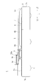
図1は、本発明の第1実施形態に係る搬送装置の概略斜視図であって、図2は、図1に示す搬送装置の概略側面図であって、図3は、図1に示す搬送装置の概略上面図である。 1 is a schematic perspective view of a transport device according to the first embodiment of the present invention, FIG. 2 is a schematic side view of the transport device shown in FIG. 1, and FIG. 3 is a transport diagram shown in FIG. It is a schematic top view of the apparatus.
本発明の第1実施形態に係る搬送装置1は、走行機構を収納した走行筐体2を有し、走行筐体2は、後述する台車100(被搬送物の一例、後述する図7参照)の底面より車高が低く、細長い矩形状とされている。走行筐体2の上面(基準面2a)には、第1連結機構3と台部材4とが設けられている。走行筐体2の下部には、走行機構の一部として、接地した複数の車輪6が設けられている。走行筐体2は、走行機構によって走行し、自身の長手方向Lに沿って、前後に進行する構成とされており、適宜旋回して、左右へ向きを変える。なお、以下では説明のため、走行筐体2の長手方向Lのうち、一方(図2では、左方向)を第1長手方向L1と呼び、他方(図2では、右方向)を第2長手方向L2と呼ぶことがある。また、走行筐体2において、長手方向Lで対向する側面のうち、第1長手方向L1側の側面を第1側面2bと呼び、第2長手方向L2側の側面を第2側面2cと呼ぶことがある。
The
基準面2aには、一方の長辺(図3では、上辺)に沿って、第1スライド部5が設けられている。第1スライド部5は、シリンダであって、上部に取り付けられた第1連絡部51を長手方向Lに移動させる。第1連絡部51には、略平板状の第2連絡部52が取り付けられている。第2連絡部52は、基準面2aの他方の長辺(図3では、下辺)側へ延伸されており、延伸された先端の下部には、第1連結機構3が取り付けられている。また、第2連絡部52は、第2長手方向L2側の端部に、上方へ立設された立設部52aが設けられている。
The
本実施の形態において、第1連結機構3は、4節のリンク機構とされている。なお、第1連結機構3については、後述する図5および図6を参照して、詳細に説明する。上述したように、第1連絡部51および第2連絡部52は、第1スライド部5によって、長手方向Lに移動する構成とされており、第2連絡部52が移動するのに伴って、第1連結機構3も長手方向Lに移動する。図3では、上面視において、第1連結機構3が長手方向Lに移動する際の軌跡を、スライド軸線SLとして示している。第1連結機構3の移動範囲は、搬送装置1の中心よりも第1側面2b寄りの位置から、第2側面2c近傍までとされている。
In the present embodiment, the first connecting
台部材4は、上面視において、スライド軸線SLと重なる位置に設けられ、長手方向Lでの長さが、第1連結機構3の移動範囲より少し短い程度とされている。台部材4の上面は、基準面2aより上方に位置しており、長手方向Lでの両端部にテーパ形状とされた案内部4aが設けられている。つまり、台部材4は、側面視(図2参照)において、略台形状に形成されており、案内部4aは、端に向かうに従って、徐々に高さが低くなるように傾斜した斜面とされている。そして、台部材4の中央は、一様な高さとされ、平坦な形状とされた摺動部4bとなっている。
The
図1ないし図3では、第1連結機構3を第1長手方向L1に移動させた状態を示しており、第1連結機構3と台部材4とは接していない。台部材4には、自身を長手方向Lに移動させる第2スライド部7が取り付けられていてもよい。台部材4を第1長手方向L1に移動させると、図4に示すように、第1連結機構3は、台部材4と当接し、案内部4aに案内されて台部材4の上に乗り上げる。なお、台部材4を移動させる構成については、後述する第2実施形態において、詳細に説明する。
1 to 3 show a state in which the first connecting
図5は、拡大した第1連結機構近傍を抽出して示す拡大側面図であって、図6は、図5に示す第1連結機構の乗り上げ状態を示す拡大側面図である。 FIG. 5 is an enlarged side view showing an enlarged vicinity of the first connecting mechanism by extracting it, and FIG. 6 is an enlarged side view showing a riding state of the first connecting mechanism shown in FIG.
本実施の形態において、第1連結機構3は、第1対向片31、第2対向片32、第1回動片33、第2回動片34、係合部35、第1乗り上げ輪36a、および第2乗り上げ輪36bで構成されている。
In the present embodiment, the first connecting
第1対向片31、第2対向片32、第1回動片33、および第2回動片34は、端部同士を連結してリンク機構を形成している。具体的に、第1対向片31は、第2連絡部52の下面に固定されており、一方(第2側面2c側)の端部に第1回動片33が連結され、他方(第1側面2b側)の端部に第2回動片34が連結されている。第1回動片33は、第1対向片31に連結された支点37を中心に回動する構成とされ、支点37と反対側の端部が第2対向片32に連結されている。また、第1回動片33は、第2対向片32に連結された端部の上面(リンク機構の外面側)に、上方へ突出した係合部35が設けられている。第1対向片31は、一方(第2側面2c側)の端部に第1回動片33が連結され、他方(第1側面2b側)の端部に第2回動片34が連結されている。そして、第2対向片32の下面には、第2回動片34側の端部に第1乗り上げ輪36aが設けられ、第1回動片33側の端部に第2乗り上げ輪36bが設けられている。
The first facing
第1連結機構3では、上部(特に、第1対向片31)が固定されているのに対し、下部(特に、第1乗り上げ輪36aおよび第2乗り上げ輪36b)は、基準面2aなどに接しているだけとされている。そのため、第1連結機構3と台部材4とが接するように、互いの位置関係を相対的に推移させると、台部材4によって、図6に示すように、第1乗り上げ輪36aおよび第2乗り上げ輪36b(乗り上げ部の一例)が上方へ押し上げられる。そして、第1乗り上げ輪36aおよび第2乗り上げ輪36bのうち、いずれか一方でも押し上げられると、第2対向片32が上方へ移動し、第1回動片33は、支点37を中心にして、係合部35側が上方へ回動する。この際、第1連結機構3は、リンク機構とされているので、第2回動片34は、第1回動片33に追従して動作する。
In the first connecting
第1連結機構3において、下部が基準面2aに接している際、係合部35の上端は、第2連絡部52(立設部52a)より低くなるように設定されている。そして、第1連結機構3が台部材4の上面に乗り上げた乗り上げ状態では、係合部35と立設部52aとが略同じ高さとなる。なお、以下では説明のため、図5に示すように、第1連結機構3が台部材4の上面に乗り上げていない状態、つまり、第1連結機構3の下部が基準面2aに接している状態を下降状態と呼ぶことがある。
In the first connecting
本実施の形態では、第1対向片31、第2対向片32、第1回動片33、および第2回動片34が連結部に相当し、特に、第1回動片33が回動部に相当する。また、本実施の形態では、乗り上げ部として、ローラとされた第1乗り上げ輪36aおよび第2乗り上げ輪36bを用いたが、これに限定されず、乗り上げ部は、台部材4の上面との間の摩擦を低減する摩擦低減機構とされていればよい。摩擦低減機構では、例えば、接地部を曲面にして接地面積を小さくしたり、滑りやすい材質などで形成したりしてもよい。
In the present embodiment, the first
図7は、搬送装置に搬送される台車の概略側面図であって、図8は、図7に示す台車の概略下面図である。 FIG. 7 is a schematic side view of the dolly transported to the transport device, and FIG. 8 is a schematic bottom view of the dolly shown in FIG. 7.
台車100は、積載物が積載される底面や側面を構成する枠体101と、枠体101の下部に取り付けられた台車輪102とで構成されている。台車100の底面は、枠体101によって矩形状に形成されており、底面の4隅の角にそれぞれ台車輪102が取り付けられている。枠体101では、棒状の部材を組み合わせて台車100の底面を構成しており、底面の外縁に沿って設けられた外枠101bと、対向する外枠の間に差し渡した補強部101cとを有している。なお、補強部101cの位置や数は、適宜調整すればよく、複数の部材を平行に配置したり、複数の部材を格子状に配置したりしてもよい。搬送装置1では、外枠101bの一部(被連結部101a)と連結する。
The
台車100については、少なくとも底面を有していればよく、側面や上面の構造は特に限定されない。つまり、側面や上面が板状の部材で覆われていてもよいし、底面より高い位置で仕切ることで、積載物を積載する面を増やしてもよい。
The
次に、搬送装置1が台車100と連結する動作について、図9ないし図11を参照して説明する。
Next, the operation of connecting the
図9は、搬送装置が台車との連結が行われる場所に移動した状態を示す説明図である。 FIG. 9 is an explanatory diagram showing a state in which the transport device has been moved to a place where the connection with the carriage is performed.
台車100との連結が行われていない状態において、搬送装置1では、第1連結機構3を第1長手方向L1に移動させており、台部材4に乗り上げていない状態とされている。つまり、係合部35を基準面2aにできるだけ近づけて、上方へ突出することを避けているので、走行中などに係合部35が物体に引っ掛かる虞を低減している。
In the state where the connection with the
搬送装置1は、サーバ等から無線で指示を受信する構成とされ、搬送する台車100の位置まで自動的に移動する。台車100については、所定の台車置場が設定されている。搬送装置1は、マップ情報と、マップ内における複数の台車置場の位置とを記録している。搬送装置1を誘導する方法としては、床面に設置した磁気テープを用いてもよい。搬送装置1は、磁気テープの情報を読み取り、磁気テープに沿って誘導される。
The
搬送装置1は、誘導工程において、台車100との連結が行われる場所に移動する。搬送装置1は、第2側面2cが台車100の外枠101b近傍に位置するようにして、走行を停止する。図9に示す状態において、搬送装置1の中心は、台車100の底面の直下の領域外に位置している。つまり、走行筐体2の端部など、搬送装置1の一部は、台車100の底面の下方に位置しているが、搬送装置1は、台車100の底面と床面との間に、完全には潜り込んでいない。
The
図10は、第1連結機構を台車に連結させた状態を示す説明図である。 FIG. 10 is an explanatory diagram showing a state in which the first connecting mechanism is connected to the carriage.
図10では、図9に対し、第1連結機構3を第2長手方向L2に移動させた状態を示している。第1連結工程において、第2長手方向L2(図10では、矢符Aの方向)に移動した第1連結機構3は、第2側面2c近傍に位置しており、台車100の被連結部101aに連結されている。ここで、第1連結機構3は、台部材4の上面に乗り上げた乗り上げ状態となっている。なお、第1連結機構3が台車100と連結する動作については、後述する図12Aないし図12Dを参照して、詳細に説明する。
FIG. 10 shows a state in which the first connecting
図11は、台車に連結した第1連結機構をスライド移動させた状態を示す説明図である。 FIG. 11 is an explanatory diagram showing a state in which the first connecting mechanism connected to the carriage is slid and moved.
図11では、図10に対し、第1連結機構3を第1長手方向L1に移動させた状態を示している。スライド移動工程において、第1連結機構3は、乗り上げ状態とされたまま、台車100と一体となって第1長手方向L1(図11では、矢符Bの方向)に移動している。これによって、搬送装置1自身を移動させずに、台車100を移動させており、搬送装置1の中心は、台車100の底面の直下の領域内に位置する。
FIG. 11 shows a state in which the first connecting
図10に示すように、搬送装置1が下部に潜り込まずに台車100と連結した状態では、搬送装置1と台車100とを合わせた全長が長くなり、走行中での旋回性や安定性に不安が生じてしまう。これに対し、図11に示すように、搬送装置1を台車100の下部に潜り込ませると、搬送装置1と台車100との位置が近くなり、走行中での旋回性や安定性を向上させることができる。
As shown in FIG. 10, when the
次に、第1連結機構3をスライド移動させた際の動作について、図12Aないし図12Dを参照して説明する。なお、図12Aないし図12Dでは、図面の見易さを考慮して、搬送装置1のうち、主に、基準面2aより上部を抽出して示している。
Next, the operation when the first connecting
図12Aは、第1連結機構が被連結部近傍に位置する状態を示す説明図である。 FIG. 12A is an explanatory diagram showing a state in which the first connecting mechanism is located in the vicinity of the connected portion.
図12Aにおいて、第1連結機構3は、第2側面2c(図12Aでは、右端)近傍に位置しており、一部が第2側面2cより外部に突出している。図12Aに示す状態において、台部材4は、第2側面2cとの間に、隙間を有する位置に配置されており、第1連結機構3は、下部(特に、第1乗り上げ輪36a)が基準面2aと当接した下降状態となっている。その結果、第1連結機構3は、台車100の被連結部101aに面しているが、係合部35は下降しており、被連結部101aと係合していない。
In FIG. 12A, the first connecting
図12Bは、連結位置において第1連結機構が被連結部と連結している状態を示す説明図である。 FIG. 12B is an explanatory diagram showing a state in which the first connecting mechanism is connected to the connected portion at the connecting position.
図12Bでは、図12Aに示す状態に対し、第1連結機構3を乗り上げ状態に移行させている。第1連結機構3は、台部材4に対して、相対的に第1長手方向L1へ移動している。その結果、第1乗り上げ輪36aは、案内部4aを経て、摺動部4b(台部材4の上面)に接している。案内部4aを設けることで、第1乗り上げ輪36aおよび第2乗り上げ輪36bは、円滑に台部材4に押し上げられる。第1連結機構3に用いられているリンク機構では、第2乗り上げ輪36bが摺動部4bに接していなくても、第1乗り上げ輪36aが摺動部4bに接しているので、第2対向片32を介して台部材4に押し上げられ、係合部35は、上昇して被連結部101aと係合している。
In FIG. 12B, the first connecting
被連結部101a(台車100)と第1連結機構3との位置関係を変化させずに、第1連結機構3を下降状態から乗り上げ状態に移行させる際には、第1スライド部5によって第1連結機構3を第1長手方向L1へ移動させつつ、走行筐体2を第2長手方向L2へ走行させればよい。図12Aおよび図12Bに示すように、搬送装置1の端部近傍において、第1連結機構3が被連結部101aと面する位置を連結位置と呼ぶことがある。
When shifting the first connecting
図12Cは、第1連結機構が被連結部を牽引している状態を示す説明図である。 FIG. 12C is an explanatory diagram showing a state in which the first connecting mechanism is pulling the connected portion.
図12Cは、第1連結機構3が台車100(被連結部101a)と一体となって、長手方向Lにスライド移動するスライド移動工程を示しており、図12Bに示す状態に対しては、第1連結機構3が第1長手方向L1に移動している。第1乗り上げ輪36aおよび第2乗り上げ輪36bのうち少なくとも1つが、台部材4に対して乗り上げ状態となっている際に、第1連結機構3を長手方向Lにスライド移動させることで、係合部35および立設部52aの間に引っ掛かっている被連結部101aは、第1連結機構3と併せてスライド移動する。第1連結機構3は、平坦な摺動部4bに接しているので、台車100との連結が安定する。
FIG. 12C shows a slide moving step in which the first connecting
図12Dは、搬送位置において第1連結機構が被連結部と連結している状態を示す説明図である。 FIG. 12D is an explanatory diagram showing a state in which the first connecting mechanism is connected to the connected portion at the transport position.
図12Dにおいて、第1連結機構3は、搬送装置1の中心よりも、第1側面2b(図12Dでは、左端)寄りに位置しており、図12Cに示す状態に対しては、第1連結機構3がさらに第1長手方向L1に移動している。図12Dでは、第2乗り上げ輪36bだけが、台部材4に対して乗り上げ状態となっており、第1乗り上げ輪36aは台部材4に接していないが、図12Bと同様に、第2対向片32を介して台部材4に押し上げられ、係合部35は、上昇して被連結部101aと係合している。図12Dに示すように、被連結部101aと連結した状態で、第1連結機構3をスライド移動させた位置を搬送位置と呼ぶことがある。搬送位置は、搬送装置1の上面の中央を基準として、連結位置と反対の側に位置している。搬送装置1は、搬送工程において、第1連結機構3および台車100が搬送位置で連結している状態で走行し、台車100と一体になって移動する。
In FIG. 12D, the first connecting
一般的に、第1連結機構3などの動作する部分に昇降装置(昇降モータ等)を設けると、サイズや重量が増大し、大掛かりな構造となるため、第1連結機構3をスライド移動させる機構への負担も大きくなる。つまり、動作機構の先に、さらに動作機構を設けることは望ましくない。また、電気ケーブルを介して昇降装置に電力を供給している場合、電気ケーブルも同時にスライド移動するため、ケーブルの取り回しを考慮せねばならず、スライド移動の際の電気ケーブルの擦れによって、断線が生じる虞がある。
Generally, if an elevating device (elevating motor or the like) is provided in an operating part of the first connecting
これに対し、本実施の形態において、第1連結機構3は、第1スライド部5によって、台部材に対する位置をスライド移動されて、台部材4の上面に乗り上げた乗り上げ状態となる。係合部35(連結部の一例)は、第1連結機構3が乗り上げ状態となった際に、上昇動作して被連結部101aと連結する。上述した構成とすることで、スライド移動する第1連結機構3自身に昇降装置を設けることなく、台部材4に対する位置を調整することで、台車100と連結することができる。
On the other hand, in the present embodiment, the first connecting
搬送装置1を利用する環境においては、様々な状況が想定され、床面が平坦ではないことも有り得る。例えば、障害物や段差などが存在して、台車100の直下への潜り込みが阻害される場合も考えられる。
In the environment in which the
これに対し、本発明の実施の形態に係る搬送方法は、搬送装置1が、台車100の底面と床面との間に潜り込んだ状態で、連結した台車100を搬送する搬送方法であって、搬送装置1を台車100との連結が行われる場所に移動させる誘導工程と、搬送装置1の上面に設けられた第1連結機構3を、連結位置で台車100に連結させる第1連結工程と、第1連結機構3が台車100と連結した状態で、第1連結機構3と台車100とを一体として、連結位置と、連結位置に対してスライド軸線SL上で離間した搬送位置との間でスライド移動させるスライド移動工程と、搬送位置で連結した状態の台車100を、搬送装置1に搬送させる搬送工程とを含む構成とされている。従って、搬送装置1が予め台車100の直下に潜り込むことなく、台車100を移動させてから搬送することができ、台車100の直下の状況に影響されない。
On the other hand, the transport method according to the embodiment of the present invention is a transport method in which the
図12Aないし図12Dでは、第1連結機構3を台車100と連結して搬送する動作を示したが、上述した動作を逆に行うことで、搬送装置1と台車100との連結を解除することができる。
In FIGS. 12A to 12D, the operation of connecting and transporting the first connecting
(第2実施形態)
次に、本発明の第2実施形態に係る搬送装置について、図面を参照して説明する。なお、第2実施形態に係る搬送装置の構造については、第1実施形態と略同様であるので、説明および図面を省略する。
(Second Embodiment)
Next, the transport device according to the second embodiment of the present invention will be described with reference to the drawings. Since the structure of the transport device according to the second embodiment is substantially the same as that of the first embodiment, the description and the drawings will be omitted.
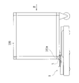
図13Aは、本発明の第2実施形態に係る搬送装置において、第1連結機構が被連結部近傍に位置する状態を示す説明図であって、図13Bは、第1連結機構が被連結部と連結している状態を示す説明図である。 FIG. 13A is an explanatory diagram showing a state in which the first connecting mechanism is located in the vicinity of the connected portion in the transport device according to the second embodiment of the present invention, and FIG. 13B shows the first connecting mechanism being connected to the connected portion. It is explanatory drawing which shows the state which is connected with.
第2実施形態では、第1実施形態に対し、第2スライド部7によって、台部材4を移動させる点が異なる。第2スライド部7は、シリンダであって、上部に設けられた台部材4を長手方向Lに移動させる。なお、図13Aは、図12Aと略同様の状況とされており、第1連結機構3は、台車100の被連結部101aに面しているが、係合部35は下降しており、被連結部101aと係合していない。
The second embodiment differs from the first embodiment in that the
図13Bでは、図13Aに示す状態に対し、第1連結機構3を乗り上げ状態に移行させている。台部材4は、第1連結機構3に対して、相対的に第2長手方向L2へ移動している。なお、図13Bに示す一点鎖線は、第2長手方向L2に移動させる前の台部材4を表している。図13Bでは、図12Bと略同様にして、第1乗り上げ輪36aが台部材4に押し上げられ、係合部35が上昇して被連結部101aと連結する。
In FIG. 13B, the first connecting
係合部35が被連結部101aと連結した後、図12Cに示すように、乗り上げ状態を維持して第1連結機構3をスライド移動させることで、台車100が移動する。この際、台部材4の位置は、第2スライド部7によって、適宜調整すればよい。
After the engaging
上述したように、第1連結機構3と台部材4とが個別に移動する構成とすることで、走行筐体2の位置を変えることなく、係合部35を昇降させることができる。
As described above, by configuring the first connecting
また、本発明の第2実施形態に係る搬送装置1の変形例では、異なる状態で台車100を搬送する搬送方法を実施してもよい。
Further, in the modified example of the
変形例では、第1スライド部5でのスライド移動が行われず、第1連結機構3は、搬送装置1の端部近傍に固定されている。そして、第1連結機構3は、図13Aおよび図13Bに示すように、台部材4を移動させることで、係合部35が昇降する。搬送装置1は、図10に示すように、搬送装置1の端部近傍に位置する第1連結機構3で台車100と連結した状態で、走行機構によって搬送装置1を走行させ、台車100を搬送する。上述したように、本発明では、スライド軸線SL上で、台部材4に対する第1連結機構3の位置を相対的にスライド移動させる構成とされていればよく、台部材4だけを移動させてもよい。
In the modified example, the slide movement is not performed in the
(第3実施形態)
次に、本発明の第3実施形態に係る搬送装置について、図面を参照して説明する。なお、第3実施形態に係る搬送装置の構造については、第1実施形態および第2実施形態と略同様であるので、説明および図面を省略する。
(Third Embodiment)
Next, the transport device according to the third embodiment of the present invention will be described with reference to the drawings. Since the structure of the transport device according to the third embodiment is substantially the same as that of the first embodiment and the second embodiment, the description and the drawings will be omitted.
図14Aは、本発明の第3実施形態に係る搬送装置において、第1連結機構が被連結部近傍に位置する状態を示す説明図であって、図14Bは、連結位置において第1連結機構が被連結部と連結している状態を示す説明図である。 FIG. 14A is an explanatory diagram showing a state in which the first connecting mechanism is located in the vicinity of the connected portion in the transport device according to the third embodiment of the present invention, and FIG. 14B shows the first connecting mechanism at the connecting position. It is explanatory drawing which shows the state which is connected with the connected part.
第3実施形態では、第1実施形態に対し、第1連結機構3の構造が異なっている。具体的に、本実施の形態において、第1連結機構3は、第1対向片31、第1回動片33、係合部35、および第3乗り上げ輪36cで構成されている。第1対向片31は、第2連絡部52の下面に固定されており、一方(第2側面2c側)の端部に第1回動片33が連結されている。第1回動片33は、第1対向片31に連結された支点37を中心に回動する構成とされ、支点37と反対側の端部の上面に、係合部35が設けられている。また、第1回動片33には、係合部35の下方に第3乗り上げ輪36c(乗り上げ部の一例)が設けられている。係合部35は、第3乗り上げ輪36cの高さ(位置)に応じて、昇降する構成とされている。本実施の形態において、第1連結機構3は、第3乗り上げ輪36cが基準面2aに接する位置を移動範囲として設定すればよく、誘導工程において、台車100に対する搬送装置1の位置を調整すればよい。
In the third embodiment, the structure of the first connecting
図14Aにおいて、第1連結機構3は、第2側面2c(図14Aでは、右端)近傍に位置しており、下部(特に、第3乗り上げ輪36c)が基準面2aと当接した下降状態となっている。
In FIG. 14A, the first connecting
図14Bでは、図14Aに示す状態に対し、台部材4を第2長手方向L2へ移動させて、第1連結機構3を乗り上げ状態に移行させている。第3乗り上げ輪36cが台部材4に押し上げられ、係合部35が上昇して被連結部101aと連結する。
In FIG. 14B, the
図14Aおよび図14Bでは、台部材4を移動させて係合部35を昇降させる動作を示したが、第1連結機構3を台部材4に対して相対的に移動させて、係合部35を昇降させてもよい。
In FIGS. 14A and 14B, the operation of moving the
(第4実施形態)
次に、本発明の第4実施形態に係る搬送装置について、図面を参照して説明する。なお、第4実施形態に係る搬送装置の構造について、第1実施形態ないし第3実施形態と略同様とされた部分は、同じ符号を付して説明および図面を省略する。
(Fourth Embodiment)
Next, the transport device according to the fourth embodiment of the present invention will be described with reference to the drawings. Regarding the structure of the transport device according to the fourth embodiment, the parts substantially the same as those of the first embodiment to the third embodiment are designated by the same reference numerals, and the description and the drawings will be omitted.
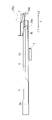
図15は、本発明の第4実施形態に係る搬送装置の概略斜視図であって、図16は、図15に示す搬送装置の概略上面図である。 FIG. 15 is a schematic perspective view of the transport device according to the fourth embodiment of the present invention, and FIG. 16 is a schematic top view of the transport device shown in FIG.
第4実施形態は、第1実施形態に対し、第2連結機構8を備えている点で異なる。第2連結機構8は、基準面2aよりも上方へ突出して設けられ、搬送装置1の上面の中央よりも、第1側面2b寄りに設けられている。具体的に、第2連結機構8は、第1連結機構3の移動範囲のうち、第1長手方向L1側の端部近傍に位置している。第2連結機構8は、上面視(図16参照)した状態で、スライド軸線SLと直交する横方向において、第1連結機構3と離間した2箇所に設けられている。本実施の形態において、2つの第2連結機構8は、スライド軸線SLに対して、線対象で一対となる位置に設けられ、2つの第2連結機構8の間に、第1連結機構3を挟むように位置している。次に、第2連結機構8の詳細な構造について、図17Aおよび図17Bを参照して説明する。
The fourth embodiment is different from the first embodiment in that the
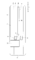
図17Aは、第2連結機構の昇降部が下降している状態を示す説明図であって、図17Bは、第2連結機構の昇降部が上昇している状態を示す説明図である。 FIG. 17A is an explanatory diagram showing a state in which the elevating portion of the second connecting mechanism is lowered, and FIG. 17B is an explanatory diagram showing a state in which the elevating portion of the second connecting mechanism is raised.
第2連結機構8は、基準面2aに対して昇降動作する昇降部8cと、昇降部8cに固定された昇降連結部8aとを備えている。具体的に、昇降部8cは、シリンダなどであって、上部に取り付けられた昇降連結部8aを昇降させる。昇降連結部8aは、上面に凹部8bが設けられている。凹部8bは、被連結部101aに応じた形状とすればよく、被連結部101aを挟み込む構造とされている。
The second connecting
図17Aでは、図14Bのように、連結位置において第1連結機構3が被連結部101aと連結している。この状態から、第1連結機構3は、被連結部101aが第2連結機構8に面する位置まで第1長手方向L1にスライド移動する。第1連結機構3がスライド移動する際、第2連結機構8は、下降しており、上面の高さが被連結部101aに接触しないように設定されている。
In FIG. 17A, as shown in FIG. 14B, the first connecting
図17Bでは、図12Dのように、被連結部101aと連結した第1連結機構3が搬送位置に位置している。第2連結工程において、昇降連結部8aは、昇降部8cが上昇(図17Bでは、矢符Cの方向)することで、被連結部101aと係合し、第2連結機構8が被連結部101aと連結している。
In FIG. 17B, as shown in FIG. 12D, the first connecting
図18は、台車に第2連結機構を連結した状態を示す説明図である。 FIG. 18 is an explanatory diagram showing a state in which the second connecting mechanism is connected to the bogie.
搬送装置1の中心が、台車100の底面の直下の領域内に位置する状態で、第2連結機構8は、図17Bに示すように、被連結部101aと連結している。第2連結機構8は、第1連結機構3よりも、台車100を牽引する際の負荷に対する靱性が高く設定されている。つまり、第1連結機構3では、回動自在な第1回動片33で被連結部101aを引っ掛けているため、各部材の接点など、構造上弱い部分が存在する。これに対し、第2連結機構8では、昇降部8cで動作させるだけの単純な構造とされているので、第1連結機構3よりも頑丈に形成することができる。このように、台車100を牽引する役割と、台車100を保持する役割とを、第1連結機構3と第2連結機構8とで分担することで、構造的脆弱性をカバーすることができる。図18では、第1連結機構3と第2連結機構8との両方が、被連結部101aと連結した状態を示しているがこれに限定されず、搬送装置1を走行させて台車100を搬送する際は、第2連結機構8だけを被連結部101aと連結させてもよい。
As shown in FIG. 17B, the second connecting
なお、今回開示した実施の形態は全ての点で例示であって、限定的な解釈の根拠となるものではない。従って、本発明の技術的範囲は、上記した実施の形態のみによって解釈されるものではなく、特許請求の範囲の記載に基づいて画定される。また、特許請求の範囲と均等の意味および範囲内での全ての変更が含まれる。 It should be noted that the embodiments disclosed this time are examples in all respects and do not serve as a basis for a limited interpretation. Therefore, the technical scope of the present invention is not construed solely by the embodiments described above, but is defined based on the description of the scope of claims. It also includes all changes within the meaning and scope of the claims.
1 搬送装置
2 走行筐体
2a 基準面
2b 第1側面
2c 第2側面
3 第1連結機構
31 第1対向片
32 第2対向片
33 第1回動片
34 第2回動片
35 係合部(連結部の一部)
36a 第1乗り上げ輪(乗り上げ部の一例)
36b 第2乗り上げ輪(乗り上げ部の一例)
36c 第3乗り上げ輪(乗り上げ部の一例)
37 支点
4 台部材
4a 案内部
4b 摺動部
5 第1スライド部(スライド機構の一例)
51 第1連絡部
52 第2連絡部
52a 立設部
6 車輪(走行機構の一部)
7 第2スライド部(スライド機構の一例)
8 第2連結機構
8a 昇降連結部
8b 凹部
8c 昇降部
100 台車(被搬送物の一例)
101 枠体
101a 被連結部
101b 外枠
101c 補強部
102 台車輪
SL スライド軸線
L 長手方向
L1 第1長手方向
L2 第2長手方向
1
36a 1st riding wheel (an example of riding section)
36b 2nd riding wheel (an example of riding section)
36c 3rd riding wheel (an example of riding section)
37
51
7 Second slide part (an example of slide mechanism)
8
101
Claims (12)
前記搬送装置の上面に設けられた第1連結機構と、
前記搬送装置の上面に設けられた台部材と、
所定のスライド軸線上において、前記台部材に対する前記第1連結機構の位置を相対的にスライド移動させるスライド機構と、
前記搬送装置を走行させる走行機構とを備え、
前記第1連結機構は、
前記スライド軸線上に設けられた乗り上げ部と、
前記被搬送物と連結する連結部とを有し、
前記連結部は、上方へ突出した係合部を備え、
前記乗り上げ部は、前記スライド機構によって、前記台部材に対する前記第1連結機構の位置をスライド移動させた際、前記台部材の上面に乗り上げた乗り上げ状態となり、
前記連結部は、前記乗り上げ部が乗り上げ状態となった際に、前記係合部が上昇動作して前記被搬送物と連結すること
を特徴とする搬送装置。 A transport device that transports connected objects to be transported.
The first connecting mechanism provided on the upper surface of the transport device and
The base member provided on the upper surface of the transport device and
A slide mechanism that slides and moves the position of the first connecting mechanism relative to the base member on a predetermined slide axis.
It is equipped with a traveling mechanism for traveling the transport device.
The first connection mechanism is
The riding part provided on the slide axis and the riding part
It has a connecting portion to be connected to the object to be transported, and has a connecting portion.
The connecting portion comprises an engaging portion that protrudes upward.
When the position of the first connecting mechanism with respect to the pedestal member is slid and moved by the slide mechanism, the riding portion is in a riding state on the upper surface of the pedestal member.
The connecting portion is a transport device, characterized in that, when the riding portion is in the riding state, the engaging portion moves up and is connected to the object to be transported.
前記台部材は、前記スライド軸線上で、前記乗り上げ部に面する側の端部に、テーパ形状とされた案内部を有すること
を特徴とする搬送装置。 The transport device according to claim 1.
The base member is a transport device having a tapered guide portion at an end portion on the slide axis on the side facing the riding portion.
前記台部材は、上面のうち、前記スライド軸線上における中央部に、平坦な形状とされた摺動部を有すること
を特徴とする搬送装置。 The transport device according to claim 1 or 2.
The base member is a transport device characterized by having a sliding portion having a flat shape at a central portion on the slide axis of the upper surface.
前記スライド機構は、前記第1連結機構を前記スライド軸線上でスライド移動させる第1スライド部を含むこと
を特徴とする搬送装置。 The transport device according to any one of claims 1 to 3.
The slide mechanism is a transport device including a first slide portion that slides and moves the first connecting mechanism on the slide axis.
前記第1連結機構は、所定の連結位置で前記被搬送物と連結し、
前記第1スライド部は、前記第1連結機構を前記被搬送物と連結させた状態において、前記連結位置と、前記スライド軸線上において前記連結位置に対し離間した搬送位置との間でスライド移動させること
を特徴とする搬送装置。 The transport device according to claim 4.
The first connection mechanism connects to the object to be transported at a predetermined connection position.
The first slide portion is slid and moved between the connection position and the transfer position separated from the connection position on the slide axis in a state where the first connection mechanism is connected to the object to be transported. A transport device characterized by this.
前記走行機構は、前記第1連結機構が前記搬送位置に位置した状態で、前記搬送装置を走行させること
を特徴とする搬送装置。 The transport device according to claim 5.
The traveling mechanism is a transporting device characterized in that the transporting device is run in a state where the first connecting mechanism is located at the transporting position.
前記第1連結機構が前記連結位置に位置する際、前記搬送装置の中心は、前記被搬送物の底面の直下の領域外に位置し、
前記第1連結機構が前記搬送位置に位置する際、前記搬送装置の中心は、前記被搬送物の底面の直下の領域内に位置すること
を特徴とする搬送装置。 The transport device according to claim 5 or 6.
When the first connecting mechanism is located at the connecting position, the center of the transport device is located outside the region directly below the bottom surface of the object to be transported.
A transport device characterized in that when the first connecting mechanism is located at the transport position, the center of the transport device is located in a region directly below the bottom surface of the object to be transported.
前記第1連結機構が前記搬送位置に位置した状態で、前記被搬送物と連結する第2連結機構を備えること
を特徴とする搬送装置。 The transport device according to any one of claims 5 to 7.
A transport device including a second connecting mechanism that connects the first connecting mechanism to the object to be transported while the first connecting mechanism is located at the transport position.
前記スライド機構は、前記台部材を前記スライド軸線上でスライド移動させる第2スライド部を含むこと
を特徴とする搬送装置。 The transport device according to any one of claims 1 to 8.
The slide mechanism is a transport device including a second slide portion that slides and moves the base member on the slide axis.
前記乗り上げ部は、前記台部材を前記スライド軸線上においてスライド移動させた際、前記台部材の上面に乗り上げること
を特徴とする搬送装置。 The transport device according to claim 9.
The riding unit is a transport device characterized in that when the platform member is slid and moved on the slide axis, the platform member rides on the upper surface of the platform member.
前記乗り上げ部は、前記台部材の上面に乗り上げる際に、前記台部材の上面との間の摩擦を低減する摩擦低減機構を有すること
を特徴とする搬送装置。 The transport device according to any one of claims 1 to 10.
The riding portion is a transport device having a friction reducing mechanism that reduces friction with the upper surface of the base member when riding on the upper surface of the base member.
前記連結部は、支点を中心にして回動する回動部を備え、
前記係合部は、前記回動部から離間して前記連結部に設けられ、
前記回動部は、前記乗り上げ部が前記台部材の上面に乗り上げた際、上方へ回動して、前記係合部を前記被搬送物の底面の一部と係合させること
を特徴とする搬送装置。 The transport device according to any one of claims 1 to 11.
The connecting portion includes a rotating portion that rotates around a fulcrum.
The engaging portion is provided in the connecting portion apart from the rotating portion.
The rotating portion is characterized in that when the riding portion rides on the upper surface of the base member, the rotating portion rotates upward to engage the engaging portion with a part of the bottom surface of the object to be transported. Transport device.
Priority Applications (2)
| Application Number | Priority Date | Filing Date | Title |
|---|---|---|---|
| JP2018132172A JP7074597B2 (en) | 2018-07-12 | 2018-07-12 | Transport device |
| US16/504,160 US11225114B2 (en) | 2018-07-12 | 2019-07-05 | Conveying device |
Applications Claiming Priority (1)
| Application Number | Priority Date | Filing Date | Title |
|---|---|---|---|
| JP2018132172A JP7074597B2 (en) | 2018-07-12 | 2018-07-12 | Transport device |
Publications (2)
| Publication Number | Publication Date |
|---|---|
| JP2020006903A JP2020006903A (en) | 2020-01-16 |
| JP7074597B2 true JP7074597B2 (en) | 2022-05-24 |
Family
ID=69140276
Family Applications (1)
| Application Number | Title | Priority Date | Filing Date |
|---|---|---|---|
| JP2018132172A Active JP7074597B2 (en) | 2018-07-12 | 2018-07-12 | Transport device |
Country Status (2)
| Country | Link |
|---|---|
| US (1) | US11225114B2 (en) |
| JP (1) | JP7074597B2 (en) |
Families Citing this family (2)
| Publication number | Priority date | Publication date | Assignee | Title |
|---|---|---|---|---|
| JP7140560B2 (en) * | 2018-06-13 | 2022-09-21 | シャープ株式会社 | Coupling devices, conveying devices and conveying systems |
| JP7074597B2 (en) * | 2018-07-12 | 2022-05-24 | シャープ株式会社 | Transport device |
Citations (2)
| Publication number | Priority date | Publication date | Assignee | Title |
|---|---|---|---|---|
| JP2010120596A (en) | 2008-11-21 | 2010-06-03 | Central Motor Co Ltd | Conveyor device |
| JP2016150691A (en) | 2015-02-18 | 2016-08-22 | 株式会社シンテックホズミ | Automatic carrier and method for coupling the same |
Family Cites Families (12)
| Publication number | Priority date | Publication date | Assignee | Title |
|---|---|---|---|---|
| JPH06143083A (en) * | 1992-11-06 | 1994-05-24 | Bando Chem Ind Ltd | Transshipping device for roller shaped work |
| JPH0885312A (en) * | 1994-09-17 | 1996-04-02 | Sanshiyuuzen Kogyo Kk | Coupling device for transportation vehicle |
| JPH08208199A (en) * | 1995-02-03 | 1996-08-13 | Nissin Electric Co Ltd | Pulling device of movable body |
| US7350799B2 (en) * | 2000-11-09 | 2008-04-01 | Valeo Thermique Moteur | Coupling device for a handling trolley |
| DK2233380T3 (en) * | 2009-03-24 | 2018-10-22 | Bull Bug Aps 2 | Transport system |
| JP6651015B2 (en) * | 2016-07-14 | 2020-02-19 | 愛知機械テクノシステム株式会社 | Automated guided vehicle towing device and automatic guided vehicle equipped with the same |
| JP6877300B2 (en) * | 2017-08-31 | 2021-05-26 | シャープ株式会社 | Coupling device, automatic towing vehicle and automatic towing system |
| JP7140560B2 (en) * | 2018-06-13 | 2022-09-21 | シャープ株式会社 | Coupling devices, conveying devices and conveying systems |
| JP7074598B2 (en) * | 2018-07-12 | 2022-05-24 | シャープ株式会社 | Transport device |
| JP7074597B2 (en) * | 2018-07-12 | 2022-05-24 | シャープ株式会社 | Transport device |
| US10532895B1 (en) * | 2018-08-20 | 2020-01-14 | Intelligrated Headquarters, Llc | Cart coupling assembly |
| JP7181097B2 (en) * | 2019-01-10 | 2022-11-30 | シャープ株式会社 | Dolly and transport system |
-
2018
- 2018-07-12 JP JP2018132172A patent/JP7074597B2/en active Active
-
2019
- 2019-07-05 US US16/504,160 patent/US11225114B2/en active Active
Patent Citations (2)
| Publication number | Priority date | Publication date | Assignee | Title |
|---|---|---|---|---|
| JP2010120596A (en) | 2008-11-21 | 2010-06-03 | Central Motor Co Ltd | Conveyor device |
| JP2016150691A (en) | 2015-02-18 | 2016-08-22 | 株式会社シンテックホズミ | Automatic carrier and method for coupling the same |
Also Published As
| Publication number | Publication date |
|---|---|
| US20200016945A1 (en) | 2020-01-16 |
| US11225114B2 (en) | 2022-01-18 |
| JP2020006903A (en) | 2020-01-16 |
Similar Documents
| Publication | Publication Date | Title |
|---|---|---|
| JP7074598B2 (en) | Transport device | |
| JP5212836B2 (en) | Work transfer equipment | |
| JP6877300B2 (en) | Coupling device, automatic towing vehicle and automatic towing system | |
| JP7074597B2 (en) | Transport device | |
| JP6566996B2 (en) | Transfer device and cargo handling vehicle | |
| JP2019214322A (en) | Coupling device, conveyance device, and conveyance system | |
| JP7172528B2 (en) | carrier | |
| JPS5938176A (en) | Travelling truck | |
| JP4979292B2 (en) | Three-dimensional parking device | |
| JP2007302242A (en) | Truck type conveying device | |
| JP4910556B2 (en) | Positioning mechanism of transfer machine | |
| CN114988044B (en) | Automatic positioning method based on transportation system | |
| JP3607863B2 (en) | Guide mechanism and tray for storing articles using the same | |
| WO2024070927A1 (en) | Transport facility | |
| JP5268252B2 (en) | Low lift truck | |
| JP7002173B2 (en) | Transfer device | |
| JPS6039323Y2 (en) | Conveyance device | |
| JP2543782Y2 (en) | Transfer device of rail connection part in coil transfer device | |
| JP2022149833A (en) | Coupler, coupling unit, and coupling method | |
| JPS60203567A (en) | Truck for carrying automobile | |
| KR20240085174A (en) | Transport facility | |
| JP2024057844A (en) | Transportation carriage | |
| JPH08192752A (en) | Universal wheel sway stopping structure of truck mounted on truck transporting vehicle | |
| JP2023106650A (en) | loader | |
| JP2022149790A (en) | Coupler, coupling unit, and coupling method |
Legal Events
| Date | Code | Title | Description |
|---|---|---|---|
| A621 | Written request for application examination |
Free format text: JAPANESE INTERMEDIATE CODE: A621 Effective date: 20210324 |
|
| A977 | Report on retrieval |
Free format text: JAPANESE INTERMEDIATE CODE: A971007 Effective date: 20220303 |
|
| A131 | Notification of reasons for refusal |
Free format text: JAPANESE INTERMEDIATE CODE: A131 Effective date: 20220315 |
|
| A521 | Request for written amendment filed |
Free format text: JAPANESE INTERMEDIATE CODE: A523 Effective date: 20220328 |
|
| TRDD | Decision of grant or rejection written | ||
| A01 | Written decision to grant a patent or to grant a registration (utility model) |
Free format text: JAPANESE INTERMEDIATE CODE: A01 Effective date: 20220426 |
|
| A61 | First payment of annual fees (during grant procedure) |
Free format text: JAPANESE INTERMEDIATE CODE: A61 Effective date: 20220512 |
|
| R150 | Certificate of patent or registration of utility model |
Ref document number: 7074597 Country of ref document: JP Free format text: JAPANESE INTERMEDIATE CODE: R150 |