JP7071748B2 - Gastric retention system - Google Patents
Gastric retention system Download PDFInfo
- Publication number
- JP7071748B2 JP7071748B2 JP2019529639A JP2019529639A JP7071748B2 JP 7071748 B2 JP7071748 B2 JP 7071748B2 JP 2019529639 A JP2019529639 A JP 2019529639A JP 2019529639 A JP2019529639 A JP 2019529639A JP 7071748 B2 JP7071748 B2 JP 7071748B2
- Authority
- JP
- Japan
- Prior art keywords
- arm
- gastric
- arms
- grdf
- stomach
- Prior art date
- Legal status (The legal status is an assumption and is not a legal conclusion. Google has not performed a legal analysis and makes no representation as to the accuracy of the status listed.)
- Active
Links
- 230000002496 gastric effect Effects 0.000 title claims description 249
- 230000014759 maintenance of location Effects 0.000 title claims description 191
- 210000002784 stomach Anatomy 0.000 claims description 157
- 230000003628 erosive effect Effects 0.000 claims description 132
- 238000000034 method Methods 0.000 claims description 67
- 239000003814 drug Substances 0.000 claims description 56
- 210000004051 gastric juice Anatomy 0.000 claims description 51
- 229940079593 drug Drugs 0.000 claims description 41
- 239000000203 mixture Substances 0.000 claims description 35
- 239000002775 capsule Substances 0.000 claims description 27
- 238000009472 formulation Methods 0.000 claims description 23
- 230000037406 food intake Effects 0.000 claims description 19
- 239000012530 fluid Substances 0.000 claims description 16
- 239000002552 dosage form Substances 0.000 claims description 15
- 239000005022 packaging material Substances 0.000 claims description 13
- 238000007789 sealing Methods 0.000 claims description 11
- 238000007906 compression Methods 0.000 claims description 10
- 230000006835 compression Effects 0.000 claims description 10
- 230000008569 process Effects 0.000 claims description 8
- 150000001875 compounds Chemical class 0.000 claims description 7
- 239000000017 hydrogel Substances 0.000 claims description 3
- 230000000242 pagocytic effect Effects 0.000 claims description 3
- 230000001131 transforming effect Effects 0.000 claims description 2
- 239000008186 active pharmaceutical agent Substances 0.000 description 41
- 239000000463 material Substances 0.000 description 30
- 229920000642 polymer Polymers 0.000 description 25
- 230000007246 mechanism Effects 0.000 description 21
- 230000007704 transition Effects 0.000 description 21
- 244000062645 predators Species 0.000 description 20
- 239000000546 pharmaceutical excipient Substances 0.000 description 17
- 238000012360 testing method Methods 0.000 description 16
- 241001465754 Metazoa Species 0.000 description 14
- 230000006870 function Effects 0.000 description 12
- 230000000717 retained effect Effects 0.000 description 11
- 238000004519 manufacturing process Methods 0.000 description 10
- 239000004480 active ingredient Substances 0.000 description 9
- -1 compacts Chemical class 0.000 description 9
- 238000010586 diagram Methods 0.000 description 9
- VEXZGXHMUGYJMC-UHFFFAOYSA-N Hydrochloric acid Chemical compound Cl VEXZGXHMUGYJMC-UHFFFAOYSA-N 0.000 description 8
- 229920002301 cellulose acetate Polymers 0.000 description 8
- 238000013270 controlled release Methods 0.000 description 8
- 238000002224 dissection Methods 0.000 description 8
- 238000001746 injection moulding Methods 0.000 description 7
- 239000003795 chemical substances by application Substances 0.000 description 6
- 230000000694 effects Effects 0.000 description 6
- 238000002594 fluoroscopy Methods 0.000 description 6
- 210000000936 intestine Anatomy 0.000 description 6
- 235000012054 meals Nutrition 0.000 description 6
- 229940124597 therapeutic agent Drugs 0.000 description 6
- 241000282472 Canis lupus familiaris Species 0.000 description 5
- 241000282412 Homo Species 0.000 description 5
- 230000009089 cytolysis Effects 0.000 description 5
- 238000013461 design Methods 0.000 description 5
- 238000010494 dissociation reaction Methods 0.000 description 5
- 230000005593 dissociations Effects 0.000 description 5
- 238000004090 dissolution Methods 0.000 description 5
- 238000003384 imaging method Methods 0.000 description 5
- 230000002829 reductive effect Effects 0.000 description 5
- 230000009747 swallowing Effects 0.000 description 5
- XLYOFNOQVPJJNP-UHFFFAOYSA-N water Substances O XLYOFNOQVPJJNP-UHFFFAOYSA-N 0.000 description 5
- TZCXTZWJZNENPQ-UHFFFAOYSA-L barium sulfate Chemical compound [Ba+2].[O-]S([O-])(=O)=O TZCXTZWJZNENPQ-UHFFFAOYSA-L 0.000 description 4
- 239000011324 bead Substances 0.000 description 4
- 235000021152 breakfast Nutrition 0.000 description 4
- 229920002678 cellulose Polymers 0.000 description 4
- 230000008859 change Effects 0.000 description 4
- 230000000052 comparative effect Effects 0.000 description 4
- 239000000470 constituent Substances 0.000 description 4
- 208000037265 diseases, disorders, signs and symptoms Diseases 0.000 description 4
- 229920003088 hydroxypropyl methyl cellulose Polymers 0.000 description 4
- 235000010979 hydroxypropyl methyl cellulose Nutrition 0.000 description 4
- 239000007788 liquid Substances 0.000 description 4
- AQHHHDLHHXJYJD-UHFFFAOYSA-N propranolol Chemical compound C1=CC=C2C(OCC(O)CNC(C)C)=CC=CC2=C1 AQHHHDLHHXJYJD-UHFFFAOYSA-N 0.000 description 4
- 238000013268 sustained release Methods 0.000 description 4
- 239000012730 sustained-release form Substances 0.000 description 4
- 230000009466 transformation Effects 0.000 description 4
- URAYPUMNDPQOKB-UHFFFAOYSA-N triacetin Chemical compound CC(=O)OCC(OC(C)=O)COC(C)=O URAYPUMNDPQOKB-UHFFFAOYSA-N 0.000 description 4
- VEXZGXHMUGYJMC-UHFFFAOYSA-M Chloride anion Chemical compound [Cl-] VEXZGXHMUGYJMC-UHFFFAOYSA-M 0.000 description 3
- 238000010521 absorption reaction Methods 0.000 description 3
- 230000000712 assembly Effects 0.000 description 3
- 238000000429 assembly Methods 0.000 description 3
- 239000011248 coating agent Substances 0.000 description 3
- 230000001419 dependent effect Effects 0.000 description 3
- 235000005911 diet Nutrition 0.000 description 3
- 230000037213 diet Effects 0.000 description 3
- 235000020931 dietary conditions Nutrition 0.000 description 3
- 210000001035 gastrointestinal tract Anatomy 0.000 description 3
- 230000001976 improved effect Effects 0.000 description 3
- 230000000968 intestinal effect Effects 0.000 description 3
- 230000000670 limiting effect Effects 0.000 description 3
- 238000012423 maintenance Methods 0.000 description 3
- 238000002844 melting Methods 0.000 description 3
- 230000008018 melting Effects 0.000 description 3
- 230000003252 repetitive effect Effects 0.000 description 3
- 230000003068 static effect Effects 0.000 description 3
- VOXZDWNPVJITMN-ZBRFXRBCSA-N 17β-estradiol Chemical compound OC1=CC=C2[C@H]3CC[C@](C)([C@H](CC4)O)[C@@H]4[C@@H]3CCC2=C1 VOXZDWNPVJITMN-ZBRFXRBCSA-N 0.000 description 2
- RZVAJINKPMORJF-UHFFFAOYSA-N Acetaminophen Chemical compound CC(=O)NC1=CC=C(O)C=C1 RZVAJINKPMORJF-UHFFFAOYSA-N 0.000 description 2
- QTBSBXVTEAMEQO-UHFFFAOYSA-M Acetate Chemical compound CC([O-])=O QTBSBXVTEAMEQO-UHFFFAOYSA-M 0.000 description 2
- CSCPPACGZOOCGX-UHFFFAOYSA-N Acetone Chemical compound CC(C)=O CSCPPACGZOOCGX-UHFFFAOYSA-N 0.000 description 2
- RTZKZFJDLAIYFH-UHFFFAOYSA-N Diethyl ether Chemical compound CCOCC RTZKZFJDLAIYFH-UHFFFAOYSA-N 0.000 description 2
- ULGZDMOVFRHVEP-RWJQBGPGSA-N Erythromycin Chemical compound O([C@@H]1[C@@H](C)C(=O)O[C@@H]([C@@]([C@H](O)[C@@H](C)C(=O)[C@H](C)C[C@@](C)(O)[C@H](O[C@H]2[C@@H]([C@H](C[C@@H](C)O2)N(C)C)O)[C@H]1C)(C)O)CC)[C@H]1C[C@@](C)(OC)[C@@H](O)[C@H](C)O1 ULGZDMOVFRHVEP-RWJQBGPGSA-N 0.000 description 2
- BFPYWIDHMRZLRN-SLHNCBLASA-N Ethinyl estradiol Chemical compound OC1=CC=C2[C@H]3CC[C@](C)([C@](CC4)(O)C#C)[C@@H]4[C@@H]3CCC2=C1 BFPYWIDHMRZLRN-SLHNCBLASA-N 0.000 description 2
- 108010051696 Growth Hormone Proteins 0.000 description 2
- 102000018997 Growth Hormone Human genes 0.000 description 2
- WTDRDQBEARUVNC-LURJTMIESA-N L-DOPA Chemical compound OC(=O)[C@@H](N)CC1=CC=C(O)C(O)=C1 WTDRDQBEARUVNC-LURJTMIESA-N 0.000 description 2
- QZVCTJOXCFMACW-UHFFFAOYSA-N Phenoxybenzamine Chemical compound C=1C=CC=CC=1CN(CCCl)C(C)COC1=CC=CC=C1 QZVCTJOXCFMACW-UHFFFAOYSA-N 0.000 description 2
- RJKFOVLPORLFTN-LEKSSAKUSA-N Progesterone Chemical compound C1CC2=CC(=O)CC[C@]2(C)[C@@H]2[C@@H]1[C@@H]1CC[C@H](C(=O)C)[C@@]1(C)CC2 RJKFOVLPORLFTN-LEKSSAKUSA-N 0.000 description 2
- 108010057464 Prolactin Proteins 0.000 description 2
- 102000003946 Prolactin Human genes 0.000 description 2
- VYPSYNLAJGMNEJ-UHFFFAOYSA-N Silicium dioxide Chemical compound O=[Si]=O VYPSYNLAJGMNEJ-UHFFFAOYSA-N 0.000 description 2
- IYKJEILNJZQJPU-UHFFFAOYSA-N acetic acid;butanedioic acid Chemical compound CC(O)=O.OC(=O)CCC(O)=O IYKJEILNJZQJPU-UHFFFAOYSA-N 0.000 description 2
- 230000004888 barrier function Effects 0.000 description 2
- 108010006025 bovine growth hormone Proteins 0.000 description 2
- 238000000576 coating method Methods 0.000 description 2
- 230000001276 controlling effect Effects 0.000 description 2
- 238000000354 decomposition reaction Methods 0.000 description 2
- 201000010099 disease Diseases 0.000 description 2
- 208000035475 disorder Diseases 0.000 description 2
- 230000008030 elimination Effects 0.000 description 2
- 238000003379 elimination reaction Methods 0.000 description 2
- 229960002568 ethinylestradiol Drugs 0.000 description 2
- 238000001125 extrusion Methods 0.000 description 2
- 235000020937 fasting conditions Nutrition 0.000 description 2
- 230000035558 fertility Effects 0.000 description 2
- 235000013773 glyceryl triacetate Nutrition 0.000 description 2
- 239000001087 glyceryl triacetate Substances 0.000 description 2
- 239000008187 granular material Substances 0.000 description 2
- 239000000122 growth hormone Substances 0.000 description 2
- LNEPOXFFQSENCJ-UHFFFAOYSA-N haloperidol Chemical compound C1CC(O)(C=2C=CC(Cl)=CC=2)CCN1CCCC(=O)C1=CC=C(F)C=C1 LNEPOXFFQSENCJ-UHFFFAOYSA-N 0.000 description 2
- 229940088597 hormone Drugs 0.000 description 2
- 239000005556 hormone Substances 0.000 description 2
- JYGXADMDTFJGBT-VWUMJDOOSA-N hydrocortisone Chemical compound O=C1CC[C@]2(C)[C@H]3[C@@H](O)C[C@](C)([C@@](CC4)(O)C(=O)CO)[C@@H]4[C@@H]3CCC2=C1 JYGXADMDTFJGBT-VWUMJDOOSA-N 0.000 description 2
- BCGWQEUPMDMJNV-UHFFFAOYSA-N imipramine Chemical compound C1CC2=CC=CC=C2N(CCCN(C)C)C2=CC=CC=C21 BCGWQEUPMDMJNV-UHFFFAOYSA-N 0.000 description 2
- 229960004801 imipramine Drugs 0.000 description 2
- 238000000338 in vitro Methods 0.000 description 2
- 238000011065 in-situ storage Methods 0.000 description 2
- 230000001965 increasing effect Effects 0.000 description 2
- CGIGDMFJXJATDK-UHFFFAOYSA-N indomethacin Chemical compound CC1=C(CC(O)=O)C2=CC(OC)=CC=C2N1C(=O)C1=CC=C(Cl)C=C1 CGIGDMFJXJATDK-UHFFFAOYSA-N 0.000 description 2
- 239000004615 ingredient Substances 0.000 description 2
- 238000002347 injection Methods 0.000 description 2
- 239000007924 injection Substances 0.000 description 2
- NOESYZHRGYRDHS-UHFFFAOYSA-N insulin Chemical compound N1C(=O)C(NC(=O)C(CCC(N)=O)NC(=O)C(CCC(O)=O)NC(=O)C(C(C)C)NC(=O)C(NC(=O)CN)C(C)CC)CSSCC(C(NC(CO)C(=O)NC(CC(C)C)C(=O)NC(CC=2C=CC(O)=CC=2)C(=O)NC(CCC(N)=O)C(=O)NC(CC(C)C)C(=O)NC(CCC(O)=O)C(=O)NC(CC(N)=O)C(=O)NC(CC=2C=CC(O)=CC=2)C(=O)NC(CSSCC(NC(=O)C(C(C)C)NC(=O)C(CC(C)C)NC(=O)C(CC=2C=CC(O)=CC=2)NC(=O)C(CC(C)C)NC(=O)C(C)NC(=O)C(CCC(O)=O)NC(=O)C(C(C)C)NC(=O)C(CC(C)C)NC(=O)C(CC=2NC=NC=2)NC(=O)C(CO)NC(=O)CNC2=O)C(=O)NCC(=O)NC(CCC(O)=O)C(=O)NC(CCCNC(N)=N)C(=O)NCC(=O)NC(CC=3C=CC=CC=3)C(=O)NC(CC=3C=CC=CC=3)C(=O)NC(CC=3C=CC(O)=CC=3)C(=O)NC(C(C)O)C(=O)N3C(CCC3)C(=O)NC(CCCCN)C(=O)NC(C)C(O)=O)C(=O)NC(CC(N)=O)C(O)=O)=O)NC(=O)C(C(C)CC)NC(=O)C(CO)NC(=O)C(C(C)O)NC(=O)C1CSSCC2NC(=O)C(CC(C)C)NC(=O)C(NC(=O)C(CCC(N)=O)NC(=O)C(CC(N)=O)NC(=O)C(NC(=O)C(N)CC=1C=CC=CC=1)C(C)C)CC1=CN=CN1 NOESYZHRGYRDHS-UHFFFAOYSA-N 0.000 description 2
- 238000002372 labelling Methods 0.000 description 2
- 229960004502 levodopa Drugs 0.000 description 2
- HQKMJHAJHXVSDF-UHFFFAOYSA-L magnesium stearate Chemical compound [Mg+2].CCCCCCCCCCCCCCCCCC([O-])=O.CCCCCCCCCCCCCCCCCC([O-])=O HQKMJHAJHXVSDF-UHFFFAOYSA-L 0.000 description 2
- XZWYZXLIPXDOLR-UHFFFAOYSA-N metformin hydrochloride Natural products CN(C)C(=N)NC(N)=N XZWYZXLIPXDOLR-UHFFFAOYSA-N 0.000 description 2
- 238000012986 modification Methods 0.000 description 2
- 230000004048 modification Effects 0.000 description 2
- 229940126701 oral medication Drugs 0.000 description 2
- 238000004806 packaging method and process Methods 0.000 description 2
- 230000036961 partial effect Effects 0.000 description 2
- 229960003418 phenoxybenzamine Drugs 0.000 description 2
- 230000004962 physiological condition Effects 0.000 description 2
- 229940097325 prolactin Drugs 0.000 description 2
- 229960003712 propranolol Drugs 0.000 description 2
- 210000001187 pylorus Anatomy 0.000 description 2
- 230000009467 reduction Effects 0.000 description 2
- 150000003839 salts Chemical class 0.000 description 2
- 239000000932 sedative agent Substances 0.000 description 2
- 230000001624 sedative effect Effects 0.000 description 2
- 239000007787 solid Substances 0.000 description 2
- 239000002195 soluble material Substances 0.000 description 2
- 239000000243 solution Substances 0.000 description 2
- 239000002904 solvent Substances 0.000 description 2
- 239000007921 spray Substances 0.000 description 2
- 239000000126 substance Substances 0.000 description 2
- 230000002459 sustained effect Effects 0.000 description 2
- ZFXYFBGIUFBOJW-UHFFFAOYSA-N theophylline Chemical compound O=C1N(C)C(=O)N(C)C2=C1NC=N2 ZFXYFBGIUFBOJW-UHFFFAOYSA-N 0.000 description 2
- 230000001988 toxicity Effects 0.000 description 2
- 231100000419 toxicity Toxicity 0.000 description 2
- 229960002622 triacetin Drugs 0.000 description 2
- 239000003981 vehicle Substances 0.000 description 2
- WWYNJERNGUHSAO-XUDSTZEESA-N (+)-Norgestrel Chemical compound O=C1CC[C@@H]2[C@H]3CC[C@](CC)([C@](CC4)(O)C#C)[C@@H]4[C@@H]3CCC2=C1 WWYNJERNGUHSAO-XUDSTZEESA-N 0.000 description 1
- RJMIEHBSYVWVIN-LLVKDONJSA-N (2r)-2-[4-(3-oxo-1h-isoindol-2-yl)phenyl]propanoic acid Chemical compound C1=CC([C@H](C(O)=O)C)=CC=C1N1C(=O)C2=CC=CC=C2C1 RJMIEHBSYVWVIN-LLVKDONJSA-N 0.000 description 1
- YKFCISHFRZHKHY-NGQGLHOPSA-N (2s)-2-amino-3-(3,4-dihydroxyphenyl)-2-methylpropanoic acid;trihydrate Chemical compound O.O.O.OC(=O)[C@](N)(C)CC1=CC=C(O)C(O)=C1.OC(=O)[C@](N)(C)CC1=CC=C(O)C(O)=C1 YKFCISHFRZHKHY-NGQGLHOPSA-N 0.000 description 1
- LSBUIZREQYVRSY-CYJZLJNKSA-N (6r,7r)-7-[[(2r)-2-amino-2-phenylacetyl]amino]-3-methyl-8-oxo-5-thia-1-azabicyclo[4.2.0]oct-2-ene-2-carboxylic acid;hydrochloride Chemical compound Cl.C1([C@@H](N)C(=O)N[C@H]2[C@@H]3N(C2=O)C(=C(CS3)C)C(O)=O)=CC=CC=C1 LSBUIZREQYVRSY-CYJZLJNKSA-N 0.000 description 1
- DBPWSSGDRRHUNT-SJFWLOONSA-N (8r,9s,10r,13s,14s,17s)-17-acetyl-17-hydroxy-10,13-dimethyl-2,6,7,8,9,11,12,14,15,16-decahydro-1h-cyclopenta[a]phenanthren-3-one Chemical compound C1CC2=CC(=O)CC[C@]2(C)[C@@H]2[C@@H]1[C@@H]1CC[C@](C(=O)C)(O)[C@@]1(C)CC2 DBPWSSGDRRHUNT-SJFWLOONSA-N 0.000 description 1
- VWXFUOAKGNJSBI-UHFFFAOYSA-N 1-[4,4-bis(4-fluorophenyl)butyl]-4-[2-(2,6-dichloroanilino)-2-oxoethyl]piperazine-2-carboxamide Chemical compound C1CN(CCCC(C=2C=CC(F)=CC=2)C=2C=CC(F)=CC=2)C(C(=O)N)CN1CC(=O)NC1=C(Cl)C=CC=C1Cl VWXFUOAKGNJSBI-UHFFFAOYSA-N 0.000 description 1
- GCKMFJBGXUYNAG-UHFFFAOYSA-N 17alpha-methyltestosterone Natural products C1CC2=CC(=O)CCC2(C)C2C1C1CCC(C)(O)C1(C)CC2 GCKMFJBGXUYNAG-UHFFFAOYSA-N 0.000 description 1
- NVUUMOOKVFONOM-GPBSYSOESA-N 19-Norprogesterone Chemical compound C1CC2=CC(=O)CC[C@@H]2[C@@H]2[C@@H]1[C@@H]1CC[C@H](C(=O)C)[C@@]1(C)CC2 NVUUMOOKVFONOM-GPBSYSOESA-N 0.000 description 1
- TYCOFFBAZNSQOJ-UHFFFAOYSA-N 2-[4-(3-fluorophenyl)phenyl]propanoic acid Chemical compound C1=CC(C(C(O)=O)C)=CC=C1C1=CC=CC(F)=C1 TYCOFFBAZNSQOJ-UHFFFAOYSA-N 0.000 description 1
- 238000010146 3D printing Methods 0.000 description 1
- ZOLBALGTFCCTJF-UHFFFAOYSA-N 4-[1-hydroxy-2-(propan-2-ylamino)ethyl]benzene-1,2-diol;sulfuric acid Chemical compound OS(O)(=O)=O.CC(C)NCC(O)C1=CC=C(O)C(O)=C1.CC(C)NCC(O)C1=CC=C(O)C(O)=C1 ZOLBALGTFCCTJF-UHFFFAOYSA-N 0.000 description 1
- SLXKOJJOQWFEFD-UHFFFAOYSA-N 6-aminohexanoic acid Chemical compound NCCCCCC(O)=O SLXKOJJOQWFEFD-UHFFFAOYSA-N 0.000 description 1
- BSYNRYMUTXBXSQ-UHFFFAOYSA-N Aspirin Chemical compound CC(=O)OC1=CC=CC=C1C(O)=O BSYNRYMUTXBXSQ-UHFFFAOYSA-N 0.000 description 1
- 241000894006 Bacteria Species 0.000 description 1
- 102000055006 Calcitonin Human genes 0.000 description 1
- 108060001064 Calcitonin Proteins 0.000 description 1
- RKWGIWYCVPQPMF-UHFFFAOYSA-N Chloropropamide Chemical compound CCCNC(=O)NS(=O)(=O)C1=CC=C(Cl)C=C1 RKWGIWYCVPQPMF-UHFFFAOYSA-N 0.000 description 1
- JZUFKLXOESDKRF-UHFFFAOYSA-N Chlorothiazide Chemical compound C1=C(Cl)C(S(=O)(=O)N)=CC2=C1NCNS2(=O)=O JZUFKLXOESDKRF-UHFFFAOYSA-N 0.000 description 1
- 108010062540 Chorionic Gonadotropin Proteins 0.000 description 1
- 102000011022 Chorionic Gonadotropin Human genes 0.000 description 1
- 102400000739 Corticotropin Human genes 0.000 description 1
- 101800000414 Corticotropin Proteins 0.000 description 1
- ITRJWOMZKQRYTA-RFZYENFJSA-N Cortisone acetate Chemical compound C1CC2=CC(=O)CC[C@]2(C)[C@@H]2[C@@H]1[C@@H]1CC[C@@](C(=O)COC(=O)C)(O)[C@@]1(C)CC2=O ITRJWOMZKQRYTA-RFZYENFJSA-N 0.000 description 1
- 229930105110 Cyclosporin A Natural products 0.000 description 1
- PMATZTZNYRCHOR-CGLBZJNRSA-N Cyclosporin A Chemical compound CC[C@@H]1NC(=O)[C@H]([C@H](O)[C@H](C)C\C=C\C)N(C)C(=O)[C@H](C(C)C)N(C)C(=O)[C@H](CC(C)C)N(C)C(=O)[C@H](CC(C)C)N(C)C(=O)[C@@H](C)NC(=O)[C@H](C)NC(=O)[C@H](CC(C)C)N(C)C(=O)[C@H](C(C)C)NC(=O)[C@H](CC(C)C)N(C)C(=O)CN(C)C1=O PMATZTZNYRCHOR-CGLBZJNRSA-N 0.000 description 1
- 108010036949 Cyclosporine Proteins 0.000 description 1
- PYGXAGIECVVIOZ-UHFFFAOYSA-N Dibutyl decanedioate Chemical compound CCCCOC(=O)CCCCCCCCC(=O)OCCCC PYGXAGIECVVIOZ-UHFFFAOYSA-N 0.000 description 1
- LTMHDMANZUZIPE-AMTYYWEZSA-N Digoxin Natural products O([C@H]1[C@H](C)O[C@H](O[C@@H]2C[C@@H]3[C@@](C)([C@@H]4[C@H]([C@]5(O)[C@](C)([C@H](O)C4)[C@H](C4=CC(=O)OC4)CC5)CC3)CC2)C[C@@H]1O)[C@H]1O[C@H](C)[C@@H](O[C@H]2O[C@@H](C)[C@H](O)[C@@H](O)C2)[C@@H](O)C1 LTMHDMANZUZIPE-AMTYYWEZSA-N 0.000 description 1
- JYGLAHSAISAEAL-UHFFFAOYSA-N Diphenadione Chemical compound O=C1C2=CC=CC=C2C(=O)C1C(=O)C(C=1C=CC=CC=1)C1=CC=CC=C1 JYGLAHSAISAEAL-UHFFFAOYSA-N 0.000 description 1
- 108010061435 Enalapril Proteins 0.000 description 1
- 229920003137 Eudragit® S polymer Polymers 0.000 description 1
- DKKCQDROTDCQOR-UHFFFAOYSA-L Ferrous lactate Chemical compound [Fe+2].CC(O)C([O-])=O.CC(O)C([O-])=O DKKCQDROTDCQOR-UHFFFAOYSA-L 0.000 description 1
- 206010070840 Gastrointestinal tract irritation Diseases 0.000 description 1
- 102400000321 Glucagon Human genes 0.000 description 1
- 108060003199 Glucagon Proteins 0.000 description 1
- 239000000579 Gonadotropin-Releasing Hormone Substances 0.000 description 1
- 101500024559 Homo sapiens Pancreatic hormone Proteins 0.000 description 1
- 101000904173 Homo sapiens Progonadoliberin-1 Proteins 0.000 description 1
- 108010000521 Human Growth Hormone Proteins 0.000 description 1
- 102000002265 Human Growth Hormone Human genes 0.000 description 1
- 239000000854 Human Growth Hormone Substances 0.000 description 1
- RKUNBYITZUJHSG-UHFFFAOYSA-N Hyosciamin-hydrochlorid Natural products CN1C(C2)CCC1CC2OC(=O)C(CO)C1=CC=CC=C1 RKUNBYITZUJHSG-UHFFFAOYSA-N 0.000 description 1
- 206010020751 Hypersensitivity Diseases 0.000 description 1
- HEFNNWSXXWATRW-UHFFFAOYSA-N Ibuprofen Chemical compound CC(C)CC1=CC=C(C(C)C(O)=O)C=C1 HEFNNWSXXWATRW-UHFFFAOYSA-N 0.000 description 1
- 206010021518 Impaired gastric emptying Diseases 0.000 description 1
- 102000004877 Insulin Human genes 0.000 description 1
- 108090001061 Insulin Proteins 0.000 description 1
- 102000014150 Interferons Human genes 0.000 description 1
- 108010050904 Interferons Proteins 0.000 description 1
- 102000015696 Interleukins Human genes 0.000 description 1
- 108010063738 Interleukins Proteins 0.000 description 1
- BFSMWENDZZIWPW-UHFFFAOYSA-N Isopropamide iodide Chemical compound [I-].C=1C=CC=CC=1C(C(N)=O)(CC[N+](C)(C(C)C)C(C)C)C1=CC=CC=C1 BFSMWENDZZIWPW-UHFFFAOYSA-N 0.000 description 1
- WTDRDQBEARUVNC-UHFFFAOYSA-N L-Dopa Natural products OC(=O)C(N)CC1=CC=C(O)C(O)=C1 WTDRDQBEARUVNC-UHFFFAOYSA-N 0.000 description 1
- 108010007859 Lisinopril Proteins 0.000 description 1
- GCKMFJBGXUYNAG-HLXURNFRSA-N Methyltestosterone Chemical compound C1CC2=CC(=O)CC[C@]2(C)[C@@H]2[C@@H]1[C@@H]1CC[C@](C)(O)[C@@]1(C)CC2 GCKMFJBGXUYNAG-HLXURNFRSA-N 0.000 description 1
- ZFMITUMMTDLWHR-UHFFFAOYSA-N Minoxidil Chemical compound NC1=[N+]([O-])C(N)=CC(N2CCCCC2)=N1 ZFMITUMMTDLWHR-UHFFFAOYSA-N 0.000 description 1
- ZBBHBTPTTSWHBA-UHFFFAOYSA-N Nicardipine Chemical compound COC(=O)C1=C(C)NC(C)=C(C(=O)OCCN(C)CC=2C=CC=CC=2)C1C1=CC=CC([N+]([O-])=O)=C1 ZBBHBTPTTSWHBA-UHFFFAOYSA-N 0.000 description 1
- SNIOPGDIGTZGOP-UHFFFAOYSA-N Nitroglycerin Chemical compound [O-][N+](=O)OCC(O[N+]([O-])=O)CO[N+]([O-])=O SNIOPGDIGTZGOP-UHFFFAOYSA-N 0.000 description 1
- 239000000006 Nitroglycerin Substances 0.000 description 1
- ICTXHFFSOAJUMG-SLHNCBLASA-N Norethynodrel Chemical compound C1CC(=O)CC2=C1[C@H]1CC[C@](C)([C@](CC3)(O)C#C)[C@@H]3[C@@H]1CC2 ICTXHFFSOAJUMG-SLHNCBLASA-N 0.000 description 1
- 101800000989 Oxytocin Proteins 0.000 description 1
- 102400000050 Oxytocin Human genes 0.000 description 1
- XNOPRXBHLZRZKH-UHFFFAOYSA-N Oxytocin Natural products N1C(=O)C(N)CSSCC(C(=O)N2C(CCC2)C(=O)NC(CC(C)C)C(=O)NCC(N)=O)NC(=O)C(CC(N)=O)NC(=O)C(CCC(N)=O)NC(=O)C(C(C)CC)NC(=O)C1CC1=CC=C(O)C=C1 XNOPRXBHLZRZKH-UHFFFAOYSA-N 0.000 description 1
- 102000006877 Pituitary Hormones Human genes 0.000 description 1
- 108010047386 Pituitary Hormones Proteins 0.000 description 1
- 229920002562 Polyethylene Glycol 3350 Polymers 0.000 description 1
- 102100024028 Progonadoliberin-1 Human genes 0.000 description 1
- 102100028255 Renin Human genes 0.000 description 1
- 108090000783 Renin Proteins 0.000 description 1
- 108010056088 Somatostatin Proteins 0.000 description 1
- 102000005157 Somatostatin Human genes 0.000 description 1
- 101000857870 Squalus acanthias Gonadoliberin Proteins 0.000 description 1
- 241000282887 Suidae Species 0.000 description 1
- QAOWNCQODCNURD-UHFFFAOYSA-L Sulfate Chemical compound [O-]S([O-])(=O)=O QAOWNCQODCNURD-UHFFFAOYSA-L 0.000 description 1
- 101000996723 Sus scrofa Gonadotropin-releasing hormone receptor Proteins 0.000 description 1
- 102000011923 Thyrotropin Human genes 0.000 description 1
- 108010061174 Thyrotropin Proteins 0.000 description 1
- GXBMIBRIOWHPDT-UHFFFAOYSA-N Vasopressin Natural products N1C(=O)C(CC=2C=C(O)C=CC=2)NC(=O)C(N)CSSCC(C(=O)N2C(CCC2)C(=O)NC(CCCN=C(N)N)C(=O)NCC(N)=O)NC(=O)C(CC(N)=O)NC(=O)C(CCC(N)=O)NC(=O)C1CC1=CC=CC=C1 GXBMIBRIOWHPDT-UHFFFAOYSA-N 0.000 description 1
- 108010004977 Vasopressins Proteins 0.000 description 1
- 102000002852 Vasopressins Human genes 0.000 description 1
- 208000027418 Wounds and injury Diseases 0.000 description 1
- 241000782624 Zema Species 0.000 description 1
- 208000023505 abnormal feces Diseases 0.000 description 1
- 229940022663 acetate Drugs 0.000 description 1
- BZKPWHYZMXOIDC-UHFFFAOYSA-N acetazolamide Chemical compound CC(=O)NC1=NN=C(S(N)(=O)=O)S1 BZKPWHYZMXOIDC-UHFFFAOYSA-N 0.000 description 1
- 229960001138 acetylsalicylic acid Drugs 0.000 description 1
- 239000012190 activator Substances 0.000 description 1
- 239000013543 active substance Substances 0.000 description 1
- 239000000853 adhesive Substances 0.000 description 1
- 230000001070 adhesive effect Effects 0.000 description 1
- NDAUXUAQIAJITI-UHFFFAOYSA-N albuterol Chemical compound CC(C)(C)NCC(O)C1=CC=C(O)C(CO)=C1 NDAUXUAQIAJITI-UHFFFAOYSA-N 0.000 description 1
- MANKSFVECICGLK-UHFFFAOYSA-K aloxiprin Chemical compound [OH-].[Al+3].CC(=O)OC1=CC=CC=C1C([O-])=O.CC(=O)OC1=CC=CC=C1C([O-])=O MANKSFVECICGLK-UHFFFAOYSA-K 0.000 description 1
- PAZJSJFMUHDSTF-UHFFFAOYSA-N alprenolol Chemical compound CC(C)NCC(O)COC1=CC=CC=C1CC=C PAZJSJFMUHDSTF-UHFFFAOYSA-N 0.000 description 1
- 229960002213 alprenolol Drugs 0.000 description 1
- 229960002684 aminocaproic acid Drugs 0.000 description 1
- 229940008238 amphetamine sulfate Drugs 0.000 description 1
- PYHRZPFZZDCOPH-UHFFFAOYSA-N amphetamine sulfate Chemical compound OS(O)(=O)=O.CC(N)CC1=CC=CC=C1.CC(N)CC1=CC=CC=C1 PYHRZPFZZDCOPH-UHFFFAOYSA-N 0.000 description 1
- 238000004458 analytical method Methods 0.000 description 1
- 210000003484 anatomy Anatomy 0.000 description 1
- 239000000729 antidote Substances 0.000 description 1
- KBZOIRJILGZLEJ-LGYYRGKSSA-N argipressin Chemical compound C([C@H]1C(=O)N[C@@H](CCC(N)=O)C(=O)N[C@@H](CC(N)=O)C(=O)N[C@@H](CSSC[C@@H](C(N[C@@H](CC=2C=CC(O)=CC=2)C(=O)N1)=O)N)C(=O)N1[C@@H](CCC1)C(=O)N[C@@H](CCCN=C(N)N)C(=O)NCC(N)=O)C1=CC=CC=C1 KBZOIRJILGZLEJ-LGYYRGKSSA-N 0.000 description 1
- RKUNBYITZUJHSG-SPUOUPEWSA-N atropine Chemical compound O([C@H]1C[C@H]2CC[C@@H](C1)N2C)C(=O)C(CO)C1=CC=CC=C1 RKUNBYITZUJHSG-SPUOUPEWSA-N 0.000 description 1
- 229960000396 atropine Drugs 0.000 description 1
- 235000013405 beer Nutrition 0.000 description 1
- 229960003515 bendroflumethiazide Drugs 0.000 description 1
- HDWIHXWEUNVBIY-UHFFFAOYSA-N bendroflumethiazidum Chemical compound C1=C(C(F)(F)F)C(S(=O)(=O)N)=CC(S(N2)(=O)=O)=C1NC2CC1=CC=CC=C1 HDWIHXWEUNVBIY-UHFFFAOYSA-N 0.000 description 1
- 230000009286 beneficial effect Effects 0.000 description 1
- 230000008901 benefit Effects 0.000 description 1
- ANFSNXAXVLRZCG-RSAXXLAASA-N benzphetamine hydrochloride Chemical compound [Cl-].C([C@H](C)[NH+](C)CC=1C=CC=CC=1)C1=CC=CC=C1 ANFSNXAXVLRZCG-RSAXXLAASA-N 0.000 description 1
- 229960002537 betamethasone Drugs 0.000 description 1
- UREBDLICKHMUKA-DVTGEIKXSA-N betamethasone Chemical compound C1CC2=CC(=O)C=C[C@]2(C)[C@]2(F)[C@@H]1[C@@H]1C[C@H](C)[C@@](C(=O)CO)(O)[C@@]1(C)C[C@@H]2O UREBDLICKHMUKA-DVTGEIKXSA-N 0.000 description 1
- 210000000941 bile Anatomy 0.000 description 1
- 239000012867 bioactive agent Substances 0.000 description 1
- 239000000227 bioadhesive Substances 0.000 description 1
- 150000001621 bismuth Chemical class 0.000 description 1
- 239000008280 blood Substances 0.000 description 1
- 210000004369 blood Anatomy 0.000 description 1
- 238000009534 blood test Methods 0.000 description 1
- 239000000872 buffer Substances 0.000 description 1
- 239000013590 bulk material Substances 0.000 description 1
- SNPPWIUOZRMYNY-UHFFFAOYSA-N bupropion Chemical compound CC(C)(C)NC(C)C(=O)C1=CC=CC(Cl)=C1 SNPPWIUOZRMYNY-UHFFFAOYSA-N 0.000 description 1
- 229960001058 bupropion Drugs 0.000 description 1
- 229960004015 calcitonin Drugs 0.000 description 1
- BBBFJLBPOGFECG-VJVYQDLKSA-N calcitonin Chemical compound N([C@H](C(=O)N[C@@H](CC(C)C)C(=O)NCC(=O)N[C@@H](CCCCN)C(=O)N[C@@H](CC(C)C)C(=O)N[C@@H](CO)C(=O)N[C@@H](CCC(N)=O)C(=O)N[C@@H](CCC(O)=O)C(=O)N[C@@H](CC(C)C)C(=O)N[C@@H](CC=1NC=NC=1)C(=O)N[C@@H](CCCCN)C(=O)N[C@@H](CC(C)C)C(=O)N[C@@H](CCC(N)=O)C(=O)N[C@@H]([C@@H](C)O)C(=O)N[C@@H](CC=1C=CC(O)=CC=1)C(=O)N1[C@@H](CCC1)C(=O)N[C@@H](CCCNC(N)=N)C(=O)N[C@@H]([C@@H](C)O)C(=O)N[C@@H](CC(N)=O)C(=O)N[C@@H]([C@@H](C)O)C(=O)NCC(=O)N[C@@H](CO)C(=O)NCC(=O)N[C@@H]([C@@H](C)O)C(=O)N1[C@@H](CCC1)C(N)=O)C(C)C)C(=O)[C@@H]1CSSC[C@H](N)C(=O)N[C@@H](CO)C(=O)N[C@@H](CC(N)=O)C(=O)N[C@@H](CC(C)C)C(=O)N[C@@H](CO)C(=O)N[C@@H]([C@@H](C)O)C(=O)N1 BBBFJLBPOGFECG-VJVYQDLKSA-N 0.000 description 1
- 239000004227 calcium gluconate Substances 0.000 description 1
- 229960004494 calcium gluconate Drugs 0.000 description 1
- 235000013927 calcium gluconate Nutrition 0.000 description 1
- NEEHYRZPVYRGPP-UHFFFAOYSA-L calcium;2,3,4,5,6-pentahydroxyhexanoate Chemical compound [Ca+2].OCC(O)C(O)C(O)C(O)C([O-])=O.OCC(O)C(O)C(O)C(O)C([O-])=O NEEHYRZPVYRGPP-UHFFFAOYSA-L 0.000 description 1
- 230000015556 catabolic process Effects 0.000 description 1
- ICZOIXFFVKYXOM-YCLOEFEOSA-M cefamandole nafate Chemical compound [Na+].CN1N=NN=C1SCC1=C(C([O-])=O)N2C(=O)[C@@H](NC(=O)[C@H](OC=O)C=3C=CC=CC=3)[C@H]2SC1 ICZOIXFFVKYXOM-YCLOEFEOSA-M 0.000 description 1
- 229940083181 centrally acting adntiadrenergic agent methyldopa Drugs 0.000 description 1
- 229940106164 cephalexin Drugs 0.000 description 1
- ZAIPMKNFIOOWCQ-UEKVPHQBSA-N cephalexin Chemical compound C1([C@@H](N)C(=O)N[C@H]2[C@@H]3N(C2=O)C(=C(CS3)C)C(O)=O)=CC=CC=C1 ZAIPMKNFIOOWCQ-UEKVPHQBSA-N 0.000 description 1
- 229940084959 cephalexin hydrochloride Drugs 0.000 description 1
- 238000001311 chemical methods and process Methods 0.000 description 1
- 229960004782 chlordiazepoxide Drugs 0.000 description 1
- ANTSCNMPPGJYLG-UHFFFAOYSA-N chlordiazepoxide Chemical compound O=N=1CC(NC)=NC2=CC=C(Cl)C=C2C=1C1=CC=CC=C1 ANTSCNMPPGJYLG-UHFFFAOYSA-N 0.000 description 1
- ZPEIMTDSQAKGNT-UHFFFAOYSA-N chlorpromazine Chemical compound C1=C(Cl)C=C2N(CCCN(C)C)C3=CC=CC=C3SC2=C1 ZPEIMTDSQAKGNT-UHFFFAOYSA-N 0.000 description 1
- 229960001076 chlorpromazine Drugs 0.000 description 1
- 229960001761 chlorpropamide Drugs 0.000 description 1
- 229940015047 chorionic gonadotropin Drugs 0.000 description 1
- 229960001265 ciclosporin Drugs 0.000 description 1
- 230000000112 colonic effect Effects 0.000 description 1
- 230000000295 complement effect Effects 0.000 description 1
- 239000000306 component Substances 0.000 description 1
- 229960000258 corticotropin Drugs 0.000 description 1
- IDLFZVILOHSSID-OVLDLUHVSA-N corticotropin Chemical compound C([C@@H](C(=O)N[C@@H](CO)C(=O)N[C@@H](CCSC)C(=O)N[C@@H](CCC(O)=O)C(=O)N[C@@H](CC=1NC=NC=1)C(=O)N[C@@H](CC=1C=CC=CC=1)C(=O)N[C@@H](CCCNC(N)=N)C(=O)N[C@@H](CC=1C2=CC=CC=C2NC=1)C(=O)NCC(=O)N[C@@H](CCCCN)C(=O)N1[C@@H](CCC1)C(=O)N[C@@H](C(C)C)C(=O)NCC(=O)N[C@@H](CCCCN)C(=O)N[C@@H](CCCCN)C(=O)N[C@@H](CCCNC(N)=N)C(=O)N[C@@H](CCCNC(N)=N)C(=O)N1[C@@H](CCC1)C(=O)N[C@@H](C(C)C)C(=O)N[C@@H](CCCCN)C(=O)N[C@@H](C(C)C)C(=O)N[C@@H](CC=1C=CC(O)=CC=1)C(=O)N1[C@@H](CCC1)C(=O)N[C@@H](CC(N)=O)C(=O)NCC(=O)N[C@@H](C)C(=O)N[C@@H](CCC(O)=O)C(=O)N[C@@H](CC(O)=O)C(=O)N[C@@H](CCC(O)=O)C(=O)N[C@@H](CO)C(=O)N[C@@H](C)C(=O)N[C@@H](CCC(O)=O)C(=O)N[C@@H](C)C(=O)N[C@@H](CC=1C=CC=CC=1)C(=O)N1[C@@H](CCC1)C(=O)N[C@@H](CC(C)C)C(=O)N[C@@H](CCC(O)=O)C(=O)N[C@@H](CC=1C=CC=CC=1)C(O)=O)NC(=O)[C@@H](N)CO)C1=CC=C(O)C=C1 IDLFZVILOHSSID-OVLDLUHVSA-N 0.000 description 1
- ALEXXDVDDISNDU-JZYPGELDSA-N cortisol 21-acetate Chemical compound C1CC2=CC(=O)CC[C@]2(C)[C@@H]2[C@@H]1[C@@H]1CC[C@@](C(=O)COC(=O)C)(O)[C@@]1(C)C[C@@H]2O ALEXXDVDDISNDU-JZYPGELDSA-N 0.000 description 1
- 229960003290 cortisone acetate Drugs 0.000 description 1
- 230000006378 damage Effects 0.000 description 1
- 238000006731 degradation reaction Methods 0.000 description 1
- 230000001934 delay Effects 0.000 description 1
- 230000003111 delayed effect Effects 0.000 description 1
- 238000001514 detection method Methods 0.000 description 1
- 229960003957 dexamethasone Drugs 0.000 description 1
- UREBDLICKHMUKA-CXSFZGCWSA-N dexamethasone Chemical compound C1CC2=CC(=O)C=C[C@]2(C)[C@]2(F)[C@@H]1[C@@H]1C[C@@H](C)[C@@](C(=O)CO)(O)[C@@]1(C)C[C@@H]2O UREBDLICKHMUKA-CXSFZGCWSA-N 0.000 description 1
- 238000003745 diagnosis Methods 0.000 description 1
- 238000002059 diagnostic imaging Methods 0.000 description 1
- 229960003529 diazepam Drugs 0.000 description 1
- AAOVKJBEBIDNHE-UHFFFAOYSA-N diazepam Chemical compound N=1CC(=O)N(C)C2=CC=C(Cl)C=C2C=1C1=CC=CC=C1 AAOVKJBEBIDNHE-UHFFFAOYSA-N 0.000 description 1
- LTMHDMANZUZIPE-PUGKRICDSA-N digoxin Chemical compound C1[C@H](O)[C@H](O)[C@@H](C)O[C@H]1O[C@@H]1[C@@H](C)O[C@@H](O[C@@H]2[C@H](O[C@@H](O[C@@H]3C[C@@H]4[C@]([C@@H]5[C@H]([C@]6(CC[C@@H]([C@@]6(C)[C@H](O)C5)C=5COC(=O)C=5)O)CC4)(C)CC3)C[C@@H]2O)C)C[C@@H]1O LTMHDMANZUZIPE-PUGKRICDSA-N 0.000 description 1
- 229960005156 digoxin Drugs 0.000 description 1
- LTMHDMANZUZIPE-UHFFFAOYSA-N digoxine Natural products C1C(O)C(O)C(C)OC1OC1C(C)OC(OC2C(OC(OC3CC4C(C5C(C6(CCC(C6(C)C(O)C5)C=5COC(=O)C=5)O)CC4)(C)CC3)CC2O)C)CC1O LTMHDMANZUZIPE-UHFFFAOYSA-N 0.000 description 1
- 230000010339 dilation Effects 0.000 description 1
- 229960004166 diltiazem Drugs 0.000 description 1
- HSUGRBWQSSZJOP-RTWAWAEBSA-N diltiazem Chemical compound C1=CC(OC)=CC=C1[C@H]1[C@@H](OC(C)=O)C(=O)N(CCN(C)C)C2=CC=CC=C2S1 HSUGRBWQSSZJOP-RTWAWAEBSA-N 0.000 description 1
- 230000003292 diminished effect Effects 0.000 description 1
- 229960000267 diphenadione Drugs 0.000 description 1
- OGAKLTJNUQRZJU-UHFFFAOYSA-N diphenidol Chemical compound C=1C=CC=CC=1C(C=1C=CC=CC=1)(O)CCCN1CCCCC1 OGAKLTJNUQRZJU-UHFFFAOYSA-N 0.000 description 1
- 229960003520 diphenidol Drugs 0.000 description 1
- 238000009826 distribution Methods 0.000 description 1
- 239000003937 drug carrier Substances 0.000 description 1
- 239000013013 elastic material Substances 0.000 description 1
- 239000003974 emollient agent Substances 0.000 description 1
- GBXSMTUPTTWBMN-XIRDDKMYSA-N enalapril Chemical compound C([C@@H](C(=O)OCC)N[C@@H](C)C(=O)N1[C@@H](CCC1)C(O)=O)CC1=CC=CC=C1 GBXSMTUPTTWBMN-XIRDDKMYSA-N 0.000 description 1
- 229960000873 enalapril Drugs 0.000 description 1
- 238000005516 engineering process Methods 0.000 description 1
- 230000007613 environmental effect Effects 0.000 description 1
- 229960003276 erythromycin Drugs 0.000 description 1
- 210000003238 esophagus Anatomy 0.000 description 1
- 229960005309 estradiol Drugs 0.000 description 1
- 238000011156 evaluation Methods 0.000 description 1
- 235000012438 extruded product Nutrition 0.000 description 1
- 230000002550 fecal effect Effects 0.000 description 1
- 235000013925 ferrous lactate Nutrition 0.000 description 1
- 239000004225 ferrous lactate Substances 0.000 description 1
- 229940037907 ferrous lactate Drugs 0.000 description 1
- 229960001781 ferrous sulfate Drugs 0.000 description 1
- 235000003891 ferrous sulphate Nutrition 0.000 description 1
- 239000011790 ferrous sulphate Substances 0.000 description 1
- 239000000945 filler Substances 0.000 description 1
- 238000007667 floating Methods 0.000 description 1
- 229950001284 fluprofen Drugs 0.000 description 1
- 230000003325 follicular Effects 0.000 description 1
- 230000030136 gastric emptying Effects 0.000 description 1
- 210000005095 gastrointestinal system Anatomy 0.000 description 1
- 208000001288 gastroparesis Diseases 0.000 description 1
- 239000011521 glass Substances 0.000 description 1
- 229960004666 glucagon Drugs 0.000 description 1
- MASNOZXLGMXCHN-ZLPAWPGGSA-N glucagon Chemical compound C([C@@H](C(=O)N[C@H](C(=O)N[C@@H](CCC(N)=O)C(=O)N[C@@H](CC=1C2=CC=CC=C2NC=1)C(=O)N[C@@H](CC(C)C)C(=O)N[C@@H](CCSC)C(=O)N[C@@H](CC(N)=O)C(=O)N[C@@H]([C@@H](C)O)C(O)=O)C(C)C)NC(=O)[C@H](CC(O)=O)NC(=O)[C@H](CCC(N)=O)NC(=O)[C@H](C)NC(=O)[C@H](CCCNC(N)=N)NC(=O)[C@H](CCCNC(N)=N)NC(=O)[C@H](CO)NC(=O)[C@H](CC(O)=O)NC(=O)[C@H](CC(C)C)NC(=O)[C@H](CC=1C=CC(O)=CC=1)NC(=O)[C@H](CCCCN)NC(=O)[C@H](CO)NC(=O)[C@H](CC=1C=CC(O)=CC=1)NC(=O)[C@H](CC(O)=O)NC(=O)[C@H](CO)NC(=O)[C@@H](NC(=O)[C@H](CC=1C=CC=CC=1)NC(=O)[C@@H](NC(=O)CNC(=O)[C@H](CCC(N)=O)NC(=O)[C@H](CO)NC(=O)[C@@H](N)CC=1NC=NC=1)[C@@H](C)O)[C@@H](C)O)C1=CC=CC=C1 MASNOZXLGMXCHN-ZLPAWPGGSA-N 0.000 description 1
- 229960003711 glyceryl trinitrate Drugs 0.000 description 1
- XLXSAKCOAKORKW-AQJXLSMYSA-N gonadorelin Chemical compound C([C@@H](C(=O)NCC(=O)N[C@@H](CC(C)C)C(=O)N[C@@H](CCCNC(N)=N)C(=O)N1[C@@H](CCC1)C(=O)NCC(N)=O)NC(=O)[C@H](CO)NC(=O)[C@H](CC=1C2=CC=CC=C2NC=1)NC(=O)[C@H](CC=1N=CNC=1)NC(=O)[C@H]1NC(=O)CC1)C1=CC=C(O)C=C1 XLXSAKCOAKORKW-AQJXLSMYSA-N 0.000 description 1
- XLXSAKCOAKORKW-UHFFFAOYSA-N gonadorelin Chemical compound C1CCC(C(=O)NCC(N)=O)N1C(=O)C(CCCN=C(N)N)NC(=O)C(CC(C)C)NC(=O)CNC(=O)C(NC(=O)C(CO)NC(=O)C(CC=1C2=CC=CC=C2NC=1)NC(=O)C(CC=1NC=NC=1)NC(=O)C1NC(=O)CC1)CC1=CC=C(O)C=C1 XLXSAKCOAKORKW-UHFFFAOYSA-N 0.000 description 1
- 229940035638 gonadotropin-releasing hormone Drugs 0.000 description 1
- 238000005469 granulation Methods 0.000 description 1
- 230000003179 granulation Effects 0.000 description 1
- 239000003102 growth factor Substances 0.000 description 1
- 229960003878 haloperidol Drugs 0.000 description 1
- VKYKSIONXSXAKP-UHFFFAOYSA-N hexamethylenetetramine Chemical compound C1N(C2)CN3CN1CN2C3 VKYKSIONXSXAKP-UHFFFAOYSA-N 0.000 description 1
- 229920001903 high density polyethylene Polymers 0.000 description 1
- 239000004700 high-density polyethylene Substances 0.000 description 1
- 229960002003 hydrochlorothiazide Drugs 0.000 description 1
- 229960000890 hydrocortisone Drugs 0.000 description 1
- 229960001067 hydrocortisone acetate Drugs 0.000 description 1
- 239000000960 hypophysis hormone Substances 0.000 description 1
- 229960001680 ibuprofen Drugs 0.000 description 1
- 239000012729 immediate-release (IR) formulation Substances 0.000 description 1
- 238000001727 in vivo Methods 0.000 description 1
- 239000005414 inactive ingredient Substances 0.000 description 1
- 229960000905 indomethacin Drugs 0.000 description 1
- 229960004187 indoprofen Drugs 0.000 description 1
- 230000006698 induction Effects 0.000 description 1
- 230000001939 inductive effect Effects 0.000 description 1
- 208000014674 injury Diseases 0.000 description 1
- 238000003780 insertion Methods 0.000 description 1
- 230000037431 insertion Effects 0.000 description 1
- 239000002198 insoluble material Substances 0.000 description 1
- 229940125396 insulin Drugs 0.000 description 1
- 230000003993 interaction Effects 0.000 description 1
- 229940079322 interferon Drugs 0.000 description 1
- 230000009545 invasion Effects 0.000 description 1
- BAUYGSIQEAFULO-UHFFFAOYSA-L iron(2+) sulfate (anhydrous) Chemical compound [Fe+2].[O-]S([O-])(=O)=O BAUYGSIQEAFULO-UHFFFAOYSA-L 0.000 description 1
- 229910000359 iron(II) sulfate Inorganic materials 0.000 description 1
- 230000001788 irregular Effects 0.000 description 1
- 230000007794 irritation Effects 0.000 description 1
- 229960001543 isopropamide iodide Drugs 0.000 description 1
- 229940018435 isoproterenol sulfate Drugs 0.000 description 1
- MOYKHGMNXAOIAT-JGWLITMVSA-N isosorbide dinitrate Chemical compound [O-][N+](=O)O[C@H]1CO[C@@H]2[C@H](O[N+](=O)[O-])CO[C@@H]21 MOYKHGMNXAOIAT-JGWLITMVSA-N 0.000 description 1
- 229960000201 isosorbide dinitrate Drugs 0.000 description 1
- DKYWVDODHFEZIM-UHFFFAOYSA-N ketoprofen Chemical compound OC(=O)C(C)C1=CC=CC(C(=O)C=2C=CC=CC=2)=C1 DKYWVDODHFEZIM-UHFFFAOYSA-N 0.000 description 1
- 229960000991 ketoprofen Drugs 0.000 description 1
- 210000002429 large intestine Anatomy 0.000 description 1
- 229960004400 levonorgestrel Drugs 0.000 description 1
- RLAWWYSOJDYHDC-BZSNNMDCSA-N lisinopril Chemical compound C([C@H](N[C@@H](CCCCN)C(=O)N1[C@@H](CCC1)C(O)=O)C(O)=O)CC1=CC=CC=C1 RLAWWYSOJDYHDC-BZSNNMDCSA-N 0.000 description 1
- 238000011068 loading method Methods 0.000 description 1
- 230000033001 locomotion Effects 0.000 description 1
- 230000007774 longterm Effects 0.000 description 1
- 235000004213 low-fat Nutrition 0.000 description 1
- 235000019359 magnesium stearate Nutrition 0.000 description 1
- 238000002595 magnetic resonance imaging Methods 0.000 description 1
- 239000011159 matrix material Substances 0.000 description 1
- 238000005259 measurement Methods 0.000 description 1
- 238000010297 mechanical methods and process Methods 0.000 description 1
- HYYBABOKPJLUIN-UHFFFAOYSA-N mefenamic acid Chemical compound CC1=CC=CC(NC=2C(=CC=CC=2)C(O)=O)=C1C HYYBABOKPJLUIN-UHFFFAOYSA-N 0.000 description 1
- 229960003464 mefenamic acid Drugs 0.000 description 1
- 229960003105 metformin Drugs 0.000 description 1
- OETHQSJEHLVLGH-UHFFFAOYSA-N metformin hydrochloride Chemical compound Cl.CN(C)C(=N)N=C(N)N OETHQSJEHLVLGH-UHFFFAOYSA-N 0.000 description 1
- 229960004329 metformin hydrochloride Drugs 0.000 description 1
- FLOSMHQXBMRNHR-DAXSKMNVSA-N methazolamide Chemical compound CC(=O)\N=C1/SC(S(N)(=O)=O)=NN1C FLOSMHQXBMRNHR-DAXSKMNVSA-N 0.000 description 1
- 229960004083 methazolamide Drugs 0.000 description 1
- VKQFCGNPDRICFG-UHFFFAOYSA-N methyl 2-methylpropyl 2,6-dimethyl-4-(2-nitrophenyl)-1,4-dihydropyridine-3,5-dicarboxylate Chemical compound COC(=O)C1=C(C)NC(C)=C(C(=O)OCC(C)C)C1C1=CC=CC=C1[N+]([O-])=O VKQFCGNPDRICFG-UHFFFAOYSA-N 0.000 description 1
- 229960001566 methyltestosterone Drugs 0.000 description 1
- 229960003632 minoxidil Drugs 0.000 description 1
- 229950008080 mioflazine Drugs 0.000 description 1
- 238000002156 mixing Methods 0.000 description 1
- 238000012544 monitoring process Methods 0.000 description 1
- 238000000465 moulding Methods 0.000 description 1
- CMWTZPSULFXXJA-VIFPVBQESA-N naproxen Chemical compound C1=C([C@H](C)C(O)=O)C=CC2=CC(OC)=CC=C21 CMWTZPSULFXXJA-VIFPVBQESA-N 0.000 description 1
- 229960001783 nicardipine Drugs 0.000 description 1
- HYIMSNHJOBLJNT-UHFFFAOYSA-N nifedipine Chemical compound COC(=O)C1=C(C)NC(C)=C(C(=O)OC)C1C1=CC=CC=C1[N+]([O-])=O HYIMSNHJOBLJNT-UHFFFAOYSA-N 0.000 description 1
- 229960001597 nifedipine Drugs 0.000 description 1
- 229960000227 nisoldipine Drugs 0.000 description 1
- SGXXNSQHWDMGGP-IZZDOVSWSA-N nizatidine Chemical class [O-][N+](=O)\C=C(/NC)NCCSCC1=CSC(CN(C)C)=N1 SGXXNSQHWDMGGP-IZZDOVSWSA-N 0.000 description 1
- 229960004872 nizatidine Drugs 0.000 description 1
- 231100001079 no serious adverse effect Toxicity 0.000 description 1
- 229960001858 norethynodrel Drugs 0.000 description 1
- 229950011191 norgesterone Drugs 0.000 description 1
- YPVUHOBTCWJYNQ-SLHNCBLASA-N norgesterone Chemical compound C1CC(=O)CC2=C1[C@H]1CC[C@](C)([C@](CC3)(O)C=C)[C@@H]3[C@@H]1CC2 YPVUHOBTCWJYNQ-SLHNCBLASA-N 0.000 description 1
- 229960001723 oxytocin Drugs 0.000 description 1
- XNOPRXBHLZRZKH-DSZYJQQASA-N oxytocin Chemical compound C([C@H]1C(=O)N[C@H](C(N[C@@H](CCC(N)=O)C(=O)N[C@@H](CC(N)=O)C(=O)N[C@@H](CSSC[C@H](N)C(=O)N1)C(=O)N1[C@@H](CCC1)C(=O)N[C@@H](CC(C)C)C(=O)NCC(N)=O)=O)[C@@H](C)CC)C1=CC=C(O)C=C1 XNOPRXBHLZRZKH-DSZYJQQASA-N 0.000 description 1
- 229960005489 paracetamol Drugs 0.000 description 1
- 239000008194 pharmaceutical composition Substances 0.000 description 1
- 229940124531 pharmaceutical excipient Drugs 0.000 description 1
- 239000000825 pharmaceutical preparation Substances 0.000 description 1
- 229940127557 pharmaceutical product Drugs 0.000 description 1
- 230000000704 physical effect Effects 0.000 description 1
- 230000001766 physiological effect Effects 0.000 description 1
- 229920000193 polymethacrylate Polymers 0.000 description 1
- 239000000843 powder Substances 0.000 description 1
- 229960005205 prednisolone Drugs 0.000 description 1
- OIGNJSKKLXVSLS-VWUMJDOOSA-N prednisolone Chemical compound O=C1C=C[C@]2(C)[C@H]3[C@@H](O)C[C@](C)([C@@](CC4)(O)C(=O)CO)[C@@H]4[C@@H]3CCC2=C1 OIGNJSKKLXVSLS-VWUMJDOOSA-N 0.000 description 1
- 238000004321 preservation Methods 0.000 description 1
- 230000037452 priming Effects 0.000 description 1
- 102000004196 processed proteins & peptides Human genes 0.000 description 1
- 108090000765 processed proteins & peptides Proteins 0.000 description 1
- 229960003111 prochlorperazine Drugs 0.000 description 1
- WIKYUJGCLQQFNW-UHFFFAOYSA-N prochlorperazine Chemical compound C1CN(C)CCN1CCCN1C2=CC(Cl)=CC=C2SC2=CC=CC=C21 WIKYUJGCLQQFNW-UHFFFAOYSA-N 0.000 description 1
- 229960002153 prochlorperazine maleate Drugs 0.000 description 1
- DSKIOWHQLUWFLG-SPIKMXEPSA-N prochlorperazine maleate Chemical compound [H+].[H+].[H+].[H+].[O-]C(=O)\C=C/C([O-])=O.[O-]C(=O)\C=C/C([O-])=O.C1CN(C)CCN1CCCN1C2=CC(Cl)=CC=C2SC2=CC=CC=C21 DSKIOWHQLUWFLG-SPIKMXEPSA-N 0.000 description 1
- 239000000186 progesterone Substances 0.000 description 1
- 229960003387 progesterone Drugs 0.000 description 1
- 230000000069 prophylactic effect Effects 0.000 description 1
- 150000003180 prostaglandins Chemical class 0.000 description 1
- 230000001681 protective effect Effects 0.000 description 1
- 102000004169 proteins and genes Human genes 0.000 description 1
- 108090000623 proteins and genes Proteins 0.000 description 1
- 239000008213 purified water Substances 0.000 description 1
- 230000001105 regulatory effect Effects 0.000 description 1
- 239000003488 releasing hormone Substances 0.000 description 1
- 229960002052 salbutamol Drugs 0.000 description 1
- WTGQALLALWYDJH-MOUKNHLCSA-N scopolamine hydrobromide (anhydrous) Chemical compound Br.C1([C@@H](CO)C(=O)O[C@H]2C[C@@H]3N([C@H](C2)[C@@H]2[C@H]3O2)C)=CC=CC=C1 WTGQALLALWYDJH-MOUKNHLCSA-N 0.000 description 1
- MEZLKOACVSPNER-GFCCVEGCSA-N selegiline Chemical compound C#CCN(C)[C@H](C)CC1=CC=CC=C1 MEZLKOACVSPNER-GFCCVEGCSA-N 0.000 description 1
- 229960003946 selegiline Drugs 0.000 description 1
- 238000000926 separation method Methods 0.000 description 1
- 230000001568 sexual effect Effects 0.000 description 1
- 239000000377 silicon dioxide Substances 0.000 description 1
- 238000004513 sizing Methods 0.000 description 1
- 150000003384 small molecules Chemical group 0.000 description 1
- 229960000553 somatostatin Drugs 0.000 description 1
- NHXLMOGPVYXJNR-ATOGVRKGSA-N somatostatin Chemical compound C([C@H]1C(=O)N[C@H](C(N[C@@H](CO)C(=O)N[C@@H](CSSC[C@@H](C(=O)N[C@@H](CCCCN)C(=O)N[C@@H](CC(N)=O)C(=O)N[C@@H](CC=2C=CC=CC=2)C(=O)N[C@@H](CC=2C=CC=CC=2)C(=O)N[C@@H](CC=2C3=CC=CC=C3NC=2)C(=O)N[C@@H](CCCCN)C(=O)N[C@H](C(=O)N1)[C@@H](C)O)NC(=O)CNC(=O)[C@H](C)N)C(O)=O)=O)[C@H](O)C)C1=CC=CC=C1 NHXLMOGPVYXJNR-ATOGVRKGSA-N 0.000 description 1
- 239000003381 stabilizer Substances 0.000 description 1
- 230000004936 stimulating effect Effects 0.000 description 1
- 229950006904 sulfisoxazole acetyl Drugs 0.000 description 1
- JFNWFXVFBDDWCX-UHFFFAOYSA-N sulfisoxazole acetyl Chemical compound C=1C=C(N)C=CC=1S(=O)(=O)N(C(=O)C)C=1ON=C(C)C=1C JFNWFXVFBDDWCX-UHFFFAOYSA-N 0.000 description 1
- 239000004094 surface-active agent Substances 0.000 description 1
- 230000008961 swelling Effects 0.000 description 1
- 230000002123 temporal effect Effects 0.000 description 1
- 229960000278 theophylline Drugs 0.000 description 1
- 230000001225 therapeutic effect Effects 0.000 description 1
- 238000002560 therapeutic procedure Methods 0.000 description 1
- 229920001187 thermosetting polymer Polymers 0.000 description 1
- 229960004869 thiethylperazine Drugs 0.000 description 1
- RVBRTNPNFYFDMZ-SPIKMXEPSA-N thiethylperazine maleate Chemical compound [H+].[H+].[H+].[H+].[O-]C(=O)\C=C/C([O-])=O.[O-]C(=O)\C=C/C([O-])=O.C12=CC(SCC)=CC=C2SC2=CC=CC=C2N1CCCN1CCN(C)CC1 RVBRTNPNFYFDMZ-SPIKMXEPSA-N 0.000 description 1
- 230000001646 thyrotropic effect Effects 0.000 description 1
- 230000036962 time dependent Effects 0.000 description 1
- 238000013519 translation Methods 0.000 description 1
- 230000001960 triggered effect Effects 0.000 description 1
- 229960003726 vasopressin Drugs 0.000 description 1
- 239000011800 void material Substances 0.000 description 1
- 238000005550 wet granulation Methods 0.000 description 1
- 238000009736 wetting Methods 0.000 description 1
- 239000000080 wetting agent Substances 0.000 description 1
- 239000000230 xanthan gum Substances 0.000 description 1
- 229920001285 xanthan gum Polymers 0.000 description 1
- 229940082509 xanthan gum Drugs 0.000 description 1
- 235000010493 xanthan gum Nutrition 0.000 description 1
Images


Classifications
-
- A—HUMAN NECESSITIES
- A61—MEDICAL OR VETERINARY SCIENCE; HYGIENE
- A61M—DEVICES FOR INTRODUCING MEDIA INTO, OR ONTO, THE BODY; DEVICES FOR TRANSDUCING BODY MEDIA OR FOR TAKING MEDIA FROM THE BODY; DEVICES FOR PRODUCING OR ENDING SLEEP OR STUPOR
- A61M31/00—Devices for introducing or retaining media, e.g. remedies, in cavities of the body
- A61M31/002—Devices for releasing a drug at a continuous and controlled rate for a prolonged period of time
-
- A—HUMAN NECESSITIES
- A61—MEDICAL OR VETERINARY SCIENCE; HYGIENE
- A61F—FILTERS IMPLANTABLE INTO BLOOD VESSELS; PROSTHESES; DEVICES PROVIDING PATENCY TO, OR PREVENTING COLLAPSING OF, TUBULAR STRUCTURES OF THE BODY, e.g. STENTS; ORTHOPAEDIC, NURSING OR CONTRACEPTIVE DEVICES; FOMENTATION; TREATMENT OR PROTECTION OF EYES OR EARS; BANDAGES, DRESSINGS OR ABSORBENT PADS; FIRST-AID KITS
- A61F5/00—Orthopaedic methods or devices for non-surgical treatment of bones or joints; Nursing devices; Anti-rape devices
- A61F5/41—Devices for promoting penis erection
-
- A—HUMAN NECESSITIES
- A61—MEDICAL OR VETERINARY SCIENCE; HYGIENE
- A61B—DIAGNOSIS; SURGERY; IDENTIFICATION
- A61B5/00—Measuring for diagnostic purposes; Identification of persons
- A61B5/68—Arrangements of detecting, measuring or recording means, e.g. sensors, in relation to patient
- A61B5/6846—Arrangements of detecting, measuring or recording means, e.g. sensors, in relation to patient specially adapted to be brought in contact with an internal body part, i.e. invasive
- A61B5/6867—Arrangements of detecting, measuring or recording means, e.g. sensors, in relation to patient specially adapted to be brought in contact with an internal body part, i.e. invasive specially adapted to be attached or implanted in a specific body part
- A61B5/6871—Stomach
-
- A—HUMAN NECESSITIES
- A61—MEDICAL OR VETERINARY SCIENCE; HYGIENE
- A61K—PREPARATIONS FOR MEDICAL, DENTAL OR TOILETRY PURPOSES
- A61K47/00—Medicinal preparations characterised by the non-active ingredients used, e.g. carriers or inert additives; Targeting or modifying agents chemically bound to the active ingredient
- A61K47/50—Medicinal preparations characterised by the non-active ingredients used, e.g. carriers or inert additives; Targeting or modifying agents chemically bound to the active ingredient the non-active ingredient being chemically bound to the active ingredient, e.g. polymer-drug conjugates
- A61K47/69—Medicinal preparations characterised by the non-active ingredients used, e.g. carriers or inert additives; Targeting or modifying agents chemically bound to the active ingredient the non-active ingredient being chemically bound to the active ingredient, e.g. polymer-drug conjugates the conjugate being characterised by physical or galenical forms, e.g. emulsion, particle, inclusion complex, stent or kit
- A61K47/6903—Medicinal preparations characterised by the non-active ingredients used, e.g. carriers or inert additives; Targeting or modifying agents chemically bound to the active ingredient the non-active ingredient being chemically bound to the active ingredient, e.g. polymer-drug conjugates the conjugate being characterised by physical or galenical forms, e.g. emulsion, particle, inclusion complex, stent or kit the form being semi-solid, e.g. an ointment, a gel, a hydrogel or a solidifying gel
-
- A—HUMAN NECESSITIES
- A61—MEDICAL OR VETERINARY SCIENCE; HYGIENE
- A61K—PREPARATIONS FOR MEDICAL, DENTAL OR TOILETRY PURPOSES
- A61K9/00—Medicinal preparations characterised by special physical form
- A61K9/0012—Galenical forms characterised by the site of application
- A61K9/0053—Mouth and digestive tract, i.e. intraoral and peroral administration
- A61K9/0065—Forms with gastric retention, e.g. floating on gastric juice, adhering to gastric mucosa, expanding to prevent passage through the pylorus
-
- A—HUMAN NECESSITIES
- A61—MEDICAL OR VETERINARY SCIENCE; HYGIENE
- A61F—FILTERS IMPLANTABLE INTO BLOOD VESSELS; PROSTHESES; DEVICES PROVIDING PATENCY TO, OR PREVENTING COLLAPSING OF, TUBULAR STRUCTURES OF THE BODY, e.g. STENTS; ORTHOPAEDIC, NURSING OR CONTRACEPTIVE DEVICES; FOMENTATION; TREATMENT OR PROTECTION OF EYES OR EARS; BANDAGES, DRESSINGS OR ABSORBENT PADS; FIRST-AID KITS
- A61F2/00—Filters implantable into blood vessels; Prostheses, i.e. artificial substitutes or replacements for parts of the body; Appliances for connecting them with the body; Devices providing patency to, or preventing collapsing of, tubular structures of the body, e.g. stents
- A61F2/50—Prostheses not implantable in the body
- A61F2002/5016—Prostheses not implantable in the body adjustable
- A61F2002/5036—Prostheses not implantable in the body adjustable self-adjustable, e.g. self-learning
-
- A—HUMAN NECESSITIES
- A61—MEDICAL OR VETERINARY SCIENCE; HYGIENE
- A61F—FILTERS IMPLANTABLE INTO BLOOD VESSELS; PROSTHESES; DEVICES PROVIDING PATENCY TO, OR PREVENTING COLLAPSING OF, TUBULAR STRUCTURES OF THE BODY, e.g. STENTS; ORTHOPAEDIC, NURSING OR CONTRACEPTIVE DEVICES; FOMENTATION; TREATMENT OR PROTECTION OF EYES OR EARS; BANDAGES, DRESSINGS OR ABSORBENT PADS; FIRST-AID KITS
- A61F5/00—Orthopaedic methods or devices for non-surgical treatment of bones or joints; Nursing devices; Anti-rape devices
- A61F5/41—Devices for promoting penis erection
- A61F2005/412—Devices for promoting penis erection by vacuum means
Description
関連出願の相互参照
本出願は、2016年12月2日付で出願された米国仮特許出願第62/429,095号、および2016年12月5日付で出願された米国仮特許出願第62/430,166号の利益を主張し、それら双方の内容全体が参照により本明細書に組み込まれる。
Cross-references to related applications This application is a US provisional patent application filed on December 2, 2016, No. 62 / 429,095, and a US provisional patent application filed on December 5, 2016, No. 62/430. , 166 claiming the interests of both, the entire contents of which are incorporated herein by reference.
本開示は、医薬品または医薬システムに関する。より詳細には、本開示は、経口医薬、または胃内滞留(gastric residence)システム、または胃滞留性(gastroretentive)剤形、およびそれに関連する配合物に関する。 The present disclosure relates to pharmaceutical products or pharmaceutical systems. More specifically, the present disclosure relates to oral formulations, or gastric resonance systems, or gastroretentive dosage forms, and related formulations.
胃内滞留システム(Gastric residence systems:GRS)は、胃に長期間留まる送達システムである。それらは、医薬有効成分(active pharmaceutical ingredient:API)、診断手段(diagnostic)、または電子装置などを、胃腸(gastrointestinal:GI)管へ、例えばGI滞留の延長のために、上部GIの局部治療のために、薬物、特に吸収窓(absorption window)が狭いまたは腸において難溶解性である薬物への連続曝露のために、経口で送達できるようにする。胃内滞留システムは、フローティングシステム、生体接着剤、および膨張または展開によって幾何学的形状を拡張させるシステムという3つの技術分野に該当する。 The gastric retention system (GRS) is a delivery system that stays in the stomach for a long period of time. They bring active pharmaceutical ingredients (APIs), diagnostics, or electronic devices into the gastrointestinal (GI) tract, eg, for prolongation of GI retention, for local treatment of the upper GI. Therefore, the drug can be delivered orally for continuous exposure to the drug, particularly the drug having a narrow absorption window or a drug that is poorly soluble in the intestine. Gastric retention systems fall into three technical areas: floating systems, bioadhesives, and systems that expand geometric shapes by expansion or deployment.
折りシステムは、折り畳まれたまたはコンパクトな形態で、例えばカプセルを介して、便利よく患者に投与される。ひとたび胃に入ると、胃でのカプセルの溶解によって、システムを、所望の滞留期間にわたって、幽門括約筋を通過するのに抵抗するサイズまで拡張または展開させる。そのようなシステムの例は、以下の公報に説明されている:米国特許第4,735,804号明細書、PCT/US2015/033850号明細書、PCT/US2015/035423号明細書、PCT/IB2011/002888号明細書。
この出願の発明に関連する先行技術文献情報としては、以下のものがある(国際出願日以降国際段階で引用された文献及び他国に国内移行した際に引用された文献を含む)。
(先行技術文献)
(特許文献)
(特許文献1) 米国特許出願公開第2015/342877号明細書
(特許文献2) 国際公開第2015/191920号
(特許文献3) 欧州特許出願公開第0415671号明細書
The folding system is conveniently administered to the patient in a folded or compact form, eg, via a capsule. Once in the stomach, dissolution of the capsule in the stomach expands or expands the system to a size that resists passing through the pyloric sphincter for the desired retention period. Examples of such systems are described in the following publications: US Pat. Nos. 4,735,804, PCT / US2015 / 033850, PCT / US2015 / 035423, PCT / IB2011. / 00288.
The prior art document information related to the invention of this application includes the following (including documents cited at the international stage after the international filing date and documents cited when domestically transferred to another country).
(Prior art document)
(Patent document)
(Patent Document 1) U.S. Patent Application Publication No. 2015/342877
(Patent Document 2) International Publication No. 2015/191920
(Patent Document 3) European Patent Application Publication No. 0415671
効果的な折りシステムの条件は、飲み込むのにコンパクトであり、所望の滞留期間、機械的および化学的に過酷な胃の環境に耐えることができる、効果的な拡張システムへと展開し、および最終的には安全におよびタイムリーに胃から出る、安全なおよび医薬的に許容されるシステムを提供することを含む。本開示は、胃での滞留を延長させるための改良型構造の設計における進歩を説明する。 The conditions for an effective folding system are to develop into an effective expansion system that is compact to swallow and can withstand the desired retention period, mechanically and chemically harsh gastric environment, and finally. Includes providing a safe and pharmaceutically acceptable system that exits the stomach safely and in a timely manner. The present disclosure describes advances in the design of improved structures for prolonging gastric retention.
本発明の観点は、添付の特許請求の範囲において定義される。 The viewpoint of the present invention is defined in the appended claims.
第1の観点によれば、ヒトの胃内での停留を延長するための装置が提供される。装置は、第1の端部と第2の対向端部とを有する第1のアームと、第2のアームと、第3のアームとを含み、第2および第3のアームは、第1のアームの第1の端部および第2の端部にそれぞれ枢動接続されている。装置は、圧縮形態(compressed configuration)と拡張形態(expanded configuration)との間で変形するように構成される。装置は、さらに、装置を拡張形態に付勢するように構成された付勢部材を含む。拡張形態では、第2および第3のアームは、互いに機械的に係合して装置を拡張形態に保持するように構成される。 According to the first aspect, a device for extending the retention in the human stomach is provided. The apparatus includes a first arm having a first end and a second opposed end, a second arm, and a third arm, the second and third arms being the first. It is pivotally connected to the first end and the second end of the arm, respectively. The device is configured to transform between a compressed configuration and an expanded configuration. The device further includes an urging member configured to urge the device in an extended form. In the extended form, the second and third arms are configured to mechanically engage with each other to hold the device in the extended form.
第1のアームから遠位の第2のアームの一部分、および第1のアームから遠位の第3のアームの一部分は、拡張形態では互いに機械的に係合するように構成される。 A portion of the second arm distal to the first arm and a portion of the third arm distal to the first arm are configured to mechanically engage with each other in the expanded form.
第3のアームは保持面を含み、装置が拡張形態にあるとき、当該保持面に対して第2のアームが係合する。 The third arm includes a holding surface, and when the device is in the extended form, the second arm engages with the holding surface.
第3のアームは突出部を含み、装置が拡張形態にあるとき、当該突出部に対して第2のアームが係合する。 The third arm includes a protrusion, and when the device is in the extended form, the second arm engages with the protrusion.
突出部は、第3のアームにおいて第1のアームに対する対向端部に設けられ、拡張形態では、第1のアームに対して遠位の第2のアームの端部は突出部と係合して先端を形成する。 The protrusion is provided at the end of the third arm facing the first arm, and in the extended form, the end of the second arm distal to the first arm engages the protrusion. Form the tip.
圧縮形態から拡張形態へ変形する間、第2のアームの外面は、第3のアームに沿ってスライドするように構成される。 During the transformation from the compressed form to the expanded form, the outer surface of the second arm is configured to slide along the third arm.
第3のアームは、その長さに沿って細長い突出部を含み、第2のアームは、圧縮形態から拡張形態へ変形する間、細長い突出部と協働するように構成された凹部を含む。 The third arm includes an elongated protrusion along its length, and the second arm includes a recess configured to cooperate with the elongated protrusion while transforming from the compressed form to the expanded form.
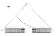
拡張形態では、第1、第2、および第3のアームは、略三角形形状を形成するように構成される。 In the extended form, the first, second, and third arms are configured to form a substantially triangular shape.
三角形形状の最小回転半径は、20mm~35mmの間にある。 The minimum turning radius of the triangular shape is between 20 mm and 35 mm.
圧縮形態では、第2のアームは第1のアームに重なるように構成され、第3のアームは第2のアームに重なるように構成される。 In the compressed form, the second arm is configured to overlap the first arm, and the third arm is configured to overlap the second arm.
第2および第3のアームは、第3のアームの内面が第2のアームの外面に対応する形状を有し、第2のアームの内面が第1のアームの外面に対応する形状を有するように形成される。 In the second and third arms, the inner surface of the third arm has a shape corresponding to the outer surface of the second arm, and the inner surface of the second arm has a shape corresponding to the outer surface of the first arm. Is formed in.
付勢部材は、第2のアームを付勢するように構成された細長い部材を含む。 The urging member includes an elongated member configured to urge the second arm.
第2のアームは、装置が拡張形態にあるとき、付勢部材の一部分に係合するように構成された凹部または突出部を含む。 The second arm includes a recess or protrusion configured to engage a portion of the urging member when the device is in an extended form.
付勢部材は、剛性部材および超多孔質ヒドロゲルに取り付けられた、弾性リーフスプリング、コイルスプリングのうちの少なくとも一方を含む。 The urging member includes at least one of an elastic leaf spring and a coil spring attached to a rigid member and a superporous hydrogel.
装置は、さらに、圧縮形態に装置を保持するように構成されたリテーナを含む。 The device further includes a retainer configured to hold the device in a compressed form.
リテーナは、装置を取り囲む包材、カプセル、またはバンドを含み、それにより、装置を圧縮形態に保持する。 The retainer comprises a packaging material, capsule, or band that surrounds the device, thereby holding the device in a compressed form.
リテーナは、胃液に曝露すると、侵食するように構成される。 Retainers are configured to erode when exposed to gastric juice.
拡張形態で所定の期間後、装置は解体するように構成される。 In the extended form, after a predetermined period of time, the device is configured to be disassembled.
装置の解体は、第1のアームからの第2および/または第3のアームの接続解除を含む。 Disassembly of the device involves disconnecting the second and / or third arm from the first arm.
第1のアームから第2および/または第3のアームが接続解除されると、第2および第3のアームは、互いに接続解除するように構成される。 When the second and / or third arm is disconnected from the first arm, the second and third arms are configured to disconnect from each other.
第1のアームはキャビティを含む。キャビティは、スリーブまたはチューブの内部によって画定される。キャビティは、受食性インサート(erodible insert)、診断手段、または電子装置を含むように構成される。受食性インサートは、医薬、診断手段、または電子装置を含み得る。 The first arm includes a cavity. The cavity is defined by the inside of the sleeve or tube. The cavity is configured to include an erotic insert, diagnostic means, or electronic device. The feeding insert may include pharmaceuticals, diagnostic means, or electronic devices.
第1のアームは開口部を含み、当該開口部を通って、胃液(gastric fluid)はキャビティに進入可能である。 The first arm includes an opening through which gastric fluid can enter the cavity.
第1のアームは、スリーブまたはチューブを含む。チューブまたはスリーブはキャビティを提供する。スリーブまたはチューブは、任意選択でスリーブまたはチューブの各端部に、1若しくはそれ以上の封止要素を含む。 The first arm includes a sleeve or tube. The tube or sleeve provides the cavity. The sleeve or tube optionally comprises one or more sealing elements at each end of the sleeve or tube.
第1のアームは、受食性配合物または診断手段などの受食性インサートを含む。 The first arm contains a feeding insert such as a feeding formulation or diagnostic means.
受食性インサートが所定の期間胃液に曝露される結果受食性インサートが侵食され、それにより前記システムが解体されるように構成されている。 As a result of the feeding insert being exposed to gastric juice for a predetermined period of time, the feeding insert is eroded, thereby disassembling the system.
第1のアームは、受食性インサート、好ましくは受食性配合物を含み、および受食性配合物はキャビティに内に配置される。 The first arm comprises a feeding insert, preferably a feeding formulation, and the feeding formulation is placed within the cavity.
封止要素は、それぞれ、スリーブまたはチューブ内へ延在するように構成された少なくとも1つの保持要素を含み、および保持要素は、受食性インサートとスリーブまたはチューブとの間に配置される。 Each sealing element comprises at least one retaining element configured to extend into the sleeve or tube, and the retaining element is disposed between the feeding insert and the sleeve or tube.
受食性インサートは保持要素に拡張力を提供し、それにより、封止要素をスリーブまたはチューブ内に保持するように構成される。受食性インサートが侵食すると、拡張力が除去され、封止要素がスリーブまたはチューブから解体されるように構成される。さらなる観点によれば、上述したようなシステムを含む胃滞留性剤形が提供され、受食性インサートは、医薬、診断手段、または電子装置を含む。 The feeding insert provides an expanding force on the holding element, thereby being configured to hold the sealing element inside the sleeve or tube. When the eroding insert erodes, the expanding force is removed and the sealing element is configured to disassemble from the sleeve or tube. In a further aspect, a gastric retention dosage form comprising the system as described above is provided, the feeding insert comprises a pharmaceutical, diagnostic means, or electronic device.
別の観点によれば、装置が提供され、装置は、第1の端部と第2の対向端部とを有する第1のアームと、第1のアームの第1の端部に枢動接続された第2のアームと、第1のアームの第2の端部に枢動接続された第3のアームと、第1のアームの第2の端部に接続された付勢部材であって、装置を圧縮形態から拡張形態へ移行させるように構成された前記付勢部材とを有し、拡張形態では、第2のアームおよび第3のアームは互いに機械的に係合されて装置を拡張形態に保持する。 According to another aspect, a device is provided, the device is pivotally connected to a first arm having a first end and a second opposed end and a first end of the first arm. A urging member connected to a second arm, a third arm pivotally connected to the second end of the first arm, and a second end of the first arm. , With said urging member configured to transition the device from a compressed form to an expanded form, in which the second arm and the third arm are mechanically engaged with each other to expand the device. Keep in shape.
別の観点によれば、胃滞留性剤形を準備する方法が提供される。この方法は、上述の装置を提供する工程と、受食性配合物、好ましくは医薬、診断手段、電子装置、またはその組み合わせを上述の装置に挿入する工程と、装置を圧縮状態に圧縮する工程と、圧縮状態の装置をリテーナ内に配置して、当該装置を摂取に好適な圧縮状態に保持する工程とを含む。 Another aspect provides a method of preparing a gastric retention dosage form. This method comprises a step of providing the above-mentioned apparatus, a step of inserting an ingestible compound, preferably a medicine, a diagnostic means, an electronic apparatus, or a combination thereof into the above-mentioned apparatus, and a step of compressing the apparatus into a compressed state. , Including a step of arranging a device in a compressed state in a retainer and holding the device in a compressed state suitable for ingestion.
さらなる観点によれば、胃滞留性剤形を準備する方法が提供される。この方法は、射出成形用の材料を提供する工程と、第1、第2、および第3のアームを含む個々の部分を射出成形する工程と、任意選択で腸溶性ポリマーによって1若しくはそれ以上のアームを被覆する工程と、好ましくは医薬、診断手段または電子装置を含む受食性配合物を第1のアームに挿入する工程と、前記第1、第2、および第3のアームを三角形の形状に接続する工程と、および任意選択で、前記三角形の形状のシステムをリテーナ内で圧縮する工程とを含む。全ての材料が、医薬的に許容される。 From a further point of view, a method of preparing a gastric retention dosage form is provided. This method comprises providing materials for injection molding, injection molding the individual parts including the first, second, and third arms, and optionally one or more with an enteric polymer. A step of covering the arm, a step of inserting a feeding compound containing preferably a medicine, a diagnostic means or an electronic device into the first arm, and a step of inserting the first, second, and third arms into a triangular shape. It comprises a step of connecting and optionally compressing the triangular shaped system in a retainer. All materials are pharmaceutically acceptable.
さらなる観点によれば、上述のような装置または上述のようなシステムを提供することを含む、活性医薬成分(active pharmaceutical)、装置、または診断手段を胃に長期間送達する方法であって、第1、第2、および第3のアームのうちの1つが、活性医薬成分、装置、または診断手段を含む、方法が提供される。 In a further aspect, a method of long-term delivery of an active pharmaceutical ingredient, device, or diagnostic instrument to the stomach, comprising providing a device as described above or a system as described above. A method is provided in which one of the first, second, and third arms comprises an active pharmaceutical ingredient, device, or diagnostic means.
さらなる観点により、上述の装置のアセンブリのための複数の部分のキットが提供される。キットは、第1、第2、および第3のアームと、付勢部材とを含む。 From a further point of view, a multi-part kit for the assembly of the above devices is provided. The kit includes first, second, and third arms and an urging member.
さらなる観点によれば、上述の装置を組み立てるためのキットが提供される。キットは、上述のような拡張形態の装置と、リテーナとを含む。あるいは、キットは、上述のような装置の第1、第2、および第3のアームと、付勢部材と、リテーナとを含む。 From a further point of view, a kit for assembling the above-mentioned device is provided. The kit includes an extended form of the device as described above and a retainer. Alternatively, the kit includes first, second, and third arms of the device as described above, an urging member, and a retainer.
説明のキットのいずれかは、さらに、好ましくは医薬、診断手段、または電子装置を含む、受食性配合物を含み得る。 Any of the kits described may further comprise a feeding compound, preferably comprising a pharmaceutical, diagnostic means, or electronic device.
本開示の教示を、ここで、以下の図面を参照して例としてのみ説明し、図面では、同様の部分は同様の参照符号によって示されている。 The teachings of the present disclosure are here provided by way of example only with reference to the following drawings, in which similar parts are indicated by similar reference numerals.
本発明は、様々な修正例および代替形態を許すが、具体的な実施形態は、図面に例として示され、および本明細書で詳細に説明される。しかしながら、具体的な実施形態の図面および詳細な説明は、本発明を開示の特定の形態に限定するものではないことを理解すべきである。それどころか、本発明は、添付の特許請求の範囲において定義されているような本発明の範囲および趣旨に入る全ての修正例、等価物、および代替例を網羅するものとする。 The present invention allows various modifications and alternatives, but specific embodiments are shown by way of illustration in the drawings and are described in detail herein. However, it should be understood that the drawings and detailed description of the specific embodiments do not limit the invention to the particular embodiments disclosed. On the contrary, the invention shall cover all modifications, equivalents, and alternatives that fall within the scope and intent of the invention as defined in the appended claims.
定義
下記の本明細書の語句表現は、当業者に公知であるような定義および説明と共通の意味を暗示する。しかしながら、下記のような、本開示の概念において理解されるべきいくつかの用語がある:
Definitions The terms and phrases used herein imply common meaning with definitions and descriptions as known to those of skill in the art. However, there are some terms that should be understood in the concepts of this disclosure, such as:
「胃滞留性装置」は、ある期間、胃に滞留することができる機械的な装置を指す。本開示の装置は、医薬有効成分、診断手段、または電子装置を、例えば対象内へ導入する手段を提供する。本開示の例では、これは、受食性インサートの形態にある。 "Stomach retention device" refers to a mechanical device that can stay in the stomach for a period of time. The apparatus of the present disclosure provides a means of introducing a pharmaceutical active ingredient, a diagnostic means, or an electronic device, for example, into a subject. In the examples of the present disclosure, this is in the form of a feeding insert.
「胃内滞留システム」、または「胃滞留性送達システム」、または「GRS」は、受食性インサートまたは装置の時限解体の他の手段を含む、胃滞留性装置を指す。 "Stomach retention system", or "gastric retention delivery system", or "GRS" refers to a gastric retention device, including a feeding insert or other means of timed disassembly of the device.
本明細書では、「受食性インサート」は、胃環境への曝露、またはそのシミュレーションした方法に基づいて、分解、溶解してダウンサイジングおよび/または崩壊できる、いずれかの配合物、材料、または組成物である。 As used herein, a "feedable insert" is any formulation, material, or composition that can be decomposed, dissolved, downsized and / or disintegrated based on exposure to the gastric environment or a simulated method thereof. It is a thing.
「1つまたは複数の胃滞留性剤形」(gastroretentive dosage form(s):GRDF、または複数形ではGRDFs)は、生物活性剤または診断用配合物の制御放出のプラットフォームを提供するために、胃の範囲内に滞留する剤形を指す。本開示では、胃滞留性剤形は、例えば医薬有効成分、診断手段、または電子装置を含む胃内滞留システムを指す。本明細書では、GRDFは、胃での停留を延長するための経口医薬、ならびに剤形とも呼ばれる。 The "gastroretentive dose form (s): GRDF, or GRDFs in the plural) is used to provide a platform for controlled release of bioactive agents or diagnostic formulations in the stomach. Refers to a dosage form that stays within the range of. In the present disclosure, the gastric retention dosage form refers to a gastric retention system comprising, for example, a pharmaceutical active ingredient, a diagnostic means, or an electronic device. As used herein, GRDF is also referred to as an oral drug for prolonging gastric retention, as well as a dosage form.
「胃内停留(Gastric retention)」は、胃滞留性であるとはみなされない自由形態でまたは胃腸(gastro-intestinal:GI)送達ビヒクル内で送達されるときに胃内に停留されるであろう時間よりも長い期間の、胃内での作用物質、例えば医薬、診断手段、または電子装置の維持または保持である。胃滞留性は、胃からの通常の排出時間よりも長い期間、例えば、約2時間超、場合によっては約3時間超、および多くの場合約4、6、8または10時間超の、胃内での停留によって特徴付けられる。胃滞留性は、一般に、約3、4、6、8、10時間、または時には18時間、さらには約21時間までの、またはそれよりも長い期間の、胃内での停留を意味する。胃滞留性はまた、少なくとも4、6、8、10、12、18、24、48、72、96、120、144、168時間、またはそれよりも長い所定の期間の胃内での停留も意味する。 A "Gastric retention" will be retained in the stomach in free form that is not considered to be gastric retention or when delivered within a gastro-intestinal (GI) delivery vehicle. Maintenance or retention of agents in the stomach, such as drugs, diagnostic means, or electronic devices, for a period of time longer than an hour. Gastric retention is intragastric for longer than normal gastric emptying time, eg, more than about 2 hours, sometimes more than about 3 hours, and often more than about 4, 6, 8 or 10 hours. Characterized by a stagnation at. Gastric retention generally means retention in the stomach for about 3, 4, 6, 8, 10 hours, or sometimes 18 hours, and even up to about 21 hours or longer. Gastric retention also means retention in the stomach for at least 4, 6, 8, 10, 12, 18, 24, 48, 72, 96, 120, 144, 168 hours, or longer for a given period of time. do.
「胃腸停留(Gastro-intestinal retention)」は、GI停留性であるとはみなされない自由形態または胃腸(gastro-intestinal:GI)送達ビヒクル内で送達されたときにGI内に停留されたであろう時間よりも長い期間の、胃腸管[本明細書ではgastrointestinal track:「GI」]内での作用物質、例えば医薬、診断手段、電子装置、またはマイクロチップの維持または保持である。GI停留性は、GIからの通常の排出時間よりも長い、例えば約24時間超、48、72、96、120、144、168時間、またはそれよりも長い期間の、GI内での停留によって特徴付けられる。 A "Gastro-intestinal retention" would have been retained in a GI when delivered in a free form or gastro-intestinal (GI) delivery vehicle that is not considered to be GI retention. Maintenance or retention of an agent, such as a pharmaceutical, diagnostic instrument, electronic device, or microchip, in the gastrointestinal tract [gastrointestinal track: "GI" herein] for a longer period of time. GI retention is characterized by retention within the GI for longer than normal discharge time from the GI, eg, greater than about 24 hours, 48, 72, 96, 120, 144, 168 hours, or longer. Attached.
本明細書では、「飲み込むのに好適な」サイズは、ヒトまたは動物のいずれかによって安全に飲み込まれることができるいずれかのサイズおよび/または形状である。他に特に規定がなければ、停留用のサイズ、または胃若しくは幽門弁などの解剖学的構造への言及は、ヒトを参照としている。 As used herein, a "suitable for swallowing" size is any size and / or shape that can be safely swallowed by either humans or animals. Unless otherwise specified, references to anatomical structures such as the size for retention or gastric or pyloric valves refer to humans.
本明細書では、「本体」は、多かれ少なかれ拘束されるか、またはそうでなければ平行移動または回転によって一緒に動くように接続される部分または材料の、いずれかの集合を含むことを意味する。 As used herein, "body" is meant to include any set of parts or materials that are more or less constrained or otherwise connected to move together by translation or rotation. ..
本明細書では、「賦形剤」は、組成物またはインサートに所望の特徴を与えるために、本開示の組成の配合物(これに限定されるものではないが、インサート、本体の部分-アームなどを含む)において使用される成分、または成分の混合物を指す。本明細書では、用語「医薬的に許容される」は、健全な医学的判断の範囲内において、妥当なベネフィット/リスク比に釣り合う所望の治療持続時間にわたって、過度の毒性、刺激、アレルギー反応、または他の問題となる合併症のない、人間および動物の組織との接触に好適な、化合物、材料、組成物、成形体(compacts)、塩、および/または剤形を指す。いくつかの実施形態では、用語「医薬的に許容される」は、動物、およびより詳細にはヒトでの使用に対し、FDAのInactive ingredient Database、または米国薬局方(U.S.Pharmacopeia)に挙げられているものなど、連邦政府または州政府の規制機関、または一般に認識されている他の国際薬局方によって承認されていることを意味する。様々な医薬的に許容される賦形剤が使用され得る。いくつかの実施形態では、医薬的に許容される賦形剤は、これに限定されるものではないが、アルカリ剤、安定剤、接着剤、分離剤、コーティング剤、外相成分(exterior phase component)、制御放出成分、溶媒、界面活性剤、湿潤剤、緩衝剤、充填剤、緩和薬(emollient)、またはこれらの組み合わせとし得る。賦形剤は、本明細書で説明したものに加えて、限定されるものではないが、Remington:The Science and Practice of Pharmacy,21st ed.(2005)に挙げられている賦形剤を含み得る。本明細書の特定の分類の賦形剤(例えば、「溶媒」)を含むことは、賦形剤の役割を限定するのではなく、明示することを意図する。特定の賦形剤は、複数の分類に入り得る。 As used herein, an "excipient" is a formulation of the composition of the present disclosure, but not limited to, an insert, a portion of the body-arm, in order to give the composition or insert the desired characteristics. Including), or a mixture of ingredients. As used herein, the term "pharmaceutically acceptable" refers to excessive toxicity, irritation, allergic reactions, over a desired duration of treatment that is commensurate with a reasonable benefit / risk ratio, within sound medical judgment. Or refers to compounds, materials, compositions, compacts, salts, and / or dosage forms that are suitable for contact with human and animal tissues without other problematic complications. In some embodiments, the term "pharmaceutically acceptable" refers to the FDA's Inactive Ingredient Database, or the United States Pharmacopeia (US Pharmacopoeia), for use in animals, and more specifically in humans. It means that it is approved by the regulatory body of the federal or state government, or other generally recognized international pharmacopoeia, such as those listed. Various pharmaceutically acceptable excipients can be used. In some embodiments, pharmaceutically acceptable excipients are, but are not limited to, alkaline agents, stabilizers, adhesives, separating agents, coating agents, exterior phase components. , Controlled release components, solvents, surfactants, wetting agents, buffers, fillers, emollients, or combinations thereof. Excipients, in addition to those described herein, are, but are not limited to, Remington: The Science and Practice of Pharmacy, 21st ed. It may include the excipients listed in (2005). The inclusion of a particular class of excipients (eg, "solvents") herein is intended to articulate, rather than limit, the role of the excipient. Certain excipients can fall into multiple categories.
本明細書では、「経口医薬」は、構成要素、医薬的に許容される材料で構成される、経口で投与されるものである。 As used herein, an "oral drug" is one that is orally administered, consisting of components, pharmaceutically acceptable materials.
本明細書では、「診断手段」または「医薬有効成分(active pharmaceutical ingredient:API)」は、当業界で認識されているような胃内停留に関連するいずれかの物質を含むことを意図する。多様なAPIs(治療、診断手段、または他の方法で有益である)が、本開示の観点に従って用いられることがある。胃内停留性送達に関連するいずれかの作用物質、例えばAPIまたは診断手段が、本明細書に含まれることを意図する。関連のAPIsは、これに限定されるものではないが、以下のものを含む:胃内で局所的に作用するAPIs;胃内で主に吸収されるAPIs;アルカリ性のpHにおいて可溶性に乏しいAPIs;吸収窓の狭いAPIs;患者アドヒアランスの少ないAPIs;GI管から迅速に吸収されるAPIs;大腸内で分解するAPIs;および腸内細菌(colonic microbes)を乱すAPIs。診断手段は、医用撮像システム(例えばスキャナー、MRI、カメラ、胃刺激装置(gastric stimulator)、放射性標識剤などを含む。電子装置は、マイクロチップ、撮像システム、送信器などを含む。 As used herein, the "diagnostic means" or "active pharmaceutical ingredient (API)" is intended to include any substance associated with gastric retention as recognized in the art. A variety of APIs (which are beneficial in therapeutic, diagnostic, or other methods) may be used in accordance with the viewpoints of the present disclosure. It is intended that any agent associated with gastric retention delivery, such as API or diagnostic means, is included herein. Related APIs include, but are not limited to, APIs that act locally in the stomach; APIs that are predominantly absorbed in the stomach; APIs that are poorly soluble at alkaline pH; APIs with a narrow absorption window; APIs with low patient adherence; APIs that are rapidly absorbed from the GI tube; APIs that decompose in the large intestine; and APIs that disturb intestinal bacteria (colonic microbes). Diagnostic means include medical imaging systems such as scanners, MRIs, cameras, gastric simulators, radiolabels and the like. Electronic devices include microchips, imaging systems, transmitters and the like.
本明細書では、用語「治療剤」、または「活性剤」、「有効分(active)」、または「医薬有効成分」とも呼ばれるものは、疾患、障害、または他の臨床的に認識された容態(condition)を治療するために、または予防目的で対象に投与される作用物質を指し、および疾患、障害、または容態を治療するおよび/または予防するために、対象の身体に対して臨床的に有意な効果を有する。医薬有効成分(active pharmaceutical ingredients:APIs)は、限定されるものではないが、以下のものを含む:プロクロルペラジンエディシレート、硫酸第一鉄、アルブテロール、アミノカプロン酸、塩酸メカミラミン、塩酸プロカインアミド、硫酸アンフェタミン、塩酸メタンフェタミン、塩酸ベンズフェタミン、硫酸イソプロテレノール、ビスマス塩、コルヒチン、塩酸フェンメトラジン、塩化ベタネコール、塩化メタコリン、塩酸ピロカルピン、硫酸アトロピン、臭化スコポラミン、ヨウ化イソプロパミド、塩化トリジヘキセチル、塩酸フェンホルミン、メトホルミン、塩酸メチルフェニデート、テオフィリンコリネート(theophylline cholinate)、塩酸セファレキシン、ジフェニドール、塩酸メクリジン、マレイン酸プロクロルぺラジン(prochlorperazine maleate)、フェノキシベンザミン、マレイン酸チエチルペラジン、アニシンジオン、ジフェナジオンエリトリチル四硝酸塩(diphenadione erythrityl tetranitrate)、ジゴキシン、イソフルロフェート、アセタゾールアミド、ニフェジピン、メタゾラミド、ベンドロフルメチアジド、クロルプロパミド、グリピジド、グリブリド、グリクラジド、4-アミノピリジントブタミド(aminopyridine tobutamide)、クロルプロアミド(chlorproamide)、トラザミド、アセトヘキサミド、トログリタゾン、オルリスタット、ブプロピオン、ネファゾドン、トラザミド、酢酸クロルマジノン、フェナグリコドール、アロプリノール、アスピリンアルミニウム、メトトレキサート、アセチルスルフィソキサゾール、ヒドロコルチゾン、酢酸ヒドロコルチコステロン(hydrocorticosterone acetate)、酢酸コルチゾン、デキサメタゾン、およびその誘導体、例えばベタメタゾン、トリアムシノロン、メチルテストステロン、17-β-エストラジオール、エチニルエストラジオール、エチニルエストラジオール3-チルエーテル、プレドニゾロン、17-β-ヒドロキシプロゲステロンアセタート、19-ノル-プロゲステロン、ノルゲストレル、ノルエチンドロン、ノルエチステロン、ノルエチエデロン(norethiederone)、プロゲステロン、ノルゲステロン、ノルエチノドレル、テルフェナジン、フェキソフェナジン、アスピリン、アセトアミノフェン、インドメタシン、ナプロキセン、フェノプロフェン、スリンダク、インドプロフェン、ニトログリセリン、二硝酸イソソルビド(isosorbide dinitrate)、プロプラノロール、チモロール、アテノロール、アルプレノロール、シメチジン、クロニジン、イミプラミン、レボドパ、カルビドパ、セレギリン、クロルプロマジン、メチルドパ、ジヒドロキシフェニルアラニン、グルコン酸カルシウム、ケトプロフェン、イブプロフェン、セファレキシン、エリスロマイシン、ハロペリドール、ゾメピラク、乳酸第一鉄、ビンカミン、フェノキシベンザミン、ジルチアゼム、ミルリノン、カプトロプリル(captropril)、マンドール(mandol)、クアンベンズ(quanbenz)、ヒドロクロロチアジド、ラニチジン、フルルビプロフェン、フェンブフェン、フルプロフェン(fluprofen)、トルメチン、アルクロフェナック、メフェナム酸(mefenamic)、フルフェナム酸(flufenamic)、ジフニナル(difuninal)、ニモジピン、ニトレンジピン、ニソルジピン、ニカルジピン、フェロジピン、リドフラジン、チアパミル、ガロパミル、アムロジピン、ミオフラジン(mioflazine)、リシノプリル、エナラプリル、カプトプリル、ラミプリル、エナラプリラト(enalaprilat)、ファモチジン、ニザチジン、スクラルファート、エチンチジン、テトラトロール(tetratolol)、ミノキシジル、クロルジアゼポキシド、ジアゼパム、アミトリプチリン、およびイミプラミン、およびこれらの活性剤の医薬塩。さらなる例は、タンパク質およびペプチドであり、これに限定されるものではないが、シクロスポリン、例えばシクロスポリンA、インスリン、グルカゴン、甲状腺刺激ホルモン(thyroid stimulating hormone)、上皮小体および下垂体ホルモン、カルシトニン、レニン、プロラクチン、コルチコトロピン、甲状腺刺激ホルモン(thyrotropic hormone)、卵胞刺激ホルモン、絨毛性ゴナドトロピン、ゴナドトロピン放出ホルモン、ウシソマトトロピン、ブタソマトトロピン、オキシトシン、バソプレシン、プロラクチン、ソマトスタチン、リプレッシン、パンクレオザイミン、黄体化ホルモン、LHRH、インターフェロン、インターロイキン、成長ホルモン、例えばヒト成長ホルモン、ウシ成長ホルモン、およびブタ成長ホルモン、生殖能抑制因子(fertility inhibitor)、例えばプロスタグランジン、生殖能促進因子(fertility promoter)、成長因子、およびヒト膵臓ホルモン放出因子を含む。公知の治療剤の追加的な例のリストは、例えば、米国薬局方(United States Pharmacopeia:USP)、Goodman and Gilman's The Pharmacological Basis of Therapeutics,10th Ed.,McGraw Hill,2001;Katzung,B.(ed.) Basic and Clinical Pharmacology,McGraw-Hill/ Appleton & Lange;8th edition (September 21,2000);Physician's Desk Reference (Thomson Publishing)、および/またはThe Merck Manual of Diagnosis and Therapy,17th ed.(1999)、またはそれに続く出版the 18th ed (2006)、Mark H.Beers and Robert Berkow (eds.),Merck Publishing Group、または、動物の場合には、The Merck Veterinary Manual,9th ed.,Kahn,C.A.(ed.),Merck Publishing Group,2005;およびアメリカ食料医薬品局(the United States Food and Drug Administration:F.D.A.)によって出版された「Approved Drug Products with Therapeutic Equivalence and Evaluations」(「Orange Book」)に見出され得る。ヒトでの使用に承認された薬物の例は、FDAによって、21 C.F.R.§§ 330.5,331~361、および440~460下に挙げられており、この参照により本明細書に組み込まれる;獣医学での使用に承認された薬物の例は、FDAによって、21 C.F.R.§§ 500~589下に挙げられており、この参照により本明細書に組み込まれる。いくつかの実施形態では、治療剤は小分子である。いくつかの実施形態では、治療剤は、1若しくはそれ以上の治療剤である可能性がある。 As used herein, the term "therapeutic agent," or "active agent," "active," or "pharmaceutical active ingredient," is a disease, disorder, or other clinically recognized condition. Refers to an agent administered to a subject to treat (condition) or for prophylactic purposes, and clinically to the subject's body to treat and / or prevent a disease, disorder, or condition. Has a significant effect. Pharmaceutical active ingredients (APIs) include, but are not limited to, prochlorperazine edicylate, ferrous sulfate, albuterol, aminocaproic acid, metformin hydrochloride, prokineamide hydrochloride. , Amphetamine sulfate, methanefetamine hydrochloride, benzfetamine hydrochloride, isoproterenol sulfate, bismuth salt, corhitin, fenmethrazine hydrochloride, betanecol chloride, metacholine chloride, pyrocarpine hydrochloride, atropin sulfate, scopolamine bromide, isopropamide iodide, tridihexetyl chloride, fen hydrochloride Formin, metformin, methylphenylate hydrochloride, theophylline cholinete, cephalexin hydrochloride, diphenidol, mecridin hydrochloride, prochlorperazine maleate, phenoxybenzamine, phenoxybenzamine, thiethylperazine maleate. Diphenadione erythrityl terranitrate, digoxin, isoflulofate, acetazoleamide, nifedipine, metazolamide, bendroflumethiazide, chlorpropamide, gripidide, glybrid, glycladide, 4-aminopyridinetobutamide. , Chlorproamide, trazamide, acethexamide, troglycazone, orristat, bupropion, nephazodon, trazamide, chlormaginone acetate, phenaglyxidol, alloprinol, aspirin aluminum, metforminate, acetylsulfisoxazole, hydrocortisone, hydrocortisone acetate Hydrocorticostranee acetate, cortisone acetate, dexamethasone, and derivatives thereof such as betamethasone, triamsinolone, methyltestosterone, 17-β-estradiol, ethynyl estradiol, ethynyl estradiol 3-tyl ether, prednisolone, 17-β-hydroxyprogesterone. 19-Nor-progesterone, norgestrel, noruetindron, noruethisterone, norethiederone ), Progesterone, Norgesterone, Norethinodrel, Terphenazine, Fexophenazine, Aspirin, Acetaminophen, Indomethacin, Naproxene, Phenoprofen, Thrindac, Indoprofen, Nitroglycerin, Isosorbide dinitrate, Propranolol, Propranolol , Alprenolol, simethidine, chronidine, imipramine, levodopa, carvidopa, selegiline, chlorpromazine, methyldopa, dihydroxyphenylalanine, calcium gluconate, ketoprofen, ibuprofen, cephalexin, erythromycin, haloperidol, zomepyrac, ferrous lactate, vincamamine, phenoxyben , Diltiazem, millinone, captropril, mandol, quanbenz, hydrochlorothiazide, lanitidin, flurubiprofen, fembufen, fluprofen, tolmethin, alcrophenac, mephenamic acid , Flufenamic, difuninal, nimodipin, nitrangepin, nisoldipine, nicardipine, ferrodipine, lidofrazin, thiapamil, galopamil, amlogipin, miofladine, miofladine, mioflazine, lysinopril, enalapril Medicinal salts of nizatidine, scralfert, ethintidine, tetratrol, minoxidil, chlordiazepoxide, diazepam, amytriptyrin, and imipramine, and activators thereof. Further examples are, but are not limited to, proteins and peptides, such as, but not limited to, cyclosporin A, insulin, glucagon, thyroid stimulating hormone, epithelial and pituitary hormones, calcitonin, renin. , Prolactin, corticotropin, thyrotropic hormone, follicular stimulating hormone, chorionic gonadotropin, gonadotropin-releasing hormone, bovine somatotropin, porcine somatotropin, oxytocin, vasopressin, prolactin, somatostatin, lipresin LHRH, interferon, interleukin, growth hormones such as human growth hormone, bovine growth hormone, and porcine growth hormone, fertility indicator such as prostaglandin, fertility promoter, growth factor, And human pancreatic hormone-releasing factors. A list of additional examples of known therapeutic agents is, for example, United States Pharmacopeia (USP), Goodman and Gilman's The Pharmaceuticals of Therapeutics, 10. , McGraw Hill, 2001; Katzung, B. et al. (ed.) Basic and Clinical Pharmacology,McGraw-Hill/ Appleton & Lange;8th edition (September 21,2000);Physician's Desk Reference (Thomson Publishing)、および/またはThe Merck Manual of Diagnosis and Therapy,17th ed. (1999), or subsequent publication the 18th ed (2006), Mark H. et al. Beers and Robert Berkow (eds.), Merck Publishing Group, or, in the case of animals, The Merck Vintage Manual, 9th ed. , Kahn, C.I. A. (Ed.), Merck Publishing Group, 2005; and "Approved Drug Technology" published by the United States Food and Drug Administration (FDA). ") Can be found. Examples of drugs approved for use in humans are described by FDA in 21 C.I. F. R. §§ 330.5, 331-361, and 440-460 are listed below and are incorporated herein by reference; examples of drugs approved for use in veterinary medicine are 21 C by the FDA. .. F. R. §§ 500-589 listed below and incorporated herein by reference. In some embodiments, the therapeutic agent is a small molecule. In some embodiments, the therapeutic agent may be one or more therapeutic agents.
本明細書では、「胃内停留終点」は、「時間依存性解体機構」、または「時限解体」、または「時限ダウンサイジング」に依存し、ここでは、装置は、例えば、以下:閉回路(closed circuit)の開放および/または関節式本体の解体;および/または介在(mediating)スリーブ、チューブ、アームと、別のアーム、またはその枢動接続部、例えばヒンジとの間の接続部の切り離し;および/または受食部の著しい医薬放出侵食のうちのいずれか1若しくはそれ以上によって、単一ユニットとしてのその機械的一体性を失う。 As used herein, the "end of gastric retention" depends on a "time-dependent dismantling mechanism", or "timed dismantling", or "timed downsizing", where the device is, for example, the following: closed circuit ( Opening of the closed cycle and / or dismantling of the articulated body; and / or disconnection of the connecting sleeve, tube, arm and the other arm, or its pivotal connection, such as the hinge; And / or any one or more of the significant drug release erosion of the predator loses its mechanical integrity as a single unit.
本明細書では、「医薬放出」は、胃環境に曝露されると、分解、溶解、崩壊などを生じるように設計される、いずれかの配合物を含むことを意味する。医薬配合物は、1若しくはそれ以上の治療剤または医薬有効成分を含み得る。 As used herein, "pharmaceutical release" is meant to include any formulation designed to undergo degradation, lysis, disintegration, etc. when exposed to the gastric environment. The pharmaceutical formulation may include one or more therapeutic agents or pharmaceutical active ingredients.
本明細書では、「胃液受食性包材」は、胃内へ送達するために医薬を包装するためのいずれかの標準的な手段、例えばカプセルを含むことを意味する。この手段は、胃環境に到達すると数分以内に、侵食、溶解、および/または崩壊することができる。 As used herein, "gastric juice-feeding packaging material" is meant to include any standard means for packaging a drug for delivery into the stomach, such as a capsule. This means can erode, dissolve, and / or disintegrate within minutes of reaching the gastric environment.
本明細書では、用語「アーム」または「複数のアーム」は、長さ、幅、および厚さを含み、および胃内停留に好適なサイズの装置を達成するのを支援する、いずれかの構造を含む。いくつかの実施形態では、各アームの長さは、約少なくとも1.5、または少なくとも2.0、または少なくとも2.5、または約2.5~約3.0、または多くとも3.0、または多くとも2.8、または多くとも2.7、または多くとも2.6である。本明細書で説明するような胃滞留性装置の少なくとも1つのアームは、活性医薬成分、診断手段、電子装置などを保持する。例えば少なくとも1つのアームは、受食性インサートまたは医薬タブレット(1若しくはそれ以上のAPIs、診断手段、電子装置、賦形剤、および/またはポリマーを含む)を保持するように構成されているキャビティを内部に画成することがある。 As used herein, the term "arm" or "multiple arms" includes any structure that includes length, width, and thickness and assists in achieving a device of suitable size for gastric retention. including. In some embodiments, the length of each arm is about at least 1.5, or at least 2.0, or at least 2.5, or about 2.5 to about 3.0, or at most 3.0. Or at most 2.8, or at most 2.7, or at most 2.6. At least one arm of a gastric retention device as described herein holds an active pharmaceutical ingredient, diagnostic means, electronic device, and the like. For example, at least one arm contains a cavity configured to hold a feeding insert or pharmaceutical tablet, including one or more APIs, diagnostic instruments, electronic devices, excipients, and / or polymers. May be imaged.
本明細書では、用語「ヒンジアセンブリ」は、2つ以上の構造間、例えば、アーム間の相対的な枢動運動を可能にするように適合されたいずれかの機構を含む。ヒンジアセンブリは、1つの一体部分(例えば、一体丁番)を含んでも、または従来の意味で組み立てられる1若しくはそれ以上の部分を含んでもよい。ヒンジアセンブリは、胃内である期間の耐久性があり、および折り畳まれた形態および拡張形態の双方において、1若しくはそれ以上のアームに取り付けられる。ヒンジアセンブリは、予め決められた時点で、または機械的事象が発生すると、1若しくはそれ以上のアームから係合解除することができる。 As used herein, the term "hinge assembly" includes any mechanism adapted to allow relative pivotal movement between two or more structures, eg, arms. The hinge assembly may include one integral part (eg, an integral hinge), or may include one or more parts assembled in the conventional sense. The hinge assembly is durable for a period of time in the stomach and is attached to one or more arms in both folded and expanded forms. The hinge assembly can be disengaged from one or more arms at predetermined times or in the event of a mechanical event.
本明細書では、用語「機械的事象」は、経時的に、または別の材料または流体、例えば、体内で胃液に接触すると、1若しくはそれ以上の構造の物理的特性を変化させるいずれかの事象を含む。吸収、溶解、融解、分解、侵食などが、機械的事象の全ての例である。 As used herein, the term "mechanical event" is any event that changes the physical properties of one or more structures over time or upon contact with another material or fluid, such as gastric juice in the body. including. Absorption, dissolution, melting, decomposition, erosion, etc. are all examples of mechanical events.
本明細書では、「受食性」材料は、例えば胃環境または胃液など、特定の環境に導入されると、または特定の材料または流体に接触すると、分解、溶解、崩壊、またはダウンサイジングする材料で構成されたいずれかの1若しくはそれ以上のユニットを含む。 As used herein, a "feedable" material is a material that decomposes, dissolves, disintegrates, or downsizes when introduced into a particular environment, such as a gastric environment or gastric juice, or upon contact with a particular material or fluid. Includes any one or more of the configured units.
本明細書では、用語「圧縮形態」および「折り畳まれた形態」は、同じ意味で使用され、および胃滞留性装置が飲み込むのに好適なサイズを有する、摂取前の状態を指す。 As used herein, the terms "compressed form" and "folded form" are used interchangeably and refer to a pre-ingestion state in which the gastric retention device has a size suitable for swallowing.
本明細書では、用語「拡張形態」は、胃滞留性装置が胃内に停留できるようにし(胃内停留)、および幽門弁の通過を防止する状態にある、摂取後の状態である。 As used herein, the term "extended form" is a post-ingestion state in which the gastric retention device is in a state of being able to stay in the stomach (gastric retention) and preventing the passage of the pyloric valve.
本明細書では、用語「胃液に曝露すると」または「シミュレーションした胃条件下」は、特に明示されない限り、文字通りに取られるか、または必要な場合には、好適なモデルに基づくことを意味する。そのような好適なモデルの一例は、37℃において、2~5RPMで400mLの0.01N HCl、pH2および任意選択でキサンタンガム0.125gr/Lを有する回転ボトル装置(rotating bottle apparatus)を含む。
As used herein, the terms "when exposed to gastric juice" or "simulated gastric conditions" mean taken literally or, where necessary, based on a suitable model, unless otherwise stated. An example of such a suitable model includes a rotating bottle apparatus with 400 mL 0.01N HCl,
本明細書では、用語「医薬的に許容される」は、本開示に従って使用されるときに、身体的にまたは他の点で容認できないものではない材料を指す。例えば、用語「医薬的に許容されるキャリア」は、容認できない生理学的影響を引き起こさずに、または組成物の他の構成成分と容認できない方法で相互作用せずに、組成物に組み込まれて患者に投与され得る材料を指す。そのような医薬的に許容される材料は、一般に、毒性および製造試験の必要な基準を満たしており、および米国食品医薬品局(U.S.Food and Drug Administration)によって、好適な不活性(inactive)成分として特定された材料を含む。 As used herein, the term "pharmaceutically acceptable" refers to material that is not physically or otherwise unacceptable when used in accordance with the present disclosure. For example, the term "pharmaceutically acceptable carrier" is incorporated into a composition without causing unacceptable physiological effects or interacting with other components of the composition in an unacceptable manner. Refers to materials that can be administered to. Such pharmaceutically acceptable materials generally meet the required criteria for toxicity and manufacturing testing, and are suitable for Inactive by the US Food and Drug Administration (US Food and Drug Administration). ) Includes the material specified as an ingredient.
本明細書では、幾何学的な用語、形状、および/または向きに関するいずれかの用語は、別段の定義または指示がない限り、主題に対し当業者によって理解されるように特徴付けられることが可能な範囲でそのような用語の数学的な定義と一致することを示し、およびそのような用語の数学的な定義に絶対的に一致することを要求しないと理解される。幾何学的な用語、形状、および/または向きに関するそのような用語の例は、これに限定されるものではないが:形状(例えば、丸い、正方形、円形/円、方形(rectangular)/長方形(rectangle)、三角形状(triangular)/三角形、シリンダー状/シリンダー、楕円形/楕円、(n)多角形状/(n)多角形、頂点など);角度向き(例えば直角、直交、平行、垂直、水平、同一直線上など);輪郭および/またはトラジェクトリー(例えば、平面/平面的な、同一平面上、半球状、四半球状(semi-hemispherical)、線/線形、双曲線、放物線、平らな、湾曲した、直線、弓状、正弦波、接線/接線方向など);表面および/またはバルク材特性、空間/時間解体能、分布(例えば、滑らか、反射性、透明、クリア、不透明、剛性、不透過性、均一(に)、不活性(inert)、非湿潤性、不溶性、安定、不変、一定、均質など)を記述する用語;ならびに当業者に明白である多くの他のものを含む。一例として、本明細書で「正方形」であると説明されるシステムは、完全に平面的または線形でありおよび正確に90度の角度で交差する面または辺を有する物品を必要とするのではなく(実際、そのような物品は、数学的抽象化としてのみ存在し得る)、むしろ、そのような物品の形状は、一般に当業者によって理解されるような、または具体的に説明されるような、説明した製作技術で達成可能でありおよび達成される範囲で、数学的に定義されるように、ほぼ「正方形」と解釈されるべきである。 As used herein, any term relating to geometrical terms, shapes, and / or orientations can be characterized as understood by one of ordinary skill in the art for the subject unless otherwise defined or indicated. It is understood to show that it is consistent with the mathematical definition of such a term to the extent that it does not require an absolute match with the mathematical definition of such term. Examples of such terms regarding geometric terms, shapes, and / or orientations are, but are not limited to: shapes (eg, round, square, circular / circular, rectangular / rectangular (eg, round, square, circular / circular, rectangular / rectangular). (Rectangle), triangle / triangle, cylinder / cylinder, ellipse / ellipse, (n) polygon / (n) polygon, apex, etc.); angular orientation (eg, orthogonal, orthogonal, parallel, vertical, horizontal) Contours and / or trajectories (eg, planar / planar, coplanar, hemispherical, semi-hemical), line / linear, bi-curved, parabolic, flat, curved. , Straight, arched, sinusoidal, tangent / tangential, etc.); Surface and / or bulk material properties, spatial / temporal dismantling ability, distribution (eg, smooth, reflective, transparent, clear, opaque, rigid, opaque) , Uniform, inactive, non-wetting, insoluble, stable, invariant, constant, homogeneous, etc.); and includes many others that are obvious to those skilled in the art. As an example, a system described herein as a "square" does not require an article that is perfectly planar or linear and has faces or sides that intersect at exactly 90 degree angles. (In fact, such articles can only exist as a mathematical abstraction), rather, the shape of such articles is as generally understood by one of ordinary skill in the art, or as specifically described. To the extent achievable and achievable with the fabrication techniques described, it should be interpreted as approximately "square" as defined mathematically.
以下の説明では、用語「収納する」、「含む」、「受け入れられた」(例えば、受食性インサートは、キャビティに受け入れられていると説明される)は、全て、同義に使用され、および「~内に保持される」意味で使用される。当業者は、これらの用語が、範囲になんら変更なく、同じ意味で使用されることを理解する。 In the following description, the terms "contain", "contain", "accepted" (eg, a feeding insert is described as being accepted in the cavity) are all used interchangeably and ". Used to mean "held within". Those skilled in the art will understand that these terms are used interchangeably without any change in scope.
本明細書では、用語「から構成される」および「で形成される」は、同じ意味で使用され、および構成要素が特定の材料から作製されるかまたはそうでなければそれを含むことを意味することを意図する。用語「実質的に」は、特定されるものが、程度においてかなりまたは大部分であるが、必ずしも完全にではない意味することを意図する。用語法は、上述の語、それらの派生物、および同様の意味の語を含む。 As used herein, the terms "consisting of" and "formed by" are used interchangeably and mean that a component is made from or otherwise included in a particular material. Intended to do. The term "substantially" is intended to mean that what is specified is, to a large extent, to a large extent, but not necessarily complete. Terminology includes the words mentioned above, their derivatives, and words with similar meanings.
本明細書では、用語「開放力」は、例えば図20Aおよび図20BのF1に図示するような、拡張形態へと開放する、または少なくとも拡張状態の構成の方へ10%だけ進む、圧縮状態の装置による付勢する力を説明するものとする。開放力は、剛性表面で測定されるような、胃内停留性装置を圧縮状態に維持するのに必要な最小力を導き出すことによって、計算される。 As used herein, the term "opening force" is used in a compressed state, for example, as illustrated in F1 of FIGS. 20A and 20B, opening to an expanded form, or at least advancing 10% towards an expanded state configuration. Explain the urging force of the device. The open force is calculated by deriving the minimum force required to keep the gastric retention device in a compressed state, as measured on a rigid surface.
本明細書では、用語「剛性」は、力が加えられるにもかかわらず、サイズの変化に抵抗する能力を表す装置の特性である。この場合、装置が、例えば図20にF2で図示するような最小力の印加下で、拡張状態の胃内停留性装置のいずれかの寸法の10%の減少まで抵抗できる程度である。 As used herein, the term "rigidity" is a characteristic of a device that describes the ability to withstand changes in size despite the application of force. In this case, the device can withstand a 10% reduction in any dimension of the dilated gastric retention device, for example under the application of the minimum force as shown in F2 in FIG.
装置の説明
本開示は、胃滞留性装置を含む胃滞留性送達システム、およびその使用方法を提供する。胃滞留性送達システムは、圧縮形態で飲み込まれ、胃内で拡張し、所定の期間、その意図した機能を果たし、およびその期間の最後に、または機械的事象が発生すると、より小さい構成要素へと解体して、最終的に胃の幽門弁を通過する。
Description of the Device The present disclosure provides a gastric retention delivery system including a gastric retention device and a method of using the same. The gastric retention delivery system is swallowed in compressed form, expands in the stomach, performs its intended function for a predetermined period of time, and at the end of that period, or when a mechanical event occurs, to a smaller component. And finally pass through the pyloric valve of the stomach.
胃から出た後、胃滞留性送達システムの解体された構成要素は、胃腸系の残りの部分を安全に通過し、および身体から放出され、および/または腸のpH条件によって徐々に侵食される。いくつかの例では、解体された構成要素は、完全に崩壊するように構成される。他の例では、解体された構成要素は、身体から排泄されるのに必要な程度まで崩壊するように構成される。さらに他の例では、胃滞留性送達システムの構成要素は、崩壊せず、および無傷で排泄される。 After exiting the stomach, the disassembled components of the gastric retention delivery system safely pass through the rest of the gastrointestinal system and are released from the body and / or are gradually eroded by intestinal pH conditions. .. In some examples, the dismantled components are configured to completely collapse. In another example, the disassembled components are configured to disintegrate to the extent necessary to be excreted from the body. In yet another example, the components of the gastric retention delivery system are undisrupted and excreted intact.
下記で詳細に説明する例の装置によれば、胃滞留性送達システムは、構造的な胃滞留性装置と、胃滞留性装置内に配置される受食性組成物などの解体またはダウンサイジングのタイミングを制御するための手段とを組み合わせる、モジュール式の設計を有する。胃滞留性装置は、下記でさらに詳細に説明するように、胃内滞留を促すサイズ、強度、および形状を有し、および要求される時点まで、胃内での分解、溶解、侵食、またはダウンサイジングに抵抗するように構成され、その時点において、胃から腸内環境へと安全に通過できるように、解体またはダウンサイジングするように構成される。胃内滞留システムに関連する受食性組成物は、胃内で分解、溶解、侵食、またはダウンサイジングするように構成され、それにより、胃内滞留システムのサイズおよび強度が失われて解体およびダウンサイジングを生じ、構造的な胃滞留性装置の構成要素部分が胃環境から通過することが可能になるようにする時間を制御する。受食性組成物は、大部分は胃滞留性装置の内部に置かれているため(侵食の制限表面は除いて)、装置の特徴は、解体事象に近い期間まで維持されることが理解される。 According to the example device described in detail below, the gastric retention delivery system is a structural gastric retention device and the timing of disassembly or downsizing of the feeding composition etc. placed within the gastric retention device. Has a modular design, combined with means for controlling. The gastric retention device has a size, strength, and shape that promotes gastric retention, as described in more detail below, and is degraded, dissolved, eroded, or down in the stomach to the required time. It is configured to resist sizing, at which point it is configured to be disassembled or downsized so that it can safely pass from the stomach to the intestinal environment. The feeding composition associated with the gastric retention system is configured to decompose, dissolve, erode, or downsize in the stomach, thereby losing the size and strength of the gastric retention system and disassembling and downsizing. And control the time that allows the components of the structural gastric retention device to pass from the gastric environment. Since the predatory composition is largely located inside the gastric retention device (except for the restricted surface of erosion), it is understood that the features of the device are maintained until a period close to the dismantling event. ..
図1~5および図7~10は、胃滞留性装置、胃滞留性装置を組み込む胃滞留性送達システム、または胃滞留性システムを組み込む胃滞留性剤形の概略的な例を図示する。装置は、潰れたすなわち圧縮した構成、拡張した構成、および解体された構成を有する。図1Aおよび図1Bは、拡張形態にある装置を示す。図1Aの装置は、3つのアーム1001、1002、および1003を含む関節式本体を含む。アーム1001および1002は、アーム1003の端部に枢動接続される。図示の例では、アーム1001および1002は、2つのヒンジアセンブリ1021、1020によってアーム1003に枢動接続される。アーム1001および1003は、ヒンジアセンブリ1020から延在し、およびその周りで枢動する;アーム1002および1003は、ヒンジアセンブリ1021から延在し、およびその周りで枢動する。好ましい例では、アーム1003は、ヒンジアセンブリ1020および1021の周りで枢動しない。その代わりに、アーム1001のみがヒンジアセンブリ1020の周りで枢動し、およびアーム1002のみがヒンジアセンブリ1021の周りで枢動する。
FIGS. 1-5 and 7-10 illustrate schematic examples of gastric retention devices, gastric retention delivery systems incorporating gastric retention devices, or gastric retention dosage forms incorporating gastric retention systems. The device has a crushed or compressed configuration, an expanded configuration, and a disassembled configuration. 1A and 1B show devices in an extended form. The device of FIG. 1A includes an articulated body that includes three
拡張形態では、アーム1001、1002、1003は閉回路-例えば多角形または円を形成する。全体を通して用語多角形を使用するが、辺またはアームが拡張状態において湾曲形状を有する場合、最終的な形状は円に似ていることが理解される。図1A~1Bおよび図2A~2Bの非限定的な例では、多角形は三角形であり、3つのアームが略三角形形状を形成するようにする。しかしながら、4つ以上の辺を有する多角形も考慮されることが理解される。三角形は、任意の形態の三角形、例えば二等辺三角形または正三角形としてよい。三角形は、3つの頂点1030A~1030Cを有する(先端(apex)とも呼ばれる用語頂点(vertices)は、多角形の各角点または角に対する数学用語である)。下記で説明する通り、図1~2の例では、頂点1030A~1030Bが「ヒンジ付き」である一方、頂点1030Cは「ヒンジレス」であり、アーム1002および1001は互いに枢動接続されていない。図示の例では、頂点1030Cは、装置が潰れた状態から拡張状態へ移行するときに、インサイチュで形成される。
In the extended form, the
同様に図面には、装置を潰れた状態から拡張状態へ機械的に付勢する弾性リーフスプリング1006を図示する。1006は、1021の周りで1002にトルクを加える。
Similarly, the drawing illustrates an
図1A~1Cの例示的な装置では、そのアーム1001~1003は閉回路(例えば多角形)を形成している。図1A~1Cの装置では、アーム1001~1003は、装置が拡張形態にあるとき、閉多角形の有効辺(例えば細長い辺)である。アーム1001~1003は、図1~2の例では、それらの長く延びる方向において直線であるが、これは条件ではなく、およびその代わりに、1若しくはそれ以上のアームが湾曲してもよい。 In the exemplary device of FIGS. 1A-1C, the arms 1001-1003 form a closed circuit (eg, polygon). In the devices of FIGS. 1A-1C, the arms 1001-1003 are effective sides (eg, elongated sides) of a closed polygon when the device is in the extended form. The arms 1001-1003 are straight in their elongated direction in the examples of FIGS. 1-2, but this is not a condition, and instead one or more arms may be curved.
アーム1001、1002、および1003は全て、比較的剛性材料で形成されて、それらが、拡張形態および圧縮形態の双方において、それらの形状を維持するようにする。それゆえ、本体は、胃の絶食条件および喫食(fed)条件の双方において、それに作用する力に耐えるような十分な強度を有して提供される。図示の例では、アーム1001、1002、および1003の長さは、それぞれ、個別に圧縮形態の長さに匹敵し、および各アームの幅は、圧縮形態の幅に匹敵する。圧縮形態に配置されるときのアームの深さは、圧縮形態の深さに匹敵する。本開示では、長さは、図1Aに図示するx軸に対応するとみなされ、幅は、図1Aに図示するz軸に対応するとみなされ、および深さは、図1Aに図示するy軸に対応するとみなされる。
The
図1A~1Bの例では、ヒンジアセンブリ1020、1021は、辺1003の各端部に取り付けられ、それゆえ、辺1003は「介在」辺と呼ばれる。介在辺は、時限解体を提供するように構成され得るか、またはあるいは、有効分、診断手段、および/または電子装置を含むように構成され得る。介在辺が時限解体を提供するいくつかの例では、有効分、診断手段、および/または電子装置は、装置の別の部分を形成する。いくつかの例では、介在辺は、時限解体を提供し、および有効分、診断手段、および/または電子装置を含むように構成され得る。
In the example of FIGS. 1A-1B,
下記で説明する通り、アーム1003は、インサートが置かれ得るキャビティを有する。
As described below, the
図1Bに示すように、アーム1003には開口部1007が設けられて、システムが胃内にあるときに、胃液がキャビティに入ることができるようにする。
As shown in FIG. 1B, the
図示の例では、アーム1003は、チューブまたはスリーブの形態にある。図示の例では、チューブまたはスリーブは円形断面を有するため、キャビティを有する中空シリンダーの形態にある。しかしながら、チューブは、正方形または方形などの代替的な断面形状を有してもよい。いくつかの例では、チューブの断面は、不規則な多角形形状である。上述の通り、チューブは、受食性インサート1036を収納するように配置される(図2Aおよび図2B)。いくつかの例では、受食性インサートは、チューブの内部に相補的な輪郭を有する。他の例では、受食性インサートは、チューブの内部の一部分のみを埋める。チューブは、いずれの場合も、受食性インサート、診断手段、または電子装置、またはこれらの組み合わせを取り囲む外殻またはスリーブを形成するとみなされる。チューブ、外殻、またはスリーブは、胃内でのその持続期間を通して、その内容物とは無関係に、機械的耐久性を有する。
In the illustrated example, the
チューブまたはスリーブは、胃液内で不溶性である材料から構成されてもよい。あるいは、チューブまたはスリーブの外面は、例えば約37℃の胃液内で不溶性である、医薬的に許容される材料を含む。下記で説明する通り、いくつかの実施形態では、1若しくはそれ以上のタブレット(例えば医薬を含んでいる)の形態にある受食性インサートは、アーム1003内に配置される。
The tube or sleeve may be composed of a material that is insoluble in gastric juice. Alternatively, the outer surface of the tube or sleeve contains a pharmaceutically acceptable material that is insoluble, for example, in gastric juice at about 37 ° C. As described below, in some embodiments, the feeding insert in the form of one or more tablets (eg, containing a drug) is placed within the
アーム1001および1002は、アーム1003とは異なる構成を有して、装置を圧縮して、圧縮したすなわち折り畳まれた形態にすることができる。具体的には、図示の例では、アーム1001および1002は、略中空の半シリンダー状形状を有する。換言すると、アーム1001および1002は、中空であり、および略半円形断面を有する。アーム1003に対して遠位のアーム1001および1002の端部は、閉鎖する四分の一半球(quarter hemispheres)の形状にあるが、そうでなければアーム1001および1002の開放端部である。アーム1003は実質的にシリンダー状形状を有し、およびアーム1001および1002は、全体に中空の半シリンダー状形状を有するため、これらアームは互いに重なることができ、例えば、圧縮形態において、図4Cに図示するような入れ子配置構成を形成する。
The
上述の通り、アーム1003の外殻またはスリーブは、内部に開口部、空隙、または窓1007を画成でき、そこを経由して、胃液がシステムに侵入して、外殻またはスリーブ内に配置された受食性インサート(例えば医薬を含んでいる受食部)を侵食することができる。いくつかの実施形態では、この開口部または窓1007は比較的小さい-下記で説明するように、これにより、スリーブまたは外殻内での受食性インサートの制御放出および/または指向性放出を可能にする。非限定的な図示の例では、単一の開口部または窓が示されている-他の実施形態では、複数の開口部または窓が提供されてもよいことが理解される。
As mentioned above, the outer shell or sleeve of the
受食性インサートは、医薬、診断手段、または電子装置、またはその組み合わせを含む。例えば、受食性インサートが、医薬を含んでいる受食性インサートである場合、その侵食によって、医薬を胃液内へ放出する。それゆえ、この場合、受食性インサートの侵食は医薬放出侵食である。 Feedable inserts include pharmaceuticals, diagnostic means, or electronic devices, or a combination thereof. For example, if the feeding insert is a feeding insert containing a drug, its erosion releases the drug into the gastric juice. Therefore, in this case, the erosion of the feeding insert is a pharmaceutical release erosion.
図2A~2Bは、アーム1003内にある受食性インサート1036(例えばタブレット)を図示する。図2Aは、アーム1003の断面であり、および胃液不溶性の医薬的に許容される材料で構成されたおよび/または胃液不溶性である外面を有する環状外殻1080またはスリーブを示す。換言すると、環状外殻1080またはスリーブは、保護外殻またはスリーブであるため、1つまたは複数の開口部1007(図1B参照)を経由して入る胃液のみが、内部の受食部に接触する-これにより、侵食プロセスをより制御できるようになり、例えば侵食は、指向性であり、例えば中心から外向きに侵食する。ある例では、侵食の表面積および速度は、侵食プロセスを通して実質的に一貫したままであることも理解される。
2A-2B illustrate the feeding insert 1036 (eg, a tablet) inside the
図1A~1Bの例では、辺/アーム1002の近位端部は1025の符号が付される;その遠位端部は1026の符号が付される;辺/アーム1001の近位端部は1027の符号が付される;その遠位端部は1028の符号が付される。
In the example of FIGS. 1A-1B, the proximal end of the side /
図1A~1Bの例では、アーム/辺1002に加えられるリーフスプリング1006によって加えられる圧力は、ヒンジアセンブリ1021の周りでのトルクを提供する。リーフスプリング1006は弾性リーフスプリングであり、および装置を拡張形態へと付勢するため、リーフスプリング1006は付勢部材の機能を果たす。図示の例では、リーフスプリングは、拡張形態においてヒンジアセンブリ1020とアーム1002との間に延在する。しかしながら、リーフスプリングは、拡張形態においてアーム1003とアーム1002との間に延在してもよい。付勢部材は、別の構成要素の一部を形成することがある。例えば、付勢部材は、ヒンジアセンブリ介在アームの一部分であることがある。別の例では、付勢部材は別個の構成要素である。
In the example of FIGS. 1A-1B, the pressure applied by the
アーム1001および1002の双方を拡張形態へ付勢するために、リーフスプリングは、アームが圧縮形態において互いに重ねられるときに、アーム1003とアーム1002との間に配置される。このようにして、リーフスプリングはアーム1002に作用し、アーム1002自体は最上のアーム1001に作用し、それにより、両アームを拡張形態へ付勢する。
To urge both
下記で説明する通り、いくつかの実施形態では、少なくとも1つの頂点1030Cはヒンジレスである。図1A~1Bの例では(図3A~3Bに概略的に図示される)、リーフスプリング1006によってアーム1002に加えられる圧力(ヒンジアセンブリ1021の周りにトルクを提供する)は、アーム1002の表面をその遠位端部1026において、辺1001のその遠位端部1028における部分に接するように強力に作用して、それらの間に圧縮または圧縮力を提供する(図3C参照)。この圧縮力は、アーム1001および1002を機械的に係合させ、それにより、アーム1001および1002を一緒にロックする。例に図示するように、この圧縮力を持続させることは、頂点1030Cを維持する(例えば安定的に維持する)ために必要である。下記で説明する通り(例えば解体の文脈において-図7参照)、いくつかの実施形態では、この圧縮力の終了(例えばヒンジ1021の周りのトルクの終了に起因する)により、頂点1030Cをばらす。
As described below, in some embodiments, at least one
図3Aは、図1Bに対応し、および三角形の概略図である。図3Aでは、アーム1001の突出部1090が追加的に図示されている。アーム1002は、装置が拡張形態へ付勢されるとき、突出部1090に作用する。これにより、拡張形態における装置の保持を容易にする。これについて下記でさらに詳細に説明する。
FIG. 3A corresponds to FIG. 1B and is a schematic diagram of a triangle. In FIG. 3A, the
図1~3の装置の圧縮状態から拡張状態への移行を、ここで図4~5を参照して説明する。図4Aは、圧縮状態にある図1~3の装置を概略的に図示する。 The transition from the compressed state to the expanded state of the devices of FIGS. 1 to 3 will be described here with reference to FIGS. 4 to 5. FIG. 4A schematically illustrates the apparatus of FIGS. 1 to 3 in a compressed state.
図4Bは、拡張状態を概略的に図示する図3A~3Bと同様の方法で、潰れたすなわち圧縮した状態を概略的に図示する。 FIG. 4B schematically illustrates a crushed or compressed state in a manner similar to FIGS. 3A-3B, which schematically illustrates an expanded state.
図4Bの様々な要素をより良好に図示するために、図4Cは、図4A~4Bの同じ圧縮状態を垂直方向に歪ませた図で図示し、ここでは、垂直空間が「引き伸ばされている」。 In order to better illustrate the various elements of FIG. 4B, FIG. 4C illustrates the same compressed state of FIGS. 4A-4B in a vertically distorted diagram, where the vertical space is "stretched". ".
それゆえ、図4Bに示すように、圧縮状態にあるとき、頂点1030Cは存在しない。下記で説明する通り、頂点1030Cは、リーフスプリング1006によって辺1002に加えられる圧力(すなわちこの圧力は、ヒンジアセンブリ1021の周りにトルクを提供する)によって、インサイチュで(例えば胃内で)形成される。
Therefore, as shown in FIG. 4B, the
例えば、リーフスプリング1006が存在することに起因して、装置は、拡張状態の方へ機械的に付勢される。摂取前、この圧力は、受食性包材(例えば、(例えば図4Aの)装置の周りのリテーナ)によって相殺される。この包材またはリテーナは、装置を図4A~4Cの圧縮形態に持続できる。しかしながら、摂取されるとおよび/または胃内に入ると、この包材またはリテーナの侵食によって、この相殺する力が減少するかまたはなくなり、図5に示すように、装置を圧縮形態から拡張形態へ移行させる。
For example, due to the presence of the
圧縮形態から拡張形態への移行は、弾性復元力-図1~5の例では、リーフスプリング1006の復元力によって駆動される。移行によって、回路(例えば多角形)を閉じる、および/または頂点(例えばヒンジレス頂点)1030Cを形成する。
The transition from the compressed form to the expanded form is driven by the elastic restoring force-in the examples of FIGS. 1-5, the restoring force of the
図1~5は、異なる実施形態では、頂点1030Cを形成するおよび/または持続するのに有用であるシステムの様々な要素を図示する。
FIGS. 1-5 illustrate various elements of the system that, in different embodiments, are useful for forming and / or sustaining
図6は、ここで説明したいずれかの胃内停留システムを使用する持続放出方法のフローチャートである。 FIG. 6 is a flow chart of a sustained release method using any of the intragastric retention systems described herein.
図7は、いくつかの実施形態による装置の拡張状態、および受食部の漸進的な侵食を図示する。特に、いくつかの実施形態では、受食性インサート(例えばタブレット1036)は、介在アーム1003内-例えば、胃液が侵入する窓または開口部1007を有する外殻またはスリーブ内に存在する。いくつかの実施形態によれば、受食性インサートは、介在アーム1003の内面と直接接触している。介在アーム1003の内側表面積の少なくとも50%、または少なくとも75%、または少なくとも90%、または少なくとも95%は、pH感受性ポリマーを含み得る。受食性インサートが介在アーム1003内に存在するとき、装置と受食性インサートとの組み合わせは、胃内滞留システムと呼ばれる。
FIG. 7 illustrates the expanded state of the device and the gradual erosion of the prey according to some embodiments. In particular, in some embodiments, the feeding insert (eg, tablet 1036) resides within the
時点t1において、胃液は、まだ、受食性インサート1036が配置されるアーム1003の内部に侵入していない。上述の通り、図1~5の例では、アーム1003の内部は、外部環境(例えば胃液)からほとんど封止されている。それゆえ、胃液は、1若しくはそれ以上の窓または開口部1007を経由してアーム1003の内部に入ることができるにすぎない。いくつかの例では、窓または開口部1007は、辺/アーム1003の中心部分にある。そのようなものとして、および図7および図8図示するように、アーム1003内の受食性インサート1036の経時的な(例えば時点t2、t3、t4における)侵食は、「外向き」の侵食であり、例えばアームの中心点から両方向においてアーム1002および1001、およびヒンジアセンブリの方へ向かう。
At time point t1, gastric juice has not yet penetrated into the
いくつかの実施形態では、受食性インサート1036は医薬を含む-それゆえ、図7に図示する侵食は、医薬放出侵食である。受食性インサート1036は医薬を含むが、均一であるかまたは複数の層におけるかに関わらず、任意の構成が想定される。 In some embodiments, the feeding insert 1036 comprises a drug-therefore, the erosion illustrated in FIG. 7 is a drug-releasing erosion. The feeding insert 1036 comprises pharmaceuticals, but any configuration is envisioned, whether uniform or in multiple layers.
ユニット(例えばタブレット)であるかまたは一連の相互間取付(inter-fitting)ユニットであるかに関わらず、受食性インサート1036が存在することによって、ヒンジアセンブリ1020またはその一部分および/またはヒンジアセンブリ1021またはその一部分と、アーム1003(すなわち外殻、またはアーム1001、1002、1003の胃液(gastric-juice)不溶性部分)との間の取り付けを維持する。この例では、受食性インサートの侵食は、インサート1036(例えば受食性である)の幾何学的および/または機械的特性を十分に修正して、ヒンジアセンブリ1020および/またはヒンジアセンブリ1021をアーム1003から取り外す。ヒンジアセンブリの取り外しを生じる受食性インサートのこの修正された幾何学的および/または機械的特性は、アーム1003の内側キャビティ内で発生する。このようにして、装置の特性は、解体するまで実質的に不変のままである。
The presence of the feeding insert 1036, whether a unit (eg, a tablet) or a series of inter-fitting units, allows the
図9に図示するように、この取り外しは、閉回路または閉多角形の開放、および/または幽門弁を経由して胃を出るためのサイズにされたユニットへのGRDFの解体を、駆動する。 As illustrated in FIG. 9, this removal drives the opening of a closed circuit or polygon, and / or the dismantling of the GRDF into a unit sized to exit the stomach via a pyloric valve.
本開示の胃滞留性装置、胃滞留性装置を組み込む胃内滞留システム、ならびに胃滞留性剤形の具体例のさらなる詳細は、図10~15を参照して下記で詳細に説明する。 Further details of the gastric retention device of the present disclosure, the gastric retention system incorporating the gastric retention device, and specific examples of the gastric retention dosage form will be described in detail below with reference to FIGS. 10 to 15.
図10は、拡張形態にある胃滞留性装置の前面図を図示する。この装置の配置構成は、図1に図示するものと同様である。 FIG. 10 illustrates a front view of the gastric retention device in an extended form. The arrangement configuration of this device is the same as that shown in FIG.
図10に図示する装置は、図1に図示するものと同様の方法で、3つのアーム2001、2002、および2003を含む。3つのアーム2001、2002、および2003は一緒に本体を形成する。本体は、略三角形形状の形態にあり、アーム2003は三角形形状の底辺であり、およびアーム2001および2002は三角形形状の辺である。アーム2001および2002は、アーム2003の端部に枢動接続され、それにより、三角形形状の2つの先端または頂点を形成する。アーム2001および2002は互いに機械的に係合されて、三角形形状の第3の先端または頂点を形成する。三角形形状は、三角形のいずれかの形態、例えば二等辺三角形または正三角形としてよい。アーム2001、2002、および2003が三角形の配置構成であることに起因して、アーム2001と2003との間、および2002と2003との間の角度αまたは角度βは、それぞれ、約30度~90度の間にすることができ、およびいくつかの例では約60度である。例えば、角度αおよび角度βは約60度としてよい。
The apparatus illustrated in FIG. 10 includes three
図示の例では、三角形形状の拡張形態が図示されるが、他の形状の拡張形態、例えば、円形(すなわちアームが湾曲を有する)、方形、菱形、または他の四辺形形状、六角形、八角形なども想定される。任意の好適な多角形または円形形状を使用してよい。 In the illustrated example, an extended form of a triangular shape is shown, but other shaped extended forms, such as a circle (ie, the arm has a curve), a square, a rhombus, or another quadrilateral, hexagon, octagon. A square shape is also assumed. Any suitable polygonal or circular shape may be used.
リーフスプリングの形態にある付勢部材は、アーム2002を機械的に付勢し、それにより、3つのアーム2001、2002、および2003を拡張形態へ付勢する。これについて下記でさらに詳細に説明する。図示の例では、細長いリーフスプリング2006を付勢部材として使用するが、他の好適な付勢配置構成を使用してもよい。例えば、コイルスプリングおよび細長い部材形態の付勢部材を使用してもよい。付勢部材用の追加的な支持体、例えば、細長いリーフスプリング2006および2001アームを付勢するために、細長いリーフスプリング2006aの形態の追加的な付勢部材も含まれることがある。あるいは、第1のアーム2003から細長いリーフスプリング2006を付勢するように構成される2006rの傾斜部は、移行するときに追加的な支持をもたらす。
The urging member in the form of a leaf spring mechanically urges the
図示の例では、アーム2003はチューブの形態にある(図19C参照)。このようにしてアーム2003の内部はキャビティを形成し、そこに受食性インサート(図19D参照)が配置される。プラグ、または封止要素2020および2021が、アーム、スリーブ、またはチューブ2003の開放端部に提供され、それにより、チューブの端部を封止する。図示の例では、プラグ2020および2021はヒンジアセンブリを含み、それにより、アーム2003はそれぞれアーム2001および2002に枢動接続される。付勢部材2006の一方の端部はプラグ2020に取り付けられる。図示の例では、付勢部材2006は、プラグ2020と一体的に形成される。他の例では、付勢部材2006は、別々に形成されて、プラグ2020に接続されることができる。さらなる例では、付勢部材2006は、プラグ2020の代わりにアーム2003に取り付けられることがある。
In the illustrated example, the
アーム2003は、受食性インサートを含むため、包含または装填アームとみなされる。図示の例では、システムの1つの辺またはアームのみが受食性インサートを装填している。
The
図示の例では、アーム2001および2002は、中空のハーフシリンダーの形態にある(図19Aおよび図19B参照)。換言すると、アーム2001および2002は、それらの長さに沿って、半分に切断されたシリンダーの形態にある。アーム2001および2002は、アーム2003と同様の断面を有するため、アーム2003に対応する。このようにして、3つのアーム2001、2002、および2003は、下記でさらに詳細に説明するように、システムが圧縮されるときに互いに重なり合うことができる。アーム2001および2002は中空であるため、まったく受食性インサートを含まない。アーム2001および2002は構造用支持材を提供して、拡張形態において必要な形状および構造を本体に提供する。それゆえ、これらは構造アームとみなすことができる。
In the illustrated example, the
図11は、図10の装置の断面図であり、およびシステムのさらなる詳細を図示する。図11の断面図では、アーム2003内に形成されたキャビティ2010を、よりはっきりと見ることができる。開口部2007は、図示の例ではアーム2003の底辺の中心に提供されて、アーム2003の外部からのキャビティ2010へのアクセスを提供する。しかしながら、開口部2007は、任意の好適な箇所に提供されることができ、それゆえ、アーム2003の上面または側面に提供されることができ、および長さまたはアーム2003に沿った任意の点に配置できる。図示の例では、1つの開口部のみが提供される。しかしながら、他の例では、複数の開口部が提供されて、装置へ胃液が入ることを容易にしてよい。これについて下記でより詳細に説明する。
11 is a cross-sectional view of the device of FIG. 10 and illustrates further details of the system. In the cross-sectional view of FIG. 11, the cavity 2010 formed in the
プラグ2020および2021は、アーム2003の内部またはキャビティ2010へ延在する保持要素20200および20210をそれぞれ含む。図示の例では、各プラグ2020および2021は、それぞれ2つの保持要素20200および20210を含む。1つの保持要素は各プラグ2020および2021の頂部から延在し、および1つの保持要素は各プラグ2020および2021の底部から延在して、プラグ2020および2021がアーム2003内に配置されるときに、保持要素20200および20210がアーム2003の内部の上面および下面に作用するようにする。しかしながら、本開示はこの配置構成に限定されず、および保持要素は、辺において、またはアーム2003の内部の周りの任意の好適な箇所において、アーム2003内へ延在するように配置できる。さらに、図示の例では、2つの保持要素を示すが、他の例では、1つのみまたはその代わりに3つ以上の保持要素が提供され得る。任意の好適な数の保持要素が提供され得る。保持要素の数が多いほど、よりしっかりとプラグ2020および2021が、胃条件下で長期間、アーム2003内に保持される。
The
保持要素20210および20200は、そこから半径方向外向きに延在する突出部20210aおよび20200aをそれぞれ含む。突出部20210aおよび20200aは、アーム2003の内面にある対応する凹部と協働するように配置される。突出部20210aおよび20200aは、アーム2003の内面が当接する肩部を含む。このようにして、保持要素20210および20200は、プラグがアーム2003から落ちるまたは簡単に取り除かれるのを防止し、およびアーム2003内でのプラグ2020および2021の保持を支援する。
The holding
図11を参照して説明すると、付勢部材2006は、プラグ2020にあるまたはその近位の第1の端部から、アーム2002にある遠位端部まで延在する。付勢部材2006の遠位端部は、アーム2002の内面の突出部と係合する。図示の例では、3つの突出部が互いに隣接して提供されて、付勢部材に、係合するための3つの異なる箇所を提供している。代替的な例では、アーム2002は単一の突出部のみが提供される。他の代替的な例では、1若しくはそれ以上の凹部が設けられて、そこに付勢部材が置かれ得る。付勢部材を設置できる突出部または凹部のいずれかを提供することによって、付勢部材2006は、拡張形態での装置の保持を支援し得る。しかしながら、これは、装置が拡張状態に保持される唯一の手段を提供するわけではない。そのようなものとして、いくつかの例では、付勢部材2006は、アーム2002と係合せず、単にそれと当接する。
Explained with reference to FIG. 11, the urging
図11は、システムの三角形形状の第3の先端または頂点を形成するためのアーム2001と2002との係合をさらに図示する。図に示すように、アーム2002の外面は、アーム2001の内面または保持面と係合する。付勢部材の外向きの力によって、アーム2002をアーム2001の内部に対して押すようにする。アーム2001の外側端部はアーム2002の外側端部を囲み、それにより、先端または頂点を形成する。このようにして、アーム2001および2002は一緒にロックされ、それにより、装置を拡張状態に保持する。アーム2001および2002の端部の機械的な係合は、装置を拡張状態に保持するための主力を提供し、それゆえ、およびロッキングまたは保持機構とみなされ得る。換言すると、圧縮形態にあるアーム2001および2003の自由端部が接触して、ロッキング機構によって、拡張状態の関節式本体にある閉回路を提供する。
FIG. 11 further illustrates the engagement of
ロッキングまたは保持機構のさらなる詳細は、図12に図示される。図12は、一緒にロックされるときのアーム2001と2002との係合を図示する。図示するように、アーム2001は、そこから突出する歯2001aを含む。歯2001aは、テーパが付けられるか、または傾斜部の形態にあるが、他の形状および構成も考えられる。アーム2002は、アーム2003に対して遠位のアーム2002の端部においてその外面に形成された切り取り部分または窪み2002aを有する。切り取り部分2002aおよび歯2001aは互いに協働し、およびアーム2001の内面とのアーム2002の外面との機械的な係合に加え、アーム2001および2002の機械的な係合のさらなる手段を提供し、それにより、例えば、そうでなければ取り外しを生じる可能性がある接線方向の力に対する追加的な保持手段を提供する。いくつかの例では、歯2001aは存在せず、およびアーム2001の縁または外面が窪み2002aと協働する。他の例では、窪み2002aも歯2001aも提供されず、およびアーム2001および2002の端部の機械的な係合が、アームを拡張状態の三角形形状に保持するための十分な力を提供する。
Further details of the locking or holding mechanism are illustrated in FIG. FIG. 12 illustrates the engagement of
半径方向力F1が外部から加えられるときに、平面2001cが平面2002cに接触する。両平面2001cおよび2002cは、平面2001cと平面2002cとの間の接触によってアーム2001をアーム2002とロックされた状態に保つような角度にされる。
When the radial force F1 is applied from the outside, the
アーム2001および2002が拡張状態で一緒にロックされる手段を提供することにおいて、装置は、十分な強度が提供されて、胃内に停留できるようにされ、および喫食条件および絶食条件の双方の下で、胃によって加えられる力に抵抗する。拡張形態にあるアーム2001、2002、および2003の形状、相互作用、および係合によってもたらされる機械的な強度は、胃条件下で拡張形態の保全を可能にするのに十分である。これにより、装置の拡張状態が、下記でさらに詳細に説明するように、幽門弁を通過するには大きすぎるサイズにされているため、胃内停留の提供を支援する。
In providing a means by which the
図13は、アーム2001および2002のさらなる特徴を図示する。図示の例では、アーム2002にある窪み2002aが、装置が拡張形態へ移行するときに、アーム2001に設けられたレールまたはスライダー2001bと係合する。レール2001bは、アーム2001から延出する細長い突出部の形態にある。レール2001bは、アーム2001の長さに沿って延在し、およびアーム2002をアーム2001に沿ってロック構成へと誘導するように配置される。このレール2001bは誘導部材であると考えられ得る。誘導部材を提供することによって、アーム2002をアーム2001と同じ平面内に保ち、それにより、圧縮形態への装置の圧縮を、または拡張形態への装置の拡張を容易にする。
FIG. 13 illustrates further features of the
図14Aおよび図14Bは、圧縮形態にある装置を図示する。図14Aは、圧縮形態にある装置の前面図であり、および図14Bは、圧縮形態にある装置の断面図である。図示するように、アーム2001および2002は、アーム2003に重なるように枢動されている。アーム2002の内部は、アーム2003の外部に対応する形状を有し、およびアーム2001の内部は、アーム2002の外部に対応する形状を有する。圧縮した位置では、アーム2002はアーム2003に重なり、およびアーム2001はアーム2002に重なる。このようにして、圧縮状態では、アーム2001、2002、および2003は、一方が他方の内側になるように提供される、すなわち一緒に入れ子にされる。これは、例えばカプセルまたは容器に含まれているときに、患者が摂取しやすいコンパクトな配置構成を提供する。
14A and 14B illustrate the device in compressed form. 14A is a front view of the device in the compressed form, and FIG. 14B is a cross-sectional view of the device in the compressed form. As shown, the
上述の通り、本開示の胃滞留性装置は、圧縮形態において飲み込まれ、胃内で拡張され、所定の期間、その意図した機能を果たし、およびその期間の最後に、または機械的事象が発生すると、解体および/または崩壊する、すなわち好ましくは、最終的に胃の幽門弁を通過するように解体するように設計される。それゆえ、装置が、胃によって加えられる力に耐えることができ、およびその形状および構成を拡張形態に保持して、所定の期間の終了前におよび/または装置がその意図した機能を果たすのを終了する前に、幽門弁を通り抜けるより小さい構成要素への意図的でない解体を防止することが重要である。本開示の装置は、好都合にも、拡張状態の特定のサイズ、形状、および強度に起因して、胃条件下で、それに加えられる著しい力に耐えることができ、それにより装置が、求められる期間、その意図した機能を果たすことができるようにする。下記でさらに詳細に説明するように、装置は、さらに、ひとたびその機能を果たしたら、幽門弁を通過するのに十分な小ささの構成要素へ解体するように設計される。 As mentioned above, the gastric retention device of the present disclosure is swallowed in a compressed form, expanded in the stomach, performs its intended function for a predetermined period of time, and at the end of that period, or when a mechanical event occurs. , Dismantled and / or disintegrated, i.e., preferably designed to dismantle to eventually pass through the pyloric valve of the stomach. Therefore, the device can withstand the force applied by the stomach, and retains its shape and composition in its extended form, before the end of a given period and / or to allow the device to perform its intended function. Before terminating, it is important to prevent unintentional dismantling into smaller components that pass through the pyloric valve. The device of the present disclosure can conveniently withstand the significant force applied to it under gastric conditions due to the particular size, shape, and strength of the expanded state, whereby the device is required for the required period of time. , To be able to perform its intended function. As described in more detail below, the device is further designed to disassemble into components small enough to pass through the pyloric valve once it has performed its function.
使用中、装置は、一般に、付勢部材の固有の付勢に起因して拡張状態で提供されるが、これは、圧縮状態で投与される。装置が患者に投与される前、遅延放出のための1若しくはそれ以上の活性医薬成分および/または診断手段が、装置に挿入される。1つまたは複数の活性医薬成分または診断手段は、一般に、胃液に曝露すると侵食または溶解しおよびアーム2003に挿入される受食性インサートの形態にある。それゆえ、受食性インサートは、アーム2003のキャビティ2010に受け入れられる。換言すると、キャビティ2010は、受食性インサートを収納するまたは含む。このようにして、アーム2003は、装置の外部の条件から受食性インサートを保護する。ひとたび受食性インサートが装置内に配置されると、受食性インサートを含んでいる装置は、胃内滞留システムであるとみなされる。
During use, the device is generally provided in an expanded state due to the inherent urging of the urging member, which is administered in a compressed state. Before the device is administered to the patient, one or more active pharmaceutical ingredients and / or diagnostic means for delayed release are inserted into the device. One or more active pharmaceutical ingredients or diagnostic means are generally in the form of a feeding insert that erodes or dissolves when exposed to gastric juice and is inserted into the
受食性インサートは、胃環境の第1の組の生理的条件において、分解する、侵食する、またはその物理的特徴を変化させる。一態様では、受食性インサートは、胃環境の第1の組の生理的条件において分解する、侵食する、またはその物理的特徴を変化させる唯一の構成要素である。それゆえ、受食性インサートの侵食は、アーム2003の分解または侵食を引き起こさない。それゆえ、アーム2003の機械的な強度は、受食性インサートの侵食を通して維持される。いくつかの例では、受食性インサートは、例えば第1のアームの中心から第2および/または第3のアームの方への指向性侵食を提供するように構成され得る。この例では、受食部は、スリーブまたはチューブ、ならびに第2および/または第3のアーム、または枢動接続部、またはその一部分に収納されるか、または機械的に係合される。それゆえ、受食性インサートは、60%超の侵食、70%超の侵食、80%超の侵食、90%超の侵食、または95%超の侵食で開始する、第2および/または第3のアームの時限接続解除を提供し得る。
Feeding inserts degrade, erode, or alter their physical characteristics in the first set of physiological conditions of the gastric environment. In one aspect, the feeding insert is the only component that degrades, erodes, or alters its physical characteristics in the first set of physiological conditions of the gastric environment. Therefore, erosion of the feeding insert does not cause decomposition or erosion of the
図15Aに図示する例では、受食性インサートは、アーム2003内のキャビティ2010の全体を満たす。特に、受食性インサートは、プラグ2021および2020が受食性インサートとアーム2003の内部表面との間に締り嵌めを有するような、サイズにされる。これらの構成要素がぴったり合うことによって、受食性インサートが外向きの力または圧縮力を提供するようにし、それにより、弾力性突出部20210aおよび20200aをアーム2003の内部表面にある凹部へ押し込む。これにより、プラグ2020および2021が確実にアーム2003の端部に置かれたままにするようにする。図示の例では、受食性インサートは、1若しくはそれ以上のタブレットの形態にある。
In the example illustrated in FIG. 15A, the feeding insert fills the entire cavity 2010 in the
ひとたび受食性インサートが装置に挿入され、それにより胃内滞留システムを形成したら、システムは、摂取前に圧縮状態に圧縮される。システムは、手で、または国際公開第2017/093976号パンフレットに説明されているものと同様の機械若しくは装置を使用して、圧縮される。圧縮後、システムは、システムをカプセルまたは容器内に置くことによって、圧縮状態に保持される。カプセルは、胃液が開口部2007に入るのを防止する追加的な機能を有する。カプセルは、付勢部材の固有の付勢力に耐えるのに十分な強度のある材料で形成されるため、システムを圧縮状態に保持する。カプセル材料はまた、胃液に曝露すると侵食または溶解する。それゆえ、ひとたびカプセルが患者によって摂取されたら、カプセルは、胃の中で胃液の存在で侵食する。これは、システム、すなわち受食性インサートを含んでいる装置を圧縮形態に保持する力を減少させる。その後、付勢部材の固有の付勢は、装置を、それゆえシステム全体を、拡張状態に付勢させ、そこで、装置は、アーム2001および2002の機械的な係合によって保持される。それゆえ、拡張形態への自動変形が達成される。拡張形態へのシステムの変形は、受食性インサートとは無関係であり、それゆえ、装置の機械的な配置構成にのみ依存する。装置は、圧縮形態から拡張形態への変形が迅速に発生するように、設計される。いくつかの例では、装置は、10分未満位内で、5分未満、4分未満、3分未満、または好ましくは2分未満で、摂取用の圧縮形態と胃内停留用の拡張形態との間で変形するように構成される。
Once the feeding insert is inserted into the device, thereby forming an intragastric retention system, the system is compressed into a compressed state prior to ingestion. The system is compressed by hand or by using a machine or device similar to that described in WO 2017/093976. After compression, the system is kept in a compressed state by placing the system in a capsule or container. The capsule has the additional function of preventing gastric fluid from entering the
ひとたびGRDFが摂取されて胃へ移動し、カプセルが侵食され、およびシステム、すなわち受食性インサートまたは代替的な時限解体機構を含んでいる装置が拡張状態に変形したら、システムは、所定の期間、胃に留まる。システム、またはより詳細には、システムを形成している装置は、それゆえ、拡張状態において、胃から幽門弁を通って出ることができないようなサイズにされる。幽門弁の通過を防止するために、拡張状態にある装置は、幽門弁の通過に抵抗できる最小回転半径を有する必要がある。「回転半径」は、システムが回転されるおよび/または回されて、開口部、例えば幽門弁、規定された直径および高さを有する環またはチューブを通り抜けることができる限界寸法を意味すると理解される。これは、必ずしも、装置の最も小さい寸法または直径ではなく、むしろ、装置の3次元の幾何学的形状(装置の深さ、幅、長さ)、弁の寸法(例えば半径rおよび高さ30mm)、またはそのシミュレーションしたモデル、および弁のいずれかのサイズの空間量と相関関係にある。適切な幾何学的形状の装置を提供することによって、所望の期間胃に留まることができる胃内滞留システムが提供される。例えば、最小回転半径は、幽門弁のシミュレーションしたモデルを通り抜けようとするいずれかの向きの回転によって測定される(例えば、規定の直径を有する環)。 Once the GRDF is ingested and transferred to the stomach, the capsule is eroded, and the system, ie, a device containing a feeding insert or an alternative timed disassembly mechanism, transforms into an expanded state, the system is in the stomach for a given period of time. Stay in. The system, or more specifically the device forming the system, is therefore sized so that it cannot exit the stomach through the pyloric valve in the dilated state. To prevent the passage of the pyloric valve, the device in the expanded state must have a minimum turning radius that can resist the passage of the pyloric valve. "Radius of rotation" is understood to mean the critical dimension in which the system can be rotated and / or rotated through an opening, such as a pyloric valve, a ring or tube with a specified diameter and height. .. This is not necessarily the smallest dimension or diameter of the device, but rather the three-dimensional geometry of the device (device depth, width, length), valve dimensions (eg radius r and height 30 mm). , Or its simulated model, and the amount of space in any size of the valve. Providing a device of suitable geometry provides an intragastric retention system that can stay in the stomach for a desired period of time. For example, the minimum turning radius is measured by rotation in either direction trying to pass through the simulated model of the pyloric valve (eg, a ring with a defined diameter).
開示の胃内停留性システムの一例では、約20mm超、または約22mm超、または約24mm超、または約25mm超、または約26mm超の最小回転半径を有する拡張状態の装置が提供される。別の実施形態では、胃内停留は、35mm未満、または32mm未満、または30mm未満、または28mm未満の最小回転半径を有する装置によって達成できる。他の実施形態では、胃内停留は、20~35mmの間、または約20mm~約32mm、または20~30mmの間、または約20~約28mm、または約22~35mmの間、または約22mm~約32mm、または22~30mmの間、または約22~約28mm、または約24~35mm、または約24mm~約32mm、または24~30mmの間、または約24~約28mm、または約24~35mmの間、または約24mm~約32mm、または24~30mmの間、または約24~約28mm、または約26~35mmの間、または約26mm~約32mm、または26~30mmの間、または約26~約28mm、または約28~35mmの間、または約28mm~約32mm、または28~30mmの間の最小回転半径を有する、拡張状態にある装置によって達成できる。上述の範囲の組み合わせも可能である。回転半径は、胃環境に曝露する前に測定される。 An example of the disclosed gastric retention system is provided with an extended state device having a minimum turning radius of greater than about 20 mm, or greater than about 22 mm, or greater than about 24 mm, or greater than about 25 mm, or greater than about 26 mm. In another embodiment gastric retention can be achieved with a device having a minimum turning radius of less than 35 mm, or less than 32 mm, or less than 30 mm, or less than 28 mm. In other embodiments, the gastric retention is between 20 and 35 mm, or between about 20 mm and about 32 mm, or between 20 and 30 mm, or between about 20 and about 28 mm, or between about 22 and 35 mm, or about 22 mm and up. Between about 32 mm, or 22-30 mm, or about 22-about 28 mm, or about 24-35 mm, or about 24 mm-about 32 mm, or between 24-30 mm, or about 24-about 28 mm, or about 24-35 mm. Between, or between about 24 mm and about 32 mm, or between 24 and 30 mm, or between about 24 and about 28 mm, or between about 26 and 35 mm, or between about 26 mm and about 32 mm, or between 26 and 30 mm, or about 26 to about. This can be achieved by an inflated device having a minimum turning radius of between 28 mm, or about 28-35 mm, or between about 28 mm and about 32 mm, or 28-30 mm. Combinations of the above ranges are also possible. The radius of gyration is measured prior to exposure to the gastric environment.
装置の適切なサイズを考慮する別の方法は:(i)拡張状態にあるGRDFの最小封入環(minimum enclosing ring)と、(ii)圧縮状態にあるGRDFの最小封入環との比を考慮することである。開示の装置の例では、比は、少なくとも1.5、または少なくとも2、または少なくとも2.5、および/または多くとも10、または多くとも7.5、または多くとも5、または多くとも4、または多くとも3.5、または多くとも3.0である。上述の範囲の組み合わせも可能である。 Another way to consider the proper size of the device is to consider the ratio of (i) the minimum enclosed ring of GRDF in the expanded state to (ii) the minimum enclosed ring of GRDF in the compressed state. That is. In the example of the disclosed device, the ratio is at least 1.5, or at least 2, or at least 2.5, and / or at most 10, or at most 7.5, or at most 5, or at most 4, or. At most 3.5, or at most 3.0. Combinations of the above ranges are also possible.
本明細書で開示する装置の適切なサイズを考慮する別の方法は、(i)介在スリーブまたはチューブの切り離し後の長さと、(ii)装置の最小封入球(minimum-enclosing sphere)の切り離し前および拡張状態の直径との比が、少なくとも0.05、または少なくとも0.1、または少なくとも0.2、または少なくとも0.3、または少なくとも0.5であると考慮することである。上述の範囲の組み合わせも可能である。 Another way to consider the appropriate size of the device disclosed herein is (i) the length after disconnection of the intervening sleeve or tube and (ii) before disconnection of the minimum-enclosing sphere of the device. And to consider that the ratio to the diameter of the expanded state is at least 0.05, or at least 0.1, or at least 0.2, or at least 0.3, or at least 0.5. Combinations of the above ranges are also possible.
装置の適切なサイズを考慮する別の方法は、凸包体積を考慮することである。この用語は、当業者には、表面が体積を規定するように、三次元の物体の周囲によって規定される1組の表面を指すと公知である。本開示では、適切なサイズは、拡張形態においては幽門弁を通過するのを防止するのに十分な大きさであるが、圧縮形態においては飲み込まれることができるように十分に小さい胃滞留性装置を指す。これらの条件を満たすために、圧縮形態の凸包体積が、拡張形態の凸包体積の約20~約40%、または約25~約35%、または約30%~約40%であるように確立された。これらの条件を満たすために、拡張形態の凸包体積が、圧縮形態の凸包体積の約200~約400%、または約250~約350%、または約300%~約400%であるように確立された。最小回転半径が拡張形態において約20~約35mm、または約22mm~約28である、および/または圧縮形態における凸包体積が拡張形態の凸包体積の約30%である装置を提供することによって、装置が、その圧縮形態において安全に飲み込まれ得るが、拡張形態において幽門弁の通過に抵抗することが保証される。 Another way to consider the proper size of the device is to consider the convex hull volume. The term is known to those of skill in the art to refer to a set of surfaces defined by the perimeter of a three-dimensional object, such that the surface defines volume. In the present disclosure, a suitable size is large enough to prevent passage through the pyloric valve in the expanded form, but small enough to be swallowed in the compressed form. Point to. To satisfy these conditions, the convex hull volume of the compressed form is about 20 to about 40%, or about 25 to about 35%, or about 30% to about 40% of the convex hull volume of the expanded form. It has been established. In order to satisfy these conditions, the convex hull volume of the expanded form is about 200 to about 400%, or about 250 to about 350%, or about 300% to about 400% of the convex hull volume of the compressed form. It has been established. By providing an apparatus in which the minimum turning radius is about 20 to about 35 mm, or about 22 mm to about 28 in the expanded form, and / or the convex hull volume in the compressed form is about 30% of the convex hull volume in the expanded form. The device can be safely swallowed in its compressed form, but is guaranteed to resist the passage of the pyloric valve in its expanded form.
医薬または診断手段が放出される、胃内での予め決められた時間後、システムは、いくつもの小さい部分に解体し、これら小さい部分は、幽門弁を通り抜けて腸へ移るのに十分な小ささであり、および従って身体から出る。装置が解体する機構を、ここで、図15A~15Dを参照して説明する。 After a predetermined time in the stomach where the drug or diagnostic instrument is released, the system disassembles into a number of small parts that are small enough to pass through the pyloric valve and into the intestine. And therefore get out of the body. The mechanism by which the device is disassembled will be described here with reference to FIGS. 15A-15D.
図15Aは、ひとたび圧縮状態を保持するカプセルが侵食または溶解されたときの、拡張状態にあるシステム(すなわち受食性インサートを含んでいる装置)を図示する。カプセルの溶解によって、開口部2007を覆うカバーを除去し、それゆえ、胃液が開口部2007を経由してアーム2003に入ることができる。胃液は受食性インサート2036を徐々に溶解または侵食し、それにより医薬または診断手段を放出する。ひとたび受食性インサートが侵食されたら、装置の構成要素は、それぞれ個別に、胃を出るサイズにされる。
FIG. 15A illustrates a system in an expanded state (ie, a device containing a feeding insert) once a capsule that holds the compressed state has been eroded or dissolved. Dissolution of the capsule removes the cover covering the
図15Bは、受食性インサート2036が部分的に侵食されるときのシステムを図示する。図15Bに示すように、開口部2007はアーム2003内の中心に位置しているため、受食性インサート2036の侵食は、受食性インサート2036の中心から受食性インサート2036の端部への外向きの指向性侵食である。
FIG. 15B illustrates a system when the
図15Cを参照して説明すると、ひとたび受食性インサート2036が実質的に侵食または溶解されたら、保持要素20210および20200に対する外向きの力は減少する。受食性インサート2036の一定量の侵食後、内向きに付勢される保持要素20210および20200の弾力が、受食性インサート2036の圧縮力に打ち勝って、弾性保持要素20200および20210が、外力を加えることによって、アーム2003内の凹部から引っ込む。突出部は、ひとたびそれらがアーム2003内の凹部から除去されると;プラグ2020、2021がもはやアーム2003内に保持されないような、寸法にされる。それにより、プラグ2020および2021は、アーム2003から解体する。
Explaining with reference to FIG. 15C, once the
一般に、受食性インサートは、少なくとも約60%の受食性インサートが侵食されると、または約少なくとも約70%、または約少なくとも約80%、または約少なくとも約90%侵食されると、実質的に侵食され、その後、受食性インサートの圧縮力が、保持要素がアーム2003内の凹部から引っ込むことができるように、十分に減少される。他の例では、少なくとも約70%、少なくとも約80%、または少なくとも約90%の受食性インサートが、システムを解体できるようにするために、侵食される必要がある。侵食の度合いは、放出される医薬または診断手段の量に対応する。
In general, erosive inserts are substantially eroded when at least about 60% of the edible inserts are eroded, or about at least about 70%, or about at least about 80%, or about at least about 90%. The compressive force of the erosive insert is then sufficiently reduced so that the retaining element can be retracted from the recess in the
アーム2003からプラグ2020および2021が解体すると、アーム2001および2002はまた、別のアームから解体する。図15Dは、装置の解体後の装置の構成要素を図示する。個々の解体された構成要素はそれぞれ、幽門弁を通過して腸へと移るように十分に小さく、従って身体から出る。代替的な例では、構成要素は、例えばさらに解体または侵食することによってさらにダウンサイジングされて、幽門弁を通過するのに十分小さい個々の構成要素を提供する。
When the
図16A~16Cは、付勢部材が角度付きの細長い部材である、図10および図14に図示する装置の代替的な構成を図示する。この構成は、図10~14に図示する構成と同様であるため、相違点のみを説明する。 16A-16C illustrate an alternative configuration of the device illustrated in FIGS. 10 and 14, wherein the urging member is an elongated member with an angle. Since this configuration is the same as the configuration shown in FIGS. 10 to 14, only the differences will be described.
圧縮形態では、上記の図1~15を参照して説明した実施形態と同様に、付勢部材の第1の部分2006aは、アーム2003の上側に延在する。付勢部材の第2の部分2006bは、付勢部材の第1の部分2006aに対して角度が付けられており、およびプラグ2020内へ延在する。
In the compressed mode, the
装置が圧縮状態へ圧縮されると、装置の大部分は、カプセルの本体部分2030b内に置かれ、それにより、装置を圧縮形態に保持する。カプセルの閉鎖部分2030aが、付勢部材の第2の部分2006bが延在するプラグ2020の上側を覆うようにはめ込まれてカプセルを閉鎖するため、閉鎖部分2030の内部から延在するプライミング部材2031が、付勢部材の第2の部分2006bを、図16Bに示すように、付勢部材の第1の部分2006aに対して直角になる位置まで押し込む。付勢部材の第2の部分2006bは、歯2040によって適所に保持される。
When the device is compressed into a compressed state, most of the device is placed within the
胃条件でカプセルを侵食すると、付勢部材2006aの第1の部分は、図10および図11を参照して説明した例と同様に、アーム2002に作用して、システムを強制的に拡張形態にする。図16Cは、拡張形態にあるこの代替的な配置構成を図示する。それゆえ、摂取のための装置の圧縮およびカプセル内への挿入を容易にする、付勢部材の代替的な配置構成が説明された。
When the capsule is eroded under gastric conditions, the first portion of the urging
図17は、拡張形態における、本開示による胃滞留性装置の代替例の前面図を図示する。この例は、上記で図1~16を参照して説明した例と実質的に同様であるため、相違点のみを説明する。この例では、2つの構造的アームの代わりに、4つの構造的アームが提供される。アーム3001および3002は、包含アーム3003の一方の側に設けられ、およびアーム3001aおよび3002aは、包含アーム3003の他方の側に設けられる。第2の付勢部材3006aが、アーム3001aおよび3002aを拡張形態へ付勢するために設けられる。
FIG. 17 illustrates a front view of an alternative example of the gastric retention device according to the present disclosure in an extended form. Since this example is substantially the same as the example described above with reference to FIGS. 1 to 16, only the differences will be described. In this example, instead of the two structural arms, four structural arms are provided. The
アーム3001および3001aは、同様に動作し、および上記で図10~16を参照して説明した例におけるアーム2001と同じ特徴を有する。アーム3002および3002aは、同様に動作し、および上記で図10~16を参照して説明した例におけるアーム2002と同じ特徴を有する。それゆえ、アーム3001および3002は機械的に係合し、それによりアーム3001、3002、および3003を第1の三角形構成にロックする。同様に、アーム3001aおよび3002aは機械的に係合し、それにより、アーム3001a、3002a、および3003を第2の三角形構成にロックする。それゆえ、この例の拡張形態は、アーム3003の両側部に1つずつの、2つの実質的な三角形構成を含む。
The
付勢部材3006および3006aは、同様に動作し、および上記で図10~16を参照して説明した例における付勢部材2006と同じ特徴を有する。付勢部材3006は、アーム3001および3002を拡張形態へ付勢する一方、付勢部材3006aは、アーム3001aおよび3002aを拡張形態へ付勢する。それゆえ、拡張形態では、本体は、図示するように、2つの略三角形形状のセクションAおよびBを含む、略四辺形形状を有する。
The urging
装置が圧縮形態へ圧縮されると、上記で図10~16を参照して説明した例のアーム2001、2002、および2003と同様の方法で、アーム3001はアーム3002に重なり、アーム3002自体はアーム3003に重なる。同様に、アーム3002aはアーム3001aに重なり、アーム3001a自体はアーム3003に重なる。それゆえ、経口投与を容易にするコンパクトな圧縮配置構成が提供される。
When the device is compressed into a compressed form, the
それゆえ、この例は、コンパクトな圧縮形態と、過酷環境および胃の力に耐える能力を有する強固な拡張形態との間で変形する能力を有する、胃滞留性装置の代替的な配置構成を提供する。 Therefore, this example provides an alternative placement configuration of a gastric retention device that has the ability to transform between a compact compressed form and a robust extended form capable of withstanding harsh environments and gastric forces. do.
図17に関連して図示する例では、アーム3001、3002、3001a、および3002aはそれぞれ直線である。しかしながら、図1~16に図示する例に関して上述したように、本開示はこれに限定されない。アーム3001、3002、3001a、および3002aは、その代わりに湾曲されることができる。別の代替例では、アーム3001、3002、3001a、および3002aは、図示するものよりも剛性が劣り、アーム3001、3002、3001a、および3002aは圧縮形態において直線になるが、拡張形態ではわずかに湾曲する。そのような例では、拡張形態における全体的な形状は、楕円形または実質的に円形である可能性がある。十分な強度の装置を胃条件内で維持できるように、一定量の剛性は維持される必要があることが理解される。しかしながら、アーム3001および3002;および3001aおよび3002aの機械的な係合が十分な力をアームに加えてアームの湾曲を生じる装置が、想定される。それゆえ、拡張形態では、装置は、求められる期間胃条件に耐えるようなサイズおよび強度を有することを条件に、任意の全体的な形状を有する。
In the example illustrated in connection with FIG. 17, the
それゆえ、胃に停留されかつ予め決められた時間後に解体できる胃滞留性装置を含む胃内滞留システムの例を、図1~17を参照して説明した。上述の例では、受食性インサートが侵食または溶解するまでに費やされる時間の長さは、システムの解体のためのタイマーの機能を果たす。このようにして、システムが胃に停留されることができる時間の長さは、受食性インサートの制御によって、制御できる。例えば、受食性インサートは、侵食または溶解に対し極めて抵抗力があるため、システムは、胃に長期間停留できる。あるいは、受食性インサートは、侵食または溶解に対する抵抗力が劣る可能性があるため、システムは、胃に短期間のみ停留される。いくつかの例では、受食性インサートは固形タブレットである。そのような例では、受食性インサートは、複数のタブレットの形態にある。いくつかの例では、各タブレットは、同じ侵食/溶解速度を有する。他の例では、開口部に最も近いタブレットは、低侵食/溶解速度を有し、および保持要素に隣接するタブレットは、高侵食/溶解速度を有する。 Therefore, an example of an intragastric retention system including a gastric retention device that is retained in the stomach and can be disassembled after a predetermined time has been described with reference to FIGS. 1-17. In the example above, the length of time it takes for the feeding insert to erode or dissolve serves as a timer for dismantling the system. In this way, the length of time the system can stay in the stomach can be controlled by controlling the feeding insert. For example, the feeding insert is extremely resistant to erosion or lysis, allowing the system to stay in the stomach for extended periods of time. Alternatively, the system is only briefly retained in the stomach because the feeding inserts may be less resistant to erosion or lysis. In some examples, the feeding insert is a solid tablet. In such an example, the feeding insert is in the form of multiple tablets. In some examples, each tablet has the same erosion / dissolution rate. In another example, the tablet closest to the opening has a low erosion / lysis rate, and the tablet adjacent to the retaining element has a high erosion / lysis rate.
図10、図11、図15を参照して説明すると、開口部2007の位置は、侵食速度を決定する要因である。例えば、アーム2003の中心に開口部2007を置くことによって、開口部と保持要素との間に最大量の受食性インサート2036を提供する。それゆえ、最大侵食が行われた後に、保持要素が引っ込み、装置の解体を可能にする必要があり、それにより、解体前に最大時間遅延を提供する。あるいは、複数の開口部がアーム2003の様々な箇所に設けられて、装置に入る胃液量を増加させ、それにより侵食速度を上昇させることができる。それゆえ、システムが胃に停留される時間の長さは、アーム2003内の開口部の配置構成およびサイズ、ならびに受食性インサート2036の形状および胃条件下の侵食速度によって、制御される。これらの特徴は、図1~9および図17において提供された例にも関連する。
Explaining with reference to FIGS. 10, 11, and 15, the position of the
図示の例では、受食性インサートは、予め決められた時間までシステムの解体を遅延させるタイマーの機能を果たす。しかしながら、本発明はこの例に限定されない。システムの解体を遅延させる他の手段も考えられる。例えば機械的なタイマーが用いられ、および所定の期間が終了すると、保持要素が、例えばアクチュエータによって、それらの対応する凹部から機械的に離されて、解体を容易にする。別の例では、感熱性のまたは他の外部からトリガーされたポリマーが用いられ、および患者に対する外部信号の印加と結合される。時限解体を提供する他の機構も考えられることが理解される。それゆえ、受食性インサートは、解体機能および/または剤形提供機能を提供できる。 In the illustrated example, the feeding insert acts as a timer that delays the dismantling of the system up to a predetermined time. However, the present invention is not limited to this example. Other means of delaying the dismantling of the system are conceivable. For example, mechanical timers are used, and at the end of a given period, the retaining elements are mechanically separated from their corresponding recesses, for example by actuators, to facilitate disassembly. In another example, a heat-sensitive or other externally-triggered polymer is used and combined with the application of an external signal to the patient. It is understood that other mechanisms that provide timed demolition are also conceivable. Therefore, the feeding insert can provide the disassembling function and / or the dosage form providing function.
一般に図1~17を参照して説明すると、飲み込む前に胃内停留性システムの折り畳まれた形態を維持するように構成されるいずれかの方法または機構が想定されることを理解すべきである。上述の例は、胃液と接触すると侵食または溶解するカプセルを含む。別の想定例では、胃滞留性システムの自然な状態が拡張状態である場合、胃滞留性システムを閉鎖状態に保持する材料があり、この材料は、胃液の存在で溶解または侵食し、それにより、胃滞留性システムを拡張形態へ解放する。別の例では、材料は、受食性バンドの形態にあってもよく、バンドが侵食して胃滞留性システムを拡張できるようにするまで、アームを包囲して胃滞留性システムを折り畳まれた形態に維持する。さらに別の想定例は、グルー様材料を含み、グルー様材料は、侵食して胃滞留性システムを拡張できるようにするまで、2つのアームを一緒に保つ。 Generally described with reference to FIGS. 1-17, it should be understood that any method or mechanism configured to maintain the folded form of the gastric retention system prior to swallowing is envisioned. .. The above examples include capsules that erode or dissolve when in contact with gastric juice. In another hypothesis, there is a material that keeps the gastric retention system closed when the natural state of the gastric retention system is dilated, which dissolves or erodes in the presence of gastric juice, thereby , Releases the gastric retention system to an expanded form. In another example, the material may be in the form of a feeding band, in which the gastric retention system is folded around the arm until the band erodes and allows the gastric retention system to expand. To maintain. Yet another hypothesis comprises a glue-like material, which holds the two arms together until they can erode and expand the gastric retention system.
上述の図示の例では、カプセルは、システムを圧縮形態に保持する保持機能と、キャビティへの開口部を覆うカバーを提供し、それにより胃液がキャビティに入るのを防止するというバリア機能との双方を提供する。しかしながら、代替的な例では、バリア機能および保持機能は、別個の構成要素によって提供される。例えば、キャビティへの開口部は、カバーによって封止でき、および圧縮形態は、受食性バンドによって維持され得る。あるいは、受食性カバーが、キャビティへの開口部の上側を覆って提供され、およびカプセルが、システムを圧縮形態に保持するために提供されることができる。これらの例では、カバーの侵食速度は、カプセルまたはバンドの侵食速度とは異なる。そのような例では、システムは拡張形態へと変形し、および胃液は、さらなる時間遅延後にキャビティに入る。代替例では、さらなる遅延は、受食性インサートの一部分によって提供されるか、または、受食性インサートがいくつかの受食性ユニットから形成される場合には、受食性ユニットは、最初に侵食するように位置決めされて、APIまたは診断手段の送達に遅延があるようにする。それゆえ、胃液がキャビティに入るのを防止する追加的なカバーの提供によって、APIまたは診断手段の送達およびシステムの解体に追加的な遅延を提供できる。 In the illustrated example above, the capsule has both a retention function that holds the system in a compressed form and a barrier function that provides a cover that covers the opening to the cavity, thereby preventing gastric fluid from entering the cavity. I will provide a. However, in an alternative example, the barrier and retention functions are provided by separate components. For example, the opening to the cavity can be sealed by a cover, and the compressed form can be maintained by a feeding band. Alternatively, a feeding cover can be provided overlying the upper side of the opening to the cavity, and a capsule can be provided to hold the system in compressed form. In these examples, the erosion rate of the cover is different from the erosion rate of the capsule or band. In such an example, the system transforms into an expanded form, and gastric juice enters the cavity after an additional time delay. In an alternative example, additional delay is provided by a portion of the feeding insert, or if the feeding insert is formed from several feeding units, the feeding unit will erode first. Positioned so that there is a delay in the delivery of the API or diagnostic means. Therefore, the provision of an additional cover that prevents gastric fluid from entering the cavity can provide an additional delay in the delivery of API or diagnostic means and the dismantling of the system.
胃滞留性装置を拡張形態へ移行させるまたは開放するように構成されるいずれの方法または機構も本開示に含まれることを理解すべきである。上述の例では、ひとたび拡張形態が開始されたら、またはひとたび潰れた条件の機械的一体性が低下したら、例えばカプセル20が溶解したら、リーフスプリングは外方向にはねて、アームの一方または双方の内部領域から延在する。あるいは、コイルスプリングと組み合わせた剛性部材が、リーフスプリングの代わりに使用され得る。代替的な想定例では、超多孔質ヒドロゲルシステムが、胃環境に曝露されると拡張するアーム2002の内側部分に組み込まれ、それにより、アーム2002をアーム2001に対して強制的に上方に動かして、拡張形態にする。さらなる代替例では、アーム2003と2002との間の枢動接続部が弾性材料で形成され、枢動接続部自体が装置を拡張形態へ付勢するようにする。
It should be understood that any method or mechanism configured to transition or open a gastric retention device to an expanded form is included in the present disclosure. In the above example, once the expansion has begun, or once the mechanical integrity of the collapsed condition has diminished, for example once the capsule 20 has melted, the leaf springs will bounce outward and one or both of the arms. Extends from the internal area. Alternatively, a rigid member combined with a coil spring may be used in place of the leaf spring. In an alternative scenario, a superporous hydrogel system is incorporated into the medial portion of the
例で説明したように、アーム2003(または同様に1003、3003)によるアーム2001と2002との(または、同様に1001と1002との、または3001と3002との)機械的な係合によって、アームを一緒に、胃内でそれに作用する力に耐える強度で、および幽門弁を通過して胃から出るのを防止するサイズで、三角形形状の構造へとロックする。代替的な実施形態では、追加的なロッキング手段を用いて、アームを拡張形態にロックするのを支援する。例えば、上述の通り、アーム2002の内向きの面はロッキング機構を含んで、拡張形態においてリーフスプリングを適所にロックする。あるいは、封止要素またはプラグのヒンジアセンブリは、解体するまで胃滞留性装置を拡張形態に維持またはロックするように構成される1若しくはそれ以上の機械的なインターフェースまたは機構、ギア、バネ、カムなどを含む。いくつかの例では、リーフスプリングは、単に、胃滞留性装置を折り畳まれた形態から付勢するように構成され、および必ずしも胃滞留性装置を拡張形態に維持する必要ないが、単に、胃滞留性装置が折り畳まれた形態へ戻るように移行するのを防止するように構成される。
As described by example, by mechanical engagement of
展開する胃内停留性システムの全体の領域では、拡張状態へ向かう開放力、または機械的付勢の測定値が、展開または拡張が望ましくない箇所で起こる場合に、安全性リスクの度合いに関連付けられ得る。望ましくない箇所は、例えば、胃に至る食道の中ほど;胃壁または胃粘膜ひだの間隙内;または溶解前にカプセルが幽門弁を通過する場合には腸内を含む。それゆえ、本明細書で開示する装置に関連して、一実施形態において、圧縮形態から開放する力は、拡張形態から装置を圧縮する力に著しく劣ることに特に関心がある。換言すると、装置を圧縮形態から拡張形態へ移行させるように働く付勢部材の力は、いずれの寸法でも拡張形態から圧縮形態へ向かって装置を約10%だけ圧縮するために必要な力よりも著しく小さい。例えば、付勢部材によって加えられる開放力対装置を約10%だけ圧縮するのに必要な圧縮力の比は、約0.2未満、または約0.1未満、または約0.05未満、または約0.03未満、または約0.02未満である。例では、比は、約0.005~約0.2、または0.005~約0.1、または約0.005~約0.05、または約0.005~約0.03、または約0.005~約0.02である。上述の範囲の組み合わせも可能である。本明細書で開示する装置に関連して、圧縮形態から拡張形態の方へ開放する力は、約100gF未満、または約50gF未満、または約20~約30gFの間である。 In the entire area of the deployed gastric retention system, measurements of open force towards dilated state, or mechanical urging, are associated with the degree of safety risk when deployment or dilation occurs where undesired. obtain. Unwanted sites include, for example, in the middle of the esophagus leading to the stomach; within the gaps in the gastric wall or gastric mucosal folds; or in the intestine if the capsule passes through the pyloric valve prior to dissolution. Therefore, in connection with the apparatus disclosed herein, it is of particular interest that, in one embodiment, the force releasing from the compressed form is significantly inferior to the force compressing the device from the expanded form. In other words, the force of the urging member acting to move the device from the compressed form to the expanded form is greater than the force required to compress the device from the expanded form to the compressed form by about 10% in any dimension. Remarkably small. For example, the ratio of compressive force required to compress the open force applied by the urging member by about 10% is less than about 0.2, less than about 0.1, or less than about 0.05, or Less than about 0.03, or less than about 0.02. In the example, the ratio is about 0.005 to about 0.2, or 0.005 to about 0.1, or about 0.005 to about 0.05, or about 0.005 to about 0.03, or about. It is 0.005 to about 0.02. Combinations of the above ranges are also possible. In connection with the apparatus disclosed herein, the force opening from the compressed form towards the expanded form is less than about 100 gF, less than about 50 gF, or between about 20 and about 30 gF.
本明細書で開示する例では、シリンダー形状の包含または介在アーム1003、2003、または3003を説明するが、包含アームは、受食性インサートが置かれ得るキャビティを含む任意の好適な形状を有する。構造的アーム1001、2001、1002、および2002の特定の形状を説明したが、同様に、3つのアームが、飲み込まれるのに十分小さい圧縮形態を形成できることを条件に、任意の好適な形状が使用される。例えば、アームの深さが、装置を飲み込むのに好適なサイズおよび形状に圧縮できるのに十分小さいことを条件に、構造的アームは中実形状を有する。代替的な例では、構造的アームは、上述の具体例と同様に、開放した(すなわち囲まれていない)外殻の形態の中空形状を有する。構造的および包含アームは、いずれかの特定の断面形状に限定されないが、構造的アームが外殻の形態にある例では、アームは、構造的アーム1001/2001の内面が構造的アーム1002/2002の外面に対応する形状を有し;および構造的アーム1002/2002の内面が包含アーム1003/2003の外面に対応する形状を有するような、形状にされる。構造的アーム1001/2001および1002/2002を、構造的アーム1002/2002および包含アーム1003/2003にそれぞれ対応する形状の内表面を有するように形成することによって、装置の経口投与を容易にするコンパクトな装置が提供される。
In the examples disclosed herein, a cylinder-shaped inclusion or intervening
上述の通り、所定の期間後、本明細書で説明する胃滞留性装置は、最終的には、単一ユニットとしてのそれらの機械的一体性を失い、解体し、および胃から通過して、その後排泄される。この結果を達成するための多くの考えられる機構があり、それら全てが本開示に含まれる。上述の図示の例では、受食性インサートは、アーム2003内に置かれて、ひとたび胃液に曝露されると崩壊または侵食し、それによりアーム2003からのプラグ2020および2021の機械的な係合解除を引き起こし、および少なくとも第1の頂点のばらしを生じる。しかしながら、本開示は、この例に限定されず、およびさらなる非限定的な例は:
- ある時点で崩壊し始める、1若しくはそれ以上の時間に敏感なポリマーで構成された、アーム2001と、2002と、2003との間の接続機構。
- ある機械的な方法で、ある機械的な形状を備える、または1若しくはそれ以上の機械的な特徴によって、アーム2001、2002、および2003に接続された接続機構であって、ひとたび胃液の導入によってアームまたはインサートが侵食されると、拡張状態の装置(またはその複数の部分)の機械的一体性が、1若しくはそれ以上の機械的な要素の形状の変化に起因して低下し、その結果、機械的な係合が失われる、接続機構。
- a)とb)との組み合わせ。
As mentioned above, after a predetermined period of time, the gastric retention devices described herein will eventually lose their mechanical integrity as a single unit, dismantle, and pass through the stomach. Then it is excreted. There are many possible mechanisms for achieving this result, all of which are included in the present disclosure. In the illustrated example above, the feeding insert is placed within the
-A connection mechanism between
-A connecting mechanism connected to the
-A combination of a) and b).
本明細書で説明する胃滞留性装置は、キャビティが内部に画成されたアームを含む。キャビティの体積は、約100mm3~約800mm3、約300mm3~約600mm3、または約350mm3~約550mm3の範囲にある。実施形態では、キャビティの体積は、約0.8ml~約0.1ml、または約0.6~約0.3mlである。 The gastric retention device described herein includes an arm in which the cavity is defined. The volume of the cavity ranges from about 100 mm 3 to about 800 mm 3 , about 300 mm 3 to about 600 mm 3 , or about 350 mm 3 to about 550 mm 3 . In embodiments, the volume of the cavity is from about 0.8 ml to about 0.1 ml, or from about 0.6 to about 0.3 ml.
本明細書で説明する胃滞留性システムのいずれかでは、受食性インサートは、一般に即時放出または制御放出に使用される賦形剤を含み得る。インサートタブレットの制御放出または侵食の機能効果は、賦形剤、および胃環境に曝露される表面積の選択によって、獲得されることを理解すべきである。 In any of the gastric retention systems described herein, the feeding insert may include excipients commonly used for immediate release or controlled release. It should be understood that the functional effects of controlled release or erosion of insert tablets are obtained by choice of excipients and surface area exposed to the gastric environment.
いくつかの例では、即時または制御放出のための1若しくはそれ以上のAPIsまたは診断手段は、APIまたは診断手段の物理的および化学的特性、および所望の放出プロファイルに依存して、様々な方法で胃滞留性システムに関連付けられる。一例では、API/診断手段は、キャビティの外壁が少なくとも部分的に被覆されている。別の例では、APIまたは診断手段は、アーム2003の外周を形成しおよびAPI/診断手段および賦形剤を収容するように構成された内部キャビティを少なくとも部分的に画成する外側ポリマー層内に、少なくとも部分的に囲まれている。API/診断手段および賦形剤は、キャビティを形成するポリマー層内に含まれる。賦形剤は、これに限定されるものではないが、受食性または非受食性ポリマーマトリクスを含む任意の医薬賦形剤であるか、または例えば機械的若しくは浸透圧的に駆動される定流量ポンプを構成する。上述の通り、キャビティはまた、制御放出効果に寄与する開口部を有する。別の例では、制御放出効果は、外殻を形成するポリマー層以外の、当業界で公知の別の方法によって達成される。実施形態では、APIは、インサート内に含まれなくてもよく、むしろ、例えば、単にアーム自体の一部分を形成するように配合される。本明細書で説明する様々な実施形態と同様に、インサートは、任意のいくつもの異なる方法で、アームから係合解除され得る。
In some examples, one or more APIs or diagnostic instruments for immediate or controlled release can be in various ways, depending on the physical and chemical properties of the API or diagnostic instrument, and the desired release profile. Associated with the gastric retention system. In one example, the API / diagnostic instrument has at least a partially covered outer wall of the cavity. In another example, the API or diagnostic instrument is in an outer polymer layer that forms the perimeter of the
材料は、システムの構成要素のそれぞれが、その規定された機能(例えば、上記で定義したような、アームおよびヒンジのための剛性、バネの弾性、および溶解における安定性)に従って動作することができるように、または所望の製造方法(例えば加熱溶融押出、射出成形)で、選択され、および加工される。耐久性と安全性または最終的な崩壊との間のバランス;pH非依存および依存などをよくするために、異なる材料が使用される。例えば、酢酸セルロース(CA)対トリアセチン比は、耐久性、弾性、脆性低下、pH変化からの独立、および受食性低下に寄与する。別の例では、射出成形されたpH依存ポリマー、例えばHPMCアセテートサクシネートは、pH依存ポリマー(例えば、HPMCアセテートサクシネート、Eudragit S(登録商標)などのポリメタクリレート)で少なくとも部分的に被覆される。別の例では、成形された部分は、pH非依存ポリマーとpH依存ポリマーとの組み合わせである。他の材料が、PCT/US2015/033850号明細書またはPCT/US2016/064439号明細書から選択されてもよい。 Each of the components of the system can operate according to its defined function (eg, stiffness for arms and hinges, elasticity of springs, and stability in melting, as defined above). As such or by the desired manufacturing method (eg, heat melt extrusion, injection molding), it is selected and processed. The balance between durability and safety or final disintegration; different materials are used to improve pH independence and dependence, etc. For example, the cellulose acetate (CA) to triacetin ratio contributes to durability, elasticity, reduced brittleness, independence from pH changes, and reduced feeding habitability. In another example, the injection molded pH dependent polymer, eg HPMC acetate succinate, is at least partially coated with a pH dependent polymer (eg, HPMC acetate succinate, a polymethacrylate such as Eudragit S®). .. In another example, the molded part is a combination of a pH independent polymer and a pH dependent polymer. Other materials may be selected from PCT / US2015 / 033850 or PCT / US2016 / 0643439.
いくつかの実施形態では、包材および受食部、例えばアーム、ヒンジ、チューブ、またはスリーブを除外する、個々の構成要素は、例えば血液、水、胆汁、胃液、これらの組み合わせなどの生体液が存在するときに、著しい膨張を全く経験しない。例えば、いくつかの実施形態では、個々の構成要素は、乾燥状態(例えば、RT)にある構成要素の体積と比較して、生理的温度の非攪拌の胃液、またはシミュレーションした胃液中で、約10vol%未満、約5vol%未満、約2vol%未満、または約1vol%未満だけ膨張する。例えば、成形されたヒンジアセンブリまたはアームの構成要素は、腸溶性ポリマー(すなわち、例えば射出成形中に含まれる)および/または腸溶性ポリマーのコート(すなわち、成形後に追加される)を含む。別の実施形態では、消化管不溶性材料、例えば酢酸セルロースが使用される。 In some embodiments, the packaging and predators, eg, arms, hinges, tubes, or sleeves, are excluded, and the individual components are biofluids, such as blood, water, bile, gastric juice, combinations thereof. When present, it does not experience any significant swelling. For example, in some embodiments, the individual components are about in unstirred gastric juice at physiological temperature, or in simulated gastric juice, compared to the volume of the component in a dry state (eg, RT). It expands by less than 10 vol%, less than about 5 vol%, less than about 2 vol%, or less than about 1 vol%. For example, the components of the molded hinge assembly or arm include an enteric polymer (ie, included, eg, during injection molding) and / or a coat of enteric polymer (ie, added after molding). In another embodiment, a gastrointestinal insoluble material, such as cellulose acetate, is used.
本開示の胃滞留性装置は、射出成形、3Dプリンティングなどを含むいくつものプロセス、当業者には明白であるような、例えば国際公開第2003057197号パンフレットに説明されている、またはZema et.al.,Journal of Controlled Release,Volume 159 (2012) 324-331における製造技術によって製造される。例えば、型は、胃滞留性装置の構成要素の所望の形状に構成され、および適切な1種または複数種の材料が液体状態で充填され、その後、化学プロセスによって硬化できるようにされるか、または1種または複数種の熱硬化性材料が使用される場合には冷却できるようにされる。 The gastric retention apparatus of the present disclosure is described in a number of processes including injection molding, 3D printing, etc., as will be apparent to those of skill in the art, eg, WO 200357197, or Zema et. al. , Journal of Controlled Release, Volume 159 (2012) Manufactured by the manufacturing technique in 324-331. For example, the mold is configured in the desired shape of the components of the gastric retention device, and the appropriate one or more materials are filled in a liquid state and then allowed to be cured by a chemical process. Alternatively, if one or more thermosetting materials are used, they can be cooled.
反復力による影響を最小限にする能力は、GRシステムが胃内停留に適したサイズを維持する能力に寄与する。本開示の例では、上記で詳細に説明した胃滞留性装置は、無傷のままでいるように機械的耐久性を含む、すなわち、胃条件に曝露されるときに、または反復圧縮力が加えられるときに、少なくとも約2時間、または約3時間、または約6時間、または約9時間、または約12時間、または約24時間、または約168時間、または約1カ月の期間にわたって、および胃条件下で、または少なくとも500grF、または少なくとも800gF、または少なくとも1000gF、または少なくとも2000gFの反復力が加えられるときに、変形/ダウンサイジングを最小にして組み立てられる。上述の例では、胃内停留性システムは、2時間ごとに加えられる少なくとも約500gF、または少なくとも約600gF、または少なくとも約700gF、または少なくとも約800gF、または少なくとも約1000gF、または約2000gFの印加下で、そのサイズを実質的に維持することができる。本明細書で開示する例では、胃滞留性装置は、少なくとも約2、または少なくとも約3、または少なくとも約6、または少なくとも約9、または少なくとも約12、または約24時間の期間にわたって、および約400gF~約3000grF、複数の実施形態では約400gF~約1000gFに及ぶ反復力の印加下で、胃内停留に適したサイズを維持する機械的耐久性を含む。上述の例では、拡張状態の胃滞留性装置は、全胃内停留期間にわたって、約200~約600gFに抵抗できる。別の例では、詳細に説明する胃内停留性装置またはシステムは、胃内停留に適したサイズを維持する機械的耐久性を提供する、すなわち、少なくとも2、3、6、9、12、24、48、72時間、または1週間まで、1カ月、または2カ月までの期間にわたっての、少なくとも約500gF、または少なくとも約800gF、または少なくとも約1000gF、または少なくとも約2000gFの任意の方向または位置における反復力の印加下で、変形/ダウンサイジングを最小にして組み立てられる。この文脈において、最小変形/ダウンサイジングは、最大寸法における約20%、または好ましくは約10%の変化とみなされる。 The ability to minimize the effects of repetitive forces contributes to the ability of the GR system to maintain a size suitable for gastric retention. In the examples of the present disclosure, the gastric retention device described in detail above includes mechanical durability such that it remains intact, i.e., when exposed to gastric conditions or repeated compressive forces are applied. Sometimes at least about 2 hours, or about 3 hours, or about 6 hours, or about 9 hours, or about 12 hours, or about 24 hours, or about 168 hours, or over a period of about 1 month, and under gastric conditions. , Or when a repetitive force of at least 500 grF, or at least 800 gF, or at least 1000 gF, or at least 2000 gF is applied, is assembled with minimal deformation / downsizing. In the above example, the gastric retention system is applied every 2 hours at least about 500 gF, or at least about 600 gF, or at least about 700 gF, or at least about 800 gF, or at least about 1000 gF, or about 2000 gF. Its size can be substantially maintained. In the examples disclosed herein, the gastric retention device is at least about 2, or at least about 3, or at least about 6, or at least about 9, or at least about 12, or over a period of about 24 hours, and about 400 gF. Includes mechanical durability to maintain a size suitable for gastric retention under application of repetitive forces ranging from ~ 3000 grF, and in some embodiments from about 400 gF to about 1000 gF. In the above example, the dilated gastric retention device can resist about 200-about 600 gF over the entire gastric retention period. In another example, the gastric retention device or system described in detail provides mechanical durability to maintain a size suitable for gastric retention, ie at least 2, 3, 6, 9, 12, 24. , 48, 72 hours, or up to 1 week, 1 month, or 2 months, at least about 500 gF, or at least about 800 gF, or at least about 1000 gF, or at least about 2000 gF in any direction or position. Is assembled with minimal deformation / downsizing under the application of. In this context, minimum deformation / downsizing is considered to be a change of about 20%, or preferably about 10%, in maximum dimensions.
図示の例では、胃滞留性送達システムは、胃内停留終点および/または閉回路の開放、および/または装置の解体、および/または受食性インサート包含アームと他のアームの少なくとも1つとの間の接続部の切り離しを提供する。受食部の幾何学的および/または機械的特性の変化によって、閉回路を開放しおよび/または本体を解体し、本体を、胃弁を通って胃から出るのに好適にする。これらはそれぞれ、30%超、40%超、50%超、60%超、70%超、80%超、90%超、または95%超の医薬有効成分の放出によって引き起こされる。 In the illustrated example, the gastric retention delivery system is an intragastric retention endpoint and / or opening of a closed circuit, and / or disassembly of the device, and / or between the feeding insert inclusion arm and at least one of the other arms. Provides disconnection of the connection. Changes in the geometric and / or mechanical properties of the prey open the closed circuit and / or dismantle the body, making the body suitable for exiting the stomach through the gastric valve. These are caused by the release of more than 30%, more than 40%, more than 50%, more than 60%, more than 70%, more than 80%, more than 90%, or more than 95% of the active pharmaceutical ingredient, respectively.
上述の例では、拡張状態の胃滞留性送達システムは、繰り返しの力の下で、胃環境内である期間にわたって、および/または受食性インサートの約50%超、60%、70%、80%、または90%が侵食されるまで、および/または有効成分の約10%、20%、30%、40%、50%、60%、70%、80%、90%が放出されるまで、寸法強度および強度を維持することができる。いくつかの実施形態では、受食性インサートの侵食は、好ましくは12時間にわたって、ゼロ次と同様の速度にある。換言すると、受食性インサートの侵食速度は、実質的に一定である。 In the above example, the dilated gastric retention delivery system is under repeated force over a period of time within the gastric environment and / or over about 50%, 60%, 70%, 80% of the erosive insert. Dimension until 90% is eroded and / or about 10%, 20%, 30%, 40%, 50%, 60%, 70%, 80%, 90% of the active ingredient is released. Strength and strength can be maintained. In some embodiments, the erosion of the feeding insert is at a rate similar to zero order, preferably over 12 hours. In other words, the erosion rate of the feeding insert is substantially constant.
上述の例では、拡張状態の胃滞留性送達システムは、標準的な経口持続放出剤形を越える長期間、対象の内部に停留されることができる。いくつかの実施形態では、胃滞留性送達システムは、対象の50%において、軽食条件下で少なくとも5時間、胃内停留できる。上述の例では、拡張状態の胃滞留性送達システムは、対象の50%超で、軽食条件下で5時間、胃内停留できる。軽食によって引き起こされる停留の影響を中和できると仮定すると、胃滞留性送達システムは、胃のハウスキーピング力の少なくとも1サイクル、または好ましくは2サイクルを通して停留できる。 In the above example, the dilated gastric retention delivery system can be retained inside the subject for extended periods of time beyond standard oral sustained release dosage forms. In some embodiments, the gastric retention delivery system is capable of gastric retention in 50% of subjects for at least 5 hours under light meal conditions. In the above example, the dilated gastric retention delivery system is capable of gastric retention in more than 50% of subjects for 5 hours under light meal conditions. Assuming that the effects of retention caused by light meals can be neutralized, the gastric retention delivery system can stay through at least one cycle, or preferably two cycles of gastric housekeeping force.
上述の例では、拡張状態の胃滞留性送達システムは、絶食条件下の犬の約50%で、ビーグル犬の胃内に少なくとも4.5時間、停留できる。上述の例では、拡張状態の胃滞留性送達システムは、犬の少なくとも約50%で、ビーグル犬の胃内に約4時間、停留できる。 In the above example, the dilated gastric retention delivery system can be retained in the stomach of beagle dogs for at least 4.5 hours in about 50% of dogs under fasting conditions. In the above example, the dilated gastric retention delivery system can reside in the stomach of a Beagle dog for about 4 hours in at least about 50% of the dog.
上述の例では、拡張状態の胃滞留性送達システムは、豚内で約1~2日間、胃内停留できる。 In the above example, the dilated gastric retention delivery system can be gastrically retained in the pig for about 1-2 days.
任意選択で、追加的な例では、本明細書で説明するまたは想定される胃滞留性装置、または胃滞留性装置を含む胃内滞留システムのいずれかは、必要な場合に胃および胃腸管から速やかに除去するために、胃滞留性装置またはシステムが幽門弁を通過できるようにする緊急離脱特徴を含む。解毒剤または他のトリガー機構を用いて、胃滞留性装置または胃内滞留システムの緊急離脱を開始する。一想定例では、本開示の胃滞留性装置は、pH感受性(例えば、pH5~5.5に感受性がある)であるプラグ(またはその任意の他の部分)を含んで、通常の胃条件下でシステム(またはその任意の部分)が無傷のままであるようにし、および胃滞留性装置は、胃内滞留システムの一部として意図されたように機能する。しかしながら、必要な場合には、環境pHはわずかに高くされて(pH感受性範囲超、または任意の他の特定の範囲内へと)、プラグ(またはその任意の部分)の機械的一体性の侵食を引き起こし、一方のアームまたは両アームからプラグを解体させ、および幽門弁を通過して、その後排泄されるようにし得る。 Optionally, in additional examples, either the gastric retention device described or envisioned herein, or the gastric retention system, including the gastric retention device, is from the gastric and gastrointestinal tract, if necessary. Includes an emergency withdrawal feature that allows a gastric retention device or system to pass through the pyloric valve for rapid removal. Initiate emergency withdrawal of the gastric retention device or gastric retention system using an antidote or other trigger mechanism. In one hypothetical example, the gastric retention apparatus of the present disclosure comprises a plug (or any other portion thereof) that is pH sensitive (eg, sensitive to pH 5 to 5.5) and under normal gastric conditions. The system (or any part thereof) remains intact in, and the gastric retention device functions as intended as part of the gastric retention system. However, if necessary, the environmental pH is slightly increased (above the pH sensitive range, or within any other specific range) and erodes the mechanical integrity of the plug (or any part thereof). Can be caused by disassembling the plug from one or both arms and allowing it to pass through the pyloric valve and then be excreted.
実施例:
実施例1:胃内停留性システムの製造
本開示の観点による、本明細書で開示するようなシステムの製造について下記で説明する。装置の製造が図1A~1Cにおいて、受食性インサートタブレットが図1Dにおいて、説明の前臨床のおよびヒトでの研究のためのラベリングが図1Eにおいて、およびアセンブリが図1Fにおいて説明される。
Example:
Example 1: Manufacture of a gastric retention system The manufacture of a system as disclosed herein from the point of view of the present disclosure will be described below. Manufacture of the device is illustrated in FIGS. 1A-1C, feeding insert tablets in FIG. 1D, labeling for preclinical and human studies described in FIG. 1E, and assembly in FIG. 1F.
実施例1A-押出ビードの製造
押出ビードは、加熱溶融押出技術を使用して準備された。
「配合物N」:酢酸セルロース(400g)およびトリアセチン(100グラム)
「配合物B」:HPMC AS HG(1600グラム)、HPMC AS MG(400グラム)、PEG3350(44グラム)、およびセバシン酸ジブチル(176グラム)
Example 1A-Manufacturing Extruded Beads Extruded beads were prepared using a heat melt extrusion technique.
"Formulation N": Cellulose acetate (400 g) and triacetin (100 g)
"Formulation B": HPMC AS HG (1600 grams), HPMC AS MG (400 grams), PEG3350 (44 grams), and dibutyl sebacate (176 grams).
配合物Nおよび配合物Bはそれぞれ、高せん断ミキサー(DIOSNA P-25)内でブレンドされた。その後、顆粒が、1kg/時の速度で、スクリュー速度は150RPM、融解温度は、配合物Nでは190℃、および配合物Bでは140℃で、二軸スクリュー押出機(スクリュー直径16mm)に供給される。押出物は、空冷コンベヤーを使用して冷却され、およびVaricut Pelletiserを使用してビードに切り刻まれた。 Formulation N and Formulation B were each blended in a high shear mixer (DIOSNA P-25). The granules are then fed to a twin-screw screw extruder (screw diameter 16 mm) at a rate of 1 kg / hour, a screw rate of 150 RPM, a melting temperature of 190 ° C. for Formulation N and 140 ° C. for Formulation B. To. The extruded product was cooled using an air-cooled conveyor and chopped into beads using a Varicut Pelletiser.
実施例1B 型の製造
胃滞留性装置の複数の部分のそれぞれの型が、射出成形技術において使用するために設計された。押出ビードは、表1に挙げた射出パラメータを使用してWittman EcoPower 55 Ton Injection Molding Machineに供給された。得られた複数の部分は、図10~15、および図19A~19Cに図示される。
Example 1 Manufacture of Mold B Each mold of the plurality of parts of the gastric retention device was designed for use in injection molding techniques. Extruded beads were fed to the Wittman EcoPower 55 Ton Injection Molding Machine using the injection parameters listed in Table 1. The obtained plurality of parts are shown in FIGS. 10 to 15 and 19A to 19C.

実施例1C:型のコーティング
アーム2001、2002、および2003は、O'Hara LabCoat 15"機を使用して被覆された。分散配合物は、表2に示されている。複数の部分が、以下のパラメータを使用して被覆された:入口温度30℃、排気温度25℃、噴霧空気圧1.5バール、溶射速度7~10g/分、およびパン速度14~18RPM。5.0%の塗布量ゲインが複数の部分に適用された。硬化ステップが40℃の入口温度で30分間行われた。
Example 1C: Mold coating

実施例1D 受食性インサートタブレットの製造
受食部2036は、合計4つのユニットに対して2つのタイプのタブレットで構成される:スリーブまたはチューブ2003の両端部に含まれる2つの側部タブレット(2036S、図19D)、および側部タブレットの間の中心に配置される2つの中心タブレット(2036L、図19D)。各パンチは、装置のキャビティを充填するように設計された。タブレットは、湿式造粒法を使用して生産された。
Example 1D Manufacture of Feedable Insert Tablets The
中心タブレットおよび側部タブレットの配合物は、表3に示されている。顆粒内(intra-granular)賦形剤が、高せん断ミキサー(Diosna P-10)内で混合された。造粒液(精製水)が、混合中、高せん断ミキサーに添加される。その後、得られた粒質物は、流動層乾燥機(fluid bed drier:FBD)を使用して乾燥され、粉砕機(Quadro 0.032")を使用して粉砕され、およびブレンダー(Y-cone 5L)を使用して顆粒外(extra-granular)賦形剤と一緒にブレンドされた。最終的なブレンドが、Fette 102を使用してタブレットに圧縮された(各中心タブの重量は220mg、および各側部タブレットの重量は160mgだった)。 The formulations of the central tablet and the side tablet are shown in Table 3. Intra-granular excipients were mixed in a high shear mixer (Diosna P-10). Granulation liquid (purified water) is added to the high shear mixer during mixing. The resulting granules are then dried using a fluidized bed dryer (FBD), ground using a grinder (Quadro 0.032 "), and blender (Y-cone 5L). ) Was blended with an extra-granular excipient. The final blend was compressed into a tablet using Fette 102 (each center tab weighs 220 mg, and each). The side tablet weighed 160 mg).

実施例1E 型のラベリング
2001、2003、2020、2021は、X線での検出のために、硫酸バリウムで手動でラベリングされた。硫酸バリウムは、2001、2020、2021、および2003に手動で置かれて(各部分に約20~25mg)、その後、アセトン中の酢酸セルロース溶液6.5%W/Vによって封止された。
Example 1
その後、ラベリングされた部分は全て、室温で乾燥された。 After that, all the labeled parts were dried at room temperature.
実施例1F GRSのアセンブリ、図10
実施例1Gで説明した酢酸セルロース溶液を使用して、傾斜部2006rが2003スリーブに追加された。アーム2001および2002は、ステアリン酸マグネシウム粉末を使用して潤滑された。インサート受食性タブレット2036は、2003スリーブ内に以下の順序で配置された:各端部に1つの2036S、および中心に2つの2036L。その後、ヒンジ2020および2021が手動でそれぞれのアーム2001および2002に接続された。最終的な胃内停留性システムは、投薬まで、シリカを備えるHDPEボトル内に保管された。インビボ投薬前、またはインビトロ試験前、組み立てられたGRDFは、折り畳まれ、およびカプセル000内に配置され、29mmに引き伸ばされた。
Example 1F GRS Assembly, FIG. 10
実施例2-インビトロ特性、図20
この実施例のために、受食部の影響を無関係にするために、ヒンジ2020および2021は、2003アームの対向端部に接着された[図10]。
Example 2-In vitro Characteristics, FIG. 20
For this embodiment, the
この実施例のために、開放力は、図20Aおよび図20BにF1で図示するような、圧縮形態から開放するために装置によって加えられる最小力である。最小開放力F1を測定するために、圧縮構造上のW(剛性表面に配置された)に加えられる最小重量(わずかに開放させた)が、比較例、および上述の試験物品の双方に対して測定された(図20A、図20B参照)。結果は、表4に示される。 For this embodiment, the release force is the minimum force applied by the device to release from the compressed form, as illustrated by F1 in FIGS. 20A and 20B. The minimum weight (slightly opened) applied to the W (placed on the rigid surface) on the compression structure to measure the minimum opening force F1 is relative to both the comparative example and the test article described above. It was measured (see FIGS. 20A and 20B). The results are shown in Table 4.
この実施例のために、装置の剛性は、図20Cおよび図20Dの圧縮力F2の印加にも関わらず変化に抵抗する装置の能力の測定値である。F2は、30秒間加えられおよび室温において拡張状態の胃内停留物の高さの10%の減少を引き起こすために必要とされる最小力を測定することによって、計算される。4つのシステムが試験され、および結果は、表4に示される。
比較用装置B:配合物Bからの材料を使用する、図20Aおよび図20C*のGRS(装置設計の追加的な詳細は、PCT/US2015/033850号明細書、実施例6-図18、図34Bにある)
比較用装置N:配合物Nからの材料を使用する、図20Aおよび図20C*のGRS(装置設計の追加的な詳細は、PCT/US2015/033850号明細書、実施例6-図18、図34Bにある)
GRS B:実施例1-配合物BのGRS
GRS N:実施例1-配合物NのGRS
For this embodiment, the stiffness of the device is a measure of the ability of the device to resist changes despite the application of the compressive force F2 of FIGS. 20C and 20D. F2 is calculated by measuring the minimum force required to apply for 30 seconds and cause a 10% reduction in the height of the dilated gastric stasis at room temperature. Four systems were tested, and the results are shown in Table 4.
Comparative Device B: GRS of FIGS. 20A and 20C * using materials from Formulation B (Additional details of device design are described in PCT / US2015 / 033850, Example 6-FIG. 18, FIG. (At 34B)
Comparative Device N: GRS of FIGS. 20A and 20C * using materials from Formulation N (Additional details of device design are described in PCT / US2015 / 033850, Examples 6-18, FIG. (At 34B)
GRS B: GRS of Example 1-Formulation B
GRS N: Example 1-GRS of Formulation N

実施例3-ビーグル犬の研究
プロトコル
5匹のビーグル犬[12~15kg]が研究に登録された。全ての動物について、3日間にわたって、一晩絶食後、繰り返し、鎮静投薬の評価をした。実施例1で説明した試験物品は、内視鏡的に、胃腔に直接投薬された。投薬にすぐ続いて、約80mlの水(室温)を、内視鏡を経由して胃腔に直接投与した。約5分後、投薬蛍光透視法を実施して、GRDFの位置および条件(開放または閉鎖)を評価した。GRDFが開放していなかった場合には、追加的な蛍光透視法評価を投薬後約15分に実施した。それに続く蛍光透視法追跡調査スケジュールは、最初の投薬および最終的な投薬後に用いた:最終的な投薬後の合計5日間±2日間で、または試験サンプルが胃腔に残されるまで、4h、8h、12h、24h、36h、および48h。投薬に続いて約5時間で、動物は、約150kcalの食事を与えられた。最低12時間の絶食前、動物は、少なくとも約300kcal、または300kcalを超える場合には通常のPM飼料の食事が提供された。
Example 3-Beagle Dog Study Protocol Five beagle dogs [12-15 kg] were enrolled in the study. All animals were repeatedly evaluated for sedative dosing after an overnight fast for 3 days. The test article described in Example 1 was endoscopically administered directly into the gastric cavity. Immediately following dosing, about 80 ml of water (room temperature) was administered directly into the gastric cavity via an endoscope. After about 5 minutes, dosing fluorescence fluoroscopy was performed to assess the location and conditions (open or closed) of GRDF. If GRDF was not open, an additional fluoroscopy evaluation was performed approximately 15 minutes after dosing. Subsequent fluorescence fluoroscopy follow-up schedules were used after the first and final doses: a total of 5 ± 2 days after the final dose, or 4h, 8h until the test sample was left in the gastric cavity. , 12h, 24h, 36h, and 48h. About 5 hours following dosing, the animals were fed a diet of about 150 kcal. Prior to a minimum of 12 hours of fasting, animals were provided with a normal PM feed diet at least about 300 kcal, or above 300 kcal.
約7日目、動物は、最終的な蛍光透視撮像を受けた。 On about 7 days, the animals underwent final fluoroscopic imaging.
安全性結果:
全ての動物は、胃腸刺激および/またはGIに傷害が観察されたことを除いて、研究の持続期間を通して一般に健康であった。胃からカプセル化された試験製品が時期尚早に排出されることはなかった。便潜血試験(Fecal Occult Blood Test:FOBT)は、研究前および研究の終了時では負であった。便は、少なくとも1日1回収集し、および収集された便を、試験物品の残遺物に関して検査した;これは、物理的な状態に関し評価した後、写真を撮り、収集し、および研究の終了後にスポンサーに戻した。異常な便は書き記されなかった。試験物品の生分解性構成要素は、非常に軟らかいか、またはほとんど完全に侵食されていたと書き記されていた。
Safety results:
All animals were generally healthy throughout the duration of the study, except that gastrointestinal irritation and / or GI injury was observed. The encapsulated test product was not prematurely excreted from the stomach. The fecal occult blood test (FOBT) was negative before and at the end of the study. Stools were collected at least once daily, and the collected stools were inspected for relics of the test article; this was evaluated for physical condition, then photographed, collected, and the end of the study. Later returned to the sponsor. Abnormal stools were not written. It was noted that the biodegradable components of the test article were very soft or almost completely eroded.
結果: result:

実施例4-豚の研究
プロトコル
12匹のヨークシャー豚を、2つの治療グループ、試験および対照に分け、合計6匹の動物(3匹の雄、3匹の雌)について、一晩絶食後に、5日間にわたって、繰り返し、沈静投薬の評価をした。実施例1で説明したような試験物品を、胃チューブを経由して、胃腔に直接投薬した。投薬にすぐ続いて、約200~250mlの水(室温)を、胃チューブを経由して胃腔に直接投与した。約5分後、投薬蛍光透視法を実施して、装置の位置および条件(開放または閉鎖)を評価した。蛍光透視法跡調査スケジュールは、最初の投薬および最終的な投薬後に用いた:4h、8h、12h、24h(2回目の投薬の直後)、36h、および48h(3回目の投薬の直後)。投薬後約5時間で、動物は、通常のAM供給飼料が与えられた。最低12時間の絶食前、動物は、通常のPM供給飼料が提供された。
Example 4-Pig Study Protocol Twelve Yorkshire pigs were divided into two treatment groups, trials and controls, for a total of 6 animals (3 males, 3 females) after an overnight fast, 5 Over the course of the day, sedative dosing was repeatedly evaluated. The test article as described in Example 1 was administered directly into the gastric cavity via a gastric tube. Immediately following dosing, about 200-250 ml of water (room temperature) was administered directly into the gastric cavity via a gastric tube. After about 5 minutes, dosing fluorescence fluoroscopy was performed to evaluate the location and conditions (open or closed) of the device. The fluoroscopy trace survey schedule was used after the first and final doses: 4h, 8h, 12h, 24h (immediately after the second dose), 36h, and 48h (immediately after the third dose). Approximately 5 hours after dosing, the animals were fed a normal AM feed. Before fasting for a minimum of 12 hours, the animals were provided with a normal PM feed.
便の監視および収集は、生存中は少なくとも毎日2回行った。収集された便は、試験物品残遺物に関して検査し、および全ての残遺物が回収されたかまたは動物が死亡するまで、継続した。 Stool monitoring and collection was performed at least twice daily during life. The collected stools were inspected for test article relics and continued until all relics were recovered or the animal died.
約7日目、動物は、最終的な蛍光透視法撮像を受け、および完全な死体検査のために安楽死させられた。組織は、さらなる組織学的分析のために収集した。 Approximately 7 days, the animals underwent final fluoroscopic imaging and were euthanized for complete carcass examination. Tissues were collected for further histological analysis.

実施例5-ヒトの研究
単一施設、単回投薬、2コホート、非盲検研究が、IRBによって認可され、および説明を受けた健康な対象(男性および女性、年齢50~70歳、総n=12)で、GCPに従って実施された。コホート1(n=4)は、単一期間を通して軽食条件下で行われ、コホート2(n=8)は、無作為の、2期間、2つの異なる食事条件(すなわち軽食および適度な食事)の2ウェイクロスオーバ(2-way-cross-over)設計を有した。
Example 5-Human study Single-center, single-dose, 2-cohort, open-label study was approved and described by the IRB in healthy subjects (male and female, ages 50-70 years, total n). = 12), and was carried out according to GCP. Cohort 1 (n = 4) is performed under light meal conditions throughout a single period, and cohort 2 (n = 8) is a random, two-period, two different dietary conditions (ie, light meal and modest diet). It had a 2-way cross-over design.
≧10時間の一晩絶食後、対象は、それぞれのコホート/期間に依存して、20分以内に低カロリーの朝食(130kcal、脂肪21%)、または45分以内に適度なカロリーの朝食(552kcal、脂肪48%)のいずれかを完食する必要があった。朝食直後(それぞれ低脂肪または適度な脂肪の朝食の開始後20分または45分)、実施例1で説明した試験製品の単回投薬が、各対象に1杯の水で経口投与された。 ≧ After 10 hours of overnight fasting, subjects have a low calorie breakfast (130 kcal, 21% fat) within 20 minutes or a moderate calorie breakfast (552 kcal) within 45 minutes, depending on their cohort / duration. , 48% fat) had to be eaten completely. Immediately after breakfast (20 or 45 minutes after the start of the low-fat or moderate-fat breakfast, respectively), a single dose of the test product described in Example 1 was orally administered to each subject with a glass of water.
軽食の試験アームでは、昼食(500kcal)および夕食は、それぞれ投薬後(本明細書では「post dose:pd」)5時間および10時間に出された。適度な食事条件下の期間では、昼食(862kcal)および夕食は、それぞれpd4時間および10時間に出された。 In the light meal test arm, lunch (500 kcal) and dinner were served 5 and 10 hours after dosing (“post dose: pd” herein), respectively. During periods of moderate dietary conditions, lunch (862 kcal) and dinner were served at pd 4 hours and 10 hours, respectively.
連続X線イメージングおよび/または蛍光透視スキャンがpdに行われ、試験製品の解剖学的な位置および状態を確認し、および文書で記録した。X線画像は、蛍光透視装置を用いてpd0.167、5、8、および10時間に実施された。胃内停留(gastric retention:GR)がpd10時間に立証された場合には、蛍光透視法のみが、pd4、7、およびさらに15時間に行われた。 Continuous X-ray imaging and / or fluoroscopic scans were performed on the pd to confirm the anatomical position and condition of the test product and documented. X-ray images were performed at pd0.167, 5, 8, and 10 hours using a fluoroscope. If gastric retention (GR) was demonstrated at pd 10 hours, only fluorescence fluoroscopy was performed at pd 4, 7, and an additional 15 hours.
結果
拡張しおよび組み立てられた試験製品の性能:
胃および腸内で拡張しおよび組み立てられた状態の試験製品の対象数を、表7に示す。
Results Performance of expanded and assembled test products:
Table 7 shows the number of subjects for the test product in the expanded and assembled state in the stomach and intestine.
拡張しおよび組み立てられた状態にある試験製品は、単回投薬後、異なる食事条件下の健康な対象の胃条件に耐えることができた。図18は、飲み込後10分(図18A)、4時間(図18B)、および24時間(図18C)後に撮られた一連のX線撮像写真である。 The test product in the expanded and assembled state was able to withstand the gastric conditions of healthy subjects under different dietary conditions after a single dose. FIG. 18 is a series of X-ray imaging photographs taken 10 minutes (FIG. 18A), 4 hours (FIG. 18B), and 24 hours (FIG. 18C) after swallowing.

健康な対象への単回投薬後の安全性、および耐容性は、容認でき、および深刻な有害事象は発生しなかった。全てのGRシステムは、下流の腸管を安全に通過するために、最終的にダウンサイジングした。 Safety and tolerability after a single dose to healthy subjects were acceptable, and no serious adverse events occurred. All GR systems were finally downsized to safely pass the downstream intestine.
それゆえ、以前から公知の装置よりも胃内停留を改善した、ヒトの胃内での停留を延長するための装置について、説明した。いくつかの例では、装置は、第1の端部および第2の対向端部を有する第1のアームと、第2のアームと、第3のアームとを含み、第2および第3のアームは、第1のアームのそれぞれに端部に枢動接続されており、装置は、圧縮形態と拡張形態との間で変形するように構成され、装置は、さらに、装置を拡張形態へ付勢するように構成された付勢部材を含み;拡張形態では、第2および第3のアームは、互いに機械的に係合して、装置を拡張形態に保持するように構成される。 Therefore, a device for extending gastric retention in humans, which has improved gastric retention over previously known devices, has been described. In some examples, the device comprises a first arm having a first end and a second opposed end, a second arm, and a third arm, the second and third arms. Is pivotally connected to each end of each of the first arms, the device is configured to deform between the compressed form and the expanded form, and the device further urges the device to the expanded form. Includes urging members configured to; in extended form, the second and third arms are configured to mechanically engage with each other to hold the device in extended form.
換言すると、ヒトの胃内での停留を延長するための装置は、圧縮形態と拡張形態との間で変形できると説明されており、拡張形態では、装置は、20mm超、または20~28mmの間の最小回転半径を有し、およびヒトの胃、またはシミュレーションしたモデル内で、拡張直後か、4時間超、または6時間、または12時間、または24時間から2カ月までの期間かに関わらず、全ての向きにおいて、250gF超、または400gF超、または600gF超の力に耐えることができる。それゆえ、拡張形態におけるサイズ、および強度、それゆえ胃内停留性能が改善された装置について説明した。 In other words, it is described that the device for extending the retention in the human stomach can be transformed between the compressed form and the expanded form, in which the device is over 20 mm, or 20-28 mm. Has a minimum turning radius between, and in the human stomach, or within the simulated model, immediately after expansion, over 4 hours, or 6 hours, or 12 hours, or 24 hours to 2 months. Can withstand forces greater than 250 gF, or greater than 400 gF, or greater than 600 gF in all orientations. Therefore, a device with improved size and strength in the expanded form and hence gastric retention performance was described.
本開示のいくつかの実施形態を図面に示したが、本開示は当業界に許される範囲の広さにありおよび本明細書は同様に読まれることを意図するため、本開示はそれに限定されることを意図しない。それゆえ、上記の説明は、限定とみなされるべきではなく、単に、特定の実施形態の実例とみなされるべきである。当業者は、添付の特許請求の範囲および趣旨内にある他の修正例を想定する。 Although some embodiments of the present disclosure are shown in the drawings, the present disclosure is limited thereto as the present disclosure is to the extent permissible in the art and the present specification is intended to be read as well. Not intended to be. Therefore, the above description should not be considered a limitation, but merely an example of a particular embodiment. Those skilled in the art envision other amendments within the scope and purpose of the attached claims.
以下の番号をつけた項は、本技術の様々なさらなる態様および特徴を規定する:
1.GRDFであって:
摂取のための潰れた状態と、胃内に停留するための拡張状態とを有する関節式本体であって、拡張状態の本体は閉多角形を規定し、第1および第2のヒンジが、多角形の第1および第2の頂点に配置され、および介在アームまたは多角形の辺を介して互いに取り付けられ、多角形は、さらに、第3の頂点を含み、本体は、受食部を含む、収納する、保持する、または機械的に係合されるため、受食部の侵食によって、介在辺を少なくとも1つのヒンジから接続解除するか、または接続解除すると、多角形はばらされて、本体のユニットを互いに分離するようにし、各ユニットは、幽門弁を経由して胃から出るようなサイズにされる、関節式本体
を含む、GRDF。
2.項1のGRDFであって、受食部は、医薬を含んでいる受食部であり、および介在辺を少なくとも1つのヒンジから接続解除する侵食は、医薬放出侵食である、GRDF。
3.いずれかの前項のGRDFであって、本体は、弾性復元力によって拡張状態の方へ機械的に付勢される、GRDF。
4.いずれかの前項のGRDFであって、関節式本体は、付勢要素によって拡張状態の方へ機械的に付勢される、GRDF。
5.いずれかの前項のGRDFであって、付勢要素は、全ヒンジの外にあり、および/または本体の全頂点の外にある、GRDF。
6.いずれかの前項のGRDFであって、さらに、
本体の外向きの付勢に対して関節式本体を潰れた状態に維持するための胃液受食性包材/カバー
を含む、GRDF。
7.項6のGRDFであって、胃液に曝露すると、GRDFは、潰れた状態から拡張状態へ移行し、潰れた状態から拡張状態への移行は、胃液受食性包材の侵食によって開始する、GRDF。
8.いずれかの前項のGRDFであって、追加的な頂点はヒンジレスである、GRDF。
9.いずれかの前項のGRDFであって、第3の頂点の維持は、ヒンジの少なくとも1つの周りでのトルクの持続印加、および/または第3の頂点の構成辺間の持続圧縮力に依存する、GRDF。
10.いずれかの前項のGRDFであって、関節式本体は、拡張状態の方へ機械的に付勢され、および機械的付勢により追加的な頂点を維持する、GRDF。
11.いずれかの前項のGRDFであって、潰れた状態から拡張状態への移行により、アームの2つの自由端部および/または遠位端部、または関節式本体の辺を接続して、閉多角形を形成する、GRDF。
12.いずれかの前項のGRDFであって、関節式本体の外面の領域の少なくとも50%、または少なくとも75%、または少なくとも90%、または少なくとも95%が、胃液不溶性である、GRDF。
13.いずれかの前項のGRDFであって、胃液不溶性がpH非感受性ポリマーを含む、GRDF。
14.前項のGRDFであって、pH非感受性ポリマーが非イオン性セルロースエステルである、GRDF。
15.前項のGRDFであって、非イオン性セルロースエステルは酢酸セルロースである、GRDF。
16.いずれかの前項のGRDFであって、介在辺が、受食部と直接接触する内面を含む、GRDF。
17.前項のGRDFであって、内面はpH感受性ポリマーを含む、GRDF。
18.前項のGRDFであって、介在辺の内面の領域の少なくとも50%、または少なくとも75%、または少なくとも90%、または少なくとも95%が、pH感受性ポリマーである、GRDF
19.前項のGRDFであって、pH非感受性ポリマーは、HPMS-AS HG、MGまたはLGである、GRDF。
20.いずれかの前項のGRDFであって、閉多角形は三角形である、GRDF。
21.いずれかの前項のGRDFであって、閉多角形がN角形であり、Nは、4以上の正整数である、GRDF。
22.いずれかの前項のGRDFであって、第1および第2の頂点は、隣接する頂点である、GRDF。
23.いずれかの前項のGRDFであって、拡張状態のGRDF構造は、少なくとも6時間、または少なくとも12時間、または少なくとも18時間、または少なくとも24時間、または少なくとも2日間、または少なくとも3日間、または最後には1週間、または少なくとも2週間、または少なくとも1カ月の胃内停留を提供する、GRDF。
24.前項のいずれかの項のGRDFであって、第1および/または第2のヒンジからの介在辺の接続解除が第3の頂点をばらす、GRDF。
25.いずれかの前項のGRDFであって、本体は、弾性復元力によって拡張状態の方へ機械的に付勢され、および第3の頂点は弾性復元力によって維持される、GRDF。
26.いずれかの前項のGRDFであって、第3の頂点は、第3の頂点の構成辺間の圧縮力によって維持され、および第1および/または第2のヒンジからの介在辺の接続解除は、圧縮力をなくし、および第3の頂点がばらされる原因となる、GRDF。
27.項26のGRDFであって、本体は、弾性復元力によって拡張状態の方へ弾性的に付勢され、および構成辺間の圧縮力は弾性復元力によって提供される、GRDF。
28.いずれかの前項のGRDFであって、受食部は、タブレットの形態の活性医薬成分を含んでいる、GRDF。
29.いずれかの前項のGRDFであって、受食部の幾何学的および/または機械的特性の変化によって、介在辺を少なくとも第1のヒンジから接続解除する、GRDF。
30.前項のいずれかのGRDFであって、少なくとも1つのヒンジからの介在辺の接続解除が、タブレットの侵食に依存する、GRDF。
31.いずれかの前項のGRDFであって、接続解除が、60%超の侵食、70%超の侵食、80%超の侵食、90%超の侵食、95%超の侵食、99%、または100%の侵食で開始する、GRDF
32.いずれかの前項のGRDFであって、タブレットは、胃液不溶性外面を有する外殻またはスリーブの内部に装填される、GRDF。
33.持続放出のための方法であって:
介在辺と、少なくとも第1のヒンジとを含む、潰れた状態のGRDF(例えば項1~32のいずれか1つの)を経口投与する工程と、
胃内停留のためにGRDFを潰れた状態から拡張状態へ移行させる工程と、
受食部の侵食によって、少なくとも第1のヒンジから介在辺を接続解除する工程と、
拡張状態のGRDF(例えば多角形)を部分的にまたは完全に別個のユニットにばらす工程と、
GRDFの部分的にまたは完全に別個のユニットを、幽門弁を経由して胃から出す工程と
を含む、方法。
34.項33の方法であって、受食部が、医薬を含んでいる受食部であり、および接続解除する侵食が、医薬放出侵食である、方法。
35.GRDFであって:
摂取のための潰れた状態と、胃内に停留するための拡張状態とを有する関節式本体であって、拡張状態の本体は、複数の頂点を規定する閉多角形を画成し、本体は、受食部を含む、保持する、収納する、またはそれに機械的に係合されるため、受食部が胃液に曝露されると、受食部の侵食によって少なくとも第1の頂点をばらす、関節式本体
を含む、GRDF。
36.項35のGRDFであって、受食部は、医薬を含んでいる受食部であり、および少なくとも第1の頂点をばらす侵食は、医薬放出侵食である、GRDF。
37.いずれかの前項のGRDFであって、受食部の幾何学的および/または機械的特性の変化によって、少なくとも第1の頂点をばらす、GRDF
38.前項のいずれかのGRDFであって、少なくとも第1の頂点のばらしは、タブレットの侵食に依存する、GRDF。
39.いずれかの前項のGRDFであって、少なくとも第1の頂点のばらしが、60%超の侵食、70%超の侵食、80%超の侵食、90%超の侵食、95%超の侵食、99%、または100%の侵食で開始する、GRDF。
40.いずれかの前項のGRDFであって、第1の頂点のばらしが、第2の頂点のばらしをトリガーし、それにより、閉多角形を複数のユニットに解体し、各ユニットは、幽門弁を経由して胃から出るようなサイズにされる、GRDF。
41.いずれかの前項のGRDFであって、第2の頂点は、その構成辺間の圧縮によって維持され、第1の頂点のばらしによって圧縮を排除し、それにより、第2の頂点をばらす、GRDF。
42.項41のGRDFであって、本体は、付勢力によって拡張状態へ機械的に付勢され、それにより圧縮を駆動する、GRDF。
43.持続放出方法であって:
潰れた状態の項35~42のいずれか1つのGRDFを経口投与すること
を含み;
胃に入ると、GRDFは、胃内停留のために潰れた状態から拡張状態へ移行し;
それに続いて、および胃内で、受食部の医薬放出侵食によって第1の頂点をばらして、閉多角形の開放および/または本体の複数のユニットへの解体を駆動し、それにより、本体を、幽門弁を経由して胃から出るのに好適にし;
それに続いて、GDRFが幽門弁を経由して胃から出る、方法。
44.本明細書で開示するいずれかの持続放出方法の方法であって、医薬用量の胃内放出は、少なくとも6時間、または少なくとも12時間、または少なくとも18時間、または少なくとも24時間、または少なくとも2日間、または少なくとも3日間、または最後には1週間、または少なくとも2週間、または少なくとも1カ月続く、方法。
45.項44の方法であって、第1のヒンジのからの介在辺の接続解除と、ユニットまたはそのほか何でもが出ることとの間の経過時間は、多くとも3時間、または多くとも2時間、または多くとも1時間、多くとも30分である、方法。
46.GRDFであって:
摂取のための潰れた状態と、胃内に停留するための拡張状態とを有する、関節式本体であって、本体は、拡張状態の方へ付勢され、潰れた状態の関節式本体は、第1および第2の端部、任意選択で自由端部を有し、拡張状態の関節式本体は、関節式本体が潰れた状態にあるときには存在しない閉回路を画成し、本体は、受食部を含む、収納する、保持する、保護する、またはそれと機械的に係合される、関節式本体と;
本体の機械的付勢に対して、本体を圧縮状態に維持する胃液受食性包材と
を含み、
胃液へのGRDFの曝露により:
i.本体を潰れた状態から拡張状態へ移行するために包材を十分に侵食し、移行すると、第1および第2の自由端部が互いに接触して閉回路を形成するようにし、
ii.それに続いて、受食部の侵食によって、幽門弁を経由して胃から出るために、任意選択で頂点に置かれた閉回路を開放し、および/または幽門弁を経由して胃から出るために関節式本体を隠す、GRDF。
47.項46のGRDFであって、受食部は、医薬を含んでいる受食部であり、および幽門弁を経由して胃から出るために閉回路を開放する、および/または幽門弁を経由して胃から出るために関節式本体を隠す侵食は、医薬放出侵食である、GRDF。
48.いずれかの前項のGRDFであって、受食部の幾何学的および/または機械的特性の変化は、幽門弁を経由して胃から出るために閉回路を開放する、および/または幽門弁を経由して胃から出るために関節式本体を隠す、GRDF。
49.前項のいずれかのGRDFであって、幽門弁を経由して胃から出るための閉回路の開放、および/または幽門弁を経由して胃から出るための関節式本体の解体は、タブレットの侵食に依存する、GRDF。
50.いずれかの前項のGRDFであって、幽門弁を経由して胃から出るための閉回路の開口部の接続解除、および/または幽門弁を経由して胃から出るための関節式本体の解体は、60%超の侵食、70%超の侵食、80%超の侵食、90%超の侵食、95%超の侵食、99%、または100%の侵食で開始する、GRDF。
51.前項のいずれかのGRDFであって、閉回路は閉多角形である、GRDF。
52.持続放出方法であって:
潰れた状態の項46~51のいずれかのGRDFを経口投与すること
を含み;
胃に入ると、内部の液体が、本体を潰れた状態から拡張状態へ移行させるように包材を十分に侵食し、移行すると、第1および第2の端部は互いに接触させられて閉回路を形成し;
それに続いて、胃から出るために、胃内の胃条件による受食部の侵食によって閉回路を開放する、および/または関節式本体を解体し;
それに続いて、本体が幽門弁を経由して胃から出る、方法。
53.持続放出方法であって:
潰れた状態の項46~51のいずれかのGRDFを経口投与すること
を含み;
胃に入ると、内部の液体が、本体を潰れた状態から拡張状態へ移行させるように包材を十分に侵食し、移行すると、第1および第2の端部は互いに接触させられて閉回路を形成し;
それに続いて、胃から出るために、胃内の胃条件による受食部の医薬放出侵食によって閉回路を開放する、および/または関節式本体を解体し;
それに続いて、本体が幽門弁を経由して胃から出る、方法。
54.項52~53のいずれかの方法であって、開放または解体前、GRDFは、少なくとも6時間、または少なくとも12時間、または少なくとも18時間、または少なくとも24時間、または少なくとも2日間、または少なくとも3日間、または最後には1週間、または少なくとも2週間、または少なくとも1カ月、胃内に停留される、方法。
55.項54の方法であって、
(i) 開放および/または解体と、
(ii) 幽門弁を経由して本体が出ることと
の間の経過時間は、多くとも3時間、または多くとも2時間、または多くとも1時間、または多くとも30分である、方法。
56.GRDFであって:
摂取のための潰れた状態と、胃内に停留するための拡張状態とを有する、関節式本体であって、拡張状態の関節式本体は閉回路を画成する、関節式本体
を含み、
本体は、受食部を含む、収納する、保持する、保護する、またはそれに機械的に係合され;
本体が受食部に曝露されると、受食部の侵食によって閉回路を開放し、および/または本体を解体し、本体を、その胃弁を経由して胃から出るのに好適にする、GRDF。
57.項56のGRDFであって、受食部は、医薬を含んでいる受食部であり、および閉回路を開放し、および/または本体を解体し、本体を、その胃弁を経由して胃から出るのに好適にする侵食は、医薬放出侵食である、GRDF。
58.前項のいずれかのGRDFであって、受食部の幾何学的および/または機械的特性の変化によって、閉回路を開放し、および/または本体を解体し、本体を、その胃弁を経由して胃から出るのに好適にする、GRDF。
59.いずれかの前項のGRDFであって、閉回路を開放し、および/または本体を解体し、本体を、その胃弁を経由して胃から出るのに好適にすることは、タブレットの侵食に依存する、GRDF。
60.いずれかの前項のGRDFであって、閉回路の開放および/または本体の解体は、60%超の侵食、70%超の侵食、80%超の侵食、90%超の侵食、95%超の侵食、99%、または100%の侵食で開始する、GRDF。
61.いずれかの前項のGRDFであって、閉回路は閉多角形である、GRDF。
62.持続放出方法であって:
潰れた状態の項56~61のいずれかのGRDFを経口投与すること
を含み;
胃に入ると、本体は、拡張状態へ移行し、および胃内に停留され;
それに続いて、胃内の胃条件による受食部の侵食によって、閉回路を切り離し、および/または本体を解体し、本体を、その胃弁を経由して胃から出るのに好適にし;
それに続いて、切り離し後、本体は、まとまってまたはバラバラになって、幽門弁を経由して胃から出る、方法。
63.持続放出方法であって:
潰れた状態の項56~61のいずれかのGRDFを経口投与すること
を含み;
胃に入ると、本体は、拡張状態に移行し、および胃内に停留され;
それに続いて、胃内の胃条件による受食部の医薬放出侵食によって、閉回路を切り離し、および/または本体を解体し、本体を、その胃弁を経由して胃から出るのに好適にし;
それに続いて、切り離し後、本体は、まとまってまたはバラバラになって、幽門弁を経由して胃から出る、方法。
64.項62~63のいずれか1つの方法であって、切り離し前、GRDFは、少なくとも6時間、または少なくとも12時間、または少なくとも18時間、または少なくとも24時間、または少なくとも2日間、または少なくとも3日間、または最後には1週間、または少なくとも2週間、または少なくとも1カ月、胃内に停留される、方法。
65.項64の方法であって、(i)切り離しと、(ii)幽門弁を経由して本体が出ることとの間の経過時間は、多くとも3時間、または多くとも2時間、または多くとも1時間、または多くとも30分である、方法。
66.GRDFであって:
摂取のための潰れた状態と、胃内に停留するための拡張状態とを有する、関節式本体であって、拡張状態の関節式本体は閉多角形を画成し、多角形は、本体を潰れた状態から拡張状態へ移行させることによって形成された、少なくとも1つのヒンジ付き頂点と、少なくとも1つのヒンジレス頂点とを含む複数の頂点を有し、本体は、受食部を含む、保持する、収納する、保護する、またはそれに機械的に係合される、関節式本体
を含み;
本体が胃液に曝露されると、受食部の侵食によって、幽門弁を経由して胃から出るために閉回路を開放する、および/または関節式本体を解体する、GRDF。
67.GRDFであって:
摂取のための潰れた状態と、胃内に停留するための拡張状態とを有する、関節式本体であって、拡張状態の関節式本体は閉多角形を画成し、多角形は、任意選択で、本体を潰れた状態から拡張状態へ移行させることによって形成された、少なくとも1つのヒンジ付き頂点と、少なくとも1つのヒンジレス頂点を含む複数の頂点を有し、本体は、医薬を含んでいる受食部を含む、保持する、収納する、保護する、またはそれに機械的に係合されている、関節式本体
を含み;
本体が胃液に曝露されると、受食部の医薬放出侵食によって、幽門弁を経由して胃から出るために、閉回路を開放する、および/または関節式本体を解体する、GRDF。
68.いずれかの前項のGRDFであって、受食部の幾何学的および/または機械的特性の変化によって、閉回路を開放する、および/または関節式本体を解体する、GRDF。
69.前項のいずれかのGRDFであって、閉回路の開放および/または関節式本体の解体が、タブレットの侵食に依存する、GRDF。
70.いずれかの前項のGRDFであって、閉回路の開放および/または関節式本体の解体が、60%超の侵食、70%超の侵食、80%超の侵食、90%超の侵食、95%超の侵食、99%、または100%の侵食で開始する、GRDF。
71.持続放出方法であって:
いずれかの上記の項のGRDFを提供すること
を含み;
胃に入ると、本体は、拡張状態に移行し、および胃内に停留され;
それに続いて、胃内の胃条件によって、受食部を侵食して、閉回路を開放し、および/または関節式本体を解体し;
それに続いて、切り離しまたは解体後、本体が、まとまってまたはバラバラになって、幽門弁を経由して胃から出る、方法。
72.項71の方法であって、切り離しまたは解体前、GRDFは、少なくとも6時間、または少なくとも12時間、または少なくとも18時間、または少なくとも24時間、または少なくとも2日間、または少なくとも3日間、または最後には1週間、または少なくとも2週間、または少なくとも1カ月、胃内に停留される、方法。
73.項71の方法であって、(i)切り離しおよび/または解体と、(ii)幽門弁を経由して本体が出ることとの間の経過時間が、多くとも3時間、または多くとも2時間、または多くとも1時間、または多くとも30分である、方法。
74.GRDFであって:
摂取のための潰れた状態と、胃内に停留するための拡張状態とを有する関節式本体であって、関節式本体は、胃液不溶性外面を有する介在スリーブを介して互いに接続された第1および第2のヒンジと、介在スリーブ内に配置されている受食部とを含み、ヒンジのそれぞれは、介在スリーブに接続されており、接続が、介在スリーブ内の受食部の存在によって維持されるようにし、介在スリーブは、内部に1つまたは複数の空隙を画成し、受食部が胃液に曝露されると、受食部の侵食は、介在スリーブと第1および第2のヒンジの少なくとも一方との間の接続を排除して、本体を、幽門弁を経由して胃から出るのに好適にする、関節式本体
を含む、GRDF。
75.GRDFであって:
摂取のための潰れた状態と、胃内に停留するための拡張状態とを有する関節式本体であって、関節式本体は、胃液不溶性外面を有する介在スリーブを介して互いに接続された第1および第2のヒンジと、介在スリーブ内に配置されている、医薬を含んでいる受食部とを含み、ヒンジのそれぞれは、介在スリーブに接続されており、接続が、介在スリーブ内に受食部が存在することによって維持されるようにし、介在スリーブは、内部に1つまたは複数の空隙を画成し、受食部が胃液に曝露されると、受食部の医薬放出侵食が、介在スリーブと、第1および第2のヒンジの少なくとも一方との間の接続を排除して、本体を、幽門弁を経由して胃から出るのに好適にする、関節式本体
を含む、GRDF。
76.いずれかの前項のGRDFであって、受食部の幾何学的および/または機械的特性の変化によって接続を排除する、GRDF。
77.前項のいずれかのGRDFであって、接続の排除が、タブレットの侵食に依存する、GRDF。
78.いずれかの前項のGRDFであって、接続の排除は、60%超の侵食、70%超の侵食、80%超の侵食、90%超の侵食、95%超の侵食、99%、または100%の侵食で開始する、GRDF。
79.いずれかの前項のGRDFであって、受食部は、1つまたは複数の医薬タブレットである、GRDF。
80.前項のいずれかのGRDFであって、第1および/または第2のヒンジは、取り出され、および機械的付勢がヒンジ外部に向けられる、GRDF。
81.いずれかの前項のGRDFであって、さらに、少なくともある程度の機械的付勢を提供する弾性リーフを含む、GRDF。
82.いずれかの前項のGRDFであって、GRDFのいずれかの所与のヒンジに関し、(i)圧縮状態にあるとき、所与のヒンジのヒンジ角度は多くともθ1であり、(ii)拡張状態にあるとき、所与のヒンジのヒンジ角度は少なくともθ2であり;および(iii)角度差θ2-θ1は、少なくとも10度、または少なくとも20度、または少なくとも30度、または少なくとも40度である、GRDF。
83.いずれかの前項のGRDFであって、第1のスリーブの長さによる少なくとも大部分は、第1のスリーブと介在ヒンジとの間の接続の切り離し後もその構造完全性を維持する、GRDF。
84.前項のいずれかのGRDFであって、切り離し後、介在スリーブの長さは、少なくとも5mm、または少なくとも10mmである、GRDF。
85.いずれかの前項のGRDFであって、(i)拡張状態にあるGRDFの最小封入環と、(ii)圧縮状態にあるGRDFの最小封入環との比は、少なくとも1.5、または少なくとも2、または少なくとも3、または少なくとも5、または少なくとも10、および/または多くとも20、または多くとも15、または多くとも10、または多くとも7.5、または多くとも5、または多くとも4、または多くとも3.5である、GRDF。
86.いずれかの前項のGRDFであって、(i)拡張状態にあるGRDFの最小封入環と、(ii)圧縮状態にあるGRDFの最小封入環との比は、少なくとも1.5、または少なくとも2、または少なくとも2.5、および/または多くとも10、または多くとも7.5、または多くとも5、または多くとも4、または多くとも3.5である、GRDF。
87.いずれかの前項のGRDFであって、(i)切り離し後の介在スリーブの長さと、(ii)GRDFの最小封入球の切り離し前および拡張状態の直径との比は、少なくとも0.05、または少なくとも0.1、または少なくとも0.2、または少なくとも0.3、または少なくとも0.5である、GRDF。
88.いずれかの前項のGRDFであって、本体が拡張状態にあり、およびGRDFが37℃の胃液に浸漬されるとき、介在ヒンジは、第1および第2のスリーブの双方に、少なくとも12時間、または少なくとも24時間、または少なくとも18時間、または少なくとも2日間、または少なくとも3日間、または少なくとも1週間、または少なくとも2週間、または少なくとも1カ月、接続されたままである、GRDF。
89.いずれかの前項のGRDFであって、本体が拡張状態にあるとき、介在スリーブの内面と、介在スリーブ内のスリーブ内部に配置された医薬タブレットの表面との間の静止摩擦が、介在ヒンジとのそれぞれの接続を維持する、GRDF。
90.いずれかの前項のGRDFであって、本体が拡張状態にあるとき、第1のヒンジは、介在スリーブ内の受食部による静止摩擦で維持されるように、介在スリーブにそれぞれ接続される、GRDF。
91.いずれかの前項のGRDFであって、拡張状態にあるときのGDRFの表面積の少なくとも50%、または少なくとも60%、または少なくとも70%、または少なくとも80%、または少なくとも90%、または少なくとも95%、または少なくとも97%、または少なくとも99%が、胃液内で不溶性である、GRDF。
92.いずれかの前項のGRDFであって、関節式本体の外面の領域の少なくとも50%、または少なくとも75%、または少なくとも90%、または少なくとも95%が、胃液不溶性である、GRDF。
93.いずれかの前項のGRDFであって、GRDFの、またはアームの、またはスリーブの、またはその介在アームの少なくとも一部分の胃液不溶性外面が、pH非感受性ポリマーを含む、GRDF
94.前項のGRDFであって、pH非感受性ポリマーは非イオン性セルロースエステルである、GRDF。
95.前項のGRDFであって、非イオン性セルロースエステルは酢酸セルロースである、GRDF。
96.前項のいずれかのGRDFであって、介在辺は、受食部と直接接触する内面を含む、GRDF。
97.前項のGRDFであって、内面はpH感受性ポリマーを含む、GRDF。
98.前項のGRDFであって、介在辺の内面の領域の少なくとも50%、または少なくとも75%、または少なくとも90%、または少なくとも95%が、pH感受性ポリマーである、GRDF
99.前項のGRDFであって、pH非感受性ポリマーはHPMS-AS HG、MGまたはLGである、GRDF。
100.持続放出方法であって:
項74~99のいずれかのGRDFを提供すること
を含み;
胃に入ると、本体は、拡張状態に移行し、および胃内に停留され;
それに続いて、胃内の胃条件によって、1つまたは複数のタブレットを侵食して、介在スリーブとヒンジの少なくとも一方との間の接続を切り離し;
それに続いて、切り離し後、本体は、まとまってまたはバラバラになって、幽門弁を経由して胃から出る、方法。
101.持続放出方法であって:
項74~99のいずれかのGRDFを提供すること
を含み;
胃に入ると、本体は、拡張状態に移行し、および胃内に停留され;
それに続いて、胃内の胃条件によって、1つまたは複数のタブレットの医薬放出侵食を誘発して、介在スリーブと、ヒンジの少なくとも一方との間の接続を切り離し;
それに続いて、切り離し後、本体は、まとまってまたはバラバラになって、幽門弁を経由して胃から出る、方法。
102.項99~100のいずれか1つの方法であって、拡張状態にあるときのGDRFの表面積の少なくとも50%、または少なくとも60%、または少なくとも70%、または少なくとも80%、または少なくとも90%、または少なくとも95%、または少なくとも97%、または少なくとも99%が、胃液内で不溶性である、方法。
103.持続放出方法であって:
摂取のための潰れた状態と、胃内での停留のための拡張状態とを有する胃滞留性剤形(gastroretentive dosage form:GRDF)であって、さらに、医薬有効成分(active pharmaceutical ingredient:API)を含むGDRFを提供すること
を含み;
胃に入ると、GDRFは、潰れた状態から拡張状態へ移行し;
拡張状態へ移行後、GDRFは、胃内に停留され;
胃内にある間、胃内の条件によって、APIの少なくとも部分放出を引き起こし;
胃内にある間、胃内の条件によって、GDRFの切り離しおよび/または解体を誘発し;および
それに続いて、解体後または切り離し後、GDRFは、まとまってまたはバラバラになって、胃から出る、方法。
104.持続放出方法であって:
摂取のための潰れた状態と、胃内での停留のための拡張状態とを有する胃滞留性剤形(gastroretentive dosage form:GRDF)であって、さらに医薬有効成分(active pharmaceutical ingredient:API)を含むGDRFを提供すること
を含み;
胃に入ると、GDRFは潰れた状態から拡張状態へ移行し;
拡張状態へ移行後、GDRFの形状および機械的特性によってGDRFを胃内に停留させ;
胃内にある間、胃内の条件によって、APIの少なくとも部分放出を引き起こし;
胃内にある間、胃内の条件によって、十分な切り離しおよび/または解体を誘発してGDRFを、それが、まとまってまたはバラバラになって、胃から出るように、十分に修正する、方法。
105.項103~104のいずれかの方法であって、GDRFの、胃から出る解体は、少なくとも1日、または少なくとも36時間、または少なくとも2日、または少なくとも3日、または約1週間、または約2週間、または約1カ月の胃内での停留後にのみ起こる、方法。
106.持続放出方法であって:
摂取のための潰れた状態と、胃内での停留のための拡張状態とを有する胃滞留性剤形(gastroretentive dosage form:GRDF)であって、さらに、医薬有効成分(active pharmaceutical ingredient:API)を含むGDRFを提供すること
を含み;
胃に入ると、GDRFは潰れた状態から拡張状態へ移行し;
拡張状態へ移行後、GDRFは胃内に停留され;
胃内にある間、API放出事象が発生し、ここで、ある量のAPIが放出されてからGDRFが放出され、API放出事象は、GDRFの切り離しおよび/または解体を引き起こし;および
それに続いて、解体後または切り離し後、GDRFは、まとまってまたはバラバラになって、胃から出る、方法。
107.いずれかの前項の方法であって、拡張状態にあるGDRFの表面積の少なくとも50%、または少なくとも60%、または少なくとも70%、または少なくとも80%、または少なくとも90%、または少なくとも95%、または少なくとも97%、または少なくとも99%が、胃液内で不溶性である、方法。
108.いずれかの前項の方法であって:
GDRFは、1つまたは複数の空隙を内部に画成する胃液不溶性外殻内に配置された胃液可溶性材料を含み;
胃内では、胃液は、1つまたは複数の空隙を経由して胃液不溶性部の内部に侵入し;および
切り離しおよび/または解体が、侵入後の胃液による胃液可溶性材料の侵食によって引き起こされる、方法。
109.いずれかの前項の方法であって、閾値量のAPIの放出が、胃内の条件に対して、GDRFの切り離しを誘発するためにおよび/または解体を誘発するために必要とされる、方法。
110.いずれかの前項の方法であって、GDRFは1若しくはそれ以上のヒンジを含み、および胃内の条件によって、ヒンジを本体の別の部分から取り外して、GDRFを十分に分解してまたは小さくして、胃から出るようにする、方法。
111.いずれかの前項の方法であって、GDRFは、少なくとも1時間、または少なくとも3時間、または少なくとも4時間、または少なくとも6時間、または少なくとも9時間、または少なくとも12時間、または少なくとも15時間、または少なくとも18時間、または少なくとも24時間、または少なくとも48時間、または少なくとも3日間、または少なくとも1週間、胃内に停留される、方法。
112.いずれかの前項の方法であって、本明細書で開示したいずれかのGDRFを使用して実施される、方法。
113.いずれかの前項のGRDFであって、胃内停留終点、および/または閉回路の開放、および/または関節式本体の解体、および/または介在スリーブとヒンジの少なくとも一方との間の接続の切り離しは、有効分の放出が30%超、40%超、50%超、60%超、70%超、80%超、90%超、または95%超であるときに、起こる、GRDF。
114.いずれかの前項のGRDFであって、拡張状態は、繰り返しの力の下で、胃環境内である期間にわたって、および/または約50%超、60%、70%、80%、または90%の受食部が侵食されるまで、および/または約10%、20%、30%、40%、50%、60%、70%、80%、90%の有効分が放出されるまで、寸法強度および強度を維持することができる、GRDF。
115.いずれかの前項のGRDFであって、受食部の侵食が、ゼロ次と同様の速度である、GRDF。
116.GRDFであって:
摂取のための潰れた状態と、胃内に停留するための拡張状態とを有する、関節式本体であって、拡張状態の本体は閉多角形を画成し、本体は、受食部を含む、収納する、保持する、またはそれに機械的に係合されるため、受食部の侵食によって多角形をばらして、本体のユニットを互いに分離し、ユニットのそれぞれは、幽門弁を経由して胃から出るサイズにされている、関節式本体
を含む、GRDF。
項116のGRDFであって、受食部は、医薬を含んでいる受食部であり、および少なくとも1つのヒンジから介在辺を接続解除する侵食は、医薬放出侵食である、GRDF。
The numbered sections below define various additional aspects and features of the technique:
1. 1. GRDF:
An articulated body with a collapsed state for ingestion and an expanded state for staying in the stomach, the expanded body defines a closed polygon, with multiple first and second vertices. Arranged at the first and second vertices of the polygon and attached to each other via intervening arms or sides of the polygon, the polygon further comprises a third vertex and the body comprises a predator. Because it is stowed, held, or mechanically engaged, when the intervening side is disconnected or disconnected from at least one hinge due to erosion of the prey, the polygon is disassembled and the body is disengaged. GRDF, including an articulated body, with units separated from each other, each unit being sized to exit the stomach via a pyloric valve.
2. 2. The GRDF of
3. 3. The GRDF of any of the preceding paragraphs, wherein the main body is mechanically urged toward the expanded state by an elastic restoring force.
4. The GRDF of any of the preceding paragraphs, wherein the articulated body is mechanically urged toward the expanded state by the urging element.
5. The GRDF of any of the preceding paragraphs, wherein the urging element is outside all hinges and / or outside all vertices of the body.
6. The GRDF of any of the preceding paragraphs, and further
GRDF containing a gastric juice-feeding packaging material / cover to keep the articulated body collapsed against outward urgency of the body.
7. The GRDF of Item 6, when exposed to gastric juice, the GRDF shifts from the crushed state to the expanded state, and the transition from the crushed state to the expanded state is initiated by the erosion of the gastric juice-eating packaging material.
8. GRDF in any of the preceding paragraphs, with additional vertices being hingeless.
9. In any of the previous GRDFs, the maintenance of the third vertex depends on the sustained application of torque around at least one of the hinges and / or the sustained compressive force between the constituent sides of the third vertex. GRDF.
10. The GRDF of any of the preceding paragraphs, wherein the articulated body is mechanically urged towards the dilated state and maintains an additional apex by mechanical urging.
11. In any of the previous GRDFs, the transition from the collapsed state to the expanded state connects the two free and / or distal ends of the arm, or the sides of the articulated body, to form a closed polygon. Forming a GRDF.
12. The GRDF of any of the preceding paragraphs, wherein at least 50%, or at least 75%, or at least 90%, or at least 95% of the area of the outer surface of the articulated body is gastric juice insoluble.
13. The GRDF of any of the preceding paragraphs, wherein the gastric fluid insoluble comprises a pH-insensitive polymer.
14. The GRDF described above, wherein the pH-insensitive polymer is a nonionic cellulose ester.
15. In the GRDF of the preceding paragraph, the nonionic cellulose ester is cellulose acetate, GRDF.
16. The GRDF of any of the preceding paragraphs, wherein the intervening side includes an inner surface that is in direct contact with the feeding portion.
17. GRDF according to the preceding paragraph, wherein the inner surface contains a pH-sensitive polymer.
18. In the GRDF of the preceding paragraph, at least 50%, or at least 75%, or at least 90%, or at least 95% of the inner surface region of the intervening side is a pH-sensitive polymer.
19. The GRDF of the preceding paragraph, the pH insensitive polymer is HPMS-AS HG, MG or LG, GRDF.
20. The GRDF of any of the preceding paragraphs, wherein the closed polygon is a triangle.
21. The GRDF of any of the preceding paragraphs, wherein the closed polygon is an N-sided polygon, and N is a positive integer of 4 or more.
22. The GRDF of any of the preceding paragraphs, wherein the first and second vertices are adjacent vertices.
23. The GRDF structure of any of the preceding paragraphs in the extended state is at least 6 hours, or at least 12 hours, or at least 18 hours, or at least 24 hours, or at least 2 days, or at least 3 days, or finally. GRDF that provides gastric retention for 1 week, or at least 2 weeks, or at least 1 month.
24. A GRDF of any of the preceding paragraphs, wherein disconnection of the intervening side from the first and / or second hinge dissociates the third vertex.
25. The GRDF of any of the preceding paragraphs, wherein the body is mechanically urged towards the expanded state by an elastic restoring force, and the third vertex is maintained by an elastic restoring force.
26. In any of the previous GRDFs, the third vertex is maintained by the compressive force between the constituent sides of the third vertex, and the disconnection of the intervening sides from the first and / or second hinges. GRDF which causes the loss of compressive force and the dislocation of the third vertex.
27. Item 26, the GRDF, wherein the main body is elastically urged toward the expanded state by an elastic restoring force, and the compressive force between the constituent sides is provided by the elastic restoring force.
28. The GRDF of any of the preceding paragraphs, wherein the predatory portion contains the active pharmaceutical ingredient in the form of a tablet.
29. The GRDF of any of the preceding paragraphs, wherein the intervening side is disconnected from at least the first hinge due to a change in the geometric and / or mechanical properties of the prey.
30. The GRDF of any of the preceding paragraphs, wherein the disconnection of the intervening side from at least one hinge depends on the erosion of the tablet.
31. In any of the GRDFs in the preceding paragraph, disconnection is more than 60% erosion, more than 70% erosion, more than 80% erosion, more than 90% erosion, more than 95% erosion, 99%, or 100%. GRDF, starting with erosion
32. The GRDF of any of the preceding paragraphs, wherein the tablet is loaded into an outer shell or sleeve having a gastric fluid insoluble outer surface.
33. A method for sustained release:
A step of orally administering a collapsed GRDF (eg, any one of Items 1-32), including an intervening side and at least a first hinge.
The process of shifting GRDF from a crushed state to an expanded state due to gastric retention, and
The process of disconnecting the intervening side from at least the first hinge by erosion of the feeding part, and
The process of disassembling the expanded GRDF (eg polygon) into partially or completely separate units,
A method comprising the step of removing a partially or completely separate unit of GRDF from the stomach via a pyloric valve.
34. Item 33, wherein the feeding part is a feeding part containing a drug, and the erosion to be disconnected is a drug-releasing erosion.
35. GRDF:
It is an articulated body that has a collapsed state for ingestion and an expanded state for staying in the stomach, and the expanded body defines a closed polygon that defines multiple vertices, and the body is When the eclipse is exposed to gastric juice, the erosion of the eclipse causes at least the first apex to be dislodged, joints, including, holding, retracting, or mechanically engaging with it. GRDF, including the formula body.
36. The GRDF of Item 35, wherein the predator is a predator containing a drug, and the erosion that disperses at least the first apex is a drug release erosion, GRDF.
37. GRDF of any of the preceding paragraphs, which disperses at least the first vertex due to changes in the geometric and / or mechanical properties of the prey.
38. GRDF in any of the preceding paragraphs, wherein at least the first apex dispersal depends on tablet erosion.
39. In any of the GRDFs in the preceding paragraph, at least the first apex of the erosion is more than 60% erosion, more than 70% erosion, more than 80% erosion, more than 90% erosion, more than 95% erosion, 99. GRDF, starting with% or 100% erosion.
40. In any of the previous GRDFs, the disassembly of the first vertex triggers the disassembly of the second vertex, thereby disassembling the closed polygon into multiple units, each unit via a pyloric valve. GRDF is sized to come out of the stomach.
41. A GRDF of any of the preceding paragraphs, wherein the second vertex is maintained by compression between its constituent sides, and the compression is eliminated by disassembling the first vertex, thereby disassembling the second vertex.
42. Item 41, the GRDF whose main body is mechanically urged to an expanded state by an urging force, thereby driving compression.
43. It is a continuous release method:
Including oral administration of any one of the collapsed items 35-42 of GRDF;
Upon entering the stomach, GRDF transitions from a collapsed state to a dilated state due to intragastric retention;
Subsequently, and in the stomach, the drug release erosion of the pylorus dissociates the first apex, driving the opening of the closed polygon and / or the dismantling of the body into multiple units, thereby causing the body. Suitable for exiting the stomach via the pyloric valve;
Following that, the method by which the GDRF exits the stomach via the pyloric valve.
44. In any of the sustained release methods disclosed herein, a pharmaceutical dose is released intragastrically for at least 6 hours, or at least 12 hours, or at least 18 hours, or at least 24 hours, or at least 2 days. Or a method that lasts at least 3 days, or finally 1 week, or at least 2 weeks, or at least 1 month.
45. Item 44, the elapsed time between disconnecting the intervening side from the first hinge and exiting the unit or anything else is at most 3 hours, or at most 2 hours, or more. A method that is at most 1 hour and at most 30 minutes.
46. GRDF:
An articulated body that has a collapsed state for ingestion and an expanded state for staying in the stomach, the body is urged toward the expanded state, and the articulated body in the collapsed state is The first and second ends, optionally free ends, the extended articulated body defines a closed circuit that does not exist when the articulated body is in the collapsed state, and the body receives. With an articulated body that includes, stores, holds, protects, or is mechanically engaged with it, including the eclipse;
Includes gastric juice-feeding packaging material that keeps the body in a compressed state against the mechanical urgency of the body.
Due to exposure of GRDF to gastric juice:
i. Sufficiently eroded the packaging material to transition the body from the crushed state to the expanded state, allowing the first and second free ends to contact each other to form a closed circuit.
ii. Subsequently, by erosion of the predator, to open the closed circuit optionally placed at the apex to exit the stomach via the pyloric valve, and / or to exit the stomach via the pyloric valve. GRDF that hides the joint type body.
47. In the GRDF of Item 46, the feeding part is a feeding part containing a drug, and opens a closed circuit to exit the stomach via the pyloric valve, and / or via the pyloric valve. The erosion that hides the articular body to get out of the stomach is a drug-releasing erosion, GRDF.
48. In any GRDF of the preceding paragraph, changes in the geometric and / or mechanical properties of the prey open the closed circuit to exit the stomach via the pyloric valve, and / or open the pyloric valve. GRDF that hides the articulated body to get out of the stomach via.
49. In any GRDF of the preceding paragraph, opening the closed circuit to exit the stomach via the pyloric valve and / or dismantling the articulated body to exit the stomach via the pyloric valve erodes the tablet. Depends on GRDF.
50. In any of the previous GRDFs, the disconnection of the closed circuit opening to exit the stomach via the pyloric valve and / or the dismantling of the articulated body to exit the stomach via the pyloric valve. , 60% erosion, 70% erosion, 80% erosion, 90% erosion, 95% erosion, 99%, or 100% erosion, GRDF.
51. A GRDF of any of the preceding paragraphs, wherein the closed circuit is a closed polygon.
52. It is a continuous release method:
Including oral administration of GRDF in any of the collapsed states 46-51;
Once in the stomach, the liquid inside erodes the packaging material enough to move the body from a crushed state to an expanded state, and when it does, the first and second ends are brought into contact with each other to close the circuit. Form;
Subsequently, to exit the stomach, the closed circuit is opened by erosion of the predatory part by gastric conditions in the stomach, and / or the articulated body is dismantled;
Following that, the body exits the stomach via the pyloric valve, the method.
53. It is a continuous release method:
Including oral administration of GRDF in any of the collapsed states 46-51;
Once in the stomach, the liquid inside erodes the packaging material enough to move the body from a crushed state to an expanded state, and when it does, the first and second ends are brought into contact with each other to close the circuit. Form;
Subsequently, to exit the stomach, the closed circuit is opened by drug release erosion of the predator due to gastric conditions in the stomach, and / or the articulated body is dismantled;
Following that, the body exits the stomach via the pyloric valve, the method.
54. Items 52-53, prior to opening or dismantling, GRDF may be used for at least 6 hours, or at least 12 hours, or at least 18 hours, or at least 24 hours, or at least 2 days, or at least 3 days. Or finally, a method of staying in the stomach for 1 week, or at least 2 weeks, or at least 1 month.
55. Item 54, which is the method of item 54.
(I) Opening and / or dismantling,
(Ii) The elapsed time between exiting the body via the pyloric valve is at most 3 hours, or at most 2 hours, or at most 1 hour, or at most 30 minutes.
56. GRDF:
An articulated body that has a collapsed state for ingestion and an expanded state for staying in the stomach, the dilated articulated body including a closed circuit, including an articulated body.
The body contains, stores, holds, protects, or is mechanically engaged with the feeding part;
When the body is exposed to the prey, erosion of the prey opens the closed circuit and / or dismantles the body, making the body suitable for exiting the stomach via its gastric valve. GRDF.
57. In the GRDF of Item 56, the feeding part is a feeding part containing a drug, and the closed circuit is opened and / or the main body is disassembled, and the main body is moved to the stomach via its gastric valve. A suitable erosion to exit from is the drug release erosion, GRDF.
58. In any GRDF of the preceding paragraph, due to changes in the geometric and / or mechanical properties of the prey, the closed circuit is opened and / or the body is disassembled, and the body is passed through its gastric valve. GRDF, which is suitable for getting out of the stomach.
59. It depends on tablet erosion to be any GRDF of the preceding paragraph, opening the closed circuit and / or disassembling the body and making the body suitable for exiting the stomach via its gastric valve. GRDF.
60. In any of the GRDFs in the preceding paragraph, the opening of the closed circuit and / or the dismantling of the main body is more than 60% erosion, more than 70% erosion, more than 80% erosion, more than 90% erosion, more than 95% erosion. GRDF, starting with erosion, 99%, or 100% erosion.
61. The GRDF of any of the preceding paragraphs, wherein the closed circuit is a closed polygon.
62. It is a continuous release method:
Including oral administration of GRDF in any of items 56-61 in a crushed state;
Upon entering the stomach, the body transitions to a dilated state and stays in the stomach;
Subsequently, by erosion of the predatory part due to gastric conditions in the stomach, the closed circuit is cut off and / or the body is dismantled, making the body suitable for exiting the stomach via its gastric valve;
Following that, after dissection, the body, either in bulk or in pieces, exits the stomach via the pyloric valve.
63. It is a continuous release method:
Including oral administration of GRDF in any of items 56-61 in a crushed state;
Upon entering the stomach, the body transitions to a dilated state and stays in the stomach;
Subsequently, drug release erosion of the predator due to gastric conditions in the stomach disconnects the closed circuit and / or dismantles the body, making the body suitable for exiting the stomach via its gastric valve;
Following that, after dissection, the body, either in bulk or in pieces, exits the stomach via the pyloric valve.
64. In any one of items 62-63, prior to dissection, GRDF is at least 6 hours, or at least 12 hours, or at least 18 hours, or at least 24 hours, or at least 2 days, or at least 3 days, or Finally, a method of staying in the stomach for 1 week, or at least 2 weeks, or at least 1 month.
65. Item 64, the elapsed time between (i) disconnection and (ii) exiting the body via the pyloric valve is at most 3 hours, or at most 2 hours, or at most 1. A method that is time, or at most 30 minutes.
66. GRDF:
It is an articulated body that has a collapsed state for ingestion and an expanded state for staying in the stomach. The articulated body in the expanded state defines a closed polygon, and the polygon defines the body. It has a plurality of vertices, including at least one hinged apex and at least one hingeless apex formed by transitioning from a collapsed state to an expanded state, the body containing and holding a predator. Includes articulated bodies that are stowed, protected, or mechanically engaged with it;
When the body is exposed to gastric juice, erosion of the predator opens a closed circuit to exit the stomach via the pyloric valve and / or dismantles the articulated body, GRDF.
67. GRDF:
It is an articulated body that has a collapsed state for ingestion and an expanded state for staying in the stomach, and the articulated body in the expanded state defines a closed polygon, and the polygon is optional. It has at least one hinged vertex and a plurality of vertices including at least one hingeless vertex formed by transitioning the body from the collapsed state to the expanded state, and the body contains the medicine. Includes articulated bodies that include, hold, store, protect, or are mechanically engaged with it;
When the body is exposed to gastric juice, GRDF opens the closed circuit and / or dismantles the articulated body to exit the stomach via the pyloric valve by drug-releasing erosion of the predator.
68. A GRDF of any of the preceding paragraphs, which opens a closed circuit and / or dismantles an articulated body due to changes in the geometric and / or mechanical properties of the prey.
69. A GRDF of any of the preceding paragraphs, wherein the opening of the closed circuit and / or the dismantling of the articulated body depends on the erosion of the tablet.
70. In any of the GRDFs in the preceding paragraph, the opening of the closed circuit and / or the dismantling of the articulated body is more than 60% erosion, more than 70% erosion, more than 80% erosion, more than 90% erosion, 95%. GRDF, starting with super erosion, 99%, or 100% erosion.
71. It is a continuous release method:
Including providing the GRDF of any of the above sections;
Upon entering the stomach, the body transitions to a dilated state and stays in the stomach;
Subsequently, depending on the gastric conditions in the stomach, it erodes the feeding area, opens the closed circuit, and / or dismantles the articulated body;
Following that, after dissection or dismantling, the body, either in bulk or in pieces, exits the stomach via the pyloric valve.
72. Item 71, prior to disassembly or disassembly, GRDF is at least 6 hours, or at least 12 hours, or at least 18 hours, or at least 24 hours, or at least 2 days, or at least 3 days, or finally 1 A method of staying in the stomach for a week, or at least two weeks, or at least one month.
73. Item 71, wherein the elapsed time between (i) dissection and / or disassembly and (ii) exiting the body via the pyloric valve is at most 3 hours, or at most 2 hours. Or at most 1 hour, or at most 30 minutes, the method.
74. GRDF:
A first and first articulated body having a collapsed state for ingestion and an expanded state for staying in the stomach, the articulated body being connected to each other via an intervening sleeve with a gastric juice insoluble outer surface. Each of the hinges includes a second hinge and a predator located within the intervening sleeve, each of which is connected to the intervening sleeve and the connection is maintained by the presence of the predator within the intervening sleeve. As such, the intervening sleeve defines one or more voids internally, and when the predator is exposed to gastric juice, erosion of the predator causes at least the intervening sleeve and the first and second hinges. A GRDF that includes an articulated body that eliminates the connection with one and makes the body suitable for exiting the stomach via the pyloric valve.
75. GRDF:
A first and first articulated body having a collapsed state for ingestion and an expanded state for staying in the stomach, the articulated body being connected to each other via an intervening sleeve with a gastric juice insoluble outer surface. Each of the hinges includes a second hinge and a phagocytic portion containing a drug located within the intervening sleeve, each of which is connected to the intervening sleeve and a connection is made within the intervening sleeve. The intervening sleeve defines one or more voids inside, and when the predator is exposed to gastric juice, the drug-releasing erosion of the predator causes the intervening sleeve to be maintained by the presence of. GRDF, including an articulated body, which eliminates the connection between the first and second hinges and makes the body more suitable for exiting the stomach via the pyloric valve.
76. A GRDF of any of the preceding paragraphs, wherein the connection is eliminated by a change in the geometric and / or mechanical properties of the prey.
77. A GRDF of any of the preceding paragraphs, wherein the elimination of the connection depends on the erosion of the tablet.
78. In any of the previous GRDFs, the elimination of connections is more than 60% erosion, more than 70% erosion, more than 80% erosion, more than 90% erosion, more than 95% erosion, 99%, or 100. GRDF, starting with% erosion.
79. The GRDF of any of the preceding paragraphs, wherein the feeding unit is one or more pharmaceutical tablets.
80. A GRDF of any of the preceding paragraphs, wherein the first and / or second hinge is removed and mechanical urging is directed outward of the hinge.
81. A GRDF of any of the preceding paragraphs, further comprising an elastic leaf that provides at least some degree of mechanical urging.
82. With respect to any given hinge of any of the preceding paragraphs of GRDF, (i) when in a compressed state, the hinge angle of a given hinge is at most θ 1 and (ii) expanded state. When at, the hinge angle of a given hinge is at least θ 2 ; and (iii) the angle difference θ 2 -θ 1 is at least 10 degrees, or at least 20 degrees, or at least 30 degrees, or at least 40 degrees. There is GRDF.
83. The GRDF of any of the preceding paragraphs, at least largely due to the length of the first sleeve, which maintains its structural integrity even after disconnection of the connection between the first sleeve and the intervening hinge.
84. A GRDF according to any of the preceding paragraphs, wherein the length of the intervening sleeve after separation is at least 5 mm, or at least 10 mm.
85. In any of the GRDFs of the preceding paragraph, the ratio of (i) the minimum enclosed ring of GRDF in the expanded state to (ii) the minimum enclosed ring of GRDF in the compressed state is at least 1.5, or at least 2. Or at least 3, or at least 5, or at least 10, and / or at most 20, or at most 15, or at most 10, or at most 7.5, or at most 5, or at most 4, or at most 3. .5, GRDF.
86. In any of the GRDFs of the preceding paragraph, the ratio of (i) the minimum enclosed ring of GRDF in the expanded state to (ii) the minimum enclosed ring of GRDF in the compressed state is at least 1.5, or at least 2. Or at least 2.5 and / or at most 10, or at most 7.5, or at most 5, or at most 4, or at most 3.5, GRDF.
87. For the GRDF of any of the preceding paragraphs, the ratio of (i) the length of the intervening sleeve after detachment to (ii) the diameter of the GRDF minimum encapsulated sphere before detachment and in the expanded state is at least 0.05, or at least. GRDF which is 0.1, or at least 0.2, or at least 0.3, or at least 0.5.
88. When the body of any GRDF of the preceding paragraph is in an expanded state and the GRDF is immersed in gastric juice at 37 ° C., the intervening hinges are placed on both the first and second sleeves for at least 12 hours, or A GRDF that remains connected for at least 24 hours, or at least 18 hours, or at least 2 days, or at least 3 days, or at least 1 week, or at least 2 weeks, or at least 1 month.
89. In any of the GRDFs of the preceding paragraph, when the main body is in the expanded state, the static friction between the inner surface of the intervening sleeve and the surface of the pharmaceutical tablet arranged inside the sleeve in the intervening sleeve is the static friction with the intervening hinge. GRDF to maintain each connection.
90. In any of the previous GRDFs, when the body is in the expanded state, the first hinge is connected to the intervening sleeve, respectively, so as to be maintained by static friction by the prey in the intervening sleeve. ..
91. GRDF of any of the preceding paragraphs, at least 50%, or at least 60%, or at least 70%, or at least 80%, or at least 90%, or at least 95%, or at least 95% of the surface area of GDRF when in the expanded state. GRDF, at least 97%, or at least 99%, insoluble in gastric juice.
92. The GRDF of any of the preceding paragraphs, wherein at least 50%, or at least 75%, or at least 90%, or at least 95% of the area of the outer surface of the articulated body is gastric juice insoluble.
93. The GRDF of any of the preceding paragraphs, wherein the gastric juice insoluble outer surface of the GRDF, or of the arm, or of the sleeve, or at least a portion of the intervening arm thereof, comprises a pH-insensitive polymer.
94. The GRDF described above, wherein the pH-insensitive polymer is a nonionic cellulose ester.
95. In the GRDF of the preceding paragraph, the nonionic cellulose ester is cellulose acetate, GRDF.
96. A GRDF according to any one of the preceding paragraphs, wherein the intervening side includes an inner surface that is in direct contact with the feeding portion.
97. GRDF according to the preceding paragraph, wherein the inner surface contains a pH-sensitive polymer.
98. In the GRDF of the preceding paragraph, at least 50%, or at least 75%, or at least 90%, or at least 95% of the inner surface region of the intervening side is a pH-sensitive polymer.
99. The GRDF of the preceding paragraph, the pH insensitive polymer is HPMS-AS HG, MG or LG, GRDF.
100. It is a continuous release method:
Including providing the GRDF of any of items 74-99;
Upon entering the stomach, the body transitions to a dilated state and stays in the stomach;
Subsequently, gastric conditions in the stomach erode one or more tablets, disconnecting the connection between the intervening sleeve and at least one of the hinges;
Following that, after dissection, the body, either in bulk or in pieces, exits the stomach via the pyloric valve.
101. It is a continuous release method:
Including providing the GRDF of any of items 74-99;
Upon entering the stomach, the body transitions to a dilated state and stays in the stomach;
Subsequently, gastric conditions in the stomach induce drug release erosion of one or more tablets, disconnecting the connection between the intervening sleeve and at least one of the hinges;
Following that, after dissection, the body, either in bulk or in pieces, exits the stomach via the pyloric valve.
102. Item 99-100, which is at least 50%, or at least 60%, or at least 70%, or at least 80%, or at least 90%, or at least the surface area of GDRF in the expanded state. A method in which 95%, or at least 97%, or at least 99%, is insoluble in gastric juice.
103. It is a continuous release method:
It is a gastroretentive dose form (GRDF) having a collapsed state for ingestion and an expanded state for retention in the stomach, and further, a pharmaceutical active ingredient (API). Including providing GDRF including;
Upon entering the stomach, GDRF transitions from a collapsed state to a dilated state;
After transitioning to the dilated state, GDRF was retained in the stomach;
While in the stomach, conditions in the stomach cause at least partial release of the API;
While in the stomach, conditions in the stomach induce dissociation and / or disassembly of the GDRF; and subsequently, after disassembly or dissociation, the GDRFs come out of the stomach in bulk or in pieces. ..
104. It is a continuous release method:
It is a gastroretentive dosage form (GRDF) having a collapsed state for ingestion and an expanded state for retention in the stomach, and further comprises a pharmaceutical active ingredient (API). Including providing GDRF including;
Upon entering the stomach, the GDRF transitions from a collapsed state to a dilated state;
After transitioning to the dilated state, the GDRF is retained in the stomach due to the shape and mechanical properties of the GDRF;
While in the stomach, conditions in the stomach cause at least partial release of the API;
A method of sufficiently modifying the GDRF so that it exits the stomach in bulk or in pieces, depending on the conditions in the stomach, while in the stomach, inducing sufficient dissection and / or disassembly.
105. In any of the methods 103 to 104, disassembly of GDRF from the stomach takes at least 1 day, or at least 36 hours, or at least 2 days, or at least 3 days, or about 1 week, or about 2 weeks. , Or a method that occurs only after retention in the stomach for about 1 month.
106. It is a continuous release method:
It is a gastroretentive dose form (GRDF) having a collapsed state for ingestion and an expanded state for retention in the stomach, and further, a pharmaceutical active ingredient (API). Including providing GDRF including;
Upon entering the stomach, the GDRF transitions from a collapsed state to a dilated state;
After transitioning to the dilated state, GDRF was retained in the stomach;
While in the stomach, an API release event occurs, where a certain amount of API is released followed by GDRF release, which causes the GDRF dissociation and / or disassembly; and subsequently. After dismantling or disassembling, the GDRF comes out of the stomach, either in bulk or in pieces.
107. Any of the methods of the preceding paragraph, at least 50%, or at least 60%, or at least 70%, or at least 80%, or at least 90%, or at least 95%, or at least 97 of the surface area of the expanded GDRF. %, Or at least 99%, is insoluble in gastric juice, the method.
108. Either of the methods in the previous paragraph:
The GDRF comprises a gastric juice soluble material placed within a gastric juice insoluble outer shell that defines one or more voids inside;
In the stomach, gastric juice invades the interior of the gastric juice insoluble part via one or more voids; and dissociation and / or disassembly is caused by erosion of the gastric juice soluble material by the gastric juice after invasion.
109. The method of any of the preceding paragraphs, wherein the release of a threshold amount of API is required to induce dissociation and / or disassembly of GDRF for conditions in the stomach.
110. In any of the preceding methods, the GDRF comprises one or more hinges, and depending on the conditions in the stomach, the hinges may be removed from another part of the body to sufficiently disassemble or reduce the GDRF. , How to get out of the stomach.
111. In any of the preceding methods, the GDRF is at least 1 hour, or at least 3 hours, or at least 4 hours, or at least 6 hours, or at least 9 hours, or at least 12 hours, or at least 15 hours, or at least 18. A method of staying in the stomach for hours, or at least 24 hours, or at least 48 hours, or at least 3 days, or at least 1 week.
112. The method of any of the preceding paragraphs, which is carried out using any of the GDRFs disclosed herein.
113. In any of the previous GRDFs, the gastric retention end point and / or the opening of the closed circuit and / or the dismantling of the articulated body and / or the disconnection of the connection between the intervening sleeve and at least one of the hinges. GRDF occurs when the release of the effective component is greater than 30%, greater than 40%, greater than 50%, greater than 60%, greater than 70%, greater than 80%, greater than 90%, or greater than 95%.
114. In any of the preceding GRDFs, the dilated state is under repeated force over a period of time within the gastric environment and / or more than about 50%, 60%, 70%, 80%, or 90%. Dimensional strength until the erosion is eroded and / or about 10%, 20%, 30%, 40%, 50%, 60%, 70%, 80%, 90% of the effective portion is released. And GRDF that can maintain strength.
115. The GRDF of any of the preceding paragraphs, wherein the erosion of the feeding part has the same speed as the zero order.
116. GRDF:
It is an articulated body having a collapsed state for ingestion and an expanded state for staying in the stomach, and the expanded body defines a closed polygon, and the body includes a feeding part. Because it is stowed, held, or mechanically engaged with it, the polygons are disintegrated by erosion of the eclipse, separating the units of the body from each other, each of which is a stomach via a pyloric valve. GRDF, including the articulated body, sized to come out of.
The GRDF of Item 116, wherein the predator is a predator containing a drug, and the erosion that disconnects the intervening side from at least one hinge is drug release erosion, GRDF.
Claims (37)
a.第1の端部と第2の対向端部とを有する第1のアームと、第2のアームと、第3のアームと、を有し、前記第2および前記第3のアームは、前記第1のアームの前記第1の端部および前記第2の端部にそれぞれに枢動接続されているものであり、
b.前記装置は、圧縮形態と拡張形態との間で変形するように構成され、
c.前記装置は、さらに、前記装置を前記拡張形態に付勢するように構成された付勢部材を有し、前記第1のアームから遠位の前記第2のアームの一部分および前記第1のアームから遠位の前記第3のアームの一部分は互いに機械的に係合して、前記装置を前記拡張形態に保持するように構成されているものである、
装置。 A device for prolonging retention in the human stomach,
a . It has a first arm having a first end and a second opposed end, a second arm, and a third arm, wherein the second and third arms are the first. It is pivotally connected to the first end and the second end of the arm of 1.
b. The device is configured to deform between a compressed form and an expanded form.
c. The device further comprises an urging member configured to urge the device to the extended form, a portion of the second arm distal to the first arm and the first arm . A portion of the third arm distal to the arm is configured to mechanically engage with each other to hold the device in said extended form.
Device.
a.請求項1~25のいずれか1つに記載の装置であって、前記第1のアームは、受食性インサート、好ましくは受食性配合物、または診断手段を有する、前記装置
を有する、胃滞留性システム。 It is a gastric retention system ,
a. The device according to any one of claims 1 to 25 , wherein the first arm has a feeding insert, preferably a feeding formulation, or a diagnostic means, comprising the device, gastric retention. system.
請求項21~25のいずれか1つに記載の装置であって、前記第1のアームは、受食性インサート、好ましくは受食性配合物を有し、前記受食性配合物は前記キャビティ内に配置されるものである、前記装置
を有する、胃滞留性システム。 It is a gastric retention system,
The apparatus according to any one of claims 21 to 25 , wherein the first arm has a feeding insert, preferably a feeding compound, and the feeding compound is arranged in the cavity. A gastric retention system having the above-mentioned device.
a.請求項26~31のいずれか1つに記載のシステムであって、前記受食性インサートは、医薬、診断手段、または電子装置、またはその組み合わせを有する、前記システムと、
リテーナと
を有する、胃滞留性剤形。 It is a gastric retention form and
a. The system according to any one of claims 26 to 31 , wherein the feeding insert has a pharmaceutical, a diagnostic means, an electronic device, or a combination thereof.
Gastric retention dosage form with retainer.
a.第1の端部と第2の対向端部とを有する第1のアームと、
b.前記第1のアームの前記第1の端部に枢動接続された第2のアームと、
c.前記第1のアームの前記第2の端部に枢動接続された第3のアームと、
d.前記第1のアームの前記第2の端部に接続された付勢部材であって、前記装置を圧縮形態から拡張形態へ移行させるように構成された、前記付勢部材と
を有し、
前記第1のアームから遠位の前記第2のアームの一部分および前記第1のアームから遠位の前記第3のアームの一部分は互いに機械的に係合して、前記装置を前記拡張形態に保持するように構成されているものである、装置。 A device for prolonging retention in the human stomach,
a. A first arm having a first end and a second opposed end,
b. A second arm pivotally connected to the first end of the first arm,
c. A third arm pivotally connected to the second end of the first arm,
d. It has an urging member connected to the second end of the first arm, the urging member configured to shift the device from a compressed form to an expanded form.
A portion of the second arm distal to the first arm and a portion of the third arm distal to the first arm mechanically engage with each other to transform the device into the extended form. A device that is configured to hold.
a.請求項1~24のいずれか1つに記載の装置を提供する工程と、
b.好ましくは医薬、診断手段、または電子装置、またはその組み合わせを有する受食性配合物を前記装置に挿入する工程と、
c.前記システムを圧縮状態へ圧縮する工程と、
d.前記圧縮状態のシステムをリテーナ内に配置して、当該システムを摂取に好適な前記圧縮状態に保持する工程と
を有する、方法。 A method of preparing a gastric retention dosage form,
a. The step of providing the apparatus according to any one of claims 1 to 24 , and
b. Preferably, a step of inserting a phagocytic compound having a drug, a diagnostic means, or an electronic device, or a combination thereof into the device, and
c. The process of compressing the system into a compressed state and
d. A method comprising the steps of arranging the compressed system in a retainer and holding the system in the compressed state suitable for ingestion.
a.第1、第2、および第3のアームと、
b.付勢部材と
を有する、キット。 A kit for assembling the device according to any one of claims 1 to 25 .
a. With the first, second, and third arms,
b. A kit with an urging member.
a.請求項1記載の装置の拡張形態と、
b.リテーナと
を有する、キット。 A kit for assembling the device according to any one of claims 1 or quoting claim 1.
a. An expanded form of the apparatus according to claim 1 and
b. A kit with a retainer.
好ましくは医薬、診断手段、または電子装置を有する受食性配合物を有するものである、キット。 In the kit of claim 35 or 36 , further
A kit, preferably having a phagocytic formulation having a pharmaceutical, diagnostic means, or electronic device.
Applications Claiming Priority (5)
| Application Number | Priority Date | Filing Date | Title |
|---|---|---|---|
| US201662429095P | 2016-12-02 | 2016-12-02 | |
| US62/429,095 | 2016-12-02 | ||
| US201662430166P | 2016-12-05 | 2016-12-05 | |
| US62/430,166 | 2016-12-05 | ||
| PCT/US2017/064417 WO2018102799A1 (en) | 2016-12-02 | 2017-12-04 | Gastric residence system |
Publications (3)
| Publication Number | Publication Date |
|---|---|
| JP2019536800A JP2019536800A (en) | 2019-12-19 |
| JP2019536800A5 JP2019536800A5 (en) | 2020-10-22 |
| JP7071748B2 true JP7071748B2 (en) | 2022-05-19 |
Family
ID=61025040
Family Applications (1)
| Application Number | Title | Priority Date | Filing Date |
|---|---|---|---|
| JP2019529639A Active JP7071748B2 (en) | 2016-12-02 | 2017-12-04 | Gastric retention system |
Country Status (7)
| Country | Link |
|---|---|
| US (3) | US10737079B2 (en) |
| EP (1) | EP3547974B1 (en) |
| JP (1) | JP7071748B2 (en) |
| CN (1) | CN110035718B (en) |
| ES (1) | ES2966736T3 (en) |
| IL (1) | IL266377B2 (en) |
| WO (1) | WO2018102799A1 (en) |
Families Citing this family (17)
| Publication number | Priority date | Publication date | Assignee | Title |
|---|---|---|---|---|
| CN108472249A (en) | 2015-10-23 | 2018-08-31 | 林德拉有限公司 | Stomach resident system and its application method for therapeutic agent sustained release |
| EP3383365A1 (en) * | 2015-12-01 | 2018-10-10 | Clexio Biosciences Ltd. | Gastric retentive devices |
| AU2017336154B2 (en) | 2016-09-30 | 2023-11-09 | Lyndra Therapeutics, Inc. | Gastric residence systems for sustained delivery of adamantane-class drugs |
| CN110035718B (en) | 2016-12-02 | 2021-04-06 | 克雷西奥生物科技有限公司 | Gastric retention system |
| CN111587088A (en) * | 2017-11-28 | 2020-08-25 | 麻省理工学院 | Stomach resident electronic device |
| WO2019111132A1 (en) * | 2017-12-04 | 2019-06-13 | Clexio Biosciences Ltd. | Long acting gastric residence system |
| WO2020102650A2 (en) * | 2018-11-15 | 2020-05-22 | Massachusetts Institute Of Technology | Thermally controlled reconfigurable medical devices |
| US20220160642A1 (en) * | 2019-03-20 | 2022-05-26 | Lyndra Therapeutics, Inc. | Capsules and capsule coatings for gastric residence dosage forms |
| CA3139217A1 (en) | 2019-05-14 | 2020-11-19 | Clexio Biosciences Ltd. | Treatment of nocturnal symptoms and morning akinesia in subjects with parkinson's disease |
| EP4037753A4 (en) * | 2019-10-01 | 2024-01-03 | Rani Therapeutics Llc | Self-sizing device for delivering a formulation to a lumen wall |
| WO2021092484A1 (en) * | 2019-11-08 | 2021-05-14 | Lyndra, Inc. | Gastric residence systems having arms with controlled stiffness for improved gastric residence |
| CA3160660A1 (en) * | 2019-11-08 | 2021-05-14 | Lyndra Therapeutics, Inc. | Formulations for release-rate modulating films for gastric residence systems |
| IL300939A (en) * | 2020-08-30 | 2023-04-01 | Teva Pharma | Devices and methods for gastric retentive drug delivery |
| IL305602A (en) * | 2021-03-02 | 2023-11-01 | Teva Pharma | Retentive devices for gastrointestinal tract |
| WO2022195476A1 (en) | 2021-03-15 | 2022-09-22 | Clexio Biosciences Ltd. | Gastroretentive devices for assessment of intragastric conditions |
| CA3229117A1 (en) | 2021-08-19 | 2023-02-23 | Dorit MIMROD | Method of treating parkinson's disease |
| CN115518052B (en) * | 2022-09-22 | 2024-01-02 | 江苏集萃新型药物制剂技术研究所有限公司 | Gastric retention preparation and preparation method thereof |
Citations (4)
| Publication number | Priority date | Publication date | Assignee | Title |
|---|---|---|---|---|
| US20130072869A1 (en) | 2011-09-15 | 2013-03-21 | The Johns Hopkins University | Intra-Gastric Timed-Release Drug Delivery System |
| WO2015083171A1 (en) | 2013-12-05 | 2015-06-11 | Tulip Medical Ltd. | Retentive devices and systems for in-situ release of pharmaceutical active agents |
| WO2015187746A1 (en) | 2014-06-02 | 2015-12-10 | Teva Pharmaceutical Industries Ltd. | Expandable gastroretentive dosage form |
| WO2015191920A1 (en) | 2014-06-11 | 2015-12-17 | Massachusetts Institute Of Technology | Residence structures and related methods |
Family Cites Families (52)
| Publication number | Priority date | Publication date | Assignee | Title |
|---|---|---|---|---|
| US1318259A (en) | 1919-10-07 | Resilient wheel | ||
| AU449029B2 (en) | 1969-08-28 | 1974-04-17 | Commonwealth Scientific And Industrial Research Organisation | Device for administration to ruminants |
| US4220153A (en) | 1978-05-08 | 1980-09-02 | Pfizer Inc. | Controlled release delivery system |
| EP0202159B1 (en) | 1985-05-10 | 1991-07-03 | Merck & Co. Inc. | Drug delivery device which can be retained in the stomach for a controlled period of time |
| JPS6226215A (en) * | 1985-05-10 | 1987-02-04 | メルク エンド カムパニ− インコ−ポレ−テツド | Drug transmission device keeping in stomach during controlled time |
| US4735804A (en) | 1985-05-10 | 1988-04-05 | Merck & Co., Inc. | Drug delivery device which can be retained in the stomach for a controlled period of time |
| US4767627A (en) | 1985-05-29 | 1988-08-30 | Merck & Co., Inc. | Drug delivery device which can be retained in the stomach for a controlled period of time |
| US5002772A (en) | 1988-05-31 | 1991-03-26 | Pfizer Inc. | Gastric retention system for controlled drug release |
| JPH03163011A (en) * | 1989-08-31 | 1991-07-15 | Yamanouchi Pharmaceut Co Ltd | Device stayed in stomach |
| IT1282650B1 (en) | 1996-02-19 | 1998-03-31 | Jagotec Ag | PHARMACEUTICAL TABLET, CHARACTERIZED BY A HIGH INCREASE IN VOLUME IN CONTACT WITH BIOLOGICAL LIQUIDS |
| DE19850309A1 (en) * | 1998-10-30 | 2000-05-04 | Lohmann Therapie Syst Lts | Expandable gastroretensive therapy system with extended stomach stay |
| IL133196A0 (en) | 1999-11-29 | 2001-03-19 | Yissum Res Dev Co | Gastroretentive controlled release pharmaceutical dosage forms |
| US6753011B2 (en) | 2000-01-14 | 2004-06-22 | Osmotica Corp | Combined diffusion/osmotic pumping drug delivery system |
| ATE340563T1 (en) | 2000-02-04 | 2006-10-15 | Depomed Inc | SHELL AND CORE TYPE DOSAGE FORM WITH A RELEASE OF ACTIVE INGREDIENTS APPROACHING TO THE ZERO ORDER |
| AR030557A1 (en) | 2000-04-14 | 2003-08-27 | Jagotec Ag | A TABLET IN MULTI-MAP OF CONTROLLED RELEASE AND TREATMENT METHOD |
| US6488962B1 (en) | 2000-06-20 | 2002-12-03 | Depomed, Inc. | Tablet shapes to enhance gastric retention of swellable controlled-release oral dosage forms |
| AUPR839001A0 (en) * | 2001-10-19 | 2001-11-15 | Eli Lilly And Company | Dosage form, device and methods of treatment |
| CA2409552A1 (en) | 2001-10-25 | 2003-04-25 | Depomed, Inc. | Gastric retentive oral dosage form with restricted drug release in the lower gastrointestinal tract |
| US6723340B2 (en) | 2001-10-25 | 2004-04-20 | Depomed, Inc. | Optimal polymer mixtures for gastric retentive tablets |
| US20050202090A1 (en) | 2002-01-03 | 2005-09-15 | Clarke Allan J. | Novel pharmaceutical dosage forms and method for producing same |
| GB0214013D0 (en) | 2002-06-18 | 2002-07-31 | Euro Celtique Sa | Pharmaceutical product |
| US20060142794A1 (en) * | 2003-02-19 | 2006-06-29 | Mnemoscience Gmbh | Self-expanding device for the gastrointestinal or urogenital area |
| US20050013863A1 (en) | 2003-07-18 | 2005-01-20 | Depomed, Inc., A Corporation Of The State Of California | Dual drug dosage forms with improved separation of drugs |
| TW200533391A (en) * | 2004-03-25 | 2005-10-16 | Sun Pharmaceutical Ind Ltd | Gastric retention drug delivery system |
| IL166183A0 (en) | 2005-01-06 | 2006-01-15 | Yissum Res Dev Co | Novel diagnostic and imaging techniques of the gi tract |
| CA2613178A1 (en) | 2005-07-15 | 2007-01-25 | Kissei Pharmaceutical Co., Ltd. | Sustained release preparation |
| US8187633B2 (en) | 2005-11-03 | 2012-05-29 | Sun Pharma Advanced Research Company Limited | Controlled release coated tablets having prolonged gastric retention |
| DE602006018529D1 (en) | 2005-12-29 | 2011-01-05 | Osmotica Kereskedelmi Es Szolgaltato Kft | MULTILAYER TABLET WITH TRIPLE RELEASE COMBINATION |
| ES2707474T3 (en) | 2006-01-18 | 2019-04-03 | Intec Pharma Ltd | Delivery device for the oral route of an agent |
| EP1991210A1 (en) | 2006-02-15 | 2008-11-19 | Intec Pharma Ltd. | A gastro-retentive system for the delivery of macromolecules |
| WO2007106957A1 (en) | 2006-03-21 | 2007-09-27 | Laboratoires Smb S.A. | Multiple units controlled-release floating dosage forms |
| US9579227B2 (en) | 2006-03-29 | 2017-02-28 | Eat Little Inc. | Ingestible implement for weight control |
| WO2008087882A1 (en) | 2007-01-15 | 2008-07-24 | Kissei Pharmaceutical Co., Ltd. | Intragastric floating-type levodopa sustained-release preparation |
| JP2010534721A (en) * | 2007-07-27 | 2010-11-11 | ディポメド,インコーポレイティド | Pulse type gastric retentive preparation |
| EP2219624A2 (en) | 2007-11-08 | 2010-08-25 | Glaxo Group Limited | Pharmaceutical formulations |
| PT2276473T (en) | 2008-04-18 | 2016-12-15 | Intec Pharma Ltd | Gastroretentive drug delivery for carbidopa/levodopa |
| EP2133071A1 (en) | 2008-06-09 | 2009-12-16 | Université de la Méditerranée | Process for making gastroretentive dosage forms |
| EP2329810A4 (en) | 2008-08-18 | 2012-09-19 | Team Academy Of Pharmaceutical Science | Gastric retention drug delivery system, preparation method and use thereof |
| WO2010035273A2 (en) | 2008-09-29 | 2010-04-01 | Intec Pharma Ltd. | Novel gastroretentive delivery system |
| US20110066175A1 (en) | 2009-05-07 | 2011-03-17 | Rainbow Medical Ltd. | Gastric anchor |
| EP2490677A2 (en) | 2009-10-19 | 2012-08-29 | Intec Pharma Ltd. | Novel gastroretentive dosage forms of poorly soluble drugs |
| WO2011090724A2 (en) | 2009-12-29 | 2011-07-28 | Impax Laboratories, Inc. | Gastroretentive solid oral dosage forms with lipid-based low-density excipient |
| CA2792862C (en) * | 2010-03-10 | 2018-03-06 | Incube Labs, Llc | Therapeutic agent preparations for delivery into a lumen of the intestinal tract using a swallowable drug delivery device |
| WO2012006963A1 (en) | 2010-07-16 | 2012-01-19 | Zhong Shuguang | Polymer reinforcing agent in controlled release preparation |
| CN101919803A (en) | 2010-07-16 | 2010-12-22 | 钟术光 | A kind of controlled release preparation |
| US9941319B2 (en) | 2010-10-13 | 2018-04-10 | Monolithic 3D Inc. | Semiconductor and optoelectronic methods and devices |
| EP2635272A1 (en) | 2010-11-01 | 2013-09-11 | Intec Pharma Ltd. | Accordion pill comprising levodopa for an improved treatment of parkinson's disease symptoms |
| US10137094B2 (en) | 2011-10-11 | 2018-11-27 | Sun Pharmaceutical Industries Limited | Gastroretentive dosage system and process of preparation thereof |
| KR101461332B1 (en) | 2013-08-02 | 2014-11-13 | 삼성전기주식회사 | Sensing Module and Angular Velocity Sensor having the same |
| US9016811B2 (en) | 2013-08-05 | 2015-04-28 | Concealment Solutions Inc. | Apparatus for concealing household objects |
| CA3007165A1 (en) | 2015-12-02 | 2017-06-08 | Clexio Biosciences Ltd. | Device for preparing gastroretentive dosage forms |
| CN110035718B (en) | 2016-12-02 | 2021-04-06 | 克雷西奥生物科技有限公司 | Gastric retention system |
-
2017
- 2017-12-04 CN CN201780073458.1A patent/CN110035718B/en active Active
- 2017-12-04 ES ES17835521T patent/ES2966736T3/en active Active
- 2017-12-04 IL IL266377A patent/IL266377B2/en unknown
- 2017-12-04 WO PCT/US2017/064417 patent/WO2018102799A1/en unknown
- 2017-12-04 EP EP17835521.0A patent/EP3547974B1/en active Active
- 2017-12-04 JP JP2019529639A patent/JP7071748B2/en active Active
- 2017-12-04 US US16/465,231 patent/US10737079B2/en active Active
-
2020
- 2020-06-17 US US16/903,765 patent/US11577061B2/en active Active
-
2022
- 2022-11-16 US US18/055,991 patent/US20230080008A1/en not_active Abandoned
Patent Citations (4)
| Publication number | Priority date | Publication date | Assignee | Title |
|---|---|---|---|---|
| US20130072869A1 (en) | 2011-09-15 | 2013-03-21 | The Johns Hopkins University | Intra-Gastric Timed-Release Drug Delivery System |
| WO2015083171A1 (en) | 2013-12-05 | 2015-06-11 | Tulip Medical Ltd. | Retentive devices and systems for in-situ release of pharmaceutical active agents |
| WO2015187746A1 (en) | 2014-06-02 | 2015-12-10 | Teva Pharmaceutical Industries Ltd. | Expandable gastroretentive dosage form |
| WO2015191920A1 (en) | 2014-06-11 | 2015-12-17 | Massachusetts Institute Of Technology | Residence structures and related methods |
Also Published As
| Publication number | Publication date |
|---|---|
| US20200376242A1 (en) | 2020-12-03 |
| EP3547974A1 (en) | 2019-10-09 |
| EP3547974B1 (en) | 2023-11-15 |
| JP2019536800A (en) | 2019-12-19 |
| US20230080008A1 (en) | 2023-03-16 |
| CN110035718A (en) | 2019-07-19 |
| IL266377A (en) | 2019-06-30 |
| CN110035718B (en) | 2021-04-06 |
| ES2966736T3 (en) | 2024-04-24 |
| IL266377B1 (en) | 2023-06-01 |
| US10737079B2 (en) | 2020-08-11 |
| IL266377B2 (en) | 2023-10-01 |
| US20200030589A1 (en) | 2020-01-30 |
| US11577061B2 (en) | 2023-02-14 |
| WO2018102799A1 (en) | 2018-06-07 |
Similar Documents
| Publication | Publication Date | Title |
|---|---|---|
| JP7071748B2 (en) | Gastric retention system | |
| JP6570043B2 (en) | Inflatable gastroretentive dosage form | |
| JP7296084B2 (en) | Long-acting gastric retention system | |
| JP2018536007A (en) | Gastric retention device | |
| CA2950373C (en) | Expandable gastroretentive dosage form | |
| EP4021554A1 (en) | Devices and methods for regio-specific drug release at ileocecal region | |
| US20230270575A1 (en) | Devices and methods for gastric retentive drug delivery | |
| EP4204064A1 (en) | Devices for regio-specific release of carried drug at ileocecal region |
Legal Events
| Date | Code | Title | Description |
|---|---|---|---|
| A521 | Request for written amendment filed |
Free format text: JAPANESE INTERMEDIATE CODE: A523 Effective date: 20200909 |
|
| A621 | Written request for application examination |
Free format text: JAPANESE INTERMEDIATE CODE: A621 Effective date: 20200909 |
|
| A131 | Notification of reasons for refusal |
Free format text: JAPANESE INTERMEDIATE CODE: A131 Effective date: 20210928 |
|
| A521 | Request for written amendment filed |
Free format text: JAPANESE INTERMEDIATE CODE: A523 Effective date: 20211201 |
|
| TRDD | Decision of grant or rejection written | ||
| A01 | Written decision to grant a patent or to grant a registration (utility model) |
Free format text: JAPANESE INTERMEDIATE CODE: A01 Effective date: 20220412 |
|
| A61 | First payment of annual fees (during grant procedure) |
Free format text: JAPANESE INTERMEDIATE CODE: A61 Effective date: 20220426 |
|
| R150 | Certificate of patent or registration of utility model |
Ref document number: 7071748 Country of ref document: JP Free format text: JAPANESE INTERMEDIATE CODE: R150 |