JP7065262B2 - Information processing equipment, machine tools and information processing systems - Google Patents
Information processing equipment, machine tools and information processing systems Download PDFInfo
- Publication number
- JP7065262B2 JP7065262B2 JP2021563987A JP2021563987A JP7065262B2 JP 7065262 B2 JP7065262 B2 JP 7065262B2 JP 2021563987 A JP2021563987 A JP 2021563987A JP 2021563987 A JP2021563987 A JP 2021563987A JP 7065262 B2 JP7065262 B2 JP 7065262B2
- Authority
- JP
- Japan
- Prior art keywords
- mesh
- unit
- information processing
- chips
- image
- Prior art date
- Legal status (The legal status is an assumption and is not a legal conclusion. Google has not performed a legal analysis and makes no representation as to the accuracy of the status listed.)
- Active
Links
Images


Classifications
-
- G—PHYSICS
- G05—CONTROLLING; REGULATING
- G05B—CONTROL OR REGULATING SYSTEMS IN GENERAL; FUNCTIONAL ELEMENTS OF SUCH SYSTEMS; MONITORING OR TESTING ARRANGEMENTS FOR SUCH SYSTEMS OR ELEMENTS
- G05B19/00—Programme-control systems
- G05B19/02—Programme-control systems electric
- G05B19/18—Numerical control [NC], i.e. automatically operating machines, in particular machine tools, e.g. in a manufacturing environment, so as to execute positioning, movement or co-ordinated operations by means of programme data in numerical form
- G05B19/406—Numerical control [NC], i.e. automatically operating machines, in particular machine tools, e.g. in a manufacturing environment, so as to execute positioning, movement or co-ordinated operations by means of programme data in numerical form characterised by monitoring or safety
-
- G—PHYSICS
- G06—COMPUTING; CALCULATING OR COUNTING
- G06T—IMAGE DATA PROCESSING OR GENERATION, IN GENERAL
- G06T7/00—Image analysis
- G06T7/0002—Inspection of images, e.g. flaw detection
- G06T7/0004—Industrial image inspection
- G06T7/001—Industrial image inspection using an image reference approach
-
- B—PERFORMING OPERATIONS; TRANSPORTING
- B23—MACHINE TOOLS; METAL-WORKING NOT OTHERWISE PROVIDED FOR
- B23Q—DETAILS, COMPONENTS, OR ACCESSORIES FOR MACHINE TOOLS, e.g. ARRANGEMENTS FOR COPYING OR CONTROLLING; MACHINE TOOLS IN GENERAL CHARACTERISED BY THE CONSTRUCTION OF PARTICULAR DETAILS OR COMPONENTS; COMBINATIONS OR ASSOCIATIONS OF METAL-WORKING MACHINES, NOT DIRECTED TO A PARTICULAR RESULT
- B23Q11/00—Accessories fitted to machine tools for keeping tools or parts of the machine in good working condition or for cooling work; Safety devices specially combined with or arranged in, or specially adapted for use in connection with, machine tools
- B23Q11/0042—Devices for removing chips
- B23Q11/005—Devices for removing chips by blowing
-
- B—PERFORMING OPERATIONS; TRANSPORTING
- B23—MACHINE TOOLS; METAL-WORKING NOT OTHERWISE PROVIDED FOR
- B23Q—DETAILS, COMPONENTS, OR ACCESSORIES FOR MACHINE TOOLS, e.g. ARRANGEMENTS FOR COPYING OR CONTROLLING; MACHINE TOOLS IN GENERAL CHARACTERISED BY THE CONSTRUCTION OF PARTICULAR DETAILS OR COMPONENTS; COMBINATIONS OR ASSOCIATIONS OF METAL-WORKING MACHINES, NOT DIRECTED TO A PARTICULAR RESULT
- B23Q17/00—Arrangements for observing, indicating or measuring on machine tools
- B23Q17/24—Arrangements for observing, indicating or measuring on machine tools using optics or electromagnetic waves
-
- G—PHYSICS
- G05—CONTROLLING; REGULATING
- G05B—CONTROL OR REGULATING SYSTEMS IN GENERAL; FUNCTIONAL ELEMENTS OF SUCH SYSTEMS; MONITORING OR TESTING ARRANGEMENTS FOR SUCH SYSTEMS OR ELEMENTS
- G05B19/00—Programme-control systems
- G05B19/02—Programme-control systems electric
- G05B19/18—Numerical control [NC], i.e. automatically operating machines, in particular machine tools, e.g. in a manufacturing environment, so as to execute positioning, movement or co-ordinated operations by means of programme data in numerical form
- G05B19/406—Numerical control [NC], i.e. automatically operating machines, in particular machine tools, e.g. in a manufacturing environment, so as to execute positioning, movement or co-ordinated operations by means of programme data in numerical form characterised by monitoring or safety
- G05B19/4065—Monitoring tool breakage, life or condition
-
- G—PHYSICS
- G06—COMPUTING; CALCULATING OR COUNTING
- G06T—IMAGE DATA PROCESSING OR GENERATION, IN GENERAL
- G06T7/00—Image analysis
- G06T7/10—Segmentation; Edge detection
- G06T7/11—Region-based segmentation
-
- B—PERFORMING OPERATIONS; TRANSPORTING
- B23—MACHINE TOOLS; METAL-WORKING NOT OTHERWISE PROVIDED FOR
- B23Q—DETAILS, COMPONENTS, OR ACCESSORIES FOR MACHINE TOOLS, e.g. ARRANGEMENTS FOR COPYING OR CONTROLLING; MACHINE TOOLS IN GENERAL CHARACTERISED BY THE CONSTRUCTION OF PARTICULAR DETAILS OR COMPONENTS; COMBINATIONS OR ASSOCIATIONS OF METAL-WORKING MACHINES, NOT DIRECTED TO A PARTICULAR RESULT
- B23Q17/00—Arrangements for observing, indicating or measuring on machine tools
- B23Q17/24—Arrangements for observing, indicating or measuring on machine tools using optics or electromagnetic waves
- B23Q17/2452—Arrangements for observing, indicating or measuring on machine tools using optics or electromagnetic waves for measuring features or for detecting a condition of machine parts, tools or workpieces
-
- G—PHYSICS
- G05—CONTROLLING; REGULATING
- G05B—CONTROL OR REGULATING SYSTEMS IN GENERAL; FUNCTIONAL ELEMENTS OF SUCH SYSTEMS; MONITORING OR TESTING ARRANGEMENTS FOR SUCH SYSTEMS OR ELEMENTS
- G05B2219/00—Program-control systems
- G05B2219/30—Nc systems
- G05B2219/35—Nc in input of data, input till input file format
- G05B2219/35111—Automatically search for clean up regions, generate clean up tool pass
-
- G—PHYSICS
- G05—CONTROLLING; REGULATING
- G05B—CONTROL OR REGULATING SYSTEMS IN GENERAL; FUNCTIONAL ELEMENTS OF SUCH SYSTEMS; MONITORING OR TESTING ARRANGEMENTS FOR SUCH SYSTEMS OR ELEMENTS
- G05B2219/00—Program-control systems
- G05B2219/30—Nc systems
- G05B2219/37—Measurements
- G05B2219/37588—Detect swarf, building up of swarf
-
- G—PHYSICS
- G06—COMPUTING; CALCULATING OR COUNTING
- G06T—IMAGE DATA PROCESSING OR GENERATION, IN GENERAL
- G06T2207/00—Indexing scheme for image analysis or image enhancement
- G06T2207/20—Special algorithmic details
- G06T2207/20021—Dividing image into blocks, subimages or windows
-
- G—PHYSICS
- G06—COMPUTING; CALCULATING OR COUNTING
- G06T—IMAGE DATA PROCESSING OR GENERATION, IN GENERAL
- G06T2207/00—Indexing scheme for image analysis or image enhancement
- G06T2207/30—Subject of image; Context of image processing
- G06T2207/30108—Industrial image inspection
- G06T2207/30164—Workpiece; Machine component
Description
この発明は、情報処理装置、工作機械及び情報処理システムに関する。 The present invention relates to an information processing apparatus, a machine tool and an information processing system.
工作機械で加工対象であるワークを加工した際、切屑が生じる。切屑が多く堆積すると、加工の継続が困難となる。そのため、工作機械では、加工において生じた切屑を除去必要がある。特許文献1には、ワークに対する加工時間の積算値又は加工回数が所定値に達した場合に、自動で清掃する技術が記載される。また、特許文献2には、機械内部の切粉の堆積状況を検出し、切粉除去が必要と判断された箇所を清掃する技術が記載される。
Chips are generated when a workpiece to be machined is machined with a machine tool. Accumulation of a large amount of chips makes it difficult to continue processing. Therefore, in a machine tool, it is necessary to remove chips generated during processing.
しかしながら、加工時間や加工回数が少ない場合でも、場所によっては多量の切屑が堆積する場合もあり得る。また、仮に堆積量は少ないとしても、逆に堆積量は少ないことにより除去作業が行われずに、長時間に渡って切屑が堆積し続けた場合、切屑が固まって除去しにくくなる場合もある。このような課題を解決するため、切り屑の堆積状態を時間経過とともに把握可能とすることが好ましい場合もある。 However, even if the processing time or the number of processing times is short, a large amount of chips may be accumulated depending on the location. Further, even if the amount of deposit is small, on the contrary, if the removal work is not performed due to the small amount of deposit and the chips continue to accumulate for a long period of time, the chips may solidify and become difficult to remove. In order to solve such a problem, it may be preferable to be able to grasp the state of chip accumulation over time.
本開示の情報処理装置は、工作機械の内部画像であって、ワークから発生する切屑を検出する対象エリアを異なる時刻で撮像した第1及び第2画像の少なくとも一部を複数のメッシュ領域に分割するメッシュ分割部(102)と、(a)前記第1画像に対応する前記複数のメッシュ領域の内の特定のメッシュ領域に対応する第1の切屑に関する情報と、(b)前記第2画像に対応する前記複数のメッシュ領域の内の前記特定のメッシュ領域に対応する第2の切屑に関する情報と、(c)前記第1画像に関連する第1時刻と、(d)前記第2画像に関連する第2時刻と、を関連付け処理する情報処理部(103)と、を備える。 The information processing apparatus of the present disclosure divides at least a part of the first and second images of the internal image of the machine tool, in which the target area for detecting chips generated from the work is captured at different times, into a plurality of mesh regions. (102), (a) information about the first chip corresponding to a specific mesh region in the plurality of mesh regions corresponding to the first image, and (b) the second image. Information about a second chip corresponding to the particular mesh region of the corresponding plurality of mesh regions, (c) a first time associated with the first image, and (d) associated with the second image. It is provided with an information processing unit (103) for associating and processing the second time.
また、本開示では、工作機械、情報処理システムも提供できる。
これらの概括的かつ特定の態様は、システム、方法、及びコンピュータプログラム、並びに、それらの組み合わせにより、実現されてもよい。Further, in the present disclosure, machine tools and information processing systems can also be provided.
These general and specific embodiments may be realized by systems, methods, and computer programs, and combinations thereof.
本発明によれば、切屑の堆積経過を把握することができる。 According to the present invention, it is possible to grasp the accumulation process of chips.
以下に、図面を参照して各実施形態に係る情報処理装置、工作機械及び情報処理システムについて説明する。以下の説明では、同一の構成について、同一の符号を付して説明を省略する。 The information processing apparatus, machine tool, and information processing system according to each embodiment will be described below with reference to the drawings. In the following description, the same configuration will be referred to with the same reference numerals and description thereof will be omitted.
以下で説明する「工作機械」は、加工対象である金属等のワークに対し、切断、研削等により所望の形状に加工するものである。また、「情報処理装置」及び「情報処理システム」は、工作機械においてワークの加工で生じた切屑堆積の時系列変化を管理するものである。 The "machine tool" described below is a machine tool that processes a work such as metal to be processed into a desired shape by cutting, grinding, or the like. Further, the "information processing apparatus" and the "information processing system" manage the time-series changes in chip accumulation caused by the machining of the workpiece in the machine tool.
以下の説明において、「対象エリア」は、工作機械内において、撮像部により撮像される撮像範囲を意味する。 In the following description, the "target area" means an imaging range imaged by the imaging unit in the machine tool.
「メッシュ領域」は、画像データを区分して得られる画像の一部の領域を意味する。 The “mesh area” means a part of the image obtained by dividing the image data.
「所定位置」は、工作機械内の特定の位置を意味し、具体的には、三次元座標で特定される位置である。また、「画像内の所定位置」は、撮像される空間内における位置を意味する。画像に示される既知の部材の三次元座標情報や異なる方向から撮った画像等により、撮像部で撮像される撮像範囲の三次元座標と、撮像された画像の二次元座標とを予め対応させておくことで、メッシュ領域の座標(画像内の所定位置)に基づいて、対応する工作機械内の三次元座標における所定位置を特定する。すなわち、メッシュ領域の座標は、工作機械内のX軸、Y軸およびZ軸の座標と関連付けられている。工作機械内の座標は、主軸方向をZ軸方向とする座標系(X軸、Y軸およびZ軸)で決定される。 The "predetermined position" means a specific position in the machine tool, specifically, a position specified by three-dimensional coordinates. Further, the "predetermined position in the image" means a position in the space to be imaged. With the 3D coordinate information of the known member shown in the image, the image taken from different directions, etc., the 3D coordinate of the image pickup range captured by the image pickup unit and the 2D coordinate of the image captured image are made to correspond in advance. By setting, the predetermined position in the three-dimensional coordinates in the corresponding machine tool is specified based on the coordinates of the mesh region (predetermined position in the image). That is, the coordinates of the mesh region are associated with the coordinates of the X-axis, Y-axis, and Z-axis in the machine tool. The coordinates in the machine tool are determined by the coordinate system (X-axis, Y-axis and Z-axis) whose main axis direction is the Z-axis direction.
「判定値」は、メッシュ領域毎または複数のメッシュ領域を含む所定領域毎に求められる。以下、複数のメッシュ領域を含む所定領域を「メッシュ領域群」とも称する。メッシュ領域群は、互いに繋がるように特定された複数のメッシュ領域で構成されてもよい。メッシュ領域群を構成するメッシュ領域の数は、例えば2個以上であればよく、3個以上でもよく、4個以上でもよい。「判定値」は、各メッシュ領域またはメッシュ領域群と対応する所定位置における切屑の堆積量を表す値を意味する。判定値を出力させるメッシュ領域もしくはメッシュ領域群は、入力部120を介して、作業者によって入力される入力信号により指定されてもよい。 The "determination value" is obtained for each mesh region or for each predetermined region including a plurality of mesh regions. Hereinafter, a predetermined area including a plurality of mesh areas is also referred to as a “mesh area group”. The mesh region group may be composed of a plurality of mesh regions specified to be connected to each other. The number of mesh regions constituting the mesh region group may be, for example, 2 or more, 3 or more, or 4 or more. The “judgment value” means a value representing the amount of chips deposited at a predetermined position corresponding to each mesh region or mesh region group. The mesh area or mesh area group for outputting the determination value may be designated by an input signal input by the operator via the input unit 120.
[実施の形態1]
〈工作機械〉
図1を用いて、実施の形態1に係る工作機械1の一例を説明する。工作機械1は、対象のワークを加工するものである。ワークの加工により、工作機械1内部では、ワークの一部が分離して生じた切屑が堆積する。例えば、工作機械1は、加工を行うために主軸の駆動制御を行う数値制御装置4と、加工により生じた切屑を移動させる液体を放出する液体放出部11と、工作機械1内部を撮像する撮像部12と、機械座標取得部13と、加工により生じた切屑堆積の時系列変化を管理する情報処理装置10と、を備える。[Embodiment 1]
<Machine Tools>
An example of the
液体放出部11は、数値制御装置4の制御に従い、工作機械1の内部に堆積した切屑を移動させるため、液体を放出する。工作機械1は、このように移動された切屑を集めて加工領域(工作機械1の内部の切屑が飛散する領域として画定される領域)外の外部に排出することができる。液体放出部11は、例えば、液体を放出することができるノズルと、ノズルを駆動するアクチュエータと、液体を貯留しておく液体貯留部から液体をくみ上げるポンプと、を備え、ノズルから切屑へと液体を放出する。この液体には、加工時に熱を生じるワーク及び加工手段等を冷却及び潤滑するためのクーラントを用いてもよいし、他の液体を使用してもよい。以下では、切屑を移動させるための液体として、クーラントを用いた例で説明する。液体放出部11は、工作機械1の内部の広範囲を洗浄可能とするため、例えば、ノズルの位置及び向き、液体の放出圧力を調整可能に構成される。また、工作機械1は、複数の液体放出部11を備えることができる。
The liquid discharge unit 11 discharges the liquid in order to move the chips accumulated inside the
撮像部12は、例えば、CCDやCMOS等の撮像素子を備えたカメラである。撮像部12は、工作機械1内の加工領域に設置されている。撮像部12は、例えば工作機械1内の上部に固定されている。撮像部12(カメラ)は、加工領域を画定する水平面の少なくとも一部と側面の少なくとも一部とを、1度の撮影で撮像が可能な画角で加工領域内に固定され設置されていることが望ましい。撮像部12は、例えば、テーブルのワーク設置面を含む加工領域をすべて含む水平面と側面とを1度の撮影で撮像が可能な画角で加工領域内に固定され設置されてもよい。この撮像部12は、所定のタイミングで、工作機械1の内部を撮像することができる。この撮像部12は、工作機械1の内部画像であって、ワークから発生する切屑を検出する対象エリアを撮像範囲とする。また、撮像部12は、得られた画像データを、情報処理装置10に出力する。例えば、撮像部12は、ワークを加工中の定期的なタイミングで撮像する。ワークを加工中の定期的なタイミングは、工作機械1が運転している時間内のうち、ワークの切削中、すなわちワークから切屑が発生するワークの加工時間内から選択することが望ましい。ワークの加工時間中、ワークからは常時切屑が発生している。ワークから常時切屑が発生している加工時間内に撮像部12が所定のタイミングで工作機械1の内部を撮像することで、情報処理装置10により処理される切屑に関する情報から、ワークの加工の開始前および加工後の切屑が発生しない時間帯の情報が除かれる。よって、作業者等のユーザは、切屑の堆積の経過をより正確に把握することが可能である。ワークの加工時間は、工作機械1の運転中であって、工作機械1の内部(切屑が飛散する領域として画定される加工領域)が開放されていない時間と言い換えてもよい。この時間帯は、工具交換などの短い期間を除き、ワークから常時切屑が発生している。工作機械1の内部が開放されるタイミングは、後述の旋回扉17が回転するタイミングや、側面18が開放されるタイミングであり、ワークの加工の開始前および加工後のタイミングが含まれる。また、撮像部12は、ワークの加工後、例えば加工されたワークが工作機械1から取り除かれるタイミングや、ワークの加工前、例えば新たなワークが裁置される前のタイミングで撮像してもよい。工作機械1は、広範囲の様子を把握可能とするため、複数の撮像部12を備えることができる。
The image pickup unit 12 is, for example, a camera provided with an image pickup element such as a CCD or CMOS. The image pickup unit 12 is installed in a processing region in the
機械座標取得部13は、工作機械1の構造のうち、図2を用いて後述するパレット14、テーブル16及び主軸22等の移動する部品について、工作機械1内での位置を表す機械座標を取得する。機械座標取得部13は、取得した機械座標を情報処理装置10に送信する。この機械座標は、例えば、加工のために数値制御装置から工作機械1へ送信された位置情報を用いてもよいし、何らかのセンサを用いて取得してもよい。
The machine coordinate acquisition unit 13 acquires the machine coordinates representing the positions in the
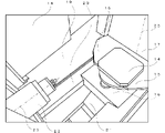
情報処理装置10については、図3を用いて後述する。また、図1では図示を省略するが、工作機械1は、他に、図2を用いて説明する種々の部品を備える。図2は、工作機械1の内部を撮像した撮像画像であり、パレット14、カバー15、テーブル16、旋回扉17、側面18、斜面19、プロテクタ20、シュータ21及び主軸22が示されている。本実施形態において、図2に示す主軸22の長軸23を工作機械1内部の前後方向として、主軸22の根元側を手前側、先端側を奥側とする。また、主軸22に直交する水平方向を左右方向、長軸23に直交する垂直方向を上下方向とする。
The
パレット14は、ワークを載せて固定する台である。工作機械1は、複数のパレット14を設けることができる。それにより、加工するワークを変更する際、パレット14を変更することでワークを変更でき、時間の効率化を図ることができる。
The
カバー15は、パレット14の左右の側部に位置している部品である。テーブル16は、前後方向へ移動することができ、それによりパレット14上に固定されたワークを移動させることができる。また、テーブルは少なくともテーブルの一部を水平方向へ回転することができ、それによりパレット上に固定されたワークを回転させることができる。
The cover 15 is a component located on the left and right sides of the
テーブル16は、パレット14を取り付けることができる部品である。テーブル16は、前後方向へ移動することができ、それによりパレット14上に固定されたワークを移動させることができる。また、テーブル16は少なくともテーブル16の一部を水平方向へ回転することができ、それによりパレット14上に固定されたワークを回転させることができる。
The table 16 is a component to which the
旋回扉17は、軸25を中心に回転することができる扉である。旋回扉17が回転する際、カバー15がパレット14をテーブル16から分離させて、パレット14およびカバー15と一緒に回転する。それにより、ワークの加工が終了したパレット14をパレット格納部へと搬出することができ、また次に加工するワークが固定されたパレット14をパレット格納部から工作機械1内へと搬入することができる。旋回扉17の工作機械1内側と格納部側の両方にカバー15を設け、旋回扉17が180°回転することで、パレット14の搬入と搬出を同時に行ってもよい。
The
側面18は、工作機械1の開閉可能な壁である。側面18は、工作機械1の内部と外部とを区画しており、側面18を開放すると作業者が工作機械1の内部に入ることができる。また、側面18に対向する位置にある図示しない側面18は、工作機械1の内部と、工具格納部とを区画している。工具区画部は、複数の工具を格納しており、加工の際、必要に応じて側面18が開き、主軸22に取り付けられている工具を工具格納部に格納されている別の工具と交換することができる。
The side surface 18 is an openable / closable wall of the
シュータ21は、洗浄によって切屑が流れていく場所である。側面18、プロテクタ20は、旋回扉17及び側面18の下側に設けられており、シュータ21へと切屑が流れやすいように、それぞれシュータ21へ向けて下向きに傾斜している。
The
主軸22は、先端に工具を取り付け、その長軸23を中心に回転させることにより、ワークを加工することができる。本実施形態においては、図2に示すように、主軸22は、円柱形の外形を有する。
A work can be machined on the
〈情報処理装置〉
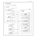
図3を用いて、実施形態に係る情報処理装置10の一例を説明する。情報処理装置10は、演算部100と、記憶部110と、入力部120と、表示部130と、通信部140とを備える。この情報処理装置10は、例えば、コンピュータやタブレット端末等の情報処理装置である。図1に示すように、情報処理装置10は、工作機械1に含まれる構成でもよいが、これに限られない。情報処理装置10は、工作機械1とは別体であり、有線通信または無線通信が可能であってもよい。また、図3に示すように、入力部120と表示部130は、情報処理装置10に含まれる構成でもよいが、これに限られない。入力部120と表示部130とは、例えば、工作機械1の操作盤に備えられていてもよい。また、入力部120と表示部130とは、情報処理装置10と工作機械1にそれぞれ設けられており、使用者が任意の入力部120と表示部130とを選択して利用可能な構成としてもよい。<Information processing equipment>
An example of the
演算部100は、情報処理装置10全体の制御を司るコントローラである。例えば、演算部100は、記憶部110に記憶される制御プログラムPを読み出して実行することにより、取得部101、メッシュ分割部102、情報処理部103、表示処理部104、検知部105及び放出制御部106としての処理を実行する。また、演算部100は、ハードウェアとソフトウェアの協働により所定の機能を実現するものに限定されず、所定の機能を実現する専用に設計されたハードウェア回路でもよい。すなわち、演算部100は、CPU、MPU、GPU、FPGA、DSP、ASIC等、種々のプロセッサで実現することができる。
The arithmetic unit 100 is a controller that controls the entire
記憶部110は種々の情報を記録する記録媒体である。記憶部110は、例えば、RAM、ROM、フラッシュメモリ、SSD(Solid State Device)、ハードディスク、その他の記憶デバイス又はそれらを適宜組み合わせて実現される。記憶部110には、演算部100が実行する制御プログラムPの他、工作機械1で使用する種々のデータ等が格納される。例えば、記憶部110は、画像データ111、メッシュデータ112及び履歴データ113を記憶する。
The storage unit 110 is a recording medium for recording various information. The storage unit 110 is realized, for example, a RAM, a ROM, a flash memory, an SSD (Solid State Device), a hard disk, another storage device, or a combination thereof as appropriate. In addition to the control program P executed by the arithmetic unit 100, the storage unit 110 stores various data and the like used by the
入力部120は、データや操作信号の入力に利用するキーボード、マウス及びタッチパネル等の入力手段である。表示部130は、データの出力に利用するディスプレイ等の出力手段である。
The input unit 120 is an input means such as a keyboard, a mouse, and a touch panel used for inputting data and operation signals. The
通信部140は、外部の装置(図示せず)とのデータ通信を可能とするためのインタフェース回路(モジュール)である。例えば、通信部140は、画像データを撮像する撮像部12とデータ通信を実行することができる。 The communication unit 140 is an interface circuit (module) for enabling data communication with an external device (not shown). For example, the communication unit 140 can execute data communication with the image pickup unit 12 that captures image data.
取得部101は、撮像部12で撮像された画像データを取得する。また、取得部101は、取得した画像データ111を、任意に付された識別情報及び撮像の時刻を特定する情報と共に記憶部110に記憶させる。したがって、記憶部110は、異なるタイミングで撮像された同一の対象エリアの画像データ111を複数記憶することができる。例えば、以下では、同一の対象エリアを撮像した画像データについて、先に撮像された画像データ111を「第1画像データ」とし、第1画像データより後に撮像された画像データ111を「第2画像データ」として説明する。また例えば、第1画像データを撮像したタイミングを「第1時刻」とし、第2画像データを撮像したタイミングを「第2時刻」とする。また、以下では、取得部101が取得した「画像データ」を、必要に応じて、「全体画像データ」とする。 The acquisition unit 101 acquires the image data captured by the image pickup unit 12. Further, the acquisition unit 101 stores the acquired image data 111 in the storage unit 110 together with arbitrarily attached identification information and information for specifying the time of imaging. Therefore, the storage unit 110 can store a plurality of image data 111s of the same target area captured at different timings. For example, in the following, regarding the image data obtained by capturing the same target area, the image data 111 captured earlier is referred to as "first image data", and the image data 111 captured after the first image data is referred to as "second image". Described as "data". Further, for example, the timing at which the first image data is captured is defined as the “first time”, and the timing at which the second image data is captured is defined as the “second time”. Further, in the following, the "image data" acquired by the acquisition unit 101 will be referred to as "whole image data" as needed.
メッシュ分割部102は、記憶部110に記憶される各画像データ111の少なくとも一部を複数のメッシュ領域に分割する。例えば、図2に示すような工作機械1内が撮像された画像データ111が取得された場合、この画像データ111を、図4Aに示すような複数のメッシュ領域に分割する。メッシュ分割部102は、記憶部110に記憶される各画像データ111についてそれぞれメッシュ領域に分割し、各メッシュ領域の画像データを当該メッシュ領域の識別情報と関連付けてメッシュデータ112として記憶部110に記憶させる。また、以下では、「全体画像データ」と区別するため、必要に応じて、メッシュ領域に分割された画像データを「メッシュ画像データ」とする。図4Aは、画像データ111の全体についてメッシュ領域に分割した例であるが、これに限定されない。具体的には、メッシュ分割部102は、全体画像データ111の一部の領域についてのみメッシュ領域を設定してもよい。また、分割するメッシュの大きさ及び形状は、必要に応じて変更可能に構成されてもよい。なお、本明細書のメッシュ画像データは、撮影画像にメッシュの情報を付加し新たな画像を生成したものに限られず、撮影画像とメッシュとを関連付けたものでもよい。つまり、撮影画像とメッシュとを別々のデータとして保存しているものもメッシュ画像データという。なお、メッシュ分割部102は、現在のリアルタイムの工作機械内の撮像画像の少なくとも一部を複数のメッシュ領域に分割する機能を有してもよい。
The
情報処理部103は、メッシュ分割部102で分割された各メッシュ領域に、「画像データ111の撮像の時刻を特定する情報」と、「切屑に関する情報」とを関連付ける。具体的には、メッシュ領域の識別情報に、時刻を特定する情報と、切屑に関する情報とを関連付ける。また、情報処理部103は、これらを関連付けた情報を履歴データ113として記憶部110に記憶させる。
The
「切屑に関する情報」として、切屑の形状、切屑の大きさ、切屑の種類、切屑の堆積量に関する判定値を例示できる。以下では、「切屑に関する情報」として、画像データから特定されるメッシュ領域内に堆積される切屑の量を表す判定値を用いて説明する。切屑の量を表す判定値としては、堆積される切屑の重さ、体積の場合もあり得るし、切屑の量を何段階かのレベルに区分した識別レベルの場合もあり得る。以下では、「切屑に関する情報」を切屑の量に応じて設定される「識別レベル」として説明する。判定値は、1つのメッシュ領域内に堆積される切屑の量を表す判定値であってもよく、複数のメッシュ領域で構成されるメッシュ領域群内に堆積される切屑の総量もしくは切屑の量の平均値を表す判定値であってもよい。切屑の量の平均値は、例えば、切屑の総量を、当該メッシュ領域群を構成するメッシュ領域の数で除して求められる。 As "information about chips", a determination value regarding the shape of the chips, the size of the chips, the type of chips, and the amount of accumulated chips can be exemplified. In the following, as "information about chips", a determination value representing the amount of chips deposited in the mesh region specified from the image data will be described. The determination value representing the amount of chips may be the weight or volume of the chips to be deposited, or may be the identification level in which the amount of chips is divided into several levels. In the following, "information about chips" will be described as "discrimination level" set according to the amount of chips. The determination value may be a determination value representing the amount of chips deposited in one mesh region, and is the total amount of chips or the amount of chips accumulated in the mesh region group composed of a plurality of mesh regions. It may be a determination value representing an average value. The average value of the amount of chips is obtained, for example, by dividing the total amount of chips by the number of mesh regions constituting the mesh region group.
具体的には、情報処理部103は、メッシュ画像データから、切屑を認識し、各メッシュ領域もしくはメッシュ領域群における切屑の存在の有無、存在する切屑の量を特定する。例えば、情報処理部103は、学習器により予め機械学習がされた学習済みモデルにより、メッシュ画像データの各メッシュ領域もしくはメッシュ領域群と対応する所定位置に存在する切屑の量を識別することができる。ここで、情報処理部103は、識別した切屑の量に応じて設定された値を「識別レベル」として特定する。以下では、「識別レベル」の値が小さい場合、対象の領域での切屑の量が少なく、切屑の量が多くなる程「識別レベル」の値が大きくなるものとする。具体的には、例えば、切屑がない場合に「0」と設定され、切屑の量が多くなるにつれてその値も大きくなり、移動が必要な程度に切屑の量が多い場合に「5」と設定される。また、判定値もしくは識別レベルは、数値ではなく、色彩で設定してもよい。例えば、対象の領域での切屑の量が多い場合は、識別レベルとして「赤」が設定され、切屑の量が少ない場合は、「黄色」が設定され、切屑が無い場合は、色彩が設定されない。このような画像は、例えば、メッシュ画像データに、情報処理部103が出力した色彩パターンを重ねることで、表示部130に表示されてもよい。
Specifically, the
「画像データに関連する時刻」とは、画像データの撮像の時刻を特定する情報である。なお、「画像データに関連する時刻」とは、実際の撮像時刻に限定されず、過去の画像データの撮像時と対象とする画像データの画像の撮影時とを区別し、その間隔を特定することができれば良い。したがって、例えば、第1画像に関連する第1時刻を『0』とし、第2画像が第1画像の撮像から『5分経過後』に取得された場合、第2時刻を『5』としてもよい。また例えば、画像データの取得間隔が固定の場合、第1画像に関連する第1時刻を『1』とし、第2画像が第1画像の撮像から『5分経過後』に取得された場合、第2時刻を『2』としてもよい。 The "time related to the image data" is information for specifying the time of imaging of the image data. The "time related to the image data" is not limited to the actual imaging time, and distinguishes between the time when the past image data is captured and the time when the image of the target image data is taken, and the interval is specified. I wish I could. Therefore, for example, if the first time related to the first image is set to "0" and the second image is acquired "after 5 minutes have passed" from the acquisition of the first image, the second time may be set to "5". good. Further, for example, when the acquisition interval of image data is fixed, the first time related to the first image is set to "1", and the second image is acquired "after 5 minutes have passed" from the acquisition of the first image. The second time may be set to "2".
このように、情報処理部103は、(a)第1画像データの複数のメッシュ領域の第1の切屑に関する情報と、(b)第2画像データの複数のメッシュ領域の第2の切屑に関する情報と、(c)第1画像データに関連する第1時刻と、(d)第2画像データに関連する第2時刻と、を関連付けることができる。
As described above, the
このとき、情報処理部103は、全てのメッシュ領域の切屑に関する情報を関連付けるのではなく、特定のメッシュ領域に対応する切屑に関する情報を関連付けるようにしてもよい。「特定のメッシュ領域」とは、例えば、予め設定される領域である。具体的には、切屑が堆積する可能性のある領域を予め特定のメッシュ領域として定めることができる。
At this time, the
図5に、情報処理部103で生成される履歴データ113の一例を示す。図5に示す履歴データ113の一例では、画像データ111を識別する『画像ID』及びメッシュ領域を識別する『領域ID』に、各メッシュ領域の「切屑に関する情報」である『識別レベル』を関連付ける。また、図5に示す例では、各『画像ID』に、画像データ111に関連する時刻として、撮像時刻を識別する『時刻ID』を関連付ける。この履歴データ113の例では、画像ID「I1」の画像データ111は、画像ID「I2」の画像データ111よりも先に取得されたものとする。また、この履歴データ113の例では、「I1」の画像データ111を撮像した時刻は「T1」であるものとする。さらに、各画像データ111のメッシュ領域は、それぞれ「A1」~「A6」等の領域IDで識別されるものとする。
FIG. 5 shows an example of the
例えば、図5の履歴データ113では、「A4」のメッシュ領域の識別レベルは「2」、「3」、「3」、「4」、「5」、「0」、「1」と変化したことが分かる。これによると、識別レベル「5」となった「T5」のタイミングと、識別レベル「0」となった「T6」のタイミングの間に、「A4」のメッシュ領域に対応する所定位置から、切屑が除去されたため、識別レベルが「5」から「0」となったことが分かる。
For example, in the
表示処理部104は、撮像部12で撮像された画像データ111を含む所定の画像データ111をディスプレイである表示部130に表示させる。このとき、例えば、表示処理部104は、図4Aで上述したような、メッシュ分割部102が分割したメッシュ領域を含む状態の画像データ111を表示部130に表示させてもよい。
The
表示処理部104は、図4Bに示すように、色彩を用いて、任意のメッシュ領域の判定値もしくは識別レベルを表示部130に表示させてもよい。例えば、切屑が多いメッシュ領域には赤色(R)が表示され、赤色の領域よりも少量であるが切屑があるメッシュ領域には黄色(Y)が表示され、切屑がない領域は色彩が設定されず、無色(透明)で表示されてもよい。なお、色彩の割り当ては任意であり、上記に限定されない。このように、表示処理部104が、撮像部12で撮像された画像データ111の任意のメッシュ領域の判定値もしくは識別レベルを色彩で表示する場合、作業者は視覚的に切屑の分布を認識しやすくなる。
As shown in FIG. 4B, the
表示部130は、現在のリアルタイムの工作機械内の画像もしくは動画を表示してもよい。この場合、メッシュ分割部102は、リアルタイムの工作機械内の画像もしくは動画の少なくとも一部を複数のメッシュ領域に分割し、リアルタイムの工作機械内の画像もしくは動画のメッシュ領域の判定値もしくは識別レベルを色彩で表示してもよい。
The
また、表示処理部104は、画像データ111とともに、特定のメッシュ領域の識別レベルの時系列情報の表示を要求する信号の入力を促すメッセージや、特定のメッシュ領域に対応する所定位置への液体の放出を要求する信号の入力を促すメッセージ等を表示部130に表示させてもよい。
Further, the
そして、時系列情報の表示の要求に対し、表示処理部104は、所定位置に対応するメッシュ領域の切屑に関する情報を、表示部130に時系列に表示させることができる。例えば、表示処理部104は、後述する検知部105により、所定位置が指定され、時系列情報の表示を要求する入力信号が検知されると、図6に一例を示すように、指定された所定位置の切屑量の時系列情報を表示部130に表示させる。
Then, in response to the request for displaying the time-series information, the
「時系列情報」とは、「識別レベル」の変化を時系列で表す情報である。例えば、図6は、画像データI1を含む表示画面W上で、所定位置に対応するメッシュ領域A147が選択された例である。この場合、例えば、図6に示すように、このメッシュ領域A147と対応する所定位置の切屑量の時系列情報w1として、切屑量のグラフがポップアップ表示される。この時系列情報w1のグラフは、横軸が「時間」、縦軸が「識別レベル」である。作業者は、このように表示される時系列情報w1により、各メッシュ領域に対応する所定位置の時系列変化を把握することができる。なお、時系列情報の表示の要求は、複数のメッシュ領域から構成されるメッシュ領域群に対して行われてもよい。この場合、メッシュ領域群と対応する所定位置の切屑の総量もしくは切屑の量の平均値の時系列情報w1として、切屑量のグラフをポップアップ表示してもよい。作業者は、このように表示される時系列情報w1により、メッシュ領域群に対応する所定位置の時系列変化を把握することができる。また、メッシュ領域A147のように、1つのメッシュ領域の時系列情報の表示が要求された場合でも、当該1つのメッシュ領域を含むメッシュ領域群が自動的に設定され、そのメッシュ領域群と対応する所定位置の切屑の総量もしくは切屑の量の平均値の時系列情報が表示されてもよい。 The "time-series information" is information that represents changes in the "discrimination level" in chronological order. For example, FIG. 6 is an example in which the mesh region A147 corresponding to a predetermined position is selected on the display screen W including the image data I1. In this case, for example, as shown in FIG. 6, a graph of the chip amount is pop-up displayed as the time series information w1 of the chip amount at the predetermined position corresponding to the mesh region A147. In the graph of the time series information w1, the horizontal axis is "time" and the vertical axis is "discrimination level". The operator can grasp the time-series change of the predetermined position corresponding to each mesh area by the time-series information w1 displayed in this way. The request for displaying the time-series information may be made to the mesh area group composed of a plurality of mesh areas. In this case, a graph of the amount of chips may be displayed in a pop-up as time-series information w1 of the total amount of chips at a predetermined position corresponding to the mesh region group or the average value of the amount of chips. The operator can grasp the time-series change of the predetermined position corresponding to the mesh region group by the time-series information w1 displayed in this way. Further, even when the display of the time series information of one mesh area is requested like the mesh area A147, the mesh area group including the one mesh area is automatically set and corresponds to the mesh area group. Time-series information of the total amount of chips at a predetermined position or the average value of the amount of chips may be displayed.
表示部130にリアルタイムの画像もしくは動画が表示され、リアルタイムの工作機械内の画像もしくは動画のメッシュ領域の判定値もしくは識別レベルを色彩で表示してもよい。リアルタイムの画像等を色彩パターンによって表示することにより、現在も切屑が残っている領域を容易に確認できる。作業者がリアルタイムの工作機械内の画像もしくは動画の任意のメッシュ領域(もしくはメッシュ領域群)を選択すると、時系列情報が表示されるようにしてもよい。時系列情報から、切屑の堆積量が所定の撮像時から増加していない場合には、当該領域では直ちに切屑の清掃は必要ないと判断してもよい。そのような場合には、所定時間後にクーラントを放出して切屑を清掃するように操作盤で清掃予約設定を行うことができる。そして、所定時間後にクーラントが放出され、切屑が清掃されると、リアルタイムの画像もしくは動画では、例えば赤色のメッシュ領域が無色に変化しているため、切屑が除去されたことを容易に確認できる。
A real-time image or moving image is displayed on the
検知部105は、表示部130に表示された画像データ111内の所定位置に対する入力信号を検知する。この入力信号は、所定位置に対応する特定メッシュ領域での切屑の量の時系列情報の表示を要求する表示リクエストである。または、この入力信号は、所定位置に関連する関連領域に液体を放出する要求をする放出リクエストである。例えば、入力信号は、入力部120を介し、作業者によって入力される。検知部105は、入力信号をメッシュ領域と関連付けて検知する。例えば、検知部105は、1つのメッシュ領域内の任意の位置で入力信号を検知した場合には、そのメッシュ領域の全体が指示されたものとして指示位置を検知してもよい。
The detection unit 105 detects an input signal for a predetermined position in the image data 111 displayed on the
検知部105は、入力信号に応じた信号を表示処理部104または放出制御部106に表示する。具体的には、検知部105は、入力信号として表示リクエストを検知すると、この入力信号で特定される所定位置に対応する特定メッシュ領域での識別レベルを表示させるため、所定位置を特定する情報を表示処理部104に表示する。また、検知部105は、入力信号として放出リクエストを検知すると、この入力信号で特定される所定位置に関連する関連領域に液体を放出させるため、所定位置を特定する情報を放出制御部106に出力することができる。
The detection unit 105 displays a signal corresponding to the input signal on the
放出制御部106は、検知部105から入力する入力信号に基づいて、ワークから発生する切屑を移動させるように液体を放出させる制御信号を生成する。また、放出制御部106は、生成した制御信号を液体放出部11に出力する。また、放出制御部106は、放出の履歴を放出履歴データとして記憶部110に記憶させてもよい。 The discharge control unit 106 generates a control signal for discharging the liquid so as to move the chips generated from the work, based on the input signal input from the detection unit 105. Further, the discharge control unit 106 outputs the generated control signal to the liquid discharge unit 11. Further, the release control unit 106 may store the release history in the storage unit 110 as release history data.
なお、情報処理装置10は、1台のコンピュータや1台のタブレットにより実現され得る。工作機械は、この情報処理装置を内部に組み込んでいてもよい。また、これらの処理を、情報処理システムとしてネットワークを介して接続される複数台のコンピュータの組み合わせにより実現されてもよい。また、例えば、記憶部110に記憶されるデータの全部又は一部が、ネットワーク(図示せず)を介して接続される外部の記録媒体に記憶され、情報処理装置10や情報処理システムは、外部の記録媒体に記憶されるデータを使用するように構成されていてもよい。
The
〈液体放出の処理〉
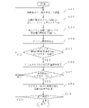
図7に示すフローチャートを用いて、実施の形態1に係る情報処理装置10における液体放出の処理について説明する。まず、取得部101は、撮像部12が撮像した画像データ111を取得し、記憶部110に記憶させる(S01)。<Processing of liquid discharge>
The liquid discharge process in the
メッシュ分割部102は、記憶部110に記憶される画像データ111を読み出し、複数のメッシュ領域に分割してメッシュデータ112を生成する(S02)。
The
情報処理部103は、メッシュ分割部102が生成したメッシュデータ112の各メッシュ領域について、切屑に関する情報として識別レベルを関連付ける。また、情報処理部103は、画像データ111の撮像時刻を特定する情報を関連付けて、履歴データ113として記憶部110に記憶させる(S03)。
The
表示処理部104は、メッシュ領域を含む画像データ111を表示部130に表示させる(S04)。
The
検知部105が、特定のメッシュ領域に対応する入力信号である表示リクエストを検知すると(S05でYES)、表示処理部104は、検知した入力信号で特定されるメッシュ領域の時系列情報を表示部130に表示させる(S06)。
When the detection unit 105 detects a display request which is an input signal corresponding to a specific mesh area (YES in S05), the
また、検知部105が、ステップS06で表示した時系列情報に対応して入力信号である放出リクエストを検知すると(S07でYES)、放出制御部106は、検知した入力信号で特定されるメッシュ領域と対応する所定位置の切屑を移動させるための制御信号を液体放出部11に出力する(S08)。これにより、液体放出部11は、切屑を移動させるための液体を放出する。 Further, when the detection unit 105 detects the emission request which is the input signal corresponding to the time series information displayed in step S06 (YES in S07), the emission control unit 106 determines the mesh area specified by the detected input signal. A control signal for moving the chips at a predetermined position corresponding to the above is output to the liquid discharge unit 11 (S08). As a result, the liquid discharge unit 11 discharges the liquid for moving the chips.
その後、工作機械1での加工が終了する場合(S09でNO)、処理は終了する。一方、工作機械1での加工が継続する場合(S09でYES)、情報処理装置10では、ステップS01の処理に戻り、ステップS01~S09の処理を繰り返す。また、検知部105により、信号が検知されなかった場合(S05でNO又はS07でNO)も同様に、情報処理装置10では、ステップS01に戻り、同様の処理を繰り返す。なお、情報処理装置10では、処理の途中で工作機械での加工が終了した場合、液体放出の各処理を終了することができる。
After that, when the processing by the
このように、実施形態に係る工作機械1及び情報処理装置10によれば、各メッシュ領域の切屑の堆積量について、ある時点の情報に限らず、時系列の情報として管理することができる。したがって、適切に切屑の堆積状況を把握することが可能となり、これにより、容易に切屑を除去することができる。
As described above, according to the
具体的には、情報処理装置10によれば、ある瞬間におけるメッシュ画像の切屑の堆積量だけでなく、切屑の堆積量を時系列で把握できる。これにより、例えば、瞬間的な堆積量は多くないが切屑が常になくならない、堆積し易い領域等の判別が可能となり、工作機械1では、切屑をより的確に除去することができる。また、情報処理装置10によれば、作業者のタッチパネル操作で選択されたメッシュ領域における判定値の時系列のデータを表示することができる。これにより、作業者は、容易に的確に切屑の堆積状況を把握することができる。さらに、情報処理装置10によれば、報知された情報に基づいて、作業者のマニュアル操作による切屑除去処理を行うことができる。これにより、工作機械1では、状況に即した迅速な切屑除去処理を実現することができる。
Specifically, according to the
[実施の形態2]
〈情報処理装置〉
実施の形態2に係る工作機械は、図1を用いて上述した工作機械1と同一の構成であるが、情報処理装置の構成が図3を用いて上述した構成と異なるため、図1及び図8を参照して説明する。図8に示すように、実施の形態2に係る工作機械1の情報処理装置10Aは、図3を用いて上述した工作機械1と比較し、堆積推移判定部107及び優先順位決定部108を備える点で異なる。[Embodiment 2]
<Information processing equipment>
The machine tool according to the second embodiment has the same configuration as the
堆積推移判定部107は、判定値に基づいて、所定の期間、所定の範囲内(所定量)の切屑が存在し続けているメッシュ領域を検出する。具体的には、判定値が、所定の期間(例えば、30分以上)、予め設定される第1閾値及び第2閾値の範囲内(例えば、識別レベル5以下かつ識別レベル2以上)であるメッシュ領域を「堆積領域」とする。この第1閾値及び第2閾値は、比較的少ない堆積量であり、通常は洗浄が必要な識別レベルとして定められる値ではないが、この範囲内であっても長時間堆積することで、その後の洗浄に影響を与える可能性がある値が設定される。また、堆積推移判定部107は、堆積領域が検出された報知を表示させるため、堆積領域とされたメッシュ領域を特定する情報を表示
処理部104に表示することができる。The sedimentation
表示処理部104は、堆積推移判定部107により検出されたメッシュ領域を報知し、メッシュ領域に対応する切屑に関する情報を表示部130に表示させる。
The
例えば、表示処理部104は、図9に示すように、堆積領域を赤色等(図9では黒色)、他のメッシュ領域と区別されるように表示画面Wにおいて表示することで報知してもよい。また、表示処理部104は、図9に示すように、堆積領域のうち、選択されたメッシュ領域A296の時系列情報w2をポップアップ表示してもよい。これにより、作業者は液体の放出が必要な所定領域を判断し、液体放出を要求するリクエストを入力することができる。
For example, as shown in FIG. 9, the
例えば、図5の履歴データ113では、「A3」のメッシュ領域の識別レベルは「2」、「2」、「2」、「2」、「2」、「2」、「0」となっている。これによると、少量である識別レベル「2」が所定期間続いていたため、液体の放出がされて「2」から「0」となったことが分かる。
For example, in the
また、表示処理部104は、堆積領域の他、液体が度々放出された所定領域に対応するメッシュ領域(図9中のx)を堆積領域とは異なる色により表示させてもよい。例えば、記憶部110に放出履歴データが記憶される場合、表示処理部104は、放出の履歴を用いて、ある期間に、液体の放出が所定回数以上、されたメッシュ領域を堆積領域とは異なる色で表示部130に表示させることができる。
Further, in addition to the deposited area, the
優先順位決定部108は、ワークから発生する切屑を移動させるように液体を放出するメッシュ領域の優先順位を定める。優先順位決定部108は、原則として、切屑の堆積量の多いメッシュ領域に高い優先順位を付与する。このとき、優先順位決定部108は、堆積推移判定部107により検出されたメッシュ領域の少なくとも一部について、液体を放出する優先順位を上げる処理を行うことができる。また、特定のメッシュ領域で、所定の範囲内の切屑が存在し続ける事象が繰り返される場合には、そのメッシュ領域について、予め高い優先順位を付与することもできる。
The priority determination unit 108 determines the priority of the mesh region that discharges the liquid so as to move the chips generated from the work. As a general rule, the priority determination unit 108 gives a high priority to the mesh region where the amount of accumulated chips is large. At this time, the priority determination unit 108 can perform a process of raising the priority of discharging the liquid for at least a part of the mesh region detected by the deposition
〈液体放出の処理〉
図10に示すフローチャートを用いて、実施の形態2に係る情報処理装置10Aにおける液体放出の処理について説明する。図10のフローチャートにおいて、図7を用いて上述した情報処理装置10における処理と同一の処理については、同一のステップ番号を付す。図10に示すように、情報処理装置10と異なる処理は、ステップS11,S12及びS13である。<Processing of liquid discharge>
The liquid discharge process in the
堆積推移判定部107は、ステップS03において情報処理部103により各メッシュ領域の識別レベルが関連付けされると、所定の期間、所定の範囲内の切屑が存在するメッシュ領域の有無を判定する(S11)。
When the identification level of each mesh region is associated by the
また、表示処理部104は、メッシュ画像を表示させる際、ステップS11で堆積推移判定部107に所定の期間、所定の範囲内の切り屑が存在するとされたメッシュ領域の情報を含むデータを表示部130に表示させる(S12)。
Further, when displaying the mesh image, the
優先順位決定部108は、ステップS07において液体放出のリクエストが検知されると、液体を放出する際の優先順位が決定される(S13)。これにより、放出制御部106によりステップS08において出力される液体放出の制御信号は、ステップS13において優先順位決定部108で決定された順位に従って生成される。 When the request for liquid discharge is detected in step S07, the priority determination unit 108 determines the priority for discharging the liquid (S13). As a result, the liquid discharge control signal output by the discharge control unit 106 in step S08 is generated in the order determined by the priority determination unit 108 in step S13.
このように、情報処理装置10では、履歴データ113を利用し、少量であっても、所定の期間切屑が除去されない領域を検出することができる。具体的には、情報処理装置10によれば、切屑が除去されないメッシュ領域を識別して報知することができる。これにより、作業者は、迅速かつ的確に切屑の除去を行うことができる。また、情報処理装置10によれば、所定期間以上、切屑が除去されない領域の切屑除去処理を行う優先順位を上げることができる。これにより、効果的に切屑の除去を行うことができる。
As described above, the
[変形例1]
上述の説明では、情報処理装置10は、図5に示すような履歴データ113として切屑堆積の時系列変化を記憶する例で説明したが、これに限定されない。例えば、情報処理部103は、加工サイクル単位で履歴データ113を用いて、ワークの加工中に切屑が堆積しやすい場所又は切屑が堆積しやすいタイミング等を分析する。「加工サイクル」とは、1つのワークの加工の開始から終了に要する期間である。撮像部12は、加工サイクル中の定期的なタイミングで工作機械1の内部(切屑が飛散する領域として画定される加工領域)を撮像してもよい。また、この加工サイクルにおける1回の画像データの取得のタイミングは、図5を用いて上述した「時刻ID」により特定される。[Modification 1]
In the above description, the
(1)例えば、情報処理部103は、各時刻IDで識別されるメッシュデータ112について、それぞれ、全メッシュの切屑の総和を「切屑発生量」として求める。図5に示す例において、時刻ID「T1」で識別されるメッシュデータ112の場合、全ての領域IDで識別される「識別レベル」の総和(0+0+2+2+3+4+・・・)を「切屑発生量」として求める。
(2)そして、情報処理部103は、時刻ID毎に、得られた「切屑発生量」の所定割合(例えば、20%)以上となる領域IDで識別される領域を「切屑の多い領域」として求める。情報処理部103は、単に、時刻ID毎に、得られた「切屑発生量」が所定値以上となる領域IDで識別される領域を「切屑の多い領域」として求めてもよい。
(3)また、情報処理部103は、時刻ID毎に、切屑量が多いとされる「識別レベル」の割合が、所定割合以上(例えば、識別レベル3以上が、全体の20%以上)の場合、その時刻IDで識別されるタイミングを、「切屑の堆積量の多い時間帯」とする。(1) For example, the
(2) Then, the
(3) Further, in the
優先順位決定部108は、液体を放出する際の優先順位を決定する際、現在の加工サイクルにおいて得られた画像データ111に基づいて得られた各メッシュ領域の堆積量に加え、情報処理部103によってこのように得られた「切屑の多い領域」と「切屑の堆積量の多い時間帯」とを利用する。すなわち、優先順位決定部108は、「切屑の多い領域」とされた領域については、同一のワークを加工する加工サイクルについては、切屑が堆積しやすいとして、優先順位を高めにしてもよい。また、「切屑の堆積量の多い時間帯」とされた時間帯については、同一のワークを加工する加工サイクルについては、切屑が堆積しやすいとし、液体の放出の頻度を高くしてもよい。これにより、現在得られた画像データ111に基づく情報に加え、過去の履歴を考慮して効率的な切屑の除去を可能とする。
When the priority determination unit 108 determines the priority when discharging the liquid, the
[変形例2]
変形例2に係る情報処理装置は、ワークの加工に異常が生じた際に、加工の異常を検知するものである。例えば、図11に示すように、変形例2に係る情報処理装置10Bは、図3を用いて上述した情報処理装置10と比較して、異常検知部109を備える点で異なる。また、変形例3に係る情報処理装置10Bの情報処理部103は、各メッシュ領域にワークが写るか否かの情報を含む履歴データ113を生成する。これにより、履歴データ113によると、切屑に関する堆積状態に加え、加工中のワークの状態を含むものとなる。[Modification 2]
The information processing apparatus according to the second modification detects a machining abnormality when an abnormality occurs in the machining of the work. For example, as shown in FIG. 11, the information processing apparatus 10B according to the modified example 2 is different from the
異常検知部109は、画像中の各メッシュ領域について得られる切屑の堆積量と、各メッシュ領域に対して予め設定される値とを比較し、異常を検知した場合に異常信号を出力する。具体的には、情報処理装置10Bは、履歴データ113から、加工による過去の各メッシュ領域の切屑の堆積量の変化を特定できる。これにより、各ワークの加工において収集した切屑の量を特定することができる。したがって、異常検知部109は、今回の加工サイクルにおいて収集した切屑の総量が、履歴データ113から得られた切屑の統計量に基づいて設定された閾値から外れていた場合、異常として検知する。例えば、異常検知部109は、履歴データ113から得られた同一のワークの加工サイクルで得られた切屑の量に基づいて設定された閾値と比較し、今回の加工サイクルでの切屑の量が多かった場合、または、少なかった場合、異常として検知する。ここで、異常検知部109が使用する閾値として、上限閾値と下限閾値とを定めてもよい。
The
[変形例3]
変形例3に係る情報処理装置は、液体放出部11で発生する異常又は撮像部12で発生する異常の少なくともいずれかを検知するものである。変形例3に係る異常検知装置は、図12を用いて上述した情報処理装置10Bと同一の構成であるため、図11を用いて説明する。[Modification 3]
The information processing apparatus according to the third modification detects at least one of the abnormality generated in the liquid discharging unit 11 and the abnormality generated in the imaging unit 12. Since the abnormality detection device according to the third modification has the same configuration as the information processing device 10B described above with reference to FIG. 12, it will be described with reference to FIG.
変形例3に係る情報処理装置10Bの異常検知部109は、所定のメッシュ領域に関する切屑の堆積量が、所定期間以上、閾値を超えるか否かを判定し、所定期間以上、閾値を超える場合に信号を出力する。具体的には、異常検知部109は、同一のメッシュ領域に関する切屑の堆積量が、所定期間以上(例えば、15分以上、又は撮像200回分以上)、閾値を超えるか否かを判定し、所定期間以上、閾値を超える場合、表示部130にアラートを表示させる。例えば、工作機械1において、ある領域に対応するメッシュ領域における切屑の堆積量が長期間、切り屑を移動させることが好ましい所定量以上である場合、液体放出部11または撮像部12で異常が生じている可能性がある。具体的には、工作機械1内で、切屑が同一の場所における多量の堆積が継続する場合、液体放出部11により、切屑の移動のための液体の放出がされていない可能性がある。または、撮像部12により、切屑が移動された工作機械1内の画像データが撮像されていない可能性がある。したがって、異常検知部109は、同一の場所での堆積の継続を検知するとともに、液体放出部11で生じた異常であるか、撮像部12で生じた異常のいずれであるかを検知する。例えば、異常検知部109は、異常の検知を表示部130にアラートとして表示させるようにすることができる。これにより、作業者は、液体放出部11又は撮像部12の異常の発生を知ることができる。
The
同一の場所での堆積の継続を検知した際、異常検知部109は、画像の信頼性を示す値が理想値の範囲内である場合、液体放出部11の異常と検知する。また、異常検知部109は、画像の信頼性を示す値が理想値の範囲外である場合、撮像部12の異常と検知する。例えば、画像の信頼性を示す値とは、ボケ具合判定のための周波数、画像の周波数分布または画像のコントラスト等であり、これら複数の値を組み合わせて利用してもよい。これにより、切屑の堆積状態の把握に加え、液体放出部11の異常及び撮像部12の異常の検知も実現することが可能となる。
When the continuation of deposition at the same place is detected, the
また、異常検知部109が堆積の継続を検知する際、1のメッシュ領域における所定期間の切屑の堆積ではなく、近接する複数のメッシュ領域における切屑の堆積を対象として検知する方法であってもよい。なお、図8を用いて上述した情報処理装置10Aに、液体放出部11及び撮像部12で発生する異常検知部109を追加する構成であってもよい。
Further, when the
[変形例4]
上述の説明では、情報処理装置10は、工作機械1に含まれるものとして説明したが、これに限定されない。具体的には、図12に示すように、情報処理装置10は、工作機械1Aに含まれず、工作機械1Aから独立し、工作機械1Aとデータ通信が可能な外部の情報処理端末であってもよい。なお、図12では詳しい説明を省略するが、工作機械1Aの構成は、図1及び図2を用いて上述した工作機械1と比較し、通信部5を備え、内部に情報処理装置10を含まない以外の構成は同一である。[Modification 4]
In the above description, the
また、上述の説明では、情報処理装置10の表示部130に画像データ111等を表示するものとして説明したが、これに限定されない。具体的には、画像データ111を表示する表示部130は、工作機械1及び情報処理装置10に含まれず、情報処理装置10とデータ通信が可能な外部の情報処理端末等のディスプレイであってもよい。
Further, in the above description, the image data 111 and the like are displayed on the
さらに、上述の説明では、情報処理装置10の表示部130に、堆積領域の検知をポップアップ表示するものとして説明したが、これに限定されない。具体的には、情報処理装置10は、作業者等の保有する情報処理端末に、堆積領域が検知された旨のメッセージの送信をしてもよい。このような方法により、仮に、作業者は工作機械1とは物理的に離れた位置に存在する場合であっても、堆積領域の検知を把握することができる。
Further, in the above description, the detection of the deposited area is pop-up displayed on the
以上のように、本出願において開示する技術の例示として、上記実施形態を説明した。しかしながら、本開示における技術は、これに限定されず、適宜、変更、置き換え、付加、省略などを行った実施形態にも適用可能である。 As described above, the above-described embodiment has been described as an example of the technique disclosed in the present application. However, the technique in the present disclosure is not limited to this, and can be applied to embodiments in which changes, replacements, additions, omissions, etc. are made as appropriate.
本開示の全請求項に記載の情報処理装置、工作機械及び情報処理システムは、ハードウェア資源、例えば、プロセッサ、メモリ、及びプログラムとの協働などによって、実現される。 The information processing devices, machine tools and information processing systems described in all claims of the present disclosure are realized by cooperation with hardware resources such as processors, memories, and programs.
本開示の情報処理装置、工作機械及び情報処理システムは、例えば、工作機械の洗浄に有用である。 The information processing apparatus, machine tool and information processing system of the present disclosure are useful for cleaning a machine tool, for example.
1 工作機械
10,10A 情報処理装置
100 演算部
101 取得部
102 メッシュ分割部
103 情報処理部
104 表示処理部
105 検知部
106 放出制御部
107 堆積推移判定部
108 優先順位決定部
1
Claims (6)
前記撮像部で撮像された内部画像を含む所定の画像を表示する表示部と、
前記表示部に表示された前記内部画像内の所定位置に対する入力信号を検知する検知部と、
を備え、
前記表示部は、前記入力信号に基づいて、前記内部画像内を所定の大きさに分割した複数のメッシュ領域のうちの前記所定位置に対応する特定のメッシュ領域の切屑に関する情報を時系列に表示し、
前記表示部は、前記工作機械において前記液体が度々放出された所定領域に対応する前記メッシュ領域を他の前記メッシュ領域と異なる態様で表示することを特徴とする情報処理装置。 An information processing device that displays an image taken by the image pickup unit in a machine tool having a liquid discharge unit that discharges the liquid so as to move chips generated from the work and an image pickup unit that images the inside.
A display unit that displays a predetermined image including an internal image captured by the image pickup unit, and a display unit.
A detection unit that detects an input signal for a predetermined position in the internal image displayed on the display unit, and a detection unit.
Equipped with
Based on the input signal, the display unit displays in chronological order information about chips in a specific mesh region corresponding to the predetermined position among a plurality of mesh regions in which the internal image is divided into predetermined sizes. death,
The information processing apparatus is characterized in that the display unit displays the mesh region corresponding to a predetermined region to which the liquid is frequently discharged in the machine tool in a manner different from that of other mesh regions .
前記ワークを加工する領域を含む工作機械の内部を撮像する撮像部と
前記撮像部で撮像された内部画像を表示する表示部と、
前記表示部に表示された前記内部画像内の所定位置に対する入力信号を検知する検知部と、を備え、
前記表示部は、前記入力信号に基づいて、前記内部画像内を所定の大きさに分割した複数のメッシュ領域のうちの前記所定位置に対応する対応メッシュ領域の切屑に関する情報を時系列に表示し、
前記表示部は、前記工作機械において前記液体が度々放出された所定領域に対応する前記メッシュ領域を他の前記メッシュ領域と異なる態様で表示することを特徴とする情報処理システム。 A liquid discharge part that discharges liquid so as to move chips generated from the work,
An image pickup unit that captures an image of the inside of a machine tool including an area for processing the work, a display unit that displays an internal image captured by the image pickup section, and a display unit.
A detection unit for detecting an input signal for a predetermined position in the internal image displayed on the display unit is provided.
Based on the input signal, the display unit displays information on chips in the corresponding mesh region corresponding to the predetermined position among a plurality of mesh regions in which the internal image is divided into predetermined sizes in chronological order. ,
The information processing system is characterized in that the display unit displays the mesh region corresponding to a predetermined region to which the liquid is frequently discharged in the machine tool in a manner different from that of other mesh regions .
Applications Claiming Priority (3)
| Application Number | Priority Date | Filing Date | Title |
|---|---|---|---|
| JP2019222208 | 2019-12-09 | ||
| JP2019222208 | 2019-12-09 | ||
| PCT/JP2020/045741 WO2021117745A1 (en) | 2019-12-09 | 2020-12-08 | Information processing device, machine tool, and information processing system |
Publications (2)
| Publication Number | Publication Date |
|---|---|
| JPWO2021117745A1 JPWO2021117745A1 (en) | 2021-06-17 |
| JP7065262B2 true JP7065262B2 (en) | 2022-05-11 |
Family
ID=76329927
Family Applications (1)
| Application Number | Title | Priority Date | Filing Date |
|---|---|---|---|
| JP2021563987A Active JP7065262B2 (en) | 2019-12-09 | 2020-12-08 | Information processing equipment, machine tools and information processing systems |
Country Status (5)
| Country | Link |
|---|---|
| US (1) | US20230011866A1 (en) |
| EP (1) | EP4074458A4 (en) |
| JP (1) | JP7065262B2 (en) |
| CN (1) | CN114786870A (en) |
| WO (1) | WO2021117745A1 (en) |
Citations (12)
| Publication number | Priority date | Publication date | Assignee | Title |
|---|---|---|---|---|
| JP2007114742A (en) | 2005-09-21 | 2007-05-10 | Olympus Corp | Observation apparatus |
| JP2010035756A (en) | 2008-08-04 | 2010-02-18 | Fujifilm Corp | Diagnosis support apparatus and diagnosis support method |
| JP2011092677A (en) | 2009-09-30 | 2011-05-12 | Fujifilm Corp | Medical image diagnostic apparatus and method using liver angiographic image, and program |
| JP2012010733A (en) | 2010-06-29 | 2012-01-19 | Fujifilm Corp | Electronic endoscope system, processor for electronic endoscope, image search system, and image search method |
| JP2012245395A (en) | 2012-09-19 | 2012-12-13 | Konica Minolta Medical & Graphic Inc | Dynamic image-capturing system and diagnosis-assisting information-generating method |
| JP2015130698A (en) | 2015-03-13 | 2015-07-16 | 株式会社東芝 | Information output device, detection device, program, and information output method |
| JP2017094420A (en) | 2015-11-20 | 2017-06-01 | ファナック株式会社 | Machine tool |
| JP2018024094A (en) | 2017-11-14 | 2018-02-15 | ファナック株式会社 | Machine tool washing system |
| JP2019111637A (en) | 2017-12-26 | 2019-07-11 | ファナック株式会社 | Chip removal device and information processing device |
| JP2019117477A (en) | 2017-12-27 | 2019-07-18 | ファナック株式会社 | Link information generation device, link information generation method, and link information generation program |
| JP2021074853A (en) | 2019-11-13 | 2021-05-20 | ファナック株式会社 | Device for determining necessity of cleaning work space of machine tool, cleaning system and method |
| JP2021074852A (en) | 2019-11-13 | 2021-05-20 | ファナック株式会社 | Cleaning system and method for cleaning work space of machine tool |
Family Cites Families (5)
| Publication number | Priority date | Publication date | Assignee | Title |
|---|---|---|---|---|
| JP2007293547A (en) * | 2006-04-24 | 2007-11-08 | Canon Inc | Information processor and information processing method in this processor |
| JP2008155324A (en) | 2006-12-25 | 2008-07-10 | Brother Ind Ltd | Machine tool |
| JP6420227B2 (en) | 2014-12-25 | 2018-11-07 | ファナック株式会社 | In-machine cleaning device for machine tools |
| ES2772928T3 (en) * | 2016-11-26 | 2020-07-08 | Agie Charmilles Sa | Method for machining and inspecting workpieces |
| JP6806736B2 (en) * | 2018-06-05 | 2021-01-06 | ファナック株式会社 | Location information display system |
-
2020
- 2020-12-08 US US17/783,487 patent/US20230011866A1/en active Pending
- 2020-12-08 CN CN202080085110.6A patent/CN114786870A/en active Pending
- 2020-12-08 JP JP2021563987A patent/JP7065262B2/en active Active
- 2020-12-08 EP EP20900655.0A patent/EP4074458A4/en active Pending
- 2020-12-08 WO PCT/JP2020/045741 patent/WO2021117745A1/en unknown
Patent Citations (12)
| Publication number | Priority date | Publication date | Assignee | Title |
|---|---|---|---|---|
| JP2007114742A (en) | 2005-09-21 | 2007-05-10 | Olympus Corp | Observation apparatus |
| JP2010035756A (en) | 2008-08-04 | 2010-02-18 | Fujifilm Corp | Diagnosis support apparatus and diagnosis support method |
| JP2011092677A (en) | 2009-09-30 | 2011-05-12 | Fujifilm Corp | Medical image diagnostic apparatus and method using liver angiographic image, and program |
| JP2012010733A (en) | 2010-06-29 | 2012-01-19 | Fujifilm Corp | Electronic endoscope system, processor for electronic endoscope, image search system, and image search method |
| JP2012245395A (en) | 2012-09-19 | 2012-12-13 | Konica Minolta Medical & Graphic Inc | Dynamic image-capturing system and diagnosis-assisting information-generating method |
| JP2015130698A (en) | 2015-03-13 | 2015-07-16 | 株式会社東芝 | Information output device, detection device, program, and information output method |
| JP2017094420A (en) | 2015-11-20 | 2017-06-01 | ファナック株式会社 | Machine tool |
| JP2018024094A (en) | 2017-11-14 | 2018-02-15 | ファナック株式会社 | Machine tool washing system |
| JP2019111637A (en) | 2017-12-26 | 2019-07-11 | ファナック株式会社 | Chip removal device and information processing device |
| JP2019117477A (en) | 2017-12-27 | 2019-07-18 | ファナック株式会社 | Link information generation device, link information generation method, and link information generation program |
| JP2021074853A (en) | 2019-11-13 | 2021-05-20 | ファナック株式会社 | Device for determining necessity of cleaning work space of machine tool, cleaning system and method |
| JP2021074852A (en) | 2019-11-13 | 2021-05-20 | ファナック株式会社 | Cleaning system and method for cleaning work space of machine tool |
Also Published As
| Publication number | Publication date |
|---|---|
| WO2021117745A1 (en) | 2021-06-17 |
| EP4074458A1 (en) | 2022-10-19 |
| JPWO2021117745A1 (en) | 2021-06-17 |
| CN114786870A (en) | 2022-07-22 |
| US20230011866A1 (en) | 2023-01-12 |
| EP4074458A4 (en) | 2024-01-10 |
Similar Documents
| Publication | Publication Date | Title |
|---|---|---|
| CN107030520B (en) | Removal system and machining system | |
| WO2022249968A1 (en) | Information processing device | |
| JP6788758B1 (en) | Information processing equipment and machine tools | |
| WO2021161592A1 (en) | Information processing device and information processing system | |
| US20220237767A1 (en) | Chip detection apparatus, machine tool, chip detection method, and learning image composition apparatus | |
| JP7065262B2 (en) | Information processing equipment, machine tools and information processing systems | |
| WO2021161775A1 (en) | Information processing device and information processing system | |
| WO2021107076A1 (en) | Display device, machine tool, and liquid ejection method | |
| JP6887033B1 (en) | Image processing equipment, machine tools and image processing methods | |
| WO2022044882A1 (en) | Information processing device and machine tool | |
| JP2023009980A (en) | Tool wear monitoring device, tool wear monitoring system and program | |
| JP6922051B1 (en) | Information processing equipment, machine tools and programs | |
| WO2021107075A1 (en) | Display device, machine tool, and liquid ejection method | |
| EP4354239A1 (en) | Information processing device, and program | |
| JP6935558B1 (en) | Information processing equipment, programs and machine tools |
Legal Events
| Date | Code | Title | Description |
|---|---|---|---|
| A621 | Written request for application examination |
Free format text: JAPANESE INTERMEDIATE CODE: A621 Effective date: 20220111 |
|
| A871 | Explanation of circumstances concerning accelerated examination |
Free format text: JAPANESE INTERMEDIATE CODE: A871 Effective date: 20220111 |
|
| A131 | Notification of reasons for refusal |
Free format text: JAPANESE INTERMEDIATE CODE: A131 Effective date: 20220215 |
|
| A521 | Request for written amendment filed |
Free format text: JAPANESE INTERMEDIATE CODE: A523 Effective date: 20220310 |
|
| TRDD | Decision of grant or rejection written | ||
| A01 | Written decision to grant a patent or to grant a registration (utility model) |
Free format text: JAPANESE INTERMEDIATE CODE: A01 Effective date: 20220329 |
|
| A61 | First payment of annual fees (during grant procedure) |
Free format text: JAPANESE INTERMEDIATE CODE: A61 Effective date: 20220425 |
|
| R150 | Certificate of patent or registration of utility model |
Ref document number: 7065262 Country of ref document: JP Free format text: JAPANESE INTERMEDIATE CODE: R150 |