JP7064567B2 - Pixels for Display Devices and Display Devices - Google Patents
Pixels for Display Devices and Display Devices Download PDFInfo
- Publication number
- JP7064567B2 JP7064567B2 JP2020502309A JP2020502309A JP7064567B2 JP 7064567 B2 JP7064567 B2 JP 7064567B2 JP 2020502309 A JP2020502309 A JP 2020502309A JP 2020502309 A JP2020502309 A JP 2020502309A JP 7064567 B2 JP7064567 B2 JP 7064567B2
- Authority
- JP
- Japan
- Prior art keywords
- image display
- acoustic
- display device
- image
- acoustic transducers
- Prior art date
- Legal status (The legal status is an assumption and is not a legal conclusion. Google has not performed a legal analysis and makes no representation as to the accuracy of the status listed.)
- Active
Links
- 230000035807 sensation Effects 0.000 claims description 14
- 238000000926 separation method Methods 0.000 claims description 11
- 238000002834 transmittance Methods 0.000 claims description 5
- 230000004048 modification Effects 0.000 claims description 4
- 238000012986 modification Methods 0.000 claims description 4
- 239000011159 matrix material Substances 0.000 claims description 2
- 239000000758 substrate Substances 0.000 description 42
- 230000000007 visual effect Effects 0.000 description 16
- 230000005540 biological transmission Effects 0.000 description 13
- 238000000034 method Methods 0.000 description 13
- 230000009471 action Effects 0.000 description 7
- 239000000463 material Substances 0.000 description 7
- 238000006243 chemical reaction Methods 0.000 description 6
- 230000006870 function Effects 0.000 description 6
- 230000033001 locomotion Effects 0.000 description 6
- 230000014509 gene expression Effects 0.000 description 4
- 239000011521 glass Substances 0.000 description 4
- 230000008859 change Effects 0.000 description 3
- 230000008569 process Effects 0.000 description 3
- 239000004065 semiconductor Substances 0.000 description 3
- 229910052581 Si3N4 Inorganic materials 0.000 description 2
- 230000000694 effects Effects 0.000 description 2
- AMGQUBHHOARCQH-UHFFFAOYSA-N indium;oxotin Chemical compound [In].[Sn]=O AMGQUBHHOARCQH-UHFFFAOYSA-N 0.000 description 2
- 230000003993 interaction Effects 0.000 description 2
- 230000015654 memory Effects 0.000 description 2
- HQVNEWCFYHHQES-UHFFFAOYSA-N silicon nitride Chemical compound N12[Si]34N5[Si]62N3[Si]51N64 HQVNEWCFYHHQES-UHFFFAOYSA-N 0.000 description 2
- 230000006978 adaptation Effects 0.000 description 1
- 239000000654 additive Substances 0.000 description 1
- 230000000996 additive effect Effects 0.000 description 1
- 230000002411 adverse Effects 0.000 description 1
- 239000005388 borosilicate glass Substances 0.000 description 1
- 239000003086 colorant Substances 0.000 description 1
- 230000008602 contraction Effects 0.000 description 1
- 230000006872 improvement Effects 0.000 description 1
- 238000010348 incorporation Methods 0.000 description 1
- 230000007246 mechanism Effects 0.000 description 1
- 239000012528 membrane Substances 0.000 description 1
- 239000000203 mixture Substances 0.000 description 1
- 230000002093 peripheral effect Effects 0.000 description 1
- 230000000704 physical effect Effects 0.000 description 1
- 230000005855 radiation Effects 0.000 description 1
- 230000001953 sensory effect Effects 0.000 description 1
- 229910052710 silicon Inorganic materials 0.000 description 1
- 239000010703 silicon Substances 0.000 description 1
- 230000003313 weakening effect Effects 0.000 description 1
Images


Classifications
-
- G—PHYSICS
- G06—COMPUTING; CALCULATING OR COUNTING
- G06F—ELECTRIC DIGITAL DATA PROCESSING
- G06F3/00—Input arrangements for transferring data to be processed into a form capable of being handled by the computer; Output arrangements for transferring data from processing unit to output unit, e.g. interface arrangements
- G06F3/01—Input arrangements or combined input and output arrangements for interaction between user and computer
- G06F3/016—Input arrangements with force or tactile feedback as computer generated output to the user
-
- G—PHYSICS
- G06—COMPUTING; CALCULATING OR COUNTING
- G06F—ELECTRIC DIGITAL DATA PROCESSING
- G06F1/00—Details not covered by groups G06F3/00 - G06F13/00 and G06F21/00
- G06F1/16—Constructional details or arrangements
- G06F1/1601—Constructional details related to the housing of computer displays, e.g. of CRT monitors, of flat displays
- G06F1/1605—Multimedia displays, e.g. with integrated or attached speakers, cameras, microphones
-
- G—PHYSICS
- G06—COMPUTING; CALCULATING OR COUNTING
- G06F—ELECTRIC DIGITAL DATA PROCESSING
- G06F1/00—Details not covered by groups G06F3/00 - G06F13/00 and G06F21/00
- G06F1/16—Constructional details or arrangements
- G06F1/1613—Constructional details or arrangements for portable computers
- G06F1/1633—Constructional details or arrangements of portable computers not specific to the type of enclosures covered by groups G06F1/1615 - G06F1/1626
- G06F1/1684—Constructional details or arrangements related to integrated I/O peripherals not covered by groups G06F1/1635 - G06F1/1675
- G06F1/1688—Constructional details or arrangements related to integrated I/O peripherals not covered by groups G06F1/1635 - G06F1/1675 the I/O peripheral being integrated loudspeakers
-
- G—PHYSICS
- G06—COMPUTING; CALCULATING OR COUNTING
- G06F—ELECTRIC DIGITAL DATA PROCESSING
- G06F3/00—Input arrangements for transferring data to be processed into a form capable of being handled by the computer; Output arrangements for transferring data from processing unit to output unit, e.g. interface arrangements
- G06F3/01—Input arrangements or combined input and output arrangements for interaction between user and computer
- G06F3/017—Gesture based interaction, e.g. based on a set of recognized hand gestures
-
- G—PHYSICS
- G06—COMPUTING; CALCULATING OR COUNTING
- G06F—ELECTRIC DIGITAL DATA PROCESSING
- G06F3/00—Input arrangements for transferring data to be processed into a form capable of being handled by the computer; Output arrangements for transferring data from processing unit to output unit, e.g. interface arrangements
- G06F3/01—Input arrangements or combined input and output arrangements for interaction between user and computer
- G06F3/03—Arrangements for converting the position or the displacement of a member into a coded form
- G06F3/041—Digitisers, e.g. for touch screens or touch pads, characterised by the transducing means
- G06F3/0412—Digitisers structurally integrated in a display
-
- G—PHYSICS
- G06—COMPUTING; CALCULATING OR COUNTING
- G06F—ELECTRIC DIGITAL DATA PROCESSING
- G06F3/00—Input arrangements for transferring data to be processed into a form capable of being handled by the computer; Output arrangements for transferring data from processing unit to output unit, e.g. interface arrangements
- G06F3/01—Input arrangements or combined input and output arrangements for interaction between user and computer
- G06F3/03—Arrangements for converting the position or the displacement of a member into a coded form
- G06F3/041—Digitisers, e.g. for touch screens or touch pads, characterised by the transducing means
- G06F3/043—Digitisers, e.g. for touch screens or touch pads, characterised by the transducing means using propagating acoustic waves
-
- G—PHYSICS
- G06—COMPUTING; CALCULATING OR COUNTING
- G06F—ELECTRIC DIGITAL DATA PROCESSING
- G06F3/00—Input arrangements for transferring data to be processed into a form capable of being handled by the computer; Output arrangements for transferring data from processing unit to output unit, e.g. interface arrangements
- G06F3/01—Input arrangements or combined input and output arrangements for interaction between user and computer
- G06F3/03—Arrangements for converting the position or the displacement of a member into a coded form
- G06F3/041—Digitisers, e.g. for touch screens or touch pads, characterised by the transducing means
- G06F3/044—Digitisers, e.g. for touch screens or touch pads, characterised by the transducing means by capacitive means
- G06F3/0447—Position sensing using the local deformation of sensor cells
-
- G—PHYSICS
- G10—MUSICAL INSTRUMENTS; ACOUSTICS
- G10K—SOUND-PRODUCING DEVICES; METHODS OR DEVICES FOR PROTECTING AGAINST, OR FOR DAMPING, NOISE OR OTHER ACOUSTIC WAVES IN GENERAL; ACOUSTICS NOT OTHERWISE PROVIDED FOR
- G10K11/00—Methods or devices for transmitting, conducting or directing sound in general; Methods or devices for protecting against, or for damping, noise or other acoustic waves in general
- G10K11/18—Methods or devices for transmitting, conducting or directing sound
- G10K11/26—Sound-focusing or directing, e.g. scanning
- G10K11/34—Sound-focusing or directing, e.g. scanning using electrical steering of transducer arrays, e.g. beam steering
-
- H—ELECTRICITY
- H04—ELECTRIC COMMUNICATION TECHNIQUE
- H04R—LOUDSPEAKERS, MICROPHONES, GRAMOPHONE PICK-UPS OR LIKE ACOUSTIC ELECTROMECHANICAL TRANSDUCERS; DEAF-AID SETS; PUBLIC ADDRESS SYSTEMS
- H04R1/00—Details of transducers, loudspeakers or microphones
- H04R1/02—Casings; Cabinets ; Supports therefor; Mountings therein
- H04R1/028—Casings; Cabinets ; Supports therefor; Mountings therein associated with devices performing functions other than acoustics, e.g. electric candles
-
- H—ELECTRICITY
- H04—ELECTRIC COMMUNICATION TECHNIQUE
- H04R—LOUDSPEAKERS, MICROPHONES, GRAMOPHONE PICK-UPS OR LIKE ACOUSTIC ELECTROMECHANICAL TRANSDUCERS; DEAF-AID SETS; PUBLIC ADDRESS SYSTEMS
- H04R1/00—Details of transducers, loudspeakers or microphones
- H04R1/20—Arrangements for obtaining desired frequency or directional characteristics
- H04R1/32—Arrangements for obtaining desired frequency or directional characteristics for obtaining desired directional characteristic only
- H04R1/40—Arrangements for obtaining desired frequency or directional characteristics for obtaining desired directional characteristic only by combining a number of identical transducers
- H04R1/403—Arrangements for obtaining desired frequency or directional characteristics for obtaining desired directional characteristic only by combining a number of identical transducers loud-speakers
-
- H—ELECTRICITY
- H04—ELECTRIC COMMUNICATION TECHNIQUE
- H04R—LOUDSPEAKERS, MICROPHONES, GRAMOPHONE PICK-UPS OR LIKE ACOUSTIC ELECTROMECHANICAL TRANSDUCERS; DEAF-AID SETS; PUBLIC ADDRESS SYSTEMS
- H04R3/00—Circuits for transducers, loudspeakers or microphones
- H04R3/12—Circuits for transducers, loudspeakers or microphones for distributing signals to two or more loudspeakers
-
- G—PHYSICS
- G03—PHOTOGRAPHY; CINEMATOGRAPHY; ANALOGOUS TECHNIQUES USING WAVES OTHER THAN OPTICAL WAVES; ELECTROGRAPHY; HOLOGRAPHY
- G03H—HOLOGRAPHIC PROCESSES OR APPARATUS
- G03H1/00—Holographic processes or apparatus using light, infrared or ultraviolet waves for obtaining holograms or for obtaining an image from them; Details peculiar thereto
- G03H1/0005—Adaptation of holography to specific applications
- G03H2001/0061—Adaptation of holography to specific applications in haptic applications when the observer interacts with the holobject
-
- G—PHYSICS
- G06—COMPUTING; CALCULATING OR COUNTING
- G06F—ELECTRIC DIGITAL DATA PROCESSING
- G06F2203/00—Indexing scheme relating to G06F3/00 - G06F3/048
- G06F2203/041—Indexing scheme relating to G06F3/041 - G06F3/045
- G06F2203/04106—Multi-sensing digitiser, i.e. digitiser using at least two different sensing technologies simultaneously or alternatively, e.g. for detecting pen and finger, for saving power or for improving position detection
-
- H—ELECTRICITY
- H04—ELECTRIC COMMUNICATION TECHNIQUE
- H04R—LOUDSPEAKERS, MICROPHONES, GRAMOPHONE PICK-UPS OR LIKE ACOUSTIC ELECTROMECHANICAL TRANSDUCERS; DEAF-AID SETS; PUBLIC ADDRESS SYSTEMS
- H04R2201/00—Details of transducers, loudspeakers or microphones covered by H04R1/00 but not provided for in any of its subgroups
- H04R2201/40—Details of arrangements for obtaining desired directional characteristic by combining a number of identical transducers covered by H04R1/40 but not provided for in any of its subgroups
- H04R2201/401—2D or 3D arrays of transducers
-
- H—ELECTRICITY
- H04—ELECTRIC COMMUNICATION TECHNIQUE
- H04R—LOUDSPEAKERS, MICROPHONES, GRAMOPHONE PICK-UPS OR LIKE ACOUSTIC ELECTROMECHANICAL TRANSDUCERS; DEAF-AID SETS; PUBLIC ADDRESS SYSTEMS
- H04R2400/00—Loudspeakers
- H04R2400/03—Transducers capable of generating both sound as well as tactile vibration, e.g. as used in cellular phones
-
- H—ELECTRICITY
- H04—ELECTRIC COMMUNICATION TECHNIQUE
- H04R—LOUDSPEAKERS, MICROPHONES, GRAMOPHONE PICK-UPS OR LIKE ACOUSTIC ELECTROMECHANICAL TRANSDUCERS; DEAF-AID SETS; PUBLIC ADDRESS SYSTEMS
- H04R2499/00—Aspects covered by H04R or H04S not otherwise provided for in their subgroups
- H04R2499/10—General applications
- H04R2499/11—Transducers incorporated or for use in hand-held devices, e.g. mobile phones, PDA's, camera's
-
- H—ELECTRICITY
- H04—ELECTRIC COMMUNICATION TECHNIQUE
- H04R—LOUDSPEAKERS, MICROPHONES, GRAMOPHONE PICK-UPS OR LIKE ACOUSTIC ELECTROMECHANICAL TRANSDUCERS; DEAF-AID SETS; PUBLIC ADDRESS SYSTEMS
- H04R2499/00—Aspects covered by H04R or H04S not otherwise provided for in their subgroups
- H04R2499/10—General applications
- H04R2499/13—Acoustic transducers and sound field adaptation in vehicles
-
- H—ELECTRICITY
- H04—ELECTRIC COMMUNICATION TECHNIQUE
- H04R—LOUDSPEAKERS, MICROPHONES, GRAMOPHONE PICK-UPS OR LIKE ACOUSTIC ELECTROMECHANICAL TRANSDUCERS; DEAF-AID SETS; PUBLIC ADDRESS SYSTEMS
- H04R2499/00—Aspects covered by H04R or H04S not otherwise provided for in their subgroups
- H04R2499/10—General applications
- H04R2499/15—Transducers incorporated in visual displaying devices, e.g. televisions, computer displays, laptops
Description
実施例は触覚フィードバック機能を備えたディスプレイ装置に関するものである。また特に、実施例はディスプレイ装置及びディスプレイ装置のためのピクセルに関するものである。 The embodiment relates to a display device having a tactile feedback function. In particular, embodiments relate to display devices and pixels for display devices.
日常生活に使用されている様々な機器、器具、機械装置(例えば、携帯電話端末、コーヒーメーカー、乗用車など)の操作部には、従前から用いられていた通常の操作部に替わって、コンフィギュレーションを自由に設定できる、手指で操作するグラフィック・ユーザ・インターフェース(いわゆる「タッチパネル」)が多用されるようになった。グラフィック・ユーザ・インターフェースにおいては、昔ながらの操作部材である例えばスライド式調節つまみや回転式調節つまみ(ダイヤル)などを画像で表示することで、直感的な操作を可能にするということが行われている。しかしながら、そのような操作部材を単に画像で表示しただけのグラフィック・ユーザ・インターフェースでは、操作部材に触れたときの感触は得られず、即ち、感触フィードバックは存在しない。そのため、例えば、バーチャルの(即ちグラフィックスで表示された)押ボタンを押下したときや、バーチャルのスライド式調節つまみを上限位置までスライドさせたとき、それに、バーチャルの回転式調節つまみを丁度半回転させたときなどに、これまでしばしば行われていたのは、ときには煩わしく感じられるような音響信号を発生させることや、操作の完了を告げる一瞬の振動を発生させることぐらいであった。 The operation units of various devices, appliances, and mechanical devices (for example, mobile phone terminals, coffee makers, passenger cars, etc.) used in daily life are configured in place of the normal operation units that have been used in the past. A hand-operated graphic user interface (so-called "touch panel") that can be freely set has come to be widely used. In the graphic user interface, it is possible to operate intuitively by displaying images of old-fashioned operation members such as slide-type adjustment knobs and rotary-type adjustment knobs (dial). There is. However, in a graphic user interface in which such an operating member is merely displayed as an image, the feeling when the operating member is touched cannot be obtained, that is, there is no tactile feedback. So, for example, when you press a virtual (ie, displayed in graphics) pushbutton, or when you slide the virtual slide adjustment knob to the upper limit position, you also rotate the virtual rotary adjustment knob just half a turn. What has often been done so far, such as when it is made to do so, is to generate an acoustic signal that sometimes feels annoying, or to generate a momentary vibration that signals the completion of the operation.
操作方式に人間の触覚を組込む場合に、グラフィックスで表示されたオブジェクト(例えば、押ボタン、スライド式調節つまみなど)の位置や形状の変化に触覚が柔軟に追従できるようにするならば、それは大きな改善となり得る。これを達成するための手段としては、例えば、ディスプレイの表面を物理的に振動させることや、空気中へ超音波を放射することなどの手段を用いることができる。例えば、振動偏位の大きさや音圧の大きさを変化させれば、人間の触覚はその変化を知覚するであろう。また、例えば、人間の手指が感じる抵抗力の大きさを変化させることでも、グラフィックスで表示された(即ちバーチャルの)スイッチなどの状態を表現することができるであろう。 When incorporating human tactile sensation into the operation method, it is possible to flexibly follow changes in the position and shape of objects displayed in graphics (for example, push buttons, sliding adjustment knobs, etc.). It can be a big improvement. As a means for achieving this, for example, means such as physically vibrating the surface of the display or radiating ultrasonic waves into the air can be used. For example, if the magnitude of vibration deviation or the magnitude of sound pressure is changed, human tactile sensation will perceive the change. Also, for example, by changing the magnitude of the resistance felt by a human finger, it will be possible to express the state of a (that is, virtual) switch displayed by graphics.
これらのような、視覚チャネルには頼らない、それ以外の感覚チャネルによるフィードバックは、ディスプレイの前でグラフィック・ユーザ・インターフェースに対するインタラクション操作を実行するためにも、また、グラフィック・ユーザ・インターフェースに直接に触れることなくそのインタラクション操作を実行するためにも有意義である。そして、これらのことが特に大きな重要性を持つのは、そのディスプレイが、例えばホログラム・ディスプレイや、3次元ディスプレイなどである場合である。 Feedback from other sensory channels, such as these, that do not rely on the visual channel, is also used to perform interaction operations with the graphic user interface in front of the display, and also directly to the graphic user interface. It is also meaningful to perform the interaction operation without touching it. And these things are of particular importance when the display is, for example, a holographic display, a three-dimensional display, or the like.
従って、触覚フィードバック機能を備え得るようにすることが、強く要望されている。 Therefore, it is strongly desired to be able to provide a tactile feedback function.
ディスプレイ装置に関する幾つかの実施例は、これを可能にするものである。該ディスプレイ装置は、画像表示構成体を備えており、該画像表示構成体は、該画像表示構成体の前面に画像を表示するための複数のピクセルを備えている。該ディスプレイ装置は更に、複数の音響トランスデューサを備えており、それら複数の音響トランスデューサは、複数の駆動信号により駆動されることで、前記画像表示構成体の前記前面の前方空間に人間の触覚を刺激する音場を形成するものである。また更に、それら複数の音響トランスデューサは、前記画像表示構成体の背面に配設されている。該ディスプレイ装置は更に、制御回路を備えており、該制御回路は、前記複数の駆動信号のうちの少なくとも1つの駆動信号を、前記画像表示構成体の少なくとも1つの音響特性に応じた駆動信号として生成する。 Some embodiments with respect to display devices make this possible. The display device includes an image display structure, and the image display structure includes a plurality of pixels for displaying an image in front of the image display structure. The display device further comprises a plurality of acoustic transducers, which are driven by a plurality of drive signals to stimulate a human tactile sensation in the front space in front of the image display configuration. It forms a sound field. Furthermore, the plurality of acoustic transducers are arranged on the back surface of the image display configuration. The display device further includes a control circuit, in which the control circuit uses at least one of the plurality of drive signals as a drive signal corresponding to at least one acoustic characteristic of the image display configuration. Generate.
更に、幾つかの実施例は、また別のディスプレイ装置に関するものである。該ディスプレイ装置は、画像表示構成体を備えており、該画像表示構成体は、該画像表示構成体の前面に画像を表示するための複数のピクセルを備えている。該ディスプレイ装置は更に、複数の音響トランスデューサを備えており、それら複数の音響トランスデューサは、前記画像表示構成体の前記前面の前方空間に人間の触覚を刺激する音場を形成するものである。また、それら複数の音響トランスデューサは、前記画像表示構成体の前記前面に配設されており、且つ、波長領域380nm~750nmに含まれる波長の光に対する光透過性を有している。 Furthermore, some embodiments relate to another display device. The display device includes an image display structure, and the image display structure includes a plurality of pixels for displaying an image in front of the image display structure. The display device further comprises a plurality of acoustic transducers, which form a sound field that stimulates human tactile sensation in the anterior space in front of the image display configuration. Further, the plurality of acoustic transducers are arranged on the front surface of the image display configuration, and have light transmission to light having a wavelength included in the wavelength region of 380 nm to 750 nm.
更に、幾つかの実施例は、また別のディスプレイ装置に関するものである。該ディスプレイ装置は、画像表示構成体を備えており、該画像表示構成体は、該画像表示構成体の前面に画像を表示するための複数のピクセルを備えている。それら複数のピクセルは該画像表示構成体の支持基板の板面上に配設されている。該ディスプレイ装置は更に、複数のエレクトロメカニカル・トランスデューサを備えており、それら複数のエレクトロメカニカル・トランスデューサは、複数の駆動信号により駆動されることで、少なくとも前記支持基板を物理的に変形させ、前記支持基板のその物理的な変形によって、前記画像表示構成体の前記前面の前方空間に人間の触覚を刺激する音場を形成する。 Furthermore, some embodiments relate to another display device. The display device includes an image display structure, and the image display structure includes a plurality of pixels for displaying an image in front of the image display structure. The plurality of pixels are arranged on the plate surface of the support substrate of the image display structure. The display device further comprises a plurality of electromechanical transducers, which are driven by a plurality of drive signals to physically deform at least the support substrate and support the support. The physical deformation of the substrate forms a sound field that stimulates human tactile sensation in the front space in front of the image display configuration.
更に、幾つかの実施例は、ディスプレイ装置のためのピクセルに関するものである。該ピクセルは、第1駆動信号により駆動されて赤色光を発する第1サブピクセルを備えている。該ピクセルは更に、第2駆動信号により駆動されて青色光を発する第2サブピクセルを備えている。該ピクセルは更に、第3駆動信号により駆動されて緑色光を発する第3サブピクセルを備えている。該ピクセルは更に、第4駆動信号により駆動されて音波を放射する音響トランスデューサを備えている。 In addition, some embodiments relate to pixels for display devices. The pixel comprises a first subpixel driven by a first drive signal to emit red light. The pixel further comprises a second subpixel driven by a second drive signal to emit blue light. The pixel further comprises a third subpixel driven by a third drive signal to emit green light. The pixel further comprises an acoustic transducer driven by a fourth drive signal to radiate sound waves.
更に、幾つかの実施例は、複数の前記ピクセルを備えたディスプレイ装置に関するものであり、それら複数のピクセルは、該ディスプレイ装置の前面に画像を表示するものである。該ディスプレイ装置は更に、前記複数のピクセルの夫々に対応した複数の第4駆動信号を生成する制御回路を備えており、該制御回路は、前記複数のピクセルの夫々の前記音響トランスデューサが該ディスプレイ装置の前記前面の前方空間に人間の触覚を刺激する音場を形成するように、それら複数の第4駆動信号を生成する。 Further, some embodiments relate to a display device comprising the plurality of pixels, the plurality of pixels displaying an image in front of the display device. The display device further comprises a control circuit that generates a plurality of fourth drive signals corresponding to each of the plurality of pixels, wherein the control circuit is such that the acoustic transducer of each of the plurality of pixels is the display device. A plurality of the fourth drive signals are generated so as to form a sound field that stimulates the human tactile sensation in the front space in front of the above.
更に、幾つかの実施例は、また別のディスプレイ装置に関するものである。該ディスプレイ装置は、画像表示構成体を備えており、該画像表示構成体は、該画像表示構成体の前面に画像を表示するための複数のピクセルを備えている。前記複数のピクセルのうちの少なくとも1つのピクセルは、第1駆動信号により駆動されて赤色光を発する第1サブピクセルを備えている。当該ピクセルは更に、第2駆動信号により駆動されて青色光を発する第2サブピクセルを備えている。当該ピクセルは更に、第3駆動信号により駆動されて緑色光を発する第3サブピクセルと、音響透過性領域とを備えている。該ディスプレイ装置は更に、複数の音響トランスデューサを備えており、それら複数の音響トランスデューサは、画像表示構成体の前面の前方空間に人間の触覚を刺激する音場を形成するものである。更に、それら複数の音響トランスデューサのうちのある1つの音響トランスデューサは、当該音響トランスデューサが音波を放射する領域である当該音響トランスデューサの近傍領域が、少なくとも部分的に、前記音響透過性領域とオーバーラップするようにして、前記画像表示構成体の背面に配設されている。 Furthermore, some embodiments relate to another display device. The display device includes an image display structure, and the image display structure includes a plurality of pixels for displaying an image in front of the image display structure. At least one of the plurality of pixels includes a first subpixel driven by a first drive signal to emit red light. The pixel further comprises a second subpixel driven by a second drive signal to emit blue light. The pixel further comprises a third subpixel driven by a third drive signal to emit green light and an acoustically transmissive region. The display device further comprises a plurality of acoustic transducers, which form a sound field that stimulates human tactile sensation in the anterior space in front of the image display configuration. Further, in one of the plurality of acoustic transducers, the region in the vicinity of the acoustic transducer, which is the region where the acoustic transducer emits sound waves, at least partially overlaps with the acoustic transmissive region. In this way, it is arranged on the back surface of the image display configuration.
これより添付図面を参照しつつ、数々の実施例について詳細に説明して行く。添付図面については以下に示す通りである。 From now on, a number of examples will be explained in detail with reference to the attached drawings. The attached drawings are as shown below.
以下に添付図面を参照しつつ様々な構成の実施例について詳細に説明して行く。添付図面は幾つかの実施例を示したものである。尚、理解を容易にするために、添付図面では、線の太さ、層の厚さ、それに領域の広さなどを誇張して描いてある。 Examples of various configurations will be described in detail with reference to the attached drawings below. The accompanying drawings show some examples. For ease of understanding, the attached drawings exaggerate the line thickness, layer thickness, and area size.
添付図面は具体例としての幾つかの実施例を示すものであり、添付図面を参照する以下の説明においては、互いに同一ないし同等の構成要素には同一の参照符号を付すことがある。また、ある構成要素ないしオブジェクトが1つの実施例に複数備えられているか、または1つの図面に複数図示されており、それら複数の構成要素ないしオブジェクトに共通する1つまたは幾つかの特徴を説明する場合には、それら複数の構成要素ないしオブジェクトの集合体を指し示すための参照符号を用いることがある。また、同一の参照符号が付された複数の構成要素ないしオブジェクト、または、集合体を指し示すための参照符号が付された複数の構成要素ないしオブジェクトは、それら複数のものが互いに同一構成であることが、本明細書に明示的に記載されまたは本明細書の記載から必然的帰結として導かれるのでない限り、場合によっては互いに同一構成ではないこともあり得る。 The accompanying drawings show some examples as specific examples, and in the following description with reference to the attached drawings, the same or equivalent components may be designated by the same reference numerals. Also, a plurality of components or objects are provided in one embodiment, or a plurality of components or objects are illustrated in one drawing, and one or several features common to the plurality of components or objects will be described. In some cases, a reference code may be used to indicate a collection of these multiple components or objects. In addition, a plurality of components or objects with the same reference code, or a plurality of components or objects with a reference code for pointing to an aggregate, the plurality of components or objects having the same configuration with each other. However, in some cases they may not be identical to each other unless explicitly stated herein or derived from the description herein as an inevitable consequence.
幾つかの実施例を具体例として図面に示し、それらについて本明細書において詳細に説明して行くが、ただし、それら実施例には様々な改変ないし変更を加えることが可能である。実施が可能な形態は、以下に開示する実施例の形態に限定されず、本発明の範囲内において、その機能及び/又は機構の全般において、数多くの改変構成、均等構成、代替構成としての形態を取り得るものである。尚、図面を参照する以下の説明の全体を通して、互いに同一ないし同質の要素には、同一の参照符号を付すようにしている。 Some embodiments are shown in the drawings as specific examples, which will be described in detail herein, although various modifications or changes can be made to those embodiments. The embodiments that can be carried out are not limited to the embodiments disclosed below, and within the scope of the present invention, there are numerous modified configurations, uniform configurations, and alternative configurations in the overall function and / or mechanism thereof. Can be taken. Throughout the following description with reference to the drawings, elements of the same or the same quality are designated by the same reference numerals.
また特に、ある要素が別のある要素と「結合」または「連結」されている旨の記載は、必ずしもそれら2つの要素が直接的に結合または連結されていることだけを意味するのではなく、それら2つの要素の間に何らかの別の要素が介在して、それら2つの要素が間接的に結合または連結されている場合をも含むものである。 Also, in particular, the statement that one element is "combined" or "connected" to another does not necessarily mean that the two elements are directly combined or connected. It also includes the case where some other element is interposed between the two elements and the two elements are indirectly connected or connected.
本明細書に用いられる言語表現は、あくまでも特定の実施例を説明するものであって、一般的な実施例の範囲を規定するものではない。例えば、本明細書において、ある要素が単数的な表現で記載されている場合であっても、その表現は、当該要素が複数存在し得ないことが文脈から明らかである場合を除き、当該要素が複数存在することを排除するものではない。また、本明細書に用いられる「~を備える」、「~から成る」などの動詞による表現は、それら動詞の目的語として記載されるところの、特徴要素、数値、ステップ、プロセス、エレメント、及び/又は、構成部材、等々が存在することを意味するものであって、それらとは別の何らかの、特徴要素、数値、ステップ、プロセス、エレメント、構成部材、及び/又は、それらのものの集合体、等々の存在ないし付加を排除するものではない。 The linguistic expressions used herein are merely intended to describe specific embodiments and do not define the scope of general embodiments. For example, in the present specification, even if an element is described in a singular expression, the expression is such an element unless it is clear from the context that the element cannot exist more than once. Does not exclude the existence of multiple. In addition, verb expressions such as "with" and "consisting of" used in the present specification are characteristic elements, numerical values, steps, processes, elements, and elements described as the objects of those verbs. / Or it means that there are components, etc., and some other characteristic element, numerical value, step, process, element, component, and / or a collection of them. It does not exclude the existence or addition of such things.
本明細書に用いられる全ての用語(技術用語及び学術用語を含む)の意味は、本明細書において当該用語の定義を特に定める場合を除き、実施例に関連した分野の当業者が認識している当該用語の意味に従うものである。また更に、通常用いられている辞書にその意味が定義されている用語であっても、例えば代名詞などでは、当該代名詞が何を指し示しているかを解釈するにあたり、関連技術分野の通常の状況に従う解釈とは異なる意味であることが本明細書に明示されている場合を除き、関連技術分野の通常の状況に従って解釈されるべきものである。 The meanings of all terms used herein (including technical and academic terms) are recognized by those skilled in the art in the context of the examples, unless the definition of such terms is specifically defined herein. It follows the meaning of the term. Furthermore, even if the meaning of a term is defined in a commonly used dictionary, for example, in the case of a synonym, in interpreting what the synonym refers to, an interpretation that follows the normal situation in the related technical field. It should be construed in accordance with the usual circumstances of the relevant art, unless expressly made herein to have a different meaning.
図1にディスプレイ装置100を示した。ディスプレイ装置100は画像表示構成体110を備えており、この画像表示構成体110は、この画像表示構成体110の前面112に画像を表示するための複数のピクセル111-1、111-2、…、111-nを備えている。ディスプレイ装置100は更に、複数の音響トランスデューサ120-1、120-2、…、120-nを備えている。それら音響トランスデューサは、複数の駆動信号131-1、131-2、…、131-nにより駆動されることで、画像表示構成体110の前面112の前方空間に人間の触覚を刺激する音場121を形成するものである。複数の音響トランスデューサ120-1、120-2、…、120-nは、画像表示構成体110の背面113に配設されている。ディスプレイ装置100は更に、制御回路130を備えており、この制御回路130は、複数の駆動信号131-1、131-2、…、131-nのうちの少なくとも1つの駆動信号を、画像表示構成体110の少なくとも1つの音響特性に応じた駆動信号として生成するものである。
FIG. 1 shows the
ディスプレイ装置100では、画像表示構成体110を介して画像を表示できることに加えて、複数の音響トランスデューサ120-1、120-2、…、120-nによって形成される音場121を介して触覚フィードバックを提供することも可能となっている。複数の音響トランスデューサ120-1、120-2、…、120-nのうちの1つまたは幾つかを、画像表示構成体110の1つまたは複数の音響特性に応じた駆動の仕方で駆動することにより、画像表示構成体110によって引き起こされる、複数の音響トランスデューサ120-1、120-2、…、120-nから放射される音波に対する音響波形変歪(音波の波形が歪められて変形すること)を、補整する(変歪を抑制する)ことができるのである。換言するならば、複数の駆動信号131-1、131-2、…、131-nのうちの1つまたは幾つかに対して、画像表示構成体110の1つまたは複数の音響特性に応じた信号改変を施すことにより、画像表示構成体110によって引き起こされる、複数の音響トランスデューサ120-1、120-2、…、120-nから放射される音波に対する音響波形変歪を補整する(変歪を抑制する)ことができるのである。そうすることで、複数の音響トランスデューサ120-1、120-2、…、120-nを画像表示構成体110の背面に配設しても、それら複数の音響トランスデューサ120-1、120-2、…、120-nにより画像表示構成体110の前面112の前方空間に形成される音場121が、画像表示構成体110から悪影響を受けるのを回避できるのである。
In the
画像表示構成体110は、1つまたは複数の制御信号により制御されて、ピクセル方式で画像をアクティブ表示し得るものでありさえすれば、いかなる形態の画像表示構成体であってもよい。その具体例を挙げるならば、画像表示構成体110は、例えば発光ダイオードディスプレイであってもよい。またその場合には、個々のピクセルが、1つまたは幾つかの無機発光ダイオード及び/又は有機発光ダイオードで構成されたものであってもよい。或いはまた、個々のピクセルが、制御信号により制御されて各々が赤色光、緑色光、青色光を発する複数の発光ダイオードの組合せから成るものであってもよい。また、画像表示構成体110は、個々のピクセルを駆動するための1つまたは幾つかの中間制御回路などの、その他の構成要素を備えているものであってもよい。画像表示構成体110のピクセル及びその他の構成要素は、例えば、画像表示構成体110の支持基板の板面上に形成ないし配設されていてもよい。ピクセルの個数は、画像表示構成体110の大きさによっても、また、画像表示構成体110の要求解像度によっても異なったものとなる。画像表示構成体110の解像度は、例えば、1280×720ピクセル、1920×1080ピクセル、4096×2160ピクセル、等々の様々な解像度とすることができる。
The
画像表示構成体110の前面112というのは、この画像表示構成体110の両面のうちの、ディスプレイ装置100のユーザの方を向いた面のことである。これに対して、画像表示構成体110の背面113とは、この画像表示構成体110の両面のうちの、前面112とは反対側の面のことである。
The
複数の音響トランスデューサ120-1、120-2、…、120-nに含まれる個々の音響トランスデューサは、変換デバイスであり、複数の駆動信号131-1、131-2、…、131-n(それらは電気信号である)の各々を、音波、即ち物理的振動波に変換するものである。その変換によって、例えば、画像表示構成体110の前面112の前方空間の然るべき位置に音圧を発生させることができる。かかる変換を行うためのそれら音響トランスデューサは、例えば、電磁作用、動電作用、静電作用、圧電作用、または圧抵抗作用などを利用して駆動信号を音波に変換し、そしてその音波を放射するように構成されたものとすることができる。
The individual acoustic transducers included in the plurality of acoustic transducers 120-1, 120-2, ..., 120-n are conversion devices, and the plurality of drive signals 131-1, 131-2, ..., 131-n (them). Is an electrical signal), which is converted into a sound wave, that is, a physical vibration wave. By the conversion, for example, sound pressure can be generated at an appropriate position in the front space of the
こうして放射する音波は、可聴周波数領域を超えた周波数を有する音波とすることができる。その場合に、例えば、複数の音響トランスデューサ120-1、120-2、…、120-nのうちの少なくとも1つの音響トランスデューサを、25kHz以上、40kHz以上、60kHz、100kHz以上、または更にそれ以上の周波数の音波を放射するように構成された音響トランスデューサとするのもよい。そうすることで、当該音響トランスデューサは超音波を生成することとなり、その超音波は、人間の触覚を刺激する音場121を形成することができ、これが可能であるのは、超音波は位置的に精密な調節ができるからであり、また、その超音波は人間の可聴周波数領域を超えた周波数を有している。図1から明らかなように、例えば、人は音場121の中へ手指を入れることで手指の触覚が刺激され、それによって触覚フィードバックを感知することができる。従ってここでいう音場121とは、複数の音響トランスデューサ120-1、120-2、…、120-nからの夫々の音波が、その空間の内部に広がり、それら音波が(あるいは強め合い、あるいは弱め合いながら)互いに重畳するところの、前面112の前方空間をいうものである。
The sound wave radiated in this way can be a sound wave having a frequency beyond the audible frequency range. In that case, for example, at least one acoustic transducer among a plurality of acoustic transducers 120-1, 120-2, ..., 120-n has a frequency of 25 kHz or more, 40 kHz or more, 60 kHz, 100 kHz or more, or even higher. It may be an acoustic transducer configured to radiate the sound wave of. By doing so, the acoustic transducer will generate ultrasonic waves, which can form a
ディスプレイ装置100を、小型の機器ないし装置(例えば、携帯電話端末、ラップトップ型コンピュータ、タブレット型コンピュータなど)にも採用可能にするには、ディスプレイ装置100の構成部品を、特に占有容積の小さな部品とすべきである。それゆえ、例えば、複数の音響トランスデューサ120-1、120-2、…、120-nのうちの少なくとも1つの音響トランスデューサを、MEMS(マイクロエレクトロメカニカルシステム)として構成された音響トランスデューサ、即ち、MEMS音響トランスデューサとするのもよい。そのようなMEMS音響トランスデューサは、半導体材料(例えばシリコンなど)で製作することができる。
In order to enable the
複数の音響トランスデューサ120-1、120-2、…、120-nは、画像表示構成体110の背面113に広範に分布させて配設するようにすることも可能である。例えば、複数の音響トランスデューサ120-1、120-2、…、120-nを、画像表示構成体110の背面113に2次元的な配列で配設するのもよい。例えば、幾つかの実施例では、複数の音響トランスデューサ120-1、120-2、…、120-nが、画像表示構成体110の背面113にマトリクス状に配列されて配設されている。換言するならば、複数の音響トランスデューサ120-1、120-2、…、120-nが、並列的な複数の列を成すようにして配設されている。
The plurality of acoustic transducers 120-1, 120-2, ..., 120-n can also be arranged so as to be widely distributed on the
制御回路130は、プロセッサ、CPU(中央処理装置)、GPU(画像処理装置)、コンピュータ、コンピュータシステム、ASiC(特定用途向け集積回路)、IC(集積回路)、SoC(システムオンチップ)、PLD(プログラマブルロジックデバイス)、または、FPGA(フィールドプログラマブルゲートアレイ)などのハードウェア上において、本明細書に記載する基本概念に従って複数の音響トランスデューサ120-1、120-2、…、120-nを制御するためのソフトウェアを走らせるように構成したものとすることができる。更に、制御回路130を、1つまたは幾つかのメモリを備えたものとして、そのメモリに、例えば、複数の音響トランスデューサ120-1、120-2、…、120-nを制御するためのソフトウェアや、その他のデータなどを格納できるようにするのもよい。記述のごとく、制御回路130は、複数の音響トランスデューサ120-1、120-2、…、120-nの夫々に対応した複数の制御信号を外部から受取るかまたは自ら生成し、そして、それら制御信号に信号改変を施すことで、複数の駆動信号131-1、131-2、…、131-nを生成することができる。換言するならば、制御回路130は、複数の音響トランスデューサ120-1、120-2、…、120-nの夫々に対応した複数の制御信号に、画像表示構成体110の少なくとも1つの音響特性に応じた事前の信号改変を施すことで、複数の駆動信号131-1、131-2、…、131-nを生成することができる。また、その事前の信号改変は、デジタル処理によって行うようにしてもよく、アナログ処理によって行うようにしてもよい。
The
ここでいう画像表示構成体110の少なくとも1つの音響特性とは、この画像表示構成体110と音波との相互関係を表すところの、この画像表示構成体110の特性である。例えば、画像表示構成体110の、ここでいう少なくとも1つの音響特性として、この画像表示構成体110の音響透過率が採用されることもある。この音響透過率は、音波が画像表示構成体110を透過する程度を表す量である。音響透過率の高い部位では、音波は全く或いは殆ど音響波形変歪作用を受けることなく画像表示構成体110を透過するが、音響透過率の低い部位では、透過する音波が画像表示構成体110から強い音響波形変歪作用を受け、場合によっては音波が透過不能となることもある。
The at least one acoustic characteristic of the
画像表示構成体110の前面112に表示する画像は、静止画を成す画像であることもあり、また、時間的に連続して表示する一連の画像(即ち動画)の1コマを成す画像であることもある。
The image displayed on the
そして更に、音場121を、画像表示構成体110の前面112に表示されている画像に示されたオブジェクトに関連付けることが可能である。ここでいうオブジェクトは、基本的に、表示されている画像に示されるいかなるオブジェクトをも含むものである。その具体例を挙げるならば、例えば、ここでいうオブジェクトは、表示されている画像に示された、スイッチ、押ボタン、スライド式調節つまみ、それに回転式調節つまみなどであり得る。
Further, the
かかる関連付けに関連して、制御回路130は、複数の駆動信号131-1、131-2、…、131-nを、画像に示されたオブジェクトの状態に応じた駆動信号として生成することができるものとされている。そうすることで、音場121を、画像に示されたオブジェクトの状態に適合させることができる。例えば、画像に示されたオブジェクトが、画像表示構成体110の前面112に平行な平面内で移動するとき、制御回路130は、そのオブジェクトの移動に合わせて複数の駆動信号131-1、131-2、…、131-nを生成することで、複数の音響トランスデューサ120-1、120-2、…、120-nにより形成される音場121を、そのオブジェクトの移動に合わせて画像表示構成体110の前面112に平行な平面内で移動させることができる。またその際には、例えば、制御回路130は、画像に示されたオブジェクトの位置に合わせて複数の駆動信号131-1、131-2、…、131-nを生成することで、画像に示されたオブジェクトの位置に合わせて音場121の焦点122の位置を調節することができる。尚、ここでいう焦点122とは、複数の音響トランスデューサ120-1、120-2、…、120-nの夫々から放射される複数の音波の少なくとも一部分どうしが、音場121の中のある点(位置)において互いに重畳し、その重畳した結果として当該点(位置)に発生する音圧ないし音圧変化が人間の触覚に意図した刺激を与える得るような、音場121の中の点(位置)をいうものである。尚、1つのオブジェクトに1つの焦点を対応付けるようにしてもよく、1つのオブジェクトに複数の焦点を対応付けるようにしてもよい。また、複数の焦点を、画像に示された複数のオブジェクトに対応付けるようにしてもよい。
In connection with such an association, the
一例として、画像に示されたオブジェクトがバーチャルの押ボタンであり、ユーザが行うユーザ入力操作がその押ボタンの押下操作であるという場合には、例えば、音場121の焦点122から画像表示構成体110の前面112までの垂直距離を変化させることによって、押下操作が行われたことを触覚によりユーザに感知させることができる。この場合には、ユーザは、音場121の焦点122から画像表示構成体110の前面112までの垂直距離によって、バーチャルの押ボタンが押下された状態にあるか否かを知ることができるのである。
As an example, when the object shown in the image is a virtual push button and the user input operation performed by the user is the push button pressing operation, for example, the image display configuration from the
また、画像に示されたオブジェクトがバーチャルの回転式調節つまみであるという場合には、例えば、音場121の焦点122がその回転運動に追従する(即ち当該焦点も円運動をする)ようにすればよい。そして、そのバーチャルの回転式調節つまみが回転限度位置に到達したときに、その回転式調節つまみの回転限度位置に対応した位置で音場121の焦点122の移動を停止させることで、限度位置に到達したことを触覚によりユーザに感知させることができる。また更に、回転限度位置に到達したときに、例えば音圧または音圧変化を強めることによって、回転限度位置への到達を知らせるようにするのもよい。
Further, when the object shown in the image is a virtual rotary adjustment knob, for example, the
更に、音場121の焦点122は、画像表示構成体110の前面112に近接した位置に形成することも、そこから多少離隔した位置に形成することも可能であるそれには、例えば、制御回路130が、複数の駆動信号131-1、131-2、…、131-nを、画像表示構成体110の前面112からの垂直離隔距離が2cm以下、1cm以下、5mm以下、或いはそれより更に短い距離となる位置に音場121の焦点122を形成するような、複数の駆動信号として生成するようにすればよい。また、制御回路130が、複数の駆動信号131-1、131-2、…、131-nを、画像表示構成体310の前面312からの垂直離隔距離が1cm以上、2cm以上、5cm以上、10cm以上、或いはそれより更に長い距離となる位置に音場121の焦点122を形成するような、複数の駆動信号として生成するようにすればよい。
Further, the
更に、制御回路130が、複数の駆動信号131-1、131-2、…、131-nのうちの1つまたは幾つかを、画像表示構成体110の前面112に設けられた基板(不図示)の少なくとも1つの音響特性に応じた駆動信号として生成するようにするとよい。そうすることで、画像表示構成体110とユーザとの間に存在する当該基板(これは例えばガラス基板などの支持層を成す基板である)によって引き起こされる、複数の音響トランスデューサ120-1、120-2、…、120-nから放射される音波に対する音響波形変歪を、補整することができる。
Further, the
更に、複数の音響トランスデューサ120-1、120-2、…、120-nのうちの1つまたは幾つかを、音響情報の取得のために利用するのもよい。そうすることで、例えば、ユーザの身体で反射した反射音波を検出することによって、ユーザのジェスチャを認識することが可能となる。更に、複数の音響トランスデューサ120-1、120-2、…、120-nのうちの少なくとも1つの音響トランスデューサを、受波した音波に応じた出力信号を送出できるように構成された音響トランスデューサとするのもよい。その出力信号に、更に、制御回路130またはその他の処理回路が信号処理を施すようにするのもよい。幾つかの実施例では、例えば、適宜の駆動シーケンスを実行することによって、複数の音響トランスデューサ120-1、120-2、…、120-nのうちの1つまたは幾つかが、音場の形成を行うための動作と、音響情報の取得を行うための動作との間で、動作の切り替えが行われるようにしている。
Further, one or several of the plurality of acoustic transducers 120-1, 120-2, ..., 120-n may be used for acquiring acoustic information. By doing so, for example, it becomes possible to recognize the user's gesture by detecting the reflected sound wave reflected by the user's body. Further, at least one of the plurality of acoustic transducers 120-1, 120-2, ..., 120-n is regarded as an acoustic transducer configured to be able to transmit an output signal corresponding to the received sound wave. Is also good. The output signal may be further signal-processed by the
図1に示したディスプレイ装置100では、複数の音響トランスデューサ120-1、120-2、…、120-nが、画像表示構成体110の背面に配設されている。これに対して、図2に示したディスプレイ装置200では、複数の音響トランスデューサが、画像表示構成体の前面に、即ちユーザの方を向いた面に配設されている。
In the
ディスプレイ装置200は画像表示構成体210を備えており、この画像表示構成体210は、この画像表示構成体210の前面212に画像を表示するための複数のピクセル211-1、211-2、…、211-nを備えている。ディスプレイ装置200は更に、複数の音響トランスデューサ220-1、220-2、…、220-nを備えている。それら音響トランスデューサは、画像表示構成体210の前面212の前方空間に人間の触覚を刺激する音場221を形成するものである。複数の音響トランスデューサ220-1、220-2、…、220-nは、画像表示構成体210の前面212に配設されており、且つ、波長領域380nm~750nmに含まれる波長の光に対して透明であり、即ちその波長領域の光に対する光透過性を有している。
The
ディスプレイ装置100と同様に、このディスプレイ装置200でも、画像表示構成体210を介して画像を表示できることに加えて、複数の音響トランスデューサ220-1、220-2、…、220-nによって形成される音場221を介して触覚フィードバックを提供することも可能となっている。複数の音響トランスデューサ220-1、220-2、…、220-nが可視光領域における光透過性を有しているため、それら複数の音響トランスデューサ220-1、220-2、…、220-nを画像表示構成体210の前面212に配設することができるのである。これによって、複数の音響トランスデューサ220-1、220-2、…、220-nから放射される音波が、画像表示構成体210による音響波形変歪を被らずに済むものとなっている。そのため、複数の音響トランスデューサ220-1、220-2、…、220-nを駆動する上で、画像表示構成体210による音響は形変歪を考慮することが不要となっている。
Similar to the
画像表示構成体210は、図1に関連して説明した画像表示構成体110と、略々同一構成のものとすることが可能である。
The
上で説明した複数の音響トランスデューサ120-1、120-2、…、120-nと同様に、複数の音響トランスデューサ220-1、220-2、…、220-nのうちの1つまたは幾つかの音響トランスデューサを、MEMS音響トランスデューサとして構成されたものとするのもよい。また、それら複数の音響トランスデューサ220-1、220-2、…、220-nを、25kHz以上、40kHz以上、60kHz、100kHz以上、または更にそれ以上の周波数の音波を放射するように構成された音響トランスデューサとするのもよい。 One or several of the plurality of acoustic transducers 220-1, 220-2, ..., 220-n, as well as the plurality of acoustic transducers 120-1, 120-2, ..., 120-n described above. The acoustic transducer of the above may be configured as a MEMS acoustic transducer. Further, the acoustic transducers 220-1, 220-2, ..., 220-n are configured to emit sound waves having a frequency of 25 kHz or higher, 40 kHz or higher, 60 kHz, 100 kHz or higher, or higher. It may be a transducer.
複数の音響トランスデューサ220-1、220-2、…、220-nに含まれる個々の音響トランスデューサは、所定の波長領域内の光に対する光透過性を有しており、そのため、当該波長領域内の光は殆ど妨げられることなく音響トランスデューサを透過することができる。例えば、音響トランスデューサに入射する所定の波長領域内の光の入射光量の40%以上、50%以上、60%以上、または70%以上がその音響トランスデューサを透過するならば、その音響トランスデューサは当該波長領域における光透過性を有すると見なすことができる。 The individual acoustic transducers included in the plurality of acoustic transducers 220-1, 220-2, ..., 220-n have light transmission to light in a predetermined wavelength region, and therefore, within the wavelength region. Light can pass through the acoustic transducer with little obstruction. For example, if 40% or more, 50% or more, 60% or more, or 70% or more of the incident light amount of light in a predetermined wavelength region incident on an acoustic transducer passes through the acoustic transducer, the acoustic transducer has the wavelength. It can be considered to have light transmission in the region.
複数の音響トランスデューサ220-1、220-2、…、220-nに、380nm~750nmの波長領域における光透過性を付与するには、トランスデューサの基体を成す基板をガラス(例えばホウケイ酸ガラスなど)から成るものとし、そこに形成する電極をインジウムスズ酸化物(ITO)から成るものとするとよい。更に、音響トランスデューサを、例えば、窒化ケイ素(SiN)またはITOから成るメンブレンで構成したものとするのもよい。ただし、自明のことであるが、以上に挙げた材料は単に具体例を提示したものに過ぎず、その他の光透過性材料を用いることも可能である。 In order to impart light transmission to a plurality of acoustic transducers 220-1, 220-2, ..., 220-n in the wavelength region of 380 nm to 750 nm, the substrate forming the substrate of the transducer is made of glass (for example, borosilicate glass). It is preferable that the electrode is made of indium tin oxide (ITO) and the electrode formed therein is made of indium tin oxide (ITO). Further, the acoustic transducer may be composed of, for example, a membrane made of silicon nitride (SiN) or ITO. However, as is self-evident, the materials listed above are merely specific examples, and other light-transmitting materials can also be used.
ディスプレイ装置100と同様に、このディスプレイ装置200でも、音場221を、画像表示構成体210の前面212に表示されている画像に示されたオブジェクトに関連付けることが可能である。これを可能とするために、ディスプレイ装置200は、複数の駆動信号を、表示されている画像に示されたオブジェクトの状態に応じた駆動信号として生成することができる制御回路(不図示)を備えている。これによって、音場221を、画像に示されたオブジェクトの状態に適合したものとすることが可能となっている。
Similar to the
更に、このディスプレイ装置200でも、音場221の焦点222は、画像表示構成体210の前面212に近接した位置に形成することも、そこから多少離隔した位置に形成することも可能である。それには、例えば、ディスプレイ装置200の制御回路が、画像表示構成体210の前面212からの垂直離隔距離が2cm以下、1cm以下、5mm以下、或いはそれより更に短い距離となる位置に音場221の焦点222を形成するような、複数の駆動信号を生成するようにすればよい。或いはまた、この制御回路が、画像表示構成体210の前面212からの垂直離隔距離が1cm以上、2cm以上、5cm以上、10cm以上、或いはそれより更に長い距離となる位置に音場221の焦点222を形成するような、複数の駆動信号を生成するようにすればよい。
Further, also in this
幾つかの実施例では、複数の音響トランスデューサ220-1、220-2、…、220-nが基板(不図示)によって覆われており、即ち、それら複数の音響トランスデューサ220-1、220-2、…、220-nが、当該基板と画像表示構成体210との間に配設されている。ここでいう基板とは、例えば支持層を成す基板などである。このような場合には、制御回路が、複数の駆動信号のうちの1つまたは幾つかを、当該基板の少なくとも1つの音響特性に応じた駆動信号として生成するようにすればよい。そうすることで、複数の音響トランスデューサ220-1、220-2、…、220-nとユーザとの間に存在する当該基板によって引き起こされる、複数の音響トランスデューサ220-1、220-2、…、220-nから放射される音波に対する音響波形変歪を、補整することが可能となる。
In some embodiments, the plurality of acoustic transducers 220-1, 220-2, ..., 220-n are covered by a substrate (not shown), i.e., the plurality of acoustic transducers 220-1, 220-2. , ..., 220-n are arranged between the substrate and the
更に、ディスプレイ装置100の複数の音響トランスデューサ120-1、120-2、…、120-nに関して上で説明したのと同様に、複数の音響トランスデューサ220-1、220-2、…、220-nのうちの少なくとも1つの音響トランスデューサを、受波した音波に応じた出力信号を送出できるように構成された音響トランスデューサとするのもよい。
Further, similar to those described above for the plurality of acoustic transducers 120-1, 120-2, ..., 120-n of the
ディスプレイ装置100及びディスプレイ装置200はいずれも、複数の音響トランスデューサを画像表示構成体の外面に取り付けた構造のものである。これに対して、画像表示構成体それそれ自体を、音場を形成するための音波の発生源として利用することも可能である。そのような構造としたものが、図3に示すディスプレイ装置300である。
Both the
ディスプレイ装置300は画像表示構成体310を備えており、この画像表示構成体310は、この画像表示構成体310の前面312に画像を表示するための複数のピクセル311-1、311-2、…、311-nを備えている。それら複数のピクセル311-1、311-2、…、311-nは、画像表示構成体310の支持基板314の板面上に配設されている。更に、ディスプレイ装置300は、複数のエレクトロメカニカル・トランスデューサ320-1、320-2、…、320-nを備えている。それらエレクトロメカニカル・トランスデューサは、複数の駆動信号331-1、331-2、…、331-nにより駆動されることで、少なくとも支持基板314を物理的に変形させ、支持基板314のその物理的な変形によって、画像表示構成体310の前面312の前方空間に人間の触覚を刺激する音場321を形成する。
The
上で説明した2つのディスプレイ装置と同様に、このディスプレイ装置300でも、画像表示構成体310を介して画像を表示できることに加えて、支持基板314の物理的な変形によって形成される音場321を介して触覚フィードバックを提供することも可能となっている。一方、このディスプレイ装置300では、音場を形成するために、外部の音響トランスデューサを必要としておらず、それが不要であるのは、画像表示構成体310それ自体が音波発生源として機能するからである。
Similar to the two display devices described above, the
画像表示構成体310は、その殆どの部分を、先に説明した画像表示構成体110及び画像表示構成体210と同一の構成とすることができるが、ただし、この画像表示構成体310には支持基板314が付加されている。
Most of the
この画像表示構成体310が、複数のエレクトロメカニカル・トランスデューサ320-1、320-2、…、320-nによって、どのように励振されるかについての具体的な一例を、図3中の部分図Aに示したエレクトロメカニカル・トランスデューサ320-nを参照して以下に説明する。部分図Aは、ディスプレイ装置300の一部分を拡大して示した図である。図3から明らかなように、複数のエレクトロメカニカル・トランスデューサ320-1、320-2、…、320-nは、画像表示構成体310の支持基板314の板面上に配設することができ、より詳しくは、この画像表示構成体310の背面に配設することができる。
A partial view in FIG. 3 shows a specific example of how the
エレクトロメカニカル・トランスデューサ320-nは、電気エネルギを機械エネルギに変換するトランスデューサである。例えば、エレクトロメカニカル・トランスデューサ320-nは、印加された電圧または供給された電流に応じて物理的な運動ないし変形を発生するものであってもよい。この変換プロセスは、例えば、圧電作用または静電作用などによって発生するものである。そのため、幾つかの実施例では、エレクトロメカニカル・トランスデューサ320-nとして、圧電アクチュエータまたは静電アクチュエータを用いるようにしている。 The electromechanical transducer 320-n is a transducer that converts electrical energy into mechanical energy. For example, the electromechanical transducer 320-n may generate physical motion or deformation depending on the applied voltage or applied current. This conversion process occurs, for example, by piezoelectric action or electrostatic action. Therefore, in some embodiments, a piezoelectric actuator or an electrostatic actuator is used as the electromechanical transducer 320-n.
例えば、エレクトロメカニカル・トランスデューサ320-nは、駆動信号331-nにより駆動されることで、図3に矢印で示したように、その長さが変化するものとするのもよい。エレクトロメカニカル・トランスデューサ320-nが支持基板314の板面上に固定されているため、エレクトロメカニカル・トランスデューサ320-nの長さが変化すると、支持基板314が部分的に変形する(例えば図3に示すように湾曲する)。支持基板314のみならず、画像表示構成体のその他の構成要素も、エレクトロメカニカル・トランスデューサ320-nによって変形させられるようにするのもよい。このことを図3では、ピクセルの変形311-nー3、311-nー2、…、311-nによって示している。このようにして、少なくとも支持基板314を、エレクトロメカニカル・トランスデューサ320-nによってある周波数で反復して変形させることができ、それによって画像表示構成体310が励振されて音波を放射することになる。
For example, the electromechanical transducer 320-n may be driven by a drive signal 331-n so that its length changes as shown by an arrow in FIG. Since the electromechanical transducer 320-n is fixed on the plate surface of the
複数のエレクトロメカニカル・トランスデューサ320-1、320-2、…、320-nによって複数の位置で画像表示構成体310を励振することで、この画像表示構成体310から複数の音波を放射させるように励振することができ、放射されたそれら複数の音波は、画像表示構成体310の前面312の前方空間において、互いに重畳して、人間の触覚を刺激する音場321を形成する。
By exciting the
複数の駆動信号331-1、331-2、…、331-nを生成するために、ディスプレイ装置300が更に制御回路330を備えているようにするとよい。例えば、制御回路330は、複数の駆動信号331-1、331-2、…、331-nのうちの少なくとも1つの駆動信号を、画像表示構成体310の少なくとも1つの物理特性に応じた駆動信号として生成するものとするとよい。そうすることで、最終的に形成される音場が、画像表示構成体310による音響波形変歪のために歪んだ音場とならぬように、支持基板314に発生する変形(即ち、画像表示構成体310に発生する変形)を、この画像表示構成体310に適合させることが可能となる。尚、ここでいう少なくとも1つの物理特性とは、画像表示構成体310の変形性能に関連した物理特性である。そのような物理特性には、例えば、画像表示構成体310またはその構成要素の、ねじり弾性係数、引張弾性係数、せん断弾性係数、圧縮弾性係数、材料係数、膨張係数、縦収縮係数などがある。
In order to generate a plurality of drive signals 331-1, 331-2, ..., 331-n, it is preferable that the
尚、複数のエレクトロメカニカル・トランスデューサ320-1、320-2、…、320-nが、複数の駆動信号331-1、331-2、…、331-nによって駆動されて、少なくとも支持基板314を変形させることで、画像表示構成体310の前面321の前方空間に、25kHz以上、40kHz以上、60kHz、100kHz以上、または更にそれ以上の周波数の音波が放射されるようにすることができる。
It should be noted that a plurality of electromechanical transducers 320-1, 320-2, ..., 320-n are driven by a plurality of drive signals 331-1, 331-2, ..., 331-n to provide at least a
ディスプレイ装置100及びディスプレイ装置200と同様に、このディスプレイ装置300でも、音場321を、表示されている画像に示されたオブジェクトに関連付けることが可能である。これを可能とするために、制御回路330は、複数の駆動信号331-1、331-2、…、331-nを、表示されている画像に示されたオブジェクトの状態に応じた駆動信号として生成することができるものとされている。これについては上述した実施例と同様であるので、重複説明を避けるべく、そちらの説明を参照されたい。
Similar to the
更に、このディスプレイ装置300でも、音場321の焦点322は、画像表示構成体310の前面312に近接した位置に形成することも、そこから多少離隔した位置に形成することも可能である。それには、例えば、制御回路330が、複数の駆動信号331-1、331-2、…、331-nを、画像表示構成体310の前面312からの垂直離隔距離が2cm以下、1cm以下、5mm以下、或いはそれより更に短い距離となる位置に音場321の焦点322を形成するような、複数の駆動信号として生成するようにすればよい。或いはまた、この制御回路が、それら複数の駆動信号を、画像表示構成体310の前面312からの垂直離隔距離が1cm以上、2cm以上、5cm以上、10cm以上、或いはそれより更に長い距離となる位置に音場321の焦点322を形成するような、複数の駆動信号として生成するようにすればよい。
Further, also in this
更に、制御回路330が、複数の駆動信号331-1、331-2、…、331-nのうちの1つまたは幾つかを、画像表示構成体310の前面312に設けられた基板(不図示)の少なくとも1つの音響特性に応じた駆動信号として生成するようにするとよい。そうすることで、画像表示構成体310とユーザとの間に存在する当該基板(これは例えばガラス基板などの支持層を成す基板である)によって引き起こされる、複数の画像表示構成体310から放射される音波に対する音響波形変歪を、補整することができる。
Further, the
更に、ディスプレイ装置100の複数の音響トランスデューサ120-1、120-2、…、120-nに関して上で説明したのと同様に、複数の音響トランスデューサ320-1、320-2、…、320-nのうちの少なくとも1つの音響トランスデューサを、受波した音波に応じた出力信号を送出できるように構成された音響トランスデューサとするのもよい。
Further, similar to those described above for the plurality of acoustic transducers 120-1, 120-2, ..., 120-n of the
音波放射機能を画像表示構成体に組込んで一体化することも可能である。そのようにしたものを示したのが図4であり、同図にはディスプレイ装置のピクセル400が図示されている。ピクセル400は、第1駆動信号411により駆動されて赤色光412を発する第1サブピクセル410を備えている。また、ピクセル400は、第2駆動信号421により駆動されて青色光422を発する第2サブピクセル420を備えている。更に、ピクセル400は、第3駆動信号431により駆動されて緑色光432を発する第3サブピクセル430を備えている。これらに加えて更に、ピクセル400は、第4駆動信号441により駆動されて音波を放射する音響トランスデューサ440を備えている。
It is also possible to incorporate the sound wave radiation function into the image display configuration and integrate it. FIG. 4 shows such a thing, and the
ピクセル400は、赤色光412、緑色光422、及び青色光432を発することによって視覚情報を表示できると共に、音波442を放射することによって触覚情報を提供することができるものとなっている。このように音響トランスデューサ440をピクセル400に一体的に組み込むことによって、触覚フィードバック機能を備えたディスプレイ装置の全体としての構造を簡明化することができる。
The
3つのサブピクセル410、420、430は、夫々、赤色光、青色光、緑色光を発する発光ダイオードで構成するようにしてもよい。また別法として、3つのサブピクセル410、420、430の、そのいずれをも、青色光を発する発光ダイオードとし、ただし、サブピクセル410とサブピクセル430は、その青色光の発光ダイオード加えて更に、その発光ダイオードの青色光を、夫々、赤色光に変換する変換素子と緑色光に変換する変換素子を備えているようにしてもよい。発光ダイオードとしては、例えば、有機半導体材料から成るものを用いてもよく、無機半導体材料から成るものを用いてもよい。ピクセル400は、赤色光412、緑色光422、及び青色光432の加色混合によって、数多くの色値(即ち混合色)を呈し得るものとなっている。
The three sub-pixels 410, 420, and 430 may each be composed of light emitting diodes that emit red light, blue light, and green light, respectively. Alternatively, all of the three
幾つかの実施例においては、音響トランスデューサ440を、MEMS音響トランスデューサとして構成されたものとしている。また更に、音響トランスデューサ440を、25kHz以上、40kHz以上、60kHz、100kHz以上、または更にそれ以上の周波数の音波を放射するように構成された音響トランスデューサとするのもよい。
In some embodiments, the
更に、ディスプレイ装置100の複数の音響トランスデューサ120-1、120-2、…、120-nに関して上で説明したのと同様に、音響トランスデューサ440を、受波した音波に応じた出力信号を生成することができるように構成された音響トランスデューサとするのもよい。
Further, as described above for the plurality of acoustic transducers 120-1, 120-2, ..., 120-n of the
かかるピクセル400を組込んだディスプレイ装置500を図5に示した。ディスプレイ装置500は、各々が図4に関連して説明した構成を有する、複数のピクセル400-1、400-2、…、400-nを備えている。それら複数のピクセル400-1、400-2、…、400-nは、ディスプレイ装置500の前面512に画像を表示するためのものである。ディスプレイ装置500は更に、それら複数のピクセル400-1、400-2、…、400-nの夫々に対応した複数の第4駆動信号441-1、441-2、…、441-nを生成する制御回路530を備えており、この制御回路530は、複数のピクセル400-1、400-2、…、400-nの夫々の音響トランスデューサによって、ディスプレイ装置500の前面512の前方空間に人間の触覚を刺激する音場521が形成されるように、それら複数の第4駆動信号441-1、441-2、…、441-nを生成するものである。
A
ディスプレイ装置500は、画像を表示できることに加えて、複数のピクセル400-1、400-2、…、400-nの夫々の音響トランスデューサにより形成される音場521を介して触覚フィードバックを提供することも可能となっている。
In addition to being able to display an image, the
ディスプレイ装置100、200、及び300と同様に、このディスプレイ装置500でも、音場521を、ないしは音場521における焦点522の位置を、表示されている画像に示されたオブジェクトに関連付けることが可能である。これを可能とするために、制御回路530は、複数の第4駆動信号を、表示されている画像に示されたオブジェクトの状態に応じた駆動信号として生成することができるものとされている。
Similar to the
幾つかの実施例では、複数のピクセル400-1、400-2、…、400-nが基板(不図示)によって覆われている。換言するならば、幾つかの実施例では、音波が当該基板を透過してディスプレイ装置500の前面の前方空間へ放射されるようになっている。ここでいう基板とは、例えば支持層を成す基板などである。このような場合には、制御回路530が、複数の第4駆動信号441-1、441-2、…、441-nのうちの1つまたは幾つかの第4駆動信号を、当該基板の少なくとも1つの音響特性に応じた駆動信号として生成するようにするとよい。そうすることで、複数のピクセル400-1、400-2、…、400-nとユーザとの間に存在する当該基板によって引き起こされる、それら複数のピクセル400-1、400-2、…、400-nから放射される音波に対する音響波形変歪を、補整することができる。
In some embodiments, a plurality of pixels 400-1, 400-2, ..., 400-n are covered by a substrate (not shown). In other words, in some embodiments, sound waves are transmitted through the substrate and radiated into the front space in front of the
更に、このディスプレイ装置500でも、音場521の焦点522は、ディスプレイ装置500の前面512に近接した位置に形成することも、そこから多少離隔した位置に形成することも可能である。それには、例えば、制御回路530が、複数の第4駆動信号441-1、441-2、…、441-nを、ディスプレイ装置500の前面512からの垂直離隔距離が2cm以下、1cm以下、5mm以下、或いはそれより更に短い距離となる位置に音場521の焦点522を形成するような、複数の駆動信号として生成するようにすればよい。或いはまた、制御回路530が、それら複数の駆動信号を、ディスプレイ装置500の前面512からの垂直離隔距離が1cm以上、2cm以上、5cm以上、10cm以上、或いはそれより更に長い距離となる位置に音場521の焦点522を形成するような、複数の駆動信号として生成するようにすればよい。
Further, in the
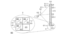
図6に、更に別のディスプレイ装置600を示した。ディスプレイ装置600は画像表示構成体610を備えている。画像表示構成体610は、この画像表示構成体610の前面612に画像を表示するための複数のピクセル611-1、611-2、…、611-nを備えている。複数のピクセル611-1、611-2、…、611-nのうちの少なくとも1つのピクセル(ここではそれをピクセル611-nとする)は、第1駆動信号641により駆動されて赤色光642を発する第1サブピクセル640を備えている。また、当該ピクセルは、第2駆動信号651により駆動されて青色光652を発する第2サブピクセル650を備えている。更に、当該ピクセルは、第3駆動信号661により駆動されて緑色光662を発する第3サブピクセル660を備えると共に、音波の透過を許容する音響透過性領域670を備えている。ディスプレイ装置600は更に、複数の音響トランスデューサ620-1、620-2、…、620-nを備えており、それら複数の音響トランスデューサは、画像表示構成体610の前面612の前方空間に人間の触覚を刺激する音場621を形成するものである。複数の音響トランスデューサ620-1、620-2、…、620-nのうちの、ある1つの音響トランスデューサ(例えば音響トランスデューサ620-n)は、当該音響トランスデューサが音波を放射する領域である当該音響トランスデューサの近傍領域が、少なくとも部分的に、ピクセルの音響透過性領域670とオーバーラップするようにして、画像表示構成体610の背面613に配設されている。
FIG. 6 shows yet another
上で説明した幾つものディスプレイ装置と同様に、このディスプレイ装置600でも、画像表示構成体610を介して画像を表示できることに加えて、複数の音響トランスデューサ620-1、620-2、…、620-nにより形成される音場621を介して触覚フィードバックを提供することも可能となっている。また、複数の音響トランスデューサ620-1、620-2、…、620-nのうちの、ある1つの音響トランスデューサから放射される音波は、ピクセルの音響透過性領域670と画像表示構成体610の背面613に配設されている音響トランスデューサとが互いに位置合わせされていることから、画像表示構成体610による音響波形変歪を被らずに済むものとなっている。そのため、音響トランスデューサを駆動する上で、画像表示構成体610による音響波形変歪を考慮することが不要となっている。
Similar to the various display devices described above, this
更に、複数の音響トランスデューサ620-1、620-2、…、620-nのうちのその他の音響トランスデューサについても、それら音響トランスデューサの各々が音波を放射する領域であるそれら音響トランスデューサの各々の近傍領域が、少なくとも部分的に、複数のピクセル611-1、611-2、…、611-nのうちの各々のピクセルの音響透過性領域670とオーバーラップするようにして、画像表示構成体610の背面613に配設するようにするとよい。そうすることで、複数の音響トランスデューサ620-1、620-2、…、620-nから放射される夫々の音波のいずれもが、画像表示構成体610による音響波形変歪を免れることができる。
Further, for the other acoustic transducers among the plurality of acoustic transducers 620-1, 620-2, ..., 620-n, each of the acoustic transducers emits a sound wave, and the vicinity of each of the acoustic transducers thereof. However, at least in part, the back surface of the
ピクセルの音響透過性領域670とは、当該ピクセルの全領域のうちの、音波が音響波形変歪作用を殆どまたは全く受けることなる透過できる領域である。この音響透過性領域670は、例えば、空隙部(孔部、開口部、スリット部など)から成るものとするのもよい。画像表示構成体610が、例えば支持基板などのその他の構成要素を備えている場合には、その構成要素の全領域のうちの、ピクセルの音響透過性領域670とオーバーラップする領域もまた、音響透過性領域とするのがよい。音響透過性領域を除いたその他の点については、画像表示構成体610は、上で説明した画像表示構成体110と略々同一構成としてもよい。
The
上で説明した数々の実施例と同様に、複数の音響トランスデューサ620-1、620-2、…、620-nのうちの1つまたは幾つかの音響トランスデューサを、MEMS音響トランスデューサとして構成されたものとするのもよい。また、それら複数の音響トランスデューサ620-1、620-2、…、620-nを、25kHz以上、40kHz以上、60kHz、100kHz以上、または更にそれ以上の周波数の音波を放射するように構成された音響トランスデューサとするのもよい。 Similar to the numerous embodiments described above, one or several of the plurality of acoustic transducers 620-1, 620-2, ..., 620-n are configured as MEMS acoustic transducers. It is also good to say. Further, the acoustic transducers 620-1, 620-2, ..., 620-n are configured to emit sound waves having a frequency of 25 kHz or higher, 40 kHz or higher, 60 kHz, 100 kHz or higher, or higher. It may be a transducer.
上で説明した数々のディスプレイ装置と同様に、このディスプレイ装置600でも、音場621を、画像表示構成体610の前面612に表示されている画像に示されたオブジェクトに関連付けることが可能である。これを可能とするために、ディスプレイ装置600は、複数の音響トランスデューサ620-1、620-2、…、620-nを駆動するための複数の駆動信号を、表示されている画像に示されたオブジェクトの状態に応じた駆動信号として生成することができるようにした制御回路(不図示)を備えている。これによって、音場621を、画像に示されたオブジェクトの状態に適合したものとすることが可能となっている。
Similar to the numerous display devices described above, the
更に、このディスプレイ装置600でも、音場621の焦点622は、画像表示構成体610の前面612に近接した位置に形成することも、そこから多少離隔した位置に形成することも可能である。それには、例えば、ディスプレイ装置600の制御回路が、画像表示構成体610の前面612からの垂直離隔距離が2cm以下、1cm以下、5mm以下、或いはそれより更に短い距離となる位置に音場621の焦点622を形成するような、複数の駆動信号を生成するようにすればよい。或いはまた、この制御回路が、画像表示構成体610の前面612からの垂直離隔距離が1cm以上、2cm以上、5cm以上、10cm以上、或いはそれより更に長い距離となる位置に音場621の焦点622を形成するような、複数の駆動信号を生成するようにすればよい。
Further, also in this
更に、ディスプレイ装置600の制御回路が、複数の駆動信号のうちの1つまたは幾つかを、画像表示構成体610の前面612に設けられた基板(不図示)の少なくとも1つの音響特性に応じた駆動信号として生成するようにするとよい。そうすることで、画像表示構成体610とユーザとの間に存在する当該基板(これは例えばガラス基板などの支持層を成す基板である)によって引き起こされる、複数の音響トランスデューサ620-1、620-2、…、620-nから放射される音波に対する音響波形変歪を、補整することができる。
Further, the control circuit of the
更に、ディスプレイ装置100の複数の音響トランスデューサ120-1、120-2、…、120-nに関して上で説明したのと同様に、複数の音響トランスデューサ620-1、620-2、…、620-nのうちの少なくとも1つの音響トランスデューサを、受波した音波に応じた出力信号を送出できるように構成された音響トランスデューサとするのもよい。
Further, similar to those described above for the plurality of acoustic transducers 120-1, 120-2, ..., 120-n of the
以上、説明したように、本開示に係る数々の実施例は、特に、視覚的な構成要素と音響的な構成要素とを重ね合わせて一体化した構成に関するものである。また、それら2つの構成要素の夫々の特質を互いに協調させ調和させたものである。そして、かかる構成によって、アクティブ視覚ディスプレイの前方空間に、空間的及び時間的に可変の音圧場を形成し得るようにしたものである。 As described above, the numerous embodiments according to the present disclosure particularly relate to a configuration in which a visual component and an acoustic component are superposed and integrated. In addition, the characteristics of each of these two components are coordinated and harmonious with each other. With this configuration, a spatially and temporally variable sound pressure field can be formed in the space in front of the active visual display.
より具体的には、例えば、複数の音響トランスデューサをアクティブ視覚ディスプレイの背面に2次元配列で配設した構成とすることも可能である。この構成とする場合には、個々の超音波音響トランスデューサの駆動態様に補正を加えることで、駆動視覚ディスプレイの音響特性を原因とする音場の変歪を抑制するようにするとよい。或いはまた、個々の超音波音響トランスデューサを、視覚ディスプレイの音響特性に合わせて設計したものとするのもよく、その場合には特に、その視覚ディスプレイが、当該視覚ディスプレイの背面に配設される当該超音波音響トランスデューサにとっての、音響適合化層として機能するように、当該音響トランスデューサを設計するようにするのもよい。また、例えば、複数の超音波音響トランスデューサを1つにまとめて、超音波音響トランスデューサ・アレイの形態として製作するようにするのもよい。またその場合には、当該超音波音響トランスデューサ・アレイを、マイクロシステム技術を用いて製作したものとするのもよい。 More specifically, for example, it is possible to configure a plurality of acoustic transducers arranged in a two-dimensional arrangement on the back surface of the active visual display. In this configuration, it is preferable to correct the drive mode of each ultrasonic acoustic transducer to suppress the distortion of the sound field caused by the acoustic characteristics of the drive visual display. Alternatively, the individual ultrasonic acoustic transducers may be designed for the acoustic characteristics of the visual display, in particular such that the visual display is disposed on the back of the visual display. The acoustic transducer may be designed to act as an acoustic adaptation layer for the ultrasonic acoustic transducer. Further, for example, a plurality of ultrasonic acoustic transducers may be combined into one and manufactured as a form of an ultrasonic acoustic transducer array. In that case, the ultrasonic acoustic transducer array may be manufactured by using the micro system technique.
或いはまた、複数の超音波音響トランスデューサをアクティブ視覚ディスプレイの前面に2次元配列で配設した構成とすることも可能である。この構成とする場合には、個々の超音波音響トランスデューサを光透過性材料で製作したものとすればよい。 Alternatively, it is also possible to configure a plurality of ultrasonic acoustic transducers arranged in a two-dimensional arrangement on the front surface of the active visual display. In this configuration, the individual ultrasonic acoustic transducers may be made of a light-transmitting material.
或いはまた、アクティブ視覚ディスプレイそれ自体を音波発生源として利用する構成とすることも可能である。この構成とする場合には、例えば、隣り合うものどうしが音響的に絶縁された複数の超音波音響トランスデューサによって、当該視覚ディスプレイの背面に音波発生源構造を一体的に構築するなどすればよい。 Alternatively, the active visual display itself can be configured to be used as a sound wave generation source. In this configuration, for example, a sound wave source structure may be integrally constructed on the back surface of the visual display by a plurality of ultrasonic acoustic transducers in which adjacent objects are acoustically isolated from each other.
これらの構成とすることで、視覚ディスプレイの前方空間に、時間的及び位置的に可変の音圧場を形成することができ、その音圧場を利用して触覚フィードバックを提供することができる。また、これらの構成によれば、視覚表示システムと音響システムとを、最適に調和させて単一のユニットとすることができる。また、平板状の構造であるため、視覚ディスプレイの厚さを非常に薄くすることができる。更に加えて、視覚ディスプレイの周縁部に、超音波音響トランスデューサを配置するためのスペースを確保する必要もない。 With these configurations, a temporally and positionally variable sound pressure field can be formed in the space in front of the visual display, and the sound pressure field can be used to provide tactile feedback. Further, according to these configurations, the visual display system and the acoustic system can be optimally harmonized into a single unit. Moreover, since it has a flat plate-like structure, the thickness of the visual display can be made very thin. Furthermore, it is not necessary to secure a space for placing the ultrasonic acoustic transducer on the peripheral edge of the visual display.
以上に提案したディスプレイ装置は、例えば、様々な端末(例えば、スマートフォン、ラップトップ型コンピュータ、タブレット型コンピュータ、等々)にも、また、コンピュータ・グラフィックス出力装置(例えば、コンピュータ・ゲーム機など)にも、更には、コオペラティブ・ロボティクスにも好適に利用し得るものである。 The display devices proposed above can be used, for example, in various terminals (for example, smartphones, laptop computers, tablet computers, etc.) and in computer graphics output devices (for example, computer game machines, etc.). Further, it can be suitably used for collaborative robotics.
本明細書の以上の記載、特許請求の範囲の記載、それに添付図面により開示されている数々の特徴は、様々な構成形態の実施例を実現する際に、個々の特徴を単独で実施例に組込むこともでき、また、幾つかの特徴を任意に組合わせて実施例に組込むことも可能なものであり、如何なる組込み方をするにせよ、それら数々の特徴は重要な意味を持つものである。 The above description of the present specification, the description of the scope of claims, and the numerous features disclosed in the accompanying drawings make each feature a stand-alone example in realizing the examples of various configurations. It can be incorporated, and some features can be arbitrarily combined and incorporated into the embodiment, and these features are important regardless of the method of incorporation. ..
以上に装置を説明することを通して数多くの局面について論じたが、容易に理解されるように、それら局面はいずも、説明した装置に対応する方法の局面でもある。従って、ある1つの装置におけるある1つのブロック乃至はある1つの構成要素は、当該装置に対応する1つの方法における1つの方法ステップ乃至は方法ステップ中の1つの特徴としても理解されるべきものである。逆もまた同じであり、ある1つの方法ステップを説明することを通して論じた、或いは、ある方法ステップそのものとして論じた数々の局面は、方法に対応する装置における1つのブロック、又はある1つの細部構造、又はある1つの特徴としても理解されるべきものである。 Many aspects have been discussed through the description of the device above, but as can be easily understood, these aspects are also aspects of the method corresponding to the described device. Therefore, one block or one component in one device should also be understood as one feature in one method step or method step in one method corresponding to the device. be. The reverse is also true, and the aspects discussed through explaining one method step, or as one method step itself, are one block in the device corresponding to the method, or one detail structure. Or should be understood as a feature.
以上に記載した数々の実施例は、あくまでも本発明の原理を明らかにするためのものである。当業者であれば、本明細書に記載した数々の構成並びに細部構造に改変を加えることにも、また、それらを別の形態で実施することにも想到すると考えられる。それゆえ、本発明の保護範囲は、特許請求の範囲の記載によってのみ規定されるものであって、実施例の説明並びに解説のために提示した個々の具体的な特徴によって規定されるものではない。 The numerous examples described above are for the purpose of clarifying the principle of the present invention. Those skilled in the art will be conceived of making modifications to the numerous configurations and detailed structures described herein, as well as implementing them in other forms. Therefore, the scope of protection of the present invention is defined only by the description of the scope of claims, not by the individual specific features presented for the explanation and explanation of the examples. ..
Claims (10)
画像表示構成体(110)を備えており、該画像表示構成体は、該画像表示構成体の前面(112)に画像を表示するための複数のピクセル(111-1、111-2、…、111-n)を備えており、
複数の音響トランスデューサ(120-1、120-2、…、120-n)を備えており、それら複数の音響トランスデューサは、複数の駆動信号(131-1、131-2、…、131-n)により駆動されることで、前記画像表示構成体(110)の前記前面(112)の前方空間に人間の触覚を刺激する音場(121)を形成するものであり、それら複数の音響トランスデューサ(120-1、120-2、…、120-n)は、前記画像表示構成体(110)の背面(112)に配設されており、
制御回路を備えており、該制御回路は、前記複数の駆動信号(131-1、131-2、…、131-n)のうちの少なくとも1つの駆動信号に、前記画像表示構成体(110)の少なくとも1つの音響特性に応じた事前の信号改変を施すことにより、前記画像表示構成体110によって引き起こされる、前記複数の音響トランスデューサ120-1、120-2、…、120-nから放射される音波に対する音響波形変歪を補整することを特徴とするディスプレイ装置。 In the display device (100)
An image display structure (110) is provided, and the image display structure includes a plurality of pixels (111-1, 111-2, ..., For displaying an image on the front surface (112) of the image display structure. It is equipped with 111-n) and
A plurality of acoustic transducers (120-1, 120-2, ..., 120-n) are provided, and the plurality of acoustic transducers have a plurality of drive signals (131-1, 131-2, ..., 131-n). By being driven by, a sound field (121) that stimulates human tactile sensation is formed in the space in front of the front surface (112) of the image display configuration (110), and a plurality of acoustic transducers (120) are formed. -1,120-2, ..., 120-n) are arranged on the back surface (112) of the image display configuration (110).
A control circuit is provided, and the control circuit includes the image display configuration (110) in addition to at least one drive signal among the plurality of drive signals (131-1, 131-2, ..., 131-n). Emitted from the plurality of acoustic transducers 120-1, 120-2, ..., 120-n caused by the image display configuration 110 by performing prior signal modification according to at least one acoustic characteristic of. A display device characterized by compensating for acoustic waveform distortion and distortion with respect to sound waves.
Priority Applications (1)
| Application Number | Priority Date | Filing Date | Title |
|---|---|---|---|
| JP2021197559A JP7366109B2 (en) | 2017-07-17 | 2021-12-06 | display device |
Applications Claiming Priority (3)
| Application Number | Priority Date | Filing Date | Title |
|---|---|---|---|
| DE102017116012.4 | 2017-07-17 | ||
| DE102017116012.4A DE102017116012A1 (en) | 2017-07-17 | 2017-07-17 | DISPLAY DEVICES AND PIXEL FOR ONE DISPLAY DEVICE |
| PCT/EP2018/065485 WO2019015882A1 (en) | 2017-07-17 | 2018-06-12 | Display apparatuses and pixels for a display apparatus |
Related Child Applications (1)
| Application Number | Title | Priority Date | Filing Date |
|---|---|---|---|
| JP2021197559A Division JP7366109B2 (en) | 2017-07-17 | 2021-12-06 | display device |
Publications (2)
| Publication Number | Publication Date |
|---|---|
| JP2020527269A JP2020527269A (en) | 2020-09-03 |
| JP7064567B2 true JP7064567B2 (en) | 2022-05-10 |
Family
ID=62597523
Family Applications (2)
| Application Number | Title | Priority Date | Filing Date |
|---|---|---|---|
| JP2020502309A Active JP7064567B2 (en) | 2017-07-17 | 2018-06-12 | Pixels for Display Devices and Display Devices |
| JP2021197559A Active JP7366109B2 (en) | 2017-07-17 | 2021-12-06 | display device |
Family Applications After (1)
| Application Number | Title | Priority Date | Filing Date |
|---|---|---|---|
| JP2021197559A Active JP7366109B2 (en) | 2017-07-17 | 2021-12-06 | display device |
Country Status (6)
| Country | Link |
|---|---|
| US (1) | US11061477B2 (en) |
| EP (2) | EP3655844A1 (en) |
| JP (2) | JP7064567B2 (en) |
| KR (2) | KR102337968B1 (en) |
| DE (1) | DE102017116012A1 (en) |
| WO (1) | WO2019015882A1 (en) |
Families Citing this family (2)
| Publication number | Priority date | Publication date | Assignee | Title |
|---|---|---|---|---|
| KR102591674B1 (en) | 2020-07-10 | 2023-10-23 | 한국전자통신연구원 | Devices for playing acoustic sound and touch sensation |
| DE102022101316A1 (en) | 2022-01-20 | 2023-07-20 | Carl Zeiss Jena Gmbh | Haptic hologram |
Citations (2)
| Publication number | Priority date | Publication date | Assignee | Title |
|---|---|---|---|---|
| US20110199342A1 (en) | 2010-02-16 | 2011-08-18 | Harry Vartanian | Apparatus and method for providing elevated, indented or texturized sensations to an object near a display device or input detection using ultrasound |
| JP2017503255A (en) | 2013-12-12 | 2017-01-26 | クアルコム,インコーポレイテッド | Micromechanical ultrasonic transducers and displays |
Family Cites Families (26)
| Publication number | Priority date | Publication date | Assignee | Title |
|---|---|---|---|---|
| US9829977B2 (en) * | 2008-04-02 | 2017-11-28 | Immersion Corporation | Method and apparatus for providing multi-point haptic feedback texture systems |
| TW201101137A (en) * | 2009-06-29 | 2011-01-01 | J Touch Corp | Touch panel with matrix type tactile feedback |
| EP2325731B1 (en) * | 2009-11-02 | 2013-11-13 | SMK Corporation | Holding structure for a touch panel |
| US8519982B2 (en) * | 2010-06-21 | 2013-08-27 | Sony Corporation | Active acoustic touch location for electronic devices |
| JP5343946B2 (en) | 2010-08-25 | 2013-11-13 | 株式会社デンソー | Tactile presentation device |
| US20120299853A1 (en) * | 2011-05-26 | 2012-11-29 | Sumit Dagar | Haptic interface |
| US20130113760A1 (en) * | 2011-11-07 | 2013-05-09 | Google Inc. | Techniques for providing localized tactile feedback to a user via an electro-acoustic touch display of a user device |
| US8570296B2 (en) * | 2012-05-16 | 2013-10-29 | Immersion Corporation | System and method for display of multiple data channels on a single haptic display |
| GB201208853D0 (en) * | 2012-05-18 | 2012-07-04 | Hiwave Technologies Uk Ltd | Panel for use in vibratory panel device |
| DE102012208355A1 (en) | 2012-05-18 | 2013-11-21 | Robert Bosch Gmbh | Arrangement and method for generating a sense of touch of a user |
| GB2513884B (en) | 2013-05-08 | 2015-06-17 | Univ Bristol | Method and apparatus for producing an acoustic field |
| US9519346B2 (en) * | 2013-05-17 | 2016-12-13 | Immersion Corporation | Low-frequency effects haptic conversion system |
| GB2516820A (en) * | 2013-07-01 | 2015-02-11 | Nokia Corp | An apparatus |
| US9576445B2 (en) * | 2013-09-06 | 2017-02-21 | Immersion Corp. | Systems and methods for generating haptic effects associated with an envelope in audio signals |
| US9817521B2 (en) * | 2013-11-02 | 2017-11-14 | At&T Intellectual Property I, L.P. | Gesture detection |
| US9639158B2 (en) * | 2013-11-26 | 2017-05-02 | Immersion Corporation | Systems and methods for generating friction and vibrotactile effects |
| US9612658B2 (en) * | 2014-01-07 | 2017-04-04 | Ultrahaptics Ip Ltd | Method and apparatus for providing tactile sensations |
| KR101464327B1 (en) * | 2014-03-27 | 2014-11-25 | 연세대학교 산학협력단 | Apparatus, system and method for providing air-touch feedback |
| WO2016007920A1 (en) * | 2014-07-11 | 2016-01-14 | New York University | Three dimensional tactile feedback system |
| KR102315184B1 (en) * | 2014-11-21 | 2021-10-20 | 삼성디스플레이 주식회사 | Display device |
| US10403084B2 (en) * | 2014-12-17 | 2019-09-03 | Igt Canada Solutions Ulc | Contactless tactile feedback on gaming terminal with 3D display |
| KR102524966B1 (en) * | 2015-02-20 | 2023-04-21 | 울트라햅틱스 아이피 엘티디 | Algorithm improvements in haptic systems |
| US10591869B2 (en) * | 2015-03-24 | 2020-03-17 | Light Field Lab, Inc. | Tileable, coplanar, flat-panel 3-D display with tactile and audio interfaces |
| JP2017027401A (en) * | 2015-07-23 | 2017-02-02 | 株式会社デンソー | Display operation device |
| DE102016210217A1 (en) * | 2016-06-09 | 2017-12-14 | Bayerische Motoren Werke Aktiengesellschaft | Means of transport, user interface and method for interaction between a means of transportation and an occupant |
| US10531212B2 (en) * | 2016-06-17 | 2020-01-07 | Ultrahaptics Ip Ltd. | Acoustic transducers in haptic systems |
-
2017
- 2017-07-17 DE DE102017116012.4A patent/DE102017116012A1/en active Pending
-
2018
- 2018-06-12 EP EP18730775.6A patent/EP3655844A1/en not_active Ceased
- 2018-06-12 WO PCT/EP2018/065485 patent/WO2019015882A1/en unknown
- 2018-06-12 EP EP24152316.6A patent/EP4345813A2/en active Pending
- 2018-06-12 KR KR1020207002978A patent/KR102337968B1/en active IP Right Grant
- 2018-06-12 KR KR1020217038081A patent/KR102367547B1/en active IP Right Grant
- 2018-06-12 US US16/631,477 patent/US11061477B2/en active Active
- 2018-06-12 JP JP2020502309A patent/JP7064567B2/en active Active
-
2021
- 2021-12-06 JP JP2021197559A patent/JP7366109B2/en active Active
Patent Citations (2)
| Publication number | Priority date | Publication date | Assignee | Title |
|---|---|---|---|---|
| US20110199342A1 (en) | 2010-02-16 | 2011-08-18 | Harry Vartanian | Apparatus and method for providing elevated, indented or texturized sensations to an object near a display device or input detection using ultrasound |
| JP2017503255A (en) | 2013-12-12 | 2017-01-26 | クアルコム,インコーポレイテッド | Micromechanical ultrasonic transducers and displays |
Also Published As
| Publication number | Publication date |
|---|---|
| US20200209969A1 (en) | 2020-07-02 |
| DE102017116012A1 (en) | 2019-01-17 |
| JP2022019992A (en) | 2022-01-27 |
| WO2019015882A1 (en) | 2019-01-24 |
| KR102367547B1 (en) | 2022-02-24 |
| US11061477B2 (en) | 2021-07-13 |
| EP4345813A2 (en) | 2024-04-03 |
| JP7366109B2 (en) | 2023-10-20 |
| KR20200023649A (en) | 2020-03-05 |
| EP3655844A1 (en) | 2020-05-27 |
| KR102337968B1 (en) | 2021-12-13 |
| KR20210147088A (en) | 2021-12-06 |
| JP2020527269A (en) | 2020-09-03 |
Similar Documents
| Publication | Publication Date | Title |
|---|---|---|
| US10705617B2 (en) | Tactile sensation providing apparatus and control method for tactile sensation providing apparatus | |
| US11100771B2 (en) | Devices and methods for providing localized haptic effects to a display screen | |
| US9448662B2 (en) | Touch panel capable of forming desired shape at desired position on detection screen, electronic device including same, and method for driiving same | |
| JP7366109B2 (en) | display device | |
| RU2554518C2 (en) | Hybrid display device | |
| US20190197284A1 (en) | Ultrasonic transducers embedded in organic light emitting diode panel and display devices including the same | |
| CN109036148B (en) | Flexible display panel and flexible display device | |
| US20110316798A1 (en) | Tactile Display for Providing Touch Feedback | |
| US20110199321A1 (en) | Apparatus for providing self-morphable haptic and visual information and method thereof | |
| WO2018062078A1 (en) | Display device | |
| US10664053B2 (en) | Multi-transducer tactile user interface for electronic devices | |
| KR102315184B1 (en) | Display device | |
| US20210072861A1 (en) | Areal device offering improved localized deformation | |
| EP3446195B1 (en) | Tactile user interface for electronic devices | |
| WO2018040675A1 (en) | Touch display panel and display device | |
| KR20110093553A (en) | Apparatus and method for providing touch and sight sensation information | |
| SE542811C2 (en) | A device, system and method for generating an acoustic-potential field of ultrasonic waves | |
| US20240111365A1 (en) | Timing of Haptic Signals | |
| TWM630793U (en) | Force sensing module with vibration feedback |
Legal Events
| Date | Code | Title | Description |
|---|---|---|---|
| A521 | Request for written amendment filed |
Free format text: JAPANESE INTERMEDIATE CODE: A523 Effective date: 20200310 |
|
| A621 | Written request for application examination |
Free format text: JAPANESE INTERMEDIATE CODE: A621 Effective date: 20200310 |
|
| A977 | Report on retrieval |
Free format text: JAPANESE INTERMEDIATE CODE: A971007 Effective date: 20210125 |
|
| A131 | Notification of reasons for refusal |
Free format text: JAPANESE INTERMEDIATE CODE: A131 Effective date: 20210201 |
|
| A521 | Request for written amendment filed |
Free format text: JAPANESE INTERMEDIATE CODE: A523 Effective date: 20210422 |
|
| A02 | Decision of refusal |
Free format text: JAPANESE INTERMEDIATE CODE: A02 Effective date: 20210810 |
|
| A521 | Request for written amendment filed |
Free format text: JAPANESE INTERMEDIATE CODE: A523 Effective date: 20211206 |
|
| C60 | Trial request (containing other claim documents, opposition documents) |
Free format text: JAPANESE INTERMEDIATE CODE: C60 Effective date: 20211206 |
|
| C11 | Written invitation by the commissioner to file amendments |
Free format text: JAPANESE INTERMEDIATE CODE: C11 Effective date: 20211227 |
|
| A911 | Transfer to examiner for re-examination before appeal (zenchi) |
Free format text: JAPANESE INTERMEDIATE CODE: A911 Effective date: 20220208 |
|
| C21 | Notice of transfer of a case for reconsideration by examiners before appeal proceedings |
Free format text: JAPANESE INTERMEDIATE CODE: C21 Effective date: 20220214 |
|
| TRDD | Decision of grant or rejection written | ||
| A01 | Written decision to grant a patent or to grant a registration (utility model) |
Free format text: JAPANESE INTERMEDIATE CODE: A01 Effective date: 20220404 |
|
| A61 | First payment of annual fees (during grant procedure) |
Free format text: JAPANESE INTERMEDIATE CODE: A61 Effective date: 20220422 |
|
| R150 | Certificate of patent or registration of utility model |
Ref document number: 7064567 Country of ref document: JP Free format text: JAPANESE INTERMEDIATE CODE: R150 |