JP7061680B2 - Inter-prediction methods and equipment that use the reduced previous line buffer in video coding - Google Patents
Inter-prediction methods and equipment that use the reduced previous line buffer in video coding Download PDFInfo
- Publication number
- JP7061680B2 JP7061680B2 JP2020546138A JP2020546138A JP7061680B2 JP 7061680 B2 JP7061680 B2 JP 7061680B2 JP 2020546138 A JP2020546138 A JP 2020546138A JP 2020546138 A JP2020546138 A JP 2020546138A JP 7061680 B2 JP7061680 B2 JP 7061680B2
- Authority
- JP
- Japan
- Prior art keywords
- motion vector
- video
- data
- current
- encoded
- Prior art date
- Legal status (The legal status is an assumption and is not a legal conclusion. Google has not performed a legal analysis and makes no representation as to the accuracy of the status listed.)
- Active
Links
Images


Classifications
-
- H—ELECTRICITY
- H04—ELECTRIC COMMUNICATION TECHNIQUE
- H04N—PICTORIAL COMMUNICATION, e.g. TELEVISION
- H04N19/00—Methods or arrangements for coding, decoding, compressing or decompressing digital video signals
- H04N19/50—Methods or arrangements for coding, decoding, compressing or decompressing digital video signals using predictive coding
- H04N19/503—Methods or arrangements for coding, decoding, compressing or decompressing digital video signals using predictive coding involving temporal prediction
- H04N19/51—Motion estimation or motion compensation
- H04N19/513—Processing of motion vectors
- H04N19/517—Processing of motion vectors by encoding
- H04N19/52—Processing of motion vectors by encoding by predictive encoding
-
- H—ELECTRICITY
- H04—ELECTRIC COMMUNICATION TECHNIQUE
- H04N—PICTORIAL COMMUNICATION, e.g. TELEVISION
- H04N19/00—Methods or arrangements for coding, decoding, compressing or decompressing digital video signals
- H04N19/10—Methods or arrangements for coding, decoding, compressing or decompressing digital video signals using adaptive coding
- H04N19/134—Methods or arrangements for coding, decoding, compressing or decompressing digital video signals using adaptive coding characterised by the element, parameter or criterion affecting or controlling the adaptive coding
- H04N19/157—Assigned coding mode, i.e. the coding mode being predefined or preselected to be further used for selection of another element or parameter
- H04N19/159—Prediction type, e.g. intra-frame, inter-frame or bidirectional frame prediction
-
- H—ELECTRICITY
- H04—ELECTRIC COMMUNICATION TECHNIQUE
- H04N—PICTORIAL COMMUNICATION, e.g. TELEVISION
- H04N19/00—Methods or arrangements for coding, decoding, compressing or decompressing digital video signals
- H04N19/10—Methods or arrangements for coding, decoding, compressing or decompressing digital video signals using adaptive coding
- H04N19/169—Methods or arrangements for coding, decoding, compressing or decompressing digital video signals using adaptive coding characterised by the coding unit, i.e. the structural portion or semantic portion of the video signal being the object or the subject of the adaptive coding
- H04N19/17—Methods or arrangements for coding, decoding, compressing or decompressing digital video signals using adaptive coding characterised by the coding unit, i.e. the structural portion or semantic portion of the video signal being the object or the subject of the adaptive coding the unit being an image region, e.g. an object
- H04N19/176—Methods or arrangements for coding, decoding, compressing or decompressing digital video signals using adaptive coding characterised by the coding unit, i.e. the structural portion or semantic portion of the video signal being the object or the subject of the adaptive coding the unit being an image region, e.g. an object the region being a block, e.g. a macroblock
-
- H—ELECTRICITY
- H04—ELECTRIC COMMUNICATION TECHNIQUE
- H04N—PICTORIAL COMMUNICATION, e.g. TELEVISION
- H04N19/00—Methods or arrangements for coding, decoding, compressing or decompressing digital video signals
- H04N19/42—Methods or arrangements for coding, decoding, compressing or decompressing digital video signals characterised by implementation details or hardware specially adapted for video compression or decompression, e.g. dedicated software implementation
- H04N19/423—Methods or arrangements for coding, decoding, compressing or decompressing digital video signals characterised by implementation details or hardware specially adapted for video compression or decompression, e.g. dedicated software implementation characterised by memory arrangements
- H04N19/426—Methods or arrangements for coding, decoding, compressing or decompressing digital video signals characterised by implementation details or hardware specially adapted for video compression or decompression, e.g. dedicated software implementation characterised by memory arrangements using memory downsizing methods
-
- H—ELECTRICITY
- H04—ELECTRIC COMMUNICATION TECHNIQUE
- H04N—PICTORIAL COMMUNICATION, e.g. TELEVISION
- H04N19/00—Methods or arrangements for coding, decoding, compressing or decompressing digital video signals
- H04N19/90—Methods or arrangements for coding, decoding, compressing or decompressing digital video signals using coding techniques not provided for in groups H04N19/10-H04N19/85, e.g. fractals
- H04N19/96—Tree coding, e.g. quad-tree coding
Description
本出願は、35U.S.C. §119に基づき、2018年6月1日にてアメリカ特許商標庁に提出されたアメリカ仮出願62/679,580号の優先権を主張し、その全内容を参照により本明細書に組み込む。 This application claims the priority of US Provisional Application No. 62 / 679,580 filed with the United States Patent and Trademark Office on June 1, 2018, based on 35USC §119, the entire contents of which are claimed. Is incorporated herein by reference.
本開示は、インターピクチャ予測符号化に関し、特に、マージモードに関する。追加の空間的又は時間的マージ候補を使用してマージ候補リストを生成し、マージ候補リストの生成を修正する。マージインデックスのシグナリング方式も提案されている。 The present disclosure relates to interpicture predictive coding, especially to merge modes. Generate a merge candidate list with additional spatial or temporal merge candidates and modify the merge candidate list generation. A signaling method for merge indexes has also been proposed.
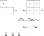
高効率ビデオ符号化(HEVC)では、インターピクチャ予測のためのマージモードが導入されている。隣接ブロックからの候補動きパラメータのマージ候補リストを生成する。そして、インデックスは信号で示され、使用対象となる候補を標識する。マージモードは、以前に符号化されたピクチャから取得した候補をリストに含めることで、時間予測も可能である。図1を参照し、HEVCでは、1つ以上の空間的マージ候補(101)、(102)、(103)、(104)、及び/又は(105)、2つの時間的コロケート〔共位置〕ブロックから導出される1つの時間的マージ候補、及び/又は組み合わせた双方向予測候補とゼロ動きベクトル候補を含む追加のマージ候補に基づいて、現在のブロック(100)のマージ候補リストを生成する。 High Efficiency Video Coding (HEVC) introduces a merge mode for interpicture prediction. Generate a merge candidate list of candidate motion parameters from adjacent blocks. The index is then signaled to indicate candidates for use. The merge mode can also predict time by including in the list the candidates taken from the previously encoded picture. With reference to FIG. 1, in HEVC, one or more spatial merge candidates (101), (102), (103), (104), and / or (105 ) , two temporal colocates blocks. Generates a list of merge candidates for the current block (100) based on one temporal merge candidate derived from and / or additional merge candidates including a combination of bidirectional prediction candidates and zero motion vector candidates.
HEVCでは、スキップモードは、ブロックについて動きデータが信号で明確に示されるものではなく、推定されるものであることを指示するために使用され、また、予測残差がゼロであることを指示するために使用され、つまり、変換係数は送信されない。HEVCでは、インターピクチャ予測スライスにおける各符号化ユニット(CU)の先頭で、skip_flagを信号で示し、当該skip_flagは、CUが1つの予測ユニット(PU)(例えば、2N×2N)のみを含み、マージモードを使用して動きデータを導出し、及び/又はビットストリームに残差データが存在しないことを意味する。 In HEVC, the skip mode is used to indicate that the motion data for the block is not clearly indicated by the signal, but is estimated, and also indicates that the predicted residuals are zero. That is, the conversion factor is not transmitted. In HEVC, the sk ip_flag is signaled at the beginning of each coding unit (CU) in the interpicture prediction slice, and the sk ip_flag has only one prediction unit (PU) (for example, 2N × 2N) with one CU. Means that motion data is derived using merge mode and / or there is no residual data in the bitstream.
共同ビデオ探査チーム(JVET)によって検討されたテストモデルソフトウェアである共同探査モデル7(JEM7)において、新しいマージ候補が導入される。サブCUモードを追加のマージ候補とすることを可能にし、これらのモードを信号で示すために追加の構文要素は必要ではない。2つの追加のマージ候補が、代替時間的動きベクトル予測(ATMVP)モードと時空間動きベクトル予測(STMVP)モードを示すために各CUのマージ候補リストに追加される。シーケンスパラメータセットが、ATMVPモードとSTMVPモードとを可能にすることを指示する場合、最大7つのマージ候補を使用する。追加のマージ候補の符号化ロジックは、HEVCにおけるマージ候補の符号化ロジックと同じであり、これは、予測(P)スライス又は双方向予測(B)スライスにおける各CUについて、これらの2つの追加のマージ候補に対してさらに2回のレート歪み(RD)チェックが必要である。JEMでは、插入されるマージ候補の順序はA、B、C、D、ATMVP、STMVP、E(リストにおけるマージ候補が6よりも小さい場合)、時間的動きベクトル予測(TMVP)、組み合わせられた双方向予測候補及びゼロ動きベクトル候補である。 A new merge candidate will be introduced in Joint Exploration Model 7 (JEM7), a test model software reviewed by the Joint Video Exploration Team (JVET). It allows sub-CU modes to be additional merge candidates and no additional syntax elements are needed to signal these modes. Two additional merge candidates are added to each CU's merge candidate list to indicate alternative temporal motion vector prediction (ATMVP) mode and spatiotemporal motion vector prediction (STMVP) mode. If the sequence parameter set indicates that ATMVP mode and STMVP mode are enabled, up to 7 merge candidates are used. The coding logic for the additional merge candidates is the same as the coding logic for the merge candidates in HEVC, which is for each CU in the predictive (P) slice or the bidirectional predictive (B) slice. Two more rate distortion (RD) checks are required for the merge candidates. In JEM, the order of merge candidates to be inserted is A, B, C, D, ATMVP, STMVP, E (when the merge candidate in the list is less than 6), temporal motion vector prediction (TMVP), both combined. It is a direction prediction candidate and a zero motion vector candidate.
JEMでは、マージインデックスの全てのバイナリビットは、コンテキスト適応型バイナリ算術符号化(CABAC)によってコンテキスト符号化される。HEVCでは、最初のバイナリビットのみをコンテキスト符号化し、残りのバイナリビットをコンテキストバイパス符号化する。JEMでは、マージ候補の最大数は7である。 In JEM, all binary bits of a merge index are context-encoded by context-adaptive binary arithmetic coding (CABAC). In HEVC, only the first binary bit is context-encoded and the remaining binary bits are context-bypass-encoded. In JEM, the maximum number of merge candidates is 7.
マージ候補リスト生成処理では、現在のCUが符号化ツリーユニット(CTU)の垂直境界にある場合に、前のCTUの動きデータを参照することができる。そのため、前のCTUの最後の行の動きデータを記憶するラインバッファが存在する。動きデータの記憶には4×4グリッドを使用する。 In the merge candidate list generation process, when the current CU is at the vertical boundary of the coded tree unit (CTU), the motion data of the previous CTU can be referred to. Therefore, there is a line buffer that stores the motion data of the last row of the previous CTU. A 4x4 grid is used to store motion data.
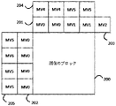
図2は、マージ候補リスト生成の例を示す。例えば、このスキームは、8×8ブロックのステップサイズで、以前に符号化されたブロックからの候補動きベクトルにおいて検索することである。当該スキームは、現在のブロック(200)の最も近い空間近傍、即ち、すぐ隣接する上の行(201)、左の列(202)、右上隅(203)をカテゴリ1として定義する。他の近傍(204、205)、例えば、外側の領域(現在のブロックの境界から最大で3つの8×8ブロック離れている)、及び以前に符号化されたフレームにおける共位置のブロックは、カテゴリ2として分類する。リストから、異なる参照フレームに基づき予測された隣接ブロック、又はフレーム内の符号化された隣接ブロックを削除する。そして、残りの参照ブロックのそれぞれに重みを割り当てる。当該重みは、現在のブロックまでの距離に関する。 FIG. 2 shows an example of merging candidate list generation. For example, this scheme is to search in candidate motion vectors from previously encoded blocks with a step size of 8x8 blocks. The scheme defines the closest spatial neighborhood of the current block (200), that is, the immediately adjacent upper row (201), left column (202), upper right corner (203) as category 1. Other neighborhoods (204, 205), such as the outer region ( up to three 8x8 blocks away from the boundaries of the current block), and co-located blocks in the previously encoded frame are Classify as category 2. Remove from the list the predicted adjacent blocks based on different reference frames, or the coded adjacent blocks within the frame. Then, weights are assigned to each of the remaining reference blocks. The weight relates to the distance to the current block.
拡張マージモードでは、追加のマージ候補は次(NEXT)のマージ候補の直接拡張である。現在ブロックにすぐ隣接しない左、上、左下、右上、左上の候補をチェックする。図1は、チェックされる詳細な位置を示す。例として、マージ候補の最大数は10であり得る。 In extended merge mode, the additional merge candidate is a direct extension of the next (NEXT) merge candidate. Check for candidates on the left, top, bottom left, top right, and top left that are not currently adjacent to the block. FIG. 1 shows the detailed position to be checked. As an example, the maximum number of merge candidates can be 10.
ATMVP及びマージモードでは、TMVPを使用するには、コロケートの参照ピクチャにおける動きデータ(動きベクトル、参照インデックス及び符号化モードを含む)を記憶する必要がある。動き表現の粒度を考慮して、動きデータを記憶するために必要なメモリサイズは重要になり得る。HEVCは動きデータストレージ縮減(MDSR)を採用して、参照ピクチャにおける動きデータをサブサンプリングすることで、動きデータバッファのサイズ、及び関連するメモリアクセス帯域幅を縮減する。HEVCは、16×16ブロックを使用し、なお、4×4グリッドをサブサンプリングする場合に、左上の4×4ブロックの情報を記憶する。当該サブサンプリングによって、MDSRは時間的予測の品質に影響を与える。また、コロケートに使用されるピクチャにおけるMVの位置とMDSRによって記憶されるMVの位置との間には密接な関連性がある。 In ATMVP and merge modes, in order to use TMVP, it is necessary to store motion data (including motion vector, reference index and coding mode) in the referenced picture of the collage. Considering the granularity of motion representation, the memory size required to store motion data can be important. HEVC employs motion data storage reduction (MDSR) to subsample motion data in a reference picture, thereby reducing the size of the motion data buffer and the associated memory access bandwidth. HEVC uses 16x16 blocks and stores information in the upper left 4x4 block when subsampling the 4x4 grid. With this subsampling, MDSR affects the quality of temporal predictions. Also, there is a close relationship between the position of the MV in the picture used for colocating and the position of the MV stored by the MDSR.
本開示の一態様によれば、ビデオシーケンスを符号化又は復号化する動きベクトルバッファを制御するための方法は、前の符号化ツリーユニット(CTU)に関連付けられる動きベクトルセットを認識するステップであって、各動きベクトルがP×Qグリッドに関連付けられ、且つ、動きベクトルセットがN×Mグリッドに関連付けられるステップと、動きベクトルセットに基づいて動きベクトルを決定するステップと、N×Mグリッドに関連付けられる位置を含む候補ブロックに基づいて、動きベクトルバッファにおいて動きベクトルにアクセスするステップと、を含む。 According to one aspect of the present disclosure, the method for controlling the motion vector buffer that encodes or decodes the video sequence is the step of recognizing the motion vector set associated with the previous encoded tree unit (CTU). Each motion vector is associated with the P × Q grid, and the motion vector set is associated with the N × M grid, the motion vector is determined based on the motion vector set, and the motion vector set is associated with the N × M grid. Includes a step to access the motion vector in the motion vector buffer, based on the candidate block containing the position to be.
本開示の一態様によれば、ビデオシーケンスを符号化又は復号化する動きベクトルバッファを制御するための装置であって、プログラムコードを記憶するように構成される少なくとも1つのメモリと、プログラムコードを読み取り、プログラムコードの指示に従って動作するように構成される少なくとも1つのプロセッサとを含み、当該プログラムコードは、少なくとも1つのプロセッサに、前の符号化ツリーユニット(CTU)に関連付けられる動きベクトルセットを認識させるように構成される認識コードであって、各動きベクトルがP×Qグリッドに関連付けられ、動きベクトルセットがN×Mグリッドに関連付けられる認識コードと、少なくとも1つのプロセッサに、動きベクトルセットに基づいて動きベクトルを決定させるように構成される決定コードと、少なくとも1つのプロセッサに、N×Mグリッドに関連付けられる位置を含む候補ブロックに基づいて、動きベクトルバッファにおいて動きベクトルにアクセスさせるように構成されるアクセスコードと、を含む。 According to one aspect of the present disclosure, it is a device for controlling a motion vector buffer that encodes or decodes a video sequence, and includes at least one memory configured to store the program code and the program code. The program code includes at least one processor that is configured to read and operate according to the instructions of the program code, and the program code recognizes the motion vector set associated with the previous coding tree unit (CTU) to the at least one processor. A recognition code configured to cause each motion vector to be associated with a PxQ grid and a motion vector set associated with an NxM grid, and at least one processor based on the motion vector set. A decision code configured to determine the motion vector and at least one processor configured to access the motion vector in the motion vector buffer based on a candidate block containing the position associated with the N × M grid. Includes access code and.
本開示の一態様によれば、命令を記憶する非一時的なコンピュータ可読媒体であって、当該命令は1つ以上の命令を含み、1つ以上の命令は、装置の1つ以上のプロセッサによって実行される場合に、1つ以上のプロセッサに、以下の動作を実行させ、
前の符号化ツリーユニット(CTU)に関連付けられる動きベクトルセットを認識し、各動きベクトルはP×Qグリッドに関連付けられ、動きベクトルセットはN×Mグリッドに関連付けられ、
動きベクトルセットに基づいて動きベクトルを決定し、
N×Mグリッドに関連付けられる位置を含む候補ブロックに基づいて、動きベクトルバッファにおいて動きベクトルにアクセスする。
According to one aspect of the present disclosure, it is a non-temporary computer-readable medium that stores instructions, wherein the instructions include one or more instructions, one or more instructions by one or more processors of the device. When executed, have one or more processors perform the following operations:
Recognizing the motion vector set associated with the previous coded tree unit (CTU), each motion vector is associated with the PxQ grid, the motion vector set is associated with the NxM grid, and so on.
Determine the motion vector based on the motion vector set,
Access the motion vector in the motion vector buffer based on the candidate blocks containing the positions associated with the NxM grid.
本開示の一態様によれば、現在のCUは、現在のブロックについて、各4×4位置から検索することができる。検索範囲が現在のCTUを超えた場合、前のCTUの最後の行のMVデータを使用する。現在のCUの場合、各4×4位置について、現在のCTUの動きデータを記憶する。現在のCUが前のCTUからのMVデータにアクセスする必要がある場合に、現在のCUは前のCTUの最後の行からMVデータを取得することができる。現在のCUが前のCUからのMVデータへのアクセスを取得する必要があり、且つ、これらのCUが現在のCTU内にある場合、これらのCUのMVデータは各4×4位置に記憶される。前のCTUについて、現在のCUは、MVデータの最後の行へのアクセスのみを取得することができる。現在のCTU内のCUについて、4×4でMVデータを記憶する。オフセットx及びオフセットyは現在のCUに対する検索範囲である。 According to one aspect of the present disclosure, the current CU can search for the current block from each 4x4 position. If the search range exceeds the current CTU, the MV data in the last row of the previous CTU is used. In the case of the current CU, the motion data of the current CTU is stored for each 4 × 4 position. If the current CU needs to access the MV data from the previous CTU, the current CU can get the MV data from the last row of the previous CTU. If the current CU needs to gain access to the MV data from the previous CU and these CUs are in the current CTU, the MV data for these CUs will be stored in each 4x4 position. To. For the previous CTU, the current CU can only get access to the last row of MV data. MV data is stored in 4 × 4 for the CU in the current CTU. Offset x and offset y are search ranges for the current CU.
開示された主題の他の特徴、性質及び様々な利点は、以下の詳細な説明及び図面からより明確になり、図面において、
本明細書におけるいくつかの実現形態は、前のラインバッファの削減を可能にし、これにより、メモリリソースと他の計算リソースを節約できる。 Some embodiments herein allow for the reduction of previous line buffers, which saves memory resources and other computational resources.
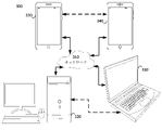
図3は、本開示の一実施形態による通信システム(300)の概略的なブロック図を示す。システム(300)はネットワーク(350)を介して互いに接続された少なくとも2つの端末(310、320)を含むことができる。データの一方向送信について、第1の端末(310)は、ローカル位置でビデオデータを符号化して、ネットワーク(350)を介して別の端末(320)に送信することができる。第2の端末(320)は、ネットワーク(350)から、他方の端末の符号化されたビデオデータを受信し、当該符号化されたデータを復号化し、復元されたビデオデータを表示することができる。一方向のデータ送信はメディアサービスアプリケーションなどでは一般的である。 FIG. 3 shows a schematic block diagram of a communication system (300) according to an embodiment of the present disclosure. The system (300) can include at least two terminals (310, 320) connected to each other via a network (350). For one-way transmission of data, the first terminal (310) can encode the video data at a local location and transmit it to another terminal (320) over the network (350). The second terminal (320) can receive the encoded video data of the other terminal from the network (350), decode the encoded data, and display the restored video data. .. One-way data transmission is common in media service applications and the like.
図3は、例えば、ビデオ会議中に発生する可能性がある符号化されたビデオの双方向送信をサポートするために提供される第2対の端末(330、340)を示す。データの双方向送信について、各端末(330、340)は、ローカル位置でキャプチャしたビデオデータを符号化して、ネットワーク(350)を介して他方の端末に送信することができる。各端末(330、340)はさらに、他方の端末から送信された、符号化されたビデオデータを受信し、当該符号化されたデータを復号化し、復元されたビデオデータをローカルディスプレイ機器に表示することができる。 FIG. 3 shows, for example, a second pair of terminals (330, 340) provided to support bidirectional transmission of coded video that may occur during a video conference. For bidirectional transmission of data, each terminal (330, 340) can encode the video data captured at the local location and transmit it to the other terminal via the network (350). Each terminal (330, 340) further receives the encoded video data transmitted from the other terminal, decodes the encoded data, and displays the restored video data on the local display device. be able to.
図3において、端末(330~340)は、サーバ、パソコンコンピュータ、スマートフォンとして例示され得るが、本開示の原理はそれに限定されない。本開示の実施例は、ラップトップコンピュータ、タブレット、メディアプレイヤー及び/又は専用のビデオ会議機器を含むがこれらに限定されない他の機器に適用することができる。ネットワーク(350)は、端末(310~340)の間で符号化されたビデオデータを送信する任意の数のネットワークを表し、例えば有線及び/又は無線通信ネットワークを含む。通信ネットワーク(350)は、回線交換及び/又はパケット交換チャネルにおいてデータを交換することができる。代表的なネットワークには、電気通信ネットワーク、ローカルエリアネットワーク、ワイドエリアネットワーク及び/又はインターネットが含まれる。本出願における論述の目的からすると、以下で解釈されない限り、ネットワーク(350)のアーキテクチャ及びトポロジは、本開示の動作にとって重要ではない場合がある。 In FIG. 3, the terminal (330 to 340) may be exemplified as a server, a personal computer, a smartphone, but the principle of the present disclosure is not limited thereto. The embodiments of the present disclosure can be applied to other devices including, but not limited to, laptop computers, tablets, media players and / or dedicated video conference devices. The network (350) represents any number of networks that transmit encoded video data between terminals (310-340), including, for example, wired and / or wireless communication networks. The communication network (350) can exchange data in circuit-switched and / or packet-switched channels. Representative networks include telecommunications networks, local area networks, wide area networks and / or the Internet. For the purposes of the discussion in this application, the architecture and topology of the network (350) may not be important to the operation of the present disclosure unless interpreted below.
開示された主題の適用例として、図4は、ストリーミング環境におけるビデオの符号器と復号器の配置を示す。開示された主題は、例えばビデオ会議、デジタルTVなどが含まれる、ビデオをサポートする他のアプリケーションに等価的に適用されることができ、CD、DVD、メモリースティックなどが含まれるデジタルメディアに圧縮されたビデオなどを記憶する。 As an application of the disclosed subject matter, FIG. 4 shows the placement of video encoders and decoders in a streaming environment. The disclosed subject matter can be equivalently applied to other applications that support video, including, for example, video conferences, digital TV, etc., and compressed into digital media including CDs, DVDs, memory sticks, etc. Memorize videos and so on.
ストリーミングシステムは、キャプチャサブシステム(413)を含むことができ、当該キャプチャサブシステムは、例えばデジタル撮影装置などの、非圧縮のビデオサンプルストリーム(402)を作成できるビデオソース(401)を含むことができる。符号化されたビデオビットストリームと比較してデータ量が多いことを強調するように、太い線として描画されるサンプルストリーム(402)は、撮影装置(401)に結合される符号器(403)によって処理されることができる。符号器(403)は、以下で詳細に説明される開示される主題の態様を実現又は実施するために、ハードウェア、ソフトウェア又はそれらの組み合わせを含むことができる。サンプルストリームと比較してデータ量が少ないことを強調するように、細い線として描画される符号化されたビデオビットストリーム(404)は、将来の使用のために、ストリーミングサーバ(405)に記憶されることができる。1つ以上のストリーミングクライアント(406、408)は、ストリーミングサーバ(405)にアクセスして、符号化されたビデオビットストリーム(404)のレプリカ(407、409)を検索することができる。クライアント(406)は、ビデオ復号器(410)を含むことができ、当該ビデオ復号器(410)は、符号化されたビデオビットストリームの着信コピー(407)を復号化し、ディスプレイ(412)又は他の表示機器(図示せず)に表示できる発信ビデオサンプルストリーム(411)を作成する。一部のストリーミングシステムでは、ビデオビットストリーム(404、407、409)は、あるビデオコーディング/圧縮規格に従って符号化され得る。これらの規格の例には、ITU-T H.465勧告書を含む。非公式に多用途ビデオ符号化(VVC)と呼ばれるビデオ符号化規格は開発中である。開示された主題は、VVCのコンテキストで使用されてもよい。 The streaming system can include a capture subsystem (413), which captures a video source (401) capable of creating an uncompressed video sample stream (402), such as a digital imaging device. Can be done. To emphasize that the amount of data is large compared to the encoded video bitstream, the sample stream (402) drawn as a thick line is drawn by the encoder (403) coupled to the imaging device (401). Can be processed. The encoder (403) can include hardware, software, or a combination thereof to realize or implement aspects of the disclosed subject matter described in detail below. The encoded video bitstream (404), which is drawn as a thin line to emphasize the small amount of data compared to the sample stream, is stored in the streaming server (405) for future use. Can be done. One or more streaming clients (406,408) can access the streaming server (405) to search for a replica (407,409) of the encoded video bitstream (404). The client (406) can include a video decoder (410), which decodes the incoming copy (407) of the encoded video bitstream and displays (412) or the like. Create an outgoing video sample stream (411) that can be displayed on a display device (not shown). In some streaming systems, video bitstreams (404, 407, 409) can be encoded according to certain video coding / compression standards. Examples of these standards include the ITU-T H.465 Recommendation. A video coding standard, informally called Versatile Video Coding (VVC), is under development. The disclosed subject matter may be used in the context of VVC.
図5は、本発明の一実施例によるビデオ復号器(410)の機能ブロック図である。 FIG. 5 is a functional block diagram of a video decoder (410) according to an embodiment of the present invention.
受信機(510)は、ビデオ復号器(410)によって復号化される1つ以上の符号化されたビデオシーケンスを受信することができ、同じ実施例又は他の実施例では、一度に1つの符号化されたビデオシーケンスを受信し、各符号化されたビデオシーケンスの復号化は、他の符号化されたビデオシーケンスと独立している。符号化されたビデオシーケンスをチャネル(512)から受信することができ、チャネル(512)は、当該符号化されたビデオデータを記憶するための記憶装置へのハードウェア/ソフトウェアリンクであってもよい。受信機(510)は、符号化されたビデオデータ及び例えば、それぞれの使用エンティティ(図示せず)に転送され得る符号化されたオーディオデータ及び/又は補助データストリームなどの他のデータを受信することができる。受信機(510)は、符号化されたビデオシーケンスを他のデータから分離することができる。ネットワークのジッタを防止するために、バッファメモリ(515)は、受信機(510)とエントロピー復号器/パーサー(520)(以下、「パーサー」と呼ばれる)との間に結合されることができる。受信機(510)は、十分な帯域幅及び制御可能性を有する記憶/転送装置、又は等時性リアルタイムネットワークからデータを受信する際に、バッファ(515)を必要としない可能性があり、又は、バッファ(515)が小さくなってもよい。例えばインターネットなどのベストエフォート型パケットネットワークで使用するために、バッファ(515)を必要とする可能性があり、バッファ(515)は比較的大きく、有利に自己適応サイズを有することができる。 The receiver (510) can receive one or more coded video sequences decoded by the video decoder (410), one code at a time in the same or other embodiments. Receiving the coded video sequences, the decoding of each coded video sequence is independent of the other coded video sequences. A coded video sequence can be received from the channel (512), which may be a hardware / software link to a storage device for storing the coded video data. .. The receiver (510) receives encoded video data and other data such as encoded audio data and / or auxiliary data streams that can be transferred to their respective used entities (not shown). Can be done. The receiver (510) can separate the encoded video sequence from other data. To prevent network jitter, the buffer memory (515) can be coupled between the receiver (510) and the entropy decoder / parser (520) (hereinafter referred to as the "parser"). The receiver (510) may not require a buffer (515) to receive data from a storage / transfer device with sufficient bandwidth and controllability, or an isochronous real-time network, or , The buffer (515) may be smaller. A buffer (515) may be required for use in a best effort packet network such as the Internet, which is relatively large and can advantageously have a self-adaptive size.
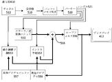
ビデオ復号器(410)は、エントロピー符号化されたビデオシーケンスに基づきシンボル(521)を再構築するように、パーサー(520)を含むことができる。図5に示すように、これらのシンボルのカテゴリには、復号器(410)の動作を管理するための情報、及びディスプレイ(412)などの表示機器を制御するための潜在情報が含まれ、当該表示機器は、復号器の構成部分ではないが復号器に結合され得る。(1つ以上の)表示機器のための制御情報は、補助拡張情報(SEIメッセージ)又はビデオユーザビリティ情報(VUI)パラメータセットセグメント(図示せず)という形であってもよい。パーサー(520)は、受信された、符号化されたビデオシーケンスを解析/エントロピー復号化することができる。符号化されたビデオシーケンスの符号化は、ビデオ符号化技術又は規格に従って実行することができ、可変長符号化、ハフマン符号化(Huffman coding)、文脈依存の有無にかかわらず算術符号化などを含む当業者に知られている原理に従うことができる。パーサー(520)は、グループに対応する少なくとも1つのパラメータに基づき、符号化されたビデオシーケンスから、ビデオ復号器における画素のサブグループのうちの少なくとも1つのサブグループのサブグループパラメータセットを抽出することができる。サブグループは、ピクチャグループ(GOP)、ピクチャ、タイル、スライス、マクロブロック、符号化ユニット(CU)、ブロック、変換ユニット(TU)、予測ユニット(PU)などを含むことができる。エントロピー復号器/パーサーはさらに、符号化されたビデオシーケンスから、変換係数、量子化器パラメータ値(QP)、動きベクトルなどの情報を抽出してもよい。 The video decoder (410) can include a parser (520) to reconstruct the symbol (521) based on the entropy-coded video sequence. As shown in FIG. 5, these symbol categories include information for managing the operation of the decoder (410) and latent information for controlling display devices such as the display (412). The display device may be coupled to the decoder, although it is not a component of the decoder. The control information for the (one or more) display devices may be in the form of auxiliary extended information (SEI messages) or video usability information (VUI) parameter set segments (not shown). The parser (520) can analyze / entropy decode the received, encoded video sequence. Coding of encoded video sequences can be performed according to video coding techniques or standards, including variable length coding, Huffman coding, arithmetic coding with or without context dependence, and the like. You can follow the principles known to those of skill in the art. The parser (520) extracts a subgroup parameter set of at least one of the pixel subgroups in the video decoder from the encoded video sequence based on at least one parameter corresponding to the group. Can be done. The subgroup can include a picture group (GOP), a picture, a tile, a slice, a macro block, a coding unit (CU), a block, a conversion unit (TU), a prediction unit (PU), and the like. The entropy decoder / parser may further extract information such as conversion factors, quantizer parameter values (QP), motion vectors, etc. from the encoded video sequence.
パーサー(520)は、バッファ(515)から受信されたビデオシーケンスに対してエントロピー復号化/解析操作を実行することで、シンボル(521)を作成することができる。パーサー(520)は符号化されたデータを受信し、特定のシンボル(521)を選択的に復号化してもよい。また、パーサー(520)は特定のシンボル(521)が動き補償予測ユニット(553)、スケーラ/逆変換ユニット(551)、イントラ予測ユニット(552)又はループフィルタ(556)に提供されるかどうかを決定してもよい。 The parser (520) can create the symbol (521) by performing an entropy decoding / analysis operation on the video sequence received from the buffer (515). The parser (520) may receive the encoded data and selectively decode the particular symbol (521). The parser (520) also determines whether a particular symbol (521) is provided to the motion compensation prediction unit (553), scaler / inverse conversion unit (551), intra prediction unit (552) or loop filter (556). You may decide.
シンボル(521)の再構築は、符号化されたビデオピクチャ又はその一部(例えば、インターピクチャとイントラピクチャ、インターブロックとイントラブロック)のタイプ及び他の要因によって、複数の異なるユニットに関わる。関与するユニット及び関与形態について、パーサー(520)が符号化されたビデオシーケンスから解析したサブグループ制御情報によって制御される。簡潔のために、パーサー(520)と以下の複数のユニットとの間の、このようなサブグループ制御情報の流れは図示されていない。 Reconstruction of symbol (521) involves several different units, depending on the type of encoded video picture or part thereof (eg, interpictures and intrapictures, interblocks and intrablocks) and other factors. The units involved and the modes of involvement are controlled by the subgroup control information analyzed by the parser (520) from the encoded video sequence. For brevity, such a flow of subgroup control information between the parser (520) and the following units is not shown.
既に言及された機能ブロックに加えて、復号器(410)は、概念的には、以下で説明される複数の機能ユニットに細分化される。ビジネス上の制約の下で運行する実際の実現形態において、これらのユニットのうち複数のユニットは互いに密接に相互作用するとともに、少なくとも部分的に互いに統合することができる。しかしながら、開示された主題を説明するために、概念的に以下の機能ユニットに細分化されることは適切である。 In addition to the functional blocks already mentioned, the decoder (410) is conceptually subdivided into a plurality of functional units as described below. In a practical implementation that operates under business constraints, multiple of these units can interact closely with each other and at least partially integrate with each other. However, it is appropriate to conceptually subdivide into the following functional units to explain the disclosed subject matter.
第1のユニットはスケーラ/逆変換ユニット(551)である。当該スケーラ/逆変換ユニット(551)はパーサー(520)から(1つ以上の)シンボル(621)としての量子化変換係数及び制御情報を受信し、使用する変換方式、ブロックサイズ、量子化因子、量子化スケーリング行列などを含む。スケーラ/逆変換ユニット(551)は、アグリゲーター(555)に入力され得るサンプル値を含むブロックを出力することができる。 The first unit is a scaler / inverse conversion unit (551). The scaler / inverse conversion unit (551) receives the quantization conversion coefficient and control information as the (one or more) symbols (621) from the parser (520), and uses the conversion method, block size, and quantization factor. Includes quantization scaling matrix and so on. The scaler / inverse conversion unit (551) can output a block containing sample values that can be input to the aggregator (555).
いくつかの場合に、スケーラ/逆変換ユニット(551)の出力サンプルは、イントラ符号化ブロック、即ち、以前に再構築されたピクチャからの予測情報を使用していないが、現在ピクチャの以前に再構築された部分からの予測情報を使用することができるブロックに属する。このような予測情報は、イントラピクチャ予測ユニット(552)によって提供されることができる。いくつかの場合に、イントラピクチャ予測ユニット(552)は現在(部分的に再構築された)ピクチャ(556)から抽出された、周囲が再構築された情報を使用して、再構築中のブロックと同じサイズ及び形状のブロックを生成する。いくつかの場合に、アグリゲーター(555)は、各サンプルごとに、イントラ予測ユニット(552)から生成された予測情報を、スケーラ/逆変換ユニット(551)によって提供される出力サンプル情報に追加する。 In some cases, the output sample of the scaler / inverse transformation unit (551) does not use the intracoded block, ie the prediction information from the previously reconstructed picture, but is now re-reformed before the picture. It belongs to a block where the prediction information from the constructed part can be used. Such prediction information can be provided by the intra-picture prediction unit (552). In some cases, the intra-picture prediction unit (552) uses the surrounding reconstructed information extracted from the currently (partially reconstructed) picture (556) to block being reconstructed. Generates blocks of the same size and shape as. In some cases, the aggregator (555), for each sample, adds the prediction information generated from the intra prediction unit (552) to the output sample information provided by the scaler / inverse transformation unit (551).
他の場合に、スケーラ/逆変換ユニット(551)の出力サンプルは、インター符号化された、潜在的に動き補償されたブロックに属することができる。このような場合に、動き補償予測ユニット(553)は参照ピクチャメモリ(557)にアクセスして、予測のためのサンプルを抽出することができる。当該ブロックに属するシンボル(521)に基づき、抽出されたサンプルに対して動き補償を行った後、これらのサンプルは、アグリゲーター(555)によって、スケーラ/逆変換ユニットの出力に追加される(この場合、残差サンプル又は残差信号と呼ばれる)ことで、出力サンプル情報が生成される。動き補償ユニットが予測サンプルを抽出するための参照ピクチャメモリ内のアドレスは動きベクトルによって制御され、動きベクトルはシンボル(521)の形で、動き補償ユニットによって使用され、シンボル(521)は、例えばX、Y及び参照ピクチャ成分を有してもよい。動き補償はさらに、サブサンプルによって動きベクトルを正確に実行するときに参照ピクチャバッファ(457)から抽出されたサンプル値の補間、動きベクトル予測メカニズムなどを含んでもよい。 In other cases, the output sample of the scaler / inverse transformation unit (551) can belong to an intercoded, potentially motion compensated block. In such a case, the motion compensation prediction unit (553) can access the reference picture memory (557) and extract a sample for prediction. After motion compensation is applied to the extracted samples based on the symbol (521) belonging to the block, these samples are added to the output of the scaler / inverse conversion unit by the aggregator (555) (in this case). , Residual sample or residual signal) to generate output sample information. The address in the reference picture memory for the motion compensation unit to extract the prediction sample is controlled by the motion vector, the motion vector is used by the motion compensation unit in the form of a symbol (521), and the symbol (521) is, for example, X. , Y and may have a reference picture component. Motion compensation may further include interpolation of sample values extracted from the reference picture buffer (457), motion vector prediction mechanism, etc. when the motion vector is accurately executed by the subsample.
ループフィルタユニット(556)において、アグリゲーター(555)の出力サンプルに対して、様々なループフィルタリング技術を採用できる。ビデオ圧縮技術は、ループ内フィルタ技術を含むことができ、ループ内フィルタ技術は、符号化されたビデシーケンスに含まれる、パーサー(520)からのシンボル(521)として、ループフィルタユニット(556)に適用可能なパラメータによって制御され、しかしながら、ビデオ圧縮技術は、符号化されたピクチャ又は符号化されたビデオシーケンスの(復号化の順序で)前の部分を復号化する期間に取得されたメタ情報、及び、以前再構築されループフィルタリングによって処理されたサンプル値に応答することもできる。 In the loop filter unit (556), various loop filtering techniques can be adopted for the output sample of the aggregator (555). The video compression technique can include an in-loop filter technique, which is included in the loop filter unit (556) as a symbol (521) from the parser (520) contained in the encoded video sequence. Controlled by applicable parameters, however, video compression techniques capture meta-information, during the period of decoding the previous part (in the order of decoding) of the encoded picture or encoded video sequence. It can also respond to sample values that were previously reconstructed and processed by loop filtering.
ループフィルタユニット(556)の出力は、サンプルストリームであってもよく、サンプルストリームは、将来のインターピクチャ予測で使用されるために、表示機器(412)に出力され、参照ピクチャバッファ(556)に記憶されることができる。 The output of the loop filter unit (556) may be a sample stream, which is output to the display device (412) and into the reference picture buffer (556) for use in future interpicture predictions. Can be remembered.
ある符号化されたピクチャは完全に再構築されたら、将来の予測のための参照ピクチャとして使用される。例えば、符号化されたピクチャは完全に再構築され、さらに、符号化されたピクチャは(例えばパーサー(520)によって)参照ピクチャとして認識されると、現在の参照ピクチャ(656)は参照ピクチャバッファ(557)の一部になってもよく、その後の符号化されたピクチャの再構築を開始する前に、新たな現在ピクチャメモリを再割り当てる。 Once a coded picture is completely reconstructed, it will be used as a reference picture for future prediction. For example, if the encoded picture is completely reconstructed and the encoded picture is recognized as a reference picture (eg by the parser (520)), the current reference picture (656) will be in the reference picture buffer (eg, by the parser (520)). May be part of 557), reallocating a new current picture memory before starting subsequent reconstruction of the encoded picture.
ビデオ復号器(410)は、例えばITU-T H.265勧告書に記録される規格における所定のビデオ圧縮技術に従って復号化動作を実行することができる。符号化されたビデオシーケンスがビデオ圧縮技術又は規格の構文に従う意味で、符号化されたビデオシーケンスは、ビデオ圧縮技術ドキュメント又は規格、特にそのプロファイルドキュメントで明確に指定されるように、使用されているビデオ圧縮技術又は規格によって指定される構文に準拠することができる。準拠性について、さらに、符号化されたビデオシーケンスの複雑さがビデオ圧縮技術又は規格のレベルによって限定される範囲にあるように要求される。いくつかの場合に、レベルは、最大ピクチャサイズ、最大フレームレート、最大再構築サンプリングレート(例えば、メガサンプル/秒で測定する)、及び/又は最大参照ピクチャのサイズなどを制限する。いくつかの場合、レベルによって設置される制限は、仮想参照復号器(HRD)の仕様、及び符号化されたビデオシーケンスにおいて信号で示されるHRDバッファが管理するメタデータによってさらに限定される。 The video decoder (410) may be, for example, an ITU-T H. Decoding operations can be performed according to the prescribed video compression techniques in the standards recorded in the 265 Recommendation. Encoded video sequences are used as explicitly specified in the video compression technology document or standard, especially its profile document, in the sense that the encoded video sequence follows the syntax of the video compression technique or standard. It can comply with the syntax specified by the video compression technique or standard. Compliance is further required to be within the complexity of the coded video sequence, limited by the level of video compression technology or standard. In some cases, the level limits the maximum picture size, maximum frame rate, maximum reconstruction sampling rate (eg, measured at megasamples / second), and / or maximum reference picture size. In some cases, the limits set by the level are further limited by the specifications of the Virtual Reference Decoder (HRD) and the metadata managed by the HRD buffer represented by the signal in the encoded video sequence.
一実施例において、受信機(510)は追加の(冗長な)データと符号化されたビデオを受信できる。追加のデータは、(1つ以上の)符号化されたビデオシーケンスの一部として含まれてもよい。追加のデータは、ビデオ復号器(410)によって使用されることで、データを正確に復号化し、及び/又は元のビデオデータをより正確に再構築する。追加のデータは、例えば時間、空間又はSNR拡張層、冗長スライス、冗長ピクチャ、前方誤り訂正符号などの形であってもよい。 In one embodiment, the receiver (510) can receive additional (redundant) data and encoded video. Additional data may be included as part of the (one or more) coded video sequences. The additional data is used by the video decoder (410) to accurately decode the data and / or reconstruct the original video data more accurately. The additional data may be in the form of, for example, time, space or SNR extension layers, redundant slices, redundant pictures, forward error correction codes, and the like.
図6は、本開示の一実施形態によるビデオ符号器(403)の機能ブロック図であり得る。 FIG. 6 may be a functional block diagram of the video encoder (403) according to an embodiment of the present disclosure.
符号器(403)は、ビデオソース(401)(符号器の一部ではない)からビデオサンプルを受信することができ、当該ビデオソースは、符号器(403)によって符号化される(1つ以上の)ビデオ画像をキャプチャすることができる。 The encoder (403) can receive a video sample from the video source (401) (not part of the encoder), and the video source is encoded by the encoder (403) (one or more). ) Video images can be captured.
ビデオソース(401)は、符号器(403)によって符号化される、デジタルビデオサンプルストリームの形であるソースビデオシーケンスを提供することができ、当該デジタルビデオサンプルストリームは、任意の適切なビット深さ(例えば:8ビット、10ビット、12ビット…)、任意の色空間(例えば、BT.601 Y CrCb、RGB……)、及び任意の適切なサンプリング構成(例えば、Y CrCb 4:2:0、Y CrCb 4:4:4)を有してもよい。メディアサービスシステムにおいて、ビデオソース(401)は、以前に準備されたビデオを記憶するための記憶装置であってもよい。ビデオ会議システムにおいて、ビデオソース(403)は、ビデオシーケンスとして、ローカル画像情報をキャプチャするための撮影装置であってもよい。ビデオデータは、順番に見たときに、動きが付与される複数の個別のピクチャとして提供されることができる。これらのピクチャ自体は、空間画素アレイとして編成され、使用されているサンプリング構成、色空間などによって、各画素には1つ以上のサンプルが含まれてもよい。画素とサンプルとの間の関係は、当業者にとって、容易に理解することができる。以下の説明はサンプルに着目する。 The video source (401) can provide a source video sequence in the form of a digital video sample stream encoded by a encoder (403), which digital video sample stream has any suitable bit depth. (Eg: 8 bits, 10 bits, 12 bits ...), any color space (eg, BT.601 Y CrC b , RGB ...), and any suitable sampling configuration (eg, Y CrCb 4: 2: 2:). It may have 0, Y CrCb 4: 4: 4). In a media service system, the video source (401) may be a storage device for storing previously prepared video. In a video conference system, the video source (403) may be a capture device for capturing local image information as a video sequence. The video data can be provided as a plurality of individual pictures to which motion is added when viewed in sequence. These pictures themselves are organized as a spatial pixel array, and each pixel may contain one or more samples depending on the sampling configuration used, the color space, and the like. The relationship between the pixel and the sample can be easily understood by those skilled in the art. The following explanation focuses on the sample.
一実施例によれば、ビデオ符号器(403)は、ソースビデオシーケンスのピクチャを、リアルタイムで、又はアプリケーションで必要とする他の任意の時間制約の下で、符号化されたビデオシーケンス(643)に符号化及び圧縮することができる。適切的な符号化速度で実行することは、コントローラ(650)の機能の1つである。コントローラは、以下で説明する他の機能ユニットを制御し、他の機能ユニットに機能的に結合される。簡潔のために、結合は示されていない。コントローラによって設置されるパラメータは、レート制御関連パラメータ(ピクチャスキップ、量子化器、レート歪み最適化技術のλ値など)、ピクチャサイズ、ピクチャグループ(GOP)配置、最大動きベクトル検索範囲などを含んでもよい。当業者は、コントローラ(650)の他の機能を容易に認識することができ、これらの機能は特定のシステム設計に対して最適化されたビデオ符号器(403)に属し得る。 According to one embodiment, the video encoder (403) encodes a picture of the source video sequence in real time or under any other time constraint required by the application (643). Can be coded and compressed. Executing at an appropriate coding rate is one of the functions of the controller (650). The controller controls other functional units described below and is functionally coupled to the other functional units. For brevity, no binding is shown. Parameters installed by the controller include rate control related parameters (picture skip, quantizer, rate distortion optimization technology λ value, etc.), picture size, picture group (GOP) placement, maximum motion vector search range, etc. good. Those skilled in the art can easily recognize other functions of the controller (650), and these functions may belong to the video encoder (403) optimized for a particular system design.
あるビデオ符号器は、当業者が容易に「符号化ループ」として認識するという方式で動作する。非常に簡単な説明として、符号化ループは、(符号化対象となる入力ピクチャと(1つ以上の)参照ピクチャに基づきシンボルストリームを作成することを担当する)符号器の符号化部分(630)(以下、「ソース符号器」と呼ばれる)と、符号器(403)に埋め込まれる(ローカル)復号器(633)とを含むことができる。当該復号器(633)はシンボルを再構築することで、(リモート)復号器も作成しようとするサンプルデータを作成する(なぜならば、シンボルと符号化されたビデオビットストリームとの間の任意の圧縮は、開示された主題で考慮されるビデオ圧縮技術において可逆であるためである)。当該再構築されたサンプルストリームを参照ピクチャメモリ(634)に入力する。シンボルストリームの復号化により、復号器位置(ローカル又はリモート)と関係がないビットが正確である結果(bit-exact)を発生させるので、参照ピクチャバッファのコンテンツはローカル符号器とリモート符号器との間でもビットが正確である。言い換えれば、符号器の予測部分から「見る」参照ピクチャサンプルは、復号化中に予測を使用するときに復号器が「見る」サンプル値とまったく同じである。参照ピクチの同期性という基本原理(及び、例えばチャネル誤差のため同期性を維持できない場合に発生するドリフト)は当業者にとって公知である。 Some video encoders operate in such a way that those skilled in the art can easily recognize them as "encoding loops". As a very brief description, the coding loop is the coding part of the encoder (responsible for creating a symbol stream based on the input picture to be encoded and the reference picture (one or more)) (630). (Hereinafter referred to as a "source encoder") and a (local) decoder (633) embedded in the encoder (403) can be included. By reconstructing the symbol, the decoder (633) creates sample data that the (remote) decoder also wants to create (because any compression between the symbol and the encoded video bitstream). Is reversible in the video compression techniques considered in the disclosed subject matter). The reconstructed sample stream is input to the reference picture memory (634). The contents of the reference picture buffer are between the local and remote encoders, because decoding the symbol stream produces a bit-exact result where the bits unrelated to the decoder position (local or remote) are accurate. Bits are accurate even in between. In other words , the reference picture sample that the decoder "sees" from the predictor portion of the encoder is exactly the same as the sample value that the decoder "sees" when using the prediction during decoding. The basic principle of reference pictogram synchrony (and drift that occurs when synchrony cannot be maintained, for example due to channel error) is known to those of skill in the art.
「ローカル」復号器(633)の動作は、例えば図5との関連で以上で詳しく説明した「リモート」復号器(410)の動作と同じであってもよい。ただし、さらに図6を簡単に参照し、シンボルは、使用可能で、エントロピー符号器(645)とパーサー(520)とがシンボルを符号化されたビデオシーケンスに無損失で符号化/復号化する場合、チャネル(512)、受信機(510)、バッファ(515)及びパーサー(520)を含む復号器(410)のエントロピー復号化部分は、ローカル復号器(633)で完全に実現されることができないおそれがある。 The operation of the "local" decoder (633) may be the same as that of the "remote" decoder (410) described in detail above, for example in the context of FIG. However, still with reference to FIG. 6, if the symbol is available and the entropy coder (645) and parser (520) encode / decode the symbol into a coded video sequence losslessly. The entropy decoding portion of the decoder (410), including the channel (512), receiver (510), buffer (515) and parser (520), cannot be fully implemented in the local decoder (633). There is a risk.
現時点で、復号器に存在する解析/エントロピー復号化に加えて、任意の復号器技術も、必然的に基本的に同じ機能形式で、対応する符号器に存在することが観察されることができる。符号器技術は、包括的に説明された復号器技術の逆であるため、符号器技術の説明を簡略化できる。より詳しい説明は、特定の領域でのみ必要であり、以下で提供される。 At this time, in addition to the analysis / entropy decoding present in the decoder, any decoder technique can be observed to be present in the corresponding encoder, necessarily in essentially the same functional form. .. Since the encoder technique is the opposite of the comprehensively described decoder technique, the description of the encoder technique can be simplified. A more detailed description is needed only in certain areas and is provided below.
ソース符号器(630)の動作の一部として、ソース符号器(630)は動き補償予測符号化を実行することができ、動き補償予測符号化はビデオシーケンスからの、「参照フレーム」として指定される1つ以上の以前に符号化されたフレームを参照して、入力フレームを予測的に符号化する。このようにして、符号化エンジン(632)は入力フレームの画素ブロックと、入力フレームの(1つ以上の)予測参照として選択される(1つ以上の)参照フレームの画素ブロックとの間の差を符号化する。 As part of the operation of the source encoder (630), the source encoder (630) can perform motion compensation predictive coding, which is designated as a "reference frame" from the video sequence. Predictively encode an input frame with reference to one or more previously encoded frames. In this way, the coding engine (632) is the difference between the pixel block of the input frame and the pixel block of the reference frame (one or more) selected as the predictive reference (one or more) of the input frame. Is encoded.
ローカルビデオ復号器(633)はソース符号器(630)によって作成されるシンボルに基づき、参照フレームとして指定され得るフレームの符号化されたビデオデータを復号化することができる。符号化エンジン(632)の動作は有利的には、非可逆処理であってもよい。符号化されたビデオデータがビデオ復号器(図6には図示せず)で復号化される場合、再構築されたビデオシーケンスは、一般的に、多少の誤差を伴うソースビデオシーケンスのレプリカであってもよい。ローカルビデオ復号器(633)は、参照フレームに対してビデオ復号器によって実行される復号化処理を複製し、再構築された参照フレームを参照ピクチャキャッシュ(636)に記憶することができる。このようにして、ビデオ符号器(403)は、再構築された参照フレームのレプリカをローカルに記憶し、当該レプリカは、リモートビデオ復号器によって取得された、再構築される参照フレームと共通のコンテンツを有する(送信誤差がない)。 The local video decoder (633) can decode the coded video data of a frame that can be designated as a reference frame based on the symbols created by the source encoder (630). The operation of the coding engine (632) may advantageously be lossy processing. If the encoded video data is decoded with a video decoder (not shown in FIG. 6), the reconstructed video sequence is generally a replica of the source video sequence with some error. You may. The local video decoder (633) can replicate the decoding process performed by the video decoder for the reference frame and store the reconstructed reference frame in the reference picture cache (636). In this way, the video encoder (403) locally stores a replica of the reconstructed reference frame, which is the content common to the reconstructed reference frame acquired by the remote video decoder. Has (no transmission error).
予測器(635)は符号化エンジン(632)に対して予測検索を実行してもよい。つまり、符号化対象となる新たなフレームに対して、予測器(635)は参照ピクチャメモリ(634)において、新たなフレームの適切な予測参照として使用され得るサンプルデータ(候補参照画素ブロックとする)、又は例えば参照ピクチャ動きベクトル、ブロック形状などの特定のメタデータを検索することができる。予測器(635)はサンプルブロックに基づき、画素ブロックごとに動作することで、適切な予測参照を見つけることができる。いくつかの場合、予測器(635)によって取得された検索結果によって決定されるように、入力ピクチャは、参照ピクチャメモリ(634)に記憶される複数の参照ピクチャから取得される予測参照を有してもよい。 The predictor (635) may perform a predictive search on the coding engine (632). That is, for a new frame to be encoded, the predictor (635) can be used as an appropriate predictive reference for the new frame in the reference picture memory (634) (referred to as a candidate reference pixel block). , Or you can search for specific metadata such as reference picture motion vectors, block shapes, and so on. The predictor (635) is based on a sample block and operates on a pixel-by-pixel basis to find a suitable predictive reference. In some cases, the input picture has a predictive reference taken from a plurality of reference pictures stored in the reference picture memory (634), as determined by the search results obtained by the predictor (635). You may.
コントローラ(650)は、例えばビデオデータを符号化するためのパラメータとサブグループパラメータの設置を含むビデオ符号器(630)の符号化動作を管理することができる。 The controller (650) can manage the coding operation of the video encoder (630), including setting parameters and subgroup parameters for encoding video data, for example.
エントロピー符号器(645)において、以上に言及された全ての機能ユニットの出力に対してエントロピー符号化を行うことができる。当該エントロピー符号器は、例えばハフマン符号化、可変長符号化、算術符号化などのような当業者に知られている技術に従って、シンボルに対して可逆圧縮を行うことで、各機能ユニットによって生成されたシンボルを符号化されたビデオシーケンスに変換する。 In the entropy coding device (645), entropy coding can be performed on the outputs of all the functional units mentioned above. The entropy coding device is generated by each functional unit by performing lossless compression on the symbol according to techniques known to those of skill in the art such as Huffman coding, variable length coding, arithmetic coding and the like. Converts the symbol to an encoded video sequence.
送信機(640)は、通信チャネル(660)を介した送信の準備をするように、エントロピー符号器(645)によって作成される(1つ以上の)符号化されたビデオシーケンスをバッファリングすることができ、通信チャネル(660)は、符号化されたビデオデータを記憶するための記憶装置へのハードウェア/ソフトウェアリンクであってもよい。送信機(640)は、ビデオ符号器(630)からの符号化されたビデオデータと、例えば符号化されたオーディオデータ及び/又は補助データストリーム(ソースは図示せず)のような、送信対象となる他のデータとを、マージすることができる。 The transmitter (640) buffers the (one or more) encoded video sequences created by the entropy-coded device (645) in preparation for transmission over the communication channel (660). The communication channel (660) may be a hardware / software link to a storage device for storing the encoded video data. The transmitter (640) is capable of transmitting encoded video data from the video encoder (630) and, for example, encoded audio data and / or an auxiliary data stream (source not shown). Can be merged with other data.
コントローラ(650)は、ビデオ符号器(403)の動作を管理することができる。符号化中に、コントローラ(650)は、各符号化されたピクチャに、対応するピクチャに適用される符号化技術に影響を与える可能性がある特定の符号化されたピクチャタイプを割り当てる。例えば、一般的に、ピクチャを次のフレームタイプのいずれかとして割り当ててもよい。 The controller (650) can manage the operation of the video encoder (403). During coding, the controller (650) assigns each coded picture a specific coded picture type that may affect the coding technique applied to the corresponding picture. For example, in general, a picture may be assigned as one of the following frame types:
イントラピクチャ(Iピクチャ)は、シーケンス内の他のピクチャのいずれかを予測のソースとして使用せず、符号化及び復号化されるピクチャであってもよい。一部のビデオコーデックは、例えば独立復号器リフレッシュピクチャが含まれる異なるタイプのイントラピクチャを許容する。当業者は、Iピクチャのそれらの変形、及び対応する用途及び特徴を知っている。 The intra-picture (I-picture) may be a picture that is encoded and decoded without using any of the other pictures in the sequence as a source of prediction. Some video codecs allow different types of intra-pictures, including, for example, independent decoder refresh pictures. Those skilled in the art are aware of those variants of I-pictures and their corresponding uses and features.
予測ピクチャ(Pピクチャ)は、イントラ予測又はインター予測を使用して符号化及び復号化するピクチャであってもよく、当該イントラ予測又はインター予測は、多くとも1つの動きベクトルと参照インデックスを使用して各ブロックのサンプル値を予測する。 The predictive picture (P-picture) may be a picture encoded and decoded using intra-prediction or inter-prediction, and the intra-prediction or inter-prediction uses at most one motion vector and reference index. Predict the sample value of each block.
双方向予測ピクチャ(Bピクチャ)は、イントラ予測又はインター予測を使用して符号化及び復号化するピクチャであってもよく、当該イントラ予測又はインター予測は、多くとも2つの動きベクトルと参照インデックスを使用して各ブロックのサンプル値を予測する。同様に、複数の予測ピクチャは、2つを超える参照ピクチャ及び関連するメタデータを、単一のブロックの再構築に使用することができる。 The bidirectional prediction picture (B picture) may be a picture encoded and decoded using intra-prediction or inter-prediction, and the intra-prediction or inter-prediction may be at most two motion vectors and a reference index. Use to predict the sample value for each block. Similarly, multiple predictive pictures can use more than two reference pictures and associated metadata to reconstruct a single block.
ソースピクチャは一般的に、空間的に複数のサンプルブロック(例えば、それぞれ4×4、8×8、4×8又は16×16個のサンプルのブロック)に細分化され、ブロックごとに符号化されることができる。これらのブロックは、他の(符号化された)ブロックを参照して、予測的に符号化されることができ、前記他のブロックは、ブロックの対応するピクチャに適用される符号化割当によって決定される。例えば、Iピクチャのブロックについて、非予測的に符号化するか、又はこれらのブロックを、同じピクチャの既に符号化されたブロックを参照して、予測的に符号化(空間予測又はイントラ予測)してもよい。Pピクチャの画素ブロックについて、以前に符号化された1つの参照ピクチャを参照して、空間的予測又は時間的予測を介して予測的に符号化してもよい。Bピクチャのブロックについて、以前に符号化された1つ又は2つの参照ピクチャを参照して、空間的予測又は時間的予測を介して非予測的に符号化してもよい。 Source pictures are generally spatially subdivided into multiple sample blocks (eg, 4x4, 8x8, 4x8, or 16x16 sample blocks, respectively) and coded block by block. Can be. These blocks can be predictively encoded with reference to other (encoded) blocks, said other blocks being determined by the coding assignment applied to the corresponding picture of the block. Will be done. For example, I-picture blocks are non-predictively encoded, or these blocks are predictively encoded (spatial or intra-prediction) with reference to the already encoded blocks of the same picture. You may. Pixel blocks of P-pictures may be predictively encoded via spatial or temporal prediction with reference to one previously encoded reference picture. A block of B-pictures may be non-predictively encoded via spatial or temporal prediction with reference to one or two previously encoded reference pictures.
ビデオ符号器(403)は、例えばITU-T H.265勧告書における所定のビデオ符号化技術又は規格に基づき符号化動作を実行することができる。ビデオ符号器(403)の動作において、ビデオ符号器(403)は、入力ビデオシーケンスにおける時間的と空間的冗長性を使用した予測符号化動作が含まれる様々な圧縮動作を実行することができる。従って、符号化されたビデオデータは、使用されているビデオ符号化技術又は規格によって指定される構文に準拠していることができる。 The video encoder (403) is, for example, ITU-T H. The coding operation can be performed according to the predetermined video coding technique or standard in the 265 Recommendation. In the operation of the video encoder (403), the video encoder (403) can perform various compression operations, including predictive coding operations using temporal and spatial redundancy in the input video sequence. Thus, the encoded video data can comply with the syntax specified by the video coding technique or standard used.
一実施例において、送信機(640)は、追加のデータと符号化されたビデオを送信することができる。ソース符号器(630)は、符号化されたビデオシーケンスの一部として、このようなデータを含んでもよい。追加のデータは、時間/空間/SNR拡張層、冗長ピクチャとスライスのような他の形式の冗長データ、補充拡張情報(SEI)メッセージ、ビデオユーザビリティ情報(VUI)パラメータセットフラグメントなどを含んでもよい。 In one embodiment, the transmitter (640) is capable of transmitting additional data and encoded video. The source encoder (630) may include such data as part of the encoded video sequence. Additional data may include time / space / SNR extension layers, other forms of redundancy data such as redundant pictures and slices, supplemental extended information (SEI) messages, video usability information (VUI) parameter set fragments, and the like.
本開示は、インターピクチャ予測符号化のための技術に関し、特に、マージモードに関する。現在のCUが前のCUのMVをマージ候補として使用する場合、別のCTUのいくつかのCUが存在する可能性がある。提案された技術は、以前に符号化されたCUのMV情報への高速アクセスに必要なラインバッファを減少する。本開示の技術は、マージ概念を使用する任意のビデオ符号化方法に拡張することができる。スキップモードはマージモードを使用して動き情報を導出するため、本開示の方法はスキップモードにも適用される。 The present disclosure relates to techniques for interpicture predictive coding, in particular to merge modes. If the current CU uses the MV of the previous CU as a merge candidate, there may be several CUs of another CTU. The proposed technique reduces the line buffer required for fast access to previously encoded CU MV information. The techniques of the present disclosure can be extended to any video coding method that uses the merge concept. Since the skip mode uses the merge mode to derive motion information, the method of the present disclosure also applies to the skip mode.
図7は、一実施例によるビデオシーケンスを符号化又は復号化する動きベクトルバッファを制御するための例示的な処理のフローチャートである。いくつかの実施形態おいて、図7の1つ又は複数の処理ブロックは符号器403により実行されてもよい。いくつかの実施方式おいて、図7の1つ又は複数の処理ブロックは、符号器403とは別の、又は符号器403を含む別のデバイス又はデバイスのグループ、例えば符号器410によって実行されもよい。
FIG. 7 is a flowchart of an exemplary process for controlling a motion vector buffer that encodes or decodes a video sequence according to an embodiment. In some embodiments, one or more processing blocks of FIG. 7 may be performed by the
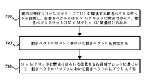
図7に示すように、処理は、前の符号化ツリーユニット(CTU)に関連付けられる動きベクトルセットを認識し、各動きベクトルがP×Qグリッドに関連付けられ、且つ、動きベクトルセットがN×Mグリッドに関連付けられること(ブロック710)を含むことができる。 As shown in FIG. 7, the process recognizes the motion vector set associated with the previous coded tree unit (CTU), each motion vector is associated with the P × Q grid, and the motion vector set is N × M. It can include being associated with a grid (block 710).
図7にさらに示されるように、処理は、動きベクトルセットに基づいて動きベクトルを決定すること(ブロック720)を含むことができる。 As further shown in FIG. 7, the process can include determining the motion vector based on the motion vector set (block 720).
図7にさらに示されるように、処理は、N×Mグリッドに関連付けられる位置を含む候補ブロックに基づいて、動きベクトルバッファにおいて動きベクトルにアクセスすること(ブロック730)を含むことができる。 As further shown in FIG. 7, the process can include accessing the motion vector in the motion vector buffer (block 730) based on the candidate blocks containing the positions associated with the N × M grid.
図7は、処理の例示的なブロックを示したが、いくつかの実現形態において、図7に図示されたこれらのブロックと比べて、処理は、追加のブロック、より少ないブロック、異なるブロック又は異なって配置されたブロックを含むことができる。追加又は代替として、処理の2つ以上のブロックは並行して実行されてもよい。 FIG. 7 shows exemplary blocks of processing, but in some embodiments, the processing is additional blocks, fewer blocks, different blocks or different compared to these blocks illustrated in FIG. Can include blocks placed in the same way. As an addition or alternative, two or more blocks of processing may be executed in parallel.
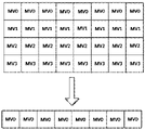
図8は、縮減ラインバッファ技術を示す図であり、現在のCUが前のCUにおいてマージ候補を検索する場合に、N×M(例えば、16×16)位置でMVにアクセスする。 FIG. 8 is a diagram illustrating a reduced line buffer technique, accessing the MV at N × M (eg, 16 × 16) positions when the current CU searches for merge candidates in the previous CU.
例として、現在のCUについて、各N×M位置で他の前のCUの動き情報にアクセスする。現在のCUが前のCTUからのMVデータにアクセスする必要がある場合に、現在のCUは各N×M位置の情報を取得してもよく、その中、NとMは正の整数である。 As an example, for the current CU, access the motion information of the other previous CU at each N × M position. If the current CU needs to access the MV data from the previous CTU, the current CU may acquire information on each N × M position, in which N and M are positive integers. ..
他の例として、現在のCUについて、各N×16位置で他の前のCUの動き情報にアクセスする。現在のCUが前のCUからのMVデータにアクセスする必要がある場合に、現在のCUは、各N×16位置の情報を取得してもよく、その中、Nは正の整数、例えば4、8、12、16などである。従って、現在のフレームについて、MVデータをサブサンプリングする。全ての前のCUについて、N×16ユニットによりMVにアクセスする。オフセットxとオフセットyは現在のCUに対する検索範囲である。 As another example, for the current CU, access the motion information of the other previous CU at each N × 16 position. If the current CU needs to access the MV data from the previous CU, the current CU may acquire information at each N × 16 position, in which N is a positive integer, eg 4 , 8, 12, 16, and so on. Therefore, the MV data is subsampled for the current frame. Access the MV with Nx16 units for all previous CUs. Offset x and offset y are search ranges for the current CU.
N×16(Nの最小値が4である)ユニットにおけるMVデータに任意の数の方法でアクセスすることができる。MVデータを記憶する最小のユニットは4×4であるので、N×16 MVバッファには4つの最小のユニット行が存在する可能性がある。図9に示すように、各行は1つの数字で指示される。1つの方法では、行0におけるMVデータは他の行のMV情報を示すために使用されてもよい。従って、行0のMVデータのみにアクセスし、他の行の情報を無視することができる。ピクチャ全体に対して当該処理を実行することができる。従って、ピクチャの最初の行から、ある位置でMVデータにアクセスしてもよい。 The MV data in the N × 16 (minimum value of N is 4) unit can be accessed in any number of ways. Since the smallest unit that stores MV data is 4x4, there may be four smallest unit rows in the Nx16 MV buffer. As shown in FIG. 9, each line is indicated by one number. In one method, the MV data in row 0 may be used to indicate the MV information in another row. Therefore, only the MV data in row 0 can be accessed and the information in other rows can be ignored. The process can be performed on the entire picture. Therefore, the MV data may be accessed at a certain position from the first line of the picture.
他の実施例において、行1のMVデータは他の行のMV情報の全てを示すために使用されてもよい。更なる他の実施例において、行2のMVデータは他の行のMV情報の全てを示すために使用されてもよい。更なる他の実施例において、行3の情報は他の行のMV情報の全てを示すために使用されてもよい。 In other embodiments, the MV data in row 1 may be used to indicate all of the MV information in the other rows. In yet another embodiment, the MV data in row 2 may be used to indicate all of the MV information in the other rows. In yet another embodiment, the information in row 3 may be used to indicate all of the MV information in the other rows.
以下、修正された行番号の疑似コードを生成するための例を示す。当該例において、行0の情報は、4つの行全てのMY情報を示すために使用される。以下のコードでは、yは縦座標である。
if (y is in above CTU)
{
y=(y/16)*16;
}
The following is an example for generating the modified line number pseudo code. In this example, the information in row 0 is used to indicate MY information for all four rows. In the code below, y is the coordinates.
if (y is in above CTU)
{
y = (y / 16) * 16;
}
他の実施例において、NはMに等しい。一実例において、NとMの両方は16である。本明細書の実施例は、16×16位置における動きデータを使用するために、様々な形態に適用できる。一実施例において、16×16グリッドにおける左上の4×4グリッドは、16×16ブロック全体を示すために使用される。 In another embodiment, N is equal to M. In one example, both N and M are 16. The embodiments of the present specification can be applied to various forms in order to use motion data at 16 × 16 positions. In one embodiment, the upper left 4x4 grid in the 16x16 grid is used to show the entire 16x16 block.
以下、修正された行番号の疑似コードを生成するための例を示す。当該例において、行0の情報はこれらの4つの行を示すために使用される。以下のコードでは、yは縦座標であり、xは横座標である。
if(y is in above CTU)
{
y=(y/16)*16;
x=(x/16)*16;
}
The following is an example for generating the modified line number pseudo code. In this example, the information in row 0 is used to indicate these four rows. In the code below, y is the coordinates and x is the abscissa.
if (y is in above CTU)
{
y = (y / 16) * 16;
x = (x / 16) * 16;
}
他の実施例において、行0から行3までの平均MVは全ての行情報を示すために使用されてもよい。他の実施例において、行0から行3までの平均MVは全ての行情報を示すために使用されてもよい。上記の実施例において、NはM以下である。 In other embodiments, the average MV from row 0 to row 3 may be used to indicate all row information. In other embodiments, the average MV from row 0 to row 3 may be used to indicate all row information. In the above embodiment, N is M or less.
他の実施例において、行に加えて、列に関連付けられて当該修正を実行してもよい。他の実施例において、参照ピクチャ方法におけるMVサブサンプリングを使用して現在ピクチャでアクセスされているMV位置を修正してもよい。 In other embodiments, the modification may be performed in association with the column in addition to the row. In other embodiments, MV subsampling in the reference picture method may be used to modify the MV position currently being accessed in the picture.
図10は、現在のCTUにおいて、現在のCUが、各4×4位置から現在のブロック(1000)を検索できる技術を示す図である。検索範囲が現在のCTUを超えた場合、N×M位置でMVにアクセスする。 FIG. 10 is a diagram showing a technique in which the current CU can search the current block (1000) from each 4 × 4 position in the current CTU. If the search range exceeds the current CTU, the MV is accessed at the N × M position.
当該方法において、現在のCUについて、各N×M位置で他の前のCTUの動き情報にアクセスする。現在のCUが前のCTUからのMVデータへのアクセスを取得する必要がある場合に、現在のCUは、各N×M(例えば16×16)位置(1009、1006、1003)に位置する情報を取得してもよく、NとMとは正の整数である。現在のCUが前のCUからのMVデータへのアクセスを取得する必要があり、且つこれらのCUが現在のCTU内にある場合に、これらのCUのMVデータは各4×4グリッドに位置する。 In this method, for the current CU, access to the motion information of the other previous CTU at each N × M position. If the current CU needs to gain access to the MV data from the previous CTU, the current CU is the information located at each NxM (eg 16x16) position (1009, 1006, 1003). May be obtained, and N and M are positive integers. If the current CU needs to gain access to the MV data from the previous CU and these CUs are in the current CTU, the MV data for these CUs will be located in each 4x4 grid. ..
一実施例において、現在のCUについて、各N×16位置で他の前のCTUの動き情報にアクセスする。現在のCUが前のCTUからのMVデータへのアクセスを取得する必要がある場合に、現在のCUは各N×16に記憶されている情報を取得してもよく、その中、Nは正の整数である。現在のCUが前のCUからのMVデータへのアクセスを取得する必要があり、これらのCUが現在のCTU内にある場合、これらのCUのMVデータは各4×4位置(1001、1002、1007、1005、1008)に位置する。前のCTUにおけるCUについて、N×16ユニットでMVデータを記憶する。現在のCTU内のCUについて、4×4ユニットでMVデータを記憶する。オフセットx及びオフセットyは現在のCUに対する検索範囲である。上記の実施例において、NはM以下である。 In one embodiment, for the current CU, access to the motion information of the other previous CTU at each N × 16 position. If the current CU needs to acquire access to the MV data from the previous CTU, the current CU may acquire the information stored in each Nx16, in which N is positive. Is an integer of. If the current CU needs to gain access to the MV data from the previous CU and these CUs are in the current CTU, then the MV data for these CUs will be in 4x4 positions (1001, 1002, respectively, It is located at 1007, 1005, 1008). MV data is stored in N × 16 units for the CU in the previous CTU. MV data is stored in 4 × 4 units for the CU in the current CTU. Offset x and offset y are search ranges for the current CU. In the above embodiment, N is M or less.
図11は、現在のCTUにおいて、現在のCUが各4×4位置から現在ブロック(1000)を検索できる技術を示す図である。検索範囲が現在のCTUを超えた場合、前のCTUの最後の行(1101)からのMVデータを使用する。 FIG. 11 is a diagram showing a technique in which the current CU can search the current block (1000) from each 4 × 4 position in the current CTU. If the search range exceeds the current CTU, the MV data from the last row (1101) of the previous CTU is used.
当該方法では、現在のCUについて、各4×4位置に対して現在のCTUの動きデータを記憶する。現在のCUが前のCTUからのMVデータにアクセスする必要がある場合に、現在のCUは、前のCTUの最後の行からMVデータを取得してもよい。現在のCUが前のCUからのMVデータへのアクセスを取得する必要があり、これらのCUが現在のCTU内にある場合、これらのCUのMVデータは各4×4位置に記憶される。前のCTUについて、現在のCUはMVデータの最後の行へのアクセスのみを取得できる。現在のCTU内のCUについて、4×4でMVデータを記憶する。オフセットx及びオフセットyは現在のCUに対する検索範囲である。 In this method, for the current CU, the motion data of the current CTU is stored for each 4 × 4 position. If the current CU needs to access the MV data from the previous CTU, the current CU may get the MV data from the last row of the previous CTU. If the current CU needs to gain access to the MV data from the previous CU and these CUs are in the current CTU, the MV data for these CUs will be stored in each 4x4 position. For the previous CTU, the current CU can only get access to the last row of MV data. MV data is stored in 4 × 4 for the CU in the current CTU. Offset x and offset y are search ranges for the current CU.
一実施例によれば、他の4×4グリッド(N×M位置が示されない)における動き情報は修正又は破棄されないが、この動き情報を複製するためにラインバッファは必要とされない。ラインバッファはN×M位置での動き情報のみをコピーすることができる。 According to one embodiment, motion information in another 4x4 grid (NxM position not shown) is not modified or discarded, but no line buffer is needed to duplicate this motion information. The line buffer can copy only the motion information at the N × M position.
上記の技術はコンピュータ可読命令を使用してコンピュータソフトウェアとして実現され、1つ以上のコンピュータ可読媒体に物理的に記憶されてもよい。例えば、図12は開示された主題のいくつかの実施例を実現するのに適したコンピュータシステム(1200)を示す。 The technique described above may be implemented as computer software using computer readable instructions and may be physically stored on one or more computer readable media. For example, FIG. 12 shows a computer system (1200) suitable for realizing some embodiments of the disclosed subject matter.
コンピュータソフトウェアは、任意の適切なマシンコード又はコンピュータ言語によって符号化することができ、任意の適切なマシンコード又はコンピュータ言語に対して、アセンブル、コンパイル、リンクなどのメカニズムを実行することで、コンピュータ中央処理ユニット(CPU)、グラフィック処理ユニット(GPU)などによって直接的に実行されるか、又は解釈、マイクロコードなどによって実行される命令を含むコードを作成することができる。 Computer software can be encoded by any suitable machine code or computer language, and by performing mechanisms such as assembling, compiling, linking, etc. to any suitable machine code or computer language, the computer is central. Code can be created that includes instructions that are executed directly by a processing unit (CPU), graphic processing unit (GPU), etc., or executed by interpretation, microcode, and the like.
当該命令は、例えばパーソナルコンピュータ、タブレット、サーバ、スマートフォン、ゲーム機器、モノのインターネット機器などを含む、様々なタイプのコンピュータ又はそれらのコンポーネントで実行されることができる。 The instructions can be executed on various types of computers or components thereof, including, for example, personal computers, tablets, servers, smartphones, gaming devices, Internet of Things devices, and the like.
図12に示すコンピュータシステム1200のコンポーネントは、本質的に例示であり、本開示の実施形態を実現するためのコンピュータソフトウェアの使用範囲又は機能に制限を加えることを意図するものではない。コンポーネントの配置は、コンピュータシステム1200の例示的な実施形態に示めされたるコンポーネントのいずれか、又はそれらの組み合わせに関連する依存性又は要件を有するものとして解釈されるべきではない。 The components of the computer system 1200 shown in FIG. 12 are exemplary in nature and are not intended to limit the scope or functionality of the computer software to realize the embodiments of the present disclosure. The placement of the components should not be construed as having any of the components shown in the exemplary embodiments of the computer system 1200, or any of the dependencies or requirements associated with their combination.
コンピュータシステム1200は、特定のヒューマンマシンインタフェース入力機器を含んでもよい。このようなヒューマンマシンインタフェース入力機器は、例えば触覚入力(例えば、キーストローク、スライド、データグローブ移動)、オーディオ入力(例えば、音声、拍手)、視覚入力(例えば、姿勢)、嗅覚入力(図示せず)による1つ以上の人間のユーザーの入力に応答することができる。ヒューマンマシンインタフェース機器はさらに、例えば、オーディオ(例えば、音声、音楽、環境音)、画像(例えば、スキャンした画像、静的画像撮影装置から取得された写真画像)、ビデオ(例えば2次元ビデオ、ステレオビデオが含まれる3次元ビデオ)などの、人間の意識的な入力に必ずしも直接関連しない特定のメディアをキャプチャするために使用されることもできる。 The computer system 1200 may include a specific human-machine interface input device. Such human-machine interface input devices include, for example, tactile input (eg, keystrokes, slides, data glove movement), audio input (eg, voice, applause), visual input (eg, posture), and olfactory input (not shown). ) Can respond to the input of one or more human users. Human-machine interface equipment also includes, for example, audio (eg, audio, music, ambient sound), images (eg, scanned images, photographic images taken from static imaging devices), video (eg, 2D video, stereo). It can also be used to capture specific media that are not necessarily directly related to human conscious input (three-dimensional video containing video).
ヒューマンマシンインタフェース入力機器は、キーボード1201、マウス1202、タッチパッド1203、タッチパネル1210、データグローブ1204、ジョイスティック1205、マイク1206、スキャナ1207及び撮影装置1208のうちの1つ以上を含んでもよい(それぞれが1つのみ図示される)。
The human machine interface input device may include one or more of a
コンピュータシステム1200はさらに特定のヒューマンマシンインタフェース出力機器を含んでもよい。このようなヒューマンマシンインタフェース出力機器は、例えば触覚出力、音、光及び匂い/味によって1つ以上の人間ユーザーの感覚を刺激することができる。このようなヒューマンマシンインタフェース出力機器は、触覚出力機器(例えば、タッチパネル1210、データグローブ1204又はジョイスティック1205による触覚フィードバックがあるが、入力機器として使用されない触覚フィードバック機器もある)、オーディオ出力機器(例えば、スピーカー1209、ヘッドフォン(図示せず))、視覚出力機器(例えば、スクリーン1212であって、陰極線管(CRT)スクリーン、液晶(LCD)スクリーン、プラズマスクリーン、有機発光ダイオード(OLED)スクリーンを含み、それぞれはタッチスクリーン入力機能がある場合とない場合、触覚フィードバック機能がある場合とない場合があり、そのうちのいくつかは、ステレオグラフィック出力のような手段で、2次元の視覚出力又は3次元以上の出力を出力できる場合がある)、バーチャルリアリティ眼鏡(図示せず)、ホログラフィックディスプレイ及びスモークタンク(図示せず))、プリンター(図示せず)を含むことができる。
The computer system 1200 may further include a specific human-machine interface output device. Such a human-machine interface output device can stimulate the senses of one or more human users, for example by tactile output, sound, light and odor / taste. Such human-machine interface output devices include tactile output devices (eg,
コンピュータシステム1200はさらに人間がアクセス可能な記憶機器及びその関連する媒体を含んでもよく、例えば、CD/DVDなどの媒体1221を有するCD/DVD ROM/RW1220などの光学媒体、サムドライブ1222、取り外し可能なハードドライブ又はソリッドステートドライブ1223、磁気テープとフロッピーディスク(図示せず)のような従来の磁気媒体、セキュリティドングル(図示せず)などの専用ROM/ASIC/PLDによる機器などを含んでもよい。
The computer system 1200 may further include a human accessible storage device and related media thereof, eg, an optical medium such as a CD / DVD ROM / RW1220 having a medium 1221 such as a CD / DVD, a
また、当業者は、現在開示された主題に関連して使用される「コンピュータ可読可能な媒体」という用語には、送信媒体、搬送波又は他の一時的な信号が含まれていないことを理解するべきである。 Also, one of ordinary skill in the art will appreciate that the term "computer-readable medium" used in connection with the currently disclosed subject matter does not include transmission media, carrier waves or other transient signals. Should be.
コンピュータシステム1200はさらに1つ以上の通信ネットワークへのインタフェースを含んでもよい。ネットワークは、例えば無線、有線、光ネットワークであってもよい。ネットワークはさらに、ローカル、ワイドエリア、メトロポリタン、車載、産業用、リアルタイム、遅延耐性ネットワークなどであってもよい。ネットワークの例は、例えば、イーサネットなどのローカルエリアネットワーク、無線LAN、GSM、3G、4G、5G、LTEなどを含むセルラーネットワーク、有線テレビ、衛星テレビ及び地上波テレビを含むテレビ有線又は無線ワイドエリアデジタルネットワーク、CANBusを含む車載及び産業用ネットワークなどを含む。一部のネットワークは一般的に、ある汎用データポート又は周辺バス(1249)(例えば、コンピュータシステム1200のUSBポート)の外部ネットワークインタフェースに接続されるアダプタを必要とし、他のネットワークは一般的に、以下のようなシステムバス(例えば、PCコンピュータシステムのイーサネットインタフェース、又はスマートフォンコンピュータシステムのセルラーネットワークインタフェース)に接続されることによって、コンピュータシステム1200のコアに統合される。これらのネットワークのいずれかを使用して、コンピュータシステム1200は他のエンティティと通信することができる。このような通信は、一方向、受信のみ(例えば、放送テレビ)、一方向送信のみ(例えば、あるCANbus機器へのCANbus)、又は双方向(例えば、ローカルエリア又はワイドエリアデジタルネットワークを使用して他のコンピュータシステムに達する)であってもよい。上記のようなこれらのネットワークとネットワークインタフェースのそれぞれに、特定のプロトコル及びプロトコルスタックを使用することができる。 The computer system 1200 may further include an interface to one or more communication networks. The network may be, for example, a wireless, wired or optical network. The network may further be local , wide area, metropolitan, automotive, industrial, real-time, delay-tolerant network, and the like. Examples of networks include local area networks such as Ethernet, cellular networks including wireless LAN, GSM, 3G, 4G, 5G, LTE and the like, television wired or wireless wide area digital including wired television, satellite television and terrestrial television. Includes in-vehicle and industrial networks including Tal networks and CANBus. Some networks generally require an adapter that connects to an external network interface of one general purpose data port or peripheral bus (1249) (eg, the USB port of a computer system 1200), while others generally require an adapter. It is integrated into the core of the computer system 1200 by being connected to the following system bus (eg, the Ethernet interface of a PC computer system or the cellular network interface of a smartphone computer system). Using any of these networks, the computer system 1200 can communicate with other entities. Such communication uses one-way, reception-only (eg, broadcast television), one-way transmission only (eg, CANbus to a CANbus device), or two-way (eg, local area or wide area digital network). To reach other computer systems). Specific protocols and protocol stacks can be used for each of these networks and network interfaces as described above.
上記のヒューマンマシンインタフェース機器、人間がアクセス可能な記憶装置及びネットワークインタフェースは、コンピュータシステム1200のコア1240に接続することができる。
The human-machine interface device, human-accessible storage device and network interface described above can be connected to the
コア1240は、1つ以上の中央処理ユニット(CPU)1241、グラフィック処理ユニット(GPU)1242、フィールドプログラム可能なゲートアレイ(FPGA)1243の形の専用のプログラム可能な処理ユニット、特定のタスクのためのハードウェアアクセラレータ1244などを含んでもよい。これらの機器は、読み取り専用メモリ(ROM)1245、ランダムアクセスメモリ1246、例えばユーザーがアクセスできない内部ハードディスクドライブ、ソリッドステートドライブ(SSD)などの内部大容量記憶装置1247とともに、システムバス1248を介して接続することができる。一部のコンピュータシステムにおいて、システムバス1248に1つ以上の物理プラグの形でアクセスできることで、追加のCPU、GPUなどによる拡張を可能にすることができる。周辺機器は、直接的又は周辺バス1249を介してコアのシステムバス1248に接続することができる。周辺バスのアーキテクチャは周辺コンポーネント相互接続(PCI)、USBなどを含む。
CPU1241、GPU1242、FPGA1243及びアクセラレータ1244は特定の命令を実行でき、これらの命令を組み合わせると、以上に言及されたコンピュータコードを構成することができる。当該コンピュータコードはROM1245又はRAM1246に記憶されてもよい。一時的なデータはRAM1246に記憶されることもでき、永久データは例えば内部大容量記憶装置1247に記憶されることができる。キャッシュメモリを使用することによって、記憶装置のいずれかへの高速ストレージ及び検索が可能になり、当該キャッシュメモリは1つ以上のCPU1241、GPU1242、大容量記憶装置1247、ROM1245、RAM1246などに密接に関連することができる。
The
コンピュータ可読媒体は、コンピュータが実現する様々な動作を実行するためのコンピュータコードをその上に有することができる。媒体とコンピュータコードは、本開示の目的のために、特別に設計及び構築される媒体とコンピュータコードであってもよいし、又は、コンピュータソフトウェアの当業者にとって周知であり、使用可能なタイプのものであってもよい。 A computer-readable medium can have computer code on it to perform various operations performed by the computer. The medium and computer code may be a medium and computer code specially designed and constructed for the purposes of the present disclosure, or of a type well known and usable by those skilled in the art of computer software. May be.
限定ではなく例として、アーキテクチャ1200を有するコンピュータシステム、特に、コア1240は、(1つ以上の)プロセッサ(CPU、GPU、FPGA、アクセラレータなどを含む)が1つ以上の有形コンピュータ読み取り可能な媒体に実装されるソフトウェアを実行することで、機能を提供することができる。このようなコンピュータ読み取り可能な媒体は、上記のような、ユーザがアクセス可能な大容量記憶装置に関する媒体、及び例えばコア内部大容量記憶装置1247又はROM1245などの非一時的なコア1240の特定の記憶装置であってもよい。本開示の各実施形態を実現するのソフトウェアはこのような機器に記憶され、コア1240によって実行されることができる。特定のニーズに応じて、コンピュータ読み取り可能な媒体には1つ以上の記憶装置又はチップが含まれてもよい。ソフトウェアは、コア1240、特にその中のプロセッサ(CPU、GPU、FPGAなどを含む)に、本明細書では説明されている特定の処理又は特定の処理の特定の部分を実行させることができ、RAM1246に記憶されるデータ構成を限定すること、及びソフトウェアによって限定された処理によってこのようなデータ構成を修正することが含まれる。さらに又は代替として、コンピュータシステムは、ロジックハードワイヤード、又は他の形式で回路(例えば、アクセラレータ1244)に実装されることによって、機能を提供することができ、当該回路は、ソフトウェアの代わりに、又はソフトウェアとともに動作して、本明細書では説明されている特定の処理又は特定の処理の特定の部分を実行することができる。適切な場合、ソフトウェアに対する言及にはロジックが含まれ、逆に、ロジックに対する言及にはソフトウェアが含まれてもよい。適切な場合に、コンピュータ読み取り可能な媒体に対する言及には、実行のためのソフトウェアが記憶される回路(例えば、集積回路(IC))、実行のためのロジックを具現化する回路、又はそれらの両方が含まれてもよい。本開示は、ハードウェアとソフトウェアとの任意の適切な組み合わせを含む。
As an example, but not limited to, a computer system with architecture 1200, in
この開示は、いくつかの例示的な実施例を説明してきたが、本開示の範囲内に含まれる変更、置換、及び様々な代替均等物が存在する。従って、本明細書では明示的に示されていないか、又は記載されていないが、本開示の原理を具現化したのでその精神及び範囲内にある多数のシステム及び方法を当業者が考案できることは認識される。 Although this disclosure has described some exemplary embodiments, there are modifications, substitutions, and various alternative equivalents included within the scope of this disclosure. Accordingly, although not expressly shown or described herein, those skilled in the art can devise a number of systems and methods within their spirit and scope as they embody the principles of the present disclosure. Be recognized.
付録A:頭字語:
高効率ビデオ符号化(HEVC)
符号化ユニット(CU)
予測ユニット(PU)
共同探査モデル(JEM7)
共同ビデオ探査グループ(JVET)
代替時間的動きベクトル予測(ATMVP)
時空間的動きベクトル予測(STMVP)
予測(P)スライス
双方向予測(B)スライス
レート歪み(RD)
時間的動きベクトル予測(TMVP)
コンテキスト適応型バイナリ算術符号化方式(CABAC)
多用途ビデオ符号化(VVC)
補助拡張情報(SEIメッセージ)
Appendix A: Acronym:
High Efficiency Video Coding (HEVC)
Coding unit (CU)
Prediction unit (PU)
Joint exploration model (JEM7)
Joint Video Exploration Group (JVET)
Alternative Time Motion Vector Prediction (ATMVP)
Spatiotemporal Motion Vector Prediction (STMVP)
Prediction (P) Slice bidirectional prediction (B) Slice rate distortion (RD)
Temporal motion vector prediction (TMVP)
Context-adaptive binary arithmetic coding (CABAC)
Versatile video coding (VVC)
Auxiliary extended information (SEI message)
Claims (12)
現在の符号化ツリーユニット(CTU)の上の符号化ツリーユニット(CTU)に関連付けられる動きベクトルセットを認識するステップであって、前記動きベクトルセットの各動きベクトルはP×Qグリッド位置に関連付けられており、前記動きベクトルセットはN×Mグリッド位置に関連付けられており、少なくともMはQより大きく、前記動きベクトルセットの各行の各ブロックが同じ単一の動きベクトルを含む、ステップと、
前記動きベクトルセットに含まれる動きベクトルに基づいて、N×Mグリッド位置に関連付けられる単一の動きベクトルを決定するステップと、
現在ブロックについて、N×Mグリッド位置に関連付けられる候補ブロックに基づいて、前記動きベクトルバッファにおいて動きベクトルにアクセスするステップと、
を含む方法。 A method performed by a processor to control a motion vector buffer that encodes or decodes a video sequence.
A step of recognizing a motion vector set associated with a coded tree unit (CTU) above the current coded tree unit (CTU), where each motion vector in the motion vector set is associated with a P × Q grid position. And that the motion vector set is associated with an N × M grid position, where at least M is greater than Q and each block in each row of the motion vector set contains the same single motion vector .
A step of determining a single motion vector associated with an N × M grid position based on the motion vectors contained in the motion vector set.
For the current block, the step of accessing the motion vector in the motion vector buffer based on the candidate block associated with the N × M grid position,
How to include.
前記P×Qグリッド位置に関連付けられる候補ブロックに基づいて、前記動きベクトルバッファにおいて前記別の動きベクトルにアクセスするステップと、
をさらに含む請求項1に記載の方法。 A step of recognizing another motion vector associated with the current CTU, wherein the other motion vector is associated with a P × Q grid position.
A step of accessing the other motion vector in the motion vector buffer based on the candidate block associated with the P × Q grid position.
The method according to claim 1, further comprising.
前記単一の動きベクトルを前記第1の動きベクトルとして決定するステップと、
をさらに含む請求項1又は2に記載の方法。 The step of recognizing the first motion vector associated with the first row of the motion vector set,
The step of determining the single motion vector as the first motion vector,
The method according to claim 1 or 2, further comprising.
前記単一の動きベクトルを前記平均動きベクトルとして決定するステップと、
をさらに含む請求項1又は2に記載の方法。 The step of determining the average motion vector based on the motion vector of the motion vector set,
The step of determining the single motion vector as the average motion vector,
The method according to claim 1 or 2, further comprising.
前記単一の動きベクトルを前記最後行動きベクトルとして決定するステップと、
をさらに含む請求項1又は2に記載の方法。 The step of determining the last row motion vector of the last row of the CTU above,
The step of determining the single motion vector as the last row motion vector,
The method according to claim 1 or 2, further comprising.
前記変更された行番号に基づいて、前記単一の動きベクトルにアクセスするステップと、
をさらに含む請求項1又は2に記載の方法。 A step to generate a modified line number for the motion vector set,
With the step of accessing the single motion vector based on the changed row number,
The method according to claim 1 or 2, further comprising.
コンピュータ・プログラム。
To cause one or more processors to perform the method according to any one of claims 1 to 10.
Computer program.
Applications Claiming Priority (5)
| Application Number | Priority Date | Filing Date | Title |
|---|---|---|---|
| US201862679580P | 2018-06-01 | 2018-06-01 | |
| US62/679,580 | 2018-06-01 | ||
| US16/233,953 US10798407B2 (en) | 2018-06-01 | 2018-12-27 | Methods and apparatus for inter prediction with a reduced above line buffer in video coding |
| US16/233,953 | 2018-12-27 | ||
| PCT/US2019/033445 WO2019231778A1 (en) | 2018-06-01 | 2019-05-22 | Methods and apparatus for inter prediction with a reduced above line buffer in video coding |
Publications (3)
| Publication Number | Publication Date |
|---|---|
| JP2021517394A JP2021517394A (en) | 2021-07-15 |
| JP2021517394A5 JP2021517394A5 (en) | 2021-08-26 |
| JP7061680B2 true JP7061680B2 (en) | 2022-04-28 |
Family
ID=68693407
Family Applications (1)
| Application Number | Title | Priority Date | Filing Date |
|---|---|---|---|
| JP2020546138A Active JP7061680B2 (en) | 2018-06-01 | 2019-05-22 | Inter-prediction methods and equipment that use the reduced previous line buffer in video coding |
Country Status (6)
| Country | Link |
|---|---|
| US (1) | US10798407B2 (en) |
| EP (1) | EP3804326A4 (en) |
| JP (1) | JP7061680B2 (en) |
| KR (1) | KR102496419B1 (en) |
| CN (1) | CN112470475B (en) |
| WO (1) | WO2019231778A1 (en) |
Families Citing this family (1)
| Publication number | Priority date | Publication date | Assignee | Title |
|---|---|---|---|---|
| EP3981157A4 (en) * | 2019-07-11 | 2022-07-06 | Huawei Technologies Co., Ltd. | Motion field storage optimization for the line buffer |
Citations (3)
| Publication number | Priority date | Publication date | Assignee | Title |
|---|---|---|---|---|
| US20140169472A1 (en) | 2012-12-19 | 2014-06-19 | Mikhail Fludkov | Motion estimation engine for video encoding |
| WO2018012886A1 (en) | 2016-07-12 | 2018-01-18 | 한국전자통신연구원 | Image encoding/decoding method and recording medium therefor |
| WO2018231700A1 (en) | 2017-06-13 | 2018-12-20 | Qualcomm Incorporated | Motion vector prediction |
Family Cites Families (11)
| Publication number | Priority date | Publication date | Assignee | Title |
|---|---|---|---|---|
| US20050013498A1 (en) * | 2003-07-18 | 2005-01-20 | Microsoft Corporation | Coding of motion vector information |
| US20050259878A1 (en) * | 2004-05-20 | 2005-11-24 | Broadcom Corporation | Motion estimation algorithm |
| CN102754442A (en) * | 2010-02-10 | 2012-10-24 | Lg电子株式会社 | Method and apparatus for processing a video signal |
| WO2012174973A1 (en) * | 2011-06-20 | 2012-12-27 | Mediatek Inc. | Method and apparatus for line buffers reduction |
| US9838684B2 (en) * | 2012-04-11 | 2017-12-05 | Qualcomm Incorporated | Wavefront parallel processing for video coding |
| EP2941883A4 (en) * | 2013-01-07 | 2016-07-06 | Mediatek Inc | Method and apparatus of depth to disparity vector conversion for three-dimensional video coding |
| JP6556942B2 (en) * | 2015-09-25 | 2019-08-07 | ホアウェイ・テクノロジーズ・カンパニー・リミテッド | Apparatus and method for video motion compensation |
| US10638152B2 (en) * | 2016-03-15 | 2020-04-28 | Mediatek Inc. | Method and apparatus of video coding with affine motion compensation |
| JP6740549B2 (en) * | 2016-03-16 | 2020-08-19 | 日本電気株式会社 | Moving picture coding apparatus, method, program, and moving picture coding system |
| CN109155856B (en) * | 2016-06-09 | 2023-10-24 | 英特尔公司 | Method and system for motion estimation using neighbor block mode for video coding |
| US11638027B2 (en) * | 2016-08-08 | 2023-04-25 | Hfi Innovation, Inc. | Pattern-based motion vector derivation for video coding |
-
2018
- 2018-12-27 US US16/233,953 patent/US10798407B2/en active Active
-
2019
- 2019-05-22 KR KR1020207029796A patent/KR102496419B1/en active IP Right Grant
- 2019-05-22 EP EP19812126.1A patent/EP3804326A4/en active Pending
- 2019-05-22 CN CN201980021965.XA patent/CN112470475B/en active Active
- 2019-05-22 JP JP2020546138A patent/JP7061680B2/en active Active
- 2019-05-22 WO PCT/US2019/033445 patent/WO2019231778A1/en unknown
Patent Citations (3)
| Publication number | Priority date | Publication date | Assignee | Title |
|---|---|---|---|---|
| US20140169472A1 (en) | 2012-12-19 | 2014-06-19 | Mikhail Fludkov | Motion estimation engine for video encoding |
| WO2018012886A1 (en) | 2016-07-12 | 2018-01-18 | 한국전자통신연구원 | Image encoding/decoding method and recording medium therefor |
| WO2018231700A1 (en) | 2017-06-13 | 2018-12-20 | Qualcomm Incorporated | Motion vector prediction |
Non-Patent Citations (6)
| Title |
|---|
| Jicheng An, Na Zhang, Xu Chen, and Jianhua Zheng,Enhanced Merge Mode based on JEM7.0,Joint Video Experts Team (JVET) of ITU-T SG 16 WP 3 and ISO/IEC JTC 1/SC 29/WG 11,JVET-J0059-v1,10th Meeting: San Diego, US,2018年04月,pp.1-14 |
| Jing Ye, Xiang Li, and Shan Liu,CE4: Additional merge candidates (Test 4.2.13),Joint Video Experts Team (JVET) of ITU-T SG 16 WP 3 and ISO/IEC JTC 1/SC 29/WG 11,JVET-K0286,11th Meeting: Ljubljana, SI,2018年07月,pp.1-9 |
| Jing Ye, Xiang Li, and Shan Liu,Merge mode modification on top of Tencent’s software in response to CfP,Joint Video Experts Team (JVET) of ITU-T SG 16 WP 3 and ISO/IEC JTC 1/SC 29/WG 11,JVET-J0058-v1,10th Meeting: San Diego, US,2018年04月,pp.1-4 |
| Jing Ye, Xiang Li, Shan Liu, Xiaozhong Xu, and Guichun Li,CE4-related: Reduce line buffer for additional merge candidates,Joint Video Experts Team (JVET) of ITU-T SG 16 WP 3 and ISO/IEC JTC 1/SC 29/WG 11,JVET-K0297,11th Meeting: Ljubljana, SI,2018年07月,pp.1-7 |
| Xiang Li et al.,Description of SDR video coding technology proposal by Tencent,Joint Video Experts Team (JVET) of ITU-T SG 16 WP 3 and ISO/IEC JTC 1/SC 29/WG 11,JVET-J0029-v1,10th Meeting: San Diego, US,2018年04月,pp.8-9 |
| Yi-Wen Chen et al.,Description of SDR, HDR and 360° video coding technology proposal by Qualcomm and Technicolor - low and high complexity versions,Joint Video Exploration Team (JVET) of ITU-T SG 16 WP 3 and ISO/IEC JTC 1/SC 29/WG 11,JVET-J0021,10th Meeting: San Diego, US,2018年04月,pp.15-19 |
Also Published As
| Publication number | Publication date |
|---|---|
| CN112470475A (en) | 2021-03-09 |
| EP3804326A4 (en) | 2022-03-16 |
| EP3804326A1 (en) | 2021-04-14 |
| CN112470475B (en) | 2022-11-08 |
| JP2021517394A (en) | 2021-07-15 |
| US20190373279A1 (en) | 2019-12-05 |
| KR20200125743A (en) | 2020-11-04 |
| KR102496419B1 (en) | 2023-02-06 |
| US10798407B2 (en) | 2020-10-06 |
| WO2019231778A1 (en) | 2019-12-05 |
Similar Documents
| Publication | Publication Date | Title |
|---|---|---|
| JP7046220B2 (en) | Methods, devices, and programs for predicting and transforming small blocks | |
| JP7057448B2 (en) | Methods and equipment for multi-line in-frame prediction in video compression | |
| JP7130851B2 (en) | Method and Apparatus for Merge Mode with Additional Intermediate Candidates in Video Coding | |
| JP7085021B2 (en) | Video coding and decoding methods, equipment and computer programs | |
| JP7055485B2 (en) | Methods for video coding and their equipment and computer programs | |
| CN110784711B (en) | Method and device for generating merging candidate list for video sequence coding or decoding | |
| JP2021524176A (en) | Methods, equipment and computer programs for video coding | |
| JP2022059032A (en) | Method, apparatus, computer program, and transitory computer readable medium for video encoding and decoding | |
| JP7080434B2 (en) | Subblock motion vector prediction method, its equipment and computer program | |
| JP7457170B2 (en) | Method, apparatus and computer program for temporal motion vector prediction based on sub-blocks | |
| JP7025562B2 (en) | Methods and devices for video coding | |
| KR102637503B1 (en) | Method and apparatus for controlling intra-inter prediction for decoding or encoding of a video sequence | |
| CN113424546A (en) | Method and apparatus for further improved context design of prediction modes and Coded Block Flags (CBFs) | |
| JP7427814B2 (en) | Video encoding and decoding methods and devices and computer programs | |
| JP2022512109A (en) | Video decoding and coding methods, equipment and programs | |
| JP7357679B2 (en) | Improved most probable mode list generation method | |
| JP2023126585A (en) | Method of mode list generation for multi-line intra prediction, apparatus therefor, and computer program | |
| CN112400320B (en) | Method, device and readable medium for decoding coded video sequence | |
| CN113728628B (en) | Merging candidate searching method and equipment | |
| JP7061680B2 (en) | Inter-prediction methods and equipment that use the reduced previous line buffer in video coding | |
| CN112135151B (en) | Video decoding method, system, computer device and storage medium | |
| JP2021517394A5 (en) | ||
| KR20220159464A (en) | Intra mode derivation on decoder side | |
| KR20220073844A (en) | Method and system for video coding, and computer readable medium | |
| JP2022523616A (en) | Video decoding methods, equipment, and computer programs |
Legal Events
| Date | Code | Title | Description |
|---|---|---|---|
| A521 | Request for written amendment filed |
Free format text: JAPANESE INTERMEDIATE CODE: A523 Effective date: 20200916 |
|
| A621 | Written request for application examination |
Free format text: JAPANESE INTERMEDIATE CODE: A621 Effective date: 20200903 |
|
| A131 | Notification of reasons for refusal |
Free format text: JAPANESE INTERMEDIATE CODE: A131 Effective date: 20211012 |
|
| A521 | Request for written amendment filed |
Free format text: JAPANESE INTERMEDIATE CODE: A523 Effective date: 20211227 |
|
| A131 | Notification of reasons for refusal |
Free format text: JAPANESE INTERMEDIATE CODE: A131 Effective date: 20220215 |
|
| A521 | Request for written amendment filed |
Free format text: JAPANESE INTERMEDIATE CODE: A523 Effective date: 20220317 |
|
| TRDD | Decision of grant or rejection written | ||
| A01 | Written decision to grant a patent or to grant a registration (utility model) |
Free format text: JAPANESE INTERMEDIATE CODE: A01 Effective date: 20220412 |
|
| A61 | First payment of annual fees (during grant procedure) |
Free format text: JAPANESE INTERMEDIATE CODE: A61 Effective date: 20220418 |
|
| R150 | Certificate of patent or registration of utility model |
Ref document number: 7061680 Country of ref document: JP Free format text: JAPANESE INTERMEDIATE CODE: R150 |