JP7061340B2 - Systems and methods for body lumen deflection - Google Patents
Systems and methods for body lumen deflection Download PDFInfo
- Publication number
- JP7061340B2 JP7061340B2 JP2019526586A JP2019526586A JP7061340B2 JP 7061340 B2 JP7061340 B2 JP 7061340B2 JP 2019526586 A JP2019526586 A JP 2019526586A JP 2019526586 A JP2019526586 A JP 2019526586A JP 7061340 B2 JP7061340 B2 JP 7061340B2
- Authority
- JP
- Japan
- Prior art keywords
- catheter
- lumen
- deflection
- shaft
- balloon
- Prior art date
- Legal status (The legal status is an assumption and is not a legal conclusion. Google has not performed a legal analysis and makes no representation as to the accuracy of the status listed.)
- Active
Links
Images


Classifications
-
- A—HUMAN NECESSITIES
- A61—MEDICAL OR VETERINARY SCIENCE; HYGIENE
- A61B—DIAGNOSIS; SURGERY; IDENTIFICATION
- A61B90/00—Instruments, implements or accessories specially adapted for surgery or diagnosis and not covered by any of the groups A61B1/00 - A61B50/00, e.g. for luxation treatment or for protecting wound edges
- A61B90/04—Protection of tissue around surgical sites against effects of non-mechanical surgery, e.g. laser surgery
-
- A—HUMAN NECESSITIES
- A61—MEDICAL OR VETERINARY SCIENCE; HYGIENE
- A61M—DEVICES FOR INTRODUCING MEDIA INTO, OR ONTO, THE BODY; DEVICES FOR TRANSDUCING BODY MEDIA OR FOR TAKING MEDIA FROM THE BODY; DEVICES FOR PRODUCING OR ENDING SLEEP OR STUPOR
- A61M25/00—Catheters; Hollow probes
- A61M25/01—Introducing, guiding, advancing, emplacing or holding catheters
- A61M25/0105—Steering means as part of the catheter or advancing means; Markers for positioning
- A61M25/0133—Tip steering devices
- A61M25/0147—Tip steering devices with movable mechanical means, e.g. pull wires
-
- A—HUMAN NECESSITIES
- A61—MEDICAL OR VETERINARY SCIENCE; HYGIENE
- A61B—DIAGNOSIS; SURGERY; IDENTIFICATION
- A61B18/00—Surgical instruments, devices or methods for transferring non-mechanical forms of energy to or from the body
-
- A—HUMAN NECESSITIES
- A61—MEDICAL OR VETERINARY SCIENCE; HYGIENE
- A61M—DEVICES FOR INTRODUCING MEDIA INTO, OR ONTO, THE BODY; DEVICES FOR TRANSDUCING BODY MEDIA OR FOR TAKING MEDIA FROM THE BODY; DEVICES FOR PRODUCING OR ENDING SLEEP OR STUPOR
- A61M25/00—Catheters; Hollow probes
- A61M25/01—Introducing, guiding, advancing, emplacing or holding catheters
- A61M25/0105—Steering means as part of the catheter or advancing means; Markers for positioning
- A61M25/0108—Steering means as part of the catheter or advancing means; Markers for positioning using radio-opaque or ultrasound markers
-
- A—HUMAN NECESSITIES
- A61—MEDICAL OR VETERINARY SCIENCE; HYGIENE
- A61M—DEVICES FOR INTRODUCING MEDIA INTO, OR ONTO, THE BODY; DEVICES FOR TRANSDUCING BODY MEDIA OR FOR TAKING MEDIA FROM THE BODY; DEVICES FOR PRODUCING OR ENDING SLEEP OR STUPOR
- A61M25/00—Catheters; Hollow probes
- A61M25/01—Introducing, guiding, advancing, emplacing or holding catheters
- A61M25/0105—Steering means as part of the catheter or advancing means; Markers for positioning
- A61M25/0133—Tip steering devices
- A61M25/0155—Tip steering devices with hydraulic or pneumatic means, e.g. balloons or inflatable compartments
-
- A—HUMAN NECESSITIES
- A61—MEDICAL OR VETERINARY SCIENCE; HYGIENE
- A61M—DEVICES FOR INTRODUCING MEDIA INTO, OR ONTO, THE BODY; DEVICES FOR TRANSDUCING BODY MEDIA OR FOR TAKING MEDIA FROM THE BODY; DEVICES FOR PRODUCING OR ENDING SLEEP OR STUPOR
- A61M25/00—Catheters; Hollow probes
- A61M25/10—Balloon catheters
- A61M25/1002—Balloon catheters characterised by balloon shape
-
- A—HUMAN NECESSITIES
- A61—MEDICAL OR VETERINARY SCIENCE; HYGIENE
- A61M—DEVICES FOR INTRODUCING MEDIA INTO, OR ONTO, THE BODY; DEVICES FOR TRANSDUCING BODY MEDIA OR FOR TAKING MEDIA FROM THE BODY; DEVICES FOR PRODUCING OR ENDING SLEEP OR STUPOR
- A61M25/00—Catheters; Hollow probes
- A61M25/10—Balloon catheters
- A61M25/1011—Multiple balloon catheters
-
- A—HUMAN NECESSITIES
- A61—MEDICAL OR VETERINARY SCIENCE; HYGIENE
- A61B—DIAGNOSIS; SURGERY; IDENTIFICATION
- A61B18/00—Surgical instruments, devices or methods for transferring non-mechanical forms of energy to or from the body
- A61B18/04—Surgical instruments, devices or methods for transferring non-mechanical forms of energy to or from the body by heating
- A61B18/12—Surgical instruments, devices or methods for transferring non-mechanical forms of energy to or from the body by heating by passing a current through the tissue to be heated, e.g. high-frequency current
- A61B18/14—Probes or electrodes therefor
- A61B18/1492—Probes or electrodes therefor having a flexible, catheter-like structure, e.g. for heart ablation
-
- A—HUMAN NECESSITIES
- A61—MEDICAL OR VETERINARY SCIENCE; HYGIENE
- A61B—DIAGNOSIS; SURGERY; IDENTIFICATION
- A61B18/00—Surgical instruments, devices or methods for transferring non-mechanical forms of energy to or from the body
- A61B2018/00053—Mechanical features of the instrument of device
- A61B2018/00273—Anchoring means for temporary attachment of a device to tissue
- A61B2018/00279—Anchoring means for temporary attachment of a device to tissue deployable
- A61B2018/00285—Balloons
-
- A—HUMAN NECESSITIES
- A61—MEDICAL OR VETERINARY SCIENCE; HYGIENE
- A61B—DIAGNOSIS; SURGERY; IDENTIFICATION
- A61B18/00—Surgical instruments, devices or methods for transferring non-mechanical forms of energy to or from the body
- A61B2018/00315—Surgical instruments, devices or methods for transferring non-mechanical forms of energy to or from the body for treatment of particular body parts
- A61B2018/00345—Vascular system
- A61B2018/00351—Heart
-
- A—HUMAN NECESSITIES
- A61—MEDICAL OR VETERINARY SCIENCE; HYGIENE
- A61B—DIAGNOSIS; SURGERY; IDENTIFICATION
- A61B18/00—Surgical instruments, devices or methods for transferring non-mechanical forms of energy to or from the body
- A61B2018/00571—Surgical instruments, devices or methods for transferring non-mechanical forms of energy to or from the body for achieving a particular surgical effect
- A61B2018/00577—Ablation
-
- A—HUMAN NECESSITIES
- A61—MEDICAL OR VETERINARY SCIENCE; HYGIENE
- A61B—DIAGNOSIS; SURGERY; IDENTIFICATION
- A61B90/00—Instruments, implements or accessories specially adapted for surgery or diagnosis and not covered by any of the groups A61B1/00 - A61B50/00, e.g. for luxation treatment or for protecting wound edges
- A61B90/04—Protection of tissue around surgical sites against effects of non-mechanical surgery, e.g. laser surgery
- A61B2090/0409—Specification of type of protection measures
- A61B2090/0427—Prevention of contact
-
- A—HUMAN NECESSITIES
- A61—MEDICAL OR VETERINARY SCIENCE; HYGIENE
- A61M—DEVICES FOR INTRODUCING MEDIA INTO, OR ONTO, THE BODY; DEVICES FOR TRANSDUCING BODY MEDIA OR FOR TAKING MEDIA FROM THE BODY; DEVICES FOR PRODUCING OR ENDING SLEEP OR STUPOR
- A61M25/00—Catheters; Hollow probes
- A61M25/10—Balloon catheters
- A61M2025/1043—Balloon catheters with special features or adapted for special applications
- A61M2025/1084—Balloon catheters with special features or adapted for special applications having features for increasing the shape stability, the reproducibility or for limiting expansion, e.g. containments, wrapped around fibres, yarns or strands
-
- A—HUMAN NECESSITIES
- A61—MEDICAL OR VETERINARY SCIENCE; HYGIENE
- A61M—DEVICES FOR INTRODUCING MEDIA INTO, OR ONTO, THE BODY; DEVICES FOR TRANSDUCING BODY MEDIA OR FOR TAKING MEDIA FROM THE BODY; DEVICES FOR PRODUCING OR ENDING SLEEP OR STUPOR
- A61M25/00—Catheters; Hollow probes
- A61M25/01—Introducing, guiding, advancing, emplacing or holding catheters
- A61M25/02—Holding devices, e.g. on the body
- A61M25/04—Holding devices, e.g. on the body in the body, e.g. expansible
-
- A—HUMAN NECESSITIES
- A61—MEDICAL OR VETERINARY SCIENCE; HYGIENE
- A61M—DEVICES FOR INTRODUCING MEDIA INTO, OR ONTO, THE BODY; DEVICES FOR TRANSDUCING BODY MEDIA OR FOR TAKING MEDIA FROM THE BODY; DEVICES FOR PRODUCING OR ENDING SLEEP OR STUPOR
- A61M25/00—Catheters; Hollow probes
- A61M25/01—Introducing, guiding, advancing, emplacing or holding catheters
- A61M25/09—Guide wires
Landscapes
- Health & Medical Sciences (AREA)
- Life Sciences & Earth Sciences (AREA)
- Heart & Thoracic Surgery (AREA)
- Engineering & Computer Science (AREA)
- Public Health (AREA)
- Animal Behavior & Ethology (AREA)
- Veterinary Medicine (AREA)
- General Health & Medical Sciences (AREA)
- Biomedical Technology (AREA)
- Hematology (AREA)
- Biophysics (AREA)
- Anesthesiology (AREA)
- Pulmonology (AREA)
- Surgery (AREA)
- Child & Adolescent Psychology (AREA)
- Nuclear Medicine, Radiotherapy & Molecular Imaging (AREA)
- Medical Informatics (AREA)
- Molecular Biology (AREA)
- Otolaryngology (AREA)
- Oral & Maxillofacial Surgery (AREA)
- Pathology (AREA)
- Mechanical Engineering (AREA)
- Media Introduction/Drainage Providing Device (AREA)
- Surgical Instruments (AREA)
Description
関連出願への相互参照
本発明は「System and method for deflection of a body lumen」という表題で2016年11月23日にGregory G.Bruckerらによって出願された米国仮特許出願第62/426,223号の35U.S.C.§119(e)下での優先権の利益を主張するものであり、当該文献は全体として参照により本明細書に組み込まれるものとする。
Cross-reference to related applications The invention was published on November 23, 2016 by Gregory G. et al. US Provisional Patent Application No. 62 / 426,223 filed by Brucker et al., 35 U.S.A. S. C. § 119 (e) claims the benefit of priority and the document as a whole is incorporated herein by reference.
本発明の実施形態は、概して、心房-食道瘻の形成の可能性を最小限にすべく、心房細動の処置のアブレーション手術中に食道を心臓から離す等の治療を行う間、身体の器官に対する意図しない損傷を実質的に減らす或いはなくすために、体管腔の位置を変えることを目的とする、体腔内の管腔の偏向のためのカテーテルに関する。本発明は、その伸縮性を軽減するために体腔を拡大するための、拡張カテーテル、および体内部のその自然な位置から体管腔を移動するための、拡張カテーテル内に付けられた、または位置付けられた偏向機構を含む。 Embodiments of the invention generally include organs of the body during treatments such as detaching the esophagus from the heart during ablation surgery for the treatment of atrial fibrillation to minimize the possibility of forming an atrial-esophageal fistula. With respect to a catheter for deflection of a lumen within a body cavity, which is intended to reposition the body lumen in order to substantially reduce or eliminate unintended damage to the body cavity. The present invention is attached or positioned within an dilated catheter to dilate the body cavity to reduce its elasticity, and to move the body cavity from its natural position within the body. Includes a deflected deflection mechanism.
体管腔の偏向用装置は、偏向が生じる機構によって分類され、すなわち偏向は:機械的または拡張可能である。機械的な偏向は、体腔内の体管腔の部分の位置を変えるために体管腔内に位置された可撓管に挿入されたスタイレット等の、あらかじめ弯曲した要素を使用する。あるいは、ワイヤは可撓管、およびチューブを弯曲し体管腔を所望の距離に移動するために使用されるワイヤ張力内に収容することができる。拡張可能な偏向は、より小さな直径から大きな直径までの拡張に際し体管腔を拡張した要素の弯曲によって位置を変えるように、あらかじめ定められた弯曲を収容している要素、例えばバルーンを使用する。両方の偏向機構は、主にほとんどの体管腔の伸縮性のため、体腔内の体管腔の位置を変えるための臨床的利点を制限する。例えば、心臓のアブレーション治療を使用する心房細動の処置では、多くの場合致命的になりうる心房の食道瘻の形成を防ぐため、或いは食道周囲の迷走神経の損傷を防ぐために、左心房の後部壁近くの領域の食道の位置を変えることが望ましい。食道の直径および伸縮性は、臨床のリスクを減らすために、前述の偏位方法が適切に食道の位置を変える性能を制限しており、それによって、それらの臨床の値を制限する。 Lumen deflection devices are classified by the mechanism by which the deflection occurs, i.e. the deflection: mechanical or expandable. Mechanical deflection uses a pre-curved element, such as a stylet inserted into a flexible tube located within the body lumen to reposition a portion of the body lumen within the body cavity. Alternatively, the wire can be contained within the flexible tube, and the wire tension used to bend the tube and move the body lumen to the desired distance. The expandable deflection uses an element containing a predetermined curvature, such as a balloon, so that it is repositioned by the curvature of the element that dilated the body lumen as it expands from a smaller diameter to a larger diameter. Both deflection mechanisms limit the clinical benefit of repositioning the body cavity within the body cavity, primarily due to the elasticity of most body cavities. For example, in the treatment of atrial fibrillation using cardiac ablation therapy, the posterior part of the left atrium to prevent the formation of an esophageal fistula in the atria, which is often fatal, or to prevent damage to the vagus nerve around the esophagus. It is desirable to reposition the esophagus in the area near the wall. The diameter and elasticity of the esophagus limit the ability of the aforementioned deviation methods to properly reposition the esophagus in order to reduce clinical risk, thereby limiting their clinical value.
チューブ、およびそこに収容されている偏向手段を典型的に使用する機械装置について、装置の直径は、それが挿入される管腔より概して小さい。装置と体管腔との間の直径差によって、機械装置の最初の偏向は初めに、管腔の壁のいくつかの態様と係合するように移動し、体管腔の管腔の壁上の集中的な力載荷、および体管腔の伸縮性のために、その後、一層高い縦横比を用いて、体管腔の横の断面のプロファイルを円形から楕円形に変える。効果的には、たとえ装置の著しい側方の動きがあっても、他の体構成に関する体管腔の中心線の動きは、実質的に軽減される。大径チューブはこれらの前述の効果を最小化するために使用することができるが、装置が大きくなるとともに、それらはより堅くなり、挿入をさらに複雑にし、付随的な組織損傷のリスクをより高める。例えば、食道の適用において、偏向装置は通常、鼻または咽喉のどちらかを通って挿入され、これは、それぞれ、装置直径を3mm(0.118インチ)および9mm(0.354インチ)に制限し、一方で食道の直径は15から30mm(0.591から1.181インチ)の範囲である。概してこれは、3.0から4.0cm(1.18から1.57インチ)である更に望ましい範囲で、食道の側方の動きを約2.0cm(0.787インチ)に制限する。 For mechanical devices that typically use a tube and the deflecting means contained therein, the diameter of the device is generally smaller than the lumen into which it is inserted. Due to the diameter difference between the device and the body lumen, the initial deflection of the mechanical device initially moves to engage with some aspects of the lumen wall and on the body lumen lumen wall. Due to the intensive force loading of the body lumen and the elasticity of the body lumen, then using a higher aspect ratio, the profile of the cross section of the body lumen is changed from circular to elliptical. Effectively, the movement of the centerline of the body lumen with respect to other body configurations is substantially reduced, even if there is significant lateral movement of the device. Large diameter tubes can be used to minimize these aforementioned effects, but as the device grows, they become stiffer, more complex to insert, and increase the risk of concomitant tissue damage. .. For example, in the application of the esophagus, the deflection device is usually inserted through either the nose or the throat, which limits the device diameter to 3 mm (0.118 inches) and 9 mm (0.354 inches), respectively. On the other hand, the diameter of the esophagus ranges from 15 to 30 mm (0.591 to 1.181 inches). Generally this limits lateral movement of the esophagus to about 2.0 cm (0.787 inches), in a more desirable range of 3.0 to 4.0 cm (1.18 to 1.57 inches).
体管腔の直径程度まで拡大する要素を有する拡張可能な装置について、拡張可能な要素は概して、拡大した際に前もって調整された弯曲を有する。使用中、あらかじめ弯曲した要素は初めに体管腔を係合するために拡張し、次に、継続的な拡張に際して、その通常の経路から体腔を通って体管腔を偏向する。偏向機構のこのタイプの最も一般的な実装は、予めに形成されたバルーンまたは弯曲したワイヤメッシュである。これらの装置の利点は、装置の弯曲がその通常の経路からの体管腔の中心線の更なる動きを結果としてもたらすように、それらが体管腔の直径および円形を維持するということである。拡張可能な装置の不利益は、偏向に必要なより高い力であり、これはより高圧のバルーンまたは、より厚いメッシュワイヤに変換され、それらの拡張していない状態では、より堅い装置および大きな直径の交差プロファイルを結果としてもたらし、どちらも体管腔を損傷する可能性があり、臨床的に不適当である。 For expandable devices that have elements that expand to about the diameter of the body lumen, the expandable elements generally have a pre-adjusted curve upon expansion. During use, the pre-curved element first dilates to engage the body lumen and then deflects the body lumen through the body cavity during continuous dilation. The most common implementation of this type of deflection mechanism is a preformed balloon or curved wire mesh. The advantage of these devices is that they maintain the diameter and circularity of the body lumen, as the curvature of the device results in further movement of the centerline of the body lumen from its normal path. .. The disadvantage of expandable devices is the higher force required for deflection, which is converted to higher pressure balloons or thicker mesh wires, and in their non-expandable state, stiffer devices and larger diameters. As a result, both of them can damage the body lumen and are clinically unsuitable.
前述の不利益に加えて、体管腔内の偏向装置の位置を変える場合、機械的な偏向装置および拡張可能な装置のどちらも追加の工程を必要とする。偏向機構は装置の一体型の部分であるので、偏向装置は体管腔内で位置を変える前にその中立状態に戻されるに違いない。最低でも、これは追加の手順の時間を必要とし、ここで偏向装置の操作中に患者をさらなるリスクにさらす可能性がある。 In addition to the aforementioned disadvantages, repositioning the deflector within the body lumen requires additional steps for both the mechanical deflector and the expandable device. Since the deflection mechanism is an integral part of the device, the deflection device must be returned to its neutral state before repositioning within the body lumen. At a minimum, this requires additional procedure time, which may put the patient at additional risk during the operation of the deflector.
米国特許第7,621,908号は、Steven W.Millerによる「Catheter for Manipulation of the Esophagus」という表題で、2009年11月24日に付与され、参照により全体として本明細書に組み込まれ、食道に挿入される長い可撓管からできている、心臓の房に関して食道の位置を変位させて固定するための食道のカテーテルを記載する。制御ワイヤは、カテーテルの形を変えて、心房性のRFアブレーションに起因する食道瘻のリスクを減らすべく心臓に関する食道を変位するように、チューブに関連する。 U.S. Pat. No. 7,621,908 describes Stephen W. et al. A heart made of a long flexible tube inserted into the esophagus, entitled "Catheter for Manipulation of the Esophagus" by Miller, granted November 24, 2009, incorporated herein by reference in its entirety. Described is an esophageal catheter for dislocating and fixing the position of the esophagus with respect to the bunch of esophagus. The control wire is associated with the tube to reshape the catheter and displace the esophagus with respect to the heart to reduce the risk of esophageal fistula due to atrial RF ablation.
米国特許第8,529,443号は、by James D.Maloneyによる「Nasogastric Tube for Use during an Ablation Procedure」という表題で、2013年9月10日に付与され、参照により全体として本明細書に組み込まれ、アブレーション手術中に食道を偏向させるための経鼻胃管を提供するための本発明の実施形態を記載する。1つの実施形態によれば、経鼻胃管は、近位および遠端部を有する少なくとも1つの管腔を含む可撓管、および少なくとも1つの体腔内に位置決めされ、近位および遠端部間でチューブの部分を偏向するように、弯曲したプロファイルを仮定すべく機械的に始動するように構成される食道のデフレクターを含む。食道のデフレクターは、食道の心臓の後ろの部分がアブレーション位置から遠ざけて偏向させられるように、食道の心臓の後ろの部分に近似のチューブの部分を偏向するように構成される。 U.S. Pat. No. 8,529,443 is described by by James D. et al. Granted September 10, 2013, entitled "Nasogastric Tube for Use daring an Ablation Procedure" by Maloney, incorporated herein by reference in its entirety, nasogastric to deflect the esophagus during ablation surgery. Embodiments of the present invention for providing a tube are described. According to one embodiment, the nasogastric tube is positioned within at least one body cavity, including a flexible tube containing at least one lumen having proximal and far ends, and between the proximal and far ends. Includes an esophageal deflector configured to mechanically initiate to assume a curved profile so as to deflect a portion of the tube at. The deflector of the esophagus is configured to deflect a portion of the tube similar to the posterior portion of the esophageal heart so that the posterior portion of the esophageal heart is deflected away from the ablation position.
米国特許第8,273,016号は、Martin F.O’Sullivanによる「Esophageal Isolation Device」という表題で、2012年9月25日に付与され、参照により全体として本明細書に組み込まれ、患者の食道を患者の心臓の左心房のアブレーション位置から遠ざけて偏向させるための食道隔離カテーテルを記載する。カテーテルは長方形のカテーテル本体および偏向可能な部分を含む。1つの実施形態において、カテーテルは、カテーテル本体の遠端部に取り付けられた偏向可能な中間の部分、および中間部分の遠端部に取り付けられた概して直線の先端部分を含む。本実施形態において、カテーテルは2つのプルワイヤを含み、一つは他方に近位でしっかり固定される。中間部分は、概してC-形状か、オメガ形状(Ω-形状)弯曲を形成するために偏向する。代替的な実施形態において、カテーテルは、カテーテル本体の遠端部に取り付けられた偏向可能な先端部分を含む。本実施形態において、カテーテルはたった1つのプルワイヤを含む。先端部分は、偏向の際の食道への損傷を防ぐために非外傷性の設計を有する先端電極を伴う。 U.S. Pat. No. 8,273,016 is published in Martin F. et al. Granted September 25, 2012, entitled "Esophageal Isolation Device" by O'Sullivan, incorporated herein by reference in its entirety, away from the ablation position of the patient's esophagus in the left atrium of the patient's heart. Describe an esophageal isolation catheter for deflection. The catheter includes a rectangular catheter body and a deflectable part. In one embodiment, the catheter comprises a deflectable intermediate portion attached to the far end of the catheter body and a generally straight tip attached to the far end of the intermediate portion. In this embodiment, the catheter comprises two pull wires, one proximal to the other and firmly anchored. The middle part is generally deflected to form a C-shape or an omega-shape (Ω-shape) curve. In an alternative embodiment, the catheter comprises a deflectable tip attached to the far end of the catheter body. In this embodiment, the catheter comprises only one pull wire. The tip is accompanied by a tip electrode with a non-traumatic design to prevent damage to the esophagus during deflection.
米国特許第8,454,588号は、Gregory B.Riekerらによる「Method and Apparatus to Prevent Esophageal Damage」という表題で、2013年6月4日に付与され、参照により全体として本明細書に組み込まれ、遠位端、制御された弯曲部分、および可撓性を有する部分を有する細長い本体を含む、食道を動かすことための装置を記載する。ハンドルは、制御された弯曲部分の弯曲を調節するため可撓性を有する部分に連結される。制御された弯曲部分の長さは、食道の胸の部分の長さより小さい。さらに、食道の外部の施術範囲の治療手順中に食道の弯曲を調節する方法は、遠位端と制御された弯曲部分と可撓性とを有する部分を有する細長い本体を食道内で位置決めすること、および食道と食道の外部の施術範囲間の距離を伸ばすために、制御された弯曲部分の弯曲を調節することを含む。 U.S. Pat. No. 8,454,588 describes Gregory B. et al. Granted June 4, 2013, entitled "Method and Apparatus to Present Esophagal Damage" by Rieker et al., Incorporated herein as a whole by reference, distal end, controlled curvature, and flexibility. Described is a device for moving the esophagus, including an elongated body with a sex portion. The handle is connected to a flexible portion to adjust the curvature of the controlled curved portion. The length of the controlled curved part is smaller than the length of the chest part of the esophagus. In addition, a method of adjusting esophageal curvature during treatment procedures outside the esophagus is to position an elongated body within the esophagus with a distal end and a controlled curved part and a flexible part. , And to adjust the curvature of the controlled curvature to increase the distance between the esophagus and the area of treatment outside the esophagus.
米国特許第9,119,927号は、Jerry B.Ratterreeらによる「Apparatus and Method for Intubating Humans and Non-Human Animals」という表題で、2015年9月1日に付与され、参照により全体として本明細書に組み込まれ、装置、およびヒトまたはヒト以外である動物患者に挿管するための対応する方法を記載する。幾つかの実施形態において、本発明は麻酔と救急医療の分野で使用される。幾つかの実施形態において、本発明は、気管を密封するための複数のブレイン(blaine)を有する統合されたBlaine Bafflex Systemを含む挿管チューブを提供し、ここでは挿管チューブは単一の材料から形成される。幾つかの実施形態において、システムの各ブレインの形状と外部の周囲は、挿管チューブ(例えば、小児科の患者または成人患者への挿管用、或いは小動物または大きな動物への挿管用)の所望の使用に従って選択される。幾つかの実施形態において、挿管チューブが患者に挿入されてブレインが曲がる場合、ブレインのどれも、それらの最も近い近隣と重ならないように、連続するブレインの間の距離は選択される。 U.S. Pat. No. 9,119,927 is published in Jerry B. et al. Granted September 1, 2015, entitled "Patients and Methods for Intubatting Humans and Non-Human Animals" by Laterre et al., Incorporated herein by reference in their entirety, and human or non-human. Describe the corresponding method for intubation in an animal patient. In some embodiments, the present invention is used in the fields of anesthesia and emergency medicine. In some embodiments, the invention provides an intubation tube comprising an integrated Braine Buffetx System with multiple brains for sealing the trachea, where the intubation tube is formed from a single material. Will be done. In some embodiments, the shape and external perimeter of each brain of the system follows the desired use of an intubation tube (eg, for intubation into a pediatric or adult patient, or for intubation into a small or large animal). Be selected. In some embodiments, when an intubation tube is inserted into the patient and the brain bends, the distance between successive brains is selected so that none of the brains overlap their closest neighbors.
米国特許第2011/0082488は、Imran K.Niaziにより「Intra-Esophageal Balloon System」という表題で、2011年4月7日に付与され、参照により全体として本明細書に組み込まれ、バルーンなどの、膨張式の本体の選択的な膨張のための、口腔を通って患者の食道へ受け入れられる装置およびシステムを開示する。膨張式の本体は、加圧された流体供給源に動作可能に連結される。膨張式の本体には比較的可撓性を有する部分および比較的可撓性を有しない部分がある。加圧された流体が本体を膨張させるために本体に送られる場合、可撓性を有する部分は可撓性を有しない部分より拡張し、患者の左心房上で手術を行なう間での偶発的な損傷を回避すべく、アブレーション位置から離れた食道の非対称の拡張および動きを、結果としてもたらす。この動きは、心臓から反対または直接的に離れることもあれば、或いは食道がアブレーション位置と横隔神経との間に挟まれる場所まで心臓に対して横向きであってもよい。供給された流体は、バルーンの位置決めを助けるために、それを画像化するのを可能にする放射線不透過性の液体かもしれない。液体は加えて、患者の体温と比較して、比較的冷たいかもしれないので、周辺領域に適用された熱に対するヒートシンクとして役立つ。 U.S. Pat. No. 2011/082488 describes Imran K. et al. Granted April 7, 2011, entitled "Intra-Esophagus Balloon System" by Niazi, incorporated herein by reference in its entirety, for the selective inflating of inflatable bodies such as balloons. Discloses devices and systems that are accepted through the oral cavity into the patient's esophagus. The inflatable body is operably connected to a pressurized fluid source. The inflatable body has a relatively flexible portion and a relatively inflexible portion. When pressurized fluid is sent to the body to inflate the body, the flexible part expands over the non-flexible part and is accidental during surgery on the patient's left atrium. The result is an asymmetric dilation and movement of the esophagus away from the ablation position to avoid any damage. This movement may be opposite or direct away from the heart, or it may be lateral to the heart to the point where the esophagus is sandwiched between the ablation position and the phrenic nerve. The supplied fluid may be a radiodensity opaque liquid that allows it to be imaged to aid in the positioning of the balloon. The liquid may also be relatively cold compared to the patient's body temperature, thus serving as a heat sink against the heat applied to the surrounding area.
米国特許第2015/0245829は、Shawn K.Fojtikにより「Expandable Device for Positioning Organs」という表題で、2015年9月3日に付与され、参照により全体として本明細書に組み込まれ、選択的に被験体の身体内の1つ以上の臓器を位置づける、そうでなければ操作するように構成される位置決め装置を開示する。位置決め装置は、非拡張または崩壊した状態、および拡張状態との間を選択的に移行させられるように構成される形成された拡張可能な要素を含む。拡張状態では、拡張可能な要素は臓器の位置を変える、そうでなければ操作する。位置決めまたはそうでなければ臓器を操作するための方法と同様に、位置決め装置を含むシステムも開示される。 U.S. Pat. No. 2015/0245529 is published by Shawn K. et al. Granted by Fojtic on September 3, 2015, entitled "Expandable Device for Positioning Ordering", incorporated herein by reference in its entirety, selectively positioning one or more organs within the subject's body. Discloses a positioning device configured to operate otherwise. The positioning device includes a formed expandable element configured to selectively transition between a non-expanded or collapsed state and an expanded state. In the expanded state, the expandable element repositions the organ, otherwise manipulates it. Systems including positioning devices as well as methods for positioning or otherwise manipulating organs are also disclosed.
外科手術および他の目的のために管腔を位置決めするための使用において、体管腔の偏向のための改善されたシステムの必要性がある。 In use for positioning the lumen for surgery and other purposes, there is a need for an improved system for body lumen deflection.
幾つかの実施形態において、本発明は、可撓性を有する標的管腔の一部を変位するための装置を提供し、ここで装置は以下を含む:内部に第1のカテーテルシャフト管腔を有するカテーテルシャフトであって、前記第1のカテーテルシャフト管腔はカテーテルシャフトの長さの少なくとも一部を通って伸びる、カテーテルシャフト、複数の膨張および縮小可能なバルーンであって、カテーテルシャフトに沿って位置付けられ、第1のカテーテルシャフト管腔に動作可能に連結され、機器の拡張された第1の部分を形成すべく可撓性を有する標的管腔内で直径を拡張するように構成された、複数の膨張および縮小可能なバルーン、側方の偏向機構であって、カテーテルシャフトに動作可能に連結され、可撓性を有する標的管腔を側方に偏向するために、可撓性を有する標的管腔内で機器の拡張された第1の部分を側方に偏向するように構成される、側方の偏向機構。 In some embodiments, the invention provides a device for displacementing a portion of a flexible target lumen, wherein the device includes: a first catheter shaft lumen inside. A catheter shaft having, said first catheter shaft lumen, extending through at least a portion of the length of the catheter shaft, a catheter shaft, a plurality of inflatable and retractable balloons, along the catheter shaft. Positioned, operably coupled to the first catheter shaft lumen, and configured to expand in diameter within the flexible target lumen to form an expanded first portion of the device. Multiple inflatable and retractable balloons, lateral deflection mechanisms, operably coupled to the catheter shaft and flexible target to laterally deflect the flexible target lumen. A lateral deflection mechanism configured to laterally deflect an expanded first portion of the device within the lumen.
身体の管腔の操作のための本発明の幾つかの実施形態は、更に確実な位置決め、より大きい体管腔偏向およびより容易な臨床的使用の利点を得るべく、拡張可能な要素アプローチと機械的なアプローチを組み合わせるように設計されている。これらの利点は、これらの望ましい臨床的利点をまとめて提供する3つの機能に由来する。第一に、その外面に取り付けられた1つ以上の拡張要素を伴うカテーテルシャフトを含む拡張カテーテルである。拡張要素は、操作された際にその伸縮性と変形能を軽減するべく、体管腔を拡大する役目をし、拡張カテーテルと体管腔との間の結びつきを有効的に固定する。第二に、偏向機構は、カテーテルシャフト内に存在し、操作された際、拡張要素に接する体管腔を同時に変位する間に、カテーテルシャフトをその中立状態から少なくともカテーテルシャフトの一部が側方に変位する弯曲した状態まで逸脱させる。第三に、拡張カテーテルおよび偏向機構が別の存在である実施形態において、偏向機構のない拡張カテーテルは、体管腔内により容易に導入され、かつ位置決めされ、体管腔への損傷が少ないことを結果としてもたらす。一度偏向機構が拡張カテーテルに挿入されれば、体構成に関する拡張カテーテルの偏向された部分の場所を変えることは、拡張要素を完全に拡張することで容易に達成される。 Some embodiments of the invention for manipulating the luminal of the body are expandable elemental approaches and machines to gain the benefits of more secure positioning, greater luminal deflection and easier clinical use. Designed to combine traditional approaches. These benefits derive from three functions that collectively provide these desirable clinical benefits. First, it is an dilated catheter that includes a catheter shaft with one or more dilators attached to its outer surface. The dilation element serves to dilate the body lumen in order to reduce its elasticity and deformability when manipulated, and effectively secures the connection between the dilation catheter and the body lumen. Second, the deflection mechanism resides within the catheter shaft and, when operated, simultaneously displaces the body lumen in contact with the dilating element while simultaneously displacementing the catheter shaft from its neutral state with at least part of the catheter shaft lateral. Deviate to a curved state that is displaced to. Third, in embodiments where the dilatation catheter and the deflection mechanism are separate, the dilatation catheter without the deflection mechanism is more easily introduced and positioned within the body lumen and has less damage to the body lumen. As a result. Once the deflection mechanism is inserted into the dilation catheter, relocation of the deflected portion of the dilatation catheter with respect to body composition is easily accomplished by fully dilating the dilation element.
体管腔の変位のための拡張要素および偏向カテーテルとして多数のバルーンを組込む、本発明の1つの実施形態において、心房細動の処置ために心臓のアブレーション手術と共に使用された場合、以下のように進行する:ガイドワイヤは食道への鼻の通路または口を通過する。しぼんだ状態のそのバルーンを伴う拡張カテーテルはガイドワイヤを介して、所望の場所に位置決めされた食道および拡張カテーテルの中へ渡される。バルーンは、その後、食道のほぼ直径まで、個々にまたは集団的に膨張し、食道内のカテーテルシャフトを固定する。ガイドワイヤは、使用された場合、拡張カテーテルから取り除かれ、偏向機構を拡張カテーテルの中央管腔に挿入され、そこで左心房に対し食道の位置を変えるための所望の場所で位置決めされる。偏向機構をその後弯曲させ、弯曲の程度および平面を蛍光透視などの画像診断法を使用して評価する。幾つかの実施形態において、拡張カテーテルの偏向された部分の場所および方向を、偏向機構を長手方向に動かすことまたはカテーテルシャフト内でそれを一回転させることで変更する。手順の終わりに、偏向機構をその中立状態へ戻し、拡張カテーテルから取り除く。幾つかの実施形態において、バルーンをその後しぼめ、拡張カテーテルを食道および、口または鼻の通路から取り除く。本発明の幾つかの実施形態において、静脈、動脈、尿道、ファロピウス管、および胃腸管の様々なセグメントなどの他の体管腔の偏向は、本発明を使用して達成される。 In one embodiment of the invention, which incorporates multiple balloons as dilators and deflection catheters for body lumen displacement, when used with cardiac ablation surgery to treat atrial fibrillation, as follows: Proceed: The guidewire passes through the nasal passage or mouth to the esophagus. The dilated catheter with its balloon in a deflated state is passed through a guide wire into the esophagus and dilated catheter positioned in the desired location. The balloon then inflates individually or collectively to approximately the diameter of the esophagus to secure the catheter shaft in the esophagus. When used, the guidewire is removed from the dilator catheter and a deflection mechanism is inserted into the central lumen of the dilator catheter where it is positioned at the desired location for repositioning the esophagus with respect to the left atrium. The deflection mechanism is then curved and the degree of curvature and plane are evaluated using diagnostic imaging techniques such as fluoroscopy. In some embodiments, the location and orientation of the deflected portion of the dilated catheter is altered by moving the deflection mechanism longitudinally or by rotating it once within the catheter shaft. At the end of the procedure, the deflection mechanism is returned to its neutral state and removed from the dilated catheter. In some embodiments, the balloon is subsequently deflated and the dilated catheter is removed from the esophagus and the oral or nasal passages. In some embodiments of the invention, deflection of other body lumens such as veins, arteries, urethra, fallopian tubes, and various segments of the gastrointestinal tract is achieved using the present invention.
幾つかの実施形態において、多数の利点は、様々な臨床の適用における本発明の使用に由来する。例えば、心房細動の処置のための心臓のアブレーションでは心房性の食道瘻の形成または食道周囲の迷走神経の網状組織の損傷を引き起こす可能性を軽減するために、食道を左心房に対してその自然な状態から離して偏向することができる。幾つかの実施形態において、これらの利点は、以下のように要約される機能の1つ以上の組み合わせに由来する:第一に、幾つかの実施形態において、多数の小さなバルーンの使用は、偏向中に拡張カテーテルが食道内のその配列を維持することを可能にする。第二に、幾つかの実施形態において、複数小さなバルーンの使用は、拡張カテーテルの長さに沿った関節の更なる点を提供し、これは偏向の所望の弯曲および角度を得るために、カテーテルシャフトを更に容易に曲げることを可能にする。第三に、幾つかの実施形態において、バルーンは主に列を維持する目的で使用されるため、操作中に必要なバルーンの圧力は、バルーンが偏向の主な手段としても使用される際に必要とされる力よりも低い。これはバルーンがより薄い壁を伴うことを可能にし、これは本来更に可撓性を有し、より小さな交差プロファイルを有する。第四に、幾つかの実施形態において、偏向機構は拡張カテーテル内で着脱式の要素であり、拡張カテーテルが別れて挿入されているので、拡張カテーテルは、特に著しいねじれの存在下において、体管腔へのより容易な侵入、操縦および通行に対し更に可撓性を有する。第五に、幾つかの実施形態において、偏向機構を収容する拡張カテーテル内の管腔も体管腔への挿入の間にガイドワイヤ管腔として役立ち、それにより体管腔への外傷を減少する。第六に、幾つかの実施形態において、拡張カテーテルから独立した偏向機構の移動は、バルーンが膨張したままの間、体構成に対する弯曲の位置を変えることが更に容易達成されることを可能にする。 In some embodiments, numerous advantages derive from the use of the invention in various clinical applications. For example, in the ablation of the heart for the treatment of atrial fibrillation, the esophagus is placed against the left atrium to reduce the possibility of causing atrial esophageal fistula formation or damage to the vagal reticular tissue around the esophagus. It can be deflected away from its natural state. In some embodiments, these advantages derive from one or more combinations of functions summarized as follows: First, in some embodiments, the use of a large number of small balloons is biased. The dilated catheter allows the esophagus to maintain its arrangement in the esophagus. Second, in some embodiments, the use of multiple small balloons provides additional points of joint along the length of the dilated catheter, which provides the desired curvature and angle of deflection of the catheter. Allows the shaft to bend more easily. Third, in some embodiments, the balloon is used primarily for the purpose of maintaining the row, so that the pressure of the balloon required during the operation is also when the balloon is also used as the primary means of deflection. Lower than required force. This allows the balloon to be accompanied by thinner walls, which are inherently more flexible and have a smaller cross profile. Fourth, in some embodiments, the deflection mechanism is a detachable element within the dilator catheter, and the dilator catheter is inserted separately so that the dilator catheter is a body tube, especially in the presence of significant twists. It has more flexibility for easier entry, maneuvering and passage into the lumen. Fifth, in some embodiments, the lumen within the dilated catheter accommodating the deflection mechanism also serves as a guidewire lumen during insertion into the body lumen, thereby reducing trauma to the body lumen. .. Sixth, in some embodiments, the movement of the deflection mechanism independent of the dilatation catheter allows it to be more easily achieved to reposition the curve with respect to body composition while the balloon remains inflated. ..
以下の詳細は例証目的で多くの細目を含んでいるが、当業者は以下の詳細に対する多くの変形や変化が本発明の範囲内であることを認識するであろう。特定の例は特定の実施形態を例証するために使用されるが;しかしながら、請求項に記載される本発明はこうした例にだけ制限されるように意図されておらず、むしろ付属の請求項の全範囲を含んでいる。これに応じて、本発明の以下の好ましい実施形態は、本発明の主題の一般法則を失うことなく、かつ、本発明の主題に制約を課すことなく述べられている。さらに、好ましい実施形態の以下の詳細な記載では、本発明の一部を形成する添付の図面について言及されており、これらは本発明が実施され得る特定の実施形態を例証する目的で示されている。他の実施形態を利用してもよく、本発明の範囲から逸脱することなく構造的な変化がなされることを理解されたい。図中で示され、本明細書で記載される実施形態は、すべての特定の実施形態には含まれていない特徴を含むこともある。特別な実施形態が記載された特徴のすべての部分集合のみを含むこともあれば、特別な実施形態が記載された特徴をすべて含むこともある。 Although the following details include many details for illustration purposes, one of ordinary skill in the art will recognize that many modifications and variations to the following details are within the scope of the invention. Although certain examples are used to illustrate certain embodiments; however, the invention described in the claims is not intended to be limited to these examples only, but rather in the accompanying claims. Includes the entire range. Accordingly, the following preferred embodiments of the invention are described without losing the general rules of the subject matter of the invention and without imposing restrictions on the subject matter of the invention. In addition, the following detailed description of preferred embodiments refers to the accompanying drawings that form part of the invention, which are presented for purposes of illustrating specific embodiments in which the invention may be practiced. There is. It should be understood that other embodiments may be utilized and structural changes are made without departing from the scope of the invention. The embodiments shown in the figures and described herein may include features not included in all specific embodiments. It may include only a subset of the features that describe a particular embodiment, or it may include all the features that describe a particular embodiment.
本発明が、本明細書に個別に記載されている、様々な実施形態および特徴の組み合わせと、部分的組み合わせとを有する実施形態を含んでいるということが、とりわけ企図されている(つまり、要素の組み合わせごとにリストするのではなく、本明細書は代表的な実施形態の説明を含み、参照によって本出願に組み入れられた、特許と出願公開に述べられていた実施形態の機能のうちのいくつかと組み合わされた1つの実施形態からの機能のうちのいくつかを含む実施形態を含む、他の実施形態の機能のうちのいくつかと組み合わされた1つの実施形態からの機能のうちのいくつかを含む、実施形態を熟考する)。さらに、幾つかの実施形態は、本明細書に記載された実施形態のいずれか1つの一部として記載されたすべてのコンポーネントよりも、少ないコンポーネントしか含まない。 It is specifically contemplated that the present invention includes embodiments having various combinations of embodiments and features, as described individually herein, and partial combinations (ie, elements). Rather than listing by combination, the specification includes a description of a representative embodiment and some of the features of the embodiments described in the patent and publication that have been incorporated into this application by reference. Some of the functions from one embodiment combined with some of the functions of other embodiments, including embodiments that include some of the functions from one embodiment combined with Consider embodiments, including). In addition, some embodiments contain fewer components than all the components described as part of any one of the embodiments described herein.
同じ参照番号が多くの図で現われる同一の構成要素を指すために使用されるように、図面で現われる参照番号の最初の桁は、その構成要素が最初に導入される図面の番号に対応する。信号と接続は同じ参照番号またはラベルによって参照されることもあり、実際の意味は記載の文脈での使用から明らかになる。 The first digit of a reference number that appears in a drawing corresponds to the number of the drawing in which that component is first introduced, so that the same reference number is used to refer to the same component that appears in many figures. Signals and connections may also be referenced by the same reference number or label, the actual meaning of which is apparent from use in the context of the description.
本明細書で参照された特定の記号は、慣習法上のものであることもあれば、出願人または譲受人と提携しているまたは提携していない第三者の登録商標であることもある。こうした記号の使用は、例として有効な開示を与えるためのものであり、請求項に記載された主題の範囲をそのようなマークに関連した材料に制限するとは解釈されないものとする。 The particular symbol referenced herein may be customary or may be a registered trademark of a third party affiliated with or not affiliated with the applicant or assignee. The use of such symbols is to provide valid disclosure by way of example and shall not be construed to limit the scope of the subject matter set forth in the claims to the material associated with such marks.
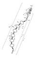
本発明の幾つかの実施形態に係る、しぼんだバルーン(170)と挿入されたガイドワイヤとを伴う拡張カテーテル(101)を例示する等角図であって、上記拡張カテーテルは長手方向軸に沿って一列に並ぶ中立状態である。図1Aは、中央管腔に挿入されたガイドワイヤを伴う中立状態の拡張カテーテル(101)を例示しており、上記拡張カテーテルは、鼻の通路または咽喉などの身体開口部への導入される準備ができている。幾つかの実施形態において、拡張カテーテル(101)は2つの主な要素を含む:カテーテル本体(100)およびハブ(140)。ガイドワイヤ(20)はハブ(140)とカテーテル本体(100)の中心を通過し、カテーテル本体(100)の遠位端で抜ける。使用時、可撓性のガイドワイヤ(20)は意図した体管腔に供給され、次に拡張カテーテル(100)の本体はガイドワイヤを超えて体管腔の所望の位置まで体管腔に押し込まれ、その後上記ガイドワイヤは取り除かれ(バルーンを膨張する前後どちらでも)、次に偏向機構が中央管腔(116)から所望の深さの位置まで挿入され(図2C参照)、所望の量の偏向の適用およびハブ(140)のテューイボルスト・ロックおよび密封機構(Tuohy Borst lock-and-seal mechanism)を締め付けることによりその深さでロックされる。 It is an isometric view illustrating an expansion catheter (101) with a deflated balloon (170) and an inserted guide wire according to some embodiments of the present invention, wherein the expansion catheter is along a longitudinal axis. It is in a neutral state in a row. FIG. 1A illustrates a neutral dilated catheter (101) with a guide wire inserted into the central lumen, which is ready to be introduced into a body opening such as a nasal passage or throat. Is done. In some embodiments, the dilated catheter (101) comprises two main elements: the catheter body (100) and the hub (140). The guide wire (20) passes through the center of the hub (140) and the catheter body (100) and exits at the distal end of the catheter body (100). In use, the flexible guide wire (20) is fed into the intended body lumen, and then the body of the dilation catheter (100) is pushed over the guide wire into the body lumen to the desired position in the body lumen. The guide wire is then removed (either before or after inflating the balloon) and then the deflection mechanism is inserted from the central lumen (116) to the desired depth (see FIG. 2C) and in the desired amount. It is locked to that depth by applying deflection and tightening the Tuoy Borst lock-and-seal mechanism of the hub (140).
本発明の幾つかの実施形態に係る、膨張させたバルーン(170)と挿入された偏向機構(300)とを伴う拡張偏向カテーテル(102)を例示する等角図であって、上記拡張カテーテルは中立状態のその長手方向軸に対して弯曲する。図1Bは、拡張カテーテル(101)へ挿入される偏向機構(300)を有する拡張偏向カテーテル(101)を例示し、偏向機構は拡張カテーテル(101)の一部を中立状態で長手方向軸から偏向させるために関節式に繋がれている。 An isometric view illustrating an extended deflection catheter (102) with an inflated balloon (170) and an inserted deflection mechanism (300) according to some embodiments of the present invention. It bends with respect to its longitudinal axis in the neutral state. FIG. 1B illustrates an extended deflection catheter (101) having a deflection mechanism (300) inserted into the expansion catheter (101), in which the deflection mechanism deflects a portion of the expansion catheter (101) from the longitudinal axis in a neutral state. It is connected in an articulated manner to make it.
図1Aを参照すると、カテーテル本体(100)は、先端部分(110)、関節部分(120)、および近位部分(130)含み、すべて動作可能に連結される。ハブ(140)は、カテーテル本体(100)に動作可能に連結される。 Referring to FIG. 1A, the catheter body (100) includes an apical portion (110), a joint portion (120), and a proximal portion (130), all operably connected. The hub (140) is operably connected to the catheter body (100).
図1Bを参照すると、関節部分(120)はそのカテーテルの外面に接合した少なくとも2つ以上のバルーン(170)(6つのバルーン(170)が図1Bの本実施形態において示される)を有する。各バルーン(170)が蛍光透視によるなど視覚化の用途のためにバルーン(170)の片端の金属リング(160)によって仕切られるように、金属バンド160は、バルーン(170)の間に点在し、最も遠位のバルーンに遠位であり、最も近位のバルーン(170)に近位である。他の実施形態において、バルーン(170)の数は2、3、4、または5つであり、さらに他の実施形態では、バルーン(170)の数は両端値を含む7から10の範囲内、両端値を含む10から15の範囲内、両端値を含む16から30の範囲内、あるいは30以上のバルーン(170)である。
Referring to FIG. 1B, the articular portion (120) has at least two or more balloons (170) joined to the outer surface of the catheter (six balloons (170) are shown in this embodiment of FIG. 1B).
幾つかの実施形態において、部分(110)、(120)および(130)は、例えば、ナイロン、ポリウレタン、ポリエステル、またはポリエーテルエーテルケトンを含むが、これらに限定されない1つ以上の材料で作られる熱可塑性エラストマーの押出しから作られた(および、もし単一のピースでないなら、その後、端と端をつながれる)カテーテルシャフト(121)を形成する1つ以上の可撓性を有するプラスチックチューブを含む。幾つかの実施形態において、プラスチック管(121)のジュロメーターは、10Aから90Dの範囲内であり、更に典型的には45Dから72Dである。幾つかの実施形態において、カテーテル本体(100)の、部分(110)、(120)および(130)は、内部に位置付けられた偏向機構の動きに対する異なる反応を提供するために、単一のジュロメーター・プラスチックを含むか、カテーテルシャフト(121)に沿ったいくつかのジュロメーターの1つ以上のポリマーを含む。例えば、幾つかの実施形態において、弯曲する必要のない(もしくはさほど弯曲する必要がない)部分(110)および(130)にとってより硬いプラスチックを、偏向の力に応じて曲がる部分(120)にはより柔軟なプラスチックを備えることが役に立つ。あるいは、幾つかの実施形態において、拡張カテーテル(101)の挿入の間に体管腔(99)(図4Aおよび図4Bを参照)に対しての傷または外傷を減らすため、カテーテル(101)の遠位端(110)により柔軟な材料を備えることは有益である。幾つかの実施形態において、カテーテルシャフト(121)の外径は、両端値を含む1から30Fr(0.33から10.0mm)(0.013から0.(130)インチ)の範囲内であり、いくつかのそのような実施形態において、4から9Fr(1.33から3.0mm)(0.052から0.118インチ)である。幾つかの実施形態において、カテーテルシャフト(121)(すなわち管腔(116)の直径)の内径は0.1から10mm(0.004から0.393インチ)の範囲であり、いくつかのそのような実施形態において0.25から2.5mm(0.001から0.098インチ)の範囲内である。幾つかの実施形態において、および本発明の範囲内では、カテーテルシャフト(121)の1つ以上の直径寸法は、異なる外および/または内径を有する(110)、(120)および(130)中の1つ以上の部分を伴って、長手方向に変化する。幾つかの実施形態において、複数のバルーン(170)は、いくつかのバルーン(170)が複数のバルーン(170)の他の直径寸法Dまたは長さ寸法Lと異なる直径Dまたは長さLを有するように、2つもしくはそれ以上の異なる直径寸法D(図2Bを参照)、および/または長さ寸法Lを有する。 In some embodiments, the moieties (110), (120) and (130) are made of one or more materials including, but not limited to, nylon, polyurethane, polyester, or polyetheretherketone, for example. Includes one or more flexible plastic tubes that form a catheter shaft (121) made from extruded thermoplastic elastomer (and, if not a single piece, then end-to-end connected) .. In some embodiments, the dulometer of the plastic tube (121) is in the range of 10A to 90D, more typically 45D to 72D. In some embodiments, the portions (110), (120) and (130) of the catheter body (100) are single juro to provide different responses to the movement of the internally positioned deflection mechanism. Includes meter plastic or contains one or more polymers of several durometers along the catheter shaft (121). For example, in some embodiments, the harder plastic for the parts (110) and (130) that do not need to be curved (or not so much), and the parts (120) that bend in response to the force of deflection. It is useful to have more flexible plastic. Alternatively, in some embodiments, a catheter (101) is used to reduce injury or trauma to the body lumen (99) (see FIGS. 4A and 4B) during insertion of the dilated catheter (101). It is beneficial to have a more flexible material at the distal end (110). In some embodiments, the outer diameter of the catheter shaft (121) is in the range of 1 to 30 Fr (0.33 to 10.0 mm) (0.013 to 0. (130) inches) including both ends. , 4 to 9 Fr (1.33 to 3.0 mm) (0.052 to 0.118 inches) in some such embodiments. In some embodiments, the inner diameter of the catheter shaft (121) (ie, the diameter of the lumen (116)) ranges from 0.1 to 10 mm (0.004 to 0.393 inches), and some such. In certain embodiments, it is in the range of 0.25 to 2.5 mm (0.001 to 0.098 inches). In some embodiments, and within the scope of the invention, one or more diametrical dimensions of the catheter shaft (121) have different outer and / or inner diameters in (110), (120) and (130). It varies longitudinally, with one or more portions. In some embodiments, the plurality of balloons (170) have a diameter D or length L that is different from the other diameter dimension D or length dimension L of the plurality of balloons (170). As such, it has two or more different diameter dimensions D (see FIG. 2B) and / or length dimensions L.
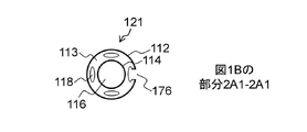
図2A1は、本発明の幾つかの実施形態に係る、図1Bによって示される平面2A1-2A1を介した、拡張カテーテル(121)、およびバルーン(170)の断面図である。 FIG. 2A1 is a cross-sectional view of an expansion catheter (121) and a balloon (170) via a plane 2A1-2A1 shown by FIG. 1B, according to some embodiments of the present invention.
図2A2は、本発明の幾つかの実施形態に係る、図1Bによって示される平面2A2-2A2を介した、カテーテルシャフト(121)、およびバルーン(170)の断面図である。幾つかの実施形態において、部分(120)のカテーテルシャフト(121)は外面(112)、管壁(113)を画定する内面(114)を含む。幾つかの実施形態において、壁(113)内に収容されているのは、1つ以上の狭楕円形管腔(118)である。幾つかの実施形態において、各管腔(118)は他の管腔(116)および(118)から分離され、カテーテル本体(100)の全長を横断する。最小では、幾つかの実施形態において、各管腔(116)および/または(118)は、各管腔(116)および/または(118)をハブ(140)内の対応する特徴に動作可能に連結するために、カテーテル本体部分(120)および(130)を横断する。しかしながら、幾つかの実施形態は、それら個々の長さの部分に沿って接合された管腔(116)および/または(118)を組み込み、一方で幾つかの他の実施形態がカテーテル本体(100)の長さに沿ったいくつかの管腔(116)および/または(118)を終端する。幾つかの実施形態において、管腔(116)および/または(118)は、バルーンの膨張および収縮用の流路、および管腔空間内の位置決め計装器具のアクセス手段等、多数の用途を務める。幾つかの実施形態において、図1Aのポート(125)を通るように、管腔(116)および/または(118)は、周囲の管腔体積の空間からの流体の注入または抽出の導管として使用することができる。幾つかの実施形態において、ポート(125)は、管腔(118)のうちの1つに動作可能に接続される。 FIG. 2A2 is a cross-sectional view of a catheter shaft (121) and a balloon (170) via a plane 2A2-2A2 shown by FIG. 1B, according to some embodiments of the present invention. In some embodiments, the catheter shaft (121) of the portion (120) comprises an outer surface (112), an inner surface (114) defining a tube wall (113). In some embodiments, contained within the wall (113) is one or more narrow elliptical lumens (118). In some embodiments, each lumen (118) is separated from the other lumens (116) and (118) and traverses the entire length of the catheter body (100). At a minimum, in some embodiments, each lumen (116) and / or (118) is capable of operating each lumen (116) and / or (118) to a corresponding feature within the hub (140). Cross the catheter body portions (120) and (130) to connect. However, some embodiments incorporate lumens (116) and / or (118) joined along their individual length portions, while some other embodiments incorporate the catheter body (100). ) Terminates several lumens (116) and / or (118) along the length. In some embodiments, the lumen (116) and / or (118) serve a number of uses, such as a flow path for balloon expansion and contraction, and an access means for positioning instrumentation within the lumen space. .. In some embodiments, the lumen (116) and / or (118) are used as conduits for injecting or extracting fluid from the space of the surrounding lumen volume, such as through the port (125) in FIG. 1A. can do. In some embodiments, the port (125) is operably connected to one of the lumens (118).
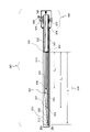
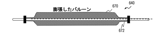
図2Bは、図1Bの断面図2B-2Bに対応する膨張要素(170)の長手方向の中心線に沿った拡張カテーテル(101)の部分(120)の長手方向の断面図である。図2Bの中で示されるように、バルーン(170)はジョイント(172)でカテーテルシャフト(121)の外面(112)に取り付けられる。図2Bで示されるように、バルーン(170)はそれらの中心領域において丸く膨らんだ形状であり、ここからバルーン(170)の各端部をカテーテルシャフト(121)に接合するための管状部分が伸びる。幾つかの実施形態において、このプロファイルを伴う拡張したバルーン(170)は、弾力がある、もしくは迎合性のある材料から作られる。幾つかの実施形態において、バルーン(170)は、カテーテル表面(112)に取り付けるための各端部で、それらの中心領域、および管状部分(172)で球形を有する。あるいは、幾つかの実施形態において、バルーン(170)は、それらの中心領域において円柱形状、バルーンカテーテルシャフト(121)に取り付けるための管状部分(172)が伸びる各端部に、円錐部分を有する。幾つかの実施形態において、この形状のバルーン(170)は非膨脹性の材料から作られる。図2Bにおいて例示されるように、拡張バルーンは球体または円錐に対して直径Dとして画定される、直径寸法、Dとして画定され、カテーテルシャフト(121)の外面(112)へ接触するためにバルーンのいずれかの端部に位置付けられるバルーンステム間の最短距離として画定される長さ、Lとによって確定される。バルーンのL/D比率は、その設計直径または圧力に拡張した時、その直径、D、で割られたバルーン、L、の長さとして画定される。本発明の幾つかの実施形態については、L/D比率は、0.5と10.0の間の範囲であり、好ましくは1.0と5.0の間、および最も好ましくは1.0と3.0の間の範囲である。
FIG. 2B is a longitudinal sectional view of a portion (120) of the dilated catheter (101) along the longitudinal centerline of the inflatable element (170) corresponding to
より小さなL/D比率のバルーン(170)を利用する拡張偏向カテーテル装置(102)は、ヒンジ点の数の増大により、食道の中心線に沿った装置のより良好な配列を有する。これは、より多くの装置の湾曲を体管腔(99)の偏向に効果的に変換する。しかしながら、より小さなL/D比率はより多くのバルーン(170)を必要とし、これは設計の複雑さおよび製造コストを増加する。 The extended deflection catheter device (102) utilizing a smaller L / D ratio balloon (170) has a better arrangement of devices along the centerline of the esophagus due to the increased number of hinge points. This effectively converts the curvature of more devices into the deflection of the body lumen (99). However, smaller L / D ratios require more balloons (170), which increases design complexity and manufacturing costs.
幾つかの実施形態において、バルーン(170)は、加圧された際に伸びる、弾力があるか迎合性のある材料で作られている。適切な材料は、様々なジュロメーターのシリコン、様々なジュロメーターのラテックスゴム、および低いジュロメーターのポリウレタン、およびC-Flex(登録商標)などの低いジュロメーターのプラスチック材料の混合物を含むが、これらに限定されない。他の実施形態において、バルーン(170)は、固定形状を有しかつ、しぼんだ状態ではカテーテルシャフトに巻き付けられて、加圧された際に広げられる、非迎合性材料で作られる。幾つかの実施形態において、そのような材料は様々なジュロメーターナイロン、ポリエチレンテレフタレート(PET)、異なるポリマー族のポリエステルおよび混合物を含む。幾つかの実施形態において、ジョイント(172)は、バルーンの拡張および収縮の目的のためにバルーンの内部空間を加圧することができるような、流体密封を形成する結合部である。一般的に、そのようなジョイントは、バルーンとカテーテルシャフトの材料を接合するのにふさわしい接着剤を使用して形成される。適切な接着剤の例は、Dymax1161などの紫外線硬化型接着剤、およびヘンケル4014などのシアノアクリレートである。あるいは、幾つかの実施形態において、結合部は、材料を混合させ均質な材料を形成するのに十分なある温度と圧力で、バルーンとシャフト材料の両方を、再度流すことで、熱形成される。あるいは、幾つかの実施形態において、カテーテルシャフト材料に対してバルーン材料を圧縮し、2つの表面を互いと密接に接触させて、結果として流体密封をもたらすために、機械的結合部は強剛なリングを使用して形成される。幾つかの実施形態において、リングは、ステンレス鋼、ニチノール、ニッケル、銅またはあらゆる他の柔軟な金属材等の1つ以上の金属から作られる、あるいはそれらを含む。幾つかの実施形態において、リングは、ナイロン、ポリエステル、ポリカーボネートまたはPEEK等の1つ以上の高強度のプラスチックから作られる、あるいはそれらを含む。幾つかの実施形態において、穴(174)は、バルーン(170)の内部空間内のカテーテルシャフト(121)に位置付けられる。幾つかの実施形態において、穴(174)は典型的にはスカイブであり、これは管腔(118)の下にある通路にバルーン(170)の内部空間を動作可能に連結するために、管腔(118)から外面層を取り除く。幾つかの実施形態において、多数のバルーンの内部空間は、各々が内部スカイブ穴(174)を介して、単一の管腔(118)に接続され、それによって全てのバルーンが一度に膨張し、一方で他の実施形態では、各バルーン(170)がそれ自体専用の管腔(118)に接続され、分離した個々のバルーンの膨張/収縮を可能にする。幾つかの実施形態は、2つのアプローチの組み合わせを使用し、ここでは1つ以上のバルーン(170)が複数管腔(118)の各1つに連結される。 In some embodiments, the balloon (170) is made of an elastic or compliant material that stretches when pressed. Suitable materials include a mixture of various Jurometer silicones, various Jurometer latex rubbers, and lower Jurometer polyurethanes, and lower Jurometer plastic materials such as C-Flex®. Not limited to. In another embodiment, the balloon (170) is made of a non-compliant material that has a fixed shape and is wound around a catheter shaft in a deflated state and unfolded when pressurized. In some embodiments, such materials include various dulometer nylons, polyethylene terephthalate (PET), polyesters of different polymer families and mixtures. In some embodiments, the joint (172) is a joint that forms a fluid seal such that the interior space of the balloon can be pressurized for the purpose of expansion and contraction of the balloon. Generally, such joints are formed using an adhesive suitable for joining the balloon and catheter shaft materials. Examples of suitable adhesives are UV curable adhesives such as Dymax1161 and cyanoacrylates such as Henkel 4014. Alternatively, in some embodiments, the junction is thermally formed by reflowing both the balloon and the shaft material at a temperature and pressure sufficient to mix the materials to form a homogeneous material. .. Alternatively, in some embodiments, the mechanical joint is rigid in order to compress the balloon material against the catheter shaft material and bring the two surfaces into close contact with each other, resulting in fluid sealing. Formed using a ring. In some embodiments, the ring is made of or comprises one or more metals such as stainless steel, nitinol, nickel, copper or any other flexible metal material. In some embodiments, the ring is made of or comprises one or more high-strength plastics such as nylon, polyester, polycarbonate or PEEK. In some embodiments, the hole (174) is located in the catheter shaft (121) within the interior space of the balloon (170). In some embodiments, the hole (174) is typically a skive, which is a tube to operably connect the interior space of the balloon (170) to the passage under the lumen (118). Remove the outer layer from the lumen (118). In some embodiments, the interior spaces of multiple balloons are each connected to a single lumen (118) via an internal skive hole (174), whereby all balloons are inflated at once. On the other hand, in other embodiments, each balloon (170) is connected to its own lumen (118), allowing expansion / contraction of the individual balloons separated. Some embodiments use a combination of the two approaches, where one or more balloons (170) are coupled to each one of the plurality of lumens (118).
図1Bは、可視化(例えばX線または蛍光透視を使用して画像化された時)の目的のために、各バルーンを仕切るためのカテーテル本体部分(120)に沿って位置されたマーカーバンド(160)を示す。幾つかの実施形態において、マーカーバンド(160)は蛍光透視下で見えるように放射線不透性物質で作られている。幾つかの実施形態において、バンドはステンレス鋼、ニチノール、ニッケル、銅またはあらゆる他の柔軟な金属等の金属で作られる(またはそれらを含む)。幾つかの実施形態において、リング(160)は、図2Bの中で示されるように、ジョイント(162)でカテーテルシャフトの外面(112)に粘着的に接合される。幾つかの実施形態において、リングは、締まりばめを形成するために外面(112)上に機械的に圧着される。幾つかの実施形態において、マーカーバンド(160)に使用されたリングは、カテーテルシャフト(121)と外面(112)に対してバルーン(170)の密封を増強するために、各バルーンステム(172)を超えて位置され、よってマーカバンド(160)が2つの機能、視化のしるし、およびバルーン密封の両方を務めることを可能にする。 FIG. 1B is a marker band (160) positioned along a catheter body portion (120) for partitioning each balloon for visualization purposes (eg when imaged using X-ray or fluoroscopy). ) Is shown. In some embodiments, the marker band (160) is made of a radiation impermeable material so that it can be seen under fluoroscopy. In some embodiments, the band is made of (or includes) a metal such as stainless steel, nitinol, nickel, copper or any other flexible metal. In some embodiments, the ring (160) is adhesively joined to the outer surface (112) of the catheter shaft at a joint (162), as shown in FIG. 2B. In some embodiments, the ring is mechanically crimped onto the outer surface (112) to form a tight fit. In some embodiments, the ring used for the marker band (160) is each balloon stem (172) to enhance the sealing of the balloon (170) to the catheter shaft (121) and outer surface (112). Positioned beyond, thus allowing the marker band (160) to serve both two functions, a sign of visualization, and a balloon seal.
幾つかの実施形態において、1つ以上のスカイブ穴(174)はカテーテルシャフトの表面(112)に形成され、カテーテル本体(100)に沿ったあらゆる適切なカテーテル位置に位置付けられる。幾つかの実施形態において、1つ以上のスカイブ穴(176)は、体管腔の内部とおよび、バルーン(170)の外部または周囲の外部環境、およびカテーテルシャフト(121)内に収容されていた1つ以上の管腔(118)に動作可能に連結される。幾つかの実施形態において、1つ以上のスカイブ穴(176)は、ポートとして機能し、このポートを通って流体は、2つのバルーンと体管腔の内表面との間の管腔体積へと注入もしくはそこから抽出される。幾つかの実施形態において、各スカイブ穴(176)およびその動作可能につながれた管腔(118)は、コンジットとしても機能し、このコンジットを通って、温度プローブ等の計器装備、バルーンと体管腔の内表面との間の管腔の空間へ挿入される。 In some embodiments, one or more skive holes (174) are formed on the surface (112) of the catheter shaft and are positioned at any suitable catheter position along the catheter body (100). In some embodiments, one or more skive holes (176) were housed inside the body lumen and outside or around the balloon (170), and within the catheter shaft (121). It is operably connected to one or more lumens (118). In some embodiments, one or more skive holes (176) act as ports through which fluid flows into the lumen volume between the two balloons and the inner surface of the body lumen. Injected or extracted from it. In some embodiments, each skive hole (176) and its operably connected lumen (118) also functions as a conduit through which instrument equipment such as a temperature probe, balloon and body tube. It is inserted into the space of the lumen between the inner surface of the cavity.
図2Cは、図1Aのハブ(140)の1つの実施形態を図示する。ハブ(140)の中心は、1つ以上の側部アーム(145)および/または(146)が動作可能に連結された長方形のプラスチック部材(142)である。幾つかの実施形態において、側部アーム(145)および/または(146)は、注射器のものなどの対になった取り付け物に接続するためにルアーフィッティングに終端となる。側部アーム(145)内に収容されるのは内部管腔(143)であり、側部アーム(146)内に収容されるのは内部管腔(144)である。両管腔(143)および(144)は、中央管腔(141)も収容するハブ(142)の内部へ、あるいは内部を通って伸びる。幾つかの実施形態において、ハブ(140)の遠端部は、カテーテル部分(130)が流体密封(149)を形成するために挿入され粘着的に接合される窪んだ縦穴(139)を収容する。管腔(143)および(144)は、カテーテルシャフト(121)の1つ以上のそれぞれの管腔(118)および/または(118)’と流体連通する。幾つかの実施形態において、キャップ(148)およびガスケット(147)を含むテューイボルストアッセンブリ(138)はプラスチック部材(142)の近位端で取り付けられる。テューイボルストアッセンブリ(138)のキャップ(148)の穴は、ハブ(140)の中央管腔(141)と流体連通し、次にカテーテルシャフト(121)の中央管腔(116)に流体連通する。幾つかの実施形態において、側部アーム(145)および(146)は、いくつかの機能の1つ以上を務める。幾つかの実施形態において、側部アームのうちの1つは、カテーテル本体(100)に取り付けられたバルーンの膨張および収縮に使用される。幾つかの実施形態において、側部アーム(145)および(146)のうちの1つは、図1Aのポート(125)を通って等、送り出しカテーテルと体管腔の内壁との間に収容される管腔のボリュメトリック空間から流体を注入および抽出するために使用される。幾つかの実施形態において、ハブ(140)のテューイボルストアッセンブリ(138)を通った管腔(141)は、体管腔へ拡張カテーテル(101)を挿入する間のガイドワイヤ(20)の収容、あるいは拡張偏向カテーテル装置(102)の形状を変えるための偏向機構(300)の収容に使用される。 FIG. 2C illustrates one embodiment of the hub (140) of FIG. 1A. At the center of the hub (140) is a rectangular plastic member (142) to which one or more side arms (145) and / or (146) are operably connected. In some embodiments, the side arms (145) and / or (146) terminate in a luer fitting to connect to a paired attachment, such as that of a syringe. It is the internal lumen (143) that is housed in the side arm (145) and the internal lumen (144) that is housed in the side arm (146). Both lumens (143) and (144) extend into or through the inside of the hub (142), which also houses the central lumen (141). In some embodiments, the far end of the hub (140) accommodates a recessed longitudinal hole (139) into which the catheter portion (130) is inserted and adhesively joined to form a fluid seal (149). .. The lumens (143) and (144) communicate with one or more of the respective lumens (118) and / or (118)'of the catheter shaft (121). In some embodiments, the tuy bolt assembly (138), including the cap (148) and gasket (147), is attached at the proximal end of the plastic member (142). The hole in the cap (148) of the tuy bolt assembly (138) allows fluid communication with the central lumen (141) of the hub (140) and then fluid communication with the central lumen (116) of the catheter shaft (121). .. In some embodiments, the side arms (145) and (146) serve one or more of several functions. In some embodiments, one of the side arms is used to inflate and deflate a balloon attached to the catheter body (100). In some embodiments, one of the side arms (145) and (146) is housed between the delivery catheter and the inner wall of the body lumen, such as through the port (125) of FIG. 1A. Used to inject and extract fluid from the volumetric space of the lumen. In some embodiments, the lumen (141) through the tuybolst assembly (138) of the hub (140) accommodates the guide wire (20) while inserting the dilated catheter (101) into the body lumen. , Or used to house a deflection mechanism (300) for changing the shape of the extended deflection catheter device (102).
図1Aは、各々が図2Bの断面図の中で示されるように、図1Aで示される直線状態、あるいは図1Bで示される弯曲した状態の体管腔において、カテーテルシャフト(121)を有効的に中心に位置付けるために、カテーテルシャフト(121)に別々に付けられた多数のバルーン(170)の使用を例示する。 FIG. 1A makes the catheter shaft (121) effective in the linear state shown in FIG. 1A or in the curved state of the body lumen shown in FIG. 1B, each as shown in the cross-sectional view of FIG. 2B. Illustrates the use of multiple balloons (170) separately attached to the catheter shaft (121) for centralization.
図2Dにおいて例示されるように、同じ効果は、全面的なバルーン形状に多数のセグメントが取り込まれた単一のバルーンを用いて達成することができる。幾つかの実施形態において、迎合的又は半迎合的な材料を含むバルーン(270)について、装置のX線の位置決めのしるしとしてだけでなく、カテーテルシャフト(221)に対する多数の膨張式のセグメントとして、マーカーバンド(162)が使用され、1つの大きな空間から効果的に複数の密閉された空間を作ることができる。幾つかの実施形態において、半迎合性のある材料または迎合性のない材料を含むバルーン(270)について、区分された幾可学的形状はバルーン形成中にバルーン(270)へ製作され、バルーンステムは、熱(熱を用いてバルーン材料をカテーテルシフト(221)に融合する)、接着剤(迎合性のある接着剤を用いる)、および/または機械的な結合(マーカーバンド(162)を用いる)を用いて2つの端部および/または各中間の場所でシャフトに接合される。 As illustrated in FIG. 2D, the same effect can be achieved with a single balloon in which multiple segments are incorporated into the overall balloon shape. In some embodiments, for a balloon (270) containing compliant or semi-compliant material, not only as a sign of X-ray positioning of the device, but also as a number of inflatable segments to the catheter shaft (221). A marker band (162) is used to effectively create multiple enclosed spaces from one large space. In some embodiments, for a balloon (270) containing semi-compliant or non-compliant material, a segmented variegated shape is made into the balloon (270) during balloon formation and the balloon stem. Heat (using heat to fuse the balloon material to the catheter shift (221)), adhesive (using a compliant adhesive), and / or mechanical binding (using a marker band (162)). Is joined to the shaft at two ends and / or at an intermediate location.
図3Aは、偏向機構(300)の長手方向の断面図を示す。幾つかの実施形態において、偏向機構(300)は4つの重要な要素を含み、すなわち:
(1)伸張ワイヤの動きに応じて偏向する、多数の長手方向の要素を収容する可撓性を有する部分(305);
(2)カラム(340)の内に長手方向に移動する伸張ワイヤ(322);
(3)伸張ワイヤによって生成された力に反応するカラム(340);および
(4)カラム(340)と接触するノブを収容するハンドル(350)。
FIG. 3A shows a sectional view of the deflection mechanism (300) in the longitudinal direction. In some embodiments, the deflection mechanism (300) comprises four important elements, ie:
(1) A flexible portion (305) that accommodates a large number of longitudinal elements that deflect in response to the movement of the stretch wire;
(2) Stretch wire (322) moving longitudinally within the column (340);
(3) A column (340) that responds to the forces generated by the extension wire; and (4) a handle (350) that houses the knob in contact with the column (340).
図3Aを参照すると、偏向機構(300)の外部骨組みは、その遠端部に先端(312)、その近端部にハンドルアッセンブリ(350)が付けられた外側チューブ(310)を含む。幾つかの実施形態において、偏向機構(300)の遠位部分は可撓性を有し弯曲し、一方で近位部分はより強剛で比較的直線のままである。幾つかの実施形態において、可撓性を有する部分(305)は板ばねアッセンブリ(307)を収容する。幾つかの実施形態において、強剛な部分はカラム(340)および伸張ワイヤ(322)を収容している。 Referring to FIG. 3A, the external skeleton of the deflection mechanism (300) includes an outer tube (310) with a tip (312) at its far end and a handle assembly (350) at its near end. In some embodiments, the distal portion of the deflection mechanism (300) is flexible and curved, while the proximal portion remains stiffer and relatively straight. In some embodiments, the flexible portion (305) houses the leaf spring assembly (307). In some embodiments, the rigid portion houses a column (340) and an extension wire (322).
幾つかの実施形態において、外側チューブ(310)は、その遠端部で先端(312)、かつその近端部で端部(350)に接合される。外側チューブ(310)は、偏向機構(300)の内部容量のためのコンテナを提供し、図1Aの拡張カテーテル(101)内の挿入および位置決めを助けるために滑らかな外面を収容する。1つの好ましい実施形態において、外側チューブ(310)は、PTFE(ポリテトラフルオロエチレン)、ETFE(エチレンテトラフロオルエチレン)またはPFA(パーフルオロアルコキシアルカン(perfluoroalkoxy alkane)のテフロン(登録商標)族、あるいはHDPE(高密度ポリエチレン)またはLDPE(低密度ポリエチレン)などのポリエチレン族等の滑らかな材料で作られる。あるいは、ナイロン、ポリエステルまたはポリウレタンなどのあまり滑らかではない材料が、幾つかの実施形態で使用され、およびApplied Membrane Technology’s SilglideTM coating等の当業者によく知られた一般に利用可能な蒸着方法を使用してその外面に滑らかなコーティングを塗布する。外側チューブ(310)は、接合されている材料に迎合性のある接着剤を用いて、遠位端(312)およびハンドル(350)に接合される。 In some embodiments, the outer tube (310) is joined to the tip (312) at its far end and to the end (350) at its near end. The outer tube (310) provides a container for the internal capacitance of the deflection mechanism (300) and houses a smooth outer surface to aid insertion and positioning within the dilator catheter (101) of FIG. 1A. In one preferred embodiment, the outer tube (310) is a Teflon family of PTFE (polytetrafluoroethylene), ETFE (ethylene tetrafluoroethylene) or PFA (perfluoroalkoxy alkane), or Made of smooth materials such as polyethylene group such as HDPE (High Density Polyethylene) or LDPE (Low Density Polyethylene), or less smooth materials such as nylon, polyester or polyurethane are used in some embodiments. , And a smooth coating is applied to its outer surface using a commonly available vapor deposition method well known to those of skill in the art, such as Applied Membrane Technology's Silklide TM coating. The outer tube (310) is joined. It is joined to the distal end (312) and handle (350) using a material compliant adhesive.
幾つかの実施形態において、外側チューブ(310)の中央管腔内に収容される板ばねアッセンブリ(307)は、長手方向の力がその遠端部に加えられる際、単一の平面で曲がる複合構造を形成する平角線(325)、(330)および(335)を含み、力の放出と同時にその中立状態へ戻る。平角線(325)は、接合点(337)に位置付けられたその最も近端部から端部(312)の最も近端部までが測定された長手方向の長さL1を有する。幾つかの実施形態において、平角線(330)は同じ近位の場所(337)で始まり、ワイヤ(325)に沿って(327)に遠位に伸びる(長さL2は、ここでL2はL1よりも短い)。幾つかの実施形態において、平角線(335)は、同じ近位の場所で始まり、ジョイント(332)に遠位に伸びるように同様に構成される(長さL3、ここでL3はL2より短い)。幾つかの実施形態において、ワイヤ(325)、(330)および(335)は、鍛練されたステンレス鋼、ニチノールおよび/または硬化鋼等の高強度の金属、或いはPEEK、ナイロン6/6、ポリイミドまたは液晶ポリマー(LCP)等の高ジュロメーターのプラスチックで作られる。 In some embodiments, the leaf spring assembly (307) housed within the central lumen of the outer tube (310) is a composite that bends in a single plane when longitudinal forces are applied to its far end. It contains the flat lines (325), (330) and (335) that form the structure and returns to its neutral state upon release of the force. The flat wire (325) has a longitudinal length L1 measured from its closest end located at the junction (337) to the closest end of the end (312). In some embodiments, the flat wire (330) begins at the same proximal location (337) and extends distally (327) along the wire ( 325) ( length L2 is here L2). Is shorter than L 1 ). In some embodiments, the flat line (335) begins at the same proximal location and is similarly configured to extend distally to the joint (332) (length L 3 , where L 3 is L). Less than 2 ). In some embodiments, the wires (325), (330) and (335) are high-strength metals such as forged stainless steel, nitinol and / or hardened steel, or PEEK, nylon 6/6, polyimide or Made of high durometer plastic such as liquidity polymer (LCP).
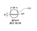
平角線は、図3Bで示されるように、幅Wおよび高さHによって画定される。本発明の幾つかの実施形態については、Wは、両端値を含む0.25から10mm(0.001から0.39インチ)の範囲内であり、いくつかのそのような実施形態において、Wは、両端値を含む0.5から5mm(0.020から0.197インチ)の範囲内、または両端値を含む1.0から2.5mm(0.039から0.098インチ)である。本発明の幾つかの実施形態については、Hは、両端値を含む0.125から5mm(0.005から0.197インチ)の範囲内、また、いくつかのそのような実施形態において、Hは、両端値を含む0.25から2.5mm(0.001から.098インチ)の範囲内、または両端値を含む0.5から1.25mm(0.020から0.049インチ)である。本発明の幾つかの実施形態については、L1は、両端値を含む11.0から18.0cm(4.33から7.08インチ)の範囲内、およびいくつかのそのような実施形態において、両端値を含む14.0から16.0cm(5.51から6.29インチ)の範囲内である。本発明の幾つかの実施形態については、L2は、両端値を含む6.0から11.0cm(2.36から4.33インチ)の範囲内、およびいくつかのそのような実施形態において、7.0から10.0cm(2.76から3.94インチ)の範囲内である。本発明については、L3は、3.0から9.0cm(1.18から3.54インチ)の範囲であることが可能だが、好ましくは4.0から6.0cm(1.57から2.36インチ)である。 The flat line is defined by a width W and a height H, as shown in FIG. 3B. For some embodiments of the invention, W is in the range of 0.25 to 10 mm (0.001 to 0.39 inches) including both ends, and in some such embodiments W Is in the range of 0.5 to 5 mm (0.020 to 0.197 inches) including both ends, or 1.0 to 2.5 mm (0.039 to 0.098 inches) including both ends. For some embodiments of the invention, H is in the range of 0.125 to 5 mm (0.005 to 0.197 inches), including both ends, and in some such embodiments, H. Is in the range of 0.25 to 2.5 mm (0.001 to 0.098 inches) including both ends, or 0.5 to 1.25 mm (0.020 to 0.049 inches) including both ends. .. For some embodiments of the invention, L 1 is in the range of 11.0 to 18.0 cm (4.33 to 7.08 inches) including both ends, and in some such embodiments. , In the range of 14.0 to 16.0 cm (5.51 to 6.29 inches) including both ends values. For some embodiments of the invention, L 2 is in the range 6.0 to 11.0 cm (2.36 to 4.33 inches) including both ends, and in some such embodiments. , 7.0 to 10.0 cm (2.76 to 3.94 inches). For the present invention, L 3 can range from 3.0 to 9.0 cm (1.18 to 3.54 inches), but preferably 4.0 to 6.0 cm (1.57 to 2). .36 inches).
幾つかの実施形態において、板ばねアッセンブリ(307)の遠端部に付けられるのは、ジョイント(315)で平角線(325)に付けられる伸張ワイヤ(322)である。幾つかの実施形態において、伸張ワイヤ(322)の近端部はジョイント(348)でハンドル(350)に付けられる。幾つかの実施形態において、伸張ワイヤ(322)は、鍛練されたステンレス鋼、ニチノール、および/または、他の硬化鋼などの高強度の金属を含む。本発明の幾つかの実施形態については、ワイヤの直径は、両端値を含む0.05から1.0mm(0.002から0.040インチ)の範囲内であり、好ましくは両端値を含む0.1から0.5mm(0.004から0.020インチ)であり、更に好ましくはその数字を含む約0.3mm(0.012インチ)である。幾つかの実施形態において、ジョイント(315)は溶接剤または接着剤を含む。 In some embodiments, attached to the far end of the leaf spring assembly (307) is an extension wire (322) attached to the flat wire (325) at the joint (315). In some embodiments, the near end of the extension wire (322) is attached to the handle (350) by a joint (348). In some embodiments, the stretch wire (322) comprises a high strength metal such as forged stainless steel, nitinol, and / or other hardened steel. For some embodiments of the invention, the diameter of the wire is in the range 0.05 to 1.0 mm (0.002 to 0.040 inch) including both ends, preferably 0 including both ends. It is .1 to 0.5 mm (0.004 to 0.020 inch), more preferably about 0.3 mm (0.012 inch) including that number. In some embodiments, the joint (315) comprises a weld or adhesive.
幾つかの実施形態において、板ばねアッセンブリ(307)の近位端に付けられるのはアダプタ(337)であって、これは平面ワイヤ(325)、(330)および(335)の近端部をしっかり固定し、伸張ワイヤ(322)の通路用の貫通穴(336)も有する。幾つかの実施形態において、平面ワイヤは各アダプタ(337)の遠位側のくぼみへ溶接されるか粘着的に結合される。 In some embodiments, attached to the proximal end of the leaf spring assembly (307) is an adapter (337), which attaches the near ends of the flat wires (325), (330) and (335). It is firmly fixed and also has a through hole (336) for the passage of the extension wire (322). In some embodiments, the flat wire is welded or adhesively coupled to the distal recess of each adapter (337).
幾つかの実施形態において、カラム(340)はアダプタ(337)の近位側に付けられる。幾つかの実施形態において、カラム(340)は、皮下組織チューブなどの壁の薄い金属チューブを含む。幾つかの実施形態において、皮下組織チューブは、硬化ステンレス鋼、ニチノール、および/または他の硬化鋼合金などの高強度の金属、またはPEEK、ナイロン6/6、ポリイミドまたは液晶ポリマー(LCP)などの高ジュロメーターのプラスチックで作られている。幾つかの実施形態において、皮下組織チューブ(340)の外径は、両端値を含む0.5から5.0mm(0.020から0.198インチ)の範囲内であり、更に好ましくは両端値を含む1.0から2.5mm(0.039から0.098インチ)である。本発明の他の実施形態において、カラム(340)は、スピードメーターケーブルの外装板のような密巻ワイヤコイル状チューブを含む。幾つかの実施形態において、ワイヤ組成は、ステンレス鋼、ニチノール、および/または鍛練された硬化鋼合金等の高強度の金属を含む。幾つかの実施形態において、ワイヤの直径は、両端値を含む0.05から1.0mm(0.002から0.039インチ)の範囲内である。幾つかの実施形態において、ワイヤコイル構造の外径は、両端値を含む0.5から5.0mm(0.020から0.198インチ)の範囲内であり、更に好ましくは、両端値を含む1.0から20mm(0.039から0.078インチ)である。 In some embodiments, the column (340) is attached to the proximal side of the adapter (337). In some embodiments, the column (340) comprises a thin-walled metal tube, such as a subcutaneous tissue tube. In some embodiments, the subcutaneous tissue tube is made of a high-strength metal such as hardened stainless steel, nitinol, and / or other hardened steel alloy, or such as PEEK, nylon 6/6, polyimide or liquid crystal polymer (LCP). Made of high julometer plastic. In some embodiments, the outer diameter of the subcutaneous tissue tube (340) is in the range of 0.5 to 5.0 mm (0.020 to 0.198 inches) including both ends, more preferably both ends. 1.0 to 2.5 mm (0.039 to 0.098 inches) including. In another embodiment of the invention, the column (340) comprises a tightly wound wire coiled tube, such as an exterior plate of a speedometer cable. In some embodiments, the wire composition comprises high-strength metals such as stainless steel, nitinol, and / or forged hardened steel alloys. In some embodiments, the diameter of the wire is in the range of 0.05 to 1.0 mm (0.002 to 0.039 inches), including both ends. In some embodiments, the outer diameter of the wire coil structure is in the range of 0.5 to 5.0 mm (0.020 to 0.198 inches) including both ends values, more preferably including both ends values. It is 1.0 to 20 mm (0.039 to 0.078 inches).
幾つかの実施形態において、カラム(340)の近端部はスライドアッセンブリ(355)に接合される。幾つかの実施形態において、スライドアッセンブリ(355)は、ノブ(358)内に収容される対応する内部スレッドと対になった雄ねじを伴う金属チューブを含む。幾つかの実施形態において、伸張ワイヤ(322)は、アダプタ(337)の穴を通り、カラム(340)の中心を通り、スライド(355)を通過し、ジョイント(348)でハンドル(350)の近位の領域中に終結する。幾つかの実施形態において、ロック装置(360)は、操作中にノブ(358)の位置を固定するために使用されるねじ込みアッセンブリであり、偏向機構(300)の弯曲の意図しない変化を防ぐ。 In some embodiments, the near end of the column (340) is joined to the slide assembly (355). In some embodiments, the slide assembly (355) comprises a metal tube with a male thread paired with a corresponding internal thread housed in a knob (358). In some embodiments, the extension wire (322) passes through the hole in the adapter (337), through the center of the column (340), through the slide (355), and at the joint (348) of the handle (350). It terminates in the proximal region. In some embodiments, the locking device (360) is a screw-in assembly used to secure the position of the knob (358) during operation to prevent unintended changes in the deflection mechanism (300).
図3Aで示されるように、偏向機構(300)の機能は、偏向機構がその中立状態つまり伸張ワイヤ(322)による力なしの場合に、先端(312)とハンドル(350)の接続により画定された直線の一部を、側方に変位する。 As shown in FIG. 3A, the function of the deflection mechanism (300) is defined by the connection of the tip (312) and the handle (350) when the deflection mechanism is in its neutral state, i.e. without force by the extension wire (322). A part of the straight line is displaced laterally.
幾つかの実施形態において、図3Cで示されるように、力が伸張ワイヤ(322)に加えられると、弧が、軸の長さLxおよび側方変位Dyによって画定されたばねアッセンブリ(307)に作り出される。この変位は伸張ワイヤ(322)に起因し、平角線(325)の一部を側方に移動させることによって平角線(325)の遠位および近端部の間の距離を縮小させる、つまり、その中立状態でその長手方向軸に垂直である。所与の適用に必要な側方変位を遂行するために、いくつかの重要な設計面での配慮がある。第一に、一般に、変位された部分Lxの軸の長さは、図3Aのジョイント(315)と(337)の場所間の距離によって制御される。この距離が増えると、弯曲した部分の長さは相応して増える。本発明については、弯曲は、20.0cm(7.87インチ)まで変動することができるが、好ましくは12.0cm(4.72インチ)まで、更に好ましくは3.0から5.0cm(1.18から1.97)である。第二に、側方変位Dyはノブ(358)の長手方向の動きまたはストロークによって制御される。より長いストロークの長さはさらなる側方の偏向を引き起こす。本発明については、側方変位は、10.0cm(3.93インチ)まで、好ましくは6.0cm(2.36インチ)まで、および更に好ましくは1.5から4.0cm(0.59から1.57インチ)である。第三に、LxとDyとの間には相互関係がある:Lxが長くなると、同等のDyに達するストロークの長さも長くなる。ストロークの長さをハンドルで実行するので、ハンドルの長さを超えると臨床的に非実用的である有限のストロークの長さがある。本発明については、ストロークの長さは5.0cm(1.96インチ)未満まで、更に好ましくは3.0cm(1.18インチ)未満までである。第四に、偏向機構を弯曲構成へ移動させるのに必要な力は、偏向機構で使用されるワイヤの厚さに依存する。ビーム曲折分析を使用すると、偏向力は、ワイヤの厚さHの3乗で増加し、ワイヤの幅、Wに直線的である。より厚いワイヤの利点は、弯曲がより反復可能になり、偏向機構は側方に締まるか曲がる前により多くの力に耐えることができることである。これは特に、体管腔を偏向するのに必要な力が大きい場合、重要である。第五に、弧の幾可学的形状は、偏向機構で使用される平角線の関係に依存する:距離L1、L2およびL3が縮小するほど、弯曲の半径は小さくなる。距離L1-L2およびL2-L3が等しければ、弯曲はより一定となり、円弧に近似の部分になる。不等なセグメントの長さは弯曲を変え、弧の一部に弯曲のより大きな半径を有させ、および他の部分により小さな半径を有させる。そのような形状は、蛇行した経路を導く或いは多数の構造体の周りで偏向する目的で非円弧を提供することに、効果的な場合がある。 In some embodiments, as shown in FIG. 3C, when a force is applied to the extension wire (322), the arc is defined by the axis length L x and the lateral displacement D y (307). Is produced in. This displacement is due to the extension wire (322), which reduces the distance between the distal and near ends of the flat wire (325) by moving part of the flat wire (325) laterally, i.e. In its neutral state, it is perpendicular to its longitudinal axis. There are some important design considerations to carry out the lateral displacement required for a given application. First, in general, the length of the axis of the displaced portion Lx is controlled by the distance between the locations of the joints (315) and (337) in FIG. 3A. As this distance increases, the length of the curved portion increases accordingly. For the present invention, the curvature can vary from 20.0 cm (7.87 inches), but preferably to 12.0 cm (4.72 inches), more preferably 3.0 to 5.0 cm (1). From .18 to 1.97). Second, the lateral displacement Dy is controlled by the longitudinal movement or stroke of the knob (358). Longer stroke lengths cause further lateral deflection. For the present invention, the lateral displacement is up to 10.0 cm (3.93 inches), preferably 6.0 cm (2.36 inches), and even more preferably 1.5 to 4.0 cm (from 0.59). 1.57 inches). Third, there is an interrelationship between L x and D y : the longer L x , the longer the stroke length to reach the equivalent D y . Since the stroke length is performed by the handle, there is a finite stroke length that is clinically impractical beyond the length of the handle. For the present invention, the stroke length is less than 5.0 cm (1.96 inches), more preferably less than 3.0 cm (1.18 inches). Fourth, the force required to move the deflection mechanism into the curved configuration depends on the thickness of the wire used in the deflection mechanism. Using beam bending analysis, the deflection force increases with the cube of the wire thickness H and is linear to the wire width, W. The advantage of thicker wires is that the curves are more repeatable and the deflection mechanism can withstand more force before it is laterally tightened or bent. This is especially important if the force required to deflect the body lumen is high. Fifth, the eccentric shape of the arc depends on the relationship of the flat lines used in the deflection mechanism: the smaller the distances L1, L2 and L3 , the smaller the radius of the curve. If the distances L 1 -L 2 and L 2 -L 3 are equal, the curve becomes more constant and becomes a part approximate to an arc. The length of the unequal segment changes the curve, giving one part of the arc a larger radius of the curve and the other part a smaller radius. Such a shape may be effective in providing a non-arc for the purpose of guiding a meandering path or deflecting around a large number of structures.
図3Aは、本発明の幾つかの実施形態に係る、拡張カテーテル中への挿入のための偏向メカニズム(300)の長手方向の断面図である。図3Aは、3つのワイヤを使用する本発明の偏向機構の実施形態を示し、各ワイヤは、その幅、W高さ、H、長さL1、L2およびL3によって画定された類似の断面を有する。他の実施形態は、例示された装置のような、同じ機械的な偏向を遂行する本発明の範囲内で可能である。そのような1つの例は、各々が異なる長さを有する類似の断面の、より多くのワイヤの使用である。2、3、4、5、6または20までのワイヤを収容しているアッセンブリは、本発明の範囲内に属する。幾つかの実施形態において、異なる幅Wおよび高さHの個々のワイヤは1つの板ばねアッセンブリ内に組み合わせられる。より多くのワイヤの使用は付随して製造の困難さの増加を伴い、本発明の幾つかの実施形態において、より大きな高さHを伴う単一のワイヤは、L1およびL3によって画定された同等の点の間で変化する長手方向の断面プロファイルと共に使用される。幾つかの実施形態において、そのような形状は機械的粉砕される或いは、L3を介してL1によって画定された部分に対応する端部領域内で、その最も高いプロファイルに化学的にエッチングされる。本発明の幾つかの実施形態において、幅Wの単一のワイヤは、L1とL3によって画定された同等な点の間で変化する長手方向の断面プロファイルと共に使用される。長手方向プロファイルは、それらが長手方向の長さに沿って継続的に変わるか、もしくは、所与の部分がL1からL3の間の総距離より小さい画定された距離に対して一定のプロファイルを有する、多数の不連続の変化を有し得る場合がある。幾つかの実施形態において、一定の断面の長手方向プロファイルを伴うワイヤの組合せは、変動可能な長手方向プロファイルを伴うものと組み合わされる。幾つかの実施形態において、そのような内部のアッセンブリ設計は、所望の偏向弯曲を得るためのカテーテルを偏向するための、弧の形状を変えることに使用される。 FIG. 3A is a longitudinal sectional view of a deflection mechanism (300) for insertion into an dilated catheter according to some embodiments of the present invention. FIG. 3A shows an embodiment of the deflection mechanism of the invention using three wires, where each wire is similar defined by its width, W height, H, length L 1 , L 2 and L 3 . Has a cross section. Other embodiments are possible within the scope of the invention to perform the same mechanical deflection, such as the illustrated device. One such example is the use of more wires of similar cross section, each with a different length. Assemblies containing up to 2, 3, 4, 5, 6 or 20 wires fall within the scope of the present invention. In some embodiments, the individual wires of different widths W and height H are combined in one leaf spring assembly. The use of more wires is accompanied by increased manufacturing difficulties , and in some embodiments of the invention a single wire with a larger height H is defined by L1 and L3. Used with longitudinal cross-sectional profiles that vary between equivalent points. In some embodiments, such shapes are either mechanically ground or chemically etched into their highest profile within the end region corresponding to the moiety defined by L1 via L3. To. In some embodiments of the invention, a single wire of width W is used with a longitudinal cross - sectional profile that varies between equivalent points defined by L1 and L3. Longitudinal profiles are profiles that either change continuously along the longitudinal length or are constant for a defined distance where a given portion is less than the total distance between L1 and L3. May have a large number of discontinuous changes. In some embodiments, a combination of wires with a longitudinal profile of a given cross section is combined with one with a variable longitudinal profile. In some embodiments, such an internal assembly design is used to change the shape of the arc to deflect the catheter to obtain the desired deflection curve.
図3Aの偏向機構は、側方変位が1つの平面の単一の弧内に生じる装置を示す。本発明の幾つかの実施形態において、変位が異なる幾何学的な弧構成に生じ、かつ多数の平面に生じるように、同じ操作の原理に基づいた偏向機構が設計される。例えば、本発明の幾つかの実施形態において、偏向機構は2つの異なる弯曲の半径を有するが、同じ平面内に依然として生じる。そのような設計は、(315)に近位の接点を伴う第2の伸張ワイヤを加えることに関わり、ハンドル(350)の第2のノブに接触し、ワイヤはノブ(358)を伴う伸張ワイヤ(322)のものに類似する。他の実施形態は、側方の偏向が2つの異なる平面に生じる偏向機構を含む。そのような設計は、1つ以上のワイヤ(325)、(335)および(340)を更に正方形にし、H/W比を1に近づけて、ジョイント(315)を有するワイヤ面がワイヤの面に対して90度のジョイントを伴う第2伸張ワイヤを加えること、およびノブ(358)を伴う伸張ワイヤ(322)に類似する、上記第2伸張ワイヤがハンドル(350)上の第2のノブに接触することで可能になる。 The deflection mechanism of FIG. 3A shows a device in which lateral displacement occurs within a single arc of one plane. In some embodiments of the invention, deflection mechanisms based on the same principle of operation are designed such that displacements occur in different geometric arc configurations and in multiple planes. For example, in some embodiments of the invention, the deflection mechanism has two different curved radii, but still occurs in the same plane. Such a design involves adding a second extension wire with a proximal contact to (315), contacting the second knob on the handle (350), where the wire is an extension wire with a knob (358). Similar to that of (322). Other embodiments include a deflection mechanism in which lateral deflection occurs in two different planes. Such a design further squares one or more wires (325), (335) and (340), brings the H / W ratio closer to 1, and the wire surface with the joint (315) is on the wire surface. Adding a second extension wire with a 90 degree joint to it, and similar to the extension wire (322) with a knob (358), the second extension wire contacts the second knob on the handle (350). It becomes possible by doing.
本発明の1つの実施形態において、図1Aの偏向機構(300)および拡張カテーテル(101)は、拡張カテーテル(5)の管腔に偏向機構(300)を挿入することにより動作可能に組み合わせられる別の存在である。偏向機構(300)の側方変位が拡張カテーテル(101)のカテーテル本体(100)の少なくとも一部の側方変位に対応するという結果をもたらすように、拡張カテーテル(101)は設計される。偏向部分の場所と偏向された部分の回転は、テューイボルストハブ(140)に関し、拡張カテーテル(101)内の偏向機構(300)を摺動可能に移動するおよび/または回転することにより変えられる。 In one embodiment of the invention, the deflection mechanism (300) and dilation catheter (101) of FIG. 1A are operably combined by inserting the deflection mechanism (300) into the lumen of the dilation catheter (5). Is the existence of. The dilated catheter (101) is designed so that the lateral displacement of the deflection mechanism (300) corresponds to a lateral displacement of at least a portion of the catheter body (100) of the dilated catheter (101). The location of the deflected portion and the rotation of the deflected portion can be altered by slidably moving and / or rotating the deflection mechanism (300) within the dilator catheter (101) with respect to the Tuibolst hub (140). ..
本発明の他の実施形態において、パッシブスタイレットは偏向装置(10)を形成するために使用される。パッシブスタイレットを使用するそのような実施形態において、弯曲したスタイレットは偏向機構(300)と同様に、拡張カテーテル(5)の部分を曲げるために使用される。 In another embodiment of the invention, the passive stylet is used to form the deflector (10). In such an embodiment using a passive stylet, the curved stylet is used to bend a portion of the dilated catheter (5) as well as the deflection mechanism (300).
図3Dは、偏向カテーテル(101)へ挿入するために、単一の偏向弯曲を用いて形成されたワイヤ(365)から作られるスタイレット(360)の遠端部を示す。ワイヤは、形成時、人体器官を偏向するのに必須の力を提供することができるステンレス鋼、ニチノールまたはあらゆる高強度の金属から作られることができる。本発明の様々な実施形態において、ワイヤのサイズは0.1から2.0mm(0.004から0.079インチ)の範囲である。 FIG. 3D shows the far end of a stylet (360) made from a wire (365) formed with a single deflection curve for insertion into a deflection catheter (101). The wire can be made of stainless steel, nitinol or any high-strength metal that can provide the essential force to deflect human organs during formation. In various embodiments of the invention, wire sizes range from 0.1 to 2.0 mm (0.004 to 0.079 inches).
図3Eは、円弧のセグメントでない幾可学的形状を図示する。図3Fは、単一の平面に在する組み合わせの弯曲を収容する幾可学的形状を図示する。図3Gは、組み合わせ弯曲が2つの異なる平面に在する幾可学的形状を図示する。 FIG. 3E illustrates a figurative shape that is not a segment of an arc. FIG. 3F illustrates a figurative shape that accommodates a combination of curves residing on a single plane. FIG. 3G illustrates the eccentric shape in which the combination curve resides in two different planes.
本発明の他の実施形態において、接合点(315)を、偏向されていない接合点(315)に遠位の部分を提供するために、先端(312)から側方に変位する。拡張カテーテルの偏向された部分の端部とその偏向されていない端部間の更に一定の移行を提供するためは、特定の用途において、効果的な場合がある。接合点(315)と先端(312)の間の距離が大きいほど、移行領域は長い。 In another embodiment of the invention, the junction (315) is displaced laterally from the tip (312) to provide a distal portion to the unbiased junction (315). It may be effective in certain applications to provide a more constant transition between the end of the deflected portion of the dilator catheter and its undeflected end. The greater the distance between the junction (315) and the tip (312), the longer the transition region.
本発明の他の実施形態において、偏向機構(300)、およびバルーン中心カテーテル本体(100)は、拡張偏向カテーテル装置(308)を形成する単一の組み合わせ一体型ユニットとして設計される。この設計の1つの主な利点は、全体的な装置直径の減少に対応した、より少ない部品/材料である。偏向された部分の場所、および拡張カテーテル(101)のテューイボルストハブ(140)に関する偏向された部分の回転は固定され、使用中に変えられない。 In another embodiment of the invention, the deflection mechanism (300) and the balloon central catheter body (100) are designed as a single combination integrated unit forming the extended deflection catheter device (308). One major advantage of this design is the smaller parts / materials that correspond to the overall reduction in equipment diameter. The location of the deflected portion and the rotation of the deflected portion with respect to the Tuibolst hub (140) of the dilated catheter (101) are fixed and cannot be changed during use.
本発明の一体型ユニットの1つの実施形態は、図3Hで示され、ここで偏向機構は拡張カテーテルに一体化する。本実施形態において、伸張ワイヤ(322)はカテーテル本体(112)の管腔(118)を通過し、接合点(392)の拡張カテーテル(101)の偏向区域(120)の遠端部にしっかり固定される。幾つかの実施形態において、より広い表面に渡って、金属サポートリング(390)は、伸張ワイヤ(322)の力を分散させるための接合部(390)を補強するために使用される。偏向区域(320)の近端部では、サポート(337)はカラム(340)に接合され、カテーテルシャフト(112)、および拡張カテーテルの近位で離脱するための枢着点を提供する。バルーン(170)およびリング(160)は先に記載されるようなカテーテルシャフト(112)に取り付けられる。 One embodiment of the integrated unit of the invention is shown in FIG. 3H, where the deflection mechanism is integrated into the dilated catheter. In this embodiment, the extension wire (322) passes through the lumen (118) of the catheter body (112) and is firmly fixed to the far end of the deflection area (120) of the dilated catheter (101) at the junction (392). Will be done. In some embodiments, over a wider surface, the metal support ring (390) is used to reinforce the joint (390) to disperse the force of the extension wire (322). At the near end of the deflection zone (320), the support (337) is joined to the column (340) to provide a catheter shaft (112), and a pivot point for withdrawal proximal to the dilated catheter. The balloon (170) and ring (160) are attached to a catheter shaft (112) as described above.
分離した拡張および偏向要素を使用する本発明の好ましい実施形態の操作において、拡張カテーテル(101)は、その中央管腔生理食塩水等の生物学的適合性流体で洗浄することで、体腔への挿入のための準備がされる。好ましくは0.089mm(0.035インチ)の直径であるガイドワイヤが体の穴へ挿入され、その後介在する体の通路へ挿入されることによりガイドワイヤの遠位端は、拡張カテーテル(101)が体管腔に存在する領域から遠位に位置される。例えば、食道の偏向について、ガイドワイヤの先端は、胃の入口(つまり幽門括約筋の上に)近くに位置決めされる。外科手術中で使用される場合、ガイドワイヤはカテーテル先端(115)を通り、管腔(116)を通って、近端部でテューイボルストキャップ(148)を通り、後ろに抜ける。ガイドワイヤの使用は、典型的に、食道の偏向の目的で使用される場合に鼻腔を通る等、狭く蛇行した経路には更に重要である。拡張カテーテル(101)はその後、体の穴へ挿入され、所望の場所に位置決めされるまで、介在する通路を通してねじ込まれる。例えば、食道の適用では、拡張カテーテル(115)の先端は口を通って、喉へ、その後食道へ挿入される。先端は、その後、幽門括約筋の上の領域の食道の下側部分の近くに位置決めされる。幾つかの実施形態において、カテーテルの位置は、蛍光透視、および拡張カテーテル(5)に位置決めされたリング(160)を使用して、評価される。幾つかの実施形態において、画像化をさらに強化するために、生理食塩水で希釈された放射線不透過性の塩等の流動性媒体が、バルーン(170)を膨張するためのハブポートのうちの1つを通って注入される。最低でも、一度拡張カテーテル(101)が位置決めされると、各バルーンは、バルーンの外面が体管腔の内壁に接するように、ハブの膨張ポートを経由して膨張し、これはその中心線に沿った体管腔内の拡張カテーテル(101)の位置を効果的に固定する。幾つかの実施形態において、バルーン膨張、および位置決めの角度は蛍光透視を使用して再確認される。ガイドワイヤはその後、拡張カテーテル(101)、および偏向装置(10)を形成するカテーテル本体(100)の中央内腔(116)を横断するテューイボルスト(148)を介して拡張カテーテル(101)に挿入された偏向機構(300)、から取り除かれる。偏向機構(300)は、弯曲する偏向機構が拡張カテーテル本体(100)の部分(120)と一直線に並ぶように、バルーン偏向装置(102)内に位置決めされる。一度適切な位置合わせが得られれば、偏向機構の位置は、ハブ(140)のテューイボルストアッセンブリ(138)のキャップ(148)を締めることにより固定される。幾つかの実施形態において、カテーテルの偏向は、偏向装置(102)の所望の側方変位に到達するまで、ハンドル(350)のノブ(358)を回転することによって達成され、このポイントではノブ(358)の位置をスクリュー(360)を使用してロックすることができる。幾つかの実施形態において、場所、角度、および重大な解剖学的構造に関する偏向の平面の確認は、透視検査を使用して評価される。例えば、食道の偏向のための本発明の使用において、左心房に相対する食道の位置が評価される。偏向の場所、角度および平面は、偏向装置(102)に関する偏向機構(300)の位置の調節により変えることができる。外科手術の完了時、偏向機構はその中立状態に戻され、次に、偏向装置から取り除かれる。バルーン(170)をすべてしぼませ、拡張カテーテル(101)は体管腔(99)から取り除かれる。 In the operation of the preferred embodiment of the invention using the separated dilation and deflection elements, the dilation catheter (101) is flushed with a biocompatible fluid such as its central luminal saline to the body cavity. Prepared for insertion. A guide wire, preferably 0.089 mm (0.035 inch) in diameter, is inserted into a hole in the body and then into an intervening body passage so that the distal end of the guide wire is an dilated catheter (101). Is located distal to the area present in the body lumen. For example, for esophageal deflection, the tip of the guide wire is positioned near the entrance to the stomach (ie, above the pyloric sphincter). When used during surgery, the guidewire passes through the tip of the catheter (115), through the lumen (116), at the near end, through the Tuibolst cap (148), and back. The use of guidewires is even more important for narrow, meandering paths, such as through the nasal passages, typically when used for the purpose of esophageal deflection. The dilation catheter (101) is then inserted into a hole in the body and screwed through an intervening passage until positioned in the desired location. For example, in the application of the esophagus, the tip of the dilated catheter (115) is inserted through the mouth, into the throat, and then into the esophagus. The tip is then positioned near the lower part of the esophagus in the area above the pyloric sphincter. In some embodiments, catheter position is assessed using fluoroscopy and a ring (160) positioned on the dilated catheter (5). In some embodiments, one of the hub ports for inflating the balloon (170) is a fluid medium, such as a radiopermeable salt diluted with saline, to further enhance imaging. It is injected through one. At a minimum, once the dilator catheter (101) is positioned, each balloon inflates through the hub's expansion port so that the outer surface of the balloon touches the inner wall of the body lumen, which is at its centerline. Effectively secures the position of the dilated catheter (101) within the body lumen along it. In some embodiments, the balloon inflatable and positioning angles are reconfirmed using fluoroscopy. The guide wire is then inserted into the dilated catheter (101) via the dilated catheter (101) and the Tuibolst (148) traversing the central lumen (116) of the catheter body (100) forming the deflector (10). It is removed from the deflection mechanism (300). The deflection mechanism (300) is positioned within the balloon deflection device (102) such that the bending deflection mechanism aligns with the portion (120) of the dilated catheter body (100). Once the proper alignment is obtained, the position of the deflection mechanism is fixed by tightening the cap (148) of the tuy bolt assembly (138) on the hub (140). In some embodiments, the deflection of the catheter is achieved by rotating the knob (358) of the handle (350) until the desired lateral displacement of the deflector (102) is reached, at which point the knob ( The position of 358) can be locked using the screw (360). In some embodiments, confirmation of the plane of deflection with respect to location, angle, and significant anatomy is assessed using fluoroscopy. For example, in the use of the present invention for esophageal deflection, the position of the esophagus relative to the left atrium is evaluated. The location, angle and plane of deflection can be varied by adjusting the position of the deflection mechanism (300) with respect to the deflection device (102). Upon completion of surgery, the deflection mechanism is returned to its neutral state and then removed from the deflection device. The balloon (170) is fully deflated and the dilated catheter (101) is removed from the body lumen (99).
本発明を使用する主な1つの利点は、偏向の領域で体管腔の円形を維持する性能である。円形を維持する装置の性能を、偏向された部分からその断面プロファイルまで離れた領域の体管腔の断面のプロファイルを画定することと、上記2つのプロファイルを比較することとで、評価することができる。図4Aを参照すると、これはそれぞれ、断面図4A1-4A1、および4A2-4A2に相当するだろう。個々の断面のプロファイルについて、最大の距離、D、はあらゆる2つの正反対の内面間で測定される。図4Aを参照すると、上記値は、偏向された領域から離れた断面のプロファイルに対するDn、および偏向された領域の断面Ddであるだろう。これらの2つの測定の値はその後、比較される。偏向された管腔の円形を維持する装置については、これらの2つの値はほぼ同じになる。 One major advantage of using the present invention is the ability to maintain the circularity of the body lumen in the area of deflection. The performance of the device that maintains the circularity can be evaluated by defining the profile of the cross section of the body lumen in the region distant from the deflected portion to its cross-sectional profile and by comparing the above two profiles. can. With reference to FIG. 4A, this would correspond to sectional views 4A 1-4A 1 and 4A 2 -4A 2 , respectively . For the profile of each cross section, the maximum distance, D, is measured between any two opposite inner surfaces. Referring to FIG. 4A, the above values would be D n for the profile of the cross section away from the deflected region and the cross section D d of the deflected region. The values of these two measurements are then compared. For devices that maintain the circularity of the deflected lumen, these two values will be approximately the same.
図4Aは、体管腔の円形を維持する本発明の偏向装置を使用して側方に移動された体管腔を例示する。一方、図4Bは、装置の外部の直径はそれが挿入される体管腔より小さい一体型の偏向装置を伴う可撓管を含む、偏向装置を使用する側方の動きを例示する。図4Aにおいて、DnとDdに対する比較可能な値によって示されるように、偏向が本発明を使用して達せられるので、体管腔の円形は偏向中ほぼ保たれる。しかしながら、図4Bを参照すると、偏向中に体管腔の重要な最初の伸張があるので、上記プロファイルは偏向された領域においてはより楕円になり、Dnよりはるかに大きいDdを結果としてもたらす。 FIG. 4A illustrates a body lumen that has been laterally moved using the deflector of the invention that maintains the circularity of the body lumen. On the other hand, FIG. 4B illustrates lateral movement using a deflector, including a flexible tube with an integrated deflector whose outer diameter of the device is smaller than the body lumen into which it is inserted. In FIG. 4A, the circularity of the body lumen is largely preserved during deflection as the deflection is achieved using the present invention, as indicated by the comparable values for D n and D d . However, referring to FIG. 4B, the profile becomes more elliptical in the deflected region, resulting in a D d much larger than D n , due to the significant initial stretch of the body lumen during deflection. ..
本発明を使用する利点の他の手段は、偏向装置の転移有効性を計算することである。このパラメーターは、装置の側方変位を体管腔の対応する動きに変換する性能を特徴づける。この分析は、その元または偏向されていない位置から、体管腔の断面の正反対のポイントの偏向を測定する。体管腔の原位置に対しての基準線は、偏向された部分の上の、およびその部分より下の体管腔の外側エッジに接続する線を引くことにより画定される。これは、体管腔上の2つの正反対のポイントに対してなされる。図4Aを参照すると、これは、1つの端部に対するライン(410)および正反対の端部に対するライン(420)を画定する。図4Bについては、対応する記号は(410)’および(420)’である。これらの2つの画定された基準線を使用して、体管腔の各端部に対して最大の偏向された距離は、基準線から体管腔上の同じポイントに対する最大の偏向のポイントまでの垂直の距離として、その対応する基準線から測定される。図4Aについて、これは、距離D1およびD2に対応し、図4Bについて、距離D1およびD2に対応する。この用語を使用すると、転移有効性は、図4Aでは{1-(D2-D1)/[(D2+D1)/2]}、図4Bでは{1-(D2’-D1’)/[(D2’+D1’)/2]}として画定することができる。1.0の転移有効性について、装置の全ての動きは、体管腔の中心線の対応する動作へ移されるだろう。 Another means of advantage of using the present invention is to calculate the transfer effectiveness of the deflector. This parameter characterizes the ability to translate the lateral displacement of the device into the corresponding movement of the body lumen. This analysis measures the deflection of the opposite point of the cross section of the body lumen from its original or unbiased position. A reference line to the in-situ of the body lumen is defined by drawing a line connecting to the outer edge of the body lumen above and below the deflected portion. This is done for two opposite points on the body lumen. Referring to FIG. 4A, this defines a line (410) for one end and a line (420) for the opposite end. For FIG. 4B, the corresponding symbols are (410)'and (420)'. Using these two demarcated reference lines, the maximum deflection distance for each end of the body lumen is from the reference line to the point of maximum deflection for the same point on the body lumen. Measured as a vertical distance from its corresponding reference line. For FIG. 4A, this corresponds to distances D 1 and D 2 , and for FIG. 4B, it corresponds to distances D 1 and D 2 . Using this term, the transfer efficacy is {1- (D 2 -D 1 ) / [(D 2 + D 1 ) / 2 ]} in FIG. 4A and {1- (D 2'-D 1 ) in FIG. 4B. It can be defined as') / [(D 2 '+ D 1 ') / 2]}. For a transfer efficacy of 1.0, all movements of the device will be transferred to the corresponding movements of the centerline of the body lumen.
図4Aを参照すると、体管腔の断面が変形されない偏向された部分では、D1およびD2はほぼ等しく、移転有効性は1.0近くになる。しかしながら、偏向された部分に体管腔の断面の顕著な変形がある図4Bにおいて、D2はD1よりはるかに大きく、0に近づく或いは最悪の場合0未満である移転有効性が生じる。本発明については、移転有効性は、好ましくは0.5より大きく、更に好ましくは0.75より大きく、そして最も好ましくは0.85より大きい。 Referring to FIG. 4A, in the deflected portion where the cross section of the body lumen is not deformed, D 1 and D 2 are approximately equal and the transfer effectiveness is close to 1.0. However, in FIG. 4B, where there is a significant deformation of the cross section of the body lumen in the deflected portion, D 2 is much larger than D 1 and results in transfer effectiveness that is close to 0 or, in the worst case, less than 0. For the present invention, the transfer efficacy is preferably greater than 0.5, more preferably greater than 0.75, and most preferably greater than 0.85.
本発明の幾つかの実施形態は、体管腔内に拡張カテーテル(101)を位置するための他の拡張手段を使用する。幾つかの実施形態において、他の手段は、スプラインの形状のニチノールワイヤ、あるいは球状の編組網を含むが限定されない。そのような手段は、1つの端部を伸張するまたは押すどちらかで各実体の2つの端部を互いに向かって移動させることで、折り畳まれた状態の拡張カテーテル(101)のほぼ直径から体管腔のほぼ直径まで作動されるだろう。拡張カテーテル(101)の拡張手段を形成するために、バルーンおよび拡張可能なワイヤの手段を互いに組み合わせて使用することができる場合があることも、本発明の範囲内で予見される。 Some embodiments of the invention use other dilation means for locating the dilation catheter (101) within the body lumen. In some embodiments, other means include, but are not limited to, nitinol wires in the form of splines, or spherical braided nets. Such means is to move the two ends of each entity towards each other by either stretching or pushing one end, thereby moving the body tube from approximately the diameter of the expanded catheter (101) in the folded state. It will be activated to almost the diameter of the cavity. It is also foreseen within the scope of the invention that balloon and expandable wire means may be used in combination with each other to form the dilator means of the dilator catheter (101).
図5Aは、本発明の幾つかの実施形態に係る、拡張可能な要素としてあらかじめ形作られたワイヤスプラインを使用する偏向装置(520)の側面図である。図5Aは、拡張可能な要素として、ワイヤスプラインを使用する偏向装置(520)を図示する。本実施形態において、多数の形成されたワイヤ(576)は、スプラインアッセンブリ(565)を形成するために各端部の金属リング(562)へ取り付けられている。多数のスプラインアッセンブリは、リング(562)を介して1つのスプラインアッセンブリの遠端部を次のスプラインアッセンブリの近端部に取り付けることにより相互に繋ぎ合わされる。最も近位のスプラインアッセンブリは、その最も近位のリングとして、チューブ(570)を有する。このチューブは個々のスプラインを拡張することや折り畳むのに使用される。繋ぎ合わされたスプラインアッセンブリは、(576)で付けられる中央チューブ(560)を超えて、その遠端部でスプラインアッセンブリの最も遠位のリングに据え付けられる。先端に向かって遠位にチューブ(570)を押すことによって、スプラインアッセンブリは拡張され、一方でチューブ(570)を先端から離して引っ張ることでスプラインアッセンブリを折り畳む。 FIG. 5A is a side view of a deflector (520) that uses preformed wire splines as expandable elements according to some embodiments of the invention. FIG. 5A illustrates a deflector (520) that uses a wire spline as an expandable element. In this embodiment, a large number of formed wires (576) are attached to metal rings (562) at each end to form a spline assembly (565). Many spline assemblies are interconnected by attaching the far end of one spline assembly to the near end of the next spline assembly via a ring (562). The most proximal spline assembly has a tube (570) as its most proximal ring. This tube is used to expand and fold individual splines. The splined assembly is mounted at its far end beyond the central tube (560) attached at (576) to the most distal ring of the spline assembly. Pushing the tube (570) distally towards the tip expands the spline assembly, while pulling the tube (570) away from the tip folds the spline assembly.
図5Bは、本発明の幾つかの実施形態に係る、金属ストラップ(561)に螺旋形に巻き付き、膨張した状態の単一のバルーン(571)を使用する、偏向装置(530)の側面図である。幾つかの実施形態において、単一のバルーン(571)は、カテーテルシャフト(582)の外部を完全に覆うために使用される。バルーン(571)は、その後、バルーン(571)とシャフト(582)を螺旋状に巻きつけられたストラップ(561)(例えば、金属または他の材料で作られた)を使用する、もしくは螺旋状のパターンでカテーテルシャフトに塗布された接着剤(図示されないが、ストラップ(561)の代わりの接着機能)によって、あるいは螺旋状のパターンでバルーンをカテーテルシャフト(582)に熱接着することによって、カテーテルシャフト(582)に渦巻状のパターンで付けられる。 FIG. 5B is a side view of a deflector (530) that spirally wraps around a metal strap (561) and uses a single balloon (571) in an inflated state, according to some embodiments of the invention. be. In some embodiments, a single balloon (571) is used to completely cover the outside of the catheter shaft (582). The balloon (571) then uses a strap (561) (eg, made of metal or other material) in which the balloon (571) and shaft (582) are spirally wound, or spiral. The catheter shaft (not shown) by an adhesive applied to the catheter shaft in a pattern (not shown, an adhesive function in place of the strap (561)) or by thermally adhering the balloon to the catheter shaft (582) in a spiral pattern. It is attached to 582) in a spiral pattern.
図6A1は、本発明の幾つかの実施形態に係る、しぼませたバルーン(671)と共に示された、カテーテルシャフトの周りを螺旋状のパターンで巻き付いた単一のバルーン(671)を使用する拡張カテーテル(620)の側面図である。 FIG. 6A1 is an extension using a single balloon (671) wrapped in a spiral pattern around a catheter shaft, shown with a deflated balloon (671), according to some embodiments of the invention. It is a side view of a catheter (620).
図6A2は、本発明の幾つかの実施形態に係る、膨張したバルーン(671)と共に示された、カテーテルシャフトの周りを螺旋状のパターンで巻き付いた単一のバルーン(671)を使用する拡張カテーテル(620)の側面図である。図6A1および図6A2は、単一のバルーンが螺旋状パターンでカテーテルシャフトに巻き付く、本発明の実施形態を図示する。バルーン(671)は、図2Aおよび図2Bで使用されるバルーンと比較して、非常に高いL/D比を有する。本発明の本実施形態において、直径は1.0から20.0mm(0.040から0.800インチ)の範囲であり、好ましくは3.0から8.0mm(0.118から0.320インチ)の範囲である。バルーンは、柔軟なジュロメーターポリウレタンまたはシリコンなどの弾性材料で作られることができる。バルーンは、固定形状を有する非迎合性の材料で作られることもできる。典型的な材料は、様々なジュロメーターナイロン、ポリエチレンテレフタレート(PET)、ポリエステル、および異なるポリマー族の混合物を含む。幾つかの実施形態において、バルーンは、0.001から0.2mm(0.0004から0.008インチ)の範囲の壁の厚みで、壁の薄いチューブになることができる。偏向部分の長さに応じて、バルーンがカテーテルシャフトの周りで作る渦巻きの数は、1以上の渦巻きから30以上の渦巻きで変化するが、好ましくは約10の渦巻き(または、他の実施形態において、約5、約15、約20または約25の渦巻き)である。これらの範囲を使用すると、幾つかの実施形態において、バルーンのL/Dの比は、最小およそ5から最大およそ100または150、あるいは1000までにも変化することができる。 FIG. 6A2 is an expansion catheter using a single balloon (671), shown with an inflated balloon (671), wrapped around a catheter shaft in a spiral pattern, according to some embodiments of the invention. It is a side view of (620). 6A1 and 6A2 illustrate embodiments of the invention in which a single balloon wraps around the catheter shaft in a spiral pattern. The balloon (671) has a very high L / D ratio as compared to the balloons used in FIGS. 2A and 2B. In this embodiment of the invention, the diameter ranges from 1.0 to 20.0 mm (0.040 to 0.800 inches), preferably 3.0 to 8.0 mm (0.118 to 0.320 inches). ). The balloon can be made of a flexible durometer polyurethane or elastic material such as silicone. The balloon can also be made of a non-compliant material with a fixed shape. Typical materials include various dulometer nylons, polyethylene terephthalates (PETs), polyesters, and mixtures of different polymer families. In some embodiments, the balloon can be a thin wall tube with a wall thickness in the range of 0.001 to 0.2 mm (0.0004 to 0.008 inches). Depending on the length of the deflection portion, the number of swirls the balloon creates around the catheter shaft varies from one or more swirls to 30 or more swirls, preferably about 10 swirls (or in other embodiments). , About 5, about 15, about 20 or about 25 swirls). Using these ranges, in some embodiments, the balloon L / D ratio can vary from a minimum of about 5 to a maximum of about 100 or 150, or even 1000.
このコンセプトを実行する際の1つの困難さは、カテーテルシャフトの長さに沿って遊走しカテーテルシャフトに長手方向で沿った一定のねじ込まれたスクリューの幾何学的形状を維持できないバルーンの傾向である。この傾向は、しぼんだバルーンの外面を引きずりそうな体管腔への挿入中で、より明白になる。この傾向を克服するために、溝をカテーテルシャフトに位置付けることができ、しぼんだバルーンを収容する。 One difficulty in implementing this concept is the tendency of balloons to migrate along the length of the catheter shaft and fail to maintain a constant screwed screw geometry along the catheter shaft longitudinally. .. This tendency becomes more pronounced during insertion of a deflated balloon into a body lumen that is likely to drag the outer surface. To overcome this tendency, a groove can be positioned on the catheter shaft to accommodate a deflated balloon.
図6B1は、図6A1で示される部分6B1-6B1に沿った図6A1の拡張カテーテル(620)の部分的な長手方向の断面図であり、ここでバルーン(671)はしぼんだ状態である。 FIG. 6B1 is a partial longitudinal cross-sectional view of the dilated catheter (620) of FIG. 6A1 along the portion 6B1-6B1 shown in FIG. 6A1, where the balloon (671) is in a deflated state.
図6B2は、図6A2で示される部分6B2-6B2に沿った図6A2の拡張カテーテル(620)の部分的な長手方向の断面図であり、ここでバルーン(671)は膨張した状態である。幾つかの実施形態において、切欠き(686)は、カテーテルシャフト(612)の外部でエンボスされる、または刻まれる。しぼんだバルーン(671)は、溝の境界内に部分的にまたは完全に(示されたように)収容されている。 FIG. 6B2 is a partial longitudinal cross-sectional view of the dilated catheter (620) of FIG. 6A2 along the portion 6B2-6B2 shown in FIG. 6A2, where the balloon (671) is in an inflated state. In some embodiments, the notch (686) is embossed or carved outside the catheter shaft (612). The deflated balloon (671) is partially or completely (as shown) contained within the boundaries of the groove.
本発明の他の実施形態は、図6Cで示される。バルーン(170)は、カテーテルシャフトがバルーン(170)の外面を通るように、カテーテル表面(112)へ取り付けられる。バルーンが拡張される場合、カテーテルシャフト(112)は、体管腔の側面に対して押しつけられ、カテーテルシャフトと拡張した体管腔の関係を固定する前述の効果が達成する。この実施形態の1つの不利益は、拡張手段を拡張カテーテルの位置を変えるために解放し、その自然な位置へ戻さなければならないことである。 Other embodiments of the present invention are shown in FIG. 6C. The balloon (170) is attached to the catheter surface (112) such that the catheter shaft passes through the outer surface of the balloon (170). When the balloon is inflated, the catheter shaft (112) is pressed against the sides of the body lumen to achieve the aforementioned effect of fixing the relationship between the catheter shaft and the dilated body lumen. One disadvantage of this embodiment is that the dilating means must be released to reposition the dilator catheter and returned to its natural position.
図6D1は、本発明の幾つかの実施形態に係る、しぼんだ状態の単一のバルーン(670)の拡張カテーテル(640)の側面図であり、ここでカテーテルシャフト(621)は中立で偏向されていない構成のバルーン(670)の中心を通過する。 FIG. 6D1 is a side view of a single balloon (670) dilated catheter (640) in a deflated state, according to some embodiments of the invention, where the catheter shaft (621) is neutrally deflected. It passes through the center of a balloon (670) that is not configured.
図6D2は、本発明の幾つかの実施形態に係る、膨張した状態および偏向されていない中立の構成の単一のバルーン(670)の拡張カテーテル(640)の側面図である。 FIG. 6D2 is a side view of a single balloon (670) dilated catheter (640) in an inflated and unbiased neutral configuration according to some embodiments of the invention.
図6D3は、本発明の幾つかの実施形態に係る、膨張した状態の単一のバルーン(670)の拡張カテーテル(640)の側面図であり、ここでカテーテルシャフト(621)は偏向された構成のバルーン(670)の内部を通過する。 FIG. 6D3 is a side view of an inflated single balloon (670) dilated catheter (640) according to some embodiments of the invention, wherein the catheter shaft (621) is deflected. Passes inside the balloon (670).
図6D1、図6D2、およびで図6D3示される本発明の実施形態は、図6D1で偏向のないしぼんだ状態で、6D2で偏向のない拡張状態で、および図6D3で偏向を伴った拡張状態で示される、単一のバルーンが含まれる。単一のバルーン(670)は、カテーテルシャフトがバルーン(170)の内部を通過するように、ジョイント(172)でカテーテルシャフト(67)(112)に接合される。図6D1はしぼんだ状態のバルーンを示す。図6D2は、体管腔を噛み合わせるための拡張状態のバルーンを示す。図6D3は、カテーテルシャフトが偏向された弯曲の外部へ動き、体管腔の凹面の内面に対して留まるように、機械的な方法によって偏向されたカテーテルシャフトを示し、カテーテルシャフトと拡張した体管腔の関係を固定し、側方に体管腔を変位し、その中立状態からカテーテルを弯曲させるという結果をもたらす。 The embodiments of the invention shown in FIGS. 6D1, 6D2, and 6D3 are in a deflected or depressed state in FIG. 6D1, in an expanded state without deflection in 6D2, and in an expanded state with deflection in FIG. 6D3. Shown contains a single balloon. The single balloon (670) is joined to the catheter shaft (67) (112) at a joint (172) such that the catheter shaft passes through the inside of the balloon (170). FIG. 6D1 shows a balloon in a deflated state. FIG. 6D2 shows an expanded balloon for engaging the body lumen. FIG. 6D3 shows a catheter shaft deflected by a mechanical method such that the catheter shaft moves out of the deflected curve and stays against the inner surface of the concave surface of the body lumen, showing the catheter shaft and the dilated body tube. The result is that the lumen relationship is fixed, the body lumen is laterally displaced, and the catheter is curved from its neutral state.
図6D4は、本発明の幾つかの実施形態に係る、しぼんだ状態の単一のバルーン(680)を伴った、拡張カテーテル(650)の側面図であり、ここでカテーテルシャフト(623)は中立状態で歪んだ構成のバルーン(680)に沿って密着する。 FIG. 6D4 is a side view of an dilated catheter (650) with a single balloon (680) in a deflated state, according to some embodiments of the invention, where the catheter shaft (623) is neutral. It adheres along the balloon (680) having a distorted configuration in the state.
図6D5は、本発明の幾つかの実施形態に係る、拡張カテーテル(650)の側面図であり、ここで偏向されない中立状態の構成であるカテーテルシャフト(623)は、バルーン(680)、しぼんだ状態である、に沿って密着する。 FIG. 6D5 is a side view of the dilated catheter (650) according to some embodiments of the present invention, wherein the catheter shaft (623), which is a neutral configuration that is not deflected, is a balloon (680), deflated. It is in close contact with the state.
図6D6は、偏向状態の単一のバルーン(680)と共に、拡張カテーテル(650)を例示し、ここでカテーテルシャフト(623)はしぼんだ状態でありバルーン(680)の側面に沿って密着され、これは本発明の幾つかの実施形態によるものである。 FIG. 6D6 illustrates an dilated catheter (650) with a single balloon (680) in a deflected state, where the catheter shaft (623) is in a deflated state and is in close contact with the side of the balloon (680). This is due to some embodiments of the present invention.
図6D4、図6D5、および図6D6の中で示される本発明の実施形態は、偏向のないしぼんだ状態のバルーン、偏向のない拡張状態のバルーン、および偏向を伴った拡張状態で示される、単一のバルーンを含む。カテーテルシャフトがバルーン(170)の外部を通るように、単一のバルーン(170)はジョイント(172)でカテーテルシャフト(121)のカテーテル外面(112)に接合される。図6D4はしぼんだ状態のバルーンを示す。図6D5は、体管腔を噛み合わせるための拡張状態のバルーンを示す。図6D6は、側方に体管腔を変位するように、機械的な方法によって偏向されたカテーテルシャフトを示し、その中立状態からカテーテルを弯曲させるという結果をもたらす。 The embodiments of the invention shown in FIGS. 6D4, 6D5, and 6D6 are shown in a deflected or deflated balloon, an undeflected expanded balloon, and an expanded state with deflection, simply. Includes one balloon. A single balloon (170) is joined to the catheter outer surface (112) of the catheter shaft (121) by a joint (172) so that the catheter shaft passes outside the balloon (170). FIG. 6D4 shows a balloon in a deflated state. FIG. 6D5 shows an expanded balloon for engaging the body lumen. FIG. 6D6 shows a catheter shaft that is mechanically deflected to displace the body lumen laterally, with the result of bending the catheter from its neutral state.
本発明の1つの実施形態において、多数の管腔チューブをシミュレートするために、拡張カテーテルは内側チューブがその中に位置される外側チューブを含む。外側チューブはPebaxTM7233等の、3.17mm(0.125インチ)の外径、2.51mm(0.100インチ)の内径、および0.33mm(0.013インチ)の計算された壁の厚みを伴う、押し出されたナイロンである。内側チューブはPebaxTM7233等の、2.33mmOD(0.092インチ)の外径、1.90mmID(0.075インチ)の内径、および0.22mm(0.008インチ)の計算された壁の厚みを伴う、押し出されたナイロンである。上記内側チューブは、0.09mm(0.0035インチ)の2つのチューブの間隔と共に外側チューブの内部でスリップする。上記2つのチューブを、それらの遠端部で接着剤、LoctiteTM4014、を用いて接合し、環状の隙間を動作可能に密封する。操作中のガイドワイヤと偏向機構の挿入を促進するために、内側チューブは、その内面に滑らかなコーティングも有する。 In one embodiment of the invention, to simulate multiple luminal tubes, the dilated catheter comprises an outer tube in which the medial tube is located. The outer tube is of a calculated wall such as Pebax TM 7233, 3.17 mm (0.125 inch) outer diameter, 2.51 mm (0.100 inch) inner diameter, and 0.33 mm (0.013 inch) inner diameter. Extruded nylon with thickness. The inner tube is of a calculated wall of 2.33 mm OD (0.092 inch) outer diameter, 1.90 mm ID (0.075 inch) inner diameter, and 0.22 mm (0.008 inch) inner diameter, such as Pebax TM 7233. Extruded nylon with thickness. The inner tube slips inside the outer tube with a distance of 0.09 mm (0.0035 inches) between the two tubes. The two tubes are joined at their far end with an adhesive, Loctite TM 4014, to operably seal the annular gap. The inner tube also has a smooth coating on its inner surface to facilitate insertion of the guide wire and deflection mechanism during operation.
本発明の1つの実施形態において、拡張カテーテルは、Dymax UV接着剤(116)1-Mを使用して外側チューブに密着した5つのバルーンを含む。各バルーンは柔軟なポリウレタンで作られており、これは2.54cm(1.00インチ)の稼働直径まで拡張することができる。バルーンはネックを含めて、長さ5.0cm(1.96インチ)である。密着した区域では、結合部の外径は3.8mm(0.150インチ)である。偏向された部分の長さ(最も遠位のバルーンの遠端部から最も近位のバルーンの近端部までの距離)は25.4cm(10.0インチ)である。アウターシャフトのスキーブは各バルーン内に位置付けられ、内部および外部間のカテーテルシャフトの環状の隙間とバルーンの内部につながれる。この構成は、バルーンが同時に膨張する/収縮するように、全てのバルーンとつながる単一の管腔を有する。 In one embodiment of the invention, the dilated catheter comprises five balloons in close contact with the outer tube using Dymax UV adhesive (116) 1-M. Each balloon is made of flexible polyurethane, which can be expanded to a working diameter of 2.54 cm (1.00 inch). The balloon, including the neck, is 5.0 cm (1.96 inches) long. In the tight area, the outer diameter of the joint is 3.8 mm (0.150 inch). The length of the deflected portion (distance from the far end of the most distal balloon to the near end of the most proximal balloon) is 25.4 cm (10.0 inches). The squib of the outer shaft is located within each balloon and connects to the annular gap of the catheter shaft between the inside and outside and the inside of the balloon. This configuration has a single lumen connected to all balloons so that the balloons inflate / contract simultaneously.
本発明の1つの実施形態において、拡張カテーテルの近端部は、雌型ルアーコネクタとねじ込みキャップを伴うテューイボルストガスケットとを有する単一の側部アームを伴うYアダプタを収容している。Yアダプタは、カテーテルシャフトの内側および外側チューブの両方に接合され、Yアダプタの側部アームに環状チャンネルを動作可能に連結する。テューイボルストは、ガイドワイヤと偏向機構を摺動可能に適合するための拡張カテーテルの中央管腔への入り口として、また操作中に拡張カテーテル内の偏向機構の位置をロックするための固定装置として機能する。 In one embodiment of the invention, the near end of the dilation catheter houses a Y adapter with a single side arm having a female luer connector and a Tuibolst gasket with a screw cap. The Y-adapter is joined to both the inner and outer tubes of the catheter shaft and operably connects the annular channel to the side arm of the Y-adapter. The Tuibolst acts as an entrance to the central lumen of the dilated catheter to slidably fit the guidewire and deflection mechanism, and as a fixation device to lock the position of the deflection mechanism within the dilator catheter during operation. ..
本発明の1つの実施形態において、偏向機構は、1.83mm(0.072インチ)の外径、1.6mm(0.063インチ)の内径、および長さ25.4cm(10インチ)の皮下組織チューブから作られたカラムを含む。皮下組織チューブおよび板ばねアッセンブリに接着するアダプタは、3つの開けられた穴を収容し、このうちの2つは互いに隣接していて、3つ目はこれら2つの穴の下の中心に置かれる。アダプタの全体の直径は1.88mm(0.074インチ)である。 In one embodiment of the invention, the deflection mechanism has an outer diameter of 1.83 mm (0.072 inches), an inner diameter of 1.6 mm (0.063 inches), and a subcutaneous length of 25.4 cm (10 inches). Includes columns made from tissue tubes. The adapter that adheres to the subcutaneous tissue tube and leaf spring assembly accommodates three perforated holes, two of which are adjacent to each other and the third is centered under these two holes. .. The total diameter of the adapter is 1.88 mm (0.074 inches).
本発明の1つの実施形態において、2つの丸いワイヤは板ばねを形成するために使用される。各ワイヤは0.81mm(0.032インチ)の直径で長さ17mm(6.7インチ)のニチノールで作られている。ニチノールワイヤは適切な溶剤および溶接剤を用いてアダプタ溶接される。上記に記載されたものに類似するが2つの穴を有するアダプタは、長いニチノールワイヤの遠端部上に溶接される。 In one embodiment of the invention, two round wires are used to form a leaf spring. Each wire is made of nitinol with a diameter of 0.81 mm (0.032 inch) and a length of 17 mm (6.7 inches). The nitinol wire is adapter welded with the appropriate solvent and welding agent. An adapter similar to that described above but with two holes is welded onto the far end of a long nitinol wire.
本発明の1つの実施形態において、板ばねを曲げるために使用される伸張ワイヤは、外径が0.32mm(0.013インチ)の編んだステンレス鋼線からで作られる。ワイヤの遠端部はより長いニチノールワイヤの端部で遠位のアダプタへ溶接される。ワイヤは、その後、近位のアダプタを通過され、ハンドル内にその後、固定された小さく重い壁の、皮下組織チューブへ溶接される。 In one embodiment of the invention, the extension wire used to bend the leaf spring is made of braided stainless steel wire with an outer diameter of 0.32 mm (0.013 inch). The far end of the wire is welded to the distal adapter at the end of the longer Nitinol wire. The wire is then passed through a proximal adapter and then welded into the handle to a small, heavy wall, subcutaneous tissue tube that is fixed.
本発明の1つの実施形態において、ハンドルは、伸張ワイヤを長手方向に移動させるためのナットとねじ棒を含む。上記ねじ棒は、それが回転することはできないが、ハンドルへ嵌合する取り付けねじを収容しているねじ棒の内の溝により側方に動くことができるように、構成される。取り付けねじは、軸方向の動きを可能にするが回転を防ぐほど十分に緩い。 In one embodiment of the invention, the handle comprises a nut and a threaded rod for longitudinally moving the extension wire. The threaded rod is configured so that it cannot rotate, but can be moved laterally by a groove in the threaded rod that houses the mounting screw that fits into the handle. The mounting screws are loose enough to allow axial movement but prevent rotation.
本発明の1つの実施形態で、その中立または直線状態の偏向機構で、偏向は、特定方向でハンドル内のノブを回転させることにより生じ、偏向機構の先端に向かってねじ棒を遠位に前進させる。これは、ねじ棒に接続されたカラムを同時に前進する。伸張ワイヤが板ばねアッセンブリの遠端部およびハンドルの後部にしっかり固定されるので、板ばねアッセンブリの終点の間の距離は動作可能に短くされ、板ばねアッセンブリをその構造的に最も可撓性を有する平面に偏向させる。ノブの回転方向の逆転は板ばね組立体の終了点の間の距離を延長し、上記アッセンブリが更に中立状態、および最後にその静止状態に戻ることを可能にする。 In one embodiment of the invention, with its neutral or linear deflection mechanism, deflection occurs by rotating the knob in the handle in a particular direction, advancing the screw rod distally towards the tip of the deflection mechanism. Let me. This simultaneously advances the column connected to the threaded rod. Since the extension wire is firmly secured to the far end of the leaf spring assembly and the rear of the handle, the distance between the end points of the leaf spring assembly is operably shortened, making the leaf spring assembly structurally most flexible. It is deflected to the plane it has. The reversal of the direction of rotation of the knob extends the distance between the end points of the leaf spring assembly, allowing the assembly to return to a more neutral state and finally to its resting state.
本発明の1つの実施形態の中で、およそ5cmの偏向、Dy、はおよそ24cmの距離Lxにわたって得られる。 In one embodiment of the invention, a deflection of about 5 cm, Dy , is obtained over a distance Lx of about 24 cm.
幾つかの実施形態において、本発明は、体管腔の内部通路の一部を変位するための偏向カテーテルを提供する。この偏向カテーテルは以下を含む:遠端部および近位端を有し、前記カテーテルシャフトトの長さの少なくとも一部にわたって、少なくとも1つの管腔をその中に収容している、カテーテルシャフト;少なくとも前記カテーテルシャフトの一部に沿ったカテーテルシャフトに付けられた、バルーン部材の拡張可能な一組;各バルーンの内部空間が前記カテーテルシャフト内で少なくとも1つの管腔に動作可能に連結されるように、その遠部および近端部の両方でカテーテルシャフトに密封可能に付けられた各バルーン部材;および、前記カテーテルシャフトの少なくとも1つの管腔内に収容され、前記カテーテルシャフトに動作可能に結合される偏向機構であって、偏向機構の形状の変化が、少なくとも1つのバルーンを収容する前記カテーテルシャフトの少なくとも一部に沿って前記カテーテルシャフトの形状の対応する変化を引き起こす、偏向機構。 In some embodiments, the invention provides a deflection catheter for displacing a portion of the internal passage of a body lumen. This deflection catheter includes: a catheter shaft having a far end and a proximal end, containing at least one lumen therein over at least a portion of the length of the catheter shaft; at least. An expandable set of balloon members attached to the catheter shaft along a portion of the catheter shaft; such that the internal space of each balloon is operably connected to at least one lumen within the catheter shaft. , Each balloon member hermetically attached to the catheter shaft at both its distant and near ends; and housed in at least one lumen of the catheter shaft and operably coupled to the catheter shaft. A deflection mechanism, wherein a change in the shape of the deflection mechanism causes a corresponding change in the shape of the catheter shaft along at least a portion of the catheter shaft that houses at least one balloon.
幾つかの実施形態において、本発明は、体管腔の内部通路の一部を変位するための偏向カテーテルを提供する。この偏向カテーテルは以下を含む:遠端部および近位端を有し、少なくとも前記カテーテルシャフトの長さの一部を超えて、少なくとも第1の管腔をその中に収容している、カテーテルシャフト;前記カテーテルシャフトの少なくとも一部に沿ってカテーテルシャフトに付けられた1つ以上の拡張可能な部材であって;各バルーンの内部空間が前記カテーテルシャフト内の第1の管腔に動作可能に連結されるように、拡張可能な部材の遠端部および拡張可能な部材の近端部の両方でカテーテルシャフトに密封される各々の拡張可能な部材;および、前記カテーテルシャフトの少なくとも1つの管腔内に収容され、前記カテーテルシャフトに動作可能に結合される偏向機構であって、偏向機構の形状の変化が、少なくとも1つのバルーンを収容する前記カテーテルシャフトの少なくとも一部に沿って前記カテーテルシャフトの形状の対応する変化を引き起こす、偏向機構。 In some embodiments, the present invention provides a deflection catheter for displacing a portion of the internal passage of a body lumen. This deflection catheter includes: a catheter shaft having a far end and a proximal end, which contains at least a first lumen in it, at least beyond a portion of the length of the catheter shaft. One or more expandable members attached to the catheter shaft along at least a portion of the catheter shaft; the internal space of each balloon is operably connected to a first lumen within the catheter shaft. Each expandable member sealed to the catheter shaft at both the far end of the expandable member and the near end of the expandable member; and within at least one lumen of the catheter shaft. A deflection mechanism accommodated in and operably coupled to the catheter shaft, wherein the shape change of the deflection mechanism is along at least a portion of the catheter shaft accommodating at least one balloon. A deflection mechanism that causes the corresponding changes in.
幾つかの実施形態において、1つまたはより拡張可能な部材はカテーテルシャフトの長さに沿って一定間隔で配置された複数の少なくとも5つのバルーンを収容する、偏向機構はカテーテルシャフトの第2の管腔へ取り外し可能に挿入される、偏向機構は偏向機構の近端部と遠端部との間の偏向部分を含む、偏向部分は偏向機構における軸力の適用で偏向平面の曲率半径を変える、1つ以上の拡張可能な部材は、カテーテルシャフトの長さに沿って一定間隔で配置された複数の少なくとも5つのバルーンを収容し、偏向機構は、カテーテルシャフトの第2の管腔へ取り外し可能に挿入され、偏向機構は、偏向機構の近端部と遠端部との間に偏向部分を含み、偏向部分は、偏向機構への軸力の適用で偏向平面の弯曲の半径を変え、および、偏向機構は偏向平面の方向(すなわち拡張可能なダイバータが標的管腔を移動する方向に向かって)の向きをセットするために複数の利用可能な角度の選択された角度で偏向機構をロックするのに操作可能なテューイボルスト締め付け機構を含む。 In some embodiments, one or more expandable member accommodates at least five balloons spaced at regular intervals along the length of the catheter shaft, the deflection mechanism being the second tube of the catheter shaft. Removably inserted into the lumen, the deflection mechanism includes a deflection portion between the near and far ends of the deflection mechanism, which changes the radius of curvature of the deflection plane by applying axial force in the deflection mechanism. One or more expandable members accommodate at least five balloons spaced at regular intervals along the length of the catheter shaft, and the deflection mechanism is removable into the second lumen of the catheter shaft. Inserted, the deflection mechanism includes a deflection portion between the near and far ends of the deflection mechanism, which changes the radius of the curvature of the deflection plane by applying an axial force to the deflection mechanism, and The deflection mechanism locks the deflection mechanism at a selected angle of multiple available angles to set the orientation of the deflection plane (ie, towards the direction in which the expandable diver moves through the target lumen). Includes an operable Twibolst tightening mechanism.
幾つかの実施形態において、本発明は、体管腔の一部を変位するための機器を提供する。この機器は次のものを含む:シャフト;少なくとも機器の長さの一部にわたって伸びるシャフト内の第1の管腔;シャフトに取り付けられ、体管腔内で拡張するように構成される、拡張可能な部材;および、第1の体管腔内に位置付けられ、拡張可能な部材に取り付けたシャフトの少なくとも一部に沿ったシャフトの対応する側方の偏向を引き起こすために、側方の偏向によって形状を変化するように構成される、偏向機構。 In some embodiments, the invention provides a device for displacing a portion of a body lumen. This device includes: shaft; first lumen in the shaft that extends at least part of the length of the device; expandable, attached to the shaft and configured to expand within the body lumen. Member; and shaped by lateral deflection to cause the corresponding lateral deflection of the shaft along at least a portion of the shaft located within the first body lumen and attached to the expandable member. A deflection mechanism configured to change.
幾つかの実施形態において、側方の偏向による形状変化は、偏向機構の弯曲の半径の変化の結果である。幾つかの実施形態において、偏向機構の一部に張力を適用することにより、横方向の偏向による形状変化が引き起こされる。 In some embodiments, the shape change due to lateral deflection is the result of a change in the radius of curvature of the deflection mechanism. In some embodiments, applying tension to a portion of the deflection mechanism causes a shape change due to lateral deflection.
幾つかの実施形態は、拡張可能な部材を体管腔内で拡張させるために、拡張可能な部材に流体を注入するための拡張可能な部材に動作可能に連結されたチューブ、をさらに含む。 Some embodiments further include a tube operably linked to the expandable member for injecting fluid into the expandable member in order to expand the expandable member within the body lumen.
幾つかの実施形態はさらに、拡張可能な部材を体管腔内で拡張させるために、拡張可能な部材に流体を注入するための、拡張可能な部材に動作可能に連結されるシャフト内の第2の管腔を含む。 In some embodiments, the first in a shaft operably coupled to the expandable member for injecting fluid into the expandable member in order to expand the expandable member within the body lumen. Includes 2 lumens.
幾つかの実施形態においてシャフト内の第1の管腔は、拡張可能な部材を体管腔内で拡張させるべく、拡張可能な部材に流体を注入するための、および拡張可能な部材に動作可能に連結される。 In some embodiments, the first lumen in the shaft is operable for injecting fluid into the expandable member and for the expandable member in order to expand the expandable member within the body lumen. Is linked to.
幾つかの実施形態において、拡張可能な部材の、シャフトに沿って連続的に位置される複数の拡張可能なセグメントを含み、拡張可能な部材の複数の拡張可能なセグメントの各々が体管腔内で拡張する際に、シャフトが複数の拡張可能なセグメントの各々1つ内で実質的に中心になるように、複数の拡張可能なセグメントの各々はシャフトを囲む。 In some embodiments, each of the plurality of expandable segments of the expandable member comprises a plurality of expandable segments located continuously along the shaft of the expandable member within the body lumen. Each of the expandable segments surrounds the shaft so that when expanded in, the shaft is substantially centered within each of the plurality of expandable segments.
幾つかの実施形態において、偏向機構は、異なる長さの複数の平な隣り合わせの金属セグメント、および張った状態で位置付けられる際に、複数の平な隣り合わせの金属セグメントで弯曲を引き起こすように構成された短縮ケーブルを含む。 In some embodiments, the deflection mechanism is configured to cause curvature in multiple flat side-by-side metal segments of different lengths, and in multiple flat side-by-side metal segments when positioned in tension. Includes shortened cables.
幾つかの実施形態において、本発明は、体管腔中へ導入のために構成される位置決め装置を提供する。この位置決め装置は次のものを含む:長手方向軸を有するカテーテルシャフト;シャフトの長さに沿って連結された拡張可能な要素であって、前記拡張可能な要素は拡張していない状態では実質的に弛緩し、拡張状態では制限された最大直径を有する、拡張可能な要素;および、シャフト内に位置付けられ偏向機構であって、前記偏向機構は偏向されない状態の場合に可撓性を有し、および前記偏向装置は偏向される状態の場合に予め決められた横方向で弯曲し、前記位置決め装置は側方に体管腔を偏向する、偏向機構を含む。 In some embodiments, the invention provides a positioning device configured for introduction into the body lumen. This positioning device includes: a catheter shaft with a longitudinal axis; an expandable element connected along the length of the shaft, wherein the expandable element is substantially non-expandable. An expandable element that is relaxed and has a limited maximum diameter in the expanded state; and a deflection mechanism located within the shaft, said deflection mechanism is flexible when in the undeflected state. And the deflection device includes a deflection mechanism that bends in a predetermined lateral direction in the case of a deflection condition, and the positioning device laterally deflects the body lumen.
幾つかの実施形態において、本発明は、体管腔の一部を変位するための方法を提供する。この管腔変位方法は次のものを含む:内部に第1の管腔を有するシャフトであって、管腔がシャフトの長さの少なくとも一部を通って伸びるシャフト、シャフトに取り付けられた拡張可能な部材、および第1の管腔内の偏向機構を提供する工程;動物の体管腔にシャフトを挿入する工程;動物の体管腔内で拡張可能な部材を拡張する工程;および動物の体管腔の対応する側方の偏向を引き起こすために、側方の偏向によって偏向機構の形状を変える工程、を含む方法。幾つかの実施形態において、被験体はヒトである。 In some embodiments, the invention provides a method for displacing a portion of a body lumen. This lumen displacement method includes: a shaft with a first lumen inside, a shaft in which the lumen extends through at least a portion of the length of the shaft, expandable attached to the shaft. A member and a step of providing a deflection mechanism in a first lumen; a step of inserting a shaft into the body lumen of an animal; a step of expanding an expandable member in the body lumen of an animal; and an animal body. A method comprising the step of changing the shape of the deflection mechanism by lateral deflection, in order to cause the corresponding lateral deflection of the lumen. In some embodiments, the subject is a human.
幾つかの実施形態において、本発明は、可撓性を有する標的管腔の一部を変位するための機器を提供する。この機器は次のものを含む:内部に第1のカテーテルシャフト管腔を有するカテーテルシャフトであって、前記第1のカテーテルシャフト管腔はカテーテルシャフトの長さの少なくとも一部を通って伸びる、カテーテルシャフト;複数の膨張および縮小可能なバルーンであって、カテーテルシャフトに沿って位置付けられ、第1のカテーテルシャフト管腔に動作可能に連結され、機器の拡張された第1の部分を形成すべく可撓性を有する標的管腔内で直径を拡張するように構成された、複数の膨張および縮小可能なバルーン;側方の偏向機構であって、カテーテルシャフトに動作可能に連結され、可撓性を有する標的管腔を側方に偏向するために、可撓性を有する標的管腔内で機器の拡張された第1の部分を側方に偏向するように構成される、側方の偏向機構。 In some embodiments, the invention provides a device for displacing a portion of a flexible target lumen. This device includes: a catheter shaft having a first catheter shaft lumen inside, said first catheter shaft lumen extending through at least a portion of the length of the catheter shaft. Shaft; Multiple inflatable and retractable balloons that are positioned along the catheter shaft and operably connected to the first catheter shaft lumen to form an expanded first portion of the device. Multiple inflatable and retractable balloons configured to expand in diameter within a flexible target lumen; a lateral deflection mechanism that is operably connected to a catheter shaft for flexibility. A lateral deflection mechanism configured to laterally deflect an extended first portion of the device within a flexible target lumen in order to deflect the target lumen having.
幾つかの実施形態はさらに、撓性を有する標的管腔の中にカテーテルシャフトの少なくとも一部を導くための、ガイドワイヤを含む。 Some embodiments further include a guide wire for guiding at least a portion of the catheter shaft into the flexible target lumen.
幾つかの実施形態は、撓性を有する標的管腔の中にカテーテルシャフトの少なくとも一部を導くための、ガイドワイヤ;;および、カテーテルシャフトの第2のカテーテルシャフト管腔であって、前記ガイドワイヤはカテーテルシャフトの第2管腔へ取り外し可能に挿入可能であり、および前記側方偏向機構は第2のカテーテルシャフト管腔へ取り外し可能に挿入可能である第2のカテーテルシャフト管腔、をさらに含む。 Some embodiments are a guide wire; and a second catheter shaft lumen of the catheter shaft for guiding at least a portion of the catheter shaft into a flexible target lumen, said guide. Further, the wire is removable into the second lumen of the catheter shaft, and the lateral deflection mechanism is removable into the second catheter shaft lumen, the second catheter shaft lumen. include.
幾つかの実施形態は、カテーテルシャフトの第2のカテーテルシャフト管腔であって、前記ガイドワイヤはカテーテルシャフトの第2管腔へ取り外し可能に挿入可能であり、および前記側方偏向機構は第2のカテーテルシャフト管腔へ取り外し可能に挿入可能である第2のカテーテルシャフト管腔、をさらに含む。 In some embodiments, there is a second catheter shaft lumen of the catheter shaft, the guide wire is removable and insertable into the second lumen of the catheter shaft, and the lateral deflection mechanism is second. Further includes a second catheter shaft lumen, which is removable and insertable into the catheter shaft lumen of the.
幾つかの実施形態において、本発明は、可撓性の標的管腔の一部を変位するための機器を提供する。この機器は次を含む:内部に第1のカテーテルシャフト管腔を有するカテーテルシャフトであって、前記第1のカテーテルシャフト管腔はカテーテルシャフトの長さの少なくとも一部を通って伸びる、カテーテルシャフト;機器が、少なくとも部分的に、可撓性を有する標的管腔内にある場合に機器の第1の部分の直径を拡張するための手段であって、機器の第1の部分の直径を拡張するための手段は、第1のカテーテルシャフト管腔に動作可能に連結される、手段;および、可撓性を有する標的管腔を偏向するために、可撓性を有する標的管腔内にある際、機器の拡張した第1の部分を側方に偏向するための手段。幾つかの実施形態はさらに、可撓性を有する標的管腔へカテーテルシャフトの少なくとも一部を導くための手段を含む。幾つかの実施形態はさらに、可撓性を有する標的管腔へカテーテルシャフトの少なくとも一部を導くための手段;および、カテーテルシャフトにおける第2のカテーテルシャフト管腔であって、導くための手段はカテーテルシャフトの第2の管腔へ取り外し可能に挿入可能であり、および可撓性を有する標的管腔内の機器の拡張した部分を側方に偏向するための手段は、第2のカテーテルシャフト管腔へ取り外し可能に挿入可能である、第2のカテーテルシャフト管腔。幾つかの実施形態は、カテーテルシャフトにおける第2のカテーテルシャフト管腔であって、可撓性を有する標的管腔内の機器の拡張した部分を側方に偏向するための手段は、第2のカテーテルシャフト管腔へ取り外し可能に挿入可能である、第2のカテーテルシャフト管腔をさらに含む In some embodiments, the invention provides a device for displacing a portion of a flexible target lumen. The device includes: a catheter shaft having a first catheter shaft lumen inside, said first catheter shaft lumen extending through at least a portion of the length of the catheter shaft; A means for expanding the diameter of a first portion of the device when the device is at least partially within a flexible target lumen, expanding the diameter of the first portion of the device. Means are operably coupled to the first catheter shaft lumen; and when in the flexible target lumen to deflect the flexible target lumen. , A means for laterally deflecting an extended first part of the device. Some embodiments further include means for guiding at least a portion of the catheter shaft into a flexible target lumen. Some embodiments are further means for guiding at least a portion of the catheter shaft to a flexible target lumen; and a second catheter shaft lumen in the catheter shaft, the means for guiding. A means for laterally deflecting an expanded portion of the device within a target lumen that is removable and flexible and is removable into the second lumen of the catheter shaft is the second catheter shaft tube. A second catheter shaft lumen that is removable and insertable into the lumen. In some embodiments, there is a second catheter shaft lumen in the catheter shaft, wherein the means for laterally deflecting an expanded portion of the device within the flexible target lumen is a second. Includes a second catheter shaft lumen that is removable and insertable into the catheter shaft lumen
幾つかの実施形態において、本発明は、体管腔の一部を変位するための機器を提供する。
この機器は、シャフト;機器の長さの少なくとも一部にわたって伸びるシャフト内の第1の管腔;シャフトに取り付けられ、体管腔内で拡張するように構成される、拡張可能な部材;および、第1の体管腔内に位置付けられ、拡張可能な部材に取り付けたシャフトの少なくとも一部に沿ったシャフトの対応する側方の偏向を引き起こすために、側方の偏向によって形状を変化するように構成される、偏向機構。
In some embodiments, the invention provides a device for displacing a portion of a body lumen.
The device is a shaft; a first lumen in the shaft that extends over at least a portion of the length of the device; an expandable member that is attached to the shaft and configured to expand within the body lumen; Positioned within the first body lumen and adapted to change shape by lateral deflection to cause corresponding lateral deflection of the shaft along at least part of the shaft attached to the expandable member. A deflection mechanism that is configured.
幾つかの実施形態において、本発明は、体管腔の一部を変位するための機器を提供する。この機器は次を含む:シャフト;少なくとも機器の長さの一部にわたって伸びるシャフト内の第1の管腔;シャフトに取り付けられ、体管腔内で拡張するように構成される、拡張可能な部材;および、第1の管腔内に位置し、体管腔の対応する横の偏向を引き起こすために、横の偏向によって形状を変えるように構成された偏向機構、を含む機器。幾つかの実施形態はさらに、拡張可能な部材を体管腔内で拡大させるために、拡張可能な部材に流体を注入するための、拡張可能な部材に動作可能に連結されたチューブを含む。幾つかの実施形態は、拡張可能な部材を体管腔内で拡張させるために、拡張可能な部材に流体を注入するための、シャフト内の、および拡張可能な部材に動作可能に連結した第2の管腔をさらに含む。幾つかの実施形態においてシャフト内の第1の管腔は、拡張可能な部材を体管腔内で拡張させるべく、拡張可能な部材に流体を注入するための、および拡張可能な部材に動作可能に連結される。幾つかの実施形態において、拡張可能な部材の、シャフトに沿って連続的に位置される複数の拡張可能なセグメントを含み、拡張可能な部材の複数の拡張可能なセグメントの各々が体管腔内で拡張する際に、シャフトが複数の拡張可能なセグメントの各々1つ内で実質的に中心になるように、複数の拡張可能なセグメントの各々はシャフトを囲む。幾つかの実施形態において、偏向機構は、異なる長さの複数の平な隣り合わせの金属セグメント、および張った状態で位置付けられる際に、複数の平な隣り合わせの金属セグメントで弯曲を引き起こすように構成された短縮ケーブル、を含む。 In some embodiments, the invention provides a device for displacing a portion of a body lumen. This device includes: a shaft; a first lumen in the shaft that extends at least part of the length of the device; an expandable member that is attached to the shaft and configured to expand within the body lumen. ; And a device that is located within the first lumen and is configured to change shape by lateral deflection, in order to cause the corresponding lateral deflection of the body lumen. Some embodiments further include a tube operably linked to the expandable member for injecting fluid into the expandable member in order to expand the expandable member within the body lumen. In some embodiments, in order to expand the expandable member in the body lumen, operably linked to the expandable member in the shaft and to the expandable member for injecting fluid into the expandable member. Further includes 2 lumens. In some embodiments, the first lumen in the shaft is operable for injecting fluid into the expandable member and for the expandable member in order to expand the expandable member within the body lumen. Is linked to. In some embodiments, each of the plurality of expandable segments of the expandable member comprises a plurality of expandable segments located continuously along the shaft of the expandable member within the body lumen. Each of the expandable segments surrounds the shaft so that when expanded in, the shaft is substantially centered within each of the plurality of expandable segments. In some embodiments, the deflection mechanism is configured to cause curvature in multiple flat side-by-side metal segments of different lengths, and in multiple flat side-by-side metal segments when positioned in tension. Including shortened cable.
幾つかの実施形態において、本発明は、体管腔中へ導入のために構成される位置決め装置を提供する。この装置は次を含む:長手方向軸を有するシャフト;シャフトの長さに沿って連結された拡張可能な要素であって、拡張されない状態では実質的に可撓性を有し薄く、拡張状態では緩やかな外向きの力をかける拡張可能な要素;および、シャフト内に位置付けられ偏向機構であって、前記偏向機構は偏向されない状態の場合に可撓性を有し、および前記偏向装置は偏向される状態の場合に予め決められた横方向で弯曲し、前記位置決め装置は側方に体管腔を偏向する、偏向機構を含む。 In some embodiments, the invention provides a positioning device configured for introduction into the body lumen. The device includes: a shaft with a longitudinal axis; an expandable element connected along the length of the shaft, which is substantially flexible and thin in the unexpanded state and thin in the expanded state. An expandable element that exerts a gentle outward force; and a deflection mechanism located within the shaft, wherein the deflection mechanism is flexible when not deflected, and the deflection device is deflected. The positioning device includes a deflection mechanism that deflects the body lumen laterally, bending in a predetermined lateral direction in the case of a state of affairs.
幾つかの実施形態において、本発明は、体管腔の一部を変位するための方法を提供し、該方法は:内部に第1の管腔を有するシャフトであって、管腔がシャフトの長さの少なくとも一部を通って伸びるシャフト、シャフトに取り付けられた拡張可能な部材、および第1の管腔内の偏向機構を提供する工程;動物の体管腔にシャフトを挿入する工程;動物の体管腔内で拡張可能な部材を拡張する工程;動物の体管腔の対応する側方の偏向を引き起こすために、側方の偏向によって偏向機構の形状を変える工程、を含む。幾つかの実施形態において、被験体はヒトである。幾つかの実施形態において、偏向機構は、シャフトを動物の体管腔へ挿入した後、第1の管腔へ差し込まれる。 In some embodiments, the invention provides a method for displacementing a portion of a body lumen, wherein the method is: a shaft having a first lumen inside, wherein the lumen is a shaft. A step of providing a shaft extending through at least a portion of its length, an expandable member attached to the shaft, and a deflection mechanism within a first lumen; a step of inserting the shaft into the body lumen of an animal; an animal. Includes the step of expanding the expandable member within the body lumen of the body; the step of changing the shape of the deflection mechanism by the lateral deflection in order to cause the corresponding lateral deflection of the animal's body lumen. In some embodiments, the subject is a human. In some embodiments, the deflection mechanism is inserted into a first lumen after inserting the shaft into the body lumen of the animal.
上記の特徴は例証的なものであって、限定的なものではないと意図されていることが理解されるべきである。本明細書に記載されるような様々な実施形態の多数の特徴および利益は先の記載で示されてきたが、様々な実施形態の構造および機能の詳細に加えて、細部に対する他の多くの実施形態および変化が、上記の記載を検討する上で当業者に明らかとなるだろう。したがって、本発明の範囲は、特許請求の範囲に与えられるものと等しい全範囲に沿って、添付の特許請求の範囲を参照して決定されなければならない。添付された請求項において、「含む(including)」および「ここで(in which)」という用語は、それぞれ「含む(comprising)」および「ここで(wherein)」という各用語の平易な英語の同義語として使用される。「第1の」、「第2の」および「第3の」などの用語は、単に標識として使用され、それらの目的語に対する数の要件を課すようには意図されない。 It should be understood that the above features are exemplary and intended not to be limiting. Numerous features and benefits of the various embodiments as described herein have been set forth above, but in addition to the structural and functional details of the various embodiments, many other details. The embodiments and changes will be apparent to those of skill in the art in considering the above description. Therefore, the scope of the present invention must be determined with reference to the appended claims, along with the entire scope equal to that given to the claims. In the accompanying claims, the terms "inclusion" and "in which" are synonyms for the plain English terms "comprising" and "herein," respectively. Used as a word. Terms such as "first," "second," and "third" are used merely as markers and are not intended to impose a number requirement on their object.
Claims (8)
シャフト、
第1の管腔であって、機器の長さの少なくとも一部にわたって伸びるシャフト内の第1の管腔、
シャフトに取り付けられ、体管腔内で拡張するように構成される、拡張可能な部材、及び
第1の管腔内の所望の深さまで第1の管腔内に挿入され、体管腔の対応する側方の偏向を引き起こすために、側方の偏向によって形状を変えるように構成された偏向機構であって、ここで、偏向機構がその偏向されていない中立の構成である場合、偏向カテーテルの遠位部は、偏向カテーテルの近位部と遠位部との間に定義される第1のラインに沿っており、および、偏向カテーテルの形状が偏向された構成に変えられる場合、前記遠位部と前記近位部との間の偏向カテーテルの偏向された部分は、前記遠位部および前記近位部が第1のラインに沿っている間、第1のラインから離れて湾曲し、第1のラインへと戻るように湾曲し、前記拡張可能な部材が前記シャフトを囲んでなり、前記拡張可能な部材の少なくとも一部が当該偏向機構の偏向された部分の少なくとも一部を囲む、偏向機構、
を含む、機器。 A device for displacing a part of the body lumen , the device is
Shaft ,
A first lumen , a first lumen in a shaft that extends over at least a portion of the length of the device.
Expandable members that are attached to the shaft and configured to expand within the body lumen , and
A deflection configured to change shape by lateral deflection, inserted into the first lumen to a desired depth within the first lumen and to cause the corresponding lateral deflection of the body lumen. If it is a mechanism, wherein the deflection mechanism is in its unbiased, neutral configuration, the distal portion of the deflection catheter is defined between the proximal and distal portions of the deflection catheter. The deflected portion of the deflection catheter between the distal portion and the proximal portion is the distal portion and when the shape of the deflection catheter is changed to a deflected configuration along the line of While the proximal portion is along the first line, it curves away from the first line and back to the first line, with the expandable member surrounding the shaft. A deflection mechanism, wherein at least a portion of the expandable member surrounds at least a portion of the deflected portion of the deflection mechanism .
Including equipment.
張った状態で位置付けられる際に、当該複数の平らな金属セグメントで弯曲を引き起こすように構成された短縮ケーブルを含み、
ここで、前記複数の平らな金属セグメントの第1の金属セグメントは前記複数の平らな金属セグメントの最大の長さを有し、前記短縮ケーブルの遠位端は前記第1の金属セグメントに取り付けられ、
前記複数の平らな金属セグメントの第2の金属セグメントは、前記第1の金属セグメントと短縮ケーブルとの間に位置する、請求項1に記載の機器。 The deflection mechanism comprises a plurality of flat metal segments of different lengths arranged facing each other, and
Includes shortened cables configured to cause curvature in the multiple flat metal segments when positioned in tension.
Here, the first metal segment of the plurality of flat metal segments has the maximum length of the plurality of flat metal segments, and the distal end of the shortened cable is attached to the first metal segment. ,
The device of claim 1, wherein the second metal segment of the plurality of flat metal segments is located between the first metal segment and the shortened cable.
Applications Claiming Priority (3)
| Application Number | Priority Date | Filing Date | Title |
|---|---|---|---|
| US201662426223P | 2016-11-23 | 2016-11-23 | |
| US62/426,223 | 2016-11-23 | ||
| PCT/US2017/063171 WO2018098388A1 (en) | 2016-11-23 | 2017-11-23 | System and method for deflection of a body lumen |
Publications (3)
| Publication Number | Publication Date |
|---|---|
| JP2020500065A JP2020500065A (en) | 2020-01-09 |
| JP2020500065A5 JP2020500065A5 (en) | 2021-01-07 |
| JP7061340B2 true JP7061340B2 (en) | 2022-04-28 |
Family
ID=62195653
Family Applications (1)
| Application Number | Title | Priority Date | Filing Date |
|---|---|---|---|
| JP2019526586A Active JP7061340B2 (en) | 2016-11-23 | 2017-11-23 | Systems and methods for body lumen deflection |
Country Status (5)
| Country | Link |
|---|---|
| US (2) | US11298203B2 (en) |
| EP (1) | EP3544666A4 (en) |
| JP (1) | JP7061340B2 (en) |
| CA (1) | CA3044635A1 (en) |
| WO (1) | WO2018098388A1 (en) |
Families Citing this family (11)
| Publication number | Priority date | Publication date | Assignee | Title |
|---|---|---|---|---|
| EP3600070A4 (en) * | 2017-03-24 | 2020-09-30 | Robert J. Cottone | Systems and methods for tissue displacement |
| US11090101B2 (en) * | 2018-05-02 | 2021-08-17 | Medtronic Cryocath Lp | Soft balloon device and system |
| WO2020068601A1 (en) * | 2018-09-24 | 2020-04-02 | Cottone Robert J | Systems and methods for tissue displacement |
| JP2022521269A (en) * | 2019-02-20 | 2022-04-06 | アブダラ マハムード エルタラウィ,モハマド | Pressure variable artery balloon |
| CN110974323B (en) * | 2020-01-04 | 2022-11-01 | 周龙安 | Muscle retractor for general surgery department operation |
| US12005216B2 (en) | 2020-03-03 | 2024-06-11 | St. Jude Medical, Cardiology Division, Inc. | Esophageal deviator |
| CN111419304A (en) * | 2020-04-16 | 2020-07-17 | 上海科赐医疗技术有限公司 | Curved balloon catheter retractor |
| JP7408816B2 (en) * | 2020-07-31 | 2024-01-05 | 朝日インテック株式会社 | balloon catheter |
| US20240090901A1 (en) * | 2020-12-16 | 2024-03-21 | Sundaram Ravikumar | Catheter device and method for selective occlusion of arteries of the descending aorta or iliac vasculature |
| US11744993B2 (en) | 2021-07-19 | 2023-09-05 | Innovations In Medicine, Llc | System and method for deflection mechanism with expandable constraint |
| WO2024115418A1 (en) * | 2022-11-29 | 2024-06-06 | Fresenius Kabi Deutschland Gmbh | Port catheter system |
Citations (4)
| Publication number | Priority date | Publication date | Assignee | Title |
|---|---|---|---|---|
| US20080033415A1 (en) | 2006-03-17 | 2008-02-07 | Rieker Gregory B | Method and apparatus to prevent esophageal damage |
| US20110034936A1 (en) | 2007-10-31 | 2011-02-10 | Maloney James D | Nasogastric tube for use during an ablation procedure |
| US20110082488A1 (en) | 2009-10-06 | 2011-04-07 | Niazi Imran K | Intra-esophageal balloon system |
| US20150245829A1 (en) | 2014-02-28 | 2015-09-03 | Manual Surgical Sciences, LLC | Expandable devices for positioning organs |
Family Cites Families (20)
| Publication number | Priority date | Publication date | Assignee | Title |
|---|---|---|---|---|
| CH667207A5 (en) | 1985-11-21 | 1988-09-30 | Sarcem Sa | REMOTE CONTROL CATHETER WITH MICRO-BALLOON. |
| US4983167A (en) | 1988-11-23 | 1991-01-08 | Harvinder Sahota | Balloon catheters |
| CA2075205C (en) | 1990-02-02 | 2003-05-13 | Ingemar Lundquist | Catheter steering mechanism |
| US5820591A (en) * | 1990-02-02 | 1998-10-13 | E. P. Technologies, Inc. | Assemblies for creating compound curves in distal catheter regions |
| US5195968A (en) * | 1990-02-02 | 1993-03-23 | Ingemar Lundquist | Catheter steering mechanism |
| US5045061A (en) | 1990-02-02 | 1991-09-03 | C. R. Bard, Inc. | Balloon catheter and locking guidewire system |
| US5626618A (en) | 1993-09-24 | 1997-05-06 | The Ohio State University | Mechanical adjunct to cardiopulmonary resuscitation (CPR), and an electrical adjunct to defibrillation countershock, cardiac pacing, and cardiac monitoring |
| US5558665A (en) | 1994-06-24 | 1996-09-24 | Archimedes Surgical, Inc. | Surgical instrument and method for intraluminal retraction of an anatomic structure |
| US20030036070A1 (en) * | 1999-10-21 | 2003-02-20 | Shukti Chakravarti | Gene expression profiling of inflammatory bowel disease |
| US6733500B2 (en) | 2000-03-31 | 2004-05-11 | Medtronic, Inc. | Method and system for delivering a medical electrical lead within a venous system |
| US7621908B2 (en) | 2005-11-18 | 2009-11-24 | Miller Steven W | Catheter for manipulation of the esophagus |
| US9931108B2 (en) * | 2005-11-18 | 2018-04-03 | Steven Miller | System and method for influencing an anatomical structure |
| US8273016B2 (en) | 2006-03-10 | 2012-09-25 | Biosense Webster, Inc. | Esophagus isolation device |
| US9119927B1 (en) | 2009-05-19 | 2015-09-01 | Jerry Blaine Ratterree | Apparatus and method for intubating humans and non-human animals |
| WO2014052368A1 (en) * | 2012-09-28 | 2014-04-03 | Ninepoint Medical, Inc. | Mechanical tensioning device |
| US11446515B2 (en) * | 2014-04-02 | 2022-09-20 | Ancer Medical, Inc. | Internal body cavity therapeutic applicators and methods for using them |
| DE102015103213A1 (en) * | 2015-03-05 | 2016-09-08 | Medfact Engineering Gmbh | Device for displacing a hollow organ of a patient |
| US9668720B2 (en) | 2015-10-19 | 2017-06-06 | DNP Biomed, LLC | Systems, devices, components and methods for displacing and repositioning the esophagus away from the heart during atrial ablation surgical procedures |
| US11045251B2 (en) * | 2016-06-15 | 2021-06-29 | Steven W. Miller | Gastric tube for ablation procedures |
| EP3570772B1 (en) | 2017-01-19 | 2023-12-20 | Ohio State Innovation Foundation | Systems and methods for mechanical displacement of an esophagus |
-
2017
- 2017-11-23 US US16/462,377 patent/US11298203B2/en active Active
- 2017-11-23 EP EP17873942.1A patent/EP3544666A4/en not_active Withdrawn
- 2017-11-23 JP JP2019526586A patent/JP7061340B2/en active Active
- 2017-11-23 WO PCT/US2017/063171 patent/WO2018098388A1/en active Search and Examination
- 2017-11-23 CA CA3044635A patent/CA3044635A1/en not_active Abandoned
-
2022
- 2022-03-31 US US17/710,472 patent/US11504205B2/en active Active
Patent Citations (4)
| Publication number | Priority date | Publication date | Assignee | Title |
|---|---|---|---|---|
| US20080033415A1 (en) | 2006-03-17 | 2008-02-07 | Rieker Gregory B | Method and apparatus to prevent esophageal damage |
| US20110034936A1 (en) | 2007-10-31 | 2011-02-10 | Maloney James D | Nasogastric tube for use during an ablation procedure |
| US20110082488A1 (en) | 2009-10-06 | 2011-04-07 | Niazi Imran K | Intra-esophageal balloon system |
| US20150245829A1 (en) | 2014-02-28 | 2015-09-03 | Manual Surgical Sciences, LLC | Expandable devices for positioning organs |
Also Published As
| Publication number | Publication date |
|---|---|
| EP3544666A1 (en) | 2019-10-02 |
| EP3544666A4 (en) | 2020-09-02 |
| CA3044635A1 (en) | 2018-05-31 |
| US11504205B2 (en) | 2022-11-22 |
| US11298203B2 (en) | 2022-04-12 |
| US20220218433A1 (en) | 2022-07-14 |
| JP2020500065A (en) | 2020-01-09 |
| US20190314109A1 (en) | 2019-10-17 |
| WO2018098388A1 (en) | 2018-05-31 |
Similar Documents
| Publication | Publication Date | Title |
|---|---|---|
| JP7061340B2 (en) | Systems and methods for body lumen deflection | |
| US4822345A (en) | Controllable flexibility catheter | |
| US10272231B2 (en) | Expandable trans-septal sheath | |
| US8348892B2 (en) | Expandable transluminal sheath | |
| EP1942975B1 (en) | Steerable catheter devices and methods of articulating catheter devices | |
| US7993350B2 (en) | Shapeable or steerable guide sheaths and methods for making and using them | |
| EP3503956B1 (en) | Multilumen catheter | |
| US20060135963A1 (en) | Expandable gastrointestinal sheath | |
| EP1417984B1 (en) | Balloon catheter | |
| US20060259061A1 (en) | Expandable sheath for percutaneous upper gastrointestinal tract access | |
| JP6389267B2 (en) | Expandable device for organ positioning | |
| EP0256478B1 (en) | Controllable flexibility catheter | |
| US10994105B2 (en) | Apparatus and method for advancing catheters or other medical devices through a lumen | |
| US5984946A (en) | Diagnostic and guiding catheter | |
| US12048820B2 (en) | Apparatus and method for advancing catheters or other medical devices through a lumen | |
| WO2011127012A1 (en) | Endovascular catheter and method with hydraulic bladder system | |
| US11744993B2 (en) | System and method for deflection mechanism with expandable constraint | |
| US20220249804A1 (en) | Deflectable Sheath With Inflatable Balloon | |
| JP2022531345A (en) | Systems and methods for balloon catheter support sleeves | |
| JP2512790Y2 (en) | Medical balloon catheter |
Legal Events
| Date | Code | Title | Description |
|---|---|---|---|
| A521 | Request for written amendment filed |
Free format text: JAPANESE INTERMEDIATE CODE: A523 Effective date: 20201118 |
|
| A621 | Written request for application examination |
Free format text: JAPANESE INTERMEDIATE CODE: A621 Effective date: 20201119 |
|
| A977 | Report on retrieval |
Free format text: JAPANESE INTERMEDIATE CODE: A971007 Effective date: 20211125 |
|
| A131 | Notification of reasons for refusal |
Free format text: JAPANESE INTERMEDIATE CODE: A131 Effective date: 20211202 |
|
| A521 | Request for written amendment filed |
Free format text: JAPANESE INTERMEDIATE CODE: A523 Effective date: 20220222 |
|
| TRDD | Decision of grant or rejection written | ||
| A01 | Written decision to grant a patent or to grant a registration (utility model) |
Free format text: JAPANESE INTERMEDIATE CODE: A01 Effective date: 20220316 |
|
| A61 | First payment of annual fees (during grant procedure) |
Free format text: JAPANESE INTERMEDIATE CODE: A61 Effective date: 20220408 |
|
| R150 | Certificate of patent or registration of utility model |
Ref document number: 7061340 Country of ref document: JP Free format text: JAPANESE INTERMEDIATE CODE: R150 |