JP7061024B2 - Pachinko machine - Google Patents
Pachinko machine Download PDFInfo
- Publication number
- JP7061024B2 JP7061024B2 JP2018113989A JP2018113989A JP7061024B2 JP 7061024 B2 JP7061024 B2 JP 7061024B2 JP 2018113989 A JP2018113989 A JP 2018113989A JP 2018113989 A JP2018113989 A JP 2018113989A JP 7061024 B2 JP7061024 B2 JP 7061024B2
- Authority
- JP
- Japan
- Prior art keywords
- main cpu
- special symbol
- game
- state
- hit
- Prior art date
- Legal status (The legal status is an assumption and is not a legal conclusion. Google has not performed a legal analysis and makes no representation as to the accuracy of the status listed.)
- Active
Links
Images


Description
本発明は、例えばパチンコ機あるいはパチスロ機といった遊技機に関する。 The present invention relates to a gaming machine such as a pachinko machine or a pachislot machine.
従来、遊技者が視認可能な演出を実行可能な装飾部を備えた遊技機の技術は公知となっている(特許文献1参照)。 Conventionally, a technique of a gaming machine provided with a decorative portion capable of performing a display visible to a player has been known (see Patent Document 1) .
上記公報に記載の遊技機は、装飾部において前枠に装着されたレンズカバー内に、光源が実装されたランプ基板を収容した構成とされ、光源からの光をレンズカバーを介して外部に照射する電飾装置を備えている。 The gaming machine described in the above publication has a configuration in which a lamp substrate on which a light source is mounted is housed in a lens cover mounted on a front frame in a decorative portion, and the light from the light source is irradiated to the outside through the lens cover. It is equipped with a lighting device .
このような遊技機において、上記のような装飾部により遊技者に視認可能な演出をすることで、遊技性の向上をさらに図ることが望まれる。 In such a gaming machine, it is desired to further improve the playability by providing a visual effect to the player by the decorative portion as described above .
本発明は、上述した課題に鑑みてなされたものであり、遊技性の向上を図ることができる遊技機を提供することを目的とする。 The present invention has been made in view of the above-mentioned problems, and an object of the present invention is to provide a gaming machine capable of improving playability .
本発明に係る遊技機は、遊技者が視認可能な演出を実行可能な装飾部を備えた遊技機であって、前記装飾部は、発光手段と、前記発光手段が実装される基板と、前記発光手段から照射される光を導く導光部材と、前記基板の背面側に配置されるベース部材と、前記導光部材を介して前記発光手段から照射される光が入光可能な位置に配置される光透過性部材と、を備え、前記光透過性部材は、前記基板における前記発光手段の実装面を覆う位置から、前記基板の少なくとも一つの端部よりも外側であり、かつ前記基板における前記発光手段の実装面の裏面を超える位置まで延設され、前記ベース部材は、光を反射可能な反射部材で形成されるとともに、前記基板の少なくとも一つの端部及び前記導光部材の端部よりも外側であり、かつ前記基板における前記発光手段の実装面の裏面を超える位置であって、前記光透過性部材の端部から出光する光及び前記導光部材の端部から出光する光を反射可能な位置に設けられ、前記導光部材は、前記基板における前記発光手段の実装面を覆う位置から、前記基板の少なくとも一つの端部よりも外側であり、かつ前記基板における前記発光手段の実装面の裏面を超える位置まで傾斜するように延設されていることを特徴としている。 The gaming machine according to the present invention is a gaming machine provided with a decorative portion capable of performing an effect that can be visually recognized by a player, and the decorative portion includes a light emitting means, a substrate on which the light emitting means is mounted, and the above. A light guide member that guides the light emitted from the light emitting means, a base member arranged on the back surface side of the substrate, and a position where the light emitted from the light emitting means via the light emitting means can enter. The light transmissive member comprises, and the light transmissive member is outside the at least one end of the substrate from a position covering the mounting surface of the light emitting means on the substrate, and is in the substrate. The base member is extended to a position beyond the back surface of the mounting surface of the light emitting means, and the base member is formed of a reflective member capable of reflecting light, and at least one end of the substrate and an end of the light guide member. Light emitted from the end portion of the light transmissive member and light emitted from the end portion of the light guide member at a position outside the surface of the substrate and beyond the back surface of the mounting surface of the light emitting means on the substrate. The light guide member is provided at a reflective position, is outside the at least one end of the substrate from a position covering the mounting surface of the light emitting means on the substrate, and is the light emitting means of the substrate. It is characterized by being extended so as to be inclined to a position beyond the back surface of the mounting surface .
本発明によれば、遊技性の向上を図ることができる。 According to the present invention, it is possible to improve the playability .
[遊技機の構成]
まず、図1から図5を用いて、パチンコ遊技機1の概観について説明する。
なお、以下の説明では、パチンコ遊技機1を遊技者から見て、手前側を前側とし、奥側を後側として、前後方向を規定する。また、パチンコ遊技機1を遊技者から見て、左手側を左側とし、右手側を右側として、左右方向を規定する。
[Composition of gaming machines]
First, an overview of the
In the following description, when the
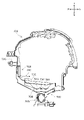
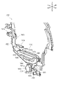
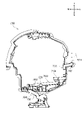
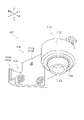
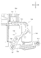
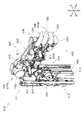
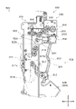
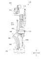
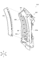
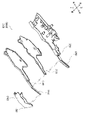
図1から図3に示すように、パチンコ遊技機1は、木枠11、ベースドア12、ガラスドア13、皿ユニット14、発射装置15、液晶表示装置16、遊技盤17、払出ユニット18及び基板ユニット19を具備する。
As shown in FIGS. 1 to 3, the
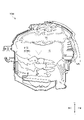
木枠11は、正面視略矩形状の枠体である。木枠11には、前後方向に貫通する開口21が設けられる。木枠11の開口21には、ベースドア12が嵌め込まれる。ベースドア12は、各種の部材を支持するものである。具体的には、ベースドア12は、裏面側に払出ユニット18及び基板ユニット19を支持すると共に、表面側にガラスドア13や、皿ユニット14、発射装置15、液晶表示装置16及び遊技盤17を支持する。
The
ガラスドア13は、ベースドア12に対して開閉自在に軸着されるものである。ガラスドア13には、開口22が設けられる。ガラスドア13の開口22には、透過性を有する保護ガラス23が配設される。保護ガラス23は、ガラスドア13がベースドア12に対して閉鎖された状態で後述する遊技盤17と前後方向に対向するように配置される。また、ガラスドア13の上部には、スピーカ24及びランプ25が配設される。スピーカ24は、例えば音声での告知や、演出、エラー報知等を行うものである。ランプ25は、例えば光での告知や、演出等を行うものである。
The
皿ユニット14は、上皿26及び下皿27を一体化したユニット体である。皿ユニット14は、ベースドア12の前下部であって、ガラスドア13の下方に配置される。
The
上皿26は、後述する遊技領域20に発射させる遊技球を貯留するためのものである。上皿26には、払出口61及び演出ボタン62が設けられる。払出口61は、遊技球の貸し出しや、払い出し(賞球)を行うためのものである。払出口61は、所定の払い出し条件が成立した場合に、遊技球を排出する。演出ボタン62は、所謂「CHANCEボタン」や、「プッシュボタン」等と呼ばれるものである。演出ボタン62は、遊技者によって操作される。
The
下皿27は、主に上皿26から溢れた遊技球を貯留するためのものである。下皿27には、払出口63が設けられる。払出口63は、上皿26の払出口63と同様に、遊技球の貸し出しや、払い出し(賞球)を行うためのものである。払出口63は、上皿26から遊技球が溢れた場合に、遊技球を排出する。
The
発射装置15は、遊技領域20に、上皿26に貯留された遊技球を発射するためのものである。発射装置15は、ベースドア12の前右下部であって、皿ユニット14の右下方に配置される。発射装置15は、パネル体31、駆動装置(不図示)及び発射ハンドル32を具備する。
The launching
パネル体31は、発射装置15において皿ユニット14の右下部と一体化されるものである。発射ハンドル32は、パネル体31の表面側に配置される。前記駆動装置は、パネル体31の裏面側に配置され、例えば発射ソレノイドにより構成される。こうして、発射装置15において、遊技者によって発射ハンドル32が操作されると、操作に応じた前記駆動装置の動作により遊技球が発射される。
The
液晶表示装置16は、当り判定の結果や、遊技に関する各種の画像を表示するものである。前記各種の画像には、例えば演出用の識別図柄(装飾図柄)や、大当り中の演出画像、デモ演出画像、識別図柄の変動表示の保留回数等が含まれる。液晶表示装置16(より詳細には、液晶表示装置16の表示領域)は、遊技盤17の略中央(後述するセンター役物42の内周側)に配置される。
The liquid
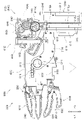
遊技盤17は、保護ガラス23の後方に位置するように、ベースドア12の前方に配置される。遊技盤17の前側面には、発射された遊技球が転動流下可能な遊技領域20が形成される。図3に示すように、遊技盤17は、ガイドレール41、センター役物42、遊技球振分装置5400(第一始動口5442)、普通電動役物ユニット400(第二始動口440及び普通電動役物460)、通過ゲート49、アタッカユニット500(大入賞口540及び特別電動役物600)、一般入賞口53・54・450、アウト口55、LEDユニット70、装飾部材56、可動役物ユニット57を具備する。
The
ガイドレール41は、2つのレール状の部材(以下では、「外レール41a」及び「内レール41b」と称する。)により構成される。外レール41aは、主に遊技領域20を区画(画定)するものである。外レール41aは、遊技領域20を囲むように配置される。内レール41bは、外レール41aと共に、発射された遊技球を遊技領域20の上部に案内するためのものである。内レール41bは、遊技盤17の左側において外レール41aの内側に配置される。
The
センター役物42は、正面視で略円環状に形成される。センター役物42の内側(内周側)は、遊技盤17が開口され、液晶表示装置16の表示領域が形成される。センター役物42は、ネジ等を用いて遊技盤17に固定される。センター役物42の前側面には、遊技者が視認可能な種々の装飾が施される。センター役物42の外周部分には枠状の部材が設けられ、当該センター役物42の内側への遊技球の侵入が阻止されている。また、センター役物42の上部は、遊技領域20における遊技球の流下領域を当該センター役物42の左右に区分けすることができる。
The
なお、発射装置15によって発射された遊技球は、センター役物42や、遊技盤17に打ち込まれた遊技釘68等との衝突により、進行方向を変えながら遊技盤17の下方へ向けて流下する。発射された遊技球は、発射ハンドル32の操作量に応じて流下領域が振り分けられる。具体的には、発射ハンドル32の操作量が小さい場合、発射された遊技球はセンター役物42の左側を流下する。一方、発射ハンドル32の操作量が大きい場合、発射された遊技球はセンター役物42の右側を流下する。なお、センター役物42の左側に遊技球を流下させる打ち方は所謂「左打ち」と呼ばれ、センター役物42の右側に遊技球を流下させる打ち方は所謂「右打ち」と呼ばれる。
The game ball launched by the launching
遊技球振分装置5400は、遊技球を第一始動口5442又はアウト口5443・5444に適宜振り分ける装置である。遊技球振分装置5400は、遊技領域20の略中央下部に配置される。
The game
第一始動口5442は、遊技球の入賞(通過)を条件に当り判定の契機を与えると共に、当り判定の結果を液晶表示装置16や、後述する第1特別図柄表示部73及び第2特別図柄表示部74に表示させる契機を与えるものである。第一始動口5442には、第一始動口スイッチ5472が配設される(図5参照)。第一始動口5442に遊技球が入賞すると、当該入賞した遊技球が第一始動口スイッチ5472に検知される。第一始動口スイッチ5472に遊技球が検知されると、パチンコ遊技機1の内部(図2に示す基板ユニット19)において当り判定が行われると共に、予め設定された数の遊技球が払出口61又は払出口63から上皿26又は下皿27に払い出される(排出される)。なお、第一始動口5442への遊技球の入賞は、左打ちによって行われる。
なお、遊技球振分装置5400の構成についての詳細な説明は後述する。
The
A detailed description of the configuration of the game
普通電動役物ユニット400は、第二始動口440及び普通電動役物460を一体化したユニット体である。普通電動役物ユニット400は、遊技領域20の略右下部に配置される。
The ordinary electric
第二始動口440は、遊技球の入賞(通過)を条件に当り判定の契機を与えると共に、当り判定の結果を液晶表示装置16や、後述する第1特別図柄表示部73及び第2特別図柄表示部74に表示させる契機を与えるものである。第二始動口440には、第二始動口スイッチ441が配設される(図5参照)。第二始動口440に遊技球が入賞すると、当該入賞した遊技球が第二始動口スイッチ441に検知される。第二始動口スイッチ441に遊技球が検知されると、パチンコ遊技機1の内部(図2に示す基板ユニット19)において当り判定が行われると共に、予め設定された数の遊技球が払出口61又は払出口63から上皿26又は下皿27に払い出される(排出される)。第二始動口440は、普通電動役物460によって入賞困難性が決定される。なお、第二始動口440への遊技球の入賞は、右打ちによって行われる。
The
普通電動役物460は、左右方向に回動可能な羽根部材461、及び当該羽根部材461を駆動する始動口ソレノイド462(図5参照)を具備する。普通電動役物460は、第二始動口440の上方に配置される。普通電動役物460は、始動口ソレノイド462により羽根部材461が駆動されることによって、遊技球の通過が容易な開放状態と遊技球の通過が困難な閉鎖状態との間で移行(駆動)可能に構成される。普通電動役物460において羽根部材461を遊技球が通過すると、当該遊技球が第二始動口440に入賞される。普通電動役物460(羽根部材461)による開閉駆動は、普通図柄表示部71において普通図柄が特定の停止表示態様となった場合に、所定の期間及び回数だけ行われる。
The ordinary
通過ゲート49は、遊技球の入賞(通過)を条件に普通図柄判定の契機を与えるものである。通過ゲート49は、遊技盤17の中央右部であって、普通電動役物ユニット400の上方に配置される。通過ゲート49には、通過ゲートスイッチ49aが配設される(図5参照)。通過ゲート49に遊技球が通過すると、当該通過した遊技球が通過ゲートスイッチ49aに検知される。通過ゲートスイッチ49aに遊技球が検知されると、パチンコ遊技機1の内部(図2に示す基板ユニット19)において普通図柄判定が行われる。なお、通過ゲート49への遊技球の通過は、右打ちによって行われる。
The passing
アタッカユニット500は、大入賞口540及び特別電動役物600を一体化したユニット体である。アタッカユニット500は、遊技領域20の略右下部であって、普通電動役物ユニット400の下方に配置される。
The
大入賞口540は、遊技者に有利な遊技状態である当り遊技状態(大当り遊技状態又は小当り遊技状態)の場合に開放可能な部分である。大入賞口540には、カウントスイッチ541が配設される(図5参照)。大入賞口540に遊技球が入賞すると、当該入賞した遊技球がカウントスイッチ541に検知される。カウントスイッチ541に遊技球が検知されると、予め設定された数の遊技球が払出口61から上皿26(又は、払出口63から下皿27)に払い出される(排出される)。
The
特別電動役物600は、前後方向に進退可能なシャッタ610、及び当該シャッタ610を駆動する大入賞口ソレノイド620(図5参照)を具備する。特別電動役物600は、大入賞口540の上方に配置される。特別電動役物600は、大入賞口ソレノイド620によりシャッタ610が駆動されることによって、大入賞口540への遊技球の入賞を可能(又は容易)とする開放状態と、大入賞口540への遊技球の入賞を不可能(又は困難)とする閉鎖状態と、に移行(駆動)可能に構成される。特別電動役物600(シャッタ610)による開放駆動は、第1特別図柄表示部73又は第2特別図柄表示部74において特別図柄が特定の停止表示態様となって、当り遊技状態(大当り遊技状態又は小当り遊技状態)に移行された場合に行われる。
The special
一般入賞口53・54は、遊技盤17の左下部に、互いに離間した状態で配置される。また、一般入賞口450は、普通電動役物ユニット400に設けられる。一般入賞口53・54・450には、一般入賞口スイッチ53a・54a・451が配設される(図5参照)。一般入賞口53・54・450に遊技球が入賞すると、当該入賞した遊技球が一般入賞口スイッチ53a・54a・451に検知される。一般入賞口スイッチ53a・54a・451に遊技球が検知されると、予め設定された数の遊技球が払出口61から上皿26(又は、払出口63から下皿27)に払い出される(排出される)。
The general winning
なお、本実施形態においては、第一始動口5442及び第二始動口440の賞球数は3個、一般入賞口53・54・450の賞球数は10個、大入賞口540の賞球数は15個にそれぞれ設定されている。この値(賞球数)は、任意に設計変更可能である。
In the present embodiment, the number of prize balls in the
アウト口55は、遊技盤17の中央最下部に配置される。アウト口55は、発射された遊技球が、第一始動口5442等の各入賞(始動)口に入賞しなかった場合に、最終的に流入される。
The out
LEDユニット70は、遊技盤17の右下部であって、ガイドレール41の外側に配置される。LEDユニット70は、各種の表示部を一体化したユニット体である。具体的には、LEDユニット70は、前記各種の表示部として、普通図柄表示部71、普通図柄用保留表示部72、第1特別図柄表示部73、第2特別図柄表示部74、第1特別図柄用保留表示部75及び第2特別図柄用保留表示部76を具備する。
The
普通図柄表示部71は、普通図柄ゲームに対する判定(普通図柄判定)の結果を表示するものである。ここで、普通図柄ゲームとは、判定(普通図柄判定)の結果によって普通電動役物460を駆動して開放状態とするか否かを決定するゲームを指す。普通図柄表示部71は、表示LED71a・71bを具備する。表示LED71a・71bは、所定の変動表示開始条件が成立すると、交互に点灯・消灯を繰り返す変動表示を開始する。表示LED71a・71bの点灯・消灯による組み合わせ(表示パターン)は、普通図柄として表示される。表示LED71a・71bは、変動表示を開始した後、所定の期間経過後に停止表示を行う。
The ordinary
判定(普通図柄判定)の結果が当りである場合、表示LED71a・71bの点灯・消灯の組み合わせ(特別図柄)が特定の停止表示態様となる。こうして、普通図柄が特定の停止表示態様で停止表示されると、普通電動役物460を開放状態とすることが決定し、普通電動役物460が所定のパターンで開閉駆動し、第二始動口440への遊技球の入賞困難性が変更される。
When the result of the determination (normal symbol determination) is a hit, the combination of lighting and extinguishing of the
普通図柄用保留表示部72は、保留されている普通図柄の変動表示の実行回数(以下、「普通図柄の変動表示の保留回数」と称する)を表示するものである。普通図柄用保留表示部72は、表示LED72a・72bを具備する。普通図柄用保留表示部72は、表示LED72a・72bの点灯・消灯の組み合わせによって普通図柄の変動表示の保留回数を表示する。例えば、普通図柄の変動表示の実行が1回分保留されている場合には、表示LED72aが点灯すると共に、表示LED72bが消灯する。また、普通図柄の変動表示の実行が2回分保留されている場合には、表示LED72aが点灯すると共に、表示LED72bが点灯する。また、普通図柄の変動表示の実行が3回分保留されている場合には、表示LED72aが点滅すると共に、表示LED72bが点灯する。また、普通図柄の変動表示の実行が4回分保留されている場合には、表示LED72aが点滅すると共に、表示LED72bが点滅する。
The
第1特別図柄表示部73及び第2特別図柄表示部74は、特別図柄ゲームに対する判定(当り判定)の結果を表示するものである。ここで、特別図柄ゲームとは、判定(当り判定)の結果によって遊技状態の移行又は維持を決定するゲームを指す。
The first special
第1特別図柄表示部73は、8個のLEDからなる表示LED群73aを具備する。表示LED群73aは、第一始動口5442への遊技球の入賞(始動入賞)を契機として変動表示を行うと共に、当該遊技球の入賞に基づく当り判定の結果を表示する。表示LED群73aは、所定の変動表示開始条件が成立すると、8個のLEDがそれぞれ点灯・消灯を繰り返す変動表示を開始する。表示LED群73aにおいて、8個のLEDの点灯・消灯による組み合わせ(表示パターン)は、特別図柄として表示される。表示LED群73aは、変動表示を開始した後、所定の期間経過後に停止表示を行う。
The first special
第一始動口5442への遊技球の入賞に基づく当り判定の結果が当りである場合、表示LED群73aの8個のLEDの点灯・消灯の組み合わせ(特別図柄)が特定の停止表示態様となる。こうして、特別図柄が特定の停止表示態様で停止表示されると、遊技状態の移行が決定し、シャッタ610が所定のパターンで開閉駆動し、大入賞口540に遊技球が入賞可能な遊技状態となる。なお、以下の説明では、第一始動口5442への遊技球の入賞に基づいて第1特別図柄表示部73に変動表示される特別図柄を、第1特別図柄と称する。
When the result of the hit determination based on the winning of the game ball to the
第2特別図柄表示部74は、8個のLEDからなる表示LED群74aを具備する。表示LED群74aは、第二始動口440への遊技球の入賞(始動入賞)を契機として変動表示を行うと共に、当該遊技球の入賞に基づく当り判定の結果を表示する。表示LED群74aは、所定の変動表示開始条件が成立すると、8個のLEDがそれぞれ点灯・消灯を繰り返す変動表示を開始する。表示LED群74aにおいて、8個のLEDの点灯・消灯による組み合わせ(表示パターン)は、特別図柄として表示される。表示LED群74aは、変動表示を開始した後、所定の期間経過後に停止表示を行う。
The second special
第二始動口440への遊技球の入賞に基づく当り判定の結果が当りである場合、表示LED群74aの8個のLEDの点灯・消灯の組み合わせ(特別図柄)が特定の停止表示態様となる。こうして、特別図柄が特定の停止表示態様で停止表示されると、遊技状態の移行が決定し、シャッタ610が所定のパターンで開閉駆動し、大入賞口540に遊技球が入賞可能な遊技状態となる。なお、以下の説明では、第二始動口440への遊技球の入賞に基づいて第2特別図柄表示部74に変動表示される特別図柄を、第2特別図柄と称する。
When the result of the hit determination based on the winning of the game ball to the
このように、第1特別図柄表示部73及び第2特別図柄表示部74の表示LED群73a・74aにおいて、第1又は第2特別図柄が特定の停止表示態様で停止表示されると、通常の遊技状態(通常遊技状態)から遊技者に有利な状態である当り遊技状態への移行が決定する。なお、本実施形態においては、当り判定に、大当り判定と、小当り判定と、が含まれる。すなわち、当り判定の結果が大当りである場合には、遊技状態は当り遊技状態として大当り遊技状態に移行される。また、当り判定の結果が小当りである場合には、遊技状態は当り遊技状態として小当り遊技状態に移行される。このように、本実施形態においては、通常遊技状態から移行する遊技状態として、2種類の当り遊技状態が設けられる。
As described above, when the first or second special symbol is stopped and displayed in the specific stop display mode in the
第1特別図柄用保留表示部75及び第2特別図柄用保留表示部76は、保留されている特別図柄の変動表示の実行回数(以下、「特別図柄の変動表示の保留回数」と称する)を表示するものである。第1特別図柄用保留表示部75は、表示LED75a・75bを具備する。第2特別図柄用保留表示部76は、表示LED76a・76bを具備する。第1特別図柄用保留表示部75及び第2特別図柄用保留表示部76は、表示LED75a・75b及び76a・76bの点灯・消灯によって特別図柄の変動表示の保留回数を表示する。表示LED75a・75b及び76a・76bの点灯・消灯の表示態様は、普通図柄用保留表示部72の表示LED72a・72bと同様である。
The first special symbol
装飾部材56は、遊技盤17を装飾する部材である。装飾部材56は、遊技盤17の上部であって、センター役物42の内周側に配置される。装飾部材56は、長手方向を左右方向とした略矩形板状に形成される。装飾部材56の表面側(遊技者側)には、ロゴ(文字)や、キャラクタ、記号等を模した装飾が施される。装飾部材56は、LED(不図示)等によって発光可能に構成される。
The
可動役物ユニット57は、後述する可動役物及び駆動源等を一体化したユニット体である。可動役物ユニット57は、前記可動役物を用いて所定の演出動作を行って、遊技者の興趣を高めることができる。本実施形態において、可動役物ユニット57は、第一の可動役物ユニット(演出装置2400)、第二の可動役物ユニット82及び第三の可動役物ユニット83を具備する。
The
第一の可動役物ユニット(演出装置2400)は、遊技盤17の右上部であって、センター役物42の内周側に配置される。
なお、第一の可動役物ユニット(演出装置2400)の構成についての詳細な説明は後述する。
The first movable accessory unit (effect device 2400) is located in the upper right portion of the
A detailed description of the configuration of the first movable accessory unit (effect device 2400) will be described later.
第二の可動役物ユニット82は、遊技盤17の上部であって、装飾部材56の後方に配置される。
なお、第二の可動役物ユニット82の構成についての詳細な説明は後述する。
The second
A detailed description of the configuration of the second
第三の可動役物ユニット83は、遊技盤17の右部及び左部であって、センター役物42の後方にそれぞれ配置される。第三の可動役物ユニット83は、人間の手を模したハンド役物86(第三の可動役物)を具備する。ハンド役物86は、可動するように構成される。また、ハンド役物86は、点灯可能に構成される。ハンド役物86は、図3に示すような待機状態(演出動作を行っていない状態)において、大部分が遊技盤17及びセンター役物42の後方に隠蔽され、遊技者に視認困難となる。また、ハンド役物86は、作動状態(演出を行っている状態)において、大部分が液晶表示装置16の表示領域の前方に露出され、遊技者に視認容易となる。
The third
以下では、上述の如く構成されたパチンコ遊技機1において、遊技球が第一始動口5442又は第二始動口440に入賞した場合の内部処理の概略について説明する。
Hereinafter, in the
遊技球が第一始動口5442に入賞すると、第一始動口スイッチ5472によって当該入賞した遊技球が検知され、第1特別図柄表示部73による第1特別図柄の変動表示が開始される。また、第1特別図柄の変動表示中に第一始動口5442へ遊技球が入賞した場合には、変動表示中の第1特別図柄が停止表示されるまで、当該第一始動口5442への遊技球の入賞に基づく第1特別図柄の変動表示の実行(開始)が保留される。その後、変動表示中の第1特別図柄が停止表示された場合、保留されていた第1特別図柄の変動表示が開始される。
When the game ball wins the
遊技球が第二始動口440に入賞すると、第二始動口スイッチ441によって当該入賞した遊技球が検知され、第2特別図柄表示部74による第2特別図柄の変動表示が開始される。また、第2特別図柄の変動表示中に第二始動口440へ遊技球が入賞した場合には、変動表示中の第2特別図柄が停止表示されるまで、当該第二始動口440への遊技球の入賞に基づく第2特別図柄の変動表示の実行(開始)が保留される。その後、変動表示中の第2特別図柄が停止表示された場合、保留されていた第1特別図柄の変動表示が開始される。
When the game ball wins the
なお、第1特別図柄表示部73及び第2特別図柄表示部74において、特別図柄(第1及び第2特別図柄)が互いに同時に変動することはない。すなわち、第1特別図柄表示部73及び第2特別図柄表示部74の一方の表示部で特別図柄の変動表示が行われている間は、他方の表示部で特別図柄の変動表示が行われない。本実施形態においては、第1及び第2特別図柄の変動表示の実行が保留されている場合、第二始動口440への始動入賞を優先し、第2特別図柄の変動表示が行われる。
In the first special
また、第1及び第2特別図柄の変動表示の保留回数には、上限が設定される。本実施形態においては、第1及び第2特別図柄の変動表示の保留回数は、それぞれ4回が上限として設定される。したがって、特別図柄の変動表示の最大の保留回数は、第一始動口5442及び第二始動口440への入賞による特別図柄の変動表示の保留回数を合計した8回となる。
Further, an upper limit is set for the number of times of holding the variable display of the first and second special symbols. In the present embodiment, the number of times of holding the variable display of the first and second special symbols is set up to 4 times each. Therefore, the maximum number of holdings for the variable display of the special symbol is eight, which is the total number of holdings for the variable display of the special symbol due to the winning of the
また、第1特別図柄表示部73及び第2特別図柄表示部74において第1又は第2特別図柄の変動中においては、特定の場合を除いて、液晶表示装置16に数字からなる識別図柄が変動表示される。本実施形態においては、前記数字として、「1」から「8」までの記号が用いられる。また、液晶表示装置16に変動表示される識別図柄は、第1特別図柄表示部73及び第2特別図柄表示部74において変動表示中の第1又は第2特別図柄が停止表示されると共に、停止表示される。なお、識別図柄は、演出用の識別情報としても用いられる。
Further, during the change of the first or second special symbol in the first special
また、第1特別図柄表示部73及び第2特別図柄表示部74において停止表示された第1又は第2特別図柄が特定の停止表示態様である場合には、当りであることを遊技者に報知させる演出画像が液晶表示装置16に表示される。なお、本実施形態においては、後述するように、前記当りは複数種類設けられる。また、第1又は第2特別図柄が停止表示される場合の特定の停止表示態様は、当りの種類に対応してそれぞれ設定される。このような構成において、液晶表示装置16において停止表示される識別図柄の組み合わせは、第1又は第2特別図柄の特定の停止表示態様に応じて、遊技者が認識可能となるような特定の表示態様となる。これにより、遊技者は、当りであることに加え、当該当りの種類を認識することができる。なお、当りの種類のうち一部は、第1又は第2特別図柄の特定の停止表示態様に応じて、遊技者が認識困難となるような特定の表示態様となる。これによれば、遊技者は、当りであること、及び当該当りの種類を認識することが困難となる。
Further, when the first or second special symbol stopped and displayed on the first special
[遊技機の電気的構成]
以下では、図5を用いて、パチンコ遊技機1の制御回路について説明する。
[Electrical configuration of gaming machines]
Hereinafter, the control circuit of the
図5に示すように、パチンコ遊技機1は、主に、遊技の制御を行う主制御回路100と、遊技の進行に応じた演出の制御を行うサブ制御回路200と、から構成される。
As shown in FIG. 5, the
主制御回路100は、メインCPU101、メインROM102(読み出し専用メモリ)及びメインRAM103(読み書き可能メモリ)等を具備する。
The
メインCPU101には、メインROM102や、メインRAM103等が接続される。メインCPU101は、メインROM102に記憶されたプログラムに従って、各種の処理を実行する機能を有する。
A
メインROM102には、メインCPU101によりパチンコ遊技機1の動作を制御するためのプログラムや、各種のテーブル等が記憶されている。
The
メインRAM103は、メインCPU101の一時記憶領域として種々のフラグや変数の値を記憶する機能を有する。なお、本実施形態においては、メインCPU101の一時記憶領域としてメインRAM103を用いているが、これに限らず、読み書き可能な記憶媒体であればよい。
The
メインRAM103には、特別図柄ゲームの情報が始動記憶として記憶される記憶領域が設けられる。具体的には、メインRAM103には、変動中の第1特別図柄に対応する特別図柄ゲームの情報が始動記憶として記憶される第1特別図柄始動記憶領域(0)と、上限4回分の第1特別図柄に対応する特別図柄ゲームの情報が始動記憶として記憶される第1特別図柄始動記憶領域(1)から第1特別図柄始動記憶領域(4)と、が設けられる。また同様に、メインRAM103には、変動中の第2特別図柄に対応する特別図柄ゲームの情報が始動記憶として記憶される第2特別図柄始動記憶領域(0)と、上限4回分の第2特別図柄に対応する特別図柄ゲームの情報が始動記憶として記憶される第2特別図柄始動記憶領域(1)から第2特別図柄始動記憶領域(4)と、が設けられる。
The
また、主制御回路100は、電源投入時においてリセット信号を生成する初期リセット回路104や、I/Oポート105、コマンド出力ポート106、バックアップコンデンサ107等を具備する。初期リセット回路104は、メインCPU101に接続される。I/Oポート105は、各種のデバイスからの入力信号をメインCPU101に送信したり、メインCPU101からの出力信号を各種の装置に送信したりするものである。コマンド出力ポート106は、メインCPU101からのコマンドをサブ制御回路200に送信するものである。バックアップコンデンサ107は、電断時において、例えばメインRAM103に対して速やかに電源を供給することにより、メインRAM103に記憶されている各種データを保持するものである。
Further, the
また、主制御回路100には、各種の装置(部材)が接続されている。
Further, various devices (members) are connected to the
例えば、主制御回路100には、普通図柄表示部71や、普通図柄用保留表示部72、第1特別図柄表示部73、第2特別図柄表示部74、第1特別図柄用保留表示部75、第2特別図柄用保留表示部76、普通電動役物460の羽根部材461を駆動する始動口ソレノイド462、シャッタ610を駆動する大入賞口ソレノイド620等が接続されている。主制御回路100は、信号を送信することにより、これらの装置(部材)の動作を制御することができる。また、主制御回路100には、ホール係員を呼び出す機能や当り回数を表示する機能等を有する呼出装置(不図示)や、ホール全体のパチンコ遊技機を管理するホールコンピュータにデータ送信するために用いる外部端子板320が接続されている。
For example, the
また、主制御回路100には、第一始動口スイッチ5472や、第二始動口スイッチ441、通過ゲートスイッチ49a、カウントスイッチ541、一般入賞口スイッチ53a・54a・451等が接続されている。主制御回路100には、これらの部材で遊技球が検知された場合に、当該部材から所定の検知信号が供給される。また、主制御回路100には、電断時におけるバックアップデータを遊技場の管理者の操作に応じてクリアするバックアップクリアスイッチ330等が接続されている。
Further, the first
また、主制御回路100には、払出・発射制御回路300が接続されている。払出・発射制御回路300には、遊技球の払い出しを行う払出装置340や、遊技球の発射を行う発射装置350、カードユニット360等が接続されている。カードユニット360には、球貸し操作パネル370が接続され、当該球貸し操作パネル370への遊技者の操作に応じた信号が供給される。
Further, a payout /
払出・発射制御回路300は、主制御回路100から供給される賞球制御コマンドや、カードユニット360から供給される貸し球制御信号を受け取ると、払出装置340に対して所定の信号を送信し、払出装置340に遊技球を払い出させる制御を行う。また、払出・発射制御回路300は、発射ハンドル32が遊技者によって握持され、かつ、時計回り方向へ回動操作されると、その回動角度(回動量)に応じて発射ソレノイドに電力を供給し、遊技球を発射させる制御を行う。
When the payout /
さらに、コマンド出力ポート106には、サブ制御回路200が接続されている。サブ制御回路200は、主制御回路100から供給される各種のコマンドに応じて、液晶表示装置16における表示制御や、スピーカ24から発生させる音声に関する制御、ランプ25の光に関する制御等を行う。
Further, a
なお、本実施形態においては、主制御回路100からサブ制御回路200にコマンドを供給する一方、サブ制御回路200から主制御回路100に信号を供給できないように構成したが、これに限らず、サブ制御回路200から主制御回路100に信号を送信できるように構成してもよい。
In the present embodiment, the command is supplied from the
サブ制御回路200は、サブCPU201、プログラムROM202、ワークRAM203、表示制御回路204、音声制御回路205、ランプ制御回路206及び役物制御回路207等を具備する。サブ制御回路200は、主制御回路100からの指令に応じて遊技の進行に応じた演出を実行する。また、サブ制御回路200は、演出ボタン62の操作によってオン・オフされる演出ボタンスイッチ310が接続されている。
The
サブCPU201は、プログラムROM202に記憶されたプログラムに従って、各種の処理を実行する機能を有する。特に、サブCPU201は、主制御回路100から供給される各種のコマンドに従って、サブ制御回路200の制御を行う。
The sub CPU 201 has a function of executing various processes according to the program stored in the
プログラムROM202には、サブCPU201によりパチンコ遊技機1の遊技演出を制御するためのプログラムや、各種のテーブル等が記憶されている。
The
なお、本実施形態においては、プログラムやテーブル等が記憶される記憶手段として、メインROM102及びプログラムROM202を用いるように構成したが、これに限らず、制御手段を備えたコンピュータにより読み取り可能な記憶媒体であれば別態様であってもよい。例えば、前記記憶手段として、ハードディスク装置や、CD-ROM及びDVD-ROM、ROMカートリッジ等の記憶媒体を用いてもよい。また、前記プログラムやテーブル等は、予め記録されているものでなくとも、電源投入後にダウンロードされ、ワークRAM203等に記録されるものでもよい。さらに、前記プログラムやテーブル等は、各々異なる記憶媒体に記録されていてもよい。
In the present embodiment, the
ワークRAM203は、サブCPU201の一時記憶領域として種々のフラグや変数の値を記憶する機能を有する。なお、本実施形態においては、サブCPU201の一時記憶領域としてワークRAM203を用いているが、これに限らず、読み書き可能な記憶媒体であればよい。
The
表示制御回路204は、液晶表示装置16における表示制御を行うための回路である。表示制御回路204は、画像データプロセッサ(以下、VDPと称する)や、各種の画像データを生成するためのデータが記憶されている画像データROM、画像データをバッファするフレームバッファ、画像データを画像信号として変換するD/Aコンバータ等を具備する。
The
表示制御回路204は、サブCPU201から供給されるデータに応じて、液晶表示装置16に画像を表示させるための種々の処理を行うことができる。表示制御回路204は、サブCPU201から供給される画像表示命令に応じて、液晶表示装置16に表示させるための画像データを一時的にフレームバッファに格納する。なお、液晶表示装置16に表示させるための画像データには、識別図柄を示す識別図柄画像データや、背景画像データ、演出用画像データ等の、遊技に関する各種の画像データが含まれる。
The
そして、表示制御回路204は、所定のタイミングで、フレームバッファに格納された画像データをD/Aコンバータに供給する。D/Aコンバータは、画像データを画像信号として変換し、当該変換した画像信号を所定のタイミングで液晶表示装置16に供給する。液晶表示装置16に画像信号が供給されると、液晶表示装置16に当該画像信号に関する画像が表示される。こうして、表示制御回路204は、液晶表示装置16に遊技に関する画像を表示させる制御を行うことができる。
Then, the
音声制御回路205は、スピーカ24から発生させる音声に関する制御を行うための回路である。音声制御回路205は、音声に関する制御を行う音源ICや、各種の音声データを記憶する音声データROM、音声信号を増幅するための増幅器(以下、AMPと称する)等を具備する。
The
前記音源ICは、スピーカ24から発生させる音声の制御を行う。音源ICは、サブCPU201から供給される音声発生命令に応じて、音声データROMに記憶されている複数の音声データから1つの音声データを選択する。また、音源ICは、選択された音声データを音声データROMから読み出し、音声データを所定の音声信号に変換し、当該変換した音声信号をAMPに供給する。AMPは、音声信号を増幅させ、スピーカ24から音声を発生させる。
The sound source IC controls the sound generated from the
ランプ制御回路206は、装飾ランプ等を含むランプ25の制御を行うための回路である。ランプ制御回路206は、ランプ制御信号を供給するためのドライブ回路や、複数種類のランプ装飾パターンが記憶されている装飾データROM等を具備する。
The
役物制御回路207は、可動役物ユニット57(第一の可動役物ユニット(演出装置2400)、第二の可動役物ユニット82及び第三の可動役物ユニット83)の制御を行うための回路である。役物制御回路207は、可動役物ユニット57に対して、駆動信号を供給するための駆動回路や、点灯制御信号を供給するための点灯回路、動作パターンや点灯パターンが記憶されている役物データROM等を有する。
The
また、駆動回路は、サブCPU201から供給される役物作動命令に応じて、役物データROMに記憶されている複数の動作パターンから1つの動作パターンを選択する。そして、選択した動作パターンを役物データROMから読み出し、読み出した動作パターンに対応する駆動信号を供給することにより、可動役物ユニット57の機械的な動作を制御する。また、点灯回路は、サブCPU201から供給される点灯命令に基づいて、役物データROMに記憶されている複数の点灯パターンから1つの点灯パターンを選択する。そして、選択した点灯パターンを役物データROMから読み出し、読み出した点灯パターンに対応する点灯制御信号を供給することにより、可動役物ユニット57の点灯動作を制御する。
Further, the drive circuit selects one operation pattern from a plurality of operation patterns stored in the accessory data ROM in response to the accessory operation command supplied from the sub CPU 201. Then, the selected operation pattern is read from the accessory data ROM, and the drive signal corresponding to the read operation pattern is supplied to control the mechanical operation of the
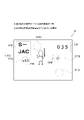
[基本仕様]
以下では、図6を用いて、パチンコ遊技機1の基本仕様について説明する。
[basic specifications]
Hereinafter, the basic specifications of the
図6は、パチンコ遊技機1の基本仕様を示す表である。具体的には、図6(a)は、特別図柄ゲームの仕様を示す表である。また、図6(b)は、普通図柄ゲームの仕様を示す表である。また、図6(c)は、当りの振り分けを示す表である。また、図6(d)は、当りの種類を示す表である。なお、図6(a)から(d)に示す表のデータは、メインROM102にテーブルとして記憶される。
FIG. 6 is a table showing the basic specifications of the
なお、特別図柄ゲームにおいては、大当り判定が、低確率状態又は高確率状態で行われる。このように、特別図柄ゲームにおいて、大当り判定が低確率状態で行われる遊技状態を、単に低確率状態(又は、通常状態や、非確変状態)と称する。また、特別図柄ゲームにおいて、大当り判定が高確率状態で行われる遊技状態を、単に高確率状態(又は、確変状態)と称する。こうして、遊技状態が確変状態となると、通常状態よりも有利な状態が遊技者に付与される。 In the special symbol game, the jackpot determination is performed in a low probability state or a high probability state. In this way, in the special symbol game, the gaming state in which the jackpot determination is performed in the low probability state is simply referred to as the low probability state (or the normal state or the non-probability change state). Further, in the special symbol game, the gaming state in which the jackpot determination is performed in the high probability state is simply referred to as the high probability state (or the probability change state). In this way, when the gaming state becomes the probabilistic state, the player is given a state more advantageous than the normal state.
また、普通図柄ゲームにおいては、普通図柄判定が、高確率状態で行われる。また、普通図柄判定の結果が当りの場合には、普通電動役物460の開放(普通当り遊技)が比較的長い時間行われる。このように、普通図柄ゲームにおいて、普通図柄判定が高確率状態で行われ、且つ普通電動役物460の開放が比較的長い時間行われる遊技状態を、電サポ状態と称する。なお、電サポ状態においては、普通図柄判定1回あたりの時間が、電サポ状態ではない場合よりも短い時間となる。このように、電サポ状態であって、且つ普通図柄判定1回あたりの時間が短い時間で行われる状態を、時短状態と称する。なお、普通図柄判定の高確率状態は、大当り判定の結果が大当りである場合等を契機として移行可能に構成される。また、普通図柄判定の高確率状態は、例えば時短状態が終了した場合等、所定の終了条件を満たした場合に終了する。
Further, in the normal symbol game, the normal symbol determination is performed in a high probability state. Further, when the result of the normal symbol determination is a hit, the normal
なお、普通図柄ゲームにおいて、普通図柄判定は、時短状態以外の遊技状態では行われない。このように、普通図柄判定が行われない遊技状態(時短状態以外の遊技状態)を、通常状態(又は非時短状態)と称する。こうして、遊技状態が時短状態となると、非時短状態よりも有利な状態が遊技者に付与される。なお、時短状態は、通常状態から移行した後、例えば特別図柄ゲームにおける当り判定(大当り判定及び小当り判定)が所定の回数行われるまで継続される。 In the normal symbol game, the normal symbol determination is not performed in the game state other than the time saving state. Such a gaming state (a gaming state other than the time saving state) in which the normal symbol determination is not performed is referred to as a normal state (or a non-time saving state). In this way, when the gaming state becomes the time saving state, the player is given a state more advantageous than the non-time saving state. The time saving state is continued until, for example, the hit determination (big hit determination and small hit determination) in the special symbol game is performed a predetermined number of times after shifting from the normal state.
なお、上述の如く、通常状態とは、特別図柄ゲームにおいて大当り判定が低確率状態で行われる遊技状態であって、且つ、普通図柄ゲームにおいて普通図柄判定が行われない遊技状態を示している。 As described above, the normal state is a gaming state in which the big hit determination is performed in a low probability state in the special symbol game, and the normal symbol determination is not performed in the normal symbol game.
まず、図6(a)を用いて、特別図柄ゲームの仕様について説明する。 First, the specifications of the special symbol game will be described with reference to FIG. 6A.
図6(a)に示すように、特別図柄ゲームにおいて、低確率状態(通常状態)における大当り判定の結果が大当りとなる確率(以下、大当り確率と称する)は、第一始動口5442及び第二始動口440のいずれの始動入賞の場合であっても、共通に1/200(200個の乱数値に対して1個の係数)に設定される。また、高確率状態(確変状態)における大当り確率は、第一始動口5442及び第二始動口440のいずれの始動入賞の場合であっても、共通に1/100(200個の乱数値に対して2個の係数)に設定される。また、第二始動口440の始動入賞により小当り判定の結果が当りとなる確率(以下、小当り確率と称する)は、1/4(200個の乱数値に対して50個の係数)に設定される。なお、第一始動口5442の始動入賞による小当り判定は行われない。換言すれば、第二始動口440に遊技球が入賞したことに基づいて小当り遊技が開始される確率は、第一始動口5442に遊技球が入賞したことに基づいて小当り遊技が開始される確率よりも高く設定される。
As shown in FIG. 6A, in the special symbol game, the probability that the result of the jackpot determination in the low probability state (normal state) becomes a jackpot (hereinafter referred to as the jackpot probability) is the
また、ST回数は、第一始動口5442及び第二始動口440のいずれの始動入賞による大当りの場合であっても、共通に100回に設定される。なお、ST(スペシャルタイム)とは、回数に応じて終了する(回数切り式)確変状態のことである。なお、以下では、特に断りがなければ、「回」とは、確変状態に移行した後からの、当り判定(大当り判定及び小当り判定)の回数を示すものとする。
Further, the number of STs is commonly set to 100 regardless of which of the
なお、ST回数は、後述する超確変状態となった場合に、液晶表示装置16に表示される。具体的には、超確変状態となると、初期値として0が表示される。そして、(判定結果がハズレとなる)当り判定を1回繰り返すごとに、数値が1ずつ加算される様子が表示される。そして、ST回数の数値が100に到達すると、超確変状態が終了することになる。なお、前記初期値は0ではなく、100であってもよい。このように、ST回数の初期値が100である場合には、当り判定を1回繰り返すごとに、数値が1ずつ減算されることとなる。
The number of STs is displayed on the liquid
また、第一始動口5442への入賞に対する賞球数は3個、第二始動口440への入賞に対する賞球数は1個、一般入賞口53・54・450への入賞に対する賞球数は10個、大入賞口540への入賞に対する賞球数は15個に、それぞれ設定される。また、大当り遊技における大入賞口540の開放1回あたりの最大入賞カウント数は、10カウントに設定される。また、普通図柄遊技における普通電動役物460の開放1回あたりの最大入賞カウント数は、10カウントに設定される。また、第一始動口5442及び第二始動口440のいずれの始動入賞の場合であっても、大当り図柄数は、共通に100に設定される。また、第二始動口440の始動入賞による場合の小当り図柄数は、100に設定される。
In addition, the number of prize balls for winning the
次に、図6(b)を用いて、普通図柄ゲームの仕様について説明する。 Next, the specifications of the ordinary symbol game will be described with reference to FIG. 6 (b).
図6(b)に示すように、普通図柄ゲームにおいては、低確率状態で普通図柄判定は行われない。また、高確率状態における普通図柄判定の結果が当りとなる確率は、100/100に設定される。また、普通図柄判定の結果が当りの場合には、第二始動口440(普通電動役物460)が、比較的長い時間である1.5秒間、3回開放される。 As shown in FIG. 6B, in the normal symbol game, the normal symbol determination is not performed in the low probability state. Further, the probability that the result of the normal symbol determination in the high probability state will be a hit is set to 100/100. If the result of the normal symbol determination is a hit, the second starting port 440 (normal electric accessory 460) is opened three times for 1.5 seconds, which is a relatively long time.
次に、図6(c)を用いて、大当り及び小当りの振り分けについて説明する。 Next, the distribution of big hits and small hits will be described with reference to FIG. 6 (c).
図6(c)に示すように、第一始動口5442の始動入賞による大当りは、6種類の大当り内容(大当り種類)に振り分けられる。具体的には、第一始動口5442の始動入賞による大当りは、15R確変、実質10R確変、実質5R確変、15R通常、実質10R通常、実質5R通常、に振り分けられる。これらの大当り内容は、第一始動口5442の始動入賞による大当りとしての特図(1)大当り-1から6に、それぞれ対応するように設定される。
As shown in FIG. 6 (c), the big hits due to the start winning of the
具体的には、特図(1)大当り-1に対応して、15R確変が設定される。また、特図(1)大当り-2に対応して、実質10R確変が設定される。また、特図(1)大当り-3に対応して、実質5R確変が設定される。また、特図(1)大当り-4に対応して、15R通常が設定される。また、特図(1)大当り-5に対応して、実質10R通常が設定される。また、特図(1)大当り-6に対応して、実質5R通常が設定される。 Specifically, a 15R probability variation is set corresponding to the special figure (1) jackpot-1. In addition, a substantial 10R probability variation is set corresponding to the special figure (1) jackpot-2. In addition, a substantial 5R probability variation is set corresponding to the special figure (1) jackpot-3. Further, 15R normal is set corresponding to the special figure (1) jackpot-4. Further, in response to the special figure (1) jackpot -5, a substantial 10R normal is set. In addition, a substantial 5R normal is set corresponding to the special figure (1) jackpot-6.
また、第二始動口440の始動入賞による大当りは、6種類の大当り内容(大当り種類)に振り分けられる。具体的には、第二始動口440の始動入賞による大当りは、15R確変、実質出玉少確変、特殊確変、15R通常、実質出玉少通常、特殊通常、に振り分けられる。これらの大当り内容は、第二始動口440の始動入賞による大当りとしての特図(2)大当り-1から6に、それぞれ対応するように設定される。
In addition, the big hit by the start winning of the
具体的には、特図(2)大当り-1に対応して、15R確変が設定される。また、特図(2)大当り-2に対応して、実質出玉少確変が設定される。また、特図(2)大当り-3に対応して、特殊確変が設定される。また、特図(2)大当り-4に対応して、15R通常が設定される。また、特図(2)大当り-5に対応して、実質出玉少通常が設定される。また、特図(2)大当り-6に対応して、特殊通常が設定される。 Specifically, a 15R probability variation is set corresponding to the special figure (2) jackpot -1. In addition, in response to the special figure (2) jackpot-2, the actual ball ejection small probability change is set. In addition, a special probability variation is set corresponding to the special figure (2) jackpot-3. Further, 15R normal is set corresponding to the special figure (2) jackpot-4. In addition, in response to the special figure (2) jackpot -5, the actual number of balls is set to be small. In addition, a special normal is set corresponding to the special figure (2) jackpot-6.
また、小当りは、2種類の小当り内容(小当り種類)に振り分けられる。具体的には、小当りは、2回開放(1)、2回開放(2)、に振り分けられる。これらの小当り内容は、小当りとしての特図(2)小当り-1及び2に、それぞれ対応するように設定される。具体的には、特図(2)小当り-1に対応して、2回開放(1)が設定される。また、特図(2)小当り-2に対応して、2回開放(2)が設定される。 In addition, small hits are divided into two types of small hit contents (small hit types). Specifically, small hits are divided into two-time opening (1) and two-time opening (2). These small hit contents are set so as to correspond to the special figures (2) small hits -1 and 2 as small hits, respectively. Specifically, the opening (1) is set twice corresponding to the special figure (2) small hit-1. Further, the opening (2) is set twice corresponding to the special figure (2) small hit-2.
ここで、図6(c)の表に示す「数」の欄(表記)は、それぞれの当り内容に対応する大当り図柄数又は小当り図柄数を示している。すなわち、上述の如く第一始動口5442の始動入賞による大当り図柄数は100であるため、特図(1)大当り-1から6は、第一始動口5442の始動入賞による大当りである場合に、それぞれ振り分けられる確率(期待値)が、25%、15%、10%、25%、15%、10%、となるように設定される。また同様に、特図(2)大当り-1から6は、第二始動口440の始動入賞による大当りである場合に、それぞれ振り分けられる確率(期待値)が、25%、15%、10%、25%、15%、10%、となるように設定される。また同様に、特図(2)小当り-1及び2は、小当りである場合に、それぞれ振り分けられる確率(期待値)が、98%、2%、となるように設定される。
Here, the column (notation) of "number" shown in the table of FIG. 6C shows the number of big hit symbols or the number of small hit symbols corresponding to each hit content. That is, since the number of jackpot symbols by the starting prize of the
また、図6(c)に示すように、特図(1)大当り-1から6、特図(2)大当り-1から6、並びに、特図(2)小当り-1及び2には、それぞれ当り遊技(大当り遊技又は小当り遊技)終了後に付与される時短回数が設定される。前記当り遊技終了後に付与される時短回数は、大当り判定又は小当り判定が行われる時における、特別図柄ゲーム及び普通図柄ゲームの状態に応じて異なるように設定される。 Further, as shown in FIG. 6 (c), special figures (1) big hits -1 to 6, special figures (2) big hits -1 to 6, and special figures (2) small hits -1 and 2 are shown. The number of time reductions given after the end of each hit game (big hit game or small hit game) is set. The number of time reductions given after the end of the hit game is set to be different depending on the state of the special symbol game and the normal symbol game when the big hit determination or the small hit determination is performed.
ここで、図6(c)の表に示す「HH」の表記は、特別図柄ゲームが確変状態であると共に、普通図柄ゲームが時短状態であることを示している。また、「HL」の表記は、特別図柄ゲームが確変状態であると共に、普通図柄ゲームが非時短状態であることを示している。また、「LH」の表記は、特別図柄ゲームが非確変状態であると共に、普通図柄ゲームが時短状態であることを示している。また、「LL」の表記は、特別図柄ゲームが非確変状態であると共に、普通図柄ゲームが非時短状態であることを示している。さらに、「高確率の間」の表記は、特別図柄ゲームにおいて高確率状態の間、すなわち最大100回の時短回数が付与されることを示している。 Here, the notation of "HH" shown in the table of FIG. 6C indicates that the special symbol game is in the probabilistic state and the normal symbol game is in the time saving state. Further, the notation of "HL" indicates that the special symbol game is in the probable change state and the normal symbol game is in the non-time saving state. Further, the notation of "LH" indicates that the special symbol game is in the non-probability changing state and the normal symbol game is in the time saving state. Further, the notation of "LL" indicates that the special symbol game is in the non-probability changing state and the normal symbol game is in the non-time saving state. Further, the notation "during high probability" indicates that during the high probability state, that is, a maximum of 100 time reductions are given in the special symbol game.
このような設定において、例えば特別図柄ゲームが非確変状態であると共に普通図柄ゲームが非時短状態である場合(「LL」の場合)において、特図(1)大当り-1又は6の大当りとなると、50回の時短回数が付与される。一方、例えば同様に「LL」の場合において、特図(1)大当り-2から5の大当りとなると、時短回数は付与されない。すなわち、特別図柄ゲームが非確変状態であると共に普通図柄ゲームが非時短状態である場合において、第一始動口5442の始動入賞による大当りである場合には、35%(特図(1)大当り-1の場合の25%+特図(1)大当り-6の場合の10%)の確率で50回の時短回数が付与され、残りの65%の確率で時短回数が付与されないこととなる。
In such a setting, for example, when the special symbol game is in the non-probability changing state and the normal symbol game is in the non-time saving state (in the case of "LL"), the special symbol (1) jackpot -1 or 6 jackpot is obtained. , 50 times of time reduction is given. On the other hand, for example, in the case of "LL" as well, in the case of the special figure (1) big hit-2 to 5 big hits, the number of time reductions is not given. That is, in the case where the special symbol game is in the non-probability changing state and the normal symbol game is in the non-time saving state, if the jackpot is due to the starting prize of the
また、小当りである場合は、小当り遊技終了後に、原則として小当りとなる前の遊技状態が変化せず、そのまま維持される。具体的には、ST中に小当りとなると、小当り遊技終了後に、前記小当りとなった当り判定に係るST回数から引き続いてカウントするようにSTが再開される。例えば、ST中に、60回目で小当りとなると、小当り遊技終了後に61回目からカウントするようにSTが再開される。この場合、小当り遊技終了後におけるSTの残り回数は40回となる。また同様に、時短状態中に小当りとなると、小当り遊技終了後に、前記小当りとなった当り判定に係る回数から引き続いてカウントするように時短状態が再開される。 Further, in the case of a small hit, after the small hit game is completed, in principle, the game state before the small hit is not changed and is maintained as it is. Specifically, when a small hit occurs during the ST, after the small hit game is completed, the ST is restarted so as to continuously count from the number of STs related to the hit determination of the small hit. For example, if a small hit is reached at the 60th time during ST, the ST is restarted so as to count from the 61st time after the small hit game is completed. In this case, the remaining number of STs after the end of the small hit game is 40 times. Similarly, when a small hit is made during the time saving state, the time saving state is restarted so as to continuously count from the number of times related to the hit determination which is the small hit after the small hit game is completed.
なお、前記原則に対する例外として、例えばST中に、(STの最終回である)100回目で小当りとなると、小当り遊技終了後に、STが終了した状態となる(小当りとなる前の状態が維持されない)。また同様に、例えば100回の時短状態中に、100回目で小当りとなると、小当り遊技終了後に、時短状態が終了した状態となる(小当りとなる前の状態が維持されない)。 As an exception to the above principle, for example, if a small hit is made at the 100th time (the final round of ST) during ST, the ST is finished after the small hit game is completed (the state before the small hit). Is not maintained). Similarly, for example, if a small hit occurs at the 100th time during the 100 times time reduction state, the time reduction state ends after the small hit game ends (the state before the small hit is not maintained).
以下では、図6(d)を用いて、当り内容(大当り内容及び小当り内容)について、詳細に説明する。 In the following, the hit contents (big hit contents and small hit contents) will be described in detail with reference to FIG. 6 (d).
上述の如く、本実施形態においては、大当り内容(大当りの種類)として、15R確変、15R通常、実質10R確変、実質10R通常、実質5R確変、実質5R通常、特殊確変、特殊通常、実質出玉少確変、実質出玉少通常、が設けられる。また、小当り内容(小当りの種類)として、2回開放(1)及び(2)が設けられる。 As described above, in the present embodiment, as the contents of the big hit (type of big hit), 15R probability variation, 15R normal, real 10R probability change, real 10R normal, real 5R probability change, real 5R normal, special probability change, special normal, real ball ejection A small probability change and a small number of actual balls are usually provided. Further, as the contents of the small hit (type of small hit), the opening twice (1) and (2) are provided.
15R確変及び15R通常とは、大当り遊技が開始された場合に、全15ラウンドの全てのラウンドにおいて、1つのラウンドあたりの大入賞口540の開放秒数が27.996秒に設定された大当りである。このように、15R確変及び15R通常では、大当り遊技が開始されると、全てのラウンドにおいて上限数の遊技球を大入賞口540に入賞可能となるように設定される。
15R probability variation and 15R normal are jackpots in which the number of open seconds of the
実質10R確変及び実質10R通常とは、大当り遊技が開始された場合に、全15ラウンドのうち、1から10ラウンド目において1つのラウンドあたりの大入賞口540の開放秒数が27.996秒に設定され、11から15ラウンド目において1つのラウンドあたりの大入賞口540の開放秒数が0.102秒に設定された大当りである。このように、実質10R確変及び実質10R通常では、大当り遊技が開始されると、1から10ラウンド目において遊技球を大入賞口540に入賞可能となるように設定され、11から15ラウンド目において遊技球を大入賞口540に入賞困難(略不可能)となるように設定される。
In the real 10R probability variation and the real 10R normal, when the big hit game is started, the number of open seconds of the big winning
実質5R確変及び実質5R通常とは、大当り遊技が開始された場合に、全15ラウンドのうち、1から5ラウンド目において1つのラウンドあたりの大入賞口540の開放秒数が27.996秒に設定され、6から15ラウンド目において1つのラウンドあたりの大入賞口540の開放秒数が0.102秒に設定された大当りである。このように、実質5R確変及び実質5R通常では、大当り遊技が開始されると、1から5ラウンド目において遊技球を大入賞口540に入賞可能となるように設定され、6から15ラウンド目において遊技球を大入賞口540に入賞困難(略不可能)となるように設定される。
In the real 5R probability change and the real 5R normal, when the big hit game is started, the number of open seconds of the big winning
特殊確変及び特殊通常とは、大当り遊技が開始された場合に、全15ラウンドのうち、最初の1ラウンド目において大入賞口540が3回開放されるように設定されると共に、当該1ラウンド目の1及び2回目の開放において大入賞口540の開放秒数が0.896秒に設定され、残りの3回目の開放において大入賞口540の開放秒数が26.466秒に設定され、2から15ラウンド目において1つのラウンドあたりの大入賞口540の開放秒数が27.966秒に設定された大当りである。このように、特殊確変及び特殊通常では、大当り遊技が開始されると、最初の1ラウンド目における1及び2回目の開放において遊技球を大入賞口540に入賞困難(例えば、開放1回あたり1個入賞する程度)となるように設定され、残りの3回目の開放及び2から15ラウンド目において上限数の遊技球を大入賞口540に入賞可能となるように設定される。なお、特殊確変及び特殊通常では、最初の1ラウンド目における2回目の開放と3回目の開放との間の開放間インターバルが5.0秒に設定される。
The special probability change and special normal are set so that when the big hit game is started, the big winning
実質出玉少確変及び実質出玉少通常とは、大当り遊技が開始された場合に、全15ラウンドのうち、1から2ラウンド目において1つのラウンドあたりの大入賞口540の開放秒数が0.896秒に設定され、3から15ラウンド目において1つのラウンドあたりの大入賞口540の開放秒数が0.102秒に設定された大当りである。このように、実質出玉少確変及び実質出玉少通常では、大当り遊技が開始されると、全てのラウンドにおいて遊技球を大入賞口540に入賞困難(より詳細には、1及び2ラウンド目は、例えば開放1回あたり1個遊技球が入賞する程度であって、3ラウンド目以降は遊技球が入賞略不可能となる程度)となるように設定される。なお、実質出玉少確変及び実質出玉少通常では、2ラウンド目と3ラウンド目との間のラウンド間インターバルが5.0秒に設定される。
When the big hit game is started, the number of open seconds of the big winning
2回開放(1)及び(2)とは、小当り遊技が開始された場合に、大入賞口540を0.896秒ずつ2回開放させる小当りである。すなわち、小当り遊技とは、所定の開閉態様で大入賞口540を動作させるものである、このように、2回開放(1)及び(2)では、小当り遊技が開始されても、遊技球を大入賞口540に入賞困難(例えば、開放1回あたり1個入賞する程度)となるように設定される。なお、2回開放(1)では、2回目の大入賞口540の開放が終了した後の小当り終了インターバルが1.0秒に設定される。また、2回開放(2)では、2回目の大入賞口540の開放が終了した後の小当り終了インターバルが5.0秒に設定される。
The double opening (1) and (2) are small hits in which the large winning
このように、大当りの種類が特殊確変及び特殊通常である場合の1ラウンド目の1及び2回目の開放における大入賞口540の開放秒数と、小当りである場合(2回開放(1)及び(2)である場合)の1及び2回目の開放における大入賞口540の開放秒数とは、互いに同一の0.896秒に設定される。すなわち、特殊確変及び特殊通常と、小当り(2回開放(1)及び(2))とは、大入賞口540の2回目の開放が終了するまで、大入賞口540の開放態様が同一に設定される。このように、特殊確変及び特殊通常の大当り遊技は、1ラウンド目の1及び2回目の開放において、小当り遊技に見せかける所定の開閉態様(擬似小当り開閉態様)で大入賞口540を開閉動作させるものである。
In this way, when the type of big hit is special probability variation and special normal, the number of opening seconds of the big winning
なお、小当り(2回開放(1)及び(2))においては、2回目の大入賞口540の開放が終了した後の当り終了インターバルが互いに異なるように設定される。具体的には、2回開放(1)では、2回目の大入賞口540の開放が終了した後の当り終了インターバルが1.0秒に設定される。また、2回開放(2)では、2回目の大入賞口540の開放が終了した後の当り終了インターバルが5.0秒に設定される。
In the small hits (twice open (1) and (2)), the hit end intervals after the second opening of the large winning
また、特殊確変及び特殊通常における前記2回目の開放と3回目の開放との間の開放間インターバルと、小当りのうち2回開放(2)における小当り終了インターバルと、が互いに同一の秒数(5.0秒)に設定される。すなわち、特殊確変及び特殊通常と、小当りの2回開放(2)とは、大入賞口540の3回目の開放が開始されるまで、大入賞口540の開放態様が同一に設定される。換言すれば、特殊確変及び特殊通常の大当り遊技は、1ラウンド目の3回目の開放が行われる後、大当り遊技であることが判明する。こうして、特殊確変及び特殊通常の大当り遊技は、擬似小当り開閉態様で動作させた後に、大当り遊技であることが判明する特定の開閉態様(大当り判明後開閉態様)で大入賞口540を開閉動作させるものである。
In addition, the interval between the opening between the second opening and the third opening in the special probability change and the special normal, and the small hit end interval in the two opening (2) of the small hits are the same number of seconds. It is set to (5.0 seconds). That is, the special probability variation and special normal and the small hit twice opening (2) are set in the same opening mode of the large winning
また同様に、大当りの種類が実質出玉少確変及び実質出玉少通常である場合の1及び2ラウンド目の開放における大入賞口540の開放秒数と、小当りである場合(2回開放(1)及び(2)である場合)の1及び2回目の開放における大入賞口540の開放秒数とは、互いに同一の0.896秒に設定される。すなわち、実質出玉少確変及び実質出玉少通常と、小当り(2回開放(1)及び(2))とは、大入賞口540の2回目の開放が終了するまで、大入賞口540の開放態様が同一に設定される。
Similarly, the number of opening seconds of the big winning
また、実質出玉少確変及び実質出玉少通常における前記2ラウンド目の開放と3ラウンド目の開放との間のラウンド間インターバルと、小当りのうち2回開放(2)における小当り終了インターバルと、が互いに同一の秒数(5.0秒)に設定される。すなわち、実質出玉少確変及び実質出玉少通常と、小当りの2回開放(2)とは、大入賞口540の3回目の開放が開始されるまで、大入賞口540の開放態様が同一に設定される。このように、実質出玉少確変及び実質出玉少通常の大当り遊技は、1及び2ラウンド目の開放において、小当り遊技に見せかける所定の開閉態様(擬似小当り開閉態様)で大入賞口540を開閉動作させるものである。
In addition, the interval between rounds between the opening of the second round and the opening of the third round in the actual ball ejection small probability change and the actual ball ejection small amount normal, and the small hit end interval in the small hit opening twice (2). And are set to the same number of seconds (5.0 seconds) as each other. That is, the real ball ejection small probability change and the real ball ejection small normal and the small hit twice opening (2) are the opening modes of the large winning
[遊技の流れ]
以下では、図7及び図8を用いて、パチンコ遊技機1の遊技の流れについて説明する。
[Flow of the game]
Hereinafter, the flow of the game of the
パチンコ遊技機1においては、所定のタイミングで適当な遊技状態へと移行を繰り返しながら遊技が進行される。ここで、前記遊技状態には、それぞれ対応する演出モードが設定される。演出モードには、各種の演出内容が設定される。すなわち、遊技が開始されると、適当な遊技状態へと移行すると共に、当該移行した遊技状態に対応する演出モードの演出が行われる。本実施形態においては、演出モードとして、主に演出モード1から6が設けられる。
In the
図7に示すように、遊技開始時においては、多くの場合、遊技状態が通常遊技状態(非確変状態・非時短(非電サポ)状態)である。また、通常遊技状態である場合には、演出モードとして演出モード1の演出が行われる(ステップS900)。通常遊技状態から他の遊技状態への移行は、主に第一始動口5442の始動入賞による当り判定の結果を契機として行われる。例外的に例えば100回の電サポ状態が終了した際に第2特別図柄の変動表示の保留が存在する場合には、通常遊技状態において第2特別図柄の当り判定が保留回数の最大数である4回を上限に行われ、その判定結果により何らかの大当りとなった場合には電サポ状態に移行することとなるが、稀なケースであるため、本図面からは省略している。なお、上記4回は電サポ状態が終了したにも関わらずそのときに大当りとなれば電サポ状態へ復帰することが可能な状態であるため、通常遊技状態であって、第2特別図柄の当り判定を行っている間は、演出モード1とは異なる特別な演出モードとして遊技者に期待感を持たせるようにしてもよい。
As shown in FIG. 7, at the start of the game, in many cases, the game state is the normal game state (non-probability change state / non-time saving (non-electric support) state). Further, in the normal gaming state, the effect of the
なお、通常遊技状態において、大当り判定は、所謂左打ちによる第一始動口5442の始動入賞により行われる。また、第一始動口5442の始動入賞による大当り判定の結果が大当りとなって、時短(電サポ)状態へと遊技状態が移行した場合には、所謂右打ちが行われる。こうして、時短(電サポ)状態が継続している間は、第二始動口440の始動入賞により大当り判定が行われる。なお、第一始動口5442の始動入賞による大当り判定の結果が大当りとなったものの、時短(電サポ)状態へと遊技状態が移行しなかった場合(遊技状態が非時短(非電サポ)状態のままである場合)には、左打ちが継続して行われる。
In the normal game state, the jackpot determination is performed by the so-called left-handed start winning of the
ステップS900に示す遊技状態が非確変状態・非時短(非電サポ)状態であって、且つ演出モード1の演出が行われる場合に、大当り判定(当り判定)の結果が特図(1)大当り-1になると、通常遊技状態から確変状態・時短(電サポ)状態へと遊技状態が移行する。また、この遊技状態の移行に伴い、演出モード1の演出が終了し、演出モード2の演出が開始される(ステップS901、S902)。なお、演出モード2の演出が行われる遊技状態では、ST回数が100回に設定され、時短回数が50回に設定されている。
When the gaming state shown in step S900 is a non-probability change state / non-time saving (non-electric support) state and the effect of the
また、ステップS902に示す遊技状態が確変状態・時短(電サポ)状態であって、且つ演出モード2の演出が行われる場合に、大当り判定(当り判定)の結果が特図(2)大当り-1から3のいずれかになると、確変状態・時短(電サポ)状態へと遊技状態が移行する(ステップS910、S911)。すなわち、移行後の遊技状態は、移行前の遊技状態と同一となる。また、この遊技状態の移行に伴い、演出モード2の演出が終了し、演出モード3の演出が開始される。なお、演出モード3の演出が行われる遊技状態では、ST回数が100回に設定され、時短回数が確変状態の間(最大100回)継続するように設定されている。
Further, when the gaming state shown in step S902 is a probability change state / time saving (electric support) state and the effect of the
また、ステップS911に示す遊技状態が確変状態・時短(電サポ)状態であって、且つ演出モード3の演出が行われる場合に、大当り判定(当り判定)の結果が特図(2)大当り-1から3のいずれかになると、再び確変状態・時短(電サポ)状態へと遊技状態が移行する(ステップS912、S911)。また、この遊技状態の移行に伴い、演出モード3の演出が継続される。また、この遊技状態の移行に伴い、大当りに至るまでにカウントされたST回数及び時短回数がクリアされる。すなわち、ST回数及び時短回数は、0からカウントされる。
Further, when the gaming state shown in step S911 is a probability change state / time saving (electric support) state and the effect of the
また、ステップS911に示す遊技状態が確変状態・時短(電サポ)状態であって、且つ演出モード3の演出が行われる場合に、大当り判定(当り判定)の結果が特図(2)大当り-4から6のいずれかになると、後述する非確変状態・時短(電サポ)状態へと遊技状態が移行する(ステップS913、S921)。なお、この遊技状態の移行に伴い、演出モード3の演出が終了し、演出モード4の演出が開始される。
Further, when the gaming state shown in step S911 is a probable change state / time saving (electric support) state and the effect of the
また、ステップS911に示す遊技状態が確変状態・時短(電サポ)状態であって、且つ演出モード3の演出が行われる場合に、小当り判定(当り判定)の結果が当り(2回開放(1)及び(2))になると、当該当りに係る当り判定の回数に応じて遊技状態が変更される。具体的には、当該当りに係る当り判定の回数が所定の回数(100回)である場合には、ST(確変状態)及び時短状態が終了するため、通常遊技状態へと遊技状態が移行する(ステップS914、S915;Yes、S900)。すなわち、演出モード3の演出が終了し、演出モード1の演出が開始される。一方、当該当りに係る当り判定の回数が所定の回数(100回)ではない場合には、現在の遊技状態(確変状態・時短(電サポ)状態)が維持され、ST回数及び時短回数がクリアされず、カウントが再開される(ステップS914、S915;No)。すなわち、演出モード3の演出が継続される。
Further, when the gaming state shown in step S911 is a probability change state / time saving (electric support) state and the effect of the
また、ステップS911に示す遊技状態が確変状態・時短(電サポ)状態であって、且つ演出モード3の演出が行われる場合に、大当り判定及び小当り判定(当り判定)の結果がハズレになると、当該ハズレに係る当り判定の回数に応じて遊技状態が変更される。具体的には、当該ハズレに係る当り判定の回数が所定の回数(100回)である場合には、ST(確変状態)及び時短状態が終了するため、通常遊技状態へと遊技状態が移行する(ステップS916、S915;Yes、S900)。すなわち、演出モード3の演出が終了し、演出モード1の演出が開始される。一方、当該ハズレに係る当り判定の回数が所定の回数(100回)ではない場合には、現在の遊技状態(確変状態・時短(電サポ)状態)が維持され、ST回数及び時短回数がクリアされず、カウントが再開される(ステップS916、S915;No)。すなわち、演出モード3の演出が継続される。
Further, when the gaming state shown in step S911 is a probability change state / time saving (electric support) state and the effect of the
また、ステップS902に示す遊技状態が確変状態・時短(電サポ)状態であって、且つ演出モード2の演出が行われる場合に、大当り判定(当り判定)の結果が特図(2)大当り-4から6のいずれかになると、非確変状態・時短(電サポ)状態へと遊技状態が移行する(ステップS920、S921)。また、この遊技状態の移行に伴い、演出モード2の演出が終了し、演出モード4の演出が開始される。なお、演出モード4の演出が行われる遊技状態では、時短回数が100回に設定されている。
Further, when the gaming state shown in step S902 is a probability change state / time saving (electric support) state and the effect of the
また、ステップS921に示す遊技状態が非確変状態・時短(電サポ)状態であって、且つ演出モード4が行われる場合に、大当り判定(当り判定)の結果が特図(2)大当り-1から3のいずれかになると、確変状態・時短(電サポ)状態へと遊技状態が移行する(ステップS922、S911)。また、この遊技状態の移行に伴い、演出モード4の演出が終了し、演出モード3の演出が開始される。この遊技状態の移行に伴い、大当りに至るまでにカウントされた時短回数がクリアされる。
Further, when the gaming state shown in step S921 is a non-probability change state / time saving (electric support) state and the
また、ステップS921に示す遊技状態が非確変状態・時短(電サポ)状態であって、且つ演出モード4が行われる場合に、大当り判定(当り判定)の結果が特図(2)大当り-4から6のいずれかになると、再び非確変状態・時短(電サポ)状態へと遊技状態が移行する(ステップS923、S921)。また、この遊技状態の移行に伴い、演出モード4の演出が継続される。また、この遊技状態の移行に伴い、大当りに至るまでにカウントされた時短回数がクリアされる。
Further, when the gaming state shown in step S921 is a non-probability change state / time saving (electric support) state and the
また、ステップS921に示す遊技状態が非確変状態・時短(電サポ)状態であって、且つ演出モード4が行われる場合に、小当り判定(当り判定)の結果が当り(2回開放(1)及び(2))になると、当該当りに係る当り判定の回数に応じて遊技状態が変更される。具体的には、当該当りに係る当り判定の回数が所定の回数(100回)である場合には、時短状態が終了するため、通常遊技状態へと遊技状態が移行する(ステップS924、S925;Yes、S900)。すなわち、演出モード4の演出が終了し、演出モード1の演出が開始される。一方、当該当りに係る当り判定の回数が所定の回数(100回)ではない場合には、現在の遊技状態(非確変状態・時短(電サポ)状態)が維持され、時短回数がクリアされず、カウントが再開される(ステップS924、S925;No)。すなわち、演出モード4の演出が継続される。
Further, when the gaming state shown in step S921 is a non-probability change state / time saving (electric support) state and the
また、ステップS921に示す遊技状態が非確変状態・時短(電サポ)状態であって、且つ演出モード4の演出が行われる場合に、大当り判定及び小当り判定(当り判定)の結果がハズレになると、当該ハズレに係る当り判定の回数に応じて遊技状態が変更される。具体的には、当該ハズレに係る当り判定の回数が所定の回数(100回)である場合には、時短状態が終了するため、通常遊技状態へと遊技状態が移行する(ステップS926、S925;Yes、S900)。すなわち、演出モード4の演出が終了し、演出モード1の演出が開始される。一方、当該ハズレに係る当り判定の回数が所定の回数(100回)ではない場合には、現在の遊技状態(非確変状態・時短(電サポ)状態)が維持され、時短回数がクリアされず、カウントが再開される(ステップS926、S925;No)。すなわち、演出モード4の演出が継続される。
Further, when the gaming state shown in step S921 is a non-probability change state / time saving (electric support) state and the effect of the
また、ステップS902に示す遊技状態が確変状態・時短(電サポ)状態であって、且つ演出モード2の演出が行われる場合に、小当り判定(当り判定)の結果が当り(2回開放(1)及び(2))になると、当該当りに係る当り判定の回数に応じて遊技状態が変更される。具体的には、当該当りに係る当り判定の回数が所定の回数(50回)である場合には、ST(確変状態)が継続する一方、時短状態が終了するため、確変状態・非時短(非電サポ)状態へと遊技状態が移行する(ステップS930、S931;Yes、S933)。すなわち、演出モード2の演出が終了し、演出モード5の演出が開始される。一方、当該当りに係る当り判定の回数が所定の回数(50回)ではない場合には、現在の遊技状態(確変状態・時短(電サポ)状態)が維持され、ST回数及び時短回数がクリアされず、カウントが再開される(ステップS930、S931;No)。すなわち、演出モード2の演出が継続される。
Further, when the gaming state shown in step S902 is a probability change state / time saving (electric support) state and the effect of the
また、ステップS902に示す遊技状態が確変状態・時短(電サポ)状態であって、且つ演出モード2の演出が行われる場合に、大当り判定及び小当り判定(当り判定)の結果がハズレになると、当該ハズレに係る当り判定の回数に応じて遊技状態が変更される。具体的には、当該ハズレに係る当り判定の回数が所定の回数(50回)である場合には、ST(確変状態)が継続する一方、時短状態が終了するため、確変状態・非時短(非電サポ)状態へと遊技状態が移行する(ステップS932、S931;Yes、S933)。すなわち、演出モード2の演出が終了し、演出モード5の演出が開始される。一方、当該ハズレに係る当り判定の回数が所定の回数(50回)ではない場合には、現在の遊技状態(確変状態・時短(電サポ))が維持され、ST回数及び時短回数がクリアされず、カウントが再開される(ステップS932、S931;No)。すなわち、演出モード2の演出が継続される。
Further, when the gaming state shown in step S902 is a probability change state / time saving (electric support) state and the effect of the
このように、演出モード2の演出が終了し、演出モード5の演出が開始された場合、ST(確変状態)が継続する一方、時短(電サポ)状態が終了する。すなわち、遊技者は右打ちではなく、左打ちを行うこととなる。なお、本実施形態においては、演出モード5の演出は、演出モード1の演出と同一の内容に設定されている。こうして、演出モード5の演出が開始された場合には、遊技者はST(確変状態)が継続していることを認識し難い遊技状態(潜伏確変状態)となる。なお、演出モード5の演出は、演出モード1の演出と同一の内容であって、遊技者に潜伏確変状態が確定した旨を報知して行われるものであってもよい。
In this way, when the effect of the
また、ステップS933に示す遊技状態が確変状態・非時短(非電サポ)状態であって、且つ演出モード5の演出が行われる場合に、大当り判定(当り判定)の結果が特図(1)大当り-1又は2のいずれかになると、確変状態・時短(電サポ)状態へと遊技状態が移行する(ステップS934、S911)。また、この遊技状態の移行に伴い、演出モード5の演出が終了し、演出モード3の演出が開始される。この遊技状態の移行に伴い、大当りに至るまでにカウントされたST回数がクリアされる。
Further, when the gaming state shown in step S933 is a probabilistic change state / non-time saving (non-electric support) state and the effect of the
また、ステップS933に示す遊技状態が確変状態・非時短(非電サポ)状態であって、且つ演出モード5の演出が行われる場合に、大当り判定(当り判定)の結果が特図(1)大当り-3になると、再び確変状態・非時短(非電サポ)状態へと遊技状態が移行する(ステップS935、S933)。また、この遊技状態の移行に伴い、演出モード5の演出が継続される。また、この遊技状態の移行に伴い、大当りに至るまでにカウントされたST回数がクリアされる。
Further, when the gaming state shown in step S933 is a probabilistic change state / non-time saving (non-electric support) state and the effect of the
また、ステップS933に示す遊技状態が確変状態・非時短(非電サポ)状態であって、且つ演出モード5の演出が行われる場合に、大当り判定(当り判定)の結果が特図(1)大当り-4又は5のいずれかになると、非確変状態・非時短(非電サポ)状態(すなわち通常遊技状態)へと遊技状態が移行する(ステップS936、S900)。また、この遊技状態の移行に伴い、演出モード5の演出が終了し、演出モード1の演出が開始される。この遊技状態の移行に伴い、大当りに至るまでにカウントされたST回数がクリアされる。
Further, when the gaming state shown in step S933 is a probabilistic change state / non-time saving (non-electric support) state and the effect of the
また、ステップS933に示す遊技状態が確変状態・非時短(非電サポ)状態であって、且つ演出モード5の演出が行われる場合に、大当り判定(当り判定)の結果が特図(1)大当り-6になると、非確変状態・時短(電サポ)状態へと遊技状態が移行する(ステップS937、S951)。また、この遊技状態の移行に伴い、演出モード5の演出が終了し、演出モード6の演出が開始される。この遊技状態の移行に伴い、大当りに至るまでにカウントされたST回数がクリアされる。
Further, when the gaming state shown in step S933 is a probable change state / non-time saving (non-electric support) state and the effect of the
また、ステップS933に示す遊技状態が確変状態・非時短(非電サポ)状態であって、且つ演出モード5の演出が行われる場合に、大当り判定(当り判定)の結果がハズレになると、当該ハズレに係る当り判定の回数に応じて遊技状態が変更される。具体的には、当該ハズレに係る当り判定の回数が所定の回数である場合には、ST(確変状態)が終了するため、通常遊技状態へと遊技状態が移行する(ステップS938、S939;Yes、S900)。すなわち、演出モード5の演出が終了し、演出モード1の演出が開始される。一方、当該ハズレに係る当り判定の回数が所定の回数ではない場合には、現在の遊技状態(確変状態・非時短(非電サポ)状態)が維持され、ST回数がクリアされず、カウントが再開される(ステップS938、S939;No)。すなわち、演出モード5の演出が継続される。
Further, when the gaming state shown in step S933 is a probabilistic change state / non-time saving (non-electric support) state and the effect of the
なお、ステップS939における所定の回数は、現在行われている演出モード5の演出が何を契機として開始されたかに応じて設定されている。具体的には、現在行われている演出モード5の演出が、演出モード2の演出が開始された後に当り判定の回数が50回となったことを契機として開始された場合(ステップS931;Yes)には、ステップS939における所定の回数は(演出モード5の演出の開始から)50回となる。一方、現在行われている演出モード5の演出が、ステップS960に示す特図(1)大当り-2又は3となったこと、又はステップS935に示す特図(1)大当り-3となったことを契機として開始された場合には、ステップS939における所定の回数は(演出モード5の演出の開始から)100回となる。
The predetermined number of times in step S939 is set according to what triggered the production of the
また、ステップS900に示す遊技状態が非確変状態・非時短(非電サポ)状態であって、且つ演出モード1の演出が行われる場合に、大当り判定(当り判定)の結果が特図(1)大当り-6になると、通常遊技状態から非確変状態・時短(電サポ)状態へと遊技状態が移行する。また、この遊技状態の移行に伴い、演出モード1の演出が終了し、演出モード6の演出が開始される(ステップS950、S951)。なお、演出モード6の演出が行われる遊技状態では、時短回数が50回に設定されている。
Further, when the gaming state shown in step S900 is a non-probability change state / non-time saving (non-electric support) state and the effect of the
また、ステップS951に示す遊技状態が非確変状態・時短(電サポ)状態であって、且つ演出モード6の演出が行われる場合に、大当り判定(当り判定)の結果が特図(2)大当り-1から3のいずれかになると、確変状態・時短(電サポ)状態へと遊技状態が移行する(ステップS952、S911)。また、この遊技状態の移行に伴い、演出モード6の演出が終了し、演出モード3の演出が開始される。この遊技状態の移行に伴い、大当りに至るまでにカウントされた時短回数がクリアされる。
Further, when the gaming state shown in step S951 is a non-probability change state / time saving (electric support) state and the effect of the
また、ステップS951に示す遊技状態が非確変状態・時短(電サポ)状態であって、且つ演出モード6の演出が行われる場合に、大当り判定(当り判定)の結果が特図(2)大当り-4から6のいずれかになると、非確変状態・時短(電サポ)状態へと遊技状態が移行する(ステップS953、S921)。また、この遊技状態の移行に伴い、演出モード6の演出が終了し、演出モード4の演出が開始される。この遊技状態の移行に伴い、大当りに至るまでにカウントされた時短回数がクリアされる。
Further, when the gaming state shown in step S951 is a non-probability change state / time saving (electric support) state and the effect of the
また、ステップS951に示す遊技状態が非確変状態・時短(電サポ)状態であって、且つ演出モード6の演出が行われる場合に、小当り判定(当り判定)の結果が当り(2回開放(1)及び(2))になると、当該当りに係る当り判定の回数に応じて遊技状態が変更される。具体的には、当該当りに係る当り判定の回数が所定の回数(50回)である場合には、時短状態が終了するため、通常遊技状態へと遊技状態が移行する(ステップS954、S955;Yes、S900)。すなわち、演出モード6の演出が終了し、演出モード1の演出が開始される。一方、当該当りに係る当り判定の回数が所定の回数(50回)ではない場合には、現在の遊技状態(非確変状態・時短(電サポ)状態)が維持され、時短回数がクリアされず、カウントが再開される(ステップS954、S955;No)。すなわち、演出モード6の演出が継続される。
Further, when the gaming state shown in step S951 is a non-probability change state / time saving (electric support) state and the effect of the
また、ステップS951に示す遊技状態が非確変状態・時短(電サポ)状態であって、且つ演出モード6の演出が行われる場合に、大当り判定及び小当り判定(当り判定)の結果がハズレになると、当該ハズレに係る当り判定の回数に応じて遊技状態が変更される。具体的には、当該ハズレに係る当り判定の回数が所定の回数(50回)である場合には、時短状態が終了するため、通常遊技状態へと遊技状態が移行する(ステップS956、S955;Yes、S900)。すなわち、演出モード6の演出が終了し、演出モード1の演出が開始される。一方、当該ハズレに係る当り判定の回数が所定の回数(50回)ではない場合には、現在の遊技状態(非確変状態・時短(電サポ))が維持され、時短回数がクリアされず、カウントが再開される(ステップS956、S955;No)。
Further, when the gaming state shown in step S951 is a non-probability change state / time saving (electric support) state and the effect of the
また、ステップS900に示す遊技状態が非確変状態・非時短(非電サポ)状態であって、且つ演出モード1の演出が行われる場合に、大当り判定(当り判定)の結果が特図(1)大当り-2又は3になると、確変状態・非時短(非電サポ)状態へと遊技状態が移行する(ステップS960、S933)。すなわち、演出モード1の演出が終了し、演出モード5の演出が開始される。
Further, when the gaming state shown in step S900 is a non-probability change state / non-time saving (non-electric support) state and the effect of the
また、ステップS900に示す遊技状態が非確変状態・非時短(非電サポ)状態であって、且つ演出モード1の演出が行われる場合に、大当り判定(当り判定)の結果が特図(1)大当り-4又は5になると、再び通常遊技状態へと遊技状態が移行する。また、この遊技状態の移行に伴い、演出モード1の演出が継続される(ステップS970、S900)。
Further, when the gaming state shown in step S900 is a non-probability change state / non-time saving (non-electric support) state and the effect of the
また、ステップS900に示す遊技状態が非確変状態・非時短(非電サポ)状態であって、且つ演出モード1の演出が行われる場合に、大当り判定(当り判定)の結果がハズレになると、通常遊技状態が維持される。すなわち、演出モード1の演出が継続される(ステップS980、S900)。
Further, when the gaming state shown in step S900 is a non-probability change state / non-time saving (non-electric support) state and the effect of the
このような遊技の流れにおいて、演出モード2が開始された場合(ステップS902)には、確変状態・時短(電サポ)状態へと遊技状態が移行することにより、ST回数が100回に設定される。また同様に、演出モード3が開始された場合(ステップS911)には、確変状態・時短(電サポ)状態へと遊技状態が移行することにより、ST回数が100回に設定される。こうして、演出モード2又は3が開始された後(すなわち、STが開始された後)、例えば当り判定の結果が小当りとなると、(原則として)小当り遊技終了後に現在の遊技状態が維持され、ST回数がクリアされず、カウントが再開される。このように、演出モード2又は3の演出は継続される。
In such a game flow, when the
ここで、上述の如く、小当り遊技が開始された場合には、開放1回あたり1個の遊技球が入賞する程度に大入賞口540が2回開放される。すなわち、演出モード2又は3が開始された場合(STが開始された場合)には、例えば当り判定の回数が所定の回数となって当該演出モードが終了するまでの間(STが終了するまでの間)に、小当り遊技を繰り返し行うことができる。こうして、小当り遊技が繰り返し行われると、当該小当り遊技によって賞球の獲得を図り、遊技者の手元にある遊技球の増加を図ることができる。
Here, as described above, when the small hit game is started, the large winning
なお以下では、小当り遊技によって賞球の獲得を図り、遊技者の手元にある遊技球の増加を図ることができるSTを、超確変状態と称する。また、超確変状態となった後、小当り遊技によって賞球の獲得を図り、遊技者の手元にある遊技球の増加を図る遊技を、ラッシュ(RUSH)と称する。すなわち、(1回あたりの)ラッシュとは、超確変状態へと移行する契機となった大当りから、次の大当り、又は時短状態の終了まで継続するものとする。このように、本実施形態において、時短状態が終了することとなる遊技(例えば、後述する当り判定の100回又は50回の遊技)は、ラッシュの終了条件となる。 In the following, an ST capable of acquiring a prize ball by a small hit game and increasing the number of game balls in the player's hand will be referred to as a super-probability change state. Further, a game in which a prize ball is acquired by a small hit game after the super-probability state is reached and the number of game balls in the player's hand is increased is referred to as a rush (RUSH). That is, the rush (per time) shall continue from the big hit that triggered the transition to the super-probability change state to the next big hit or the end of the time saving state. As described above, in the present embodiment, the game in which the time saving state ends (for example, 100 or 50 times of the hit determination described later) is a condition for ending the rush.
なお、演出モード2が開始された後に、特図(2)大当り-1から3のいずれかの大当りによって演出モード3が開始された場合には、当該大当りの前後の遊技状態とも超確変状態であるため、超確変状態が継続しているものとする。このような場合には、ラッシュが連続して行われた(2回目のラッシュが行われた)ものとする。
If the
また、本実施形態に係るパチンコ遊技機1においては、超確変状態となった場合に、獲得した出玉に関する出玉表示が行われる。なお、前記出玉表示についての詳細な説明は後述する。
Further, in the
[主制御回路の動作説明]
以下では、主制御回路100(メインCPU101)によって行われる処理について説明する。
[Operation explanation of main control circuit]
Hereinafter, the processing performed by the main control circuit 100 (main CPU 101) will be described.
[メイン処理]
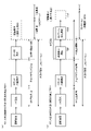
まず、図9を用いて、主制御回路100(メインCPU101)によって行われるメイン処理について説明する。
[Main processing]
First, the main processing performed by the main control circuit 100 (main CPU 101) will be described with reference to FIG.
ステップS10において、メインCPU101は、初期化処理を行う。この処理において、メインCPU101は、バックアップ復帰処理や、初期化設定処理等を行う。この処理が終了した場合、メインCPU101は、ステップS11に処理を移す。
In step S10, the
ステップS11において、メインCPU101は、乱数値更新処理を行う。この処理において、メインCPU101は、初期値乱数値カウンタや、演出条件選択用乱数値カウンタ等の更新を行う。この処理が終了した場合、メインCPU101は、ステップS12に処理を移す。
In step S11, the
ステップS12において、メインCPU101は、タイマ更新処理を行う。この処理において、メインCPU101は、メインCPU101とサブCPU201との同期をとるためのタイマや、大入賞口540の開放時間タイマ等の各種のタイマの更新を行う。この処理が終了した場合、メインCPU101は、ステップS13に処理を移す。
In step S12, the
ステップS13において、メインCPU101は、特別図柄制御処理を行う。この処理において、メインCPU101は、第一始動口スイッチ5472又は第二始動口スイッチ441からの検知信号に応じて当り判定の結果が当りであるか否かを判定し、判定結果をメインRAM103に記憶する処理等を行う。この処理が終了した場合、メインCPU101は、ステップS14に処理を移す。なお、この処理の詳細については後述する。
In step S13, the
ステップS14において、メインCPU101は、普通図柄制御処理を行う。この処理において、メインCPU101は、通過ゲートスイッチ49aからの検知信号に応じて普通図柄判定の結果が当りであるか否かを判定し、判定結果をメインRAM103に記憶する処理等を行う。この処理が終了した場合、メインCPU101は、ステップS15に処理を移す。
In step S14, the
ステップS15において、メインCPU101は、図柄表示装置制御処理を行う。この処理において、メインCPU101は、ステップS13及びステップS14における処理でメインRAM103に記憶された当り判定及び普通図柄判定の判定結果に応じて、第1特別図柄表示部73又は第2特別図柄表示部74と、普通図柄表示部71と、を駆動するための制御信号をメインRAM103に記憶する処理を行う。メインCPU101は、前記記憶した制御信号を、第1特別図柄表示部73又は第2特別図柄表示部74、及び普通図柄表示部71に送信する。こうして、第1特別図柄表示部73又は第2特別図柄表示部74は、受信した制御信号に基づいて特別図柄を変動表示及び停止表示する。また、普通図柄表示部71は、受信した制御信号に基づいて普通図柄を変動表示及び停止表示する。この処理が終了した場合、メインCPU101は、ステップS16に処理を移す。
In step S15, the
ステップS16において、メインCPU101は、遊技情報出力処理を行う。この処理において、メインCPU101は、外部機器(例えば、前記呼出装置や、前記ホールコンピュータ等)に、遊技情報を出力する。この処理が終了した場合、メインCPU101は、ステップS17に処理を移す。
In step S16, the
ステップS17において、メインCPU101は、ポート出力処理を行う。この処理において、メインCPU101は、大入賞口540(シャッタ610)や、第二始動口440(普通電動役物460)を駆動するための制御信号を出力する。この処理が終了した場合、メインCPU101は、ステップS18に処理を移す。
In step S17, the
ステップS18において、メインCPU101は、コマンド出力処理を行う。この処理において、メインCPU101は、サブ制御回路200(サブCPU201)に各種のコマンドを送信する。この処理が終了した場合、メインCPU101は、ステップS19に処理を移す。
In step S18, the
ステップS19において、メインCPU101は、払出処理を行う。この処理において、メインCPU101は、各種の入賞口(具体的には、大入賞口540や、第一始動口5442、第二始動口440、一般入賞口53・54・450)に遊技球が入賞したか否かの判定を行う。メインCPU101は、各種の入賞口に遊技球が入賞したと判定した場合、当該入賞に対応する払出要求コマンドを払出・発射制御回路300に送信する。この処理が終了した場合、メインCPU101は、再びステップS11に処理を移し、ステップS11からステップS19までの処理を繰り返し行う。
In step S19, the
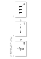
[システムタイマ割込処理]
以下では、図10を用いて、主制御回路100(メインCPU101)によって行われるシステムタイマ割込処理について説明する。
システムタイマ割込処理は、メイン処理が行われている状態であっても、所定の周期毎にメイン処理を中断して行われる。
[System timer interrupt processing]
Hereinafter, the system timer interrupt process performed by the main control circuit 100 (main CPU 101) will be described with reference to FIG.
The system timer interrupt process is performed by interrupting the main process at predetermined intervals even when the main process is being performed.
ステップS20において、メインCPU101は、レジスタ退避処理を行う。この処理において、メインCPU101は、レジスタに記憶されている実行中のプログラムを退避させる。この処理が終了した場合、メインCPU101は、ステップS21に処理を移す。
In step S20, the
ステップS21において、メインCPU101は、乱数値更新処理を行う。この処理において、メインCPU101は、大当り判定用乱数値カウンタや、大当り図柄決定用乱数値カウンタ等の更新を行う。この処理が終了した場合、メインCPU101は、ステップS22に処理を移す。
In step S21, the
ステップS22において、メインCPU101は、スイッチ入力処理を行う。この処理において、メインCPU101は、各種のスイッチ(具体的には、第一始動口スイッチ5472や、第二始動口スイッチ441、通過ゲートスイッチ49a、カウントスイッチ541、一般入賞口スイッチ53a・54a・451等)への信号の入力の有無(すなわち、各種のスイッチにおける遊技球の検知の有無)を判定する。メインCPU101は、各種のスイッチのいずれかにおいて遊技球の検知が有ったと判定した場合(各種の入賞口のいずれかに遊技球が入賞した場合)には、サブ制御回路200にコマンドを送信する。例えば、メインCPU101は、カウントスイッチ541が遊技球をカウント(検知)したときには、サブ制御回路200に大入賞口入賞コマンドを送信する。この処理が終了した場合、メインCPU101は、ステップS23に処理を移す。なお、この処理の詳細については後述する。
In step S22, the
ステップS23において、メインCPU101は、レジスタ復帰処理を行う。この処理において、メインCPU101は、退避させたプログラムをレジスタに復帰させる。この処理が終了した場合、メインCPU101は、本サブルーチンを終了する。
In step S23, the
[特別図柄制御処理]
以下では、図11を用いて、図9のステップS13において行われるサブルーチン(特別図柄制御処理)について説明する。
なお、図11において、ステップS101からステップS108の側方に記載された数値は、これらのステップに対応する制御状態フラグを示している。ここで、制御状態フラグは、特別図柄ゲームの遊技の状態を示すものであって、ステップS101からステップS108における処理のいずれかを実行可能にするものである。前記数値は、メインRAM103における、制御状態フラグとして機能する記憶領域に記憶されている。
[Special symbol control processing]
Hereinafter, the subroutine (special symbol control process) performed in step S13 of FIG. 9 will be described with reference to FIG.
In FIG. 11, the numerical values described on the sides of steps S101 to S108 indicate the control state flags corresponding to these steps. Here, the control state flag indicates the state of the game of the special symbol game, and enables any of the processes in steps S101 to S108 to be executed. The numerical value is stored in the storage area of the
ステップS100において、メインCPU101は、制御状態フラグをロードする処理を行う。この処理において、メインCPU101は、制御状態フラグを読み出す。この処理が終了した場合には、メインCPU101は、ステップS101に処理を移す。
In step S100, the
なお、後述するステップS101からステップS108において、メインCPU101は、メインRAM103に記憶されている制御状態フラグの値に応じて、その値に対応するステップを実行する。より詳細には、メインCPU101は、制御状態フラグの値に基づいて各ステップにおける処理を行うか否かを判定し、その判定結果に応じて、各ステップに対して設定された所定のタイミングで各ステップにおける処理を行う。これによって、特定図柄ゲームが進行されることになる。前記所定のタイミングは、待ち時間タイマ等に応じて決定される。メインCPU101は、前記所定のタイミングに至る前においては、各ステップにおける処理を行うことなく本サブルーチンを終了し、他のサブルーチンを行う。なお、メインCPU101は、本サブルーチンとは別に、所定の周期毎に図10に示すシステムタイマ割込処理も行う。
In steps S101 to S108, which will be described later, the
ステップS101において、メインCPU101は、特別図柄記憶チェック処理を行う。この処理の詳細については後述する。この処理が終了した場合、メインCPU101は、ステップS102に処理を移す。
In step S101, the
ステップS102において、メインCPU101は、特別図柄変動時間管理処理を行う。この処理において、メインCPU101は、制御状態フラグが特別図柄変動時間管理を示す値(01H)であって、変動時間が経過した場合に、特別図柄表示時間管理を示す値(02H)を制御状態フラグにセットし、確定後待ち時間(例えば600ms)を待ち時間タイマにセットする。つまり、メインCPU101は、確定後待ち時間が経過した後、ステップS103の処理を行うように設定する。この処理の詳細については後述する。この処理が終了した場合、メインCPU101は、ステップS103に処理を移す。
In step S102, the
ステップS103において、メインCPU101は、特別図柄表示時間管理処理を行う。この処理においては、メインCPU101は、制御状態フラグが特別図柄表示時間管理を示す値(02H)であって、確定後待ち時間が経過した場合に、当り判定の結果が当り(大当り又は小当り)であるか否かを判定する。メインCPU101は、当り判定の結果が当りである場合に、当り開始インターバル管理を示す値(03H)を制御状態フラグにセットし、当り開始インターバルに対応する時間を待ち時間タイマにセットする。つまり、メインCPU101は、当り開始インターバルに対応する時間が経過した後、ステップS104の処理を行うように設定する。一方、メインCPU101は、当り判定の結果がハズレである場合に、特別図柄ゲーム終了を示す値(07H)をセットする。つまり、メインCPU101は、ステップS108の処理を実行するように設定する。この処理の詳細については後述する。この処理が終了した場合、メインCPU101は、ステップS104に処理を移す。
In step S103, the
ステップS104において、メインCPU101は、当り開始インターバル管理処理を行う。この処理において、メインCPU101は、制御状態フラグが当り開始インターバル管理を示す値(03H)であって、当り開始インターバルに対応する時間が経過した場合に、大入賞口540を開放させる旨の信号を、大入賞口ソレノイド620に供給する。これにより、メインCPU101は、大入賞口540の開閉制御を行う。
In step S104, the
さらに、メインCPU101は、大入賞口開放中を示す値(04H)を制御状態フラグにセットすると共に、開放上限時間(例えば、約0.1秒や、約30秒)を大入賞口開放時間タイマにセットする。つまり、メインCPU101は、ステップS105の処理を行うように設定する。この処理の詳細については後述する。この処理が終了した場合、メインCPU101は、ステップS105に処理を移す。
Further, the
ステップS105において、メインCPU101は、大入賞口再開放待ち時間管理処理を行う。この処理において、メインCPU101は、制御状態フラグが大入賞口再開放待ち時間管理を示す値(05H)であって、ラウンド間インターバルに対応する時間が経過した場合に、大入賞口開放回数カウンタを“1”増加するように記憶更新する。メインCPU101は、大入賞口開放中を示す値(04H)を制御状態フラグにセットする。メインCPU101は、開放上限時間(例えば、約0.1秒又は約30秒)を大入賞口開放時間タイマにセットする。つまり、メインCPU101は、ステップS106の処理を行うように設定する。この処理の詳細については後述する。この処理が終了した場合、メインCPU101は、ステップS106に処理を移す。
In step S105, the
ステップS106において、メインCPU101は、大入賞口開放処理を行う。この処理において、メインCPU101は、制御状態フラグが大入賞口開放中を示す値(04H)である場合に、大入賞口入賞カウンタが“10”以上であるという条件、開放上限時間を経過した(大入賞口開放時間タイマが“0”である)という条件のいずれかを満たすか否かを判定する。メインCPU101は、いずれかの条件を満たした場合に、大入賞口540を閉鎖させるために、メインRAM103に位置付けられた変数を更新する。そして、大入賞口開放回数カウンタが大入賞口開放回数最大値以上である(最終ラウンドである)という条件を満たすか否かを判定する。メインCPU101は、最終ラウンドである場合に、当り終了インターバルを示す値(06H)を制御状態フラグにセットする一方、最終ラウンドでない場合に、大入賞口再開放待ち時間管理を示す値(05H)を制御状態フラグにセットする。この処理の詳細については後述する。この処理が終了した場合、メインCPU101は、ステップS107に処理を移す。
In step S106, the
ステップS107において、メインCPU101は、当り終了インターバル処理を行う。この処理において、メインCPU101は、制御状態フラグが当り終了インターバルを示す値(06H)であって、当り終了インターバルに対応する時間が経過した場合に、特別図柄ゲーム終了を示す値(07H)を制御状態フラグにセットする。つまり、メインCPU101は、ステップS108の処理を行うように設定する。この処理の詳細については後述する。この処理が終了した場合、メインCPU101は、ステップS108に処理を移す。
In step S107, the
ステップS108において、メインCPU101は、特別図柄ゲーム終了処理を行う。この処理において、メインCPU101は、制御状態フラグが特別図柄ゲーム終了を示す値(07H)である場合に、特別図柄記憶チェックを示す値(00H)をセットする。つまり、メインCPU101は、ステップS101の処理を行うように設定する。この処理の詳細については後述する。この処理が終了した場合、メインCPU101は、本サブルーチンを終了する。
In step S108, the
上述の如く、メインCPU101が制御状態フラグをセットすることにより、特別図柄ゲームが進行される。具体的には、メインCPU101は、大当り又は小当り遊技状態ではない場合において、当り判定の結果がハズレであるときには、制御状態フラグを“00H”、“01H”、“02H”、“07H”と順にセットすることにより、図11に示すステップS101、ステップS102、ステップS103、ステップS108の処理を所定のタイミングで行う。また、メインCPU101は、大当り又は小当り遊技状態ではない場合において、当り判定の結果が大当り又は小当りであるときには、制御状態フラグを“00H”、“01H”、“02H”、“03H”と順にセットすることにより、図11に示すステップS101、ステップS102、ステップS103、ステップS104の処理を所定のタイミングで行って、大当り又は小当り遊技状態への制御を行う。さらに、メインCPU101は、大当り又は小当り遊技状態への制御が行われた場合には、制御状態フラグを“04H”、“05H”と順にセットすることにより、図11に示すステップS105、ステップS106の処理を所定のタイミングで行って、大当り又は小当り遊技を行う。また、メインCPU101は、大当り又は小当り遊技の終了条件が成立した場合には、制御状態フラグを“04H”、“06H”、“07H”と順にセットすることにより、図11に示すステップS105、ステップS107、ステップS108の処理を所定のタイミングで行って、大当り又は小当り遊技を終了する。
As described above, the special symbol game is advanced by setting the control state flag by the
[特別図柄記憶チェック処理]
以下では、図12を用いて、図11のステップS101において行われるサブルーチン(特別図柄記憶チェック処理)について説明する。
[Special symbol memory check processing]
Hereinafter, the subroutine (special symbol memory check process) performed in step S101 of FIG. 11 will be described with reference to FIG.
ステップS110において、メインCPU101は、制御状態フラグが特別図柄記憶チェックを示す値(00H)であるか否かの判定を行う。メインCPU101は、制御状態フラグが特別図柄記憶チェックを示す値であると判別した場合には、ステップS111に処理を移す。一方、メインCPU101は、制御状態フラグが特別図柄記憶チェックを示す値ではないと判定した場合には、本サブルーチンを終了する。
In step S110, the
ステップS111において、メインCPU101は、始動記憶の有無を判定する処理を行う。この処理において、メインCPU101は、特別図柄ゲームの始動記憶がないと判定した場合、すなわち第1特別図柄始動記憶領域(0)から第1特別図柄始動記憶領域(4)又は第2特別図柄始動記憶領域(0)から第2特別図柄始動記憶領域(4)にデータ(当り判定用乱数値)が記憶されていない場合には、ステップS112に処理を移す。一方、メインCPU101は、始動記憶(より詳細には、第1及び第2特別図柄の少なくともいずれかに対応する始動記憶)があると判定した場合には、ステップS113に処理を移す。
In step S111, the
ステップS112において、メインCPU101は、デモ表示処理を行う。この処理において、メインCPU101は、メインRAM103にデモ表示許可値をセットする処理を行う。メインCPU101は、特別図柄ゲームの始動記憶が0になった状態が所定時間(例えば、30秒)維持された場合、デモ表示許可値として、デモ表示の実行を許可する値をセットする。そして、メインCPU101は、デモ表示許可値が所定値であった場合に、デモ表示コマンドをセットする。デモ表示コマンドは、主制御回路100のメインCPU101からサブ制御回路200のサブCPU201に供給される。これにより、サブ制御回路200の制御によってデモ表示が液晶表示装置16に行われる。この処理が終了した場合、メインCPU101は、本サブルーチンを終了する。
In step S112, the
ステップS113において、メインCPU101は、第2特別図柄に対応する始動記憶が0であるか否かを判定する処理を行う。この処理において、メインCPU101は、第2特別図柄始動記憶領域(0)から第2特別図柄始動記憶領域(4)のデータの有無を判別し、第2特別図柄に対応する始動記憶が0である、すなわち、第2特別図柄始動記憶領域(0)から第2特別図柄始動記憶領域(4)にデータが記憶されていないと判定した場合には、ステップS115に処理を移す。一方、メインCPU101は、第2特別図柄に対応する始動記憶が0ではない、すなわち、第2特別図柄始動記憶領域(0)から第2特別図柄始動記憶領域(4)にデータが記憶されていると判定した場合には、ステップS114に処理を移す。
In step S113, the
ステップS114において、メインCPU101は、変動状態番号として第2特別図柄の変動であることを示す値(02H)をメインRAM103の所定領域にセットする処理を行う。この処理が終了した場合、メインCPU101は、ステップS116に処理を移す。
In step S114, the
ステップS115において、メインCPU101は、変動状態番号として第1特別図柄の変動であることを示す値(01H)をメインRAM103の所定領域にセットする処理を行う。この処理が終了した場合、メインCPU101は、ステップS116に処理を移す。
In step S115, the
ステップS116において、メインCPU101は、制御状態フラグとして特別図柄変動時間管理を示す値(01H)をセットする処理を行う。この処理が終了した場合、メインCPU101は、ステップS117に処理を移す。
In step S116, the
ステップS117において、メインCPU101は、特別図柄記憶転送処理を行う。この処理において、メインCPU101は、変動表示させる特別図柄が第1特別図柄の場合には、第1特別図柄始動記憶領域(1)から第1特別図柄始動記憶領域(4)のデータのそれぞれを、第1特別図柄始動記憶領域(0)から第1特別図柄始動記憶領域(3)にシフト(記憶)する処理を行う。また、メインCPU101は、変動表示させる特別図柄が第2特別図柄の場合には、第2特別図柄始動記憶領域(1)から第2特別図柄始動記憶領域(4)のデータのそれぞれを、第2特別図柄始動記憶領域(0)から第2特別図柄始動記憶領域(3)にシフト(記憶)する処理を行う。この処理が終了した場合、メインCPU101は、ステップS118に処理を移す。
In step S117, the
ステップS118において、メインCPU101は、大当り判定処理を行う。この処理において、メインCPU101は、高確率フラグを読み出し、読み出した高確率フラグに基づいて、大当りとなる判定値(大当り判定値)の数が異なる複数の当り判定テーブルから1つの当り判定テーブルを選択する。すなわち、高確率フラグが所定の値である場合には、大当り判定値の数が多い高確率用の当り(大当り)判定テーブルが参照され、高確率フラグが所定の値でない場合には、大当り判定値が少ない通常用の当り(大当り)判定テーブルが参照される。このように、高確率フラグが所定の値である場合、つまり遊技状態が高確率状態(確変状態)である場合には、大当り遊技状態に移行する確率は、通常時よりも向上する。
In step S118, the
そして、メインCPU101は、始動入賞時に抽出され、第1特別図柄始動記憶領域(0)と第2特別図柄始動記憶領域(0)において先にセットされた特別図柄始動記憶領域の当り判定用乱数値と、選択された当り判定テーブルとを参照する。そして、メインCPU101は、当り判定用乱数値と大当り判定値とが一致している場合には、大当りであると判定する。一方、メインCPU101は、当り判定用乱数値と大当り判定値とが一致していない場合には、大当りではない(ハズレである)と判定する。こうして、メインCPU101は、大当り判定処理において、遊技者に有利な大当り遊技状態とするか否かの判定(大当り判定)を行っている。この処理が終了した場合、メインCPU101は、ステップS119に処理を移す。
Then, the
ステップS119において、メインCPU101は、小当り判定処理を行う。なお、小当り判定処理は、ステップS118における大当り判定処理において、大当りではなかった場合に行われる。この処理において、メインCPU101は、第1特別図柄始動記憶領域(0)と第2特別図柄始動記憶領域(0)において先にセットされた特別図柄始動記憶領域の当り判定用乱数値と、予め設定されている小当りの判定値とが一致しているか否かを判定する。そして、メインCPU101は、当り判定用乱数値と小当り判定値とが一致している場合には、小当りであると判定する。一方、メインCPU101は、当り判定用乱数値と小当り判定値とが一致していない場合には、小当りではない(ハズレである)と判定する。こうして、メインCPU101は、小当り判定処理において、小当り遊技状態とするか否かの判定(小当り判定)を行っている。
In step S119, the
本実施形態においては、第1特別図柄始動記憶領域に記憶されている当り判定用乱数値と参照する当り判定テーブルとして、通常用と高確率用(確変用)の2種類が用意されており、第2特別図柄始動記憶領域に記憶されている当り判定用乱数値と参照する当り判定テーブルとして、通常用と高確率用(確変用)の2種類が用意されており、合計4種類の当り判定テーブルが用意されている。なお、通常用の2種類の当り判定テーブルはそれぞれ大当り確率が同じであり、また高確率用の2種類の当り判定テーブルはそれぞれ大当り確率が同じである。その一方で、第1特別図柄始動記憶領域に記憶されている当り判定用乱数値と参照する、通常用の当り判定テーブルと高確率用(確変用)の当り判定テーブルにおける小当り判定値の数は同じである。また、第2特別図柄始動記憶領域に記憶されている当り判定用乱数値と参照する、通常用の当り判定テーブルと高確率用(確変用)の当り判定テーブルにおける小当り判定値の数は同じである。このように、メインCPU101は、遊技球が始動領域(第一始動口5442、第二始動口440)を通過したことを条件に通常遊技状態よりも遊技者が多量の遊技球を獲得可能な第1の当り遊技状態、第1の当り遊技状態に比較して少量の遊技球を獲得可能な第2の当り遊技状態、第2の当り遊技状態と同等の遊技球を獲得可能な第3の当り遊技状態、に移行させるか否かの判定を行う当り判定手段の一例である。
In the present embodiment, two types of hit judgment tables, one for normal use and the other for high probability (probability variation), are prepared as the hit judgment random value stored in the first special symbol start storage area and the hit judgment table to be referred to. Two types of hit judgment tables, one for normal use and the other for high probability (probability variation), are prepared as the hit judgment random value stored in the second special symbol start storage area and the hit judgment table to be referred to, and a total of four types of hit judgment are prepared. A table is available. The two types of hit determination tables for normal use have the same jackpot probability, and the two types of hit determination tables for high probability have the same jackpot probability. On the other hand, the number of small hit judgment values in the normal hit judgment table and the high probability (probability variation) hit judgment table referred to as the hit judgment random value stored in the first special symbol start storage area. Is the same. Further, the number of small hit judgment values in the normal hit judgment table and the high probability (probability variation) hit judgment table referred to as the hit judgment random value stored in the second special symbol start storage area is the same. Is. As described above, the
なお、通常遊技の第一始動口5442への入賞による小当り確率は、第二始動口440への入賞による小当り確率より、大きくしてもあるいは小さくしてもよい。通常遊技の第一始動口5442への入賞による大当り確率は、第二始動口440への入賞による大当り確率より、大きくしてもあるいは小さくしてもよい。
The probability of a small hit by winning a prize in the
このように、ステップS118及びS119の処理によって、特別図柄ゲームに対する当り判定の結果として大当り、小当り、ハズレのいずれかが決定される。この処理が終了した場合、メインCPU101は、ステップS120に処理を移す。
In this way, by the processing of steps S118 and S119, one of a big hit, a small hit, and a loss is determined as a result of the hit determination for the special symbol game. When this process is completed, the
ステップS120において、メインCPU101は、特別図柄決定処理を行う。この処理において、メインCPU101は、当り判定の結果が大当りの場合には大当り図柄を決定し、当り判定の結果が小当りの場合には小当り図柄を決定し、大当りでも小当りでもない場合、すなわちハズレの場合にはハズレ図柄を決定する。この処理の詳細については後述する。この処理が終了した場合、メインCPU101は、ステップS121に処理を移す。
In step S120, the
ステップS121において、メインCPU101は、特別図柄変動パターン決定処理を行う。この処理において、メインCPU101は、ステップS120の処理において決定された特別図柄と、ステップS118及びS119の処理において決定された当り判定の結果に基づいて、特別図柄変動パターンを決定するための変動パターン決定テーブルを選択する。そして、メインCPU101は、演出条件判定用乱数カウンタから抽出した演出条件判定用乱数値と選択した変動パターン決定テーブルとに基づいて、変動パターンを決定(選択)する。メインCPU101は、選択した変動パターンを、メインRAM103の所定領域に記憶する。メインCPU101は、このような変動パターンを示すデータに基づいて、第1特別図柄表示部73又は第2特別図柄表示部74における特別図柄の変動表示態様を決定する。
In step S121, the
このように記憶された変動パターンを示すデータは、第1特別図柄表示部73又は第2特別図柄表示部74に供給される。これによって、第1特別図柄表示部73又は第2特別図柄表示部74に、決定した変動パターンで特別図柄が変動表示される。また、このように記憶された変動パターンを示すデータは、主制御回路100のメインCPU101からサブ制御回路200のサブCPU201に特図変動パターン指定コマンドとして供給される。これにより、サブ制御回路200の制御によって、受信した特図変動パターン指定コマンドに応じた演出表示が行われる。この処理が終了した場合、メインCPU101は、ステップS122に処理を移す。
The data indicating the variation pattern stored in this way is supplied to the first special
ステップS122において、メインCPU101は、特別図柄変動時間設定処理を行う。この処理において、メインCPU101は、決定した特別図柄変動パターンに対応する変動時間を待ち時間タイマにセットする。この処理が終了した場合、メインCPU101は、ステップS123に処理を移す。
In step S122, the
ステップS123において、メインCPU101は、特別図柄演出開始コマンドをメインRAM103にセットする処理を行う。特別図柄演出開始コマンドは、主制御回路100のメインCPU101からサブ制御回路200のサブCPU201に供給される。サブ制御回路200は、受信した特別図柄演出開始コマンドに基づいて演出を開始する。この処理が終了した場合、メインCPU101は、ステップS124に処理を移す。
In step S123, the
ステップS124において、メインCPU101は、今回の変動表示に用いられた記憶領域(0)の値をクリアする処理を行う。この処理が終了した場合、メインCPU101は、本サブルーチンを終了する。
In step S124, the
[特別図柄決定処理]
以下では、図13を用いて、図12のステップS120において行われるサブルーチン(特別図柄決定処理)について説明する。
[Special symbol determination process]
Hereinafter, the subroutine (special symbol determination process) performed in step S120 of FIG. 12 will be described with reference to FIG.
ステップS150において、メインCPU101は、ステップS118の大当り判定の結果が大当りであるか否かを判定する処理を行う。メインCPU101は、大当り判定の結果が大当りであると判定した場合には、ステップS151に処理を移す。一方、メインCPU101は、大当り判定の結果が大当りではないと判定した場合には、ステップS156に処理を移す。
In step S150, the
ステップS151において、メインCPU101は、変動状態番号が(01H)であるか否かを判定する処理を行う。メインCPU101は、変動状態番号が(01H)であると判定した場合には、ステップS152に処理を移す。一方、メインCPU101は、変動状態番号が(01H)ではないと判定した場合には、ステップS154に処理を移す。
In step S151, the
ステップS152において、メインCPU101は、第1特別図柄の大当り図柄を決定する処理を行う。この処理において、メインCPU101は、大当り図柄決定用カウンタから抽出した大当り図柄決定用乱数値と当り判定テーブルに基づいて、第1特別図柄の大当り図柄を決定する処理を行う。この処理が終了した場合、メインCPU101は、ステップS153に処理を移す。
In step S152, the
ステップS153において、メインCPU101は、第1特別図柄の大当り図柄のデータ及び大当り図柄のコマンドをセットする処理を行う。この処理において、メインCPU101は、第1特別図柄の大当り図柄のデータを、メインRAM103の所定領域にセットし、第1特別図柄表示部73に供給する。第1特別図柄表示部73は、第1特別図柄を変動表示させて、第1特別図柄の大当り図柄のデータに基づく態様で停止表示させる。また、メインCPU101は、第1特別図柄の大当り図柄のコマンドを、メインRAM103の所定領域にセットし、主制御回路100のメインCPU101からサブ制御回路200のサブCPU201に特別図柄指定コマンドとして供給する。これにより、サブ制御回路200の制御によって識別図柄が大当り停止表示態様で液晶表示装置16に導出表示される。この処理が終了した場合、メインCPU101は、ステップS162に処理を移す。
In step S153, the
ステップS154において、メインCPU101は、第2特別図柄の大当り図柄を決定する処理を行う。この処理において、メインCPU101は、大当り図柄決定用カウンタから抽出した大当り図柄決定用乱数値と当り判定テーブルに基づいて、第2特別図柄の大当り図柄を決定する処理を行う。この処理が終了した場合、メインCPU101は、ステップS155に処理を移す。
In step S154, the
ステップS155において、メインCPU101は、第2特別図柄の大当り図柄のデータ及び大当り図柄のコマンドをセットする処理を行う。この処理において、メインCPU101は、第2特別図柄の大当り図柄のデータを、メインRAM103の所定領域にセットし、第2特別図柄表示部74に供給する。第2特別図柄表示部74は、第2特別図柄を変動表示させて、第2特別図柄の大当り図柄のデータに基づく態様で停止表示させる。また、メインCPU101は、第2特別図柄の大当り図柄のコマンドを、メインRAM103の所定領域にセットし、主制御回路100のメインCPU101からサブ制御回路200のサブCPU201に特別図柄指定コマンドとして供給する。これにより、サブ制御回路200の制御によって識別図柄が大当り停止表示態様で液晶表示装置16に導出表示される。この処理が終了した場合、メインCPU101は、ステップS162に処理を移す。
In step S155, the
ステップS156において、メインCPU101は、ステップS119の小当り判定の結果が小当りであるかを判定する処理を行う。メインCPU101は、小当り判定の結果が小当りであると判定した場合には、ステップS160に処理を移す。メインCPU101は、小当り判定の結果が小当りではないと判定した場合には、ステップS164に処理を移す。
In step S156, the
ステップS160において、メインCPU101は、第2特別図柄の小当り図柄を決定する処理を行う。この処理において、メインCPU101は、大当り図柄決定用カウンタから抽出した乱数値に基づいて、第2特別図柄の小当り図柄を決定する処理を行う。この処理が終了した場合、メインCPU101は、ステップS161に処理を移す。
In step S160, the
ステップS161において、メインCPU101は、第2特別図柄の小当り図柄のデータ及び小当り図柄のコマンドをセットする処理を行う。この処理において、メインCPU101は、第2特別図柄の小当り図柄のデータを、メインRAM103の所定領域にセットし、第2特別図柄表示部74に供給する。第2特別図柄表示部74は、第2特別図柄を変動表示させて、第2特別図柄の小当り図柄のデータに基づく態様で停止表示させる。また、メインCPU101は、第2特別図柄の小当り図柄のコマンドを、メインRAM103の所定領域にセットし、主制御回路100のメインCPU101からサブ制御回路200のサブCPU201に特別図柄指定コマンドとして供給する。これにより、サブ制御回路200の制御によって識別図柄が小当り停止表示態様で液晶表示装置16に導出表示される。この処理が終了した場合、メインCPU101は、ステップS162に処理を移す。
In step S161, the
ステップS162において、メインCPU101は、当り図柄(大当り図柄、小当り図柄)に対応する当り開始インターバル表示時間データをセットする処理を行う。この処理において、メインCPU101は、メインRAM103の所定領域に当り図柄(大当り図柄、小当り図柄)に対応する当り開始インターバル表示時間データをメインRAM103にセットする。この処理が終了した場合、メインCPU101は、ステップS163に処理を移す。
In step S162, the
ステップS163において、メインCPU101は、大入賞口開放回数関連データをセットする処理を行う。この処理において、メインCPU101は、大入賞口開放回数関連データをメインRAM103にセットする。この処理が終了した場合、メインCPU101は、本サブルーチンを終了する。
In step S163, the
ステップS164において、メインCPU101は、ハズレ図柄のデータ及びハズレ図柄のコマンドをセットする処理を行う。この処理において、メインCPU101は、ハズレ図柄のデータを、メインRAM103の所定領域にセットし、変動している特別図柄が第1特別図柄か第2特別図柄かに応じて、第1特別図柄表示部73又は第2特別図柄表示部74に供給する。第1特別図柄表示部73又は第2特別図柄表示部74は、特別図柄を変動表示させて、特別図柄のハズレ図柄のデータに基づく態様で停止表示させる。また、メインCPU101は、ハズレ図柄のコマンドを、メインRAM103の所定領域にセットし、主制御回路100のメインCPU101からサブ制御回路200のサブCPU201に特別図柄指定コマンドとして供給する。これにより、サブ制御回路200の制御によって識別図柄がハズレ停止表示態様で液晶表示装置16に導出表示される。この処理が終了した場合、メインCPU101は、本サブルーチンを終了する。
In step S164, the
[特別図柄変動時間管理処理]
以下では、図14を用いて、図11のステップS102において行われるサブルーチン(特別図柄変動時間管理処理)について説明する。
[Special symbol fluctuation time management process]
Hereinafter, the subroutine (special symbol fluctuation time management process) performed in step S102 of FIG. 11 will be described with reference to FIG.
ステップS200において、メインCPU101は、制御状態フラグが特別図柄変動時間管理を示す値(01H)であるか否かの判定を行う。メインCPU101は、制御状態フラグが特別図柄変動時間管理を示す値(01H)であると判定した場合には、ステップS201に処理を移す。一方、メインCPU101は、制御状態フラグが特別図柄変動時間管理を示す値(01H)ではないと判定した場合には、本サブルーチンを終了する。
In step S200, the
ステップS201において、メインCPU101は、待ち時間タイマが“0”であるか否かの判定を行う。メインCPU101は、待ち時間タイマが“0”であると判定した場合には、ステップS202に処理を移す。一方、メインCPU101は、待ち時間タイマが“0”ではないと判定した場合には、本サブルーチンを終了する。
In step S201, the
ステップS202において、メインCPU101は、制御状態フラグとして特別図柄表示時間管理を示す値(02H)をセットする処理を行う。この処理において、メインCPU101は、特別図柄表示時間管理を示す値(02H)を制御状態フラグにセットする。この処理が終了した場合、メインCPU101は、ステップS203に処理を移す。
In step S202, the
ステップS203において、メインCPU101は、図柄停止コマンドをセットする処理を行う。図柄停止コマンドデータは、主制御回路100のメインCPU101からサブ制御回路200のサブCPU201に供給される。これにより、サブ制御回路200が図柄停止を認識するようになる。この処理が終了した場合、メインCPU101は、ステップS204に処理を移す。
In step S203, the
ステップS204において、メインCPU101は、確定後待ち時間としての待ち時間タイマをセットする処理を行う。この処理において、メインCPU101は、メインRAM103における待ち時間タイマとして機能する領域に、確定後待ち時間を記憶する。この処理が終了した場合、メインCPU101は、本サブルーチンを終了する。
In step S204, the
[特別図柄表示時間管理処理]
以下では、図15及び図16を用いて、図11のステップS103において行われるサブルーチン(特別図柄表示時間管理処理)について説明する。
[Special symbol display time management process]
Hereinafter, the subroutine (special symbol display time management process) performed in step S103 of FIG. 11 will be described with reference to FIGS. 15 and 16.
ステップS300において、メインCPU101は、制御状態フラグが特別図柄表示時間管理処理を示す値(02H)であるか否かを判定する処理を行う。メインCPU101は、制御状態フラグが特別図柄表示時間管理処理を示す値(02H)であると判定した場合には、ステップS301に処理を移行する。一方、メインCPU101は、制御状態フラグが特別図柄表示時間管理処理を示す値(02H)ではない判定した場合には、本サブルーチンを終了する。
In step S300, the
ステップS301において、メインCPU101は、特別図柄表示管理処理に対応する待ち時間タイマが“0”であるか否かの判定を行う。メインCPU101は、待ち時間タイマが“0”であると判定した場合には、ステップS302に処理を移す。一方、メインCPU101は、待ち時間タイマが“0”ではないと判定した場合には、ステップS304に処理を移す。
In step S301, the
ステップS302において、メインCPU101は、ステップS118の大当り判定の結果が大当りであるか否かを判定する処理を行う。メインCPU101は、大当り判定の結果が大当りであると判定した場合には、ステップS303に処理を移す。一方、メインCPU101は、大当り判定の結果が大当りではないと判定した場合には、本サブルーチンを終了する。
In step S302, the
ステップS303において、メインCPU101は、メインRAM103の遊技状態フラグをクリアにする処理を行う。この処理が終了した場合、メインCPU101は、本サブルーチンを終了する。
In step S303, the
ステップS304において、メインCPU101は、ステップS118の大当り判定の結果が大当りであるか否かを判定する処理を行う。メインCPU101は、大当り判定の結果が大当りであると判定した場合には、ステップS311に処理を移す。一方、メインCPU101は、大当り判定の結果が大当りではないと判定した場合には、ステップS305に処理を移す。
In step S304, the
ステップS305において、メインCPU101は、メインRAM103の時短回数カウンタが“0”であるか否か判定する。メインCPU101は、時短回数カウンタが“0”であると判定した場合には、ステップS325に処理を移す。一方、メインCPU101は、時短回数カウンタが“0”ではないと判定した場合には、ステップS306に処理を移す。
In step S305, the
ステップS306において、メインCPU101は、メインRAM103の時短回数カウンタの値を1減算する処理を行う。この処理が終了した場合、メインCPU101は、ステップS307に処理を移す。
In step S306, the
ステップS307において、メインCPU101は、メインRAM103の時短回数カウンタが“0”であるか否か判定する。メインCPU101は、時短回数カウンタが“0”であると判定した場合には、ステップS308に処理を移す。一方、メインCPU101は、時短回数カウンタが“0”ではないと判定した場合には、ステップS325に処理を移す。
In step S307, the
ステップS308において、メインCPU101は、メインRAM103の時短回数フラグをクリアにする処理を行う。この処理が終了した場合、メインCPU101は、ステップS309に処理を移す。
In step S308, the
ステップS309において、メインCPU101は、時短終了コマンドをメインRAM103にセットする処理を行う。時短終了コマンドは、主制御回路100のメインCPU101からサブ制御回路200のサブCPU201に供給される。これにより、サブ制御回路200が時短終了を認識するようになる。この処理が終了した場合、メインCPU101は、ステップS325に処理を移す。
In step S309, the
ステップS325において、メインCPU101は、メインRAM103のST回数カウンタが“0”であるか否か判定する。メインCPU101は、ST回数カウンタが“0”であると判定した場合には、ステップS310に処理を移す。一方、メインCPU101は、ST回数カウンタが“0”ではないと判定した場合には、ステップS326に処理を移す。
In step S325, the
ステップS326において、メインCPU101は、メインRAM103のST回数カウンタの値を1減算する処理を行う。この処理が終了した場合、メインCPU101は、ステップS327に処理を移す。
In step S326, the
ステップS327において、メインCPU101は、メインRAM103のST回数カウンタが“0”であるか否か判定する。メインCPU101は、ST回数カウンタが“0”であると判定した場合には、ステップS328に処理を移す。一方、メインCPU101は、ST回数カウンタが“0”ではないと判定した場合には、ステップS310に処理を移す。
In step S327, the
ステップS328において、メインCPU101は、メインRAM103のST回数フラグをクリアにする処理を行う。この処理が終了した場合、メインCPU101は、ステップS329に処理を移す。
In step S328, the
ステップS329において、メインCPU101は、ST終了コマンドをメインRAM103にセットする処理を行う。ST終了コマンドは、主制御回路100のメインCPU101からサブ制御回路200のサブCPU201に供給される。これにより、サブ制御回路200がST終了を認識するようになる。この処理が終了した場合、メインCPU101は、ステップS310に処理を移す。
In step S329, the
ステップS310において、メインCPU101は、ステップS119の小当り判定の結果が小当りであるかを判定する処理を行う。メインCPU101は、小当り判定の結果が小当りであると判定した場合には、ステップS311に処理を移す。メインCPU101は、小当り判定の結果が小当りではないと判定した場合には、ステップS315に処理を移す。
In step S310, the
ステップS311において、メインCPU101は、制御状態フラグとして当り開始インターバル管理処理を示す値(03H)をセットする処理を行う。この処理が終了した場合、メインCPU101は、ステップS312に処理を移す。
In step S311 the
ステップS312において、メインCPU101は、特別図柄(第1特別図柄又は第2特別図柄)に対応する当り開始インターバル時間としての待ち時間タイマをセットする処理を行う。この処理において、メインCPU101は、メインRAM103における待ち時間タイマとして機能する領域に、当り開始インターバル時間を記憶する。この処理が終了した場合、メインCPU101は、ステップS313に処理を移す。なお、当り開始インターバル時間も当り種別ごとに定められているが、本実施形態においては少なくとも特殊確変、特殊通常、実質出玉少確変、実質出玉少通常及び特図(2)小当り-2の当り開始インターバル時間は同一又は遊技者が区別困難な時間(例えば、1秒)に設定している。
In step S312, the
ステップS313において、メインCPU101は、特別図柄演出停止コマンドをセットする処理を行う。特別図柄演出停止コマンドは、主制御回路100のメインCPU101からサブ制御回路200のサブCPU201に供給される。これにより、サブ制御回路200が特別図柄演出停止を認識するようになる。この処理が終了した場合、メインCPU101は、ステップS314処理を移す。
In step S313, the
ステップS314において、メインCPU101は、特別図柄に対応する大当り開始コマンド又は小当り開始コマンドをセットする処理を行う。大当り開始コマンド又は小当り開始コマンドは、主制御回路100のメインCPU101からサブ制御回路200のサブCPU201に供給される。これにより、サブ制御回路200が大当り又は小当り開始を認識するようになる。この処理が終了した場合、メインCPU101は、本サブルーチンを終了する。
In step S314, the
ステップS315において、メインCPU101は、制御状態フラグとして特別図柄ゲーム終了処理を示す値(07H)をセットする処理を行う。この処理が終了した場合、メインCPU101は、ステップS316に処理を移す。
In step S315, the
ステップS316において、メインCPU101は、特別図柄演出停止コマンドをセットする処理を行う。特別図柄演出停止コマンドは、主制御回路100のメインCPU101からサブ制御回路200のサブCPU201に供給される。これにより、サブ制御回路200が特別図柄演出停止を認識するようになる。この処理が終了した場合、メインCPU101は、本サブルーチンを終了する。
In step S316, the
[当り開始インターバル管理処理]
以下では、図16を用いて、図11のステップS104において行われるサブルーチン(当り開始インターバル管理処理)について説明する。
[Hit start interval management process]
Hereinafter, the subroutine (hit start interval management process) performed in step S104 of FIG. 11 will be described with reference to FIG.
ステップS401において、メインCPU101は、制御状態フラグが当り開始インターバル管理処理を示す値(03H)であるか否かを判定する処理を行う。メインCPU101は、制御状態フラグが当り開始インターバル管理処理を示す値(03H)であると判定した場合には、ステップS402に処理を移す。一方、メインCPU101は、制御状態フラグが当り開始インターバル管理処理を示す値(03H)ではないと判定した場合には、本サブルーチンを終了する。
In step S401, the
ステップS402において、メインCPU101は、特別図柄表示管理処理に対応する待ち時間タイマが“0”であるか否かの判定を行う。メインCPU101は、待ち時間タイマが“0”であると判定した場合には、ステップS403に処理を移す。一方、メインCPU101は、待ち時間タイマが“0”ではないと判定した場合には、本サブルーチンを終了する。
In step S402, the
ステップS403において、メインCPU101は、メインRAM103の大入賞口開放回数カウンタ上限値をセットする。
In step S403, the
ステップS404において、メインCPU101は、メインRAM103の大入賞口開放回数カウンタの値を1加算する処理を行う。この処理が終了した場合、メインCPU101は、ステップS405に処理を移す。
In step S404, the
ステップS405において、メインCPU101は、大当り図柄の種類に応じたラウンド毎又は小当りの開閉パターンをセットする処理を行う。この処理が終了した場合、メインCPU101は、ステップS406に処理を移す。
In step S405, the
ステップS406において、メインCPU101は、メインRAM103の所定領域に、大入賞口開放中表示コマンドをセットする処理を行う。この場合の大入賞口開放中表示コマンドは、1ラウンド目を示すデータとなる。大入賞口開放中表示コマンドは、主制御回路100のメインCPU101からサブ制御回路200のサブCPU201に大入賞口開放中コマンドとして供給される。この処理が終了した場合、メインCPU101は、ステップS407に処理を移す。
In step S406, the
ステップS407において、メインCPU101は、制御状態フラグとして大入賞口再開放待ち時間管理処理を示す値(04H)をセットする処理を行う。この処理が終了した場合、メインCPU101は、ステップS408に処理を移す。
In step S407, the
ステップS408において、メインCPU101は、メインRAM103の大入賞口入賞カウンタをクリアにする処理を行う。この処理が終了した場合、メインCPU101は、ステップS409に処理を移す。
In step S408, the
ステップS409において、メインCPU101は、大入賞口開放時間としての待ち時間タイマの値をメインRAM103にセットする処理を行う。この処理が終了した場合、メインCPU101は、ステップS410に処理を移す。
In step S409, the
ステップS410において、メインCPU101は、メインRAM103の所定領域に大入賞口開放中データをセットする処理を行う。この処理において、メインCPU101は、大入賞口540を開放させるために、メインROM102から読み出されたデータに基づいて、メインRAM103に位置付けられた変数を更新する。このように記憶された変数は、大入賞口ソレノイド620を駆動して大入賞口540を開放状態とすることとなる。この処理を終了した場合、メインCPU101は、本サブルーチンを終了する。
In step S410, the
[大入賞口再開放待ち時間管理処理]
以下では、図17を用いて、図11のステップS105において行われるサブルーチン(大入賞口再開放待ち時間管理処理)について説明する。
[Large winning opening reopening waiting time management process]
Hereinafter, the subroutine (large winning opening reopening waiting time management process) performed in step S105 of FIG. 11 will be described with reference to FIG.
ステップS500において、メインCPU101は、制御状態フラグが大入賞口再開放待ち時間管理処理を示す値(05H)であるか否かを判定する処理を行う。メインCPU101は、制御状態フラグが大入賞口再開放待ち時間管理処理を示す値(05H)であると判定した場合には、ステップS501に処理を移す。一方、メインCPU101は、制御状態フラグが大入賞口再開放待ち時間管理処理を示す値(05H)ではないと判定した場合には、本サブルーチンを終了する。
In step S500, the
ステップS501において、メインCPU101は、特別図柄表示管理処理に対応する待ち時間タイマが“0”であるか否かを判定する処理を行う。メインCPU101は、待ち時間タイマが“0”であると判定した場合には、ステップS502に処理を移す。一方、メインCPU101は、待ち時間タイマが“0”ではないと判定した場合には、本サブルーチンを終了する。
In step S501, the
ステップS502において、メインCPU101は、メインRAM103の大入賞口開放回数カウンタの値に1加算する処理を行う。この処理が終了した場合、メインCPU101は、ステップS503に処理を移す。
In step S502, the
ステップS503において、メインCPU101は、メインRAM103の所定領域に、大入賞口開放中表示コマンドをセットする処理を行う。この場合の大入賞口開放中表示コマンドは、2ラウンド目以降を示すデータとなる。大入賞口開放中表示コマンドデータは、主制御回路100のメインCPU101からサブ制御回路200のサブCPU201に供給される。大入賞口開放中表示コマンドには、サブCPU201に対してラウンドカウンタ+1を行う旨の指示が含まれている。この処理が終了した場合、メインCPU101は、ステップS504に処理を移行する。
In step S503, the
ステップS504において、メインCPU101は、制御状態フラグとして大入賞口開放処理を示す値(04H)をセットする処理を行う。この処理が終了した場合、メインCPU101は、ステップS505に処理を移す。
In step S504, the
ステップS505において、メインCPU101は、ステップS118の大当り判定の結果が大当りであるか否かを判定する処理を行う。メインCPU101は、大当り判定の結果が大当りであると判定した場合には、ステップS506に処理を移す。一方、メインCPU101は、大当り判定の結果が大当りではないと判定した場合には、ステップS507に処理を移す。
In step S505, the
ステップS506において、メインCPU101は、メインRAM103の大入賞口入賞カウンタをクリアにする処理を行う。この処理が終了した場合、メインCPU101は、ステップS507に処理を移す。
In step S506, the
ステップS507において、メインCPU101は、大入賞口開放時間としての待ち時間タイマの値をメインRAM103にセットする処理を行う。この処理が終了した場合、メインCPU101は、ステップS508に処理を移す。
In step S507, the
ステップS508において、メインCPU101は、メインRAM103の所定領域に大入賞口開放中データをセットする処理を行う。この処理を終了した場合、メインCPU101は、本サブルーチンを終了する。
In step S508, the
[大入賞口開放処理]
以下では、図18を用いて、図11のステップS106において行われるサブルーチン(大入賞口開放処理)について説明する。
[Large winning opening opening process]
Hereinafter, the subroutine (large winning opening opening process) performed in step S106 of FIG. 11 will be described with reference to FIG.
ステップS600において、メインCPU101は、制御状態フラグが大入賞口開放処理を示す値(04H)であるか否かを判定する処理を行う。この処理において、メインCPU101は、制御状態フラグが大入賞口開放処理を示す値(04H)であると判定した場合には、ステップS601に処理を移す。一方、メインCPU101は、制御状態フラグが大入賞口開放処理を示す値(04H)ではないと判定した場合には、本サブルーチンを終了する。
In step S600, the
ステップS601において、メインCPU101は、大入賞口入賞カウンタが“10”以上であるか否かを判定する処理を行う。この処理において、メインCPU101は、大入賞口入賞カウンタが“10”以上であると判定した場合には、ステップS604に処理を移す。一方、メインCPU101は、大入賞口入賞カウンタが“10”以上ではないと判定した場合には、ステップS602に処理を移す。
In step S601, the
ステップS602において、メインCPU101は、セットしたラウンド毎又は小当りの開閉パターンに応じた大入賞口開閉処理を行う。この処理において、メインCPU101は、ステップS405でセットしたラウンド毎又は小当りの開閉パターンに応じて大入賞口540を開閉させる処理を行う。具体的には、ラウンド毎又は小当りの開閉パターンに応じて、時間を待って大入賞口540を閉じて開けるという処理を繰り返すことによって、所定ラウンド中に大入賞口540を複数回開閉させる処理を行う。この処理が終了した場合には、ステップS603に処理を移す。
In step S602, the
ここで、本実施形態において、特殊確変、特殊通常の1ラウンド目の1回目の開放と2回目の開放間のインターバル時間、特図(2)小当り-2の1回目の開放と2回目の開放間のインターバル時間は、同一又は遊技者が区別困難な時間(例えば、0.1秒)に設定している。すなわち、ステップS602の処理において、特殊確変、特殊通常、特図(2)小当り-2は、「0.896秒の開放時間→0.1秒の開放間インターバル時間→0.896秒の開放時間」という順番で実行されることとなる。また、このステップで処理されるものではなくステップS607でセットされるものであるが、実質出玉少確変、実質出玉少通常の1ラウンド目と2ラウンド目のラウンド間インターバル時間も、同一又は遊技者が区別困難な時間(例えば、0.1秒)に設定することで「0.896秒の1ラウンド目の開放時間→0.1秒のラウンド間インターバル時間→0.896秒の2ラウンド目の開放時間」という順番で実行されることとなる。それにより大入賞口540が閉鎖している時間に基づいても、遊技者は当り種別の区別が困難である。
Here, in the present embodiment, the special probability change, the interval time between the first opening and the second opening of the special normal first round, the first opening and the second opening of the special figure (2) small hit-2. The interval time between openings is set to the same time or a time that is difficult for the player to distinguish (for example, 0.1 second). That is, in the process of step S602, the special probability variation, the special normal, and the special figure (2) small hit-2 are "0.896 seconds open time → 0.1 seconds open interval time → 0.896 seconds open. It will be executed in the order of "time". Further, although it is not processed in this step but is set in step S607, the actual ball ejection small probability change and the actual ball ejection small amount are the same or the interval time between the normal first and second rounds. By setting a time that is difficult for the player to distinguish (for example, 0.1 seconds), "Opening time of the first round of 0.896 seconds → Interval time between rounds of 0.1 seconds → 2 rounds of 0.896 seconds" It will be executed in the order of "opening time of eyes". As a result, it is difficult for the player to distinguish the winning type even based on the time when the big winning
ステップS603において、メインCPU101は、大入賞口開放時間タイマとしての待ち時間タイマが“0”であるか否かを判定する処理を行う。この処理において、メインCPU101は、待ち時間タイマが“0”であると判定した場合には、ステップS604に処理を移す。一方、メインCPU101は、待ち時間タイマが“0”ではないと判定した場合には、本サブルーチンを終了する。
In step S603, the
ステップS604において、メインCPU101は、大入賞口閉鎖データをセットする処理を行う。この処理において、メインCPU101は、大入賞口540を閉鎖させるために、メインROM102から読み出されたデータに基づいて、メインRAM103に位置付けられた変数を更新する。このように記憶された変数は、大入賞口ソレノイド620を閉鎖状態とすることとなる。この処理が終了した場合、メインCPU101は、ステップS605に処理を移す。
In step S604, the
ステップS605において、メインCPU101は、ステップS119の小当り判定の結果が小当りであるかを判定する処理を行う。この処理において、メインCPU101は、小当り判定の結果が小当りであると判定した場合には、ステップS610に処理を移す。メインCPU101は、小当り判定の結果が小当りではないと判定した場合には、ステップS606に処理を移す。
In step S605, the
ステップS606において、メインCPU101は、大入賞口開放回数カウント値が大入賞口開放回数上限値以上であるか否かを判定する処理を行う。この処理において、メインCPU101は、メインRAM103に記憶されている大入賞口開放回数カウント値と大入賞口開放回数上限値以上とを比較して、大入賞口開放回数カウント値が大入賞口開放回数上限値以上であるか否かを判定する。メインCPU101は、大入賞口開放回数カウント値が入賞口開放回数上限値以上であると判定した場合には、ステップS610に処理を移す。一方、メインCPU101は、大入賞口開放回数カウント値が入賞口開放回数上限値以上ではないと判定した場合には、ステップS607に処理を移す。
In step S606, the
ステップS607において、メインCPU101は、開放時間インターバル表示時間としての待ち時間タイマの値をメインRAM103にセットする処理を行う。この処理が終了した場合、メインCPU101は、ステップS608に処理を移す。
In step S607, the
ステップS608において、メインCPU101は、制御状態フラグとして大入賞口再開放待ち時間管理処理を示す値(05H)をセットする処理を行う。この処理が終了した場合、メインCPU101は、ステップS609に処理を移す。
In step S608, the
ステップS609において、メインCPU101は、メインRAM103の所定領域に、ラウンド間表示コマンドをセットする処理を行う。ラウンド間表示コマンドは、主制御回路100のメインCPU101からサブ制御回路200のサブCPU201に供給される。この処理が終了した場合、メインCPU101は、本サブルーチンを終了する。
In step S609, the
ステップS610において、メインCPU101は、当り終了インターバル表示時間としての待ち時間タイマの値をメインRAM103にセットする処理を行う。この処理が終了した場合、メインCPU101は、ステップS611に処理を移す。
In step S610, the
ステップS611において、メインCPU101は、制御状態フラグとして当り終了インターバル処理を示す値(06H)をセットする処理を行う。この処理が終了した場合、メインCPU101は、ステップS612に処理を移す。
In step S611, the
ステップS612において、メインCPU101は、メインRAM103の所定領域に、特別図柄当りインターバル終了表示コマンドをセットする処理を行う。具体的には、当り判定の結果が大当りの場合には大当り終了表示コマンドがセットされ、当り判定の結果が小当りの場合には小当り終了表示コマンドがセットされる。大当り終了表示コマンド及び小当り終了表示コマンドは、主制御回路100のメインCPU101からサブ制御回路200のサブCPU201に供給される。この処理が終了した場合、メインCPU101は、本サブルーチンを終了する。
In step S612, the
[当り終了インターバル処理]
以下では、図11のステップS107において実行されるサブルーチン(当り終了インターバル処理)について図19を用いて説明する。
[Hit end interval processing]
Hereinafter, the subroutine (hit end interval processing) executed in step S107 of FIG. 11 will be described with reference to FIG.
最初に、ステップS700において、メインCPU101は、メインRAM103の制御状態フラグが当り終了インターバル処理を示す値(06H)であるか否かを判定する処理を行う。制御状態フラグが当り終了インターバル処理を示す値(06H)であると判定した場合には、ステップS701に処理を移行する。制御状態フラグが当り終了インターバル処理を示す値(06H)であると判定しない場合には、本サブルーチンを終了する。
First, in step S700, the
ステップS701において、メインCPU101は、メインRAM103の制御状態フラグが当り終了インターバル処理を示す値(06H)である場合に、当り終了インターバルに対応する待ち時間タイマ(t)の値が“0”であるか否か判定する。また、メインCPU101は、待ち時間タイマの値が“0”である場合には、ステップS702に処理を移し、待ち時間タイマの値が“0”でない場合には、本サブルーチンを終了する。
In step S701, when the control state flag of the
ステップS702において、メインCPU101は、メインRAM103の特別図柄ゲーム終了を示す値(07H)を制御状態フラグにセットする。この処理が終了した場合には、ステップS703に処理を移す。
In step S702, the
ステップS703において、メインCPU101は、メインRAM103の所定領域に、大当り図柄又は小当り図柄及び遊技状態に応じた制御データをセットする処理を行う。具体的には、制御データとして、通常遊技状態、確変状態等の遊技状態がセットされる。また、メインCPU101は、サブ制御回路200に当り終了コマンドを送信する。この処理が終了した場合には、本サブルーチンを終了する。
In step S703, the
[特別図柄ゲーム終了処理]
以下では、図20を用いて、図11のステップS108において実行されるサブルーチン(特別図柄ゲーム終了処理)について説明する。
[Special symbol game end processing]
Hereinafter, the subroutine (special symbol game end processing) executed in step S108 of FIG. 11 will be described with reference to FIG. 20.
最初に、ステップS710において、メインCPU101は、メインRAM103の制御状態フラグが特別図柄ゲーム終了処理を示す値(07H)であるか否かを判定する処理を行う。制御状態フラグが特別図柄ゲーム終了処理を示す値(07H)であると判定した場合には、ステップS711に処理を移す。制御状態フラグが特別図柄ゲーム終了処理を示す値(07H)であると判定しない場合には、本サブルーチンを終了する。
First, in step S710, the
ステップS711において、メインCPU101は、制御状態フラグとして特別図柄記憶チェックを示す値(00H)をメインRAM103にセットする処理を行う。この処理が終了した場合には、本サブルーチンを終了する。
In step S711, the
[サブ制御回路の動作説明]
以下では、サブ制御回路200の処理について説明する。サブ制御回路200は、主制御回路100から送信された各種のコマンドを受信し、サブCPU201により表示処理等の種々の処理を行う。
[Operation explanation of sub control circuit]
Hereinafter, the processing of the
[サブ制御メイン処理]
まず、サブ制御回路200のサブCPU201によって行われるサブ制御メイン処理について、図21を用いて説明する。
[Sub-control main processing]
First, the sub-control main process performed by the sub-CPU 201 of the
ステップS1101において、サブCPU201は、初期化処理を行う。この処理において、サブCPU201は、電源投入に応じて、ワークRAM203の作業領域を初期化する。この処理が終了した場合には、サブCPU201は、ステップS1102に処理を移す。
In step S1101, the sub CPU 201 performs an initialization process. In this process, the sub CPU 201 initializes the work area of the
ステップS1102において、サブCPU201は、乱数値更新処理を行う。この処理において、サブCPU201は、ワークRAM203に記憶される乱数値(例えば、演出決定用乱数値や、大当り演出決定用乱数値、停止図柄決定用乱数値等)を更新する。この処理が終了した場合には、サブCPU201は、ステップS1103に処理を移す。 In step S1102, the sub CPU 201 performs a random number value update process. In this process, the sub CPU 201 updates the random number value stored in the work RAM 203 (for example, the random value for determining the effect, the random value for determining the jackpot effect, the random value for determining the stop symbol, and the like). When this process is completed, the sub CPU 201 shifts the process to step S1103.
ステップS1103において、サブCPU201は、コマンド解析処理を行う。この処理において、サブCPU201は、ワークRAM203の受信バッファに格納されたコマンドを解析する。この処理の詳細については後述する。この処理が終了した場合には、サブCPU201は、ステップS1104に処理を移す。
In step S1103, the sub CPU 201 performs a command analysis process. In this process, the sub CPU 201 analyzes the command stored in the receive buffer of the
ステップS1104において、サブCPU201は、演出制御処理を行う。この処理において、サブCPU201は、演出ボタン62を用いた演出の制御を行う。この処理が終了した場合には、サブCPU201は、ステップS1105に処理を移す。
In step S1104, the sub CPU 201 performs an effect control process. In this process, the sub CPU 201 controls the effect using the
ステップS1105において、サブCPU201は、表示制御処理を行う。この処理において、サブCPU201は、液晶表示装置16の表示領域に表示を行うためのデータを、表示制御回路204に送信する。この処理が終了した場合には、サブCPU201は、ステップS1106に処理を移す。
In step S1105, the sub CPU 201 performs a display control process. In this process, the sub CPU 201 transmits data for displaying in the display area of the liquid
なお、表示制御回路204においては、サブCPU201からデータを受信すると、当該表示制御回路204のVDPが、受信したデータに基づいて、識別図柄のデータや、背景画像データ、演出用画像データ等の各種の画像データを、画像データROMから読み出す。VDPは、画像データROMから読み出した各種の画像データを重ね合わせ、液晶表示装置16の表示領域に表示させる。
When data is received from the sub CPU 201 in the
ステップS1106において、サブCPU201は、音・ランプ制御処理を行う。この処理において、サブCPU201は、スピーカ24から発生させる音の制御や、ランプ25等の各種のランプの発光制御を行う。この処理が終了した場合には、サブCPU201は、ステップS1107に処理を移す。
In step S1106, the sub CPU 201 performs sound / lamp control processing. In this process, the sub CPU 201 controls the sound generated from the
ステップS1107において、サブCPU201は、役物制御処理を行う。この処理において、サブCPU201は、役物制御回路207を介して可動役物ユニット57の動作(機械的な動作や点灯動作)を制御する。サブCPU201が行う可動役物ユニット57の動作の制御には、第一の可動役物ユニット(演出装置2400)、第二の可動役物ユニット82及び第三の可動役物ユニット83の動作の制御が含まれる。この処理が終了した場合には、再びステップS1102の乱数値更新処理に処理を移す。
In step S1107, the sub CPU 201 performs the accessory control process. In this process, the sub CPU 201 controls the operation (mechanical operation and lighting operation) of the
[タイマ割り込み処理]
図21に示すサブ制御メイン処理を行っている状態であっても、サブ制御メイン処理を中断させ、タイマ割込処理を行う場合がある。以下では、図22を用いて、サブCPU201によって行われるタイマ割り込み処理について説明する。
[Timer interrupt processing]
Even in the state where the sub-control main process shown in FIG. 21 is being performed, the sub-control main process may be interrupted and the timer interrupt process may be performed. Hereinafter, the timer interrupt processing performed by the sub CPU 201 will be described with reference to FIG. 22.
ステップS1201において、サブCPU201は、レジスタを退避させる処理を行う。この処理において、サブCPU201は、各レジスタ(記憶領域)に記憶される実行中のプログラムにおいて使用されていた値を退避させる。この処理が終了した場合には、サブCPU201は、ステップS1202に処理を移す。 In step S1201, the sub CPU 201 performs a process of saving the register. In this process, the sub CPU 201 saves the value used in the running program stored in each register (storage area). When this process is completed, the sub CPU 201 shifts the process to step S1202.
ステップS1202において、サブCPU201は、タイマ更新処理を行う。この処理において、サブCPU201は、ワークRAM203に記憶されるタイマを更新する。具体的には、サブCPU201は、ラウンド演出等のタイマを更新する。この処理が終了した場合には、サブCPU201は、ステップS1203に処理を移す。
In step S1202, the sub CPU 201 performs a timer update process. In this process, the sub CPU 201 updates the timer stored in the
ステップS1203において、サブCPU201は、演出ボタンスイッチ入力検出処理を行う。この処理において、サブCPU201は、演出ボタン62の操作による演出ボタンスイッチ310の入力の有無を検出する。この処理が終了した場合には、サブCPU201は、ステップS1204に処理を移す。
In step S1203, the sub CPU 201 performs the effect button switch input detection process. In this process, the sub CPU 201 detects whether or not the effect button switch 310 is input by operating the
ステップS1204においては、サブCPU201は、レジスタを復帰させる処理を行う。この処理において、サブCPU201は、ステップS201で退避した値を各レジスタに復帰させる。この処理が終了した場合には、サブCPU201は、本サブルーチンを終了する。 In step S1204, the sub CPU 201 performs a process of restoring the register. In this process, the sub CPU 201 restores the value saved in step S201 to each register. When this process is completed, the sub CPU 201 ends this subroutine.
[コマンド割り込み処理]
図21に示すサブ制御メイン処理を実行している状態であっても、サブ制御メイン処理を中断させ、コマンド割り込み処理を行う場合がある。以下では、図23を用いて、サブCPU201によって行われるコマンド割り込み処理について説明する。
[Command interrupt processing]
Even in the state where the sub-control main process shown in FIG. 21 is being executed, the sub-control main process may be interrupted and the command interrupt process may be performed. Hereinafter, the command interrupt processing performed by the sub CPU 201 will be described with reference to FIG. 23.
ステップS1301においては、サブCPU201は、レジスタを退避させる処理を行う。この処理において、サブCPU201は、各レジスタ(記憶領域)に記憶される実行中のプログラムにおいて使用されていた値を退避させる。この処理が終了した場合には、サブCPU201は、ステップS1302に処理を移す。 In step S1301, the sub CPU 201 performs a process of saving the register. In this process, the sub CPU 201 saves the value used in the running program stored in each register (storage area). When this process is completed, the sub CPU 201 shifts the process to step S1302.
ステップS1302において、サブCPU201は、受信コマンドをバッファに格納する処理を行う。この処理が終了した場合には、サブCPU201は、ステップS1303に処理を移す。 In step S1302, the sub CPU 201 performs a process of storing the received command in the buffer. When this process is completed, the sub CPU 201 shifts the process to step S1303.
ステップS1303においては、サブCPU201は、レジスタを復帰させる処理を行う。この処理において、サブCPU201は、ステップS1301で退避した値を各レジスタに復帰させる。この処理が終了した場合には、サブCPU201は、本サブルーチンを終了する。 In step S1303, the sub CPU 201 performs a process of restoring the register. In this process, the sub CPU 201 restores the value saved in step S1301 to each register. When this process is completed, the sub CPU 201 ends this subroutine.
[コマンド解析処理]
以下では、図24及び図25を用いて、図21のステップS1103において行われるサブルーチン(コマンド解析処理)について説明する。
[Command analysis processing]
Hereinafter, the subroutine (command analysis process) performed in step S1103 of FIG. 21 will be described with reference to FIGS. 24 and 25.
ステップS1401において、サブCPU201は、コマンドを受信したか否かを判定する処理を行う。この処理において、サブCPU201は、受信コマンドありと判定した場合には、ステップS1402に処理を移す。一方、サブCPU201は、受信コマンドなしと判定した場合には、本サブルーチンを終了する。 In step S1401, the sub CPU 201 performs a process of determining whether or not a command has been received. In this process, if the sub CPU 201 determines that there is a receive command, the sub CPU 201 shifts the process to step S1402. On the other hand, if the sub CPU 201 determines that there is no receive command, the sub-CPU 201 ends this subroutine.
ステップS1402において、サブCPU201は、受信したコマンドの読み出し処理を行う。この処理において、サブCPU201は、受信バッファに格納されているコマンドを読み出す。この処理が終了した場合には、サブCPU201は、ステップS1403に処理を移す。 In step S1402, the sub CPU 201 performs a read processing of the received command. In this process, the sub CPU 201 reads the command stored in the receive buffer. When this process is completed, the sub CPU 201 shifts the process to step S1403.
ステップS1403において、サブCPU201は、受信コマンドが大入賞口入賞コマンドであるか否かを判定する処理を行う。この処理において、サブCPU201は、受信コマンドが大入賞口入賞コマンドであると判定した場合には、ステップS1404に処理を移す。一方、サブCPU201は、受信コマンドが大入賞口入賞コマンドではない判定した場合には、ステップS1405に処理を移す。 In step S1403, the sub CPU 201 performs a process of determining whether or not the receiving command is a large winning opening winning command. In this process, if the sub CPU 201 determines that the receive command is a large winning opening winning command, the sub CPU 201 shifts the processing to step S1404. On the other hand, if the sub CPU 201 determines that the reception command is not a large winning opening winning command, the sub CPU 201 shifts the process to step S1405.
ステップS1404において、サブCPU201は、大当り中の獲得数カウンタ及び総獲得数カウンタを更新する処理を行う。このように、サブCPU201は、大入賞口540への遊技球の入賞によって遊技者が獲得した賞球数(遊技球の獲得数)に関するデータを取得することができる。なお、大当り中の獲得数カウンタ及び総獲得数カウンタは、大当り遊技の開始を区切りとしてカウント(計数)が開始される。こうして、大当り又は小当りが行われるごとに、賞球数に関するデータが取得される。この処理が終了した場合には、サブCPU201は、本サブルーチンを終了する。
In step S1404, the sub CPU 201 performs a process of updating the acquisition number counter and the total acquisition number counter during the big hit. In this way, the sub CPU 201 can acquire data regarding the number of prize balls (the number of acquired game balls) acquired by the player by winning the game ball in the large winning
ステップS1405において、サブCPU201は、受信コマンドが特別図柄指定コマンドであるか否かを判定する処理を行う。この処理において、サブCPU201は、受信コマンドが特別図柄指定コマンドであると判定した場合には、ステップS1406に処理を移す。一方、サブCPU201は、受信コマンドが特別図柄指定コマンドではないと判定した場合には、ステップS1407に処理を移す。 In step S1405, the sub CPU 201 performs a process of determining whether or not the reception command is a special symbol designation command. In this process, if the sub CPU 201 determines that the receive command is a special symbol designation command, the sub CPU 201 shifts the process to step S1406. On the other hand, if the sub CPU 201 determines that the received command is not a special symbol designation command, the sub CPU 201 shifts the process to step S1407.
ステップS1406において、サブCPU201は、特別図柄指定コマンドに基づいて停止図柄を決定する処理を行う。この処理が終了した場合には、サブCPU201は、本サブルーチンを終了する。 In step S1406, the sub CPU 201 performs a process of determining a stop symbol based on the special symbol designation command. When this process is completed, the sub CPU 201 ends this subroutine.
ステップS1407において、サブCPU201は、受信コマンドが特図変動パターン指定コマンドであるか否かを判定する処理を行う。この処理において、サブCPU201は、受信コマンドが特図変動パターン指定コマンドであると判定した場合には、ステップS1408に処理を移す。一方、サブCPU201は、受信コマンドが特図変動パターン指定コマンドではないと判定した場合には、ステップS1409に処理を移す。 In step S1407, the sub CPU 201 performs a process of determining whether or not the reception command is a special figure fluctuation pattern designation command. In this process, if the sub CPU 201 determines that the receive command is a special figure fluctuation pattern designation command, the sub CPU 201 shifts the process to step S1408. On the other hand, when the sub CPU 201 determines that the reception command is not the special figure fluctuation pattern designation command, the sub CPU 201 shifts the processing to step S1409.
ステップS1408において、サブCPU201は、特図変動パターン指定コマンド、停止図柄及び抽出した演出決定用乱数値に基づいて、演出パターンを決定する処理を行う。この処理が終了した場合には、サブCPU201は、本サブルーチンを終了する。 In step S1408, the sub CPU 201 performs a process of determining the effect pattern based on the special figure variation pattern designation command, the stop symbol, and the extracted effect determination random number value. When this process is completed, the sub CPU 201 ends this subroutine.
ステップS1409において、サブCPU201は、受信コマンドが当り開始コマンド(大当り開始コマンド、小当り開始コマンド)であるか否かを判定する処理を行う。この処理において、サブCPU201は、受信コマンドが当り開始コマンド(大当り開始コマンド、小当り開始コマンド)であると判定した場合には、ステップS1410に処理を移す。一方、サブCPU201は、受信コマンドが当り開始コマンド(大当り開始コマンド、小当り開始コマンド)ではないと判定した場合には、ステップS1411に処理を移す。 In step S1409, the sub CPU 201 performs a process of determining whether or not the received command is a hit start command (big hit start command, small hit start command). In this process, if the sub CPU 201 determines that the received command is a hit start command (big hit start command, small hit start command), the sub CPU 201 shifts the process to step S1410. On the other hand, when the sub CPU 201 determines that the received command is not a hit start command (big hit start command, small hit start command), the sub CPU 201 shifts the process to step S1411.
ステップS1410において、サブCPU201は、大当り開始演出を決定する処理を行う。この処理が終了した場合には、サブCPU201は、本サブルーチンを終了する。 In step S1410, the sub CPU 201 performs a process of determining the jackpot start effect. When this process is completed, the sub CPU 201 ends this subroutine.
ステップS1411において、サブCPU201は、受信コマンドが大入賞口開放中演出表示コマンドであるか否かを判定する処理を行う。この処理において、サブCPU201は、受信コマンドが大入賞口開放中演出表示コマンドであると判定した場合には、ステップS1412に処理を移す。一方、サブCPU201は、受信コマンドが大入賞口開放中演出表示コマンドではないと判定した場合には、ステップS1413に処理を移す。 In step S1411, the sub CPU 201 performs a process of determining whether or not the reception command is the effect display command during the opening of the big winning opening. In this process, if the sub CPU 201 determines that the receive command is the effect display command during the opening of the big winning opening, the sub CPU 201 shifts the process to step S1412. On the other hand, when the sub CPU 201 determines that the reception command is not the effect display command during the opening of the big winning opening, the sub CPU 201 shifts the process to step S1413.
ステップS1412において、サブCPU201は、大入賞口開放中の演出を決定する処理を行う。この処理が終了した場合には、サブCPU201は、本サブルーチンを終了する。 In step S1412, the sub CPU 201 performs a process of determining the effect during the opening of the big winning opening. When this process is completed, the sub CPU 201 ends this subroutine.
ステップS1413において、サブCPU201は、受信コマンドがラウンド間表示コマンドであるか否かを判定する処理を行う。この処理において、サブCPU201は、受信コマンドがラウンド間表示コマンドであると判定した場合には、ステップS1414に処理を移す。一方、サブCPU201は、受信コマンドがラウンド間表示コマンドではないと判定した場合には、ステップS1415に処理を移す。 In step S1413, the sub CPU 201 performs a process of determining whether or not the received command is an inter-round display command. In this process, if the sub CPU 201 determines that the receive command is an inter-round display command, the sub CPU 201 shifts the process to step S1414. On the other hand, if the sub CPU 201 determines that the received command is not an inter-round display command, the sub CPU 201 shifts the process to step S1415.
ステップS1414において、サブCPU201は、ラウンド間の演出を決定する処理を行う。この処理が終了した場合には、サブCPU201は、本サブルーチンを終了する。 In step S1414, the sub CPU 201 performs a process of determining the effect between rounds. When this process is completed, the sub CPU 201 ends this subroutine.
ステップS1415において、サブCPU201は、受信コマンドが当り終了表示コマンドであるか否かを判定する処理を行う。この処理において、サブCPU201は、受信コマンドが当り終了表示コマンドであると判定した場合には、ステップS1416に処理を移す。一方、サブCPU201は、受信コマンドが当り終了表示コマンドではないと判定した場合には、ステップS1417に処理を移す。 In step S1415, the sub CPU 201 performs a process of determining whether or not the received command is a hit end display command. In this process, if the sub CPU 201 determines that the received command is a hit end display command, the sub CPU 201 shifts the process to step S1416. On the other hand, when the sub CPU 201 determines that the received command is not a hit end display command, the sub CPU 201 shifts the process to step S1417.
ステップS1416において、サブCPU201は、大当り終了時の演出を決定する処理を行う。この処理が終了した場合には、サブCPU201は、本サブルーチンを終了する。 In step S1416, the sub CPU 201 performs a process of determining the effect at the end of the big hit. When this process is completed, the sub CPU 201 ends this subroutine.
ステップS1417において、サブCPU201は、受信コマンドが時短終了コマンドであるか否かを判定する処理を行う。この処理において、サブCPU201は、受信コマンドが時短終了コマンドであると判定した場合には、ステップS1418に処理を移す。一方、サブCPU201は、受信コマンドが時短終了コマンドではないと判定した場合には、ステップS1419に処理を移す。 In step S1417, the sub CPU 201 performs a process of determining whether or not the reception command is a time saving end command. In this process, if the sub CPU 201 determines that the receive command is a time-saving end command, the sub CPU 201 shifts the process to step S1418. On the other hand, if the sub CPU 201 determines that the received command is not a time-saving end command, the sub CPU 201 shifts the process to step S1419.
ステップS1418において、サブCPU201は、時短フラグクリア、時短表示終了等の制御を行う。この処理が終了した場合には、サブCPU201は、本サブルーチンを終了する。 In step S1418, the sub CPU 201 controls such as clearing the time saving flag and ending the time saving display. When this process is completed, the sub CPU 201 ends this subroutine.
ステップS1419において、サブCPU201は、受信したその他のコマンドに対応した処理を行う。この処理が終了した場合には、サブCPU201は、本サブルーチンを終了する。 In step S1419, the sub CPU 201 performs processing corresponding to other received commands. When this process is completed, the sub CPU 201 ends this subroutine.
なお、ステップS1408の演出パターン決定処理、ステップS1410の当り開始演出決定処理、ステップS1414のラウンド間演出決定処理、及び、ステップS1416の当り終了演出決定処理については、後述する第二実施形態に係るパチンコ遊技の説明にて詳細に記載している。 The pachinko machine according to the second embodiment described later with respect to the effect pattern determination process of step S1408, the hit start effect determination process of step S1410, the inter-round effect determination process of step S1414, and the hit end effect determination process of step S1416. It is described in detail in the explanation of the game.
<第二実施形態に係るパチンコ遊技機>
次に、図26から図91までを用いて、本発明の第二実施形態に係るパチンコ遊技機について説明する。なお、先述した第一実施形態によるものと同一又は類似の構成要素については、同一符号を付してその説明を省略する。
<Pachinko gaming machine according to the second embodiment>
Next, the pachinko gaming machine according to the second embodiment of the present invention will be described with reference to FIGS. 26 to 91. The same or similar components as those according to the first embodiment described above are designated by the same reference numerals, and the description thereof will be omitted.
[遊技盤]
まず、第二実施形態で用いられる遊技盤17について説明する。
[Game board]
First, the
図26に示す第二実施形態で用いられる遊技盤17は、図3に示した遊技盤17の別例である。図26に示す遊技盤17において、図3に示した遊技盤17と大きく異なる点は、主として、センター役物42及び遊技球振分装置5400(第一始動口5442)の代わりにセンター役物7000及び始動口ユニット7070(始動口7071a及び台板側有利往路7072b(第一始動口))が設けられている点、及び、可動役物ユニット57(第一の可動役物ユニット(演出装置2400)、第二の可動役物ユニット82及び第三の可動役物ユニット83)の代わりに第一の可動役物ユニット6000及び第二の可動役物ユニット8000が設けられている点である。なお、センター役物7000、始動口ユニット7070、第一の可動役物ユニット6000及び第二の可動役物ユニット8000の構成についての詳細な説明は後述する。
The
[主制御回路の動作説明]
以下では、第二実施形態における主制御回路100(メインCPU101)によって行われる処理について説明する。
[Operation explanation of main control circuit]
Hereinafter, the processing performed by the main control circuit 100 (main CPU 101) in the second embodiment will be described.
第二実施形態における主制御回路100によって行われる処理において、第一実施形態における処理と大きく異なる点は、主としてメイン処理である。
In the processing performed by the
[メイン処理]
図27を用いて、主制御回路100(メインCPU101)によって行われるメイン処理について説明する。
[Main processing]
The main processing performed by the main control circuit 100 (main CPU 101) will be described with reference to FIG. 27.
ステップS10において、メインCPU101は、初期化処理を行う。この処理において、メインCPU101は、バックアップ復帰処理や、初期化設定処理等を行う。この処理が終了した場合、メインCPU101は、ステップS11に処理を移す。
In step S10, the
ステップS11において、メインCPU101は、乱数値更新処理を行う。この処理において、メインCPU101は、初期値乱数値カウンタや、演出条件選択用乱数値カウンタ等の更新を行う。この処理が終了した場合、メインCPU101は、ステップS12に処理を移す。
In step S11, the
ステップS12において、メインCPU101は、タイマ更新処理を行う。この処理において、メインCPU101は、メインCPU101とサブCPU201との同期をとるためのタイマや、大入賞口540の開放時間タイマや、後述する連通孔7031の開放時間タイマ等の各種のタイマの更新を行う。この処理が終了した場合、メインCPU101は、ステップS7000に処理を移す。
In step S12, the
ステップS7000において、メインCPU101は、振分装置制御処理を行う。この処理において、メインCPU101は、連通孔7031の開放時間タイマに基づいて、ソレノイド7250を通電状態とするための制御信号を出力する。なお、この処理の詳細については後述する。この処理が終了した場合、メインCPU101は、ステップS13に処理を移す。
In step S7000, the
ステップS13において、メインCPU101は、特別図柄制御処理を行う。この処理において、メインCPU101は、第一始動口スイッチ5472又は第二始動口スイッチ441からの検知信号に応じて当り判定の結果が当りであるか否かを判定し、判定結果をメインRAM103に記憶する処理等を行う。この処理が終了した場合、メインCPU101は、ステップS14に処理を移す。なお、この処理の詳細については後述する。
In step S13, the
ステップS14において、メインCPU101は、普通図柄制御処理を行う。この処理において、メインCPU101は、通過ゲートスイッチ49aからの検知信号に応じて普通図柄判定の結果が当りであるか否かを判定し、判定結果をメインRAM103に記憶する処理等を行う。この処理が終了した場合、メインCPU101は、ステップS15に処理を移す。
In step S14, the
ステップS15において、メインCPU101は、図柄表示装置制御処理を行う。この処理において、メインCPU101は、ステップS13及びステップS14における処理でメインRAM103に記憶された当り判定及び普通図柄判定の判定結果に応じて、第1特別図柄表示部73又は第2特別図柄表示部74と、普通図柄表示部71と、を駆動するための制御信号をメインRAM103に記憶する処理を行う。メインCPU101は、前記記憶した制御信号を、第1特別図柄表示部73又は第2特別図柄表示部74、及び普通図柄表示部71に送信する。こうして、第1特別図柄表示部73又は第2特別図柄表示部74は、受信した制御信号に基づいて特別図柄を変動表示及び停止表示する。また、普通図柄表示部71は、受信した制御信号に基づいて普通図柄を変動表示及び停止表示する。この処理が終了した場合、メインCPU101は、ステップS16に処理を移す。
In step S15, the
ステップS16において、メインCPU101は、遊技情報出力処理を行う。この処理において、メインCPU101は、外部機器(例えば、前記呼出装置や、前記ホールコンピュータ等)に、遊技情報を出力する。この処理が終了した場合、メインCPU101は、ステップS17に処理を移す。
In step S16, the
ステップS17において、メインCPU101は、ポート出力処理を行う。この処理において、メインCPU101は、大入賞口540(シャッタ610)や、第二始動口440(普通電動役物460)を駆動するための制御信号を出力する。この処理が終了した場合、メインCPU101は、ステップS18に処理を移す。
In step S17, the
ステップS18において、メインCPU101は、コマンド出力処理を行う。この処理において、メインCPU101は、サブ制御回路200(サブCPU201)に各種のコマンドを送信する。この処理が終了した場合、メインCPU101は、ステップS19に処理を移す。
In step S18, the
ステップS19において、メインCPU101は、払出処理を行う。この処理において、メインCPU101は、各種の入賞口(具体的には、大入賞口540や、第一始動口5442、第二始動口440、一般入賞口53・54・450)に遊技球が入賞したか否かの判定を行う。メインCPU101は、各種の入賞口に遊技球が入賞したと判定した場合、当該入賞に対応する払出要求コマンドを払出・発射制御回路300に送信する。この処理が終了した場合、メインCPU101は、ステップS7001に処理を移す。
In step S19, the
ステップS7001において、メインCPU101は、不正検出処理を行う。なお、不正検出処理についての詳細な説明は後述する。この処理が終了した場合、メインCPU101は、再びステップS11に処理を移し、ステップS11からステップS19までの処理を繰り返し行う。
In step S7001, the
このように、第二実施形態におけるメイン処理においては、第一実施形態におけるメイン処理とは異なり、ステップS12に示すタイマ更新処理とステップS13に示す特別図柄制御処理との間に、ステップS7000に示す振分装置制御処理が行われる。 As described above, unlike the main process in the first embodiment, the main process in the second embodiment is shown in step S7000 between the timer update process shown in step S12 and the special symbol control process shown in step S13. The distribution device control process is performed.
[振分装置制御処理]
以下では、図28を用いて、図27のステップS7000において行われるサブルーチン(振分装置制御処理)について説明する。
[Distribution device control process]
Hereinafter, the subroutine (distribution device control process) performed in step S7000 of FIG. 27 will be described with reference to FIG. 28.
ステップS7010において、メインCPU101は、ソレノイド7250が通電状態(励磁状態)であるか否かを判定する。メインCPU101は、ソレノイド7250が通電状態であると判定した場合(ステップS7010で「YES」)、ステップS7013に移行する。一方、メインCPU101は、ソレノイド7250が通電状態でないと判定した場合(ステップS7010で「NO」)、ステップS7011に移行する。
In step S7010, the
ステップS7011において、メインCPU101は、連通孔7031の開放時間タイマが開放タイミングか否かを判定する。ここで、連通孔7031の開放時間タイマは、開放タイミング0.5秒と、閉鎖タイミング1.5秒とが常に交互に繰り返されるように設定される。メインCPU101は、連通孔7031の開放時間タイマが開放タイミングであると判定した場合(ステップS7011で「YES」)、ステップS7012に移行する。一方、メインCPU101は、連通孔7031の開放時間タイマが開放タイミングでない(すなわち、連通孔7031の開放時間タイマが閉鎖タイミングである)と判定した場合(ステップS7011で「NO」)、本サブルーチンを終了する。
In step S7011, the
ステップS7012において、メインCPU101は、ソレノイド励磁処理を行う。この処理において、メインCPU101は、ソレノイド7250を通電状態とするための制御信号を出力する。これにより、ソレノイド7250は通電状態(励磁状態)となる。この処理が終了した場合、メインCPU101は、本サブルーチンを終了する。
In step S7012, the
ステップS7013において、メインCPU101は、連通孔7031の開放時間タイマが閉鎖タイミングか否かを判定する。メインCPU101は、連通孔7031の開放時間タイマが閉鎖タイミングであると判定した場合(ステップS7013で「YES」)、ステップS7014に移行する。一方、メインCPU101は、連通孔7031の開放時間タイマが閉鎖タイミングでない(すなわち、連通孔7031の開放時間タイマが開放タイミングである)と判定した場合(ステップS7013で「NO」)、本サブルーチンを終了する。
In step S7013, the
ステップS7014において、メインCPU101は、ソレノイド励磁停止処理を行う。この処理において、メインCPU101は、ソレノイド7250を通電状態とするための制御信号の出力を停止する。これにより、ソレノイド7250は非通電状態(非励磁状態)となる。この処理が終了した場合、メインCPU101は、本サブルーチンを終了する。なお、本実施形態においては、ソレノイド7250の周期的な励磁/非励磁の処理を図27のメイン処理にて行っているが、図10のシステムタイマ割込処理にて行ってもよい。その場合、タイマ割込毎にカウントタイマを更新し、カウントタイマの値が所定の条件(例えば所定の値を超える)を満たした場合、その割込処理にて図28の振分装置制御処理を実行し、処理実行後にカウントタイマを初期化するようにすればよい。
In step S7014, the
[センター役物及び始動口ユニット]
以下では、図29から図53までを用いて、センター役物7000及び始動口ユニット7070の構成について詳細に説明する。
[Center accessory and starting port unit]
Hereinafter, the configurations of the
まず、センター役物7000の構成について詳細に説明する。
First, the configuration of the
図29から図32に示すセンター役物7000は、後述するように、遊技領域20を流下する遊技球を、ワープ通路7020等を介して、始動口ユニット7070の第一始動口に案内することができる。なお、詳細については後述するが、始動口ユニット7070の第一始動口は、第一実施形態における第一始動口5442に相当するものであり、第二実施形態においては2つ(具体的には、台板側有利往路7072b及び始動口7071a)設けられている。センター役物7000は、入球口7010、ワープ通路7020、クルーン7100、上段通路7030、遊技球振分装置7200、ステージ7040、裏球通路7050及び中央樋7060を具備する。
As will be described later, the
まず、センター役物7000よって始動口ユニット7070に案内される、遊技球の転動経路の概略について説明する。
First, the outline of the rolling path of the game ball guided to the starting
本実施形態において、センター役物7000によって案内される遊技球の転動経路には、2種類の転動経路(「有利コース」及び「不利コース」)が設けられる。有利コース及び不利コースは、それぞれ遊技球が通過した場合に、遊技者にとっての有利度合いが互いに異なるように設定されている。具体的には、有利コースを遊技球が通過した場合には、不利コースを遊技球が通過した場合よりも、遊技者にとっての有利度合いが高くなるように設定されている。遊技球が通過する有利コースと不利コースとの振り分けは、遊技球振分装置7200によって行われる。
In the present embodiment, two types of rolling paths (“advantageous course” and “disadvantageous course”) are provided in the rolling path of the game ball guided by the
発射ハンドル32が操作されて左打ちが行われた場合、発射された遊技球がセンター役物7000の左側の遊技領域20を流下し、当該流下する遊技球の一部が入球口7010に入球する。入球口7010に入球した遊技球は、ワープ通路7020、クルーン7100、上段通路7030を順番に通過する。
When the launch handle 32 is operated to strike left, the launched game ball flows down the
そして、上段通路7030を通過する遊技球は、当該上段通路7030の中途部で、遊技球振分装置7200によって有利コース又は不利コースに振り分けられる。不利コースに振り分けられた遊技球は、そのまま上段通路7030を通過した後、ステージ7040から始動口ユニット7070方向へ案内される。一方、上段通路7030の中途部で、遊技球振分装置7200によって有利コースに振り分けられた遊技球は、裏球通路7050、中央樋7060を順番に通過した後、始動口ユニット7070方向へ案内される。なお、遊技球の転動経路(球技球の流れ)についての具体的な説明は後述する。
Then, the game ball passing through the
次に、センター役物7000に具備された、入球口7010、ワープ通路7020、クルーン7100、上段通路7030、遊技球振分装置7200、ステージ7040、裏球通路7050及び中央樋7060の構成について詳細に説明する。
Next, the details of the configurations of the
図29から図32までに示す入球口7010は、遊技球が入球可能に構成される部分である。入球口7010は、センター役物7000の上下中途部において左端部近傍に設けられる。入球口7010は、液晶表示装置16の左側の遊技領域20(より詳細には、当該左側の遊技領域20の左右方向略中央部)に設けられる。こうして、入球口7010は、発射ハンドル32が操作されて左打ちが行われた場合に、前記左側の遊技領域20を流下する遊技球の一部が入球するように構成される。
The
図29から図32までに示すワープ通路7020は、入球口7010に入球した遊技球を右下方向(後述するクルーン7100)へと案内するための通路である。ワープ通路7020の一端部(左上端部)は、入球口7010と連通される。ワープ通路7020は、入球口7010から右方に延びた後、概ね下方に延びるように形成される。ワープ通路7020の他端部(下端部)は、後方に向けて開口するように形成される。ワープ通路7020には、上流側通路7021及び下流側通路7022が形成される。
The
図31及び図32に示す上流側通路7021は、ワープ通路7020のうち上流側(入球口7010側)に位置する部分である。上流側通路7021は、左右方向に延びるように形成される。上流側通路7021の左端部は、入球口7010に連通される。上流側通路7021の前側面は、遊技盤17の一部が切り欠かれた部分に嵌め込まれ、遊技領域20と面一となって前方に露出している。こうして、上流側通路7021の前側面は、遊技領域20の一部を構成している。また、遊技領域20においては、入球口7010の左方だけでなく、右方も遊技球が流下可能に構成される。また、上流側通路7021の前側面以外の部分(前側面よりも後側の部分)は、遊技盤17の前側面よりも後方、すなわち遊技領域20よりも後方に位置するように形成される。また、上流側通路7021は、透過性を有さない部材により形成される。こうして、入球口7010に入球した遊技球は、ワープ通路7020の上流側通路7021を通過する場合、遊技者から視認困難となる。ここで、視認困難とは他の状態よりも視認性が低くなるものであり、全く見えないものを含んでも含まなくてもよい。
The
図30及び図32に示す下流側通路7022は、ワープ通路7020のうち下流側(クルーン7100側)に位置する部分である。下流側通路7022は、上下方向に延びるように形成される。下流側通路7022の上端部は、上流側通路7021の下端部に連通される。下流側通路7022は、上流側通路7021と連通した部分から前方に延びた後、下方に延びて、その後後方に屈曲するように形成される。こうして、下流側通路7022は、側面視で後方が開放されたコの字状に形成される。下流側通路7022の前側面は、センター役物7000の前側面に施された装飾よりも前方に位置するように形成される。また、下流側通路7022は、透過性を有する部材により形成される。こうして、上流側通路7021から下流側通路7022へ遊技球が案内されると、当該下流側通路7022を通過する遊技球は、遊技者から視認可能となる。
The
このようなワープ通路7020の構成によって、入球口7010に入球した遊技球は、上流側通路7021を通過する際に一旦遊技者から視認困難となり、その後、下流側通路7022を通過する際に遊技者から視認可能となる。こうして、遊技者からすると、入球口7010内に消えた遊技球が突然現れてクルーン7100へ案内されるため、入球口7010に入球した遊技球がワープしてきたかのような印象を与えることができる。
Due to such a configuration of the
図29から図36までに示すクルーン7100は、ワープ通路7020から流入した遊技球を右方(後述する上段通路7030)へ案内するための通路である。クルーン7100は、当該クルーン7100を通過する遊技球の通過(転動)時間にランダム性をもたせることができる。クルーン7100は、ワープ通路7020の下端部に対して後方に隣接するように設けられる。これにより、クルーン7100は、ワープ通路7020を通過した遊技球を受けることができるように構成される。クルーン7100は、誘導部7110、転動部7120及び段差部7130を具備する。
The
図33から図36までに示す誘導部7110は、ワープ通路7020から流入する遊技球を右方へ(後述する転動部7120に)誘導する部分である。誘導部7110は、平面視において、長手方向を左右方向に向けた略矩形状に形成され、左後側の角部がアール形状となるように形成される(図35参照)。誘導部7110は、その左端部がワープ通路7020の下端部近傍に位置するように設けられる。誘導部7110は、流入口7111、底面部7112及び側壁部7113を具備する。
The
図33から図35までに示す流入口7111は、遊技球を誘導部7110に案内するための孔(入口)である。流入口7111は、ワープ通路7020の下端の開口部と対向する位置(誘導部7110の左端部)に、誘導部7110の前側が開口するように設けられる。流入口7111は、ワープ通路7020の下流側通路7022の下端部と連通される。流入口7111は、遊技球が通過可能な大きさに形成される。
The
図33、図35及び図36に示す底面部7112は、誘導部7110の底部を構成する部分である。底面部7112は、その上側面を遊技球が通過可能に構成される。また、底面部7112の上側面は、右下がりに傾斜するように形成される。すなわち、底面部7112の上側面は、遊技球を右方に案内可能な形状に形成される。
The
側壁部7113は、ワープ通路7020から流入した遊技球を案内するものである。側壁部7113は、底面部7112の端部から立ち上がるように形成される。側壁部7113は、前側壁部7113a及び後側壁部7113bを具備する。
The
図33から図35までに示す前側壁部7113aは、底面部7112の前端部から立ち上がるように形成される。前側壁部7113aは、流入口7111の右側に隣接するように形成される。換言すれば、流入口7111は、前側壁部7113aの左端部が開口するように形成される。前側壁部7113aは、底面部7112からの高さが一定となるように形成される。
The front
図33、図35及び図36に示す後側壁部7113bは、底面部7112の後端部から立ち上がるように形成される。より詳細には、後側壁部7113bは、底面部7112の左前端部から右後端部にかけて延びる端部から立ち上がるように形成される。後側壁部7113bは、前端部において、前側壁部7113aに対して流入口7111を隔てて設けられる。後側壁部7113bは、底面部7112からの高さが一定となるように形成される。
The rear
転動部7120は、誘導部7110から流入した遊技球が転動可能に構成された部分である。転動部7120は、平面視略円形状に形成される(図35参照)。転動部7120は、誘導部7110の右側に隣接するように設けられる。転動部7120は、底面部7121、案内壁7122及び排出部7123を具備する。
The rolling
図33、図35及び図36に示す底面部7121は、転動部7120の底部を構成する部分である。底面部7121は、その上側面を遊技球が転動可能に構成される。また、底面部7121の上側面は、その中央部に向かうにつれて下方向に傾斜するように形成される。すなわち、底面部7121の上側面は、遊技球を中央部に案内可能な形状に形成される。底面部7121は、誘導部7110の底面部7112よりも低い位置となるように形成される。
The
案内壁7122は、底面部7121を転動するように遊技球を案内するものである。案内壁7122は、底面部7121の外周端部から立ち上がるように形成される。案内壁7122は、平面視において略円環状(略部分円環状)に形成される。具体的には、案内壁7122は、平面視において、誘導部7110の後側壁部7113bとの接続部(後側壁部7113bの右端部)を始点とし前側壁部7113aとの接続部(前側壁部7113aの右端部)を終点とする円環状に形成される。これにより、転動部7120に流入した遊技球が案内壁7122と接触しながら転動した場合には、当該遊技球は案内壁7122によって、平面視で円軌道をとるように案内される。
The
案内壁7122には、その始点(後側壁部7113bとの接続部)の近傍に、遊技球と当該案内壁7122との衝突を緩衝するためのふくらみ部7122aが形成される。図33及び図35に示すように、ふくらみ部7122aは、平面視において、後側壁部7113bから後方にふくらむように形成される。つまり、案内壁7122の内壁面は、基本的に、平面視において底面部7121の外周面と同形状に形成されるのに対し、ふくらみ部7122aは、平面視において底面部7121の外周面よりも径方向外側に位置するように形成される。
The
排出部7123は、転動部7120を転動する遊技球を外部に排出可能に構成される部分である。排出部7123は、底面部7121の中央部に形成される。排出部7123は、底面部7121から下方に突出するように形成される。排出部7123は、下方に向かうにつれて径が小さくなる逆円錐状に形成される(図34及び図36参照)。排出部7123には、排出孔7123aが形成される。
The
排出孔7123aは、排出部7123の中央部に形成される。排出孔7123aは、下方に向かうにつれて径が小さくなる逆円錐状の孔として形成される(図34及び図36参照)。排出孔7123aは、遊技球を排出可能な大きさとなるように形成される。
The
図33、図35及び図36に示す段差部7130は、誘導部7110の底面部7112と転動部7120の底面部7121との接続部分に設けられる部分であって、誘導部7110の底面部7112より転動部7120の底面部7121が低いことによって形成される壁部である。段差部7130の高さは、遊技球の半径以下となるように形成される(図49参照)。段差部7130は、案内壁7122の終点(前側壁部7113aとの接続部)から案内壁7122の始点(後側壁部7113bとの接続部)にかけて形成される。段差部7130は、平面視において、案内壁7122(のふくらみ部7122aを除く部分)と同心同径の部分円環状に形成される。これにより、案内壁7122の終点を超えて転動する遊技球が、それまで転動してきた円軌道と略同一の軌道をとることとなる。
The stepped
図29から図32まで及び図41に示す上段通路7030は、クルーン7100の排出孔7123aから排出された遊技球を右方(裏球通路7050)へと案内するための通路である。上段通路7030は、クルーン7100の下方から概ね右方へ延びるように形成される。上段通路7030の左端部は、クルーン7100の排出孔7123aと上下方向に連通される。上段通路7030は、右下がりに傾斜するように形成される。上段通路7030の前側及び後側の側壁部には、それぞれ通路の中央側に突出する突出部7030aが複数(本実施形態においては、2、3個づつ)形成される。前側及び後側の突出部7030aは、前後方向に互いにずれた位置(対向しない位置)に形成される。こうして、上段通路7030を通過する遊技球は、前側及び後側の突出部7030aに衝突しながら下流側へと移動する。このように、上段通路7030を通過する遊技球は、前側及び後側の突出部7030aと衝突することにより、移動(転動)速度が遅くなると共に、移動(転動)時間にランダム性を有することとなる。また、上段通路7030には、連通孔7031が形成される。
The
図32及び図41に示す連通孔7031は、後述する「有利コース」へと遊技球を案内するための入口となる部分である。連通孔7031は、上段通路7030を上下に貫通するように形成される。連通孔7031は、平面視略矩形状に形成される。連通孔7031は、遊技球が通過可能な大きさに形成される。連通孔7031は、上段通路7030の略中央に形成される。より詳細には、連通孔7031は、前側及び後側の突出部7030aよりも下流側に形成される。
The
なお、詳細については後述するが、連通孔7031は、遊技球振分装置7200の可動片7220によって所定のタイミングで開放及び閉鎖される。連通孔7031が可動片7220によって閉鎖されている場合、当該可動片7220の上側面は、上段通路7030の一部を構成している。こうして、連通孔7031が可動片7220によって閉鎖されている場合、上段通路7030を通過する遊技球は、当該可動片7220を介して左端部から右端部(下流側端部)に到達する。一方、連通孔7031が可動片7220によって開放されている場合、上段通路7030を通過する遊技球は、当該連通孔7031から落下することとなり、当該上段通路7030の右端部に到達しない。
Although details will be described later, the
こうして、連通孔7031から落下しなかった遊技球(すなわち、上段通路7030の右端部に到達した遊技球)は、不利コースに振り分けられたこととなる。一方、連通孔7031から落下した遊技球(すなわち、上段通路7030の右端部に到達しなかった遊技球)は、有利コースに振り分けられたこととなる。 In this way, the game balls that did not fall from the communication hole 7031 (that is, the game balls that reached the right end of the upper passage 7030) were distributed to the disadvantageous course. On the other hand, the game ball that has fallen from the communication hole 7031 (that is, the game ball that has not reached the right end of the upper passage 7030) is distributed to the advantageous course.
図31、図32及び図37から図41までに示す遊技球振分装置7200は、遊技領域20を流下する遊技球を複数の通路に振り分けるためのものである。具体的には、遊技球振分装置7200は、(遊技領域20を流下する遊技球のうち、入球口7010から入球して)上段通路7030を通過する遊技球を、有利コース又は不利コースに振り分けることができる。このように、有利コースに振り分けられた遊技球は、当該有利コースを通過することによって、始動口ユニット7070の第一始動口(より詳細には、台板側有利往路7072b及び始動口7071aのうち、台板側有利往路7072b)に確実に入賞することができる。一方、不利コースに振り分けられた遊技球は、当該不利コースを通過することによって、始動口ユニット7070の第一始動口(より詳細には、台板側有利往路7072b及び始動口7071aのうち、始動口7071a)に入賞することができる場合がある(すなわち、入賞するかは不確実である)。また、本実施形態においては、2つの第一始動口において、(有利コースを通過した場合の)台板側有利往路7072bに入賞した方が、(不利コースを通過した場合の)始動口7071aに入賞した場合よりも、多くの賞球を得られるように設定されている。このように、有利コースに遊技球が振り分けられた場合には、不利コースに遊技球が振り分けられた場合よりも、遊技者にとっての有利度合いが高くなるように設定されている。遊技球振分装置7200は、上段通路7030の下方に設けられる。遊技球振分装置7200は、ベース部7210、可動片7220、フラッパー7230、金属片7240、ソレノイド7250及びカバー部7260を具備する。
The game
なお、説明の便宜上、図40においてはベース部7210及びカバー部7260を、図41においてはベース部7210を省略して図示している。
For convenience of explanation, the
図37から図39までに示すベース部7210は、遊技球振分装置7200の外郭の左部を構成する部分である。ベース部7210は、右側面が開口した略箱状に形成される。ベース部7210は、センター役物7000の下後部に固定される。
The
図37から図41までに示す可動片7220は、連通孔7031を開放及び閉鎖するものである。ここで、連通孔7031が開放された状態とは、遊技球が連通孔7031を通過可能な程度(上段通路7030を通過している遊技球が、連通孔7031から落下する程度)に開放された状態のことをいう。また、連通孔7031が閉鎖された状態とは、遊技球が連通孔7031を通過不能な程度(上段通路7030を通過している遊技球が、連通孔7031から落下しない程度)に閉鎖された状態のことをいい、連通孔7031が完全に塞がれることに限定されて解されるものではない。可動片7220が連通孔7031を開放することにより、遊技球は「有利コース」へと案内される。一方、可動片7220が連通孔7031を閉鎖することにより、遊技球は「不利コース」へと案内される。なお、「有利コース」及び「不利コース」を通過する遊技球の流れの詳細については後述する。
The
可動片7220は、ベース部7210の右方に設けられる。可動片7220は、可動片上部7221及び可動片下部7222を具備する。なお以下では、可動片7220が連通孔7031を閉鎖している状態に基づいて、形状を説明する。
The
図38から図41までに示す可動片上部7221は、可動片7220の上部を構成する部分であって、連通孔7031の開放と閉鎖を行う部分である。可動片上部7221は、平面視略矩形状に形成され、長手方向が前後方向に向くように設けられる。可動片上部7221は、連通孔7031のすぐ下方に位置するように(連通孔7031を閉鎖するように)設けられる。
The movable piece
図38から図41までに示す可動片下部7222は、可動片7220の下部を構成する部分である。可動片下部7222は、可動片上部7221と一体的に形成される。可動片下部7222は、可動片上部7221の後端部から概ね下方に延びるように形成される。可動片下部7222は、その中途部において前下方(斜め方向)に屈曲するように形成される。可動片下部7222の中途部には、当該可動片下部7222を左右方向に貫通する貫通孔が形成され、当該貫通孔にはベース部7210に固定された第一ピン7211が挿入される。これにより、可動片7220は、第一ピン7211の軸線回りに揺動可能に、ベース部7210に支持される。可動片下部7222には、長孔7222aが形成される。
The movable piece
長孔7222aは、可動片下部7222の下部を左右方向に貫通するように形成される。長孔7222aは、側面視で長手方向が可動片下部7222の延設方向(前下方から後上方へ向かう斜め方向)に向くように形成される。
The
図38から図41までに示すフラッパー7230は、可動片7220に駆動力を伝達するための部材である。フラッパー7230は、平面視略矩形の板状に形成される。フラッパー7230は、長手方向が概ね前後方向に向くように設けられる。フラッパー7230の後端部には、フラッパー7230を左右方向に貫通する貫通孔が形成され、当該貫通孔にはベース部7210に固定された第二ピン7212が挿入される。第二ピン7212は、第一ピン7211の後方やや下側(後述するソレノイド7250の後方)に位置するように設けられる。これにより、フラッパー7230は、第二ピン7212の軸線回りに揺動可能に、ベース部7210に支持される。フラッパー7230は、ベース部7210の内部に収容される。フラッパー7230には、突起部7231が形成される。
The
図41に示す突起部7231は、フラッパー7230の前端部から右方へ突出する円柱状に形成される。突起部7231は、可動片7220の長孔7222aに挿入される。突起部7231の直径は、長孔7222aの短手方向の幅よりもやや小さくなるように形成される。
The
このように構成されたフラッパー7230は、自重によりその前部が下方に揺動しようとするが、突起部7231が長孔7222aの下端部に当接することで、揺動幅が制限されている。このとき、可動片7220(可動片上部7221)は、連通孔7031を閉鎖している。
The front portion of the
図39から図41までに示す金属片7240は、金属により形成される部材である。金属片7240は、板材を略L字状に屈曲させて形成される。金属片7240は、平面部7241及びフランジ部7242を具備する。
The
平面部7241は、板面が概ね上下方向に向けられた部分である。平面部7241は、フラッパー7230の上部に、当該平面部7241の上面が露出するように設けられる。平面部7241は、フラッパー7230の突起部7231と、フラッパー7230の揺動中心である第二ピン7212との間に設けられる。
The
フランジ部7242は、平面部7241の左端部から下方に屈曲するように形成される部分である。フランジ部7242は、板面が左右方向に向くように形成される。フランジ部7242には貫通孔が形成され、当該貫通孔に挿入されたボルトがフラッパー7230に締結されることにより、金属片7240がフラッパー7230に固定される。
The
ソレノイド7250は、フラッパー7230を駆動させることにより可動片7220を動作させるためのものである。ソレノイド7250は、金属片7240の平面部7241の上方に位置するように、ベース部7210の内部に収容される。ソレノイド7250は、金属片7240に対して非接触に設けられる。ソレノイド7250は、通電状態(励磁状態)となると、金属片7240を吸着する吸着力を発生させる。ソレノイド7250は、当該吸着力が上方に向くように設けられる。ソレノイド7250は、非通電状態(非励磁状態)となると、当該吸着力の発生を停止する。
The
このように構成されるフラッパー7230、金属片7240及びソレノイド7250によって、フラッパー式ソレノイドが構成される。
The flapper type solenoid is configured by the
図37から図39までに示すカバー部7260は、遊技球振分装置7200の外郭の右部を構成する部分である。カバー部7260は、左側面が開口した略箱状に形成される。カバー部7260の内部には、可動片7220が収容される。カバー部7260は、ベース部7210と組み合わされて、遊技球振分装置7200の外郭を構成すると共に、可動片7220、フラッパー7230、金属片7240及びソレノイド7250を収容する収容空間を形成する。
The
なお、遊技球振分装置7200の動作についての具体的な説明は後述する。
A specific description of the operation of the game
図29及び図30に示すステージ7040は、連通孔7031から落下することなく上段通路7030を通過した遊技球を、左右方向に繰り返し往復するように転動させるものである。ステージ7040は、「不利コース」の一部を形成する。ステージ7040は、上段通路7030の前下方に設けられ、上段通路7030から流入した遊技球を案内可能に形成される。ステージ7040は、延設方向が左右方向に向くように設けられる。ステージ7040の底面(転動面)は、正面視で左右両端側に行くに従って徐々に高さが高くなるような略椀状に形成される。すなわち、ステージ7040は、遊技球を左右中央部に案内するように形成される。
The
ステージ7040の左右略中央には、遊技球を流下させる流下口7041・7042・7043が左右方向に並ぶように設けられる。3つの流下口7041・7042・7043のうち真ん中の流下口7042は、始動口ユニット7070の始動口7071aの真上方に形成される。こうして、当該流下口7042から流下した遊技球が、後述する始動口ユニット7070の始動口7071aに入球し易いように形成される。一方、右側の流下口7041及び左側の流下口7043はそれぞれ、当該流下口7041・7043から流下した遊技球が始動口7071aに入球せずにそのまま下方へ流下するように形成される。
At substantially the center of the left and right sides of the
図31、図32及び図37に示す裏球通路7050は、連通孔7031から落下した遊技球を右方(中央樋7060)へと案内するための通路である。裏球通路7050は、有利コースの一部を形成する。裏球通路7050は、連通孔7031の下方から右方へ延びるように形成される。裏球通路7050は、右下がりに傾斜するように形成される。裏球通路7050の左端部は、上段通路7030の連通孔7031と、可動片7220を介して上下方向に連通される。裏球通路7050は、センター役物7000の下部の後側に配置される。こうして、裏球通路7050を通過する遊技球は、遊技者から視認不可能に形成される。裏球通路7050には、切欠部7051が形成される。
The
図37に示す切欠部7051は、裏球通路7050の底面が切り欠かれて形成されるものである。切欠部7051は、裏球通路7050の右前部に形成される。切欠部7051は、遊技球が通過可能な大きさに形成される。
The
図29から図32、図37、図42及び図43に示す中央樋7060は、裏球通路7050の切欠部7051から落下した遊技球を、一旦始動口ユニット7070へ案内した後に回収するものである。さらに、中央樋7060は、後述する始動口7071aから始動口ユニット7070に入球した遊技球を回収するものである。このように、中央樋7060は、互いに異なる経路(有利コース又は不利コース)を介して始動口ユニット7070に案内された遊技球(より詳細には、第一始動口、すなわち台板側有利往路7072b又は始動口7071aに入賞した遊技球)を、パチンコ遊技機1に回収可能に構成される。中央樋7060は、センター役物7000の最下部であって遊技領域20の後方に配置される。こうして、中央樋7060を流通する遊技球は、遊技者から視認不可能に形成される。中央樋7060は、中央樋ベース7061、中央樋飾り7064及び中央樋カバー7065を具備する。
The
図37、図42及び図43に示す中央樋ベース7061は、中央樋7060の主たる構造体を構成するものである。中央樋ベース7061には、流入口7061a、導入路7061b、排出口7061c、樋ベース側不利通路7061d、樋ベース側有利通路7061e、不利コース排出口7061f及び有利コース排出口7061gが形成される。
The
流入口7061aは、遊技球を入球させるための孔(入口)である。流入口7061aは、中央樋ベース7061の右上端部に形成される。流入口7061aは、開口側を上方に向けた平面視略四角形状に形成される。流入口7061aは、遊技球が入球可能な大きさとなるように形成される。流入口7061aは、切欠部7051の下方に位置するように設けられる。これにより、流入口7061aは、切欠部7051から流下した遊技球が上方向から入球可能に構成される。
The
導入路7061bは、流入口7061aに入球した遊技球を左下方向へと案内するための通路である。導入路7061bは、「有利コース」の一部を形成する。導入路7061bは、流入口7061aから左下方向に延びるように形成される。
The
図42に示す排出口7061cは、導入路7061bを通過した遊技球を外部へ排出するための孔(出口)である。排出口7061cは、開口側が前方に向くように、導入路7061bの左下端部に形成される。
The
図42に示す樋ベース側不利通路7061dは、「不利コース」の一部を形成するものである。樋ベース側不利通路7061dは、排出口7061cの左側に、遊技球を概ね下方向へと案内するように形成される。
The gutter base side
図42に示す樋ベース側有利通路7061eは、「有利コース」の一部を形成するものである。樋ベース側有利通路7061eは、排出口7061cの右側に、遊技球を概ね下方向へと案内するように形成される。
The gutter base side
図42に示す不利コース排出口7061fは、「不利コース」を通過した遊技球を外部に排出させるための孔(出口)である。不利コース排出口7061fは、樋ベース側不利通路7061dの下端部に、下方が開口するように形成される。
The disadvantageous
図42に示す有利コース排出口7061gは、「有利コース」を通過した遊技球を外部に排出させるための孔(出口)である。有利コース排出口7061gは、樋ベース側有利通路7061eの下端部に、下方が開口するように形成される。
The advantageous
図37、図42及び図43に示す中央樋飾り7064は、導入路7061bを前側から覆うように形成される。
The
図37、図42及び図43に示す中央樋カバー7065は、中央樋ベース7061を前側から覆うものである。中央樋カバー7065には、樋カバー側有利往路7065a及び樋カバー側有利復路7065bが形成される。
The
図42及び図43に示す樋カバー側有利往路7065aは、中央樋ベース7061の導入路7061bを通過して排出口7061cから排出された遊技球を、前方向へと案内する通路である。樋カバー側有利往路7065aは、「有利コース」の一部を形成する。樋カバー側有利往路7065aは、中央樋カバー7065を前後方向に貫通するように形成される。樋カバー側有利往路7065aは、上方が開放されるように形成される。樋カバー側有利往路7065aの後端部は、中央樋ベース7061の排出口7061cと連通するように形成される。
The gutter cover side advantageous
図42及び図43に示す樋カバー側有利復路7065bは、樋カバー側有利往路7065a等を通過して戻ってきた遊技球を、後方向へと案内するための通路である。樋カバー側有利復路7065bは、「有利コース」の一部を形成する。樋カバー側有利復路7065bは、中央樋カバー7065を前後方向に貫通するように形成される。樋カバー側有利復路7065bは、樋カバー側有利往路7065aの下方に設けられる。樋カバー側有利復路7065bは、中央樋ベース7061の樋ベース側有利通路7061eに遊技球を案内可能に形成される。
The gutter cover side
次に、始動口ユニット7070の構成について詳細に説明する。
Next, the configuration of the starting
図29、図30、図37、図42及び図43に示す始動口ユニット7070は、2つの第一始動口(台板側有利往路7072b及び始動口7071a)を一体化したユニット体である。なお、始動口ユニット7070の内側においても、2つの第一始動口を通過した遊技球の通路は互いに異なるように形成されている。すなわち、始動口ユニット7070の内側にも有利コース及び不利コースが形成され、2つの第一始動口から入球した遊技球が(当該始動口ユニット7070から排出されるまで)互いに混在しないように構成される。始動口ユニット7070は、始動口飾り7071、始動口台板7072、第一近接スイッチ7073及び第二近接スイッチ7074を具備する。
The starting
図42及び図43に示す始動口飾り7071は、始動口ユニット7070の前側を構成する部分である。始動口飾り7071は、後側面が開口した略箱状に形成される。始動口飾り7071は、始動口7071a及び飾り側有利通路7071bを具備する。
The starting
始動口7071aは、ステージ7040の流下口7042から流下した遊技球が入球可能に構成される部分である(図29及び図30参照)。始動口7071aは、第一実施形態における第一始動口5442に相当する。始動口7071aは、流下口7042の真下に位置するように、始動口飾り7071の上部に設けられる。始動口7071aは、上方向及び後方向が開放されるように形成される。
The starting
図43に示す飾り側有利通路7071bは、中央樋ベース7061の排出口7061cから排出されて始動口ユニット7070に送られてきた遊技球を、後方向へと案内する通路である。飾り側有利通路7071bは、始動口飾り7071の下部に設けられる。飾り側有利通路7071bは、上方向及び後方向が開放されるように形成される。
The decorative side
図42及び図43に示す始動口台板7072は、始動口ユニット7070の後側を構成する部分である。始動口台板7072は、平面視略矩形の板状に形成される。始動口台板7072は、台板側不利通路7072a、台板側有利往路7072b及び台板側有利復路7072cを具備する。
The starting
台板側不利通路7072aは、始動口7071aに入球した遊技球を後方向へと案内する通路である。台板側不利通路7072aは、始動口台板7072の上部に、上方、前方及び後方が開放されるように形成される。台板側不利通路7072aの前端部は、始動口7071aの後端部と連通するように設けられる。
The
台板側有利往路7072bは、樋カバー側有利往路7065aを通過した遊技球を前方向へと案内し、ひいては始動口ユニット7070(飾り側有利通路7071b)へと案内する通路(開口部)である。台板側有利往路7072bは、始動口台板7072を前後方向に貫通するように形成される。台板側有利往路7072bは、台板側不利通路7072aの下方に(始動口台板7072の略中央部に)設けられる。なお、台板側有利往路7072bは、第一実施形態における第一始動口5442に相当する。
The base plate side advantageous
台板側有利復路7072cは、飾り側有利通路7071bを通過した遊技球を後方向へと案内し、ひいては中央樋7060(樋カバー側有利復路7065b)へと案内する通路である。台板側有利復路7072cは、始動口台板7072を前後方向に貫通するように形成される。台板側有利復路7072cは、台板側有利往路7072bの下方に(始動口台板7072の下部に)設けられる。
The base plate side
このようにして、流入口7061a、導入路7061b、排出口7061c、樋カバー側有利往路7065a、台板側有利往路7072b、飾り側有利通路7071b、台板側有利復路7072c、樋カバー側有利復路7065b、樋ベース側有利通路7061e及び有利コース排出口7061g等により、「有利コース」が構成される。一方、ステージ7040、始動口7071a、台板側不利通路7072a、樋ベース側不利通路7061d及び不利コース排出口7061f等により、「不利コース」が構成される。
In this way, the
図42に示す第一近接スイッチ7073は、始動口7071a(第一始動口)に遊技球が入球したことを検出するためのセンサである。第一近接スイッチ7073は、不利コース上に配置される。すなわち、第一近接スイッチ7073は、遊技球が「不利コース」を通過したことを検出することができる。第一近接スイッチ7073は、中央樋7060の内側に配置される。第一近接スイッチ7073は、その板面を上下方向に向けた平板状に形成される。第一近接スイッチ7073は、樋ベース側不利通路7061dの中途部に設けられる。第一近接スイッチ7073は、貫通孔7073aを具備する。
The
貫通孔7073aは、第一近接スイッチ7073を上下方向に貫通する正面視略円状の孔である。貫通孔7073aは、遊技球が通過可能となるような内径を有する。
The through
このように構成される第一近接スイッチ7073は、例えば、貫通孔7073aに磁界を形成すると共に、当該磁界(貫通孔7073a)を遊技球が通過する際に発生する渦電流を検出可能に構成される。第一近接スイッチ7073は、当該渦電流の検出結果に基づいて、第一近接スイッチ7073は、遊技球が始動口7071a(第一始動口)に入球したこと(「不利コース」を通過したこと)を検出する。なお、第一近接スイッチ7073は、第一実施形態における第一始動口スイッチ5472に相当する。
The
図42に示す第二近接スイッチ7074は、台板側有利往路7072b(第一始動口)に遊技球が入球したことを検出するためのセンサである。第二近接スイッチ7074は、有利コース上に配置される。すなわち、第二近接スイッチ7074は、遊技球が「有利コース」を通過したことを検出することができる。第二近接スイッチ7074は、その板面を上下方向に向けた平板状に形成される。第二近接スイッチ7074は、樋ベース側有利通路7061eの中途部に設けられる。第二近接スイッチ7074は、貫通孔7074aを具備する。
The
貫通孔7074aは、第二近接スイッチ7074を上下方向に貫通する正面視略円状の孔である。貫通孔7074aは、遊技球が通過可能となるような内径を有する。
The through
このように構成される第二近接スイッチ7074は、例えば、貫通孔7074aに磁界を形成すると共に、当該磁界(貫通孔7074a)を遊技球が通過する際に発生する渦電流を検出可能に構成される。第二近接スイッチ7074は、当該渦電流の検出結果に基づいて、第一近接スイッチ7073は、遊技球が台板側有利往路7072b(第一始動口)に入球したこと(「有利コース」を通過したこと)を検出する。なお、第二近接スイッチ7074は、第一実施形態における第一始動口スイッチ5472に相当する。
The
このように、始動口ユニット7070においては、第一実施形態における第一始動口5442に相当する始動口とスイッチとが、2対(具体的には、始動口7071a及び第一近接スイッチ7073と、台板側有利往路7072b及び第二近接スイッチ7074とが)設けられる。こうして、始動口7071a及び台板側有利往路7072bは、それぞれ遊技球の入賞(通過)を条件に当り判定の契機を与えると共に、当り判定の結果を液晶表示装置16や、第1特別図柄表示部73及び第2特別図柄表示部74に表示させる契機を与える。
As described above, in the starting
次に、図40、図41、図44及び図45を用いて、遊技球振分装置7200の動作について具体的に説明する。
Next, the operation of the game
ソレノイド7250が非通電状態(非励磁状態)である場合、図40及び図41に示すように、可動片7220は、連通孔7031のすぐ下方に位置している。これにより、連通孔7031は可動片7220によって閉鎖されている。
When the
ソレノイド7250は、通電状態(励磁状態)となると、上方への吸着力を生じさせる。そうすると、図44に示すように、ソレノイド7250は、当該吸着力により、金属片7240を上方へ吸引する。すると、フラッパー7230は、左側面視において第二ピン7212の軸線回りに時計回りに揺動する。つまり、フラッパー7230の前部が上方向に揺動する。
The
そうすると、フラッパー7230の突起部7231は、可動片7220の長孔7222aを他方側(下側)から一方側(上側)へスライドしながら、可動片7220の下部(前部)を上前方向に押圧する。これにより、可動片7220は、左側面視において第一ピン7211の軸線回りに時計回りに揺動する。そうすると、可動片7220の可動片上部7221は、後下方向へと揺動(移動)し、上段通路7030の連通孔7031から離間する。これにより、可動片7220の可動片上部7221は、連通孔7031を開放する。
Then, the
一方、ソレノイド7250は、非通電状態(非励磁状態)となると、上方への吸着力を生じなくなる。このため、図45に示すように、フラッパー7230は、その自重により、左側面視において第二ピン7212の軸線回りに反時計回りに揺動する。つまり、フラッパー7230の前部が下方向に揺動する。
On the other hand, the
そうすると、フラッパー7230の突起部7231は、可動片7220の長孔7222aを一方側(上後側)から他方側(下前側)へスライドしながら、可動片7220の下部(前部)を下方向に押圧する。これにより、可動片7220は、左側面視において第一ピン7211の軸線回りに反時計回りに揺動する。そうすると、可動片7220の可動片上部7221は、前上方向へと揺動(移動)し、上段通路7030の連通孔7031に近接する。これにより、可動片7220の可動片上部7221は、連通孔7031を閉鎖する。この際に、上段通路7030と遊技球振分装置7200(可動片上部7221)はお互いに非接触状態を保つ配置関係にある。よって、遊技球振分装置7200が閉鎖状態となっても、通路と可動片がお互いに擦れ合うことがなく、擦れ合うことによって生じる粉塵が発生しないので、遊技機を長期間使用しても遊技球振分装置7200が動作不良を起こすことがない。
Then, the
このように、可動片7220が下方(後下方向)に揺動することにより、連通孔7031から離間して当該連通孔7031を開放することができる。また、可動片7220が上方(前上方向)に揺動することにより、連通孔7031に近接して当該連通孔7031を閉鎖することができる。このように、可動片7220による連通孔7031の閉鎖及び開放は、当該可動片7220と連通孔7031とが互いにほとんど摺動することなく行われる。そして、このような可動片7220の動作は、ソレノイド7250の通電状態と非通電状態とを切り替えることにより行うことができる。つまり、ソレノイド7250の通電状態と非通電状態とを切り替えることにより、連通孔7031の閉鎖と開放を切り替えることができる。
By swinging the
こうして、遊技球振分装置7200においては、可動片7220を揺動させることによって連通孔7031を閉鎖及び開放し、上段通路7030を通過する遊技球を、有利コース又は不利コースに振り分けることができる。
In this way, in the game
ここで、パチンコ遊技機1においては、上述の如く、有利コースに遊技球が振り分けられた場合には、不利コースに遊技球が振り分けられた場合よりも、遊技者にとっての有利度合いが高くなるように設定されている。さらに、遊技球振分装置7200において、可動片7220の揺動は、上述の如く、開放時間タイマを用いた時間管理(図28に示す振分装置制御処理参照)によって行われるため、可動片7220の揺動(ひいては、連通孔7031の閉鎖及び開放)は、常に一定のタイミングで繰り返される。したがって、例えば遊技者が狙い打ちをして意図的に特定のタイミングで遊技球を連通孔7031に到達させることができれば、遊技球振分装置7200による適切な振り分けが行われず、遊技球が有利コースへ案内されることとなる。
Here, in the
このように、遊技球振分装置7200による適切な振り分けが行われなければ、遊技者にとっての有利度合いが意図的に高くなる可能性があるため望ましくない。そこで、パチンコ遊技機1においては、意図的に特定のタイミングで遊技球を連通孔7031に到達させることができないよう、発射された遊技球が連通孔7031に到達する時間にランダム性をもたせることができる構成(クルーン7100等)を有している。
As described above, if proper distribution by the game
次に、図46から図54までを用いて、入球口7010に入球された遊技球Aの流れについて具体的に説明する。
Next, the flow of the game ball A entered into the
図46に示すように、入球口7010に入球された遊技球Aは、ワープ通路7020を流下して、クルーン7100へと案内される。なお、本実施形態においては、クルーン7100における遊技球の転動時間をできるだけ長くすることによって、当該クルーン7100から遊技球を排出するタイミングを一定となり難くしている。
As shown in FIG. 46, the game ball A that has entered the
図47に示すように、クルーン7100へと案内された遊技球Aは、流入口7111を介して誘導部7110へと流入する。ここで、底面部7112は右下がりに傾斜している(図36参照)。このため、誘導部7110へと案内された遊技球Aは、底面部7112を右方向に移動する。このとき、ワープ通路7020から送られてきた遊技球は、後方への勢いが付与されているため、多くの場合、後側壁部7113bに当接しつつ底面部7112を右方向に移動する。
As shown in FIG. 47, the game ball A guided to the
遊技球Aは、後側壁部7113bに当接しながら右方向に移動して、転動部7120へと案内される。具体的には、当該遊技球Aは、案内壁7122の始点部分(後側壁部7113bとの接続部)へと案内される。
The game ball A moves to the right while abutting on the rear
案内壁7122の始点部分へと案内された遊技球Aは、案内壁7122に当接しながら、底面部7121を平面視時計回りに転動する。そして、遊技球Aは、案内壁7122の終点部分(前側壁部7113aとの接続部)に到達する。
The game ball A guided to the starting point portion of the
図48に示すように、案内壁7122の終点部分に到達した遊技球Aは、段差部7130の角部に当接しながら平面視時計回りに転動する。このとき遊技球Aは、図49に示すように、誘導部7110側に一部が突出した状態で、段差部7130の角部に当接しながら転動する。
As shown in FIG. 48, the game ball A that has reached the end point portion of the
ここで、図50に示すように、仮に案内壁7122にふくらみ部7122aが設けられていない場合には、遊技球Aは、段差部7130の始点近傍において、その突出部B(図49参照)が、案内壁7122の内壁面に対して垂直に近い角度で衝突してしまう。そうすると、遊技球Aは、案内壁7122に弾かれて、底面部7121を転動することなく排出孔7123aから外部に排出されてしまう。このため、遊技球Aの転動時間が短くなってしまい、遊技球Aの転動時間にランダム性をもたせるという、クルーン7100の役割を果たすことができなくなる。
Here, as shown in FIG. 50, if the
一方、本実施形態においては、案内壁7122の始点部分にふくらみ部7122aが設けられているので、遊技球Aは案内壁7122の内壁面に対して垂直に近い角度で衝突するのを回避することができる。つまり、遊技球Aは案内壁7122の内壁面に対して平行に近い角度で当該案内壁7122に滑らかに当接する。したがって、案内壁7122の内壁面に対する遊技球Aの衝突を緩衝することができる。よって、遊技球Aが案内壁7122に弾かれることがなく、ひいては遊技球Aが直ぐに排出孔7123aから外部に排出されてしまうのを防ぐことができる。
On the other hand, in the present embodiment, since the bulging
底面部7121は、中心に向かうにつれて下方向に傾斜している(図36参照)。このため、底面部7121を転動する遊技球Aは、平面視時計回りに回動しながら中心に向かって移動し、排出部7123へと案内される。
The
排出部7123へと案内された遊技球Aは、排出孔7123aの内壁に当接しつつ平面視時計回りに回動しながら下方向へと案内される。ここで、排出孔7123aは、逆円錐状に形成されているので、回転速度が落ちにくい。このため、遊技球Aが排出孔7123aから排出されるまでの最大時間を長くすることができる。このように、クルーン7100における遊技球の転動時間をできるだけ長くすることによって、当該クルーン7100から遊技球を排出するタイミングが一定となり難くなる。すなわち、クルーン7100を通過する遊技球の通過(転動)時間にランダム性をもたせることができるため、遊技者が狙い打ちした場合であっても、意図的に特定のタイミングで遊技球を連通孔7031に到達させることができない。
The game ball A guided to the
図46に示すように、排出孔7123aから排出された遊技球は、上段通路7030によって受けられる。上段通路7030は、右下がりに傾斜しているため、遊技球は、上段通路7030によって右方向へと案内される。上段通路7030を移動する遊技球は、連通孔7031が設けられた部分に到達する。
As shown in FIG. 46, the game ball discharged from the
ここで、遊技球振分装置7200の可動片7220によって連通孔7031が閉鎖されている場合には、遊技球は、連通孔7031から落下することなく、そのまま上段通路7030を右方向に移動し、「不利コース」へと案内される。一方、可動片7220によって連通孔7031が閉鎖されている場合には、遊技球は、連通孔7031から落下して、「有利コース」へと案内される。
Here, when the
以下では、遊技球が「不利コース」を通過する流れについて説明する。 In the following, the flow of the game ball passing through the "disadvantageous course" will be described.
図51に示すように、連通孔7031から落下することなく、そのまま上段通路7030を右方向に移動した遊技球は、ステージ7040の右端部へと案内される。ステージ7040の右端部は左下がりに傾斜しているので、ステージ7040に流入した遊技球は、左方向へと案内される。遊技球は、ステージ7040を移動する速度等の条件によって、流下口7041・7042・7043のいずれかから流下する。
As shown in FIG. 51, the game ball that has moved to the right in the
ここで、遊技球が右側の流下口7041及び左側の流下口7043から流下した場合、当該遊技球は、始動口ユニット7070の始動口7071aに入球せずにそのまま下方へ流下する。この場合、遊技者は賞球を得ることができない。
Here, when the game ball flows down from the right
一方、遊技球が真ん中の流下口7042から流下した場合、当該遊技球は、始動口ユニット7070の始動口7071aに入球する。
On the other hand, when the game ball flows down from the
図52に示すように、始動口7071aに入球した遊技球は、台板側不利通路7072aによって後方へと案内され、中央樋7060へと送られる。そして、遊技球は、樋ベース側不利通路7061dによって左方及び下方へと案内され、第一近接スイッチ7073の貫通孔7073aを通過する。これにより、メインCPU101は、遊技球が「不利コース」を通過したことを確認することができる。メインCPU101は、遊技球が「不利コース」を通過したことを確認すると、所定数の賞球を行う。第一近接スイッチ7073を通過した遊技球は、そのまま下方へと案内され、不利コース排出口7061fから外部へと排出される。
As shown in FIG. 52, the game ball that has entered the starting
次に、遊技球が「有利コース」を通過する流れについて説明する。 Next, the flow in which the game ball passes through the "advantageous course" will be described.
図53に示すように、連通孔7031から流下した遊技球は、中央樋ベース7061の流入口7061aに入球する。そして、遊技球は、導入路7061bを通過し、排出口7061cから排出される。
As shown in FIG. 53, the game ball flowing down from the
図53及び図54に示すように、排出口7061cから排出された遊技球は、樋カバー側有利往路7065aによって前方へと案内されて、始動口ユニット7070へと送られる。始動口ユニット7070へと送られた遊技球は、台板側有利往路7072bを通過し、始動口飾り7071へと送られる。始動口飾り7071へと送られた遊技球は、飾り側有利通路7071bによって後方へと案内される(図54参照)。
As shown in FIGS. 53 and 54, the game ball discharged from the
そして、遊技球は、台板側有利復路7072cを通過し、中央樋7060へと送られる。そして、遊技球は、樋カバー側有利復路7065bを通過し、中央樋ベース7061へと送られる。中央樋ベース7061へと送られた遊技球は、樋ベース側有利通路7061eによって右方及び下方へと案内され、第二近接スイッチ7074の貫通孔7074aを通過する(図53参照)。これにより、メインCPU101は、遊技球が「有利コース」を通過したことを確認することができる。メインCPU101は、遊技球が「有利コース」を通過したことを確認すると、「不利コース」よりも多い数の賞球を行う。第二近接スイッチ7074を通過した遊技球は、そのまま下方へと案内され、有利コース排出口7061gから外部へと排出される。
Then, the game ball passes through the base plate side
このように、本実施形態に係るパチンコ遊技機1においては、遊技球振分装置7200の可動片7220を動作させることにより、遊技球を「有利コース」又は「不利コース」に振り分けることができる。可動片7220の駆動源として、発電部(ソレノイド7250)と駆動部(フラッパー7230及び金属片7240)とが非接触のフラッパ式ソレノイドを用いているので、ソレノイド本体とプランジャとの接触面が削れてがたついたり、部材の削れにより生じた粉塵が固まってプランジャがうまく伸縮しなくなったりといった不具合の発生を防止することができる。
As described above, in the
また、フラッパー7230は、ソレノイド7250の非通電時には、可動片7220が連通孔7031を閉鎖する位置に移行するが、当該位置へは、ばね等の付勢手段を用いることなく自重によって移行する。よって、ばねが劣化してしまい、うまく退避位置に戻らなくなってしまうといった不具合の発生を防ぐことができる。
Further, the
また、本実施形態においては、ソレノイド7250を常時駆動させている(開放タイミング0.5秒と、閉鎖タイミング1.5秒とが常に交互に繰り返されるように設定されている)。このような設定は、可動片7220の動作の不具合の発生が生じ易い状態といえる。しかしながら、遊技球振分装置7200が前述の如く構成されていることにより、可動片7220の動作の不具合の発生を防止することができる。
Further, in the present embodiment, the
[第一の可動役物ユニット]
以下では、図55から図73までを用いて、本発明の一実施形態に係る第一の可動役物ユニット6000について説明する。
[First movable accessory unit]
Hereinafter, the first
第一の可動役物ユニット6000は、適宜のタイミングで動作することで、遊技者に視覚的な印象(インパクト)を与えるものである。第一の可動役物ユニット6000は、遊技盤17に設置される。第一の可動役物ユニット6000は、遊技盤17上において遊技者が視認可能な位置で可動体を移動制御することで、遊技者に視覚的な印象を与える。第一の可動役物ユニット6000は、第1可動機構6100、第1移動制御手段6120、第2可動機構6200、第2移動制御手段6260、第3可動機構6300及び第3移動制御手段6340を具備している。
The first
可動体は、第一の可動役物ユニット6000において、手や手首を備えた腕を模した部分であって駆動されるもの(例えば、後述する手首部6220、手甲部6230、人差し指部6310、薬指部6320及び小指部6330等)である。第1可動機構6100、第2可動機構6200及び第3可動機構6300は、上記可動体を有し、当該可動体を駆動するものである。
The movable body is a portion of the first
第1可動機構6100、第2可動機構6200及び第3可動機構6300は、後述する第1移動制御手段6120、第2移動制御手段6260及び第3移動制御手段6340によってそれぞれ移動制御される。なお、第1可動機構6100、第1移動制御手段6120、第2可動機構6200、第2移動制御手段6260、第3可動機構6300及び第3移動制御手段6340の詳細な説明については後述する。
The first
本実施形態では、図55から図61まで、図70に示すように、第一の可動役物ユニット6000が移動制御されていない状態を初期状態としている。また、図62から図64まで、図68及び図69、図71から図73までに示すように、第一の可動役物ユニット6000が移動制御されている状態を演出状態としている。なお、図57から図64まで、図67から図69までの図では、後述する昇降カバー部材6124、手首部6220及び手甲部6230を省略している。
In the present embodiment, as shown in FIGS. 70 from 55 to 61, the initial state is the state in which the movement of the first
図57から図62までに示す第1移動制御手段6120は、遊技盤17上において、第1可動機構6100を上下方向に沿って昇降するように移動制御するものである。第1移動制御手段6120は、主として、昇降ベース部材6121、昇降カバー部材6124、昇降モータ6130、昇降機構6140、上昇助勢部材6150及びロック部材6160を具備する。なお、以下では、初期状態を基準として第1移動制御手段6120の構成を説明する。
The first movement control means 6120 shown in FIGS. 57 to 62 controls the movement of the first
図57から図59まで、図62に示す昇降ベース部材6121は、後述する昇降モータ6130及び昇降機構6140が設置されるものである。昇降ベース部材6121は、遊技盤17に固定される。昇降ベース部材6121は、正面視、略逆L字状(L字を上下に反転させたような形状)とされている(図62参照)。昇降ベース部材6121は、主として、本体部6122及び保持部6123を具備する。
From FIG. 57 to FIG. 59, the elevating
本体部6122は、後述する昇降モータ6130及び昇降機構6140が設置されるものである。本体部6122は、上下方向に沿って長尺な形状に形成されている。本体部6122は、板面を前後方向に向けた略板状に形成されている。
The
保持部6123は、第1可動機構6100を、初期状態において保持するものである。保持部6123は、本体部6122の右側端部から右方向に突出している。保持部6123は、板面を前後方向に向けた略板状に形成されている。
The
図55及び図56に示す昇降カバー部材6124は、本体部6122及び後述する昇降機構6140を覆うものである。昇降カバー部材6124は、本体部6122に対して固定される。また、昇降カバー部材6124は、本体部6122とによって、後述する昇降機構6140を収容するハウジングを構成する。
The elevating
昇降モータ6130は、第1可動機構6100を移動させるための駆動源である。昇降モータ6130は、昇降ベース部材6121の本体部6122の上端部に固定される。昇降モータ6130は、図61に示すように、出力軸6131が、本体部6122を前後に貫通して後方へと突出するように設けられる。
The elevating
図57から図62までに示す昇降機構6140は、昇降モータ6130で発生した駆動力を第1可動機構6100へと伝達するものである。昇降機構6140は、主として、出力ギヤ6141、第1伝達ギヤ6142、第2伝達ギヤ6143、プーリー6144、ベルト6145及び昇降ガイド6146を具備する。なお、図60及び図61では、昇降ベース部材6121を省略している。
The elevating
図60に示す出力ギヤ6141は、昇降モータ6130の駆動力を取り出すものである。出力ギヤ6141は、昇降モータ6130の出力軸6131の後端部に固定される。
The
第1伝達ギヤ6142は、出力ギヤ6141の略下方に配置され、出力ギヤ6141と歯合される。本実施形態では、第1伝達ギヤ6142は、図60において示された部位よりも径の小さい小径部(不図示)が前方側に形成されており、当該小径部が出力ギヤ6141と歯合される。第1伝達ギヤ6142は、当該第1伝達ギヤ6142の軸心回りに回転する。本実施形態では、第1伝達ギヤ6142は、本体部6122の前方側を向く面に、回転自在に軸支される。
The
第2伝達ギヤ6143は、第1伝達ギヤ6142の略下方に配置され、第1伝達ギヤ6142と歯合される。第2伝達ギヤ6143は、当該第2伝達ギヤ6143の軸心回りに回転する。本実施形態では、第2伝達ギヤ6143は、本体部6122の前方側を向く面に、回転自在に軸支される。第2伝達ギヤ6143は、主として、プーリー部6143aを具備する。
The
図61に示すプーリー部6143aは、後述するベルト6145に昇降モータ6130の駆動力を伝達するものである。プーリー部6143aは、上記ベルト6145が巻回される。プーリー部6143aは、第2伝達ギヤ6143の前端部に形成されている。プーリー部6143aは、第2伝達ギヤ6143の軸心を中心とした正面視円形状に形成されている。
The
図62に示すプーリー6144は、後述するベルト6145が巻回されるものである。プーリー6144は、第2伝達ギヤ6143のプーリー部6143aの下方側に配置される。本実施形態では、プーリー6144は、昇降ベース部材6121の本体部6122の前方側を向く面における下端部に、回転自在に軸支されている。
The
ベルト6145は、無端状に形成され、プーリー部6143a及びプーリー6144に巻回されるものである。ベルト6145は、プーリー部6143aの回転に伴い回転する。本実施形態では、図60に示すように、ベルト6145は、プーリー部6143a及びプーリー6144に対向する内周面の一部にラック状の歯部6145aが形成されている。歯部6145aは、後述する第1可動機構6100に設けられた係合歯部6112aに係合する。
The
図59から図62までに示す昇降ガイド6146は、第1可動機構6100に設けられた披ガイド部6113をガイドするものである。昇降ガイド6146は、当該第1可動機構6100を上下方向に沿ってガイドする。昇降ガイド6146は、上下方向に長尺な棒状とされている。本実施形態では、一対の昇降ガイド6146を、左右に間隔を空けて、昇降ベース部材6121の本体部6122に配置した構成としている。
The elevating
図57から図62までに示す上昇助勢部材6150は、第1可動機構6100を、上方側に付勢するものである。上昇助勢部材6150は、主として、ケース6151及び定荷重ばね6152を具備している。
The
図58及び図60に示すケース6151は、後述する定荷重ばね6152を、左右方向に沿う軸回りに回転自在に保持するものである。ケース6151は、昇降ベース部材6121の保持部6123の左方側の上端部に固定される。
The
定荷重ばね6152は、帯状のばねを、軸方向を左右方向に沿わせたドラムに巻回させて成るものである。定荷重ばね6152は、ドラムから引き出された当該定荷重ばね6152の一端部が戻る力(トルク)が一定となるように形成されている。定荷重ばね6152の一端部は、第1可動機構6100の第1ベース部材6110のアーム6114に連結されている。
The
図60から図62までに示すロック部材6160は、第1可動機構6100を、初期状態において保持するものである。ロック部材6160は、突出状態において前方に向けて突出するロック部6161が、没入自在に設けられている。ロック部材6160は、ロック部6161が、昇降ベース部材6121の保持部6123を前後に貫通するように設けられる。また、ロック部材6160は、昇降ベース部材6121の保持部6123の右方側の上下方向略中央に設けられる(図62参照)。
The
ロック部材6160は、コイル状に巻回された電線を有し、電力を受けて磁界を発生させる図示せぬソレノイド(不図示)を有している。ソレノイドは、ばね部材(不図示)により前方に突出するように付勢されたプランジャ(不図示)を有しており、当該プランジャがロック部6161に連結されている。ロック部6161は、通電による磁界の発生に伴い、ソレノイドがプランジャを後方へ引き込むことで没入する。また、ロック部6161は、通電の解除に伴い、ばね部材の付勢力により前方へ突出する。
The
図55から図62までに示す第1可動機構6100は、第1移動制御手段6120によって遊技盤17上を上下方向に沿って昇降するように移動制御される。第1可動機構6100は、主として、第1ベース部材6110を具備する。
The first
第1ベース部材6110は、第2可動機構6200及び後述する第2移動制御手段6260を保持すると共に、第1移動制御手段6120に連結されるものである。第1ベース部材6110は、主として、本体部6111、アーム6114及びベースカバー6117を具備する。
The
図60に示す本体部6111は、板面を前後方向に向けた略板状に形成されている。本体部6111は、主として、溝部6112及び披ガイド部6113を具備する。
The
図60に示す溝部6112は、昇降機構6140のベルト6145が連結されるものである。溝部6112は、本体部6111の後方に向く面において、前方に凹むように形成されている。溝部6112は、ベルト6145の歯部6145aに係合する係合歯部6112aが形成されている。本実施形態では、溝部6112の上下端部にそれぞれ、係合歯部6112aを形成している。当該係合歯部6112aが、ベルト6145の歯部6145aに対して係合することで、ベルト6145に対して第1ベース部材6110が連結される。
The
図60及び図61に示す披ガイド部6113は、昇降ガイド6146に係合し、上下方向にガイドされるものである。披ガイド部6113は、本体部6111の後方に向く面において形成されている。披ガイド部6113が、昇降ガイド6146の外周面に対して摺動することで、第1可動機構6100の上下方向の移動がガイドされる。本実施形態では、本体部6111の一対の昇降ガイド6146に対応する位置に、それぞれ披ガイド部6113を設けている。
The
アーム6114は、第2可動機構6200を支持するものである。アーム6114は、本体部6111の上端部において、当該本体部6111の右端部から右方向に向けて延出するように設けられている。また、アーム6114は、延出方向先端部が、斜め右上方側に向かって延出している。アーム6114は、主として、軸受部6115及びロック受け部6116を具備している。
The
軸受部6115は、アーム6114の延出方向先端部に設けられている。軸受部6115は、前後方向に開口する略円形の孔状とされている。ロック受け部6116は、ロック部材6160のロック部6161を受けるものである。ロック受け部6116は、軸受部6115の上端部から、右方に向けて突出している。ロック受け部6116は、図60に示すように、当該ロック受け部6116の下面が、突出した状態のロック部6161の上面に対向する。ロック受け部6116の下面がロック部6161の上面に対向している状態では、第1可動機構6100の落下が規制される。
The bearing
図55及び図56、図63及び図64に示すベースカバー6117は、本体部6111と共に後述する回動機構6270を保持するものである。ベースカバー6117は、本体部6111の前方側に配置される。ベースカバー6117は、板面を前後方向に向けた略板状に形成されている。
The
図58、図63及び図64に示す第2移動制御手段6260は、遊技盤17上において、第2可動機構6200を、後述する回動軸6211回りに回動(揺動)するように移動制御するものである。第2移動制御手段6260は、主として、回動モータ6261及び回動機構6270を具備する。また、以下では、第2移動制御手段6260を構成する部材の位置関係を説明する際には、図62に示すように、第1可動機構6100が降下した状態であって、第2可動機構6200が回動される前の状態(後述する降下状態)を基準として説明する。
The second movement control means 6260 shown in FIGS. 58, 63 and 64 controls the movement of the second
回動モータ6261は、第2可動機構6200を移動させるための駆動源である。回動モータ6261は、図63及び図64に示すように、ベースカバー6117の前方側を向く面において、アーム6114よりも下側部位に固定される。回動モータ6261は、出力軸6262が、ベースカバー6117を前後に貫通して、後方へと突出するように設けられる。
The
図63及び図64に示す回動機構6270は、回動モータ6261で発生した駆動力を第2可動機構6200へと伝達するものである。回動機構6270は、主として、出力ギヤ6271、第1伝達ギヤ6272及び回動アーム6273を具備する。
The
出力ギヤ6271は、回動モータ6261の駆動力を取り出すものである。出力ギヤ6271は、回動モータ6261の出力軸6262の後端部に固定される。
The
第1伝達ギヤ6272は、出力ギヤ6271の略上方に配置され、出力ギヤ6271と歯合される。第1伝達ギヤ6272は、当該第1伝達ギヤ6272の軸心回りに回転する。本実施形態では、第1伝達ギヤ6272は、ベースカバー6117の後方側を向く面に、回転自在に軸支される。第1伝達ギヤ6272は、主として偏心軸部6272aを具備する。
The
偏心軸部6272aは、略円柱状の部材である。偏心軸部6272aは、軸線方向を前後方向に向けて配置される。偏心軸部6272aは、前端部が、第1伝達ギヤ6272の後方を向く面に連結されている。偏心軸部6272aは、背面視において第1伝達ギヤ6272の中心から所定距離だけ離れた位置(偏心した位置)に配置される。偏心軸部6272aは、後述する第1長孔6275aに挿通される。本実施形態では、偏心軸部6272aは、第1長孔6275aに対する抜けを抑制するように、当該第1長孔6275aの溝幅よりも外径が大きいフランジ部を有する略円筒状のブシュが、後端部に固定されている。
The
回動アーム6273は、板面を前後方向に向けた略板状に形成されている。回動アーム6273は、第1伝達ギヤ6272の偏心軸部6272aと、第2可動機構6200の後述する回動ピン6212と、を連結する。回動アーム6273は、背面視、略倒L字状とされている。回動アーム6273は、主として、回動軸6274、短辺部6275及び長辺部6276を具備している。
The
回動軸6274は、回動アーム6273の回動支点となる軸である。回動軸6274は、軸線方向を前後方向に向けて配置される。回動軸6274は、略円柱状の部材である。本実施形態では、回動軸6274は、ベースカバー6117の後方側を向く面に、回転自在に軸支される。
The
短辺部6275は、回動軸6274側を基端部として、第1伝達ギヤ6272側に延出する辺部である。短辺部6275の延出方向(長手方向)先端側には、当該短辺部6275を前後方向に貫通する第1長孔6275aが形成されている。第1長孔6275aは、第1伝達ギヤ6272の偏心軸部6272aが挿通される。第1長孔6275aは、短辺部6275の長手方向に沿って所定の距離だけ直線状に延びるように形成される。
The
長辺部6276は、回動軸6274側を基端部として、第2可動機構6200側に延出する辺部である。長辺部6276は、短辺部6275よりも長尺状とされている。長辺部6276の延出方向(長手方向)先端側には、当該長辺部6276を前後方向に貫通する第2長孔6276aが形成されている。第2長孔6276aは、第2可動機構6200に設けられた後述する回動ピン6212が挿通される。第2長孔6276aは、長辺部6276の長手方向に沿って所定の距離だけ直線状に延びるように形成される。また、第2長孔6276aは、長手方向先端側に、略上方に向かって屈曲した屈曲部6276bを有している。
The
第2可動機構6200は、第2移動制御手段6260によって遊技盤17上を、後述する回動軸6211回りに回動(揺動)するように移動制御される。第2可動機構6200は、主として、第2ベース部材6210、ベースカバー6213及び固定手指部6214を具備する。
The second
図63、図64及び図67に示す第2ベース部材6210は、第3可動機構6300及び後述する第3移動制御手段6340を保持すると共に、第2移動制御手段6260に連結されるものである。第2ベース部材6210は、板面を前後方向に向けた略板状に形成されている。第2ベース部材6210は、主として、回動軸6211及び回動ピン6212を具備する。
The
回動軸6211は、第2可動機構6200の回動支点となる軸である。回動軸6211は、軸線方向を前後方向に向けて配置される。回動軸6211は、略円柱状とされている。回動軸6211は、第2ベース部材6210の後方を向く面から、後方側に突出するように設けられている。回動軸6211は、第1ベース部材6110のアーム6114に設けられた軸受部6115に挿通される。本実施形態では、回動軸6211は、略円筒状のブシュを介して、軸受部6115に挿通される。
The
回動ピン6212は、回動アーム6273の第2長孔6276aに挿通される軸である。回動ピン6212は、軸線方向を前後方向に向けて配置される。回動ピン6212は、略円柱状とされている。回動ピン6212は、前端部が、第2ベース部材6210の後方を向く面に連結されている。本実施形態では、回動ピン6212は、第2長孔6276aに対する抜けを抑制するように、当該第2長孔6276aの溝幅よりも外径が大きい円盤状のワッシャが、後端部に固定されている。
The
図65及び図67に示すベースカバー6213は、第2ベース部材6210と共に後述する開閉機構6350を保持するものである。ベースカバー6213は、第2ベース部材6210の前方側に配置される。ベースカバー6213は、板面を前後方向に向けた略板状に形成されている。本実施形態では、ベースカバー6213は、後述する手甲部6230の反射部材6231及び中指部6240の反射部材6241を構成する。なお、当該ベースカバー6213の反射部材6231及び反射部材6241としての詳細な説明は後述する。
The
図55及び図56に示す固定手指部6214は、第2可動機構6200において、手指を模した部位を構成する部位である。固定手指部6214は、第2ベース部材6210の前面側を覆うように、当該第2ベース部材6210に固定される。固定手指部6214は、手首部6220、手甲部6230、中指部6240及び親指部6250を具備する。
The fixed
図55及び図56に示す手首部6220は、第2ベース部材6210の左方部位を覆うものである。手甲部6230は、第2ベース部材6210の右方部位を覆うものである。本実施形態では、手首部6220及び手甲部6230は、一体に形成されている。また、本実施形態では、手首部6220及び手甲部6230の上下方向中央が、透過性部材によって形成された透光部6221及び透光部6234とされている。透光部6221及び透光部6234は、後述するレンズ部材6244と同様な材料から形成されている。
The
図55及び図56、図65及び図66に示す中指部6240は、手甲部6230の右端部から右方に向けて突出する。中指部6240は、反射部材6241、基板6242、導光部材6243、レンズ部材6244及びカバー部材6245を具備する。
The
図65及び図66に示す反射部材6241は、第2ベース部材6210に対して固定される。反射部材6241は、板面を前後方向に向けた略板状に形成されている。反射部材6241は、後述する発光手段6242aから照射される光を反射可能な部材で形成されている。本実施形態では、反射部材6241は、左右方向に長尺な略板状とされている。また、本実施形態では、反射部材6241は、ベースカバー6213の右方側部位を構成している。
The
反射部材6241は、後述する基板6242の右端部よりも外側(右方側)に位置するように設けられている。また、反射部材6241は、基板6242における発光手段6242aの実装面の裏面よりも後方側(実装面の裏面を超える位置)であって、後述するレンズ部材6244の端部から出光する光を反射可能な位置に設けられている。本実施形態では、反射部材6241は、右方側端部が後述する基板6242の裏面よりも後方側に位置するように、右方側部位が、右方へ向かうに従い後方側に傾斜する傾斜部6241aとされている。
The
基板6242は、電子部品(機能部品)が実装されるものである。基板6242は、板面を前後方向に向けた略板状に形成されている。基板6242は、前面が、発光手段6242aが実装される実装面とされている。基板6242は、反射部材6241の前面側に配置される。
The
本実施形態では、基板6242は、左右方向に長尺な略板状とされている。本実施形態では、基板6242は、傾斜部6241aを除いて、正面視、反射部材6241と略同形状であって、当該反射部材6241よりも面積が小さくなるように形成されている。
In the present embodiment, the
導光部材6243は、発光手段6242aから照射される光を導くものである。導光部材6243は、透過性部材によって形成されている。導光部材6243は、板面を前後方向に向けた略板状に形成されている。導光部材6243は、基板6242の前面側を覆うように配置され、発光手段6242aから導入された光を、当該導光部材6243内部において板面方向へ導き、当該導光部材6243の外部へ導出する。本実施形態では、導光部材6243は、左右方向に長尺な略板状とされている。
The
導光部材6243は、基板6242における発光手段6242aの実装面を覆う位置から、基板6242の右端部よりも外側(右方側)に位置するように設けられている。また、導光部材6243は、基板6242における発光手段6242aの実装面の裏面よりも後方側(実装面の裏面を超える位置)に設けられている。本実施形態では、導光部材6243は、右方側端部が基板6242の裏面よりも後方側に位置するように、右方側部位が、右方へ向かうに従い後方側に傾斜する傾斜部6243aとされている。また、傾斜部6243aの傾斜角度は、反射部材6241の傾斜部6241aの傾斜角度と略同様とされている。本実施形態では、導光部材6243は、正面視、反射部材6231に概ね対応した形状とされている。
The
レンズ部材6244は、導光部材6243の前面側を覆うように配置される。レンズ部材6244は、透過性部材によって形成されている。レンズ部材6244は、導光部材6243から導出された光を拡散する。レンズ部材6244は、反射部材6241、基板6242及び導光部材6243のそれぞれ右方側部位における上方側、前方側、下方側及び右方側を覆うように配置されている。
The
レンズ部材6244は、基板6242における発光手段6242aの実装面を覆う位置から、基板6242の右端部よりも外側(右方側)に位置するように設けられている。また、導光部材6243は、基板6242における発光手段6242aの実装面の裏面よりも後方側(実装面の裏面を超える位置)まで延設されている。本実施形態では、レンズ部材6244は、右方側端部が基板6242の裏面よりも後方側に位置するように、右方側部位(図66において二点鎖線で囲った部位)が、右方へ向かうに従い後方側に傾斜する傾斜部6244aとされている。
The
レンズ部材6244の傾斜部6244aは、反射部材6241の傾斜部6241a及び導光部材6243の傾斜部6243aとは異なる態様で傾斜するように延設されている。本実施形態では、上下方向に見て、レンズ部材6244の傾斜部6244aの水平面に対する傾斜角度を、反射部材6241の傾斜部6241a及び導光部材6243の傾斜部6243aの水平面に対する傾斜角度よりも大きくしている。これにより、上記反射部材6241の傾斜部6241a及び導光部材6243の傾斜部6243aは、延出方向先端側が、レンズ部材6244の延設方向先端側に近接するように配置される。
The
カバー部材6245は、レンズ部材6244と共に、導光部材6243を覆うように配置されるものである。カバー部材6245は、不透過性部材によって形成されている。本実施形態では、カバー部材6245は、反射部材6241、基板6242及び導光部材6243のそれぞれ左方側部位における上方側、前方側及び下方側を覆うように配置されている。
The
また、本実施形態では、図65に示すように、手甲部6230についても、上述した中指部6240と同様の反射部材6231、基板6232及び導光部材6233を具備したものとしている。本実施形態では、手甲部6230の反射部材6231及び中指部6240の反射部材6241は、ベースカバー6213を構成するように一体的に形成されている。手甲部6230の反射部材6231は、ベースカバー6213の左方側部位を構成している。また、本実施形態では、手甲部6230の基板6232及び導光部材6233についても、それぞれ、中指部6240の基板6242及び導光部材6243と一体的に形成されている。
Further, in the present embodiment, as shown in FIG. 65, the back of the
親指部6250は、手甲部6230の右方側上端部から、斜め右下に向けて突出する。親指部6250は、反射部材、基板、導光部材、レンズ部材及びカバー部材を具備する。なお、親指部6250の反射部材、基板、導光部材、レンズ部材及びカバー部材の構成は、上述した中指部6240における反射部材6241、基板6242、導光部材6243、レンズ部材6244及びカバー部材6245と、具体的な形状を除いて略同様であるので詳細な説明は省略する。
The
図58、図67から図69までに示す第3移動制御手段6340は、遊技盤17上において、第3可動機構6300を、回動(開閉)するように移動制御するものである。第3移動制御手段6340は、主として、開閉モータ6341及び開閉機構6350を具備する。なお、以下では、第3移動制御手段6340を構成する部材の位置関係を説明する際には、初期状態(図67に示す状態)を基準として説明する。また、図67では、ベースカバー6213を二点鎖線で示している。
The third movement control means 6340 shown in FIGS. 58 and 67 to 69 controls the movement of the third
開閉モータ6341は、第3可動機構6300を移動させるための駆動源である。開閉モータ6341は、ベースカバー6213の後方側を向く面において、左方側の下端部に固定される。開閉モータ6341は、出力軸6342が、右方側に向いて突出するように設けられる。当該出力軸6342は、左右方向に沿う軸回りに回転する。
The opening /
開閉機構6350は、開閉モータ6341で発生した駆動力を第3可動機構6300へと伝達するものである。開閉機構6350は、主として、出力ギヤ6351、第1伝達ギヤ6352、第2伝達ギヤ6353、上側第1アーム6354、上側第2アーム6355、下側第1アーム6356及び下側第2アーム6357を具備する。
The opening /
出力ギヤ6351は、開閉モータ6341の駆動力を取り出すものである。出力ギヤ6351は、回動モータ6261の出力軸6342の右端部に固定される。
The
第1伝達ギヤ6352は、出力ギヤ6351の略上方に配置され、出力ギヤ6351と歯合される。第1伝達ギヤ6352は、前後方向に沿う軸心回りに回転するように配置されている。本実施形態では、第1伝達ギヤ6352は、ベースカバー6213の後方側を向く面に、回転自在に軸支される。第1伝達ギヤ6352は、出力軸6342の左右方向に沿う軸回りの回転を、前後方向に沿う軸心回りの回転として伝達する。また、本実施形態では、第1伝達ギヤ6352は、出力ギヤ6351に歯合する部位よりも径の小さい小径部が前方側に形成されており、当該小径部が後述する第2伝達ギヤ6353と歯合される。
The
第2伝達ギヤ6353は、第1伝達ギヤ6352の略上方に配置され、当該第1伝達ギヤ6352と歯合される。第2伝達ギヤ6353は、前後方向に沿う軸心回りに回転するように配置されている。本実施形態では、第2伝達ギヤ6353は、ベースカバー6213の後方側を向く面に、回転自在に軸支される。本実施形態では、第2伝達ギヤ6353は、正面視略半円状に形成されている。
The
上側第1アーム6354は、第2伝達ギヤ6353の略右方に配置されている。上側第1アーム6354は、前後方向に沿う軸心回りに回転するように配置されている。本実施形態では、上側第1アーム6354は、ベースカバー6213の後方側を向く面に、回転自在に軸支される。上側第1アーム6354は、主として、ギヤ部6354a、アーム部6354b及び軸部6354cを具備する。
The upper
ギヤ部6354aは、第2伝達ギヤ6353に歯合される。ギヤ部6354aは、正面視、上側第1アーム6354の軸心を円心とした所定の中心角の略扇状に形成されている。アーム部6354bは、上側第1アーム6354の軸心から右斜め上方に延出している。軸部6354cは、軸線方向を前後方向に向けて配置される。軸部6354cは、アーム部6354bの延出方向先端において、前方側に向けて突出するように形成されている。
The
上側第2アーム6355は、上側第1アーム6354の略右方に配置されている。上側第2アーム6355は、主として、アーム部6355a及び人差し指側延出部6355dを具備する。
The upper
アーム部6355aは、上側第1アーム6354に連結される。アーム部6355aは、上側第1アーム6354側から、右斜め下方に延出している。アーム部6355aは、主として、長孔6355b及び回動軸6355cを具備する。
The
長孔6355bは、アーム部6355aの左側の端部を前後方向に貫通するように形成されている。長孔6355bは、アーム部6355aの延出方向(長手方向)に沿って所定の距離だけ直線状に延びるように形成される。当該長孔6355bに、上側第1アーム6354の軸部6354cが挿通されて、上側第1アーム6354と上側第2アーム6355とが連結される。
The
回動軸6355cは、アーム部6355aの右側の端部に形成されている。回動軸6355cは、軸線方向を前後方向に向けて配置される。回動軸6355cは、上側第2アーム6355の回動支点となる。回動軸6355cは、ベースカバー6213の後方側を向く面において、右方側の上下方向略中央に回動自在に軸支される。
The
人差し指側延出部6355dは、後述する人差し指部6310が固定されるものである。人差し指側延出部6355dは、アーム部6355aの長手方向途中部位から、斜め右上方に向けて延出している。
The index finger
下側第1アーム6356は、上側第1アーム6354の略下方に配置されている。下側第1アーム6356は、前後方向に沿う軸心回りに回転するように配置されている。下側第1アーム6356は、ベースカバー6213の後方側を向く面に、回転自在に軸支される。下側第1アーム6356は、主として、ギヤ部6356a、アーム部6356b及び軸部6356cを具備する。
The lower
ギヤ部6356aは、上側第1アーム6354のギヤ部6354aに歯合される。ギヤ部6354aは、正面視、下側第1アーム6356の軸心を円心とした所定の中心角の円弧を構成する。アーム部6356bは、下側第1アーム6356の軸心から右斜め下方に延出している。軸部6356cは、軸線方向を前後方向に向けて配置される。軸部6356cは、アーム部6356bの延出方向先端において、前方側に向けて突出するように形成されている。
The
下側第2アーム6357は、下側第1アーム6356の略右方に配置されている。下側第2アーム6357は、主として、アーム部6357a及び薬指・小指側延出部6357dを具備する。
The lower
アーム部6357aは、下側第1アーム6356に連結される。アーム部6357aは、下側第1アーム6356側から、右斜め上方に延出している。アーム部6357aは、主として、長孔6357b及び回動軸6357cを具備する。
The
長孔6357bは、アーム部6357aの左側の端部を前後方向に貫通するように形成されている。長孔6357bは、アーム部6357aの延出方向(長手方向)に沿って所定の距離だけ直線状に延びるように形成される。当該長孔6357bに、下側第1アーム6356の軸部6356cが挿通されて、下側第1アーム6356と下側第2アーム6357とが連結される。
The
回動軸6357cは、アーム部6357aの右側の端部に形成されている。回動軸6357cは、軸線方向を前後方向に向けて配置される。回動軸6357cは、下側第2アーム6357の回動支点となる。回動軸6357cは、ベースカバー6213の後方側を向く面において、右方側の上下方向略中央に回動自在に軸支される。本実施形態では、下側第2アーム6357の回動軸6357cと、上側第2アーム6355の回動軸6355cと、は、同軸上に連結されている。
The
薬指・小指側延出部6357dは、後述する薬指部6320及び小指部6330が固定されるものである。薬指・小指側延出部6357dは、アーム部6357aの長手方向途中部位から、斜め右下方に向けて延出している。
The ring finger / little finger
第3可動機構6300は、第3移動制御手段6340によって遊技盤17上において、上下方向に開閉するように移動制御される。第3可動機構6300は、主として、人差し指部6310、薬指部6320及び小指部6330を具備する。
The third
人差し指部6310は、手甲部6230の右端部から右方に向けて突出する。人差し指部6310は、開閉機構6350の人差し指側延出部6355dに対して固定される。人差し指部6310は、反射部材、基板、導光部材、レンズ部材及びカバー部材を具備する。なお、人差し指部6310の反射部材、基板、導光部材、レンズ部材及びカバー部材の構成は、上述した中指部6240における反射部材6241、基板6242、導光部材6243、レンズ部材6244及びカバー部材6245と、具体的な形状を除いて略同様であるので詳細な説明は省略する。
The
薬指部6320は、手甲部6230の右端部から右方に向けて突出する。薬指部6320は、開閉機構6350の薬指・小指側延出部6357dに対して固定される。薬指部6320は、反射部材、基板、導光部材、レンズ部材及びカバー部材を具備する。なお、薬指部6320の反射部材、基板、導光部材、レンズ部材及びカバー部材の構成は、上述した中指部6240における反射部材6241、基板6242、導光部材6243、レンズ部材6244及びカバー部材6245と、具体的な形状を除いて略同様であるので詳細な説明は省略する。
The
小指部6330は、手甲部6230の右端部から右方に向けて突出する。小指部6330は、開閉機構6350の薬指・小指側延出部6357dに対して固定される。小指部6330は、反射部材、基板、導光部材、レンズ部材及びカバー部材を具備する。なお、小指部6330の反射部材、基板、導光部材、レンズ部材及びカバー部材の構成は、上述した中指部6240における反射部材6241、基板6242、導光部材6243、レンズ部材6244及びカバー部材6245と、具体的な形状を除いて略同様であるので詳細な説明は省略する。
The
以下では、上述の如く構成された第一の可動役物ユニット6000の移動制御について説明する。なお、以下では、初期状態とされた第一の可動役物ユニット6000を、演出状態とする移動制御について説明する。
Hereinafter, the movement control of the first
図70に示す初期状態では、第1可動機構6100は、正面視で液晶表示装置16の上方に位置する。本実施形態では、第1可動機構6100は、センター役物7000の上部の後方に配置される。また、本実施形態では、第1可動機構6100は、遊技盤17の上部に配置された装飾部材56の背後に隠れ、遊技者から視認し難い構成とされている。
In the initial state shown in FIG. 70, the first
まず、第1移動制御手段6120による第1の移動制御について説明する。図60に示すように、昇降モータ6130を駆動させれば、互いに歯合する出力ギヤ6141及び第1伝達ギヤ6142を介して第2伝達ギヤ6143が軸心回りに、背面視時計回りに回転する。
First, the first movement control by the first movement control means 6120 will be described. As shown in FIG. 60, when the elevating
第2伝達ギヤ6143の回転は、当該第2伝達ギヤ6143のプーリー部6143a及びプーリー6144に巻回されたベルト6145に伝達され、当該ベルト6145は、背面視時計回りに回転する。これにより、ベルト6145に連結された第1可動機構6100が、下方側に移動(直線運動)する。
The rotation of the
本実施形態では、第1の移動制御に際して、ロック部材6160による第1可動機構6100の下方側への移動の規制が解除される。ロック部材6160は、第1の移動制御に際して、ロック部6161を没入させるように制御される。これにより、第1可動機構6100に設けられたロック受け部6116に対するロック部6161の規制が解除され、第1可動機構6100は、下方側に移動可能となる。また、本実施形態では、第1の移動制御に際して、第1可動機構6100は、上昇助勢部材6150の定荷重ばね6152による上方側への付勢力に抗して下方側に移動する。つまり、遊技盤17の左側の領域(第1の移動経路)上を経由してを上から下に移動(落下)する。すなわち、第1の移動経路とは、上述のように移動する第1可動機構6100の経路である。
In the present embodiment, upon the first movement control, the restriction on the downward movement of the first
上述のように移動制御したことで、図62及び図71に示すように、第1可動機構6100は、演出状態の一態様である降下状態となる。降下状態では、図71に示すように、第1可動機構6100は、センター役物7000内において下方側に位置する。また、降下状態では、第1可動機構6100は、センター役物7000内において液晶表示装置16の前方側に配置される。また、降下状態では、第1の移動経路のうち、第1可動機構6100が通過した領域(降下状態における第1可動機構6100の上方側の領域)が空いた状態となる。
By controlling the movement as described above, as shown in FIGS. 62 and 71, the first
次に、第2移動制御手段6260による第2の移動制御について説明する。図63及び図64に示すように、回動モータ6261を駆動させれば、互いに歯合する出力ギヤ6271を介して第1伝達ギヤ6272が軸心回りに回転する。第1伝達ギヤ6272の回転に伴い、第1伝達ギヤ6272の偏心軸部6272aが、当該第1伝達ギヤ6272の軸心回りに旋回する。
Next, the second movement control by the second movement control means 6260 will be described. As shown in FIGS. 63 and 64, when the
偏心軸部6272aは、当該偏心軸部6272aが挿通された回動アーム6273の第1長孔6275a内を移動する。これに伴い、回動アーム6273が、回動軸6274回りに、背面視反時計回りに回動する。回動アーム6273の回動に伴い、第2可動機構6200の回動ピン6212が、第2長孔6276a内を移動すると共に、当該第2可動機構6200が、回動軸6211回りに、背面視時計回りに揺動(回動)する。これにより、図64に示すように、第2可動機構6200は、先端側(手先側)が上方側に向かって移動するように揺動する。つまり、第2可動機構6200の移動経路である遊技盤17の中央下部から中央上部の領域(第2の移動経路)を下から上に円を描くように回転移動する。すなわち、第2の移動経路とは、上述のように移動する第2可動機構6200の経路である。
The
また、上述のように、第2可動機構6200が揺動した状態では、図64に示すように、当該第2可動機構6200の回動ピン6212が、第2長孔6276aの屈曲部6276bに係合する。これにより、第2の移動制御がされた第2可動機構6200の姿勢が保持される。
Further, as described above, in the state where the second
上述のように移動制御したことで、第1の移動制御が実行された後、図72に示すように、第1の移動経路において、第1可動機構6100が通過した領域に戻るように、第2の移動経路を経由して第2可動機構6200を移動させることができる。すなわち、第2可動機構6200は、第1可動機構6100が落下(降下)してきた領域を回転移動しながら戻るように移動する。図例では、第2可動機構6200の手先側が上方側に向くように移動させた例を示している。これにより、センター役物7000内の空間を有効に利用することができる。
By controlling the movement as described above, after the first movement control is executed, as shown in FIG. 72, in the first movement path, the first
また、上述のように移動制御したことで、図68及び図72に示すように、第2可動機構6200は、演出状態の一態様である揺動状態となる。揺動状態では、図72に示すように、第2可動機構6200の手先側が斜め右上方に向くように位置することで、第2の移動経路のうち、第2可動機構6200が通過した領域(揺動状態における第2可動機構6200の下方側の領域)が空いた状態となる。また、この状態では、図72に示すように、第2可動機構6200が位置する領域を除いて、第1の移動経路のうち、第1可動機構6100が通過した領域(揺動状態における第2可動機構6200の上方側の領域)も空いている。図例では、センター役物7000内において、揺動状態の第2可動機構6200の斜め左上方側に、上記第1可動機構6100が通過した領域があり、斜め右下方側に、上記第2可動機構6200が通過した領域がある例を示している。
Further, by controlling the movement as described above, as shown in FIGS. 68 and 72, the second
次に、第3移動制御手段6340による第3の移動制御について説明する。図68及び図69に示すように、開閉モータ6341を駆動させれば、互いに歯合する出力ギヤ6351、第1伝達ギヤ6352及び第2伝達ギヤ6353を介して、上側第1アーム6354が、正面視時計回りに回動する。上側第1アーム6354の回動に伴い、当該上側第1アーム6354の軸部6354cが、上側第2アーム6355の長孔6355b内を移動すると共に、上側第2アーム6355が、回動軸6355c回りに、正面視反時計回りに回動する。これにより、上側第2アーム6355の人差し指側延出部6355dに固定された人差し指部6310が、当該人差し指部6310の先端側(指先側)が上方側に移動するように回動する。つまり、遊技盤17の中央上方の領域(第3の移動経路)を斜め下から斜め上に移動する。すなわち、第3の移動経路とは、上述のように移動する人差し指部6310(第3可動機構6300)の経路である。
Next, the third movement control by the third movement control means 6340 will be described. As shown in FIGS. 68 and 69, when the opening /
上述のように移動制御したことで、第1の移動制御が実行された後、図73に示すように、第1の移動経路において、第1可動機構6100が通過した領域に、人差し指部6310を移動させることができる。なお、上述の移動制御では、第1の移動経路上であって、第2の移動経路以外の領域に、人差し指部6310を移動させている。図例では、人差し指部6310の指先側が上方側に向くように移動させた例を示している。また、上述のように移動制御したことで、第2の移動制御、第3の移動制御ともに、第1可動機構6100が落下(降下)するのに利用された領域(第1の移動経路)上を動くこととなる。これにより、センター役物7000内の空間を有効に利用することができる。
By controlling the movement as described above, after the first movement control is executed, as shown in FIG. 73, the
また、上述した上側第1アーム6354の回動に伴い、当該上側第1アーム6354のギヤ部6354aに歯合するギヤ部6356aを介して、下側第1アーム6356が、正面視反時計回りに回動する。下側第1アーム6356の回動に伴い、当該下側第1アーム6356の軸部6356cが、下側第2アーム6357の長孔6357b内を移動すると共に、下側第2アーム6357が、回動軸6357c回りに、正面視時計回りに回動する。これにより、下側第2アーム6357の薬指・小指側延出部に固定された薬指部6320及び小指部6330が、当該薬指部6320及び小指部6330の先端側(指先側)が下方側に移動するように回動する。つまり、遊技盤17の中央の領域(第3の移動経路)を斜め上から斜め下に移動する。すなわち、第3の移動経路は、薬指部6320及び小指部6330(第3可動機構6300)の経路でもある。
Further, with the rotation of the upper
上述のように移動制御したことで、第2の移動制御が実行された後、図73に示すように、第2の移動経路において、第2可動機構6200が通過した領域に、薬指部6320及び小指部6330を移動させることができる。図例では、薬指部6320及び小指部6330の指先側が下方側に向くように移動させた例を示している。これにより、センター役物7000内の空間を有効に利用することができる。
By controlling the movement as described above, after the second movement control is executed, as shown in FIG. 73, the
また、本実施形態では、人差し指部6310と、薬指部6320及び小指部6330と、は単一の駆動源(開閉モータ6341)によって移動制御される。したがって、人差し指部6310と、薬指部6320及び小指部6330と、は互いに連動して揺動する。これにより、第3の移動制御において、第2可動機構6200は、人差し指部6310と、薬指部6320及び小指部6330と、が同時に開くように移動制御される。
Further, in the present embodiment, the
上述のように移動制御したことで、図69及び図73示すように、第3可動機構6300は、演出状態の一態様である回動状態となる。回動状態では、人差し指部6310は、揺動状態における当該人差し指部6310よりも斜め左上方側の空間に位置する。また、回動状態では、薬指部6320及び小指部6330は、揺動状態における当該薬指部6320及び小指部6330よりも斜め右下方側に位置する。これにより、図73に示すように、センター役物7000内の空間を有効に利用して、可動体(第1可動機構6100、第2可動機構6200及び第3可動機構6300)を大きい動作で移動制御(開閉)することができ、遊技者に視覚的な印象(インパクト)を与えることができる。
By controlling the movement as described above, as shown in FIGS. 69 and 73, the third
また、演出状態とされた第一の可動役物ユニット6000を、初期状態とする際には、上述した移動制御とは逆の移動制御を実行する。
Further, when the first
第3移動制御手段6340の開閉モータ6341を、上述した移動制御とは逆方向に回転させれば、当該開閉モータ6341の駆動を、開閉機構6350が伝達することで、人差し指部6310の指先側が下方側(斜め右下方側)に移動するように揺動する。また、薬指部6320及び小指部6330の指先側が上方側(斜め左上方側)に移動するように揺動する。これにより、人差し指部6310と、薬指部6320及び小指部6330と、が閉じるように互いに回動する。
If the opening /
また、第2移動制御手段6260の回動モータ6261を、上述した移動制御とは逆方向に回転させれば、当該回動モータ6261の駆動を、回動機構6270が伝達することで、第2可動機構6200が、手先側が下方側(斜め右下方)に向かって移動するように揺動する。
Further, if the
また、第1移動制御手段6120の昇降モータ6130を、上述した移動制御とは逆方向に回転させれば、当該昇降モータ6130の駆動を、昇降機構6140が伝達することで、第1可動機構6100が上方側に移動(上昇)する(第1の移動制御)。本実施形態では、第1可動機構6100は、上昇助勢部材6150の定荷重ばね6152によって上方側へ付勢されているので、第1移動制御手段6120によって上昇する際には、上方側への移動が助勢される。また、本実施形態では、第一の可動役物ユニット6000が初期状態とされれば、ロック部材6160のロック部6161が突出するように制御される。これにより、第1可動機構6100のロック受け部6116の下面に対してロック部6161の上面が対向し、第1可動機構6100の落下が規制される。
Further, if the elevating
上述のように、それぞれ異なる移動態様とされた第1の移動制御(直線運動)、第2の移動制御(揺動)及び第3の移動制御(回動)によれば、第1可動機構6100、第2可動機構6200及び第3可動機構6300の移動を変化に富んだものとすることができ、遊技者の興趣を高めることができる。
As described above, according to the first movement control (linear motion), the second movement control (swing), and the third movement control (rotation), which have different movement modes, the first
また、手首部6220、手甲部6230、中指部6240、親指部6250、人指し指部6310、薬指部6320及び小指部6330を発光させる発光制御を実行してもよい。以下では、図65及び図66に示す中指部6240を一例として、発光の態様について説明する。
Further, light emission control may be executed to make the
図66に示すように、発光制御が実行されれば、基板6242に実装された発光手段6242aが発光する。当該発光手段6242aから照射された光は、基板6242の前面側に配置された導光部材6243に入光する。なお、図例では、発光手段6242aにより照射された光を二点鎖線で示している。
As shown in FIG. 66, when the light emission control is executed, the
導光部材6243に入光(入射)し、当該導光部材6243内に進入する光の一部は、当該導光部材6243を透過する光と、当該導光部材6243の表面(レンズ部材6244側の面)に対して反射する光と、に分かれる。また、導光部材6243に進入する光の他の一部は、当該導光部材6243の内部において全反射される。
Part of the light that enters (incidents) into the
具体的には、導光部材6243に進入する光のうち、当該導光部材6243の前記表面に対する入射角(断面視において、入射する光と、前記表面に対して直交する線と、の成す角)が所定の角度よりも小さいものは、当該導光部材6243を透過して反反射部材6241側に出光する光と、当該導光部材6243の表面に対して反射して反射部材6241に出光する光と、に分かれる。また、導光部材6243に進入する光のうち、入射角が所定の角度よりも大きいものは、当該導光部材6243の内部において全反射を繰り返しながら当該導光部材6243の面方向へ導かれる。
Specifically, among the light entering the
導光部材6243を介してレンズ部材6244に入光(入射)し、当該レンズ部材6244に進入する光の一部は、当該レンズ部材6244を透過する光と、当該レンズ部材6244の表面(反導光部材6243側の面)に対して反射する光と、に分かれる。また、レンズ部材6244に進入する光の他の一部は、当該レンズ部材6244の内部において全反射される。
Part of the light that enters (incidents) into the
具体的には、レンズ部材6244に進入する光のうち、当該レンズ部材6244の前記表面に対する入射角(断面視において、入射する光と、前記表面に対して直交する線と、の成す角)が所定の角度よりも小さいものは、当該レンズ部材6244を透過して反導光部材6243側に出光する光と、当該レンズ部材6244の表面に対して反射して導光部材6243側(反射部材6241側)に出光する光と、に分かれる。また、レンズ部材6244に進入する光のうち、入射角が所定の角度よりも大きいものは、当該レンズ部材6244の内部において全反射を繰り返しながら当該レンズ部材6244の面方向へ導かれる。
Specifically, among the light entering the
また、上述したように、レンズ部材6244及び導光部材6243によって反射し、反射部材6241側に出光した光は、当該反射部材6241によって反射され、再び、レンズ部材6244(導光部材6243)に入光する。
Further, as described above, the light reflected by the
上述のような構成としたことで、発光手段6242aからの光が届き難い、基板6242における実装面に対する裏面側に位置するレンズ部材6244に対しても、反射部材6241によって反射した光を入光させることができ、レンズ部材6244を介した照射にムラが生じることを抑制することができる。
With the above-mentioned configuration, the light reflected by the reflecting
また、本実施形態では、上下方向に見て、レンズ部材6244の傾斜部6244aの水平面に対する傾斜角度を、反射部材6241の傾斜部6241a及び導光部材6243の傾斜部6243aの水平面に対する傾斜角度よりも大きくしている。これにより、上記反射部材6241の傾斜部6241a及び導光部材6243の傾斜部6243aは、延出方向先端側が、レンズ部材6244の傾斜部6244aの延設方向先端側に近接している。これにより、光が届きにくい、レンズ部材6244の延設方向先端部位に対して近接させた位置から、導光部材6243及び反射部材6241を介した光を入光させることで、レンズ部材6244を介した照射にムラが生じることを抑制することができる。
Further, in the present embodiment, when viewed in the vertical direction, the inclination angle of the
[第二の可動役物ユニット]
以下では、図74から図87を用いて、本発明の一実施形態に係る第二の可動役物ユニット8000について説明する。
[Second movable accessory unit]
Hereinafter, the second
第二の可動役物ユニット8000は、適宜のタイミングで発光することで、遊技者に視覚的な印象(インパクト)を与えるものである。第二の可動役物ユニット8000は、遊技盤17に設置される。第二の可動役物ユニット8000は、遊技盤17上において遊技者が視認可能な位置で、役物(後述する可動発光体8200)を発光制御することで、遊技者に視覚的な印象を与える。また、本実施形態では、上記発光制御される役物を、適宜のタイミングで移動することで、遊技者に視覚的な印象を与える可動発光体としている。可動発光体8200は、遊技盤17上において遊技者が視認可能な位置で、移動制御が実行される。第二の可動役物ユニット8000は、主として、昇降制御手段8100及び可動発光体8200を具備する。
The second
可動発光体8200は、後述する昇降制御手段8100によって移動制御されるものである。可動発光体8200は、刀剣を模した役物である。なお、可動発光体8200の詳細な説明については後述する。
The
本実施形態では、図74から図78まで、図85に示すように、可動発光体8200が移動制御されていない状態を初期状態としている。また、図79から図81まで、図86に示すように、可動発光体8200が移動制御されている状態を演出状態としている。なお、図76から図78、図80及び図81では、後述するカバー部材8120を省略している。
In the present embodiment, from FIG. 74 to FIG. 78, as shown in FIG. 85, the initial state is the state in which the movement of the
図74から図82までに示す昇降制御手段8100は、遊技盤17上において、可動発光体8200を上下方向に沿って昇降するように移動制御するものである。昇降制御手段8100は、主として、昇降ベース部材8110、カバー部材8120、回動ガイド部8121、昇降モータ8130及び昇降機構8140を具備する。なお、以下では、初期状態を基準として昇降制御手段8100の構成を説明する。
The elevating control means 8100 shown in FIGS. 74 to 82 controls the movement of the movable
図82に示す昇降ベース部材8110は、後述する昇降モータ8130及び昇降機構8140を保持するものである。当該昇降ベース部材8110に沿って、可動発光体8200が上下に移動制御される。昇降ベース部材8110は、遊技盤17に固定される。昇降ベース部材8110は、上下方向に沿って長尺な形状に形成されている。昇降ベース部材8110は、板面を前後方向に向けた略板状に形成されている。当該昇降ベース部材8110の後方側に、後述する昇降機構8140が配置される。また、昇降ベース部材8110は、主として、第1ガイド溝8111、第2ガイド溝8112及び第3ガイド溝8113を具備する。
The elevating
図82に示す第1ガイド溝8111は、可動発光体8200を上下方向にガイドするものである。第1ガイド溝8111は、昇降ベース部材8110を前後に貫通して形成されている。第1ガイド溝8111は、昇降ベース部材8110の上方側に形成されている。また、第1ガイド溝8111は、上下に長尺な長孔状とされている。
The first guide groove 8111 shown in FIG. 82 guides the movable
第2ガイド溝8112は、可動発光体8200を上下方向にガイドするものである。第2ガイド溝8112は、昇降ベース部材8110を前後に貫通して形成されている。第2ガイド溝8112は、昇降ベース部材8110の下方側に形成されている。また、第2ガイド溝8112は、上下に長尺な長孔状とされている。また、本実施形態では、第2ガイド溝8112は、左右に間隔を空けて、一対形成されている。
The
第3ガイド溝8113は、可動発光体8200を上下方向にガイドするものである。第3ガイド溝8113は、昇降ベース部材8110を前後に貫通して形成されている。第3ガイド溝8113は、昇降ベース部材8110において第2ガイド溝8112よりも下方側に形成されている。また、第3ガイド溝8113は、上下に長尺な長孔状とされている。
The
図74に示すカバー部材8120は、昇降ベース部材8110と共に後述する昇降機構8140を保持するものである。カバー部材8120は、昇降ベース部材8110の後方側に配置される。カバー部材8120は、前方に開口する略箱形状とされている。当該カバー部材8120と、昇降ベース部材8110と、によって、昇降機構8140を収容するハウジングを構成する。
The
図76から図78までに示す回動ガイド部8121は、後述するレバー部8270に設けられた回動ガイドピン8273aをガイドするものである。回動ガイド部8121は、カバー部材8120の後方側を向く面に設けられる(図示省略)。回動ガイド部8121は、図78に示すように、前方及び左方に開口する略箱形状とされている。また、回動ガイド部8121は、主として、回動ガイド溝8121aを具備している。
The
図77及び図78に示す回動ガイド溝8121aは、後述する回動ガイドピン8273aが挿通されるものである。回動ガイド溝8121aは、回動ガイド部8121を前後に貫通して形成されている。回動ガイド溝8121aは、上下に長尺な長孔状とされている。また、回動ガイド溝8121aは、下端側部位が、斜め右下方側に向けて延びるように屈曲する屈曲部8121bとされている。
The
図74及び図75に示す昇降モータ8130は、可動発光体8200を移動させるための駆動源である。昇降モータ8130は、昇降ベース部材8110の上端部における前方側を向く面に固定される。昇降モータ8130の出力軸8131は、昇降ベース部材8110を前後に貫通して、後方へと突出するように設けられる(図77参照)。
The elevating
図76から図78までに示す昇降機構8140は、昇降モータ8130で発生した駆動力を可動発光体8200へと伝達するものである。昇降機構8140は、主として、出力ギヤ8141、第1伝達ギヤ8142、中間伝達ギヤ8143、第2伝達ギヤ8144、付勢ばね8150及びロック部材8160を具備する。
The elevating
図77に示す出力ギヤ8141は、昇降モータ8130の駆動力を取り出すものである。出力ギヤ8141は、昇降モータ8130の出力軸8131の後端部に固定される。
The
第1伝達ギヤ8142は、出力ギヤ8141と歯合されるものである。第1伝達ギヤ8142は、出力ギヤ8141の略右方に配置される。第1伝達ギヤ8142は、当該第1伝達ギヤ8142の軸心回りに回転する。本実施形態では、第1伝達ギヤ8142は、カバー部材8120の前方側を向く面に、回転自在に軸支される(図示省略)。
The
中間伝達ギヤ8143は、第1伝達ギヤ8142と、後述する第2伝達ギヤ8144と、の間に配置されるものである。中間伝達ギヤ8143は、第1伝達ギヤ8142の駆動を後述する第2伝達ギヤ8144に伝達する。中間伝達ギヤ8143は、当該中間伝達ギヤ8143の軸心回りに回転する。本実施形態では、中間伝達ギヤ8143は、カバー部材8120の前方側を向く面に、回転自在に軸支される(図示省略)。また、本実施形態では、複数の中間伝達ギヤ8143(図例では6個)を配置している。なお、図77では、複数の中間伝達ギヤ8143のうちの一部を二点鎖線で示している。
The
第2伝達ギヤ8144は、中間伝達ギヤ8143に歯合されるものである。第2伝達ギヤ8144は、第1伝達ギヤ8142の略右下方に配置される。第2伝達ギヤ8144は、可動発光体8200に設けられた後述するラック部8222に歯合する。第2伝達ギヤ8144は、当該第2伝達ギヤ8144の軸心回りに回転する。本実施形態では、第2伝達ギヤ8144は、カバー部材8120の前方側を向く面に、回転自在に軸支される(図示省略)。
The
図76に示す付勢ばね8150は、可動発光体8200を、上方側に付勢するものである。本実施形態では、付勢ばね8150は、コイル状の引張りばねとされている。付勢ばね8150は、一端側が昇降ベース部材8110における第3ガイド溝8113の上方側に連結されている。また、付勢ばね8150は、他端側が可動発光体8200に設けられた後述する第3ガイドピン8242に連結されている。
The urging
図77及び図78に示すロック部材8160は、可動発光体8200を、初期状態において保持するものである。ロック部材8160は、突出状態において右方に向けて突出するロック部8161が、没入自在に設けられている。ロック部材8160は、昇降ベース部材8110の後方側を向く面に設けられる。また、ロック部材8160は、昇降ベース部材8110の上方側の左端部に、ロック部8161が右方を向くように配置される。
The
ロック部材8160は、コイル状に巻回された電線を有し、電力を受けて磁界を発生させる図示せぬソレノイド(不図示)を有している。ソレノイドは、ばね部材(不図示)により右方に突出するように付勢されたプランジャ(不図示)を有しており、当該プランジャがロック部8161に連結されている。ロック部8161は、通電による磁界の発生に伴い、ソレノイドがプランジャを左方へ引き込むことで没入する。また、ロック部8161は、通電の解除に伴い、ばね部材の付勢力により右方へ突出する。
The
図74から図81までに示す可動発光体8200は、昇降制御手段8100によって遊技盤17上を上下方向に沿って昇降するように移動制御される。可動発光体8200は、主として、ベース部材8210、柄部8250、鍔部8260、レバー部8270及び刀身部8280を具備する。
The movable
図82に示すベース部材8210は、後述する柄部8250、鍔部8260、レバー部8270及び刀身部8280が設置されるものである。ベース部材8210は、昇降ベース部材8110に対して、上下方向に移動可能に連結される。ベース部材8210は、図78に示すように、昇降ベース部材8110の前方側に配置される。ベース部材8210は、上下方向に沿って長尺な形状に形成されている。ベース部材8210は、板面を前後方向に向けた略板状に形成されている。ベース部材8210は、主として、柄部側ベース部8220、鍔部側ベース部8230及び刀身部側ベース部8240を具備する。
The
柄部側ベース部8220は、ベース部材8210の上方側部位を構成するものである。柄部側ベース部8220は、後述する柄部8250が設置される。柄部側ベース部8220は、後述する柄部8250に対応した形状とされている。本実施形態では、柄部側ベース部8220は、上下に長尺な形状とされている。柄部側ベース部8220は、主として、第1ガイドピン8221及びラック部8222を具備する。
The handle portion
図82に示す第1ガイドピン8221は、昇降ベース部材8110の第1ガイド溝8111に沿ってガイドされるものである。第1ガイドピン8221は、第1ガイド溝8111に挿通される(図示省略)。第1ガイドピン8221は、略円柱状とされている。第1ガイドピン8221は、軸線方向を前後方向に向けて配置される。第1ガイドピン8221は、前端部が、柄部側ベース部8220の後方を向く面に連結されている。また、本実施形態では、第1ガイドピン8221は、上下に一対、設けられている。
The
図77、図78及び図81に示すラック部8222は、昇降ベース部材8110の後方側において、第2伝達ギヤ8144に歯合するものである。ラック部8222は、正面視、略矩形状のブロック状とされている。ラック部8222は、第1ガイドピン8221の後端部に連結されている。つまり、ラック部8222は、第1ガイドピン8221を介して柄部側ベース部8220に連結されている。本実施形態では、ラック部8222には、上下に一対の第1ガイドピン8221が、それぞれ連結されている。また、ラック部8222は、主として、歯部8222a及びロック受け部8222bを具備している。
The
歯部8222aは、第2伝達ギヤ8144に歯合する部位である。歯部8222aは、第2伝達ギヤ8144の右方に配置される。歯部8222aは、ラック部8222の上下に亘って形成されている。
The
図77及び図78に示すロック受け部8222bは、ロック部材8160のロック部8161を受けるものである。ロック受け部8222bは、ラック部8222の左方側において、ロック部8161と対向する位置に形成されている。ロック受け部8222bは、前後方向及び左方に開口する凹状に形成されている。図77に示すように、当該ロック受け部8222bが、ロック部8161を受け入れている状態では、可動発光体8200の落下が規制される。
The
図82に示す鍔部側ベース部8230は、ベース部材8210の上下方向中間部位を構成するものである。鍔部側ベース部8230は、後述する鍔部8260が設置される。鍔部側ベース部8230は、後述する鍔部8260に対応した形状とされている。本実施形態では、鍔部側ベース部8230は、柄部側ベース部8220よりも左右方向に幅広な形状とされている。鍔部側ベース部8230は、主として、軸孔8231及びボス部8232を具備している。
The flange
軸孔8231は、後述するレバー部8270の回動軸8272が挿通されるものである。軸孔8231は、鍔部側ベース部8230の左方側部位を、前後に貫通して形成されている。
The
図78に示すボス部8232は、鍔部側ベース部8230の左方側部位の後方側に向く面から突出するように形成されている。ボス部8232は、円柱筒状とされている。本実施形態では、ボス部8232を前後に貫通するように軸孔8231が形成されている。
The
刀身部側ベース部8240は、ベース部材8210の下方側部位を構成するものである。刀身部側ベース部8240は、後述する刀身部8280が設置される。刀身部側ベース部8240は、後述する刀身部8280に対応した形状とされている。本実施形態では、刀身部側ベース部8240は、鍔部側ベース部8230よりも左右方向に幅広で、上下に長尺な形状とされている。
The blade portion
本実施形態では、刀身部側ベース部8240は、後述する発光手段8281aから照射される光を反射する反射部材を構成する。当該刀身部側ベース部8240の反射部材としての詳細な説明は後述する。刀身部側ベース部8240は、主として、第2ガイドピン8241及び第3ガイドピン8242を具備する。
In the present embodiment, the blade portion
図76、図78及び図82に示す第2ガイドピン8241は、昇降ベース部材8110の第2ガイド溝8112に挿通され、当該第2ガイド溝8112に沿ってガイドされるものである。第2ガイドピン8241は、略円柱状とされている。第2ガイドピン8241は、軸線方向を前後方向に向けて配置される。第2ガイドピン8241は、前端部が、刀身部側ベース部8240の後方を向く面に連結されている。また、本実施形態では、第2ガイドピン8241は、一対の第2ガイド溝8112に対応するように左右に間隔を空けて、一対形成されている。本実施形態では、第2ガイドピン8241は、第2ガイド溝8112に対する抜けを抑制するように、当該第2ガイド溝8112の溝幅よりも外径が大きいフランジ部を有する略円筒状のブシュが、後端部に固定されている(図78参照)。
The
図76及び図82に示す第3ガイドピン8242は、昇降ベース部材8110の第3ガイド溝8113に挿通され、当該第3ガイド溝8113に沿ってガイドされるものである。第3ガイドピン8242は、略円柱状とされている。第3ガイドピン8242は、軸線方向を前後方向に向けて配置される。第3ガイドピン8242は、前端部が、刀身部側ベース部8240の後方を向く面に連結されている。また、本実施形態では、第3ガイドピン8242は、付勢ばね8150の他端側が連結される(図76参照)。
The
図74及び図75に示す柄部8250は、柄部側ベース部8220を覆うように固定されるものである。柄部8250は、刀剣の柄を模した形状とされている。
The
鍔部8260は、鍔部側ベース部8230を覆うように固定されるものである。鍔部8260は、刀剣の鍔を模した形状とされている。
The
図74から図81までに示すレバー部8270は、鍔部側ベース部8230に連結され、当該鍔部側ベース部8230に対して回動するものである。レバー部8270は、主として、レバー本体8271、回動軸8272及びアーム8273を具備している。
The
レバー本体8271は、鍔部側ベース部8230側から斜め左上方に延出する部材である。レバー本体8271は、鍔部側ベース部8230の前方を向く面側に配置されている。レバー部8270は、自動二輪車のクラッチレバーやブレーキレバーのような、ハンドルに設置されるレバーを模した形状とされている。
The
図77及び図78に示す回動軸8272は、レバー本体8271に連結される軸である。回動軸8272は、前端部が、レバー本体8271の基端側(鍔部側ベース部8230側)に連結されている。回動軸8272は、略円柱状とされている。回動軸8272は、軸線方向を前後方向に向けて配置される。回動軸8272は、鍔部側ベース部8230のボス部8232に形成された軸孔8231(図82参照)に挿通される。当該回動軸8272が、軸孔8231に挿通されることで、レバー部8270が鍔部側ベース部8230に対して軸支される。
The
図77に示すアーム8273は、鍔部側ベース部8230側から斜め右上方側に延出する部材である。また、アーム8273は、図78に示すように、基端側(鍔部側ベース部8230側)が、回動軸8272の後端部に連結されている。本実施形態では、アーム8273は、鍔部側ベース部8230のボス部8232の突出方向先端側に配置されている。また、アーム8273は、図78に示すように、延出方向先端部が、回動ガイド部8121の左方側に向く開口から、当該回動ガイド部8121内に受け入れられるように配置される。また、アーム8273は、主として、回動ガイドピン8273aを具備する。
The
回動ガイドピン8273aは、昇降ベース部材8110の回動ガイド溝8121a側に挿通されるものである。回動ガイドピン8273aは、略円柱状とされている。回動ガイドピン8273aは、軸線方向を前後方向に向けて配置される。回動ガイドピン8273aは、前端部が、アーム8273の延出方向先端部に連結されている。本実施形態では、回動ガイドピン8273aは、回動ガイド溝8121aに対する抜けを抑制するように、当該回動ガイド溝8121aの溝幅よりも外径が大きいフランジ部を有する略円筒状のブシュが、後端部に固定されている(図78参照)。
The
図74、図75、図83、図84及び図87に示す刀身部8280は、刀身部側ベース部8240を覆うように固定されるものである。刀身部8280は、後述する発光手段8281aが実装されており、発光制御が実行されることで発光する発光部として機能する。刀身部8280は、刀剣の刀身を模した形状とされている。刀身部8280は、主として、基板8281、導光部材8282、レンズ部材8283及びカバー部材8284を具備する。なお、図87は、図84に相当する横断面図であって、刀身部8280を模式的に示すものである。
The
図82から図84までに示す基板8281は、電子部品(機能部品)が実装されるものである。基板8281は、板面を前後方向に向けた略板状に形成されている。基板8281は、前面が、後述する発光手段8281aが実装される実装面とされている。基板8281は、刀身部側ベース部8240の前方を向く面側に装着される。
The
本実施形態では、図82及び図84に示すように、基板8281は、正面視、刀身部側ベース部8240と略同形状であって、当該刀身部側ベース部8240よりも面積が小さくなるように形成されている。
In the present embodiment, as shown in FIGS. 82 and 84, the
図87に示す発光手段8281aは、光源として、光を照射するものである。発光手段8281aは、基板8281の前方を向く面である実装面に実装される。発光手段8281aは、基板8281の実装面において互いに間隔を空けて複数配置される。発光手段8281aは、種々の構成を採用可能である。例えば、発光手段8281aは、LEDとしてもよい。
The
導光部材8282は、発光手段8281aから照射される光を導くものである。導光部材8282は、透過性部材によって形成されている。導光部材8282は、板面を前後方向に向けた略板状に形成されている。導光部材8282は、基板8281の実装面側を覆うように配置され、発光手段8281aから導入された光を、当該導光部材8282内部において板面方向へ導き、当該導光部材8282の外部へ導出する。
The
図82に示すように、本実施形態では、導光部材8282は、正面視、基板8281に概ね対応した形状とされている。また、図84に示すように、本実施形態では、導光部材8282の左側端部が、左斜め前方に向く傾斜面状とされている。また、当該導光部材8282の左側端部は、後述するレンズ部材8283の裏面に沿うような傾斜面状とされている。
As shown in FIG. 82, in the present embodiment, the
レンズ部材8283は、刀身部側ベース部8240、基板8281及び導光部材8282の一部を覆うものである。レンズ部材8283は、透過性部材によって形成されている。レンズ部材8283は、導光部材8282から導出された光を拡散する。本実施形態では、レンズ部材8283は、刀身部側ベース部8240、基板8281及び導光部材8282の左端部を覆うように配置される。
The
図84に示すように、レンズ部材8283は、基板8281における発光手段8281aの実装面を覆う位置から、基板8281の外側の端部(左端部)よりも外側(左方側)に位置するように延設されている。レンズ部材8283は、基板8281の後方に向く面よりも後方側(基板8281における発光手段8281aの実装面の裏面を超える位置)まで延設されている。本実施形態では、レンズ部材8283は、表面(反導光部材8282側の面)が、左斜め前方に向くように配置された略板状に形成されている。本実施形態では、レンズ部材8283は、当該レンズ部材8283の左端部が、基板8281の左端部よりも外側に位置するように配置されている。
As shown in FIG. 84, the
また、本実施形態では、刀身部側ベース部8240(ベース部材8210)は、光を反射可能な反射部材で形成されている。刀身部側ベース部8240は、発光手段8281a、導光部材8282及びレンズ部材8283から出光された光を反射する。
Further, in the present embodiment, the blade portion side base portion 8240 (base member 8210) is formed of a reflective member capable of reflecting light. The blade portion
図84に示すように、本実施形態では、刀身部側ベース部8240は、基板8281の外側の端部(左端部)よりも外側(左方側)に位置するように延設されている。また、刀身部側ベース部8240は、基板8281の後方に向く面よりも後方側(基板8281における発光手段8281aの実装面の裏面を超える位置)であって、レンズ部材8283から出光する光を反射可能な位置に設けられている。本実施形態では、レンズ部材8283の端部(左端部)から出光する光を反射可能なように、刀身部側ベース部8240の左方側部位の前方側に向く面が、レンズ部材8283の左方側部位の後方側に向く面に対して対向する位置に設けられている。また、本実施形態では、刀身部側ベース部8240の左端部は、左斜め前方に向く傾斜面とされている。また、当該刀身部側ベース部8240の左端部は、レンズ部材8283の裏面に沿うような傾斜面状とされている。
As shown in FIG. 84, in the present embodiment, the blade portion
図74、図75、図76及び図77に示すカバー部材8284は、レンズ部材8283と共に、刀身部側ベース部8240、基板8281及び導光部材8282の一部を覆うものである。本実施形態では、カバー部材8284は、レンズ部材8283が配置される部位を除いて、刀身部側ベース部8240、基板8281及び導光部材8282を覆うように配置される。カバー部材8284は、不透過性部材によって形成されている。また、本実施形態では、カバー部材8284は下端部が、炎を模したような形状とされている。また、カバー部材8284は、主として、透光部8284aを具備している。
The
透光部8284aは、透過性部材によって形成されているものである。透光部8284aは、カバー部材8284の左右方向中央に配置されている。透光部8284aは、レンズ部材8283と同様な材質から成るものでもよい。
The
また、上述した刀身部8280だけでなく、柄部8250及び鍔部8260についても、発光部として機能するものとしてもよい。この場合は、柄部8250及び鍔部8260についても、刀身部側ベース部8240と略同様、基板、発光手段、導光部材、レンズ部材及びカバー部材を具備するものとしてもよい。
Further, not only the
以下では、上述の如く構成された第二の可動役物ユニット8000の移動制御について説明する。なお、以下では、初期状態とされた可動発光体8200を、演出状態とする移動制御について説明する。
Hereinafter, the movement control of the second
図85及び図86に示すように、第二の可動役物ユニット8000は、正面視で液晶表示装置16の右方側に位置する。図75に示す初期状態では、可動発光体8200は、昇降ベース部材8110に対して上方側に位置する。また、図85に示すように、初期状態では、可動発光体8200は、柄部8250及びレバー部8270の上方側部位が、センター役物7000の上部(装飾部材56)の背後に隠れ、遊技者から視認し難い構成とされている。
As shown in FIGS. 85 and 86, the second
図77及び図81に示すように、昇降制御手段8100の昇降モータ8130を駆動させれば、互いに歯合する出力ギヤ8141及び第1伝達ギヤ8142、中間伝達ギヤ8143を介して、第2伝達ギヤ8144が軸心回りに、背面視反時計回りに回転する。
As shown in FIGS. 77 and 81, when the elevating
第2伝達ギヤ8144の回転は、当該第2伝達ギヤ8144に歯合するラック部8222に伝達される。ラック部8222は、第2伝達ギヤ8144の回転に伴い、下方側に送られる。当該ラック部8222が連結された可動発光体8200は、昇降ベース部材8110の第1ガイド溝8111、第2ガイド溝8112及び第3ガイド溝8113に沿ってガイドされながら下方側に移動(降下)する。
The rotation of the
本実施形態では、上記移動制御に際して、ロック部材8160による可動発光体8200の下方側への移動の規制が解除される。ロック部材8160は、上記移動制御に際して、ロック部8161を没入させるように制御される。これにより、可動発光体8200に設けられたロック受け部8222bに対するロック部8161の規制が解除され、可動発光体8200は、下方側に移動可能となる。また、本実施形態では、上記移動制御に際して、可動発光体8200は、付勢ばね8150による上方側への付勢力に抗して下方側に移動する。
In the present embodiment, the restriction on the downward movement of the
また、上述した可動発光体8200の昇降ベース部材8110に対する下方側への移動に伴い、レバー部8270に設けられた回動ガイドピン8273aが、昇降ベース部材8110の回動ガイド溝8121aに沿って下方側へ移動する。可動発光体8200の下方側への移動が進むに従い、回動ガイドピン8273aは、回動ガイド溝8121aの屈曲部8121bに案内される。これにより、レバー部8270は、回動軸8272回りに、背面視反時計回りに回動する。これにより、レバー部8270のレバー本体8271は、先端側が、柄部8250側に近接するように移動する。
Further, as the movable
上述のように移動制御したことで、可動発光体8200は、演出状態となる。図79に示すように、演出状態では、可動発光体8200は、昇降ベース部材8110に対して下方側に位置する。また、図86に示すように、演出状態では、レバー部8270の全体が、液晶表示装置16の前方側に配置される。
By controlling the movement as described above, the
また、演出状態とされた可動発光体8200を、初期状態とする際には、上述した移動制御とは逆の移動制御を実行する。昇降モータ8130を上述した移動制御とは逆方向に回転させれば、当該昇降モータ8130の駆動を昇降機構8140が伝達することで、可動発光体8200は上方側に移動(上昇)する。本実施形態では、可動発光体8200は、付勢ばね8150によって上方側へ付勢されているので、上昇する際には、上方側への移動が助勢される。また、本実施形態では、可動発光体8200が初期状態とされれば、ロック部材8160のロック部8161が突出するように制御される。これにより、可動発光体8200のロック受け部8222bが、ロック部8161を受け入れることで、可動発光体8200の落下が規制される。
Further, when the
上述のように、可動発光体8200により遊技者が視認可能な演出をすることで、遊技性の向上を図ることができる。
As described above, the
また、以下では、上述の如く構成された第二の可動役物ユニット8000の発光制御について説明する。
Further, in the following, the light emission control of the second
図87に示すように、発光制御が実行されれば、基板8281に実装された発光手段8281aが発光する。当該発光手段8281aから照射された光は、基板8281の前面側に配置された導光部材8282に入光する。なお、図例では、発光手段8281aにより照射された光を二点鎖線で示している。
As shown in FIG. 87, when the light emission control is executed, the
導光部材8282に入光(入射)し、当該導光部材8282内に進入する光の一部は、当該導光部材8282を透過する光と、当該導光部材8282の表面(レンズ部材8283側の面)に対して反射する光と、に分かれる。また、導光部材8282に進入する光の他の一部は、当該導光部材8282の内部において全反射される。
Part of the light that enters (incidents) into the light guide member 8822 and enters the light guide member 8582 is the light that passes through the light guide member 828 and the surface of the light guide member 8582 (
具体的には、導光部材8282に進入する光のうち、当該導光部材8282の前記表面に対する入射角(断面視において、入射する光と、前記表面に対して直交する線と、の成す角)が所定の角度よりも小さいものは、当該導光部材8282を透過して反刀身部側ベース部8240側に出光する光と、当該導光部材8282の表面に対して反射して刀身部側ベース部8240側に出光する光と、に分かれる。また、導光部材8282に進入する光のうち、入射角が所定の角度よりも大きいものは、当該導光部材8282の内部において全反射を繰り返しながら当該導光部材8282の面方向へ導かれる。
Specifically, among the light entering the light guide member 8482, the angle formed by the incident angle of the light guide member 8828 with respect to the surface (in the cross-sectional view, the incident light and the line orthogonal to the surface). ) Is smaller than a predetermined angle, the light transmitted through the
導光部材8282を介してレンズ部材8283に入光(入射)し、当該レンズ部材8283に進入する光の一部は、当該レンズ部材8283を透過する光と、当該レンズ部材8283の表面(反導光部材8282側の面)に対して反射する光と、に分かれる。また、レンズ部材8283に進入する光の他の一部は、当該レンズ部材8283の内部において全反射される。
Part of the light that enters (incidents) into the
具体的には、レンズ部材8283に進入する光のうち、当該レンズ部材8283の前記表面に対する入射角(断面視において、入射する光と、前記表面に対して直交する線と、の成す角)が所定の角度よりも小さいものは、当該レンズ部材8283を透過して反導光部材8282側に出光する光と、当該レンズ部材8283の表面に対して反射して導光部材8282側(刀身部側ベース部8240側)に出光する光と、に分かれる。また、レンズ部材8283に進入する光のうち、入射角が所定の角度よりも大きいものは、当該レンズ部材8283の内部において全反射を繰り返しながら当該レンズ部材8283の面方向へ導かれる。
Specifically, among the light entering the
また、上述したように、レンズ部材8283及び導光部材8282によって反射し、刀身部側ベース部8240(反射部材)側に出光した光は、当該刀身部側ベース部8240によって反射され、再び、レンズ部材8283(導光部材8282)に入光する。
Further, as described above, the light reflected by the
上述のような構成としたことで、光を反射可能な反射部材で形成された刀身部側ベース部8240を、レンズ部材8283の端部から出光する光を反射可能な位置に設けているので、発光手段8281aからの光が届き難い、基板8281における実装面に対する裏面側に位置するレンズ部材8283に対しても、刀身部側ベース部8240によって反射した光を入光させることができ、レンズ部材8283を介した照射にムラが生じることを抑制することができる。
With the above configuration, the blade
また、本実施形態では、レンズ部材8283を、表面が斜め前方に向くように配置している。これにより、遊技者の方を向く前方側に、レンズ部材8283からの光を出光させることができる。
Further, in the present embodiment, the
上述した発光制御は、種々の発光態様を採用可能である。例えば、発光手段8281aを適宜、点灯や点滅させることで、所定のパターンで発光させるようにしてもよい。
As the light emission control described above, various light emission modes can be adopted. For example, the
以上、本発明の第一実施形態を説明したが、本発明は上記構成に限定されるものではなく、特許請求の範囲に記載された発明の範囲内で種々の変更が可能である。 Although the first embodiment of the present invention has been described above, the present invention is not limited to the above configuration, and various modifications can be made within the scope of the invention described in the claims.
例えば、図88に示す第二実施形態のように、刀身部側ベース部8240(ベース部材8210)の外側の端部(左端部)を、レンズ部材8283の外側の端部(左端部)よりも外側(左方側)に位置するように形成してもよい。また、レンズ部材8283の左端部における後方側に向く面は、隙間を空けて刀身部側ベース部8240の前方側に向く面に対向している。
For example, as in the second embodiment shown in FIG. 88, the outer end portion (left end portion) of the blade portion side base portion 8240 (base member 8210) is set closer to the outer end portion (left end portion) of the
本実施形態においても、上述した第一実施形態と同様、発光手段8281aにより照射された光は、反導光部材8282を介して、当該レンズ部材8283に進入する。なお、図例では、発光手段8281aにより照射された光を二点鎖線で示している。レンズ部材8283に進入する光の一部は、当該レンズ部材8283を透過して当該レンズ部材8283の表面(反導光部材8282側の面)に対して反射する光と、に分かれる。また、レンズ部材8283に進入する光の他の一部は、当該レンズ部材8283の内部において全反射される。
Also in the present embodiment, as in the first embodiment described above, the light emitted by the
本実施形態においては、当該レンズ部材8283の内部において全反射を繰り返しながら当該レンズ部材8283の面方向へ導かれた光は、当該レンズ部材8283の先端面(左端部における後方側に向く面)から、後方に向けて出光する。
In the present embodiment, the light guided toward the surface of the
上記レンズ部材8283の先端面から後方に向けて出光した光は、刀身部側ベース部8240の左端部における前方側に向く面によって、レンズ部材8283側に反射され、再びレンズ部材8283に入光する。
The light emitted rearward from the tip surface of the
このように構成される遊技機においても、レンズ部材8283を介した照射にムラが生じることを抑制することができる。また、本実施形態では、レンズ部材8283の先端面から後方に向けて出光した光を、刀身部側ベース部8240の左端部における前方側に向く面によって、反射させることができる。これにより、上記レンズ部材8283の先端面から後方に向けて出光した光を、遊技者の方を向く前方側に向けて反射させ、レンズ部材8283を介して光を照射させることができる。
Even in the gaming machine configured as described above, it is possible to suppress the occurrence of unevenness in the irradiation via the
また、本実施形態では、可動発光体8200を上下に可動制御されるものとしたが、このような態様に限られない。可動発光体8200の可動制御については、種々の方向を採用可能である。
Further, in the present embodiment, the
また、上述した実施形態では、可動発光体8200を剣を模した形状としたが、このような態様に限られず、種々の形状を採用可能である。
Further, in the above-described embodiment, the movable
例えば、図89から図91までに示す第三実施形態のように、可動発光体8900は、手及び手首を供えた腕を模した役物を構成するものでもよい。可動発光体8900は、移動制御手段により移動制御が実行され、発光制御手段により発光制御が実行される。本実施形態では、可動発光体8900は、指部8910を具備する。可動発光体8900には、互いに構成が共通する5本の指部が設けられている。以下では1本の指部8910を一例として説明する。
For example, as in the third embodiment shown in FIGS. 89 to 91, the
指部8910は、主として、ベース部材8920、基板8930、導光部材8940、レンズ部材8950及びカバー部材8960を具備する。
The
図90及び図91に示す基板8930は、上述した基板8281と略同様、発光手段8931が実装されるものである。基板8930は、後述するベース部材8920に配置される。また、発光手段8931は、上述した発光手段8281aと略同様、光源として、光を照射するものである。
The
ベース部材8920は、上述した刀身部側ベース部8240と略同様、光を反射可能な反射部材で形成されている。ベース部材8920は、基板8930における発光手段8931の実装面を覆う位置から、基板8930の外側の端部(指先側端部)よりも外側(反基板8930側)に位置するように設けられている。また、ベース部材8920は、基板8930における発光手段8931の実装面の裏面よりも当該裏面が向く方向の先側の位置(実装面の裏面を超える位置)に設けられている。本実施形態では、ベース部材8920は、指先側端部が、先側へ向かうに従い、実装面の裏面が向く方側に傾斜する傾斜部8921とされている。
The
導光部材8940は、上述した導光部材8282と略同様、発光手段8931から照射される光を導くものである。導光部材8940は、基板8930における発光手段8931の実装面を覆う位置から、基板8930の外側の端部(指先側端部)よりも外側(反基板8930側)に位置するように設けられている。また、導光部材8940は、基板8930における発光手段8931の実装面の裏面よりも当該裏面が向く方向の先側の位置(実装面の裏面を超える位置)に設けられている。本実施形態では、導光部材8940は、指先側端部が、先側へ向かうに従い、実装面の裏面が向く方側に傾斜する傾斜部8941とされている。
The
レンズ部材8950は、基板8930における発光手段8931の実装面を覆う位置から、基板8930の端部(指先側端部)よりも外側(反基板8930側)に位置するように設けられている。また、レンズ部材8950は、基板8930における発光手段8931の実装面の裏面よりも当該裏面が向く方向の先側の位置(実装面の裏面を超える位置)まで傾斜するように延設されている。本実施形態では、レンズ部材8950は、指先側端部(図91において二点鎖線で囲った部位)が、先側へ向かうに従い、実装面の裏面が向く方側に傾斜する傾斜部8951とされている。
The
レンズ部材8950の傾斜部8951は、ベース部材8920の傾斜部8921及び導光部材8940の傾斜部8941とは異なる態様で傾斜するように延設されている。本実施形態では、断面視、レンズ部材8950の傾斜部8951の水平面に対する傾斜角度を、ベース部材8920の傾斜部8921及び導光部材8940の傾斜部8941の水平面に対する傾斜角度よりも大きくしている。これにより、上記ベース部材8920の傾斜部8921及び導光部材8940の傾斜部8941は、延出方向先端側が、レンズ部材8950の延設方向先端側に近接するように配置される。
The
カバー部材8960は、上述したカバー部材8284と略同様、レンズ部材8950と共に、導光部材8940を覆うように配置されるものである。カバー部材8960は、不透過性部材によって形成されている。
The
以下では、上述の如く構成された第二の可動役物ユニット8000(可動発光体8900)の発光制御について説明する。 Hereinafter, the light emission control of the second movable accessory unit 8000 (movable light emitting body 8900) configured as described above will be described.
図91に示すように、発光制御が実行されれば、基板8930に実装された発光手段8931が発光する。当該発光手段8931から照射された光は、基板8930の前面側に配置された導光部材8940に入光する。なお、図例では、発光手段8931により照射された光を二点鎖線で示している。
As shown in FIG. 91, when the light emission control is executed, the light emitting means 8931 mounted on the
導光部材8940に入光(入射)し、当該導光部材8940内に進入する光の一部は、当該導光部材8940を透過する光と、当該導光部材8940の表面(レンズ部材8950側の面)に対して反射する光と、に分かれる。また、導光部材8940に進入する光の他の一部は、当該導光部材8940の内部において全反射される。
Part of the light that enters (incidents) into the
具体的には、導光部材8940に進入する光のうち、当該導光部材8940の前記表面に対する入射角(断面視において、入射する光と、前記表面に対して直交する線と、の成す角)が所定の角度よりも小さいものは、当該導光部材8940を透過して反ベース部材8920側に出光する光と、当該導光部材8940の表面に対して反射してベース部材8920側に出光する光と、に分かれる。また、導光部材8940に進入する光のうち、入射角が所定の角度よりも大きいものは、当該導光部材8940の内部において全反射を繰り返しながら当該導光部材8940の面方向へ導かれる。
Specifically, among the light entering the
導光部材8940を介してレンズ部材8950に入光(入射)し、当該レンズ部材8950に進入する光の一部は、当該レンズ部材8950を透過する光と、当該レンズ部材8950の表面(反導光部材8940側の面)に対して反射する光と、に分かれる。また、レンズ部材8950に進入する光の他の一部は、当該レンズ部材8950の内部において全反射される。
Part of the light that enters (incidents) into the
具体的には、レンズ部材8950に進入する光のうち、当該レンズ部材8950の前記表面に対する入射角(断面視において、入射する光と、前記表面に対して直交する線と、の成す角)が所定の角度よりも小さいものは、当該レンズ部材8950を透過して反導光部材8940側に出光する光と、当該レンズ部材8950の表面に対して反射して導光部材8940側(ベース部材8920側)に出光する光と、に分かれる。また、レンズ部材8950に進入する光のうち、入射角が所定の角度よりも大きいものは、当該レンズ部材8950の内部において全反射を繰り返しながら当該レンズ部材8950の面方向へ導かれる。
Specifically, among the light entering the
また、上述したように、レンズ部材8950及び導光部材8940によって反射し、ベース部材8920側に出光した光は、当該ベース部材8920によって反射され、再び、レンズ部材8950(導光部材8940)に入光する。
Further, as described above, the light reflected by the
また、本実施形態では、断面視、レンズ部材8950の傾斜部8951の水平面に対する傾斜角度を、ベース部材8920の傾斜部8921及び導光部材8940の傾斜部8941の水平面に対する傾斜角度よりも大きくしている。これにより、上記ベース部材8920の傾斜部8921及び導光部材8940の傾斜部8941は、延出方向先端側が、レンズ部材8950の傾斜部8951の延設方向先端側に近接する。これにより、光が届きにくい、レンズ部材8950の延設方向先端部位に対して近接させた位置から、導光部材8940及びベース部材8920を介した光を入光させることで、レンズ部材8950を介した照射にムラが生じることを抑制することができる。
Further, in the present embodiment, in cross-sectional view, the tilt angle of the tilted
以上の実施形態に基づき、本発明の概要を以下に列挙する。 Based on the above embodiments, the outline of the present invention is listed below.
従来、役物を作動させる演出装置を備える遊技機の技術は公知となっている(特開2015-47429号公報参照)。 Conventionally, the technique of a gaming machine provided with an effect device for operating an accessory is known (see JP-A-2015-47429).
上記公報に記載の遊技機は、単一の駆動源に接続されたスライドバーに支持される前面可動演出役物と、当該前面可動演出役物の移動に連動して所定角度回転可能な第1可動演出役物と、を備えた遊技機が開示されている。 The gaming machine described in the above-mentioned publication has a front movable effect accessory supported by a slide bar connected to a single drive source, and a first movable object that can rotate a predetermined angle in conjunction with the movement of the front movable effect object. A gaming machine equipped with a movable effect and a game machine is disclosed.
しかしながら、このような遊技機においては、第1の可動体(前面可動演出役物)の動きに連動して第2の可動体(第1可動演出役物)が動くのみで面白みに欠けていた。 However, in such a gaming machine, the second movable body (first movable effect character) moves in conjunction with the movement of the first movable body (front movable effect character), which is not interesting. ..
本発明は以上の如き状況に鑑みてなされたものであり、遊技者の興趣を高めることができる遊技機を提供することを目的とする。 The present invention has been made in view of the above circumstances, and an object of the present invention is to provide a gaming machine capable of enhancing the interest of a player.
以上の如く、本実施形態に係る遊技機は、
遊技者が視認可能な位置で可動体を移動可能な第一の可動役物ユニット6000を備えた遊技機であって、
前記第一の可動役物ユニット6000は、
前記可動体を駆動する第1可動機構6100(第1の可動機構)と、前記第1可動機構6100とは異なる第2可動機構6200(第2の可動機構)と、前記第1可動機構6100及び前記第2可動機構6200とは異なる第3可動機構6300(第3の可動機構)と、を含み、
前記可動体の少なくとも一部が、
前記第1可動機構6100により第1の移動経路上を経由して、第1の方向及び第1の方向へ移動後に前記第1の方向とは逆の方向へ移動制御される第1の移動制御と、
前記第1の方向へ第1の移動制御が実行された後、前記第2可動機構6200により前記第1の移動制御とは異なる移動態様で前記第1の移動経路上の少なくとも一部の領域に戻るように第2の移動経路を経由して移動制御される第2の移動制御と、
前記第2の移動制御が実行された後、前記第3可動機構6300により前記第1の移動制御及び前記第2の移動制御とは異なる移動態様で移動制御される第3の移動制御と、
を実行可能であるものである。
As described above, the gaming machine according to this embodiment is
A gaming machine equipped with a first
The first
A first movable mechanism 6100 (first movable mechanism) for driving the movable body, a second movable mechanism 6200 (second movable mechanism) different from the first
At least a part of the movable body
The first movement control in which the movement is controlled in the direction opposite to the first direction after moving in the first direction and the first direction via the first movement path by the first
After the first movement control is executed in the first direction, the second
After the second movement control is executed, the third movement control is controlled by the third
Is feasible.
このような構成により、遊技者の興趣を高めることができる。すなわち、それぞれ異なる移動態様とされた第1の移動制御、第2の移動制御及び第3の移動制御によって、第1可動機構6100、第2可動機構6200及び第3可動機構6300を移動させることで、可動体の移動を変化に富んだものとすることができ、遊技者の興趣を高めることができる。
With such a configuration, the interest of the player can be enhanced. That is, by moving the first
また、第1の移動制御によって、第1可動機構6100が下方向へ移動した状態では、第1の移動経路において、第1可動機構6100が通過した領域が空いた状態となる。第2の移動制御及び第3の移動制御においては、上記第1可動機構6100が通過した領域に、第2可動機構6200及び第3可動機構6300を上方側に移動させることができ、遊技機内の空間を有効に利用することができる。
Further, in the state where the first
また、第2の移動制御によって、第2可動機構6200が上方向へ移動した状態では、第2の移動経路において、第2可動機構6200が通過した領域が空いた状態となる。第3の移動制御においては、第2の移動制御が実行された後、上記第2可動機構6200が通過した領域に、第3可動機構6300を下方側に移動させることができ、遊技機内の空間を有効に利用することができる。
Further, in the state where the second
また、本実施形態に係る遊技機は、
遊技者が視認可能な位置で可動体を移動可能な第一の可動役物ユニット6000を備えた遊技機であって、
前記第一の可動役物ユニット6000は、
前記可動体を駆動する第1可動機構6100(第1の可動機構)と、前記第1可動機構6100とは異なる第2可動機構6200(第2の可動機構)と、前記第1可動機構6100及び前記第2可動機構6200とは異なる第3可動機構6300(第3の可動機構)と、を含み、
前記可動体の少なくとも一部が、
前記第1可動機構6100により第1の移動経路上を経由して、第1の方向及び第1の方向へ移動後に前記第1の方向とは逆の方向へ移動制御される第1の移動制御と、
前記第1の方向へ第1の移動制御が実行された後、前記第2可動機構6200により前記第1の移動制御とは異なる移動態様で前記第1の移動経路上の少なくとも一部の領域に戻るように第2の移動経路を経由して移動制御される第2の移動制御と、
前記第2の移動制御が実行された後、前記第3可動機構6300により前記第1の移動経路上を移動制御される第3の移動制御と、
を実行可能であるものである。
In addition, the gaming machine according to this embodiment is
A gaming machine equipped with a first
The first
A first movable mechanism 6100 (first movable mechanism) for driving the movable body, a second movable mechanism 6200 (second movable mechanism) different from the first
At least a part of the movable body
The first movement control in which the movement is controlled in the direction opposite to the first direction after moving in the first direction and the first direction via the first movement path by the first
After the first movement control is executed in the first direction, the second
After the second movement control is executed, the third movement control, in which the movement is controlled on the first movement path by the third
Is feasible.
このような構成により、遊技者の興趣を高めることができる。すなわち、それぞれ異なる移動態様とされた第1の移動制御、第2の移動制御及び第3の移動制御によって、第1可動機構6100、第2可動機構6200及び第3可動機構6300を移動させることで、可動体の移動を変化に富んだものとすることができ、遊技者の興趣を高めることができる。
With such a configuration, the interest of the player can be enhanced. That is, by moving the first
また、第2の移動制御によって、第2可動機構6200が上方向へ移動した状態では、第2の移動経路において、第2可動機構6200が通過した領域が空いた状態となる。第3の移動制御においては、第2の移動制御が実行された後、上記第2可動機構6200が通過した領域に、第3可動機構6300を下方側に移動させることができ、遊技機内の空間を有効に利用することができる。
Further, in the state where the second
また、本実施形態に係る遊技機は、
遊技者が視認可能な位置で可動体を移動可能な第一の可動役物ユニット6000を備えた遊技機であって、
前記第一の可動役物ユニット6000は、
前記可動体を駆動する第1可動機構6100(第1の可動機構)と、前記第1可動機構6100とは異なる第2可動機構6200(第2可動機構)と、前記第1可動機構6100及び前記第2可動機構6200とは異なる第3可動機構6300(第3の可動機構)と、を含み、
前記可動体の少なくとも一部が、
前記第1可動機構6100により第1の移動経路上を経由して、第1の方向及び第1の方向へ移動後に前記第1の方向とは逆の方向へ移動制御される第1の移動制御と、
前記第1の方向へ第1の移動制御が実行された後、前記第2可動機構6200により前記第1の移動制御とは異なる移動態様で前記第1の移動経路上の少なくとも一部の領域に戻るように第2の移動経路を経由して移動制御される第2の移動制御と、
前記第2の移動制御が実行された後、前記第3可動機構6300により前記第1の移動経路上であって前記第2の移動制御による第2の移動経路以外の領域に移動制御される第3の移動制御と、
を実行可能であるものである。
In addition, the gaming machine according to this embodiment is
A gaming machine equipped with a first
The first
The first movable mechanism 6100 (first movable mechanism) for driving the movable body, the second movable mechanism 6200 (second movable mechanism) different from the first
At least a part of the movable body
The first movement control in which the movement is controlled in the direction opposite to the first direction after moving in the first direction and the first direction via the first movement path by the first
After the first movement control is executed in the first direction, the second
After the second movement control is executed, the movement is controlled by the third
Is feasible.
このような構成により、遊技者の興趣を高めることができる。すなわち、それぞれ異なる移動態様とされた第1の移動制御、第2の移動制御及び第3の移動制御によって第1可動機構6100、第2可動機構6200及び第3可動機構6300を移動させることで、可動体の移動を変化に富んだものとすることができ、遊技者の興趣を高めることができる。
With such a configuration, the interest of the player can be enhanced. That is, by moving the first
また、第1の移動制御によって、第1可動機構6100が下方向へ移動した状態では、第1の移動経路において、第1可動機構6100が通過した領域が空いた状態となる。第2の移動制御及び第3の移動制御においては、上記第1可動機構6100が通過した領域に、第2可動機構6200及び第3可動機構6300を上方側に移動させることができ、遊技機内の空間を有効に利用することができる。
Further, in the state where the first
なお、第1可動機構6100は、第1の可動機構の一形態である。
また、第2可動機構6200は、第2の可動機構の一形態である。
また、第3可動機構6300は、第3の可動機構の一形態である。
The first
Further, the second
Further, the third
以上、本発明の第一実施形態を説明したが、本発明は上記構成に限定されるものではなく、特許請求の範囲に記載された発明の範囲内で種々の変更が可能である。 Although the first embodiment of the present invention has been described above, the present invention is not limited to the above configuration, and various modifications can be made within the scope of the invention described in the claims.
例えば、実施形態では、可動体を、手及び手首を備えた腕を模したものとしたが、このような態様に限られず、種々の形状を採用可能である。 For example, in the embodiment, the movable body imitates an arm provided with a hand and a wrist, but the present invention is not limited to such an embodiment, and various shapes can be adopted.
また、第1の移動制御、第2の移動制御及び第3の移動制御は、上述した態様に限られない。例えば、各移動制御の順番を適宜、入れ替えてもよい。また、各移動制御を適宜、反復するようにしてもよい。 Further, the first movement control, the second movement control and the third movement control are not limited to the above-described embodiments. For example, the order of each movement control may be changed as appropriate. Further, each movement control may be repeated as appropriate.
本実施形態では、第1の方向を下方向としたが、このような態様に限られない。第1の方向は種々の方向を採用可能である。 In the present embodiment, the first direction is downward, but the present invention is not limited to such an embodiment. Various directions can be adopted as the first direction.
また従来、パチンコ機あるいはパチスロ機といった遊技機において、遊技領域を流下する遊技球を第1の通路と前記第1の通路とは異なる第2の通路に振分可能な遊技球振分装置を設ける技術は公知となっている(特開2006-130126号公報参照)。 Further, conventionally, in a gaming machine such as a pachinko machine or a pachislot machine, a game ball distribution device capable of distributing a game ball flowing down a game area to a first passage and a second passage different from the first passage is provided. The technique is known (see JP-A-2006-130126).
上記公報には、ソレノイドのプランジャの伸長、伸縮に応じて退避位置と出現位置に移動する可動片によって、流下中の遊技球をセンター役物上の第1スロープと第2スロープに振り分ける技術が開示されている。こうして、遊技の興趣を高めることができる。 The above-mentioned publication discloses a technique for distributing a flowing game ball into a first slope and a second slope on a center accessory by a movable piece that moves to a retracted position and an appearance position according to the expansion and contraction of the plunger of the solenoid. Has been done. In this way, the interest of the game can be enhanced.
しかしながら、上記従来のパチンコ機は、可動片を高頻度に長時間にわたり駆動すると、非通電時に退避位置に戻すばねが劣化してしまい、うまく退避位置に戻らなくなってしまったり、ソレノイド本体とプランジャとの接触面が削れてがたついたり、部材の削れにより生じた粉塵が固まってプランジャがうまく伸縮しなくなったり、可動片と通路部材が擦り合うことで生じる粉塵が固まってうまく動作しなくなるといった問題があった。 However, in the above-mentioned conventional pachinko machine, if the movable piece is driven frequently for a long time, the spring that returns to the retracted position deteriorates when the power is off, and the spring cannot return to the retracted position properly. Problems such as the contact surface being scraped and rattling, the dust generated by the scraping of the member solidifying and the plunger not expanding and contracting well, and the dust generated by the rubbing of the movable piece and the passage member solidifying and not working properly. was there.
本発明は、上述した課題に鑑みてなされたものであり、可動片の動作の不具合の発生を抑制することができる遊技機を提供することを目的とする。 The present invention has been made in view of the above-mentioned problems, and an object of the present invention is to provide a gaming machine capable of suppressing the occurrence of malfunctions in the operation of movable pieces.
以上の如く、本実施形態に係る遊技機は、
遊技球が流下する遊技領域20を有する遊技盤17と、
前記遊技領域20を流下する遊技球を第1の通路(有利コース)と前記第1の通路とは異なる第2の通路(不利コース)に振分可能な遊技球振分装置7200と、
を備えた遊技機であって、
前記遊技球振分装置7200は、
遊技球を前記第1の通路に案内する第1の位置と、遊技球を前記第2の通路に案内する第2の位置とに移動可能な可動片7220(遊技球振分部材)と、
前記可動片7220を移動可能な電気的駆動手段(フラッパー7230、金属片7240及びソレノイド7250)と、
前記可動片7220と前記電気的駆動手段とを接続する接続手段(長孔7222a及び突起部7231)と、
を含み、
前記電気的駆動手段は、
前記接続手段に接続されたフラッパー7230(駆動部)が、通電状態では前記可動片7220が前記第1の位置となる第1状態となり、前記第1状態中において非通電状態となった場合に、前記可動片7220が前記第2の位置となる第2状態に自重により移行することを特徴とするものである。
As described above, the gaming machine according to this embodiment is
A
A game
It is a gaming machine equipped with
The game
A movable piece 7220 (game ball distribution member) that can be moved to a first position that guides the game ball to the first passage and a second position that guides the game ball to the second passage.
An electric driving means (flapper 7230,
Connecting means (
Including
The electric drive means is
When the flapper 7230 (driving unit) connected to the connecting means is in the first state in which the
このような構成によれば、可動片の動作の不具合の発生を抑制することができる遊技機を提供することができる。 According to such a configuration, it is possible to provide a gaming machine capable of suppressing the occurrence of a malfunction in the operation of the movable piece.
具体的には、駆動部(フラッパー7230)は、可動片が連通孔を閉鎖する位置に、自重によって移行するように構成されている。よって、駆動部を前記位置に移行させるためのばねが不要となる。したがって、ばねが劣化してしまい、うまく退避位置に戻らなくなってしまうといった不具合の発生を防ぐことができる。 Specifically, the drive unit (flapper 7230) is configured to move to a position where the movable piece closes the communication hole by its own weight. Therefore, a spring for moving the drive unit to the position is not required. Therefore, it is possible to prevent the occurrence of a problem that the spring deteriorates and cannot return to the retracted position properly.
また、本実施形態に係る遊技機は、
遊技球が流下する遊技領域20を有する遊技盤17と、
前記遊技領域20を流下する遊技球を、上段通路7030(案内通路)を介して、第1の通路(有利コース)と前記第1の通路とは異なる第2の通路(不利コース)に振分可能な遊技球振分装置7200と、
を備えた遊技機であって、
前記上段通路7030は、
前記第1の通路と連通する連通孔7031を具備し、
前記遊技球振分装置7200は、
前記上段通路7030に対して離間する位置に設けられた軸心(第一ピン7211)回りに揺動可能に設けられた可動片7220(遊技球振分部材)と、
前記可動片7220を移動可能な電気的駆動手段(フラッパー7230、金属片7240及びソレノイド7250)と、
を含み、
前記可動片7220は、
下方に揺動することにより前記連通孔7031から離間して当該連通孔7031を開放し、当該連通孔7031の開放により遊技球を前記第1の通路に案内する第1の位置と、上方に揺動することにより前記連通孔7031に近接して前記連通孔7031を閉鎖し、当該連通孔7031の閉鎖により遊技球を前記第2の通路に案内する第2の位置とに移動可能に形成されるとともに、前記第2の位置に移動した場合も、前記第1の通路とは非接触状態に保たれ、前記第1の位置から前記第2の位置には、前記可動片7220の自重により移行可能であることを特徴とするものである。
In addition, the gaming machine according to this embodiment is
A
The game ball flowing down the
It is a gaming machine equipped with
The
A
The game
A movable piece 7220 (game ball distribution member) provided so as to be swingable around an axis (first pin 7211) provided at a position separated from the
An electric driving means (flapper 7230,
Including
The
By swinging downward, the
このような構成によれば、可動片の動作の不具合の発生を抑制することができる遊技機を提供することができる。 According to such a configuration, it is possible to provide a gaming machine capable of suppressing the occurrence of a malfunction in the operation of the movable piece.
具体的には、可動片7220の揺動軸(第一ピン7211)は、上段通路7030に対して離間して設けられているので、揺動軸(第一ピン7211)と上段通路7030とが摺動することがない。また、可動片7220は、上段通路7030の連通孔7031に対して摺動するのではなく、近接又は離間することにより連通孔7031を閉鎖又は開放するように構成されている。このため、可動片7220と上段通路7030とが摺動することがない。このように、摺動箇所が非常に少ないため、摺動による部材の削れにより粉塵が生じるのを防止することができ、ひいては可動片の動作の不具合の発生を抑制することができる。
Specifically, since the swing shaft (first pin 7211) of the
また、本実施形態に係る遊技機は、
遊技球が流下する遊技領域20を有する遊技盤17と、
前記遊技領域20を流下する遊技球を第1の通路(有利コース)と前記第1の通路とは異なる第2の通路(不利コース)に振分可能な遊技球振分装置7200と、
前記遊技球振分装置7200を制御する主制御回路100(制御部)と、
を備えた遊技機であって、
前記遊技球振分装置7200は、
遊技球を前記第1の通路に案内する第1の位置と、遊技球を前記第2の通路に案内する第2の位置とに移動可能な可動片7220(遊技球振分部材)と、
前記可動片7220を移動可能な電気的駆動手段(フラッパー7230、金属片7240及びソレノイド7250)と、
を含み、
前記電気的駆動手段のフラッパー7230(駆動部)は、
通電状態では前記可動片7220が前記第1の位置となる第1状態となり、前記第1状態中において非通電状態となった場合に、前記可動片7220が前記第2の位置となる第2状態に自重により移行し、
前記主制御回路100は、
前記電気的駆動手段の通電状態と非通電状態とを切り替えることで前記可動片7220の動作を制御すると共に、所定の周期で前記電気的駆動手段を通電状態とすることを特徴とするものである。
In addition, the gaming machine according to this embodiment is
A
A game
The main control circuit 100 (control unit) that controls the game
It is a gaming machine equipped with
The game
A movable piece 7220 (game ball distribution member) that can be moved to a first position that guides the game ball to the first passage and a second position that guides the game ball to the second passage.
An electric driving means (flapper 7230,
Including
The flapper 7230 (driving unit) of the electric driving means is
In the energized state, the
The
It is characterized in that the operation of the
このような構成によれば、可動片の動作の不具合の発生を抑制することができる遊技機を提供することができる。 According to such a configuration, it is possible to provide a gaming machine capable of suppressing the occurrence of a malfunction in the operation of the movable piece.
具体的には、メインCPU101は、ソレノイド7250を常時駆動させている(開放タイミング0.5秒と、閉鎖タイミング1.5秒とが常に交互に繰り返されるように設定されている)。このような設定は、可動片の動作の不具合の発生が生じ易い状態といえる。しかしながら、駆動部(フラッパー7230)は、可動片が連通孔を閉鎖する位置に、自重によって移行するように構成されているため、駆動部を前記位置に移行させるためのばねが不要となる。したがって、ばねが劣化してしまい、うまく退避位置に戻らなくなってしまうといった不具合の発生を防ぐことができる。
Specifically, the
また、本実施形態に係る遊技機は、
遊技球が流下する遊技領域20を有する遊技盤17と、
前記遊技領域20から装置内に流入した遊技球が所定の軌道をとるように案内するクルーン7100(遊技球誘導装置)と、
前記クルーン7100から流下する遊技球を第1の通路(有利コース)と前記第1の通路とは異なる第2の通路(不利コース)に振分可能な遊技球振分装置7200と、
を備えた遊技機であって、
前記クルーン7100は、
外部から流入する遊技球を誘導する誘導部7110と、
遊技球が転動可能な転動部7120と、
を含み、
前記誘導部7110は、底面部7112、及び前記底面部7112の両端部から立ち上がる一対の側壁部7113を有し、
前記転動部7120は、
遊技球が転動可能な底面部7121(転動領域)と、
前記誘導部7110から流入した遊技球を案内する案内壁7122と、
遊技球を排出可能な排出孔7123a(排出部)と、
を含み、
前記案内壁7122は、
流入した遊技球が前記案内壁7122と接触しつつ転動した場合に円軌道をとるように、前記誘導部7110の一方の側壁部(後側壁部7113b)との接続部を始点とし他方の側壁部(前側壁部7113a)との接続部を終点とする円環状に形成され、
前記案内壁7122の始点部分には、円軌道をとるように転動してきた遊技球と前記案内壁7122との衝突を緩衝するためのふくらみ部7122aが設けられており、
前記遊技球振分装置7200は、
前記クルーン7100の前記排出孔7123aから排出された遊技球を前記第1の通路に案内する第1の位置と、遊技球を前記第2の通路に案内する第2の位置とに移動可能な可動片7220(遊技球振分部材)と、
前記可動片7220を移動可能な電気的駆動手段(フラッパー7230、金属片7240及びソレノイド7250)と、
を含み、
前記電気的駆動手段のフラッパー7230(駆動部)は、
通電状態では前記可動片7220が前記第1の位置となる第1状態となり、前記第1状態中において非通電状態となった場合に、前記可動片7220が前記第2の位置となる第2状態に自重により移行することを特徴とするものである。
In addition, the gaming machine according to this embodiment is
A
The Kroon 7100 (game ball guidance device) that guides the game ball that has flowed into the device from the
A game
It is a gaming machine equipped with
The
A rolling
Including
The
The rolling
The bottom surface 7121 (rolling area) where the game ball can roll, and
A
A
Including
The
The other side wall starts from the connection part with one side wall portion (rear
At the starting point of the
The game
Movable so that the game ball discharged from the
An electric driving means (flapper 7230,
Including
The flapper 7230 (driving unit) of the electric driving means is
In the energized state, the
このような構成によれば、可動片の動作の不具合の発生を抑制することができ、かつ、遊技球を適切に回転(転動)させることができる遊技球誘導装置を備えた遊技機を提供することができる。 According to such a configuration, a gaming machine provided with a gaming ball guidance device capable of suppressing the occurrence of malfunction of the movement of the movable piece and appropriately rotating (rolling) the gaming ball is provided. can do.
また、従来、パチンコ機あるいはパチスロ機といった遊技機において、遊技領域から装置内に流入した遊技球が所定の軌道をとるように案内する遊技球誘導装置を設ける技術は公知となっている(2006-115899号公報参照)。 Further, conventionally, in a gaming machine such as a pachinko machine or a pachislot machine, a technique for providing a game ball guidance device for guiding a game ball flowing into the device from a gaming area so as to take a predetermined trajectory is known (2006-). See No. 115899).
上記公報には、クルーン中央に設けられた貫通孔からクルーン周囲の側壁に向けて所定の傾斜角度をつけた転動案内面を備えたクルーンが開示されている。こうして、遊技球の転動時間にランダム性をもたせることができる。 The above-mentioned publication discloses a crune having a rolling guide surface having a predetermined inclination angle from a through hole provided in the center of the crune toward a side wall around the crune. In this way, the rolling time of the game ball can be given randomness.
しかしながら、上記従来のパチンコ機は、クルーンの内壁に当接しながら1周してきた遊技球が、流入口部分で一度内壁から離れた後、流入口を通過して再び内壁に接触する部分で内壁に弾かれてしまい、スムーズな回転が妨げられるという問題があった。 However, in the above-mentioned conventional pachinko machine, the game ball that has made one round while contacting the inner wall of the crune once separates from the inner wall at the inflow port, then passes through the inflow port and comes into contact with the inner wall again. There was a problem that it was flipped and smooth rotation was hindered.
本発明は、上述した課題に鑑みてなされたものであり、遊技球をスムーズに回転(転動)させることができる遊技球誘導装置を備えた遊技機を提供することを目的とする。 The present invention has been made in view of the above-mentioned problems, and an object of the present invention is to provide a gaming machine provided with a gaming ball guidance device capable of smoothly rotating (rolling) a gaming ball.
本実施形態に係る遊技機は、
遊技球が流下する遊技領域20を有する遊技盤17と、
前記遊技領域20から装置内に流入した遊技球が所定の軌道をとるように案内するクルーン7100(遊技球誘導装置)と、
を備えた遊技機であって、
前記クルーン7100は、
外部から流入する遊技球を誘導する誘導部7110と、
遊技球が転動可能な転動部7120と、
を含み、
前記誘導部7110は、底面部7112、及び前記底面部7112の両端部から立ち上がる一対の側壁部7113を有し、
前記転動部7120は、
遊技球が転動可能な底面部7121(転動領域)と、
前記誘導部7110から流入した遊技球を案内する案内壁7122と、
遊技球を排出可能な排出孔7123a(排出部)と、
を含み、
前記案内壁7122は、
流入した遊技球が前記案内壁7122と接触しつつ転動した場合に円軌道をとるように、前記誘導部7110の一方の側壁部(後側壁部7113b)との接続部を始点とし他方の側壁部(前側壁部7113a)との接続部を終点とする円環状に形成され、
前記誘導部7110と前記転動部7120との接続部分では、前記誘導部7110の前記底面部7112より前記転動部7120の底面部7121が低くなるような段差部7130が設けられ、
前記段差部7130は、
当該段差部7130の高さを遊技球の半径以下とし、かつ前記案内壁7122の終点を超えて転動する遊技球がそれまで転動してきた円軌道と略同一の軌道をとるように、前記案内壁7122の終点から前記案内壁7122の始点までに円環状に形成され、
前記案内壁7122の始点部分には、前記段差部7130に沿って転動してきた遊技球と前記案内壁7122との衝突を緩衝するためのふくらみ部7122aが設けられていることを特徴とするものである。
The gaming machine according to this embodiment is
A
The Kroon 7100 (game ball guidance device) that guides the game ball that has flowed into the device from the
It is a gaming machine equipped with
The
A rolling
Including
The
The rolling
The bottom surface 7121 (rolling area) where the game ball can roll, and
A
A
Including
The
The other side wall starts from the connection part with one side wall portion (rear
At the connecting portion between the guiding
The
The height of the
The starting point portion of the
このような構成によれば、遊技球をスムーズに回転(転動)させることができる遊技球誘導装置を備えた遊技機を提供することができる。 According to such a configuration, it is possible to provide a gaming machine provided with a gaming ball guidance device capable of smoothly rotating (rolling) the gaming ball.
具体的には、クルーン7100の案内壁7122の始点部分にふくらみ部7122aが設けられているので、遊技球を案内壁7122の内壁面に対して平行に近い角度で当該案内壁7122に滑らかに当接させることができる。したがって、遊技球が案内壁7122に弾かれることがなく、ひいては遊技球Aが直ぐに排出孔7123aから外部に排出されてしまうのを防ぐことができる。
Specifically, since the bulging
また、上記従来のパチンコ機は、クルーン内に流入した遊技球は一律に同じような軌道を描くため、遊技球がクルーン内部に流入してから貫通穴にて落下するまでの時間が一定の規則性を持ってしまい、狙い打ちされてしまう問題があった。 In addition, in the above-mentioned conventional pachinko machine, the game balls that have flowed into the crune uniformly draw the same trajectory, so the time from when the game balls flow into the crune to when they fall through the through hole is a fixed rule. There was a problem of having sex and being targeted.
本発明は、上述した課題に鑑みてなされたものであり、遊技球の転動時間のランダム性の幅を広げることができる遊技球誘導装置を備えた遊技機を提供することを目的とする。 The present invention has been made in view of the above-mentioned problems, and an object of the present invention is to provide a gaming machine provided with a gaming ball guidance device capable of widening the range of randomness of the rolling time of the gaming ball.
本実施形態に係る遊技機は、
遊技球が流下する遊技領域20を有する遊技盤17と、
前記遊技領域20から装置内に流入した遊技球が所定の軌道をとるように案内するクルーン7100(遊技球誘導装置)と、
を備えた遊技機であって、
前記クルーン7100は、
外部から流入する遊技球を誘導する誘導部7110と、
遊技球が転動可能な転動部7120と、
を含み、
前記転動部7120は、
遊技球が転動可能な底面部7121(転動領域)と、
前記誘導部7110から流入した遊技球が円軌道をとるように当該遊技球を案内する案内壁7122と、
遊技球を排出可能な排出孔7123a(排出部)と、
を含み、
前記排出孔7123aは、
下方に向かうにつれて径が小さくなる逆円錐状の孔として形成されていることを特徴とするものである。
The gaming machine according to this embodiment is
A
The Kroon 7100 (game ball guidance device) that guides the game ball that has flowed into the device from the
It is a gaming machine equipped with
The
A rolling
Including
The rolling
The bottom surface 7121 (rolling area) where the game ball can roll, and
A
A
Including
The
It is characterized in that it is formed as an inverted conical hole whose diameter decreases toward the bottom.
このような構成によれば、遊技球の転動時間のランダム性の幅を広げることができる遊技球誘導装置を備えた遊技機を提供することができる。 According to such a configuration, it is possible to provide a gaming machine provided with a gaming ball guidance device capable of widening the range of randomness of the rolling time of the gaming ball.
具体的には、排出孔7123aは、逆円錐状に形成されているので、遊技球の回転速度が落ちにくい。このため、クルーン7100のサイズを大きくすることなく、遊技球が排出孔7123aから排出されるまでの最大時間を長くすることができる。このため、遊技球の転動時間のランダム性の幅を広げることができる。したがって、連通孔7031が閉鎖されているタイミングを遊技者が狙い打ちするのを困難にすることができる。
Specifically, since the
また、本実施形態に係る遊技機は、
遊技球が流下する遊技領域20を有する遊技盤17と、
前記遊技領域から装置内に流入した遊技球が所定の軌道をとるように案内するクルーン7100(遊技球誘導装置)と、
を備えた遊技機であって、
前記クルーン7100は、
外部から流入する遊技球を誘導する誘導部7110と、
遊技球が転動可能な転動部7120と、
を含み、
前記誘導部7110は、底面部7112、及び前記底面部7112の両端部から立ち上がる一対の側壁部7113を有し、
前記転動部7120は、
遊技球が転動可能な底面部7121(転動領域)と、
前記誘導部7110から流入した遊技球を案内する案内壁7122と、
遊技球を排出可能な排出孔7123a(排出部)と、
を含み、
前記案内壁7122は、
流入した遊技球が前記案内壁7122と接触しつつ転動した場合に円軌道をとるように、前記誘導部7110の一方の側壁部(後側壁部7113b)との接続部を始点とし他方の側壁部(前側壁部7113a)との接続部を終点とする円環状に形成され、
前記案内壁7122の始点部分には、円軌道をとるように転動してきた遊技球と前記案内壁7122との衝突を緩衝するためのふくらみ部7122aが設けられており、
前記排出孔7123aは、
下方に向かうにつれて径が小さくなる逆円錐状の孔として形成されていることを特徴とするものである。
In addition, the gaming machine according to this embodiment is
A
The Kroon 7100 (game ball guidance device) that guides the game ball that has flowed into the device from the game area to take a predetermined trajectory, and
It is a gaming machine equipped with
The
A rolling
Including
The
The rolling
The bottom surface 7121 (rolling area) where the game ball can roll, and
A
A
Including
The
The other side wall starts from the connection part with one side wall portion (rear
At the starting point of the
The
It is characterized in that it is formed as an inverted conical hole whose diameter decreases toward the bottom.
このような構成によれば、遊技球の転動時間のランダム性の幅を広げることができる遊技球誘導装置を備えた遊技機を提供することができる。 According to such a configuration, it is possible to provide a gaming machine provided with a gaming ball guidance device capable of widening the range of randomness of the rolling time of the gaming ball.
具体的には、クルーン7100の案内壁7122の始点部分にふくらみ部7122aが設けられているので、遊技球を案内壁7122の内壁面に対して平行に近い角度で当該案内壁7122に滑らかに当接させることができる。したがって、遊技球の回動速度が低下するのを抑制することができる。さらに、排出孔7123aは、逆円錐状に形成されているので、遊技球の回動速度が低下するのを抑制することができる。このため、クルーン7100のサイズを大きくすることなく、遊技球が排出孔7123aから排出されるまでの最大時間を長くすることができる。このため、遊技球の転動時間のランダム性の幅を広げることができる。したがって、連通孔7031が閉鎖されているタイミングを遊技者が狙い打ちするのを困難にすることができる。
Specifically, since the bulging
以上、本発明の一実施形態を説明したが、本発明は上記構成に限定されるものではなく、特許請求の範囲に記載された発明の範囲内で種々の変更が可能である。 Although one embodiment of the present invention has been described above, the present invention is not limited to the above configuration, and various modifications can be made within the scope of the invention described in the claims.
例えば、本実施形態においては、連通孔7031の開放時間タイマは、開放タイミング0.5秒と、閉鎖タイミング1.5秒とが常に繰り返されるように設定されるものとしたが、開放タイミング及び閉鎖タイミングの時間は適宜の値に設定することができる。
For example, in the present embodiment, the opening time timer of the
また、遊技球振分装置7200の可動片7220及びフラッパー7230等の形状は、限定されるものではなく、本発明の効果を発揮することができるものであればよい。
Further, the shapes of the
また従来、遊技者が視認可能な演出を実行可能な装飾装置(可動役物ユニット)を備えた遊技機の技術は公知となっている(特開2002-143403号公報参照)。 Further, conventionally, a technique of a gaming machine provided with a decorative device (movable accessory unit) capable of executing a visual effect by a player is known (see JP-A-2002-143403).
上記公報に記載の遊技機は、装飾装置において前枠に装着されたレンズカバー内に、光源が実装されたランプ基板を収容した構成とされ、光源からの光をレンズカバーを介して外部に照射する電飾装置を備えている。 The gaming machine described in the above publication has a configuration in which a lamp substrate on which a light source is mounted is housed in a lens cover mounted on a front frame of a decorative device, and irradiates light from the light source to the outside through the lens cover. It is equipped with a lighting device.
しかしながら、このような遊技機においては、装飾装置において前記ランプ基板よりも当該ランプ基板の裏面側に位置するレンズカバーには、光源からの光が届き難く、レンズカバーを介した照射にムラが生じるという問題があった。 However, in such a gaming machine, it is difficult for the light from the light source to reach the lens cover located on the back surface side of the lamp substrate with respect to the lamp substrate in the decorative device, and uneven irradiation occurs through the lens cover. There was a problem.
本発明は以上の如き状況に鑑みてなされたものであり、装飾装置においてレンズ部材を介した照射にムラが生じることを抑制することができる遊技機を提供することを目的とする。 The present invention has been made in view of the above circumstances, and an object of the present invention is to provide a gaming machine capable of suppressing uneven irradiation through a lens member in a decorative device.
以上の如く、本実施形態に係る遊技機は、
遊技者が視認可能な演出を実行可能な第二の可動役物ユニット8000(装飾装置)を備えた遊技機であって、
前記第二の可動役物ユニット8000は、
発光手段8281aと、
前記発光手段8281aが実装される基板8281と、
前記基板8281が装着されるベース部材8210と、
透過性部材で形成され、前記発光手段8281aから照射される光が入光可能な位置に配置されるレンズ部材8283と、を備え、
前記レンズ部材8283は、
前記基板8281における前記発光手段8281aの実装面を覆う位置から、前記基板8281の少なくとも1つの端部(左端部)よりも外側であり、かつ前記基板8281における前記発光手段8281aの実装面の裏面を超える位置まで延設され、
前記ベース部材8210は、
光を反射可能な反射部材で形成されるとともに、前記基板8281の少なくとも1つの端部(左端部)よりも外側であり、かつ前記基板8281における前記発光手段8281aの実装面の裏面を超える位置であって、前記レンズ部材8283の端部(左端部)から出光する光を反射可能な位置に設けられているものである。
As described above, the gaming machine according to this embodiment is
It is a gaming machine equipped with a second movable accessory unit 8000 (decorative device) capable of performing a visual effect to the player.
The second
Light emitting means 8281a and
The
The
The
The
From the position of the
The
It is formed of a reflective member capable of reflecting light, is outside the at least one end (left end) of the
このような構成により、第二の可動役物ユニット8000においてレンズ部材8283を介した照射にムラが生じることを抑制することができる。すなわち、光を反射可能な反射部材で形成されたベース部材8210を、レンズ部材8283の端部から出光する光を反射可能な位置に設けているので、発光手段8281aからの光が届き難い、基板8281における実装面に対する裏面側に位置するレンズ部材8283に対しても、ベース部材8210によって反射した光を入光させることができ、レンズ部材8283を介した照射にムラが生じることを抑制することができる。
With such a configuration, it is possible to prevent uneven irradiation via the
以上の如く、本実施形態に係る遊技機は、
遊技者が視認可能な演出を実行可能な第二の可動役物ユニット8000を備えた遊技機であって、
前記第二の可動役物ユニット8000は、
発光手段8931と、
前記発光手段8931が実装される基板8930と、
前記発光手段8931から照射される光を導く導光部材8940と、
前記基板8930が装着されるベース部材8920と、
透過性部材で形成され、前記導光部材8940を介して前記発光手段8931から照射される光が入光可能な位置に配置されるレンズ部材8950と、を備え、
前記レンズ部材8950は、
前記基板8930における前記発光手段8931の実装面を覆う位置から、前記基板8930の少なくとも1つの端部(指先側端部)よりも外側であり、かつ前記基板8930における前記発光手段8931の実装面の裏面を超える位置まで傾斜するように延設され、
前記導光部材8940は、
前記基板8930における前記発光手段8931の実装面を覆う位置から、前記基板8930の少なくとも1つの端部(指先側端部)よりも外側であり、かつ前記基板8930における前記発光手段8931の実装面の裏面を超える位置であって、前記レンズ部材8950の延設方向先端側に近接するように、前記レンズ部材8950とは異なる態様で傾斜するように延設されているものである。
As described above, the gaming machine according to this embodiment is
It is a gaming machine equipped with a second
The second
Light emitting means 8931 and
The
A
The
A
The
From the position of the
The
From a position covering the mounting surface of the light emitting means 8931 on the
このような構成により、第二の可動役物ユニット8000(装飾装置)においてレンズ部材8950を介した照射にムラが生じることを抑制することができる。すなわち、光が届きにくい、レンズ部材8950の延設方向先端部位に対して近接させた位置から、導光部材8940を介した光を入光させることで、レンズ部材8950を介した照射にムラが生じることを抑制することができる。
With such a configuration, it is possible to prevent uneven irradiation via the
[スペック]
次に、図92を用いて、第二実施形態に係るパチンコ遊技機1のスペックについて説明する。
[spec]
Next, the specifications of the
図92は、第二実施形態に係るパチンコ遊技機1における(遊技)スペックの概略を示している。図92において、「特図1」とは、例えば、第一始動口(図42に示す始動口ユニット7070の始動口7071a及び台板側有利往路7072b)への入賞を示している。また、「特図2」とは、例えば、第二始動口(図26に示す普通電動役物460の第二始動口440)への入賞を示している。なお以下では、第一始動口への入賞を単に「特図1」と称し、第二始動口への入賞を単に「特図2」と称する場合がある。
FIG. 92 shows an outline of (game) specifications in the
図92に示すように、低確率状態において、大当り確率は、1/199.8に設定されている。また、高確率状態において、大当り確率は、1/24に設定されている。また、小当り確率は、特図2において、1/24に設定されている。このように、特図2に基づく小当りの確率は、特図2に基づく大当りの確率と同一に設定されている。また、継続率は、特図1において10%に設定され、特図2において95%に設定されている。なお、本実施形態では、大当り終了後に実行される確変状態の継続回数にリミット(限度)が設けられており、本実施形態では、10回となっている。リミット回数に到達すると、確変図柄で大当りが発生した場合であっても、大当り終了後に確変状態に移行しない。例えば、確変図柄(特定領域通過容易図柄)の大当り中に変位部材が開放し、特定領域を遊技球が通過することで、大当り終了後に確変状態に移行する遊技機(いわゆるV確変機)の場合、今回の大当りがリミット回数に到達している場合、大当り中に特定領域を通過しても通常大当りの扱いとなり、大当り終了後に確変状態に移行することがない。 As shown in FIG. 92, the jackpot probability is set to 1 / 199.8 in the low probability state. Further, in the high probability state, the jackpot probability is set to 1/24. Further, the small hit probability is set to 1/24 in the special figure 2. As described above, the probability of a small hit based on the special figure 2 is set to be the same as the probability of a large hit based on the special figure 2. The continuation rate is set to 10% in Special Figure 1 and 95% in Special Figure 2. In the present embodiment, a limit is set for the number of times the probability change state is continued to be executed after the end of the big hit, and in the present embodiment, it is 10 times. When the limit number of times is reached, even if a big hit occurs in the probabilistic symbol, it does not shift to the probable change state after the big hit ends. For example, in the case of a gaming machine (so-called V probabilistic machine) in which the displacement member opens during a big hit of a probabilistic symbol (a symbol that easily passes through a specific area) and the game ball passes through the specific area to shift to a probabilistic state after the big hit ends. If the current jackpot has reached the limit number of times, even if it passes through a specific area during the jackpot, it will be treated as a normal jackpot, and it will not shift to a probable change state after the jackpot ends.
また、実質のラウンド(当り種類)として、特図1においては、90%の確率で5R(通常)の大当りが選択される(5ラウンドの大当り遊技が行われ、当該大当り遊技後に非確変・非時短状態となる)。同様に、10%の確率で5R(確変)の大当りが選択される(5ラウンドの大当り遊技が行われ、当該大当り遊技後に確変・時短状態となる)。 Further, as a real round (hit type), in Special Figure 1, a big hit of 5R (normal) is selected with a probability of 90% (a big hit game of 5 rounds is performed, and non-probability / non-probability change / non-probability after the big hit game). It will be in a short time state). Similarly, a 5R (probability variation) jackpot is selected with a 10% probability (a 5 round jackpot game is performed, and the probability variation / time reduction state occurs after the jackpot game).
また、特図2においては、5%の確率で4R(通常)の大当りが選択される(4ラウンドの大当り遊技が行われ、当該大当り遊技後に非確変・時短状態となる)。同様に、45%の確率で4R(確変)の大当りが選択される(4ラウンドの大当り遊技が行われ、当該大当り遊技後に確変状態・時短状態となる)。同様に、10%の確率で6R(確変)の大当りが選択される(6ラウンドの大当り遊技が行われ、当該大当り遊技後に確変・時短状態となる)。同様に、40%の確率で8R(確変)の大当りが選択される(8ラウンドの大当り遊技が行われ、当該大当り遊技後に確変・時短状態となる)。なお以下では、確変・時短状態において特図2の4R(通常)の大当りとなって、大当り遊技後に非確変・時短状態となることを「転落」と称する場合もある。 Further, in Special Figure 2, a 4R (normal) jackpot is selected with a probability of 5% (a jackpot game of 4 rounds is performed, and after the jackpot game, a non-probability change / time saving state occurs). Similarly, a 4R (probability variation) jackpot is selected with a 45% probability (a four-round jackpot game is performed, and after the jackpot game, the probability variation state / time saving state is reached). Similarly, a 6R (probability variation) jackpot is selected with a 10% probability (a 6-round jackpot game is performed, and the probability variation / time reduction state occurs after the jackpot game). Similarly, a big hit of 8R (probability change) is selected with a probability of 40% (8 rounds of big hit games are performed, and after the big hit game, the probability changes and the time is shortened). In the following, it may be referred to as "falling" that the 4R (normal) big hit of the special figure 2 becomes a big hit in the probable change / time saving state and becomes a non-probable change / time saving state after the big hit game.
このように、本実施形態(第二実施形態)においては、特図1の大当りとなった場合であっても(すなわち、左打ちを行っている場合に大当りとなった場合には)、大当り遊技後に確変・時短状態となるのは比較的困難である。しかし、一旦確変・時短状態になって特図2の大当りとなる間(すなわち、右打ちを行っている間)は、確変・時短状態が比較的長く継続し易いように設定されている。 As described above, in the present embodiment (second embodiment), even if the jackpot is as shown in FIG. 1 (that is, if the jackpot is a left-handed hit), the jackpot is a jackpot. It is relatively difficult to get into a probable change / time saving state after the game. However, it is set so that the probabilistic change / time saving state can be easily continued for a relatively long time while the probabilistic change / time saving state is once reached and the big hit of the special figure 2 is made (that is, while the right-handed hit is performed).
なお、確変状態の継続回数は、主制御回路100が有する所定のカウンタにより加算(記憶)される。主制御回路100は、上述した特別図柄決定処理において、一旦非確変状態から確変状態になると、カウントを開始し、確変大当りとなるごとにカウンタの値を1加算する処理を行う。こうして、主制御回路100は、加算された値が10となった場合には、リミットに到達したと判定し、大当り遊技の終了後に確変・時短状態から非確変・時短状態へと移行させる。なお、カウンタの値は、確変・時短状態から非確変・時短状態へ移行された場合にクリアされる。
The number of continuations of the probabilistic state is added (stored) by a predetermined counter included in the
なお、本実施形態においては、後述するように、リミットへの到達に関連して各種の演出が行われる。そのため、主制御回路100だけではなく、サブ制御回路200も、リミットに到達したか否かの情報を取得する必要がある。サブ制御回路200は、リミットに到達したか否かの情報を、主制御回路100から取得してもよく、また自らがカウンタを有してカウントを行うことによって取得してもよい。
In this embodiment, as will be described later, various effects are performed in relation to reaching the limit. Therefore, not only the
なお、本実施形態においては、遊技者の興趣の向上を図る遊技(以下では「JACゲーム」と称する)を行う。JACゲームは、確変状態が連続して発生している場合に行われる遊技であり、例えば上述したV確変機において、特図1又は特図2で大当りが発生して、大当り中に特定領域を遊技球が通過する限り、大当り終了後のJACゲームが継続される。この場合、特図1での大当りか特図2の大当りかでJACゲーム中の演出態様を異ならせてもよい。なお、JACゲームについての詳細な説明は後述する。 In this embodiment, a game (hereinafter referred to as "JAC game") for improving the interest of the player is performed. The JAC game is a game performed when a probability change state is continuously generated. For example, in the above-mentioned V probability change machine, a big hit is generated in the special figure 1 or the special figure 2, and a specific area is set during the big hit. As long as the game ball passes, the JAC game after the big hit is continued. In this case, the production mode in the JAC game may be different depending on whether the jackpot in the special figure 1 or the jackpot in the special figure 2 is hit. A detailed description of the JAC game will be described later.
次に、図93を用いて、大当り種類に基づいて決定される時短回数とその大当りが終了した後の遊技において使用される変動パターンの種別について説明する。 Next, with reference to FIG. 93, the number of time reductions determined based on the jackpot type and the type of variation pattern used in the game after the jackpot is completed will be described.
図93は、時短回数と変動パターンテーブルを選択するためのテーブル(変動パターンテーブル選択テーブル)を示している。変動パターンテーブルは、図12に示すステップS121において、メインCPU101により変動パターンが決定(選択)される際に用いられる。
FIG. 93 shows a table (variation pattern table selection table) for selecting the number of time reductions and the variation pattern table. The variation pattern table is used when the variation pattern is determined (selected) by the
図93に示すように、本実施形態においては、図92における、特図1の5R(通常)である場合には変動パターンAが使用される。また、特図2の4R(通常)の大当りである場合には、変動パターンテーブルAが使用される。また、特図1の5R(確変)、特図2の4R(確変)、特図2の6R(確変)、又は、特図2の8R(確変)の大当りである場合には、(原則として)変動パターンテーブルBが使用される。ただし、確変図柄(特定領域通過容易図柄)の大当り中に特定領域を遊技球が通過しなかった場合には変動パターンAが使用される。 As shown in FIG. 93, in the present embodiment, the variation pattern A is used in the case of 5R (normal) of the special figure 1 in FIG. 92. Further, in the case of a big hit of 4R (normal) of the special figure 2, the fluctuation pattern table A is used. In addition, if it is a big hit of 5R (probability change) of special figure 1, 4R (probability change) of special figure 2, 6R (probability change) of special figure 2, or 8R (probability change) of special figure 2, (in principle). ) Fluctuation pattern table B is used. However, if the game ball does not pass through the specific area during the big hit of the probability variation symbol (the symbol that easily passes through the specific area), the variation pattern A is used.
また、特図2の4R(確変)、特図2の6R(確変)、又は、特図2の8R(確変)である場合において、後述するリミット到達時には、例外として変動パターンテーブルCが使用される。また、時短回数は、特図1の5R(通常)は100回、特図1の5R(確変)は次回大当りまでとなる。ただし、リミット回数に到達した場合は、時短回数は100回となる。また、JACゲーム中に4R(通常)当選した場合、時短回数は20回となる。
また、これらの変動パターンテーブルA、B、Cは、同一の変動パターンテーブルにおいても、特図1に関する変動パターンについては長時間の変動パターンが選択されやすく、特図2に関する変動パターンについては短期間の変動パターンが選択されやすい構成となっている。
なお、時短状態が終了して通常状態に戻った後は、通常遊技用の変動パターンテーブルDを用いて変動パターンが決定される。
Further, in the case of 4R (probability variation) of Special Figure 2, 6R (probability variation) of Special Figure 2, or 8R (probability variation) of Special Figure 2, the variation pattern table C is used as an exception when the limit described later is reached. To. In addition, the number of time reductions is 100 times for 5R (normal) in Special Figure 1 and up to the next big hit for 5R (probability change) in Special Figure 1. However, when the limit number of times is reached, the number of time reductions is 100 times. Also, if 4R (normal) is won during the JAC game, the number of time reductions will be 20 times.
Further, in these fluctuation pattern tables A, B, and C, even in the same fluctuation pattern table, a long-term fluctuation pattern is likely to be selected for the fluctuation pattern related to the special figure 1, and a short-term fluctuation pattern is easily selected for the fluctuation pattern related to the special figure 2. The configuration is such that the fluctuation pattern of is easy to select.
After the time saving state ends and returns to the normal state, the fluctuation pattern is determined using the fluctuation pattern table D for normal games.
このように、変動パターンは、メインCPU101により上述の如き各変動パターンテーブルを用いて選択される。なお、詳細な説明は省略するが、各変動パターンテーブルには、複数の変動パターンが規定されており、当選結果と変動パターン選択用乱数により前記複数の変動パターンの中から1つの変動パターンが決定される。
In this way, the variation pattern is selected by the
また、本実施形態においては、変動パターンテーブルCを用いた場合、リミット到達後の1変動目(図柄の最初の変動表示の際)に、2変動目以降と比べて長い変動パターン(例えば、13秒)が選択される。なお、リミット到達後においては、上述の如き変動パターンテーブルCを用いた場合のみならず、他の変動パターンテーブル(例えば、変動パターンテーブルD等)を用いた場合も同様に、リミット到達後の1変動目に2変動目以降と比べて長い変動パターンが選択される。なお以下では、これらのリミット到達後の1変動目の長い変動パターンを「変動パターンLG」と称する場合もある。 Further, in the present embodiment, when the fluctuation pattern table C is used, the fluctuation pattern (for example, 13) is longer than that of the second and subsequent fluctuations in the first fluctuation (when the first fluctuation is displayed in the symbol) after reaching the limit. Seconds) is selected. After reaching the limit, not only when the fluctuation pattern table C as described above is used, but also when another fluctuation pattern table (for example, fluctuation pattern table D or the like) is used, 1 after reaching the limit is similarly obtained. A fluctuation pattern that is longer than the second and subsequent fluctuations is selected for the fluctuation. In the following, the long fluctuation pattern of the first fluctuation after reaching these limits may be referred to as “variation pattern LG”.
次に、パチンコ遊技機1のサブ制御回路200(サブCPU201)による処理について説明する。
Next, processing by the sub control circuit 200 (sub CPU 201) of the
なお、先述した第一実施形態によるものと同一又は類似の構成要素(処理)については、同一符号を付してその説明を省略する。ここでは、前記図24及び図25に示す処理のうち、ステップS1408の演出パターン決定処理、ステップS1410の当り開始演出決定処理、ステップS1414のラウンド間演出決定処理、及び、ステップS1416の当り終了演出決定処理についての説明を行う。 The components (processes) that are the same as or similar to those according to the first embodiment described above are designated by the same reference numerals and the description thereof will be omitted. Here, among the processes shown in FIGS. 24 and 25, the effect pattern determination process of step S1408, the hit start effect determination process of step S1410, the inter-round effect determination process of step S1414, and the hit end effect determination of step S1416 are performed. The processing will be explained.
まず、図94(a)を用いて、演出パターン決定処理について説明する。 First, the effect pattern determination process will be described with reference to FIG. 94 (a).
ステップS1431において、サブCPU201は、演出パターン決定の処理を行う。具体的には、サブCPU201は、メインCPU101により決定された変動パターンを示すデータである特図変動パターン指定コマンドや、停止図柄、抽出した演出決定用乱数値に基づいて、演出パターンを決定する処理を行う。
In step S1431, the sub CPU 201 performs an effect pattern determination process. Specifically, the sub CPU 201 is a process of determining an effect pattern based on a special figure variation pattern designation command which is data indicating a variation pattern determined by the
なお、メインCPU101により決定された変動パターンが変動パターンLGであった場合には、サブCPU201により当該変動パターンLGに基づいた演出パターンが決定される。具体的には、当該演出パターンとして、後述するEXモード移行演出を含む演出パターンが決定される。この処理を終了した場合、サブCPU201は、ステップS1432に処理を移す。
If the variation pattern determined by the
ステップS1432において、サブCPU201は、決定された演出パターンに応じた演出データをセットする処理を行う。この処理を終了した場合、サブCPU201は、演出パターン決定処理を終了する。 In step S1432, the sub CPU 201 performs a process of setting the effect data according to the determined effect pattern. When this process is completed, the sub CPU 201 ends the effect pattern determination process.
次に、図94(b)を用いて、当り開始演出決定処理について説明する。 Next, the hit start effect determination process will be described with reference to FIG. 94 (b).
ステップS1434において、サブCPU201は、当り開始演出の決定の処理を行う。具体的には、サブCPU201は、受信した当り開始コマンド等に応じて当り開始演出を決定する処理を行う。なお、当り開始演出には、後述するオープニング(OP)演出が含まれる。この処理を終了した場合、サブCPU201は、ステップS1435に処理を移す。 In step S1434, the sub CPU 201 performs a process of determining the hit start effect. Specifically, the sub CPU 201 performs a process of determining a hit start effect according to a received hit start command or the like. The hit start effect includes an opening (OP) effect described later. When this process is completed, the sub CPU 201 shifts the process to step S1435.
ステップS1435において、サブCPU201は、決定された当り開始演出に応じた演出データをセットする処理を行う。この処理を終了した場合、サブCPU201は、当り開始演出決定処理を終了する。 In step S1435, the sub CPU 201 performs a process of setting effect data according to the determined hit start effect. When this process is completed, the sub CPU 201 ends the hit start effect determination process.
次に、図95(a)を用いて、ラウンド間演出決定処理について説明する。 Next, the inter-round effect determination process will be described with reference to FIG. 95 (a).
ステップS1437において、サブCPU201は、ラウンド間演出の決定の処理を行う。具体的には、サブCPU201は、受信したラウンド間表示コマンド等に応じてラウンド間演出を決定する処理を行う。なお、ラウンド間演出には、後述するラウンド継続演出が含まれる。この処理を終了した場合、サブCPU201は、ステップS1438に処理を移す。 In step S1437, the sub CPU 201 processes the determination of the inter-round effect. Specifically, the sub CPU 201 performs a process of determining the inter-round effect according to the received inter-round display command or the like. The inter-round effect includes a round continuation effect described later. When this process is completed, the sub CPU 201 shifts the process to step S1438.
ステップS1438において、サブCPU201は、決定されたラウンド間演出に応じた演出データをセットする処理を行う。この処理を終了した場合、サブCPU201は、ラウンド間演出決定処理を終了する。 In step S1438, the sub CPU 201 performs a process of setting effect data according to the determined inter-round effect. When this process is completed, the sub CPU 201 ends the inter-round effect determination process.
次に、図95(b)を用いて、当り終了演出決定処理について説明する。 Next, the hit end effect determination process will be described with reference to FIG. 95 (b).
ステップS1441において、サブCPU201は、当り終了演出の決定の処理を行う。具体的には、サブCPU201は、受信した当り終了表示コマンド等に応じて当り終了演出を決定する処理を行う。なお、当り終了表示コマンドには、当り種類が後述するJAC4である場合にセットされる(リミット到達時の)当り終了表示コマンドと、当り種類がJAC4以外である場合にセットされる(リミット未到達時の)当り終了表示コマンドと、が含まれている。 In step S1441, the sub CPU 201 performs a process of determining the winning end effect. Specifically, the sub CPU 201 performs a process of determining the hit end effect according to the received hit end display command or the like. The hit end display command is set when the hit type is JAC4, which will be described later, and is set when the hit type is other than JAC4 (limit not reached). Includes a hit end display command (at the time).
こうして、リミット到達時又はリミット未到達時の当り終了演出コマンドに応じて異なる当り終了演出が決定される。本実施形態においては、当り終了演出には、リミット到達時の当り終了表示コマンドに応じて決定される結果表示演出と、リミット未到達時の当り終了表示コマンドに応じて決定される第一エンディング演出と、が含まれる。なお、結果表示演出及び第一エンディング演出についての説明は後述する。この処理を終了した場合、サブCPU201は、ステップS1442に処理を移す。 In this way, different hit end effects are determined according to the hit end effect command when the limit is reached or the limit is not reached. In the present embodiment, the hit end effect includes a result display effect determined according to the hit end display command when the limit is reached and a first ending effect determined according to the hit end display command when the limit is not reached. And, are included. The result display effect and the first ending effect will be described later. When this process is completed, the sub CPU 201 shifts the process to step S1442.
ステップS1442において、サブCPU201は、決定された当り終了演出に応じた演出データをセットする処理を行う。この処理を終了した場合、サブCPU201は、当り終了演出決定処理を終了する。 In step S1442, the sub CPU 201 performs a process of setting effect data according to the determined hit end effect. When this process is completed, the sub CPU 201 ends the hit end effect determination process.
[JACゲーム]
次に、JACゲームについて詳細に説明する。
[JAC game]
Next, the JAC game will be described in detail.
まず、図96を用いて、遊技状態が確変・時短状態である場合に行われるJACゲーム中の当り種類について説明する。 First, with reference to FIG. 96, a hit type in a JAC game performed when the gaming state is a probable change / time saving state will be described.
図96に示すように、本実施形態においては、JACゲーム中に選択される当り種類として、JAC1、JAC2、JAC3、JAC4、突当り動作、及び、S-JACが設けられる。なお、図96に示す「図柄・アイコン」とは、JACゲームにおいて大当り遊技を行う際、遊技者に当り種類を報知するために表示される内容を示している。また、「対応図柄」とは、具体的に図96に示す名称の当り種類に対応する図柄を示している。 As shown in FIG. 96, in the present embodiment, JAC1, JAC2, JAC3, JAC4, abutment operation, and S-JAC are provided as the hit types selected during the JAC game. The "design / icon" shown in FIG. 96 indicates the content displayed to notify the player of the hit type when performing a big hit game in a JAC game. Further, the "corresponding symbol" specifically indicates a symbol corresponding to the hit type of the name shown in FIG. 96.
それぞれの当りは、まずメインCPU101で、4R(確変)、6R(確変)、8R(確変)のいずれかが選択された後、サブCPU201にて、8R(確変)の場合は、基本的には抽選でJAC1またはJAC2に決定されるが、保留内にもう1つ8R(確変)が記憶されている場合にはJAC3に決定され、リミット到達時にはJAC4に決定される。6R(確変)または4R(確変)の場合は、基本的にはJAC1に決定されるが、リミット到達時にはJAC4に決定される。また、メインCPU101で、4R(通常)が選択された場合、サブCPU201にて、突当り動作に決定される。また、メインCPU101で、小当りが選択された場合、サブCPU201にて、S-JACに決定される。
このように、当り種類が、JAC1である場合、図柄・アイコン(以下では、単に「アイコン」と称する)として、7(青色)が表示され、8R(確変)、6R(確変)又は4R(確変)のいずれかの大当りであることを示す。また、当り種類が、JAC2である場合、アイコンとして、7(赤色)が表示され、8R(確変)の大当りであることを示す。
For each hit, first, 4R (probability change), 6R (probability change), or 8R (probability change) is selected in the
In this way, when the hit type is JAC1, 7 (blue) is displayed as a symbol / icon (hereinafter, simply referred to as "icon"), and 8R (probability variation), 6R (probability variation) or 4R (probability variation). ) Is one of the big hits. Further, when the hit type is JAC2, 7 (red) is displayed as an icon, indicating that it is a big hit of 8R (probability variation).
また、当り種類が、JAC3である場合、アイコンとして、Vが表示され、8R(確変)の大当りであることを示す。なお、「備考」に記載されたように、JAC3である場合は、基本的には8R(確変)に対応するものであるが、このJAC3に関する(図柄の)変動表示が開始した時点で、保留内での8R(確変)の大当りも確定する。本実施形態においては、このように2つの8R(確変)の大当りが確定した場合、当該2つの8R(確変)の大当りに係る保留の間に別の保留があっても、当該2つの8R(確変)の大当りを、一連で16R(確変)の大当りであるかのような演出を行う(後述する第二先読み演出)。 Further, when the hit type is JAC3, V is displayed as an icon, indicating that it is a big hit of 8R (probability variation). As described in "Remarks", the case of JAC3 basically corresponds to 8R (probability change), but it is suspended when the (design) variation display related to this JAC3 starts. The big hit of 8R (probability change) in the inside is also confirmed. In the present embodiment, when two 8R (probability change) jackpots are confirmed in this way, even if there is another hold between the hold related to the two 8R (probability change) jackpots, the two 8Rs (probability change) ( The jackpot of (probability change) is produced as if it is a 16R (probability variation) jackpot in a series (second look-ahead effect described later).
また、当り種類が、JAC4である場合、アイコンとして、7(黄色)が表示され、8R(確変)、6R(確変)又は4R(確変)のいずれかの大当りであることを示す。なお、「備考」に記載されたように、JAC4は、リミット到達(継続回数が、10回目の大当り)時に出現する。すなわち、この場合には、確変図柄(特定領域通過容易図柄)の大当り中に特定領域を通過した場合であっても、大当り遊技後に確変・時短状態とならず、非確変・時短状態となる。このように、当り種類がJAC4である場合には、大当り遊技後に、JACゲーム(確変・時短状態)から非確変・時短状態の遊技(以下では「EXゲーム」と称する)へと移行される。なお、リミット完走時に開始されるEXゲームは、最大で(もし大当りにならなければ)100回行われる。 When the hit type is JAC4, 7 (yellow) is displayed as an icon, indicating that the hit is any of 8R (probability change), 6R (probability change), or 4R (probability change). As described in "Remarks", JAC4 appears when the limit is reached (the number of continuations is the 10th big hit). That is, in this case, even when the specific area is passed during the big hit of the probabilistic symbol (the symbol that easily passes through the specific area), the probable change / time saving state does not occur after the big hit game, but the non-probable change / time saving state. In this way, when the hit type is JAC4, after the big hit game, the game is shifted from the JAC game (probability change / time reduction state) to the non-probability change / time reduction state game (hereinafter referred to as “EX game”). The EX game that starts when the limit is completed is played up to 100 times (if it is not a big hit).
また、当り種類が、突当り動作である場合、アイコンは表示されず、4R(通常)の大当りであることを改めて示すことはない。より詳細には、当り種類が突当り動作である場合には、大入賞口540が短い時間(例えば、1.7秒)だけ4回開放されると共に、遊技状態の変更に関する演出(モード移行演出)が行われる。なお、当り種類が突当り動作である場合には、大当り遊技後に、JACゲーム(確変・時短状態)からEXゲーム(非確変・時短状態)へと移行される(すなわち、転落する)。なお、転落した場合に開始されるEXゲームは、最大で(もし大当りにならなければ)20回行われる。
Further, when the hit type is a hit operation, the icon is not displayed and it does not indicate again that it is a 4R (normal) big hit. More specifically, when the hit type is a hit operation, the big winning
また、当り種類が、S-JACである場合、アイコンとして、S-JACが表示され、小当りであることを示す。なお、小当り遊技が行われた場合、大入賞口540が短い時間(例えば、1.7秒)だけ1回開放される。なお、小当りは複数種類設けてもよく、またそれぞれの小当りで開放時間や開放パターンを異なるようにしてもよい。
When the hit type is S-JAC, S-JAC is displayed as an icon to indicate that it is a small hit. When the small hit game is played, the big winning
次に、図97を用いて、JACゲーム中において、変動表示が行われている間の、液晶表示装置16に表示される画面(レイアウト)について説明する。
Next, the screen (layout) displayed on the liquid
図97は、JACゲーム中(すなわち、確変・時短状態)における、変動表示が実行されている間の、液晶表示装置16に表示される画面の一例を示している。液晶表示装置16の表示領域には、各種の演出や情報を表示するため、複数の表示領域が設けられる。具体的には、液晶表示装置16の表示領域には、ミニ図柄表示領域1001、リミット回数表示領域1002、GC表示領域1003、及び、JAC数表示領域1004が設けられる。
FIG. 97 shows an example of a screen displayed on the liquid
ミニ図柄表示領域1001とは、識別図柄の変動表示を表示するための領域である。ミニ図柄表示領域1001は、液晶表示装置16の表示領域の右下部に位置している。ミニ図柄表示領域1001に表示された識別図柄は、JACゲームが開始される前の遊技状態(非確変・非時短状態)と比べて小さく、かつ、液晶表示装置16の表示領域の中心から外れた位置で(すなわち、遊技者が視認し難い態様で)変動表示が行われる(例えば、後述する図128参照)。
The mini
リミット回数表示領域1002とは、現在のJACゲームの開始後、現時点までに行われた確変大当り遊技の合計回数を表示するための領域である。リミット回数表示領域1002は、半円弧状に形成される。リミット回数表示領域1002には、合計10個の円形状をした点灯部1005が表示される。点灯部1005は、JACゲームの開始時には1つ点灯しており、大当り遊技が1回行われるとごとに、1つの点灯部1005の色が白色に変更される。図97に示す一例においては、リミット回数表示領域1002に表示された画像によって、現在のJACゲームの開始後、現時点までに大当り遊技が7回行われたことを表示している。
The limit
GC表示領域1003とは、現在のJACゲームの開始後、現時点までに行われた変動表示の合計回数(ゲームの合計回数)を表示するための領域である。GC表示領域1003は、半円弧状に形成されたリミット回数表示領域1002の内方に位置している。図97に示す一例においては、GC表示領域1003に表示された画像によって、現在のJACゲームの開始後、現時点までに324回の変動表示が行われたことを表示している。
The
JAC数表示領域1004とは、現在のJACゲームの開始後、現時点までに行われたJAC数の合計回数を表示するための領域である。なお、JAC数とは、大当り遊技及び小当り遊技において大入賞口540が開放された回数を意味している。すなわち、JAC数とは、大当り遊技においてはラウンド遊技の回数(具体的には、例えば8R(確変)であれば、8回)を意味し、小当り遊技においては1回を意味している。なお、JAC数とは、大当り遊技及び小当り遊技において大入賞口540が開放された回数とするのではなく、例えば大当り遊技及び小当り遊技の回数(すなわち、当り遊技が行われた回数)としてもよい。なお、小当り遊技として、例えば0.9秒×2回の開放を行う場合であってもJAC回数は1回とすることが望ましい。
The JAC
JAC数表示領域1004は、液晶表示装置16の表示領域のうち右上部に位置している。図97に示す一例においては、JAC数表示領域1004に表示された画像によって、現在のJACゲームの開始後、現時点までにJAC数の合計が35回であることを表示している。
The JAC
このように、JACゲーム中において、変動表示が行われている間の液晶表示装置16に表示される画面には、各種の表示領域によって、識別図柄の変動表示の他、JACゲームに関する各種の情報(具体的には、大当り遊技の合計回数、変動表示の合計回数、及び、JAC数の合計回数)が表示される。これにより、遊技者は、JACゲーム中において、変動表示が行われている間に、当該JACゲームに関する情報を把握しながら遊技を行うことができる。なお、上記した各種の情報に加えて払出数の表示を行ってもよい。
As described above, in the JAC game, on the screen displayed on the liquid
なお、液晶表示装置16の表示領域には、識別図柄の変動表示やJACゲームに関する情報の他、背景画面や所定のキャラクタが表示される。例えば、図97に示す一例においては、液晶表示装置16の表示領域に、2つのキャラクタがバトルを行っている様子が表示されている。
In the display area of the liquid
次に、図98を用いて、JACゲーム中において、大当り遊技が実行されている間の、液晶表示装置16に表示される画面(レイアウト)について説明する。
Next, with reference to FIG. 98, a screen (layout) displayed on the liquid
図98は、JACゲーム中に大当り(具体的には、8R(確変)の大当り)となって、大当り遊技が実行されている間(より詳細には、後述する大当りラウンド期間)の、液晶表示装置16に表示される画面の一例を示している。液晶表示装置16の表示領域には、各種の演出や情報を表示するため、複数の表示領域が設けられる。具体的には、液晶表示装置16の表示領域には、JAC図柄表示領域1010、残ラウンド表示領域1011及びJAC数表示領域1004が設けられる。
FIG. 98 shows a liquid crystal display during a jackpot (specifically, a jackpot of 8R (probability variation)) during a JAC game and while the jackpot game is being executed (more specifically, a jackpot round period described later). An example of the screen displayed on the
JAC図柄表示領域1010とは、大当りとなった当り種類の名称及びJAC図柄(アイコン)を表示するための領域である。JAC図柄表示領域1010は、液晶表示装置16の表示領域のうち左上部に位置している。図98に示す一例においては、JAC図柄表示領域1010に表示された画像(すなわち、アイコン)によって、大当りとなった当り種類がJAC1であることを表示している。
The JAC
残ラウンド表示領域1011とは、残ラウンド数(すなわち、現在の大当り遊技において、大入賞口540が開放される残りの回数)を表示するための領域である。残ラウンド表示領域1011は、液晶表示装置16の表示領域の左下部に位置している。残ラウンド表示領域1011には、残ラウンド数に応じた数のJAC表示1012が表示される。例えば、図97に示す一例においては、8R(確変)の大当りが開始された直後、すなわち残ラウンド数が8であることを表示している。こうして、図98に示す一例においては、今から大入賞口540が1回開放される(1ラウンドを消化する)ごとに、JAC表示1012が消去されていく。
The remaining
JAC数表示領域1004は、図97に示す変動表示が行われている間のJAC数表示領域1004と同じである。すなわち、大当り遊技が実行されている間のJAC数表示領域1004は、変動表示が行われている間と同様に、現在のJACゲームの開始後、現時点までに行われたJAC数の合計回数を表示している。
The JAC
このように、JACゲーム中において、大当り遊技が実行されている間の液晶表示装置16に表示される画面には、各種の表示領域によって、JACゲームに関する各種の情報(具体的には、大当りとなった当り種類の名称・JAC図柄、残ラウンド数、及び、JAC数の合計回数)が表示される。これにより、遊技者は、JACゲーム中において、大当り遊技が実行されている間に、当該JACゲームに関する情報を把握しながら遊技を行うことができる。
As described above, in the JAC game, the screen displayed on the liquid
なお、液晶表示装置16の表示領域には、識別図柄の変動表示やJACゲームに関する情報の他、背景画面や所定のキャラクタが表示される。例えば、図98に示す一例においては、キャラクタが剣を持って立っている様子が表示されている。
In the display area of the liquid
次に、JACゲーム中に大当りとなった場合における大当り遊技に関する演出について説明する。 Next, the production related to the big hit game in the case of a big hit during the JAC game will be described.
なお、大当り遊技とは、大当りとなった図柄の確定後、次の変動表示が開始されるまでの間に行われる遊技である。大当り遊技に関する演出は、主としてオープニング(OP)演出期間、大当りラウンド期間、終了インターバル期間という、3つの期間に分けて行われる。なお、OP演出期間には、当り開始演出(例えば、オープニング(OP)演出)が行われる。また、大当りラウンド期間には、ラウンド間演出(例えば、ラウンド継続演出)が行われる。また、終了インターバル期間には、当り終了演出(例えば、エンディング(ED)演出)が行われる。 The big hit game is a game that is performed after the symbol that has become a big hit is confirmed and before the next variable display is started. The production related to the jackpot game is mainly divided into three periods: an opening (OP) production period, a jackpot round period, and an end interval period. During the OP effect period, a hit start effect (for example, an opening (OP) effect) is performed. In addition, during the jackpot round period, an inter-round effect (for example, a round continuous effect) is performed. Further, during the end interval period, a hit end effect (for example, an ending (ED) effect) is performed.
また、本実施形態においては、リミット未到達時(すなわち、大当り遊技の終了後にJACゲームが継続する場合)の大当りである場合と、リミット到達時(すなわち、大当り遊技の終了後にJACゲームが終了すると共に、EXゲームが開始される場合)の大当りである場合とで、ED演出期間が終了するタイミング(ED演出が終了するタイミング)を、互いに異ならせている。また通常大当りや、確変図柄(特定領域通過容易図柄)の大当り中に特定領域を遊技球が通過しなかった場合において実行されるED演出が終了するタイミングとも異なっている。 Further, in the present embodiment, there are cases where the jackpot is not reached (that is, when the JAC game continues after the jackpot game ends) and when the limit is reached (that is, the JAC game ends after the jackpot game ends). At the same time, the timing at which the ED effect period ends (the timing at which the ED effect ends) differs between the case where the EX game is started and the case where the ED effect ends. It is also different from the timing at which the ED effect executed when the game ball does not pass through the specific area during the normal big hit or the big hit of the probability variation symbol (the symbol that easily passes through the specific area) ends.
まず以下では、図99及び図100を用いて、リミット未到達時の大当りである場合の大当り遊技に関する演出について説明する。 First, in the following, with reference to FIGS. 99 and 100, the production related to the big hit game in the case of the big hit when the limit is not reached will be described.
なお、図99(a)は、リミット未到達時の大当り遊技の演出フローである。図99(a)においては、紙面左側から右側へ向けて時間の経過と、当該時間の経過に対応して行われる演出内容と、を示している。また、図99(a)においては、大当り遊技の終了後に確変・時短遊技であるJACゲームが継続するものとする。 Note that FIG. 99A is a production flow of a big hit game when the limit is not reached. FIG. 99A shows the passage of time from the left side to the right side of the paper and the content of the effect performed in response to the passage of time. Further, in FIG. 99 (a), it is assumed that the JAC game, which is a probabilistic / short-time game, continues after the end of the big hit game.
図99(a)に示すように、例えば当り種類がJAC1の大当りとなって図柄(アイコン)の7(青)が確定すると、まずOP演出期間となって、オープニング(OP)演出が行われる。OP演出においては、例えば大入賞口540が開放されることを遊技者に報知すると共に、賞球の取得に関して当該遊技者の期待を高めるような演出が行われる。
As shown in FIG. 99 (a), for example, when the hit type is a big hit of JAC1 and 7 (blue) of the symbol (icon) is confirmed, the OP effect period is first performed and the opening (OP) effect is performed. In the OP production, for example, the player is notified that the
OP演出が終了すると、次に大当りラウンド期間となって、ラウンド継続演出が開始される。ラウンド継続演出においては、例えば1ラウンドごとに、ラウンド遊技が継続することを遊技者に報知するような演出が行われる。また、ラウンド継続演出が行われている場合、液晶表示装置16に表示される画面(レイアウト)は、例えば図98に示すものとなる。すなわち、ラウンド継続演出が行われている間には、液晶表示装置16に、大当りとなった当り種類の名称・JAC図柄、残ラウンド数、及び、JAC数の合計回数が表示される。
When the OP production is completed, the next big hit round period is reached, and the round continuous production is started. In the round continuation effect, for example, for each round, an effect is performed to notify the player that the round game will continue. Further, when the round continuous effect is performed, the screen (layout) displayed on the liquid
ラウンド継続演出が終了すると、次に終了インターバル期間となって、エンディング(ED)演出が開始される。なお、図99(a)に示すように、リミット未到達時の大当り遊技の演出フローにおいては、ED演出の開始及び終了のタイミングは、終了インターバル期間の開始及び終了のタイミングと同一に設定されている。また、以下の説明では、このリミット未到達時のED演出を「第一ED演出」と称する。ここで、図100(a)及び(b)は、第一ED演出で表示される演出内容の一例を示している。具体的には、図100(a)に示すように、第一ED演出においては、まず「大当り終了!!」の文字が表示され、大当り遊技が終了することが遊技者に報知される。次に、図100(b)に示すように、「まだまだこれから!」の文字が表示され、JACゲームが継続することが遊技者に報知される。第一ED演出は、終了インターバル期間の終了、すなわち大当り遊技の終了と同時に終了する。 When the round continuation effect is completed, the ending (ED) effect is started in the end interval period. As shown in FIG. 99A, in the effect flow of the jackpot game when the limit is not reached, the start and end timings of the ED effect are set to be the same as the start and end timings of the end interval period. There is. Further, in the following description, the ED effect when the limit is not reached is referred to as "first ED effect". Here, FIGS. 100 (a) and 100 (b) show an example of the effect content displayed in the first ED effect. Specifically, as shown in FIG. 100A, in the first ED effect, the characters "Big hit end !!" are first displayed, and the player is notified that the big hit game is finished. Next, as shown in FIG. 100 (b), the characters "still to come!" Are displayed, and the player is notified that the JAC game will continue. The first ED effect ends at the same time as the end of the end interval period, that is, the end of the jackpot game.
こうして、大当り遊技が終了する際には第一ED演出(すなわち、大当り遊技に関する演出)も同様に終了し、次に確変・時短状態において図柄の1変動目(最初の変動表示)が行われる。なお、前記1変動目には、図柄の変動表示が開始されると同時に、当該変動表示に関する演出が表示される。 In this way, when the jackpot game ends, the first ED effect (that is, the effect related to the jackpot game) also ends, and then the first variation (first variation display) of the symbol is performed in the probability variation / time saving state. In the first variation, the variation display of the symbol is started, and at the same time, the effect related to the variation display is displayed.
このように、リミット未到達時の大当りである場合に、大当り遊技に関する演出(OP演出、ラウンド継続演出、及び、第一ED演出)は、当該演出が終了するタイミング(より詳細には、第一ED演出が終了するタイミング)が大当り遊技の終了するタイミングと同一となる。 In this way, in the case of a big hit when the limit is not reached, the effect related to the big hit game (OP effect, round continuation effect, and first ED effect) is the timing at which the effect ends (more specifically, the first). The timing at which the ED effect ends) is the same as the timing at which the jackpot game ends.
なお、本実施形態において、終了インターバル期間(ED演出期間)は、比較的短い期間(例えば5秒)に設定されている。こうして、終了インターバル期間(ED演出期間)を短い期間に設定することにより、次の大当りをできるだけ早くすることができる。すなわち、リミットの範囲内で短期間に多くの大当り遊技を行うことができるため、遊技者に多くの賞球の獲得機会を与えることができ、ひいては当該遊技者の興趣を向上させることができる。なお、本実施形態においては、(JACゲームを継続させることができる)複数種類の特図2の大当りが設けられているが、これらの終了インターバル期間は全て同一に設定されている。なお、EDの演出期間は、特定の当りグループ(例えば、確変大当りグループなど)は同一とし、その他のグループ(例えば、通常大当りグループなど)とは異なるように設定してもよいし、大当り種別ごとに異なるようにしてもよい。また、大当り遊技もJACゲーム中と同様の演出を実行し、遊技者に大当り中であることを演出上判別困難とし、大当りとJACゲーム又は小当り遊技との演出をシームレスに行うようにしてもよい。その際にはリミット表示を行わず、いつリミッタに到達するか認識困難にするようにしてもよい。また、それらのJACゲーム中演出態様を初回確変大当り時に遊技者に初心者用、上級者用などとして選択させるようにしてもよい。又は初回確変大当り時の図柄種別や抽選等によってその後開始されるJACゲームの演出を決定するようにしてもよい。遊技者に選択させる場合には遊技者のニーズにあった遊技機を提供でき、また初回確変大当り時に決定するようにすれば飽きのこない遊技機が提供可能となる。
なお、リミッタの更新タイミングとしては、大当り開始でリミッタ回数を加算してもよい。また、大当り終了でリミット回数を加算して、その後の遊技が確変遊技であればリミットに到達したか否かを判定してリミットに到達していなければ確変遊技とし、リミットに到達したのであれば通常遊技としリミット回数をクリアするようにしてもよい(これらは、特定領域(V入賞領域)を遊技球が通過することで、大当り終了後に確変状態に移行する遊技機にも、確変図柄によって大当りが発生した場合に確変状態に移行する遊技機にも適用できる。また時短遊技の発生回数についてもリミッタを適用するようにしてもよい)。また、確変図柄で大当りが開始された場合にリミット回数を加算してもよいし、確変図柄で大当りが開始してその確変大当りが終了した場合にリミット回数を加算してもよい。その他リミット回数の計数に関してはリミット回数が異ならない限り、これらの構成に限定されるものではない。
In the present embodiment, the end interval period (ED effect period) is set to a relatively short period (for example, 5 seconds). In this way, by setting the end interval period (ED effect period) to a short period, the next big hit can be made as soon as possible. That is, since many big hit games can be played in a short period of time within the limit range, it is possible to give the player a lot of chances to win a prize ball, and by extension, it is possible to improve the interest of the player. In the present embodiment, a plurality of types of jackpots of the special figure 2 (which can continue the JAC game) are provided, but the end interval periods of these are all set to be the same. The ED production period may be set to be the same for a specific hit group (for example, a probabilistic jackpot group) and different from other groups (for example, a normal jackpot group), or for each jackpot type. May be different. In addition, the jackpot game also performs the same effect as during the JAC game, making it difficult for the player to determine that the jackpot is being played, and seamlessly performing the effect between the jackpot and the JAC game or the small hit game. good. In that case, the limit may not be displayed and it may be difficult to recognize when the limiter is reached. Further, the player may be made to select the production mode during the JAC game for beginners, advanced players, etc. at the time of the first probability change big hit. Alternatively, the production of the JAC game to be started thereafter may be determined by the symbol type at the time of the first probability change big hit, a lottery, or the like. When letting the player select, it is possible to provide a gaming machine that meets the needs of the player, and if the decision is made at the time of the first probable change jackpot, it is possible to provide a gaming machine that does not get tired of.
As the limiter update timing, the number of limiters may be added at the start of the big hit. In addition, the limit number is added at the end of the big hit, and if the subsequent game is a probabilistic game, it is determined whether or not the limit has been reached. It may be a normal game and the limit number of times may be cleared. It can also be applied to a gaming machine that shifts to a probabilistic state when Further, the limit number of times may be added when the jackpot starts with the probability variation symbol, or the limit number of times may be added when the jackpot starts with the probability variation symbol and the probability variation jackpot ends. Others The counting of the limit number of times is not limited to these configurations as long as the limit number of times is not different.
次に、図99、図100及び図101を用いて、リミット到達時の大当りである場合の大当り遊技に関する演出について説明する。 Next, with reference to FIGS. 99, 100, and 101, the production related to the big hit game in the case of the big hit when the limit is reached will be described.
なお、図99(b)は、リミット到達時の大当り遊技の演出フローである。図99(b)においては、図99(a)と同様に、紙面左側から右側へ向けて時間の経過と、当該時間の経過に対応して行われる演出内容と、を示している。また、図99(b)においては、終了インターバル期間の終了後、すなわち大当り遊技の終了後に、リミット到達によりJACゲーム(確変・時短状態の遊技)が終了し、新たにEXゲーム(非確変・時短状態の遊技)が開始されるものとする。 Note that FIG. 99B is an effect flow of the jackpot game when the limit is reached. FIG. 99 (b) shows the passage of time from the left side to the right side of the paper and the content of the effect performed in response to the passage of time, as in FIG. 99 (a). Further, in FIG. 99 (b), after the end interval period ends, that is, after the jackpot game ends, the JAC game (probability change / time saving state game) ends when the limit is reached, and the EX game (non-probability change / time saving state) is newly completed. The game of the state) shall be started.
なお、本実施形態においては、例えば当り種類がJAC4の大当りとなって図柄(アイコン)の7(黄)が確定した後、リミット到達時の大当り遊技に関する演出のうち、OP演出及びラウンド継続演出は、リミット未到達時の大当り遊技に関する演出のものと同一である。したがって、リミット到達時の大当り遊技に関する演出のうち、OP演出及びラウンド継続演出についての説明は省略する。また以下では、前記当り種類がJAC4の大当りは、停止表示された識別図柄が「111」であったものとする。 In this embodiment, for example, after the hit type is a big hit of JAC4 and the symbol (icon) 7 (yellow) is confirmed, the OP effect and the round continuous effect are among the effects related to the big hit game when the limit is reached. , It is the same as the production related to the jackpot game when the limit is not reached. Therefore, among the effects related to the jackpot game when the limit is reached, the description of the OP effect and the round continuation effect will be omitted. Further, in the following, it is assumed that the identification symbol displayed as stopped is "111" for the big hit whose hit type is JAC4.
ラウンド継続演出が終了すると、次に終了インターバル期間が開始されることによりエンディング(ED)演出期間となって、エンディング(ED)演出が開始される。また、リミット到達時のED演出には、結果表示演出と、EXゲーム移行演出と、が含まれる。 When the round continuation effect is completed, the end interval period is started next to enter the ending (ED) effect period, and the ending (ED) effect is started. Further, the ED effect when the limit is reached includes a result display effect and an EX game transition effect.
結果表示演出においては、JACゲームにおいて、大当り遊技が終了することと、リミットに到達したことを遊技者に報知する演出が行われる。ここで、図100(c)及び(d)は、結果表示演出で表示される演出内容の一例を示している。具体的には、図100(c)に示すように、結果表示演出においては、リミット未到達時の第一ED演出と同様に(図100(a)参照)、まず「大当り終了!!」の文字が表示され、大当り遊技が終了することが遊技者に報知される。次に、図100(d)に示すように、リミット未到達時の第一ED演出とは異なり(図100(b)参照)、「結果発表!!」及び「ランクS」の文字が表示され、JACゲームにおける遊技者の遊技の評価(成績)が報知される。 In the result display effect, in the JAC game, an effect of notifying the player that the big hit game is completed and that the limit has been reached is performed. Here, FIGS. 100 (c) and 100 (d) show an example of the effect content displayed in the result display effect. Specifically, as shown in FIG. 100 (c), in the result display effect, as in the case of the first ED effect when the limit is not reached (see FIG. 100 (a)), first, "Big hit ends !!" Characters are displayed to notify the player that the jackpot game is over. Next, as shown in FIG. 100 (d), unlike the first ED effect when the limit is not reached (see FIG. 100 (b)), the characters "result announcement !!" and "rank S" are displayed. , The evaluation (results) of the player's game in the JAC game is notified.
ここで、結果表示演出は、図99(a)及び(b)に示すように、リミット未到達時の第一ED演出と対応する期間(すなわち、終了インターバル期間)に行われるものである。具体的には、結果表示演出が開始及び終了するタイミングは、リミット未到達時の第一ED演出が開始及び終了するタイミングと同一に設定されている。換言すれば、結果表示演出が終了するタイミングは、大当り遊技が終了するタイミング(終了インターバル期間が終了するタイミング)と同一となる。 Here, as shown in FIGS. 99 (a) and 99 (b), the result display effect is performed during the period corresponding to the first ED effect when the limit is not reached (that is, the end interval period). Specifically, the timing at which the result display effect starts and ends is set to be the same as the timing at which the first ED effect when the limit is not reached starts and ends. In other words, the timing at which the result display effect ends is the same as the timing at which the jackpot game ends (the timing at which the end interval period ends).
こうして、結果表示演出が終了すると、次にED演出のうち残りのEXゲーム移行演出が行われる。すなわち、図99(a)に示すリミット未到達時のED演出(第一ED演出)は、大当り遊技が終了するタイミング(終了インターバル期間が終了するタイミング)で終了していたが、図99(b)に示すリミット到達時のED演出は、大当り遊技が終了するタイミング(終了インターバル期間が終了するタイミング)で終了せずに継続することとなる。 In this way, when the result display effect is completed, the remaining EX game transition effect of the ED effect is performed next. That is, the ED effect (first ED effect) when the limit is not reached shown in FIG. 99 (a) was ended at the timing when the jackpot game ends (the timing when the end interval period ends), but FIG. 99 (b). The ED effect at the time of reaching the limit shown in)) will continue without ending at the timing when the jackpot game ends (the timing when the end interval period ends).
このように、EXゲーム移行演出は、大当り遊技が終了した後(終了インターバル期間が終了した後)に行われる。すなわち、EXゲーム移行演出は、図99(b)に示すように、大当り遊技が終了した後(終了インターバル期間が終了した後)の1変動目(最初の変動表示)と同時に開始される。こうして、EXゲーム移行演出は、1変動目の変動表示と並行して行われる。本実施形態において、EXゲーム移行演出は、例えば10秒の期間に設定される。
なお大当り終了時に保留がない場合は、ED演出における結果表示演出を表示した状態で停止し、新たに始動入賞が発生した場合に、EXゲーム移行演出が開始される。
In this way, the EX game transition effect is performed after the jackpot game ends (after the end interval period ends). That is, as shown in FIG. 99 (b), the EX game transition effect is started at the same time as the first variation (first variation display) after the jackpot game is completed (after the end interval period is completed). In this way, the EX game transition effect is performed in parallel with the first variable display. In the present embodiment, the EX game transition effect is set to a period of, for example, 10 seconds.
If there is no hold at the end of the big hit, the game stops with the result display effect in the ED effect displayed, and when a new start prize is generated, the EX game transition effect is started.
ここで、リミット到達後の1変動目は、上述の如く、変動パターンとして、変動パターンLGが選択される。すなわち、リミット到達後の1変動目は、他の変動パターンが選択された場合(2変動目以降)よりも長い期間が設定されている。本実施形態においては、変動パターンLGは、例えば13秒に規定されている。したがって、EXゲーム移行演出は、1変動目の変動表示と同時に開始されるものの、当該1変動目の変動表示の途中で(具体的には、残り3秒を残して)終了する。 Here, for the first fluctuation after reaching the limit, the fluctuation pattern LG is selected as the fluctuation pattern as described above. That is, the first fluctuation after reaching the limit is set to a longer period than when another fluctuation pattern is selected (second and subsequent fluctuations). In this embodiment, the variation pattern LG is defined as, for example, 13 seconds. Therefore, although the EX game transition effect is started at the same time as the variation display of the first variation, it ends in the middle of the variation display of the first variation (specifically, leaving 3 seconds remaining).
EXゲーム移行演出においては、JACゲームが終了して、次にEXゲームが開始されることを遊技者に報知する演出が行われる。ここで、図101(a)から(c)は、EXゲーム移行演出で表示される演出内容の一例を示している。具体的には、図101(a)に示すように、EXゲーム移行演出においては、まずキャラクタが活力に満ち溢れている様子が表示される。次に、図101(b)に示すように、「EXゲーム!!」の文字が表示され、次に行われる具体的なゲームが遊技者に報知される。次に、図101(c)に示すように、大当り遊技が行われる契機となった大当りに関する識別図柄(図101(c)においては「111」)が仮停止表示される。こうして、あたかも(実際には終了している)大当り遊技が今まで継続していたかのような印象を遊技者に与えることができる。 In the EX game transition effect, an effect is performed to notify the player that the JAC game is finished and the EX game is started next. Here, FIGS. 101 (a) to 101 (c) show an example of the effect content displayed in the EX game transition effect. Specifically, as shown in FIG. 101 (a), in the EX game transition effect, first, a state in which the character is full of vitality is displayed. Next, as shown in FIG. 101 (b), the characters "EX game !!" are displayed, and the player is notified of the specific game to be played next. Next, as shown in FIG. 101 (c), an identification symbol (“111” in FIG. 101 (c)) relating to the jackpot that triggered the jackpot game is temporarily stopped and displayed. In this way, it is possible to give the player the impression that the jackpot game (which is actually finished) has continued until now.
こうして、EXゲーム移行演出が行われている期間とは、大当り遊技が終了した後の1変動目の期間であるが、あたかも大当り遊技がまだ継続しており、その継続している間に大当り遊技に関する演出(ED演出)が行われているかの如き印象を、遊技者に与えることができる。 In this way, the period during which the EX game transition effect is performed is the period of the first fluctuation after the jackpot game is completed, but it is as if the jackpot game is still continuing and the jackpot game is being continued. It is possible to give the player the impression that the production (ED production) is being performed.
なお、EXゲーム移行演出が行われるのと並行して1変動目の変動表示が行われているが、当該変動表示は、図101(a)及び(b)に示すように、小さく、かつ、液晶表示装置16の表示領域の中心から外れた位置で(すなわち、遊技者が視認し難い態様で)行われている。すなわち、大当り遊技がまだ継続している(すなわち、次の1変動目の変動表示は開始されていない)との印象を受けている遊技者が、実際に変動表示を視認することにより違和感を受けないようにしている。なお、ED演出が終了した後は、図101(c)の識別図柄が変動表示を開始するが、右下の小さな変動表示部分は継続して表示してもよいし、表示しないようにしてもよい。あるいは、一度識別図柄の表示を消して、右下の小さな変動表示が拡大されながら中央に移動して変動を開始するようにしてもよい。 In addition, the fluctuation display of the first fluctuation is performed in parallel with the EX game transition effect, and the fluctuation display is small and small as shown in FIGS. 101 (a) and 101 (b). It is performed at a position off the center of the display area of the liquid crystal display device 16 (that is, in a manner that is difficult for the player to see). That is, the player who has the impression that the jackpot game is still continuing (that is, the fluctuation display of the next first fluctuation has not started) feels uncomfortable by actually visually recognizing the fluctuation display. I try not to. After the ED effect is completed, the identification symbol in FIG. 101 (c) starts variable display, but the small variable display portion at the lower right may be continuously displayed or may not be displayed. good. Alternatively, the display of the identification symbol may be turned off once, and the small fluctuation display at the lower right may be enlarged and moved to the center to start the fluctuation.
また、EXゲーム移行演出が終了すると、1変動目の残りの期間(例えば3秒)を用いて、当該1変動目の変動表示に関する演出が行われる。すなわち、1変動目の識別図柄の変動表示は、残りの期間に停止表示され、次に2変動目が開始される。 Further, when the EX game transition effect is completed, the effect related to the variation display of the first variation is performed using the remaining period (for example, 3 seconds) of the first variation. That is, the variation display of the identification symbol of the first variation is stopped and displayed during the remaining period, and then the second variation is started.
このように、上述の如く、JACゲームにおいては、大当り遊技の回数の高速消化を促進させることが求められるため、ED演出を行う期間が短い期間(例えば5秒)に設定されている。しかし、リミット到達時においては、例えば結果表示演出によりJACゲームにおける遊技者の成績や、EXゲーム移行演出により次に行われる具体的なゲーム等の情報を遊技者に報知する必要がある。そのため、上述の如き短い期間では、必要な情報の全てを遊技者に報知できない場合が想定される。 As described above, in the JAC game, since it is required to promote the high-speed digestion of the number of big hit games, the period for performing the ED effect is set to a short period (for example, 5 seconds). However, when the limit is reached, it is necessary to notify the player of information such as the player's performance in the JAC game by the result display effect and the specific game to be played next by the EX game transition effect. Therefore, in the short period as described above, it is assumed that all the necessary information cannot be notified to the player.
そこで、本実施形態においては、リミット到達時においては、ED演出を大当り遊技の終了するタイミング(終了インターバル期間が終了するタイミング)で終了させず、次の1変動目の途中まで継続させている。これによって、例えばサブCPU201で設定される終了インターバル期間を全て同一に設定した場合であっても、リミット未到達時においてはED演出を短い期間で行うと共に、リミット到達時においてはED演出(結果表示演出及びEXゲーム移行演出)を長い期間(例えば15秒)で行うことができる。すなわち、演出の時間管理を容易とすることができる。 Therefore, in the present embodiment, when the limit is reached, the ED effect is not ended at the timing when the jackpot game ends (the timing when the end interval period ends), but is continued until the middle of the next first variation. As a result, for example, even when all the end interval periods set in the sub CPU 201 are set to be the same, the ED effect is performed in a short period when the limit is not reached, and the ED effect (result display) is performed when the limit is reached. The effect and the EX game transition effect) can be performed for a long period of time (for example, 15 seconds). That is, it is possible to facilitate the time management of the production.
[先読み演出]
また、本実施形態に係るパチンコ遊技機1は、上述の如く、第一始動口又は第二始動口に遊技球が入賞した場合に、当該入賞時に取得される始動記憶(始動情報)、すなわち各種データ(大当り判定用乱数値、図柄決定用乱数値等)が保留される。こうして、現在実行中の図柄の変動表示が終了した後に、保留されている図柄の変動表示が開始される。保留されている図柄の変動回数(保留回数)は、普通図柄用保留表示部72や、第1特別図柄用保留表示部75、第2特別図柄用保留表示部76、液晶表示装置16に表示される。
[Look-ahead production]
Further, as described above, the
また、液晶表示装置16には、保留回数の表示として、当該保留回数に応じた数の球状のアイコンが表示される。以下では、前記球状のアイコンを「保留球」と称する。保留球には、当該保留球に対応する図柄に関して、当該図柄が選択される契機となった始動口の入賞時に取得された各種のデータ(情報)が関連付けられる。こうして、本実施形態においては、保留球の情報に基づいて、当該保留球に対応する図柄に関する当り判定を行うと共に、その判定結果に基づいて所定の演出(先読み演出)を行っている。なお、先読み演出のうち、前記判定結果に基づく前記アイコンの見た目(表示態様)に係る演出を、保留先読み演出という場合がある。
Further, the liquid
先読み演出を行うか否かは、上述の如きサブ制御回路200(サブCPU201)による演出パターン決定処理(図94(a)参照)により決定される。より詳細には、サブCPU201は、メインCPU101により決定された変動パターンを示すデータである特図変動パターン指定コマンドや、停止図柄、抽出した演出決定用乱数値等に基づいて、演出パターンの一部として、先読み演出を行うか否かを決定する(ステップS1431参照)。なお、本実施形態においては、先読み演出に、後述する第一先読み演出、第二先読み演出、小当り遊技中の保留連示唆演出等が含まれる。
Whether or not to perform the look-ahead effect is determined by the effect pattern determination process (see FIG. 94 (a)) by the sub control circuit 200 (sub CPU 201) as described above. More specifically, the sub CPU 201 is a part of the effect pattern based on the special figure variation pattern designation command which is the data indicating the variation pattern determined by the
以下では、先読み演出について詳細な説明を行う前に、保留球の表示の概略について説明する。 In the following, before giving a detailed explanation about the look-ahead effect, the outline of the display of the reserved ball will be described.
なお以下の説明では、便宜上、液晶表示装置16に表示される画面を簡略化した図面を用いる。例えば、液晶表示装置16には、3つの装飾図柄(変動表示)が表示される他、当該保留球表示領域1100と、保留球表示領域1200と、が設けられる(図105参照)。
In the following description, for convenience, a drawing that simplifies the screen displayed on the liquid
当該保留球表示領域1100は、識別図柄の変動表示中(擬似連の場合は最初の変動表示中)に、その基になる始動記憶に応じた保留情報を保留球の画像として表示するための領域であり、画面の左下部に位置する。また、識別図柄が最終的に確定表示された場合にあって、保留球表示領域1200に少なくとも1つの保留球が表示されている場合は、保留球表示領域1200から当該保留球表示領域1100へと1つの保留球が移動するように表示される。
The reserved
保留球表示領域1200は、1~4番目までの始動記憶に対応する保留情報を保留球の画像として個々に並べて表示するための領域であり、当該保留球表示領域1100の右方に位置する。保留球表示領域1200においては、最も以前に記憶された1番目の保留情報が左端の保留球として表示され、2~4番目の保留情報が左端の保留球の右側に順次並ぶ複数の保留球により表示される。保留球表示領域1200においては、基本的に、1番目の保留情報を示す左端の保留球が消去されるごとに当該保留球表示領域1100に移動表示され、その余の2~4番目の保留情報を示す保留球がある場合は、それぞれ左隣りにシフトするように移動表示される。
The hold
なお以下では、保留球表示領域1200のうち、1番目の保留情報が保留球として表示される領域を「第1保留球表示領域1201」、2番目の保留情報が保留球として表示される領域を「第2保留球表示領域1202」、3番目の保留情報が保留球として表示される領域を「第3保留球表示領域1203」、4番目の保留情報が保留球として表示される領域を「第4保留球表示領域1204」と、それぞれ称する場合がある。
In the following, among the reserved
[第一先読み演出]
以下では、第一先読み演出について説明する。
[First look-ahead production]
Hereinafter, the first look-ahead effect will be described.
第一先読み演出とは、先読み演出の対象となった保留球が当該保留球表示領域1100へと移動するように表示された際に、暗転された状態の画面に所定の画像(本実施形態においては、キャラクタ)を出現させるか否かを表示する演出である。第一先読み演出は、主として、第1演出と、第2演出と、に分けられる。
The first look-ahead effect is a predetermined image (in the present embodiment) on a screen in a darkened state when the hold ball targeted for the look-ahead effect is displayed so as to move to the hold
第1演出とは、液晶表示装置16の画面を暗転させる(黒色で塗り潰したように表示する)演出である。第1演出が行われて画面が暗転されると、当該画面には、3つの識別図柄、当該保留球表示領域1100及び保留球表示領域1200だけが表示される(図105参照)。保留球が保留球表示領域1200に表示された後、第1演出が行われるタイミングは、第一先読み演出の対象となった保留球の始動記憶を取得した入賞時に決定される。また、第1演出が行われるタイミングは、所定のテーブル(暗転開始パターン決定テーブル)を用いて決定される。なお、暗転開始パターン決定テーブルは複数設けられ、第一先読み演出の対象である保留球が最初に保留球表示領域1200のどこに表示されたかに応じて1つのテーブルが選択される。
The first effect is an effect that darkens the screen of the liquid crystal display device 16 (displays as if it is filled with black). When the first effect is performed and the screen is darkened, only three identification symbols, the reserved
次に、図102を用いて、暗転開始パターン決定テーブルについて説明する。 Next, the darkening start pattern determination table will be described with reference to FIG. 102.
図102(a)は、第一先読み演出の対象となった保留球が最初に第4保留球表示領域1204に表示された場合に使用される暗転開始パターン決定テーブルである。図102(a)においては、第一先読み演出を行わないパターン(PTN)0を除く3つのパターン(パターン1、パターン2、パターン3)から1つのパターンが所定の抽選によって選択される。なお、「保留-3」、「保留-2」、「保留-1」、「当該」の表示は、最初に第4保留球表示領域1204に表示された保留球が、その後に移動表示された表示領域を意味している。
FIG. 102 (a) is a darkening start pattern determination table used when the reserved ball targeted for the first look-ahead effect is first displayed in the fourth reserved
具体的には、保留球が最初に第4保留球表示領域1204に表示された場合であって、例えばパターン2が選択された場合、この保留球が「保留-3」(第3保留球表示領域1203)に移動表示されると、「-」となる。すなわち、保留球が第3保留球表示領域1203に移動表示された場合であっても、まだ第1演出が開始されない(液晶表示装置16の画面が暗転されない)。次に、この保留球が「保留-2」(第2保留球表示領域1202)に移動表示されると、「暗転開始」となる。すなわち、保留球が第2保留球表示領域1202に移動表示されると、第1演出が開始される(液晶表示装置16の画面が暗転される)。
Specifically, when the reserved ball is first displayed in the 4th reserved
次に、この保留球が「保留-1」(第1保留球表示領域1201)に移動表示されると、「暗転継続」となる。すなわち、保留球が第1保留球表示領域1201に移動表示されると、第1演出が継続される(画面が暗転されたままとなる)。次に、この保留球が「当該」(当該保留球表示領域1100)に移動表示された場合には、「当該抽選」となる。すなわち、保留球が当該保留球表示領域1100に移動表示された場合には、所定の抽選が行われ、その抽選結果に応じた演出(後述する第2演出)が行われる。
Next, when this reserved ball is moved and displayed in "hold-1" (first reserved ball display area 1201), it becomes "continuation of darkening". That is, when the reserved ball is moved and displayed in the first reserved
また、図102(b)は、第一先読み演出の対象となった保留球が最初に第3保留球表示領域1203に表示された場合に使用される暗転開始パターン決定テーブルである。同様に、図102(c)は、第一先読み演出の対象となった保留球が最初に第2保留球表示領域1202に表示された場合に使用される暗転開始パターン決定テーブルである。保留球が最初に第3保留球表示領域1203又は第2保留球表示領域1202に表示された場合には、これらのテーブルを用いて、所定のタイミングの保留球の移動表示にあわせて、第1演出が開始される(液晶表示装置16の画面が暗転される)。
Further, FIG. 102 (b) is a darkening start pattern determination table used when the reserved ball targeted for the first look-ahead effect is first displayed in the third reserved
第2演出とは、第1演出により暗転された液晶表示装置16の画面に、所定のキャラクタを出現させるか否かを表示する演出である。より詳細には、図105及び図106を用いて後述するが、第2演出が行われると、まず最初に、暗転された画面に、輝度の高い光の粒からなるエフェクト(EF)が表示される。そして、当該粒が集まることにより徐々に所定のキャラクタが出現していく様子(過程)が表示される。そして、エフェクトにより所定のキャラクタが完全に出現する演出(出現演出)、又は、所定のキャラクタが完全に出現しない(出現途中で消去される)演出(ガセ演出)の、いずれか一方を表示する。
The second effect is an effect of displaying whether or not a predetermined character appears on the screen of the liquid
なお、本実施形態において、第2演出は、保留連がある場合に、当該保留連があることを示唆する場合があるため、保留連示唆演出(保留連の有無を示唆する演出)としての性質を有している。なお、保留連とは、大当りとなる保留球が当該保留球表示領域1100に移動表示された際(すなわち、当該保留球表示領域1100に移動表示された保留球に対応する図柄の変動表示が開始された際)、保留球表示領域1200に表示されている1つ又は複数の保留球に、大当りとなる保留球がある場合を意味している。
In addition, in this embodiment, since the second effect may suggest that there is a hold sequence when there is a hold sequence, the second effect is a property as a hold sequence suggestion effect (an effect that suggests the presence or absence of the hold sequence). have. In addition, the holding ream means that when the holding ball that becomes a big hit is moved and displayed in the holding ball display area 1100 (that is, the variable display of the symbol corresponding to the holding ball moved and displayed in the holding
第2演出の具体的な内容は、第一先読み演出の対象となった保留球が、当該保留球表示領域1100に移動表示された際(すなわち、当該保留球表示領域1100に移動表示された保留球に対応する図柄の変動表示が開始された際)に、所定の抽選によって決定される。このように、第2演出の具体的な内容は、第一先読み演出を行うことが決定されたタイミング(すなわち、第一先読み演出の対象となった保留球の始動記憶を取得したタイミング)ではなく、保留球表示領域1200に表示されている1つ又は複数の保留球に大当りとなる保留球があるか否かを確認できるタイミング(すなわち、保留連があるか否かを確認できるタイミング)で決定される。 The specific content of the second effect is that when the reserved ball targeted for the first look-ahead effect is moved and displayed in the reserved ball display area 1100 (that is, the reserved ball is moved and displayed in the reserved ball display area 1100). It is determined by a predetermined lottery when the variable display of the symbol corresponding to the sphere is started). As described above, the specific content of the second effect is not the timing at which the first look-ahead effect is determined (that is, the timing at which the start memory of the reserved ball targeted for the first look-ahead effect is acquired). , Determined at the timing when it can be confirmed whether or not there is a reserved ball which is a big hit in one or more reserved balls displayed in the reserved ball display area 1200 (that is, when it is possible to confirm whether or not there is a reserved ball). Will be done.
また、第2演出の具体的な内容は、所定のテーブル(キャラ出現可否決定テーブル)を用いて決定される。なお、キャラ出現可否決定テーブルは複数設けられ、所定の処理に応じて1つのテーブルが選択される。なお、前記所定の処理においては、詳細については後述するが、保留連の示唆を行わない場合と、保留連の示唆を行ってもよい場合と、に応じて1つのテーブルが選択される。 Further, the specific content of the second effect is determined using a predetermined table (character appearance availability determination table). A plurality of character appearance availability determination tables are provided, and one table is selected according to a predetermined process. In the predetermined process, the details will be described later, but one table is selected depending on the case where the suggestion of the reserved sequence is not performed and the case where the suggestion of the reserved sequence is allowed.
なお以下では、複数の(本実施形態においては、2つの)キャラ出現可否決定テーブルのうち、保留連の示唆を行わない場合に選択されるテーブルを「保留連非報知キャラ選択テーブル」と称する。また、保留連の示唆を行ってもよい場合に選択されるテーブルを「保留連報知キャラ選択テーブル」と称する。また、本実施形態においては、前記所定のキャラクタとして、キャラA、キャラB、キャラC、キャラDが設けられているものとする。 In the following, among the plurality of (two in the present embodiment) character appearance possibility determination table, the table selected when the suggestion of the pending sequence is not performed is referred to as a “pending sequence non-notifying character selection table”. Further, the table selected when the suggestion of the pending sequence may be made is referred to as a "pending sequence notification character selection table". Further, in the present embodiment, it is assumed that the characters A, B, C, and D are provided as the predetermined characters.
次に、図103を用いて、キャラ出現可否決定テーブルについて説明する。 Next, the character appearance possibility determination table will be described with reference to FIG. 103.
図103(a)は、保留連非報知キャラ選択テーブルを示している。図103(a)に示すように、保留連非報知キャラ選択テーブルを使用した場合には、8つのパターン(パターン1~8)から1つのパターンが所定の抽選によって選択される。なお、当該保留球表示領域1100に移動表示された保留球が当りではない場合(ハズレである場合)には、パターン1~5のうちから1つのパターンが選択される。また、当該保留球表示領域1100に移動表示された保留球が当りである場合には、パターン6~8のうちから1つのパターンが選択される。
FIG. 103 (a) shows a hold consecutive non-notification character selection table. As shown in FIG. 103 (a), when the reserved continuous non-notifying character selection table is used, one pattern is selected from eight patterns (
図103(a)に示す「内容1」とは、第1演出によって液晶表示装置16の画面が暗転された状態であることを示している。また、「内容2」とは、暗転された画面に、どのキャラクタのエフェクトが表示されるのかを示している。また、「出目」とは、エフェクトによりキャラクタが完全に出現するか否か(すなわち、出現演出又はガセ演出か)を示している。図103(a)に示すように、パターン1を除いて、当否がはずれである場合には、必ずガセ演出が選択される。一方、当否が当りである場合には、必ず出現演出が選択される。
The “
図103(b)は、保留連報知キャラ選択テーブルを示している。図103(b)に示すように、保留連報知キャラ選択テーブルを使用した場合には、9つのパターン(パターン1~9)から1つのパターンが所定の抽選によって選択される。なお、当該保留球表示領域1100に移動表示された保留球が当りではない場合(ハズレである場合)には、パターン1~5のうちから1つのパターンが選択される。また、当該保留球表示領域1100に移動表示された保留球が当りである場合には、パターン6~9のうちから1つのパターンが選択される。
FIG. 103 (b) shows a hold continuous notification character selection table. As shown in FIG. 103 (b), when the hold continuous notification character selection table is used, one pattern is selected from nine patterns (
なお、図103(b)に示すように、保留連報知キャラ選択テーブルを使用した場合には、図103(a)に示す保留連非報知キャラ選択テーブルを使用した場合と同様に、パターン1を除いて、当否がはずれである場合には、必ずガセ演出が選択される。一方、当否が当りである場合には、必ず出現演出が選択される。
As shown in FIG. 103 (b), when the hold continuous notification character selection table is used,
また、図103(b)に示すように、保留連報知キャラ選択テーブルには、保留連非報知キャラ選択テーブルとは異なり、当りの場合に選択可能なパターンとしてパターン9が規定されている。こうして、保留連の示唆を行ってもよい場合において、パターン9が選択された場合には、キャラDのエフェクトが表示され、出現演出により当該キャラDが完全に出現する。これに対して、保留連非報知キャラ選択テーブルが使用される場合、すなわち保留連の示唆を行わない場合には、出現演出により当該キャラDが完全に出現することはない。このように、第一先読み演出において、キャラDが完全に出現した場合には、保留連があることが示唆される。
第1演出及び第2演出の演出内容は、第一先読み演出の対象となる保留が発生した際に第1演出と第2演出の双方共に決定してもよいし、第一先読み演出の対象となる保留が発生した際に第1演出の演出内容を決定し、第一先読み演出の対象となる保留の変動表示が行われる際に第2演出の内容を決定するようにしてもよい。また、第1演出と第2演出の演出内容の決定後、確変大当りであり、かつリミッタに到達していない場合に、第2演出の演出内容を変更してもよいし、第1演出と第2演出の演出内容の決定後、第一先読み演出の対象となる保留の変動表示が行われる際に保留内に確変大当りがある場合、第2演出の内容を一度変更するが、その後リミットに到達していると判定された場合、変更前の演出内容に基づいて第2演出を実行するようにしてもよい。
Further, as shown in FIG. 103 (b), the hold continuous notification character selection table defines the
The production contents of the first effect and the second effect may be determined for both the first effect and the second effect when a hold that is the target of the first look-ahead effect occurs, or may be the target of the first look-ahead effect. The content of the first effect may be determined when the hold occurs, and the content of the second effect may be determined when the variable display of the hold, which is the target of the first look-ahead effect, is performed. Further, after the production contents of the first production and the second production are determined, if the probability change jackpot and the limiter has not been reached, the production contents of the second production may be changed, and the first production and the first production may be changed. 2 After the production content of the production is decided, if there is a probability change jackpot in the hold when the variable display of the hold that is the target of the first look-ahead effect is performed, the content of the second production is changed once, but then the limit is reached. If it is determined that the effect is being performed, the second effect may be executed based on the effect content before the change.
次に、図104を用いて、保留連報知キャラ選択テーブルと保留連非報知キャラ選択テーブルとの選択処理について説明する。 Next, the selection process between the hold continuous notification character selection table and the hold continuous non-notification character selection table will be described with reference to FIG. 104.
キャラ出現可否決定テーブルに関するテーブル選択処理は、サブ制御回路200(サブCPU201)による演出パターン決定処理において実行される。 The table selection process relating to the character appearance possibility determination table is executed in the effect pattern determination process by the sub control circuit 200 (sub CPU 201).
ステップS1451において、サブCPU201は、第一先読み演出の第1演出が実行中であるか否かを判定する。サブCPU201は、第一先読み演出の第1演出が実行中ではないと判定した場合には、ステップS1452に処理を移す。一方、サブCPU201は、第一先読み演出の第1演出が実行中であると判定した場合には、ステップS1453に処理を移す。なお、「第1演出が実行中」とは、図102(a)から(c)に示す各暗転開始パターン決定テーブルにおいて、第一先読み演出を行わないパターン0以外のパターン(例えばパターン1等)が選択された状態を示しており、実際に液晶表示装置16の画面が暗転された否かを問うものではない。
In step S1451, the sub CPU 201 determines whether or not the first effect of the first look-ahead effect is being executed. When the sub CPU 201 determines that the first effect of the first look-ahead effect is not being executed, the sub CPU 201 shifts the process to step S1452. On the other hand, when the sub CPU 201 determines that the first effect of the first look-ahead effect is being executed, the sub CPU 201 shifts the process to step S1453. In addition, "the first effect is being executed" means a pattern other than pattern 0 (for example,
ステップS1452において、サブCPU201は、第1演出決定処理を実行する。第1演出決定処理においては、上述の如き暗転開始パターン決定テーブルを用いて、第1演出を実行するか否かを決定すると共に、第1演出を実行すると決定した場合には、当該第1演出が開始されるタイミング(液晶表示装置16の画面が暗転されるタイミング)を決定する。サブCPU201は、第1演出決定処理を実行した場合には、演出パターン決定処理を終了する。
In step S1452, the sub CPU 201 executes the first effect determination process. In the first effect determination process, the darkening start pattern determination table as described above is used to determine whether or not to execute the first effect, and if it is determined to execute the first effect, the first effect is determined. Determines the timing at which is started (the timing at which the screen of the liquid
ステップS1453において、サブCPU201は、第1演出の実行に係る保留が今回の変動であるか否かを判定する。すなわち、サブCPU201は、第一先読み演出の対象となった保留球が、当該保留球表示領域1100に表示中であるか否かを判定する。サブCPU201は、第1演出の実行に係る保留が今回の変動であると判定した場合には、ステップS1454に処理を移す。一方、サブCPU201は、第1演出の実行に係る保留が今回の変動ではないと判定した場合には、演出パターン決定処理を終了する。
In step S1453, the sub CPU 201 determines whether or not the hold related to the execution of the first effect is the current variation. That is, the sub CPU 201 determines whether or not the reserved ball targeted for the first look-ahead effect is being displayed in the reserved
ステップS1454において、サブCPU201は、保留球表示領域1200に表示されている保留球に、当り種類が突当り動作の大当りがあるか否かを判定する。なお、当り種類が突当り動作の大当りとは、対応図柄が、特図2の4R(通常)の大当りである。すなわち、当り種類が突当り動作の大当りとは、大当り遊技後にJACゲーム(確変・時短状態)からEXゲーム(非確変・時短状態)へと移行する大当りである。サブCPU201は、保留球表示領域1200に表示されている保留球に、当り種類が突当り動作の大当りがあると判定した場合には、ステップS1455に処理を移す。一方、サブCPU201は、保留球表示領域1200に表示されている保留球に、当り種類が突当り動作の大当りがないと判定した場合には、ステップS1456に処理を移す。
In step S1454, the sub CPU 201 determines whether or not the reserved ball displayed in the reserved
ステップS1456において、サブCPU201は、保留球表示領域1200に表示されている保留球に特定種類(当り種類がJAC1、JAC2又はJAC3)の大当りがあるか否かを判定する。なお、当り種類がJAC1、JAC2又はJAC3の大当りとは、対応図柄が、特図2の4R(確変)、6R(確変)、又は、8R(確変)の大当りである。すなわち、当り種類がJAC1、JAC2又はJAC3の大当りとは、大当り遊技後にJACゲーム(確変・時短状態)が継続する大当りである。サブCPU201は、保留球表示領域1200に表示されている保留球に特定種類の大当りがないと判定すると、ステップS1455に処理を移す。一方、サブCPU201は、保留球表示領域1200に表示されている保留球に特定種類の大当りがあると判定すると、ステップS1457に処理を移す。
In step S1456, the sub CPU 201 determines whether or not the reserved ball displayed in the reserved
ステップS1457において、サブCPU201は、第一先読み演出の対象となった保留球に対応する図柄の当り判定の結果により、リミットに到達したか否か(継続回数が10回目の大当りか否か)を判定する。すなわち、サブCPU201は、第一先読み演出の対象となった保留球の大当りによる大当り遊技の終了後に、JACゲーム(確変・時短状態)からEXゲーム(非確変・時短状態)に移行するか否かを判定する。サブCPU201は、リミットに到達していないと判定した場合には、ステップS1458に処理を移す。一方、サブCPU201は、リミットに到達したと判定した場合には、ステップS1455に処理を移す。 In step S1457, the sub CPU 201 determines whether or not the limit has been reached (whether or not the number of continuations is the 10th big hit) based on the result of the hit determination of the symbol corresponding to the reserved ball that is the target of the first look-ahead effect. judge. That is, whether or not the sub CPU 201 shifts from the JAC game (probability change / time saving state) to the EX game (non-probability change / time saving state) after the end of the big hit game by the big hit of the reserved ball that is the target of the first look-ahead effect. To judge. If the sub CPU 201 determines that the limit has not been reached, the sub CPU 201 shifts the process to step S1458. On the other hand, when the sub CPU 201 determines that the limit has been reached, the sub CPU 201 shifts the process to step S1455.
ステップS1458において、サブCPU201は、第一先読み演出のうち、第2演出の具体的な内容(より詳細には、保留連の示唆を行ってもよい場合の、第2演出の具体的な内容)を決定するためのキャラ出現可否決定テーブルとして、保留連報知キャラ選択テーブルを選択する。サブCPU201は、ステップS1458の処理の後、ステップS1459に処理を移す。 In step S1458, the sub CPU 201 is the specific content of the second effect of the first look-ahead effect (more specifically, the specific content of the second effect when the pending ream may be suggested). Select the hold continuous notification character selection table as the character appearance availability determination table for determining. The sub CPU 201 shifts the process to step S1459 after the process of step S1458.
また、(ステップS1454においてサブCPU201が保留内に特図2の4R(通常)の大当りがあると判定した場合、又は、ステップS1456においてサブCPU201が保留内に特図2の4R(確変)等の大当りがないと判定した場合、又は、ステップS1457においてサブCPU201がリミットに到達したと判定した場合に移行された)ステップS1455において、サブCPU201は、第一先読み演出のうち、第2演出の具体的な内容(より詳細には、保留連の示唆を行わない場合の、第2演出の具体的な内容)を決定するためのキャラ出現可否決定テーブルとして、保留連非報知キャラ選択テーブルを選択する。サブCPU201は、ステップS1455の処理の後、ステップS1459に処理を移す。 Further, (when the sub CPU 201 determines in step S1454 that there is a big hit of 4R (normal) of special figure 2 in the hold, or in step S1456, the sub CPU 201 is in the hold of 4R (probability change) of special figure 2 etc. In step S1455 (shifted when it is determined that there is no big hit or when it is determined that the sub CPU 201 has reached the limit in step S1457), the sub CPU 201 is the specific of the second effect of the first look-ahead effect. A hold-ream non-notification character selection table is selected as a character appearance availability determination table for determining various contents (more specifically, specific contents of the second effect when the hold-ream suggestion is not performed). The sub CPU 201 shifts the process to step S1459 after the process of step S1455.
ステップS1459において、サブCPU201は、第2演出決定処理を実行する。第2演出決定処理においては、上述の如くステップS1458で選択された保留連報知キャラ選択テーブル、又は、ステップS1455で選択された保留連非報知キャラ選択テーブルを用いて、第2演出の具体的な内容を決定する。サブCPU201は、第2演出決定処理を実行した場合には、演出パターン決定処理を終了する。 In step S1459, the sub CPU 201 executes the second effect determination process. In the second effect determination process, the hold continuous notification character selection table selected in step S1458 or the hold continuous non-notification character selection table selected in step S1455 as described above is used to specify the second effect. Determine the content. When the sub CPU 201 executes the second effect determination process, the sub CPU 201 ends the effect pattern determination process.
このように、演出パターン決定処理においては、保留球表示領域1200の保留球に突当り動作である大当りがある場合(ステップS1454でYES)、又は、保留球表示領域1200の保留球に大当り遊技後にJACゲーム(確変・時短状態)が継続するJAC1、JAC2又はJAC3の大当りがない場合(ステップS1456でNO)、又は、リミットに到達した場合(ステップS1457でYES)には、保留連の示唆を行うことは望ましくないため(もしくは、不要であるため)、保留連非報知キャラ選択テーブルを選択して、第一先読み演出のうち、第2演出の具体的な内容を決定する。
As described above, in the effect pattern determination process, when the reserved ball in the reserved
これに対して、保留球表示領域1200の保留球に突当り動作である大当りがない場合(ステップS1454でNO)、且つ、保留球表示領域1200の保留球に大当り遊技後にJACゲーム(確変・時短状態)が継続するJAC1、JAC2又はJAC3の大当りがある場合(ステップS1456でYES)、且つ、リミットに到達していない場合(ステップS1457でNO)には、保留連の示唆を行っても問題ないため、保留連報知キャラ選択テーブルを選択して、第一先読み演出のうち、第2演出の具体的な内容を決定する。
On the other hand, when the reserved ball in the reserved
次に、図105及び図106を用いて、第一先読み演出の具体的な内容の一例について説明する。 Next, an example of the specific content of the first look-ahead effect will be described with reference to FIGS. 105 and 106.
まず前提として、現状が、図105(a)に示すように、JACゲーム中であって図柄が変動表示中であるとする。また、次の大当りがリミットに到達しないとする。また、保留球表示領域1200(第1保留球表示領域1201及び第2保留球表示領域1202)には、2つ保留球が表示されているものとする。また、この2つの保留球は、両方ともハズレであるとする。
First, as a premise, it is assumed that the current situation is during the JAC game and the symbol is being displayed in a variable manner, as shown in FIG. 105 (a). Also, assume that the next jackpot does not reach the limit. Further, it is assumed that two reserved balls are displayed in the reserved ball display area 1200 (the first reserved
また、図105(a)に示す状態において、始動口に入賞した場合、図105(b)に示すように、第3保留球表示領域1203に保留球が表示される。ここで、第3保留球表示領域1203に表示された保留球は、大当りであるものとする。
Further, in the state shown in FIG. 105 (a), when the starting opening is won, the reserved ball is displayed in the third reserved
なお便宜上、図105(b)に示す状態において、第3保留球表示領域1203に表示された保留球(すなわち、大当りの保留球)を「当り1保留球」と称する。また、第1保留球表示領域1201に表示された保留球を「保留球1」と称する。また、第2保留球表示領域1202に表示された保留球を「保留球2」と称する。また図面上、これらの保留球を識別し易くするため、保留球内にマーク(「1」、「2」、「当1」)を付した。
For convenience, in the state shown in FIG. 105 (b), the reserved sphere displayed in the third reserved sphere display area 1203 (that is, the reserved sphere of the big hit) is referred to as "one reserved sphere per hit". Further, the reserved ball displayed in the first reserved
また以下では、第3保留球表示領域1203に当り1保留球が表示された場合、演出パターンとして、第一先読み演出が選択されたものとする。
Further, in the following, when one reserved ball is displayed in the third reserved
このような場合、第一先読み演出に対応する保留球が最初に第3保留球表示領域1203に表示されたため、図102(b)に示す暗転開始パターン決定テーブルを用いて、第一先読み演出の第1演出の具体的な内容が決定される。ここでは、所定の抽選によって、図102(b)に示す暗転開始パターン決定テーブルに規定された複数のパターンから、パターン1が選択されたものとする。
In such a case, since the reserved ball corresponding to the first look-ahead effect is first displayed in the third reserved
図105(b)に示す状態から所定の期間が経過すると、図105(c)に示す状態となる。具体的には、図105(c)に示すように、識別図柄の変動表示がハズレ図柄で停止される。 After a predetermined period has elapsed from the state shown in FIG. 105 (b), the state shown in FIG. 105 (c) is reached. Specifically, as shown in FIG. 105 (c), the variable display of the identification symbol is stopped at the lost symbol.
図105(c)に示す状態の後、図105(d)に示す状態となる。具体的には、第1保留球表示領域1201に表示されていた保留球1が、当該保留球表示領域1100に移動表示される。また、これに伴って、保留球1に対応する識別図柄が変動表示される。また、第2保留球表示領域1202に表示されていた保留球2が、第1保留球表示領域1201に移動表示される。また、第3保留球表示領域1203に表示されていた当り1保留球が、第2保留球表示領域1202に移動表示される。
After the state shown in FIG. 105 (c), the state shown in FIG. 105 (d) is obtained. Specifically, the
ここで、第3保留球表示領域1203に表示されていた当り1保留球が第2保留球表示領域1202に移動表示されるため、図102(b)に示す暗転開始パターン決定テーブルに規定されたパターン1に従って、液晶表示装置16の画面が暗転される。これによって、当該画面においては、3つの識別図柄、当該保留球表示領域1100及び保留球表示領域1200だけが視認可能な状態となる。
Here, since one reserved ball displayed in the third reserved
図105(d)に示す状態から所定の期間が経過すると、図105(e)に示す状態となる。具体的には、図105(e)に示すように、保留球1に対応する識別図柄の変動表示がハズレ図柄で停止される。
After a predetermined period has elapsed from the state shown in FIG. 105 (d), the state shown in FIG. 105 (e) is reached. Specifically, as shown in FIG. 105 (e), the variable display of the identification symbol corresponding to the
図105(e)に示す状態の後、図105(f)に示す状態となる。具体的には、第1保留球表示領域1201に表示されていた保留球2が、当該保留球表示領域1100に移動表示される。また、これに伴って、保留球2に対応する識別図柄が変動表示される。また、第2保留球表示領域1202に表示されていた当り1保留球が、第1保留球表示領域1201に移動表示される。また、図102(b)に示す暗転開始パターン決定テーブルに規定されたパターン1に従って、液晶表示装置16の画面の暗転が継続される。
After the state shown in FIG. 105 (e), the state shown in FIG. 105 (f) is obtained. Specifically, the
また、この状態において、例えば2つの遊技球が始動口に入賞した場合、図105(f)に示すように、第2保留球表示領域1202に新たな保留球(「保留球3」と称する)が表示され、同様に、第3保留球表示領域1203に新たな保留球(「当り2保留球」と称する)が表示される。ここで、第3保留球表示領域1203に表示された新たな保留球は、大当りであるものとする。こうして、図105(f)に示す状態は、当該保留球表示領域1100に表示された当り1保留球が大当りであって、且つ、保留球表示領域1200に表示された1つ又は複数の保留球に大当りの保留球があるため、保留連の状態となる(なおこの場合、当り2保留球によって大当りが発生する場合にリミット回数に到達していないことが条件となる)。
Further, in this state, for example, when two game balls win a prize in the starting opening, as shown in FIG. 105 (f), a new reserved ball (referred to as "reserved
図105(f)に示す状態から所定の期間が経過すると、図105(g)に示す状態となる。具体的には、図105(g)に示すように、保留球2に対応する識別図柄の変動表示がハズレ図柄で停止される。
After a predetermined period has elapsed from the state shown in FIG. 105 (f), the state shown in FIG. 105 (g) is reached. Specifically, as shown in FIG. 105 (g), the variable display of the identification symbol corresponding to the holding
図105(g)に示す状態の後、図105(h)に示す状態となる。具体的には、第3保留球表示領域1203に表示されていた当り2保留球が、第2保留球表示領域1202に移動表示される。また、第2保留球表示領域1202に表示されていた保留球3が、第1保留球表示領域1201に移動表示される。
After the state shown in FIG. 105 (g), the state shown in FIG. 105 (h) is obtained. Specifically, the 2 reserved balls displayed in the 3rd reserved
また、第1保留球表示領域1201に表示されていた当り1保留球が、当該保留球表示領域1100に移動表示される。また、これに伴って、当り1保留球に対応する識別図柄が変動表示される。また、3つの識別図柄は、液晶表示装置16の画面の左上部に移動されると共に、大きさを小さくして変動表示される。こうして、当該画面の中央に、所定の演出(具体的には、第2演出)のためのスペースが確保される。
Further, one reserved ball displayed in the first reserved
また、図105(h)に示す状態、すなわち第一先読み演出の対象となった当1保留球が当該保留球表示領域1100に移動表示された場合には、図103に示すキャラ出現可否決定テーブルを用いて、第一先読み演出の第2演出の具体的な内容が決定される。ここでは、図103(b)に示す保留連報知キャラ選択テーブルに規定されたパターン9が選択されたものとする。
Further, in the state shown in FIG. 105 (h), that is, when the current reserved ball targeted for the first look-ahead effect is moved and displayed in the reserved
こうして、図105(h)に示す状態において、保留連報知キャラ選択テーブルに規定されたパターン9が選択されると、画面が暗転された状態で第1演出が終了すると共に第2演出が開始され、図106(a)及び図106(b)に示すように、暗転された画面に、輝度の高い光の粒からなるエフェクト(EF)が表示される。そして、当該粒が集まることにより徐々にキャラDが出現していく様子(過程)が表示される。そして、図106(c)に示す状態になると、エフェクトによりキャラDが完全に出現されると共に、画面の暗転が解消される。こうして、第一先読み演出の第2演出における出現演出が実行される。
In this way, in the state shown in FIG. 105 (h), when the
なお、本実施形態において、出現演出によりキャラDが出現する場合とは、保留連がある場合に限られる。すなわち、出現演出によりキャラDが出現することにより、遊技者に対して保留連の示唆を行うことができる。 In addition, in this embodiment, the case where the character D appears due to the appearance effect is limited to the case where there is a hold ream. That is, when the character D appears due to the appearance effect, it is possible to suggest a hold ream to the player.
特に本実施形態においては、第1演出が終了する際には、暗転された画面が表示されており、第2演出が開始する際には、前記暗転された画面にエフェクト(EF)が表示されるものである。このように、第1演出が終了する際の演出態様と、第2演出が開始する際の演出態様とは、略同一の演出態様である。こうして、第一先読み演出は、液晶表示装置16の画面を暗転させる第1演出と、第1演出により暗転された画面にエフェクトを用いて所定のキャラクタを浮かび上がらせて出現させる第2演出と、を組み合わせることによって、第1演出と第2演出の繋ぎに違和感を生じさせずに保留連の示唆を行うことができる。このように、黒色に対して輝度の高い光の粒という組み合わせによる演出(すなわち、第2演出の演出内容が映えるような第1演出を行うという、相互に関連した演出)を行うことによって、遊技者の興趣を向上させることができる。
In particular, in the present embodiment, when the first effect ends, the darkened screen is displayed, and when the second effect starts, the effect (EF) is displayed on the darkened screen. It is a thing. As described above, the effect mode when the first effect ends and the effect mode when the second effect starts are substantially the same effect mode. In this way, the first look-ahead effect includes a first effect of darkening the screen of the liquid
なお、図106(c)に示す状態においては、当り1保留球に対応する識別図柄の変動表示が大当り図柄で停止されている。 In the state shown in FIG. 106 (c), the variation display of the identification symbol corresponding to one reserved ball per hit is stopped at the jackpot symbol.
こうして、図105(a)から図106(c)を用いて、第一先読み演出の第2演出における出現演出が実行される場合の、第一先読み演出の具体的な内容の一例について説明したが、次に、第一先読み演出の第2演出におけるガセ演出が実行される場合の、第一先読み演出の具体的な内容の一例について説明する。 In this way, using FIGS. 105 (a) to 106 (c), an example of the specific content of the first look-ahead effect when the appearance effect in the second effect of the first look-ahead effect is executed has been described. Next, an example of specific contents of the first look-ahead effect will be described when the Gase effect in the second effect of the first look-ahead effect is executed.
ここでは、図105(f)に示した第3保留球表示領域1203に新たに表示された保留球(「ハズレ保留球」と称する)がハズレであったものとする。また、図105(h)に示す状態、すなわち第一先読み演出の対象となった前記ハズレ保留球が当該保留球表示領域1100に移動表示された場合に、図103(a)に示す保留連非報知キャラ選択テーブルに規定されたパターン5が選択されたものとする。
Here, it is assumed that the reserved ball (referred to as “lost reserved ball”) newly displayed in the third reserved
この場合、図106(b)に示す状態までは、第一先読み演出の第2演出における出現演出が実行される場合と同じ画像が表示される。すなわち、暗転された画面に、輝度の高い光の粒からなるエフェクト(EF)が表示される。そして、当該粒が集まることにより徐々にキャラDが出現していく様子(過程)が表示される。しかし、図106(b)に示す状態のあと、図106(d)に示すように、光の粒(エフェクト)が飛び散ることにより、キャラDが完全に出現しない(出現途中で消去される)演出(ガセ演出)が表示される。 In this case, up to the state shown in FIG. 106 (b), the same image as when the appearance effect in the second effect of the first look-ahead effect is executed is displayed. That is, an effect (EF) composed of high-brightness light particles is displayed on the darkened screen. Then, the appearance (process) of the character D gradually appearing as the grains gather is displayed. However, after the state shown in FIG. 106 (b), as shown in FIG. 106 (d), the character D does not completely appear (erased in the middle of appearance) due to the scattering of light particles (effects). (Gase production) is displayed.
また、図106(d)に示す状態においては、ハズレ保留球に対応する識別図柄の変動表示がハズレ図柄で停止されている。 Further, in the state shown in FIG. 106 (d), the variation display of the identification symbol corresponding to the lost holding ball is stopped at the lost symbol.
[第二先読み演出]
以下では、第二先読み演出について説明する。
[Second look-ahead production]
Hereinafter, the second look-ahead effect will be described.
第二先読み演出は、特図2の8R(確変)の大当りの保留連がある場合に行われる演出である。具体的には、第二先読み演出は、当該保留球表示領域1100に表示された保留球が特図2の8R(確変)の大当りが2つあって、かついずれの大当り保留球においてもリミットに到達しない場合、最初の8R(確変)大当り時にJAC3を表示し、あたかも16R確変が発生しているような印象を遊技者に与える。
The second look-ahead effect is an effect performed when there is a pending ream of the 8R (probability change) of Special Figure 2. Specifically, in the second look-ahead effect, the reserved ball displayed in the reserved
第二先読み演出においては、1セット目の8R(確変)の大当り終了から2セット目の8R(確変)の大当り開始までが継続しているかのような演出が行われる。こうして、第二先読み演出が行われると、1セット目の8R(確変)の大当りと2セット目の8R(確変)の大当りとがひと続き(一連)であるような印象(すなわち、16R(確変)の大当りであるような印象)を遊技者に与えることができる。 In the second look-ahead effect, the effect is performed as if the end of the big hit of 8R (probability change) in the first set and the start of the big hit of 8R (probability change) in the second set continue. In this way, when the second look-ahead effect is performed, the impression that the big hit of 8R (probability change) in the first set and the big hit of 8R (probability change) in the second set are continuous (series) (that is, 16R (probability change)). ) Can give the player the impression of being a big hit).
なお、本実施形態においては、2つの特図2の8R(確変)の大当り(当り種類が、JAC3)がある状態(以下では「第二先読み演出を行うことができる状態」と称する場合もある)となって、当該第二先読み演出が演出パターンとして選択された場合には、2つの8R(確変)の保留球の間に他のハズレの保留球が表示されている場合であっても、第二先読み演出を行う。しかし、第二先読み演出を行うことができる状態となって、当該第二先読み演出が演出パターンとして選択された場合であっても、2つの8R(確変)の保留球の間に小当りの保留球が表示されている場合には、第二先読み演出を行わない。 In addition, in this embodiment, it may be referred to as a state in which there is a big hit (hit type is JAC3) of 8R (probability variation) of two special figures 2 (hereinafter, "a state in which a second look-ahead effect can be performed". ), And when the second look-ahead effect is selected as the effect pattern, even if another lost hold ball is displayed between the two 8R (probability change) hold balls. Perform a second look-ahead effect. However, even when the second look-ahead effect is available and the second look-ahead effect is selected as the effect pattern, a small hit is held between the two 8R (probability change) hold balls. If the sphere is displayed, the second look-ahead effect is not performed.
まず、第二先読み演出の演出フローの説明を行う前に、当該第二先読み演出が行われない場合の、特図2の8R(確変)の大当り(当り種類が、JAC1)の大当り演出の演出フローの説明を行う。 First, before explaining the production flow of the second look-ahead effect, when the second look-ahead effect is not performed, the effect of the 8R (probability variation) jackpot (hit type is JAC1) in Special Figure 2 is produced. I will explain the flow.
なお、図107は、第二先読み演出が行われない場合の、特図2の8R(確変)の大当り(当り種類が、JAC1)の大当り演出の演出フローである。なお以下では、当該大当り演出を「通常の8R(確変)の大当り演出」と称する場合もある。 Note that FIG. 107 is an effect flow of a big hit effect (hit type is JAC1) of 8R (probability variation) of the special figure 2 when the second look-ahead effect is not performed. In the following, the jackpot effect may be referred to as "normal 8R (probability variation) jackpot effect".
図107に示すように、特図2の8R(確変)の図柄が確定すると、8R(確変)の大当り遊技が開始される。大当り遊技が開始されると、まずOP演出期間となって、オープニング(OP)演出が行われる。OP演出においては、今から大当り遊技が開始されることを遊技者に報知するような演出が行われる。具体的には、例えば大入賞口540が開放されることを遊技者に報知すると共に、賞球の取得に関して当該遊技者の期待を高めるような演出が行われる。
As shown in FIG. 107, when the 8R (probability variation) symbol of the special figure 2 is confirmed, the 8R (probability variation) jackpot game is started. When the big hit game is started, the OP production period is first performed, and the opening (OP) production is performed. In the OP production, the production is performed to notify the player that the big hit game will be started from now on. Specifically, for example, the player is notified that the
OP演出が終了すると、次に大当りラウンド期間となって、ラウンド継続演出が開始される。ラウンド継続演出においては、例えば1ラウンドごとに、ラウンド遊技が継続することを遊技者に報知するような演出が行われる。また、液晶表示装置16には、現在のラウンド数(1R、2R、・・、8R)が表示される。
When the OP production is completed, the next big hit round period is reached, and the round continuous production is started. In the round continuation effect, for example, for each round, an effect is performed to notify the player that the round game will continue. Further, the liquid
ラウンド継続演出が終了すると、次にエンディング(ED)演出期間となって、エンディング(ED)演出が開始される。第一ED演出では、大当り遊技が終了することが遊技者に報知されると共に、JACゲームが継続することが遊技者に報知される。なお、ED演出は、大当り遊技の終了と同時に終了する。 When the round continuous production is completed, the ending (ED) production period is next, and the ending (ED) production is started. In the first ED production, the player is notified that the jackpot game is finished, and the player is notified that the JAC game is to be continued. The ED production ends at the same time as the end of the big hit game.
次に、図108を用いて、第二先読み演出を行った場合の大当り演出の演出フローの説明を行う。 Next, with reference to FIG. 108, the effect flow of the jackpot effect when the second look-ahead effect is performed will be described.
なお、図108は、第二先読み演出を行った場合の大当り演出の演出フローである。図108においては、1セット目(1回目の大当り遊技)の演出フローと2セット目(2回目の大当り遊技)の演出フローとを、上下段に分けて記載している。なお以下では、第二先読み演出を行った場合の大当り演出において、通常の8R(確変)の大当り演出と同様の演出内容については、説明を省略するものとする。 Note that FIG. 108 is an effect flow of the big hit effect when the second look-ahead effect is performed. In FIG. 108, the production flow of the first set (first big hit game) and the production flow of the second set (second big hit game) are described separately in the upper and lower stages. In the following, in the jackpot effect when the second look-ahead effect is performed, the description of the effect content similar to the normal 8R (probability variation) jackpot effect will be omitted.
図108に示すように、特図2の8R(確変)の図柄が確定すると、8R(確変)の大当り遊技が開始される。なお、本実施形態において、第二先読み演出が行われる場合の当り種類はJAC3であり、大当りの図柄(アイコン)として「V」が表示される(図96等参照)。1セット目の大当り遊技が開始されると、まずOP演出期間となって、1セット目のOP演出が行われる。1セット目のOP演出においては、今から大当り遊技が開始されることを遊技者に報知するような演出が行われる。 As shown in FIG. 108, when the 8R (probability variation) symbol of the special figure 2 is confirmed, the 8R (probability variation) jackpot game is started. In the present embodiment, the hit type when the second look-ahead effect is performed is JAC3, and "V" is displayed as a big hit symbol (icon) (see FIG. 96 and the like). When the jackpot game of the first set is started, the OP production period is first set, and the OP production of the first set is performed. In the OP production of the first set, the production is performed to notify the player that the big hit game will be started from now on.
1セット目のOP演出が終了すると、次に大当りラウンド期間となって、1セット目のラウンド継続演出が開始される。また、液晶表示装置16には、現在のラウンド数(1R、2R、・・、8R)が表示される。
When the OP production of the first set is completed, the next big hit round period is reached, and the continuous production of the first set is started. Further, the liquid
1セット目のラウンド継続演出が終了すると、次にエンディング(ED)演出期間となって、1セット目のED演出が開始される。1セット目のED演出では、通常の8R(確変)の大当り演出とは異なり、大当り遊技が終了することやJACゲームが継続すること等は遊技者に報知されない。なお、1セット目のED演出は、通常の8R(確変)の大当り演出と同様に、大当り遊技の終了と同時に終了する。なお、上述の実施形態では、1セット目終了後にED演出を行ったが、ED演出を行わないように構成してもよい。その場合、1セット目と2セット目があたかも1つの大当りのような感覚を遊技者に与えることができる。 When the round continuation production of the first set is completed, the ending (ED) production period is next, and the ED production of the first set is started. In the first set of ED effects, unlike the normal 8R (probability change) jackpot effect, the player is not notified that the jackpot game ends or the JAC game continues. The ED effect of the first set ends at the same time as the end of the big hit game, like the normal 8R (probability change) big hit effect. In the above-described embodiment, the ED effect is performed after the first set is completed, but the ED effect may not be performed. In that case, the player can be given the feeling that the first set and the second set are as if they were one big hit.
1セット目の大当り遊技が終了すると、次に変動中演出として保留連演出(便宜上、「一連保留連演出」と称する)が行われる。ここで、一連保留連演出とは、2つ目の8R(確変)の保留球よりも前に表示されているハズレの保留球、及び、当該2つ目の8R(確変)の保留球について行われる演出である。一連保留連演出においては、ハズレの保留球に対応する図柄を小さく表示する等して、当該図柄の変動表示及び変動停止を遊技者に視認し難くしている。 When the jackpot game of the first set is completed, a hold continuous effect (referred to as a "series hold continuous effect" for convenience) is then performed as a changing effect. Here, the series of hold continuous effects is a line for the lost hold ball displayed before the second 8R (probability change) hold ball and the second 8R (probability change) hold ball. It is a production that is done. In the series of hold continuous production, the symbol corresponding to the reserved ball of the loss is displayed in a small size, so that it is difficult for the player to visually recognize the fluctuation display and the fluctuation stop of the symbol.
また、一連保留連演出において、2セット目の特図2の8R(確変)の図柄を確定させる。ここでは、1セット目と同様に、2セット目の大当りの図柄(アイコン)として「V」が表示される。 In addition, in the series of hold continuous production, the 8R (probability variation) symbol of the second set of special figure 2 is fixed. Here, as in the first set, "V" is displayed as the big hit symbol (icon) of the second set.
こうして、2セット目の大当り遊技が開始されると、まずOP演出期間となって、2セット目のOP演出が行われる。なお、2セット目のOP演出においては、1セット目のOP演出とは異なり、今から大当り遊技が開始されることを遊技者に報知するような演出は行われない。 In this way, when the big hit game of the second set is started, the OP production period is first set, and the OP production of the second set is performed. Note that, unlike the OP effect of the first set, the OP effect of the second set does not perform the effect of notifying the player that the big hit game will start from now on.
2セット目のOP演出が終了すると、次に大当りラウンド期間となって、2セット目のラウンド継続演出が開始される。また、液晶表示装置16には、現在のラウンド数として実際のラウンド数に8が加算されたラウンド数(9R、10R、・・、16R)が表示される。
When the OP production of the second set is completed, the next big hit round period is reached, and the continuous production of the second set is started. Further, the liquid
2セット目のラウンド継続演出が終了すると、次にエンディング(ED)演出期間となって、2セット目のED演出が開始される。2セット目のED演出では、1セット目のED演出とは異なり、大当り遊技が終了することや、JACゲームが継続することが遊技者に報知される。2セット目のED演出は、2セット目の大当り遊技の終了と同時に終了する。 When the second set of round continuation effects is completed, the ending (ED) effect period is reached and the second set of ED effects is started. In the second set of ED effects, unlike the first set of ED effects, the player is notified that the jackpot game ends and the JAC game continues. The ED production of the second set ends at the same time as the end of the big hit game of the second set.
このように、第二先読み演出においては、一連保留連演出等によって、1セット目の8R(確変)の大当り終了から2セット目の8R(確変)の大当り開始までが継続しているかのような演出が行われる。こうして、第二先読み演出が行われると、1セット目の8R(確変)の大当りと2セット目の8R(確変)の大当りとがひと続き(一連)であるような印象(すなわち、16R(確変)の大当りであるような印象)を遊技者に与えることができる。 In this way, in the second look-ahead effect, it seems as if the end of the big hit of 8R (probability change) in the first set and the start of the big hit of 8R (probability change) in the second set are continued by a series of hold continuous effects. The production is done. In this way, when the second look-ahead effect is performed, the impression that the big hit of 8R (probability change) in the first set and the big hit of 8R (probability change) in the second set are continuous (series) (that is, 16R (probability change)). ) Can give the player the impression of being a big hit).
ここで、上述の如く、第二先読み演出を行うことができる状態となって当該第二先読み演出が演出パターンとして選択された場合には、2つの8R(確変)の保留球の間に他のハズレの保留球が表示されている場合であっても、第二先読み演出を行う。しかし、第二先読み演出を行うことができる状態となって当該第二先読み演出が演出パターンとして選択された場合であっても、2つの8R(確変)の保留球の間に小当りの保留球が表示されている場合には、第二先読み演出を行わない。 Here, as described above, when the second look-ahead effect is selected as the effect pattern in a state where the second look-ahead effect can be performed, another 8R (probability variation) reserved ball is placed between the two 8R (probability change) reserved balls. Even if the reserved ball of loss is displayed, the second look-ahead effect is performed. However, even when the second look-ahead effect is available and the second look-ahead effect is selected as the effect pattern, a small hit hold ball is placed between the two 8R (probability change) hold balls. If is displayed, the second look-ahead effect is not performed.
そこで、以下では、図109のフローチャートを用いて、第二先読み演出を行うことができる状態となった場合に、実際に第二先読み演出を行うか否かを決定する処理(第二先読み演出実行決定処理)について説明する。 Therefore, in the following, a process of determining whether or not to actually perform the second look-ahead effect when the second look-ahead effect can be performed by using the flowchart of FIG. 109 (execution of the second look-ahead effect). The determination process) will be described.
図109に示す第二先読み演出実行決定処理は、上述の如きサブ制御回路200(サブCPU201)による演出パターン決定処理(図94(a)参照)内で行われる。 The second look-ahead effect execution determination process shown in FIG. 109 is performed in the effect pattern determination process (see FIG. 94 (a)) by the sub control circuit 200 (sub CPU 201) as described above.
ステップS1461において、サブCPU201は、演出パターンとして第二先読み演出が選択されているか否かを判定する。なお、第二先読み演出の選択は、メインCPU101により決定された変動パターンを示すデータである特図変動パターン指定コマンドや、停止図柄、抽出した演出決定用乱数値等に基づいて決定される。サブCPU201は、演出パターンとして第二先読み演出が選択されていると判定した場合には、ステップS1462に処理を移す。一方、サブCPU201は、演出パターンとして第二先読み演出が選択されていないと判定した場合には、第二先読み演出実行決定処理を終了する。
In step S1461, the sub CPU 201 determines whether or not the second look-ahead effect is selected as the effect pattern. The selection of the second look-ahead effect is determined based on the special figure variation pattern designation command, which is data indicating the variation pattern determined by the
ステップS1462において、サブCPU201は、保留球表示領域1200に表示された複数の保留球において、特図2の8Rの大当り(当り種類が、JAC3)の保留球よりも左側(以前)に、小当り(当り種類が、S-JAC)の保留球があるか否かを判定する。サブCPU201は、特図2の8Rの大当りの保留球よりも左側(以前)に、小当りの保留球がないと判定した場合には、ステップS1463に処理を移す。一方、サブCPU201は、特図2の8Rの大当りの保留球よりも左側(以前)に、小当りの保留球があると判定した場合には、ステップS1464に処理を移す。
In step S1462, the sub CPU 201 has a small hit on the left side (previous) of the large hit (hit type is JAC3) of 8R of the special figure 2 in the plurality of reserved balls displayed in the reserved
ステップS1463において、サブCPU201は、選択された第二先読み演出を実際に行うことを決定する。その後、サブCPU201は、第二先読み演出実行決定処理を終了する。 In step S1463, the sub CPU 201 decides to actually perform the selected second look-ahead effect. After that, the sub CPU 201 ends the second look-ahead effect execution determination process.
また、ステップS1464において、サブCPU201は、選択された第二先読み演出を実際に行わないことを決定する。この場合、サブCPU201は、第二先読み演出ではなく、特図2の8R(確変)の大当り(当り種類が、JAC1)の大当り演出を行う(図107参照)。その後、サブCPU201は、第二先読み演出実行決定処理を終了する。 Further, in step S1464, the sub CPU 201 determines that the selected second look-ahead effect is not actually performed. In this case, the sub CPU 201 does not perform the second look-ahead effect, but performs the jackpot effect of 8R (probability variation) of the special figure 2 (the hit type is JAC1) (see FIG. 107). After that, the sub CPU 201 ends the second look-ahead effect execution determination process.
このようなに処理よって、第二先読み演出を行うことができる状態となって当該第二先読み演出が演出パターンとして選択された場合であっても、2つの8R(確変)の保留球の間に小当りの保留球が表示されている場合に、第二先読み演出を行うのを中止することができる。 Even when the second look-ahead effect is selected as the effect pattern in a state where the second look-ahead effect can be performed by such processing, between the two 8R (probability change) reserved balls. When the reserved ball of the small hit is displayed, the second look-ahead effect can be stopped.
ここで、例えば、第二先読み演出が行われた場合において、2つの8R(確変)の保留球の間に小当りの保留球が表示されている場合を想定してみる。このような場合、小当り遊技が行われることによって、1セット目の8R(確変)の大当り終了から2セット目の8R(確変)の大当り開始までが継続しているかのような演出を行うことができない。すなわち、小当り遊技が行われると、1セット目の8R(確変)の大当りと2セット目の8R(確変)の大当りとがひと続き(一連)であるような印象を遊技者に与えることができないという不都合が生じる。 Here, for example, in the case where the second look-ahead effect is performed, it is assumed that a small hit holding ball is displayed between two 8R (probability variation) holding balls. In such a case, by performing a small hit game, it is possible to produce an effect as if the end of the big hit of 8R (probability change) in the first set and the start of the big hit of 8R (probability change) in the second set continue. I can't. That is, when a small hit game is performed, it is possible to give the player the impression that the big hit of 8R (probability variation) in the first set and the big hit of 8R (probability variation) in the second set are continuous (series). The inconvenience of not being able to occur occurs.
そこで、本実施形態においては、第二先読み演出を行うことができる状態となって当該第二先読み演出が演出パターンとして選択された場合であっても、2つの8R(確変)の保留球の間に小当りの保留球が表示されている場合に、第二先読み演出を行うのを中止することによって、第二先読み演出が行われた場合において、上述の如き不都合が生じるのを防止している。
なお、上記の例においては保留連を含め2回の大当りが実行される例を示したが、最大で保留4つが8R確変大当りとなる場合があり、その場合には40Rまで表示することが可能である。
なお、上記の例においては、1セット目の8R大当り終了時にED演出を行うようにしていたが、ED演出を行わず、8R目の終了直前に継続するような演出を行い、9R目以降も継続するようにしてもよい。ただしその場合には途中のハズレ変動の時間や、2セット目の8R大当りのOP時間等があるため、演出上の8R~9Rの間には「R開始準備中」などの表示を行うことが望ましい。また、JACゲーム中のハズレ変動パターンは短いものが選択されやすいよう抽選値が設定されているものが望ましい。ただしハズレの変動パターンにおいて長い時間の変動パターンが決定された場合には準備中が長くなってしまう可能性があるため、1セット目と2セット目の間のハズレの変動時間も先読みし、長い場合には第二先読み演出を実行しないようにしてもよい。具体的には所定時間未満の変動パターン(例えば5秒未満)のときには第二先読みを許可状態として、JAC3を表示することとし、所定時間以上の変動パターン(例えば5秒以上、ハズレリーチ対応の変動時間など)のときには第二演出を実行禁止とする。
また、上記の例においては1セット目の8R大当りと2セット目の8R大当りとの間に小当りがあった場合、第二先読み演出を行わないようにしたが、行うようにしてもよい。その場合、1セット目の8R大当りにおいて1R~8Rを実行し、その後2セット目の8R大当りより前に実行される小当りにおいて、演出上の9R目を実行し、その後2セット目の8R大当りにおいて、演出上の10R~17Rを実行するようにしてもよい。さらに途中に2回の小当りがある場合にはその後2セット目の8R大当りにおいて、演出上の11R~18Rを実行するようにしてもよい。
なお、上述した実施形態では、特定遊技である一例として確変・時短状態を、特定遊技ではない一例として非確変・時短状態をあげたが、他にも様々な例があげられる。例えば、特定遊技である一例として、確変・時短状態又は非確変・時短状態、特定遊技ではない一例として非確変・時短なし状態であってもよい。また、特定遊技である一例として、非確変・時短状態、特定遊技ではない状態として非確変・時短なし状態であってもよい。
Therefore, in the present embodiment, even when the second look-ahead effect is selected as the effect pattern in a state where the second look-ahead effect can be performed, between the two 8R (probability change) reserved balls. By stopping the second look-ahead effect when the small hit hold ball is displayed, the above-mentioned inconvenience is prevented when the second look-ahead effect is performed. ..
In addition, in the above example, an example in which two big hits including the hold ream are executed is shown, but a maximum of four hold may be an 8R probability variable big hit, and in that case, it is possible to display up to 40R. Is.
In the above example, the ED effect was performed at the end of the 8R jackpot of the first set, but the ED effect was not performed, and the effect was continued immediately before the end of the 8Rth, and even after the 9Rth. You may try to continue. However, in that case, since there is a time of loss fluctuation in the middle and the OP time of the 8R jackpot in the second set, it is possible to display "Preparing to start R" between 8R and 9R in the production. desirable. Further, it is desirable that the lottery value is set so that a short one can be easily selected as the loss fluctuation pattern in the JAC game. However, if a long-time fluctuation pattern is determined in the loss fluctuation pattern, preparation may take a long time, so the loss fluctuation time between the first set and the second set is also pre-read and long. In some cases, the second look-ahead effect may not be executed. Specifically, when the fluctuation pattern is less than the predetermined time (for example, less than 5 seconds), the second look-ahead is permitted and JAC3 is displayed, and the fluctuation pattern for the predetermined time or more (for example, 5 seconds or more, the fluctuation corresponding to the loss reach) is displayed. When (time, etc.), the second production is prohibited.
Further, in the above example, when there is a small hit between the 8R big hit of the first set and the 8R big hit of the second set, the second look-ahead effect is not performed, but it may be performed. In that case, 1R to 8R are executed in the 8R jackpot of the first set, then the 9Rth on the production is executed in the small hit executed before the 8R jackpot of the second set, and then the 8R jackpot of the second set is executed. In the production, 10R to 17R may be executed. Further, if there are two small hits in the middle, 11R to 18R may be executed in the second set of 8R big hits.
In the above-described embodiment, the probabilistic change / time saving state is given as an example of the specific game, and the non-probability change / time saving state is given as an example of the non-specific game, but various other examples can be given. For example, as an example of a specific game, a probable change / time saving state or a non-probable change / time saving state may be used, and as an example of a non-specific game, a non-probable change / time saving state may be used. Further, as an example of the specific game, a non-probable change / time saving state may be used, and a non-probable change / time saving state may be used as a non-specific game.
[小当り中の保留連示唆演出]
以下では、小当り遊技中に行われる保留連示唆演出について説明する。
[Holding consecutive suggestion production during small hit]
In the following, the hold-ream suggestion effect performed during the small hit game will be described.
小当り遊技中に行われる保留連示唆演出とは、JACゲームにおいて小当り遊技が行われている場合に、保留球表示領域1200に表示された保留球に、特定種類の大当りがあることを示唆する演出である。なお、本実施形態において、特定種類の大当りとは、当り種類がJAC1、JAC2又はJAC3である大当りを意味する。換言すれば、特定種類の大当りとは、JACゲームにおいて大当り遊技が終了した場合に、EXゲーム(非確変・時短状態)へと移行しない(確変・時短状態が継続される)大当りを意味する。保留連示唆演出は、液晶表示装置16に表示される画面を用いて行われる。
The hold continuous suggestion effect performed during the small hit game suggests that the hold ball displayed in the hold
以下では、図110を用いて、JACゲーム中において、小当り遊技が実行されている間の、液晶表示装置16に表示される画面(レイアウト)について説明する。
Hereinafter, the screen (layout) displayed on the liquid
図110に示すように、液晶表示装置16の表示領域には、各種の演出(情報)を表示するため、複数の表示領域が設けられる。具体的には、液晶表示装置16の表示領域には、JAC図柄表示領域1010、JAC数表示領域1004及び賞球数表示領域1013が設けられる。
As shown in FIG. 110, a plurality of display areas are provided in the display area of the liquid
なお、JAC図柄表示領域1010及びJAC数表示領域1004については、図98に示す大当り遊技が実行されている間の液晶表示装置16に表示される画面(レイアウト)と同様であるため、詳細な説明を省略する。なお、JAC図柄表示領域1010には、アイコン「S-JAC」が表示され、当り遊技の当り種類が小当りであることを報知している。
The JAC
賞球数表示領域1013は、小当り遊技で獲得した賞球数を表示するための表示領域である。例えば、小当り遊技において大入賞口540に1個の遊技球が入賞した場合、賞球数表示領域1013には、当該1個の賞球数を意味する「+10」が表示される。賞球数表示領域1013に表示された「+10」は、所定の期間が経過すると消去される。なお、複数の遊技球が入賞した場合には、入賞した遊技球の数と同じ数だけの「+10」が表示される。
The prize ball
また、賞球数表示領域1013は、複数の表示領域から構成される。本実施形態においては、賞球数表示領域1013は、第1賞球数表示領域1013a、第2賞球数表示領域1013b、第3賞球数表示領域1013c及び第4賞球数表示領域1013dという、4つの表示領域から構成される。
Further, the prize ball
第1賞球数表示領域1013aは、液晶表示装置16の画面の左中央部であって、JAC図柄表示領域1010の下方に設けられる。また、第2賞球数表示領域1013bは、液晶表示装置16の画面の右中央部であって、JAC数表示領域1004の下方に設けられる。また、第3賞球数表示領域1013cは、液晶表示装置16の画面の右下部に設けられる。また、第4賞球数表示領域1013dは、液晶表示装置16の画面の上中央部であって、JAC図柄表示領域1010とJAC数表示領域1004との間に設けられる。
The first prize ball
また、第1賞球数表示領域1013a、第2賞球数表示領域1013b、第3賞球数表示領域1013c及び第4賞球数表示領域1013dには、大入賞口540に遊技球が入賞した順番に「+10」が表示される。具体的には、小当り遊技が開始された後、最初に遊技球が入賞すると、第1賞球数表示領域1013aに「+10」が表示される。また、次に遊技球が入賞すると、第2賞球数表示領域1013bに「+10」が表示される。また、次に遊技球が入賞すると、第3賞球数表示領域1013cに「+10」が表示される。また、次に遊技球が入賞すると、第4賞球数表示領域1013dに「+10」が表示される。また、次に遊技球が入賞すると、順番が第1賞球数表示領域1013aに戻される。
Further, in the first prize ball
なお、図110においては、小当り遊技が開始された後、開放された大入賞口540に2個の遊技球が入賞した場合の表示の一例を示している。すなわち、図110に示す表示の一例においては、小当り遊技が開始された後、最初に入賞した遊技球に対応して第1賞球数表示領域1013aに「+10」が表示され、次に入賞した遊技球に対応して第2賞球数表示領域1013bに「+10」が表示されている。
Note that FIG. 110 shows an example of a display when two game balls win a prize in the open large winning
以下では、液晶表示装置16の賞球数表示領域1013を用いて行われる保留連示唆演出の具体的な演出内容について説明する。なお、以下に説明する保留連示唆演出とは、JACゲーム中に小当りが発生した際に、保留内に確変大当りが記載されている場合、大当り終了後JACゲームが継続することを意味する。
Hereinafter, the specific content of the pending continuous suggestion effect performed using the prize ball
具体的な演出内容について説明すると、図111に示すように、保留連示唆演出とは、液晶表示装置16の賞球数表示領域1013に表示される「+10」の色を変化させる演出である。具体的には、保留連示唆演出が行われると、液晶表示装置16の賞球数表示領域1013に表示される「+10」の色が、通常(保留連示唆演出が行われない場合)の白色とは異なり、金色となる。こうして、保留連示唆演出が行われると、遊技者は賞球数表示領域1013に表示された金色の「+10」の視認することにより、保留連があることを認識することができる。
Explaining the specific contents of the effect, as shown in FIG. 111, the hold continuous suggestion effect is an effect of changing the color of “+10” displayed in the prize ball
このように、小当り遊技中において大入賞口540に遊技球が入賞すると、当該入賞に合わせて賞球数が表示されると共に、表示された文字の色を通常と異ならせることによって保留連の存在を示唆することができる。
In this way, when a game ball wins in the large winning
ここで、上述の如く、保留連がある場合に保留連示唆演出が行われるのは、JACゲームにおいて大当り遊技が終了した場合に、EXゲーム(非確変・時短状態)へと移行しない(確変・時短状態が継続される)大当りの保留球がある場合である。すなわち、本実施形態においては、所定の処理を実行することにより、保留連を行うことが可能な状態となっても、さらに所定の条件を満たさなければ保留連示唆演出が行われない。なお、本実施形態において、保留連示唆演出を行うか否かの処理は、賞球数表示領域1013に小当り遊技にける賞球数を表示するか否かを決定する処理(以下では「小当り遊技賞球数表示処理」と称する)に含まれる。 Here, as described above, when there is a hold ream, the hold ream suggestion effect is performed without shifting to the EX game (non-probability change / time saving state) when the big hit game ends in the JAC game (probability change / time saving state). When there is a big hit holding ball (the time saving state continues). That is, in the present embodiment, even if the hold sequence can be performed by executing the predetermined process, the hold sequence suggestion effect is not performed unless the predetermined condition is further satisfied. In the present embodiment, the process of whether or not to perform the hold continuous suggestion effect is a process of determining whether or not to display the number of prize balls in the small hit game in the prize ball number display area 1013 (hereinafter, "small"). It is included in (referred to as "winning game prize ball number display processing").
以下では、図112のフローチャートを用いて、小当り遊技賞球数表示処理について説明する。 Hereinafter, the small hit game prize ball number display process will be described with reference to the flowchart of FIG. 112.
図112に示す小当り遊技賞球数表示処理は、上述の如きサブ制御回路200(サブCPU201)による演出パターン決定処理内で行われる。 The small hit game prize ball number display process shown in FIG. 112 is performed in the effect pattern determination process by the sub control circuit 200 (sub CPU 201) as described above.
ステップS1471において、サブCPU201は、小当り遊技中であるか否かを判定する。サブCPU201は、小当り遊技中であると判定した場合には、ステップS1472に処理を移す。一方、サブCPU201は、小当り遊技中ではないと判定した場合には、小当り遊技賞球数表示処理を終了する。 In step S1471, the sub CPU 201 determines whether or not the small hit game is in progress. When the sub CPU 201 determines that the small hit game is in progress, the sub CPU 201 shifts the process to step S1472. On the other hand, when the sub CPU 201 determines that the small hit game is not in progress, the sub CPU 201 ends the small hit game prize ball number display process.
ステップS1472において、サブCPU201は、大入賞口540に遊技球の入賞があったか否かを判定する。サブCPU201は、大入賞口540に遊技球の入賞があったと判定した場合には、ステップS1473に処理を移す。一方、サブCPU201は、大入賞口540に遊技球の入賞がなかったと判定した場合には、小当り遊技賞球数表示処理を終了する。
In step S1472, the sub CPU 201 determines whether or not the game ball has won a prize in the large winning
このように、小当り遊技中ではない場合(ステップS1471でNO)や、大入賞口540に遊技球の入賞がなかった場合(ステップS1472でNO)には、小当り遊技における賞球の獲得がないため、液晶表示装置16の賞球数表示領域1013に賞球(「+10」)の表示を行わない。
In this way, when the small hit game is not in progress (NO in step S1471) or when the game ball is not won in the large winning opening 540 (NO in step S1472), the prize ball in the small hit game is won. Therefore, the prize balls (“+10”) are not displayed in the prize ball
次に、ステップS1473において、サブCPU201は、保留球表示領域1200に表示されている保留球に特定種類(当り種類がJAC1、JAC2又はJAC3)の大当りがあるか否かを判定する。なお、当り種類がJAC1、JAC2又はJAC3の大当りとは、対応図柄が、特図2の4R(確変)、6R(確変)、又は、8R(確変)の大当りである。すなわち、当り種類がJAC1、JAC2又はJAC3の大当りとは、大当り遊技後にJACゲーム(確変・時短状態)が継続する大当りである。サブCPU201は、保留球表示領域1200に表示されている保留球に特定種類の大当りがないと判定すると、ステップS1476に処理を移す。一方、サブCPU201は、保留球表示領域1200に表示されている保留球に特定種類の大当りがあると判定すると、ステップS1474に処理を移す。
Next, in step S1473, the sub CPU 201 determines whether or not the reserved ball displayed in the reserved
ステップS1474において、サブCPU201は、保留球表示領域1200に表示されている保留球に、当り種類が突当り動作の大当りがあるか否かを判定する。なお、当り種類が突当り動作の大当りとは、対応図柄が、特図2の4R(通常)の大当りである。すなわち、当り種類が突当り動作の大当りとは、大当り遊技後にJACゲーム(確変・時短状態)からEXゲーム(非確変・時短状態)へと移行する大当りである。サブCPU201は、保留球表示領域1200に表示されている保留球に、当り種類が突当り動作の大当りがあると判定した場合には、ステップS1476に処理を移す。一方、サブCPU201は、保留球表示領域1200に表示されている保留球に、当り種類が突当り動作の大当りがないと判定した場合には、ステップS1475に処理を移す。
In step S1474, the sub CPU 201 determines whether or not the reserved ball displayed in the reserved
ステップS1475において、サブCPU201は、保留内の大当りがリミットに到達しているか否かを判定する。サブCPU201は、リミットに到達していると判定した場合には、ステップS1476に処理を移す。一方、サブCPU201は、リミットに到達していないと判定した場合には、ステップS1477に処理を移す。 In step S1475, the sub CPU 201 determines whether or not the jackpot in hold has reached the limit. When the sub CPU 201 determines that the limit has been reached, the sub CPU 201 shifts the process to step S1476. On the other hand, if the sub CPU 201 determines that the limit has not been reached, the sub CPU 201 shifts the process to step S1477.
ステップS1476において、サブCPU201は、液晶表示装置16の賞球数表示領域1013に賞球数を表示させると共に、表示させた文字(「+10」)の色を白色とする。すなわち、今回の小当り遊技賞球数表示処理において、サブCPU201は、保留連示唆演出を行わない。
In step S1476, the sub CPU 201 displays the number of prize balls in the prize ball
このように、ステップS1476の処理が行われる場合には、小当り遊技中である場合(ステップS1471でYES)に大入賞口540に遊技球の入賞があった場合(ステップS1472でYES)であるが、保留球に大当り遊技後にJACゲーム(確変・時短状態)が継続する大当りがない場合(ステップS1473でNO)が含まれる。このような場合には、そもそも保留連がないため、保留連を行わない。 In this way, when the process of step S1476 is performed, it is the case where the small hit game is in progress (YES in step S1471) and the game ball is won in the large winning opening 540 (YES in step S1472). However, the case where the reserved ball does not have a big hit in which the JAC game (probability change / time saving state) continues after the big hit game (NO in step S1473) is included. In such a case, since there is no hold ream in the first place, the hold ream is not performed.
また、ステップS1476の処理が行われる場合には、小当り遊技中である場合(ステップS1471でYES)に大入賞口540に遊技球の入賞があった場合(ステップS1472でYES)であるが、保留球に当り種類が突当り動作の大当りがある場合(ステップS1474でYES)が含まれる。このような場合には、次回の大当りが行われるとJACゲーム(確変・時短状態)から転落することになるため(すなわち、遊技者に比較的不利益な大当りが行われて、当該遊技者の興趣を削ぐこととなるため)保留連を行わない。 Further, when the process of step S1476 is performed, it is the case that the small hit game is in progress (YES in step S1471) and the game ball is won in the large winning opening 540 (YES in step S1472). The case where the holding ball has a big hit of the hit type and the hit operation (YES in step S1474) is included. In such a case, when the next big hit is made, the player will fall from the JAC game (probability change / time saving state) (that is, a big hit that is relatively disadvantageous to the player is made, and the player's Do not hold a ream (because it will reduce the interest).
次に、ステップS1477において、サブCPU201は、液晶表示装置16の賞球数表示領域1013に賞球数を表示させると共に、表示させた文字(「+10」)の色を金色とする。すなわち、今回の小当り遊技賞球数表示処理において、サブCPU201は、保留連示唆演出を行う。
Next, in step S1477, the sub CPU 201 displays the number of prize balls in the prize ball
このように、ステップS1477の処理が行われる場合には、小当り遊技中である場合(ステップS1471でYES)に大入賞口540に遊技球の入賞があった場合(ステップS1472でYES)であって、且つ、保留球に大当り遊技後にJACゲーム(確変・時短状態)が継続する大当りがある場合(ステップS1473でYES)、且つ、保留球に当り種類が突当り動作の大当りがない場合(ステップS1474でNO)、且つ、現在の状態がリミットに到達しておらずJACゲーム中(確変・時短状態)である場合(ステップS1475でNO)が含まれる。このような場合には、保留連があって、且つ、保留連示唆演出を行ったとしても遊技者の興趣を削ぐこととならないため、保留連を行う。こうして、保留連示唆演出を行った場合には、遊技者の興趣を向上させることができる。
なお、ステップS1475が肯定の場合、必ず金色としたが、そこに抽選を付加してもよい。また、小当り中に保留内に小当りがある場合にも色を変化させるようにしてもよい。その場合金色ではなく小当り連を示す色として赤色のようにしてもよい。また上記のように抽選を付加する場合には保留内に大当りがあったときに白、赤、金のいずれかから決定するようにしてもよいし、4R確変の場合は白が多く決定されやすく、6R確変の場合は赤が多く決定されやすく。8R確変の場合は金が多く決定されやすくしてもよい。
In this way, when the process of step S1477 is performed, it is the case that the small hit game is in progress (YES in step S1471) and the game ball is won in the large winning opening 540 (YES in step S1472). In addition, when the reserved ball has a big hit in which the JAC game (probability change / time saving state) continues after the big hit game (YES in step S1473), and there is no big hit in the hit type of the reserved ball (step S1474). NO), and the case where the current state has not reached the limit and the JAC game is in progress (probability change / time saving state) (NO in step S1475) is included. In such a case, there is a hold ream, and even if the hold ream suggestion effect is performed, the player's interest is not reduced, so the hold ream is performed. In this way, it is possible to improve the interest of the player when the hold-ream suggestion effect is performed.
If step S1475 is affirmative, it is always gold, but a lottery may be added thereto. Further, the color may be changed even when there is a small hit in the hold during the small hit. In that case, red may be used as the color indicating the small hit ream instead of gold. In addition, when adding a lottery as described above, it may be decided from either white, red, or gold when there is a big hit in the hold, and in the case of 4R probability change, white is likely to be decided. , In the case of 6R probability change, it is easy to determine red. In the case of 8R probability variation, a large amount of money may be easily determined.
[遊技評価処理]
以下では、、JACゲームにおける遊技評価処理について説明する。
[Game evaluation processing]
Hereinafter, the game evaluation process in the JAC game will be described.
まず、図113を用いて、JACゲームにおける遊技評価処理について説明する。当該遊技評価処理では、JACゲーム中に遊技者が行った遊技について、後述する所定の基準に基づいて評価を行う。当該遊技評価処理は、図21に示すステップS1104の演出制御処理において行われる。当該遊技評価処理は、リミット到達時及びリミット未到達の場合は転落時に行われる。 First, the game evaluation process in the JAC game will be described with reference to FIG. 113. In the game evaluation process, the game played by the player during the JAC game is evaluated based on a predetermined standard described later. The game evaluation process is performed in the effect control process of step S1104 shown in FIG. The game evaluation process is performed when the limit is reached and when the limit is not reached, when the player falls.
ステップS1501において、サブCPU201は、ゲームカウントのランクポイントの決定の処理を行う。この処理において、サブCPU201は、図114に示すゲームカウントのランクポイント決定テーブルに基づいて、ゲームカウントのランクポイントを決定する。なお、(JACゲーム中の)ゲームカウントとは、現在のJACゲームの開始後、確変終了時までに行われる変動表示の合計回数のことをいう。また、ゲームカウントのランクポイントとは、ゲームカウントの数値に応じてなされる評価を示す点数のことをいう。 In step S1501, the sub CPU 201 performs a process of determining the rank point of the game count. In this process, the sub CPU 201 determines the rank points of the game count based on the rank point determination table of the game count shown in FIG. 114. The game count (during the JAC game) is the total number of fluctuation displays performed from the start of the current JAC game to the end of the probability change. Further, the rank point of the game count means a score indicating an evaluation made according to the numerical value of the game count.
図114は、ゲームカウントに関するランク及びランクポイントを規定したテーブルを示すものである。図114に示すテーブルは、JACゲーム中のゲームカウントに応じて、ランク及びランクポイントが規定されている。ランクは、4段階(S、A、B、C)に分類されており、S、A、B、Cの順で評価が高いものである。ランクポイントも同様に、4段階(4点、3点、2点、1点)に分類されており、数字が大きい順(4点、3点、2点、1点の順)で評価が高いものである。ランクとランクポイントは対応しており、ランクSの場合ランクポイント4点、ランクAの場合ランクポイント3点、ランクBの場合ランクポイント2点、ランクCの場合ランクポイント1点が付与される。 FIG. 114 shows a table that defines ranks and rank points for game counts. In the table shown in FIG. 114, ranks and rank points are defined according to the game count during the JAC game. The ranks are classified into 4 stages (S, A, B, C), and the evaluation is highest in the order of S, A, B, C. Rank points are also classified into 4 levels (4 points, 3 points, 2 points, 1 point), and the evaluation is high in descending order of numbers (4 points, 3 points, 2 points, 1 point). It is a thing. Ranks and rank points correspond to each other, and rank S is given 4 rank points, rank A is given 3 rank points, rank B is given 2 rank points, and rank C is given 1 rank point.
図114に示すゲームカウントのランクポイント決定テーブルにおいては、ゲームカウントが199以下の場合、ランクS、ランクポイント4点が付与され、ゲームカウントが200~239の場合、ランクA、ランクポイント3点が付与され、ゲームカウントが240~299の場合、ランクB、ランクポイント2点が付与され、ゲームカウントが300以上の場合、ランクC、ランクポイント1点が付与される。つまり、図114に示すテーブルは、ゲームカウントが少ない方が、ランク及びランクポイントが高評価となるように規定されている。 In the rank point determination table of the game count shown in FIG. 114, when the game count is 199 or less, rank S and 4 rank points are given, and when the game count is 200 to 239, rank A and 3 rank points are given. When the game count is 240 to 299, rank B and 2 rank points are given, and when the game count is 300 or more, rank C and 1 rank point are given. That is, the table shown in FIG. 114 is defined so that the smaller the game count, the higher the rank and rank points.
なお、当該ゲームカウントは、非確変・時短状態に移行した場合(すなわち、リミットに到達した場合、又は特図2の8R(通常)の大当りによって転落した場合)にクリアされる。ゲームカウントは多いほど評価が低いものとなるため、後述のJAC数とは異なり、EXゲームで引き戻した場合でも0からのカウントとなる。その場合ゲーム数が少なくJAC数が多くなりやすいため引き戻し時はランクが高くなりやすいことから遊技者に引き戻すことに対する興趣を向上させることが可能となる。 In addition, the game count is cleared when the game shifts to the non-probability change / time saving state (that is, when the limit is reached or when the game falls due to the big hit of 8R (normal) in FIG. 2). The higher the game count, the lower the evaluation. Therefore, unlike the JAC number described later, even if the game is pulled back in the EX game, the count starts from 0. In that case, since the number of games is small and the number of JACs is likely to be large, the rank is likely to be high at the time of pulling back, so that it is possible to improve the interest in pulling back to the player.
また、途中で転落してしまいリミット未到達の場合のゲームカウントは、以下の計算式に基づいて算出された数値によって擬制される。
{(転落時のゲームカウント)/(大当り回数)}×10
In addition, the game count when the player falls on the way and does not reach the limit is fictitious by a numerical value calculated based on the following formula.
{(Game count at the time of falling) / (Number of big hits)} x 10
つまり、途中で転落してしまいリミット未到達の場合、大当り1回に対して転落までにかかったゲームカウントの平均値を算出し、そして大当りが10回当ったと仮定した場合の数値によって、リミット未到達時のゲームカウントを擬制する。なお、上記の算出式における大当り回数には、転落となった大当たりは含まない。 In other words, if you fall in the middle and the limit is not reached, the average value of the game count taken until the fall is calculated for one big hit, and the limit is not reached by the numerical value assuming that the big hit is hit 10 times. It mimics the game count when it arrives. The number of big hits in the above formula does not include the big hits that have fallen.
例えば、転落時のゲームカウントが100、大当り回数が4であった場合、ゲームカウントは、(100/4)×10=250と擬制される。そして、擬制されたゲームカウント250を図114のテーブルに当てはめることにより、ランクB、ランクポイント2点が付与される。つまり、転落時のゲームカウント100をそのまま図114のテーブルに当てはめると、ランクS、ランクポイント4点が付与されることとなるが、転落時はリミッタ到達時と比べて当然ゲームカウントが少なくなることから、転落時に不当に高評価とならないように、上記のように擬制されたゲームカウントを用いることにより、ランク及びランクポイントの是正を行っている。
なお、JACゲーム中に、特図2の4R(通常)に当選した場合や確変図柄(特定領域通過容易図柄)において特定領域を遊技球が通過しなかった場合なども遊技評価結果は表示される。本実施形態では、特図2の4R(通常)は突当り動作で大当り期間が短いので、大当り中から遊技評価結果を表示するようにしてもよい。
For example, if the game count at the time of a fall is 100 and the number of big hits is 4, the game count is fictitious as (100/4) × 10 = 250. Then, by applying the fictitious game count 250 to the table of FIG. 114, rank B and two rank points are given. That is, if the game count 100 at the time of the fall is applied to the table of FIG. 114 as it is, rank S and 4 rank points will be given, but the game count will naturally be smaller at the time of the fall than at the time of reaching the limiter. Therefore, the rank and rank points are corrected by using the game count imitated as described above so as not to give an unreasonably high evaluation at the time of a fall.
In addition, during the JAC game, the game evaluation result is also displayed when the 4R (normal) of the special figure 2 is won or when the game ball does not pass through the specific area in the probability variation symbol (the symbol which easily passes through the specific area). .. In the present embodiment, since the 4R (normal) of the special figure 2 is a bumping operation and the jackpot period is short, the game evaluation result may be displayed from the jackpot.
サブCPU201は、この処理を終了した場合には、ステップS1502に処理を移す。 When the sub CPU 201 finishes this process, the sub CPU 201 shifts the process to step S1502.
ステップS1502において、サブCPU201は、JAC数のランクポイントの決定の処理を行う。この処理において、サブCPU201は、図115に示すJAC数のランクポイント決定テーブルに基づいて、JAC数のランクポイントを決定する。なお、JAC数とは、現在のJACゲームの開始後、確変終了時までに、大当り遊技及び小当り遊技において大入賞口540が開放された回数のことをいう。また、JAC数のランクポイントとは、JAC数の数値に応じてなされる評価を示す点数のことをいう。
In step S1502, the sub CPU 201 performs a process of determining the rank point of the number of JACs. In this process, the sub CPU 201 determines the rank points of the JAC number based on the rank point determination table of the JAC number shown in FIG. 115. The number of JACs refers to the number of times that the big winning
図115は、JAC数に関するランク及びランクポイントを規定したテーブルを示すものである。図115に示すテーブルは、JAC数に応じて、ランク及びランクポイントが規定されている。ランクは、4段階(S、A、B、C)に分類されており、S、A、B、Cの順で評価が高いものである。ランクポイントも同様に、4段階(4点、3点、2点、1点)に分類されており、数字が大きい順(4点、3点、2点、1点の順)で評価が高いものである。ランクとランクポイントは対応しており、ランクSの場合ランクポイント4点、ランクAの場合ランクポイント3点、ランクBの場合ランクポイント2点、ランクCの場合ランクポイント1点が付与される。 FIG. 115 shows a table that defines ranks and rank points regarding the number of JACs. In the table shown in FIG. 115, ranks and rank points are defined according to the number of JACs. The ranks are classified into 4 stages (S, A, B, C), and the evaluation is highest in the order of S, A, B, C. Rank points are also classified into 4 levels (4 points, 3 points, 2 points, 1 point), and the evaluation is high in descending order of numbers (4 points, 3 points, 2 points, 1 point). It is a thing. Ranks and rank points correspond to each other, and rank S is given 4 rank points, rank A is given 3 rank points, rank B is given 2 rank points, and rank C is given 1 rank point.
図115に示すテーブルにおいては、JAC数が80以上の場合、ランクS、ランクポイント4点が付与され、JAC数が70~79の場合、ランクA、ランクポイント3点が付与され、JAC数が60~69の場合、ランクB、ランクポイント2点が付与され、JAC数が59以下の場合、ランクC、ランクポイント1点が付与される。つまり、図115に示すテーブルは、JAC数が多い方が、ランク及びランクポイントが高評価となるように規定されている。 In the table shown in FIG. 115, when the number of JACs is 80 or more, rank S and 4 rank points are given, and when the number of JACs is 70 to 79, rank A and 3 rank points are given, and the number of JACs is given. In the case of 60 to 69, rank B and 2 rank points are given, and when the number of JACs is 59 or less, rank C and 1 rank point are given. That is, the table shown in FIG. 115 is defined so that the larger the number of JACs, the higher the rank and rank points.
なお、当該JAC数は、非確変・時短状態に移行した場合(すなわち、リミットに到達した場合、又は特図2の8R(通常)の大当りによって転落した場合)にクリアされ、非確変・時短状態において大当り(引き戻し)があった場合は、クリア時のJAC数に基づいてカウントを継続する。 In addition, the JAC number is cleared when the state shifts to the non-probability change / time saving state (that is, when the limit is reached or when the player falls due to the 8R (normal) jackpot in FIG. 2), and the non-probability change / time saving state is reached. If there is a big hit (pull back) in, the count is continued based on the number of JACs at the time of clearing.
サブCPU201は、この処理を終了した場合には、ステップS1503に処理を移す。 When the sub CPU 201 finishes this process, the sub CPU 201 shifts the process to step S1503.
ステップS1503において、サブCPU201は、JACゲーム中の獲得出玉数のランクポイントの決定の処理を行う。この処理において、サブCPU201は、図116に示す獲得出玉数のランクポイント決定テーブルに基づいて、JACゲーム中の獲得出玉数のランクポイントを決定する。なお、(JACゲーム中の)獲得出玉数とは、現在のJACゲームの開始後、確変終了時までの獲得出玉数のことをいう。また、獲得出玉数のランクポイントとは、獲得出玉数の数値に応じてなされる評価を示す点数のことをいう。 In step S1503, the sub CPU 201 performs a process of determining the rank points of the number of balls acquired during the JAC game. In this process, the sub CPU 201 determines the rank points of the number of acquired balls in the JAC game based on the rank point determination table of the number of acquired balls shown in FIG. 116. The number of balls won (during the JAC game) refers to the number of balls won from the start of the current JAC game to the end of the probability change. In addition, the rank point of the number of acquired balls means the score indicating the evaluation made according to the numerical value of the number of acquired balls.
図116は、JACゲーム中の獲得出玉数に関するランク及びランクポイントを規定したテーブルを示すものである。図116に示すテーブルは、JACゲーム中の獲得出玉数に応じて、ランク及びランクポイントが規定されている。ランクは、4段階(S、A、B、C)に分類されており、S、A、B、Cの順で評価が高いものである。ランクポイントも同様に、4段階(4点、3点、2点、1点)に分類されており、数字が大きい順(4点、3点、2点、1点の順)で評価が高いものである。ランクとランクポイントは対応しており、ランクSの場合ランクポイント4点、ランクAの場合ランクポイント3点、ランクBの場合ランクポイント2点、ランクCの場合ランクポイント1点が付与される。 FIG. 116 shows a table that defines ranks and rank points regarding the number of balls acquired during the JAC game. In the table shown in FIG. 116, ranks and rank points are defined according to the number of balls acquired during the JAC game. The ranks are classified into 4 stages (S, A, B, C), and the evaluation is highest in the order of S, A, B, C. Rank points are also classified into 4 levels (4 points, 3 points, 2 points, 1 point), and the evaluation is high in descending order of numbers (4 points, 3 points, 2 points, 1 point). It is a thing. Ranks and rank points correspond to each other, and rank S is given 4 rank points, rank A is given 3 rank points, rank B is given 2 rank points, and rank C is given 1 rank point.
図116に示すテーブルにおいては、JACゲーム中の獲得出玉数が5600以上の場合、ランクS、ランクポイント4点が付与され、JACゲーム中の獲得出玉数が5000~5599の場合、ランクA、ランクポイント3点が付与され、JACゲーム中の獲得出玉数が4200~4999の場合、ランクB、ランクポイント2点が付与され、JACゲーム中の獲得出玉数が4199以下の場合、ランクC、ランクポイント1点が付与される。つまり、図116に示すテーブルは、JACゲーム中の獲得出玉数が多い方が、ランク及びランクポイントが高評価となるように規定されている。 In the table shown in FIG. 116, if the number of balls acquired during the JAC game is 5600 or more, rank S and 4 rank points are given, and when the number of balls acquired during the JAC game is 5000 to 5599, rank A is given. , Rank points 3 points are given, and if the number of balls earned in the JAC game is 4200-4999, rank B, 2 rank points are given, and if the number of balls earned in the JAC game is 4199 or less, the rank is given. C, 1 rank point will be awarded. That is, the table shown in FIG. 116 is defined so that the higher the number of balls obtained during the JAC game, the higher the rank and rank points.
なお、当該獲得出玉数は、非確変・時短状態に移行した場合(すなわち、リミットに到達した場合、又は特図2の8R(通常)の大当りによって転落した場合)にクリアされる。なお、非確変・時短状態において大当り(引き戻し)があった場合は、クリア時の獲得出玉に基づいてカウントを継続し、総獲得出玉数のカウントも継続する。 It should be noted that the number of balls to be won is cleared when the player shifts to the non-probability change / time saving state (that is, when the limit is reached or when the player falls due to the big hit of 8R (normal) in FIG. 2). If there is a big hit (pull back) in the non-probability change / time saving state, the counting is continued based on the winning balls at the time of clearing, and the total number of winning balls is also counted.
サブCPU201は、この処理を終了した場合には、ステップS1504に処理を移す。 When the sub CPU 201 finishes this process, the sub CPU 201 shifts the process to step S1504.
ステップS1504において、サブCPU201は、総合ランクの決定の処理を行う。この処理において、サブCPU201は、図117に示す総合ランク決定テーブルに基づいて、総合ランクを決定する。 In step S1504, the sub CPU 201 performs a process of determining the overall rank. In this process, the sub CPU 201 determines the total rank based on the comprehensive rank determination table shown in FIG. 117.
なお、総合ランクとは、ゲームカウント、JAC数及び獲得出玉数のランクポイントを総合的に評価したランクのことをいう。サブCPU201は、ステップS1501からS1503によって決定されたゲームカウントのランクポイント、JAC数のランクポイント及び獲得出玉数のランクポイントを足し合わせることで、ランクポイント合計を算出する。そして、図117に示すように、算出したランクポイント合計に応じて、総合ランクが決定される。 The overall rank is a rank that comprehensively evaluates the rank points of the game count, the number of JACs, and the number of balls acquired. The sub CPU 201 calculates the total rank points by adding the rank points of the game count, the rank points of the number of JACs, and the rank points of the number of acquired balls determined by steps S1501 to S1503. Then, as shown in FIG. 117, the total rank is determined according to the calculated total rank points.
図117に示すテーブルにおいては、ランクポイント合計が3~4点の場合、総合ランクCが付与され、ランクポイント合計が5~8点の場合、総合ランクBが付与され、ランクポイント合計が9~10点の場合、総合ランクAが付与され、ランクポイント合計が11~12点の場合、総合ランクSが付与される。 In the table shown in FIG. 117, when the total rank points are 3 to 4 points, the total rank C is given, and when the total rank points are 5 to 8 points, the total rank B is given and the total rank points are 9 to. If the score is 10 points, the overall rank A is given, and if the total rank points are 11 to 12 points, the overall rank S is given.
例えば、現在のJACゲームの開始後確変終了時までのゲームカウントが224、JAC数が82、獲得出玉数が5615であるとすると、ゲームカウントに係るランクポイントが3点(図114参照)、JAC数に係るランクポイントが4点(図115参照)、獲得出玉数に係るランクポイントが4点(図116参照)であるので、ランクポイント合計が11点となり、総合ランクSとなる(図117参照)。 For example, assuming that the game count from the start of the current JAC game to the end of the probability change is 224, the number of JACs is 82, and the number of balls acquired is 5615, the rank points related to the game count are 3 points (see FIG. 114). Since the rank points related to the number of JACs are 4 points (see Fig. 115) and the rank points related to the number of balls won are 4 points (see Fig. 116), the total rank points are 11 points, which is the total rank S (Fig. 117).
サブCPU201は、この処理を終了した場合には、遊技評価処理ルーチンを終了する。 When the sub CPU 201 ends this process, the sub CPU 201 ends the game evaluation process routine.
図21に示すステップS1105の表示制御処理において、サブCPU201は、図113に示す遊技評価処理によって算出された遊技評価結果を表示する制御処理を行う。この処理において、サブCPU201は、確変終了時に、ゲームカウント、JAC数及び獲得出玉数、並びにステップS1504で決定した総合ランクを含む遊技評価結果表示画面を、液晶表示装置16に表示させる。当該遊技評価結果表示画面においては、時短状態に突入してから時短状態を抜けるまでに獲得した総獲得出玉数も併せて表示する。
In the display control process of step S1105 shown in FIG. 21, the sub CPU 201 performs a control process of displaying the game evaluation result calculated by the game evaluation process shown in FIG. 113. In this process, the sub CPU 201 causes the liquid
サブCPU201は、例えば図118に示すような遊技評価結果表示画面を、液晶表示装置16に表示させる。図118の遊技評価結果表示画面においては、ゲームカウントが224、JAC数が82、獲得出玉数が5615、総合ランクS、総出玉獲得数が44444である旨が表示される。
The sub CPU 201 causes the liquid
なお、サブCPU201は、転落した場合でも、その時点において遊技評価結果表示画面を、液晶表示装置16に表示させる。
Even if the sub CPU 201 falls, the liquid
このように、JACゲームにおけるゲームカウント、JAC数及び獲得出玉数といった遊技に関係する様々な項目が総合的に反映されたランク(総合ランク)を遊技者に示すことにより、JACゲームについて遊技者の興趣を向上させることができる。 In this way, by showing the player a rank (overall rank) in which various items related to the game such as the game count, the number of JACs, and the number of balls obtained in the JAC game are comprehensively reflected, the player can read about the JAC game. It is possible to improve the interest of.
また、総合ランクは、JACゲームにおけるゲームカウントが多いほど低評価となり、JAC数及びJACゲームにおける獲得出玉数が多いほど高評価となるように算出される。したがって、ゲームカウント(変動表示)1回に対してJAC数及び獲得出玉数の値が多いほど、総合ランクは高評価となる。このため、少ないゲームカウント(変動表示)にもかかわらずJAC数が多い場合や、少ないゲームカウント(変動表示)にもかかわらず多くの獲得出玉数を得た場合、総合ランクは高評価となる。このようにプラス評価(JAC数及び獲得出玉数)だけでなく、マイナス評価(ゲームカウント)も評価に取り入れることにより、遊技の効率性を評価の対象とすることができ、JACゲームについて遊技者の興趣を向上させることができる。 Further, the overall rank is calculated so that the higher the game count in the JAC game, the lower the evaluation, and the larger the number of JACs and the number of balls acquired in the JAC game, the higher the evaluation. Therefore, the larger the values of the number of JACs and the number of balls acquired for each game count (variable display), the higher the overall rank. For this reason, if the number of JACs is large despite a small game count (variable display), or if a large number of balls are acquired despite a small game count (variable display), the overall rank will be highly evaluated. .. By incorporating not only the positive evaluation (the number of JACs and the number of balls obtained) but also the negative evaluation (game count) into the evaluation in this way, the efficiency of the game can be evaluated, and the player can evaluate the JAC game. It is possible to improve the interest of.
[不正行為の検知]
パチンコ遊技機1は、不正な磁気を検出可能な磁気センサ(不図示)を具備している。磁気センサは、磁石を使用した不正行為(いわゆるゴト行為)を検知するために設けられている。磁気センサは、初期状態からの磁界の強さの変化量が所定の閾値以上であった場合に、不正な磁気を検知したことを示す磁気検知信号を主制御回路100に送信するように構成されている。
[Detection of fraud]
The
[磁気センサの初期化処理]
磁気センサは、パチンコ遊技機1の電源投入時に初期化処理を実行する。初期化処理においては、磁気センサは、不正な磁気を検出したか否かの判定の基準となる基準値を設定する。
[Magnetic sensor initialization process]
The magnetic sensor executes an initialization process when the power of the
以下、具体的に説明する。磁気センサには、メインCPU101からの信号(磁気センサ初期化信号)を入力可能な初期化用端子が設けられている。磁気センサは、初期化用端子への入力が1秒間ONとなると(メインCPU101からの磁気センサ初期化信号が1秒間入力されると)、その時の磁気センサの周辺磁界を初期状態として記憶し、当該初期状態の検出値を初期値として設定する。
Hereinafter, a specific description will be given. The magnetic sensor is provided with an initialization terminal capable of inputting a signal (magnetic sensor initialization signal) from the
そして、磁気センサは、設定した初期値に、不正行為が行われたときの磁界の変化量に相当する所定の値を加算した値を、基準値として設定する。このため、初期値が大きいと基準値も大きい値に設定されることとなる。 Then, the magnetic sensor sets a value obtained by adding a predetermined value corresponding to the amount of change in the magnetic field when an illegal act is performed to the set initial value as a reference value. Therefore, if the initial value is large, the reference value is also set to a large value.
[不正検出処理]
次に、図120を用いて、不正検出処理について説明する。図120に示す不正検出処理は、図27に示すステップS7001で行われるものである。
[Fraud detection processing]
Next, the fraud detection process will be described with reference to FIG. 120. The fraud detection process shown in FIG. 120 is performed in step S7001 shown in FIG. 27.
図120に示すように、ステップS1511において、メインCPU101は、磁気センサが不正な磁気を検出したか否かを判定する。この処理において、メインCPU101は、磁気センサからの磁気検知信号を受信した場合(すなわち、磁気センサの検出値が基準値以上であった場合)に、不正な磁気を検出したと判定する。
As shown in FIG. 120, in step S1511, the
メインCPU101は、磁気センサが不正な磁気を検出したと判定した場合には、ステップS1512に処理を移す。一方、メインCPU101は、磁気センサが不正な磁気を検出していないと判定した場合には、不正検知処理ルーチンを終了する。
If the
ステップS1512において、メインCPU101は、エラー状態フラグをオンする。この処理において、メインCPU101は、メインRAM103に記憶されたエラー状態フラグをオンする処理を行う。既にエラー状態フラグがオンである場合には、オンのままとする。メインCPU101は、この処理を終了した場合には、ステップS1513に処理を移す。
In step S1512, the
ステップS1513において、メインCPU101は、報知設定処理を行う。この処理において、メインCPU101は、報知設定コマンドをメインRAM103の所定領域にセットするとともに副制御回路200のサブCPU201に送信する。この処理を終了した場合には、不正検知処理ルーチンを終了する。
In step S1513, the
ステップS1513の報知設定処理により、メインCPU101は、外部端子板320を介してホールコンピュータ等遊技機外部に不正な磁気を検出したことを示す信号を出力する。したがって、店員は、その旨を認識することができる。
By the notification setting process of step S1513, the
[メインCPU起動処理]
次に、図121を用いて、メインCPU起動処理について説明する。図121に示すメインCPU起動処理は、図27に示すステップS10の初期化処理において行われるものである。
[Main CPU startup process]
Next, the main CPU startup process will be described with reference to FIG. 121. The main CPU startup process shown in FIG. 121 is performed in the initialization process of step S10 shown in FIG. 27.
図121に示すように、ステップS1521において、メインCPU101は、パチンコ遊技機1の電源がONされたか否かを判定する。この処理において、メインCPU101は、電源スイッチと接続された電源基板から電源ON信号を受信しているか否かによって、この判定を行う。メインCPU101は、電源がONされたと判定した場合には、ステップS1522に処理を移す。一方、メインCPU101は、電源がONされていないと判定した場合には、メインCPU起動処理ルーチンを終了する。
As shown in FIG. 121, in step S1521, the
なお、電源スイッチは、パチンコ遊技機1に、扉を開くことによってON/OFF操作可能な位置に設けられている。電源スイッチがONされると、電源スイッチと接続された電源基板から、電源ON信号がメインCPU101、サブCPU201及び払出・発射制御回路300に出力される。
The power switch is provided on the
ステップS1522において、メインCPU101は、ウエイトタイマが経過したか否かを判定する。メインCPU101のウエイトタイマは、扉を閉めるのに十分な時間に設定される。本実施形態において、メインCPU101のウエイトタイマは、10秒間に設定される。メインCPU101は、ウエイトタイマが経過したと判定した場合には、ステップS1523に処理を移す。一方、メインCPU101は、ウエイトタイマが経過していないと判定した場合には、メインCPU起動処理ルーチンを終了する。
In step S1522, the
これにより、メインCPU101は、予め設定されたウエイトタイマの間(10秒間)、後述する処理を行わず待機状態となる(起動ウエイトを行う)。
As a result, the
ステップS1523において、メインCPU101は、磁気センサ初期化信号ON処理を行う。この処理において、メインCPU101は、磁気センサに初期化処理の指示を行う(磁気センサが初期化処理を行う契機となる)磁気センサ初期化信号を、磁気センサの初期化用端子に1秒間出力する。メインCPU101は、この処理を終了した場合には、ステップS1524に処理を移す。
In step S1523, the
ステップS1524において、メインCPU101は、起動時の初期設定処理を行う。この処理が終了した場合、メインCPU101は、ステップS1525に処理を移す。なお、上述した遊技球振分装置7200において一定周期で駆動する可動片7220は、メインCPU101で管理しており、本ステップで初期設定が実行された後、動作を開始する。
In step S1524, the
ステップS1525において、メインCPU101は、遊技可能状態への移行処理を行う。この処理が終了した場合、メインCPU101は、メインCPU起動処理ルーチンを終了する。
In step S1525, the
[払出・発射制御回路起動処理]
次に、図122を用いて、払出・発射制御回路起動処理について説明する。図122に示す払出・発射制御回路起動処理は、払出・発射制御回路300の初期化処理において行われるものである。
[Payout / launch control circuit activation processing]
Next, the payout / launch control circuit activation process will be described with reference to FIG. 122. The payout / launch control circuit activation process shown in FIG. 122 is performed in the initialization process of the payout /
図122に示すように、ステップS1531において、払出・発射制御回路300は、パチンコ遊技機1の電源がONされたか否かを判定する。この処理において、払出・発射制御回路300は、電源スイッチと接続された電源基板から電源ON信号を受信しているか否かによって、この判定を行う。払出・発射制御回路300は、電源がONされたと判定した場合には、ステップS1532に処理を移す。一方、払出・発射制御回路300は、電源がONされていないと判定した場合には、払出・発射制御回路起動処理ルーチンを終了する。
As shown in FIG. 122, in step S1531, the payout /
ステップS1532において、払出・発射制御回路300は、ウエイトタイマが経過したか否かを判定する。払出・発射制御回路300のウエイトタイマは、メインCPU101のウエイトタイマ(10秒間)と磁気センサ初期化信号の出力時間(1秒間)との合計時間よりも長い時間に設定される。本実施形態において、払出・発射制御回路300のウエイトタイマは、12秒間に設定される。払出・発射制御回路300は、ウエイトタイマが経過したと判定した場合には、ステップS1533に処理を移す。一方、払出・発射制御回路300は、ウエイトタイマが経過していないと判定した場合には、払出・発射制御回路起動処理ルーチンを終了する。
In step S1532, the payout /
これにより、払出・発射制御回路300は、予め設定されたウエイトタイマの間(12秒間)、後述する処理を行わず待機状態となる(起動ウエイトを行う)。
As a result, the payout /
ステップS1533において、払出・発射制御回路300は、起動時の初期設定処理を行う。この処理において、払出・発射制御回路300は、払出装置340の駆動部材(遊技球を払い出させる動作を行うためのモータ等)を初期位置に設定する。この処理が終了した場合、払出・発射制御回路300は、ステップS1534に処理を移す。
In step S1533, the payout /
ステップS1534において、払出・発射制御回路300は、遊技可能状態への移行処理を行う。この処理が終了した場合、払出・発射制御回路300は、払出・発射制御回路起動処理ルーチンを終了する。
In step S1534, the payout /
[サブCPU起動処理]
次に、図123を用いて、サブCPU起動処理について説明する。図123に示すサブCPU起動処理は、図21に示すステップS1101の初期化処理において行われるものである。
[Sub CPU startup process]
Next, the sub CPU startup process will be described with reference to FIG. 123. The sub CPU activation process shown in FIG. 123 is performed in the initialization process of step S1101 shown in FIG. 21.
図123に示すように、ステップS1541において、サブCPU201は、パチンコ遊技機1の電源がONされたか否かを判定する。この処理において、サブCPU201は、電源スイッチと接続された電源基板から電源ON信号を受信しているか否かによって、この判定を行う。サブCPU201は、電源がONされたと判定した場合には、ステップS1542に処理を移す。一方、サブCPU201は、電源がONされていないと判定した場合には、サブCPU起動処理ルーチンを終了する。
As shown in FIG. 123, in step S1541, the sub CPU 201 determines whether or not the power of the
ステップS1542において、サブCPU201は、ウエイトタイマが経過したか否かを判定する。サブCPU201のウエイトタイマは、メインCPU101のウエイトタイマ(10秒間)と磁気センサ初期化信号の出力時間(1秒間)との合計時間よりも長い時間に設定される。本実施形態において、サブCPU201のウエイトタイマは、12秒間に設定される。サブCPU201は、ウエイトタイマが経過したと判定した場合には、ステップS1543に処理を移す。一方、サブCPU201は、ウエイトタイマが経過していないと判定した場合には、サブCPU起動処理ルーチンを終了する。
In step S1542, the sub CPU 201 determines whether or not the weight timer has elapsed. The weight timer of the sub CPU 201 is set to a time longer than the total time of the weight timer (10 seconds) of the
これにより、サブCPU201は、予め設定されたウエイトタイマの間(12秒間)、後述する処理を行わず待機状態となる(起動ウエイトを行う)。 As a result, the sub CPU 201 goes into a standby state (performs a start weight) during the preset weight timer (12 seconds) without performing the process described later.
ステップS1543において、サブCPU201は、起動時の初期設定処理を行う。この処理において、サブCPU201は、第一の可動役物ユニット(演出装置2400)、第二の可動役物ユニット82及び第三の可動役物ユニット83等の駆動部材を動作確認として駆動動作を行い、その後に初期位置に戻すことで初期位置に設定する。なお初期位置には位置検出用のセンサがあり、各可動役物ユニットには検出用センサに対応する被検出部を備え、初期位置に戻ったことを検出可能とする。この処理が終了した場合、サブCPU201は、ステップS1544に処理を移す。
In step S1543, the sub CPU 201 performs an initial setting process at startup. In this process, the sub CPU 201 performs a drive operation with the drive members such as the first movable accessory unit (effect device 2400), the second
ステップS1544において、サブCPU201は、遊技可能状態への移行処理を行う。この処理が終了した場合、サブCPU201は、サブCPU起動処理ルーチンを終了する。 In step S1544, the sub CPU 201 performs a transition process to the game-enabled state. When this process is completed, the sub CPU 201 ends the sub CPU start process routine.
次に、図124を用いて、磁気センサによる初期化処理のタイミングを、払出・発射制御回路300及びサブCPU201の初期設定処理のタイミングと比較しつつ、説明する。
Next, with reference to FIG. 124, the timing of the initialization process by the magnetic sensor will be described while comparing it with the timing of the initialization process of the payout /
メインCPU101は、電源投入があった場合、10秒間の起動ウエイトの後、磁気センサ初期化信号(図121のステップS1523参照)の出力を1秒間行う。磁気センサは、メインCPU101から出力される磁気センサ初期化信号の入力が1秒間ONされると、その時の周辺磁界を初期状態として記憶し、当該初期状態の検出値を初期値として設定する。
When the power is turned on, the
これに対して、サブCPU201及び払出・発射制御回路300は、電源投入があった場合、12秒間の起動ウエイトの後、初期設定処理を行う。つまり、サブCPU201及び払出・発射制御回路300は、磁気センサの初期化の後に、初期設定処理を行う。
On the other hand, when the power is turned on, the sub CPU 201 and the payout /
ここで仮に、サブCPU201及び払出・発射制御回路300の初期設定中に磁気センサの初期化処理が行われるとすると、磁気センサの初期化処理時において、サブCPU201及び払出・発射制御回路300の初期設定(駆動部材の初期位置への設定)によって磁気センサの周辺磁界が大きくなる可能性がある。この周辺磁界を検出して磁気センサの初期値が比較的大きな値に設定されたとすると、これに伴って磁気センサの基準値も比較的大きな値となる。そうすると、磁石を用いた不正行為があり本来不正な磁気を検出したと判断すべき状況であっても、基準値以下と判断されて不正な磁気を検出できないといった事態が生じ得る。また、磁気センサは主に始動口等遊技盤の下方周辺を検出できるように設置されており、駆動部材が上方等から遊技盤下方側に移動しているときに駆動手段等により通常では発生しない磁界が発生する場合がある。
Here, assuming that the magnetic sensor initialization process is performed during the initial setting of the sub CPU 201 and the payout /
一方、本実施形態においては、サブCPU201及び払出・発射制御回路300の初期設定処理は、磁気センサの初期化処理と互いに重ならないタイミングで実行されるものであり、当該磁気センサの初期化処理を待って行われる。換言すれば、磁気センサの初期化処理は、サブCPU201及び払出・発射制御回路300の初期設定処理の前に行われる。したがって、磁気センサは、第一の可動役物ユニット(演出装置2400)、第二の可動役物ユニット82及び第三の可動役物ユニット83等の役物や、払出装置340の駆動部材(遊技球を払い出させる動作を行うためのモータ等)等の全ての駆動系が停止している状態において、その時の周辺磁界を初期状態として記憶し、当該初期状態の検出値を初期値として設定する。
On the other hand, in the present embodiment, the initial setting process of the sub CPU 201 and the payout /
よって、磁気センサの初期値は、駆動部材の駆動によって発生する磁界の影響を受けない。このため、磁気センサの初期値ひいては基準値が不当に高く設定されることが防止される。したがって、適切な不正検出を行うことが可能となる。 Therefore, the initial value of the magnetic sensor is not affected by the magnetic field generated by driving the driving member. Therefore, it is possible to prevent the initial value of the magnetic sensor and thus the reference value from being set unreasonably high. Therefore, it is possible to perform appropriate fraud detection.
また、メインCPU101のウエイトタイマ(10秒間)は、パチンコ遊技機であれば、外枠と本体部とを開放している場合、パチスロ遊技機であれば、筐体と前面扉とを開放している場合などに、扉等を閉めるのに十分な時間に設定されているため、磁気センサの初期化処理は、扉が閉まった状態で行われる(と考えられる)。よって、磁気センサの初期化処理は、パチンコ遊技機1が本来の使用状況にあるときに行われるため、適切な不正検出を行うことができる。
なお、初期設定処理は、磁気センサの初期化処理と重ならないタイミングであれば、ウェイトタイマの期間中に行ってもよい。
Further, the weight timer (10 seconds) of the
The initial setting process may be performed during the period of the wait timer as long as the timing does not overlap with the initialization process of the magnetic sensor.
[第二実施形態に係るメインCPU起動処理]
次に、図125を用いて、第二実施形態に係るメインCPU起動処理について説明する。
[Main CPU startup process according to the second embodiment]
Next, the main CPU startup process according to the second embodiment will be described with reference to FIG. 125.
図125に示すメインCPU起動処理において、ステップS1551からS1554までの処理は、図121に示すステップS1521からS1524までの処理と同じである。 In the main CPU startup process shown in FIG. 125, the processes from steps S1551 to S1554 are the same as the processes from steps S1521 to S1524 shown in FIG. 121.
ステップS1555において、メインCPU101は、サブCPU201及び払出・発射制御回路300に起動コマンドを送信する。この処理が終了した場合、メインCPU101は、ステップS1556に処理を移す。
In step S1555, the
ステップS1556において、メインCPU101は、遊技可能状態への移行処理を行う。この処理が終了した場合、メインCPU101は、第二実施形態に係るメインCPU起動処理ルーチンを終了する。
In step S1556, the
[第二実施形態に係る払出・発射制御回路起動処理]
次に、図126を用いて、第二実施形態に係る払出・発射制御回路起動処理について説明する。
[Disbursement / launch control circuit activation processing according to the second embodiment]
Next, the payout / launch control circuit activation process according to the second embodiment will be described with reference to FIG. 126.
図126に示す払出・発射制御回路起動処理において、ステップS1561の処理は、図122に示すステップS1531の処理と同じである。 In the payout / launch control circuit activation process shown in FIG. 126, the process of step S1561 is the same as the process of step S1531 shown in FIG. 122.
ステップS1562において、払出・発射制御回路300は、メインCPU101からの起動コマンドを受信したか否かの判定を行う。払出・発射制御回路300は、起動コマンドを受信したと判定した場合には、ステップS1563に処理を移す。一方、払出・発射制御回路300は、起動コマンドを受信していないと判定した場合には、第二実施形態に係る払出・発射制御回路起動処理ルーチンを終了する。
In step S1562, the payout /
ステップS1563において、払出・発射制御回路300は、起動時の初期設定処理を行う。この処理が終了した場合、払出・発射制御回路300は、ステップS1564に処理を移す。
In step S1563, the payout /
ステップS1564において、払出・発射制御回路300は、遊技可能状態への移行処理を行う。この処理が終了した場合、払出・発射制御回路300は、第二実施形態に係る払出・発射制御回路起動処理ルーチンを終了する。
In step S1564, the payout /
[第二実施形態に係るサブCPU起動処理]
次に、図127を用いて、第二実施形態に係るサブCPU起動処理について説明する。
[Sub CPU startup process according to the second embodiment]
Next, the sub CPU activation process according to the second embodiment will be described with reference to FIG. 127.
図127に示すサブCPU起動処理において、ステップS1571の処理は、図123に示すステップS1541の処理と同じである。 In the sub CPU activation process shown in FIG. 127, the process of step S1571 is the same as the process of step S1541 shown in FIG. 123.
ステップS1572において、サブCPU201は、メインCPU101からの起動コマンドを受信したか否かの判定を行う。サブCPU201は、起動コマンドを受信したと判定した場合には、ステップS1573に処理を移す。一方、サブCPU201は、起動コマンドを受信していないと判定した場合には、第二実施形態に係るサブCPU起動処理ルーチンを終了する。
In step S1572, the sub CPU 201 determines whether or not a start command from the
ステップS1573において、サブCPU201は、起動時の初期設定処理を行う。この処理が終了した場合、サブCPU201は、ステップS1574に処理を移す。 In step S1573, the sub CPU 201 performs an initial setting process at startup. When this process is completed, the sub CPU 201 shifts the process to step S1574.
ステップS1574において、サブCPU201は、遊技可能状態への移行処理を行う。この処理が終了した場合、サブCPU201は、サブCPU起動処理ルーチンを終了する。 In step S1574, the sub CPU 201 performs a transition process to the game-enabled state. When this process is completed, the sub CPU 201 ends the sub CPU start process routine.
このように、第二実施形態においても、サブCPU201及び払出・発射制御回路300の初期化処理は、磁気センサの初期化処理を待って行われる。換言すれば、磁気センサの初期化処理は、サブCPU201及び払出・発射制御回路300の初期設定処理の前に行われる。したがって、第一実施形態と同様に、磁気センサの初期値ひいては基準値が不当に高く設定されることが防止される。したがって、適切な不正検出を行うことが可能となる。
As described above, also in the second embodiment, the initialization process of the sub CPU 201 and the payout /
[特定入賞に基づく演出処理]
次に、通常時に行われる特定入賞演出について説明する。
[Direction processing based on specific prizes]
Next, the specific winning effect that is normally performed will be described.
特定入賞演出とは、所定の始動口に遊技球が入賞した場合に、液晶表示装置16の画面に所定の演出画像を表示する演出である。特定入賞演出は、通常時(非確変・非時短状態)に表示される。本実施形態において、所定の始動口とは、たとえば図42等に示す始動口ユニット7070の2つの第一始動口(台板側有利往路7072b及び始動口7071a)のうち、台板側有利往路7072bを指す。
The specific winning effect is an effect of displaying a predetermined effect image on the screen of the liquid
なお、上述の如く2つの第一始動口において、(有利コースを通過した場合の)台板側有利往路7072bに入賞した方が、(不利コースを通過した場合の)始動口7071aに入賞した場合よりも、多くの賞球を得られるように設定されている。こうして、台板側有利往路7072bに遊技球が入賞した場合に、液晶表示装置16の画面に所定の演出画像を表示することにより、多くの賞球が獲得されたことを遊技者に報知することができる。なお以下では、台板側有利往路7072bへの遊技球の入賞を「特定入賞」と称する場合がある。
In addition, as described above, in the case where the person who wins the base plate side advantageous
以下では、図128を用いて、特定入賞演出が行われた場合の液晶表示装置16に表示される画面の一例を示している。
In the following, FIG. 128 shows an example of a screen displayed on the liquid
図128に示すように、通常遊技(非確変・非時短状態)において、液晶表示装置16には、図柄変動用表示領域1021と、特定入賞演出用表示領域1022と、が設けられる。
As shown in FIG. 128, in a normal game (non-probability change / non-time saving state), the liquid
図柄変動用表示領域1021は、3つの識別図柄の変動表示が行われる表示領域である。図柄変動用表示領域1021は、液晶表示装置16の画面の上側半分を概ね占めるように設けられる。こうして、図柄変動用表示領域1021は、3つの識別図柄の変動表示を、遊技者に視認させ易いように設定される。
The symbol
特定入賞演出用表示領域1022は、液晶表示装置16の画面の下部中央部に設けられる。図128に示す一例においては、特定入賞があったことにより、特定入賞演出用表示領域1022に「GOOD」の文字が表示されている(特定入賞演出が行われている)。特定入賞演出の「GOOD」の文字は、所定の期間経過後に消去される。
The
なお、特定入賞があった場合であっても、所定のリーチ演出中である場合には、特定入賞演出は行われない。本実施形態においては、所定の条件として、例えば暗転リーチ演出(不図示)があげられる。暗転リーチ演出とは、上述の如き第一先読み演出における第1演出と同様に、液晶表示装置16の画面が暗転されるリーチ演出である。このようなリーチ演出においては、「GOOD」の文字が表示されると、暗転された状態での演出が妨げられることととなる。そこで、このような場合には、特定入賞演出が行われないようにしている。
Even if there is a specific prize, the specific prize effect is not performed if the predetermined reach effect is in progress. In the present embodiment, as a predetermined condition, for example, a darkening reach effect (not shown) can be mentioned. The blackout reach effect is a reach effect in which the screen of the liquid
以下では、図129のフローチャートを用いて、特定入賞演出を行うか否かを決定する特定入賞演出決定処理について説明する。 Hereinafter, the specific winning effect determination process for determining whether or not to perform the specific winning effect will be described using the flowchart of FIG. 129.
図129に示す特定入賞演出決定処理は、上述の如きサブ制御回路200(サブCPU201)による演出パターン決定処理(図94(a)参照)内で行われる。 The specific winning effect determination process shown in FIG. 129 is performed in the effect pattern determination process (see FIG. 94 (a)) by the sub control circuit 200 (sub CPU 201) as described above.
ステップS1581において、サブCPU201は、通常遊技(非確変・非時短状態)であるか否かを判定する。サブCPU201は、通常遊技(非確変・非時短状態)であると判定した場合には、ステップS1582に処理を移す。一方、サブCPU201は、通常遊技(非確変・非時短状態)ではないと判定した場合には、特定入賞演出決定処理を終了する。 In step S1581, the sub CPU 201 determines whether or not the game is a normal game (non-probability change / non-time saving state). When the sub CPU 201 determines that the game is a normal game (non-probability change / non-time saving state), the process shifts to step S1582. On the other hand, when the sub CPU 201 determines that the game is not a normal game (non-probability change / non-time saving state), the sub CPU 201 ends the specific winning effect determination process.
ステップS1582において、サブCPU201は、特定入賞(台板側有利往路7072bへの遊技球の入賞)があったか否かを判定する。サブCPU201は、特定入賞があったと判定した場合には、ステップS1583に処理を移す。一方、サブCPU201は、特定入賞がないと判定した場合には、特定入賞演出決定処理を終了する。
In step S1582, the sub CPU 201 determines whether or not there is a specific winning (winning of the game ball on the base plate side advantageous
ステップS1583において、サブCPU201は、暗転リーチ演出中であるか否かを判定する。サブCPU201は、暗転リーチ演出中ではないと判定した場合には、ステップS1584に処理を移す。一方、サブCPU201は、暗転リーチ演出中であると判定した場合には、特定入賞演出決定処理を終了する。すなわち、この場合には、特定入賞があったにもかかわらず、特定入賞演出は行われない。 In step S1583, the sub CPU 201 determines whether or not the blackout reach effect is being produced. When the sub CPU 201 determines that the blackout reach effect is not in progress, the sub CPU 201 shifts the process to step S1584. On the other hand, when the sub CPU 201 determines that the blackout reach effect is in progress, the sub CPU 201 ends the specific winning effect determination process. That is, in this case, even though there is a specific prize, the specific prize production is not performed.
ステップS1584において、サブCPU201は、特定入賞演出を行うことを決定する。こうして、特定入賞演出が行われて、液晶表示装置16の特定入賞演出用表示領域1022に「GOOD」の文字が表示される。サブCPU201は、この処理の後、特定入賞演出決定処理を終了する。
In step S1584, the sub CPU 201 decides to perform a specific winning effect. In this way, the specific winning effect is performed, and the characters "GOOD" are displayed in the specific winning
なお、本実施形態においては、前記所定のリーチ演出として、暗転リーチ演出を例示したが、これに限定されるものではない。 In the present embodiment, the blackout reach effect is exemplified as the predetermined reach effect, but the present invention is not limited to this.
[常時特定の状態での変動パターンを先読み] [Always look ahead to fluctuation patterns in specific states]
次に、常時特定の状態での変動パターンの先読みについて説明する。 Next, the look-ahead of the fluctuation pattern in a specific state at all times will be described.
従来技術においては、保留入賞時の遊技状態、変動パターン選択状態に基づき、大当り、小当り、ハズレの判定(大当りについては、特図高確率中、特図低確率中でそれぞれ判定)や、当り時は当り図柄の判定(高確率、低確率を問わず、いずれかの状態で大当り又は小当りするものに対して実施)や、変動パターンの判定(現在滞在している状態での上記2つの判定結果に基づいて実施)を行っていた。なお、保留入賞時の状態でこれらの先読み判定を行うのが一般的だが、保留消化順を考慮し、実際に変動するときに滞在していると想定される遊技状態での先読み判定を行う遊技機もある。 In the conventional technique, a big hit, a small hit, and a loss are judged based on the game state at the time of the hold winning and the fluctuation pattern selection state (the big hit is judged in the special figure high probability and the special figure low probability, respectively) and the hit. At times, the hit symbol is judged (implemented for big hits or small hits in either state regardless of high probability or low probability), and the fluctuation pattern is judged (the above two in the state of staying now). It was carried out based on the judgment result). In addition, although it is common to make these look-ahead judgments in the state at the time of the hold winning, a game that makes a look-ahead judgment in the game state where it is assumed that the player is staying when the game actually fluctuates, considering the hold digestion order. There is also an opportunity.
保留球となったものが実際に変動する際に特定条件下(例えば、大当り後4回転のみ滞在する変動パターン選択状態など)でどのような変動が選択されるのかの先読み判定を行いたい場合、保留球が消化されるまでの変動回数や消化順、保留内にある大当りによる遊技状態の移行等を考慮した判定を主制御回路100で行っていると、判定に要するプログラム容量が増大するという問題点がある。そこで、主制御回路100での判定を単純なプログラムとして、サブ制御回路200側で前記主制御回路100の判定結果を使用するか否かを判定できるようにした。
When you want to make a look-ahead judgment of what kind of fluctuation is selected under specific conditions (for example, a fluctuation pattern selection state where only 4 rotations stay after the big hit) when the reserved ball actually fluctuates. If the
具体的には、以下の方法を採用する。 Specifically, the following method is adopted.
主制御回路100において、通常行う先読み判定に加え、実際にその状態へ移行する可能性があるか否かにかかわらず、特定条件下で変動するとしたらどうなるのかの抽選を行う。すなわち、大当り、小当り、ハズレの判定、当り時においては当り図柄の判定、変動パターンの判定を行うのに加え、特定条件下での変動パターンの判定を行う。なお、本実施形態に係る遊技機において、特定条件となる状態は「大当り後に確変中となる場合の大当り終了直後の4回転」に限っているため、主制御回路100側の判定は、「大当り、小当り、ハズレの判定」において、「高確率中に大当りとなる場合」のみ、大当りするものとして変動パターン判定を行い、それ以外はハズレになるものとして変動パターンの判定を行う。
In the
また、サブ制御回路200側では、所定の状態でのみ(ここでは、確変中の大当り開始時でのみ)大当り後に確変中となる場合の大当り終了直後の4回転の変動パターン情報を使用する。また、サブ制御回路200側において、その他の状態では通常の先読み判定の変動パターン情報を使用する。また、通常中の大当り時には、保留連演出を行うかの抽選はない。
Further, on the
また、特図2の保留を以前の保留から順にチェックし、各保留から「大当り後に確変中となる場合の大当り終了直後の4回転」での変動パターンを取得し、その変動パターン情報を元に保留連演出を行うかの抽選テーブルを決定させる。また、確変中の大当りにおいて、大当り中の演出で保留連を示唆する演出を行うかどうかの判定に、特定のハズレ変動パターンがあるかの判定にも使用する。また、特図2の保留を以前の保留から順にチェックし、各保留から「大当り後に確変中となる場合の大当り終了直後の4回転」での変動パターンを取得し、その変動パターン情報を元に特定のハズレ変動パターンが大当り変動より手前にあるか判定し、保留連演出を行うかを決定させる。 In addition, the hold of special figure 2 is checked in order from the previous hold, and the fluctuation pattern in "4 rotations immediately after the end of the big hit when the probability change is in progress after the big hit" is acquired from each hold, and based on the fluctuation pattern information. Let the lottery table decide whether to perform the hold continuous production. It is also used to determine whether or not there is a specific loss fluctuation pattern in determining whether or not to perform an effect suggesting a pending ream in the effect during the big hit in the big hit during the probability change. In addition, the hold of Special Figure 2 is checked in order from the previous hold, and the fluctuation pattern in "4 rotations immediately after the end of the big hit when the probability change is in progress after the big hit" is acquired from each hold, and based on the fluctuation pattern information. It is determined whether or not a specific loss fluctuation pattern is in front of the jackpot fluctuation, and it is decided whether or not to perform the hold continuous production.
以上の実施形態に基づき、本発明の概要を以下に列挙する。 Based on the above embodiments, the outline of the present invention is listed below.
従来、大当り遊技が終了する際に行われるエンディング演出の時間の長さを変化させる遊技機の技術は公知となっている(特開2015-198776号公報参照)。 Conventionally, a technique of a gaming machine for changing the length of time of an ending effect performed when a jackpot game is completed is known (see JP-A-2015-198776).
上記公報には、大当り遊技中の特定領域への遊技球の入賞状況に応じてエンディング演出の時間の長さを変化させる遊技機が開示されている。 The above-mentioned publication discloses a gaming machine that changes the length of the ending effect time according to the winning situation of the gaming ball in a specific area during the jackpot game.
しかしながら、上記従来の遊技機は、エンディング演出の時間が遊技状況によって異なってしまうため、演出の時間管理が複雑になってしまう問題があった。 However, the above-mentioned conventional gaming machine has a problem that the time management of the production becomes complicated because the time of the ending production differs depending on the game situation.
本発明は、上述した課題に鑑みてなされたものであり、演出の時間管理を容易とすることができる遊技機を提供することを目的とする。 The present invention has been made in view of the above-mentioned problems, and an object of the present invention is to provide a gaming machine capable of facilitating time management of production.
以上の如く、本実施形態に係る遊技機は、遊技球が転動可能な遊技領域20を有する遊技盤17と、遊技球が入賞し易い第1の位置と遊技球が入賞し難い第2の位置に変位可能なシャッタ610(変位部材)を備えた特別電動役物600(入賞装置)と、前記遊技領域20において遊技球が通過可能な第一・第二始動口(通過領域)と、前記第一・第二始動口(通過領域)を遊技球が通過したことに基づいて始動情報を記憶可能な主制御回路100(始動情報記憶手段)と、前記始動情報に基づく判定結果により前記シャッタ610(変位部材)を前記第1の位置に変位する当り遊技を実行可能な主制御回路100(当り遊技制御手段)と、前記当り遊技の終了後、遊技者に有利な特定遊技を実行可能な主制御回路100(特定遊技制御手段)と、前記始動情報に基づき決定される識別情報を表示可能な液晶表示装置16(表示手段)と、前記識別情報を変動表示した後に停止表示可能な主制御回路100(識別情報制御手段)と、演出を制御するサブ制御回路200(演出制御手段)と、を備えた遊技機であって、前記当り遊技は、前記当り遊技の開始後、前記シャッタ610(変位部材)を前記第2の位置から前記第1の位置に変位させるラウンド遊技を有し、前記主制御回路100(当り遊技制御手段)は、前記ラウンド遊技が終了してから所定の終了インターバル期間が経過した後に前記大当り遊技(当り遊技)を終了させ、前記主制御回路100(識別情報制御手段)は、前記大当り遊技(当り遊技)が終了した後、前記始動情報に基づいて、前記識別情報を変動表示可能であり、前記サブ制御回路200(演出制御手段)は、前記大当り遊技(当り遊技)が終了した後に前記確変遊技(特定遊技)が実行される場合、前記終了インターバル期間において前記大当り遊技(当り遊技)の終了演出を実行するとともに、前記大当り遊技(当り遊技)終了後に前記確変遊技(特定遊技)に関する演出を開始し、前記大当り遊技(当り遊技が終了した後に前記確変遊技(特定遊技)が実行されない場合、前記終了インターバル期間)から前記大当り遊技(当り遊技)終了後の最初の識別情報の変動表示の少なくとも一部の期間にまでわたり前記大当り遊技(当り遊技)のED演出(終了演出)を実行可能であることを特徴とする。
As described above, the gaming machine according to the present embodiment has a
このような構成によれば、演出の時間管理を容易とすることができる。 With such a configuration, it is possible to facilitate the time management of the production.
具体的には、リミット到達時においては、ED演出を大当り遊技の終了するタイミング(終了インターバル期間が終了するタイミング)で終了させず、次の1変動目の途中まで継続させる。これによって、例えばサブCPU201で設定される終了インターバル期間を全て同一に設定した場合であっても、リミット未到達時においてはED演出を短い期間で行うと共に、リミット到達時においてはED演出(結果表示演出及びEXゲーム移行演出)を長い期間(例えば15秒)で行うことができる。 Specifically, when the limit is reached, the ED effect is not ended at the timing when the jackpot game ends (the timing when the end interval period ends), but continues until the middle of the next first variation. As a result, for example, even when all the end interval periods set in the sub CPU 201 are set to be the same, the ED effect is performed in a short period when the limit is not reached, and the ED effect (result display) is performed when the limit is reached. The effect and the EX game transition effect) can be performed for a long period of time (for example, 15 seconds).
また、本実施形態に係る遊技機は、遊技球が転動可能な遊技領域20を有する遊技盤17と、遊技球が入賞し易い第1の位置と遊技球が入賞し難い第2の位置に変位可能なシャッタ610(変位部材)を備えた特別電動役物600(入賞装置)と、前記遊技領域20において遊技球が通過可能な第一・第二始動口(通過領域)と、前記第一・第二始動口(通過領域)を遊技球が通過したことに基づいて始動情報を記憶可能な主制御回路100(始動情報記憶手段)と、前記始動情報に基づく判定結果により前記シャッタ610(変位部材)を前記第1の位置に変位する当り遊技を実行可能な主制御回路100(当り遊技制御手段)と、前記当り遊技の終了後、遊技者に有利な特定遊技を実行可能な主制御回路100(特定遊技制御手段)と、前記始動情報に基づき決定される識別情報を表示可能な液晶表示装置16(表示手段)と、前記識別情報を変動表示した後に停止表示可能な主制御回路100(識別情報制御手段)と、演出を制御するサブ制御回路200(演出制御手段)と、を備えた遊技機であって、前記当り遊技は、前記当り遊技の開始後、前記シャッタ610(変位部材)を前記第2の位置から前記第1の位置に変位させるラウンド遊技を有し、前記主制御回路100(当り遊技制御手段)は、前記ラウンド遊技が終了してから所定の終了インターバル期間が経過した後に前記大当り遊技(当り遊技)を終了させ、前記主制御回路100(識別情報制御手段)は、前記大当り遊技(当り遊技)が終了した後、前記始動情報に基づいて、前記識別情報を変動表示可能であり、前記サブ制御回路200(演出制御手段)は、前記大当り遊技(当り遊技)が終了した後に前記確変遊技(特定遊技)が実行される場合、前記終了インターバル期間において前記大当り遊技(当り遊技)のED演出(終了演出)を実行するとともに、前記大当り遊技(当り遊技)終了後に前記確変遊技(特定遊技)に関する演出を開始し、前記大当り遊技(当り遊技)が終了した後に前記確変遊技(特定遊技)が実行されない場合、前記終了インターバル期間から前記大当り遊技(当り遊技)終了後の最初の識別情報の変動表示の少なくとも一部の期間にまでわたり前記大当り遊技(当り遊技)のED演出(終了演出)を実行し、
前記大当り遊技(当り遊技)終了後の最初の識別情報の変動開始から前記大当り遊技(当り遊技)のED演出(終了演出)が終了するまでの期間(本実施形態においては、10秒)は、前記終了インターバル期間(本実施形態においては、5秒)よりも長いことを特徴とする。
Further, the gaming machine according to the present embodiment has a
The period (10 seconds in this embodiment) from the start of fluctuation of the first identification information after the end of the big hit game (hit game) to the end of the ED effect (end effect) of the big hit game (hit game) is It is characterized in that it is longer than the end interval period (5 seconds in this embodiment).
このような構成によれば、演出の時間管理を容易とすることができる。 With such a configuration, it is possible to facilitate the time management of the production.
また、本実施形態においては、結果表示演出を行う終了インターバル期間よりも、EXゲーム移行演出を行う期間(大当り遊技終了後の最初の識別情報の変動開始から大当り遊技のED演出が終了するまでの期間)の方が長い期間となっているため、次にEXゲームが開始されることを報知する演出を比較的多様なものとすることができる。こうして、確変・時短状態から非確変・時短状態へと遊技状態が不利なものへ移行するにもかかわらず、遊技者の興趣を向上させることができる。 Further, in the present embodiment, the period during which the EX game transition effect is performed (from the start of fluctuation of the first identification information after the end of the big hit game to the end of the ED effect of the big hit game) rather than the end interval period during which the result display effect is performed. Since the period) is a longer period, it is possible to make the effect of notifying that the EX game is to be started relatively diverse. In this way, it is possible to improve the interest of the player even though the gaming state shifts from the probabilistic / shortened state to the non-probable / shortened state.
また、本実施形態に係る遊技機は、遊技球が転動可能な遊技領域20を有する遊技盤17と、遊技球が入賞し易い第1の位置と遊技球が入賞し難い第2の位置に変位可能なシャッタ610(変位部材)を備えた特別電動役物600(入賞装置)と、前記遊技領域20において遊技球が通過可能な第一・第二始動口(通過領域)と、前記第一・第二始動口(通過領域)を遊技球が通過したことに基づいて始動情報を記憶可能な主制御回路100(始動情報記憶手段)と、前記始動情報に基づく判定結果により前記シャッタ610(変位部材)を前記第1の位置に変位する当り遊技を実行可能な主制御回路100(当り遊技制御手段)と、前記当り遊技の終了後、遊技者に有利な特定遊技を実行可能な主制御回路100(特定遊技制御手段)と、前記始動情報に基づき決定される識別情報を表示可能な液晶表示装置16(表示手段)と、前記識別情報を変動表示した後に停止表示可能な主制御回路100(識別情報制御手段)と、演出を制御するサブ制御回路200(演出制御手段)と、を備えた遊技機であって、前記特定遊技は、当該特定遊技として選択し得る遊技の中に、主制御回路100(当り遊技判定手段)による前記当り遊技を発生させるか否かの判定を通常遊技よりも高確率で実行可能な確変遊技を有し、前記当り遊技は、前記当り遊技の開始後、前記シャッタ610(変位部材)を前記第2の位置から前記第1の位置に変位させるラウンド遊技を有し、前記主制御回路100(当り遊技制御手段)は、前記ラウンド遊技が終了してから所定の終了インターバル期間が経過した後に前記大当り遊技(当り遊技)を終了させ、前記主制御回路100(識別情報制御手段)は、前記大当り遊技(当り遊技)が終了した後、前記始動情報に基づいて、前記識別情報を変動表示可能であり、前記サブ制御回路200(演出制御手段)は、前記大当り遊技(当り遊技)が終了した後に前記確変遊技(特定遊技)が実行される場合、前記終了インターバル期間において前記大当り遊技(当り遊技)の終了演出を実行するとともに、前記大当り遊技(当り遊技)終了後に前記確変遊技(特定遊技)に関する演出を開始し、前記大当り遊技(当り遊技)が終了した後に前記確変遊技(特定遊技)が実行されない場合、前記終了インターバル期間から前記大当り遊技(当り遊技)終了後の最初の識別情報の変動表示の少なくとも一部の期間にまでわたり前記大当り遊技(当り遊技)のED演出(終了演出)を実行するとともに、前記最初の識別情報の変動表示を前記大当り遊技(当り遊技)が実行される前の前記通常遊技よりも遊技者から視認し難い所定の態様で行うことを特徴とする。
Further, the gaming machine according to the present embodiment has a
このような構成によれば、演出の時間管理を容易とすることができる。 With such a configuration, it is possible to facilitate the time management of the production.
また、すなわち、大当り遊技がまだ継続している(すなわち、次の1変動目の変動表示は開始されていない)との印象を受けている遊技者が、実際に変動表示を視認することにより違和感を受けないようにすることができる。すなわち、遊技者の興趣を向上させることができる。 In other words, the player who has the impression that the jackpot game is still continuing (that is, the fluctuation display of the next first fluctuation has not started) feels uncomfortable by actually visually recognizing the fluctuation display. You can avoid receiving it. That is, it is possible to improve the interest of the player.
なお、本実施形態においては、リミット到達時においては、ED演出を、大当り遊技の終了するタイミングで終了させず、次の1変動目の途中まで継続させるものとしたが、これに限定するものではない。具体的には、リミット到達時においては、ED演出を、次の1変動目の変動表示が終了するタイミングで終了させたり、2変動目以降まで継続させるものであってもよい。 In the present embodiment, when the limit is reached, the ED effect is not terminated at the timing when the jackpot game ends, but is continued until the middle of the next first fluctuation, but the present invention is not limited to this. not. Specifically, when the limit is reached, the ED effect may be terminated at the timing when the next variation display of the first variation is completed, or may be continued until the second variation or later.
以上の実施形態に基づき、本発明の概要を以下に列挙する。 Based on the above embodiments, the outline of the present invention is listed below.
従来、大当り遊技の演出中に、保留内に大当りが含まれることを示唆する保留連示唆演出を行う遊技機の技術は公知となっている(特開2016-150093号公報参照)。 Conventionally, there is a known technique for a gaming machine that performs a hold continuous suggestion effect that suggests that a jackpot is included in a hold during the production of a big hit game (see JP-A-2016-15093).
上記公報には、大当りラウンド遊技中の大当り演出として、保留内に大当りが含まれることを示唆する保留連示唆演出を行う遊技機が開示されている。 The above-mentioned publication discloses a gaming machine that performs a hold continuous suggestion effect suggesting that a big hit is included in the hold as a big hit effect during a big hit round game.
しかしながら、上記従来の遊技機は、保留連を示唆するタイミングが同一であるため、遊技の興趣に欠けるという問題があった。 However, the above-mentioned conventional gaming machines have a problem that they lack the interest in playing games because the timings for suggesting hold reams are the same.
本発明は、上述した課題に鑑みてなされたものであり、興趣を向上させることができる遊技機を提供することを目的とする。 The present invention has been made in view of the above-mentioned problems, and an object of the present invention is to provide a gaming machine capable of improving the interest.
以上の如く、本実施形態に係る遊技機は、遊技球が転動可能な遊技領域20を有する遊技盤17と、遊技球が入賞し易い第1の位置と遊技球が入賞し難い第2の位置に変位可能なシャッタ610(変位部材)を備えた特別電動役物600(入賞装置)と、前記遊技領域20において遊技球が通過可能な第一・第二始動口(通過領域)と、前記第一・第二始動口(通過領域)を遊技球が通過したことに基づいて始動情報を記憶可能な主制御回路100(始動情報記憶手段)と、前記始動情報に基づく判定結果に応じて前記シャッタ610(変位部材)を前記第1の位置に変位する当り遊技を実行可能な主制御回路100(当り遊技制御手段)と、前記始動情報に基づき決定される識別情報を表示可能な液晶表示装置16(画像表示手段)と、前記識別情報を変動表示した後に停止表示可能な主制御回路100(識別情報制御手段)と、前記始動情報に基づいて実行する演出の内容を決定可能なサブ制御回路200(演出内容決定手段)と、前記サブ制御回路200(演出内容決定手段)により決定された演出内容に基づく演出制御を実行可能なサブ制御回路200(演出制御手段)と、を備えた遊技機であって、前記サブ制御回路200(演出制御手段)は、前記液晶表示装置16(画像表示手段)に前記主制御回路100(始動情報記憶手段)に記憶された始動情報に基づく保留球(始動情報画像)を表示する制御を実行可能であり、前記サブ制御回路200(演出内容決定手段)は、前記始動情報が特定の始動情報であった場合に、前記保留球(始動情報画像)を表示することが決定された後から前記特定の始動情報に基づく変動表示が開始される前までの期間において、第1演出(第1の特定演出)を実行することを決定可能であり、前記特定の始動情報に基づく前記識別情報の変動表示が実行されることに関連して、前記主制御回路100(始動情報記憶手段)に記憶されている始動情報に基づいて第2演出(第2の特定演出)を実行することを決定可能であり、前記サブ制御回路200(演出制御手段)は、前記第1演出(第1の特定演出)を実行した後、前記第2演出(第2の特定演出)を実行可能であることを特徴とする。
As described above, the game machine according to the present embodiment has a
このような構成によれば、興趣を向上させることができる。 With such a configuration, it is possible to improve the interest.
具体的には、本実施形態においては、第1演出が終了する際には、暗転された画面が表示されており、第2演出が開始する際には、前記暗転された画面にエフェクト(EF)が表示されるものである。このように、第1演出が終了する際の演出態様と、第2演出が開始する際の演出態様とは、略同一の演出態様である。こうして、液晶表示装置16の画面を暗転させる第1演出と、第1演出により暗転された画面にエフェクトを用いて所定のキャラクタを浮かび上がらせて出現させる第2演出と、を組み合わせることによって、第1演出と第2演出の繋ぎに違和感を生じさせずに保留連の示唆を行うことができる。このように、遊技者に違和感を生じさせることなく、黒色に対して輝度の高い光の粒という組み合わせによる演出(すなわち、第2演出の演出内容が映えるような第1演出を行うという、相互に関連した演出)を行うことによって、遊技者の興趣を向上させることができる。
Specifically, in the present embodiment, when the first effect ends, the darkened screen is displayed, and when the second effect starts, the effect (EF) is displayed on the darkened screen. ) Is displayed. As described above, the effect mode when the first effect ends and the effect mode when the second effect starts are substantially the same effect mode. In this way, by combining the first effect of darkening the screen of the liquid
また、前記特定の始動情報は、前記当り遊技と判定される始動情報であり、前記第2演出(第2の特定演出)は、前記第1演出(第1の特定演出)を実行する特定の始動情報に基づく前記識別情報の変動表示中に実行されるものである。 Further, the specific start information is start information determined to be a hit game, and the second effect (second specific effect) is a specific effect for executing the first effect (first specific effect). It is executed during the variable display of the identification information based on the start information.
このような構成によれば、第2演出が実行された場合に、現在の状況が第1演出を実行する特定の始動情報に基づく識別情報の変動表示中であることを遊技者に認識させることができる。こうして、興趣を向上させることができる。 According to such a configuration, when the second effect is executed, the player is made to recognize that the current situation is in the variable display of the identification information based on the specific start information for executing the first effect. Can be done. In this way, the interest can be improved.
また、本実施形態に係る遊技機は、遊技球が転動可能な遊技領域20を有する遊技盤17と、遊技球が入賞し易い第1の位置と遊技球が入賞し難い第2の位置に変位可能なシャッタ610(変位部材)を備えた特別電動役物600(入賞装置)と、前記遊技領域20において遊技球が通過可能な第一・第二始動口(通過領域)と、前記第一・第二始動口(通過領域)を遊技球が通過したことに基づいて始動情報を記憶可能な主制御回路100(始動情報記憶手段)と、前記始動情報に基づく判定結果により前記シャッタ610(変位部材)を前記第1の位置に変位する当り遊技を実行可能な主制御回路100(当り遊技制御手段)と、前記始動情報に基づき決定される識別情報を表示可能な液晶表示装置16(画像表示手段)と、前記識別情報を変動表示した後に停止表示可能な主制御回路100(識別情報制御手段)と、前記始動情報に基づいて実行する演出の内容を決定可能なサブ制御回路200(演出内容決定手段)と、前記サブ制御回路200(演出内容決定手段)により決定された演出内容に基づく演出制御を実行可能なサブ制御回路200(演出制御手段)と、を備えた遊技機であって、前記サブ制御回路200(演出制御手段)は、前記液晶表示装置16(画像表示手段)に前記主制御回路100(始動情報記憶手段)に記憶された始動情報に基づく保留球(始動情報画像)を表示する制御を実行可能であり、前記サブ制御回路200(演出内容決定手段)は、前記始動情報が第1特定始動情報であった場合に、前記保留球(始動情報画像)を表示することが決定された後から前記第1特定始動情報に基づく変動表示が開始される前までの期間において、第1演出(第1の特定演出)を実行することを決定可能であり、前記第1特定始動情報に基づく前記識別情報の変動表示が実行されることに関連して、前記前記主制御回路100(始動情報記憶手段)に第2特定始動情報(大当り)が記憶されているか否かに応じて演出内容を特定の演出内容に変更可能な第2演出(第2の特定演出)を実行することを決定可能であり、前記サブ制御回路200(演出制御手段)は、前記第1演出(第1の特定演出)を実行した後、前記第2演出(第2の特定演出)を実行可能であることを特徴とする。
Further, the game machine according to the present embodiment has a
このような構成によれば、興趣を向上させることができる。 With such a configuration, it is possible to improve the interest.
具体的には、本実施形態においては、第1演出が終了する際には、暗転された画面が表示されており、第2演出が開始する際には、前記暗転された画面にエフェクト(EF)が表示されるものである。このように、第1演出が終了する際の演出態様と、第2演出が開始する際の演出態様とは、略同一の演出態様である。こうして、液晶表示装置16の画面を暗転させる第1演出と、第1演出により暗転された画面にエフェクトを用いて所定のキャラクタを浮かび上がらせて出現させる第2演出と、を組み合わせることによって、第1演出と第2演出の繋ぎに違和感を生じさせずに保留連の示唆を行うことができる。このように、遊技者に違和感を生じさせることなく、黒色に対して輝度の高い光の粒という組み合わせによる演出(すなわち、第2演出の演出内容が映えるような第1演出を行うという、相互に関連した演出)を行うことによって、遊技者の興趣を向上させることができる。
また、第2演出は、保留球表示領域1200の保留球が大当りであるか否かに応じて演出内容が変更される。具体的には、保留球表示領域1200の保留球が大当りである場合には、出現演出が行われ、保留球表示領域1200の保留球がハズレである場合には、ガセ演出が行われる。このように、多様な演出を行うことができるため、遊技者の興趣を向上させることができる。
Specifically, in the present embodiment, when the first effect ends, the darkened screen is displayed, and when the second effect starts, the effect (EF) is displayed on the darkened screen. ) Is displayed. As described above, the effect mode when the first effect ends and the effect mode when the second effect starts are substantially the same effect mode. In this way, by combining the first effect of darkening the screen of the liquid
Further, in the second effect, the content of the effect is changed depending on whether or not the hold ball in the hold
また、前記第1特定始動情報は、前記当り遊技と判定される始動情報であり、前記第2演出(第2の特定演出)は、前記第1演出(第1の特定演出)を実行する第1特定始動情報に基づく前記識別情報の変動表示中に実行されるものである。 Further, the first specific start information is start information determined to be a hit game, and the second effect (second specific effect) is a first effect of executing the first effect (first specific effect). 1 It is executed during the variable display of the identification information based on the specific start information.
このような構成によれば、第2演出が実行された場合に、現在の状況が第1演出を実行する第1特定始動情報に基づく識別情報の変動表示中であることを遊技者に認識させることができる。こうして、興趣を向上させることができる。 According to such a configuration, when the second effect is executed, the player is made to recognize that the current situation is changing the identification information based on the first specific start information for executing the first effect. be able to. In this way, the interest can be improved.
また、本実施形態に係る遊技機は、遊技球が転動可能な遊技領域20を有する遊技盤17と、遊技球が入賞し易い第1の位置と遊技球が入賞し難い第2の位置に変位可能なシャッタ610(変位部材)を備えた特別電動役物600(入賞装置)と、前記遊技領域20において遊技球が通過可能な第一・第二始動口(通過領域)と、前記第一・第二始動口(通過領域)を遊技球が通過したことに基づいて始動情報を記憶可能な主制御回路100(始動情報記憶手段)と、前記始動情報に基づく判定結果により前記シャッタ610(変位部材)を前記第1の位置に変位する当り遊技を実行可能な主制御回路100(当り遊技制御手段)と、前記始動情報に基づき決定される識別情報を表示可能な液晶表示装置16(画像表示手段)と、前記識別情報を変動表示した後に停止表示可能な主制御回路100(識別情報制御手段)と、前記始動情報に基づいて実行する演出の内容を決定可能なサブ制御回路200(演出内容決定手段)と、前記サブ制御回路200(演出内容決定手段)により決定された演出内容に基づく演出制御を実行可能なサブ制御回路200(演出制御手段)と、を備えた遊技機であって、前記サブ制御回路200(演出制御手段)は、前記液晶表示装置16(画像表示手段)に前記主制御回路100(始動情報記憶手段)に記憶された始動情報に基づく保留球(始動情報画像)を表示する制御を実行可能であり、前記サブ制御回路200(演出内容決定手段)は、前記始動情報が第1特定始動情報であった場合に、前記保留球(始動情報画像)を表示することが決定された後から前記第1特定始動情報に基づく変動表示が開始される前までの期間において実行される第1演出(第1の特定演出)、及び前記第1特定始動情報に基づく前記識別情報の変動表示中に実行される第2演出(第2の特定演出)を実行することを決定可能であり、前記第1特定始動情報に基づく前記識別情報の変動表示が実行されることに関連して、前記主制御回路100(始動情報記憶手段)に第2特定始動情報(大当り)が記憶されており、かつ所定の条件を満たしている場合(図104参照)、前記第2演出(第2の特定演出)の演出内容を(ガセ演出又は出現演出に)変更する演出変更処理を実行可能であり、前記サブ制御回路200(演出制御手段)は、前記第1演出(第1の特定演出)を実行した後、前記第2演出(第2の特定演出)を実行可能であることを特徴とする。
Further, the game machine according to the present embodiment has a
このような構成によれば、興趣を向上させることができる。 With such a configuration, it is possible to improve the interest.
具体的には、本実施形態において、第2演出は、保留球表示領域1200の保留球が大当りであるか否かに応じて演出内容が変更される。具体的には、保留球表示領域1200の保留球が大当りである場合には、出現演出が行われ、保留球表示領域1200の保留球がハズレである場合には、ガセ演出が行われる。さらには、保留球表示領域1200の保留球が大当りである場合であっても、例えば、保留球表示領域1200に表示されている保留球に、当り種類が突当り動作の大当りがある場合には、第2演出の演出内容をガセ演出から出現演出に変更しない。このように、多様な演出を行うことができるため、遊技者の興趣を向上させることができる。
Specifically, in the present embodiment, the content of the second effect is changed depending on whether or not the hold ball in the hold
なお、第1演出と第2演出との相互の関連性は、本実施形態に係るもの(第2演出と当該第2演出の演出内容が映えるような第1演出との関連性)に限定されない。例えば、第1演出の表示された演出画像の一部を第2演出に表示するものでもよく、また演出画像が全く異なる場合であっても第1演出及び第2演出に表示される演出画像が概念的に関連するようなものであってもよい。 The mutual relationship between the first effect and the second effect is not limited to that according to the present embodiment (relationship between the second effect and the first effect so that the effect content of the second effect can be seen). .. For example, a part of the effect image displayed in the first effect may be displayed in the second effect, and even if the effect images are completely different, the effect images displayed in the first effect and the second effect may be displayed. It may be conceptually related.
以上の実施形態に基づき、本発明の概要を以下に列挙する。 Based on the above embodiments, the outline of the present invention is listed below.
従来、大当り遊技中に所定の条件を満たした場合に、通常の大当り演出とは異なる専用の演出を実行する遊技機の技術は公知となっている(特開2017-213104号公報参照)。 Conventionally, a technique of a gaming machine that executes a dedicated effect different from a normal big hit effect when a predetermined condition is satisfied during a big hit game is known (see JP-A-2017-213104).
上記公報には、大当り遊技中に一般入賞口へ遊技球が入球した場合に、通常の大当り演出とは異なる専用の演出を実行する遊技機が開示されている。 The above-mentioned publication discloses a gaming machine that executes a special effect different from a normal big hit effect when a game ball enters a general winning opening during a big hit game.
しかしながら、上記従来の遊技機において、専用の演出は1回の大当り遊技において単発で表示されるだけで、興趣に欠ける問題があった。 However, in the above-mentioned conventional gaming machine, there is a problem that the dedicated production is displayed only in a single shot in one big hit game and lacks interest.
本発明は、上述した課題に鑑みてなされたものであり、興趣を向上させることができる遊技機を提供することを目的とする。 The present invention has been made in view of the above-mentioned problems, and an object of the present invention is to provide a gaming machine capable of improving the interest.
以上の如く、本実施形態に係る遊技機は、遊技球が転動可能な遊技領域20を有する遊技盤17と、遊技球が入賞し易い第1の位置と遊技球が入賞し難い第2の位置に変位可能なシャッタ610(変位部材)を備えた特別電動役物600(入賞装置)と、前記遊技領域20において遊技球が通過可能な第一・第二始動口(通過領域)と、前記第一・第二始動口(通過領域)を遊技球が通過したことに基づいて始動情報を記憶可能な主制御回路100(始動情報記憶手段)と、前記始動情報に基づく判定結果により前記シャッタ610(変位部材)を前記第1の位置に変位する当り遊技を実行可能な主制御回路100(当り遊技制御手段)と、前記始動情報に基づき決定される識別情報を表示可能な液晶表示装置16(画像表示手段)と、前記識別情報を変動表示した後に停止表示可能な主制御回路100(識別情報制御手段)と、前記液晶表示装置16(画像表示手段)を含む演出装置の演出制御を実行可能なサブ制御回路200(演出制御手段)と、を備えた遊技機であって、前記当り遊技は、前記当り遊技が終了した後から特定遊技を開始可能な第1の当り遊技と、前記当り遊技が終了した後から新たに前記特定遊技を開始しない小当り遊技(第2の当り遊技)と、を有し、前記サブ制御回路200(演出制御手段)は、前記主制御回路100(始動情報記憶手段)に前記第1の当り遊技(8R大当り遊技)が発生する特定の始動情報が記憶されている場合、前記特定の始動情報が記憶されていない場合に実行される第1の特定演出とは異なる第2の特定演出(第二先読み演出、特に一連保留連演出)を実行可能であるが、前記主制御回路100(始動情報記憶手段)に記憶されている特定の始動情報よりも前に前記主制御回路100(始動情報記憶手段)に前記小当り遊技(第2の当り遊技)が発生する始動情報が記憶されている場合、前記第2の特定演出(第二先読み演出、特に一連保留連演出)を実行しないことを特徴とする。
As described above, the gaming machine according to the present embodiment has a
このような構成によれば、興趣を向上させることができる。 With such a configuration, it is possible to improve the interest.
具体的には、第二先読み演出が行われると、1セット目の8R(確変)の大当りと2セット目の8R(確変)の大当りとがひと続き(一連)であるような印象(すなわち、16R(確変)の大当りであるような印象)を遊技者に与えることができる。その一方で、1セット目の8R(確変)の大当りと2セット目の8R(確変)の大当りとの間で小当り遊技が行われると、1セット目の8R(確変)の大当り終了から2セット目の8R(確変)の大当り開始までが継続しているかのような演出を行うことができない。そこで、第二先読み演出を行うことができる状態であっても、2つの8R(確変)の保留球の間に小当りの保留球が表示されている場合には、第二先読み演出を行うのを中止している。これによって、遊技者の興趣を向上させることができる。 Specifically, when the second look-ahead effect is performed, the impression that the big hit of 8R (probability change) in the first set and the big hit of 8R (probability change) in the second set are continuous (series) (that is,). It is possible to give the player the impression that it is a big hit of 16R (probability change). On the other hand, when a small hit game is played between the big hit of 8R (probability change) in the first set and the big hit of 8R (probability change) in the second set, 2 from the end of the big hit of 8R (probability change) in the first set. It is not possible to produce as if the start of the 8R (probability change) jackpot of the set is continuing. Therefore, even if the second look-ahead effect can be performed, if a small hit hold ball is displayed between the two 8R (probability change) hold balls, the second look-ahead effect is performed. Has been discontinued. This can improve the interest of the player.
以上の実施形態に基づき、本発明の概要を以下に列挙する。 Based on the above embodiments, the outline of the present invention is listed below.
従来、大当り遊技の演出中に、保留内に大当りが含まれることを示唆する保留連示唆演出を行う遊技機の技術は公知となっている(特開2016-150093号公報参照)。 Conventionally, there is a known technique for a gaming machine that performs a hold continuous suggestion effect that suggests that a jackpot is included in a hold during the production of a big hit game (see JP-A-2016-15093).
上記公報には、大当りラウンド遊技中の大当り演出として、保留内に大当りが含まれることを示唆する保留連示唆演出を行う遊技機が開示されている。 The above-mentioned publication discloses a gaming machine that performs a hold continuous suggestion effect suggesting that a big hit is included in the hold as a big hit effect during a big hit round game.
しかしながら、上記従来の遊技機は、保留連を示唆するタイミングが同一であるため、遊技の興趣に欠けるという問題があった。 However, the above-mentioned conventional gaming machines have a problem that they lack the interest in playing games because the timings for suggesting hold reams are the same.
本発明は、上述した課題に鑑みてなされたものであり、興趣を向上させることができる遊技機を提供することを目的とする。 The present invention has been made in view of the above-mentioned problems, and an object of the present invention is to provide a gaming machine capable of improving the interest.
以上の如く、本実施形態に係る遊技機は、遊技球が転動可能な遊技領域20を有する遊技盤17と、遊技球が入賞し易い第1の位置と遊技球が入賞し難い第2の位置に変位可能なシャッタ610(変位部材)を備えた特別電動役物600(入賞装置)と、前記遊技領域20において遊技球が通過可能な第一・第二始動口(通過領域)と、前記第一・第二始動口(通過領域)を遊技球が通過したことに基づいて始動情報を記憶可能な主制御回路100(始動情報記憶手段)と、前記始動情報に基づく判定結果により前記シャッタ610(変位部材)を前記第1の位置に変位する当り遊技を実行可能な主制御回路100(当り遊技制御手段)と、前記始動情報に基づき決定される識別情報を表示可能な液晶表示装置16(表示手段)と、前記識別情報を変動表示した後に停止表示可能な主制御回路100(識別情報制御手段)と、演出を制御するサブ制御回路200(演出制御手段)と、を備えた遊技機であって、前記当り遊技は、前記当り遊技が終了した後に確変遊技(特定遊技)が開始する大当り遊技である確変当り遊技(特定大当り遊技)と、前記当り遊技が終了した後に前記確変遊技(特定遊技)が開始しない大当り遊技である非特定大当り遊技と、前記当り遊技が終了した後から新たに前記確変遊技(特定遊技)を開始しない小当り遊技と、を含み、前記大当り遊技が発生し、所定の条件を満たす場合、発生回数を累積して計数可能な主制御回路100(計数手段)と、前記非特定大当り遊技が発生した場合、前記計数手段による計数値をリセットする主制御回路100(計数値リセット手段)と、を備え、前記計数値が所定の値を超える場合、前記大当り遊技が終了した後に前記確変遊技(特定遊技)への移行制御を行わず、前記サブ制御回路200(演出制御手段)は、前記小当り遊技中において、前記主制御回路100(始動情報記憶手段)に前記大当り遊技が発生する特定の始動情報が記憶されている場合、前記特別電動役物600(入賞装置)に遊技球が入賞したことに基づいて保留連示唆演出(特定の演出)を実行可能であるが、前記特定の始動情報に基づく大当り遊技が発生することによって前記計数値が所定の値を超える場合、前記保留連示唆演出(特定の演出)を実行しないことを特徴とする。
As described above, the gaming machine according to the present embodiment has a
このような構成によれば、興趣を向上させることができる。 With such a configuration, it is possible to improve the interest.
具体的には、保留連示唆演出を行ったとしても遊技者の興趣を削ぐこととならない場合に、保留連を行うことができる。こうして、遊技者の興趣を向上させることができる。 Specifically, if the player's interest is not reduced even if the hold ream suggestion effect is performed, the hold ream can be performed. In this way, the interest of the player can be improved.
以上の実施形態に基づき、本発明の概要を以下に列挙する。 Based on the above embodiments, the outline of the present invention is listed below.
従来、遊技者が行った遊技の評価結果を表示可能な遊技機の技術は公知となっている(特開2015-8978号公報参照)。 Conventionally, a technique of a gaming machine capable of displaying an evaluation result of a game performed by a player is known (see JP-A-2015-8978).
上記公報には、特定期間中における連荘回数や獲得出玉数をランキング表示可能な遊技機が開示されている。 The above-mentioned gazette discloses a gaming machine capable of ranking and displaying the number of consecutive villas and the number of balls acquired during a specific period.
しかしながら、上記従来のパチンコ機は、表示される内容は連荘の回数や獲得した出玉を表示するのみで、興趣に欠ける問題があった。 However, the above-mentioned conventional pachinko machine has a problem that it lacks interest because the displayed contents only display the number of consecutive villas and the number of balls that have been won.
本発明は、上述した課題に鑑みてなされたものであり、興趣を向上させることができる遊技機を提供することを目的とする。 The present invention has been made in view of the above-mentioned problems, and an object of the present invention is to provide a gaming machine capable of improving the interest.
以上の如く、本実施形態に係る遊技機は、遊技者に有利な当り遊技を実行可能な当り遊技制御手段(例えば、メインCPU101)と、所定の情報を報知可能な報知手段(例えば、液晶表示装置16)と、を備えた遊技機であって、所定の期間中における遊技結果についてプラスの評価結果を算出するプラス評価結果算出手段(例えば、サブCPU201)と、前記所定の期間中における遊技結果についてマイナスの評価結果を算出するマイナス評価結果算出手段(例えば、サブCPU201)と、前記プラス評価結果と前記マイナス評価結果とに基づいて、前記所定の期間中における総合評価を算出する総合評価結果算出手段(例えば、サブCPU201)と、を備え、前記報知手段(例えば、液晶表示装置16)は、所定の条件が満たされた場合に、前記総合評価結果算出手段によって算出された総合評価結果(例えば、総合ランク)を報知することを特徴とするものである。 As described above, the gaming machine according to the present embodiment has a hit game control means (for example, main CPU 101) capable of executing a hit game advantageous to the player and a notification means (for example, a liquid crystal display) capable of notifying predetermined information. A gaming machine comprising the device 16), a positive evaluation result calculating means (for example, a sub CPU 201) for calculating a positive evaluation result for a game result during a predetermined period, and a game result during the predetermined period. Comprehensive evaluation result calculation for calculating the comprehensive evaluation during the predetermined period based on the negative evaluation result calculating means (for example, sub CPU201) for calculating the negative evaluation result and the positive evaluation result and the negative evaluation result. The notification means (for example, the liquid crystal display device 16) includes means (for example, a sub CPU 201), and the comprehensive evaluation result (for example) calculated by the comprehensive evaluation result calculation means when a predetermined condition is satisfied. , Overall rank).
また、前記当り遊技は、前記当り遊技が終了した後に遊技者に有利な特定遊技(例えば、確変遊技)を開始する特定当り遊技(例えば、確変当り遊技)を含み、前記当り遊技が発生し、所定の条件を満たす場合、発生回数を累積して計数可能な計数手段(例えば、メインCPU101)を備え、前記計数手段によって計数される値が所定の値(例えば、リミット回数)を超えた場合、前記当り遊技が終了した後に前記特定遊技(例えば、確変遊技)への移行制御を行わず、前記所定の期間の終了条件として、前記計数手段によって計数される値が前記所定の値(例えば、リミット回数)を超えることを含み、前記所定の条件には、前記計数手段によって計数される値が前記所定の値を超えることとなった特定当り遊技(例えば、確変当り遊技)が終了するという条件が含まれることを特徴とするものである。 Further, the hit game includes a specific hit game (for example, a probabilistic hit game) that starts a specific game (for example, a probabilistic change game) that is advantageous to the player after the hit game is completed, and the hit game occurs. When a predetermined condition is satisfied, a counting means (for example, the main CPU 101) capable of accumulating and counting the number of occurrences is provided, and when the value counted by the counting means exceeds a predetermined value (for example, the limit number of times). After the hit game is completed, the transition control to the specific game (for example, a probabilistic game) is not performed, and the value counted by the counting means is the predetermined value (for example, the limit) as the end condition of the predetermined period. The predetermined condition includes the condition that the specific hit game (for example, the probability variation hit game) in which the value counted by the counting means exceeds the predetermined value is terminated. It is characterized by being included.
このような構成によれば、興趣を向上させることができる。 With such a configuration, it is possible to improve the interest.
具体的には、本実施形態において、総合ランクは、JACゲーム中の獲得出玉数が多いほど高評価となるように算出され、JACゲーム中のゲームカウントが多いほど低評価となるように算出される。このようにプラス評価(JACゲーム中の獲得出玉数)だけでなく、マイナス評価(JACゲーム中のゲームカウント)もランク付けに取り入れることにより、遊技者のJACゲームへの興趣を向上させることができる。 Specifically, in the present embodiment, the overall rank is calculated so that the larger the number of balls acquired in the JAC game, the higher the evaluation, and the larger the game count in the JAC game, the lower the evaluation. Will be done. In this way, by incorporating not only the positive evaluation (the number of balls acquired during the JAC game) but also the negative evaluation (the game count during the JAC game) into the ranking, it is possible to improve the interest of the player in the JAC game. can.
また、本実施形態に係る遊技機は、遊技者に有利な当り遊技を実行可能な当り遊技制御手段(例えば、メインCPU101)と、遊技者に有利な特定遊技を実行可能な特定遊技制御手段(例えば、メインCPU101)と、所定の画像を表示可能な画像表示手段(例えば、液晶表示装置16)と、前記画像表示手段を制御可能な演出制御手段(例えば、サブCPU201)と、を備えた遊技機であって、前記特定遊技の期間中の遊技回数を累積して計数可能な遊技回数計数手段(例えば、サブCPU201)と、前記特定遊技の期間中の前記当り遊技の回数を累積して計数可能な当り遊技回数計数手段(例えば、サブCPU201)と、前記特定遊技の期間中の前記当り遊技によって遊技者に付与された価値を計数する付与価値計数手段(例えば、サブCPU201)と、前記遊技回数計数手段による計数結果に基づいて遊技回数評価を算出可能な遊技回数評価算出手段(例えば、サブCPU201)と、前記付与価値計数手段による計数結果に基づいて付与価値評価を算出可能な付与価値評価算出手段(例えば、サブCPU201)と、前記当り遊技回数計数手段による計数結果に基づいて当り遊技回数評価を算出可能な当り遊技回数評価算出手段(例えば、サブCPU201)と、前記遊技回数評価算出手段と前記付与価値評価算出手段と前記当り遊技回数評価算出手段とに基づいて、遊技者が行った遊技の総合評価(例えば、総合ランク)を算出可能な総合評価算出手段(例えば、サブCPU201)と、を有し、前記総合評価算出手段は、前記総合評価を、評価が低い段階から評価が高い段階まで複数段階にわたって算出可能であり、前記付与価値計数手段による計数値(例えば、獲得出玉数)が大きいほど前記付与価値評価は高く算出され、前記当り遊技回数計数手段による計数値(例えば、JAC数)が大きいほど前記当り遊技回数評価は高く算出され、前記遊技回数計数手段による計数値(例えば、ゲームカウント)が大きいほど前記遊技回数評価は低く算出され、前記演出制御手段は、所定の条件が満たされた場合に、前記総合評価を前記画像表示手段に表示することを特徴とするものである。 Further, the gaming machine according to the present embodiment includes a hit game control means (for example, the main CPU 101) capable of executing a hit game advantageous to the player, and a specific game control means (for example, a specific game control means capable of executing a specific game advantageous to the player). For example, a game including a main CPU 101), an image display means capable of displaying a predetermined image (for example, a liquid crystal display device 16), and an effect control means capable of controlling the image display means (for example, a sub CPU 201). A game number counting means (for example, sub CPU 201) capable of accumulating and counting the number of games during the specific game period, and the machine, accumulating and counting the number of hit games during the specific game period. A possible hit game number counting means (for example, sub CPU 201), an imparted value counting means (for example, sub CPU 201) for counting the value given to the player by the hit game during the period of the specific game, and the game. A game number evaluation calculation means (for example, sub CPU 201) capable of calculating a game count evaluation based on the counting result by the number counting means, and a given value evaluation capable of calculating the given value evaluation based on the counting result by the given value counting means. A calculation means (for example, sub CPU 201), a hit game number evaluation calculation means (for example, sub CPU 201) capable of calculating a hit game count evaluation based on the counting result by the hit game count counting means, and the game count evaluation calculation means. And a comprehensive evaluation calculation means (for example, sub CPU 201) capable of calculating a comprehensive evaluation (for example, a total rank) of a game performed by a player based on the given value evaluation calculation means and the winning game count evaluation calculation means. The comprehensive evaluation calculation means can calculate the comprehensive evaluation over a plurality of stages from a low evaluation stage to a high evaluation stage, and the counting value by the given value counting means (for example, the number of balls acquired). ) Is larger, the given value evaluation is calculated higher, and the larger the counting value by the winning game number counting means (for example, the number of JACs) is, the higher the winning game number evaluation is calculated, and the counting value by the game number counting means (for example). For example, the larger the game count), the lower the game count evaluation is calculated, and the effect control means is characterized in that the comprehensive evaluation is displayed on the image display means when a predetermined condition is satisfied. Is.
このような構成によれば、興趣を向上させることができる。 With such a configuration, it is possible to improve the interest.
具体的には、総合ランクは、付与価値計数手段による計数値(JACゲーム中の獲得出玉数)及び当り遊技回数計数手段による計数値(JAC数)が多いほど高評価となるように算出され、遊技回数計数手段による計数値(JACゲーム中のゲームカウント)が多いほど低評価となるように算出される。このようにプラス評価(JACゲーム中の獲得出玉数及びゲームカウント)だけでなく、マイナス評価(ゲームカウント)もランク付けに取り入れることにより、遊技者のJACゲームへの興趣を向上させることができる。 Specifically, the overall rank is calculated so that the larger the counting value by the given value counting means (the number of balls acquired during the JAC game) and the counting value by the winning game count counting means (the number of JACs), the higher the evaluation. , It is calculated so that the larger the counting value (game count in the JAC game) by the game count counting means, the lower the evaluation. In this way, by incorporating not only the positive evaluation (number of balls acquired during the JAC game and the game count) but also the negative evaluation (game count) into the ranking, it is possible to improve the interest of the player in the JAC game. ..
なお、本実施形態に係るメインCPU101は、当り遊技制御手段及び特定遊技制御手段の実施の一形態である。
また、本実施形態に係るサブCPU201は、演出制御手段、遊技回数計数手段、付与価値計数手段、評価結果算出手段及び当り遊技回数計数手段の実施の一形態である。
また、本実施形態に係る液晶表示装置16は、画像表示手段の実施の一形態である。
The
Further, the sub CPU 201 according to the present embodiment is an embodiment of an effect control means, a game number counting means, an added value counting means, an evaluation result calculation means, and a winning game number counting means.
Further, the liquid
以上、本発明の一実施形態を説明したが、本発明は上記構成に限定されるものではなく、特許請求の範囲に記載された発明の範囲内で種々の変更が可能である。 Although one embodiment of the present invention has been described above, the present invention is not limited to the above configuration, and various modifications can be made within the scope of the invention described in the claims.
例えば、図119に示す如く、サブCPU201は、遊技評価結果表示画面に、総合ランクだけでなく、ゲームカウント、JAC数及び獲得出玉数それぞれについてのランクも併せて表示するようにしてもよい。これにより、遊技者は、遊技評価結果をより詳細に知ることができる。 For example, as shown in FIG. 119, the sub CPU 201 may display not only the overall rank but also the rank for each of the game count, the number of JACs, and the number of balls acquired on the game evaluation result display screen. As a result, the player can know the game evaluation result in more detail.
以上の如く、本実施形態に係る遊技機は、遊技者に有利な当り遊技を実行可能な当り遊技制御手段(例えば、メインCPU101)と、所定の情報を報知可能な報知手段(例えば、液晶表示装置16)と、を備えた遊技機であって、所定の期間中における遊技結果についてプラスの評価結果を算出するプラス評価結果算出手段(例えば、サブCPU201)と、前記所定の期間中における遊技結果についてマイナスの評価結果を算出するマイナス評価結果算出手段(例えば、サブCPU201)と、前記プラス評価結果と前記マイナス評価結果とに基づいて、前記所定の期間中における総合評価(例えば、総合ランク)を算出する総合評価結果算出手段(例えば、サブCPU201)と、を備え、前記プラス評価結果算出手段は、前記当り遊技によって遊技者に付与された価値に基づいて付与価値評価を算出可能な付与価値評価算出手段(例えば、サブCPU201)を含み、前記マイナス評価結果算出手段は、前記所定の期間中の遊技回数に基づいて遊技回数評価を算出可能な遊技回数評価算出手段(例えば、サブCPU201)を含み、前記報知手段(例えば、液晶表示装置16)は、所定の条件が満たされた場合に、前記総合評価結果算出手段によって算出された総合評価結果(例えば、総合ランク)を報知することを特徴とするものである。 As described above, the game machine according to the present embodiment has a hit game control means (for example, main CPU 101) capable of executing a hit game advantageous to the player, and a notification means (for example, a liquid crystal display) capable of notifying predetermined information. A game machine provided with a device 16), a positive evaluation result calculation means (for example, a sub CPU 201) for calculating a positive evaluation result for a game result during a predetermined period, and a game result during the predetermined period. Based on the negative evaluation result calculation means (for example, sub CPU201) for calculating the negative evaluation result, and the positive evaluation result and the negative evaluation result, the comprehensive evaluation (for example, the overall rank) during the predetermined period is performed. A comprehensive evaluation result calculation means (for example, sub CPU 201) for calculating is provided, and the positive evaluation result calculation means can calculate an added value evaluation based on the value given to the player by the hit game. The negative evaluation result calculation means includes a calculation means (for example, sub CPU201), and the negative evaluation result calculation means includes a game number evaluation calculation means (for example, subCPU201) capable of calculating a game number evaluation based on the number of games during the predetermined period. The notification means (for example, the liquid crystal display device 16) is characterized in that when a predetermined condition is satisfied, the notification means (for example, the total rank) calculated by the comprehensive evaluation result calculation means is notified. It is something to do.
また、前記当り遊技は、前記当り遊技が終了した後に遊技者に有利な特定遊技(例えば、確変遊技)を開始する特定当り遊技(例えば、確変当り遊技)を含み、前記当り遊技が発生し、所定の条件を満たす場合、発生回数を累積して計数可能な計数手段(例えば、メインCPU101)を備え、前記計数手段によって計数される値が所定の値(例えば、リミット回数)を超えた場合、前記当り遊技が終了した後に前記特定遊技(例えば、確変遊技)への移行制御を行わず、前記所定の期間の終了条件として、前記計数手段によって計数される値が前記所定の値(例えば、リミット回数)を超えることを含み、前記所定の条件には、前記計数手段によって計数される値が前記所定の値を超えることとなった特定当り遊技(例えば、確変当り遊技)が終了するという条件が含まれることを特徴とするものである。 Further, the hit game includes a specific hit game (for example, a probabilistic hit game) that starts a specific game (for example, a probabilistic change game) that is advantageous to the player after the hit game is completed, and the hit game occurs. When a predetermined condition is satisfied, a counting means (for example, the main CPU 101) capable of accumulating and counting the number of occurrences is provided, and when the value counted by the counting means exceeds a predetermined value (for example, the limit number of times). After the hit game is completed, the transition control to the specific game (for example, a probabilistic game) is not performed, and the value counted by the counting means is the predetermined value (for example, the limit) as the end condition of the predetermined period. The predetermined condition includes the condition that the specific hit game (for example, the probability variation hit game) in which the value counted by the counting means exceeds the predetermined value is terminated. It is characterized by being included.
このような構成によれば、興趣を向上させることができる。 With such a configuration, it is possible to improve the interest.
具体的には、本実施形態において、総合ランクは、JACゲーム中の獲得出玉数が多いほど高評価となるように算出され、JACゲーム中のゲームカウントが多いほど低評価となるように算出される。このようにプラス評価(JACゲーム中の獲得出玉数)だけでなく、マイナス評価(JACゲーム中のゲームカウント)もランク付けに取り入れることにより、遊技者のJACゲームへの興趣を向上させることができる。 Specifically, in the present embodiment, the overall rank is calculated so that the larger the number of balls acquired in the JAC game, the higher the evaluation, and the larger the game count in the JAC game, the lower the evaluation. Will be done. In this way, by incorporating not only the positive evaluation (the number of balls acquired during the JAC game) but also the negative evaluation (the game count during the JAC game) into the ranking, it is possible to improve the interest of the player in the JAC game. can.
以上の実施形態に基づき、本発明の概要を以下に列挙する。 Based on the above embodiments, the outline of the present invention is listed below.
従来、エラーが発生したか否かを判定可能なエラー判定手段を具備する遊技機の技術は公知となっている(2002-282505号公報参照)。 Conventionally, a technique of a gaming machine provided with an error determining means capable of determining whether or not an error has occurred is known (see Japanese Patent Publication No. 2002-282505).
上記公報には、不正な磁気等を検出する不正検出手段を遊技盤に設け、不正検出手段が不正な磁気を検出した場合にエラーが発生したと判定し、可動翼片の動作を中断する遊技機が開示されている。 In the above publication, a game board is provided with fraudulent detection means for detecting fraudulent magnetism, etc., and it is determined that an error has occurred when the fraudulent detection means detects fraudulent magnetism, and the operation of the movable wing piece is interrupted. The machine is disclosed.
しかしながら、磁気等は遊技機の正常な動作でも発生するため、エラーが発生したと判定する(不正な磁気等と判定する)基準が周囲の環境や遊技機の状態などによって変動し、適正な不正検出を行うことができないという問題があった。 However, since magnetism and the like occur even in the normal operation of the gaming machine, the criteria for determining that an error has occurred (determining as illegal magnetism, etc.) vary depending on the surrounding environment and the state of the gaming machine, and are appropriate fraudulent. There was a problem that detection could not be performed.
本発明は、上述した課題に鑑みてなされたものであり、適正なエラー判定を行うことができる遊技機を提供することを目的とする。 The present invention has been made in view of the above-mentioned problems, and an object of the present invention is to provide a gaming machine capable of performing appropriate error determination.
以上の如く、本実施形態に係る遊技機は、遊技者が行う遊技操作に応じて遊技制御を実行可能な遊技制御手段(例えば、メインCPU101)と、前記遊技制御手段と接続される検知手段(例えば、磁気センサ)と、前記検知手段からの検知信号に基づいてエラーが発生したか否かを判定可能なエラー判定手段(例えば、メインCPU101)と、可動体を移動させる電気的な駆動源を有する演出装置(例えば、普通電動役物460、特別電動役物600、第一の可動役物ユニット(演出装置2400)、第二の可動役物ユニット82及び第三の可動役物ユニット83)と、前記演出装置を制御可能な演出制御手段(例えば、サブCPU201)と、前記遊技制御手段から前記演出制御手段にコマンドを送信可能な送信手段(例えば、メインCPU101)と、を備えた遊技機であって、前記遊技制御手段は、電源供給後、前記エラー判定手段によるエラー判定の基準となる基準値を設定する基準値設定処理を実行可能であり、前記送信手段は、前記遊技制御手段の起動時の初期設定処理において、前記基準値設定処理が実行された後に前記演出制御手段にコマンドを送信可能であり、前記演出制御手段は、電源供給後、前記遊技制御手段から送信されたコマンドを受信した場合に、前記可動体の移動を含む初期化処理を実行可能であることを特徴とする。
As described above, the game machine according to the present embodiment has a game control means (for example, the main CPU 101) capable of executing game control according to a game operation performed by the player, and a detection means connected to the game control means (for example). For example, a magnetic sensor), an error determining means (for example, the main CPU 101) capable of determining whether or not an error has occurred based on a detection signal from the detecting means, and an electrical drive source for moving a movable body. With the effect device (for example, ordinary
このような構成によれば、適正なエラー判定を行うことができる遊技機を提供することができる。 According to such a configuration, it is possible to provide a gaming machine capable of performing an appropriate error determination.
具体的には、本実施形態においては、所定の条件が満たされてから第1の期間(例えば、10秒間)が経過した後に磁気センサの初期化処理が実行され、第1の期間と磁気センサの初期化処理に要する期間(例えば、1秒間)との合計期間より長い第2の期間(例えば、12秒間)が経過した後に演出装置の初期化処理が実行される。このように、演出装置の初期化処理と磁気センサの初期化処理とは、互いに重ならないタイミングで実行される。こうして、磁気センサの初期化処理は、サブCPU201の初期設定処理の前に行われるため、磁気センサは、普通電動役物460(始動口ソレノイド462)、特別電動役物600(大入賞口ソレノイド620)、第一の可動役物ユニット(演出装置2400)、第二の可動役物ユニット82及び第三の可動役物ユニット83等の駆動系が停止している状態において、その時の周辺磁界を初期状態として記憶し、当該初期状態の検出値を初期値として設定する。よって、磁気センサの初期値は、これら駆動部材の駆動によって発生する磁界の影響を受けない。このため、磁気センサの初期値ひいては基準値が不当に高く設定されることが防止される。したがって、適切な不正検出を行うことが可能となる。
Specifically, in the present embodiment, the initialization process of the magnetic sensor is executed after the first period (for example, 10 seconds) has elapsed after the predetermined condition is satisfied, and the first period and the magnetic sensor are executed. The initialization process of the effector is executed after a second period (for example, 12 seconds) longer than the total period of the period required for the initialization process (for example, 1 second) has elapsed. In this way, the initialization process of the effect device and the initialization process of the magnetic sensor are executed at timings that do not overlap with each other. In this way, since the initialization process of the magnetic sensor is performed before the initial setting process of the sub CPU 201, the magnetic sensor is a normal electric accessory 460 (starting port solenoid 462) and a special electric accessory 600 (large winning opening solenoid 620). ), The peripheral magnetic field at that time is initially set in a state where the drive system of the first movable accessory unit (directing device 2400), the second
また、本実施形態に係る遊技機は、遊技者が行う遊技操作に応じて遊技制御を実行可能な遊技制御手段(例えば、メインCPU101)と、前記遊技制御手段と接続される検知手段(例えば、磁気センサ)と、前記検知手段からの検知信号に基づいてエラーが発生したか否かを判定可能なエラー判定手段(例えば、メインCPU101)と、可動体を移動させる電気的な駆動源を有する演出装置(例えば、普通電動役物460、特別電動役物600、第一の可動役物ユニット(演出装置2400)、第二の可動役物ユニット82及び第三の可動役物ユニット83)と、前記演出装置を制御可能な演出制御手段(例えば、サブCPU201)と、を備えた遊技機であって、前記遊技制御手段は、電源供給後、前記エラー判定手段によるエラー判定の基準となる基準値を設定する基準値設定処理を実行可能であり、前記演出制御手段は、電源供給後、前記可動体の移動を含む初期化処理を実行可能であり、前記遊技制御手段は、電源供給されてから第1の期間(例えば、10秒間)が経過した後に前記基準値設定処理を実行し、前記演出制御手段は、電源供給されてから前記第1の期間と前記基準値設定処理に要する期間(例えば、1秒間)との合計期間より長い第2の期間(例えば、12秒間)が経過した後に前記可動体の移動を含む初期化処理を実行することを特徴とする。
Further, the game machine according to the present embodiment has a game control means (for example, a main CPU 101) capable of executing game control according to a game operation performed by a player, and a detection means connected to the game control means (for example, for example). A magnetic sensor), an error determining means (for example, the main CPU 101) capable of determining whether or not an error has occurred based on a detection signal from the detecting means, and an electric drive source for moving a movable body. Devices (for example, ordinary
このような構成によれば、適正なエラー判定を行うことができる遊技機を提供することができる。 According to such a configuration, it is possible to provide a gaming machine capable of performing an appropriate error determination.
具体的には、磁気センサの初期化処理は、サブCPU201の初期設定処理の前に行われるため、磁気センサは、普通電動役物460(始動口ソレノイド462)、特別電動役物600(大入賞口ソレノイド620)、第一の可動役物ユニット(演出装置2400)、第二の可動役物ユニット82及び第三の可動役物ユニット83等の駆動系が停止している状態において、その時の周辺磁界を初期状態として記憶し、当該初期状態の検出値を初期値として設定する。よって、磁気センサの初期値は、これら駆動部材の駆動によって発生する磁界の影響を受けない。このため、磁気センサの初期値ひいては基準値が不当に高く設定されることが防止される。したがって、適切な不正検出を行うことが可能となる。
Specifically, since the initialization process of the magnetic sensor is performed before the initial setting process of the sub CPU 201, the magnetic sensor is a normal electric accessory 460 (starting port solenoid 462) and a special electric accessory 600 (large prize). In a state where the drive system of the mouth solenoid 620), the first movable accessory unit (effect device 2400), the second
また、本実施形態に係る遊技機は、遊技者が行う遊技操作に応じて遊技制御を実行可能な遊技制御手段(例えば、メインCPU101)と、前記遊技制御手段と接続される検知手段(例えば、磁気センサ)と、前記検知手段からの検知信号に基づいてエラーが発生したか否かを判定可能なエラー判定手段(例えば、メインCPU101)と、可動体を移動させる電気的な駆動源を有する演出装置(例えば、普通電動役物460、特別電動役物600、第一の可動役物ユニット(演出装置2400)、第二の可動役物ユニット82及び第三の可動役物ユニット83)と、前記演出装置を制御可能な演出制御手段(例えば、サブCPU201)と、を備えた遊技機であって、前記遊技制御手段は、電源供給後、前記エラー判定手段によるエラー判定の基準となる基準値を設定する基準値設定処理を実行可能であり、前記演出制御手段は、電源供給後、前記可動体の移動を含む初期化処理を実行可能であり、前記遊技制御手段は、電源供給されてから第1の期間(例えば、10秒間)が経過した後に前記基準値設定処理を実行し、前記演出制御手段は、電源供給されてから前記第1の期間と前記基準値設定処理に要する期間(例えば、1秒間)との合計期間より長い第2の期間(例えば、12秒間)が経過した後に前記可動体の移動を含む初期化処理を実行し、前記遊技制御手段は、前記基準値設定処理の初期化処理が実行された後に遊技が可能な状態となることを特徴とする。
Further, the game machine according to the present embodiment has a game control means (for example, a main CPU 101) capable of executing game control according to a game operation performed by a player, and a detection means connected to the game control means (for example, for example). A magnetic sensor), an error determining means (for example, the main CPU 101) capable of determining whether or not an error has occurred based on a detection signal from the detecting means, and an electric drive source for moving a movable body. Devices (for example, ordinary
このような構成によれば、適正なエラー判定を行うことができる遊技機を提供することができる。 According to such a configuration, it is possible to provide a gaming machine capable of performing an appropriate error determination.
具体的には、磁気センサの初期化処理は、メインCPU101及びサブCPU201の遊技可能状態への移行の前に行われる。したがって、磁気センサは、遊技時に駆動する駆動系が停止している状態において、その時の周辺磁界を初期状態として記憶し、当該初期状態の検出値を初期値として設定する。よって、磁気センサの初期値は、駆動部材の駆動によって発生する磁界の影響を受けない。このため、磁気センサの初期値ひいては基準値が不当に高く設定されることが防止される。したがって、適切な不正検出を行うことが可能となる。
Specifically, the initialization process of the magnetic sensor is performed before the transition of the
なお、本実施形態に係るメインCPU101は、遊技制御手段及びエラー判定手段の実施の一形態である。
また、本実施形態に係るサブCPU201は、演出制御手段の実施の一形態である。
The
Further, the sub CPU 201 according to the present embodiment is an embodiment of the effect control means.
以上、本発明の一実施形態を説明したが、本発明は上記構成に限定されるものではなく、特許請求の範囲に記載された発明の範囲内で種々の変更が可能である。 Although one embodiment of the present invention has been described above, the present invention is not limited to the above configuration, and various modifications can be made within the scope of the invention described in the claims.
例えば、本実施形態においては、払出・発射制御回路300及びサブCPU201は、それぞれのウエイトタイマに基づいて、起動ウエイト(12秒間)後に、起動時の初期設定及び遊技可能状態への移行を行うものとしたが、これに限定されるものではなく、上述の第二実施形態の如く、メインCPU101からの起動コマンドに基づいて、起動時の初期設定及び遊技可能状態への移行を行うものとしてもよい。
For example, in the present embodiment, the payout /
16 液晶表示装置
17 遊技盤
20 遊技領域
100 主制御回路
200 サブ制御回路
600 特別電動役物
610 シャッタ
16 Liquid
Claims (1)
前記装飾部は、
発光手段と、
前記発光手段が実装される基板と、
前記発光手段から照射される光を導く導光部材と、
前記基板の背面側に配置されるベース部材と、
前記導光部材を介して前記発光手段から照射される光が入光可能な位置に配置される光透過性部材と、を備え、
前記光透過性部材は、
前記基板における前記発光手段の実装面を覆う位置から、前記基板の少なくとも一つの端部よりも外側であり、かつ前記基板における前記発光手段の実装面の裏面を超える位置まで延設され、
前記ベース部材は、
光を反射可能な反射部材で形成されるとともに、前記基板の少なくとも一つの端部及び前記導光部材の端部よりも外側であり、かつ前記基板における前記発光手段の実装面の裏面を超える位置であって、前記光透過性部材の端部から出光する光及び前記導光部材の端部から出光する光を反射可能な位置に設けられ、
前記導光部材は、
前記基板における前記発光手段の実装面を覆う位置から、前記基板の少なくとも一つの端部よりも外側であり、かつ前記基板における前記発光手段の実装面の裏面を超える位置まで傾斜するように延設されていることを特徴とする遊技機。 It is a gaming machine equipped with a decorative part that can execute a production that can be visually recognized by the player.
The decorative part is
Light emitting means and
The substrate on which the light emitting means is mounted and
A light guide member that guides the light emitted from the light emitting means, and
A base member arranged on the back side of the substrate and
A light transmissive member arranged at a position where light emitted from the light emitting means through the light guide member can enter is provided.
The light transmissive member is
It extends from a position on the substrate covering the mounting surface of the light emitting means to a position outside the at least one end of the substrate and beyond the back surface of the mounting surface of the light emitting means on the substrate.
The base member is
A position formed of a reflective member capable of reflecting light, outside the at least one end of the substrate and the end of the light guide member, and beyond the back surface of the mounting surface of the light emitting means on the substrate. It is provided at a position where the light emitted from the end portion of the light transmissive member and the light emitted from the end portion of the light guide member can be reflected.
The light guide member is
Extends so as to incline from a position covering the mounting surface of the light emitting means on the substrate to a position outside the at least one end of the substrate and exceeding the back surface of the mounting surface of the light emitting means on the substrate. A gaming machine characterized by being played.
Priority Applications (1)
| Application Number | Priority Date | Filing Date | Title |
|---|---|---|---|
| JP2018113989A JP7061024B2 (en) | 2018-06-14 | 2018-06-14 | Pachinko machine |
Applications Claiming Priority (1)
| Application Number | Priority Date | Filing Date | Title |
|---|---|---|---|
| JP2018113989A JP7061024B2 (en) | 2018-06-14 | 2018-06-14 | Pachinko machine |
Publications (3)
| Publication Number | Publication Date |
|---|---|
| JP2019213807A JP2019213807A (en) | 2019-12-19 |
| JP2019213807A5 JP2019213807A5 (en) | 2021-08-26 |
| JP7061024B2 true JP7061024B2 (en) | 2022-04-27 |
Family
ID=68918188
Family Applications (1)
| Application Number | Title | Priority Date | Filing Date |
|---|---|---|---|
| JP2018113989A Active JP7061024B2 (en) | 2018-06-14 | 2018-06-14 | Pachinko machine |
Country Status (1)
| Country | Link |
|---|---|
| JP (1) | JP7061024B2 (en) |
Citations (6)
| Publication number | Priority date | Publication date | Assignee | Title |
|---|---|---|---|---|
| JP2010142276A (en) | 2008-12-16 | 2010-07-01 | Kyoraku Sangyo Kk | Game machine |
| JP2011087686A (en) | 2009-10-21 | 2011-05-06 | Sammy Corp | Light-emitting unit |
| JP2014133057A (en) | 2013-01-11 | 2014-07-24 | Omron Corp | Game machine |
| JP2016059483A (en) | 2014-09-16 | 2016-04-25 | 株式会社ユニバーサルエンターテインメント | Game machine |
| JP2016202206A (en) | 2015-04-15 | 2016-12-08 | 株式会社ユニバーサルエンターテインメント | Game machine |
| JP2017127754A (en) | 2017-05-06 | 2017-07-27 | 株式会社三洋物産 | Game machine |
-
2018
- 2018-06-14 JP JP2018113989A patent/JP7061024B2/en active Active
Patent Citations (6)
| Publication number | Priority date | Publication date | Assignee | Title |
|---|---|---|---|---|
| JP2010142276A (en) | 2008-12-16 | 2010-07-01 | Kyoraku Sangyo Kk | Game machine |
| JP2011087686A (en) | 2009-10-21 | 2011-05-06 | Sammy Corp | Light-emitting unit |
| JP2014133057A (en) | 2013-01-11 | 2014-07-24 | Omron Corp | Game machine |
| JP2016059483A (en) | 2014-09-16 | 2016-04-25 | 株式会社ユニバーサルエンターテインメント | Game machine |
| JP2016202206A (en) | 2015-04-15 | 2016-12-08 | 株式会社ユニバーサルエンターテインメント | Game machine |
| JP2017127754A (en) | 2017-05-06 | 2017-07-27 | 株式会社三洋物産 | Game machine |
Also Published As
| Publication number | Publication date |
|---|---|
| JP2019213807A (en) | 2019-12-19 |
Similar Documents
| Publication | Publication Date | Title |
|---|---|---|
| JP6898217B2 (en) | Pachinko machine | |
| JP7076292B2 (en) | Pachinko machine | |
| JP6966976B2 (en) | Pachinko machine | |
| JP7061024B2 (en) | Pachinko machine | |
| JP7061025B2 (en) | Pachinko machine | |
| JP7061026B2 (en) | Pachinko machine | |
| JP7061027B2 (en) | Pachinko machine | |
| JP7061515B2 (en) | Pachinko machine | |
| JP7076291B2 (en) | Pachinko machine | |
| JP7249698B2 (en) | game machine | |
| JP7249699B2 (en) | game machine | |
| JP6803320B2 (en) | Game machine | |
| JP6803319B2 (en) | Game machine | |
| JP6803322B2 (en) | Game machine | |
| JP7154566B2 (en) | game machine | |
| JP7154567B2 (en) | game machine | |
| JP6803321B2 (en) | Game machine | |
| JP6807826B2 (en) | Game machine | |
| JP7153310B2 (en) | game machine | |
| JP6807825B2 (en) | Game machine | |
| JP6803323B2 (en) | Game machine | |
| JP7153311B2 (en) | game machine | |
| JP6898218B2 (en) | Pachinko machine | |
| JP7114683B2 (en) | game machine | |
| JP7114682B2 (en) | game machine |
Legal Events
| Date | Code | Title | Description |
|---|---|---|---|
| A621 | Written request for application examination |
Free format text: JAPANESE INTERMEDIATE CODE: A621 Effective date: 20210514 |
|
| A521 | Request for written amendment filed |
Free format text: JAPANESE INTERMEDIATE CODE: A523 Effective date: 20210713 |
|
| A977 | Report on retrieval |
Free format text: JAPANESE INTERMEDIATE CODE: A971007 Effective date: 20220325 |
|
| TRDD | Decision of grant or rejection written | ||
| A01 | Written decision to grant a patent or to grant a registration (utility model) |
Free format text: JAPANESE INTERMEDIATE CODE: A01 Effective date: 20220405 |
|
| A61 | First payment of annual fees (during grant procedure) |
Free format text: JAPANESE INTERMEDIATE CODE: A61 Effective date: 20220415 |
|
| R150 | Certificate of patent or registration of utility model |
Ref document number: 7061024 Country of ref document: JP Free format text: JAPANESE INTERMEDIATE CODE: R150 |