JP7058129B2 - Plasma processing equipment - Google Patents
Plasma processing equipment Download PDFInfo
- Publication number
- JP7058129B2 JP7058129B2 JP2018005761A JP2018005761A JP7058129B2 JP 7058129 B2 JP7058129 B2 JP 7058129B2 JP 2018005761 A JP2018005761 A JP 2018005761A JP 2018005761 A JP2018005761 A JP 2018005761A JP 7058129 B2 JP7058129 B2 JP 7058129B2
- Authority
- JP
- Japan
- Prior art keywords
- plasma processing
- plasma
- data
- prediction model
- unit
- Prior art date
- Legal status (The legal status is an assumption and is not a legal conclusion. Google has not performed a legal analysis and makes no representation as to the accuracy of the status listed.)
- Active
Links
- 238000012545 processing Methods 0.000 title claims description 195
- 238000004458 analytical method Methods 0.000 claims description 52
- 238000003860 storage Methods 0.000 claims description 33
- 238000004140 cleaning Methods 0.000 claims description 4
- 238000012544 monitoring process Methods 0.000 claims description 4
- 238000004886 process control Methods 0.000 claims description 3
- 235000012431 wafers Nutrition 0.000 description 33
- 238000000034 method Methods 0.000 description 23
- 238000004364 calculation method Methods 0.000 description 7
- 238000004891 communication Methods 0.000 description 5
- 238000001636 atomic emission spectroscopy Methods 0.000 description 4
- 238000010586 diagram Methods 0.000 description 4
- 239000000126 substance Substances 0.000 description 4
- 239000011159 matrix material Substances 0.000 description 3
- 238000009832 plasma treatment Methods 0.000 description 3
- 230000001276 controlling effect Effects 0.000 description 2
- 238000012935 Averaging Methods 0.000 description 1
- 230000005856 abnormality Effects 0.000 description 1
- 230000032683 aging Effects 0.000 description 1
- 238000012790 confirmation Methods 0.000 description 1
- 238000010276 construction Methods 0.000 description 1
- 230000002596 correlated effect Effects 0.000 description 1
- 230000000875 corresponding effect Effects 0.000 description 1
- 239000006185 dispersion Substances 0.000 description 1
- 230000000694 effects Effects 0.000 description 1
- 238000011156 evaluation Methods 0.000 description 1
- 238000007689 inspection Methods 0.000 description 1
- 238000004519 manufacturing process Methods 0.000 description 1
- 239000000203 mixture Substances 0.000 description 1
- 238000010238 partial least squares regression Methods 0.000 description 1
- 230000000717 retained effect Effects 0.000 description 1
- 239000004065 semiconductor Substances 0.000 description 1
- 238000004088 simulation Methods 0.000 description 1
Images


Classifications
-
- H—ELECTRICITY
- H01—ELECTRIC ELEMENTS
- H01J—ELECTRIC DISCHARGE TUBES OR DISCHARGE LAMPS
- H01J37/00—Discharge tubes with provision for introducing objects or material to be exposed to the discharge, e.g. for the purpose of examination or processing thereof
- H01J37/32—Gas-filled discharge tubes
- H01J37/32917—Plasma diagnostics
- H01J37/32926—Software, data control or modelling
-
- G—PHYSICS
- G01—MEASURING; TESTING
- G01J—MEASUREMENT OF INTENSITY, VELOCITY, SPECTRAL CONTENT, POLARISATION, PHASE OR PULSE CHARACTERISTICS OF INFRARED, VISIBLE OR ULTRAVIOLET LIGHT; COLORIMETRY; RADIATION PYROMETRY
- G01J3/00—Spectrometry; Spectrophotometry; Monochromators; Measuring colours
- G01J3/28—Investigating the spectrum
- G01J3/443—Emission spectrometry
-
- G—PHYSICS
- G05—CONTROLLING; REGULATING
- G05B—CONTROL OR REGULATING SYSTEMS IN GENERAL; FUNCTIONAL ELEMENTS OF SUCH SYSTEMS; MONITORING OR TESTING ARRANGEMENTS FOR SUCH SYSTEMS OR ELEMENTS
- G05B19/00—Programme-control systems
- G05B19/02—Programme-control systems electric
- G05B19/418—Total factory control, i.e. centrally controlling a plurality of machines, e.g. direct or distributed numerical control [DNC], flexible manufacturing systems [FMS], integrated manufacturing systems [IMS], computer integrated manufacturing [CIM]
- G05B19/41875—Total factory control, i.e. centrally controlling a plurality of machines, e.g. direct or distributed numerical control [DNC], flexible manufacturing systems [FMS], integrated manufacturing systems [IMS], computer integrated manufacturing [CIM] characterised by quality surveillance of production
-
- H—ELECTRICITY
- H01—ELECTRIC ELEMENTS
- H01J—ELECTRIC DISCHARGE TUBES OR DISCHARGE LAMPS
- H01J37/00—Discharge tubes with provision for introducing objects or material to be exposed to the discharge, e.g. for the purpose of examination or processing thereof
- H01J37/32—Gas-filled discharge tubes
- H01J37/32917—Plasma diagnostics
- H01J37/32935—Monitoring and controlling tubes by information coming from the object and/or discharge
- H01J37/32972—Spectral analysis
-
- H—ELECTRICITY
- H01—ELECTRIC ELEMENTS
- H01L—SEMICONDUCTOR DEVICES NOT COVERED BY CLASS H10
- H01L21/00—Processes or apparatus adapted for the manufacture or treatment of semiconductor or solid state devices or of parts thereof
- H01L21/67—Apparatus specially adapted for handling semiconductor or electric solid state devices during manufacture or treatment thereof; Apparatus specially adapted for handling wafers during manufacture or treatment of semiconductor or electric solid state devices or components ; Apparatus not specifically provided for elsewhere
- H01L21/67005—Apparatus not specifically provided for elsewhere
- H01L21/67242—Apparatus for monitoring, sorting or marking
- H01L21/67253—Process monitoring, e.g. flow or thickness monitoring
-
- G—PHYSICS
- G05—CONTROLLING; REGULATING
- G05B—CONTROL OR REGULATING SYSTEMS IN GENERAL; FUNCTIONAL ELEMENTS OF SUCH SYSTEMS; MONITORING OR TESTING ARRANGEMENTS FOR SUCH SYSTEMS OR ELEMENTS
- G05B2219/00—Program-control systems
- G05B2219/20—Pc systems
- G05B2219/26—Pc applications
- G05B2219/2602—Wafer processing
Description
本発明は、プラズマ処理装置に関する。 The present invention relates to a plasma processing apparatus.
半導体のウェハ上に微細形状を形成するために、物質をプラズマ化し、その物質の作用(ウェハ表面における反応)によりウェハ上の物質を除去するプラズマ処理が行われる。
微細形状の寸法などのプラズマ処理の処理結果を安定化するために、プラズマ処理条件を調整する制御技術(APC:Advanced Process Control)が採用されている。
In order to form a fine shape on a semiconductor wafer, a plasma process is performed in which a substance is turned into plasma and the substance on the wafer is removed by the action of the substance (reaction on the wafer surface).
In order to stabilize the processing result of plasma processing such as the size of a fine shape, a control technique (APC: Advanced Process Control) for adjusting plasma processing conditions is adopted.
APCでは、プラズマ処理装置においてプラズマ処理中に計測した装置のモニタデータを用いて処理結果を予測し、予測に応じて次に処理するウェハやロットのプラズマ処理条件を調整している。ここで、ロットとは、連続してプラズマ処理する複数のウェハを束ねた着工単位を言う。 In APC, the processing result is predicted by using the monitor data of the device measured during the plasma processing in the plasma processing device, and the plasma processing conditions of the wafer or lot to be processed next are adjusted according to the prediction. Here, the lot refers to a construction start unit in which a plurality of wafers to be continuously plasma-processed are bundled.
プラズマ処理には発光が伴うため、プラズマ処理装置には分光器(OES:Optical Emission Spectroscopy)が搭載されている。分光器で計測されたデータ(以下、発光データと言う)などがモニタデータとして用いられる。 Since the plasma processing involves light emission, the plasma processing apparatus is equipped with a spectroscope (OES: Optical Emission Spectroscopy). Data measured by a spectroscope (hereinafter referred to as emission data) is used as monitor data.
特許文献1には、発光データの多数の発光波長の中から、加工寸法の予測誤差の小さな発光波長を選択し、加工寸法を予測して制御する方法が記載されている。
特許文献1では、発光データを入力とし、処理結果の予測値を出力とする単一の関数である予測モデルを用いて処理結果を予測している。
In
しかし、特許文献1では、単一の予測モデルを用いているため、プラズマ処理を重ねて装置の状態が変化し、発光データと処理結果との間の相関関係が変化した場合、この相関関係の変化に対応できず予測精度が低下してしまう。
However, since
本発明の目的は、プラズマ処理装置の状態の変化に対応して処理結果を高精度で予測することにある。 An object of the present invention is to predict a processing result with high accuracy in response to a change in the state of a plasma processing apparatus.
本発明の一態様のプラズマ処理装置は、プラズマの発光をモニタするモニタを具備し試料がプラズマ処理される処理部を備えるプラズマ処理装置において、前記処理部は、プラズマ処理結果を予測する予測モデルが格納された予測モデル記憶部と、前記処理部の状態変動の指標となる装置データと発光データに基づいて選択された予測モデルを用いてプラズマ処理結果が予測される制御部とを具備することを特徴とする。 The plasma processing apparatus of one aspect of the present invention is a plasma processing apparatus including a monitor for monitoring the emission of plasma and a processing unit in which a sample is plasma-processed. The processing unit includes a prediction model for predicting a plasma processing result. It is provided with a stored prediction model storage unit and a control unit for predicting plasma processing results using a prediction model selected based on device data and emission data that are indicators of state fluctuations of the processing unit. It is a feature.
本発明の一態様のプラズマ処理装置は、プラズマ処理結果を予測する予測モデルが格納された予測モデル記憶部を具備し試料がプラズマ処理される処理部を備えるプラズマ処理装置において、前記プラズマ処理結果と前記予測モデルの説明変数との偏相関関係に基づいて選択された説明変数を用いて前記予測モデルを構築する解析部をさらに備えることを特徴とする。 The plasma processing apparatus of one aspect of the present invention is a plasma processing apparatus including a prediction model storage unit in which a prediction model for predicting a plasma processing result is stored and a processing unit in which a sample is plasma-processed. It is characterized by further including an analysis unit for constructing the prediction model using the explanatory variables selected based on the partial correlation with the explanatory variables of the prediction model.
本発明の一態様によれば、プラズマ処理装置の状態の変化に対応して処理結果を高精度で予測することができる。 According to one aspect of the present invention, the processing result can be predicted with high accuracy in response to the change in the state of the plasma processing apparatus.
最初に、実施形態について説明する。
実施形態は、APC実行時に処理した複数のウェハ(例えば、次に加工するロットの前のロット)におけるモニタデータ間の相関関係に基づき、次に加工するウェハやロットに用いる予測モデルを切換える。
First, an embodiment will be described.
In the embodiment, the prediction model used for the next wafer or lot to be machined is switched based on the correlation between the monitor data in the plurality of wafers processed at the time of APC execution (for example, the lot before the next lot to be machined).
また、実施形態は、複数のモニタデータを予測モデルの入力(以下、説明変数と呼ぶ)とする。単一の説明変数で予測モデルを構築すると、例えば、複数のモニタデータが処理結果に影響する場合に予測精度が低下する。そこで、複数の変数を用いて予測モデルを構築する。 Further, in the embodiment, a plurality of monitor data are input to a prediction model (hereinafter, referred to as explanatory variables). Building a prediction model with a single explanatory variable reduces prediction accuracy, for example, when multiple monitor data affect the processing results. Therefore, a prediction model is constructed using multiple variables.
この際、処理結果と直接相関が低いモニタデータを、予測モデルの説明変数に選択してしまうことで予測精度が低下することがある。この不適切な変数選択を防ぐために、多数のモニタデータの中から予測に適した説明変数を選択する。 At this time, the prediction accuracy may be lowered by selecting the monitor data having a low direct correlation with the processing result as the explanatory variable of the prediction model. To prevent this inappropriate variable selection, select an explanatory variable suitable for prediction from a large number of monitor data.
また、実施形態は、予測モデルを構築する際に、ロット内の変動を考慮した解析を行う。ロット内とロット間では処理結果の変動の傾向が異なる場合が多いため、ロット内の変動の影響を捉えられず予測精度の低い予測モデルが構築される可能性がある。そこで、実施形態は、複数のモニタデータから偏相関とロット内の変動を考慮した説明変数の選択により、予測精度の高い多変量の予測モデルを構築する。 Further, in the embodiment, when the prediction model is constructed, the analysis in consideration of the fluctuation in the lot is performed. Since the tendency of fluctuations in processing results is often different between lots, there is a possibility that a prediction model with low prediction accuracy cannot be captured because the effects of fluctuations within lots cannot be captured. Therefore, in the embodiment, a multivariate prediction model with high prediction accuracy is constructed by selecting explanatory variables in consideration of partial correlation and intra-lot variation from a plurality of monitor data.
実施形態によれば、プラズマ処理装置において、モニタデータと処理結果との相関関係が変化した場合でも、APC実行時の装置状態に応じて予測モデルを切換え、処理結果を予測して制御する。また、モニタデータが複数存在する場合でも、予測に適した説明変数を選択して予測モデルを構築する。
以下、図面を用いて、実施例について説明する。
According to the embodiment, even when the correlation between the monitor data and the processing result changes in the plasma processing apparatus, the prediction model is switched according to the apparatus state at the time of APC execution, and the processing result is predicted and controlled. In addition, even if there are multiple monitor data, a prediction model is constructed by selecting explanatory variables suitable for prediction.
Hereinafter, examples will be described with reference to the drawings.
(1)プラズマ処理装置
図1を参照して、プラズマ処理装置の構成について説明する。
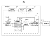
図1に示すように、プラズマ処理装置1は、処理部10と解析部20と入力部30と出力部31と通信インターフェース部32(通信IF部)と処理結果取得部33を有し、これらはバス34を介して相互に接続されている。
(1) Plasma processing device The configuration of the plasma processing device will be described with reference to FIG.
As shown in FIG. 1, the
処理部10は、プラズマ処理実行部11と分光器(OES)12と装置管理部13と制御部14と予測モデル記憶部15とインターフェース(IF)部110とを有する。プラズマ処理実行部11は、プラズマを発生させてウェハを加工し、分光器12はプラズマ処理中に発光データを取得する。また、本実施例では、分光器12を用いたが、プラズマの発光をモニタできる手段であれば良いため、ポリクロメーター、モノクロメーター、フィルタ等のモニタを分光器12の代替品として使用しても良い。発光データは、IF部210を介して解析部20の有する解析記憶部22に格納される。
The processing unit 10 includes a plasma
装置管理部13は、プラズマ処理実行部11のウエットクリーニングからのプラズマ処理されたウェハの枚数や、待機時間、処理条件の設定値と実行値などのデータを測定して保持する。これらのデータの値を以後、装置データと呼ぶ。装置データは、IF部210を介して、解析部20の有する解析記憶部22に格納される。
The
制御部14は、予測モデル記憶部15に格納されている予測モデルを用いてプラズマ処理の処理結果を予測し、プラズマ処理条件を調整する予測・制御処理を行う。ここで、プラズマ処理の処理結果とは、例えば、プラズマ処理後のウェハ上の微細形状の寸法や、プラズマ処理装置が微細形状を加工する際の加工速度を言う。
The
制御部14の詳細は、以下の(2)において述べる。
予測モデル記憶部15は、予測モデル記憶領域16と予測モデル切換条件記憶領域17を有する。予測モデル記憶領域16は、解析部20において処理履歴データを用いて構築した、発光データや装置データを入力として処理結果の予測値を出力とする予測モデルを記憶する。
Details of the
The predictive
実施例のプラズマ処理装置1では、予測モデルの切換が可能なため、複数の予測モデルを記憶することができる。予測モデル切換条件記憶領域17は、APCを実行する際に、予測モデル記憶領域16に記憶している複数の予測モデルの中から、使用する予測モデルを選択するための条件を格納する。
In the
条件の詳細については、以下の(2)において述べる。 Details of the conditions will be described in (2) below.
解析部20は、演算部21と解析記憶部22とインターフェース部(IF部)210を有する。解析記憶部22は、過去のプラズマ処理における処理結果、発光データ、装置データを記憶する処理履歴記憶領域23と、解析処理の結果を記憶する解析結果記憶領域24を備えている。
The analysis unit 20 includes a
入力部30は、例えば、マウスやキーボードなどの、ユーザの操作による情報入力を受け付ける入力装置である。
The
出力部31は、例えば、ディスプレイやプリンタなどの、ユーザに対して情報を出力して表示する出力装置である。
The
通信IF部32は、バス34や外部ネットワークなどを介して、例えば既存の生産管理システムなどの他の装置やシステムと接続し、情報送受信を行うためのインターフェースである。
The communication IF
バス34は、処理部1010、解析部20、入力部30、出力部31及び通信IF部32を連結する。IF部110、210は、バス34を介して情報送受信を行うためのインターフェースである。
The
処理結果取得部33は、処理結果を計測する検査装置などから処理結果を取得するためのインターフェースである。なお、解析部20を解析装置として独立させて、処理部10からなるプラズマ処理装置に、IF部210を介して接続する形態としてもよい。
The processing
(2)制御部
図2~4を参照して、制御部14で行われる予測・制御(APC)の処理の例について説明する。
APCを実行する前には、予め、解析部20においてプラズマ処理の処理履歴データを用いて予測モデルを構築し、予測モデルテーブル16a(図3参照)として予測モデル記憶領域16に格納しておく(S110)。
(2) Control Unit An example of the prediction / control (APC) processing performed by the
Before executing APC, the analysis unit 20 constructs a prediction model using the processing history data of plasma processing in advance, and stores it in the prediction
図3に示すように、予測モデルテーブル16aは、予測モデルID16bと各予測モデルの説明変数16cと予測モデルの計算式16dを有する。同様に、予測モデル切換に必要な情報を決定しておき、予測モデル切換条件テーブル17a(図4参照)として予測モデル切換条件記憶領域17に格納しておく(S110)。
As shown in FIG. 3, the prediction model table 16a has a
図4に示すように、予測モデル切換には、偏相関関係を利用する。APC実行時に取得したデータに対し、偏相関関係が類似した予測モデルに切換えて処理結果の予測を行う。
ここで、偏相関とは、注目している変数以外の変数の影響を除いた相関である。偏相関関係の評価には、例えば、グラフィカルLASSOなどのデータから各変数間の偏相関関係をスパース(多くの偏相関が0となるよう)に推定する手法を用いる。
As shown in FIG. 4, a partial correlation is used for predictive model switching. For the data acquired at the time of APC execution, the processing result is predicted by switching to a prediction model having a similar partial correlation.
Here, the partial correlation is a correlation excluding the influence of variables other than the variable of interest. For the evaluation of the partial correlation, for example, a method of estimating the partial correlation between each variable sparsely (so that many partial correlations become 0) is used from data such as a graphical lasso.
切換モニタ変数17bは、モデル切換の指標となる偏相関関係の類似度を算出する際に使用する変数の組である。偏相関関係は、予測モデル毎に保持されるため、予測モデルID17cを保持する。偏相関関係は、精度行列(分散共分散行列の逆行列)と対応するため、これを偏相関関係17dとして保持する。
The switching monitor variable 17b is a set of variables used when calculating the similarity of the partial correlation which is an index of model switching. Since the partial correlation is held for each prediction model, the
ウェハあるいはロット(ここでは、ロットとする)のプラズマ処理が完了すると、APCを実行する設定になっている場合には、制御部14では、予測モデル切換条件テーブル17aに格納されている切換モニタ変数17bを用いて、各予測モデルと分光器12と装置管理部13から取得したデータの偏相関関係の類似度を演算する(S101)。
If the APC is set to be executed when the plasma processing of the wafer or lot (here, the lot) is completed, the
次に、制御部14は、モデル切換判定を行う(S102)。S102では、予測モデル切換条件テーブル17aにおいて、S101で演算した偏相関関係の類似度が最も高い予測モデルID17cを次のウェハあるいはロットの処理結果の予測に用いる予測モデルとして特定する。
Next, the
このように、APCを実行する直近のウェハまたはロットにおけるモニタデータ間の相関関係に基づき予測モデルを切換えることにより、APC実行時の装置状態により即した予測モデル切換が可能となる。なお、実施例では、予測モデルの切換に偏相関関係を用いているが、切換モニタ変数17b同士の距離などの他の統計量を使用してもよい。
In this way, by switching the prediction model based on the correlation between the monitor data in the latest wafer or lot in which the APC is executed, it is possible to switch the prediction model according to the device state at the time of executing the APC. In the embodiment, the partial correlation is used for switching the prediction model, but other statistics such as the distance between the switching
次に、制御部14は、特定した予測モデルと発光データと装置データを用いて処理結果を予測する(S103)。S103では、特定した予測モデルについて、予測モデルテーブル16aの説明変数16cのデータを分光器12と装置管理部13からウェハ1枚毎に逐次取得し、計算式16dに代入することで処理結果の予測値を算出する。
Next, the
例えば、ウェハ1枚毎に取得するデータは図7の1行分に相当する。予測モデルテーブル16aの予測モデル1を用いる場合、説明変数はx3とx5を用いるため、処理結果の予測値は計算式のx3とx5に取得したデータの列x3とx5の値を代入して算出した値となる。
For example, the data acquired for each wafer corresponds to one row in FIG. 7. When the
さらに、制御部14は、処理結果の予測値と目標値の差分に従いプラズマ処理条件を調整する(S104)。プラズマ処理条件としては、例えば、プラズマ処理ガスの流量が調整される。また、S104においては、プラズマ処理条件の調整だけでなく、処理結果の予測値と目標値の差分が予め定めた閾値よりも大きい場合に、異常としてアラートする構成でもよい。また、プラズマ処理装置1より後の工程で使用される装置で利用するために、処理結果の予測値を出力する構成でもよい。
Further, the
(3)予測・制御処理(APC)の表示
処理履歴データを用いて解析部20で構築した予測モデルおよび決定した予測モデル切換条件を用いてAPCを実行するかどうかはユーザが決定する必要がある。図5は、ユーザによるAPCの設定画面D100の例であり、図1に示す出力部31に表示される。
(3) Display of prediction / control processing (APC) It is necessary for the user to decide whether to execute APC using the prediction model constructed by the analysis unit 20 using the processing history data and the determined prediction model switching condition. .. FIG. 5 is an example of the APC setting screen D100 by the user, and is displayed on the
ユーザは、予測モデル切換え条件D101で予測モデルを切換える条件を、予測モデルD102で予測モデルに使用する説明変数や計算式を確認して入力する。確認・入力後、予測のみを行う場合はD103にて指示し、APCを行う場合はD104にて指示をする。 The user inputs the condition for switching the prediction model by the prediction model switching condition D101 by confirming the explanatory variables and the calculation formula used for the prediction model in the prediction model D102. After confirmation / input, if only prediction is performed, an instruction is given by D103, and if APC is performed, an instruction is given by D104.
図6は予測・制御結果の表示画面の例であり、図1に示す出力部31に表示される。予測結果の例がD200である。解析記憶部22に処理結果の実測値が保存されている場合、処理結果の実測値と予測値を併せて表示することができる。
FIG. 6 is an example of a display screen of the prediction / control result, and is displayed on the
また、各ウェハあるいはロットにおいて、予測に使用した予測モデルを表示する。例えば、D200のように、ウェハ処理数に対して処理結果が右下がりのトレンドのロットと、処理結果の変動が小さいロットで、異なる予測モデルを用いることで予測精度が向上する。 Also, for each wafer or lot, the prediction model used for prediction is displayed. For example, the prediction accuracy is improved by using different prediction models for a lot such as D200 in which the processing result tends to decrease to the right with respect to the number of wafers processed and a lot in which the fluctuation of the processing result is small.
APCを実行し、制御した結果の例がD300であり、図1に示す出力部31に表示される。ここでは、処理結果の実測値と予測に用いた予測モデルを表示している。前述のように、予測モデルの切換えにより予測精度が向上した結果、制御後の処理結果のばらつきを低減できる。以上のAPCの設定は、次の解析部20の解析処理にて処理履歴から作成される。
An example of the result of executing and controlling APC is D300, which is displayed in the
(4)解析部
解析部20は、処理履歴記憶領域23に記憶している処理履歴データを用いて、演算部21において演算を行い、解析結果を解析結果記憶領域24に保存する。
(4) Analysis unit The analysis unit 20 performs an operation in the
処理履歴記憶領域23には、プラズマ処理をしたウェハごとに、プラズマ処理中に分光器12で計測した発光データと、装置管理部13で管理している装置データと、処理結果取得部33で取得した処理結果が格納される。
In the processing
図7は、処理履歴記憶領域23に格納する処理履歴データの例である。
処理履歴データテーブル23aは、ウェハID23bと発光データ23cと装置データ23dと処理結果23eなどの項目を有する。各列はモニタデータの項目(変数)に対応し、各行はウェハ1枚1枚に対応している。
FIG. 7 is an example of processing history data stored in the processing
The processing history data table 23a has items such as a
ウェハID23bには、処理したウェハを特定する情報を格納する。発光データ23cには、分光器12の計測値を演算した発光データを格納する。分光器12の計測値は、時間、発光強度、波長のデータとなっている。発光データ23cには、波長ごとに発光強度をプラズマ処理時間で平均した値を格納する。
Information for identifying the processed wafer is stored in the
なお、格納する発光データは、ウェハを加工するためのプラズマ処理の際に取得した発光データであってもよく、また、ウェハを加工する前後にプラズマ加工部11の状態を整えるために行うプラズマ処理(エージング処理やクリーニング処理)の際に取得した発光データであってもよい。
The light emitting data to be stored may be the light emitting data acquired during the plasma processing for processing the wafer, and the plasma processing performed to adjust the state of the
また、各波長は、プラズマに含まれる物質(ArやSiなど)の発光波長が格納される。また、ウェハや壁面から反射された光の強度を用いる場合には、ウェハや壁面の状態によって強度が異なる波長が格納される。また、複数の波長における発光強度の比を用いてもよい。 Further, each wavelength stores the emission wavelength of a substance (Ar, Si, etc.) contained in the plasma. Further, when the intensity of the light reflected from the wafer or the wall surface is used, wavelengths having different intensities depending on the state of the wafer or the wall surface are stored. Further, the ratio of the emission intensities at a plurality of wavelengths may be used.
また、格納する値は、発光強度のプラズマ処理時間の平均値に限らず、最大値や分散などの他の統計量であってもよい。また、プラズマ処理の中間時点における発光強度の値など、ある指定した時間における発光強度の値であってもよい。 Further, the stored value is not limited to the average value of the plasma processing time of the emission intensity, and may be another statistic such as the maximum value or the dispersion. Further, it may be a value of emission intensity at a specified time such as a value of emission intensity at an intermediate time point of plasma treatment.
装置データ23dには、各ウェハの処理を行ったときの装置管理部13の管理値や測定値を格納する。例えば、クリーニングからのプラズマ処理の回数や、前回のプラズマ処理からの待機時間などである。また、数値データに限らず、ロットIDなどのデータも格納される。
The
処理結果23eには、処理結果取得部33から取得したプラズマ処理結果を格納する。ウェハごとにプラズマ処理条件が調整された場合には、プラズマ処理条件の調整量と処理結果の変更量の間の関数を用いて、プラズマ処理条件の調整量による処理結果指標の変更量を算出し、処理結果の実測値を処理結果の変更量で補正した値を処理結果23eに格納してもよい。
The plasma processing result acquired from the processing
図8は、処理履歴データを用いた解析結果の表示画面D300の例であり、図1に示す出力部31に表示される。表示画面D300は、後述の解析部20の解析処理後に表示する。
FIG. 8 is an example of the analysis result display screen D300 using the processing history data, and is displayed on the
予測モデル切換条件テーブルD304と予測モデルテーブルD302は、解析部20の解析処理において決定した予測モデルの切換条件と構築した予測モデルが格納されている。 The prediction model switching condition table D304 and the prediction model table D302 store the switching conditions of the prediction model determined in the analysis process of the analysis unit 20 and the constructed prediction model.
処理履歴を用いたシミュレーションによる予測結果D301は、処理履歴データにおける処理結果の実測値と予測値を表示する。各ウェハあるいはロットごとに使用した予測モデルも表示している。 The prediction result D301 by the simulation using the processing history displays the measured value and the predicted value of the processing result in the processing history data. The predictive model used for each wafer or lot is also displayed.
予測誤差D303は、処理結果の実測値と予測値から計算した予測誤差(例えば、平均二乗誤差平方根)を表示する。 The prediction error D303 displays the measured value of the processing result and the prediction error calculated from the predicted value (for example, the square root of the mean square error).
ユーザは、本解析結果を確認して、構築した予測モデルと予測モデル切換条件を、APCに使用するものとして保存するかをD305にて決定する。保存する場合、予測モデルは予測モデル記憶領域16に、予測モデル切換条件は予測モデル切換条件記憶領域17に格納される。
The user confirms the analysis result, and determines in D305 whether to save the constructed prediction model and the prediction model switching condition for use in APC. When storing, the predictive model is stored in the predictive
(5)解析部20の解析処理
解析部20の解析処理では、処理結果を予測する予測モデルの切換えに用いる相関モニタ変数の特定と、多数のモニタデータから説明変数を厳選した上で予測モデルの構築を行う。
(5) Analysis processing of the analysis unit 20 In the analysis processing of the analysis unit 20, the correlation monitor variables used for switching the prediction model for predicting the processing result are specified, and the explanatory variables are carefully selected from a large number of monitor data, and then the prediction model is used. Build.
予測モデルとその切換えの条件は、プラズマ処理の対象であるウェハ表面上の膜の構成などにより変化するため、プラズマ処理の立上げ時には、適宜、本解析処理を実行することが必要である。 Since the prediction model and the conditions for switching the model change depending on the composition of the film on the wafer surface to be plasma-processed, it is necessary to appropriately execute this analysis process at the start of plasma processing.
図9は、処理履歴記憶領域23に格納された処理履歴データを用いた解析処理の例であり、この例を用いて解析処理の流れを説明する。
FIG. 9 is an example of analysis processing using the processing history data stored in the processing
図10は、解析処理の入力を指定する画面D400の例であり、図1に示す出力部31に表示される。ユーザは、解析処理に入る前に、解析処理の入力とする発光データD401と装置データD402を指定し、解析処理の実行を指示する(D403)。
FIG. 10 is an example of the screen D400 for designating the input of the analysis process, and is displayed on the
まず、処理履歴データをロットで層別し、各ロットについて、S202、S203の処理を行う(S201)。
次に、ロットで層別された処理履歴データについて、各変数間の偏相関関係を評価する(S202)。
次に、装置状態が変化すると偏相関関係も変化すると考えられるため、変数間の偏相関関係の変化が最大となるようにデータを分割する(S203)。このようにデータを分割することにより、装置の状態毎にモデルを用意することができる。
次に、分割後の各データについて、S205からS208の処理を行う(S204)。
First, the processing history data is stratified by lot, and the processing of S202 and S203 is performed for each lot (S201).
Next, the partial correlation between each variable is evaluated for the processing history data stratified by lot (S202).
Next, since it is considered that the partial correlation also changes when the device state changes, the data is divided so that the change in the partial correlation between the variables is maximized (S203). By dividing the data in this way, a model can be prepared for each state of the device.
Next, each of the divided data is processed from S205 to S208 (S204).
まず、ロット内での処理結果とモニタデータ間の偏相関を評価し、偏相関のある(偏相関の値が0と推定されない)モニタデータの変数を選択する(S205)。これにより、ロット内で処理結果と直接相関のあるモニタデータを、予測モデルの説明変数として選択することができ、ロット内における処理結果のトレンドを捉えた予測モデルを構築できる。
同様に、ロット間(ロットで層別しない場合)での処理結果とモニタデータ間の偏相関を評価し、偏相関のあるモニタデータの変数を選択する(S206)。
First, the partial correlation between the processing result in the lot and the monitor data is evaluated, and the variable of the monitor data having the partial correlation (the value of the partial correlation is not estimated to be 0) is selected (S205). As a result, monitor data that is directly correlated with the processing result in the lot can be selected as an explanatory variable of the prediction model, and a prediction model that captures the trend of the processing result in the lot can be constructed.
Similarly, the partial correlation between the processing result between lots (when not stratified by lot) and the monitor data is evaluated, and the variable of the monitor data having the partial correlation is selected (S206).
次に、選択したモニタデータの変数を説明変数とした予測モデルを構築する。ここでは、例えば、プロセスデータに多用されるPLS回帰や変数選択機能を有するLASSO回帰などの手法により、複数の説明変数から処理結果を予測する多変量回帰モデルを構築する(S207)。
続いて、処理履歴データにおいて、構築した予測モデルを用いて算出した処理結果の予測値と実測値とから予測誤差を評価する。(S208)
次に、図8に示す処理履歴データの解析結果を表示してユーザに提示する(S209)。
Next, a prediction model is constructed using the variables of the selected monitor data as explanatory variables. Here, for example, a multivariate regression model that predicts a processing result from a plurality of explanatory variables is constructed by a method such as PLS regression, which is often used for process data, or Lasso regression, which has a variable selection function (S207).
Subsequently, in the processing history data, the prediction error is evaluated from the predicted value and the actually measured value of the processing result calculated by using the constructed prediction model. (S208)
Next, the analysis result of the processing history data shown in FIG. 8 is displayed and presented to the user (S209).
以上、実施例について説明したが、本発明は前記実施例に限定されるものではなく、その要旨を逸脱しない範囲で種々変更可能である。
例えば、図11Aでは、処理結果取得部33から処理結果を逐次取得する構成となっている。
図11Aに示すように、直近に加工したウェハのデータを用いて、処理結果を含んだ偏相関関係の各予測モデルとの類似度を演算(S105)し、予測モデル切換判定(S102)を行う構成としてもよい。処理結果を含んだ偏相関関係を評価することで、装置状態をより反映したモデル切換を実現できる。
Although the examples have been described above, the present invention is not limited to the above examples and can be variously modified without departing from the gist thereof.
For example, in FIG. 11A, the processing results are sequentially acquired from the processing
As shown in FIG. 11A, using the data of the most recently processed wafer, the similarity of the partial correlation including the processing result with each prediction model is calculated (S105), and the prediction model switching determination (S102) is performed. It may be configured. By evaluating the partial correlation including the processing result, it is possible to realize model switching that more reflects the device state.
また、図11Bでは、逐次取得した処理結果を用いて、対応したウェハにおける各予測モデルとの予測誤差を算出する(S106)構成となっている。 Further, in FIG. 11B, the prediction error with each prediction model in the corresponding wafer is calculated by using the processing results sequentially acquired (S106).
算出した予測誤差の小さい予測モデルを用いることで、次に加工するウェハの処理結果の予測においても予測誤差の小さい予測モデルの選択が可能となる。 By using the calculated prediction model with a small prediction error, it is possible to select a prediction model with a small prediction error in the prediction of the processing result of the wafer to be processed next.
1 プラズマ処理装置
10 処理部
11 プラズマ処理実行部
12 分光器(OES)
13 装置管理部
14 制御部
15 予測モデル記憶部
20 解析部
21 演算部
22 解析記憶部
30 入力部
31 出力部
32 通信IF部
33 処理結果取得部
1 Plasma processing device 10
13
Claims (7)
前記処理部は、プラズマ処理結果を予測する複数の予測モデルが格納された予測モデル記憶部と、
プラズマ処理条件に規定されたパラメータの前記処理部にて取得されたデータを含む装置データと発光データの予測モデル毎の偏相関関係における類似度がAdvanced Process Controlを実行するために取得されたデータに対して最も高い予測モデルを用いてプラズマ処理結果が予測される制御部とを具備することを特徴とするプラズマ処理装置。 In a plasma processing apparatus provided with a monitor for monitoring plasma emission and a processing unit for processing a sample with plasma.
The processing unit includes a prediction model storage unit in which a plurality of prediction models for predicting plasma processing results are stored.
The similarity in the partial correlation between the device data including the data acquired by the processing unit of the parameters specified in the plasma processing conditions and the emission data for each prediction model is the data acquired to execute Advanced Process Control. On the other hand, a plasma processing apparatus including a control unit in which a plasma processing result is predicted using the highest prediction model.
ウェットクリーニング後からの前記プラズマ処理された試料の枚数が前記装置データに含まれることを特徴とするプラズマ処理装置。 In the plasma processing apparatus according to claim 1,
A plasma processing apparatus, characterized in that the number of plasma-treated samples after wet cleaning is included in the apparatus data.
前記制御部は、前記予測モデルを用いて求められた予測値と目標値の差分に基づいて求められた補正量に応じて前記パラメータの値を補正することを特徴とするプラズマ処理装置。 In the plasma processing apparatus according to claim 1,
The control unit is a plasma processing apparatus characterized in that the value of the parameter is corrected according to a correction amount obtained based on a difference between a predicted value and a target value obtained by using the prediction model.
前記プラズマ処理結果と偏相関関係にあるモニタデータの変数を説明変数とした前記予測モデルを構築する解析部をさらに備えることを特徴とするプラズマ処理装置。 In the plasma processing apparatus according to claim 1,
A plasma processing apparatus further comprising an analysis unit for constructing the prediction model using a variable of monitor data having a partial correlation with the plasma processing result as an explanatory variable.
プラズマの発光の波長と装置データに係る物理量が前記説明変数に含まれ、
前記装置データは、前記処理部の状態変動の指標となるデータであることを特徴とするプラズマ処理装置。 In the plasma processing apparatus according to claim 4 ,
The wavelength of plasma emission and the physical quantity related to the device data are included in the explanatory variables.
The device data is a plasma processing device characterized in that it is data that is an index of state fluctuation of the processing unit.
前記偏相関関係は、前記プラズマ処理の単位であるロット毎における、前記プラズマ処理結果とモニタデータの変数との偏相関関係であることを特徴とするプラズマ処理装置。 In the plasma processing apparatus according to claim 4 ,
The plasma processing apparatus, characterized in that the partial correlation is a partial correlation between the plasma processing result and a variable of monitor data in each lot, which is a unit of the plasma processing.
前記処理部は、プラズマ処理結果を予測する複数の予測モデルが格納された予測モデル記憶部と、
プラズマ処理条件に規定されたパラメータの前記処理部にて取得されたデータを含む装置データと発光データの予測モデル毎の統計量における類似度がAdvanced Process Controlを実行するために取得されたデータに対して最も高い予測モデルを用いてプラズマ処理結果が予測される制御部とを具備することを特徴とするプラズマ処理装置。 In a plasma processing apparatus provided with a monitor for monitoring plasma emission and a processing unit for processing a sample with plasma.
The processing unit includes a prediction model storage unit in which a plurality of prediction models for predicting plasma processing results are stored.
The similarity between the device data including the data acquired by the processing unit of the parameters specified in the plasma processing conditions and the statistic of the emission data for each prediction model is for the data acquired to execute Advanced Process Control. A plasma processing apparatus including a control unit in which a plasma processing result is predicted using the highest prediction model.
Priority Applications (4)
| Application Number | Priority Date | Filing Date | Title |
|---|---|---|---|
| JP2018005761A JP7058129B2 (en) | 2018-01-17 | 2018-01-17 | Plasma processing equipment |
| KR1020180083797A KR102100210B1 (en) | 2018-01-17 | 2018-07-19 | Plasma processing apparatus |
| TW107127210A TWI739024B (en) | 2018-01-17 | 2018-08-06 | Plasma processing device |
| US16/123,208 US11289313B2 (en) | 2018-01-17 | 2018-09-06 | Plasma processing apparatus |
Applications Claiming Priority (1)
| Application Number | Priority Date | Filing Date | Title |
|---|---|---|---|
| JP2018005761A JP7058129B2 (en) | 2018-01-17 | 2018-01-17 | Plasma processing equipment |
Publications (3)
| Publication Number | Publication Date |
|---|---|
| JP2019125506A JP2019125506A (en) | 2019-07-25 |
| JP2019125506A5 JP2019125506A5 (en) | 2020-09-03 |
| JP7058129B2 true JP7058129B2 (en) | 2022-04-21 |
Family
ID=67214239
Family Applications (1)
| Application Number | Title | Priority Date | Filing Date |
|---|---|---|---|
| JP2018005761A Active JP7058129B2 (en) | 2018-01-17 | 2018-01-17 | Plasma processing equipment |
Country Status (4)
| Country | Link |
|---|---|
| US (1) | US11289313B2 (en) |
| JP (1) | JP7058129B2 (en) |
| KR (1) | KR102100210B1 (en) |
| TW (1) | TWI739024B (en) |
Families Citing this family (2)
| Publication number | Priority date | Publication date | Assignee | Title |
|---|---|---|---|---|
| US11966203B2 (en) * | 2019-08-21 | 2024-04-23 | Kla Corporation | System and method to adjust a kinetics model of surface reactions during plasma processing |
| JP7429623B2 (en) | 2020-08-31 | 2024-02-08 | 株式会社日立製作所 | Manufacturing condition setting automation device and method |
Citations (4)
| Publication number | Priority date | Publication date | Assignee | Title |
|---|---|---|---|---|
| JP2004281461A (en) | 2003-03-12 | 2004-10-07 | Tokyo Electron Ltd | Method and apparatus of prediction of processing result |
| WO2007066404A1 (en) | 2005-12-08 | 2007-06-14 | Spansion Llc | Semiconductor manufacturing device, its controlling system and its controlling method |
| JP2009010370A (en) | 2008-06-11 | 2009-01-15 | Hitachi Ltd | Semiconductor processing apparatus |
| JP2009049382A (en) | 2007-07-26 | 2009-03-05 | Panasonic Corp | Method for drying etching and dry etching apparatus |
Family Cites Families (9)
| Publication number | Priority date | Publication date | Assignee | Title |
|---|---|---|---|---|
| JP2004335841A (en) * | 2003-05-09 | 2004-11-25 | Tokyo Electron Ltd | Prediction system and prediction method for plasma treatment apparatus |
| JP2005051269A (en) * | 2004-10-12 | 2005-02-24 | Hitachi Ltd | Semiconductor processing apparatus |
| JP5334787B2 (en) * | 2009-10-09 | 2013-11-06 | 株式会社日立ハイテクノロジーズ | Plasma processing equipment |
| US9184021B2 (en) * | 2013-10-04 | 2015-11-10 | Applied Materials, Inc. | Predictive method of matching two plasma reactors |
| JP6220319B2 (en) | 2014-07-17 | 2017-10-25 | 株式会社日立ハイテクノロジーズ | Data analysis method, plasma etching method, and plasma processing apparatus |
| JP6310866B2 (en) * | 2015-01-30 | 2018-04-11 | 株式会社日立ハイテクノロジーズ | Plasma processing apparatus, plasma processing method and analysis method |
| JP6446334B2 (en) * | 2015-06-12 | 2018-12-26 | 東京エレクトロン株式会社 | Plasma processing apparatus, plasma processing apparatus control method, and storage medium |
| JP6549917B2 (en) * | 2015-06-26 | 2019-07-24 | 株式会社日立ハイテクノロジーズ | Plasma processing apparatus and data analysis apparatus therefor |
| KR20170103657A (en) * | 2016-03-03 | 2017-09-13 | 램 리써치 코포레이션 | Systems and methods for using one or more fixtures and efficiency to determine parameters of a match network model |
-
2018
- 2018-01-17 JP JP2018005761A patent/JP7058129B2/en active Active
- 2018-07-19 KR KR1020180083797A patent/KR102100210B1/en active IP Right Grant
- 2018-08-06 TW TW107127210A patent/TWI739024B/en active
- 2018-09-06 US US16/123,208 patent/US11289313B2/en active Active
Patent Citations (4)
| Publication number | Priority date | Publication date | Assignee | Title |
|---|---|---|---|---|
| JP2004281461A (en) | 2003-03-12 | 2004-10-07 | Tokyo Electron Ltd | Method and apparatus of prediction of processing result |
| WO2007066404A1 (en) | 2005-12-08 | 2007-06-14 | Spansion Llc | Semiconductor manufacturing device, its controlling system and its controlling method |
| JP2009049382A (en) | 2007-07-26 | 2009-03-05 | Panasonic Corp | Method for drying etching and dry etching apparatus |
| JP2009010370A (en) | 2008-06-11 | 2009-01-15 | Hitachi Ltd | Semiconductor processing apparatus |
Also Published As
| Publication number | Publication date |
|---|---|
| KR102100210B1 (en) | 2020-04-14 |
| TWI739024B (en) | 2021-09-11 |
| KR20190087940A (en) | 2019-07-25 |
| US11289313B2 (en) | 2022-03-29 |
| US20190221407A1 (en) | 2019-07-18 |
| JP2019125506A (en) | 2019-07-25 |
| TW201933418A (en) | 2019-08-16 |
Similar Documents
| Publication | Publication Date | Title |
|---|---|---|
| US20210074528A1 (en) | Plasma processing apparatus and plasma processing system | |
| US9972478B2 (en) | Method and process of implementing machine learning in complex multivariate wafer processing equipment | |
| JP5334787B2 (en) | Plasma processing equipment | |
| KR101746044B1 (en) | Plasma processing device and plasma processing method and analyzing device and analyzing method | |
| KR101763780B1 (en) | Plazma processing apparatus and data analysis device | |
| EP3819930A1 (en) | Manufacturing process determination device for substrate processing device, substrate processing system, manufacturing process determination device for substrate processing device, group of learning models, method for generating group of learning models, and program | |
| JP6220319B2 (en) | Data analysis method, plasma etching method, and plasma processing apparatus | |
| TW201003812A (en) | Etching process state judgment method and system therefor | |
| JP7058129B2 (en) | Plasma processing equipment | |
| US20210372943A1 (en) | Processing condition determination system and processing condition searching method | |
| US20190100840A1 (en) | Plasma processing apparatus |
Legal Events
| Date | Code | Title | Description |
|---|---|---|---|
| A521 | Request for written amendment filed |
Free format text: JAPANESE INTERMEDIATE CODE: A523 Effective date: 20200720 |
|
| A621 | Written request for application examination |
Free format text: JAPANESE INTERMEDIATE CODE: A621 Effective date: 20200720 |
|
| A977 | Report on retrieval |
Free format text: JAPANESE INTERMEDIATE CODE: A971007 Effective date: 20210707 |
|
| A131 | Notification of reasons for refusal |
Free format text: JAPANESE INTERMEDIATE CODE: A131 Effective date: 20210720 |
|
| A601 | Written request for extension of time |
Free format text: JAPANESE INTERMEDIATE CODE: A601 Effective date: 20210917 |
|
| A521 | Request for written amendment filed |
Free format text: JAPANESE INTERMEDIATE CODE: A523 Effective date: 20211112 |
|
| TRDD | Decision of grant or rejection written | ||
| A01 | Written decision to grant a patent or to grant a registration (utility model) |
Free format text: JAPANESE INTERMEDIATE CODE: A01 Effective date: 20220315 |
|
| A61 | First payment of annual fees (during grant procedure) |
Free format text: JAPANESE INTERMEDIATE CODE: A61 Effective date: 20220411 |
|
| R150 | Certificate of patent or registration of utility model |
Ref document number: 7058129 Country of ref document: JP Free format text: JAPANESE INTERMEDIATE CODE: R150 |