JP7057166B2 - Fuel supply device - Google Patents
Fuel supply device Download PDFInfo
- Publication number
- JP7057166B2 JP7057166B2 JP2018040978A JP2018040978A JP7057166B2 JP 7057166 B2 JP7057166 B2 JP 7057166B2 JP 2018040978 A JP2018040978 A JP 2018040978A JP 2018040978 A JP2018040978 A JP 2018040978A JP 7057166 B2 JP7057166 B2 JP 7057166B2
- Authority
- JP
- Japan
- Prior art keywords
- housing
- nozzle
- panel
- fuel supply
- frame
- Prior art date
- Legal status (The legal status is an assumption and is not a legal conclusion. Google has not performed a legal analysis and makes no representation as to the accuracy of the status listed.)
- Active
Links
Images


Landscapes
- Loading And Unloading Of Fuel Tanks Or Ships (AREA)
Description
本開示は、ガソリンスタンド等の燃料供給所で車輌等への燃料供給に用いられる燃料供給装置に関する。 The present disclosure relates to a fuel supply device used for supplying fuel to a vehicle or the like at a fuel supply station such as a gas station.
一般に、燃料供給装置は、装置筐体内に、送液機器としてのポンプ、計測機器としての流量計、装置各部の制御を行う供給制御装置、等の機器や装置が配設され、装置筐体外に、基端がポンプ及び流量計と連通接続され、先端に燃料供給ノズルを備えた燃料供給ホースが配設された構成になっている。そして、燃料供給作業の際は、作業者は、装置筐体面に設けられたノズル収納部から燃料供給ノズルを取り外して操作して、供給対象に燃料供給作業を行う。 Generally, in a fuel supply device, devices and devices such as a pump as a liquid feeding device, a flow meter as a measuring device, and a supply control device for controlling each part of the device are arranged inside the device housing, and outside the device housing. The base end is connected to the pump and the flow meter in communication, and a fuel supply hose equipped with a fuel supply nozzle is arranged at the tip. Then, in the fuel supply work, the worker removes the fuel supply nozzle from the nozzle storage portion provided on the surface of the apparatus housing and operates the fuel supply work to supply the fuel to the supply target.
ところで、このような燃料供給装置の一例として、特許文献1には、作業者による燃料供給作業が行われていない待機時に燃料供給ノズルを載置しておくノズル収納部を、ノズル支持部と、燃料供給ノズル先端の吐出パイプが収容される吐出パイプ収納部を有するノズル収納部枠体とに分割して構成し、ノズル支持部を、ポンプ、流量計等の機器と同様に装置筐体の筐体フレームに固定し、ノズル収納部枠体を装置筐体の筐体パネルに固定した燃料供給装置が開示されている。
By the way, as an example of such a fuel supply device, in
特許文献1に記載の燃料供給制御装置によれば、点検等のために筐体パネルを筐体フレームから取り外して装置筐体内の機器や装置を露出させた際には、ノズル支持部とノズル収納部枠体とが筐体パネルの取り外しに伴い分離され、筐体パネルを取り外した後の筐体フレームにはノズル収納部の吐出パイプ収納部が配置されていない構成とすることによって、ノズルをノズル支持部に支持させた状態でメンテナンスを行うことができ、装置筐体内の機器や装置のメンテナンス性の向上がはかれるようになっている。
According to the fuel supply control device described in
しかしながら、特許文献1に記載の燃料供給装置においては、筐体パネルを取り外した後の筐体フレームには、ノズル収納部のノズル支持部が筐体フレームに固定されたままになっているため、次に述べるような課題があった。
However, in the fuel supply device described in
筐体フレームに固定されたノズル支持部は、筐体フレームに筐体パネルが取り付けられた状態で筐体パネルに固定されたノズル収納部枠体と一体化されてノズル収納部を形成する構造上から、筐体フレームから筐体パネルを取り外して装置筐体内の機器や装置を露出させた状態では、装置筐体内の筐体パネル側寄り、すなわち露出させた装置筐体内の手前側に配置されていることになる。そのため、メンテナンス時には、作業員と装置筐体内の奥部の機器や装置との間にノズル支持部が位置することになり、これらノズル支持部よりも奥部の機器や装置を点検・補修しようとした場合、露出させた装置筐体内の手前側に位置するノズル支持部によって作業者の視界が遮られ、作業の邪魔になる場合があった。 The nozzle support portion fixed to the housing frame is structurally integrated with the nozzle storage unit frame body fixed to the housing panel with the housing panel attached to the housing frame to form the nozzle storage unit. Therefore, when the housing panel is removed from the housing frame to expose the devices and devices in the device housing, they are arranged closer to the housing panel side in the device housing, that is, on the front side in the exposed device housing. Will be there. Therefore, at the time of maintenance, the nozzle support part is located between the worker and the equipment or device in the inner part of the device housing, and it is attempted to inspect and repair the device or device in the inner part than these nozzle support parts. In this case, the view of the operator may be obstructed by the nozzle support portion located on the front side in the exposed device housing, which may interfere with the work.
本開示は、上述した課題を鑑み、装置筐体内の機器や装置のメンテナンス性のさらなる向上をはかった燃料供給装置を提供することを目的とする。 In view of the above-mentioned problems, it is an object of the present disclosure to provide a fuel supply device for further improving the maintainability of the device and the device in the device housing.
本開示に係る燃料供給装置は、
筐体フレームに筐体パネルを取り付けて構成され、送液機器及び流量計測機器を収容する装置筐体と、装置筐体から延設され、基端が装置筐体内の流量計測機器及び送液機器と連通し、先端に燃料供給ノズルを備えた燃料供給ホースと、筐体パネルに配設され、燃料供給ノズルが格納されるノズル収納部と、を備え、
ノズル収納部を、燃料供給ノズルを支持するノズル支持部と、燃料供給ノズル先端の吐出パイプが収容される吐出パイプ収納部を備えたノズル収納部枠体と、で構成し、
ノズル支持部は、筐体パネルに形成された取付孔を介して筐体パネルの表面から突出し、筐体パネルに着脱可能に取り付けられた取付パネルに対して固定され、ノズル収納部枠体は、前記筐体パネルに固定された構成になっている。
The fuel supply device according to this disclosure is
A device housing that is configured by attaching a housing panel to the housing frame and accommodates liquid feeding equipment and flow rate measuring equipment, and a flow measuring device and liquid feeding equipment that extend from the device housing and have a base end inside the device housing. It is equipped with a fuel supply hose having a fuel supply nozzle at the tip and a nozzle storage part which is arranged on the housing panel and stores the fuel supply nozzle.
The nozzle storage unit is composed of a nozzle support unit that supports the fuel supply nozzle and a nozzle storage unit frame body that includes a discharge pipe storage unit that houses the discharge pipe at the tip of the fuel supply nozzle.
The nozzle support portion protrudes from the surface of the housing panel through a mounting hole formed in the housing panel and is fixed to the mounting panel detachably attached to the housing panel. It has a configuration fixed to the housing panel.
本開示に係る燃料供給装置によれば、流量計測機器及び送液機器が収容されている装置筐体内の点検・補修を行う場合は、ノズル収納部が、燃料供給ノズルを支持するノズル支持部と、吐出パイプ収納部を備えたノズル収納部枠体とに分離可能に構成され、かつ、ノズル支持部が、ノズル収納部枠体が固定された筐体パネルに着脱可能に設けられた取付パネルに対して固定されているので、装置筐体内の機器や装置のメンテナンス性がさらに向上する。 According to the fuel supply device according to the present disclosure, when inspecting / repairing the inside of the device housing in which the flow rate measuring device and the liquid feeding device are housed, the nozzle storage portion is the nozzle support portion that supports the fuel supply nozzle. , The nozzle support is detachably provided on the housing panel to which the nozzle storage frame is fixed, and the nozzle support is detachably provided on the mounting panel. On the other hand, since it is fixed, the maintainability of the device and the device in the device housing is further improved.
また、本開示の上記した以外の、課題、構成及び効果については、以下の実施の形態の説明により明らかにされる。 In addition, issues, configurations, and effects other than those described above in the present disclosure will be clarified by the following description of the embodiments.
本開示に係る燃料供給装置の一実施の形態について、給油所(ガソリンスタンド)で用いられ、車輌等の燃料補給を行う給油装置を例に、図面に基づき説明する。 An embodiment of the fuel supply device according to the present disclosure will be described with reference to the drawings, taking as an example a refueling device used at a refueling station (gas station) to refuel a vehicle or the like.
図1は、本開示に係る給油装置の一実施例の正面図である。
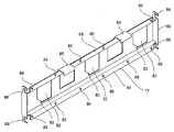
図2は、図1に示した給油装置の装置筐体の下部の外観斜視図である。
なお、図1においては、給油装置の装置筐体の下部(後述する機器収納筐体部10B)については、図中、正面中央に付した一点鎖線の中心にして、その左側部分では、筐体パネル(後述する機器収納部筐体パネル61)が取り付けられている構成が、その右側側部分では、筐体パネルが取り外されている構成が対比的に示されている。
FIG. 1 is a front view of an embodiment of the refueling device according to the present disclosure.
FIG. 2 is an external perspective view of the lower part of the device housing of the refueling device shown in FIG.
In addition, in FIG. 1, the lower part of the device housing of the refueling device (equipment
図示の例では、給油装置1は、装置筐体10の正面及び背面それぞれに、それぞれ油種が異なる3つの給油系統(例えば、レギュラーガソリン、ハイオクガソリン、軽油の各給油系統)を備え、装置筐体10の正面側及び背面側それぞれで、個別に別々の車輌に対する所望の油種の給油作業が行える構成になっている。
In the illustrated example, the
給油装置1の装置筐体10は、通常、筐体フレームに筐体パネルを取り付けて構成されている。筐体フレームは、ベース(基台)20に立設された複数の柱材フレーム間を、高さ方向に位置を異ならせて複数の横架材フレームで連結して構成されている。装置筐体10内は、筐体フレームに取り付けられた筐体パネルや、筐体フレームの外周面によって、外部から隠蔽された構成になっている。
The device housing 10 of the
その上で、図示の給油装置1の場合、装置筐体10は、一対の柱状筐体部10A,10A間に、ベース20側から高さ方向に沿って、機器収納筐体部10B、制御装置筐体部10C、ホース接続筐体部10Dが順次配置された構成になっている。
Further, in the case of the illustrated
装置筐体10の機器収納筐体部10B内には、ポンプモータ31により駆動されるポンプユニット32,電磁弁33といった送液機器や、給油ノズル39に送液された油量を計測する流量計34,流量計34に付設された流量発信器35といった流量計測機器が、給油ノズル39を備えた給油系統毎若しくは給油ノズル39からの供給油種毎に対応させて、それぞれ配設されている。
In the
図示の例では、ポンプユニット32は、油種毎に対応させて3台設けられ、横架材フレームを構成するポンプユニット取付フレーム21に固定されている。ポンプモータ31は、ポンプユニット取付フレーム21とベース20と連結するように立設されたモータ取付フレーム22に固定されている。流量計34は、ポンプユニット32の吐出口部分に一体的に取り付けられた分岐管ユニット36に、油種毎に、正面側及び背面側の2つ給油系統用の2台の流量計34が取り付けられている。流量発信器35及び電磁弁33は、各流量計に対して一体的に取り付けされている。
In the illustrated example, three
その上で、各流量計34から、対応する電磁弁33を介して送液される油液は、給油系統別の筐体内配管37によって、柱状筐体部10A内を介して、ホース接続筐体部10Dに案内される構成になっている。
Then, the oil liquid sent from each
さらに、装置筐体10の機器収納筐体部10Bの正面及び背面には、正面及び背面の各給油系統(レギュラーガソリン、ハイオクガソリン、軽油)の給油ノズル39を、給油作業が行われていない待機時に格納しておくためのノズル収納部40が設けられている。
Further, on the front and back of the
一方、制御装置筐体部10Cには、内部に、給油装置1の各部を制御し、装置筐体10の正面及び背面それぞれでの個別給油作業の実行制御を行う制御装置(図示せず)が配設されている。そして、制御装置筐体部10Cの正面及び背面それぞれには、図示の給油装置1の場合は、給油作業を行うに当たって、供給油種をはじめとする各種設定操作を行うための操作表示パネル51、顧客識別カードの読取を行うカード読取機52、給油量や給油金額等を表示する給油表示器53、給油作業終了時に給油伝票を発行する伝票発行機54等の機器が設けられている。
On the other hand, in the control device housing unit 10C, a control device (not shown) that controls each part of the
また、ホース接続筐体部10Dの正面及び背面それぞれでは、給油系統毎の、先端に給油ノズル39が接続された給油ホース38の基端が、対応する給油系統の筐体内配管37と連通接続された構成になっている。
Further, on each of the front surface and the back surface of the hose
次に、装置筐体10の機器収納筐体部10Bの正面及び背面に設けられたノズル収納部40の構成について、図3に基づき説明する。
図3は、ノズル収納部の構成説明図である。
Next, the configuration of the
FIG. 3 is a configuration explanatory view of the nozzle accommodating portion.
ノズル収納部40は、格納された給油ノズル39の重量を支えるノズル支持部41と、給油ノズル先端の吐出パイプ39aを収容する吐出パイプ収納部43を備えたノズル収納部枠体42とから構成されている。ノズル支持部41は、例えばアルミダイキャスト製からなり、ノズル収納部枠体42に対して係合可能な外観形状を有している。ノズル収納部40は、装置筐体10(図示の例では、機器収納筐体部10B)内の、後述するノズル支持部取付パネル71に取り付け固定されている。
The
これに対し、ノズル収納部枠体42は、例えば樹脂材で成形され、吐出パイプ収納部43が形成された部分の下方位置には、ノズル支持部41が係合配置されるノズル支持部挿通孔44が貫通形成されている。
On the other hand, the nozzle
ノズル支持部41は、吐出パイプ収納部43が突出するノズル収納部枠体42の裏側からノズル支持部挿通孔44に挿入配置されて、ノズル収納部枠体42と係合し、そのノズル載置部45を、吐出パイプ収納部43が開口するノズル収納部枠体42の表側に対して、露出させることができるようになっている。ノズル収納部枠体42は、機器収納筐体部10Bの筐体面(図示の例では、後述する機器収納部筐体パネル61)に取り付け固定されている。
The
そして、ノズル支持部41とノズル収納部枠体42とは、このノズル載置部45とノズル支持部挿通孔44との係合によって、ノズル収納部40として一体化される。すなわち、ノズル支持部41とノズル収納部枠体42との間には、直接的な固定手段は備えられておらず、ノズル収納部枠体42に対するノズル支持部41の配置位置関係に応じて一体化され、ノズル収納部40が形成される。
The
給油ノズル39は、ノズル収納部枠体42の吐出パイプ収納部43に吐出パイプ39aを収容させた状態で、ノズル支持部41のノズル載置部45にレバーガード39bを当接支持させて、ノズル収納部40に格納される。
The
また、ノズル支持部41には、ノズル収納部40に対する給油ノズル39の格納状態/非格納状態に応じて開成/閉成するノズルスイッチ機構46が付設されている。ノズルスイッチ機構46は、例えば、ノズル載置部45に回動可能に設けられた検知レバー47がレバーガード39bからの押圧力を受けてばね力に抗して回動変位することによってノズル検出スイッチ48が閉成若しくは開成し、検知レバー47がレバーガード39bからの押圧力を受けなくなってばね力によって回動変位(復帰変位)することによってノズル検出スイッチ48が開成若しくは閉成し、ノズル収納部40に対する給油ノズル39の格納状態/非格納状態を検出できる構成になっている。
Further, the
ノズル収納部枠体42におけるノズル支持部挿通孔44の裏側開口から眺めることができる、ノズル支持部41の背面部分には、高さ方向に一対の取付凸部49が設けられている。各取付凸部49には、その突出方向に沿って延びた結合部材取付孔(図示略)が形成されている。
A pair of mounting
次に、図4~図8に基づき、ノズル収納部40の、装置筐体10の機器収納筐体部10Bに対する取付構造について説明する。
Next, based on FIGS. 4 to 8, the mounting structure of the
図4は、装置筐体における機器収納筐体部の内部構成を示した斜視図である。
図4は、図2に示した給油装置1の装置筐体10の下部について、機器収納筐体部10B内を外部から隠蔽する機器収納部筐体パネル61を、機器収納筐体部10B部分のフレームに対する取付固定を解除して、前方に傾倒させた状態に該当する。この場合における機器収納筐体部10B部分のフレームは、機器収納筐体部10Bに位置している、装置筐体10の横架材フレーム及び/又は柱材フレームが該当する。
FIG. 4 is a perspective view showing the internal configuration of the device storage housing portion in the device housing.
FIG. 4 shows the device
機器収納部筐体パネル61は、高さ方向に沿った下側パネル部分に、機器収納筐体部10B部分のフレーム若しくはベース20に形成された被係止部と係合する係止部が形成され(図4においては、係止部、被係止部とも表れない)、高さ方向に沿った上側パネル部分には、係止部を被係止部に係合させた状態で、機器収納部筐体パネル61を機器収納筐体部10B分のフレームから取り外しできないように固定するための錠63が設けられている。錠63は、図示せぬ鍵片の操作に応じて、係止部としての錠片が機器収納筐体部10B部分の横架材フレーム23に設けられたロック片(被係止部)64に対して掛止/掛止解除されるようになっている。図示の例では、横架材フレーム23は、機器収納筐体部10B内と制御装置筐体部10C内とを区画する境界フレームに該当する。
In the device
したがって、図4に示した機器収納部筐体パネル61が傾倒した状態は、機器収納部筐体パネル61の錠63が解錠された状況で、機器収納部筐体パネル61の係止部と、機器収納筐体部10B部分のフレーム若しくはベース20に形成された被係止部とを係合させたまま、機器収納部筐体パネル61の上側パネル部分を手前に引くことにより、機器収納部筐体パネル61の上側パネル部分を、下側パネル部分を中心にして回動させた状態に対応する。
Therefore, in the state where the device storage
その上で、図4に示すように、ノズル収納部40のノズル収納部枠体42は、吐出パイプ収納部43を機器収納部筐体パネル61に形成された枠体取付孔62(図7参照)に挿通させ、かつノズル支持部挿通孔44がこの枠体取付孔62を介してパネル61の裏側から眺められるようにして、機器収納部筐体パネル61に取り付け固定される。これに対し、ノズル支持部41は、機器収納部筐体パネル61の裏面に配置されるノズル支持部取付パネル71に取り付け固定される。そして、ノズル支持部41が固定されたノズル支持部取付パネル71は、ノズル支持部41がノズル収納部枠体42のノズル支持部挿通孔44に挿入配置されるよう位置合わせされて、機器収納部筐体パネル61の裏面に取り付け固定される。
Then, as shown in FIG. 4, the nozzle
その一方で、機器収納部10B内の所定位置には、機器収納部筐体パネル61の裏面から取り外されたノズル支持部取付パネル71を仮置き可能な横架材フレームの仮置きフレーム72が、一対の柱状筐体部10Aをそれぞれ形成する柱材フレーム73間に架設されている。仮置きフレーム72は、ポンプユニット取付フレーム21への機器の取付の妨げとならないように、機器収納部筐体パネル61が取り外されて現れる機器収納筐体部10B内の手前側、すなわち機器収納筐体部10B内の開放端寄りに配置されている。仮置きフレーム72は、その長さ方向に対して直交する断面がL字形状になっており、L字形状の一辺に対応する水平面部分がノズル支持部取付パネル71の被搭載面72aとなり、他の一辺に対応する垂直面部分が搭載されたノズル支持部取付パネル71の、機器収納筐体部10B内の奥部側への変位を規制する規制面72bとなっている。
On the other hand, at a predetermined position in the
また、仮置きフレーム72が架設されている各柱状筐体部10Aの柱材フレーム73には、仮置きフレーム72に載置されたノズル支持部取付パネル71の係止フック89と係合可能な、例えばウェルドボルトからなる係合突起74が固定されている。
Further, the
ここで、係止フック89が備えられ、ノズル支持部41が固定されるノズル支持部取付パネル71の構成について、図5、図6に基づいて説明する。
Here, the configuration of the nozzle support
図5は、ノズル支持部が固定されるノズル支持部取付パネルの構成図である。図5(a)は、ノズル支持部取付パネルの、機器収納部筐体パネル61に対する取付面側を眺めた正面図、図5(b)は、ノズル支持部取付パネルの平面図、図5(c)は、ノズル支持部取付パネルの右側面図、図5(d)は、図5(a)中におけるd-d矢視方向に眺めた断面図である。
図6は、図5に示したノズル支持部取付パネルを背面側から眺めた斜視図である。
FIG. 5 is a configuration diagram of a nozzle support portion mounting panel to which the nozzle support portion is fixed. 5A is a front view of the nozzle support mounting panel as viewed from the mounting surface side with respect to the equipment
FIG. 6 is a perspective view of the nozzle support portion mounting panel shown in FIG. 5 as viewed from the rear side.
ノズル支持部取付パネル71は、平板状の本体部81にノズル支持部41及びノズルスイッチ機構46の点検窓82を含む開口窓が形成されている。点検窓82からは、ノズル検出スイッチ48の信号線92(図9参照)が引き出される。ノズル検出スイッチ48の信号線92は、制御装置筐体部10Cに収容された制御装置に接続されている。
The nozzle support
本体部81の点検窓82の周辺の所定位置には、ノズル支持部41の取付凸部49に形成された支持部固定用のねじ孔に取り付ける結合部材66(図8参照)の挿通孔83が形成されている。ノズル支持部41は、例えば締結ボルトからなる結合部材66(図8参照)を挿通孔83を介して取付凸部49の結合部材取付孔に取り付けることによって、ノズル支持部41は、ノズル支持部取付パネル71に一体的に固定されるようになっている。
An
本体部81の上・下縁部には、機器収納部筐体パネル61の裏面に対する取付固定フランジ部84が、本体部81に対して一体的に折曲形成されている。各取付固定フランジ部84には、機器収納部筐体パネル61の裏面側の所定位置に立設されたウェルドボルトからなる係合部材67(図8参照)が挿通可能な挿通孔86が複数形成されている。
On the upper and lower edges of the
ノズル支持部取付パネル71は、機器収納部筐体パネル61に設けられた係合部材67を挿通孔86に挿通させて、蝶ナットからなる固定具87を係合部材67に装着固定することにより機器収納部筐体パネル61と一体的に締結される。一方、これとは逆に、係合部材67に装着固定された固定具87(図8参照)を係合部材67から脱着することにより、機器収納部筐体パネル61の係合部材67に挿通孔86が挿通されているノズル支持部取付パネル71は、その挿通孔86が機器収納部筐体パネル61の係合部材67から取り外しできるようになり、機器収納部筐体パネル61から分離可能になっている。
The nozzle support
さらに、図示の例では、上・下一対の取付固定フランジ部83の中、上側の取付固定フランジ部83には、ノズル支持部41が一体的に固定されたノズル支持部取付パネル71を移動させる際に掴む把手部85がさらに折曲形成され、下側の取付固定フランジ部83の縁端面は、仮置きフレーム72の被搭載面72aに対しての載置部にもなっている。
Further, in the illustrated example, the nozzle support
一方、本体部81の左右両側の縁部には、係合折片部88が本体部81に対して一体的に折曲形成されている。係合折片部88の高さ方向の上・下所定位置には、仮置きフレーム72が架設されている各柱状筐体部10Aの柱材フレーム73に固定された係合突起74と係合可能な、鉤の手状の係止フック89が形成されている。また、高さ方向の下側の係合折片部88の縁端面は、仮置きフレーム72の被搭載面72a(図2、図9参照)に対しての載置部にもなっている。
On the other hand, on the left and right edge portions of the
次に、ノズル支持部41が一体的に固定されたノズル支持部取付パネル71の、機器収納部筐体パネル61に対する固定状態について、図7、図8に基づき説明する。
Next, the fixed state of the nozzle support
図7は、ノズル支持部取付パネルの機器収納部筐体パネルに対する固定状態の説明図である。
図8は、ノズル支持部取付パネルの機器収納部筐体パネルに対する固定状態、並びに機器収納部筐体パネルのフレームに対する固定状態を、機器収納筐体部の内方から眺めた斜視図である。
FIG. 7 is an explanatory diagram of a fixed state of the nozzle support portion mounting panel with respect to the device storage portion housing panel.
FIG. 8 is a perspective view of the nozzle support portion mounting panel fixed to the device storage housing panel and the fixed state of the device storage housing panel to the frame as viewed from the inside of the device storage housing.
ノズル支持部41が一体的に固定されたノズル支持部取付パネル71を、ノズル収納部枠体42が固定された機器収納部筐体パネル61に取り付けるに当たっては、まず、上・下一対の取付固定フランジ部83に形成された挿通孔86を、機器収納部筐体パネル61に予め固設されたパネル補強部65から立設されたウェルドボルトからなる係合部材67に対して位置合わせするとともに、ノズル支持部41を、機器収納部筐体パネル61に形成された枠体取付孔62及びノズル収納部枠体42のノズル支持部挿通孔44に対して位置合わせする。
When attaching the nozzle
そして、上・下一対の取付固定フランジ部83に形成された挿通孔86から、機器収納部筐体パネル61の係合部材67が突出させ、ノズル支持部取付パネル71の取付固定フランジ部83の正面側を、機器収納部筐体パネル61のパネル補強部65に当接させるようにして、機器収納部筐体パネル61に対するノズル支持部取付パネル71の移動をはかる。その際も、機器収納部筐体パネル61の係合部材67によって、ノズル支持部取付パネル71が支持され、かつ移動の案内がなされるので、作業が容易である。
Then, the engaging
このノズル支持部取付パネル71の移動に伴い、ノズル支持部取付パネル71に固定されたノズル支持部41は、機器収納部筐体パネル61に形成された枠体取付孔62を介して、機器収納部筐体パネル61に固定されたノズル収納部枠体42のノズル支持部挿通孔44に収容させられ、ノズル支持部41はノズル収納部枠体42の所定位置に位置決めされる。この場合における所定位置とは、吐出パイプ39aがノズル収納部枠体42の吐出パイプ収納部43に格納された姿勢状態の給油ノズル39のレバーガード39bをノズル支持部41のノズル載置部45で安定支持することができ、かつノズルスイッチ機構46がその際の検知レバー47の変位によってノズル検出スイッチ48を正常に作動させることができる、機器収納部筐体パネル61に対してのノズル支持部41の相対位置を指す。
With the movement of the nozzle support
そして、ノズル収納部枠体42のノズル支持部挿通孔44から突出した機器収納部筐体パネル61の係合部材67に固定具87を装着して固定すれば、ノズル支持部41が一体的に固定されたノズル支持部取付パネル71は、機器収納部筐体パネル61に一体的に締結され、ノズル支持部41とノズル収納部枠体42とからなるノズル収納部40も自ずと形成される。
Then, if the
これに対し、機器収納部筐体パネル61からを脱着し、ノズル収納部40をノズル支持部41とノズル収納部枠体42とに分離する場合は、上述したノズル支持部取付パネル71の機器収納部筐体パネル61に対する取付固定作業手順と逆の作業手順で、容易に行うことができる。
On the other hand, when the
また、ノズル支持部取付パネル71が一体的に締結された機器収納部筐体パネル61が機器収納筐体部10B部分のフレームに対して正常に取り付けられて、機器収納筐体部10Bの内部が筐体外部から隠蔽されて状態では、機器収納部筐体パネル61に一体的に締結されたノズル支持部取付パネル71は、図8に示すような状態になっている。
Further, the device
すなわち、ノズル支持部取付パネル71が一体的に締結された機器収納部筐体パネル61の、機器収納筐体部10B部分のフレームに対する正常な取付状態においては、ノズル支持部取付パネル71の係合折片部88に形成された鉤の手状の係止フック89はいずれも、各柱状筐体部10Aの柱材フレーム73に固定された係合突起74の上方に配置されるようになっている。そのため、ノズル支持部取付パネル71の係合折片部88の係止フック89はいずれも、仮置きフレーム72(図8では、図示略)が架設されている各柱状筐体部10Aの柱材フレーム73に固定された、対応する係合突起74と係合せず、下側の取付固定フランジ部83の縁端面及び下側の係合折片部88の縁端面は、仮置きフレーム72の被搭載面72aから離間した状態になっている。
That is, in the normal mounting state of the device
これにより、ノズル支持部取付パネル71が一体的に締結された機器収納部筐体パネル61は、錠63が解錠された状況で、機器収納部筐体パネル61の上側パネル部分を手前に引くことにより、図4で示したように、手前に傾倒(回動)できるようになっている。
As a result, the device storage
また、このようにして機器収納部筐体パネル61を傾倒(回動)させた状態でその傾倒角度が所定角度以上あれば、例えば機器収納部筐体パネル61を持ち上げる等の所定操作によって、フレームの被係合部に対する、機器収納部筐体パネル61の係止部の係合が完全解除し、機器収納部筐体パネル61を取外して分離することが可能である。
Further, if the tilting angle of the device storage
図9は、ノズル支持部取付パネルの機器収納部筐体パネルに対する固定状態、並びに機器収納部筐体パネルのフレームに対する傾倒状態を、機器収納筐体部の内方から眺めた斜視図である。 FIG. 9 is a perspective view of the nozzle support portion mounting panel in a fixed state with respect to the equipment storage portion housing panel and a state in which the equipment storage portion housing panel is tilted with respect to the frame, as viewed from the inside of the equipment storage housing portion.
図9に示すように、本実施例の給油装置1では、機器収納部筐体パネル61と機器収納筐体部10B部分のフレーム23との間は、錠63が解錠された状況で、機器収納部筐体パネル61の自重に基づくモーメントによって機器収納部筐体パネル61が傾倒し過ぎないように、索条91を介して連結されている。索条91は、機器収納部筐体パネル61の傾倒限度角度を、その長さに応じて任意角度に調整できるようになっている。
As shown in FIG. 9, in the
これにより、メンテナンス作業者は、点検・補修のために機器収納部筐体パネル61を傾倒させても、傾倒させた機器収納部筐体パネル61を作業者自らが支持していなくとも、索条91により傾倒限度角度が所望の角度に調整された状態で、機器収納筐体部10Bに設けられた機器や装置の点検・補修が行えるので、給油装置1のメンテナンス性が向上する。
As a result, even if the maintenance worker tilts the equipment storage
また、ノズル検出スイッチ48(図7参照)から引き出され、制御装置に接続される信号線92は、その中間部分を索条91の途中に設けられた結束具93によって支持されているので、点検・補修の際、作業の邪魔にならないようになっている。
Further, the
本実施例の給油装置1にあっては、各ノズル収納部40のノズル支持部41が、機器収納筐体部10B部分のフレーム72に直接固定されているのではなくて、機器収納部筐体パネル61に対して着脱可能なノズル支持部取付パネル71に固定されているので、給油装置1の機器収納筐体部10Bに設けられた機器や装置のメンテナンスにおいて、次のような作用を奏することができる。その作用について、図10、図11に基づき説明する。
In the
図10は、機器収納筐体部に設けられた機器や装置の第1の点検・補修作業状態における給油装置の状態図である。 FIG. 10 is a state diagram of the refueling device in the first inspection / repair work state of the device and the device provided in the device storage housing.
第1の点検・補修作業状態では、給油装置は、作業中、ノズル支持部取付パネル71が一体的に締結された機器収納部筐体パネル61を傾倒させた状態に保持される。
In the first inspection / repair work state, the refueling device is held in a state in which the equipment storage
これにより、機器収納筐体部10B内において、機器収納部筐体パネル61の傾倒によって形成された機器収納筐体部10Bの開放部から、機器収納筐体部10Bに収容されたポンプモータ31、ポンプユニット32、電磁弁33、流量計34、流量発信器35(図10では、いずれも記載を省略した。図1参照)等の機器や装置の点検・補修を行う場合、ノズル収納部40のノズル支持部41が邪魔になることはなく、また、開放部から離れた奥部に位置する機器や装置であっても、点検・補修を行うことが可能になる。さらに、配管を含む機器や機器同士の接続部から油液も漏れや、ポンプユニット32を駆動するポンプモータ31のベルトの摩耗等も、機器収納筐体部10B内に対する作業者の視野が向上するので、早期の発見が可能になる。さらに、従来はノズル支持部41を取り外さなければ困難であったノズルスイッチ機構46の点検・補修も、ノズル支持部取付パネル71に形成された点検窓82(図8、図9参照)を介して、ノズル支持部41を取り外さないで行うことが可能になる。
As a result, in the
図11は、機器収納筐体部に設けられた機器や装置の第2の点検・補修作業状態における給油装置の状態図である。
第1の点検・補修作業状態では、給油装置は、ノズル支持部取付パネル71が一体的に締結された機器収納部筐体パネル61を傾倒させた状態で、機器収納部筐体パネル61から、ノズル支持部41が一体的に固定されたノズル支持部取付パネル71を一旦取り外した後、仮置きフレーム72に仮置きした状態になっている。
FIG. 11 is a state diagram of the refueling device in the second inspection / repair work state of the device and the device provided in the device storage housing.
In the first inspection / repair work state, the refueling device is from the device storage
これにより、給油ノズル39の吐出パイプ39aからの油液だれや吐出パイプ39aの接触に痛みやすい吐出パイプ収納部43を備えたノズル収納部枠体42等の交換作業も、容易に行える。
As a result, it is possible to easily replace the nozzle
加えて、従来、装置筐体内の機器や装置の点検・補修中は、燃料供給ノズルをノズル収納部の分離したノズル支持部に保持しておくことは作業の邪魔になるので、燃料供給ノズルをノズル収納部とは別の場所、例えば地面や取り外した筐体パネル上に置いておく必要があったが、第1、第2のいずれの点検・補修作業状態にあっても、作業の邪魔にならない範囲で、燃料供給ノズルをノズル収納部又はノズル収納部の分離したノズル支持部に保持しておくこともできるので、燃料供給ノズルをノズル収納部とは別の場所、例えば地面や取り外した筐体パネル上に置かずに済む。 In addition, conventionally, during inspection and repair of equipment and devices in the device housing, holding the fuel supply nozzle in the separate nozzle support part of the nozzle storage part interferes with the work, so the fuel supply nozzle is used. It had to be placed in a place other than the nozzle storage, for example, on the ground or on the removed housing panel, but it would interfere with the work regardless of whether it was in the first or second inspection / repair work state. Since the fuel supply nozzle can be held in the nozzle storage part or the nozzle support part separated from the nozzle storage part, the fuel supply nozzle can be held in a place different from the nozzle storage part, for example, the ground or the removed casing. You don't have to put it on the body panel.
また、燃料供給装置に備えられた燃料供給系統が増えるにつれ、それぞれ燃料供給系統を構成する燃料供給ノズル、燃料供給ホース、流量計、ポンプの数も増えた場合においても、本実施例によれば、点検・補修作業状態には、作業の邪魔にならない範囲で、燃料供給ノズルをノズル収納部又はノズル収納部の分離したノズル支持部に保持しておくことができるので、点検・補修作業のメンテナンス性が向上する。 Further, even when the number of fuel supply nozzles, fuel supply hoses, flow meters, and pumps constituting the fuel supply system increases as the number of fuel supply systems provided in the fuel supply system increases, according to this embodiment, In the inspection / repair work state, the fuel supply nozzle can be held in the nozzle storage part or the nozzle support part separated from the nozzle storage part as long as it does not interfere with the work, so maintenance of inspection / repair work can be performed. Sex improves.
また、本実施例では、筐体パネルの裏面にノズル支持部取付パネルが取り付けられる構成としたが、ノズル支持部取付パネルの取付先は筐体パネルの裏面に位置して着脱可能に設けられていればよい。
したがって、ノズル支持部取付パネルの筐体パネルに対する取付方法は、図示の例では、筐体パネルの裏面にノズル支持部取付パネルを固定具87を用いて固定する構成としたが、その固定方法はこれに限られるものではなく、例えば、ノズル支持部取付パネルに係合部を設け、この係合部を筐体パネルに形成された係止部に係合させて固定する構成であってもよい。また、ノズル支持部取付パネルと筐体パネルとの固定解除も、筐体パネルの表面側から行える構成であってもよい。
Further, in this embodiment, the nozzle support mounting panel is mounted on the back surface of the housing panel, but the mounting destination of the nozzle support mounting panel is located on the back surface of the housing panel and is detachably provided. Just do it.
Therefore, the method of mounting the nozzle support mounting panel to the housing panel is such that the nozzle support mounting panel is fixed to the back surface of the housing panel using the
なお、本開示に係る給油装置の実施の形態は、ノズル収納部40のノズル支持部41が、機器収納筐体部10B部分のフレーム72に直接固定されているのではなくて、機器収納部筐体パネル61に対して着脱可能なノズル支持部取付パネル71に固定されている構成であれば、上記説明した構成の給油装置1に限定されるものではない。
In the embodiment of the refueling device according to the present disclosure, the
例えば、給油系統数等の仕様は、上記説明した以外の仕様の給油装置であってもよい。
また、上記説明した給油装置では、一のノズル支持部取付パネル71に複数の給油系統のノズル支持部41を固定したが、ノズル支持部取付パネル71を給油系統毎に対応させて分割構成することも可能である。このように、本開示に係る給油装置の具体的構成については、種々の変形例が可能である。
For example, the specifications such as the number of refueling systems may be refueling devices having specifications other than those described above.
Further, in the refueling device described above, the
1 給油装置、 10、装置筐体、 10A 柱状筐体部、
10B、機器収納筐体部、 10C 制御装置筐体部、
10D ホース接続筐体部、
20 ベース、 21 ポンプユニット取付フレーム、
22 モータ取付フレーム、 23 横架材フレーム、
31 ポンプモータ、 32 ポンプユニット、 33 電磁弁、
34 流量計、 35 流量発信器、 36 分岐管ユニット、
37 筐体内配管、 38 給油ホース、 39 給油ノズル、
39a 吐出パイプ、 39b レバーガード、
40 ノズル収納部、 41 ノズル支持部、 42 ノズル収納部枠体、
43 吐出パイプ収納部、 44 ノズル支持部挿通孔、 45 ノズル載置部、
46 ノズルスイッチ機構、 47 検知レバー、 48 ノズル検出スイッチ、
49 取付凸部、 51 操作表示パネル、 52 カード読取機、
53 給油表示器、 54 伝票発行機、 61 機器収納部筐体パネル、
62 枠体取付孔、 63 錠、 64 ロック片、 65 パネル補強部、
66 結合部材、 67 係合部材、
71 ノズル支持部取付パネル、 72 仮置きフレーム、
72a 被搭載面、 72b 規制面、 73 柱材フレーム、
74 係合突起、
81 本体部、 82 点検窓、 83 装着孔、 84 取付固定フランジ部、
85 把手部、 86 挿通孔、 87 固定具、
88 係合折片部、 89 係止フック、
91 索条、 92 信号線、 93 結束具。
1 Refueling device, 10, Equipment housing, 10A columnar housing,
10B, equipment storage housing, 10C control device housing,
10D hose connection housing,
20 base, 21 pump unit mounting frame,
22 Motor mounting frame, 23 Horizontal material frame,
31 pump motor, 32 pump unit, 33 solenoid valve,
34 flow meter, 35 flow transmitter, 36 branch pipe unit,
37 Internal piping, 38 Refueling hose, 39 Refueling nozzle,
39a discharge pipe, 39b lever guard,
40 Nozzle storage, 41 Nozzle support, 42 Nozzle storage frame,
43 Discharge pipe storage part, 44 Nozzle support part insertion hole, 45 Nozzle mounting part,
46 Nozzle switch mechanism, 47 Detection lever, 48 Nozzle detection switch,
49 Mounting convex part, 51 Operation display panel, 52 Card reader,
53 Refueling indicator, 54 Slip issuing machine, 61 Equipment storage housing panel,
62 Frame mounting holes, 63 locks, 64 lock pieces, 65 panel reinforcements,
66 coupling member, 67 engaging member,
71 Nozzle support mounting panel, 72 Temporary placement frame,
72a mounted surface, 72b regulation surface, 73 pillar frame,
74 Engagement protrusion,
81 Main body, 82 Inspection window, 83 Mounting hole, 84 Mounting fixed flange,
85 Handle, 86 Insertion Hole, 87 Fixture,
88 engaging folds, 89 locking hooks,
91 cord, 92 signal line, 93 tie.
Claims (3)
前記装置筐体から延設され、基端が前記装置筐体内の前記流量計測機器及び前記送液機器と連通し、先端に燃料供給ノズルを備えた燃料供給ホースと、
前記燃料供給ノズルが格納されるノズル収納部と、
を備え、
前記ノズル収納部を、
前記燃料供給ノズルを支持するノズル支持部と、
前記燃料供給ノズル先端の吐出パイプが収容される吐出パイプ収納部を備えたノズル収納部枠体と、
で構成し、
前記ノズル支持部は、前記筐体パネルに形成された取付孔を介して前記筐体パネルの表面から突出し、前記筐体パネルに着脱可能に設けられた取付パネルに対して固定され、
前記ノズル収納部枠体は、前記筐体パネルに固定され、
前記取付パネルは、前記筐体パネルに係合可能であって、
前記筐体パネルは、前記取付パネルが係合している場合には前記取付パネルとともに移動し、前記取付パネルが係合していない場合には前記取付パネルとは分離して移動するように構成される
燃料供給装置。 A device housing that is configured by attaching a housing panel to the housing frame and accommodates liquid feeding equipment and flow rate measuring equipment.
A fuel supply hose extending from the device housing, having a base end communicating with the flow rate measuring device and the liquid feeding device in the device housing, and having a fuel supply nozzle at the tip.
A nozzle storage unit in which the fuel supply nozzle is stored and
Equipped with
The nozzle storage unit
A nozzle support portion that supports the fuel supply nozzle and
A nozzle storage frame body provided with a discharge pipe storage unit for accommodating the discharge pipe at the tip of the fuel supply nozzle.
Consists of
The nozzle support portion projects from the surface of the housing panel through a mounting hole formed in the housing panel, and is fixed to a mounting panel detachably provided on the housing panel.
The nozzle housing frame is fixed to the housing panel and is fixed to the housing panel.
The mounting panel is engageable with the housing panel and
The housing panel is configured to move together with the mounting panel when the mounting panel is engaged, and to move separately from the mounting panel when the mounting panel is not engaged. Be done
Fuel supply device.
前記装置筐体から延設され、基端が前記装置筐体内の前記流量計測機器及び前記送液機器と連通し、先端に燃料供給ノズルを備えた燃料供給ホースと、
前記燃料供給ノズルが格納されるノズル収納部と、
を備え、
前記ノズル収納部を、
前記燃料供給ノズルを支持するノズル支持部と、
前記燃料供給ノズル先端の吐出パイプが収容される吐出パイプ収納部を備えたノズル収納部枠体と、
で構成し、
前記ノズル支持部は、前記筐体パネルに形成された取付孔を介して前記筐体パネルの表面から突出し、前記筐体パネルに着脱可能に設けられた取付パネルに対して固定され、
前記ノズル収納部枠体は、前記筐体パネルに固定され、
前記筐体フレームに取り付けられている前記筐体パネルとの固定を解除した状態において、前記筐体フレームに対する前記筐体パネルの開放姿勢を所定形態に保つ姿勢規制機構を備えている
燃料供給装置。 A device housing that is configured by attaching a housing panel to the housing frame and accommodates liquid feeding equipment and flow rate measuring equipment.
A fuel supply hose extending from the device housing, having a base end communicating with the flow rate measuring device and the liquid feeding device in the device housing, and having a fuel supply nozzle at the tip.
A nozzle storage unit in which the fuel supply nozzle is stored and
Equipped with
The nozzle storage unit
A nozzle support portion that supports the fuel supply nozzle and
A nozzle storage frame body provided with a discharge pipe storage unit for accommodating the discharge pipe at the tip of the fuel supply nozzle.
Consists of
The nozzle support portion projects from the surface of the housing panel through a mounting hole formed in the housing panel, and is fixed to a mounting panel detachably provided on the housing panel.
The nozzle housing frame is fixed to the housing panel and is fixed to the housing panel.
It is provided with a posture regulating mechanism that keeps the open posture of the housing panel with respect to the housing frame in a predetermined form when the fixing to the housing panel attached to the housing frame is released .
Fuel supply device.
前記装置筐体から延設され、基端が前記装置筐体内の前記流量計測機器及び前記送液機器と連通し、先端に燃料供給ノズルを備えた燃料供給ホースと、
前記燃料供給ノズルが格納されるノズル収納部と、
を備え、
前記ノズル収納部を、
前記燃料供給ノズルを支持するノズル支持部と、
前記燃料供給ノズル先端の吐出パイプが収容される吐出パイプ収納部を備えたノズル収納部枠体と、
で構成し、
前記ノズル支持部は、前記筐体パネルに形成された取付孔を介して前記筐体パネルの表面から突出し、前記筐体パネルに着脱可能に設けられた取付パネルに対して固定され、
前記ノズル収納部枠体は、前記筐体パネルに固定され、
前記取付パネルが取り付けられた前記筐体パネルを前記筐体フレームに対して取り付けた場合と近似する姿勢又は位置状態で、前記筐体パネルから取り外した前記取付パネルを前記筐体フレームに対して仮置きする仮置き機構が、前記筐体フレームに備えられている
燃料供給装置。 A device housing that is configured by attaching a housing panel to the housing frame and accommodates liquid feeding equipment and flow rate measuring equipment.
A fuel supply hose extending from the device housing, having a base end communicating with the flow rate measuring device and the liquid feeding device in the device housing, and having a fuel supply nozzle at the tip.
A nozzle storage unit in which the fuel supply nozzle is stored and
Equipped with
The nozzle storage unit
A nozzle support portion that supports the fuel supply nozzle and
A nozzle storage frame body provided with a discharge pipe storage unit for accommodating the discharge pipe at the tip of the fuel supply nozzle.
Consists of
The nozzle support portion projects from the surface of the housing panel through a mounting hole formed in the housing panel, and is fixed to a mounting panel detachably provided on the housing panel.
The nozzle housing frame is fixed to the housing panel and is fixed to the housing panel.
Temporarily attach the mounting panel removed from the housing panel to the housing frame in a posture or position similar to the case where the housing panel to which the mounting panel is mounted is mounted on the housing frame. A temporary placement mechanism for placing is provided in the housing frame .
Fuel supply device.
Priority Applications (1)
| Application Number | Priority Date | Filing Date | Title |
|---|---|---|---|
| JP2018040978A JP7057166B2 (en) | 2018-03-07 | 2018-03-07 | Fuel supply device |
Applications Claiming Priority (1)
| Application Number | Priority Date | Filing Date | Title |
|---|---|---|---|
| JP2018040978A JP7057166B2 (en) | 2018-03-07 | 2018-03-07 | Fuel supply device |
Publications (2)
| Publication Number | Publication Date |
|---|---|
| JP2019156407A JP2019156407A (en) | 2019-09-19 |
| JP7057166B2 true JP7057166B2 (en) | 2022-04-19 |
Family
ID=67993013
Family Applications (1)
| Application Number | Title | Priority Date | Filing Date |
|---|---|---|---|
| JP2018040978A Active JP7057166B2 (en) | 2018-03-07 | 2018-03-07 | Fuel supply device |
Country Status (1)
| Country | Link |
|---|---|
| JP (1) | JP7057166B2 (en) |
Families Citing this family (1)
| Publication number | Priority date | Publication date | Assignee | Title |
|---|---|---|---|---|
| JP7366347B2 (en) * | 2021-10-04 | 2023-10-23 | 株式会社タツノ | Refueling device |
Citations (1)
| Publication number | Priority date | Publication date | Assignee | Title |
|---|---|---|---|---|
| JP2004123120A (en) | 2002-09-30 | 2004-04-22 | Tokiko Techno Kk | Panel mounting structure of meter |
Family Cites Families (2)
| Publication number | Priority date | Publication date | Assignee | Title |
|---|---|---|---|---|
| JPS58125500A (en) * | 1982-01-14 | 1983-07-26 | 株式会社東京タツノ | Lubricator |
| US5083846A (en) * | 1990-04-10 | 1992-01-28 | Gilbarco, Inc. | Door panel for multiple product fuel dispensers |
-
2018
- 2018-03-07 JP JP2018040978A patent/JP7057166B2/en active Active
Patent Citations (1)
| Publication number | Priority date | Publication date | Assignee | Title |
|---|---|---|---|---|
| JP2004123120A (en) | 2002-09-30 | 2004-04-22 | Tokiko Techno Kk | Panel mounting structure of meter |
Also Published As
| Publication number | Publication date |
|---|---|
| JP2019156407A (en) | 2019-09-19 |
Similar Documents
| Publication | Publication Date | Title |
|---|---|---|
| US20070181212A1 (en) | Method and apparatus for refueling multiple vehicles | |
| JP3419468B2 (en) | Tank assembly method | |
| JP7057166B2 (en) | Fuel supply device | |
| US20220403982A1 (en) | Filling station for gas cylinders and motor vehicles, and method | |
| US6234224B1 (en) | Aircraft fueling nozzle | |
| US4537437A (en) | Nozzle positioner for automatic fuel tank | |
| EP0809601B1 (en) | Locking forecourt fuel pump | |
| JP4806779B2 (en) | Lubrication device | |
| US9878895B2 (en) | Test port for fuel dispenser | |
| JPH0880999A (en) | Oil filling device | |
| JP2003154886A (en) | Fuel supply vehicle | |
| KR100656614B1 (en) | Lpg tank input apparatus for automobile | |
| EP2145698B1 (en) | Control panel for a high-pressure cleaner | |
| JP2011041635A (en) | Tunnel fire extinguisher apparatus | |
| JP2003034397A (en) | Oil feeder | |
| JP3573923B2 (en) | Refueling nozzle holding device for fueling vehicles | |
| JPH0676198U (en) | Refueling device | |
| JP2024118593A (en) | Fuel supply system | |
| JP3544067B2 (en) | Refueling nozzle holding device for fueling vehicles | |
| JP6830788B2 (en) | Gas filling device | |
| KR101194352B1 (en) | Fuel tank for ship | |
| CN219807774U (en) | Fuel storage and transportation filling system | |
| JP7467235B2 (en) | Fuel supply system | |
| US20220144080A1 (en) | Auxiliary fueling system for trailer mounted engines | |
| JPH08290736A (en) | Fuel supply car |
Legal Events
| Date | Code | Title | Description |
|---|---|---|---|
| A621 | Written request for application examination |
Free format text: JAPANESE INTERMEDIATE CODE: A621 Effective date: 20210303 |
|
| A131 | Notification of reasons for refusal |
Free format text: JAPANESE INTERMEDIATE CODE: A131 Effective date: 20211130 |
|
| A977 | Report on retrieval |
Free format text: JAPANESE INTERMEDIATE CODE: A971007 Effective date: 20211130 |
|
| A521 | Request for written amendment filed |
Free format text: JAPANESE INTERMEDIATE CODE: A523 Effective date: 20220119 |
|
| TRDD | Decision of grant or rejection written | ||
| A01 | Written decision to grant a patent or to grant a registration (utility model) |
Free format text: JAPANESE INTERMEDIATE CODE: A01 Effective date: 20220329 |
|
| A61 | First payment of annual fees (during grant procedure) |
Free format text: JAPANESE INTERMEDIATE CODE: A61 Effective date: 20220407 |
|
| R150 | Certificate of patent or registration of utility model |
Ref document number: 7057166 Country of ref document: JP Free format text: JAPANESE INTERMEDIATE CODE: R150 |