JP7051485B2 - Pachinko machine - Google Patents

Pachinko machine Download PDF

Info

Publication number
JP7051485B2
JP7051485B2 JP2018030717A JP2018030717A JP7051485B2 JP 7051485 B2 JP7051485 B2 JP 7051485B2 JP 2018030717 A JP2018030717 A JP 2018030717A JP 2018030717 A JP2018030717 A JP 2018030717A JP 7051485 B2 JP7051485 B2 JP 7051485B2
Authority
JP
Japan
Prior art keywords
movable body
frame
game
effect
state
Prior art date
Legal status (The legal status is an assumption and is not a legal conclusion. Google has not performed a legal analysis and makes no representation as to the accuracy of the status listed.)
Active
Application number
JP2018030717A
Other languages
Japanese (ja)
Other versions
JP2019141488A (en
JP2019141488A5 (en
Inventor
敏男 小倉
Current Assignee (The listed assignees may be inaccurate. Google has not performed a legal analysis and makes no representation or warranty as to the accuracy of the list.)
Sankyo Co Ltd
Original Assignee
Sankyo Co Ltd
Priority date (The priority date is an assumption and is not a legal conclusion. Google has not performed a legal analysis and makes no representation as to the accuracy of the date listed.)
Filing date
Publication date
Application filed by Sankyo Co Ltd filed Critical Sankyo Co Ltd
Priority to JP2018030717A priority Critical patent/JP7051485B2/en
Publication of JP2019141488A publication Critical patent/JP2019141488A/en
Publication of JP2019141488A5 publication Critical patent/JP2019141488A5/ja
Application granted granted Critical
Publication of JP7051485B2 publication Critical patent/JP7051485B2/en
Active legal-status Critical Current
Anticipated expiration legal-status Critical

Links

Images

Description

本発明は、遊技が可能な遊技機に関する。 The present invention relates to a gaming machine capable of playing a game.

遊技機として、第1機構体(例えば、遊技盤や前面扉など)と該第1機構体を着脱可能な第2機構体(例えば、遊技枠や筐体)とを備え、第1機構体に該第1機構体や第2機構体を制御可能な制御手段(例えば、演出制御手段など)が設けられたパチンコ遊技機やスロットマシン等がある。 As a gaming machine, a first mechanism body (for example, a game board or a front door) and a second mechanism body (for example, a game frame or a housing) to which the first mechanism body can be attached and detached are provided, and the first mechanism body There are pachinko gaming machines, slot machines, and the like provided with control means (for example, effect control means) capable of controlling the first mechanism and the second mechanism.

この種の遊技機として、例えば、遊技盤(第1機構体)に設けられた制御手段が、遊技枠(第2機構体)に動作可能に設けられた可動体の異常状態を検出したことに基づいて所定の異常報知を行うことが可能なもの等があった(例えば、特許文献1参照)。 As a gaming machine of this type, for example, a control means provided on a gaming board (first mechanism) detects an abnormal state of a movable body operably provided on a gaming frame (second mechanism). Based on this, there are some that can perform a predetermined abnormality notification (see, for example, Patent Document 1).

特開2016-67424号公報Japanese Unexamined Patent Publication No. 2016-67424

上記特許文献1の遊技機では、可動体を有する遊技枠に対応しない遊技盤(例えば、種類が異なる特定遊技枠に対応する遊技盤など)が装着された場合、制御手段が可動体の異常を認識できずにモータ等に駆動信号を出力してしまうことで、モータ等が発火するなどの不具合が発生する可能性があるという問題があった。 In the game machine of Patent Document 1, when a game board that does not correspond to a game frame having a movable body (for example, a game board corresponding to a specific game frame of a different type) is attached, the control means causes an abnormality in the movable body. There is a problem that a problem such as ignition of the motor or the like may occur because the drive signal is output to the motor or the like without being recognized.

本発明は、上記実情に鑑みてなされたものであり、特定第2機構体に装着されることによる不具合の発生を防止することができる遊技機を提供することを目的とする。 The present invention has been made in view of the above circumstances, and an object of the present invention is to provide a gaming machine capable of preventing the occurrence of a defect due to being attached to a specific second mechanism.

手段Aの遊技機は、第1機構体と該第1機構体を着脱可能な特定第2機構体とを備える遊技機であって、
前記第1機構体は、前記特定第2機構体と遊技機外の特別第2機構体とを含む第2機構体に着脱可能であり、前記第1機構体と前記第2機構体を制御可能な制御手段を有し
前記第2機構体は、
動作可能な可動体と、
前記可動体を駆動させる駆動手段と、
前記可動体の状態を検出するための第1検出手段と、遊技者の操作を検出するための第2検出手段と、を含む複数の検出手段と、
を備え、
各検出手段の検出状態を特定可能な検出特定情報を前記制御手段に出力可能であり、
前記制御手段は、
前記駆動手段により前記可動体を駆動させる制御が可能であり、
前記第1検出手段の検出状態が変化する動作であって前記可動体を原点位置に復帰させる初期動作を前記可動体に行わせるための初期動作制御を実行可能であり、
前記初期動作制御の実行によって前記第2機構体から出力される検出特定情報に基づいて、前記第1機構体が装着されている前記特定第2機構体であるか否かを判定し、該判定の結果に基づいて、前記複数種類の第2機構体各々の状態に応じた態様の演出を行うことが可能である
ことを特徴とする。
さらに、前記課題を解決するために、本発明の手段1の遊技機は、
第1機構体(例えば、遊技盤2/可変表示ユニット)と該第1機構体を着脱可能な第2機構体(例えば、開閉枠50及び遊技機用枠3からなる遊技枠/本体部)とを備える遊技機(例えば、パチンコ遊技機1A,1B/スロットマシン)であって、
前記第1機構体は、該第1機構体と第2機構体を制御可能な制御手段(例えば、演出制御用CPU120)を有し、特定第2機構体を含む複数種類の第2機構体(例えば、専用枠と共通枠)に着脱可能であり、
前記第2機構体は、該第2機構体の状態を検出するための複数の検出手段(例えば、遊技枠は、該遊技枠に搭載された操作手段や可動体の状態(位置)を検出可能なスティック原点位置センサ35A、スティック引き位置センサ35B、ボタンセンサ36A、ロケット原点位置センサ37A、ロケット突出位置センサ37B、十字ボタンセンサ38A~38D、カバー体原点位置センサ39A、カバー体開放位置センサ39Bなど)を備え、各検出手段の検出状態を特定可能な検出特定情報を前記制御手段に出力可能であり(例えば、遊技枠に設けられるシリアル変換IC130は、入力ポート131への検出信号の入力状態を特定可能なシリアルデータを生成して演出制御基板12に出力することが可能である。)、
前記制御手段は、前記第2機構体から出力される検出特定情報に基づいて、前記第1機構体が装着されている前記特定第2機構体であるか否かを判定し、該判定結果に基づいて演出を行うことが可能である(例えば、演出制御用CPU120が、S51Bの第3初期化処理のS61~S65,S68~S71,S80~S83,S87において、シリアル変換IC130から受信したシリアルデータに基づいて遊技枠の種類を判定し、該判定結果に基づいて、図18に示すような演出を行う部分。)
ことを特徴としている。
この特徴によれば、特定第2機構体に装着されることによる不具合の発生を防止することができる。
The gaming machine of the means A is a gaming machine including a first mechanism body and a specific second mechanism body to which the first mechanism body can be attached and detached.
The first mechanism can be attached to and detached from a second mechanism including the specific second mechanism and a special second mechanism outside the gaming machine, and the first mechanism and the second mechanism can be controlled. Has various control means ,
The second mechanism is
Movable movable body and
The driving means for driving the movable body and
A plurality of detection means including a first detection means for detecting the state of the movable body and a second detection means for detecting the operation of the player.
Equipped with
The detection specific information that can specify the detection state of each detection means can be output to the control means.
The control means is
It is possible to control to drive the movable body by the driving means.
It is possible to execute an initial operation control for causing the movable body to perform an initial operation of returning the movable body to the origin position, which is an operation of changing the detection state of the first detecting means.
Based on the detection specific information output from the second mechanism by the execution of the initial operation control, it is determined whether or not the first mechanism is attached to the specific second mechanism, and the determination is made. Based on the results of the above, it is possible to produce an aspect according to the state of each of the plurality of types of second mechanisms.
Further, in order to solve the above-mentioned problems, the gaming machine of the means 1 of the present invention is
A first mechanism body (for example, a game board 2 / variable display unit) and a second mechanism body (for example, a game frame / main body portion including an opening / closing frame 50 and a game machine frame 3) to which the first mechanism body can be attached and detached. (For example, pachinko gaming machines 1A, 1B / slot machines)
The first mechanism has a control means (for example, a CPU 120 for effect control) capable of controlling the first mechanism and the second mechanism, and has a plurality of types of second mechanisms including the specific second mechanism (for example, the effect control CPU 120). For example, it can be attached to and detached from the dedicated frame and the common frame).
The second mechanism can detect a plurality of detection means for detecting the state of the second mechanism (for example, the game frame can detect the state (position) of the operating means and the movable body mounted on the game frame. Stick origin position sensor 35A, stick pull position sensor 35B, button sensor 36A, rocket origin position sensor 37A, rocket protrusion position sensor 37B, cross button sensors 38A to 38D, cover body origin position sensor 39A, cover body open position sensor 39B, etc. ), And the detection specific information that can specify the detection state of each detection means can be output to the control means (for example, the serial conversion IC 130 provided in the game frame can output the detection signal input state to the input port 131. It is possible to generate identifiable serial data and output it to the effect control board 12),.
Based on the detection specific information output from the second mechanism, the control means determines whether or not the first mechanism is attached to the specific second mechanism, and the determination result is determined. It is possible to perform the effect based on (for example, the serial data received from the serial conversion IC 130 by the effect control CPU 120 in S61 to S65, S68 to S71, S80 to S83, S87 of the third initialization process of S51B. The type of the game frame is determined based on the above, and the effect as shown in FIG. 18 is performed based on the determination result.)
It is characterized by that.
According to this feature, it is possible to prevent the occurrence of a defect due to being attached to the specific second mechanism body.

本発明の手段2の遊技機は、手段1に記載の遊技機であって、
前記制御手段は、前記第2機構体から出力される特定の信号に基づいて前記特定第2機構体であるか否かを判定する(例えば、演出制御用CPU120が、S51Bの第3初期化処理のS61~S65,S68~S71,S80~S83,S87において、特定のポート番号(例えば、4(D)、5(C)、1(g)、2(f))のシリアルデータを特定し、該特定したシリアルデータに検出信号の入力状態を示すデータがあるか否かにより専用枠か共通枠かを判定する部分。)
ことを特徴としている。
この特徴によれば、特定第2機構体であるか否かを好適に判定することができる。
The gaming machine of the means 2 of the present invention is the gaming machine according to the means 1.
The control means determines whether or not it is the specific second mechanism based on a specific signal output from the second mechanism (for example, the effect control CPU 120 determines the third initialization process of S51B. In S61 to S65, S68 to S71, S80 to S83, and S87, serial data of a specific port number (for example, 4 (D), 5 (C), 1 (g), 2 (f)) is specified. A part for determining whether the frame is a dedicated frame or a common frame depending on whether or not the specified serial data contains data indicating the input state of the detection signal.)
It is characterized by that.
According to this feature, it can be suitably determined whether or not it is a specific second mechanism.

本発明の手段3の遊技機は、手段1または2に記載の遊技機であって、
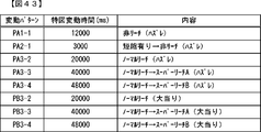
前記制御手段は、前記第2機構体から出力される特定の信号の入力時間に基づいて前記特定第2機構体であるか否かを判定する(例えば、演出制御用CPU120が、S51Bの第3初期化処理において、遊技枠側のシリアル変換IC130から出力される特定の信号の入力時間に基づいて専用枠と共通枠のいずれであるかを判定する部分。変形例)
ことを特徴としている。
この特徴によれば、特定第2機構体であるか否かを好適に判定することができる。
The gaming machine of the means 3 of the present invention is the gaming machine according to the means 1 or 2.
The control means determines whether or not the control means is the specific second mechanism based on the input time of the specific signal output from the second mechanism (for example, the effect control CPU 120 is the third of S51B. In the initialization process, a portion for determining whether the frame is a dedicated frame or a common frame based on the input time of a specific signal output from the serial conversion IC 130 on the game frame side. Modification example)
It is characterized by that.
According to this feature, it can be suitably determined whether or not it is a specific second mechanism.

本発明の手段4の遊技機は、手段1~3のいずれかに記載の遊技機であって、
前記制御手段は、前記第2機構体から出力される複数の特定の信号に基づいて前記特定第2機構体であるか否かを判定する(例えば、演出制御用CPU120が、S51Bの第3初期化処理のS61~S65,S68~S71,S80~S83,S87において、複数の特定のポート番号(例えば、4(D)、5(C)、1(g)、2(f))のシリアルデータを特定し、該特定したシリアルデータに検出信号の入力状態を示すデータがあるか否かにより専用枠か共通枠かを判定する部分。)
ことを特徴としている。
この特徴によれば、特定第2機構体であるか否かを好適に判定することができる。
The gaming machine of the means 4 of the present invention is the gaming machine according to any one of the means 1 to 3.
The control means determines whether or not the control means is the specific second mechanism based on a plurality of specific signals output from the second mechanism (for example, the effect control CPU 120 is the third initial stage of the S51B. Serial data of a plurality of specific port numbers (for example, 4 (D), 5 (C), 1 (g), 2 (f)) in S61 to S65, S68 to S71, S80 to S83, S87 of the conversion process. Is specified, and whether it is a dedicated frame or a common frame is determined depending on whether or not the specified serial data has data indicating the input state of the detection signal.)
It is characterized by that.
According to this feature, it can be suitably determined whether or not it is a specific second mechanism.

本発明の手段5の遊技機は、手段1~4のいずれかに記載の遊技機であって、
前記第2機構体(例えば、開閉枠50及び遊技機用枠3からなる遊技枠)は、
遊技者が操作可能な操作手段(例えば、スティックコントローラ31A、プッシュボタン31Bなど)を含み、
前記操作手段の操作を検出するための検出手段の検出状態を特定可能な検出特定情報を前記制御手段に出力可能である(例えば、シリアル変換IC130が、入力ポート131へのスティックコントローラ31Aやプッシュボタン31Bからの検出信号の入力状態を特定可能なシリアルデータを生成して演出制御基板12に出力することが可能な部分。)
ことを特徴としている。
この特徴によれば、操作異常の発生を防止することができる。
The gaming machine of the means 5 of the present invention is the gaming machine according to any one of the means 1 to 4.
The second mechanism (for example, a gaming frame including an opening / closing frame 50 and a gaming machine frame 3) is
Including operating means that can be operated by the player (for example, stick controller 31A, push button 31B, etc.)
The detection specific information that can specify the detection state of the detection means for detecting the operation of the operation means can be output to the control means (for example, the serial conversion IC 130 has a stick controller 31A or a push button to the input port 131. A part capable of generating serial data capable of specifying the input state of the detection signal from 31B and outputting it to the effect control board 12.)
It is characterized by that.
According to this feature, it is possible to prevent the occurrence of an operation abnormality.

本発明の手段6の遊技機は、手段1~5のいずれかに記載の遊技機であって、
前記第2機構体(例えば、開閉枠50及び遊技機用枠3からなる遊技枠)は、
動作可能な可動体(例えば、専用枠のロケット45、カバー体48、スティックコントローラ31Aなど)を含み、
前記可動体の駆動状態を特定可能な駆動特定情報を前記制御手段に出力可能である(例えば、シリアル変換IC130が、入力ポート131への振動モータ35C、ロケットモータ37C、カバー体モータ39C、スティックモータ35Dからの駆動信号の入力状態を特定可能なシリアルデータを生成して演出制御基板12に出力することが可能な部分。)
ことを特徴としている。
この特徴によれば、動作異常の発生を防止することができる。
The gaming machine of the means 6 of the present invention is the gaming machine according to any one of the means 1 to 5.
The second mechanism (for example, a gaming frame including an opening / closing frame 50 and a gaming machine frame 3) is
Including movable bodies (for example, rocket 45 with a dedicated frame, cover body 48, stick controller 31A, etc.)
Drive specific information that can specify the drive state of the movable body can be output to the control means (for example, the serial conversion IC 130 has a vibration motor 35C, a rocket motor 37C, a cover motor 39C, and a stick motor to the input port 131. A part capable of generating serial data that can specify the input state of the drive signal from the 35D and outputting it to the effect control board 12.)
It is characterized by that.
According to this feature, it is possible to prevent the occurrence of an operation abnormality.

本発明の手段7の遊技機は、手段1~6のいずれかに記載の遊技機であって、
前記制御手段は、前記判定の結果に基づいて、前記複数種類の第2機構体各々の状態に応じた態様の演出を行う(例えば、演出制御用CPU120が、S51Bの第3初期化処理において専用枠フラグがセットされている場合、各演出タイミングで専用枠に対応する画像を表示する演出を行い(図18(A)~(C)参照)、S51Bの第3初期化処理において共通枠フラグがセットされている場合、各演出タイミングで共通枠に対応する画像を表示する演出を行う(図18(D)~(F)参照)部分。)
ことを特徴としている。
この特徴によれば、第2機構体の種類に応じて適切な演出を行うことができる。
The gaming machine of the means 7 of the present invention is the gaming machine according to any one of the means 1 to 6.
Based on the result of the determination, the control means produces an effect according to the state of each of the plurality of types of second mechanisms (for example, the effect control CPU 120 is dedicated to the third initialization process of S51B). When the frame flag is set, an effect of displaying an image corresponding to the dedicated frame is performed at each effect timing (see FIGS. 18A to 18C), and the common frame flag is set in the third initialization process of S51B. If it is set, the effect of displaying the image corresponding to the common frame at each effect timing is performed (see FIGS. 18 (D) to (F)).
It is characterized by that.
According to this feature, it is possible to perform an appropriate effect according to the type of the second mechanism.

本発明の手段8の遊技機は、手段1~7のいずれかに記載の遊技機であって、
前記複数種類の第2機構体は、動作可能な可動体(例えば、共通枠のスティックコントローラ31A)を有する第2機構体(例えば、共通枠)を含み、
前記制御手段は、前記判定の結果に基づいて、前記第2機構体の種類に応じた異なる動作態様で可動体を動作させる演出を行う(例えば、演出制御用CPU120が、共通枠の場合、スティックコントローラ31Aの操作促進演出において、スティックコントローラ31Aを上昇位置まで上昇させる演出を実行可能な部分。図18(D)参照)
ことを特徴としている。
この特徴によれば、第2機構体の種類に応じて適切な演出を行うことができる。
The gaming machine of the means 8 of the present invention is the gaming machine according to any one of the means 1 to 7.
The plurality of types of second mechanisms include a second mechanism (eg, a common frame) having an operable movable body (eg, a stick controller 31A of a common frame).
Based on the result of the determination, the control means performs an effect of operating the movable body in a different operation mode according to the type of the second mechanism (for example, when the effect control CPU 120 is a common frame, the stick. In the operation promotion effect of the controller 31A, an effect of raising the stick controller 31A to the ascending position can be executed. See FIG. 18 (D).
It is characterized by that.
According to this feature, it is possible to perform an appropriate effect according to the type of the second mechanism.

本発明の手段9の遊技機は、手段1~8のいずれかに記載の遊技機であって、
前記制御手段は、遊技機への電力供給が開始されたときに前記特定第2機構体であるか否かを判定し、該判定の結果に応じた種別の演出制御処理を行うことが可能である(例えば、演出制御用CPU120が、S51Bの第3初期化処理で遊技枠の種類を特定した結果に基づいて、演出図柄変動中処理や大当り遊技中処理において、遊技枠の種類に応じた演出(例えば、図18参照)を実行する部分。)
ことを特徴としている。
この特徴によれば、第2機構体の種類に応じて適切な演出を行うことができる。
The gaming machine of the means 9 of the present invention is the gaming machine according to any one of the means 1 to 8.
The control means can determine whether or not it is the specific second mechanism when the power supply to the gaming machine is started, and can perform a type of effect control process according to the result of the determination. (For example, based on the result that the effect control CPU 120 specifies the type of the game frame in the third initialization process of S51B, the effect according to the type of the game frame in the effect symbol changing process or the jackpot game process. (For example, the part that executes (see FIG. 18).)
It is characterized by that.
According to this feature, it is possible to perform an appropriate effect according to the type of the second mechanism.

本発明の手段10の遊技機は、手段1~9のいずれかに記載の遊技機であって、
前記制御手段は、遊技機への電力供給が開始されたときに前記特定第2機構体であるか否かを判定し、所定の演出タイミングにおいて前記判定結果に応じた態様で演出を行うことが可能である(例えば、演出制御用CPU120が、S51Bの第3初期化処理において専用枠フラグがセットされている場合、各演出タイミングで専用枠に対応する画像を表示する演出を行い(図18(A)~(C)参照)、S51Bの第3初期化処理において共通枠フラグがセットされている場合、各演出タイミングで共通枠に対応する画像を表示する演出を行う(図18(D)~(F)参照)部分。)
ことを特徴としている。
この特徴によれば、第2機構体の種類に応じて適切な演出を行うことができる。
The gaming machine of the means 10 of the present invention is the gaming machine according to any one of the means 1 to 9.
The control means may determine whether or not it is the specific second mechanism when the power supply to the gaming machine is started, and perform the effect at a predetermined effect timing in an manner corresponding to the determination result. It is possible (for example, when the effect control CPU 120 sets the dedicated frame flag in the third initialization process of S51B, an effect corresponding to the dedicated frame is displayed at each effect timing (FIG. 18 (FIG. 18). (See A) to (C)), when the common frame flag is set in the third initialization process of S51B, an effect of displaying an image corresponding to the common frame is performed at each effect timing (FIGS. 18 (D) to 18 (D) to C). (Refer to F)) Part.)
It is characterized by that.
According to this feature, it is possible to perform an appropriate effect according to the type of the second mechanism.

尚、本発明は、本発明の請求項に記載された発明特定事項のみを有するものであっても良いし、本発明の請求項に記載された発明特定事項とともに該発明特定事項以外の構成を有するものであっても良い。 The present invention may have only the invention-specific matters described in the claims of the present invention, or may have a configuration other than the invention-specific matters together with the invention-specific matters described in the claims of the present invention. It may have.

本発明の実施例としてのパチンコ遊技機1Aを正面から見た正面図である。It is a front view which looked at the pachinko gaming machine 1A as an Example of this invention from the front. 図1のパチンコ遊技機1Aの主基板における回路構成の一例を示すブロック図である。It is a block diagram which shows an example of the circuit structure in the main board of the pachinko gaming machine 1A of FIG. 図1のパチンコ遊技機1Aの遊技機用枠を開放した状態を示す斜視図である。It is a perspective view which shows the state which opened the frame for the gaming machine of the pachinko gaming machine 1A of FIG. 本発明の実施例としてのパチンコ遊技機1Bを正面から見た正面図である。It is a front view which looked at the pachinko gaming machine 1B as an Example of this invention from the front. 図4のパチンコ遊技機1Bの主基板における回路構成の一例を示すブロック図である。It is a block diagram which shows an example of the circuit structure in the main board of the pachinko gaming machine 1B of FIG. 図4のパチンコ遊技機1Bの遊技機用枠を開放した状態を示す斜視図である。It is a perspective view which shows the state which opened the frame for the gaming machine of the pachinko gaming machine 1B of FIG. 専用枠と共通枠に搭載される操作手段や可動体の種類を比較する説明図である。It is explanatory drawing which compares the type of the operation means and the movable body mounted on a special frame and a common frame. 遊技枠側の検出手段と演出制御基板との配線接続状態を示すブロック図である。It is a block diagram which shows the wiring connection state between the detection means on the game frame side, and an effect control board. (A)は専用枠、(B)は共通枠のシリアル変換ICの各入力ポートに接続される各種電子部品との関係を示す説明図である。(A) is a dedicated frame, and (B) is an explanatory diagram showing the relationship with various electronic components connected to each input port of the serial conversion IC of the common frame. 演出制御用CPUが実行する演出制御メイン処理の制御内容の一例を示すフローチャートである。It is a flowchart which shows an example of the control content of the effect control main process executed by the effect control CPU. 演出制御用CPUが実行する第2初期化処理の制御内容の一例を示すフローチャートである。It is a flowchart which shows an example of the control content of the 2nd initialization process executed by the effect control CPU. 演出制御用CPUが実行する第2初期化処理の制御内容の一例を示すフローチャートである。It is a flowchart which shows an example of the control content of the 2nd initialization process executed by the effect control CPU. 非検出時動作制御と検出時動作制御と実動作確認用動作制御の動作例を示す説明図である。It is explanatory drawing which shows the operation example of the operation control at the time of non-detection, the operation control at the time of detection, and the operation control for actual operation confirmation. 非検出時動作制御と検出時動作制御と実動作確認用動作制御の動作速度例を示す説明図である。It is explanatory drawing which shows the operation speed example of the operation control at the time of non-detection, the operation control at the time of detection, and the operation control for actual operation confirmation. 演出制御用CPUが実行する第3初期化処理の制御内容の一例を示すフローチャートである。It is a flowchart which shows an example of the control content of the 3rd initialization process executed by the effect control CPU. (A)~(F)は演出制御用CPUが第3初期化処理において行う報知の一例を示す図である。(A) to (F) are diagrams showing an example of notification performed by the effect control CPU in the third initialization process. 演出制御プロセス処理の一例を示すフローチャートである。It is a flowchart which shows an example of an effect control process process. (A)~(F)は本発明の変形例1としての演出態様の一例を示す図である。(A) to (F) are diagrams showing an example of an effect mode as a modification 1 of the present invention. 本発明の変形例2としての第3初期化処理の制御内容の一例を示すフローチャートである。It is a flowchart which shows an example of the control content of the 3rd initialization process as the modification 2 of this invention. 本発明の変形例3としての演出制御メイン処理の制御内容の一例を示すフローチャートである。It is a flowchart which shows an example of the control content of the effect control main process as the modification 3 of this invention. 本発明の変形例4としての遊技枠と遊技盤との要部を示す図である。It is a figure which shows the main part of the game frame and the game board as the modification 4 of this invention. (A)は窓部ユニットを示す正面図、(B)は窓部ユニットを示す背面図である。(A) is a front view showing a window unit, and (B) is a rear view showing a window unit. (A)は窓部ユニットを斜め前から見た状態を示す斜視図、(B)は窓部ユニットを斜め後から見た状態を示す斜視図である。(A) is a perspective view showing a state in which the window unit is viewed diagonally from the front, and (B) is a perspective view showing a state in which the window unit is viewed diagonally from the rear. 窓部ユニットの構成を斜め前から見た状態を示す分解斜視図である。It is an exploded perspective view which shows the state which looked at the structure of the window part diagonally from the front. 窓部ユニットの構成を斜め後ろから見た状態を示す分解斜視図である。It is an exploded perspective view which shows the state which the structure of a window unit is seen from diagonally behind. 筒状部を示す縦断面図である。It is a vertical sectional view which shows the tubular part. 開閉枠及び遊技機用枠の内部構造を示す縦断面図である。It is a vertical sectional view which shows the internal structure of the opening / closing frame and the frame for a game machine. 動作待機形態の可動体ユニットを斜め前から見た状態を示す斜視図である。It is a perspective view which shows the state which looked at the movable body unit of the operation standby mode from the diagonally front. 第1動作形態の可動体ユニットを斜め前から見た状態を示す斜視図である。It is a perspective view which shows the state which looked at the movable body unit of the 1st operation form diagonally from the front. 第2動作形態の可動体ユニットを斜め前から見た状態を示す斜視図である。It is a perspective view which shows the state which looked at the movable body unit of the 2nd operation form diagonally from the front. 動作待機形態の可動体ユニットを正面から見た概略図である。It is the schematic which looked at the movable body unit of the operation standby form from the front. 第1動作形態の可動体ユニットを正面から見た概略図である。It is the schematic which looked at the movable body unit of 1st operation form from the front. 第2動作形態の可動体ユニットを正面から見た概略図である。It is the schematic which looked at the movable body unit of the 2nd operation form from the front. 動作待機形態の可動体ユニットを側面から見た概略図である。It is the schematic which looked at the movable body unit of the operation standby form from the side. 第1動作形態の可動体ユニットを側面から見た概略図である。It is the schematic which looked at the movable body unit of 1st operation form from the side view. 第2動作形態の可動体ユニットを側面から見た概略図である。It is the schematic which looked at the movable body unit of the 2nd operation form from the side view. 可動体演出における各可動体及び演出用LEDの動作の一例を示すタイミングチャートである。It is a timing chart which shows an example of the operation of each movable body and the effect LED in the movable body effect. (A)は演出用LED及び可動体LEDの発光態様を側方から見た概略図、(B)は演出用LED及び可動体LEDの発光態様を上方から見た概略図である。(A) is a schematic view of the light emitting mode of the effect LED and the movable body LED from the side, and (B) is a schematic view of the light emitting mode of the effect LED and the movable body LED seen from above. (A)は演出表示装置の通常時を示す待機状態を示す概略図、(B)は演出表示装置の第1動作状態を示す概略図、(C)は演出表示装置の第2動作状態を示す概略図である。(A) is a schematic diagram showing a standby state showing a normal time of the effect display device, (B) is a schematic view showing a first operation state of the effect display device, and (C) shows a second operation state of the effect display device. It is a schematic diagram. 可動体ユニットの第2動作形態において開閉枠を開放した状態を示す概略図である。It is a schematic diagram which shows the state which opened the opening / closing frame in the 2nd operation mode of a movable body unit. 特別図柄プロセス処理で送信設定される主な演出制御コマンドの一例を示す図である。It is a figure which shows an example of the main effect control command which is transmitted and set in a special symbol process process. 特別図柄プロセス処理の一例を示すフローチャートである。It is a flowchart which shows an example of a special symbol process process. 変動パターンの構成例を示す説明図である。It is explanatory drawing which shows the structural example of the fluctuation pattern. コマンド解析処理にて実行される処理内容の一例を示す説明図である。It is explanatory drawing which shows an example of the processing contents executed in the command analysis processing. (A)は演出制御メイン処理の一例を示すフローチャート、(B)はS57中の処理の一例を示すフローチャートである。(A) is a flowchart showing an example of the effect control main process, and (B) is a flowchart showing an example of the process in S57. 演出制御プロセス処理の一例を示すフローチャートである。It is a flowchart which shows an example of an effect control process process. 可変表示開始設定処理の一例を示すフローチャートである。It is a flowchart which shows an example of the variable display start setting process. (A)は可動体演出設定処理の一例を示すフローチャート、(B)はスーパーリーチAの場合の可動体演出の決定例を示す図である。(A) is a flowchart showing an example of a movable body effect setting process, and (B) is a diagram showing a determination example of a movable body effect in the case of Super Reach A. 可変表示中演出処理の一例を示すフローチャートである。It is a flowchart which shows an example of the effect processing during variable display. (A)~(F)は複合演出の流れの一例を示す説明図である。(A) to (F) are explanatory views showing an example of the flow of the composite effect. 変形例5の第1可動体の二段階動作を示す説明図である。It is explanatory drawing which shows the two-step operation of the 1st movable body of the modification 5. (A)~(C)は変形例5、別例1、別例2の場合の可動体演出の決定例を示す図である。(A) to (C) are diagrams showing a determination example of the movable body effect in the case of the modified example 5, the alternative example 1, and the alternative example 2. (A)は各種の予告の実行タイミングの一例を示す図、(B)、(C)は可動体演出の決定例を示す図である。(A) is a diagram showing an example of execution timing of various notices, and (B) and (C) are diagrams showing a determination example of a movable body effect. リーチ発展予告時と煽り演出時の可動体演出の一例を示す説明図である。It is explanatory drawing which shows an example of the movable body production at the time of the reach development notice and at the time of the fanning production. 変形例6Aの第1可動体の円弧状経路で動作することを示す説明図である。It is explanatory drawing which shows that it operates in the arc-shaped path of the 1st movable body of the modification 6A. 変形例6Bの第1可動体の揺動動作を示す説明図である。It is explanatory drawing which shows the swinging motion of the 1st movable body of the modification 6B. 変形例6Cの第1可動体の複数位置停止を示す説明図である。It is explanatory drawing which shows the multi-position stop of the 1st movable body of the modification 6C. (A)は変形例6Dの窓部ユニットを示す横断面図、(B)は仕切り板の案内孔などを説明するための図である。(A) is a cross-sectional view showing the window unit of the modified example 6D, and (B) is a diagram for explaining a guide hole of a partition plate and the like. 変形例7の窓部ユニットを示す横断面図である。It is a cross-sectional view which shows the window part unit of the modification 7. 変形例8の窓部ユニットを示す横断面図である。It is a cross-sectional view which shows the window part unit of the modification 8. (A)は変形例9の固定式の球通路を示す縦断面図、(B)(C)は変形例9の移動式の球通路を示す縦断面図である。(A) is a vertical cross-sectional view showing the fixed ball passage of the modified example 9, and (B) (C) is a vertical cross-sectional view showing the mobile ball passage of the modified example 9. (A)は変形例10の窓部ユニットを示す横断面図、(B)は窓部ユニットを示す縦断面図、(C)は他の例としての窓部ユニットを示す横断面図、(D)は(C)の側面図である。(A) is a cross-sectional view showing the window unit of the modified example 10, (B) is a vertical cross-sectional view showing the window unit, (C) is a cross-sectional view showing the window unit as another example, (D). ) Is a side view of (C). 変形例11の第2透過体と遊技機用枠の構成を示す説明図である。It is explanatory drawing which shows the structure of the 2nd transmission body of the modification 11 and the frame for a game machine. (A)は変形例12の窓部ユニットを示す横断面図、(B)は変形例13の窓部ユニットを示す横断面図である。(A) is a cross-sectional view showing the window unit of the modified example 12, and (B) is a cross-sectional view showing the window unit of the modified example 13. (A)は変形例14の筒状体の構成を示す説明図、(B)は変形例14の筒状体における発光態様が段階的に異なる例を示す図である。(A) is an explanatory diagram showing the configuration of the tubular body of the modified example 14, and (B) is a diagram showing an example in which the light emitting mode of the tubular body of the modified example 14 is stepwise different. (A)は変形例15の筒状体の構成を示す説明図、(B)は変形例15の筒状体における発光態様が段階的に異なる例を示す図である。(A) is an explanatory diagram showing the configuration of the tubular body of the modified example 15, and (B) is a diagram showing an example in which the light emitting mode of the tubular body of the modified example 15 is stepwise different. (A)は変形例16の窓部ユニットを示す横断面図、(B)は導光板演出の演出態様を示す正面図である。(A) is a cross-sectional view showing the window unit of the modified example 16, and (B) is a front view showing an effect mode of the light guide plate effect. 変形例17の第1可動体と第2可動体の動作を示す説明図である。It is explanatory drawing which shows the operation of the 1st movable body and the 2nd movable body of the modification 17. 変形例18の可動体演出実行処理の一例を示すフローチャートである。It is a flowchart which shows an example of the movable body effect execution processing of the modification 18. 変形例18の第1可動体と第2可動体の動作を示す説明図である。It is explanatory drawing which shows the operation of the 1st movable body and the 2nd movable body of the modification 18. (A)(B)は変形例19の窓部ユニットを示す縦断面図である。(A) and (B) are vertical sectional views showing the window unit of the modified example 19. (A)は変形例20の窓部ユニットが第1視認位置に位置する状態を示す縦断面図、(B)は窓部ユニットが第2視認位置へ移動した状態を示す縦断面図である。(A) is a vertical cross-sectional view showing a state in which the window unit of the modified example 20 is located at the first viewing position, and (B) is a vertical cross-sectional view showing a state in which the window unit is moved to the second viewing position. 変形例20の可動体演出設定処理の一例を示すフローチャート、(B)はスーパーリーチBの場合の枠動作演出の決定例を示す図、(C)はスーパーリーチBの場合の可動体演出の決定例を示す図である。A flowchart showing an example of the movable body effect setting process of the modification 20, (B) is a diagram showing a determination example of the frame operation effect in the case of super reach B, and (C) is a determination of the movable body effect in the case of super reach B. It is a figure which shows an example. 変形例21のパチンコ遊技機を正面から見た正面図である。It is a front view which looked at the pachinko gaming machine of the modification 21 from the front. (A)、(B)は変形例21の枠側可動体の動作例を示す図である。(A) and (B) are diagrams showing an operation example of the frame-side movable body of the modified example 21. 変形例21の可動体演出設定処理の一例を示すフローチャート、(B)はスーパーリーチBの場合の枠側可動体演出の決定例を示す図、(C)は第2動作パターンPTB-2の場合の枠側可動体演出の決定例を示す図である。A flowchart showing an example of the movable body effect setting process of the modification 21, (B) is a diagram showing a determination example of the frame side movable body effect in the case of super reach B, and (C) is a case of the second operation pattern PTB-2. It is a figure which shows the determination example of the frame side movable body production of. (A)は変形例22の第1可動体の変形動作を示す説明図、(B)は(A)に示す第1可動体と第2透過体の孔部との大小関係などを示す正面図である。(A) is an explanatory diagram showing the deformation operation of the first movable body of the modified example 22, and (B) is a front view showing the magnitude relationship between the holes of the first movable body and the second transmissive body shown in (A). Is. 変形例23の第1可動体の変形動作を示す説明図である。It is explanatory drawing which shows the deformation operation of the 1st movable body of the modification 23.

本発明に係る遊技機を実施するための形態を実施例に基づいて以下に説明する。 A mode for carrying out the gaming machine according to the present invention will be described below based on examples.

まず、遊技機の一例であるパチンコ遊技機1Aの全体の構成について説明する。図1は、パチンコ遊技機を正面から見た正面図である。図2は、主基板における回路構成の一例を示すブロック図である。図3は、遊技機用枠を開放した状態を示す斜視図である。尚、以下において、図1の手前側をパチンコ遊技機1Aの前方(前面、正面)側、奥側を背面(後方)側とし、パチンコ遊技機1Aを前面側から見たときの上下左右方向を基準として説明する。尚、本実施の形態におけるパチンコ遊技機1Aの前面とは、該パチンコ遊技機1Aにて遊技を行う遊技者と対向する対向面である。 First, the overall configuration of the pachinko gaming machine 1A, which is an example of the gaming machine, will be described. FIG. 1 is a front view of the pachinko gaming machine as viewed from the front. FIG. 2 is a block diagram showing an example of a circuit configuration on a main board. FIG. 3 is a perspective view showing a state in which the frame for the gaming machine is opened. In the following, the front side of FIG. 1 is the front (front, front) side of the pachinko gaming machine 1A, the back side is the back (rear) side, and the vertical and horizontal directions when the pachinko gaming machine 1A is viewed from the front side. It will be explained as a standard. The front surface of the pachinko gaming machine 1A in the present embodiment is a facing surface facing the player playing the game on the pachinko gaming machine 1A.

図1は、本実施の形態におけるパチンコ遊技機の正面図であり、主要部材の配置レイアウトを示す。パチンコ遊技機1A(以下、遊技機と略記する場合がある)は、大別して、遊技盤面を前面側に有する遊技盤2(ゲージ盤ともいう)と、遊技盤2を支持固定する遊技機用枠3(台枠)とから構成されている。遊技盤2は、遊技機用枠3に対し着脱可能であり、また、遊技盤2には、ガイドレール2bによって囲まれた正面視略円形状の遊技領域(「遊技部」ともいう)10が形成されている。この遊技領域10は、遊技媒体としての遊技球が打球発射装置(図示略)から発射されて打ち込まれ、打ち込まれた遊技球が流下可能な領域とされている。 FIG. 1 is a front view of the pachinko gaming machine according to the present embodiment, and shows an arrangement layout of main members. The pachinko gaming machine 1A (hereinafter, may be abbreviated as a gaming machine) is roughly divided into a gaming board 2 (also referred to as a gauge board) having a gaming board surface on the front side and a gaming machine frame for supporting and fixing the gaming board 2. It is composed of 3 (underframe). The game board 2 is removable from the game machine frame 3, and the game board 2 has a game area (also referred to as a “game unit”) 10 having a substantially circular shape in front view surrounded by a guide rail 2b. It is formed. The game area 10 is a region in which a game ball as a game medium is launched from a hitting ball launching device (not shown) and hit, and the hit game ball can flow down.

また、遊技機用枠3には、遊技領域10を視認するための窓部51が設けられた開閉枠50が左側辺を中心として回動可能に設けられ、該開閉枠50により遊技領域10を開閉できるようになっており、開閉枠50を閉鎖したときに窓部51を通して遊技領域10を透視できるようになっている。また、開閉枠50は、遊技機用枠3の前面全域を被覆可能な大きさに形成されており、窓部51の下方には遊技球を遊技領域に向けて発射するために遊技者等によって操作される打球操作ハンドル30(操作ノブ)が設けられている。 Further, the gaming machine frame 3 is provided with an opening / closing frame 50 provided with a window portion 51 for visually recognizing the gaming area 10 so as to be rotatable around the left side, and the opening / closing frame 50 provides the gaming area 10 with the opening / closing frame 50. It can be opened and closed, and when the opening / closing frame 50 is closed, the game area 10 can be seen through the window portion 51. Further, the opening / closing frame 50 is formed in a size capable of covering the entire front surface of the gaming machine frame 3, and is formed below the window portion 51 by a player or the like in order to launch the gaming ball toward the gaming area. A ball striking operation handle 30 (operation knob) to be operated is provided.

打球操作ハンドル30の前面には、原点位置と該原点位置よりも前方に突出する突出位置との間で前後方向に移動可能な可動体としてのロケット45が設けられており、打球操作ハンドル30の内部に設けられたロケットモータ37Cにより前後に駆動できるようになっている。また、打球操作ハンドル30の内部には、ロケット45が原点位置にあることを検出し、検出信号を演出制御基板12に出力するロケット原点位置センサ37Aと、ロケット45が突出位置にあることを検出し、検出信号を演出制御基板12に出力するロケット突出位置センサ37Bと、が設けられている。 A rocket 45 as a movable body that can move in the front-rear direction between the origin position and the protruding position protruding forward from the origin position is provided on the front surface of the ball striking operation handle 30. It can be driven back and forth by a rocket motor 37C provided inside. Further, inside the ball striking operation handle 30, it is detected that the rocket 45 is at the origin position, and the rocket origin position sensor 37A that outputs a detection signal to the effect control board 12 and the rocket 45 are detected at the protruding position. A rocket protrusion position sensor 37B that outputs a detection signal to the effect control board 12 is provided.

遊技盤2は、アクリル樹脂、ポリカーボネート樹脂、メタクリル樹脂等の透光性を有する合成樹脂材(透過性部材)にて正面視略四角形状に形成され、前面である遊技盤面に障害釘(図示略)やガイドレール2b(図3参照)等が設けられた盤面板(図示略)と、該盤面板の背面側に一体的に取付けられるスペーサ部材(図示略)と、から主に構成されている。本実施の形態の遊技盤2は、透光性を有する合成樹脂材にて構成されていたが、これに限られるものではなく、ベニヤ板等の非透光性部材にて正面視略四角形状に構成されていてもよい。 The game board 2 is made of a translucent synthetic resin material (transmissive member) such as acrylic resin, polycarbonate resin, and methacrylic resin, and is formed in a substantially square shape in front view. ), A board surface plate (not shown) provided with a guide rail 2b (see FIG. 3), and a spacer member (not shown) integrally attached to the back surface side of the board surface plate. .. The game board 2 of the present embodiment is made of a translucent synthetic resin material, but is not limited to this, and is formed into a substantially square shape in front view by a non-translucent member such as a veneer plate. It may be configured.

遊技盤2の所定位置(図1に示す例では、遊技領域10の右側下部位置)には、第1特別図柄表示器4Aと、第2特別図柄表示器4Bとが設けられている。これらは、7セグメントのLEDなどからなり、特別図柄は、「0」~「9」を示す数字や「-」などの点灯パターンなどであればよい。特別図柄には、LEDを全て消灯したパターンが含まれてもよい。第1特別図柄表示器4Aと第2特別図柄表示器4Bはそれぞれ、変動表示ゲームの一例となる特図ゲームにおいて、各々を識別可能な複数種類の識別情報(特別識別情報)である特別図柄(「特図」ともいう)が、変動可能に表示(変動表示または可変表示ともいう)される。特別図柄の変動表示(可変表示)とは、複数種類の特別図柄を更新表示などにより変動させる(変動可能に表示する)ことである(他の可変表示についても同じ)。変動表示の最後には、表示結果(可変表示結果)として所定の特別図柄が停止表示(導出表示)される。以下では、第1特別図柄表示器4Aにおいて変動表示される特別図柄を「第1特図」ともいい、第2特別図柄表示器4Bにおいて変動表示される特別図柄を「第2特図」ともいう。第1特図の特図ゲームを「第1特図ゲーム」と、第2特図の特図ゲームを「第2特図ゲーム」ともいう。 A first special symbol display 4A and a second special symbol display 4B are provided at a predetermined position of the game board 2 (in the example shown in FIG. 1, a lower right position of the game area 10). These are composed of 7-segment LEDs and the like, and the special symbol may be a number indicating "0" to "9" or a lighting pattern such as "-". The special symbol may include a pattern in which all the LEDs are turned off. The first special symbol display 4A and the second special symbol display 4B are special symbols (special identification information) that are a plurality of types of identification information (special identification information) that can identify each of them in a special symbol game that is an example of a variable display game. A "special figure") is displayed in a variable manner (also referred to as a variable display or a variable display). The variable display (variable display) of a special symbol is to change (display in a variable manner) a plurality of types of special symbols by an update display or the like (the same applies to other variable displays). At the end of the variable display, a predetermined special symbol is stopped and displayed (derived display) as a display result (variable display result). In the following, the special symbol that is variablely displayed on the first special symbol display 4A is also referred to as "first special symbol", and the special symbol that is variablely displayed on the second special symbol display 4B is also referred to as "second special symbol". .. The special figure game of the first special figure is also referred to as a "first special figure game", and the special figure game of the second special figure is also referred to as a "second special figure game".

遊技盤2における遊技領域10の中央付近には、演出表示装置5A,5X,5Yが設けられている。演出表示装置5A,5X,5Yは、例えばLCD(液晶表示装置)等から構成され、各種の演出画像を表示する表示領域を形成している。演出表示装置5Aの表示領域では、特図ゲームにおける第1特別図柄表示器4Aによる第1特図の変動表示や第2特別図柄表示器4Bによる第2特図の変動表示のそれぞれに対応して(例えば、第1特図ゲームや第2特図ゲームと同期して)、例えば3つといった複数の変動表示部となる「左」、「中」、「右」の演出図柄表示エリア5L,5C,5Rにて、各々を識別可能な複数種類の識別情報(装飾識別情報)である演出図柄(飾り図柄)が変動表示(例えば上下方向のスクロール表示や更新表示)される。この演出図柄の変動表示も、変動表示ゲームに含まれる。 The effect display devices 5A, 5X, and 5Y are provided near the center of the game area 10 on the game board 2. The effect display devices 5A, 5X, and 5Y are composed of, for example, an LCD (liquid crystal display device) or the like, and form a display area for displaying various effect images. In the display area of the effect display device 5A, the variation display of the first special symbol by the first special symbol display 4A and the variation display of the second special symbol by the second special symbol display 4B in the special symbol game are supported. (For example, in synchronization with the 1st special figure game and the 2nd special figure game), for example, "left", "middle", and "right" production symbol display areas 5L, 5C, which are multiple variable display units such as three. In 5R, the effect symbol (decorative symbol), which is a plurality of types of identification information (decorative identification information) that can identify each of them, is variablely displayed (for example, scroll display in the vertical direction or update display). The variable display of this effect symbol is also included in the variable display game.

このように、演出表示装置5Aの表示領域では、第1特別図柄表示器4Aにおける第1特図を用いた特図ゲーム、または、第2特別図柄表示器4Bにおける第2特図を用いた特図ゲームと同期して、各々が識別可能な複数種類の演出図柄の変動表示を行い、変動表示結果となる確定演出図柄(最終停止図柄)を導出表示する。また、図1に示すように、演出表示装置5Aの表示領域には、後述する可動体(第1可動体300、第2可動体400、第3可動体500L,500R及び第4可動体600L,600R)がいずれの位置にあっても遊技に関する特定遊技情報(例えば、小図柄、第4図柄、右打ち表示、保留表示などのうちの少なくとも一つ)を表示する特定遊技情報表示領域5Zを備えている。小図柄は、第1特図ゲームに対応して可変表示され演出図柄よりも小さい第1小図柄と、第2特図ゲームに対応して可変表示され演出図柄よりも小さい第2小図柄とが含まれる。小図柄は、常時表示されるものや所定期間のみ表示されるものであってもよい。第4図柄は、現在変動表示(可変表示)中の状態であるのか否かを示す図柄である。右打ち表示は、遊技者に対して、遊技球が遊技領域の10の右側に発射されるよう打球操作ハンドルの操作を促す表示である。この実施の形態では、演出表示装置5Aの表示領域の一部を特定遊技情報表示領域5Zとしているが、演出表示装置5X,5Yの少なくとも一方の表示領域に特定遊技情報表示領域5Zを備えるようにしてもよい。また、遊技盤2に特定遊技情報表示装置(例えば、LED、ランプ、7セグメントLED、液晶表示装置など)を備えるようにしてもよい。 As described above, in the display area of the effect display device 5A, the special figure game using the first special figure in the first special symbol display 4A or the special figure using the second special figure in the second special symbol display 4B is used. In synchronization with the figure game, a variation display of a plurality of types of effect symbols that can be identified by each is performed, and a definite effect symbol (final stop symbol) that is a variation display result is derived and displayed. Further, as shown in FIG. 1, the display area of the effect display device 5A includes movable bodies (first movable body 300, second movable body 400, third movable body 500L, 500R, and fourth movable body 600L, which will be described later. 600R) is provided with a specific game information display area 5Z for displaying specific game information related to the game (for example, at least one of a small symbol, a fourth symbol, a right-handed display, a hold display, etc.) regardless of the position. ing. The small symbols are the first small symbol that is variably displayed corresponding to the first special symbol game and smaller than the effect symbol, and the second small symbol that is variably displayed corresponding to the second special symbol game and smaller than the effect symbol. included. The small symbol may be one that is always displayed or one that is displayed only for a predetermined period. The fourth symbol is a symbol indicating whether or not the state is currently in the variable display (variable display). The right-handed display is a display that urges the player to operate the hitting ball operation handle so that the game ball is launched on the right side of 10 in the game area. In this embodiment, a part of the display area of the effect display device 5A is set as the specific game information display area 5Z, but at least one of the effect display devices 5X and 5Y is provided with the specific game information display area 5Z. You may. Further, the game board 2 may be provided with a specific game information display device (for example, LED, lamp, 7-segment LED, liquid crystal display device, etc.).

演出表示装置5X,5Yは、演出表示装置5Aよりも表示画面の横幅が略半分とされ、演出表示装置5Aの左右側に、後述するように移動及び回動可能に設けられている。本実施の形態では、主に中央の演出表示装置5Aにて演出図柄の変動表示や各種演出が行われ、演出表示装置5X,5Yにて演出表示装置5Aに関連する演出が行われるようになっているが、演出表示装置5Aに替えて演出図柄の変動表示が行われたり、演出表示装置5Aとは別個の演出も行われたりすることがある。 The width of the display screen of the effect display devices 5X and 5Y is substantially half that of the effect display device 5A, and the effect display devices 5X and 5Y are provided on the left and right sides of the effect display device 5A so as to be movable and rotatable as described later. In the present embodiment, the central effect display device 5A mainly performs variable display of the effect symbol and various effects, and the effect display devices 5X and 5Y perform the effects related to the effect display device 5A. However, the effect display device 5A may be replaced with a variable display of the effect symbol, or an effect separate from the effect display device 5A may be performed.

また、これら演出表示装置5A,5X,5Yは、遊技盤2よりも背面側に配設され、該遊技盤2に形成された開口2cを通して視認できるようになっている。尚、本実施の形態では、演出表示装置5X,5Yの一部は盤面板200を通して視認できるようになっている。また、遊技盤2における開口2cには枠状のセンター飾り枠52が設けられている。 Further, these effect display devices 5A, 5X, and 5Y are arranged on the back side of the game board 2 and can be visually recognized through the opening 2c formed in the game board 2. In the present embodiment, a part of the effect display devices 5X and 5Y can be visually recognized through the board plate 200. Further, a frame-shaped center decorative frame 52 is provided in the opening 2c of the game board 2.

演出表示装置5A,5X,5Yの表示領域の下部の左右2個所には、第1保留記憶表示エリア5D、第2保留記憶表示エリア5Uが設定されている。第1保留記憶表示エリア5D、第2保留記憶表示エリア5Uでは、特図ゲームに対応した変動表示の保留記憶数(特図保留記憶数)を特定可能に表示する保留記憶表示が行われる。つまり、第1保留記憶表示エリア5D、第2保留記憶表示エリア5Uでは、実行が保留されている特図ゲームに対応する保留表示画像の表示が行われる。 A first reserved storage display area 5D and a second reserved storage display area 5U are set at two places on the left and right below the display area of the effect display devices 5A, 5X, and 5Y. In the first hold storage display area 5D and the second hold storage display area 5U, the hold storage display for identifiablely displaying the hold storage number (special figure hold storage number) of the variable display corresponding to the special figure game is performed. That is, in the first hold storage display area 5D and the second hold storage display area 5U, the hold display image corresponding to the special figure game whose execution is held is displayed.

ここで、特図ゲームに対応した変動表示の保留は、普通入賞球装置6Aが形成する第1始動入賞口や、普通可変入賞球装置6Bが形成する第2始動入賞口を、遊技球が通過(進入)することによる始動入賞に基づいて発生する。すなわち、特図ゲームや演出図柄の変動表示といった変動表示ゲームを実行するための始動条件(「実行条件」ともいう)は成立したが、先に成立した開始条件に基づく変動表示ゲームが実行中であることやパチンコ遊技機1Aが大当り遊技状態に制御されていることなどにより、変動表示ゲームの開始を許容する開始条件が成立していないときに、成立した始動条件に対応する変動表示の保留が行われる。 Here, the holding of the variable display corresponding to the special figure game is such that the game ball passes through the first starting winning opening formed by the normal winning ball device 6A and the second starting winning opening formed by the ordinary variable winning ball device 6B. It occurs based on the starting prize by (entering). That is, the start condition (also referred to as "execution condition") for executing the variable display game such as the special figure game or the variable display of the effect symbol is satisfied, but the variable display game based on the previously established start condition is being executed. When the start condition that allows the start of the variable display game is not satisfied due to the fact that the pachinko game machine 1A is controlled to the jackpot game state, the variable display corresponding to the established start condition is suspended. It will be done.

第1特別図柄表示器4A及び第2特別図柄表示器4Bの右側方位置には、特図保留記憶数を特定可能に表示するための第1保留表示器25Aと第2保留表示器25Bとが設けられている。第1保留表示器25Aは、第1特図保留記憶数を特定可能に表示し、第2保留表示器25Bは、第2特図保留記憶数を特定可能に表示する。例えば、第1保留表示器25Aと第2保留表示器25Bとはそれぞれ、複数のLEDを含んで構成され、LEDの点灯個数によって第1特図保留記憶数(第1特図ゲームの保留記憶数)と第2特図保留記憶数(第2特図ゲームの保留記憶数)とを表示する。 At the right side position of the first special symbol display 4A and the second special symbol display 4B, there are a first hold display 25A and a second hold display 25B for identifiable display of the number of special symbol hold storages. It is provided. The first hold indicator 25A displays the number of first special figure hold storage identifiable, and the second hold indicator 25B displays the number of second special figure hold storage identifiable. For example, the first hold indicator 25A and the second hold indicator 25B are each configured to include a plurality of LEDs, and the first special figure hold storage number (the hold storage number of the first special figure game) depends on the number of lighting of the LEDs. ) And the number of second special figure hold storage (the number of hold memory of the second special figure game) are displayed.

演出表示装置5Aの下方には、普通入賞球装置6Aが設けられ、演出表示装置5Yの下方には、普通可変入賞球装置6Bが設けられている。普通入賞球装置6Aは、例えば所定の球受部材によって常に一定の開放状態に保たれる始動領域(第1始動領域)としての第1始動入賞口を形成する。普通可変入賞球装置6Bは、図2に示す普通電動役物用となるソレノイド81によって、遊技領域10に突出する突出位置となる閉鎖状態と遊技領域10から退避する退避位置となる開放状態とに変化する可動板を有する普通電動役物を備え、始動領域(第2始動領域)としての第2始動入賞口を形成する。 A normal winning ball device 6A is provided below the effect display device 5A, and a normal variable winning ball device 6B is provided below the effect display device 5Y. The ordinary winning ball device 6A forms a first starting winning opening as a starting region (first starting region) that is always kept in a constant open state by, for example, a predetermined ball receiving member. The normal variable winning ball device 6B is in a closed state in which it protrudes into the game area 10 and in an open state in which it is retracted from the game area 10 by the solenoid 81 for the normal electric accessory shown in FIG. It is provided with a normal electric accessory having a variable movable plate, and forms a second start winning opening as a start area (second start area).

第1始動入賞口を通過(進入)した遊技球が第1始動口スイッチ22Aによって検出されたことに基づき、所定個数(例えば3個)の遊技球が賞球として払い出され、第1特図保留記憶数が所定の上限値(例えば「4」)以下であれば、第1始動条件が成立する。また、第2始動入賞口を通過(進入)した遊技球が第2始動口スイッチ22Bによって検出されたことに基づき、所定個数(例えば3個)の遊技球が賞球として払い出され、第2特図保留記憶数が所定の上限値(例えば「4」)以下であれば、第2始動条件が成立する。 Based on the fact that the game balls that have passed (entered) the first start winning opening are detected by the first starting opening switch 22A, a predetermined number (for example, 3) of game balls are paid out as prize balls, and the first special drawing. If the number of reserved storages is equal to or less than a predetermined upper limit value (for example, "4"), the first start condition is satisfied. Further, based on the fact that the game balls that have passed (entered) the second start winning opening are detected by the second starting opening switch 22B, a predetermined number (for example, 3) of game balls are paid out as prize balls, and the second If the number of reserved special figures is equal to or less than a predetermined upper limit value (for example, "4"), the second start condition is satisfied.

図1に示すように、普通入賞球装置6Aの右方位置には、特別可変入賞球装置7が設けられている。特別可変入賞球装置7は、図2に示すソレノイド82によって開閉駆動される大入賞口扉によって開放状態と閉鎖状態とに変化する特定領域としての大入賞口を形成する。このように、特定領域としての大入賞口は、遊技球が通過(進入)しやすく遊技者にとって有利な開放状態と、遊技球が通過(進入)できない(または通過(進入)しにくい)遊技者にとって不利な閉鎖状態とに変化する。 As shown in FIG. 1, a special variable winning ball device 7 is provided at a right position of the normal winning ball device 6A. The special variable winning ball device 7 forms a large winning opening as a specific region that changes between an open state and a closed state by the large winning opening door that is opened and closed by the solenoid 82 shown in FIG. In this way, the large winning opening as a specific area is an open state in which the game ball is easy to pass (enter), which is advantageous for the player, and a player who cannot pass (enter) (or is difficult to enter) the game ball. It changes to a closed state that is disadvantageous to.

大入賞口を通過(進入)した遊技球が図2に示すカウントスイッチ23によって検出されたことに基づき、所定個数(例えば15個)の遊技球が賞球として払い出される。従って、特別可変入賞球装置7において大入賞口が開放状態となれば、その大入賞口に遊技球が進入可能となり、遊技者にとって有利な第1状態となる。その一方で、特別可変入賞球装置7において大入賞口が閉鎖状態となれば、大入賞口に遊技球を通過(進入)させて賞球を得ることが不可能または困難になり、遊技者にとって不利な第2状態となる。 Based on the fact that the game balls that have passed (entered) the large winning opening are detected by the count switch 23 shown in FIG. 2, a predetermined number (for example, 15) of game balls are paid out as prize balls. Therefore, if the large winning opening is opened in the special variable winning ball device 7, the game ball can enter the large winning opening, which is the first state advantageous for the player. On the other hand, if the large winning opening is closed in the special variable winning ball device 7, it becomes impossible or difficult for the player to obtain the winning ball by passing (entering) the game ball through the large winning opening. It becomes a disadvantageous second state.

第2保留表示器25Bの右側方位置には、普通図柄表示器20が設けられている。一例として、普通図柄表示器20は、7セグメントのLEDなどからなり、特別図柄とは異なる複数種類の普通識別情報である普通図柄(普図、普通図)の可変表示を行う。普通図柄の可変表示は普図ゲーム(普通図ゲーム)ともいう。普図ゲームは、遊技球が通過ゲート41を通過したことに基づいて実行される。遊技球が通過ゲート41を通過したときには、図2のゲートスイッチ21がオンになり、これにより当該遊技球の通過が検出される。普通図柄表示器20の右側方位置には、普図保留表示器25Cが設けられている。普図保留表示器25Cは、例えば4個のLEDを含んで構成され、通過ゲート41を通過した有効通過球数としての普図保留記憶数を表示する。つまり、普図保留表示器25Cは、実行が保留されている普図ゲームの数である普図保留記憶数をLEDの点灯個数により表示する。 An ordinary symbol display 20 is provided at a position on the right side of the second hold display 25B. As an example, the ordinary symbol display 20 is composed of 7-segment LEDs or the like, and performs variable display of ordinary symbols (ordinary figures, ordinary figures) which are a plurality of types of ordinary identification information different from special symbols. The variable display of a normal pattern is also called a normal figure game (normal figure game). The normal game is executed based on the fact that the game ball has passed through the passing gate 41. When the game ball passes through the passing gate 41, the gate switch 21 in FIG. 2 is turned on, whereby the passing of the game ball is detected. At a position on the right side of the normal symbol display 20, a normal symbol hold display 25C is provided. The normal figure hold indicator 25C is configured to include, for example, four LEDs, and displays the normal figure hold storage number as the number of effective passing balls that have passed through the passing gate 41. That is, the normal figure hold display 25C displays the number of normal figure hold storages, which is the number of normal figure games whose execution is held, by the number of LED lights.

遊技盤2の表面には、遊技球の流下方向や速度を変化させる風車及び多数の障害釘が設けられている。また、遊技盤2には、遊技領域側発光部品が配置されている。この遊技領域側発光部品としては、例えばセンター飾り枠52に設けられた図示省略の発光部品(LED)、普通入賞球装置6Aや普通可変入賞球装置6Bに設けられた図示省略の発光部品(LED)などがある。また、遊技盤2は、その表面の少なくとも一部(例えば導光領域)を発光させるための発光部品(LED)を備えるようにしてもよい。遊技領域の最下方には、いずれの入賞口にも進入しなかった遊技球が取り込まれるアウト口が設けられている。遊技機用枠3の左右上部位置には効果音等を再生出力するためのスピーカ8L,8Rが設けられており、遊技領域周辺部には遊技効果用の演出用LED9が設けられている。 On the surface of the game board 2, a windmill that changes the flow direction and speed of the game ball and a large number of obstacle nails are provided. Further, the game board 2 is arranged with light emitting parts on the game area side. Examples of the light emitting component on the game area side include a light emitting component (LED) not shown in the center decorative frame 52, and a light emitting component (LED) not shown in the ordinary winning ball device 6A and the ordinary variable winning ball device 6B. )and so on. Further, the game board 2 may be provided with a light emitting component (LED) for emitting light at least a part of its surface (for example, a light guide region). At the bottom of the game area, there is an out opening for taking in a game ball that has not entered any of the winning openings. Speakers 8L and 8R for reproducing and outputting sound effects and the like are provided at the upper left and right positions of the gaming machine frame 3, and an effect LED 9 for the gaming effect is provided in the peripheral portion of the gaming area.

遊技領域10の下方における遊技機用枠3の所定位置には、賞球として払い出された遊技球や所定の球貸機により貸し出された遊技球を、打球発射装置(図示略)へと供給可能に保持(貯留)する上皿90(打球供給皿ともいう)が設けられている。遊技機用枠3の下部には、上皿90から僅かれた余剰球やファール球などをパチンコ遊技機1Aの外部へと排出する排出口(図示略)が設けられている。上皿を形成する部材にはプッシュボタン31Bが設けられている。プッシュボタン31Bの設置位置における上皿の本体内部などには、プッシュボタン31Bに対する遊技者の操作(例えば押下)を検出し、操作検出信号を演出制御基板12に出力するボタンセンサ36Aが設けられている。また、上皿90を形成する部材には十字ボタン46が設けられている。十字ボタン46の設置位置における上皿90の本体内部などには、十字ボタン46に対する遊技者の操作(例えば、上、下、左、右の押下)を検出し、操作検出信号を演出制御基板12に出力する十字ボタンセンサ38A~38Dが設けられている。 At a predetermined position of the gaming machine frame 3 below the gaming area 10, a gaming ball paid out as a prize ball or a gaming ball rented by a predetermined ball lending machine is supplied to a hitting ball launching device (not shown). An upper plate 90 (also referred to as a hitting ball supply plate) for holding (storing) the ball is provided. At the lower part of the gaming machine frame 3, a discharge port (not shown) is provided to discharge a small amount of surplus balls, foul balls, etc. from the upper plate 90 to the outside of the pachinko gaming machine 1A. A push button 31B is provided on the member forming the upper plate. Inside the main body of the upper plate at the installation position of the push button 31B, a button sensor 36A that detects the player's operation (for example, pressing) on the push button 31B and outputs the operation detection signal to the effect control board 12 is provided. There is. Further, a cross-shaped button 46 is provided on the member forming the upper plate 90. Inside the main body of the upper plate 90 at the installation position of the cross-shaped button 46, the player's operation (for example, pressing up, down, left, right) on the cross-shaped button 46 is detected, and the operation detection signal is produced on the control board 12. Cross-shaped button sensors 38A to 38D for outputting to are provided.

遊技機用枠3の下部箇所には、遊技者が把持して傾倒操作が可能なスティックコントローラ31Aが取付けられている。スティックコントローラ31Aの下部における遊技機用枠3の下部内部などには、操作桿が原点位置にあることを検出し、検出信号を演出制御基板12に出力するスティック原点位置センサ35Aと、操作桿が引き位置にあることを検出し、操作検出信号を演出制御基板12に出力するスティック引き位置センサ35Bと、が設けられている。また、スティックコントローラ31Aの内部には、該スティックコントローラ31Aを振動させることが可能な振動モータ35Cが設けられている。 A stick controller 31A that can be grasped and tilted by the player is attached to the lower portion of the gaming machine frame 3. Inside the lower part of the gaming machine frame 3 in the lower part of the stick controller 31A, there are a stick origin position sensor 35A that detects that the operation rod is at the origin position and outputs a detection signal to the effect control board 12, and an operation rod. A stick pull position sensor 35B that detects that the position is in the pull position and outputs an operation detection signal to the effect control board 12 is provided. Further, inside the stick controller 31A, a vibration motor 35C capable of vibrating the stick controller 31A is provided.

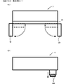
遊技機用枠3の前面上部には、天発光部47を遊技者に視認不能に隠蔽する原点位置と演出部を遊技者に視認可能に開放する開放位置との間で回動可能な可動体としてのカバー体48が設けられており、内部に設けられたカバー体モータ39Cにより開閉駆動できるようになっている。また、遊技機用枠3の内部には、カバー体48が原点位置にあることを検出し、検出信号を演出制御基板12に出力するカバー体原点位置センサ39Aと、カバー体48が開放位置にあることを検出し、検出信号を演出制御基板12に出力するカバー体開放位置センサ39Bと、が設けられている。 In the upper part of the front surface of the gaming machine frame 3, a movable body that can rotate between an origin position that hides the celestial light emitting unit 47 invisible to the player and an open position that opens the effect unit so that the player can see it. The cover body 48 is provided as a cover body 48, and can be opened and closed by a cover body motor 39C provided inside. Further, inside the frame 3 for the game machine, the cover body origin position sensor 39A that detects that the cover body 48 is at the origin position and outputs the detection signal to the effect control board 12 and the cover body 48 are in the open position. A cover body open position sensor 39B that detects the presence and outputs a detection signal to the effect control board 12 is provided.

また、遊技機用枠3の前面には、天発光部47の左右側から窓部51の左右側辺に沿うように下方に向けて複数の演出用LED9からなる発光部が帯状に延設されている。 Further, on the front surface of the gaming machine frame 3, a light emitting portion composed of a plurality of effect LEDs 9 is extended in a band shape downward from the left and right sides of the heavenly light emitting portion 47 along the left and right sides of the window portion 51. ing.

次に、パチンコ遊技機1Aの回路構成について説明する。パチンコ遊技機1Aには、例えば図2に示すような主基板11、演出制御基板12、音声制御基板13、LED制御基板14、主基板11と演出制御基板12との間で伝送される各種の制御信号を中継するための中継基板15、払出制御基板、情報端子基板、発射制御基板、インタフェース基板などといった、各種の基板が配置されている。 Next, the circuit configuration of the pachinko gaming machine 1A will be described. In the pachinko gaming machine 1A, for example, as shown in FIG. 2, various types of transmissions are transmitted between the main board 11, the effect control board 12, the voice control board 13, the LED control board 14, the main board 11 and the effect control board 12. Various boards such as a relay board 15 for relaying a control signal, a payout control board, an information terminal board, a launch control board, and an interface board are arranged.

主基板11は、メイン側の制御基板であり、パチンコ遊技機1Aにおける遊技の進行を制御するための各種回路が搭載されている。主基板11は、主として、特図ゲームにおいて用いる乱数の設定機能、所定位置に配設されたスイッチ等からの信号の入力を行う機能、演出制御基板12などからなるサブ側の制御基板に宛てて、指令情報の一例となる制御コマンドを制御信号として出力して送信する機能、ホールの管理コンピュータに対して各種情報を出力する機能などを備えている。また、主基板11は、第1特別図柄表示器4Aと第2特別図柄表示器4Bを構成する各LED(例えばセグメントLED)などの点灯/消灯制御を行って第1特図や第2特図の変動表示を制御することや、普通図柄表示器20の点灯/消灯/発色制御などを行って普通図柄表示器20による普通図柄の変動表示を制御することといった、所定の表示図柄の変動表示を制御する機能も備えている。また、主基板11には、例えば遊技制御用マイクロコンピュータ100や、スイッチ回路110、ソレノイド回路111などが搭載されている。 The main board 11 is a control board on the main side, and is equipped with various circuits for controlling the progress of the game in the pachinko gaming machine 1A. The main board 11 is mainly addressed to a sub-side control board including a random number setting function used in a special figure game, a function of inputting a signal from a switch or the like arranged at a predetermined position, and an effect control board 12. , It has a function to output and transmit a control command as an example of command information as a control signal, and a function to output various information to a hall management computer. Further, the main board 11 controls lighting / extinguishing of each LED (for example, a segment LED) constituting the first special symbol display 4A and the second special symbol display 4B to control the lighting / extinguishing of the first special symbol and the second special symbol. The variable display of a predetermined display symbol such as controlling the variable display of the normal symbol and controlling the variable display of the normal symbol by the normal symbol display 20 by controlling the lighting / extinguishing / coloring of the normal symbol display 20. It also has a control function. Further, for example, a game control microcomputer 100, a switch circuit 110, a solenoid circuit 111, and the like are mounted on the main board 11.

図2に示すように、主基板11には、通過ゲート41を通過した遊技球を検出するゲートスイッチ21、第1始動口スイッチ22A、第2始動口スイッチ22B、カウントスイッチ23からの検出信号を伝送する配線が接続されている。また、第1特別図柄表示器4A、第2特別図柄表示器4B、普通図柄表示器20、第1保留表示器25A、第2保留表示器25B、普図保留表示器25Cなどの表示制御を行うための指令信号を伝送する配線が接続されている。 As shown in FIG. 2, on the main board 11, detection signals from a gate switch 21, a first start port switch 22A, a second start port switch 22B, and a count switch 23 for detecting a game ball that has passed through the pass gate 41 are transmitted to the main board 11. The wiring to be transmitted is connected. In addition, display control of the first special symbol display 4A, the second special symbol display 4B, the normal symbol display 20, the first hold display 25A, the second hold display 25B, the normal figure hold display 25C, and the like is performed. The wiring that transmits the command signal for is connected.

主基板11から演出制御基板12に向けて伝送される制御信号は、例えば電気信号として送受信される演出制御コマンドである。演出制御コマンドには、例えば、演出図柄の変動時間及びリーチ演出の種類や擬似連の有無等の変動態様を示す変動パターンを示す変動パターン指定コマンド等が含まれている。 The control signal transmitted from the main board 11 to the effect control board 12 is, for example, an effect control command transmitted and received as an electric signal. The effect control command includes, for example, a variation pattern designation command indicating a variation pattern indicating a variation mode such as a variation time of the effect symbol, a type of reach effect, and the presence / absence of a pseudo-ream.

主基板11に搭載された遊技制御用マイクロコンピュータ100は、例えば1チップのマイクロコンピュータであり、遊技制御用のプログラムや固定データ等を記憶するROM101(Read Only Memory101)と、遊技制御用のワークエリアを提供するRAM102(Random Access Memory102)と、遊技制御用のプログラムを実行して制御動作を行うCPU103(Central Processing Unit103)と、CPU103とは独立して乱数値を示す数値データの更新を行う乱数回路104と、I/O105(Input/Output port105)と、を備えて構成される。一例として、遊技制御用マイクロコンピュータ100では、CPU103がROM101から読み出したプログラムを実行することにより、パチンコ遊技機1Aにおける遊技の進行を制御するための処理が実行される。このとき、ROM101が記憶する各種データ(変動パターンや各種の決定テーブルなどのデータ)が用いられ、RAM102がメインメモリとして使用される。 The game control microcomputer 100 mounted on the main board 11 is, for example, a one-chip microcomputer, and has a ROM 101 (Read Only Memory 101) for storing game control programs, fixed data, and the like, and a game control work area. RAM 102 (Random Access Memory 102), a CPU 103 (Central Processing Unit 103) that executes a game control program to perform control operations, and a random number circuit that updates numerical data indicating random number values independently of the CPU 103. It is configured to include 104 and an I / O 105 (Input / Output port 105). As an example, in the game control microcomputer 100, a process for controlling the progress of the game in the pachinko gaming machine 1A is executed by executing the program read from the ROM 101 by the CPU 103. At this time, various data (data such as fluctuation patterns and various determination tables) stored in the ROM 101 are used, and the RAM 102 is used as the main memory.

乱数回路104は、遊技の進行を制御するときに使用される各種の乱数値(遊技用乱数)を示す数値データを更新可能にカウントする。遊技用乱数はCPU103が所定のコンピュータプログラムを実行することで更新されるものであってもよい。I/O105は、各種信号が入力される入力ポートと、各種信号を伝送するための出力ポートとを備える。 The random number circuit 104 counts updatable numerical data indicating various random numbers (game random numbers) used when controlling the progress of the game. The game random number may be updated by the CPU 103 executing a predetermined computer program. The I / O 105 includes an input port into which various signals are input and an output port for transmitting various signals.

スイッチ回路110は、遊技球検出用の各種スイッチ(ゲートスイッチ21、始動口スイッチ(第1始動口スイッチ22Aおよび第2始動口スイッチ22B)、カウントスイッチ23)からの検出信号(遊技球が通過又は進入してスイッチがオンになったことを示す検出信号)を取り込んで遊技制御用マイクロコンピュータ100に伝送する。 The switch circuit 110 is a detection signal (a game ball passes or is passed) from various switches for detecting a game ball (gate switch 21, start port switch (first start port switch 22A and second start port switch 22B), count switch 23). A detection signal indicating that the player has entered and the switch has been turned on) is taken in and transmitted to the game control microcomputer 100.

ソレノイド回路111は、遊技制御用マイクロコンピュータ100からのソレノイド駆動信号(例えば、ソレノイド81やソレノイド82をオンする信号など)を、普通電動役物用のソレノイド81や大入賞口扉用のソレノイド82に伝送する。主基板11から演出制御基板12に伝送される演出制御コマンドは、中継基板15によって中継される。 The solenoid circuit 111 transfers a solenoid drive signal from the game control microcomputer 100 (for example, a signal for turning on the solenoid 81 or the solenoid 82) to the solenoid 81 for an ordinary electric accessory or the solenoid 82 for a prize-winning door. To transmit. The effect control command transmitted from the main board 11 to the effect control board 12 is relayed by the relay board 15.

図2に示すように、演出制御基板12は、主基板11とは独立したサブ側の制御基板であり、中継基板15を介して主基板11から伝送された制御信号を受信して、演出表示装置5A,5X,5Y、スピーカ8L,8R及び演出用LED9といった演出用の電気部品による演出動作を制御するための各種回路が搭載されている。 As shown in FIG. 2, the effect control board 12 is a control board on the sub side independent of the main board 11, and receives a control signal transmitted from the main board 11 via the relay board 15 to display the effect. Various circuits for controlling the production operation by the production electrical components such as the devices 5A, 5X, 5Y, the speakers 8L, 8R, and the production LED 9 are mounted.

演出制御基板12には、プログラムに従って制御動作を行う演出制御用CPU120と、演出制御用のプログラムや固定データ等を記憶するROM121と、演出制御用CPU120のワークエリアを提供するRAM122と、演出表示装置5A,5X,5Yにおける表示動作の制御内容を決定するための処理などを実行する表示制御部123と、演出制御用CPU120とは独立して乱数値を示す数値データの更新を行う乱数回路124と、I/O125とが搭載されている。一例として、演出制御用CPU120がROM121に記憶されたプログラムを実行することにより、演出制御基板12の機能(演出の実行)を実現する。このとき、ROM121が記憶する各種データ(演出制御パターンに用いるデータや各種の決定テーブルなどのデータ)が用いられ、RAM122がメインメモリとして使用される。 The effect control board 12 includes an effect control CPU 120 that performs control operations according to a program, a ROM 121 that stores an effect control program, fixed data, and the like, a RAM 122 that provides a work area for the effect control CPU 120, and an effect display device. A display control unit 123 that executes processing for determining the control content of the display operation in 5A, 5X, and 5Y, and a random number circuit 124 that updates numerical data indicating a random number value independently of the effect control CPU 120. , I / O 125 and so on. As an example, the effect control CPU 120 realizes the function of the effect control board 12 (execution of the effect) by executing the program stored in the ROM 121. At this time, various data stored in the ROM 121 (data used for the effect control pattern, data such as various determination tables, etc.) are used, and the RAM 122 is used as the main memory.

また、演出制御基板12のROM121には、遊技盤2に設けられた可動体を動作させるための動作制御データだけでなく、パチンコ遊技機1Aを構成する開閉枠50及び遊技機用枠3を含む遊技枠に設けられた可動体を動作させるための動作制御データや、遊技枠に設けられた操作手段に対応する画像を表示するための画像データ等が記憶されている。 Further, the ROM 121 of the effect control board 12 includes not only the operation control data for operating the movable body provided on the game board 2, but also the opening / closing frame 50 and the game machine frame 3 constituting the pachinko gaming machine 1A. Motion control data for operating a movable body provided in the game frame, image data for displaying an image corresponding to the operation means provided in the game frame, and the like are stored.

表示制御部123は、演出制御用CPU120からの表示制御指令に基づき、演出表示装置5において表示する演出画像の映像信号を出力し、演出表示装置5に演出画像を表示する。一例として、表示制御部123には、VDP(Video Display Processor)、CGROM(Character Generator ROM)、VRAM(Video RAM)などが搭載されていればよい。 The display control unit 123 outputs a video signal of the effect image to be displayed on the effect display device 5 based on the display control command from the effect control CPU 120, and displays the effect image on the effect display device 5. As an example, the display control unit 123 may be equipped with a VDP (Video Display Processor), a CGROM (Character Generator ROM), a VRAM (Video RAM), or the like.

乱数回路124は、演出動作を制御するときに使用される各種の乱数値(演出用乱数)を示す数値データを更新可能にカウントする。演出用乱数は、演出制御用CPU120が所定のコンピュータプログラムを実行することで更新されるものであってもよい。演出制御基板12に搭載されたI/O125は、主基板11などから伝送された演出制御コマンドを取り込むための入力ポートと、各種信号を伝送するための出力ポートとを備える。 The random number circuit 124 counts updatable numerical data indicating various random number values (random numbers for effect) used when controlling the effect operation. The effect random number may be updated by the effect control CPU 120 executing a predetermined computer program. The I / O 125 mounted on the effect control board 12 includes an input port for taking in the effect control command transmitted from the main board 11 and the like, and an output port for transmitting various signals.

音声制御基板13は、演出制御基板12からの効果音信号に基づき、スピーカ8L、8Rから音声(効果音信号が指定する音声)を出力させる機能を有する。LED制御基板14は、演出制御基板12からの電飾信号に基づき、演出用LED9の点灯/消灯駆動(電飾信号が示す駆動内容による点灯/消灯)を行う機能を有する。 The voice control board 13 has a function of outputting voice (voice specified by the sound effect signal) from the speakers 8L and 8R based on the sound effect signal from the effect control board 12. The LED control board 14 has a function of turning on / off the effect LED 9 (turning on / off according to the driving content indicated by the illumination signal) based on the illumination signal from the effect control board 12.

演出表示装置5Aは、液晶パネルなどの表示パネルと、表示パネルを駆動するドライバ回路を備える。表示制御部123からI/O125を介して演出表示装置5Aに供給された映像信号は、ドライバ回路に入力される。ドライバ回路は、映像信号が表す画像を表示パネルに表示させる。また、演出表示装置5X,5Yは、演出表示装置5Aとのサイズの違いや後述するように可動することなどの違いはあるものの、表示構成に関しては演出表示装置5Aと同様に構成されている。 The effect display device 5A includes a display panel such as a liquid crystal panel and a driver circuit for driving the display panel. The video signal supplied from the display control unit 123 to the effect display device 5A via the I / O 125 is input to the driver circuit. The driver circuit displays the image represented by the video signal on the display panel. Further, although the effect display devices 5X and 5Y are different in size from the effect display device 5A and movable as described later, the display configuration is the same as that of the effect display device 5A.

演出表示装置5Aの演出図柄表示エリア5L,5C,5Rや演出表示装置5X,5Yの演出図柄表示エリアでは、第1又は第2特図ゲームが開始されることに対応して、演出図柄の変動表示が開始される。第1、第2特図ゲームにおいて可変表示結果(確定特別図柄ともいう)が停止表示されるときには、演出図柄の変動表示の表示結果(可変表示結果)となる確定演出図柄(3つの演出図柄の組合せ)が停止表示(導出表示)される。 In the effect symbol display area 5L, 5C, 5R of the effect display device 5A and the effect symbol display area of the effect display devices 5X, 5Y, the effect symbol changes in response to the start of the first or second special symbol game. The display starts. When the variable display result (also referred to as the fixed special symbol) is stopped and displayed in the first and second special symbol games, the finalized effect symbol (three effect symbols) becomes the display result (variable display result) of the variable display of the effect symbol. Combination) is displayed as a stop (derivative display).

また、演出制御基板12には、音量や光量等の演出設定を行うための設定切替スイッチ55、第1可動体300の第1駆動機構310、第2駆動機構320、第3駆動機構330、第4駆動機構340、第2可動体400の第5駆動機構410、第3可動体500L,500Rの第6駆動機構510L,510R、第4可動体600L,600Rの第7駆動機構610L,610Rといった遊技盤2側に設けられる盤側電子部品と、スティック原点位置センサ35A、スティック引き位置センサ35B、振動モータ35C、ボタンセンサ36A、ロケット原点位置センサ37A、ロケット突出位置センサ37B、ロケットモータ37C、十字ボタンセンサ38A~38D、カバー体原点位置センサ39A、カバー体開放位置センサ39B、カバー体モータ39Cといった遊技枠側に設けられる枠側電子部品と、が接続されている。 Further, the effect control board 12 has a setting changeover switch 55 for setting effects such as volume and light amount, a first drive mechanism 310, a second drive mechanism 320, a third drive mechanism 330, and a third drive mechanism 330 of the first movable body 300. 4 Drive mechanism 340, 5th drive mechanism 410 of 2nd movable body 400, 6th drive mechanism 510L, 510R of 3rd movable body 500L, 500R, 7th drive mechanism 610L, 610R of 4th movable body 600L, 600R Board-side electronic components provided on the board 2 side, stick origin position sensor 35A, stick pull position sensor 35B, vibration motor 35C, button sensor 36A, rocket origin position sensor 37A, rocket protrusion position sensor 37B, rocket motor 37C, cross button Frame-side electronic components provided on the game frame side, such as sensors 38A to 38D, cover body origin position sensor 39A, cover body open position sensor 39B, and cover body motor 39C, are connected.

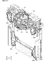
次に、図3に基づいて、パチンコ遊技機1Aの構造について説明する。 Next, the structure of the pachinko gaming machine 1A will be described with reference to FIG.

図3に示すように、遊技機用枠3は、上板61、下板62、左側板63及び右側板64により縦長四角枠状に形成される外枠60に支持されている。詳しくは、外枠60の開口下部は幕板65により閉塞され、外枠60の左上角部及び左下角部には、遊技機用枠3の左上角部及び左下角部に設けられた上下方向を向く回動軸(図示略)を回動可能に支持する軸受部(図示略)が設けられており、遊技機用枠3は、外枠60の左側辺付近を中心として該外枠60の開口を閉鎖する閉鎖位置と開口を開放する開放位置との間で回動可能に支持されている。 As shown in FIG. 3, the gaming machine frame 3 is supported by an outer frame 60 formed in a vertically long square frame shape by an upper plate 61, a lower plate 62, a left side plate 63, and a right side plate 64. Specifically, the lower part of the opening of the outer frame 60 is closed by the curtain plate 65, and the upper left corner portion and the lower left corner portion of the outer frame 60 are provided in the upper left corner portion and the lower left corner portion of the gaming machine frame 3 in the vertical direction. A bearing portion (not shown) that rotatably supports a rotating shaft (not shown) facing the machine is provided, and the gaming machine frame 3 is the outer frame 60 centered on the vicinity of the left side of the outer frame 60. It is rotatably supported between a closed position that closes the opening and an open position that opens the opening.

遊技機用枠3には、遊技盤2の背面側に設けられる各種部品や装置を被覆する裏カバー70が挿入可能な大きさの開口を有する装着部160が形成されており、装着部160の左側上下位置には係止凹部(図示略)が設けられ、右側上下位置には盤押え金具(図示略)が設けられている。よって、遊技機用枠3の前方から遊技盤2の背面の裏カバー70を装着部160に挿入し、該遊技盤2の左端部を係止凹部(図示略)に差し込んだ状態で右端部を盤押え金具(図示略)で係止することにより、遊技機用枠3に遊技盤2を装着できるようになっている。また、盤押え金具の係止状態を解除すれば遊技盤2を遊技機用枠3から容易に取外すことができる。 The gaming machine frame 3 is formed with a mounting portion 160 having an opening large enough to insert a back cover 70 for covering various parts and devices provided on the back side of the gaming board 2. A locking recess (not shown) is provided at the upper and lower positions on the left side, and a board holding metal fitting (not shown) is provided at the upper and lower positions on the right side. Therefore, the back cover 70 on the back surface of the gaming board 2 is inserted into the mounting portion 160 from the front of the gaming machine frame 3, and the right end portion is inserted into the locking recess (not shown) with the left end portion of the gaming board 2 inserted. The gaming board 2 can be mounted on the gaming machine frame 3 by locking with the board holding metal fittings (not shown). Further, the gaming board 2 can be easily removed from the gaming machine frame 3 by releasing the locked state of the board holding metal fittings.

また、図3及び図6に示すように、遊技機用枠3の装着部160の下部には、遊技機用枠3及び開閉枠50からなる遊技枠に設けられたセンサやモータ等の各種電子部品からの配線が接続される枠側コネクタWCNが設けられ、遊技盤2の下部には、遊技盤2に設けられたセンサやモータ等の各種電子部品からの配線が接続される盤側コネクタBCNが設けられており、遊技盤2を前方から装着部160に装着することで枠側コネクタWCNと盤側コネクタBCNとが接続されるようになっている。これにより、遊技盤2を装着部160に装着することで演出制御基板12に制御される電子部品のうち盤側の電子部品がそれぞれ演出制御基板12に接続され、遊技盤2を装着部160から取外すことで演出制御基板12に制御される電子部品のうち盤側の電子部品と演出制御基板12との接続が解除されるようになっている。 Further, as shown in FIGS. 3 and 6, various electronic components such as sensors and motors provided in the game frame including the game machine frame 3 and the opening / closing frame 50 are below the mounting portion 160 of the game machine frame 3. A frame-side connector WCN to which wiring from parts is connected is provided, and a board-side connector BCN to which wiring from various electronic parts such as sensors and motors provided on the game board 2 is connected is provided at the lower part of the game board 2. Is provided, and the frame-side connector WCN and the board-side connector BCN are connected by mounting the game board 2 on the mounting portion 160 from the front. As a result, among the electronic components controlled by the effect control board 12 by mounting the game board 2 on the mounting unit 160, the electronic components on the board side are connected to the effect control board 12, and the game board 2 is mounted from the mounting unit 160. By removing the electronic components controlled by the effect control board 12, the connection between the electronic components on the board side and the effect control board 12 is released.

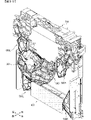
次に、図4~図7には、他のパチンコ遊技機1Bが示されている。パチンコ遊技機1Aは、開閉枠50及び遊技機用枠3からなる遊技枠が、特定の機種に固有の意匠及び役物等を有し、特定の機種にのみ使用される専用枠として製造されたものであるのに対し、パチンコ遊技機1Bは、開閉枠50及び遊技機用枠3からなる遊技枠が、所定の意匠及び役物等を有し、複数の機種に共通して使用される共通枠として製造されたものである。 Next, FIGS. 4 to 7 show another pachinko gaming machine 1B. The pachinko gaming machine 1A is manufactured as a dedicated frame in which a gaming frame composed of an opening / closing frame 50 and a gaming machine frame 3 has a design and an accessory unique to a specific model and is used only for the specific model. On the other hand, in the pachinko gaming machine 1B, the gaming frame composed of the opening / closing frame 50 and the gaming machine frame 3 has a predetermined design, accessories, and the like, and is commonly used by a plurality of models. It was manufactured as a frame.

図4~図6に示すように、パチンコ遊技機1Bは、遊技機の基本的な構造や回路構成などについてはパチンコ遊技機1Aとほぼ同様に構成されているため、パチンコ遊技機1Aと同様の機能を有する構成部位や電子部品等については同じ符号を付すことにより詳細な説明は省略することとする。 As shown in FIGS. 4 to 6, the pachinko gaming machine 1B has almost the same configuration as the pachinko gaming machine 1A in terms of the basic structure and circuit configuration of the gaming machine, and thus is the same as the pachinko gaming machine 1A. Detailed explanations will be omitted by assigning the same reference numerals to functional parts, electronic parts, and the like.

図1~図6に示すように、パチンコ遊技機1Aとパチンコ遊技機1Bとは、それぞれ外枠60に回動可能に支持され開閉枠50を有する遊技機用枠3と、遊技機用枠3の装着部160に着脱可能な遊技盤2と、から主に構成され、遊技盤2の背面側には主基板11及び演出制御基板12が取付けられているが、開閉枠50の前面意匠は異なる。 As shown in FIGS. 1 to 6, the pachinko gaming machine 1A and the pachinko gaming machine 1B are a gaming machine frame 3 rotatably supported by an outer frame 60 and having an opening / closing frame 50, and a gaming machine frame 3 respectively. The main board 11 and the effect control board 12 are mounted on the back side of the game board 2, but the front design of the opening / closing frame 50 is different. ..

各パチンコ遊技機1A,1Bの遊技盤2は、機種に固有の役物(例えば、各種入賞口など)が設けられた遊技領域10が形成されるとともに、機種に固有の演出用可動体や装飾部材等が設けられている一方で、盤面板の外形などはほぼ同様に形成されているため、パチンコ遊技機1Aの遊技機用枠3の装着部160とパチンコ遊技機1Bの遊技機用枠3の装着部160のいずれにも装着できるようになっている。また、前述した枠側コネクタWCNと盤側コネクタBCNも、各パチンコ遊技機1A,1Bにおいて同じように設けられている。 In the game board 2 of each pachinko gaming machine 1A and 1B, a game area 10 provided with a unique accessory (for example, various winning openings) is formed, and a movable body and decoration for directing unique to the model are formed. While the members and the like are provided, the outer shape of the board is formed in almost the same manner. Therefore, the mounting portion 160 of the gaming machine frame 3 of the pachinko gaming machine 1A and the gaming machine frame 3 of the pachinko gaming machine 1B are provided. It can be mounted on any of the mounting portions 160 of the above. Further, the above-mentioned frame-side connector WCN and board-side connector BCN are also provided in the same manner in the pachinko gaming machines 1A and 1B.

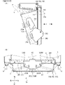
図7に示すように、各パチンコ遊技機1A,1Bの遊技枠は、打球操作ハンドル30、スティックコントローラ31A、プッシュボタン31B、十字ボタン46など、遊技者が操作可能な操作手段が設けられている。また、パチンコ遊技機1Aには、天発光部47を開閉可能なカバー体48が設けられている。これら打球操作ハンドル30、スティックコントローラ31A、プッシュボタン31B、十字ボタン46などは、同様の機能を有し同じ用途で使用される操作手段であるが、図7に示すように、それぞれ外観意匠や機能等が異なっている。 As shown in FIG. 7, the gaming frames of the pachinko gaming machines 1A and 1B are provided with operating means that can be operated by the player, such as a ball striking operation handle 30, a stick controller 31A, a push button 31B, and a cross button 46. .. Further, the pachinko gaming machine 1A is provided with a cover body 48 capable of opening and closing the celestial light emitting unit 47. The ball striking operation handle 30, the stick controller 31A, the push button 31B, the cross button 46, and the like are operation means having similar functions and used for the same purpose, but as shown in FIG. 7, they have appearance designs and functions, respectively. Etc. are different.

詳しくは、打球操作ハンドル30は、発射装置により遊技領域10に遊技球を発射させるための回転操作が可能とされている。パチンコ遊技機1Aの打球操作ハンドル30には、原点位置と突出位置との間で移動可能な可動体であるロケット45が設けられているが、パチンコ遊技機1Bの打球操作ハンドル30にはロケットは設けられていない。 Specifically, the ball striking operation handle 30 can be rotated by a launching device to launch a game ball into the game area 10. The ball striking operation handle 30 of the pachinko gaming machine 1A is provided with a rocket 45 which is a movable body that can move between the origin position and the protruding position. Not provided.

スティックコントローラ31Aは、原点位置(非操作位置)と該原点位置よりも手前側の引き位置(操作位置)との間で移動可能であり、原点位置においてスティック原点位置センサ35Aにより検出され、引き位置においてスティック引き位置センサ35Bにより検出され、振動モータ35Cにより振動するようになっている。一方、パチンコ遊技機1Aのスティックコントローラ31Aは上下動しないが、パチンコ遊技機1Bのスティックコントローラ31Aはスティックモータ35Dにより上下動するようになっている。また、パチンコ遊技機1Aとパチンコ遊技機1Bとでスティックコントローラ31Aの意匠は異なる。 The stick controller 31A can move between the origin position (non-operation position) and the pull position (operation position) on the front side of the origin position, and is detected by the stick origin position sensor 35A at the origin position and the pull position. It is detected by the stick pull position sensor 35B and vibrates by the vibration motor 35C. On the other hand, the stick controller 31A of the pachinko gaming machine 1A does not move up and down, but the stick controller 31A of the pachinko gaming machine 1B moves up and down by the stick motor 35D. Further, the design of the stick controller 31A is different between the pachinko gaming machine 1A and the pachinko gaming machine 1B.

プッシュボタン31Bは、原点位置(非操作位置)と該原点位置よりも下側の操作位置(操作位置)との間で移動可能であり、操作位置においてボタンセンサ36Aにより検出されるようになっている。また、パチンコ遊技機1Aとパチンコ遊技機1Bとでプッシュボタン31Bの意匠は異なる。 The push button 31B can be moved between the origin position (non-operation position) and the operation position (operation position) below the origin position, and is detected by the button sensor 36A at the operation position. There is. Further, the design of the push button 31B is different between the pachinko gaming machine 1A and the pachinko gaming machine 1B.

十字ボタン46は、原点位置(非操作位置)と該原点位置よりも前側、後側、左側、右側のいずれかの部位が下方に押下可能であり、各操作位置において各十字ボタンセンサ38A~38Dにより検出されるようになっている。尚、パチンコ遊技機1Aとパチンコ遊技機1Bとで十字ボタン46の意匠は同一である。 The cross button 46 can be pressed downward at the origin position (non-operation position) and any part on the front side, the rear side, the left side, or the right side of the origin position, and the cross button sensors 38A to 38D at each operation position. Is to be detected by. The design of the cross-shaped button 46 is the same for the pachinko gaming machine 1A and the pachinko gaming machine 1B.

カバー体48は、原点位置と開放位置との間で回動可能であり、原点位置においてカバー体原点位置センサ39Aにより検出され、開放位置においてカバー体開放位置センサ39Bにより検出され、カバー体モータ39Cによりカバー体48を回動できるようになっている。一方、パチンコ遊技機1Bには、天発光部47及び該天発光部47を開閉可能なカバー体48は設けられていない。 The cover body 48 is rotatable between the origin position and the open position, is detected by the cover body origin position sensor 39A at the origin position, is detected by the cover body open position sensor 39B at the open position, and is detected by the cover body motor 39C. Allows the cover body 48 to rotate. On the other hand, the pachinko gaming machine 1B is not provided with a celestial light emitting unit 47 and a cover body 48 capable of opening and closing the celestial light emitting unit 47.

また、専用枠(パチンコ遊技機1A)はスティックコントローラ31Aを上下動させるスティックモータを有しないしないが、共通枠(パチンコ遊技機1B)はスティックコントローラ31Aを上下動させるスティックモータ35Dを有している。また、専用枠(パチンコ遊技機1A)は演出用の可動体としてロケット45を動作させるためのロケットモータ37Cと、カバー体48を動作させるためのカバー体モータ39Cとを有しているが、共通枠はロケットモータやカバー体モータを有しない。 Further, the dedicated frame (pachinko gaming machine 1A) does not have a stick motor for moving the stick controller 31A up and down, but the common frame (pachinko gaming machine 1B) has a stick motor 35D for moving the stick controller 31A up and down. .. Further, the dedicated frame (pachinko gaming machine 1A) has a rocket motor 37C for operating the rocket 45 and a cover body motor 39C for operating the cover body 48 as a movable body for directing, but they are common. The frame does not have a rocket motor or a cover motor.

尚、パチンコ遊技機1Bの演出制御基板12には、図5に示すように、音量や光量等の演出設定を行うための設定切替スイッチ55、可動体700の第1駆動機構701、第2駆動機構702といった遊技盤2側に設けられる盤側電子部品と、スティック原点位置センサ35A、スティック引き位置センサ35B、振動モータ35C、スティックモータ35D、ボタンセンサ36A、十字ボタンセンサ38A~38Dといった遊技枠側に設けられる枠側電子部品と、が接続されている。 As shown in FIG. 5, the effect control board 12 of the pachinko gaming machine 1B has a setting changeover switch 55 for setting effects such as volume and light intensity, a first drive mechanism 701 of the movable body 700, and a second drive. Board-side electronic components such as the mechanism 702 provided on the game board 2 side, and game frame sides such as stick origin position sensor 35A, stick pull position sensor 35B, vibration motor 35C, stick motor 35D, button sensor 36A, and cross button sensors 38A to 38D. Is connected to the frame-side electronic component provided in.

また、演出制御基板12のROM121には、遊技盤2に設けられた可動体を動作させるための動作制御データだけでなく、パチンコ遊技機1Bを構成する開閉枠50及び遊技機用枠3を含む遊技枠に設けられた可動体を動作させるための動作制御データや、遊技枠に設けられた操作手段に対応する画像を表示するための画像データ等が記憶されている。 Further, the ROM 121 of the effect control board 12 includes not only the operation control data for operating the movable body provided on the game board 2, but also the opening / closing frame 50 and the game machine frame 3 constituting the pachinko gaming machine 1B. Motion control data for operating a movable body provided in the game frame, image data for displaying an image corresponding to the operation means provided in the game frame, and the like are stored.

本実施例では、例えば、パチンコ遊技機1Aの遊技盤2をパチンコ遊技機1Bの遊技機用枠3の装着部160に装着したり、パチンコ遊技機1Bの遊技盤2をパチンコ遊技機1Aの遊技機用枠3の装着部160に装着することが可能である。すなわち、一の遊技盤2(例えば、所定機種の遊技盤2)を、専用枠または共通枠のいずれにも装着可能である。また、遊技盤2を装着部160に装着することにより枠側コネクタWCNと盤側コネクタBCNとが接続され、遊技盤2に設けられる演出制御基板12に制御される電子部品のうち、遊技枠側に設けられる電子部品が演出制御基板12に配線接続される。 In this embodiment, for example, the gaming board 2 of the pachinko gaming machine 1A is attached to the mounting portion 160 of the gaming machine frame 3 of the pachinko gaming machine 1B, or the gaming board 2 of the pachinko gaming machine 1B is used for the gaming of the pachinko gaming machine 1A. It can be mounted on the mounting portion 160 of the machine frame 3. That is, one game board 2 (for example, a game board 2 of a predetermined model) can be mounted on either a dedicated frame or a common frame. Further, among the electronic components controlled by the effect control board 12 provided on the game board 2, the frame side connector WCN and the board side connector BCN are connected by mounting the game board 2 on the mounting portion 160, and the game frame side is used. The electronic components provided in the above are connected by wiring to the effect control board 12.

よって、例えば、パチンコ遊技機の製造メーカでの製造開発段階あるいは遊技店に納入された後などにおいて、専用枠に装着するものとして製造された遊技盤2をパチンコ遊技機1Bの装着部160に装着したり、共通枠に装着するものとして製造された遊技盤2をパチンコ遊技機1Aの装着部160に装着した場合でも、演出制御基板12と遊技枠側の電子部品とは配線接続されてしまう。そして、遊技枠に対応しない遊技盤2を装着したままパチンコ遊技機1A,1Bの電源を投入した場合、演出制御用CPU120が制御する遊技枠側の可動体の動作態様等が異なるため、演出制御用CPU120が遊技枠側の可動体に対し動作信号等を出力しても、可動体が動作しなかったり、可動体が誤動作したりすることがあるばかりか、対応しない動作信号を出力することによって駆動源であるモータ等に無理な負荷がかかり焼きついてしまうといった不具合が生じる可能性がある。 Therefore, for example, the gaming board 2 manufactured to be mounted on a dedicated frame is mounted on the mounting portion 160 of the pachinko gaming machine 1B at the manufacturing development stage of the pachinko gaming machine manufacturer or after it is delivered to the game store. Even when the gaming board 2 manufactured to be mounted on the common frame is mounted on the mounting portion 160 of the pachinko gaming machine 1A, the effect control board 12 and the electronic parts on the game frame side are connected by wiring. When the power of the pachinko gaming machines 1A and 1B is turned on while the gaming board 2 that does not correspond to the gaming frame is attached, the operation mode of the movable body on the gaming frame side controlled by the effect control CPU 120 is different, so that the effect control is performed. Even if the CPU 120 outputs an operation signal or the like to the movable body on the game frame side, the movable body may not operate or the movable body may malfunction, and by outputting an operation signal that does not correspond to the movable body. There is a possibility that a problem may occur in which an unreasonable load is applied to the motor or the like, which is the drive source, and the machine burns.

また、後述するようにスティックコントローラ31Aやプッシュボタン31Bの操作を促す演出を行う場合に、これらスティックコントローラ31Aやプッシュボタン31Bの演出表示装置5に画像を表示することがあるが(図18参照)、遊技枠に対応しない遊技盤2が装着された場合、演出制御用CPU120は、当該遊技盤2を装着した遊技枠に設けられているスティックコントローラ31Aやプッシュボタン31Bとは異なるスティックコントローラ31Aやプッシュボタン31Bの画像を表示してしまう可能性がある。 Further, as will be described later, when an effect for urging the operation of the stick controller 31A or the push button 31B is performed, an image may be displayed on the effect display device 5 of the stick controller 31A or the push button 31B (see FIG. 18). When a game board 2 that does not correspond to the game board 2 is mounted, the effect control CPU 120 has a stick controller 31A or a push different from the stick controller 31A or the push button 31B provided in the game board to which the game board 2 is mounted. There is a possibility that the image of the button 31B will be displayed.

よって、本実施例では、遊技盤2を遊技機用枠3の装着部160に装着して電源を投入した際に、演出制御用CPU120は、遊技枠に設けられる各種検出手段から出力される検出特定情報に基づいて、遊技盤2が装着されている遊技機用枠3が特定遊技機用枠(例えば、専用枠または共通枠)であるか否かを判定し、特定遊技機用枠であると判定したときに報知を行うことが可能である。 Therefore, in this embodiment, when the gaming board 2 is attached to the mounting portion 160 of the gaming machine frame 3 and the power is turned on, the effect control CPU 120 detects the output from various detection means provided in the gaming frame. Based on the specific information, it is determined whether or not the gaming machine frame 3 on which the gaming board 2 is mounted is a specific gaming machine frame (for example, a dedicated frame or a common frame), and is a specific gaming machine frame. It is possible to give a notification when it is determined.

次に、図8に基づいて、開閉枠50及び遊技機用枠3からなる遊技枠に設けられる各種電子部品と演出制御基板12との配線接続状況について説明する。 Next, with reference to FIG. 8, the wiring connection state between the effect control board 12 and various electronic components provided in the game frame including the opening / closing frame 50 and the game machine frame 3 will be described.

図8(A)に示すように、遊技枠が専用枠であるパチンコ遊技機1Aにおいては、演出制御基板12と各種電子部品(例えば、スティック原点位置センサ35A、スティック引き位置センサ35B、振動モータ35C、ボタンセンサ36A、ロケット原点位置センサ37A、ロケット突出位置センサ37B、ロケットモータ37C、十字ボタンセンサ38A~38D、カバー体原点位置センサ39A、カバー体開放位置センサ39B、カバー体モータ39C)との間には、パラレルデータをシリアルデータに変換するためのシリアル変換IC130が設けられている。 As shown in FIG. 8A, in the pachinko game machine 1A in which the game frame is a dedicated frame, the effect control board 12 and various electronic components (for example, stick origin position sensor 35A, stick pull position sensor 35B, vibration motor 35C) , Button sensor 36A, rocket origin position sensor 37A, rocket protrusion position sensor 37B, rocket motor 37C, cross button sensors 38A to 38D, cover body origin position sensor 39A, cover body open position sensor 39B, cover body motor 39C) Is provided with a serial conversion IC 130 for converting parallel data into serial data.

また、図8(B)に示すように、共通枠であるパチンコ遊技機1Bにおいては、演出制御基板12と各種電子部品(例えば、スティック原点位置センサ35A、スティック引き位置センサ35B、振動モータ35C、スティックモータ35D、ボタンセンサ36A、十字ボタンセンサ38A~38D)との間には、パラレルデータをシリアルデータに変換するためのシリアル変換IC130が設けられている。 Further, as shown in FIG. 8B, in the pachinko gaming machine 1B which is a common frame, the effect control board 12 and various electronic components (for example, stick origin position sensor 35A, stick pull position sensor 35B, vibration motor 35C, etc. A serial conversion IC 130 for converting parallel data into serial data is provided between the stick motor 35D, the button sensor 36A, and the cross button sensors 38A to 38D).

図8(A)(B)に示すシリアル変換IC130は、各種電子部品からの検出信号(パラレルデータ)が入力される入力ポート131と、演出制御基板12のシリアル通信部133に対しシリアルデータを出力するためのシリアル通信部132と、を有し、入力ポート131の各ポート番号(0(H)~7(a)、図9参照)各々の検出信号の入力状態に基づいて、入力ポート131への検出信号の入力状態を特定可能な16ビットのシリアルデータを生成し、該生成したシリアルデータをシリアル通信部132から演出制御基板12に出力できるようになっている。 The serial conversion IC 130 shown in FIGS. 8A and 8B outputs serial data to the input port 131 to which detection signals (parallel data) from various electronic components are input and to the serial communication unit 133 of the effect control board 12. To the input port 131 based on the input state of each detection signal of each port number (0 (H) to 7 (a), see FIG. 9) of the input port 131. 16-bit serial data that can specify the input state of the detection signal of the above is generated, and the generated serial data can be output from the serial communication unit 132 to the effect control board 12.

このようにパチンコ遊技機1A,1Bにあっては、遊技機用枠3に対して着脱可能な遊技盤2に演出制御基板12が設けられており、演出制御基板12と遊技枠側に設けられる枠側電子部品とはシリアルデータ通信が可能とされていることで、パラレルデータにより通信する場合に比べて演出制御基板12と各枠側電子部品との配線数を減らすことができるようになっている。 As described above, in the pachinko gaming machines 1A and 1B, the effect control board 12 is provided on the game board 2 which is detachable from the game machine frame 3, and is provided on the effect control board 12 and the game frame side. Since serial data communication is possible with the frame-side electronic components, the number of wires between the effect control board 12 and each frame-side electronic component can be reduced as compared with the case of communication by parallel data. There is.

尚、図8においては、遊技枠の各種電子部品から入力されるパラレルデータをシリアル変換IC130によりシリアルデータに変換して演出制御基板12に出力する回路構成を記載しているが、パチンコ遊技機1A,1Bは、特に詳細な図示はしないが、演出制御基板12からシリアルデータにて出力される各種制御情報をパラレルデータに変換するパラレル変換IC(図示略)を有し、パラレル変換ICにより変換したパラレルデータを遊技枠の各種電子部品(例えば、振動モータ35C、ロケットモータ37C、カバー体モータ39C、スティックモータ35D)に出力できるようになっている。 Note that FIG. 8 shows a circuit configuration in which parallel data input from various electronic components of the game frame is converted into serial data by the serial conversion IC 130 and output to the effect control board 12, but the pachinko game machine 1A is shown. , 1B has a parallel conversion IC (not shown) that converts various control information output as serial data from the effect control board 12 into parallel data, although not shown in detail, and converted by the parallel conversion IC. Parallel data can be output to various electronic components of the game frame (for example, vibration motor 35C, rocket motor 37C, cover body motor 39C, stick motor 35D).

また、図8においては、説明の便宜上、遊技枠側に設けられる全ての電子部品からの検出信号は一のシリアル変換IC130の入力ポート131に入力される形態を例示したが、本発明はこれに限定されるものではなく、シリアル変換IC130を複数設けてもよい。また、シリアル変換IC130は、遊技枠の所定箇所(例えば、開閉枠50の背面など)に設けられることが好ましい。 Further, in FIG. 8, for convenience of explanation, a mode in which detection signals from all electronic components provided on the game frame side are input to the input port 131 of one serial conversion IC 130 is illustrated, but the present invention illustrates this. A plurality of serial conversion ICs 130 may be provided without limitation. Further, it is preferable that the serial conversion IC 130 is provided at a predetermined position of the game frame (for example, the back surface of the opening / closing frame 50).

また、本実施例では、パチンコ遊技機1A,1Bの電源を投入したときに、入力ポート131に、スティックコントローラ31A、プッシュボタン31B、十字ボタン46、ロケット45、カバー体28を検出している各種センサからは検出信号(オン状態を示す信号)が出力されるようになっている。そして、シリアル変換IC130は、入力ポート131の各ポート番号(0(H)~7(a)、図9参照)各々の信号の入力状態(オン状態、オフ状態)を確認し、入力ポート131への検出信号の入力状態を特定可能な16ビットのシリアルデータを生成し、シリアル通信部132を介して演出制御基板12のシリアル通信部133に出力するようになっている。 Further, in this embodiment, when the power of the pachinko gaming machines 1A and 1B is turned on, the stick controller 31A, the push button 31B, the cross button 46, the rocket 45, and the cover body 28 are detected in the input port 131. A detection signal (a signal indicating an ON state) is output from the sensor. Then, the serial conversion IC 130 confirms the input state (on state, off state) of each signal of each port number (0 (H) to 7 (a), see FIG. 9) of the input port 131, and goes to the input port 131. 16-bit serial data that can specify the input state of the detection signal of the above is generated and output to the serial communication unit 133 of the effect control board 12 via the serial communication unit 132.

また、本実施例では、パチンコ遊技機1A,1Bの電源を投入したときに、シリアル変換IC130が、入力ポート131の各ポート番号(0(H)~7(a))各々の信号の入力状態を確認することにより入力ポート131への検出信号の入力状態を特定可能なシリアルデータを生成して演出制御基板12に出力する形態を例示したが、本発明はこれに限定されるものではなく、パチンコ遊技機1A,1Bの電源を投入したときに、演出制御用CPU120がシリアル変換IC130に対し入力取込信号(ラッチ信号)を出力し、該入力取込信号(ラッチ信号)が入力されたことに基づいてシリアル変換IC130が入力ポート131への検出信号の入力状態を特定可能なシリアルデータを生成して演出制御基板12に出力するようにしてもよい。 Further, in this embodiment, when the power of the pachinko gaming machines 1A and 1B is turned on, the serial conversion IC 130 inputs the signals of each port number (0 (H) to 7 (a)) of the input port 131. However, the present invention is not limited to this, although the embodiment in which serial data capable of specifying the input state of the detection signal to the input port 131 is generated and output to the effect control board 12 is illustrated. When the power of the pachinko gaming machines 1A and 1B was turned on, the effect control CPU 120 output an input capture signal (latch signal) to the serial conversion IC 130, and the input capture signal (latch signal) was input. The serial conversion IC 130 may generate serial data that can specify the input state of the detection signal to the input port 131 and output it to the effect control board 12.

また、本実施例では、パチンコ遊技機1A,1Bの電源を投入したときに、振動モータ35C、ロケットモータ37C、カバー体モータ39C、スティックモータ35Dからの駆動信号は入力ポート131に入力されることはなく、演出制御用CPU120からモータの駆動信号が出力され、該駆動信号に基づいて各モータが駆動することにより、駆動信号が入力ポート131に入力されるようになっている。 Further, in this embodiment, when the power of the pachinko gaming machines 1A and 1B is turned on, the drive signals from the vibration motor 35C, the rocket motor 37C, the cover body motor 39C, and the stick motor 35D are input to the input port 131. Instead, the drive signal of the motor is output from the effect control CPU 120, and each motor is driven based on the drive signal, so that the drive signal is input to the input port 131.

尚、本実施例では、演出制御用CPU120からモータの駆動信号が出力されたことに基づいて各モータが駆動することで駆動信号が入力ポート131に入力される形態を例示したが、本発明はこれに限定されるものではなく、モータを検出可能な検出手段を設け、パチンコ遊技機1A,1Bの電源を投入したときに該検出手段からの検出信号が入力されるようにしてもよい。 In this embodiment, the mode in which the drive signal is input to the input port 131 by driving each motor based on the output of the drive signal of the motor from the effect control CPU 120 is illustrated, but the present invention exemplifies. The present invention is not limited to this, and a detection means capable of detecting the motor may be provided so that the detection signal from the detection means is input when the power of the pachinko gaming machines 1A and 1B is turned on.

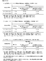
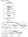
図9(A)に示すように、遊技枠が専用枠であるパチンコ遊技機1Aでは、遊技枠の各種電子部品からの検出信号は、入力ポート131の各ポート番号0(H)~7(A)、0(h)~7(a)に入力され、図9(B)に示すように、共通枠であるパチンコ遊技機1Bでは、遊技枠の各種電子部品からの検出信号は、入力ポート131における各ポート番号0(H)~7(A)、0(h)~7(a)に入力されるようになっている。 As shown in FIG. 9A, in the pachinko gaming machine 1A in which the gaming frame is a dedicated frame, the detection signals from various electronic parts of the gaming frame are the port numbers 0 (H) to 7 (A) of the input port 131. ), 0 (h) to 7 (a), and as shown in FIG. 9 (B), in the pachinko gaming machine 1B which is a common frame, the detection signals from various electronic parts of the game frame are input ports 131. It is designed to be input to each port number 0 (H) to 7 (A) and 0 (h) to 7 (a) in.

詳しくは、図9(A)(B)に示すように、ボタンセンサ35は、パチンコ遊技機1A,1Bともにポート番号3(E)に接続され、スティック原点位置センサ35A、スティック引き位置センサ35Bは、パチンコ遊技機1A,1Bともにポート番号7(A)、0(h)に接続され、十字ボタンセンサ38A~38Dは、パチンコ遊技機1A,1Bともにポート番号4(d)~7(a)に接続されている。 Specifically, as shown in FIGS. 9A and 9B, the button sensor 35 is connected to the port number 3 (E) for both the pachinko gaming machines 1A and 1B, and the stick origin position sensor 35A and the stick pull position sensor 35B are , Pachinko gaming machines 1A and 1B are both connected to port numbers 7 (A) and 0 (h), and the cross button sensors 38A to 38D are connected to port numbers 4 (d) to 7 (a) for both pachinko gaming machines 1A and 1B. It is connected.

一方、振動モータ35Cは、パチンコ遊技機1Aではポート番号2(F)、パチンコ遊技機1Bではポート番号0(H)に接続されている。つまり、振動モータ35Cからの検出信号が入力されるポート番号がパチンコ遊技機1Aとパチンコ遊技機1Bとで異なっている。また、ロケット原点位置センサ37A、ロケット突出位置センサ37B、ロケットモータ37Cは、パチンコ遊技機1Aではポート番号4(D)~6(B)に接続されているが、パチンコ遊技機1Bではポート番号4(D)~6(B)には接続されていない。また、カバー体原点位置センサ39A、カバー体開放位置センサ39B、カバー体モータ39Cは、パチンコ遊技機1Aではポート番号1(g)~3(e)に接続されているが、パチンコ遊技機1Bではポート番号1(g)~3(e)に接続されていない。 On the other hand, the vibration motor 35C is connected to the port number 2 (F) in the pachinko gaming machine 1A and to the port number 0 (H) in the pachinko gaming machine 1B. That is, the port number to which the detection signal from the vibration motor 35C is input is different between the pachinko gaming machine 1A and the pachinko gaming machine 1B. Further, the rocket origin position sensor 37A, the rocket protrusion position sensor 37B, and the rocket motor 37C are connected to the port numbers 4 (D) to 6 (B) in the pachinko gaming machine 1A, but the port number 4 in the pachinko gaming machine 1B. It is not connected to (D) to 6 (B). Further, the cover body origin position sensor 39A, the cover body open position sensor 39B, and the cover body motor 39C are connected to the port numbers 1 (g) to 3 (e) in the pachinko gaming machine 1A, but in the pachinko gaming machine 1B. Not connected to port numbers 1 (g) to 3 (e).

このように、シリアル変換IC130の入力ポート131に入力される検出信号は、ボタンセンサ35、スティック原点位置センサ35A及びスティック引き位置センサ35B、十字ボタンセンサ38A~38Dについてはパチンコ遊技機1A,1Bともに共通のポート番号に入力されるが、振動モータ35Cについては、パチンコ遊技機1Aとパチンコ遊技機1Bとで異なるポート番号に入力され、また、ロケット原点位置センサ37A、ロケット突出位置センサ37B、ロケットモータ37C、カバー体原点位置センサ39A、カバー体開放位置センサ39B、カバー体モータ39Cについては、検出信号はパチンコ遊技機1Aの特定のポート番号に入力されるが、パチンコ遊技機1Bの特定のポート番号には入力されない。 As described above, the detection signals input to the input port 131 of the serial conversion IC 130 are the button sensor 35, the stick origin position sensor 35A and the stick pull position sensor 35B, and the cross button sensors 38A to 38D are all the pachinko gaming machines 1A and 1B. Although it is input to a common port number, the vibration motor 35C is input to a different port number for the pachinko game machine 1A and the pachinko game machine 1B, and the rocket origin position sensor 37A, the rocket protrusion position sensor 37B, and the rocket motor. For the 37C, the cover body origin position sensor 39A, the cover body open position sensor 39B, and the cover body motor 39C, the detection signal is input to the specific port number of the pachinko game machine 1A, but the specific port number of the pachinko game machine 1B. Is not entered.

すなわち、演出制御用CPU120は、検出対象物が同じ検出手段や機能や用途が同じ駆動源であっても、専用枠と共通枠とで、検出信号が入力される入力ポート131のポート番号が異なっていることや、特定のポート番号に専用枠と共通枠のうち一方でしか検出信号が入力されないことや、専用枠と共通枠とで検出信号の入力ポート数が異なることのうち少なくともいずれか一の判別事項に基づいて、専用枠と共通枠とを判別する。 That is, in the effect control CPU 120, the port number of the input port 131 to which the detection signal is input differs between the dedicated frame and the common frame even if the detection target is the same detection means, function, and use. At least one of the fact that the detection signal is input to a specific port number in only one of the dedicated frame and the common frame, and that the number of detection signal input ports differs between the dedicated frame and the common frame. Based on the discrimination items of, the dedicated frame and the common frame are discriminated.

図9(A)(B)に示すように、演出制御基板12のROM121には、専用枠及び共通枠の各電子部品からの検出信号が入力ポート131のいずれのポート番号に入力されるかを特定可能なデータが記憶されている。よって、演出制御用CPU120は、電源投入時において、シリアル変換IC130から受信したシリアルデータにおいて、遊技枠に設けられた各種電子部品のうち特定の電子部品からの検出信号が入力されるポート番号に該当するシリアルデータを特定し、特定したシリアルデータに検出信号の入力状態を示すデータがあるか否かを確認することにより、遊技盤2を装着した遊技枠が専用枠または共通枠であるかを判定し、該判定結果に基づく報知を行うことができるようになっている。 As shown in FIGS. 9A and 9B, the ROM 121 of the effect control board 12 indicates to which port number of the input port 131 the detection signals from the electronic components of the dedicated frame and the common frame are input. Identifiable data is stored. Therefore, the effect control CPU 120 corresponds to a port number to which a detection signal from a specific electronic component among various electronic components provided in the game frame is input in the serial data received from the serial conversion IC 130 when the power is turned on. By specifying the serial data to be used and checking whether or not the specified serial data has data indicating the input state of the detection signal, it is determined whether the game frame equipped with the game board 2 is a dedicated frame or a common frame. However, it is possible to perform notification based on the determination result.

次に、演出制御基板12の動作を説明する。先ず、演出制御用CPU120は、電源が投入されると、図10に示すメイン処理の実行を開始する。メイン処理では、まず、RAM領域のクリアや各種初期値の設定、また演出制御の起動間隔(例えば、2ms)を決めるためのタイマの初期設定等を行うための第1初期化処理(S50)と、遊技盤2側に設けられた各可動体(第1可動体300、第2可動体400、第3可動体500L,500R及び第4可動体600L,600R/可動体700)の原点位置への復帰と動作確認を行うための第2初期化処理(S51A)と、遊技枠側に設けられた各可動体(ロケット45、カバー体28、パチンコ遊技機1Bのスティックコントローラ31Aなど)の原点位置への復帰と動作確認を行うための第3初期化処理(S51B)とを行う。その後、演出制御用CPU120は、タイマ割込フラグの監視(S52)を行うループ処理に移行する。タイマ割込が発生すると、演出制御用CPU120は、タイマ割込処理によりタイマ割込フラグをセットする。メイン処理で、タイマ割込フラグがセット(オン)されていたら、演出制御用CPU120は、そのフラグをクリアし(S53)、以下の処理を実行する。 Next, the operation of the effect control board 12 will be described. First, when the power is turned on, the effect control CPU 120 starts executing the main process shown in FIG. In the main process, first, the first initialization process (S50) for clearing the RAM area, setting various initial values, and initializing the timer for determining the activation interval (for example, 2 ms) of the effect control. , To the origin position of each movable body (first movable body 300, second movable body 400, third movable body 500L, 500R and fourth movable body 600L, 600R / movable body 700) provided on the game board 2 side. To the origin position of the second initialization process (S51A) for returning and checking the operation, and each movable body (rocket 45, cover body 28, stick controller 31A of pachinko game machine 1B, etc.) provided on the game frame side. The third initialization process (S51B) for returning and confirming the operation is performed. After that, the effect control CPU 120 shifts to the loop process for monitoring the timer interrupt flag (S52). When the timer interrupt occurs, the effect control CPU 120 sets the timer interrupt flag by the timer interrupt process. If the timer interrupt flag is set (on) in the main process, the effect control CPU 120 clears the flag (S53) and executes the following process.

演出制御用CPU120は、まず、コマンド解析処理を行う(S54)。コマンド解析処理では、受信コマンドバッファに格納されている主基板11から送信されてきたコマンドが、どのコマンド(図4参照)であるのか解析する。尚、遊技制御用マイクロコンピュータ100から送信された演出制御コマンドは、演出制御INT信号にもとづく割込処理で受信され、RAMに形成されているバッファ領域に保存されている。そして、受信した演出制御コマンドに応じたフラグをセットする処理等を行う。 The effect control CPU 120 first performs command analysis processing (S54). In the command analysis process, it is analyzed which command (see FIG. 4) is the command transmitted from the main board 11 stored in the received command buffer. The effect control command transmitted from the game control microcomputer 100 is received by the interrupt process based on the effect control INT signal, and is stored in the buffer area formed in the RAM. Then, a process of setting a flag corresponding to the received effect control command is performed.

次いで、演出制御用CPU120は、演出制御プロセス処理を行う(S55)。演出制御プロセス処理では、制御状態に応じた各プロセスのうち、現在の制御状態(演出制御プロセスフラグ)に対応した処理を選択して演出表示装置5の表示制御を実行する。 Next, the effect control CPU 120 performs the effect control process process (S55). In the effect control process process, the process corresponding to the current control state (effect control process flag) is selected from each process according to the control state, and the display control of the effect display device 5 is executed.

次いで、大当り図柄判定用乱数などの演出用乱数を生成するためのカウンタのカウント値を更新する演出用乱数更新処理を実行した後(S56)、サブ側エラー処理(S57)を実行し、その後、サブ側報知処理(S58)を実行した後、S52に移行する。 Next, after executing the effect random number update process (S56) for updating the count value of the counter for generating the effect random number such as the jackpot symbol determination random number, the sub-side error process (S57) is executed, and then the sub-side error process (S57) is executed. After executing the sub-side notification process (S58), the process proceeds to S52.

図11は、本実施例の第2初期化処理(S51A)を示すフローチャートである。第2初期化処理において演出制御用CPU120は、先ず、設定データに基づいて最初に動作させる可動体を特定する(S101)。設定データには、可動体の順序データが含まれており、本実施例では、該順序として第1可動体300→第2可動体400→第3可動体500L,500R→第4可動体600L,600Rの順が予め設定されている。よって、最初にS101が実行されるときには、第1可動体300が対象の可動体として特定されることになる。次いで、S101で特定した可動体が原点検出を行うことが必要な原点検出対象可動体であるか否かを判定する(S102)。 FIG. 11 is a flowchart showing the second initialization process (S51A) of this embodiment. In the second initialization process, the effect control CPU 120 first identifies the movable body to be operated first based on the setting data (S101). The setting data includes the order data of the movable bodies, and in this embodiment, the order is as follows: 1st movable body 300 → 2nd movable body 400 → 3rd movable body 500L, 500R → 4th movable body 600L, The order of 600R is preset. Therefore, when S101 is executed for the first time, the first movable body 300 is specified as the target movable body. Next, it is determined whether or not the movable body specified in S101 is an origin detection target movable body that needs to perform origin detection (S102).

本実施例において、これら原点検出を行うことが必要な原点検出対象可動体としては、原点位置検出センサを有する可動体のみが該当し、原点検出センサを有しない可動体は該当しない。よって、S101で特定した可動体が原点位置検出センサを有する可動体のいずれかである場合には、該判定において「Y」と判定される一方、S101で特定した可動体が原点位置検出センサを有しない可動体である場合には、「N」と判定されることになる。 In this embodiment, as the origin detection target movable body for which it is necessary to perform origin detection, only the movable body having the origin position detection sensor is applicable, and the movable body without the origin detection sensor is not applicable. Therefore, when the movable body specified in S101 is any of the movable bodies having the origin position detection sensor, it is determined as "Y" in the determination, while the movable body specified in S101 uses the origin position detection sensor. If it is a movable body that does not have it, it will be determined as "N".

S102において「N」と判定された場合にはS130に進む。一方、S102において「Y」と判定された場合には、S103に進んで、動作対象可動体に対応する原点検出センサの検出状態を特定し(S103)、原点検出センサが検出状態であるか否か、つまり、対象の可動体が原点位置(初期位置)に位置しているか否かを判定する(S104)。 If it is determined to be "N" in S102, the process proceeds to S130. On the other hand, if it is determined to be "Y" in S102, the process proceeds to S103 to specify the detection state of the origin detection sensor corresponding to the movable body to be operated (S103), and whether or not the origin detection sensor is in the detection state. That is, it is determined whether or not the target movable body is located at the origin position (initial position) (S104).

原点位置(初期位置)に位置していない場合(S104;N)には、S105に進んで、非検出時動作制御の実行回数を計数するための非検出時動作回数カウンタに0をセットした後(S105)、動作対象可動体を動作させるための制御速度として、後述する実動作確認用動作制御(ロング初期化動作制御)における最低速度(図13、図14参照)と同じ動作速度で動作対象可動体を動作させるための最低制御速度を設定し(S106)、動作対象可動体の駆動モータ、例えば、動作対象可動体が第1可動体300であれば、第1可動体駆動モータ303を原点位置方向に駆動開始し、例えば、動作対象可動体が第1可動体300であれば、レバー用モータ36を原点位置方向に駆動開始するとともに(S107)、非検出時動作期間タイマのタイマカウントを開始する(S108)。尚、非検出時動作期間タイマのタイマカウントは、例えば、第1初期化処理にて初期化されたCTCから一定期間毎に出力される信号の数をカウントすること等により行うようにすればよい。 If it is not located at the origin position (initial position) (S104; N), the process proceeds to S105, and after setting 0 in the non-detection operation count counter for counting the number of executions of the non-detection operation control. (S105), The operation target is the control speed for operating the movable body, which is the same as the minimum speed (see FIGS. 13 and 14) in the actual operation confirmation operation control (long initialization operation control) described later. The minimum control speed for operating the movable body is set (S106), and the drive motor of the movable body to be operated, for example, if the movable body to be operated is the first movable body 300, the origin is the first movable body drive motor 303. Driving starts in the position direction, for example, if the movable body to be operated is the first movable body 300, the lever motor 36 is started to be driven in the direction of the origin position (S107), and the timer count of the non-detection operation period timer is counted. Start (S108). The timer count of the non-detection operation period timer may be performed, for example, by counting the number of signals output from the CTC initialized in the first initialization process at regular intervals. ..

そして、原点検出センサが検出状態となるかとともに、非検出時動作期間タイマが上限時間に対応する値となったか否かを監視する監視状態に移行する(S109、S110)。 Then, as soon as the origin detection sensor is in the detection state, it shifts to the monitoring state of monitoring whether or not the non-detection operation period timer has reached the value corresponding to the upper limit time (S109, S110).

動作対象可動体の駆動装置(例えば、第1可動体駆動モータ303等)を原点位置方向に駆動させることで動作対象可動体が原点位置(初期位置)に位置して原点検出センサが検出状態となった場合には、駆動モータの駆動を停止してS130に進む。一方、非検出時動作期間タイマが上限時間に対応する値となった場合、つまり、上限時間が経過しても動作対象可動体が原点位置(初期位置)に位置しなかった場合には、S112に進んで、非検出時動作回数カウンタに1を加算して(S112)、該加算後の非検出時動作回数カウンタの値が、動作エラー判定回数(例えば3)に達したか否かを判定する(S113)。 By driving the drive device of the movable object to be operated (for example, the first movable body drive motor 303, etc.) in the direction of the origin position, the movable object to be operated is positioned at the origin position (initial position) and the origin detection sensor is in the detection state. If this happens, the drive of the drive motor is stopped and the process proceeds to S130. On the other hand, when the non-detection operation period timer reaches a value corresponding to the upper limit time, that is, when the operation target movable body is not located at the origin position (initial position) even after the upper limit time has elapsed, S112 1 is added to the non-detection operation count counter (S112), and it is determined whether or not the value of the non-detection operation count counter after the addition reaches the operation error determination number (for example, 3). (S113).

S113において非検出時動作回数カウンタの値が動作エラー判定回数に達している場合には、駆動モータの駆動を停止し、当該動作対象可動体の原点復帰エラーを記憶し(S114)、S130に進む。つまり、非検出時動作制御において動作対象可動体が原点位置(初期位置)に位置しなかった場合には、当該動作対象可動体について後述する実動作確認用動作制御を実行しないようにする(当該動作対象可動体をデッドエンド状態する)ために原点復帰エラーを記憶し、S130に進む。 When the value of the operation count counter at the time of non-detection reaches the operation error determination number in S113, the drive of the drive motor is stopped, the origin return error of the operation target movable body is stored (S114), and the process proceeds to S130. .. That is, when the operation target movable body is not located at the origin position (initial position) in the non-detection operation control, the operation control for actual operation confirmation described later is not executed for the operation target movable body (the relevant). The origin return error is stored in order to put the movable body to be operated in the dead end state), and the process proceeds to S130.

尚、本実施例では、S113において非検出時動作回数カウンタの値が動作エラー判定回数に達している場合には、当該動作対象可動体をデッドエンド状態する形態を例示したが、本発明はこれに限定されるものではなく、S113において非検出時動作回数カウンタの値が動作エラー判定回数に達している場合に、初期化エラー処理を開始し、該初期化エラー処理を実行することにより、第2初期化処理を中断することで、演出制御メイン処理がS52に進むことなく中断され、演出制御基板12(演出制御用CPU120など)は起動しない状態(デッドエンド状態)にするようにしてもよい。 In this embodiment, when the value of the operation count counter at the time of non-detection reaches the operation error determination number in S113, the embodiment in which the operation target movable body is in the dead end state is exemplified. When the value of the operation count counter at the time of non-detection reaches the operation error determination number in S113, the initialization error processing is started and the initialization error processing is executed. 2. By interrupting the initialization process, the effect control main process may be interrupted without proceeding to S52, and the effect control board 12 (such as the effect control CPU 120) may be put into a non-startable state (dead end state). ..

また、動作対象可動体をデッドエンド状態とした場合、演出制御基板12(演出制御用CPU120など)は起動するが、例えば、演出制御用CPU120は、可動体を動作させることを示す入力信号(例えば、演出ボタン等の検出信号)の受付けを無効としたり、該入力信号が入力されても、当該動作対象可動体を動作させないようにするといった処理を実行することが好ましい。 Further, when the movable body to be operated is set to the dead end state, the effect control board 12 (effect control CPU 120 or the like) is activated, but for example, the effect control CPU 120 is an input signal (for example, indicating that the movable body is operated). , The reception of the detection signal of the effect button and the like) is invalidated, and even if the input signal is input, it is preferable to execute a process such as preventing the movable body to be operated from operating.

一方、非検出時動作回数カウンタの値が動作エラー判定回数に達していない場合には、駆動モータの駆動を停止してS106に戻り、再度、S106~S108の処理を行うことにより、動作対象可動体を、実動作確認用動作制御(ロング初期化動作制御)における最低速度にて原点位置に移動させる動作(非検出時動作制御)を開始して、前述したS109、S110の監視状態に移行する。 On the other hand, if the value of the operation count counter at the time of non-detection has not reached the operation error determination number, the drive motor is stopped and returned to S106, and the processing of S106 to S108 is performed again to move the operation target. The operation of moving the body to the origin position at the lowest speed in the operation control for confirming the actual operation (long initialization operation control) (operation control at the time of non-detection) is started, and the operation shifts to the monitoring state of S109 and S110 described above. ..

よって、S110にてエラー判定時間が経過したと判定されたとしても、動作エラー判定回数に達するまで繰返し動作対象可動体を原点位置(初期位置)に移動させる動作(非検出時動作制御)を実行している間に動作対象可動体が原点位置(初期位置)にて検出した場合には、S114に進むことなく、S130に進むことになる。 Therefore, even if it is determined in S110 that the error determination time has elapsed, the operation of repeatedly moving the operation target movable body to the origin position (initial position) (operation control at the time of non-detection) is executed until the number of operation error determinations is reached. If the movable body to be operated is detected at the origin position (initial position) during the operation, the process proceeds to S130 without proceeding to S114.

一方、上記したS104において「Y」と判定されてS120に進んだ場合には、検出時動作回数カウンタに0をセットした後、検出時動作プロセスデータをセットし(S121a)、検出時動作プロセスタイマのタイマカウントを開始する(S121b)。尚、検出時動作プロセスタイマのタイマカウントとしては、前述した非検出時動作期間タイマのタイマカウントと同様に、第1初期化処理にて初期化されたCTCから一定期間毎に出力される信号の数をカウントすること等により行うようにすればよい。また、本実施例の検出時動作プロセスデータには、動作対象可動体を動作させるための制御速度として、後述する実動作確認用動作制御(ロング初期化動作制御)における最低速度(図13、図14参照)と同じ動作速度で動作対象可動体を動作させるための最低制御速度が記述(設定)されている。 On the other hand, when the determination is "Y" in S104 described above and the process proceeds to S120, 0 is set in the detection operation count counter, the detection operation process data is set (S121a), and the detection operation process timer is set. (S121b). As the timer count of the detection operation process timer, the signal output from the CTC initialized in the first initialization process at regular intervals is the same as the timer count of the non-detection operation period timer described above. It may be done by counting the number or the like. Further, in the detection operation process data of this embodiment, the minimum speed (FIG. 13, FIG. 13) in the operation control for actual operation confirmation (long initialization operation control) described later is described as the control speed for operating the operation target movable body. The minimum control speed for operating the moving object to be operated at the same operating speed as (see 14) is described (set).

次いで、セットされた検出時動作プロセスデータに設定されている最低制御速度に基づいて動作対象可動体を動作させるとともに(S122)、プロセスデータが完了したか否かを判定し(S123)、プロセスデータが完了していない場合には、S122に戻り、動作対象可動体を検出時動作プロセスデータに設定されている最低制御速度に基づいて動作させる。 Next, the operation target movable body is operated based on the minimum control speed set in the set detection time operation process data (S122), and it is determined whether or not the process data is completed (S123), and the process data is processed. If is not completed, the process returns to S122, and the movable object to be operated is operated based on the minimum control speed set in the operation process data at the time of detection.

このように、検出時動作制御においては、検出時動作プロセスデータが完了するまで、検出時動作プロセスデータに設定されている最低制御速度に基づく最低速度、つまり、実動作確認用動作制御(ロング初期化動作制御)における最低速度にて、原点位置(初期位置)から一旦離れ、該原点位置(初期位置)から離れた位置から原点位置(初期位置)に戻るという動作を行う(図13参照)。尚、原点位置から離れた位置とは、原点位置の近傍位置、つまり、各原点センサにより各可動体の被検出部を検出できない位置であって各演出位置よりも原点位置に近い所定位置(検出時動作位置)として設定されている。 In this way, in the operation control at the time of detection, the minimum speed based on the minimum control speed set in the operation process data at the time of detection, that is, the operation control for confirming the actual operation (long initial stage) until the operation process data at the time of detection is completed. At the lowest speed in the conversion operation control), the operation of temporarily leaving the origin position (initial position) and returning to the origin position (initial position) from the position away from the origin position (initial position) is performed (see FIG. 13). The position away from the origin position is a position near the origin position, that is, a position where the detected portion of each movable body cannot be detected by each origin sensor, and a predetermined position (detection) closer to the origin position than each effect position. When operating position) is set.

S123の判定において、セットされている検出時動作プロセスデータが完了したと判定した場合には、可動体駆動モータの駆動を停止してS124に進んで、原点検出センサが検出状態になっているか否か、つまり、動作対象可動体が原点位置(初期位置)に位置しているか否かを判定(確認)する。 If it is determined in the determination of S123 that the set detection operation process data is completed, the drive of the movable body drive motor is stopped and the process proceeds to S124 to determine whether the origin detection sensor is in the detection state. That is, it is determined (confirmed) whether or not the movable body to be operated is located at the origin position (initial position).

原点検出センサが検出状態になっている場合、つまり、動作対象可動体が原点位置(初期位置)に位置している場合にはS130に進む。 When the origin detection sensor is in the detection state, that is, when the movable body to be operated is located at the origin position (initial position), the process proceeds to S130.

一方、原点検出センサが検出状態になっていない場合、つまり、動作対象可動体が原点位置(初期位置)に位置していない場合には、検出時動作回数カウンタに1を加算して(S126)、該加算後の検出時動作回数カウンタの値が、動作エラー判定回数(例えば3)に達したか否かを判定する(S127)。検出時動作回数カウンタの値が動作エラー判定回数に達している場合には、S128に進んで当該動作対象可動体の原点復帰エラーを記憶し(S128)、S130に進む。つまり、検出時動作制御において動作対象可動体が原点位置(初期位置)に位置しなかった場合には、当該動作対象可動体について後述する実動作確認用動作制御を実行しないようにする(当該動作対象可動体をデッドエンド状態する)ために原点復帰エラーを記憶し、S130に進む。 On the other hand, when the origin detection sensor is not in the detection state, that is, when the movable object to be operated is not located at the origin position (initial position), 1 is added to the detection operation count counter (S126). , It is determined whether or not the value of the detection operation number counter after the addition reaches the operation error determination number (for example, 3) (S127). When the value of the operation count counter at the time of detection has reached the operation error determination number, the process proceeds to S128 to store the origin return error of the operation target movable body (S128), and then proceeds to S130. That is, when the motion target movable body is not located at the origin position (initial position) in the motion control at the time of detection, the motion control for actual motion confirmation described later is not executed for the motion target movable body (the motion). The origin return error is stored in order to put the target movable body in the dead end state), and the process proceeds to S130.

尚、本実施例では、S127において検出時動作回数カウンタの値が動作エラー判定回数に達している場合には、当該動作対象可動体をデッドエンド状態する形態を例示したが、本発明はこれに限定されるものではなく、S113において検出時動作回数カウンタの値が動作エラー判定回数に達している場合に、初期化エラー処理を開始し、該初期化エラー処理を実行することにより、第2初期化処理が中断されることで、演出制御メイン処理がS52に進むことなく中断され、演出制御基板12は起動しない状態(デッドエンド状態)にするようにしてもよい。 In this embodiment, when the value of the operation count counter at the time of detection reaches the operation error determination number in S127, a mode in which the operation target movable body is in a dead-end state is exemplified. The second initial stage is not limited, and when the value of the operation count counter at the time of detection reaches the operation error determination number in S113, the initialization error processing is started and the initialization error processing is executed. By interrupting the conversion process, the effect control main process may be interrupted without proceeding to S52, and the effect control board 12 may be put into a non-startable state (dead end state).

また、動作対象可動体をデッドエンド状態とした場合、演出制御基板12(演出制御用CPU120など)は起動するが、例えば、演出制御用CPU120は、可動体を動作させる入力信号(例えば、演出ボタン等の検出信号)の受付けを無効としたり、該入力信号が入力されても当該動作対象可動体を動作させないようにするといった処理を実行することが好ましい。 Further, when the movable body to be operated is in the dead end state, the effect control board 12 (effect control CPU 120 or the like) is activated, but for example, the effect control CPU 120 has an input signal (for example, an effect button) for operating the movable body. It is preferable to execute a process such as invalidating the reception of the detection signal) or preventing the operation target movable body from operating even if the input signal is input.

S102で「N]と判定された場合、S109で「Y」と判定された場合、もしくはS124で「Y」と判定された場合に実行するS130においては、可動体のうちで未だ動作対象としていない残りの可動体が存在するか否かを判定し、残りの可動体が存在しない場合(具体的には、動作対象可動体が第3可動体500である場合)には、図12に示す実動作確認用動作制御を行う処理に移行する。一方、残りの可動体が存在する場合には、S131に進んで、次に動作させる可動体を特定した後、S102に戻って、該特定した動作対象可動体について、S102以降の上記した処理を同様に実行する。 In S130 to be executed when it is determined to be "N" in S102, when it is determined to be "Y" in S109, or when it is determined to be "Y" in S124, it has not yet been targeted for operation among the movable bodies. It is determined whether or not the remaining movable body exists, and when the remaining movable body does not exist (specifically, when the operating target movable body is the third movable body 500), the actual state shown in FIG. Move to the process of performing operation control for operation check. On the other hand, when the remaining movable body exists, the process proceeds to S131 to specify the movable body to be operated next, and then returns to S102 to perform the above-mentioned processing after S102 for the specified movable body to be operated. Do the same.

尚、動作対象可動体が第1可動体300である場合にS131が実行される場合には、設定データに基づいて第2可動体400が動作対象可動体として特定され、動作対象可動体が第2可動体400である場合にS131が実行される場合には、設定データに基づいて(操作レバー31)が動作対象可動体として特定され、動作対象可動体が(操作レバー31)である場合にS131が実行される場合には、設定データに基づいて第3可動体500が動作対象可動体として特定される。 When S131 is executed when the operation target movable body is the first movable body 300, the second movable body 400 is specified as the operation target movable body based on the setting data, and the operation target movable body is the first. 2 When S131 is executed in the case of the movable body 400, the (operation lever 31) is specified as the operation target movable body based on the setting data, and the operation target movable body is the (operation lever 31). When S131 is executed, the third movable body 500 is specified as the operating target movable body based on the setting data.

次に図12に示す処理について説明すると、図12に示すS200において演出制御用CPU120は、先ず、前述のS101と同様に、設定データに基づいて最初に動作確認する可動体(確認対象可動体)を特定する(S200)。次いで、当該対象可動体の原点復帰エラーの記憶が有るか否かを判定する(S201)。 Next, the process shown in FIG. 12 will be described. In S200 shown in FIG. 12, the effect control CPU 120 is a movable body (confirmation target movable body) whose operation is first confirmed based on the setting data, as in the above-mentioned S101. (S200). Next, it is determined whether or not there is a memory of the origin return error of the target movable body (S201).

確認対象可動体の原点復帰エラーの記憶が有る場合は、S202a~S213までの処理を実行することなくS220に進む。このようにすることで、本実施例では、これら非検出時動作制御や検出時動作制御において原点復帰エラーと判定された可動体については実動作確認用動作制御を行わないようになっている。 If there is a memory of the origin return error of the movable body to be confirmed, the process proceeds to S220 without executing the processes S202a to S213. By doing so, in this embodiment, the operation control for confirming the actual operation is not performed for the movable body determined to have the origin return error in the operation control at the time of non-detection and the operation control at the time of detection.

一方、確認対象可動体の原点復帰エラーの記憶が無い場合は、S202aに進んで、確認対象可動体に対応する実動作確認用プロセスデータをセットする。つまり、確認対象可動体が第1可動体300であれば、第1可動体300の実動作確認用プロセスデータをセットし、確認対象可動体が第2可動体400であれば、第2可動体400の実動作確認用プロセスデータをセットし、確認対象可動体が(操作レバー31)であれば、(操作レバー31)の実動作確認用プロセスデータをセットし、確認対象可動体が第3可動体500であれば、第3可動体500の実動作確認用プロセスデータをセットする。尚、これら各実動作確認用プロセスデータには、演出において当該可動体が可動体演出において実際に行う動作と同一の動作を行うように制御速度等が記述(設定)されている。 On the other hand, if there is no memory of the origin return error of the movable body to be confirmed, the process proceeds to S202a and the process data for confirming the actual operation corresponding to the movable body to be confirmed is set. That is, if the movable body to be confirmed is the first movable body 300, the process data for confirming the actual operation of the first movable body 300 is set, and if the movable body to be confirmed is the second movable body 400, the second movable body is set. If the actual operation confirmation process data of 400 is set and the confirmation target movable body is (operation lever 31), the actual operation confirmation process data of (operation lever 31) is set and the confirmation target movable body is the third movable body. If it is the body 500, the process data for confirming the actual operation of the third movable body 500 is set. In each of these actual operation confirmation process data, the control speed and the like are described (set) so that the movable body performs the same operation as the actual operation in the movable body effect in the effect.

次いで、実動作確認用プロセスタイマのタイマカウントを開始する(S202b)。尚、実動作確認用プロセスタイマのタイマカウントとしては、前述した非検出時動作期間タイマのタイマカウントと同様に、第1初期化処理にて初期化されたCTCから一定期間毎に出力される信号の数をカウントすること等により行うようにすればよい。 Next, the timer count of the process timer for confirming the actual operation is started (S202b). As the timer count of the process timer for confirming the actual operation, a signal output from the CTC initialized in the first initialization process at regular intervals is the same as the timer count of the non-detection operation period timer described above. It may be done by counting the number of.

そして、セットされた実動作確認用プロセスデータにおいて実動作確認用プロセスタイマのタイマカウント値に対応して設定されている制御速度にて確認対象可動体を動作させるとともに(S203)、プロセスデータが完了したか否かを判定し(S204)、プロセスデータが完了していない場合には、S203に戻り、確認対象可動体を、その時点の実動作確認用プロセスタイマのタイマカウント値に対応して設定されている制御速度に基づいて動作させる。 Then, in the set actual operation confirmation process data, the confirmation target movable body is operated at the control speed set corresponding to the timer count value of the actual operation confirmation process timer (S203), and the process data is completed. It is determined whether or not the process data has been completed (S204), and if the process data has not been completed, the process returns to S203 and the movable body to be confirmed is set according to the timer count value of the process timer for confirming the actual operation at that time. Operate based on the controlled speed.

このように、実動作確認用プロセスデータが完了するまで、実動作確認用プロセスデータに実動作確認用プロセスタイマのタイマカウント値に対応して設定されている制御速度にて確認対象可動体を動作させることにより、確認対象可動体の制御速度を、時系列的に順次変更して、可動体演出において当該可動体を実際に動作させる際に設定する制御速度と同一の加速または減速を行うことができる。 In this way, until the actual operation confirmation process data is completed, the moving object to be confirmed is operated at the control speed set in the actual operation confirmation process data corresponding to the timer count value of the actual operation confirmation process timer. By doing so, the control speed of the movable body to be confirmed can be sequentially changed in chronological order to accelerate or decelerate the same as the control speed set when the movable body is actually operated in the movable body effect. can.

そして、S204の判定において、セットされている実動作確認用プロセスデータが完了したと判定した場合には、駆動モータの駆動を停止し、当該確認対象可動体は原点検出対象可動体であるか否かを判定する(S204a)。当該確認対象可動体が原点検出対象可動体でなければ、つまり、第3可動体500であればS220に進む。一方、当該対象役物が原点検出対象可動体であれば、つまり、第1可動体300または第2可動体400であれば原点検出センサが検出状態になっているか否か、つまり、動作対象可動体が原点位置(初期位置)に位置しているか否かを判定(確認)する(S205)。 Then, in the determination of S204, when it is determined that the set actual operation confirmation process data is completed, the drive of the drive motor is stopped, and whether or not the confirmation target movable body is the origin detection target movable body. (S204a). If the confirmed target movable body is not the origin detection target movable body, that is, if the third movable body 500, the process proceeds to S220. On the other hand, if the target accessory is an origin detection target movable body, that is, if the first movable body 300 or the second movable body 400, whether or not the origin detection sensor is in the detection state, that is, the operation target is movable. It is determined (confirmed) whether or not the body is located at the origin position (initial position) (S205).

原点検出センサが検出状態になっている場合、つまり、確認対象可動体が原点位置(初期位置)に位置している場合にはS220に進む。一方、原点検出センサが検出状態になっていない場合、つまり、確認対象可動体が原点位置(初期位置)に位置していない場合には、前述した非検出時動作制御を(図11参照)を行って確認対象可動体を原点位置(初期位置)に位置させるためにS206~S213の処理を行う。 When the origin detection sensor is in the detection state, that is, when the movable body to be confirmed is located at the origin position (initial position), the process proceeds to S220. On the other hand, when the origin detection sensor is not in the detection state, that is, when the movable body to be confirmed is not located at the origin position (initial position), the above-mentioned non-detection operation control is performed (see FIG. 11). The process of S206 to S213 is performed in order to position the movable body to be confirmed at the origin position (initial position).

具体的には、非検出時動作制御の実行回数を計数するための非検出時動作回数カウンタに0をセットした後(S206)、制御速度として実動作確認用動作制御(ロング初期化動作制御)における最低速度と同じ動作速度で動作対象可動体を動作させるための最低制御速度を設定し(S207)、確認対象可動体の駆動装置、例えば、確認対象可動体が第1可動体300であれば、第1可動体駆動モータ303を原点位置(初期位置)方向に駆動開始するとともに(S208)、非検出時動作期間タイマのタイマカウントを開始する(S209)。 Specifically, after setting 0 in the non-detection operation count counter for counting the number of executions of the non-detection operation control (S206), the actual operation confirmation operation control (long initialization operation control) is used as the control speed. The minimum control speed for operating the operation target movable body at the same operation speed as the minimum speed in (S207) is set, and the drive device of the confirmation target movable body, for example, if the confirmation target movable body is the first movable body 300. , The first movable body drive motor 303 is started to be driven in the origin position (initial position) direction (S208), and the timer count of the non-detection operation period timer is started (S209).

そして、原点検出センサが検出状態となるかとともに、非検出時動作期間タイマが上限時間に対応する値となったか否かを監視する監視状態に移行する(S210、S211)。 Then, as soon as the origin detection sensor is in the detection state, it shifts to the monitoring state of monitoring whether or not the non-detection operation period timer has reached the value corresponding to the upper limit time (S210, S211).

確認対象可動体の駆動装置(例えば、第1可動体駆動モータ303)を原点位置(初期位置)方向に駆動させることで確認対象可動体が原点位置(初期位置)に位置して原点検出センサが検出状態となった場合には、S210にて「Y」と判定されてS220に進む。一方、非検出時動作期間タイマが上限時間に対応する値となった場合、つまり、上限時間が経過しても確認対象可動体が原点位置(初期位置)に位置しなかった場合には、S212に進んで、非検出時動作回数カウンタに1を加算して(S212)、該加算後の非検出時動作回数カウンタの値が、動作エラー判定回数(例えば3)に達したか否かを判定する(S213)。 By driving the drive device of the movable body to be confirmed (for example, the first movable body drive motor 303) in the direction of the origin position (initial position), the movable body to be confirmed is positioned at the origin position (initial position) and the origin detection sensor is activated. When the detection state is reached, it is determined as "Y" in S210 and the process proceeds to S220. On the other hand, when the non-detection operation period timer reaches a value corresponding to the upper limit time, that is, when the movable body to be confirmed is not located at the origin position (initial position) even after the upper limit time has elapsed, S212 1 is added to the non-detection operation count counter (S212), and it is determined whether or not the value of the non-detection operation count counter after the addition reaches the operation error determination count (for example, 3). (S213).

非検出時動作回数カウンタの値が動作エラー判定回数に達している場合には、S220に進む。尚、本実施例では、S213において非検出時動作回数カウンタの値が動作エラー判定回数に達している場合には、当該動作対象可動体をデッドエンド状態する形態を例示したが、本発明はこれに限定されるものではなく、S213において非検出時動作回数カウンタの値が動作エラー判定回数に達している場合に、当該動作対象可動体の原点復帰エラーを記憶し、当該動作対象可動体について以後は実動作を実行しないようにするようにしてもよい。あるいは、初期化エラー処理を開始し、該初期化エラー処理を実行することにより、第2初期化処理が中断されることで、演出制御メイン処理がS52に進むことなく中断され、演出制御基板12は起動しない状態(デッドエンド状態)にするようにしてもよい。 If the value of the non-detection operation count counter has reached the operation error determination count, the process proceeds to S220. In this embodiment, when the value of the operation count counter at the time of non-detection reaches the operation error determination number in S213, the embodiment in which the operation target movable body is in the dead end state is exemplified. When the value of the operation count counter at the time of non-detection reaches the operation error determination number in S213, the origin return error of the operation target movable body is stored, and the operation target movable body is thereafter. May not perform the actual operation. Alternatively, by starting the initialization error processing and executing the initialization error processing, the second initialization processing is interrupted, so that the effect control main process is interrupted without proceeding to S52, and the effect control board 12 May be set to a non-starting state (dead end state).

また、動作対象可動体をデッドエンド状態とした場合、演出制御基板12(演出制御用CPU120など)は起動するが、例えば、演出制御用CPU120は、可動体を動作させる入力信号(例えば、演出ボタン等の検出信号)の受付けを無効としたり、該入力信号が入力されても当該動作対象可動体を動作させないようにするといった処理を実行することが好ましい。 Further, when the movable body to be operated is in the dead end state, the effect control board 12 (effect control CPU 120 or the like) is activated, but for example, the effect control CPU 120 has an input signal (for example, an effect button) for operating the movable body. It is preferable to execute a process such as invalidating the reception of the detection signal) or preventing the operation target movable body from operating even if the input signal is input.

一方、非検出時動作回数カウンタの値が動作エラー判定回数に達していない場合には、S207に戻り、再度、S207、S208、S209の処理を行うことにより、確認対象可動体を、実動作確認用動作制御(ロング初期化動作制御)における最低速度にて原点位置(初期位置)に移動させる動作(原点復帰時動作)を開始して、前述したS210、S211の監視状態に移行する。 On the other hand, if the value of the operation count counter at the time of non-detection has not reached the operation error determination number, the process returns to S207 and the processing of S207, S208, and S209 is performed again to confirm the actual operation of the movable body to be confirmed. The operation of moving to the origin position (initial position) at the lowest speed in the operation control (long initialization operation control) (operation at the time of returning to the origin) is started, and the process shifts to the monitoring state of S210 and S211 described above.

よって、S211にてエラー判定時間が経過したと判定されたとしても、動作エラー判定回数に達するまで繰返し確認対象可動体を原点位置(初期位置)に移動させる動作(非検出時動作制御)を実行している間において、確認対象可動体が原点位置(初期位置)にて検出された場合には、S220に進むことになる。 Therefore, even if it is determined in S211 that the error determination time has elapsed, an operation (operation control at the time of non-detection) of repeatedly moving the movable body to be confirmed to the origin position (initial position) is executed until the number of operation error determinations is reached. If the movable body to be confirmed is detected at the origin position (initial position) during the operation, the process proceeds to S220.

S201で「Y」と判定された場合、S204aで「N」と判定された場合、S205で「Y」と判定された場合、もしくはS210で「Y」と判定された場合に実行するS220においては、可動体のうちで未だ動作確認の確認対象としていない残りの可動体が存在するか否かを判定し、残りの可動体が存在しない場合(具体的には、動作確認の対象役物が第3可動体500である場合)には、S114やS128で記憶したエラーの記録をクリア(S222)して、当該処理を終了する一方、残りの可動体が存在する場合には、S221に進んで、次に動作確認する可動体を特定した後、S201に戻って、該特定した対象体について、S201以降の上記した処理を同様に実行する。 In S220 to be executed when it is determined as "Y" in S201, when it is determined as "N" in S204a, when it is determined as "Y" in S205, or when it is determined as "Y" in S210. , It is determined whether or not there is a remaining movable body among the movable bodies that has not yet been confirmed for operation confirmation, and if the remaining movable body does not exist (specifically, the target accessory for operation confirmation is the first. (3 When the movable body is 500), the error recording stored in S114 or S128 is cleared (S222), and the process is terminated. On the other hand, when the remaining movable body is present, the process proceeds to S221. Next, after specifying the movable body whose operation is to be confirmed, the process returns to S201, and the above-mentioned processes after S201 are similarly executed for the specified target body.

ここで、これら図11、図12に示す第2初期化処理が実行されることによる可動体の動作態様及び制御内容について、図13、図14を用いて説明する。図13は、演出制御用CPU120が行う非検出時動作制御、検出時動作制御及び実動作確認用動作制御の動作態様を示す概略説明図である。図14は、(A)は実動作確認用動作制御における制御速度を示す説明図、(B)は検出時動作制御における制御速度を示す説明図、(C)は非検出時動作制御における制御速度を示す説明図である。 Here, the operation mode and the control content of the movable body by executing the second initialization process shown in FIGS. 11 and 12 will be described with reference to FIGS. 13 and 14. FIG. 13 is a schematic explanatory view showing operation modes of non-detection operation control, detection operation control, and actual operation confirmation operation control performed by the effect control CPU 120. 14A and 14B are explanatory diagrams showing the control speed in the operation control for confirming the actual operation, FIG. 14B is an explanatory diagram showing the control speed in the operation control at the time of detection, and FIG. 14C is the control speed in the operation control at the time of non-detection. It is explanatory drawing which shows.

尚、図13及び図14においては、原点検出対象可動体である可動体における非検出時動作制御(ショート初期化動作制御)、検出時動作制御(ショート初期化動作制御)及び実動作確認用動作制御(ロング初期化動作制御)についてのみ説明し、原点検出対象可動体でない可動体についての説明は省略することとする。また、第1可動体300の往復動作距離(回動範囲)と第2可動体400の往復動作距離(移動範囲)等の往復動作距離(移動範囲)とは同一ではないが、説明の便宜上、同一の概念図を用いて説明することとする。 In addition, in FIGS. 13 and 14, the non-detection operation control (short initialization operation control), the detection operation control (short initialization operation control), and the actual operation confirmation operation in the movable body whose origin is to be detected are shown. Only the control (long initialization operation control) will be described, and the description of the movable body that is not the origin detection target movable body will be omitted. Further, although the reciprocating operating distance (rotation range) of the first movable body 300 and the reciprocating operating distance (moving range) such as the reciprocating operating distance (moving range) of the second movable body 400 are not the same, for convenience of explanation, It will be explained using the same conceptual diagram.

図13に示すように、各可動体は、それぞれ原点位置(退避位置、初期位置)と演出位置(操作可能位置)との間で往復動作可能に設けられており、原点位置から演出位置への往動作や演出位置から原点位置への復動作は、前述した可動体演出等において実際に行う実動作とされている。 As shown in FIG. 13, each movable body is provided so as to be able to reciprocate between the origin position (retracted position, initial position) and the effect position (operable position), and from the origin position to the effect position. The forward movement and the return movement from the effect position to the origin position are considered to be actual operations actually performed in the above-mentioned movable body effect and the like.

演出制御用CPU120は、第2初期化処理を実行したときに可動体の被検出部が原点検出センサにより検出されない場合、つまり、可動体が何らかの理由(例えば、搬送や遊技島への設置時に原点位置から動いてしまっている場合、前回の動作時に原点復帰できなかった場合(例えば、演出の実行時において、モータの脱調、故障、引っ掛かりなどにより可動体の原点復帰が確認できなかったり動作できなくなるといった可動体エラー(動作異常)が発生した場合など)、遊技機の振動により原点位置から動いてしまった場合など)により原点位置以外の位置(例えば、図13における非検出時動作制御に対応する黒丸で示す位置など、原点位置と演出位置との間の所定位置)にある場合、原点復帰させるための非検出時動作制御を実行する。この非検出時動作制御を実行する場合、可動体は原点位置から離れた位置にあるため、動作としては可動体を原点位置方向に移動させる動作のみとされている。また、演出制御用CPU120は、第2初期化処理を実行したときに各可動体の被検出部が原点検出センサにより検出された場合、検出時動作制御を実行する。 In the effect control CPU 120, when the detected portion of the movable body is not detected by the origin detection sensor when the second initialization process is executed, that is, the origin of the movable body is some reason (for example, when the movable body is transported or installed on a game island). If it has moved from the position, or if it could not return to the origin during the previous operation (for example, when the production is executed, the origin return of the movable body cannot be confirmed or it can operate due to step-out, failure, catching, etc. of the motor. Corresponds to the non-detection operation control in FIG. 13 due to a position other than the origin position (for example, when a movable body error (operation abnormality) such as disappearance occurs) or when the game machine moves from the origin position due to vibration of the game machine). If it is in a predetermined position between the origin position and the effect position, such as the position indicated by the black circle), the non-detection operation control for returning to the origin is executed. When this non-detection motion control is executed, since the movable body is located at a position away from the origin position, the motion is limited to the motion of moving the movable body toward the origin position. Further, when the detected portion of each movable body is detected by the origin detection sensor when the second initialization process is executed, the effect control CPU 120 executes the detection operation control.

例えば、被検出部が原点検出センサにより確実に検出されるように、被検出部が原点検出センサにより検出されたときから可動体の原点位置方向への動作が規制されるまでの間に所定の動作可能範囲(例えば、遊び)が設定されている場合などにおいては、原点復帰して原点検出センサにより検出された位置よりもさらに奥側にずれた位置に停止することがある。よって、被検出部が原点検出センサにより検出されていても、可動体をより正確な原点位置に復帰させるための検出時動作制御を行う。 For example, in order to ensure that the detected portion is detected by the origin detection sensor, a predetermined period is determined between the time when the detected portion is detected by the origin detection sensor and the time when the movement of the movable body in the origin position direction is restricted. When the operable range (for example, play) is set, the origin may be returned and the vehicle may stop at a position further backward from the position detected by the origin detection sensor. Therefore, even if the detected portion is detected by the origin detection sensor, the operation control at the time of detection is performed to return the movable body to the more accurate origin position.

この検出時動作制御は、原点検出センサによる被検出部の検出状態を一旦解除するために可動体を原点位置から離れた位置へ移動させた後に原点位置に復帰させる必要があるが、演出位置まで移動させる必要はないので、可動体を原点位置から該原点位置の近傍である検出時動作位置まで移動させた後、原点位置に復帰させる。つまり、実動作よりも短い距離で往復動作させる。 In this detection operation control, it is necessary to move the movable body to a position away from the origin position and then return it to the origin position in order to temporarily release the detection state of the detected portion by the origin detection sensor. Since it is not necessary to move the movable body, the movable body is moved from the origin position to the detection operating position near the origin position, and then returned to the origin position. That is, the reciprocating operation is performed at a shorter distance than the actual operation.

また、演出制御用CPU120は、第2初期化処理において非検出時動作制御または検出時動作制御を実行した後、実動作確認用動作制御を実行する。実動作確認用動作制御は、可動体が各種演出等において実際に行う実動作と同一の動作とされている。 Further, the effect control CPU 120 executes the actual operation confirmation operation control after executing the non-detection time operation control or the detection time operation control in the second initialization process. The operation control for confirming the actual operation is the same as the actual operation actually performed by the movable body in various effects and the like.

次に、演出制御用CPU120が非検出時動作制御、検出時動作制御及び実動作確認用動作制御を実行する際に設定する制御速度について比較する。尚、図14(A)、図14(B)、図14(C)にて示す速度は、演出制御用CPU120が各可動体を動作させるために設定する制御速度であって、可動体の実際の動作速度とは異なる。つまり、例えば、所定の可動体を動作させる場合において、原点位置と演出位置との間における一の移動区間と他の移動区間に同一の制御速度を設定した場合でも、一の移動区間と他の移動区間とで態様が異なる場合(例えば、バネがある区間とない区間、直線区間と曲線区間)や、同一の移動区間でも上昇する場合と下降する場合においては、可動体を実際に動作させた場合の動作速度は制御速度とは異なることがある。また、可動体に対し同一の制御速度を設定しても、各可動体の大きさ、重量、動作態様、動作距離、駆動機構等の違いがある場合、各可動体の実際の動作速度は必ずしも同一にはならない。複数の可動体を同一性能のステッピングモータにて動作させる場合において、各可動体に対し同一の制御速度を設定しても、各可動体の大きさ、重量、動作態様、動作距離、駆動機構等の違いがある場合、各可動体の実際の動作速度は必ずしも同一にはならない。 Next, the control speeds set when the effect control CPU 120 executes the non-detection operation control, the detection operation control, and the actual operation confirmation operation control will be compared. The speeds shown in FIGS. 14 (A), 14 (B), and 14 (C) are control speeds set by the effect control CPU 120 for operating each movable body, and are actual movements of the movable body. It is different from the operating speed of. That is, for example, when operating a predetermined movable body, even if the same control speed is set for one moving section and another moving section between the origin position and the effect position, one moving section and another The movable body was actually operated when the mode was different between the moving sections (for example, sections with and without springs, straight sections and curved sections), and when rising and falling even in the same moving section. The operating speed in the case may differ from the control speed. Even if the same control speed is set for the movable body, if there are differences in the size, weight, operating mode, operating distance, drive mechanism, etc. of each movable body, the actual operating speed of each movable body is not always the same. Not the same. When operating multiple movable bodies with stepping motors of the same performance, even if the same control speed is set for each movable body, the size, weight, operating mode, operating distance, drive mechanism, etc. of each movable body, etc. If there is a difference, the actual operating speeds of each movable body will not necessarily be the same.

図14(A)に示すように、演出制御用CPU120は、実動作確認用動作制御を実行する場合、セットした実動作確認用プロセスデータにおいて実動作確認用プロセスタイマのタイマカウント値に対応して設定されている制御速度に基づいて確認対象可動体を動作させる。具体的には、原点位置から加速した後に減速して演出位置に停止させるとともに、演出位置から加速した後に減速して原点位置に停止させる制御を行う。すなわち、各可動体が正常に動作可能であることを確認するための実動作確認用動作制御では、原点位置と演出位置との間において、可動体の制御速度を低速→高速→低速の順に変化させる。つまり、演出制御用CPU120は、各可動体の可動体演出を実行する場合、第1速度である最低速度(低速)と該最低速度よりも速い第2速度としての最高速度(高速)との範囲内の速度で各可動体が動作するように制御するため、実動作確認用動作制御を実行する場合においても、第1速度である最低速度(低速)と該最低速度よりも速い第2速度としての最高速度(高速)との範囲内の速度で各可動体が動作するように制御する。 As shown in FIG. 14A, when the effect control CPU 120 executes the actual operation check operation control, the set actual operation check process data corresponds to the timer count value of the actual operation check process timer. Operate the movable body to be confirmed based on the set control speed. Specifically, it controls to accelerate from the origin position and then decelerate to stop at the effect position, and to accelerate from the effect position and then decelerate to stop at the origin position. That is, in the actual operation confirmation operation control for confirming that each movable body can operate normally, the control speed of the movable body is changed in the order of low speed → high speed → low speed between the origin position and the effect position. Let me. That is, when the effect control CPU 120 executes the movable body effect of each movable body, the range between the minimum speed (low speed) which is the first speed and the maximum speed (high speed) as the second speed faster than the minimum speed. Since each movable body is controlled to operate at the speed within, even when the operation control for actual operation confirmation is executed, the minimum speed (low speed) which is the first speed and the second speed faster than the minimum speed are set. It controls each movable body to operate at a speed within the range of the maximum speed (high speed) of.

すなわち、上記第1速度としての最低速度や第2速度としての最高速度は、可動体の実際の動作速度であって、該動作速度としての最低速度や最高速度となるように制御速度が設定されることになる。尚、以下においては、最低制御速度に基づいて可動体を動作させた場合は最低速度にて動作し、最高制御速度に基づいて可動体を動作させた場合は最高速度にて動作するものとして説明する。 That is, the minimum speed as the first speed and the maximum speed as the second speed are the actual operating speeds of the movable body, and the control speed is set so as to be the minimum speed or the maximum speed as the operating speed. Will be. In the following, it is assumed that when the movable body is operated based on the minimum control speed, it operates at the minimum speed, and when the movable body is operated based on the maximum control speed, it operates at the maximum speed. do.

ここで、可動体の加速時及び減速時における動作速度が、実動作確認用動作制御における最低速度となるように制御速度が設定されている。また、演出位置に移動した後に原点位置に復帰させる際においては、演出位置に停止させるときよりも長い時間にわたり実動作確認用動作制御における最低速度となるように制御することで、可動体を確実に減速させてから原点検出センサにより被検出部が検出されるようにしている。 Here, the control speed is set so that the operation speed at the time of acceleration and deceleration of the movable body becomes the minimum speed in the operation control for actual operation confirmation. In addition, when returning to the origin position after moving to the effect position, the movable body is reliably controlled by controlling it so that it becomes the minimum speed in the operation control for actual operation check for a longer time than when it is stopped at the effect position. After decelerating to, the origin detection sensor detects the detected part.

図14(B)に示すように、演出制御用CPU120は、検出時動作制御を実行する場合、原点位置から演出位置まで移動させる期間及び演出位置から原点位置まで移動させる期間において、常に実動作確認用動作制御における最低速度(第1速度)にて可動体が動作するように制御する。つまり、演出制御用CPU120は、第1動作制御としての検出時動作制御における最高速度が、第2動作制御としての実動作確認用動作制御における最低速度以下の速度(本実施例では、実動作確認用動作制御における最低速度と同じ速度)となるように、常に実動作確認用動作制御において設定されている制御速度のうち最も低い最低制御速度に基づいて可動体を動作させる制御を行う。 As shown in FIG. 14B, when the effect control CPU 120 executes the detection operation control, the actual operation is always confirmed during the period of moving from the origin position to the effect position and the period of moving from the effect position to the origin position. The movable body is controlled to operate at the lowest speed (first speed) in the operation control. That is, the effect control CPU 120 has a speed in which the maximum speed in the detection operation control as the first operation control is equal to or less than the minimum speed in the actual operation confirmation operation control as the second operation control (in this embodiment, the actual operation confirmation). The moving body is always controlled to operate based on the lowest minimum control speed set in the actual operation confirmation operation control so as to be the same speed as the minimum speed in the operation control.

また、検出時動作制御の場合、実動作確認用動作制御に比べて可動体の動作距離が短いため、実動作確認用動作制御において加速したときの制御速度、つまり高速で動作させると、原点検出センサにて被検出部を確実に検出できなかったり、近距離から可動体が原点位置に復帰して移動規制されたときの衝撃により可動体等が破損したりする虞があるため、実動作確認用動作制御における最低速度にて動作するように制御する。 In addition, in the case of motion control at the time of detection, since the motion distance of the movable body is shorter than that of the motion control for actual motion check, the origin detection is performed at the control speed when accelerated in the motion control for actual motion check, that is, at high speed. Check the actual operation because the sensor may not be able to detect the detected part reliably, or the movable body may be damaged by the impact when the movable body returns to the origin position and the movement is restricted from a short distance. It is controlled to operate at the lowest speed in the operation control.

また、図14(C)に示すように、演出制御用CPU120は、非検出時動作制御を実行する場合、原点位置と演出位置との間の任意の位置から原点位置まで移動させる期間において、常に実動作確認用動作制御における最低速度(第1速度)にて動作するように制御する。つまり、演出制御用CPU120は、第1動作制御としての非検出時動作制御における最高速度(最大動作速度)が、第2動作制御としての実動作確認用動作制御における最低速度以下の速度(本実施例では、実動作確認用動作制御における最低速度と同じ速度)となるように、常に実動作確認用動作制御において設定されている制御速度のうち最も低い最低制御速度に基づいて可動体を動作させる制御を行う。 Further, as shown in FIG. 14C, when the effect control CPU 120 executes non-detection operation control, it is always moved from an arbitrary position between the origin position and the effect position to the origin position. It is controlled to operate at the lowest speed (first speed) in the operation control for actual operation confirmation. That is, the effect control CPU 120 has a maximum speed (maximum operation speed) in the non-detection operation control as the first operation control, which is equal to or less than the minimum speed in the actual operation confirmation operation control as the second operation control (this implementation). In the example, the movable body is always operated based on the lowest control speed set in the actual operation confirmation operation control so as to be the same speed as the minimum speed in the actual operation confirmation operation control). Take control.

この場合、可動体は原点位置からどの程度離れた位置にあるかが不明であるため、可動体が原点位置の近傍に位置していた場合、実動作確認用動作制御において加速したときの制御速度、つまり高速で動作させると、可動体が原点位置に復帰したときに原点検出センサにて被検出部を確実に検出できなかったり、近距離から可動体が原点位置に復帰して移動規制されたときの衝撃により可動体等が破損したりする虞があるため、実動作確認用動作制御における最低速度にて動作するように制御する。 In this case, it is unknown how far the movable body is from the origin position, so if the movable body is located near the origin position, the control speed when accelerating in the operation control for actual operation confirmation In other words, when operated at high speed, the origin detection sensor could not reliably detect the detected part when the movable body returned to the origin position, or the movable body returned to the origin position from a short distance and movement was restricted. Since there is a risk that the movable body or the like may be damaged due to the impact at that time, the operation is controlled to operate at the lowest speed in the operation control for actual operation confirmation.

このように本実施例では、演出制御用CPU120は、第1動作制御としての非検出時動作制御や検出時動作制御を実行する場合、実動作確認用動作制御において設定されている最低制御速度に基づいて常に単一(一定)の動作速度で可動体が動作するように制御を行う。そして、これら最低速度は、各可動体に対応する実動作確認用動作制御における最低速度であり、各可動体に共通する動作速度ではないので、各可動体における最低速度は異なる場合がある。 As described above, in this embodiment, when the effect control CPU 120 executes the non-detection operation control or the detection operation control as the first operation control, the minimum control speed set in the actual operation confirmation operation control is set. Based on this, control is performed so that the movable body always operates at a single (constant) operating speed. Since these minimum speeds are the minimum speeds in the actual operation confirmation motion control corresponding to each movable body and are not the motion speeds common to each movable body, the minimum speeds in each movable body may be different.

具体的には、第1可動体300の第1可動部302と第2可動体400の第2可動部401,402との操作レバー31は、図1に示すように、大きさ、重量、動作態様、動作距離、駆動モータを含む駆動機構が各々異なるため、同一の制御速度を設定した場合でも可動体の実際の動作速度は異なる。また、各可動体に対し異なる制御速度を設定した場合においても可動体の実際の動作速度は異なる。このように、最低速度は各可動体に応じて設定された制御速度に基づく動作速度であり、可動体に最適な最低速度にて動作するように制御するため、態様が異なる複数の可動体を原点位置にて確実に検出させることが可能となる。 Specifically, as shown in FIG. 1, the operation lever 31 of the first movable portion 302 of the first movable body 300 and the second movable portion 401, 402 of the second movable body 400 has a size, weight, and operation. Since the mode, the operating distance, and the drive mechanism including the drive motor are different, the actual operating speed of the movable body is different even if the same control speed is set. Further, even when different control speeds are set for each movable body, the actual operating speeds of the movable bodies are different. In this way, the minimum speed is an operating speed based on the control speed set for each movable body, and in order to control the operation so as to operate at the optimum minimum speed for the movable body, a plurality of movable bodies having different modes can be used. It is possible to reliably detect at the origin position.

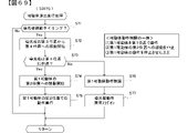
図15は、本実施例の第3初期化処理(S51B)を示すフローチャートである。第3初期化処理において演出制御用CPU120は、先ず、シリアル変換IC130から受信したシリアルデータから、入力ポート131のポート番号4(D)、5(C)、1(g)、2(f)のシリアルデータ、つまり、パチンコ遊技機1Bの共通枠には搭載されていないロケット45のロケット原点位置センサ37Aからの検出信号が入力されるポート番号4(D)、ロケット突出位置センサ37Bからの検出信号が入力されるポート番号5(C)、カバー体28のカバー体原点位置センサ39Aからの検出信号が入力されるポート番号1(g)、カバー体開放位置センサ39Bからの検出信号が入力されるポート番号2(f)のシリアルデータを特定する(S61)。 FIG. 15 is a flowchart showing the third initialization process (S51B) of this embodiment. In the third initialization process, the effect control CPU 120 first selects the port numbers 4 (D), 5 (C), 1 (g), and 2 (f) of the input port 131 from the serial data received from the serial conversion IC 130. Serial data, that is, port number 4 (D) to which the detection signal from the rocket origin position sensor 37A of the rocket 45, which is not mounted in the common frame of the pachinko game machine 1B, is input, and the detection signal from the rocket protrusion position sensor 37B. Port number 5 (C) to which is input, port number 1 (g) to which the detection signal from the cover body origin position sensor 39A of the cover body 28 is input, and the detection signal from the cover body open position sensor 39B are input. The serial data of the port number 2 (f) is specified (S61).

次いで、特定したシリアルデータに検出信号の入力状態を示すデータがあるか否かを判定し(S62)、検出信号の入力状態を示すデータ(例えば、ロケット原点位置センサ37A(ポート番号4(D))やカバー体原点位置センサ39A(ポート番号7(A))からの検出信号の入力状態を示すデータ)がある場合は、専用枠である可能性が高いため、ロケットモータ37Cを駆動してロケット45の初期化(原点位置への復帰動作)を実行し、ポート番号6(B)のシリアルデータを特定した後(S63)、カバー体モータ39Cを駆動してカバー体28の初期化(原点位置への復帰動作)を実行し、ポート番号3(e)のシリアルデータを特定する(S64)。 Next, it is determined whether or not the specified serial data includes data indicating the input state of the detection signal (S62), and data indicating the input state of the detection signal (for example, rocket origin position sensor 37A (port number 4 (D)). ) Or the data indicating the input state of the detection signal from the cover body origin position sensor 39A (data indicating the input state of the detection signal from the port number 7 (A)), since there is a high possibility that it is a dedicated frame, the rocket motor 37C is driven to drive the rocket. After the initialization of 45 (return operation to the origin position) is executed and the serial data of the port number 6 (B) is specified (S63), the cover body motor 39C is driven to initialize the cover body 28 (origin position). (Return operation to) is executed, and the serial data of the port number 3 (e) is specified (S64).

そして、ポート番号6(B)、3(e)の両方が検出信号の入力状態を示すデータであるか否かを判定し(S65)、ポート番号6(B)、3(e)の両方が駆動信号の入力状態を示すデータであった場合、共通枠にはないロケットモータ37Cやカバー体モータ39Cが搭載されているとして、遊技枠が専用枠であることを示す専用枠フラグをセットし(S66)、専用枠であることを示す報知A(図16(A)参照)を開始し(S67)、処理を終了する。 Then, it is determined whether or not both the port numbers 6 (B) and 3 (e) are data indicating the input state of the detection signal (S65), and both the port numbers 6 (B) and 3 (e) are used. If the data indicates the input state of the drive signal, it is assumed that the rocket motor 37C and the cover body motor 39C, which are not in the common frame, are mounted, and a dedicated frame flag indicating that the game frame is a dedicated frame is set ( S66), the notification A (see FIG. 16A) indicating that the frame is dedicated is started (S67), and the process is terminated.

S65においてポート番号6(B)、3(e)の両方が駆動信号の入力状態を示すデータでなかった場合、ポート番号6(B)、3(e)の一方が駆動信号の入力状態を示すデータであるか否かを判定し(S68)、ポート番号6(B)、3(e)の一方が駆動信号の入力状態を示すデータである場合は、他方の可動体に動作エラーが生じている可能性があるとして、駆動信号の非入力状態のデータに対応する可動体についてのエラー情報を記憶し(S69)、S66に進む。つまり、一方が駆動信号の入力状態を示すデータである場合は、他方の可動体に動作エラーが生じているだけである可能性が高いため、専用枠であると判定する。 When both port numbers 6 (B) and 3 (e) are not data indicating the input state of the drive signal in S65, one of the port numbers 6 (B) and 3 (e) indicates the input state of the drive signal. It is determined whether or not the data is data (S68), and if one of the port numbers 6 (B) and 3 (e) is the data indicating the input state of the drive signal, an operation error occurs in the other movable body. Assuming that there is a possibility, the error information about the movable body corresponding to the data in the non-input state of the drive signal is stored (S69), and the process proceeds to S66. That is, when one of the data indicates the input state of the drive signal, there is a high possibility that an operation error has only occurred in the other movable body, so it is determined that the frame is dedicated.

また、S68においてポート番号6(B)、3(e)の一方が駆動信号の入力状態を示すデータでない場合、つまり、ポート番号6(B)、3(e)の両方が駆動信号の入力状態を示すデータではない場合は、ロケットモータ37Cやカバー体モータ39Cが搭載されていない共通枠である可能性があるとして、振動モータ35Cを駆動させてポート番号2(F)、0(H)のシリアルデータを特定する(S70)。 Further, in S68, when one of the port numbers 6 (B) and 3 (e) is not the data indicating the input state of the drive signal, that is, both the port numbers 6 (B) and 3 (e) are the input states of the drive signal. If the data does not indicate, it is assumed that the rocket motor 37C and the cover body motor 39C may not be mounted in the common frame, and the vibration motor 35C is driven to drive the port numbers 2 (F) and 0 (H). Specify the serial data (S70).

そして、ポート番号2(F)が駆動信号の入力状態を示すデータであるか否かを判定し(S71)、ポート番号2(F)が駆動信号の入力状態を示すデータである場合は、遊技枠が専用枠である可能性が高いため、S69に進む。一方、ポート番号2(F)が駆動信号の入力状態を示すデータでない場合、つまり、ポート番号0(H)が駆動信号の入力状態を示すデータである場合は、共通枠である可能性もあり、専用枠であるか共通枠であるかを特定不能であるため、S72に進む。つまり、操作手段からの検出信号の入力状態を確認したときには専用枠である可能性が高いと判定したが、可動体からの駆動信号の入力状態を確認したときには共通枠である可能性もあると判定したことで、専用枠であるか共通枠であるかを特定不能であり、何らかの異常が発生している可能性が高いと判定する。 Then, it is determined whether or not the port number 2 (F) is the data indicating the input state of the drive signal (S71), and when the port number 2 (F) is the data indicating the input state of the drive signal, the game is played. Since there is a high possibility that the frame is a dedicated frame, the process proceeds to S69. On the other hand, if the port number 2 (F) is not data indicating the input state of the drive signal, that is, if the port number 0 (H) is the data indicating the input state of the drive signal, it may be a common frame. , Since it is not possible to specify whether it is a dedicated frame or a common frame, the process proceeds to S72. In other words, when the input state of the detection signal from the operating means was confirmed, it was determined that there was a high possibility that it was a dedicated frame, but when the input state of the drive signal from the movable body was confirmed, it was possible that it was a common frame. By the determination, it is not possible to specify whether the frame is a dedicated frame or a common frame, and it is determined that there is a high possibility that some abnormality has occurred.

S62において検出信号の入力状態を示すデータがない場合は、振動モータ35Cを駆動してポート番号0(H)のシリアルデータを特定する(S80)。そして、ポート番号0(H)が駆動信号の入力状態を示すデータであるか否かを判定し(S81)、ポート番号0(H)が駆動信号の入力状態を示すデータである場合は、共通枠である可能性が高いとして、スティックモータ35Dを駆動させてスティックコントローラ31Aの初期化(原点位置への復帰動作)を実行し、ポート番号1(G)のシリアルデータを特定する(S82)。そして、ポート番号1(G)が駆動信号の入力状態を示すデータであるか否かを判定し(S83)、ポート番号1(G)が駆動信号の入力状態を示すデータである場合はS85に進み、ポート番号1(G)が駆動信号の入力状態を示すデータでない場合は、駆動信号が非入力状態のデータに対応するスティックコントローラ31Aのエラー情報を記憶した後(S84)、S85に進む。そして、共通枠であるパチンコ遊技機1Bであることを示す共通枠フラグをセットし(S85)、共通枠であることを示す報知B(図16(B)参照)を開始し(S86)、処理を終了する。 When there is no data indicating the input state of the detection signal in S62, the vibration motor 35C is driven to specify the serial data of the port number 0 (H) (S80). Then, it is determined whether or not the port number 0 (H) is the data indicating the input state of the drive signal (S81), and when the port number 0 (H) is the data indicating the input state of the drive signal, it is common. Assuming that there is a high possibility that it is a frame, the stick motor 35D is driven to initialize the stick controller 31A (return operation to the origin position), and the serial data of the port number 1 (G) is specified (S82). Then, it is determined whether or not the port number 1 (G) is the data indicating the input state of the drive signal (S83), and if the port number 1 (G) is the data indicating the input state of the drive signal, the data is set to S85. If the port number 1 (G) is not the data indicating the input state of the drive signal, the process proceeds to S85 after storing the error information of the stick controller 31A corresponding to the data in the non-input state of the drive signal (S84). Then, a common frame flag indicating that the pachinko gaming machine 1B is a common frame is set (S85), notification B indicating that the frame is a common frame (see FIG. 16B) is started (S86), and processing is performed. To finish.

このように、ポート番号1(G)の駆動信号の入力状態を確認する前に、スティックコントローラ31Aの初期化(原点位置への復帰動作)を実行することで、スティックコントローラ31Aがあるにもかかわらず、何らかの理由でスティックコントローラ31Aが原点位置からずれた位置に移動してしまっていることによりポート番号1(G)が駆動信号の入力状態を示すデータにならないことで、共通枠ではないと判定してしまうことを回避できる。 In this way, by executing the initialization of the stick controller 31A (returning operation to the origin position) before confirming the input state of the drive signal of the port number 1 (G), the stick controller 31A is present. However, it is determined that the port number 1 (G) is not a common frame because the port number 1 (G) does not become the data indicating the input state of the drive signal because the stick controller 31A has moved to a position deviated from the origin position for some reason. You can avoid doing it.

S81においてポート番号0(H)が駆動信号の入力状態を示すデータでない場合、専用枠である可能性があるため、ポート番号2(F)が駆動信号の入力状態を示すデータであるか否かを判定し(S87)、ポート番号2(F)が駆動信号の入力状態を示すデータである場合は、専用枠である可能性が高いため、S63に進み、ポート番号2(F)が駆動信号の入力状態を示すデータでない場合は、専用枠であるか共通枠であるかを特定することが困難であるため、S72に進む。 If port number 0 (H) is not data indicating the input state of the drive signal in S81, it may be a dedicated frame, so whether port number 2 (F) is data indicating the input state of the drive signal. (S87), and if the port number 2 (F) is the data indicating the input state of the drive signal, it is highly possible that the frame is dedicated, so the process proceeds to S63, and the port number 2 (F) is the drive signal. If the data does not indicate the input state of, it is difficult to specify whether the frame is a dedicated frame or a common frame, so the process proceeds to S72.

S71またはS87においてポート番号2(F)が駆動信号の入力状態を示すデータでない場合は、専用枠であるか共通枠であるかを特定不能(または特定困難)であるため、共通枠であるパチンコ遊技機1Bであることを示す共通枠フラグをセットし(S72)、共通枠であることを示す報知C(図16(C)参照)を開始し(S73)、処理を終了する。 If the port number 2 (F) is not the data indicating the input state of the drive signal in S71 or S87, it is impossible (or difficult to specify) whether it is a dedicated frame or a common frame, so that the pachinko is a common frame. A common frame flag indicating that the game machine 1B is set (S72), notification C indicating that the game machine 1B is used (see FIG. 16C) is started (S73), and processing is completed.

尚、S72においては、専用枠であるか共通枠であるかを特定不能であるが、専用枠よりも汎用性が高い共通枠であることを示す共通枠フラグをセットすることで、演出制御用CPU120は暫定的に共通枠であるとして以降の制御を行うことができるようにした形態を例示したが、本発明はこれに限定されるものではなく、専用枠であることを示す専用枠フラグをセットしてもよいし、特定不能であることを示す別個のフラグをセットするようにしてもよい。 In S72, it is not possible to specify whether it is a dedicated frame or a common frame, but by setting a common frame flag indicating that it is a common frame with higher versatility than the dedicated frame, it is for effect control. The CPU 120 tentatively assumes a common frame and exemplifies a form in which subsequent control can be performed. However, the present invention is not limited to this, and a dedicated frame flag indicating that the CPU 120 is a dedicated frame is set. It may be set, or it may be set with a separate flag indicating that it is not identifiable.

また、S69,S84にて可動体のエラー状態が記憶された場合、該エラー状態はRAMクリアが行われない限り消去されないため、以降の処理に進んだときにエラー状態として記憶された可動体について動作制御を行わないようにする(当該動作対象可動体をデッドエンド状態する)ことができるため、不具合が生じている可能性がある可動体の動作制御を実行することによりモータ等の駆動源に負荷をかけてしまうことを抑制できる。 Further, when the error state of the movable body is stored in S69 and S84, the error state is not erased unless the RAM is cleared. Therefore, the movable body stored as the error state when proceeding to the subsequent processing is performed. Since it is possible to prevent the operation control (the operation target movable body is in a dead-end state), the operation control of the movable body that may have a problem can be executed to drive the motor or the like. It is possible to suppress the load.

また、演出制御用CPU120は、S67、S73、S86にて開始した各種報知A~Cについて、演出制御メイン処理におけるS58において継続的に実行する。詳しくは、報知A及び報知Bについては、報知を開始してから所定時間(例えば、10秒など)が経過したタイミングで終了し、報知Cについては、所定の解除条件(例えば、電源をオフ状態にする、RAMクリアを実行するなど)が成立するまで継続するようにすればよい。 Further, the effect control CPU 120 continuously executes various notifications A to C started in S67, S73, and S86 in S58 in the effect control main process. Specifically, the notification A and the notification B end at the timing when a predetermined time (for example, 10 seconds) has elapsed from the start of the notification, and the notification C has a predetermined release condition (for example, a power off state). , RAM clear, etc.) may be satisfied.

次に、演出制御用CPU120が実行する各種報知の報知態様について説明する。演出制御用CPU120は、遊技機用枠3が専用枠であると判定した場合、図16(A)に示すように、演出表示装置5の表示画面に「遊技機用枠は「専用枠」です」なる画像G1を表示する報知Aを実行する。また、演出制御用CPU120は、遊技機用枠3が共通枠であると判定した場合、図16(B)に示すように、演出表示装置5の表示画面に「遊技機用枠は「共通枠」です」なる画像G2を表示する報知Bを実行する。また、演出制御用CPU120は、遊技機用枠3が専用枠であるか共通枠であるかを特定不能であると判定した場合、図16(C)に示すように、演出表示装置5の表示画面に「盤枠不一致エラー 遊技機用枠と遊技盤の組合せまたは可動体の動作状況をご確認ください」なる画像G3を表示するとともに、表示画面左右の演出用LED9を所定態様で点灯させる報知Cを実行する。 Next, a notification mode of various notifications executed by the effect control CPU 120 will be described. When the effect control CPU 120 determines that the game machine frame 3 is a dedicated frame, as shown in FIG. 16A, the display screen of the effect display device 5 shows that the game machine frame is a “dedicated frame”. The notification A for displaying the image G1 is executed. Further, when the effect control CPU 120 determines that the gaming machine frame 3 is a common frame, as shown in FIG. 16B, the display screen of the effect display device 5 displays "the gaming machine frame is a" common frame ". The notification B for displaying the image G2 "is" is executed. Further, when the effect control CPU 120 determines that it is not possible to specify whether the gaming machine frame 3 is a dedicated frame or a common frame, as shown in FIG. 16C, the effect display device 5 is displayed. Notification C that displays the image G3 on the screen, "Please check the combination of the game machine frame and the game board or the operating status of the movable body", and lights the effect LEDs 9 on the left and right of the display screen in a predetermined mode. To execute.

このように、遊技盤2を装着した遊技機用枠3が専用枠であるか共通枠であるかの報知を、専用枠のパチンコ遊技機1Aと共通枠のパチンコ遊技機1Bとにそれぞれ搭載される演出表示装置5(5A)により行うことで、遊技盤2を装着した遊技枠が専用枠及び共通枠のいずれであるか、または特定不能であるかを、遊技者に認識可能に報知することができる。また、報知Cのように、演出表示装置5以外の演出用LED9や天発光部47などの他の報知手段を用いて報知を行うようにしてもよい。 In this way, the notification of whether the gaming machine frame 3 to which the gaming board 2 is mounted is a dedicated frame or a common frame is mounted on the pachinko gaming machine 1A of the dedicated frame and the pachinko gaming machine 1B of the common frame, respectively. By using the effect display device 5 (5A), the player can be recognizable to know whether the game frame on which the game board 2 is mounted is a dedicated frame or a common frame, or whether it cannot be specified. Can be done. Further, as in the notification C, the notification may be performed by using other notification means such as the effect LED 9 and the celestial light emitting unit 47 other than the effect display device 5.

また、S51Aの第2初期化処理におけるS114、S128、S214において可動体の動作エラーを記憶した場合において、演出制御用CPU120は、図16(D)に示すように、演出表示装置5の表示画面に「振動モータエラー」なる画像G4を表示するとともに、表示画面左右の演出用LED9を所定態様で点灯させる報知Dを実行してもよい。 Further, when the operation error of the movable body is stored in S114, S128, and S214 in the second initialization process of S51A, the effect control CPU 120 displays the display screen of the effect display device 5 as shown in FIG. 16 (D). In addition to displaying the image G4 of "vibration motor error", the notification D for lighting the effect LEDs 9 on the left and right of the display screen in a predetermined mode may be executed.

また、S51Bの第3初期化処理におけるS69やS84において非入力状態のデータに対応する可動体のエラー情報を記憶する場合、つまり、遊技枠側の可動体の動作エラーが生じている可能性がある場合において、演出制御用CPU120は、図16(E)に示すように、演出表示装置5の表示画面に「枠可動体エラー」なる画像G5を表示するとともに、表示画面の上方左右側の演出用LED9を所定態様で点灯させる報知Eを実行してもよい。また、スティックコントローラの動作エラーの場合、演出表示装置5の表示画面に「スティックコントローラエラー」なる画像G6を表示するとともに、表示画面の上方の共通枠にしかない天発光部47を所定態様で点灯させる報知Eを実行してもよい。 Further, when the error information of the movable body corresponding to the data in the non-input state is stored in S69 or S84 in the third initialization process of S51B, that is, there is a possibility that an operation error of the movable body on the game frame side has occurred. In a certain case, as shown in FIG. 16E, the effect control CPU 120 displays the image G5, which is a “frame movable body error”, on the display screen of the effect display device 5, and also displays the effect on the upper left and right sides of the display screen. The notification E for lighting the LED 9 in a predetermined mode may be executed. Further, in the case of an operation error of the stick controller, the image G6 "stick controller error" is displayed on the display screen of the effect display device 5, and the sky light emitting unit 47, which is only in the common frame above the display screen, is lit in a predetermined manner. Notification E may be executed.

また、図16においては、報知手段の一例として、演出表示装置5などの表示装置と演出用LED9や天発光部47などの発光体とを記載した形態を例示したが、本発明はこれに限定されるものではなく、例えば、音を出力可能なスピーカ8L,8R等を報知手段として適用してもよい。 Further, in FIG. 16, as an example of the notification means, a mode in which a display device such as an effect display device 5 and a light emitting body such as an effect LED 9 and a celestial light emitting unit 47 are described has been illustrated, but the present invention is limited thereto. For example, speakers 8L, 8R and the like capable of outputting sound may be applied as the notification means.

図17は、演出制御メイン処理の演出制御プロセス処理(S55)を示すフローチャートである。演出制御プロセス処理では、演出制御用CPU120は、先ず、演出表示装置5の第1保留記憶表示エリア5D及び第2保留記憶表示エリア5Uでの保留記憶表示を、保留記憶バッファの記憶内容に応じた表示に更新する保留表示更新処理を実行する(S172)。 FIG. 17 is a flowchart showing the effect control process process (S55) of the effect control main process. In the effect control process process, the effect control CPU 120 first sets the hold storage display in the first hold storage display area 5D and the second hold storage display area 5U of the effect display device 5 according to the storage contents of the hold storage buffer. The hold display update process for updating the display is executed (S172).

その後、演出制御用CPU120は、演出制御プロセスフラグの値に応じてS173~S179のうちのいずれかの処理を行う。各処理においては、以下のような処理を実行する。 After that, the effect control CPU 120 performs any of the processes S173 to S179 according to the value of the effect control process flag. In each process, the following processes are executed.

変動パターン指定コマンド受信待ち処理(S173):遊技制御用マイクロコンピュータ100から変動パターン指定コマンドを受信しているか否か確認する。具体的には、コマンド解析処理で変動パターン指定コマンドを受信しているか否か確認する。変動パターン指定コマンドを受信していれば、演出制御プロセスフラグの値を演出図柄変動開始処理(S174)に対応した値に変更する。 Fluctuation pattern designation command reception waiting process (S173): It is confirmed whether or not the variation pattern designation command is received from the game control microcomputer 100. Specifically, it is confirmed whether or not the fluctuation pattern specification command is received in the command analysis process. If the variation pattern specification command is received, the value of the effect control process flag is changed to the value corresponding to the effect symbol variation start process (S174).

演出図柄変動開始処理(S174):演出図柄の変動が開始されるように制御する。そして、演出制御プロセスフラグの値を演出図柄変動中処理(S175)に対応した値に更新する。 Effect symbol change start process (S174): Control so that change of the effect symbol is started. Then, the value of the effect control process flag is updated to the value corresponding to the effect symbol changing process (S175).

演出図柄変動中処理(S175):変動パターンを構成する各変動状態(変動速度)の切替タイミング等を制御するとともに、変動時間の終了を監視する。そして、変動時間が終了したら、演出制御プロセスフラグの値を演出図柄変動停止処理(S176)に対応した値に更新する。 Processing during effect symbol change (S175): Controls the switching timing and the like of each change state (change rate) constituting the change pattern, and monitors the end of the change time. Then, when the fluctuation time ends, the value of the effect control process flag is updated to the value corresponding to the effect symbol variation stop process (S176).

演出図柄変動停止処理(S176):全図柄停止を指示する演出制御コマンド(図柄確定コマンド)を受信したことにもとづいて、演出図柄の変動を停止し表示結果(停止図柄)を導出表示する制御を行う。そして、演出制御プロセスフラグの値を大当り表示処理(S177)または変動パターン指定コマンド受信待ち処理(S173)に対応した値に更新する。 Effect symbol change stop processing (S176): Control to stop the change of the effect symbol and derive and display the display result (stop symbol) based on the reception of the effect control command (symbol confirmation command) instructing to stop all the symbols. conduct. Then, the value of the effect control process flag is updated to a value corresponding to the jackpot display process (S177) or the variation pattern designation command reception wait process (S173).

大当り表示処理(S177):変動時間の終了後、演出表示装置5に大当りの発生を報知するための画面を表示する制御を行う。そして、演出制御プロセスフラグの値を大当り遊技中処理(S178)に対応した値に更新する。 Jackpot display process (S177): After the end of the fluctuation time, control is performed to display a screen for notifying the effect display device 5 of the occurrence of a jackpot. Then, the value of the effect control process flag is updated to the value corresponding to the big hit in-game process (S178).

大当り遊技中処理(S178):大当り遊技中の制御を行う。例えば、大入賞口開放中指定コマンドや大入賞口開放後指定コマンドを受信したら、演出表示装置5におけるラウンド数の表示制御等を行う。そして、演出制御プロセスフラグの値を大当り終了演出処理(S179)に対応した値に更新する。 Process during big hit game (S178): Control during big hit game. For example, when the designated command during the opening of the large winning opening or the designated command after opening the large winning opening is received, the display control of the number of rounds in the effect display device 5 is performed. Then, the value of the effect control process flag is updated to the value corresponding to the jackpot end effect process (S179).

大当り終了演出処理(S179):演出表示装置5において、大当り遊技状態が終了したことを遊技者に報知する表示制御を行う。そして、演出制御プロセスフラグの値を変動パターン指定コマンド受信待ち処理(S173)に対応した値に更新する。 Big hit end effect processing (S179): In the effect display device 5, display control is performed to notify the player that the big hit game state has ended. Then, the value of the effect control process flag is updated to the value corresponding to the variation pattern designation command reception waiting process (S173).

尚、演出制御用CPU120は、演出図柄変動中処理(S175)、大当り表示処理(S177)、大当り遊技中処理(S178)、大当り遊技中処理(S178)などにおける所定のタイミング(例えば、可動体演出の実行条件が成立したタイミング)で、可動体を原点位置と演出位置との間で移動させる可動体演出を実行可能としている。 In addition, the effect control CPU 120 has a predetermined timing (for example, a movable body effect) in the effect symbol changing process (S175), the jackpot display process (S177), the jackpot game process (S178), the jackpot game process (S178), and the like. At the timing when the execution condition is satisfied), it is possible to execute the movable body effect of moving the movable body between the origin position and the effect position.

以上説明したように、本発明の実施例としてのパチンコ遊技機1A,1Bにあっては、遊技盤2(第1機構体)と該遊技盤2を着脱可能な遊技枠(第2機構体)とを備え、遊技盤2は、該遊技盤2と遊技枠を制御可能な制御手段としての演出制御用CPU120を有し、特定遊技枠(例えば、専用枠)を含む複数種類の遊技枠(例えば、専用枠と共通枠)に着脱可能であり、遊技枠は、該遊技枠に搭載された操作手段や可動体の状態(位置)を検出可能な検出手段(例えば、スティック原点位置センサ35A、スティック引き位置センサ35B、ボタンセンサ36A、ロケット原点位置センサ37A、ロケット突出位置センサ37B、十字ボタンセンサ38A~38D、カバー体原点位置センサ39A、カバー体開放位置センサ39Bなど)を備え、遊技枠に設けられるシリアル変換IC130は、入力ポート131への検出信号の入力状態を特定可能なシリアルデータを生成して演出制御基板12に出力することが可能であり、演出制御用CPU120は、遊技枠から出力される検出特定情報(シリアル変換IC130から受信したシリアルデータ)に基づいて、遊技盤2が装着されている遊技枠が専用枠(または共通枠)であるか否かを判定し、専用枠(または共通枠)であると判定したときに報知を行う。 As described above, in the pachinko game machines 1A and 1B as the embodiment of the present invention, the game board 2 (first mechanism body) and the game frame (second mechanism body) to which the game board 2 can be attached and detached are attached / detached. The game board 2 has a game board 2 and a CPU 120 for effect control as a control means capable of controlling the game frame, and has a plurality of types of game frames (for example, a dedicated frame) including a specific game frame (for example, a dedicated frame). , A dedicated frame and a common frame), and the game frame is a detection means (for example, stick origin position sensor 35A, stick) capable of detecting the state (position) of an operating means or a movable body mounted on the game frame. A pull position sensor 35B, a button sensor 36A, a rocket origin position sensor 37A, a rocket protrusion position sensor 37B, a cross button sensor 38A to 38D, a cover body origin position sensor 39A, a cover body open position sensor 39B, etc.) are provided in the game frame. The serial conversion IC 130 can generate serial data capable of specifying the input state of the detection signal to the input port 131 and output it to the effect control board 12, and the effect control CPU 120 is output from the game frame. Based on the detection specific information (serial data received from the serial conversion IC 130), it is determined whether or not the game frame on which the game board 2 is mounted is a dedicated frame (or common frame), and the dedicated frame (or common frame) is determined. A notification is given when it is determined that the frame).

このようにすることで、共通枠用の遊技盤2が専用枠に装着されることによる不具合の発生を防止することができる。また、専用枠用の遊技盤2が共通枠に装着されることによる不具合の発生を防止することができる。 By doing so, it is possible to prevent the occurrence of problems due to the game board 2 for the common frame being mounted on the dedicated frame. Further, it is possible to prevent the occurrence of a problem due to the game board 2 for the dedicated frame being mounted on the common frame.

詳しくは、遊技盤2を遊技枠に装着することで、遊技盤2に設けられる演出制御用CPU120は、遊技枠側のシリアル変換IC130から出力されるシリアルデータにより入力ポート131への検出信号の入力状態を確認することによって、専用枠であるか共通枠であるかを判定するだけでなく、該判定結果を演出表示装置5により報知するため、遊技盤2と遊技枠とが一致しているか否かを作業者が容易に認識することができる。よって、遊技盤2と遊技枠とが一致していない状態で電源を投入して遊技を行った場合に、演出制御用CPU120が、装着した遊技枠に搭載されている可動体を該可動体とは異なる可動体の動作制御データに基づいて駆動させてしまい、これにより可動体の駆動源であるモータ等に負荷がかかり焼き付いてしまったり、可動体の部品を破損させてしまう、といった不具合が生じることを防止することができる。 Specifically, by mounting the game board 2 on the game board 2, the effect control CPU 120 provided on the game board 2 inputs a detection signal to the input port 131 by the serial data output from the serial conversion IC 130 on the game frame side. By checking the state, not only is it determined whether the frame is a dedicated frame or a common frame, but also the determination result is notified by the effect display device 5, so whether or not the game board 2 and the game frame match. The operator can easily recognize this. Therefore, when the power is turned on and the game is played in a state where the game board 2 and the game frame do not match, the movable body mounted on the game frame mounted by the effect control CPU 120 is referred to as the movable body. Is driven based on the motion control data of different movable bodies, which causes problems such as a load applied to the motor, etc., which is the drive source of the movable body, and seizure, or damage to the parts of the movable body. Can be prevented.

さらに、パチンコ遊技機1Aは、図22以降に説明するように、遊技領域を視認可能な窓部(例えば、窓部51)が設けられた枠体(例えば、開閉枠50など)と、可動体(例えば、第1可動体300など)と、を備え、前記窓部は、第1透過部材(例えば、第1透過体250)と、該第1透過部材よりも前記遊技領域側に設けられ、孔部(例えば、孔部270)または切欠部が形成された第2透過部材(例えば、第2透過体260)と、を有し、該第1透過部材と該第2透過部材との間に形成された空間(例えば、空間部S)に前記孔部または前記切欠部を介して前記可動体の少なくとも一部が進入可能である。よって、このような第1可動体300を有する遊技盤2を共通枠に装着した場合、共通枠の窓部51には、第1可動体300が進入可能な孔部や切欠部を有していないため、第1可動体300を動作させたときに第1可動体300が窓部51に衝突して破損してしまうことがあるため、上記のようにすることで、専用枠用の遊技盤2が共通枠に装着されることによる不具合の発生を防止することができる。 Further, the pachinko gaming machine 1A has a frame body (for example, an opening / closing frame 50, etc.) provided with a window portion (for example, a window portion 51) capable of visually recognizing the game area, and a movable body, as described in FIG. 22 and later. (For example, a first movable body 300, etc.), and the window portion is provided on the first transmissive member (for example, the first transmissive body 250) and the game area side of the first transmissive member. It has a hole portion (for example, a hole portion 270) or a second transmission member (for example, a second transmission body 260) in which a notch portion is formed, and is between the first transmission member and the second transmission member. At least a part of the movable body can enter the formed space (for example, the space portion S) through the hole portion or the notch portion. Therefore, when the game board 2 having such a first movable body 300 is attached to the common frame, the window portion 51 of the common frame has a hole portion or a notch portion through which the first movable body 300 can enter. Therefore, when the first movable body 300 is operated, the first movable body 300 may collide with the window portion 51 and be damaged. Therefore, by performing the above, the game board for the dedicated frame is used. It is possible to prevent the occurrence of a problem due to the fact that 2 is mounted on the common frame.

また、本実施例では、遊技盤2を装着した遊技枠の種別を、遊技盤2に設けられた制御手段(演出制御用CPU120)と、複数種類の遊技枠に搭載され演出制御用CPU120により制御される操作手段や可動体を検出可能な複数の検出手段を利用して特定することができるため、例えば、複数種類の遊技枠に各々を識別可能な識別情報を設け、遊技盤2に設けられた制御手段が該識別情報を読み取ることにより判定するといった手間をかけることなく容易に行うことができる。 Further, in this embodiment, the type of the game frame on which the game board 2 is mounted is controlled by the control means (the effect control CPU 120) provided on the game board 2 and the effect control CPU 120 mounted on the plurality of types of game frames. Since it is possible to specify the operating means and the movable body to be detected by using a plurality of detecting means, for example, identification information that can identify each of the plurality of types of game frames is provided on the game board 2. The control means can be easily performed without the trouble of making a determination by reading the identification information.

また、演出制御用CPU120は、S51Bの第3初期化処理のS61~S65,S68~S71,S80~S83,S87において、特定のポート番号のシリアルデータを特定し、該特定したシリアルデータに検出信号の入力状態を示すデータがあるか否かにより専用枠か共通枠かを判定する。 Further, the effect control CPU 120 identifies serial data of a specific port number in S61 to S65, S68 to S71, S80 to S83, and S87 of the third initialization process of S51B, and detects signals in the specified serial data. Whether it is a dedicated frame or a common frame is determined depending on whether or not there is data indicating the input state of.

このようにすることで、専用枠(または共通枠)であるか否かを好適に判定することができる。例えば、専用枠にしか搭載されていない可動体が原点位置にあることを検出可能な複数の原点位置センサからの検出信号が入力される複数のポート番号のうち特定のポート番号(例えば、4(D)、5(C)、1(g)、2(f))のシリアルデータを特定し、該特定したシリアルデータに検出信号の入力状態を示すデータがあるか否かにより専用枠か共通枠かを判定するようにすることで、専用枠(または共通枠)であるか否かを好適に判定することができる。 By doing so, it is possible to suitably determine whether or not the frame is a dedicated frame (or a common frame). For example, a specific port number (for example, 4 (for example, 4) among a plurality of port numbers to which detection signals from a plurality of origin position sensors capable of detecting that a movable body mounted only in a dedicated frame is at the origin position is input. D), 5 (C), 1 (g), 2 (f)) serial data is specified, and a dedicated frame or a common frame is used depending on whether or not the specified serial data contains data indicating the input state of the detection signal. By determining whether or not the frame is a dedicated frame (or a common frame), it can be suitably determined.

また、演出制御用CPU120は、S51Bの第3初期化処理のS61~S65,S68~S71,S80~S83,S87において、複数の特定のポート番号のシリアルデータを特定し、該特定したシリアルデータに検出信号の入力状態を示すデータがあるか否かにより専用枠か共通枠かを判定する。 Further, the effect control CPU 120 specifies serial data of a plurality of specific port numbers in S61 to S65, S68 to S71, S80 to S83, and S87 of the third initialization process of S51B, and uses the specified serial data. Whether it is a dedicated frame or a common frame is determined depending on whether or not there is data indicating the input state of the detection signal.

このようにすることで、専用枠(または共通枠)であるか否かを好適に判定することができる。例えば、専用枠にしか搭載されていない可動体が原点位置にあることを検出可能な複数の原点位置センサからの検出信号が入力される複数のポート番号(例えば、4(D)、5(C)、1(g)、2(f))のシリアルデータを特定し、該特定したシリアルデータに検出信号の入力状態を示すデータがあるか否かにより専用枠か共通枠かを判定するようにすることで、一のポート番号のシリアルデータに基づいて判定する場合よりも、専用枠(または共通枠)であるか否かを正確に判定することができる。 By doing so, it is possible to suitably determine whether or not the frame is a dedicated frame (or a common frame). For example, a plurality of port numbers (for example, 4 (D), 5 (C)) to which detection signals from a plurality of origin position sensors capable of detecting that a movable body mounted only on a dedicated frame is at the origin position are input. ), 1 (g), 2 (f)), and determine whether it is a dedicated frame or a common frame depending on whether or not the specified serial data contains data indicating the input state of the detection signal. By doing so, it is possible to accurately determine whether or not the frame is a dedicated frame (or a common frame), as compared with the case where the determination is based on the serial data of one port number.

また、遊技枠は、遊技者が操作可能な操作手段(例えば、スティックコントローラ31A、プッシュボタン31Bなど)を含み、シリアル変換IC130は、入力ポート131へのスティックコントローラ31Aやプッシュボタン31Bからの検出信号の入力状態を特定可能なシリアルデータを生成して演出制御基板12に出力することが可能である。 Further, the game frame includes an operation means that can be operated by the player (for example, a stick controller 31A, a push button 31B, etc.), and the serial conversion IC 130 is a detection signal from the stick controller 31A or the push button 31B to the input port 131. It is possible to generate serial data that can specify the input state of the above and output it to the effect control board 12.

このようにすることで、操作異常の発生を防止することができる。また、遊技者が操作可能な操作手段は、専用枠や共通枠を問わず多くの機種に搭載されている可能性が高く、また、各種遊技枠で意匠や操作態様等が変更される可能性が高いものであるため、操作手段からの検出信号の入力状態を利用すれば、遊技枠の種類を特定しやすくなる。 By doing so, it is possible to prevent the occurrence of an operation abnormality. In addition, the operation means that can be operated by the player is likely to be installed in many models regardless of the dedicated frame or the common frame, and the design, operation mode, etc. may be changed in various game frames. Therefore, if the input state of the detection signal from the operating means is used, it becomes easy to specify the type of the game frame.

また、遊技枠は、動作可能な可動体(例えば、専用枠のロケット45、カバー体48、スティックコントローラ31Aなど)を含み、シリアル変換IC130は、入力ポート131への振動モータ35C、ロケットモータ37C、カバー体モータ39C、スティックモータ35Dからの駆動信号の入力状態を特定可能なシリアルデータを生成して演出制御基板12に出力することが可能である。 Further, the game frame includes an movable movable body (for example, a rocket 45 of a dedicated frame, a cover body 48, a stick controller 31A, etc.), and the serial conversion IC 130 includes a vibration motor 35C to an input port 131, a rocket motor 37C, and the like. It is possible to generate serial data that can specify the input state of the drive signal from the cover body motor 39C and the stick motor 35D and output it to the effect control board 12.

このようにすることで、動作異常の発生を防止することができる。また、可動体は、専用枠や共通枠を問わず多くの機種に搭載されている可能性が高く、また、各種遊技枠で意匠や操作態様等が変更される可能性が高いものであるため、可動体からの駆動信号の入力状態を利用すれば、遊技枠の種類を特定しやすくなる。 By doing so, it is possible to prevent the occurrence of an operation abnormality. In addition, the movable body is likely to be mounted on many models regardless of whether it is a dedicated frame or a common frame, and there is a high possibility that the design, operation mode, etc. will be changed in various game frames. , If the input state of the drive signal from the movable body is used, it becomes easy to specify the type of the game frame.

また、演出制御用CPU120は、複数種類の遊技枠で共通に設けられる報知手段(例えば、演出表示装置5,5A、演出用LED9など)を用いて報知を行う。 Further, the effect control CPU 120 performs notification using notification means (for example, effect display devices 5, 5A, effect LED 9 and the like) commonly provided in a plurality of types of game frames.

このようにすることで、いずれの種類の遊技枠でも適切に報知できる。つまり、遊技盤2を専用枠でない共通枠に装着した場合でも、遊技盤2と遊技枠と一致していない旨の報知を行うことができるため、不具合の発生を防止することができる。 By doing so, it is possible to appropriately notify any type of game frame. That is, even when the game board 2 is attached to a common frame other than the dedicated frame, it is possible to notify that the game board 2 and the game frame do not match, so that it is possible to prevent the occurrence of a problem.

また、演出制御用CPU120が報知していても遊技は実行可能であり、報知の対象となった検出対象物の使用を制限する。詳しくは、演出制御用CPU120がS51Bの第3初期化処理でエラー情報が記憶された可動体をデッドエンド状態としたまま遊技を行うことが可能となる。 Further, the game can be executed even if the effect control CPU 120 notifies the game, and the use of the detection target object to be notified is restricted. Specifically, the effect control CPU 120 can play a game while keeping the movable body in which the error information is stored in the third initialization process of S51B in the dead end state.

このようにすることで、異常の発生を防止することができる。詳しくは、演出制御用CPU120が不適切な制御データに基づく制御を実行することを回避できるため、不具合の発生を好適に防止することができる。 By doing so, it is possible to prevent the occurrence of an abnormality. Specifically, since it is possible to prevent the effect control CPU 120 from executing control based on inappropriate control data, it is possible to suitably prevent the occurrence of defects.

また、本発明の実施例としてのパチンコ遊技機1A,1Bにあっては、遊技盤2(第1機構体)と該遊技盤2を着脱可能な遊技枠(第2機構体)とを備え、遊技盤2は、該遊技盤2と遊技枠を制御可能な制御手段としての演出制御用CPU120を有し、特定遊技枠(例えば、専用枠)を含む複数種類の遊技枠(例えば、専用枠と共通枠)に着脱可能であり、遊技枠は、該遊技枠に搭載された操作手段や可動体の状態(位置)を検出可能な検出手段(例えば、スティック原点位置センサ35A、スティック引き位置センサ35B、ボタンセンサ36A、ロケット原点位置センサ37A、ロケット突出位置センサ37B、十字ボタンセンサ38A~38D、カバー体原点位置センサ39A、カバー体開放位置センサ39Bなど)を備え、遊技枠に設けられるシリアル変換IC130は、入力ポート131への検出信号の入力状態を特定可能なシリアルデータを生成して演出制御基板12に出力することが可能であり、演出制御用CPU120は、遊技枠から出力される検出特定情報(シリアル変換IC130から受信したシリアルデータ)に基づいて、遊技盤2が装着されている遊技枠が専用枠(または共通枠)であるか否かを判定することが可能である。 Further, the pachinko game machines 1A and 1B as examples of the present invention include a game board 2 (first mechanism body) and a game frame (second mechanism body) to which the game board 2 can be attached and detached. The game board 2 has an effect control CPU 120 as a control means capable of controlling the game board 2 and the game frame, and has a plurality of types of game frames (for example, a dedicated frame) including a specific game frame (for example, a dedicated frame). The game frame is removable from the common frame), and the game frame is a detection means (for example, a stick origin position sensor 35A, a stick pull position sensor 35B) that can detect the state (position) of an operating means or a movable body mounted on the game frame. , Button sensor 36A, rocket origin position sensor 37A, rocket protrusion position sensor 37B, cross button sensors 38A to 38D, cover body origin position sensor 39A, cover body open position sensor 39B, etc.) Can generate serial data that can specify the input state of the detection signal to the input port 131 and output it to the effect control board 12, and the effect control CPU 120 has the detection specific information output from the game frame. Based on (serial data received from the serial conversion IC 130), it is possible to determine whether or not the game frame on which the game board 2 is mounted is a dedicated frame (or a common frame).

このようにすることで、共通枠用の遊技盤2が専用枠に装着されることによる不具合の発生を防止することができる。また、専用枠用の遊技盤2が共通枠に装着されることによる不具合の発生を防止することができる。 By doing so, it is possible to prevent the occurrence of problems due to the game board 2 for the common frame being mounted on the dedicated frame. Further, it is possible to prevent the occurrence of a problem due to the game board 2 for the dedicated frame being mounted on the common frame.

詳しくは、遊技盤2を遊技枠に装着することで、遊技盤2に設けられる演出制御用CPU120は、遊技枠側のシリアル変換IC130から出力されるシリアルデータにより入力ポート131への検出信号の入力状態を確認することによって、専用枠であるか共通枠であるかを判定する。よって、遊技盤2と遊技枠とが一致していない状態で電源を投入して遊技を行った場合に、演出制御用CPU120が、装着した遊技枠に搭載されている可動体を該可動体とは異なる可動体の動作制御データに基づいて駆動させてしまい、これにより可動体の駆動源であるモータ等に負荷がかかり焼き付いてしまったり、可動体の部品を破損させてしまう、といった不具合が生じることを防止することができる。 Specifically, by mounting the game board 2 on the game board 2, the effect control CPU 120 provided on the game board 2 inputs a detection signal to the input port 131 by the serial data output from the serial conversion IC 130 on the game frame side. By checking the state, it is determined whether the frame is a dedicated frame or a common frame. Therefore, when the power is turned on and the game is played in a state where the game board 2 and the game frame do not match, the movable body mounted on the game frame mounted by the effect control CPU 120 is referred to as the movable body. Is driven based on the motion control data of different movable bodies, which causes problems such as a load applied to the motor, etc., which is the drive source of the movable body, and seizure, or damage to the parts of the movable body. Can be prevented.

また、前記実施例では、演出制御用CPU120は、S51Bの第3初期化処理におけるS63,S64にて可動体の初期化動作制御を実行することで、該可動体を駆動するモータからの駆動信号の入力状態を特定する形態を例示したが、本発明はこれに限定されるものではなく、各検出手段は、初期化動作制御の実行によって検出状況が変化するものであって、演出制御用CPU120は、初期化動作制御の実行時において可動体の原点位置検出センサからの検出信号が入力されるポート番号のシリアルデータを特定して遊技枠の種類を特定するようにしてもよい。 Further, in the above embodiment, the effect control CPU 120 executes the initialization operation control of the movable body in S63 and S64 in the third initialization process of S51B, thereby driving a drive signal from the motor for driving the movable body. Although the embodiment for specifying the input state of the above is illustrated, the present invention is not limited to this, and each detection means changes the detection status by executing the initialization operation control, and the effect control CPU 120 May specify the type of the game frame by specifying the serial data of the port number to which the detection signal from the origin position detection sensor of the movable body is input when the initialization operation control is executed.

このようにすることで、的確な判定ができる。詳しくは、可動体の原点位置センサからの検出信号の入力状態を確認する前に、ロケット45やカバー体28の初期化(原点位置への復帰動作)を実行することで、ロケット45やカバー体28があるにもかかわらず、何らかの理由で可動体が原点位置からずれた位置に移動してしまっていることにより検出信号の入力状態を示すデータにならないことで、専用枠ではないと判定してしまうことを回避できる。 By doing so, an accurate judgment can be made. Specifically, by executing the initialization (returning operation to the origin position) of the rocket 45 and the cover body 28 before confirming the input state of the detection signal from the origin position sensor of the movable body, the rocket 45 and the cover body Despite the presence of 28, it is determined that it is not a dedicated frame because the data does not indicate the input state of the detection signal because the movable body has moved to a position deviated from the origin position for some reason. You can avoid it.

尚、操作手段であるスティックコントローラ31A、プッシュボタン31B及び十字ボタン46については、図示しない付勢手段等により常時原点位置に位置するようになっているため、本実施例では、初期化処理を実行することなく原点位置センサからの検出信号の入力状態を確認するようにしているが、初期化処理を実行してから検出信号の入力状態を確認するようにしてもよい。また、可動体について、初期化処理を実行することなく原点位置センサからの検出信号の入力状態を確認することで可動体を特定するようにしてもよい。 Since the stick controller 31A, the push button 31B, and the cross button 46, which are the operating means, are always located at the origin position by an urging means (not shown) or the like, the initialization process is executed in this embodiment. Although the input state of the detection signal from the origin position sensor is confirmed without doing so, the input state of the detection signal may be confirmed after the initialization process is executed. Further, the movable body may be specified by checking the input state of the detection signal from the origin position sensor without executing the initialization process.

また、前記実施例では、S51Bの第3初期化処理において、遊技盤2が装着された遊技枠の種別を判定した後、該判定結果を報知する形態を例示したが、本発明はこれに限定されるものではなく、遊技盤2が装着された遊技枠の種別を判定した後、必ずしも判定結果を報知しなくてもよい。このようにした場合、遊技盤2が非正規な遊技枠に装着されたまま遊技が行われる可能性があるが、演出制御用CPU120がS51Bの第3初期化処理において可動体のエラー状態等を記憶していることになるので、可動体は動作しないものの、負荷がかかる状態で作動すること等は回避できる。 Further, in the above embodiment, in the third initialization process of S51B, after determining the type of the game frame to which the game board 2 is mounted, an embodiment in which the determination result is notified is exemplified, but the present invention is limited to this. After determining the type of the game frame to which the game board 2 is mounted, it is not always necessary to notify the determination result. In this case, the game may be played while the game board 2 is mounted on the non-regular game frame, but the effect control CPU 120 causes an error state of the movable body in the third initialization process of S51B. Since it is memorized, the movable body does not operate, but it can be avoided that it operates under a load.

また、前記実施例では、専用枠の遊技盤2を共通枠に装着した場合または共通枠の遊技盤2を専用枠に装着した場合、つまり、遊技盤2が非正規な遊技枠に装着された場合でも、装着された遊技枠の種類が特定できた場合は該特定した遊技枠の種類が報知される形態を例示したが、本発明はこれに限定されるものではなく、遊技盤2が非正規の遊技枠または正規の遊技枠に装着された場合、遊技枠の種類を特定可能に報知しなくても、遊技盤2と遊技枠とが不一致または一致している旨を報知するようにしてもよい。さらに、遊技盤2と遊技枠とが不一致であると判定したときにのみエラー報知を行い、一致していると判定したときには報知を行わないようにしてもよい。あるいは、遊技盤2が非正規な遊技枠に装着された場合に、遊技を行うことが不能な状態とするようにしてもよい。 Further, in the above embodiment, when the game board 2 of the dedicated frame is mounted on the common frame or when the game board 2 of the common frame is mounted on the dedicated frame, that is, the game board 2 is mounted on the non-regular game frame. Even in this case, when the type of the mounted game frame can be specified, the embodiment in which the specified type of the game frame is notified is illustrated, but the present invention is not limited to this, and the game board 2 is not. When it is attached to a regular game frame or a regular game frame, it is notified that the game board 2 and the game frame do not match or match, even if the type of the game frame is not identifiable. May be good. Further, the error notification may be performed only when it is determined that the game board 2 and the game frame do not match, and the notification may not be performed when it is determined that the game board 2 and the game frame do not match. Alternatively, when the game board 2 is attached to a non-regular game frame, it may be in a state where it is impossible to play a game.

また、前記実施例では、遊技盤2を装着した遊技枠の種類を特定することができない場合、特定不能である旨を報知する形態を例示したが、本発明はこれに限定されるものではなく、特定不能であった場合は、遊技盤2と遊技枠とが不一致であることを特定可能に報知してもよいし、あるいはエラー報知を行ってもよい。 Further, in the above-described embodiment, when the type of the game frame on which the game board 2 is mounted cannot be specified, a mode for notifying that the game frame cannot be specified is exemplified, but the present invention is not limited to this. If it is not possible to specify, the game board 2 and the game frame may be notified so that they do not match, or an error may be notified.

また、前記実施例では、演出制御用CPU120は、S51Bの第3初期化処理において遊技盤2が装着された遊技枠の種類が専用枠または共通枠のいずれであるか判定する処理を実行する形態を例示したが、本発明はこれに限定されるものではなく、例えば、遊技盤2が装着された遊技枠の種類が専用枠であるか否かまたは共通枠であるか否かを判定する、つまり、特定遊技枠(例えば、専用枠または専用枠)であるか否かを判定するようにしてもよい。 Further, in the above embodiment, the effect control CPU 120 executes a process of determining whether the type of the game frame to which the game board 2 is mounted is a dedicated frame or a common frame in the third initialization process of S51B. However, the present invention is not limited to this, and for example, it is determined whether or not the type of the game frame on which the game board 2 is mounted is a dedicated frame or a common frame. That is, it may be determined whether or not it is a specific game frame (for example, a dedicated frame or a dedicated frame).

また、前記実施例では、S51Bの第3初期化処理において遊技盤2が装着された遊技枠の種類が専用枠または共通枠のいずれであるか判定する処理を実行する形態を例示したが、本発明はこれに限定されるものではなく、遊技枠の可動体の初期化処理(原点位置への復帰動作制御)と、遊技盤2が装着された遊技枠の種類が専用枠または共通枠のいずれであるか判定する処理とを切り離して別個で行うようにしてもよい。つまり、少なくとも遊技盤2が装着された遊技枠の種類が専用枠または共通枠のいずれであるか特定する処理が行われるようになっていれば、判定結果の報知や、判定結果に基づいて遊技枠側の電子部品の制御を行うようになっていればよい。 Further, in the above-described embodiment, a mode of executing a process of determining whether the type of the game frame to which the game board 2 is mounted is a dedicated frame or a common frame in the third initialization process of S51B has been exemplified. The invention is not limited to this, and the type of the game frame to which the game board 2 is mounted is either a dedicated frame or a common frame, and the initialization process of the movable body of the game frame (control of the return operation to the origin position). It may be performed separately from the process of determining whether or not. That is, if at least a process of specifying whether the type of the game frame to which the game board 2 is mounted is a dedicated frame or a common frame is performed, the determination result is notified and the game is played based on the determination result. It suffices to control the electronic components on the frame side.

また、前記実施例では、演出制御用CPU120は、S51Bの第3初期化処理において、遊技枠側のシリアル変換IC130から受信したシリアルデータから特定のポート番号、つまり、専用枠と共通枠とを判別可能なポート番号のシリアルデータを特定し、該特定したデータに検出信号の入力状態を示すデータがあるか否かによって専用枠であるか否かを判定する形態を例示したが、本発明はこれに限定されるものではなく、例えば、遊技枠側のシリアル変換IC130から出力される特定の信号の入力時間に基づいて専用枠と共通枠のいずれであるかを判定するようにしてもよい。 Further, in the above embodiment, the effect control CPU 120 determines a specific port number, that is, a dedicated frame and a common frame from the serial data received from the serial conversion IC 130 on the game frame side in the third initialization process of S51B. An example is exemplified in a mode in which serial data of a possible port number is specified and whether or not the specified data is a dedicated frame depending on whether or not there is data indicating an input state of a detection signal. For example, it may be determined whether it is a dedicated frame or a common frame based on the input time of a specific signal output from the serial conversion IC 130 on the game frame side.

例えば、専用枠に搭載された可動体と共通枠に搭載された可動体とで、可動体を初期化動作制御により原点位置に復帰させる際に、可動体が原点位置検出センサにより検出されてから可動体を停止させるまでの時間などが違う場合は、原点位置検出センサからの信号が入力される時間の違いによって専用枠と共通枠のいずれであるかを判定することが可能であるため、入力ポートに入力される信号数や入力されるビット(ポート番号)が同じである場合であっても、専用枠と共通枠のいずれであるかを判定することができる。 For example, when the movable body mounted on the dedicated frame and the movable body mounted on the common frame are returned to the origin position by the initialization operation control, after the movable body is detected by the origin position detection sensor. If the time until the movable body is stopped is different, it is possible to determine whether it is a dedicated frame or a common frame by the difference in the time when the signal from the origin position detection sensor is input, so input. Even when the number of signals input to the port and the input bits (port number) are the same, it is possible to determine whether the frame is a dedicated frame or a common frame.

また、前記実施例では、遊技盤2が装着された遊技枠の種別を特定するためのS51Bの第3初期化処理を、遊技盤2側に設けられた可動体の原点位置への復帰動作制御を行う第2初期化処理の後に実行する形態を例示したが、本発明はこれに限定されるものではなく、第3初期化処理を第2初期化処理の前に実行してもよいし、第3初期化処理と第2初期化処理とを一の初期化処理にて一緒に行うようにしてもよい。 Further, in the above embodiment, the third initialization process of S51B for specifying the type of the game frame on which the game board 2 is mounted is controlled to return to the origin position of the movable body provided on the game board 2 side. Although the embodiment to be executed after the second initialization process is exemplified, the present invention is not limited to this, and the third initialization process may be executed before the second initialization process. The third initialization process and the second initialization process may be performed together in one initialization process.

また、第3初期化処理を第2初期化処理の前に実行するようにした場合において、第3初期化処理にて遊技盤2と遊技枠とが一致していないと判定した場合や遊技枠の種類を特定不能と判定した場合において、第2初期化処理以降の処理を実行しないようにしてもよく、このようにすることで、遊技盤2と遊技枠とが一致していない状態で遊技が行われて不具合が生じてしまうことを回避することができる。 Further, when the third initialization process is executed before the second initialization process, it is determined in the third initialization process that the game board 2 and the game frame do not match, or the game frame. When it is determined that the type of is unspecified, the processing after the second initialization processing may not be executed. By doing so, the game is played in a state where the game board 2 and the game frame do not match. It is possible to prevent the problem from occurring due to the above.

次に、本発明の変形例1について、図18に基づいて説明する。図18は、(A)~(C)は専用枠における表示態様の一例、(D)~(F)は共通枠における表示態様の一例を示す図である。 Next, a modification 1 of the present invention will be described with reference to FIG. 18 (A) to (C) are diagrams showing an example of a display mode in a dedicated frame, and FIGS. 18 (D) to (F) are diagrams showing an example of a display mode in a common frame.

図18に示すように、演出制御用CPU120は、例えば、図柄の変動表示中や大当り遊技状態等における所定タイミングにおいて、スティックコントローラ31Aやプッシュボタン31Bの操作を促す操作促進演出を行うことが可能とされており、操作促進演出として、スティックコントローラ31Aやプッシュボタン31Bの操作を促す画像を表示することが可能である。 As shown in FIG. 18, the effect control CPU 120 can perform an operation promotion effect that encourages the operation of the stick controller 31A and the push button 31B, for example, at a predetermined timing during a symbol variation display or a big hit game state. As an operation promotion effect, it is possible to display an image prompting the operation of the stick controller 31A and the push button 31B.

詳しくは、専用枠の場合、プッシュボタン31Bの操作促進演出では、図18(A)に示すように、「押せ!!」なる画像G10と、専用枠のプッシュボタン31Bに対応する画像G11と、が表示され、スティックコントローラ31Aの操作促進演出では、図18(B)に示すように、「引け!!」なる画像G12と、専用枠のスティックコントローラ31Aに対応する画像G13と、が表示される。 Specifically, in the case of the dedicated frame, in the operation promotion effect of the push button 31B, as shown in FIG. 18A, the image G10 "press !!" and the image G11 corresponding to the push button 31B of the dedicated frame are used. Is displayed, and in the operation promotion effect of the stick controller 31A, as shown in FIG. 18B, an image G12 "close !!" and an image G13 corresponding to the stick controller 31A of the dedicated frame are displayed. ..

一方、共通枠の場合、プッシュボタン31Bの操作促進演出では、図18(D)に示すように、「押せ!!」なる画像G10と、共通枠のプッシュボタン31Bに対応する画像であり画像G11とは異なるG21と、が表示され、スティックコントローラ31Aの操作促進演出では、図18(E)に示すように、「引け!!」なる画像G12と、共通枠のスティックコントローラ31Aに対応する画像であり画像G13とは異なる画像G23と、が表示される。 On the other hand, in the case of the common frame, in the operation promotion effect of the push button 31B, as shown in FIG. 18D, the image G10 "press !!" and the image G11 corresponding to the push button 31B of the common frame. Is displayed, and in the operation promotion effect of the stick controller 31A, as shown in FIG. 18 (E), the image G12 "close !!" and the image corresponding to the stick controller 31A of the common frame are displayed. An image G23 different from the existing image G13 is displayed.

また、演出制御用CPU120は、例えば、大当り遊技中など球抜きが必要になったタイミングにおいて、球抜きを促す画像を表示することがある。詳しくは、下皿を有していない専用枠の場合は、図18(C)に示すように、「球を抜いてください」なる画像G14が表示されるが、下皿91を有する共通枠の場合は、図18(F)に示すように、「下皿が満タンです。球を抜いてください」など、画像G14とは異なる画像G24が表示される。 Further, the effect control CPU 120 may display an image prompting the ball removal at a timing when the ball removal is required, for example, during a big hit game. Specifically, in the case of a dedicated frame that does not have a lower plate, as shown in FIG. 18C, the image G14 "Please pull out the ball" is displayed, but the image G14 that has the lower plate 91 is displayed. In this case, as shown in FIG. 18 (F), an image G24 different from the image G14 is displayed, such as "The lower plate is full. Please pull out the ball."

前記実施例では、専用枠に装着される遊技盤2に設けられる演出制御基板12のROM121には、専用枠に対応する動作制御データや画像データが記憶され、共通枠に装着される遊技盤2に設けられる演出制御基板12のROM121には、共通枠に対応する動作制御データや画像データが記憶されているため、専用枠に対応する遊技盤2を共通枠に装着したり、共通枠に対応する遊技盤2を専用枠に装着したりする、つまり、遊技盤2を非正規な(対応しない)遊技枠に装着すると、対応しない動作制御データに基づいて可動体の動作制御を実行したり、対応しない画像データに基づいて操作手段の画像を表示してしまうことになる。 In the above embodiment, the ROM 121 of the effect control board 12 provided on the game board 2 mounted on the dedicated frame stores the operation control data and the image data corresponding to the dedicated frame, and the game board 2 mounted on the common frame. Since the operation control data and image data corresponding to the common frame are stored in the ROM 121 of the effect control board 12 provided in the above, the game board 2 corresponding to the dedicated frame can be mounted on the common frame or the common frame can be supported. When the game board 2 is mounted on a dedicated frame, that is, when the game board 2 is mounted on a non-regular (non-corresponding) game frame, the motion control of the movable body is executed based on the non-corresponding motion control data. The image of the operating means will be displayed based on the unsupported image data.

ここで、一の遊技盤2を、専用枠である遊技機用枠3と共通枠である遊技機用枠3との双方に装着して使用することができるようにする場合、演出制御基板12のROM121には、専用枠に対応する可動体の動作制御データや画像データと共通枠に対応する可動体の動作制御データや画像データ、つまり、複数種類の遊技枠各々に対応する動作制御データや画像データを予め記憶しておき、S51Bの第3初期化処理において専用枠フラグと共通枠フラグのいずれがセットされたかによって、セットされているフラグに対応する可動体の動作制御データや画像データに基づいて動作制御や表示制御を行うことができるようにすることで、遊技盤2を装着した遊技枠の可動体や操作手段に対応する制御を行うことができる。 Here, in the case where one game board 2 can be used by being attached to both the game machine frame 3 which is a dedicated frame and the game machine frame 3 which is a common frame, the effect control board 12 The ROM 121 contains motion control data and image data of a movable body corresponding to a dedicated frame, motion control data and image data of a movable body corresponding to a common frame, that is, motion control data corresponding to each of a plurality of types of game frames. Image data is stored in advance, and depending on whether the dedicated frame flag or the common frame flag is set in the third initialization process of S51B, the motion control data or image data of the movable body corresponding to the set flag is used. By making it possible to perform motion control and display control based on the above, it is possible to perform control corresponding to the movable body and the operating means of the game frame on which the game board 2 is mounted.

このようにすることで、遊技盤2を専用枠に装着した場合は、専用枠に対応する制御データに基づいて、例えば、図18(A)~(C)に示すような表示制御や可動体の動作制御を実行することができ、また、遊技盤2を共通枠に装着した場合は、共通枠に対応する制御データに基づいて、例えば、図18(D)~(F)に示すような表示制御や可動体の動作制御を実行することができるため、モータ等の電子部品に負荷をかけることなく動作制御を実行したり、遊技者に違和感を与えることがない画像を表示する制御を実行することが可能となる。 By doing so, when the game board 2 is attached to the dedicated frame, for example, the display control and the movable body as shown in FIGS. 18A to 18C are based on the control data corresponding to the dedicated frame. When the game board 2 is mounted on the common frame, for example, as shown in FIGS. 18 (D) to 18 (F), based on the control data corresponding to the common frame. Since display control and motion control of the movable body can be executed, motion control can be executed without imposing a load on electronic parts such as motors, and control for displaying an image that does not give a sense of discomfort to the player is executed. It becomes possible to do.

このように、本発明の実施例としてのパチンコ遊技機1A,1Bにあっては、遊技盤2(第1機構体)と該遊技盤2を着脱可能な遊技枠(第2機構体)とを備え、遊技盤2は、該遊技盤2と遊技枠を制御可能な制御手段としての演出制御用CPU120を有し、特定遊技枠(例えば、専用枠)を含む複数種類の遊技枠(例えば、専用枠と共通枠)に着脱可能であり、遊技枠は、該遊技枠に搭載された操作手段や可動体の状態(位置)を検出可能な検出手段(例えば、スティック原点位置センサ35A、スティック引き位置センサ35B、ボタンセンサ36A、ロケット原点位置センサ37A、ロケット突出位置センサ37B、十字ボタンセンサ38A~38D、カバー体原点位置センサ39A、カバー体開放位置センサ39Bなど)を備え、遊技枠に設けられるシリアル変換IC130は、入力ポート131への検出信号の入力状態を特定可能なシリアルデータを生成して演出制御基板12に出力することが可能であり、演出制御用CPU120は、遊技枠から出力される検出特定情報(シリアル変換IC130から受信したシリアルデータ)に基づいて、遊技盤2が装着されている遊技枠が専用枠(または共通枠)であるか否かを判定し、該判定結果に基づいて演出(例えば、図18に示す操作促進演出や球抜きエラー演出など)を行うことが可能である。 As described above, in the pachinko game machines 1A and 1B as the embodiment of the present invention, the game board 2 (first mechanism body) and the game frame (second mechanism body) to which the game board 2 can be attached and detached are provided. The game board 2 has a game board 2 and a CPU 120 for effect control as a control means capable of controlling the game frame, and has a plurality of types of game frames (for example, dedicated frames) including a specific game frame (for example, a dedicated frame). It is removable from the frame and the common frame), and the game frame is a detection means (for example, stick origin position sensor 35A, stick pull position) that can detect the state (position) of the operating means and the movable body mounted on the game frame. A serial provided in the game frame with a sensor 35B, a button sensor 36A, a rocket origin position sensor 37A, a rocket protrusion position sensor 37B, a cross button sensor 38A to 38D, a cover body origin position sensor 39A, a cover body open position sensor 39B, etc.). The conversion IC 130 can generate serial data that can specify the input state of the detection signal to the input port 131 and output it to the effect control board 12, and the effect control CPU 120 has the detection output from the game frame. Based on the specific information (serial data received from the serial conversion IC 130), it is determined whether or not the game frame on which the game board 2 is mounted is a dedicated frame (or a common frame), and the effect is produced based on the determination result. (For example, the operation promotion effect shown in FIG. 18, the ball removal error effect, and the like) can be performed.

このようにすることで、共通枠用の遊技盤2が専用枠に装着されることによる不具合の発生を防止することができる。また、専用枠用の遊技盤2が共通枠に装着されることによる不具合の発生を防止することができる。 By doing so, it is possible to prevent the occurrence of problems due to the game board 2 for the common frame being mounted on the dedicated frame. Further, it is possible to prevent the occurrence of a problem due to the game board 2 for the dedicated frame being mounted on the common frame.

また、演出制御用CPU120は、前記判定の結果に基づいて、前記複数種類の第2機構体各々の状態に応じた態様の演出を行う。例えば、S51Bの第3初期化処理において専用枠フラグがセットされている場合、各演出タイミングで専用枠に対応する画像を表示する演出を行い(図18(A)~(C)参照)、S51Bの第3初期化処理において共通枠フラグがセットされている場合、各演出タイミングで共通枠に対応する画像を表示する演出を行う(図18(D)~(F)参照)。 Further, the effect control CPU 120 performs an effect according to the state of each of the plurality of types of second mechanisms based on the result of the determination. For example, when the dedicated frame flag is set in the third initialization process of S51B, an effect of displaying an image corresponding to the dedicated frame is performed at each effect timing (see FIGS. 18A to 18C), and S51B is displayed. When the common frame flag is set in the third initialization process of No. 1, the effect of displaying the image corresponding to the common frame is performed at each effect timing (see FIGS. 18D to 18F).

このようにすることで、遊技枠の種類に応じた適切な演出を行うことができる。 By doing so, it is possible to perform an appropriate effect according to the type of the game frame.

また、複数種類の遊技枠は、動作可能な可動体(例えば、共通枠のスティックコントローラ31A)を有する共通枠を含み、演出制御用CPU120は、共通枠の場合、例えば、図18(E)に示すようなスティックコントローラ31Aの操作促進演出を行う場合において、スティックコントローラ31Aを上昇位置まで上昇させる演出を実行可能にしてもよい。 Further, the plurality of types of game frames include a common frame having an operable movable body (for example, the stick controller 31A of the common frame), and the effect control CPU 120 is in the case of the common frame, for example, in FIG. 18 (E). In the case of performing the operation promotion effect of the stick controller 31A as shown, the effect of raising the stick controller 31A to the ascending position may be executed.

このようにすることで、遊技枠の種類に応じた適切な演出を行うことができる。 By doing so, it is possible to perform an appropriate effect according to the type of the game frame.

また、演出制御用CPU120は、S51Bの第3初期化処理で遊技枠の種類を特定した結果に基づいて、演出図柄変動中処理や大当り遊技中処理において、遊技枠の種類に応じた演出(例えば、図18参照)を実行することが可能である。 Further, the effect control CPU 120 is produced according to the type of the game frame in the effect symbol changing process and the jackpot game process based on the result of specifying the game frame type in the third initialization process of S51B. , See FIG. 18).

このようにすることで、遊技枠の種類に応じた適切な演出を行うことができる。 By doing so, it is possible to perform an appropriate effect according to the type of the game frame.

また、演出制御用CPU120は、遊技機への電力供給が開始されたときに専用枠であるか否かを判定し、例えば、図柄の変動表示中や大当り遊技状態中などの所定の演出タイミングにおいて前記判定結果に応じた態様で演出を行うことが可能である。例えば、演出制御用CPU120が、S51Bの第3初期化処理において専用枠フラグがセットされている場合、各演出タイミングで専用枠に対応する画像を表示する演出を行い(図18(A)~(C)参照)、S51Bの第3初期化処理において共通枠フラグがセットされている場合、各演出タイミングで共通枠に対応する画像を表示する演出を行う(図18(D)~(F)参照)。 Further, the effect control CPU 120 determines whether or not it is a dedicated frame when the power supply to the gaming machine is started, and at a predetermined effect timing such as during a symbol variation display or during a jackpot gaming state. It is possible to produce the effect according to the determination result. For example, when the effect control CPU 120 sets the dedicated frame flag in the third initialization process of S51B, the effect is performed to display the image corresponding to the dedicated frame at each effect timing (FIGS. 18A to 18 (A) to (FIG. 18A). (C)), when the common frame flag is set in the third initialization process of S51B, the effect of displaying the image corresponding to the common frame is performed at each effect timing (see FIGS. 18 (D) to 18 (F)). ).

このようにすることで、遊技枠の種類に応じて適切な演出を行うことができる。 By doing so, it is possible to perform an appropriate effect according to the type of the game frame.

次に、本発明の変形例2について、図19に基づいて説明する。図19は、本発明の変形例2における第3初期化処理を示すフローチャートである。 Next, a modification 2 of the present invention will be described with reference to FIG. FIG. 19 is a flowchart showing a third initialization process according to the second modification of the present invention.

前記変形例1では、演出制御用CPU120は、S51Bの第3初期化処理においてセットされている専用枠フラグまたは共通枠フラグに応じた動作制御データや画像データに基づいて動作制御や表示制御を行う形態を例示したが、本発明はこれに限定されるものではなく、例えば、演出制御基板12に接続された設定切替スイッチ55に、専用枠に対応する制御または共通枠に対応する制御のいずれを行うかを遊技場の店員等が切替操作可能な機能を付加し、演出制御用CPU120は、設定切替スイッチ55により設定された内容に応じて制御を行うようにしてもよい。 In the first modification, the effect control CPU 120 performs operation control and display control based on operation control data and image data according to the dedicated frame flag or the common frame flag set in the third initialization process of S51B. Although the embodiment is exemplified, the present invention is not limited to this, and for example, the setting changeover switch 55 connected to the effect control board 12 is provided with either a control corresponding to a dedicated frame or a control corresponding to a common frame. A function that can be switched by a store clerk of the amusement park or the like may be added, and the effect control CPU 120 may be controlled according to the content set by the setting changeover switch 55.

ここで、演出制御用CPU120が設定切替スイッチ55により設定された内容に応じた制御を行うことができるようにした場合における第3初期化処理の一例を、図19に基づいて説明する。 Here, an example of the third initialization process in the case where the effect control CPU 120 can perform control according to the content set by the setting changeover switch 55 will be described with reference to FIG.

図19に示すように、第3初期化処理において演出制御用CPU120は、先ず、設定切替スイッチ55による設定内容は専用枠に設定されているか否かを判定する(S301)。専用枠である場合には、シリアル変換IC130から受信したシリアルデータから、入力ポート131におけるポート番号4(D)、5(C)、1(g)、2(f)のシリアルデータ、つまり、非正規なパチンコ遊技機1Bの共通枠には搭載されていないロケット45のロケット原点位置センサ37Aからの検出信号が入力されるポート番号4(D)、ロケット突出位置センサ37Bからの検出信号が入力されるポート番号5(C)、カバー体28のカバー体原点位置センサ39Aからの検出信号が入力されるポート番号1(g)、カバー体開放位置センサ39Bからの検出信号が入力されるポート番号2(f)のシリアルデータを特定する(S302)。 As shown in FIG. 19, in the third initialization process, the effect control CPU 120 first determines whether or not the setting content by the setting changeover switch 55 is set in the dedicated frame (S301). In the case of the dedicated frame, the serial data of the port numbers 4 (D), 5 (C), 1 (g), and 2 (f) in the input port 131 from the serial data received from the serial conversion IC 130, that is, the non-serial data. The detection signal from the rocket origin position sensor 37A of the rocket 45, which is not mounted in the common frame of the regular pachinko game machine 1B, is input to the port number 4 (D), and the detection signal from the rocket protrusion position sensor 37B is input. Port number 5 (C), port number 1 (g) to which the detection signal from the cover body origin position sensor 39A of the cover body 28 is input, and port number 2 to which the detection signal from the cover body open position sensor 39B is input. The serial data of (f) is specified (S302).

次いで、特定したシリアルデータに検出信号の入力状態を示すデータがあるか否かを判定し(S303)、検出信号の入力状態を示すデータ(例えば、ロケット原点位置センサ37A(ポート番号4(D))やカバー体原点位置センサ39A(ポート番号7(A))からの検出信号の入力状態を示すデータ)がある場合は、専用枠である可能性が高いため、ロケットモータ37Cを駆動してロケット45の初期化(原点位置への復帰動作)を実行し、ポート番号6(B)のシリアルデータを特定した後(S304)、カバー体モータ39Cを駆動してカバー体28の初期化(原点位置への復帰動作)を実行し、ポート番号3(e)のシリアルデータを特定する(S305)。 Next, it is determined whether or not the specified serial data includes data indicating the input state of the detection signal (S303), and data indicating the input state of the detection signal (for example, rocket origin position sensor 37A (port number 4 (D)). ) Or the data indicating the input state of the detection signal from the cover body origin position sensor 39A (data indicating the input state of the detection signal from the port number 7 (A)), since there is a high possibility that it is a dedicated frame, the rocket motor 37C is driven to drive the rocket. After the initialization of 45 (return operation to the origin position) is executed and the serial data of the port number 6 (B) is specified (S304), the cover body motor 39C is driven to initialize the cover body 28 (origin position). (Return operation to) is executed, and the serial data of the port number 3 (e) is specified (S305).

そして、ポート番号6(B)、3(e)の両方が駆動信号の入力状態を示すデータであるか否かを判定し(S306)、ポート番号6(B)、3(e)の両方が駆動信号の入力状態を示すデータであった場合、共通枠にはないロケットモータ37Cやカバー体モータ39Cが搭載されているとして、遊技枠が専用枠であることを示す専用枠フラグをセットし(S307)、専用枠であることを示す報知A(図16(A)参照)を開始し(S308)、処理を終了する。 Then, it is determined whether or not both the port numbers 6 (B) and 3 (e) are data indicating the input state of the drive signal (S306), and both the port numbers 6 (B) and 3 (e) are used. If the data indicates the input state of the drive signal, it is assumed that the rocket motor 37C and the cover body motor 39C, which are not in the common frame, are mounted, and a dedicated frame flag indicating that the game frame is a dedicated frame is set ( S307), the notification A (see FIG. 16A) indicating that the frame is dedicated is started (S308), and the process is terminated.

S301において設定切替スイッチ55による設定内容は専用枠に設定されていない、つまり、共通枠に設定されている場合、ポート番号3(E)、7(A)のシリアルデータを特定する(S310)。次いで、検出信号の入力状態を示すデータがあるか否かを判定し(S311)、検出信号の入力状態を示すデータがある場合は、振動モータ35Cを駆動し、共通枠であれば検出信号が入力されるポート番号0(H)のシリアルデータを特定した後(S312)、ポート番号0(H)が検出信号の入力状態を示すデータであるか否かを判定する(S313)。 In S301, when the setting content by the setting changeover switch 55 is not set in the dedicated frame, that is, when it is set in the common frame, the serial data of the port numbers 3 (E) and 7 (A) is specified (S310). Next, it is determined whether or not there is data indicating the input state of the detection signal (S311), and if there is data indicating the input state of the detection signal, the vibration motor 35C is driven, and if there is a common frame, the detection signal is transmitted. After specifying the serial data of the input port number 0 (H) (S312), it is determined whether or not the port number 0 (H) is the data indicating the input state of the detection signal (S313).

ポート番号0(H)が検出信号の入力状態を示すデータである場合は、スティックモータ335Cを駆動してスティックコントローラ31Aの初期化(原点位置への復帰動作)を実行し、ポート番号1(G)のシリアルデータを特定した後(S314)、ポート番号1(G)が駆動信号の入力状態を示すデータであるか否かを判定する(S315)。そして、ポート番号1(G)が駆動信号の入力状態を示すデータである場合、共通枠にしか搭載されていないスティックモータ35Dがあることから、共通枠であることを示す共通枠フラグをセットし(S316)、共通枠であることを示す報知B(図16(B)参照)を開始し(S317)、処理を終了する。 When the port number 0 (H) is the data indicating the input state of the detection signal, the stick motor 335C is driven to execute the initialization of the stick controller 31A (return operation to the origin position), and the port number 1 (G). ) Is specified (S314), and then it is determined whether or not the port number 1 (G) is the data indicating the input state of the drive signal (S315). Then, when the port number 1 (G) is the data indicating the input state of the drive signal, since there is a stick motor 35D mounted only in the common frame, a common frame flag indicating that the port number 1 (G) is a common frame is set. (S316), the notification B (see FIG. 16B) indicating that the frame is common is started (S317), and the process is terminated.

また、S303においてシリアルデータがない場合、S306においてポート番号6(B)、3(e)の両方が駆動信号の入力状態を示すデータでない場合、S311において検出信号の入力状態を示すデータがない場合、S313においてポート番号0(H)が信号の入力状態を示すデータでない場合、S315においてポート番号1(G)が駆動信号の入力状態を示すデータでない場合のいずれかであるときには、専用枠であるか共通枠であるかを特定不能であるため、共通枠であるパチンコ遊技機1Bであることを示す共通枠フラグをセットし(S318)、共通枠であることを示す報知C(図16(C)参照)を開始し(S319)、処理を終了する。 Further, when there is no serial data in S303, when both port numbers 6 (B) and 3 (e) are not data indicating the input state of the drive signal in S306, when there is no data indicating the input state of the detection signal in S311. , When the port number 0 (H) is not the data indicating the input state of the signal in S313, or when the port number 1 (G) is not the data indicating the input state of the drive signal in S315, it is a dedicated frame. Since it is not possible to specify whether it is a common frame or a common frame, a common frame flag indicating that the pachinko game machine 1B is a common frame is set (S318), and notification C indicating that the frame is a common frame C (FIG. 16 (C)). ) Is started (S319), and the process is terminated.

このように、遊技盤2(第1機構体)と該遊技盤2を着脱可能な遊技枠(第2機構体)とを備え、遊技盤2は、該遊技盤2と遊技枠を制御可能な制御手段としての演出制御用CPU120と、該遊技盤2の正規の遊技枠の種別若しくは該遊技盤2の非正規の遊技枠の種別のいずれかを設定可能な設定手段(例えば、設定切替スイッチ55)と、を有し、遊技枠(例えば、専用枠と共通枠)に着脱可能であり、遊技枠は、該遊技枠に搭載された操作手段や可動体の状態(位置)を検出可能な検出手段(例えば、スティック原点位置センサ35A、スティック引き位置センサ35B、ボタンセンサ36A、ロケット原点位置センサ37A、ロケット突出位置センサ37B、十字ボタンセンサ38A~38D、カバー体原点位置センサ39A、カバー体開放位置センサ39Bなど)を備え、遊技枠に設けられるシリアル変換IC130は、入力ポート131への検出信号の入力状態を特定可能なシリアルデータを生成して演出制御基板12に出力することが可能であり、演出制御用CPU120は、シリアル変換IC130から出力されるシリアルデータに基づいて、遊技盤2が設定切替スイッチ55にて設定されている遊技枠の種別と一致しているか否かを判定する。 In this way, the game board 2 (first mechanism body) and the game frame (second mechanism body) to which the game board 2 can be attached and detached are provided, and the game board 2 can control the game board 2 and the game frame. A setting means (for example, a setting changeover switch 55) capable of setting either the effect control CPU 120 as the control means and the type of the regular game frame of the game board 2 or the type of the non-regular game frame of the game board 2. ), And can be attached to and detached from the game frame (for example, a dedicated frame and a common frame), and the game frame can detect the state (position) of the operating means and the movable body mounted on the game frame. Means (for example, stick origin position sensor 35A, stick pull position sensor 35B, button sensor 36A, rocket origin position sensor 37A, rocket protrusion position sensor 37B, cross button sensors 38A to 38D, cover body origin position sensor 39A, cover body open position. The serial conversion IC 130 provided in the game frame and equipped with a sensor (39B, etc.) can generate serial data that can specify the input state of the detection signal to the input port 131 and output it to the effect control board 12. The effect control CPU 120 determines whether or not the game board 2 matches the type of the game frame set by the setting changeover switch 55 based on the serial data output from the serial conversion IC 130.

このようにすることで、遊技盤2が非正規の遊技枠に装着されることによる不具合の発生を防止することができる。詳しくは、遊技盤2を遊技枠に装着したときに、演出制御用CPU120は、遊技枠側のシリアル変換IC130から出力されるシリアルデータに基づいて、遊技盤2が設定切替スイッチ55にて設定されている遊技枠の種別と一致しているか否か、つまり、正規な遊技枠に装着されたか否かを判定するため、遊技枠が多種類ある場合でも、遊技盤2と遊技枠とが一致しているか否かを容易に判定することができる。 By doing so, it is possible to prevent the occurrence of problems due to the game board 2 being attached to the non-regular game frame. Specifically, when the game board 2 is mounted on the game frame, the effect control CPU 120 sets the game board 2 with the setting changeover switch 55 based on the serial data output from the serial conversion IC 130 on the game frame side. In order to determine whether or not it matches the type of the game frame, that is, whether or not it is attached to the regular game frame, even if there are many types of game frames, the game board 2 and the game frame match. It can be easily determined whether or not it is.

また、演出制御用CPU120は、複数種類の遊技枠のうち一の遊技枠に対応する第1初期化動作制御(例えば、S51Bの第3初期化処理のS304,S305)と他の遊技枠に対応する第2初期化動作制御(例えば、S51Bの第3初期化処理のS314)とを実行可能であり、第1初期化動作制御と第2初期化動作制御各々の実行時における検出特定情報に基づいて遊技枠の種類の判定を行うようにしてもよい。 Further, the effect control CPU 120 corresponds to the first initialization operation control corresponding to one game frame among a plurality of types of game frames (for example, S304 and S305 of the third initialization process of S51B) and other game frames. It is possible to execute the second initialization operation control (for example, S314 of the third initialization process of S51B), and based on the detection specific information at the time of execution of each of the first initialization operation control and the second initialization operation control. The type of the game frame may be determined.

このようにすることで、的確な判定ができる。 By doing so, an accurate judgment can be made.

また、演出制御用CPU120は、複数種類の遊技枠のうち一の遊技枠に対応する第1初期化動作制御(例えば、S51Bの第3初期化処理のS304,S305)と他の遊技枠に対応する第2初期化動作制御(例えば、S51Bの第3初期化処理のS314)とを実行可能であり、S51Bの第3初期化処理のS301にて設定切替スイッチ55の設定内容を確認し、専用枠に設定されている場合は304,S305において専用枠に対応する初期化動作制御を実行し、共通枠に設定されている場合はS312,S314において共通枠に対応する初期化動作制御を実行し、シリアル変換IC130から受信したシリアルデータに基づいて遊技枠の種類の判定を行う。 Further, the effect control CPU 120 corresponds to the first initialization operation control corresponding to one game frame among a plurality of types of game frames (for example, S304 and S305 of the third initialization process of S51B) and other game frames. The second initialization operation control (for example, S314 of the third initialization process of S51B) can be executed, and the setting content of the setting changeover switch 55 is confirmed in S301 of the third initialization process of S51B and dedicated. If it is set in the frame, the initialization operation control corresponding to the dedicated frame is executed in 304 and S305, and if it is set in the common frame, the initialization operation control corresponding to the common frame is executed in S312 and S314. , The type of the game frame is determined based on the serial data received from the serial conversion IC 130.

このようにすることで、的確な判定ができる。詳しくは、遊技盤2を遊技枠に装着したときに、演出制御用CPU120は、S51Bの第3初期化処理において、設定切替スイッチ55が専用枠に設定されている場合はS304,S305のみを実行し、設定切替スイッチ55が共通枠に設定されている場合はS314のみを実行すればよいため、遊技枠が多種類ある場合でも、遊技盤2と遊技枠とが一致しているか否かを容易に判定することができる。 By doing so, an accurate judgment can be made. Specifically, when the game board 2 is mounted on the game frame, the effect control CPU 120 executes only S304 and S305 when the setting changeover switch 55 is set in the dedicated frame in the third initialization process of S51B. However, when the setting changeover switch 55 is set to the common frame, only S314 needs to be executed. Therefore, even if there are many types of game frames, it is easy to check whether the game board 2 and the game frame match. Can be determined.

次に、本発明の変形例3について、図20に基づいて説明する。図20は、本発明の変形例3における演出制御メイン処理を示すフローチャートである。 Next, a modification 3 of the present invention will be described with reference to FIG. FIG. 20 is a flowchart showing the effect control main process in the third modification of the present invention.

前記変形例1では、演出制御用CPU120は、S55における演出制御プロセス処理において、S51Bの第3初期化処理においてセットされた専用枠フラグまたは共通枠フラグに対応する動作制御データや画像データに基づいて動作制御や表示制御を行う形態を例示したが、本発明はこれに限定されるものではなく、例えば、図20に示すように、S55における演出制御プロセス処理として、予め専用枠に対応する第1演出制御プロセス処理(S55A)と、共通枠に対応する第2演出制御プロセス処理(S55B)とを実行可能としておき、セットされたフラグが専用枠である場合は第1演出制御プロセス処理(S55A)を実行し、セットされたフラグが共通枠である場合は第2演出制御プロセス処理(S55B)を実行するようにしてもよい。 In the first modification, the effect control CPU 120 is based on the operation control data and the image data corresponding to the dedicated frame flag or the common frame flag set in the third initialization process of S51B in the effect control process process in S55. Although the mode of performing the operation control and the display control is illustrated, the present invention is not limited to this, and for example, as shown in FIG. 20, as the effect control process process in S55, the first one corresponding to the dedicated frame in advance. The effect control process process (S55A) and the second effect control process process (S55B) corresponding to the common frame are made executable, and when the set flag is a dedicated frame, the first effect control process process (S55A) Is executed, and if the set flag is a common frame, the second effect control process process (S55B) may be executed.

次に、本発明の変形例4について、図21に基づいて説明する。図21は、本発明の変形例4を説明する図であり、(A)は専用枠の要部を示す斜視図、(B)は共通枠の要部を示す斜視図である。 Next, a modification 4 of the present invention will be described with reference to FIG. 21A and 21B are views for explaining a modification 4 of the present invention, in which FIG. 21A is a perspective view showing a main part of a dedicated frame, and FIG. 21B is a perspective view showing a main part of a common frame.

前記実施例及び変形例1~3では、遊技盤2は、専用枠と共通枠の双方の遊技機用枠3に装着可能な形態を例示したが、本発明はこれに限定されるものではなく、例えば、専用枠に対応する遊技盤2を共通枠に装着または共通枠に対応する遊技盤2を専用枠に装着したときに、遊技を行うことが困難な状態となるようにしてもよい。 In the above-mentioned Examples and Modifications 1 to 3, the gaming board 2 exemplifies a form in which the gaming machine 2 can be attached to both the dedicated frame and the common frame for the gaming machine, but the present invention is not limited thereto. For example, when the game board 2 corresponding to the dedicated frame is mounted on the common frame or the game board 2 corresponding to the common frame is mounted on the dedicated frame, it may be difficult to play the game.

具体的には、例えば、図21(A)に示すように、専用枠に対応する遊技盤2の前面所定位置に凸部800を設け、また、専用枠の開閉枠50の背面における凸部800に対応する位置に凸部800を収容可能な凹部801を形成する一方、図21(B)に示すように、共通枠の開閉枠50の背面における凸部800に対応する位置に凹部801を形成しない。このようにすることで、専用枠に対応する遊技盤2を共通枠に装着した場合、開閉枠50を閉鎖しようとしても凸部800が開閉枠50の背面に当接して閉鎖できなくなるので、遊技を行うことが困難な状態とすることができる。 Specifically, for example, as shown in FIG. 21A, a convex portion 800 is provided at a predetermined position on the front surface of the game board 2 corresponding to the dedicated frame, and the convex portion 800 on the back surface of the opening / closing frame 50 of the dedicated frame is provided. While the concave portion 801 capable of accommodating the convex portion 800 is formed at the position corresponding to the above, the concave portion 801 is formed at the position corresponding to the convex portion 800 on the back surface of the opening / closing frame 50 of the common frame as shown in FIG. 21 (B). do not. By doing so, when the game board 2 corresponding to the dedicated frame is attached to the common frame, even if the opening / closing frame 50 is to be closed, the convex portion 800 abuts on the back surface of the opening / closing frame 50 and cannot be closed. Can be difficult to do.

また、専用枠の遊技盤2に設けられた可動体の一部が、原点位置において開閉枠50側に突出しており、開閉枠50を閉鎖したときに前方に突出した窓部51側に収容されるものである場合において、この専用枠の遊技盤2を共通枠に装着したとしても、共通枠の開閉枠50を閉鎖しようとしても凸部800が開閉枠50の背面に当接して閉鎖できなくなることで、閉鎖した開閉枠50が遊技盤2から前方に突出する可動体に接触して可動体を破損してしまうことを回避することができる。 Further, a part of the movable body provided on the game board 2 of the dedicated frame protrudes toward the opening / closing frame 50 at the origin position, and is housed in the window portion 51 side protruding forward when the opening / closing frame 50 is closed. Even if the game board 2 of this dedicated frame is attached to the common frame, even if the opening / closing frame 50 of the common frame is to be closed, the convex portion 800 abuts on the back surface of the opening / closing frame 50 and cannot be closed. This makes it possible to prevent the closed opening / closing frame 50 from coming into contact with the movable body protruding forward from the game board 2 and damaging the movable body.

尚、特に図示しないが、共通枠に対応する遊技盤2の前面所定位置に凸部を設け、また、共通枠の開閉枠50の背面における凸部に対応する位置に凸部を収容可能な凹部を形成する一方、専用枠の開閉枠50の背面における凸部に対応する位置に凹部を形成しないようにしてもよく、このようにすることで、共通枠に対応する遊技盤2を専用枠に装着した場合、開閉枠50を閉鎖しようとしても凸部が開閉枠50の背面に当接して閉鎖できなくなるので、遊技を行うことが困難な状態とすることができる。 Although not particularly shown, a concave portion is provided at a predetermined position on the front surface of the game board 2 corresponding to the common frame, and a concave portion capable of accommodating the convex portion at a position corresponding to the convex portion on the back surface of the opening / closing frame 50 of the common frame. On the other hand, it is possible not to form a concave portion at a position corresponding to the convex portion on the back surface of the opening / closing frame 50 of the dedicated frame. When attached, even if an attempt is made to close the opening / closing frame 50, the convex portion abuts on the back surface of the opening / closing frame 50 and cannot be closed, so that it is possible to make the game difficult.

上記のように、遊技盤2を非正規な遊技機用枠3に装着した場合に、開閉枠50が閉鎖できなくなるなどして遊技を行うことが困難な状態とすることで、非正規な遊技盤2を装着したまま遊技が可能な状態となることで、遊技枠の電子部品に不具合が生じること等を抑制することができる。 As described above, when the gaming board 2 is attached to the non-regular gaming machine frame 3, the opening / closing frame 50 cannot be closed, making it difficult to play the game. By allowing the game to be played with the board 2 attached, it is possible to suppress the occurrence of defects in the electronic components of the game frame.

さらに、上記では、遊技盤2は専用枠と共通枠のいずれにも装着可能な形態を例示したが、本発明はこれに限定されるものではなく、遊技盤2を非正規な遊技枠に装着することができない、つまり、専用枠に対応する遊技盤2は専用枠にしか装着できず、共通枠に対応する遊技盤2は共通枠にしか装着できないようにしてもよい。 Further, in the above, the form in which the game board 2 can be mounted on both the dedicated frame and the common frame is illustrated, but the present invention is not limited to this, and the game board 2 is mounted on the non-regular game frame. That is, the game board 2 corresponding to the dedicated frame can be mounted only on the dedicated frame, and the game board 2 corresponding to the common frame may be mounted only on the common frame.

また、前記実施例では、専用枠の一例として、窓部51が前方に突出するように設けられたパチンコ遊技機1Aを適用した形態を例示したが、本発明はこれに限定されるものではなく、パチンコ遊技機1Bのように窓部51が前方に突出しないものであってもよい。 Further, in the above embodiment, as an example of the dedicated frame, a mode in which the pachinko gaming machine 1A provided so that the window portion 51 protrudes forward is applied has been exemplified, but the present invention is not limited thereto. , The window portion 51 may not protrude forward as in the pachinko gaming machine 1B.

また、前記実施例では、本発明を遊技機の一例であるパチンコ遊技機に適用した場合において、第1機構体として遊技盤2を、第1機構体を着脱可能な第2機構体として開閉枠50及び遊技機用枠3からなる遊技枠を適用した形態を例示したが、本発明はこれに限定されるものではなく、本発明を遊技機の他の例であるスロットマシンに適用した場合においては、リール等の可変表示装置を視認可能な視認領域を有し演出制御基板が設けられる可変表示ユニットを第1機構体とし、可変表示ユニットを着脱可能な本体部を第2機構体とすることが考えられる。 Further, in the above embodiment, when the present invention is applied to a pachinko gaming machine which is an example of a gaming machine, the gaming board 2 is used as the first mechanism body, and the opening / closing frame is used as the second mechanism body to which the first mechanism body can be attached and detached. Although the embodiment to which the gaming frame including the 50 and the gaming machine frame 3 is applied is illustrated, the present invention is not limited to this, and when the present invention is applied to a slot machine which is another example of the gaming machine. The first mechanism is a variable display unit having a visible area in which a variable display device such as a reel can be visually recognized and an effect control board is provided, and the second mechanism is a main body to which the variable display unit can be attached and detached. Can be considered.

また、前記実施例では、遊技枠の種別として、専用枠と共通枠の2種類の遊技枠を記載した形態を例示したが、本発明はこれに限定されるものではなく、専用枠として第1専用枠や第2専用枠といったように複数種類の専用枠を有していてもよいし、共通枠が第1共通枠や第2共通枠といったように複数種類の共通枠を有していてもよい。つまり、遊技枠の種類が3種類以上あってもよい。また、複数種類の遊技枠は、専用枠と共通枠といった分類だけでなく、単に装飾(カラーバリエーション)や搭載される可動体、つまり、検出手段の種類等が異なるなどの分類でもよいし、旧バージョンと新バージョンなどの分類であってもよい。すなわち、複数種類の遊技枠とは、遊技枠の状態(例えば、搭載される可動体や操作手段、モータやソレノイドなどの駆動源等の状態など)を検出するための複数の検出手段の数量が異なるもの、複数の検出手段のうち一の検出手段の検出対象物の意匠や動作態様が異なるものが含まれる。 Further, in the above-described embodiment, a mode in which two types of game frames, a dedicated frame and a common frame, are described as the types of the game frame is illustrated, but the present invention is not limited to this, and the first frame is the dedicated frame. It may have a plurality of types of dedicated frames such as a dedicated frame and a second dedicated frame, and even if the common frame has a plurality of types of common frames such as the first common frame and the second common frame. good. That is, there may be three or more types of game frames. Further, the multiple types of game frames may be classified not only as a dedicated frame and a common frame, but also as a simple decoration (color variation) or a movable body to be mounted, that is, a different type of detection means, etc. It may be classified into a version and a new version. That is, the plurality of types of game frames are the quantity of a plurality of detection means for detecting the state of the game frame (for example, the state of the mounted movable body, the operating means, the drive source such as a motor or a solenoid, etc.). It includes different ones and ones having different designs and operation modes of the detection target of one of the plurality of detection means.

詳しくは、可変表示ユニットは、筐体の前面開口の上部を閉鎖可能であり前記視認領域を有する上部パネル、リール、演出制御基板を有し、本体部は、前面が開口する筐体と、該筐体の前面開口の下部を閉鎖し、スタートスイッチ、ストップスイッチ、メダル投入部、クレジットスイッチ等、複数の機種に共通して使用され遊技の進行に関連する操作手段が設けられる下部パネルと、から構成されていればよい。このようにすることで、可変表示ユニットを、特定の機種にのみ使用される専用体と複数の機種に共通して使用可能な共通体とを含む複数種類の本体部に着脱可能とすることができる。 Specifically, the variable display unit has an upper panel, a reel, and an effect control board that can close the upper part of the front opening of the housing and has the viewing area, and the main body has a housing that opens the front and the housing. From the lower panel that closes the lower part of the front opening of the housing and provides operating means related to the progress of the game, which is commonly used for multiple models such as start switch, stop switch, medal insertion part, credit switch, etc. It suffices if it is configured. By doing so, the variable display unit can be attached to and detached from a plurality of types of main bodies including a dedicated body used only for a specific model and a common body that can be used in common with a plurality of models. can.

次に、窓部51を構成する窓部ユニット51Aについて、図22~図27に基づいて説明する。図22は、(A)は窓部ユニットを示す正面図、(B)は窓部ユニットを示す背面図である。図23は、(A)は窓部ユニットを斜め前から見た状態を示す斜視図、(B)は窓部ユニットを斜め後から見た状態を示す斜視図である。図24は、窓部ユニットの構成を斜め前から見た状態を示す分解斜視図である。図25は、窓部ユニットの構成を斜め後ろから見た状態を示す分解斜視図である。図26は、筒状部を示す縦断面図である。図27は、開閉枠及び遊技機用枠の内部構造を示す縦断面図である。 Next, the window unit 51A constituting the window 51 will be described with reference to FIGS. 22 to 27. 22A is a front view showing the window unit, and FIG. 22B is a rear view showing the window unit. 23A and 23B are a perspective view showing a state in which the window unit is viewed diagonally from the front, and FIG. 23B is a perspective view showing a state in which the window unit is viewed diagonally from the rear. FIG. 24 is an exploded perspective view showing a state in which the configuration of the window unit is viewed diagonally from the front. FIG. 25 is an exploded perspective view showing a state in which the configuration of the window unit is viewed from diagonally behind. FIG. 26 is a vertical cross-sectional view showing a tubular portion. FIG. 27 is a vertical cross-sectional view showing the internal structure of the opening / closing frame and the gaming machine frame.

図22~図25に示すように、窓部ユニット51Aは、第1透過体250と、該第1透過体250よりも遊技領域10側に配置され、盤面板200の開口2cに対応する位置に孔部270が形成された第2透過体260と、を有する。 As shown in FIGS. 22 to 25, the window unit 51A is arranged on the game area 10 side of the first transmissive body 250 and the first transmissive body 250, and is located at a position corresponding to the opening 2c of the board plate 200. It has a second permeator 260 in which a hole 270 is formed.

第1透過体250は、透明なガラス材からなる前透過板251からなる板状部と、非透光性の合成樹脂材により筒状に形成された第1筒状体252及び第2筒状体253からなる筒状部と、から構成されている。第2筒状体253は、第1筒状体252の内部に背面側の開口から嵌合可能に設けられ、第1筒状体252及び第2筒状体253各々の前側の開口は前透過板251よりも若干小さく形成されており、第1筒状体252の背面側の開口から前透過板251を挿入し、そのさらに背面側から第2筒状体253を嵌合することで、前透過板251の周縁部が第1筒状体252及び第2筒状体253各々の前側の開口周縁部により挟持されるようになっている。 The first transmissive body 250 has a plate-shaped portion made of a front transmissive plate 251 made of a transparent glass material, and a first tubular body 252 and a second tubular body formed in a tubular shape by a non-transmissive synthetic resin material. It is composed of a tubular portion made of a body 253 and a tubular portion. The second tubular body 253 is provided inside the first tubular body 252 so as to be fitted from the opening on the back side, and the front opening of each of the first tubular body 252 and the second tubular body 253 is front-transmitted. It is formed slightly smaller than the plate 251. By inserting the front transmission plate 251 through the opening on the back side of the first tubular body 252 and further fitting the second tubular body 253 from the back side, the front The peripheral edge portion of the transmission plate 251 is sandwiched by the opening peripheral edge portions on the front side of each of the first tubular body 252 and the second tubular body 253.

第1筒状体252は、筒状部と、該筒状部における後側の開口周縁部から周囲に広がるように形成された板状のフランジ部256と、を有している。また、第1筒状体252の外周面と、第2筒状体253の内周面にはメッキ加工が施され、メッキ加工により補強されている。 The first tubular body 252 has a tubular portion and a plate-shaped flange portion 256 formed so as to spread from the rear opening peripheral edge portion of the tubular portion to the periphery. Further, the outer peripheral surface of the first tubular body 252 and the inner peripheral surface of the second tubular body 253 are plated and reinforced by the plating process.

第2筒状体253は、後側の開口周縁部に複数形成された取付孔にネジN1を取付け、該ネジN1を第1筒状体252の後側の開口周縁部に複数形成されたネジ孔に螺入することにより第1筒状体252に一体化されて筒状部を構成するとともに、これら第1筒状体252及び第2筒状体253各々の前側の開口周縁部により挟持された前透過板251も一体化されて第1透過体250を構成する。なお、前透過板251の周縁部と第1筒状体252及び第2筒状体253各々の前側の開口周縁部とは接着剤等を介して接合される。 In the second cylindrical body 253, screws N1 are attached to a plurality of mounting holes formed in the rear opening peripheral edge portion, and a plurality of the screws N1 are formed in the rear opening peripheral edge portion of the first tubular body 252. By being screwed into the hole, it is integrated into the first cylindrical body 252 to form a tubular portion, and is sandwiched by the opening peripheral portions on the front side of each of the first tubular body 252 and the second tubular body 253. The front transmission plate 251 is also integrated to form the first transmission body 250. The peripheral edge of the front transmission plate 251 and the peripheral edge of the opening on the front side of each of the first tubular body 252 and the second tubular body 253 are joined via an adhesive or the like.

第1筒状体252及び第2筒状体253は、上壁部の前後長さ寸法が下壁部の前後長さ寸法よりも長寸となるように形成されていることで、特に図27に示すように縦断面視略三角状をなしており、前透過板251は、下方に向けて後側に傾斜する、つまり、上端が前側に傾倒する傾倒姿勢をなすように配置されている。 The first tubular body 252 and the second tubular body 253 are formed so that the front-rear length dimension of the upper wall portion is longer than the front-rear length dimension of the lower wall portion, and in particular, FIG. 27. As shown in the above, the front transmission plate 251 has a substantially triangular shape in a vertical cross-sectional view, and is arranged so as to be tilted downward toward the rear side, that is, in a tilted posture in which the upper end is tilted toward the front side.

窓部51の下方位置には、前述した上皿90が設けられている。上皿90は上方が開放しており、遊技を行うための遊技球を投入可能としているため、上皿90の上方に第1透過体250が突出していると遊技球の投入の邪魔になってしまう。また、第1透過体250は、上皿90を形成する部材よりも前方に突出するように設けられている。よって、前透過板251は、上端が上皿90を形成する部材の前端よりも前方に位置するとともに、下端が上皿90よりも後側に位置するように、上方から下方に向けて後側に傾斜するように配設される。 The above-mentioned upper plate 90 is provided at a position below the window portion 51. Since the upper part of the upper plate 90 is open so that a game ball for playing a game can be thrown in, if the first transmissive body 250 protrudes above the upper plate 90, it interferes with the throwing of the game ball. It ends up. Further, the first permeator 250 is provided so as to project forward from the member forming the upper plate 90. Therefore, the front transmission plate 251 is located on the rear side from the upper side to the lower side so that the upper end is located in front of the front end of the member forming the upper plate 90 and the lower end is located on the rear side of the upper plate 90. It is arranged so as to be inclined to.

本実施の形態では、第1筒状体252及び第2筒状体253からなる筒状部は、下壁部の前後長さ寸法が上壁部の前後長さ寸法に比べて極端に短いが、本発明はこれに限定されるものではなく、上壁部と下壁部の前後長さ寸法はほぼ同じであってもよいし、上壁部の前後長さ寸法が下壁部の前後長さ寸法よりも短寸となっていてもよい。また、前透過板251の全周縁に沿うように設けられる筒状部でなくても、前透過板251の周縁の一部に沿うアーチ状部であってもよい。 In the present embodiment, in the tubular portion composed of the first tubular body 252 and the second tubular body 253, the front-rear length dimension of the lower wall portion is extremely shorter than the front-rear length dimension of the upper wall portion. The present invention is not limited to this, and the front-rear length dimension of the upper wall portion and the lower wall portion may be substantially the same, and the front-rear length dimension of the upper wall portion is the front-rear length dimension of the lower wall portion. It may be shorter than the dimension. Further, it may not be a tubular portion provided along the entire peripheral edge of the front transmission plate 251 but may be an arch-shaped portion along a part of the peripheral edge of the front transmission plate 251.

また、図24~図26に示すように、第1筒状体252や第2筒状体253の周方向の複数個所には、前後方向に延設される凸条部254Aや凹条部254Bからなる補強構造部254が形成されている。また、第1筒状体252にネジN1のネジ孔を形成するために内周面に形成される凸条部255Aや、第2筒状体253にネジN1の取付孔を形成するために内周面に形成される凸条部255Aや外周面に形成される凹条部255Bなども補強構造部254として機能している。このように第1筒状体252や第2筒状体253の周方向の複数個所に補強構造部254が形成されることで、筒状部の外周面に凹凸部が形成されて強度が向上する。 Further, as shown in FIGS. 24 to 26, the convex portions 254A and the concave portions 254B extending in the front-rear direction are provided at a plurality of locations in the circumferential direction of the first tubular body 252 and the second tubular body 253. A reinforcing structure portion 254 made of the above is formed. Further, the convex portion 255A formed on the inner peripheral surface for forming the screw hole of the screw N1 in the first cylindrical body 252, and the inner portion for forming the mounting hole for the screw N1 in the second tubular body 253. The convex portion 255A formed on the peripheral surface and the concave portion 255B formed on the outer peripheral surface also function as the reinforcing structure portion 254. By forming the reinforcing structure portions 254 at a plurality of locations in the circumferential direction of the first tubular body 252 and the second tubular body 253 in this way, uneven portions are formed on the outer peripheral surface of the tubular portion to improve the strength. do.

また、このような凹凸部と前述したように外周面に施されたメッキ加工とにより、筒状部の外周面に装飾部が設けられている。本実施の形態では、補強用の凹凸部とメッキ加工とにより装飾部が設けられているが、本発明はこれに限定されるものではなく、外周面を着色したり絵柄を設けたりするなどして装飾部を構成してもよい。 Further, a decorative portion is provided on the outer peripheral surface of the tubular portion by the uneven portion and the plating process applied to the outer peripheral surface as described above. In the present embodiment, the decorative portion is provided by the uneven portion for reinforcement and the plating process, but the present invention is not limited to this, and the outer peripheral surface is colored or a pattern is provided. May form a decorative portion.

第2透過体260は、透明なアクリル樹脂、ポリカーボネート樹脂、メタクリル樹脂等の透光性を有する合成樹脂材からなり、孔部270が形成された後透過板261からなる板状部と、非透光性の合成樹脂材により枠状に形成された枠体262と、から構成されている。後透過板261は、枠体262の開口262Aを閉鎖するように枠体262の背面に接着剤等を介して固着される。 The second transmissive body 260 is made of a translucent synthetic resin material such as a transparent acrylic resin, a polycarbonate resin, and a methacrylic resin, and has a plate-like portion made of a rear transmissive plate 261 in which a hole 270 is formed and a non-transparent portion. It is composed of a frame body 262 formed in a frame shape by a light synthetic resin material. The rear transmission plate 261 is fixed to the back surface of the frame body 262 via an adhesive or the like so as to close the opening 262A of the frame body 262.

このように構成された第1透過体250と第2透過体260とは、第1筒状体252のフランジ部256に形成された複数の取付孔に前側から取付けたネジN2を、枠体262に形成されたネジ孔に螺入することにより一体化されて一の窓部ユニット51Aを形成する。窓部ユニット51Aは、図3に示すように、遊技機用枠3を開放する開放位置にある開閉枠50の背面側に、該開閉枠50の開口(図示略)を閉鎖するように取付けられる。 The first transmissive body 250 and the second transmissive body 260 configured in this way have screws N2 attached from the front side to a plurality of mounting holes formed in the flange portion 256 of the first tubular body 252, and the frame body 262. By screwing into the screw hole formed in, it is integrated to form one window unit 51A. As shown in FIG. 3, the window unit 51A is attached to the back side of the opening / closing frame 50 at the opening position where the gaming machine frame 3 is opened so as to close the opening (not shown) of the opening / closing frame 50. ..

窓部ユニット51Aは、開閉枠50に対し着脱可能とされ、機種変更等に応じて交換できるようになっている。具体的には、開閉枠50の背面に突設された係止ピンを枠体262に形成された係止孔に挿通した状態で、枠体262に設けられた係止フックを係止ピンに係止することで取付けられている。 The window unit 51A is removable from the opening / closing frame 50 and can be replaced when the model is changed. Specifically, in a state where the locking pin projecting from the back surface of the opening / closing frame 50 is inserted into the locking hole formed in the frame body 262, the locking hook provided in the frame body 262 is used as the locking pin. It is attached by locking.

窓部ユニット51Aを開閉枠50の背面に取付けた状態で、開閉枠50を開放位置から閉鎖位置まで回動して遊技機用枠3の前面を閉鎖すると、図27に示すように、後透過板261が、遊技盤2の盤面板200の前方に所定の隙間を隔てて該盤面板200に対しほぼ平行に配置され、盤面板200と後透過板261との間に、遊技球が流下可能な遊技領域10が形成される。 When the opening / closing frame 50 is rotated from the open position to the closed position to close the front surface of the gaming machine frame 3 with the window unit 51A attached to the back surface of the opening / closing frame 50, the rear transmission is performed as shown in FIG. The plate 261 is arranged substantially parallel to the board surface plate 200 with a predetermined gap in front of the board surface plate 200 of the game board 2, and a game ball can flow down between the board surface plate 200 and the rear transmission plate 261. A game area 10 is formed.

また、図26に示すように、後透過板261は、パチンコ遊技機1を正面(遊技者側)から見たときに、盤面板200の遊技盤面200Aにおいてガイドレール2bにより囲まれる遊技領域10全域を前方から覆うように配置されるとともに、孔部270は、盤面板200に形成された開口2cに対応する位置に配置される。 Further, as shown in FIG. 26, the rear transmission plate 261 covers the entire game area 10 surrounded by the guide rails 2b on the game board surface 200A of the board surface plate 200 when the pachinko game machine 1 is viewed from the front (player side). The hole 270 is arranged so as to cover from the front, and the hole 270 is arranged at a position corresponding to the opening 2c formed in the board plate 200.

本実施の形態では、遊技領域10とは、遊技球が流下可能な領域、つまり、盤面板200の遊技盤面200Aにおいてガイドレール2bに囲まれた領域のうち開口2cを除く領域と、開口2cに対応する領域、つまり、演出表示装置5A,5X,5Yや後述する各種可動体が遊技者から視認可能に設けられる領域と、を含む(図26において斜線で示す領域)。また、開口2cにはセンター飾り枠52が設けられていることで、遊技球が開口2c内に流入することが規制されている。 In the present embodiment, the game region 10 is a region where the game ball can flow down, that is, a region surrounded by the guide rails 2b on the game board surface 200A of the board plate 200, excluding the opening 2c, and the opening 2c. It includes a corresponding area, that is, an area in which the effect display devices 5A, 5X, 5Y and various movable bodies described later are visibly provided by the player (areas shown by diagonal lines in FIG. 26). Further, since the center decorative frame 52 is provided in the opening 2c, it is restricted that the game ball flows into the opening 2c.

また、本実施の形態では、孔部270は、盤面板200に形成された開口2cとは、形状が異なるとともに大きさも小さく、かつ、該開口2cに対応する位置に設けられているが、本発明はこれに限定されるものではなく、孔部270とほぼ同形に形成されていてもよいし、一部が開口2cの外側に位置するようになっていてもよい。 Further, in the present embodiment, the hole portion 270 is different in shape and smaller in size from the opening 2c formed in the board plate 200, and is provided at a position corresponding to the opening 2c. The invention is not limited to this, and may be formed in substantially the same shape as the hole 270, or may be partially located outside the opening 2c.

よって、このように構成される遊技領域10は、窓部51を構成する前透過板251と後透過板261とを透して、パチンコ遊技機1の前方である遊技者側から視認(透視)できるようになっている(図22(A)にて網線領域で示す窓部51参照)。図27に示すように、後透過板261と遊技盤面200Aとは互いに平行をなすように起立状態で設置されるのに対し、前透過板251は、上方から下方に向けて漸次後側に傾斜するように、後透過板261に対し傾斜する前傾姿勢で配置されるため、後透過板261に対する上方の離間寸法L1よりも下方の離間寸法L2の方が離間寸法L1よりも短寸とされている。 Therefore, the game area 10 configured in this way is visible (perspective) from the player side in front of the pachinko gaming machine 1 through the front transmission plate 251 and the rear transmission plate 261 constituting the window portion 51. (See the window portion 51 shown in the mesh line area in FIG. 22 (A)). As shown in FIG. 27, the rear transmission plate 261 and the game board surface 200A are installed in an upright state so as to be parallel to each other, whereas the front transmission plate 251 gradually inclines backward from the upper side to the lower side. Therefore, since the rear transmissive plate 261 is arranged in a forward tilted posture, the lower separation dimension L2 than the upper separation dimension L1 with respect to the rear transmission plate 261 is shorter than the separation dimension L1. ing.

板状部としての前透過板251と、筒状部としての第1筒状体252及び第2筒状体253と、からなる第1透過体250は、第2透過体260を構成する後透過板261に対し前方に突出する凸状に形成されており、窓部ユニット51Aを開閉枠50に取付けた状態において、第1筒状体252及び第2筒状体253からなる筒状部が、開閉枠50の開口に背面側から挿入され前方に突出するように設けられる。 The first transmissive body 250 composed of the front transmissive plate 251 as a plate-shaped portion, the first tubular body 252 and the second tubular body 253 as the tubular portion, is the post-transmissive body constituting the second transmissive body 260. It is formed in a convex shape protruding forward with respect to the plate 261, and in a state where the window unit 51A is attached to the opening / closing frame 50, the tubular portion composed of the first tubular body 252 and the second tubular body 253 is formed. It is inserted into the opening of the opening / closing frame 50 from the back surface side and is provided so as to project forward.

よって、遊技盤面200Aとともに遊技領域10を形成する後透過板261は開閉枠50の前後方向の板厚寸法内に収める一方、筒状部は開閉枠50の前面に対し前方に突出するように設けることで、開閉枠50の前後寸法を長寸化することなく、前透過板251を後透過板261から極力前方に離して配置することができる。これにより、前透過板251と後透過板261との間に広い空間部Sを形成することができる。 Therefore, the rear transmission plate 261 forming the game area 10 together with the game board surface 200A is accommodated within the plate thickness dimension in the front-rear direction of the opening / closing frame 50, while the tubular portion is provided so as to project forward with respect to the front surface of the opening / closing frame 50. As a result, the front transmission plate 251 can be arranged as far forward as possible from the rear transmission plate 261 without increasing the front-rear dimension of the opening / closing frame 50. Thereby, a wide space portion S can be formed between the front transmission plate 251 and the rear transmission plate 261.

また、第1筒状体252及び第2筒状体253の上壁部は、前方に向けて下方に傾斜するように形成され、パチンコ遊技機1の前上方からの外光を遊技領域10に入りにくくしているため、遊技領域10の上部の前方が上壁部にて隠されてしまうが、遊技者の目線位置は上壁部よりも下方に位置するため、見上げれば視認可能である。 Further, the upper wall portions of the first tubular body 252 and the second tubular body 253 are formed so as to incline downward toward the front, and external light from the front upper part of the pachinko gaming machine 1 is transmitted to the gaming area 10. Since it is difficult to enter, the front of the upper part of the game area 10 is hidden by the upper wall portion, but since the player's line of sight is located below the upper wall portion, it can be visually recognized by looking up.

また、パチンコ遊技機1にあっては、例えば、前透過板251に磁石を押しつけるなどして磁気センサを誤作動させて不正に入賞を発生させたり、遊技領域10を流下する遊技球を磁力により不正に誘導するといった不正行為が行われる可能性があるが、前透過板251と後透過板261との離間寸法L1,L2を長くすることで、後透過板261の板厚を増大させることなく、前透過板251を遊技領域10から極力遠ざけて磁石の磁力による影響を減衰させることができるので、磁石による不正行為を好適に抑制することができる。また、不正な磁気を感知する磁石センサを搭載した遊技機にあっては、磁石センサでは検知できない範囲における前透過板251と後透過板261との離間寸法を長くすることで、上記不正行為を好適に抑制することが可能となるとともに、磁石センサの配置数を軽減することができる。 Further, in the pachinko game machine 1, for example, a magnet is pressed against the front transmission plate 251 to cause a malfunction of the magnetic sensor to illegally generate a prize, or a game ball flowing down the game area 10 is magnetically driven. There is a possibility that fraudulent acts such as fraudulent guidance will be performed, but by lengthening the separation dimensions L1 and L2 between the front transmission plate 251 and the rear transmission plate 261 without increasing the thickness of the rear transmission plate 261. Since the front transmission plate 251 can be kept away from the game area 10 as much as possible to attenuate the influence of the magnetic force of the magnet, fraudulent acts by the magnet can be suitably suppressed. Further, in a game machine equipped with a magnet sensor that detects illegal magnetism, the above-mentioned fraudulent activity can be performed by lengthening the separation dimension between the front transmission plate 251 and the rear transmission plate 261 within a range that cannot be detected by the magnet sensor. It is possible to suppress it suitably, and it is possible to reduce the number of magnet sensors arranged.

次に、図28~図36に基づいて、第1可動体300、第2可動体400、第3可動体500L,500R及び第4可動体600L,600Rを有する可動体ユニットについて説明する。図28は、動作待機形態の可動体ユニットを斜め前から見た状態を示す斜視図である。図29は、第1動作形態の可動体ユニットを斜め前から見た状態を示す斜視図である。図30は、第2動作形態の可動体ユニットを斜め前から見た状態を示す斜視図である。図31は、動作待機形態の可動体ユニットを正面から見た概略図である。図32は、第1動作形態の可動体ユニットを正面から見た概略図である。図33は、第2動作形態の可動体ユニットを正面から見た概略図である。図34は、動作待機形態の可動体ユニットを側面から見た概略図である。図35は、第1動作形態の可動体ユニットを側面から見た概略図である。図36は、第2動作形態の可動体ユニットを側面から見た概略図である。 Next, a movable body unit having a first movable body 300, a second movable body 400, a third movable body 500L, 500R, and a fourth movable body 600L, 600R will be described with reference to FIGS. 28 to 36. FIG. 28 is a perspective view showing a state in which the movable body unit in the operation standby mode is viewed diagonally from the front. FIG. 29 is a perspective view showing a state in which the movable body unit of the first operation mode is viewed diagonally from the front. FIG. 30 is a perspective view showing a state in which the movable body unit of the second operation mode is viewed diagonally from the front. FIG. 31 is a schematic view of the movable body unit in the operation standby mode as viewed from the front. FIG. 32 is a schematic view of the movable body unit of the first operation mode as viewed from the front. FIG. 33 is a schematic view of the movable body unit of the second operation mode as viewed from the front. FIG. 34 is a schematic view of the movable body unit in the operation standby mode as viewed from the side. FIG. 35 is a schematic view of the movable body unit of the first operation mode as viewed from the side surface. FIG. 36 is a schematic view of the movable body unit of the second operation mode as viewed from the side surface.

このように演出制御用CPU120は、遊技制御用マイクロコンピュータ100から送信された演出制御コマンド(制御情報)に基づいて、演出図柄の変動表示制御や予告演出といった遊技に関連する各種演出を実行可能とされている。 In this way, the effect control CPU 120 can execute various game-related effects such as variable display control of the effect symbol and advance notice effect based on the effect control command (control information) transmitted from the game control microcomputer 100. Has been done.

なお、演出制御用CPU120が演出図柄の変動表示中において実行する予告演出としては、例えば、大当りの可能性を示唆する大当り予告演出や、リーチになるか否かを示唆するリーチ予告、停止図柄を予告する停止図柄予告、遊技状態が確率変動状態であるか否か(潜伏しているか否か)を予告する潜伏予告といったように、変動表示開始時やリーチ成立時において実行される複数の予告を含む。 The advance notice effect executed by the effect control CPU 120 during the variable display of the effect symbol includes, for example, a big hit notice effect suggesting the possibility of a big hit, a reach notice suggesting whether or not to reach, and a stop symbol. Multiple notices executed at the start of fluctuation display or when reach is established, such as a stop symbol notice to be announced and a latent notice to announce whether or not the game state is a probability fluctuation state (whether or not it is latent). include.

本実施の形態では、以下に説明する第1可動体300、第2可動体400、第3可動体500L,500R及び第4可動体600L,600Rによる可動体演出や、これら可動体とスピーカ8L,8R、及び演出用LED9等とによる複合演出や、遊技者がスティックコントローラ31A等の操作手段を操作したことを条件に実行される操作演出といった各種演出が各種予告として実行可能とされている。 In the present embodiment, the movable body effect by the first movable body 300, the second movable body 400, the third movable body 500L, 500R and the fourth movable body 600L, 600R described below, and these movable bodies and the speaker 8L, Various effects such as a combined effect using the 8R and the effect LED 9 and an operation effect executed on condition that the player operates an operation means such as the stick controller 31A can be executed as various notices.

図28~図36に示すように、可動体ユニットは、遊技盤2と該遊技盤2の背面側に設けられる演出表示装置5A,5X,5Yとの間に設けられ、演出表示装置5A,5X,5Yを支持する裏カバー70に固定されるベース部材700と、該ベース部材700に対し移動可能に設けられた第1可動体300、第2可動体400、第3可動体500L,500R及び第4可動体600L,600Rと、を有する。ベース部材700は、上辺部、左側辺部、右側辺部、下辺部により四角枠状に形成され、各上辺部、左側辺部、右側辺部、下辺部が演出表示装置5Aの表示画面の各辺に沿うように配設され、中央の開口を介して演出表示装置5A,5X,5Yの表示画面を視認できるようになっている。この可動体ユニットは、後述するように動作待機形態、第1動作形態、第2動作形態に変化可能である。 As shown in FIGS. 28 to 36, the movable body unit is provided between the game board 2 and the effect display devices 5A, 5X, 5Y provided on the back side of the game board 2, and is provided between the effect display devices 5A, 5X, 5X. , The base member 700 fixed to the back cover 70 supporting 5Y, and the first movable body 300, the second movable body 400, the third movable body 500L, 500R, and the third movable body 300, which are movably provided with respect to the base member 700. It has 4 movable bodies 600L and 600R. The base member 700 is formed in a square frame shape by the upper side portion, the left side portion, the right side portion, and the lower side portion, and each upper side portion, left side portion, right side portion, and lower side portion are each of the display screens of the effect display device 5A. It is arranged along the sides so that the display screens of the effect display devices 5A, 5X, and 5Y can be visually recognized through the central opening. This movable body unit can be changed into an operation standby mode, a first motion mode, and a second motion mode as described later.

第1可動体300は、ベース部材700の上辺部から斜め下方に向けて延びるレール701に沿って前後方向に移動可能に取付けられるスライド板301と、スライド板301の先端に回動軸305を介して回動可能に軸支される本体部302と、本体部302に対し突出及び収納動作可能に取付けられる第1突出部303及び第2突出部304と、第1駆動機構310、第2駆動機構320、第3駆動機構330及び第4駆動機構340(図2参照)と、から主に構成されている。 The first movable body 300 has a slide plate 301 movably attached in the front-rear direction along a rail 701 extending diagonally downward from the upper side of the base member 700, and a rotation shaft 305 at the tip of the slide plate 301. A main body portion 302 rotatably supported by the main body portion, a first protruding portion 303 and a second protruding portion 304 attached to the main body portion 302 so as to be able to project and retract, a first drive mechanism 310, and a second drive mechanism. It is mainly composed of 320, a third drive mechanism 330, and a fourth drive mechanism 340 (see FIG. 2).

第1可動体300は、第1駆動モータ311やギヤ等から成る第1駆動機構310により、遊技盤2の上方側に配置される原点位置である第1待機位置(図31及び図34参照)と、遊技盤2の中央側に配置される第1演出位置(図32及び図35参照)と、にレール701に沿って移動可能となっている。第1駆動機構310は、第1可動体300の位置を検出する第1待機位置センサ及び第1演出位置センサを備えている。 The first movable body 300 is a first standby position (see FIGS. 31 and 34), which is an origin position arranged on the upper side of the game board 2 by a first drive mechanism 310 including a first drive motor 311 and gears. And, it is possible to move along the rail 701 to the first effect position (see FIGS. 32 and 35) arranged on the center side of the game board 2. The first drive mechanism 310 includes a first standby position sensor and a first effect position sensor that detect the position of the first movable body 300.

第1可動体300のスライド板301が、ベース部材700のレール701に沿って前後方向に移動可能に取付けられているので、第1可動体300が第1透過体250と第2透過体260との間に加速させて進出させることができる。つまり、第1可動体300のスライド板301とベース部材700のレール701とが加速進出手段を構成する。また、加速性をさらに高めるために、スライド板301とレール701との摺動抵抗がより低い材料、形状にしてもよい。また、さらに摺動抵抗を低下させるために潤滑油などを塗るようにしてもよい。また、第1可動体300の加速を支援する図示省略しない加速支援手段(例えば、バネ部材など)を備えるようにしてもよい。例えば、バネ部材が自然長よりも縮められた付勢状態から、自然長に戻ろうとするバネ力により、第1可動体300の加速を支援することができる。このため、遊技者に対して迫力のある可動体演出を提供することができる。 Since the slide plate 301 of the first movable body 300 is attached so as to be movable in the front-rear direction along the rail 701 of the base member 700, the first movable body 300 is attached to the first transparent body 250 and the second transparent body 260. You can accelerate and advance in the meantime. That is, the slide plate 301 of the first movable body 300 and the rail 701 of the base member 700 form the acceleration advance means. Further, in order to further enhance the acceleration property, a material and a shape having a lower sliding resistance between the slide plate 301 and the rail 701 may be used. Further, a lubricating oil or the like may be applied in order to further reduce the sliding resistance. Further, an acceleration support means (for example, a spring member or the like) (for example, a spring member or the like) which is not shown and is not omitted may be provided to support the acceleration of the first movable body 300. For example, the acceleration of the first movable body 300 can be supported by the spring force that tries to return to the natural length from the urging state in which the spring member is contracted to the natural length. Therefore, it is possible to provide a powerful movable body effect to the player.

本体部302は、略六面体を成しており、左右方向を向く回動軸305に対して固着されている。以降、本体部302において、通常状態(動作待機形態)で正面を向く面を面A、上方を向く面を面Bとして説明する。 The main body 302 has a substantially hexahedron and is fixed to a rotation shaft 305 facing in the left-right direction. Hereinafter, in the main body portion 302, a surface facing the front in a normal state (operation standby mode) will be referred to as a surface A, and a surface facing upward will be described as a surface B.

回動軸305は、図示しない第2駆動モータやギヤ等から成る第2駆動機構320により回動するようになっており、本体部302の面Aが正面を向き、面Bが上方を向く回動待機状態(図31及び図34参照)と、面Aが斜め前方側上方を向き、面Bが後方側を向く第1回動状態(図32及び図35参照)と、面Aが斜め前方側下方を向き、面Bが斜め前方側上方を向く第2回動状態(図33及び図36参照)と、に本体部302の回動状態を切換え可能となっている。第2駆動機構320は、第1可動体300の回動状態を検出する回動待機位置センサ、第1回動位置センサ及び第2回動位置センサを備えている。 The rotation shaft 305 is rotated by a second drive mechanism 320 including a second drive motor, gears, etc. (not shown), and the surface A of the main body 302 faces the front and the surface B faces upward. The motion standby state (see FIGS. 31 and 34), the first rotation state in which the surface A faces diagonally forward and upward and the surface B faces the rear side (see FIGS. 32 and 35), and the surface A diagonally forward. It is possible to switch between the second rotation state (see FIGS. 33 and 36) in which the surface B faces downward on the side and the surface B faces upward on the diagonally front side, and the rotation state of the main body portion 302. The second drive mechanism 320 includes a rotation standby position sensor, a first rotation position sensor, and a second rotation position sensor that detect the rotation state of the first movable body 300.

第1突出部303は、第3駆動モータ331や図示しないギヤ及びラック等から成る第3駆動機構330により、本体部302に内蔵される第1収納状態(図31、図33及び図34、図36参照)と、本体部302の面Aから外方へ突出する第1突出状態(図32及び図35参照)と、に切換え可能となっている。第1収納状態にあっては、第1突出部303全体が本体部302内に収納されており、該本体部302から外部に突出しないようになっている。第3駆動機構330は、第1突出部303の状態を検出する第1突出位置センサ及び第1収納位置センサを備えている。 The first protruding portion 303 is a first retracted state (FIGS. 31, 33 and 34, FIG. 31) incorporated in the main body portion 302 by a third drive mechanism 330 including a third drive motor 331, a gear and a rack (not shown), and the like. 36) and the first protruding state (see FIGS. 32 and 35) protruding outward from the surface A of the main body 302 can be switched. In the first stored state, the entire first protruding portion 303 is housed in the main body portion 302 so as not to protrude to the outside from the main body portion 302. The third drive mechanism 330 includes a first protrusion position sensor and a first storage position sensor that detect the state of the first protrusion 303.

第2突出部304は、第4駆動モータ341や図示しないギヤ及びラック等から成る第4駆動機構340により、本体部302に一部内蔵される第2収納状態(図31、図32及び図34、図35参照)と、本体部302の面Bから外方へ突出する第2突出状態(図33及び図36参照)と、に切換え可能となっている。第2収納状態にあっては、第1突出部303の一部が本体部302の面Bよりも外方に突出しているが、前記回動待機状態や第1回動状態において面Bの背面側に配置されているため、遊技者(正面側)から目立たなくなっている。第4駆動機構340は、第2突出部304の状態を検出する第2突出位置センサ及び第2収納位置センサを備えている。 The second protruding portion 304 is partially incorporated in the main body portion 302 by a fourth drive mechanism 340 including a fourth drive motor 341 and a gear and a rack (not shown) (FIGS. 31, 32 and 34). , FIG. 35) and a second protruding state (see FIGS. 33 and 36) protruding outward from the surface B of the main body 302. In the second stored state, a part of the first protruding portion 303 protrudes outward from the surface B of the main body portion 302, but the back surface of the surface B in the rotation standby state or the first rotating state. Since it is placed on the side, it is not noticeable from the player (front side). The fourth drive mechanism 340 includes a second protrusion position sensor and a second storage position sensor that detect the state of the second protrusion 304.

第2可動体400は、ベース部材700の下辺部に取付けられており、図示しない第5駆動モータやギヤ及びラック等から成る第5駆動機構410により、遊技盤2の下方側に配置される第2待機位置(図31、図33及び図34、図36参照)と、遊技盤2の中央側に配置される第2演出位置(図32及び図35参照)と、の間で上下方向に移動可能となっている。第2可動体400は、第2演出位置において上端が前方側に倒れるように傾斜している。第5駆動機構410は、第2可動体400の位置を検出する第2待機位置センサ及び第2演出位置センサを備えている。 The second movable body 400 is attached to the lower side portion of the base member 700, and is arranged on the lower side of the game board 2 by a fifth drive mechanism 410 including a fifth drive motor, a gear, a rack, and the like (not shown). 2 Moves up and down between the standby position (see FIGS. 31, 33, 34, and 36) and the second effect position (see FIGS. 32 and 35) arranged on the center side of the game board 2. It is possible. The second movable body 400 is inclined so that the upper end thereof falls forward at the second effect position. The fifth drive mechanism 410 includes a second standby position sensor and a second effect position sensor that detect the position of the second movable body 400.

第3可動体500L,500Rは、ベース部材700の下辺部の左右両側に取付けられており、第6駆動モータ511L,511Rや図示しない回動アーム、ギヤ等から成る第6駆動機構510L,510Rにより、遊技盤2の下方側に配置される第3待機位置(図31、図33及び図34、図36参照)と、遊技盤2の中央側に配置される第3演出位置(図32及び図35参照)と、の間で上下方向に移動可能となっている。詳しくは、前記回動アームは、前後方向に延びる図示しない軸を中心として回動するようになっており、各第3可動体500L,500Rは、第3待機位置において第2待機位置における第2可動体400の左右両側から離間した位置に配置され、第3演出位置において第2演出位置における第2可動体400の左右両側に近接した位置に配置される。第3可動体500L,500Rは、第3演出位置において上端が前方側に倒れるように傾斜している。第6駆動機構510L,510Rは、第3可動体500L,500Rの位置を検出する第3待機位置センサ及び第3演出位置センサを備えている。 The third movable bodies 500L and 500R are attached to both left and right sides of the lower side portion of the base member 700, and are provided by the sixth drive mechanism 510L and 510R including the sixth drive motors 511L and 511R and a rotating arm and gear (not shown). , A third standby position (see FIGS. 31, 33, 34, and 36) arranged on the lower side of the game board 2 and a third effect position (see FIGS. 32 and 32) arranged on the center side of the game board 2. It is possible to move up and down between (see 35) and. Specifically, the rotating arm is adapted to rotate about an axis (not shown) extending in the front-rear direction, and each of the third movable bodies 500L and 500R is a second in the second standby position in the third standby position. It is arranged at a position separated from the left and right sides of the movable body 400, and is arranged at a position close to the left and right sides of the second movable body 400 at the second effect position in the third effect position. The third movable bodies 500L and 500R are inclined so that the upper ends of the third movable bodies 500L and 500R fall forward at the third effect position. The sixth drive mechanism 510L, 510R includes a third standby position sensor and a third effect position sensor that detect the positions of the third movable bodies 500L, 500R.

第4可動体600L,600Rは、ベース部材700の上辺部の左右両側に取付けられており、図示しない第7駆動モータやギヤ及びラック等から成る第7駆動機構610L,610Rにより、遊技盤2の上方側に配置される第4待機位置(図31及び図32参照)と、遊技盤2の中央側に配置される第4演出位置(図33参照)と、の間で上下方向に移動可能となっている。詳しくは、各第4可動体600L,600Rは、ベース部材700の上辺部の左右両側から中央部に向けて互いに近接するように移動するようになっており、各第4可動体600L,600Rは、第4待機位置において第1待機位置における第1可動体300の左右両側から離間した位置に配置され、第4演出位置において第1演出位置における第1可動体300の左右両側に近接した位置に配置される。第7駆動機構610L,610Rは、第4可動体600L,600Rの位置を検出する第4待機位置センサ及び第4演出位置センサを備えている。 The fourth movable bodies 600L and 600R are attached to both left and right sides of the upper side portion of the base member 700, and the seventh drive mechanism 610L and 610R including a seventh drive motor, gears, racks and the like (not shown) of the game board 2 It is possible to move up and down between the fourth standby position (see FIGS. 31 and 32) arranged on the upper side and the fourth effect position (see FIG. 33) arranged on the center side of the game board 2. It has become. Specifically, the fourth movable bodies 600L and 600R move so as to be close to each other from the left and right sides of the upper side portion of the base member 700 toward the central portion, and the fourth movable bodies 600L and 600R are , At the 4th standby position, they are arranged at positions separated from the left and right sides of the 1st movable body 300 at the 1st standby position, and at the 4th effect position, at positions close to the left and right sides of the 1st movable body 300 at the 1st effect position. Be placed. The seventh drive mechanism 610L, 610R includes a fourth standby position sensor and a fourth effect position sensor that detect the positions of the fourth movable bodies 600L, 600R.

図28に示すように、可動体ユニットの動作待機形態にあっては、第1可動体300が第1待機位置(原点位置)、第2可動体400が第2待機位置、第3可動体500L,500Rが第3待機位置、第4可動体600L,600Rが第4待機位置に配置されており、第1可動体300は、回動待機状態であるとともに、第1突出部303及び第2突出部304は、第1収納状態及び第2収納状態となっている。このとき、各可動体は、遊技盤2の開口2cの周縁側に配置されるため、遊技者(正面側)から演出表示装置5A,5X,5Yの表示画面を視認できるようになっている(図31参照)。例えば、図1に示すように、第1可動体300の第1待機位置(原点位置)は、第1可動体300が演出表示装置5Aに重複しない位置であると言える。なお、第1可動体300の第1待機位置(原点位置)はこれに限定されず、例えば、第1可動体300が演出表示装置5Aの一部に重複する位置としてもよい。また、図34に示すように、第1待機位置(原点位置)にある第1可動体300の前面側の一部分のみが、後透過板261の孔部270を介して、僅かに第1透過体250と第2透過体260との間に進入しているが、進入しないようにしてもよい。 As shown in FIG. 28, in the operation standby mode of the movable body unit, the first movable body 300 is the first standby position (origin position), the second movable body 400 is the second standby position, and the third movable body 500L. , 500R are arranged in the third standby position, the fourth movable bodies 600L and 600R are arranged in the fourth standby position, and the first movable body 300 is in the rotation standby state and the first protrusion 303 and the second protrusion. The unit 304 is in the first storage state and the second storage state. At this time, since each movable body is arranged on the peripheral side of the opening 2c of the game board 2, the display screens of the effect display devices 5A, 5X, and 5Y can be visually recognized from the player (front side) (the display screen of the effect display devices 5A, 5X, 5Y). See FIG. 31). For example, as shown in FIG. 1, it can be said that the first standby position (origin position) of the first movable body 300 is a position where the first movable body 300 does not overlap with the effect display device 5A. The first standby position (origin position) of the first movable body 300 is not limited to this, and may be, for example, a position where the first movable body 300 overlaps a part of the effect display device 5A. Further, as shown in FIG. 34, only a part of the front surface side of the first movable body 300 in the first standby position (origin position) is slightly the first transparent body through the hole 270 of the rear transmission plate 261. Although it has entered between the 250 and the second transmissive body 260, it may not enter.

また、図29に示すように、可動体ユニットの第1動作形態にあっては、第1可動体300が第1演出位置、第2可動体400が第2演出位置、第3可動体500L,500Rが第3演出位置、第4可動体600L,600Rが第4待機位置に配置されており、第1可動体300は、第1回動状態であるとともに、第1突出部303は、第1突出状態となり、第2突出部304は、第2収納状態となっている。このとき、第1可動体300、第2可動体400、第3可動体500L,500R及び第1突出部303が演出表示装置5A,5X,5Yの前面側に配置され、所定の形状を成す構造物を構成するように互いに接触または近接することにより合体する(図32参照)。つまり、演出制御用CPU120は、第1制御を行った後に、第1可動体300に第2可動体400や第3可動体500L,500Rを合体可能に移動させる制御が可能である。 Further, as shown in FIG. 29, in the first operation mode of the movable body unit, the first movable body 300 is the first effect position, the second movable body 400 is the second effect position, and the third movable body 500L. The 500R is arranged at the third effect position, the fourth movable bodies 600L and 600R are arranged at the fourth standby position, the first movable body 300 is in the first rotating state, and the first protruding portion 303 is the first. It is in a protruding state, and the second protruding portion 304 is in a second stored state. At this time, the first movable body 300, the second movable body 400, the third movable body 500L, 500R, and the first protruding portion 303 are arranged on the front side of the effect display devices 5A, 5X, 5Y to form a predetermined shape. They coalesce by coming into contact with or close to each other to form an object (see FIG. 32). That is, the effect control CPU 120 can control the first movable body 300 to move the second movable body 400 and the third movable bodies 500L and 500R so as to be able to be combined after the first control is performed.

また、図30に示すように、可動体ユニットの第2動作形態にあっては、第1可動体300が第1演出位置、第2可動体400が第2待機位置、第3可動体500L,500Rが第3待機位置、第4可動体600L,600Rが第4演出位置に配置されており、第1可動体300は、第2回動状態であるとともに、第1突出部303は、第1収納状態となり、第2突出部304は、第2突出状態となっている。このとき、第1可動体300、第4可動体600L,600R及び第2突出部304が演出表示装置5A,5X,5Yの前面側に配置され、第1動作形態とは異なる形状の構造物を構成するように互いに接触または近接することにより合体する(図33参照)。つまり、演出制御用CPU120は、第1制御を行った後に、第1可動体300に第4可動体600L,600Rを合体可能に移動させる制御が可能である。 Further, as shown in FIG. 30, in the second operation mode of the movable body unit, the first movable body 300 is the first effect position, the second movable body 400 is the second standby position, and the third movable body 500L. The 500R is arranged at the third standby position, the fourth movable bodies 600L and 600R are arranged at the fourth effect position, the first movable body 300 is in the second rotating state, and the first protruding portion 303 is the first. It is in the stored state, and the second protruding portion 304 is in the second protruding state. At this time, the first movable body 300, the fourth movable body 600L, 600R and the second protruding portion 304 are arranged on the front side of the effect display devices 5A, 5X, 5Y, and a structure having a shape different from that of the first operating mode is formed. They coalesce by coming into contact with or close to each other to form a structure (see FIG. 33). That is, the effect control CPU 120 can control the first movable body 300 to move the fourth movable bodies 600L and 600R so as to be able to be combined after the first control is performed.

また、第1動作形態において第2可動体400及び第3可動体500L,500Rが第1可動体300と合体したときや、第2動作形態において第4可動体600L,600Rが第1可動体300と合体したときにおいて、これら第2可動体400、第3可動体500L,500R及び第4可動体600L,600Rは、後透過板261よりも後側に配置されるようになっている(図35、図36参照)。 Further, when the second movable body 400 and the third movable body 500L, 500R are combined with the first movable body 300 in the first motion mode, or when the fourth movable body 600L, 600R is the first movable body 300 in the second motion mode. When combined with, the second movable body 400, the third movable body 500L, 500R and the fourth movable body 600L, 600R are arranged on the rear side of the rear transmission plate 261 (FIG. 35). , See FIG. 36).

よって、第1可動体300と、第2可動体400、第3可動体500L,500R、第4可動体600L,600Rとは、合体したときに第1制御における第1可動体300の移動方向、つまり、前後方向の異なる位置に位置するため、奥行き感を生じさせることができる。 Therefore, when the first movable body 300, the second movable body 400, the third movable body 500L, 500R, and the fourth movable body 600L, 600R are combined, the moving direction of the first movable body 300 in the first control, That is, since they are located at different positions in the front-rear direction, a sense of depth can be created.

次に、演出制御用CPU120による可動体ユニットの動作制御の一例について図31~図37を用いて説明する。図37は、可動体演出における各可動体及び演出用LEDの動作の一例を示すタイミングチャートである。 Next, an example of operation control of the movable body unit by the effect control CPU 120 will be described with reference to FIGS. 31 to 37. FIG. 37 is a timing chart showing an example of the operation of each movable body and the effect LED in the movable body effect.

図31及び図34に示すように、可動体ユニットの動作待機形態にあっては、第1可動体300は、第1待機位置において、本体部302の面A側(前側)の一部が後透過板261の孔部270を介して後透過板261よりも前透過板251側、つまり前側に位置している(特に、図31及び図34の実線部分参照)。 As shown in FIGS. 31 and 34, in the operation standby mode of the movable body unit, in the first movable body 300, a part of the surface A side (front side) of the main body portion 302 is rearward at the first standby position. It is located on the front transmission plate 251 side, that is, on the front side of the rear transmission plate 261 via the hole portion 270 of the transmission plate 261 (particularly, see the solid line portion in FIGS. 31 and 34).

本実施の形態における可動体演出では、図37に示すように、演出制御用CPU120は、可動体演出の開始条件が成立する(例えば、可動演出の実行中における操作手段(例えば、演出ボタンやスティックコントローラ31Aなど)の操作受付期間中に操作手段の操作を検出したときや、操作有効期間が終了して可動体の実行タイミングとなったときなど)と、第1可動体300、第2可動体400、第3可動体500L,500Rを動作させる。演出用LED9は、第1発光態様により発光演出を行う。 In the movable body effect according to the present embodiment, as shown in FIG. 37, the effect control CPU 120 satisfies the start condition of the movable body effect (for example, an operation means during execution of the movable body effect (for example, an effect button or a stick). When the operation of the operating means is detected during the operation acceptance period of the controller 31A, etc., or when the operation valid period ends and the execution timing of the movable body is reached, etc.), the first movable body 300, the second movable body, etc. 400, the third movable body 500L, 500R is operated. The effect LED 9 performs a light emission effect according to the first light emission mode.

詳しくは、第1可動体300は、第1駆動機構310により第1待機位置から第1演出位置に向けて斜め下方向に移動する(図31及び図34の矢印1参照)。図31及び図34の仮想線部分に示すように、第1可動体300が第1演出位置に移動した際には、本体部302の面A側(前側)の所定部(前半分)が後透過板261の孔部270を介して後透過板261よりも前透過板251側に位置し、本体部302が第1待機位置よりも前方側に配置される。つまり、演出制御用CPU120は、第1待機位置にある第1可動体300を、本体部302の面A側(前側)の所定部(前半分)が後透過板261の孔部270を介して後透過板261よりも前透過板251側に位置するまで前側に移動させる第1制御を実行可能である。また、第2可動体400は第2演出位置、第3可動体500L,500Rは第3演出位置に向けて移動する。 Specifically, the first movable body 300 moves diagonally downward from the first standby position to the first effect position by the first drive mechanism 310 (see arrow 1 in FIGS. 31 and 34). As shown in the virtual line portions of FIGS. 31 and 34, when the first movable body 300 moves to the first effect position, the predetermined portion (front half) of the surface A side (front side) of the main body portion 302 is rearward. The main body portion 302 is located on the front transmission plate 251 side of the rear transmission plate 261 via the hole portion 270 of the transmission plate 261, and the main body portion 302 is arranged on the front side of the first standby position. That is, in the effect control CPU 120, the predetermined portion (front half) of the surface A side (front side) of the main body portion 302 of the first movable body 300 in the first standby position passes through the hole portion 270 of the rear transmission plate 261. It is possible to execute the first control of moving to the front side until it is located on the front transmission plate 251 side of the rear transmission plate 261. Further, the second movable body 400 moves toward the second effect position, and the third movable bodies 500L and 500R move toward the third effect position.

第1可動体300、第2可動体400、及び第3可動体500L,500Rが所定位置まで移動すると、図示しない第1演出位置センサ、第2演出位置センサ、第3演出位置センサにより検出され、演出制御用CPU120は、前記第1演出位置センサ、第2演出位置センサ、第3演出位置センサが各可動体を検出したことに基づいて、第1可動体300が第1回動状態となるように回動軸305を右側面視反時計回りに回動させる(第1回転、図32及び図35の矢印2参照)。演出制御用CPU120は、第1可動体300が第1回動位置センサに検出されたことに基づいて第1可動体300の第1回動を停止させる。このとき、第2可動体400及び第3可動体500L,500Rの前端側が前方側に傾倒(図32及び図35の矢印3参照)し、第1可動体300、第2可動体400、第3可動体500L,500Rが合体する。回動するときでも、本体部302の面A側(前側)の所定部(前半分)が後透過板261の孔部270を介して後透過板261よりも前透過板251側に位置している。 When the first movable body 300, the second movable body 400, and the third movable body 500L, 500R move to a predetermined position, they are detected by the first effect position sensor, the second effect position sensor, and the third effect position sensor (not shown). The effect control CPU 120 causes the first movable body 300 to be in the first rotation state based on the detection of each movable body by the first effect position sensor, the second effect position sensor, and the third effect position sensor. The rotation shaft 305 is rotated counterclockwise when viewed from the right side (first rotation, see arrow 2 in FIGS. 32 and 35). The effect control CPU 120 stops the first rotation of the first movable body 300 based on the detection of the first movable body 300 by the first rotation position sensor. At this time, the front end side of the second movable body 400 and the third movable body 500L, 500R is tilted forward (see arrow 3 in FIGS. 32 and 35), and the first movable body 300, the second movable body 400, and the third Movable bodies 500L and 500R are united. Even when rotating, the predetermined portion (front half) on the surface A side (front side) of the main body portion 302 is located closer to the front transmission plate 251 than the rear transmission plate 261 via the hole portion 270 of the rear transmission plate 261. There is.

次いで、演出制御用CPU120は、演出用LED9を第2発光態様により発光させるとともに、第3駆動機構330により第1突出部303を前記第1突出位置センサに検出されるまで本体部302の面Aから外方へ突出させ第1突出状態とする。前述のように第1可動体300の第1回動状態にあっては、本体部302の面Aが斜め前方側上方を向いているため、第1突出部303は斜め前上方に向けて突出する(図32及び図35の矢印4参照)。すなわち、第1突出部303は、本体部302の移動方向(斜め下方向)に対し交差する方向に移動する。つまり、演出制御用CPU120は、第1制御を実行した後、本体部302の面A側(前側)の所定部(前半分)の一部である第1突出部303を、前記第1制御における移動方向(前下方向)に対し交差する方向(前上方向)に移動させる第2制御を実行可能である。これら第1制御と第2制御とを実行することにより、可動体ユニットは第1動作形態に変化する。 Next, the effect control CPU 120 causes the effect LED 9 to emit light according to the second light emitting mode, and the surface A of the main body portion 302 until the first protrusion 303 is detected by the first protrusion position sensor by the third drive mechanism 330. It is set to the first protruding state by projecting outward from the surface. As described above, in the first rotation state of the first movable body 300, the surface A of the main body portion 302 faces diagonally forward and upward, so that the first protruding portion 303 projects diagonally forward and upward. (See arrow 4 in FIGS. 32 and 35). That is, the first protruding portion 303 moves in a direction intersecting the moving direction (oblique downward direction) of the main body portion 302. That is, after the effect control CPU 120 executes the first control, the first protruding portion 303, which is a part of the predetermined portion (front half) on the surface A side (front side) of the main body portion 302, is subjected to the first control. It is possible to execute the second control of moving in the direction (front-up direction) intersecting with the movement direction (front-down direction). By executing these first control and second control, the movable body unit changes to the first operation mode.

このように、第1可動体300は、本体部302が斜め前方下側に移動した後、第1突出部303が前透過板251と後透過板261との間に形成された空間部Sで斜め前方側上方に突出するため、後透過板261に接触させることなく、第1突出部303の移動動作を好適に見せることができる。また、第1動作形態や第2動作形態に変化する際においても、前透過板251に接触することはない。 As described above, in the first movable body 300, after the main body portion 302 is moved diagonally forward and downward, the first protruding portion 303 is a space portion S formed between the front transmission plate 251 and the rear transmission plate 261. Since it projects diagonally forward and upward, the moving operation of the first projecting portion 303 can be preferably shown without contacting the rear transmission plate 261. Further, even when the mode changes to the first operation mode or the second operation mode, the front transmission plate 251 does not come into contact with the front transmission plate 251.

また、本体部302の前側の所定部が後透過板261よりも前側の空間部Sに位置する第1動作形態においては、第1突出部303が第1突出状態に変化していることで、図32に示すようにパチンコ遊技機1の前側から見たときに、第1突出部303は本体部302の周囲に広がるように移動、つまり、突出することで、本体部302の一部が拡張して第1可動体300が拡大しているように見えるため、遊技者にインパクトを与えることができる。 Further, in the first operation mode in which the predetermined portion on the front side of the main body portion 302 is located in the space portion S on the front side of the rear transmission plate 261, the first protruding portion 303 is changed to the first protruding state. As shown in FIG. 32, when viewed from the front side of the pachinko gaming machine 1, the first protruding portion 303 moves so as to spread around the main body portion 302, that is, by projecting, a part of the main body portion 302 expands. Since the first movable body 300 seems to be expanded, it is possible to give an impact to the player.

また、第1突出部303が本体部302の周囲に広がるように第1突出状態に変化した後においても、パチンコ遊技機1の前側から見たときに第1突出部303は孔部270に対応する領域外へ突出する、つまり、遊技球の遊技領域10側へせり出すことがないので、第1突出部303により遊技球の視認が阻害されることはない。 Further, even after the first protruding portion 303 is changed to the first protruding state so as to spread around the main body portion 302, the first protruding portion 303 corresponds to the hole portion 270 when viewed from the front side of the pachinko gaming machine 1. Since it does not protrude to the outside of the area to be played, that is, it does not protrude to the game area 10 side of the game ball, the first protruding portion 303 does not hinder the visibility of the game ball.

また、可動体ユニットの第1動作形態の際には、第1可動体300、第2可動体400、第3可動体500L,500R及び第1突出部303が所定の形状を成す構造物を構成する。詳しくは、第1可動体300の下方には、第2可動体400が当接または近接するように配置され、第1可動体300の左右には、第3可動体500L,500Rが当接または近接するように配置されることで、第2可動体400及び第3可動体500L,500Rが第1可動体300の支持手段となり、互いに支え合うようになるため、第1突出部303の突出動作や該突出動作後の第1可動体300の揺れ等が抑制され、姿勢を安定させることができる。 Further, in the first operation mode of the movable body unit, the first movable body 300, the second movable body 400, the third movable body 500L, 500R and the first protruding portion 303 form a structure having a predetermined shape. do. Specifically, the second movable body 400 is arranged so as to be in contact with or close to the lower part of the first movable body 300, and the third movable bodies 500L and 500R are in contact with or adjacent to the left and right sides of the first movable body 300. By arranging them so as to be close to each other, the second movable body 400 and the third movable bodies 500L and 500R serve as supporting means for the first movable body 300 and support each other, so that the protruding operation of the first protruding portion 303 is performed. And the shaking of the first movable body 300 after the protruding operation is suppressed, and the posture can be stabilized.

また、第2可動体400及び第3可動体500L,500Rの大部分は、第1可動体300と合体したときに、後透過板261よりも遊技領域10側(背面側)に配置されるため、合体して構成される構造物に奥行き感を生じさせることができる。 Further, most of the second movable body 400 and the third movable bodies 500L and 500R are arranged on the game area 10 side (back side) of the rear transmission plate 261 when combined with the first movable body 300. , It is possible to give a sense of depth to the structure constructed by coalescing.

また、演出用LED9の第2発光態様は、第1発光態様よりも輝度が低下しているため、可動体ユニットが第1動作形態時(第2制御時)において、演出用LED9の光により各可動体の視認性の低下を抑制することができる。 Further, since the brightness of the second light emitting mode of the effect LED 9 is lower than that of the first light emitting mode, when the movable body unit is in the first operation mode (during the second control), the light of the effect LED 9 is used. It is possible to suppress the deterioration of the visibility of the movable body.

次に、演出制御用CPU120は、可動体ユニットの第1動作形態の状態が所定時間経過したことに基づいて、第1突出部303を前記第1収納位置センサに検出されるまで移動させて第1収納状態とするとともに、前記第2待機位置センサ及び第3待機位置センサに検出されるまで第2可動体400を第2待機位置、第3可動体500L,500Rを第3待機位置に移動させる(図33及び図36の矢印5参照)。次いで、第2可動体400及び第3可動体500L,500Rが第1可動体300の回動動作に干渉しない位置に到達した後に、第1可動体300が第2回動状態となるように回動軸305を右側面視時計回りに回動させる(第2回転、図33及び図36の矢印6参照)とともに、演出用LED9を第3発光態様により発光させる。演出制御用CPU120は、第1可動体300が第2回動位置センサに検出されたことに基づいて第1可動体300の第2回動を停止させる。 Next, the effect control CPU 120 moves the first protrusion 303 until it is detected by the first storage position sensor based on the elapse of the state of the first operation mode of the movable body unit. 1 The stored state is set, and the second movable body 400 is moved to the second standby position and the third movable bodies 500L and 500R are moved to the third standby position until they are detected by the second standby position sensor and the third standby position sensor. (See arrow 5 in FIGS. 33 and 36). Next, after the second movable body 400 and the third movable bodies 500L and 500R reach positions that do not interfere with the rotational movement of the first movable body 300, the first movable body 300 is rotated so as to be in the second rotating state. The moving shaft 305 is rotated clockwise in the right side view (second rotation, see arrows 6 in FIGS. 33 and 36), and the effect LED 9 is made to emit light in the third light emitting mode. The effect control CPU 120 stops the second rotation of the first movable body 300 based on the detection of the first movable body 300 by the second rotation position sensor.

そして、第2突出部304を前記第2突出位置センサに検出されるまで突出させて第2突出状態とする(図33及び図36の矢印7参照)とともに、第4可動体600L,600Rを前記第4演出位置センサに検出されるまで第4演出位置に向けて移動させる(図33及び図36の矢印7参照)。つまり、演出制御用CPU120は、第1制御を実行した後、本体部302の面A側(前側)の所定部(前半分)の一部である第2突出部304を、前記第1制御における移動方向(前下方向)に対し交差する方向(前上方向)に移動させる第2制御を実行可能である。これら第1制御と第2制御とを実行することにより、可動体ユニットは第2動作形態に変化する。このとき、演出用LED9を第4発光態様により発光させる。 Then, the second projecting portion 304 is projected until it is detected by the second projecting position sensor to bring it into the second projecting state (see arrows 7 in FIGS. 33 and 36), and the fourth movable bodies 600L and 600R are described. It is moved toward the fourth effect position until it is detected by the fourth effect position sensor (see arrow 7 in FIGS. 33 and 36). That is, after executing the first control, the effect control CPU 120 uses the second protruding portion 304, which is a part of the predetermined portion (front half) on the surface A side (front side) of the main body portion 302, in the first control. It is possible to execute the second control of moving in the direction (front-up direction) intersecting with the movement direction (front-down direction). By executing these first control and second control, the movable body unit changes to the second operation mode. At this time, the effect LED 9 is made to emit light according to the fourth light emitting mode.

また、本体部302の前側の所定部が後透過板261よりも前側の空間部Sに位置する第2動作形態においては、第2突出部304が第2突出状態に変化していることで、図33に示すようにパチンコ遊技機1の前側から見たときに、第2突出部304は本体部302の周囲に広がるように移動、つまり、突出することで、本体部302の一部が拡張して第1可動体300が拡大しているように見えるため、遊技者にインパクトを与えることができる。 Further, in the second operation mode in which the predetermined portion on the front side of the main body portion 302 is located in the space portion S on the front side of the rear transmission plate 261, the second protruding portion 304 is changed to the second protruding state. As shown in FIG. 33, when viewed from the front side of the pachinko gaming machine 1, the second protruding portion 304 moves so as to spread around the main body portion 302, that is, by projecting, a part of the main body portion 302 expands. Since the first movable body 300 seems to be expanded, it is possible to give an impact to the player.

また、第2突出部304が本体部302の周囲に広がるように第2突出状態に変化した後においても、パチンコ遊技機1の前側から見たときに第2突出部304は孔部270に対応する領域外へ突出する、つまり、遊技球の流下領域へせり出すことがないので、第1突出部303により遊技球の視認が阻害されることはない。 Further, even after the second protruding portion 304 is changed to the second protruding state so as to spread around the main body portion 302, the second protruding portion 304 corresponds to the hole portion 270 when viewed from the front side of the pachinko gaming machine 1. Since it does not project out of the region where the pachinko ball is to flow, that is, it does not protrude into the flowing region of the pachinko ball, the first projecting portion 303 does not hinder the visibility of the pachinko ball.

可動体ユニットの第2動作形態の際には、第1可動体300、第4可動体600L,600R及び第2突出部304が第1動作形態とは異なる形状の構造物を構成するように合体する。詳しくは、第1可動体300の左右には、第4可動体600L,600Rが当接または近接するように配置されることで、第4可動体600L,600Rが第1可動体300の支持手段となり、互いに支え合うようになるため、第2突出部304の突出動作や該突出動作後の第1可動体300の揺れ等が抑制され、姿勢を安定させることができる。 In the second operating mode of the movable body unit, the first movable body 300, the fourth movable body 600L, 600R and the second protruding portion 304 are united so as to form a structure having a shape different from that of the first operating mode. do. Specifically, the fourth movable bodies 600L and 600R are arranged so as to be in contact with or close to each other on the left and right sides of the first movable body 300, so that the fourth movable body 600L and 600R are supporting means of the first movable body 300. Therefore, the protruding motion of the second protruding portion 304 and the shaking of the first movable body 300 after the protruding motion are suppressed, and the posture can be stabilized.

また、第4可動体600L,600Rの大部分は、第1可動体300と合体したときに、後透過板261よりも遊技領域10側(背面側)に配置されるため、合体して構成される構造物に奥行き感を生じさせることができる(図30参照)。 Further, most of the fourth movable bodies 600L and 600R are arranged on the game area 10 side (rear side) of the rear transmission plate 261 when combined with the first movable body 300, and thus are configured to be combined. It is possible to give a sense of depth to the structure (see FIG. 30).

また、演出用LED9の第4発光態様は、第1発光態様及び第3発光態様よりも輝度が低下しているため、可動体ユニットが第2動作形態時(第2制御時)において、演出用LED9の光により各可動体の視認性の低下を抑制することができる。 Further, since the brightness of the fourth light emitting mode of the effect LED 9 is lower than that of the first light emitting mode and the third light emitting mode, the movable body unit is used for the effect when the movable body unit is in the second operation mode (during the second control). The light of the LED 9 can suppress the deterioration of the visibility of each movable body.

可動体ユニットの第2動作形態が所定時間経過することにより各可動体による演出動作が終了すると、演出制御用CPU120は、第2突出部304を前記第2収納位置センサに検出されるまで移動させて第2収納状態とするととともに、前記第1待機位置センサ及び第4待機位置センサに検出されるまで第1可動体300を第1待機位置、第4可動体600L,600Rを第4待機位置に向けて移動させる(収納動作)。このとき、演出用LED9を第5発光態様により発光させる。第1可動体300が第1待機位置、第4可動体600L,600Rが第4待機位置に移動すると、可動体ユニットによる可動体演出が完了する。 When the effect operation by each movable body is completed after the second operation mode of the movable body unit elapses for a predetermined time, the effect control CPU 120 moves the second protrusion 304 until it is detected by the second storage position sensor. The first movable body 300 is set to the first standby position, and the fourth movable bodies 600L and 600R are set to the fourth standby position until they are detected by the first standby position sensor and the fourth standby position sensor. Move toward (storage operation). At this time, the effect LED 9 is made to emit light according to the fifth light emitting mode. When the first movable body 300 moves to the first standby position and the fourth movable bodies 600L and 600R move to the fourth standby position, the movable body effect by the movable body unit is completed.

なお、演出用LED9による第1発光態様~第5発光態様は、可動体の各種動作態様に応じて異なる態様となっていればよい。発光態様とは、例えば、発光する色、輝度、点灯または点滅、点滅速度等含む。 It should be noted that the first light emitting mode to the fifth light emitting mode by the effect LED 9 may be different depending on various operation modes of the movable body. The light emitting mode includes, for example, a light emitting color, brightness, lighting or blinking, blinking speed, and the like.

次いで、演出用LED9及び可動体LED350A、350B、350CL,350CR、350DL,350DRによる発光演出における演出効果について図38を用いて説明する。図38は、(A)は演出用LED及び可動体LEDの発光態様を側方から見た概略図、(B)は演出用LED及び可動体LEDの発光態様を上方から見た概略図である。 Next, the effect of the effect of the effect LED 9 and the movable LED 350A, 350B, 350CL, 350CR, 350DL, and 350DR on the light emission effect will be described with reference to FIG. 38. 38A and 38B are schematic views of the light emitting modes of the effect LED and the movable body LED as viewed from the side, and FIG. 38 is a schematic view of the light emitting modes of the effect LED and the movable body LED as viewed from above. ..

図38(A)(B)に示されるように、開閉枠50の前面における第1透過体250の周囲に配置される演出用LED9は、第1透過体250に向けて光を照射するが、第1透過体250(第1筒状体252)の外周面にはメッキ加工が施されているため、演出用LED9からの光は、反射されて第1透過体250内に入り込まないようになっている。さらに、演出用LED9からの光以外の周囲の外光R(例えば、遊技店の室内光などの光や隣接する遊技機からの光など)も同様に第1透過体250内に入り込まないようになっている。 As shown in FIGS. 38 (A) and 38 (B), the effect LED 9 arranged around the first transmissive body 250 on the front surface of the opening / closing frame 50 irradiates light toward the first transmissive body 250. Since the outer peripheral surface of the first transmissive body 250 (first tubular body 252) is plated, the light from the effect LED 9 is reflected and does not enter the first transmissive body 250. ing. Further, the ambient external light R other than the light from the effect LED 9 (for example, the light such as the indoor light of the game store or the light from the adjacent game machine) should not enter the first transmitter 250 in the same manner. It has become.

つまり、各可動体及び遊技領域10の視認性が低下することを防止できるとともに、可動体LED350A、350B、350CL,350CR、350DL,350DRの発光演出に影響を与えないようにできる。また、第1透過体250の周囲が照射されることにより、各可動体の周囲を囲うように目立たせることができるとともに、当該パチンコ遊技機1にて遊技を行う遊技者だけでなく周囲にも演出をアピールすることができる。 That is, it is possible to prevent the visibility of each movable body and the game area 10 from being lowered, and it is possible to prevent the movable body LEDs 350A, 350B, 350CL, 350CR, 350DL, and 350DR from affecting the light emission effect. Further, by irradiating the periphery of the first transmissive body 250, it is possible to make it stand out so as to surround the periphery of each movable body, and not only the player playing the game with the pachinko gaming machine 1 but also the surroundings. You can appeal the production.

また、可動体LEDは、正面側(遊技者側)を向く本体部302に取付けられる可動体LED350A、第2突出部304に取付けられる可動体LED350Bと、側面側を向く可動体LED350CL,350CRと、背面側(遊技領域10側)を向くそれぞれ光を可動体LED350DL,350DRと、から成る(発光手段)。可動体LED350A,350Bによる正面側への光は前透過板251を介して前方側に照射され、可動体LED350DL,350DRによる背面側への光は遊技領域10(遊技領域10を流下する遊技球、入賞口や誘導通路など)を照射するようになっている。なお、可動体LED350CL,350CRの側面側への光は、第1透過体250に向けて照射されるが、第1透過体250(第2筒状体253)の内周面にはメッキ加工が施されているため、可動体LED350CL,350CRの光は、前方側へ反射される。つまり、正面側に対して光を集めて演出効果を高めることができるとともに、演出用LED9の発光演出に影響を与えないようにすることができる。 Further, the movable body LEDs include a movable body LED 350A attached to the main body portion 302 facing the front side (player side), a movable body LED 350B attached to the second protruding portion 304, and movable body LEDs 350CL and 350CR facing the side surface side. The light is directed to the back side (game area 10 side) and consists of movable LEDs 350DL and 350DR (light emitting means). The light to the front side by the movable body LEDs 350A and 350B is irradiated to the front side through the front transmission plate 251 and the light to the back side by the movable body LEDs 350DL and 350DR is the game area 10 (the game ball flowing down the game area 10). It is designed to irradiate the winning opening, guidance passage, etc.). The light to the side surface side of the movable body LEDs 350CL and 350CR is emitted toward the first transmissive body 250, but the inner peripheral surface of the first transmissive body 250 (second tubular body 253) is plated. Since the light is applied, the light of the movable body LEDs 350CL and 350CR is reflected to the front side. That is, it is possible to collect light on the front side to enhance the effect of the effect, and it is possible to prevent the effect of the light emission of the effect LED 9 from being affected.

次いで、演出表示装置5X,5Yにおける表示装置演出の一例を、図39を用いて説明する。図39は、(A)は演出表示装置の通常時を示す待機状態を示す概略図、(B)は演出表示装置の第1動作状態を示す概略図、(C)は演出表示装置の第2動作状態を示す概略図である。 Next, an example of the display device effect in the effect display devices 5X and 5Y will be described with reference to FIG. 39. 39 is a schematic view showing a standby state showing a normal time of the effect display device, FIG. 39 is a schematic view showing a first operation state of the effect display device, and FIG. 39 is a second diagram of the effect display device. It is a schematic diagram which shows the operating state.

図39(A)に示すように、演出表示装置の通常時には、演出表示装置5X,5Yが演出表示装置5Aの左右両側に配置される待機状態となっている。この待機状態にあっては、待機状態は、表示部が中央側を向くように若干傾斜した状態で配置されている。 As shown in FIG. 39 (A), in the normal state of the effect display device, the effect display devices 5X and 5Y are in a standby state in which the effect display devices 5X and 5Y are arranged on the left and right sides of the effect display device 5A. In this standby state, the standby state is arranged in a slightly inclined state so that the display unit faces the center side.

なお、演出表示装置5X,5Yの上下には、演出表示装置5X,5Yの移動を案内する図示しないレール部材(案内手段)がそれぞれ配設されている。このレール部材は、演出表示装置5Aの前面側の位置で前後方向に延びる部分と、前後の部分の両端部から左右に離れる方向に延びる部分と、から構成されており、演出表示装置5X,5Yは、レール部材に対して上下方向の回動軸を中心に回動可能に取付けられている。このように演出表示装置5X,5Yは、図示しないレール部材や駆動モータ等からなる表示装置駆動機構900により移動及び回動可能に設けられている。 Above and below the effect display devices 5X and 5Y, rail members (guidance means) (not shown) that guide the movement of the effect display devices 5X and 5Y are arranged. This rail member is composed of a portion extending in the front-rear direction at a position on the front side of the effect display device 5A and a portion extending in a direction away from both ends of the front-rear portion to the left and right. Is rotatably attached to the rail member about a rotation axis in the vertical direction. As described above, the effect display devices 5X and 5Y are movably and rotatably provided by the display device drive mechanism 900 including a rail member, a drive motor, and the like (not shown).

演出制御用CPU120は、表示装置演出の所定の開始条件が成立すると、図39(B)に示すように、演出表示装置5X,5Yを演出表示装置5Aの前方側の位置に近づけるように移動させた後、孔部270を介して後透過板261の背面側の位置から前面側の位置に移動させ、演出表示装置5X,5Yを第1動作状態に変化させる。つまり、演出制御用CPU120は、後透過板261の背面側の位置で待機状態の演出表示装置5X,5Yを、該演出表示装置5X,5Yの所定部が後透過板261の孔部270を介して後透過板261よりも前透過板251側に位置するまで前側に移動させる第3制御を実行可能である。 When the predetermined start condition of the display device effect is satisfied, the effect control CPU 120 moves the effect display devices 5X and 5Y closer to the position on the front side of the effect display device 5A, as shown in FIG. 39 (B). After that, the rear transmission plate 261 is moved from the position on the back surface side to the position on the front surface side via the hole portion 270, and the effect display devices 5X and 5Y are changed to the first operating state. That is, the effect control CPU 120 passes through the effect display devices 5X and 5Y in the standby state at the position on the back side of the rear transmission plate 261, and the predetermined portion of the effect display devices 5X and 5Y via the hole portion 270 of the rear transmission plate 261. It is possible to execute the third control of moving the rear transmission plate 261 to the front transmission plate 251 until it is located closer to the front transmission plate 251.

演出表示装置5X,5Yは、表示部が中央側を向くように若干傾斜した状態のまま後透過板261よりも前透過板251側の位置に移動するため、遊技者から表示部が視認しやすい状態を保ちながら演出表示装置5X,5Yの移動を好適に見せることができる。 Since the effect display devices 5X and 5Y move to the position on the front transmission plate 251 side of the rear transmission plate 261 while the display unit is slightly tilted so as to face the center side, the display unit is easy for the player to see. The movement of the effect display devices 5X and 5Y can be preferably shown while maintaining the state.

演出表示装置5X,5Yが後透過板261よりも前透過板251側の位置まで移動すると、図39(C)に示すように、演出制御用CPU120は、演出表示装置5X,5Yを互いに離間する方向に移動させるとともに、図示しない回動モータにより演出表示装置5X,5Yの表示部が左右方向の外側を向くように回動させる。つまり、演出制御用CPU120は、第3制御を実行した後、前記第3制御における移動方向(前後方向)に対し交差する方向(左右方向)に移動させる第4制御を実行可能である。これら第3制御と第4制御とを実行することにより、演出表示装置5X,5Yは第2動作状態に変化する。 When the effect display devices 5X and 5Y move to the position on the front transmission plate 251 side of the rear transmission plate 261, the effect control CPU 120 separates the effect display devices 5X and 5Y from each other as shown in FIG. 39 (C). While moving in the direction, a rotation motor (not shown) rotates the display units of the effect display devices 5X and 5Y so as to face the outside in the left-right direction. That is, after executing the third control, the effect control CPU 120 can execute the fourth control of moving in the direction (left-right direction) intersecting the moving direction (front-back direction) in the third control. By executing these the third control and the fourth control, the effect display devices 5X and 5Y change to the second operation state.

また、演出表示装置5X,5Yの表示部は、第2動作状態において左右方向の外側を向くため、表示部の表示内容を遊技者以外にも視認可能とすることができる。なお、演出表示装置5X,5Yの移動を案内するレール部材は、待機状態から第1動作状態に変化する際、また第1動作状態から第2動作状態に変化する際において、演出表示装置5X,5Yと後透過板261との接触を防止する接触防止手段として機能しているため、演出表示装置5X,5Yまたは後透過板261が破損することを防止できる。 Further, since the display units of the effect display devices 5X and 5Y face outward in the left-right direction in the second operating state, the display contents of the display unit can be visually recognized by other than the player. The rail member that guides the movement of the effect display devices 5X, 5Y is the effect display device 5X, when changing from the standby state to the first operating state, or when changing from the first operating state to the second operating state. Since it functions as a contact prevention means for preventing contact between the 5Y and the rear transmission plate 261, it is possible to prevent the effect display device 5X, 5Y or the rear transmission plate 261 from being damaged.

次に、後透過板261と第1可動体300との関係性について図40を用いて説明する。図40は、可動体ユニットの第2動作形態において開閉枠を開放した状態を示す概略図である。 Next, the relationship between the rear transmission plate 261 and the first movable body 300 will be described with reference to FIG. 40. FIG. 40 is a schematic view showing a state in which the opening / closing frame is opened in the second operation mode of the movable body unit.

図40に示すように、後透過板261の孔部270は、第1可動体300よりも大きく形成されている。より詳しくは、開閉枠50を開閉動作する際には、開閉枠50のヒンジ部分(上下方向の回動軸)を中心として孔部270も回動する。可動体ユニットの第2動作形態における第1可動体300は、可動体ユニットの各動作形態において最も突出している可動体であり、該第1可動体300の前側の部分(開閉枠50の閉鎖状態において孔部270よりも前透過板251側に配置される部分)は、孔部270の回動領域Z内に配置されている。 As shown in FIG. 40, the hole portion 270 of the rear transmission plate 261 is formed to be larger than the first movable body 300. More specifically, when the opening / closing frame 50 is opened / closed, the hole portion 270 also rotates around the hinge portion (rotating shaft in the vertical direction) of the opening / closing frame 50. The first movable body 300 in the second operating mode of the movable body unit is the most protruding movable body in each operating mode of the movable body unit, and is a front portion of the first movable body 300 (closed state of the opening / closing frame 50). The portion arranged on the front transmission plate 251 side of the hole portion 270) is arranged in the rotation region Z of the hole portion 270.

したがって、開閉枠50を開閉動作しても後透過板261が第1可動体300に対して接触することがない。これによれば、例えば、可動体ユニットの動作中、つまり、第1制御や第2制御の実行中に動作エラー等が発生し、開閉枠50を開放してメンテナンスを行う必要が生じた場合であっても、後透過板261に接触することなく開閉枠50を開放できるため、後透過板261や第1可動体300が破損することを防止できる。 Therefore, even if the opening / closing frame 50 is opened / closed, the rear transmission plate 261 does not come into contact with the first movable body 300. According to this, for example, when an operation error or the like occurs during the operation of the movable body unit, that is, during the execution of the first control or the second control, and it becomes necessary to open the opening / closing frame 50 for maintenance. Even if there is, since the opening / closing frame 50 can be opened without contacting the rear transmission plate 261, it is possible to prevent the rear transmission plate 261 and the first movable body 300 from being damaged.

(遊技の進行や演出の進行など)
次に、パチンコ遊技機1における遊技の進行を概略的に説明する。パチンコ遊技機1の打球操作ハンドルを遊技者が回転操作すると、遊技球が遊技領域10に向けて発射される。遊技領域10を流下した遊技球が通過ゲート41を遊技球が通過したことに基づいて、普通図柄表示器20による普図ゲームが開始される。普通図柄の変動を開始させた後、普図変動時間となる所定時間が経過し、普図当り図柄以外の普通図柄が停止表示されれば、普通図柄の変動表示結果が「普図はずれ」となる。特定の普通図柄(普図当り図柄)が停止表示されれば、普通図柄の変動表示結果が「普図当り」となり、普通可変入賞球装置6Bの可動板が遊技領域10から退避する開放制御が行われ、所定時間が経過すると遊技領域10に突出する閉鎖位置に戻る通常開放制御が行われる。なお、すでに他の普図ゲームが実行されている下記の開放制御中など、普図ゲームを開始できないときには、4つなどを上限として普図ゲームの実行は保留される。保留された普図ゲームは、開始可能になったときに開始される。
(Progress of games, progress of production, etc.)
Next, the progress of the game in the pachinko gaming machine 1 will be schematically described. When the player rotates the hitting operation handle of the pachinko gaming machine 1, the gaming ball is launched toward the gaming area 10. Based on the fact that the game ball that has flowed down the game area 10 has passed through the passage gate 41, the normal symbol game by the normal symbol display 20 is started. After the start of the fluctuation of the normal symbol, if the predetermined time that is the normal symbol fluctuation time elapses and the normal symbol other than the normal symbol per symbol is stopped and displayed, the fluctuation display result of the normal symbol is "out of normal symbol". Become. If a specific normal symbol (design per normal symbol) is stopped and displayed, the variable display result of the normal symbol becomes "per normal symbol", and the open control for retracting the movable plate of the normal variable winning ball device 6B from the game area 10 is performed. It is performed, and when a predetermined time elapses, a normal opening control is performed to return to the closed position protruding to the game area 10. In addition, when the normal figure game cannot be started, such as during the following open control in which another normal figure game is already executed, the execution of the normal figure game is suspended up to four or the like. The pending Fuzu game will start when it becomes available.

遊技球が第1始動入賞口に入賞したことなどにより第1始動条件が成立した後に、例えば前回の特図ゲームや大当り遊技状態が終了したことなどにより第1開始条件が成立したことに基づいて、第1特別図柄表示器4Aによる特図ゲームが開始される。また、遊技球が第2始動入賞口に入賞したことなどにより第2始動条件が成立した後に、例えば前回の特図ゲームや大当り遊技状態が終了したことなどにより第2開始条件が成立したことに基づいて、第2特別図柄表示器4Bによる特図ゲームが開始される。なお、すでに他の特図ゲームが実行されている、後述の大当り遊技状態に制御されているときなど、特図ゲームを開始できないとき(開始条件が成立していないとき)には、4つなどを上限として特図ゲームの実行は保留される。保留された特図ゲームは、開始条件の成立により実行される。 Based on the fact that the first start condition is satisfied, for example, due to the end of the previous special figure game or the jackpot game state, after the first start condition is satisfied due to the game ball winning the first start winning opening. , The special symbol game by the first special symbol display 4A is started. In addition, after the second start condition is satisfied due to the game ball winning the second start winning opening, for example, the second start condition is satisfied due to the end of the previous special figure game or the jackpot game state. Based on this, the special symbol game by the second special symbol display 4B is started. In addition, when the special figure game cannot be started (when the start condition is not satisfied), such as when another special figure game is already executed or when the game is controlled to the big hit game state described later, four or the like are used. The execution of the special figure game is suspended up to the upper limit. The reserved special figure game is executed when the start condition is satisfied.

特図ゲームでは、特別図柄の変動表示を開始させた後、変動表示時間が経過すると確定特別図柄(特図表示結果)を導出表示する。このとき、特定の特別図柄(大当り図柄、例えば「3」、「7」などの特図)が停止表示されれば、特定表示結果としての「大当り」となり、大当り図柄とは異なる特別図柄(ハズレ図柄、例えば「-」などの特図)が停止表示されれば「はずれ」となる。特図ゲームでの変動表示結果が「大当り」になった後には、遊技者にとって有利なラウンド(「ラウンド遊技」ともいう)を所定回数実行する特定遊技状態としての大当り遊技状態に制御される。大当り遊技状態は、遊技者にとって有利な有利状態である。特図ゲームでの変動表示結果が「ハズレ」のときには、大当り遊技状態には制御されない。 In the special symbol game, after the variable display of the special symbol is started, the confirmed special symbol (special symbol display result) is derived and displayed when the variable display time elapses. At this time, if a specific special symbol (big hit symbol, for example, a special symbol such as "3" or "7") is stopped and displayed, it becomes a "big hit" as a specific display result, and a special symbol (loss) different from the jackpot symbol is obtained. If a symbol (for example, a special figure such as "-") is stopped and displayed, it is "missing". After the variable display result in the special figure game becomes a "big hit", the game is controlled to a big hit game state as a specific game state in which a round advantageous to the player (also referred to as a "round game") is executed a predetermined number of times. The jackpot gaming state is an advantageous state that is advantageous to the player. When the variable display result in the special figure game is "missing", it is not controlled to the jackpot game state.

大当り遊技状態においては、特別可変入賞球装置7の大入賞口扉が、所定の上限時間(例えば29秒間や0.1秒間)が経過するまでの期間あるいは所定個数(例えば9個)の入賞球が発生するまでの期間にて、大入賞口を開放状態とする。これにより、特別可変入賞球装置7を遊技者にとって有利な第1の状態(開放状態)とするラウンドが実行される。 In the big hit game state, the big winning door of the special variable winning ball device 7 is a period until a predetermined upper limit time (for example, 29 seconds or 0.1 seconds) elapses or a predetermined number (for example, 9) of winning balls. The big prize opening will be open until the occurrence of. As a result, a round is executed in which the special variable winning ball device 7 is set to the first state (open state) which is advantageous for the player.

ラウンドの実行中に大入賞口を開放状態とした大入賞口扉は、遊技盤2の表面を落下する遊技球を受け止め、その後に大入賞口を閉鎖状態とすることにより、特別可変入賞球装置7を遊技者にとって不利な第2の状態(閉鎖状態)に変化させて、1回のラウンドを終了させる。大入賞口の開放サイクルであるラウンドは、その実行回数が所定の上限回数(例えば「16」など)に達するまで、繰り返し実行される(ラウンド遊技以外の期間では、大入賞口が閉鎖する)。 The large winning opening door that opens the large winning opening during the execution of the round catches the game ball falling on the surface of the game board 2, and then closes the large winning opening, so that the special variable winning ball device can be used. 7 is changed to a second state (closed state) which is disadvantageous to the player, and one round is completed. The round, which is the opening cycle of the big winning opening, is repeatedly executed until the number of executions reaches a predetermined upper limit (for example, "16") (the big winning opening is closed during the period other than the round game).

演出表示装置5Aの演出図柄表示エリア5L,5C,5Rでは、特図ゲームが開始されることに対応して、演出図柄の変動表示が開始される。そして、演出図柄の変動表示が開始されてから変動表示が終了するまでの期間では、演出図柄の変動表示状態が所定のリーチ状態となることがある。リーチ状態とは、演出表示装置5Aまたは演出表示装置5X,5Yの表示領域にて停止表示された演出図柄が大当り組合せの一部を構成しているときに未だ停止表示されていない演出図柄については変動が継続している表示状態、あるいは、全部または一部の演出図柄が大当り組合せの全部または一部を構成しながら同期して変動している表示状態のことである。 In the effect symbol display areas 5L, 5C, and 5R of the effect display device 5A, the variable display of the effect symbol is started in response to the start of the special figure game. Then, in the period from the start of the variable display of the effect symbol to the end of the variable display, the variable display state of the effect symbol may be in a predetermined reach state. The reach state refers to an effect symbol that has not yet been stopped and displayed when the effect symbol that has been stopped and displayed in the display area of the effect display device 5A or the effect display devices 5X and 5Y constitutes a part of the jackpot combination. It is a display state in which the fluctuation is continuous, or a display state in which all or part of the effect symbols are changed in synchronization while forming all or part of the jackpot combination.

実施の形態では、可変表示中に上記リーチ態様となったことに対応してリーチ演出が実行される。リーチ演出として、演出態様がそれぞれ異なるノーマルリーチ、スーパーリーチA(ノーマルリーチから発展する)、及び、スーパーリーチB(ノーマルリーチから発展する)が用意されている。実施の形態では、大当り期待度は、スーパーリーチB>スーパーリーチA>ノーマルリーチ(スーパーリーチに発展しないノーマルリーチ)の順で高い。大当り期待度は、例えば、特図ゲームの可変表示結果が「大当り」となる割合であり、ここでは、演出図柄の可変表示の表示結果が「大当り」となる割合でもある。 In the embodiment, the reach effect is executed in response to the above-mentioned reach mode during the variable display. As the reach effect, normal reach, super reach A (developed from normal reach), and super reach B (developed from normal reach), which have different production modes, are prepared. In the embodiment, the jackpot expectation is higher in the order of super reach B> super reach A> normal reach (normal reach that does not develop into super reach). The jackpot expectation degree is, for example, the ratio at which the variable display result of the special figure game becomes "big hit", and here, the ratio at which the display result of the variable display of the effect symbol becomes "big hit".

特図ゲームの可変表示結果が「大当り」となるときには、演出表示装置5Aまたは演出表示装置5X,5Yの表示領域にて、演出図柄の可変表示の表示結果として、予め定められた大当り組合せとなる確定演出図柄が導出表示される(演出図柄の可変表示の表示結果が「大当り」となる)。一例として、「左」、「中」、「右」の演出図柄表示エリア5L、5C、5Rにおける所定の有効ライン上に同一の演出図柄(例えば、確変大当りのときに「7」、非確変大当りのときに「6」など)が揃って停止表示される。実施の形態では、後述する図41(B)に示すように、「非確変」には、大当り中に昇格演出(失敗)が実行される非確変大当りと、昇格演出自体を実行しない非確変大当りの2種類があり、「確変」には、大当り中に昇格演出(成功)が実行される確変大当りと、昇格演出自体を実行しない確変大当りの2種類がある。昇格演出は、確変昇格演出のことであり、大当り中の所定ラウンド(例えば、7ラウンド)において実行され、確変大当りへの昇格に成功又は失敗したことを表示する演出である。大当り種別が「非確変(昇格演出失敗)」のときには、同一の演出図柄「6」が揃って停止表示され、大当り中の7ラウンドにおいて確変昇格演出(失敗)が実行される。大当り種別が「確変(昇格演出成功)」のときには、同一の演出図柄「6」が揃って停止表示され、大当り中の7ラウンドにおいて確変昇格演出(成功)が実行される。なお、確変昇格演出は、7ラウンド以外のラウンドや複数ラウンドにわたって実行されるものや、ファンファーレ演出、エンディング演出などに実行されるものであってもよい。また、昇格演出は、ラウンド継続を報知するラウンド昇格演出などであってもよい。 When the variable display result of the special figure game is "big hit", a predetermined big hit combination is obtained as the display result of the variable display of the effect symbol in the display area of the effect display device 5A or the effect display devices 5X and 5Y. The confirmed effect symbol is derived and displayed (the display result of the variable display of the effect symbol is "big hit"). As an example, the same production symbol (for example, "7" at the time of probability variation jackpot, non-probability variation jackpot) on a predetermined effective line in the production symbol display areas 5L, 5C, and 5R of "left", "middle", and "right". At that time, "6" etc.) are all displayed as a stop. In the embodiment, as shown in FIG. 41 (B) described later, the “non-probability change” includes a non-probability change jackpot in which a promotion effect (failure) is executed during the jackpot and a non-probability change jackpot in which the promotion effect itself is not executed. There are two types of "probability change": the probabilistic jackpot in which the promotion effect (success) is executed during the jackpot, and the probabilistic jackpot in which the promotion effect itself is not executed. The promotion effect is a probabilistic promotion effect, which is executed in a predetermined round (for example, 7 rounds) during the jackpot and indicates that the promotion to the probabilistic jackpot was successful or unsuccessful. When the jackpot type is "non-probability change (probability of promotion effect)", the same effect symbols "6" are all stopped and displayed, and the probability change promotion effect (failure) is executed in the 7 rounds during the jackpot. When the jackpot type is "probability change (successful promotion effect)", the same effect symbols "6" are all stopped and displayed, and the probability change promotion effect (success) is executed in the 7 rounds during the jackpot. The probabilistic promotion effect may be executed in a round other than the 7 rounds, a plurality of rounds, a fanfare effect, an ending effect, or the like. Further, the promotion effect may be a round promotion effect for notifying the continuation of the round.

可変表示結果が「ハズレ」となる場合には、演出図柄の可変表示態様がリーチ態様とならずに、演出図柄の可変表示の表示結果として、非リーチ組合せの確定演出図柄が停止表示されることや、演出図柄の可変表示態様がリーチ態様となった後に、演出図柄の可変表示の表示結果として、大当り組合せでない所定のリーチ組合せ(リーチハズレ組合せ)の確定演出図柄が停止表示されることもある。 When the variable display result is "missing", the variable display mode of the effect symbol does not become the reach mode, and the final effect symbol of the non-reach combination is stopped and displayed as the display result of the variable display of the effect symbol. Alternatively, after the variable display mode of the effect symbol becomes the reach mode, the final effect symbol of a predetermined reach combination (reach loss combination) that is not a big hit combination may be stopped and displayed as a display result of the variable display of the effect symbol.

特図ゲームにおける確定特別図柄として、複数種類の大当り組合せのうち、所定の通常大当り組合せ(「非確変大当り組合せ」ともいう)となる確定演出図柄が停止表示され、変動表示結果が「非確変大当り」となった場合は大当り遊技状態に制御され、その終了後には、時間短縮制御(時短制御)が行われる。時短制御が行われることにより、特図ゲームにおける特別図柄の変動表示時間(特図変動時間)は、通常状態に比べて短縮される。なお、時短制御では、普通図柄の当選頻度が高められて、普通可変入賞球装置6Bへの入賞頻度が高められる、いわゆる電チューサポートが実施される。このため、時短制御が行われる状態(時短状態)は、通常状態に比べて遊技者にとって有利な遊技状態である。時短制御は、大当り遊技状態の終了後に所定回数(例えば100回)の特図ゲームが実行されることと、変動表示結果が「大当り」となることのうち、いずれかの条件が先に成立したときに、終了すればよい。 As a definite special symbol in the special figure game, of the multiple types of jackpot combinations, the definite effect symbol that is a predetermined normal jackpot combination (also referred to as "non-probability variable jackpot combination") is stopped and displayed, and the variable display result is "non-probable variable jackpot". If it becomes, it is controlled to the big hit game state, and after the end, the time reduction control (time reduction control) is performed. By performing the time reduction control, the fluctuation display time (special figure fluctuation time) of the special symbol in the special figure game is shortened as compared with the normal state. In the time saving control, the so-called electric chew support is carried out in which the winning frequency of the normal symbol is increased and the winning frequency of the normal variable winning ball device 6B is increased. Therefore, the state in which the time reduction control is performed (time reduction state) is an advantageous gaming state for the player as compared with the normal state. In the time reduction control, either of the conditions that the special figure game is executed a predetermined number of times (for example, 100 times) after the end of the big hit game state and that the variable display result becomes "big hit" is satisfied first. Sometimes you just have to quit.

特図ゲームにおける確定特別図柄として、複数種類の大当り組合せのうち、所定の確変大当り組合せ(「確変大当り組合せ」ともいう)となる確定演出図柄が停止表示され、変動表示結果が「確変大当り」となった場合は大当り遊技状態に制御され、その終了後には、時短制御とともに確率変動制御(確変制御)が行われる。この確変制御が行われることにより、各回の特図ゲームにおいて変動表示結果が「大当り」となる確率は、通常状態に比べて高くなるように向上する。このため、確変制御が行われる状態(確変状態)は、通常状態に比べて遊技者にとって有利な遊技状態である。確変制御は、大当り遊技状態の終了後に変動表示結果が「大当り」となって再び大当り遊技状態に制御されるという条件が成立したとき、大当り遊技状態の終了後に所定回数(例えば時短回数と同じ100回)の特図ゲームが実行されたとき、大当り遊技状態の終了後に特図ゲームが開始されるごとに実行される確変転落抽選にて確変制御を終了させる「確変転落あり」の決定がなされたとき、などに終了すればよい。 As a definite special symbol in the special figure game, of the multiple types of jackpot combinations, the definite effect symbol that is a predetermined probability variation jackpot combination (also referred to as "probability variation jackpot combination") is stopped and displayed, and the variable display result is "probability variation jackpot". If it becomes, it is controlled to the big hit game state, and after the end, the probability fluctuation control (probability change control) is performed together with the time saving control. By performing this probability variation control, the probability that the variation display result becomes a "big hit" in each special figure game is improved so as to be higher than in the normal state. Therefore, the state in which the probability change control is performed (probability change state) is a gaming state that is more advantageous to the player than the normal state. In the probabilistic control, when the condition that the fluctuation display result becomes "big hit" after the end of the big hit game state and the control is made to the big hit game state again is satisfied, a predetermined number of times (for example, 100, which is the same as the time reduction number) after the end of the big hit game state is satisfied. When the special figure game of (times) is executed, it is decided that "there is a probability change fall" to end the probability change control in the probability change fall lottery that is executed every time the special figure game is started after the jackpot game state ends. When, etc., it should end.

時短制御が行われるときには、普図ゲームにおける普通図柄の変動時間(普図変動時間)を通常状態のときよりも短くする制御や、各回の普図ゲームで普通図柄の変動表示結果が「普図当り」となる確率を通常状態のときよりも向上させる制御、変動表示結果が「普図当り」となったことに基づく普通可変入賞球装置6Bにおける可動板の移動制御を行う移動制御時間を通常状態のときよりも長くする制御、その移動回数を通常状態のときよりも増加させる制御といった、遊技球が第2始動入賞口を通過(進入)しやすくして第2始動条件が成立する可能性を高めることで遊技者にとって有利となる制御(電チューサポート制御、高開放制御)が行われる。これにより、第2特図を用いた特図ゲームを実行するための第2始動条件が成立しやすくなり、特図ゲームが頻繁に実行可能となることで、次に変動表示結果が「大当り」となるまでの時間が短縮される。 When the time reduction control is performed, the fluctuation time of the normal symbol in the normal figure game (normal figure fluctuation time) is controlled to be shorter than in the normal state, and the fluctuation display result of the normal symbol in each normal figure game is "normal figure". The control to improve the probability of "hit" compared to the normal state, and the movement control time to control the movement of the movable plate in the normal variable winning ball device 6B based on the fact that the variable display result is "hit" is normal. There is a possibility that the second starting condition will be satisfied by making it easier for the game ball to pass (enter) the second starting winning opening, such as control to make it longer than in the state and control to increase the number of movements compared to the normal state. Controls (electric chew support control, high open control) that are advantageous to the player are performed by increasing the value. This makes it easier to establish the second start condition for executing the special figure game using the second special figure, and the special figure game can be executed frequently, so that the variable display result is "big hit" next. The time until becomes is shortened.

通常状態とは、大当り遊技状態等の有利状態や、時短状態や、確変状態等の遊技者にとって有利な状態以外の遊技状態のことであり、例えば、普図ゲームにおける可変表示結果が「普図当り」となる確率及び特図ゲームにおける可変表示結果が「大当り」となる確率が、パチンコ遊技機1の初期設定状態(例えばシステムリセットが行われた場合のように、電源投入後に所定の復帰処理を実行しなかったとき)と同一に制御される状態である。 The normal state is a gaming state other than an advantageous state such as a big hit gaming state, a time saving state, or a probabilistic change state, and the variable display result in the normal drawing game is, for example, "normal drawing". The probability of "hit" and the probability of the variable display result in the special figure game becoming "big hit" are the initial setting states of the pachinko gaming machine 1 (for example, when the system is reset, a predetermined return process is performed after the power is turned on. It is a state that is controlled in the same way as (when) is not executed.

時短状態は「高ベース」と、時短状態でない遊技状態は「低ベース」「非時短状態」と、確変状態は「高確」ともいわれる。確変状態でない遊技状態は、「低確」、「非確変」ともいわれる。確変状態及び時短状態になっているときの遊技状態は、「高確高ベース」ともいわれる。確変状態となっているが時短状態になっていないときの遊技状態は、「高確低ベース」ともいわれる。確変状態となっていないが時短状態になっているときの遊技状態は、「低確高ベース」ともいわれる。通常状態は、「低確低ベース」ともいわれる。 The time saving state is also called "high base", the gaming state that is not the time saving state is called "low base" and "non-time saving state", and the probabilistic state is also called "high accuracy". A gaming state that is not a probabilistic state is also called "low probability" or "non-probability change". The game state in the probabilistic state and the time saving state is also called "high probability high base". The game state when the game is in the probable change state but not in the time saving state is also called "high probability low base". The game state when the time is shortened although it is not in the probable change state is also called "low probability high base". The normal state is also called "low accuracy low base".

次に、本実施の形態におけるパチンコ遊技機1の主要な動作を、フローチャートなどを参照して説明する。各動作(各処理)では、フローチャートに現れていない処理などが行われる場合がある。 Next, the main operation of the pachinko gaming machine 1 in the present embodiment will be described with reference to a flowchart and the like. In each operation (each process), a process that does not appear in the flowchart may be performed.

(主基板11の主要な動作)
主基板11では、CPU103が遊技制御用タイマ割込み処理を実行する。遊技制御用タイマ割込み処理は、所定期間(例えば2ミリ秒)ごとに供給されるCTC(カウンタ/タイマ回路)からの割込み要求信号によるタイマ割り込みが発生するごと、つまり、割込み要求信号の供給間隔である所定時間(2ms)ごとに実行される。遊技制御用タイマ割込み処理では、CPU103は、スイッチ処理、遊技用乱数更新処理、特別図柄プロセス、普通図柄プロセス処理、コマンド制御処理などを実行し、遊技制御用タイマ割込み処理がタイマ割り込みごとに繰り返し実行されることで、遊技の制御などが実現される。
(Main operation of main board 11)
On the main board 11, the CPU 103 executes a game control timer interrupt process. The game control timer interrupt processing is performed every time a timer interrupt is generated by an interrupt request signal from the CTC (counter / timer circuit) supplied every predetermined period (for example, 2 milliseconds), that is, at the interrupt request signal supply interval. It is executed every predetermined time (2 ms). In the game control timer interrupt processing, the CPU 103 executes a switch process, a game random number update process, a special symbol process, a normal symbol process process, a command control process, and the like, and the game control timer interrupt process is repeatedly executed for each timer interrupt. By doing so, control of the game and the like are realized.

スイッチ処理では、スイッチ回路110を介してゲートスイッチ21、第1始動口スイッチ22A、第2始動口スイッチ22B、カウントスイッチ23といった各種スイッチから検出信号が入力されたかを判定することによって、各スイッチがオンとなったか否か(つまり、遊技球の進入又は通過があったか否か)をスイッチごとに判定する。この判定の結果は、特別図柄プロセス処理や普通図柄プロセス処理において使用される。 In the switch processing, each switch determines whether or not a detection signal has been input from various switches such as the gate switch 21, the first start port switch 22A, the second start port switch 22B, and the count switch 23 via the switch circuit 110. Whether or not it is turned on (that is, whether or not the game ball has entered or passed) is determined for each switch. The result of this determination is used in the special symbol process process and the normal symbol process process.

遊技用乱数更新処理は、主基板11の側で用いられる複数種類の遊技用乱数のうち、少なくとも一部をソフトウェアにより更新するための処理である。特別図柄プロセス処理は、スイッチ処理での判定結果などに基づいて、特図ゲームの保留や実行、大当り遊技状態などを実現するための処理である。普通図柄プロセス処理は、スイッチ処理での判定結果などに基づいて、普図ゲームの保留や実行、普図当りのときの普通可変入賞球装置6B(第2始動入賞口)の開放状態などを実現するための処理である。コマンド制御処理は、特別図柄プロセス処理などで送信設定された演出制御コマンドを、主基板11から演出制御基板12に対して実際に伝送させる処理である。 The game random number update process is a process for updating at least a part of a plurality of types of game random numbers used on the main board 11 side by software. The special symbol process process is a process for realizing the hold and execution of the special symbol game, the jackpot game state, and the like based on the determination result in the switch process. The normal symbol process processing realizes the hold and execution of the normal figure game, the open state of the normal variable winning ball device 6B (second start winning opening), etc. at the time of hitting the normal figure, based on the judgment result in the switch processing. It is a process to do. The command control process is a process of actually transmitting the effect control command set for transmission in the special symbol process process or the like from the main board 11 to the effect control board 12.

(特別図柄プロセス処理で送信設定される演出制御コマンド)
次に、特別図柄プロセス処理にて送信設定され、コマンド制御処理にて主基板11から演出制御基板12に送信される演出制御コマンドについて説明する。図41(A)に、主な演出制御コマンドの例を示す。なお、以下の「(H)」は16進数であることを示す。
(Production control command set to be transmitted in the special symbol process process)
Next, an effect control command that is set to be transmitted in the special symbol process process and transmitted from the main board 11 to the effect control board 12 in the command control process will be described. FIG. 41 (A) shows an example of a main effect control command. The following "(H)" indicates that it is a hexadecimal number.

変動パターン指定コマンド81XX(H)、表示結果指定コマンド8CXX(H)、図柄確定指定コマンド8F00(H)、当り開始指定コマンドA000(H)、当り終了指定コマンドA300(H)、第1始動入賞指定コマンドB100(H)、第2始動入賞指定コマンドB200(H)、大入賞口入賞指定コマンドB300(H)が予め用意されている。「XX」はEXTデータである。表示結果指定コマンド8CXX(H)の「XX」には、可変表示結果に対応する数値が設定される(例えば、図41(B)に示すように、「ハズレ」なら「00」、「非確変大当り」なら「01」、「非確変大当り(昇格演出失敗)」なら「02」、「確変大当り」なら「03」、「確変大当り(昇格演出成功)」なら「04」など)。 Fluctuation pattern designation command 81XX (H), display result designation command 8CXX (H), symbol confirmation designation command 8F00 (H), hit start designation command A000 (H), hit end designation command A300 (H), first start winning designation A command B100 (H), a second start prize designation command B200 (H), and a large prize opening prize designation command B300 (H) are prepared in advance. "XX" is EXT data. A numerical value corresponding to the variable display result is set in "XX" of the display result specification command 8CXX (H) (for example, as shown in FIG. 41 (B), "00" for "loss" and "non-probability change". "01" for "big hit", "02" for "non-probable big hit (probable change production failure)", "03" for "probable change big hit", "04" for "probable change big hit (probable change production success)", etc.).

(特別図柄プロセス処理)
図42は、特別図柄プロセス処理の一例を示すフローチャートである。以下で説明する各フラグ、各カウンタ、各タイマは、RAM102に設けられる。特別図柄プロセス処理において、CPU103は、始動入賞判定処理を実行する(S101)。例えば、CPU103は、第1始動口スイッチ22Aがオンであるか(スイッチ処理でオンと判定されたか。他のスイッチについても同じ。)を判定する。オンの場合には、第1特図保留記憶数が上限数(例えば、4)に達しているかを判定し、上限数に達していない場合には、第1始動入賞が発生したとして、乱数回路104または遊技用乱数更新処理で更新される遊技用乱数値のうちから、特図表示結果(特別ゲームの可変表示結果)決定用の乱数値MR1、大当り種別決定用の乱数値MR2、変動パターン決定用の乱数値MR3を抽出し、抽出した数値を第1保留データとして、RAM102の第1特図保留記憶部に保持する。第2始動口スイッチ22Bがオンであるかを判定する。オンの場合には、第2特図保留記憶数が上限数(例えば、4)に達しているかを判定し、上限数に達していない場合には、第2始動入賞が発生したとして、前記と同様に乱数値MR1~MR3を抽出し、抽出した数値を第2保留データとして、RAM102の第2特図保留記憶部に保持する。第1保留データ及び第2保留データは、始動入賞順に保持される。第1特図保留記憶数や第2特図保留記憶数は、第1保留データや第2保留データの数や、各記憶数をカウントするカウンタによって特定すればよい(以下、同じ。)。始動入賞判定処理では、第1始動入賞があったときに、第1始動入賞指定コマンド、第1特図保留記憶数の加算指定コマンドの送信設定が行われ、第2始動入賞があったときに、第2始動入賞指定コマンド、第2特図保留記憶数の加算指定コマンドの送信設定が行われる。
(Special symbol process processing)
FIG. 42 is a flowchart showing an example of special symbol process processing. Each flag, each counter, and each timer described below are provided in the RAM 102. In the special symbol process process, the CPU 103 executes a start winning determination process (S101). For example, the CPU 103 determines whether the first start port switch 22A is on (whether it is determined to be on by the switch process, and the same applies to the other switches). When it is on, it is determined whether the first special figure reserved storage number has reached the upper limit number (for example, 4), and if it has not reached the upper limit number, it is assumed that the first start winning prize has occurred and the random number circuit. From 104 or the game random number value updated by the game random number update process, the random number value MR1 for determining the special figure display result (variable display result of the special game), the random number value MR2 for determining the jackpot type, and the fluctuation pattern determination The random number value MR3 for use is extracted, and the extracted numerical value is held in the first special figure holding storage unit of the RAM 102 as the first holding data. It is determined whether the second start port switch 22B is on. When it is on, it is determined whether the second special figure reserved storage number has reached the upper limit number (for example, 4), and when it has not reached the upper limit number, it is assumed that the second start winning prize has occurred. Similarly, the random numbers MR1 to MR3 are extracted, and the extracted numerical values are held in the second special figure holding storage unit of the RAM 102 as the second holding data. The first hold data and the second hold data are held in the order of starting winning. The first special figure reserved storage number and the second special figure reserved storage number may be specified by the number of the first reserved data and the second reserved data, or by a counter that counts each stored number (hereinafter, the same applies). In the start winning judgment process, when the first start winning is given, the transmission setting of the first starting winning designation command and the addition designation command of the first special figure reserved memory is performed, and when the second starting winning is given. , The transmission setting of the second start prize designation command and the addition designation command of the second special figure reserved storage number is performed.

CPU103は、S101を実行した後、特図プロセスフラグの値に応じて、S110~S117の処理のいずれかを選択して実行する。下記の時短フラグは、時短状態のときにオンになるフラグで、確変フラグは、確変状態のときにオンになるフラグである。 After executing S101, the CPU 103 selects and executes any of the processes S110 to S117 according to the value of the special figure process flag. The following time saving flag is a flag that is turned on in the time saving state, and the probability change flag is a flag that is turned on in the probability change state.

S110の特別図柄通常処理は、特図プロセスフラグの値が「0」のときに実行される。例えば、CPU103は、第2特図保留記憶数が「0」でないときには、第2特図ゲームを実行するための処理を行い、特図プロセスフラグの値を「1」に更新して本処理を終了する。第2特図保留記憶数が「0」で、第1特図保留記憶数が「0」でないときには、第1特図ゲームを実行するための処理を行い、特図プロセスフラグの値を「1」に更新して本処理を終了する。両者が「0」のときは、本処理を終了する。 The special symbol normal processing of S110 is executed when the value of the special symbol process flag is "0". For example, when the second special figure hold storage number is not "0", the CPU 103 performs a process for executing the second special figure game, updates the value of the special figure process flag to "1", and performs this process. finish. When the second special figure holding memory number is "0" and the first special figure holding storage number is not "0", the process for executing the first special figure game is performed, and the value of the special figure process flag is set to "1". To end this process. When both are "0", this process is terminated.

第2特図ゲームを実行するための処理では、第2特図保留記憶部に保持されている第2保留データ(乱数値MR1~MR3)のうち最も古い第2保留データを第2特図保留記憶部からRAM102の所定バッファに読み出す。読み出された第2保留データは、第2特図保留記憶部から削除される。そして、所定バッファに読み出した第2保留データのうち、乱数値MR1と、大当り決定テーブル(ROM101に格納されている。以下、決定テーブルについて同じ)と、に基づいて、今回実行する第2特図ゲームの可変表示結果(「大当り」又は「ハズレ」)を決定する。「大当り」とする決定割合は、確変状態のとき(確変フラグがオンのとき)の方が、非確変状態のとき(確変フラグがオフのとき)よりも高い。「大当り」と決定した場合には、乱数値MR2と、大当り種別決定テーブルと、に基づいて、大当り種別(「確変」又は「非確変」)を決定する。実施の形態では、「非確変」、「非確変(昇格演出失敗)」、「確変」、「確変(昇格演出成功)」のいずれかを決定する。前記の決定結果や第2特図ゲームを実行する旨の情報はRAM102に保持され、適宜参照される(他の決定などについても同じ)。 In the process for executing the second special figure game, the oldest second hold data among the second hold data (random values MR1 to MR3) held in the second special figure hold storage unit is held in the second special figure hold. Read from the storage unit to a predetermined buffer of RAM 102. The read second hold data is deleted from the second special figure hold storage unit. Then, among the second reserved data read into the predetermined buffer, the second special figure to be executed this time is based on the random number value MR1 and the jackpot determination table (stored in ROM 101; hereinafter the same applies to the determination table). Determine the variable display result (“big hit” or “miss”) of the game. The determination rate of "big hit" is higher in the probabilistic state (when the probabilistic flag is on) than in the non-probable change state (when the probabilistic flag is off). When "big hit" is determined, the big hit type ("probable variation" or "non-probable variation") is determined based on the random number value MR2 and the jackpot type determination table. In the embodiment, one of "non-probability change", "non-probability change (probability of promotion production)", "probability change", and "probability change (success of promotion production)" is determined. The above-mentioned decision result and information to execute the second special figure game are held in the RAM 102 and are appropriately referred to (the same applies to other decisions and the like).

第1特図ゲームを実行するための処理でも、上記第2特図ゲームを実行するための処理と同様の処理を行い、第1保留データの所定バッファへの読み出し、第1特図ゲームの可変表示結果の決定(大当り種別の決定を含む)などを行う。 In the process for executing the first special figure game, the same process as the process for executing the second special figure game is performed, the first reserved data is read into a predetermined buffer, and the first special figure game is variable. Determine the display result (including determining the jackpot type).

S111の変動パターン設定処理は、特図プロセスフラグの値が「1」のときに実行される。例えば、CPU103は、変動パターンを決定(選択)し、第1特図ゲーム又は第2特図ゲームの実行開始の設定を行う。変動パターンは、可変表示の実行時間(特図変動時間)や、演出図柄の可変表示のパターンを指定するものである。 The variation pattern setting process of S111 is executed when the value of the special figure process flag is “1”. For example, the CPU 103 determines (selects) a fluctuation pattern and sets the execution start of the first special figure game or the second special figure game. The variation pattern specifies the execution time of the variable display (special figure variation time) and the variable display pattern of the effect symbol.

実施の形態では、図43に示すように、ハズレ時変動パターンとして、PA1-1、PA2-1、PA3-2~PA3-4がある。大当り時変動パターンとして、B3-2~PB3-4がある。PA1-1、PA2-1は、非リーチを指定する。PA2-1は、特図変動時間(特図ゲームの実行期間)が通常(PA1-1)よりも短くなっている時短用(短縮有り)のパターンである。PA3-2、PB3-2は、ノーマルリーチの実行(スーパーリーチへの発展無し)を指定し、PA3-3、PB3-3は、スーパーリーチA(ノーマルリーチから発展する。)の実行を指定し、PA3-4、PB3-4は、スーパーリーチB(ノーマルリーチから発展する。)の実行を指定する。 In the embodiment, as shown in FIG. 43, there are PA1-1, PA2-1, PA3-2 to PA3-4 as the fluctuation pattern at the time of loss. There are B3-2 to PB3-4 as a jackpot fluctuation pattern. PA1-1 and PA2-1 specify non-reach. PA2-1 is a pattern for shortening the time (with shortening) in which the special figure fluctuation time (execution period of the special figure game) is shorter than the normal (PA1-1). PA3-2 and PB3-2 specify the execution of normal reach (no development to super reach), PA3-3 and PB3-3 specify the execution of super reach A (evolve from normal reach), and PA3 -4, PB3-4 specify the execution of Super Reach B (developed from normal reach).

CPU103は、今回の可変表示結果が「大当り」のときには、所定バッファに読み出した第1、第2保留データのうちの乱数値MR3と大当り用の変動パターン決定テーブルとに基づいて、PB3-2~PB3-4のいずれかを今回の変動パターンとして決定する。可変表示結果が「ハズレ」のときで且つ非時短状態のとき(時短フラグがオフのとき)には、乱数値MR3と第1ハズレ用の変動パターン決定テーブルとに基づいて、PA1-1、PA3-2~PA3-4のいずれかを今回の変動パターンとして決定する。可変表示結果が「ハズレ」のときで且つ時短状態のとき(時短フラグがオンのとき)には、乱数値MR3と第2ハズレ用の変動パターン決定テーブルとに基づいて、PA2-1、PA3-2~PA3-4のいずれかを今回の変動パターンとして決定する。変動パターンの決定割合は、ハズレ時は、PA1-1又はPA2-1>PA3-2>PA3-3>PA3-4の順で高い。大当り時は、PB3-4>PB3-3>PB3-2の順で高い。このため、スーパーリーチB>スーパーリーチA>ノーマルリーチの順で大当り期待度が高い。 When the variable display result of this time is "big hit", the CPU 103 has PB3-2 to PB3-2 based on the random number value MR3 of the first and second reserved data read into the predetermined buffer and the fluctuation pattern determination table for the big hit. One of PB3-4 is determined as the fluctuation pattern of this time. When the variable display result is "missing" and in the non-time saving state (when the time saving flag is off), PA1-1 and PA3 are based on the random number value MR3 and the fluctuation pattern determination table for the first loss. Any one of -2 to PA3-4 is determined as the fluctuation pattern of this time. When the variable display result is "missing" and the time saving state (when the time saving flag is on), PA2-1 and PA3- based on the random number value MR3 and the fluctuation pattern determination table for the second loss. Any of 2 to PA3-4 is determined as the fluctuation pattern of this time. The rate of determination of the fluctuation pattern is higher in the order of PA1-1 or PA2-1> PA3-2> PA3-3> PA3-4 at the time of loss. At the time of big hit, it is higher in the order of PB3-4> PB3-3> PB3-2. Therefore, the expectation of a big hit is high in the order of Super Reach B> Super Reach A> Normal Reach.

変動パターンの決定後、例えば、駆動信号を第1特別図柄表示器4A又は第2特別図柄表示器4Bに供給開始し、第1特図ゲーム又は第2特図ゲームの実行を開始する。上記の決定結果や現在の遊技状態(確変フラグや時短フラグの状態で特定できる)などを指定する、表示結果指定コマンド、第1又は第2特図保留記憶数の減算指定コマンド、変動パターン指定コマンドの送信設定を行い、特図プロセスフラグの値を「2」にしてから、本処理を終了する。 After determining the variation pattern, for example, the drive signal is started to be supplied to the first special symbol display 4A or the second special symbol display 4B, and the execution of the first special symbol game or the second special symbol game is started. Display result specification command, 1st or 2nd special figure hold storage subtraction specification command, variation pattern specification command to specify the above decision result and the current game state (can be specified by the state of the probability change flag and the time reduction flag). Set the transmission setting of, set the value of the special figure process flag to "2", and then end this process.

S112の特別図柄変動処理は、特図プロセスフラグの値が「2」のときに実行される。例えば、CPU103は、特図ゲームが開始してからの経過時間(タイマなどによって測定すればよい。他の経過時間についても同じ。)が、今回の変動パターンに対応する特図変動時間に達したか(可変表示結果の導出タイミングであるか)を判定し、達していないときには、第1特図ゲーム又は第2特図ゲームを実行する駆動信号を第1特別図柄表示器4A又は第2特別図柄表示器4Bに供給して特別図柄を変動させる処理を行ってから本処理を終了する。一方、特図変動時間に達したときには、所定の駆動信号を第1特別図柄表示器4A又は第2特別図柄表示器4Bに供給し、今回の可変表示結果の図柄(「ハズレ」のときは「-」、「確変大当り」のときは「7」、「非確変大当り」のときは「3」など)を停止表示(導出表示)させ、図柄確定指定コマンドの送信設定を行い、特図プロセスフラグの値を「3」に更新する。タイマ割り込みの発生毎にS112が繰り返し実行されることによって、特図ゲームの実行が実現される。 The special symbol variation process of S112 is executed when the value of the special symbol process flag is "2". For example, in the CPU 103, the elapsed time from the start of the special figure game (may be measured by a timer or the like. The same applies to other elapsed times) has reached the special figure fluctuation time corresponding to the current fluctuation pattern. (Whether it is the derivation timing of the variable display result) is determined, and if it is not reached, the drive signal for executing the first special figure game or the second special figure game is set to the first special symbol display 4A or the second special symbol. This process ends after the process of supplying to the display 4B and changing the special symbol is performed. On the other hand, when the special symbol fluctuation time is reached, a predetermined drive signal is supplied to the first special symbol display 4A or the second special symbol display 4B, and the symbol of the current variable display result (in the case of "missing", "" -”,“ 7 ”for“ probability variation jackpot ”,“ 3 ”for non-probability variation jackpot”, etc. Update the value of to "3". Execution of the special figure game is realized by repeatedly executing S112 each time a timer interrupt occurs.

S113の特別図柄停止処理は、特図プロセスフラグの値が「3」のときに実行される。例えば、CPU103は、今回の可変表示結果が「大当り」のときは、時短フラグ、確変フラグをオフにリセットなどする。その後、当り開始指定コマンドの送信設定を行い、特図プロセスフラグを「4」に更新して本処理を終了する。「ハズレ」で時短状態のときは、時短状態において実行可能な所定回数の可変表示が実行されたかを判定し(例えば、カウンタなどによってカウントすればよい。)、所定回数の可変表示が実行されている場合には、時短フラグをオフにリセットし、特図プロセスフラグの値を「0」にするなどして本処理を終了する。「ハズレ」で時短状態でない、所定回数の可変表示が未実行の場合にも、特図プロセスフラグの値を「0」にするなどして本処理を終了する。 The special symbol stop processing of S113 is executed when the value of the special symbol process flag is "3". For example, when the variable display result of this time is "big hit", the CPU 103 resets the time saving flag and the probability change flag to off. After that, the transmission setting of the hit start designation command is set, the special figure process flag is updated to "4", and this process is terminated. When the time saving state is "missing", it is determined whether the variable display of a predetermined number of times that can be executed in the time saving state has been executed (for example, it may be counted by a counter or the like), and the variable display of the predetermined number of times is executed. If so, the time saving flag is reset to off, the value of the special figure process flag is set to "0", and this process is terminated. Even if the variable display of a predetermined number of times has not been executed due to "loss" and the time is not shortened, this process is terminated by setting the value of the special figure process flag to "0".

S114の大当り開放前処理は、特図プロセスフラグの値が「4」のときに実行される。例えば、当り開始指定コマンドの送信設定を行ってからの経過時間が、予め設定されているファンファーレ待ち時間(大当り遊技状態におけるファンファーレの開始から終了するまでの待ち時間)に達したかを判定し、達していなければ、大当り開放前処理を終了する。ファンファーレ待ち時間に達したときには、ラウンド遊技の開始のため、大入賞口を開放状態とする処理(ソレノイド駆動信号の供給)などを行い、特図プロセスフラグを「5」に更新する。タイマ割り込みの発生毎にS114が繰り返し行われることによって、ラウンド遊技の開始タイミングまでの待機(ファンファーレの終了までの待機)及び大入賞口の開放などが実現される。 The jackpot opening preprocessing of S114 is executed when the value of the special figure process flag is "4". For example, it is determined whether the elapsed time since the transmission setting of the hit start designation command has reached the preset fanfare waiting time (waiting time from the start to the end of the fanfare in the big hit game state). If it has not been reached, the jackpot opening preprocessing is terminated. When the fanfare waiting time is reached, in order to start the round game, processing such as opening the large winning opening (supplying a solenoid drive signal) is performed, and the special figure process flag is updated to "5". By repeating S114 each time a timer interrupt occurs, waiting until the start timing of the round game (waiting until the end of the fanfare), opening of the big winning opening, and the like are realized.

S115の大当り開放中処理は、特図プロセスフラグの値が「5」のときに実行される。例えば、CPU103は、ラウンド遊技を終了するタイミングになったかを判定する。カウントスイッチ23がオンの回数(大入賞口に進入した遊技球の数)が所定値(例えば「9」)になったり(カウンタなどでカウントすればよい。)、ラウンド遊技を開始してから(大入賞口を開放状態としてから)の経過時間がラウンド遊技の上限期間(例えば、29秒)に達したりして、ラウンド遊技を終了するタイミングとなったときには、大入賞口を閉鎖状態に戻してラウンド遊技を終了させる処理(ソレノイド82をオフにする処理)などを行う。このとき、終了したラウンド遊技が、最後のラウンド遊技(例えば、15ラウンド目)であるとき(カウンタなどでカウントすればよい。)、当り終了指定コマンドを送信する設定を行い、特図プロセスフラグの値を「7」に更新し、本処理を終了する。最後のラウンド遊技でないときは、特図プロセスフラグを「6」に更新し、本処理を終了する。現在がラウンド遊技を終了するタイミングでないときは、そのまま本処理を終了する(大入賞口を開放状態に維持する処理などを行ってもよい)。タイマ割り込みの発生毎にS115が繰り返し行われることによって、大入賞口を閉鎖状態に戻すタイミングまで大入賞口の開放状態が維持され、最後に大入賞口が閉鎖される。 The process of opening the jackpot in S115 is executed when the value of the special figure process flag is "5". For example, the CPU 103 determines whether it is time to end the round game. After the number of times the count switch 23 is turned on (the number of game balls that have entered the large winning opening) reaches a predetermined value (for example, "9") (it may be counted by a counter or the like), or after the round game is started ( When the elapsed time (after opening the large winning opening) reaches the upper limit period of the round game (for example, 29 seconds) and it is time to end the round game, the large winning opening is returned to the closed state. A process of ending the round game (a process of turning off the solenoid 82) and the like are performed. At this time, when the finished round game is the last round game (for example, the 15th round) (it may be counted by a counter or the like), the setting to send the hit end designation command is set, and the special figure process flag is set. The value is updated to "7" and this process ends. If it is not the last round game, the special figure process flag is updated to "6" and this process is terminated. If it is not the timing to end the round game at present, this process is terminated as it is (a process of maintaining the large winning opening in an open state may be performed). By repeating S115 each time a timer interrupt occurs, the open state of the large winning opening is maintained until the timing of returning the large winning opening to the closed state, and finally the large winning opening is closed.

S116の大当り開放後処理は、特図プロセスフラグの値が「6」のときに実行される。例えば、CPU103は、ラウンド遊技が終了してから(大入賞口を閉鎖してから)の経過時間が、所定の閉鎖時間(ラウンド遊技のインターバル期間)に達したかを判定し、達していない場合には、閉鎖状態が維持され、本処理は終了する。所定の閉鎖時間に達したときには、ラウンド遊技の開始のため、大入賞口を開放状態とする処理などを実行し、特図プロセスフラグの値を「5」に更新し、本処理を終了する。 The post-processing after opening the jackpot in S116 is executed when the value of the special figure process flag is "6". For example, the CPU 103 determines whether the elapsed time from the end of the round game (after closing the big winning opening) has reached a predetermined closing time (interval period of the round game), and if not. The closed state is maintained, and this process is completed. When the predetermined closing time is reached, in order to start the round game, a process of opening the large winning opening is executed, the value of the special figure process flag is updated to "5", and this process is terminated.

S114で大入賞口が開放されてからタイマ割り込みの発生ごとにS115、S116が繰り返し実行されることによって、各ラウンド遊技が実現される。 Each round game is realized by repeatedly executing S115 and S116 each time a timer interrupt occurs after the big winning opening is opened in S114.

S117の大当り終了処理は、特図プロセスフラグの値が「7」のときに実行される。例えば、最後のラウンド遊技を終了してから(大入賞口を閉鎖してから)の経過時間が、予め定められたエンディング待ち時間(大当り遊技状態におけるエンディングの開始から終了するまでの待ち時間)に達したかを判定し、達していないときには、本処理を終了する。エンディング待ち時間に達したときには、エンディングが終了するので、今回の大当り種別が「確変」のときに時短フラグ及び確変フラグをオンにし、「非確変」のときに、時短フラグをオンにして、確変フラグをオフのままにする。そして、特図プロセスフラグの値を「0」に更新して本処理を終了する。 The jackpot end processing of S117 is executed when the value of the special figure process flag is "7". For example, the elapsed time from the end of the last round game (after closing the big winning opening) is the predetermined ending waiting time (waiting time from the start to the end of the ending in the big hit game state). It is determined whether or not it has been reached, and if it has not been reached, this process is terminated. When the ending waiting time is reached, the ending ends, so when the jackpot type this time is "probability change", turn on the time saving flag and probability change flag, and when "non-probability change", turn on the time saving flag and change the probability. Leave the flag off. Then, the value of the special figure process flag is updated to "0", and this process is terminated.

(演出制御基板12の動作)
図45(A)は、演出制御基板12の演出制御用CPU120が実行する演出制御メイン処理を示すフローチャートである。演出制御用CPU120は、電源が投入されると、メイン処理の実行を開始する。メイン処理では、RAM領域のクリアや各種初期値の設定、演出制御の起動間隔(例えば、2ms)を決めるためのタイマの初期設定等を行うための初期化処理を行う(S51)。その後、タイマ割込フラグの監視(S52)を行うループ処理に移行する。タイマ割込が発生すると、タイマ割込処理においてタイマ割込フラグをセットする。メイン処理において、タイマ割込フラグがセット(オン)されていたら、そのフラグをクリアし(S53)、以下の処理を実行する。
(Operation of production control board 12)
FIG. 45A is a flowchart showing an effect control main process executed by the effect control CPU 120 of the effect control board 12. When the power is turned on, the effect control CPU 120 starts executing the main process. In the main process, an initialization process for clearing the RAM area, setting various initial values, initializing a timer for determining an effect control activation interval (for example, 2 ms), and the like is performed (S51). After that, the process shifts to the loop processing for monitoring the timer interrupt flag (S52). When a timer interrupt occurs, the timer interrupt flag is set in the timer interrupt process. If the timer interrupt flag is set (on) in the main process, the flag is cleared (S53) and the following process is executed.

演出制御用CPU120は、受信した演出制御コマンドを解析し、受信した演出制御コマンドに応じたフラグをセットする処理等を行う(コマンド解析処理:S54)。このコマンド解析処理において演出制御用CPU120は、受信コマンドバッファに格納されている主基板11から送信されてきたコマンドの内容を確認する。遊技制御用マイクロコンピュータ100から送信された演出制御コマンドは、演出制御INT信号にもとづく割込処理で受信され、RAMに形成されているバッファ領域に保存されている。コマンド解析処理では、バッファ領域に保存されている演出制御コマンドがどのコマンド(図3参照)であるのか解析し、解析結果に対応した設定や制御などを行う。 The effect control CPU 120 analyzes the received effect control command and performs a process of setting a flag corresponding to the received effect control command (command analysis process: S54). In this command analysis process, the effect control CPU 120 confirms the contents of the command transmitted from the main board 11 stored in the receive command buffer. The effect control command transmitted from the game control microcomputer 100 is received by the interrupt process based on the effect control INT signal, and is stored in the buffer area formed in the RAM. In the command analysis process, which command (see FIG. 3) is the effect control command stored in the buffer area is analyzed, and settings and controls corresponding to the analysis result are performed.

次いで、演出制御用CPU120は、演出制御プロセス処理を行う(S55)。演出制御プロセス処理では、制御状態に応じた各プロセスのうち、現在の制御状態(演出制御プロセスフラグ)に対応した処理を選択して演出表示装置5A,5X,5Yの表示および動作制御を実行する。次いで、演出制御用CPU120は、大当り図柄判定用乱数などの演出用乱数を生成するためのカウンタのカウント値を更新する演出用乱数更新処理を実行する(S56)。 Next, the effect control CPU 120 performs the effect control process process (S55). In the effect control process process, the process corresponding to the current control state (effect control process flag) is selected from each process according to the control state, and the display and operation control of the effect display devices 5A, 5X, 5Y are executed. .. Next, the effect control CPU 120 executes an effect random number update process for updating the count value of the counter for generating an effect random number such as a big hit symbol determination random number (S56).

次いで、演出制御用CPU120は、異常又はエラーが発生している場合には、異常等報知を実行する報知制御処理を実行し(S57)、この後、S52に移行する。図45(B)に示すように報知制御処理では、例えば、開閉枠50の開放を検知可能な図示しない扉開放検出スイッチがオンであるか否かを判定する(S61)。例えば、主基板11には、開閉枠50の開放を検出するための扉開放検出スイッチ(図示略)が接続されている。主基板11は、扉開放検出スイッチにより開閉枠50の開放を検出したことに基づいて、開閉枠50が開放されたことを示す扉開放中指定コマンドを演出制御基板12に送信する。このため、主基板11からの扉開放中指定コマンドを受信している場合には、扉開放検出スイッチがオンであると判定することができる。 Next, when an abnormality or an error has occurred, the effect control CPU 120 executes a notification control process for executing an abnormality notification (S57), and then shifts to S52. As shown in FIG. 45B, in the notification control process, for example, it is determined whether or not a door opening detection switch (not shown) capable of detecting the opening of the opening / closing frame 50 is on (S61). For example, a door opening detection switch (not shown) for detecting the opening of the opening / closing frame 50 is connected to the main board 11. The main board 11 transmits to the effect control board 12 a door opening designation command indicating that the opening / closing frame 50 has been opened, based on the detection of the opening of the opening / closing frame 50 by the door opening detection switch. Therefore, when the door opening designation command from the main board 11 is received, it can be determined that the door opening detection switch is on.

扉開放検出スイッチがオンであれば(S61;Yes)、第1可動体300が動作中であるか否かを判定する(S62)。例えば、第1可動体300が原点位置にあれば、動作中でないと判定され、原点位置になければ動作中であると判定される。第1可動体300が動作中であれば(S62;Yes)、可動体動作時の扉開放報知(第1開放報知)が実行される(S63)。一方、第1可動体300が動作中でなければ(S62;No)、通常時の扉開放報知(第2開放報知)が実行される(S65)。可動体動作時の扉開放報知は、通常時の扉開放報知とは異なる態様としている。例えば、可動体動作時の扉開放報知は、通常時の扉開放報知に比べて報知音が大きいあるいは報知画像や報知発光が目立つ態様としている。また、可動体動作時の扉開放報知は、可動物が動作中である旨の報知(例えば「可動物が動作中!」や「動作中の可動物に注意!」の報知画像を表示したりやその内容を音声出力したりするなどなど)を有するものであり、通常時の扉開放報知はその旨を有さないものとしてもよい。 If the door open detection switch is on (S61; Yes), it is determined whether or not the first movable body 300 is in operation (S62). For example, if the first movable body 300 is at the origin position, it is determined that it is not in operation, and if it is not at the origin position, it is determined that it is in operation. If the first movable body 300 is in operation (S62; Yes), the door opening notification (first opening notification) when the movable body is operating is executed (S63). On the other hand, if the first movable body 300 is not in operation (S62; No), the door opening notification (second opening notification) in the normal state is executed (S65). The door opening notification during the operation of the movable body is different from the door opening notification during the normal operation. For example, the door opening notification during the operation of the movable body has a mode in which the notification sound is louder than the door opening notification during the normal operation, or the notification image and the notification light emission are conspicuous. In addition, the door opening notification when the movable body is operating displays a notification image indicating that the moving object is in operation (for example, "moving object is operating!" Or "be careful of the moving moving object!". The contents may be output by voice, etc.), and the door opening notification at normal times may not have that effect.

このように第1開放報知であれば、第1可動体300の動作中における開閉枠50の開放であることを報知でき、動作中の第1可動体300を考慮しつつ開閉枠50の開放に対処することができる。また、第2開放報知であれば、第1可動体300が動作していないときの開閉枠50の開放であることを報知でき、第1可動体300を気にせず開閉枠50の開放に対処することができる。このため、開閉枠50の開放報知の際に、第1可動体300の動作有無に応じた適切な処置を実行できる。なお、可動体動作時の扉開放報知と通常時の扉開放報知とを区別せずに同一の報知としてもよい。 In this way, with the first opening notification, it is possible to notify that the opening / closing frame 50 is being opened during the operation of the first movable body 300, and the opening / closing frame 50 is opened while considering the operating first movable body 300. Can be dealt with. Further, in the case of the second opening notification, it is possible to notify that the opening / closing frame 50 is open when the first movable body 300 is not operating, and the opening / closing frame 50 can be dealt with without worrying about the first movable body 300. can do. Therefore, when the opening / closing frame 50 is notified of opening, appropriate measures can be taken according to the presence / absence of operation of the first movable body 300. It should be noted that the door opening notification during the operation of the movable body and the door opening notification during the normal operation may be the same notification without distinction.

S63のあとには、第1可動体300の動作を制限する(S64)。例えば、第1可動体300の動作を停止する。第1可動体300の動作中に、開閉枠50の開放が検知されると、第1可動体300の動作が制限されるので、第1可動体300や第2透過体260の破損を防止できる。 After S63, the operation of the first movable body 300 is restricted (S64). For example, the operation of the first movable body 300 is stopped. If the opening / closing frame 50 is detected during the operation of the first movable body 300, the operation of the first movable body 300 is restricted, so that damage to the first movable body 300 and the second transparent body 260 can be prevented. ..

なお、第1可動体300の動作を制限する(S64)例として、第1可動体300を待機位置へ移動させる制御を行うようにしてもよい。これによれば、例えば、可動体演出において第1制御や第2制御を実行しているときに、第1可動体300の動作異常が発生して該第1可動体300が第1演出位置などで動かなくなったり、遊技領域10内で球詰まりが生じたりするなどして、開閉枠50を開放してメンテナンスを行う必要が生じた場合であっても、開閉枠50を開放する際に第1可動体300が後透過板261と接触しない位置(例えば、待機位置等)に向けて退避するため、後透過板261や第1可動体300が破損することを防止できる。 As an example of limiting the operation of the first movable body 300 (S64), control may be performed to move the first movable body 300 to the standby position. According to this, for example, when the first control or the second control is being executed in the movable body effect, an operation abnormality of the first movable body 300 occurs and the first movable body 300 is placed in the first effect position or the like. Even if it becomes necessary to open the opening / closing frame 50 for maintenance due to the fact that the opening / closing frame 50 becomes stuck or the ball is clogged in the game area 10, the first opening / closing frame 50 is opened. Since the movable body 300 retracts toward a position where it does not come into contact with the rear transmission plate 261 (for example, a standby position or the like), it is possible to prevent the rear transmission plate 261 and the first movable body 300 from being damaged.

さらに、開閉枠50を開放する際に、球詰まりにより数珠繋ぎ状態で滞留していた遊技球が落下したとしても、第1制御により後透過板261よりも前側、つまり、遊技領域10よりも前側に移動していた第1可動体300が待機位置側へ退避することにより、落下した遊技球が第1可動体300に衝突することを回避できるため、遊技球との衝突により第1可動体300が破損したり、遊技球が第1可動体300との衝突により跳ねて盤面板200の開口2cを介して盤面板200の背面側に進入してしまうことを防止できる。 Further, when the opening / closing frame 50 is opened, even if the game ball that has been stagnant in a beaded state due to ball clogging falls, it is moved to the front side of the rear transmission plate 261 by the first control, that is, to the front side of the game area 10. By retracting the moving first movable body 300 to the standby position side, it is possible to prevent the dropped game ball from colliding with the first movable body 300, so that the first movable body 300 collides with the game ball. It is possible to prevent the game ball from being damaged or bouncing due to a collision with the first movable body 300 and entering the back surface side of the board surface plate 200 through the opening 2c of the board surface plate 200.

一方、扉開放検出スイッチがオンでないとき(S61;No)、S64のあと、又は、S65のあとには、本処理は終了する。 On the other hand, when the door open detection switch is not on (S61; No), this process ends after S64 or after S65.

(コマンド解析処理)
コマンド解析処理では、演出制御コマンド受信用バッファに格納されている受信コマンド(演出制御基板12が受信した演出制御コマンド)を解析し(例えば、MODEデータを確認する)、当該受信コマンドがどの演出制御コマンドであるかを特定し、特定した演出制御コマンドに応じた処理を行う。
(Command analysis processing)
In the command analysis process, the reception command (effect control command received by the effect control board 12) stored in the effect control command reception buffer is analyzed (for example, the MODE data is confirmed), and which effect control is the received command. It identifies whether it is a command and performs processing according to the specified effect control command.

図44に、コマンド解析処理による解析によって特定された演出制御コマンドと、その演出制御コマンドに対応してコマンド解析処理にて行われる処理内容と、の関係を示す。図中における各フラグ、各格納領域は、RAM122に設けられる。フラグについて「セット」とは、当該フラグをオン状態にすることである。各フラグの状態や各格納領域に格納されたコマンドは、適宜のタイミングでリセットや消去されるようにすればよい。特図保留記憶数の加算指定コマンドや特図保留記憶数の減算指定コマンドを受信したときには、それに応じて演出表示装置5Aの第1保留記憶表示エリア5Dまたは第2保留記憶表示エリア5Uの保留表示画像の数を増減させてもよい。 FIG. 44 shows the relationship between the effect control command specified by the analysis by the command analysis process and the processing content performed in the command analysis process corresponding to the effect control command. Each flag and each storage area in the figure are provided in the RAM 122. About a flag "Set" means to turn on the flag. The state of each flag and the command stored in each storage area may be reset or deleted at an appropriate timing. When the command to specify the addition of the number of special figure hold storage or the command to specify the subtraction of the special figure hold storage number is received, the hold display of the first hold storage display area 5D or the second hold storage display area 5U of the effect display device 5A is received accordingly. You may increase or decrease the number of images.

(演出制御プロセス処理)
演出制御用CPU120は、演出制御プロセス処理において各種演出の実行を開始するための開始設定(演出の開始設定)、開始設定した演出を実行する演出動作制御などを行う。以下で説明する各フラグ、各タイマ、各カウンタなどはRAM122に設けられる。
(Production control process processing)
The effect control CPU 120 performs start setting (start setting of effect) for starting execution of various effects in the effect control process process, effect operation control for executing the effect set to start, and the like. Each flag, each timer, each counter and the like described below are provided in the RAM 122.

演出の開始設定は、例えば、演出制御パターンをRAM122に使用パターンとしてセットし、かつ、プロセスタイマに、前記でセットした演出制御パターンに応じた初期値を設定することを含む。プロセスタイマのタイマ値は、初期値の設定後、タイマ割り込みの発生毎に所定タイミング(演出制御プロセス処理開始時、後述の演出動作制御時など)において減算される。演出制御パターンは、各種演出(演出図柄の可変表示を含む。)を実行するためのデータの集まりであって、プロセスタイマのタイマ値と比較されるプロセスタイマ判定値と、当該判定値に対応付けられた演出制御実行データ(表示制御データ、音声制御データ、点灯制御データなど)や終了コードなどを含んだプロセスデータから構成されている。演出制御パターンを構成するデータは、ROM121に格納されている。 The effect start setting includes, for example, setting an effect control pattern in the RAM 122 as a pattern to be used, and setting an initial value in the process timer according to the effect control pattern set above. After setting the initial value, the timer value of the process timer is subtracted at a predetermined timing (at the start of the effect control process process, at the time of the effect operation control described later, etc.) every time a timer interrupt occurs. The effect control pattern is a collection of data for executing various effects (including variable display of effect symbols), and is associated with a process timer determination value to be compared with the timer value of the process timer and the determination value. It is composed of process data including the effect control execution data (display control data, voice control data, lighting control data, etc.) and the end code. The data constituting the effect control pattern is stored in the ROM 121.

演出動作制御は、演出の開始設定でセットした演出制御パターンに基づいて演出の実行する制御である。具体的には、プロセスタイマの現在のタイマ値に合致するプロセスタイマ判定値に対応する演出制御実行データのうちの、表示制御データに従った表示制御指令を表示制御部123に伝送して演出表示装置5A,5X,5Yに画像を表示させたり、駆動制御データに従った駆動制御指令を表示装置駆動機構900に伝送して演出表示装置5X,5Yを駆動させたり、音声制御データに従った効果音信号を音声制御基板13に伝送してスピーカ8L、8Rから音声を出力させたり、点灯制御データに従った電飾信号をLED制御基板14に伝送して演出用LED9を点灯/消灯させたりして、演出を実行する制御を行う。タイマ割り込みの発生毎に演出動作制御が繰り返し行われることで、各種の演出の実行が実現される。 The effect operation control is a control for executing the effect based on the effect control pattern set in the effect start setting. Specifically, among the effect control execution data corresponding to the process timer determination value that matches the current timer value of the process timer, the display control command according to the display control data is transmitted to the display control unit 123 to display the effect. The effect of displaying an image on the devices 5A, 5X, 5Y, transmitting a drive control command according to the drive control data to the display device drive mechanism 900 to drive the effect display device 5X, 5Y, or following the voice control data. The sound signal is transmitted to the voice control board 13 to output the sound from the speakers 8L and 8R, and the illumination signal according to the lighting control data is transmitted to the LED control board 14 to turn on / off the effect LED 9. And control to execute the production. By repeatedly performing the effect operation control each time a timer interrupt occurs, various effects can be executed.

図46は、演出制御プロセス処理の一例を示すフローチャートである。演出制御プロセス処理において、演出制御用CPU120は、演出プロセスフラグの値に応じて、S170~S175のいずれかを実行する。 FIG. 46 is a flowchart showing an example of the effect control process process. In the effect control process process, the effect control CPU 120 executes any of S170 to S175 according to the value of the effect process flag.

次にS170~S175の処理を説明する。S170の可変表示開始待ち処理は、演出プロセスフラグの値が「0」のときに実行される処理である。可変表示開始待ち処理では、演出制御用CPU120は、主基板11からの変動パターン指定コマンドなどを受信したか否かを判定する。当該判定は、例えば変動パターン指定コマンド格納領域に当該コマンドが格納されているか否かによって判定すればよい。当該コマンドを受信している場合、演出プロセスフラグの値を「1」に更新して本処理は終了する。当該コマンドを受信していない場合、本処理はそのまま終了する。 Next, the processes of S170 to S175 will be described. The variable display start waiting process of S170 is a process executed when the value of the effect process flag is “0”. In the variable display start waiting process, the effect control CPU 120 determines whether or not a variation pattern designation command or the like from the main board 11 has been received. The determination may be made, for example, by whether or not the command is stored in the variation pattern specification command storage area. When the command is received, the value of the effect process flag is updated to "1" and this process ends. If the command has not been received, this process ends as it is.

S171の可変表示開始設定処理は、演出プロセスフラグの値が「1」のときに実行される処理である。図47に示す可変表示開始設定処理において、演出制御用CPU120は、まず、演出図柄の可変表示結果としての確定演出図柄となる最終停止図柄などを決定する(S321)。例えば、演出制御用CPU120は、主基板11から伝送された変動パターン指定コマンドで示された変動パターンや、可変表示結果通知コマンドで示された可変表示結果といった、可変表示内容に基づいて、最終停止図柄を決定する。一例として、変動パターンや可変表示結果の組合せに応じた可変表示内容には、「非リーチ(ハズレ)」、「リーチ(ハズレ)」、「非確変(大当り)」、「確変(大当り)」がある。 The variable display start setting process of S171 is a process executed when the value of the effect process flag is “1”. In the variable display start setting process shown in FIG. 47, the effect control CPU 120 first determines a final stop symbol or the like as a final effect symbol as a variable display result of the effect symbol (S321). For example, the effect control CPU 120 is finally stopped based on variable display contents such as a variable pattern indicated by a variable pattern designation command transmitted from the main board 11 and a variable display result indicated by a variable display result notification command. Determine the design. As an example, the variable display contents according to the combination of the fluctuation pattern and the variable display result include "non-reach (loss)", "reach (loss)", "non-probability (big hit)", and "probability (big hit)". be.

可変表示内容が「非リーチ(ハズレ)」の場合には、演出図柄の可変表示状態がリーチ状態にはならずに、非リーチ組合せの確定演出図柄が停止表示されて、可変表示結果が「ハズレ」となる。可変表示内容が「リーチ(ハズレ)」の場合には、演出図柄の可変表示状態がリーチ状態となった後に、リーチハズレ組合せの確定演出図柄が停止表示されて、可変表示結果が「ハズレ」となる。可変表示内容が「非確変(大当り)」の場合には、可変表示結果が「大当り」となり、大当り遊技状態の終了後における遊技状態が時短状態となる。可変表示内容が「確変(大当り)」の場合には、可変表示結果が「大当り」となり、大当り遊技状態の終了後における遊技状態が確変状態となる。 When the variable display content is "non-reach (loss)", the variable display state of the effect symbol does not change to the reach state, the confirmed effect symbol of the non-reach combination is stopped and displayed, and the variable display result is "loss". ". When the variable display content is "reach (loss)", after the variable display state of the effect symbol becomes the reach state, the final effect symbol of the reach loss combination is stopped and displayed, and the variable display result becomes "loss". .. When the variable display content is "non-probability change (big hit)", the variable display result becomes "big hit", and the gaming state after the end of the big hit gaming state becomes the time saving state. When the variable display content is "probability change (big hit)", the variable display result becomes "big hit", and the game state after the end of the big hit game state becomes the probable change state.

可変表示内容が「非リーチ(ハズレ)」である場合に、演出制御用CPU120は、「左」及び「右」の演出図柄表示エリア5L、5Rにて異なる(不一致の)演出図柄を最終停止図柄に決定する。演出制御用CPU120は、乱数回路124又は演出用ランダムカウンタなどにより更新される左確定図柄決定用の乱数値を示す数値データを抽出し、ROM121に予め記憶されて用意された左確定図柄決定テーブルを参照することなどにより、確定演出図柄のうち演出表示装置5Aの画面上における「左」の演出図柄表示エリア5Lに停止表示される左確定演出図柄を決定する。次に、乱数回路124又は演出用ランダムカウンタなどにより更新される右確定図柄決定用の乱数値を示す数値データを抽出し、ROM121に予め記憶されて用意された右確定図柄決定テーブルを参照することなどにより、確定演出図柄のうち演出表示装置5Aの画面上における「右」の演出図柄表示エリア5Rに停止表示される右確定演出図柄を決定する。このときには、右確定図柄決定テーブルにおける設定などにより、右確定演出図柄の図柄番号が左確定演出図柄の図柄番号とは異なるように、決定されるとよい。続いて、乱数回路124又は演出用ランダムカウンタなどにより更新される中確定図柄決定用の乱数値を示す数値データを抽出し、ROM121に予め記憶されて用意された中確定図柄決定テーブルを参照することなどにより、確定演出図柄のうち演出表示装置5Aの画面上における「中」の演出図柄表示エリア5Cに停止表示される中確定演出図柄を決定する。 When the variable display content is "non-reach (loss)", the effect control CPU 120 stops different (mismatched) effect symbols in the "left" and "right" effect symbol display areas 5L and 5R. To decide. The effect control CPU 120 extracts numerical data indicating a random number value for determining the left confirmed symbol updated by the random number circuit 124, the random counter for effect, or the like, and uses a left confirmed symbol determination table stored in advance in the ROM 121 and prepared. By referring to or the like, among the confirmed effect symbols, the left confirmed effect symbol that is stopped and displayed in the “left” effect symbol display area 5L on the screen of the effect display device 5A is determined. Next, the numerical data indicating the random number value for right-determined symbol determination updated by the random number circuit 124 or the random counter for effect is extracted, and the right-determined symbol determination table stored in advance in ROM 121 and prepared is referred to. For example, among the confirmed effect symbols, the right confirmed effect symbol to be stopped and displayed in the “right” effect symbol display area 5R on the screen of the effect display device 5A is determined. At this time, it is preferable that the symbol number of the right confirmed effect symbol is determined so as to be different from the symbol number of the left confirmed effect symbol by the setting in the right confirmed symbol determination table or the like. Subsequently, the numerical data indicating the random number value for determining the medium-determined symbol updated by the random number circuit 124 or the random counter for effect is extracted, and the medium-determined symbol determination table stored in advance in the ROM 121 and prepared is referred to. As a result, among the finalized effect symbols, the medium confirmed effect symbol that is stopped and displayed in the “middle” effect symbol display area 5C on the screen of the effect display device 5A is determined.

可変表示内容が「リーチ(ハズレ)」である場合に、演出制御用CPU120は、「左」及び「右」の演出図柄表示エリア5L、5Rにて同一の(一致する)演出図柄を最終停止図柄に決定する。演出制御用CPU120は、乱数回路124又は演出用ランダムカウンタなどにより更新される左右確定図柄決定用の乱数値を示す数値データを抽出し、ROM121に予め記憶されて用意された左右確定図柄決定テーブルを参照することなどにより、確定演出図柄のうち演出表示装置5Aの画面上における「左」と「右」の演出図柄表示エリア5L、5Rにて揃って停止表示される図柄番号が同一の演出図柄を決定する。さらに、乱数回路124又は演出用ランダムカウンタなどにより更新される中確定図柄決定用の乱数値を示す数値データを抽出し、ROM121に予め記憶されて用意された中確定図柄決定テーブルを参照することなどにより、確定演出図柄のうち演出表示装置5Aの画面上における「中」の演出図柄表示エリア5Cにて停止表示される中確定演出図柄を決定する。例えば中確定演出図柄の図柄番号が左確定演出図柄及び右確定演出図柄の図柄番号と同一になる場合のように、確定演出図柄が大当り組合せとなってしまう場合には、任意の値(例えば「1」)を中確定演出図柄の図柄番号に加算又は減算することなどにより、確定演出図柄が大当り組合せとはならずにリーチ組合せとなるようにすればよい。あるいは、中確定演出図柄を決定するときには、左確定演出図柄及び右確定演出図柄の図柄番号との差分(図柄差)を決定し、その図柄差に対応する中確定演出図柄を設定してもよい。 When the variable display content is "reach (loss)", the effect control CPU 120 finally stops the same (matching) effect symbol in the "left" and "right" effect symbol display areas 5L and 5R. To decide. The effect control CPU 120 extracts numerical data indicating a random number value for determining the left and right confirmed symbols updated by the random number circuit 124, the random counter for effects, and the like, and uses the left and right confirmed symbol determination table stored in advance in the ROM 121. By referring to the finalized effect symbols, the effect symbols having the same stop display in the effect symbol display areas 5L and 5R of the "left" and "right" on the screen of the effect display device 5A can be displayed. decide. Further, the numerical data indicating the random number value for determining the medium-determined symbol updated by the random number circuit 124 or the random counter for effect is extracted, and the medium-determined symbol determination table stored in advance in the ROM 121 and prepared is referred to. As a result, among the confirmed effect symbols, the middle confirmed effect symbol that is stopped and displayed in the “middle” effect symbol display area 5C on the screen of the effect display device 5A is determined. For example, when the definite effect symbol is a big hit combination, such as when the symbol number of the middle definite effect symbol is the same as the symbol number of the left definite effect symbol and the right definite effect symbol, an arbitrary value (for example, "" By adding or subtracting 1)) to the symbol number of the medium-determined effect symbol, the confirmed effect symbol may be a reach combination instead of a jackpot combination. Alternatively, when determining the middle confirmed effect symbol, the difference (symbol difference) between the left confirmed effect symbol and the right confirmed effect symbol may be determined, and the middle confirmed effect symbol corresponding to the symbol difference may be set. ..

可変表示内容が「非確変(大当り)」や「確変(大当り)」である場合に、演出制御用CPU120は、「左」、「中」、「右」の演出図柄表示エリア5L、5C、5Rにて同一の(一致する)演出図柄を最終停止図柄に決定する。演出制御用CPU120は、乱数回路124又は演出用ランダムカウンタなどにより更新される大当り確定図柄決定用の乱数値を示す数値データを抽出する。続いて、ROM121に予め記憶されて用意された大当り確定図柄決定テーブルを参照することなどにより、演出表示装置5Aの画面上における「左」、「中」、「右」の演出図柄表示エリア5L、5C、5Rに揃って停止表示される図柄番号が同一の演出図柄を決定する。このときには、可変表示内容が「非確変(大当り)」と「確変(大当り)」のいずれであるかや、大当り中昇格演出が実行されるか否かなどに応じて、通常図柄(例えば偶数を示す演出図柄)と確変図柄(例えば奇数を示す演出図柄)のいずれを確定演出図柄とするかが決定されればよい。大当り中昇格演出は、演出表示装置5Aにおいて大当りを想起させるが確変状態を想起させないような演出図柄の組合せ(非確変大当り組合せ)が一旦は停止表示されてから、大当り遊技状態中や大当り遊技状態の終了時に確変状態となるか否かを報知する演出である。 When the variable display content is "non-probability (big hit)" or "probability (big hit)", the effect control CPU 120 has "left", "middle", and "right" effect symbol display areas 5L, 5C, 5R. The same (matching) effect symbol is determined as the final stop symbol. The effect control CPU 120 extracts numerical data indicating a random number value for determining a jackpot confirmed symbol, which is updated by the random number circuit 124, the effect random counter, or the like. Subsequently, by referring to the jackpot confirmation symbol determination table stored and prepared in advance in the ROM 121, the “left”, “middle”, and “right” effect symbol display areas 5L on the screen of the effect display device 5A, Determines the effect symbols having the same symbol numbers that are stopped and displayed in 5C and 5R. At this time, depending on whether the variable display content is "non-probability (big hit)" or "probable change (big hit)", and whether or not the big hit medium promotion effect is executed, a normal symbol (for example, an even number) is displayed. It suffices to determine which of the effect symbol (shown effect symbol) and the probabilistic symbol (for example, the effect symbol indicating an odd number) is to be the definite effect symbol. In the big hit middle promotion effect, the combination of the effect symbols (non-probable change big hit combination) that reminds the big hit but does not remind the probable change state is temporarily stopped and displayed in the effect display device 5A, and then the big hit game state or the big hit game state. It is a production that notifies whether or not a probable change state is reached at the end of.

具体的な一例として、可変表示内容が「非確変(大当り)」である場合には、複数種類の通常図柄のうちから、確定演出図柄となるものを決定する。また、可変表示内容が「確変(大当り)」で大当り中昇格演出を実行しないと決定されたときには、複数種類の確変図柄のうちから、確定演出図柄となるものを決定する。これに対して、可変表示内容が「確変(大当り)」であっても大当り中昇格演出を実行すると決定されたときには、複数種類の通常図柄のうちから、確定演出図柄となるものを決定する。これにより、確定演出図柄として確変図柄が揃って導出表示されたにもかかわらず、大当り中昇格演出が実行されてしまうことを防止して、遊技者に不信感を与えないようにすればよい。 As a specific example, when the variable display content is "non-probability change (big hit)", a fixed effect symbol is determined from a plurality of types of normal symbols. Further, when it is determined that the variable display content is "probability change (big hit)" and the promotion effect during the big hit is not executed, the definite effect symbol is determined from among a plurality of types of probabilistic symbols. On the other hand, when it is decided to execute the big hit middle promotion effect even if the variable display content is "probability change (big hit)", the final effect symbol is determined from among a plurality of types of normal symbols. As a result, it is possible to prevent the player from being distrusted by preventing the big hit middle promotion effect from being executed even though the probabilistic patterns are aligned and displayed as the final effect symbols.

S321の処理の後、保留表示変化演出の実行設定を行う変化演出設定処理が実行される(S322)。変化演出設定処理では、保留表示データ記憶部の記憶内容などに基づいて保留表示変化演出の実行条件が成立したときに、保留表示変化演出の実行設定が行われる。なお、変化演出設定処理では、「擬似連」の可変表示演出が実行されるか否かなどに基づいて保留表示変化演出の実行条件が成立したときに、保留表示変化演出の実行設定が行われるようにしてもよい。 After the process of S321, the change effect setting process for setting the execution of the hold display change effect is executed (S322). In the change effect setting process, when the execution condition of the hold display change effect is satisfied based on the stored contents of the hold display data storage unit, the execution setting of the hold display change effect is performed. In the change effect setting process, the execution setting of the hold display change effect is performed when the execution condition of the hold display change effect is satisfied based on whether or not the variable display effect of the "pseudo-ream" is executed. You may do so.

S322の処理の後、演出制御パターンを予め用意された複数パターンのいずれかに決定する(S323)。例えば、演出制御用CPU120は、変動パターン指定コマンドで示された変動パターンなどに対応して、複数用意された演出制御パターン(特図変動時演出制御パターン)のいずれかを選択し、使用パターンとしてセットする。また、演出制御用CPU120は、S322の変化演出設定処理による保留表示変化演出の実行設定に対応して、複数用意された演出制御パターン(表示変化演出制御パターン)のいずれかを選択し、使用パターンとしてセットする。 After the processing of S322, the effect control pattern is determined to be one of a plurality of prepared patterns (S323). For example, the effect control CPU 120 selects one of a plurality of prepared effect control patterns (special figure variation effect control pattern) in response to the variation pattern indicated by the variation pattern designation command, and uses the effect control pattern 120. set. Further, the effect control CPU 120 selects one of a plurality of prepared effect control patterns (display change effect control pattern) in response to the execution setting of the hold display change effect by the change effect setting process of S322, and uses the pattern. Set as.

S323の処理の後、演出制御用CPU120は、例えばスーパーリーチAのリーチ演出の場合に可動体を動作させる可動体演出設定処理(S323A)を実行する。 After the process of S323, the effect control CPU 120 executes a movable body effect setting process (S323A) for operating the movable body in the case of the reach effect of, for example, Super Reach A.

図48(A)に示す可動体演出設定処理では、演出制御用CPU120は、主基板11からの変動パターン指定コマンドに示された変動パターンに基づいて、スーパーリーチAの変動パターンであるかを判定する(S501)。スーパーリーチAの変動パターンであると判定された場合(S501;Yes)には、可動体演出の有無及び種類を決定する(S502)。詳しくは、S502の処理では、演出制御用CPU120は、可動体演出決定用乱数を示す数値データを抽出するとともに、この抽出した数値データと図48(B)に示す可動体演出決定用テーブルとを用いて、可動体演出を実行するか否かと、実行ありの場合にはその動作パターンとを決定する。 In the movable body effect setting process shown in FIG. 48 (A), the effect control CPU 120 determines whether or not the effect pattern is the variation pattern of the super reach A based on the variation pattern indicated by the variation pattern designation command from the main board 11. (S501). When it is determined that the fluctuation pattern of the super reach A is (S501; Yes), the presence / absence and type of the movable body effect are determined (S502). Specifically, in the process of S502, the effect control CPU 120 extracts the numerical data indicating the random number for determining the movable body effect, and also extracts the extracted numerical data and the table for determining the movable body effect shown in FIG. 48 (B). It is used to determine whether or not to execute the movable body effect, and if there is execution, its operation pattern.

図48(B)に示すように、スーパーリーチA(ハズレ)変動パターンの場合は、「実行なし」が15%、「実行あり」で「動作パターンPTA-1(図29に示す第1動作形態)」が55%の確率で決定され、「実行あり」で「動作パターンPTA-2(図29に示す第1動作形態となった後に図30に示す第2動作形態)」が30%の確率で決定される。これに対して、スーパーリーチA(大当り)変動パターンの場合は、「実行なし」が10%、「実行あり」で「動作パターンPTA-1(第1動作形態)」が20%の確率で決定され、「実行あり」で「動作パターンPTA-2(第1動作形態後に第2動作形態)」が70%の確率で決定される。大当りの場合には、ハズレの場合よりも可動体演出が実行され易くなっており、可動体演出について大当りの期待感を持つことができ、遊技の興趣が向上する。また、スーパーリーチA(大当り)変動パターンの場合は、スーパーリーチA(ハズレ)変動パターンの場合よりも、「動作パターンPTA-2(第1動作形態後に第2動作形態)」の可動体演出が実行され易くなっており、第1可動体300が図30に示す第2動作形態に動作する可動体演出について、大当りの期待感を持つことができ、遊技の興趣が向上する。また、スーパーリーチA(大当り)変動パターンの場合にも、「動作パターンPTA-1(図29に示す第1動作形態)」が実行されるため、第1可動体300が図29に示す第1動作形態に動作する可動体演出についても大当りの期待感を持つことができ、遊技の興趣が向上する。なおここでは、動作パターンPTA-2は、第1動作形態となった後に第2動作形態を行うものとしているが、これに限定されない。例えば、動作パターンPTA-2は、図30に示す第2動作形態のみを行うものとしてもよい。 As shown in FIG. 48 (B), in the case of the super reach A (loss) fluctuation pattern, “without execution” is 15%, and “with execution” is “operation pattern PTA-1 (first operation mode shown in FIG. 29). ) ”Is determined with a 55% probability, and“ with execution ”has a 30% probability of“ motion pattern PTA-2 (second motion mode shown in FIG. 30 after becoming the first motion mode shown in FIG. 29) ”. Is determined by. On the other hand, in the case of the super reach A (big hit) fluctuation pattern, "without execution" is determined with a probability of 10%, and with "execution", "operation pattern PTA-1 (first operation form)" is determined with a probability of 20%. Then, with "execution", the "operation pattern PTA-2 (second operation mode after the first operation mode)" is determined with a probability of 70%. In the case of a big hit, it is easier to execute the movable body effect than in the case of loss, and it is possible to have a feeling of expectation of the big hit about the movable body effect, and the interest of the game is improved. Further, in the case of the super reach A (big hit) fluctuation pattern, the movable body effect of "motion pattern PTA-2 (second motion mode after the first motion mode)" is higher than that in the case of the super reach A (loss) fluctuation pattern. It is easy to execute, and the movable body effect in which the first movable body 300 operates in the second motion mode shown in FIG. 30 can have a big hit expectation, and the interest of the game is improved. Further, even in the case of the super reach A (big hit) fluctuation pattern, since the "operation pattern PTA-1 (first operation mode shown in FIG. 29)" is executed, the first movable body 300 is the first movable body 300 shown in FIG. 29. It is possible to have a sense of expectation of a big hit in the production of a movable body that operates in a motion form, and the interest of the game is improved. Here, the operation pattern PTA-2 is assumed to perform the second operation mode after becoming the first operation mode, but the operation pattern PTA-2 is not limited to this. For example, the operation pattern PTA-2 may perform only the second operation mode shown in FIG.

なお、スーパーリーチAの変動パターンに限らず、スーパーリーチBの変動パターンにおいて可動体演出が実行可能であるとしてもよい。また、スーパーリーチの変動パターンには、擬似連変動を有する変動パターンを含めるようにしてもよい。例えば、可動体演出の決定については、擬似連変動の回数が多いほど期待度が高くなるような決定割合にしてもよい。大当りか否かと擬似連変動の回数とに応じて決定割合を異なるように設定すればよい。 It should be noted that the movable body effect may be executed not only in the fluctuation pattern of the super reach A but also in the fluctuation pattern of the super reach B. Further, the fluctuation pattern of the super reach may include a fluctuation pattern having a pseudo-continuous fluctuation. For example, regarding the determination of the movable body effect, the determination ratio may be set so that the degree of expectation increases as the number of pseudo-continuous fluctuations increases. The determination ratio may be set differently depending on whether or not it is a big hit and the number of pseudo-continuous fluctuations.

図48(A)に示すS502の処理の後、可動体演出が有りに決定されたか否かを判定する(S503)。可動体演出が有りに決定された場合(S503;Yes)には、可動体演出の実行有りを示す可動体演出フラグをオン状態にセットする(S504)。S504の処理の後、S502で決定された種類の可動体演出に対応する可動体演出パターンを設定する(S505)。つまり、S502において決定された動作パターンPTA-1又はPTA-2を設定する。S501にてスーパーリーチ変動パターンでないと判定された場合(S501;No)や、S503にて可動体演出が無しの場合(S503;No)や、S505の処理の後には、可動体演出設定処理を終了する。 After the processing of S502 shown in FIG. 48 (A), it is determined whether or not the movable body effect is determined to be present (S503). When it is determined that the movable body effect is present (S503; Yes), the movable body effect flag indicating that the movable body effect is executed is set to the on state (S504). After the processing of S504, a movable body effect pattern corresponding to the type of movable body effect determined in S502 is set (S505). That is, the operation pattern PTA-1 or PTA-2 determined in S502 is set. When it is determined in S501 that the pattern is not the super reach fluctuation pattern (S501; No), when there is no movable body effect in S503 (S503; No), or after the process of S505, the movable body effect setting process is performed. finish.

図47に戻って、S323Aの処理に続いて、演出制御用CPU120は、例えば変動パターン指定コマンドにより指定された変動パターンに対応して、RAM122の所定領域(演出制御タイマ設定部など)に設けられた演出制御プロセスタイマの初期値を設定する(S324)。そして、演出表示装置5Aの画面上にて演出図柄などの変動を開始させるための設定を行う(S325)。このときには、例えばS323の処理にて決定された演出制御パターン(特図変動時演出制御パターン)に含まれる表示制御データが指定する表示制御指令を表示制御部123のVDPに対して伝送させることなどにより、演出表示装置5Aの表示領域に設けられた「左」、「中」、「右」の各演出図柄表示エリア5L、5C、5Rにて演出図柄の変動を開始させればよい。 Returning to FIG. 47, following the process of S323A, the effect control CPU 120 is provided in a predetermined area (effect control timer setting unit, etc.) of the RAM 122 in response to the variation pattern specified by, for example, the variation pattern designation command. The initial value of the effect control process timer is set (S324). Then, a setting for starting the fluctuation of the effect symbol or the like is made on the screen of the effect display device 5A (S325). At this time, for example, the display control command specified by the display control data included in the effect control pattern (effect control pattern when the special figure fluctuates) determined in the process of S323 is transmitted to the VDP of the display control unit 123. Therefore, the variation of the effect symbols may be started in the effect symbol display areas 5L, 5C, and 5R of the "left", "middle", and "right" provided in the display area of the effect display device 5A.

S325の処理の後には、演出図柄の可変表示が開始されることに対応して、第1保留記憶表示エリア5Dの第1保留表示や第2保留記憶表示エリア5Uの第2保留表示などを更新するための設定を行う(S326)。例えば、第1特図ゲームが実行(開始)される場合には、第1保留記憶表示エリア5Dにおいて保留番号が「1」に対応した表示部位(左端の表示部位)を消去(消化)するとともに、他の保留番号「2」~「4」に対応した表示部位における第1保留表示を1つずつ左方向に移動(シフト)させる。一方、第2特図ゲームが実行(開始)される場合には、第2保留記憶表示エリア5Uにおいて、保留番号が「1」に対応した表示部位(右端の表示部位)を消去(消化)するとともに、他の保留番号「2」~「4」に対応した表示部位における第2保留表示を1つずつ右方向に移動(シフト)させる。その後、演出プロセスフラグの値を可変表示中演出処理に対応した値である“2”に更新してから(S327)、可変表示開始設定処理を終了する。 After the processing of S325, the first hold display of the first hold storage display area 5D, the second hold display of the second hold storage display area 5U, and the like are updated in response to the start of the variable display of the effect symbol. (S326). For example, when the first special figure game is executed (started), the display portion (display portion at the left end) corresponding to the hold number "1" is deleted (digested) in the first hold storage display area 5D. , The first hold display in the display portion corresponding to the other hold numbers "2" to "4" is moved (shifted) one by one to the left. On the other hand, when the second special figure game is executed (started), the display portion (display portion at the right end) corresponding to the hold number "1" is erased (digested) in the second hold storage display area 5U. At the same time, the second hold display in the display portion corresponding to the other hold numbers "2" to "4" is moved (shifted) one by one to the right. After that, the value of the effect process flag is updated to "2", which is a value corresponding to the effect process during variable display (S327), and then the variable display start setting process is terminated.

図46に戻って、S172の可変表示中処理は、演出プロセスフラグの値が「2」のときに実行される処理である。図49に示す可変表示中演出処理では、演出制御用CPU120は、例えば演出制御プロセスタイマのタイマ値などに基づいて、変動パターンに対応した可変表示時間が経過したか否かを判定する(S341)。一例として、S341の処理では、演出制御プロセスタイマのタイマ値を更新(例えば1減算)し、更新後の演出制御プロセスタイマ値に対応して演出制御パターンから終了コードが読み出されたときなどに、可変表示時間が経過したと判定すればよい。S341にて可変表示時間が経過していない場合には(S341;No)、演出制御用CPU120は、保留表示変化演出を実行するための保留表示変化演出期間であるか否かを判定する(S342)。保留表示変化演出期間は、例えば図47に示すS323の処理にて決定された演出制御パターン(表示変化演出制御パターン)において予め定められていればよい。保留表示変化演出期間である場合には(S342;Yes)、保留表示変化演出を実行するための制御が行われる(S343)。S343の処理では、表示変化演出制御パターンの設定に基づいて作成した各種指令を、表示制御部123や音声制御基板13、LED制御基板14などに対して伝送させる。これにより、演出表示装置5A,5X,5Yの画面上に所定の演出画像を表示させること、スピーカ8L、8Rから所定の効果音を出力させること、演出用LED9を点灯、点滅又は消灯させること、あるいは、これらの一部又は全部を組み合わせることで、所定の演出装置にて保留表示変化演出を実行できればよい。 Returning to FIG. 46, the variable display process in S172 is a process executed when the value of the effect process flag is “2”. In the effect processing during variable display shown in FIG. 49, the effect control CPU 120 determines whether or not the variable display time corresponding to the fluctuation pattern has elapsed, for example, based on the timer value of the effect control process timer (S341). .. As an example, in the process of S341, when the timer value of the effect control process timer is updated (for example, 1 is subtracted) and the end code is read from the effect control pattern corresponding to the updated effect control process timer value. , It may be determined that the variable display time has elapsed. When the variable display time has not elapsed in S341 (S341; No), the effect control CPU 120 determines whether or not it is the hold display change effect period for executing the hold display change effect (S342). ). The hold display change effect period may be predetermined, for example, in the effect control pattern (display change effect control pattern) determined by the process of S323 shown in FIG. 47. In the case of the hold display change effect period (S342; Yes), control for executing the hold display change effect is performed (S343). In the process of S343, various commands created based on the setting of the display change effect control pattern are transmitted to the display control unit 123, the voice control board 13, the LED control board 14, and the like. As a result, a predetermined effect image is displayed on the screen of the effect display devices 5A, 5X, 5Y, a predetermined sound effect is output from the speakers 8L and 8R, and the effect LED 9 is turned on, blinking or extinguished. Alternatively, by combining some or all of these, it is sufficient that the hold display change effect can be executed by a predetermined effect device.

S342にて保留表示変化演出期間ではないと判定されたときや(S342;No)、S343の処理の後には、演出制御用CPU120は、リーチ演出を実行するためのリーチ演出期間であるか否かを判定する(S346)。リーチ演出期間は、例えば変動パターンに応じて決定された演出制御パターンにおいて、予め定められていればよい。S346にてリーチ演出期間であると判定されたときには(S346;Yes)、リーチ演出を実行するための制御が行われる(S347)。S347の処理の後には、演出制御用CPU120は、可動体演出フラグがオンであるか否かを判定する(S347A)。可動体演出フラグがオンである場合には(S347A;Yes)、スティックコントローラ31A等の操作が有効である操作有効期間であるか否かを判定する(S347B)。操作有効期間である場合には(S347B;Yes)、スティックコントローラ31Aの操作があったか否かを判定する(S347C)。スティックコントローラ31Aの操作があった場合には(S347C;Yes)、操作フラグをオン状態にセットする(S347D)。S347Bにて操作有効期間ではないと判定されたときや(S347B;No)、S347Cにてスティックコントローラ31Aの操作がないと判定されたときや(S347C;No)、S347Dの処理の後には、可動体演出期間であるか否かを判定する(S347E)。可動体演出期間である場合には(S347E;Yes)、操作フラグがオンであるか否かを判定する(S347F)。操作フラグがオンである場合には(S347F;Yes)、可動体演出実行処理が行われる(S347G)。操作フラグがオンでない場合には(S347F;No)、可動体演出に替わる代替演出実行処理が行われる(S347H)。なお、操作フラグがオンでない場合でも(S347F;No)、可動体演出実行処理が行われる(S347G)ようにしてもよい。 When it is determined in S342 that it is not the hold display change effect period (S342; No), or after the processing of S343, whether or not the effect control CPU 120 is the reach effect period for executing the reach effect. Is determined (S346). The reach effect period may be predetermined, for example, in an effect control pattern determined according to a fluctuation pattern. When it is determined in S346 that the reach effect period is reached (S346; Yes), control for executing the reach effect is performed (S347). After the processing of S347, the effect control CPU 120 determines whether or not the movable body effect flag is on (S347A). When the movable body effect flag is on (S347A; Yes), it is determined whether or not the operation of the stick controller 31A or the like is valid during the operation valid period (S347B). When the operation is valid (S347B; Yes), it is determined whether or not the stick controller 31A has been operated (S347C). When the stick controller 31A is operated (S347C; Yes), the operation flag is set to the ON state (S347D). Movable when S347B determines that the operation is not valid (S347B; No), when S347C determines that the stick controller 31A is not operated (S347C; No), or after processing S347D. It is determined whether or not it is the body production period (S347E). In the case of the movable body effect period (S347E; Yes), it is determined whether or not the operation flag is on (S347F). When the operation flag is on (S347F; Yes), the movable body effect execution process is performed (S347G). If the operation flag is not on (S347F; No), an alternative effect execution process is performed instead of the movable body effect (S347H). Even when the operation flag is not on (S347F; No), the movable body effect execution process may be performed (S347G).

S347Aにて可動体演出フラグがオンではないと判定されたときや(S347A;No)、S347Eにて可動体演出期間ではないと判定されたときや(S347E;No)、S347Gの処理の後や、S347Hの処理の後には、演出制御用CPU120は、例えば変動パターンに対応して決定された演出制御パターンにおける設定などに基づいて、その他、演出図柄の可変表示動作を含めた可変表示中における演出を実行するための制御が行われる(S348)。 When it is determined in S347A that the movable body effect flag is not on (S347A; No), when it is determined in S347E that it is not the movable body effect period (S347E; No), or after the processing of S347G. After the processing of S347H, the effect control CPU 120 performs an effect during variable display including a variable display operation of the effect symbol, based on, for example, a setting in the effect control pattern determined corresponding to the fluctuation pattern. Control is performed to execute (S348).

S341にて可変表示時間が経過した場合には(S341;Yes)、主基板11から伝送される図柄確定コマンドの受信があったか否かを判定する(S349)。このとき、図柄確定コマンドの受信がなければ(S349;No)、可変表示中演出処理を終了して待機する。なお、可変表示時間が経過した後、図柄確定コマンドを受信することなく所定時間が経過した場合には、図柄確定コマンドを正常に受信できなかったことに対応して、所定のエラー処理が実行されるようにしてもよい。S349にて図柄確定コマンドの受信があった場合には(S349;Yes)、例えば表示制御部123のVDP等に対して所定の表示制御指令を伝送させることといった、演出図柄の可変表示において表示結果となる最終停止図柄(確定演出図柄)を導出表示させる制御を行う(S350)。また、S350の処理では、演出図柄の可変表示における最終停止図柄を導出表示させる。そして、S350の処理の後には、当り開始指定コマンド受信待ち時間として予め定められた一定時間を設定する(S351)。S351の処理の後には、可動体演出フラグと操作フラグとをオフ状態にリセットする(S351A)。そして、演出プロセスフラグの値を特図当り待ち処理に対応した値である“3”に更新してから(S352)、可変表示中演出処理を終了する。 When the variable display time has elapsed in S341 (S341; Yes), it is determined whether or not the symbol determination command transmitted from the main board 11 has been received (S349). At this time, if the symbol confirmation command is not received (S349; No), the variable display effect processing is terminated and the process is waited for. If the predetermined time elapses without receiving the symbol confirmation command after the variable display time has elapsed, the predetermined error processing is executed in response to the failure to normally receive the symbol confirmation command. You may do so. When the symbol confirmation command is received in S349 (S349; Yes), the display result in the variable display of the effect symbol, for example, transmitting a predetermined display control command to the VDP or the like of the display control unit 123. Control is performed to derive and display the final stop symbol (fixed effect symbol) to be displayed (S350). Further, in the process of S350, the final stop symbol in the variable display of the effect symbol is derived and displayed. Then, after the processing of S350, a predetermined fixed time is set as the waiting time for receiving the hit start designation command (S351). After the processing of S351, the movable body effect flag and the operation flag are reset to the off state (S351A). Then, after updating the value of the effect process flag to "3", which is a value corresponding to the special figure hit wait process (S352), the variable display effect process is terminated.

S173の特図当り待ち処理は、演出プロセスフラグの値が「3」のときに実行される処理である。演出制御用CPU120は、最終停止図柄を導出表示させてからの現在の経過時間(所定のタイマで計測すればよい)が、予め設定されている当り開始指定コマンド受信待ち時間に達したかを判定し、達していないときに、当り開始指定コマンドの受信があった場合(当り開始指定コマンド受信フラグがオンのとき)、大当り中演出(大当り遊技状態中に実行されるファンファーレ開始からエンディングの前までの演出)の開始設定(演出制御パターンのセットなど)を行う。その後、演出プロセスフラグの値を「4」に更新し、本処理を終了する。当り開始指定コマンド受信待ち時間に達しておらず、当り開始指定コマンドの受信もない場合は、そのまま本処理を終了する。現在の経過時間が前記の待ち時間に達している場合、特図ゲームの可変表示結果が「ハズレ」と判断して、演出プロセスフラグの値を「0」に更新し、本処理を終了する。現在の経過時間が前記の待ち時間に達しておらず、当り開始指定コマンド受信待ち時間は経過していないことになるので、そのまま本処理を終了する。 The special figure hit waiting process in S173 is a process executed when the value of the effect process flag is “3”. The effect control CPU 120 determines whether the current elapsed time (measured by a predetermined timer) after the final stop symbol is derived and displayed has reached the preset hit start designation command reception waiting time. However, if the hit start designation command is received when the hit start designation command is received (when the hit start designation command reception flag is on), the jackpot middle production (from the start of the fanfare executed during the jackpot game state to before the ending) Set the start of the effect) (set the effect control pattern, etc.). After that, the value of the effect process flag is updated to "4", and this process is terminated. If the waiting time for receiving the hit start designation command has not been reached and the hit start designation command has not been received, this process is terminated as it is. When the current elapsed time has reached the above-mentioned waiting time, it is determined that the variable display result of the special figure game is "missing", the value of the effect process flag is updated to "0", and this process is terminated. Since the current elapsed time has not reached the above-mentioned waiting time and the waiting time for receiving the hit start designation command has not elapsed, this process is terminated as it is.

S174の当り中処理は、演出プロセスフラグの値が「4」のときに実行される処理である。演出制御用CPU120は、例えば大当り遊技状態での演出内容に対応した演出制御パターン等を設定し、その設定内容に基づく演出画像を演出表示装置5A,5X,5Yの画面上に表示させることや、演出表示装置5X,5Yを動作させることや、音声制御基板13に対する指令(効果音信号)の出力によりスピーカ8L,8Rから音声や効果音を出力させること、LED制御基板14に対する指令(電飾信号)の出力により演出用LED9を点灯、消灯等させることといった、アタッカーとしての大入賞口扉が開放状態となる所定期間における各種の演出動作を制御する。当り中処理では、例えば主基板11からの当り終了指定コマンドを受信したことに対応して、演出プロセスフラグの値をエンディング演出処理に対応した値である“5”に更新する。 The hitting process in S174 is a process executed when the value of the effect process flag is “4”. The effect control CPU 120 sets, for example, an effect control pattern corresponding to the effect content in the jackpot game state, and displays an effect image based on the set content on the screens of the effect display devices 5A, 5X, and 5Y. Operating the staging display devices 5X and 5Y, outputting voice and sound effects from the speakers 8L and 8R by outputting commands (sound effects signals) to the voice control board 13, and commands to the LED control board 14 (illumination signals). ) Is used to control various effects such as turning on and off the effect LED 9 during a predetermined period in which the big winning door as an attacker is open. In the hitting process, for example, the value of the effect process flag is updated to "5", which is the value corresponding to the ending effect process, in response to receiving the hit end designation command from the main board 11.

S175のエンディング処理は、演出プロセスフラグの値が「5」のときに実行される処理であり、大当り遊技状態終了時のエンディングを実行するための処理である。エンディング処理においては、演出表示装置5A,5X,5Yにおいて、大当り遊技状態が終了したことを遊技者に報知する表示制御を行う。 The ending process of S175 is a process executed when the value of the effect process flag is “5”, and is a process for executing the ending at the end of the big hit game state. In the ending process, the effect display devices 5A, 5X, and 5Y perform display control to notify the player that the big hit game state has ended.

次に、本実施の形態における可動体演出及び表示装置演出を含む複合演出の一例を、図50を用いて説明する。図50は、(A)~(F)は複合演出の流れの一例を示す説明図である。 Next, an example of the combined effect including the movable body effect and the display device effect in the present embodiment will be described with reference to FIG. 50. 50 is an explanatory diagram showing an example of the flow of the composite effect in FIGS. 50A to 50F.

先ず、図50(A)に示すように、例えば、所定の図柄変動表示中においてリーチ状態が成立した後、図50(B)に示すように、演出表示装置5X,5Yを演出表示装置5Aの前方側の位置に近づくように移動し、演出表示装置5X,5Yにスーパーリーチ演出等に発展したことを示す表示が実行される。 First, as shown in FIG. 50 (A), for example, after the reach state is established during the predetermined symbol variation display, as shown in FIG. 50 (B), the effect display devices 5X and 5Y are changed to the effect display device 5A. It moves closer to the position on the front side, and displays indicating that it has developed into a super reach effect or the like are executed on the effect display devices 5X and 5Y.

その後、図50(C)に示すように、演出表示装置5X,5Yが互いに接触して1つの表示部を形成するとともに、該表示部に遊技者に対して操作手段を操作するよう促す操作促進画像が表示される。 After that, as shown in FIG. 50C, the effect display devices 5X and 5Y come into contact with each other to form one display unit, and the display unit is urged to operate the operation means. The image is displayed.

遊技者が操作手段の操作受付期間中に該操作手段を操作すると、図50(D)に示すように、演出表示装置5X,5Yが待機位置に移動するとともに、本実施の形態における可動体演出の開始条件が成立したとして可動体演出が実行され、第1可動体300、第2可動体400、第3可動体500L,500Rが演出動作して可動体ユニットが動作待機形態から第1動作形態に変化する。このとき、各可動体が演出表示装置5Aの表示部の前方に重畳して演出表示装置5Aの表示部が遊技者から視認困難となる。 When the player operates the operating means during the operation acceptance period of the operating means, the effect display devices 5X and 5Y move to the standby position and the movable body effect in the present embodiment is shown as shown in FIG. 50 (D). The movable body effect is executed assuming that the start condition of is satisfied, the first movable body 300, the second movable body 400, and the third movable body 500L, 500R are produced and the movable body unit is changed from the operation standby mode to the first operation mode. Changes to. At this time, each movable body is superimposed on the front of the display unit of the effect display device 5A, and the display unit of the effect display device 5A becomes difficult to see from the player.

可動体ユニットの第1動作形態が所定時間経過すると、図50(E)に示すように、第2可動体400、第3可動体500L,500Rが収納されるとともに、第1可動体300及び第4可動体600L,600Rが演出動作して可動体ユニットが第1動作形態から第2動作形態に変化する。このときにも、各可動体が演出表示装置5Aの表示部の前方に重畳して演出表示装置5Aの表示部が遊技者から視認困難となる。また、可動体演出の実行中(例えば、図50(D)に示すように可動体ユニットが動作待機形態から第1動作形態に変化するとき、可動体ユニットが第1動作形態のとき、図50(E)に示すように第2動作形態に変化するときなど)には、遊技領域側発光部品(例えば、センター飾り枠52の発光部品(LED)、普通入賞球装置6Aや普通可変入賞球装置6Bの発光部品(LED)、遊技盤2の表面の少なくとも一部を発光させるための発光部品(LED)の少なくとも一つ)を消灯または該可動体演出を実行していないときよりも低い輝度で発光させている。これにより、可動体演出を目立たせることができ、可動体演出に遊技者を注視させることができる。よって、演出の効果を向上させることができる。 When the first operation mode of the movable body unit elapses for a predetermined time, as shown in FIG. 50 (E), the second movable body 400, the third movable body 500L, and 500R are housed, and the first movable body 300 and the first movable body 300 and the first movable body unit are stored. 4 The movable bodies 600L and 600R perform an effect operation, and the movable body unit changes from the first operation form to the second operation form. Also at this time, each movable body is superimposed on the front of the display unit of the effect display device 5A, and the display unit of the effect display device 5A becomes difficult to see from the player. Further, during execution of the movable body effect (for example, when the movable body unit changes from the operation standby mode to the first motion mode as shown in FIG. 50 (D), and when the movable body unit is in the first motion mode, FIG. 50 When changing to the second operation mode as shown in (E), the game area side light emitting component (for example, the light emitting component (LED) of the center decorative frame 52, the normal winning ball device 6A or the normal variable winning ball device) 6B light emitting component (LED), at least one of the light emitting component (LED) for emitting light at least a part of the surface of the game board 2) is turned off or the brightness is lower than when the movable body effect is not executed. It is emitting light. As a result, the movable body effect can be made to stand out, and the player can be watched by the movable body effect. Therefore, the effect of the production can be improved.

次いで、可動体ユニットの第2動作形態が所定時間経過すると、第1可動体300及び第4可動体600L,600Rの収納動作が実行され、可動体演出が終了する。そして、スーパーリーチ演出が実行され、このスーパーリーチ演出の実行後に、例えば大当りの場合には、演出表示装置5Aに大当りを示す図柄を揃えて(例えば、7-7-7等)を表示するとともに、演出表示装置5X,5Yにエフェクト画像(例えば、キャラクタや文字等)を表示する。 Next, when the second operation mode of the movable body unit elapses for a predetermined time, the storage operation of the first movable body 300 and the fourth movable body 600L, 600R is executed, and the movable body effect is completed. Then, the super reach effect is executed, and after the execution of the super reach effect, for example, in the case of a big hit, the effect display device 5A aligns the symbols indicating the big hit (for example, 7-7-7, etc.) and displays them. , An effect image (for example, a character, a character, etc.) is displayed on the effect display devices 5X and 5Y.

以上説明したように、上記実施の形態のパチンコ遊技機1では、遊技領域10を視認するための窓部51と、動作可能に設けられた第1可動体300と、第1可動体300を制御するための制御手段としての演出制御用CPU120と、を備え、窓部51は、第1透過体250と、該第1透過体250よりも遊技領域10側に配置され孔部270が形成された第2透過体260と、を有し、第1透過体250と第2透過体260との間に形成された空間部Sに孔部270を介して第1可動体300の少なくとも一部が進入可能であり、第1可動体300は、第1透過体250と第2透過体260との間に進入する第1演出位置に移動する第2動作が実行可能である。つまり、第1可動体300が図34に示す第1待機位置(原点位置)から、図35または図36に示す第1演出位置に一気に進入させることができ、驚きのある可動体演出を提供することができる。これにより、演出の効果を向上させることができる。 As described above, in the pachinko game machine 1 of the above-described embodiment, the window portion 51 for visually recognizing the game area 10, the first movable body 300 provided so as to be operable, and the first movable body 300 are controlled. A CPU 120 for effect control as a control means for the above is provided, and the window portion 51 is arranged on the game region 10 side of the first transmissive body 250 and the first transmissive body 250, and the hole portion 270 is formed. A second permeable body 260, and at least a part of the first movable body 300 enters the space portion S formed between the first permeable body 250 and the second permeable body 260 via the hole portion 270. It is possible, and the first movable body 300 can perform the second operation of moving to the first effect position that enters between the first transparent body 250 and the second transparent body 260. That is, the first movable body 300 can be made to enter the first effect position shown in FIG. 35 or 36 at once from the first standby position (origin position) shown in FIG. 34, providing a surprising movable body effect. be able to. Thereby, the effect of the production can be improved.

また、第1可動体300を第1透過体250と第2透過体260との間に加速させて進出させる加速進出手段(第1可動体300のスライド板301とベース部材700のレール701とで構成される)を備えるので、第1可動体300のスライド板301が、ベース部材700のレール701に沿って斜め下方向に加速させて進出させることができる。このため、遊技者に対して迫力のある可動体演出を提供することができる。これにより、演出の効果を向上させることができる。 Further, the acceleration advance means for accelerating and advancing the first movable body 300 between the first transmissive body 250 and the second transmissive body 260 (with the slide plate 301 of the first movable body 300 and the rail 701 of the base member 700). The slide plate 301 of the first movable body 300 can be accelerated diagonally downward along the rail 701 of the base member 700 to advance. Therefore, it is possible to provide a powerful movable body effect to the player. Thereby, the effect of the production can be improved.

例えば、ベース部材700のレール701は、斜め下向き直線状の経路(下向き案内経路部)を有する案内部材としているので、斜め下向きのレール701に沿って第1可動体300のスライド板301が下向きに案内されることで、第1可動体300を加速させて第2位置P2に進出させることができる。このため、遊技者に対して迫力のある可動体演出を提供することができる。なお、レール701の一部に、下向き以外の部分を有していてもよい。 For example, since the rail 701 of the base member 700 is a guide member having a diagonally downward linear path (downward guide path portion), the slide plate 301 of the first movable body 300 is downward along the diagonally downward rail 701. By being guided, the first movable body 300 can be accelerated and advanced to the second position P2. Therefore, it is possible to provide a powerful movable body effect to the player. In addition, a part of the rail 701 may have a part other than the downward direction.

また、第1可動体300は、演出表示装置5A(表示手段)に重畳しない位置(あるいは、一部が表示手段に重畳する位置であってもよい)である図34に示す第1待機位置(原点位置)から、図35または図36に示す第1演出位置に動作可能である。例えば、原点位置の第1可動体300は、遊技者から見えないまたは見え難くなっており、原点位置にあった第1可動体300が突然に第1演出位置に出現してくるので、遊技者に驚きを与えることができる。このため、遊技者に対して迫力のある可動体演出を提供することができる。 Further, the first movable body 300 is a first standby position (or a position where a part thereof may be superimposed on the display means) shown in FIG. 34, which is a position not superimposed on the effect display device 5A (display means). It is possible to operate from the origin position) to the first effect position shown in FIG. 35 or FIG. For example, the first movable body 300 at the origin position is invisible or difficult to see from the player, and the first movable body 300 at the origin position suddenly appears at the first effect position, so that the player Can give a surprise to. Therefore, it is possible to provide a powerful movable body effect to the player.

また、演出制御用CPU120は、第1待機位置にある第1可動体300を、本体部302の面A側(前側)の所定部(前半分)が後透過板261の孔部270を介して後透過板261よりも前透過板251側に位置するまで前側に移動させる第1制御と、該第1制御を実行した後、本体部302の面A側(前側)の所定部(前半分)の一部である第1突出部303を、前記第1制御における移動方向(前下方向)に対し交差する方向(前上方向)に移動させたり、第1制御を実行した後、本体部302の面A側(前側)の所定部(前半分)の一部である第2突出部304を、前記第1制御における移動方向(前下方向)に対し交差する方向(前上方向)に移動させる第2制御と、を行うことが可能である。この構成によれば、第1可動体300を第1透過体250側へ移動させる第1制御を行った後、本体部302の所定部の少なくとも一部(例えば、第1突出部303や第2突出部304)を、第2透過体260よりも第1透過体250側で第1制御における移動方向(前下方向)とは異なる方向(前上方向)に移動させる第2制御を行うことにより、遊技者によりインパクトを与えることができるため、演出の効果を向上させることができる。 Further, in the effect control CPU 120, the first movable body 300 in the first standby position has a predetermined portion (front half) on the surface A side (front side) of the main body 302 via the hole 270 of the rear transmission plate 261. After executing the first control of moving the front transmission plate 251 to the front transmission plate 251 side of the rear transmission plate 261 and the first control, a predetermined portion (front half) of the surface A side (front side) of the main body portion 302. The first protruding portion 303, which is a part of the above, is moved in a direction (front-up direction) intersecting with the movement direction (front-down direction) in the first control, or after the first control is executed, the main body portion 302. The second protruding portion 304, which is a part of the predetermined portion (front half) on the surface A side (front side) of the surface A, is moved in a direction (front upward direction) intersecting with the movement direction (front lower direction) in the first control. It is possible to perform the second control to cause the operation. According to this configuration, after performing the first control for moving the first movable body 300 toward the first transmissive body 250, at least a part of a predetermined portion of the main body portion 302 (for example, the first protruding portion 303 or the second By performing the second control of moving the protrusion 304) on the side of the first transmissive body 250 with respect to the second transmissive body 260 in a direction different from the movement direction (front down direction) in the first control (front up direction). , Since the player can give an impact, the effect of the production can be improved.

具体的には、第1可動体300を第1透過体250側へ移動させる第1制御だけでなく、第1制御を行った後、第1制御における移動方向(前下方向)とは異なる方向(前上方向)に移動させる第2制御を行うことにより、本体部302の一部(例えば、第1突出部303や第2突出部304)が拡張して第1可動体300が拡大しているように見えるため、遊技者にインパクトを与えることができる。 Specifically, not only the first control for moving the first movable body 300 to the first transmissive body 250 side, but also a direction different from the movement direction (front and lower direction) in the first control after the first control is performed. By performing the second control of moving in the (forward and upward direction), a part of the main body portion 302 (for example, the first protruding portion 303 and the second protruding portion 304) is expanded and the first movable body 300 is expanded. Because it looks like it is, it can have an impact on the player.

また、後透過板261は、遊技盤面200Aとの間を遊技球が流下可能となるように盤面板200の前側に対向して配置され、遊技盤面200Aとの間に遊技球の流下領域を形成するものであるため、孔部270は、遊技領域10において遊技球の流下領域に対応しない演出領域(盤面板200に形成された開口2c)に対応する位置に形成される。つまり、遊技球の流下領域を確保する必要があるので孔部270を大きくするには限界があり、また、第1可動体300を孔部270に通過させるためには、第1可動体300を孔部270よりも大きくすることはできない。 Further, the rear transmission plate 261 is arranged to face the front side of the board surface plate 200 so that the game ball can flow down from the game board surface 200A, and forms a flow area of the game ball between the game board surface 200A and the game board surface 200A. Therefore, the hole portion 270 is formed at a position corresponding to an effect region (opening 2c formed in the board plate 200) that does not correspond to the flow-down region of the game ball in the game region 10. That is, since it is necessary to secure the flow area of the game ball, there is a limit to increasing the hole portion 270, and in order to allow the first movable body 300 to pass through the hole portion 270, the first movable body 300 is used. It cannot be larger than the hole 270.

よって、本発明のように、第1可動体300を前側へ移動させる第1制御を行った後、本体部302の所定部の少なくとも一部(例えば、第1突出部303や第2突出部304)を、第2透過体260よりも前側で第1制御における移動方向(前下方向)とは異なる方向(前上方向)に移動させる第2制御を行うことにより、孔部270を必要以上に大きくすることなく、しかも後透過板261よりも前側の遊技者に近い位置にて、第1可動体300を正面(遊技者側)から見たときに本体部302の一部が拡張しているように見せることができるため、遊技者により迫力ある演出を提供することができる。 Therefore, as in the present invention, after performing the first control for moving the first movable body 300 to the front side, at least a part of a predetermined portion of the main body portion 302 (for example, the first protruding portion 303 or the second protruding portion 304). ) Is moved in a direction (front-up direction) different from the movement direction (front-down direction) in the first control on the front side of the second transmission body 260, so that the hole portion 270 is made more than necessary. A part of the main body 302 is expanded when the first movable body 300 is viewed from the front (player side) at a position closer to the player on the front side than the rear transmission plate 261 without increasing the size. Because it can be made to look like, it is possible to provide a more powerful effect to the player.

また、演出制御用CPU120は、第2制御において、本体部302の所定部(前半分)の一部である第1突出部303や第2突出部304を、第1制御における移動方向(前下方向)に対し交差する方向(前上方向)に移動させる。このようにすることで、第2制御における第1可動体300の第1突出部303や第2突出部304の移動(突出動作)を好適に見せることができる。 Further, in the second control, the effect control CPU 120 moves the first protruding portion 303 and the second protruding portion 304, which are a part of the predetermined portion (front half) of the main body portion 302, in the moving direction (front lower) in the first control. Move in the direction (forward and upward) that intersects with the direction). By doing so, it is possible to suitably show the movement (protruding operation) of the first protruding portion 303 and the second protruding portion 304 of the first movable body 300 in the second control.

また、第2制御において、本体部302の所定部(前半分)の一部である第1突出部303や第2突出部304を、第1制御における移動方向(前下方向)に対し交差する方向であって、かつ、前透過板251に沿う方向である前上方向に移動させるため、正面から見たときに、第1突出部303や第2突出部304を、本体部302の周囲に拡張するように、かつ、遊技者側に向けて移動させることができるため、より迫力ある演出を提供することができる。 Further, in the second control, the first protruding portion 303 and the second protruding portion 304, which are a part of the predetermined portion (front half) of the main body portion 302, intersect with each other in the moving direction (front downward direction) in the first control. The first protrusion 303 and the second protrusion 304 are placed around the main body 302 when viewed from the front in order to move the first protrusion 303 and the second protrusion 304 in the front-up direction, which is a direction and is a direction along the front transmission plate 251. Since it can be expanded and moved toward the player side, it is possible to provide a more powerful effect.

第1可動体300は、第2制御において遊技領域10とは反対方向(前側)へ移動する、すなわち、第1制御及び第2制御により漸次前方側にせり出すように移動するため、迫力のある演出を行うことができる。 The first movable body 300 moves in the direction opposite to the game area 10 (front side) in the second control, that is, moves so as to gradually protrude to the front side by the first control and the second control, so that a powerful effect is produced. It can be performed.

また、第1可動体300は、第1制御により、第1待機位置から第1演出位置へ向けて前下方に下降しながら前側に移動するため、水平に移動するものに比べて、遊技者側に向けて移動してくる様子を分かりやすくすることができる。また、前方への移動時に本体部302の面Aだけでなく面Bも視認できるようになるため、本体部302を大きく見せることができる。 Further, since the first movable body 300 moves to the front side while descending forward and downward from the first standby position to the first effect position by the first control, the player side is compared with the one that moves horizontally. It is possible to make it easier to understand how it moves toward. Further, since not only the surface A of the main body 302 but also the surface B can be visually recognized when moving forward, the main body 302 can be made to look larger.

また、第1動作形態において、第1可動体300を支持する第2可動体400及び第3可動体500L,500Rや、第2動作形態において、第1可動体300を支持する第4可動体600L,600Rなどの支持手段を備える。このようにすることで、第1可動体300の動作時や動作後の姿勢を安定させることができる。 Further, in the first operating mode, the second movable body 400 and the third movable body 500L, 500R supporting the first movable body 300, and in the second operating mode, the fourth movable body 600L supporting the first movable body 300. , 600R and other support means are provided. By doing so, it is possible to stabilize the posture of the first movable body 300 during and after the operation.

より詳しくは、第1可動体300は、遊技盤2の背面側に設けられたベース部材700に動作可能に支持されており、盤面板200と後透過板261とを介して前側に移動するため、後透過板261の手前までしか移動しない従来の可動体に比べて移動距離が長くなるため、ガイドレール等を介して安定して支持させることも考えられるが、後透過板261よりも前側までガイドレール等を設けると、可動体演出の非実行時において、ガイドレール等により後方の遊技領域10の一部が見え難くなるなど、視認性が低下する虞がある。よって、このように他の第4可動体600L,600Rなどにより演出動作時にのみ支持されるようにすることで、可動体演出の非実行時における遊技領域10の視認性の低下を防止することができる。 More specifically, the first movable body 300 is operably supported by the base member 700 provided on the back surface side of the game board 2, and moves to the front side via the board surface plate 200 and the rear transmission plate 261. Since the moving distance is longer than that of the conventional movable body that moves only to the front of the rear transmission plate 261, it is possible to stably support it via a guide rail or the like, but to the front side of the rear transmission plate 261. If a guide rail or the like is provided, the visibility may be deteriorated because the guide rail or the like makes it difficult to see a part of the game area 10 behind when the movable body effect is not executed. Therefore, by supporting only during the effect operation by the other fourth movable bodies 600L, 600R and the like in this way, it is possible to prevent the visibility of the game area 10 from deteriorating when the movable body effect is not executed. can.

また、第1可動体300とは異なる第2可動体(例えば、第2可動体400、第3可動体500L,500R及び第4可動体600L,600Rなど)を備え、演出制御用CPU120は、第1制御を行った後に、第1可動体300に第2可動体400、第3可動体500L,500R、第4可動体600L,600Rなどを合体可能に移動させる制御が可能である。このようにすることで、合体により第1可動体300と第2可動体(例えば、第2可動体400、第3可動体500L,500R及び第4可動体600L,600Rなど)とが互いに支え合うため、移動後の姿勢を安定させることができる。 Further, a second movable body (for example, a second movable body 400, a third movable body 500L, 500R, a fourth movable body 600L, 600R, etc.) different from the first movable body 300 is provided, and the effect control CPU 120 is the first. After performing one control, it is possible to control the first movable body 300 to move the second movable body 400, the third movable body 500L, 500R, the fourth movable body 600L, 600R, and the like so as to be able to be combined. By doing so, the first movable body 300 and the second movable body (for example, the second movable body 400, the third movable body 500L, 500R, the fourth movable body 600L, 600R, etc.) support each other by the union. Therefore, the posture after movement can be stabilized.

具体的には、可動体ユニットの第1動作形態及び第2動作形態において、第1可動体300とは異なる第2可動体400、第3可動体500L,500R及び第4可動体600L,600Rが、第1可動体300の周辺位置で当接または近接するように配置されるため、第1突出部303及び第2突出部304の突出動作や該突出動作後に該第1可動体300が揺れたりしても、互いに支え合い、姿勢を安定させることができる。 Specifically, in the first operation mode and the second operation form of the movable body unit, the second movable body 400, the third movable body 500L, 500R and the fourth movable body 600L, 600R different from the first movable body 300 are Since the first movable body 300 is arranged so as to be in contact with or close to the peripheral position, the first movable body 300 may shake after the protruding operation of the first protruding portion 303 and the second protruding portion 304 or the protruding operation. Even so, they can support each other and stabilize their posture.

また、第1動作形態において第2可動体400及び第3可動体500L,500Rが第1可動体300と合体したときや、第2動作形態において第4可動体600L,600Rが第1可動体300と合体したときにおいて、これら第2可動体400、第3可動体500L,500R及び第4可動体600L,600Rは、後透過板261よりも後側に配置されるようになっている。このようにすることで、第1可動体300と第2可動体(例えば、第2可動体400、第3可動体500L,500R及び第4可動体600L,600Rなど)とは、合体したときに第1制御における第1可動体300の移動方向(前後方向)の異なる位置に位置するため、奥行き感を生じさせることができる。 Further, when the second movable body 400 and the third movable body 500L, 500R are combined with the first movable body 300 in the first motion mode, or when the fourth movable body 600L, 600R is the first movable body 300 in the second motion mode. When combined with, the second movable body 400, the third movable body 500L, 500R and the fourth movable body 600L, 600R are arranged on the rear side of the rear transmission plate 261. By doing so, when the first movable body 300 and the second movable body (for example, the second movable body 400, the third movable body 500L, 500R, the fourth movable body 600L, 600R, etc.) are combined, Since the first movable body 300 is located at different positions in the moving direction (front-back direction) in the first control, a sense of depth can be generated.

また、窓部51は、遊技領域10を開閉可能であり(図3参照)、第1可動体300は、窓部51を開閉する際に第2透過体260に接触しない(図39参照)。このようにすることで、第1可動体300や第2透過体260の破損を防止できる。 Further, the window portion 51 can open and close the game area 10 (see FIG. 3), and the first movable body 300 does not come into contact with the second transmissive body 260 when opening and closing the window portion 51 (see FIG. 39). By doing so, it is possible to prevent damage to the first movable body 300 and the second transmissive body 260.

具体的には、第1可動体300の前側の部分(開閉枠50の閉鎖状態において孔部270よりも前透過板251側に配置される部分)は、孔部270の回動領域Z内に配置されているため、開閉枠50を開閉動作しても後透過板261が第1可動体300に対して接触することがない。これによれば、例えば、可動体ユニットの動作中、つまり、第1制御や第2制御の実行中に動作エラー等が発生して第1可動体300が第1演出位置にて停止したままとなり、開閉枠50を開放してメンテナンスを行う必要が生じた場合であっても、後透過板261に接触することなく開閉枠50を開放できるため、後透過板261や第1可動体300が破損することを防止できる。 Specifically, the front portion of the first movable body 300 (the portion arranged on the front transmission plate 251 side of the hole portion 270 in the closed state of the opening / closing frame 50) is located in the rotation region Z of the hole portion 270. Since it is arranged, the rear transmission plate 261 does not come into contact with the first movable body 300 even if the opening / closing frame 50 is opened / closed. According to this, for example, an operation error or the like occurs during the operation of the movable body unit, that is, during the execution of the first control or the second control, and the first movable body 300 remains stopped at the first effect position. Even if it becomes necessary to open the opening / closing frame 50 for maintenance, the opening / closing frame 50 can be opened without contacting the rear transmission plate 261, so that the rear transmission plate 261 and the first movable body 300 are damaged. Can be prevented from doing so.

なお本実施の形態では、第1可動体300は、可動体演出において第1制御や第2制御の実行中であっても孔部270の回動領域Z内に配置されているため、後透過板261に接触することなく開閉枠50を開放できる形態を例示したが、本発明はこれに限定されるものではなく、開閉枠50を開閉する際に第2透過体に接触しないようになっていればよい。 In the present embodiment, since the first movable body 300 is arranged in the rotation region Z of the hole portion 270 even during the execution of the first control and the second control in the movable body effect, the rear transmission is performed. Although the embodiment in which the opening / closing frame 50 can be opened without contacting the plate 261 is exemplified, the present invention is not limited to this, and the opening / closing frame 50 is not in contact with the second transmissive body when opening / closing. Just do it.

また、第1可動体300には、第1制御を行った後に、第1透過体250以外に向けて光を照射可能な発光手段(例えば、可動体LED350A、可動体LED350B、可動体LED350CL,350CR、及び可動体LED350DL,350DR等)が設けられている。このようにすることで、遊技者だけでなく周囲にも演出をアピールすることができる。 Further, the first movable body 300 has a light emitting means (for example, a movable body LED 350A, a movable body LED 350B, a movable body LED 350CL, 350CR) capable of irradiating light to a direction other than the first transmissive body 250 after performing the first control. , And movable body LEDs 350DL, 350DR, etc.) are provided. By doing so, it is possible to appeal the production not only to the player but also to the surroundings.

具体的には、第1可動体300の移動演出だけでなく、可動体LED350A、可動体LED350B、可動体LED350CL,350CR、及び可動体LED350DL,350DRの発光演出も行うことができるため、広範囲に演出をアピールすることができる。 Specifically, not only the movement effect of the first movable body 300, but also the light emission effect of the movable body LED 350A, the movable body LED 350B, the movable body LED 350CL, 350CR, and the movable body LEDs 350DL, 350DR can be performed, so that the effect is produced in a wide range. Can be appealed.

また、遊技領域10を形成するための遊技盤2を有する遊技機用枠3と、遊技機用枠3に対し開閉可能に設けられ窓部51を有する開閉枠50と、開閉枠50における窓部51以外の領域に設けられる開閉扉側発光部品としての演出用LED9と、演出用LED9の発光制御を行う発光制御手段としての演出制御用CPU120とを備え、演出制御用CPU120は、第1可動体300、第2可動体400、第3可動体500L,500R及び第4可動体600L,600Rの動作に応じて演出用LED9の発光態様を第1~第5発光態様に変化させることが可能である。このようにすることで、第1可動体300の移動を好適に演出することができる。 Further, a gaming machine frame 3 having a gaming board 2 for forming the gaming area 10, an opening / closing frame 50 having a window portion 51 which is openable / closable with respect to the gaming machine frame 3, and a window portion in the opening / closing frame 50. The effect LED 9 as a light emitting component on the opening / closing door side provided in an area other than 51 and the effect control CPU 120 as a light emission control means for controlling the light emission of the effect LED 9 are provided, and the effect control CPU 120 is a first movable body. It is possible to change the light emitting mode of the effect LED 9 to the first to fifth light emitting modes according to the operations of the 300, the second movable body 400, the third movable body 500L, 500R, and the fourth movable body 600L, 600R. .. By doing so, the movement of the first movable body 300 can be suitably produced.

また、演出制御用CPU120は、演出用LED9を第1発光態様にて発光させた後、該第1発光態様よりも輝度が低い第2発光態様にて発光させる制御を行う。このようにすることで、第1可動体300などの透視性の低下を抑制することができる。 Further, the effect control CPU 120 controls the effect LED 9 to emit light in the first light emission mode and then emit light in the second light emission mode having a lower brightness than the first light emission mode. By doing so, it is possible to suppress a decrease in the transparency of the first movable body 300 and the like.

具体的には、第1発光態様で第1制御を行った後、可動体ユニットが第1動作形態時(第2制御時)において、第1発光態様よりも輝度が低い第2発光態様にて発光させるため、第1可動体300が拡大しているように見える演出である第2制御時に、演出用LED9の光によりハレーション等が起こり、各可動体の視認性の低下を抑制することができる。 Specifically, after performing the first control in the first light emitting mode, in the second light emitting mode in which the brightness is lower than that in the first light emitting mode when the movable body unit is in the first operating mode (during the second control). Since the light is emitted, halation or the like occurs due to the light of the effect LED 9 at the time of the second control, which is an effect in which the first movable body 300 seems to be enlarged, and it is possible to suppress the deterioration of the visibility of each movable body. ..

また、遊技領域10を形成するための遊技盤2を有する遊技機用枠3と、遊技機用枠3に対し開閉可能に設けられ窓部51を有する開閉枠50と、開閉枠50における窓部51以外の領域に設けられる開閉扉側発光部品としての演出用LED9と、演出用LED9の発光制御を行う発光制御手段としての演出制御用CPU120とを備え、演出用LED9は、第1制御が行われた後に第1可動体300に向けて光を照射可能に設けられている。このようにすることで、第1可動体300を光により目立たせることができる。 Further, a gaming machine frame 3 having a gaming board 2 for forming the gaming area 10, an opening / closing frame 50 having a window portion 51 which is openable / closable with respect to the gaming machine frame 3, and a window portion in the opening / closing frame 50. The effect LED 9 as a light emitting component on the opening / closing door side provided in an area other than 51 and the effect control CPU 120 as a light emission control means for controlling the light emission of the effect LED 9 are provided, and the effect LED 9 is controlled by the first control. It is provided so as to be able to irradiate light toward the first movable body 300 after being broken. By doing so, the first movable body 300 can be made to stand out by light.

この発明は、上記実施の形態などに限定されず、さらに様々な変形及び応用が可能である(上記構成を削除してもよい)。以下に上記実施の形態の変形例を示す。下記の変形例それぞれについて、少なくとも一部を組み合わせても良い。 The present invention is not limited to the above-described embodiment, and various modifications and applications are possible (the above-mentioned configuration may be deleted). A modified example of the above embodiment is shown below. At least a part of each of the following modifications may be combined.

上記実施の形態では、第2透過体260には孔部270が形成されているが、これに限定されない。例えば、第2透過体260には、第1可動体300が進入可能な大きさの切欠部が形成されているものであってもよい。 In the above embodiment, the second transmissive body 260 is formed with a hole portion 270, but the present invention is not limited to this. For example, the second transmissive body 260 may be formed with a notch having a size that allows the first movable body 300 to enter.

(変形例5)
上記実施の形態では、第1可動体300は、第1駆動機構310により第1待機位置(原点位置)から第1演出位置に向けて斜め下方向に移動する(図31及び図34の矢印1参照)ようにしているが、これに限定されない。図51に示す変形例5のように、第1可動体300は、第1透過体250と第2透過体260との間に進入しない第1位置P1に動作する第1動作ACT1と、第1透過体250と第2透過体260との間に進入する第2位置P2に動作する第2動作ACT2と、が実行可能としてもよい。つまり、第1可動体300が図51に示すように二段階動作するようにしてもよい。例えば、第1可動体300は、第1透過体250と第2透過体260との間に進入しない第1待機位置(原点位置P0)から真下の第1位置P1に移動する第1動作ACT1(例えば、垂下方向への移動)が可能である。さらに、第1可動体300は、第1位置P1から遊技者側に向かって、第1透過体250と第2透過体260との間に後透過板261の孔部270を介して進入する第2位置P2に動作する第2動作ACT2(例えば、水平方向への移動)が可能である。
(Modification 5)
In the above embodiment, the first movable body 300 moves diagonally downward from the first standby position (origin position) toward the first effect position by the first drive mechanism 310 (arrow 1 in FIGS. 31 and 34). (See), but not limited to this. As in the modified example 5 shown in FIG. 51, the first movable body 300 has a first operation ACT1 that operates at a first position P1 that does not enter between the first transparent body 250 and the second transparent body 260, and a first movement. The second operation ACT2 that operates at the second position P2 that enters between the transmission body 250 and the second transmission body 260 may be feasible. That is, the first movable body 300 may be operated in two stages as shown in FIG. 51. For example, the first movable body 300 moves from the first standby position (origin position P0) that does not enter between the first transparent body 250 and the second transparent body 260 to the first position P1 directly below (the first operation ACT1). For example, movement in the hanging direction) is possible. Further, the first movable body 300 enters from the first position P1 toward the player side between the first transmissive body 250 and the second transmissive body 260 through the hole 270 of the rear transmissive plate 261. A second operation ACT2 (for example, movement in the horizontal direction) that operates at the two positions P2 is possible.

また、第1可動体300は、図51に示すように、演出表示装置5A(表示手段)に重畳しない位置(あるいは、一部が表示手段に重畳する位置であってもよい)である原点位置P0から第1位置P1または第2位置P2に動作可能である。例えば、原点位置P0の第1可動体300は、遊技者から見えないまたは見え難くなっており、原点位置P0にあった第1可動体300が突然に第1位置P1または第2位置P2に出現してくるので、遊技者に驚きを与えることができる。このため、遊技者に対して迫力のある可動体演出を提供することができる。 Further, as shown in FIG. 51, the first movable body 300 is at an origin position that is not superimposed on the effect display device 5A (display means) (or may be a position where a part thereof is superimposed on the display means). It is possible to operate from P0 to the first position P1 or the second position P2. For example, the first movable body 300 at the origin position P0 is invisible or difficult to see from the player, and the first movable body 300 at the origin position P0 suddenly appears at the first position P1 or the second position P2. As it comes, it can surprise the player. Therefore, it is possible to provide a powerful movable body effect to the player.

さらに、第1可動体300は、図52(A)に示すように、第1動作ACT1と第2動作ACT2とで動作速度が異なるようにしてもよい。第1動作ACT1(原点位置P0から第1位置P1への移動)は第1速度V1で実行される。第2動作ACT2(第1位置P1から第2位置P2への移動)は第2速度V2で実行される。第2動作ACT2の動作速度(第2速度V2)は第1動作ACT1の動作速度(第1速度V1)よりも大きい。例えば、第1速度V1、V2は最大速度、平均速度などとしてもよい。詳しくは、変形例5のS502の処理では、演出制御用CPU120は、可動体演出決定用乱数を示す数値データを抽出するとともに、この抽出した数値データと図52(A)に示す可動体演出決定用テーブルとを用いて、可動体演出を実行するか否かと、実行ありの場合にはその動作パターンとを決定すればよい。 Further, as shown in FIG. 52 (A), the first movable body 300 may have different operating speeds between the first motion ACT1 and the second motion ACT2. The first operation ACT1 (movement from the origin position P0 to the first position P1) is executed at the first speed V1. The second operation ACT2 (movement from the first position P1 to the second position P2) is executed at the second speed V2. The operating speed of the second operation ACT2 (second speed V2) is higher than the operating speed of the first operation ACT1 (first speed V1). For example, the first speeds V1 and V2 may be the maximum speed, the average speed, and the like. Specifically, in the process of S502 of the modification 5, the effect control CPU 120 extracts the numerical data indicating the random number for determining the movable body effect, and the extracted numerical data and the movable body effect determination shown in FIG. 52 (A). Whether or not to execute the movable body effect and, if there is execution, the operation pattern may be determined by using the table.

図52(A)に示すように、スーパーリーチA(ハズレ)変動パターンの場合は、「実行なし」が15%、「実行あり」で「第1動作パターンPTB-1(第1動作ACT1のみ)」が55%の確率で決定され、「実行あり」で「第2動作パターンPTB-2(第1動作ACT1後に第2動作ACT2)」が30%の確率で決定される。これに対して、スーパーリーチA(大当り)変動パターンの場合は、「実行なし」が10%、「実行あり」で「第1動作パターンPTB-1(第1動作ACT1のみ)」が20%の確率で決定され、「実行あり」で「第2動作パターンPTB-2(第1動作ACT1後に第2動作ACT2)」が70%の確率で決定される。大当りの場合には、ハズレの場合よりも可動体演出が実行され易くなっており、可動体演出について大当りの期待感を持つことができ、遊技の興趣が向上する。また、スーパーリーチA(大当り)変動パターンの場合は、スーパーリーチA(ハズレ)変動パターンの場合よりも、「第2動作パターンPTB-2(第1動作ACT1後に第2動作ACT2)」の可動体演出が実行され易くなっており、第1可動体300が図51に示す第2動作ACT2を実行する可動体演出について、大当りの期待感を持つことができ、遊技の興趣が向上する。また、スーパーリーチA(大当り)変動パターンの場合にも、「第1動作パターンPTB-1(第1動作ACT1のみ)」が実行されるため、第1可動体300が図51に示す第1動作ACT1を実行する可動体演出についても大当りの期待感を持つことができ、遊技の興趣が向上する。 As shown in FIG. 52 (A), in the case of the super reach A (loss) fluctuation pattern, "without execution" is 15%, and "with execution" is "first operation pattern PTB-1 (first operation ACT1 only)". Is determined with a probability of 55%, and "second operation pattern PTB-2 (second operation ACT2 after the first operation ACT1)" is determined with a probability of 30% with "execution". On the other hand, in the case of the super reach A (big hit) fluctuation pattern, "no execution" is 10%, "execution" and "first operation pattern PTB-1 (first operation ACT1 only)" are 20%. It is determined by probability, and "second operation pattern PTB-2 (second operation ACT2 after first operation ACT1)" is determined with a probability of 70% in "execution". In the case of a big hit, it is easier to execute the movable body effect than in the case of a loss, and it is possible to have a feeling of expectation of the big hit about the movable body effect, and the interest of the game is improved. Further, in the case of the super reach A (big hit) fluctuation pattern, the movable body of the "second movement pattern PTB-2 (second movement ACT2 after the first movement ACT1)" is higher than in the case of the super reach A (loss) fluctuation pattern. The effect is easy to be executed, and the movable body effect in which the first movable body 300 executes the second operation ACT2 shown in FIG. 51 can have a big hit expectation, and the interest of the game is improved. Further, even in the case of the super reach A (big hit) fluctuation pattern, the "first operation pattern PTB-1 (only the first operation ACT1)" is executed, so that the first movable body 300 is the first operation shown in FIG. 51. It is possible to have a sense of expectation of a big hit in the movable body production that executes ACT1, and the interest of the game is improved.

変形例5によれば、第1可動体300は、第1透過体250と第2透過体260との間に進入しない第1位置P1に動作する第1動作ACT1と、第1透過体250と第2透過体260との間に進入する第2位置P2に動作する第2動作ACT2と、が実行可能である。特に、第2動作ACT2では、第1可動体300が第1透過体250と第2透過体260との間に進入する第2位置P2に動作するので、遊技者に対して迫力のある可動体演出を提供することができる。また、第1動作ACT1と第2動作ACT2とで動作速度が異なる。このため、多様性のある可動体演出を提供することができる。これにより、演出の効果を向上させることができる。 According to the fifth modification, the first movable body 300 has a first operation ACT1 that operates at a first position P1 that does not enter between the first transparent body 250 and the second transparent body 260, and the first transparent body 250. The second operation ACT2, which operates at the second position P2 that enters between the second transmissive body 260, is feasible. In particular, in the second operation ACT2, the first movable body 300 operates at the second position P2 that enters between the first transparent body 250 and the second transparent body 260, so that the movable body is powerful for the player. It is possible to provide a production. Further, the operation speed differs between the first operation ACT1 and the second operation ACT2. Therefore, it is possible to provide a variety of movable body effects. Thereby, the effect of the production can be improved.

例えば、第2動作ACT2の動作速度(第2速度V2)は第1動作ACT1の動作速度(第1速度V1)よりも大きいとしている。このため、遊技者にとって遠い第1位置P1の動作速度よりも、遊技者に近い第2位置P2の動作速度の方が速いので、迫力のある可動体演出を提供できる。 For example, the operating speed of the second operation ACT2 (second speed V2) is higher than the operating speed of the first operation ACT1 (first speed V1). Therefore, since the operating speed of the second position P2 close to the player is faster than the operating speed of the first position P1 far from the player, it is possible to provide a powerful movable body effect.

なお、第2動作ACT2の動作速度(第2速度V2)は第1動作ACT1の動作速度(第1速度V1)よりも小さいとしてもよい。この場合には、第1可動体300が後透過板261の孔部270または切欠部を介して進入するときの動作速度が遅くなっているので、第2動作ACT2における第1可動体300の振動など(進行方向とは異なる方向の振動など)が低減され、第1可動体300が孔部270または切欠部に接触することを抑制できる。このため、第1可動体300の第2動作ACT2による故障を低減することができる。 The operating speed of the second operation ACT2 (second speed V2) may be smaller than the operating speed of the first operation ACT1 (first speed V1). In this case, since the operating speed when the first movable body 300 enters through the hole 270 or the notch in the rear transmission plate 261 is slow, the vibration of the first movable body 300 in the second operation ACT2 Etc. (vibration in a direction different from the traveling direction, etc.) are reduced, and contact of the first movable body 300 with the hole portion 270 or the notch portion can be suppressed. Therefore, it is possible to reduce the failure of the first movable body 300 due to the second operation ACT2.

なお、第1動作ACT1と第2動作ACT2とで、動作速度、動作範囲、動作経路及び動作方向のうちの少なくとも一つが異なるようにしてもよい。なお、この変形例5では、図52に示すように第1動作ACT1と第2動作ACT2とで動作速度が異なっており、図51に示すように第1動作ACT1と第2動作ACT2とで動作方向も異なっている。例えば、動作範囲については、第2動作ACT2の方が第1動作ACT1よりも動作範囲が大きいとしたり、その逆に小さくしたりしてもよい。また、動作経路については、第2動作ACT2の方が第1動作ACT1よりも動作経路が大きいとしたり、その逆に小さくしたりしてもよい。また、動作方向については、第2動作ACT2は第1動作ACT1とは異なる方向によりも動作経路が大きいとしたり、その逆に小さくしたりしてもよい。 It should be noted that at least one of the operation speed, the operation range, the operation path, and the operation direction may be different between the first operation ACT1 and the second operation ACT2. In this modification 5, as shown in FIG. 52, the operation speeds of the first operation ACT1 and the second operation ACT2 are different, and as shown in FIG. 51, the first operation ACT1 and the second operation ACT2 operate. The directions are also different. For example, regarding the operating range, the operating range of the second motion ACT2 may be larger than that of the first motion ACT1, or vice versa. Further, regarding the operation path, the operation path of the second operation ACT2 may be larger than that of the first operation ACT1, or vice versa. Further, regarding the operation direction, the operation path of the second operation ACT2 may be larger or smaller than that of the first operation ACT1.

また、図52(B)に示す別例1のように、第1可動体300は、第1動作ACT1と第2動作ACT2とで動作に伴う発光手段(例えば、可動体LED350A、350B、350CL,350CR、350DL,350DRなど)の発光態様が異なるようにしてもよい。第1動作ACT1(原点位置P0から第1位置P1への移動)は第1発光態様(例えば輝度I1)で実行される。第2動作ACT2(第1位置P1から第2位置P2への移動)は第2発光態様(例えば輝度I2)で実行される。第2動作ACT2の輝度I2は第1動作ACT1の輝度I1よりも小さい。詳しくは、別例1のS502の処理では、演出制御用CPU120は、可動体演出決定用乱数を示す数値データを抽出するとともに、この抽出した数値データと図52(B)に示す可動体演出決定用テーブルとを用いて、可動体演出を実行するか否かと、実行ありの場合にはその動作パターンとを決定すればよい。 Further, as in another example 1 shown in FIG. 52 (B), the first movable body 300 has light emitting means (for example, movable body LEDs 350A, 350B, 350CL, etc.) associated with the operation in the first operation ACT1 and the second operation ACT2. The light emission mode of 350CR, 350DL, 350DR, etc.) may be different. The first operation ACT1 (movement from the origin position P0 to the first position P1) is executed in the first light emission mode (for example, brightness I1). The second operation ACT2 (movement from the first position P1 to the second position P2) is executed in the second light emission mode (for example, brightness I2). The luminance I2 of the second operation ACT2 is smaller than the luminance I1 of the first operation ACT1. Specifically, in the process of S502 of Another Example 1, the effect control CPU 120 extracts the numerical data indicating the random number for determining the movable body effect, and the extracted numerical data and the movable body effect determination shown in FIG. 52 (B). Whether or not to execute the movable body effect and, if there is execution, the operation pattern may be determined by using the table.

図52(B)に示すように、スーパーリーチA(ハズレ)変動パターンの場合は、「実行なし」が15%、「実行あり」で「第1動作パターンPTC-1(第1動作ACT1のみ)」が55%の確率で決定され、「実行あり」で「第2動作パターンPTC-2(第1動作ACT1後に第2動作ACT2)」が30%の確率で決定される。これに対して、スーパーリーチA(大当り)変動パターンの場合は、「実行なし」が10%、「実行あり」で「第1動作パターンPTC-1(第1動作ACT1のみ)」が20%の確率で決定され、「実行あり」で「第2動作パターンPTC-2(第1動作ACT1後に第2動作ACT2)」が70%の確率で決定される。大当りの場合には、ハズレの場合よりも可動体演出が実行され易くなっており、可動体演出について大当りの期待感を持つことができ、遊技の興趣が向上する。また、スーパーリーチA(大当り)変動パターンの場合は、スーパーリーチA(ハズレ)変動パターンの場合よりも、「第2動作パターンPTC-2(第1動作ACT1後に第2動作ACT2)」の可動体演出が実行され易くなっており、第1可動体300が図51に示す第2動作ACT2を実行する可動体演出について、大当りの期待感を持つことができ、遊技の興趣が向上する。また、スーパーリーチA(大当り)変動パターンの場合にも、「第1動作パターンPTC-1(第1動作ACT1のみ)」が実行されるため、第1可動体300が図51に示す第1動作ACT1を実行する可動体演出についても大当りの期待感を持つことができ、遊技の興趣が向上する。 As shown in FIG. 52 (B), in the case of the super reach A (loss) fluctuation pattern, "without execution" is 15%, and "with execution" is "first operation pattern PTC-1 (first operation ACT1 only)". Is determined with a probability of 55%, and "second operation pattern PTC-2 (second operation ACT2 after the first operation ACT1)" is determined with a probability of 30% with "execution". On the other hand, in the case of the super reach A (big hit) fluctuation pattern, "no execution" is 10%, "execution" and "first operation pattern PTC-1 (first operation ACT1 only)" is 20%. It is determined by probability, and "second operation pattern PTC-2 (second operation ACT2 after first operation ACT1)" is determined with a probability of 70% in "execution". In the case of a big hit, it is easier to execute the movable body effect than in the case of loss, and it is possible to have a feeling of expectation of the big hit about the movable body effect, and the interest of the game is improved. Further, in the case of the super reach A (big hit) fluctuation pattern, the movable body of the "second movement pattern PTC-2 (second movement ACT2 after the first movement ACT1)" is higher than in the case of the super reach A (loss) fluctuation pattern. The effect is easy to be executed, and the movable body effect in which the first movable body 300 executes the second operation ACT2 shown in FIG. 51 can have a big hit expectation, and the interest of the game is improved. Further, even in the case of the super reach A (big hit) fluctuation pattern, the "first operation pattern PTC-1 (only the first operation ACT1)" is executed, so that the first movable body 300 is the first operation shown in FIG. 51. It is possible to have a sense of expectation of a big hit in the movable body production that executes ACT1, and the interest of the game is improved.

別例1によれば、第1可動体300は、第1透過体250と第2透過体260との間に進入しない第1位置P1に動作する第1動作ACT1と、第1透過体250と第2透過体260との間に進入する第2位置P2に動作する第2動作ACT2と、が実行可能である。特に、第2動作ACT2では、第1可動体300が第1透過体250と第2透過体260との間に進入する第2位置P2に動作するので、遊技者に対して迫力のある可動体演出を提供することができる。また、第1動作ACT1と第2動作ACT2とで動作に伴う発光手段(例えば、可動体LED350A、350B、350CL,350CR、350DL,350DRなど)の発光態様が異なる。このため、多様性のある可動体演出を提供することができる。これにより、演出の効果を向上させることができる。 According to another example 1, the first movable body 300 includes a first movement ACT1 operating at a first position P1 that does not enter between the first transmission body 250 and the second transmission body 260, and a first transmission body 250. The second operation ACT2, which operates at the second position P2 that enters between the second transmissive body 260, is feasible. In particular, in the second operation ACT2, since the first movable body 300 operates at the second position P2 that enters between the first transparent body 250 and the second transparent body 260, the movable body is powerful for the player. It is possible to provide a production. Further, the light emitting mode of the light emitting means (for example, movable body LEDs 350A, 350B, 350CL, 350CR, 350DL, 350DR, etc.) associated with the operation is different between the first operation ACT1 and the second operation ACT2. Therefore, it is possible to provide a variety of movable body effects. Thereby, the effect of the production can be improved.

例えば、第2動作ACT2の第2発光態様(例えば輝度I2)は第1動作ACT1の第1発光態様(例えば輝度I1)よりも小さいとしている。このため、第1可動体300が遊技者側に近づいたときの眩しさを低減することができる。 For example, the second light emitting mode (for example, brightness I2) of the second operation ACT2 is smaller than the first light emitting mode (for example, brightness I1) of the first operation ACT1. Therefore, it is possible to reduce the glare when the first movable body 300 approaches the player side.

なお、第2動作ACT2の第2発光態様(例えば輝度I2)は第1動作ACT1の第1発光態様(例えば輝度I1)よりも大きいとしてもよい。この場合には、第1可動体300が遊技者側に近づいたときの方が眩しくすることができ、インパクトのある発光演出を提供することができる。 The second light emitting mode (for example, brightness I2) of the second operation ACT2 may be larger than the first light emitting mode (for example, brightness I1) of the first operation ACT1. In this case, when the first movable body 300 approaches the player side, it can be dazzled, and it is possible to provide a light emitting effect having an impact.

なお、別例1では、第1可動体300の発光手段(例えば、可動体LED350A、350B、350CL,350CR、350DL,350DRなど)の第1発光態様と第2発光態様として輝度が異なるとしているが、光量、発光色、点滅間隔、発光シーケンス(例えば可動体LED350A、350B、350CL,350CR、350DL,350DRが点灯する順番など)などの少なくとも一つが異なるようにしてもよい。 In another example 1, the light emitting means of the first movable body 300 (for example, the movable body LEDs 350A, 350B, 350CL, 350CR, 350DL, 350DR, etc.) has different brightness as the first light emitting mode and the second light emitting mode. , Light intensity, emission color, blinking interval, emission sequence (for example, the order in which the movable LEDs 350A, 350B, 350CL, 350CR, 350DL, 350DR are lit, etc.) may be different.

また、図52(C)に示す別例2のように、第1可動体300は、第1動作ACT1と第2動作ACT2とで動作に伴う音出力手段(例えば、スピーカ8L,8Rなど)の演出音が異なるようにしてもよい。第1動作ACT1(原点位置P0から第1位置P1への移動)では、第1演出音態様(例えば音量Vo1)の演出音が出力される。第2動作ACT2(第1位置P1から第2位置P2への移動)では、第2演出音態様(例えば音量Vo2)の演出音が出力される。第2動作ACT2の音量Vo2は第1動作ACT1の音量Vo1よりも大きい。詳しくは、別例2のS502の処理では、演出制御用CPU120は、可動体演出決定用乱数を示す数値データを抽出するとともに、この抽出した数値データと図52(C)に示す可動体演出決定用テーブルとを用いて、可動体演出を実行するか否かと、実行ありの場合にはその動作パターンとを決定すればよい。 Further, as in another example 2 shown in FIG. 52 (C), the first movable body 300 is a sound output means (for example, speakers 8L, 8R, etc.) associated with the operation of the first operation ACT1 and the second operation ACT2. The production sound may be different. In the first operation ACT1 (movement from the origin position P0 to the first position P1), the production sound of the first production sound mode (for example, volume Vo1) is output. In the second operation ACT2 (movement from the first position P1 to the second position P2), the production sound of the second production sound mode (for example, volume Vo2) is output. The volume Vo2 of the second operation ACT2 is higher than the volume Vo1 of the first operation ACT1. Specifically, in the process of S502 of the second embodiment, the effect control CPU 120 extracts the numerical data indicating the random number for determining the movable body effect, and the extracted numerical data and the movable body effect determination shown in FIG. 52 (C). Whether or not to execute the movable body effect and, if there is execution, the operation pattern may be determined by using the table.

図52(C)に示すように、スーパーリーチA(ハズレ)変動パターンの場合は、「実行なし」が15%、「実行あり」で「第1動作パターンPTC-1(第1動作ACT1のみ)」が55%の確率で決定され、「実行あり」で「第2動作パターンPTC-2(第1動作ACT1後に第2動作ACT2)」が30%の確率で決定される。これに対して、スーパーリーチA(大当り)変動パターンの場合は、「実行なし」が10%、「実行あり」で「第1動作パターンPTC-1(第1動作ACT1のみ)」が20%の確率で決定され、「実行あり」で「第2動作パターンPTC-2(第1動作ACT1後に第2動作ACT2)」が70%の確率で決定される。大当りの場合には、ハズレの場合よりも可動体演出が実行され易くなっており、可動体演出について大当りの期待感を持つことができ、遊技の興趣が向上する。また、スーパーリーチA(大当り)変動パターンの場合は、スーパーリーチA(ハズレ)変動パターンの場合よりも、「第2動作パターンPTC-2(第1動作ACT1後に第2動作ACT2)」の可動体演出が実行され易くなっており、第1可動体300が図51に示す第2動作ACT2を実行する可動体演出について、大当りの期待感を持つことができ、遊技の興趣が向上する。また、スーパーリーチA(大当り)変動パターンの場合にも、「第1動作パターンPTC-1(第1動作ACT1のみ)」が実行されるため、第1可動体300が図51に示す第1動作ACT1を実行する可動体演出についても大当りの期待感を持つことができ、遊技の興趣が向上する。 As shown in FIG. 52 (C), in the case of the super reach A (loss) fluctuation pattern, "without execution" is 15%, and "with execution" is "first operation pattern PTC-1 (first operation ACT1 only)". Is determined with a probability of 55%, and "second operation pattern PTC-2 (second operation ACT2 after the first operation ACT1)" is determined with a probability of 30% with "execution". On the other hand, in the case of the super reach A (big hit) fluctuation pattern, "no execution" is 10%, "execution" and "first operation pattern PTC-1 (first operation ACT1 only)" is 20%. It is determined by probability, and "second operation pattern PTC-2 (second operation ACT2 after first operation ACT1)" is determined with a probability of 70% in "execution". In the case of a big hit, it is easier to execute the movable body effect than in the case of loss, and it is possible to have a feeling of expectation of the big hit about the movable body effect, and the interest of the game is improved. Further, in the case of the super reach A (big hit) fluctuation pattern, the movable body of the "second movement pattern PTC-2 (second movement ACT2 after the first movement ACT1)" is higher than in the case of the super reach A (loss) fluctuation pattern. The effect is easy to be executed, and the movable body effect in which the first movable body 300 executes the second operation ACT2 shown in FIG. 51 can have a big hit expectation, and the interest of the game is improved. Further, even in the case of the super reach A (big hit) fluctuation pattern, the "first operation pattern PTC-1 (only the first operation ACT1)" is executed, so that the first movable body 300 is the first operation shown in FIG. 51. It is possible to have a sense of expectation of a big hit in the movable body production that executes ACT1, and the interest of the game is improved.

別例2によれば、第1可動体300は、第1透過体250と第2透過体260との間に進入しない第1位置P1に動作する第1動作ACT1と、第1透過体250と第2透過体260との間に進入する第2位置P2に動作する第2動作ACT2と、が実行可能である。特に、第2動作ACT2では、第1可動体300が第1透過体250と第2透過体260との間に進入する第2位置P2に動作するので、遊技者に対して迫力のある可動体演出を提供することができる。また、第1動作ACT1と第2動作ACT2とで動作に伴う(例えば、スピーカ8L,8Rなど)の演出音が異なる。このため、多様性のある可動体演出を提供することができる。これにより、演出の効果を向上させることができる。 According to another example 2, the first movable body 300 has a first operation ACT1 operating at a first position P1 that does not enter between the first transparent body 250 and the second transparent body 260, and the first transparent body 250. The second operation ACT2, which operates at the second position P2 that enters between the second transmissive body 260, is feasible. In particular, in the second operation ACT2, since the first movable body 300 operates at the second position P2 that enters between the first transparent body 250 and the second transparent body 260, the movable body is powerful for the player. It is possible to provide a production. Further, the effect sound associated with the operation (for example, the speakers 8L, 8R, etc.) differs between the first operation ACT1 and the second operation ACT2. Therefore, it is possible to provide a variety of movable body effects. Thereby, the effect of the production can be improved.

例えば、第2動作ACT2の第2演出音態様(例えば音量Vo2)の演出音は第1動作ACT1の第1演出音態様(例えば音量Vo1)の演出音よりも大きいとしている。このため、第1可動体300の遊技者に近い第2動作を演出音によって盛り上げることができる。このため、迫力のある可動体演出を提供できる。 For example, it is assumed that the production sound of the second production sound mode (for example, volume Vo2) of the second operation ACT2 is louder than the production sound of the first production sound mode (for example, volume Vo1) of the first operation ACT1. Therefore, the second movement close to the player of the first movable body 300 can be excited by the effect sound. Therefore, it is possible to provide a powerful movable body effect.

なお、第2動作ACT2の第2演出音態様(例えば音量Vo2)の演出音は第1動作ACT1の第1演出音態様(例えば音量Vo1)の演出音よりも小さいとしてもよい。この場合には、第1可動体300の遊技者に近い第2動作を、あえて演出音による演出を弱めることで、第1可動体300の第2動作ACT2自体に注目させることができる。例えば、静寂効果によって第1可動体300の第2動作ACT2に注視させることができる。このため、迫力のある可動体演出を提供できる。 The production sound of the second production sound mode (for example, volume Vo2) of the second operation ACT2 may be smaller than the production sound of the first production sound mode (for example, volume Vo1) of the first operation ACT1. In this case, the second motion ACT2 itself of the first movable body 300 can be focused on by intentionally weakening the effect by the effect sound for the second motion close to the player of the first movable body 300. For example, the silence effect allows the first movable body 300 to gaze at the second motion ACT2. Therefore, it is possible to provide a powerful movable body effect.

なお、この別例2では、第1動作ACT1と第2動作ACT2とで、動作に伴う演出音の音量が異なるとしているが、これに限定されない。第1動作ACT1と第2動作ACT2とで、動作に伴う演出音の音量、音程、テンポ、楽曲、メロディなどのうちの少なくとも一つが異なるようにしてもよい。一例として、楽曲が異なる例としては、第1動作ACT1の第1演出音態様は例えば楽曲Aが所定音量で再生され、第2動作ACT2の第2演出音態様は例えば楽曲Bが所定音量(楽曲Aのときと同じ音量)で再生されるようにしてもよい。また、楽曲及び音量が異なる例としては、第1動作ACT1の第1演出音態様は例えば楽曲Aが第1音量で再生され、第2動作ACT2の第2演出音態様は例えば楽曲Bが第2音量(楽曲Aのときの第1音量とは異なる音量)で再生されるようにしてもよい。 In this alternative example 2, the volume of the effect sound accompanying the operation is different between the first operation ACT1 and the second operation ACT2, but the present invention is not limited to this. At least one of the volume, pitch, tempo, music, melody, and the like of the effect sound accompanying the operation may be different between the first operation ACT1 and the second operation ACT2. As an example, as an example in which the music is different, in the first production sound mode of the first operation ACT1, for example, the music A is reproduced at a predetermined volume, and in the second production sound mode of the second operation ACT2, for example, the music B is a predetermined volume (music). It may be played back at the same volume as in A). Further, as an example in which the music and the volume are different, in the first production sound mode of the first operation ACT1, for example, the music A is reproduced at the first volume, and in the second production sound mode of the second operation ACT2, for example, the music B is the second. It may be played at a volume (a volume different from the first volume in the case of the music A).

図52(A)~(C)に示すように、第1可動体300は、第1動作ACT1の実行後に第2動作ACT2を実行する場合と、第1動作ACT1の実行後に第2動作ACT2を実行せずに原点位置P0に戻る場合とがあり、第1動作ACT1と第2動作ACT2とで、有利状態に制御される期待度(例えば、大当り期待度など)が異なるので、可動体演出に遊技者を注視させることができる。これにより、演出の効果を向上させることができる。例えば、第1動作ACT1よりも第2動作ACT2の方が、期待度が高い場合には、第2動作ACT2が第1動作ACT1よりも遊技者に近い位置での動作演出となることと相まって、可動体演出の効果を高めることができる。 As shown in FIGS. 52 (A) to 52 (C), the first movable body 300 performs the second operation ACT2 after the execution of the first operation ACT1 and the second operation ACT2 after the execution of the first operation ACT1. There is a case where it returns to the origin position P0 without execution, and the degree of expectation controlled in an advantageous state (for example, the degree of expectation of a big hit) differs between the first operation ACT1 and the second operation ACT2. The player can be watched. Thereby, the effect of the production can be improved. For example, when the second motion ACT2 has a higher expectation than the first motion ACT1, the second motion ACT2 is coupled with the motion effect at a position closer to the player than the first motion ACT1. The effect of moving body production can be enhanced.

また、演出制御用CPU120が演出図柄の変動表示中において実行する予告演出としては、図53(A)に示すように、変動開始から変動停止までの複数のタイミングにおいて各種の予告演出が実行可能となっている。これらの予告演出としては、リーチになるか否かを示唆するリーチ予告、有利なリーチに発展するか否かを示唆するリーチ発展予告、大当りの可能性を示唆する大当り予告演出などがある。上記実施の形態や変形例の可動体演出をこれらの予告演出において実行するようにしてもよい。 Further, as the advance notice effect executed by the effect control CPU 120 during the variation display of the effect symbol, as shown in FIG. 53 (A), various advance notice effects can be executed at a plurality of timings from the start of the change to the stop of the change. It has become. These notices include a reach notice that suggests whether or not to reach, a reach development notice that suggests whether or not to develop into an advantageous reach, and a big hit notice that suggests the possibility of a big hit. The movable body effect of the above-described embodiment or modification may be executed in these advance notice effects.

リーチ発展予告時の可動体演出の決定例としては、図53(B)に示すように、演出制御用CPU120は、可動体演出決定用乱数を示す数値データを抽出するとともに、この抽出した数値データと図53(B)に示す可動体演出決定用テーブルとを用いて、可動体演出の動作パターンを決定すればよい。なお、可動体演出を実行するか否かと、実行ありの場合にはその動作パターンを決定するようにしてもよい。図53(B)に示すように、スーパーリーチ変動パターンの場合は、「第1動作ACT1のみ」が30%の確率で決定され、「第1動作ACT1後に第2動作ACT2」が70%の確率で決定される。スーパーリーチに発展する場合には、「第1動作ACT1のみ」の可動体演出よりも「第1動作ACT1後に第2動作ACT2」の可動体演出が実行され易くなっており、可動体演出について大当りの期待感を持つことができ、遊技の興趣が向上する。 As an example of determining the movable body effect at the time of the reach development notice, as shown in FIG. 53 (B), the effect control CPU 120 extracts the numerical data indicating the random number for determining the movable body effect, and the extracted numerical data. And the table for determining the movable body effect shown in FIG. 53 (B) may be used to determine the operation pattern of the movable body effect. It should be noted that whether or not to execute the movable body effect, and if there is execution, the operation pattern may be determined. As shown in FIG. 53 (B), in the case of the super reach fluctuation pattern, "only the first operation ACT1" is determined with a probability of 30%, and "the second operation ACT2 after the first operation ACT1" has a probability of 70%. Is determined by. In the case of developing into super reach, it is easier to execute the movable body effect of "second operation ACT2 after the first operation ACT1" than the movable body effect of "first operation ACT1 only", and the big hit about the movable body effect. You can have a sense of expectation, and the interest of the game will improve.

リーチ発展予告時の可動体演出は、例えば、図54(A1)に示すように、ノーマルリーチ演出が開始され、スティックコントローラ31Aの操作を促進する操作促進画像が表示される。遊技者がスティックコントローラ31Aを操作すると、図53(B)に示す可動体演出決定用テーブルを用いて第1動作ACT1に決定された場合には、図54(A2)に示すように、第1可動体300が第1動作ACT1(図51に示す第1可動体300が原点位置P0から第1位置P1に移動)を行う。図53(B)に示す可動体演出決定用テーブルを用いて第2動作ACT2に決定された場合には、図54(A2)に示す第1可動体300が第1動作ACT1を行った後、図54(A3)に示すように第2動作ACT2(図51に示す第1可動体300が遊技者側に向かって第2位置P2進出)を行う。そして、図54(A4)に示すように、スーパーリーチ発展が表示され、第1可動体300が原点位置P0に復帰する。なお、第1動作ACT1のみの場合には、スーパーリーチに発展しないとしてもよい。また、図53(B)に示す決定例には、第1可動体300が動作せずにリーチ発展を示すリーチ発展パターンを選択可能に備えるようにしてもよい。 As for the movable body effect at the time of the reach development notice, for example, as shown in FIG. 54 (A1), the normal reach effect is started, and an operation promotion image for promoting the operation of the stick controller 31A is displayed. When the player operates the stick controller 31A, when the first operation ACT1 is determined by using the movable body effect determination table shown in FIG. 53 (B), the first operation is determined as shown in FIG. 54 (A2). The movable body 300 performs the first operation ACT1 (the first movable body 300 shown in FIG. 51 moves from the origin position P0 to the first position P1). When the second operation ACT2 is determined using the movable body effect determination table shown in FIG. 53 (B), after the first movable body 300 shown in FIG. 54 (A2) performs the first operation ACT1. As shown in FIG. 54 (A3), the second operation ACT2 (the first movable body 300 shown in FIG. 51 advances to the second position P2 toward the player side) is performed. Then, as shown in FIG. 54 (A4), the super reach development is displayed, and the first movable body 300 returns to the origin position P0. In addition, in the case of only the first operation ACT1, it may not develop into super reach. Further, in the determination example shown in FIG. 53B, a reach development pattern indicating reach development without the first movable body 300 not operating may be provided so as to be selectable.

大当り予告時の可動体演出の決定例としては、図53(C)に示すように、演出制御用CPU120は、可動体演出決定用乱数を示す数値データを抽出するとともに、この抽出した数値データと図53(C)に示す可動体演出決定用テーブルとを用いて、可動体演出の動作パターンを決定すればよい。また、スーパーリーチA(ハズレ)変動パターンの場合は、可動体演出が実行されない。つまり、第1可動体300が動作せず、原点位置P0に止まったままとなる。一方、スーパーリーチA(大当り)変動パターンの場合は、「第1動作ACT1後に第2動作ACT2」の可動体演出が実行される。図51に示すように第1可動体300が第1動作ACT1した後に第2動作ACT2を実行する可動体演出について、大当りの期待感を持つことができ、第1可動体300が動作すれば(第1動作ACT1後に第2動作ACT2)大当りとなることを知る(大当り確定予告)ことができ、遊技の興趣が向上する。 As an example of determining the movable body effect at the time of the big hit notice, as shown in FIG. 53 (C), the effect control CPU 120 extracts the numerical data indicating the random number for determining the movable body effect, and together with the extracted numerical data. The operation pattern of the movable body effect may be determined by using the table for determining the movable body effect shown in FIG. 53 (C). Further, in the case of the super reach A (loss) fluctuation pattern, the movable body effect is not executed. That is, the first movable body 300 does not operate and remains stopped at the origin position P0. On the other hand, in the case of the super reach A (big hit) fluctuation pattern, the movable body effect of "second operation ACT2 after first operation ACT1" is executed. As shown in FIG. 51, if the first movable body 300 can have a big hit expectation for the movable body effect of executing the second movement ACT2 after the first movement ACT1, and the first movable body 300 operates ( After the first action ACT1, the second action ACT2) can be known that a big hit will be made (big hit confirmation notice), and the interest of the game is improved.

大当り予告時の可動体演出は、例えば図54(B1)に示すように、スーパーリーチ演出が開始され、煽り演出においてスティックコントローラ31Aの操作を促進する操作促進画像が表示される。遊技者がスティックコントローラ31Aを操作すると、図54(B2)に示すように、第1可動体300が第1動作ACT1(図51に示す第1可動体300が原点位置P0から第1位置P1に移動)を行う。そして、図53(C)に示すスーパーリーチ(大当り)の場合には、図54(B3)に示すように第1可動体300が第2動作ACT2(図51に示す第1可動体300が遊技者側に向かって第2位置P2進出)を行う。そして、図54(B4)に示すように、大当り表示がされ、第1可動体300が原点位置P0に復帰する。一方、図53(C)に示すスーパーリーチ(ハズレ)の場合には、第1可動体300が動作せず、図54(B5)に示すように、第1可動体300が原点位置P0に止まったままで、ハズレ表示がされる。つまり、大当り予告時の可動体演出では、第1可動体300が動作すれば(第1動作ACT1後に第2動作ACT2)大当りとなることを知る(大当り確定予告)ことができる。 As for the movable body effect at the time of the big hit notice, for example, as shown in FIG. 54 (B1), the super reach effect is started, and the operation promotion image that promotes the operation of the stick controller 31A is displayed in the fanning effect. When the player operates the stick controller 31A, as shown in FIG. 54 (B2), the first movable body 300 moves to the first operation ACT1 (the first movable body 300 shown in FIG. 51 moves from the origin position P0 to the first position P1). Move). Then, in the case of the super reach (big hit) shown in FIG. 53 (C), as shown in FIG. 54 (B3), the first movable body 300 is the second operation ACT2 (the first movable body 300 shown in FIG. 51 is a game. 2nd position P2 advance toward the person side). Then, as shown in FIG. 54 (B4), a big hit display is displayed, and the first movable body 300 returns to the origin position P0. On the other hand, in the case of the super reach (loss) shown in FIG. 53 (C), the first movable body 300 does not operate, and as shown in FIG. 54 (B5), the first movable body 300 stops at the origin position P0. The loss is displayed as it is. That is, in the movable body effect at the time of the big hit notice, it is possible to know that if the first movable body 300 operates (the second action ACT2 after the first action ACT1), it will be a big hit (big hit confirmation notice).

なお、図54(B1)では、第1可動体300が原点位置P0にあるときにスティックコントローラ31Aを操作しているが、図54(B2)に示すように第1可動体300が第1位置P1に移動した後、スティックコントローラ31Aの操作に基づいて第1可動体300の第2動作ACT2を実行させる動作演出が実行可能としてもよい。例えば、図53(C)に示す「動作せず」を「第1動作のみ」とすればよい。この場合には、遊技者の動作の検出に基づいて第1可動体300が第2動作ACT2を実行するという動作演出を提供することができる。つまり、第1位置P1にある第1可動体300が第2位置P2に移動するのか否かに遊技者を注視させることができ、遊技者を遊技に参加させることができ、遊技の興趣を向上させることができる。 In FIG. 54 (B1), the stick controller 31A is operated when the first movable body 300 is at the origin position P0, but as shown in FIG. 54 (B2), the first movable body 300 is in the first position. After moving to P1, the operation effect of executing the second operation ACT2 of the first movable body 300 based on the operation of the stick controller 31A may be executable. For example, "does not operate" shown in FIG. 53 (C) may be changed to "only the first operation". In this case, it is possible to provide an motion effect in which the first movable body 300 executes the second motion ACT2 based on the detection of the player's motion. That is, the player can be watched as to whether or not the first movable body 300 in the first position P1 moves to the second position P2, the player can be made to participate in the game, and the interest of the game is improved. Can be made to.

また、変動表示(可変表示)における第1タイミングと第2タイミングとで、第1動作ACT1のみが実行される実行割合と、第1動作ACT1の実行後に第2動作ACT2が実行される実行割合とが異なるようにしてもよい。例えば図53(A)に示すリーチ発展予告の実行タイミング(第1タイミング)と、図53(A)に示す大当り予告の実行タイミング(第2タイミング)とで、第1動作ACT1のみが実行される実行割合と、第1動作ACT1の実行後に第2動作ACT2が実行される実行割合とが異なるようにしている。この場合には、遊技の興趣を向上させることができる。また、所定予告(例えばリーチ発展予告)における複数のタイミングで両実行割合が異なるようにしてもよい。 Further, at the first timing and the second timing in the variable display (variable display), the execution ratio in which only the first operation ACT1 is executed and the execution ratio in which the second operation ACT2 is executed after the execution of the first operation ACT1 May be different. For example, only the first operation ACT1 is executed at the execution timing (first timing) of the reach development notice shown in FIG. 53 (A) and the execution timing (second timing) of the jackpot notice shown in FIG. 53 (A). The execution rate is different from the execution rate at which the second operation ACT2 is executed after the execution of the first operation ACT1. In this case, the interest of the game can be improved. Further, both execution ratios may be different at a plurality of timings in a predetermined notice (for example, reach development notice).

(変形例6A)
上記実施の形態では、第1可動体300は、第1駆動機構310により第1待機位置(原点位置)から第1演出位置に向けて斜め下方向に移動する(図34の矢印1参照)ようにしているが、これに限定されない。図55に示す変形例6Aのように、第1可動体300が原点位置P0から第2位置P2に凹円弧状経路RT1で動作するようにしたり、凸円弧状経路RT2で動作するようにしたりしてもよい。つまり、第1可動体300を下向き案内経路部(図示省略のレール、ガイド部材など)は、凸状または凹状の下向き円弧状の経路に形成されていればよい。変形例6Aによれば、第1可動体300を下向き円弧状の経路で案内することができ、第1可動体300を下向きに加速させて進出させることができる。このため、遊技者に対して迫力のある可動体演出を提供することができる。
(Modification 6A)
In the above embodiment, the first movable body 300 is moved diagonally downward from the first standby position (origin position) to the first effect position by the first drive mechanism 310 (see arrow 1 in FIG. 34). However, it is not limited to this. As in the modification 6A shown in FIG. 55, the first movable body 300 may be operated from the origin position P0 to the second position P2 by the concave arcuate path RT1 or by the convex arcuate path RT2. You may. That is, the downward guide path portion (rail, guide member, etc., which is not shown) of the first movable body 300 may be formed in a convex or concave downward arc-shaped path. According to the modification 6A, the first movable body 300 can be guided by a downward arcuate path, and the first movable body 300 can be accelerated downward and advanced. Therefore, it is possible to provide a powerful movable body effect to the player.

(変形例6B)
また、図56に示す変形例6Bのように、第1可動体300が原点位置P0から第1位置P1に動作した後、第1可動体300が第1位置P1と第2位置P2とで凹円弧状経路RT3に沿って揺動可能としてもよい。つまり、第1可動体300の揺動案内経路部(図示省略のレール、ガイド部材など)は、凹円弧状の経路に形成されていればよい。変形例6Bによれば、第1可動体300が凹円弧状経路RT3に沿って揺動可能であるので、第1可動体300の進出と後退とが実行される可動体揺動演出を提供することができる。このため、演出の効果を向上させることができる。
(Modification 6B)
Further, as in the modified example 6B shown in FIG. 56, after the first movable body 300 operates from the origin position P0 to the first position P1, the first movable body 300 is concave at the first position P1 and the second position P2. It may be possible to swing along the arcuate path RT3. That is, the swing guide path portion (rail, guide member, etc., which is not shown) of the first movable body 300 may be formed in a concave arc-shaped path. According to the modification 6B, since the first movable body 300 can swing along the concave arcuate path RT3, it is possible to provide a movable body swing effect in which the first movable body 300 is advanced and retracted. be able to. Therefore, the effect of the production can be improved.

(変形例6C)
また、図57に示す変形例6Cのように、第1可動体300は、凹円弧状経路RT1の途中位置PS1と該途中位置PS1よりも進出した進出位置PS2とに進出可能であり、第1可動体300が途中位置PS1に進出する場合と、第1可動体300が進出位置PS2に進出する場合とで、有利状態に制御される期待度(例えば、大当り期待度など)が異なるようにしてもよい。変形例6Cによれば、第1可動体300が途中位置PS1に進出する場合と、第1可動体300が進出位置PS2に進出する場合とで、有利状態に制御される期待度(例えば、大当り期待度など)が異なるので、可動体演出に遊技者を注視させることができる。これにより、演出の効果を向上させることができる。例えば、途中位置PS1よりも進出位置PS2の方が、期待度が高い場合には、進出位置PS2では途中位置PS1よりも遊技者に近い位置での動作演出となることと相まって、可動体演出の効果を高めることができる。
(Modification 6C)
Further, as in the modified example 6C shown in FIG. 57, the first movable body 300 can advance to the intermediate position PS1 of the concave arcuate path RT1 and the advance position PS2 advanced from the intermediate position PS1. The degree of expectation controlled in an advantageous state (for example, the degree of expectation of a big hit) differs depending on whether the movable body 300 advances to the intermediate position PS1 or the first movable body 300 advances to the advance position PS2. May be good. According to the modification 6C, the degree of expectation (for example, a big hit) controlled in an advantageous state depending on whether the first movable body 300 advances to the advance position PS1 or the first movable body 300 advances to the advance position PS2. Since the degree of expectation etc.) is different, it is possible to make the player pay close attention to the movable body production. Thereby, the effect of the production can be improved. For example, if the advance position PS2 has a higher expectation than the intermediate position PS1, the advance position PS2 will produce an operation at a position closer to the player than the intermediate position PS1, and the movable body effect will be produced. The effect can be enhanced.

(変形例6D)
また、図58に示す変形例6Dのように、窓部51は、第1透過体250と第2透過体260とを結ぶ方向に延出する壁部WL,WR(仕切り板)を備える。壁部WL,WRは、前透過板251と後透過板261とのうちの少なくとも一方に立設されたものとすればよい。この場合には、窓部51の強度を高めることができる。また、壁部WL,WRは、前透過板251と後透過板261とで連結されたものであってもよい。この場合には、窓部51の強度をさらに高めることができる。特に、第1可動体300が進入可能な空間部Sを有する窓部51においては、このような強度向上は有用である。この壁部WL,WRには、第1可動体300を第2位置P2に案内する下向き直線状または円弧状の案内孔WL1,WR1(あるいは案内溝であってもよい)がそれぞれ形成されている。この壁部WL,WRの各案内孔WL1,WR1には、第1可動体300の左側面と右側面とに突出した突出棒部BPが挿入可能となっている。このため、壁部WL,WRは、窓部51の強度を高めるだけでなく、第2位置P2に動作する第1可動体300が上下方向に振動することを低減でき、第1可動体300を安定して支持できる。
(Modification 6D)
Further, as in the modified example 6D shown in FIG. 58, the window portion 51 includes wall portions WL and WR (partition plates) extending in the direction connecting the first transmissive body 250 and the second transmissive body 260. The wall portions WL and WR may be erected on at least one of the front transmission plate 251 and the rear transmission plate 261. In this case, the strength of the window portion 51 can be increased. Further, the wall portions WL and WR may be connected by the front transmission plate 251 and the rear transmission plate 261. In this case, the strength of the window portion 51 can be further increased. In particular, in the window portion 51 having the space portion S into which the first movable body 300 can enter, such an improvement in strength is useful. The wall portions WL and WR are formed with downward linear or arcuate guide holes WL1 and WR1 (or guide grooves) that guide the first movable body 300 to the second position P2, respectively. .. Protruding rod portions BP protruding from the left side surface and the right side surface of the first movable body 300 can be inserted into the guide holes WL1 and WR1 of the wall portions WL and WR. Therefore, the wall portions WL and WR can not only increase the strength of the window portion 51 but also reduce the vibration of the first movable body 300 operating at the second position P2 in the vertical direction. Can be stably supported.

また、上記実施の形態では、図34に示すようにレール701が孔部270に向かって進出するものの、第1透過体250と第2透過体260との間に進入していないが、レール701(案内部材)が孔部270を介して第1透過体250と第2透過体260との間に進入するようにしてもよい。これによれば、レール701が孔部270または切欠部に向けて進出可能であるので、進出したレール701によって第1可動体300が加速されて第1透過体250と第2透過体260との間に進出させることができる。このため、遊技者に対して迫力のある可動体演出を提供することができる。 Further, in the above embodiment, as shown in FIG. 34, the rail 701 advances toward the hole 270, but does not enter between the first transmission body 250 and the second transmission body 260, but the rail 701 The (guide member) may enter between the first transmissive body 250 and the second transmissive body 260 via the hole portion 270. According to this, since the rail 701 can advance toward the hole 270 or the notch, the advanced rail 701 accelerates the first movable body 300, and the first transmissive body 250 and the second transmissive body 260 You can advance in the meantime. Therefore, it is possible to provide a powerful movable body effect to the player.

また、扉開放検出スイッチによる開閉枠50の開放検知に基づいて、第1可動体300の第1透過体250と第2透過体260との間への進入を制限するようにしてもよい。これによれば、第1可動体300や第2透過体260の破損を防止できる。 Further, the entry of the first movable body 300 between the first transparent body 250 and the second transparent body 260 may be restricted based on the opening detection of the opening / closing frame 50 by the door opening detection switch. According to this, it is possible to prevent the first movable body 300 and the second transmissive body 260 from being damaged.

前記実施の形態では、第2制御の実行により、第1突出部303が本体部302の周囲に広がるように第1突出状態に変化した場合、パチンコ遊技機1の前側から見たときに第1突出部303は孔部270に対応する領域外へ突出する、つまり、遊技球の遊技領域10側へせり出すことがないので、第1突出部303により遊技球の視認が阻害されることはない形態を例示したが、本発明はこれに限定されるものではなく、図59の変形例7に示すように、第1可動体300の所定部の少なくとも一部が、遊技球の遊技領域10に対応する領域に重なるように移動してもよいし、あるいは、図60の変形例8に示すように、第1可動体300の所定部の少なくとも一部が遊技球の遊技領域10に対応する領域に重なるように、本体部302全体を移動させてもよい。 In the above-described embodiment, when the first protruding portion 303 is changed to the first protruding state so as to spread around the main body portion 302 by the execution of the second control, the first when viewed from the front side of the pachinko gaming machine 1. Since the protruding portion 303 protrudes out of the region corresponding to the hole portion 270, that is, does not protrude toward the game region 10 of the game ball, the first protruding portion 303 does not hinder the visibility of the game ball. However, the present invention is not limited to this, and as shown in the modified example 7 of FIG. 59, at least a part of a predetermined portion of the first movable body 300 corresponds to the gaming area 10 of the gaming ball. It may be moved so as to overlap the region to be formed, or as shown in the modified example 8 of FIG. 60, at least a part of the predetermined portion of the first movable body 300 is located in the region corresponding to the gaming region 10 of the gaming ball. The entire main body 302 may be moved so as to overlap.

(変形例7)
ここで、図59に基づいて、変形例7について説明する。図59は、変形例7の窓部ユニットを示す横断面図である。図59に示すように、第1可動体300の本体部302において、第1制御の実行により後透過板261よりも前側に位置する所定部に、可動部306L,306Rが左右方向に移動可能に設けられている場合において、これら可動部306L,306Rをそれぞれ外側方に向けて移動させたときに、これら可動部306L,306Rのすくなくとも一部が、孔部270に対応する領域外である遊技領域10に対応する位置に重なるようにしてもよい。
(Modification 7)
Here, a modification 7 will be described with reference to FIG. 59. FIG. 59 is a cross-sectional view showing the window unit of the modified example 7. As shown in FIG. 59, in the main body portion 302 of the first movable body 300, the movable portions 306L and 306R can be moved in the left-right direction to a predetermined portion located in front of the rear transmission plate 261 by executing the first control. In the case where the movable portions 306L and 306R are moved outward, at least a part of the movable portions 306L and 306R is outside the region corresponding to the hole portion 270. It may overlap with the position corresponding to 10.

(変形例8)
また、図60に基づいて、変形例8について説明する。図60は、変形例8の窓部ユニットを示す横断面図である。図60に示すように、第1可動体300の本体部302において、第1制御の実行により後透過板261よりも前側に位置する所定部に、突出部307L,307Rが本体部302に対し突設されている場合において、これら突出部307L,307Rのすくなくとも一部が、孔部270に対応する領域外である遊技領域10に対応する位置に重なるように、本体部302を含む第1可動体300全体を左右方向や上下方向に移動させてもよい。
(Modification 8)
Further, a modified example 8 will be described with reference to FIG. 60. FIG. 60 is a cross-sectional view showing the window unit of the modified example 8. As shown in FIG. 60, in the main body portion 302 of the first movable body 300, the protruding portions 307L and 307R project against the main body portion 302 at a predetermined portion located in front of the rear transmission plate 261 by executing the first control. In the case where it is provided, the first movable body including the main body portion 302 is provided so that at least a part of these protrusions 307L and 307R overlaps with the position corresponding to the game area 10 which is outside the area corresponding to the hole portion 270. The entire 300 may be moved in the left-right direction or the up-down direction.

また、前記実施の形態では、第1待機位置にある第1可動体300を、本体部302の所定部(前半分)が後透過板261の孔部270を介して後透過板261よりも前透過板251側に位置するまで前側に移動させることができる形態を例示したが、本発明はこれに限定されるものではなく、ベース部に動作不能に設けられた非可動体の少なくとも一部を、後透過板261の孔部270を介して後透過板261よりも前透過板251側に位置するように設けてもよい。また、このようにする場合、可動体演出に用いる可動体だけでなく、例えば、遊技球を誘導可能な誘導通路の少なくとも一部を、後透過板261の孔部270を介して後透過板261よりも前透過板251側に位置するように設けてもよい。 Further, in the above-described embodiment, the first movable body 300 in the first standby position has a predetermined portion (front half) of the main body portion 302 in front of the rear transmission plate 261 via the hole portion 270 of the rear transmission plate 261. Although an embodiment in which the transparent plate can be moved to the front side until it is located on the 251 side, the present invention is not limited to this, and at least a part of the non-movable body provided in the base portion inoperably is provided. , It may be provided so as to be located on the front transmission plate 251 side with respect to the rear transmission plate 261 via the hole 270 of the rear transmission plate 261. Further, in this case, not only the movable body used for producing the movable body, but also, for example, at least a part of the guide passage capable of guiding the game ball is provided through the hole portion 270 of the rear transmission plate 261 through the rear transmission plate 261. It may be provided so as to be located on the front transmission plate 251 side.

例えば、誘導通路の一例としてのワープ通路800は、遊技領域10を流下する遊技球を所定領域(例えば、ステージや入賞口など)まで誘導する誘導通路であるが、誘導通路は、このようなワープ通路800に限らず、入賞領域に進入した入賞球を誘導する入賞通路や演出用の球通路等であってもよい。 For example, the warp passage 800 as an example of the guidance passage is a guidance passage that guides the game ball flowing down the game area 10 to a predetermined area (for example, a stage, a winning opening, etc.), and the guidance passage is such a warp. Not limited to the passage 800, it may be a winning passage for guiding the winning ball that has entered the winning area, a ball passage for directing, or the like.

(変形例9)
ここで、図61に基づいて、変形例9について説明する。図61は、(A)は変形例9の固定式の球通路を示す縦断面図、(B)(C)は変形例7の移動式の球通路を示す縦断面図である。
(Modification 9)
Here, a modification 9 will be described with reference to FIG. 61. 61 is a vertical cross-sectional view showing the fixed ball passage of the modified example 9, and FIGS. 61B and 61C are vertical cross-sectional views showing the mobile ball passage of the modified example 7.

図61(A)に示すように、一部が前方に屈曲するワープ通路800を形成する透光性を有する合成樹脂材からなる通路形成部材801の一部を、後透過板261に形成した孔部271に背面側から挿入し、ワープ通路800の一部が孔部271を介して後透過板261よりも前側に位置するようになっている。 As shown in FIG. 61 (A), a hole formed in a rear transmission plate 261 is a part of a passage forming member 801 made of a translucent synthetic resin material that forms a warp passage 800 in which a part bends forward. It is inserted into the portion 271 from the back surface side, and a part of the warp passage 800 is located on the front side of the rear transmission plate 261 via the hole portion 271.

このようにすることで、通路形成部材801を透して、遊技球が第1透過体250の前透過板251に近い位置を流下する様子を視認できるようになるので、遊技の興趣が向上する。 By doing so, it becomes possible to visually recognize how the game ball flows down the position close to the front transmission plate 251 of the first transmission body 250 through the passage forming member 801. Therefore, the interest of the game is improved. ..

また、遊技球を直線状に流下させる第1ワープ通路800Aと、遊技球を前後に蛇行させて流下させる第2ワープ通路800Bと、を形成する透光性を有する合成樹脂材からなる通路形成部材801の一部を、第1通路位置(図61(B)参照)と該第1通路位置よりも前方の第2通路位置(図61(C)参照)との間で前後移動可能に設け、第2通路位置に移動したときに、後透過板261に形成した孔部271を介して第2ワープ通路800Bの少なくとも一部が後透過板261よりも前側に位置するようにしてもよい。 Further, a passage forming member made of a translucent synthetic resin material forming a first warp passage 800A for flowing the game ball in a straight line and a second warp passage 800B for causing the game ball to meander and flow down. A part of 801 is provided so as to be movable back and forth between the first passage position (see FIG. 61 (B)) and the second passage position (see FIG. 61 (C)) in front of the first passage position. When moving to the second passage position, at least a part of the second warp passage 800B may be located in front of the rear transmission plate 261 through the hole 271 formed in the rear transmission plate 261.

このようにすることで、通路形成部材801を透して、遊技球が第1透過体250の前透過板251に近い位置を流下する様子を視認できるようになるので、遊技の興趣が向上する。 By doing so, it becomes possible to visually recognize how the game ball flows down the position close to the front transmission plate 251 of the first transmission body 250 through the passage forming member 801. Therefore, the interest of the game is improved. ..

また、前記実施の形態では、第2制御で移動する本体部302の一部が、本体部302内から突出動作する第1突出部303や第2突出部304である形態を例示したが、本発明はこれに限定されるものではなく、可動体において、第1制御により孔部を介して第2透過体よりも第1透過体側に位置する部分(所定部)またはその一部が、第2制御において第1制御での移動方向と異なる方向に移動できればよい。つまり、第2制御において動作する部分は、突出動作するものに限られず、スライド移動や回動などにより移動できるものであってもよい。また、可動体の所定部の移動方向は、第1制御における可動体の移動方向と異なれば、例えば、左右、上下、斜め方向等自由に変更することができる。 Further, in the above-described embodiment, the embodiment in which a part of the main body portion 302 that moves by the second control is the first protruding portion 303 or the second protruding portion 304 that protrudes from the inside of the main body portion 302 has been exemplified. The invention is not limited to this, and in the movable body, a portion (predetermined portion) or a part thereof located on the first transmissive body side of the second transmissive body via the hole portion by the first control is the second. It suffices if the control can move in a direction different from the movement direction in the first control. That is, the portion that operates in the second control is not limited to the portion that operates in a protruding manner, and may be a portion that can be moved by sliding movement, rotation, or the like. Further, the moving direction of the predetermined portion of the movable body can be freely changed, for example, left-right, up-down, diagonal direction, etc., if it is different from the moving direction of the movable body in the first control.

また、前記実施の形態では、第1可動体300が第1演出位置まで移動したときに、本体部302の所定部(前半部)のみが後透過板261よりも前側に位置するようになっていたが、本発明はこれに限定されるものではなく、第1可動体300全体が後透過板261よりも前側に位置するようにしてもよい。 Further, in the above-described embodiment, when the first movable body 300 moves to the first effect position, only a predetermined portion (front half portion) of the main body portion 302 is located on the front side of the rear transmission plate 261. However, the present invention is not limited to this, and the entire first movable body 300 may be located on the front side of the rear transmission plate 261.

また、前記実施の形態では、可動体の一例である第1可動体300は、第1待機位置から第1演出位置へ向けて前下方にスライド移動する形態を例示したが、本発明はこれに限定されるものではなく、第1待機位置から第1演出位置へ向けて前側に水平に移動するものでもよいし、前上方、前左方、前右方等に移動するものでもよい。つまり、後透過板261の後側から前側に向けて移動可能に設けられていればよい。また、前側に移動するものであればスライド移動ではなく、回動により前側に移動するものでもよい。 Further, in the above-described embodiment, the first movable body 300, which is an example of the movable body, exemplifies a form in which the first movable body 300 slides forward and downward from the first standby position to the first effect position. It is not limited to this, and it may move horizontally to the front side from the first standby position to the first effect position, or may move to the front upper side, the front left side, the front right side, or the like. That is, it suffices if it is provided so as to be movable from the rear side to the front side of the rear transmission plate 261. Further, as long as it moves to the front side, it may move to the front side by rotation instead of slide movement.

また、前記実施の形態では、可動体の一例である第1可動体300は、第1待機位置において前部が後透過板261よりも前側に位置するように配置されている形態を例示したが、本発明はこれに限定されるものではなく、第1待機位置において全体が後透過板261よりも後側に位置するように配置されていてもよい。 Further, in the above-described embodiment, the first movable body 300, which is an example of the movable body, exemplifies a form in which the front portion is arranged in the front side of the rear transmission plate 261 in the first standby position. The present invention is not limited to this, and the whole may be arranged so as to be located behind the rear transmission plate 261 in the first standby position.

また、前記実施の形態では、第1可動体300のみが第1演出位置まで移動したときに、本体部302の所定部が後透過板261よりも前側に位置する形態を例示したが、本発明はこれに限定されるものではなく、第2可動体400、第3可動体500L,500R、第4可動体600L,600Rといった複数の可動体が、演出位置まで移動したときに所定部が後透過板261よりも前側に位置するようにしてもよい。 Further, in the above-described embodiment, when only the first movable body 300 moves to the first effect position, the predetermined portion of the main body portion 302 is located on the front side of the rear transmission plate 261. Is not limited to this, and when a plurality of movable bodies such as the second movable body 400, the third movable body 500L, 500R, and the fourth movable body 600L, 600R move to the effect position, the predetermined portion is transmitted backward. It may be located in front of the plate 261.

また、前記実施の形態では、第1可動体300は、演出表示装置5Aの上方位置に配置されている形態を例示したが、本発明はこれに限定されるものではなく、可動体の配置位置は任意に変更可能である。 Further, in the above-described embodiment, the first movable body 300 exemplifies a form in which the first movable body 300 is arranged at an upper position of the effect display device 5A, but the present invention is not limited to this, and the arrangement position of the movable body is not limited to this. Can be changed arbitrarily.

また、前記実施の形態では、演出位置まで移動したときに所定部が後透過板261よりも前側に位置するように動作する可動体の一例として、演出用の可動役物である第1可動体300を例示したが、本発明はこれに限定されるものではなく、第2可動体400、第3可動体500L,500R及び第4可動体600L,600R等を演出位置まで移動したときに所定部が後透過板261よりも前側に位置するように動作する可動体として適用してもよいし、これらとは別個に設けた演出用の可動体でもよい。さらに、このように演出制御基板12に接続される演出用の可動役物に限らず、第1特別図柄表示器4A、第2特別図柄表示器4B、普通図柄表示器20、第1保留表示器25A、第2保留表示器25B、普図保留表示器25Cなど主基板11に接続される各種表示装置や、普通可変入賞球装置6Bや特別可変入賞球装置7等を可動体として適用してもよい。 Further, in the above-described embodiment, as an example of a movable body that operates so that a predetermined portion is positioned in front of the rear transmission plate 261 when moved to the effect position, the first movable body that is a movable accessory for effect is used. Although 300 is exemplified, the present invention is not limited to this, and when the second movable body 400, the third movable body 500L, 500R, the fourth movable body 600L, 600R, etc. are moved to the effect position, the predetermined portion is specified. May be applied as a movable body that operates so as to be located on the front side of the rear transmission plate 261, or may be a movable body for effect provided separately from these. Further, the first special symbol display 4A, the second special symbol display 4B, the normal symbol display 20, and the first hold display are not limited to the movable accessory for the effect connected to the effect control board 12 in this way. Even if various display devices connected to the main board 11, such as 25A, the second hold display 25B, and the normal figure hold display 25C, the normal variable winning ball device 6B, the special variable winning ball device 7, etc. are applied as movable bodies. good.

また、前記実施の形態では、可動体としての第1可動体300は、少なくとも一部(後半部)が遊技盤2の背面側に設けられている形態を例示したが、本発明はこれに限定されるものではなく、盤面板200の遊技盤面200Aよりも前側に設けられているものであってもよい。 Further, in the above-described embodiment, the first movable body 300 as a movable body exemplifies a form in which at least a part (second half) is provided on the back surface side of the game board 2, but the present invention is limited to this. It may be provided on the front side of the game board surface 200A of the board surface plate 200.

また、前記実施の形態では、可動体とは異なる第2可動体(例えば、第2可動体400、第3可動体500L,500R及び第4可動体600L,600Rなど)を、可動体を支持する支持手段とする形態を例示したが、本発明はこれに限定されるものではなく、例えば、可動体自体や可動体を動作させる駆動機構等を適宜タイミングで固定するロック機構等を支持手段としてもよい。 Further, in the above-described embodiment, the movable body is supported by a second movable body (for example, a second movable body 400, a third movable body 500L, 500R, a fourth movable body 600L, 600R, etc.) different from the movable body. Although the form as the support means has been exemplified, the present invention is not limited to this, and for example, a lock mechanism or the like for fixing the movable body itself or a drive mechanism for operating the movable body at an appropriate timing may be used as the support means. good.

また、前記実施の形態では、第2可動体400、第3可動体500L,500R及び第4可動体600L,600Rが第1可動体300と合体したときにおいて、後透過板261よりも後側に配置される形態を例示したが、例えば、可動体を前後に伸縮自在に構成し、後透過板261よりも後側の位置から後透過板261よりも前側の位置まで伸長するようにすることで奥行き感を生じさせるようにしてもよい。 Further, in the above-described embodiment, when the second movable body 400, the third movable body 500L, 500R and the fourth movable body 600L, 600R are combined with the first movable body 300, the second movable body 400, the third movable body 600L, and the 600R are rearward from the rear transmission plate 261. Although the arrangement is illustrated, for example, the movable body can be expanded and contracted back and forth so as to extend from the position behind the rear transmission plate 261 to the position in front of the rear transmission plate 261. You may try to create a sense of depth.

また、前記実施の形態では、第2可動体400、第3可動体500L,500R及び第4可動体600L,600Rが第1可動体300と合体した後に第2制御により第1突出部303や第2突出部304が突出する形態を例示したが、本発明はこれに限定されるものではなく、合体と同時または合体前に第1突出部303や第2突出部304が突出したり移動したりするようにしてもよい。 Further, in the above-described embodiment, after the second movable body 400, the third movable body 500L, 500R and the fourth movable body 600L, 600R are united with the first movable body 300, the first protruding portion 303 and the first protrusion 303 and the second are controlled by the second control. 2 The form in which the protruding portion 304 protrudes is exemplified, but the present invention is not limited to this, and the first protruding portion 303 and the second protruding portion 304 may protrude or move at the same time as or before the coalescence. You may do so.

また、以上説明したように、本実施の形態のパチンコ遊技機1では、遊技領域10を視認するための窓部51を備え、窓部51は、第1透過体250と、第1透過体250よりも前記遊技領域10側に配置される第2透過体260と、を有し、第1透過体250は、板状部としての前透過板251と筒状部としての第1筒状体252及び第2筒状体253とを有してなり、前記筒状部は、補強構造部254を有する。 Further, as described above, the pachinko gaming machine 1 of the present embodiment includes a window portion 51 for visually recognizing the game area 10, and the window portion 51 includes a first transmissive body 250 and a first transmissive body 250. The first transmissive body 250 has a front transmissive plate 251 as a plate-shaped portion and a first tubular body 252 as a tubular portion. And a second tubular body 253, and the tubular portion has a reinforcing structure portion 254.

このように、筒状部としての第1筒状体252及び第2筒状体253を有することにより、開閉枠50の板厚を大きくしなくても板状部としての前透過板251と後透過板261とを離して配置できるので演出効果が向上するとともに、第1透過体250の筒状部が補強されているため、第1透過体250の板状部である前透過板251と後透過板261との間に形成される空間部Sの周囲を覆う筒状部から不正部材が進入されるといった不正行為を防止できる。 In this way, by having the first tubular body 252 and the second tubular body 253 as the tubular portion, the front transmission plate 251 and the rear as the plate-shaped portion can be obtained without increasing the plate thickness of the opening / closing frame 50. Since the transmission plate 261 can be arranged apart from each other, the effect of effect is improved, and since the tubular portion of the first transmission body 250 is reinforced, the front transmission plate 251 and the rear transmission plate 251 which are the plate-like portions of the first transmission body 250 are reinforced. It is possible to prevent fraudulent acts such as an unauthorized member entering from a tubular portion that covers the periphery of the space portion S formed between the transparent plate 261 and the transparent plate 261.

より詳しくは、第1筒状体252及び第2筒状体253からなる筒状部は、開閉枠50の開口から前方に突出するように遊技者から視認可能に設けられていることで、ガラス板からなる前透過板251を避けて筒状部から不正部材などを進入させる不正行為が行われる可能性が高いが、上記のように補強構造部254が複数個所に設けられていることで、筒状部の強度が向上するため、筒状部を撓ませて前透過板251との間に隙間を生じさせたり、穴をあけたりするなどして不正部材を進入させるといった不正行為を抑制できる。 More specifically, the tubular portion composed of the first tubular body 252 and the second tubular body 253 is provided so as to be visible to the player so as to project forward from the opening of the opening / closing frame 50. There is a high possibility that fraudulent acts such as entering fraudulent members from the tubular part while avoiding the front transmission plate 251 made of plates will be performed. Since the strength of the tubular portion is improved, it is possible to suppress fraudulent acts such as bending the tubular portion to create a gap between the tubular portion and the front transmission plate 251 or making a hole to allow an unauthorized member to enter. ..

また、補強構造部254は、前透過板251から第2透過体260に向けて延設される凹凸状部(例えば、凸条部254A,255Aや凹条部254B,255Bなど)であることで、筒状部を好適に補強することができる。より詳しくは、前後方向の強度が向上するので、前透過板251が叩かれるなど外力が加えられたときの衝撃により第1筒状体252や第2筒状体253が破損することを抑制できる。 Further, the reinforcing structure portion 254 is an uneven portion (for example, a convex portion 254A, 255A, a concave portion 254B, 255B, etc.) extending from the front transmission plate 251 toward the second transmission body 260. , The tubular portion can be suitably reinforced. More specifically, since the strength in the front-rear direction is improved, it is possible to prevent the first tubular body 252 and the second tubular body 253 from being damaged by an impact when an external force is applied such as the front transmission plate 251 being hit. ..

また、筒状部としての第1筒状体252及び第2筒状体253は非透光性の合成樹脂材により筒状に形成されている。また、第1筒状体252の外周面と、第2筒状体253の内周面にはメッキ加工が施されていることで、周囲の光(例えば、外光や隣接する遊技機からの光など)が入り込んで遊技領域10の視認性が低下することを防止できる。 Further, the first tubular body 252 and the second tubular body 253 as the tubular portion are formed in a tubular shape by a non-translucent synthetic resin material. Further, since the outer peripheral surface of the first tubular body 252 and the inner peripheral surface of the second tubular body 253 are plated, ambient light (for example, external light or an adjacent gaming machine) can be used. It is possible to prevent light or the like from entering and deteriorating the visibility of the game area 10.

また、第1筒状体252や第2筒状体253の周方向の複数個所に補強構造部254が形成されることで、筒状部の外周面に凹凸部が形成され、このような凹凸部と外周面に施されたメッキ加工とにより、筒状部の外周面に装飾部が設けられていることで、外観体裁を向上させることができる。 Further, by forming the reinforcing structure portions 254 at a plurality of locations in the circumferential direction of the first tubular body 252 and the second tubular body 253, uneven portions are formed on the outer peripheral surface of the tubular portion, and such unevenness is formed. By plating the portion and the outer peripheral surface, the decorative portion is provided on the outer peripheral surface of the tubular portion, so that the appearance can be improved.

また、窓部51の下方に、遊技球を貯留可能な貯留部としての上皿90を備え、前透過板251は、下方に向けて遊技領域10側に傾斜するように設けられていることで、上皿90へ遊技球を投入する際に第1透過体250が邪魔になることを回避できる。 Further, an upper plate 90 as a storage portion capable of storing the game ball is provided below the window portion 51, and the front transmission plate 251 is provided so as to be inclined downward toward the game region 10. , It is possible to prevent the first transmissive body 250 from becoming an obstacle when the game ball is thrown into the upper plate 90.

また、第1透過体250と第2透過体260とは、分離可能に一体化されている。具体的には、図24及び図25に示すように、第1透過体250と第2透過体260とは、ネジN2を取付けることで一体化され、ネジN2を取外すことで分離できるようになっている。 Further, the first permeator 250 and the second permeator 260 are separably integrated. Specifically, as shown in FIGS. 24 and 25, the first transmissive body 250 and the second transmissive body 260 are integrated by attaching the screw N2, and can be separated by removing the screw N2. ing.

このようにすることで、例えば、前透過板251と後透過板261とのうち一方に傷が付いたり、経年劣化したりすることで遊技領域10の視認性が低下したり、あるいは破損するなどして交換が必要になった場合、第1透過体250と第2透過体260とを分離することで一方のみを部分的に交換することができるため、交換時のコストを低減することができる。特に、機種によって孔部270の形状や位置等が異なる後透過板261を有する第2透過体260だけを交換可能とし、第1透過体250は複数の機種に共通して使用することが可能となる。 By doing so, for example, one of the front transmission plate 251 and the rear transmission plate 261 may be scratched or deteriorated over time, so that the visibility of the game area 10 may be reduced or damaged. When it becomes necessary to replace the first transparent body 250 and the second transparent body 260, only one of them can be partially replaced, so that the cost at the time of replacement can be reduced. .. In particular, only the second transmissive body 260 having the rear transmissive plate 261 having a different shape and position of the hole 270 depending on the model can be replaced, and the first transmissive body 250 can be used in common with a plurality of models. Become.

また、前記実施の形態では、第2透過体260を構成する後透過板261に形成される孔部270は、盤面板200に形成された開口2cに対応する位置、つまり、遊技球の流下領域以外の領域(演出領域)に対応する位置に形成されている形態を例示したが、本発明はこれに限定されるものではなく、少なくとも一部が遊技球の流下領域に対応する位置に形成されていてもよい。 Further, in the above-described embodiment, the hole portion 270 formed in the rear transmission plate 261 constituting the second transmission body 260 is located at a position corresponding to the opening 2c formed in the board surface plate 200, that is, a flow region of the game ball. Although the embodiment formed at the position corresponding to the area other than the area (effect area) is illustrated, the present invention is not limited to this, and at least a part thereof is formed at the position corresponding to the flow area of the game ball. You may be.

また、前記実施の形態では、第2透過体260を構成する後透過板261に孔部270が形成されている形態を例示したが、本発明はこれに限定されるものではなく、後透過板261に切欠部が形成されていてもよい。具体的には、例えば、遊技領域10を視認可能とするために、後透過板261は遊技領域10とほぼ同形に形成されるものであるが、その周縁の一部に切欠部を形成し、該切欠部を介して可動体を後透過板261よりも前側に位置するまで前側へ移動させることができるようにしてもよい。 Further, in the above embodiment, the embodiment in which the hole portion 270 is formed in the post-transmissive plate 261 constituting the second transmissive body 260 is exemplified, but the present invention is not limited to this, and the post-transmissive plate is not limited thereto. A notch may be formed in 261. Specifically, for example, in order to make the game area 10 visible, the rear transmission plate 261 is formed to have substantially the same shape as the game area 10, but a notch is formed in a part of the peripheral edge thereof. The movable body may be moved forward through the notch until it is located in front of the rear transmission plate 261.

また、前記実施の形態では、孔部270は1個所にのみ設けられた形態を例示したが、本発明はこれに限定されるものではなく、孔部や切欠部は複数個所に形成されていてもよい。 Further, in the above-described embodiment, the hole 270 is provided at only one place, but the present invention is not limited to this, and the hole and the notch are formed at a plurality of places. May be good.

また、前記実施の形態では、第1透過体250は、透過性部材からなる板状部としての前透過板251と筒状部としての第1筒状体252及び第2筒状体253とを有しており、第1筒状体252及び第2筒状体253は非透過性部材にて構成されている、つまり、第1透過体250の一部が非透過性部材からなる形態を例示したが、本発明はこれに限定されるものではなく、第1筒状体252及び第2筒状体253も透過性部材にて構成されていてもよい。すなわち、第1透過体250は、板状部または筒状部の少なくとも一部が透過性部材にて構成されていればよい。 Further, in the above-described embodiment, the first transmissive body 250 includes a front transmissive plate 251 as a plate-shaped portion made of a transparent member, and a first tubular body 252 and a second tubular body 253 as a tubular portion. The first tubular body 252 and the second tubular body 253 are made of a non-permeable member, that is, a form in which a part of the first transparent body 250 is made of a non-permeable member is exemplified. However, the present invention is not limited to this, and the first tubular body 252 and the second tubular body 253 may also be composed of a permeable member. That is, the first permeable body 250 may have at least a part of a plate-shaped portion or a tubular portion made of a permeable member.

また、前記実施の形態では、第2透過体260は、後透過板261と枠体262とを有しており、枠体262は非透過性部材にて構成されている、つまり、第2透過体260の一部が非透過性部材からなる形態を例示したが、本発明はこれに限定されるものではなく、枠体262も透過性部材にて構成されていてもよい。すなわち、第2透過体260は、少なくとも一部が透過性部材にて構成されていればよい。 Further, in the above-described embodiment, the second transmissive body 260 has a rear transmissive plate 261 and a frame body 262, and the frame body 262 is composed of a non-permeable member, that is, the second transmissive body. Although a form in which a part of the body 260 is made of a non-permeable member is exemplified, the present invention is not limited to this, and the frame body 262 may also be made of a transparent member. That is, the second transmissive body 260 may be at least partially composed of a transmissive member.

また、前記実施の形態では、第1透過体250を構成する筒状部として、第1筒状体252及び第2筒状体253を適用した形態を例示したが、本発明はこれに限定されるものではなく、筒状部は、前透過板251と後透過板261との間に形成される空間部Sの側周面を閉鎖する壁部にて構成されていれば完全な筒状でなくてもよく、例えば、アーチ状に形成された側壁部にて構成されていてもよい。詳しくは、筒状部は側面視略四角形状となるが、側面視三角形状になっていてもよい。 Further, in the above-described embodiment, the first tubular body 252 and the second tubular body 253 are applied as the tubular portion constituting the first transparent body 250, but the present invention is limited thereto. The tubular portion is completely tubular if it is composed of a wall portion that closes the side peripheral surface of the space portion S formed between the front transmission plate 251 and the rear transmission plate 261. It may not be necessary, and may be composed of, for example, an arch-shaped side wall portion. Specifically, the tubular portion has a substantially quadrangular shape in the side view, but may have a triangular shape in the side view.

また、前記実施の形態では、第1透過体250を構成する板状部としての前透過板251と、筒状部としての第1筒状体252及び第2筒状体253とは、それぞれ別部材を一体に組付けることにより構成した形態を例示したが、本発明はこれに限定されるものではなく、板状部及び筒状部を、透過性を有する合成樹脂材により一体成型により形成するようにしてもよい。 Further, in the above-described embodiment, the front transmissive plate 251 as the plate-shaped portion constituting the first transmissive body 250 and the first tubular body 252 and the second tubular body 253 as the tubular portion are separately separated from each other. Although the form configured by integrally assembling the members is illustrated, the present invention is not limited to this, and the plate-shaped portion and the tubular portion are formed by integral molding with a permeable synthetic resin material. You may do so.

また、前記実施の形態では、筒状部を第1筒状体252と第2筒状体253、つまり、複数の部材により構成した形態を例示したが、本発明はこれに限定されるものではなく、単一の部材にて構成してもよい。 Further, in the above-described embodiment, the first tubular body 252 and the second tubular body 253, that is, a form in which the tubular portion is composed of a plurality of members is exemplified, but the present invention is not limited thereto. Instead, it may be composed of a single member.

また、前記実施の形態では、前透過板251はガラス材、第1筒状体252及び第2筒状体253は非透光性の合成樹脂材、後透過板261は透光性を有する合成樹脂材にて構成した形態を例示したが、本発明はこれに限定されるものではなく、例えば、前透過板251を透光性を有する合成樹脂材にて構成してもよいし、後透過板261をガラス材にて構成してもよい。また、第1筒状体252や第2筒状体253を、透光性を有する合成樹脂材にて構成してもよい。 Further, in the above embodiment, the front transmissive plate 251 is a glass material, the first tubular body 252 and the second tubular body 253 are a non-transmissive synthetic resin material, and the post-transmissive plate 261 is a synthetic material having translucency. Although the form made of the resin material is exemplified, the present invention is not limited to this, and for example, the front transmission plate 251 may be made of a translucent synthetic resin material or the back transmission. The plate 261 may be made of a glass material. Further, the first tubular body 252 and the second tubular body 253 may be made of a translucent synthetic resin material.

(変形例10)
ここで、図62に基づいて、変形例10について説明する。図62は、(A)は変形例8としての窓部ユニットを示す横断面図、(B)は窓部ユニットを示す縦断面図、(C)は他の例としての窓部ユニットを示す横断面図、(D)は(C)の側面図である。
(Modification 10)
Here, the modified example 10 will be described with reference to FIG. 62. 62 is a cross-sectional view showing the window unit as a modification 8 in FIG. 62, a vertical cross-sectional view showing the window unit in FIG. 62, and a cross section showing the window unit as another example in FIG. A plan view, (D) is a side view of (C).

図62(A)に示すように、第1透過体250の筒状部を構成する筒状体252Aが透光性を有する合成樹脂材にて構成されている場合、例えば、第1可動体300の所定部が後透過板261よりも前側になる第1演出位置まで移動した状態において、該第1可動体300に搭載された可動体LED350CL,350CRから外側方に向けて照射された光は、筒状体252Aを透過してパチンコ遊技機1の左右側方に出射されるようになる。
よって、当該パチンコ遊技機1にて遊技を行う遊技者だけでなく、その周囲の遊技客に演出をアピールすることが可能となる。
As shown in FIG. 62 (A), when the tubular body 252A constituting the tubular portion of the first transmissive body 250 is made of a translucent synthetic resin material, for example, the first movable body 300. The light emitted outward from the movable body LEDs 350CL and 350CR mounted on the first movable body 300 is in a state where the predetermined portion of the above is moved to the first effect position which is on the front side of the rear transmission plate 261. It passes through the tubular body 252A and is emitted to the left and right sides of the pachinko gaming machine 1.
Therefore, it is possible to appeal the production not only to the players who play the game with the pachinko gaming machine 1 but also to the players around it.

また、図62(B)に示すように、例えば、第1可動体300の所定部が後透過板261よりも前側になる演出位置まで移動した状態において、開閉枠50における窓部51の上方(または左右側方や下方)に設けられた演出用LED9から照射された光が、筒状体252Aを透過して空間部Sの内部にある第1可動体300に出射されるようにしてもよい。このようにすることで、第1演出位置まで移動した第1可動体300の直上(または真横や真下)から光を照射可能となるので、第1可動体300の演出効果をより向上させることができる。 Further, as shown in FIG. 62 (B), for example, in a state where the predetermined portion of the first movable body 300 is moved to the effect position which is on the front side of the rear transmission plate 261, the upper part of the window portion 51 in the opening / closing frame 50 ( Alternatively, the light emitted from the effect LED 9 provided on the left and right sides or below may be transmitted to the first movable body 300 inside the space portion S through the tubular body 252A. .. By doing so, it is possible to irradiate light from directly above (or directly beside or directly below) the first movable body 300 that has moved to the first effect position, so that the effect of the first movable body 300 can be further improved. can.

また、図62(B)に示すように、第1可動体300が第1透過体250と第2透過体260との間に進入したときに、第1透過体250と第2透過体260とを結ぶ側面部(図62の筒状体252A)から所定演出(例えば、演出用LED9から照射された光が、筒状体252Aを透過して空間部Sの内部にある第1可動体300に出射されることで、第1可動体300が発光装飾されるなど)を実行することで、第1可動体300を装飾する装飾演出が実行される。つまり、第1透過体250と第2透過体260との間に進入した第1可動体300を、側面部(図62の筒状体252A)の所定演出によって装飾することができる。このため、遊技者に対して迫力のある可動体演出を提供することができる。これにより、演出の効果を向上させることができる。 Further, as shown in FIG. 62B, when the first movable body 300 enters between the first permeation body 250 and the second permeation body 260, the first permeation body 250 and the second permeation body 260 (For example, the light emitted from the effect LED 9 passes through the tubular body 252A from the side surface portion (cylindrical body 252A in FIG. 62) to the first movable body 300 inside the space portion S. By executing (for example, the first movable body 300 is light-emittingly decorated by being emitted), a decorative effect for decorating the first movable body 300 is executed. That is, the first movable body 300 that has entered between the first transparent body 250 and the second transparent body 260 can be decorated by a predetermined effect of the side surface portion (cylindrical body 252A in FIG. 62). Therefore, it is possible to provide a powerful movable body effect to the player. Thereby, the effect of the production can be improved.

また、装飾演出としては複数種類の実行パターンがある。例えば、演出用LED9はフルカラーLEDであり、図62(B)に示すように、演出用LED9は、青色、緑色、赤色の3種類の発光パターン(複数種類の実行パターン)で発光可能である。この発光パターンの種類(装飾演出の実行パターンの種類)に応じて、有利状態に制御される期待度(例えば、大当り期待度など)が異なるようにしてもよい。例えば、期待度は、青色(期待度:小)<緑色(期待度:中)<赤色(期待度:大)の関係としてもよい。これによれば、装飾演出(演出用LED9からの青色、緑色、赤色の光が第1可動体300に照射されることで、期待度に応じた第1可動体300の発光演出)に遊技者を注視させることができる。これにより、演出の効果を向上させることができる。 In addition, there are a plurality of types of execution patterns as decoration effects. For example, the effect LED 9 is a full-color LED, and as shown in FIG. 62 (B), the effect LED 9 can emit light in three types of light emission patterns (a plurality of types of execution patterns) of blue, green, and red. Depending on the type of the light emission pattern (the type of the execution pattern of the decorative effect), the degree of expectation controlled in an advantageous state (for example, the degree of expectation of a big hit) may be different. For example, the degree of expectation may be in the relationship of blue (degree of expectation: small) <green (degree of expectation: medium) <red (degree of expectation: large). According to this, the player performs a decorative effect (a light emission effect of the first movable body 300 according to the degree of expectation by irradiating the first movable body 300 with blue, green, and red light from the effect LED 9). Can be watched. Thereby, the effect of the production can be improved.

また、筒状体252A全体が透光性を有していなくても、一部のみが透光性を有していればよい。具体的には、例えば、図62(C)に示すように、非透光性の合成樹脂材にて構成した筒状体252Aの周面(例えば、左右側面など)の一部に透視窓258を形成し、演出表示装置5X,5Yを、その表示部が後透過板261よりも前側になる演出位置まで移動させた際に表示部が透視窓258に臨むように配置することで、空間部Sの内部にある演出表示装置5X,5Yの表示部に表示された画像を、透視窓258を透して視認することができるようにしてもよい。このようにすることで、表示位置まで移動した演出表示装置5X,5Yに表示された画像をパチンコ遊技機1の側方から視認できるという所定演出が実行されるため、演出効果をより向上させることができる。 Further, even if the entire tubular body 252A does not have translucency, only a part thereof may have translucency. Specifically, for example, as shown in FIG. 62 (C), a see-through window 258 is formed on a part of the peripheral surface (for example, the left and right side surfaces) of the tubular body 252A made of a non-transmissive synthetic resin material. And arrange the effect display devices 5X and 5Y so that the display unit faces the perspective window 258 when the display unit is moved to the effect position where the display unit is on the front side of the rear transmission plate 261. The image displayed on the display unit of the effect display devices 5X and 5Y inside S may be made visible through the perspective window 258. By doing so, a predetermined effect that the image displayed on the effect display devices 5X and 5Y moved to the display position can be visually recognized from the side of the pachinko gaming machine 1 is executed, so that the effect of the effect can be further improved. Can be done.

(変形例11)
図63に示す変形例11のように、第2透過体260(第2透過部材)は、光が入射可能な光入射部260aを有し、遊技機用枠3(遊技機本体)は、第2透過体260の光入射部260aと対向する対向部3aに配置されたLED9a(発光部品)を有し、第2透過体260の筒状体252A(側面部)は、LED9aから光入射部260aに入射された光が該筒状体252A(側面部)の内部を導光可能な導光部260bを有し、この導光部260bからの光が筒状体252A(側面部)の空間部S側の面から第1可動体300に向けて出射可能であるとしてもよい。筒状体252Aは例えば導光部材であり、該筒状体252Aの内部に入射された光が空間部S側の面から出射可能となっている。また、筒状体252Aの第1透過体250側の先端部には、遮光部材260c(入射抑制手段)を有しており、該筒状体252Aの内部に入射された光が第1透過体250に入射されないようになっている。なお、遮光部材260cに替えて反射部材(入射抑制手段)を設けるようにしてもよい。
(Modification 11)
As in the modified example 11 shown in FIG. 63, the second transmissive body 260 (second transmissive member) has a light incident portion 260a through which light can be incident, and the gaming machine frame 3 (game machine main body) is the first. 2 The tubular body 252A (side surface portion) of the second transmissive body 260 has an LED 9a (light emitting component) arranged on the facing portion 3a facing the light incident portion 260a of the transmissive body 260, and the light incident portion 260a is formed from the LED 9a. The light incident on the tubular body 252A (side surface portion) has a light guide portion 260b capable of guiding the inside of the tubular body 252A (side surface portion), and the light from the light guide portion 260b is a space portion of the tubular body 252A (side surface portion). It may be possible to emit light from the surface on the S side toward the first movable body 300. The tubular body 252A is, for example, a light guide member, and light incident on the inside of the tubular body 252A can be emitted from the surface on the space S side. Further, a light-shielding member 260c (incident suppression means) is provided at the tip of the tubular body 252A on the first transmissive body 250 side, and the light incident on the inside of the tubular body 252A is the first transmissive body. It is designed not to be incident on 250. A reflective member (incident suppression means) may be provided instead of the light-shielding member 260c.

変形例11によれば、遊技機用枠3にLED9aを配置し、遊技機用枠3に対して開閉可能な開閉枠50の第2透過体260は、LED9aから入射された光を該第2透過体260の内部で伝播させて筒状体252A(側面部)に導光可能な導光部260bを有し、該導光部260bからの光が筒状体252A(側面部)から第1可動体300に向けて出射可能としているので、開閉枠50と遊技機用枠3とを接続ケーブルなどで電気的接続すること無く装飾演出を実現できる。つまり、開閉枠50に電気部品を設けること必要が無い。このため、開閉枠50を閉じる際に電気配線を噛み込む問題を解消できる。 According to the modification 11, the second transmissive body 260 of the opening / closing frame 50 in which the LED 9a is arranged in the gaming machine frame 3 and can be opened / closed with respect to the gaming machine frame 3 receives the light incident from the LED 9a. A light guide portion 260b that can be propagated inside the transmissive body 260 and can be guided to the tubular body 252A (side surface portion) is provided, and light from the light guide portion 260b is first from the tubular body 252A (side surface portion). Since it is possible to emit light toward the movable body 300, it is possible to realize a decorative effect without electrically connecting the opening / closing frame 50 and the game machine frame 3 with a connection cable or the like. That is, it is not necessary to provide an electric component on the opening / closing frame 50. Therefore, the problem of biting the electrical wiring when closing the opening / closing frame 50 can be solved.

なお、開閉枠50側にLED9a(発光部品)を設け、開閉枠50側のLED9aと遊技機用枠3(遊技機本体)側に設けられた制御基板や電源基板などとを接続ケーブルによって電気的に接続されるようにしてもよい。この構成によれば、開閉枠50は、筒状体252A(側面部)を発光させるためのLED9a(発光部品)を備えているので、開閉枠50側のみでLED9a(発光部品)から筒状体252A(側面部)までの光路を確保できる。また、遊技機用枠3(遊技機本体)側にLED9a(発光部品)を配置することが不要となるので、遊技機用枠3(遊技機本体)の設計自由度を向上させることができる。 An LED 9a (light emitting component) is provided on the opening / closing frame 50 side, and the LED 9a on the opening / closing frame 50 side and the control board or power supply board provided on the gaming machine frame 3 (game machine main body) side are electrically connected by a connection cable. It may be connected to. According to this configuration, since the opening / closing frame 50 includes an LED 9a (light emitting component) for causing the tubular body 252A (side surface portion) to emit light, the tubular body from the LED 9a (light emitting component) only on the opening / closing frame 50 side. An optical path up to 252A (side surface) can be secured. Further, since it is not necessary to arrange the LED 9a (light emitting component) on the side of the gaming machine frame 3 (game machine main body), the degree of freedom in designing the gaming machine frame 3 (game machine main body) can be improved.

また、第1可動体300は、第1透過体250と第2透過体260との間に進入したときに、図63に示すように、複数種類の動作(例えば、第1可動体300の回転、拡張、揺動、変形など)が実行可能であり、この複数種類の動作に応じて装飾演出の実行パターンが異なる(第1可動体300の回転、拡張、揺動、変形に合わせた複数種類の発光態様とするなど)ようにしてもよい。この場合には、多様性のある装飾演出を提供することができる。これにより、演出の効果を向上させることができる。 Further, when the first movable body 300 enters between the first transparent body 250 and the second transparent body 260, as shown in FIG. 63, a plurality of types of movements (for example, rotation of the first movable body 300) are performed. , Expansion, rocking, deformation, etc.), and the execution pattern of the decorative effect differs according to these multiple types of movements (multiple types according to the rotation, expansion, rocking, and deformation of the first movable body 300). (For example, the light emitting mode of) may be used. In this case, it is possible to provide a variety of decorative effects. Thereby, the effect of the production can be improved.

また、遊技領域には、前記発光部品(例えば、図63に示すLED9aなど)とは異なる遊技領域側発光部品(例えば、センター飾り枠52の発光部品(LED)、普通入賞球装置6Aや普通可変入賞球装置6Bの発光部品(LED)、遊技盤2の表面の少なくとも一部を発光させるための発光部品(LED)の少なくとも一つ)が配置され、前記装飾演出を実行するときには、前記遊技領域側発光部品を消灯または該装飾演出を実行していないときよりも低い輝度で発光させるようにしてもよい。この場合には、第1透過体250と第2透過体260との間に進入した第1可動体300を、筒状体252A(側面部)からの光の照射によって目立たせることができる。このため、装飾演出に遊技者を注視させることができる。これにより、演出の効果を向上させることができる。 Further, in the game area, a game area side light emitting component (for example, a light emitting component (LED) of the center decorative frame 52) different from the light emitting component (for example, LED9a shown in FIG. 63), a normal winning ball device 6A, or a normal variable A light emitting component (LED) of the winning ball device 6B and at least one of a light emitting component (LED) for emitting light at least a part of the surface of the game board 2) are arranged, and when the decorative effect is executed, the game area The side light emitting component may be turned off or may be made to emit light with a lower brightness than when the decorative effect is not executed. In this case, the first movable body 300 that has entered between the first transparent body 250 and the second transparent body 260 can be made conspicuous by irradiation with light from the tubular body 252A (side surface portion). Therefore, the player can be watched for the decoration effect. Thereby, the effect of the production can be improved.

また、開閉枠50には、図63に示すLED9a(発光部品)とは異なる演出用LED9(開閉扉側発光部品)が配置され、装飾演出を実行するときには、演出用LED9を消灯または該装飾演出を実行していないときよりも低い輝度で発光させるようにしてもよい。この場合には、装飾演出を実行するときには、開閉枠50の演出用LED9(開閉扉側発光部品)を消灯または該装飾演出を実行していないときよりも低い輝度で発光させるので、第1透過体250と第2透過体260との間に進入した第1可動体300を、導光部260bを伝わって筒状体252A(側面部)から出射された光が第1可動体300に照射され、第1可動体300は明るく、開閉枠50の窓部51以外は暗くなることによって装飾演出を目立たせることができる。このため、装飾演出に遊技者を注視させることができる。これにより、演出の効果を向上させることができる。 Further, the opening / closing frame 50 is arranged with an effect LED 9 (light emitting component on the opening / closing door side) different from the LED 9a (light emitting component) shown in FIG. 63, and when performing a decorative effect, the effect LED 9 is turned off or the decorative effect is performed. It may be made to emit light with a lower brightness than when the above is not executed. In this case, when the decorative effect is executed, the effect LED 9 (light emitting component on the opening / closing door side) of the opening / closing frame 50 is turned off or emitted with a lower brightness than when the decorative effect is not executed, so that the first transmission is performed. The light emitted from the tubular body 252A (side surface portion) transmitted through the light guide portion 260b to the first movable body 300 that has entered between the body 250 and the second transmissive body 260 is irradiated to the first movable body 300. The first movable body 300 is bright, and the decorative effect can be made conspicuous by darkening the parts other than the window portion 51 of the opening / closing frame 50. Therefore, the player can be watched for the decoration effect. Thereby, the effect of the production can be improved.

また、コントローラセンサユニット35Aによるスティックコントローラ31Aの操作検出またはプッシュセンサ35Bによるプッシュボタン31Bの操作検出に基づいて前記所定演出が実行可能であるとしてもよい。これによれば、演出の効果を向上させることができる。また、遊技者を遊技に参加させることができ、遊技の興趣を向上させることができる。また、コントローラセンサユニット35Aによるスティックコントローラ31Aの操作検出またはプッシュセンサ35Bによるプッシュボタン31Bの操作検出に基づいて前記所定演出の態様が変化可能であるとしてもよい。これによれば、演出の効果を向上させることができる。また、遊技者を遊技に参加させることができ、遊技の興趣を向上させることができる。 Further, the predetermined effect may be executed based on the operation detection of the stick controller 31A by the controller sensor unit 35A or the operation detection of the push button 31B by the push sensor 35B. According to this, the effect of the production can be improved. In addition, the player can participate in the game, and the interest of the game can be improved. Further, the mode of the predetermined effect may be changed based on the operation detection of the stick controller 31A by the controller sensor unit 35A or the operation detection of the push button 31B by the push sensor 35B. According to this, the effect of the production can be improved. In addition, the player can participate in the game, and the interest of the game can be improved.

(変形例12)
図64(A)に示す変形例12のように、第1透過体250と第2透過体260とを結ぶ筒状体252A(側面部)において特定演出を実行可能であるとしてもよい。変形例12によれば、第1透過体250と第2透過体260とを結ぶ筒状体252A(側面部)において特定演出が実行されることにより、演出の効果を向上させることができる。また、側面部における特定演出は、第1可動体300の進出の有無に関わらず実行可能であるが、例えば、第1透過体250と第2透過体260との間に第1可動体300が進入したときに、側面部において特定演出を実行することにより、遊技者に対して迫力のある可動体演出を提供することができる。また、第1透過体250と第2透過体260との間に可動体が進入していないときに、側面部において特定演出を実行することにより、可動体演出の実行などを期待させることができ、演出の効果を高めることができる。
(Modification 12)
As in the modified example 12 shown in FIG. 64 (A), the specific effect may be executed in the tubular body 252A (side surface portion) connecting the first transmissive body 250 and the second transmissive body 260. According to the modification 12, the effect of the effect can be improved by executing the specific effect on the tubular body 252A (side surface portion) connecting the first transmissive body 250 and the second transmissive body 260. Further, the specific effect on the side surface portion can be executed regardless of whether or not the first movable body 300 has advanced. For example, the first movable body 300 is placed between the first transparent body 250 and the second transparent body 260. By executing a specific effect on the side surface when entering, it is possible to provide a powerful movable body effect to the player. Further, when the movable body does not enter between the first transmissive body 250 and the second transmissive body 260, the execution of the movable body effect can be expected by executing the specific effect on the side surface portion. , The effect of the production can be enhanced.

図64(A)に示すように、筒状体252A(側面部)は、前記特定演出として画像を表示する画像表示手段DP(例えば、液晶表示装置、有機ELなど)を備える。これによれば、側面部に設けられた画像表示手段DPが特定演出の画像を表示するので、演出の効果を向上させることができる。なお、画像表示手段DPに替えて、画像を投影する投影手段(プロジェクタ)を備え、この投影手段(プロジェクタ)からの画像が筒状体252A(側面部)に投影されることにより、この筒状体252A(側面部)において前記特定演出が実行可能であるとしてもよい。 As shown in FIG. 64 (A), the tubular body 252A (side surface portion) includes an image display means DP (for example, a liquid crystal display device, an organic EL, etc.) for displaying an image as the specific effect. According to this, since the image display means DP provided on the side surface portion displays the image of the specific effect, the effect of the effect can be improved. In addition, instead of the image display means DP, a projection means (projector) for projecting an image is provided, and the image from the projection means (projector) is projected onto the tubular body 252A (side surface portion) to form the tubular shape. The specific effect may be feasible on the body 252A (side surface portion).

(変形例13)
図64(B)に示す変形例13のように、筒状体252A(側面部)は、入射された光が内部に導光されることで前記特定演出のための画像を導光表示する画像導光表示手段(例えば導光板GP)を備えるとしてもよい。例えば、筒状体252Aに入射されて該筒状体252Aの内部を導光された光が導光板GPに入射され、この入射光によって導光板GPでの導光表示が行われるようものや、発光部品(例えば、図62に示す可動体LED350CL,350CRなど)からの光が筒状体252Aを透過して導光板GPに入射され、この入射光によって導光板GPでの導光表示が行われるようものであればよい。変形例13によれば、筒状体252A(側面部)に設けられた画像導光表示手段(例えば導光板GP)が特定演出のための画像を導光表示するので、演出の効果を向上させることができる。
(Modification 13)
As in the modified example 13 shown in FIG. 64 (B), the tubular body 252A (side surface portion) is an image that guides and displays an image for the specific effect by guiding the incident light to the inside. A light guide display means (for example, a light guide plate GP) may be provided. For example, light incident on the tubular body 252A and guided inside the tubular body 252A is incident on the light guide plate GP, and the incident light is used to display the light guide on the light guide plate GP. Light from a light emitting component (for example, movable body LEDs 350CL, 350CR, etc. shown in FIG. 62) passes through the tubular body 252A and is incident on the light guide plate GP, and the light guide is displayed on the light guide plate GP by this incident light. Anything like that is fine. According to the modification 13, the image light guide display means (for example, the light guide plate GP) provided on the tubular body 252A (side surface portion) guides and displays the image for the specific effect, so that the effect of the effect is improved. be able to.

(変形例14)
図65(A)に示す変形例14のように、筒状体252A(側面部)は、入射された光を導光可能な導光部材260dを備え、導光部材260dは、複数の光出射部9b(図65では横3列のLED群)と、各光出射部9bに対応して該導光部材260dを複数に区分けした対応領域部260e(図65では横3列の対応領域部260e)とを備える。なお、筒状体252A自体が導光部材であってもよい。前記特定演出は、光出射部9bに対応する筒状体252A(側面部)における対応領域部260eが発光する演出であるとしてもよい。例えば、図65(B)に示すように、特定演出は、各対応領域部260eが遊技者から遠い方から近い方に順次に発光する演出としてもよい。その逆に、遊技者から近い方から遠い方に順次に発光する演出としてもよい。なお、前記特定演出は、導光部材260dの光出射部9bが発光する演出としてもよい。変形例14によれば、演出の効果を向上させることができる。
(Modification 14)
As in the modified example 14 shown in FIG. 65 (A), the tubular body 252A (side surface portion) includes a light guide member 260d capable of guiding the incident light, and the light guide member 260d emits a plurality of light. A corresponding area portion 260e (in FIG. 65, a corresponding area portion 260e having three horizontal rows) in which the light guide member 260d is divided into a plurality of portions 9b (a group of LEDs having three horizontal rows in FIG. 65) and each light emitting portion 9b. ) And. The tubular body 252A itself may be a light guide member. The specific effect may be an effect in which the corresponding region portion 260e in the tubular body 252A (side surface portion) corresponding to the light emitting portion 9b emits light. For example, as shown in FIG. 65 (B), the specific effect may be an effect in which each corresponding region portion 260e sequentially emits light from a side farther from the player to a side closer to the player. On the contrary, it may be an effect of sequentially emitting light from the one closer to the player to the one farther from the player. The specific effect may be an effect in which the light emitting portion 9b of the light guide member 260d emits light. According to the modification 14, the effect of the effect can be improved.

図65(B)に示すように、筒状体252A(側面部)における発光態様が段階的に異なる複数種類の発光態様パターン(最奥側の対応領域部260eのみ発光するパターン、最奥側と中間の2つの対応領域部260eが発光するパターン、全ての対応領域部260eが発光するパターンの3種類)があり、これらの発光態様パターンの種類に応じて、有利状態に制御される期待度が異なるようにしてもよい。この場合には、発光態様パターンの種類に応じて、有利状態に制御される期待度が異なるので、特定演出に遊技者を注視させることができる。これにより、演出の効果を向上させることができる。 As shown in FIG. 65 (B), a plurality of types of light emitting mode patterns in which the light emitting modes in the tubular body 252A (side surface portion) are stepwise different (a pattern in which only the corresponding region portion 260e on the innermost side emits light, and the innermost side). There are three types of patterns: a pattern in which the two intermediate region portions 260e emit light and a pattern in which all the corresponding region portions 260e emit light), and the degree of expectation to be controlled to an advantageous state is determined according to the type of these emission mode patterns. It may be different. In this case, since the degree of expectation controlled to the advantageous state differs depending on the type of the light emitting mode pattern, the player can be watched for the specific effect. Thereby, the effect of the production can be improved.

また、特定演出としては複数種類の特定発光パターン(例えば、発光色、輝度、点滅間隔のうちの少なくとも一つが異なる特定発光パターン)があり、この特定発光パターンの種類に応じて、有利状態に制御される期待度が異なるようにしてもよい。この場合には、特定発光パターンの種類に応じて、有利状態に制御される期待度が異なるので、特定演出に遊技者を注視させることができる。これにより、演出の効果を向上させることができる。 Further, as the specific effect, there are a plurality of types of specific light emission patterns (for example, specific light emission patterns in which at least one of the light emission color, the brightness, and the blinking interval is different), and the control is performed in an advantageous state according to the type of the specific light emission pattern. Expectations may be different. In this case, since the degree of expectation controlled in the advantageous state differs depending on the type of the specific light emission pattern, the player can be watched for the specific effect. Thereby, the effect of the production can be improved.

また、特定演出を実行するときには、前記遊技領域側発光部品(例えば、センター飾り枠52の発光部品(LED)、普通入賞球装置6Aや普通可変入賞球装置6Bの発光部品(LED)、遊技盤2の表面の少なくとも一部を発光させるための発光部品(LED)の少なくとも一つ)を消灯または該特定演出を実行していないときよりも低い輝度で発光させるようにしてもよい。これによれば、特定演出を実行するときには、遊技領域側発光部品を消灯または該特定演出を実行していないときよりも低い輝度で発光させるので、特定演出を目立たせることができる。このため、特定演出に遊技者を注視させることができる。これにより、演出の効果を向上させることができる。 Further, when executing the specific effect, the game area side light emitting component (for example, the light emitting component (LED) of the center decorative frame 52, the light emitting component (LED) of the normal winning ball device 6A or the normal variable winning ball device 6B, the game board). At least one of the light emitting components (LEDs) for emitting light at least a part of the surface of 2 may be turned off or emitted with a lower brightness than when the specific effect is not executed. According to this, when the specific effect is executed, the light emitting component on the game area side is turned off or the specific effect is emitted with a lower brightness than when the specific effect is not executed, so that the specific effect can be made conspicuous. Therefore, it is possible to make the player pay close attention to the specific effect. Thereby, the effect of the production can be improved.

また、特定演出を実行するときには、開閉扉側発光部品(開閉枠50の演出用LED9)を消灯または該特定演出を実行していないときよりも低い輝度で発光させるようにしてもよい。これによれば、特定演出を実行するときには、開閉扉の開閉扉側発光部品(開閉枠50の演出用LED9)を消灯または該特定演出を実行していないときよりも低い輝度で発光させるので、特定演出を目立たせることができる。このため、特定演出に遊技者を注視させることができる。これにより、演出の効果を向上させることができる。 Further, when the specific effect is executed, the light emitting component on the opening / closing door side (effect LED 9 of the opening / closing frame 50) may be turned off or may be made to emit light with a lower brightness than when the specific effect is not executed. According to this, when the specific effect is executed, the light emitting component on the opening / closing door side of the opening / closing door (the effect LED 9 of the opening / closing frame 50) is turned off or emitted with a lower brightness than when the specific effect is not executed. You can make a specific effect stand out. Therefore, it is possible to make the player pay close attention to the specific effect. Thereby, the effect of the production can be improved.

また、遊技者の動作を検出する動作検出手段(例えば、コントローラセンサユニット35A、プッシュセンサ35Bなど)を備え、動作検出手段による遊技者の動作の検出に基づいて(例えば、コントローラセンサユニット35Aによるスティックコントローラ31Aの操作検出またはプッシュセンサ35Bによるプッシュボタン31Bの操作検出に基づいて)前記特定演出が実行可能であるようにしてもよい。これによれば、演出の効果を向上させることができる。また、遊技者を遊技に参加させることができ、遊技の興趣を向上させることができる。 Further, it is provided with motion detection means (for example, controller sensor unit 35A, push sensor 35B, etc.) for detecting the player's motion, and is based on the detection of the player's motion by the motion detection means (for example, stick by the controller sensor unit 35A). The specific effect may be made executable (based on the operation detection of the controller 31A or the operation detection of the push button 31B by the push sensor 35B). According to this, the effect of the production can be improved. In addition, the player can participate in the game, and the interest of the game can be improved.

また、画像導光表示手段(例えば図64(B)に示す導光板GP)または前記導光部材(例えば図65(A)に示す導光部材260d)からの光が第1透過体250と第2透過体260とのうちの少なくとも一方に入射されることを抑制する入射抑制手段(例えば、図63に示す遮光部材260cや反射部材など)を備えるようにしてもよい。これによれば、入射抑制手段(例えば、図63に示す遮光部材260cや反射部材など、あるいは離間部(隙間部)など)により、画像導光表示手段(例えば図64(B)に示す導光板GP)または前記導光部材(例えば図65(A)に示す導光部材260d)からの光が第1透過体250と第2透過体260とのうちの少なくとも一方に入射されることが抑制されるので、第1透過体250または第2透過体260の一部が予期せぬ発光態様となることを抑制できる。このため、演出の効果を向上させることができる。 Further, light from the image light guide display means (for example, the light guide plate GP shown in FIG. 64 (B)) or the light guide member (for example, the light guide member 260d shown in FIG. 65 (A)) is the first transmitter 250 and the first. It is also possible to provide an incident suppressing means (for example, a light shielding member 260c or a reflecting member shown in FIG. 63) for suppressing the incident on at least one of the two transmissive bodies 260. According to this, by the incident suppressing means (for example, the light shielding member 260c and the reflecting member shown in FIG. 63, the separated portion (gap portion), etc.), the image light guide display means (for example, the light guide plate shown in FIG. 64 (B)). It is suppressed that light from the GP) or the light guide member (for example, the light guide member 260d shown in FIG. 65 (A)) is incident on at least one of the first transmissive body 250 and the second transmissive body 260. Therefore, it is possible to prevent a part of the first permeator 250 or the second permeator 260 from becoming an unexpected light emitting mode. Therefore, the effect of the production can be improved.

また、窓部51は、第1透過体250と第2透過体260とが着脱可能な本体部材を備えるようにしてもよい。例えば、第1透過体250は遊技者側に露出しており、第1透過体250が悪意の遊技者などに故意に傷つけられる虞もあり、第2透過体260に比べて損傷し易い。また、第2透過体260については、第1可動体300が進出しているときに開閉枠50が開かれると該第1可動体300が接触する虞がある。このように、第1透過体250または第2透過体260の単位で交換が可能であるので、窓部51全部を交換する必要が無い。このため、部品交換コストを低減でき、窓部51のメンテナンス性に優れる。 Further, the window portion 51 may be provided with a main body member to which the first transmissive body 250 and the second transmissive body 260 can be attached and detached. For example, the first permeator 250 is exposed to the player side, and the first permeator 250 may be intentionally injured by a malicious player or the like, and is more easily damaged than the second permeator 260. Further, regarding the second transmissive body 260, if the opening / closing frame 50 is opened while the first movable body 300 is advanced, the first movable body 300 may come into contact with the second movable body 300. As described above, since the first transmissive body 250 or the second transmissive body 260 can be exchanged in units, it is not necessary to exchange the entire window portion 51. Therefore, the parts replacement cost can be reduced, and the maintenance of the window portion 51 is excellent.

(変形例15)
変形例14では、図65では横3列の光出射部9bと、横3列の対応領域部260eとしているが、図66(A)に示す変形例15のように、縦複数列の光出射部9bと、縦複数列の対応領域部260eとしてもよい。前記特定演出は、縦複数列の対応領域部260eが発光する演出であるとしてもよい。例えば、図66(B)に示すように、特定演出は、各対応領域部260eが下から上に順次に発光する演出としてもよい。その逆に、上から下に順次に発光する演出としてもよい。なお、前記特定演出は、導光部材260dの光出射部9bが発光する演出としてもよい。変形例15によれば、演出の効果を向上させることができる。
(Modification 15)
In the modified example 14, the light emitting portion 9b in three horizontal rows and the corresponding region portion 260e in three horizontal rows are used in FIG. 65, but as in the modified example 15 shown in FIG. The portion 9b and the corresponding region portion 260e of a plurality of vertical rows may be used. The specific effect may be an effect in which the corresponding region portions 260e in a plurality of vertical rows emit light. For example, as shown in FIG. 66 (B), the specific effect may be an effect in which each corresponding region portion 260e emits light sequentially from the bottom to the top. On the contrary, it may be produced to emit light sequentially from top to bottom. The specific effect may be an effect in which the light emitting portion 9b of the light guide member 260d emits light. According to the modification 15, the effect of the effect can be improved.

(変形例16)
次に、図67に基づいて、変形例16について説明する。図67は、(A)は変形例16の窓部ユニットを示す横断面図、(B)は導光板演出の演出態様を示す正面図である。本変形例16では、前透過板251や後透過板261が導光板として機能する一例について説明する。
(Modification 16)
Next, a modification 16 will be described with reference to FIG. 67. 67 is a cross-sectional view showing the window unit of the modified example 16 in FIG. 67, and is a front view showing an effect mode of the light guide plate effect in FIG. 67. In the present modification 16, an example in which the front transmission plate 251 and the rear transmission plate 261 function as a light guide plate will be described.

具体的には、図67(A)(B)に示すように、前透過板251は、左右の側端面から内部に入射された導光板LED290からの光を前方へ反射して前面から出射させる所定の導光パターンを形成する発光領域E1、つまり、前透過板251の内部に入射された光により発光する発光領域E1(図67(B)における網点領域を参照)と、左右の側端面から内部に入射された導光板LED290からの光を前方へ反射して前面から出射させる所定の導光パターンを形成しない非発光領域と、を有する。 Specifically, as shown in FIGS. 67 (A) and 67 (B), the front transmission plate 251 reflects the light from the light guide plate LED 290 incident inside from the left and right side end faces forward and emits the light from the front surface. The light emitting region E1 forming a predetermined light guide pattern, that is, the light emitting region E1 (see the halftone dot region in FIG. 67B) that emits light by the light incident on the inside of the front transmission plate 251 and the left and right side end faces. It has a non-light emitting region that does not form a predetermined light guide pattern that reflects light from the light guide plate LED 290 incident on the inside from the front and emits it from the front surface.

後透過板261は、第1可動体300に設けられ、孔部270の側端面から内部に入射された導光板LED291からの光を前方へ反射して前面から出射させる所定の導光パターンを形成する発光領域E2、つまり、後透過板261の内部に入射された光により発光する発光領域E2(図67(B)における斜線領域を参照)と、孔部270の側端面から内部に入射された導光板LED291からの光を前方へ反射して前面から出射させる所定の導光パターンを形成しない非発光領域と、を有する。 The rear transmission plate 261 is provided in the first movable body 300, and forms a predetermined light guide pattern that reflects the light from the light guide plate LED 291 incident inside from the side end surface of the hole 270 forward and emits it from the front surface. The light emitting region E2, that is, the light emitting region E2 (see the shaded area in FIG. 67 (B)) that emits light by the light incident on the inside of the back-transmitting plate 261 and the side end surface of the hole 270 are incident on the inside. It has a non-light emitting region that does not form a predetermined light guide pattern that reflects light from the light guide plate LED 291 forward and emits light from the front surface.

発光領域E1,E2は、端面から内部に入射された導光板LED290,291からの入射光を誘導して前面から出射させるように微細な凹凸状態(粗面)に背面側に形成されている。具体的には、発光領域E1,E2は、光の進行方向を側方から見たときの断面視で一定ピッチの略半円形状をなす凹凸状態(粗面)に形成されている(詳細な図示なし)。 The light emitting regions E1 and E2 are formed on the back side in a fine uneven state (rough surface) so as to guide the incident light from the light guide plate LEDs 290 and 291 incident on the inside from the end face and emit it from the front surface. Specifically, the light emitting regions E1 and E2 are formed in an uneven state (rough surface) forming a substantially semicircular shape with a constant pitch in a cross-sectional view when the traveling direction of the light is viewed from the side (detailed). Not shown).

前透過板251や後透過板261の端面から内部に光が入射されると、発光領域E1,E2に形成された複数の凹部からなるドットパターンによって前透過板251や後透過板261に所定の画像(静止画像)が表示される(図67(B)における網点領域と斜線領域を参照)。 When light is incident inside from the end faces of the front transmission plate 251 and the rear transmission plate 261, the front transmission plate 251 and the rear transmission plate 261 are designated by a dot pattern consisting of a plurality of recesses formed in the light emitting regions E1 and E2. An image (still image) is displayed (see the halftone dot area and the shaded area in FIG. 67B).

本変形例16に示すように、第1透過体250の前透過板251と第2透過体260の後透過板261とは、端面から入射された光を導光して面発光させる導光板として機能することで、可動体演出における演出効果をより高めることができる。特に、可動体が、所定部が後透過板261よりも前側になる演出位置まで移動した状態においても、その前方で発光領域E1を発光させて可動体を演出することができる。 As shown in the present modification 16, the front transmissive plate 251 of the first transmissive body 250 and the rear transmissive plate 261 of the second transmissive body 260 serve as a light guide plate that guides the light incident from the end face to emit light. By functioning, it is possible to further enhance the effect of the movable body effect. In particular, even when the movable body is moved to an effect position where the predetermined portion is on the front side of the rear transmission plate 261, the light emitting region E1 can be emitted in front of the movable body to produce the movable body.

また、発光領域E1と、該発光領域E1より後方の発光領域E2と、を発光可能とすることで、可動体の前後位置に応じた発光領域E1,E2を発光させることができるため、可動体により近い個所で発光演出を行うことができる。また、発光領域E1,E2を同時に発光させることで、前後の奥行き感を生じさせることができるため、演出効果が向上する。 Further, by enabling the light emitting region E1 and the light emitting region E2 behind the light emitting region E1 to emit light, the light emitting regions E1 and E2 corresponding to the front-rear position of the movable body can be made to emit light, so that the movable body can emit light. It is possible to produce light emission at a closer location. Further, by simultaneously emitting light in the light emitting regions E1 and E2, it is possible to create a sense of depth in the front and back, so that the effect of effect is improved.

また、本変形例16では、可動体に設けた導光板LEDからの光を孔部270の端面から入射させることができるようにすることで、開閉枠50側に取付けられる第1透過体250や第2透過体260に発光体を設けなくて済み、配線を演出制御基板12が搭載される遊技機用枠3側から引き回す必要がなくなるので、配線作業の複雑化を回避できる。なお、発光領域E2を、窓部ユニット51A側に設けた導光板LEDからの光により発光させるようにしてもよい。また、前透過板251と後透過板261の双方に発光領域E1,E2を設けたが、いずれか一方のみに設けるようにしてもよい。 Further, in the present modification 16, the first transmissive body 250 attached to the opening / closing frame 50 side is provided by allowing the light from the light guide plate LED provided on the movable body to be incidented from the end face of the hole portion 270. Since it is not necessary to provide a light emitting body on the second transmissive body 260 and it is not necessary to route the wiring from the game machine frame 3 side on which the effect control board 12 is mounted, it is possible to avoid complication of the wiring work. The light emitting region E2 may be made to emit light by the light from the light guide plate LED provided on the window unit 51A side. Further, although the light emitting regions E1 and E2 are provided on both the front transmission plate 251 and the rear transmission plate 261, they may be provided on only one of them.

また、本変形例16では、前透過板251と後透過板261の双方に発光領域E1,E2を設けた一例を説明したが、筒状部を、端面から入射された光を導光して面発光させる導光体として機能させるようにしてもよい。この場合、筒状部を透光性を有する透過性部材にて構成し、筒状部の前端または後端から光を入射させることで、外周面の一部に設けた発光領域が発光するようにすればよい。 Further, in the present modification 16, an example in which the light emitting regions E1 and E2 are provided on both the front transmission plate 251 and the rear transmission plate 261 has been described, but the tubular portion is guided by the light incident from the end face. It may function as a light guide body that emits surface light. In this case, the tubular portion is composed of a translucent member having translucency, and light is incident from the front end or the rear end of the tubular portion so that the light emitting region provided on a part of the outer peripheral surface emits light. It should be.

(変形例17)
図68に示す変形例17のように、第1可動体300とは別の可動導光板MGP(第2可動体)を備え、可動導光板MGPは、第1可動体300の第1位置P1と第2位置P2との間の第3位置P3に位置可能であり、第1可動体300を第2位置P2に移動させるときには該第1可動体300の第2位置P2への移動に干渉しない第4位置P4に移動可能であるとしてもよい。例えば、可動導光板MGPは、光が内部に導光されることで導光表示する導光板(透明演出手段)であって、図示しない導光板用駆動機構によって第3位置P3と第4位置P4とで移動可能となっている。第4位置P4は、図68に示すように、第2位置P2よりも第1透過体250に近い位置である。図示しない導光板用駆動機構は、可動導光板MGPの位置を検出する第3位置センサ及び第4位置センサ(判定手段)を備えている。
(Modification 17)
As in the modified example 17 shown in FIG. 68, the movable light guide plate MGP (second movable body) different from the first movable body 300 is provided, and the movable light guide plate MGP is the first position P1 of the first movable body 300. It can be located at the third position P3 between the second position P2, and when the first movable body 300 is moved to the second position P2, it does not interfere with the movement of the first movable body 300 to the second position P2. It may be possible to move to the four positions P4. For example, the movable light guide plate MGP is a light guide plate (transparent effect means) that displays light by guiding light inside, and is a light guide plate drive mechanism (not shown) at a third position P3 and a fourth position P4. It is possible to move with. As shown in FIG. 68, the fourth position P4 is a position closer to the first permeator 250 than the second position P2. The drive mechanism for the light guide plate (not shown) includes a third position sensor and a fourth position sensor (determining means) for detecting the position of the movable light guide plate MGP.

図69に示す変形例17の可動体演出実行処理(S347G)では、演出制御用CPU120は、可動導光板MGPの移動タイミングであるか否かを判定する(S71)。移動タイミングであると判定された場合(S71;Yes)には、可動導光板MGPの第3位置P3から第4位置P4への移動を開始させる(S72)。S72の処理の後、可動導光板MGPが第4位置P4に到達したか否かを判定する(S73)。演出制御用CPU120は、可動導光板MGPが第4位置P4に位置すると第4位置センサの検出信号がオンとなり、第4位置センサからの検出信号に基づいて、可動導光板MGPが第4位置P4に到達したことを判定することができる。可動導光板MGPが第4位置P4に到達している場合(S73;Yes)には、第1可動体300の第2位置P2への移動を開始し(S74)、第1可動体300の第2位置P2での動作が実行される(S75)。 In the movable body effect execution process (S347G) of the modification 17 shown in FIG. 69, the effect control CPU 120 determines whether or not it is the movement timing of the movable light guide plate MGP (S71). When it is determined that the movement timing is (S71; Yes), the movement of the movable light guide plate MGP from the third position P3 to the fourth position P4 is started (S72). After the processing of S72, it is determined whether or not the movable light guide plate MGP has reached the fourth position P4 (S73). In the effect control CPU 120, when the movable light guide plate MGP is located at the 4th position P4, the detection signal of the 4th position sensor is turned on, and the movable light guide plate MGP is at the 4th position P4 based on the detection signal from the 4th position sensor. Can be determined to have reached. When the movable light guide plate MGP has reached the fourth position P4 (S73; Yes), the movement of the first movable body 300 to the second position P2 is started (S74), and the first movable body 300 is the first. The operation at the two positions P2 is executed (S75).

一方、可動導光板MGPが第4位置P4に到達していない場合(S73;No)には、第1可動体300の動作を制限する(S76)。演出制御用CPU120は、可動導光板MGPの第4位置P4への移動開始から所定の第1時間が経過した後において第4位置センサからの検出信号がオンでない場合には、可動導光板MGPが第4位置P4に到達していないと判断すればよい。また、可動導光板MGPの第4位置P4への移動開始から第2時間(但し、第2時間は第1時間よりも短い時間であって第3位置P3から離れる時間を含む時間である)が経過した後も第3位置センサでの検出信号がオフにならない場合には、可動導光板MGPが第3位置P3に止まったままであり、可動導光板MGPが第4位置P4に到達していないと判断してもよい。 On the other hand, when the movable light guide plate MGP has not reached the fourth position P4 (S73; No), the operation of the first movable body 300 is restricted (S76). When the detection signal from the fourth position sensor is not turned on after a predetermined first time has elapsed from the start of movement of the movable light guide plate MGP to the fourth position P4, the effect control CPU 120 has the movable light guide plate MGP. It may be determined that the fourth position P4 has not been reached. Further, the second time from the start of movement of the movable light guide plate MGP to the fourth position P4 (however, the second time is shorter than the first time and includes the time away from the third position P3). If the detection signal of the third position sensor does not turn off even after the lapse of time, the movable light guide plate MGP remains stopped at the third position P3, and the movable light guide plate MGP has not reached the fourth position P4. You may judge.

第1可動体300の動作を制限する(S76)内容としては、図69に示すように、第1可動体300を第1位置P1で動作させること、第1可動体300の第2位置P2への移動を中止すること、第1可動体300の動作を停止させたままとすることなどとすればよい。 As the content of limiting the operation of the first movable body 300 (S76), as shown in FIG. 69, the first movable body 300 is operated at the first position P1 and the second movable body 300 is moved to the second position P2. It may be possible to stop the movement of the first movable body 300, keep the operation of the first movable body 300 stopped, and the like.

S76の処理の後、可動導光板MGPが動作異常であることを示す導光板動作異常フラグをオンにセットする(S77)。なお、可動導光板MGPの移動タイミングでない場合(S71;No)や、S75の処理の後や、S77の処理の後には、可動体演出実行処理を終了する。 After the processing of S76, the light guide plate operation abnormality flag indicating that the movable light guide plate MGP is operation abnormality is set to ON (S77). When it is not the movement timing of the movable light guide plate MGP (S71; No), after the processing of S75, or after the processing of S77, the movable body effect execution processing is terminated.

変形例17によれば、第1可動体300を第2位置P2に移動させるときには該第1可動体300の該第2位置P2への移動に干渉しない第4位置P4に移動可能であるので、遊技者に対して迫力のある可動体演出を提供することができる。このため、演出の効果を高めることができる。 According to the modification 17, when the first movable body 300 is moved to the second position P2, the first movable body 300 can be moved to the fourth position P4 which does not interfere with the movement of the first movable body 300 to the second position P2. It is possible to provide a powerful movable body effect to the player. Therefore, the effect of the production can be enhanced.

また、可動導光板MGPの第4位置P4が、第2位置P2よりも第1透過体250に近い位置である場合には、第1透過体250と第2透過体260との間に進入した第2位置P2よりも手前側の第4位置P4に可動導光板MGPが移動しているので、第1可動体300と可動導光板MGPとが進出した可動体演出を提供することができ、演出の効果を向上させることができる。 Further, when the fourth position P4 of the movable light guide plate MGP is closer to the first transmission body 250 than the second position P2, the movable light guide plate MGP has entered between the first transmission body 250 and the second transmission body 260. Since the movable light guide plate MGP is moved to the fourth position P4 on the front side of the second position P2, it is possible to provide the movable body effect in which the first movable body 300 and the movable light guide plate MGP advance. The effect of can be improved.

可動導光板MGPは、光が内部に導光されることで導光表示する透明演出手段であるので、可動導光板MGPの導光表示により、演出の効果を向上させることができる。例えば、可動導光板MGPが第3位置P3に位置し、第1可動体300が第1位置P1に位置するとき、つまり、可動導光板MGPが第1位置P1の第1可動体300よりも手前側に位置するとき、可動導光板MGPの導光表示とその背後に位置する第1可動体300とによる可動体演出が実行可能であるので、遊技者に対して迫力のある可動体演出を提供することができる。また、可動導光板MGPが第4位置P4に位置し、第1可動体300が第2位置P2に位置するとき、つまり、進出した可動導光板MGPの導光表示とその背後で進出した第1可動体300とによる可動体演出が実行可能であるので、遊技者に対して迫力のある可動体演出を提供することができる。また、可動導光板MGPが第4位置P4に移動した後に、第1可動体300が第2位置P2に移動するという一連の可動体演出を提供できる。このため、演出の効果を向上させることができる。 Since the movable light guide plate MGP is a transparent effect means for displaying light by guiding the light inside, the effect of the effect can be improved by the light guide display of the movable light guide plate MGP. For example, when the movable light guide plate MGP is located at the third position P3 and the first movable body 300 is located at the first position P1, that is, the movable light guide plate MGP is in front of the first movable body 300 at the first position P1. When it is located on the side, it is possible to perform a movable body effect by the light guide display of the movable light guide plate MGP and the first movable body 300 located behind it, so that a powerful movable body effect is provided to the player. can do. Further, when the movable light guide plate MGP is located at the fourth position P4 and the first movable body 300 is located at the second position P2, that is, the light guide display of the advanced movable light guide plate MGP and the advanced first position behind it. Since the movable body effect can be executed by the movable body 300, it is possible to provide a powerful movable body effect to the player. Further, it is possible to provide a series of movable body effects in which the first movable body 300 moves to the second position P2 after the movable light guide plate MGP moves to the fourth position P4. Therefore, the effect of the production can be improved.

また、可動導光板MGPが第4位置P4に移動した後に、第1可動体300が第2位置P2に移動するという一連の可動体演出を提供できる。このため、演出の効果を向上させることができる。 Further, it is possible to provide a series of movable body effects in which the first movable body 300 moves to the second position P2 after the movable light guide plate MGP moves to the fourth position P4. Therefore, the effect of the production can be improved.

可動導光板MGPが第4位置P4に移動不可能の場合には、第1可動体300を第2位置P2に進出させることに替えて、第1可動体300を第1位置P1にて動作させることができる。このため、移動不可能な可動導光板MGPに第1可動体300が接触することを防止でき、第1可動体300や可動導光板MGPの破損を防止できる。また、第1可動体300が第1位置P1にて動作するので、可動体演出に対する違和感を低減できる。 When the movable light guide plate MGP cannot move to the fourth position P4, the first movable body 300 is operated at the first position P1 instead of advancing the first movable body 300 to the second position P2. be able to. Therefore, it is possible to prevent the first movable body 300 from coming into contact with the immovable movable light guide plate MGP, and it is possible to prevent the first movable body 300 and the movable light guide plate MGP from being damaged. Further, since the first movable body 300 operates at the first position P1, it is possible to reduce a sense of discomfort with respect to the movable body effect.

また、可動導光板MGPが第4位置P4に移動不可能の場合には、第1可動体300を第2位置P2に移動させないとしたり、第1可動体300を停止させたままとしたりするので、移動不可能な可動導光板MGPに第1可動体300が接触することを防止でき、第1可動体300や可動導光板MGPの破損を防止できる。 Further, when the movable light guide plate MGP cannot be moved to the fourth position P4, the first movable body 300 is not moved to the second position P2, or the first movable body 300 is kept stopped. The first movable body 300 can be prevented from coming into contact with the immovable movable light guide plate MGP, and the first movable body 300 and the movable light guide plate MGP can be prevented from being damaged.

また、可動導光板MGPが第3位置P3に位置するときと第4位置P4に位置するときとで、有利状態に制御される期待度(例えば、大当り期待度など)が異なるようにしてもよい。これによれば、可動体演出に遊技者を注視させることができる。これにより、演出の効果を向上させることができる。 Further, the degree of expectation controlled in an advantageous state (for example, the degree of expectation of a big hit) may be different depending on whether the movable light guide plate MGP is located at the third position P3 or the fourth position P4. .. According to this, the player can be watched for the movable body production. Thereby, the effect of the production can be improved.

また、可動導光板MGPが第4位置P4に位置するときには、遊技領域側発光部品(例えば、センター飾り枠52の発光部品(LED)、普通入賞球装置6Aや普通可変入賞球装置6Bの発光部品(LED)、遊技盤2の表面の少なくとも一部を発光させるための発光部品(LED)の少なくとも一つ)を消灯または該該可動導光板MGPが第4位置P4に位置していないときよりも低い輝度で発光させるようにしてもよい。これによれば、可動体演出を目立たせることができる。このため、可動体演出に遊技者を注視させることができる。これにより、演出の効果を向上させることができる。 Further, when the movable light guide plate MGP is located at the fourth position P4, the light emitting component on the game area side (for example, the light emitting component (LED) of the center decorative frame 52, the light emitting component of the normal winning ball device 6A or the normal variable winning ball device 6B). (LED), at least one of the light emitting components (LEDs) for emitting light at least a part of the surface of the game board 2) is turned off or the movable light guide plate MGP is not located at the fourth position P4. The light may be emitted at a low brightness. According to this, it is possible to make the movable body effect stand out. Therefore, the player can be watched for the movable body production. Thereby, the effect of the production can be improved.

また、可動導光板MGPが第4位置P4に位置するときには、開閉枠50の演出用LED9(開閉扉側発光部品)を消灯または該可動導光板MGPが第4位置P4に位置していないときよりも低い輝度で発光させるようにしてもよい。これによれば、可動体演出を目立たせることができる。このため、可動体演出に遊技者を注視させることができる。これにより、演出の効果を向上させることができる。 Further, when the movable light guide plate MGP is located at the fourth position P4, the effect LED 9 (light emitting component on the opening / closing door side) of the opening / closing frame 50 is turned off or the movable light guide plate MGP is not located at the fourth position P4. May be made to emit light with low brightness. According to this, it is possible to make the movable body effect stand out. Therefore, the player can be watched for the movable body production. Thereby, the effect of the production can be improved.

また、動作検出手段(例えば、コントローラセンサユニット35A、プッシュセンサ35Bなど)による遊技者の動作の検出に基づいて、可動導光板MGPの第4位置P4への移動と第1可動体300の第2位置P2への移動とが実行可能であるとしてもよい。これによれば、演出の効果を向上させることができる。また、遊技者を遊技に参加させることができ、遊技の興趣を向上させることができる。 Further, the movement of the movable light guide plate MGP to the fourth position P4 and the second movement of the first movable body 300 based on the detection of the player's motion by the motion detecting means (for example, the controller sensor unit 35A, the push sensor 35B, etc.). It may be feasible to move to position P2. According to this, the effect of the production can be improved. In addition, the player can participate in the game, and the interest of the game can be improved.

(変形例18)
前記変形例17では、第4位置P4は図68に示すように第2位置P2よりも第1透過体250に近い位置としているが、これに限定されない。例えば、図70に示す変形例18のように、第4位置P4は、第1可動体300の移動経路から離れた位置であるとしてもよい。変形例18のように、可動導光板MGP(第2可動体)の第4位置P4が、第1可動体300の移動経路から離れた位置である場合でも、第1可動体300が第2位置P2に進出し、且つ、可動導光板MGPが第1可動体300の移動経路から離れた第4位置P4に位置するという可動体演出を提供することができ、演出の効果を向上させることができる。
(Modification 18)
In the modification 17, the fourth position P4 is located closer to the first transmissive body 250 than the second position P2 as shown in FIG. 68, but the present invention is not limited to this. For example, as in the modification 18 shown in FIG. 70, the fourth position P4 may be a position away from the movement path of the first movable body 300. Even when the fourth position P4 of the movable light guide plate MGP (second movable body) is at a position away from the movement path of the first movable body 300 as in the modified example 18, the first movable body 300 is in the second position. It is possible to provide a movable body effect that advances to P2 and the movable light guide plate MGP is located at the fourth position P4 away from the movement path of the first movable body 300, and the effect of the effect can be improved. ..

また、第2位置に進出した第1可動体300と該第1可動体300の移動経路から離れた位置に移動した透明演出手段が位置することによる可動体演出が実行可能であるので、遊技者に対して迫力のある可動体演出を提供することができる。 Further, since the movable body effect can be executed by locating the first movable body 300 that has advanced to the second position and the transparent effect means that has moved to a position away from the movement path of the first movable body 300, the player can perform the movable body effect. It is possible to provide a powerful movable body effect.

また、特に図示しないが、開閉枠50における窓部51以外の領域に設けられ筒状部である第1筒状体252や第2筒状体253を支持する支持部として、例えば、開閉枠50の前面に突設され演出用LED9により発光する発光部を形成するLEDカバーを備えることで、筒状部が支持部としてのLEDカバーにより支持されるため、破損や不正行為を抑制できる。 Further, although not particularly shown, as a support portion for supporting the first tubular body 252 and the second tubular body 253, which are tubular portions provided in the area other than the window portion 51 of the opening / closing frame 50, for example, the opening / closing frame 50. By providing an LED cover that is projected from the front surface of the window and forms a light emitting portion that emits light by the effect LED 9, the tubular portion is supported by the LED cover as a support portion, so that damage or fraudulent activity can be suppressed.

また、前記実施の形態では、板状部としての前透過板251は筒状部の前側の開口を閉鎖するように配置され、該前透過板251を透して遊技領域10の全域を視認可能な形態を例示したが、板状部としての前透過板251は、筒状部の前側の開口を閉鎖する第1板状部と筒状部の外側に配置される第2板状部とから構成されていてもよい。 Further, in the above-described embodiment, the front transmission plate 251 as the plate-shaped portion is arranged so as to close the opening on the front side of the tubular portion, and the entire area of the game area 10 can be visually recognized through the front transmission plate 251. The front transmission plate 251 as a plate-shaped portion is composed of a first plate-shaped portion that closes an opening on the front side of the tubular portion and a second plate-shaped portion that is arranged outside the tubular portion. It may be configured.

また、前記実施の形態では、前透過板251は後透過板261に対し傾斜するように配置した形態を例示したが、本発明はこれに限定されるものではなく、以下の変形例19、16に示すように、前透過板251を後透過板261に対し略平行に配置してもよい。また、前透過板251の一部のみが傾斜し、他部は平行に配置されていてもよい。 Further, in the above-described embodiment, the front transmission plate 251 is arranged so as to be inclined with respect to the rear transmission plate 261. However, the present invention is not limited to this, and the following modifications 19 and 16 are not limited thereto. As shown in, the front transmission plate 251 may be arranged substantially parallel to the rear transmission plate 261. Further, only a part of the front transmission plate 251 may be inclined and the other parts may be arranged in parallel.

(変形例19)
ここで、図71に基づいて、変形例19について説明する。図71は、(A)、(B)は変形例19の窓部ユニットを示す縦断面図である。
(Modification 19)
Here, a modification 19 will be described with reference to FIG. 71. 71 is a vertical sectional view showing the window unit of the modified example 19 in FIGS. 71A and 71B.

図71(A)(B)に示す変形例9のように、前透過板251は、筒状部としての筒状体252Aの前側の開口を閉鎖する第1板状部251Aと、筒状体252Aの外側に配置される第2板状部251Bと、から構成されていてもよい。 As in the modified example 9 shown in FIGS. 71 (A) and 71 (B), the front transmission plate 251 includes a first plate-shaped portion 251A that closes the opening on the front side of the tubular body 252A as a tubular portion, and a tubular body. It may be composed of a second plate-shaped portion 251B arranged outside the 252A.

また、図71(A)に示すように、第1板状部251Aは後透過板261に対し傾斜するように配置し、第2板状部251Bは後透過板261に対し略平行に配置してもよい。
さらに、図71(B)に示すように、第1板状部251A及び第2板状部251B双方を後透過板261に対し略平行に配置してもよい。
Further, as shown in FIG. 71 (A), the first plate-shaped portion 251A is arranged so as to be inclined with respect to the rear transmission plate 261, and the second plate-shaped portion 251B is arranged substantially parallel to the rear transmission plate 261. You may.
Further, as shown in FIG. 71 (B), both the first plate-shaped portion 251A and the second plate-shaped portion 251B may be arranged substantially parallel to the rear transmission plate 261.

また、前記実施の形態では、第1可動体300の下方に配置される第2可動体400や第3可動体500L,500Rは、演出位置へ移動した場合でも後透過板261よりも前側に位置しないように設けられている形態を例示したが、本発明はこれに限定されるものではなく、前透過板251が、下方に向けて後側に傾斜するように配置されたものにおいて、第1可動体300を、本体部302の所定部が後透過板261の孔部270を介して後透過板261よりも前透過板251側に位置するまで前側に移動可能とするとともに、第2可動体400や第3可動体500L,500Rを、所定部が後透過板261の孔部270を介して後透過板261よりも前透過板251側に位置するまで前側に移動可能とするようにしてもよい。 Further, in the above-described embodiment, the second movable body 400 and the third movable bodies 500L and 500R arranged below the first movable body 300 are positioned in front of the rear transmission plate 261 even when they are moved to the effect position. The present invention is not limited to this, and the present invention is not limited to this. The movable body 300 can be moved to the front side until the predetermined portion of the main body portion 302 is located closer to the front transmission plate 251 than the rear transmission plate 261 via the hole portion 270 of the rear transmission plate 261, and the second movable body Even if the 400 and the third movable bodies 500L and 500R can be moved forward until the predetermined portion is located on the front transmission plate 251 side with respect to the rear transmission plate 261 via the hole portion 270 of the rear transmission plate 261. good.

そしてこのようにした場合、各可動体を演出位置まで移動した状態において、第1可動体300の第1所定部は、第2可動体400や第3可動体500L,500Rの所定部よりも前側に位置するようにすることが好ましい。このようにすることで、前透過板251の傾斜に合わせて第1可動体300と第2可動体(第2可動体400や第3可動体500L,500R)の移動量を異ならせることができる。 In this case, when each movable body is moved to the effect position, the first predetermined portion of the first movable body 300 is on the front side of the predetermined portion of the second movable body 400 and the third movable bodies 500L and 500R. It is preferable to be located at. By doing so, the movement amounts of the first movable body 300 and the second movable body (second movable body 400 and third movable body 500L, 500R) can be made different according to the inclination of the front transmission plate 251. ..

また、第1可動体300、第2可動体400や第3可動体500L,500Rは、演出位置まで移動したときに遊技者の目線位置よりも下方に位置する場合、後透過板261よりも前側に移動することになると、演出位置まで移動した可動体により該可動体よりも下方の遊技領域10(特に、始動入賞口や大入賞口など)が見え難くなってしまう虞がある。よって、上記のように第1可動体300よりも下方の第2可動体400や第3可動体500L,500Rについては、演出位置において第1可動体300よりも前側に突出しないように移動させることで、下方の遊技領域10の視認性を低下させることを防止することができる。 Further, when the first movable body 300, the second movable body 400, and the third movable body 500L, 500R are located below the player's line of sight when moved to the effect position, they are on the front side of the rear transmission plate 261. When moving to, there is a risk that the game area 10 below the movable body (particularly, the starting winning opening, the large winning opening, etc.) will be difficult to see due to the movable body that has moved to the effect position. Therefore, as described above, the second movable body 400 and the third movable bodies 500L and 500R below the first movable body 300 are moved so as not to protrude to the front side of the first movable body 300 at the effect position. Therefore, it is possible to prevent the visibility of the lower gaming area 10 from being lowered.

また、前記実施の形態では、板状部としての前透過板251は、前面が平坦面状に形成されていたが、本発明はこれに限定されるものではなく、非平坦面状(例えば、湾曲面状や球面状など)に形成されていてもよい。 Further, in the above-described embodiment, the front transmission plate 251 as the plate-shaped portion is formed in a flat surface shape on the front surface, but the present invention is not limited to this, and the front transmission plate 251 is not limited to this, and has a non-flat surface shape (for example,). It may be formed in a curved surface shape, a spherical shape, etc.).

(変形例20)
次に、図72に基づいて、変形例20について説明する。図72は、(A)は変形例20の窓部ユニットが第1視認位置に位置する状態を示す縦断面図、(B)は窓部ユニットが第2視認位置へ移動した状態を示す縦断面図である。
(Modification 20)
Next, a modification 20 will be described with reference to FIG. 72. 72 is a vertical cross-sectional view showing a state in which the window unit of the modified example 20 is located at the first viewing position, and FIG. 72 is a vertical cross section showing a state in which the window unit is moved to the second viewing position. It is a figure.

前記実施の形態では、窓部ユニット51Aは、開閉枠50に対し筒状部が前方に突出する状態で移動不能に設けられている形態を例示したが、本発明はこれに限定されるものではなく、例えば、変形例10の窓部ユニット51Bの第1透過体250のように、前透過板251が、後透過板261に対し前方に離れた位置に該後透過板261とほぼ平行をなすように位置する第1視認位置(図72(A)参照)と、後透過板261に対し上端が前側に傾斜する第2視認位置(図72(B)参照)と、の間で、下辺部に設けられた左右方向を向く回動軸280を中心として回動可能に設けられていてもよい。 In the above embodiment, the window unit 51A is provided so as to be immovable with the tubular portion protruding forward with respect to the opening / closing frame 50, but the present invention is not limited thereto. However, for example, the front transmission plate 251 is substantially parallel to the rear transmission plate 261 at a position distant from the rear transmission plate 261 forward, as in the first transmission body 250 of the window unit 51B of the modification 10. The lower side portion between the first visible position (see FIG. 72 (A)) and the second visible position (see FIG. 72 (B)) whose upper end is inclined forward with respect to the rear transmission plate 261. It may be provided so as to be rotatable around a rotation shaft 280 that faces in the left-right direction.

この場合、窓部ユニット51Bの一部である第1透過体250は、第1視認位置から第2視認位置へ向けて遊技者側に突出可能に設けられているので、遊技者は第1透過体250が第2視認位置へ移動したことが分かりにくい。しかし、第1透過体250の第2視認位置への移動に応じて第1可動体300が前方に移動することで、第1透過体250が移動したことを認識しやすくなる。具体的に説明すると、例えば、前透過板251の傾倒角度が変化することで、可動体LED350Aから出射された光の前透過板251への入射角度が変化し、これにより前透過板251の背面で反射する光が増加し、後方にある遊技領域10の前面が照らされるばかりか、前方に出射される光量が低減することにより、遊技者側からの遊技領域10の視認性が向上する。 In this case, since the first transmissive body 250, which is a part of the window unit 51B, is provided so as to be able to project toward the player side from the first viewing position to the second viewing position, the player can perform the first permeation. It is difficult to see that the body 250 has moved to the second viewing position. However, the movement of the first movable body 300 forward in response to the movement of the first transparent body 250 to the second visual recognition position makes it easier to recognize that the first transparent body 250 has moved. Specifically, for example, by changing the tilt angle of the front transmissive plate 251 the incident angle of the light emitted from the movable body LED 350A to the front transmissive plate 251 changes, thereby changing the back surface of the front transmissive plate 251. The light reflected by the player increases, and not only the front surface of the game area 10 in the rear is illuminated, but also the amount of light emitted in the front is reduced, so that the visibility of the game area 10 from the player side is improved.

また、第1透過体250の第2視認位置から第1視認位置への移動に応じて第1可動体300も後側へ戻るので演出効果が向上する。また、外光Rの前透過板251に対する入射角度が変化することによっても、前透過板251で反射する光が変化し、前透過板251を通した第1可動体300や遊技領域10の視認態様が変化することにより、第1透過体250が前方へ移動したことを認識しやすくなる。 Further, the first movable body 300 also returns to the rear side according to the movement of the first transparent body 250 from the second visible position to the first visible position, so that the effect of effect is improved. Further, when the incident angle of the external light R with respect to the front transmission plate 251 changes, the light reflected by the front transmission plate 251 also changes, and the first movable body 300 and the game area 10 can be visually recognized through the front transmission plate 251. By changing the aspect, it becomes easy to recognize that the first permeator 250 has moved forward.

また、第1透過体250と共に可動体も遊技者側に飛び出すので、インパクトを与えることができる。さらに、第1透過体250の下辺側は移動しないので、他の部位(例えば、下方にある上皿90への遊技球の投入など)の邪魔になることを回避できる。 Further, since the movable body also pops out to the player side together with the first transparent body 250, an impact can be given. Further, since the lower side of the first permeator 250 does not move, it is possible to avoid obstructing other parts (for example, throwing the game ball into the upper plate 90 below).

変形例20では、図72に示すように第1透過体250のみを遊技者側に動作させる透過部材動作演出が実行可能であるが、これ以外に、第1透過体250と第2透過体260との両方を遊技者側に動作させる透過部材動作演出も実行可能としてもよい。 In the modified example 20, as shown in FIG. 72, it is possible to execute a transmission member operation effect in which only the first transmission body 250 is operated on the player side, but in addition to this, the first transmission body 250 and the second transmission body 260 can be executed. It may be possible to execute the transparent member operation effect that causes both of the above and the player to operate on the player side.

例えば、図73に示す変形例20の可動体演出設定処理(S323A)では、演出制御用CPU120は、主基板11からの変動パターン指定コマンドに示された変動パターンに基づいて、スーパーリーチBの変動パターンであるかを判定する(S501)。スーパーリーチBの変動パターンであると判定された場合(S501;Yes)には、枠動作演出の種類を決定する(S501A)。例えば、S501Aの処理では、演出制御用CPU120は、枠動作演出決定用乱数を示す数値データを抽出するとともに、この抽出した数値データと図73(B)に示す枠動作演出決定用テーブルとを用いて、枠動作演出を実行するか否かと、実行ありの場合にはその動作パターンとを決定する。 For example, in the movable body effect setting process (S323A) of the modification 20 shown in FIG. 73, the effect control CPU 120 changes the super reach B based on the change pattern indicated by the change pattern designation command from the main board 11. It is determined whether it is a pattern (S501). When it is determined that the fluctuation pattern of the super reach B is (S501; Yes), the type of the frame operation effect is determined (S501A). For example, in the processing of S501A, the effect control CPU 120 extracts numerical data indicating a random number for determining the frame operation effect, and uses the extracted numerical data and the frame operation effect determination table shown in FIG. 73 (B). Then, it is determined whether or not to execute the frame motion effect, and if there is execution, the motion pattern.

図73(B)に示すように、スーパーリーチB(ハズレ)変動パターンの場合は、「一方透過部材動作パターン(第1透過体250のみが突出)」が70%の確率で決定され、「両方透過部材動作パターン(第1透過体250及び第2透過体260が突出)」が30%の確率で決定される。これに対して、スーパーリーチB(大当り)変動パターンの場合は、「一方透過部材動作パターン(第1透過体250のみが突出)」が30%の確率で決定され、「両方透過部材動作パターン(第1透過体250及び第2透過体260が突出)」が70%の確率で決定される。スーパーリーチB(大当り)変動パターンの場合は、スーパーリーチB(ハズレ)変動パターンの場合よりも、両方透過部材動作パターンによる枠動作演出が実行され易くなっており、両方透過部材動作パターンによる枠動作演出について、大当りの期待感を持つことができ、遊技の興趣が向上する。また、スーパーリーチA(大当り)変動パターンの場合にも、一方透過部材動作パターンが実行されるため、一方透過部材動作パターン(第1透過体250のみが突出)による枠動作演出についても大当りの期待感を持つことができ、遊技の興趣が向上する。 As shown in FIG. 73 (B), in the case of the super reach B (loss) fluctuation pattern, the "one-sided transmission member operation pattern (only the first transmission body 250 protrudes)" is determined with a probability of 70%, and "both". The transmission member operation pattern (the first transmission body 250 and the second transmission body 260 project) ”is determined with a probability of 30%. On the other hand, in the case of the super reach B (big hit) fluctuation pattern, the "one-sided transmission member operation pattern (only the first transmission member 250 protrudes)" is determined with a probability of 30%, and the "both transmission member operation pattern (both transmission member operation patterns). The first permeator 250 and the second permeator 260 protrude) ”is determined with a 70% probability. In the case of the super reach B (big hit) fluctuation pattern, it is easier to execute the frame movement effect by both transparent member operation patterns than in the case of the super reach B (loss) fluctuation pattern, and the frame movement by both transparent member movement patterns is easy to be executed. With regard to the production, you can have a sense of expectation of a big hit, and the interest of the game will improve. Further, even in the case of the super reach A (big hit) fluctuation pattern, since the one-way transmission member operation pattern is executed, the big hit is expected for the frame movement effect by the one-way transmission member operation pattern (only the first transmission body 250 protrudes). You can have a feeling and the fun of the game will improve.

S501Aの処理の後、可動体演出の有無及び種類を決定する(S502)。例えば、S502の処理では、演出制御用CPU120は、可動体演出決定用乱数を示す数値データを抽出するとともに、この抽出した数値データと図73(C)に示す可動体演出決定用テーブルとを用いて、可動体演出を実行するか否かと、実行ありの場合にはその動作パターンとを決定する。 After the processing of S501A, the presence / absence and type of the movable body effect are determined (S502). For example, in the process of S502, the effect control CPU 120 extracts numerical data indicating a random number for determining the movable body effect, and uses the extracted numerical data and the movable body effect determination table shown in FIG. 73 (C). Then, it is determined whether or not to execute the movable body effect, and if there is execution, the operation pattern.

図73(C)に示すように、スーパーリーチB(ハズレ)変動パターンの場合は、「実行なし」が15%、「実行あり」で「第1動作パターンPTB-1(第1動作ACT1のみ)」が55%の確率で決定され、「実行あり」で「第2動作パターンPTB-2(第1動作ACT1後に第2動作ACT2)」が30%の確率で決定される。これに対して、スーパーリーチB(大当り)変動パターンの場合は、「実行なし」が10%、「実行あり」で「第1動作パターンPTB-1(第1動作ACT1のみ)」が20%の確率で決定され、「実行あり」で「「第2動作パターンPTB-2(第1動作ACT1後に第2動作ACT2)」が70%の確率で決定される。大当りの場合には、ハズレの場合よりも可動体演出が実行され易くなっており、可動体演出について大当りの期待感を持つことができ、遊技の興趣が向上する。また、スーパーリーチB(大当り)変動パターンの場合は、スーパーリーチB(ハズレ)変動パターンの場合よりも、「第2動作パターンPTB-2(第1動作ACT1後に第2動作ACT2)」の可動体演出が実行され易くなっており、第1可動体300が図51に示す第2動作ACT2を実行する可動体演出について、大当りの期待感を持つことができ、遊技の興趣が向上する。また、スーパーリーチB(大当り)変動パターンの場合にも、「第1動作パターンPTB-1(第1動作ACT1のみ)」が実行されるため、第1可動体300が図51に示す第1動作ACT1を実行する可動体演出についても大当りの期待感を持つことができ、遊技の興趣が向上する。 As shown in FIG. 73 (C), in the case of the super reach B (loss) fluctuation pattern, "without execution" is 15%, and "with execution" is "first operation pattern PTB-1 (first operation ACT1 only)". Is determined with a probability of 55%, and "second operation pattern PTB-2 (second operation ACT2 after the first operation ACT1)" is determined with a probability of 30% with "execution". On the other hand, in the case of the super reach B (big hit) fluctuation pattern, "no execution" is 10%, "execution" and "first operation pattern PTB-1 (first operation ACT1 only)" are 20%. It is determined by the probability, and "the second operation pattern PTB-2 (the second operation ACT2 after the first operation ACT1)" is determined with a probability of 70% in "execution". In the case of a big hit, it is easier to execute the movable body effect than in the case of loss, and it is possible to have a feeling of expectation of the big hit about the movable body effect, and the interest of the game is improved. Further, in the case of the super reach B (big hit) fluctuation pattern, the movable body of the "second movement pattern PTB-2 (second movement ACT2 after the first movement ACT1)" is higher than in the case of the super reach B (loss) fluctuation pattern. The effect is easy to be executed, and the movable body effect in which the first movable body 300 executes the second operation ACT2 shown in FIG. 51 can have a big hit expectation, and the interest of the game is improved. Further, even in the case of the super reach B (big hit) fluctuation pattern, since the "first operation pattern PTB-1 (first operation ACT1 only)" is executed, the first movable body 300 performs the first operation shown in FIG. 51. It is possible to have a sense of expectation of a big hit in the movable body production that executes ACT1, and the interest of the game is improved.

なお、スーパーリーチBの変動パターンに限らず、スーパーリーチAの変動パターンにおいて可動体演出が実行可能であるとしてもよい。また、スーパーリーチの変動パターンには、擬似連変動を有する変動パターンを含めるようにしてもよい。例えば、可動体演出の決定については、擬似連変動の回数が多いほど期待度が高くなるような決定割合にしてもよい。大当りか否かと擬似連変動の回数とに応じて決定割合を異なるように設定すればよい。 It should be noted that the movable body effect may be executed not only in the fluctuation pattern of the super reach B but also in the fluctuation pattern of the super reach A. Further, the fluctuation pattern of the super reach may include a fluctuation pattern having a pseudo-continuous fluctuation. For example, regarding the determination of the movable body effect, the determination ratio may be set so that the degree of expectation increases as the number of pseudo-continuous fluctuations increases. The determination ratio may be set differently depending on whether or not it is a big hit and the number of pseudo-continuous fluctuations.

図73(A)に戻り、S502の処理の後、可動体演出が有りに決定されたか否かを判定する(S503)。可動体演出が有りに決定された場合(S503;Yes)には、可動体演出の実行有りを示す可動体演出フラグをオン状態にセットする(S504)。S504の処理の後、S502で決定された種類の可動体演出に対応する可動体演出パターンを設定する(S505)。つまり、S502において決定された動作パターンPTB-1又はPTB-2を設定する。S501にてスーパーリーチ変動パターンでないと判定された場合(S501;No)や、S503にて可動体演出が無しの場合(S503;No)や、S505の処理の後には、可動体演出設定処理を終了する。 Returning to FIG. 73 (A), after the processing of S502, it is determined whether or not the movable body effect is determined to be present (S503). When it is determined that the movable body effect is present (S503; Yes), the movable body effect flag indicating that the movable body effect is executed is set to the on state (S504). After the processing of S504, a movable body effect pattern corresponding to the type of movable body effect determined in S502 is set (S505). That is, the operation pattern PTB-1 or PTB-2 determined in S502 is set. When it is determined in S501 that the pattern is not the super reach fluctuation pattern (S501; No), when there is no movable body effect in S503 (S503; No), or after the process of S505, the movable body effect setting process is performed. finish.

変形例20では、少なくとも第1透過体250を遊技者側に動作させる透過部材動作演出が実行可能であり、この透過部材動作演出が実行されたことにより、第1可動体300を第1透過体250と第2透過体260との間に移動可能であるので、遊技者に対して迫力のある可動体演出を提供することができる。このため、演出の効果を高めることができる。 In the modification 20, at least the transmission member operation effect of operating the first transmission body 250 on the player side can be executed, and by executing this transmission member operation effect, the first movable body 300 is the first transmission body. Since it is movable between the 250 and the second transmissive body 260, it is possible to provide a powerful movable body effect to the player. Therefore, the effect of the production can be enhanced.

また、透過部材動作演出は、第1透過体250のみを遊技者側に動作させる演出、または、第1透過体250と第2透過体260との両方を遊技者側に動作させる演出であるので、遊技者に対して迫力のある透過部材動作演出を提供することができる。このため、演出の効果を高めることができる。 Further, the transmission member operation effect is an effect of operating only the first transmission body 250 on the player side, or an effect of operating both the first transmission body 250 and the second transmission body 260 on the player side. , It is possible to provide a powerful transparent member operation effect to the player. Therefore, the effect of the production can be enhanced.

また、透過部材動作演出としては、第1透過体250のみを遊技者側に動作させる一方透過部材動作パターンと、第1透過体250と第2透過体260との両方を遊技者側に動作させる両方透過部材動作パターンとがあり、一方透過部材動作パターンと両方透過部材動作パターンとで、有利状態に制御される期待度(例えば、大当り期待度など)が異なるので、透過部材動作演出に遊技者を注視させることができる。これにより、演出の効果を向上させることができる。 Further, as the transmission member operation effect, only the first transmission body 250 is operated on the player side, while both the transmission member operation pattern and the first transmission body 250 and the second transmission body 260 are operated on the player side. There are both transmission member operation patterns, and the expectation degree controlled in an advantageous state (for example, the jackpot expectation degree) differs between the transmission member operation pattern and both transmission member operation patterns. Can be watched. Thereby, the effect of the production can be improved.

また、透過部材動作演出の実行と、動作検出手段(例えば、コントローラセンサユニット35A、プッシュセンサ35Bなど)による遊技者の動作の検出とに基づいて、第1可動体300を第1透過体250と第2透過体260との間に移動可能であるとしてもよい。この場合は、演出の効果を向上させることができる。また、遊技者を遊技に参加させることができ、遊技の興趣を向上させることができる。 Further, the first movable body 300 is referred to as the first transparent body 250 based on the execution of the transparent member motion effect and the detection of the player's motion by the motion detection means (for example, the controller sensor unit 35A, the push sensor 35B, etc.). It may be movable to and from the second transmissive body 260. In this case, the effect of the effect can be improved. In addition, the player can participate in the game, and the interest of the game can be improved.

また、透過部材動作演出が実行されて第1可動体300が第1透過体250と第2透過体260との間に移動する第1動作パターンと、透過部材動作演出が実行されて第1可動体300が第1透過体250と第2透過体260との間に移動しない第2動作パターンとが実行可能であるとしてもよい。この場合には、可動体演出にバリエーションを持たせることができ、可動体演出の興趣を向上させることができる。これにより、演出の効果を向上させることができる。また、第1動作パターンと第2動作パターンとで、有利状態に制御される期待度が異なるので、可動体演出に遊技者を注視させることができる。これにより、演出の効果を向上させることができる。 Further, the first motion pattern in which the transmission member operation effect is executed and the first movable body 300 moves between the first transmission body 250 and the second transmission body 260, and the transmission member operation effect is executed and the first movement is performed. A second motion pattern in which the body 300 does not move between the first transmissive body 250 and the second transmissive body 260 may be feasible. In this case, it is possible to give variation to the movable body production, and it is possible to improve the interest of the movable body production. Thereby, the effect of the production can be improved. Further, since the degree of expectation to be controlled in an advantageous state differs between the first motion pattern and the second motion pattern, the player can be watched for the movable body effect. Thereby, the effect of the production can be improved.

また、透過部材動作演出を実行するときには、遊技領域側発光部品(例えば、センター飾り枠52の発光部品(LED)、普通入賞球装置6Aや普通可変入賞球装置6Bの発光部品(LED)、遊技盤2の表面の少なくとも一部を発光させるための発光部品(LED)の少なくとも一つ)を消灯または該透過部材動作演出を実行していないときよりも低い輝度で発光させるようにしてもよい。この場合には、透過部材動作演出を目立たせることができる。このため、透過部材動作演出に遊技者を注視させることができる。これにより、演出の効果を向上させることができる。 Further, when the transmission member operation effect is executed, the light emitting component on the game area side (for example, the light emitting component (LED) of the center decorative frame 52, the light emitting component (LED) of the normal winning ball device 6A or the normal variable winning ball device 6B, the game At least one of the light emitting components (LEDs) for emitting light at least a part of the surface of the board 2) may be turned off or may be made to emit light with a lower brightness than when the transmissive member operation effect is not executed. In this case, the transparent member operation effect can be made conspicuous. Therefore, the player can be watched for the transparent member operation effect. Thereby, the effect of the production can be improved.

また、透過部材動作演出を実行するときには、開閉扉側発光部品(開閉枠50の演出用LED9)を消灯または該透過部材動作演出を実行していないときよりも低い輝度で発光させるようにしてもよい。この場合には、透過部材動作演出を目立たせることができる。このため、透過部材動作演出に遊技者を注視させることができる。これにより、演出の効果を向上させることができる。 Further, when the transmission member operation effect is executed, the light emitting component on the opening / closing door side (the effect LED 9 of the opening / closing frame 50) may be turned off or may be made to emit light with a lower brightness than when the transmission member operation effect is not executed. good. In this case, the transparent member operation effect can be made conspicuous. Therefore, the player can be watched for the transparent member operation effect. Thereby, the effect of the production can be improved.

また、透過部材動作演出を実行するときには、窓部51の窓部側発光部品を点灯または該透過部材動作演出を実行していないときよりも高い輝度で発光させるようにしてもよい。この場合には、透過部材動作演出を目立たせることができる。このため、透過部材動作演出に遊技者を注視させることができる。これにより、演出の効果を向上させることができる。 Further, when the transmission member operation effect is executed, the window side light emitting component of the window portion 51 may be turned on or may be made to emit light with a higher brightness than when the transmission member operation effect is not executed. In this case, the transparent member operation effect can be made conspicuous. Therefore, the player can be watched for the transparent member operation effect. Thereby, the effect of the production can be improved.

また、第1透過体250が遊技者側に動作したことを検出する検出手段(例えば、第1透過体用位置センサなど)を備え、第1透過体250が遊技者側に動作したことが検出された場合に、第1可動体300の第1透過体250と第2透過体260との間への移動が実行されるようにしてもよい。この場合には、第1透過体250が遊技者側に動作した後に、第1可動体300が第1透過体250と第2透過体260との間に移動するという一連の可動体演出を適切に実行することができる。このため、演出の効果を向上させることができる。また、第1透過体250が遊技者側に動作していないときには、第1可動体300が第1透過体250と第2透過体260との間に移動しないので、第1透過体250と第1可動体300の破損を防止できる。 Further, it is provided with a detection means (for example, a position sensor for the first transparent body) for detecting that the first transparent body 250 has operated on the player side, and detects that the first transparent body 250 has operated on the player side. If so, the movement of the first movable body 300 between the first transparent body 250 and the second transparent body 260 may be executed. In this case, a series of movable body effects in which the first movable body 300 moves between the first transparent body 250 and the second transparent body 260 after the first transparent body 250 operates toward the player side is appropriate. Can be executed. Therefore, the effect of the production can be improved. Further, when the first transparent body 250 is not operating on the player side, the first movable body 300 does not move between the first transparent body 250 and the second transparent body 260, so that the first transparent body 250 and the first transparent body 250 1 It is possible to prevent damage to the movable body 300.

(変形例21)
図74に示す変形例21のように、開閉枠50(枠体)は、動作可能な枠側可動体SL,SR(枠側可動手段)を備える。枠側可動体SL,SRは、図示しない枠側可動体用駆動機構によって、図75(A)に破線で示す非突出状態と、図75(A)に実線で示す突出状態とに変位可能となっている。また、第1可動体300が第1透過体250と第2透過体260との間に進入することに関連して枠側可動体SL,SRを動作させる枠連動演出(単に、連動演出と呼ぶこともある)を実行可能であるようにしてもよい。この枠連動演出では、第1可動体300が第1透過体250と第2透過体260との間に進入するタイミングと、枠側可動体SL,SRの動作を開始するタイミングとを合わせる演出となっている。つまり、第1可動体300の第2位置P2への第1動作ACT2と、枠側可動体SL,SRが図75(A)に実線で示す突出状態になる動作とが同期しており、両動作が開始する際の連動感に優れた枠連動演出を提供することができる。
(Modification 21)
As in the modified example 21 shown in FIG. 74, the opening / closing frame 50 (frame body) includes movable frame-side movable bodies SL and SR (frame-side movable means). The frame-side movable bodies SL and SR can be displaced between the non-protruding state shown by the broken line in FIG. 75 (A) and the protruding state shown by the solid line in FIG. 75 (A) by a drive mechanism for the frame-side movable body (not shown). It has become. Further, the frame interlocking effect (simply referred to as interlocking effect) for operating the frame side movable bodies SL and SR in connection with the first movable body 300 entering between the first transmissive body 250 and the second transmissive body 260. May be feasible). In this frame interlocking effect, the timing at which the first movable body 300 enters between the first transparent body 250 and the second transparent body 260 and the timing at which the frame-side movable bodies SL and SR start to operate are combined. It has become. That is, the first operation ACT2 to the second position P2 of the first movable body 300 and the operation in which the frame-side movable bodies SL and SR are in the protruding state shown by the solid line in FIG. 75A are synchronized. It is possible to provide a frame interlocking effect having an excellent interlocking feeling when the operation starts.

例えば、図76に示す変形例21の可動体演出設定処理(S323A)では、演出制御用CPU120は、主基板11からの変動パターン指定コマンドに示された変動パターンに基づいて、スーパーリーチBの変動パターンであるかを判定する(S501)。スーパーリーチBの変動パターンであると判定された場合(S501;Yes)には、可動体演出の有無及び種類を決定する(S502)。例えば、S502の処理では、演出制御用CPU120は、可動体演出決定用乱数を示す数値データを抽出するとともに、この抽出した数値データと図76(B)に示す可動体演出決定用テーブルとを用いて、可動体演出を実行するか否かと、実行ありの場合にはその動作パターンとを決定する。 For example, in the movable body effect setting process (S323A) of the modification 21 shown in FIG. 76, the effect control CPU 120 changes the super reach B based on the change pattern indicated by the change pattern designation command from the main board 11. It is determined whether it is a pattern (S501). When it is determined that the fluctuation pattern of the super reach B is (S501; Yes), the presence / absence and type of the movable body effect are determined (S502). For example, in the process of S502, the effect control CPU 120 extracts numerical data indicating a random number for determining the movable body effect, and uses the extracted numerical data and the movable body effect determination table shown in FIG. 76 (B). Then, it is determined whether or not to execute the movable body effect, and if there is execution, the operation pattern.

図76(B)に示すように、スーパーリーチB(ハズレ)変動パターンの場合は、「実行なし」が15%、「実行あり」で「第1動作パターンPTB-1(第1動作ACT1のみ)」が55%の確率で決定され、「実行あり」で「第2動作パターンPTB-2(第1動作ACT1後に第2動作ACT2)」が30%の確率で決定される。これに対して、スーパーリーチB(大当り)変動パターンの場合は、「実行なし」が10%、「実行あり」で「第1動作パターンPTB-1(第1動作ACT1のみ)」が20%の確率で決定され、「実行あり」で「「第2動作パターンPTB-2(第1動作ACT1後に第2動作ACT2)」が70%の確率で決定される。大当りの場合には、ハズレの場合よりも可動体演出が実行され易くなっており、可動体演出について大当りの期待感を持つことができ、遊技の興趣が向上する。また、スーパーリーチB(大当り)変動パターンの場合は、スーパーリーチB(ハズレ)変動パターンの場合よりも、「第2動作パターンPTB-2(第1動作ACT1後に第2動作ACT2)」の可動体演出が実行され易くなっており、第1可動体300が図51に示す第2動作ACT2を実行する可動体演出について、大当りの期待感を持つことができ、遊技の興趣が向上する。また、スーパーリーチB(大当り)変動パターンの場合にも、「第1動作パターンPTB-1(第1動作ACT1のみ)」が実行されるため、第1可動体300が図51に示す第1動作ACT1を実行する可動体演出についても大当りの期待感を持つことができ、遊技の興趣が向上する。 As shown in FIG. 76 (B), in the case of the super reach B (loss) fluctuation pattern, "without execution" is 15%, and "with execution" is "first operation pattern PTB-1 (first operation ACT1 only)". Is determined with a probability of 55%, and "second operation pattern PTB-2 (second operation ACT2 after the first operation ACT1)" is determined with a probability of 30% with "execution". On the other hand, in the case of the super reach B (big hit) fluctuation pattern, "no execution" is 10%, "execution" and "first operation pattern PTB-1 (first operation ACT1 only)" are 20%. It is determined by the probability, and "the second operation pattern PTB-2 (the second operation ACT2 after the first operation ACT1)" is determined with a probability of 70% in "execution". In the case of a big hit, it is easier to execute the movable body effect than in the case of loss, and it is possible to have a feeling of expectation of the big hit about the movable body effect, and the interest of the game is improved. Further, in the case of the super reach B (big hit) fluctuation pattern, the movable body of the "second movement pattern PTB-2 (second movement ACT2 after the first movement ACT1)" is higher than in the case of the super reach B (loss) fluctuation pattern. The effect is easy to be executed, and the movable body effect in which the first movable body 300 executes the second operation ACT2 shown in FIG. 51 can have a big hit expectation, and the interest of the game is improved. Further, even in the case of the super reach B (big hit) fluctuation pattern, since the "first operation pattern PTB-1 (first operation ACT1 only)" is executed, the first movable body 300 performs the first operation shown in FIG. 51. It is possible to have a sense of expectation of a big hit in the movable body production that executes ACT1, and the interest of the game is improved.

なお、スーパーリーチBの変動パターンに限らず、スーパーリーチAの変動パターンにおいて可動体演出が実行可能であるとしてもよい。また、スーパーリーチの変動パターンには、擬似連変動を有する変動パターンを含めるようにしてもよい。例えば、可動体演出の決定については、擬似連変動の回数が多いほど期待度が高くなるような決定割合にしてもよい。大当りか否かと擬似連変動の回数とに応じて決定割合を異なるように設定すればよい。 It should be noted that the movable body effect may be executed not only in the fluctuation pattern of the super reach B but also in the fluctuation pattern of the super reach A. Further, the fluctuation pattern of the super reach may include a fluctuation pattern having a pseudo-continuous fluctuation. For example, regarding the determination of the movable body effect, the determination ratio may be set so that the degree of expectation increases as the number of pseudo-continuous fluctuations increases. The determination ratio may be set differently depending on whether or not it is a big hit and the number of pseudo-continuous fluctuations.

S502の処理の後、可動体演出が有りに決定されたか否かを判定する(S503)。可動体演出が有りに決定された場合(S503;Yes)には、可動体演出の実行有りを示す可動体演出フラグをオン状態にセットする(S504)。 After the processing of S502, it is determined whether or not the movable body effect is determined to be present (S503). When it is determined that the movable body effect is present (S503; Yes), the movable body effect flag indicating that the movable body effect is executed is set to the on state (S504).

S504の処理の後、第2動作パターンPTB-2に決定されたか否かを判定する(S504A)。第2動作パターンPTB-2に決定された場合(S504A;Yes)には、枠側可動体SL,SRが動作する演出である枠側可動体演出の種類を決定する(S504B)。例えば、S504Bの処理では、演出制御用CPU120は、枠側可動体演出決定用乱数を示す数値データを抽出するとともに、この抽出した数値データと図76(C)に示す枠側可動体演出決定用テーブルとを用いて、枠側可動体演出を実行するか否かと、実行ありの場合にはその動作パターンとを決定する。 After the processing of S504, it is determined whether or not the second operation pattern PTB-2 is determined (S504A). When the second operation pattern PTB-2 is determined (S504A; Yes), the type of the frame-side movable body effect, which is the effect in which the frame-side movable bodies SL and SR operate, is determined (S504B). For example, in the processing of S504B, the effect control CPU 120 extracts numerical data indicating a random number for determining the frame-side movable body effect, and also extracts the extracted numerical data and for determining the frame-side movable body effect shown in FIG. 76 (C). Using the table, it is determined whether or not to execute the frame-side movable body effect, and if there is execution, the operation pattern.

図76(C)に示すように、スーパーリーチB(ハズレ)変動パターンの場合は、「非連動パターン(第1可動体300のみが動作)」が80%の確率で決定され、「連動パターン(第1可動体300と枠側可動体SL,SRとが連動)」が20%の確率で決定される。これに対して、スーパーリーチB(大当り)変動パターンの場合は、「非連動パターン(第1可動体300のみが動作)」が20%の確率で決定され、「連動パターン(第1可動体300と枠側可動体SL,SRとが連動)」が80%の確率で決定される。スーパーリーチB(大当り)変動パターンの場合は、スーパーリーチB(ハズレ)変動パターンの場合よりも、連動パターンによる枠動作演出が実行され易くなっており、第1可動体300と枠側可動体SL,SRとが連動する連動演出について、大当りの期待感を持つことができ、遊技の興趣が向上する。また、スーパーリーチB(大当り)変動パターンの場合にも、枠側可動体SL,SRが動作せずに第1可動体300のみが動作する非連動演出についても大当りの期待感を持つことができ、遊技の興趣が向上する。 As shown in FIG. 76 (C), in the case of the super reach B (loss) fluctuation pattern, the "non-interlocking pattern (only the first movable body 300 operates)" is determined with an 80% probability, and the "interlocking pattern (interlocking pattern). The first movable body 300 and the frame-side movable bodies SL and SR are interlocked) ”is determined with a probability of 20%. On the other hand, in the case of the super reach B (big hit) fluctuation pattern, the "non-interlocking pattern (only the first movable body 300 operates)" is determined with a 20% probability, and the "interlocking pattern (first movable body 300)" is determined. And the frame-side movable body SL and SR are linked) ”is determined with a probability of 80%. In the case of the super reach B (big hit) fluctuation pattern, the frame operation effect by the interlocking pattern is easier to be executed than in the case of the super reach B (loss) fluctuation pattern, and the first movable body 300 and the frame side movable body SL are easily executed. , It is possible to have a sense of expectation of a big hit about the interlocking production linked with SR, and the interest of the game is improved. In addition, even in the case of the super reach B (big hit) fluctuation pattern, it is possible to have a feeling of expectation of a big hit for the non-interlocking effect in which only the first movable body 300 operates without the frame side movable bodies SL and SR operating. , The fun of the game is improved.

S504Bの処理の後、S502で決定された種類の可動体演出に対応する可動体演出パターンを設定する(S505)。つまり、S502において決定された動作パターンPTB-1又はPTB-2を設定する。S501にてスーパーリーチ変動パターンでないと判定された場合(S501;No)や、S503にて可動体演出が無しの場合(S503;No)や、S505の処理の後には、可動体演出設定処理を終了する。 After the processing of S504B, a movable body effect pattern corresponding to the type of movable body effect determined in S502 is set (S505). That is, the operation pattern PTB-1 or PTB-2 determined in S502 is set. When it is determined in S501 that the pattern is not the super reach fluctuation pattern (S501; No), when there is no movable body effect in S503 (S503; No), or after the process of S505, the movable body effect setting process is performed. finish.

変形例21では、第1可動体300が第1透過体250と第2透過体260との間に進入することに関連して枠体の枠側可動手段を動作させる枠連動演出を実行可能であるので、遊技者に対して迫力のある枠連動演出を提供することができる。このため、演出の効果を高めることができる。 In the modification 21, it is possible to execute a frame interlocking effect in which the frame-side movable means of the frame body is operated in connection with the first movable body 300 entering between the first transparent body 250 and the second transparent body 260. Therefore, it is possible to provide a powerful frame-linked effect to the player. Therefore, the effect of the production can be enhanced.

また、第1可動体300が第1透過体250と第2透過体260との間に進入したときに、枠側可動手段を動作させる連動パターンと、枠側可動手段を動作させない非連動パターンとが実行可能であるので、枠連動演出にバリエーションを持たせることができ、枠連動演出の興趣を向上させることができる。これにより、演出の効果を向上させることができる。 Further, an interlocking pattern that operates the frame-side movable means when the first movable body 300 enters between the first transmissive body 250 and the second transmissive body 260, and a non-interlocking pattern that does not operate the frame-side movable means. Is feasible, so it is possible to have variations in the frame-linked production, and it is possible to improve the interest of the frame-linked production. Thereby, the effect of the production can be improved.

また、連動パターンと非連動パターンとで、有利状態に制御される期待度(例えば、大当り期待度など)が異なるので、枠連動演出に遊技者を注視させることができる。これにより、演出の効果を向上させることができる。 Further, since the degree of expectation controlled in an advantageous state (for example, the degree of expectation of a big hit) differs between the interlocking pattern and the non-interlocking pattern, the player can be watched for the frame interlocking effect. Thereby, the effect of the production can be improved.

また、第1可動体300が第1透過体250と第2透過体260との間に進入するタイミングと、枠側可動手段の動作を開始するタイミングとを合わせるので、両動作が開始する際の連動感に優れた枠連動演出を提供することができる。このため、演出の効果を向上させることができる。 Further, since the timing at which the first movable body 300 enters between the first transparent body 250 and the second transparent body 260 and the timing at which the operation of the frame-side movable means is started are matched, both operations are started. It is possible to provide a frame interlocking effect with an excellent interlocking feeling. Therefore, the effect of the production can be improved.

なお、第1透過体250と第2透過体260との間に進入した第1可動体300を戻すタイミングと、枠側可動手段の動作前を戻すタイミングとを合わせるとうにしてもよい。この場合には、両動作が終了する際の連動感に優れた枠連動演出を提供することができる。このため、演出の効果を向上させることができる。 The timing of returning the first movable body 300 that has entered between the first transparent body 250 and the second transparent body 260 may be matched with the timing of returning the first movable body 300 before the operation of the frame-side movable means. In this case, it is possible to provide a frame interlocking effect having an excellent interlocking feeling when both operations are completed. Therefore, the effect of the production can be improved.

また、第1可動体300が第1透過体250と第2透過体260との間に進入することに関連して枠体の操作手段(例えば図74に示す打球操作ハンドルHB)の少なくとも一部が動作する枠連動演出を実行可能であるとしてもよい。ここでは、図75(B)に示すように打球操作ハンドルHBの少なくとも一部が突出する動作としている。なお、操作手段の動作は、例えば、その操作手段(例えば図74に示す打球操作ハンドルHB)の少なくとも一部が振動、揺動、進出、後退及び移動のうちの少なくとも一つの動作とすればよい。これによれば、操作手段の動作が遊技者に直接的に伝達されることから、遊技者に対してより迫力のある枠連動演出を提供することができる。このため、演出の効果を高めることができる。なお、操作手段としては打球操作ハンドルHBに限らず、スティックコントローラ31A、プッシュボタン31Bなどとしてもよい。 Further, at least a part of the frame body operating means (for example, the ball striking operation handle HB shown in FIG. 74) in connection with the first movable body 300 entering between the first transparent body 250 and the second transparent body 260. It may be possible to execute a frame-linked effect in which. Here, as shown in FIG. 75 (B), at least a part of the ball striking operation handle HB is projected. The operation of the operating means may be, for example, such that at least a part of the operating means (for example, the ball striking operation handle HB shown in FIG. 74) is an operation of at least one of vibration, rocking, advancement, retreat, and movement. .. According to this, since the operation of the operating means is directly transmitted to the player, it is possible to provide the player with a more powerful frame interlocking effect. Therefore, the effect of the production can be enhanced. The operation means is not limited to the ball striking operation handle HB, and may be a stick controller 31A, a push button 31B, or the like.

また、動作検出手段(例えば、コントローラセンサユニット35A、プッシュセンサ35Bなど)による遊技者の動作の検出に基づいて、第1可動体300を第1透過体250と第2透過体260との間に進入可能であるとしてもよい。この場合は、演出の効果を向上させることができる。また、遊技者を遊技に参加させることができ、遊技の興趣を向上させることができる。 Further, the first movable body 300 is placed between the first transparent body 250 and the second transparent body 260 based on the detection of the player's motion by the motion detection means (for example, the controller sensor unit 35A, the push sensor 35B, etc.). It may be possible to enter. In this case, the effect of the effect can be improved. In addition, the player can participate in the game, and the interest of the game can be improved.

(変形例22)
図77(A)、(B)に示す変形例22のように、第1可動体300は、第1透過体250と第2透過体260との間に位置しないときと、第1透過体250と第2透過体260との間に位置するときとで、その大きさが異なっている。例えば、第1可動体300は、該第1可動体300の上部が上方向に進出可能であり、且つ、該第1可動体300の下部が下方向に進出可能であり、上下方向に拡張可能とするものである。詳しくは、第1可動体300は、第1透過体250と第2透過体260との間に位置しないとき、例えば第1位置P1にあるときには、第2透過体260の孔部270(図24に示す後透過板261に形成された孔部270)の開口径(開口の縦方向の長さLY)よりも小さい縦方向の長さLWであり、孔部270に進入直前の位置では縦方向の長さがLX(但し、各長さはLY>LX>LWである)となり、第1透過体250と第2透過体260との間に位置するときには、孔部270の開口径(開口の縦方向の長さLY)よりも大きい縦方向の長さLZとなる。例えば、第1可動体300は、孔部270から出た後に縦方向が長さLZに拡張されている。なお、第1可動体300は、第1透過体250と第2透過体260との間に位置しないときには、第1位置P1から一定速度で第2位置P2に向かうようにしてもよいし、孔部270に進入するまでは速度が徐徐に大きくなり該孔部270に進入した後はそれよりも大きい速度で移動するようにしてもよい。
(Modification 22)
As in the modified example 22 shown in FIGS. 77 (A) and 77 (B), the first movable body 300 is not located between the first transparent body 250 and the second transparent body 260, and the first transparent body 250. The size is different between the case where it is located between the second transmissive body 260 and the second transmissive body 260. For example, in the first movable body 300, the upper portion of the first movable body 300 can advance upward, and the lower portion of the first movable body 300 can advance downward, and can be expanded in the vertical direction. Is to be. Specifically, when the first movable body 300 is not located between the first transparent body 250 and the second transparent body 260, for example, when it is in the first position P1, the hole portion 270 of the second transparent body 260 (FIG. 24). The length LW in the vertical direction is smaller than the opening diameter (length LY in the vertical direction of the opening) of the hole portion 270 formed in the rear transmission plate 261 shown in 1. When the length of the hole is LX (however, each length is LY>LX> LW) and is located between the first transmission body 250 and the second transmission body 260, the opening diameter of the hole 270 (of the opening). The vertical length LZ is larger than the vertical length LY). For example, the first movable body 300 is extended in the vertical direction to a length LZ after coming out of the hole 270. When the first movable body 300 is not located between the first transparent body 250 and the second transparent body 260, the first movable body 300 may be directed from the first position P1 toward the second position P2 at a constant speed, or may be a hole. The speed may be gradually increased until it enters the portion 270, and after entering the hole portion 270, it may move at a higher speed.

変形例22によれば、第1可動体300の大きさが、第1透過体250と第2透過体260との間に位置しないときと、第1透過体250と第2透過体260との間に位置するときとで、異なっているので、可動体演出を向上させることができる。特に、第1可動体300は、第1透過体250と第2透過体260との間に位置しないときには、孔部270の開口径よりも小さいが、第1透過体250と第2透過体260との間に位置するときには、孔部270の開口径よりも大きくなるので、遊技者側で大きくなった第1可動体300を見せることができ、より迫力のある可動体演出を提供することができる。 According to the modification 22, when the size of the first movable body 300 is not located between the first transparent body 250 and the second transparent body 260, and when the first transparent body 250 and the second transparent body 260 are located. Since it is different from when it is located in between, it is possible to improve the effect of the movable body. In particular, when the first movable body 300 is not located between the first transmission body 250 and the second transmission body 260, the first movable body 300 is smaller than the opening diameter of the hole 270, but the first transmission body 250 and the second transmission body 260. When it is located between and, it becomes larger than the opening diameter of the hole 270, so that the player can show the enlarged first movable body 300, and it is possible to provide a more powerful movable body effect. can.

(変形例23)
図78に示す変形例23のように、第1可動体300は、第2透過体260の孔部270を進入する際には小さくなっており、第1透過体250と第2透過体260との間に位置しないときと、第1透過体250と第2透過体260との間に位置するときとの両方で、その大きさが孔部270よりも大きくなっている。例えば、第1可動体300は、第1透過体250と第2透過体260との間に位置しないとき(例えば第1位置P1にあるとき)の縦方向の長さがLZであり、第1透過体250と第2透過体260との間に位置するとき(例えば第2位置P2にあるとき)の縦方向の長さもLZであり、いずれも孔部270よりも大きくなっている(孔部270の開口径(開口の縦方向の長さLYよりも大きくなっている)。なお、第1可動体300は、孔部270よりも大きければ、第1位置P1と第2位置P2とで同じ大きさでなくてもよい。
(Modification 23)
As in the modified example 23 shown in FIG. 78, the first movable body 300 becomes smaller when entering the hole portion 270 of the second transparent body 260, and the first transparent body 250 and the second transparent body 260 The size is larger than that of the hole 270 both when it is not located between the first transmissive bodies 250 and when it is located between the first permeator 250 and the second permeator 260. For example, the first movable body 300 has a vertical length of LZ when it is not located between the first transmissive body 250 and the second transmissive body 260 (for example, when it is at the first position P1), and is the first. The length in the vertical direction when it is located between the transmission body 250 and the second transmission body 260 (for example, when it is at the second position P2) is also LZ, and both are larger than the hole portion 270 (hole portion). The opening diameter of 270 (larger than the vertical length LY of the opening). If the first movable body 300 is larger than the hole 270, it is the same at the first position P1 and the second position P2. It does not have to be the size.

変形例23によれば、孔部270の開口径よりも大きかった第1可動体300が、一旦、孔部270の開口径よりも小さくなって該孔部270を通過し、第2位置P2にて孔部270の開口径よりも大きくなるので、変化に意外性のある可動体演出を提供することができる。このため、可動体演出を向上させることができる。 According to the modification 23, the first movable body 300, which is larger than the opening diameter of the hole 270, once becomes smaller than the opening diameter of the hole 270, passes through the hole 270, and reaches the second position P2. Since it is larger than the opening diameter of the hole portion 270, it is possible to provide a movable body effect that is unexpected to change. Therefore, it is possible to improve the effect of the movable body.

なお、変形例22、変形例23では、第1可動体300は上下方向に拡張しているが、上下、左右、斜め等の少なくとも一方に拡張するようにしたり、変形するようにしたりしてもよい。また、第1可動体300は、その少なくとも一部が進出方向を回動軸として回動可能に構成され、時計方向に回動するとその時計方向の回動によって外周側か拡張され(例えば、第1可動体300の羽根部が放射方向あるいは周方向などに進出されるなど)、それとは反対に反時計回りに回動するとその反時計方向の回動によって外周側か縮小され(例えば、第1可動体300の羽根部が回転中心方向あるいは周方向などに収納されるなど)るとしてもよい。 In the modified example 22 and the modified example 23, the first movable body 300 is expanded in the vertical direction, but it may be expanded or deformed in at least one of the vertical, horizontal, and diagonal directions. good. Further, at least a part of the first movable body 300 is configured to be rotatable about the advance direction as a rotation axis, and when it is rotated in the clockwise direction, the first movable body 300 is expanded to the outer peripheral side by the rotation in the clockwise direction (for example, the first movable body 300). 1 When the blade portion of the movable body 300 is advanced in the radial direction or the circumferential direction, and conversely, when it is rotated counterclockwise, the outer peripheral side is reduced by the counterclockwise rotation (for example, the first). The blade portion of the movable body 300 may be housed in the direction of the center of rotation, the circumferential direction, or the like).

また、以上説明したように、本実施の形態のパチンコ遊技機1では、遊技領域10を視認するための窓部51と、動作可能に設けられた演出表示装置5X,5Yと、演出表示装置5X,5Yを制御するための演出制御用CPU120と、を備え、窓部51は、第1透過体250と該第1透過体250よりも前記遊技領域10側に配置され孔部270が形成された第2透過体260と、を有し、演出制御用CPU120は、後透過板261の背面側の位置で待機状態の演出表示装置5X,5Yを、該演出表示装置5X,5Yの所定部が後透過板261の孔部270を介して後透過板261よりも前透過板251側に位置するまで前側に移動させる第3制御を実行可能である。 Further, as described above, in the pachinko gaming machine 1 of the present embodiment, the window portion 51 for visually recognizing the game area 10, the effect display devices 5X and 5Y provided so as to be operable, and the effect display device 5X , 5Y is provided with an effect control CPU 120, and the window portion 51 is arranged on the game region 10 side of the first transmissive body 250 and the first transmissive body 250, and a hole portion 270 is formed. The effect control CPU 120 has a second transmission body 260, and the effect display device 5X, 5Y in a standby state is provided at a position on the back side of the rear transmission plate 261, and a predetermined portion of the effect display device 5X, 5Y is rearward. It is possible to execute the third control of moving the transmission plate 261 to the front side through the hole portion 270 until the transmission plate 261 is located closer to the front transmission plate 251 than the rear transmission plate 261.

このようにすることで、演出表示装置5X,5Yの所定部を第2透過体260の後透過板261よりも第1透過体250側に位置するまで移動させることが可能であることにより、遊技者によりインパクトを与えることができるため、演出の効果を向上させることができる。 By doing so, it is possible to move the predetermined portion of the effect display devices 5X and 5Y until it is located closer to the first transmissive body 250 than the rear transmissive plate 261 of the second transmissive body 260. Since it is possible to give more impact to the person, the effect of the production can be improved.

また、演出表示装置5X,5Yは、表示部が中央側を向くように若干傾斜した状態のまま後透過板261よりも前透過板251側の位置に移動することが可能である。このようにすることで、演出表示装置5X,5Yの移動を好適に見せることができる。 Further, the effect display devices 5X and 5Y can be moved to a position closer to the front transmission plate 251 than the rear transmission plate 261 while the display unit is slightly tilted so as to face the center side. By doing so, the movement of the effect display devices 5X and 5Y can be preferably shown.

また、演出制御用CPU120は、前記第3制御を実行した後、演出表示装置5X,5Yを、前記第3制御における移動方向(前後方向)に対し交差する方向(左右方向)に移動させる第4制御を実行可能である。このようにすることで、表示部の表示内容を遊技者以外にも視認可能とすることができる。 Further, the effect control CPU 120 moves the effect display devices 5X and 5Y in a direction (horizontal direction) intersecting the movement direction (front-back direction) in the third control after executing the third control. Control is feasible. By doing so, the display content of the display unit can be made visible to people other than the player.

また、前述したように、後透過板261は、遊技盤面200Aとの間を遊技球が流下可能となるように盤面板200の前側に対向して配置され、遊技盤面200Aとの間に遊技球の流下領域を形成するものであるため、孔部270は、遊技領域10において遊技球の流下領域に対応しない演出領域(盤面板200に形成された開口2c)に対応する位置に形成される。つまり、遊技球の流下領域を確保する必要があるので孔部270を大きくするには限界があり、また、演出表示装置5X,5Yを孔部270に通過させるためには、演出表示装置5X,5Yを孔部270よりも大きくすることはできない。 Further, as described above, the rear transmission plate 261 is arranged so as to face the front side of the board surface plate 200 so that the game ball can flow down from the game board surface 200A, and the rear transmission plate 261 is arranged between the game board surface 200A and the game board surface 200A. The hole 270 is formed in the game area 10 at a position corresponding to an effect region (opening 2c formed in the board plate 200) that does not correspond to the flow area of the game ball. That is, since it is necessary to secure the flow area of the game ball, there is a limit to increasing the hole portion 270, and in order to allow the effect display devices 5X and 5Y to pass through the hole portion 270, the effect display device 5X, 5Y cannot be made larger than the hole 270.

よって、本発明のように、演出表示装置5X,5Yを前側へ移動させる第3制御を行った後、演出表示装置5X,5Yの所定部の少なくとも一部(本実施の形態では全体)を、第2透過体260よりも前側で第1制御における移動方向(前方向)とは異なる方向(左右方向)に移動させる第4制御を行うことにより、孔部270を必要以上に大きくすることなく、しかも後透過板261よりも前側の遊技者に近い位置にて、演出表示装置5X,5Yの表示部を見せることができるため、遊技者により迫力ある演出を提供することができる。 Therefore, as in the present invention, after performing the third control for moving the effect display devices 5X and 5Y to the front side, at least a part of the predetermined portion of the effect display devices 5X and 5Y (the whole in the present embodiment) is displayed. By performing the fourth control of moving the hole 270 in a direction (left-right direction) different from the moving direction (forward direction) in the first control on the front side of the second transmissive body 260, the hole 270 is not made larger than necessary. Moreover, since the display unit of the effect display devices 5X and 5Y can be shown at a position closer to the player on the front side of the rear transmission plate 261, it is possible to provide a more powerful effect to the player.

また、左右の演出表示装置5X,5Yを孔部270を介して前側に移動させるために、一旦中央寄りに移動させてから孔部270を通過させるので、孔部270を必要以上に大きくすることなく演出表示装置5X,5Yを通過可能とすることができる。そして、孔部270を通過した後、さらに演出表示装置5X,5Yを左右方向へ移動させることができるため、孔部270の位置に制限されることなく、所望の位置(例えば、中央の演出表示装置5Aの視認を妨げない、あるいは隠蔽する位置など)にて、表示部に表示した画像を見せることができる。また、移動後は、演出表示装置5X,5Yの後方に演出表示装置5Aが位置するので、奥行き感を生じさせることができる。 Further, in order to move the left and right effect display devices 5X and 5Y to the front side via the hole portion 270, the hole portion 270 is made larger than necessary because it is once moved toward the center and then passed through the hole portion 270. It is possible to pass through the effect display devices 5X and 5Y without any problems. Then, after passing through the hole portion 270, the effect display devices 5X and 5Y can be further moved in the left-right direction, so that the desired position (for example, the central effect display) is not limited to the position of the hole portion 270. The image displayed on the display unit can be shown at a position (such as a position where the device 5A is not obstructed or concealed). Further, after the movement, the effect display device 5A is located behind the effect display devices 5X and 5Y, so that a sense of depth can be generated.

また、第3制御を実行することにより演出表示装置5X,5Yの表示部が遊技領域10よりも前側に配置されるので、例えば、左打ちや右打ちなどの報知だけでなく、所定位置に設けられた入賞領域に向けて遊技球を狙って打ち出させる報知画像などを、遊技領域10の前側から、かつ、狙い箇所の近くで表示することができる。 Further, since the display unit of the effect display devices 5X and 5Y is arranged in front of the game area 10 by executing the third control, for example, it is provided at a predetermined position in addition to the notification of left-handed or right-handed. A notification image or the like for aiming and launching a game ball toward the winning area can be displayed from the front side of the game area 10 and near the target location.

また、演出表示装置5X,5Yの移動を案内するレール部材(図示略)は、待機状態から第1動作状態に変化する際、また第1動作状態から第2動作状態に変化する際において、演出表示装置5X,5Yと後透過板261との接触を防止する接触防止手段として機能している。このようにすることで、演出表示装置5X,5Yと第2透過体260の後透過板261とが接触して破損することを防止することができる。 Further, the rail member (not shown) that guides the movement of the effect display devices 5X and 5Y is produced when changing from the standby state to the first operating state and when changing from the first operating state to the second operating state. It functions as a contact prevention means for preventing contact between the display devices 5X and 5Y and the rear transmission plate 261. By doing so, it is possible to prevent the effect display devices 5X and 5Y from coming into contact with the rear transmission plate 261 of the second transmission body 260 and being damaged.

また、前記実施の形態では、表示装置の一例として、演出図柄の変動表示が可能な演出表示装置5Aの側方に補助的に設けられる演出表示装置5X,5Yを適用した形態を例示したが、本発明はこれに限定されるものではなく、表示装置は、演出表示装置5Aを対象としてもよいし、演出表示装置5A,5X,5Yとは別個に設けた演出用の表示装置(例えば、可動体などに搭載される表示装置など)であってもよい。また、このように演出制御基板12に接続される演出用の表示装置に限らず、第1特別図柄表示器4A、第2特別図柄表示器4B、普通図柄表示器20、第1保留表示器25A、第2保留表示器25B、普図保留表示器25Cなど主基板11に接続される各種表示装置であってもよい。 Further, in the above-described embodiment, as an example of the display device, an embodiment in which the effect display devices 5X and 5Y auxiliary provided on the side of the effect display device 5A capable of variable display of the effect symbol are applied has been illustrated. The present invention is not limited to this, and the display device may target the effect display device 5A, or a display device for effect (for example, movable) provided separately from the effect display devices 5A, 5X, 5Y. It may be a display device mounted on the body or the like). Further, the display device for effect connected to the effect control board 12 in this way is not limited to the first special symbol display 4A, the second special symbol display 4B, the normal symbol display 20, and the first hold display 25A. , Second hold display 25B, normal figure hold display 25C, and various other display devices connected to the main board 11.

また、前記実施の形態では、第3制御において、演出表示装置5X,5Yが後透過板261よりも前側まで移動する形態を例示したが、本発明はこれに限定されるものではなく、例えば、このような演出表示装置5X,5Yの移動に応じて、表示画面の表示態様を変化させる(例えば、演出表示装置5X,5Yの前方への移動に応じて画像を拡大したり、図柄やキャラクタを動かしたり、背景色を変化させたりするなど)表示制御を行うことで、表示装置の移動と表示画像の変化とによって演出効果を向上させることが可能となる。 Further, in the above-described embodiment, the mode in which the effect display devices 5X and 5Y move to the front side of the rear transmission plate 261 is exemplified in the third control, but the present invention is not limited to this, and the present invention is not limited to this, for example. The display mode of the display screen is changed according to the movement of the effect display devices 5X and 5Y (for example, the image is enlarged or the design and the character are enlarged according to the forward movement of the effect display devices 5X and 5Y). By performing display control (such as moving or changing the background color), it is possible to improve the effect by moving the display device and changing the displayed image.

また、前記実施の形態では、演出表示装置5X,5Yを第1動作状態に変化させたときに、演出表示装置5X,5Y全体が後透過板261よりも前側に位置するようになっていたが、本発明はこれに限定されるものではなく、演出表示装置5X,5Yの所定部(例えば、表示部)のみが後透過板261よりも前側に位置するようにしてもよい。 Further, in the above-described embodiment, when the effect display devices 5X and 5Y are changed to the first operating state, the entire effect display devices 5X and 5Y are located in front of the rear transmission plate 261. The present invention is not limited to this, and only a predetermined portion (for example, a display portion) of the effect display devices 5X and 5Y may be located in front of the rear transmission plate 261.

また、前記実施の形態では、第4制御において、演出表示装置5X,5Yを左右方向に移動させた後、表示部が外側方を向くように回動させる形態を例示したが、本発明はこれに限定されるものではなく、演出表示装置5X,5Yの表示部が前透過板251に沿うように回動させるようにしてもよく、このようにすることで、表示部をより遊技者側に近づけることが可能となる。 Further, in the above-described embodiment, in the fourth control, the effect display devices 5X and 5Y are moved in the left-right direction and then rotated so that the display unit faces outward. The display unit of the effect display devices 5X and 5Y may be rotated along the front transmission plate 251, and by doing so, the display unit may be moved closer to the player side. It will be possible to get closer.

また、前記実施の形態では、演出表示装置5X,5Yは、前後左右方向に略平行に移動可能に設けられた形態を例示したが、本発明はこれに限定されるものではなく、第3制御において前後方向に向けて上方または下方に傾斜するように移動させてもよい。また、第4制御において、上方または下方に移動させるようにしてもよい。 Further, in the above-described embodiment, the effect display devices 5X and 5Y are provided so as to be movable substantially in parallel in the front-back and left-right directions, but the present invention is not limited to this, and the third control is not limited thereto. It may be moved so as to incline upward or downward in the front-rear direction. Further, in the fourth control, it may be moved upward or downward.

また、前記実施の形態では、演出表示装置5X,5Yのみが後透過板261よりも前側まで移動する形態を例示したが、本発明はこれに限定されるものではなく、演出表示装置5Aや他の表示装置が後透過板261よりも前側に移動するようにしてもよい。 Further, in the above-described embodiment, the embodiment in which only the effect display devices 5X and 5Y move to the front side of the rear transmission plate 261 is exemplified, but the present invention is not limited to this, and the effect display device 5A and others. The display device may be moved to the front side of the rear transmission plate 261.

また、前記実施の形態では、可動体としての演出表示装置5X,5Yは、非動作状態において遊技盤2の背面側に設けられている形態を例示したが、本発明はこれに限定されるものではなく、盤面板200の遊技盤面200Aよりも前側に設けられているものであってもよい。 Further, in the above-described embodiment, the effect display devices 5X and 5Y as movable bodies are exemplified in a form provided on the back surface side of the game board 2 in a non-operating state, but the present invention is limited thereto. Instead, it may be provided on the front side of the game board surface 200A of the board surface plate 200.

また、前記実施の形態では、演出表示装置5X,5Yは、第4制御の実行後、正面から見たときに遊技領域10における遊技球の流下領域に対応する位置に配置される形態を例示したが、本発明はこれに限定されるものではなく、第4制御の実行後、正面から見たときに遊技領域10における遊技球の流下領域に対応する位置以外(演出領域に対応する位置)、つまり、孔部270に対応する領域内で演出表示装置5X,5Yを移動させるようにすることが好ましい。 Further, in the above-described embodiment, the effect display devices 5X and 5Y are arranged at positions corresponding to the flow-down area of the game ball in the game area 10 when viewed from the front after the execution of the fourth control. However, the present invention is not limited to this, except for the position corresponding to the flow-down area of the game ball in the game area 10 when viewed from the front after the execution of the fourth control (position corresponding to the effect area). That is, it is preferable to move the effect display devices 5X and 5Y within the region corresponding to the hole portion 270.

また、このようにすることで、図40にて可動体を一例として説明したように、例えば、演出表示装置5X,5Yの動作中、つまり、第3制御や第4制御の実行中に動作エラー等が発生し、開閉枠50を開放してメンテナンスを行う必要が生じた場合であっても、後透過板261に接触することなく開閉枠50を開放できるため、後透過板261や演出表示装置5X,5Yが破損することを防止できる。 Further, by doing so, as described with reference to the movable body as an example in FIG. 40, for example, an operation error occurs during the operation of the effect display devices 5X and 5Y, that is, during the execution of the third control and the fourth control. Even when it becomes necessary to open the opening / closing frame 50 for maintenance, the opening / closing frame 50 can be opened without contacting the rear transmission plate 261. Therefore, the rear transmission plate 261 and the effect display device can be opened. It is possible to prevent the 5X and 5Y from being damaged.

前記実施の形態では、演出表示装置5X,5Yを孔部270に対応する領域内で移動させるため、後透過板261に接触することなく開閉枠50を開放できる形態を例示したが、本発明はこれに限定されるものではなく、開閉枠50を開閉する際に第2透過体に接触しないようになっていればよい。 In the above-described embodiment, in order to move the effect display devices 5X and 5Y within the region corresponding to the hole portion 270, the opening / closing frame 50 can be opened without contacting the rear transmission plate 261. The present invention is not limited to this, and it is sufficient that the opening / closing frame 50 does not come into contact with the second transmissive body when opening / closing.

例えば、主基板11に、開閉枠50の開放を検出するための扉開放検出スイッチ(図示略)を接続するとともに、主基板11は、扉開放検出スイッチにより開閉枠50の開放を検出したことに基づいて、開閉枠50が開放されたことを示す扉開放中指定コマンドを演出制御基板12に送信するようにする。そして、演出制御用CPU120は、第3制御や第4制御を実行しているときに扉開放中指定コマンドを受信した場合演出表示装置5X,5Yを待機位置へ移動させる制御を行うようにしてもよい。 For example, a door opening detection switch (not shown) for detecting the opening of the opening / closing frame 50 is connected to the main board 11, and the main board 11 detects the opening of the opening / closing frame 50 by the door opening detecting switch. Based on this, the door opening designation command indicating that the opening / closing frame 50 has been opened is transmitted to the effect control board 12. Then, even if the effect control CPU 120 controls to move the effect display devices 5X and 5Y to the standby position when the door opening designated command is received while executing the third control or the fourth control. good.

これによれば、例えば、演出表示装置5X,5Yの第3制御や第4制御を実行しているときに、演出表示装置5X,5Yの動作異常が発生して該演出表示装置5X,5Yが後透過板261の前側で動かなくなったり、遊技領域10内で球詰まりが生じたりするなどして、開閉枠50を開放してメンテナンスを行う必要が生じた場合であっても、開閉枠50を開放する際に演出表示装置5X,5Yが後透過板261と接触しない位置(例えば、待機位置等)に向けて退避するため、後透過板261や演出表示装置5X,5Yが破損することを防止できる。 According to this, for example, when the third control or the fourth control of the effect display devices 5X, 5Y is being executed, an operation abnormality of the effect display devices 5X, 5Y occurs, and the effect display devices 5X, 5Y cause the effect display devices 5X, 5Y. Even if it becomes necessary to open the opening / closing frame 50 for maintenance due to immobility on the front side of the rear transmission plate 261 or ball clogging in the game area 10, the opening / closing frame 50 can be used. When the effect display device 5X, 5Y is opened, the effect display device 5X, 5Y is retracted toward a position where it does not contact the rear transmission plate 261 (for example, a standby position), so that the rear transmission plate 261 and the effect display device 5X, 5Y are prevented from being damaged. can.

さらに、開閉枠50を開放する際に、球詰まりにより数珠繋ぎ状態で滞留していた遊技球が落下したとしても、第3制御により後透過板261よりも前側、つまり、遊技領域10よりも前側に移動していた演出表示装置5X,5Yが待機位置側へ退避することにより、落下した遊技球が演出表示装置5X,5Yに衝突することを回避できるため、遊技球との衝突により演出表示装置5X,5Yが破損したり、遊技球が演出表示装置5X,5Yとの衝突により跳ねて盤面板200の開口2cを介して盤面板200の背面側に進入してしまうことを防止できる。 Further, when the opening / closing frame 50 is opened, even if the game ball that has stayed in the beaded state due to ball clogging falls, it is moved to the front side of the rear transmission plate 261 by the third control, that is, to the front side of the game area 10. By retracting the moving effect display devices 5X and 5Y to the standby position side, it is possible to prevent the dropped game ball from colliding with the effect display devices 5X and 5Y. Therefore, the effect display device 5X due to the collision with the game ball. , 5Y can be prevented from being damaged, or the game ball can be prevented from bouncing due to a collision with the effect display devices 5X, 5Y and entering the back surface side of the board surface plate 200 through the opening 2c of the board surface plate 200.

また、演出制御用CPU120は、第1可動体300の第1制御や第2制御、または演出表示装置5X,5Yの第3制御や第4制御を実行しているときに扉開放中指定コマンドを受信した場合、第1可動体300や演出表示装置5X,5Yを待機位置へ移動させるだけでなく、実行中の演出表示を中断して、少なくとも第1可動体300や演出表示装置5X,5Yが後透過板261よりも後側に移動するまで、開閉枠50の開放を規制する報知(例えば、「開閉枠を開放しないでください」なる音声を出力したり演出表示装置5X,5Yなどにメッセージを表示したりする)を行うようにしてもよい。 Further, the effect control CPU 120 issues a door open designation command while executing the first control or the second control of the first movable body 300, or the third control or the fourth control of the effect display devices 5X and 5Y. When received, not only the first movable body 300 and the effect display devices 5X and 5Y are moved to the standby position, but also the running effect display is interrupted so that at least the first movable body 300 and the effect display devices 5X and 5Y move. A notification that regulates the opening of the opening / closing frame 50 (for example, a voice saying "Please do not open the opening / closing frame" is output or a message is sent to the effect display devices 5X, 5Y, etc. until it moves to the rear side of the rear transmission plate 261. It may be displayed).

また、開閉枠50を閉鎖状態にロックするためのロック機構等を設け、演出制御用CPU120は、第1可動体300の第1制御や第2制御、または演出表示装置5X,5Yの第3制御や第4制御を実行しているときに扉開放中指定コマンドを受信した場合、ロック機構によりロックして開閉枠50の開放を規制するようにしてもよい。 Further, a lock mechanism or the like for locking the opening / closing frame 50 in the closed state is provided, and the effect control CPU 120 is used for the first control and the second control of the first movable body 300, or the third control of the effect display devices 5X and 5Y. If a designated command for opening the door is received while executing the fourth control or the fourth control, the lock mechanism may be used to lock the door to restrict the opening of the opening / closing frame 50.

(A1)遊技が可能な遊技機(例えば、パチンコ遊技機など)であって、
遊技領域を視認可能な窓部(例えば、窓部51)と、
可動体(例えば、第1可動体300など)と、
を備え、
前記窓部は、第1透過部材(例えば、第1透過体250)と、該第1透過部材よりも前記遊技領域側に設けられ、孔部(例えば、孔部270)または切欠部が形成された第2透過部材(例えば、第2透過体260)と、を有し、該第1透過部材と該第2透過部材との間に形成された空間(例えば、空間部S)に前記孔部または前記切欠部を介して前記可動体の少なくとも一部が進入可能であり、
前記可動体は、前記第1透過部材と前記第2透過部材との間に進入しない第1位置に動作する第1動作と、前記第1透過部材と前記第2透過部材との間に進入する第2位置に動作する第2動作と、が実行可能であり(例えば、S323A、S172の処理を実行する演出制御用CPU120により、図51に示すように第1可動体300は、第1位置P1に移動する第1動作ACT1と、第2位置P2に動作する第2動作ACT2と、が実行可能であるなど)、
前記第1動作と前記第2動作とで動作速度が異なる(例えば、図52(A)に示すように第1動作での第1速度V1と第2動作での第2速度V2とが異なるなど)。
この構成によれば、演出の効果を向上させることができる。
(A1) A gaming machine capable of playing (for example, a pachinko gaming machine).
A window portion (for example, a window portion 51) in which the game area can be visually recognized, and
With a movable body (for example, the first movable body 300),
Equipped with
The window portion is provided with a first transmissive member (for example, a first transmissive body 250) and the game region side of the first transmissive member, and a hole portion (for example, a hole portion 270) or a notch portion is formed. The hole portion has a second transmissive member (for example, a second transmissive body 260) and is formed in a space (for example, a space portion S) formed between the first transmissive member and the second transmissive member. Alternatively, at least a part of the movable body can enter through the notch.
The movable body enters between the first movement that operates at a first position that does not enter between the first transmission member and the second transmission member, and between the first transmission member and the second transmission member. The second operation that operates at the second position can be executed (for example, by the effect control CPU 120 that executes the processing of S323A and S172, the first movable body 300 is the first position P1 as shown in FIG. 51. The first operation ACT1 that moves to the second operation ACT1 and the second operation ACT2 that operates at the second position P2 are feasible, etc.),.
The operating speed differs between the first operation and the second operation (for example, as shown in FIG. 52A, the first speed V1 in the first operation and the second speed V2 in the second operation are different, etc. ).
According to this configuration, the effect of the effect can be improved.

(A2)遊技が可能な遊技機(例えば、パチンコ遊技機など)であって、
遊技領域を視認可能な窓部(例えば、窓部51)と、
可動体(例えば、第1可動体300など)と、
発光手段(例えば、可動体LED350A、350B、350CL,350CR、350DL,350DRなど)と、を備え、
前記窓部は、第1透過部材(例えば、第1透過体250)と、該第1透過部材よりも前記遊技領域側に設けられ、孔部(例えば、孔部270)または切欠部が形成された第2透過部材(例えば、第2透過体260)と、を有し、該第1透過部材と該第2透過部材との間に形成された空間(例えば、空間部S)に前記孔部または前記切欠部を介して前記可動体の少なくとも一部が進入可能であり、
前記可動体は、前記第1透過部材と前記第2透過部材との間に進入しない第1位置に動作する第1動作と、前記第1透過部材と前記第2透過部材との間に進入する第2位置に動作する第2動作と、が実行可能であり(例えば、S323A、S172の処理を実行する演出制御用CPU120により、図51に示すように第1可動体300は、第1位置P1に移動する第1動作ACT1と、第2位置P2に動作する第2動作ACT2と、が実行可能であるなど)、
前記第1動作と前記第2動作とで動作に伴う前記発光手段の発光態様が異なる(例えば、図52(B)に示すように第1動作での第1発光態様I1と第2動作での第2発光態様I2とが異なるなど)。
この構成によれば、演出の効果を向上させることができる。
(A2) A gaming machine capable of playing (for example, a pachinko gaming machine).
A window portion (for example, a window portion 51) in which the game area can be visually recognized, and
With a movable body (for example, the first movable body 300),
A light emitting means (for example, movable body LEDs 350A, 350B, 350CL, 350CR, 350DL, 350DR, etc.) is provided.
The window portion is provided with a first transmissive member (for example, a first transmissive body 250) and the game region side of the first transmissive member, and a hole portion (for example, a hole portion 270) or a notch portion is formed. The hole portion has a second transmissive member (for example, a second transmissive body 260) and is formed in a space (for example, a space portion S) formed between the first transmissive member and the second transmissive member. Alternatively, at least a part of the movable body can enter through the notch.
The movable body enters between the first movement that operates at a first position that does not enter between the first transmission member and the second transmission member, and between the first transmission member and the second transmission member. The second operation that operates at the second position can be executed (for example, by the effect control CPU 120 that executes the processing of S323A and S172, the first movable body 300 is the first position P1 as shown in FIG. 51. The first operation ACT1 that moves to the second operation ACT1 and the second operation ACT2 that operates at the second position P2 are feasible, etc.),.
The light emitting mode of the light emitting means associated with the operation differs between the first operation and the second operation (for example, as shown in FIG. 52B, in the first light emitting mode I1 in the first operation and in the second operation. (For example, different from the second light emission mode I2).
According to this configuration, the effect of the effect can be improved.

(A3)遊技が可能な遊技機(例えば、パチンコ遊技機など)であって、
遊技領域を視認可能な窓部(例えば、窓部51)と、
可動体(例えば、第1可動体300など)と、
演出音を出力可能な音出力手段(例えば、スピーカ8L,8Rなど)と、
を備え、
前記窓部は、第1透過部材(例えば、第1透過体250)と、該第1透過部材よりも前記遊技領域側に設けられ、孔部(例えば、孔部270)または切欠部が形成された第2透過部材(例えば、第2透過体260)と、を有し、該第1透過部材と該第2透過部材との間に形成された空間(例えば、空間部S)に前記孔部または前記切欠部を介して前記可動体の少なくとも一部が進入可能であり、
前記可動体は、前記第1透過部材と前記第2透過部材との間に進入しない第1位置に動作する第1動作と、前記第1透過部材と前記第2透過部材との間に進入する第2位置に動作する第2動作と、が実行可能であり(例えば、S323A、S172の処理を実行する演出制御用CPU120により、図51に示すように第1可動体300は、第1位置P1に移動する第1動作ACT1と、第2位置P2に動作する第2動作ACT2と、が実行可能であるなど)、
前記第1動作と前記第2動作とで動作に伴う前記音出力手段の演出音が異なる(例えば、図52(C)に示すように第1動作ACT1での第1演出音態様(例えば音量Vo1)と第2動作ACT2での第2演出音態様(例えば音量Vo2)とが異なるなど)。
この構成によれば、演出の効果を向上させることができる。
(A3) A gaming machine capable of playing (for example, a pachinko gaming machine).
A window portion (for example, a window portion 51) in which the game area can be visually recognized, and
With a movable body (for example, the first movable body 300),
Sound output means capable of outputting directing sound (for example, speakers 8L, 8R, etc.) and
Equipped with
The window portion is provided with a first transmissive member (for example, a first transmissive body 250) and the game region side of the first transmissive member, and a hole portion (for example, a hole portion 270) or a notch portion is formed. The hole portion has a second transmissive member (for example, a second transmissive body 260) and is formed in a space (for example, a space portion S) formed between the first transmissive member and the second transmissive member. Alternatively, at least a part of the movable body can enter through the notch.
The movable body enters between the first movement that operates at a first position that does not enter between the first transmission member and the second transmission member, and between the first transmission member and the second transmission member. The second operation that operates at the second position can be executed (for example, by the effect control CPU 120 that executes the processing of S323A and S172, the first movable body 300 is the first position P1 as shown in FIG. 51. The first operation ACT1 that moves to the second operation ACT1 and the second operation ACT2 that operates at the second position P2 are feasible, etc.),.
The effect sound of the sound output means associated with the operation differs between the first operation and the second operation (for example, as shown in FIG. 52 (C), the first effect sound mode (for example, volume Vo1) in the first operation ACT1. ) And the second production sound mode (for example, volume Vo2) in the second operation ACT2 are different).
According to this configuration, the effect of the effect can be improved.

(A4)上記(A1)~(A3)のいずれかの遊技機において、
表示演出を実行可能な表示手段(例えば、演出表示装置5Aなど)が前記窓部を介して視認可能に配置され、
前記可動体は、前記表示手段に重畳しない位置または一部が前記表示手段に重畳する位置である原点位置に位置可能であり、該原点位置から前記第1位置または前記第2位置に動作可能である、ようにしてもよい。
この構成によれば、遊技者に対して迫力のある可動体演出を提供することができる。
(A4) In any of the game machines (A1) to (A3) above,
A display means capable of executing a display effect (for example, an effect display device 5A or the like) is visibly arranged through the window portion.
The movable body can be positioned at an origin position where the movable body is not superimposed on the display means or a part thereof is superimposed on the display means, and can operate from the origin position to the first position or the second position. Yes, you may.
According to this configuration, it is possible to provide a powerful movable body effect to the player.

(A5)上記(A1)~(A4)のいずれかの遊技機において、
前記可動体がいずれの位置にあっても遊技に関する特定遊技情報(例えば、小図柄、第4図柄、右打ち表示、保留表示などのうちの少なくとも一つ)を表示する特定遊技情報表示手段(例えば、図1の特定遊技情報表示領域5Zなど)を備える、ようにしてもよい。
この構成によれば、迫力のある可動体演出を提供できるだけでなく、遊技に関する特定遊技情報、つまり遊技者にとって重要な遊技情報を、常時遊技者に見せることができる。このため、重要な遊技情報が可動体演出で視認不可能になることを防止できる。
(A5) In any of the game machines (A1) to (A4) above,
Specific game information display means (for example, at least one of a small symbol, a fourth symbol, a right-handed display, a hold display, etc.) related to a game regardless of the position of the movable body. , The specific game information display area 5Z in FIG. 1 and the like) may be provided.
According to this configuration, not only can a powerful movable body effect be provided, but also specific game information related to the game, that is, game information important to the player can be always shown to the player. Therefore, it is possible to prevent important game information from becoming invisible due to the movable body effect.

(A6)上記(A1)の遊技機において、
前記第2動作の動作速度は前記第1動作の動作速度よりも大きい(例えば、図52(A)の第2速度V2は第1速度V1よりも大きいなど)、ようにしてもよい。
この構成によれば、迫力のある可動体演出を提供できる。
(A6) In the gaming machine of the above (A1)
The operating speed of the second operation may be larger than the operating speed of the first operation (for example, the second speed V2 in FIG. 52 (A) is larger than the first speed V1).
According to this configuration, it is possible to provide a powerful movable body effect.

(A7)上記(A1)の遊技機において、
前記第2動作の動作速度は前記第1動作の動作速度よりも小さい(例えば、図52(A)の第2速度V2は第1速度V1よりも小さいなど)、ようにしてもよい。
この構成によれば、可動体の第2動作による故障を低減することができる。
(A7) In the gaming machine of (A1) above,
The operating speed of the second operation may be smaller than the operating speed of the first operation (for example, the second speed V2 in FIG. 52 (A) is smaller than the first speed V1).
According to this configuration, it is possible to reduce the failure due to the second operation of the movable body.

(A8)上記(A2)の遊技機において、
前記発光手段は前記可動体に設けられ、
前記第2動作の方が前記第1動作よりも前記発光手段の発光輝度が低い(例えば、図52(B)の第2輝度I2は第1輝度I1よりも小さいなど)、ようにしてもよい。
この構成によれば、遊技者側に近づいたときの眩しさを低減することができる。
(A8) In the gaming machine of the above (A2)
The light emitting means is provided on the movable body and is provided on the movable body.
The second operation may have a lower emission brightness of the light emitting means than the first operation (for example, the second brightness I2 in FIG. 52B is smaller than the first brightness I1). ..
According to this configuration, it is possible to reduce the glare when approaching the player side.

(A9)上記(A2)の遊技機において、
前記発光手段は前記可動体に設けられ、
前記第2動作の方が前記第1動作よりも前記発光手段の発光輝度が高い(例えば、図52(B)の第2輝度I2は第1輝度I1よりも大きいなど)、ようにしてもよい。
この構成によれば、遊技者側に近づいたときの方が眩しくすることができ、インパクトのある発光演出を提供することができる。
(A9) In the gaming machine of the above (A2)
The light emitting means is provided on the movable body and is provided on the movable body.
The second operation may have a higher luminous intensity of the light emitting means than the first operation (for example, the second luminance I2 in FIG. 52B is larger than the first luminance I1). ..
According to this configuration, it is possible to make the player dazzle when approaching the player side, and it is possible to provide a light emitting effect with an impact.

(A10)上記(A3)の遊技機において、
前記第2動作では、前記第1動作の場合よりも前記音出力手段の演出音の音量が大きい、音程が高い、テンポが速いとすることのうちの少なくとも一つが実行可能である(例えば、図52(C)の第2演出音態様(音量Vo2)が第1演出音態様(音量Vo1)よりも大きいなど)、ようにしてもよい。
この構成によれば、迫力のある可動体演出を提供できる。
(A10) In the gaming machine of the above (A3)
In the second operation, at least one of the loud volume, the high pitch, and the fast tempo of the effect sound of the sound output means can be executed as compared with the case of the first operation (for example, FIG. The second effect sound mode (volume Vo2) of 52 (C) may be larger than the first effect sound mode (volume Vo1).
According to this configuration, it is possible to provide a powerful movable body effect.

(A11)上記(A3)の遊技機において、
前記第2動作では、前記第1動作の場合よりも前記音出力手段の演出音の音量が小さい、音程が低い、テンポが遅いとすることのうちの少なくとも一つが実行可能である(例えば、図52(C)の第2演出音態様(音量Vo2)が第1演出音態様(音量Vo1)よりも小さいなど)、ようにしてもよい。
この構成によれば、迫力のある可動体演出を提供できる。
(A11) In the gaming machine of the above (A3)
In the second operation, at least one of the fact that the volume of the effect sound of the sound output means is lower, the pitch is lower, and the tempo is slower than in the case of the first operation can be executed (for example, FIG. The second effect sound mode (volume Vo2) of 52 (C) may be smaller than the first effect sound mode (volume Vo1).
According to this configuration, it is possible to provide a powerful movable body effect.

(A12)上記(A1)~(A11)のいずれかの遊技機において、
遊技機本体(例えば、遊技機用枠3など)と、前記遊技機本体に対して開閉可能な開閉扉(例えば、開閉枠50など)とを備え、
前記開閉扉は前記窓部を備え、
前記可動体が動作中に前記開閉扉が開放されたときの第1開放報知は、前記可動体が動作していないときに前記開閉扉が開放されたときの第2開放報知とは異なる、ようにしてもよい。
この構成によれば、開閉扉の開放報知の際に、可動体の動作有無に応じた適切な処置を実行できる。
(A12) In any of the above-mentioned gaming machines (A1) to (A11),
A gaming machine main body (for example, a gaming machine frame 3 or the like) and an opening / closing door (for example, an opening / closing frame 50 or the like) that can be opened / closed with respect to the gaming machine main body are provided.
The opening / closing door includes the window portion.
The first opening notification when the opening / closing door is opened while the movable body is operating is different from the second opening notification when the opening / closing door is opened when the movable body is not operating. You may do it.
According to this configuration, when the opening / closing door is notified of opening, an appropriate measure can be taken according to the presence / absence of operation of the movable body.

(A13)上記(A1)~(A12)のいずれかの遊技機において、
前記可動体を制御するための制御手段(例えば、演出制御用CPU120)を備え、
前記制御手段は、
前記可動体の所定部が前記孔部または前記切欠部を介して前記第2透過部材よりも前記第1透過部材側に位置するまで該第1透過部材側へ移動させる第1制御(例えば、演出制御用CPU120は、第1待機位置にある第1可動体300を、本体部302の面A側(前側)の所定部(前半分)が後透過板261の孔部270を介して後透過板261よりも前透過板251側に位置するまで前側に移動させる第1制御を実行可能である部分)と、
前記第1制御を実行した後、前記所定部の少なくとも一部を前記第1制御における移動方向に対し交差する方向に移動させる第2制御(例えば、演出制御用CPU120は、第1制御を実行した後、本体部302の面A側(前側)の所定部(前半分)の一部である第1突出部303を、前記第1制御における移動方向(前下方向)に対し交差する方向(前上方向)に移動させる第2制御を実行可能である部分や、第1制御を実行した後、本体部302の面A側(前側)の所定部(前半分)の一部である第2突出部304を、前記第1制御における移動方向(前下方向)に対し交差する方向(前上方向)に移動させる第2制御を実行可能である部分など)と、
を行うことが可能である、ようにしてもよい。
この構成によれば、可動体を第1透過部材側へ移動させる第1制御を行った後、所定部の少なくとも一部を、第2透過部材よりも第1透過部材側で第1制御における移動方向とは異なる方向に移動させる第2制御を行うことにより、遊技者によりインパクトを与えることができるため、演出の効果を向上させることができる。
(A13) In any of the above-mentioned gaming machines (A1) to (A12),
A control means for controlling the movable body (for example, an effect control CPU 120) is provided.
The control means is
The first control (for example, effect) of moving a predetermined portion of the movable body to the first transmissive member side until it is located closer to the first transmissive member than the second transmissive member through the hole portion or the notch portion. In the control CPU 120, the first movable body 300 in the first standby position has a predetermined portion (front half) on the surface A side (front side) of the main body 302 via the hole 270 of the rear transmission plate 261. The part where the first control of moving to the front side until it is located on the front transmission plate 251 side of 261) and
After executing the first control, the second control for moving at least a part of the predetermined portion in a direction intersecting the moving direction in the first control (for example, the effect control CPU 120 executed the first control). After that, the direction (front) in which the first protruding portion 303, which is a part of the predetermined portion (front half) on the surface A side (front side) of the main body portion 302, intersects the moving direction (front lower direction) in the first control. A portion capable of executing the second control to move upward), or a second protrusion which is a part of a predetermined portion (front half) on the surface A side (front side) of the main body portion 302 after executing the first control. A portion capable of executing a second control for moving the unit 304 in a direction (front-up direction) intersecting with the movement direction (front-down direction) in the first control) and
It is possible to do so.
According to this configuration, after performing the first control for moving the movable body to the first transmission member side, at least a part of the predetermined portion is moved on the first transmission member side of the second transmission member side in the first control. By performing the second control of moving in a direction different from the direction, the player can give an impact, so that the effect of the effect can be improved.

(A14)上記(A13)の遊技機において、
前記所定部の少なくとも一部は、前記第2制御において前記遊技領域とは異なる方向へ移動する(例えば、演出制御用CPU120は、第2制御において、本体部302の所定部(前半分)の一部である第1突出部303や第2突出部304を、第1制御における移動方向(前下方向)に対し交差する方向(前上方向)に移動させる部分)、ようにしてもよい。
この構成によれば、第2制御における可動体の移動を好適に見せることができる。
(A14) In the gaming machine of the above (A13),
At least a part of the predetermined portion moves in a direction different from the game area in the second control (for example, the effect control CPU 120 is one of the predetermined portions (front half) of the main body portion 302 in the second control. The first protruding portion 303 or the second protruding portion 304, which is a portion, may be moved in a direction (front-up direction) intersecting with the movement direction (front-down direction) in the first control).
According to this configuration, the movement of the movable body in the second control can be preferably shown.

(A15)上記(A13)または(A14)の遊技機において、
前記可動体の移動に応じて該可動体を支持する支持手段(例えば、第1動作形態において、第1可動体300を支持する第2可動体400及び第3可動体500L,500Rや、第2動作形態において、第1可動体300を支持する第4可動体600L,600Rなど)を備える、ようにしてもよい。
この構成によれば、可動体の動作や動作後の姿勢を安定させることができる。
(A15) In the gaming machine of (A13) or (A14) above,
Supporting means for supporting the movable body in response to the movement of the movable body (for example, in the first operation mode, the second movable body 400 and the third movable body 500L, 500R supporting the first movable body 300, and the second In the operation mode, the fourth movable body 600L, 600R, etc. that supports the first movable body 300 may be provided.
According to this configuration, the movement of the movable body and the posture after the movement can be stabilized.

(A16)上記(A13)~(A15)のいずれかの遊技機において、
前記可動体(例えば、第1可動体300)とは異なる第2可動体(例えば、第2可動体400、第3可動体500L,500R及び第4可動体600L,600Rなど)を備え、
前記制御手段は、前記第1制御を行った後に、前記可動体に前記第2可動体を合体可能に移動させる制御が可能である(例えば、演出制御用CPU120は、第1制御を行った後に、第1可動体300に第2可動体400、第3可動体500L,500R、第4可動体600L,600Rなどを合体可能に移動させる制御が可能である部分)、ようにしてもよい。
この構成によれば、合体により可動体と第2可動体とが互いに支え合うため、移動後の姿勢を安定させることができる。
(A16) In any of the above-mentioned gaming machines (A13) to (A15),
A second movable body (for example, a second movable body 400, a third movable body 500L, 500R, a fourth movable body 600L, 600R, etc.) different from the movable body (for example, the first movable body 300) is provided.
The control means can control to move the second movable body to the movable body so as to be unitable after the first control is performed (for example, the effect control CPU 120 is after the first control is performed). , A portion capable of being controlled to move the second movable body 400, the third movable body 500L, 500R, the fourth movable body 600L, 600R, etc. to the first movable body 300 so as to be able to be combined).
According to this configuration, since the movable body and the second movable body support each other by the coalescence, the posture after the movement can be stabilized.

(A17)上記(A16)の遊技機において、
前記第2可動体は、前記可動体と合体したときに該第2可動体の少なくとも一部が前記第2透過部材よりも前記遊技領域側に配置される(例えば、第1動作形態において第2可動体400及び第3可動体500L,500Rが第1可動体300と合体したときや、第2動作形態において第4可動体600L,600Rが第1可動体300と合体したときにおいて、これら第2可動体400、第3可動体500L,500R及び第4可動体600L,600Rは、後透過板261よりも後側に配置されるようになっている部分(図35、図36参照))、ようにしてもよい。
この構成によれば、可動体と第2可動体とは、合体したときに第1制御における可動体の移動方向の異なる位置に位置するため、奥行き感を生じさせることができる。
(A17) In the gaming machine of the above (A16),
When the second movable body is combined with the movable body, at least a part of the second movable body is arranged on the gaming region side of the second transmission member (for example, the second in the first operation mode). When the movable body 400 and the third movable body 500L, 500R are combined with the first movable body 300, or when the fourth movable body 600L, 600R is combined with the first movable body 300 in the second operation mode, these second The movable body 400, the third movable body 500L, 500R and the fourth movable body 600L, 600R are arranged behind the rear transmission plate 261 (see FIGS. 35 and 36). You may do it.
According to this configuration, the movable body and the second movable body are located at different positions in the moving direction of the movable body in the first control when they are combined, so that a sense of depth can be generated.

(A18)上記(A13)~(A17)のいずれかの遊技機において、
前記窓部(例えば、窓部51)は、前記遊技領域(例えば、遊技領域10)を開閉可能であり(図3参照)、
前記可動体は、前記窓部を開閉する際に前記第2透過部材に接触しない(図40参照)、ようにしてもよい。
この構成によれば、可動体や第2透過部材の破損を防止できる。
(A18) In any of the above-mentioned gaming machines (A13) to (A17),
The window portion (for example, the window portion 51) can open and close the game area (for example, the game area 10) (see FIG. 3).
The movable body may not come into contact with the second transmissive member when opening and closing the window portion (see FIG. 40).
According to this configuration, it is possible to prevent damage to the movable body and the second transmissive member.

(A19)上記(A13)~(A18)のいずれかの遊技機において、
前記可動体には、前記第1制御を行った後に、前記第1透過部材以外に向けて光を照射可能な発光手段(例えば、可動体LED350CL,350CR、350DL,350DRなど)が設けられている(図38参照)、ようにしてもよい。
この構成によれば、遊技者だけでなく周囲にも演出をアピールすることができる。
(A19) In any of the above-mentioned gaming machines (A13) to (A18),
The movable body is provided with light emitting means (for example, movable body LEDs 350CL, 350CR, 350DL, 350DR, etc.) capable of irradiating light toward other than the first transmissive member after performing the first control. (See FIG. 38).
According to this configuration, it is possible to appeal the production not only to the player but also to the surroundings.

(A20)上記(A13)~(A19)のいずれかの遊技機において、
前記遊技領域(例えば、遊技領域10)を形成するための遊技盤(例えば、遊技盤2)を有する遊技機枠(例えば、遊技機用枠3など)と、
前記遊技機枠に対し開閉可能に設けられ前記窓部(例えば、窓部51)を有する開閉枠(例えば、開閉枠50)と、
前記開閉枠における前記窓部以外の領域に設けられる開閉扉側発光部品(例えば、演出用LED9)と、
前記開閉扉側発光部品の発光制御を行う発光制御手段(例えば、演出制御用CPU120)と、を備え、
前記発光制御手段は、前記可動体の移動に応じて発光態様を異ならせる(例えば、演出制御用CPU120は、第1可動体300、第2可動体400、第3可動体500L,500R及び第4可動体600L,600Rの動作に応じて演出用LED9の発光態様を第1~第5発光態様に変化させることが可能な部分。図37参照)、ようにしてもよい。
この構成によれば、可動体の移動を好適に演出することができる。
(A20) In any of the above-mentioned gaming machines (A13) to (A19),
A gaming machine frame (for example, a gaming machine frame 3 or the like) having a gaming board (for example, a gaming board 2) for forming the gaming area (for example, a gaming area 10).
An opening / closing frame (for example, an opening / closing frame 50) provided so as to be openable / closable with respect to the gaming machine frame and having the window portion (for example, the window portion 51).
A light emitting component on the opening / closing door side (for example, an effect LED 9) provided in an area other than the window portion of the opening / closing frame.
A light emitting control means (for example, a CPU 120 for effect control) that controls light emission of the light emitting component on the opening / closing door side is provided.
The light emitting control means changes the light emitting mode according to the movement of the movable body (for example, the effect control CPU 120 includes a first movable body 300, a second movable body 400, a third movable body 500L, 500R, and a fourth. A portion capable of changing the light emitting mode of the effect LED 9 to the first to fifth light emitting modes according to the operation of the movable bodies 600L and 600R. See FIG. 37).
According to this configuration, the movement of the movable body can be suitably produced.

(A21)上記(A20)の遊技機において、
前記発光制御手段は、前記第1制御を行った後、該第1制御を行う前よりも輝度を低下させる(例えば、演出制御用CPU120は、演出用LED9を第1発光態様にて発光させた後、該第1発光態様よりも輝度が低い第2発光態様にて発光させる制御を行う部分。
図38参照)、ようにしてもよい。
この構成によれば、可動体の透視性の低下を抑制することができる。
(A21) In the gaming machine of the above (A20)
After the first control is performed, the light emission control means lowers the brightness as compared with that before the first control (for example, the effect control CPU 120 causes the effect LED 9 to emit light in the first light emission mode. After that, a portion for controlling light emission in the second light emitting mode in which the brightness is lower than that in the first light emitting mode.
(See FIG. 38).
According to this configuration, it is possible to suppress a decrease in the transparency of the movable body.

(A22)上記(A13)~(A21)のいずれかの遊技機において、
前記遊技領域(例えば、遊技領域10)を形成するための遊技盤(例えば、遊技盤2)を有する遊技機枠(例えば、遊技機用枠3など)と、
前記遊技機枠に対し開閉可能に設けられ前記窓部(例えば、窓部51)を有する開閉枠(例えば、開閉枠50)と、
前記開閉枠における前記窓部以外の領域に設けられる開閉扉側発光部品(例えば、演出用LED9)と、
前記開閉扉側発光部品の発光制御を行う発光制御手段(例えば、演出制御用CPU120)と、を備え、
前記開閉扉側発光部品は、前記第1制御を行った後に前記可動体に向けて光を照射可能に設けられている(例えば、演出用LED9は、第1制御を行った後に第1可動体300に向けて光を照射可能に設けられている。変形例10の図62(B)参照)、ようにしてもよい。
この構成によれば、可動体を光により目立たせることができる。
(A22) In any of the above-mentioned gaming machines (A13) to (A21),
A gaming machine frame (for example, a gaming machine frame 3 or the like) having a gaming board (for example, a gaming board 2) for forming the gaming area (for example, a gaming area 10).
An opening / closing frame (for example, an opening / closing frame 50) provided so as to be openable / closable with respect to the gaming machine frame and having the window portion (for example, the window portion 51).
A light emitting component on the opening / closing door side (for example, an effect LED 9) provided in an area other than the window portion of the opening / closing frame.
A light emitting control means (for example, a CPU 120 for effect control) that controls light emission of the light emitting component on the opening / closing door side is provided.
The opening / closing door side light emitting component is provided so as to be able to irradiate light toward the movable body after performing the first control (for example, the effect LED 9 is provided with the first movable body after performing the first control. It is provided so as to be able to irradiate light toward 300. See FIG. 62 (B) of the modified example 10.
According to this configuration, the movable body can be made to stand out by light.

(A23)上記(A13)~(A22)のいずれかの遊技機において、
前記遊技領域(例えば、遊技領域10)には、遊技媒体(例えば、遊技球)を誘導する誘導通路(例えば、ワープ通路800など)が設けられ、
前記誘導通路は、該誘導通路の少なくとも一部が前記孔部(例えば、孔部271)または前記切欠部を介して前記第2透過部材(例えば、第2透過体260)よりも前記第1透過部材(例えば、第1透過体250)側に位置する(変形例7の図61(A)参照)、ようにしてもよい。
この構成によれば、遊技媒体が第1透過部材に近い位置を流下するようになるので、遊技の興趣が向上する。
(A23) In any of the above-mentioned gaming machines (A13) to (A22),
The game area (for example, the game area 10) is provided with a guide passage (for example, a warp passage 800, etc.) for guiding a game medium (for example, a game ball).
In the guide passage, at least a part of the guide passage passes through the hole portion (for example, the hole portion 271) or the notch portion, and the first transmission is more than the second transmission member (for example, the second transmission body 260). It may be located on the member (for example, the first transmissive body 250) side (see FIG. 61 (A) of the modified example 7).
According to this configuration, the game medium flows down at a position close to the first transmission member, so that the interest of the game is improved.

(A24)上記(A13)~(A23)のいずれかの遊技機において、
前記遊技領域(例えば、遊技領域10)には、遊技媒体(例えば、遊技球)を誘導する誘導通路(例えば、第1ワープ通路800A,第2ワープ通路800Bなど)が設けられ、
前記誘導通路は、該誘導通路の少なくとも一部が前記孔部(例えば、孔部271)または前記切欠部を介して前記第2透過部材よりも前記第1透過部材側に位置するまで第1透過部材側へ移動可能である(変形例9の図61(B)(C)参照)、ようにしてもよい。
この構成によれば、遊技媒体が第1透過部材に近い位置を流下するようになるので、遊技の興趣が向上する。
(A24) In any of the above-mentioned gaming machines (A13) to (A23),
In the game area (for example, the game area 10), a guidance passage (for example, a first warp passage 800A, a second warp passage 800B, etc.) for guiding a game medium (for example, a game ball) is provided.
The guide passage is first permeated until at least a part of the guide passage is located closer to the first permeation member than the second permeation member via the hole (for example, hole 271) or the notch. It may be movable toward the member side (see FIGS. 61 (B) and 61 (C) of the modified example 9).
According to this configuration, the game medium flows down at a position close to the first transmission member, so that the interest of the game is improved.

(B1)遊技が可能な遊技機(例えば、パチンコ遊技機など)であって、
遊技領域を視認可能な窓部(例えば、窓部51)と、
可動体(例えば、第1可動体300など)と、
を備え、
前記窓部は、第1透過部材(例えば、第1透過体250)と、該第1透過部材よりも前記遊技領域側に設けられ、孔部(例えば、孔部270)または切欠部が形成された第2透過部材(例えば、第2透過体260)と、を有し、該第1透過部材と該第2透過部材との間に形成された空間(例えば、空間部S)に前記孔部または前記切欠部を介して前記可動体の少なくとも一部が進入可能であり、
前記可動体は、原点位置から前記第1透過部材と前記第2透過部材との間に進入しない第1位置に動作する第1動作と、前記第1位置から前記第1透過部材と前記第2透過部材との間に進入する第2位置に動作する第2動作と、が実行可能である(例えば、S323A、S172の処理を実行する演出制御用CPU120により、図51に示すように第1可動体300は、第1位置P1に移動する第1動作ACT1と、第2位置P2に動作する第2動作ACT2と、が実行可能であるなど)。
この構成によれば、演出の効果を向上させることができる。
(B1) A gaming machine capable of playing (for example, a pachinko gaming machine).
A window portion (for example, a window portion 51) in which the game area can be visually recognized, and
With a movable body (for example, the first movable body 300),
Equipped with
The window portion is provided with a first transmissive member (for example, a first transmissive body 250) and the game region side of the first transmissive member, and a hole portion (for example, a hole portion 270) or a notch portion is formed. The hole portion has a second transmissive member (for example, a second transmissive body 260) and is formed in a space (for example, a space portion S) formed between the first transmissive member and the second transmissive member. Alternatively, at least a part of the movable body can enter through the notch.
The movable body has a first operation that operates from the origin position to a first position that does not enter between the first transmission member and the second transmission member, and the first transmission member and the second transmission from the first position. A second operation that operates at a second position that enters between the transparent member and the second operation is feasible (for example, the first movable as shown in FIG. 51 by the effect control CPU 120 that executes the processes of S323A and S172. The body 300 can execute the first operation ACT1 that moves to the first position P1 and the second operation ACT2 that operates to the second position P2).
According to this configuration, the effect of the effect can be improved.

(B2)上記(B1)の遊技機において、
前記可動体は、前記第1動作の実行後に前記第2動作を実行せずに前記原点位置に戻ることが可能であり、
前記第1動作と前記第2動作とで、有利状態に制御される期待度が異なる。
この構成によれば、演出の効果を向上させることができる。
(B2) In the gaming machine of the above (B1)
The movable body can return to the origin position without executing the second operation after executing the first operation.
The degree of expectation controlled in an advantageous state differs between the first operation and the second operation.
According to this configuration, the effect of the effect can be improved.

(B3)上記(B1)または(B2)の遊技機において、
遊技機本体(例えば、遊技機用枠3など)と、前記遊技機本体に対して開閉可能な開閉扉(例えば、開閉枠50など)と、前記開閉扉の開放を検知する扉開放検知手段と、を備え、
前記開閉扉は前記窓部を備え、
前記可動体が前記第1動作を実行した後、前記扉開放検知手段による前記開閉扉の開放検知に基づいて前記可動体の前記第2動作が制限される。
この構成によれば、可動体や第2透過部材の破損を防止できる。
(B3) In the gaming machine of (B1) or (B2) above,
A gaming machine main body (for example, a gaming machine frame 3 or the like), an opening / closing door that can be opened / closed with respect to the gaming machine main body (for example, an opening / closing frame 50 or the like), and a door opening detecting means for detecting the opening of the opening / closing door. , Equipped with
The opening / closing door includes the window portion.
After the movable body performs the first operation, the second operation of the movable body is restricted based on the opening detection of the opening / closing door by the door opening detecting means.
According to this configuration, it is possible to prevent damage to the movable body and the second transmissive member.

(B4)上記(B3)の遊技機において、
前記可動体が動作中に前記開閉扉が開放されたときの第1開放報知(例えば、図45(B)のS63の可動体動作時の扉開放報知など)は、前記可動体が動作していないときに前記開閉扉が開放されたときの第2開放報知(例えば、図45(B)のS65の通常時の扉開放報知など)とは異なる。
この構成によれば、開閉扉の開放報知の際に、可動体の動作有無に応じた適切な処置を実行できる。
(B4) In the gaming machine of the above (B3)
In the first opening notification when the opening / closing door is opened while the movable body is operating (for example, the door opening notification when the movable body is operating in S63 of FIG. 45B), the movable body is operating. It is different from the second opening notification (for example, the normal door opening notification of S65 in FIG. 45B) when the opening / closing door is opened when the door is not open.
According to this configuration, when the opening / closing door is notified of opening, an appropriate measure can be taken according to the presence / absence of operation of the movable body.

(B5)上記(B1)~(B4)のいずれかの遊技機において、
遊技者の動作を検出する動作検出手段(例えば、コントローラセンサユニット35A、プッシュセンサ35Bなど)を備え、
前記可動体が前記第1動作を実行した後、前記動作検出手段による遊技者の動作の検出に基づいて(例えば、コントローラセンサユニット35Aによるスティックコントローラ31Aの操作検出またはプッシュセンサ35Bによるプッシュボタン31Bの操作検出に基づいて)前記可動体の前記第2動作を実行させる動作演出が実行可能である。
この構成によれば、演出の効果を向上させることができる。
(B5) In any of the above-mentioned gaming machines (B1) to (B4),
A motion detection means (for example, a controller sensor unit 35A, a push sensor 35B, etc.) for detecting a player's motion is provided.
After the movable body executes the first motion, the operation detection of the stick controller 31A by the controller sensor unit 35A or the push button 31B by the push sensor 35B is based on the detection of the player's motion by the motion detection means (for example, the operation detection of the stick controller 31A by the controller sensor unit 35A or the push button 31B by the push sensor 35B. It is possible to execute an operation effect for executing the second operation of the movable body (based on the operation detection).
According to this configuration, the effect of the effect can be improved.

(B6)上記(B1)~(B5)のいずれかの遊技機において、
可変表示における複数のタイミングにおいて前記可動体が動作可能であり、
前記複数のタイミングにおける第1タイミングと第2タイミングとで、前記第1動作のみが実行される実行割合と、前記第1動作の実行後に前記第2動作が実行される実行割合とが異なる(例えば、図53(A)に示すリーチ発展予告の実行タイミング(第1タイミング)と、図53(A)に示す大当り予告の実行タイミング(第2タイミング)とで、第1動作ACT1のみが実行される実行割合と、第1動作ACT1の実行後に第2動作ACT2が実行される実行割合とが異なるなど)。
この構成によれば、遊技の興趣を向上させることができる。
(B6) In any of the above-mentioned gaming machines (B1) to (B5),
The movable body can operate at a plurality of timings in the variable display.
At the first timing and the second timing at the plurality of timings, the execution ratio in which only the first operation is executed and the execution ratio in which the second operation is executed after the execution of the first operation are different (for example). , Only the first operation ACT1 is executed at the execution timing (first timing) of the reach development notice shown in FIG. 53 (A) and the execution timing (second timing) of the jackpot notice shown in FIG. 53 (A). The execution rate is different from the execution rate at which the second operation ACT2 is executed after the execution of the first operation ACT1).
According to this configuration, it is possible to improve the interest of the game.

(B7)上記(B1)~(B6)のいずれかの遊技機において、
表示演出を実行可能な表示手段(例えば、演出表示装置5Aなど)が前記窓部を介して視認可能に配置され、
前記原点位置は、前記可動体が前記表示手段に重畳しない位置または前記可動体の一部のみが前記表示手段に重畳する位置である。
この構成によれば、遊技者に対して迫力のある可動体演出を提供することができる。
(B7) In any of the above-mentioned gaming machines (B1) to (B6),
A display means capable of executing a display effect (for example, an effect display device 5A or the like) is visibly arranged through the window portion.
The origin position is a position where the movable body does not superimpose on the display means or a position where only a part of the movable body superimposes on the display means.
According to this configuration, it is possible to provide a powerful movable body effect to the player.

(C1)遊技が可能な遊技機(例えば、パチンコ遊技機など)であって、
遊技領域を視認可能な窓部(例えば、窓部51)と、
可動体(例えば、第1可動体300など)と、を備え、
前記窓部は、第1透過部材(例えば、第1透過体250)と、該第1透過部材よりも前記遊技領域側に設けられ、孔部(例えば、孔部270)または切欠部が形成された第2透過部材(例えば、第2透過体260)と、を有し、該第1透過部材と該第2透過部材との間に形成された空間(例えば、空間部S)に前記孔部または前記切欠部を介して前記可動体の少なくとも一部が進入可能であり、
該遊技機は、前記可動体を前記第1透過部材と前記第2透過部材との間に加速させて進出させる加速進出手段(例えば、第1可動体300のスライド板301とベース部材700のレール701など)を備える。
この構成によれば、演出の効果を向上させることができる。
(C1) A gaming machine capable of playing (for example, a pachinko gaming machine).
A window portion (for example, a window portion 51) in which the game area can be visually recognized, and
With a movable body (for example, the first movable body 300, etc.),
The window portion is provided with a first transmissive member (for example, a first transmissive body 250) and the game region side of the first transmissive member, and a hole portion (for example, a hole portion 270) or a notch portion is formed. The hole portion has a second transmissive member (for example, a second transmissive body 260) and is formed in a space (for example, a space portion S) formed between the first transmissive member and the second transmissive member. Alternatively, at least a part of the movable body can enter through the notch.
The gaming machine has accelerated advance means for accelerating and advancing the movable body between the first transmissive member and the second transmissive member (for example, the slide plate 301 of the first movable body 300 and the rail of the base member 700). 701 etc.).
According to this configuration, the effect of the effect can be improved.

(C2)上記(C1)の遊技機において、
前記加速進出手段は、前記可動体を前記第1透過部材と前記第2透過部材との間に案内する案内経路部の少なくとも一部に下向き案内経路部を有する案内部材である(例えば、第1可動体300のスライド板301とベース部材700のレール701など)。
この構成によれば、演出の効果を向上させることができる。
(C2) In the gaming machine of the above (C1)
The accelerated advance means is a guide member having a downward guide path portion in at least a part of a guide path portion that guides the movable body between the first transmission member and the second transmission member (for example, a first transmission member). The slide plate 301 of the movable body 300 and the rail 701 of the base member 700, etc.).
According to this configuration, the effect of the effect can be improved.

(C3)上記(C2)の遊技機において、
前記下向き案内経路部は下向き直線状(例えば、図34の直線形状のレール701など)または下向き円弧状の経路(例えば、図55の凹円弧状経路RT1、凸円弧状経路RT2など)に形成されている。
この構成によれば、演出の効果を向上させることができる。
(C3) In the gaming machine of the above (C2)
The downward guide path portion is formed in a downward linear shape (for example, the linear rail 701 in FIG. 34) or a downward arc-shaped path (for example, concave arc-shaped path RT1 in FIG. 55, convex arc-shaped path RT2, etc.). ing.
According to this configuration, the effect of the effect can be improved.

(C4)上記(C3)の遊技機において、
前記案内経路部は、前記可動体を揺動可能に形成されている(例えば、図56の凹円弧状経路RT3など)。
この構成によれば、演出の効果を向上させることができる。
(C4) In the gaming machine of the above (C3)
The guide path portion is formed so that the movable body can swing (for example, the concave arc-shaped path RT3 in FIG. 56).
According to this configuration, the effect of the effect can be improved.

(C5)上記(C1)~(C3)のいずれかの遊技機において、
前記可動体は、前記案内経路部の途中位置と該途中位置よりも進出した進出位置とに進出可能であり(例えば、図57の途中位置PS1と進出位置PS2など)、
前記可動体が前記途中位置に進出する場合と、前記可動体が前記進出位置に進出する場合とで、有利状態に制御される期待度が異なる(例えば、第1可動体300が途中位置PS1に進出する場合と、第1可動体300が進出位置PS2に進出する場合とで、有利状態に制御される期待度(例えば、大当り期待度など)が異なるなど)。
この構成によれば、演出の効果を向上させることができる。
(C5) In any of the above-mentioned (C1) to (C3) gaming machines.
The movable body can advance to an intermediate position of the guide path portion and an advance position advanced from the intermediate position (for example, the intermediate position PS1 and the advance position PS2 in FIG. 57).
The degree of expectation to be controlled in an advantageous state differs depending on whether the movable body advances to the intermediate position or the movable body advances to the advanced position (for example, the first movable body 300 moves to the intermediate position PS1). The degree of expectation controlled in an advantageous state (for example, the degree of expectation of a big hit) differs between the case of advancing and the case of advancing the first movable body 300 to the advancing position PS2.
According to this configuration, the effect of the effect can be improved.

(C6)上記(C2)~(C5)のいずれかの遊技機において、
前記窓部は、前記第1透過部材と前記第2透過部材とを結ぶ方向に延出する壁部(例えば、図58の壁部WL,WRなど)を備え、
前記案内経路部は、前記可動体の案内方向に沿って前記壁部に形成された案内溝または案内孔(例えば、図58(B)に示すように、第1可動体300を第2位置P2に案内する下向き直線状または円弧状の案内孔WL1,WR1など)である。
この構成によれば、遊技の興趣を向上させることができる。
(C6) In any of the above-mentioned (C2) to (C5) gaming machines.
The window portion includes a wall portion (for example, the wall portion WL, WR, etc. in FIG. 58) extending in a direction connecting the first transmissive member and the second transmissive member.
The guide path portion has a guide groove or a guide hole formed in the wall portion along the guide direction of the movable body (for example, as shown in FIG. 58 (B), the first movable body 300 is placed at a second position P2. It is a downward linear or arcuate guide hole WL1, WR1, etc. that guides to.
According to this configuration, it is possible to improve the interest of the game.

(C7)上記(C1)~(C6)のいずれかの遊技機において、
前記可動体の加速を支援する加速支援手段(例えば、バネ部材など)を備える。
この構成によれば、遊技者に対して迫力のある可動体演出を提供することができる。
(C7) In any of the above-mentioned (C1) to (C6) gaming machines
An acceleration support means (for example, a spring member or the like) for supporting the acceleration of the movable body is provided.
According to this configuration, it is possible to provide a powerful movable body effect to the player.

(C8)上記(C1)~(C7)のいずれかの遊技機において、
前記案内部材は、前記孔部または前記切欠部に向けて進出可能である(例えば、レール701(案内部材)が孔部270を介して第1透過体250と第2透過体260との間に進入するなど)。
この構成によれば、遊技者に対して迫力のある可動体演出を提供することができる。
(C8) In any of the above-mentioned gaming machines (C1) to (C7),
The guide member can advance toward the hole portion or the notch portion (for example, a rail 701 (guide member) is placed between the first transmission body 250 and the second transmission body 260 via the hole portion 270. Entering, etc.).
According to this configuration, it is possible to provide a powerful movable body effect to the player.

(C9)上記(C1)~(C8)のいずれかの遊技機において、
遊技機本体と、前記遊技機本体に対して開閉可能な開閉扉(例えば、開閉枠50など)と、前記開閉扉の開放を検知する扉開放検知手段(例えば、扉開放検出スイッチなど)と、を備え、
前記開閉扉は前記窓部を備え、
前記扉開放検知手段による前記開閉扉の開放検知に基づいて、前記可動体の前記第1透過部材と前記第2透過部材との間への進入を制限する(例えば、扉開放検出スイッチによる開閉枠50の開放検知に基づいて、第1可動体300の第1透過体250と第2透過体260との間への進入を制限するなど)。
この構成によれば、可動体や第2透過部材の破損を防止できる。
(C9) In any of the above-mentioned gaming machines (C1) to (C8),
A gaming machine main body, an opening / closing door that can be opened / closed with respect to the gaming machine main body (for example, an opening / closing frame 50), a door opening detecting means for detecting the opening of the opening / closing door (for example, a door opening detection switch), and the like. Equipped with
The opening / closing door includes the window portion.
Based on the opening detection of the opening / closing door by the door opening detecting means, the entry of the movable body between the first transmission member and the second transmission member is restricted (for example, the opening / closing frame by the door opening detection switch). Restricting the entry of the first movable body 300 between the first transmissive body 250 and the second transmissive body 260 based on the opening detection of 50, etc.).
According to this configuration, it is possible to prevent damage to the movable body and the second transmissive member.

(C10)上記(C9)の遊技機において、
前記可動体が動作中に前記開閉扉が開放されたときの第1開放報知(例えば、図45(B)のS63の可動体動作時の扉開放報知など)は、前記可動体が動作していないときに前記開閉扉が開放されたときの第2開放報知(例えば、図45(B)のS65の通常時の扉開放報知など)とは異なる。
この構成によれば、開閉扉の開放報知の際に、可動体の動作有無に応じた適切な処置を実行できる。
(C10) In the gaming machine of the above (C9)
The first opening notification when the opening / closing door is opened while the movable body is operating (for example, the door opening notification when the movable body is operating in S63 of FIG. 45B) is that the movable body is operating. It is different from the second opening notification (for example, the normal door opening notification of S65 in FIG. 45B) when the opening / closing door is opened when the door is not open.
According to this configuration, when the opening / closing door is notified of opening, an appropriate measure can be taken according to the presence / absence of operation of the movable body.

(C11)上記(C1)~(C10)のいずれかの遊技機において、
遊技者の動作を検出する動作検出手段(例えば、コントローラセンサユニット35A、プッシュセンサ35Bなど)を備え、
前記動作検出手段による遊技者の動作の検出に基づいて(例えば、コントローラセンサユニット35Aによるスティックコントローラ31Aの操作検出またはプッシュセンサ35Bによるプッシュボタン31Bの操作検出に基づいて)、前記可動体を前記第1透過部材と前記第2透過部材との間に進入させる動作演出が実行可能である。
この構成によれば、演出の効果を向上させることができる。
(C11) In any of the above-mentioned (C1) to (C10) gaming machines.
A motion detection means (for example, a controller sensor unit 35A, a push sensor 35B, etc.) for detecting a player's motion is provided.
Based on the detection of the player's motion by the motion detection means (for example, based on the operation detection of the stick controller 31A by the controller sensor unit 35A or the operation detection of the push button 31B by the push sensor 35B), the movable body is subjected to the first movement. It is possible to perform an operation effect of entering between the 1 transmission member and the second transmission member.
According to this configuration, the effect of the effect can be improved.

(D1)遊技が可能な遊技機(例えば、パチンコ遊技機など)であって、
遊技領域を視認可能な窓部(例えば、窓部51)と、
可動体(例えば、第1可動体300など)と、
を備え、
前記窓部は、第1透過部材(例えば、第1透過体250)と、該第1透過部材よりも前記遊技領域側に設けられ、孔部(例えば、孔部270)または切欠部が形成された第2透過部材(例えば、第2透過体260)と、を有し、該第1透過部材と該第2透過部材との間に形成された空間(例えば、空間部S)に前記孔部または前記切欠部を介して前記可動体の少なくとも一部が進入可能であり、
前記可動体が前記第1透過部材と前記第2透過部材との間に進入したときに、該第1透過部材と該第2透過部材とを結ぶ側面部(例えば、図62の筒状体252Aなど)から所定演出(例えば、図62(B)に示すように、演出用LED9から照射された光が、筒状体252Aを透過して空間部Sの内部にある第1可動体300に出射されることで、第1可動体300が発光装飾されるなど)を実行することで、前記可動体を装飾する装飾演出が実行可能である。
この構成によれば、演出の効果を向上させることができる。
(D1) A gaming machine capable of playing (for example, a pachinko gaming machine).
A window portion (for example, a window portion 51) in which the game area can be visually recognized, and
With a movable body (for example, the first movable body 300),
Equipped with
The window portion is provided with a first transmissive member (for example, a first transmissive body 250) and the game region side of the first transmissive member, and a hole portion (for example, a hole portion 270) or a notch portion is formed. The hole portion has a second transmissive member (for example, a second transmissive body 260) and is formed in a space (for example, a space portion S) formed between the first transmissive member and the second transmissive member. Alternatively, at least a part of the movable body can enter through the notch.
When the movable body enters between the first transmission member and the second transmission member, a side surface portion connecting the first transmission member and the second transmission member (for example, the tubular body 252A of FIG. 62). (For example, as shown in FIG. 62B), the light emitted from the effect LED 9 passes through the tubular body 252A and is emitted to the first movable body 300 inside the space portion S. By doing so, the first movable body 300 is light-emittingly decorated, etc.), so that the decorative effect of decorating the movable body can be executed.
According to this configuration, the effect of the effect can be improved.

(D2)上記(D1)の遊技機において、
前記所定演出は、前記側面部から前記可動体に向けて光を照射可能な演出である。
この構成によれば、演出の効果を向上させることができる。
(D2) In the gaming machine of the above (D1),
The predetermined effect is an effect capable of irradiating light from the side surface portion toward the movable body.
According to this configuration, the effect of the effect can be improved.

(D3)上記(D1)または(D2)の遊技機において、
遊技機本体(例えば、遊技機用枠3など)と、前記遊技機本体に対して開閉可能な開閉扉(例えば、開閉枠50など)と、を備え、
前記開閉扉は前記窓部を備え、
前記第2透過部材は、光が入射可能な光入射部(例えば、図63に示す光入射部260aなど)を有し、
前記遊技機本体は、前記第2透過部材の前記光入射部と対向する対向部(例えば、対向部3aなど)に配置された発光部品(例えば、LED9aなど)を有し、
前記第2透過部材は、前記発光部品から前記光入射部に入射された光を該第2透過部材の内部を伝わって前記側面部に導光可能な導光部(例えば、導光部260bなど)を有し、該導光部からの光が前記側面部から前記可動体に向けて出射可能である(例えば、図63に示すように、導光部260bからの光が筒状体252Aの空間部S側の面から第1可動体300に向けて出射可能であるなど)。
この構成によれば、開閉扉と遊技機本体とを電気的接続を行うこと無く装飾演出を実現できる。
(D3) In the gaming machine of (D1) or (D2) above,
A gaming machine main body (for example, a gaming machine frame 3 or the like) and an opening / closing door (for example, an opening / closing frame 50 or the like) that can be opened / closed with respect to the gaming machine main body are provided.
The opening / closing door includes the window portion.
The second transmissive member has a light incident portion (for example, a light incident portion 260a shown in FIG. 63) on which light can be incident.
The gaming machine main body has a light emitting component (for example, LED9a or the like) arranged on an opposing portion (for example, the facing portion 3a or the like) facing the light incident portion of the second transmissive member.
The second transmissive member is a light guide unit (for example, a light guide unit 260b, etc.) capable of guiding light incident on the light incident portion from the light emitting component to the side surface portion through the inside of the second transmissive member. ), And the light from the light guide portion can be emitted from the side surface portion toward the movable body (for example, as shown in FIG. 63, the light from the light guide portion 260b is the tubular body 252A. It can be emitted from the surface on the space portion S side toward the first movable body 300, etc.).
According to this configuration, it is possible to realize a decorative effect without electrically connecting the opening / closing door and the gaming machine main body.

(D4)上記(D1)または(D2)の遊技機において、
遊技機本体(例えば、遊技機用枠3など)と、前記遊技機本体に対して開閉可能な開閉扉と、を備え、
前記開閉扉は前記窓部を備え、
前記開閉扉は、前記側面部を発光させるための発光部品(例えば、LED9aなど)を備え、
前記発光部品は、前記遊技機本体側の接続ケーブルと電気的に接続されており、
前記発光部品からの光が前記側面部から前記可動体に向けて出射可能である。
この構成によれば、開閉扉側のみで光路を確保でき、遊技機本体の設計自由度を向上させることができる。
(D4) In the gaming machine of (D1) or (D2) above,
A gaming machine main body (for example, a gaming machine frame 3 or the like) and an opening / closing door that can be opened / closed with respect to the gaming machine main body are provided.
The opening / closing door includes the window portion.
The opening / closing door includes a light emitting component (for example, LED9a) for causing the side surface portion to emit light.
The light emitting component is electrically connected to the connection cable on the main body side of the gaming machine.
The light from the light emitting component can be emitted from the side surface portion toward the movable body.
According to this configuration, the optical path can be secured only on the opening / closing door side, and the degree of freedom in designing the gaming machine main body can be improved.

(D5)上記(D1)~(D4)のいずれかの遊技機において、
前記装飾演出としては複数種類の実行パターンがあり(例えば、図62(B)に示すように、演出用LED9が、青色、緑色、赤色の3種類の発光パターン(複数種類の実行パターン)で発光可能であるなど)、
前記装飾演出の実行パターンの種類に応じて、有利状態に制御される期待度が異なる(例えば、期待度は、青色(期待度:小)<緑色(期待度:中)<赤色(期待度:大)の関係とするなど)。
この構成によれば、演出の効果を向上させることができる。
(D5) In any of the above-mentioned gaming machines (D1) to (D4),
As the decorative effect, there are a plurality of types of execution patterns (for example, as shown in FIG. 62B, the effect LED 9 emits light in three types of light emission patterns (a plurality of types of execution patterns) of blue, green, and red. It is possible, etc.),
The degree of expectation controlled in an advantageous state differs depending on the type of the execution pattern of the decoration effect (for example, the degree of expectation is blue (expectation: small) <green (expectation: medium) <red (expectation:). Large) relationship, etc.).
According to this configuration, the effect of the effect can be improved.

(D6)上記(D1)~(D5)のいずれかの遊技機において、
前記可動体は、前記第1透過部材と前記第2透過部材との間に進入したときに複数種類の動作が実行可能であり(例えば、図63に示すように、第1可動体300の回転、拡張、揺動、変形など)、前記複数種類の動作に応じて前記装飾演出の実行パターンが異なる(例えば、第1可動体300の回転、拡張、揺動、変形に合わせた複数種類の発光態様とするなど)。
この構成によれば、演出の効果を向上させることができる。
(D6) In any of the game machines (D1) to (D5) above,
The movable body can perform a plurality of types of operations when entering between the first transmissive member and the second transmissive member (for example, as shown in FIG. 63, rotation of the first movable body 300). , Expansion, rocking, deformation, etc.), the execution pattern of the decorative effect differs depending on the plurality of types of movements (for example, a plurality of types of light emission according to the rotation, expansion, rocking, and deformation of the first movable body 300). Aspects, etc.).
According to this configuration, the effect of the effect can be improved.

(D7)上記(D1)~(D6)のいずれかの遊技機において、
前記遊技領域には、前記発光部品(例えば、図63に示すLED9aなど)とは異なる遊技領域側発光部品(例えば、センター飾り枠52の発光部品(LED)、普通入賞球装置6Aや普通可変入賞球装置6Bの発光部品(LED)、遊技盤2の表面の少なくとも一部を発光させるための発光部品(LED)の少なくとも一つなど)が配置され、
前記装飾演出を実行するときには、前記遊技領域側発光部品を消灯または該装飾演出を実行していないときよりも低い輝度で発光させる。
この構成によれば、演出の効果を向上させることができる。
(D7) In any of the game machines (D1) to (D6) above,
In the game area, a game area side light emitting component (for example, a light emitting component (LED) of the center decorative frame 52) different from the light emitting component (for example, LED9a shown in FIG. 63), a normal winning ball device 6A, or a normal variable winning. A light emitting component (LED) of the ball device 6B, at least one of a light emitting component (LED) for causing at least a part of the surface of the game board 2 to emit light, etc.) are arranged.
When the decorative effect is executed, the light emitting component on the game area side is turned off or the light is emitted with a lower brightness than when the decorative effect is not executed.
According to this configuration, the effect of the effect can be improved.

(D8)上記(D1)~(D7)のいずれかの遊技機において、
遊技機本体(例えば、遊技機用枠3など)と、前記遊技機本体に対して開閉可能な開閉扉(例えば、開閉枠50など)と、を備え、
前記開閉扉は前記窓部を備え、
前記開閉扉には、前記発光部品とは異なる開閉扉側発光部品(例えば、演出用LED9など)が配置され、
前記装飾演出を実行するときには、前記開閉扉側発光部品を消灯または該装飾演出を実行していないときよりも低い輝度で発光させる。
この構成によれば、演出の効果を向上させることができる。
(D8) In any of the above-mentioned gaming machines (D1) to (D7),
A gaming machine main body (for example, a gaming machine frame 3 or the like) and an opening / closing door that can be opened / closed with respect to the gaming machine main body (for example, an opening / closing frame 50 or the like) are provided.
The opening / closing door includes the window portion.
On the opening / closing door, a light emitting component on the opening / closing door side (for example, an effect LED 9 or the like) different from the light emitting component is arranged.
When the decorative effect is executed, the light emitting component on the opening / closing door side is turned off or is made to emit light with a lower brightness than when the decorative effect is not executed.
According to this configuration, the effect of the effect can be improved.

(D9)上記(D1)~(D8)のいずれかの遊技機において、
遊技者の動作を検出する動作検出手段(例えば、コントローラセンサユニット35A、プッシュセンサ35Bなど)を備え、
前記動作検出手段による遊技者の動作の検出に基づいて(例えば、コントローラセンサユニット35Aによるスティックコントローラ31Aの操作検出またはプッシュセンサ35Bによるプッシュボタン31Bの操作検出に基づいて)前記所定演出が実行可能である。
この構成によれば、演出の効果を向上させることができる。
(D9) In any of the above-mentioned gaming machines (D1) to (D8),
A motion detection means (for example, a controller sensor unit 35A, a push sensor 35B, etc.) for detecting a player's motion is provided.
The predetermined effect can be executed based on the detection of the player's motion by the motion detection means (for example, based on the operation detection of the stick controller 31A by the controller sensor unit 35A or the operation detection of the push button 31B by the push sensor 35B). be.
According to this configuration, the effect of the effect can be improved.

(D10)上記(D1)~(D9)のいずれかの遊技機において、
遊技者の動作を検出する動作検出手段(例えば、コントローラセンサユニット35A、プッシュセンサ35Bなど)を備え、
前記動作検出手段による遊技者の動作の検出に基づいて(例えば、コントローラセンサユニット35Aによるスティックコントローラ31Aの操作検出またはプッシュセンサ35Bによるプッシュボタン31Bの操作検出に基づいて)前記所定演出の態様が変化可能である。
この構成によれば、演出の効果を向上させることができる。
(D10) In any of the above-mentioned gaming machines (D1) to (D9),
A motion detection means (for example, a controller sensor unit 35A, a push sensor 35B, etc.) for detecting a player's motion is provided.
The mode of the predetermined effect is changed based on the detection of the player's motion by the motion detection means (for example, based on the operation detection of the stick controller 31A by the controller sensor unit 35A or the operation detection of the push button 31B by the push sensor 35B). It is possible.
According to this configuration, the effect of the effect can be improved.

(E1)遊技が可能な遊技機(例えば、パチンコ遊技機など)であって、
遊技領域を視認可能な窓部(例えば、窓部51)と、
可動体(例えば、第1可動体300など)と、
を備え、
前記窓部は、第1透過部材(例えば、第1透過体250)と、該第1透過部材よりも前記遊技領域側に設けられ、孔部(例えば、孔部270)または切欠部が形成された第2透過部材(例えば、第2透過体260)と、を有し、該第1透過部材と該第2透過部材との間に形成された空間(例えば、空間部S)に前記孔部または前記切欠部を介して前記可動体の少なくとも一部が進入可能であり、
前記第1透過部材と前記第2透過部材とを結ぶ側面部において特定演出を実行可能である(例えば、図64(A)に示す変形例12のように、第1透過体250と第2透過体260とを結ぶ筒状体252A(側面部)において特定演出を実行可能であるなど)。
この構成によれば、演出の効果を向上させることができる。
(E1) A gaming machine capable of playing (for example, a pachinko gaming machine).
A window portion (for example, a window portion 51) in which the game area can be visually recognized, and
With a movable body (for example, the first movable body 300),
Equipped with
The window portion is provided with a first transmissive member (for example, a first transmissive body 250) and the game region side of the first transmissive member, and a hole portion (for example, a hole portion 270) or a notch portion is formed. The hole portion has a second transmissive member (for example, a second transmissive body 260) and is formed in a space (for example, a space portion S) formed between the first transmissive member and the second transmissive member. Alternatively, at least a part of the movable body can enter through the notch.
A specific effect can be executed on the side surface portion connecting the first transmissive member and the second transmissive member (for example, as in the modified example 12 shown in FIG. 64 (A), the first transmissive body 250 and the second transmissive member are available. A specific effect can be performed on the tubular body 252A (side surface portion) connecting the body 260 (for example).
According to this configuration, the effect of the effect can be improved.

(E2)上記(E1)の遊技機において、
前記側面部は、前記特定演出として画像を表示する画像表示手段(例えば、図64(A)に示す画像表示手段DPなど)を備える。
この構成によれば、演出の効果を向上させることができる。
(E2) In the gaming machine of the above (E1)
The side surface portion includes an image display means (for example, an image display means DP shown in FIG. 64 (A)) for displaying an image as the specific effect.
According to this configuration, the effect of the effect can be improved.

(E3)上記(E1)の遊技機において、
画像を投影する投影手段(例えば、プロジェクタなど)を備え、
前記投影手段からの画像が前記側面部に投影されることにより、該側面部において前記特定演出が実行可能である(例えば、プロジェクタからの画像が筒状体252A(側面部)に投影されることにより、この筒状体252A(側面部)において前記特定演出が実行可能であるなど)。
この構成によれば、演出の効果を向上させることができる。
(E3) In the gaming machine of the above (E1),
Equipped with a projection means (for example, a projector) to project an image,
By projecting the image from the projection means onto the side surface portion, the specific effect can be executed on the side surface portion (for example, the image from the projector is projected onto the tubular body 252A (side surface portion). Therefore, the specific effect can be performed on the tubular body 252A (side surface portion), etc.).
According to this configuration, the effect of the effect can be improved.

(E4)上記(E1)の遊技機において、
前記側面部は、入射された光が内部に導光されることで前記特定演出のための画像を導光表示する画像導光表示手段(例えば、図64(B)に示す変形例13の導光板GPなど)を備える。
この構成によれば、演出の効果を向上させることができる。
(E4) In the gaming machine of the above (E1)
The side surface portion guides the image light guide display means (for example, the modification 13 shown in FIG. 64 (B)) that guides and displays the image for the specific effect by guiding the incident light to the inside. (Optical plate GP, etc.) is provided.
According to this configuration, the effect of the effect can be improved.

(E5)上記(E1)の遊技機において、
前記側面部は、入射された光を導光可能な導光部材(例えば、図65(A)に示す変形例14の導光部材260dなど)を有し、
前記特定演出は、前記導光部材に設けられた光出射部が発光する演出、または、前記光出射部(例えば、光出射部9bなど)に対応する該側面部における対応領域部(例えば、図65、図66の対応領域部260eなど)が発光する演出である。
この構成によれば、演出の効果を向上させることができる。
(E5) In the gaming machine of the above (E1)
The side surface portion has a light guide member capable of guiding the incident light (for example, the light guide member 260d of the modification 14 shown in FIG. 65 (A)).
The specific effect is an effect that the light emitting portion provided on the light guide member emits light, or a corresponding region portion (for example, the figure) in the side surface portion corresponding to the light emitting portion (for example, the light emitting portion 9b). 65, the corresponding area portion 260e in FIG. 66, etc.) emits light.
According to this configuration, the effect of the effect can be improved.

(E6)上記(E1)~(E5)のいずれかの遊技機において、
前記特定演出としては複数種類の特定発光パターン(例えば、発光色、輝度、点滅間隔のうちの少なくとも一つが異なる特定発光パターンなど)があり、
前記特定発光パターンの種類に応じて、有利状態に制御される期待度(例えば、大当り期待度など)が異なる。
この構成によれば、演出の効果を向上させることができる。
(E6) In any of the above-mentioned gaming machines (E1) to (E5),
As the specific effect, there are a plurality of types of specific light emission patterns (for example, specific light emission patterns in which at least one of emission color, luminance, and blinking interval is different).
The degree of expectation (for example, the degree of expectation of a big hit) controlled in an advantageous state differs depending on the type of the specific light emission pattern.
According to this configuration, the effect of the effect can be improved.

(E7)上記(E5)の遊技機において、
前記特定演出としては、前記側面部における発光態様が段階的に異なる複数種類の発光態様パターン(例えば、図65(B)、図66(B)に示すように、筒状体252A(側面部)における発光態様が段階的に異なる複数種類の発光態様パターンなど)があり、
前記発光態様パターンの種類に応じて、有利状態に制御される期待度(例えば、大当り期待度など)が異なる。
この構成によれば、演出の効果を向上させることができる。
(E7) In the gaming machine of the above (E5),
As the specific effect, as shown in a plurality of types of light emitting mode patterns in which the light emitting modes on the side surface portions are stepwise different (for example, as shown in FIGS. 65 (B) and 66 (B)), the tubular body 252A (side surface portion). There are multiple types of light emission mode patterns, etc., in which the light emission modes are gradually different.
The degree of expectation (for example, the degree of expectation of a big hit) controlled in an advantageous state differs depending on the type of the light emission mode pattern.
According to this configuration, the effect of the effect can be improved.

(E8)上記(E1)~(E7)のいずれかの遊技機において、
前記遊技領域には、遊技領域側発光部品(例えば、センター飾り枠52の発光部品(LED)、普通入賞球装置6Aや普通可変入賞球装置6Bの発光部品(LED)、遊技盤2の表面の少なくとも一部を発光させるための発光部品(LED)の少なくとも一つなど)が配置され、
前記特定演出を実行するときには、前記遊技領域側発光部品を消灯または該特定演出を実行していないときよりも低い輝度で発光させる。
この構成によれば、演出の効果を向上させることができる。
(E8) In any of the above-mentioned (E1) to (E7) gaming machines
In the game area, the light emitting component on the game area side (for example, the light emitting component (LED) of the center decorative frame 52, the light emitting component (LED) of the ordinary winning ball device 6A or the ordinary variable winning ball device 6B, and the surface of the game board 2 At least one of the light emitting parts (LEDs) to make at least a part of the light emitted) is arranged.
When the specific effect is executed, the light emitting component on the game area side is turned off or the specific effect is emitted with a lower brightness than when the specific effect is not executed.
According to this configuration, the effect of the effect can be improved.

(E9)上記(E1)~(E8)のいずれかの遊技機において、
遊技機本体(例えば、遊技機用枠3など)と、前記遊技機本体に対して開閉可能な開閉扉(例えば、開閉枠50など)と、を備え、
前記開閉扉は前記窓部を備え、
前記開閉扉には、開閉扉側発光部品(例えば、開閉枠50の演出用LED9など)が配置され、
前記特定演出を実行するときには、前記開閉扉側発光部品を消灯または該特定演出を実行していないときよりも低い輝度で発光させる。
この構成によれば、演出の効果を向上させることができる。
(E9) In any of the above-mentioned (E1) to (E8) gaming machines
A gaming machine main body (for example, a gaming machine frame 3 or the like) and an opening / closing door that can be opened / closed with respect to the gaming machine main body (for example, an opening / closing frame 50 or the like) are provided.
The opening / closing door includes the window portion.
Light emitting parts on the opening / closing door side (for example, the effect LED 9 of the opening / closing frame 50) are arranged on the opening / closing door.
When the specific effect is executed, the light emitting component on the opening / closing door side is turned off or is made to emit light with a lower brightness than when the specific effect is not executed.
According to this configuration, the effect of the effect can be improved.

(E10)上記(E1)~(E9)のいずれかの遊技機において、
遊技者の動作を検出する動作検出手段(例えば、コントローラセンサユニット35A、プッシュセンサ35Bなど)を備え、
前記動作検出手段による遊技者の動作の検出に基づいて(例えば、コントローラセンサユニット35Aによるスティックコントローラ31Aの操作検出またはプッシュセンサ35Bによるプッシュボタン31Bの操作検出に基づいて)前記特定演出が実行可能である。
この構成によれば、演出の効果を向上させることができる。
(E10) In any of the above-mentioned (E1) to (E9) gaming machines.
A motion detection means (for example, a controller sensor unit 35A, a push sensor 35B, etc.) for detecting a player's motion is provided.
The specific effect can be executed based on the detection of the player's motion by the motion detection means (for example, based on the operation detection of the stick controller 31A by the controller sensor unit 35A or the operation detection of the push button 31B by the push sensor 35B). be.
According to this configuration, the effect of the effect can be improved.

(E11)上記(E4)または(E5)の遊技機において、
前記画像導光表示手段または前記導光部材からの光が前記第1透過部材と前記第2透過部材とのうちの少なくとも一方に入射されることを抑制する入射抑制手段(例えば、図63に示す遮光部材260cや反射部材など)を備える。
この構成によれば、演出の効果を向上させることができる。
(E11) In the above-mentioned (E4) or (E5) gaming machine
An incident suppressing means (for example, shown in FIG. 63) for suppressing light from the image light guide display means or the light guide member from being incident on at least one of the first transmission member and the second transmission member. A light-shielding member 260c, a reflective member, etc.) are provided.
According to this configuration, the effect of the effect can be improved.

(E12)上記(E1)~(E11)のいずれかの遊技機において、
前記窓部は、前記第1透過部材と前記第2透過部材とが着脱可能な本体部材を備える。
この構成によれば、部品交換コストを低減でき、窓部のメンテナンス性に優れる。
(E12) In any of the game machines (E1) to (E11) above,
The window portion includes a main body member to which the first transmissive member and the second transmissive member can be attached and detached.
According to this configuration, the parts replacement cost can be reduced and the maintenance of the window portion is excellent.

(F1)遊技が可能な遊技機(例えば、パチンコ遊技機など)であって、
遊技領域を視認可能な窓部(例えば、窓部51)と、
第1可動体(例えば、第1可動体300など)と、
前記第1可動体とは別の第2可動体(例えば、図68に示す変形例17の可動導光板MGPなど)と、を備え、
前記窓部は、第1透過部材(例えば、第1透過体250)と、該第1透過部材よりも前記遊技領域側に設けられ、孔部(例えば、孔部270)または切欠部が形成された第2透過部材(例えば、第2透過体260)と、を有し、該第1透過部材と該第2透過部材との間に形成された空間(例えば、空間部S)に前記孔部または前記切欠部を介して前記第1可動体の少なくとも一部が進入可能であり、
前記第1可動体は、前記第1透過部材と前記第2透過部材との間に進入しない第1位置と、前記第1透過部材と前記第2透過部材との間に進入する第2位置と、に移動可能であり(例えば、S323A、S172の処理を実行する演出制御用CPU120により、図51に示すように第1可動体300は、第1位置P1に移動する第1動作ACT1と、第2位置P2に動作する第2動作ACT2と、が実行可能であるなど)、
前記第2可動体は、前記第1可動体の前記第1位置と前記第2位置との間の第3位置に位置可能であり、前記第1可動体を前記第2位置に移動させるときには該第1可動体の該第2位置への移動に干渉しない第4位置に移動可能である(例えば、可動導光板MGPは、第1可動体300の第1位置P1と第2位置P2との間の第3位置P3に位置可能であり、第1可動体300を第2位置P2に移動させるときには該第1可動体300の第2位置P2への移動に干渉しない第4位置P4に移動可能であるなど)。
この構成によれば、演出の効果を向上させることができる。
(F1) A gaming machine capable of playing (for example, a pachinko gaming machine).
A window portion (for example, a window portion 51) in which the game area can be visually recognized, and
With the first movable body (for example, the first movable body 300),
A second movable body different from the first movable body (for example, the movable light guide plate MGP of the modification 17 shown in FIG. 68) is provided.
The window portion is provided with a first transmissive member (for example, a first transmissive body 250) and the game region side of the first transmissive member, and a hole portion (for example, a hole portion 270) or a notch portion is formed. The hole portion has a second transmissive member (for example, a second transmissive body 260) and is formed in a space (for example, a space portion S) formed between the first transmissive member and the second transmissive member. Alternatively, at least a part of the first movable body can enter through the notch.
The first movable body has a first position that does not enter between the first transmission member and the second transmission member, and a second position that enters between the first transmission member and the second transmission member. (For example, the effect control CPU 120 that executes the processes of S323A and S172 allows the first movable body 300 to move to the first position P1 and the first operation ACT1 as shown in FIG. 51. The second operation ACT2, which operates at the two positions P2, can be executed, etc.),
The second movable body can be positioned at a third position between the first position and the second position of the first movable body, and when the first movable body is moved to the second position, the second movable body can be positioned. It is movable to a fourth position that does not interfere with the movement of the first movable body to the second position (for example, the movable light guide plate MGP is between the first position P1 and the second position P2 of the first movable body 300. It can be positioned at the third position P3 of the above, and when the first movable body 300 is moved to the second position P2, it can be moved to the fourth position P4 which does not interfere with the movement of the first movable body 300 to the second position P2. There is etc.).
According to this configuration, the effect of the effect can be improved.

(F2)上記(F1)の遊技機において、
前記第4位置は、前記第2位置よりも前記第1透過部材に近い位置(例えば、図68に示すように、第2位置P2よりも第1透過体250に近い位置など)または前記第1可動体の移動経路から離れた位置(例えば、図70に示す変形例18のように、第1可動体300の移動経路から離れた位置など)である。
この構成によれば、演出の効果を向上させることができる。
(F2) In the game machine of the above (F1)
The fourth position is a position closer to the first transmission member than the second position (for example, a position closer to the first transmission body 250 than the second position P2 as shown in FIG. 68) or the first position. It is a position away from the movement path of the movable body (for example, a position away from the movement path of the first movable body 300 as in the modification 18 shown in FIG. 70).
According to this configuration, the effect of the effect can be improved.

(F3)上記(F1)または(F2)の遊技機において、
前記第2可動体は、光が内部に導光されることで導光表示する透明演出手段(例えば、図68、図70の可動導光板MGPなど)である。
この構成によれば、演出の効果を向上させることができる。
(F3) In the above-mentioned (F1) or (F2) gaming machine,
The second movable body is a transparent effect means (for example, the movable light guide plate MGP in FIGS. 68 and 70) that displays light by guiding light inside.
According to this configuration, the effect of the effect can be improved.

(F4)上記(F1)~(F3)のいずれかの遊技機において、
前記第1可動体が前記第1位置に位置するときに前記第2可動体が前記第3位置に位置可能である。
この構成によれば、演出の効果を向上させることができる。
(F4) In any of the above-mentioned (F1) to (F3) gaming machines.
The second movable body can be positioned at the third position when the first movable body is located at the first position.
According to this configuration, the effect of the effect can be improved.

(F5)上記(F1)~(F4)のいずれかの遊技機において、
前記第1可動体を前記第2位置に移動させる前に、前記第2可動体を前記第4位置に移動させる。
この構成によれば、演出の効果を向上させることができる。
(F5) In any of the above-mentioned (F1) to (F4) gaming machines.
Before moving the first movable body to the second position, the second movable body is moved to the fourth position.
According to this configuration, the effect of the effect can be improved.

(F6)上記(F1)~(F5)のいずれかの遊技機において、
前記第2可動体が前記第4位置に移動したことを判定する判定手段(例えば、可動導光板MGPの位置を検出する第3位置センサ及び第4位置センサなど)を備え、
前記判定手段による判定に基づいて、前記第1可動体の前記第2位置への移動が実行可能である。
この構成によれば、演出の効果を向上させることができる。
(F6) In any of the above-mentioned (F1) to (F5) gaming machines.
A determination means for determining that the second movable body has moved to the fourth position (for example, a third position sensor and a fourth position sensor for detecting the position of the movable light guide plate MGP) is provided.
The movement of the first movable body to the second position is feasible based on the determination by the determination means.
According to this configuration, the effect of the effect can be improved.

(F7)上記(F1)~(F6)のいずれかの遊技機において、
前記第2可動体が前記第4位置に移動不可能の場合には、前記第1可動体が前記第1位置で動作可能である。
この構成によれば、第1可動体や第2可動体の破損を防止でき、可動体演出に対する違和感を低減できる。
(F7) In any of the above-mentioned (F1) to (F6) gaming machines
When the second movable body cannot move to the fourth position, the first movable body can operate at the first position.
According to this configuration, it is possible to prevent damage to the first movable body and the second movable body, and it is possible to reduce a sense of discomfort with respect to the movable body effect.

(F8)上記(F1)~(F6)のいずれかの遊技機において、
前記第2可動体が前記第4位置に移動不可能の場合には、前記第1可動体を前記第2位置に移動させない。
この構成によれば、第1可動体や第2可動体の破損を防止できる。
(F8) In any of the above-mentioned (F1) to (F6) gaming machines
When the second movable body cannot be moved to the fourth position, the first movable body is not moved to the second position.
According to this configuration, damage to the first movable body and the second movable body can be prevented.

(F9)上記(F1)~(F6)のいずれかの遊技機において、
前記第2可動体が前記第4位置に移動不可能の場合には、前記第1可動体を停止させたままとする。
この構成によれば、第1可動体や第2可動体の破損を防止できる。
(F9) In any of the above-mentioned (F1) to (F6) gaming machines
When the second movable body cannot move to the fourth position, the first movable body is kept stopped.
According to this configuration, damage to the first movable body and the second movable body can be prevented.

(F10)上記(F1)~(F6)のいずれかの遊技機において、
前記第2可動体が前記第3位置に位置するときと前記第4位置に位置するときとで、有利状態に制御される期待度が異なる(例えば、可動導光板MGPが第3位置P3に位置するときと第4位置P4に位置するときとで、有利状態に制御される期待度(例えば、大当り期待度など)が異なるなど)。
この構成によれば、演出の効果を向上させることができる。
(F10) In any of the above-mentioned (F1) to (F6) gaming machines.
The degree of expectation to be controlled in an advantageous state differs depending on whether the second movable body is located at the third position or the fourth position (for example, the movable light guide plate MGP is located at the third position P3). The degree of expectation controlled in an advantageous state (for example, the degree of expectation of a big hit) differs between when the player is in the fourth position and when the player is in the fourth position P4.
According to this configuration, the effect of the effect can be improved.

(F11)上記(F1)~(F10)のいずれかの遊技機において、
前記遊技領域には、遊技領域側発光部品(例えば、センター飾り枠52の発光部品(LED)、普通入賞球装置6Aや普通可変入賞球装置6Bの発光部品(LED)、遊技盤2の表面の少なくとも一部を発光させるための発光部品(LED)の少なくとも一つなど)が配置され、
前記第2可動体が前記第4位置に位置するときには、前記遊技領域側発光部品を消灯または該第2可動体が前記第4位置に位置していないときよりも低い輝度で発光させる。
この構成によれば、演出の効果を向上させることができる。
(F11) In any of the above-mentioned (F1) to (F10) gaming machines.
In the game area, the light emitting component on the game area side (for example, the light emitting component (LED) of the center decorative frame 52, the light emitting component (LED) of the ordinary winning ball device 6A or the ordinary variable winning ball device 6B, and the surface of the game board 2 At least one of the light emitting parts (LEDs) to make at least a part of the light emitted) is arranged.
When the second movable body is located at the fourth position, the light emitting component on the game area side is turned off or light is emitted with a lower brightness than when the second movable body is not located at the fourth position.
According to this configuration, the effect of the effect can be improved.

(F12)上記(F1)~(F11)のいずれかの遊技機において、
遊技機本体(例えば、遊技機用枠3など)と、前記遊技機本体に対して開閉可能な開閉扉(例えば、開閉枠50など)と、を備え、
前記開閉扉は前記窓部を備え、
前記開閉扉には、開閉扉側発光部品(例えば、開閉枠50の演出用LED9など)が配置され、
前記第2可動体が前記第4位置に位置するときには、前記開閉扉側発光部品を消灯または該第2可動体が前記第4位置に位置していないときよりも低い輝度で発光させる。
この構成によれば、演出の効果を向上させることができる。
(F12) In any of the above-mentioned (F1) to (F11) gaming machines.
A gaming machine main body (for example, a gaming machine frame 3 or the like) and an opening / closing door (for example, an opening / closing frame 50 or the like) that can be opened / closed with respect to the gaming machine main body are provided.
The opening / closing door includes the window portion.
Light emitting parts on the opening / closing door side (for example, the effect LED 9 of the opening / closing frame 50) are arranged on the opening / closing door.
When the second movable body is located at the fourth position, the light emitting component on the opening / closing door side is turned off or light is emitted with a lower brightness than when the second movable body is not located at the fourth position.
According to this configuration, the effect of the effect can be improved.

(F13)上記(F1)~(F12)のいずれかの遊技機において、
遊技者の動作を検出する動作検出手段(例えば、コントローラセンサユニット35A、プッシュセンサ35Bなど)を備え、
前記動作検出手段による遊技者の動作の検出に基づいて、前記第2可動体の前記第4位置への移動と前記第1可動体の前記第2位置への移動とが実行可能である(例えば、可動導光板MGPの第4位置P4への移動と第1可動体300の第2位置P2への移動とが実行可能であるなど)。
この構成によれば、演出の効果を向上させることができる。
(F13) In any of the above-mentioned (F1) to (F12) gaming machines.
A motion detection means (for example, a controller sensor unit 35A, a push sensor 35B, etc.) for detecting a player's motion is provided.
Based on the detection of the player's motion by the motion detecting means, the movement of the second movable body to the fourth position and the movement of the first movable body to the second position can be executed (for example,). , The movement of the movable light guide plate MGP to the fourth position P4 and the movement of the first movable body 300 to the second position P2 are feasible, etc.).
According to this configuration, the effect of the effect can be improved.

(G1)遊技が可能な遊技機(例えば、パチンコ遊技機など)であって、
遊技領域を視認可能な窓部(例えば、窓部51)と、
可動体(例えば、第1可動体300など)と、
を備え、
前記窓部は、第1透過部材(例えば、第1透過体250)と、該第1透過部材よりも前記遊技領域側に設けられ、孔部(例えば、孔部270)または切欠部が形成された第2透過部材(例えば、第2透過体260)と、を有し、該第1透過部材と該第2透過部材との間に形成された空間(例えば、空間部S)に前記孔部または前記切欠部を介して前記可動体の少なくとも一部が進入可能であり、
前記第1透過部材と前記第2透過部材とのうちの少なくとも該第1透過部材を遊技者側に動作させる透過部材動作演出を実行可能であり(例えば、図73(B)に示すように、第1透過体250のみを遊技者側に動作させる透過部材動作演出、第1透過体250と第2透過体260との両方を遊技者側に動作させる透過部材動作演出など)、
前記透過部材動作演出が実行されたことにより、前記可動体を、前記第1透過部材と前記第2透過部材との間に移動可能である(例えば、図72(B)に示すように、第1可動体300を第1透過体250と第2透過体260との間に移動可能であるなど)。
この構成によれば、演出の効果を向上させることができる。
(G1) A gaming machine capable of playing (for example, a pachinko gaming machine).
A window portion (for example, a window portion 51) in which the game area can be visually recognized, and
With a movable body (for example, the first movable body 300),
Equipped with
The window portion is provided with a first transmissive member (for example, a first transmissive body 250) and the game region side of the first transmissive member, and a hole portion (for example, a hole portion 270) or a notch portion is formed. The hole portion has a second transmissive member (for example, a second transmissive body 260) and is formed in a space (for example, a space portion S) formed between the first transmissive member and the second transmissive member. Alternatively, at least a part of the movable body can enter through the notch.
It is possible to execute a transmission member operation effect of operating at least the first transmission member of the first transmission member and the second transmission member toward the player side (for example, as shown in FIG. 73B). A transmission member operation effect that causes only the first transmission body 250 to operate on the player side, a transmission member operation effect that causes both the first transmission body 250 and the second transmission body 260 to operate on the player side, etc.),
By executing the transmission member operation effect, the movable body can be moved between the first transmission member and the second transmission member (for example, as shown in FIG. 72B). 1 Movable body 300 can be moved between the first transmissive body 250 and the second transmissive body 260, etc.).
According to this configuration, the effect of the effect can be improved.

(G2)上記(G1)の遊技機において、
前記透過部材動作演出は、前記第1透過部材のみを遊技者側に動作させる演出、または、前記第1透過部材と前記第2透過部材との両方を遊技者側に動作させる演出である(例えば、図73(B)に示すように、第1透過体250のみを遊技者側に動作させる透過部材動作演出、第1透過体250と第2透過体260との両方を遊技者側に動作させる透過部材動作演出など)。
この構成によれば、演出の効果を向上させることができる。
(G2) In the above-mentioned (G1) gaming machine
The transmission member operation effect is an effect of operating only the first transmission member on the player side, or an effect of operating both the first transmission member and the second transmission member on the player side (for example,). , As shown in FIG. 73B, a transmission member operation effect in which only the first transmission body 250 is operated on the player side, and both the first transmission body 250 and the second transmission body 260 are operated on the player side. Transmission member operation effect, etc.).
According to this configuration, the effect of the effect can be improved.

(G3)上記(G1)の遊技機において、
前記透過部材動作演出としては、前記第1透過部材のみを遊技者側に動作させる一方透過部材動作パターンと、前記第1透過部材と前記第2透過部材との両方を遊技者側に動作させる両方透過部材動作パターンとがあり、
前記一方透過部材動作パターンと前記両方透過部材動作パターンとで、有利状態に制御される期待度(例えば、大当り期待度など)が異なる。
この構成によれば、演出の効果を向上させることができる。
(G3) In the game machine of the above (G1)
As the transmission member operation effect, both the transmission member operation pattern in which only the first transmission member is operated on the player side and both the first transmission member and the second transmission member are operated on the player side. There is a transmission member operation pattern,
The degree of expectation (for example, the degree of expectation of a big hit) controlled in an advantageous state differs between the one-sided transmission member operation pattern and the both transmission member operation patterns.
According to this configuration, the effect of the effect can be improved.

(G4)上記(G1)~(G3)のいずれかの遊技機において、
遊技者の動作を検出する動作検出手段(例えば、コントローラセンサユニット35A、プッシュセンサ35Bなど)を備え、
前記透過部材動作演出の実行と、前記動作検出手段による遊技者の動作の検出とに基づいて、前記可動体を前記第1透過部材と前記第2透過部材との間に移動可能である(例えば、第1可動体300を第1透過体250と第2透過体260との間に移動可能であるなど)。
この構成によれば、演出の効果を向上させることができる。
(G4) In any of the above-mentioned (G1) to (G3) gaming machines
A motion detection means (for example, a controller sensor unit 35A, a push sensor 35B, etc.) for detecting a player's motion is provided.
The movable body can be moved between the first transmission member and the second transmission member (for example, based on the execution of the transmission member motion effect and the detection of the player's motion by the motion detection means. , The first movable body 300 can be moved between the first transparent body 250 and the second transparent body 260, etc.).
According to this configuration, the effect of the effect can be improved.

(G5)上記(G1)~(G4)のいずれかの遊技機において、
前記透過部材動作演出が実行されて前記可動体が前記第1透過部材と前記第2透過部材との間に移動する第1動作パターンと、前記透過部材動作演出が実行されて前記可動体が前記第1透過部材と前記第2透過部材との間に移動しない第2動作パターンとが実行可能である(例えば、透過部材動作演出が実行されて第1可動体300が第1透過体250と第2透過体260との間に移動する第1動作パターンと、透過部材動作演出が実行されて第1可動体300が第1透過体250と第2透過体260との間に移動しない第2動作パターンとが実行可能であるなど)。
この構成によれば、演出の効果を向上させることができる。
(G5) In any of the above-mentioned (G1) to (G4) gaming machines
The first motion pattern in which the transmission member operation effect is executed and the movable body moves between the first transmission member and the second transmission member, and the transmission member operation effect is executed to cause the movable body to move. A second motion pattern that does not move between the first transmission member and the second transmission member is feasible (for example, the transmission member operation effect is executed and the first movable body 300 is the first transmission body 250 and the first. The first motion pattern that moves between the two transmissive bodies 260 and the second motion in which the transmissive member motion effect is executed and the first movable body 300 does not move between the first transmissive body 250 and the second transmissive body 260. Patterns and are feasible, etc.).
According to this configuration, the effect of the effect can be improved.

(G6)上記(G5)の遊技機において、
前記第1動作パターンと前記第2動作パターンとで、有利状態に制御される期待度が異なる。
この構成によれば、演出の効果を向上させることができる。
(G6) In the above-mentioned (G5) gaming machine
The degree of expectation controlled in an advantageous state differs between the first operation pattern and the second operation pattern.
According to this configuration, the effect of the effect can be improved.

(G7)上記(G1)~(G6)のいずれかの遊技機において、
前記遊技領域には、遊技領域側発光部品(例えば、センター飾り枠52の発光部品(LED)、普通入賞球装置6Aや普通可変入賞球装置6Bの発光部品(LED)、遊技盤2の表面の少なくとも一部を発光させるための発光部品(LED)の少なくとも一つなど)が配置され、
前記透過部材動作演出を実行するときには、前記遊技領域側発光部品を消灯または該透過部材動作演出を実行していないときよりも低い輝度で発光させる。
この構成によれば、演出の効果を向上させることができる。
(G7) In any of the above-mentioned (G1) to (G6) gaming machines
In the game area, the light emitting component on the game area side (for example, the light emitting component (LED) of the center decorative frame 52, the light emitting component (LED) of the ordinary winning ball device 6A or the ordinary variable winning ball device 6B, and the surface of the game board 2 At least one of the light emitting parts (LEDs) to make at least a part of the light emitted) is arranged.
When the transmission member operation effect is executed, the light emitting component on the game area side is turned off or light is emitted with a lower brightness than when the transmission member operation effect is not executed.
According to this configuration, the effect of the effect can be improved.

(G8)上記(G1)~(G7)のいずれかの遊技機において、
遊技機本体体(例えば、遊技機用枠3など)と、前記遊技機本体に対して開閉可能な開閉扉(例えば、開閉枠50など)と、を備え、
前記開閉扉は前記窓部を備え、
前記開閉扉には、開閉扉側発光部品(例えば、開閉枠50の演出用LED9など)が配置され、
前記透過部材動作演出を実行するときには、前記開閉扉側発光部品を消灯または該透過部材動作演出を実行していないときよりも低い輝度で発光させる。
この構成によれば、演出の効果を向上させることができる。
(G8) In any of the above-mentioned (G1) to (G7) gaming machines
A gaming machine main body (for example, a gaming machine frame 3 or the like) and an opening / closing door that can be opened / closed with respect to the gaming machine main body (for example, an opening / closing frame 50 or the like) are provided.
The opening / closing door includes the window portion.
Light emitting parts on the opening / closing door side (for example, the effect LED 9 of the opening / closing frame 50) are arranged on the opening / closing door.
When the transmission member operation effect is executed, the light emitting component on the opening / closing door side is turned off or light is emitted with a lower brightness than when the transmission member operation effect is not executed.
According to this configuration, the effect of the effect can be improved.

(G9)上記(G1)~(G7)のいずれかの遊技機において、
前記窓部には、窓部側発光部品が配置され、
前記透過部材動作演出を実行するときには、前記窓部側発光部品(例えば、窓部51の窓部側発光部品など)を点灯または該透過部材動作演出を実行していないときよりも高い輝度で発光させる。
この構成によれば、演出の効果を向上させることができる。
(G9) In any of the above-mentioned (G1) to (G7) gaming machines
A light emitting component on the window side is arranged in the window portion.
When the transmission member operation effect is executed, the window side light emitting component (for example, the window side light emitting component of the window portion 51) is turned on, or light is emitted with higher brightness than when the transmission member operation effect is not executed. Let me.
According to this configuration, the effect of the effect can be improved.

(G10)上記(G1)~(G9)のいずれかの遊技機において、
前記透過部材動作演出が実行されたことに基づいて、前記第1透過部材が遊技者側に動作したことを検出可能な検出手段(例えば、第1透過体用位置センサなど)を備え、
前記検出手段による検出に基づいて、前記可動体を、前記第1透過部材と前記第2透過部材との間に移動可能である(例えば、第1透過体250が遊技者側に動作したことが検出された場合に、第1可動体300の第1透過体250と第2透過体260との間への移動が実行されるなど)。
この構成によれば、演出の効果を向上させることができる。
(G10) In any of the above-mentioned (G1) to (G9) gaming machines.
A detection means (for example, a position sensor for a first transparent body) capable of detecting that the first transparent member has operated on the player side based on the execution of the transparent member operation effect is provided.
Based on the detection by the detection means, the movable body can be moved between the first transmission member and the second transmission member (for example, the first transmission body 250 operates toward the player side). When detected, the movement of the first movable body 300 between the first transparent body 250 and the second transparent body 260 is executed (for example).
According to this configuration, the effect of the effect can be improved.

(H1)遊技が可能な遊技機(例えば、パチンコ遊技機など)であって、
遊技領域を視認可能な窓部(例えば、窓部51)が設けられた枠体(例えば、開閉枠50など)と、
可動体(例えば、第1可動体300など)と、を備え、
前記窓部は、第1透過部材(例えば、第1透過体250)と、該第1透過部材よりも前記遊技領域側に設けられ、孔部(例えば、孔部270)または切欠部が形成された第2透過部材(例えば、第2透過体260)と、を有し、該第1透過部材と該第2透過部材との間に形成された空間(例えば、空間部S)に前記孔部または前記切欠部を介して前記可動体の少なくとも一部が進入可能であり、
前記枠体は、動作可能な枠側可動手段(例えば、図74に示す変形例21の枠側可動体SL,SR、図75(B)に示す打球操作ハンドルHBなど)を備え、
前記可動体が前記第1透過部材と前記第2透過部材との間に進入することに関連して前記枠側可動手段を動作させる枠連動演出を実行可能である(例えば、第1可動体300が第1透過体250と第2透過体260との間に進入することに関連して枠側可動体SL,SRや打球操作ハンドルHBを動作させる枠連動演出など)。
この構成によれば、演出の効果を向上させることができる。
(H1) A gaming machine capable of playing (for example, a pachinko gaming machine).
A frame body (for example, an opening / closing frame 50) provided with a window portion (for example, a window portion 51) capable of visually recognizing a game area, and a frame body (for example, an opening / closing frame 50).
With a movable body (for example, the first movable body 300, etc.),
The window portion is provided with a first transmissive member (for example, a first transmissive body 250) and the game region side of the first transmissive member, and a hole portion (for example, a hole portion 270) or a notch portion is formed. The hole portion has a second transmissive member (for example, a second transmissive body 260) and is formed in a space (for example, a space portion S) formed between the first transmissive member and the second transmissive member. Alternatively, at least a part of the movable body can enter through the notch.
The frame body includes movable frame-side movable means (for example, the frame-side movable body SL, SR of the modification 21 shown in FIG. 74, the ball striking operation handle HB shown in FIG. 75 (B), and the like).
It is possible to execute a frame interlocking effect of operating the frame-side movable means in relation to the movable body entering between the first transmissive member and the second transmissive member (for example, the first movable body 300). In connection with entering between the first transmissive body 250 and the second transmissive body 260, the frame-side movable body SL, SR, the frame interlocking effect for operating the ball striking operation handle HB, etc.).
According to this configuration, the effect of the effect can be improved.

(H2)上記(H1)の遊技機において、
前記可動体が前記第1透過部材と前記第2透過部材との間に進入したときに、前記枠側可動手段を動作させる連動パターンと、前記枠側可動手段を動作させない非連動パターンとが実行可能である(例えば、図76(C)に示す「非連動パターン(第1可動体300のみが動作)」と「連動パターン(第1可動体300と枠側可動体SL,SRとが連動)」など)。
この構成によれば、演出の効果を向上させることができる。
(H2) In the gaming machine of the above (H1)
When the movable body enters between the first transmissive member and the second transmissive member, an interlocking pattern that operates the frame-side movable means and a non-interlocking pattern that does not operate the frame-side movable means are executed. It is possible (for example, "non-interlocking pattern (only the first movable body 300 operates)" and "interlocking pattern (the first movable body 300 and the frame-side movable body SL, SR are interlocked)" shown in FIG. 76 (C). "Such).
According to this configuration, the effect of the effect can be improved.

(H3)上記(H2)の遊技機において、
前記連動パターンと前記非連動パターンとで、有利状態に制御される期待度(例えば、大当り期待度など)が異なる。
この構成によれば、演出の効果を向上させることができる。
(H3) In the gaming machine of the above (H2)
The degree of expectation (for example, the degree of expectation of a big hit) controlled in an advantageous state differs between the interlocking pattern and the non-interlocking pattern.
According to this configuration, the effect of the effect can be improved.

(H4)上記(H1)~(H3)のいずれかの遊技機において、
前記可動体が前記第1透過部材と前記第2透過部材との間に進入するタイミングと、前記枠側可動手段の動作を開始するタイミングとを合わせる。
この構成によれば、演出の効果を向上させることができる。
(H4) In any of the above-mentioned (H1) to (H3) gaming machines.
The timing at which the movable body enters between the first transmissive member and the second transmissive member and the timing at which the operation of the frame-side movable means is started are matched.
According to this configuration, the effect of the effect can be improved.

(H5)上記(H1)~(H4)のいずれかの遊技機において、
前記第1透過部材と前記第2透過部材との間に進入した前記可動体を戻すタイミングと、前記枠側可動手段の動作前を戻すタイミングとを合わせる。
この構成によれば、演出の効果を向上させることができる。
(H5) In any of the above-mentioned (H1) to (H4) gaming machines.
The timing of returning the movable body that has entered between the first transmission member and the second transmission member and the timing of returning the movable body before the operation of the frame-side movable means are matched.
According to this configuration, the effect of the effect can be improved.

(H6)上記(H1)~(H5)のいずれかの遊技機において、
前記枠側可動手段は、遊技者による操作が可能な操作手段(例えば、図74に示す打球操作ハンドルHB、スティックコントローラ31A、プッシュボタン31Bなど)であり、
前記枠側可動手段の動作は、前記操作手段の少なくとも一部が動作することである(例えば、例えば図74に示す打球操作ハンドルHBの少なくとも一部が動作することなど)。
この構成によれば、演出の効果を向上させることができる。
(H6) In any of the above-mentioned (H1) to (H5) gaming machines.
The frame-side movable means is an operation means that can be operated by a player (for example, a ball striking operation handle HB, a stick controller 31A, a push button 31B, etc. shown in FIG. 74).
The operation of the frame-side movable means is that at least a part of the operating means operates (for example, at least a part of the ball striking operation handle HB shown in FIG. 74 operates).
According to this configuration, the effect of the effect can be improved.

(H7)上記(H6)の遊技機において、
前記操作手段の動作は、振動、揺動、進出、後退及び移動のうちの少なくとも一つの動作である(例えば、例えば図74に示す打球操作ハンドルHBの少なくとも一部が振動、揺動、進出、後退及び移動のうちの少なくとも一つの動作など)。
この構成によれば、演出の効果を向上させることができる。
(H7) In the gaming machine of the above (H6),
The operation of the operating means is at least one operation of vibration, swing, advance, retreat and movement (for example, at least a part of the ball striking operation handle HB shown in FIG. 74 vibrates, swings, advances, etc. At least one movement of retreat and movement, etc.).
According to this configuration, the effect of the effect can be improved.

(H8)上記(H1)~(H7)のいずれかの遊技機において、
遊技者の動作を検出する動作検出手段(例えば、コントローラセンサユニット35A、プッシュセンサ35Bなど)を備え、
前記動作検出手段による遊技者の動作の検出に基づいて、前記可動体を前記第1透過部材と前記第2透過部材との間に進入可能である(例えば、第1可動体300を第1透過体250と第2透過体260との間に進入可能であるなど)。
この構成によれば、演出の効果を向上させることができる。
(H8) In any of the above-mentioned (H1) to (H7) gaming machines.
A motion detection means (for example, a controller sensor unit 35A, a push sensor 35B, etc.) for detecting a player's motion is provided.
Based on the detection of the player's motion by the motion detecting means, the movable body can enter between the first transmissive member and the second transmissive member (for example, the first movable body 300 is first permeated). It is possible to enter between the body 250 and the second transmissive body 260, etc.).
According to this configuration, the effect of the effect can be improved.

以上、本発明の実施の形態を図面により説明してきたが、具体的な構成はこれら実施の形態に限られるものではなく、本発明の要旨を逸脱しない範囲における変更や追加があっても本発明に含まれる。 Although embodiments of the present invention have been described above with reference to the drawings, the specific configuration is not limited to these embodiments, and the present invention may be changed or added without departing from the gist of the present invention. include.

例えば、前記実施の形態では、遊技機の一例としてパチンコ遊技機1を例示しているが、本発明はこれに限定されるものではなく、例えば、予め定められた球数の遊技球が遊技機内部に循環可能に内封され、遊技者による貸出要求に応じて貸し出された貸出球や、入賞に応じて付与された賞球数が加算される一方、遊技に使用された遊技球数が減算されて記憶される、所謂、封入式遊技機にも本発明を適用可能である。これら封入式遊技機においては遊技球ではなく得点やポイントが遊技者に付与されるので、これら付与される得点やポイントが遊技価値に該当する。 For example, in the above-described embodiment, the pachinko gaming machine 1 is exemplified as an example of the gaming machine, but the present invention is not limited to this, and for example, a gaming machine having a predetermined number of balls is used as the gaming machine. The number of rented balls that are circulated inside and lent out in response to the player's request for rent and the number of prize balls given according to the prize are added, while the number of game balls used for the game is subtracted. The present invention can also be applied to a so-called enclosed gaming machine that is stored and stored. In these enclosed gaming machines, points and points are given to the player instead of the game ball, and the points and points given are given to the game value.

また、前記実施の形態では、遊技媒体の一例として、球状の遊技球(パチンコ球)が適用されていたが、球状の遊技媒体に限定されるものではなく、例えば、メダル等の非球状の遊技媒体であってもよい。 Further, in the above-described embodiment, a spherical game ball (pachinko ball) has been applied as an example of the game medium, but the present invention is not limited to the spherical game medium, and for example, a non-spherical game such as a medal. It may be a medium.

また、前記実施の形態では、遊技機の一例としてパチンコ遊技機が適用されていたが、例えば遊技用価値を用いて1ゲームに対して所定数の賭数を設定することによりゲームが開始可能となるとともに、各々が識別可能な複数種類の図柄を変動表示可能な変動表示装置に変動表示結果が導出されることにより1ゲームが終了し、該変動表示装置に導出された変動表示結果に応じて入賞が発生可能とされたスロットマシンにも適用可能である。 Further, in the above-described embodiment, the pachinko gaming machine is applied as an example of the gaming machine, but for example, the game can be started by setting a predetermined number of bets for one game using the gaming value. At the same time, one game is completed by deriving the variable display result to the variable display device capable of variable display of a plurality of types of symbols, each of which can be identified, and the variable display result is derived from the variable display device. It can also be applied to slot machines that can generate prizes.

スロットマシンの場合、本発明の遊技領域とは、例えば、リール等の変動表示装置による図柄の変動表示が実行される可変表示領域などが該当する。また、本発明の表示装置とは、上記のような図柄の変動表示装置(例えば、リールや液晶表示器など)が該当する。 In the case of a slot machine, the gaming area of the present invention corresponds to, for example, a variable display area in which a variable display of a symbol is executed by a variable display device such as a reel. Further, the display device of the present invention corresponds to a variable display device having a pattern as described above (for example, a reel or a liquid crystal display).

実施の形態では、検出手段としてコントローラセンサユニット35Aやプッシュセンサ35Bを用いた例について説明したが、これに限らず、赤外線センサ等の非接触式の検出手段やタッチパネルなどの接触式の検出手段を設け、遊技者の動作を検出するようにしてもよい。 In the embodiment, an example in which the controller sensor unit 35A or the push sensor 35B is used as the detection means has been described, but the present invention is not limited to this, and non-contact detection means such as an infrared sensor or contact type detection means such as a touch panel may be used. It may be provided to detect the movement of the player.

識別情報(特図、演出図柄、普図など)の可変表示は識別情報が点滅することも含む。例えば特図において、全てのセグメントが消灯したパターンと少なくとも一部のセグメントを点灯させた1つのパターン(例えば、ハズレ図柄)とを交互に繰り返すものも可変表示に含まれる。可変表示にて停止表示される特別図柄は、停止表示の前(変動中)に表示される特別図柄とは異なる図柄であってもよい(演出図柄、普通図柄についても同様)。 The variable display of the identification information (special figure, effect pattern, normal figure, etc.) includes the blinking of the identification information. For example, in a special figure, a variable display includes a pattern in which all segments are turned off and a pattern in which at least some segments are turned on (for example, a lost pattern) are alternately repeated. The special symbol that is stopped and displayed in the variable display may be a symbol different from the special symbol that is displayed before the stop display (during change) (the same applies to the effect symbol and the normal symbol).

本発明の遊技機は、遊技媒体を封入し入賞の発生に基づいて得点を付与する封入式遊技機やスロットマシンなどにも適用することができる。 The gaming machine of the present invention can also be applied to an enclosed gaming machine, a slot machine, or the like in which a gaming medium is enclosed and a score is given based on the occurrence of a prize.

1A,1B パチンコ遊技機
2 遊技盤
3 遊技機用枠
5,5X,5Y,5Z 演出表示装置
12 演出制御基板
35A スティック原点位置センサ
35B プッシュセンサ
35C 振動モータ
36A ボタンセンサ
37A ロケット原点位置センサ
37C ロケットモータ
38A~38D 十字ボタンセンサ
39A カバー体原点位置センサ
50 開閉枠
55 設定切替スイッチ
120 演出制御用CPU
1A, 1B Pachinko game machine 2 Game board 3 Game machine frame 5,5X, 5Y, 5Z Production display device 12 Production control board 35A Stick origin position sensor 35B Push sensor 35C Vibration motor 36A Button sensor 37A Rocket origin position sensor 37C Rocket motor 38A-38D Cross button sensor 39A Cover body Origin position sensor 50 Open / close frame 55 Setting changeover switch 120 Production control CPU

Claims (1)

第1機構体と該第1機構体を着脱可能な特定第2機構体とを備える遊技機であって、
前記第1機構体は、前記特定第2機構体と遊技機外の特別第2機構体とを含む第2機構体に着脱可能であり、前記第1機構体と前記第2機構体を制御可能な制御手段を有し
前記第2機構体は、
動作可能な可動体と、
前記可動体を駆動させる駆動手段と、
前記可動体の状態を検出するための第1検出手段と、遊技者の操作を検出するための第2検出手段と、を含む複数の検出手段と、
を備え、
各検出手段の検出状態を特定可能な検出特定情報を前記制御手段に出力可能であり、
前記制御手段は、
前記駆動手段により前記可動体を駆動させる制御が可能であり、
前記第1検出手段の検出状態が変化する動作であって前記可動体を原点位置に復帰させる初期動作を前記可動体に行わせるための初期動作制御を実行可能であり、
前記初期動作制御の実行によって前記第2機構体から出力される検出特定情報に基づいて、前記第1機構体が装着されている前記特定第2機構体であるか否かを判定し、該判定の結果に基づいて、前記複数種類の第2機構体各々の状態に応じた態様の演出を行うことが可能である
ことを特徴とする遊技機。
A gaming machine including a first mechanism body and a specific second mechanism body to which the first mechanism body can be attached and detached.
The first mechanism can be attached to and detached from a second mechanism including the specific second mechanism and a special second mechanism outside the gaming machine, and the first mechanism and the second mechanism can be controlled. Has various control means ,
The second mechanism is
Movable movable body and
The driving means for driving the movable body and
A plurality of detection means including a first detection means for detecting the state of the movable body and a second detection means for detecting the operation of the player.
Equipped with
The detection specific information that can specify the detection state of each detection means can be output to the control means.
The control means is
It is possible to control to drive the movable body by the driving means.
It is possible to execute an initial operation control for causing the movable body to perform an initial operation of returning the movable body to the origin position, which is an operation of changing the detection state of the first detecting means.
Based on the detection specific information output from the second mechanism by the execution of the initial operation control, it is determined whether or not the first mechanism is attached to the specific second mechanism, and the determination is made. Based on the results of the above, the gaming machine is characterized in that it is possible to produce an aspect according to the state of each of the plurality of types of second mechanisms.
JP2018030717A 2018-02-23 2018-02-23 Pachinko machine Active JP7051485B2 (en)

Priority Applications (1)

Application Number Priority Date Filing Date Title
JP2018030717A JP7051485B2 (en) 2018-02-23 2018-02-23 Pachinko machine

Applications Claiming Priority (1)

Application Number Priority Date Filing Date Title
JP2018030717A JP7051485B2 (en) 2018-02-23 2018-02-23 Pachinko machine

Publications (3)

Publication Number Publication Date
JP2019141488A JP2019141488A (en) 2019-08-29
JP2019141488A5 JP2019141488A5 (en) 2021-07-26
JP7051485B2 true JP7051485B2 (en) 2022-04-11

Family

ID=67773078

Family Applications (1)

Application Number Title Priority Date Filing Date
JP2018030717A Active JP7051485B2 (en) 2018-02-23 2018-02-23 Pachinko machine

Country Status (1)

Country Link
JP (1) JP7051485B2 (en)

Citations (3)

* Cited by examiner, † Cited by third party
Publication number Priority date Publication date Assignee Title
JP2013116159A (en) 2011-12-01 2013-06-13 Kyoraku Sangyo Kk Game machine
JP2016096873A (en) 2014-11-19 2016-05-30 株式会社三共 Game board, and game machine
JP2017113198A (en) 2015-12-23 2017-06-29 株式会社サンセイアールアンドディ Game machine

Patent Citations (3)

* Cited by examiner, † Cited by third party
Publication number Priority date Publication date Assignee Title
JP2013116159A (en) 2011-12-01 2013-06-13 Kyoraku Sangyo Kk Game machine
JP2016096873A (en) 2014-11-19 2016-05-30 株式会社三共 Game board, and game machine
JP2017113198A (en) 2015-12-23 2017-06-29 株式会社サンセイアールアンドディ Game machine

Also Published As

Publication number Publication date
JP2019141488A (en) 2019-08-29

Similar Documents

Publication Publication Date Title
JP6626479B2 (en) Gaming machine
JP2018130185A (en) Game machine
JP7022529B2 (en) Pachinko machine
JP2019017680A (en) Game machine
JP6630320B2 (en) Gaming machine
JP7022530B2 (en) Pachinko machine
JP7058948B2 (en) Pachinko machine
JP7051485B2 (en) Pachinko machine
JP7046644B2 (en) Pachinko machine
JP6549166B2 (en) Gaming machine
JP7073062B2 (en) Pachinko machine
JP7073061B2 (en) Pachinko machine
JP6756756B2 (en) Game machine
JP7013531B2 (en) Pachinko machine
JP2019072032A (en) Game machine
JP6985029B2 (en) Pachinko machine
JP6725585B2 (en) Amusement machine
JP6892318B2 (en) Pachinko machine
JP6985028B2 (en) Pachinko machine
JP6549167B2 (en) Gaming machine
JP6743075B2 (en) Amusement machine
JP2018130186A (en) Game machine
JP2018130192A (en) Game machine
JP6660323B2 (en) Gaming machine
JP6660324B2 (en) Gaming machine

Legal Events

Date Code Title Description
A621 Written request for application examination

Free format text: JAPANESE INTERMEDIATE CODE: A621

Effective date: 20210108

A521 Request for written amendment filed

Free format text: JAPANESE INTERMEDIATE CODE: A523

Effective date: 20210514

A977 Report on retrieval

Free format text: JAPANESE INTERMEDIATE CODE: A971007

Effective date: 20211129

A131 Notification of reasons for refusal

Free format text: JAPANESE INTERMEDIATE CODE: A131

Effective date: 20211214

A521 Request for written amendment filed

Free format text: JAPANESE INTERMEDIATE CODE: A523

Effective date: 20220204

TRDD Decision of grant or rejection written
A01 Written decision to grant a patent or to grant a registration (utility model)

Free format text: JAPANESE INTERMEDIATE CODE: A01

Effective date: 20220329

A61 First payment of annual fees (during grant procedure)

Free format text: JAPANESE INTERMEDIATE CODE: A61

Effective date: 20220330

R150 Certificate of patent or registration of utility model

Ref document number: 7051485

Country of ref document: JP

Free format text: JAPANESE INTERMEDIATE CODE: R150