JP7050755B2 - Insulation auxiliary power supply and DALI power supply control for sensor-compatible LED drivers - Google Patents
Insulation auxiliary power supply and DALI power supply control for sensor-compatible LED drivers Download PDFInfo
- Publication number
- JP7050755B2 JP7050755B2 JP2019508975A JP2019508975A JP7050755B2 JP 7050755 B2 JP7050755 B2 JP 7050755B2 JP 2019508975 A JP2019508975 A JP 2019508975A JP 2019508975 A JP2019508975 A JP 2019508975A JP 7050755 B2 JP7050755 B2 JP 7050755B2
- Authority
- JP
- Japan
- Prior art keywords
- voltage
- sensor
- external device
- enable signal
- lighting
- Prior art date
- Legal status (The legal status is an assumption and is not a legal conclusion. Google has not performed a legal analysis and makes no representation as to the accuracy of the status listed.)
- Active
Links
Images


Classifications
-
- H—ELECTRICITY
- H05—ELECTRIC TECHNIQUES NOT OTHERWISE PROVIDED FOR
- H05B—ELECTRIC HEATING; ELECTRIC LIGHT SOURCES NOT OTHERWISE PROVIDED FOR; CIRCUIT ARRANGEMENTS FOR ELECTRIC LIGHT SOURCES, IN GENERAL
- H05B47/00—Circuit arrangements for operating light sources in general, i.e. where the type of light source is not relevant
- H05B47/10—Controlling the light source
- H05B47/175—Controlling the light source by remote control
- H05B47/18—Controlling the light source by remote control via data-bus transmission
-
- H—ELECTRICITY
- H02—GENERATION; CONVERSION OR DISTRIBUTION OF ELECTRIC POWER
- H02M—APPARATUS FOR CONVERSION BETWEEN AC AND AC, BETWEEN AC AND DC, OR BETWEEN DC AND DC, AND FOR USE WITH MAINS OR SIMILAR POWER SUPPLY SYSTEMS; CONVERSION OF DC OR AC INPUT POWER INTO SURGE OUTPUT POWER; CONTROL OR REGULATION THEREOF
- H02M3/00—Conversion of dc power input into dc power output
- H02M3/22—Conversion of dc power input into dc power output with intermediate conversion into ac
- H02M3/24—Conversion of dc power input into dc power output with intermediate conversion into ac by static converters
- H02M3/28—Conversion of dc power input into dc power output with intermediate conversion into ac by static converters using discharge tubes with control electrode or semiconductor devices with control electrode to produce the intermediate ac
- H02M3/325—Conversion of dc power input into dc power output with intermediate conversion into ac by static converters using discharge tubes with control electrode or semiconductor devices with control electrode to produce the intermediate ac using devices of a triode or a transistor type requiring continuous application of a control signal
- H02M3/335—Conversion of dc power input into dc power output with intermediate conversion into ac by static converters using discharge tubes with control electrode or semiconductor devices with control electrode to produce the intermediate ac using devices of a triode or a transistor type requiring continuous application of a control signal using semiconductor devices only
- H02M3/33569—Conversion of dc power input into dc power output with intermediate conversion into ac by static converters using discharge tubes with control electrode or semiconductor devices with control electrode to produce the intermediate ac using devices of a triode or a transistor type requiring continuous application of a control signal using semiconductor devices only having several active switching elements
- H02M3/33576—Conversion of dc power input into dc power output with intermediate conversion into ac by static converters using discharge tubes with control electrode or semiconductor devices with control electrode to produce the intermediate ac using devices of a triode or a transistor type requiring continuous application of a control signal using semiconductor devices only having several active switching elements having at least one active switching element at the secondary side of an isolation transformer
-
- H—ELECTRICITY
- H05—ELECTRIC TECHNIQUES NOT OTHERWISE PROVIDED FOR
- H05B—ELECTRIC HEATING; ELECTRIC LIGHT SOURCES NOT OTHERWISE PROVIDED FOR; CIRCUIT ARRANGEMENTS FOR ELECTRIC LIGHT SOURCES, IN GENERAL
- H05B45/00—Circuit arrangements for operating light-emitting diodes [LED]
- H05B45/30—Driver circuits
- H05B45/37—Converter circuits
- H05B45/3725—Switched mode power supply [SMPS]
- H05B45/382—Switched mode power supply [SMPS] with galvanic isolation between input and output
-
- H—ELECTRICITY
- H05—ELECTRIC TECHNIQUES NOT OTHERWISE PROVIDED FOR
- H05B—ELECTRIC HEATING; ELECTRIC LIGHT SOURCES NOT OTHERWISE PROVIDED FOR; CIRCUIT ARRANGEMENTS FOR ELECTRIC LIGHT SOURCES, IN GENERAL
- H05B45/00—Circuit arrangements for operating light-emitting diodes [LED]
- H05B45/30—Driver circuits
- H05B45/37—Converter circuits
- H05B45/3725—Switched mode power supply [SMPS]
- H05B45/39—Circuits containing inverter bridges
-
- H—ELECTRICITY
- H05—ELECTRIC TECHNIQUES NOT OTHERWISE PROVIDED FOR
- H05B—ELECTRIC HEATING; ELECTRIC LIGHT SOURCES NOT OTHERWISE PROVIDED FOR; CIRCUIT ARRANGEMENTS FOR ELECTRIC LIGHT SOURCES, IN GENERAL
- H05B47/00—Circuit arrangements for operating light sources in general, i.e. where the type of light source is not relevant
- H05B47/10—Controlling the light source
- H05B47/175—Controlling the light source by remote control
- H05B47/19—Controlling the light source by remote control via wireless transmission
-
- H—ELECTRICITY
- H05—ELECTRIC TECHNIQUES NOT OTHERWISE PROVIDED FOR
- H05B—ELECTRIC HEATING; ELECTRIC LIGHT SOURCES NOT OTHERWISE PROVIDED FOR; CIRCUIT ARRANGEMENTS FOR ELECTRIC LIGHT SOURCES, IN GENERAL
- H05B45/00—Circuit arrangements for operating light-emitting diodes [LED]
- H05B45/30—Driver circuits
- H05B45/37—Converter circuits
- H05B45/3725—Switched mode power supply [SMPS]
- H05B45/375—Switched mode power supply [SMPS] using buck topology
-
- H—ELECTRICITY
- H05—ELECTRIC TECHNIQUES NOT OTHERWISE PROVIDED FOR
- H05B—ELECTRIC HEATING; ELECTRIC LIGHT SOURCES NOT OTHERWISE PROVIDED FOR; CIRCUIT ARRANGEMENTS FOR ELECTRIC LIGHT SOURCES, IN GENERAL
- H05B45/00—Circuit arrangements for operating light-emitting diodes [LED]
- H05B45/30—Driver circuits
- H05B45/37—Converter circuits
- H05B45/3725—Switched mode power supply [SMPS]
- H05B45/38—Switched mode power supply [SMPS] using boost topology
-
- Y—GENERAL TAGGING OF NEW TECHNOLOGICAL DEVELOPMENTS; GENERAL TAGGING OF CROSS-SECTIONAL TECHNOLOGIES SPANNING OVER SEVERAL SECTIONS OF THE IPC; TECHNICAL SUBJECTS COVERED BY FORMER USPC CROSS-REFERENCE ART COLLECTIONS [XRACs] AND DIGESTS
- Y02—TECHNOLOGIES OR APPLICATIONS FOR MITIGATION OR ADAPTATION AGAINST CLIMATE CHANGE
- Y02B—CLIMATE CHANGE MITIGATION TECHNOLOGIES RELATED TO BUILDINGS, e.g. HOUSING, HOUSE APPLIANCES OR RELATED END-USER APPLICATIONS
- Y02B20/00—Energy efficient lighting technologies, e.g. halogen lamps or gas discharge lamps
- Y02B20/30—Semiconductor lamps, e.g. solid state lamps [SSL] light emitting diodes [LED] or organic LED [OLED]
Description
本発明は、広くは、照明ユニットのための照明ドライバを対象とする。より詳細には、本明細書に開示されている様々な本発明の方法及び装置は、センサ対応発光ダイオード(LED)ドライバから、センサ、又は屋外照明コントローラのような照明制御ユニットなどの外部デバイスへの電力の供給を制御するための方法及びシステムに関する。 The present invention broadly relates to lighting drivers for lighting units. More specifically, the various methods and devices of the invention disclosed herein can be from sensor-enabled light emitting diode (LED) drivers to sensors or external devices such as lighting control units such as outdoor lighting controllers. With respect to methods and systems for controlling the supply of power.
最近、コネクテッド発光ダイオード(LED)照明システムにおいては、所謂スマート照明ドライバが用いられている。このようなスマートドライバは、電源内蔵DALIインターフェースを含むことから、多くの場合、センサ対応(Sensor Ready)(SR)と呼ばれる。この電源内蔵DALIインターフェース、即ち、SRインターフェースは、無線センサ又は屋外照明コントローラ(OLC)などの外部デバイスと通信し、前記外部デバイスに電力を供給するために用いられ得る。スマートドライバは、SRインターフェースとそれに接続されている外部デバイスとを通して照明ネットワークと通信する。 Recently, so-called smart lighting drivers have been used in connected light emitting diode (LED) lighting systems. Such smart drivers are often referred to as Sensor Ready (SR) because they include a built-in DALI interface. This built-in power supply DALI interface, i.e., the SR interface, can be used to communicate with and power external devices such as wireless sensors or outdoor lighting controllers (OLCs). The smart driver communicates with the lighting network through the SR interface and the external devices connected to it.
幾つかのコネクテッドシステムにおいては、単純な無線センサはSRバスによって十分に給電され得る。しかしながら、OLCのようなより複雑な制御ユニットのためには、通常、より高い電力又はSRバス電圧とは異なるDC電圧が必要とされる。その場合には、この要件を満たすために、スマートドライバによって補助低電圧電源も供給される。 In some connected systems, simple radio sensors can be fully powered by the SR bus. However, for more complex control units such as OLC, higher power or DC voltage different from SR bus voltage is usually required. In that case, an auxiliary low voltage power supply is also supplied by the smart driver to meet this requirement.
SRバスは、通信用のDALIプロトコルを用いてデバイスに接続される、即ち、SRバスは、DALIコマンドの送信中、周期的にロー(low)に引き下げられる。SRバスがローに引き下げられるとき、それは、SRバスを短絡させることと等価である。この短絡電流を制限するためには、SR電源からSRバスへの電流の制限器が必要とされる。更に、異なる用途、又は特定の用途における異なる作動条件のために、照明ドライバの低電圧二次側に位置するSR電源及び補助電源は、照明ドライバ内のメインコントローラによってイネーブル又はディスエーブルにされる機能を必要とし、メインコントローラは、制御機構のほとんどが高電圧一次側に位置することから、通常、高電圧一次側にある。 The SR bus is connected to the device using the DALI protocol for communication, i.e. the SR bus is periodically lowered to low during transmission of the DALI command. When the SR bus is pulled low, it is equivalent to shorting the SR bus. In order to limit this short circuit current, a current limiter from the SR power supply to the SR bus is required. In addition, the SR and auxiliary power supplies located on the low voltage secondary side of the lighting driver are enabled or disabled by the main controller in the lighting driver for different applications or different operating conditions in a particular application. The main controller is usually on the high voltage primary side because most of the control mechanisms are located on the high voltage primary side.
従って、簡易化されたやり方で、センサ対応LEDドライバの「一次側」の制御ユニットから「二次側」のDALI電源及び補助電源の両方に電力又は電圧のイネーブル及びディスエーブルコマンド(power or voltage enabling and disabling commands)を通信することができる、照明ドライバ、及び関連する、照明ドライバを動作させる方法を提供することは望ましいであろう。 Therefore, in a simplified manner, power or voltage enabling commands (power or voltage enabling) from the "primary" control unit of the sensor-enabled LED driver to both the "secondary" DALI power supply and the auxiliary power supply. It would be desirable to provide a lighting driver capable of communicating and disabling commands), and a related method of operating the lighting driver.
本開示は、センサ対応LEDドライバの「一次側」の制御ユニットから「二次側」のDALI電源及び補助電源の両方に電力又は電圧のイネーブル及びディスエーブルコマンドを通信することができ、DALI電源からDALIバスへの電流の制限を供給する照明ドライバのための本発明の方法及び装置を対象とする。 The present disclosure allows power or voltage enable and disable commands to be communicated from the "primary" control unit of the sensor-enabled LED driver to both the "secondary" DALI power supply and the auxiliary power supply, from the DALI power supply. The method and apparatus of the present invention for a lighting driver that supplies a current limit to the DALI bus is of interest.
広くは、或る態様においては、少なくとも1つの照明デバイスを駆動するための照明ドライバが提供される。前記照明ドライバは、電気絶縁バリアの第1の側に配置される制御ユニットと、前記少なくとも1つの照明デバイスに電力を供給するための変圧器であって、前記電気絶縁バリアの第2の側に電力を供給するための補助巻線を含む変圧器と、前記制御ユニットから電気的に絶縁されるように前記電気絶縁バリアの前記第2の側に配置される電源ユニットとを有し、前記制御ユニットは、前記電気絶縁バリアを越えて前記電源ユニットに単一のイネーブル信号を供給し、前記電源ユニットは、前記照明ドライバとデータを通信する外部デバイスに電力を供給するための2つの出力電圧を、前記単一のイネーブル信号に応じて、選択的にイネーブル及びディスエーブルにするよう構成されるスイッチング回路を含む。 Broadly, in some embodiments, a lighting driver for driving at least one lighting device is provided. The lighting driver is a control unit arranged on the first side of the electrically insulating barrier and a transformer for supplying power to the at least one lighting device, and is on the second side of the electrically insulating barrier. The control comprises a transformer including an auxiliary winding for supplying power and a power supply unit arranged on the second side of the electrically isolated barrier so as to be electrically isolated from the control unit. The unit supplies a single enable signal to the power supply unit across the electrical isolation barrier, and the power supply unit provides two output voltages to power an external device communicating data with the lighting driver. , Includes a switching circuit configured to selectively enable and disable in response to the single enable signal.
幾つかの実施例においては、前記制御ユニットは、少なくとも3つの状態のうちの選択された1つの状態を持つ前記単一のイネーブル信号を供給するよう構成され、前記電源ユニットは、前記少なくとも3つの状態のうちの前記選択された1つの状態に依存して、前記外部デバイスに前記2つの出力電圧の一方若しくは両方が供給される、又はいずれもが供給されないように、前記2つの出力電圧を切り替えるように構成される。 In some embodiments, the control unit is configured to supply the single enable signal with at least one of the three selected states, and the power supply unit is at least three of the above. Depending on the selected state of the states, the two output voltages are switched so that one or both of the two output voltages are supplied or not supplied to the external device. It is configured as follows.
これらの実施例の幾つかのバージョンにおいては、前記単一のイネーブル信号の前記少なくとも3つの状態は、定常高電圧レベル、定常低電圧レベル、及びパルス幅変調(PWM)信号を含み、前記電源ユニットは、前記単一のイネーブル信号が、前記定常低電圧レベルを持つのか、前記定常高電圧レベルを持つのか、又は前記PWM信号であるのかに依存して、前記外部デバイスに前記2つの出力電圧の一方が供給される、いずれもが供給されない、又は両方が供給されるように、前記2つの出力電圧を切り替えるよう構成される。 In some versions of these embodiments, the at least three states of the single enable signal include a steady high voltage level, a steady low voltage level, and a pulse width modulation (PWM) signal, said power supply unit. Depends on whether the single enable signal has the steady low voltage level, the steady high voltage level, or the PWM signal, to the external device of the two output voltages. It is configured to switch between the two output voltages so that one is supplied, none is supplied, or both are supplied.
これらの実施例の幾つかのバージョンにおいては、第1の前記出力電圧は、補助電圧であり、第2の前記出力電圧は、DALIバスのための、前記補助電圧よりも低いデジタルアドレス指定可能な照明インターフェース(DALI)電圧であり、前記電源ユニットは、前記補助電圧から前記DALI供給電圧を生成し、調整するよう構成されるDALI供給電圧回路を含み、前記照明ドライバは、前記DALIバスを介して前記外部デバイスと通信するためのDALIインターフェースを含む。 In some versions of these embodiments, the first output voltage is an auxiliary voltage and the second output voltage can be digitally addressed for the DALI bus to be lower than the auxiliary voltage. A lighting interface (DALI) voltage, wherein the power supply unit includes a DALI supply voltage circuit configured to generate and adjust the DALI supply voltage from the auxiliary voltage, and the lighting driver is via the DALI bus. Includes a DALI interface for communicating with the external device.
これらの実施例の幾つかのバージョンにおいては、前記補助電圧のための戻り接続(return connection)と、前記DALI供給電圧の負端子とが、前記外部デバイスに接続される共通線を共用し、前記電源ユニットは、前記DALI供給電圧の正端子に接続され、前記DALIバスによって前記DALI供給電圧から引き出される電流を制限するよう構成されるハイサイド電流制限器(high side current limiter)を更に含む。 In some versions of these embodiments, the return connection for the auxiliary voltage and the negative terminal of the DALI supply voltage share a common line connected to the external device, said. The power supply unit further includes a high side current limiter that is connected to the positive terminal of the DALI supply voltage and is configured to limit the current drawn from the DALI supply voltage by the DALI bus.
これらの実施例の幾つかのバージョンにおいては、前記スイッチング回路は、第1スイッチと、第2スイッチとを含み、前記第1スイッチは、前記補助電圧と、前記DALIバスの正の電圧の側との間に接続され、前記第2スイッチは、前記外部デバイスに接続される前記共通線と直列に接続され、前記電源ユニットは、前記単一のイネーブル信号が前記定常低電圧レベルを持つとき、及び前記単一のイネーブル信号が前記PWM信号であるときには、前記第2スイッチをオンにし、前記外部デバイスに前記補助電圧を供給し、前記単一のイネーブル信号が前記定常高電圧レベルを持つときには、前記第2スイッチをオフにし、前記外部デバイスへの前記補助電圧及び前記DALI供給電圧の供給をディスエーブルにするよう、前記単一の選択信号に応じて、前記第2スイッチの制御端子に制御信号を供給するよう構成されるフィルタと、前記単一のイネーブル信号が前記PWM信号であるかどうかを検出するよう構成される検出器と、前記単一のイネーブル信号が前記PWM信号であるときには、前記第1スイッチをオンにし、前記外部デバイスに前記DALI供給電圧を供給し、前記単一のイネーブル信号が前記定常低電圧レベルを持つときには、前記第1スイッチをオフにし、前記外部デバイスへの前記DALI供給電圧の供給をディスエーブルにするよう、前記PWM信号のピーク電圧を2倍にし、2倍にされた前記ピーク電圧を前記第1スイッチの制御端子に供給する倍電圧器とを更に有する。 In some versions of these embodiments, the switching circuit comprises a first switch and a second switch, wherein the first switch is on the side of the auxiliary voltage and the positive voltage of the DALI bus. The second switch is connected in series with the common line connected to the external device, and the power supply unit is used when the single enable signal has the steady low voltage level and. When the single enable signal is the PWM signal, the second switch is turned on to supply the auxiliary voltage to the external device, and when the single enable signal has the steady high voltage level, the said. A control signal is sent to the control terminal of the second switch in response to the single selection signal so that the second switch is turned off and the supply of the auxiliary voltage and the DALI supply voltage to the external device is disabled. A filter configured to supply, a detector configured to detect whether the single enable signal is the PWM signal, and when the single enable signal is the PWM signal, the first. One switch is turned on to supply the DALI supply voltage to the external device, and when the single enable signal has the steady low voltage level, the first switch is turned off to supply the DALI to the external device. It further has a voltage doubler that doubles the peak voltage of the PWM signal and supplies the doubled peak voltage to the control terminal of the first switch so that the voltage supply can be disabled.
これらの実施例の幾つかのバージョンにおいては、前記外部デバイスは、照明ネットワークと無線通信する屋外照明コントローラであり、前記照明ドライバは、前記屋外照明コントローラに給電するために前記屋外照明コントローラに前記補助電圧と前記DALI供給電圧とを供給するよう構成され、前記照明ドライバは、前記DALIインターフェースを介して前記DALIバスを通じて前記屋外照明コントローラと前記データを通信するよう構成される。 In some versions of these embodiments, the external device is an outdoor lighting controller that wirelessly communicates with a lighting network, and the lighting driver assists the outdoor lighting controller in order to power the outdoor lighting controller. It is configured to supply the voltage and the DALI supply voltage, and the lighting driver is configured to communicate the data with the outdoor lighting controller through the DALI bus via the DALI interface.
これらの実施例の幾つかのバージョンにおいては、前記少なくとも3つの状態のうちの第1状態を持つ前記単一のイネーブル信号に応じて、前記2つの出力電圧のいずれもが、前記外部デバイスに供給されるのをイネーブルにされず、前記少なくとも3つの状態のうちの第2状態を持つ前記単一のイネーブル信号に応じて、前記2つの出力電圧のうちの第1の出力電圧が、前記外部デバイスに供給されるのをイネーブルにされ、前記2つの出力電圧のうちの第2の出力電圧が、ディスエーブルにされ、前記外部デバイスに供給されず、前記少なくとも3つの状態のうちの第3状態を持つ前記単一のイネーブル信号に応じて、前記2つの出力電圧の両方が、イネーブルにされ、前記外部デバイスに供給される。 In some versions of these embodiments, either of the two output voltages is supplied to the external device in response to the single enable signal having the first of the at least three states. The first output voltage of the two output voltages is the external device in response to the single enable signal that is not enabled and has the second state of the at least three states. The second output voltage of the two output voltages is disabled and not supplied to the external device, and the third state of the at least three states is enabled. In response to the single enable signal having, both of the two output voltages are enabled and supplied to the external device.
本発明の別の態様においては、方法は、照明ドライバの電気絶縁バリアの第1の側に配置された制御ユニットから、前記制御ユニットから電気的に絶縁されるように前記電気絶縁バリアの第2の側に配置された電源ユニットに単一のイネーブル信号及び補助電源を供給するステップと、前記電源ユニットが、前記単一のイネーブル信号及び前記補助電源に応じて、前記照明ドライバとデータを通信する外部デバイスに電力を供給するための2つの出力電圧を選択的にイネーブル及びディスエーブルにするステップとを有する。 In another aspect of the invention, the method is from a control unit located on the first side of the electrical insulation barrier of the lighting driver to a second of the electrical insulation barrier such that it is electrically isolated from the control unit. A step of supplying a single enable signal and auxiliary power supply to a power supply unit arranged on the side of the power supply unit, and the power supply unit communicates data with the lighting driver according to the single enable signal and the auxiliary power supply. It has a step of selectively enabling and disabling two output voltages for supplying power to an external device.
幾つかの実施形例においては、前記方法は、前記制御ユニットが、少なくとも3つの状態のうちの1つの状態を選択し、選択された前記1つの状態を持つ前記単一のイネーブル信号を供給するステップと、前記選択された1つの状態に依存して、前記2つの出力電圧の一方若しくは両方が供給される、又はいずれもが供給されないように、前記2つの出力電圧を切り替えるステップとを更に有する。 In some embodiments, the method allows the control unit to select one of at least three states and supply the single enable signal with the selected state. It further comprises a step and a step of switching between the two output voltages so that one or both of the two output voltages are supplied, or neither, depending on the selected state. ..
これらの実施例の幾つかのバージョンにおいては、前記単一のイネーブル信号の前記少なくとも3つの状態は、定常高電圧レベル、定常低電圧レベル、及びパルス幅変調(PWM)信号を含み、前記方法は、前記単一のイネーブル信号が、前記定常低電圧レベルを持つのか、前記定常高電圧レベルを持つのか、又は前記PWM信号であるのかに依存して、前記外部デバイスに前記2つの出力電圧の一方が供給される、いずれもが供給されない、又は両方が供給されるように、前記2つの出力電圧を切り替えるステップを更に有する。 In some versions of these embodiments, the at least three states of the single enable signal include a steady high voltage level, a steady low voltage level, and a pulse width modulation (PWM) signal. , One of the two output voltages to the external device, depending on whether the single enable signal has the steady low voltage level, the steady high voltage level, or the PWM signal. Further comprises a step of switching between the two output voltages such that is supplied, neither is supplied, or both are supplied.
これらの実施例の幾つかのバージョンにおいては、第1の前記出力電圧は、補助電圧であり、第2の前記出力電圧は、DALIバスのための、前記補助電圧よりも低いデジタルアドレス指定可能な照明インターフェース(DALI)電圧であり、前記方法は、前記補助電圧から前記DALI供給電圧を生成し、調整するステップと、前記DALIバスを介して前記外部デバイスと通信するステップとを更に有する。 In some versions of these embodiments, the first output voltage is an auxiliary voltage and the second output voltage can be digitally addressed for the DALI bus to be lower than the auxiliary voltage. A lighting interface (DALI) voltage, the method further comprises a step of generating and adjusting the DALI supply voltage from the auxiliary voltage and a step of communicating with the external device via the DALI bus.
これらの実施例の幾つかのバージョンにおいては、前記方法は、前記補助電圧のための戻り接続、及び前記DALI供給電圧の負端子が、前記外部デバイスに接続される共通線を共用するステップと、前記DALIバスによって前記DALI供給電圧から引き出される電流を、前記DALI供給電圧の正端子に接続されるハイサイド電流制限器によって制限するステップとを更に有する。 In some versions of these embodiments, the method comprises a return connection for the auxiliary voltage and a step in which the negative terminal of the DALI supply voltage shares a common line connected to the external device. It further comprises a step of limiting the current drawn from the DALI supply voltage by the DALI bus by a high side current limiter connected to the positive terminal of the DALI supply voltage.
これらの実施例の幾つかのバージョンにおいては、前記方法は、前記単一のイネーブル信号が前記定常低電圧レベルを持つとき、及び前記単一のイネーブル信号が前記PWM信号であるときには、前記外部デバイスに前記補助電圧を供給するステップと、前記単一のイネーブル信号が前記定常低電圧レベルを持つときには、前記外部デバイスへの前記補助電圧及び前記DALI供給電圧の供給をディスエーブルにするステップと、前記単一のイネーブル信号が前記PWM信号であるときには、前記外部デバイスに前記DALI供給電圧を供給するステップと、前記単一のイネーブル信号が前記定常低電圧レベルを持つときには、前記外部デバイスへの前記DALI供給電圧の供給をディスエーブルにするステップとを更に有する。 In some versions of these embodiments, the method is the external device when the single enable signal has the steady low voltage level and when the single enable signal is the PWM signal. A step of supplying the auxiliary voltage to the external device, and a step of disabling the supply of the auxiliary voltage and the DALI supply voltage to the external device when the single enable signal has the steady low voltage level. The step of supplying the DALI supply voltage to the external device when the single enable signal is the PWM signal, and the DALI to the external device when the single enable signal has the steady low voltage level. It further has a step of disabling the supply of the supply voltage.
これらの実施例の幾つかのバージョンにおいては、前記外部デバイスは、照明ネットワークと無線通信する屋外照明コントローラであり、前記方法は、前記屋外照明コントローラに給電するために前記屋外照明コントローラに前記補助電圧及び前記DALI供給電圧を供給するステップと、前記照明ドライバが、DALIインターフェースを介して前記屋外照明コントローラと前記データを通信するステップとを含む。 In some versions of these embodiments, the external device is an outdoor lighting controller that wirelessly communicates with the lighting network, the method of which is the auxiliary voltage to the outdoor lighting controller to power the outdoor lighting controller. And the step of supplying the DALI supply voltage, and the step of the lighting driver communicating the data with the outdoor lighting controller via the DALI interface.
これらの実施例の幾つかのバージョンにおいては、前記方法は、前記少なくとも3つの状態のうちの第1状態を持つ前記単一のイネーブル信号に応じて、前記外部デバイスへの前記2つの出力電圧の両方の供給をディスエーブルにするステップと、前記少なくとも3つの状態のうちの第2状態を持つ前記単一のイネーブル信号に応じて、前記2つの出力電圧のうちの第1の出力電圧が前記外部デバイスに供給されるのをイネーブルにすると共に、前記2つの出力電圧のうちの第2の出力電圧をディスエーブルにし、前記外部デバイスへの前記2つの出力電圧のうちの前記第2の出力電圧の供給を抑止するステップと、前記少なくとも3つの状態のうちの第3状態を持つ前記単一のイネーブル信号に応じて、前記2つの出力電圧の両方が前記外部デバイスに供給されるのをイネーブルにするステップとを更に有する。 In some versions of these embodiments, the method comprises the two output voltages to the external device in response to the single enable signal having the first of the at least three states. Depending on the step of disabling both supplies and the single enable signal having the second state of at least three states, the first output voltage of the two output voltages is said to be external. The second output voltage of the two output voltages to the external device is enabled and the second output voltage of the two output voltages to the external device is disabled. Enables both of the two output voltages to be supplied to the external device in response to the step of deterring the supply and the single enable signal having the third of the at least three states. It also has steps.
本発明の更に別の態様においては、照明デバイスのためのドライバは、制御部と、前記制御部を少なくとも1つのセンサと接続するための電気的に絶縁されたインターフェースとを有し、前記電気的に絶縁されたインターフェースは、前記制御部から受け取った入力電圧を、前記センサへの供給のために、1つの電圧から少なくとも2つの電圧に変換するよう構成される供給回路を有する。 In yet another aspect of the invention, the driver for a lighting device has a control unit and an electrically isolated interface for connecting the control unit to at least one sensor, said electrically. The isolated interface has a supply circuit configured to convert the input voltage received from the control unit from one voltage to at least two voltages for supply to the sensor.
幾つかの実施例においては、前記制御部は、前記電気的に絶縁されたインターフェースの電気的に絶縁された信号経路を通しての遠隔デバイスへの前記少なくとも2つの電圧の供給を切り替える。 In some embodiments, the control switches the supply of the at least two voltages to the remote device through the electrically isolated signal path of the electrically isolated interface.
これらの実施例の幾つかのバージョンにおいては、前記制御部は、前記制御部から受信した1つの電圧に応じて、前記遠隔デバイスへの前記少なくとも2つの電圧の供給を独立して切り替える。 In some versions of these embodiments, the control unit independently switches the supply of the at least two voltages to the remote device in response to one voltage received from the control unit.
これらの実施例の幾つかのバージョンにおいては、前記制御部は、前記1つの電圧を、定常高電圧、定常低電圧、及びパルス幅変調(PWM)電圧のうちの1つになるよう制御するよう構成され、前記電気的に絶縁されたインターフェースは、前記1つの電圧が、前記定常高電圧であるのか、前記定常低電圧であるのか、又は前記PWM電圧であるのかに依存して、前記センサに前記2つの電圧の一方若しくは両方が供給される、又はいずれもが供給されないように、前記2つの電圧を独立して切り替えるよう構成される。 In some versions of these embodiments, the control unit controls the one voltage to be one of a steady high voltage, a steady low voltage, and a pulse width modulation (PWM) voltage. The configured, electrically isolated interface is attached to the sensor depending on whether the one voltage is the steady high voltage, the steady low voltage, or the PWM voltage. The two voltages are configured to be independently switched so that one or both of the two voltages are supplied or neither is supplied.
本開示の目的のために本願明細書で用いられているような「LED」という用語は、電気信号に応じて放射線を生成することができるあらゆるエレクトロルミネッセンスダイオード又は他のタイプのキャリア注入/ジャンクションベースのシステムを含むと理解されるべきである。従って、LEDという用語は、電流に応じて光を発する様々な半導体ベースの構造、発光ポリマ、有機発光ダイオード(OLED)及びエレクトロルミネッセンスストリップなどを含むが、これらに限定されない。LEDという用語は、とりわけ、赤外線スペクトル、紫外線スペクトル、及び(一般に、約400ナノメートルから約700ナノメートルまでの放射線波長を含む)可視スペクトルの様々な部分のうちの1つ以上において放射線を生成するよう構成され得る(半導体及び有機発光ダイオードを含む)全てのタイプの発光ダイオードを指す。LEDの幾つかの例は、様々なタイプの赤外線LED、紫外線LED、赤色LED、青色LED、緑色LED、黄色LED、琥珀色LED、橙色LED及び(下で更に記述する)白色LEDを含むが、これらに限定されない。LEDは、所与のスペクトル(例えば、狭帯域幅、広帯域幅)のための様々な帯域幅(例えば、半値全幅、即ち、FWHM)、及び所与の一般的な色分類内の様々な主波長を持つ放射線を生成するよう構成及び/又は制御され得ることも理解されるべきである。 The term "LED" as used herein for the purposes of this disclosure is any electroluminescence diode or other type of carrier injection / junction base capable of producing radiation in response to electrical signals. Should be understood to include the system of. Thus, the term LED includes, but is not limited to, various semiconductor-based structures that emit light in response to current, light emitting polymers, organic light emitting diodes (OLEDs), electroluminescence strips, and the like. The term LED produces radiation, among other things, in one or more of the various parts of the infrared spectrum, the ultraviolet spectrum, and the visible spectrum (generally including radiation wavelengths from about 400 nanometers to about 700 nanometers). Refers to all types of light emitting diodes that can be configured (including semiconductors and organic light emitting diodes). Some examples of LEDs include various types of infrared LEDs, UV LEDs, red LEDs, blue LEDs, green LEDs, yellow LEDs, amber LEDs, orange LEDs and white LEDs (discussed further below), although Not limited to these. LEDs have different bandwidths (eg, full width at half maximum, ie FWHM) for a given spectrum (eg, narrow bandwidth, wide band width), and different main wavelengths within a given general color classification. It should also be understood that it can be configured and / or controlled to produce radiation with.
例えば、本質的に白色の光を生成するよう構成されるLEDの或る実施例(例えば、白色LED)は、組み合わせにおいて、本質的に白色の光を形成するよう混ざり合う、異なるスペクトルのエレクトロルミネッセンスを各々発する多数のチップを含み得る。別の実施例においては、白色光LEDは、第1スペクトルを持つエレクトロルミネッセンスを、異なる第2スペクトルを持つエレクトロルミネッセンスに変換する蛍光体材料と関連づけられ得る。この実施の或る例においては、相対的に短い波長及び狭い帯域幅のスペクトルを持つエレクトロルミネッセンスが、蛍光体材料を「励起」し、次に、前記蛍光体材料が、幾らかより広いスペクトルを持つより長い波長の放射線を放射する。 For example, some embodiments of LEDs configured to produce essentially white light (eg, white LEDs), in combination, mix to form essentially white light, electroluminescence of different spectra. Can contain a large number of chips, each emitting. In another embodiment, the white light LED can be associated with a fluorophore material that converts electroluminescence with a first spectrum into electroluminescence with a different second spectrum. In one example of this implementation, electroluminescence with a relatively short wavelength and narrow bandwidth spectrum "excites" the fluorophore material, which in turn causes the fluorophore material to have a somewhat broader spectrum. It emits radiation with a longer wavelength than it has.
LEDという用語は、LEDの物理的な及び/又は電気的なパッケージのタイプを限定しないことも理解されるべきである。例えば、上に記述したように、LEDは、(個々に制御可能であってもよく、又は個々に制御可能でなくてもよい)各々異なるスペクトルの放射線を発するよう構成される複数のチップを持つ単一の発光デバイスを指してもよい。また、LEDは、前記LEDの一体部分とみなされる蛍光体と関連づけられてもよい(例えば、幾つかのタイプの白色LED)。一般に、LEDという用語は、パッケージLED、非パッケージLED、表面実装LED、チップ・オン・ボードLED、TパッケージマウントLED、ラジアルパッケージLED、パワーパッケージLED、何らかのタイプの容器(encasement)及び/又は光学素子(例えば、拡散レンズ)を含むLED等を指し得る。 It should also be understood that the term LED does not limit the type of physical and / or electrical package of LED. For example, as described above, an LED has multiple chips configured to emit different spectra of radiation (which may or may not be individually controllable). It may refer to a single light emitting device. The LED may also be associated with a phosphor that is considered an integral part of the LED (eg, some type of white LED). Generally, the term LED refers to packaged LEDs, non-packaged LEDs, surface-mounted LEDs, chip-on-board LEDs, T-package mounted LEDs, radial packaged LEDs, power packaged LEDs, some type of encasement and / or optics. It may refer to an LED or the like including (for example, a diffuser lens).
「光源」という用語は、(上で規定されているようなLEDを1つ以上含む)LED光源、白熱光源(例えば、フィラメントランプ、ハロゲンランプ)、蛍光源、燐光源、高輝度放電源(例えば、ナトリウム蒸気、水銀蒸気及びメタルハライドランプ)、レーザ、他のタイプのエレクトロルミネッセンス源、パイロルミネッセンス源(pyro-luminescent source)(例えば、炎)、キャンドルルミネッセンス源(candle-luminescent source)(例えば、ガスマントル、炭素アーク放射線源)、フォトルミネッセンス源(photo-luminescent source)(例えば、ガス放電源)、電子飽和を用いるカソードルミネッセンス源(cathode luminescent source)、ガルバノルミネッセンス源(galvano-luminescent sources)、クリスタロルミネッセンス源(crystallo-luminescent source)、カイネルミネッセンス源(kine-luminescent source)、熱ルミネッセンス源、トライボルミネッセンス源(triboluminescent source)、ソノルミネッセンス源(sonoluminescent source)、ラジオルミネッセンス源(radioluminescent source)、及びルミネッセンスポリマを含むが、これらに限定されない様々な放射線源のうちの任意の1つ以上を指すと理解されるべきである。 The term "light source" refers to LED light sources (including one or more LEDs as defined above), incandescent light sources (eg, filament lamps, halogen lamps), fluorescent sources, phosphorus light sources, high-intensity emission power sources (eg, eg filament lamps, halogen lamps). , Sodium vapor, mercury vapor and metal halide lamps), lasers, other types of electroluminescence sources, pyro-luminescent sources (eg flames), candle-luminescent sources (eg gas mantles) , Carbon arc luminescence source), photo-luminescent source (eg, gas emission source), cathode luminescence source using electron saturation, galvano-luminescent source, crystall luminescence source Includes crystallo-luminescent source, kine-luminescent source, thermal luminescence source, triboluminescent source, sonoluminescent source, radioluminescent source, and luminescence polymer. However, it should be understood to refer to any one or more of the various sources of radiation, not limited to these.
所与の光源は、可視スペクトル内の電磁放射線、可視スペクトル外の電磁放射線、又は両方の組み合わせを生成するよう構成され得る。従って、「光」及び「放射線」という用語は、本明細書では区別なく用いられている。更に、光源は、一体的な構成要素として、1つ以上のフィルタ(例えば、カラーフィルタ)、レンズ、又は他の光学部品を含み得る。また、光源は、指示、表示、及び/又は照明を含むが、これらに限定されない様々な用途のために構成され得ると理解されるべきである。「照明光源」は、とりわけ、内部空間又は外部空間を効果的に照明するのに十分な強度を持つ放射線を生成するよう構成される光源である。これに関連して、「十分な強度」は、周囲照明(即ち、間接的に知覚され得る光であって、例えば、全体的又は部分的に知覚される前に様々な介在面のうちの1つ以上で反射され得る光)を供給するために空間又は環境において生成される可視スペクトルにおける十分な放射力を指す(放射力又は「光束」に関して、光源から全ての方向への全光出力を表わすために、多くの場合、単位「ルーメン」が用いられる)。 A given light source may be configured to produce electromagnetic radiation within the visible spectrum, electromagnetic radiation outside the visible spectrum, or a combination of both. Therefore, the terms "light" and "radiation" are used interchangeably herein. Further, the light source may include one or more filters (eg, color filters), lenses, or other optics as an integral component. It should also be understood that the light source may be configured for a variety of applications including, but not limited to, indication, display, and / or illumination. An "illuminating light source" is, among other things, a light source configured to generate radiation having sufficient intensity to effectively illuminate an internal or external space. In this regard, "sufficient intensity" is ambient lighting (ie, light that can be indirectly perceived, eg, one of various intervening surfaces before being perceived entirely or partially. Refers to sufficient radiation in the visible spectrum generated in space or environment to supply light that can be reflected by one or more (represents the total light output in all directions from the light source with respect to radiation or "luminous flux"). Therefore, the unit "lumen" is often used).
「照明ユニット」という用語は、本願明細書においては、同じ又は異なるタイプの1つ以上の光源を含む装置を指すために用いられる。所与の照明ユニットは、様々な、前記光源のための取り付け構成、筐体/ハウジング構成及び形状、並びに/又は電気的及び機械的接続構成のうちの任意の1つを有し得る。更に、所与の照明ユニットは、随意に、前記光源の動作に関連する様々な他の構成要素(例えば、制御回路)と関連づけられ得る(例えば、含む、結合される、且つ/又は一緒にパッケージ化される)。「LED照明ユニット」は、1つ以上の、上記のようなLED光源を、単独で又は他の非LED光源と組み合わせて含む照明ユニットを指す。 The term "lighting unit" is used herein to refer to a device that includes one or more light sources of the same or different types. A given lighting unit may have any one of a variety of mounting configurations, housing / housing configurations and shapes for said light sources, and / or electrical and mechanical connection configurations. Further, a given lighting unit can optionally be associated (eg, include, coupled, and / or packaged together) with various other components (eg, control circuits) associated with the operation of the light source. Will be). "LED lighting unit" refers to a lighting unit that includes one or more LED light sources such as those described above, alone or in combination with other non-LED light sources.
「コントローラ」という用語は、本願明細書においては、広くは、1つ以上の光源の動作に関連する様々な装置について述べるために用いられる。コントローラは、(例えば、専用ハードウェアを用いるなどの)多くの方法で、本願明細書に記述されている様々な機能を実施するよう実現され得る。「プロセッサ」は、本願明細書に記述されている様々な機能を実施するためにソフトウェア(例えば、マイクロコード)を用いてプログラムされ得る1つ以上のマイクロプロセッサを用いるコントローラの一例である。コントローラは、プロセッサを用いて実現されてもよく、又はプロセッサを用いずに実現されてもよく、更に、幾つかの機能を実施するための専用ハードウェアと、他の機能を実施するためのプロセッサ(例えば、1つ以上のプログラムされるマイクロプロセッサ及び関連回路)との組み合わせとして実現されてもよい。本開示の様々な実施例において用いられ得るコントローラ構成要素の例は、従来のマイクロプロセッサ、特定用途向け集積回路(ASIC)、及びフィールド・プログラマブル・ゲート・アレイ(FPGA)を含むが、これらに限定されない。 The term "controller" is used herein broadly to describe various devices associated with the operation of one or more light sources. The controller can be implemented in many ways (eg, using dedicated hardware) to perform the various functions described herein. A "processor" is an example of a controller using one or more microprocessors that can be programmed with software (eg, microcode) to perform the various functions described herein. The controller may be realized with or without a processor, and further, dedicated hardware for performing some functions and a processor for performing other functions. It may be implemented in combination with (eg, one or more programmable microprocessors and related circuits). Examples of controller components that may be used in the various embodiments of the present disclosure include, but are limited to, conventional microprocessors, application specific integrated circuits (ASICs), and field programmable gate arrays (FPGAs). Not done.
様々な実施例において、プロセッサ又はコントローラは、(本願明細書においては総称して「メモリ」と呼ばれる、例えば、RAM、PROM、EPROM、EEPROM及びフラッシュメモリのような揮発性及び不揮発性コンピュータメモリ、フロッピー(登録商標)ディスク、コンパクトディスク、光ディスク、磁気テープなどである)1つ以上の記憶媒体と関連づけられ得る。幾つかの実施例においては、前記記憶媒体は、1つ以上のプロセッサ及び/又はコントローラにおいて実行されるときに、本願明細書に記述されている機能のうちの少なくとも幾つかを実施する1つ以上のプログラムでコード化され得る。様々な記憶媒体は、プロセッサ又はコントローラ内に取り付けられてもよく、又は前記記憶媒体に記憶されている1つ以上のプログラムが、本願明細書に記述されている本発明の様々な態様を実施するためにプロセッサ又はコントローラにロードされ得るような、可搬型のものであってもよい。「プログラム」又は「コンピュータプログラム」という用語は、本願明細書においては、1つ以上のプロセッサ又はコントローラをプログラムするために用いられ得るあらゆるタイプのコンピュータコード(例えばソフトウェア、マイクロコード)を指すために一般的な意味で用いられる。 In various embodiments, the processor or controller (collectively referred to herein as "memory", volatile and non-volatile computer memory such as RAM, PROM, EPROM, EEPROM and flash memory, floppy disk. (Registered Trademarks) Discs, compact discs, optical discs, magnetic tapes, etc.) Can be associated with one or more storage media. In some embodiments, the storage medium is one or more that, when executed in one or more processors and / or controllers, performs at least some of the functions described herein. Can be coded in the program of. The various storage media may be mounted within a processor or controller, or one or more programs stored in the storage medium may implement various aspects of the invention described herein. It may be portable so that it can be loaded into a processor or controller for this purpose. The term "program" or "computer program" is used herein to generally refer to any type of computer code (eg, software, microcode) that can be used to program one or more processors or controllers. It is used in a general sense.
上記の概念及び下でより詳細に記述する更なる概念の(このような概念が互いに矛盾しない場合には)全ての組み合わせが、本願明細書に開示されている本発明の対象の一部であると意図されていることは理解されるべきである。とりわけ、この開示の最後にある請求項記載の対象の全ての組み合わせは、本願明細書に開示されている本発明の対象の一部であると意図されている。本願明細書において明示的に用いられている専門用語であって、参照により盛り込まれているいずれかの開示にも出てくることがある専門用語は、本願明細書に開示されている特定の概念と最も一致する意味を与えられるべきであることも理解されるべきである。 All combinations of the above concepts and the further concepts described in more detail below (if such concepts are consistent with each other) are part of the subject matter of the invention disclosed herein. It should be understood that it is intended. In particular, all combinations of claims at the end of this disclosure are intended to be part of the subject matter of the invention disclosed herein. Terminology expressly used herein and that may also appear in any of the disclosures contained by reference is a particular concept disclosed herein. It should also be understood that it should be given the most consistent meaning with.
図面においては、様々な図を通して、同様の参照符号は、概して、同じパーツを指す。また、図面は、必ずしも、縮尺通りではなく、その代わりに、概して、本発明の原理を説明することに重点が置かれている。
図1は、このコネクテッド照明システムのハイレベルブロック図を図示している。照明システム100は、照明ドライバ110と、照明ユニット120と、照明制御ユニット130と、無線通信トランシーバ及びアンテナ140とを含む。
FIG. 1 illustrates a high level block diagram of this connected lighting system. The
ここで、照明ドライバ100は、AC主電源などの電源から電力を受け取るよう接続されることができ、発光ダイオード(LED)照明ユニットであり得る照明ユニット120を駆動するための電力を構成及びフォーマットし得る。照明制御ユニット130は、本願明細書においてはセンサ対応(SR)インターフェースと呼ばれる内蔵電源を備えるデジタルアドレス指定可能な照明インターフェース(DALI)バスを介して照明ドライバ110と通信し得る。照明制御ユニット130は、DALIバスをサポートする補助電圧及びSR電圧として照明ドライバ110からその電力を受け取ることができ、それによって、照明制御ユニット130は照明ドライバ110と通信し得る。その場合には、照明ドライバ110は、センサ対応(SR)LED照明ドライバであり得る。
Here, the
幾つかの実施例においては、照明制御ユニット130は、無線通信トランシーバ及びアンテナ140を介して照明ネットワーク内の他のコントローラ及びデバイスと通信し得る屋外照明コントローラ(OLC)であってもよい。例えば、幾つかの実施例においては、照明制御ユニット130は、街路灯システム又は屋外照明ネットワークの一部であってもよく、照明ドライバ110によって照明ユニット120の照明を制御するための情報を確認するためにセンサ、他の照明制御ユニット及び/又はマスター制御端末と無線通信し得る。幾つかの実施例においては、照明制御ユニット130は、周囲光センサなどの1つ以上のセンサを含んでもよい。幾つかの実施例においては、照明制御ユニット130は、DALIバスを介して照明ドライバ110に通信する1つ以上のセンサ信号及び/又は1つ以上の制御信号を表すデータを生成し得る。同様に、照明ドライバ110は、DALIバスを介して照明制御ユニット130にデータを通信し得る。即ち、一般に、照明制御ユニット130は、DALIバスを介して照明ドライバ110とデータを通信することができ、本願明細書において用いられているようなこの記載は、データが照明ドライバ110から照明制御ユニット130に送られること、若しくはデータが照明制御ユニット130から照明ドライバ110に送られること、又はその両方を意味するよう意図されている。このようにして、照明ドライバ110は、それに接続されるSRインターフェース及び照明制御ユニット130を通して照明ネットワークと通信し得る。
In some embodiments, the
図2は、照明ドライバ110の或る実施例であり得るセンサ対応(SR)発光ダイオード(LED)照明ドライバ200の例の機能ブロック図を図示している。
FIG. 2 illustrates a functional block diagram of an example of a sensor-enabled (SR) light emitting diode (LED)
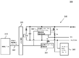
照明ドライバ200は、絶縁バリア220によって互いに電気的に絶縁される制御ユニット210と電源ユニット250とを含む。制御ユニット210は、幾つかの実施例においては照明ドライバ200がAC主電源から入力電力を受け取り得る、絶縁バリア220の「一次側」又は高電圧側にある。電源ユニット250は、絶縁バリア220の「二次側」又は低電圧側にあり、絶縁バリア220を越えて通信されるSRイネーブル信号及び補助電力イネーブル信号に応じて、外部デバイス(例えば、照明制御ユニット)に補助電圧及びSR(即ち、DALI)電圧を供給し得る。この目的のために、電源ユニット250は、第1変圧器巻線232と、補助電力イネーブル制御機構234と、第1スイッチ236と、第2変圧器巻線242と、SR(即ち、DALI)電力イネーブル制御機構244と、第2スイッチ246と、電流制限器248とを含む。照明ドライバ200は、DALIインターフェース260も含む。照明ドライバ200は、図2に示されていない他の要素、とりわけ、様々な実施例において、電力変圧器、バックコンバータ、ブーストコンバータ、バックブーストコンバータ、PWM変調器などを含み得る、照明ユニット、とりわけ、LED照明ユニットに電力を供給するための要素を含み得る。
The
照明ドライバ200は、フライバックコンバータなどの内蔵低電圧源の変圧器巻線242から得られる専用の低電圧源からのSR電圧Vsrを供給し、電源ユニット250によって外部デバイス(例えば、照明制御ユニット)に供給されるのを、制御ユニット210から絶縁バリア220を越えて受信されるSRイネーブル信号に応じて、スイッチ246によって、選択的にディスエーブル又はイネーブルにされる。補助供給電圧Vauxは、同じ変圧器の別の巻線232から、又は独立したコンバータから得られ、電源ユニット250によって外部デバイス(例えば、照明制御ユニット)に供給されるのを、制御ユニット210から絶縁バリア220を越えて受信される補助電力イネーブル信号に応じて、スイッチ236によって、選択的にディスエーブル又はイネーブルにされる。幾つかの実施例においては、外部デバイスは、電源ユニット250によって前記外部デバイスに供給される電源以外の電源を持たなくてもよい。
The
次に、SRバスは、外部デバイス(及び随意に、1つ以上の他の外部デバイス)に接続されてもよく、それによって、外部デバイスは、通信用のDALIプロトコルを用いて照明ドライバ200とデータを通信し得る、即ち、SRバスは、DALIコマンドの送信中、周期的にローに引き下げられる。SRバスがローに引き下げられるとき、それは、SRバスを短絡させることと等価である。この短絡電流を制限するために、SR供給電圧の負端子又はローサイドのSR-からSRバスに接続される電流制限器248が設けられる。異なる用途、又は特定の用途における異なる作動条件のために、SR電源及び補助電源は、制御ユニット210によってイネーブル又はディスエーブルにされる機能を必要とし、制御ユニット210は、制御機構のほとんどが絶縁バリア220の高電圧一次側に位置することから、絶縁バリア220の高電圧一次側にある。照明ドライバ200においては、これらのイネーブル及びディスエーブルコマンドは、2つの独立した信号又はチャネルによって低電圧二次側に転送される。電流制限器248は、SR供給電圧の負端子又はローサイドSR-であることから、SRバス用のイネーブルスイッチ(enabling switch)246及び電流制限器249の両方が、SR供給電圧から直接制御され得る。
The SR bus may then be connected to an external device (and optionally one or more other external devices) so that the external device can use the DALI protocol for communication with the
しかしながら、図2において図示されている構成には、幾つかの不利な点がある。或る不利な点は、絶縁バリア220を越えて一次側から低電圧二次側へ複数の制御信号(即ち、SRイネーブル信号及び補助電力イネーブル信号)を送信することの複雑さ及び高コストである。幾つかの実施例においては、これは、絶縁バリア220のための2つのオプトカプラの使用を含み得る。別の不利な点は、低電圧補助電力及びSR供給電圧のために異なる電圧源(例えば、より複雑な及び/又は追加の変圧器巻線)を用いることの複雑さ及び高コストである。別の不利な点は、SR電流制限器の制御のためのSRイネーブル信号からの駆動電圧が、多くの場合、不十分であることである。
However, the configuration illustrated in FIG. 2 has some disadvantages. One disadvantage is the complexity and high cost of transmitting multiple control signals (ie, SR enable signal and auxiliary power enable signal) from the primary side to the low voltage secondary side over the
より一般的には、本発明者は、簡易化されたやり方で、センサ対応LEDドライバの「一次側」の制御ユニットから「二次側」のDALI電源及び補助電源の両方に電力又は電圧のイネーブル及びディスエーブルコマンドを通信し得る、照明ドライバ、及び関連する、照明ドライバを動作させる方法を提供することは有益であるだろうことを認識及び理解した。より詳細には、本発明者は、単一の絶縁信号経路を用いて、センサ対応LEDドライバの「一次側」の制御ユニットから「二次側」のDALI電源及び補助電源に電力又は電圧のイネーブル及びディスエーブルコマンドを通信し得る、照明ドライバ、及び関連する、照明ドライバを動作させる方法のニーズが当技術分野にあることを認識した。 More generally, the present inventor enables power or voltage from the "primary" control unit of the sensor-enabled LED driver to both the "secondary" DALI power supply and the auxiliary power supply in a simplified manner. And recognized and understood that it would be beneficial to provide a lighting driver, and related, methods of operating the lighting driver, capable of communicating disable commands. More specifically, we use a single isolated signal path to enable power or voltage from the "primary" control unit of the sensor-enabled LED driver to the "secondary" DALI and auxiliary power supplies. And recognized that there is a need in the art for lighting drivers and related methods of operating lighting drivers capable of communicating disable commands.
前述のことを考慮して、本発明の様々な実施例及び実施態様は、単一の絶縁信号経路を用いる単一のイネーブル信号を介して、センサ対応LEDドライバの「一次側」の制御ユニットから「二次側」のDALI電源及び補助電源に電力又は電圧のイネーブル及びディスエーブルコマンドを通信し得る照明ドライバのための本発明の方法及び装置を対象としている。 In view of the above, various embodiments and embodiments of the present invention are made from the "primary side" control unit of the sensor-enabled LED driver via a single enable signal using a single isolated signal path. It is intended for the methods and devices of the invention for lighting drivers capable of communicating power or voltage enable and disable commands to "secondary" DALI and auxiliary power supplies.
図3は、単一の絶縁信号経路を用いる単一のイネーブル信号302を介して、照明ドライバ300の「一次側」から「二次側」に電力又は電圧のイネーブル及びディスエーブルコマンドを通信し得るセンサ対応発光ダイオード(LED)照明ドライバ300の例示的な実施例の機能ブロック図を図示している。ここで、「単一のイネーブル信号」は、追加のイネーブル信号を排除するための厳密に1つのイネーブル信号を意味し、「単一の絶縁信号経路」は、追加のイネーブル信号の絶縁信号経路を排除するための厳密に1つの絶縁信号経路を意味すると理解されるべきである。
FIG. 3 may communicate power or voltage enable and disable commands from the "primary side" to the "secondary side" of the
照明ドライバ300は、絶縁バリア320によって互いに電気的に絶縁される制御ユニット310と電源ユニット350とを含む。制御ユニット310は、幾つかの実施例においては照明ドライバ300がAC主電源から入力電力を受け取り得る、絶縁バリア320の「一次側」又は高電圧側にある。電源ユニット350は、絶縁バリア320の「二次側」又は低電圧側にあり、絶縁バリア320を越えて通信される(ここでは、「SR及び補助電力イネーブル信号」と呼ばれる)単一のイネーブル信号に応じて、外部デバイス(例えば、屋外照明コントローラなどの照明制御ユニット)に補助電圧及びSR(即ち、DALI)電圧の両方を供給し得る。この目的のために、電源ユニット350は、第1変圧器巻線332、補助電力イネーブル制御機構334、倍電圧・イネーブル/ディスエーブル制御・電流制限・電圧制限回路344、並びに第1スイッチS1及び第2スイッチS2を含む。照明ドライバ300は、DALIインターフェース360も含む。照明ドライバ300は、図3に示されていない他の要素、とりわけ、様々な実施例において、電力変圧器、バックコンバータ、ブーストコンバータ、バックブーストコンバータ、PWM変調器などを含み得る、照明ユニット、とりわけ、LED照明ユニットに電力を供給するための要素を含み得る。
The
照明ドライバ300は、巻線322から、又は照明ドライバ300内の独立したコンバータから補助電圧(例えば、24VDC)を生成し、巻線322は、照明ドライバ300によって駆動される照明ユニット(例えば、照明ユニット120)の1つ以上の照明デバイス(例えば、LED)に照明するための電力を供給するために照明ドライバ300によって用いられ得る変圧器の別の巻線であり得る。補助電圧は、電源ユニット350によって外部デバイス(例えば、照明制御ユニット)に供給されるのを、制御ユニット310から絶縁バリア320を越えて受信される単一のイネーブル信号302に応じて、第2スイッチS2の動作によって、イネーブルにされる。
The
照明ドライバ300においては、補助電源は、SR電圧と同じ電源を共用する。詳細には、照明ドライバ300は、補助電圧からSR電圧を生成し、電源ユニット350によって外部デバイス(例えば、照明制御ユニット)に供給されるのを、制御ユニット310から絶縁バリア320を越えて受信されるSRイネーブル信号に応じて、イネーブルにされる。SR電圧は、電源ユニット350によって外部デバイス(例えば、照明制御ユニット)に供給されるのを、制御ユニット310から絶縁バリア320を越えて受信される単一のイネーブル信号302に応じて、下でより詳細に説明するような第1スイッチS1及び第2スイッチS2の動作の組み合わせによって、イネーブルにされる。幾つかの実施例においては、外部デバイスは、電源ユニット350によって前記外部デバイスに供給される電源以外の電源を持たなくてもよい。
In the
SRバスは、外部デバイス(及び随意に、1つ以上の他の外部デバイス)に接続されてもよく、それによって、外部デバイスは、通信用のDALIプロトコルを用いて照明ドライバ300とデータを通信し得る、即ち、SRバスは、DALIコマンドの送信中、周期的にローに引き下げられる。上記のように、SRバスがローに引き下げられるとき、それは、SRバスを短絡させることと等価である。この短絡電流を制限するために、回路344は、SR供給電圧の正端子又はハイサイドSR+からSRバスに接続される電流制限器を含む。ここで、Rsは、回路344を介してS1のゲート制御回路に電流フィードバックを供給する電流検出抵抗器である。S1及び電流制限器は、SR供給電圧のハイサイド又は正端子側にあり、故に、SR供給電圧の負端子側SR-及び補助電圧のための外部デバイスから照明ドライバ300への戻り接続(COM)は、外部デバイスに接続される共通のリード線又は電線を共用する。
The SR bus may be connected to an external device (and optionally one or more other external devices), whereby the external device communicates data with the
或る実施例においては、制御ユニット310は、少なくとも3つの状態のうちの選択された1つの状態を持つ単一のイネーブル信号302を供給するよう構成され、電源ユニット350は、少なくとも3つの状態のうちのどの1つの状態が選択されているかに依存して、外部デバイスに2つの出力電圧の一方若しくは両方が供給される、又はいずれもが供給されないように、2つの出力電圧(補助電圧及びSR供給電圧)を切り替えるように構成される。
In one embodiment, the
特定の実施例においては、単一のイネーブル信号の少なくとも3つの状態は、定常高電圧レベル、定常低電圧レベル、及びパルス幅変調(PWM)信号を含み、電源ユニット350は、単一のイネーブル信号が、定常低電圧レベルを持つのか、定常高電圧レベルを持つのか、又はPWM信号であるのかに依存して、外部デバイスに2つの出力電圧の一方が供給される、いずれもが供給されない、又は両方が供給されるように、2つの出力電圧(補助電圧及びSR供給電圧)を切り替えるように構成される。
In a particular embodiment, at least three states of a single enable signal include a steady high voltage level, a steady low voltage level, and a pulse width modulation (PWM) signal, and the
このような実施例の更なる詳細は、下で、照明ドライバ300の或る実施例であり得るセンサ対応LED照明ドライバ400の例示的な実施例の概略図を示している図4を参照して、説明される。下でより詳細に説明されるように、照明ドライバ400は、単一のイネーブル信号を介して単一の絶縁信号経路を用いて、照明ドライバ400の「一次側」から「二次側」へ電力又は電圧のイネーブル及びディスエーブルコマンドを通信し得る
For further details of such an embodiment, see FIG. 4, which shows a schematic illustration of an exemplary embodiment of the sensor-enabled
照明ドライバ400は、オプトカプラU1によって供給される絶縁バリア420によって互いに電気的に絶縁される制御ユニット410と電源ユニット450とを含む。制御ユニット410は、幾つかの実施例においては照明ドライバ400がAC主電源から入力電力を受け取り得る、絶縁バリア420の「一次側」又は高電圧側にある。電源ユニット450は、絶縁バリア420の「二次側」又は低電圧側にあり、オプトカプラU1を用いて絶縁バリア420を越えて通信される(ここでは、「SR及び補助電力イネーブル信号」と呼ばれる)単一のイネーブル信号402に応じて、外部デバイス(例えば、屋外照明コントローラなどの照明制御ユニット)に補助電圧及びSR(即ち、DALI)電圧の両方を供給し得る。ここで、電圧V1によって表される単一のイネーブル信号402の極性は、オプトカプラU1の動作によって照明ドライバの二次側においては電圧V2として反対又は逆にされることに留意されたい。この目的のために、電源ユニット450は、プッシュプルドライバ434、フィルタ436、PWM信号検出器442、倍電圧器444、SR供給電圧レギュレータ446、SR供給電圧電流制限器448、第1及び第2スイッチS1及びS2、並びに下に記載される他の構成要素を含む。照明ドライバ400は、DALIインターフェース460も含む。照明ドライバ400は、図4に示されていない他の要素、とりわけ、様々な実施例において、電力変圧器、バックコンバータ、ブーストコンバータ、バックブーストコンバータ、PWM変調器などを含み得る、照明ユニット、とりわけ、LED照明ユニットに電力を供給するための要素を含み得る。
The
動作中、制御ユニット410は、外部デバイスに給電するために、電源ユニット450によって出力され、外部デバイスに供給されるのをディスエーブル又はイネーブルにされるべき電圧(補助電圧及びSR供給電圧)をどのように制御する又はイネーブルにすることが望ましいかに依存して、少なくとも3つの状態又は電圧のうちの1つを持つよう選択される単一のイネーブル信号402を生成する。幾つかの実施例においては、外部デバイスは、電源ユニット450によって前記外部デバイスに供給される電源以外の電源を持たなくてもよい。単一のイネーブル信号402の少なくとも3つの状態は、とりわけ、定常高電圧レベル、定常低電圧レベル、およびパルス幅変調(PWM)信号を含む。電源ユニット450は、単一のイネーブル信号が、定常低電圧レベルを持つのか、定常高電圧レベルを持つのか、又はPWM信号を持つのかに依存して、外部デバイスに2つの出力電圧の一方が供給される、いずれもが供給されない、又は両方が供給されるように、2つの出力電圧(補助電圧及びSR供給電圧)を切り替えるように構成される。より具体的には、補助電圧とSR供給電圧との両方をディスエーブルにすることが望ましい場合には、制御ユニット410は、定常高電圧レベルを持つよう単一のイネーブル信号402(即ち、V1)を出力する。他方で、補助電圧をイネーブルにし、SR供給電圧をディスエーブルにすることが望ましい場合には、制御ユニット410は、定常低電圧レベルを持つよう単一のイネーブル信号402(即ち、V1)を出力する。最後に、補助電圧とSR供給電圧との両方をイネーブルにすることが望ましい場合には、制御ユニット410は、単一のイネーブル信号402(即ち、V1)をPWM信号として出力する。
During operation, the
U1は一次から二次まで絶縁バリアを供給し、制御ユニット410によって出力される電圧V1に対して逆の論理レベルを持つ電圧V2を出力する。U1の出力は、駆動能力を高める、Q1、Q2及びR2を含むプッシュプルドライバ434を駆動し、電圧V2と同じ論理レベルを維持するプッシュプル出力電圧V3を出力する。R3及びC3を含むフィルタ436は、プッシュプル出力電圧V3を入力として受け取り、単一のイネーブル信号402がPWM信号である場合にはAC成分を除去する。フィルタ436の出力は、第2スイッチS2のゲートに印加される電圧Vg2であり、それによって、外部デバイスに供給されるべき補助電圧及び電力をイネーブルにするための第2スイッチS2のオン/オフスイッチング動作を制御する。第2スイッチS2のゲート駆動電圧は、ツェナーZ3によってクランプされる。
U1 supplies an insulating barrier from the primary to the secondary, and outputs a voltage V2 having a logic level opposite to the voltage V1 output by the
別の分岐では、プッシュプル出力電圧V3が、C4、D3、D4、及びC5によって形成される倍電圧器444に給電するために用いられる。単一のイネーブル信号402(V1)がPWM信号である場合、倍電圧器444は、アクティブであり、第1スイッチS1のゲートを駆動するための出力電圧V5を供給する。V5の電圧レベルは、補助出力電圧Vauxよりも大きく、回路設計(例えば、構成要素の値の選択)に依存して、2*Vauxまで高くなり得る。電圧V5は、SR供給電圧電流制限器448を駆動し、ゲート抵抗器R4を通して第1スイッチS1をイネーブルにするために用いられる。電圧V5がVauxよりも大きいことで、SR供給電圧(例えば、20.5V)の正端子(SR+)における電圧は、Vaux(例えば、24V)付近で調整されることができ、第1スイッチS1及びRsの両端の電圧は最小化され得る。これは、DALI要件を満たすのに十分なSR供給電圧を供給するだけでなく、第1スイッチS1における電力消費を最小限にするという利点も与える。電圧レギュレータ446は、トランジスタQ10及びツェナーダイオードZ5を含み、Vsr=V(Z5)+VbeのレベルでSR供給電圧を調整するために用いられ、ここでV(Z5)は、Z5のツェナー電圧であり、Vbeは、Q10のベース・エミッタ接合電圧である。 この電圧フィードバックループは、SR供給電圧Vsrが指定されたDALIバス電圧範囲内に収まることを確実にする。U3は、SR供給電圧出力電流に比例するRsの両端の電圧に従ってゲート電圧Vg1を調整するシャント電圧レギュレータである。これは、SRバスが、短絡される、又はSR供給電圧を調整電圧Vsrよりも低くさせる負荷に接続される場合に、SR供給電圧出力電流が調整されるように、電流フィードバックループを形成する。
In another branch, the push-pull output voltage V3 is used to feed the voltage doubler 444 formed by C4, D3, D4, and C5. When the single enable signal 402 (V1) is a PWM signal, the voltage doubler 444 is active and supplies an output voltage V5 to drive the gate of the first switch S1. The voltage level of V5 is greater than the auxiliary output voltage Vaux and can be as high as 2 * Vaux, depending on the circuit design (eg, the choice of component values). The voltage V5 is used to drive the SR supply voltage
プッシュプル出力電圧V3の第3分岐は、単一のイネーブル信号402(V1)が、PWM信号であるか、純粋なDC信号(定常低電圧又は定常高電圧)であるかを検出するために用いられる。この検出は、プッシュプル出力電圧V3において負ピーク検出を実施する、D5、R5、C6、Z4、R6、及びQ9を含むPWM信号検出器442によって達成される。単一のイネーブル信号402(V1)の3つの異なる状態は、とりわけ、以下のように、Q9の異なる動作モードを生成する。 The third branch of the push-pull output voltage V3 is used to detect whether the single enable signal 402 (V1) is a PWM signal or a pure DC signal (stationary low voltage or steady high voltage). Be done. This detection is achieved by a PWM signal detector 442 including D5, R5, C6, Z4, R6, and Q9, which performs negative peak detection at push-pull output voltage V3. Three different states of a single enable signal 402 (V1) generate different modes of operation for Q9, among others:
第1状態においては、単一のイネーブル信号402(V1)は、定常高電圧を持ち(常に高く)、従って、プッシュプル出力電圧V3は、V(be)において常に低く、ここで、V(be)は、Q2のベース・エミッタ接合電圧である。電圧V4も、Vbe+Vfdにおいて低く、ここで、Vfdは、ダイオードD5の順方向電圧降下である。ツェナーダイオードZ4のツェナー電圧(V(Z4))は、電圧V4のこの低レベルよりも大きくなるよう選択され、Z4を通る如何なるあり得る漏れ電流も、Q9を駆動するベース電流がないように、R6によってバイパスされる。この場合には、Q9は、オフである、又は開いている。 In the first state, the single enable signal 402 (V1) has a steady high voltage (always high), so the push-pull output voltage V3 is always low at V (be), where V (be). ) Is the base-emitter junction voltage of Q2. The voltage V4 is also low at Vbe + Vfd, where Vfd is the forward voltage drop of the diode D5. The Zener voltage (V (Z4)) of the Zener diode Z4 is chosen to be greater than this low level of voltage V4 so that any possible leakage current through Z4 is such that there is no base current driving Q9. Bypassed by. In this case, Q9 is off or open.
第2状態においては、単一のイネーブル信号402(V1)は、定常低電圧を持ち(常に低く)、従って、プッシュプル出力電圧V3は、Vaux-Vbeにおいて常に高く、ここで、Vauxは、補助供給電圧であり、V(be)は、Q1のベース・エミッタ接合電圧である。この場合には、電圧V4は、ツェナー電圧V(Z4)よりも大きい、Vax-Vbe+Vfdまで高くなるようR5によって充電され得る。この場合には、この高い電圧V4がQ9をオンにし、Q9が電流を伝導し、このことが、Vg1をローに引き下げ、第1スイッチS1をオフにする。 In the second state, the single enable signal 402 (V1) has a steady-state low voltage (always low), so the push-pull output voltage V3 is always high in Vaux-Vbe, where Vaux is auxiliary. It is a supply voltage, and V (be) is the base-emitter junction voltage of Q1. In this case, the voltage V4 can be charged by R5 to be higher than the Zener voltage V (Z4) up to Vax-Vbe + Vfd. In this case, this high voltage V4 turns on Q9 and Q9 conducts current, which pulls Vg1 low and turns off the first switch S1.
第3状態においては、単一のイネーブル信号402(V1)は、デューティ比δを持つPWM信号であり、従って、プッシュプル出力電圧V3は、デューティ比1 - δを持つPWM信号である。この場合には、C6は、プッシュプル出力電圧V3のPWMのローサイクル中に完全に放電する。R5は、C5が、プッシュプル出力電圧V3のPWM信号のハイサイクル中にツェナー電圧V(Z4)より低い電圧までしか充電されることができないように、十分に大きな値を持つよう選択される。したがって、電圧V4は、ツェナー電圧V(Z4)より小さく、Q9は、オフである、又は開いている。
In the third state, the single enable signal 402 (V1) is a PWM signal with a duty ratio δ, so the push-pull output voltage V3 is a PWM signal with a
上記の3つの動作モードに基づいて、単一のイネーブル信号402(V1)の異なる状態の各々に対するSR供給電圧及び補助電圧のイネーブル及びディスエーブルについて説明する。 Based on the above three modes of operation, enabling and disabling the SR supply voltage and auxiliary voltage for each of the different states of a single enable signal 402 (V1) will be described.
第1状態においては、単一のイネーブル信号402(V1)は、定常高電圧を持つ(常に高い)。この状態においては、プッシュプル出力電圧V3が低いことから、第2スイッチS2は、オフである、又はディスエーブルにされる。従って、補助電圧は、ディスエーブルにされ、照明ドライバ400によって外部デバイスに供給されない。SR供給電圧の正端子は、ディスエーブルにされる同じ補助電圧から導き出され、従って、この場合には、第2スイッチS2は、この供給経路内にあることから、たとえS1がイネーブルにされても、SR供給電圧も、ディスエーブルにされ、照明ドライバ400によって外部デバイスに供給されない。
In the first state, the single enable signal 402 (V1) has a steady high voltage (always high). In this state, since the push-pull output voltage V3 is low, the second switch S2 is turned off or disabled. Therefore, the auxiliary voltage is disabled and is not supplied to the external device by the
第2状態においては、単一のイネーブル信号402(V1)は、定常低電圧を持つ(常に低い)。この状態においては、プッシュプル出力電圧V3が高いことから、第2スイッチS2は、オンである、又はイネーブルにされる。従って、補助電圧は、イネーブルにされ、照明ドライバ400によって外部デバイスに供給され得る。しかしながら、上で説明したように、Q9が、オンであり、電流を伝導し、Vg1をローに引き下げることから、第1スイッチS1は、オフである、又はディスエーブルにされる。それ故、SR供給電圧は、ディスエーブルにされ、照明ドライバ400によって外部デバイスに供給されない。
In the second state, the single enable signal 402 (V1) has a steady low voltage (always low). In this state, since the push-pull output voltage V3 is high, the second switch S2 is turned on or enabled. Therefore, the auxiliary voltage can be enabled and supplied to the external device by the
第3状態においては、単一のイネーブル信号402(V1)は、PWM信号である。この場合には、第2スイッチS2のゲート電圧Vg2は、プッシュプル出力電圧V3からフィルタリングされたDC電圧であり、プッシュプル出力電圧V3の平均電圧に等しい。このDC電圧は、第2スイッチS2のゲート閾値電圧よりも大きくなるよう設計され、従って、第2スイッチS2は、オンにされ、従って、補助電源は、イネーブルされ、照明ドライバ400によって外部デバイスに供給され得る。この場合には、Q9は、オフであり、又は開いており、従って、第1スイッチS1も、倍電圧器444の出力である電圧V5によってオンにされる。それ故、単一のイネーブル信号402(V1)が第3状態にある状態では、SR供給電圧も、イネーブルにされ、照明ドライバ400によって外部デバイスに供給され得る。
In the third state, the single enable signal 402 (V1) is a PWM signal. In this case, the gate voltage Vg2 of the second switch S2 is a DC voltage filtered from the push-pull output voltage V3, and is equal to the average voltage of the push-pull output voltage V3. This DC voltage is designed to be greater than the gate threshold voltage of the second switch S2, so that the second switch S2 is turned on and thus the auxiliary power supply is enabled and supplied to the external device by the
論理レベル及びイネーブル状態の一覧を、下で表1において示す。
表1

Table 1
表1から、補助電圧/電力及びSR供給電圧/電力の4つのあり得るイネーブル/ディスエーブル状態の組み合わせのうちの3つが、単一の絶縁信号経路を用いる単一のイネーブル信号402で実施されることは、明らかである。SR供給電圧/電力がイネーブルにされ、且つ補助電力がディスエーブルにされる第4の組み合わせは含まれない。なぜなら、通常、この作動条件はSR照明ドライバには必要ないからである。 From Table 1, three of the four possible enable / disable state combinations of auxiliary voltage / power and SR supply voltage / power are performed on a single enable signal 402 with a single isolated signal path. That is clear. The fourth combination in which the SR supply voltage / power is enabled and the auxiliary power is disabled is not included. This is because this operating condition is usually not required for SR lighting drivers.
図5は、照明ドライバの「一次側」で生成されるイネーブル及びディスエーブルコマンドに応じて、センサ対応LED照明ドライバの「二次側」から外部デバイスへ供給される電力をイネーブル及びディスエーブルにする方法500のフローチャートを示している。
FIG. 5 enables and disables power supplied to an external device from the “secondary side” of a sensor-enabled LED lighting driver in response to enable and disable commands generated on the “primary side” of the lighting driver. The flowchart of the
第1動作510において、照明ドライバの電気絶縁バリアの第1の側に配置された制御ユニットが、電気絶縁バリアの第2の側に配置された電源ユニットに単一のイネーブル信号を供給する。
In the
第2動作520においては、電源ユニットが、照明ドライバとデータを通信する外部デバイスに電力を供給するための2つの出力電圧を、単一のイネーブル信号に応じて、選択的にイネーブル及びディスエーブルにする。
In the
本願明細書には幾つかの本発明の実施例が記載及び図示されているが、当業者は、本願明細書に記載されている機能を実施するための、並びに/又は本願明細書に記載されている利点のうちの1つ以上及び/若しくは本願明細書に記載されている結果を得るための、様々な他の手段及び/又は構造を容易に案出するだろう。このような変形例及び/又は修正例の各々は、本願明細書に記載されている本発明の実施例の範囲内にあるとみなされる。更に一般的に言えば、当業者は、本願明細書に記載されている全てのパラメータ、寸法、材料及び構成が、例示的なものであるよう意図されており、実際のパラメータ、寸法、材料及び構成は、本発明の教示が用いられる1つ又は複数の特定のアプリケーションに依存するだろうことを、容易に理解するだろう。当業者は、本願明細書に記載されている特定の本発明の実施例と同等の多くの実施例を、理解するだろう、又は単なるルーチン実験を用いて確認することができるだろう。それ故、上記の実施例は、ほんの一例として提示されているに過ぎず、添付の特許請求の範囲及びそれと同等のものの範囲内で、詳細に記載されているもの及び請求項記載のもの以外に、本発明の実施例が実施され得ることは、理解されるべきである。本開示の本発明の実施例は、本願明細書に記載されている個々の特徴、システム、物、材料、キット及び/又は方法を対象にしている。更に、2つ以上のこのような特徴、システム、物、材料、キット及び/又は方法の如何なる組み合わせも、このような特徴、システム、物、材料、キット及び/又は方法が互いに矛盾しない場合には、本開示の本発明の範囲内に含まれ得る。 Although some embodiments of the present invention are described and illustrated in the specification of the present application, those skilled in the art are described in and / or in the specification of the present application for performing the functions described in the specification of the present application. One or more of these advantages and / or various other means and / or structures for obtaining the results described herein will be readily devised. Each of such modifications and / or modifications is considered to be within the scope of the embodiments of the invention described herein. More generally, one of ordinary skill in the art intends that all parameters, dimensions, materials and configurations described herein are exemplary and actual parameters, dimensions, materials and It will be readily appreciated that the configuration will depend on one or more specific applications in which the teachings of the present invention are used. One of ordinary skill in the art will understand, or will be able to confirm, using simple routine experiments, many embodiments equivalent to the particular embodiments of the invention described herein. Therefore, the above embodiment is presented as an example only, and within the scope of the appended claims and equivalents, other than those described in detail and those described in the claims. It should be understood that the embodiments of the present invention can be carried out. The embodiments of the invention of the present disclosure are directed to the individual features, systems, objects, materials, kits and / or methods described herein. Further, any combination of two or more such features, systems, objects, materials, kits and / or methods may be used if such features, systems, objects, materials, kits and / or methods are consistent with each other. , May be included within the scope of the present invention of the present disclosure.
本願明細書において規定及び使用されているような全ての定義は、辞書的定義、参照により盛り込まれる文書における定義、及び/又は規定されている用語の通常の意味にわたって制御するよう理解されるべきである。 All definitions as defined and used herein should be understood to control over dictionary definitions, definitions in documents incorporated by reference, and / or the usual meanings of the terms defined. be.
ここで、本願明細書及び請求項において用いられているような単数形表記は、そうではないと明確に示されていない限り、「少なくとも1つ」を意味すると理解されるべきである。 Here, the singular notation, as used herein and in the claims, should be understood to mean "at least one" unless explicitly stated otherwise.
ここで、本願明細書及び請求項において用いられているような「及び/又は」という語句は、そのように等位結合されている要素の「いずれか又は両方」、即ち、幾つかの場合には結合的に存在し、他の場合には分離的に存在する要素を意味すると理解されるべきである。「及び/又は」と共に列挙されている複数の要素は、同じように、即ち、そのように等位結合されている要素のうちの「1つ以上」と解釈されるべきである。「及び/又は」の句によって明確に特定されている要素以外の他の要素も、明確に特定されている要素と関連するか関連しないかにかかわらず、随意に存在し得る。従って、非限定的な例として、「A及び/又はB」への言及は、「有する」のような制約のない言い回しと併せて用いられるときには、或る実施例においては、(随意にB以外の要素を含む)Aだけを、別の実施例においては、(随意にA以外の要素を含む)Bだけを、更に別の実施例においては、(随意に他の要素を含む)AとBとの両方を指し得る。 Here, the phrase "and / or" as used herein and in the claims is "any or both" of such equilibrium-bonded elements, i.e., in some cases. Should be understood to mean elements that exist associative and otherwise separate. Multiple elements listed with "and / or" should be construed in the same way, i.e., as "one or more" of the elements coordinated in that way. Other elements other than those explicitly identified by the phrase "and / or" may optionally exist, whether or not they are associated with the explicitly identified elements. Thus, as a non-limiting example, when the reference to "A and / or B" is used in conjunction with an unconstrained phrase such as "have", in some embodiments (optionally other than B). Only A (including elements of), in another embodiment only B (optionally including elements other than A), and in yet another embodiment A and B (optionally including other elements). Can point to both.
ここで、本願明細書及び請求項において用いられているような「又は」は、上で定義されているような「及び/又は」と同じ意味を持つと理解されるべきである。例えば、リストにおいて項目を分ける場合、「又は」又は「及び/又は」は、包含的なものであると解釈されるべきであり、即ち、多くの又はリストの要素のうちの少なくとも1つを含むものであるが、1つより多く、及び随意に、リストにない更なる項目も含むものであると解釈されるべきである。「~のうちの1つだけ」若しくは「~のうちの厳密に1つ」、又は請求項において用いられる場合の「~から成る」のような、そうではないと明確に示されている用語だけが、多くの又はリストの要素のうちの厳密に1つの要素を含むことを指すだろう。一般に、本願明細書において用いられているような「又は」という用語は、「いずれか」、「~のうちの1つ」、「~のうちの1つだけ」又は「~のうちの厳密に1つ」のような排他性の用語が前に付く場合にだけ、排他的な選択肢(即ち、「一方又は他方であり、両方ではない」)を示すものと解釈されるべきである。請求項において用いられる場合の「本質的に~から成る」は、特許法の分野で用いられるような通常の意味を持つものとする。 Here, "or" as used in the specification and claims should be understood to have the same meaning as "and / or" as defined above. For example, when separating items in a list, "or" or "and / or" should be construed as inclusive, i.e., including at least one of many or the elements of the list. However, it should be construed to include more than one and, optionally, additional items not on the list. Only terms clearly indicated otherwise, such as "only one of" or "exactly one of", or "consisting of" as used in the claims. Would mean to include exactly one element of many or list elements. In general, the term "or" as used herein is "any", "one of", "only one of" or "strictly of". It should be construed to indicate an exclusive option (ie, "one or the other, not both") only if it is preceded by a term of exclusivity such as "one". As used in the claims, "essentially consisting of" shall have the usual meaning as used in the field of patent law.
ここで、本願明細書及び請求項において用いられているような、1つ以上の要素のリストに関する「少なくとも1つ」という語句は、要素のリストにおける要素のうちの任意の1つ以上から選択される少なくとも1つの要素を意味すると理解されるべきであるが、必ずしも要素のリスト内で特に列挙されているありとあらゆる要素のうちの少なくとも1つを含むとは限らず、要素のリストにおける要素の如何なる組み合わせも除外しないと理解されるべきである。この定義は、「少なくとも1つ」という語句が指す要素のリスト内で明確に特定されている要素以外の要素が、明確に特定されている要素と関連するか関連しないかにかかわらず、随意に存在し得ることも許容する。従って、非限定的な例として、「A及びBのうちの少なくとも1つ」(又は同等に、「A又はBのうちの少なくとも1つ」、又は同等に、「A及び/又はBのうちの少なくとも1つ」)は、或る実施例においては、Bが存在しない(且つ随意に、B以外の要素を含む)状態での、随意に1つより多くを含む少なくとも1つのAを、別の実施例においては、Aが存在しない(且つ随意に、A以外の要素を含む)状態での、随意に1つより多くを含む少なくとも1つのBを、更に別の実施例においては、(随意に他の要素を含む、)随意に1つより多くを含む少なくとも1つのA、及び随意に1つより多くを含む少なくとも1つのBを指し得る。 Here, the phrase "at least one" with respect to a list of one or more elements, as used herein and in the claims, is selected from any one or more of the elements in the list of elements. It should be understood to mean at least one element, but it does not necessarily include at least one of all the elements specifically listed in the list of elements, and any combination of elements in the list of elements. Should also be understood not to exclude. This definition is voluntary, regardless of whether elements other than those specifically specified in the list of elements pointed to by the phrase "at least one" are related or unrelated to the clearly specified elements. It is also acceptable that it may exist. Thus, as a non-limiting example, "at least one of A and B" (or equivalently, "at least one of A or B", or equivalently, of "A and / or B". At least one ") is, in one embodiment, at least one A optionally containing more than one in the absence of B (and optionally including elements other than B). In the embodiment, at least one B containing more than one at will in the absence of A (and optionally including elements other than A), and in yet another embodiment (optionally). It may refer to at least one A, optionally including more than one, and at least one B, optionally including more than one.
1つより多くのステップ又は動作を含む請求記載のあらゆる方法において、方法のステップ又は動作の順序は、そうではないと明確に示されていない限り、必ずしも、方法のステップ又は動作が列挙されている順序に限定されているわけではないことも理解されるべきである。 In all methods of claim that include more than one step or action, the order of the steps or actions of the method does not necessarily list the steps or actions of the method unless explicitly stated otherwise. It should also be understood that it is not limited to order.
請求項において、及び上記の明細書において、「有する」、「含む」、「担持する」、「持つ」、「含有する」、「包含する」、「保持する」及び「~によって構成される」などのような全ての移行句は、制約のないものであると、即ち、含むが、限定されないことを意味すると理解されるべきである。米国特許庁審査手続マニュアルの第2111.03項に記載されているように、「~から成る」及び「本質的に~から成る」という移行句だけが、各々、排他的な又は半排他的な移行句であるものとする。 In the claims and above, "have", "include", "carry", "have", "contain", "include", "hold" and "consist of". It should be understood that all transitional clauses, such as, are unconstrained, that is, they include, but are not limited. As described in Section 2111.03 of the US Patent Office Examination Procedures Manual, only the transitional phrases "consisting of" and "consisting of essentially" are exclusive or semi-exclusive transitional phrases, respectively. Suppose that
Claims (15)
電気絶縁バリアの第1の側に配置される制御ユニットと、
前記少なくとも1つの照明デバイスに電力を供給するための変圧器であって、前記電気絶縁バリアの第2の側に電力を供給するための補助巻線を含み、前記補助巻線が、前記少なくとも1つの照明デバイスの電力供給から切り離されている変圧器と、
前記制御ユニットから電気的に絶縁されるように前記電気絶縁バリアの前記第2の側に配置される電源ユニットとを有する照明ドライバであって、前記制御ユニットが、前記電気絶縁バリアを越えて前記電源ユニットに単一のイネーブル信号を供給し、前記電源ユニットが、前記照明ドライバとデータを通信する外部デバイスに電力を供給するための2つの出力電圧を、前記単一のイネーブル信号に応じて、選択的にイネーブル及びディスエーブルにするよう構成されるスイッチング回路を含む照明ドライバ。 A lighting driver for driving at least one lighting device,
A control unit located on the first side of the electrical insulation barrier,
A transformer for supplying power to the at least one lighting device, comprising an auxiliary winding for supplying power to a second side of the electrically isolated barrier, wherein the auxiliary winding is at least one. With a transformer that is disconnected from the power supply of two lighting devices,
A lighting driver having a power supply unit arranged on the second side of the electrical insulation barrier so as to be electrically isolated from the control unit, wherein the control unit crosses the electrical insulation barrier. A single enable signal is supplied to the power supply unit, and the power supply unit supplies two output voltages for supplying power to an external device that communicates data with the lighting driver, depending on the single enable signal. A lighting driver that includes a switching circuit that is configured to be selectively enabled and disabled.
前記単一のイネーブル信号が前記定常低電圧レベルを持つとき、及び前記単一のイネーブル信号が前記PWM信号であるときには、前記第2スイッチをオンにし、前記外部デバイスに前記補助電圧を供給し、前記単一のイネーブル信号が前記定常高電圧レベルを持つときには、前記第2スイッチをオフにし、前記外部デバイスへの前記補助電圧及び前記センサ対応供給電圧の供給をディスエーブルにするよう、前記単一のイネーブル信号に応じて、前記第2スイッチの制御端子に制御信号を供給するよう構成されるフィルタと、
前記単一のイネーブル信号が前記PWM信号であるかどうかを検出するよう構成される検出器と、
前記単一のイネーブル信号が前記PWM信号であるときには、前記第1スイッチをオンにし、前記外部デバイスに前記センサ対応供給電圧を供給し、前記単一のイネーブル信号が前記定常低電圧レベルを持つときには、前記第1スイッチをオフにし、前記外部デバイスへの前記センサ対応供給電圧の供給をディスエーブルにするよう、前記PWM信号のピーク電圧を2倍にし、2倍にされた前記ピーク電圧を前記第1スイッチの制御端子に供給する倍電圧器とを更に有する請求項5に記載の照明ドライバ。 The switching circuit includes a first switch and a second switch, the first switch is connected between the auxiliary voltage and the positive voltage side of the sensor-compatible bus, and the second switch is , The power supply unit connected in series with the common line connected to the external device.
When the single enable signal has the steady low voltage level and when the single enable signal is the PWM signal, the second switch is turned on to supply the auxiliary voltage to the external device. When the single enable signal has the steady high voltage level, the single switch is turned off and the supply of the auxiliary voltage and the sensor-compatible supply voltage to the external device is disabled. A filter configured to supply a control signal to the control terminal of the second switch according to the enable signal of
A detector configured to detect whether the single enable signal is the PWM signal,
When the single enable signal is the PWM signal, the first switch is turned on to supply the sensor-compatible supply voltage to the external device, and when the single enable signal has the steady low voltage level. The peak voltage of the PWM signal is doubled and the peak voltage doubled is used as the first switch so that the first switch is turned off and the supply of the sensor-compatible supply voltage to the external device is disabled. The lighting driver according to claim 5, further comprising a voltage doubler for supplying to the control terminal of one switch.
前記照明デバイスの電力供給のための変圧器の補助巻線であって、前記照明デバイスの電力供給から切り離されている補助巻線によって、電気絶縁バリアの第2の側に電力を供給するステップと、
前記照明ドライバの前記電気絶縁バリアの第1の側に配置された制御ユニットから、前記制御ユニットから電気的に絶縁されるように前記電気絶縁バリアの前記第2の側に配置された電源ユニットに単一のイネーブル信号を供給するステップと、
前記電源ユニットが、前記単一のイネーブル信号に応じて、前記照明ドライバとデータを通信する前記外部デバイスに電力を供給するための2つの出力電圧を選択的にイネーブル及びディスエーブルにするステップとを有する方法。 A method for supplying power to an external device including a lighting driver, wherein the power supply of the external device is separated from the power supply of the lighting device.
With the step of supplying power to the second side of the electrical insulation barrier by an auxiliary winding of the transformer for powering the lighting device, which is separated from the power supply of the lighting device. ,
From a control unit located on the first side of the electrically insulating barrier of the lighting driver to a power supply unit arranged on the second side of the electrically insulating barrier so as to be electrically insulated from the control unit. With the step of supplying a single enable signal ,
A step in which the power supply unit selectively enables and disables two output voltages for supplying power to the external device communicating data with the lighting driver in response to the single enable signal. How to have.
前記選択された1つの状態に依存して、前記2つの出力電圧の一方若しくは両方が供給される、又はいずれもが供給されないように、前記2つの出力電圧を切り替えるステップとを更に有する請求項8に記載の方法。 A step in which the control unit selects one of at least three states and supplies the single enable signal with the selected state.
8. Claim 8 further comprising a step of switching between the two output voltages so that one or both of the two output voltages are supplied or neither is supplied, depending on the one selected state. The method described in.
前記補助電圧から前記センサ対応供給電圧を生成し、調整するステップと、
前記センサ対応バスを介して前記外部デバイスと通信するステップとを更に有する請求項10に記載の方法。 The first output voltage is an auxiliary voltage, the second output voltage is a sensor- compatible supply voltage for the sensor- compatible bus, which is lower than the auxiliary voltage, and the method is:
The step of generating and adjusting the supply voltage corresponding to the sensor from the auxiliary voltage, and
10. The method of claim 10, further comprising a step of communicating with the external device via the sensor-enabled bus.
前記センサ対応バスによって前記センサ対応供給電圧から引き出される電流を、前記センサ対応供給電圧の正端子に接続されるハイサイド電流制限器によって制限するステップとを更に有する請求項11に記載の方法。 A step in which the return connection for the auxiliary voltage and the negative terminal of the sensor-compatible supply voltage share a common line connected to the external device.
11. The method of claim 11, further comprising a step of limiting the current drawn from the sensor- compatible supply voltage by the sensor-compatible bus with a high-side current limiter connected to the positive terminal of the sensor- compatible supply voltage.
前記単一のイネーブル信号が前記定常高電圧レベルを持つときには、前記外部デバイスへの前記補助電圧及び前記センサ対応供給電圧の供給をディスエーブルにするステップと、
前記単一のイネーブル信号が前記PWM信号であるときには、前記外部デバイスに前記センサ対応供給電圧を供給するステップと、
前記単一のイネーブル信号が前記定常低電圧レベルを持つときには、前記外部デバイスへの前記センサ対応供給電圧の供給をディスエーブルにするステップとを更に有する請求項12に記載の方法。 When the single enable signal has the steady low voltage level, and when the single enable signal is the PWM signal, the step of supplying the auxiliary voltage to the external device.
When the single enable signal has the steady high voltage level, the step of disabling the supply of the auxiliary voltage and the sensor-compatible supply voltage to the external device.
When the single enable signal is the PWM signal, the step of supplying the sensor-compatible supply voltage to the external device and
12. The method of claim 12, further comprising disabling the supply of the sensor-aware supply voltage to the external device when the single enable signal has the steady low voltage level.
前記屋外照明コントローラに給電するために前記屋外照明コントローラに前記補助電圧及び前記センサ対応供給電圧を供給するステップと、
前記照明ドライバが、センサ対応インターフェースを介して前記屋外照明コントローラと前記データを通信するステップとを含む請求項11に記載の方法。 The external device is an outdoor lighting controller that wirelessly communicates with the lighting network, and the method is:
A step of supplying the auxiliary voltage and the sensor-compatible supply voltage to the outdoor lighting controller in order to supply power to the outdoor lighting controller.
11. The method of claim 11, wherein the lighting driver comprises a step of communicating the data with the outdoor lighting controller via a sensor-enabled interface.
前記少なくとも3つの状態のうちの第2状態を持つ前記単一のイネーブル信号に応じて、前記2つの出力電圧のうちの第1の出力電圧が前記外部デバイスに供給されるのをイネーブルにすると共に、前記2つの出力電圧のうちの第2の出力電圧をディスエーブルにし、前記外部デバイスへの前記2つの出力電圧のうちの前記第2の出力電圧の供給を抑止するステップと、
前記少なくとも3つの状態のうちの第3状態を持つ前記単一のイネーブル信号に応じて、前記2つの出力電圧の両方が前記外部デバイスに供給されるのをイネーブルにするステップとを更に有する請求項9に記載の方法。 A step of disabling both supply of the two output voltages to the external device in response to the single enable signal having the first of the at least three states.
In response to the single enable signal having the second state of at least three states, the first output voltage of the two output voltages is enabled to be supplied to the external device. A step of disabling the second output voltage of the two output voltages and suppressing the supply of the second output voltage of the two output voltages to the external device.
Claimed further having a step of enabling both of the two output voltages to be supplied to the external device in response to the single enable signal having a third of the at least three states. 9. The method according to 9.
Applications Claiming Priority (5)
| Application Number | Priority Date | Filing Date | Title |
|---|---|---|---|
| US201662380678P | 2016-08-29 | 2016-08-29 | |
| US62/380,678 | 2016-08-29 | ||
| EP16189130.4 | 2016-09-16 | ||
| EP16189130 | 2016-09-16 | ||
| PCT/EP2017/071199 WO2018041687A1 (en) | 2016-08-29 | 2017-08-23 | Control of isolated auxiliary power supply and dali supply for sensor-ready led drivers |
Publications (3)
| Publication Number | Publication Date |
|---|---|
| JP2019528554A JP2019528554A (en) | 2019-10-10 |
| JP2019528554A5 JP2019528554A5 (en) | 2020-10-01 |
| JP7050755B2 true JP7050755B2 (en) | 2022-04-08 |
Family
ID=59699693
Family Applications (1)
| Application Number | Title | Priority Date | Filing Date |
|---|---|---|---|
| JP2019508975A Active JP7050755B2 (en) | 2016-08-29 | 2017-08-23 | Insulation auxiliary power supply and DALI power supply control for sensor-compatible LED drivers |
Country Status (5)
| Country | Link |
|---|---|
| US (1) | US10548189B2 (en) |
| EP (1) | EP3504936B1 (en) |
| JP (1) | JP7050755B2 (en) |
| CN (1) | CN109644534B (en) |
| ES (1) | ES2839798T3 (en) |
Families Citing this family (8)
| Publication number | Priority date | Publication date | Assignee | Title |
|---|---|---|---|---|
| KR102385357B1 (en) * | 2017-07-21 | 2022-04-11 | 엘지이노텍 주식회사 | Led lighting device, and light control method of the same |
| JP7241240B2 (en) * | 2019-09-06 | 2023-03-16 | シグニファイ ホールディング ビー ヴィ | POWER SUPPLY DEVICE, POWER RECEIVING DEVICE, AND POWER SUPPLY AND POWER RECEIVING METHOD |
| CN113223444B (en) * | 2020-01-17 | 2022-03-11 | 厦门凌阳华芯科技有限公司 | Single-pixel LED driving chip and LED display screen |
| US11539559B2 (en) | 2020-10-08 | 2022-12-27 | Skyworks Solutions, Inc. | Demodulator for an isolation communication channel for dual communication |
| US11888658B2 (en) | 2020-10-08 | 2024-01-30 | Skyworks Solutions, Inc. | Transmitter for dual communication over an isolation channel |
| US11575305B2 (en) | 2020-10-08 | 2023-02-07 | Skyworks Solutions, Inc. | Interface for passing control information over an isolation channel |
| US11476703B2 (en) * | 2021-02-26 | 2022-10-18 | Building Robotics, Inc. | Emergency lighting control bypass |
| EP4240114A1 (en) * | 2022-03-02 | 2023-09-06 | Zumtobel Lighting GmbH | Driver for lighting means, emergency lighting system and methods for operating driver |
Citations (1)
| Publication number | Priority date | Publication date | Assignee | Title |
|---|---|---|---|---|
| JP2014524130A (en) | 2011-07-25 | 2014-09-18 | コーニンクレッカ フィリップス エヌ ヴェ | System and method for performing dimming based on main power signal of solid state lighting module |
Family Cites Families (15)
| Publication number | Priority date | Publication date | Assignee | Title |
|---|---|---|---|---|
| US8957601B2 (en) * | 2008-09-18 | 2015-02-17 | Lumastream Canada Ulc | Configurable LED driver/dimmer for solid state lighting applications |
| US8288954B2 (en) * | 2008-12-07 | 2012-10-16 | Cirrus Logic, Inc. | Primary-side based control of secondary-side current for a transformer |
| US9137864B2 (en) * | 2009-04-20 | 2015-09-15 | Marvell World Trade Ltd. | LED lighting device |
| DE102010031244B4 (en) | 2010-03-19 | 2023-01-12 | Tridonic Ag | Modular LED lighting system |
| ES2953373T3 (en) | 2010-12-21 | 2023-11-10 | Signify Holding Bv | Method and apparatus for limiting over and under current in a light controller |
| EP2671427A1 (en) * | 2011-01-31 | 2013-12-11 | Koninklijke Philips N.V. | Device and method for interfacing a dimming control input to a dimmable lighting driver with galvanic isolation |
| EP2533612A1 (en) * | 2011-06-10 | 2012-12-12 | Exscitron GmbH | LED power supply for standby control mode |
| US8694817B2 (en) | 2011-06-15 | 2014-04-08 | Osram Sylvania Inc. | System bus with variable output power supply |
| EP2805572A1 (en) * | 2012-01-20 | 2014-11-26 | Osram Sylvania Inc. | Auxiliary power supply for lighting driver circuitry |
| GB2499016B (en) * | 2012-02-03 | 2016-08-03 | Tridonic Uk Ltd | Lighting power supply |
| KR101337241B1 (en) * | 2012-11-30 | 2013-12-05 | 주식회사 실리콘웍스 | Power apparatus for led lighting and led lighting apparatus |
| US9921627B2 (en) | 2013-01-08 | 2018-03-20 | Semiconductor Components Industries, Llc | Control circuit for programmable power supply |
| US9006977B2 (en) * | 2013-03-11 | 2015-04-14 | Osram Sylvania Inc. | Systems and methods for power supply load detection with hot-plug compatibility |
| US10187934B2 (en) * | 2013-03-14 | 2019-01-22 | Philips Lighting Holding B.V. | Controlled electronic system power dissipation via an auxiliary-power dissipation circuit |
| CN110312340A (en) * | 2013-08-19 | 2019-10-08 | 昕诺飞控股有限公司 | Programmable lighting apparatus and the method and system for being programmed to lighting apparatus |
-
2017
- 2017-08-23 US US16/326,248 patent/US10548189B2/en active Active
- 2017-08-23 ES ES17757531T patent/ES2839798T3/en active Active
- 2017-08-23 CN CN201780053035.3A patent/CN109644534B/en active Active
- 2017-08-23 EP EP17757531.3A patent/EP3504936B1/en active Active
- 2017-08-23 JP JP2019508975A patent/JP7050755B2/en active Active
Patent Citations (1)
| Publication number | Priority date | Publication date | Assignee | Title |
|---|---|---|---|---|
| JP2014524130A (en) | 2011-07-25 | 2014-09-18 | コーニンクレッカ フィリップス エヌ ヴェ | System and method for performing dimming based on main power signal of solid state lighting module |
Also Published As
| Publication number | Publication date |
|---|---|
| US20190215920A1 (en) | 2019-07-11 |
| JP2019528554A (en) | 2019-10-10 |
| ES2839798T3 (en) | 2021-07-05 |
| US10548189B2 (en) | 2020-01-28 |
| EP3504936A1 (en) | 2019-07-03 |
| CN109644534A (en) | 2019-04-16 |
| CN109644534B (en) | 2022-01-28 |
| EP3504936B1 (en) | 2020-10-21 |
Similar Documents
| Publication | Publication Date | Title |
|---|---|---|
| JP7050755B2 (en) | Insulation auxiliary power supply and DALI power supply control for sensor-compatible LED drivers | |
| US9854651B2 (en) | Programmable lighting device and method and system for programming lighting device | |
| US10298014B2 (en) | System and method for controlling solid state lamps | |
| US8624513B2 (en) | Multichannel lighting unit and driver for supplying current to light sources in multichannel lighting unit | |
| US8629619B2 (en) | Method and apparatus for controlling dimming levels of LEDs | |
| RU2604869C2 (en) | System and method of reducing brightness based on the mains signal of solid-state lighting module | |
| US9693402B2 (en) | Modular LED-lighting system | |
| US9894725B2 (en) | Current feedback for improving performance and consistency of LED fixtures | |
| US9295119B2 (en) | Lighting device and illumination apparatus using the same | |
| WO2018041687A1 (en) | Control of isolated auxiliary power supply and dali supply for sensor-ready led drivers | |
| JP5454189B2 (en) | Power supply circuit and lighting device | |
| US9265106B2 (en) | Lighting device and illumination apparatus using the same |
Legal Events
| Date | Code | Title | Description |
|---|---|---|---|
| A521 | Request for written amendment filed |
Free format text: JAPANESE INTERMEDIATE CODE: A523 Effective date: 20200821 |
|
| A621 | Written request for application examination |
Free format text: JAPANESE INTERMEDIATE CODE: A621 Effective date: 20200821 |
|
| A977 | Report on retrieval |
Free format text: JAPANESE INTERMEDIATE CODE: A971007 Effective date: 20210826 |
|
| A131 | Notification of reasons for refusal |
Free format text: JAPANESE INTERMEDIATE CODE: A131 Effective date: 20210916 |
|
| A521 | Request for written amendment filed |
Free format text: JAPANESE INTERMEDIATE CODE: A523 Effective date: 20211203 |
|
| TRDD | Decision of grant or rejection written | ||
| A01 | Written decision to grant a patent or to grant a registration (utility model) |
Free format text: JAPANESE INTERMEDIATE CODE: A01 Effective date: 20220228 |
|
| A61 | First payment of annual fees (during grant procedure) |
Free format text: JAPANESE INTERMEDIATE CODE: A61 Effective date: 20220329 |
|
| R150 | Certificate of patent or registration of utility model |
Ref document number: 7050755 Country of ref document: JP Free format text: JAPANESE INTERMEDIATE CODE: R150 |