JP7048229B2 - Pachinko machine - Google Patents
Pachinko machine Download PDFInfo
- Publication number
- JP7048229B2 JP7048229B2 JP2017179233A JP2017179233A JP7048229B2 JP 7048229 B2 JP7048229 B2 JP 7048229B2 JP 2017179233 A JP2017179233 A JP 2017179233A JP 2017179233 A JP2017179233 A JP 2017179233A JP 7048229 B2 JP7048229 B2 JP 7048229B2
- Authority
- JP
- Japan
- Prior art keywords
- lottery
- game
- state
- sub
- flag
- Prior art date
- Legal status (The legal status is an assumption and is not a legal conclusion. Google has not performed a legal analysis and makes no representation as to the accuracy of the status listed.)
- Active
Links
Images


Landscapes
- Game Rules And Presentations Of Slot Machines (AREA)
Description
本発明は、遊技機に関する。 The present invention relates to a gaming machine.
従来、複数の図柄がそれぞれの表面に設けられた複数のリールと、スタートスイッチと、ストップスイッチと、各リールに対応して設けられたステッピングモータと、制御部とを備えた、パチスロと呼ばれる遊技機が知られている。スタートスイッチは、メダルやコインなどの遊技媒体が遊技機に投入された後、スタートレバーが遊技者により操作されたこと(以下、「開始操作」ともいう)を検出し、全てのリールの回転の開始を要求する信号を出力する。ストップスイッチは、各リールに対応して設けられたストップボタンが遊技者により押されたこと(以下、「停止操作」ともいう)を検出し、該当するリールの回転の停止を要求する信号を出力する。ステッピングモータは、その駆動力を対応するリールに伝達する。また、制御部は、スタートスイッチ及びストップスイッチにより出力された信号に基づいて、ステッピングモータの動作を制御し、各リールの回転動作及び停止動作を行う。 Conventionally, a game called a pachislot machine equipped with a plurality of reels having a plurality of symbols on each surface, a start switch, a stop switch, a stepping motor provided corresponding to each reel, and a control unit. The machine is known. The start switch detects that the start lever is operated by the player (hereinafter, also referred to as "start operation") after the game medium such as a medal or coin is inserted into the game machine, and the rotation of all reels is rotated. Output a signal requesting a start. The stop switch detects that the stop button provided corresponding to each reel is pressed by the player (hereinafter, also referred to as "stop operation"), and outputs a signal requesting the stop of rotation of the corresponding reel. do. The stepping motor transfers its driving force to the corresponding reel. Further, the control unit controls the operation of the stepping motor based on the signals output by the start switch and the stop switch, and performs the rotation operation and the stop operation of each reel.
このような遊技機では、開始操作が検出されると、プログラム上で乱数を用いた抽籤処理(以下、「内部抽籤処理」という)が行われ、その抽籤の結果(以下、「内部当籤役」という)と停止操作のタイミングとに基づいてリールの回転の停止を行う。そして、全てのリールの回転が停止され、入賞の成立に係る図柄の組合せ(表示役)が表示されると、その図柄の組合せに対応する特典が遊技者に付与される。なお、遊技者に付与される特典の例としては、遊技媒体(メダル等)の払い出し、遊技媒体を消費することなく再度、内部抽籤処理を行う再遊技(以下、「リプレイ」ともいう)の作動、遊技媒体の払い出し機会が増加するボーナスゲームの作動等を挙げることができる。 In such a gaming machine, when a start operation is detected, a lottery process using random numbers (hereinafter referred to as "internal lottery process") is performed on the program, and the result of the lottery (hereinafter referred to as "internal winning combination") is performed. The rotation of the reel is stopped based on the timing of the stop operation. Then, when the rotation of all the reels is stopped and the combination of symbols (display combination) related to the establishment of the winning is displayed, the player is given a privilege corresponding to the combination of the symbols. As an example of the privilege given to the player, the payout of the game medium (medals, etc.) and the operation of the re-game (hereinafter, also referred to as "replay") in which the internal lottery process is performed again without consuming the game medium. , The operation of a bonus game that increases the chances of paying out game media can be mentioned.
また、従来、上記構成の遊技機において、特定の小役(遊技媒体の払い出しに係る役)の成立をランプ等でナビゲートする機能、すなわち、アシストタイム(以下、「AT」という)の機能を備える遊技機が開発されている。また、従来、特定の図柄組合せが表示された場合にリプレイの当籤確率が通常時より高い遊技状態が作動する機能、すなわち、リプレイタイム(以下、「RT」という)の機能を備える遊技機も開発されている。さらに、従来、ATとRTとが同時に作動するアシストリプレイタイム(以下、「ART」という)の機能を備えたパチスロが開発されている。 Further, conventionally, in a gaming machine having the above configuration, a function of navigating the establishment of a specific small winning combination (a winning combination related to paying out a gaming medium) with a lamp or the like, that is, a function of assist time (hereinafter referred to as "AT") is provided. A gaming machine is being developed. In addition, we have also developed a gaming machine that has a function to operate a gaming state in which the winning probability of replay is higher than normal when a specific symbol combination is displayed, that is, a function of replay time (hereinafter referred to as "RT"). Has been done. Further, conventionally, a pachi-slot machine having an assist replay time (hereinafter referred to as "ART") function in which AT and RT operate at the same time has been developed.
上述した遊技機は、通常、内部当籤役の決定、各リールの回転及び停止、入賞の有無の判定等の遊技機の主な遊技動作を制御する回路(主制御回路)が実装された主制御基板と、映像の表示等による演出動作を制御する回路(副制御回路)が実装された副制御基板とを備える。そして、遊技動作は、主制御回路に搭載されたCPU(Central Processing Unit)により制御される。この際、CPUの制御により、主制御回路のROM(Read Only Memory)に記憶されたプログラム及び各種テーブルデータ等が主制御回路のRAM(Random Access Memory)に展開され、各種遊技動作に関する処理が実行される。 The above-mentioned gaming machine is usually a main control equipped with a circuit (main control circuit) for controlling the main gaming operation of the gaming machine such as determination of an internal winning combination, rotation and stop of each reel, and determination of presence / absence of winning. It includes a board and a sub-control board on which a circuit (sub-control circuit) for controlling an effect operation by displaying an image or the like is mounted. The game operation is controlled by a CPU (Central Processing Unit) mounted on the main control circuit. At this time, under the control of the CPU, the program stored in the ROM (Read Only Memory) of the main control circuit, various table data, etc. are expanded in the RAM (Random Access Memory) of the main control circuit, and processing related to various game operations is executed. Will be done.
また、従来、上記構成の遊技機において、ソフトウエアによるタイマー減算処理で制御される遊技機が知られている(例えば、特許文献1参照)。 Further, conventionally, in a gaming machine having the above configuration, a gaming machine controlled by a timer subtraction process by software is known (see, for example, Patent Document 1) .
ところで、従来、上述した遊技機特有の制限として、主制御回路のプログラム容量が、規則により小容量に制限されている。さらに、近年、遊技性の複雑化により主制御回路のROMの容量が圧迫されており、主制御回路で管理する処理プログラムやテーブルなどの容量削減が求められている。 By the way, conventionally, as a limitation peculiar to the above-mentioned gaming machine, the program capacity of the main control circuit is limited to a small capacity by a rule. Further, in recent years, the capacity of the ROM of the main control circuit has been squeezed due to the complexity of playability, and there is a demand for reducing the capacity of processing programs and tables managed by the main control circuit .
本発明は、上記課題を解決するためになされたものであり、本発明の目的は、主制御回路で管理する処理プログラムやテーブルなどの容量を削減して主制御回路のROMの空き容量を増やし、該増えた容量分のROMの空き領域を利用して遊技性を高めることが可能な遊技機を提供することである。 The present invention has been made to solve the above problems, and an object of the present invention is to reduce the capacity of processing programs and tables managed by the main control circuit to increase the free space of the ROM of the main control circuit. The present invention is to provide a gaming machine capable of enhancing game playability by utilizing the free area of the ROM corresponding to the increased capacity .
上記課題を解決するために、本発明では、以下のような構成の遊技機を提供する。 In order to solve the above problems, the present invention provides a gaming machine having the following configuration.
遊技動作を制御するための演算処理を行う演算処理手段(例えば、後述のメインCPU101)と、
前記演算処理手段による前記演算処理の実行に必要な情報が記憶された第1記憶手段(例えば、後述のメインROM102)と、
前記演算処理手段による前記演算処理の実行に必要な情報が記憶される第2記憶手段(例えば、後述のメインRAM103)と、を備え、
前記演算処理手段は、
2バイトのソフトタイマーのタイマー値の計数処理(例えば、後述のタイマー更新処理)において、
更新命令、下限判定命令及び判断分岐命令を一つの命令で実行可能な所定の更新命令(例えば、後述の「DCPWLD」命令)を実行することにより、現在の前記ソフトタイマーのタイマー値と前記タイマー値の下限値とを比較するとともに、現在の前記ソフトタイマーのタイマー値が前記下限値より大きければ、前記ソフトタイマーのタイマー値を減算更新し、現在の前記ソフトタイマーのタイマー値が前記下限値以下であれば、前記ソフトタイマーのタイマー値を前記下限値に保持し、
その後、前記第2記憶手段内の前記ソフトタイマーの更新開始アドレスを2バイト分更新し、
前記所定の更新命令では、オペランドとして、前記ソフトタイマーの更新開始アドレスを示す情報、及び、前記タイマー値の下限値が指定され、
前記演算処理手段は、前記演算処理手段による前記演算処理の実行時にデータが格納される2つの汎用レジスタを組み合わせて構成されたペアレジスタと、前記演算処理手段による前記演算処理の実行時に格納されたデータにより前記第2記憶手段内の上位側のアドレスを指定可能な1バイトの拡張レジスタ(例えば、後述のQレジスタ)と、を有し、
前記演算処理手段は、前記拡張レジスタを使用した特定のロード命令(例えば、後述の「LDQ」命令)を実行することにより、前記ソフトタイマーのタイマー値の格納領域のアドレスデータを前記ペアレジスタに格納し、
前記第1記憶手段には、第1の記憶領域(例えば、後述の遊技用ROM領域)及び第2の記憶領域(例えば、後述の規定外ROM領域)が設けられ、
前記第1の記憶領域には、前記計数処理を実行するためのプログラムが記憶され、
前記第2の記憶領域には、試験に用いられる信号を制御するためのプログラムが記憶され、
前記演算処理手段、前記第1記憶手段及び前記第2記憶手段が実装され、かつ、特定の電子部品が実装可能な主制御部をさらに備え、
試験信号出力処理では、
前記主制御部に前記特定の電子部品が実装されている場合に、生成された制御信号が遊技機の外部に出力され、
前記特定の電子部品が前記主制御部に実装されていなくても、前記制御信号が生成され、該生成された制御信号のためのデータが、対象となる出力ポートにセットされる
ことを特徴とする遊技機。
An arithmetic processing means (for example, the
A first storage means (for example, the
A second storage means (for example, a
The arithmetic processing means is
In the timer value counting process of a 2-byte soft timer (for example, the timer update process described later),
By executing a predetermined update instruction (for example, "DCPWLD" instruction described later) that can execute an update instruction, a lower limit determination instruction, and a determination branch instruction with one instruction, the current timer value of the soft timer and the timer value. If the current timer value of the soft timer is larger than the lower limit value, the timer value of the soft timer is subtracted and updated, and the current timer value of the soft timer is equal to or less than the lower limit value. If there is, the timer value of the soft timer is held at the lower limit value,
After that, the update start address of the soft timer in the second storage means is updated by 2 bytes.
In the predetermined update instruction, information indicating the update start address of the soft timer and the lower limit of the timer value are specified as operands.
The arithmetic processing means is stored in a pair register configured by combining two general-purpose registers in which data is stored when the arithmetic processing means executes the arithmetic processing, and when the arithmetic processing means executes the arithmetic processing. It has a 1-byte extension register (for example, a Q register described later) that can specify an upper address in the second storage means by data.
The arithmetic processing means stores the address data of the timer value storage area of the soft timer in the pair register by executing a specific load instruction (for example, a “LDQ” instruction described later) using the expansion register. death,
The first storage means is provided with a first storage area (for example, a gaming ROM area described later) and a second storage area (for example, an unspecified ROM area described later).
A program for executing the counting process is stored in the first storage area.
A program for controlling the signal used for the test is stored in the second storage area.
A main control unit to which the arithmetic processing means, the first storage means, and the second storage means are mounted and to which a specific electronic component can be mounted is further provided.
In test signal output processing,
When the specific electronic component is mounted on the main control unit, the generated control signal is output to the outside of the gaming machine.
Even if the specific electronic component is not mounted on the main control unit, the control signal is generated and the data for the generated control signal is set in the target output port. A game machine to play.
上記構成の本発明の遊技機によれば、主制御回路で管理する処理プログラムやテーブルなどの容量を削減して主制御回路のROM(第1記憶手段)の空き容量を増やし、該増えた容量分のROMの空き領域を利用して遊技性を高めることができる。 According to the gaming machine of the present invention having the above configuration, the capacity of the processing program and the table managed by the main control circuit is reduced to increase the free capacity of the ROM (first storage means) of the main control circuit, and the increased capacity is increased. It is possible to improve the playability by using the free area of the ROM for the minute .
以下、本発明の一実施形態に係る遊技機としてパチスロを例に挙げ、図面を参照しながら、その構成及び動作について説明する。なお、本実施形態では、ボーナス作動機能及びART機能を備えたパチスロについて説明する。 Hereinafter, a pachi-slot machine will be described as an example of a gaming machine according to an embodiment of the present invention, and its configuration and operation will be described with reference to the drawings. In this embodiment, a pachi-slot machine having a bonus operation function and an ART function will be described.
<機能フロー>
まず、図1を参照して、パチスロの機能フローについて説明する。本実施形態のパチスロでは、遊技を行うための遊技媒体としてメダルを用いる。なお、遊技媒体としては、メダル以外にも、例えば、コイン、遊技球、遊技用のポイントデータ又はトークン等を適用することもできる。
<Functional flow>
First, the functional flow of the pachislot machine will be described with reference to FIG. In the pachislot machine of the present embodiment, a medal is used as a game medium for playing a game. In addition to medals, coins, game balls, game point data, tokens, and the like can also be applied as the game medium.
遊技者によりパチスロにメダルが投入され、スタートレバーが操作されると、予め定められた数値範囲(例えば、0~65535)の乱数から1つの値(以下、乱数値という)が抽出される。 When a medal is inserted into a pachislot machine by a player and the start lever is operated, one value (hereinafter referred to as a random number value) is extracted from a random number in a predetermined numerical range (for example, 0 to 65535).
内部抽籤手段は、抽出された乱数値に基づいて抽籤を行い、内部当籤役を決定する。この内部抽籤手段は、後述の主制御回路が備える各種処理手段(処理機能)の一つである。内部当籤役の決定により、後述の有効ライン(入賞判定ライン)に沿って表示を行うことを許可する図柄の組合せが決定される。なお、図柄の組合せの種別としては、メダルの払い出し、再遊技(リプレイ)の作動、ボーナスの作動等といった特典が遊技者に与えられる「入賞」に係るものと、それ以外のいわゆる「はずれ」に係るものとが設けられる。なお、以下では、メダルの払い出しに係る役を「小役」と称し、再遊技(リプレイ)の作動に係る役を「リプレイ役」と称する。また、ボーナスの作動(ボーナスゲーム)に係る役を「ボーナス役」ともいう。 The internal lottery means draws lots based on the extracted random number values, and determines the internal winning combination. This internal lottery means is one of various processing means (processing functions) included in the main control circuit described later. By determining the internal winning combination, the combination of symbols that are permitted to be displayed along the valid line (winning determination line) described later is determined. The types of symbol combinations are those related to "winning" where benefits such as medal payout, replay operation, bonus operation, etc. are given to the player, and other so-called "missing". Such things are provided. In the following, the role related to the payout of medals will be referred to as a "small role", and the role related to the operation of the replay (replay) will be referred to as a "replay role". In addition, the role related to the operation of the bonus (bonus game) is also referred to as a "bonus role".
また、スタートレバーが操作されると、複数のリールの回転が行われる。その後、遊技者により所定のリールに対応するストップボタンが押されると、リール停止制御手段は、内部当籤役とストップボタンが押されたタイミングとに基づいて、該当するリールの回転を停止する制御を行う。このリール停止制御手段は、後述の主制御回路が備える各種処理手段(処理機能)の一つである。 Further, when the start lever is operated, a plurality of reels are rotated. After that, when the stop button corresponding to the predetermined reel is pressed by the player, the reel stop control means controls to stop the rotation of the corresponding reel based on the internal winning combination and the timing when the stop button is pressed. conduct. This reel stop control means is one of various processing means (processing functions) included in the main control circuit described later.
パチスロでは、基本的に、ストップボタンが押されたときから規定時間(190msec)内に、該当するリールの回転を停止する制御が行われる。本実施形態では、この規定時間内にリールの回転に伴って移動する図柄の数を「滑り駒数」という。そして、本実施形態では、規定期間が190msecである場合には、滑り駒数の最大数(最大滑り駒数)を図柄4個分に定める。 In pachislot, basically, control is performed to stop the rotation of the corresponding reel within a specified time (190 msec) from the time when the stop button is pressed. In the present embodiment, the number of symbols that move with the rotation of the reel within this specified time is referred to as "the number of sliding pieces". Then, in the present embodiment, when the specified period is 190 msec, the maximum number of sliding pieces (maximum number of sliding pieces) is set for four symbols.
リール停止制御手段は、入賞に係る図柄の組合せ表示を許可する内部当籤役が決定されているときは、通常、190msec(図柄4駒分)の規定時間内に、その図柄の組合せが有効ラインに沿って極力表示されるようにリールの回転を停止させる。また、リール停止制御手段は、規定時間を利用して、内部当籤役によってその表示が許可されていない図柄の組合せが有効ラインに沿って表示されないようにリールの回転を停止させる。 When the internal winning combination that permits the combination display of the symbols related to the winning is determined, the reel stop control means usually sets the combination of the symbols to the effective line within the specified time of 190 msec (for 4 symbols). Stop the rotation of the reel so that it is displayed as much as possible along the line. Further, the reel stop control means uses a specified time to stop the rotation of the reel so that the combination of symbols whose display is not permitted by the internal winning combination is not displayed along the valid line.
このようにして、複数のリールの回転がすべて停止されると、入賞判定手段は、有効ラインに沿って表示された図柄の組合せが、入賞に係るものであるか否かの判定を行う。この入賞判定手段もまた、後述の主制御回路が備える各種処理手段(処理機能)の一つである。そして、表示された図柄の組合せが、入賞判定手段により入賞に係るものであると判定されると、メダルの払い出し等の特典が遊技者に与えられる。パチスロでは、以上のような一連の流れが1回の遊技(単位遊技)として行われる。 In this way, when all the rotations of the plurality of reels are stopped, the winning determination means determines whether or not the combination of symbols displayed along the valid line is related to the winning. This winning determination means is also one of various processing means (processing functions) included in the main control circuit described later. Then, when it is determined by the winning determination means that the combination of the displayed symbols is related to the winning, a privilege such as a medal payout is given to the player. In pachislot, the above series of flows is performed as one game (unit game).
また、パチスロでは、前述した一連の遊技動作の流れの中で、表示装置などによる映像の表示、各種ランプによる光の出力、スピーカによる音の出力、或いは、これらの組合せを利用して様々な演出が行われる。 In addition, in pachislot, in the flow of the above-mentioned series of game operations, various effects are produced by displaying images by a display device, outputting light by various lamps, outputting sounds by speakers, or a combination of these. Is done.
具体的には、スタートレバーが操作されると、上述した内部当籤役の決定に用いられた乱数値とは別に、演出用の乱数値が抽出される。演出用の乱数値が抽出されると、演出内容決定手段は、内部当籤役に対応づけられた複数種類の演出内容の中から今回実行する演出を抽籤により決定する。この演出内容決定手段は、後述の副制御回路が備える各種処理手段(処理機能)の一つである。 Specifically, when the start lever is operated, a random value for effect is extracted in addition to the random value used for determining the internal winning combination described above. When the random value for the effect is extracted, the effect content determining means determines the effect to be executed this time from a plurality of types of effect contents associated with the internal winning combination by lottery. This effect content determining means is one of various processing means (processing functions) included in the sub-control circuit described later.
次いで、演出内容決定手段により演出内容が決定されると、演出実行手段は、リールの回転開始時、各リールの回転停止時、入賞の有無の判定時等の各契機に連動させて対応する演出を実行する。このように、パチスロでは、例えば、内部当籤役に対応づけられた演出内容を実行することによって、決定された内部当籤役(言い換えると、狙うべき図柄の組合せ)を知る機会又は予想する機会が遊技者に提供され、遊技者の興味の向上を図ることができる。 Next, when the effect content is determined by the effect content determining means, the effect execution means responds in conjunction with each opportunity such as when the reel rotation starts, when the rotation of each reel stops, and when it is determined whether or not there is a prize. To execute. In this way, in pachislot, for example, by executing the production content associated with the internal winning combination, the opportunity to know or anticipate the determined internal winning combination (in other words, the combination of symbols to be aimed at) is a game. It is provided to the player and can improve the interest of the player.
<パチスロの構造>
次に、図2~図4を参照して、本発明の一実施形態に係るパチスロの構造について説明する。
<Structure of pachislot>
Next, the structure of the pachi-slot machine according to the embodiment of the present invention will be described with reference to FIGS. 2 to 4.
[外観構造]
図2は、パチスロ1の外部構造を示す斜視図である。
[Appearance structure]
FIG. 2 is a perspective view showing the external structure of the pachi-
パチスロ1は、図2に示すように、外装体(遊技機本体)2を備える。外装体2は、リールや回路基板等を収容するキャビネット2aと、キャビネット2aの開口を開閉可能に取り付けられるフロントドア2bとを有する。
As shown in FIG. 2, the pachi-
キャビネット2aの内部には、3つのリール3L,3C,3R(変動表示手段、表示列)が横一列に並べて設けられている。以下、各リール3L,3C,3R(メインリール)を、それぞれ左リール3L、中リール3C、右リール3Rともいう。各リール3L,3C,3Rは、円筒状に形成されたリール本体と、リール本体の周面に装着された透光性のシート材を有する。そして、シート材の表面には、複数(例えば20個)の図柄が周方向(リールの回転方向)に沿って所定の間隔をあけて描かれている。
Inside the
フロントドア2bは、ドア本体9と、フロントパネル10と、腰部パネル12と、台座部13とを備える。ドア本体9は、ヒンジ(不図示)を用いてキャビネット2aに開閉可能に取り付けられる。ヒンジは、パチスロ1の前方側(遊技者側)から見て、ドア本体9の左側の側端部に設けられる。
The
フロントパネル10は、ドア本体9の上部に設けられている。このフロントパネル10は、開口10aを有する枠状部材で構成される。フロントパネル10の開口10aは、表示装置カバー30によって塞がれ、表示装置カバー30は、キャビネット2aの内部に配置された後述の表示装置11と対向して配置される。
The
表示装置カバー30は、黒色の半透明な合成樹脂により形成される。それゆえ、遊技者は、後述の表示装置11により表示された映像(画像)を、表示装置カバー30を介して視認することができる。 また、本実施形態では、表示装置カバー30を黒色の半透明な合成樹脂で形成することにより、キャビネット2a内への外光の入り込みを抑制して、表示装置11により表示された映像(画像)を鮮明に視認できるようにしている。
The
フロントパネル10には、ランプ群21が設けられている。ランプ群21は、例えば、遊技者側から見て、フロントパネル10の上部に設けられたランプ21a、21bを含む。ランプ群21を構成する各ランプは、LED(Light Emitting Diode)等で構成され(後述の図7中のLED群85参照)、演出内容に対応するパターンで、光を点灯及び消灯する。
The
腰部パネル12は、ドア本体9の略中央部に設けられる。腰部パネル12は、任意の画像が描かれた装飾パネルと、この装飾パネルを背面側から照明するための光を出射する光源(後述のLED群85に含まれるLED)とを有する。
The
台座部13は、フロントパネル10と腰部パネル12との間に設けられる。台座部13には、図柄表示領域4と、遊技者による操作の対象となる各種装置(メダル投入口14、MAXベットボタン15a、1ベットボタン15b、スタートレバー16、3つのストップボタン17L,17C,17R、精算ボタン(不図示)等)とが設けられる。
The
図柄表示領域4は、正面から見て、3つのリール3L,3C,3Rに重畳する領域で、かつ、3つのリール3L,3C,3Rより遊技者側の位置に配置されており、3つのリール3L,3C,3Rを視認可能にするサイズを有する。この図柄表示領域4は、表示窓としての機能を果たすものであり、その背後に設けられた各リール3L,3C,3Rを視認することが可能な構成になっている。以下、図柄表示領域4を、リール表示窓4という。
The
リール表示窓4は、その背後に設けられた3つのリール3L,3C,3Rの回転が停止されたとき、各リールの周面に設けられた複数の図柄のうち、連続して配置された3つの図柄がその枠内に表示されるように構成されている。すなわち、3つのリール3L,3C,3Rの回転が停止されたとき、リール表示窓4の枠内には、リール毎に上段、中段及び下段の各領域にそれぞれ1個の図柄(合計で3個)が表示される(リール表示窓4の枠内には、3行×3列の態様で図柄が表示される)。そして、本実施形態では、リール表示窓4の枠内において、左リール3Lの中段領域、中リール3Cの中段領域、及び、右リール3Rの中段領域を結ぶ擬似的なライン(センターライン)を、入賞か否かの判定を行う有効ラインとして定義する。
The
リール表示窓4は、台座部13に設けられた枠部材31の開口により形成される。また、リール表示窓4を画成する枠部材31の下方には、略水平面の台座領域が設けられる。そして、遊技者側から見て、台座領域の右側にはメダル投入口14が設けられ、左側にはMAXベットボタン15a及び1ベットボタン15bが設けられる。
The
メダル投入口14は、遊技者によって外部からパチスロ1に投下されるメダルを受け入れるために設けられる。メダル投入口14から受け入れられたメダルは、予め設定された所定枚数(例えば3枚)を上限として1回の遊技に使用され、所定枚数を超えたメダルの枚数分は、パチスロ1の内部に預けることができる(いわゆるクレジット機能(遊技媒体貯留手段))。
The
MAXベットボタン15a及び1ベットボタン15bは、キャビネット2aの内部に預けられているメダルから1回の遊技に使用する枚数を決定するために設けられる。なお、MAXベットボタン15aの内部には、メダル投入が可能な時に点灯するベットボタンLED(不図示)が設けられている。また、精算ボタンは、パチスロ1の内部に預けられているメダルを外部に引き出す(排出する)ために設けられる。
The
なお、遊技者がMAXベットボタン15aを押下操作すると、単位遊技のベット枚数(3枚)のメダルが投入され、有効ラインが有効化される。一方、1ベットボタン15bが1回、押下操作される度に1枚のメダルが投入される。1ベットボタン15bが3回操作されると、単位遊技のベット枚数(3枚)のメダルが投入され、有効ラインが有効化される。
When the player presses the
なお、以下では、MAXベットボタン15aの操作、1ベットボタン15bの操作及びメダル投入口14にメダルを投入する操作(遊技を行うためにメダルを投入する操作)をいずれも「投入操作」という。
In the following, the operation of the
スタートレバー16は、全てのリール(3L,3C,3R)の回転を開始するために設けられる。ストップボタン17L,17C,17Rは、それぞれ、左リール3L、中リール3C、右リール3Rに対応づけて設けられ、各ストップボタンは対応するリールの回転を停止するために設けられる。以下、ストップボタン17L,17C,17Rを、それぞれ左ストップボタン17L、中ストップボタン17C、右ストップボタン17Rともいう。
The
また、リール表示窓4の下方の略水平面の台座領域の略中央には、情報表示器6が設けられる。なお、情報表示器6は、透明の窓カバー(不図示)によって覆われている。
Further, an
情報表示器6には、特典として遊技者に対して払い出されるメダルの枚数(以下、「払出枚数」という)の情報を遊技者に対してデジタル表示(報知)するための2桁の7セグメントLED(以下、「7セグLED」という)や、パチスロ1の内部に預けられているメダルの枚数(以下、「クレジット枚数」という)などの情報を遊技者に対してデジタル表示(報知)するための2桁の7セグLEDが設けられる。なお、本実施形態では、メダルの払出枚数表示用の2桁の7セグLEDは、エラー発生及びエラー種別の情報を遊技者に対してデジタル表示(報知)するための2桁の7セグLEDとしても用いられる。それゆえ、エラー発生時には、メダルの払出枚数表示用の2桁の7セグLEDの表示態様は、払出枚数の表示態様からエラー種別の情報の表示態様に切り替わる。
The
さらに、情報表示器6には、内部当籤役として決定された役に応じた図柄組合せを有効ラインに沿って表示するために必要な停止操作の情報を報知する指示モニタ(不図示)が設けられている。指示モニタ(指示表示器)は、例えば、2桁の7セグメントLEDにより構成される。そして、指示モニタでは、報知する停止操作の情報と一義的に対応する態様で、2桁の7セグLEDが点灯、点滅又は消灯することにより、遊技者に対して必要な停止操作の情報を報知する。
Further, the
なお、ここでいう、報知する停止操作の情報と一義的に対応する態様とは、例えば、押し順「1st(第1停止操作を左リール3Lに対して行うこと)」を報知する場合には指示モニタに数値「1」を表示し、押し順「2nd(第1停止操作を中リール3Cに対して行うこと)」を報知する場合には指示モニタに数値「2」を表示し、押し順「3rd(第1停止操作を右リール3Rに対して行うこと)」を報知する場合には指示モニタに数値「3」を表示するなどの態様のことである。なお、指示モニタにおける停止操作の情報の報知態様(後述のメイン側で決定されるナビデータ)については、後述の図63を参照しながら後で詳述する。
The mode that uniquely corresponds to the information of the stop operation to be notified here is, for example, when the push order "1st (the first stop operation is performed on the
情報表示器6は、後述の図7に示すように、ドア中継基板68及び遊技作動表示基板81を介して主制御基板71に電気的に接続され、情報表示器6の表示動作は、主制御基板71内の後述の主制御回路90により制御される。また、上述した各種7セグLEDの制御方式は、ダイナミック点灯制御である。
As shown in FIG. 7 described later, the
なお、本実施形態のパチスロ1では、主制御基板71により制御される指示モニタに加えて、副制御基板72により制御される他の手段を用いて停止操作の情報を報知する構成を設ける。具体的には、後述のプロジェクタ機構211及び表示ユニット212(図3及び後述の図7参照)により構成される後述の表示装置11により停止操作の情報を報知する。
In the pachi-
このような構成を適用した場合、指示モニタにおける報知の態様と、副制御基板72により制御されるその他の手段における報知の態様とは、互いに異なる態様であってもよい。すなわち、指示モニタでは、報知する停止操作の情報と一義的に対応する態様で報知すればよく、必ずしも、停止操作の情報を直接的に報知する必要はない(例えば、指示モニタにおいて数値「1」が表示されたとしても、遊技者によっては報知内容を特定できない可能性もあり、直接的な報知とは言えない)。一方、後述の表示装置11等のその他の手段によるサブ側(副制御基板側)での報知では、停止操作の情報を直接的に報知してもよい。例えば、押し順「1st」を報知する場合、指示モニタでは報知する押し順と一義的に対応する数値「1」を表示するが、その他の手段(例えば、表示装置11等)では、左リール3Lに対して第1停止操作を行わせるための指示情報を直接的に報知してもよい。
When such a configuration is applied, the mode of notification in the instruction monitor and the mode of notification in other means controlled by the
このような構成のパチスロ1では、副制御基板72の制御だけでなく、主制御基板71の制御によっても、内部当籤役に応じた必要な停止操作の情報を報知することができる。また、このような停止操作の情報の報知の有無は、遊技状態に応じて制御されるようにしてもよい。例えば、後述の一般遊技状態(非ART遊技状態)では停止操作の情報を報知せずに、後述のART遊技状態(後述の図14参照)において停止操作の情報を報知するようにしてもよい。
In the pachi-
また、遊技者側から見て、リール表示窓4の左方には、サブ表示装置18が設けられる。サブ表示装置18は、図2に示すように、ドア本体9の前面部のうち、台座部13の略水平面の台座領域から略垂直に立設するように設けられる。サブ表示装置18は、液晶ディスプレイや有機EL(Electro-Luminescence)ディスプレイで構成され、各種情報を表示する。
Further, a
また、サブ表示装置18の表示面上には、タッチセンサ19が設けられている(後述の図7参照)。タッチセンサ19は、静電容量方式などの所定の動作原理に従い動作し、遊技者の操作を受け付けると、タッチ入力情報として当該操作に応じた信号を出力する。そして、本実施形態のパチスロ1は、タッチセンサ19を介して受け付けた遊技者の操作(タッチセンサ19から出力されるタッチ入力情報)に応じて、サブ表示装置18の表示を切り替え可能にする機能を有する。なお、サブ表示装置18は、タッチセンサ19から出力されるタッチ入力情報に基づいて後述の副制御基板72(後述の図7参照)により制御される。
Further, a
ドア本体9の下部には、メダル払出口24、メダル受皿25、2つのスピーカ用孔20L,20R等が設けられる。メダル払出口24は、後述のメダル払出装置51の駆動により排出されるメダルを外部に導く。メダル受皿25は、メダル払出口24から排出されたメダルを貯める。また、2つのスピーカ用孔20L,20Rからは、演出内容に対応する効果音や楽曲等の音声が出力される。
At the lower part of the
[内部構造]
次に、パチスロ1の内部構造を、図3及び図4を参照しながら説明する。図3は、キャビネット2aの内部構造を示す図であり、図4は、フロントドア2bの裏面側の内部構造を示す図である。
[Internal structure]
Next, the internal structure of the pachi-
キャビネット2aは、図3に示すように、上面板27aと、底面板27bと、左右の側面板27c,27dと、背面板27eとを有する。そして、キャビネット2a内の上部には、表示装置11が配設される。
As shown in FIG. 3, the
表示装置11は、プロジェクタ機構211と、プロジェクタ機構211から投射された映像光が投影される箱状の被投影部材212aとを有し、プロジェクションマッピングによる映像表示を行う。具体的には、表示装置11では、立体物となる被投影部材212aの位置(投影距離や角度など)や形状に基づいて映像光を生成し、その映像光が、プロジェクタ機構211により被投影部材212aの表面に投影される。このような演出機能を設けることにより、高度で且つ迫力のある演出を行うことができる。また、図3には示さないが、箱状の被投影部材212aの裏側には、表示面が湾曲した別の被投影部材が設けられ、遊技状態に応じて、どちらか一方の被投影部材が、映像光が投影されるスクリーンとして使用される。それゆえ、キャビネット2a内は、遊技状態に応じて、被投影部材を切り換える機能(不図示)も設けられる。
The
キャビネット2a内の下部には、メダル払出装置(以下、ホッパー装置という)51と、メダル補助収納庫52と、電源装置53とが配設される。
At the lower part of the
ホッパー装置51は、キャビネット2aにおける底面板27bの中央部に取り付けられる。このホッパー装置51は、多量のメダルを収容可能で、それらを1枚ずつ排出可能な構造を有する。ホッパー装置51は、貯留されたメダルが例えば50枚を超えたとき、又は、精算ボタンが押下されてメダルの精算が実行されるときに、メダルを払い出す。そして、ホッパー装置51によって払い出されたメダルは、メダル払出口24(図2参照)から排出される。
The
メダル補助収納庫52は、ホッパー装置51から溢れ出たメダルを収納する。このメダル補助収納庫52は、キャビネット2a内部を正面から見て、ホッパー装置51の右側に配置される。また、メダル補助収納庫52は、キャビネット2aの底面板27bに対して着脱可能に取り付けられている。
The medal
電源装置53は、電源スイッチ53aと、電源基板53b(電源供給手段)とを有している(後述の図7参照)。この電源装置53は、キャビネット2a内部を正面から見て、ホッパー装置51の左側に配置されており、左側面板27cに取り付けられている。電源装置53は、サブ電源装置(不図示)から供給された交流電圧100Vの電力を各部で必要な直流電圧の電力に変換して、変換した電力を各部へ供給する。
The
また、キャビネット2a内の電源装置53の上方には、副制御基板72(後述の図7参照)を収容する副制御基板ケース57が配設される。副制御基板ケース57に収納された副制御基板72には、後述の副制御回路200(後述の図10参照)が搭載されている。この副制御回路200は、映像の表示等による演出の実行を制御する回路である。副制御回路200の具体的な構成については後述する。
Further, above the
キャビネット2a内の副制御基板ケース57の上方には、副中継基板61が配設される。この副中継基板61は、副制御基板72と後述の主制御基板71とを接続する配線が実装された中継基板である。また、副中継基板61は、副制御基板72と副制御基板72の周辺に配設された基板や各種装置部(ユニット)などとを接続する配線が実装された中継基板である。
The
また、図3には示さないが、キャビネット2a内には、キャビネット側中継基板44(後述の図7参照)が配設される。このキャビネット側中継基板44は、主制御基板71(後述の図7参照)と、ホッパー装置51、遊技メダル補助収納庫スイッチ77(後述の図7参照)及びメダル払出カウントスイッチ(不図示)のそれぞれとを接続する配線が実装された中継基板である。
Further, although not shown in FIG. 3, a cabinet-side relay board 44 (see FIG. 7 described later) is arranged in the
フロントドア2bの裏面側の中央部には、図4に示すように、ミドルドア41が、配設され、リール表示窓4(図2参照)を裏側から開閉可能に取り付けられている。また、図4には示さないが、ミドルドア41のリール表示窓4側には、3つのリール3L,3C,3Rが取り付けられ、ミドルドア41のリール表示窓4側とは反対側には、主制御基板71(後述の図7参照)が収納された主制御基板ケース55が取り付けられている。なお、3つのリール3L,3C,3Rには、所定の減速比をもったギアを介してステッピングモータ(不図示)が接続されている。
As shown in FIG. 4, a
主制御基板ケース55に収納された主制御基板71は、後述する主制御回路90(後述の図9参照)を有する。主制御回路90(主制御手段)は、内部当籤役の決定、各リール3L,3C,3Rの回転及び停止、入賞の有無の判定といった、パチスロ1における遊技の主な流れを制御する回路である。また、本実施形態では、例えば、ARTの決定の有無の抽籤処理、ナビ情報の指示モニタへの表示処理、各種試験信号の送信処理などの制御も主制御回路90により行われる。なお、主制御回路90の具体的な構成は後述する。
The
フロントドア2bの裏面側において、ミドルドア41の下方には、スピーカ65L,65Rが配設される。スピーカ65L,65Rは、それぞれスピーカ用孔20L,20R(図2参照)と対向する位置に配置されている。
また、スピーカ65Lの上方には、セレクタ66と、ドア開閉監視スイッチ67とが配設される。セレクタ66は、メダルの材質や形状等が適正であるか否かを選別する装置であり、メダル投入口14に投入された適正なメダルをホッパー装置51へ案内する。セレクタ66内においてメダルが通過する経路上には、適正なメダルが通過したことを検出するメダルセンサ(遊技媒体検出手段:不図示)が設けられている。
Further, above the
ドア開閉監視スイッチ67は、フロントドア2bを裏面側から見て、セレクタ66の左斜め下に配置される。このドア開閉監視スイッチ67は、フロントドア2bの開閉を報知するためのセキュリティ信号をパチスロ1の外部に出力する。
The door open /
また、図4には示さないが、フロントドア2bを裏面において、ミドルドア41により開閉された領域であり且つリール表示窓4の下方には、ドア中継端子板68が配設される(後述の図7参照)。このドア中継端子板68は、主制御基板ケース55内の主制御基板71と、各種のボタンやスイッチ、副中継基板61、セレクタ66、遊技動作表示基板81、試験機用第1インターフェースボード301及び試験機用第2インターフェースボード302のそれぞれとを接続する配線が実装された中継基板である。なお、各種のボタン及びスイッチとしては、例えば、MAXベットボタン15a、1ベットボタン15b、ドア開閉監視スイッチ67、後述のBETスイッチ77、スタートスイッチ79等が挙げられる。
Further, although not shown in FIG. 4, a door
<サブ表示装置の表示例>
ここで、図5A~図5Eを参照して、サブ表示装置18に表示される各種表示画面について説明する。なお、図5Aは、サブ表示装置18に表示されるトップ画面221を示す図であり、図5Bは、サブ表示装置18に表示されるメニュー画面222を示す図である。また、図5C~図5Eは、サブ表示装置18に表示される遊技情報画面223,224,225を示す図である。
<Display example of sub-display device>
Here, various display screens displayed on the
サブ表示装置18には、遊技者のタッチ操作により様々な表示画面が表示され、図5A~図5Eに示すように、トップ画面221、メニュー画面222及び遊技情報画面223,224,225を含む各種表示画面が表示される。これらの表示画面は、タッチセンサ19を介して受け付けた遊技者の操作信号に基づいて切り替えられる。
Various display screens are displayed on the
トップ画面221は、サブ表示装置18に表示される表示画面のうちの初期画面であり、トップ画面221では、「MENU」ボタン221aと、概要遊技履歴221bとが表示される。「MENU」ボタン221aは、図5Bに示すメニュー画面222を呼び出すための操作ボタンであり、「MENU」ボタン221aに対して遊技者による所定操作(例えばタップ)が行われると、メニュー画面222が呼び出される。また、トップ画面221では、概要遊技履歴221bとして、パチスロ1の一部の遊技履歴(概要遊技履歴)を表示する。本実施形態では、概要遊技履歴221bとして、例えば、ボーナス回数、ART回数及びゲーム数(遊技回数)が表示される。
The
メニュー画面222は、サブ表示装置18で表示可能なメニューを表示する画面であり、メニュー画面222では、「戻る」ボタン222a、「登録」ボタン222b、「説明」ボタン222c、「配列配当」ボタン222d、「リーチ目」ボタン222e、「WEBサイト」ボタン222f及び「音量」ボタン222gが表示される。「戻る」ボタン222aは、トップ画面221を呼び出すための操作ボタンであり、「戻る」ボタン222aに対して遊技者による操作が行われると、トップ画面221が呼び出される。また、「登録」ボタン222b~「音量」ボタン222gは、対応するメニュー内容の表示画面を呼び出すための操作ボタンであり、各ボタンに対して遊技者による操作が行われると、対応するメニュー内容の表示画面が呼び出される。
The
例えば、メニュー画面222において「登録」ボタン222bが遊技者により操作された場合、遊技中の遊技者を登録するための登録画面(不図示)がサブ表示装置18の表示画面に呼び出される。近年のパチスロでは、機種ごとに遊技者を登録しておき、当該遊技者のこれまでの遊技履歴から、定められたミッションの達成状況などの様々な情報を管理するサービスが広く行われている。「登録」ボタン222bにより呼び出される登録画面は、このサービスの提供を受ける際に遊技者を登録するための表示画面である。
For example, when the "register"
また、例えば、メニュー画面222において「説明」ボタン222cが遊技者により操作された場合、パチスロ1の説明画面(不図示)がサブ表示装置18の表示画面に呼び出される。説明画面で表示される情報には、例えば、設定値ごとのボーナス当籤確率やART当籤確率などのパチスロ1の仕様に関する説明や、パチスロ1の演出に登場するキャラクタの紹介説明などが含まれる。
Further, for example, when the "explanation"
また、例えば、メニュー画面222において「配列配当」ボタン222dが遊技者により操作された場合、パチスロ1の配列配当画面(不図示)がサブ表示装置18の表示画面に呼び出される。配列配当画面には、例えば、パチスロ1において入賞と判定される図柄の組合せと、入賞と判定された際の特典との対応関係(配当表)や、各リール3L,3C,3Rに描かれた図柄列(リール配列)などが表示される。
Further, for example, when the "array payout"
また、例えば、メニュー画面222において「リーチ目」ボタン222eが遊技者により操作された場合、パチスロ1のリーチ目画面(不図示)がサブ表示装置18の表示画面に呼び出される。リーチ目画面には、パチスロ1で設定されている「リーチ目」と称される図柄組合せの情報が表示される。なお、「リーチ目」と称する図柄組合せは、該図柄組合せが有効ラインに沿って表示されることにより、特別な特典が付与される図柄組合せであり、本実施形態のパチスロ1では、後述の図28~図30の入賞作動フラグ格納領域の内容欄に示す略称「リーチ目リプ」に対応する図柄組合せが該当する。そして、本実施形態では、「リーチ目リプ」に係る図柄組合せが有効ラインに沿って表示された場合、その後、遊技者にとって有利な状態(例えば、ボーナス状態、通常ART又はCT(後述の図14参照))に移行することが確定する。
Further, for example, when the "reach eye"
また、例えば、メニュー画面222において「WEBサイト」ボタン222fが遊技者により操作された場合、パチスロ1のWEB紹介画面(不図示)がサブ表示装置18の表示画面に呼び出される。WEB紹介画面には、例えば、パチスロ1の機種ごとに設けられた特設WEBサイトやパチスロ1のメーカーのWEBサイトなど任意のWEBサイトのURLを示す二次元コード(例えば、QRコード(登録商標))が表示される。遊技者は、携帯電話などでWEB紹介画面に表示される二次元コードを読み込むことにより、対応するWEBサイトにアクセスすることができる。
Further, for example, when the "WEB site"
また、例えば、メニュー画面222において「音量」ボタン222gが遊技者により操作された場合、スピーカ65L,65Rから出力する音の音量を調整することが可能な音量調整画面(不図示)がサブ表示装置18の表示画面に呼び出される。遊技者は、音量調整画面を介してパチスロ1の演出音の音量を調整することができる。
Further, for example, when the "volume"
なお、サブ表示装置18は、上述した表示装置11(プロジェクタ機構211及び表示ユニット212)とは別体に設けられるため、表示装置11とは別個に制御することができる。それゆえ、本実施形態のパチスロ1では、遊技中(表示装置11による演出の実行中)であっても、サブ表示装置18の表示画面を遊技者の操作により切り替えることができる。その結果、例えば、遊技者が、表示装置11の演出において登場するキャラクタのことを知りたいと思った場合、遊技者は、「説明」ボタン222cを操作して説明画面を呼び出すことにより、キャラクタ間の関係性などの情報を遊技中に把握することができる。また、例えば、遊技者が、遊技中に、いわゆる「レア役」が当籤した場合のリール回転中にレア役を入賞させるために目安とすべき図柄を把握したいと思った場合、遊技者は、「配列配当」ボタン222dを操作して配列配当画面を呼び出すことにより、リール配列を把握することができる。
Since the
遊技情報画面223,224,225は、パチスロ1の遊技履歴のうちのトップ画面221に表示する概要遊技履歴を含む詳細遊技履歴情報を表示する表示画面である。
The game information screens 223, 224, and 225 are display screens that display detailed game history information including an outline game history to be displayed on the
遊技情報画面223には、「戻る」ボタン223aと、「MENU」ボタン223bと、「前へ」ボタン223cと、「次へ」ボタン223dと、遊技履歴223eとが表示される。「戻る」ボタン223a及び「MENU」ボタン223bは、それぞれトップ画面221及びメニュー画面222をサブ表示装置18の表示画面に呼び出すための操作ボタンであり、各ボタンを遊技者が操作することにより、対応する表示画面が呼び出される。また、「前へ」ボタン223c及び「次へ」ボタン223dは、遊技情報画面を所定の順序で切り替えるための操作ボタンであり、「前へ」ボタン223cが遊技者により操作されると、表示画面が遊技情報画面223から遊技情報画面225に切り替わり、「次へ」ボタン223dが遊技者により操作されると、表示画面が遊技情報画面223から遊技情報画面224に切り替わる。また、遊技履歴223eとしては、図5Cに示すように、ゲーム数(遊技回数)、ボーナス回数、ART回数及びCZ(チャンスゾーン)回数が表示される。
On the
遊技情報画面224には、「戻る」ボタン224aと、「MENU」ボタン224bと、「前へ」ボタン224cと、「次へ」ボタン224dと、遊技履歴214eとが表示される。「戻る」ボタン224a及び「MENU」ボタン224bは、それぞれトップ画面221及びメニュー画面222をサブ表示装置18の表示画面に呼び出すための操作ボタンであり、各ボタンを遊技者が操作することにより、対応する表示画面が呼び出される。また、「前へ」ボタン224c及び「次へ」ボタン224dは、遊技情報画面を所定の順序で切り替える操作ボタンであり、「前へ」ボタン224cが遊技者に操作されると、表示画面が遊技情報画面224から遊技情報画面223に切り替わり、「次へ」ボタン224dが遊技者により操作されると、表示画面が遊技情報画面224から遊技情報画面225に切り替わる。また、遊技履歴224eとしては、後述のCZ(チャンスゾーン)の突入回数及び成功回数が表示される。なお、後述するように、本実施形態では、CZとして、CZ1,CZ2,CZ3の3種類のCZが設けられる。それゆえ、遊技履歴224eとしては、図5Dに示すように、CZ1~CZ3のそれぞれの突入回数及び成功回数が表示される。
On the
遊技情報画面225には、「戻る」ボタン225aと、「MENU」ボタン225bと、「前へ」ボタン225cと、「次へ」ボタン225dと、遊技履歴225eとが表示される。「戻る」ボタン225a及び「MENU」ボタン225bは、それぞれトップ画面221及びメニュー画面222をサブ表示装置18の表示画面に呼び出すための操作ボタンであり、各ボタンを遊技者が操作することにより、対応する表示画面が呼び出される。また、「前へ」ボタン225c及び「次へ」ボタン225dは、所定の順序で遊技情報画面を切り替えるための操作ボタンであり、「前へ」ボタン225cが遊技者に操作されると、表示画面が遊技情報画面225から遊技情報画面224に切り替わり、「次へ」ボタン225dが遊技者により操作されると、表示画面が遊技情報画面225から遊技情報画面223に切り替わる。また、遊技履歴225eとしては、図5Eに示すように、小役の当籤回数及び当籤確率(分子が1の分数)が表示される。
On the
なお、サブ表示装置18に表示される表示画面の切り替え手法としては、例えば、それぞれの表示画面に表示される操作ボタンに対するタップ操作に基づいて切り替える手法を採用してもよいし、また、例えば、表示画面に対するスワイプ操作に基づいて切り替える手法を採用してもよい。
As a display screen switching method displayed on the
<サブ表示装置の表示画面の各種切り替え機能>
次に、本実施形態のパチスロ1におけるサブ表示装置18の表示画面の各種切り替え機能について説明する。
<Various switching functions of the display screen of the sub display device>
Next, various switching functions of the display screen of the
[サブ表示装置の表示画面の遷移例]
まず、図6A及び6Bを参照して、本実施形態のパチスロ1におけるサブ表示装置18の表示画面の遷移例(切り替え態様)について説明する。なお、図6Aは、遊技者登録状態がセットされていない状況におけるサブ表示装置18の表示画面の遷移例を示す図であり、図6Bは、遊技者登録状態がセットされている状況におけるサブ表示装置18の表示画面の遷移例を示す図である。
[Example of transition of display screen of sub-display device]
First, a transition example (switching mode) of the display screen of the
遊技者登録状態がセットされていない状況では、図6Aに示すように、サブ表示装置18の表示画面は、トップ画面221とメニュー画面222との間、並びに、メニュー画面222とメニュー画面222から遷移可能な各種表示画面との間でのみ遷移可能であり、これらの表示画面間の遷移は副制御基板72(後述のサブCPU201)により制御される。例えば、副制御基板72は、タッチセンサ19を介して取得したタッチ操作(例えば、所定のボタンに対するタップ操作や、表示画面上におけるスワイプ操作)に基づいて、トップ画面221及びメニュー画面222間で、表示画面を切り替える。しかしながら、遊技者登録状態がセットされていない状況では、副制御基板72は、遊技情報画面223,224,225の表示が不可能となるように制御する。すなわち、遊技者登録状態がセットされていない状況では、遊技者は、サブ表示装置18に遊技情報画面223,224,225を表示することができない。
In the situation where the player registration state is not set, as shown in FIG. 6A, the display screen of the
一方、遊技者登録状態がセットされている状況では、図6Bに示すように、サブ表示装置18の表示画面は、トップ画面221とメニュー画面222との間、並びに、メニュー画面222とメニュー画面222から遷移可能な各種表示画面との間に加え、メニュー画面222と遊技情報画面223,224,225との間においても遷移可能となり、これらの表示画面間の遷移は副制御基板72(後述のサブCPU201)により制御される。すなわち、副制御基板72は、タッチセンサ19を介して取得したタッチ操作に基づいて、トップ画面221とメニュー画面222との間だけでなく、トップ画面221及びメニュー画面222のそれぞれと、遊技情報画面223,224,225との間においても表示画面を切り替えることができる。それゆえ、本実施形態において、遊技者登録状態がセットされている場合、遊技者は、サブ表示装置18に遊技情報画面223,224,225を表示することができる。
On the other hand, in the situation where the player registration state is set, as shown in FIG. 6B, the display screen of the
なお、図6Bに示すように、トップ画面221、メニュー画面222及び遊技情報画面223,224,225間における表示画面の遷移順序は任意である。それゆえ、例えば、トップ画面221から遊技情報画面223,224,225に直接遷移可能となる構成にしてもよいし、トップ画面221からメニュー画面222を介してのみ遊技情報画面223,224,225に遷移可能となる構成にしてもよい。
As shown in FIG. 6B, the transition order of the display screens between the
本実施形態のパチスロ1では、トップ画面221からメニュー画面222を介してのみ遊技情報画面223,224,225に遷移可能な構成(トップ画面221から遊技情報画面223,224,225に直接遷移できない構成)を採用している。なお、本実施形態のパチスロ1では、メニュー画面222において、遊技者が表示画面に対してスワイプ操作(メニュー選択操作ではない)を行うことにより、表示画面をメニュー画面222から遊技情報画面223,224,225に遷移させることができる。
In the pachi-
なお、本実施形態では、遊技情報画面223,224,225は、メニュー画面222とは完全に独立して設けられた表示画面である。すなわち、本実施形態のパチスロ1では、遊技履歴という、遊技者が遊技中に強い関心を抱く遊技の結果を示す情報を、配当配列や音量調節などの遊技の結果とは関係のない情報として独立して表示する。そして、本実施形態では、遊技者登録状態がセットされている状況において、メニュー画面222に対して遊技者がメニュー選択操作を行うことなく、遊技情報画面223,224,225を表示可能にしている。それゆえ、本実施形態では、遊技者登録状態がセットされている場合、遊技者が所望する情遊技履歴情報へのアクセスを容易に行うことができる。
In this embodiment, the game information screens 223, 224, and 225 are display screens provided completely independently of the
また、本実施形態では、メニュー画面222に対するメニュー選択操作では、表示画面を遊技情報画面223,224,225に遷移させることができず、メニュー画面222に対してスワイプ操作(メニュー表示では指定されていない操作)を行わなければ、表示画面を遊技情報画面223,224,225に遷移させることができない。それゆえ、本実施形態のパチスロ1では、表示画面を遊技情報画面223,224,225に遷移させるためのスワイプ操作を、遊技者登録状態がセットされている状況における隠しコマンドとして扱うことができる。この場合、遊技者にとってみれば、パチスロ1に対する自身の知識により、知識の少ない他の遊技者では見ることのできない、より詳細な遊技履歴情報を見ることができるため、当該他の遊技者よりも有利に遊技を行うことができ、結果、遊技者が積極的に遊技を行うことを期待することができる。
Further, in the present embodiment, in the menu selection operation for the
[遊技情報画面からトップ画面への表示切り替え機能]
本実施形態のパチスロ1は、サブ表示装置18の表示画面を、遊技情報画面223,224,225から、遊技者の手動により、又は、自動的に、トップ画面221に遷移させる機能を有する。具体的には、本実施形態では、遊技情報画面223,224,225において「戻る」ボタンが操作されると、表示画面が遊技情報画面223,224,225からトップ画面221に遷移する(手動遷移機能)。また、本実施形態では、遊技情報画面223,224,225が表示されている状態において所定の条件を満たした場合には、遊技者の操作とは関係なく自動的に表示画面がトップ画面221に遷移する(自動遷移機能)。
[Display switching function from game information screen to top screen]
The pachi-
より具体的には、パチスロ1では、遊技情報画面223,224,225が表示されている状態において、投入操作(MAXベットボタン15aへの操作、1ベットボタン15bへの操作及びメダル投入口14にメダルを投入する操作)が行われると、サブ表示装置18の表示画面が自動的にトップ画面221に遷移する。なお、ART遊技状態のように、リプレイ役が内部当籤役として決定される確率が高い遊技状態(高リプ状態)では、リプレイ役入賞に伴う再遊技の作動によりメダルが自動的に投入されてしまう結果、高リプ状態では、遊技情報画面223,224,225を表示する機会が制限されてしまう可能性がある。そこで、本実施形態のパチスロ1では、再遊技の作動によりメダルが自動的に投入された場合には、メダルの投入操作ではなく、開始操作を契機として、自動的に表示画面が遊技情報画面223,224,225からトップ画面221に遷移する。
More specifically, in the pachi-
すなわち、本実施形態では、再遊技が作動し、かつ、遊技情報画面223,224,225が表示されている場合には、開始操作を契機として、自動的に表示画面が遊技情報画面223,224,225からトップ画面221に遷移する。一方、再遊技の作動が行われていない場合には、投入操作を契機として、自動的に表示画面が遊技情報画面223,224,225からトップ画面221に遷移する。
That is, in the present embodiment, when the re-game is activated and the game information screens 223, 224, 225 are displayed, the display screen is automatically changed to the game information screens 223, 224 with the start operation as a trigger. , 225 transitions to the
[メニュー内容表示画面からトップ画面(又はメニュー画面)への表示切り替え機能]
本実施形態のパチスロ1は、サブ表示装置18の表示画面を、メニュー画面222に対するメニュー選択操作により遷移可能な各種メニュー内容表示画面(登録画面、説明画面、配列配当画面、リーチ目画面、WEB紹介画面及び音量調整画面)から、遊技者の手動により、又は、自動的に、トップ画面221(又はメニュー画面222)に遷移させる機能を有する。具体的には、本実施形態では、メニュー内容表示画面において所定のボタン(例えば、「TOPへ戻る」ボタン)が操作されると、表示画面が当該メニュー内容表示画面からトップ画面221に遷移する(手動遷移機能)。また、本実施形態では、メニュー内容表示画面において特定のボタン(例えば、「戻る」ボタン)が操作されると、表示画面が当該メニュー内容表示画面からメニュー画面222に表示画面を遷移する(手動遷移機能)。
[Display switching function from the menu content display screen to the top screen (or menu screen)]
The pachi-
さらに、本実施形態では、メニュー内容表示画面が表示されている状態において所定の時間が経過すると、遊技者の操作とは関係なく、自動的に表示画面がトップ画面221(又はメニュー画面222)に遷移する(自動遷移機能)。なお、この際、トップ画面221(又はメニュー画面222)に自動遷移する契機となる所定の時間は、現在表示しているメニュー内容表示画面の種類に応じて異なる。例えば、パチスロ1から出力する音量の調整を行う音量調整画面を長時間表示していると、音量が誤操作により意図しない音量に調整されてしまうおそれがあるだけでなく、誤操作により他の遊技者を不快にしてしまうおそれもある。それゆえ、音量調整画面では、他のメニュー内容表示画面よりも短い時間で、自動的にトップ画面221(又はメニュー画面222)に遷移するように設定されている。一方、登録画面は、遊技者の登録を行い易くするために、他のメニュー内容表示画面よりも長い時間で、自動的にトップ画面221(又はメニュー画面222)に遷移するように設定されている。
Further, in the present embodiment, when a predetermined time elapses while the menu content display screen is displayed, the display screen automatically changes to the top screen 221 (or menu screen 222) regardless of the player's operation. Transition (automatic transition function). At this time, the predetermined time that triggers the automatic transition to the top screen 221 (or the menu screen 222) differs depending on the type of the menu content display screen currently displayed. For example, if the volume adjustment screen for adjusting the volume output from the
すなわち、各メニュー内容表示画面には、トップ画面221(又はメニュー画面222)に自動遷移する契機となる経過時間(自動遷移時間)が、当該メニュー内容表示画面の種別に応じて適宜設定されており、音量調整画面には、他のメニュー内容表示画面よりも短い自動遷移時間が設定され、登録画面には、他のメニュー内容表示画面よりも長い自動遷移時間が設定されている。 That is, on each menu content display screen, an elapsed time (automatic transition time) that triggers an automatic transition to the top screen 221 (or menu screen 222) is appropriately set according to the type of the menu content display screen. , The volume adjustment screen is set to have a shorter automatic transition time than the other menu content display screens, and the registration screen is set to have a longer automatic transition time than the other menu content display screens.
[メニューの操作可否の選択機能]
本実施形態のパチスロ1では、サブ表示装置18の表示画面を、メニュー画面222から、登録画面、説明画面、配列配当画面、リーチ目画面、WEB紹介画面及び音量調整画面に遷移させることにより、遊技者が、これらのメニュー内容表示画面に応じた各種操作を行うことができ、また、各種情報を確認することができる。なお、このような遊技者がメニュー選択できる機能を遊技店側の設定に応じて制限できるような機能(メニューの操作可否の選択機能)を設けてもよい。
[Menu operation enable / disable selection function]
In the pachi-
例えば、遊技店側の設定により、表示画面をメニュー画面222から音量調節画面に遷移不可能にする(例えば、メニュー画面222に「音量」ボタン222gを表示しない)ようにしてもよい。この場合、遊技者による音量調節を不可能にすることができる。
For example, the display screen may not be transitioned from the
<パチスロが備える制御系>
次に、パチスロ1が備える制御系について、図7を参照して説明する。図7は、パチスロ1の制御系の構成を示す回路ブロック図である。
<Control system provided by pachislot>
Next, the control system included in the pachi-
パチスロ1は、ミドルドア41に設けられた主制御基板71と、フロントドア2bに設けられた副制御基板72とを有する。また、パチスロ1は、主制御基板71に接続された、リール中継端子板74、設定用鍵型スイッチ54(設定スイッチ)及びキャビネット側中継基板44を有する。さらに、パチスロ1は、キャビネット側中継基板44を介して主制御基板71に接続された外部集中端子板47、ホッパー装置51、メダル補助収納庫スイッチ75、リセットスイッチ76及び電源装置53を有する。なお、ホッパー装置51の構成については上述したので、ここでは、その説明を省略する。
The pachi-
リール中継端子板74は、各リール3L,3C,3Rのリール本体の内側に配設されている。リール中継端子板74は、各リール3L,3C,3Rのステッピングモータ(不図示)に電気的に接続されており、主制御基板71からステッピングモータに出力される信号を中継する。
The reel
設定用鍵型スイッチ54は、主制御基板ケース55に設けられる。設定用鍵型スイッチ54は、パチスロ1の設定(設定1~設定6)を変更するとき、もしくは、パチスロ1の設定を確認するときに使用される。
The setting
キャビネット側中継基板44は、主制御基板71と、外部集中端子板47、ホッパー装置51、メダル補助収納庫スイッチ75、リセットスイッチ76及び電源装置53のそれぞれとを接続する配線が実装された中継基板である。外部集中端子板47は、メダル投入信号、メダル払出信号及びセキュリティ信号などの信号をパチスロ1の外部へ出力するために設けられる。メダル補助収納庫スイッチ75は、メダル補助収納庫52に設けられ、メダル補助収納庫52がメダルで満杯になっているか否かを検出する。リセットスイッチ76は、例えば、パチスロ1の設定を変更する際に用いられる。
The cabinet-
電源装置53は、電源基板53bと、電源基板53bに接続された電源スイッチ53aとを有する。電源スイッチ53aは、パチスロ1に必要な電源を供給するときに押下される。電源基板53bは、キャビネット側中継基板44を介して主制御基板71に接続されるとともに、副中継基板61を介して副制御基板72にも接続される。
The
また、パチスロ1は、ドア中継端子板68、並びに、該ドア中継端子板68を介して、主制御基板71に接続された、セレクタ66、ドア開閉監視スイッチ67、BETスイッチ77、精算スイッチ78、スタートスイッチ79、ストップスイッチ基板80、遊技動作表示基板81、副中継基板61、試験機用第1インターフェースボード301及び試験機用第2インターフェースボード302を有する。なお、セレクタ66、ドア開閉監視スイッチ67及び副中継基板61については、上述したので、ここでは、それらの説明を省略する。
Further, the pachi-
BETスイッチ77(投入操作検出手段)は、MAXベットボタン15a又は1ベットボタン15bが遊技者により押下されたことを検出する。精算スイッチ78は、精算ボタン(不図示)が遊技者により押下されたことを検出する。スタートスイッチ79(開始操作検出手段)は、スタートレバー16が遊技者により操作されたこと(開始操作)を検出する。
The BET switch 77 (throwing operation detecting means) detects that the
ストップスイッチ基板80(停止操作検出手段)は、回転しているメインリールを停止させるための回路と、停止可能なメインリールをLEDなどにより表示するための回路とを備える。また、ストップスイッチ基板80には、ストップスイッチ(不図示)が設けられる。ストップスイッチは、各ストップボタン17L,17C,17Rが遊技者により押下されたこと(停止操作)を検出する。
The stop switch board 80 (stop operation detecting means) includes a circuit for stopping the rotating main reel and a circuit for displaying the stoptable main reel by an LED or the like. Further, the
遊技動作表示基板81は、情報表示器(7セグ表示器)6及びLED82に接続される。LED82には、例えば、今回の遊技に投入されたメダルの枚数(以下、「投入枚数」という)に対応して点灯する、メダル投入枚数表示用の3つのLED(以下、「第1LED」~「第3LED」という)や、遊技動作表示基板81から入力される信号に基づいて、メダル投入が可能であることを表示するマーク、遊技開始を表示するマーク、再遊技を行うマークなどを点灯させるLEDなどが含まれる。第1LED~第3LED(表示手段)では、メダルが1枚投入されると、第1LEDが点灯し、メダルが2枚投入されると、第1及び第2LEDが点灯し、メダルが3枚(遊技開始可能枚数)投入されると、第1LED~第3LEDが点灯する。なお、情報表示器6については、上述したので、ここでは、それらの説明を省略する。
The game
試験機用第1インターフェースボード301及び試験機用第2インターフェースボード302はともに、パチスロ1の検定試験(試射試験)において、遊技に関する各種信号を試験機に出力する際に用いられる中継基板である(なお、販売用のリリース製品としてのパチスロ1にはこれらの中継基板は搭載されていないので、販売用の主制御基板71の主制御回路90には、試験機用第1インターフェースボード301及び試験機用第2インターフェースボード302に接続するために必要な各種電子部品もまた実装されていない)。例えば、遊技に係る主要な動作(例えば、内部抽籤、リール停止制御等)を制御するための試験信号は、試験機用第1インターフェースボード301を介して出力され、例えば、主制御基板71で決定された押し順ナビに係る試験信号などは、試験機用第2インターフェースボード302を介して出力される。
Both the
副制御基板72は、ドア中継端子板68及び副中継基板61を介して主制御基板71に接続される。また、パチスロ1は、副中継基板61を介して副制御基板72に接続された、スピーカ群84、LED群85、24hドア開閉監視ユニット63、タッチセンサ19及び表示ユニット212を有する。なお、タッチセンサ19については、上述したので、ここでは、その説明を省略する。
The
スピーカ群84は、スピーカ65L,65Rや図示しない各種スピーカを含んで構成される。LED群85は、フロントパネル10に設けられたランプ群21や、腰部パネル12の装飾パネルを背面側から照明するための光を出射する光源などを含んで構成される。24hドア開閉監視ユニット63は、ミドルドア41の開閉の履歴情報を保存する。また、24hドア開閉監視ユニット63は、ミドルドア41が開放されたときに、表示装置11によりエラー表示を行うための信号を副制御基板72(副制御回路200)に出力する。表示ユニット212は、例えば、表示装置11を構成する被投影部材212a、及び、被投影部材212aの裏側に設けられた表示面が湾曲した別の被投影部材を含んで構成される。
The
また、パチスロ1は、副制御基板72に接続された、ロムカートリッジ基板86及び液晶中継基板87を有する。なお、ロムカートリッジ基板86及び液晶中継基板87は、副制御基板72とともに副制御基板ケース57に収納されている。
Further, the pachi-
ロムカートリッジ基板86は、サブCPU102により実行される各種制御プログラムと、演出用の画像(映像)、音声(スピーカ群84)、光(LED群85)及び通信のデータを管理するための基板である。液晶中継基板87は、副制御基板72と、表示装置11を構成するプロジェクタ機構211、及び、サブ表示装置18との間の接続配線を中継する基板である。なお、プロジェクタ機構211及びサブ表示装置18については、上述したので、ここでは、それらの説明を省略する。
The
<主制御回路>
次に、図8を参照して、主制御基板71に実装される主制御回路90の構成について説明する。図8は、パチスロ1の主制御回路90の構成例を示すブロック図である。
<Main control circuit>
Next, the configuration of the
主制御回路90は、マイクロプロセッサ91と、クロックパルス発生回路92と、電源管理回路93と、スイッチングレギュレータ94(電源供給手段)とを備える。
The
マイクロプロセッサ91は、遊技機用のセキュリティ機能付きマイクロプロセッサである。なお、本実施形態のマイクロプロセッサ91では、後述するように、ソースプログラム上で規定可能な該マイクロプロセッサ91に特有の様々な命令コード(例えば、後述の「LDQ」命令等:以下、「メインCPU101専用命令コード」という)が設けられている。本実施形態では、このメインCPU101専用命令コードを用いることにより、処理の効率化やプログラム容量の削減などを実現している。マイクロプロセッサ91の内部構成については、後述の図9を参照して詳述し、マイクロプロセッサ91に設けられているメインCPU101専用命令コードについては、後述の主制御回路が実行する各種処理において詳述する。
The
クロックパルス発生回路92は、メインCPU作動用のクロックパルス信号を生成し、該生成したクロックパルス信号をマイクロプロセッサ91に出力する。マイクロプロセッサ91は、入力されたクロックパルス信号に基づいて、制御プログラムを実行する。
The clock
電源管理回路93は、電源基板53b(図7参照)から供給される直流12Vの電源電圧の変動を管理する。そして、電源管理回路93は、例えば、電源が投入された際(電源電圧が0Vから起動電圧値(10V)を上回った際)には、リセット信号をマイクロプロセッサ91の「XSRST」端子に出力し、電断が発生した際(電源電圧が12Vから停電電圧値(10.5V)を下回った際)には、電断検知信号をマイクロプロセッサ91の「XINT」端子に出力する。すなわち、電源管理回路93は、電源投入時に、マイクロプロセッサ91にリセット信号(起動信号)を出力する手段(起動手段)、及び、電断発生時に、マイクロプロセッサ91に電断検知信号(停電信号)を出力する手段(停電手段)も兼ねる。
The power
スイッチングレギュレータ94は、DC/DC変換回路であり、マイクロプロセッサ91の直流駆動電圧(直流5Vの電源電圧)を生成し、該生成した直流駆動電圧をマイクロプロセッサ91の「VCC」端子に出力する。
The switching
<マイクロプロセッサ>
次に、図9を参照して、マイクロプロセッサ91の内部構成について説明する。図9は、マイクロプロセッサ91の内部構成を示すブロック図である。
<Microprocessor>
Next, the internal configuration of the
マイクロプロセッサ91は、メインCPU101と、メインROM102(第1記憶手段)と、メインRAM103(第2記憶手段)と、外部バスインターフェース104と、クロック回路105と、リセットコントローラ105と、演算回路107と、乱数回路110と、パラレルポート111と、割込みコントローラ112と、タイマー回路113と、第1シリアル通信回路114と、第2シリアル通信回路115と、を有する。そして、マイクロプロセッサ91を構成するこれらの各部は信号バス116を介して互いに接続されている。
The
メインCPU101は、クロック回路105で生成されたクロックパルスに基づいて、各種制御プログラムを実行して、遊技動作全般に係る制御を行う。ここで、メインCPU101の制御動作の一例としてリール停止制御について説明する。
The
メインCPU101は、リールインデックスを検出してから各リール3L,3C,3L(メインリール)のステッピングモータに対してパルスを出力した回数をカウントする。これにより、メインCPU101は、各リールの回転角度(主に、リールが図柄何個分だけ回転したか)を管理する。なお、リールインデックスとは、リールが一回転したことを示す情報である。このリールインデックスは、例えば、発光部及び受光部を有する光センサと、各リールの所定の位置に設けられ、各メインリールの回転により発光部と受光部との間に介在される検知片とを備えたリール位置検出部(不図示)により検出される。
The
ここで、各リール3L,3C,3L(メインリール)の回転角度の管理について、具体的に説明する。ステッピングモータに対して出力されたパルスの数は、メインRAM103に設けられたパルスカウンタによって計数される。そして、図柄1つ分の回転に必要な所定回数のパルスの出力がパルスカウンタで計数される毎に、メインRAM103に設けられた図柄カウンタが1ずつ加算される。図柄カウンタは、各リールに応じて設けられている。図柄カウンタの値は、リール位置検出部(不図示)によってリールインデックスが検出されるとクリアされる。
Here, the management of the rotation angle of each
すなわち、本実施形態では、図柄カウンタを管理することにより、リールインデックスが検出されてから図柄何個分の回転が行われたのかを管理する。したがって、各リールの各図柄の位置は、リールインデックスが検出される位置を基準として検出される。 That is, in the present embodiment, by managing the symbol counter, it is possible to manage how many symbols have been rotated since the reel index was detected. Therefore, the position of each symbol of each reel is detected with reference to the position where the reel index is detected.
メインROM102には、メインCPU101により実行される各種制御プログラム、各種データテーブル、副制御回路200に対して各種制御指令(コマンド)を送信するためのデータ等が記憶される。メインRAM103には、制御プログラムの実行により決定された内部当籤役等の各種データを格納する格納領域が設けられる。なお、メインROM102及びメインRAM103の内部構成(メモリーマップ)については、後述の図12を参照して詳述する。
The
外部バスインターフェース104は、マイクロプロセッサ91の外部に設けられた各種構成部(例えば、各リール等)が接続された外部信号バス(不図示)と、マイクロプロセッサ104とを電気的に接続するためのインターフェース回路である。クロック回路105は、例えば分周器(不図示)等を含んで構成され、クロックパルス発生回路92から入力されたCPU作動用のクロックパルス信号を、その他の構成部(例えば、タイマー回路113)で使用される周波数のクロックパルス信号に変換する。なお、クロック回路105で生成されたクロックパルス信号は、リセットコントローラ106にも出力される。
The
リセットコントローラ106は、電源管理回路93から入力されたリセット信号に基づいて、IAT(Illegal Address Trap)やWDT(watchdog timer)のリセットを行う。演算回路107は、乗算回路及び除算回路を含んで構成される。例えば、ソースプログラム上において、後述する「MUL(乗算)」命令(後述の図93B参照)を実行するときには、演算回路107がこの「MUL」命令に基づく乗算処理を実行する。
The
乱数回路110は、予め定められた範囲の乱数(例えば、0~65535又は0~255)を発生させる。また、図示しないが、乱数回路110は、2バイトのハードラッチ乱数を得るための乱数レジスタ0と、2バイトのソフトラッチ乱数を得るための乱数レジスタ1~3と、1バイトのソフトラッチ乱数を得るための乱数レジスタ4~7とで構成されている。なお、メインCPU101は、乱数回路110で発生させた所定範囲の乱数の中から1つの値を、例えば内部抽籤用の乱数値として抽出する。パラレルポート111は、マイクロプロセッサ91と、マイクロプロセッサ91の外部に設けられた各種回路(例えば、電源管理回路93等)との間で入出力される信号のポート(メモリーマップI/O)である。また、パラレルポート111は、乱数回路110及び割込みコントローラ112にも接続される。スタートスイッチ79はパラレルポート111のPI0~PI4のいずれかの入力ポートに接続され、スタートスイッチ79がオン状態になったタイミング(オンエッジ)で、パラレルポート111から乱数回路110の乱数レジスタ0へラッチ信号が出力される。そして、乱数回路110では、ラッチ信号が入力されることにより乱数レジスタ0がラッチされ、2バイトのハードラッチ乱数が取得される。
The
割込みコントローラ112は、パラレルポート111を介して電源管理回路93から入力される電断検知信号、又は、タイマー回路113から1.1172ms周期で入力されるタイムアウト信号に基づいて、メインCPU101による割込処理の実行タイミングを制御する。電源管理回路93から電断検知信号が入力された場合、又は、タイマー回路113からタイムアウト信号が入力された場合には、割込みコントローラ112は、割込処理開始指令を示す割込要求信号をメインCPU101に出力する。メインCPU101は、タイマー回路103からのタイムアウト信号に応じて割込みコントローラ112から入力される割込要求信号に基づいて、入力ポートチェック処理、リール制御処理、通信データ送信処理、7セグLED駆動処理、タイマー更新処理等の各種割込処理(後述の図158参照)を行う。
The interrupt
タイマー回路113(PTC)は、クロック回路105で生成されたクロックパルス信号(メインCPU作動用のクロックパルス信号を分周器(不図示)で分周された周波数のクロックパルス信号)で動作する(経過時間をカウントする)。そして、タイマー回路113は、1.1172msecの周期で割込みコントローラ112にタイムアウト信号(トリガー信号)を出力する。
The timer circuit 113 (PTC) operates with a clock pulse signal generated by the clock circuit 105 (a clock pulse signal having a frequency obtained by dividing the clock pulse signal for operating the main CPU by a divider (not shown)) ( Count the elapsed time). Then, the
第1シリアル通信回路114は、主制御基板71から副制御基板72にデータ(各種制御指令(コマンド))を送信する際のシリアル送信動作を制御する回路である。第2シリアル通信回路115は、主制御基板71から試験機用第2インターフェースボード302にデータを送信する際のシリアル送信動作を制御する回路である。
The first
<副制御回路>
次に、図10を参照して、副制御基板72に実装される副制御回路200(副制御手段)の構成について説明する。図10は、パチスロ1の副制御回路200の構成例を示すブロック図である。
<Secondary control circuit>
Next, with reference to FIG. 10, the configuration of the sub-control circuit 200 (sub-control means) mounted on the
副制御回路200は、主制御回路90と電気的に接続されており、主制御回路90から送信されるコマンドに基づいて演出内容の決定や実行等の処理を行う。副制御回路200は、基本的に、サブCPU201、サブRAM202、レンダリングプロセッサ203、描画用RAM204、ドライバ205を含んで構成される。
The
なお、サブCPU201は、ロムカートリッジ基板86に接続される。ドライバ205は、液晶中継基板87に接続される。すなわち、ドライバ205は、液晶中継基板87を介してプロジェクタ機構211及びサブ表示装置18に接続される。
The
サブCPU201は、主制御回路90から送信されたコマンドに応じて、ロムカートリッジ基板86に記憶されている制御プログラムに従い、映像、音、光の出力の制御を行う。ロムカートリッジ基板86は、基本的に、プログラム記憶領域とデータ記憶領域とによって構成される。
The
プログラム記憶領域には、サブCPU201が実行する制御プログラムが記憶される。例えば、制御プログラムには、主制御回路90との通信を制御するための主基板通信タスクや、演出用の乱数値を抽出し、演出内容(演出データ)の決定及び登録を行うための演出登録タスクを実行するための各種プログラムが含まれる。また、制御プログラムには、決定した演出内容に基づいて表示装置11による映像の表示を制御する描画制御タスク、LED群85等の光源による光の出力を制御するランプ制御タスク、スピーカ群84による音の出力を制御する音声制御タスク等を実行するための各種プログラムも含まれる。
The control program executed by the
データ記憶領域には、各種データテーブルを記憶する記憶領域、各演出内容を構成する演出データを記憶する記憶領域、映像の作成に関するアニメーションデータを記憶する記憶領域が含まれる。また、データ記憶領域には、BGMや効果音に関するサウンドデータを記憶する記憶領域、光の点消灯のパターンに関するランプデータを記憶する記憶領域等も含まれる。 The data storage area includes a storage area for storing various data tables, a storage area for storing effect data constituting each effect content, and a storage area for storing animation data related to video creation. Further, the data storage area includes a storage area for storing sound data related to BGM and sound effects, a storage area for storing lamp data related to a pattern of turning on and off light, and the like.
サブRAM202には、決定された演出内容や演出データを登録する格納領域や、主制御回路90から送信されるサブフラグ(内部当籤役)等の各種データを格納する格納領域が設けられる。
The
サブCPU201、レンダリングプロセッサ203、描画用RAM(フレームバッファを含む)204及びドライバ205は、演出内容により指定されたアニメーションデータに従って映像を作成し、作成した映像を表示装置11(プロジェクタ機構211)及び/又はサブ表示装置18に表示させる。なお、表示装置11(プロジェクタ機構211)及びサブ表示装置18は、副制御基板72により、それぞれ個別に制御される。
The
また、サブCPU201は、演出内容により指定されたサウンドデータに従ってBGMなどの音をスピーカ群84により出力させる。また、サブCPU201は、演出内容により指定されたランプデータに従ってLED群85の点灯及び消灯を制御する。
Further, the
<メインCPUが有する各種レジスタ>
次に、図11を参照しながら、メインCPU101が有する各種レジスタについて説明する。なお、図11は、メインCPU101に含まれる各種レジスタの概略構成図である。
<Various registers of the main CPU>
Next, various registers included in the
メインCPU101は、メイン・レジスタとして、アキュームレータA(以下、「Aレジスタ」という)、フラグ・レジスタF(フラグレジスタ)、汎用レジスタB(以下、「Bレジスタ」という)、汎用レジスタC(以下、「Cレジスタ」という)、汎用レジスタD(以下、「Dレジスタ」という)、汎用レジスタE(以下、「Eレジスタ」という)、汎用レジスタH(以下、「Hレジスタ」という)及び汎用レジスタL(以下、「Lレジスタ」という)を有する。また、メインCPU101は、サブ・レジスタとして、アキュームレータA′、フラグ・レジスタF′、汎用レジスタB′、汎用レジスタC′、汎用レジスタD′、汎用レジスタE′、汎用レジスタH′及び汎用レジスタL′を汎用レジスタとして有する。なお、各レジスタは、1バイトのレジスタで構成される。
As the main register, the
また、本実施形態では、BレジスタとCレジスタとをペアレジスタ(以下、「BCレジスタ」という)として用い、DレジスタとEレジスタとをペアレジスタ(以下、「DEレジスタ」という)として用いる。さらに、本実施形態では、HレジスタとLレジスタとをペアレジスタ(以下、「HLレジスタ」という)として用いる。 Further, in the present embodiment, the B register and the C register are used as a pair register (hereinafter referred to as "BC register"), and the D register and the E register are used as a pair register (hereinafter referred to as "DE register"). Further, in the present embodiment, the H register and the L register are used as a pair register (hereinafter referred to as "HL register").
フラグ・レジスタF,F′の各ビットには、図11に示すように、演算処理の結果等を示す所定のフラグ情報がセットされる。例えばビット6(D6)には、演算結果の判定処理において演算結果が「0」であるか否かを示すデータ(ゼロフラグ)がセットされる。具体的には、演算結果が「0」である場合、ビット6にデータ「1」がセットされ、演算結果が「0」でない場合には、ビット6にデータ「0」がセットされる。そして、演算結果の判定処理では、メインCPU101は、ビット6のデータ「0」/「1」を参照して判定(YES/NO)を行う。
As shown in FIG. 11, predetermined flag information indicating the result of arithmetic processing or the like is set in each bit of the flag registers F and F'. For example, the bit 6 (D6) is set with data (zero flag) indicating whether or not the calculation result is “0” in the calculation result determination process. Specifically, when the calculation result is "0", the data "1" is set in the
また、メインCPU101は、拡張レジスタQ(以下、「Qレジスタ」という)を有する。Qレジスタは、1バイトのレジスタで構成される。なお、本実施形態では、後述の各種処理フローの中で説明するように、ソースプログラム上において、このQレジスタを用いてアドレス指定を行う各種メインCPU101専用命令コードが設けられており、この命令コードの使用により、処理の効率化やメインROM102の容量削減などを実現している。なお、Qレジスタを用いてアドレス指定を行う各種メインCPU101専用命令コードでは、Qレジスタには、アドレスの上位側のアドレスデータ(アドレス値)が格納される。なお、Qレジスタには、メインCPU101のリセット直後に、初期値として「F0H」がセットされる。また、Qレジスタを用いた「LD Q,n(8ビットデータ)」命令において、「n」に任意の1バイトのデータをセットして該命令を実行することにより、Qレジスタの値を変更することができる。
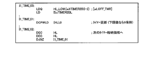
Further, the
さらに、メインCPU101は、1バイトのレジスタで構成された、インタラプト・ページアドレス・レジスタI及びメモリ・リフレッシュ・レジスタR、並びに、2バイトのレジスタで構成された、インデックス・レジスタIX、インデックス・レジスタIY、スタックポインタSP及びプログラムカウンタPCを専用レジスタとして有する。
Further, the
<メインROM及びメインRAMの内部構成(メモリマップ)>
次に、図12A~図12Cを参照しながら、主制御回路90(マイクロプロセッサ91)に含まれるメインROM102及びメインRAM103の内部構成(以下「メモリマップ」という)について説明する。なお、図12Aは、メモリ全体のメモリマップを示す図であり、図12Bは、メインROM102のメモリマップを示す図であり、図12Cは、メインRAM103のメモリマップを示す図である。
<Internal configuration of main ROM and main RAM (memory map)>
Next, the internal configurations (hereinafter referred to as “memory maps”) of the
主制御回路90(マイクロプロセッサ91)が備えるメモリ全体のメモリマップでは、図12Aに示すように、アドレスの先頭(0000H)側から、メインROM102のメモリ領域、メインRAM103のメモリ領域、内蔵レジスタエリア及びXCSデコードエリアが、不使用領域を間に挟んでこの順で、それぞれ所定のアドレスに配置される。
In the memory map of the entire memory included in the main control circuit 90 (microprocessor 91), as shown in FIG. 12A, from the head (0000H) side of the address, the memory area of the
メインROM102のメモリマップでは、図12Bに示すように、メインROM102のアドレスの先頭(0000H)側から、プログラムエリア、データエリア、規定外エリア、商標記録エリア、プログラム管理エリア及びセキュリティ設定エリアが、この順で、それぞれ所定のアドレスに配置される。
In the memory map of the
なお、プログラムエリアには、遊技者により実施される遊技の遊技性に関連する各種制御処理において、メインCPU101により実行される各種処理の制御プログラムが記憶される。データエリアには、遊技者により実施される遊技の遊技性に関連する各種制御処理において、メインCPU101により使用される各種データ(例えば、内部抽籤テーブル等のデータテーブル、副制御回路42に対して各種制御指令(コマンド)を送信するためのデータ等)が記憶される。すなわち、プログラムエリアとデータエリアとからなる遊技用ROM領域(遊技用記憶領域)には、遊技店で遊技者が実際に行う遊技の遊技性に関連する制御処理(遊技性に関する処理)に必要な各種プログラム及び各種データが格納される。
In the program area, control programs for various processes executed by the
また、規定外エリアには、遊技者により実施される遊技の遊技性に直接関与しない各種処理(遊技性に影響を与えない処理)の制御プログラム及びデータが記憶される。例えば、パチスロ1の検定試験(試射試験)で使用されるプログラム及びデータ、電断時のチェックサム生成処理や電源復帰時のサムチェック処理などで使用される制御プログラム及びデータ、並びに、不正対策プログラム及びそれに必要なデータ等が、規定外エリアに格納される。
Further, in the non-regulated area, control programs and data of various processes (processes that do not affect the playability) that are not directly related to the playability of the game performed by the player are stored. For example, programs and data used in the
メインRAM103のメモリマップでは、図12Cに示すように、メインRAM103のアドレスの先頭(F000H)側から、遊技用RAM領域(所定格納領域、遊技用一時記憶領域)及び規定外RAM領域(規定外一時記憶領域)が、この順で、それぞれ所定のアドレスに配置される。
In the memory map of the
遊技用RAM領域には、遊技者により実施される遊技の遊技性に関連する制御プログラムの実行により決定された例えば内部当籤役等の各種データを一時的に格納する作業領域及びスタックエリアが設けられる。そして、各種データのそれぞれは、遊技用RAM領域内の所定アドレスの作業領域に格納される。 The game RAM area is provided with a work area and a stack area for temporarily storing various data such as an internal winning combination determined by executing a control program related to the game playability performed by the player. .. Then, each of the various data is stored in the work area of the predetermined address in the game RAM area.
また、規定外RAM領域には、遊技者により実施される遊技の遊技性に直接関与しない各種処理の作業領域となる規定外作業領域と、規定外スタックとが設けられる。本実施形態では、この規定外RAM領域を使用して、例えばサムチェック処理等の遊技者により実施される遊技の遊技性に直接関与しない各種処理が実行される。 Further, the non-standard RAM area is provided with a non-standard work area that is a work area for various processes that are not directly related to the playability of the game performed by the player, and a non-standard stack. In the present embodiment, various processes that are not directly related to the playability of the game performed by the player, such as a thumb check process, are executed using this non-standard RAM area.
上述のように、本実施形態のパチスロ1では、メインROM102内において、遊技者により実施される遊技の遊技性に直接関与しない各種処理に使用される各種プログラム及び各種データ(テーブル)を、遊技用ROM領域とは異なるアドレスに配置された規定外ROM領域(規定外記憶領域)に格納する。また、そのような遊技者により実施される遊技の遊技性に直接関与しない各種処理は、メインRAM103内において、遊技用RAM領域とは異なるアドレスに配置された規定外RAM領域を使用して行われる。
As described above, in the pachi-
このようなメインROM102の構成では、従来の規則上においてプログラム等の配置不可とされていたROM領域(規定外ROM領域)に、遊技者が実際に行う遊技そのものには不要なプログラム及びデータを配置することができる。それゆえ、本実施形態では、遊技用ROM領域の容量の圧迫を回避することができる。
In such a configuration of the
<遊技状態の遷移フロー>
次に、図13及び図14を参照しながら、本実施形態のパチスロ1の主制御回路90(メインCPU101)により管理される各種遊技状態及びその遷移フローについて説明する。なお、図13Aは、パチスロ1の基本的な遊技状態の遷移フロー図であり、図13Bは、その遊技状態の移行条件をまとめた表である。また、図14Aは、報知(ART)機能の作動の有無を考慮した遊技状態の遷移フロー図であり、図14Bは、その遊技状態の移行条件をまとめた表である。
<Transition flow of game state>
Next, various gaming states managed by the main control circuit 90 (main CPU 101) of the pachi-
[基本的な遊技状態の遷移フロー]
本実施形態のパチスロ1では、ボーナスゲームの種類として、ビッグボーナス(以下、「BB」と記す)が設けられる。BBは、第1種特別役物と呼ばれるレギュラーボーナス(以下、「RB」と記す)に係る役物連続作動装置であり、RBを連続して作動させる。
[Basic game state transition flow]
In the pachi-
それゆえ、本実施形態では、主制御回路90は、ボーナス役の当籤/作動(入賞)の有無に基づいて遊技状態を管理する。具体的には、図13Aに示すように、主制御回路90は、ボーナス役(後述の名称「F_BB1」,「F_BB2」の内部当籤役)の当籤/作動(入賞)の有無に基づいて、「ボーナス非当籤状態」、「フラグ間状態」及び「ボーナス状態」と称する3種類の遊技状態を管理する。
Therefore, in the present embodiment, the
なお、ボーナス非当籤状態は、ボーナスに非当籤であり、かつ、ボーナスが作動(入賞)していない状態であり、ボーナス状態は、ボーナスが作動している状態である。また、本実施形態では、ボーナス役が内部当籤役として決定されると、ボーナスが入賞するまで複数回の遊技に渡りボーナス役が内部当籤役として持ち越された状態が発生する。フラグ間状態は、ボーナス役が内部当籤役として持ち越されている状態、すなわち、ボーナス役が当籤し、かつ、ボーナスが作動していない状態である。 The bonus non-winning state is a state in which the bonus is not winning and the bonus is not activated (winning), and the bonus state is a state in which the bonus is activated. Further, in the present embodiment, when the bonus combination is determined as the internal winning combination, the bonus combination is carried over as the internal winning combination over a plurality of games until the bonus is won. The inter-flag state is a state in which the bonus combination is carried over as an internal winning combination, that is, a state in which the bonus combination is winning and the bonus is not activated.
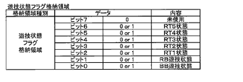
なお、ボーナス役の当籤の有無は、メインRAM103に設けられる後述の当り要求フラグ格納領域(後述の図28~図30参照)及び持越役格納領域(後述の図31参照)に格納されるデータに基づいて管理される。また、ボーナスの作動(入賞)の有無は、メインRAM103に設けられる後述の遊技状態フラグ格納領域(後述の図32参照)に格納されるデータに基づいて管理される。
Whether or not the bonus combination is won is determined by the data stored in the hit request flag storage area (see FIGS. 28 to 30 described later) and the carry-over combination storage area (see FIG. 31 described later) provided in the
また、本実施形態では、図13Aに示すように、ボーナスが作動していない遊技状態(ボーナス非当籤状態及びフラグ間状態)において、リプレイに係る内部当籤役の種別及びその当籤確率が互いに異なる、RT0遊技状態~RT5遊技状態の6種類の状態(以下、それぞれ「RT0状態」~「RT5状態」という)が設けられる。なお、RT0状態、RT2状態及びRT5状態は、リプレイ役が内部当籤役として決定される確率が低確率となる遊技状態であり、RT1状態はリプレイ役が内部当籤役として決定される確率が中程度の中確率となる遊技状態である。また、RT3状態及びRT4状態は、リプレイ役が内部当籤役として決定される確率が高確率となる遊技状態である。なお、本実施形態では、ボーナス非当籤状態のRT状態は、RT0状態~RT4状態のいずれかとなり、フラグ間状態のRT状態はRT5状態となる。 Further, in the present embodiment, as shown in FIG. 13A, in the gaming state in which the bonus is not activated (bonus non-winning state and inter-flag state), the types of internal winning combinations related to the replay and the winning probabilities thereof are different from each other. Six types of states (hereinafter, referred to as "RT0 state" to "RT5 state") are provided from the RT0 gaming state to the RT5 gaming state. The RT0 state, RT2 state, and RT5 state are gaming states in which the probability that the replay combination is determined as the internal winning combination is low, and the RT1 state has a medium probability that the replay combination is determined as the internal winning combination. It is a game state with a medium probability. Further, the RT3 state and the RT4 state are gaming states in which the probability that the replay combination is determined as the internal winning combination is high. In the present embodiment, the RT state in the bonus non-winning state is any of the RT0 state to the RT4 state, and the RT state in the inter-flag state is the RT5 state.
それゆえ、本実施形態では、主制御回路90は、ボーナスが作動していない遊技状態(ボーナス非当籤状態及びフラグ間状態)において、さらに、リプレイに係る内部当籤役の種別及びその当籤確率に基づいて、RT1状態~RT5状態の6種類の状態も管理する。
Therefore, in the present embodiment, the
なお、RT0状態~RT5状態は、メインRAM103に設けられる後述の遊技状態フラグ格納領域(後述の図32参照)に格納されるデータに基づいて管理される。具体的には、本実施形態のパチスロ1では、RT1状態フラグ~RT5状態フラグの5つのRT状態を示すフラグが設けられ、これらのフラグのオン/オフ状態をメインRAM103により管理することによりRT状態が管理される。そして、主制御回路90は、オン状態であるRT状態フラグに対応するRT状態を現在のRT状態として特定する。なお、全てのRT状態フラグがオフ状態である場合には、主制御回路90は、現在のRT状態がRT0状態であると特定する。
The RT0 state to the RT5 state are managed based on the data stored in the game state flag storage area (see FIG. 32 described later) provided in the
図13A及び13Bに示すように、ボーナス非当籤状態においてボーナス役(後述の名称「F_BB1」,「F_BB2」の内部当籤役)が内部当籤役として決定されると(移行条件(1)が成立すると)、主制御回路90は、遊技状態をボーナス非当籤状態からフラグ間状態に移行させる。また、フラグ間状態においてボーナス役が入賞すると(移行条件(2)が成立すると)、主制御回路90は、遊技状態をフラグ間状態からボーナス状態に移行させる。
As shown in FIGS. 13A and 13B, when the bonus combination (internal winning combination of the names "F_BB1" and "F_BB2" described later) is determined as the internal winning combination in the bonus non-winning state (when the transition condition (1) is satisfied). ), The
また、ボーナス状態において規定枚数(216枚)を超えるメダルが払い出され、ボーナス状態が終了すると(移行条件(3)が成立すると)、主制御回路90は、遊技状態をボーナス状態からRT1状態(ボーナス非当籤状態)に移行させる。
Further, when the number of medals exceeding the specified number (216) is paid out in the bonus state and the bonus state ends (when the transition condition (3) is satisfied), the
RT1状態において、20ゲームが経過すると(移行条件(4)が成立すると)、主制御回路90は、遊技状態をRT1状態からRT0状態に移行させる。また、RT1状態において、20ゲームが経過する前に、略称「ベルこぼし目」に係る図柄組合せ(後述の図28参照)が有効ライン上に表示されると(移行条件(5)が成立すると)、主制御回路90は、遊技状態をRT1状態からRT2状態に移行させる。
When 20 games have elapsed in the RT1 state (when the transition condition (4) is satisfied), the
RT0状態において、略称「ベルこぼし目」に係る図柄組合せが有効ライン上に表示されると(移行条件(5)が成立すると)、主制御回路90は、遊技状態をRT0状態からRT2状態に移行させる。RT2状態において、略称「RT3移行リプ」に係る図柄組合せ(後述の図28参照)が有効ライン上に表示されると(移行条件(6)が成立すると)、主制御回路90は、遊技状態をRT2状態からRT3状態に移行させる。
In the RT0 state, when the symbol combination related to the abbreviation "bell spilled eye" is displayed on the valid line (when the transition condition (5) is satisfied), the
RT3状態において、略称「RT4移行リプ」に係る図柄組合せ(後述の図28参照)が有効ライン上に表示されると(移行条件(7)が成立すると)、主制御回路90は、遊技状態をRT3状態からRT4状態に移行させる。また、RT3状態において、略称「ベルこぼし目」又は「RT2移行リプ」に係る図柄組合せ(後述の図28参照)が有効ライン上に表示されると(移行条件(8)が成立すると)、主制御回路90は、遊技状態をRT3状態からRT2状態に遊技状態を移行させる。さらに、RT4状態において、略称「ベルこぼし目」又は「RT2移行リプ」に係る図柄組合せが有効ライン上に表示されると(移行条件(8)が成立すると)、主制御回路90は、遊技状態をRT4状態からRT2状態に遊技状態を移行させる。
In the RT3 state, when the symbol combination (see FIG. 28 described later) related to the abbreviation "RT4 transition lip" is displayed on the valid line (when the transition condition (7) is satisfied), the
なお、略称「ベルこぼし目」に係る図柄組合せは、後述の名称「F_3択ベル_1st」、「F_3択ベル_2nd」又は「F_3択ベル_3rd」に係る内部当籤役(小役)が決定され、かつ、停止操作の順序が該小役の種別ごとに定められた押し順に対して不正解であるときに表示される図柄の組合せである(後述の図24参照)。略称「RT2移行リプ」に係る図柄組合せは、後述の名称「F_維持リプ_1st」、「F_維持リプ_2nd」又は「F_維持リプ_3rd」に係る内部当籤役(リプレイ役)が決定され、かつ、停止操作の順序が該リプレイ役の種別ごとに定められた押し順に対して不正解であるときに表示される図柄の組合せである。 As for the symbol combination related to the abbreviation "bell spilled eyes", the internal winning combination (small combination) related to the names "F_3 selection bell_1st", "F_3 selection bell_2nd" or "F_3 selection bell_3rd" described later is determined. Moreover, it is a combination of symbols displayed when the order of the stop operation is incorrect with respect to the push order determined for each type of the small winning combination (see FIG. 24 described later). As for the symbol combination related to the abbreviation "RT2 transition lip", the internal winning combination (replay combination) related to the names "F_maintenance lip_1st", "F_maintenance lip_2nd" or "F_maintenance lip_3rd" described later is determined, and It is a combination of symbols displayed when the order of the stop operation is incorrect with respect to the push order determined for each type of the replay combination.
略称「RT3移行リプ」に係る図柄組合せは、後述の名称「F_RT3リプ_1st」、「F_RT3リプ_213」、「F_RT3リプ_231」又は「F_RT3リプ_3rd」に係る内部当籤役(リプレイ役)が決定され、かつ、停止操作の順序が該リプレイ役の種別ごとに定められた押し順に対して正解であるときに表示される図柄の組合せである。また、略称「RT4移行リプ」に係る図柄組合せは、後述の名称「F_RT4リプ_123」、「F_RT4リプ_132」、「F_RT4リプ_2nd」又は「F_RT4リプ_3rd」に係る内部当籤役(リプレイ役)が決定され、かつ、停止操作の順序が該リプレイ役の種別ごとに定められた押し順に対して正解であるときに表示される図柄の組合せである。 As for the symbol combination related to the abbreviation "RT3 transition lip", the internal winning combination (replay role) related to the names "F_RT3 lip_1st", "F_RT3 lip_213", "F_RT3 lip_231" or "F_RT3 lip_3rd" described later is determined. Moreover, it is a combination of symbols displayed when the order of the stop operation is the correct answer for the push order determined for each type of the replay combination. Further, the symbol combination related to the abbreviation "RT4 transition lip" has an internal winning combination (replay role) related to the names "F_RT4 lip_123", "F_RT4 lip_132", "F_RT4 lip_2nd" or "F_RT4 lip_3rd" described later. It is a combination of symbols that are determined and displayed when the order of the stop operation is the correct answer for the push order determined for each type of the replay combination.
[報知(ART)機能の作動の有無を考慮した遊技状態の遷移フロー]
本実施形態では、主制御回路90(メインCPU101)により、遊技者にとって有利な停止操作を報知する機能(ART機能)の作動の有無が決定される。それゆえ、本実施形態では、ボーナス非作動状態においてART機能の作動/非作動状態も遊技状態として管理する。
[Transition flow of game state considering whether or not the notification (ART) function is activated]
In the present embodiment, the main control circuit 90 (main CPU 101) determines whether or not the function (ART function) for notifying a stop operation advantageous to the player is activated. Therefore, in the present embodiment, the activated / non-activated state of the ART function is also managed as the gaming state in the bonus non-operating state.
本実施形態のパチスロ1では、図14Aに示すように、主制御回路90は、非ボーナス作動状態において、報知(ART)の有無に基づいて「一般遊技状態」と「ART遊技状態」とを別個の遊技状態として管理する。すなわち、報知(ART)の有無を考慮した遊技状態の管理では、図14Aに示すように、主制御回路90は、大きな分類として、「ボーナス状態」、「一般遊技状態」及び「ART遊技状態」の3種類の遊技状態を管理する。
In the pachi-
なお、一般遊技状態は、基本的には、遊技者にとって有利な停止操作の情報を報知しない遊技状態(非ART)であり、遊技者にとって不利な遊技状態である。また、一般遊技状態は、RT0~RT4状態のいずれかの状態であり、かつ、ART非当籤の遊技状態である。 The general gaming state is basically a gaming state (non-ART) in which information on a stop operation advantageous to the player is not notified, and is a gaming state disadvantageous to the player. Further, the general gaming state is any of the RT0 to RT4 states, and is an ART non-winning gaming state.
一方、ART遊技状態は、遊技者にとって有利な停止操作の情報を報知する遊技状態であり、遊技者にとって有利な遊技状態である。また、ART遊技状態は、基本的には、RT4状態であり、かつ、ART当籤中の遊技状態である。なお、本実施形態では、ART当籤後、RT状態がRT4状態まで移行すると、ART遊技が開始される。 On the other hand, the ART gaming state is a gaming state in which information on a stop operation advantageous to the player is notified, and is a gaming state advantageous to the player. Further, the ART gaming state is basically the RT4 state and the gaming state during the ART winning. In this embodiment, when the RT state shifts to the RT4 state after winning the ART, the ART game is started.
また、本実施形態では、図14Aに示すように、一般遊技状態として、「通常遊技状態」及び「CZ(チャンスゾーン)」と称する2種類の状態が設けられる。 Further, in the present embodiment, as shown in FIG. 14A, two types of states called "normal gaming state" and "CZ (chance zone)" are provided as general gaming states.
通常遊技状態は、遊技者にとって最も不利な遊技状態であるが、通常遊技状態の遊技ではCZへの移行抽籤を行っている。そして、図14A及び14Bに示すように、通常遊技状態の遊技において、CZへの移行抽籤に当籤すると(移行条件(A)が成立すると)、主制御回路90は、遊技状態を、通常遊技状態からCZに移行させる。
The normal game state is the most disadvantageous game state for the player, but in the game in the normal game state, a lottery for shifting to the CZ is performed. Then, as shown in FIGS. 14A and 14B, in the game in the normal gaming state, when the lottery for transition to the CZ is won (when the transition condition (A) is satisfied), the
CZは、ART遊技状態への移行に対する期待度が高い遊技状態(チャンスゾーン)であり、CZ中の遊技ではARTへの移行抽籤が行われている。そして、図14A及び14Bに示すように、CZ中の遊技において、ARTへの移行抽籤に非当籤である場合には(移行条件(B)が成立すると)、主制御回路90は、遊技状態を、CZから通常遊技状態に移行させる。一方、CZ中の遊技において、ARTへの移行抽籤に当籤すると(移行条件(C)が成立すると)、主制御回路90は、遊技状態を、CZからART遊技状態に移行させる。この際、図14Aには示さないが、主制御回路90は、遊技状態を、CZから後述のART準備状態を経由してART遊技状態(後述の通常ART又はCT)に移行させる。
The CZ is a gaming state (chance zone) in which the expectation for the transition to the ART gaming state is high, and the lottery for the transition to the ART is performed in the game during the CZ. Then, as shown in FIGS. 14A and 14B, in the game in CZ, when the lottery for transition to ART is not won (when the transition condition (B) is satisfied), the
ART遊技状態は、上述のように、ART当籤後にRT状態がRT4状態まで移行すると開始される。なお、図13Aで示したように、RT4状態は、RT0~RT2状態からRT3状態を経由して移行するので、ART当籤後であってもすぐにART遊技状態が開始されない。そこで、本実施形態のパチスロ1では、ART当籤後からRT状態がRT4状態に移行するまでの期間の遊技状態をART準備状態とする。そして、このART準備状態の遊技では、RT状態をRT4状態に移行させるために必要な停止操作の情報が報知される。
As described above, the ART gaming state is started when the RT state shifts to the RT4 state after winning the ART. As shown in FIG. 13A, since the RT4 state shifts from the RT0 to RT2 states via the RT3 state, the ART gaming state is not started immediately even after winning the ART. Therefore, in the pachi-
また、本実施形態では、図14Aに示すように、ART遊技状態として、遊技性が互いに異なる、「通常ART」及び「CT(上乗せチャンス)」と称する2種類の状態が設けられる。 Further, in the present embodiment, as shown in FIG. 14A, two types of ART gaming states, called "normal ART" and "CT (additional chance)", in which the playability is different from each other, are provided.
通常ARTは、所定ゲーム数の期間、遊技者にとって有利な停止操作(例えば、払い出されるメダルの枚数が多い図柄組合せを表示させるための停止操作や、RT4状態を維持するために必要な停止操作)が報知される遊技状態である。また、通常ART中の遊技では、CTへの移行抽籤が行われる。 Normally, ART is a stop operation that is advantageous for the player for a predetermined number of games (for example, a stop operation for displaying a symbol combination having a large number of medals to be paid out, or a stop operation necessary for maintaining the RT4 state). Is a gaming state to be notified. In addition, in a game during normal ART, a lottery for transition to CT is performed.
CTは、遊技者にとって有利な停止操作が報知されるとともに、特定期間(1セット8ゲームの期間)、通常ARTの継続期間を上乗せすることが可能となる遊技状態であり、上乗せチャンスゾーンとして機能する遊技状態である。また、CT中では、通常ARTの継続期間を消化せずに遊技が行われる。なお、CT中の遊技性については、後述の図52A~52Cを参照して後で詳述する。 CT is a gaming state in which a player is notified of an advantageous stop operation and can add a normal ART duration for a specific period (a period of 8 games per set), and functions as an additional chance zone. It is a game state to play. Also, during CT, the game is usually played without digesting the duration of ART. The playability during CT will be described in detail later with reference to FIGS. 52A to 52C described later.
図14A及び14Bに示すように、通常ART中の遊技において、CTへの移行抽籤に当籤すると(移行条件(D)が成立すると)、主制御回路90は、遊技状態を、通常ARTからCTに遊技状態を移行させる。また、通常ARTにおいて、当該通常ARTの継続期間が終了すると(移行条件(E)が成立すると)、主制御回路90は、遊技状態を、通常ARTから一般遊技状態(通常遊技状態又はCZ)に移行させる。なお、本実施形態では、ゲーム数により通常ARTの継続期間を管理するが、本発明はこれに限定されず、通常ARTの継続期間の管理方法は任意である。例えば、通常ARTの継続期間を、通常ART中に払い出されるメダルの枚数や差枚数により管理してもよいし、通常ART中にメダルの払い出しに影響を与える報知を行った回数(ナビ回数)により管理してもよい。
As shown in FIGS. 14A and 14B, in a game during normal ART, when the lottery for transition to CT is won (when the transition condition (D) is satisfied), the
図14A及び14Bに示すように、CT中の遊技において、CTの継続期間(1セット8ゲーム)が終了すると(移行条件(F)が成立すると)、主制御回路90は、遊技状態を、CTから通常ARTに移行させる。
As shown in FIGS. 14A and 14B, in the game during CT, when the duration of CT (1 set of 8 games) ends (when the transition condition (F) is satisfied), the
また、図14Aに示すように、一般遊技状態(通常遊技状態又はCZ)又はART遊技状態(通常ART又はCT)において、ボーナス役が入賞すると(図13A及び13B中で説明した移行条件(2)が成立すると)、主制御回路90は、遊技状態を、一般遊技状態又はART遊技状態からボーナス状態に移行させる。
Further, as shown in FIG. 14A, when the bonus combination is won in the general gaming state (normal gaming state or CZ) or ART gaming state (normal ART or CT) (transition condition (2) described in FIGS. 13A and 13B). When is established), the
ボーナス状態の遊技では、上述のように、ARTへの移行抽籤を行っており、ボーナス状態の遊技において、ARTへの移行抽籤が非当籤である場合には(移行条件(G)が成立すると)、主制御回路90は、遊技状態を、ボーナス状態から一般遊技状態(通常遊技状態又はCZ)に移行させる。ただし、ART遊技状態(通常ART又はCT)からボーナス状態に移行していた場合には、ボーナス状態の遊技においてARTの移行抽籤に非当籤であっても、主制御回路90は、遊技状態を、ボーナス状態からART遊技状態(通常ART又はCT)に移行させる。一方、ボーナス状態の遊技において、ARTへの移行抽籤に当籤すると(移行条件(H)が成立すると)、主制御回路90は、遊技状態を、ボーナス状態からART遊技状態(通常ART又はCT)に移行させる。なお、上述のように、ボーナス状態の終了時には、RT状態がRT1状態に移行するので、ボーナス状態からART遊技状態に遊技状態を移行する場合には、主制御回路90は、遊技状態を、ART準備状態を経由してART遊技状態に移行させる。
In the game in the bonus state, as described above, the lottery for transition to ART is performed, and in the game in the bonus state, if the lottery for transition to ART is non-winning (when the transition condition (G) is satisfied). , The
<メインROMに記憶されているデータテーブルの構成>
次に、図15~図27を参照して、メインROM102に記憶されている各種データテーブルの構成について説明する。なお、一般遊技状態中及びART遊技状態中の遊技性(CZ、通常ART,CTの遊技性)に係る各種抽籤で用いられる各種データテーブルについては、別途、各遊技性の説明と一緒に後述する。
<Structure of data table stored in main ROM>
Next, the configurations of various data tables stored in the
[図柄配置テーブル]
まず、図15を参照して、図柄配置テーブルについて説明する。図柄配置テーブルは、左リール3L、中リール3C及び右リール3Rのそれぞれの回転方向における各図柄の位置と、各位置に配置された図柄の種類を特定するデータ(以下、図柄コード(図15中の図柄コード表を参照)という)との対応関係を規定する。
[Design layout table]
First, the symbol arrangement table will be described with reference to FIG. The symbol arrangement table is data that specifies the position of each symbol in each rotation direction of the
図柄配置テーブルでは、リールインデックスが検出されたときに、リール表示窓4の枠内における各リールの中段領域に位置する図柄の位置を「0」と規定する。そして、各リールにおいて、図柄位置「0」を基準としてリールの回転方向(図15中の図柄位置「19」から図柄位置「0」に向かう方向)に進む順に、図柄カウンタの値に対応する「0」~「19」が、図柄位置として、各図柄に割り当てられる。
In the symbol arrangement table, when the reel index is detected, the position of the symbol located in the middle region of each reel in the frame of the
すなわち、図柄カウンタの値(「0」~「19」)と、図柄配置テーブルとを参照することにより、リール表示窓4の枠内における各リールの上段領域、中段領域及び下段領域に表示されている図柄の種類を特定することができる。なお、本実施形態では、図柄として、「白7」、「青7」、「チリ上1」、「チリ上2」、「チリ下」、「リプレイ」、「帽子」、「サボテン1」、「サボテン2」及び「サボテン3」の10種類の図柄を用いる。
That is, by referring to the value of the symbol counter ("0" to "19") and the symbol arrangement table, it is displayed in the upper region, the middle region, and the lower region of each reel in the frame of the
また、本実施形態では、図柄コード表に示すように、図柄「白7」(図柄コード1)には、データとして「00000001」が割り当てられ、図柄「青7」(図柄コード2)には、データとして「00000010」が割り当てられている。図柄「チリ上1」(図柄コード3)には、データとして「00000011」が割り当てられ、図柄「チリ上2」(図柄コード4)には、データとして「00000100」が割り当てられている。
Further, in the present embodiment, as shown in the symbol code table, "00000001" is assigned as data to the symbol "white 7" (symbol code 1), and the symbol "blue 7" (symbol code 2) is assigned. "00000010" is assigned as data. The symbol "
図柄「チリ下」(図柄コード5)には、データとして「00000101」が割り当てられ、図柄「リプレイ」(図柄コード6)には、データとして「00000110」が割り当てられている。図柄「帽子」(図柄コード7)には、データとして「00000111」が割り当てられ、図柄「サボテン1」(図柄コード8)には、データとして「00001000」が割り当てられている。また、図柄「サボテン2」(図柄コード9)には、データとして「00001001」が割り当てられ、図柄「サボテン3」(図柄コード10)には、データとして「00001010」が割り当てられている。
"00000011" is assigned as data to the symbol "Chile bottom" (symbol code 5), and "00000011" is assigned as data to the symbol "replay" (symbol code 6). The symbol "hat" (symbol code 7) is assigned "000000111" as data, and the symbol "
[内部抽籤テーブル]
次に、図16及び図17を参照して、内部当籤役を決定する際に参照される内部抽籤テーブルについて説明する。なお、図16は、RT0状態~RT4状態のそれぞれにおいて参照される内部抽籤テーブルである。また、図17Aは、RT5状態において参照される内部抽籤テーブルであり、図17Bは、ボーナス状態において参照される内部抽籤テーブルである。
[Internal lottery table]
Next, the internal lottery table referred to when determining the internal winning combination will be described with reference to FIGS. 16 and 17. Note that FIG. 16 is an internal lottery table referred to in each of the RT0 state to the RT4 state. Further, FIG. 17A is an internal lottery table referenced in the RT5 state, and FIG. 17B is an internal lottery table referenced in the bonus state.
内部抽籤テーブルは、遊技状態毎に設けられ、各種内部当籤役と、各内部当籤役が決定されるときの抽籤値との対応関係を規定する。なお、抽籤値は、予め設定されたボーナス役や小役等の内部当籤の期待値を調整するための設定(設定1~6)毎に規定される。この設定は、例えば、リセットスイッチ76及び設定用鍵型スイッチ54(図7参照)を用いて変更される。
The internal lottery table is provided for each game state, and defines the correspondence between various internal winning combinations and the lottery value when each internal winning combination is determined. The lottery value is defined for each setting (
本実施形態の内部抽籤処理では、まず、乱数回路110の乱数レジスタ0により、予め定められた数値の範囲(例えば、0~65535)から抽出される乱数値を、各内部当籤役に対応して規定された抽籤値で順次加算する。次いで、抽籤結果(抽籤値+乱数値)が65535を超えたか否か(抽籤結果がオーバーフローしたか否か)の判定を行う。そして、所定の内部当籤役において、抽籤結果が65535を超えた場合、該内部当籤役が当籤したと判定される。なお、本実施形態の内部抽籤処理では、抽出した乱数値に抽籤値を加算して抽籤を行う例を説明したが、本発明はこれに限定されず、乱数値から抽籤値を減算して、減算結果(抽籤結果)が「0」を下回ったか否か(抽籤結果がアンダーフローしたか否か)を判定して、内部抽籤の当籤/非当籤を決定してもよい。
In the internal lottery process of the present embodiment, first, a random number value extracted from a predetermined numerical range (for example, 0 to 65535) by the
それゆえ、本実施形態の内部抽籤処理では、抽籤値として規定されている数値が大きい内部当籤役ほど、決定される確率が高い。なお、各内部当籤役の当籤確率は、「各当籤番号に規定された抽籤値/抽出される可能性のある全ての乱数値の個数(乱数分母:65536)」によって表すことができる。 Therefore, in the internal lottery process of the present embodiment, the probability that the internal winning combination having a larger numerical value defined as the lottery value is determined is higher. The winning probability of each internal winning combination can be expressed by "the lottery value specified in each winning number / the number of all random number values that may be extracted (random number denominator: 65536)".
RT0状態~RT4状態のそれぞれにおいて参照される内部抽籤テーブルでは、図16に示すように、基本的には、RT状態の種別に応じて、内部当籤役として決定されるリプレイ役の種別及び当籤確率が変化する。例えば、名称「F_チリリプ(No.25)」~「F_リーチ目リプD(No.31)」に係るリプレイ役は、RT0状態~RT3状態では内部当籤役として決定されることなく、RT4状態でのみ内部当籤役として決定される。なお、本実施形態のパチスロ1では、RT4状態中に、名称「F_チリリプ(No.25)」~「F_リーチ目リプD(No.31)」に係るリプレイ役が内部当籤役として決定された場合、特有の制御(後述のフラグ変換)を行う。このフラグ変換については、後で詳述する。
In the internal lottery table referred to in each of the RT0 state to the RT4 state, as shown in FIG. 16, basically, the type and the winning probability of the replay combination determined as the internal winning combination according to the type of the RT state. Changes. For example, the replay combination related to the names "F_chili lip (No. 25)" to "F_reach eye lip D (No. 31)" is not determined as an internal winning combination in the RT0 state to RT3 state, and is in the RT4 state. Only determined as an internal winning role. In the pachi-
また、図16に示すように、RT0状態~RT3状態では、名称「F_リーチ目リプA」~「F_リーチ目リプD」のそれぞれの内部当籤役は、名称「F_BB1」又は「F_BB2」に係るボーナス役と重複して決定されることはあるが(No.3~6、15~18参照)、名称「F_リーチ目リプA」~「F_リーチ目リプD」のそれぞれの内部当籤役(リプレイ役)が単独で内部当籤役として決定されることはない。それゆえ、本実施形態において、RT0状態~RT3状態中に名称「F_リーチ目リプA」~「F_リーチ目リプD」に係るリプレイ役が内部当籤役として決定された場合(遊技者からすると名称「F_リーチ目リプA」~「F_リーチ目リプD」に係るリプレイ役に応じた図柄組合せが表示された場合)、ボーナス役(名称「F_BB1」又は「F_BB2」)が同時に内部当籤役として決定されていることになる。 Further, as shown in FIG. 16, in the RT0 state to the RT3 state, the respective internal winning combinations of the names "F_reach eye lip A" to "F_reach eye lip D" are related to the names "F_BB1" or "F_BB2". Although it may be decided in duplicate with the bonus role (see Nos. 3 to 6 and 15 to 18), each internal winning role (replay) of the names "F_reach eye lip A" to "F_reach eye lip D" The role) is not determined as an internal winning role by itself. Therefore, in the present embodiment, when the replay combination related to the names "F_reach eye lip A" to "F_reach eye lip D" is determined as the internal winning combination during the RT0 state to the RT3 state (name from the player's point of view). When the symbol combination corresponding to the replay combination related to "F_reach eye lip A" to "F_reach eye lip D" is displayed), the bonus combination (name "F_BB1" or "F_BB2") is determined as the internal winning combination at the same time. It will be done.
また、フラグ間状態であるRT5状態は、上述のようにボーナス役を内部当籤役として持ち越す遊技状態である。それゆえ、図17Aに示すように、RT5状態において参照される内部抽籤テーブルでは、持ち越しているボーナス役が必ず内部当籤役として決定されるようになっている。また、図17Bに示すように、ボーナス状態において参照される内部抽籤テーブルでは、名称「F_RB役1」~「F_RB役4」のいずれかに係る内部当籤役が必ず当籤する構成になっている(「はずれ」が当籤することはない)。
Further, the RT5 state, which is a state between flags, is a gaming state in which the bonus combination is carried over as an internal winning combination as described above. Therefore, as shown in FIG. 17A, in the internal lottery table referred to in the RT5 state, the carried-over bonus combination is always determined as the internal winning combination. Further, as shown in FIG. 17B, in the internal lottery table referred to in the bonus state, the internal winning combination according to any of the names "
[内部当籤役と図柄組合せ(入賞役)との対応表(図柄組合せ決定テーブル)]
次に、図18~図23を参照して、内部当籤役と図柄組合せとの対応表(図柄組合せ決定テーブル)について説明する。図柄組合せ決定テーブルは、各種内部当籤役と、各内部当籤役に対応付けられた、有効ライン(センターライン)上に表示可能な図柄組合せ(コンビネーション)との対応関係を規定する。すなわち、内部当籤役が決定されると、有効ライン上に表示可能な図柄組合せの種別(入賞可能な表示役の種別)が一義的に決定される。
[Correspondence table between internal winning combination and symbol combination (winning combination) (symbol combination determination table)]
Next, with reference to FIGS. 18 to 23, a correspondence table (symbol combination determination table) between the internal winning combination and the symbol combination will be described. The symbol combination determination table defines the correspondence between various internal winning combinations and the symbol combinations (combinations) that can be displayed on the effective line (center line) associated with each internal winning combination. That is, when the internal winning combination is determined, the type of symbol combination that can be displayed on the valid line (type of display combination that can be won) is uniquely determined.
各図柄組合せ決定テーブル中の図柄組合せ欄に記載の各種データは、左リール3L、中リール3C及び右リール3Rに渡って設定された有効ラインに沿って表示を許可する図柄組合せを識別するためのデータである。なお、図柄組合せ(表示役)欄に記載の各名称と、具体的な図柄組合せとの関係は、後述の図28~図30の入賞作動フラグ格納領域に示す。
The various data described in the symbol combination column in each symbol combination determination table is for identifying the symbol combination that is permitted to be displayed along the valid line set over the
また、図柄組合せ決定テーブル中に記載の「○」印は、決定された内部当籤役において、有効ライン上に表示可能な図柄組合せ(コンビネーション)、すなわち、入賞可能となる表示役を示す。例えば、内部当籤役「F_チリリプ」が決定された場合、図18及び図19に示すように、コンビネーション名称「C_維持リプA_01」~「C_維持リプG_01」、「C_チリリプA_01」~「C_チリリプD_01」に係る図柄組合せが停止表示可能となる。なお、図柄組合せ決定テーブルには、「内部当籤役」が「はずれ」となる場合が規定されていないが、これは、図18~図23に示した図柄組合せテーブルにより規定されている全ての図柄組合せの表示が許可されないことを示す。 Further, the "○" mark described in the symbol combination determination table indicates a symbol combination (combination) that can be displayed on the effective line in the determined internal winning combination, that is, a display combination that can win a prize. For example, when the internal winning combination "F_chili lip" is determined, as shown in FIGS. 18 and 19, the combination names "C_maintenance lip A_01" to "C_maintenance lip G_01" and "C_chili lip A_01" to "C_chili lip" are determined. The symbol combination related to "D_01" can be stopped and displayed. It should be noted that the symbol combination determination table does not specify the case where the "internal winning combination" is "off", but this is all the symbols defined by the symbol combination tables shown in FIGS. 18 to 23. Indicates that the display of combinations is not allowed.
本実施形態のパチスロ1では、主制御回路90(メインCPU101)は、内部当籤役及び遊技状態に応じて停止制御を異ならせ、所定の役が内部当籤役として決定された場合に、図18~図23に示す対応関係の図柄組合せ(コンビネーション)を表示可能とするように左リール3L、中リール3C及び右リール3Rの回転停止制御を行う。なお、図18~図23に示す対応表では、決定された内部当籤役に対して表示可能な全ての図柄組合せを「○」印で列挙しているが、「○」印が付された図柄組合せであっても、表示されないことがある。
In the pachi-
本実施形態では、停止表示可能な図柄組合せや現在の遊技状態に応じて停止制御(例えば、優先して引き込む図柄)を異ならせる機能を有し、優先して引き込む図柄の関係上、「○」印が付された図柄組合せであっても表示されないことがある。内部当籤役の種別と実際に表示される図柄組合せとの対応関係については、後述の図24及び図25を参照して説明する。 In the present embodiment, there is a function to make the stop control (for example, the symbol to be preferentially pulled in) different according to the combination of symbols that can be stopped and displayed and the current game state, and "○" is given because of the symbol to be preferentially pulled in. Even the symbol combination marked may not be displayed. The correspondence between the types of internal winning combinations and the actually displayed symbol combinations will be described with reference to FIGS. 24 and 25 described later.
[非フラグ間状態中の当籤役と停止表示される図柄組合せとの対応関係]
ここで、図24を参照して、フラグ間状態を除く遊技状態(非フラグ間状態)における内部当籤役と停止表示される図柄組合せとの対応関係について説明する。なお、図24は、非フラグ間状態において決定され得る各種内部当籤役と、各内部当籤役決定時に停止表示される図柄組合せ(略称)との対応関係(一部の役については省略)を示す図である。なお、図24中に記載の図柄組合せの名称は、後述の図28~図30の入賞作動フラグ格納領域に示す内容欄に記載の「略称」である。
[Correspondence between the winning combination in the non-flag state and the symbol combination displayed as stopped]
Here, with reference to FIG. 24, the correspondence between the internal winning combination and the symbol combination displayed as stopped in the gaming state (non-flag state) excluding the flag state will be described. Note that FIG. 24 shows the correspondence between various internal winning combinations that can be determined in the non-flag state and the symbol combination (abbreviation) that is stopped and displayed when each internal winning combination is determined (some combinations are omitted). It is a figure. The name of the symbol combination described in FIG. 24 is the “abbreviation” described in the content column shown in the winning operation flag storage area of FIGS. 28 to 30 described later.
本実施形態のパチスロ1では、遊技者の停止操作の順序(押し順)に応じて表示される図柄組合せが異なる役、いわゆる「押し順役」を設ける。なお、図24に記載の「押し順正解」に対応付けられた図柄組合せは、押し順に応じて表示される図柄組合せのうち、遊技者にとって有利な図柄組合せであり、「押し順不正解」に対応付けられた図柄組合せは、押し順に応じて表示される図柄組合せのうち、遊技者にとって不利な図柄組合せである。遊技者にとって有利な停止操作を報知する場合、正解となる押し順が報知され、その報知に従って停止操作が行われれば、「押し順正解」に対応付けられた図柄組合せが表示される。また、ART遊技状態であっても、不正解となる押し順が報知されることもあるが、その内容については、後で詳述する。
In the pachi-
なお、本実施形態では、押し順役の一部に対しては、その名称の末尾に、正解となる押し順を示す。具体的には、内部当籤役の名称の末尾「1st」は、正解となる押し順が、第1停止操作(1番目に行われる停止操作)が左リール3Lに対するものであることを意味し、内部当籤役の名称の末尾「2nd」は、正解となる押し順が、第1停止操作が中リール3Cに対するものであることを意味し、内部当籤役の名称の末尾「3rd」は、正解となる押し順が、第1停止操作が右リール3Rに対するものであることを意味する。また、内部当籤役の名称の末尾「123」は、正解となる押し順が「左、中、右」の順であることを意味し、内部当籤役の名称の末尾「132」は、正解となる押し順が「左、右、中」の順であることを意味し、内部当籤役の名称の末尾「213」は、正解となる押し順が「中、左、右」の順であることを意味し、内部当籤役の名称の末尾「231」は、正解となる押し順が「左、右、中」の順であることを意味する。
In addition, in this embodiment, for a part of the push order combination, the push order that is the correct answer is shown at the end of the name. Specifically, the last "1st" in the name of the internal winning combination means that the correct push order is that the first stop operation (the first stop operation) is for the
また、以下では、第1停止操作が左リール3Lに対して行われた場合の停止操作順序、具体的には、「左、中、右」及び「左、右、中」の押し順を「順押し」ともいう。さらに、以下では、第1停止操作が中リール3C又は右リール3Rに対して行われた場合の停止操作順序、具体的には、「中、左、右」、「中、右、左」、「右、中、左」、及び、「右、左、中」の押し順を、「変則押し」ともいう。
Further, in the following, the stop operation order when the first stop operation is performed on the
本実施形態では、図24に示すように、内部当籤役「F_チリリプ」は、押し順に応じて表示される図柄組合せが異なる押し順役であり、押し順が正解である場合には、略称「チリリプ」に係る図柄組合せ(後述の図28参照)のうちの図18~図23に示した表示可能な図柄組合せのいずれかが有効ラインに沿って表示される。一方、押し順が正解でない場合には、略称「リプレイ」に係る図柄組合せ(後述の図28参照)のうちの図18~図23に示した表示可能な図柄組合せのいずれかが有効ラインに沿って表示される。なお、内部当籤役「F_チリリプ」が決定された場合、図18~図23に示すように、コンビネーション名称「C_チリリプA_01」、「C_チリリプB_01」又は「C_チリリプC_01」(略称「単チリリプ」又は「2連チリリプ」:後述の図28中の略称「チリリプ(否3連)」に対応)に係る図柄組合せは表示できるが、コンビネーション名称「C_チリリプD_01」~「C_1確チリリプD_01」(略称「3連チリリプ」:後述の図28中の略称「チリリプ(3連)」に対応)に係る図柄組合せを表示できない。すなわち、内部当籤役「F_チリリプ」は、略称「3連チリリプ」に係る図柄組合せを表示できない役である。 In the present embodiment, as shown in FIG. 24, the internal winning combination “F_chililip” is a pressing order combination in which the symbol combinations displayed according to the pressing order are different, and when the pressing order is the correct answer, the abbreviation “ Any of the displayable symbol combinations shown in FIGS. 18 to 23 among the symbol combinations related to "Chillilip" (see FIG. 28 described later) is displayed along the effective line. On the other hand, if the push order is not correct, one of the displayable symbol combinations shown in FIGS. 18 to 23 among the symbol combinations related to the abbreviation "replay" (see FIG. 28 described later) is along the effective line. Is displayed. When the internal winning combination "F_chililip" is determined, as shown in FIGS. 18 to 23, the combination names "C_chililip A_01", "C_chililip B_01" or "C_chililip C_01" (abbreviation "single chililip") Or, "double chili lip": corresponding to the abbreviation "chili lip (no triple)" in FIG. 28 described later) can be displayed, but the combination names "C_chili lip D_01" to "C_1 certain chili lip D_01" (abbreviation). "Triple chili lip": Corresponding to the abbreviation "chili lip (triple)" in FIG. 28, which will be described later), the symbol combination cannot be displayed. That is, the internal winning combination "F_chililip" is a combination that cannot display the symbol combination related to the abbreviation "triple chili lip".
また、内部当籤役「F_確チリリプ」及び「F_1確チリリプ」はともに、押し順に応じて表示される図柄組合せが異なる押し順役であり、押し順が正解である場合には、略称「チリリプ」に係る図柄組合せ(後述の図28参照)のうちの図18~図23に示した表示可能な図柄組合せのいずれかが有効ラインに沿って表示される。一方、押し順が正解でない場合には、略称「リプレイ」に係る図柄組合せ(後述の図28参照)のうちの図18~図23に示した表示可能な図柄組合せのいずれかが有効ラインに沿って表示される。なお、内部当籤役「F_確チリリプ」又は「F_1確チリリプ」が決定された場合、図18~図23に示すように、略称「3連チリリプ」に係る図柄組合せを表示できる。すなわち、内部当籤役「F_確チリリプ」及び「F_1確チリリプ」は、略称「3連チリリプ」に係る図柄組合せを表示できる役である。 In addition, both the internal winning combinations "F_certain chili lip" and "F_1 certain chili lip" are push order combinations with different symbol combinations displayed according to the push order, and if the push order is correct, the abbreviation "chili lip" is used. Any of the displayable symbol combinations shown in FIGS. 18 to 23 among the symbol combinations (see FIG. 28 described later) according to the above is displayed along the valid line. On the other hand, if the push order is not correct, one of the displayable symbol combinations shown in FIGS. 18 to 23 among the symbol combinations related to the abbreviation "replay" (see FIG. 28 described later) is along the effective line. Is displayed. When the internal winning combination "F_certain chili lip" or "F_1 certain chili lip" is determined, the symbol combination related to the abbreviation "triple chili lip" can be displayed as shown in FIGS. 18 to 23. That is, the internal winning combinations "F_certain chili lip" and "F_1 certain chili lip" are roles that can display the symbol combination related to the abbreviation "triple chili lip".
また、内部当籤役「F_リーチ目リプA」~「F_リーチ目リプD」は、押し順に応じて表示される図柄組合せが異なる押し順役であり、押し順が正解である場合には、略称「リーチ目リプ」に係る図柄組合せ(後述の図28及び図29参照)のうちの図18~図23に示した表示可能な図柄組合せのいずれかが有効ラインに沿って表示される。一方、押し順が正解でない場合には、略称「リプレイ」に係る図柄組合せ(後述の図28参照)のうちの図18~図23に示した表示可能な図柄組合せのいずれかが有効ラインに沿って表示される。 In addition, the internal winning combinations "F_reach eye lip A" to "F_reach eye lip D" are push order combinations with different symbol combinations displayed according to the push order, and are abbreviated when the push order is correct. Any of the displayable symbol combinations shown in FIGS. 18 to 23 among the symbol combinations (see FIGS. 28 and 29 described later) related to the "reach eye lip" is displayed along the effective line. On the other hand, if the push order is not correct, one of the displayable symbol combinations shown in FIGS. 18 to 23 among the symbol combinations related to the abbreviation "replay" (see FIG. 28 described later) is along the effective line. Is displayed.
なお、本実施形態では、内部当籤役「F_チリリプ」、「F_確チリリプ」、「F_1確チリリプ」及び「F_リーチ目リプA」~「F_リーチ目リプD」の当籤時における正解の押し順は、左リール3Lに対して第1停止操作を行うものである。それゆえ、例えば、内部当籤役「F_リーチ目リプA」が決定されている遊技において、遊技者が左リール3Lに対して第1停止操作を行った場合には、略称「リーチ目リプ」に係る図柄組合せが停止表示される。なお、本発明はこれに限定されず、内部当籤役「F_チリリプ」、「F_確チリリプ」、「F_1確チリリプ」及び「F_リーチ目リプA」~「F_リーチ目リプD」の当籤時における正解の押し順は、任意に設定することができる。
In this embodiment, the order of pressing the correct answers at the time of winning the internal winning roles "F_chili lip", "F_certain chili lip", "F_1 certain chili lip" and "F_reach eye lip A" to "F_reach eye lip D". Is to perform the first stop operation on the
また、内部当籤役「F_維持リプA」及び「F_維持リプB」はともに、押し順役ではなく、押し順に関わらず略称「リプレイ」に係る図柄組合せ(後述の図28参照)のうちの図18~図23に示した表示可能な図柄組合せのいずれかが有効ラインに沿って表示される。 In addition, both the internal winning combinations "F_maintenance rip A" and "F_maintenance rip B" are not the push order, and are the figures among the symbol combinations (see FIG. 28 described later) related to the abbreviation "replay" regardless of the push order. Any of the displayable symbol combinations shown in FIGS. 18 to 23 is displayed along the valid line.
また、内部当籤役「F_維持リプ_1st」~「F_維持リプ_3rd」はいずれも、押し順に応じて表示される図柄組合せが異なる押し順役であり、押し順が正解である場合には、略称「リプレイ」に係る図柄組合せ(後述の図28参照)のうちの図18~図23に示した表示可能な図柄組合せのいずれかが有効ラインに沿って表示される。一方、押し順が正解でない場合には、略称「RT2移行リプ」に係る図柄組合せ(後述の図28参照)のうちの図18~図23に示した表示可能な図柄組合せのいずれかが有効ラインに沿って表示される。 In addition, the internal winning combinations "F_maintenance rip_1st" to "F_maintenance rip_3rd" are all push order combinations with different symbol combinations displayed according to the push order, and are abbreviated when the push order is correct. Any of the displayable symbol combinations shown in FIGS. 18 to 23 among the symbol combinations related to "replay" (see FIG. 28 described later) is displayed along the valid line. On the other hand, if the push order is not correct, one of the displayable symbol combinations shown in FIGS. 18 to 23 among the symbol combinations (see FIG. 28 described later) related to the abbreviation "RT2 transition lip" is an effective line. It is displayed along with.
また、内部当籤役「F_RT3リプ_1st」~「F_RT3リプ_3rd」はいずれも、押し順に応じて表示される図柄組合せが異なる押し順役であり、押し順が正解である場合には、略称「RT3移行リプ」に係る図柄組合せ(後述の図28参照)が有効ラインに沿って表示される。一方、押し順が正解でない場合には、略称「リプレイ」に係る図柄組合せ(後述の図28参照)のうちの図18~図23に示した表示可能な図柄組合せのいずれかが有効ラインに沿って表示される。 In addition, the internal winning combinations "F_RT3 rip_1st" to "F_RT3 rip_3rd" are all push order combinations in which the symbol combinations displayed according to the push order are different, and when the push order is correct, the abbreviation "RT3" is used. The symbol combination related to "Transition Lip" (see FIG. 28 described later) is displayed along the valid line. On the other hand, if the push order is not correct, one of the displayable symbol combinations shown in FIGS. 18 to 23 among the symbol combinations related to the abbreviation "replay" (see FIG. 28 described later) is along the effective line. Is displayed.
また、内部当籤役「F_RT4リプ_123」~「F_RT4リプ_3rd」はいずれも、押し順に応じて表示される図柄組合せが異なる押し順役であり、押し順が正解である場合には、略称「RT4移行リプ」に係る図柄組合せ(後述の図28参照)が有効ラインに沿って表示される。一方、押し順が正解でない場合には、略称「リプレイ」に係る図柄組合せ(後述の図28参照)のうちの図18~図23に示した表示可能な図柄組合せのいずれかが有効ラインに沿って表示される。 In addition, the internal winning combinations "F_RT4 rip_123" to "F_RT4 rip_3rd" are all push order combinations in which the symbol combinations displayed according to the push order are different, and when the push order is correct, the abbreviation "RT4" is used. The symbol combination related to "Transition Lip" (see FIG. 28 described later) is displayed along the valid line. On the other hand, if the push order is not correct, one of the displayable symbol combinations shown in FIGS. 18 to 23 among the symbol combinations related to the abbreviation "replay" (see FIG. 28 described later) is along the effective line. Is displayed.
また、内部当籤役「F_3択ベル_1st」~「F_3択ベル_3rd」はいずれも、押し順に応じて表示される図柄組合せが異なる押し順役であり、押し順が正解である場合には、略称「ベル」に係る図柄組合せ(後述の図19参照)が有効ラインに沿って表示される。一方、押し順が正解でない場合には、略称「ベルこぼし目」に係る図柄組合せ(後述の図28参照)、又は、略称「1枚出目」に係る図柄組合せ(後述の図30参照)が表示される。 In addition, the internal winning combinations "F_3 choice bell_1st" to "F_3 choice bell_3rd" are all push order combinations with different symbol combinations displayed according to the push order, and are abbreviated when the push order is correct. The symbol combination related to the "bell" (see FIG. 19 described later) is displayed along the valid line. On the other hand, if the push order is not correct, the symbol combination related to the abbreviation "bell spilled eyes" (see FIG. 28 described later) or the symbol combination related to the abbreviation "first sheet" (see FIG. 30 described later) is used. Is displayed.
また、内部当籤役「F_共通ベル」は、押し順役ではなく、押し順に関わらず略称「ベル」に係る図柄組合せ(後述の図29参照)のうちの図18~図23に示した表示可能な図柄組合せのいずれかが有効ラインに沿って表示される。また、内部当籤役「F_サボ1」及び「F_サボ2」はいずれも、押し順役ではなく、押し順に関わらず略称「サボテン」に係る図柄組合せ(後述の図30参照)のうちの図18~図23に示した表示可能な図柄組合せのいずれかが有効ラインに沿って表示される。
Further, the internal winning combination "F_common bell" is not a pressing order combination, and can be displayed as shown in FIGS. 18 to 23 among the symbol combinations (see FIG. 29 described later) related to the abbreviation "bell" regardless of the pushing order. Any of the various symbol combinations is displayed along the valid line. Further, neither of the internal winning combinations "
また、内部当籤役「弱チェリー」は、押し順役ではなく、押し順に関わらず略称「弱チェリー」に係る図柄組合せ(後述の図30参照)のうちの図18~図23に示した表示可能な図柄組合せのいずれかが有効ラインに沿って表示される。また、内部当籤役「F_強チリ1」及び「F_強チリ2」はいずれも、押し順役ではなく、押し順に関わらず略称「強チェリー」に係る図柄組合せ(後述の図30参照)のうちの図18~図23に示した表示可能な図柄組合せのいずれかが有効ラインに沿って表示される。
Further, the internal winning combination "weak cherry" is not a pressing order, and can be displayed as shown in FIGS. 18 to 23 among the symbol combinations (see FIG. 30 described later) related to the abbreviation "weak cherry" regardless of the pushing order. Any of the various symbol combinations is displayed along the valid line. In addition, the internal winning combinations "
[フラグ間状態中の当籤役と停止表示される図柄組合せとの対応関係]
次に、図25を参照して、フラグ間状態における、内部当籤役と停止表示される図柄組合せとの対応関係について説明する。なお、図25は、フラグ間状態における、内部当籤役と停止表示される図柄組合せとの対応関係(一部の役については省略)を示す図であり、特に、フラグ間状態中にボーナス役(BB役)に係る図柄組合せ(コンビネーション名称「C_BB1」又は「C_BB2」)を表示可能であるか否を示す図である。
[Correspondence between the winning combination in the state between flags and the symbol combination displayed as stopped]
Next, with reference to FIG. 25, the correspondence between the internal winning combination and the symbol combination displayed as stopped in the inter-flag state will be described. Note that FIG. 25 is a diagram showing the correspondence between the internal winning combination and the symbol combination displayed as stopped in the inter-flag state (some combinations are omitted), and in particular, the bonus combination (in particular, during the inter-flag state). It is a figure which shows whether or not it is possible to display the symbol combination (combination name "C_BB1" or "C_BB2") which concerns on BB combination).
図25の対応表中の「BBの成立可否」欄に記載の「○」印は、BB役に係る図柄組み合わせが表示可能であることを示し、「×」印は、BB役に係る図柄組合せが表示不可能であることを示す。なお、BB役に係る図柄組合せが表示不可能である場合には、内部当籤役としてボーナス役と重複して決定されている役に係る図柄組合せが表示される。例えば、内部当籤役「F_BB1+F_チリリプ」が当籤した場合(内部当籤役「F_BB1」と、内部当籤役「F_チリリプ」とが重複当籤した場合)、図25に示すように、内部当籤役「F_BB1」に係る図柄組合せを停止表示することはできす、内部当籤役「F_チリリプ」に係る図柄組合せが停止表示される。 In the correspondence table of FIG. 25, the “○” mark in the “Bb establishment / non-establishment” column indicates that the symbol combination related to the BB combination can be displayed, and the “×” mark indicates the symbol combination related to the BB combination. Indicates that is not displayable. If the symbol combination related to the BB combination cannot be displayed, the symbol combination related to the combination determined to overlap with the bonus combination as the internal winning combination is displayed. For example, when the internal winning combination "F_BB1 + F_chililip" is won (when the internal winning combination "F_BB1" and the internal winning combination "F_chililip" are duplicated), as shown in FIG. 25, the internal winning combination "F_BB1" It is possible to stop and display the symbol combination according to the above, and the symbol combination related to the internal winning combination "F_chili lip" is stopped and displayed.
また、フラグ間状態中において、BB役に係る図柄組合せが表示不可能であり、かつ、ボーナス役と重複して決定されている役に係る図柄組合せが表示される場合、図24で説明した押し順正解時の図柄組合せのみを表示可能にしてもよいし、押し順不正解時の図柄組合せのみを表示可能にしてもよい。 Further, when the symbol combination related to the BB combination cannot be displayed and the symbol combination related to the combination determined to overlap with the bonus combination is displayed in the inter-flag state, the push described with reference to FIG. 24 is performed. Only the symbol combination at the time of correct answer may be displayed, or only the symbol combination at the time of incorrect answer may be displayed.
例えば、内部当籤役「F_BB1+F_3択ベル_1st」が当籤した場合、図25に示すように、内部当籤役「F_BB1」に係る図柄組合せを停止表示することはできないので、内部当籤役「F_3択ベル_1st」に係る図柄組合せが停止表示されるが、この際、押し順正解時に表示される略称「ベル」に係る図柄組合せのみを表示可能にし、押し順不正解時に表示される略称「ベルこぼし目」又は「1枚出目」に係る図柄組合せを表示不可能にしてもよい(図24参照)。また、例えば、内部当籤役「F_BB1+F_RT3リプ_1st」が当籤した場合に、押し順不正解時に表示される略称「リプレイ」に係る図柄組合せのみを表示可能にし、押し順正解時に表示される略称「RT3移行リプ」に係る図柄組合せを表示不可能にしてもよい(図24参照)。 For example, when the internal winning combination "F_BB1 + F_3 selection bell_1st" is won, as shown in FIG. 25, the symbol combination related to the internal winning combination "F_BB1" cannot be stopped and displayed, so that the internal winning combination "F_3 selection bell_1st" cannot be stopped and displayed. The symbol combination related to "" is stopped and displayed, but at this time, only the symbol combination related to the abbreviation "bell" displayed when the push order is correct can be displayed, and the abbreviation "bell spilled eye" displayed when the push order is incorrect is displayed. Alternatively, the symbol combination related to the "first sheet" may not be displayed (see FIG. 24). Further, for example, when the internal winning combination "F_BB1 + F_RT3 rip_1st" is won, only the symbol combination related to the abbreviation "replay" displayed when the push order is incorrect can be displayed, and the abbreviation "RT3" displayed when the push order is correct is displayed. The symbol combination related to "Transition Lip" may be disabled (see FIG. 24).
なお、フラグ間状態では、図25に示すように、ボーナス役(BB役)と、内部当籤役「はずれ」、「F_特殊1」、「F_特殊2」及び「F_特殊3」のいずれかとが重複して決定された場合、BB役に係る図柄組合せを停止表示することができる。
In the inter-flag state, as shown in FIG. 25, one of the bonus combination (BB combination) and the internal winning combination "off", "
[リール停止初期設定テーブル]
次に、図26を参照して、リール停止初期設定テーブルについて説明する。リール停止初期設定テーブルは、内部当籤役と、後述のリール停止制御処理で用いられる各種データとの対応関係を規定する。
[Reel stop initial setting table]
Next, the reel stop initial setting table will be described with reference to FIG. 26. The reel stop initial setting table defines the correspondence between the internal winning combination and various data used in the reel stop control process described later.
図26に示すリール停止初期設定テーブルは、内部当籤役(小役当籤番号)と、引込優先順位テーブル選択テーブル番号、引込優先順位テーブル番号及び停止テーブル番号との対応関係を規定する。なお、図26には、参照される遊技状態、及び、内部当籤役の名称も併せて記載する。 The reel stop initial setting table shown in FIG. 26 defines the correspondence between the internal winning combination (small winning combination winning number) and the attraction priority table selection table number, attraction priority table number, and stop table number. In addition, FIG. 26 also shows the reference gaming state and the name of the internal winning combination.
引込優先順位テーブル選択テーブル番号、及び、引込優先順位テーブル番号は、引込優先順位テーブルの選択処理で用いられるデータである。例えば、リール停止初期設定テーブルにおいて、停止テーブル番号に対応する引込優先順位テーブル番号が規定されていれば、引込優先順位テーブル(後述の図27参照)に規定された引込優先順位テーブル番号に対応する表示役の優先順位に関するデータを取得することができる。一方、リール停止初期設定テーブルにおいて、停止テーブル番号に対応する引込優先順位テーブル番号が規定されていなければ、引込優先順位テーブル選択テーブル(不図示)を参照して、引込優先順位テーブル選択テーブル番号に対応する引込優先順位テーブル番号が決定される。 The pull-in priority table selection table number and the pull-in priority table number are data used in the selection process of the pull-in priority table. For example, if the attraction priority table number corresponding to the stop table number is specified in the reel stop initial setting table, it corresponds to the attraction priority table number specified in the attraction priority table (see FIG. 27 described later). It is possible to acquire data regarding the priority of the display combination. On the other hand, if the pull-in priority table number corresponding to the stop table number is not specified in the reel stop initial setting table, the pull-in priority table selection table (not shown) is referred to and the pull-in priority table selection table number is used. The corresponding pull-in priority table number is determined.
ここで、本実施形態のパチスロ1におけるリールの停止制御(停止図柄位置の決定手法)について簡単に説明する。本実施形態では、ストップスイッチにより停止操作が検出された後、該当するリールの回転が190msec以内に停止するようにリールの停止制御が行われる。具体的には、停止操作が検出されたときの該当リールに応じた図柄カウンタの値に、滑り駒数「0」~「4」のうちの何れかを加算し、得られた値に対応する図柄位置を、リールの回転が停止する図柄位置(以下、「停止予定位置」という)として決定する。なお、停止操作が検出されたときの該当リールに応じた図柄カウンタの値に対応する図柄位置は、リールの回転の停止が開始される図柄位置(以下、「停止開始位置」という)である。
Here, the reel stop control (method for determining the stop symbol position) in the pachi-
すなわち、滑り駒数は、ストップスイッチにより停止操作が検出されてから該当するリールの回転が停止するまでのリールの回転量である。言い換えれば、ストップスイッチにより停止操作が検出されてから該当するリールの回転が停止するまでの期間において、リール表示窓4の該当するリールの中段領域を通過する図柄の数である。これは、ストップスイッチにより停止操作が検出されてから更新された図柄カウンタの値により把握される。
That is, the number of slip pieces is the amount of rotation of the reel from the detection of the stop operation by the stop switch to the stop of the rotation of the corresponding reel. In other words, it is the number of symbols that pass through the middle region of the corresponding reel of the
図示しない停止テーブルを参照すると、各リールの停止開始位置に応じて滑り駒数が取得される。なお、本実施形態では、停止テーブルに基づいて滑り駒数が取得されるが、これは仮のものであり、取得した滑り駒数が直ちにリールの停止予定位置が決定されるものではない。本実施形態では、停止テーブルに基づいて取得された滑り駒数(以下、「滑り駒数決定データ」という)より適切な滑り駒数が存在する場合には、後述する引込優先順位テーブル(後述の図27参照)を参照して滑り駒数を変更する。そして、滑り駒数決定データは、停止開始位置から最大滑り駒数である4個先の図柄位置までの各図柄について、優先順位の比較を行う際の検索順序を決定するために参照される。 With reference to a stop table (not shown), the number of sliding pieces is acquired according to the stop start position of each reel. In the present embodiment, the number of sliding pieces is acquired based on the stop table, but this is tentative, and the acquired number of sliding pieces does not immediately determine the scheduled stop position of the reel. In the present embodiment, if there is a more appropriate number of sliding pieces than the number of sliding pieces acquired based on the stop table (hereinafter referred to as “sliding piece number determination data”), the pull-in priority table (described later) described later will be described later. Refer to FIG. 27) to change the number of sliding pieces. Then, the slip piece number determination data is referred to for determining the search order when comparing the priorities of each symbol from the stop start position to the symbol position four ahead, which is the maximum number of slip pieces.
[引込優先順位テーブル]
次に、図27を参照して、引込優先順位テーブルについて説明する。引込優先順位テーブルは、引込優先順位テーブル番号「00」~「05」のそれぞれにおける、後述の入賞作動フラグ格納領域(後述の図28~図30参照)の種別毎の引込データ(入賞作動フラグデータ)と、予め定められたその優先順位との対応関係を規定する。
[Draw-in priority table]
Next, the pull-in priority table will be described with reference to FIG. 27. The attraction priority table is the attraction data (winning operation flag data) for each type of the winning operation flag storage area (see FIGS. 28 to 30 described later) in each of the attraction priority table numbers “00” to “05”. ) And its predetermined priority.
引込優先順位テーブルは、停止テーブル(不図示)に基づいて得られた滑り駒数の他に、より適切な滑り駒数が存在するか否かを検索するために使用される。優先順位は、入賞に係る図柄組合せ(入賞作動フラグ)の種別間で優先的に停止表示される(引き込まれる)順位を規定するデータである。また、図27では、説明の便宜上、引込データ(入賞作動フラグデータ)の欄には、入賞作動フラグのコンビネーション名称を記載するが、実際の引込優先順位テーブルでは、各引込データは、後述の入賞作動フラグ格納領域(後述の図28~図30参照)に示すように、1バイトのデータで表され、該1バイトデータ中の各ビットに対して固有の図柄組合せ(入賞作動フラグ)が割り当てられる。 The pull-in priority table is used to search whether or not a more appropriate number of slip pieces exists in addition to the number of slip pieces obtained based on the stop table (not shown). The priority order is data that defines the order in which the symbols are preferentially stopped and displayed (pulled in) among the types of symbol combinations (winning operation flags) related to winning. Further, in FIG. 27, for convenience of explanation, the combination name of the winning operation flag is described in the column of the attraction data (winning operation flag data), but in the actual attraction priority table, each attraction data is described later as a prize. As shown in the operation flag storage area (see FIGS. 28 to 30 described later), it is represented by 1-byte data, and a unique symbol combination (winning operation flag) is assigned to each bit in the 1-byte data. ..
本実施形態のリール停止制御では、まず、停止テーブル(不図示)に基づいて滑り駒数が取得される。しかしながら、優先順位に基づいて、この滑り駒数の他に、より適切な滑り駒数が存在する場合には、その適切な滑り駒数に変更する。すなわち、本実施形態では、停止テーブルにより取得された滑り駒数に関係なく、内部当籤役によって停止表示を許可する図柄組合せの優先順位に基づいて、より適切な滑り駒数を決定する。 In the reel stop control of the present embodiment, first, the number of sliding pieces is acquired based on the stop table (not shown). However, if there is a more appropriate number of sliding pieces in addition to the number of sliding pieces based on the priority order, the number is changed to the appropriate number of sliding pieces. That is, in the present embodiment, the more appropriate number of sliding pieces is determined based on the priority of the symbol combination that allows the stop display by the internal winning combination, regardless of the number of sliding pieces acquired by the stop table.
本実施形態では、優先順位が上位である図柄組合せの停止表示(引き込み)が、優先順位が下位である図柄組合せの停止表示よりも優先的に行われる。 In the present embodiment, the stop display (pull-in) of the symbol combination having the higher priority is given priority over the stop display of the symbol combination having the lower priority.
また、本実施形態では、図27に示すように、引込優先順位テーブル番号に応じて図柄組合せ(入賞作動フラグ)の優先順位が異なるだけでなく、優先順位の区分数も異なる。具体的には、引込優先順位テーブル番号が「00」である場合には、優先順位の区分数を5とし、引込優先順位テーブル番号が「01」又は「04」である場合には、優先順位の区分数を4とする。また、引込優先順位テーブル番号が「02」又は「03」である場合には、優先順位の区分数を2とし、引込優先順位テーブル番号が「05」である場合には、優先順位の区分数を3とする。 Further, in the present embodiment, as shown in FIG. 27, not only the priority of the symbol combination (winning operation flag) is different according to the attraction priority table number, but also the number of priority divisions is different. Specifically, when the attraction priority table number is "00", the number of priority divisions is 5, and when the attraction priority table number is "01" or "04", the priority order is set. Let the number of divisions be 4. Further, when the attraction priority table number is "02" or "03", the number of priority divisions is 2, and when the attraction priority table number is "05", the number of priority divisions is set. Is set to 3.
ここでは、引込優先順位テーブル番号が「00」である場合の優先順位について説明し、それ以外の引込優先順位テーブル番号における優先順位の説明は省略する。引込優先順位テーブル番号が「00」である場合の優先順位「1」(最上位の優先順位)には、コンビネーション名称「C_9枚A_01」、「C_1確チリリプC_01」、「C_1確チリリプD_01」及び「C_RT3リプ_01」に対応する引込データが規定される。 Here, the priority when the pull-in priority table number is "00" will be described, and the description of the priority in the other pull-in priority table numbers will be omitted. When the pull-in priority table number is "00", the priority "1" (highest priority) includes the combination names "C_9 sheets A_01", "C_1 certain chili lip C_01", "C_1 certain chili lip D_01" and The pull-in data corresponding to "C_RT3 lip_01" is specified.
引込優先順位テーブル番号が「00」である場合の優先順位「2」には、コンビネーション名称「C_強2枚C_01」~「C_強2枚C_09」、「C_弱2枚B_01」~「C_弱2枚B_03」、「C_3枚E_01」、「C_3枚E_02」、「C_9枚F_01」~「C_9枚F_03」、「C_1確チリリプB_01」、「C_チリリプD_01」及び「C_チリリプC_01」に対応する引込データが規定される。
When the pull-in priority table number is "00", the priority "2" includes the combination names "
引込優先順位テーブル番号が「00」である場合の優先順位「3」には、コンビネーション名称「C_1確チリリプA_01」、「C_チリリプA_01」、「C_チリリプB_01」及び「C_維持リプE_01」~「C_維持リプE_04」に対応する引込データが規定される。 When the pull-in priority table number is "00", the priority "3" includes the combination names "C_1 sure chili lip A_01", "C_chili lip A_01", "C_chili lip B_01" and "C_maintenance lip E_01" to "C_maintenance lip E_01". The pull-in data corresponding to "C_maintenance lip E_04" is specified.
引込優先順位テーブル番号が「00」である場合の優先順位「4」には、コンビネーション名称「C_SP1_01」、「C_SP2_01」、「C_リーチ目リプP_01」、「C_リーチ目リプP_02」、「C_リーチ目リプO_01」、「C_リーチ目リプO_02」、「C_リーチ目リプN_01」、「C_リーチ目リプN_02」、「C_リーチ目リプM_01」、「C_リーチ目リプM_02」、「C_リーチ目リプL_01」~「C_リーチ目リプL_03」、「C_リーチ目リプK_01」~「C_リーチ目リプK_03」、「C_リーチ目リプJ_01」、「C_リーチ目リプI_01」~「C_リーチ目リプI_09」、「C_リーチ目リプH_01」~「C_リーチ目リプH_03」、「C_リーチ目リプG_01」、「C_リーチ目リプF_01」、「C_リーチ目リプF_02」、「C_リーチ目リプE_01」、「C_リーチ目リプD_01」、「C_リーチ目リプD_02」、「C_リーチ目リプC_01」~「C_リーチ目リプC_03」、「C_リーチ目リプB_01」、「C_リーチ目リプB_02」、「C_リーチ目リプA_01」、「C_維持リプF_01」、「C_維持リプF_02」、「C_維持リプD_01」~「C_維持リプD_04」、「C_維持リプC_01」~「C_維持リプC_03」、「C_維持リプB_01」、「C_維持リプB_02」及び「C_維持リプA_01」に対応する引込データが規定される。 When the pull-in priority table number is "00", the priority "4" includes the combination names "C_SP1_01", "C_SP2_01", "C_reach eye lip P_01", "C_reach eye lip P_02", and "C_reach". Eye Lip O_01 "," C_Reach Eye Lip O_02 "," C_Reach Eye Lip N_01 "," C_Reach Eye Lip N_02 "," C_Reach Eye Lip M_01 "," C_Reach Eye Lip M_02 "," C_Reach Eye Lip M_02 " L_01 "to" C_reach eye lip L_03 "," C_reach eye lip K_01 "to" C_reach eye lip K_03 "," C_reach eye lip J_01 "," C_reach eye lip I_01 "to" C_reach eye lip I_09 " , "C_reach eye lip H_01" to "C_reach eye lip H_03", "C_reach eye lip G_01", "C_reach eye lip F_01", "C_reach eye lip F_02", "C_reach eye lip E_01", " C_reach eye lip D_01 "," C_reach eye lip D_02 "," C_reach eye lip C_01 "to" C_reach eye lip C_03 "," C_reach eye lip B_01 "," C_reach eye lip B_02 "," C_reach Eye Lip A_01 "," C_Maintenance Lip F_01 "," C_Maintenance Lip F_02 "," C_Maintenance Lip D_01 "to" C_Maintenance Lip D_04 "," C_Maintenance Lip C_01 "to" C_Maintenance Lip C_03 "," C_Maintenance Lip The pull-in data corresponding to "Rip B_01", "C_Maintenance Lip B_02" and "C_Maintenance Lip A_01" is specified.
また、引込優先順位テーブル番号が「00」である場合の優先順位「5」(最下位の優先順位)には、コンビネーション名称「C_BB1」及び「C_BB2」に対応する引込データが規定される。 Further, in the priority order "5" (lowest priority) when the attraction priority table number is "00", the attraction data corresponding to the combination names "C_BB1" and "C_BB2" are defined.
<メインRAMに設けられている格納領域の構成>
次に、図28~図35を参照して、メインRAM103に設けられる各種格納領域の構成について説明する。
<Structure of storage area provided in main RAM>
Next, the configurations of various storage areas provided in the
[当り要求フラグ格納領域及び入賞作動フラグ格納領域]
まず、図28~図30を参照して、当り要求フラグ格納領域(内部当籤役格納領域)及び入賞作動フラグ格納領域(表示役格納領域)の構成について説明する。なお、本実施形態では、当り要求フラグ格納領域(フラグデータ格納領域、当籤フラグデータ格納領域)と、入賞作動フラグ格納領域(入賞フラグデータ格納領域)とは、互いに同じ構成を有する。
[Hit request flag storage area and winning operation flag storage area]
First, with reference to FIGS. 28 to 30, the configuration of the winning request flag storage area (internal winning combination storage area) and the winning operation flag storage area (display combination storage area) will be described. In the present embodiment, the hit request flag storage area (flag data storage area, winning flag data storage area) and the winning operation flag storage area (winning flag data storage area) have the same configuration.
本実施形態では、当り要求フラグ格納領域は、それぞれ1バイトのデータにより表される当り要求格納領域0~11で構成され、入賞作動フラグ格納領域は、それぞれ1バイトのデータにより表される入賞作動格納領域0~11で構成される。なお、当り要求フラグ格納領域及び入賞作動フラグ格納領域の各格納領域に格納されるデータは、図28~図30中の「データ」欄の1バイトデータのみであるが、図28~図30では、説明の便宜上、各格納領域のビットに対応付けられた、各リールの図柄組合せ(図中では、左リール3Lの図柄、中リール3Cの図柄及び右リール3Rの図柄の順で記載)、その名称(コンビネーション名称)及び略称、並びに、メダルの払出枚数も併せて記載する。
In the present embodiment, the hit request flag storage area is composed of hit
当り要求フラグ格納領域0~11のそれぞれにおいて、所定のビットに「1」が格納されているとき、その所定のビットに対応する内部当籤役が内部当籤したことを示す。また、入賞作動格納領域0~11のそれぞれにおいて、所定のビットに「1」が格納されているとき、その所定のビットに対応する表示役(入賞作動フラグ)が入賞したことを示す。すなわち、所定のビットに「1」が格納されているとき、その所定のビットに対応する内部当籤役の各種図柄組合せが有効ライン上に表示されたことを示す。
When "1" is stored in a predetermined bit in each of the hit request
また、当り要求フラグ格納領域及び入賞作動フラグ格納領域では、図28~図30に示すように、各格納領域内の一つのビット(フラグ)に対して、複数の図柄組合せ(コンビネーション)が割り当てられているものもある。すなわち、そのようなフラグに対しては、停止表示可能な図柄組合せ(入賞可能なコンビネーション)が複数存在することを意味する。 Further, in the hit request flag storage area and the winning operation flag storage area, as shown in FIGS. 28 to 30, a plurality of symbol combinations (combinations) are assigned to one bit (flag) in each storage area. Some are. That is, for such a flag, it means that there are a plurality of symbol combinations (combinations that can be won) that can be stopped and displayed.
例えば、当り要求格納領域5及び入賞作動格納領域5のビット5には、図柄組合せ「サボテン2」-「白7」-「帽子」(コンビネーション名称「C_維持リプC_01」)、図柄組合せ「サボテン2」-「チリ上1」-「帽子」(コンビネーション名称「C_維持リプC_02」)、及び、図柄組合せ「サボテン2」-「サボテン2」-「帽子」(コンビネーション名称「C_維持リプC_03」)の3つの図柄組合せが割り当てられている。それゆえ、当り要求格納領域5のビット5に「1」が格納されている場合には、この3つの図柄組合せが有効ライン上に停止表示可能であることを示す。また、入賞作動格納領域5のビット5に「1」が格納されている場合には、この3つの図柄組合せのいずれかが有効ライン上に表示されたことを示す。
For example, the symbol combination "
[持越役格納領域]
次に、図31を参照して、持越役格納領域の構成について説明する。本実施形態では、持越役格納領域は、1バイトのデータ格納領域で構成される。
[Carryover storage area]
Next, the configuration of the carry-over combination storage area will be described with reference to FIG. 31. In the present embodiment, the carry-over combination storage area is composed of a 1-byte data storage area.
内部抽籤の結果、内部当籤役「F_BB1」又は「F_BB2」が決定されたときには、その内部当籤役(BB役)は、持越役として持越役格納領域に格納される。持越役格納領域に格納された持越役は、対応する図柄組合せが有効ライン上に表示されるまでクリアされずに保持される。また、持越役格納領域に持越役が格納されている間、内部抽籤によって決定された内部当籤役に加えて、持越役が当り要求格納領域に格納される。 When the internal winning combination "F_BB1" or "F_BB2" is determined as a result of the internal lottery, the internal winning combination (BB combination) is stored in the carry-over combination storage area as a carry-over combination. The carry-over combination stored in the carry-over combination storage area is retained without being cleared until the corresponding symbol combination is displayed on the valid line. Further, while the carry-over combination is stored in the carry-over combination storage area, the carry-over combination is stored in the hit request storage area in addition to the internal winning combination determined by the internal lottery.
[遊技状態フラグ格納領域]
次に、図32を参照して、遊技状態フラグ格納領域の構成について説明する。遊技状態フラグ格納領域は、1バイトのデータ格納領域で構成される。本実施形態では、図32に示すように、遊技状態フラグ格納領域の各ビットに対して固有のボーナスの種別又はRTの種別が割り当てられる。
[Game status flag storage area]
Next, the configuration of the game state flag storage area will be described with reference to FIG. 32. The game state flag storage area is composed of a 1-byte data storage area. In the present embodiment, as shown in FIG. 32, a unique bonus type or RT type is assigned to each bit in the game state flag storage area.
遊技状態フラグ格納領域において、所定のビットに「1」が格納されているとき、その所定のビットに該当するボーナスゲーム又はRTの作動が行われていることを示す。例えば、遊技状態フラグ格納領域のビット0に「1」が格納されているときには、ビッグボーナス「BB」の作動が行われており、遊技状態がBB遊技状態であることを示す。また、例えば、遊技状態フラグ格納領域のビット3に「1」が格納されているときは、遊技状態がRT3状態であることを示す。
When "1" is stored in a predetermined bit in the game state flag storage area, it indicates that the bonus game or RT corresponding to the predetermined bit is being operated. For example, when "1" is stored in
[作動ストップボタン格納領域]
次に、図33を参照して、作動ストップボタン格納領域の構成について説明する。作動ストップボタン格納領域は、1バイトのデータ格納領域で構成され、1バイトからなる作動ストップボタンフラグを格納する。作動ストップボタンフラグにおいて、各ビットには、ストップボタンの操作状態が割り当てられる。
[Activity stop button storage area]
Next, the configuration of the operation stop button storage area will be described with reference to FIG. 33. The operation stop button storage area is composed of a 1-byte data storage area, and stores an operation stop button flag consisting of 1 byte. In the operation stop button flag, the operation state of the stop button is assigned to each bit.
例えば、左ストップボタン17Lが今回押されたストップボタン、つまり、作動ストップボタンである場合には、作動ストップボタン格納領域のビット0に「1」が格納される。また、例えば、左ストップボタン17Lが未だに押されていないストップボタン、つまり、有効ストップボタンである場合には、ビット4に「1」が格納される。メインCPU101は、作動ストップボタン格納領域に格納されているデータに基づいて、今回押されたストップボタンと未だに押されていないストップボタンとを識別する。
For example, when the
[押下順序格納領域]
次に、図34を参照して、押下順序格納領域の構成について説明する。押下順序格納領域は、1バイトのデータ格納領域で構成され、1バイトからなる押下順序フラグを格納する。
[Press order storage area]
Next, the configuration of the pressing order storage area will be described with reference to FIG. 34. The press order storage area is composed of a 1-byte data storage area, and stores a press order flag consisting of 1 byte.
押下順序フラグにおいて、各ビットには、ストップボタンの押下順序の種別が割り当てられる。例えば、ストップボタンの押下順序が「左、中、右」である場合には、押下順序格納領域のビット0に「1」が格納される。
In the pressing order flag, each bit is assigned the type of pressing order of the stop button. For example, when the pressing order of the stop buttons is "left, middle, right", "1" is stored in
[図柄コード格納領域]
次に、図35を参照して、図柄コード格納領域の構成について説明する。本実施形態では、図柄コード格納領域は、それぞれ1バイトのデータにより表される図柄コード格納領域0~11で構成される。なお、図柄コード格納領域は、当り要求フラグ格納領域及び入賞作動フラグ格納領域(図28~図30参照)と同様の構成となる。
[Design code storage area]
Next, the configuration of the symbol code storage area will be described with reference to FIG. 35. In the present embodiment, the symbol code storage area is composed of symbol
図柄コード格納領域では、有効ライン上に停止可能な図柄組合せ(コンビネーション)に対応するビットに「1」が格納される。なお、全てのリールが停止後、図柄コード格納領域0~11には、表示役(入賞作動フラグ)に対応する図柄コードが格納される。
In the symbol code storage area, "1" is stored in the bit corresponding to the symbol combination (combination) that can be stopped on the valid line. After all the reels are stopped, the symbol code corresponding to the display combination (winning operation flag) is stored in the symbol
[内部当籤役と各種サブフラグとの関係]
一般遊技状態やART遊技状態において、主制御回路90による各種抽籤では各種データテーブルを参照するが、この際に用いるパラメータとして、本実施形態では、内部当籤役だけでなく、内部当籤役に対応する別の名称の各種パラメータ(以下、「サブフラグ(第1のサブフラグ)」、「サブフラグEX(第2のサブフラグ)」及び「サブフラグD」という)も用いる。それゆえ、本実施形態では、主制御回路90により、内部当籤役を各種サブフラグに変換する処理を行う(後述の図104中のサブフラグ変換処理、フラグ変換処理、サブフラグ圧縮処理参照)。なお、本実施形態では、内部当籤役に関する情報(通信パラメータ)として、サブフラグがスタートコマンドにセットされ、主制御回路90から副制御回路200に送信される。
[Relationship between internal winning combination and various sub-flags]
In the general game state and the ART game state, various data tables are referred to in various lottery by the
ここで、図36及び図37を参照して、内部当籤役と各種サブフラグとの対応関係について説明する。図36は、内部当籤役(小役当籤番号)と各種サブフラグとの対応関係を示す図であり、図37は、内部当籤役(特賞当籤番号)とサブフラグとの対応関係を示す図である。 Here, with reference to FIGS. 36 and 37, the correspondence between the internal winning combination and various sub-flags will be described. FIG. 36 is a diagram showing the correspondence relationship between the internal winning combination (small winning combination winning number) and various sub-flags, and FIG. 37 is a diagram showing the correspondence relationship between the internal winning combination (special prize winning number) and the sub-flags.
本実施形態のフラグ変換処理では、まず、同じ種別に属する複数の内部当籤役を一つのサブフラグにまとめる。本実施形態では、このフラグ変換処理により、図36に示すように、小役及びリプレイ役に関する32種類の内部当籤役(小役当籤番号)が、18種類のサブフラグ(「01」~「18」:フラグデータ)に変換される。例えば、内部当籤役「F_維持リプ_1st(10:小役当籤番号)」~「F_維持リプ_3rd(12)」は、サブフラグ「押し順リプ1(09:フラグデータ)」にまとめられる。なお、内部当籤役「はずれ」に対しては、サブフラグ「ハズレ(00)」が割り当てられる。 In the flag conversion process of the present embodiment, first, a plurality of internal winning combinations belonging to the same type are combined into one sub-flag. In the present embodiment, as shown in FIG. 36, by this flag conversion process, 32 types of internal winning combinations (small winning combination winning numbers) related to small winning combinations and replay winning combinations are converted into 18 types of sub-flags (“01” to “18”. : Flag data) is converted. For example, the internal winning combination "F_maintenance rip_1st (10: small winning combination number)" to "F_maintenance rip_3rd (12)" are grouped into the sub-flag "pushing order rip 1 (09: flag data)". The sub-flag "Loss (00)" is assigned to the internal winning combination "missing".
また、本実施形態のフラグ変換処理では、図36に示すように、サブフラグ「ハズレ(00)」を含む19種類のサブフラグ(「00」~「18」)が、9種類のサブフラグEX(「00」~「08」:フラグデータ)に変換される。それゆえ、この変換処理では、サブフラグデータをさらに圧縮することができる。なお、この際、本実施形態では、抽籤(フラグ変換抽籤)によりサブフラグをサブフラグEXに変換する。具体的には、次のように変換される。 Further, in the flag conversion process of the present embodiment, as shown in FIG. 36, 19 types of sub-flags ("00" to "18") including the sub-flag "loss (00)" are replaced with 9 types of sub-flag EX ("00"). "-" 08 ": flag data). Therefore, in this conversion process, the sub-flag data can be further compressed. At this time, in the present embodiment, the sub flag is converted into the sub flag EX by lottery (flag conversion lottery). Specifically, it is converted as follows.
サブフラグ「ハズレ(00)」は、フラグ変換抽籤の結果に関係なく、サブフラグEX「ハズレ(00)」に変換され、サブフラグ「2連チリリプ(01)」は、フラグ変換抽籤の結果に関係なく、サブフラグEX「リプレイ(01)」に変換される。 The sub-flag "missing (00)" is converted to the sub-flag EX "missing (00)" regardless of the result of the flag conversion lottery, and the sub-flag "double chili lip (01)" is converted to the sub-flag "double chili lip (01)" regardless of the result of the flag conversion lottery. It is converted to the sub-flag EX "replay (01)".
サブフラグ「3連チリリプA(02)」及びサブフラグ「3連チリリプB(03)」は、フラグ変換抽籤に当籤した場合(後述の「変換有り」の場合)、サブフラグEX「確定役(06)」又は「3連チリリプ(07)」に変換され、フラグ変換抽籤に非当籤であった場合(後述の「変換無し」の場合)には、サブフラグEX「リプレイ(01)」に変換される。 When the sub-flag "triple chili lip A (02)" and the sub-flag "triple chili lip B (03)" are won in the flag conversion lottery (in the case of "with conversion" described later), the sub-flag EX "fixed combination (06)" Alternatively, it is converted to "triple chili lip (07)", and if the flag conversion lottery is not won (in the case of "no conversion" described later), it is converted to the sub-flag EX "replay (01)".
サブフラグ「リーチ目リプ1(04)」~「リーチ目リプ4(07)」は、フラグ変換抽籤に当籤した場合、サブフラグEX「確定役(06)」又は「リーチ目リプ(08)」に変換され、フラグ変換抽籤に非当籤であった場合には、サブフラグEX「リプレイ(01)」に変換される。 The sub-flags "reach-eye rip 1 (04)" to "reach-eye rip 4 (07)" are converted to the sub-flag EX "fixed combination (06)" or "reach-eye rip (08)" when the flag conversion lottery is won. If the flag conversion lottery is not won, it is converted to the sub-flag EX "replay (01)".
サブフラグ「リプレイ(08)」及び「押し順リプ1(09)」~「押し順リプ3(11)」は、フラグ変換抽籤の結果に関係なく、サブフラグEX「リプレイ(01)」に変換され、サブフラグ「押し順ベル(12)」及び「共通ベル(13)」は、フラグ変換抽籤の結果に関係なく、サブフラグEX「ベル(02)」に変換される。 The sub-flags "replay (08)" and "push order rip 1 (09)" to "push order rip 3 (11)" are converted to the sub-flag EX "replay (01)" regardless of the result of the flag conversion lottery. The sub-flags "push order bell (12)" and "common bell (13)" are converted to the sub-flag EX "bell (02)" regardless of the result of the flag conversion lottery.
サブフラグ「サボテン(14)」、「弱チェリー(15)」及び「強チェリー(16)」は、フラグ変換抽籤の結果に関係なく、それぞれサブフラグEX「サボテン(03)」、「弱チェリー(04)」及び「強チェリー(05)」に変換される。また、サブフラグ「リーチ目1(17)」及び「リーチ目2(18)」は、フラグ変換抽籤の結果に関係なく、サブフラグEX「ハズレ(00)」に変換される。 The sub-flags "cactus (14)", "weak cherry (15)" and "strong cherry (16)" are the sub-flags EX "cactus (03)" and "weak cherry (04)" regardless of the result of the flag conversion lottery, respectively. "And" strong cherry (05) ". Further, the sub-flags "reach 1 (17)" and "reach 2 (18)" are converted into the sub-flag EX "miss (00)" regardless of the result of the flag conversion lottery.
上述のように、本実施形態では、実質、サブフラグ「3連チリリプA(02)」、「3連チリリプB(03)」及び「リーチ目リプ1(04)」~「リーチ目リプ4(07)」のみがフラグ変換抽籤の対象となる。なお、上述したフラグ変換抽籤に用いられる抽籤テーブルについては、後で詳述する。 As described above, in the present embodiment, the sub-flags "triple chili lip A (02)", "triple chili lip B (03)" and "reach eye lip 1 (04)" to "reach eye lip 4 (07)" are substantially present. ) ”Is the target of the flag conversion lottery. The lottery table used for the above-mentioned flag conversion lottery will be described in detail later.
さらに、本実施形態のフラグ変換処理では、図36に示すように、9種類のサブフラグEX(「00」~「08」)が7種類のサブフラグD(「00」~「06」)に変換される。それゆえ、この変換処理では、より一層、サブフラグデータを圧縮することができる。なお、この変換処理では抽籤を行わず、次のようにして、サブフラグEXとサブフラグDとを対応付けて変換を行う。 Further, in the flag conversion process of the present embodiment, as shown in FIG. 36, nine types of sub-flags EX (“00” to “08”) are converted into seven types of sub-flags D (“00” to “06”). The flag. Therefore, in this conversion process, the sub-flag data can be further compressed. In this conversion process, the lottery is not performed, and the sub-flag EX and the sub-flag D are associated with each other for conversion as follows.
サブフラグEX「ハズレ(00)」、「リプレイ(01)」及び「ベル(02)」は、サブフラグD「ハズレ(00)」に変換される。サブフラグEX「サボテン(03)」は、サブフラグD「サボテン(01)」に変換され、サブフラグEX「弱チェリー(04)」は、サブフラグD「弱チェリー(02)」に変換され、サブフラグEX「強チェリー(05)」は、サブフラグD「強チェリー(03)」に変換される。 The sub-flag EX "loss (00)", "replay (01)" and "bell (02)" are converted into the sub-flag D "loss (00)". The sub-flag EX "cactus (03)" is converted to the sub-flag D "cactus (01)", the sub-flag EX "weak cherry (04)" is converted to the sub-flag D "weak cherry (02)", and the sub-flag EX "strong". "Cherry (05)" is converted into subflag D "strong cherry (03)".
また、サブフラグEX「確定役(06)」は、サブフラグD「確定役(04)」に変換され、サブフラグEX「3連チリリプ(07)」は、サブフラグD「3連チリリプ(05)」に変換され、サブフラグEX「リーチ目リプ(08)」は、サブフラグD「リーチ目リプ(06)」に変換される。 Further, the sub flag EX "fixed combination (06)" is converted to the sub flag D "fixed combination (04)", and the sub flag EX "triple chili lip (07)" is converted to the sub flag D "triple chili lip (05)". Then, the sub-flag EX "reach-eye lip (08)" is converted into the sub-flag D "reach-eye lip (06)".
また、本実施形態のフラグ変換処理では、図37に示すように、内部当籤役「F_BB1(01:特賞当籤番号)」及び「F_BB2(02)」はいずれも、サブフラグ「BB」に変換される。 Further, in the flag conversion process of the present embodiment, as shown in FIG. 37, both the internal winning combination "F_BB1 (01: special prize winning number)" and "F_BB2 (02)" are converted into the sub-flag "BB". ..
[サブフラグEX変換時の遊技性]
ここで、上述した内部当籤役をサブフラグ及びサブフラグEXに変換する処理の過程、及び、サブフラグEX変換時の遊技性の一例を、図38A及び38Bを参照して説明する。図38Aは、内部当籤役「F_確チリリプ」又は「F_1確チリリプ」が決定された場合のフラグ変換過程を示す図であり、図38Bは、内部当籤役「F_リーチ目リプA」~「F_リーチ目リプD」のいずれかが決定された場合のフラグ変換過程を示す図である。
[Gameability at the time of sub-flag EX conversion]
Here, an example of the process of converting the above-mentioned internal winning combination into the sub-flag and the sub-flag EX and the playability at the time of sub-flag EX conversion will be described with reference to FIGS. 38A and 38B. FIG. 38A is a diagram showing a flag conversion process when the internal winning combination “F_certain chili lip” or “F_1 certain chili lip” is determined, and FIG. 38B is a diagram showing the internal winning combination “F_reach eye lip A” to “F_”. It is a figure which shows the flag conversion process when any of "reach eyes lip D" is determined.
なお、本実施形態のパチスロ1では、RT4遊技状態中に内部当籤役「F_確チリリプ」、「F_1確チリリプ」及び「F_リーチ目リプA」~「F_リーチ目リプD」のいずれかが単独で内部当籤役として決定されると、フラグ変換抽籤を行う。そして、本実施形態では、このフラグ変換抽籤に当籤した場合、特別な特典(例えば、ARTゲーム数の上乗せやCT当籤)が付与される。
In the pachi-
例えば、内部当籤役「F_確チリリプ」又は「F_1確チリリプ」が決定された場合、図38Aに示すように、内部当籤役「F_確チリリプ」及び「F_1確チリリプ」は、それぞれサブフラグ「3連チリリプA(02)」及び「3連チリリプB(03)」に変換される。 For example, when the internal winning combination "F_certain chili lip" or "F_1 certain chili lip" is determined, as shown in FIG. 38A, the internal winning combination "F_certain chili lip" and "F_1 certain chili lip" are each sub-flag "3 consecutive". It is converted into "chili lip A (02)" and "triple chili lip B (03)".
次いで、サブフラグ「3連チリリプA(02)」及び「3連チリリプB(03)」は、フラグ変換抽籤に当籤すると、サブフラグEX「3連チリリプ(07)」又は「確定役(06)」に変換される。一方、フラグ変換抽籤に非当籤であった場合には、サブフラグ「3連チリリプA(02)」及び「3連チリリプB(03)」はともに、サブフラグEX「リプレイ(01)」に変換される。 Next, when the sub-flags "triple chili lip A (02)" and "triple chili lip B (03)" are won in the flag conversion lottery, they become the sub-flag EX "triple chili lip (07)" or "fixed combination (06)". Will be converted. On the other hand, if the flag conversion lottery is not won, both the sub-flags "triple chili lip A (02)" and "triple chili lip B (03)" are converted to the sub-flag EX "replay (01)". ..
なお、図24で説明したように、内部当籤役「F_確チリリプ」又は「F_1確チリリプ」が当籤した場合、押し順正解時には略称「3連チリリプ」に係る図柄組合せが表示され、押し順不正解時には略称「リプレイ」に係る図柄組合せが表示される。それゆえ、本実施形態では、内部当籤役「F_確チリリプ」又は「F_1確チリリプ」が決定され、かつ、フラグ変換抽籤に当籤した場合、内部当籤役「F_確チリリプ」及び「F_1確チリリプ」はいずれも、サブフラグEX「3連チリリプ(07)」又は「確定役(06)」の役として扱われる。 As described in FIG. 24, when the internal winning combination "F_certain chili lip" or "F_1 certain chili lip" is won, the symbol combination related to the abbreviation "triple chili lip" is displayed at the time of the correct answer in the push order, and the push order is irregular. When the answer is correct, the symbol combination related to the abbreviation "replay" is displayed. Therefore, in the present embodiment, when the internal winning combination "F_certain chili lip" or "F_1 certain chili lip" is determined and the flag conversion lottery is won, the internal winning combination "F_certain chili lip" and "F_1 certain chili lip" are determined. Are all treated as the combination of the sub-flag EX "triple chili lip (07)" or "determined combination (06)".
そして、このフラグ変換過程によって内部当籤役「F_確チリリプ」又は「F_1確チリリプ」がサブフラグEX「3連チリリプ(07)」又は「確定役(06)」に変換されると、略称「3連チリリプ」に係る図柄組合せを表示するための情報が報知される(例えば、遊技者に対して順押しでチリ図柄を狙わせる旨の情報が報知される)。一方、このフラグ変換過程において、フラグ変換抽籤が非当籤となり、内部当籤役「F_確チリリプ」又は「F_1確チリリプ」がサブフラグEX「リプレイ(01)」に変換されると、略称「リプレイ」に係る図柄組合せを表示するための情報が報知される(例えば、順押し以外の押し順(変則押し)が報知される)。 Then, when the internal winning combination "F_certain chili lip" or "F_1 certain chili lip" is converted into the sub-flag EX "triple chili lip (07)" or "fixed combination (06)" by this flag conversion process, the abbreviation "triple chili lip" is abbreviated. Information for displaying the symbol combination related to "Chile Lip" is notified (for example, information to the player to aim at the Chile symbol by pushing forward is notified). On the other hand, in this flag conversion process, when the flag conversion lottery becomes non-winning and the internal winning combination "F_certain chili lip" or "F_1 certain chili lip" is converted to the sub-flag EX "replay (01)", it becomes an abbreviation "replay". Information for displaying the symbol combination is notified (for example, a push order other than forward push (irregular push) is notified).
また、例えば、内部当籤役「F_リーチ目リプA」~「F_リーチ目リプD」のいずれかが決定された場合、図38Bに示すように、内部当籤役「F_リーチ目リプA」~「F_リーチ目リプD」は、それぞれサブフラグ「リーチ目リプ1(04)」~「リーチ目リプ4(07)」に変換される。 Further, for example, when any one of the internal winning combination "F_reach eye lip A" to "F_reach eye lip D" is determined, as shown in FIG. 38B, the internal winning combination "F_reach eye lip A" to " "F_reach eye lip D" is converted into subflags "reach eye lip 1 (04)" to "reach eye lip 4 (07)", respectively.
次いで、サブフラグ「リーチ目リプ1(04)」~「リーチ目リプ4(07)」は、フラグ変換抽籤に当籤すると、サブフラグEX「リーチ目リプ(08)」又は「確定役(06)」に変換される。一方、フラグ変換抽籤に非当籤であった場合には、サブフラグ「リーチ目リプ1(04)」~「リーチ目リプ4(07)」は、サブフラグEX「リプレイ(01)」に変換される。 Next, when the sub-flags "reach-eye rip 1 (04)" to "reach-eye rip 4 (07)" are won in the flag conversion lottery, they become the sub-flag EX "reach-eye rip (08)" or "determined role (06)". Will be converted. On the other hand, when the flag conversion lottery is not won, the sub-flags "reach-eye lip 1 (04)" to "reach-eye lip 4 (07)" are converted into the sub-flag EX "replay (01)".
なお、図24で説明したように、内部当籤役「F_リーチ目リプA」~「F_リーチ目リプD」のいずれかが当籤した場合、押し順正解時には略称「リーチ目リプ」に係る図柄組合せが表示され、押し順不正解時には略称「リプレイ」に係る図柄組合せが表示される。それゆえ、本実施形態では、内部当籤役「F_リーチ目リプA」~「F_リーチ目リプD」のいずれかが決定され、かつ、フラグ変換抽籤に当籤した場合、内部当籤役「F_リーチ目リプA」~「F_リーチ目リプD」はいずれも、サブフラグEX「リーチ目リプ(08)」又は「確定役(06)」の役として扱われる。 As described in FIG. 24, when any of the internal winning combinations "F_reach-eye lip A" to "F_reach-eye lip D" is won, the symbol combination related to the abbreviation "reach-eye lip" is used when the push order is correct. Is displayed, and when the push order is incorrect, the symbol combination related to the abbreviation "replay" is displayed. Therefore, in the present embodiment, when any one of the internal winning combination "F_reach eye lip A" to "F_reach eye lip D" is determined and the flag conversion lottery is won, the internal winning combination "F_reach eye" is determined. All of "Rip A" to "F_Reach-eye Lip D" are treated as the roles of the sub-flag EX "Reach-eye Lip (08)" or "Definite role (06)".
そして、このフラグ変換過程によって内部当籤役「F_リーチ目リプA」~「F_リーチ目リプD」が例えばサブフラグEX「リーチ目リプ(08)」又は「確定役(06)」に変換されると、略称「リーチ目リプ」に係る図柄組合せを表示するための情報が報知される(例えば、遊技者に対して順押しで図柄「白7」を狙わせる旨の情報が報知される)。一方、このフラグ変換過程において、フラグ変換抽籤が非当籤となり、内部当籤役「F_リーチ目リプA」~「F_リーチ目リプD」がサブフラグEX「リプレイ(01)」に変換されると、略称「リプレイ」に係る図柄組合せを表示するための情報が報知される(例えば、順押し以外の押し順(変則押し)が報知される)。 Then, when the internal winning combination "F_reach eye lip A" to "F_reach eye lip D" is converted into, for example, the sub-flag EX "reach eye lip (08)" or "determined combination (06)" by this flag conversion process. , Information for displaying the symbol combination related to the abbreviation "reach eye lip" is notified (for example, information to the player to aim at the symbol "white 7" by pushing forward is notified). On the other hand, in this flag conversion process, when the flag conversion lottery becomes non-winning and the internal winning combinations "F_reach eye lip A" to "F_reach eye lip D" are converted into the sub-flag EX "replay (01)", it is abbreviated. Information for displaying the symbol combination related to "replay" is notified (for example, a pressing order other than forward pressing (irregular pressing) is notified).
また、本実施形態では、図38A又は38Bに示すフラグ変換過程において、フラグ変換抽籤に当籤して報知に従い遊技者が停止操作を行うと、略称「3連チリリプ」又は「リーチ目リプ」に係る図柄組合せが有効ライン上に停止表示され、特別な特典が付与される。この付与処理は、実質的には処理上において、パチスロ1がフラグ変換抽籤に当籤したことに応じて特別な特典を遊技者に付与することになるが、遊技者に対しては、略称「3連チリリプ」に係る図柄組合せが表示されたことにより、特別な特典が付与されたと感じさせることができる。
Further, in the present embodiment, in the flag conversion process shown in FIG. 38A or 38B, when the player wins the flag conversion lottery and performs the stop operation according to the notification, it relates to the abbreviation "triple chili lip" or "reach eye lip". The symbol combination is stopped and displayed on the valid line, and a special privilege is given. In this granting process, a special privilege is given to the player according to the fact that the
パチスロの遊技性を高めるためには、特典が付与される図柄組合せの出現頻度が一定であるよりも、状態に応じて異なる方が好ましい場合がある。停止制御(表示される図柄組合せ)は、内部当籤役の種類によって異なるため、特典が付与される図柄組合せの出現頻度を状態に応じて異ならせる手法としては、内部当籤役の当籤確率を異ならせる手法も考えられる(パチスロ1では、内部当籤役の当籤確率は、ボーナスの作動の有無やRT状態に応じて異ならせることができるため、例えば、ART遊技状態に対応するRT状態として、RT4状態だけでなく、RT6状態やRT7状態などの他のRT状態を設けるという手法も考えられる)。しかしながら、内部当籤役の当籤確率を異ならせる契機(RT状態の移行契機)は限定されているため、遊技性(興趣)の向上という観点では、この手法は柔軟性に欠けている。
In order to enhance the playability of pachislot, it may be preferable that the frequency of appearance of the symbol combinations to which the privilege is given is different depending on the state. Since the stop control (displayed symbol combination) differs depending on the type of internal winning combination, as a method of making the appearance frequency of the symbol combination to which the privilege is given different depending on the state, the winning probability of the internal winning combination is made different. A method is also conceivable (in
それに対して、本実施形態のパチスロ1では、内部当籤役の当籤確率を変えることなく、内部当籤役を決定するための内部抽籤に加え、フラグ変換抽籤及びその抽籤結果に基づく報知を行うことにより、特典が付与される図柄組合せの出現頻度を状態に応じて柔軟に異ならせることができる。すなわち、フラグ変換抽籤に当籤し易い状態では、特典が付与される図柄組合せの出現頻度を上げることができ、逆に、フラグ変換抽籤に当籤し難い状態では、特典が付与される図柄組合せの出現頻度を下げることができる。
On the other hand, in the pachi-
<一般遊技状態中の遊技性>
次に、図39A~39Cを参照して、一般遊技状態中の遊技の流れについて説明する。本実施形態のパチスロ1では、一般遊技状態中において、遊技状態が通常遊技状態からCZに移行し、その後、遊技状態がCZからART遊技状態に移行することにより、一般遊技状態(非ART遊技状態)からART遊技状態への移行が行われる(図14A及び14B参照)。
<Gameability during general game state>
Next, the flow of the game during the general game state will be described with reference to FIGS. 39A to 39C. In the pachi-
図39Aは、一般遊技状態中において、遊技状態が通常遊技状態からCZに移行する際の遊技の流れを示す図である。通常遊技状態は、図39Aに示すように、CZの抽籤状態として低確率状態と高確率状態とを有する。この低確率状態及び高確率状態は、通常遊技状態中に行われるCZ抽籤に当籤する期待度が互いに異なる状態であり、低確率状態はCZ抽籤に当籤し難い状態であり、高確率状態はCZ抽籤に当籤し易い状態である。そして、通常遊技状態中の遊技において行われるCZ抽籤に当籤した場合には、遊技状態が通常遊技状態からCZに移行する。 FIG. 39A is a diagram showing a flow of a game when the game state shifts from the normal game state to the CZ during the general game state. As shown in FIG. 39A, the normal gaming state has a low probability state and a high probability state as a lottery state of CZ. The low-probability state and the high-probability state are states in which the expectations for winning the CZ lottery performed during the normal gaming state are different from each other, the low-probability state is the state in which it is difficult to win the CZ lottery, and the high-probability state is the CZ. It is in a state where it is easy to win a lottery. Then, when the CZ lottery performed in the game during the normal game state is won, the game state shifts from the normal game state to the CZ.
なお、本実施形態のパチスロ1では、CZ(チャンスゾーン)として、「CZ1」、「CZ2」及び「CZ3」の複数のチャンスゾーンを設ける。CZ1~CZ3は、CZ中の遊技で行われるART抽籤に当籤する期待度が互いに異なるチャンスゾーンであり、CZ3は、ART抽籤に必ず当籤するチャンスゾーンであり、CZ1及びCZ2は、所定の確率でART抽籤に当籤するチャンスゾーンである。通常遊技状態中の遊技で行われるCZ抽籤では、CZの当籤/非当籤だけでなく、当籤時に移行するCZの種別(CZ1~CZ3のいずれか)も決定される(後述の図41参照)。
In the pachi-
図39Bは、遊技状態が一般遊技状態のCZ1及びCZ2からART遊技状態に移行する際の遊技の流れを示す図である。CZ1及びCZ2はともに、前半部と後半部とから構成される。前半部は、CZ中の遊技で行われるART抽籤に当籤する期待度のランクを昇格させる期間であり、後半部は、ランクに基づくART抽籤の抽籤結果を所定の演出(本実施形態では、キャラクタによるバトル演出)により報知する期間である。 FIG. 39B is a diagram showing the flow of the game when the game state shifts from the general game states CZ1 and CZ2 to the ART game state. Both CZ1 and CZ2 are composed of a first half portion and a second half portion. The first half is a period for promoting the rank of the expectation to win the ART lottery performed in the game during the CZ, and the second half is a predetermined production of the lottery result of the ART lottery based on the rank (in this embodiment, the character). It is a period to be notified by (battle production by).
CZ1中では、ランクとして6段階のモード(モード1~6)が用意され、モードが上がるほど、ART抽籤に当籤する期待度が高くなる。CZ1の前半部では、第1の所定ゲーム数(例えば、最大で12ゲーム)の期間、継続して遊技が行われ、内部当籤役に基づいてモードの昇格抽籤が行われる。そして、CZ1の後半部の1ゲーム目では、前半部で昇格させたモード(前半部終了時点のモード)に基づいてART抽籤が行われる。
In CZ1, six modes (
また、CZ2中では、ランクとして10段階のポイントが用意され、ポイントが上がるほど、ART抽籤に当籤する期待度が高くなる。CZ2の前半部では、第2の所定ゲーム数(例えば、最大で15ゲーム)の期間、継続して遊技が行われ、内部当籤役に基づいてポイントの昇格抽籤が行われる。そして、CZ2の後半部の1ゲーム目では、前半部で昇格させたポイント(前半部終了時点のポイント)に基づいてART抽籤が行われる。 Also, in CZ2, 10 levels of points are prepared as ranks, and the higher the points, the higher the expectation of winning the ART lottery. In the first half of CZ2, games are continuously played for a period of a second predetermined number of games (for example, a maximum of 15 games), and points are promoted by lottery based on the internal winning combination. Then, in the first game of the latter half of CZ2, the ART lottery is performed based on the points promoted in the first half (points at the end of the first half).
CZ1の後半部では、味方キャラクタと敵キャラクタAとが対戦するバトル演出が行われ、CZ2の後半部では、味方キャラクタと敵キャラクタBとが対戦するバトル演出が行われる。このバトル演出は、第3の所定ゲーム数(例えば、最大で4ゲーム)の期間の遊技に渡って行われる。また、バトル演出の勝敗は、ART抽籤の結果に基づいて管理(決定)され、ART抽籤に当籤している場合には、バトル演出で味方キャラクタが勝利し、非当籤である場合には、バトル演出で敵キャラクタが勝利する。 In the latter half of CZ1, a battle effect in which the ally character and the enemy character A play against each other is performed, and in the latter half of CZ2, a battle effect in which the ally character and the enemy character B play against each other is performed. This battle effect is performed over a period of a third predetermined number of games (for example, a maximum of 4 games). In addition, the victory or defeat of the battle production is managed (determined) based on the result of the ART lottery, and if the ART lottery is won, the ally character wins in the battle production, and if it is not the winning, the battle The enemy character wins in the production.
また、CZ1及びCZ2の各後半部(バトル演出中)では、毎ゲーム、内部当籤役に基づいてART抽籤が行われる。そして、このART抽籤に当籤すると、バトル演出の結果が書き換えられる。例えば、バトル演出中にいわゆる「レア」役が内部当籤役として決定されると、ART抽籤が行われ、その結果に基づいてバトル演出の結果が書き換えられる。 Further, in the latter half of each of CZ1 and CZ2 (during the battle production), ART lottery is performed every game based on the internal winning combination. Then, when the ART lottery is won, the result of the battle effect is rewritten. For example, if a so-called "rare" role is determined as an internal winning role during a battle production, an ART lottery is performed, and the result of the battle production is rewritten based on the result.
CZ1及びCZ2において、ARTに非当籤の場合には、後半部のバトル演出で敗北し、基本的には、その後、遊技状態が通常遊技状態に移行する。一方、CZ1及びCZ2において、ARTに当籤している場合には、後半部のバトル演出で勝利し、その後、遊技状態がCZからART準備状態を経由して通常ARTに移行する。なお、本実施形態では、CZ1及びCZ2の前半部の遊技において、フリーズが発生する場合があり、その場合には、遊技状態がCZからART準備状態を経由して、通常ARTではなくCT(上乗せチャンスゾーン)に移行する。 In CZ1 and CZ2, if the ART is not won, the player is defeated in the battle effect in the latter half, and basically, the gaming state shifts to the normal gaming state after that. On the other hand, in CZ1 and CZ2, when the ART is won, the battle effect in the latter half is won, and then the gaming state shifts from the CZ to the normal ART via the ART preparation state. In addition, in this embodiment, a freeze may occur in the game of the first half of CZ1 and CZ2, and in that case, the game state is CT (additional addition) instead of normal ART via the CZ to the ART preparation state. Move to the chance zone).
図39Cは、遊技状態が一般遊技状態のCZ3からART遊技状態に移行する際の遊技の流れを示す図である。CZ3は、第4の所定ゲーム数(例えば、最大で17ゲーム)の期間、継続して遊技が行われる。そして、CZ3では、毎ゲーム、内部当籤役に基づいてART抽籤が行われる。 FIG. 39C is a diagram showing the flow of the game when the game state shifts from the general game state CZ3 to the ART game state. The CZ3 is continuously played for a period of a fourth predetermined number of games (for example, 17 games at the maximum). Then, in CZ3, ART lottery is performed every game based on the internal winning combination.
CZ3は、ART抽籤に当籤した時点で終了し、その次のゲーム以降、遊技状態がCZ3からART準備状態を経由してCT(上乗せチャンスゾーン)に移行する。また、CZ3では、フリーズが発生する場合があり、その場合にも、次ゲーム以降、遊技状態がCZ3からART準備状態を経由してCT(上乗せチャンスゾーン)に移行する。一方、CZ3において、ART抽籤に当籤せずにCZ3の遊技期間(第4の所定ゲーム数)が経過した場合、遊技状態がCZ3からART準備状態を経由して通常ARTに移行する。すなわち、本実施形態では、CZ3は、ART遊技状態への移行が確定しているチャンスゾーンである。 The CZ3 ends when the ART lottery is won, and after the next game, the game state shifts from the CZ3 to the CT (additional chance zone) via the ART preparation state. Further, in CZ3, a freeze may occur, and even in that case, the game state shifts from CZ3 to CT (additional chance zone) via the ART preparation state after the next game. On the other hand, in CZ3, when the game period (fourth predetermined number of games) of CZ3 elapses without winning the ART lottery, the game state shifts from CZ3 to normal ART via the ART preparation state. That is, in the present embodiment, the CZ3 is a chance zone in which the transition to the ART gaming state is confirmed.
<一般遊技状態中に用いる各種データテーブル>
続いて、図40~図45を参照して、一般遊技状態中に行われる遊技性に関する抽籤処理で用いられる各種データテーブルについて説明する。なお、以下に説明する各種データテーブルは、メインROM102に格納される。
<Various data tables used during general gaming conditions>
Subsequently, with reference to FIGS. 40 to 45, various data tables used in the lottery process relating to the playability performed during the general game state will be described. The various data tables described below are stored in the
また、以下に示す各種データテーブルでは、抽籤値の情報を概念的に示す。データテーブル中の「0」は、当籤確率「0%」に相当する抽籤値が規定されていることを意味し、「極々低」は、当籤確率「0%~1%未満」に相当する抽籤値が規定されていることを意味し、「極低」は、当籤確率「1%~10%未満」に相当する抽籤値が規定されていることを意味する。また、データテーブル中の「低」は、当籤確率「10%~30%未満」に相当する抽籤値が規定されていることを意味し、「中」は、当籤確率「30%~60%未満」に相当する抽籤値が規定されていることを意味し、「高」は、当籤確率「60%~80%未満」に相当する抽籤値が規定されていることを意味する。さらに、データテーブル中の「極高」は、当籤確率「80%~99%未満」に相当する抽籤値が規定されていることを意味し、「極々高」は、当籤確率「99%~100%未満」に相当する抽籤値が規定されていることを意味し、「確定」は、当籤確率「100%」に相当する抽籤値が規定されていることを意味する。 Further, in the various data tables shown below, the lottery value information is conceptually shown. "0" in the data table means that the lottery value corresponding to the winning probability "0%" is specified, and "extremely low" means the lottery corresponding to the winning probability "0% to less than 1%". It means that the value is specified, and "extremely low" means that the lottery value corresponding to the winning probability "1% to less than 10%" is specified. Further, "low" in the data table means that a lottery value corresponding to a winning probability "10% to less than 30%" is specified, and "medium" means a winning probability "30% to less than 60%". It means that the lottery value corresponding to "" is specified, and "high" means that the lottery value corresponding to the winning probability "60% to less than 80%" is specified. Further, "extremely high" in the data table means that a lottery value corresponding to a winning probability of "80% to less than 99%" is specified, and "extremely high" means a winning probability of "99% to 100%". It means that the lottery value corresponding to "less than%" is specified, and "confirmed" means that the lottery value corresponding to the winning probability "100%" is specified.
そして、以下に示す各種データテーブルでは、乱数回路110の乱数レジスタ1により、予め定められた数値の範囲(0~65535)から抽出される抽籤用乱数値を、規定された抽籤値で順次減算し、減算の結果が負となったか否か(いわゆる「桁かり」が生じたか否か)の判定を行うことによって内部的な抽籤が行われる。なお、本実施形態では、一般遊技状態中に行われる遊技性に関する抽籤処理において抽籤用乱数値から抽籤値を減算して当籤/非当籤を判定する例を説明したが、本発明はこれに限定されず、抽出した抽籤用乱数値に抽籤値を加算し、加算結果が65536を超えたか否か(いわゆる「桁あふれ」が生じたか否か)を判定して、当籤/非当籤を決定してもよい。
Then, in the various data tables shown below, the random number value for lottery extracted from the predetermined numerical value range (0 to 65535) is sequentially subtracted by the specified lottery value by the
[通常中高確率抽籤テーブル]
まず、図40A及び40Bを参照して、CZの抽籤状態(低確率及び高確率)の移行抽籤で用いられる通常中高確率抽籤テーブルについて説明する。なお、本実施形態のパチスロ1では、毎ゲーム、内部当籤役に基づいてCZの抽籤状態の移行抽籤が行われるだけでなく、例えばボーナス終了時やCZ,ART終了時などの場合にもCZの抽籤状態の移行抽籤が行われる。図40Aは、通常遊技状態中に毎ゲーム参照される通常中高確率抽籤テーブルの構成図であり、図40Bは、例えば設定変更時、ボーナス終了時又はCZ,ART終了時等に参照される通常中高確率抽籤テーブルの構成図である。なお、図40Aに示す内部当籤役の名称は、上述したサブフラグの名称に対応する。
[Normal medium and high probability lottery table]
First, the normal medium-high probability lottery table used in the transition lottery of the lottery state (low probability and high probability) of the CZ will be described with reference to FIGS. 40A and 40B. In the pachi-
図40Aに示す通常中高確率抽籤テーブルは、現在のCZの抽籤状態と内部当籤役との各組合せと、移行後のCZの抽籤状態の抽籤結果(低確率/高確率)と、各抽籤結果に対応付けられた抽籤値の情報との対応関係を規定する。 The normal medium-high probability lottery table shown in FIG. 40A is used for each combination of the current CZ lottery state and the internal winning combination, the lottery result (low probability / high probability) of the CZ lottery state after the transition, and each lottery result. It defines the correspondence with the associated lottery value information.
図40Aに示す通常中高確率抽籤テーブルから明らかなように、現在のCZの抽籤状態が低確率である場合には、内部当籤役がサブフラグ「弱チェリー」に対応する役であるときに、CZの抽籤状態が高確率に移行し易くなる。一方、現在のCZの抽籤状態が高確率である場合には、内部当籤役がサブフラグ「共通ベル」、「サボテン」、「弱チェリー」及び「強チェリー」のいずれかに対応する役であるときに、CZの抽籤状態が高確率に維持される。 As is clear from the normal medium-high probability lottery table shown in FIG. 40A, when the current lottery state of CZ is low probability, when the internal winning combination corresponds to the sub-flag "weak cherry", the CZ The lottery state is likely to shift to a high probability. On the other hand, when the current lottery state of CZ has a high probability, when the internal winning combination corresponds to any of the subflags "common bell", "cactus", "weak cherry" and "strong cherry". In addition, the lottery state of CZ is maintained with high probability.
図40Bに示す通常中高確率抽籤テーブルは、該テーブルを参照する際の各状況と、移行後のCZの抽籤状態の抽籤結果(低確率/高確率)と、各抽籤結果に対応付けられた抽籤値の情報との対応関係を規定する。図40Bに示す通常中高確率抽籤テーブルから明らかなように、ボーナス終了時にはCZの抽籤状態が必ず高確率に移行する。 In the normal medium-high probability lottery table shown in FIG. 40B, each situation when referring to the table, the lottery result (low probability / high probability) of the lottery state of CZ after the transition, and the lottery associated with each lottery result. Specify the correspondence with the value information. As is clear from the normal medium-high probability lottery table shown in FIG. 40B, the lottery state of CZ always shifts to high probability at the end of the bonus.
[CZ抽籤テーブル]
次に、図41A及び41Bを参照して、CZ抽籤で用いられるCZ抽籤テーブルについて説明する。図41Aは、通常遊技状態中に内部当籤役に基づいてCZ抽籤を行う際に用いられるCZ抽籤テーブルの構成図であり、図41Bは、例えばCZ失敗時やART終了時などにおいて、CZの引き戻しを行うか否かのCZ抽籤を行う際に用いられるCZ抽籤テーブルの構成図である。なお、図41Aに示す内部当籤役の名称は、上述したサブフラグの名称に対応する。
[CZ lottery table]
Next, the CZ lottery table used in the CZ lottery will be described with reference to FIGS. 41A and 41B. FIG. 41A is a block diagram of a CZ lottery table used when performing a CZ lottery based on an internal winning combination during a normal game state, and FIG. 41B shows a CZ pullback at the time of CZ failure or the end of ART, for example. It is a block diagram of the CZ lottery table used when performing the CZ lottery whether or not to perform. The name of the internal winning combination shown in FIG. 41A corresponds to the name of the sub-flag described above.
図41Aに示すCZ抽籤テーブルは、現在のCZの抽籤状態と内部当籤役との各組合せと、CZ1、CZ2,CZ3の当籤/非当籤(抽籤結果)と、各抽籤結果に対応付けられた抽籤値の情報との対応関係を規定する。図41Aに示すCZ抽籤テーブルから明らかなように、現在のCZの抽籤状態が高確率中である場合には、現在のCZの抽籤状態が低確率中である場合よりも、CZ抽籤に当籤する確率が高くなる。 In the CZ lottery table shown in FIG. 41A, each combination of the current CZ lottery state and the internal winning combination, the winning / non-winning (lottery result) of CZ1, CZ2, and CZ3, and the lottery associated with each lottery result. Specify the correspondence with the value information. As is clear from the CZ lottery table shown in FIG. 41A, when the current CZ lottery state is in the high probability, the CZ lottery is won more than in the case where the current CZ lottery state is in the low probability. The probability is high.
図41Bに示すCZ抽籤テーブルは、CZ失敗時やART終了時における、CZ1、CZ2,CZ3の当籤/非当籤(抽籤結果)と、各抽籤結果に対応付けられた抽籤値の情報との対応関係を規定する。CZ失敗時(CZ1、CZ2中のART抽籤に非当籤時)やART遊技状態の終了時には、このCZ抽籤テーブルを用いてCZの引き戻し抽籤が行われる。 In the CZ lottery table shown in FIG. 41B, the correspondence between the winning / non-winning (lottery result) of CZ1, CZ2, and CZ3 at the time of CZ failure or the end of ART and the information of the lottery value associated with each lottery result. Is specified. At the time of CZ failure (when the ART lottery in CZ1 and CZ2 is not won) or at the end of the ART gaming state, the CZ pull-back lottery is performed using this CZ lottery table.
[CZ1中モードアップ抽籤テーブル]
次に、図42を参照して、CZ1の前半部において行われるCZ1のモードアップ抽籤で用いられるCZ1中モードアップ抽籤テーブルについて説明する。図42は、CZ1中モードアップ抽籤テーブルの構成図である。なお、図42に示す内部当籤役の名称は、上述したサブフラグの名称に対応する。
[CZ1 medium mode up lottery table]
Next, the CZ1 medium mode-up lottery table used in the CZ1 mode-up lottery performed in the first half of the CZ1 will be described with reference to FIG. 42. FIG. 42 is a block diagram of a mode-up lottery table in CZ1. The name of the internal winning combination shown in FIG. 42 corresponds to the name of the sub-flag described above.
CZ1中モードアップ抽籤テーブルは、現在のモードと内部当籤役との各組合せと、モードアップ抽籤の結果(当籤/非当籤)と、各抽籤結果に対応付けられた抽籤値の情報との対応関係を規定する。後述の図44Aに示すように、CZ1では、モードが上がる(モードの値が高くなる)ほどART抽籤に当籤する確率が上がり、モードがモード6まで上がると、ART抽籤に必ず当籤する。
The CZ1 medium mode-up lottery table has a correspondence relationship between each combination of the current mode and the internal winning combination, the mode-up lottery result (winning / non-winning), and the lottery value information associated with each lottery result. Is specified. As shown in FIG. 44A described later, in CZ1, the higher the mode (the higher the value of the mode), the higher the probability of winning the ART lottery, and when the mode goes up to the
なお、図42中の抽籤結果「モード1UP」とは、CZ1のモードが1段階上がることを意味し、抽籤結果「モード2UP」とは、CZ1のモードが2段階上がることを意味する。それゆえ、例えば、現在のモードがモード2である状況において、抽籤結果「モード2UP」に当籤すると、CZ1のモードはモード2からモード4に上がる。また、例えば、抽籤結果「モード6UP_フリーズ発生」に当籤すると、フリーズが発生し、ART抽籤の当籤及びCTの付与が決定される。
The lottery result "
[CZ2中ポイント抽籤テーブル]
次に、図43を参照して、CZ2の前半部において行われるCZ2のポイントアップ抽籤で用いられるCZ2中ポイント抽籤テーブルについて説明する。図43は、CZ2中ポイント抽籤テーブルの構成図である。なお、図43に示す内部当籤役の名称は、上述したサブフラグの名称に対応する。
[CZ2 middle point lottery table]
Next, the CZ2 middle point lottery table used in the CZ2 point-up lottery performed in the first half of the CZ2 will be described with reference to FIG. 43. FIG. 43 is a block diagram of a point lottery table in CZ2. The name of the internal winning combination shown in FIG. 43 corresponds to the name of the sub-flag described above.
CZ2中ポイント抽籤テーブルは、現在のポイントと内部当籤役との各組合せと、ポイントアップ抽籤の結果(当籤/非当籤)と、各抽籤結果に対応付けられた抽籤値の情報との対応関係を規定する。後述の図44Bに示すように、CZ2では、ポイントが上がるほどART抽籤に当籤する確率が上がり、ポイントが「ポイント10」まで上がると、ART抽籤に必ず当籤する。なお、図43中の抽籤結果「ポイント2UP」とは、現在のCZ2のポイントに「2」が加算されることを意味し、例えば、現在のポイントが「2」である状況において、抽籤結果「ポイント2UP」に当籤すると、CZ2のポイントは「2」から「4」に上がる。また、例えば、抽籤結果の「ポイント10UP_フリーズ発生」に当籤すると、フリーズが発生し、ART抽籤の当籤及びCTの付与が決定される。
The CZ2 middle point lottery table shows the correspondence between each combination of the current points and the internal winning combination, the result of the point-up lottery (winning / non-winning), and the lottery value information associated with each lottery result. Prescribe. As shown in FIG. 44B described later, in CZ2, the probability of winning the ART lottery increases as the points increase, and when the points increase to "
[CZ中ART抽籤テーブル]
次に、図44A~44C及び図45を参照して、CZ中に実行されるART抽籤で用いられるCZ中ART抽籤テーブルについて説明する。なお、図44Aは、CZ1の後半部の1ゲーム目で用いられるCZ中ART抽籤テーブル(CZ1用)の構成図であり、図44Bは、CZ2の後半部の1ゲーム目で用いられるCZ中ART抽籤テーブル(CZ2用)の構成図であり、図44Cは、CZ1,CZ2の後半部で用いられるCZ中ART抽籤テーブル(CZ1,CZ2共通 後半バトル中用)の構成図である。また、図45は、CZ3中に実行されるART抽籤で用いられるCZ中ART抽籤テーブル(CZ3用)の構成図である。なお、図44C及び図45に示す内部当籤役の名称は、上述したサブフラグの名称に対応する。
[ART lottery table in CZ]
Next, the ART lottery table in CZ used in the ART lottery performed in CZ will be described with reference to FIGS. 44A-44C and 45. Note that FIG. 44A is a block diagram of the CZ medium ART lottery table (for CZ1) used in the first game of the latter half of CZ1, and FIG. 44B is a configuration diagram of the CZ medium ART used in the first game of the latter half of CZ2. It is a block diagram of the lottery table (for CZ2), and FIG. 44C is the block diagram of the ART lottery table (for CZ1, CZ2 common latter half battle) used in the latter half of CZ1 and CZ2. Further, FIG. 45 is a block diagram of an ART lottery table (for CZ3) in CZ used in an ART lottery executed in CZ3. The names of the internal winning combinations shown in FIGS. 44C and 45 correspond to the names of the sub-flags described above.
図44Aに示すCZ中ART抽籤テーブル(CZ1用)は、現在のモードと、ART抽籤の結果(当籤の有無)と、各抽籤結果に対応付けられた抽籤値の情報との対応関係を規定する。また、図44Bに示すCZ中ART抽籤テーブル(CZ2用)は、現在のポイントと、ART抽籤の結果(当籤の有無)と、各抽籤結果に対応付けられた抽籤値の情報との対応関係を規定する。 The ART lottery table (for CZ1) in CZ shown in FIG. 44A defines the correspondence between the current mode, the result of ART lottery (presence or absence of winning), and the information of the lottery value associated with each lottery result. .. Further, the ART lottery table (for CZ2) in CZ shown in FIG. 44B shows the correspondence between the current points, the result of the ART lottery (presence or absence of winning), and the information of the lottery value associated with each lottery result. Prescribe.
CZ中ART抽籤テーブル(CZ1用)及びCZ中ART抽籤テーブル(CZ2用)から明らかなように、CZ1及びCZ2では前半部のランク(モード又はポイント)が上がるほど、ART抽籤に当籤し易くなる。 As is clear from the CZ medium ART lottery table (for CZ1) and the CZ medium ART lottery table (for CZ2), in CZ1 and CZ2, the higher the rank (mode or point) of the first half, the easier it is to win the ART lottery.
図44Cに示すCZ中ART抽籤テーブル(CZ1,CZ2共通 後半バトル中用)は、内部当籤役と、ART抽籤の結果(当籤の有無)と、各抽籤結果に対応付けられた抽籤値の情報との対応関係を規定する。CZ中ART抽籤テーブル(CZ1,CZ2共通 後半バトル中用)から明らかなように、CZ1及びCZ2の後半部において、レア役(サブフラグ「弱チェリー」、「サボテン」又は「強チェリー」に対応する役)が内部当籤役として決定されると、所定の確率でART抽籤に当籤する。 The CZ middle ART lottery table (common to CZ1 and CZ2 for the latter half of the battle) shown in FIG. 44C includes the internal winning combination, the ART lottery result (presence / absence of winning), and the lottery value information associated with each lottery result. Prescribe the correspondence of. As is clear from the ART lottery table in CZ (common to CZ1 and CZ2 for the latter half of the battle), in the latter half of CZ1 and CZ2, the role corresponding to the rare role (sub flag "weak cherry", "cactus" or "strong cherry". ) Is determined as an internal winning combination, and the ART lottery is won with a predetermined probability.
図45に示すCZ中ART抽籤テーブル(CZ3用)は、CZ3の消化ゲーム数と内部当籤役との各組合せと、ART抽籤の結果(当籤の有無)と、各抽籤結果に対応付けられた抽籤値の情報との対応関係を規定する。CZ中ART抽籤テーブル(CZ3用)から明らかなように、本実施形態では、CZ3中においてART抽籤に当籤すると必ずCTにも当籤する。 The ART lottery table (for CZ3) in CZ shown in FIG. 45 shows each combination of the number of digestion games of CZ3 and the internal winning combination, the result of ART lottery (presence or absence of winning), and the lottery associated with each lottery result. Specify the correspondence with the value information. As is clear from the ART lottery table in CZ (for CZ3), in the present embodiment, when the ART lottery is won in CZ3, the CT is always won.
<通常ART中の遊技性>
次に、図46A及び46Bを参照して、遊技ART中の遊技の流れについて説明する。本実施形態のパチスロ1では、上述のように、ART遊技状態として、通常ARTとCTとが設けられ(図14A及び14B参照)、CT中を上乗せチャンスゾーンとしている。それゆえ、本実施形態では、遊技者は、通常ART中の遊技において、CTへの移行を目指して遊技を行うことになる。
<Playability during normal ART>
Next, the flow of the game during the game ART will be described with reference to FIGS. 46A and 46B. In the pachi-
[通常ARTからCTへの移行態様]
図46Aは、通常ARTからCTへの遊技状態の移行態様を示す図である。本実施形態のパチスロ1では、図46Aに示すように、通常ART中に行われるCT抽籤に当籤した場合、遊技状態が通常ARTからCTに移行する。なお、本実施形態のパチスロ1は、図46Aに示すように、通常ART中に行われる様々な抽籤に影響を与えるパラメータとして、ARTレベル及びCT抽籤状態が設けられる。
[Mode of transition from normal ART to CT]
FIG. 46A is a diagram showing a transition mode of a gaming state from a normal ART to a CT. In the pachi-
ARTレベルとしては、レベル1~レベル4の4段階のレベルが設けられ、このARTレベルは、主に通常ART中の継続(消化)ゲーム数に基づいて制御(決定)される。そして、ARTレベルは、CT抽籤状態の決定や後述する通常ART中のフラグ変換抽籤などに対して影響を与える。
As the ART level, four levels of
CT抽籤状態としては、低確率、通常、高確率及び超高確率の4段階の状態が設けられ、CT抽籤状態は、主に、ARTレベルや通常ART中の内部当籤役などに基づいて制御(決定)される。そして、CT抽籤状態は、通常ART中に行うCT抽籤や後述する通常ART中のフラグ変換抽籤などに対して影響を与える。 The CT lottery state is provided with four stages of low probability, normal, high probability, and ultra-high probability, and the CT lottery state is mainly controlled based on the ART level and the internal winning combination during normal ART ( It is determined. Then, the CT lottery state affects the CT lottery performed during the normal ART, the flag conversion lottery during the normal ART described later, and the like.
[通常ART中のフラグ変換]
上述のように、本実施形態のパチスロ1では、RT4状態中、すなわち、ART遊技状態中に、内部当籤役「F_確チリリプ」、「F_1確チリリプ」及び「F_リーチ目リプA」~「F_リーチ目リプD」のいずれかが単独で内部当籤役として決定されると、フラグ変換抽籤を行い、その抽籤結果に応じて特別な特典(例えば、ARTゲーム数の上乗せやCT当籤)を付与する。図46Bは、通常ART中に行われるフラグ変換抽籤の手法の概要を示す図である。
[Flag conversion during normal ART]
As described above, in the pachi-
本実施形態では、図46Bに示すように、通常ART中において、ARTレベル及びCT抽籤状態を参照して、フラグ変換抽籤が行われる。その結果、フラグ変換抽籤に当籤した場合には、特別な特典を付与するとともに、略称「3連チリリプ」に係る図柄組合せや略称「リーチ目リプ」に係る図柄組合せなどを有効ライン上に停止表示させるためのナビ(例えば、順押しで所定の図柄を狙わせる旨の情報の報知)が行われる。一方、フラグ変換抽籤に非当籤であった場合には、略称「リプレイ」に係る図柄組合せを有効ライン上に停止表示させるためのナビ(例えば、順押し以外の押し順の報知)が行われる。 In the present embodiment, as shown in FIG. 46B, the flag conversion lottery is performed in the normal ART with reference to the ART level and the CT lottery state. As a result, if the flag conversion lottery is won, a special privilege will be given, and the symbol combination related to the abbreviation "Triple Chili Lip" and the symbol combination related to the abbreviation "Reach Eye Lip" will be stopped and displayed on the effective line. Navigation (for example, notification of information to aim at a predetermined symbol by pushing forward) is performed. On the other hand, if the flag conversion lottery is not won, navigation (for example, notification of a push order other than forward push) is performed to stop and display the symbol combination related to the abbreviation "replay" on the valid line.
そして、遊技者がこの報知(ナビ)に従い停止操作を行うと、報知内容に応じた図柄組合せが有効ライン上に停止表示される。具体的には、フラグ変換抽籤に当籤した場合には略称「3連チリリプ」に係る図柄組合せや略称「リーチ目リプ」に係る図柄組合せなどが有効ライン上に停止表示され、フラグ変換抽籤に非当籤であった場合には略称「リプレイ」に係る図柄組合せが有効ライン上に停止表示される。 Then, when the player performs a stop operation according to this notification (navigation), the symbol combination according to the notification content is stopped and displayed on the effective line. Specifically, when the flag conversion lottery is won, the symbol combination related to the abbreviation "triple chili lip" and the symbol combination related to the abbreviation "reach eye lip" are stopped and displayed on the valid line and are not displayed in the flag conversion lottery. In the case of winning, the symbol combination related to the abbreviation "replay" is stopped and displayed on the effective line.
<通常ART中に用いる各種データテーブル>
次に、図47~図51を参照して、通常ART中の抽籤処理で用いられる各種データテーブルについて説明する。なお、以下に説明する各種データテーブルは、メインROM102に格納される。
<Various data tables normally used during ART>
Next, with reference to FIGS. 47 to 51, various data tables normally used in the lottery process during ART will be described. The various data tables described below are stored in the
[ART中フラグ変換抽籤テーブル]
図47A及び47Bは、通常ART中に行われるフラグ変換抽籤で用いられるART中フラグ変換抽籤テーブルの構成図である。
[ART flag conversion lottery table]
FIGS. 47A and 47B are block diagrams of a flag conversion lottery table during ART used in a flag conversion lottery normally performed during ART.
本実施形態に係るパチスロ1では、通常ART中のフラグ変換抽籤を2段階で行う。具体的には、内部当籤役「F_確チリリプ」又は「F_1確チリリプ」が当籤した場合、まず、1段階目のフラグ変換抽籤が行われ、この1段階目のフラグ変換抽籤に当籤すると、その後、2段階目のフラグ変換抽籤が行われる。そして、この2段階目のフラグ変換抽籤に当籤すると、内部当籤役「F_確チリリプ」又は「F_1確チリリプ」がサブフラグEX「3連チリリプ」に変換される。一方、1段階目のフラグ変換抽籤又は2段階目のフラグ変換抽籤が非当籤であった場合には、内部当籤役「F_確チリリプ」又は「F_1確チリリプ」はサブフラグEX「リプレイ」に変換される(通常のリプレイ役として扱う)。なお、内部当籤役「F_リーチ目リプA」~「F_リーチ目リプD」のいずれかが当籤した場合には、2段階目のフラグ変換抽籤のみが行われる。
In the pachi-
図47Aは、1段階目のフラグ変換抽籤で用いられるART中フラグ変換抽籤テーブルの構成図であり、図47Bは、2段階目のフラグ変換抽籤で用いられるART中フラグ変換抽籤テーブルの構成図である。 FIG. 47A is a configuration diagram of the flag conversion lottery table during ART used in the first stage flag conversion lottery, and FIG. 47B is a configuration diagram of the flag conversion lottery table during ART used in the flag conversion lottery of the second stage. be.
図47Aに示すART中フラグ変換抽籤テーブルは、内部当籤役(「F_確チリリプ」又は「F_1確チリリプ」)と、1段階目のフラグ変換抽籤の抽籤結果(変換無し/変換有り(仮))と、各抽籤結果に対応付けられた抽籤値の情報との対応関係を規定する。 The ART middle flag conversion lottery table shown in FIG. 47A has an internal winning combination (“F_certain chili lip” or “F_1 certain chili lip”) and a lottery result of the first stage flag conversion lottery (no conversion / with conversion (provisional)). And the correspondence relationship with the lottery value information associated with each lottery result is defined.
図47Bに示すART中フラグ変換抽籤テーブルは、内部当籤役とARTレベルとCT抽籤状態との各組合せと、2段階目のフラグ変換抽籤の抽籤結果(変換無し/変換有り)と、各抽籤結果に対応付けられた抽籤値の情報との対応関係を規定する。なお、通常ARTにおいて1回、CTに当籤するまでの遊技では、図47B中の項目「ARTレベル」の「初回(一度CTに当籤するまで)」欄のテーブルが参照される。 In the ART middle flag conversion lottery table shown in FIG. 47B, each combination of the internal winning combination, the ART level, and the CT lottery state, the lottery result of the second stage flag conversion lottery (without conversion / with conversion), and each lottery result. Specifies the correspondence with the lottery value information associated with. It should be noted that, in the game until the CT is won once in the normal ART, the table in the "First time (until the CT is won once)" column of the item "ART level" in FIG. 47B is referred to.
本実施形態において、図47A及び47Bに示すように、ART中フラグ変換抽籤テーブルのそれぞれを用いた段階目及び2段階目のフラグ変換抽籤では、確率分母が「256」となる乱数値(0~255)を用いて抽籤が行われる。それゆえ、本実施形態では、上述した2段階のフラグ変換抽籤は、確率分母が「65536」となる乱数値を用いて一回抽籤を行う場合と実質同一の抽籤であるとみなすことができる。 In the present embodiment, as shown in FIGS. 47A and 47B, in the first and second stage flag conversion lottery using each of the flag conversion lottery tables during ART, a random number value (0 to 0) in which the probability denominator is "256". A lottery is performed using 255). Therefore, in the present embodiment, the above-mentioned two-step flag conversion lottery can be regarded as substantially the same lottery as the case where one lottery is performed using a random number value whose probability denominator is "65536".
近年のパチスロでは、従来、副制御基板72側(以下、「サブ側」という)で行っていた出玉に関する抽籤(ART抽籤など)を主制御基板71側(以下、「メイン側」という)で行うことが求められている。しかしながら、メイン側の記憶手段(メインROM102)の容量が小容量に制限されているため、処理容量の増加を抑えつつ遊技性を損なうことのない抽籤を可能にする仕組みが求められている。
In recent pachislot machines, lottery (ART lottery, etc.) related to ball ejection, which was conventionally performed on the
この点に関して、本実施形態のパチスロ1では、確率分母が「256」となる抽籤を2段階で行うことにより、確率分母が「65536」となる抽籤を行うことができるので、抽籤処理に係るメイン側の容量の増加を抑えることができる。また、2段階目の抽籤では、ARTレベルやCT抽籤状態などを参照するので、内部当籤役だけでなく現在の状態に応じたフラグ変換抽籤を行うことができ、その結果、多様な遊技性を持ったフラグ変換抽籤を行うことができる。
Regarding this point, in the pachi-
[ARTレベル決定テーブル]
図48A及び48Bは、ARTレベルを決定する際に用いられるARTレベル決定テーブルの構成図である。なお、ARTレベルの決定処理は、ART遊技状態への移行が決まったART当籤時、及び、通常ART中に行われる。図48Aは、ART当籤時に用いられるARTレベル決定テーブルの構成図であり、図48Bは、通常ART中に用いられるARTレベル決定テーブルの構成図である。
[ART level determination table]
48A and 48B are block diagrams of an ART level determination table used when determining an ART level. The process of determining the ART level is performed at the time of winning the ART when the transition to the ART gaming state is decided, and during the normal ART. FIG. 48A is a configuration diagram of an ART level determination table used at the time of winning ART, and FIG. 48B is a configuration diagram of an ART level determination table normally used during ART.
図48Aに示すARTレベル決定テーブルは、ARTレベル1~4(抽籤結果)と、各ARTレベルに対応付けられた抽籤値の情報との対応関係を規定する。なお、本実施形態では、ART当籤時にフリーズが発生している場合には、ARTレベルとしてARTレベル2が決定される。
The ART level determination table shown in FIG. 48A defines a correspondence relationship between
図48Bに示すARTレベル決定テーブルは、現在のARTレベルと通常ARTの経過(消化)ゲーム数との各組合せと、移行先の各種ARTレベルと、移行先の各ARTレベルに対応付けられた抽籤値の情報との対応関係を規定する。また、図48Bに示すARTレベル決定テーブルは、現在のARTレベルとCT突入時の通常ARTの経過ゲーム数との各組合せと、移行先の各種ARTレベルと、移行先の各ARTレベルに対応付けられた抽籤値の情報との対応関係を規定する。すなわち、通常ART中では、通常ARTの経過(消化)ゲーム数が所定ゲーム数に到達したタイミングでARTレベルが移行可能となるだけでなく、通常ART中においてCTに突入したタイミングにおいてもARTレベルが移行可能となる。 The ART level determination table shown in FIG. 48B is a lottery associated with each combination of the current ART level and the number of elapsed (digested) games of the normal ART, various ART levels of the migration destination, and each ART level of the migration destination. Specify the correspondence with the value information. Further, the ART level determination table shown in FIG. 48B is associated with each combination of the current ART level and the number of elapsed games of the normal ART at the time of CT entry, various ART levels of the migration destination, and each ART level of the migration destination. The correspondence with the information of the lottery value obtained is specified. That is, during normal ART, not only the ART level can be changed when the number of elapsed (digested) games of normal ART reaches a predetermined number of games, but also the ART level can be changed at the timing of entering CT during normal ART. It will be possible to migrate.
[通常ART中高確率抽籤テーブル]
図49は、通常ART中においてCT抽籤状態を決定する際に用いられる通常ART中高確率抽籤テーブルの構成図である。
[Normal ART medium and high probability lottery table]
FIG. 49 is a block diagram of a normal ART medium-high probability lottery table used when determining a CT lottery state during normal ART.
通常ART中高確率抽籤テーブルは、現在のCT抽籤状態と内部当籤役との各組合せと、移行先の各種CT抽籤状態と、各CT抽籤状態に対応付けられた抽籤値の情報との対応関係を規定する。なお、図49に示す内部当籤役の名称は、上述したサブフラグの名称に対応する。 The normal ART medium-high probability lottery table has a correspondence relationship between each combination of the current CT lottery state and the internal winning combination, various CT lottery states of the migration destination, and the lottery value information associated with each CT lottery state. Prescribe. The name of the internal winning combination shown in FIG. 49 corresponds to the name of the sub-flag described above.
通常ART中高確率抽籤テーブルから明らかなように、サブフラグ「3連チリリプ(3連チリリプA及び3連チリリプB)」やサブフラグ「リーチ目リプ(リーチ目リプ1~4)」に対応する内部当籤役が当籤している場合、CT抽籤状態が「低確率」に移行(転落)し易くなる。ただし、後述の図50に示すように、サブフラグ「3連チリリプ」や「リーチ目リプ」に対応する内部当籤役が当籤している場合には、CT抽籤状態が転落してしても、CT抽籤に必ず当籤する構成になっている。 As is clear from the normal ART medium and high probability lottery table, the internal winning combination corresponding to the sub-flag "triple chili lip (triple chili lip A and triple chili lip B)" and the sub-flag "reach eye lip (reach eye lip 1-4)". If you win, the CT lottery state is likely to shift (fall) to a "low probability". However, as shown in FIG. 50 described later, when the internal winning combination corresponding to the sub-flags "triple chili lip" and "reach eye lip" is won, even if the CT lottery state falls, the CT is CT. The structure is such that the lottery is always won.
[ART中CT抽籤テーブル]
図50は、通常ART中に行われるCT抽籤で用いられるART中CT抽籤テーブルの構成図である。
[CT lottery table during ART]
FIG. 50 is a block diagram of a CT lottery table during ART used in a CT lottery normally performed during ART.
ART中CT抽籤テーブルは、現在のCT抽籤状態と内部当籤役との各組合せと、CT抽籤の各種抽籤結果(非当籤/通常CT/高確率CT)と、各抽籤結果に対応付けられた抽籤値の情報との対応関係を規定する。なお、図50に示す内部当籤役の名称は、上述したサブフラグの名称に対応する。 The CT lottery table during ART is a lottery associated with each combination of the current CT lottery state and the internal winning combination, various lottery results (non-winning / normal CT / high probability CT) of the CT lottery, and each lottery result. Specify the correspondence with the value information. The name of the internal winning combination shown in FIG. 50 corresponds to the name of the sub-flag described above.
本実施形態において、内部当籤役として、サブフラグ「サボテン」、「弱チェリー」、「強チェリー」、「3連チリリプ(3連チリリプA及び3連チリリプB)」、「リーチ目リプ(リーチ目リプ1~4)」又は「BB」に対応する役が決定されている場合、ART中CT抽籤テーブルを用いたCT抽籤処理では、確率分母が「256」となる範囲の乱数値を用いたCT抽籤が行われる。また、内部当籤役としてこれらの役以外の内部当籤役(例えば、サブフラグ「リプレイ」、「共通ベル」、「押し順ベル」などに対応する役)が決定されている場合には、ART中CT抽籤テーブルを用いたCT抽籤処理において、確率分母が「65536」となる範囲の乱数値を用いたCT抽籤が行われる。 In the present embodiment, the sub-flags "cactus", "weak cherry", "strong cherry", "triple chili lip (triple chili lip A and triple chili lip B)", and "reach eye lip" are used as internal winning roles. When the combination corresponding to "1 to 4)" or "BB" is determined, in the CT lottery process using the CT lottery table during ART, the CT lottery using the random value in the range where the probability denominator is "256" is used. Is done. In addition, if an internal winning combination other than these roles (for example, a combination corresponding to the sub-flags "replay", "common bell", "pushing order bell", etc.) is determined as the internal winning combination, CT during ART In the CT lottery process using the lottery table, CT lottery using random values in the range where the probability denominator is "65536" is performed.
なお、本実施形態のパチスロ1では、CTとして「通常CT」及び「高確率CT」と称する2種類のCTを設ける。通常CTと高確率CTとでは、CT(上乗せチャンスゾーン)中に上乗せされるARTゲーム数の期待度が互いに異なり、高確率CTは、通常CTに比べて多くのARTゲーム数が上乗せされ易いCTである(後述の図55参照)。
In the pachi-
[通常ART中上乗せ抽籤テーブル]
図51は、通常ART中に行われるARTゲーム数の上乗せ抽籤で用いられる通常ART中上乗せ抽籤テーブルの構成図である。なお、図51に示す内部当籤役の名称は、上述したサブフラグの名称に対応する。
[Normal ART middle lottery table]
FIG. 51 is a configuration diagram of an additional lottery table during normal ART used in an additional lottery for the number of ART games performed during normal ART. The name of the internal winning combination shown in FIG. 51 corresponds to the name of the sub-flag described above.
通常ART中上乗せ抽籤テーブルは、内部当籤役と、上乗せ抽籤の各種抽籤結果(非当籤/上乗せ10G~300G)と、各抽籤結果に対応付けられた抽籤値の情報との対応関係を規定する。 Normally, the additional lottery table in ART defines the correspondence between the internal winning combination, various lottery results (non-winning / additional 10G to 300G) of the additional lottery, and the lottery value information associated with each lottery result.
<CT中の遊技性>
次に、図52A~52Cを参照して、CT中の遊技の流れについて説明する。なお、図52A及び52Bは、主に、サブフラグEX「3連チリリプ」当籤時におけるCT中の遊技フローの概要を示す図であり、図52Cは、CT中に行われるフラグ変換処理の概要を示す図である。
<Playability during CT>
Next, the flow of the game during CT will be described with reference to FIGS. 52A to 52C. It should be noted that FIGS. 52A and 52B are mainly diagrams showing an outline of the game flow during CT at the time of winning the sub-flag EX "triple chili lip", and FIG. 52C shows an outline of the flag conversion process performed during CT. It is a figure.
[CT中の遊技内容]
本実施形態のパチスロ1において、CTでは、1セット8回(8ゲーム)の遊技が行われる。CT期間中には、毎ゲーム、内部当籤役に基づいて、ARTゲーム数の上乗せ抽籤が行われる。そして、その上乗せ抽籤に当籤した場合には、CT遊技の単位遊技数(ゲーム数)の減算は行われず、一方、上乗せ抽籤が非当籤であった場合には、CT遊技の単位遊技数(ゲーム数)の減算が行われる。それゆえ、CT期間中において、ARTゲーム数が上乗せされた遊技では、CTが終了することはなく、同一のセット内でARTゲーム数が上乗せされない遊技が8回実施されると、CTが終了する。
[Game content during CT]
In the pachi-
また、本実施形態では、図52A及び52Bに示すように、CT期間中にサブフラグEX「3連チリリプ」が当籤した場合、すなわち、内部当籤役「F_確チリリプ」又は「F_1確チリリプ」が当籤し、かつ、フラグ変換抽籤に当籤した場合、1セット8回のCT遊技が再セット(ストック)される。そして、この再セット(ストック)されたCT遊技のセットは、当該CT遊技のセットが終了した後に開始される。
Further, in the present embodiment, as shown in FIGS. 52A and 52B, when the sub-flag EX "triple chili lip" is won, that is, the internal winning combination "F_certain chili lip" or "F_1 certain chili lip" is won. However, if the flag conversion lottery is won, the
例えば、同一セット内でARTゲーム数の上乗せ抽籤に非当籤である単位遊技が7回行われた後、ARTゲーム数が上乗せされないCT遊技が1回行われるとCTが終了するが、このゲームにおいてサブフラグEX「3連チリリプ」が当籤していると、CT遊技の再セットが行われる。その結果、CT遊技が再セットされた後、ARTゲーム数の上乗せ抽籤に非当籤である単位遊技が8回行われるまでCTが終了しないことになる。それゆえ、CTの遊技期間は、サブフラグEX「3連チリリプ」が当籤するほど長くなる。 For example, in the same set, after a unit game that is not a winning lottery for the number of ART games is played 7 times, a CT game in which the number of ART games is not added is played once, but in this game, the CT ends. If the sub-flag EX "triple chili lip" is won, the CT game is reset. As a result, after the CT game is reset, the CT will not end until the unit game, which is a non-winning lottery for the number of ART games, is performed eight times. Therefore, the game period of CT becomes long enough to win the sub-flag EX "triple chili lip".
[CT中のフラグ変換]
次に、図52Cを参照して、CT中に行われるフラグ変換抽籤の手法について説明する。上述のように、本実施形態では、CT期間中にサブフラグEX「3連チリリプ」が当籤すると(内部当籤役「F_確チリリプ」又は「F_1確チリリプ」が当籤し、かつ、フラグ変換抽籤に当籤すると)、CTが再セット(ストック)される。また、後述の図54のCT中フラグ変換抽籤テーブルに示すように、CT中に内部当籤役「F_確チリリプ」又は「F_1確チリリプ」が当籤すると、フラグ変換抽籤に必ず当籤する(サブフラグEX「3連チリリプ」に必ず変換される)。すなわち、本実施形態では、CT中において、内部当籤役「F_確チリリプ」又は「F_1確チリリプ」が当籤すると、CTが必ず再セットされる。
[Flag conversion during CT]
Next, with reference to FIG. 52C, a method of flag conversion lottery performed during CT will be described. As described above, in the present embodiment, when the sub-flag EX "triple chili lip" is won during the CT period (internal winning combination "F_certain chili lip" or "F_1 certain chili lip" is won, and the flag conversion lottery is won. Then), CT is reset (stocked). Further, as shown in the CT flag conversion lottery table of FIG. 54, which will be described later, if the internal winning combination “F_certain chili lip” or “F_1 certain chili lip” is won during CT, the flag conversion lottery is always won (sub-flag EX “sub-flag EX”. It will always be converted to "triple chili lip"). That is, in the present embodiment, when the internal winning combination "F_certain chili lip" or "F_1 certain chili lip" is won during CT, the CT is always reset.
また、内部当籤役「F_リーチ目リプA」~「F_リーチ目リプD」のいずれかが当籤した場合におけるフラグ変換抽籤では、3種類のフラグ変換テーブル(テーブル0~2)に基づいて、フラグ変換抽籤の当籤確率が制御される。具体的には、図52Cに示すように、テーブル0はサブフラグEX「リーチ目リプ」に変換される確率が最も低いフラグ変換テーブルであり、テーブル1はサブフラグEX「リーチ目リプ」に変換される確率が次に低いフラグ変換テーブルであり、テーブル2はサブフラグEX「リーチ目リプ」に変換される確率が最も高いフラグ変換テーブルである。なお、CT中にサブフラグEX「リーチ目リプ」に当籤すると、後述の図56のCT中セット数上乗せ抽籤テーブルに示すように、CTが新たに付与される。 Further, in the flag conversion lottery when any one of the internal winning combinations "F_reach eye lip A" to "F_reach eye lip D" is won, the flag is based on three types of flag conversion tables (tables 0 to 2). The winning probability of the conversion lottery is controlled. Specifically, as shown in FIG. 52C, table 0 is a flag conversion table having the lowest probability of being converted to the sub-flag EX "reach-eye lip", and table 1 is converted to the sub-flag EX "reach-eye lip". It is a flag conversion table having the next lowest probability, and table 2 is a flag conversion table having the highest probability of being converted into the sub-flag EX “reach eye lip”. If the sub-flag EX "reach eye lip" is won during CT, a new CT is added as shown in the lottery table for adding the number of sets in CT in FIG. 56, which will be described later.
また、本実施形態において、通常CTでは、図52Cに示すように、ARTレベルに基づいてフラグ変換テーブルが決定される。一方、高確率CTでは、ARTレベルに関係なく、フラグ変換テーブルとして、テーブル0が必ず決定される。 Further, in the present embodiment, in normal CT, as shown in FIG. 52C, the flag conversion table is determined based on the ART level. On the other hand, in high-probability CT, table 0 is always determined as a flag conversion table regardless of the ART level.
<CT中に用いる各種データテーブル>
次に、図53~図56を参照して、CT中に行われる抽籤処理で用いられる各種データテーブルについて説明する。なお、以下に説明する各種データテーブルは、メインROM102に格納される。
<Various data tables used during CT>
Next, various data tables used in the lottery process performed during CT will be described with reference to FIGS. 53 to 56. The various data tables described below are stored in the
[CT中テーブル抽籤テーブル]
図53は、3段階のフラグ変換テーブル(テーブル0~2)の中からフラグ変換抽籤に用いるテーブルを決定する際に用いられるCT中テーブル抽籤テーブルの構成図である。
[CT table lottery table]
FIG. 53 is a configuration diagram of a CT medium table lottery table used when determining a table to be used for the flag conversion lottery from the three-stage flag conversion tables (tables 0 to 2).
CT中テーブル抽籤テーブルは、ARTレベルやこれから実行するCTの種別などの各状態と、フラグ変換テーブル(テーブル0~2)の種別と、各種別に対応付けられた抽籤値の情報との対応関係を規定する。なお、CT中テーブル抽籤テーブルは、CT抽籤に当籤してCTに移行することが決定された時、又は、CTの開始時に参照される。 The lottery table during CT has a correspondence relationship between each state such as the ART level and the type of CT to be executed from now on, the type of the flag conversion table (tables 0 to 2), and the lottery value information associated with each type. Prescribe. The table lottery table during CT is referred to when it is decided to win the CT lottery and shift to CT, or at the start of CT.
[CT中フラグ変換抽籤テーブル]
図54は、CT中に行われるフラグ変換抽籤で用いられるCT中フラグ変換抽籤テーブルの構成図である。
[CT flag conversion lottery table]
FIG. 54 is a configuration diagram of a flag conversion lottery table during CT used in a flag conversion lottery performed during CT.
CT中フラグ変換抽籤テーブルは、内部当籤役(「F_確チリリプ」、「F_1確チリリプ」及び「F_リーチ目リプA」~「F_リーチ目リプD」のいずれか)と、各フラグ変換テーブル(テーブル0~2)におけるフラグ変換抽籤の抽籤結果(変換無し/変換有り)と、各抽籤結果に対応付けられた抽籤値の情報との対応関係を規定する。CT中フラグ変換抽籤テーブルから明らかなように、CT中に内部当籤役「F_確チリリプ」又は「F_1確チリリプ」が当籤すると、フラグ変換抽籤に必ず当籤する(サブフラグEX「3連チリリプ」に必ず変換される)。 The CT middle flag conversion lottery table includes an internal winning combination (one of "F_certain chili lip", "F_1 certain chili lip" and "F_reach eye lip A" to "F_reach eye lip D") and each flag conversion table ( The correspondence between the lottery result (without conversion / with conversion) of the flag conversion lottery in Tables 0 to 2) and the lottery value information associated with each lottery result is defined. As is clear from the CT mid-flag conversion lottery table, if the internal winning combination "F_certain chili lip" or "F_1 certain chili lip" is won during CT, the flag conversion lottery is always won (sub-flag EX "triple chili lip" is always won. Will be converted).
[CT中上乗せ抽籤テーブル]
図55は、CT中に行われるARTゲーム数の上乗せ抽籤で用いられるCT中上乗せ抽籤テーブルの構成図である。
[Additional lottery table during CT]
FIG. 55 is a configuration diagram of an additional lottery table during CT used in an additional lottery for the number of ART games performed during CT.
CT中上乗せ抽籤テーブルは、現在のCT状態と内部当籤役との各組合せと、上乗せ抽籤の各種抽籤結果(非当籤/上乗せ10ゲーム/…/上乗せ300ゲーム)と、各抽籤結果に対応付けられた抽籤値の情報との対応関係を規定する。なお、図55に示す内部当籤役の名称は、上述したサブフラグの名称に対応し、図55に示す内部当籤役(サブフラグ)以外の役が内部当籤した場合には、CT中の上乗せ抽籤に当籤することはない。 The extra lottery table during CT is associated with each combination of the current CT state and the internal winning combination, various lottery results of the additional lottery (non-winning / additional 10 games / ... / additional 300 games), and each lottery result. The correspondence with the lottery value information is specified. The name of the internal winning combination shown in FIG. 55 corresponds to the name of the sub-flag described above, and when a combination other than the internal winning combination (sub-flag) shown in FIG. 55 is internally won, the additional lottery during CT is won. There is nothing to do.
また、本実施形態の通常CT中における上乗せ抽籤では、サブフラグ「3連チリリプ」(内部当籤役「F_確チリリプ」又は「F_1確チリリプ」)の当籤回数に応じて上乗せゲーム数の付与形態が変化する。 Further, in the additional lottery during the normal CT of the present embodiment, the form of granting the number of additional games changes according to the number of wins of the sub-flag "triple chili lip" (internal winning combination "F_certain chili lip" or "F_1 certain chili lip"). do.
具体的には、同一のCTセット中におけるサブフラグ「3連チリリプ」の当籤回数が1~8回である場合には、図55中に示す抽籤結果「上乗せ_10G」及び「上乗せ_20G」で付与される上乗せゲーム数はそれぞれ10ゲーム及び20ゲームとなる。それゆえ、この場合には、ARTの上乗せゲーム数として10ゲームが決定され易くなる。また、同一のCTセット中におけるサブフラグ「3連チリリプ」の当籤回数が9~16回である場合には、図55中に示す抽籤結果「上乗せ_10G」及び「上乗せ_20G」で付与される上乗せゲーム数はともに20ゲームとなる。すなわち、図55中のサブフラグ「3連チリリプ」の抽籤値「極高」に対応する上乗せゲーム数(抽籤結果)が20ゲームに昇格する。それゆえ、この場合には、ARTの上乗せゲーム数として20ゲームが決定され易くなる。 Specifically, when the number of winnings of the sub-flag "triple chili lip" in the same CT set is 1 to 8, the lottery results "addition_10G" and "addition_20G" shown in FIG. 55 are given. The number of additional games is 10 games and 20 games, respectively. Therefore, in this case, it becomes easy to determine 10 games as the number of additional games of ART. Further, when the number of winnings of the sub-flag "triple chili lip" in the same CT set is 9 to 16 times, the extra game given by the lottery results "addition_10G" and "addition_20G" shown in FIG. 55. Both numbers will be 20 games. That is, the number of additional games (lottery result) corresponding to the lottery value "extremely high" of the sub-flag "triple chili lip" in FIG. 55 is promoted to 20 games. Therefore, in this case, 20 games can be easily determined as the number of additional games of ART.
また、同一のCTセット中におけるサブフラグ「3連チリリプ」の当籤回数が17~24回である場合には、図55中に示す抽籤結果「上乗せ_10G」及び「上乗せ_20G」で付与される上乗せゲーム数はともに30ゲームとなる。すなわち、図55中のサブフラグ「3連チリリプ」の抽籤値「極高」及び「極低」に対応する上乗せゲーム数(抽籤結果)が30ゲームに昇格する。それゆえ、この場合には、ARTの上乗せゲーム数として「30ゲーム」が決定され易くなる。さらに、同一のCTセット中におけるサブフラグ「3連チリリプ」の当籤回数が25回以上である場合には、図55中に示す抽籤結果「上乗せ_10G」及び「上乗せ_20G」で付与される上乗せゲーム数はともに50ゲームとなる。すなわち、図55中のサブフラグ「3連チリリプ」の抽籤値「極高」及び「極低」に対応する上乗せゲーム数(抽籤結果)が50ゲームに昇格する。それゆえ、この場合には、ARTの上乗せゲーム数として「50ゲーム」が決定され易くなる。 Further, when the number of winnings of the sub-flag "triple chili lip" in the same CT set is 17 to 24 times, the extra game given by the lottery results "addition_10G" and "addition_20G" shown in FIG. 55. Both numbers will be 30 games. That is, the number of additional games (lottery result) corresponding to the lottery values "extremely high" and "extremely low" of the sub-flag "triple chili lip" in FIG. 55 is promoted to 30 games. Therefore, in this case, "30 games" can be easily determined as the number of additional games of ART. Further, when the number of winnings of the sub-flag "triple chili lip" in the same CT set is 25 or more, the number of additional games given by the lottery results "addition_10G" and "addition_20G" shown in FIG. 55. Will both be 50 games. That is, the number of additional games (lottery result) corresponding to the lottery values "extremely high" and "extremely low" of the sub-flag "triple chili lip" in FIG. 55 is promoted to 50 games. Therefore, in this case, "50 games" can be easily determined as the number of additional games of ART.
上述のように、本実施形態のパチスロ1では、CT中のサブフラグ「3連チリリプ」の当籤回数に応じて1回の上乗せ抽籤により上乗せできるARTゲーム数を増やすことが可能になる。また、上述のように、本実施形態では、ARTゲーム数の上乗せが行われている限り、CTは終了することなく、さらに、サブフラグEX「3連チリリプ」に当籤するとCTの再セット(ストック)が行われる。それゆえ、本実施形態では、遊技者に対して、CTが継続するほど、1ゲーム当りの上乗せ量の増加に対する期待を抱かせることができ、CT中の興趣を向上させることができる。また、1ゲーム当りの上乗せ量を増やす契機となるサブフラグ「3連チリリプ」の当籤回数は、CT1セット分の基本遊技回数(8回)よりも多い回数(9回以上)であるため、遊技者に対して過大な利益を与えてしまうことを防止でき、遊技者及び遊技店間において、利益のバランスをとることができる。
As described above, in the pachi-
なお、本実施形態では、上述したサブフラグ「3連チリリプ」(内部当籤役「F_確チリリプ」又は「F_1確チリリプ」)の当籤回数は、同一のCTセット中において計数された回数とするが、本発明はこれに限定されない。例えば、CT中に行われるセット数上乗せ抽籤に当籤した場合に付与される新たなCTも「同一のCTセット中」に含めるようにしてもよい。 In the present embodiment, the number of winnings of the above-mentioned sub-flag "triple chili lip" (internal winning combination "F_certain chili lip" or "F_1 certain chili lip") is the number of times counted in the same CT set. The present invention is not limited to this. For example, a new CT given when a lottery for adding the number of sets performed during CT is won may be included in "in the same CT set".
[CT中セット数上乗せ抽籤テーブル]
図56は、CT中に行われるCTセットの上乗せ抽籤で用いられるCT中セット数上乗せ抽籤テーブルの構成図である。
[Additional lottery table for the number of sets during CT]
FIG. 56 is a configuration diagram of a lottery table for adding the number of sets during CT used in the additional lottery for CT sets performed during CT.
CT中セット数上乗せ抽籤テーブルは、現在のCT状態と内部当籤役(サブフラグ「リーチ目リプ(リーチ目リプ1~4)」)との各組合せと、上乗せ抽籤の各種抽籤結果(非当籤/通常CT当籤/高確率CT当籤)と、各抽籤結果に対応付けられた抽籤値の情報との対応関係を規定する。 The lottery table for adding the number of sets during CT is a combination of the current CT state and the internal winning combination (sub-flag "reach-eye rip (reach-eye rips 1 to 4)"), and various lottery results of the additional lottery (non-winning / normal). The correspondence between the CT winning / high probability CT winning) and the lottery value information associated with each lottery result is defined.
CT中セット数上乗せ抽籤テーブルから明らかなように、CT中に内部当籤役「F_リーチ目リプA」~「F_リーチ目リプD」のいずれかに当籤すると、CTセットの上乗せ抽籤に必ず当籤する(CTのセットが必ずストックされる)。なお、ストックされたCTのセットは、現在作動中のCTのセットが終了した後に開始される。 As is clear from the extra lottery table for the number of sets during CT, if you win any of the internal winning roles "F_reach eye lip A" to "F_reach eye lip D" during CT, you will definitely win the additional lottery for the CT set. (The CT set is always stocked). The stocked CT set is started after the currently operating CT set is completed.
<ボーナス状態中の遊技性>
次に、図57A~57Cを参照して、ボーナス状態中の遊技の流れについて説明する。図57Aは、一般遊技状態(ART非当籤)中に遊技状態がボーナス状態に移行した場合における遊技の流れを示す図であり、図57Bは、通常ART中に遊技状態がボーナス状態に移行した場合における遊技の流れを示す図であり、図57Cは、CT中に遊技状態がボーナス状態に移行した場合における遊技の流れを示す図である。
<Playability in bonus state>
Next, the flow of the game in the bonus state will be described with reference to FIGS. 57A to 57C. FIG. 57A is a diagram showing the flow of the game when the game state shifts to the bonus state during the general game state (ART non-winning), and FIG. 57B shows the case where the game state shifts to the bonus state during normal ART. FIG. 57C is a diagram showing the flow of the game in the above, and FIG. 57C is a diagram showing the flow of the game when the game state shifts to the bonus state during CT.
なお、本実施形態のパチスロ1では、図57A~57Cに示すように、遊技性の面において、ボーナスの種別として通常BBと特殊BBとを設け、ボーナス状態への移行時にこのボーナスの種別が決定される。この際、特殊BBが決定された場合には、ボーナス状態の終了後、遊技状態はART準備状態を経由してCTに移行する。一方、通常BBが決定された場合には、移行先の遊技状態は、ボーナス状態に移行する前の状態に応じて異なる。
In the pachi-
遊技状態が一般遊技状態から通常BBに移行した場合、図57Aに示すように、通常BB中の遊技では、内部当籤役に基づいてART抽籤が行われる。そして、このART抽籤に当籤すると、ボーナス状態の終了後、遊技状態がART準備状態を経由して通常ARTに移行する。なお、この場合、ART抽籤に当籤した後のボーナス状態中の遊技では、ARTゲーム数の上乗せ抽籤が行われる。 When the gaming state shifts from the general gaming state to the normal BB, as shown in FIG. 57A, in the game during the normal BB, the ART lottery is performed based on the internal winning combination. Then, when the ART lottery is won, the game state shifts to the normal ART via the ART preparation state after the end of the bonus state. In this case, in the game in the bonus state after winning the ART lottery, the lottery with the number of ART games added is performed.
遊技状態が通常ARTから通常BBに移行した場合、図57Bに示すように、通常BBの終了時にCT抽籤が行われる。このCT抽籤の当籤確率は50%であり、当籤するとボーナス状態の終了後に、遊技状態はART準備状態を経由してCTに移行する。一方、CT抽籤に非当籤である場合には、ボーナス状態の終了後に、遊技状態はART準備状態を経由して通常ARTに移行する。なお、通常ARTから移行したボーナス状態中の遊技では、ARTゲーム数の上乗せ抽籤も行われる。 When the gaming state shifts from the normal ART to the normal BB, as shown in FIG. 57B, a CT lottery is performed at the end of the normal BB. The winning probability of this CT lottery is 50%, and if the winning is done, the gaming state shifts to CT via the ART preparation state after the end of the bonus state. On the other hand, when the CT lottery is not won, the game state shifts to the normal ART via the ART preparation state after the end of the bonus state. In addition, in the game in the bonus state that has been transferred from the normal ART, an additional lottery for the number of ART games is also performed.
遊技状態がCTから通常BB又は特殊BBに移行した場合、図57Cに示すように、ボーナス状態の終了後に、遊技状態はART準備状態を経由してCTに移行する。なお、CTから移行したボーナス状態中の遊技では、ARTゲーム数の上乗せ抽籤も行われる。 When the gaming state shifts from CT to normal BB or special BB, as shown in FIG. 57C, the gaming state shifts to CT via the ART preparation state after the end of the bonus state. In addition, in the game in the bonus state transferred from CT, a lottery for adding the number of ART games is also performed.
<ボーナス状態中の遊技で用いる各種データテーブル>
続いて、図58~図60を参照して、ボーナス状態中の遊技で行われる抽籤処理で用いられる各種データテーブルについて説明する。なお、以下に説明する各種データテーブルは、メインROM102に格納される。
<Various data tables used in games in the bonus state>
Subsequently, with reference to FIGS. 58 to 60, various data tables used in the lottery process performed in the game in the bonus state will be described. The various data tables described below are stored in the
[ボーナス種別抽籤テーブル]
図58は、ボーナス種別(通常BB、特殊BB)を決定する際に用いられるボーナス種別抽籤テーブルの構成図である。
[Bonus type lottery table]
FIG. 58 is a configuration diagram of a bonus type lottery table used when determining a bonus type (normal BB, special BB).
ボーナス種別抽籤テーブルは、ボーナス状態に移行する前の各遊技状態(CT及びそれ以外)と、各種抽籤結果(ボーナス種別:通常BB/特殊BB)と、各抽籤結果に対応付けられた抽籤値の情報との対応関係を規定する。なお、ボーナス種別抽籤テーブルを参照したボーナス種別の決定処理は、ボーナス状態の開始時に行われる。 The bonus type lottery table shows each game state (CT and others) before shifting to the bonus state, various lottery results (bonus type: normal BB / special BB), and the lottery value associated with each lottery result. Define the correspondence with information. The process of determining the bonus type with reference to the bonus type lottery table is performed at the start of the bonus state.
[ボーナス中ARTゲーム数上乗せ抽籤テーブル]
図59は、ボーナス状態中の遊技で行われるART抽籤及びARTゲーム数の上乗せ抽籤で用いられるボーナス中ARTゲーム数上乗せ抽籤テーブルの構成図である。
[Bonus lottery table with the number of ART games added]
FIG. 59 is a configuration diagram of a lottery table for adding the number of ART games in the bonus used in the ART lottery and the lottery for adding the number of ART games performed in the game in the bonus state.
ボーナス中ARTゲーム数上乗せ抽籤テーブルは、現在のボーナス種別と内部当籤役との各組合せと、上乗せ抽籤の各種抽籤結果(非当籤/5ゲーム/…/300ゲーム)と、各抽籤結果に対応付けられた抽籤値の情報との対応関係を規定する。 The lottery table for adding the number of ART games in the bonus is associated with each combination of the current bonus type and the internal winning combination, various lottery results (non-winning / 5 games / ... / 300 games) of the additional lottery, and each lottery result. The correspondence with the information of the lottery value obtained is specified.
本実施形態では、ART非当籤の状態(一般遊技状態から移行した通常BBにおいて、ART抽籤に当籤するまでの状態)では、ボーナス中ARTゲーム数上乗せ抽籤テーブルは、ART抽籤に用いられる。具体的には、ART非当籤の状態において、ボーナス中ARTゲーム数上乗せ抽籤テーブルを用いた抽籤により1ゲーム以上(図59に示す例では50ゲーム以上)の上乗せゲーム数が決定されると、ART抽籤に当籤するとともに、対応するゲーム数がARTゲーム数として付与される。一方、ART当籤後の状態では、ボーナス中ARTゲーム数上乗せ抽籤テーブルは、ARTゲーム数の上乗せ抽籤のみに用いられる。 In the present embodiment, in the ART non-winning state (the state until the ART lottery is won in the normal BB transitioned from the general gaming state), the lottery table for adding the number of ART games during the bonus is used for the ART lottery. Specifically, in the ART non-winning state, when the number of additional games of 1 game or more (50 games or more in the example shown in FIG. 59) is determined by the lottery using the lottery table for adding the number of ART games during the bonus, ART is performed. Along with winning the lottery, the corresponding number of games is given as the number of ART games. On the other hand, in the state after winning the ART, the lottery table for adding the number of ART games during the bonus is used only for the lottery for adding the number of ART games.
[ボーナス終了時CT抽籤テーブル]
図60は、ボーナス状態の終了時に行われるCT抽籤で用いられるボーナス終了時CT抽籤テーブルの構成図である。
[CT lottery table at the end of bonus]
FIG. 60 is a block diagram of a CT lottery table at the end of the bonus used in the CT lottery performed at the end of the bonus state.
ボーナス終了時CT抽籤テーブルは、ボーナス種別(通常BB、特殊BB)とボーナス状態に移行する前の遊技状態(通常CT中、高確率CT中)との各組合せと、CT抽籤の各種抽籤結果(非当籤/通常CT当籤/高確率CT当籤)と、各抽籤結果に対応付けられた抽籤値の情報との対応関係を規定する。ボーナス終了時CT抽籤テーブルから明らかなように、例えば、通常ART中に通常BBが行われると、ボーナス状態の終了時に50%の確率でCTに当籤する。 The CT lottery table at the end of the bonus shows each combination of the bonus type (normal BB, special BB) and the game state (during normal CT, high probability CT) before shifting to the bonus state, and various lottery results of the CT lottery (during normal CT, high probability CT). The correspondence between the non-winning / normal CT winning / high-probability CT winning) and the lottery value information associated with each lottery result is defined. As is clear from the CT lottery table at the end of the bonus, for example, if a normal BB is performed during a normal ART, there is a 50% chance of winning the CT at the end of the bonus state.
<一般遊技状態中の例外的な遊技性>
次に、図61を参照して、一般遊技状態中の例外的な遊技の流れについて説明する。
<Exceptional playability during general game state>
Next, with reference to FIG. 61, an exceptional game flow during the general game state will be described.
本実施形態のパチスロ1における基本的な遊技状態の流れでは、一般遊技状態中に遊技状態が通常遊技状態からCZに移行し、CZにおいてART抽籤に当籤することにより遊技状態がART遊技状態に移行する。そして、本実施形態では、RT4状態において報知を行うことによりART遊技状態を実現している。また、本実施形態では、図61に示すように、停止表示される図柄組合せに応じてRT状態の移行制御を行う。
In the flow of the basic gaming state in the pachi-
なお、RT状態を移行させるための図柄組合せは、遊技者の停止操作の順序(押し順)に応じて停止表示されるもの(図24参照)であるので、報知が行われない場合であっても偶然、RT状態がRT4状態に移行することもある。また、RT4状態では、内部当籤役「F_リーチ目リプA」~「F_リーチ目リプD」のいずれかが決定される可能性があるので、一般遊技状態(非ART)中であっても、特別な特典が付与されるリーチ目(略称「リーチ目リプ」に係る図柄組合せ)を表示することができる。 It should be noted that the symbol combination for shifting the RT state is one in which the stop display is performed according to the order (pushing order) of the stop operation of the player (see FIG. 24), so that the notification may not be performed. However, by chance, the RT state may shift to the RT4 state. Further, in the RT4 state, one of the internal winning combinations "F_reach-eye lip A" to "F_reach-eye lip D" may be determined, so that even during the general gaming state (non-ART), the player may be determined. It is possible to display a reach eye (a symbol combination related to the abbreviation "reach eye lip") to which a special privilege is given.
そこで、本実施形態のパチスロ1では、図61に示すように、一般遊技状態(非ART)中に偶然、RT状態がRT4状態に移行し、略称「リーチ目リプ」に係る図柄組合せが表示可能な状態になると、CZを経由することなく、遊技状態をART遊技状態(通常ART)に移行可能にする。
Therefore, in the pachi-
より具体的には、一般遊技状態で、かつ、RT4状態中に内部当籤役「F_リーチ目リプA」~「F_リーチ目リプD」のいずれかが決定されると、フラグ変換抽籤を行い、このフラグ変換抽籤に当籤すると、略称「リーチ目リプ」に係る図柄組合せを表示するための報知(ナビ)が行われるとともに、ARTの権利が付与される。一方、一般遊技状態で、かつ、RT4状態中に内部当籤役「F_リーチ目リプA」~「F_リーチ目リプD」のいずれかが決定された場合において、フラグ変換抽籤に非当籤となると、略称「リプレイ」に係る図柄組合せを表示するための報知が行われ、略称「リーチ目リプ」に係る図柄組合せが表示されないような制御が行われる。 More specifically, when any of the internal winning combinations "F_reach eye lip A" to "F_reach eye lip D" is determined in the general game state and in the RT4 state, a flag conversion lottery is performed. When this flag conversion lottery is won, notification (navigation) for displaying the symbol combination related to the abbreviation "reach eye lip" is performed, and the right of ART is granted. On the other hand, when any of the internal winning combinations "F_reach-eye lip A" to "F_reach-eye lip D" is determined in the general game state and in the RT4 state, the flag conversion lottery is not won. Notification is performed to display the symbol combination related to the abbreviation "replay", and control is performed so that the symbol combination related to the abbreviation "reach eye lip" is not displayed.
<一般遊技状態中の例外的な遊技制御で用いる各種データテーブル>
次に、図62を参照して、上述した一般遊技状態中の例外的な遊技制御で行われる抽籤処理で用いるデータテーブルについて説明する。なお、以下に説明するデータテーブルは、メインROM102に格納される。
<Various data tables used for exceptional game control during general game states>
Next, with reference to FIG. 62, a data table used in the lottery process performed in the exceptional game control during the above-mentioned general game state will be described. The data table described below is stored in the
[非ART中フラグ変換抽籤テーブル]
図62は、一般遊技状態で、かつ、RT4状態中の遊技で行われるフラグ変換抽籤で用いられる非ART中フラグ変換抽籤テーブルの構成図である。
[Non-ART flag conversion lottery table]
FIG. 62 is a block diagram of a non-ART flag conversion lottery table used in a flag conversion lottery performed in a game in the general game state and in the RT4 state.
非ART中フラグ変換抽籤テーブルは、内部当籤役(「F_リーチ目リプA」~「F_リーチ目リプD」)と、フラグ変換抽籤の抽籤結果(変換無し/変換あり)と、各抽籤結果に対応付けられた抽籤値の情報との対応関係を規定する。 The non-ART medium flag conversion lottery table has an internal winning combination ("F_reach eye lip A" to "F_reach eye lip D"), a lottery result of the flag conversion lottery (without conversion / with conversion), and each lottery result. It defines the correspondence with the associated lottery value information.
<メイン側の制御による報知機能>
従来のパチスロでは、ART中にサブ(副制御基板72)側の制御により、リールの停止操作の情報(押し順など)の報知(ナビ)を行っていた。しかしながら、この報知の有無が遊技者の利益(いわゆる、出玉)に影響を与えるため、近年では、遊技者の利益を管理するメイン(主制御基板71)側で報知を行うことが求められている。そこで、本実施形態のパチスロ1では、上述のように、メイン側で制御される情報表示器6に停止操作の情報を報知するための指示モニタ(不図示)を設け、メイン側の制御により、リールの停止操作の情報を報知する機能が設けられている。
<Notification function controlled by the main side>
In the conventional pachislot machine, information (navigation) of reel stop operation information (pushing order, etc.) is performed by control on the sub (sub control board 72) side during ART. However, since the presence or absence of this notification affects the profit of the player (so-called ball ejection), in recent years, it has been required to perform the notification on the main (main control board 71) side that manages the profit of the player. There is. Therefore, in the pachi-
ここで、図63A~63Dに、本実施形態のパチスロ1において、メイン側で行う報知(ナビ)とサブ側で行う報知(ナビ)との対応関係を示す。なお、図63Aは、ART準備状態における、メイン側で行う報知(ナビ)とサブ側で行う報知(ナビ)との対応関係を示す図であり、図63Bは、ART(通常ART又はCT)中における、メイン側で行う報知(ナビ)とサブ側で行う報知(ナビ)との対応関係を示す図である。また、図63Cは、RT5状態中(BB1フラグ間)における、メイン側で行う報知(ナビ)とサブ側で行う報知(ナビ)との対応関係を示す図であり、図63Dは、RT5状態中(BB2フラグ間)における、メイン側で行う報知(ナビ)とサブ側で行う報知(ナビ)との対応関係を示す図である。
Here, FIGS. 63A to 63D show the correspondence between the notification (navigation) performed on the main side and the notification (navigation) performed on the sub side in the pachi-
本実施形態では、図63A~63Dに示すように、メイン(主制御基板71)側では、指示モニタに「1」~「11」の数値を表示することにより、リールの停止操作の情報を報知する。なお、指示モニタに表示されるこの「1」~「11」の数値は、それぞれが報知する停止操作の内容に一義的に対応している。 In the present embodiment, as shown in FIGS. 63A to 63D, on the main (main control board 71) side, the information of the reel stop operation is notified by displaying the numerical values of "1" to "11" on the instruction monitor. do. The numerical values of "1" to "11" displayed on the instruction monitor uniquely correspond to the contents of the stop operation notified by each.
具体的には、数値「1」~「3」はそれぞれ、第1停止操作を行うリールの種別を示しており、数値「1」は第1停止操作を左リール3Lに対して行うことを意味し、数値「2」は第1停止操作を中リール3Cに対して行うことを意味し、数値「3」は第1停止操作を右リール3Rに対して行うことを意味する。
Specifically, the numerical values "1" to "3" indicate the type of the reel on which the first stop operation is performed, and the numerical value "1" means that the first stop operation is performed on the
また、数値「4」~「9」はそれぞれ、報知する押し順を示しており、数値「4」は押し順が「左、中、右」の順であることを意味し、数値「5」は押し順が「左、右、中」の順であることを意味し、数値「6」は押し順が「中、左、右」の順であることを意味し、数値「7」は押し順が「中、右、左」の順であることを意味し、数値「8」は押し順が「右、左、中」の順であることを意味し、数値「9」は押し順が「右、中、左」の順であることを意味する。 Further, the numerical values "4" to "9" indicate the push order to be notified, and the numerical value "4" means that the push order is in the order of "left, middle, right", and the numerical value "5". Means that the push order is "left, right, middle", the numerical value "6" means that the push order is "middle, left, right", and the numerical value "7" is the push order. The order is "middle, right, left", the numerical value "8" means that the pushing order is "right, left, middle", and the numerical value "9" is the pushing order. It means that the order is "right, middle, left".
また、数値「10」及び「11」はそれぞれ、ボーナス役を報知するものであり、数値「10」は、コンビネーション名称「C_BB1」に係る図柄組合せ(図柄「白7」-図柄「白7」-図柄「白7」)を意味し、数値「11」は、コンビネーション名称「C_BB2」に係る図柄組合せ(図柄「青7」-図柄「青7」-図柄「青7」)を意味する。 Further, the numerical values "10" and "11" are for notifying the bonus combination, respectively, and the numerical value "10" is a symbol combination (design "white 7"-design "white 7"-" related to the combination name "C_BB1". The symbol "white 7") is meant, and the numerical value "11" means a symbol combination (design "blue 7" -design "blue 7" -design "blue 7") related to the combination name "C_BB2".
なお、メイン側(指示モニタ)で報知する数値「1」~「11」は、報知する停止操作の内容に一義的に対応しているものの、全ての遊技者が、その数値に基づいて、明確に報知内容を把握できるとは限らない。例えば、メイン側で指示モニタに数値「6」を表示しただけでは、遊技者によっては報知内容を把握できない可能性もある。 Although the numerical values "1" to "11" notified on the main side (instruction monitor) uniquely correspond to the content of the stop operation to be notified, all players are clear based on the numerical values. It is not always possible to grasp the content of the notification. For example, it may not be possible for some players to grasp the content of the notification simply by displaying the numerical value "6" on the instruction monitor on the main side.
そこで、本実施形態のパチスロ1では、メイン側の報知と併せてサブ側でもストップボタンの停止操作に係る情報を報知する。具体的には、サブ側で制御される表示措置11(プロジェクタ機構211及び表示ユニット212)を用いて、サブ側の制御により停止操作に係る情報の報知を行う。
Therefore, in the pachi-
例えば、第1停止操作を左リール3Lに対して行う押し順を報知する場合、メイン側で指示モニタに数値「1」を表示するとともに、サブ側では、表示装置11の表示画面内の左リール3Lの上方に数値「1」と表示し、左リール3Lが第1停止操作の対象であることを報知する。また、押し順「中、左、右」を報知する場合、メイン側で指示モニタに数値「6」を表示するとともに、サブ側では、表示装置11の表示画面内の中リール3Cの上方に数値「1」を表示し、左リール3Lの上方に数値「2」を表示し、右リール3Rの上方に数値「3」を表示し、この表示により押し順が「中、左、右」の順であることを報知する。また、内部当籤役「F_BB1」が決定されている場合、メイン側で指示モニタに数値「10」を表示するとともに、サブ側では、表示装置11の表示画面に「白7」-「白7」-「白7」の図柄組合せに関する情報を表示し、遊技者に対して狙うべき図柄を報知する。
For example, when notifying the push order in which the first stop operation is performed on the
なお、メイン側で報知を行うタイミングは、少なくとも報知を行う一遊技の期間であれば任意のタイミングに設定することができる。例えば、遊技者の開始操作を検知した(受け付けた)タイミングでメイン側の報知を行ってもよいし、リールの回転開始時にメイン側の報知を行ってもよいし、第1停止操作~第3停止操作のいずれかを検知したタイミングでメイン側の報知を行ってもよい。一方、サブ側で報知を行うタイミングは、少なくとも第1停止操作よりも前のタイミングであることが好ましい。それゆえ、本実施形態のパチスロ1では、開始操作を検知したタイミング、又は、リールの回転開始時のタイミングで、メイン側及びサブ側の双方において報知(ナビ)を行う。これにより、遊技者が停止操作を行う前に、メイン側の指示モニタ及びサブ側の表示装置11の双方において停止操作の情報が報知される。
The timing of notification on the main side can be set to any timing as long as it is at least the period of one game in which notification is performed. For example, the main side may be notified at the timing when the player's start operation is detected (accepted), the main side may be notified when the reel rotation starts, and the first stop operation to the third stop operation may be performed. The main side may be notified at the timing when any of the stop operations is detected. On the other hand, it is preferable that the timing of performing the notification on the sub side is at least a timing before the first stop operation. Therefore, in the pachi-
ART準備状態では、図63Aに示すように、メイン側の制御により、「ベルナビ」、「維持リプナビ」、「RT3移行リプナビ」及び「RT4移行リプナビ」と称する報知(ナビ)が行われる。「ベルナビ」では、内部当籤役「F_3択ベル_1st」~「F_3択ベル_3rd」が決定された際に、略称「ベル」に係る図柄組合せ(図29参照)を有効ライン上に停止表示させるための押し順が報知される。「維持リプナビ」では、内部当籤役「F_維持リプ_1st」~「F_維持リプ_3rd」が決定された際に、略称「リプレイ」に係る図柄組合せ(図28参照)を有効ライン上に停止表示させるための押し順が報知される。「RT3移行リプナビ」では、内部当籤役「F_RT3移行リプ_1st」~「F_RT3移行リプ_3rd」が決定された際に、略称「RT3移行リプ」に係る図柄組合せ(図28参照)を有効ライン上に停止表示させるための押し順が報知される。また、「RT4移行リプナビ」では、内部当籤役「F_RT4移行リプ_123」~「F_RT4移行リプ_3rd」が決定された際に、略称「RT4移行リプ」に係る図柄組合せ(図28参照)を有効ライン上に停止表示させるための押し順が報知される。 In the ART preparation state, as shown in FIG. 63A, notifications (navigation) called "bell navigation", "maintenance lip navigation", "RT3 transition lip navigation" and "RT4 transition lip navigation" are performed by the control of the main side. In "Bell Navi", when the internal winning combination "F_3 choice bell_1st" to "F_3 choice bell_3rd" is decided, the symbol combination (see FIG. 29) related to the abbreviation "bell" is stopped and displayed on the effective line. The push order of is notified. In "Maintenance Lip Navi", when the internal winning combination "F_Maintenance Lip_1st" to "F_Maintenance Lip_3rd" is determined, the symbol combination (see FIG. 28) related to the abbreviation "Replay" is stopped and displayed on the effective line. The push order for is notified. In "RT3 Transition Lip Navi", when the internal winning combination "F_RT3 Transition Lip_1st" to "F_RT3 Transition Lip_3rd" is determined, the symbol combination (see FIG. 28) related to the abbreviation "RT3 Transition Lip" is placed on the effective line. The push order for displaying the stop is notified. Further, in the "RT4 transition lip navigation", when the internal winning combination "F_RT4 transition lip_123" to "F_RT4 transition lip_3rd" is determined, the symbol combination (see FIG. 28) related to the abbreviation "RT4 transition lip" is valid. The push order for displaying the stop display on the top is notified.
また、ART遊技状態(通常ART又はCT)中では、図63Bに示すように、メイン側の制御により、「ベルナビ」、「維持リプナビ」、「RT3移行リプナビ」及び「RT4移行リプナビ」と称する報知(ナビ)が行われる。なお、ART遊技状態(RT4状態)中の遊技は、フラグ変換抽籤が行われ、この抽籤結果に基づいて略称「3連チリリプ」、「リーチ目リプ」又は「リプレイ」に係る図柄組合せを表示させるための押し順が報知されるが、この報知は、サブ側のみで行われ、メイン側では行われない。 Further, in the ART gaming state (normal ART or CT), as shown in FIG. 63B, the notifications referred to as "Bell Navi", "Maintenance Lip Navi", "RT3 Transition Lip Navi" and "RT4 Transition Lip Navi" are controlled by the main side. (Navigation) is performed. In the game in the ART game state (RT4 state), a flag conversion lottery is performed, and based on the lottery result, a symbol combination related to the abbreviations "triple chili lip", "reach eye lip" or "replay" is displayed. The push order is notified, but this notification is performed only on the sub side and not on the main side.
上述のように、略称「3連チリリプ」又は「リーチ目リプ」に係る図柄組合せは、特別な特典の付与に関係しているため、報知の有無が遊技者の利益(出玉)に影響を与えるように見えるが、実際には、本実施形態のパチスロ1では、特別な特典は、フラグ変換抽籤の抽籤結果に基づいて付与されるものであるので、表示される図柄組合せは付与する特典に対して影響を与えない。それゆえ、例えば、フラグ変換抽籤に当籤している状態において、仮に、略称「リプレイ」に係る図柄組合せが停止表示されてしまっても、特別な特典が付与される。一方、フラグ変換抽籤に当籤していない状態において、仮に、略称「3連チリリプ」又は「リーチ目リプ」に係る図柄組合せを停止表示できたとしても、特別な特典は付与されない。本実施形態のパチスロ1では、このように表示される図柄組合せが遊技者の利益(出玉)に影響を与えない場合、メイン側の指示モニタでの報知を行わずに、サブ側で制御される表示装置11でのみ報知を行う。
As mentioned above, since the symbol combination related to the abbreviation "triple chili lip" or "reach eye lip" is related to the granting of special benefits, the presence or absence of notification affects the player's profit (ball output). Although it seems to be given, in reality, in the
また、RT5状態(フラグ間状態)中では、図63C及び63Dに示すように、内部当籤役として持ち越されているボーナス役に係る図柄組合せを遊技者に狙わせる旨の情報が報知される。例えば、内部当籤役「F_BB1」が持ち越されている場合には、図63Cに示すように、メイン側の制御により、「白7ナビ」と称する報知(ナビ)が行われ、内部当籤役「F_BB2」が持ち越されている場合には、図63Dに示すように、メイン側の制御により、「青7ナビ」と称する報知(ナビ)が行われる。 Further, in the RT5 state (inter-flag state), as shown in FIGS. 63C and 63D, information is notified to the player to aim at the symbol combination related to the bonus combination carried over as the internal winning combination. For example, when the internal winning combination "F_BB1" is carried over, as shown in FIG. 63C, a notification (navigation) called "white 7 navigation" is performed by the control of the main side, and the internal winning combination "F_BB2" is performed. Is carried over, as shown in FIG. 63D, a notification (navigation) called "blue 7 navigation" is performed by the control of the main side.
「白7ナビ」では、内部当籤役「F_BB1」に対応する図柄組合せ、すなわち、コンビネーション名称「C_BB1」に係る図柄組合せ(「白7」-「白7」-「白7」:図28参照)を有効ライン上に停止表示させるための停止操作の情報が報知される。また、「青7ナビ」では、内部当籤役「F_BB2」に対応する図柄組合せ、すなわち、コンビネーション名称「C_BB2」に係る図柄組合せ(「青7」-「青7」-「青7」:図28参照)を有効ライン上に停止表示させるための停止操作の情報が報知される。
In "
フラグ間状態において、ボーナス役と、内部当籤役「はずれ」、「F_特殊1」、「F_特殊2」及び「F_特殊3」のいずれかとが決定されている場合、図24で説明したように、ボーナス役(BB役)に係る図柄組合せを有効ライン上に停止表示することができる。しかしながら、内部当籤役「はずれ」、「F_特殊1」、「F_特殊2」及び「F_特殊3」以外の内部当籤役とボーナス役とが当籤している場合には、ボーナス役に係る図柄組合せを有効ライン上に停止表示することができない。それゆえ、本実施形態では、図63C及び63Dに示すように、持ち越されているボーナス役と、内部当籤役「はずれ」、「F_特殊役1」、「F_特殊役2」及び「F_特殊役3」のいずれかとが当籤としている場合に限り、メイン側の制御による「白7ナビ」又は「青7ナビ」と称する報知が行われる。それゆえ、本実施形態では、メイン側の制御による「白7ナビ」又は「青7ナビ」と称する報知(ナビ)を、ボーナス役を入賞させることのできる適切なタイミングで行うことができる。
When the bonus combination and any of the internal winning combinations "missing", "
なお、本実施形態のパチスロ1には、例えば、ボーナス確定画面を表示することや、ボーナス確定ランプを点灯させることなどにより、ボーナス告知を行う機能も設けられている。そこで、メイン側では、ボーナス役が内部当籤役として決定されていることを告知(ボーナス告知)した後にのみ、「白7ナビ」又は「青7ナビ」と称するナビを行うようにしてもよい。
The pachi-
ボーナス告知としては、例えば、複数回の遊技期間に渡って行われる演出(いわゆる連続演出)を行い、この連続演出の結果に応じてボーナス確定画面を表示するような演出が一般的に行われている。このような連続演出の最中にメイン側で「白7ナビ」などを行うと、連続演出の結果が途中で分かってしまうので、興趣を損ねてしまう可能性がある。そこで、本実施形態では、主制御基板71は、ボーナス告知が行われた後に、メイン側の制御による「白7ナビ」又は「青7ナビ」と称する報知(ナビ)が行われる。
As a bonus notification, for example, an effect that is performed over a plurality of game periods (so-called continuous effect) is generally performed, and an effect that displays a bonus confirmation screen according to the result of this continuous effect is generally performed. There is. If "
なお、ボーナス告知が行われたタイミングをメイン側で把握可能にする手法は任意である。その一手法として、ボーナス役が内部当籤役として決定されると、主制御基板71がボーナス告知終了までに要するゲーム数を決定し、このゲーム数の遊技を消化した後に、「白7ナビ」又は「青7ナビ」と称する報知(ナビ)を行う手法が考えられる。より具体的には、主制御基板71は、ボーナス告知終了までに要するゲーム数を決定すると、このゲーム数を副制御基板72に通知する。副制御基板72は、このゲーム数に従い演出の制御を行い、該ゲーム数の遊技が消化されたタイミングでボーナス確定画面を表示することにより、メイン側においてボーナス告知が行われたタイミングを把握することができる。すなわち、主制御基板71は、ボーナス役が持ち越されていない状態でボーナス役を内部当籤役として決定してからの単位遊技の回数を計数し、その計数結果が所定回数に達した後、ボーナス役と、内部当籤役「はずれ」、「F_特殊役1」、「F_特殊役2」及び「F_特殊役3」のいずれかとが内部当籤役として決定された場合に、「白7ナビ」又は「青7ナビ」を行う。
The method of making it possible for the main side to grasp the timing of the bonus announcement is arbitrary. As one of the methods, when the bonus combination is determined as the internal winning combination, the
また、他の手法としては、ボーナス告知をサブ側ではなくメイン側において制御する手法が考えられる。より具体的には、主制御基板71は、ボーナス役が持ち越されていない状態でボーナス役を内部当籤役として決定すると、表示装置11で実行する演出(少なくとも演出に要するゲーム数)を決定し、副制御基板72に通知する。副制御基板72が通知された演出を実行し、ボーナス確定画面を表示することにより、メイン側においてボーナス告知が行われたタイミングを把握することができる。
Further, as another method, a method of controlling the bonus notification on the main side instead of the sub side can be considered. More specifically, when the
なお上述した2つの手法以外の他の手法によりボーナス告知が行われたタイミングをメイン側で把握可能にする構成にしてもよい。この場合、主制御基板71は、副制御基板72などからの信号を受け付けることができないため、主制御基板71が受け付け可能な信号に基づいてボーナス告知が行われたタイミングを把握する必要がある。例えば、停止操作に伴う信号は、主制御基板71が受け付け可能であるため、ボーナス役が内部当籤役として決定されている状態で、所定の停止操作(例えば、順押し以外)が行われた場合に、ボーナス告知を行う手法も考えられる。具体的には、副制御基板72は、主制御基板71から内部当籤役に関する情報と停止操作に関する情報とを取得し、これらの情報の組合せが所定の組合せである場合にボーナス告知を行う。このようなボーナス告知の手法を採用することにより、ボーナス告知の契機を主制御基板71でも把握することができるため、メイン側においてボーナス告知が行われたタイミングを把握することができる。
It should be noted that the main side may be configured to be able to grasp the timing at which the bonus notification is made by a method other than the above-mentioned two methods. In this case, since the
<主制御回路の動作説明>
次に、図64~図170を参照して、主制御回路90のメインCPU101が、プログラムを用いて実行する各種処理の内容について説明する。
<Explanation of operation of main control circuit>
Next, with reference to FIGS. 64 to 170, the contents of various processes executed by the
[電源投入(リセット割込)時処理]
まず、メインCPU101の制御により行われるパチスロ1の電源投入(リセット割込)時処理を、図64及び図65を参照して説明する。図64は、電源投入(リセット割込)時処理の手順を示すフローチャートであり、図65A~65Cは、それぞれ、該フローチャート中のS2、S7及びS8、並びに、S13の処理を実行するためのソースプログラムの一例を示す図である。なお、図64に示す電源投入(リセット割込)時処理は、電源管理回路93が、マイクロプロセッサ91に電源電圧の供給が開始されたことを検知した際に、リセット信号をマイクロプロセッサ91の「XSRST」端子に出力し、それにより、マイクロプロセッサ91の割込みコントローラ112からメインCPU101に出力される割込要求信号に基づいて、実行される。
[Processing when power is turned on (reset interrupt)]
First, the power-on (reset interrupt) processing of the pachi-
まず、メインCPU101は、電源監視ポート(電源監視手段)がオン状態であるか否かを判別する(S1)。
First, the
S1において、メインCPU101が、電源監視ポートがオン状態であると判別したとき(S1がYES判定の場合)、メインCPU101は、S1の処理を繰り返す。なお、ここでいう、電源監視ポートがオン状態とは、メインCPU101に供給されている電源電圧(DC+5V)が安定していない状態のことである。
When the
一方、S1において、メインCPU101が、電源監視ポートがオン状態でないと判別したとき(S1がNO判定の場合)、メインCPU101は、タイマー回路113(PTC)の初期化処理を行う(S2)。この処理では、メインCPU101は、タイマー回路113の初期設定を行う。具体的には、メインCPU101は、タイマー用プリスケーラレジスタ(不図示)に分周比をセットし、タイマー用制御レジスタ(不図示)に割り込み可等の設定を行い、タイマー用カウンタ(不図示)の初期カウント値を設定する。
On the other hand, when the
次いで、メインCPU101は、主制御回路90及び副制御回路200間用の第1シリアル通信回路114(SCU1)の初期化処理、及び、第2インターフェースボード用の第2シリアル通信回路115(SCU2)の初期化処理を行う(S3)。次いで、メインCPU101は、乱数回路110(RDG)の初期化処理を行う(S4)。次いで、メインCPU101は、メインRAM103の書き込みテストを行う(S5)。
Next, the
次いで、メインCPU101は、書き込みテストの結果、メインRAM103への書き込みが正常に行われたか否かを判別する(S6)。
Next, as a result of the write test, the
S6において、メインCPU101が、メインRAM103への書き込みが正常に行われなかったと判別したとき(S6がNO判定の場合)、メインCPU101は、後述のS13の処理を行う。一方、S6において、メインCPU101が、メインRAM103への書き込みが正常に行われたと判別したとき(S6がYES判定の場合)、メインCPU101は、タイマー回路113のタイマー用制御レジスタ(不図示)の状態を取得する(S7)。
In S6, when the
次いで、メインCPU101は、取得したタイマー用制御レジスタの状態に基づいて、現在の状態が割込処理の発生タイミングであるか否かを判別する(S8)。具体的には、メインCPU101は、取得したタイマー用制御レジスタの状態に基づいて、タイマーカウント開始後から1.1172ms経過したか否かを判別する。
Next, the
なお、本実施形態では、S2のタイマー回路113の初期化処理によりタイマー時間1.1172msがセットされると、CPU内蔵タイマーのカウント処理が開始される。その後、タイマー用制御レジスタ(不図示)の情報を読み込むことによりタイマー回路113のステータスを取得することができる。そして、本実施形態では、タイマー用制御レジスタに、現在の状態が割込処理の発生タイミングであるか否か(タイマー割込状態であるか否か)を判別(参照)可能なビット(判別ビット)が設けられる。
In the present embodiment, when the timer time 1.1172 ms is set by the initialization process of the
それゆえ、上記S7の処理では、メインCPU101は、タイマー用制御レジスタ(不図示)の情報を読み込み、上記S8の処理では、メインCPU101は、タイマー用制御レジスタ内の判別ビットのオン/オフ状態(「1」/「0」)を参照することにより、現在の状態が割込処理の発生タイミングであるか否かを判別する。なお、タイマー回路113によるカウント開始から1.1172ms経過したとき(タイマー回路113のカウント値が0であれば)、該判別ビットはオン状態となる。
Therefore, in the process of S7, the
S8において、メインCPU101が、現在の状態が割込処理の発生タイミングでないと判別したとき(S8がNO判定の場合)、メインCPU101は、処理をS7の処理に戻し、S7以降の処理を繰り返す。
In S8, when the
一方、S8において、メインCPU101が、現在の状態が割込処理の発生タイミングであると判別したとき(S8がYES判定の場合)、メインCPU101は、サムチェック処理(規定外)を行う(S9)。この処理では、メインCPU101は、メインRAM103のサムチェック処理を行うが、この処理の作業は、メインRAM103内の規定外作業領域(図12C参照)で行われる。また、このサムチェック処理で用いられるプログラムはメインROM102内の規定外エリアに格納されている(図12B参照)。なお、サムチェック処理の詳細については、後述の図79及び図80を参照しながら後で説明する。
On the other hand, in S8, when the
また、S8において、メインCPU101が、現在の状態が割込処理の発生タイミングであると判別したとき(S8がYES判定の場合)には、メインCPU101は、S9の処理の前に、後述の割込処理(後述の図158参照)を実行する。そして、この割込処理により、主制御回路90(主制御基板71)から副制御回路200(副制御基板72)には、無操作コマンドが送信される。
Further, in S8, when the
S9の処理後、メインCPU101は、設定用鍵型スイッチ54がオン状態であるか否かを判別する(S10)。
After the processing of S9, the
S10において、メインCPU101が、設定用鍵型スイッチ54がオン状態であると判別したとき(S10がYES判定の場合)、メインCPU101は、後述のS15の処理を行う。一方、S10において、メインCPU101が、設定用鍵型スイッチ54がオン状態でないと判別したとき(S10がNO判定の場合)、メインCPU101は、S9のサムチェック処理の結果に基づいて、サムチェック判定結果が正常であったか否かを判別する(S11)。
In S10, when the
S11において、メインCPU101が、サムチェック判定結果が正常でないと判別したとき(S11がNO判定の場合)、メインCPU101は、後述のS13の処理を行う。一方、S11において、メインCPU101が、サムチェック判定結果が正常であると判別したとき(S11がYES判定の場合)、メインCPU101は、遊技復帰処理を行う(S12)。この処理では、メインCPU101は、遊技の状態を電断検知前の状態に戻す処理を行う。なお、遊技復帰処理の詳細については、後述の図66を参照しながら後で説明する。
In S11, when the
S6又はS11がNO判定の場合、メインCPU101は、情報表示器6(7セグLED表示器)に、エラー発生を意味する文字列「rr」を表示する(S13)。その後、メインCPU101は、WDTのクリア処理を繰り返す(S14)。
When the determination in S6 or S11 is NO, the
ここで再度、S10の処理に戻って、S10がYES判定の場合、メインCPU101は、設定変更確認処理を行う(S15)。この処理では、メインCPU101は、主に、設定変更開始時における設定変更コマンドの生成格納処理を行う。なお、設定変更確認処理の詳細については、後述の図68を参照しながら後で説明する。
Here, the process returns to S10 again, and if S10 is YES, the
次いで、メインCPU101は、RAM初期化処理を行う(S16)。この処理では、メインCPU101は、図12Cに示すメインRAM103の遊技用RAM領域内の「RAM異常時又は設定変更開始時」のアドレスを、初期化開始の先頭アドレスとして設定し、該先頭アドレスから遊技用RAM領域の最終アドレスまでの情報を消去(クリア)する。そして、S16の処理後、メインCPU101は、後述のメイン処理(後述の図82参照)を開始する。
Next, the
本実施形態では、上述のようにして電源投入(リセット割込)時処理が行われる。そして、上述した電源投入(リセット割込)時処理中のS2の処理は、メインCPU101が、図65Aのソースプログラムで規定されている各ソースコードを順次実行することにより行われる。
In this embodiment, the power-on (reset interrupt) processing is performed as described above. Then, the processing of S2 during the power-on (reset interrupt) processing described above is performed by the
図65Aのソースプログラムでは、CPUクロックとして10MHz(供給クロックは20MHz)が設定され、プリスケーラレジスタ設定値として228が設定され、初期カウント値として49が設定される。この結果、割り込み処理のタイマー時間(実行周期)として、1.1172ms(=1/(10MHz/288)×49)が算出される。 In the source program of FIG. 65A, 10 MHz (supply clock is 20 MHz) is set as the CPU clock, 228 is set as the prescaler register set value, and 49 is set as the initial count value. As a result, 1.1172 ms (= 1 / (10 MHz / 288) × 49) is calculated as the timer time (execution cycle) of the interrupt process.
また、上述した電源投入(リセット割込)時処理中のS7及びS8の処理は、メインCPU101が、図65Bのソースプログラムで規定されている各ソースコードを順次実行することにより行われる。具体的には、S7のタイマー用制御レジスタの状態の取得処理は、図65B中の「LD」命令により実行され、S8の判定処理は、図65B中の「JBIT」命令により実行される。そして、タイマー回路113によるカウント開始から1.1172ms経過するまで、図65B中の「LD」命令及び図65B中の「JBIT」命令が繰り返し行われ、タイマー回路113によるカウント開始から1.1172ms経過すると、タイマー回路113から割込みコントローラ112を介してメインCPU101に割込要求信号が出力される。メインCPU101は、この割込要求信号の入力を契機として、電源復帰後の最初の1.1172ms周期の割込処理を開始する。
Further, the processing of S7 and S8 during the power-on (reset interrupt) processing described above is performed by the
なお、この電源復帰直後(電源投入時の初期化後)の最初の1.1172ms周期の割込処理では、遊技動作に関するコマンドはセットされていないので、主制御回路90から副制御回路200には無操作コマンドが送信される。このように電源復帰直後に割込処理を許可することにより、電源復帰後、最短時間で無操作コマンドが送信され、主制御回路90及び副制御回路200間の通信接続を確立することができ、主制御回路90及び副制御回路200間の通信動作を安定化させることができる。
Since the command related to the game operation is not set in the first 1.1172 ms cycle interrupt process immediately after the power is restored (after initialization when the power is turned on), the
また、この通信動作で送信される無操作コマンドを構成する通信パラメータ1~5には、電源復帰時に、それぞれLレジスタ、Hレジスタ、Eレジスタ、Dレジスタ及びCレジスタに格納されているデータがセットされる。それゆえ、本実施形態では、電源復帰後の最初の割込処理で送信される無操作コマンドの通信パラメータ1~5にそれぞれセットされるデータを、電源復帰毎に異ならせる(不定にする)ことができる。すなわち、電源復帰直後(電源投入時の初期化後)の割込処理で送信される無操作コマンドのサム値(BCC)を、電源復帰毎に異ならせることができる。この場合、ゴト等の不正行為を抑制することができる。
Further, the data stored in the L register, the H register, the E register, the D register, and the C register are set in the
また、上述した電源投入(リセット割込)時処理中のS13の処理(割込み禁止処理)は、メインCPU101が、図65Cのソースプログラムで規定されている各ソースコードを順次実行することにより行われる。そして、エラーコード「rr」を、情報表示器6内の2桁の7セグLEDに表示する際の制御は、図65Cに示すように、一つのソースコード「LDW HL,100H*cZCHRAR+cBX_PAYSEG」により実行され、2桁の7セグLEDへの7セグコモン出力データの出力動作と7セグカソード出力データの出力動作とが同時に行われる。
Further, the processing (interrupt prohibition processing) of S13 during the power-on (reset interruption) processing described above is performed by the
すなわち、本実施形態のパチスロ1では、2桁の7セグLEDをダイナミック点灯制御する際に、7セグコモン出力データと、7セグカソード出力データとが同時に出力される。この場合、ソースプログラム上において、7セグLEDのダイナミック点灯制御に必要な命令コード数を減らすことができ、ソースプログラムの容量(メインROM102の使用容量)を低減することができる。それゆえ、本実施形態では、メインROM102において、空き容量を確保する(増大させる)ことができ、増えた空き容量を活用して、遊技性を高めることができる。
That is, in the pachi-
なお、ここでいう、「7セグコモン出力データ」は、7セグLEDをダイナミック制御する際に、7セグLEDのコモン(共通)端子に出力されるLED駆動データであり、「7セグカソード出力データ」は、7セグLEDをダイナミック点灯制御する際に、7セグLEDの各カソード端子に出力されるLED駆動データである。 The "7-segment common output data" referred to here is LED drive data output to the common (common) terminal of the 7-segment LED when the 7-segment LED is dynamically controlled, and the "7-segment cathode output data" is. , This is LED drive data output to each cathode terminal of the 7-segment LED when the 7-segment LED is dynamically lit and controlled.
[遊技復帰処理]
次に、図66及び図67を参照して、電源投入(リセット割込)時処理(図64参照)中のS12で行う遊技復帰処理について説明する。なお、図66は、遊技復帰処理の手順を示すフローチャートであり、図67は、該フローチャート中のS25~S32の処理を実行するためのソースプログラムの一例を示す図である。
[Game return processing]
Next, with reference to FIGS. 66 and 67, the game return process performed in S12 during the power-on (reset interrupt) process (see FIG. 64) will be described. Note that FIG. 66 is a flowchart showing the procedure of the game return process, and FIG. 67 is a diagram showing an example of a source program for executing the processes of S25 to S32 in the flowchart.
まず、メインCPU101は、スタックポインタ(SP)に、電断時のスタックポインタをセットする(S21)。次いで、メインCPU101は、入力ポートの1割込処理前のオンエッジデータ、及び、現在セットされているオンエッジデータをクリア(オフ)する(S22)。次いで、メインCPU101は、出力ポートのバックアップデータを出力ポートにセットする(S23)。次いで、メインCPU101は、入力ポートのデータを読み込み、該データを、入力ポートの現在及び1割込処理前のデータ格納領域に保存する(S24)。
First, the
次いで、メインCPU101は、回胴制御データ格納領域のアドレスをセットする(S25)。次いで、メインCPU101は、チェックするリール数(本実施形態では「3」)をセットする(S26)。
Next, the
次いで、メインCPU101は、セットされた回胴制御データ格納領域のアドレスに基づいて、所定のリールのリール制御管理情報(電断発生時の表示列の変動制御に関するデータ)を取得する(S27)。なお、リール制御管理情報(表示列の変動制御管理情報)は、各リールの制御状態(回転状況)に関する情報であり、電断時には、バックアップされて保存される。
Next, the
次いで、メインCPU101は、リール制御管理情報がリールの加速中、定速待ち又は定速中の回転状況に対応する情報であるか否かを判別する(S28)。
Next, the
S28において、メインCPU101が、S28の条件を満たさないと判別したとき(S28がNO判定の場合)、メインCPU101は、後述のS31の処理を行う。一方、S28において、メインCPU101が、S28の条件を満たすと判別したとき(S28がYES判定の場合)、メインCPU101は、回胴制御データ(リール制御管理情報)をクリアする(S29)。この処理により、遊技復帰後、リールの回転制御が加速処理から開始される。次いで、メインCPU101は、リールの作動タイミング値(回胴制御データの実行開始タイミング「1」)をセットする(S30)。なお、リールの作動タイミングに「1」がセットされると、リール制御処理(後述の図158中のS903参照)内で、励磁変更タイミングとなるため、メインCPU101は、リールの回転制御を加速処理から開始する。
When the
S30の処理後又はS28がNO判定の場合、メインCPU101は、リール数の値を1減算する(S31)。次いで、メインCPU101は、減算後のリール数の値が「0」であるか否かを判別する(S32)。
After the processing of S30 or when the determination in S28 is NO, the
S32において、メインCPU101が、減算後のリール数の値が「0」でないと判別したとき(S32がNO判定の場合)、メインCPU101は、チェック対象のリールを変えて、処理をS27の処理に戻し、S27以降の処理を繰り返す。
In S32, when the
一方、S32において、メインCPU101が、減算後のリール数の値が「0」であると判別したとき(S32がYES判定の場合)、メインCPU101は、RAM初期化処理を行う(S33)。この処理では、メインCPU101は、図12Cに示すメインRAM103の遊技用RAM領域内の「電源復帰時」のアドレスを、初期化開始の先頭アドレスとして設定し、該先頭アドレスから遊技用RAM領域の最終アドレスまでの情報を消去(クリア)する。
On the other hand, in S32, when the
次いで、メインCPU101は、電断検知時に退避させた全てのレジスタのデータを全てのレジスタに復帰させる(S34)。そして、S34の処理後、メインCPU101は、遊技復帰処理を終了し、処理を電断検知時の処理に戻す。
Next, the
本実施形態では、上述のようにして遊技復帰処理が行われる。本実施形態の遊技復帰処理では、上述のように、電断発生時の各ポートの入出力状態を電源復帰時に担保するとともに、電断時にリール回転中の場合には、電源復帰時にリール制御管理情報を取得してリールの再回転開始に必要な処理も行う(S25~S32の処理参照)。それゆえ、本実施形態では、回胴回転中の電断から復帰したときであっても、安定して、リールの再回転制御を行うことができ、遊技者に不快感を与えることが無くなる。 In the present embodiment, the game return process is performed as described above. In the game return processing of the present embodiment, as described above, the input / output state of each port at the time of power failure is secured at the time of power recovery, and when the reel is rotating at the time of power failure, the reel control management is performed at the time of power recovery. The processing necessary for starting the re-rotation of the reel by acquiring the information is also performed (see the processing of S25 to S32). Therefore, in the present embodiment, the reel rotation control can be stably performed even when the reel is recovered from the electric power failure during the rotation of the cylinder, and the player is not uncomfortable.
また、上述した遊技復帰処理中のS25~S32の処理は、メインCPU101が、図67のソースプログラムで規定されている各ソースコードを順次実行することにより行われる。なお、上述のように、本実施形態のパチスロ1で用いられている遊技機用セキュリティ機能付きのマイクロプロセッサ91では、メインCPU101専用の各種命令コードが設けられている。例えば、図67中の「LDQ」命令(所定の読み出し命令)は、メインCPU101専用命令コードの一つである。
Further, the processes of S25 to S32 during the game return process described above are performed by the
ソースプログラム上において、例えば、ソースコード「LDQ HL,k」が実行されると、Qレジスタの内容(格納データ)と、1バイトの整数k(直値)とで指定されたアドレスが、HLレジスタにロードされる。この際、Qレジスタの内容が指定先アドレスの上位側のアドレス値となり、整数k(直値)が指定先アドレスの下位側のアドレス値となる。それゆえ、図67中のソースコード「LDQ HL,.LOW.wR1_CTRL」が実行されると、Qレジスタの内容(回胴制御データ格納領域のアドレスの上位側のアドレス値)と、整数値「.LOW.wR1_CTRL」(回胴制御データ格納領域のアドレスの下位側のアドレス値)とで指定されるアドレス(回胴制御データ格納領域のアドレス)が、HLレジスタにロードされる。なお、「.LOW.」は、実際の命令ではなく、擬似命令と呼ばれるものである。この疑似命令の機能では、「.LOW.」に続いて規定される格納領域のアドレスの下位側アドレスのみが有効にされる。また、疑似命令は、実際のROMに格納される命令ではなく、ソースファイルをROMに格納するための形式に変換する際に、変換プログラム(アセンブラ)が参照するための命令である。 For example, when the source code "LDQ HL, k" is executed on the source program, the address specified by the contents of the Q register (stored data) and the 1-byte integer k (direct value) becomes the HL register. Loaded into. At this time, the content of the Q register becomes the address value on the upper side of the designated destination address, and the integer k (direct value) becomes the address value on the lower side of the designated destination address. Therefore, when the source code "LDQ HL, .LOW.wR1_CTRL" in FIG. 67 is executed, the contents of the Q register (the address value on the upper side of the address of the rotation control data storage area) and the integer value ". The address (address of the rotation control data storage area) specified by "LOW.wR1_CTRL" (address value on the lower side of the address of the rotation control data storage area) is loaded into the HL register. Note that ".LOW." Is not an actual instruction but a pseudo instruction. In this pseudo-instruction function, only the lower address of the address of the storage area specified after ".LOW." Is enabled. Further, the pseudo instruction is not an instruction stored in the actual ROM, but an instruction to be referred by the conversion program (assembler) when converting the source file into a format for storing in the ROM.
上述のように、本実施形態では、Qレジスタ(拡張レジスタ)を用いてアドレス指定を行うメインCPU101専用命令コードを使用することにより、直値により、メインROM102、メインRAM103やメモリーマップI/Oにアクセスすることができる。この場合、ソースプログラム上において、アドレス設定に係る命令コードを省略することができ、その分、ソースプログラムの容量(メインROM102の使用容量)を低減することができる。この結果、本実施形態では、メインROM102において、空き容量を確保する(増大させる)ことができ、増えた空き容量を活用して、遊技性を高めることが可能になる。
As described above, in the present embodiment, by using the instruction code dedicated to the
[設定変更確認処理]
次に、図68及び図69を参照して、電源投入(リセット割込)時処理(図64参照)中のS15で行う設定変更確認処理について説明する。なお、図68は、設定変更確認処理の手順を示すフローチャートであり、図69Aは、該フローチャート中のS44~S47の処理を実行するためのソースプログラムの一例を示す図であり、図69Bは、該フローチャート中のS57の処理を実行するためのソースプログラムの一例を示す図である。
[Setting change confirmation process]
Next, the setting change confirmation process performed in S15 during the power-on (reset interrupt) process (see FIG. 64) will be described with reference to FIGS. 68 and 69. Note that FIG. 68 is a flowchart showing the procedure of the setting change confirmation process, FIG. 69A is a diagram showing an example of a source program for executing the processes of S44 to S47 in the flowchart, and FIG. 69B is a diagram. It is a figure which shows an example of the source program for executing the process of S57 in the flowchart.
まず、メインCPU101は、メインRAM103内の規定外RAM領域の初期化処理を行う(S41)。次いで、メインCPU101は、1割り込み待ち処理を行う(S42)。この処理では、メインCPU101は、割込処理による無操作コマンドの副制御回路200への送信処理が終了するまで待機する。
First, the
次いで、メインCPU101は、RAM初期化処理を行う(S43)。この処理では、メインCPU101は、図12Cに示すメインRAM103の遊技用RAM領域内の「RAM異常時又は設定変更開始時」のアドレスを、初期化開始の先頭アドレスとして設定し、該先頭アドレスから遊技用RAM領域の最終アドレスまでの情報を消去(クリア)する。
Next, the
次いで、メインCPU101は、設定用鍵型スイッチ54がオン状態であるか否かを判別する(S44)。なお、設定用鍵型スイッチ54に差し込まれる設定キー(不図示)は、パチスロ1の設定(設定1~6)を操作するための操作キーであり、設定キーがオンされていると、設定用鍵型スイッチ54がオン状態となる。
Next, the
S44において、メインCPU101が、設定用鍵型スイッチ54がオン状態でないと判別したとき(S44がNO判定の場合)、メインCPU101は、設定変更確認処理を終了し、処理を電源投入(リセット割込)時処理(図64参照)のS16の処理に移す。一方、S44において、メインCPU101が、設定用鍵型スイッチ54がオン状態であると判別したとき(S44がYES判定の場合)、メインCPU101は、メダル受付禁止の処理を行う(S45)。この処理により、セレクタ66(図7参照)のソレノイドの駆動が行われず、投入されたメダルがメダル払出口24(図2参照)から排出される。
In S44, when the
次いで、メインCPU101は、Lレジスタに設定変更開始又は設定確認開始の情報(005H:第1の値)をセットし、設定変更コマンド(設定変更/設定確認開始)の生成格納処理を行う(S46)。この処理では、メインCPU101は、設定変更処理又は設定確認処理の開始時に主制御回路90から副制御回路200に送信される設定変更コマンドデータ(第1のコマンドデータ)を生成し、該コマンドデータをメインRAM103に設けられた通信データ格納領域に保存する。なお、設定変更コマンド生成格納処理の詳細については、後述の図70を参照しながら後で説明する。また、通信データ格納領域に保存された設定変更コマンド(設定変更/設定確認開始)は、後述の図158で説明する割込処理内の通信データ送信処理により、主制御回路90から副制御回路200に送信される。
Next, the
次いで、メインCPU101は、エラーカウントリレーをオン状態にセットする(S47)。次いで、メインCPU101は、設定変更及び設定確認のいずれが行われたかを判別する(S48)。
Next, the
S48において、メインCPU101が、設定変更が行われていない(設定確認が行われた)と判別したとき(S48がNO判定の場合)、メインCPU101は、後述のS55の処理を行う。
In S48, when the
一方、S48において、メインCPU101が、設定変更が行われた(設定確認が行われていない)と判別したとき(S48がYES判定の場合)、メインCPU101は、設定値の更新処理を行う(S49)。次いで、メインCPU101は、設定値の7セグ表示設定処理を行う(S50)。この処理により、更新後の設定値が情報表示器6内の7セグLEDで表示可能になる。
On the other hand, in S48, when the
次いで、メインCPU101は、リセットスイッチ76がオン状態であるか否かを判別する(S51)。
Next, the
S51において、メインCPU101が、リセットスイッチ76がオン状態であると判別したとき(S51がYES判定の場合)、メインCPU101は、処理をS49の処理に戻し、S49以降の処理を繰り返す。一方、S51において、メインCPU101が、リセットスイッチ76がオン状態でないと判別したとき(S51がNO判定の場合)、メインCPU101は、スタートスイッチ79がオン状態であるか否かを判別する(S52)。
When the
S52において、メインCPU101が、スタートスイッチ79がオン状態でないと判別したとき(S52がNO判定の場合)、メインCPU101は、処理をS51の処理に戻し、S51以降の処理を繰り返す。一方、S52において、メインCPU101が、スタートスイッチ79がオン状態であると判別したとき(S52がYES判定の場合)、メインCPU101は、メインRAM103に設けられた設定値格納領域(不図示)に設定値を格納する(S53)。
When the
次いで、メインCPU101は、設定用鍵型スイッチ54がオフ状態であるか否かを判別する(S54)。
Next, the
S54において、メインCPU101が、設定用鍵型スイッチ54がオフ状態でないと判別したとき(S54がNO判定の場合)、メインCPU101は、S54の処理を繰り返す。一方、S54において、メインCPU101が、設定用鍵型スイッチ54がオフ状態であると判別したとき(S54がYES判定の場合)、メインCPU101は、後述のS55の処理を行う。
In S54, when the
S48がNO判定の場合又はS54がYES判定の場合、メインCPU101は、設定変更及び設定確認のいずれが行われたか否かを判別する(S55)。
When the determination in S48 is NO or the determination in S54 is YES, the
S55において、メインCPU101が、設定変更が行われていない(設定確認が行われた)と判別したとき(S55がNO判定の場合)、メインCPU101は、後述のS57の処理を行う。一方、S55において、メインCPU101が、設定変更が行われた(設定確認が行われていない)と判別したとき(S55がYES判定の場合)、メインCPU101は、RAM初期化処理を行う(S56)。この処理では、メインCPU101は、図12Cに示すメインRAM103の遊技用RAM領域内の図示しない「設定変更終了時」のアドレス(設定値格納領域の次のアドレス)を、初期化開始の先頭アドレスとして設定し、該先頭アドレスから遊技用RAM領域の最終アドレスまでの情報を消去(クリア)する。
In S55, when the
S56の処理後又はS55がNO判定の場合、メインCPU101は、Lレジスタに設定変更終了又は設定確認終了の情報(004H:第2の値)をセットし、設定変更コマンド(設定変更/設定確認終了)の生成格納処理を行う(S57)。この処理では、メインCPU101は、設定変更処理又は設定確認処理の終了時に主制御回路90から副制御回路200に送信される設定変更コマンドデータ(第2のコマンドデータ)を生成し、該コマンドデータをメインRAM103に設けられた通信データ格納領域に保存する。なお、設定変更コマンド生成格納処理の詳細については、後述の図70を参照しながら後で説明する。また、通信データ格納領域に保存された設定変更コマンド(設定変更/設定確認終了)は、後述の図158で説明する割込処理内の通信データ送信処理により、主制御回路90から副制御回路200に送信される。そして、S57の処理後、メインCPU101は、設定変更確認処理を終了し、処理を電源投入(リセット割込)時処理(図64参照)のS16の処理に移す。
After processing S56 or when S55 is NO determination, the
本実施形態では、上述のようにして、設定変更確認処理が行われる。上述した設定変更確認処理中のS44~S47の処理は、メインCPU101が、図69Aのソースプログラムで規定されている各ソースコードを順次実行することにより行われる。その中で、例えば、S44の設定キーの状態判定処理は、図69A中のソースコード「BITQ 7,(.LOW.(wIBUF+4))」により実行され、S47のエラーカウントリレーをオン状態にセットする処理は、図69A中のソースコード「SETQ 1,(.LOW.wECRREQ)」により実行される。
In the present embodiment, the setting change confirmation process is performed as described above. The processes S44 to S47 during the above-mentioned setting change confirmation process are performed by the
「BITQ」命令及び「SETQ」命令はともに、Qレジスタ(拡張レジスタ)を用いてアドレス指定を行うメインCPU101専用命令コードである。
Both the "BITQ" instruction and the "SETQ" instruction are instruction codes dedicated to the
ソースプログラム上において、例えば、ソースコード「BITQ b,(k)」が実行されると、Qレジスタの格納データ(上位側アドレス値)と、1バイトの整数値k(直値:下位側アドレス値)とで指定されるアドレスのメモリのビットbがチェックされ、該ビットbに「1」が格納されていれば、フラグ・レジスタFのゼロフラグ(ビット6:図11参照)に「0」がセットされ、該ビットbに「0」が格納されていれば、フラグ・レジスタFのゼロフラグ(所定のビット領域)に「1」がセットされる。それゆえ、図69A中のソースコード「BITQ 7,(.LOW.(wIBUF+4)」が実行されると、Qレジスタの格納データと、整数値「.LOW.(wIBUF+4)」とで指定されるアドレスのメモリのビット7がチェックされ、該ビット7に「1」が格納されていれば、フラグ・レジスタFのゼロフラグに「0」がセットされ、該ビット7に「0」が格納されていれば、フラグ・レジスタFのゼロフラグに「1」がセットされる。
For example, when the source code "BITQ b, (k)" is executed on the source program, the stored data (upper side address value) of the Q register and the 1-byte integer value k (direct value: lower side address value) are executed. ), And if the bit b of the memory at the address specified by) is checked and "1" is stored in the bit b, "0" is set in the zero flag (bit 6: see FIG. 11) of the flag register F. If "0" is stored in the bit b, "1" is set in the zero flag (predetermined bit area) of the flag register F. Therefore, when the source code "
また、ソースプログラム上において、例えば、ソースコード「SETQ b,(k)」が実行されると、Qレジスタの格納データ(上位側アドレス値)と、1バイトの整数値k(直値:下位側アドレス値)とで指定されるアドレスのメモリのビットbに「1」がセットされる。それゆえ、図69A中のソースコード「SETQ 1,(.LOW.wECRREQ)」が実行されると、Qレジスタの格納データと、整数値「.LOW.wECRREQ」とで指定されるアドレスのメモリのビット1に「1」がセットされる。
Further, for example, when the source code "SETQ b, (k)" is executed on the source program, the stored data (upper address value) of the Q register and the 1-byte integer value k (direct value: lower side) are executed. "1" is set in the bit b of the memory of the address specified by the address value). Therefore, when the source code "
すなわち、本実施形態の設定変更確認処理では、上述のようなQレジスタ(拡張レジスタ)を用いた各種メインCPU101専用命令コードが使用されており、これらのメインCPU101専用命令コードの使用により、直値で、メインROM102、メインRAM103やメモリーマップI/Oにアクセスすることができる。この場合、アドレス設定に係る命令コードを省略することができ、その分、ソースプログラムの容量(メインROM102の使用容量)を低減することができる。この結果、本実施形態では、メインROM102の空き容量を増やすことが可能となるとともに、処理の高速化も図ることができる。
That is, in the setting change confirmation process of the present embodiment, various
また、上述した設定変更確認処理中のS46の設定変更/設定確認開始時に行う設定変更コマンド(初期化コマンド)の生成格納処理は、メインCPU101が図69A中の「CALLF」命令を実行することにより行われ、上述したS57の設定変更/設定確認終了時に行う設定変更コマンド(初期化コマンド)の生成格納処理は、メインCPU101が図69B中の「CALLF」命令を実行することにより行われる。なお、「CALLF」命令もまた、メインCPU101専用命令コードである。
Further, the generation / storage process of the setting change command (initialization command) performed at the start of the setting change / setting confirmation of S46 during the setting change confirmation process described above is performed by the
ソースプログラム上において、例えば、ソースコード「CALLF mn」が実行されると、現在のPCレジスタ(プログラム・カウンタPC:図11参照)の値(格納データ)がスタックポインタ(SP)で指定されているメモリに保存され、スタックポインタが-2更新され、「mn」がPCレジスタに格納されて、「mn」で指定されているアドレスに処理がジャンプする。ただし、「CALLF」命令は、2バイト命令であり、ジャンプできるアドレス範囲は、0000H~11FFHの範囲となる。それゆえ、例えば、図69A中のソースコード「CALLF SB_PCINIT_00」が実行されると、現在のPCレジスタの値がスタックポインタ(SP)で指定されているメモリに保存され、スタックポインタが-2更新され、「SB_PCINIT_00」のアドレスがPCレジスタに格納されて、「SB_PCINIT_00」で指定されているアドレスに処理がジャンプする。 For example, when the source code "CALLF mn" is executed on the source program, the value (stored data) of the current PC register (program counter PC: see FIG. 11) is specified by the stack pointer (SP). It is saved in the memory, the stack pointer is updated by -2, "mn" is stored in the PC register, and the process jumps to the address specified by "mn". However, the "CALLF" instruction is a 2-byte instruction, and the jumpable address range is in the range of 0000H to 11FFH. Therefore, for example, when the source code "CALLF SB_PCIIT_00" in FIG. 69A is executed, the value of the current PC register is saved in the memory specified by the stack pointer (SP), and the stack pointer is updated by -2. , The address of "SB_PCIIT_00" is stored in the PC register, and the process jumps to the address specified by "SB_PCIIT_00".
なお、本実施形態では、「CALLF」命令と同種の命令コードとして、「CALL」命令と呼ばれる命令コードも用意されている。そして、ソースプログラム上において、例えば、ソースコード「CALL mn」が実行されると、「CALLF」命令と同様に、現在のPCレジスタ(プログラム・カウンタPC:図11参照)の値(格納データ)がスタックポインタ(SP)で指定されているメモリに保存され、スタックポインタが-2更新され、「mn」がPCレジスタに格納されて、「mn」で指定されているアドレスに処理がジャンプする。ただし、「CALL」命令は、3バイト命令であり、ジャンプできるアドレス範囲が、「CALLF」命令のそれと異なり、ジャンプできるアドレス範囲は、0000H~FFFFHの範囲である。なお、「CALLF」命令は、「CALL」命令に比べてバイト数の少ない命令コードであるので、ソースプログラムの容量(メインROM102の使用容量)を低減することができるとともに、処理の効率化も図ることができる。 In the present embodiment, an instruction code called an "CALL" instruction is also prepared as an instruction code of the same type as the "CALLF" instruction. Then, for example, when the source code "CALL mn" is executed on the source program, the value (stored data) of the current PC register (program counter PC: see FIG. 11) becomes the same as the "CALLF" instruction. It is saved in the memory specified by the stack pointer (SP), the stack pointer is updated by -2, "mn" is stored in the PC register, and the process jumps to the address specified by "mn". However, the "CALL" instruction is a 3-byte instruction, and the jumpable address range is different from that of the "CALLF" instruction, and the jumpable address range is in the range of 0000H to FFFFH. Since the "CALLF" instruction is an instruction code having a smaller number of bytes than the "CALL" instruction, the capacity of the source program (the capacity used by the main ROM 102) can be reduced and the processing efficiency can be improved. be able to.
また、本実施形態の設定変更確認処理では、図69A及び69Bに示すように、S46の「CALLF」命令で指定するジャンプ先のアドレス「SB_PCINIT_00」は、S57の「CALLF」命令で指定するジャンプ先のアドレスと同じである。すなわち、本実施形態では、設定変更時(遊技機起動時)、設定確認開始時(通常動作中)及び設定確認終了時に副制御回路200に送信する設定変更コマンド(初期化コマンド)の生成格納処理を実行するためのソースプログラムが、互いに同じであり、S46及びS57の両処理において用いられる、設定変更コマンド生成格納処理のソースプログラムが共有化(モジュール化)されている。
Further, in the setting change confirmation process of the present embodiment, as shown in FIGS. 69A and 69B, the jump destination address “SB_PCIT_00” specified by the “CALLF” command of S46 is the jump destination specified by the “CALLF” command of S57. Is the same as the address of. That is, in the present embodiment, the setting change command (initialization command) to be transmitted to the
この場合、S46及びS57の両処理において、それぞれ別個に設定変更コマンド生成格納処理のソースプログラムを設ける必要が無くなるので、その分、ソースプログラムの容量(メインROM102の使用容量)を低減することができる。この結果、本実施形態では、メインROM102において、空き容量を確保する(増大させる)ことができ、増えた空き容量を活用して、遊技性を高めることが可能になる。
In this case, since it is not necessary to separately provide the source program for the setting change command generation and storage processing in both the S46 and S57 processes, the capacity of the source program (the capacity used by the main ROM 102) can be reduced accordingly. .. As a result, in the present embodiment, the free space can be secured (increased) in the
[設定変更コマンド生成格納処理]
次に、図70及び図71を参照して、設定変更確認処理(図68参照)中のS46及びS57で行う設定変更コマンド生成格納処理について説明する。なお、図70は、設定変更コマンド生成格納処理の手順を示すフローチャートであり、図71は、設定変更コマンド生成格納処理を実行するためのソースプログラムの一例を示す図である。
[Setting change command generation and storage processing]
Next, the setting change command generation / storage process performed in S46 and S57 in the setting change confirmation process (see FIG. 68) will be described with reference to FIGS. 70 and 71. Note that FIG. 70 is a flowchart showing the procedure of the setting change command generation / storage process, and FIG. 71 is a diagram showing an example of a source program for executing the setting change command generation / storage process.
まず、メインCPU101は、設定値(1~6)の情報をEレジスタにセットする(S61)。次いで、メインCPU101は、RT状態の情報をCレジスタにセットする(S62)。次いで、メインCPU101は、設定変更コマンドのコマンド種別情報(02H)をAレジスタにセットする(S63)。
First, the
次いで、メインCPU101は、通信データ格納処理を行う(S64)。この処理では、メインCPU101は、S61~S63で各レジスタにセットされた情報と、S46又はS57(図68参照)でLレジスタにセットされた情報(設定ステータスである設定変更開始/設定変更終了/設定確認開始/設定確認終了)とを用いて、設定変更コマンドデータを生成し、該生成されたコマンドデータを通信データ格納領域に保存する。なお、通信データ格納処理の詳細については、後述の図72を参照しながら後で説明する。
Next, the
S64の処理後、メインCPU101は、設定変更コマンド生成格納処理を終了する。なお、設定変更確認処理(図68参照)中のS46で行う設定変更コマンド生成格納処理を終了する際には、メインCPU101は、S64の処理後、処理を設定変更確認処理(図68参照)のS47の処理に移す。また、設定変更確認処理(図68参照)中のS57で行う設定変更コマンド生成格納処理を終了する際には、メインCPU101は、S64の処理後、設定変更コマンド生成格納処理を終了するとともに、設定変更確認処理(図68参照)も終了する。
After the processing of S64, the
本実施形態では、上述のようにして設定変更コマンド生成格納処理が行われる。なお、上述した設定変更コマンド生成格納処理は、メインCPU101が、図71のソースプログラムで規定されている各ソースコードを順次実行することにより行われる。
In the present embodiment, the setting change command generation / storage process is performed as described above. The above-mentioned setting change command generation / storage process is performed by the
上述のように、設定変更コマンド生成格納処理では、設定変更コマンド生成格納処理が実行される直前に設定ステータスが通信パラメータ1としてLレジスタに格納され、設定変更コマンド生成格納処理の実行中に設定値が通信パラメータ3としてEレジスタに格納され、RT情報が通信パラメータ5としてCレジスタに格納される。すなわち、設定変更コマンド(初期化コマンド)を構成する通信パラメータ1~5のうち、通信パラメータ3及び5は副制御回路200側で使用(解析)される通信パラメータ(使用パラメータ)であり、これらの通信パラメータには新たな情報がセットされる。一方、設定変更コマンド(初期化コマンド)を構成するその他の通信パラメータ1、2及び4は、副制御回路200側で使用(解析)されない通信パラメータ(未使用パラメータ)であり、通信パラメータ1、2及び4に対しては、現時点でLレジスタ、Hレジスタ及びDレジスタにそれぞれ格納されている値がセットされる。それゆえ、設定変更コマンド(初期化コマンド)送信時における通信パラメータ1、2及び4の値は不定値となる。この場合、設定変更コマンドのサム値(BCC)を送信毎に不定値にすることができ、ゴト等の不正行為を抑制することができる。
As described above, in the setting change command generation / storage process, the setting status is stored in the L register as
[通信データ格納処理]
次に、図72及び図73を参照して、例えば、設定変更コマンド生成格納処理(図70参照)中のS64で行う通信データ格納処理について説明する。なお、通信データ格納処理は、設定変更コマンド生成時だけでなく、他のコマンド生成時にも実行される。図72は、通信データ格納処理の手順を示すフローチャートであり、図73は、通信データ格納処理中のS71~S76の処理を実行するためのソースプログラムの一例を示す図である。
[Communication data storage process]
Next, with reference to FIGS. 72 and 73, for example, the communication data storage process performed in S64 during the setting change command generation / storage process (see FIG. 70) will be described. The communication data storage process is executed not only when the setting change command is generated but also when other commands are generated. FIG. 72 is a flowchart showing the procedure of the communication data storage process, and FIG. 73 is a diagram showing an example of a source program for executing the processes of S71 to S76 during the communication data storage process.
まず、メインCPU101は、Aレジスタにセットされているデータを通信コマンド種別のデータとして、メインRAM103内の通信データ一時格納領域(不図示)に格納する(S71)。次いで、メインCPU101は、Lレジスタ及びHレジスタにセットされているデータを、それぞれ通信コマンドのパラメータ1及び2として、メインRAM103内の通信データ一時格納領域(所定の格納領域)に格納する(S72)。
First, the
次いで、メインCPU101は、Eレジスタ及びDレジスタにセットされているデータを、それぞれ通信コマンドのパラメータ3及び4として、メインRAM103内の通信データ一時格納領域に格納する(S73)。次いで、メインCPU101は、Cレジスタ及びBレジスタにセットされているデータを、それぞれ通信コマンドのパラメータ5及びRT状態のデータとして、メインRAM103内の通信データ一時格納領域に格納する(S74)。
Next, the
次いで、メインCPU101は、Aレジスタ~Lレジスタにセットされているデータ値から通信コマンドのBCCデータ(サム値)を生成する(S75)。次いで、メインCPU101は、生成したBCCデータをメインRAM103内の通信データ一時格納領域に格納する(S76)。
Next, the
S76の処理後、メインCPU101は、メインRAM103内の通信データ格納領域に空きがあるか否かを判別する(S77)。なお、本実施形態では、通信データ格納領域に最大9個のコマンドデータが格納可能である(後述の図75B参照)。
After the processing of S76, the
S77において、メインCPU101が、通信データ格納領域に空きがないと判別したとき(S77がNO判定の場合)、メインCPU101は、通信データ格納処理を終了するとともに、例えば、設定変更コマンド生成格納処理(図70参照)も終了する。
When the
一方、S77において、メインCPU101が、通信データ格納領域に空きがあると判別したとき(S77がYES判定の場合)、メインCPU101は、上述したS71~S76の処理により通信データ一時格納領域に格納された通信データを通信コマンドデータとして、通信データ格納領域に格納する(S78)。
On the other hand, when the
次いで、メインCPU101は、通信データポインタ更新処理を行う(S79)。この処理では、メインCPU101は、主に、通信データ格納領域内における通信データの格納アドレスを示す通信データポインタの更新処理を行う。なお、通信データポインタ更新処理の詳細については、後述の図74を参照しながら後で説明する。
Next, the
そして、S79の処理後、メインCPU101は、通信データ格納処理を終了するとともに、例えば、設定変更コマンド生成格納処理(図70参照)も終了する。
Then, after the processing of S79, the
本実施形態では、上述のようにして通信データ格納処理が行われる。なお、上述した通信データ格納処理中のS71~S76の処理は、メインCPU101が、図73のソースプログラムで規定されている各ソースコードを順次実行することにより行われる。そして、この一連の処理において、コマンドデータに含まれる、通信コマンドの種別データ、各種通信パラメータ、遊技状態フラグデータ及びBCCデータの格納処理は、図73に示すように、ソースプログラム上では、Qレジスタ(拡張レジスタ)を用いてアドレス指定を行うメインCPU101専用命令コードである、「LDQ」命令を用いて実行される。
In this embodiment, the communication data storage process is performed as described above. The processes S71 to S76 during the above-mentioned communication data storage process are performed by the
具体的には、ソースコード「LDQ (.LOW.(wPDT_TMP+0)),A」の実行により、Aレジスタに格納された通信コマンドの種別データが、Qレジスタの格納データ(上位側アドレス値)と1バイトの整数値「.LOW.(wPDT_TMP+0)」(下位側アドレス値)とで指定されたアドレスの通信データ一時格納領域に格納される。また、ソースコード「LDQ (.LOW.(wPDT_TMP+1)),HL」の実行により、Lレジスタに格納された通信パラメータ1が、Qレジスタの格納データと1バイトの整数値「.LOW.(wPDT_TMP+1)」とで指定されたアドレスの通信データ一時格納領域に格納され、Hレジスタに格納された通信パラメータ2が、その次のアドレスの通信データ一時格納領域に格納される。また、ソースコード「LDQ (.LOW.(wPDT_TMP+3)),DE」の実行により、Eレジスタに格納された通信パラメータ3が、Qレジスタの格納データと1バイトの整数値「.LOW.(wPDT_TMP+3)」とで指定されたアドレスの通信データ一時格納領域に格納され、Dレジスタに格納された通信パラメータ4が、その次のアドレスの通信データ一時格納領域に格納される。そして、ソースコード「LDQ (.LOW.(wPDT_TMP+5)),BC」の実行により、Cレジスタに格納された通信パラメータ5が、Qレジスタの格納データと1バイトの整数値「.LOW.(wPDT_TMP+5)」とで指定されたアドレスの通信データ一時格納領域に格納され、Bレジスタに格納された遊技状態フラグデータが、その次のアドレスの通信データ一時格納領域に格納される。
Specifically, by executing the source code "LDQ (.LOW. (WPDT_TPP + 0)), A", the type data of the communication command stored in the A register is the stored data (upper address value) of the Q register and 1. It is stored in the communication data temporary storage area of the address specified by the integer value ".LOW. (WPDT_TMP + 0)" (lower address value) of the byte. Further, by executing the source code "LDQ (.LOW. (WPDT_TPP + 1)), HL", the
さらに、通信データ格納処理でセットされたコマンドデータのサム値となるBCCデータは、一連のソースコード「ADD(加算命令コード) A,H」~「ADD A,B」の実行により算出され、Aレジスタに格納される。そして、ソースコード「LDQ (.LOW.(wPDT_TMP+7)),A」の実行により、Aレジスタに格納されたBCCデータが、Qレジスタの格納データと1バイトの整数値「.LOW.(wPDT_TMP+7)」とで指定されたアドレスの通信データ一時格納領域に格納される。 Further, the BCC data which is the sum value of the command data set in the communication data storage process is calculated by executing a series of source codes "ADD (addition instruction code) A, H" to "ADD A, B", and A. Stored in a register. Then, by executing the source code "LDQ (.LOW. (WPDT_TPP + 7)), A", the BCC data stored in the A register becomes the stored data in the Q register and the 1-byte integer value ".LOW. (WPDT_TPP + 7)". It is stored in the communication data temporary storage area of the address specified in.
上述のように、本実施形態では、1パケット(8バイト)の通信データ(コマンドデータ)を作成する際に、各種パラメータをレジスタから転送して通信データ一時格納領域(通信バッファ)に格納する。このようなコマンドデータの作成手法では、コマンド生成時に各レジスタに格納されているデータがそのままコマンドデータの各種パラメータとして通信データ一時格納領域に格納される。それゆえ、未使用パラメータを含むコマンドデータを作成した時には、作成時毎に、未使用パラメータの値が不定値となる。この場合、同じ種別のコマンドデータあり、かつ、使用パラメータの値が同一であっても、コマンド作成毎に、コマンドデータのサム値(BCCデータ)が可変可能となる。また、本実施形態では、誤り符号の一つであるサム値の計算をADD(加算命令コード)により算出したが、加算命令コードに換えて、SUB(減算命令コード)、XOR(排他的論理和命令コード)により誤り符号を算出しても同様の効果が得られる。さらに、メインCPU101専用命令である、MUL(乗算命令コード)又はDIV(除算命令コード)を使用して誤り符号を算出しても同様の効果が得られる。
As described above, in the present embodiment, when creating one packet (8 bytes) of communication data (command data), various parameters are transferred from the register and stored in the communication data temporary storage area (communication buffer). In such a command data creation method, the data stored in each register at the time of command generation is directly stored in the communication data temporary storage area as various parameters of the command data. Therefore, when command data including unused parameters is created, the value of the unused parameters becomes an undefined value each time it is created. In this case, even if there is command data of the same type and the values of the parameters used are the same, the sum value (BCC data) of the command data can be changed for each command creation. Further, in the present embodiment, the calculation of the sum value, which is one of the error codes, is calculated by ADD (addition instruction code), but instead of the addition instruction code, SUB (subtraction instruction code) and XOR (exclusive OR). The same effect can be obtained by calculating the error code using the instruction code). Further, the same effect can be obtained by calculating the error code using MUL (multiplication instruction code) or DIV (division instruction code), which is an instruction dedicated to the
それゆえ、本実施形態では、未使用パラメータを不定値とすることにより、通信データの解析を困難にしてゴト等の不正行為を抑止することができるとともに、不必要なゴト対策処理を加える必要がないため、ゴト対策処理の追加による、主制御回路90のプログラム容量の圧迫を抑制することができる。
Therefore, in the present embodiment, by setting the unused parameter to an undefined value, it is possible to make it difficult to analyze the communication data and suppress fraudulent acts such as goto, and it is necessary to add unnecessary goto countermeasure processing. Therefore, it is possible to suppress the pressure on the program capacity of the
[通信データポインタ更新処理]
次に、図74及び図75を参照して、通信データ格納処理(図72参照)中のS79で行う通信データポインタ更新処理について説明する。なお、図74は、通信データポインタ更新処理の手順を示すフローチャートであり、図75Aは、通信データポインタ更新処理を実行するためのソースプログラムの一例を示す図であり、図75Bは、通信データポインタ更新処理のソースプログラム上で実際にセットされる通信データ格納領域の構成を示す図である。
[Communication data pointer update process]
Next, the communication data pointer update process performed in S79 during the communication data storage process (see FIG. 72) will be described with reference to FIGS. 74 and 75. 74 is a flowchart showing the procedure of the communication data pointer update process, FIG. 75A is a diagram showing an example of a source program for executing the communication data pointer update process, and FIG. 75B is a diagram showing an example of a source program for executing the communication data pointer update process. It is a figure which shows the structure of the communication data storage area which is actually set on the source program of an update process.
まず、メインCPU101は、現在、セットされている通信データポインタの値を取得する(S81)。
First, the
次いで、メインCPU101は、通信データポインタの値を1パケット分(8バイト)加算更新する(S82)。なお、この処理において、更新後の通信データポインタの値が、通信データ格納領域(図75B参照)の上限サイズ以上となる場合には、メインCPU101は、更新後の通信データポインタの値を「0」にセットし、これにより、通信データ格納領域に格納されているコマンドデータを全て無効にする(破棄した状態と同様の状態にする)。
Next, the
本実施形態では、1回の送信動作で送信されるデータ量(1パケット)は8バイトである。すなわち、本実施形態では、一つの送信動作で一つのコマンドデータを送信することができる。また、本実施形態では、通信データ格納領域に最大9個のコマンドデータを格納可能であるので(図75B参照)、通信データ格納領域の上限サイズは、72バイト(=8バイト×9)となる。それゆえ、本実施形態では、通信データポインタの範囲を「0」~「71」とし、S82の処理において、更新後(通信データポインタを+8更新した場合)の通信データポインタの値が「71(上限値)」を超えるような値となる場合には、更新後の通信データポインタの値を「0」にセットして(通信データの格納先のアドレスを先頭アドレスに戻して)、通信データ格納領域に格納されているコマンドデータを全て無効にする(破棄した状態と同様の状態にする)。なお、通信データポインタの値を「0」にセットすると、次にコマンドデータを通信データ格納領域に格納する場合には、通信データ格納領域の先頭アドレスから格納されるので、その前に格納されていたコマンドデータは新たなコマンドデータで上書きされることになる。それゆえ、本実施形態では、通信データポインタの値が「71(上限値)」を超えた場合に、通信データ格納領域を初期化(クリア)する必要はない。 In the present embodiment, the amount of data (1 packet) transmitted in one transmission operation is 8 bytes. That is, in the present embodiment, one command data can be transmitted by one transmission operation. Further, in the present embodiment, since a maximum of 9 command data can be stored in the communication data storage area (see FIG. 75B), the upper limit size of the communication data storage area is 72 bytes (= 8 bytes × 9). .. Therefore, in the present embodiment, the range of the communication data pointer is set to "0" to "71", and the value of the communication data pointer after the update (when the communication data pointer is updated by +8) is "71 (when the communication data pointer is updated by +8) in the process of S82. If the value exceeds "upper limit value)", set the updated communication data pointer value to "0" (return the communication data storage destination address to the start address) and store the communication data. Disable all command data stored in the area (make it the same as the discarded state). If the value of the communication data pointer is set to "0", the next time the command data is stored in the communication data storage area, it is stored from the start address of the communication data storage area, so it is stored before that. The command data will be overwritten with new command data. Therefore, in the present embodiment, it is not necessary to initialize (clear) the communication data storage area when the value of the communication data pointer exceeds "71 (upper limit value)".
そして、S82の処理後、メインCPU101は、通信データポインタ更新処理を終了するとともに、通信データ格納処理(図72参照)も終了する。
Then, after the processing of S82, the
本実施形態では、上述のようにして通信データポインタ更新処理が行われる。そして、上述した通信データポインタ更新処理は、メインCPU101が、図75Aのソースプログラムで規定されている各ソースコードを順次実行することにより行われる。その中で、S82の通信データポインタの更新処理は、図75A中の「ADD」命令及び「ICPLD」命令(所定の更新命令)により実行されるが、この「ICPLD」命令もまた、メインCPU101専用命令コードである。
In this embodiment, the communication data pointer update process is performed as described above. Then, the communication data pointer update process described above is performed by the
ソースプログラム上において、例えば、ソースコード「ICPLD A,n」が実行されると、Aレジスタの内容(格納データ)と整数nとが比較され、Aレジスタの内容が整数n未満である場合には、Aレジスタの内容に「1」が加算され、Aレジスタの内容が整数n以上である場合には、Aレジスタに「0」がセットされる。 For example, when the source code "ICPLD A, n" is executed on the source program, the contents (stored data) of the A register are compared with the integer n, and when the contents of the A register are less than the integer n, the contents are compared. , "1" is added to the contents of the A register, and when the contents of the A register are an integer n or more, "0" is set in the A register.
それゆえ、S82の通信データポインタの更新処理を実行する場合、図75Aのソースプログラム上では、まず、ソースコード「ADD A,7」が実行され、Aレジスタの内容(更新前の通信データポインタの値)に「7」が加算され、該加算結果がAレジスタに格納される。次いで、ソースコード「ICPLD A,71」が実行され、Aレジスタの内容(7加算後の通信データポインタの値)と整数「71」とを比較し、Aレジスタの内容が整数「71」未満である場合には、Aレジスタの内容に「1」を加算し、Aレジスタの内容が整数「71」以上である場合には、Aレジスタに「0」をセットする。すなわち、S82の処理において、通信データポインタの値を+7更新したときに、更新後の通信データポインタの値が上限値「71」を超えるような場合には、通信データポインタをゼロクリアする処理(通信データの格納アドレスを通信データ格納領域の先頭アドレスに戻す処理)が行われる。一方、更新後の通信データポインタの値が上限値「71」を超えない場合には、「ICPLD」命令でさらに通信データポインタに「1」を加算することにより、トータルで通信データポインタの値を+8更新する。
Therefore, when the communication data pointer update process of S82 is executed, the source code "ADD A, 7" is first executed on the source program of FIG. 75A, and the contents of the A register (the communication data pointer before the update) are executed. "7" is added to the value), and the addition result is stored in the A register. Next, the source code "ICPLD A, 71" is executed, the contents of the A register (value of the communication data pointer after 7 additions) are compared with the integer "71", and the contents of the A register are less than the integer "71". If there is, "1" is added to the contents of the A register, and if the contents of the A register are an integer "71" or more, "0" is set in the A register. That is, in the process of S82, when the value of the communication data pointer is updated by +7, if the value of the updated communication data pointer exceeds the upper limit value "71", the process of clearing the communication data pointer to zero (communication). The process of returning the data storage address to the start address of the communication data storage area) is performed. On the other hand, if the updated communication data pointer value does not exceed the upper limit value "71", the communication data pointer value is totaled by adding "1" to the communication data pointer with the "ICPLD" instruction.
上述のように、本実施形態では、通信データポインタ更新処理において、一つの「ICPLD」命令コード(送信バッファの上限判定命令と、判断分岐命令とが一体になっている命令コード)により、通信データポインタの更新(1加算)処理、更新後の通信データポインタの判定チェック処理及び通信データポインタのクリア処理をまとめて実行することができる。この場合、各処理を別個に実行するための命令コードを設ける必要がなくなる。例えば、更新後の通信データポインタの値がその上限値「71」を超えるか否かの判断分岐命令コードを省略することができる。 As described above, in the present embodiment, in the communication data pointer update process, communication data is used by one "ICPLD" instruction code (instruction code in which the upper limit determination instruction of the transmission buffer and the determination branch instruction are integrated). It is possible to collectively execute the pointer update (1 addition) process, the communication data pointer determination check process after the update, and the communication data pointer clear process. In this case, it is not necessary to provide an instruction code for executing each process separately. For example, the branch instruction code for determining whether or not the updated communication data pointer value exceeds the upper limit value "71" can be omitted.
それゆえ、通信データポインタ更新処理等において、メインCPU101専用の「ICPLD」命令コードを用いることにより、ソースプログラムの容量(メインROM102の使用容量)を低減することができる。この結果、本実施形態では、メインROM102において、空き容量を確保する(増大させる)ことができ、増えた空き容量を活用して、遊技性を高めることが可能になる。
Therefore, the capacity of the source program (capacity used by the main ROM 102) can be reduced by using the "ICPLD" instruction code dedicated to the
[電断時(外部)処理]
次に、メインCPU101の制御により行われるパチスロ1の電断時(外部)処理を、図76を参照して説明する。図76は、電断時(外部)処理の手順を示すフローチャートである。なお、図76に示す電断時(外部)処理は、電源管理回路93が、マイクロプロセッサ91に供給される電源電圧の低下(電断)を検知した際に、電断検知信号をマイクロプロセッサ91の「XINT」端子に出力し、これにより、マイクロプロセッサ91の割込みコントローラ112からメインCPU101に出力される割込要求信号に基づいて、実行される。
[Processing at the time of power failure (external)]
Next, the power failure (external) processing of the pachi-
まず、メインCPU101は、全てのレジスタにセットされているデータを退避させる(S91)。次いで、メインCPU101は、電断検知ポートにセットされているデータを読み込む(S92)。
First, the
次いで、メインCPU101は、電断検知ポートがオン状態であるか否かを判別する(S93)。
Next, the
S93において、メインCPU101が、電断検知ポートがオン状態でないと判別したとき(S93がNO判定の場合)、メインCPU101は、割込処理許可をセットする(S94)。そして、S94の処理後、メインCPU101は、電断時(外部)処理を終了する。なお、S93がNO判定である場合に行われるこれらの処理は、電源管理回路93が瞬間的に電断を検知した場合等に発生する瞬停対策の処理に対応する。
In S93, when the
一方、S93において、メインCPU101が、電断検知ポートがオン状態であると判別したとき(S93がYES判定の場合)、メインCPU101は、メダル投入不可を設定し、ホッパー装置51の停止を設定する(S95)。
On the other hand, in S93, when the
次いで、メインCPU101は、現在セットされているスタックポインタ(SP)の値をメインRAM103内の遊技用RAM領域のスタックエリアに保存する(S96)。
Next, the
次いで、メインCPU101は、メインRAM103のチェックサム生成処理を行う(S97)。なお、この処理は、メインRAM103内の規定外作業領域(図12C参照)で行われる。また、このチェックサム生成処理で用いられるプログラムはメインROM102内の規定外エリアに格納されている(図12B参照)。なお、チェックサム生成処理の詳細については、後述の図77を参照しながら後で説明する。
Next, the
次いで、メインCPU101は、メインRAM103へのアクセス禁止を設定する(S98)。そして、S98の処理後、電源が停止するまで(電源電圧が、メインCPU101が動作できない電圧に達するまで)無限ループ処理が行われる。
Next, the
[チェックサム生成処理(規定外)]
次に、図77及び図78を参照して、電断時(外部)処理(図76参照)中のS97で行うチェックサム生成処理について説明する。なお、図77は、チェックサム生成処理の手順を示すフローチャートであり、図78Aは、チェックサム生成処理を実行するためのソースプログラムの一例を示す図であり、図78Bは、チェックサム生成処理で実行されるスタックポインタの更新動作及びメインRAM103からレジスタへのデータの読み出し動作の様子を示す図である。
[Checksum generation process (non-standard)]
Next, with reference to FIGS. 77 and 78, the checksum generation process performed in S97 during the (external) process at the time of power failure (see FIG. 76) will be described. 77 is a flowchart showing the procedure of the checksum generation process, FIG. 78A is a diagram showing an example of a source program for executing the checksum generation process, and FIG. 78B is a checksum generation process. It is a figure which shows the state of the update operation of the stack pointer and the operation of reading data from a
まず、メインCPU101は、現在のスタックポインタ(SP)の値(遊技用RAM領域のスタックエリアの使用中アドレス)をメインRAM103の規定外RAM領域の規定外スタックエリアに保存する(S101)。次いで、メインCPU101は、スタックポインタに規定外スタックエリアのアドレスをセットする(S102)。次いで、メインCPU101は、RAMアドレス(規定外スタックエリアのアドレス)の上位側のアドレス値(F0H)をQレジスタにセットする(S103)。次いで、メインCPU101は、電断発生フラグを設定する(S104)。
First, the
次いで、メインCPU101は、スタックポインタに、遊技用RAM領域内のサム値の計算開始アドレスをセットし、サム算出カウンタに、サム値の算出対象格納領域のバイト数を「2」で除算した値をセットする(S105)。なお、サム算出カウンタは、サム値算出の終了契機を判定するためのカウンタであり、メインRAM103に設けられる。そして、S105で設定されたサム算出カウンタが「0」になれば、メインRAM103の遊技用RAM領域のサム値算出処理を終了する。
Next, the
次いで、メインCPU101は、HLレジスタを0クリア(値「0」をセット)する(S106)。この処理により、サム値の初期値「0」がセットされる。
Next, the
次いで、メインCPU101は、「POP命令」(特定の命令)と呼ばれる命令コード(図78A中に記載のソースコード「POP DE」)を実行し、スタックポインタ(SP)にセットされたメインRAM103の格納領域のアドレスから2バイト分の領域のデータ(保存値)をDEレジスタに読み出す(S107)。
Next, the
なお、「POP」命令が実行されると、スタックポインタで指定されたアドレスの1バイト領域に保存されているデータ(メモリ内容)が、ペアレジスタの下位側のレジスタにロードされ、スタックポインタで指定されたアドレスを1更新したアドレスの1バイト領域に保存されているデータ(メモリ内容)が、ペアレジスタの上位側のレジスタにロードされる。また、「POP」命令が実行されると、スタックポインタ(SP)にセットされたアドレスに対して2バイト分のアドレス更新処理(アドレスを「2」加算する処理)が行われる。 When the "POP" instruction is executed, the data (memory contents) stored in the 1-byte area of the address specified by the stack pointer is loaded into the lower register of the pair register and specified by the stack pointer. The data (memory contents) stored in the 1-byte area of the address where the added address is updated by 1 is loaded into the upper register of the pair register. Further, when the "POP" instruction is executed, an address update process for 2 bytes (a process of adding "2" to the address) is performed for the address set in the stack pointer (SP).
それゆえ、S107の処理では、スタックポインタで指定されたアドレスに保存されているデータ(メモリ内容)がEレジスタにロードされ、スタックポインタで指定されたアドレスに「1」を加算したアドレスに保存されているデータ(メモリ内容)がDレジスタにロードされる。 Therefore, in the processing of S107, the data (memory contents) stored at the address specified by the stack pointer is loaded into the E register and stored at the address specified by the stack pointer plus "1". The data (memory contents) is loaded into the D register.
図78Bには、「POP」命令実行時における、DEレジスタへのデータの読み込み動作、及び、スタックポインタにセットされるアドレスの更新動作の様子を示す。サム値の算出開始時に、スタックポインタ(SP)にセットされているアドレスが「F010h」である場合には、アドレス「F010h」に保存されているデータ(メモリ内容)がEレジスタにロードされ、アドレス「F011h」に保存されているデータ(メモリ内容)がDレジスタにロードされる。また、この際、スタックポインタ(SP)にセットされているアドレスに2加算する更新処理が行われ、スタックポインタ(SP)にセットされているアドレスが「F010h」から「F012h」に変更される。次いで、再度、「POP」命令が実行されると、アドレス「F012h」に保存されているデータ(メモリ内容)がEレジスタにロードされ、アドレス「F013h」に保存されているデータ(メモリ内容)がDレジスタにロードされる。また、この際、スタックポインタ(SP)にセットされているアドレスの更新処理が行われ、スタックポインタ(SP)にセットされているアドレスが「F012h」から「F014h」に変更される。その後、「POP」命令が実行される度に上述した、DEレジスタへのデータの読み込み動作及びスタックポンタにセットされるアドレスの更新動作が繰り返される。 FIG. 78B shows the operation of reading data to the DE register and the operation of updating the address set in the stack pointer when the “POP” instruction is executed. If the address set in the stack pointer (SP) is "F010h" at the start of calculation of the sum value, the data (memory contents) stored in the address "F010h" is loaded into the E register and the address. The data (memory contents) stored in "F011h" is loaded into the D register. Further, at this time, an update process of adding 2 to the address set in the stack pointer (SP) is performed, and the address set in the stack pointer (SP) is changed from "F010h" to "F012h". Then, when the "POP" instruction is executed again, the data (memory contents) stored in the address "F012h" is loaded into the E register, and the data (memory contents) stored in the address "F013h" is loaded. It is loaded into the D register. At this time, the address set in the stack pointer (SP) is updated, and the address set in the stack pointer (SP) is changed from "F012h" to "F014h". After that, every time the "POP" instruction is executed, the above-mentioned operation of reading data to the DE register and the operation of updating the address set in the stack ponter are repeated.
S107の処理後、メインCPU101は、サム値の算出処理を行う(S108)。具体的には、メインCPU101は、HLレジスタに格納されている値にDEレジスタに格納されている値を加算し、該加算された値をサム値としてHLレジスタに格納する。
After the processing of S107, the
次いで、メインCPU101は、サム算出カウンタの値を1減算する(S109)。次いで、メインCPU101は、更新後のサム算出カウンタの値が「0」であるか否かを判別する(S110)。
Next, the
S110において、メインCPU101が、サム算出カウンタの値が「0」でないと判別したとき(S110がNO判定の場合)、メインCPU101は、処理をS107の処理に戻し、S107以降の処理を繰り返す。すなわち、メインRAM103の遊技用RAM領域のサム値算出処理が終了するまで、S107~S110の処理が繰り返される。
In S110, when the
一方、S110において、メインCPU101が、サム算出カウンタの値が「0」であると判別したとき(S110がYES判定の場合)、メインCPU101は、DEレジスタに、メインRAM103内の規定外RAM領域のサム値の計算開始アドレスをセットし、サム算出カウンタに、規定外用サムカウント値をセットする(S111)。なお、規定外用サムカウント値は、規定外用格納領域のバイト数となる。それゆえ、S111で設定されたサム算出カウンタが「0」になれば、メインRAM103の規定外RAM領域のサム値算出処理、すなわち、メインRAM103全体のサム値算出処理が終了する。
On the other hand, in S110, when the
次いで、メインCPU101は、DEレジスタにセットされた規定外RAM領域のアドレスから1バイト分の領域のデータ(保存値)をAレジスタに読み出す(S112)。
Next, the
次いで、メインCPU101は、サム値の算出処理を行う(S113)。具体的には、メインCPU101は、HLレジスタに格納されている値にAレジスタに格納されている値を加算し、該加算された値をサム値としてHLレジスタに格納する。
Next, the
次いで、メインCPU101は、DEレジスタに格納されているアドレスを1加算し、サム算出カウンタの値を1減算する(S114)。次いで、メインCPU101は、更新後のサム算出カウンタの値が「0」であるか否かを判別する(S115)。
Next, the
S115において、メインCPU101が、サム算出カウンタの値が「0」でないと判別したとき(S115がNO判定の場合)、メインCPU101は、処理をS112の処理に戻し、S112以降の処理を繰り返す。すなわち、メインRAM103の規定外RAM領域のサム値を遊技用RAM領域のサム値に加算する処理が終了するまで、S112~S115の処理が繰り返される。
In S115, when the
一方、S115において、メインCPU101が、サム算出カウンタの値が「0」であると判別したとき(S115がYES判定の場合)、メインCPU101は、HLレジスタに格納されている値を電断発生時のサム値として、メインRAM103内のサム値格納領域(不図示)に保存する(S116)。次いで、メインCPU101は、S101で規定外スタックエリアに保存されたスタックポインタ(SP)の値をスタックポインタにセットする(S117)。そして、S117の処理後、メインCPU101は、チェックサム生成処理を終了し、処理を電断時(外部)処理(図76参照)のS98の処理に移す。
On the other hand, in S115, when the
本実施形態では、上述のようにしてチェックサム生成処理が行われる。そして、上述したチェックサム生成処理は、メインCPU101が、図78Aのソースプログラムで規定されている各ソースコードを順次実行することにより行われる。上述のように、本実施形態では、電断発生時のメインRAM103のチェックサムは、加算式で算出される。この際、遊技用RAM領域のサム値算出では、2バイト単位で加算処理(図78A中のソースコード「ADD HL,DE」参照)が行われ、規定外RAM領域では、1バイト単位で加算処理(図78A中のソースコード「ADDWB HL,A」参照)が行われる。
In this embodiment, the checksum generation process is performed as described above. The checksum generation process described above is performed by the
[サムチェック処理(規定外)]
次に、図79~図81を参照して、電源投入時処理(図64参照)中のS9で行うサムチェック処理について説明する。なお、図79及び図80は、サムチェック処理の手順を示すフローチャートであり、図81は、サムチェック処理中のS122~S132の処理を実行するためのソースプログラムの一例を示す図である。
[Sum check processing (non-regulation)]
Next, the thumb check process performed in S9 during the power-on process (see FIG. 64) will be described with reference to FIGS. 79 to 81. 79 and 80 are flowcharts showing the procedure of the thumb check process, and FIG. 81 is a diagram showing an example of a source program for executing the processes of S122 to S132 during the checksum check process.
まず、メインCPU101は、現在のスタックポインタ(SP)の値を規定外スタックエリアに保存する(S121)。次いで、メインCPU101は、スタックポインタにサム値格納領域のアドレスをセットし、サム算出カウンタに、サム値の算出対象格納領域のバイト数を「2」で除算した値をセットする(S122)。なお、ここでセットされるサム算出カウンタは、サム値算出(サム値の減算処理)の終了契機を判定するためのカウンタであり、メインRAM103に設けられる。次いで、メインCPU101は、サム値格納領域からサム値(チェックサム)を取得する(S123)。この処理により、電断発生時に生成されたチェックサム(減算前の初期値)がHLレジスタに格納される。
First, the
次いで、メインCPU101は、「POP」命令を実行し、スタックポインタ(SP)にセットされたメインRAM103の格納領域のアドレスから2バイト分の領域のデータ(保存値)をDEレジスタに読み出す(S124)。なお、この際、「POP」命令の実行により、スタックポインタで指定されたアドレスの1バイト領域に保存されているデータ(メモリ内容)が、Eレジスタにロードされ、スタックポインタで指定されたアドレスを1更新したアドレスの1バイト領域に保存されているデータ(メモリ内容)が、Dレジスタにロードされる(図78B参照)。また、「POP」命令が実行されると、スタックポインタ(SP)にセットされたアドレスに対して2バイト分のアドレス更新処理(アドレスを2加算する処理)が行われる。
Next, the
次いで、メインCPU101は、サム値の算出(減算)処理を行う(S125)。具体的には、メインCPU101は、HLレジスタに格納されている値(サム値の初期値又は前回の減算処理後のサム値)からDEレジスタに格納されている値を減算し、該減算された値をサム値としてHLレジスタに格納する。
Next, the
次いで、メインCPU101は、サム算出カウンタの値を1減算する(S126)。次いで、メインCPU101は、更新後のサム算出カウンタの値が「0」であるか否かを判別する(S127)。
Next, the
S127において、メインCPU101が、サム算出カウンタの値が「0」でないと判別したとき(S127がNO判定の場合)、メインCPU101は、処理をS124の処理に戻し、S124以降の処理を繰り返す。すなわち、メインRAM103の遊技用RAM領域の全域に渡ってサム値の減算処理が終了するまで、S124~S127の処理が繰り返される。
In S127, when the
一方、S127において、メインCPU101が、サム算出カウンタの値が「0」であると判別したとき(S127がYES判定の場合)、メインCPU101は、DEレジスタに、メインRAM103内の規定外RAM領域のサム値の計算開始アドレスをセットし、サム算出カウンタに、規定外用サムカウント値をセットする(S128)。なお、規定外用サムカウント値は、規定外RAM領域のバイト数となる。
On the other hand, in S127, when the
次いで、メインCPU101は、DEレジスタにセットされた規定外RAM領域のアドレスから1バイト分の領域のデータ(保存値)をAレジスタに読み出す(S129)。
Next, the
次いで、メインCPU101は、サム値の算出(減算)処理を行う(S130)。具体的には、メインCPU101は、HLレジスタに格納されている値からAレジスタに格納されている値を減算し、該減算された値をサム値としてHLレジスタに格納する。
Next, the
次いで、メインCPU101は、DEレジスタに格納されているアドレスを1加算し、サム算出カウンタの値を1減算する(S131)。次いで、メインCPU101は、更新後のサム算出カウンタの値が「0」であるか否かを判別する(S132)。
Next, the
S132において、メインCPU101が、サム算出カウンタの値が「0」でないと判別したとき(S132がNO判定の場合)、メインCPU101は、処理をS129の処理に戻し、S129以降の処理を繰り返す。すなわち、メインRAM103の規定外RAM領域の全域に渡ってサム値の減算処理が終了するまで、S129~S132の処理が繰り返される。
In S132, when the
一方、S132において、メインCPU101が、サム算出カウンタの値が「0」であると判別したとき(S132がYES判定の場合)、メインCPU101は、サムチェック処理の判定結果に「サム異常」をセットする(S133)。次いで、メインCPU101は、算出されたサム値が「0」であるか否かを判別する(S134)。
On the other hand, in S132, when the
なお、この処理では、メインCPU101は、フラグ・レジスタFのゼロフラグ(ビット6)の状態(1/0)を参照して、サム値が「0」であるか否かを判別する。本実施形態では、S128でセットされたサム算出カウンタの値が「0」になった時点、すなわち、メインRAM103の全域に渡ってサム値の減算処理が終了した時点において、サム値が「0」である場合には、フラグ・レジスタFのゼロフラグには「1」がセットされ、サム値が「0」でない場合には、フラグ・レジスタFのゼロフラグには「0」がセットされている。それゆえ、S134の処理の時点において、フラグ・レジスタFのゼロフラグに「1(オン状態)」がセットされていれば、メインCPU101はサム値が「0」であると判定する。
In this process, the
S134において、メインCPU101が、算出されたサム値が「0」でないと判別したとき(S134がNO判定の場合)、メインCPU101は、後述のS139の処理を行う。一方、S134において、メインCPU101が、算出されたサム値が「0」であると判別したとき(S134がYES判定の場合)、メインCPU101は、判定結果に「電断異常」をセットする(S135)。
In S134, when the
次いで、メインCPU101は、電断発生フラグを取得する(S136)。次いで、メインCPU101は、電断発生フラグが電断なしの状態(オフ状態)であるか否かを判別する(S137)。
Next, the
S137において、メインCPU101が、電断発生フラグが電断なしの状態であると判別したとき(S137がYES判定の場合)、メインCPU101は、後述のS139の処理を行う。一方、S137において、メインCPU101が、電断発生フラグが電断なしの状態でないと判別したとき(S137がNO判定の場合)、メインCPU101は、判定結果に「正常」をセットする(S138)。
In S137, when the
S138の処理後、S134がNO判定の場合、又は、S137がYES判定の場合、メインCPU101は、サムチェック判定結果に判定結果を保存し、電断発生フラグをクリア(オフ)する(S139)。次いで、メインCPU101は、S121で規定外スタックエリアに保存されたスタックポインタ(SP)の値をスタックポインタにセットする(S140)。そして、S140の処理後、メインCPU101は、サムチェック処理を終了し、処理を電源投入時処理(図64参照)のS10の処理に移す。
After the processing of S138, if S134 is a NO determination or S137 is a YES determination, the
本実施形態では、上述のようにしてサムチェック処理が行われる。そして、上述したサムチェック処理中のS122~S132の処理は、メインCPU101が、図81のソースプログラムで規定されている各ソースコードを順次実行することにより行われる。
In this embodiment, the sum check process is performed as described above. Then, the processes of S122 to S132 during the above-mentioned sum check process are performed by the
上述のように、本実施形態における、メインRAM103のサムチョックの判定処理では、まず、電断発生時に生成されたチェックサムの値を、電源復帰時のメインRAM103に格納されたデータで順次減算する。この際、遊技用RAM領域では、2バイト単位で減算処理(図81中のソースコード「SUB HL,DE」参照)が行われ、規定外RAM領域では、1バイト単位で減算処理(図81中のソースコード「SUBWB HL,A」参照)が行われる。次いで、最終的な減算結果が「0」であるか否か(ゼロフラグがオン状態であるか否か)に基づいて、異常の発生の有無を判定する。そして、減算結果が「0」である場合(ゼロフラグがオン状態である場合)には、正常と判定され、減算結果が「0」でない場合(ゼロフラグがオフ状態である場合)には、異常と判定される。
As described above, in the thumbchock determination process of the
すなわち、本実施形態では、電断発生時のチェックサムの生成処理は加算方式で行われ、電源復帰時のチェックサムの判定処理は減算方式で行われる。そして、チェックサムの最終的な減算結果に基づいて、正常/異常の判定が行われる。このようなチェックサムの生成処理及び判定処理を行った場合、電源復帰時に再度チェックサムを生成して、該チェックサムを電断発生時のチェックサムと照合する処理が不要となる。この場合、ソースプログラム上において、照合命令コードを省略することができ、ソースプログラムの容量を低減することができる。この結果、本実施形態では、メインROM102において、照合命令コードの省略分に対応する空き容量を確保することができ、増えた空き容量を活用して、遊技性を高めることが可能になる。なお、上述の電断発生時のチェックサムの生成処理、及び、電源復帰時のチェックサムの判定処理で実行される「POP」命令は、スタックポインタ(SP)操作専用命令であり、ソースコード「POP DE」以外にもソースコード「POP HL」、「POP AF」等が存在する。
That is, in the present embodiment, the checksum generation process when a power failure occurs is performed by an addition method, and the checksum determination process when the power is restored is performed by a subtractive method. Then, normal / abnormal determination is performed based on the final subtraction result of the checksum. When such a checksum generation process and determination process are performed, it is not necessary to generate the checksum again when the power is restored and to collate the checksum with the checksum when the power failure occurs. In this case, the collation instruction code can be omitted on the source program, and the capacity of the source program can be reduced. As a result, in the present embodiment, in the
[メインCPUの制御によるパチスロのメイン処理]
次に、図82を参照して、メインCPU101の制御により実行されるパチスロ1のメイン処理(主要動作処理)について説明する。なお、図82は、メイン処理の手順を示すフローチャート(以下、メインフローという)である。
[Main processing of pachislot under the control of the main CPU]
Next, with reference to FIG. 82, the main processing (main operation processing) of the pachi-
まず、メインCPU101は、RAM初期化処理を行う(S201)。この処理では、メインCPU101は、図12Cに示すメインRAM103の遊技用RAM領域内の「一遊技終了時」のアドレスを、初期化開始の先頭アドレスとして設定し、該先頭アドレスから遊技用RAM領域の最終アドレスまでの情報を消去(クリア)する。なお、この範囲の格納領域は、例えば、内部当籤役格納領域や表示役格納領域などの1回の単位遊技(ゲーム)ごとにデータの消去が必要な格納領域である。
First, the
次いで、メインCPU101は、メダル受付・スタートチェック処理を行う(S202)。この処理では、メインCPU101は、メダルセンサ(不図示)やスタートスイッチ79などの入力チェック処理等を行う。なお、メダル受付・スタートチェック処理の詳細については、後述の図83を参照しながら後で説明する。
Next, the
次いで、メインCPU101は、乱数取得処理を行う(S203)。この処理では、メインCPU101は、内部当籤役抽籤用の乱数値(0~65535:ハードラッチ乱数となる乱数回路110の乱数レジスタ0の値)やART関連の各種抽籤で用いられる演出用乱数値(0~65535:ソフトラッチ乱数となる乱数回路110の乱数レジスタ1~3の各値、0~255:ソフトラッチ乱数となる乱数回路110の乱数レジスタ4~7の各値)などを抽出し、該抽出した各種乱数値をメインRAM103に設けられた乱数値格納領域(不図示)に格納する。なお、乱数取得処理の詳細については、後述の図91を参照しながら後で説明する。
Next, the
次いで、メインCPU101は、内部抽籤処理を行う(S204)。この処理では、メインCPU101は、S203で抽出した乱数値(ハードラッチ乱数)に基づいた抽籤により内部当籤役の決定処理を行う。なお、内部抽籤処理の詳細については、後述の図92を参照しながら後で説明する。
Next, the
次いで、メインCPU101は、図柄設定処理を行う(S205)。この処理では、メインCPU101は、例えば、当り要求フラグステータス(フラグステータス情報)から内部当籤役を生成する処理、当り要求フラグデータの展開処理、当り要求フラグデータを当り要求フラグ格納領域を格納する処理等を行う。なお、図柄設定処理の詳細については、後述の図97を参照しながら後で説明する。
Next, the
次いで、メインCPU101は、スタートコマンド生成格納処理を行う(S206)。この処理では、メインCPU101は、副制御回路200に送信するスタートコマンドのデータを生成し、該コマンドデータをメインRAM103に設けられた通信データ格納領域(図75B参照)に保存する。通信データ格納領域に保存されたスタートコマンドは、後述の図158で説明する割込処理内の通信データ送信処理により、主制御回路90から副制御回路200に送信される。なお、スタートコマンドは、内部当籤役等を特定するパラメータ(サブフラグ等)を含んで構成される。
Next, the
次いで、メインCPU101は、第2インターフェースボード制御処理を行う(S207)。なお、第2インターフェースボード制御処理は、メインRAM103の規定外用作業領域で実行される。第2インターフェースボード制御処理の詳細については、後述の図102を参照しながら後で説明する。
Next, the
次いで、メインCPU101は、状態別制御処理を行う(S208)。この処理では、メインCPU101は、主に、遊技状態に応じた遊技開始時処理(スタート処理)を行う。なお、状態別制御処理の詳細については、後述の図104を参照しながら後で説明する。
Next, the
次いで、メインCPU101は、リール停止初期設定処理を行う(S209)。この処理では、メインCPU101は、リール停止初期設定テーブル(図26参照)を参照し、内部当籤役及び遊技状態に基づいて、引込優先順位テーブル選択テーブル番号、引込優先順位テーブル番号、停止テーブル番号を取得する処理や、ストップボタン未作動カウンタに「3」を格納する処理などを行う。
Next, the
次いで、メインCPU101は、リール回転開始処理を行う(S210)。この処理では、メインCPU101は、全リールの回転開始を要求する。そして、全リールの回転開始が要求されると、一定の周期(1.1172msec)で実行される後述の割込処理(後述の図158参照)により、3つのステッピングモータ(不不図示)の駆動が制御され、左リール3L、中リール3C及び右リール3Rの回転が開始される。次いで、各リールは、その回転速度が定速度に達するまで加速制御され、その後、該定速度が維持されるように制御される。
Next, the
次いで、メインCPU101は、リール回転開始コマンド生成格納処理を行う(S211)。この処理では、メインCPU101は、副制御回路200に送信するリール回転開始コマンドのデータを生成し、該コマンドデータをメインRAM103に設けられた通信データ格納領域(図75B参照)に保存する。通信データ格納領域に保存されたリール回転開始コマンドは、後述の図158で説明する割込処理内の通信データ送信処理により、主制御回路90から副制御回路200に送信される。なお、リール回転開始コマンドは、リールの回転開始動作開始されたことを示すパラメータを含んで構成される。
Next, the
次いで、メインCPU101は、引込優先順位格納処理を行う(S212)。この処理では、メインCPU101は、引込優先順位データを取得して、引込優先順位データ格納領域に格納する。なお、引込優先順位格納処理の詳細については、後述の図126を参照しながら後で説明する。
Next, the
次いで、メインCPU101は、リール停止制御処理を行う(S213)。この処理では、メインCPU101は、左ストップボタン17L、中ストップボタン17C及び右ストップボタン17Rがそれぞれ押されたタイミングと内部当籤役とに基づいて該当するリールの回転の停止制御を行う。なお、リール停止制御処理の詳細については、後述の図138を参照しながら後で説明する。
Next, the
次いで、メインCPU101は、入賞検索処理を行う(S214)。この処理では、メインCPU101は、図柄コード格納領域(図35参照)のデータを入賞作動フラグ格納領域(図28~図30参照)に格納する。また、この処理では、メインCPU101は、有効ラインに表示役が表示されたか否かを判定し、その判定結果に基づいて、メダルの払出枚数をセットする。なお、入賞検索処理の詳細については、後述の図145を参照しながら後で説明する。
Next, the
次いで、メインCPU101は、イリーガルヒットチェック処理を行う(S215)。この処理では、メインCPU101は、当り要求フラグ(内部当籤役)と入賞作動フラグ(表示役)とを合成し、その合成結果に基づいてイリーガルヒットエラーの有無を判定する。なお、イリーガルヒットチェック処理の詳細については、後述の図148を参照しながら後で説明する。
Next, the
次いで、メインCPU101は、入賞チェック・メダル払出処理を行う(S216)。この処理では、メインCPU101は、入賞作動コマンドの生成処理を行う。また、この処理では、メインCPU101は、S214において決定された表示役の払出枚数に基づいて、ホッパー装置51の駆動やクレジット枚数の更新を行い、メダルの払い出し処理を行う。なお、入賞チェック・メダル払出処理の詳細については、後述の図150を参照しながら後で説明する。
Next, the
次いで、メインCPU101は、BBチェック処理を行う(S217)。この処理では、メインCPU101は、ボーナス状態の作動及び終了を制御する。なお、BBチェック処理の詳細については、後述の図154を参照しながら後で説明する。
Next, the
次いで、メインCPU101は、RTチェック処理を行う(S218)。この処理では、メインCPU101は、有効ライン上に停止表示された図柄組合せに基づいてRT状態の移行制御を行う。なお、RTチェック処理の詳細については、後述の図155及び図156を参照しながら後で説明する。
Next, the
次いで、メインCPU101は、CZ・ART終了時処理を行う(S219)。この処理では、メインCPU101は、主に、CZの引き戻し抽籤処理を行う。なお、CZ・ART終了時処理の詳細については、後述の図157を参照しながら後で説明する。そして、S219の処理後(一遊技終了後)、メインCPU101は、処理をS201の処理に戻す。
Next, the
[メダル受付・スタートチェック処理]
次に、図83及び図84を参照して、メインフロー(図82参照)中のS202で行うメダル受付・スタートチェック処理について説明する。なお、図83は、メダル受付・スタートチェック処理の手順を示すフローチャートであり、図84は、メダル受付・スタートチェック処理中のS231~S233の処理を実行するためのソースプログラムの一例を示す図である。
[Medal reception / start check processing]
Next, the medal acceptance / start check process performed in S202 in the main flow (see FIG. 82) will be described with reference to FIGS. 83 and 84. FIG. 83 is a flowchart showing the procedure of the medal acceptance / start check process, and FIG. 84 is a diagram showing an example of a source program for executing the processes of S231 to S233 during the medal acceptance / start check process. be.
まず、メインCPU101は、自動投入メダルカウンタの値が「0」であるか否か(自動投入要求はあるか否か)を判別する(S221)。なお、この処理において、自動投入メダルカウンタが「1」以上であるときは、メインCPU101は、自動投入要求があると判別する。また、自動投入メダルカウンタは、前回の単位遊技において再遊技(リプレイ)に係る表示役が成立したか否かを識別するためのデータである。再遊技に係る表示役が成立したときには、前回の単位遊技において投入された枚数分のメダルが自動投入メダルカウンタに自動的に投入される。
First, the
S221において、メインCPU101が、自動投入メダルカウンタの値が「0」であると判別したとき(S221がYES判定の場合)、メインCPU101は、後述のS225の処理を行う。
In S221, when the
一方、S221において、メインCPU101が、自動投入メダルカウンタの値が「0」でないと判別したとき(S221がNO判定の場合)、メインCPU101は、メダル投入処理を行う(S222)。この処理では、メインCPU101は、メダル投入コマンドの生成格納処理やメダル投入枚数のLED点灯制御処理などを行う。なお、メダル投入処理の詳細については、後述の図85を参照しながら後で説明する。
On the other hand, in S221, when the
次いで、メインCPU101は、自動投入メダルカウンタの値を1減算する(S223)。次いで、減算後の自動投入メダルカウンタの値が「0」であるか否かを判別する(S224)。
Next, the
S224において、メインCPU101が、自動投入メダルカウンタの値が「0」でないと判別したとき(S224がNO判定の場合)、メインCPU101は、処理をS222の処理に戻し、S222以降の処理を繰り返す。
In S224, when the
一方、S224において、メインCPU101が、自動投入メダルカウンタの値が「0」であると判別したとき(S224がYES判定の場合)、又は、S221がYES判定の場合、メインCPU101は、メダル補助収納庫スイッチチェック処理を行う(S225)。この処理では、メインCPU101は、メダル補助収納庫スイッチ75のオン/オフ状態に基づいて、メダル補助収納庫52がメダルで満杯になっているか否かを検出する。
On the other hand, in S224, when the
次いで、メインCPU101は、メダル投入状態チェック処理を行う(S226)。次いで、メインCPU101は、メダル投入状態チェック処理の結果に基づいて、メダル投入可能な状態であるか否かを判別する(S227)。
Next, the
S227において、メインCPU101が、メダル投入可能な状態でないと判別したとき(S227がNO判定の場合)、メインCPU101は、後述のS231の処理を行う。
When the
一方、S227において、メインCPU101が、メダル投入可能な状態であると判別したとき(S227がYES判定の場合)、メインCPU101は、メダル投入チェック処理を行う(S228)。この処理では、メインCPU101は、例えば、メダルセンサ入力状態に基づいて、メダルが正常に通過したか否かの判定処理や、規定数を超えてメダル投入が行われた場合に該メダルをクレジットする処理などを行う。なお、メダル投入チェック処理の詳細については、後述の図87を参照しながら後で説明する。
On the other hand, when the
次いで、メインCPU101は、メダル投入チェック処理の結果に基づいて、メダル投入又はクレジット可能な状態であるか否かを判別する(S229)。
Next, the
S229において、メインCPU101が、メダル投入又はクレジット可能な状態であると判別したとき(S229がYES判定の場合)、メインCPU101は、後述のS231の処理を行う。一方、S229において、メインCPU101が、メダル投入又はクレジット可能な状態でないと判別したとき(S229がNO判定の場合)、メインCPU101は、メダル受付禁止の処理を行う(S230)。この処理により、セレクタ66(図4参照)のソレノイドの駆動が行われず、投入されたメダルがメダル払出口24から排出される。
When it is determined in S229 that the
S230の処理後、S227がNO判定の場合、又は、S229がYES判定の場合、メインCPU101は、現在のメダルの投入枚数が遊技可能開始枚数であるか否かを判別する(S231)。なお、本実施形態では、遊技開始可能枚数は3枚である(図28~図30参照)。
After the processing of S230, if S227 is a NO determination or S229 is a YES determination, the
S231において、メインCPU101が、現在のメダルの投入枚数が遊技可能開始枚数であると判別したとき(S231がYES判定の場合)、メインCPU101は、後述のS234の処理を行う。一方、S231において、メインCPU101が、現在のメダルの投入枚数が遊技可能開始枚数でないと判別したとき(S231がNO判定の場合)、メインCPU101は、メダル投入があるか否かを判別する(S232)。
In S231, when the
S232において、メインCPU101が、メダル投入があると判別したとき(S232がYES判定の場合)、メインCPU101は、処理をS226に戻し、S226以降の処理を繰り返す。一方、S232において、メインCPU101が、メダル投入がないと判別したとき(S232がNO判定の場合)、メインCPU101は、図68で説明した設定変更確認処理を行う(S233)。この処理では、メインCPU101は、設定確認開始時の設定変更コマンドの生成格納処理などを行う。
In S232, when the
S233の処理後又はS231がYES判定の場合、メインCPU51は、スタートスイッチ79がオン状態であるか否かを判別する(S234)。
After the processing of S233 or when the determination in S231 is YES, the
S234において、メインCPU101が、スタートスイッチ79がオン状態でないと判別したとき(S234がNO判定の場合)、メインCPU101は、処理をS226に戻し、S226以降の処理を繰り返す。
When the
一方、S234において、メインCPU101が、スタートスイッチ79がオン状態であると判別したとき(S234がYES判定の場合)、メインCPU101は、メダル受付禁止の処理を行う(S235)。この処理により、セレクタ66(図4参照)のソレノイドの駆動が行われず、投入されたメダルがメダル払出口24から排出される。そして、S235の処理後、メインCPU101は、メダル受付・スタートチェック処理を終了し、処理をメインフロー(図82参照)のS203に移す。
On the other hand, when the
本実施形態では、上述のようにしてメダル受付・スタートチェック処理が行われる。そして、上述したメダル受付・スタートチェック処理中のS231~S233の処理は、メインCPU101が、図84のソースプログラムで規定されている各ソースコードを順次実行することにより行われる。その中でも、S233の処理では、メインCPU101専用命令コードである「CALLF」命令により、処理を設定変更確認処理の実行プログラムのアドレス「SB_WVSC_00」にジャンプさせ、図68及び図69で説明した設定変更確認処理を行う。
In this embodiment, the medal acceptance / start check process is performed as described above. Then, the processes of S231 to S233 during the above-mentioned medal acceptance / start check process are performed by the
そして、上述したメダル受付・スタートチェック処理中のS233の処理、すなわち、設定変更確認処理は、遊技状態に関係なく実行される。それゆえ、本実施形態では、遊技状態に関係なく、すなわち、遊技状態がボーナス状態(特賞作動状態)であっても、設定値及びホールメニュー(各種履歴データ(エラー、電断履歴等))を確認することができ、ゴト等の不正行為を抑制することができる。 Then, the process of S233 during the above-mentioned medal acceptance / start check process, that is, the setting change confirmation process, is executed regardless of the gaming state. Therefore, in the present embodiment, regardless of the gaming state, that is, even if the gaming state is a bonus state (special prize operating state), the set value and the hall menu (various history data (error, power failure history, etc.)) are displayed. It can be confirmed and fraudulent acts such as goto can be suppressed.
[メダル投入処理]
次に、図85及び図86を参照して、メダル受付・スタートチェック処理(図83参照)中のS222で行うメダル投入処理について説明する。なお、図85は、メダル投入処理の手順を示すフローチャートであり、図86は、メダル投入処理を実行するためのソースプログラムの一例を示す図である。
[Medal insertion process]
Next, with reference to FIGS. 85 and 86, the medal insertion process performed in S222 during the medal acceptance / start check process (see FIG. 83) will be described. Note that FIG. 85 is a flowchart showing the procedure of the medal insertion process, and FIG. 86 is a diagram showing an example of a source program for executing the medal insertion process.
まず、メインCPU101は、メダルカウンタの値に「1」を加算する(S241)。なお、メダルカウンタは、メダルの投入枚数をカウント(計数)するためのカウンタであり、メインRAM103に設けられる。
First, the
次いで、メインCPU101は、メダル投入コマンド生成格納処理を行う(S242)。この処理では、メインCPU101は、副制御回路200に送信するメダル投入コマンドのデータを生成し、該コマンドデータをメインRAM103に設けられた通信データ格納領域(図75B参照)に保存する。通信データ格納領域に保存されたメダル投入コマンドは、後述の図158で説明する割込処理内の通信データ送信処理により、主制御回路90から副制御回路200に送信される。すなわち、メダル投入コマンドは、メダルが1枚投入される度に、主制御回路90から副制御回路200に送信される。なお、メダル投入コマンドは、投入枚数等を特定するためのパラメータを含んで構成される。
Next, the
次いで、メインCPU101は、LED82(図7参照)に含まれるメダル投入枚数表示用の第1~第3LEDを消灯させる(S243)。次いで、メインCPU101は、メダル投入枚数(メダルカウンタの値)に基づいて、該メダル投入枚数に対応するLED点灯データ(点灯制御データ)を算出する(S244)。この処理において、例えば、メダル投入枚数が1枚である場合には、メダル投入枚数表示用の第1LEDのみを点灯させるLED点灯データが算出され、また、例えば、メダル投入枚数が3枚である場合には、メダル投入枚数表示用の第1~第3LEDの全てを点灯させるLED点灯データが算出される。なお、このLED点灯データの算出手法については、後で詳述する。
Next, the
次いで、メインCPU101は、算出されたLED点灯データを用いて、対応するメダル投入枚数表示用のLEDを点灯させる(S245)。そして、S245の処理後、メインCPU101は、メダル投入処理を終了し、処理をメダル受付・スタートチェック処理(図83参照)のS223に移す。
Next, the
本実施形態では、上述のようにしてメダル投入処理が行われる。なお、上述したメダル投入処理は、メインCPU101が、図86のソースプログラムで規定されている各ソースコードを順次実行することにより行われる。その中でS244の処理では、メダル投入枚数表示用のLED点灯データがテーブルを参照したループ処理でなく、演算処理により生成される。この演算処理は、メインCPU101が図86に示すソースプログラム中のソースコード「LD A,L」~「OR L」を順次実行することにより行われる。
In the present embodiment, the medal insertion process is performed as described above. The medal insertion process described above is performed by the
この演算処理では、まず、ソースコード「LD A,L」の実行により、Lレジスタに格納されたメダル投入枚数のデータがAレジスタに格納される。例えば、メダル投入枚数が3枚である場合には、「00000011B」(10進数で「3」)がAレジスタに格納される。なお、本実施形態において、1バイトデータを「********B」と記すが、最後の文字「B」は、文字「B」の前に示された「0」又は「1」がビットデータであることを意味する。 In this arithmetic processing, first, by executing the source code "LD A, L", the data of the number of inserted medals stored in the L register is stored in the A register. For example, when the number of inserted medals is 3, "00000011B" ("3" in decimal) is stored in the A register. In the present embodiment, the 1-byte data is referred to as "***** B", but the last character "B" is "0" or "1" indicated before the character "B". Means that it is bit data.
次いで、ソースコード「ADD A,A」の実行により、Aレジスタに格納されたデータにAレジスタに格納されたデータが加算され、該加算結果がAレジスタに格納される。例えば、この「ADD」命令の実行前の時点でAレジスタに格納されているデータが「00000011B」である場合(メダル投入枚数が3枚である場合)、この「ADD」命令により、加算結果となる「00000110B」がAレジスタに格納される。 Next, by executing the source code "ADD A, A", the data stored in the A register is added to the data stored in the A register, and the addition result is stored in the A register. For example, when the data stored in the A register before the execution of this "ADD" instruction is "00000011B" (when the number of inserted medals is 3), this "ADD" instruction causes the addition result. "00000011B" is stored in the A register.
次いで、ソースコード「DEC A」の実行により、Aレジスタに格納されているデータが1減算され、該減算結果がAレジスタに格納される。例えば、この「DEC」命令の実行前の時点でAレジスタに格納されているデータが「00000110B」である場合、この「DEC」命令により、減算結果となる「00000101B」がAレジスタに格納される。 Next, by executing the source code "DEC A", the data stored in the A register is decremented by 1, and the subtraction result is stored in the A register. For example, if the data stored in the A register before the execution of the "DEC" instruction is "00000011B", the subtraction result "000000101B" is stored in the A register by this "DEC" instruction. ..
次いで、ソースコード「OR L」の実行により、Lレジスタに格納されているデータ(メダル投入枚数)とAレジスタに格納されているデータとの論理和演算が行われ、該演算結果がAレジスタに格納される。例えば、この「OR」命令の実行前の時点でAレジスタに格納されているデータが「00000101B」であり、Lレジスタに格納されているデータが「00000011B」である場合(メダル投入枚数が3枚である場合)、この「OR」命令により、両データの論理和演算の結果となる「00000111B」がAレジスタに格納される。そして、「OR」命令の実行によりAレジスタに格納されたデータが、メダル投入枚数表示用のLED点灯データ(メダル投入LEDの点灯状態を示すデータ)となる。 Next, by executing the source code "OR L", a logical sum operation is performed between the data stored in the L register (the number of inserted medals) and the data stored in the A register, and the operation result is stored in the A register. Stored. For example, when the data stored in the A register is "000000101B" and the data stored in the L register is "000000111B" before the execution of this "OR" instruction (the number of medals inserted is three). In the case of), this "OR" instruction stores "000000111B", which is the result of the OR operation of both data, in the A register. Then, the data stored in the A register by executing the "OR" command becomes the LED lighting data (data indicating the lighting state of the medal insertion LED) for displaying the number of inserted medals.
例えば、メダル投入枚数が3枚である場合には、上述のように、S244のメダル投入枚数表示用のLED点灯データの算出処理により、最終的な算出結果「00000111B」がメダル投入枚数表示用のLED点灯データとなる。そして、本実施形態では、最終的に算出されたLED点灯データのビット0の「1/0」が1枚目のメダル投入枚数表示用のLED(第1LED)への出力ポートの「オン/オフ」状態に対応し、ビット1の「1/0」が2枚目のメダル投入枚数表示用のLED(第2LED)への出力ポートの「オン/オフ」状態に対応し、ビット2の「1/0」が3枚目のメダル投入枚数表示用のLED(第3LED)への出力ポートの「オン/オフ」状態に対応する。それゆえ、メダル投入枚数が3枚である場合には、上述のように、LED点灯データとして「00000111B」が生成されるので、メダル投入枚数表示用の第1~第3LEDの全ての出力ポートがオン状態にセットされ、メダル投入枚数表示用の第1~第3LEDが全て点灯状態となる。
For example, when the number of inserted medals is 3, as described above, the final calculation result "000000111B" is for displaying the number of inserted medals by the calculation process of the LED lighting data for displaying the number of inserted medals in S244. It becomes LED lighting data. Then, in the present embodiment, "1/0" of
上述のようにしてメダル投入枚数表示用のLED点灯データを演算処理により生成した場合、メダル投入枚数表示用のLED点灯データを生成する際に参照するテーブルデータが不要となるのでメインROM102のテーブル領域の空き容量を増やすことができるとともに、プログラムの容量増を最小限に抑えることができる。すなわち、本実施形態の上述したメダル投入処理では、メダル投入LED表示の処理を効率化することができるとともに、メインROM102の空き容量を確保し(増やし)、該増えた空き領域を活用して、遊技性を高めることが可能になる。
When the LED lighting data for displaying the number of inserted medals is generated by arithmetic processing as described above, the table data referred to when generating the LED lighting data for displaying the number of inserted medals is not required, so that the table area of the
[メダル投入チェック処理]
次に、図87及び図88を参照して、メダル受付・スタートチェック処理(図83参照)中のS228で行うメダル投入チェック処理について説明する。なお、図87は、メダル投入チェック処理の手順を示すフローチャートであり、図88は、メダル投入チェック処理中のS255~S258の処理を実行するためのソースプログラムの一例を示す図である。
[Medal insertion check process]
Next, the medal insertion check process performed in S228 during the medal acceptance / start check process (see FIG. 83) will be described with reference to FIGS. 87 and 88. FIG. 87 is a flowchart showing the procedure of the medal insertion check process, and FIG. 88 is a diagram showing an example of a source program for executing the processes of S255 to S258 during the medal insertion check process.
まず、メインCPU101は、再遊技中であるか否かを判別する(S251)。
First, the
S251において、メインCPU101が、再遊技中であると判別したとき(S251がYES判定の場合)、メインCPU101は、メダル投入チェック処理を終了し、処理をメダル受付・スタートチェック処理(図83参照)のS229に移す。
When the
一方、S251において、メインCPU101が、再遊技中でないと判別したとき(S251がNO判定の場合)、メインCPU101は、メダル受付許可を行う(S252)。この処理では、セレクタ66(図4参照)のソレノイドの駆動が行われ、メダル投入口24から投入されたメダルが受け入れられる。受け入れられたメダルは計数されてからホッパー装置51へ案内される。
On the other hand, when the
次いで、メインCPU101は、ベットボタンチェック処理を行う(S253)。この処理では、メインCPU101は、BETスイッチ77のオン/オフ状態に基づいて、ベットボタン(MAXベットボタン15a又は1ベットボタン15b)の操作が行われたか否かを判別する。次いで、メインCPU101は、S253のベットボタンチェック処理の結果に基づいて、ベット動作が完了したか否かを判別する(S254)。
Next, the
S254において、メインCPU101が、ベット動作が完了したと判別したとき(S254がYES判定の場合)、メインCPU101は、メダル投入チェック処理を終了し、処理をメダル受付・スタートチェック処理(図83参照)のS229に移す。
When the
一方、S254において、メインCPU101が、ベット動作が完了していないと判別したとき(S254がNO判定の場合)、メインCPU101は、現処理時のメダルセンサ入力状態(遊技媒体の受付状態)と、前回処理時のメダルセンサ入力状態とを取得する(S255)。なお、メダルセンサ入力状態は、メダル投入口24に受け入れられたメダルのセレクタ66内の通過状況を示す情報であり、セレクタ66に入口及び出口に設けられた各メダルセンサ(不図示)の検知結果により生成される。
On the other hand, in S254, when the
本実施形態では、メダルセンサ入力状態は、1バイト(8ビット)のデータで表され、セレクタ66の出口にメダルの通過方向に並んで設けられた上流側の第1メダルセンサ(不図示)の検知結果がビット0の情報(「0」又は「1」)に対応し、下流側の第2メダルセンサ(不図示)の検知結果がビット1の情報(「0」又は「1」)に対応する。第1メダルセンサによりメダルの通過が検知された場合には、ビット0に「1」がセットされ、第2メダルセンサによりメダルの通過が検知された場合には、ビット1に「1」がセットされる。それゆえ、メダルセンサ入力状態「00000000B」は、メダル通過前又は通過後(通過時)の状態を示し、メダルセンサ入力状態「00000001B」は、メダル通過開始時の状態を示し、メダルセンサ入力状態「00000011B」は、メダル通過中の状態を示し、メダルセンサ入力状態「00000010B」は、メダル通過完了直前の状態を示す。
In the present embodiment, the medal sensor input state is represented by 1-byte (8-bit) data of the upstream first medal sensor (not shown) provided side by side in the medal passing direction at the exit of the
次いで、メインCPU101は、現処理時のメダルセンサ入力状態が前回処理時のメダルセンサ入力状態から変化したか否かを判別する(S256)。
Next, the
S256において、メインCPU101が、現処理時のメダルセンサ入力状態が前回処理時のメダルセンサ入力状態から変化していないと判別したとき(S256がNO判定の場合)、メインCPU101は、後述のS261の処理を行う。
In S256, when the
一方、S256において、メインCPU101が、現処理時のメダルセンサ入力状態が前回処理時のメダルセンサ入力状態から変化したと判別したとき(S256がYES判定の場合)、メインCPU101は、前回処理時のメダルセンサ入力状態に基づいて、演算処理により、現処理時で得られるメダルセンサ入力状態の正常値(正常変化値)を生成する(S257)。
On the other hand, in S256, when the
なお、この処理において、前回処理時のメダルセンサ入力状態が「00000000B」である場合(第1及び第2メダルセンサがともにメダル未検知である場合)には、メダルセンサ入力状態の正常変化値として「00000001B」(第1メダルセンサがメダル検知であり、第2メダルセンサがメダル未検知である場合)が生成され、前回処理時のメダルセンサ入力状態が「00000001B」である場合には、メダルセンサ入力状態の正常変化値として「00000011B」(第1及び第2メダルセンサがともにメダル検知である場合)が生成される。また、この処理において、前回処理時のメダルセンサ入力状態が「00000011B」である場合には、メダルセンサ入力状態の正常変化値として「00000010B」(第1メダルセンサがメダル未検知であり、第2メダルセンサがメダル検知である場合)が生成され、前回処理時のメダルセンサ入力状態が「00000010B」である場合には、メダルセンサ入力状態の正常変化値として「00000000B」(第1及び第2メダルセンサがともにメダル未検知である場合)が生成される。なお、メダルセンサ入力状態の正常変化値の生成(算出)手法については後で詳述する。 In this process, when the medal sensor input state at the time of the previous process is "0000000000B" (when both the first and second medal sensors have not detected medals), it is regarded as a normal change value of the medal sensor input state. When "00000001B" (when the first medal sensor is medal detection and the second medal sensor is not medal detection) is generated and the medal sensor input state at the time of the previous processing is "00000001B", the medal sensor "00000011B" (when both the first and second medal sensors are medal detection) is generated as a normal change value of the input state. Further, in this process, when the medal sensor input state at the time of the previous process is "00000011B", the normal change value of the medal sensor input state is "00000010B" (the first medal sensor has not detected a medal, and the second (When the medal sensor is medal detection) is generated, and when the medal sensor input state at the time of the previous processing is "00000010B", the normal change value of the medal sensor input state is "0000000000B" (first and second medals). If both sensors do not detect medals) is generated. The method of generating (calculating) the normal change value of the medal sensor input state will be described in detail later.
次いで、メインCPU101は、現処理時のメダルセンサ入力状態がS257で生成された正常変化値と同じであるか否かを判別する(S258)。なお、この判定処理では、メダル逆行エラーの発生の有無が判定され、S258の判定条件が満たされない場合には、メインCPU101は、メダル逆行エラーが発生したと判定する。
Next, the
S258において、メインCPU101が、現処理時のメダルセンサ入力状態がS257で生成された正常変化値と同じでないと判別したとき(S258がNO判定の場合)、メインCPU101は、後述のS262の処理を行う。
In S258, when the
一方、S258において、メインCPU101が、現処理時のメダルセンサ入力状態がS257で生成された正常変化値と同じであると判別したとき(S258がYES判定の場合)、メインCPU101は、現処理時のメダルセンサ入力状態がメダル通過時の状態(「00000000B」)であるか否かを判別する(S259)。S259において、メインCPU101が、現処理時のメダルセンサ入力状態がメダル通過時の状態であると判別したとき(S259がYES判定の場合)、メインCPU101は、後述のS263の処理を行う。
On the other hand, in S258, when the
S259において、メインCPU101が、現処理時のメダルセンサ入力状態がメダル通過時の状態でないと判別したとき(S259がNO判定の場合)、メインCPU101は、メダル通過チェックタイマーをセットする(S260)。この処理でメダル通過チェックタイマーにセットされる時間は、メダルがセレクタ66を通過したか否かを判別可能な時間であれば、任意の時間に設定することができる。また、この処理でセットされるタイマー値は、例えば、現処理時のメダルセンサ入力状態に応じて変化させてもよい。
In S259, when the
S260の処理後又はS256がNO判定の場合、メインCPU101は、現処理時のメダルセンサ入力状態がメダル通過中の状態(「00000011B」)であり、かつ、メダル通過チェックタイマーが停止しているか否かを判別する(S261)。この判定処理では、メダル通過エラー(投入メダル通過時間エラー)の発生の有無が判定され、S261の判定条件が満たされた場合、メインCPU101は、メダル通過エラーが発生したと判定する。
After the processing of S260 or when the determination of S256 is NO, the
S261において、メインCPU101が、S261の判定条件が満たされないと判別したとき(S261がNO判定の場合)、メインCPU101は、処理をS253の処理に戻し、S253以降の処理を繰り返す。
When the
一方、S261において、メインCPU101が、S261の判定条件が満たされると判別したとき(S261がYES判定の場合)、又は、S258がNO判定の場合、すなわち、メダル通過エラー又はメダル逆行エラーが発生したと判定された場合、メインCPU101は、エラー処理を行う(S262)。この処理では、メインCPU101は、例えば、エラーコマンド生成格納処理等のエラー発生時の各種処理を行う。なお、エラー処理の詳細については、後述の図89を参照しながら後で説明する。そして、S262の処理後、メインCPU101は、処理をS253の処理に戻し、S253以降の処理を繰り返す。
On the other hand, in S261, when the
ここで再度、S259の処理に戻って、S259がYES判定の場合、メインCPU101は、規定数(本実施形態では3枚)のメダルが投入済みの状態であるか否かを判別する(S263)。
Here, returning to the process of S259 again, if S259 is a YES determination, the
S263において、メインCPU101が、規定数のメダルが投入済みの状態でないと判別したとき(S263がNO判定の場合)、メインCPU101は、図85で説明したメダル投入処理を行う(S264)。そして、S264の処理後、メインCPU101は、処理をS253の処理に戻し、S253以降の処理を繰り返す。
In S263, when the
一方、S263において、メインCPU101が、規定数のメダルが投入済みの状態であると判別したとき(S263がYES判定の場合)、メインCPU101は、クレジットカウンタの値に「1」を加算する(S265)。次いで、メインCPU101は、メダル投入コマンド生成格納処理を行う(S266)。この処理では、メインCPU101は、副制御回路200に送信するメダル投入コマンドのデータを生成し、該コマンドデータをメインRAM103に設けられた通信データ格納領域(図75B参照)に保存する。通信データ格納領域に保存されたメダル投入コマンドは、後述の図158で説明する割込処理内の通信データ送信処理により、主制御回路90から副制御回路200に送信される。
On the other hand, in S263, when the
次いで、メインCPU101は、クレジットカウンタの値に基づいて、メダルのクレジット枚数が上限値(本実施形態では50枚)であるか否かを判別する(S267)。
Next, the
S267において、メインCPU101が、メダルのクレジット枚数が上限値でないと判別したとき(S267がNO判定の場合)、メインCPU101は、処理をS253の処理に戻し、S253以降の処理を繰り返す。一方、S267において、メインCPU101が、メダルのクレジット枚数が上限値であると判別したとき(S267がYES判定の場合)、メインCPU101は、メダル投入チェック処理を終了し、処理をメダル受付・スタートチェック処理(図83参照)のS229に移す。
In S267, when the
本実施形態では、上述のようにしてメダル投入チェック処理が行われる。そして、上述したメダル投入チェック処理中のS255~S258の処理は、メインCPU101が、図88のソースプログラムで規定されている各ソースコードを順次実行することにより行われる。その中で、S257のメダルセンサ入力状態の正常変化値の生成処理は、テーブルを参照して取得する処理ではなく、演算処理により行われる。具体的には、正常変化値の生成処理は、メインCPU101が図88に示すソースプログラム中のソースコード「RLA」及び「AND cBX_MDINSW」をこの順で実行することにより行われる。
In the present embodiment, the medal insertion check process is performed as described above. Then, the processes of S255 to S258 during the above-mentioned medal insertion check process are performed by the
「RLA」命令は、Aレジスタに格納された1バイトのデータを、左(ビット0からビット7に向かう方向)に1回(1ビット分)シフトさせる命令コードである。図88に示す例では、「RLA」命令より前に実行されるソースコード「LD A,B」によりAレジスタに格納された前回のメダルセンサ入力状態を示す1バイトのデータが、「RLA」命令により、左に1回シフトされる。この際、ビット0に新たに格納されるビットデータは、「RLA」命令より前に実行されるソースコード「CP cBX_MDISW2」の実行結果に基づいて決定される。
The "RLA" instruction is an instruction code that shifts the 1-byte data stored in the A register to the left (in the direction from
「CP」命令は比較動作を実行する命令コードである。また、「cBX_MDISW2」は、1バイトのデータであり、本実施形態では「00000010B」である。ソースコード「CP cBX_MDISW2」が実行されると、Aレジスタに格納された前回のメダルセンサ入力状態を示す1バイトのデータが、「cBX_MDISW2(00000010B)」と比較される。 The "CP" instruction is an instruction code that executes a comparison operation. Further, "cBX_MDISW2" is 1 byte of data, and is "00000010B" in this embodiment. When the source code "CP cBX_MDISW2" is executed, 1-byte data indicating the previous medal sensor input state stored in the A register is compared with "cBX_MDISW2 (00000010B)".
そして、ソースコード「CP cBX_MDISW2」を実行した結果、前回のメダルセンサ入力状態を示す1バイトのデータが「cBX_MDISW2(00000010B)」未満であるという結果が得られた場合にはフラグレジスタFのキャリーフラグ(図11参照)に「1」がセットされ、「RLA」命令の実行時に、Aレジスタのビット0にフラグレジスタFのキャリーフラグの「1」が格納される。一方、ソースコード「CP cBX_MDISW2」を実行した結果、前回のメダルセンサ入力状態を示す1バイトのデータが「cBX_MDISW2(00000010B)」以上であるという結果が得られた場合にはフラグレジスタFのキャリーフラグ(図11参照)に「0」がセットされ、「RLA」命令の実行時により、Aレジスタのビット0にフラグレジスタFのキャリーフラグの「0」が格納される。
Then, as a result of executing the source code "CP cBX_MDISW2", if the result that the 1-byte data indicating the previous medal sensor input state is less than "cBX_MDISW2 (00000010B)" is obtained, the carry flag of the flag register F is obtained. (See FIG. 11) is set to "1", and when the "RLA" instruction is executed, the carry flag "1" of the flag register F is stored in
それゆえ、例えば、前回のメダルセンサ入力状態を示す1バイトのデータが「00000000B(メダル通過前又は通過後(通過時)の状態)」(<「cBX_MDISW2」)であれば、「RLA」命令の実行により、「00000001B」が生成され、前回のメダルセンサ入力状態を示す1バイトのデータが「00000001B(メダル通過開始時の状態)」(<「cBX_MDISW2」)であれば、「RLA」命令の実行により、「00000011B」が生成される。一方、例えば、前回のメダルセンサ入力状態を示す1バイトのデータが「00000011B(メダル通過中の状態)」(>「cBX_MDISW2」)であれば、「RLA」命令の実行により、「00000110B」が生成され、前回のメダルセンサ入力状態を示す1バイトのデータが「00000010B(メダル通過完了直前の状態)」(=「cBX_MDISW2」)であれば、「RLA」命令の実行により、「00000100B」が生成される。 Therefore, for example, if the 1-byte data indicating the previous medal sensor input state is "0000000000B (state before or after passing the medal (when passing))" (<"cBX_MDISW2"), the "RLA" command is issued. By execution, "00000001B" is generated, and if the 1-byte data indicating the previous medal sensor input status is "00000001B (state at the start of passing the medal)" (<"cBX_MDISW2"), the "RLA" instruction is executed. Will generate "00000011B". On the other hand, for example, if the 1-byte data indicating the previous medal sensor input state is "00000011B (state during medal passing)" (> "cBX_MDISW2"), "00000011B" is generated by executing the "RLA" command. If the 1-byte data indicating the previous medal sensor input state is "00000010B (state immediately before the completion of medal passage)" (= "cBX_MDISW2"), "00000100B" is generated by executing the "RLA" command. To.
次いで、ソースコード「AND cBX_MDINSW」が実行されると、「RLA」命令の実行により生成された1バイトデータ(Aレジスタの格納データ)が、1バイトのデータ「cBX_MDINSW」と論理積され、メダルセンサ入力状態の正常変化値が算出される。なお、1バイトのデータ「cBX_MDISW」は、本実施形態では「00000011B」である。それゆえ、ソースコード「AND cBX_MDINSW」が実行されれば、Aレジスタの格納データ中のビット0及びビット1のデータだけがマスクされ、その他のビットデータが「0」になる。
Next, when the source code "AND cBX_MDINSW" is executed, the 1-byte data (stored data in the A register) generated by executing the "RLA" instruction is logically ANDed with the 1-byte data "cBX_MDINSW", and the medal sensor. The normal change value of the input state is calculated. The 1-byte data "cBX_MDISW" is "00000011B" in the present embodiment. Therefore, when the source code "AND cBX_MDINSW" is executed, only the data of
その結果、例えば、前回のメダルセンサ入力状態を示す1バイトのデータが「00000000B(メダル通過前の状態)」であれば、メダルセンサ入力状態の正常変化値として「00000001B(メダル通過開始時の状態)」が生成され、前回のメダルセンサ入力状態を示す1バイトのデータが「00000001B(メダル通過開始時の状態)」であれば、メダルセンサ入力状態の正常変化値として「00000011B(メダル通過中の状態)」が生成される。一方、例えば、前回のメダルセンサ入力状態を示す1バイトのデータが「00000011B(メダル通過中の状態)」であれば、メダルセンサ入力状態の正常変化値として「00000010B(メダル通過完了直前の状態)」が生成され、前回のメダルセンサ入力状態を示す1バイトのデータが「00000010B」(メダル通過完了直前の状態)であれば、メダルセンサ入力状態の正常変化値として「00000000B(メダル通過後(通過時)の状態)」が生成される。 As a result, for example, if the 1-byte data indicating the previous medal sensor input state is "0000000000B (state before passing the medal)", the normal change value of the medal sensor input state is "00000001B (state at the start of passing the medal)". ) ”Is generated, and if the 1-byte data indicating the previous medal sensor input state is“ 00000001B (state at the start of medal passage) ”, the normal change value of the medal sensor input state is“ 0000000111B (during medal passing). State) ”is generated. On the other hand, for example, if the 1-byte data indicating the previous medal sensor input state is "00000011B (state during medal passing)", the normal change value of the medal sensor input state is "00000010B (state immediately before the completion of medal passage)". Is generated, and if the 1-byte data indicating the previous medal sensor input state is "00000010B" (the state immediately before the completion of passing the medal), the normal change value of the medal sensor input state is "0000000000B (after passing the medal (passing)). Time) state) ”is generated.
上述のようにして、メダルセンサ入力状態の変化態様の検知処理をテーブル参照処理から演算処理に変更することにより、メインROM102のテーブル格納領域の空き容量を増やすことができるとともに、プログラムの容量増を最小限に抑えることができる。それゆえ、上述した手法を採用することにより、メダル投入センサ状態の検知処理を効率化することができるとともに、メインROM102において増えた空き容量を活用して、遊技性を高めることが可能となる。
As described above, by changing the detection process of the change mode of the medal sensor input state from the table reference process to the arithmetic process, the free space of the table storage area of the
[エラー処理]
次に、図89及び図90を参照して、例えば、メダル投入チェック処理(図87参照)中のS262で行うエラー処理について説明する。図89は、エラー処理の手順を示すフローチャートであり、図90は、エラー処理のソースプログラム上で、実際に参照されるエラーテーブルの構成の一例を示す図である。
[Error handling]
Next, with reference to FIGS. 89 and 90, for example, the error processing performed in S262 during the medal insertion check processing (see FIG. 87) will be described. FIG. 89 is a flowchart showing an error processing procedure, and FIG. 90 is a diagram showing an example of the configuration of an error table actually referred to on the error processing source program.
なお、図90に示すエラーテーブルでは、エラー要因の種別を示すポートのオン/オフ状態を表す1バイトデータ(図90中の例えばアドレス「dERR_HE」に格納されている1バイトデータ等)毎に、エラー表示データ(図90中の例えばアドレス「dERR_HE+1」及び「dERR_HE+2」に格納されている1バイトデータ等)が規定される。このエラー表示データは、情報表示器6に含まれる2桁の7セグLED(払出枚数表示用及びエラー表示用兼用)に出力される。
In the error table shown in FIG. 90, for each 1-byte data (for example, 1-byte data stored in the address “dERR_HE” in FIG. 90) indicating the on / off state of the port indicating the type of the error factor, Error display data (for example, 1-byte data stored in the addresses "dERR_HE + 1" and "dERR_HE + 2" in FIG. 90) is defined. This error display data is output to the 2-digit 7-segment LED (both for displaying the number of payouts and for displaying the error) included in the
まず、メインCPU101は、メダルソレノイドのオフ処理を行う(S271)。具体的には、メインCPU101は、セレクタ66(図7参照)のソレノイドの駆動を停止する。次いで、メインCPU101は、メダルの払出枚数表示データの退避処理を行う(S272)。
First, the
次いで、メインCPU101は、エラーテーブルのセット処理を行う(S273)。この処理により、図90に示すエラーテーブルの先頭アドレスがソースプログラム上にセットされる。
Next, the
次いで、メインCPU101は、エラー要因を取得する(S274)。なお、この処理で取得されるエラー要因は、現在処理中のエラー処理を読み出した処理に応じて変化する。なお、本実施形態で対象とするエラー要因としては、図90に示すように、「ホッパーエンプティエラー」、「ホッパージャムエラー」、「投入メダル通過カウントエラー」、「投入メダル通過チェックエラー」、「投入メダル通過チェックエラー」、「投入メダル通過時間エラー」、「投入メダル逆行エラー」、「投入メダル補助収納庫満杯エラー」、「イリーガルヒットエラー」が規定される。例えば、メダル投入チェック処理中のS258の処理後にエラー処理が読み出された場合には、この処理において、エラー要因として図90中の「投入メダル逆行エラー(Cr)」が取得される。また、例えば、メダル投入チェック処理中のS261の処理後にエラー処理が読み出された場合には、この処理において、エラー要因として図90中の「投入メダル通過時間エラー(CE)」が取得される。
Next, the
次いで、メインCPU101は、エラーテーブルとエラー要因とから、エラー表示データを取得する(S275)。例えば、エラー要因が「投入メダル逆行エラー(Cr)」である場合、この処理において、2桁の7セグLEDのうち、上位桁の7セグLEDに出力するエラー表示データとして、図90に示すエラーテーブル中のアドレス「dERR_CR+1」に格納されている1バイトデータ「01001110B」が取得され、下位桁の7セグLEDに出力するエラー表示データとして、アドレス「dERR_CR+2」に格納されている1バイトデータ「00001001B」が取得される。この場合、2桁の7セグLEDには、「Cr」の2文字がエラー情報として表示される。
Next, the
次いで、メインCPU101は、エラーコマンド(発生)生成格納処理を行う(S276)。この処理では、メインCPU101は、副制御回路200に送信する、エラー発生時のエラーコマンドのデータを生成し、該コマンドデータをメインRAM103に設けられた通信データ格納領域(図75B参照)に保存する。通信データ格納領域に保存されたエラー発生時のエラーコマンドは、後述の図158で説明する割込処理内の通信データ送信処理により、主制御回路90から副制御回路200に送信される。なお、エラー発生時のエラーコマンドには、エラー発生を示すパラメータを含んで構成される。
Next, the
次いで、メインCPU101は、1割込時間(1.1172ms)の待機処理を行う(S277)。次いで、メインCPU101は、エラーが解除されたか否かを判別する(S278)。
Next, the
S278において、メインCPU101が、エラーが解除されていないと判別したとき(S278がNO判定の場合)、メインCPU101は、処理をS277の処理に戻し、S277以降の処理を繰り返す。
When the
一方、S278において、メインCPU101が、エラーが解除されたと判別したとき(S278がYES判定の場合)、メインCPU101は、エラー要因のクリア処理を行う(S279)。なお、この処理は、メインRAM103の規定外作業領域で行われる。次いで、メインCPU101は、S272で退避させたメダルの払出枚数表示データの復帰処理を行う(S280)。
On the other hand, in S278, when the
次いで、メインCPU101は、エラーコマンド(解除)生成格納処理を行う(S281)。この処理では、メインCPU101は、副制御回路200に送信する、エラー解除時のエラーコマンドのデータを生成し、該コマンドデータをメインRAM103に設けられた通信データ格納領域(図75B参照)に保存する。通信データ格納領域に保存されたエラー解除時のエラーコマンドは、後述の図158で説明する割込処理内の通信データ送信処理により、主制御回路90から副制御回路200に送信される。なお、エラー解除時のエラーコマンドには、エラー解除を示すパラメータを含んで構成される。そして、S281の処理後、メインCPU101は、エラー処理を終了し、処理を例えばメダル投入チェック処理(図87参照)中のS253に移す。なお、エラー解除では、発生したエラー要因が解除され、リセットスイッチ76が押下されることにより、エラー状態が解除される。
Next, the
[乱数取得処理]
次に、図91を参照して、メインフロー(図82参照)中のS203で行う乱数取得処理について説明する。なお、図91は、乱数取得処理の手順を示すフローチャートである。
[Random number acquisition process]
Next, with reference to FIG. 91, the random number acquisition process performed in S203 in the main flow (see FIG. 82) will be described. Note that FIG. 91 is a flowchart showing the procedure of the random number acquisition process.
まず、メインCPU101は、乱数回路の乱数レジスタ0のハードラッチ乱数(0~65535)を取得し、取得した乱数値を内部当籤役抽籤用の乱数値として、メインRAM103内の乱数値格納領域(不図示)に保存する(S291)。
First, the
次いで、メインCPU101は、乱数回路の乱数レジスタ1~7のソフトラッチ乱数(0~65535:ART関連の抽籤処理で用いられる演出用乱数値、0~255:1バイト抽籤処理で乱数値)を生成するためのソフトラッチ乱数取得レジスタのセット処理を行う(S292)。次いで、メインCPU101は、ソフトラッチ乱数の取得個数(例えば、7)をセットする(S293)。
Next, the
次いで、メインCPU101は、取得個数分のソフトラッチ乱数を一括で取得し、取得個数分のソフトラッチ乱数を乱数値格納領域に保存する(S294)。なお、この際、乱数回路110の乱数レジスタ1から取得されるソフトラッチ乱数(演出用乱数値、2バイト乱数値)は、乱数値格納領域内において、乱数回路の乱数レジスタ0から取得されるハードラッチ乱数(内部当籤役抽籤用の乱数値)が格納された領域とは異なる領域に保存される。そして、S294の処理後、メインCPU101は、乱数取得処理を終了し、処理をメインフロー(図82参照)のS204に移す。なお、本実施形態では、4つの2バイト乱数と、4つの1バイト乱数を格納するために、メインRAM103に12バイトの格納領域が乱数格納領域として割り当てられている。
Next, the
[内部抽籤処理]
次に、図92~図96を参照して、メインフロー(図82参照)中のS204で行う内部抽籤処理について説明する。なお、図92は、内部抽籤処理の手順を示すフローチャートであり、図93Aは、内部抽籤処理中のS302~S305の処理を実行するためのソースプログラムの一例を示す図であり、図93Bは、内部抽籤処理中のS308~S309の処理を実行するためのソースプログラムの一例を示す図である。
[Internal lottery processing]
Next, the internal lottery process performed in S204 in the main flow (see FIG. 82) will be described with reference to FIGS. 92 to 96. 92 is a flowchart showing the procedure of the internal lottery process, FIG. 93A is a diagram showing an example of a source program for executing the processes of S302 to S305 during the internal lottery process, and FIG. 93B is a diagram. It is a figure which shows an example of the source program for executing the process of S308-S309 in the internal lottery process.
また、図94は、内部抽籤処理のソースプログラム上で、実際に参照される内部抽籤テーブル(一般遊技中用)の構成の一例を示す図であり、図95は、内部抽籤処理のソースプログラム上で、実際に参照されるRT状態別抽籤値選択テーブルの構成の一例を示す図である。さらに、図96は、内部抽籤処理のソースプログラム上で、実際に参照される、内部抽籤値テーブル選択テーブル、1バイト内部抽籤値テーブル、2バイト内部抽籤値テーブル、1バイト設定別内部抽籤値テーブル及び2バイト設定別内部抽籤値テーブルの構成の一例を示す図である。なお、本実施形態では、RB(BB)中用の内部抽籤テーブルも設けられているが、ここでは、内部抽籤処理のソースプログラム上で参照されるRB中用の内部抽籤テーブルの構成の図示は省略する。 Further, FIG. 94 is a diagram showing an example of the configuration of the internal lottery table (for general game) actually referred to on the source program of the internal lottery process, and FIG. 95 is a diagram on the source program of the internal lottery process. It is a figure which shows an example of the structure of the lottery value selection table by RT state which is actually referred. Further, FIG. 96 shows an internal lottery value table selection table, a 1-byte internal lottery value table, a 2-byte internal lottery value table, and a 1-byte internal lottery value table for each setting, which are actually referred to on the source program of the internal lottery process. It is a figure which shows an example of the structure of the internal lottery value table for each 2 byte setting. In the present embodiment, an internal lottery table for RB (BB) is also provided, but here, the configuration of the internal lottery table for RB used referred to on the source program for internal lottery processing is not shown. Omit.
まず、メインCPU101は、設定値・メダル投入枚数チェック処理を行う(S301)。この処理では、メインCPU101は、現遊技の設定値(1~6のいずれか)及びメダル投入枚数(本実施形態では3枚)のチェック処理を行う。
First, the
次いで、メインCPU101は、一般遊技中用の内部抽籤テーブル及び抽籤回数(本実施形態では53回)をセットする(S302)。この処理では、図94に示す内部抽籤テーブル(一般遊技中用)中の「特賞当籤番号+小役当籤番号」の値(当り要求フラグステータス)がCレジスタにセットされ、「抽籤値選択テーブルor抽籤係数テーブル」の値(判定データ:アドレスに関するデータ)がAレジスタにセットされる。なお、当り要求フラグステータスは、図94に示すように、特賞当籤番号(「00H(はずれ)」、「01H(BB1)」、「02H(BB2)」:10進数で0、1、2)に「25H(16進数:10進数では37(後述の特賞番号))が乗算された値に、小役当籤番号(「00H」~「24H」:10進数で0~36)を加算した値である。
Next, the
次いで、メインCPU101は、RB作動中であるか否かを判別する(S303)。S303において、メインCPU101が、RB作動中でないと判別したとき(S303がNO判定の場合)、メインCPU101は、後述のS305の処理を行う。
Next, the
一方、S303において、メインCPU101が、RB作動中であると判別したとき(S303がYES判定の場合)、メインCPU101は、RB中用の内部抽籤テーブル及び抽籤回数(本実施形態では5回)をセットする(S304)。この処理では、S302でセットされた一般遊技中用の内部抽籤テーブル及び抽籤回数をRB中用の内部抽籤テーブル及び抽籤回数で上書きする。
On the other hand, when the
S304の処理後又はS303がNO判定の場合、メインCPU101は、セットされている内部抽籤テーブルから抽籤対象役の判定データ(アドレスに関するデータ)を取得し、抽籤テーブルアドレスを更新する(S305)。
After the processing of S304 or when the determination in S303 is NO, the
次いで、メインCPU101は、判定データがRT状態別データであるか否かを判別する(S306)。この処理では、メインCPU101は、現在取得されている抽籤対象役がRT状態に応じて抽籤値が変化する内部当籤役であるか否かを判別する。具体的には、メインCPU101は、現在取得されている抽籤対象役の判定データに規定されているアドレスが、図95に示すRT状態別抽籤値選択テーブル内のアドレスであるか否かを判別する。
Next, the
例えば、図94の内部抽籤テーブルにおいて内部当籤役「F_チリリプ」に対応付けられている判定データ「(dRPPTR01-dRTRB_SEL)*2+001H」では、図95に示すRT状態別抽籤値選択テーブル内の内部当籤役「F_チリリプ」のアドレス「dRPPTR01」が規定されているので、内部当籤役「F_チリリプ」に対応付けられている判定データは、RT状態別データに対応する。それゆえ、現在取得されている抽籤対象役が内部当籤役「F_チリリプ」である場合には、S306の処理において、メインCPU101は、判定データがRT状態別データであると判定する。
For example, in the determination data "(dRPPTR01-dRTRB_SEL) * 2 + 001H" associated with the internal winning combination "F_chililip" in the internal lottery table of FIG. 94, the internal winning in the lottery value selection table for each RT state shown in FIG. 95. Since the address "dRPPTR01" of the combination "F_chililip" is specified, the determination data associated with the internal winning combination "F_chililip" corresponds to the RT state-specific data. Therefore, when the currently acquired lottery target combination is the internal winning combination “F_chili lip”, the
S306において、メインCPU101が、判定データがRT状態別データでないと判別したとき(S306がNO判定の場合)、メインCPU101は、後述のS308の処理を行う。一方、S306において、メインCPU101が、判定データがRT状態別データであると判別したとき(S306がYES判定の場合)、メインCPU101は、判定データに基づいて、図95に示すRT状態抽籤値選択テーブルから選択データを取得し、該取得した選択データを判定データにセットする(S307)。
When the
S307の処理後又はS306がNO判定の場合、メインCPU101は、抽籤対象役の判定データが設定別データであるか否かを判別する(S308)。この処理では、メインCPU101は、現在取得されている抽籤対象役が、設定値に応じて抽籤値が変化する内部当籤役であるか否かを判別する。具体的には、メインCPU101は、現在取得されている抽籤対象役の判定データに規定されているアドレスが、図96に示す1バイト設定別内部抽籤値テーブル又は2バイト設定別内部抽籤値テーブル内のアドレスであるか否かを判別する。
After the processing of S307 or when the determination in S306 is NO, the
例えば、図94の内部抽籤テーブルにおいて内部当籤役「F_強チリ1」に対応付けられている判定データ「((dNMLB00F289-dPRB_DB_WV)/06H)*2+080H」では、図96に示す1バイト設定別内部抽籤値テーブル内の内部当籤役「F_強チリ1」のアドレス「dNMLB00F289」が規定されているので、内部当籤役「F_強チリ1」に対応付けられている判定データは、設定別データに対応する。それゆえ、現在取得されている抽籤対象役が内部当籤役「F_強チリ1」である場合には、S308の処理において、メインCPU101は、判定データが設定別データであると判定する。
For example, in the determination data "((dNMLB00F289-dPRB_DB_WV) / 06H) * 2 + 080H" associated with the internal winning combination "
S308において、メインCPU101が、判定データが設定別データでないと判別したとき(S308がNO判定の場合)、メインCPU101は、後述のS310の処理を行う。一方、S308において、メインCPU101が、判定データが設定別データであると判別したとき(S308がYES判定の場合)、メインCPU101は、判定データに設定値データ(0~5にいずれか)を加算し、該加算した値を判定データにセットする(S309)。なお、この処理で判定データに加算される設定値データは、設定値に対応付けられたデータであるが、設定値そのものの値ではなく、設定値データ「0」~「5」は、それぞれ「設定1」~「設定6」に対応するデータである。
In S308, when the
S309の処理後又はS308がNO判定の場合、メインCPU101は、セットされている判定データ(アドレスデータ)に基づいて、抽籤対象役の抽籤値が格納された領域のアドレスを算出し、該アドレスに格納された抽籤値を取得する(S310)。
After the processing of S309 or when the determination in S308 is NO, the
S310の処理において、例えば、抽籤対象役が、その抽籤値がRT状態及び設定値の両方に依存しない内部当籤役「F_サボ2」である場合には、図96に示す1バイト内部抽籤値テーブルからアドレス「dNM_B00F26」に格納された抽籤値「128」が取得される。また、例えば、抽籤対象役が、その抽籤値がRT状態により変化する内部当籤役「F_RT3リプ_1st」であり、RT状態がRT2状態である場合には、図96に示す2バイト内部抽籤値テーブルからアドレス「dRT2B00F13456」に格納された抽籤値「1800」が取得される。
In the process of S310, for example, when the lottery target combination is the internal winning combination “
また、S310の処理において、例えば、抽籤対象役が、その抽籤値が設定値により変化する内部当籤役「F_強チリ1」である場合には、図96に示す1バイト設定別内部抽籤値テーブルに規定されている6種類の抽籤値「150(設定1),150(設定2),150(設定3),150(設定4),160(設定5),170(設定6)」の中から設定値に対応する抽籤値が取得される。この際、設定値に対応する抽籤値の取得は、判定データに設定値データを加算(S309の処理)して求められたアドレスを指定することにより取得される。それゆえ、例えば、抽籤対象役が「F_強チリ1」であり、設定値が「6」(設定値データが「5」)である場合には、アドレス「dNMLB00F289+5」に格納された抽籤値「170」が取得される。
Further, in the processing of S310, for example, when the lottery target combination is the internal winning combination “
なお、本実施形態では、例えば内部当籤役「F_維持リプA」のように、その抽籤値がRT状態及び設定値の両方に依存する役の場合には、内部抽籤値テーブル及び設定別内部抽籤値テーブルの両方を参照して、抽籤値が取得される。 In this embodiment, in the case of a combination whose lottery value depends on both the RT state and the set value, such as the internal winning combination “F_maintenance lip A”, the internal lottery value table and the internal lottery by setting are used. The lottery value is obtained by referring to both of the value tables.
次いで、メインCPU101は、乱数格納領域に格納された内部当籤役抽籤用の乱数値(0~65535のいずれか)を取得する(S311)。
Next, the
次いで、メインCPU101は、抽籤実行処理を行う(S312)。この処理では、メインCPU101は、S310で取得された抽籤値に、S311で取得された乱数値を加算し、その加算結果を抽籤結果(抽籤対象役の当籤/非当籤)とする。なお、この抽籤実行処理において、抽籤値と乱数値との和が65535を超えた場合(オーバーフローした場合)、抽籤対象役が当籤した(抽籤対象役が内部当籤役として決定された)と判定される。
Next, the
次いで、メインCPU101は、乱数値に抽籤値を加算した値(抽籤実行後の乱数値)を新たな乱数値として、乱数格納領域に保存する(S313)。次いで、メインCPU101は、抽籤実行処理で当籤したか否か(オーバーフローが発生したか否か)を判別する(S314)。
Next, the
S314において、メインCPU101が、抽籤実行処理で当籤したと判別したとき(S314がYES判定の場合)、メインCPU101は、内部抽籤テーブルを参照して当籤した内部当籤役に対応する当り要求フラグステータス(「特賞当籤番号+小役当籤番号」の値)を取得する(S315)。例えば、一般遊技中において、抽籤対象役が「F_確チリリプ」であるときの抽籤実行処理で当籤した場合、S315の処理では、当り要求フラグステータス「(00H*25H)+02H」(特賞当籤番号=0、小役当籤番号=2)が取得される。そして、S315の処理後、メインCPU101は、内部抽籤処理を終了し、処理をメインフロー(図82参照)のS205に移す。
In S314, when the
一方、S314において、メインCPU101が、抽籤実行処理で当籤していないと判別したとき(S314がNO判定の場合)、メインCPU101は、内部抽籤テーブルにおいて抽籤対象役を次の役に更新し、抽籤回数を1減算する(S316)。次いで、メインCPU101は、減算後の抽籤回数が「0」であるか否かを判別する(S317)。
On the other hand, in S314, when the
S317において、メインCPU101が、減算後の抽籤回数が「0」でないと判別したとき(S317がNO判定の場合)、メインCPU101は、処理をS305の処理に戻し、S305以降の処理を繰り返す。
In S317, when the
一方、S317において、メインCPU101が、減算後の抽籤回数が「0」であると判別したとき(S317がYES判定の場合)、すなわち、内部当籤役が「はずれ」である場合、メインCPU101は、ハズレステータスをセットする(S318)。なお、「ハズレステータス」は、特賞当籤番号及び小役当籤番号のいずれもが「0」となる当り要求フラグステータスに対応する。そして、S318の処理後、メインCPU101は、内部抽籤処理を終了し、処理をメインフロー(図82参照)のS205に移す。
On the other hand, in S317, when the
本実施形態では、上述のようにして内部抽籤処理が行われる。なお、上述した内部抽籤処理中のS302~S305の処理は、メインCPU101が、図93Aのソースプログラムで規定されている各ソースコードを順次実行することにより行われる。その中でも、S305の判定データの取得処理は、図93A中のソースコード「LDIN AC,(HL)」により実行される。
In the present embodiment, the internal lottery process is performed as described above. The processes S302 to S305 during the above-mentioned internal lottery process are performed by the
ソースプログラム上において、例えば、ソースコード「LDIN ss,(HL)」が実行されると、HLレジスタ(ペアレジスタ)にセットされたアドレス及び該アドレスに「1」を加算したアドレスで指定されるメモリの内容(データ)が、ss(BC、DE、AC、AE又はBD)ペアレジスタにロードされるとともに、HLレジスタにセットされているアドレスが+2更新(2加算)される。それゆえ、図93A中のソースコード「LDIN AC,(HL)」が実行されると、HLレジスタ(ペアレジスタ)にセットされたアドレス及び該アドレスに1加算したアドレスで指定されるメモリの内容(データ)が、ACレジスタにロードされるとともに、HLレジスタにセットされているアドレスが+2更新(2加算)される。なお、S305の判定データの取得処理では、上述のように、この「LDIN」命令(所定の読み出し命令)により、Aレジスタに、判定データ(「抽籤値選択テーブルor抽籤係数テーブル」の値)が格納され、Cレジスタに当り要求フラグステータス(「特賞当籤番号+小役当籤番号」の値)が格納される。 For example, when the source code "LDIN ss, (HL)" is executed on the source program, the memory specified by the address set in the HL register (pair register) and the address obtained by adding "1" to the address. The contents (data) of are loaded into the ss (BC, DE, AC, AE or BD) pair register, and the address set in the HL register is updated by +2 (2 additions). Therefore, when the source code "LDIN AC, (HL)" in FIG. 93A is executed, the contents of the memory specified by the address set in the HL register (pair register) and the address obtained by adding 1 to the address (the contents of the memory). Data) is loaded into the AC register, and the address set in the HL register is updated by +2 (addition of 2). In the determination data acquisition process of S305, as described above, the determination data (value of "lottery value selection table or lottery coefficient table") is stored in the A register by this "LDIN" instruction (predetermined read instruction). It is stored, and the hit request flag status (value of "special prize winning number + small winning combination winning number") is stored in the C register.
上述のように、内部抽籤処理中のS305の判定データの取得処理では、一つの命令コード(「LDIN」命令)により、データのロード処理及びアドレスの更新処理の両方を行うことができる。この場合、ソースプログラム上において、アドレス設定に係る命令コードを省略することができ、その分、ソースプログラムの容量(メインROM102の使用容量)を低減することができる。この結果、本実施形態では、メインROM102において、空き容量を確保する(増大させる)ことができ、増えた空き容量を活用して、遊技性を高めることが可能になる。
As described above, in the determination data acquisition process of S305 during the internal lottery process, both the data load process and the address update process can be performed by one instruction code (“LDIN” instruction). In this case, the instruction code related to the address setting can be omitted on the source program, and the capacity of the source program (the capacity used by the main ROM 102) can be reduced accordingly. As a result, in the present embodiment, the free space can be secured (increased) in the
また、上述した内部抽籤処理中のS308及びS309の処理は、メインCPU101が、図93Bのソースプログラムで規定されている各ソースコードを順次実行することにより行われる。その中で、S309の設定値データ(0~5のいずれか)の加算処理は、メインCPU101が図93B中のソースコード「MUL A,6」及び「ADDQ A,(.LOW.wWAVENUM)」をこの順で実行することにより行われる。なお、「MUL」命令及び「ADDQ」命令はともに、メインCPU101専用命令コードであり、「ADDQ」命令は、Qレジスタ(拡張レジスタ)を用いてアドレス指定を行うメインCPU101専用命令コードである。
Further, the processes of S308 and S309 during the above-mentioned internal lottery process are performed by the
ソースプログラム上において、例えば、ソースコード「MUL A,n」が実行されると、Aレジスタの格納データと、1バイトの整数nとを乗算し、その乗算結果をAレジスタに格納する。それゆえ、図93B中のソースコード「MUL A,6」では、Aレジスタの内容(格納データ)に、1バイトの整数6が乗算され、その乗算結果がAレジスタに格納される。なお、この乗算処理は、マイクロプロセッサ91に含まれる演算回路107(図9参照)により実行される。すなわち、本実施形態のパチスロ1では、ソースプログラム上における乗算処理及び除算処理を実行するための演算専用回路(演算回路107)が設けられているので、乗算処理及び除算処理の効率化を図ることができる。
For example, when the source code "MUL A, n" is executed on the source program, the stored data in the A register is multiplied by the 1-byte integer n, and the multiplication result is stored in the A register. Therefore, in the source code "MUL A, 6" in FIG. 93B, the content (stored data) of the A register is multiplied by a 1-
また、ソースプログラム上において、例えば、ソースコード「ADDQ r,(k)」が実行されると、Qレジスタの格納データ(上位側アドレス値)及び1バイトの整数k(直値:下位側アドレス値)で指定されたアドレスのメモリの内容(格納データ)に、rレジスタ(A、B、C、D、E、H又はLレジスタ)の格納データが加算され、該加算結果がrレジスタに格納される。それゆえ、図93B中のソースコード「ADDQ A,(.LOW.wWAVENUM)」が実行されると、Qレジスタの格納データ及び1バイトの整数値「.LOW.wWAVENUM」で指定されたアドレスのメモリの内容(設定値データ)にAレジスタの内容(格納データ)が加算され、該加算結果がAレジスタに格納される。 Further, for example, when the source code "ADDQ r, (k)" is executed on the source program, the stored data (upper address value) of the Q register and the 1-byte integer k (direct value: lower address value) are executed. ), The stored data of the r register (A, B, C, D, E, H or L register) is added to the memory contents (stored data) of the address, and the addition result is stored in the r register. To. Therefore, when the source code "ADDQ A, (.LOW.wWAVENUM)" in FIG. 93B is executed, the stored data of the Q register and the memory of the address specified by the 1-byte integer value ".LOW.wWAVENUM" are executed. The contents (stored data) of the A register are added to the contents (set value data) of, and the addition result is stored in the A register.
すなわち、図93Bに示す例では、S309の設定値の加算処理において、抽籤テーブル選択用相対値に係数「6」を乗算して、その乗算値に設定値データを加算することにより、抽籤対象役の抽籤値が格納された抽籤テーブルのアドレスを算出している。 That is, in the example shown in FIG. 93B, in the addition process of the set value of S309, the lottery target combination is obtained by multiplying the relative value for lottery table selection by the coefficient "6" and adding the set value data to the multiplied value. The address of the lottery table in which the lottery value of is stored is calculated.
上述のように、本実施形態では、内部抽籤処理において、Qレジスタ(拡張レジスタ)を用いたメインCPU101専用命令コード(「ADDQ」命令)が用いられており、この命令コードを用いれば、直値により、メインROM102、メインRAM103やメモリーマップI/Oにアクセスすることができる。それゆえ、内部抽籤処理のソースプログラム上において、アドレス設定に係る命令を省略することができ、その分、ソースプログラムの容量(メインROM102の使用容量)を低減することができる。この結果、本実施形態では、メインROM102において、空き容量を確保する(増大させる)ことができ、増えた空き容量を活用して、遊技性を高めることが可能になる。
As described above, in the present embodiment, the
[図柄設定処理]
次に、図97~図100を参照して、メインフロー(図82参照)中のS205で行う図柄設定処理について説明する。
[Design setting process]
Next, the symbol setting process performed in S205 in the main flow (see FIG. 82) will be described with reference to FIGS. 97 to 100.
図97は、図柄設定処理の手順を示すフローチャートである。図98は、特賞(ボーナス)当籤番号及び小役当籤番号と、内部当籤役との対応表である。なお、図98では、「はずれ(00)」に対応する特賞当籤番号及び小役当籤番号の図示は省略している。また、図99は、図柄設定処理中のS324~S330の処理を実行するためのソースプログラムの一例を示す図であり、図100は、図柄設定処理のソースプログラム上で、実際に参照される当り要求フラグテーブル(フラグデータテーブル、当籤フラグテーブルデータ)の構成の一例を示す図である。 FIG. 97 is a flowchart showing the procedure of the symbol setting process. FIG. 98 is a correspondence table between the special prize (bonus) winning number and the small winning combination winning number and the internal winning combination. In addition, in FIG. 98, the illustration of the special prize winning number and the small winning combination winning number corresponding to “missing (00)” is omitted. Further, FIG. 99 is a diagram showing an example of a source program for executing the processes of S324 to S330 during the symbol setting process, and FIG. 100 is a hit actually referred to on the source program of the symbol setting process. It is a figure which shows an example of the structure of the request flag table (flag data table, winning flag table data).
まず、メインCPU101は、内部抽籤処理で取得された当り要求フラグステータスに基づいて、特賞当籤番号及び小役当籤番号を抽出し、該抽出された特賞当籤番号及び小役当籤番号をメインRAM103内の当籤番号格納領域(不図示)に保存する(S321)。
First, the
本実施形態では、図98に示すように、特賞(ボーナス)当籤番号「1」及び「2」には、それぞれ、内部当籤役「F_BB1」及び「F_BB2」が対応付けられている。また、小役当籤番号「1」~「36」には、それぞれ、内部当籤役「F_チリリプ」~「F_RB役4」が対応付けられている。そして、図94で説明したように、当り要求フラグステータスの値は、特賞当籤番号に特賞番号(本実施形態では「37(16進数では25H)」)を乗算した値に、小役当籤番号を加算した値である。それゆえ、S321の処理において、当り要求フラグステータスの値から特賞当籤番号及び小役当籤番号を抽出するため、本実施形態では、メインCPU101は、当り要求フラグステータスの値を特賞番号(「37」)で除算する。その結果、除算処理により生成された、商の値が特賞当籤番号(10進数で0~2のいずれか)となり、余りの値が小役当籤番号(10進数で0~36のいずれか)となる。
In the present embodiment, as shown in FIG. 98, the special prize (bonus) winning numbers “1” and “2” are associated with the internal winning combinations “F_BB1” and “F_BB2”, respectively. Further, the small winning combination "1" to "36" are associated with the internal winning combination "F_chililip" to "
次いで、メインCPU101は、抽出された小役当籤番号に基づいて、小役が当籤したか否かを判別する(S322)。この処理において、小役当籤番号が1~36のいずれかである場合には、メインCPU101は、小役が当籤したと判定し、小役当籤番号が0である場合には、メインCPU101は、小役が当籤しなかったと判定する。
Next, the
S322において、メインCPU101が、小役が当籤していないと判別したとき(S322がNO判定の場合)、メインCPU101は、後述のS331の処理を行う。一方、S322において、メインCPU101が、小役が当籤したと判別したとき(S322がYES判定の場合)、メインCPU101は、小役当籤番号を減算結果の初期値としてセットする(S323)。
In S322, when the
次いで、メインCPU101は、当り要求フラグテーブル(図100参照)をセットする(S324)。次いで、メインCPU101は、減算結果を1減算し、該減算結果を更新する(S325)。次いで、メインCPU101は、減算結果が「0」未満であるか否かを判別する(S326)。
Next, the
S326において、メインCPU101が、減算結果が「0」未満でないと判別したとき(S326がNO判定の場合)、メインCPU101は、ビット数算出処理を行う(S327)。なお、S327のビット数算出処理では、当り要求フラグテーブルに規定されている、小役当籤番号に対応する当り要求フラグデータの格納領域のブロック数を取得する。
When the
なお、本実施形態では、当り要求フラグ格納領域(内部当籤役格納領域)において、当り要求格納領域0~7のブロックと、当り要求格納領域8~11のブロックとが設けられている。それゆえ、S327のビット数算出処理で取得される当り要求フラグデータの格納領域のブロック数の最大値は「2」となる。例えば、内部当籤役が「F_確チリリプ」である場合には、当り要求フラグテーブル(図100参照)に示すように、当り要求格納領域0~7のブロックに含まれる格納領域7と、当り要求格納領域8~11のブロックに含まれる格納領域9にそれぞれ当り要求フラグデータが規定されているので、S327のビット数算出処理で取得される当り要求フラグデータの格納領域のブロック数は「2」となる。
In the present embodiment, the hit request flag storage area (internal winning combination storage area) is provided with blocks of hit
次いで、メインCPU101は、ビット数算出処理を行う(S328)。なお、S328のビット数算出処理では、当り要求フラグテーブル(図100参照)において規定されるブロック単位の当り要求フラグデータのバイト数を算出する。例えば、内部当籤役が「F_確チリリプ」である場合には、当り要求フラグテーブル(図100参照)に示すように格納領域7及び格納領域9ではともに1バイトの当り要求フラグデータが格納されるので、S328のビット数算出処理で取得されるブロック単位の当り要求フラグデータのバイト数は1バイトとなる。なお、図100に記載のテーブルにおいて、格納領域7に格納される当り要求フラグデータには「10000000B |01000000B」と記載されているが、これは、格納領域7に格納される当り要求フラグデータが「10000000B」又は(「|」は論理和の記号)「01000000B」であることを意味する。
Next, the
なお、上述したS325~S328の処理は、小役当籤番号の回数だけ繰り返される。例えば、内部当籤役が「F_確チリリプ」(小役当籤番号が「2」)である場合には、上述したS325~S328の処理は、2回繰り返される。また、S325~S328の処理が複数回繰り返される場合には、S327及びS328のビット数算出処理でそれぞれ取得されるブロック数及びブロック単位の当り要求フラグデータのバイト数は、別の格納領域に保存される。また、上述したS325~S328の処理により得られたブロック数及びブロック単位の当り要求フラグデータのバイト数は、当り要求フラグデータの格納先を指定する情報(オンビット情報)となる。 The above-mentioned processes of S325 to S328 are repeated as many times as the number of small winning combination winning numbers. For example, when the internal winning combination is "F_certain winning combination" (small winning combination winning number is "2"), the above-mentioned processes of S325 to S328 are repeated twice. When the processes of S325 to S328 are repeated a plurality of times, the number of blocks acquired in the bit number calculation process of S327 and S328 and the number of bytes of the hit request flag data for each block are stored in another storage area. Will be done. Further, the number of blocks obtained by the above-mentioned processes of S325 to S328 and the number of bytes of the hit request flag data in the block unit are information (on-bit information) for designating the storage destination of the hit request flag data.
ここで再度、S326の処理に戻って、S326において、メインCPU101が、減算結果が「0」未満であると判別したとき(S326がYES判定の場合)、メインCPU101は、当り要求フラグ格納領域(内部当籤役格納領域)のセット処理を行う(S329)。この際、メインCPU101は、上述したS325~S328の処理により得られたブロック数及びブロック単位の当り要求フラグデータのバイト数(オンビット情報)に基づいて、チェック(更新)対象となる当り要求フラグ格納領域のみをセットする。具体的には、チェック(更新)対象となる当り要求フラグ格納領域のアドレスをDEレジスタに格納する(図99参照)。
Here, returning to the processing of S326 again, when the
次いで、メインCPU101は、圧縮データ格納処理を行う(S330)。この処理では、メインCPU101は、主に、当り要求フラグデータをチェック(更新)対象となる当り要求フラグ格納領域内の所定の格納領域に転送(展開)する処理を行う。圧縮データ格納処理の詳細については、後述の図101を参照しながら後で説明する。
Next, the
S330の処理後又はS322がNO判定の場合、メインCPU101は、持越役格納領域(図31参照)を参照して、持越役があるか否かを判別する(S331)。S331において、メインCPU101が、持越役があると判別したとき(S331がYES判定の場合)、メインCPU101は、後述のS334の処理を行う。
After the processing of S330 or when the determination in S322 is NO, the
一方、S331において、メインCPU101が、持越役がないと判別したとき(S331がNO判定の場合)、メインCPU101は、S321の処理で抽出された特賞当籤番号に基づいて、ボーナス役(BB1又はBB2)が当籤したか否かを判別する(S332)。
On the other hand, when the
S332において、メインCPU101が、ボーナス役が当籤していないと判別したとき(S332がNO判定の場合)、メインCPU101は、図柄判定処理を終了し、処理をメインフロー(図82参照)のS206に移す。
In S332, when the
一方、S332において、メインCPU101が、ボーナス役が当籤したと判別したとき(S332がYES判定の場合)、メインCPU101は、当籤した特賞当籤番号を持越役格納領域に格納する(S333)。
On the other hand, in S332, when the
S333の処理後又はS331がNO判定の場合、メインCPU101は、特賞当籤番号を当籤番号格納領域(不図示)にセットし、当り要求フラグ格納領域に当り要求フラグデータをセットし、RT状態をRT5状態にセットし、RT遊技数(RT1状態の消化ゲーム数)をクリア(「0」)する(S334)。そして、S334の処理後、メインCPU101は、図柄設定処理を終了し、処理をメインフロー(図82参照)のS206に移す。
After the processing of S333 or when the determination in S331 is NO, the
本実施形態では、上述のようにして図柄設定処理が行われる。上述した図柄設定処理中のS324~S330の処理(入賞に係るデータの圧縮・展開処理)は、メインCPU101が、図99のソースプログラムで規定されている各ソースコードを順次実行することにより行われる。その中で、S330の圧縮データ格納処理は、メインCPU101が図99中のソースコード「CALLF SB_BTEP_00」を実行することにより行われる。
In the present embodiment, the symbol setting process is performed as described above. The processing of S324 to S330 (compression / decompression processing of data related to winning) during the above-mentioned symbol setting processing is performed by sequentially executing each source code defined by the source program of FIG. 99 by the
「CALLF」命令は、上述のようにメインCPU101専用の2バイト命令コードであり、図99中のソースコード「CALLF SB_BTEP_00」が実行されると、「SB_BTEP_00」で指定されているアドレスに、処理をジャンプさせ、圧縮データ格納処理が開始される。なお、S330の圧縮データ格納処理では、上述のように、当り要求フラグテーブルに格納された当り要求フラグデータ(圧縮データ)が、対応する当り要求フラグ格納領域に展開(コピー)される。
The "CALLF" instruction is a 2-byte instruction code dedicated to the
また、上述した図柄設定処理中のS329の当り要求フラグ格納領域のアドレスのセット処理は、メインCPU101が図99中のソースコード「LDQ DE,.LOW.wWAVEBIT」を実行することにより行われる。すなわち、図柄設定処理中のS329の処理は、Qレジスタ(拡張レジスタ)を用いてアドレス指定を行うメインCPU101専用の「LDQ」命令により行われる。この場合、図柄設定処理のソースプログラム上において、アドレス設定に係る命令コードを省略することができ、その分、図柄設定処理のソースプログラムの容量(メインROM102の使用容量)を低減することができる。この結果、本実施形態では、メインROM102において、空き容量を確保する(増大させる)ことができ、増えた空き容量を活用して、遊技性を高めることが可能になる。
Further, the setting process of the address of the hit request flag storage area of S329 during the symbol setting process described above is performed by the
さらに、本実施形態では、上述した図柄設定処理中のS324~S330で説明した処理手順で入賞に係るデータの圧縮・展開処理を行い、かつ、その処理の中で上述したメインCPU101専用命令コードを用いることにより、入賞に係るデータの圧縮・展開処理の効率化を図ることができるとともに、限られたメインRAM103の容量を有効活用することができる。
Further, in the present embodiment, the data related to the winning is compressed / decompressed by the processing procedure described in S324 to S330 during the above-mentioned symbol setting processing, and the above-mentioned
[圧縮データ格納処理]
次に、図101を参照して、例えば、図柄判定処理(図97参照)中のS330で行う圧縮データ処理について説明する。図101は、圧縮データ格納処理の手順を示すフローチャートである。
[Compressed data storage process]
Next, with reference to FIG. 101, for example, the compressed data processing performed in S330 during the symbol determination processing (see FIG. 97) will be described. FIG. 101 is a flowchart showing the procedure of the compressed data storage process.
なお、図101に示す圧縮データ格納処理は、図柄判定処理(図97参照)中のS330だけでなく、後述の図柄コード取得処理(後述の図128参照)中のS649においても実行される。図柄判定処理(図97参照)中のS330で実行される圧縮データ格納処理では、処理対象となるフラグデータは当り要求フラグデータ(当籤役に係るフラグデータ)となるが、後述の図柄コード取得処理(後述の図128参照)中のS649で実行される圧縮データ格納処理では、処理対象となるフラグデータは入賞作動フラグデータ(入賞役に係るフラグデータ)である。そして、処理対象となるフラグデータの種別が異なること以外は、両者の処理は同じ処理になる。 The compressed data storage process shown in FIG. 101 is executed not only in S330 during the symbol determination process (see FIG. 97) but also in S649 during the symbol code acquisition process (see FIG. 128 described later) described later. In the compressed data storage process executed in S330 during the symbol determination process (see FIG. 97), the flag data to be processed is the hit request flag data (flag data related to the winning combination), but the symbol code acquisition process described later. In the compressed data storage process executed in S649 (see FIG. 128 described later), the flag data to be processed is the winning operation flag data (flag data related to the winning combination). Then, both processes are the same except that the types of flag data to be processed are different.
それゆえ、図101のフローチャートでは、処理対象とするフラグデータを「処理対象フラグデータ」と記し、処理対象となるフラグテーブルを「処理対象フラグテーブル」と記す。また、この記載に合わせて、以下の圧縮データ格納処理の説明においても、当り要求フラグデータ又は入賞作動フラグデータを「処理対象フラグデータ」と称し、当り要求フラグテーブル(図100参照)又は後述の図柄対応入賞作動テーブル(例えば、後述の図130A等参照)を「処理対象フラグテーブル」と称す。 Therefore, in the flowchart of FIG. 101, the flag data to be processed is referred to as “process target flag data”, and the flag table to be processed is referred to as “process target flag table”. Further, in accordance with this description, in the following description of the compressed data storage process, the hit request flag data or the winning operation flag data is referred to as "process target flag data", and the hit request flag table (see FIG. 100) or described later. The symbol-corresponding winning operation table (see, for example, FIG. 130A described later) is referred to as a “processing target flag table”.
まず、メインCPU101は、格納先チェックビットをセットする(S341)。この処理では、格納先チェックビットはAレジスタ以外のレジスタに格納される。
First, the
格納先チェックビットは、処理対象フラグデータの格納先(転送先)となるブロックを指定するための1バイトのデータである。本実施形態では、当り要求フラグ格納領域及び入賞作動フラグ格納領域はともに、2つのブロック(格納領域0~7のブロック及び格納領域8~11のブロック)で構成される。そして、例えば、内部当籤役「F_確チリリプ」が決定された場合には、図100の当り要求フラグテーブルに示すように格納領域7及び格納領域9のそれぞれに当り要求フラグデータが格納されるので(格納先のブロック数が「2」になるので)、S341の処理では、格納先チェックビットとして、「00000011B」がセットされる。なお、この1バイトのデータのビット0の値(1/0)が格納領域0~7のブロック内の格納先の有無に対応し、ビット1の値(1/0)が格納領域8~11のブロック内の格納先の有無に対応する。
The storage destination check bit is 1-byte data for designating a block that is a storage destination (transfer destination) of the processing target flag data. In the present embodiment, both the hit request flag storage area and the winning operation flag storage area are composed of two blocks (blocks of
次いで、メインCPU101は、バイト単位の転送カウンタの値を「8」にセットする(S342)。本実施形態では、各ブロックのバイト数が「8」であるので、転送カウンタの初期値には「8」がセットされる。
Next, the
次いで、格納先チェックビットから転送指示ビットの値を抽出する(S343)。なお、転送指示ビットは、格納先チェックビット内のビット0のデータに対応し、S343の処理では、1バイトのレジスタに格納されている格納先チェックビットを1回(1ビット分)右シフトすることにより、転送指示ビットが抽出される。具体的には、格納先チェックビットが格納された1バイトのレジスタ(Aレジスタ以外のレジスタ)を1回右シフトすると、ビット7~ビット1に格納されているデータがそれぞれビット6~ビット0に移動するとともに、シフト前のビット0のデータが出力される。そして、このシフト処理により出力されたデータが転送指示ビットの値となる。
Next, the value of the transfer instruction bit is extracted from the storage destination check bit (S343). The transfer instruction bit corresponds to the data of
次いで、メインCPU101は、抽出された転送指示ビットの値に基づいて、転送指示があるか否かを判別する(S344)。この処理では、メインCPU101は、抽出された転送指示ビットの値が「1」である場合に転送指示があると判定する。例えば、格納先チェックビットとして、「00000011B」がセットされた場合、1回目(格納領域の1ブロック目に対応)及び2回目(格納領域の2ブロック目に対応)のS344の判定処理では、転送指示ありの判定となるが、3回目以降のS344の判定処理では、転送指示なしの判定となる。
Next, the
S344において、メインCPU101が、転送指示がないと判別したとき(S344がNO判定の場合)、メインCPU101は、後述のS354の処理を行う。
In S344, when the
一方、S344において、メインCPU101が、転送指示があると判別したとき(S344がYES判定の場合)、メインCPU101は、処理対象フラグテーブルからバイト単位格納先指定情報を取得する(S345)。この処理では、バイト単位格納先指定情報として、処理対象フラグテーブル内の処理対象役(当籤役又は入賞役)のフラグデータが格納された領域の先頭アドレスに格納されている、転送先を示す1バイトのデータが取得される。例えば、内部当籤役が「F_確チリリプ」である場合には、図100に示す当り要求フラグテーブル内の「F_確チリリプ」のフラグデータが格納された領域の先頭アドレスに格納されている、格納領域7を転送先として指定する1バイトデータ「10000000B」がバイト単位格納先指定情報として取得される。
On the other hand, when the
次いで、メインCPU101は、処理対象フラグテーブル内で参照するアドレスの更新処理(アドレスを1加算する処理)を行う(S346)。また、この処理では、メインCPU101は、処理対象フラグデータの格納(転送)先となるブロックの先頭格納領域を指定するアドレスを初期アドレスとしてセットする。例えば、1ブロック目の処理では、S346の処理において、初期アドレスとして格納領域0のアドレスがセットされ、2ブロック目の処理では、S346の処理において、初期アドレスとして格納領域8のアドレスがセットされる。
Next, the
次いで、メインCPU101は、バイト単位格納先指定情報から転送指示ビットの値を抽出する(S347)。なお、ここでいう転送指示ビットは、バイト単位格納先指定情報のビット0に対応し、S347の処理では、1バイトのレジスタに格納されているバイト単位格納先指定情報を1回右シフトすることにより、転送指示ビットの値を抽出する(ビット0のデータを出力する)。
Next, the
次いで、メインCPU101は、S347の処理で抽出された転送指示ビットの値に基づいて、転送指示があるか否かを判別する(S348)。この処理では、メインCPU101は、抽出された転送指示ビットの値が「1」である場合、転送指示があると判定する。例えば、バイト単位格納先指定情報として、「00000010B」がセットされた場合、2回目(1ブロック目の格納領域1又は2ブロック目の格納領域9)のS347の処理でビット1のデータ「1」が転送指示ビットの値として出力され転送指示ありの判定となるが、1回目及び3~8回目のS347の処理では、転送指示なしの判定となる。
Next, the
S348において、メインCPU101が、転送指示がないと判別したとき(S348がNO判定の場合)、メインCPU101は、後述のS351の処理を行う。
In S348, when the
一方、S348において、メインCPU101が、転送指示があると判別したとき(S348がYES判定の場合)、メインCPU101は、現在セットされている処理対象フラグテーブル内のアドレスに格納されている処理対象フラグデータ(当り要求フラグデータ又は入賞作動フラグデータ)を、指定された格納領域に転送(コピー)する(S349)。
On the other hand, in S348, when the
例えば、内部当籤役が「F_確チリリプ」であり、現在の処理が1ブロック目の格納領域(格納領域0~7)に対して行われている場合には、バイト単位格納先指定情報が「10000000B」(格納領域7を格納先として指定するデータ)となるので、8回目のS347の処理で転送指示があると判定され、その後のS349の処理で、当り要求フラグデータ「10000000B」、「01000000B」、「00100000B」及び「00010000B」のいずれかが、当り要求フラグ格納領域の格納領域7に転送(コピー)される。
For example, when the internal winning combination is "F_certain chili lip" and the current processing is performed for the storage area (
次いで、メインCPU101は、処理対象フラグテーブル内で参照するアドレスの更新処理(アドレスを1加算する処理)を行う(S350)。
Next, the
S350の処理後又はS348がNO判定の場合、メインCPU101は、処理対象フラグデータの格納先となる格納領域を指定するアドレスの更新処理(アドレスを1加算する処理)を行う(S351)。次いで、メインCPU101は、転送カウンタの値を1減算する(S352)。
After the processing of S350 or when the determination in S348 is NO, the
次いで、メインCPU101は、転送カウンタの値が「0」であるか否かを判別する(S353)。S353において、メインCPU101が、転送カウンタの値が「0」でないと判別したとき(S353がNO判定の場合)、メインCPU101は、処理をS347の処理に戻し、S347以降の処理を繰り返す。
Next, the
一方、S353において、メインCPU101が、転送カウンタの値が「0」であると判別したとき(S353がYES判定の場合)、メインCPU101は、現在の格納先チェックビットに転送指示対象が残っているか否かを判別する(S354)。この処理では、メインCPU101は、現処理時点において、格納先チェックビット内に「1」が格納されているビットが残っているか否かを判別する。そして、メインCPU101は、格納先チェックビット内に「1」が格納されているビットが残っている場合、すなわち、処理対象となるブロックが存在する場合には、現在の格納先チェックビットに転送指示対象が残っていると判定する。
On the other hand, in S353, when the
S354において、メインCPU101が、現在の格納先チェックビットに転送指示対象が残っていると判別したとき(S354がYES判定の場合)、メインCPU101は、処理をS342の処理に戻し、S342以降の処理を繰り返す。一方、S354において、メインCPU101が、現在の格納先チェックビットに転送指示対象が残っていないと判別したとき(S354がNO判定の場合)、メインCPU101は、圧縮データ格納処理を終了し、処理を例えば図柄判定処理(図97参照)中のS331に移す。
In S354, when the
[第2インターフェースボード制御処理(規定外)]
次に、図102を参照して、メインフロー(図82参照)中のS207で行う第2インターフェースボード制御処理について説明する。図102は、第2インターフェースボード制御処理の手順を示すフローチャートである。なお、この処理は、メインRAM103内の規定外作業領域(図12C参照)で行われる。また、この第2インターフェースボード制御処理で用いられるプログラムはメインROM102内の規定外エリアに格納されている(図12B参照)。
[Second interface board control process (non-standard)]
Next, with reference to FIG. 102, the second interface board control process performed in S207 in the main flow (see FIG. 82) will be described. FIG. 102 is a flowchart showing the procedure of the second interface board control process. This process is performed in the non-standard work area (see FIG. 12C) in the
まず、メインCPU101は、スタックポインタ(SP)にセットされているメインRAM103内のスタックエリアのアドレスデータを退避させる(S361)。次いで、メインCPU101は、メインRAM103内の規定外スタックエリアのアドレスデータをスタックポインタ(SP)にセットする(S362)。
First, the
次いで、メインCPU101は、ナビデータを取得する(S363)。次いで、メインCPU101は、ナビ変換テーブルをメインRAM103内の規定外作業領域にセットする(S364)。
Next, the
次いで、メインCPU101は、ナビ変換テーブルを参照して第2インターフェース用押し順番号を取得する(S365)。次いで、メインCPU101は、取得した第2インターフェース用押し順番号を、規定外作業領域に設けられた規定外押し順番号格納領域(不図示)に格納する(S366)。次いで、メインCPU101は、規定外作業領域に設けられた押下位置テーブル選択カウンタの値に「0」をセットする(S367)。
Next, the
次いで、メインCPU101は、取得したナビデータが押し順ナビ(押し順小役用のナビデータ)であるか否かを判別する(S368)。S368において、メインCPU101が、取得したナビデータが押し順ナビであると判別したとき(S368がYES判定の場合)、メインCPU101は、後述のS372の処理を行う。
Next, the
一方、S368において、メインCPU101が、取得したナビデータが押し順ナビでないと判別したとき(S368がNO判定の場合)、メインCPU101は、取得したナビデータがBB1停止操作用のナビデータ(10)であるか否かを判別する(S369)。
On the other hand, in S368, when the
S369において、メインCPU101が、取得したナビデータがBB1停止操作用のナビデータであると判別したとき(S369がYES判定の場合)、メインCPU101は、後述のS371の処理を行う。一方、S369において、メインCPU101が、取得したナビデータがBB1停止操作用のナビデータでないと判別したとき(S369がNO判定の場合)、メインCPU101は、押下位置テーブル選択カウンタの値に「1」を加算する(S370)。S370において、押下位置テーブル選択カウンタの値に「1」を加算する処理は、押下位置テーブル(不図示)からBB2の押下位置を取得するために行われる処理である。
In S369, when the
S370の処理後又はS369がYES判定の場合、メインCPU101は、押下位置テーブル選択カウンタの値に「1」を加算する(S371)。S371において、押下位置テーブル選択カウンタの値に「1」を加算する処理は、押下位置テーブル(不図示)からBB1又はBB2の押下位置を取得するために行われる処理である。
After the processing of S370 or when the determination in S369 is YES, the
S371の処理後又はS368がYES判定の場合、メインCPU101は、押下位置テーブル選択カウンタの値に基づいて、押下位置テーブル(不図示)を選択する(S372)。次いで、メインCPU101は、選択した押下位置テーブルを参照して、3リール分(左リール3L、中リール3C及び右リール3R)の押下位置データを取得する(S373)。次いで、メインCPU101は、取得した押下位置データを規定外作業領域に設けられた規定外押下位置格納領域(不図示)に格納する(S374)。S367~S371の処理により、ナビデータが押し順ナビであれば、押下位置テーブル選択カウンタの値は「0」となり、ナビデータがBB1停止操作用のナビデータであれば、押下位置テーブル選択カウンタの値は「1」となり、ナビデータがBB2停止操作用のナビデータであれば、押下位置テーブル選択カウンタの値は「2」となる。すなわち、ナビデータに基づいて、押下位置データが取得される。
After the processing of S371 or when the determination in S368 is YES, the
次いで、メインCPU101は、第2インターフェースボード出力処理を行う(S375)。なお、第2インターフェースボード出力処理の詳細については、後述の図103を参照しながら後で説明する。
Next, the
次いで、メインCPU101は、全レジスタの復帰処理を行う(S376)。次いで、メインCPU101は、S361で退避させたスタックエリアのアドレスデータをスタックポインタ(SP)にセットする(S377)。そして、S377の処理後、メインCPU101は、第2インターフェースボード制御処理を終了し、処理をメインフロー(図82参照)のS208に移す。
Next, the
[第2インターフェースボード出力処理]
次に、図103を参照して、第2インターフェースボード制御処理(図102参照)中のS375で行う第2インターフェースボード出力処理について説明する。図103は、第2インターフェースボード出力処理の手順を示すフローチャートである。なお、この第2インターフェースボード出力処理は、メインRAM103の規定外作業領域で行われる。
[Second interface board output processing]
Next, with reference to FIG. 103, the second interface board output process performed in S375 during the second interface board control process (see FIG. 102) will be described. FIG. 103 is a flowchart showing the procedure of the second interface board output processing. The second interface board output process is performed in the non-standard work area of the
まず、メインCPU101は、第2インターフェース用シリアル回線(第2シリアル通信回路115:SCU2)を介して送信動作が行われているか否かを判別する(S381)。S381において、メインCPU101が、第2インターフェース用シリアル回線を介して送信動作が行われていると判別したとき(S381がYES判定の場合)、メインCPU101は、第2インターフェースボード出力処理を終了し、処理を第2インターフェースボード制御処理(図102参照)のS376に移す。
First, the
一方、S381において、メインCPU101が、第2インターフェース用シリアル回線を介して送信動作が行われていないと判別したとき(S381がNO判定の場合)、メインCPU101は、規定外作業領域に設けられたループカウンタの値に「3」(リールの個数)をセットし、シリアル通信用サム値に初期値「1」をセットする(S382)。次いで、メインCPU101は、第2インターフェース用シリアル回線(第2シリアル通信回路115:SCU2)を介して、送信開始データを送信する(S383)。
On the other hand, when the
次いで、メインCPU101は、所定のリール(回胴)の規定外押下位置格納領域を参照し、所定のリールの押下位置データを取得する(S384)。次いで、メインCPU101は、参照する規定外押下位置格納領域を次の対象リール(回胴)のそれに更新する(S385)。
Next, the
次いで、メインCPU101は、パルス変換データ(不図示)及び取得した押下位置データに基づいて、押下位置データ(図柄位置)に対応するパルス数データを取得する(S386)。なお、押下位置データ(図柄位置)とパルス数データとの対応関係の詳細については省略するが、例えば、取得した押下位置データ(図柄位置)が「3」(左リール3Lでは図柄「白7」)である場合には、パルス数データとして「38」が取得され、押下位置データ(図柄位置)が「10」(左リール3Lでは図柄「リプレイ」)である場合には、パルス数データとして「155」が取得される。また、例えば、取得した押下位置データ(図柄位置)が「12」(左リール3Lでは図柄「青7」)である場合には、パルス数データとして「189」が取得され、押下位置データ(図柄位置)が「15」(左リール3Lでは図柄「リプレイ」)である場合には、パルス数データとして「239」が取得される。
Next, the
次いで、メインCPU101は、取得したパルス数データを、第2インターフェース用シリアル回線(第2シリアル通信回路115:SCU2)を介して送信する(S387)。次いで、メインCPU101は、シリアル通信用サム値にパルス数データを加算する(S388)。次いで、メインCPU101は、ループカウンタの値を1減算する(S389)。
Next, the
次いで、メインCPU101は、ループカウンタの値が「0」であるか否かを判別する(S390)。S390において、メインCPU101が、ループカウンタの値が「0」でないと判別したとき(S390がNO判定の場合)、メインCPU101は、対象リールを次のリールに変更するとともに、処理をS384に戻し、S384以降の処理を繰り返す。
Next, the
一方、S390において、メインCPU101が、ループカウンタの値が「0」であると判別したとき(S390がYES判定の場合)、メインCPU101は、シリアル通信用サム値を、第2インターフェース用シリアル回線(第2シリアル通信回路115:SCU2)を介して送信する(S391)。そして、S391の処理後、メインCPU101は、第2インターフェースボード出力処理を終了し、処理を第2インターフェースボード制御処理(図102参照)のS376に移す。
On the other hand, in S390, when the
[状態別制御処理]
次に、図104を参照して、メインフロー(図82参照)中のS208で行う状態別制御処理について説明する。図104は、状態別制御処理の手順を示すフローチャートである。
[Control processing by state]
Next, with reference to FIG. 104, the state-specific control process performed in S208 in the main flow (see FIG. 82) will be described. FIG. 104 is a flowchart showing the procedure of the state-based control process.
まず、メインCPU101は、サブフラグ変換処理を行う(S401)。この処理では、メインCPU101は、内部当籤役をサブフラグ(図36及び図37参照)に変換する処理を行う。なお、サブフラグ変換処理の詳細については、後述の図105を参照しながら後で説明する。
First, the
次いで、メインCPU101は、ナビセット処理を行う(S402)。この処理では、メインCPU101は、RT状態、遊技状態及び小役当籤番号に基づいてナビデータを取得する。なお、ナビセット処理の詳細については、後述の図108を参照しながら後で説明する。
Next, the
次いで、メインCPU101は、現在のRT状態がRT4状態であるか否かを判別する(S403)。S403において、メインCPU101が、現在のRT状態がRT4状態でないと判別したとき(S403がNO判定の場合)、メインCPU101は、後述のS406の処理を行う。
Next, the
一方、S403において、メインCPU101が、現在のRT状態がRT4状態であると判別したとき(S403がYES判定の場合)、メインCPU101は、フラグ変換処理を行う(S404)。この処理では、メインCPU101は、サブフラグをサブフラグEX(図36参照)に変換するためのフラグ変換抽籤処理(サブフラグデータの圧縮処理)を行う。このフラグ変換処理により、19種類(ハズレも含む)のサブフラグが、9種類(ハズレも含む)のサブフラグEXに変換(圧縮)される。なお、フラグ変換処理の詳細については、後述の図111を参照しながら後で説明する。
On the other hand, when the
次いで、メインCPU101は、サブフラグ圧縮処理を行う(S405)。この処理では、メインCPU101は、サブフラグEXをサブフラグD(図36参照)に変換し、サブフラグデータのさらなる圧縮処理を行う。このサブフラグ圧縮処理により、9種類(ハズレも含む)のサブフラグEXが、7種類(ハズレも含む)のサブフラグDに変換(圧縮)される。
Next, the
S405の処理後又はS403がNO判定の場合、メインCPU101は、現在の遊技状態が通常遊技状態であるか否かを判別する(S406)。
After the processing of S405 or when the determination in S403 is NO, the
S406において、メインCPU101が、現在の遊技状態が通常遊技状態であると判別したとき(S406がYES判定の場合)、メインCPU101は、通常中スタート時処理を行う(S407)。なお、通常中スタート時処理の詳細については、後述の図112を参照しながら後で説明する。そして、S407の処理後、メインCPU101は、状態別制御処理を終了し、処理をメインフロー(図82参照)のS209に移す。
In S406, when the
一方、S406において、メインCPU101が、現在の遊技状態が通常遊技状態でないと判別したとき(S406がNO判定の場合)、メインCPU101は、現在の遊技状態がCZであるか否かを判別する(S408)。
On the other hand, in S406, when the
S408において、メインCPU101が、現在の遊技状態がCZであると判別したとき(S408がYES判定の場合)、メインCPU101は、CZ中スタート時処理を行う(S409)。なお、CZ中スタート時処理の詳細については、後述の図113を参照しながら後で説明する。そして、S409の処理後、メインCPU101は、状態別制御処理を終了し、処理をメインフロー(図82参照)のS209に移す。
In S408, when the
一方、S408において、メインCPU101が、現在の遊技状態がCZでないと判別したとき(S408がNO判定の場合)、メインCPU101は、現在の遊技状態が通常ARTであるか否かを判別する(S410)。
On the other hand, in S408, when the
S410において、メインCPU101が、現在の遊技状態が通常ARTであると判別したとき(S410がYES判定の場合)、メインCPU101は、通常ART中スタート時処理を行う(S411)。なお、通常ART中スタート時処理の詳細については、後述の図117を参照しながら後で説明する。そして、S411の処理後、メインCPU101は、状態別制御処理を終了し、処理をメインフロー(図82参照)のS209に移す。
In S410, when the
一方、S410において、メインCPU101が、現在の遊技状態が通常ARTでないと判別したとき(S410がNO判定の場合)、メインCPU101は、現在の遊技状態がCTであるか否かを判別する(S412)。
On the other hand, in S410, when the
S412において、メインCPU101が、現在の遊技状態がCTであると判別したとき(S412がYES判定の場合)、メインCPU101は、CT中スタート時処理を行う(S413)。なお、CT中スタート時処理の詳細については、後述の図118を参照しながら後で説明する。そして、S413の処理後、メインCPU101は、状態別制御処理を終了し、処理をメインフロー(図82参照)のS209に移す。
In S412, when the
一方、S412において、メインCPU101が、現在の遊技状態がCTでないと判別したとき(S412がNO判定の場合)、メインCPU101は、現在の遊技状態がボーナス状態であるか否かを判別する(S414)。
On the other hand, in S412, when the
S414において、メインCPU101が、現在の遊技状態がボーナス状態であると判別したとき(S414がYES判定の場合)、メインCPU101は、BB中スタート時処理を行う(S415)。なお、BB中スタート時処理の詳細については、後述の図125を参照しながら後で説明する。そして、S415の処理後、メインCPU101は、状態別制御処理を終了し、処理をメインフロー(図82参照)のS209に移す。
In S414, when the
一方、S414において、メインCPU101が、現在の遊技状態がボーナス状態でないと判別したとき(S414がNO判定の場合)、メインCPU101は、その他処理を行う(S416)。この処理では、メインCPU101は、上記各種判定処理で対象となった遊技状態以外の遊技状態に応じた処理を行う。例えば、現在の遊技状態がART準備状態である場合には、ART準備状態に対応した処理を行う。そして、S416の処理後、メインCPU101は、状態別制御処理を終了し、処理をメインフロー(図82参照)のS209に移す。
On the other hand, in S414, when the
[サブフラグ変換処理]
次に、図105~図107を参照して、状態別制御処理(図104参照)中のS401で行うサブフラグ変換処理について説明する。図105は、サブフラグ変更処理の手順を示すフローチャートである。また、図106は、サブフラグ変更処理を実行するためのソースプログラムの一例を示す図であり、図107は、サブフラグ変換処理のソースプログラム上で、実際に参照されるサブフラグ変換テーブル(変換テーブル)の構成の一例を示す図である。
[Sub-flag conversion process]
Next, the sub-flag conversion process performed in S401 during the state-based control process (see FIG. 104) will be described with reference to FIGS. 105 to 107. FIG. 105 is a flowchart showing the procedure of the sub flag change process. Further, FIG. 106 is a diagram showing an example of a source program for executing the sub-flag change process, and FIG. 107 is a diagram of a sub-flag conversion table (conversion table) actually referred to on the source program of the sub-flag conversion process. It is a figure which shows an example of the structure.
まず、メインCPU101は、小役当籤番号(0~36)を取得する(S421)。次いで、メインCPU101は、現在、ボーナス作動中であるか否かを判別する(S422)。
First, the
S422において、メインCPU101が、現在、ボーナス作動中であると判別したとき(S422がYES判定の場合)、メインCPU101は、小役当籤番号をボーナス作動中のサブフラグに変換して保存する(S423)。この小役当籤番号をボーナス作動中のサブフラグに変換する処理は、メインCPU101が図106中のソースコード「SUB(減算命令) cNHT_RBST-c7HT1_FLA」を実行することにより行われる。そして、本実施形態では、この「SUB」命令の実行により、一律、小役当籤番号をサブフラグ「サボテン(14)」に変換する。そして、S423の処理後、メインCPU101は、サブフラグ変換処理を終了し、処理を状態別制御処理(図104参照)のS402に移す。
In S422, when the
一方、S422において、メインCPU101が、現在、ボーナス作動中でないと判別したとき(S422がNO判定の場合)、メインCPU101は、図107に示すサブフラグ変換テーブルをセットする(S424)。この処理では、判定対象とするサブフラグの初期値を「ハズレ(00)」にセットするとともの参照対象とする図107に示すサブフラグ変換テーブル内のブロックの初期アドレスとして、サブフラグ「ハズレ(00)」が格納されているアドレス(「dSBCVTB+1」)をセットする。
On the other hand, when it is determined in S422 that the
次いで、メインCPU101は、現在、参照対象となっているサブフラグ変換テーブル内のブロックに規定されている小役当籤番号のデータが、現ゲームで取得された小役当籤番号に対応するデータであるか否かを判別する(S425)。
Next, in the
S425において、メインCPU101が、参照対象となっているサブフラグ変換テーブル内のブロックに規定されている小役当籤番号のデータが、現ゲームで取得された小役当籤番号に対応するデータでないと判別したとき(S425がNO判定の場合)、メインCPU101は、参照対象とするサブフラグ変換テーブル内のブロックを次のアドレスのブロックに更新する(S426)。次いで、メインCPU101は、サブフラグの値に「1」を加算する(S427)。そして、S427の処理後、メインCPU101は、処理をS425の処理に戻し、S425以降の処理を繰り返す。
In S425, the
一方、S425において、メインCPU101が、参照対象となっているサブフラグ変換テーブル内のブロックに規定されている小役当籤番号のデータが、現ゲームで取得された小役当籤番号に対応するデータであると判別したとき(S425がYES判定の場合)、メインCPU101は、図107に示すサブフラグ変換テーブルを参照して、小役当籤番号に対応付けられたサブフラグ変換制御データ(小役当籤番号のアドレスの次のアドレスに格納された1バイトデータ)を取得し、該サブフラグ変換制御データをメインRAM103に設けられたサブフラグ変換制御データ格納領域(不図示)に格納する(S428)。この処理において、例えば、現ゲームで取得された小役当籤番号が「03」(内部当籤役「F_3連チリリプ」)である場合には、図107に示すサブフラグ変換テーブルを参照して、サブフラグ変換制御データ「00000011B」が取得される。そして、S428の処理後、メインCPU101は、サブフラグ変換処理を終了し、処理を状態別制御処理(図104参照)のS402に移す。
On the other hand, in S425, the data of the small winning combination winning number defined in the block in the sub-flag conversion table to be referred to by the
本実施形態では、上述のようにしてサブフラグ変換処理が行われる。なお、上述したサブフラグ変換処理は、メインCPU101が、図106のソースプログラムで規定されている各ソースコードを順次実行することにより行われる。また、サブフラグ変換処理のソースプログラム上で実際に参照される、図107に示すサブフラグ変換テーブルでは、各サブフラグに対してサブフラグ変換制御データ(制御ステータス)が対応付けられている。この際、同種のサブフラグに対しては、同じサブフラグ変換制御データ(制御ステータス)が対応付けられている。
In the present embodiment, the sub-flag conversion process is performed as described above. The above-mentioned sub-flag conversion process is performed by the
例えば、サブフラグ「3連チリリプA」及び「3連チリリプB」に対しては、サブフラグ変換制御データ(制御ステータス)「00000011B」が共通して割り付けられている。また、例えば、サブフラグ「リーチ目リプ1」~「リーチ目リプ4」に対しては、サブフラグ変換制御データ(制御ステータス)「00000001B」が共通して割り付けられている。そして、上述した内部当籤役(サブフラグ)をサブフラグEXに変換する際のフラグ変換抽籤処理では、サブフラグ変換制御データ格納領域に格納されたサブフラグ変換制御データ(制御ステータス)に基づいて、抽籤が行われる。
For example, the sub-flag conversion control data (control status) "00000011B" is commonly assigned to the sub-flags "triple chili lip A" and "triple chili lip B". Further, for example, the sub-flag conversion control data (control status) "00000001B" is commonly assigned to the sub-flags "reach-
メイン側で管理するフラグ(内部当籤役)をサブ側で管理可能なフラグに変換するためのサブフラグ変換テーブルにおいて、同種の内部当籤役(サブフラグ)に対して共通のサブフラグ変換制御データを設けることにより、該変換テーブルの汎用性が高くなり、機種変更に伴う変換プログラムの変更も軽微な変更で対応可能となるので、開発コストの増大を抑制することができる。 By providing common sub-flag conversion control data for the same type of internal winning combination (sub-flag) in the sub-flag conversion table for converting the flag managed on the main side (internal winning combination) to a flag manageable on the sub side. The versatility of the conversion table is increased, and changes in the conversion program due to a model change can be handled with minor changes, so that an increase in development cost can be suppressed.
[ナビセット処理]
次に、図108~図110を参照して、状態別制御処理(図104参照)中のS402で行うナビセット処理について説明する。図108は、ナビセット処理の手順を示すフローチャートである。また、図109は、ナビセット処理中の後述のS434~S436の処理を実行するためのソースプログラムの一例を示す図であり、図110は、ナビセット処理のソースプログラム上で、実際に参照されるナビデータテーブルの構成の一例を示す図である。
[Naviset processing]
Next, with reference to FIGS. 108 to 110, the navigation set process performed in S402 during the state-based control process (see FIG. 104) will be described. FIG. 108 is a flowchart showing the procedure of the navigation set process. Further, FIG. 109 is a diagram showing an example of a source program for executing the processes of S434 to S436 described later during the navigation set processing, and FIG. 110 is actually referred to on the source program of the navigation set processing. It is a figure which shows an example of the structure of the navigation data table.
まず、メインCPU101は、サブフラグ変換制御データ格納領域(不図示)にナビセットフラグがセットされているか否かを判別する(S431)。具体的には、メインCPU101は、サブフラグ変換制御データ格納領域を参照し、セットされているサブフラグ変換制御データが、押し順ナビを発生させる小役当籤番号(10~23)に対応するデータであるか否かを判別する。S431において、メインCPU101が、サブフラグ変換制御データ格納領域にナビセットフラグがセットされていないと判別したとき(S431がNO判定の場合)、メインCPU101は、ナビセット処理を終了し、処理を状態別制御処理(図104参照)のS403に移す。
First, the
一方、S431において、メインCPU101が、サブフラグ変換制御データ格納領域にナビセットフラグがセットされていると判別したとき(S431がYES判定の場合)、メインCPU101は、RT状態がRT0又はRT1状態であるか否かを判別する(S432)。S432において、メインCPU101が、RT状態がRT0又はRT1状態でないと判別したとき(S432がNO判定の場合)、メインCPU101は、ナビセット処理を終了し、処理を状態別制御処理(図104参照)のS403に移す。
On the other hand, in S431, when the
一方、S432において、メインCPU101が、RT状態がRT0又はRT1状態であると判別したとき(S432がYES判定の場合)、メインCPU101は、遊技状態が一般遊技状態であるか否かを判別する(S433)。S433において、メインCPU101が、遊技状態が一般遊技状態であると判別したとき(S433がYES判定の場合)、メインCPU101は、ナビセット処理を終了し、処理を状態別制御処理(図104参照)のS403に移す。
On the other hand, in S432, when the
一方、S433において、メインCPU101が、遊技状態が一般遊技状態でないと判別したとき(S433がNO判定の場合)、メインCPU101は、小役当籤番号を取得する(S434)。次いで、メインCPU101は、図110に示すナビデータテーブルを参照し、小役当籤番号に基づいて、ナビデータ(1~9のいずれか)を取得する(S435)。
On the other hand, in S433, when the
次いで、メインCPU101は、取得したナビデータ(複数の表示列の変動表示の停止操作に関する情報)をメインRAM103内の図示しないナビデータ格納領域(停止操作指示情報格納領域)に格納する(S436)。そして、S436の処理後、メインCPU101は、ナビセット処理を終了し、処理を状態別制御処理(図104参照)のS403に移す。
Next, the
本実施形態では、上述のようにしてナビセット処理が行われる。なお、上述したナビセット処理中のS434~S436の処理は、メインCPU101が、図109のソースプログラムで規定されている各ソースコードを順次実行することにより行われる。この一連の処理では、図109に示すように、ソースプログラム上において、Qレジスタ(拡張レジスタ)を用いてアドレス指定を行うメインCPU101専用の「LDQ」命令が用いられる。
In this embodiment, the navigation set process is performed as described above. The processes S434 to S436 during the above-mentioned navigation set process are performed by the
ソースプログラム上において、例えば、ソースコード「LDQ A,(k)」が実行されると、Qレジスタの格納データ(上位側アドレス値)と、1バイトの整数k(直値:下位側アドレス値)とで指定されたアドレスのメモリの内容(格納データ)がAレジスタにロードされる。それゆえ、例えば、図109中のソースコード「LDQ A,(wHITFRT)」が実行されると、Qレジスタの格納データと、整数値「wHITFRT」とで指定されるアドレスのメモリの内容がAレジスタにロードされる。 For example, when the source code "LDQ A, (k)" is executed on the source program, the stored data (upper address value) of the Q register and the 1-byte integer k (direct value: lower address value) are executed. The contents (stored data) of the memory at the address specified in and are loaded into the A register. Therefore, for example, when the source code "LDQ A, (wHITFRT)" in FIG. 109 is executed, the stored data of the Q register and the contents of the memory of the address specified by the integer value "wHITFRT" are stored in the A register. Loaded into.
また、ソースプログラム上において、例えば、ソースコード「LDQ (k),A」が実行されると、Aレジスタの格納データが、Qレジスタの格納データ(上位側アドレス値)と、1バイトの整数k(直値:下位側アドレス値)とで指定されたアドレスのメモリにロードされる。それゆえ、例えば、図109中のソースコード「LDQ (wNAVIPTN),A」の実行により、Aレジスタに格納されたデータ(ナビデータ)が、Qレジスタの格納データ(上位側アドレス値)と1バイトの整数値「wNAVIPTN」(下位側アドレス値)とで指定されたアドレスのナビデータ格納領域に格納される。 Further, for example, when the source code "LDQ (k), A" is executed on the source program, the stored data of the A register is the stored data of the Q register (upper address value) and the 1-byte integer k. It is loaded into the memory of the address specified by (direct value: lower address value). Therefore, for example, by executing the source code "LDQ (wNAVIPTN), A" in FIG. 109, the data (navigation data) stored in the A register is one byte with the stored data (upper address value) in the Q register. It is stored in the navigation data storage area of the address specified by the integer value "wNAVIPTN" (lower address value) of.
上述のように、本実施形態では、ナビセット処理において、Qレジスタ(拡張レジスタ)を用いたメインCPU101専用命令コードが用いられ、直値により、メインROM102、メインRAM103やメモリーマップI/Oにアクセスすることができる。この場合、ナビセット処理のソースプログラム上において、アドレス設定に係る命令を省略することができ、その分、ソースプログラムの容量(メインROM102の使用容量)を低減することができる。この結果、本実施形態では、メインROM102において、空き容量を確保する(増大させる)ことができ、増えた空き容量を活用して、遊技性を高めることが可能になる。
As described above, in the present embodiment, the instruction code dedicated to the
[フラグ変換処理]
次に、図111を参照して、状態別制御処理(図104参照)中のS404で行うフラグ変換処理について説明する。なお、図111は、フラグ変換処理の手順を示すフローチャートである。
[Flag conversion process]
Next, with reference to FIG. 111, the flag conversion process performed in S404 during the state-based control process (see FIG. 104) will be described. Note that FIG. 111 is a flowchart showing the procedure of the flag conversion process.
まず、メインCPU101は、CT開始時であるか否かを判別する(S441)。
First, the
S441において、メインCPU101が、CT開始時でないと判別したとき(S441がNO判定の場合)、メインCPU101は、後述のS443の処理を行う。一方、S441において、メインCPU101が、CT開始時であると判別したとき(S441がYES判定の場合)、メインCPU101は、CT中のフラグ変換抽籤に用いるフラグ変換抽籤テーブルのテーブル番号を抽籤で決定し、セットする(S442)。
When the
S442の処理後又はS441がNO判定の場合、メインCPU101は、現在の状態に応じたフラグ変換抽籤テーブルをセットする(S443)。例えば、現在の状態が非ART中のRT4状態である場合には、非ART中フラグ変換抽籤テーブル(図62参照)がセットされ、現在の状態が通常ART中のRT4状態である場合には、ART中フラグ変換抽籤テーブル(図47A及び47B参照)がセットされ、現在の状態がCT中のRT4状態である場合には、CT中フラグ変換抽籤テーブル(図54参照)がセットされる。
After the processing of S442 or when the determination in S441 is NO, the
次いで、メインCPU101は、セットされたフラグ変換抽籤テーブルを参照し、内部当籤役に基づいてフラグ変換抽籤処理を行う(S444)。なお、実際、この処理では、メインCPU101は、内部当籤役に対応するサブフラグに基づいて、図107に示すサブフラグ変換テーブルから取得されるサブフラグ変換制御データを用いてフラグ変換抽籤処理を行う。
Next, the
次いで、メインCPU101は、S444のフラグ変換抽籤に当籤したか否かを判別する(S445)。
Next, the
S445において、メインCPU101が、フラグ変換抽籤に当籤したと判別したとき(S445がYES判定の場合)、メインCPU101は、サブフラグ変換処理を行う(S446)。この処理において、例えば、内部当籤役が「F_1確チリリプ」である場合、すなわち、サブフラグが「3連チリリプB(03)」である場合、フラグ変換抽籤処理に当籤すると、S446のサブフラグ変換処理により、サブフラグ「3連チリリプB(03)」が、サブフラグEX「確定役(06)」又はサブフラグEX「3連チリリプ(07)」に変換される(図36参照)。
In S445, when the
S446の処理後、メインCPU101は、現在の遊技状態が非ART状態であるか否かを判別する(S447)。S447において、メインCPU101が、現在の遊技状態が非ART状態でないと判別したとき(S447がNO判定の場合)、メインCPU101は、フラグ変換処理を終了し、処理を状態別制御処理(図104参照)のS405に移す。
After the processing of S446, the
一方、S447において、メインCPU101が、現在の遊技状態が非ART状態であると判別したとき(S447がYES判定の場合)、メインCPU101は、ARTセット数に「1」を加算する(S448)。次いで、メインCPU101は、次遊技の遊技状態にART準備状態をセットする(S449)。そして、S449の処理後、メインCPU101は、フラグ変換処理を終了し、処理を状態別制御処理(図104参照)のS405に移す。
On the other hand, in S447, when the
ここで再度、S445の処理に戻って、S445において、メインCPU101が、フラグ変換抽籤に当籤しなかったと判別したとき(S445がNO判定の場合)、メインCPU101は、サブフラグ維持処理を行う(S450)。この処理において、例えば、内部当籤役が「F_1確チリリプ」である場合、すなわち、サブフラグが「3連チリリプB(03)」である場合、フラグ変換抽籤に非当籤であると、S450のサブフラグ維持処理により、サブフラグ「3連チリリプB(03)」が、サブフラグEX「リプレイ(01)」に変換(維持)される。そして、S450の処理後、メインCPU101は、フラグ変換処理を終了し、処理を状態別制御処理(図104参照)のS405に移す。
Here, returning to the process of S445 again, when it is determined in S445 that the
[通常中スタート時処理]
次に、図112を参照して、状態別制御処理(図104参照)中のS407で行う通常中スタート時処理について説明する。なお、図112は、通常中スタート時処理の手順を示すフローチャートである。
[Processing at normal start]
Next, with reference to FIG. 112, the normal middle start process performed in S407 during the state-based control process (see FIG. 104) will be described. Note that FIG. 112 is a flowchart showing the procedure of the normal start processing.
まず、メインCPU101は、CZ抽籤テーブル(図41A参照)を参照し、現在のCZの抽籤状態及び内部当籤役(サブフラグ)に基づいてCZ抽籤処理を行う(S461)。次いで、メインCPU101は、S461のCZ抽籤に当籤したか否かを判別する(S462)。
First, the
S462において、メインCPU101が、CZ抽籤に当籤しなかったと判別したとき(S462がNO判定の場合)、メインCPU101は、後述のS465の処理を行う。
In S462, when it is determined that the
一方、S462において、メインCPU101が、CZ抽籤に当籤したと判別したとき(S462がYES判定の場合)、メインCPU101は、次遊技の遊技状態に当籤した種別のCZをセットする(S463)。次いで、メインCPU101は、当籤した種別のCZゲーム数をCZゲーム数カウンタにセットする(S464)。なお、CZゲーム数カウンタは、CZの継続期間を計数するカウンタであり、メインRAM103に設けられる。S464の処理において、例えば、CZ1が当籤している場合には、CZゲーム数カウンタ(前半部)に第1の所定ゲーム数(例えば、「12」)がセットされ、CZ2が当籤している場合には、CZゲーム数カウンタ(前半部)に第2の所定ゲーム数(例えば、「15」)がセットされ、CZ3が当籤している場合には、CZゲーム数カウンタに第4の所定ゲーム数(例えば、「17」)がセットされる。
On the other hand, in S462, when the
S464の処理後又はS462がNO判定の場合、メインCPU101は、通常中高確率抽籤テーブル(図40A参照)を参照し、内部当籤役(サブフラグ)に基づいてCZの抽籤状態の移行抽籤を行う(S465)。次いで、メインCPU101は、移行抽籤の結果に基づいて、CZの抽籤状態を更新する(S466)。そして、S466の処理後、メインCPU101は、通常中スタート時処理を終了するとともに、状態別制御処理(図104参照)も終了する。
After the processing of S464 or when the determination in S462 is NO, the
[CZ中スタート時処理]
次に、図113を参照して、状態別制御処理(図104参照)中のS409で行うCZ中スタート時処理について説明する。なお、図113は、CZ中スタート時処理の手順を示すフローチャートである。
[Processing at start during CZ]
Next, with reference to FIG. 113, the CZ middle start process performed in S409 during the state-based control process (see FIG. 104) will be described. Note that FIG. 113 is a flowchart showing the procedure of the CZ middle start processing.
まず、メインCPU101は、現在の遊技状態がCZ1であるか否かを判別する(S471)。
First, the
S471において、メインCPU101が、現在の遊技状態がCZ1であると判別したとき(S471がYES判定の場合)、メインCPU101は、CZ1(CZ2)中処理を行う(S472)。なお、CZ1(CZ2)中処理の詳細については、後述の図114及び図115を参照しながら後で説明する。そして、S472の処理後、メインCPU101は、CZ中スタート時処理を終了するとともに、状態別制御処理(図104参照)も終了する。
In S471, when the
一方、S471において、メインCPU101が、現在の遊技状態がCZ1でないと判別したとき(S471がNO判定の場合)、メインCPU101は、現在の遊技状態がCZ2であるか否かを判別する(S473)。
On the other hand, in S471, when the
S473において、メインCPU101が、現在の遊技状態がCZ2であると判別したとき(S473がYES判定の場合)、メインCPU101は、CZ1(CZ2)中処理を行う(S474)。CZ1(CZ2)中処理の詳細については、後述の図114及び図115を参照しながら後で説明する。そして、S474の処理後、メインCPU101は、CZ中スタート時処理を終了するとともに、状態別制御処理(図104参照)も終了する。なお、本実施形態では、CZ1中処理とCZ2中処理との間ではART抽籤に当籤する期待度を示すランク(モード又はポイント)が異なるだけであり、基本的な処理内容は同じである。そこで、本実施形態では、CZ1中処理及びCZ2中処理をCZ1(CZ2)中処理として一つの処理で説明する。
In S473, when the
一方、S473において、メインCPU101が、現在の遊技状態がCZ2でないと判別したとき(S473がNO判定の場合)、メインCPU101は、CZ3中処理を行う(S475)。なお、CZ3中処理の詳細については、後述の図116を参照しながら後で説明する。そして、S475の処理後、メインCPU101は、CZ中スタート時処理を終了するとともに、状態別制御処理(図104参照)も終了する。
On the other hand, in S473, when the
[CZ1(CZ2)中処理]
次に、図114及び図115を参照して、CZ中スタート時処理(図113参照)中のS472又はS474で行うCZ1(CZ2)中処理について説明する。なお、図114及び図115は、CZ1(CZ2)中処理の手順を示すフローチャートである。
[Processing during CZ1 (CZ2)]
Next, the CZ1 (CZ2) processing performed in S472 or S474 during the CZ middle start processing (see FIG. 113) will be described with reference to FIGS. 114 and 115. It should be noted that FIGS. 114 and 115 are flowcharts showing the procedure of the processing during CZ1 (CZ2).
まず、メインCPU101は、現遊技がCZ1(又はCZ2)の前半部の遊技であるか否かを判別する(S481)。S481において、メインCPU101が、現遊技がCZ1(又はCZ2)の前半部の遊技でないと判別したとき(S481がNO判定の場合)、メインCPU101は、後述のS490の処理を行う。
First, the
一方、S481において、メインCPU101が、現遊技がCZ1の前半部の遊技であると判別したとき(S481がYES判定の場合)、メインCPU101は、CZ1中モードアップ抽籤テーブル(図42参照)を参照し、内部当籤役(サブフラグ)に基づいてモードアップ抽籤処理を行う(S482)。また、S481において、メインCPU101が、現遊技がCZ2の前半部の遊技であると判別したとき(S481がYES判定の場合)、メインCPU101は、CZ2中ポイント抽籤テーブル(図43参照)を参照し、内部当籤役(サブフラグ)に基づいてポイントアップ抽籤を行う(S482)。
On the other hand, when the
次いで、メインCPU101は、S482の抽籤結果に基づいて、ランク(モード又はポイント)を更新する(S483)。次いで、メインCPU101は、S482の抽籤においてフリーズに当籤したか否かを判別する(S484)。
Next, the
S484において、メインCPU101が、フリーズに当籤したと判別したとき(S484がYES判定の場合)、メインCPU101は、遊技の進行を一時的に停止するフリーズ処理を行うとともに、ARTセット数及びCTセット数に「1」を加算する(S485)。また、この処理では、メインCPU101は、ARTレベル決定テーブル(図48A参照)を参照してARTレベルを決定し、セットする。なお、フリーズ発生時には、ARTレベルとして「ARTレベル2」が決定される。
In S484, when the
次いで、メインCPU101は、次遊技の遊技状態にART準備状態をセットする(S486)。そして、S486の処理後、メインCPU101は、CZ1(CZ2)中処理を終了するとともに、CZ中スタート時処理(図113参照)も終了する。
Next, the
ここで再度、S484の処理に戻って、S484において、メインCPU101が、フリーズに当籤しなかったと判別したとき(S484がNO判定の場合)、メインCPU101は、CZゲーム数カウンタ(前半部)の値を1減算する(S487)。次いで、メインCPU101は、CZゲーム数カウンタ(前半部)の値が「0」であるか否かを判別する(S488)。
Here, returning to the processing of S484 again, when it is determined in S484 that the
S488において、メインCPU101が、CZゲーム数カウンタ(前半部)の値が「0」でないと判別したとき(S488がNO判定の場合)、メインCPU101は、CZ1(CZ2)中処理を終了するとともに、CZ中スタート時処理(図113参照)も終了する。
In S488, when the
一方、S488において、メインCPU101が、CZゲーム数カウンタ(前半部)の値が「0」であると判別したとき(S488がYES判定の場合)、メインCPU101は、次遊技の遊技状態にCZ1又はCZ2の後半部をセットする(S489)。そして、S489の処理後、メインCPU101は、CZ1(CZ2)中処理を終了するとともに、CZ中スタート時処理(図113参照)も終了する。
On the other hand, in S488, when the
ここで再度、S481の処理に戻って、S481がNO判定の場合、メインCPU101は、現ゲームがCZ1又はCZ2の後半部の1ゲーム目であるか否かを判別する(S490)。S490において、メインCPU101が、現ゲームがCZ1又はCZ2の後半部の1ゲーム目でないと判別したとき(S490がNO判定の場合)、メインCPU101は、後述のS495の処理を行う。
Here, returning to the process of S481 again, when the determination in S481 is NO, the
一方、S490において、メインCPU101が、現ゲームがCZ1又はCZ2の後半部の1ゲーム目であると判別したとき(S490がYES判定の場合)、メインCPU101は、CZ中ART抽籤テーブル(図44A及び44B参照)を参照し、前半部のランク(モード又はポイント)に基づいてART抽籤処理を行う(S491)。
On the other hand, in S490, when the
次いで、メインCPU101は、ART抽籤に当籤したか否かを判別する(S492)。S492において、メインCPU101が、ART抽籤に当籤しなかったと判別したとき(S492がNO判定の場合)、メインCPU101は、後述のS494の処理を行う。
Next, the
一方、S492において、メインCPU101が、ART抽籤に当籤したと判別したとき(S492がYES判定の場合)、メインCPU101は、ARTセット数に「1」を加算し、ARTレベル決定テーブル(図48A参照)を参照してARTレベルの抽籤を行い、その抽籤結果をセットする(S493)。
On the other hand, in S492, when the
S493の処理後又はS492がNO判定の場合、メインCPU101は、CZゲーム数カウンタ(後半部)に所定値をセットする(S494)。なお、S494の処理において、例えば、ART抽籤に当籤している場合には、CZゲーム数カウンタ(後半部)に「4」がセットされ、ART抽籤に非当籤である場合には、CZゲーム数カウンタ(後半部)に「3」がセットされる。
After the processing of S493 or when the determination in S492 is NO, the
S494の処理後又はS490がNO判定の場合、メインCPU101は、CZ中ART抽籤テーブル(図44C参照)を参照して、内部当籤役(サブフラグ)に基づいてART抽籤処理を行う(S495)。
After the processing of S494 or when the determination in S490 is NO, the
次いで、メインCPU101は、ART抽籤に当籤したか否かを判別する(S496)。S496において、メインCPU101が、ART抽籤に当籤しなかったと判別したとき(S496がNO判定の場合)、メインCPU101は、後述のS498の処理を行う。
Next, the
一方、S496において、メインCPU101が、ART抽籤に当籤したと判別したとき(S496がYES判定の場合)、メインCPU101は、ARTセット数に「1」を加算し、ARTレベル決定テーブル(図48A参照)を参照してARTレベルの抽籤を行い、その抽籤結果をセットする(S497)。
On the other hand, in S496, when the
S497の処理後又はS496がNO判定の場合、メインCPU101は、CZゲーム数カウンタ(後半部)の値を1減算する(S498)。次いで、メインCPU101は、CZゲーム数カウンタ(後半部)の値が「0」であるか否かを判別する(S499)。
After the processing of S497 or when the determination in S496 is NO, the
S499において、メインCPU101が、CZゲーム数カウンタ(後半部)の値が「0」でないと判別したとき(S499がNO判定の場合)、メインCPU101は、CZ1(CZ2)中処理を終了するとともに、CZ中スタート時処理(図113参照)も終了する。
In S499, when the
一方、S499において、メインCPU101が、CZゲーム数カウンタ(後半部)の値が「0」であると判別したとき(S499がYES判定の場合)、メインCPU101は、ARTセット数が「1」以上であるか否かを判別する(S500)。
On the other hand, in S499, when the
S500において、メインCPU101が、ARTセット数が「1」以上であると判別したとき(S500がYES判定の場合)、メインCPU101は、次遊技の遊技状態にART準備状態をセットする(S501)。そして、S501の処理後、メインCPU101は、CZ1(CZ2)中処理を終了するとともに、CZ中スタート時処理(図113参照)も終了する。
In S500, when the
一方、S500において、メインCPU101が、ARTセット数が「1」以上でないと判別したとき(S500がNO判定の場合)、メインCPU101は、次遊技の遊技状態にCZ失敗時の状態をセットする(S502)。そして、S502の処理後、メインCPU101は、CZ1(CZ2)中処理を終了するとともに、CZ中スタート時処理(図113参照)も終了する。
On the other hand, in S500, when the
[CZ3中処理]
次に、図116を参照して、CZ中スタート時処理(図113参照)中のS475で行うCZ3中処理について説明する。なお、図116は、CZ3中処理の手順を示すフローチャートである。
[Processing during CZ3]
Next, with reference to FIG. 116, the CZ3 middle processing performed in S475 during the CZ middle start processing (see FIG. 113) will be described. Note that FIG. 116 is a flowchart showing the procedure of processing during CZ3.
まず、メインCPU101は、CZ中ART抽籤テーブル(図45参照)を参照し、内部当籤役(サブフラグ)に基づいてART抽籤処理を行う(S511)。
First, the
次いで、メインCPU101は、ART抽籤に当籤したか否かを判別する(S512)。S512において、メインCPU101が、ART抽籤に当籤しなかったと判別したとき(S512がNO判定の場合)、メインCPU101は、後述のS518の処理を行う。
Next, the
一方、S512において、メインCPU101が、ART抽籤に当籤したと判別したとき(S512がYES判定の場合)、メインCPU101は、ARTセット数に「1」を加算し、CTセット数に「1」を加算する(S513)。次いで、メインCPU101は、S512のART抽籤においてフリーズに当籤したか否かを判別する(S514)。
On the other hand, in S512, when the
S514において、メインCPU101が、フリーズに当籤しなかったと判別したとき(S514がNO判定の場合)、メインCPU101は、後述のS516の処理を行う。一方、S514において、メインCPU101が、フリーズに当籤したと判別したとき(S514がYES判定の場合)、メインCPU101は、遊技の進行を一時的に停止するフリーズ処理を行う(S515)。
When the
S515の処理後又はS514がNO判定の場合、メインCPU101は、ARTレベル決定テーブル(図48A参照)を参照してARTレベルの抽籤処理を行い、その抽籤結果(ARTレベル)をセットする(S516)。次いで、メインCPU101は、次遊技の遊技状態にART準備状態をセットする(S517)。そして、S517の処理後、メインCPU101は、CZ3中処理を終了するとともに、CZ中スタート時処理(図113参照)も終了する。
After the processing of S515 or when the determination in S514 is NO, the
ここで再度、S512の処理に戻って、S512がNO判定の場合、メインCPU101は、CZゲーム数カウンタの値を1減算する(S518)。次いで、メインCPU101は、CZゲーム数カウンタの値が「0」であるか否かを判別する(S519)。
Here, returning to the process of S512 again, when the determination in S512 is NO, the
S519において、メインCPU101が、CZゲーム数カウンタの値が「0」でないと判別したとき(S519がNO判定の場合)、メインCPU101は、CZ3中処理を終了するとともに、CZ中スタート時処理(図113参照)も終了する。
In S519, when the
一方、S519において、メインCPU101が、CZゲーム数カウンタの値が「0」であると判別したとき(S519がYES判定の場合)、メインCPU101は、ARTセット数に「1」を加算し、ARTレベル決定テーブル(図48A参照)を参照してARTレベルの抽籤を行い、その抽籤結果をセットする(S520)。次いで、メインCPU101は、次遊技の遊技状態にART準備状態をセットする(S521)。そして、S521の処理後、メインCPU101は、CZ3中処理を終了するとともに、CZ中スタート時処理(図113参照)も終了する。
On the other hand, in S519, when the
[通常ART中スタート時処理]
次に、図117を参照して、状態別制御処理(図104参照)中のS411で行う通常ART中スタート時処理について説明する。なお、図117は、通常ART中スタート時処理の手順を示すフローチャートである。
[Processing at start during normal ART]
Next, with reference to FIG. 117, the process at the start of normal ART performed in S411 during the state-based control process (see FIG. 104) will be described. Note that FIG. 117 is a flowchart showing the procedure of the normal start processing during ART.
まず、メインCPU101は、ART継続ゲーム数カウンタの値に「1」を加算する(S531)。なお、ART継続ゲーム数カウンタは、通常ARTが継続したゲーム数(消化ゲーム数)を計数するカウンタである。また、本実施形態では、ART継続ゲーム数カウンタの他に、通常ARTが継続可能なゲーム数を計数するART終了ゲーム数カウンタも設ける。そして、本実施形態のパチスロ1では、ART継続ゲーム数カウンタの値とART終了ゲーム数カウンタの値とを比較し、ART継続ゲーム数カウンタの値がART終了ゲーム数カウンタの値に到達すると、ART遊技状態が終了する。
First, the
次いで、メインCPU101は、ART中CT抽籤テーブル(図50参照)を参照し、現在のCT抽籤状態及び内部当籤役(サブフラグ)に基づいてCT抽籤処理を行う(S532)。次いで、メインCPU101は、CT抽籤に当籤したか否かを判別する(S533)。S533において、メインCPU101が、CT抽籤に当籤しなかったと判別したとき(S533がNO判定の場合)、メインCPU101は、後述のS536の処理を行う。
Next, the
一方、S533において、メインCPU101が、CT抽籤に当籤したと判別したとき(S533がYES判定の場合)、メインCPU101は、CTセット数に「1」を加算し、CTゲーム数カウンタの値に「8」をセットする(S534)。次いで、メインCPU101は、次遊技の遊技状態に当籤した種別のCTをセットする(S535)。
On the other hand, in S533, when the
S535の処理後又はS533がNO判定の場合、メインCPU101は、ARTレベル決定テーブル(図48B参照)を参照し、ART継続ゲーム数カウンタの値に基づいてARTレベルを抽籤し、その抽籤結果をセットする(S536)。次いで、メインCPU101は、通常ART中高確率抽籤テーブル(図49参照)を参照し、現在のCT抽籤状態及び内部当籤役(サブフラグ)に基づいて、移行先のCT抽籤状態を抽籤し、その抽籤結果をセットする(S537)。
After the processing of S535 or when the determination of S533 is NO, the
次いで、メインCPU101は、通常ART中上乗せ抽籤テーブル(図51参照)を参照し、内部当籤役(サブフラグ)に基づいてARTゲーム数の上乗せ抽籤処理を行う(S538)。次いで、メインCPU101は、上乗せ抽籤に当籤したか否かを判別する(S539)。
Next, the
S539において、メインCPU101が、上乗せ抽籤に当籤しなかったと判別したとき(S539がNO判定の場合)、メインCPU101は、後述のS541の処理を行う。一方、S539において、メインCPU101が、上乗せ抽籤に当籤したと判別したとき(S539がYES判定の場合)、メインCPU101は、当籤結果をART終了ゲーム数カウンタに加算する(S540)。
In S539, when it is determined that the
S540の処理後又はS539がNO判定の場合、メインCPU101は、ART継続ゲーム数カウンタの値が、ART終了ゲーム数カウンタの値に達したか否かを判定する(S541)。S541において、メインCPU101が、ART継続ゲーム数カウンタの値が、ART終了ゲーム数カウンタの値に達していないと判別したとき(S541がNO判定の場合)、メインCPU101は、通常ART中スタート時処理を終了するとともに、状態別制御処理(図104参照)も終了する。
After the processing of S540 or when the determination in S539 is NO, the
一方、S541において、メインCPU101が、ART継続ゲーム数カウンタの値が、ART終了ゲーム数カウンタの値に達したと判別したとき(S541がYES判定の場合)、メインCPU101は、ARTセット数を1減算する(S542)。次いで、メインCPU101は、ART終了時の状態をセットする(S543)。そして、S543の処理後、メインCPU101は、通常ART中スタート時処理を終了するとともに、状態別制御処理(図104参照)も終了する。
On the other hand, in S541, when the
[CT中スタート時処理]
次に、図118を参照して、状態別制御処理(図104参照)中のS413で行うCT中スタート時処理について説明する。なお、図118は、CT中スタート時処理の手順を示すフローチャートである。
[Processing at start during CT]
Next, with reference to FIG. 118, the process at the start of CT performed in S413 during the state-based control process (see FIG. 104) will be described. Note that FIG. 118 is a flowchart showing the procedure of the start processing during CT.
まず、メインCPU101は、CT中上乗せ抽籤テーブル(図55参照)を参照し、内部当籤役(サブフラグ)に基づいてARTゲーム数の上乗せ抽籤を行う(S551)。次いで、メインCPU101は、上乗せ抽籤に当籤したか否かを判別する(S552)。
First, the
S552において、メインCPU101が、上乗せ抽籤に当籤しなかったと判別したとき(S552がNO判定の場合)、メインCPU101は、後述のS556の処理を行う。一方、S552において、メインCPU101が、上乗せ抽籤に当籤したと判別したとき(S552がYES判定の場合)、メインCPU101は、当籤結果をART終了ゲーム数カウンタに加算する(S553)。なお、上述したように、本実施形態のパチスロ1では、同一のCT中にサブフラグ「3連チリリプ(3連チリリプA又は3連チリリプB)」に当籤した回数が増えるほど、1回の抽籤当りの上乗せ量が増える。
In S552, when it is determined that the
S553の処理後、メインCPU101は、内部当籤役がサブフラグEX「3連チリリプ」(又は「確定役」)に対応する役であるか否か、すなわち、内部当籤役「F_確チリリプ」又は「F_1確チリリプ」であり、かつ、図111中のS444のフラグ変換抽籤処理に当籤したか否かを判別する(S554)。
After the processing of S553, the
S554において、メインCPU101が、内部当籤役がサブフラグEX「3連チリリプ」に対応する役でないと判別したとき(S554がNO判定の場合)、メインCPU101は、CT中スタート時処理を終了するとともに、状態別制御処理(図104参照)も終了する。
In S554, when the
一方、S554において、メインCPU101が、内部当籤役がサブフラグEX「3連チリリプ」に対応する役であると判別したとき(S554がYES判定の場合)、メインCPU101は、CTゲーム数カウンタの値に「1」を加算する(S555)。そして、S555の処理後、メインCPU101は、CT中スタート時処理を終了するとともに、状態別制御処理(図104参照)も終了する。
On the other hand, in S554, when the
ここで再度、S552の処理に戻って、S552がNO判定の場合、メインCPU101は、CT中CT抽籤処理を行う(S556)。この処理では、メインCPU101は、主に、CTセット数の上乗せ抽籤を行う。なお、CT中CT抽籤処理の詳細については、後述の図119を参照しながら後で説明する。
Here, returning to the processing of S552 again, when S552 is NO determination, the
次いで、メインCPU101は、CTゲーム数カウンタの値を1減算する(S557)。次いで、メインCPU101は、CTゲーム数カウンタの値が「0」であるか否かを判別する(S558)。
Next, the
S558において、メインCPU101が、CTゲーム数カウンタの値が「0」でないと判別したとき(S558がNO判定の場合)、メインCPU101は、CT中スタート時処理を終了するとともに、状態別制御処理(図104参照)も終了する。一方、S558において、メインCPU101が、CTゲーム数カウンタの値が「0」であると判別したとき(S558がYES判定の場合)、メインCPU101は、CTセット数が「1」以上であるか否かを判別する(S559)。
In S558, when the
S559において、メインCPU101が、CTセット数が「1」以上であると判別したとき(S559がYES判定の場合)、メインCPU101は、CTセット数を1減算する(S560)。次いで、メインCPU101は、CTゲーム数カウンタの値に「8」をセットする(S561)。そして、S561の処理後、メインCPU101は、CT中スタート時処理を終了するとともに、状態別制御処理(図104参照)も終了する。
In S559, when the
一方、S559において、メインCPU101が、CTセット数が「1」以上でないと判別したとき(S559がNO判定の場合)、メインCPU101は、次遊技の遊技状態に通常ARTをセットする(S562)。そして、S562の処理後、メインCPU101は、CT中スタート時処理を終了するとともに、状態別制御処理(図104参照)も終了する。
On the other hand, in S559, when the
[CT中CT抽籤処理]
次に、図119を参照して、CT中スタート時処理(図118参照)中のS556で行うCT中CT抽籤処理について説明する。なお、図119は、CT中CT抽籤処理の手順を示すフローチャートである。
[CT lottery processing during CT]
Next, with reference to FIG. 119, the CT lottery process during CT performed in S556 during the start process during CT (see FIG. 118) will be described. Note that FIG. 119 is a flowchart showing the procedure of the CT lottery process during CT.
まず、メインCPU101は、CT中CT抽籤テーブルをセットする(S571)。なお、ここで、セットされるCT中CT抽籤テーブルは、上記図56で説明したCT中セット数上乗せ抽籤テーブルであるが、ソースプログラム上で実際にセットされるCT中CT抽籤テーブル(CT中セット数上乗せ抽籤テーブル)の構成については、後述の図122を参照しながら後で説明する。
First, the
次いで、メインCPU101は、テーブルデータ取得処理を行う(S572)。この処理では、メインCPU101は、CT中CT抽籤処理で参照する抽籤テーブルのアドレスを取得する。なお、テーブルデータ取得処理の詳細については、後述の図120を参照しながら後で説明する。
Next, the
次いで、メインCPU101は、1バイト抽籤処理を行う(S573)。この処理では、メインCPU101は、CTセットの上乗せ抽籤を行う。なお、1バイト抽籤処理の詳細については、後述の図123を参照しながら後で説明する。
Next, the
次いで、メインCPU101は、1バイト抽籤処理に当籤したか否かを判別する(S574)。S574において、メインCPU101が、1バイト抽籤処理に当籤しなかったと判別したとき(S574がNO判定の場合)、メインCPU101は、CT中CT抽籤処理を終了し、処理をCT中スタート時処理(図118参照)のS557に移す。
Next, the
一方、S574において、メインCPU101が、1バイト抽籤処理に当籤したと判別したとき(S574がYES判定の場合)、メインCPU101は、CTセット数に「1」を加算する(S575)。そして、S575の処理後、メインCPU101は、CT中CT抽籤処理を終了し、処理をCT中スタート時処理(図118参照)のS557に移す。
On the other hand, in S574, when the
[テーブルデータ取得処理]
次に、図120~図122を参照して、CT中CT抽籤処理(図119参照)中のS572で行うテーブルデータ取得処理について説明する。図120は、テーブルデータ取得処理の手順を示すフローチャートである。また、図121は、テーブルデータ取得処理を実行するためのソースプログラムの一例を示す図であり、図122は、CT中CT抽籤処理及びテーブルデータ取得処理のソースプログラム上で、実際に参照されるCT中CT抽籤テーブル(図56で説明したCT中セット数上乗せ抽籤テーブルに対応)の構成の一例を示す図である。なお、図122に示すCT中CT抽籤テーブルに格納されている具体的な各種抽籤値は一例である。
[Table data acquisition process]
Next, with reference to FIGS. 120 to 122, the table data acquisition process performed in S572 during the CT lottery process during CT (see FIG. 119) will be described. FIG. 120 is a flowchart showing the procedure of the table data acquisition process. Further, FIG. 121 is a diagram showing an example of a source program for executing the table data acquisition process, and FIG. 122 is actually referred to on the source program of the CT lottery process and the table data acquisition process during CT. It is a figure which shows an example of the structure of the CT lottery table in CT (corresponding to the lottery table which added the number of sets in CT explained with FIG. 56). The specific lottery values stored in the CT lottery table during CT shown in FIG. 122 are examples.
なお、本実施形態において、CT中CT抽籤処理で参照する抽籤値を取得する際、2段階のアドレス算出処理(1段階目及び2段階目のテーブルデータ取得処理)を経て、抽籤値が格納されているアドレスを算出する。まず、1段階目のテーブルデータ取得処理(後述のS582及びS583の処理)では、内部当籤役(実際にはサブフラグD)に対応付けられた「選択値(1バイト)」が取得される。なお、選択値には、内部当籤役の種別毎に設けられ、内部当籤役が抽籤対象であるか否かが判別可能であり且つ内部当籤役に対応付けられた抽籤テーブルの配置先を指定可能な値(相対値)が規定される。また、本実施形態では、CT中CT抽籤処理の抽籤結果が非当籤となる内部当籤役(実際にはサブフラグD)に対して予め選択値「0」を規定し、それらの内部当籤役を1段階目のテーブルデータ取得処理の時点で「ハズレ」として扱う。そして、2段階目のテーブルデータ取得処理(後述のS585~S587の処理)では、「0」以外の選択値が規定された内部当籤役の抽籤値が格納されたアドレスが算出される(抽籤テーブルの基準アドレス(2バイト)から相対値(選択値)を加算したアドレスが算出される)。 In the present embodiment, when the lottery value referred to in the CT lottery process during CT is acquired, the lottery value is stored through the two-step address calculation process (first-step and second-step table data acquisition process). Calculate the address. First, in the first-stage table data acquisition process (processing of S582 and S583 described later), a "selection value (1 byte)" associated with an internal winning combination (actually, sub-flag D) is acquired. The selected value is provided for each type of internal winning combination, it is possible to determine whether or not the internal winning combination is a lottery target, and it is possible to specify the placement destination of the lottery table associated with the internal winning combination. Value (relative value) is specified. Further, in the present embodiment, a selection value "0" is specified in advance for the internal winning combination (actually, the sub-flag D) in which the lottery result of the CT lottery process during CT is non-winning, and the internal winning combination is set to 1. It is treated as "missing" at the time of table data acquisition processing in the stage. Then, in the second stage table data acquisition processing (processing of S585 to S587 described later), an address in which the lottery value of the internal winning combination in which the selection value other than "0" is defined is stored is calculated (lottery table). The address is calculated by adding the relative value (selected value) from the reference address (2 bytes) of.
まず、メインCPU101は、CT中CT抽籤選択テーブル(不図示)を参照して、CT中CT抽籤テーブルのアドレスを算出するための1段階目及び2段階目の加算選択データのアドレス、並びに、CT抽籤の抽籤回数(本実施形態では、2回)を取得する(S581)。次いで、メインCPU101は、1段階目の加算選択データのアドレスをCT中CT抽籤テーブルのアドレスに加算して、1段階目の選択アドレスを算出する(S582)。
First, the
次いで、メインCPU101は、算出した1段階目の選択アドレスに格納されている選択値を取得する(S583)。次いで、メインCPU101は、選択値が「0」であるか否かを判別する(S584)。
Next, the
S584において、メインCPU101が、選択値が「0」であると判別したとき(S584がYES判定の場合)、メインCPU101は、テーブルデータ取得処理を終了し、処理をCT中CT抽籤処理(図119参照)のS573に移す。
In S584, when the
一方、S584において、メインCPU101が、選択値が「0」でないと判別したとき(S584がNO判定の場合)、メインCPU101は、選択アドレスに選択値を加算して、2段階目の選択アドレスを算出する(S585)。次いで、メインCPU101は、2段階目の選択アドレスに2段階目の加算選択データのアドレスを加算して、選択アドレスを算出する(S586)。
On the other hand, in S584, when the
次いで、メインCPU101は、S586で算出した選択アドレスに格納されている選択値を取得し、該選択値を選択アドレスに加算して、CT中CT抽籤テーブル内において参照するアドレスを算出する(S587)。そして、S587の処理後、メインCPU101は、テーブルデータ取得処理を終了し、処理をCT中CT抽籤処理(図119参照)のS573に移す。
Next, the
本実施形態では、上述のようにしてテーブルデータ取得処理が行われる。そして、上述したテーブルデータ取得処理は、メインCPU101が、図121のソースプログラムで規定されている各ソースコードを順次実行することにより行われる。
In this embodiment, the table data acquisition process is performed as described above. Then, the above-mentioned table data acquisition process is performed by the
その中で、1段階目のテーブルデータ取得処理(S581~S584の処理)では、図122に示すCT中CT当籤抽籤テーブル中のアドレス「dCTCTSTTB」~「dCTCTS_RER-1」までの領域に格納されたテーブル(当籤役別テーブル選択相対テーブル)が参照される。また、当籤役別テーブル選択相対テーブル(抽籤テーブル選択テーブル)内において、CT当籤がハズレとなる各役(サブフラグD「ハズレ」、「サボテン」、「弱チェリー」、「強チェリー」、「確定役」、「3連チリリプ」)の選択テーブルのアドレスには、上述した選択値(相対値)として「0」が格納される。そして、1段階目のテーブルデータ取得処理(アドレス算出処理)では、選択値が「0」である場合には、抽籤結果を「ハズレ」にする(上記S584の判定処理参照)。 Among them, in the first stage table data acquisition processing (processing of S581 to S584), the data was stored in the areas from the addresses "dCTCTSTTB" to "dCTCTS_RER-1" in the CT winning lottery table during CT shown in FIG. 122. The table (table selection relative table by winning combination) is referred to. In addition, in the table selection relative table by winning combination (lottery table selection table), each combination (sub flag D "loss", "cactus", "weak cherry", "strong cherry", "fixed role" in which the CT winning is lost (sub-flag D "loss", "cactus", "weak cherry", "fixed role" , "Triple chili lip"), "0" is stored as the above-mentioned selection value (relative value) in the address of the selection table. Then, in the first stage table data acquisition process (address calculation process), when the selected value is "0", the lottery result is set to "miss" (see the determination process in S584 above).
上記構成のCT中CT当籤抽籤テーブルでは、1段階目のテーブルデータ取得処理で参照する当籤役別テーブル選択相対テーブルにおいて、役の種別だけで「ハズレ」を設定することができるので、抽籤テーブルに「ハズレ」役の抽籤値を規定する必要がなくなる。それゆえ、本実施形態では、CT中CT当籤抽籤テーブルにおいて、「ハズレ」役の抽籤値データ(「0」)を格納する必要が無くなり、メインROM102のテーブル領域の容量を節約することができる。
In the CT-during CT winning lottery table having the above configuration, in the winning combination table selection relative table referred to in the first stage table data acquisition process, "loss" can be set only by the combination type, so that the lottery table can be set. It is no longer necessary to specify the lottery value for the "missing" role. Therefore, in the present embodiment, it is not necessary to store the lottery value data (“0”) of the “missing” role in the CT winning lottery table during CT, and the capacity of the table area of the
また、2段階目(サブフラグD「リーチ目リプ」取得時)のテーブルデータ取得処理(S585~S587の処理)中のS587の処理では、算出された抽籤テーブルアドレスに基づいて、図122に示すCT中CT当籤抽籤テーブル(図56のCT中セット数上乗せ抽籤テーブルに対応)内から、通常CT状態時に用いる抽籤テーブル(先頭アドレス「dNMCTCTS_RER」)又は高確率CT状態の抽籤テーブル(先頭アドレス「dSPCTCTS_RER」)の一方が選択される。 Further, in the processing of S587 during the table data acquisition processing (processing of S585 to S587) in the second stage (when the sub flag D “reach eye lip” is acquired), the CT shown in FIG. 122 is based on the calculated lottery table address. From the medium CT winning lottery table (corresponding to the lottery table with the number of sets added during CT in FIG. 56), the lottery table (starting address "dNMCTTS_RR") used in the normal CT state or the lottery table in the high probability CT state (starting address "dSPCTTS_RR"). ) Is selected.
高確率CT状態時に用いる抽籤テーブルでは、図122に示すように、先頭アドレス「dSPCTCTS_RER」の次のアドレス領域に1バイトデータからなる「判定ビット」(判定データ)が格納される。判定ビットには、抽籤対象の抽籤値が格納されたアドレスの範囲を示すデータが格納される。図122に示す例のように、高確率CT状態の抽籤テーブルの「判定ビット」の格納領域の次のアドレスにのみ抽籤対象(高確CT)の抽籤値が格納されている場合には、判定ビットの格納領域には、ビット0にのみ「1」が格納された1バイトデータ「00000001B」が判定ビットとして格納される。一方、通常CT状態時に用いる抽籤テーブルのように、判定ビットの格納領域の次のアドレス及び次々アドレスに抽籤対象(高確CT及び通常CT)の抽籤値が格納されている場合には、図122に示すように、判定ビットの格納領域には、ビット0及び1にのみ「1」が格納された1バイトデータ「00000011B」が判定ビットとして格納される。このような判定ビットを設けた場合、抽籤テーブルにおいて、判定ビットにおいてビットデータが「0」となるアドレスの領域に抽籤対象外の抽籤値データを格納する必要が無くなる。
In the lottery table used in the high-probability CT state, as shown in FIG. 122, a "determination bit" (determination data) composed of 1-byte data is stored in the address area next to the start address "dSPCTTS_RR". In the determination bit, data indicating a range of addresses in which the lottery value to be drawn is stored is stored. As in the example shown in FIG. 122, when the lottery value of the lottery target (high accuracy CT) is stored only in the next address of the storage area of the "determination bit" of the lottery table in the high probability CT state, the determination is made. In the bit storage area, 1-byte data "00000001B" in which "1" is stored only in
さらに、高確率CT状態時に用いる抽籤テーブルでは、図122に示すように、「判定ビット」の次のアドレス「dSPCTCTS_RER+2」に高確率CT当籤の抽籤値が格納され、高確率CT当籤の抽籤値としてアドレス「cABS_HIT」に規定されたデータが格納される。本実施形態では、このアドレス「cABS_HIT」に規定されているデータは、当籤確定(100%当籤)を示すデータ(以下、「確定データ」という)である。また、本実施形態では、CT中CT当籤抽籤テーブルにおいてハズレ用の抽籤値データ(「0」)を設ける必要がないので、図122に示すように、アドレス「cABS_HIT」に規定されている確定データに「0」を規定することができる。すなわち、上記構成のCT中CT当籤抽籤テーブルでは、抽籤値「0」を確定データとして使用することができる。 Further, in the lottery table used in the high-probability CT state, as shown in FIG. 122, the lottery value of the high-probability CT win is stored in the address "dSPCTCTS_RR + 2" next to the "determination bit", and the lottery value of the high-probability CT win is stored as the lottery value. The data specified in the address "cABS_HIT" is stored. In the present embodiment, the data defined in this address "cABS_HIT" is data indicating winning confirmation (100% winning) (hereinafter referred to as "confirmed data"). Further, in the present embodiment, since it is not necessary to provide the lottery value data (“0”) for loss in the CT winning lottery table during CT, as shown in FIG. 122, the definite data defined in the address “cABS_HIT”. Can be specified as "0". That is, in the CT-in-CT winning lottery table having the above configuration, the lottery value "0" can be used as definite data.
なお、図56のCT中セット数上乗せ抽籤テーブルに説明したように、本実施形態では、高確率CT状態時のCT中セット数上乗せ抽籤では、必ず、「高確率CT当籤」が決定される。それゆえ、本実施形態では、ソースプログラム上では、図122に示すCT中CT当籤抽籤テーブルにおいて、高確率CT当籤の抽籤値として確定データを格納することができる。 As described in the lottery table for adding the number of sets during CT in FIG. 56, in the present embodiment, the “high probability CT winning” is always determined in the lottery for adding the number of sets during CT in the high probability CT state. Therefore, in the present embodiment, on the source program, the confirmed data can be stored as the lottery value of the high-probability CT win in the CT winning lottery table during CT shown in FIG. 122.
上述した2段階目(サブフラグD「リーチ目リプ」取得時)の抽籤テーブルのように、判定ビットを構成する各ビットデータの値により、CT抽籤の抽籤対象役及び抽籤対象外の役(サブフラグD)を判別することにより、抽籤対象外の役の抽籤値データ(ハズレデータ)をテーブルに格納する必要が無くなる。また、抽籤対象役の当籤確率が100%である確定データとしては、抽籤値「0」を用いることができる。これらのことから、本実施形態では、CT中CT当籤抽籤テーブル(CT中セット数上乗せ抽籤テーブル)の容量を圧縮することができ、メインROM102において、空き容量を確保する(増大させる)ことができ、増えた空き容量を活用して、遊技性を高めることが可能になる。また、本実施形態では、この技術をCT中CT当籤処理で使用する例を説明したが、本発明はこれに限定されず、ART抽籤(図115参照)、ARTゲーム数上乗せ抽籤(図117参照)、後述のCT抽籤(後述の図154参照)及び後述のCZの引き戻し抽籤(後述の図157参照)等で使用してもよい。
Like the lottery table in the second stage (when the sub-flag D "reach-eye lip" is acquired) described above, the lottery target combination and the non-lottery target combination (sub flag D) of the CT lottery are determined by the value of each bit data constituting the determination bit. ) Is determined, so that it is not necessary to store the lottery value data (loss data) of the winning combination not subject to the lottery in the table. Further, the lottery value "0" can be used as the definite data in which the winning probability of the lottery target combination is 100%. From these things, in this embodiment, the capacity of the CT winning lottery table during CT (the lottery table with the number of sets added during CT) can be compressed, and the free capacity can be secured (increased) in the
[1バイト抽籤処理]
次に、図123及び図124を参照して、CT中CT抽籤処理(図119参照)中のS573で行う1バイト抽籤処理について説明する。図123は、1バイト抽籤処理の手順を示すフローチャートである。また、図124は、1バイト抽籤処理を実行するためのソースプログラムの一例を示す図である。
[1 byte lottery process]
Next, with reference to FIGS. 123 and 124, the 1-byte lottery process performed in S573 during the CT lottery process during CT (see FIG. 119) will be described. FIG. 123 is a flowchart showing the procedure of the 1-byte lottery process. Further, FIG. 124 is a diagram showing an example of a source program for executing the 1-byte lottery process.
まず、メインCPU101は、メインRAM103内の乱数格納領域(不図示)に格納されているCT中CT抽籤用の1バイト乱数値(0~255:乱数回路110の乱数レジスタ4のソフトラッチ乱数)をセットする(S591)。次いで、メインCPU101は、テーブルデータ取得処理中のS587で算出したアドレスに基づいて、CT中CT抽籤テーブルから抽籤判定データ(図122の2段階目に規定されている抽籤テーブル中の判定ビット)を取得する(S592)。また、この処理では、メインCPU101は、抽籤回数の初期値として、判定ビットのビット数「8」をセットする。
First, the
次いで、メインCPU101は、抽籤判定データが抽籤対象であるか否かを判別する(S593)。この判定処理では、メインCPU101は、現在の抽籤回数に対応付けられた判定ビット内のビットデータを参照し、該ビットデータが「1」であれば、抽籤対象であると判定する。なお、本実施形態では、判定ビット内のビット0~ビット7が、抽籤回数「8」~「1」にそれぞれ対応付けられている。
Next, the
S593において、メインCPU101が、抽籤判定データが抽籤対象でないと判別したとき(S593がNO判定の場合)、メインCPU101は、後述のS599の処理を行う。一方、S593において、メインCPU101が、抽籤判定データが抽籤対象であると判別したとき(S593がYES判定の場合)、メインCPU101は、CT中CT抽籤テーブルから抽籤値を取得する(S594)。
In S593, when the
次いで、メインCPU101は、抽籤値が「0」(当籤確定データ)であるか否かを判別する(S595)。
Next, the
S595において、メインCPU101が、抽籤値が「0」であると判別したとき(S595がYES判定の場合)、メインCPU101は、1バイト抽籤処理を終了し、処理をCT中CT抽籤処理(図119参照)のS574に移す。一方、S595において、メインCPU101が、抽籤値が「0」でないと判別したとき(S595がNO判定の場合)、メインCPU101は、CT抽籤(CTセット数の上乗せ抽籤)処理を行う(S596)。具体的には、メインCPU101は、乱数値(1バイト乱数値)から抽籤値を減算し、その減算結果を乱数値とする。
In S595, when the
次いで、メインCPU101は、S596のCT抽籤に当籤したか否かを判別する(S597)。なお、S596のCT抽籤では、メインCPU101は、S596の減算結果が「0」以下となった場合(いわゆる「桁かり」が生じた場合)に、当籤したと判定する。
Next, the
S597において、メインCPU101が、CT抽籤に当籤したと判別したとき(S597がYES判定の場合)、メインCPU101は、1バイト抽籤処理を終了し、処理をCT中CT抽籤処理(図119参照)のS574に移す。一方、S597において、メインCPU101が、CT抽籤に当籤しなかったと判別したとき(S597がNO判定の場合)、メインCPU101は、CT中CT抽籤テーブル内において参照する抽籤値の格納アドレス(抽籤アドレス)を次の抽籤アドレスに更新する(S598)。
In S597, when the
S598の処理後又はS593がNO判定の場合、メインCPU101は、抽籤回数を1減算する(S599)。次いで、メインCPU101は、抽籤回数が「0」であるか否かを判別する(S600)。
After the processing of S598 or when the determination in S593 is NO, the
S600において、メインCPU101が、抽籤回数が「0」でないと判別したとき(S600がNO判定の場合)、メインCPU101は、処理をS593に戻し、S593以降の処理を繰り返す。一方、S600において、メインCPU101が、抽籤回数が「0」であると判別したとき(S600がYES判定の場合)、メインCPU101は、1バイト抽籤処理を終了し、処理をCT中CT抽籤処理(図119参照)のS574に移す。
In S600, when the
本実施形態では、上述のようにして1バイト抽籤処理が行われる。なお、上述した1バイト抽籤処理は、メインCPU101が、図124のソースプログラムで規定されている各ソースコードを順次実行することにより行われる。
In the present embodiment, the 1-byte lottery process is performed as described above. The 1-byte lottery process described above is performed by the
1バイト抽籤処理中のS591の乱数取得処理では、図124に示すように、ソースプログラム上において、Qレジスタ(拡張レジスタ)を用いてアドレス指定を行うメインCPU101専用命令コードである「LDQ」命令が用いられる。それゆえ、本実施形態では、1バイト抽籤処理においても、Qレジスタ(拡張レジスタ)を用いた命令コードが用いることにより、直値により、メインROM102、メインRAM103やメモリーマップI/Oにアクセスすることができるので、アドレス設定に係る命令コードを省略することができ、その分、ソースプログラムの容量(メインROM102の使用容量)を低減することができる。この結果、本実施形態では、メインROM102において、空き容量を確保する(増大させる)ことができ、増えた空き容量を活用して、遊技性を高めることが可能になる。
In the random number acquisition process of S591 during the 1-byte lottery process, as shown in FIG. 124, an "LDQ" instruction, which is an instruction code dedicated to the
[BB中スタート時処理]
次に、図125を参照して、状態別制御処理(図104参照)中のS415で行うBB中スタート時処理について説明する。なお、図125は、BB中スタート時処理の手順を示すフローチャートである。
[Processing at the start during BB]
Next, with reference to FIG. 125, the BB start time process performed in S415 during the state-based control process (see FIG. 104) will be described. Note that FIG. 125 is a flowchart showing the procedure of the start processing during BB.
まず、メインCPU101は、ボーナス中ARTゲーム数上乗せ抽籤テーブル(図59参照)を参照し、内部当籤役に基づいてARTゲーム数の上乗せ抽籤処理を行う(S611)。次いで、メインCPU101は、上乗せ抽籤に当籤したか否かを判別する(S612)。
First, the
S612において、メインCPU101が、上乗せ抽籤に当籤しなかったと判別したとき(S612がNO判定の場合)、メインCPU101は、BB中スタート時処理を終了するとともに、状態別制御処理(図104参照)も終了する。一方、S612において、メインCPU101が、上乗せ抽籤に当籤したと判別したとき(S612がYES判定の場合)、メインCPU101は、当籤結果(上乗せゲーム数)をART終了ゲーム数カウンタに加算する(S613)。
In S612, when the
次いで、メインCPU101は、ARTセット数が「0」であるか否かを判別する(S614)。S614において、メインCPU101が、ARTセット数が「0」でないと判別したとき(S614がNO判定の場合)、メインCPU101は、BB中スタート時処理を終了するとともに、状態別制御処理(図104参照)も終了する。
Next, the
一方、S614において、メインCPU101が、ARTセット数が「0」であると判別したとき(S614がYES判定の場合)、メインCPU101は、ARTセット数に「1」を加算する(S615)。そして、S615の処理後、メインCPU101は、BB中スタート時処理を終了するとともに、状態別制御処理(図104参照)も終了する。
On the other hand, in S614, when the
[引込優先順位格納処理]
次に、図126及び図127を参照して、メインフロー(図82参照)中のS212で行う引込優先順位格納処理について説明する。図126は、引込優先順位格納処理の手順を示すフローチャートである。また、図127は、引込優先順位格納処理中の後述のS625及びS626の処理を実行するためのソースプログラムの一例を示す図である。
[Retract priority storage process]
Next, with reference to FIGS. 126 and 127, the pull-in priority storage process performed in S212 in the main flow (see FIG. 82) will be described. FIG. 126 is a flowchart showing the procedure of the pull-in priority storage process. Further, FIG. 127 is a diagram showing an example of a source program for executing the processes of S625 and S626 described later during the attraction priority storage process.
まず、メインCPU101は、検索リール数に「3」をセットする(S621)。次いで、メインCPU101は、引込優先順位テーブル選択処理を行う(S622)。この処理では、内部当籤役及び作動ストップボタンに基づいて、引込優先順位テーブル(図27参照)が選択される。
First, the
次いで、メインCPU101は、引込優先順位格納領域選択処理を行う(S623)。この処理では、検索対象のリールの引込優先順位データ格納領域が選択される。次いで、メインCPU101は、図柄チェック数(回数)として「20」をセットする(S624)。
Next, the
次いで、メインCPU101は、図柄コード取得処理を行う(S625)。この処理では、図柄チェック数に対応した入賞作動フラグ格納領域及び図柄コード格納領域を参照して、図柄コードを取得する。なお、図柄コード取得処理の詳細については、後述の図128を参照しながら後で説明する。
Next, the
次いで、メインCPU101は、論理積演算処理を行う(S626)。この処理では、メインCPU101は、入賞作動フラグデータの生成処理を行う。論理積演算処理の詳細については、後述の図133を参照しながら後で説明する。
Next, the
次いで、メインCPU101は、引込優先順位取得処理を行う(S627)。この処理では、メインCPU101は、入賞作動フラグ(入賞役)格納領域(図28~図30参照)内においてビットが「1」にセットされており、かつ、当り要求フラグ格納領域でビットが「1」にされている役について、引込優先順位テーブル(図27参照)を参照して、引込優先順位データを取得する。なお、引込優先順位取得処理の詳細については、後述の図134及び図135を参照しながら後で説明する。
Next, the
次いで、メインCPU101は、取得した引込優先順位データをメインRAM103内の引込優先順位データ格納領域(不図示)に格納する(S628)。この際、引込優先順位データは、各優先順位の値と、格納領域のビットとが対応するように引込優先順位データ格納領域に格納される。
Next, the
なお、引込優先順位データ格納領域には、メインリールの種類毎に優先順位データの格納領域が設けられる。各引込優先順位データ格納領域には、対応するメインリールの各図柄位置「0」~「19」に応じて決定された引込優先順位データが格納される。本実施形態では、この引込優先順位データ格納領域を参照することにより、停止テーブルに基づいて決定された滑り駒数の他に、より適切な滑り駒数が存在するか否かを検索する。 The pull-in priority data storage area is provided with a priority data storage area for each type of main reel. In each attraction priority data storage area, the attraction priority data determined according to each symbol position "0" to "19" of the corresponding main reel is stored. In the present embodiment, by referring to this attraction priority data storage area, it is searched whether or not a more appropriate number of slip pieces exists in addition to the number of slip pieces determined based on the stop table.
引込優先順位データ格納領域に格納される優先順位引込データの内容は、引込優先順位データを決定する際に参照された引込優先順位テーブル内の引込優先順位テーブル番号の種類によって異なる。また、引込優先順位データは、その値が大きいほど優先順位が高いことを表す。引込優先順位データを参照することにより、メインリールの周面に配された各図柄間における優先順位の相対的な評価が可能となる。すなわち、引込優先順位データとして最も大きい値が決定されている図柄が最も優先順位の高い図柄となる。したがって、引込優先順位データは、メインリールの周面に配された各図柄間の順位を示すものともいえる。なお、引込優先順位データの値が等しい図柄が複数存在する場合には、優先順序テーブルが規定する優先順序に従って1つの図柄が決定される。 The content of the priority pull-in data stored in the pull-in priority data storage area differs depending on the type of the pull-in priority table number in the pull-in priority table referred to when determining the pull-in priority data. Further, the pull-in priority data indicates that the larger the value, the higher the priority. By referring to the pull-in priority data, it is possible to relatively evaluate the priority among the symbols arranged on the peripheral surface of the main reel. That is, the symbol whose highest value is determined as the attraction priority data is the symbol having the highest priority. Therefore, it can be said that the pull-in priority data indicates the order between the symbols arranged on the peripheral surface of the main reel. If there are a plurality of symbols having the same value of the pull-in priority data, one symbol is determined according to the priority order defined by the priority order table.
次いで、メインCPU101は、引込優先順位格納領域の更新処理を行う(S629)。この処理では、メインCPU101は、次のチェック図柄の引込優先順位データ格納領域をセットする。次いで、メインCPU101は、図柄チェック数を1減算する(S630)。次いで、メインCPU101は、図柄チェック数が「0」であるか否かを判別する(S631)。
Next, the
S631において、メインCPU101が、図柄チェック数が「0」でないと判別したとき(S631がNO判定の場合)、メインCPU101は、処理をS625の処理に戻し、S625以降の処理を繰り返す。一方、S631において、メインCPU101が、図柄チェック数が「0」であると判別したとき(S631がYES判定の場合)、メインCPU101は、検索対象リールの変更処理を行う(S632)。
In S631, when the
次いで、メインCPU101は、検索リール数を1減算する(S633)。次いで、メインCPU101は、検索リール数が「0」であるか否か、すなわち、全てのメインリールに対して上述した一連の処理が行われたか否かを判別する(S634)。
Next, the
S634において、メインCPU101が、検索リール数が「0」でないと判別したとき(S634がNO判定の場合)、メインCPU101は、処理をS622の処理に戻し、S622以降の処理を繰り返す。一方、S634において、メインCPU101が、検索リール数が「0」であると判別したとき(S634がYES判定の場合)、メインCPU101は、引込優先順位格納処理を終了し、処理をメインフロー(図82参照)のS213に移す。
When the
本実施形態では、上述のようにして引込優先順位格納処理が行われる。上述した引込優先順位格納処理中のS625及びS626の処理は、メインCPU101が、図127のソースプログラムで規定されている各ソースコードを順次実行することにより行われる。
In the present embodiment, the attraction priority storage process is performed as described above. The processing of S625 and S626 during the above-mentioned attraction priority storage processing is performed by the
その中で、S626の論理積演算処理は、メインCPU101が図127中のソースコード「CALLF SB_DAND_00」を実行することにより行われる。「CALLF」命令は、上述のようにメインCPU101専用の2バイト命令コードであり、図127中のソースコード「CALLF SB_DAND_00」が実行されると、「SB_DAND_00」で指定されているアドレスに、処理をジャンプさせ、論理積演算処理が開始される。
Among them, the logical product calculation process of S626 is performed by the
[図柄コード取得処理]
次に、図128~図132を参照して、引込優先順位格納処理(図126参照)中のS625で行う図柄コード取得処理について説明する。図128は、図柄コード取得処理の手順を示すフローチャートであり、図129は、図柄コード取得処理を実行するためのソースプログラムの一例を示す図である。図130Aは、図柄コード取得処理のソースプログラム上で、実際に参照される第1リール(左リール)図柄配置テーブルの構成の一例を示す図であり、図130Bは、第1リール図柄配置テーブルセット時に参照される図柄対応入賞作動テーブルの構成の一例を示す図である。図131Aは、図柄コード取得処理のソースプログラム上で、実際に参照される第2リール(中リール)図柄配置テーブルの構成の一例を示す図であり、図131Bは、第2リール図柄配置テーブルセット時に参照される図柄対応入賞作動テーブルの構成の一例を示す図である。また、図132Aは、図柄コード取得処理のソースプログラム上で、実際に参照される第3リール(右リール)図柄配置テーブルの構成の一例を示す図であり、図132Bは、第3リール図柄配置テーブルセット時に参照される図柄対応入賞作動テーブルの構成の一例を示す図である。
[Design code acquisition process]
Next, with reference to FIGS. 128 to 132, the symbol code acquisition process performed in S625 during the attraction priority storage process (see FIG. 126) will be described. FIG. 128 is a flowchart showing the procedure of the symbol code acquisition process, and FIG. 129 is a diagram showing an example of a source program for executing the symbol code acquisition process. FIG. 130A is a diagram showing an example of the configuration of the first reel (left reel) symbol arrangement table actually referred to on the source program of the symbol code acquisition process, and FIG. 130B is a diagram showing a first reel symbol arrangement table set. It is a figure which shows an example of the structure of the symbol correspondence winning operation table which is sometimes referred. FIG. 131A is a diagram showing an example of the configuration of the second reel (middle reel) symbol arrangement table actually referred to on the source program of the symbol code acquisition process, and FIG. 131B is a diagram showing a second reel symbol arrangement table set. It is a figure which shows an example of the structure of the symbol correspondence winning operation table which is sometimes referred. Further, FIG. 132A is a diagram showing an example of the configuration of the third reel (right reel) symbol arrangement table actually referred to on the source program of the symbol code acquisition process, and FIG. 132B is a diagram showing the third reel symbol arrangement. It is a figure which shows an example of the structure of the symbol correspondence winning operation table referred to at the time of table setting.
まず、メインCPU101は、入賞作動フラグ格納領域のクリア処理を行う(S641)。この処理では、メインCPU101は、入賞作動フラグ格納領域(図28~図30参照)内の全ての格納領域に「0」をセットする。次いで、メインCPU101は、第1リール図柄配置テーブル(図130A参照)をセットする(S642)。
First, the
次いで、メインCPU101は、第1リール(左リール3L)の停止時であるか否かを判別する(S643)。
Next, the
S643において、メインCPU101が、第1リール(左リール3L)の停止時であると判別したとき(S643がYES判定の場合)、メインCPU101は、後述のS647の処理を行う。一方、S643において、メインCPU101が、第1リール(左リール3L)の停止時でないと判別したとき(S643がNO判定の場合)、メインCPU101は、第2リール図柄配置テーブル(図131A参照)をセットする(S644)。この処理では、S642の処理でセットされた第1リール図柄配置テーブルが、第2リール図柄配置テーブルで上書きされる。
In S643, when the
次いで、メインCPU101は、第2リール(中リール3C)の停止時であるか否かを判別する(S645)。
Next, the
S645において、メインCPU101が、第2リール(中リール3C)の停止時であると判別したとき(S645がYES判定の場合)、メインCPU101は、後述のS647の処理を行う。一方、S645において、メインCPU101が、第2リール(中リール3C)の停止時でないと判別したとき(S645がNO判定の場合)、メインCPU101は、第3リール図柄配置テーブル(図132A参照)をセットする(S646)。この処理では、S644の処理でセットされた第2リール図柄配置テーブルが、第3リール図柄配置テーブルで上書きされる。
When the
S646の処理後、又は、S643或いはS645がYES判定の場合、メインCPU101は、停止制御対象のリールに対する停止操作実行時の図柄チェック処理を行い、図柄チェック処理により取得された図柄に対応する図柄対応入賞作動テーブルを取得する(S647)。例えば、第1リール(左リール3L)停止時であり、停止操作時に有効ライン上に位置する図柄が「白7」である場合、メインCPU101は、図130B中のアドレス「dR1_SVN1」~アドレス「dR1_SVN2-1」の範囲のブロックに規定された図柄対応入賞作動テーブルの先頭アドレスを取得する。
After the processing of S646, or when S643 or S645 determines YES, the
次いで、メインCPU101は、入賞作動フラグ格納領域をセットする(S648)。次いで、メインCPU81は、図101で説明した圧縮データ格納処理を行う(S649)。この処理では、メインCPU101は、主に、図柄対応入賞作動テーブルに格納された入賞可能な入賞作動フラグデータを、入賞作動フラグ格納領域内の対応する格納領域に転送(展開)する処理を行う。
Next, the
例えば、第1リール(左リール3L)停止時であり、停止操作時に有効ライン上に位置する図柄が「白7」である場合には、入賞可能な図柄組合せ(コンビネーション)は、図28~図30に示すように、第2格納領域に規定されるコンビネーション名称「C_2nd_A_01」、「C_2nd_A_01」及び「C_SP1_01」、第3格納領域に規定されるコンビネーション名称「C_9枚C_01」~「C_9枚C_03」、「C_9枚C_07」~「C_9枚C_09」及び「C_9枚E_01」、第4格納領域に規定されるコンビネーション名称「C_RB役A_01」、「C_RB役A_02」、「C_RB役B_01」~「C_RB役B_04」、「C_RB役C_01」及び「C_RB役C_02」、第6格納領域に規定されるコンビネーション名称「C_リーチ目リプC_01」~「C_リーチ目リプC_03」、「C_リーチ目リプD_01」、「C_リーチ目リプD_02」及び「C_リーチ目リプE_01」、並びに、第10格納領域に規定されるコンビネーション名称「C_BB1」である。
For example, when the first reel (left
この場合、図柄対応入賞作動テーブルに格納された入賞可能な入賞作動フラグデータの第1ブロック(第0~第7格納領域)の格納先は、図130Bに示すテーブル内のアドレス「dR1_SVN1+1」に格納されている1バイトの指定データ「01011100B」により指定される(図130B中のコメント「格納領域 +2, +3, +4, +6」欄参照)。また、図柄対応入賞作動テーブルに格納された入賞可能な入賞作動フラグデータの第2ブロック(第8~第11格納領域)の格納先は、図130Bに示すテーブル内のアドレス「dR1_SVN1+6」に格納されている1バイトの指定データ「10000000B」により指定される(図130B中のコメント「格納領域 +10」欄参照)。
In this case, the storage destination of the first block (0th to 7th storage areas) of the winning operation flag data stored in the symbol-corresponding winning operation table is stored in the address "dR1_SVN1 + 1" in the table shown in FIG. 130B. It is designated by the 1-byte designated data "01011100B" (see the comment "
なお、本実施形態では、第1ブロックの指定データのビット0~ビット7が、格納先として、それぞれ第1ブロックの第0~第7格納領域を指定するビットであり、第2ブロックの指定データのビット0~ビット3が、格納先として、それぞれ第2ブロックの第8~第11格納領域を指定するビットである。そして、各ブロックの1バイトの指定データでは、入賞作動フラグデータの格納先となる入賞作動フラグ格納領域内の格納領域に対応するビットに「1」が格納される。
In the present embodiment,
それゆえ、例えば、第1リール(左リール3L)停止時であり、停止操作時に有効ライン上に位置する図柄が「白7」である場合、S649の処理において、図130Bに示すテーブル内のアドレス「dR1_SVN1+2」に格納されている入賞作動フラグデータ「00010000B」又は「00000100B」が、図柄対応入賞作動テーブルから入賞作動フラグ格納領域内の第2格納領域に転送され、アドレス「dR1_SVN1+3」に格納されている入賞作動フラグデータ「00100000B」又は「00000100B」が、図柄対応入賞作動テーブルから入賞作動フラグ格納領域内の第3格納領域に転送される。また、この場合、S649の処理において、図130Bに示すテーブル内のアドレス「dR1_SVN1+4」に格納されている入賞作動フラグデータ「10000000B」、「01000000B」又は「00100000B」が、図柄対応入賞作動テーブルから入賞作動フラグ格納領域内の第4格納領域に転送され、アドレス「dR1_SVN1+5」に格納されている入賞作動フラグデータ「00100000B」、「00010000B」又は「00001000B」が、図柄対応入賞作動テーブルから入賞作動フラグ格納領域内の第6格納領域に転送される。さらに、この場合、S649の処理において、図130Bに示すテーブル内のアドレス「dR1_SVN1+8」に格納されている入賞作動フラグデータ「10000000B」が、図柄対応入賞作動テーブルから入賞作動フラグ格納領域内の第10格納領域に転送される。
Therefore, for example, when the first reel (left
S649の処理後、メインCPU101は、圧縮データ格納処理により更新された入賞作動フラグ格納領域をセットし、図柄コード格納領域をセットし、入賞作動フラグ格納領域のデータ長(本実施形態では12バイト)をセットする(S650)。そして、S650の処理後、メインCPU101は、図柄コード取得処理を終了し、処理を引込優先順位格納処理(図126参照)のS626に移す。
After the processing of S649, the
本実施形態では、上述のようにして図柄コード取得処理が行われる。なお、上述した図柄コード取得処理は、メインCPU101が、図129のソースプログラムで規定されている各ソースコードを順次実行することにより行われる。その中でも、S649の圧縮データ格納処理は、メインCPU101が図129中のソースコード「CALLF SB_BTEP_00」を実行することにより行われる。
In the present embodiment, the symbol code acquisition process is performed as described above. The symbol code acquisition process described above is performed by the
「CALLF」命令は、上述のようにメインCPU101専用の2バイト命令コードであり、図129中のソースコード「CALLF SB_BTEP_00」が実行されると、「SB_BTEP_00」で指定されているアドレスに、処理をジャンプさせ、圧縮データ格納処理が開始される。そして、この圧縮データ格納処理では、上述のように、各リールの図柄対応入賞作動フラグテーブルに格納された入賞作動フラグデータ(圧縮データ)が、入賞作動フラグ格納領域に展開(コピー)される。
The "CALLF" instruction is a 2-byte instruction code dedicated to the
なお、本実施形態では、上述した図柄コード取得処理中のS647~S649で説明した処理手順で入賞に係るデータの圧縮・展開処理を行い、かつ、その処理の中で上述したメインCPU101専用命令コードを用いることにより、入賞に係るデータの圧縮・展開処理の効率化を図ることができるとともに、限られたメインRAM103の容量を有効活用することができる。
In this embodiment, the data related to the winning is compressed / decompressed by the processing procedure described in S647 to S649 during the symbol code acquisition process described above, and the command code dedicated to the
また、本実施形態では、図柄コード取得処理中のS649の圧縮データ格納処理において、「CALLF」命令で指定するジャンプ先のアドレス「SB_BTEP_00」は、図97で説明した図柄設定処理中のS330の圧縮データ格納処理において、「CALLF」命令で指定するジャンプ先のアドレスと同じである。すなわち、本実施形態では、図柄コード取得処理で行う圧縮データ格納処理を実行するためのソースプログラムが、図柄設定処理で行う圧縮データ格納処理を実行するためのソースプログラムと同じであり、S649及びS330の両処理において、圧縮データ格納処理のソースプログラムが共有化(モジュール化)されている。この場合、S649及びS330の両処理において、それぞれ別個に圧縮データ格納処理のソースプログラムを設ける必要が無くなるので、その分、ソースプログラムの容量(メインROM102の使用容量)を低減することができる。この結果、本実施形態では、メインROM102において、空き容量を確保する(増大させる)ことができ、増えた空き容量を活用して、遊技性を高めることが可能になる。
Further, in the present embodiment, in the compressed data storage process of S649 during the symbol code acquisition process, the jump destination address “SB_BTEP_00” specified by the “CALLF” command is the compression of S330 during the symbol setting process described with reference to FIG. 97. In the data storage process, it is the same as the jump destination address specified by the "CALLF" instruction. That is, in the present embodiment, the source program for executing the compressed data storage process performed in the symbol code acquisition process is the same as the source program for executing the compressed data storage process performed in the symbol setting process, S649 and S330. In both processes, the source program for the compressed data storage process is shared (modularized). In this case, in both the S649 and S330 processes, it is not necessary to separately provide the source program for the compressed data storage process, so that the capacity of the source program (the capacity used by the main ROM 102) can be reduced accordingly. As a result, in the present embodiment, the free space can be secured (increased) in the
[論理積演算処理]
次に、図133を参照して、例えば、引込優先順位格納処理(図126参照)中のS626で行う論理積演算処理について説明する。図133は、論理積演算処理の手順を示すフローチャートである。なお、図133に示す論理積演算処理は、引込優先順位格納処理(図126参照)中のS626だけでなく、後述の引込優先順位取得処理(後述の図134及び図135参照)中のS687においても実行される。
[Logical product operation processing]
Next, with reference to FIG. 133, for example, the logical product calculation process performed in S626 during the attraction priority storage process (see FIG. 126) will be described. FIG. 133 is a flowchart showing the procedure of the AND operation processing. The logical product operation process shown in FIG. 133 is not only in S626 in the pull-in priority storage process (see FIG. 126), but also in S687 in the pull-in priority acquisition process (see FIGS. 134 and 135 described later) described later. Is also executed.
引込優先順位格納処理(図126参照)中のS626で実行される論理積演算処理において、論理積演算される2つのデータは、上述した図柄コード取得処理中のS650でセットされた入賞作動フラグ格納領域のデータ、及び、図柄コード格納領域のデータである。そして、前者のデータが後述の「論理積先データ」に対応し、後者のデータが後述の「論理積元データ」に対応する。また、この場合、上述した図柄コード取得処理中のS650でセットされたデータ長(12バイト)のバイト数「12」が後述の「論理積回数」に対応する。 In the logical product operation process executed in S626 during the attraction priority storage process (see FIG. 126), the two data to be ANDed are stored in the winning operation flag set in S650 during the above-mentioned symbol code acquisition process. It is the data of the area and the data of the symbol code storage area. The former data corresponds to the "logical product destination data" described later, and the latter data corresponds to the "logical product source data" described later. Further, in this case, the number of bytes "12" of the data length (12 bytes) set in S650 during the above-mentioned symbol code acquisition process corresponds to the "number of logical products" described later.
一方、後述の引込優先順位取得処理(後述の図134及び図135参照)中のS687で実行される論理積演算処理において、論理積演算される2つのデータは、当り(引込)要求フラグ格納領域のデータ、及び、入賞作動フラグ格納領域のデータである。そして、前者のデータが後述の「論理積先データ」に対応し、後者のデータが後述の「論理積元データ」に対応する。また、この場合、後述の図136B中に記載のRT作動組み合わせ表示フラグのデータ長(1バイト)のバイト数「1」が後述の「論理積回数」に対応する。 On the other hand, in the logical product operation process executed in S687 in the fetch priority acquisition process described later (see FIGS. 134 and 135 described later), the two data to be logically ANDed are the hit (pull) request flag storage area. And the data of the winning operation flag storage area. The former data corresponds to the "logical product destination data" described later, and the latter data corresponds to the "logical product source data" described later. Further, in this case, the number of bytes “1” of the data length (1 byte) of the RT operation combination display flag described in FIG. 136B described later corresponds to the “number of logical products” described later.
まず、メインCPU101は、論理積元データ(例えば、図柄コード格納領域のデータ)を取得する(S661)。次いで、メインCPU101は、論理積元データと論理積先データ(例えば、入賞作動フラグ格納領域のデータ)との論理積演算を行い、その演算結果を論理積先データとして保存する(S662)。
First, the
次いで、メインCPU101は、取得する論理積元データのアドレスを1加算する(S663)。次いで、メインCPU101は、参照する論理積先データのアドレスを1加算する(S664)。
Next, the
次いで、メインCPU101は、論理積回数を1減算する(S665)。次いで、メインCPU101は、論理積回数が「0」であるか否かを判別する(S666)。
Next, the
S666において、メインCPU101が、論理積回数が「0」でないと判別したとき(S666がNO判定の場合)、メインCPU101は、処理をS661の処理に戻し、S661以降の処理を繰り返す。一方、S666において、メインCPU101が、論理積回数が「0」であると判別したとき(S666がYES判定の場合)、メインCPU101は、論理積演算処理を終了し、処理を例えば引込優先順位格納処理(図126参照)のS627に移す。
In S666, when the
[引込優先順位取得処理]
次に、図134~図137を参照して、引込優先順位格納処理(図126参照)中のS627で行う引込優先順位取得処理について説明する。なお、図134及び図135は、引込優先順位取得処理の手順を示すフローチャートである。図136Aは、引込優先順位取得処理中の後述のS680~S683の処理を実行するためのソースプログラムの一例を示す図であり、図136Bは、引込優先順位取得処理中の後述のS686の処理を実行するためのソースプログラムの一例を示す図であり、図136Cは、引込優先順位取得処理中の後述のS687の処理を実行するためのソースプログラムの一例を示す図である。また、図137は、引込優先順位取得処理のソースプログラム上で、実際に参照される引込優先順位テーブルの構成の一例を示す図である。
[Pull-in priority acquisition process]
Next, with reference to FIGS. 134 to 137, the attraction priority acquisition process performed in S627 during the attraction priority storage process (see FIG. 126) will be described. Note that FIGS. 134 and 135 are flowcharts showing the procedure of the attraction priority acquisition process. FIG. 136A is a diagram showing an example of a source program for executing the processes of S680 to S683 described later during the attraction priority acquisition process, and FIG. 136B shows the process of S686 described later during the attraction priority acquisition process. FIG. 136C is a diagram showing an example of a source program for execution, and FIG. 136C is a diagram showing an example of a source program for executing the process of S687 described later during the pull-in priority acquisition process. Further, FIG. 137 is a diagram showing an example of the configuration of the attraction priority table actually referred to on the source program of the attraction priority acquisition process.
まず、メインCPU101は、右リール3R(特定の表示列)のチェック時であるか否かを判別する(S671)。
First, the
S671において、メインCPU101が、右リール3Rのチェック時でないと判別したとき(S671がNO判定の場合)、メインCPU101は、後述のS674の処理を行う。一方、S671において、メインCPU101が、右リール3Rのチェック時であると判別したとき(S671がYES判定の場合)、メインCPU101は、内部当籤役に係る図柄組合せ(入賞役)に「ANY役」(所定の図柄の組合せ)が含まれるか否かを判別する(S672)。なお、ここでいう「ANY役」とは、少なくとも右リール3Rの停止図柄に関係なく入賞が確定する役(少なくとも右リール3Rの停止図柄が任意の図柄である入賞役)のことをいう。
When the
S672において、メインCPU101が、内部当籤役に係る図柄組合せに「ANY役」が含まれないと判別したとき(S672がNO判定の場合)、メインCPU101は、後述のS674の処理を行う。一方、S672において、メインCPU101が、内部当籤役に係る図柄組合せに「ANY役」が含まれると判別したとき(S672がYES判定の場合)、メインCPU101は、入賞作動フラグ格納領域内の「ANY役」に対応する格納領域をマスクする(S673)。具体的には、メインCPU101は、入賞作動フラグ格納領域内の「ANY役」に対応するビットに「1」をセットする。
In S672, when the
S673の処理後、又は、S671或いはS672がNO判定の場合、メインCPU101は、入賞作動フラグ格納領域(図28~図30参照)のアドレスとして、その最後尾の格納領域のアドレスに「1」を加算したアドレスをセットし、停止禁止データをセットし、入賞作動フラグデータ長(入賞作動フラグ格納領域のデータ長:本実施形態では、12バイト)をセットする(S674)。次いで、メインCPU101は、ストックボタン作動カウンタの値、及び、ストップボタン作動状態を取得する(S675)。なお、ストップボタン作動カウンタは、停止操作が検出されているストップボタンの数を管理するためのカウンタである。また、ストップボタン作動状態は、作動ストップボタン格納領域(図33参照)を参照することにより取得される。
After the processing of S673, or when S671 or S672 is determined to be NO, the
次いで、メインCPU101は、セットされている入賞作動フラグ格納領域のアドレスを1減算(-1更新)する(S676)。次いで、メインCPU101は、セットされている入賞作動フラグ格納領域とそれに対応する当り要求フラグ格納領域(図28~図30参照)とから当り要求フラグデータを生成し、該生成された当り要求フラグデータに基づいて禁止入賞作動位置を生成する(S677)。
Next, the
次いで、メインCPU101は、停止操作位置が禁止入賞作動位置であるか否かを判別する(S678)。
Next, the
S678において、メインCPU101が、停止操作位置が禁止入賞作動位置でないと判別したとき(S678がNO判定の場合)、メインCPU101は、後述のS684の処理を行う。一方、S678において、メインCPU101が、停止操作位置が禁止入賞作動位置であると判別したとき(S678がYES判定の場合)、メインCPU101は、ストップボタン作動カウンタの値が第3停止の値であるか否かを判別する(S679)。
In S678, when the
S679において、メインCPU101が、ストップボタン作動カウンタの値が第3停止の値であると判別したとき(S679がYES判定の場合)、メインCPU101は、後述のS705の処理を行う。一方、S679において、メインCPU101が、ストップボタン作動カウンタの値が第3停止の値でないと判別したとき(S679がNO判定の場合)、メインCPU101は、ストップボタン作動カウンタの値が第2停止の値であるか否かを判別する(S680)。
In S679, when the
S680において、メインCPU101が、ストップボタン作動カウンタの値が第2停止の値でないと判別したとき(S680がNO判定の場合)、メインCPU101は、後述のS684の処理を行う。一方、S680において、メインCPU101が、ストップボタン作動カウンタの値が第2停止の値であると判別したとき(S680がYES判定の場合)、メインCPU101は、右リール3Rの停止後であるか否かを判別する(S681)。
In S680, when the
S681において、メインCPU101が、右リール3Rの停止後であると判別したとき(S681がYES判定の場合)、メインCPU101は、後述のS684の処理を行う。一方、S681において、メインCPU101が、右リール3Rの停止後でないと判別したとき(S681がNO判定の場合)、メインCPU101は、当り要求フラグが「ANY役」の干渉を受ける可能性があるフラグでないか否か(内部当籤役に係る図柄組合せ(入賞役)に「ANY役」が含まれないか否か)を判別する(S682)。
When the
S682において、メインCPU101が、当り要求フラグが「ANY役」の干渉を受ける可能性があるフラグでないと判別したとき(S682がYES判定の場合)、メインCPU101は、後述のS684の処理を行う。一方、S682において、メインCPU101が、当り要求フラグが「ANY役」の干渉を受ける可能性があるフラグであると判別したとき(S682がNO判定の場合)、メインCPU101は、現チェックが「ANY役」を含む当り要求フラグのチェック時であるか否かを判別する(S683)。
In S682, when the
S683において、メインCPU101が、現チェックが「ANY役」を含む当り要求フラグのチェック時であると判別したとき(S683がYES判定の場合)、メインCPU101は、後述のS705の処理を行う。
In S683, when the
一方、S683において、メインCPU101が、現チェックが「ANY役」を含む当り要求フラグのチェック時でないと判別したとき(S683がNO判定の場合)、S678或いはS680がNO判定の場合、又は、S681或いはS682がYES判定の場合、メインCPU101は、入賞作動フラグデータ長を1減算する(S684)。次いで、メインCPU101は、入賞作動フラグデータ長が「0」であるか否かを判別する(S685)。
On the other hand, in S683, when the
S685において、メインCPU101が、入賞作動フラグデータ長が「0」でないと判別したとき(S685がNO判定の場合)、メインCPU101は、処理をS676の処理に戻し、S676以降の処理を繰り返す。
In S685, when the
一方、S685において、メインCPU101が、入賞作動フラグデータ長が「0」であると判別したとき(S685がYES判定の場合)、メインCPU101は、停止制御用引込要求フラグ設定処理を行う(S686)。この処理は、メインCPU101により、図136Bのソースプログラムで規定されている各処理が順次実行されることにより行われる。それゆえ、この処理の中では、図133で説明した論理積演算処理が行われる。なお、S686の処理内で実行される論理積演算処理では、上述のように、当り(引込)要求フラグ格納領域のデータが「論理積先データ」にセットされ、入賞作動フラグ格納領域のデータが「論理積元データ」にセットされ、「論理積回数」には、RT作動組み合わせ表示フラグのデータ長(1バイト)のバイト数「1」がセットされる。RT作動組み合わせ表示フラグは、入賞作動フラグ格納領域において、RT移行に係る図柄組合せが規定された格納領域のことであり、本実施形態では、図28~図30に示すように格納領域11のみとなる。
On the other hand, in S685, when the
次いで、メインCPU101は、引込優先順位テーブルアドレス格納領域を参照して、引込優先順位テーブルを取得する(S687)。この処理は、メインCPU101により、図136Cのソースプログラムで規定されている各処理が順次実行されることにより行われる。それゆえ、この処理では、現在セットされているアドレスに、引込優先順位データの初期値「1(001H)」が設定されるとともに、図137に示す、先頭アドレスが「dPLVLTB00」~「dPLVLTB05」のいずれかとなるブロックに格納された引込優先順位テーブルが取得される。なお、図137に示す、先頭アドレスが「dPLVLTB00」~「dPLVLTB05」となるブロックに格納された引込優先順位テーブルは、それぞれ、図27に記載の引込優先順位テーブル番号「00」~「05」の引込優先順位テーブルに対応する。
Next, the
次いで、メインCPU101は、現在セットされているアドレスに格納されている引込優先順位テーブルのデータが、エンドコード(000H)であるか否かを判別する(S688)。
Next, the
S688において、メインCPU101が、現在セットされているアドレスに格納されている引込優先順位テーブルのデータが、エンドコードであると判別したとき(S688がYES判定の場合)、メインCPU101は、後述のS705の処理を行う。一方、S688において、メインCPU101が、現在セットされているアドレスに格納されている引込優先順位テーブルのデータが、エンドコードでないと判別したとき(S688がNO判定の場合)、メインCPU101は、入賞作動フラグ格納領域をセットする(S689)。
In S688, when the
次いで、メインCPU101は、現在セットされているアドレスに基づいて、引込優先順位テーブルから引込優先順位データを取得する(S690)。次いで、メインCPU101は、引込優先順位テーブルのブロックカウンタをセットする(S691)。本実施形態では、この処理において、メインCPU101は、引込優先順位テーブルのブロックカウンタの値に「2」をセットする。
Next, the
次いで、メインCPU101は、引込優先順位テーブルのチェック回数をセットし、参照する引込優先順位テーブルのアドレスを1加算(+1更新)する(S692)。本実施形態では、この処理において、メインCPU101は、引込優先順位テーブルのチェック回数に「8」(図137に示す引込優先順位テーブルに規定されているチェックデータのビット数)をセットする。
Next, the
次いで、メインCPU101は、更新された引込優先順位テーブルのアドレスに基づいて、チェックデータ(図137参照)を取得し、チェックデータからチェックビットを抽出する(S693)。なお、本実施形態では、ここで抽出するチェックビットは、チェックデータのビット0に対応する。例えば、S690の処理において、先頭アドレスが「dPLVLTB00」であるブロックに規定された引込優先順位テーブルから引込優先順位データ「03EH」が取得された場合、S693の処理では、チェックデータとして「10001000B」が取得され、チェックビットの値として「0」が抽出される。
Next, the
次いで、メインCPU101は、抽出されたチェックビットの値が「1」であるか否かを判別する(S694)。
Next, the
S694において、メインCPU101が、抽出されたチェックビットの値が「1」でないと判別したとき(S694がNO判定の場合)、メインCPU101は、後述のS699の処理を行う。一方、S694において、メインCPU101が、抽出されたチェックビットの値が「1」であると判別したとき(S694がYES判定の場合)、メインCPU101は、参照する引込優先順位テーブルのアドレスを1加算(+1更新)し、更新後のアドレスに基づいて、引込優先順位テーブルから判定データ(図137中の「フラグ判定データ」)を取得する(S695)。
In S694, when the
次いで、メインCPU101は、S695で取得した判定データに基づいて、現在取得されている入賞作動フラグデータが判定対象であるか否かを判別する(S696)。この処理では、メインCPU101は、現在取得されている入賞作動フラグデータと、判定データとを比較し、前者が後者に対応するものである否かを判定し、前者が後者に対応するものである場合には、現在取得されている入賞作動フラグデータが判定対象であると判定する。
Next, the
S696において、メインCPU101が、入賞作動フラグデータが判定対象でないと判別したとき(S696がNO判定の場合)、メインCPU101は、後述のS699の処理を行う。一方、S696において、メインCPU101が、入賞作動フラグデータが判定対象であると判別したとき(S696がYES判定の場合)、メインCPU101は、引込優先順位データの更新処理を行う(S697)。この処理では、メインCPU101は、S697で取得した判定データに対応付けられた引込優先順位データで、現在セットされている引込優先順位データを更新(上書き)する。
In S696, when the
次いで、メインCPU101は、チェックデータの更新処理を行う(S698)。この処理では、メインCPU101は、チェックデータを1ビットだけ右方向(ビット7からビット0に向かう方向)にシフトする。なお、この処理において、シフト後のチェックデータのビット7には、「0」がセットされる。
Next, the
S698の処理後、又は、S694或いはS696がNO判定の場合、メインCPU101は、チェックデータにチェック対象のビット(「1」がセットされているビット)があるか否かを判別する(S699)。
After the processing of S698, or when the determination in S694 or S696 is NO, the
S699において、メインCPU101が、チェックデータにチェック対象のビットがないと判別したとき(S699がNO判定の場合)、メインCPU101は、後述のS702の処理を行う。一方、S699において、メインCPU101が、チェックデータにチェック対象のビットがあると判別したとき(S699がYES判定の場合)、メインCPU101は、チェックする入賞作動フラグ格納領域のアドレスを1加算(+1更新)し、チェック回数を1減算する(S700)。
In S699, when the
次いで、メインCPU101は、チェック回数が「0」であるか否かを判別する(S701)。S701において、メインCPU101が、チェック回数が「0」でないと判別したとき(S701がNO判定の場合)、メインCPU101は、処理をS698の処理に戻し、S698以降の処理を繰り返す。
Next, the
一方、S701において、メインCPU101が、チェック回数が「0」であると判別したとき(S701がYES判定の場合)、メインCPU101は、現在参照している入賞作動フラグ格納領域のアドレスにチェック回数の初期値「8」を加算して入賞作動フラグ格納領域のアドレスを更新し、ブロックカウンタの値を1減算する(S702)。次いで、メインCPU101は、ブロックカウンタの値が「0」であるか否かを判別する(S703)。
On the other hand, in S701, when the
S703において、メインCPU101が、ブロックカウンタの値が「0」でないと判別したとき(S703がNO判定の場合)、メインCPU101は、処理をS692の処理に戻し、S692以降の処理を繰り返す。
In S703, when the
一方、S703において、メインCPU101が、ブロックカウンタの値が「0」であると判別したとき(S703がYES判定の場合)、メインCPU101は、参照する引込優先順位テーブルのアドレスを1加算(+1更新)する(S704)。例えば、現在参照している引込優先順位テーブルが、先頭アドレスが「dPLVLTB00」であるブロックに規定された引込優先順位テーブルである場合、この処理により、参照する引込優先順位テーブルが、先頭アドレスが「dPLVLTB01」であるブロックに規定された引込優先順位テーブルに変更される。そして、S704の処理後、メインCPU101は、処理をS688の処理に戻し、S688以降の処理を繰り返す。
On the other hand, in S703, when the
ここで再度、S679、S683又はS688の処理に戻って、S679、S683又はS688がYES判定の場合、メインCPU101は、この時点でセットされている引込順位データを、最終的な引込優先順位データとしてセットする(S705)。なお、S679又はS683がYES判定の場合、メインCPU101は、最終的な引込優先順位データとして「0(00H)」をセットする。この場合、引込優先順位データ「0(00H)」にはエンドコードが割り付けられているので、引込データ無し(停止禁止)がセットされる。そして、S705の処理後、メインCPU101は、引込優先順位取得処理を終了し、処理を引込優先順位格納処理(図126参照)のS628に移す。
Here, returning to the processing of S679, S683 or S688 again, if S679, S683 or S688 is a YES determination, the
本実施形態では、上述のようにして引込優先順位取得処理が行われる。なお、上述した引込優先順位取得処理中のS680~S683の「ANY役」の引込優先対応処理は、メインCPU101が、図136Aのソースプログラムで規定されている各ソースコードを順次実行することにより行われる。その中で、例えば、S683の判定処理は、ソースプログラム上において、「JCP」命令(所定の判定命令)により実行される。なお、「JCP」命令は、比較命令相当の動作を実行する命令であり、メインCPU101専用命令コードである。
In the present embodiment, the attraction priority acquisition process is performed as described above. The attraction priority correspondence process of the "ANY combination" of S680 to S683 during the above-mentioned attraction priority acquisition process is performed by the
ソースプログラム上において、例えば、ソースコード「JCP cc,A,n,e」が実行されると、Aレジスタの内容(格納データ)と、整数nとを比較し、その比較結果が、ccの条件となれば、処理をeで指定されるアドレスにジャンプさせる。なお、「JCP」命令の「ccの条件」には、フラグ・レジスタF内のキャリーフラグの状態及びゼロフラグの状態の一方が指定される(図11参照)。例えば、ccに「C」が指定されていれば、ccの条件はキャリーフラグが「1」(オン状態)であることを意味し、ccに「NC」が指定されていれば、ccの条件はキャリーフラグが「0」(オフ状態)であることを意味する。また、例えば、ccに「Z」が指定されていれば、ccの条件はゼロフラグが「1」(オン状態)であることを意味し、ccに「NZ」が指定されていれば、ccの条件はゼロフラグが「0」(オフ状態)であることを意味する。 For example, when the source code "JCP cc, A, n, e" is executed on the source program, the contents (stored data) of the A register are compared with the integer n, and the comparison result is the condition of cc. If so, the process is jumped to the address specified by e. In the "cc condition" of the "JCP" instruction, one of the carry flag state and the zero flag state in the flag register F is specified (see FIG. 11). For example, if "C" is specified for cc, the condition of cc means that the carry flag is "1" (on state), and if "NC" is specified for cc, the condition of cc. Means that the carry flag is "0" (off state). Further, for example, if "Z" is specified for cc, the condition of cc means that the zero flag is "1" (on state), and if "NZ" is specified for cc, cc The condition means that the zero flag is "0" (off state).
「ANY役」の引込優先対応処理のソースプログラム上において、図136Aに示すように、「JCP」命令を用いた場合、アドレス設定に係る命令を省略することができる(アドレス設定に係る命令を別途設ける必要がなくなる)ので、「ANY役」の引込優先対応処理の処理効率を高めることができるとともに、ソースプログラムの容量(メインROM102の使用容量)を低減することができる。 As shown in FIG. 136A, when the "JCP" instruction is used on the source program of the pull-in priority correspondence process of the "ANY combination", the instruction related to the address setting can be omitted (the instruction related to the address setting is separately provided). Since it is not necessary to provide it), it is possible to increase the processing efficiency of the pull-in priority handling process of the "ANY combination" and reduce the capacity of the source program (the capacity used by the main ROM 102).
また、上述した引込優先順位取得処理中のS686の停止制御用引込要求フラグ設定処理は、メインCPU101が、図136Bのソースプログラムで規定されている各ソースコードを順次実行することにより行われる。S686の停止制御用引込要求フラグ設定処理では、図136Bに示すように、メインCPU101専用命令コードである、Qレジスタ(拡張レジスタ)を用いてアドレス指定を行う「LDQ」命令、及び、「CALLF」命令が利用される。
Further, the stop control pull-in request flag setting process of S686 during the above-mentioned pull-in priority acquisition process is performed by the
それゆえ、S686の停止制御用引込要求フラグ設定処理において、Qレジスタ(拡張レジスタ)を用いた「LDQ」命令を用いることにより、直値により、メインROM102、メインRAM103やメモリーマップI/Oにアクセスすることができる。この場合、ソースプログラム上において、アドレス設定に係る命令を省略することができ、ソースプログラムの容量(メインROM102の使用容量)を低減することができる。また、「CALLF」命令は、上述のように、2バイトの命令コードである。それゆえ、停止制御用引込要求フラグ設定処理において、これらのメインCPU101専用命令コードを使用することにより、処理の効率化を図ることができ、限られたメインRAM103の容量を有効活用することができる。
Therefore, by using the "LDQ" instruction using the Q register (extended register) in the stop control pull-in request flag setting process of S686, the
さらに、本実施形態では、優先引込順位取得処理中のS686の停止制御用引込要求フラグ設定処理において、「CALLF」命令で指定するジャンプ先の論理積演算処理のアドレス「SB_DAND_00」は、上記図126で説明した引込優先順位格納処理中のS626の論理積演算処理において「CALLF」命令で指定するジャンプ先のアドレスと同じである(図127参照)。すなわち、本実施形態では、優先引込順位取得処理中のS686の停止制御用引込要求フラグ設定処理で行う論理積演算処理を実行するためのソースプログラムが、引込優先順位格納処理中のS626で行う論理積演算処理を実行するためのソースプログラムと同じであり、S686及びS626の両処理において、論理積演算処理のソースプログラムが共有化(モジュール化)されている。この場合、S686及びS626の両処理において、それぞれ別個に論理積演算処理のソースプログラムを設ける必要が無くなるので、その分、ソースプログラムの容量(メインROM102の使用容量)を低減することができる。この結果、本実施形態では、メインROM102において、空き容量を確保する(増大させる)ことができ、増えた空き容量を活用して、遊技性を高めることが可能になる。
Further, in the present embodiment, in the stop control pull-in request flag setting process of S686 during the priority pull-in order acquisition process, the address "SB_DAND_00" of the jump destination logical product operation process specified by the "CALLF" instruction is the above-mentioned FIG. 126. It is the same as the jump destination address specified by the "CALLF" instruction in the AND operation processing of S626 during the attraction priority storage processing described in (see FIG. 127). That is, in the present embodiment, the source program for executing the AND operation process performed in the stop control pull-in request flag setting process of S686 during the priority pull-in order acquisition process is the logic performed in S626 during the lead-in priority storage process. It is the same as the source program for executing the AND operation process, and the source program for the AND operation process is shared (modularized) in both the S686 and S626 processes. In this case, in both the S686 and S626 processes, it is not necessary to separately provide the source program for the AND operation, so that the capacity of the source program (the capacity used by the main ROM 102) can be reduced accordingly. As a result, in the present embodiment, the free space can be secured (increased) in the
また、上述した引込優先順位取得処理中のS687の引込優先順位テーブル(図137参照)の取得処理は、メインCPU101が、図136Cのソースプログラムで規定されている各ソースコードを順次実行することにより行われる。そして、S687の引込優先順位テーブルの取得処理では、図136Cに示すように、メインCPU101専用命令コードである、Qレジスタ(拡張レジスタ)を用いてアドレス指定を行う「LDQ」命令が利用される。
Further, in the acquisition process of the attraction priority table (see FIG. 137) of S687 during the above-mentioned attraction priority acquisition process, the
それゆえ、S687の引込優先順位テーブルの取得処理においても、「LDQ」命令の使用により、ソースプログラム上において、アドレス設定に係る命令を省略することができる。その結果、引込優先順位テーブルの取得処理の効率化を図ることができるとともに、ソースプログラムの容量(メインROM102の使用容量)を低減することができる。 Therefore, even in the acquisition process of the pull-in priority table of S687, the instruction related to the address setting can be omitted on the source program by using the "LDQ" instruction. As a result, the efficiency of the acquisition process of the pull-in priority table can be improved, and the capacity of the source program (the capacity used by the main ROM 102) can be reduced.
上述のように、本実施形態の優先引込順位取得処理中の上記各種処理では、上述したメインCPU101専用の各種命令コードが適宜用いられ、対応する処理の効率化及びソースプログラムの容量の削減を実現している。その結果、本実施形態では、主制御回路90のプログラム処理速度の効率化と容量の削減とを図ることができ、削減した容量に対応する空き領域を活用して、遊技性を高めることが可能となる。
As described above, in the above-mentioned various processes during the priority attraction order acquisition process of the present embodiment, the above-mentioned various instruction codes dedicated to the
[リール停止制御処理]
次に、図138~図140を参照して、メインフロー(図82参照)中のS213で行うリール停止制御処理について説明する。なお、図138は、リール停止制御処理の手順を示すフローチャートである。図139は、リール停止制御処理中の後述のS711~S716の処理を実行するためのソースプログラムの一例を示す図であり、図140は、リール停止制御処理中の後述のS726の処理を実行するためのソースプログラムの一例を示す図である。
[Reel stop control process]
Next, the reel stop control process performed in S213 in the main flow (see FIG. 82) will be described with reference to FIGS. 138 to 140. Note that FIG. 138 is a flowchart showing the procedure of the reel stop control process. FIG. 139 is a diagram showing an example of a source program for executing the processes of S711 to S716 described later during the reel stop control process, and FIG. 140 is a diagram showing the process of S726 described later during the reel stop control process. It is a figure which shows an example of the source program for this.
まず、メインCPU101は、リール停止可能信号OFF処理を行う(S711)。この処理では、メインCPU101は、主に、リール停止可能信号OFFデータのポート出力処理を行う。また、この処理は、メインRAM103の規定外作業領域を使用して行われる。なお、リール停止可能信号OFF処理の詳細については、後述の図141を参照しながら後で説明する。
First, the
次いで、メインCPU101は、全リールの回転速度が所定の一定速度に到達したか否か(「定速」になったか否か)を判別する(S712)。S712において、メインCPU101が、全リールの回転速度が「定速」になっていないと判別したとき(S712がNO判定の場合)、メインCPU101は、S712の処理を繰り返す。
Next, the
一方、S712において、メインCPU101が、全リールの回転速度が「定速」になったと判別したとき(S712がYES判定の場合)、メインCPU101は、リール停止可能信号ON処理を行う(S713)。この処理では、メインCPU101は、主に、リール停止可能信号ONデータのポート出力処理を行う。また、この処理は、メインRAM103の規定外作業領域を使用して行われる。なお、リール停止可能信号ON処理の詳細については、後述の図142を参照しながら後で説明する。
On the other hand, in S712, when the
次いで、メインCPU101は、有効なストップボタンが押されたか否かを判別する(S714)。
Next, the
S714において、メインCPU101が、有効なストップボタンが押されていないと判別したとき(S714がNO判定の場合)、メインCPU101は、処理をS713の処理に戻し、S713以降の処理を繰り返す。一方、S714において、メインCPU101が、有効なストップボタンが押されたと判別したとき(S714がYES判定の場合)、メインCPU101は、作動ストップボタン格納領域(図33参照)を更新し、ストップボタン未作動カウンタの値を1減算する(S715)。
When the
次いで、メインCPU101は、作動ストップボタンから検索対象リールを決定する(S716)。また、この処理では、検索対象リールのリール制御管理情報が格納される回胴制御データ格納領域のアドレス(先頭アドレス)セット処理も行われる(図139中のソースコード「LDQ IX,wR1_CTRL-(wR2_CTRL-wR1_CTRL)」参照)。
Next, the
次いで、メインCPU101は、リール停止可能信号OFF処理を行う(S717)。この処理は、上記S711と同様に、メインRAM103の規定外作業領域を使用して行われる。なお、リール停止可能信号OFF処理の詳細については、後述の図141を参照しながら後で説明する。次いで、メインCPU101は、図柄カウンタの値に基づいて停止開始位置をメインRAM103に格納する(S718)。
Next, the
次いで、メインCPU101は、リール停止選択処理を行う(S719)。詳細な説明は省略するが、この処理では、メインCPU101は、滑り駒数の選択処理を行う。
Next, the
次いで、メインCPU101は、停止開始位置と、S719で決定された滑り駒数とに基づいて停止予定位置を決定し、該決定した停止予定位置をメインRAM103に格納する(S720)。この処理では、メインCPU101は、停止開始位置に滑り駒数を加算し、その加算結果を停止予定位置とする。
Next, the
次いで、メインCPU101は、図柄コード格納処理を実行する(S721)。この処理では、停止予定位置に対応する図柄コードが図柄コード格納領域に格納される。次いで、メインCPU101は、制御対象のリールが最終停止(第3停止)のリールであるか否かを判別する(S722)。この処理では、メインCPU101は、ストップボタン未作動カウンタの値に基づいて、制御対象のリールが最終停止(第3停止)のリールであるか否かを判別し、ストップボタン未作動カウンタの値が「0」であるときには、制御対象のリールが最終停止のリールであると判定する。
Next, the
S722において、メインCPU101が、制御対象のリールが最終停止のリールでないと判別したとき(S722がNO判定の場合)、メインCPU101は、制御変更処理を行う(S723)。この処理では、特定の停止位置にあった場合に、リールの停止に用いる停止情報群が更新される。次いで、メインCPU101は、図126で説明した引込優先順位格納処理を行う(S724)。
In S722, when the
次いで、メインCPU101は、停止間隔残時間待機処理を行う(S725)。この処理では、メインCPU101は、予め設定された所定のリール停止間隔時間が経過するまで、待機処理を行う。そして、S725の処理後、メインCPU101は、処理をS711の処理に戻し、S711以降の処理を繰り返す。
Next, the
ここで再度、S722の処理に戻って、S722において、メインCPU101が、制御対象のリールが最終停止のリールであると判別したとき(S722がYES判定の場合)、メインCPU101は、全リールの励磁が停止状態であるか否かを判別する(S726)。S726において、メインCPU101が、全リールの励磁が停止状態でないと判別したとき(S726がNO判定の場合)、メインCPU101は、S726の処理を繰り返す。
Here, returning to the processing of S722 again, when the
一方、S726において、メインCPU101が、全リールの励磁が停止状態であると判別したとき(S726がYES判定の場合)、メインCPU101は、第3停止操作されたストップボタンがオン状態のままである(ストップボタンが放されていない)か否かを判別する(S727)。S727において、メインCPU101が、第3停止操作されたストップボタンがオン状態のままであると判別したとき(S727がYES判定の場合)、メインCPU101は、S727の処理を繰り返す。一方、S727において、メインCPU101が、第3停止操作されたストップボタンがオン状態のままでないと判別したとき(S727がNO判定の場合)、メインCPU101は、リール停止制御処理を終了し、処理をメインフロー(図82参照)のS214に移す。
On the other hand, in S726, when the
本実施形態では、上述のようにしてリール停止制御処理が行われる。なお、上述したリール停止制御処理中のS711~S716の処理は、メインCPU101が、図139のソースプログラムで規定されている各ソースコードを順次実行することにより行われる。図139に示すように、本実施形態のリール停止制御処理のソースプログラムでは、メインCPU101専用命令コードである、例えば、Qレジスタ(拡張レジスタ)を用いてアドレス指定を行う「LDQ」命令や、「CALLF」命令が用いられる。
In this embodiment, the reel stop control process is performed as described above. The processes S711 to S716 during the reel stop control process described above are performed by the
それゆえ、リール停止制御処理において、このようなメインCPU101専用命令コードを用いることにより、リール制御処理のソースプログラムの容量を削減することができるともに、リール停止制御処理の処理効率を向上させることができる。すなわち、本実施形態では、主制御回路90におけるプログラム処理速度の効率化と容量の削減とを行うことが可能となり、削減した容量に応じて増加したメインROM102の空き領域を活用して、遊技性を高めることが可能となる。
Therefore, by using such a
また、上述したリール停止制御処理中のS726の判定処理は、メインCPU101が、図140のソースプログラムで規定されている各ソースコードを順次実行することにより行われる。この処理は、図140に示すように、ソースコード上では、「LDQ」命令、「ORQ」命令(所定の論理和演算命令)を用いて実行される。
Further, the determination process of S726 during the reel stop control process described above is performed by the
なお、「ORQ」命令は、論理和演算を行う命令コードであり、Qレジスタ(拡張レジスタ)を用いてアドレス指定を行うメインCPU101専用命令コードである。そして、ソースプログラム上において、例えば、ソースコード「ORQ (k)」が実行されると、Qレジスタの格納データ(上位側アドレス値)及び1バイトの整数k(直値:下位側アドレス値)で指定されたアドレスのメモリの内容(格納データ)と、Aレジスタの内容(格納データ)との論理和演算が行われ、その演算結果がAレジスタに記憶される。
The "ORQ" instruction is an instruction code for performing a logical sum operation, and is an instruction code dedicated to the
それゆえ、リール停止制御処理中のS726の判定処理において、まず、図140中のソースコード「LDQ A,(.LOW.wR1_TIM)」が実行されると、Qレジスタの格納データと、整数値「.LOW.wR1_TIM」とで指定されるアドレスのメモリの内容(第1リールの励磁タイマー値)がAレジスタにロードされる。なお、本実施形態では、メインRAM103内における第1リールの励磁タイマー値が格納された領域のアドレスは、「F032h」である。そして、上述したS726の判定処理では、LDQ命令実行時に予めQレジスタに、アドレス「wR1_TIM(F032h)」の上位側アドレス値「F0h」がセットされ、kの値(直値)には、下位側アドレス値(「.LOW.wR2_TIM」=32h)が代入される。
Therefore, when the source code "LDQ A, (.LOW.wR1_TIM)" in FIG. 140 is first executed in the determination process of S726 during the reel stop control process, the stored data of the Q register and the integer value ". The contents of the memory (excitation timer value of the first reel) at the address specified by ".LOW.wR1_TIM" are loaded into the A register. In the present embodiment, the address of the area in the
次いで、図140中のソースコード「ORQ (.LOW.wR2_TIM)」が実行されると、Qレジスタの格納データ(F0h)と、第2リールの励磁タイマー値が格納された領域のアドレス「wR2_TIM(F03Dh)」の下位側アドレス値(3Dh)で指定されたアドレスのメモリの内容(第2リールの励磁タイマー値)と、Aレジスタの内容(第1リールの励磁タイマー値)との論理和演算が行われ、その演算結果(第1リールの励磁タイマー値と第2リールの励磁タイマー値との合成結果)がAレジスタに記憶される。次いで、図140中のソースコード「ORQ (.LOW.wR3_TIM)」が実行されると、Qレジスタの格納データ(F0h)と、第3リールの励磁タイマー値が格納された領域のアドレス「wR3_TIM(F048h)」の下位側アドレス値(48h)で指定されたアドレスのメモリの内容(第3リールの励磁タイマー値)と、Aレジスタの内容(第1リールの励磁タイマー値と第2リールの励磁タイマー値との合成結果)との論理和演算が行われ、その演算結果(第1~第3リールの励磁タイマー値の合成結果)がAレジスタに記憶される。 Next, when the source code "ORQ (.LOW.wR2_TIM)" in FIG. 140 is executed, the address "wR2_TIM" of the area where the stored data (F0h) of the Q register and the excitation timer value of the second reel are stored. The logical sum operation of the memory contents (excitation timer value of the second reel) of the address specified by the lower address value (3Dh) of "F03Dh)" and the contents of the A register (excitation timer value of the first reel) is performed. The calculation result (combination result of the excitation timer value of the first reel and the excitation timer value of the second reel) is stored in the A register. Next, when the source code "ORQ (.LOW.wR3_TIM)" in FIG. 140 is executed, the address "wR3_TIM" of the area where the stored data (F0h) of the Q register and the excitation timer value of the third reel are stored. The contents of the memory of the address specified by the lower address value (48h) of "F048h)" (excitation timer value of the third reel) and the contents of the A register (excitation timer value of the first reel and the excitation timer of the second reel). A logical sum operation with the value (combination result with the value) is performed, and the operation result (combination result of the excitation timer values of the first to third reels) is stored in the A register.
上述のように、本実施形態では、リール(回胴)の停止状態のチェック処理において、Qレジスタ(拡張レジスタ)を用いた各種メインCPU101専用命令コードが用いられる。それゆえ、これらのメインCPU101専用命令コードを用いることにより、直値により、メインROM102、メインRAM103やメモリーマップI/Oにアクセスすることができ、ソースプログラム上において、アドレス設定に係る命令を省略することができ、その分、ソースプログラムの容量(メインROM102の使用容量)を低減することができる。この結果、本実施形態では、メインROM102において、空き容量を確保する(増大させる)ことができ、増えた空き容量を活用して、遊技性を高めることが可能になる。
As described above, in the present embodiment, various
上述のように、本実施形態のリール停止制御処理中の上記各種処理では、上述したメインCPU101専用の各種命令コードが適宜用いられ、対応する処理の効率化及びソースプログラムの容量の削減を実現している。その結果、本実施形態では、主制御回路90のプログラム処理速度の効率化と容量の削減とを図ることができ、削減した容量に対応する空き領域を活用して、遊技性を高めることが可能となる。
As described above, in the various processes during the reel stop control process of the present embodiment, the various instruction codes dedicated to the
[リール停止可能信号OFF処理]
次に、図141を参照して、リール停止制御処理(図138参照)中のS711又はS717で行うリール停止可能信号OFF処理について説明する。なお、図141は、リール停止可能信号OFF処理の手順を示すフローチャートである。
[Reel stoptable signal OFF processing]
Next, with reference to FIG. 141, the reel stop enable signal OFF process performed in S711 or S717 during the reel stop control process (see FIG. 138) will be described. Note that FIG. 141 is a flowchart showing the procedure of the reel stop enable signal OFF process.
まず、メインCPU101は、スタックポインタ(SP)にセットされているメインRAM103のスタックエリア(図12C参照)のアドレスを退避させる(S731)。次いで、メインCPU101は、スタックポインタ(SP)に規定外スタックエリアのアドレスをセットする(S732)。
First, the
次いで、メインCPU101は、全てのレジスタにセットされているデータを退避させる(S733)。次いで、メインCPU101は、リール停止可能信号OFFデータのセット処理を行う(S734)。
Next, the
次いで、メインCPU101は、規定外ポート出力処理を行う(S735)。この処理では、メインCPU101は、リール停止可能信号OFFデータに基づいて、後述のOFF出力データ(出力オフモードデータ)の生成及び出力処理を行う。なお、この処理は、メインRAM103の規定外作業領域を使用して行われる。規定外ポート出力処理の詳細については、後述の図143を参照しながら後で説明する。
Next, the
次いで、メインCPU101は、S733で退避させた全レジスタのデータを復帰させる(S736)。次いで、メインCPU101は、S731で退避させたスタックエリアのアドレスをスタックポインタ(SP)にセットする(S737)。
Next, the
そして、S737の処理後、メインCPU101は、リール停止可能信号OFF処理を終了する。この際、実行したリール停止可能信号OFF処理がリール停止制御処理(図138参照)中のS711の処理である場合には、メインCPU101は、処理をリール停止制御処理中のS712の処理に移す。一方、実行したリール停止可能信号OFF処理がリール停止制御処理(図138参照)中のS717の処理である場合には、メインCPU101は、処理をリール停止制御処理中のS718の処理に移す。
Then, after the processing of S737, the
[リール停止可能信号ON処理]
次に、図142を参照して、リール停止制御処理(図138参照)中のS713で行うリール停止可能信号ON処理について説明する。なお、図142は、リール停止可能信号ON処理の手順を示すフローチャートである。
[Reel stoptable signal ON processing]
Next, with reference to FIG. 142, the reel stop enable signal ON process performed in S713 during the reel stop control process (see FIG. 138) will be described. Note that FIG. 142 is a flowchart showing the procedure of the reel stop enable signal ON processing.
まず、メインCPU101は、スタックポインタ(SP)にセットされているメインRAM103のスタックエリア(図12C参照)のアドレスを退避させる(S741)。次いで、メインCPU101は、スタックポインタ(SP)に規定外スタックエリアのアドレスをセットする(S742)。
First, the
次いで、メインCPU101は、全てのレジスタにセットされているデータを退避させる(S743)。次いで、メインCPU101は、作動ストップボタン格納領域(図33参照)を参照し、ストップボタン状態を取得する(S744)。次いで、メインCPU101は、リール停止可能信号ONデータのセット処理を行う(S745)。
Next, the
次いで、メインCPU101は、規定外ポート出力処理を行う(S746)。この処理では、メインCPU101は、リール停止可能信号ONデータに基づいて、後述のON出力データ(出力オンモードデータ)の生成及び出力処理を行う。なお、この処理は、メインRAM103の規定外作業領域を使用して行われる。規定外ポート出力処理の詳細については、後述の図143を参照しながら後で説明する。
Next, the
次いで、メインCPU101は、S743で退避させた全レジスタのデータを復帰させる(S747)。次いで、メインCPU101は、S741で退避させたスタックエリアのアドレスをスタックポインタ(SP)にセットする(S748)。そして、S748の処理後、メインCPU101は、リール停止可能信号ON処理を終了し、処理をリール停止制御処理(図138参照)中のS714の処理に移す。
Next, the
[規定外ポート出力処理]
次に、図143及び図144を参照して、リール停止可能信号OFF処理(図141参照)中のS735及びリール停止可能信号ON処理(図142参照)中のS746で行う規定外ポート出力処理について説明する。なお、図143は、規定外ポート出力処理の手順を示すフローチャートである。また、図144は、規定外ポート出力処理を実行するためのソースプログラムの一例を示す図である。
[Unspecified port output processing]
Next, with reference to FIGS. 143 and 144, the non-standard port output process performed in S735 during the reel stoptable signal OFF process (see FIG. 141) and S746 during the reel stoptable signal ON process (see FIG. 142). explain. Note that FIG. 143 is a flowchart showing the procedure of the non-standard port output process. Further, FIG. 144 is a diagram showing an example of a source program for executing the non-standard port output process.
まず、メインCPU101は、ポート出力設定がON出力モードであるか否かを判別する(S751)。この処理において、メインCPU101は、リール停止可能信号ONデータがセットされている場合には、ポート出力設定がON出力モードであると判定し、リール停止可能信号OFFデータがセットされている場合には、ポート出力設定がON出力モードでないと判定する。
First, the
S751において、メインCPU101が、ポート出力設定がON出力モードであると判別したとき(S751がYES判定の場合)、メインCPU101は、後述のS753の処理を行う。一方、S751において、メインCPU101が、ポート出力設定がON出力モードでないと判別したとき(S751がNO判定の場合)、メインCPU101は、OFF出力データ(出力オフモードデータ)の生成処理を行う(S752)。この処理では、現在、出力オン状態となっているポート(ビット)のうち、オフ状態にしたいポート(ビット)をオフ状態にするとともに、現在、出力オフ状態となっているポート(ビット)をオフ状態に維持するためのOFF出力データが生成される。
In S751, when the
S752の処理後又はS751がNO判定の場合、メインCPU101は、ON出力データ(出力オンモードデータ)の生成処理を行う(S753)。この処理では、現在、出力オフ状態となっているポート(ビット)のうち、オン状態にしたいポート(ビット)をオン状態にするとともに、現在、出力オン状態となっているポート(ビット)をオン状態に維持するためのON出力データが生成される。次いで、メインCPU101は、生成された出力データを指定ポートから出力する(S754)。
After the processing of S752 or when the determination in S751 is NO, the
そして、S754の処理後、メインCPU101は、規定外ポート出力処理を終了する。この際、実行した規定外ポート出力処理がリール停止可能信号OFF処理(図141参照)中のS735の処理である場合には、メインCPU101は、処理をリール停止可能信号OFF処理中のS736の処理に移す。一方、実行した規定外ポート出力処理がリール停止可能信号ON処理(図142参照)中のS746の処理である場合には、メインCPU101は、処理をリール停止可能信号ON処理中のS747の処理に移す。
Then, after the processing of S754, the
本実施形態では、上述のようにして規定外ポート出力処理が行われる。そして、上述した規定外ポート出力処理は、メインCPU101が、図144のソースプログラムで規定されている各ソースコードを順次実行することにより行われる。
In this embodiment, the non-standard port output process is performed as described above. Then, the above-mentioned non-standard port output processing is performed by the
その中で、上述した規定外ポート出力処理中のS752のOFF出力データの生成処理は、図144中のソースコード「XOR (HL)」及び「AND (HL)」をこの順で実行することに行われる。また、上述した規定外ポート出力処理中のS753のON出力データの生成処理は、図144中のソースコード「OR (HL)」を実行することに行われる。 Among them, in the process of generating the OFF output data of S752 during the above-mentioned non-standard port output process, the source codes "XOR (HL)" and "AND (HL)" in FIG. 144 are executed in this order. Will be done. Further, the process of generating the ON output data of S753 during the above-mentioned non-standard port output process is performed by executing the source code "OR (HL)" in FIG. 144.
ソースプログラム上において、このような各出力データの生成処理を行うことにより、S752のOFF出力データの生成処理後に、S753のON出力データの生成処理が行われてもS752で生成されたOFF出力データは変化しない。 By performing such output data generation processing on the source program, the OFF output data generated in S752 is generated even if the ON output data generation processing of S753 is performed after the OFF output data generation processing of S752. Does not change.
例えば、ポート出力設定がOFF出力モードであり、今回の処理でオフ状態にしたい規定外ポートを示す出力データが「00010111」(「1」がオフ状態にしたいビット)であり、現在、規定外ポートに出力されている出力データ(バックアップデータ)が「01010011」(「1」が現在、オン状態のビット)である場合、バックアップデータのビット0、ビット1及びビット5のデータを「1」から「0」にするためのOFF出力データが生成される。この場合、まず、図144中のソースコード「XOR (HL)」が実行されると、出力データ「00010111」と、バックアップデータ「01010011」との排他的論理和演算が行われ、演算結果として「01000100」が得られる。次いで、図144中のソースコード「AND (HL)」が実行されると、演算結果「01000100」とバックアップデータ「01010011」との論理積演算が行われ、演算結果「01000000」がOFF出力データとして生成される。
For example, the port output setting is the OFF output mode, and the output data indicating the non-standard port that you want to turn off in this process is "00010111" ("1" is the bit that you want to turn off), and the non-standard port is currently When the output data (backup data) output to is "0100011" ("1" is a bit currently on), the data of
その後、S753のON出力データの生成処理が(図144中のソースコード「OR (HL)」)が実行されると、演算結果「01000000」(OFF出力データ)と、今回の処理でオン状態にしたい規定外ポートを示す出力データ「00000000」(ポート出力設定がOFF出力モードであるので、出力データの各ビットには「0」がセットされる)との論理和演算が行われ、演算結果として「01000000」が得られ、OFF出力データは変化しない。定性的には、ポート出力設定がOFF出力モードである場合、S753のON出力データの生成処理では、OFF出力データにおいて出力オン状態となっているポート(ビット)をオン状態に維持するための出力データが生成されるので、S752のOFF出力データの生成処理後に、S753のON出力データの生成処理が行われてもS752で生成されたOFF出力データは変化しない。 After that, when the ON output data generation process of S753 (source code “OR (HL)” in FIG. 144) is executed, the calculation result “01000000” (OFF output data) is turned on by this process. A logical sum operation is performed with the output data "0000000000" indicating the non-standard port to be desired ("0" is set for each bit of the output data because the port output setting is OFF output mode), and the result of the operation is "01000000" is obtained, and the OFF output data does not change. Qualitatively, when the port output setting is the OFF output mode, in the ON output data generation process of S753, the output for keeping the port (bit) that is in the output ON state in the OFF output data in the ON state. Since the data is generated, the OFF output data generated in S752 does not change even if the ON output data generation process of S753 is performed after the OFF output data generation process of S752.
[入賞検索処理]
次に、図145~図147を参照して、メインフロー(図82参照)中のS214で行う入賞検索処理について説明する。なお、図145は、入賞検索処理の手順を示すフローチャートである。図146は、入賞検索処理を実行するためのソースプログラムの一例を示す図である。また、図147は、入賞検索処理のソースプログラム上で、実際に参照される払出枚数データテーブルの構成の一例を示す図である。
[Prize search process]
Next, the winning search process performed in S214 in the main flow (see FIG. 82) will be described with reference to FIGS. 145 to 147. Note that FIG. 145 is a flowchart showing the procedure of the winning search process. FIG. 146 is a diagram showing an example of a source program for executing a winning search process. Further, FIG. 147 is a diagram showing an example of the configuration of the payout number data table that is actually referred to on the source program of the winning search process.
まず、メインCPU101は、図柄コード格納領域(図35参照)に格納された各格納領域のデータを、入賞作動フラグ格納領域(図28~図30参照)の対応する格納領域に転送して保存する(S761)。そして、この処理終了時点では、DEレジスタに入賞作動フラグ格納領域の最後尾のアドレスがセットされる。
First, the
次いで、メインCPU101は、払出枚数データテーブルのアドレス(図147に示す払出枚数データテーブルの先頭アドレス「dPAYNUMTB」)をHLレジスタにセットする(S762)。次いで、メインCPU101は、払出枚数テーブル数(本実施形態では「5」)を入賞検索カウンタの初期値とし、該初期値をBレジスタにセットする(S763)。
Next, the
次いで、メインCPU101は、HLレジスタにセットされたアドレスに基づいて、メダルの払出枚数(本実施形態では、1枚、2枚、3枚及び9枚のいずれか)のデータをCレジスタにセットし、判定対象データをAレジスタにセットし、HLレジスタにセットされているアドレスに「2」を加算(+2更新)する(S764)。なお、図147に示す払出枚数データテーブルにおいて、メダルの払出枚数のデータは、「払出枚数(1,2,3又は9)*2+0」であり、判定対象データは、払出枚数のデータの次のアドレスに格納されている1バイトのデータ(例えば「11111000B」等)である。また、以下では、Cレジスタにセットされたメダルの払出枚数のデータ「払出枚数(1,2,3又は9)*2+0」内のデータ「0」を「判定ビット」という。この判定ビットは入賞検索の判定対象ブロックであるか否かを示す情報である。
Next, the
次いで、メインCPU101は、Cレジスタにセットされたメダルの払出枚数のデータから判定ビットの値を抽出する(S765)。次いで、メインCPU101は、抽出した判定ビットの値に基づいて、判定対象ブロックであるか否かを判別する(S766)。この処理において、メインCPU101は、抽出した判定ビットの値が「1」である場合に、判定対象ブロックであると判定する。なお、本実施形態では、図147に示すように、メダルの払出枚数に関係なく、判定ビットの値は、常に「0」であるので、S766の処理は必ずNO判定となる。
Next, the
S766において、メインCPU101が、判定対象ブロックでないと判別したとき(S766がNO判定の場合)、メインCPU101は、後述のS768の処理を行う。一方、S766において、メインCPU101が、判定対象ブロックであると判別したとき(S766がYES判定の場合)、メインCPU101は、DEレジスタにセットされている入賞作動フラグ格納領域のアドレスを1減算(-1更新)する(S767)。
In S766, when the
S767の処理後又はS766がNO判定の場合、メインCPU101は、DEレジスタにセットされた入賞作動フラグ格納領域のアドレスで指定される格納領域のデータを判定データとして抽出する(S768)。
After the processing of S767 or when the determination in S766 is NO, the
次いで、メインCPU101は、S764でAレジスタにセットされた判定対象データと、S768で抽出した判定データとに基づいて、判定の結果が入賞であるか否かを判別する(S769)。この処理において、メインCPU101は、S764でAレジスタにセットされた判定対象データが、S768で抽出した判定データと同じであれば、判定の結果が入賞であると判定する。
Next, the
S769において、メインCPU101が、判定の結果が入賞でないと判別したとき(S769がNO判定の場合)、メインCPU101は、後述のS776の処理を行う。一方、S769において、メインCPU101が、判定の結果が入賞であると判別したとき(S769がYES判定の場合)、メインCPU101は、現遊技が3枚遊技(メダルのベット枚数が3枚である遊技)であるか否かを判別する(S770)。
In S769, when the
S770において、メインCPU101が、現遊技が3枚遊技であると判別したとき(S770がYES判定の場合)、メインCPU101は、後述のS772の処理を行う。一方、S770において、メインCPU101が、現遊技が3枚遊技でないと判別したとき(S770がNO判定の場合)、メインCPU101は、2枚遊技(メダルのベット枚数が2枚である遊技)の払出枚数(2枚)をCレジスタにセットする(S771)。
In S770, when the
S771の処理後又はS770がYES判定の場合、メインCPU101は、払出枚数の更新処理を行う(S772)。具体的には、メインCPU101は、現在の入賞枚数カウンタの値に、Cレジスタにセットされたメダルの払出枚数を加算し、加算後の値を払出枚数にセットする。
After the processing of S771 or when the determination in S770 is YES, the
次いで、メインCPU101は、払出枚数の値が最大払出枚数「10」未満であるか否かを判別する(S773)。
Next, the
S773において、メインCPU101が、払出枚数の値が最大払出枚数「10」未満であると判別したとき(S773がYES判定の場合)、メインCPU101は、後述のS775の処理を行う。一方、S773において、メインCPU101が、払出枚数の値が最大払出枚数「10」未満でないと判別したとき(S773がNO判定の場合)、メインCPU101は、払出枚数に最大払出枚数「10」をセットする(S774)。
In S773, when the
S774の処理後又はS773がYES判定の場合、メインCPU101は、払出枚数を入賞枚数カウンタに保存する(S775)。
After the processing of S774 or when the determination in S773 is YES, the
S775の処理後又はS769がNO判定の場合、メインCPU101は、他の入賞があるか否かを判別する(S776)。S776において、メインCPU101が、他の入賞があると判別したとき(S776がYES判定の場合)、メインCPU101は、処理をS769の処理に戻し、S769以降の処理を繰り返す。
After the processing of S775 or when the determination in S769 is NO, the
一方、S776において、メインCPU101が、他の入賞がないと判別したとき(S776がNO判定の場合)、メインCPU101は、入賞検索カウンタの値を1減算(-1更新)する(S777)。なお、本実施形態のように、有効ラインが1本である場合には、複数の小役が重複して入賞することがないので、S776の判定処理は必ずNO判定となる。
On the other hand, in S777, when the
次いで、メインCPU101は、入賞検索カウンタの値が「0」であるか否かを判別する(S778)。
Next, the
S778において、メインCPU101が、入賞検索カウンタの値が「0」でないと判別したとき(S778がNO判定の場合)、メインCPU101は、処理をS764の処理に戻し、S764以降の処理を繰り返す。一方、S778において、メインCPU101が、入賞検索カウンタの値が「0」であると判別したとき(S778がYES判定の場合)、メインCPU101は、入賞検索処理を終了し、処理をメインフロー(図82参照)中のS215の処理に移す。
In S778, when the
本実施形態では、上述のようにして入賞検索処理が行われる。そして、上述した入賞検索処理は、メインCPU101が、図146のソースプログラムで規定されている各ソースコードを順次実行することにより行われる。その中でも、S764の払出枚数及び判定対象データのセット処理は、メインCPU101がソースコード「LDIN AC,(HL)」を実行することにより行われる。
In the present embodiment, the winning search process is performed as described above. Then, the above-mentioned winning search process is performed by the
ソースプログラム上において、例えば、ソースコード「LDIN ss,(HL)」が実行されると、HLレジスタ(ペアレジスタ)にセットされたアドレス及び該アドレスに1加算したアドレスで指定されるメモリの内容(データ)がss(BC、DE、AC、AE又はBD)ペアレジスタにロードされるとともに、HLレジスタにセットされているアドレスが+2更新(2加算)される。それゆえ、図146中のソースコード「LDIN AC,(HL)」が実行されると、HLレジスタ(ペアレジスタ)にセットされたアドレス及び該アドレスに1加算したアドレスで指定されるメモリの内容(払出枚数及び判定対象データ)が、ACレジスタにロードされるとともに、HLレジスタにセットされているアドレスが+2更新(2加算)される。なお、S764の処理では、この「LDIN」命令により、Aレジスタに払出枚数のデータが格納され、Cレジスタに判定対象データが格納され、HLレジスタにセットされているアドレスが+2更新される。 When, for example, the source code "LDIN ss, (HL)" is executed on the source program, the contents of the memory specified by the address set in the HL register (pair register) and the address obtained by adding 1 to the address ( The data) is loaded into the ss (BC, DE, AC, AE or BD) pair register, and the address set in the HL register is updated by +2 (2 additions). Therefore, when the source code "LDIN AC, (HL)" in FIG. 146 is executed, the contents of the memory specified by the address set in the HL register (pair register) and the address obtained by adding 1 to the address (the contents of the memory). The number of payouts and the data to be determined) are loaded into the AC register, and the address set in the HL register is updated by +2 (2 additions). In the process of S764, by this "LDIN" instruction, the data of the number of payouts is stored in the A register, the determination target data is stored in the C register, and the address set in the HL register is updated by +2.
上述のように、本実施形態の入賞検索処理では、一つの「LDIN」命令により、データのロード処理及びアドレスの更新処理の両方を行うことができる。この場合、ソースプログラム上において、アドレス設定に係る命令を省略することができ、その分、ソースプログラムの容量(メインROM102の使用容量)を低減することができる。この結果、本実施形態では、メインROM102において、空き容量を確保する(増大させる)ことができ、増えた空き容量を活用して、遊技性を高めることが可能になる。
As described above, in the winning search process of the present embodiment, both the data loading process and the address updating process can be performed by one "LDIN" instruction. In this case, the instruction related to the address setting can be omitted on the source program, and the capacity of the source program (the capacity used by the main ROM 102) can be reduced accordingly. As a result, in the present embodiment, the free space can be secured (increased) in the
また、上述した入賞検索処理中のS770の判定処理で参照するメダルカウンタの値の取得処理、S772の処理で参照する入賞枚数カウンタの値の取得処理、及び、S775の処理で行う入賞枚数カウンタの保存(更新)処理はいずれも、図146に示すように、Qレジスタ(拡張レジスタ)を用いてアドレス指定を行う「LDQ」命令(メインCPU101専用命令コード)により実行される。それゆえ、本実施形態の入賞検索処理では、「LDQ」命令を用いることにより、直値により、メインROM102、メインRAM103やメモリーマップI/Oにアクセスすることができるので、ソースプログラム上において、アドレス設定に係る命令を省略することができ(アドレス設定に係る命令を別途設ける必要がなくなる)、その分、ソースプログラムの容量(メインROM102の使用容量)を低減することができる。この結果、本実施形態では、メインROM102において、空き容量を確保する(増大させる)ことができ、増えた空き容量を活用して、遊技性を高めることが可能になる。
Further, the acquisition process of the value of the medal counter referred to in the determination process of S770 during the above-mentioned winning search process, the acquisition process of the value of the winning number counter referred to in the processing of S772, and the winning number counter performed in the processing of S775. As shown in FIG. 146, all the save (update) processes are executed by the "LDQ" instruction (instruction code dedicated to the main CPU 101) that specifies the address using the Q register (extended register). Therefore, in the winning search process of the present embodiment, the
また、上述した入賞検索処理中のS769の判定処理は、図146に示すように、ソースプログラム上において、「JSLAA」命令(所定の判定命令)により実行される。なお、「JSLAA」命令は、左シフト(SLA)命令相当の動作を実行する命令である。 Further, as shown in FIG. 146, the determination process of S769 during the winning search process described above is executed by the "JSLAA" instruction (predetermined determination instruction) on the source program. The "JSLAA" instruction is an instruction that executes an operation equivalent to a left shift (SLA) instruction.
ソースプログラム上において、例えば、ソースコード「JSLAA cc,e」が実行されると、ccの条件が成立すれば、処理をeで指定されるアドレスにジャンプさせる。なお、「JSLAA」命令で規定される「ccの条件」には、フラグ・レジスタF内のキャリーフラグの状態が指定される。例えば、ccに「C」が指定されていれば、ccの条件はキャリーフラグが「1」(オン状態)であることを意味し、ccに「NC」が指定されていれば、ccの条件はキャリーフラグが「0」(オフ状態)であることを意味する。それゆえ、図146中のソースコード「JSLAA NC,MN_CKLN_06」では、キャリーフラグが「0」(オフ状態)であれば、「MN_CKLN_06」で指定されるアドレスに処理がジャンプする。 For example, when the source code "JSLAA cc, e" is executed on the source program, if the condition of cc is satisfied, the process is jumped to the address specified by e. The state of the carry flag in the flag register F is specified in the "cc condition" specified by the "JSLAA" instruction. For example, if "C" is specified for cc, the condition of cc means that the carry flag is "1" (on state), and if "NC" is specified for cc, the condition of cc. Means that the carry flag is "0" (off state). Therefore, in the source code "JSLAA NC, MN_CKLN_06" in FIG. 146, if the carry flag is "0" (off state), the process jumps to the address specified by "MN_CKLN_06".
また、上述した入賞検索処理中のS770及びS773の判定処理は、図146に示すように、ソースプログラム上において、「JCP」命令により実行される。なお、「JCP」命令は、上述のように、比較命令相当の動作を実行する命令であり、メインCPU101専用命令コードである。
Further, the determination process of S770 and S773 during the above-mentioned winning search process is executed by the "JCP" instruction on the source program as shown in FIG. 146. As described above, the "JCP" instruction is an instruction that executes an operation equivalent to a comparison instruction, and is an instruction code dedicated to the
それゆえ、入賞検索処理のソースプログラム上において、上述した「JSLAA」命令及び「JCP」命令を用いた場合、アドレス設定に係る命令を省略することができ(アドレス設定に係る命令を別途設ける必要がなくなる)、その分、ソースプログラムの容量(メインROM102の使用容量)を低減することができる。この結果、本実施形態では、メインROM102において、空き容量を確保する(増大させる)ことができ、増えた空き容量を活用して、遊技性を高めることが可能になる。
Therefore, when the above-mentioned "JSLAA" command and "JCP" command are used on the source program of the winning search process, the command related to the address setting can be omitted (it is necessary to separately provide the command related to the address setting). The capacity of the source program (the capacity used by the main ROM 102) can be reduced accordingly. As a result, in the present embodiment, the free space can be secured (increased) in the
[イリーガルヒットチェック処理]
次に、図148及び図149を参照して、メインフロー(図82参照)中のS215で行うイリーガルヒットチェック処理について説明する。なお、図148は、イリーガルヒットチェック処理の手順を示すフローチャートである。また、図149は、イリーガルヒットチェック処理を実行するためのソースプログラムの一例を示す図である。なお、イリーガルヒットとは、内部抽籤処理(図92参照)で抽籤され、図柄設定処理(図97参照)で当籤番号格納領域に格納されたBB当籤番号及び小役当籤番号(内部当籤役)に基づいて、左リール3L、中リール3C及び右リール3Rが、成立しえない図柄の組合せで有効ライン上に停止(図柄組合せ不成立)したことを示す用語である。
[Illegal hit check processing]
Next, the illegal hit check process performed in S215 in the main flow (see FIG. 82) will be described with reference to FIGS. 148 and 149. Note that FIG. 148 is a flowchart showing the procedure of the illegal hit check process. Further, FIG. 149 is a diagram showing an example of a source program for executing the illegal hit check process. The illegal hit is a BB winning number and a small winning combination (internal winning combination) that are drawn by the internal lottery process (see FIG. 92) and stored in the winning number storage area by the symbol setting process (see FIG. 97). Based on this, it is a term indicating that the
まず、メインCPU101は、入賞作動フラグ格納領域(図28~図30参照)のアドレスをセットする(S781)。次いで、メインCPU101は、入賞作動フラグ格納領域のサイズ(バイト数、本実施形態では「12」)を、チェックカウンタの値にセットする(S782)。
First, the
次いで、メインCPU101は、現在セットされている入賞作動フラグ格納領域のアドレスに基づいて、該アドレスに対応する当り要求フラグ格納領域(内部当籤役格納領域)内の格納領域に格納された内部当籤役のデータ(当り要求フラグデータ)を取得する(S783)。次いで、メインCPU101は、現在セットされている入賞作動フラグ格納領域のアドレスに格納された入賞役のデータ(入賞作動フラグデータ)と、内部当籤役のデータ(当り要求フラグデータ)とを合成する(S784)。
Next, the
なお、この合成処理では、まず、メインCPU101は、入賞役のデータ(入賞作動フラグデータ)と内部当籤役のデータ(当り要求フラグデータ)との排他的論理和を求める(図149に示すソースプログラム中のソースコード「XOR (HL)」)。次いで、メインCPU101は、求められた排他的論理和の算出結果と入賞役のデータ(入賞作動フラグデータ)との論理積を求め(図149に示すソースプログラム中のソースコード「AND (HL)」)、論理積の算出結果を合成結果とする。なお、イリーガルヒットエラーが発生していない場合、この合成結果の値は「0」となる。
In this synthesis process, the
次いで、メインCPU101は、S784の合成処理の結果に基づいて、イリーガルヒットエラーが発生しているか否かを判別する(S785)。
Next, the
S785において、メインCPU101が、イリーガルヒットエラーが発生していないと判別したとき(S785がNO判定の場合)、メインCPU101は、参照する入賞作動フラグ格納領域のアドレスを+1更新する(S786)。次いで、メインCPU101は、チェックカウンタの値を1減算する(S787)。次いで、メインCPU101は、チェックカウンタの値が「0」であるか否かを判別する(S788)。
In S785, when the
S788において、メインCPU101が、チェックカウンタの値が「0」でないと判別したとき(S788がNO判定の場合)、メインCPU101は、処理をS783の処理に戻し、S783以降の処理を繰り返す。一方、S788において、メインCPU101が、チェックカウンタの値が「0」であると判別したとき(S788がYES判定の場合)、メインCPU101は、イリーガルヒットチェック処理を終了し、処理をメインフロー(図82参照)中のS216の処理に移す。
In S788, when the
ここで再度、S785の処理に戻って、S785において、メインCPU101が、イリーガルヒットエラーが発生していると判別したとき(S785がYES判定の場合)、メインCPU101は、図89で説明したエラー処理を行う(S789)。この処理により、情報表示器6に含まれる2桁の7セグLED(払出枚数表示用及びエラー表示用兼用)に、イリーガルヒットエラーの発生を示す2文字「EE」をエラー情報として表示するためのエラー表示データが出力される。なお、イリーガルヒットエラーの発生状態(エラー状態)は、リセットスイッチ76(図7参照)を押下することにより解除される。
Here, returning to the processing of S785 again, when the
次いで、メインCPU101は、入賞枚数カウンタの値及び当り要求フラグ格納領域のデータをクリアする(S790)。そして、S790の処理後、メインCPU101は、イリーガルヒットチェック処理を終了し、処理をメインフロー(図82参照)中のS216の処理に移す。
Next, the
本実施形態では、上述のようにしてイリーガルヒットチェック処理が行われる。そして、上述したイリーガルヒットチェック処理は、メインCPU101が、図149のソースプログラムで規定されている各ソースコードを順次実行することにより行われる。
In this embodiment, the illegal hit check process is performed as described above. Then, the above-mentioned illegal hit check process is performed by the
なお、本実施形態では、図28~図30に示すように、入賞作動フラグ格納領域(表示役格納領域)の構成が当り要求フラグ格納領域(内部当籤役格納領域)のそれと同じであるので、入賞作動フラグ格納領域の役と内部当籤役との合成処理時にメインRAM103に配置される当り要求フラグ格納領域と入賞作動フラグ格納領域とを同一構成にすることができる。それゆえ、本実施形態のイリーガルヒットチェック処理におけるS784の演算結果(入賞役のデータと内部当籤役のデータとを合成結果)は、上述のように、ソースプログラム上において、入賞役のデータと内部当籤役のデータとを単純に論理積(「AND」命令で実行する)することにより求められる。その結果、本実施形態では、イリーガルヒットチェック処理を効率化及び簡略化することができ、主制御プログラムの空き容量を確保する(増やす)ことができ、増えた空き容量を使用して遊技性を高めることが可能になる。
In this embodiment, as shown in FIGS. 28 to 30, the configuration of the winning operation flag storage area (display combination storage area) is the same as that of the hit request flag storage area (internal winning combination storage area). The winning request flag storage area and the winning operation flag storage area arranged in the
[入賞チェック・メダル払出処理]
次に、図150及び図151を参照して、メインフロー(図82参照)中のS216で行う入賞チェック・メダル払出処理について説明する。なお、図150は、入賞チェック・メダル払出処理の手順を示すフローチャートである。また、図151は、入賞チェック・メダル払出処理中の後述のS804~S808の処理を実行するためのソースプログラムの一例を示す図である。
[Prize check / medal payout process]
Next, with reference to FIGS. 150 and 151, the winning check / medal payout process performed in S216 in the main flow (see FIG. 82) will be described. Note that FIG. 150 is a flowchart showing the procedure of winning check / medal payout processing. Further, FIG. 151 is a diagram showing an example of a source program for executing the processes of S804 to S808 described later during the winning check / medal payout process.
まず、メインCPU101は、入賞作動コマンド生成処理を行う(S801)。この処理では、メインCPU101は、副制御回路200に送信する入賞作動コマンドに含まれる、種別データおよび各種通信パラメータを生成する。なお、入賞作動コマンドは、入賞作動フラグ(表示役)等を特定するパラメータを含んで構成される。
First, the
次いで、メインCPU101は、図72で説明した通信データ格納処理を行う(S802)。この処理により、入賞作動コマンドデータがメインRAM103に設けられた通信データ格納領域(図75B参照)に保存される。なお、入賞作動コマンドは、後述の図158で説明する割込処理内の通信データ送信処理により、主制御回路90から副制御回路200に送信される。
Next, the
次いで、メインCPU101は、入賞枚数カウンタの値が「0」であるか否かを判別する(S803)。S803において、メインCPU101が、入賞枚数カウンタの値が「0」であると判別したとき(S803がYES判定の場合)、メインCPU101は、入賞チェック・メダル払出処理を終了し、処理をメインフロー(図82参照)中のS217の処理に移す。
Next, the
一方、S803において、メインCPU101が、入賞枚数カウンタの値が「0」でないと判別したとき(S803がNO判定の場合)、メインCPU101は、メダルのクレジット枚数(貯留枚数)がその上限枚数(本実施形態では50枚)以上であるか否かを判別する(S804)。
On the other hand, in S803, when the
S804において、メインCPU101が、メダルのクレジット枚数がその上限枚数以上でないと判別したとき(S804がNO判定の場合)、メインCPU101は、クレジットカウンタの値に「1」を加算(+1更新)する(S805)。加算されたクレジットカウンタの値は、情報表示器6に含まれる貯留枚数表示用の2桁の7セグLED(不図示)により表示される。次いで、メインCPU101は、メダル払出枚数チェック処理を行う(S806)。なお、メダル払出枚数チェック処理の詳細については、後述の図152を参照しながら後で説明する。
In S804, when the
次いで、メインCPU101は、メダルの払い出しが終了したか否かを判別する(S807)。S807において、メインCPU101が、メダルの払い出しが終了したと判別したとき(S807がYES判定の場合)、メインCPU101は、入賞チェック・メダル払出処理を終了し、処理をメインフロー(図82参照)中のS217の処理に移す。
Next, the
一方、S807において、メインCPU101が、メダルの払い出しが終了していないと判別したとき(S807がNO判定の場合)、メインCPU101は、払出間隔待機処理を行う(S808)。この処理では、メインCPU101は、予め設定されたメダル払出間隔時間(本実施形態では60.33msec:後述の図158で説明する割込処理(1.1172msec周期)の54周期分)が経過するまでウェイトする。そして、S808の処理後、メインCPU101は、処理をS803の処理に戻し、S803以降の処理を繰り返す。
On the other hand, when the
ここで再度、S804の処理に戻って、S804において、メインCPU101が、メダルのクレジット枚数がその上限枚数(50枚)以上であると判別したとき(S804がYES判定の場合)、メインCPU101は、メダルの払出処理を行う(S809)。この処理により、メダルが1枚、払い出される。そして、S809の処理後、メインCPU101は、入賞チェック・メダル払出処理を終了し、処理をメインフロー(図82参照)中のS217の処理に移す。
Here, returning to the process of S804 again, when the
本実施形態では、上述のようにして入賞チェック・メダル払出処理が行われる。なお、上述した入賞チェック・メダル払出処理中のS804~S808の処理は、メインCPU101が、図151のソースプログラムで規定されている各ソースコードを順次実行することにより行われる。
In the present embodiment, the winning check and the medal payout process are performed as described above. The processes S804 to S808 during the above-mentioned winning check / medal payout process are performed by the
なお、本実施形態では、クレジットカウンタの更新(+1)後、払出動作を継続する場合、メインCPU101は、S808の処理で60.33ms間のウェイト(払出間隔待ち)処理を行うが、この処理は、ソースプログラム上では、メインCPU101がソースコード「LD BC,cTM_PAYC」及び「RST SB_W1BC_00」をこの順で実行することにより実現されている。このように、入賞チェック・メダル払出処理において、クレジットカウンタの更新(+1)後、払出動作を継続するときに60.33ms間のウェイト(払出間隔待ち)を行った場合、無駄な待ち時間を減らすことができ、遊技者の精神的負担を軽減することができる。
In the present embodiment, when the payout operation is continued after the credit counter is updated (+1), the
[メダル払出枚数チェック処理]
次に、図152及び図153を参照して、入賞チェック・メダル払出処理(図150参照)中のS806で行うメダル払出枚数チェック処理について説明する。なお、図152は、メダル払出枚数チェック処理の手順を示すフローチャートである。また、図153Aは、メダル払出枚数チェック処理中の後述のS811~S814の処理を実行するためのソースプログラムの一例を示す図であり、図153Bは、メダル払出枚数チェック処理中の後述のS816及びS817の処理を実行するためのソースプログラムの一例を示す図である。
[Medal payout number check process]
Next, with reference to FIGS. 152 and 153, the medal payout number check process performed in S806 during the winning check / medal payout process (see FIG. 150) will be described. Note that FIG. 152 is a flowchart showing the procedure of the medal payout number check process. Further, FIG. 153A is a diagram showing an example of a source program for executing the processes of S811 to S814 described later during the medal payout number check process, and FIG. 153B shows S816 and S816 described later during the medal payout number check process. It is a figure which shows an example of the source program for executing the process of S817.
まず、メインCPU101は、メダルOUTカウンタの値に「1」を加算(+1更新)する(S811)。なお、メダルOUTカウンタは、メダルの払出回数を計数するためのカウンタである。次いで、メインCPU101は、払出枚数カウンタの値に「1」を加算(+1更新)する(S812)。なお、払出枚数カウンタは、メダルの払出枚数を計数するためのカウンタである。
First, the
次いで、メインCPU101は、払出枚数7SEG表示処理を行う(S813)。この処理では、メインCPU101は、払出枚数カウンタの値を、情報表示器6に含まれる払出枚数表示用の2桁の7セグLED(不図示)により表示させる制御処理を行う。
Next, the
次いで、メインCPU101は、役連終了枚数カウンタの更新処理を行う(S814)。なお、役連終了枚数カウンタは、入賞役に対応するメダルの払出枚数の残り枚数を計数するためのカウンタである。この処理では、メインCPU101は、役連終了枚数カウンタの値とその下限値「0」とを比較し、役連終了枚数カウンタの値が下限値「0」より大きい場合には、役連終了枚数カウンタの値を1減算(-1更新)し、役連終了枚数カウンタの値が下限値「0」以下である場合には、役連終了枚数カウンタの値を「0」に保持する。
Next, the
次いで、メインCPU101は、入賞枚数カウンタの値を1減算(-1更新)する(S815)。
Next, the
次いで、メインCPU101は、クレジット情報コマンド生成処理を行う(S816)。この処理では、メインCPU101は、副制御回路200に送信するクレジット情報コマンドに含まれる、種別データ及び各種通信パラメータを生成する。なお、クレジット情報コマンドは、メダルのクレジット枚数を特定するパラメータを含んで構成される。
Next, the
次いで、メインCPU101は、図72で説明した通信データ格納処理を行う(S817)。この処理により、クレジット情報コマンドデータがメインRAM103に設けられた通信データ格納領域(図75B参照)に保存される。なお、クレジット情報コマンドは、後述の図158で説明する割込処理内の通信データ送信処理により、主制御回路90から副制御回路200に送信される。そして、S817の処理後、メインCPU101は、メダル払出枚数チェック処理を終了し、処理を入賞チェック・メダル払出処理(図150参照)中のS807の処理に移す。
Next, the
本実施形態では、上述のようにしてメダル払出枚数チェック処理が行われる。なお、上述したメダル払出枚数チェック処理中のS811~S814の処理は、メインCPU101が、図153Aのソースプログラムで規定されている各ソースコードを順次実行することにより行われる。その中で、S814の役連終了枚数カウンタの更新処理は、図153A中の「DCPLD」命令(所定の更新命令)により実行される。なお、「DCPLD」命令は、メインCPU101専用命令コードである。
In the present embodiment, the medal payout number check process is performed as described above. The processes of S811 to S814 during the above-mentioned medal payout number check process are performed by the
ソースプログラム上において、例えば、ソースコード「DCPLD (HL),n」が実行されると、HLレジスタで指定されたアドレスのメモリの内容(格納データ)と整数nとが比較され、メモリの内容が整数nより大きい場合には、メモリの内容が1減算され、メモリの内容が整数n以下である場合には、HLレジスタで指定されたアドレスのメモリに整数nが格納される。それゆえ、図153A中のソースコード「DCPLD (HL),0」が実行されると、HLレジスタで指定されたアドレスのメモリの内容(役連終了枚数カウンタの値)と整数0(下限値)とが比較され、メモリの内容(役連終了枚数カウンタの値)が整数0より大きい場合には、メモリの内容が1減算され、メモリの内容が整数0以下である場合には、メモリの内容(役連終了枚数カウンタの値)に「0」がセットされる。すなわち、現時点の役連終了枚数カウンタの値が「0」より大きい場合には、役連終了枚数カウンタの更新処理が行われ、現時点の役連終了枚数カウンタの値が「0」以下であれば、役連終了枚数カウンタの値を「0」に保持する処理が行われる。
For example, when the source code "DCPLD (HL), n" is executed on the source program, the contents of the memory (stored data) at the address specified by the HL register are compared with the integer n, and the contents of the memory are compared. If it is larger than the integer n, the contents of the memory are decremented by 1, and if the contents of the memory are not more than or equal to the integer n, the integer n is stored in the memory at the address specified by the HL register. Therefore, when the source code "DCPLD (HL), 0" in FIG. 153A is executed, the contents of the memory at the address specified by the HL register (value of the winning combination end number counter) and an integer 0 (lower limit value). If the memory content (value of the winning combination end number counter) is greater than the
上述のように、メダル払出枚数チェック処理中のS814の処理では、一つの「DCPLD」命令(枚数管理カウンタの下限判定命令と、判断分岐命令が一体になっている命令)により、役連終了枚数カウンタの更新(減算)処理及び連終了枚数カウンタの値を「0」に保持する処理の両方を実行することができる。この場合、両処理を別個に実行するための命令コードを設ける必要がなくなる。例えば、連終了枚数カウンタの値が「0」であるか否かを判別するための判断分岐命令コードを省略することができる。それゆえ、本実施形態のメダル払出枚数チェック処理では、ソースプログラムの容量(メインROM102の使用容量)を低減することができ、メインROM102において、空き容量を確保する(増大させる)ことができ、増えた空き容量を活用して、遊技性を高めることが可能になる。
As described above, in the processing of S814 during the medal payout number check processing, one "DCPLD" command (command in which the lower limit judgment command of the number management counter and the judgment branch command are integrated) is used to complete the number of consecutive combinations. Both the counter update (subtraction) process and the process of holding the value of the continuous end number counter at "0" can be executed. In this case, it is not necessary to provide an instruction code for executing both processes separately. For example, the determination branch instruction code for determining whether or not the value of the continuous end number counter is "0" can be omitted. Therefore, in the medal payout number check process of the present embodiment, the capacity of the source program (the capacity used by the main ROM 102) can be reduced, and the free capacity can be secured (increased) in the
また、上述したメダル払出枚数チェック処理中のS816及びS817の処理は、メインCPU101が、図153Bのソースプログラムで規定されている各ソースコードを順次実行することにより行われる。
Further, the processes of S816 and S817 during the above-mentioned medal payout number check process are performed by the
その中で、S816の処理では、図153Bに示すように、クレジット情報コマンドの通信パラメータ1にはLレジスタを介して払出枚数カウンタの値がセットされ、通信パラメータ5にはCレジスタを介してクレジットカウンタの値がセットされる。しかしながら、クレジット情報コマンドを構成するその他の通信パラメータ2~4には、現時点においてHレジスタ、Eレジスタ及びDレジスタにそれぞれ格納されている値(不定値)がセットされる。それゆえ、クレジット情報コマンド送信時における通信パラメータ2~4の値は不定値となる。その結果、本実施形態では、クレジット情報コマンドのサム値(BCC)を送信毎に不定値にすることができ、ゴト等の不正行為を抑制することができる。
Among them, in the process of S816, as shown in FIG. 153B, the
[BBチェック処理]
次に、図154を参照して、メインフロー(図82参照)中のS217で行うBBチェック処理について説明する。なお、図154は、BBチェック処理の手順を示すフローチャートである。
[BB check process]
Next, the BB check process performed in S217 in the main flow (see FIG. 82) will be described with reference to FIG. 154. Note that FIG. 154 is a flowchart showing the procedure of the BB check process.
まず、メインCPU101は、現在の遊技状態がボーナス状態であるか否かを判別する(S821)。S821において、メインCPU101が、現在の遊技状態がボーナス状態でないと判別したとき(S821がNO判定の場合)、メインCPU101は、後述のS832の処理を行う。
First, the
一方、S821において、メインCPU101が、現在の遊技状態がボーナス状態であると判別したとき(S821がYES判定の場合)、メインCPU101は、ボーナス状態中に払い出し可能なメダルの枚数を計数するためのBB中払出枚数カウンタの値から、入賞チェック・メダル払出処理において払い出されたメダルの払出枚数を減算する(S822)。
On the other hand, in S821, when the
次いで、メインCPU101は、BB中払出枚数カウンタの値が「0」未満であるか否かを判別する(S823)。S823において、メインCPU101が、BB中払出枚数カウンタの値が「0」未満でないと判別したとき(S823がNO判定の場合)、メインCPU101は、BBチェック処理を終了し、処理をメインフロー(図82参照)中のS218の処理に移す。
Next, the
一方、S823において、メインCPU101が、BB中払出枚数カウンタの値が「0」未満であると判別したとき(S823がYES判定の場合)、メインCPU101は、ボーナス終了時処理を行う(S824)。この処理では、メインCPU101は、ボーナス状態中の各種情報をクリアするとともに、RT1状態フラグをオン状態にセットする。
On the other hand, in S823, when the
次いで、メインCPU101は、ボーナス終了時CT抽籤テーブル(図60参照)を参照して、ボーナス終了時のCT抽籤を行う(S825)。次いで、メインCPU91は、ボーナス終了時のCT抽籤に当籤したか否かを判別する(S826)。
Next, the
S826において、メインCPU101が、CT抽籤に当籤しなかったと判別したとき(S826がNO判定の場合)、メインCPU101は、後述のS828の処理を行う。一方、S826において、メインCPU101が、CT抽籤に当籤したと判別したとき(S826がYES判定の場合)、メインCPU101は、CTセット数に「1」を加算する(S827)。なお、ARTセット数が「0」であるときにCT抽籤に当籤した場合には、S827の処理において、CTセット数に「1」を加算するとともに、ARTセット数にも「1」を加算する。
In S826, when the
S827の処理後又はS826がNO判定の場合、メインCPU101は、ARTセット数又はCTセット数が「1」以上であるか否かを判別する(S828)。
After the processing of S827 or when the determination in S826 is NO, the
S828おいて、メインCPU101が、ARTセット数又はCTセット数が「1」以上であると判別したとき(S828がYES判定の場合)、メインCPU101は、次遊技の遊技状態にART準備状態をセットする(S829)。そして、S829の処理後メインCPU101は、BBチェック処理を終了し、処理をメインフロー(図82参照)中のS218の処理に移す。
In S828, when the
一方、S828において、メインCPU101が、ARTセット数又はCTセット数が「1」以上でないと判別したとき(S828がNO判定の場合)、メインCPU101は、次遊技の遊技状態に通常遊技状態をセットする(S830)。次いで、メインCPU101は、通常中高確率抽籤テーブル(図40B参照)を参照して、CZの抽籤状態を抽籤し、抽籤結果をセットする(S831)。そして、S831の処理後、メインCPU101は、BBチェック処理を終了し、処理をメインフロー(図82参照)中のS218の処理に移す。
On the other hand, in S828, when the
ここで再度、S821の処理に戻って、S821がNO判定の場合、メインCPU101は、BB役に係る図柄組合せ(コンビネーション「C_BB1」又は「C_BB2」の図柄組合せ)が表示されたか否かを判定する(S832)。S832において、メインCPU101が、BB役に係る図柄組合せが表示されなかったと判別したとき(S832がNO判定の場合)、メインCPU101は、BBチェック処理を終了し、処理をメインフロー(図82参照)中のS218の処理に移す。
Here, returning to the process of S821 again, when S821 is NO determination, the
一方、S832において、メインCPU101が、BB役に係る図柄組合せが表示されたと判別したとき(S832がYES判定の場合)、メインCPU101は、ボーナス種別抽籤テーブル(図58参照)を参照して、ボーナス種別を抽籤し、抽籤結果をセットする(S833)。次いで、メインCPU101は、BB中払出枚数カウンタの値に所定値(ボーナス終了契機となる払出枚数:本実施形態では、「216」)をセットする(S834)。
On the other hand, in S832, when the
次いで、メインCPU101は、ボーナス開始時処理を行う(S835)。この処理では、メインCPU101は、例えば、次遊技の遊技状態にボーナス状態をセットするなどのボーナスの作動開始に必要な各種処理を行う。そして、S835の処理後、メインCPU101は、BBチェック処理を終了し、処理をメインフロー(図82参照)中のS218の処理に移す。
Next, the
[RTチェック処理]
次に、図155及び図156を参照して、メインフロー(図82参照)中のS218で行うRTチェック処理について説明する。なお、図155及び図156は、RTチェック処理の手順を示すフローチャートである。
[RT check processing]
Next, the RT check process performed in S218 in the main flow (see FIG. 82) will be described with reference to FIGS. 155 and 156. Note that FIGS. 155 and 156 are flowcharts showing the procedure of the RT check process.
まず、メインCPU101は、RT状態がRT5状態であるか否かを判別する(S841)。S841において、メインCPU101が、RT状態がRT5状態であると判別したとき(S841がYES判定の場合)、メインCPU101は、RTチェック処理を終了し、処理をメインフロー(図82参照)中のS219の処理に移す。
First, the
一方、S841において、メインCPU101が、RT状態がRT5状態でないと判別したとき(S841がNO判定の場合)、メインCPU101は、RT状態がRT0状態であるか否かを判別する(S842)。S842において、メインCPU101が、RT状態がRT0状態でないと判別したとき(S842がNO判定の場合)、メインCPU101は、後述のS845の処理を行う。
On the other hand, in S841, when the
一方、S842において、メインCPU101が、RT状態がRT0状態であると判別したとき(S842がYES判定の場合)、メインCPU101は、略称「ベルこぼし目」の図柄組合せ(図28参照)が表示されたか否かを判別する(S843)。S843において、メインCPU101が、略称「ベルこぼし目」の図柄組合せが表示されなかったと判別したとき(S843がNO判定の場合)、メインCPU101は、RTチェック処理を終了し、処理をメインフロー(図82参照)中のS219の処理に移す。
On the other hand, in S842, when the
一方、S843において、メインCPU101が、略称「ベルこぼし目」の図柄組合せが表示されたと判別したとき(S843がYES判定の場合)、メインCPU101は、RT2状態フラグをオン状態にセットする(S844)。この処理により、RT状態がRT0状態からRT2状態に移行する。そして、S844の処理後、メインCPU101は、RTチェック処理を終了し、処理をメインフロー(図82参照)中のS219の処理に移す。
On the other hand, in S843, when the
ここで再度、S842の処理に戻って、S842がNO判定の場合、メインCPU101は、RT状態がRT1状態であるか否かを判別する(S845)。S845において、メインCPU101が、RT状態がRT1状態でないと判別したとき(S845がNO判定の場合)、メインCPU101は、後述のS850の処理を行う。
Here, returning to the process of S842 again, when the determination in S842 is NO, the
一方、S845において、メインCPU101が、RT状態がRT1状態であると判別したとき(S845がYES判定の場合)、メインCPU101は、略称「ベルこぼし目」の図柄組合せが表示されたか否かを判別する(S846)。
On the other hand, in S845, when the
S846において、メインCPU101が、略称「ベルこぼし目」の図柄組合せが表示されたと判別したとき(S846がYES判定の場合)、メインCPU101は、RT1状態フラグをオフ状態にセットするとともに、RT2状態フラグをオン状態にセットする(S847)。この処理により、RT状態がRT1状態からRT2状態に移行する。そして、S847の処理後、メインCPU101は、RTチェック処理を終了し、処理をメインフロー(図82参照)中のS219の処理に移す。
In S846, when the
一方、S846において、メインCPU101が、略称「ベルこぼし目」の図柄組合せが表示されなかったと判別したとき(S846がNO判定の場合)、メインCPU101は、RT1状態の遊技が20ゲーム経過したか否かを判別する(S848)。
On the other hand, in S846, when the
S848において、メインCPU101が、RT1状態の遊技が20ゲーム経過していないと判別したとき(S848がNO判定の場合)、メインCPU101は、RTチェック処理を終了し、処理をメインフロー(図82参照)中のS219の処理に移す。一方、S848において、メインCPU101が、RT1状態の遊技が20ゲーム経過したと判別したとき(S848がYES判定の場合)、メインCPU101は、RT1状態フラグをオフ状態にセットする(S849)。この処理により、RT状態がRT1状態からRT0状態に移行する。そして、S849の処理後、メインCPU101は、RTチェック処理を終了し、処理をメインフロー(図82参照)中のS219の処理に移す。
In S848, when the
ここで再度、S845の処理に戻って、S845がNO判定の場合、メインCPU101は、RT状態がRT2状態であるか否かを判別する(S850)。S850において、メインCPU101が、RT状態がRT2状態でないと判別したとき(S850がNO判定の場合)、メインCPU101は、後述のS853の処理を行う。
Here, returning to the process of S845 again, when the determination in S845 is NO, the
一方、S850において、メインCPU101が、RT状態がRT2状態であると判別したとき(S850がYES判定の場合)、メインCPU101は、略称「RT3移行リプ」の図柄組合せ(図28参照)が表示されたか否かを判別する(S851)。S851において、メインCPU101が、略称「RT3移行リプ」の図柄組合せが表示されなかったと判別したとき(S851がNO判定の場合)、メインCPU101は、RTチェック処理を終了し、処理をメインフロー(図82参照)中のS219の処理に移す。
On the other hand, in S850, when the
一方、S851において、メインCPU101が、略称「RT3移行リプ」の図柄組合せが表示されたと判別したとき(S851がYES判定の場合)、メインCPU101は、RT2状態フラグをオフ状態にセットするとともに、RT3状態フラグをオン状態にセットする(S852)。この処理により、RT状態がRT2状態からRT3状態に移行する。そして、S852の処理後、メインCPU101は、RTチェック処理を終了し、処理をメインフロー(図82参照)中のS219の処理に移す。
On the other hand, in S851, when the
ここで再度、S850の処理に戻って、S850がNO判定の場合、メインCPU101は、RT状態がRT3状態であるか否かを判別する(S853)。S853において、メインCPU101が、RT状態がRT3状態でないと判別したとき(S853がNO判定の場合)、メインCPU101は、後述のS862の処理を行う。
Here, returning to the process of S850 again, when the determination in S850 is NO, the
一方、S853において、メインCPU101が、RT状態がRT3状態であると判別したとき(S853がYES判定の場合)、メインCPU101は、略称「ベルこぼし目」又は「RT2移行リプ」の図柄組合せが表示されたか否かを判別する(S854)。
On the other hand, in S853, when the
S854において、メインCPU101が、略称「ベルこぼし目」又は「RT2移行リプ」の図柄組合せが表示されたと判別したとき(S854がYES判定の場合)、メインCPU101は、RT3状態フラグをオフ状態にセットするとともに、RT2状態フラグをオン状態にセットする(S855)。この処理により、RT状態がRT3状態からRT2状態に移行する。そして、S855の処理後、メインCPU101は、RTチェック処理を終了し、処理をメインフロー(図82参照)中のS219の処理に移す。
In S854, when the
一方、S854において、メインCPU101が、略称「ベルこぼし目」又は「RT2移行リプ」の図柄組合せが表示されていないと判別したとき(S854がNO判定の場合)、メインCPU101は、略称「RT4移行リプ」の図柄組合せ(図28参照)が表示されたか否かを判別する(S856)。
On the other hand, in S854, when the
S856において、メインCPU101が、略称「RT4移行リプ」の図柄組合せが表示されていないと判別したとき(S856がNO判定の場合)、メインCPU101は、RTチェック処理を終了し、処理をメインフロー(図82参照)中のS219の処理に移す。一方、S856において、メインCPU101が、略称「RT4移行リプ」の図柄組合せが表示されたと判別したとき(S856がYES判定の場合)、メインCPU101は、RT3状態フラグをオフ状態にセットするとともに、RT4状態フラグをオン状態にセットする(S857)。この処理により、RT状態がRT3状態からRT4状態に移行する。
In S856, when the
S857の処理後、メインCPU101は、遊技状態がART準備状態であるか否かを判別する(S858)。S858において、メインCPU101が、遊技状態がART準備状態でないと判別したとき(S858がNO判定の場合)、メインCPU101は、RTチェック処理を終了し、処理をメインフロー(図82参照)中のS219の処理に移す。
After the processing of S857, the
一方、S858において、メインCPU101が、遊技状態がART準備状態であると判別したとき(S858がYES判定の場合)、メインCPU101は、CTセット数が「1」以上であるか否かを判別する(S859)。
On the other hand, in S858, when the
S859において、メインCPU101が、CTセット数が「1」以上であると判別したとき(S859がYES判定の場合)、メインCPU101は、次遊技の遊技状態にCTをセットし、CTゲーム数カウンタに「8」をセットする(S860)。そして、S860の処理後、メインCPU101は、RTチェック処理を終了し、処理をメインフロー(図82参照)中のS219の処理に移す。
In S859, when the
一方、S859において、メインCPU101が、CTセット数が「1」以上でないと判別したとき(S859がNO判定の場合)、メインCPU101は、次遊技の遊技状態に通常ARTをセットし、ART終了ゲーム数カウンタに所定値をセットする(S861)。そして、S861の処理後、メインCPU101は、RTチェック処理を終了し、処理をメインフロー(図82参照)中のS219の処理に移す。
On the other hand, in S859, when the
ここで再度、S853の処理に戻って、S853がNO判定の場合、メインCPU101は、略称「ベルこぼし目」又は「RT2移行リプ」の図柄組合せが表示されたか否かを判別する(S862)。S862において、メインCPU101が、略称「ベルこぼし目」又は「RT2移行リプ」の図柄組合せが表示されていないと判別したとき(S862がNO判定の場合)、メインCPU101は、RTチェック処理を終了し、処理をメインフロー(図82参照)中のS219の処理に移す。
Here, returning to the process of S853 again, when the determination in S853 is NO, the
一方、S862において、メインCPU101が、略称「ベルこぼし目」又は「RT2移行リプ」の図柄組合せが表示されたと判別したとき(S862がYES判定の場合)、メインCPU101は、RT4状態フラグをオフ状態にセットするとともに、RT2状態フラグをオン状態にセットする(S863)。この処理により、RT状態がRT4状態からRT2状態に移行する。そして、S863の処理後、メインCPU101は、RTチェック処理を終了し、処理をメインフロー(図82参照)中のS219の処理に移す。
On the other hand, in S862, when the
[CZ・ART終了時処理]
次に、図157を参照して、メインフロー(図82参照)中のS219で行うCZ・ART終了時処理について説明する。なお、図157は、CZ・ART終了時処理の手順を示すフローチャートである。
[Processing at the end of CZ / ART]
Next, with reference to FIG. 157, the CZ / ART end-time processing performed in S219 in the main flow (see FIG. 82) will be described. Note that FIG. 157 is a flowchart showing the procedure for processing at the end of CZ / ART.
まず、メインCPU101は、現在の遊技状態がCZ失敗時及びART終了時のいずれかであるか否かを判別する(S871)。S871において、メインCPU101が、現在の遊技状態がCZ失敗時及びART終了時のいずれかでないと判別したとき(S871がNO判定の場合)、メインCPU101は、CZ・ART終了時処理を終了し、処理をメインフロー(図82参照)中のS201の処理に移す。
First, the
一方、S871において、メインCPU101が、現在の遊技状態がCZ失敗時及びART終了時のいずれかであると判別したとき(S871がYES判定の場合)、メインCPU101は、CZ抽籤テーブル(図41B参照)を参照して、CZの引き戻し抽籤を行う(S872)。次いで、メインCPU101は、CZの引き戻し抽籤に当籤したか否かを判別す(S873)。
On the other hand, in S871, when the
S873において、メインCPU101が、CZの引き戻し抽籤に当籤したと判別したとき(S873がYES判定の場合)、メインCPU101は、次遊技の遊技状態に当籤した種別のCZをセットする(S874)。次いで、メインCPU101は、当籤した種別のCZに応じた値をCZゲーム数カウンタにセットする(S875)。そして、S875の処理後、メインCPU101は、CZ・ART終了時処理を終了し、処理をメインフロー(図82参照)中のS201の処理に移す。
In S873, when the
一方、S873において、メインCPU101が、CZの引き戻し抽籤に当籤しなかったと判別したとき(S873がNO判定の場合)、メインCPU101は、次遊技の遊技状態に通常遊技状態をセットする(S876)。次いで、メインCPU101は、通常中高確率抽籤テーブル(図40B参照)を参照して、CZの抽籤状態を抽籤し、抽籤結果をセットする(S877)。そして、S877の処理後、メインCPU101は、CZ・ART終了時処理を終了し、処理をメインフロー(図82参照)中のS201の処理に移す。
On the other hand, when it is determined in S873 that the
[メインCPUの制御による割込処理(1.1172msec)]
次に、図158を参照して、1.1172msec周期で、メインCPU101が行う割込処理について説明する。なお、図158は、割込処理の手順を示すフローチャートである。1.1172msec周期で繰り返し実行される割込処理は、タイマー回路113(PTC)の初期化処理(図64中のS2参照)で設定されたタイマー回路113のタイムアウト信号の出力タイミングに基づいて発生する割込みコントローラ112からの割込要求信号がメインCPU101に入力された際に実行される処理である。
[Interrupt processing controlled by the main CPU (1.1172 msec)]
Next, with reference to FIG. 158, the interrupt processing performed by the
まず、メインCPU101は、レジスタの退避処理を行う(S901)。次いで、メインCPU101は、入力ポートチェック処理を行う(S902)。この処理では、ストップスイッチ等の各種スイッチから入力される信号がチェックされる。
First, the
次いで、メインCPU101は、リール制御処理を行う(S903)。この処理では、メインCPU101は、全リールの回転開始が要求されたときに、左リール3L、中リール3C及び右リール3Rの回転を開始し、その後、各リールが一定速度で回転するように、3つのステッピングモータを駆動制御する。また、滑り駒数が決定されたときは、メインCPU101は、該当するリールの図柄カウンタを滑り駒数分だけ更新する。そして、メインCPU101は、更新された図柄カウンタが停止予定位置に対応する値に一致する(停止予定位置の図柄が表示窓の有効ライン上の領域に到達する)のを待って、該当するリールの回転の減速及び停止が行われるように、対応するステッピングモータを駆動制御する。
Next, the
次いで、メインCPU101は、通信データ送信処理を行う(S904)。この処理では、主に、通信データ格納領域に格納された各種コマンドを主制御回路90の第1シリアル通信回路114(図9参照)を介して副制御回路200に送信する。メインCPU101は、副制御回路200にコマンドを送信した後、通信データポインタを1パケット分減算更新し(不図示)、通信データ格納領域の送信済みのコマンドデータをクリアする。なお、通信データ格納領域に複数のコマンドデータが格納されている場合には、格納された古い順で、コマンドデータを副制御回路200に送信する。また、通信データ格納領域にコマンドデータが格納されていない場合、すなわち、通信データポインタの値が「0」である場合には、無操作コマンドを生成して副制御回路200に送信する。次いで、メインCPU101は、投入メダル通過チェック処理を行う(S905)。この処理では、メインCPU101は、メダルセンサ(不図示)の検出結果(メダルセンサ入力状態)に基づいて、投入メダルがセレクタ66を通過したか否かのチェック処理を行う。次いで、メインCPU101は、WDTのリスタート処理を行う(S906)。
Next, the
次いで、メインCPU101は、7セグLED駆動処理を行う(S907)。この処理では、メインCPU101は、情報表示器6に含まれる各種7セグLEDを駆動制御して、例えば、メダルの払出枚数やクレジット枚数、ストップボタンの押し順データなどを表示する。なお、7セグLED駆動処理の詳細については、後述の図159を参照しながら後で説明する。
Next, the
次いで、メインCPU101は、タイマー更新処理を行う(S908)。この処理では、メインCPU101は、セットされた各種タイマーのカウント(減算)処理を行う。なお、タイマー更新処理の詳細については、後述の図164を参照しながら後で説明する。
Next, the
次いで、メインCPU101は、エラー検知処理を行う(S909)。次いで、メインCPU101は、ドア開閉チェック処理を行う(S910)。ドア開閉チェック処理では、メインCPU101は、ドア開閉監視スイッチ67のオン(ドア閉)/オフ(ドア開)状態をチェックすることにより、フロントドア2b(図2参照)の開閉状態をチェックする。
Next, the
次いで、メインCPU101は、試射試験信号制御処理を行う(S911)。この処理では、第2インターフェースボート等を介して試験機に各種試験信号の出力する際の制御処理が行われる。また、この処理は、メインRAM103の規定外作業領域(図12C参照)を用いて実行される。なお、本実施形態では、この処理は、試射試験時以外のとき(パチスロ1が遊技店に設置された後)にも行われるが、この時には、主制御基板71が第2インターフェースボート等を介して試験機に接続されていないので、各種試験信号は生成されても出力はされない。試射試験信号制御処理の詳細については、後述の図166を参照しながら後で説明する。
Next, the
次いで、メインCPU101は、レジスタの復帰処理を行う(S912)。そして、S912の処理後、メインCPU101は、割込処理を終了する。
Next, the
[7セグLED駆動処理]
次に、図159及び図160を参照して、割込処理(図158参照)中のS907で行う7セグLED駆動処理について説明する。なお、図159は、7セグLED駆動処理の手順を示すフローチャートである。また、図160Aは、7セグLED駆動処理中の後述のS923~S925の処理を実行するためのソースプログラムの一例を示す図であり、図160Bは、7セグLED駆動処理中の後述のS931~S936の処理を実行するためのソースプログラムの一例を示す図である。
[7-segment LED drive processing]
Next, with reference to FIGS. 159 and 160, the 7-segment LED drive process performed in S907 during the interrupt process (see FIG. 158) will be described. Note that FIG. 159 is a flowchart showing the procedure of the 7-segment LED drive process. Further, FIG. 160A is a diagram showing an example of a source program for executing the processes of S923 to S925 described later during the 7-segment LED drive process, and FIG. 160B is a diagram showing S931 to S931 to be described later during the 7-segment LED drive process. It is a figure which shows an example of the source program for executing the process of S936.
まず、メインCPU101は、割込カウンタの値に「1」を加算(+1更新)する(S921)。次いで、メインCPU101は、割込カウンタの値が奇数であるか否かを判別する(S922)。
First, the
S922において、メインCPU101が、割込カウンタの値が奇数でないと判別したとき(S922がNO判定の場合)、メインCPU101は、7セグLED駆動処理を終了し、処理を割込処理(図158参照)中のS908の処理に移す。すなわち、本実施形態では、2回の割込周期毎に、7セグLED駆動処理が行われる。なお、本実施形態では、7セグLED駆動処理を割込みカウンタの値が偶数の場合に実行する例を説明したが、本発明はこれに限定されず、割込みカウンタの値が奇数の場合に7セグLED駆動処理を実行してもよいし、また、任意の整数で割込みカウンタの値を除算したときの商又は余りを用いて、7セグLED駆動処理の実行タイミングを決定してもよい。
In S922, when the
一方、S922において、メインCPU101が、割込カウンタの値が奇数であると判別したとき(S922がYES判定の場合)、メインCPU101は、ナビデータ格納領域からナビデータを取得する(S923)。次いで、メインCPU101は、7セグLEDの各カソードに出力される押し順表示データを格納するための押し順表示データ格納領域のアドレスをセットする(S924)。
On the other hand, in S922, when the
次いで、メインCPU101は、7セグ表示データ生成処理を行う(S925)。この処理では、メインCPU101は、ナビデータに基づいて、押し順表示データ(7セグ表示データ)を作成し、生成された押し順表示データを押し順表示データ格納領域に格納する。なお、7セグ表示データ生成処理の詳細については、後述の図161を参照しながら後で説明する。
Next, the
次いで、メインCPU101は、クレジットカウンタの値を取得する(S926)。次いで、メインCPU101は、7セグLEDの各カソードに出力されるクレジット表示データを格納するためのクレジット表示データ格納領域のアドレスをセットする(S927)。
Next, the
次いで、メインCPU101は、7セグ表示データ生成処理を行う(S928)。この処理では、メインCPU101は、クレジットカウンタの値に基づいて、クレジット表示データ(7セグ表示データ)を生成し、生成されたクレジット表示データをクレジット表示データ格納領域に格納する。なお、7セグ表示データ生成処理の詳細については、後述の図161を参照しながら後で説明する。
Next, the
次いで、メインCPU101は、後述の7セグコモンカウンタの値を格納するための7セグコモンカウンタ格納領域のアドレスをセットする(S929)。次いで、メインCPU101は、7セグコモンカウンタの値に「1」を加算(+1更新)する(S930)。なお、この処理において、更新後の7セグコモンカウンタの値が「8」となった場合には、メインCPU101は、7セグコモンカウンタの値に「0」をセットする。本実施形態では、7セグLEDをダイナミック制御するため、8回周期で7セグコモンカウンタの値が更新される。
Next, the
次いで、メインCPU101は、7セグコモンカウンタの値に基づいて、コモン選択データを作成し、対象のカソードデータ格納領域(押し順表示データ格納領域又はクレジット表示データ格納領域内の対象格納領域)のアドレスをセットする(S931)。次いで、メインCPU101は、7セグLEDのカソードにクリアデータを出力する(S932)。この処理は、7セグLEDを一旦消灯して、残像の影響を無くすために行われる。
Next, the
次いで、メインCPU101は、対象のカソードデータ格納領域から7セグカソード出力データを取得してセットする(S933)。次いで、メインCPU101は、7セグコモンバックアップデータとコモン選択データとから、7セグコモン出力データを生成する(S934)。
Next, the
次いで、メインCPU101は、7セグコモンバックアップデータ及び7セグカソードバックアップデータにそれぞれ7セグコモン出力データ及び7セグカソード出力データを保存する(S935)。次いで、メインCPU101は、7セグカソード出力データ及び7セグコモン出力データを出力する(S936)。そして、S936の処理後、メインCPU101は、7セグLED駆動処理を終了し、処理を割込処理(図158参照)中のS908の処理に移す。
Next, the
本実施形態では、上述のようにして7セグLED駆動処理が行われる。なお、上述した7セグLED駆動処理中のS923~S925の処理は、メインCPU101が、図160Aのソースプログラムで規定されている各ソースコードを順次実行することにより行われる。また、上述した7セグLED駆動処理中のS931~S936の処理は、メインCPU101が、図160Bのソースプログラムで規定されている各ソースコードを順次実行することにより行われる。
In this embodiment, the 7-segment LED drive process is performed as described above. The processing of S923 to S925 during the above-mentioned 7-segment LED drive processing is performed by the
その中で、S936の各7セグ出力データの出力処理は、図160Bに示すように、一つのソースコード「LD (cPA_SEGCOM),BC」により実行される。それゆえ、本実施形態の7セグLED駆動処理では、2桁の7セグLEDをダイナミック点灯制御する際に、7セグコモン出力(選択)データと、7セグカソード出力データとが同時に出力される。すなわち、指示モニタで押し順ナビを実施する際の7セグLEDをダイナミック点灯制御、及び、2桁の7セグLEDでクレジット情報を表示する際の7セグLEDをダイナミック点灯制御では、7セグコモン出力(選択)データと、7セグカソード出力データとが同時に出力される。 Among them, the output processing of each 7-segment output data of S936 is executed by one source code "LD (cPA_SEGCOM), BC" as shown in FIG. 160B. Therefore, in the 7-segment LED drive process of the present embodiment, the 7-segment common output (selection) data and the 7-segment cathode output data are output at the same time when the 2-digit 7-segment LED is dynamically lit and controlled. That is, the 7-segment LED when performing push order navigation on the instruction monitor is dynamically lit, and the 7-segment LED when displaying credit information with the 2-digit 7-segment LED is dynamically lit control, and the 7-segment common output ( (Selection) data and 7-segment cathode output data are output at the same time.
この場合、ソースプログラム上において、7セグLEDのダイナミック点灯制御に必要な命令コード数を減らすことができる。それゆえ、本実施形態では、ソースプログラムの容量(メインROM102の使用容量)を低減することができ、メインROM102において、空き容量を確保する(増大させる)ことができ、増えた空き容量を活用して、遊技性を高めることが可能になる。また、本実施形態では、7セグLED駆動処理を行う7セグ駆動回路(不図示)をカソードコモン回路で構成し、カソードで制御する例を説明したが、本発明はこれに限定されず、7セグ駆動回路をアノードコモン回路で構成し、アノードで7セグLEDの制御を行ってもよい。
In this case, the number of instruction codes required for the dynamic lighting control of the 7-segment LED can be reduced on the source program. Therefore, in the present embodiment, the capacity of the source program (the capacity used by the main ROM 102) can be reduced, the free capacity can be secured (increased) in the
また、上述した7セグLED駆動処理中のS923のナビデータの取得処理及びS924の押し表示データ格納領域のアドレスセット処理はいずれも、図160Aに示すように、Qレジスタ(拡張レジスタ)を用いてアドレス指定を行う「LDQ」命令(メインCPU101専用命令コード)により実行される。それゆえ、本実施形態の7セグLED駆動処理では、「LDQ」命令を用いることにより、直値により、メインROM102、メインRAM103やメモリーマップI/Oにアクセスすることができるので、ソースプログラム上において、アドレス設定に係る命令を省略することができ(アドレス設定に係る命令を別途設ける必要がなくなる)、その分、ソースプログラムの容量(メインROM102の使用容量)を低減することができる。この結果、本実施形態では、メインROM102において、空き容量を確保する(増大させる)ことができ、増えた空き容量を活用して、遊技性を高めることが可能になる。
Further, as shown in FIG. 160A, the Q register (extended register) is used for both the acquisition process of the navigation data of S923 and the address set process of the push display data storage area of S924 during the above-mentioned 7-segment LED drive process. It is executed by the "LDQ" instruction (instruction code dedicated to the main CPU 101) that specifies the address. Therefore, in the 7-segment LED drive process of the present embodiment, the
[7セグ表示データ生成処理]
次に、図161~図163を参照して、7セグLED駆動処理(図159参照)中のS925及びS928で行う7セグ表示データ生成処理について説明する。なお、図161は、7セグ表示データ生成処理の手順を示すフローチャートである。図162は、7セグ表示データ生成処理を実行するためのソースプログラムの一例を示す図である。また、図163は、7セグ表示データ生成処理のソースプログラム上で、実際に参照される7セグカソードテーブルの構成の一例を示す図である。
[7-segment display data generation process]
Next, the 7-segment display data generation process performed in S925 and S928 in the 7-segment LED drive process (see FIG. 159) will be described with reference to FIGS. 161 to 163. Note that FIG. 161 is a flowchart showing the procedure of the 7-segment display data generation process. FIG. 162 is a diagram showing an example of a source program for executing a 7-segment display data generation process. Further, FIG. 163 is a diagram showing an example of the configuration of the 7-segment cathode table actually referred to on the source program of the 7-segment display data generation process.
なお、7セグLED駆動処理(図159参照)中のS925で行われる7セグ表示データ生成処理で生成される後述の「表示データ」は押し順表示データに対応し、7セグLED駆動処理(図159参照)中のS928で行われる7セグ表示データ生成処理で生成される後述の「表示データ」はクレジット表示データに対応する。 The "display data" described later, which is generated in the 7-segment display data generation process performed in S925 during the 7-segment LED drive process (see FIG. 159), corresponds to the push order display data and corresponds to the 7-segment LED drive process (FIG. 159). The "display data" described later generated in the 7-segment display data generation process performed in S928 in (see 159) corresponds to the credit display data.
まず、メインCPU101は、カソードデータ格納領域にセットされた表示データを「10」で除算し、その除算結果の商の値を、2桁の7セグLEDの上位桁の表示データとして取得し、除算結果の余の値を下位桁の表示データとして取得する(S941)。次いで、メインCPU101は、取得した上位桁の表示データに基づいて、上位桁表示を行うか否かを判別する(S942)。
First, the
S942において、メインCPU101が、上位桁表示を行うと判別したとき(S942がYES判定の場合)、メインCPU101は、後述のS944の処理を行う。一方、S942において、メインCPU101が、上位桁表示を行わないと判別したとき(S942がNO判定の場合)、メインCPU101は、上位桁の表示無しをセットする(S943)。
When the
S943の処理後又はS942がYES判定の場合、メインCPU101は、7セグカソードテーブル(図163参照)を参照して、上位桁の表示データを取得する(S944)。次いで、メインCPU101は、上位桁の表示データ格納領域(不図示)に取得した上位桁の表示データを保存する(S945)。
After the processing of S943 or when the determination in S942 is YES, the
次いで、メインCPU101は、7セグカソードテーブル(図163参照)を参照して、下位桁の表示データを取得する(S946)。次いで、メインCPU101は、下位桁の表示データ格納領域(不図示)に取得した下位桁の表示データを保存する(S947)。
Next, the
そして、S947の処理後、メインCPU101は、7セグ表示データ生成処理を終了する。この際、実行した7セグ表示データ生成処理が7セグLED駆動処理(図158参照)中のS925の処理である場合には、メインCPU101は、処理を7セグLED駆動処理中のS926の処理に移す。一方、実行した7セグ表示データ生成処理が7セグLED駆動処理(図158参照)中のS928の処理である場合には、メインCPU101は、処理を7セグLED駆動処理中のS929の処理に移す。
Then, after the processing of S947, the
本実施形態では、上述のようにして7セグ表示データ生成処理が行われる。なお、上述した7セグ表示データ生成処理は、メインCPU101が、図162のソースプログラムで規定されている各ソースコードを順次実行することにより行われる。
In this embodiment, the 7-segment display data generation process is performed as described above. The 7-segment display data generation process described above is performed by the
[タイマー更新処理]
次に、図164及び図165を参照して、割込処理(図158参照)中のS908で行うタイマー更新処理について説明する。なお、図164は、タイマー更新処理の手順を示すフローチャートである。また、図165は、タイマー更新処理中の後述のS951~S954の処理を実行するためのソースプログラムの一例を示す図である。
[Timer update process]
Next, the timer update process performed in S908 during the interrupt process (see FIG. 158) will be described with reference to FIGS. 164 and 165. Note that FIG. 164 is a flowchart showing the procedure of the timer update process. Further, FIG. 165 is a diagram showing an example of a source program for executing the processes of S951 to S954 described later during the timer update process.
まず、メインCPU101は、HLレジスタに2バイトタイマー格納領域(不図示)の更新開始アドレスをセットし、Bレジスタに2バイトタイマー数をセットする(S951)。
First, the
次いで、メインCPU101は、2バイトタイマー値とその下限値「0」とを比較し、2バイトタイマー値が下限値「0」より大きい場合には、2バイトタイマー値を1減算(-1更新)し、2バイトタイマー値が下限値「0」以下である場合には、2バイトタイマー値を「0」に保持する(S952)。さらに、S952の処理では、メインCPU101は、HLレジスタにセットされている2バイトタイマー格納領域の更新開始アドレスを2減算(-2更新)する。
Next, the
次いで、メインCPU101は、Bレジスタにセットされた2バイトタイマー数を1減算(-1更新)する(S953)。次いで、メインCPU101は、Bレジスタにセットされた2バイトタイマー数が「0」であるか否かを判別する(S954)。
Next, the
S954において、メインCPU101が、Bレジスタにセットされた2バイトタイマー数が「0」でないと判別したとき(S954がNO判定の場合)、メインCPU101は、処理をS952の処理に戻し、S952以降の処理を繰り返す。
In S954, when the
一方、S954において、メインCPU101が、Bレジスタにセットされた2バイトタイマー数が「0」であると判別したとき(S954がYES判定の場合)、メインCPU101は、HLレジスタに1バイトタイマー格納領域の更新開始アドレスをセットし、Bレジスタに1バイトタイマー数をセットする(S955)。
On the other hand, in S954, when the
次いで、メインCPU101は、1バイトタイマー値とその下限値「0」とを比較し、1バイトタイマー値が下限値「0」より大きい場合には、1バイトタイマー値を1減算(-1更新)し、1バイトタイマー値が下限値「0」以下である場合には、1バイトタイマー値を「0」に保持する(S956)。さらに、S956の処理では、メインCPU101は、HLレジスタにセットされている1バイトタイマー格納領域の更新開始アドレスを1減算(-1更新)する。
Next, the
次いで、メインCPU101は、Bレジスタにセットされた1バイトタイマー数を1減算(-1更新)する(S957)。次いで、メインCPU101は、Bレジスタにセットされた1バイトタイマー数が「0」であるか否かを判別する(S958)。
Next, the
S958において、メインCPU101が、Bレジスタにセットされた1バイトタイマー数が「0」でないと判別したとき(S958がNO判定の場合)、メインCPU101は、処理をS956の処理に戻し、S956以降の処理を繰り返す。
In S958, when the
一方、S958において、メインCPU101が、Bレジスタにセットされた1バイトタイマー数が「0」であると判別したとき(S958がYES判定の場合)、メインCPU101は、電磁カウンタ制御処理を行う(S959)。この処理では、メダルのIN/OUTを示す信号を外部集中端子板47に出力する際の出力制御処理が行われる。そして、S959の処理後、メインCPU101は、タイマー更新処理を終了し、処理を割込処理(図158参照)中のS909の処理に移す。
On the other hand, in S958, when the
本実施形態では、上述のようにしてタイマー更新処理が行われる。なお、上述したタイマー更新処理中のS951~S954の処理(2バイトタイマーの更新処理)は、メインCPU101が、図165のソースプログラムで規定されている各ソースコードを順次実行することにより行われる。
In this embodiment, the timer update process is performed as described above. The processing of S951 to S954 (update processing of the 2-byte timer) during the timer update processing described above is performed by the
その中で、S952の処理(2バイトタイマーの更新処理)は、図165中の「DCPWLD」命令(所定の更新命令)により実行される。なお、「DCPWLD」命令は、メインCPU101専用命令コードである。
Among them, the process of S952 (update process of the 2-byte timer) is executed by the "DCPWLD" instruction (predetermined update instruction) in FIG. 165. The "DCPWLD" instruction is an instruction code dedicated to the
ソースプログラム上において、例えば、ソースコード「DCPWLD (HL),n」が実行されると、HLレジスタで指定されたアドレスから2バイト分のメモリの内容(格納データ)と整数nとが比較され、2バイト分のメモリの内容が整数nより大きい場合には、2バイト分のメモリの内容が1減算され、2バイト分のメモリの内容が整数n以下である場合には、HLレジスタで指定されたアドレスから2バイト分のメモリに整数nが格納される。 For example, when the source code "DCPWLD (HL), n" is executed on the source program, the contents (stored data) of the memory for 2 bytes from the address specified by the HL register are compared with the integer n. If the content of the memory for 2 bytes is larger than the integer n, the content of the memory for 2 bytes is subtracted by 1, and if the content of the memory for 2 bytes is not more than the integer n, it is specified by the HL register. The integer n is stored in the memory for 2 bytes from the address.
それゆえ、図165中のソースコード「DCPWLD (HL),0」では、HLレジスタで指定されたアドレスから2バイト分のメモリの内容(2バイトタイマー値)と整数「0」(下限値)とが比較され、2バイト分のメモリの内容が整数「0」より大きい場合には、2バイト分のメモリの内容が1減算され、2バイト分のメモリの内容が整数「0」以下である場合には、2バイト分のメモリの内容に「0」がセットされる。すなわち、現時点の2バイトタイマー値が「0」より大きい場合には、2バイトタイマーの更新処理が行われ、現時点の2バイトタイマー値が「0」以下であれば、2バイトタイマー値が「0」に保持される。 Therefore, in the source code "DCPWLD (HL), 0" in FIG. 165, the contents of the memory for 2 bytes (2-byte timer value ) and the integer "0" (lower limit value) from the address specified by the HL register are used. When the contents of the memory for 2 bytes are larger than the integer "0", the contents of the memory for 2 bytes are subtracted by 1, and the contents of the memory for 2 bytes are equal to or less than the integer "0". Is set to "0" in the contents of the memory for 2 bytes. That is, if the current 2-byte timer value is larger than "0", the 2-byte timer update process is performed, and if the current 2-byte timer value is "0" or less, the 2-byte timer value is "0". Is held in.
上述のように、本実施形態のタイマー更新処理では、メインCPU101専用命令コードである「DCPWLD」命令により、タイマー値の更新(減算)処理及びタイマー値を「0」に保持する処理の両方を実行することができる。この場合、両処理を別個に実行するための命令コードを設ける必要がなくなる。また、タイマー値が「0」であるか否かを判別するための判断分岐命令コードも省略することができる。それゆえ、本実施形態では、ソースプログラムの容量(メインROM102の使用容量)を低減することができ、メインROM102において、空き容量を確保する(増大させる)ことができ、増えた空き容量を活用して、遊技性を高めることが可能になる。なお、本実施形態では、2バイトタイマーの更新処理においてのみ「DCPWLD」命令を使用する例を説明したが、本発明はこれに限定されず、1バイトタイマーの更新処理においても「DCPWLD」命令を使用してもよい。
As described above, in the timer update process of the present embodiment, both the timer value update (subtraction) process and the timer value holding process are executed by the "DCPWLD" instruction, which is the instruction code dedicated to the
[試射試験信号制御処理(規定外)]
次に、図166を参照して、割込処理(図158参照)中のS911で行う試射試験信号制御処理について説明する。なお、図166は、試射試験信号制御処理の手順を示すフローチャートである。
[Test firing test signal control processing (non-standard)]
Next, with reference to FIG. 166, the test firing test signal control process performed in S911 during the interrupt process (see FIG. 158) will be described. Note that FIG. 166 is a flowchart showing the procedure of the test firing test signal control process.
まず、メインCPU101は、メインRAM103のスタックエリアのアドレスを退避させる(S961)。次いで、メインCPU101は、スタックポインタ(SP)に規定外スタックエリアのアドレスをセットする(S962)。次いで、メインCPU101は、全レジスタのデータを退避させる(S963)。
First, the
次いで、メインCPU101は、回胴制動信号生成処理を行う(S964)。この処理では、メインCPU101は、第2インターフェースボート等を介して試験機に出力される、各リールの回転制御信号(駆動信号)の生成及び出力処理を行う。なお、回胴制動信号生成処理の詳細については、後述の図167を参照しながら後で説明する。
Next, the
次いで、メインCPU101は、特賞信号制御処理を行う(S965)。この処理では、メインCPU101は、試験機に出力される、ボーナス(特賞)のON/OFF信号(試験信号)の出力処理を行う。なお、特賞信号制御処理の詳細については、後述の図168を参照しながら後で説明する。
Next, the
次いで、メインCPU101は、条件装置信号制御処理を行う(S966)。この処理では、メインCPU101は、条件装置信号制御フラグの状態に対応する制御信号の出力処理を行う。なお、条件装置信号制御処理の詳細については、後述の図169及び図170を参照しながら後で説明する。
Next, the
次いで、メインCPU101は、S963の処理で退避させた全レジスタのデータの復帰処理を行う(S967)。次いで、メインCPU101は、S961の処理で退避させたスタックエリアのアドレスをスタックポインタ(SP)にセットする(S968)。そして、S968の処理後、メインCPU101は、試射試験信号制御処理を終了し、処理を割込処理(図158参照)中のS912の処理に移す。
Next, the
[回胴制動信号生成処理]
次に、図167を参照して、試射試験信号制御処理(図166参照)中のS964で行う回胴制動信号生成処理について説明する。なお、図167は、回胴制動信号生成処理の手順を示すフローチャートである。
[Circuit braking signal generation processing]
Next, with reference to FIG. 167, the rotation cylinder braking signal generation process performed in S964 during the test firing test signal control process (see FIG. 166) will be described. Note that FIG. 167 is a flowchart showing the procedure of the rotating cylinder braking signal generation processing.
まず、メインCPU101は、規定外作業領域に回胴制御データ格納領域(不図示)をセットする(S971)。次いで、メインCPU101は、リール数に「3」をセットし、回胴制御信号及びその生成状態(1バイトデータ)をクリアする(S972)。
First, the
次いで、メインCPU101は、回胴制御データが「停止中未満」のデータであるか否かを判別する(S973)。なお、ここでいう「停止中未満」の回胴制御データとは、リールを停止するための回胴制御データ以外の回胴制御データ、すなわち、リールを回転駆動するための回胴制御データ(加速準備、加速中、定速待ち、定速中及び停止開始位置待ちのいずれかの状態)のことである。
Next, the
S973において、メインCPU101が、回胴制御データが「停止中未満」のデータであると判別したとき(S973がYES判定の場合)、メインCPU101は、後述のS975の処理を行う。一方、S973において、メインCPU101が、回胴制御データが「停止中未満」のデータでないと判別したとき(S973がNO判定の場合)、メインCPU101は、回胴制御データが「静定ホールド制御終了」のデータであるか否かを判別する(S974)。なお、ここでいう「静定ホールド制御終了」の回胴制御データとは、リールの全相全停止状態を示す回胴制御データのことである。
In S973, when the
S974において、メインCPU101が、回胴制御データが「静定ホールド制御終了」のデータであると判別したとき(S974がYES判定の場合)、メインCPU101は、後述のS976の処理を行う。一方、S974において、メインCPU101が、回胴制御データが「静定ホールド制御終了」のデータでないと判別したとき(S974がNO判定の場合)、又は、S973がYES判定の場合、メインCPU101は、回胴制御信号の生成状態(1バイトデータ)のビット3をオン状態(「1」)にする(S975)。
In S974, when the
S975の処理後又はS974がNO判定の場合、メインCPU101は、生成状態の各ビットのデータを1ビット分、右(ビット7からビット0に向かう方向)にシフトする(S976)。次いで、メインCPU101は、回胴制御データ格納領域のアドレスを次の制御対象のリールのアドレスに更新する(S977)。
After the processing of S975 or when the determination in S974 is NO, the
次いで、メインCPU101は、リール数を1減算する(S978)。次いで、メインCPU101は、リール数が「0」であるか否かを判別する(S979)。
Next, the
S979において、メインCPU101が、リール数が「0」でないと判別したとき(S979がNO判定の場合)、メインCPU101は、処理をS973の処理に戻し、S973以降の処理を繰り返す。
When the
一方、S979において、メインCPU101が、リール数が「0」であると判別したとき(S979がYES判定の場合)、メインCPU101は、生成状態のデータを、回胴制動信号出力ポートを介して試験機用第1インターフェースボード301(図7参照)へ出力する(S980)。そして、S980の処理後、メインCPU101は、回胴制動信号生成処理を終了し、処理を試射試験信号制御処理(図166参照)中のS965の処理に移す。
On the other hand, in S979, when the
[特賞信号制御処理]
次に、図168を参照して、試射試験信号制御処理(図166参照)中のS965で行う特賞信号制御処理について説明する。なお、図168は、特賞信号制御処理の手順を示すフローチャートである。
[Special prize signal control processing]
Next, with reference to FIG. 168, the special prize signal control process performed in S965 during the test firing test signal control process (see FIG. 166) will be described. Note that FIG. 168 is a flowchart showing the procedure of the special prize signal control process.
まず、メインCPU101は、遊技状態フラグ格納領域(図32参照)を参照して、遊技状態フラグを取得する(S991)。次いで、メインCPU101は、遊技状態がRB遊技状態であるか否かを判別する(S992)。
First, the
S992において、メインCPU101が、遊技状態がRB遊技状態であると判別したとき(S992がYES判定の場合)、メインCPU101は、試験信号用のRB中信号ポートからON信号を試験機用第1インターフェースボード301(図7参照)へ出力する(S993)。一方、S992において、メインCPU101が、遊技状態がRB遊技状態でないと判別したとき(S992がNO判定の場合)、メインCPU101は、試験信号用のRB中信号ポートからOFF信号を試験機用第1インターフェースボード301(図7参照)へ出力する(S994)。
In S992, when the
S993又はS994の処理後、メインCPU101は、遊技状態フラグ格納領域(図32参照)を参照して、遊技状態がBB遊技状態であるか否かを判別する(S995)。
After the processing of S993 or S994, the
S995において、メインCPU101が、遊技状態がBB遊技状態であると判別したとき(S995がYES判定の場合)、メインCPU101は、試験信号用のBB中信号ポートからON信号を試験機用第1インターフェースボード301(図7参照)へ出力する(S996)。一方、S995において、メインCPU101が、遊技状態がBB遊技状態でないと判別したとき(S995がNO判定の場合)、メインCPU101は、試験信号用のBB中信号ポートからOFF信号を試験機用第1インターフェースボード301(図7参照)へ出力する(S997)。
In S995, when the
そして、S996又はS997の処理後、メインCPU101は、特賞信号制御処理を終了し、処理を試射試験信号制御処理(図166参照)中のS966の処理に移す。
Then, after the processing of S996 or S997, the
[条件装置信号制御処理]
次に、図169及び図170を参照して、試射試験信号制御処理(図166参照)中のS966で行う条件装置信号制御処理について説明する。なお、図169及び図170は、条件装置信号制御処理の手順を示すフローチャートである。
[Condition device signal control processing]
Next, the condition device signal control process performed in S966 in the test firing test signal control process (see FIG. 166) will be described with reference to FIGS. 169 and 170. Note that FIGS. 169 and 170 are flowcharts showing the procedure of the condition device signal control process.
まず、メインCPU101は、条件装置信号制御フラグが初期状態であるか否かを判別する(S1001)。S1001において、メインCPU101が、条件装置信号制御フラグが初期状態であると判別したとき(S1001がYES判定の場合)、メインCPU101は、条件装置信号制御処理を終了し、処理を試射試験信号制御処理(図166参照)中のS967の処理に移す。
First, the
一方、S1001において、メインCPU101が、条件装置信号制御フラグが初期状態でないと判別したとき(S1001がNO判定の場合)、メインCPU101は、条件装置信号制御フラグが再遊技状態識別信号のオン状態を示すものであるか否かを判別する(S1002)。
On the other hand, in S1001, when the
S1002において、メインCPU101が、条件装置信号制御フラグが再遊技状態識別信号のオン状態を示すものであると判別したとき(S1002がYES判定の場合)、メインCPU101は、条件装置信号制御状態に役物条件装置信号のオン状態をセットする(S1003)。次いで、メインCPU101は、条件装置1~6信号ポートからRT状態の情報を試験機用第1インターフェースボード301(図7参照)へ出力する(S1004)。そして、S1004の処理後、メインCPU101は、条件装置信号制御処理を終了し、処理を試射試験信号制御処理(図166参照)中のS967の処理に移す。
In S1002, when the
一方、S1002において、メインCPU101が、条件装置信号制御フラグが再遊技状態識別信号のオン状態を示すものでないと判別したとき(S1002がNO判定の場合)、メインCPU101は、条件装置信号制御フラグが再遊技状態識別信号のオフ状態を示すものであるか否かを判別する(S1005)。
On the other hand, in S1002, when the
S1005において、メインCPU101が、条件装置信号制御フラグが再遊技状態識別信号のオフ状態を示すものであると判別したとき(S1005がYES判定の場合)、メインCPU101は、条件装置1~8信号ポートからOFF信号を試験機用第1インターフェースボード301(図7参照)へ出力する(S1006)。そして、S1006の処理後、メインCPU101は、条件装置信号制御処理を終了し、処理を試射試験信号制御処理(図166参照)中のS967の処理に移す。
In S1005, when the
一方、S1005において、メインCPU101が、条件装置信号制御フラグが再遊技状態識別信号のオフ状態を示すものでないと判別したとき(S1005がNO判定の場合)、メインCPU101は、条件装置信号制御状態が役物条件装置信号のオン状態であるか否かを判別する(S1007)。
On the other hand, in S1005, when the
S1007において、メインCPU101が、条件装置信号制御状態が役物条件装置信号のオン状態であると判別したとき(S1007がYES判定の場合)、メインCPU101は、条件装置1~8信号ポートから特賞当籤番号の情報を試験機用第1インターフェースボード301(図7参照)へ出力し、この際、条件装置8信号ポートからON信号を試験機用第1インターフェースボード301(図7参照)へ出力する(S1008)。次いで、メインCPU101は、条件装置信号出力待ちタイマーに所定の待ち時間(本実施形態では、24.58ms)をセットする(S1009)。次いで、メインCPU101は、条件装置信号制御状態に条件装置信号出力待ちの状態をセットする(S1010)。そして、S1010の処理後、メインCPU101は、条件装置信号制御処理を終了し、処理を試射試験信号制御処理(図166参照)中のS967の処理に移す。
In S1007, when the
一方、S1007において、メインCPU101が、条件装置信号制御状態が役物条件装置信号のオン状態でないと判別したとき(S1007がNO判定の場合)、メインCPU101は、条件装置信号制御状態が条件装置信号出力待ちの状態であるか否かを判別する(S1011)。
On the other hand, in S1007, when the
S1011において、メインCPU101が、条件装置信号制御状態が条件装置信号出力待ちの状態であると判別したとき(S1011がYES判定の場合)、メインCPU101は、条件装置信号出力待ちタイマーの値が「0」であるか否かを判別する(S1012)。
In S1011, when the
S1012において、メインCPU101が、条件装置信号出力待ちタイマーの値が「0」でないと判別したとき(S1012がNO判定の場合)、メインCPU101は、条件装置信号制御処理を終了し、処理を試射試験信号制御処理(図166参照)中のS967の処理に移す。一方、S1012において、メインCPU101が、条件装置信号出力待ちタイマーの値が「0」であると判別したとき(S1012がYES判定の場合)、メインCPU101は、条件装置信号制御状態に小役条件装置信号のオン状態又は条件装置信号のオフ状態をセットする(S1013)。そして、S1013の処理後、メインCPU101は、条件装置信号制御処理を終了し、処理を試射試験信号制御処理(図166参照)中のS967の処理に移す。
In S1012, when the
ここで再度、S1011の処理に戻って、S1011において、メインCPU101が、条件装置信号制御状態が条件装置信号出力待ちの状態でないと判別したとき(S1011がNO判定の場合)、メインCPU101は、条件装置信号制御状態が小役条件装置信号のオン状態であるか否かを判別する(S1014)。
Here, returning to the processing of S1011 again, when the
S1014において、メインCPU101が、条件装置信号制御状態が小役条件装置信号のオン状態であると判別したとき(S1014がYES判定の場合)、メインCPU101は、条件装置1~8信号ポートから小役当籤番号の情報を試験機用第1インターフェースボード301(図7参照)へ出力し、この際、条件装置7信号ポートからON信号を試験機用第1インターフェースボード301(図7参照)へ出力する(S1015)。次いで、条件装置信号出力待ちタイマーに所定の待ち時間(本実施形態では、24.58ms)をセットする(S1016)。次いで、メインCPU101は、条件装置信号制御状態に条件装置信号出力待ちの状態をセットする(S1017)。そして、S1017の処理後、メインCPU101は、条件装置信号制御処理を終了し、処理を試射試験信号制御処理(図166参照)中のS967の処理に移す。
In S1014, when the
一方、S1014において、メインCPU101が、条件装置信号制御状態が小役条件装置信号のオン状態でないと判別したとき(S1014がNO判定の場合)、メインCPU101は、条件装置1~8信号ポートからOFF信号を試験機用第1インターフェースボード301(図7参照)へ出力する(S1018)。そして、S1018の処理後、メインCPU101は、条件装置信号制御処理を終了し、処理を試射試験信号制御処理(図166参照)中のS967の処理に移す。
On the other hand, in S1014, when the
<副制御回路の動作説明>
次に、図171~図173を参照して、副制御回路200のサブCPU201が、プログラムを用いて実行する各種処理の内容について説明する。
<Explanation of operation of sub-control circuit>
Next, with reference to FIGS. 171 to 173, the contents of various processes executed by the
[サブ側ナビ制御処理]
最初に、図171を参照して、サブ側ナビ制御処理について説明する。なお、図171は、サブ側ナビ制御処理の手順を示すフローチャートである。
[Sub-side navigation control processing]
First, the sub-side navigation control process will be described with reference to FIG. 171. Note that FIG. 171 is a flowchart showing the procedure of the sub-side navigation control process.
まず、サブCPU201は、ナビデータを取得したか否かを判定する(S1101)。サブCPU201は、主制御基板71から受信したスタートコマンドデータの中から主制御基板71で決定されたナビデータを取得する。それゆえ、S1101の処理では、サブCPU201は、受信したスタートコマンドデータの中にナビデータが含まれていたか否かを判定する。
First, the
S1101において、サブCPU201が、ナビデータを取得したと判別したとき(S1101がYES判定の場合)、サブCPU201は、ナビデータに応じたサブ側ナビデータをセットする(S1102)。例えば、サブCPU201がナビデータ「4」を取得した場合、図63に示すように、サブ側ナビデータとして押し順「左、中、右」を報知するためのナビデータが、この処理でセットされる。この結果、メイン側及びサブ側の双方において停止操作の内容を報知することができる。そして、S1102の処理後、サブCPU201は、サブ側ナビ制御処理を終了する。
When the
一方、S1101において、サブCPU201が、ナビデータを取得していないと判別したとき(S1101がNO判定の場合)、サブCPU201は、ナビ(停止操作の報知)の必要があるか否かを判定する(S1103)。本実施形態では、サブCPU201は、例えば、主制御基板71においてフラグ変換抽籤が行われた場合や、主制御基板71において所定の役が内部当籤役として決定された場合に、ナビの必要があると判定する。なお、フラグ変換抽籤の結果や、内部当籤役の種別は、スタートコマンドデータに含まれている。それゆえ、S1103の処理では、サブCPU201は、スタートコマンドデータに含まれるこれらの各種情報に基づいて、ナビの必要があるか否かを判定する。
On the other hand, in S1101, when the
S1103において、サブCPU201が、ナビの必要がないと判別したとき(S1103がNO判定の場合)、サブCPU201は、サブ側ナビ制御処理を終了する。
When the
一方、S1103において、サブCPU201が、ナビの必要があると判別したとき(S1103がYES判定の場合)、サブCPU201は、各種抽籤結果に応じたサブ側ナビデータをセットする(S1104)。例えば、内部当籤役「F_確チリリプ」が決定され、かつ、フラグ変換抽籤に当籤している場合、サブCPU201は、この処理において、略称「3連チリリプ」に係る図柄組合せを表示するためのナビデータ(例えば、順押しでチリ図柄を狙わせるナビデータ)をセットする。また、例えば、内部当籤役「F_確チリリプ」が決定され、かつ、フラグ変換抽籤に非当籤であった場合、サブCPU201は、この処理において、略称「リプレイ」に係る図柄組合せを表示するためのナビデータ(例えば、順押し以外の押し順を示すナビデータ)をセットする。これらの処理により、メイン側で停止操作の内容を報知しない場合であっても、サブ側単独で停止操作の内容を報知することができる。そして、S1104の処理後、サブCPU201は、サブ側ナビ制御処理を終了する。
On the other hand, when the
[遊技者登録処理]
次に、図172を参照して、遊技者登録処理について説明する。なお、図172は、遊技者登録処理の手順を示すフローチャートである。
[Player registration process]
Next, the player registration process will be described with reference to FIG. 172. Note that FIG. 172 is a flowchart showing the procedure of the player registration process.
まず、サブCPU201は、登録操作を受け付けたか否かを判別する(S1111)。例えば、サブ表示装置18のメニュー画面222(図5B参照)において登録ボタン222bの操作を受け付け、その場合に表示される登録画面(不図示)において所定の操作を受け付けると、サブCPU201は、登録操作を受け付けたと判定する。
First, the
S1111において、サブCPU201が、登録操作を受け付けたと判別したとき(S1111がYES判定の場合)、サブCPU201は、遊技者登録状態をセットする(S1112)。なお、遊技者登録状態がセットされている状況では、サブCPU201は、サブ表示装置18に遊技情報画面223,224,225(図5C~5E参照)が表示可能となるようにサブ表示装置18の表示画面を制御する。そして、S1112の処理後、サブCPU201は、遊技者登録処理を終了する。
When the
一方、S1111において、サブCPU201が、登録操作を受け付けていないと判別したとき(S1111がNO判定の場合)、サブCPU201は、登録削除操作を受け付けたか否かを判別する(S1113)。例えば、サブ表示装置18の登録画面において特定の操作を受け付けると、サブCPU201は、登録削除操作を受け付けたと判定する。
On the other hand, when it is determined in S1111 that the
S1113において、サブCPU201が、登録削除操作を受け付けていないと判別したとき(S1113がNO判定の場合)、サブCPU201は、遊技者登録処理を終了する。
When the
一方、S1113において、サブCPU201が、登録削除操作を受け付けたと判別したとき(S1113がYES判定の場合)、サブCPU201は、遊技者登録状態をクリアする(S1114)。なお、遊技者登録状態がクリアされている状況では、サブCPU201は、サブ表示装置18に遊技情報画面223,224,225(図5C~5E参照)が表示不可能となるようにサブ表示装置18の表示画面を制御する。そして、S1114の処理後、サブCPU201は、遊技者登録処理を終了する。
On the other hand, when it is determined in S1113 that the
[履歴管理処理]
次に、図173を参照して、履歴管理処理について説明する。なお、図173は、履歴管理処理の手順を示すフローチャートである。
[History management process]
Next, the history management process will be described with reference to FIG. 173. Note that FIG. 173 is a flowchart showing the procedure of the history management process.
まず、サブCPU201は、主制御基板71から受信した各種コマンドデータから遊技結果を取得する(S1121)。例えば、サブCPU201は、この処理において、スタートコマンドデータから内部当籤役として決定された役の種類を把握することができる。また、例えば、サブCPU201は、この処理において、入賞作動コマンドデータから表示された図柄組合せ(すなわち、内部当籤役として決定された役の入賞の有無)を把握することができる。さらに、例えば、サブCPU201は、この処理において、スタートコマンドデータなどから現在の遊技状態や遊技状態の移行状況を把握することができる。
First, the
次いで、サブCPU201は、取得した遊技結果に基づいて、遊技履歴の更新処理を行う(S1122)。この処理により、サブCPU201は、各種コマンドデータから取得した遊技結果に基づいて、例えば、ボーナス回数、ART回数、ゲーム数(遊技回数)、CZ回数、CZ成功回数、それぞれの役の当籤回数及び当籤確率などの様々な遊技履歴を管理することができる。そして、S1122の処理後、サブCPU201は、履歴管理処理を終了する。
Next, the
<各種効果>
本実施形態のパチスロ1では、その遊技性において、次のような各種効果が得られる。
<Various effects>
In the pachi-
[CT中の継続期間の管理]
本実施形態のパチスロ1では、通常ARTの継続期間を延長可能な上乗せチャンスゾーンとしてCTを設け、このCT中の内部当籤役(サブフラグ)に基づいてARTゲーム数の上乗せを行う。なお、CTでは、1セット8回の遊技が行われるが、CT中にARTゲーム数の上乗せを行うことができた場合には遊技回数の減算を行わずに、上乗せできない場合に限り遊技回数を減算する。それゆえ、遊技者にとってみれば、CTがいつまで続くか分からず、また、上乗せが行われている限りCTが終了することがないため、CT中の遊技の興趣を高めることができる。
[Management of duration during CT]
In the pachi-
また、本実施形態において、CT中にサブフラグEX「3連チリリプ」に当籤(サブフラグ変換抽籤に当籤)して上乗せが行われた場合には、1セット8回のCT遊技も再セット(ストック)される。この場合、例えば、CTの遊技期間が終了直前になっても、サブフラグEX「3連チリリプ」当籤時には、上乗せが行われ、CTが初めから再開されることになるので、CT中の遊技に対して強い関心を抱くことになり、退屈することなく遊技を継続できるとともに、CT中の遊技の興趣を高めることができる。
Further, in the present embodiment, when the sub-flag EX "triple chili lip" is won (winned in the sub-flag conversion lottery) and added during CT, the
また、サブフラグEX「3連チリリプ」当籤時の上乗せは、内部当籤役「F_確チリリプ」又は「F_1確チリリプ」が内部当籤役として決定され、かつ、フラグ変換抽籤に当籤した場合に限り行われる。それゆえ、遊技者に対して過大な利益を与えてしまうことを防止することができ、遊技者と遊技店との間の利益のバランスをとることができる。なお、上記実施形態では、CT中に、内部当籤役「F_確チリリプ」又は「F_1確チリリプ」が決定された際にはフラグ変換抽籤に必ず当籤する例(図54参照)を説明したが、本発明はこれに限定されず、フラグ変換抽籤の当籤確率は、遊技者及び遊技店間の利益のバランスに応じて適宜設定することができる。 In addition, the addition of the sub-flag EX "triple chili lip" at the time of winning is performed only when the internal winning combination "F_certain chili lip" or "F_1 certain chili lip" is determined as the internal winning combination and the flag conversion lottery is won. .. Therefore, it is possible to prevent giving an excessive profit to the player, and it is possible to balance the profit between the player and the game store. In the above embodiment, an example (see FIG. 54) in which the flag conversion lottery is always won when the internal winning combination “F_certain chili lip” or “F_1 certain chili lip” is determined during CT has been described. The present invention is not limited to this, and the winning probability of the flag conversion lottery can be appropriately set according to the balance of profits between the player and the game store.
[CT中の「3連チリリプ」当籤時の上乗せゲーム数]
上記実施形態のパチスロ1では、CT中にサブフラグ「3連チリリプ」に当籤し、該サブフラグ「3連チリリプ」に基づく上乗せが行われた回数が所定回数を超えると、1回の上乗せ抽籤あたりに当籤するARTの上乗せゲーム数が増加する(図55参照)。また、上述のように、ARTゲーム数の上乗せが行われている限り、CTは終了することなく、また、サブフラグEX「3連チリリプ」に当籤するとCTの再セットが行われる。それゆえ、遊技者からすると、CTが継続するほど1回(1ゲーム)当りの上乗せ量が増えることについての期待を持つことができ、CT中の興趣が向上する。さらに、1回(1ゲーム)当りの上乗せ量を増やす契機となる回数は、CTの1セット分の基本遊技回数(8回)よりも多い回数(9回以上)であるため、遊技者に対して過大な利益を与えてしまうことを防止でき、遊技者及び遊技店間の利益のバランスをとる(良好に保つ)ことができる。
[Number of additional games at the time of winning the "triple chili lip" during CT]
In the pachi-
[メイン側で行うボーナス報知]
上記実施形態のパチスロ1では、情報表示器6の指示モニタ(不図示)に、ボーナス役(BB役)に係る図柄組合せを表示させるための停止操作の情報に一義的に対応付けた数値「10」(又は「11」)を表示することにより、メイン側でボーナス報知を行う(図63参照)。しかしながら、通常、パチスロでは、有効ライン上に引き込む(停止表示する)図柄の優先順位が定められており、ボーナス役とその他の役とが重複して内部当籤役として決定されている場合、優先順位により、ボーナス役に係る図柄組合せを引き込めることもあれば、引き込めないこともある。
[Bonus notification performed on the main side]
In the pachi-
例えば、本実施形態のパチスロ1において、ボーナス役と、内部当籤役「はずれ」、「F_特殊役1」、「F_特殊役2」及び「F_特殊役3」のいずれかとが重複して決定されている場合には、ボーナス役に係る図柄組合せを引き込むことができるが、ボーナス役と、内部当籤役「はずれ」、「F_特殊役1」、「F_特殊役2」及び「F_特殊役3」以外の役とが重複して決定されている場合には、ボーナス役に係る図柄組合せを引き込むことができない。それゆえ、本実施形態において、ボーナス役と、内部当籤役「はずれ」、「F_特殊役1」、「F_特殊役2」及び「F_特殊役3」のいずれかとが重複して決定されている場合に限り、指示モニタに数値「10」(又は「11」)を表示する。この場合、メイン側のナビ(ボーナス報知)を、ボーナス役を入賞させることのできる適切なタイミングで行うことができる。
For example, in the pachi-
また、本実施形態のパチスロ1において、ボーナス役と、内部当籤役「はずれ」、「F_特殊役1」、「F_特殊役2」及び「F_特殊役3」のいずれかとが重複して決定されたとしても、ボーナス役が最初に当籤してから所定回数の遊技が経過するまでは、指示モニタに数値「10」(又は「11」)を表示せず(ナビをせず)、所定回数の遊技が経過したことを条件に、指示モニタに数値「10」(又は「11」)を表示する。
Further, in the pachi-
なお、例えば、ボーナス役に当籤したことを契機として複数回の遊技にわたり行われる演出(いわゆる連続演出)が行われた場合、この連続演出の最中に、指示モニタに数値「10」(又は「11」)を表示すると、連続演出の意味が薄れてしまい、興趣を損ねてしまう可能性がある。それゆえ、本実施形態のパチスロ1では、所定回数の遊技が経過するまでは、指示モニタによる表示を行わず、所定回数の遊技が経過した後に、指示モニタによる表示を行う。その結果、演出効果を損ねることなく、メイン側でのボーナス報知を行うことができる。
In addition, for example, when an effect (so-called continuous effect) performed over a plurality of games is performed with the winning of the bonus role as an opportunity, the numerical value "10" (or "or" If 11 ") is displayed, the meaning of the continuous production is diminished, and there is a possibility that the interest is spoiled. Therefore, in the pachi-
[メイン側及びサブ側の両方で行う報知とサブ側単独で行う報知]
本実施形態のパチスロ1では、停止操作の態様(押し順)に応じて表示される図柄組合せが異なる役を複数種類設けるとともに(図24参照)、これら複数種類の役には、表示される図柄組合せによって異なる特典が付与される役と、表示される図柄組合せが異なったとしても同一の特典が付与される役とが含まれる。
[Notification performed on both the main side and sub side and notification performed on the sub side alone]
In the pachi-
例えば、略称「ベル」に係る図柄組合せが表示された場合と略称「ベルこぼし目」に係る図柄組合せが表示された場合とでは払い出されるメダルの枚数が異なり、これらの役は、表示される図柄組合せによって異なる特典が付与される役である。また、略称「リプレイ」に係る図柄組合せが表示された場合と略称「RT2移行リプ」に係る図柄組合せが表示された場合とでは再遊技の作動に加えてRT状態の移行が行われるか否かが異なるため、内部当籤役「F_3択ベル_1st」や「F_維持リプ_1st」もまた、表示される図柄組合せによって異なる特典が付与される役である。 For example, the number of medals to be paid out differs depending on whether the symbol combination related to the abbreviation "bell" is displayed or the symbol combination related to the abbreviation "bell spilled eye" is displayed, and these roles are displayed symbols. It is a role that gives different benefits depending on the combination. In addition, whether or not the RT state is transferred in addition to the operation of the replay between the case where the symbol combination related to the abbreviation "replay" is displayed and the case where the symbol combination related to the abbreviation "RT2 transition lip" is displayed. Therefore, the internal winning combination "F_3 choice bell_1st" and "F_maintenance lip_1st" are also roles in which different benefits are given depending on the displayed symbol combination.
一方、略称「3連チリリプ」に係る図柄組合せが表示された場合と略称「リプレイ」に係る図柄組合せが表示された場合とでは、両者ともに再遊技の作動が行われるだけである。それゆえ、内部当籤役「F_確チリリプ」又は「F_1確チリリプ」は、表示される図柄組合せが異なったとしても同一の特典が付与される役である。なお、内部当籤役「F_確チリリプ」又は「F_1確チリリプ」は、上述のように、フラグ変換抽籤の結果に応じて付与する特典が異なる役であるが、表示される図柄組合せが付与する特典に影響を与える役ではない。 On the other hand, in both the case where the symbol combination related to the abbreviation "triple chili lip" is displayed and the case where the symbol combination related to the abbreviation "replay" is displayed, the replay operation is only performed. Therefore, the internal winning combination "F_certain chili lip" or "F_1 certain chili lip" is a role to which the same privilege is given even if the displayed symbol combination is different. As described above, the internal winning combination "F_certain chili lip" or "F_1 certain chili lip" has different benefits depending on the result of the flag conversion lottery, but the benefits given by the displayed symbol combination. It is not a role that affects.
本実施形態のパチスロ1では、表示される図柄組合せによって異なる特典が付与される役に対して、メイン側及びサブ側の両方で報知を行うが、表示される図柄組合せが異なったとしても同一の特典が付与される役に対しては、メイン側の指示モニタでは報知を行わずに、サブ側の表示装置11のみで報知を行う。このような報知機能を設けることにより、特典に影響する報知は、特典を管理するメイン側の指示モニタで適切に行いつつ、特典に影響しない報知は、サブ側の表示装置11で多様性のあるナビで行うことができる。
In the pachi-
[遊技履歴の表示機能]
本実施形態のパチスロ1では、表示装置11(プロジェクタ機構211及び表示ユニット212)とは別にサブ表示装置18を設け、このサブ表示装置18により遊技者に役立つ様々な情報を表示する。例えば、図5A~5Eに示すように、概要遊技履歴を表すトップ画面221、パチスロ1に対する様々な操作が可能なメニュー画面222、詳細遊技履歴を表す遊技情報画面223,224,225をサブ表示装置18に表示することができる。
[Game history display function]
In the pachi-
また、本実施形態のパチスロ1は、サブ表示装置18を介して、遊技を行う遊技者を登録可能にする機能、及び、登録された遊技者に対して固有のサービスを提供する機能を備える。例えば、本実施形態では、遊技者の登録を受け付けていない場合には、詳細遊技履歴を表す遊技情報画面223,224,225をサブ表示装置18に表示不可能にするが、遊技者の登録を受け付けている場合には、詳細遊技履歴を表す遊技情報画面223,224,225をサブ表示装置201に表示可能にする。より詳細な遊技履歴を確認できるようにすることは、遊技者の利便性の向上につながるので、本実施形態では、遊技者の登録を受け付けている場合に、利便性を向上させることができる。
Further, the pachi-
また、本実施形態のパチスロ1では、サブ表示装置18は、演出を行う表示装置11とは別体に設けられる。サブ表示装置18は、液晶中継基板87を介して副制御基板72(サブCPU201)により制御される。また、表示装置11を構成する表示ユニット212は、役物中継基板(不図示せ)を介して副制御基板72(サブCPU201)により制御される。それゆえ、本実施形態では、サブ表示装置18を、表示装置11とは別個に制御することができる。具体的には、遊技中(すなわち、表示装置11による演出の実行中)であっても、サブ表示装置18の表示画面を切り替えることができる。それゆえ、遊技中であっても、表示装置11により実行されている演出を邪魔することなく、サブ表示装置18の表示を切り替えることにより、遊技者は様々な情報を取得することができる。
Further, in the pachi-
また、本実施形態のパチスロ1の表示装置11では、プロジェクタ機構211からの照射光の照射により映像を出現させる複数のスクリーン機構(表示ユニット212)を切り替えることにより、平面状の映像表示を用いた演出、奥行き感(立体感)のある映像表示を用いた演出、及び、湾曲した映像表示を用いた演出を実行する場合、演出効果を著しく高めることができる。しかしながら、このような情報の表示形態は、演出中に遊技履歴などの演出とは関係ない情報を表示することには適さない。それゆえ、本実施形態のパチスロ1では、表示装置11とは別個に設けられたサブ表示装置18に演出とは関係ない情報を表示することができるので、演出効果を損なうことなく、かつ、遊技履歴などの各種情報を適切に表示することができる。
Further, in the
ところで、一般的なパチスロでは、遊技者側から見て、台座部13の右側にメダル投入口14が設けられ、台座部13の左側にベットボタン15a,15bやスタートレバー16が設けられる。それゆえ、通常、遊技を進行させる際、遊技者は台座部13の右側又は左側(側方)の操作部を操作することになる。
By the way, in a general pachi-slot machine, a
それに対して、本実施形態のパチスロ1では、台座部13から略垂直に立設する面の側方(左側)にサブ表示装置18を設け、このサブ表示装置18の画面上にサブ表示装置18の表示画面を切り替えるためのタッチセンサ19が設けられる。それゆえ、本実施形態では、遊技中に遊技者の手が位置する場所にサブ表示装置18やその表示を制御する入力装置(タッチセンサ19)が設けられることになるので、遊技者の操作性を向上させることができる。特に、本実施形態のように、タッチセンサ19付きのサブ表示装置18を、台座部13の水平面から立設する面に設けた場合には、遊技者は、台座部13に自身の手を置きながら、サブ表示装置18を操作することができる。この場合、遊技者の操作性が向上するだけでなく、操作に伴う遊技者の疲労も軽減することができ、この結果、稼働率の向上も期待することができる。
On the other hand, in the pachi-
[規定外ROM領域及び規定外RAM領域]
本実施形態のパチスロ1では、図12Bに示すように、遊技者により実施される遊技の遊技性に直接関与しない各種処理(遊技性に影響を与えない各種処理)に使用される各種プログラム及び各種データ(テーブル)を、メインROM102内において、遊技用ROM領域とは異なるアドレスに配置された規定外ROM領域に格納する。
[Non-standard ROM area and non-standard RAM area]
In the pachi-
このようなメインROM102の構成では、従来の規則上では、プログラム等の配置不可とされていたROM領域(規定外ROM領域)に、遊技者が実際に行う遊技そのものに不要なプログラム及びデータを配置することができる。それゆえ、本実施形態では、主制御基板71のメインROM102内において、遊技用ROM領域の容量の圧迫を回避することができるとともに、メインROM102内におけるプログラム及びテーブルの拡張性を高めることができる。
In such a configuration of the
[電源投入(リセット割込)時処理により得られる効果]
本実施形態のパチスロ1の電源投入(リセット割込)時処理では、図64に示すように、電源復帰直後(サムチェック前)に最初の1.1172ms周期の割込処理を行い(S7及びS8)、主制御回路90から副制御回路200に無操作コマンドが送信される。このように電源復帰直後に割込処理を許可することにより、電源復帰後、最短時間で無操作コマンドが送信され、主制御回路90及び副制御回路200間の通信接続を確立することができ、主制御回路90及び副制御回路200間の通信動作を安定化させることができる。
[Effects obtained by processing when the power is turned on (reset interrupt)]
In the power-on (reset interrupt) processing of the pachi-
また、電源復帰直後に送信される無操作コマンドを構成する通信パラメータ1~5には、電源復帰時に、それぞれLレジスタ、Hレジスタ、Eレジスタ、Dレジスタ及びCレジスタに格納されているデータがセットされる。それゆえ、本実施形態では、電源復帰直後の割込処理で送信される無操作コマンドのサム値(BCC)を、電源復帰毎に異ならせることができ、ゴト等の不正行為を抑制することができる。
Further, the data stored in the L register, the H register, the E register, the D register, and the C register are set in the
さらに、電源投入(リセット割込)時処理中のS13の処理において行われる、エラーコード「rr」を情報表示器6内の2桁の7セグLEDに表示する際の制御は、一つの「LDW」命令(所定の読み出し命令)により実行され、2桁の7セグLEDへの7セグコモン出力(選択)データの出力動作と7セグカソード出力データの出力動作とが同時に行われる(図65C参照)。すなわち、本実施形態のパチスロ1では、電源投入(リセット割込)時処理において、2桁の7セグLEDをダイナミック点灯制御する際に、7セグコモン出力(選択)データと、7セグカソード出力データとが同時に出力される。
Further, the control for displaying the error code "rr" on the 2-digit 7-segment LED in the
この場合、ソースプログラム上において、7セグLEDのダイナミック点灯制御に必要な命令コード数を減らすことができる。それゆえ、本実施形態では、ソースプログラムの容量(メインROM102の使用容量)を低減することができ、メインROM102において、空き容量を確保する(増大させる)ことができ、増えた空き容量を活用して、遊技性を高めることができる。
In this case, the number of instruction codes required for the dynamic lighting control of the 7-segment LED can be reduced on the source program. Therefore, in the present embodiment, the capacity of the source program (the capacity used by the main ROM 102) can be reduced, the free capacity can be secured (increased) in the
[遊技復帰処理で得られる効果]
本実施形態のパチスロ1の遊技復帰処理では、図66に示すように、電断発生時の各ポートの入出力状態を電源復帰時に担保するとともに、電断時に回胴回転中の場合には、電源復帰時にリール制御管理情報を取得してリールの再回転開始に必要な処理も行う(S25~S32参照)。それゆえ、本実施形態では、リール回転中の電断から復帰したときであっても、安定して、リールの再回転制御を行うことが可能となり、遊技者に不快感を与えることが無くなる。
[Effects obtained by game return processing]
In the game return processing of the pachi-
また、本実施形態のパチスロ1は、上述のように、遊技機用のセキュリティ機能付きマイクロプロセッサ91を備える。そして、このマイクロプロセッサ91には、ソースプログラム上において規定可能な該マイクロプロセッサ91に特有の命令コード(メインCPU101専用命令コード)が各種設けられており、このメインCPU101専用命令コードを各種処理において用いることにより、処理の効率化やプログラム容量の削減などを可能にしている。
Further, as described above, the pachi-
例えば、遊技復帰処理では、図67に示すように、ソースプログラム上において、メインCPU101専用命令コードの一つである「LDQ」命令が用いられる。「LDQ」命令は、Qレジスタ(拡張レジスタ)を用いてアドレス指定を行う命令コードであり、上述のように、直値でメインROM102、メインRAM103やメモリーマップI/Oにアクセスすることができる。この場合、アドレス設定に係る命令コードを省略することができ、その分、遊技復帰処理のソースプログラムの容量(メインROM102の使用容量)を低減することができる。この結果、本実施形態では、メインROM102において、空き容量を確保する(増大させる)ことができ、増えた空き容量を活用して、遊技性を高めることができる。
For example, in the game return process, as shown in FIG. 67, the “LDQ” instruction, which is one of the instruction codes dedicated to the
[設定変更確認処理で得られる効果]
本実施形態のパチスロ1の設定変更確認処理では、図69Aに示すように、ソースプログラム上において、メインCPU101専用命令コードである、「BITQ」命令及び「SETQ」命令(所定の命令)が用いられる。「BITQ」命令及び「SETQ」命令はいずれも、Qレジスタ(拡張レジスタ)を用いてアドレス指定を行う命令コードであり、これらの命令コードを使用した場合、上述のように、直値でメインRAM103やメモリーマップI/Oにアクセスすることができる。この場合、アドレス設定に係る命令コードを省略することができ、その分、ソースプログラムの容量(メインROM102の使用容量)を低減することができる。この結果、本実施形態では、メインROM102の空き容量を増やすことが可能となるとともに、処理の高速化も図ることができる。
[Effects obtained by setting change confirmation processing]
In the setting change confirmation process of the pachi-
また、設定変更確認処理中のS46の設定変更/設定確認開始時及びS57の設定変更/設定確認終了時で行う設定変更コマンド(初期化コマンド)の生成格納処理は、図69A及び69Bに示すように、ソースプログラム上において、メインCPU101専用命令コードである「CALLF」命令により実行される。そして、S46の「CALLF」命令で指定するジャンプ先のアドレスは、S57の「CALLF」命令で指定するジャンプ先のアドレスと同じである。すなわち、本実施形態では、設定変更時(遊技機起動時)、設定確認開始時(通常動作中)及び設定確認終了時に副制御回路200に送信する設定変更コマンド(初期化コマンド)の生成格納処理を実行するためのソースプログラムが、互いに同じであり、S46及びS57の両処理において、そのソースプログラムが共有化(モジュール化)されている。
Further, the generation and storage processing of the setting change command (initialization command) performed at the time of setting change / setting confirmation start of S46 and at the end of setting change / setting confirmation of S57 during the setting change confirmation processing is as shown in FIGS. 69A and 69B. In addition, it is executed by the "CALLF" instruction, which is an instruction code dedicated to the
この場合、S46及びS57の両処理において、それぞれ別個に設定変更コマンドの生成格納処理のソースプログラムを設ける必要が無くなるので、その分、ソースプログラムの容量(メインROM102の使用容量)を低減することができる。この結果、本実施形態では、メインROM102において、空き容量を確保する(増大させる)ことができ、増えた空き容量を活用して、遊技性を高めることができる。
In this case, in both the processes of S46 and S57, it is not necessary to separately provide the source program for the generation and storage process of the setting change command, so that the capacity of the source program (the capacity used by the main ROM 102) can be reduced accordingly. can. As a result, in the present embodiment, the free space can be secured (increased) in the
[設定変更コマンド生成格納処理で得られる効果]
本実施形態のパチスロ1の設定変更コマンド生成格納処理では、図70に示すように、設定値が通信パラメータ3としてEレジスタに格納され、RT情報が通信パラメータ5としてCレジスタに格納される。すなわち、設定変更コマンド(初期化コマンド)を構成する通信パラメータ1~5のうち、通信パラメータ3及び5は副制御回路200側で使用(解析)される通信パラメータ(使用パラメータ)であり、これらの通信パラメータには新たな情報がセットされる。一方、設定変更コマンド(初期化コマンド)を構成するその他の通信パラメータ1,2及び4は、副制御回路200側で使用(解析)されない通信パラメータ(未使用パラメータ)であり、通信パラメータ1,2及び4に対しては、現時点でLレジスタ、Hレジスタ及びDレジスタにそれぞれ格納されている値がセットされる。それゆえ、設定変更コマンド(初期化コマンド)送信時における通信パラメータ1,2及び4の値は不定値となる。この場合、設定変更コマンドのサム値(BCC)を送信毎に不定値にすることができ、ゴト等の不正行為を抑制することができる。
[Effects obtained by setting change command generation and storage processing]
In the setting change command generation / storage process of the pachi-
[通信データ格納処理で得られる効果]
本実施形態のパチスロ1の通信データ格納処理では、図72に示すように、Aレジスタに格納されたデータが通信コマンドの種別データとしてセットされ、Lレジスタ、Hレジスタ、Eレジスタ、Dレジスタ及びCレジスタに格納されたデータがそれぞれ通信コマンドの通信パラメータ1~5としてセットされ、Bレジスタに格納されたデータが通信コマンドの遊技状態フラグデータとしてセットされる。すなわち、本実施形態では、1パケット(8バイト)の通信データ(コマンドデータ)を作成する際に、各種パラメータをレジスタから転送して通信データ一時格納領域(通信バッファ)に格納する。
[Effects obtained by communication data storage processing]
In the communication data storage process of the
この場合、未使用パラメータを含むコマンドデータを作成した時には、作成時毎に、未使用パラメータの値が不定値となる。すなわち、未使用パラメータを含むコマンドデータでは、同じ種別のコマンドデータあり、かつ、使用パラメータの値が同一であっても、コマンド作成毎に、コマンドデータのサム値(BCCデータ)が可変可能となる。それゆえ、本実施形態では、未使用パラメータを不定値とすることにより、通信データの解析を困難にしてゴト等の不正行為を抑止することができるとともに、不必要なゴト対策処理を加える必要がないため、ゴト対策処理の追加による、主制御回路90のプログラム容量の圧迫を抑制することができる。
In this case, when command data including unused parameters is created, the value of the unused parameters becomes an undefined value each time it is created. That is, in the command data including unused parameters, even if there is command data of the same type and the values of the used parameters are the same, the sum value (BCC data) of the command data can be changed for each command creation. .. Therefore, in the present embodiment, by setting the unused parameter to an undefined value, it is possible to make it difficult to analyze the communication data and suppress fraudulent acts such as goto, and it is necessary to add unnecessary goto countermeasure processing. Therefore, it is possible to suppress the pressure on the program capacity of the
[通信データポインタ更新処理で得られる効果]
本実施形態のパチスロ1の通信データポインタ更新処理では、図75Aに示すように、ソースプログラム上において、メインCPU101専用命令コードである、「ICPLD」命令が用いられる。
[Effects obtained by updating the communication data pointer]
In the communication data pointer update process of the pachi-
通信データポインタ更新処理において、「ICPLD」命令は、送信バッファの上限判定命令と、判断分岐命令とが一体になっている命令コードであるので、各命令処理を別個に実行するための命令コードを設ける必要がなくなる。それゆえ、「ICPLD」命令を用いることにより、通信データポインタ更新処理のソースプログラムの容量(メインROM102の使用容量)を低減することができる。この結果、本実施形態では、メインROM102において、空き容量を確保する(増大させる)ことができ、増えた空き容量を活用して、遊技性を高めることができる。
In the communication data pointer update process, the "ICPLD" instruction is an instruction code in which the upper limit determination instruction of the transmission buffer and the determination branch instruction are integrated, so that the instruction code for executing each instruction process separately is used. There is no need to provide it. Therefore, by using the "ICPLD" instruction, the capacity of the source program for the communication data pointer update process (the capacity used by the main ROM 102) can be reduced. As a result, in the present embodiment, the free space can be secured (increased) in the
[チェックサム生成処理及びサムチェック処理で得られる効果]
本実施形態のパチスロ1において、電断時に行われるチェックサム生成処理(規定外)では、図77に示すように、メインRAM103のデータを順次加算することにより、チェックサムが算出される。一方、電源投入時(電源復帰時)に行われるサムチェック処理(規定外)では、図79に示すように、電断発生時に生成されたチェックサムの値を、電源復帰時のメインRAM103に格納されたデータで順次減算し、最終的な減算結果が「0」であるか否かに基づいて、異常の発生の有無を判定する。すなわち、本実施形態では、電断発生時のチェックサムの生成処理は加算方式で行われ、電源復帰時のチェックサムの判定処理は減算方式で行われる。
[Effects obtained by checksum generation process and checksum check process]
In the checksum generation process (outside the regulation) performed at the time of power failure in the pachi-
このようなチェックサムの生成処理及び判定処理を採用した場合、電源復帰時に再度チェックサムを生成して、該チェックサムを電断発生時のチェックサムと照合する処理が不要となる。この場合、ソースプログラム上において、照合命令コードを省略することができ、ソースプログラムの容量を低減することができる。この結果、本実施形態では、メインROM102において、照合命令コードの省略分に対応する空き容量を確保する(増やす)ことができ、増えた空き容量を活用して、遊技性を高めることが可能になる。
When such a checksum generation process and determination process are adopted, it is not necessary to generate a checksum again when the power is restored and to collate the checksum with the checksum when a power failure occurs. In this case, the collation instruction code can be omitted on the source program, and the capacity of the source program can be reduced. As a result, in the present embodiment, in the
[メダル受付・スタートチェック処理で得られる効果]
本実施形態のパチスロ1のメダル受付・スタートチェック処理では、図83に示すように、設定変更確認処理(S233の処理)が行われるが、この処理は、遊技状態に関係なく実行される。それゆえ、本実施形態では、遊技状態がボーナス状態(特賞作動状態)であっても、設定値及びホールメニュー(各種履歴データ(エラー、電断履歴等))を確認することができ、ゴト等の不正行為を抑制することができる。
[Effects obtained by medal reception / start check processing]
In the medal acceptance / start check process of the pachi-
[メダル投入処理で得られる効果]
本実施形態のパチスロ1のメダル投入処理では、図85に示すように、S244の処理において、メダル投入枚数表示用のLED点灯データが、テーブルを参照したループ処理でなく、演算処理により生成される。具体的には、図86に示すソースプログラム中の一連のソースコード「LD A,L」~「OR L」が順次実行されるにより、メダル投入枚数表示用のLED点灯データが生成される。
[Effects obtained by inserting medals]
In the medal insertion process of the pachi-
メダル投入枚数表示用のLED点灯データを演算処理により生成した場合、メインROM102のテーブル領域の空き容量を増やすことができるとともに、プログラムの容量増を最小限に抑えることができる。すなわち、本実施形態のメダル投入処理では、メダル投入LED表示の処理を効率化することができるとともに、メインROM102の空き容量を確保し(増やし)、増えた空き領域を活用して、遊技性を高めることができる。
When the LED lighting data for displaying the number of inserted medals is generated by arithmetic processing, the free capacity of the table area of the
[メダル投入チェック処理で得られる効果]
本実施形態のパチスロ1のメダル投入チェック処理(図87参照)において、S257のメダルセンサ入力状態の正常変化値の生成処理は、テーブルを参照して取得する処理ではなく、演算処理により行われる。具体的には、図88に示すソースプログラム中のソースコード「RLA」及び「AND cBX_MDINSW」が順次実行されることにより、メダルセンサ入力状態正常変化値が算出される。
[Effects obtained by the medal insertion check process]
In the medal insertion check process (see FIG. 87) of the pachi-
メダルセンサ入力状態の変化態様の検知処理をテーブル参照処理から演算処理に変更することにより、メインROM102のテーブル格納領域の空き容量を増やすことができるとともに、プログラムの容量増を最小限に抑えることができる。それゆえ、上述した処理手法を採用することにより、メダル投入センサ状態の変化態様の検知処理を効率化することができるとともに、メインROM102において増えた空き容量を活用して、遊技性を高めることができる。
By changing the detection process of the change mode of the medal sensor input state from the table reference process to the arithmetic process, the free space of the table storage area of the
[内部抽籤処理で得られる効果]
本実施形態のパチスロ1の内部抽籤処理(図92参照)において、S305の判定データの取得処理は、図93A中のソースコード「LDIN AC,(HL)」により実行される。この「LDIN」命令の実行により、S305の処理では、Aレジスタに、判定データ(「抽籤値選択テーブルor抽籤計数テーブル」の値)が格納され、Cレジスタに当り要求フラグステータス(「特賞当籤番号+小役当籤番号」の値)が格納される。また、「LDIN」命令の実行により、HLレジスタにセットされているアドレスが+2更新(2加算)される。
[Effects obtained by internal lottery processing]
In the internal lottery process of the pachi-
すなわち、内部抽籤処理中のS305の判定データの取得処理では、一つの命令コード(「LDIN」命令)により、データのロード処理及びアドレスの更新処理の両方を行うことができる。この場合、ソースプログラム上において、アドレス設定に係る命令コードを省略することができ、その分、ソースプログラムの容量(メインROM102の使用容量)を低減することができる。この結果、本実施形態では、メインROM102において、空き容量を確保する(増大させる)ことができ、増えた空き容量を活用して、遊技性を高めることができる。
That is, in the determination data acquisition process of S305 during the internal lottery process, both the data load process and the address update process can be performed by one instruction code (“LDIN” instruction). In this case, the instruction code related to the address setting can be omitted on the source program, and the capacity of the source program (the capacity used by the main ROM 102) can be reduced accordingly. As a result, in the present embodiment, the free space can be secured (increased) in the
また、内部抽籤処理のS309の設定値データ(0~5のいずれか)の加算処理は、メインCPU101が図93B中のソースコード「MUL A,6」及びを「ADDQ A,(.LOW.wWAVENUM)」をこの順で実行することにより行われる。
Further, in the addition processing of the set value data (any of 0 to 5) of S309 of the internal lottery processing, the
「MUL」命令は、メインCPU101専用の乗算処理の命令コードであり、この命令の実行は、マイクロプロセッサ91に含まれる演算回路107(図9参照)により実行される。すなわち、本実施形態のパチスロ1では、ソースプログラム上における乗算処理及び除算処理を実行するための演算専用回路(演算回路107)が設けられているので、乗算処理及び除算処理の効率化を図ることができる。
The "MUL" instruction is an instruction code for multiplication processing dedicated to the
また、「ADDQ」命令(所定の加算命令)は、メインCPU101専用命令コードであり、Qレジスタ(拡張レジスタ)を用いてアドレス指定を行う命令コードである。そして、この「ADDQ」命令を用いれば、直値により、メインROM102、メインRAM103やメモリーマップI/Oにアクセスすることができる。それゆえ、「ADDQ」命令の使用により、内部抽籤処理のソースプログラム上において、アドレス設定に係る命令を省略することができ、その分、ソースプログラムの容量(メインROM102の使用容量)を低減することができる。この結果、本実施形態では、メインROM102において、空き容量を確保する(増大させる)ことができ、増えた空き容量を活用して、遊技性を高めることができる。
Further, the "ADDQ" instruction (predetermined addition instruction) is an instruction code dedicated to the
[図柄設定処理で得られる効果]
本実施形態のパチスロ1の図柄設定処理(図97参照)において、S330の圧縮データ格納処理は、メインCPU101が図99中のソースコード「CALLF SB_BTEP_00」を実行することにより行われる。「CALLF」命令は、上述のようにメインCPU101専用の2バイト命令コードであり、図99中のソースコード「CALLF SB_BTEP_00」が実行されると、「SB_BTEP_00」で指定されているアドレスに、処理をジャンプさせ、圧縮データ格納処理が開始される。
[Effects obtained by design setting process]
In the symbol setting process (see FIG. 97) of the pachi-
また、図柄設定処理中のS329の当り要求フラグ格納領域のアドレスのセット処理は、メインCPU101が図99中のソースコード「LDQ DE,.LOW.wWAVEBIT」を実行することにより行われる。すなわち、S329の処理は、Qレジスタ(拡張レジスタ)を用いたメインCPU101専用の「LDQ」命令により行われる。この場合、図柄設定処理のソースプログラム上において、アドレス設定に係る命令コードを省略することができ、その分、図柄設定処理のソースプログラムの容量(メインROM102の使用容量)を低減することができる。この結果、本実施形態では、メインROM102において、空き容量を確保する(増大させる)ことができ、増えた空き容量を活用して、遊技性を高めることができる。
Further, the setting process of the address of the hit request flag storage area of S329 during the symbol setting process is performed by the
また、本実施形態では、上述した図柄設定処理中のS324~S330で説明した処理手順で入賞に係るデータの圧縮・展開処理を行い、かつ、その処理の中で上述したメインCPU101専用命令コードを用いることにより、入賞に係るデータの圧縮・展開処理の効率化を図ることができるとともに、限られたメインRAM103の容量を有効活用することができる。
Further, in the present embodiment, the data related to the winning is compressed / decompressed by the processing procedure described in S324 to S330 during the above-mentioned symbol setting processing, and the above-mentioned
[サブフラグ変換処理で得られる効果]
本実施形態のパチスロ1において、サブフラグ変換処理のソースプログラム上で実際に参照される、図107に示すサブフラグ変換テーブルでは、各サブフラグに対してサブフラグ変換制御データ(制御ステータス)が対応付けられている。この際、同種のサブフラグに対しては、同じサブフラグ変換制御データ(制御ステータス)が対応付けられている。
[Effects obtained by sub-flag conversion processing]
In the sub-flag conversion table shown in FIG. 107, which is actually referred to on the source program of the sub-flag conversion process in the pachi-
例えば、サブフラグ「3連チリリプA」及び「3連チリリプB」に対しては、サブフラグ変換制御データ(制御ステータス)「00000011B」が共通して割り付けられている。そして、内部当籤役(サブフラグ)をサブフラグEXに変換する際のフラグ変換抽籤処理では、サブフラグに対応付けられたサブフラグ変換制御データ(制御ステータス)に基づいて、抽籤が行われる。 For example, the sub-flag conversion control data (control status) "00000011B" is commonly assigned to the sub-flags "triple chili lip A" and "triple chili lip B". Then, in the flag conversion lottery process when converting the internal winning combination (sub flag) to the sub flag EX, the lottery is performed based on the sub flag conversion control data (control status) associated with the sub flag.
このように、メイン側で管理するサブフラグ変換テーブルにおいて、同種の内部当籤役(サブフラグ)に対して共通のサブフラグ変換制御データを設けることにより、該変換テーブルの汎用性が高くなり、機種変更に伴う変換プログラムの変更も軽微な変更で対応可能となるので、開発コストの増大を抑制することができる。 In this way, by providing common sub-flag conversion control data for the same type of internal winning combination (sub-flag) in the sub-flag conversion table managed on the main side, the versatility of the conversion table is increased and the model is changed. Since changes in the conversion program can be handled with minor changes, it is possible to suppress an increase in development costs.
[ナビセット処理で得られる効果]
本実施形態のパチスロ1のナビセット処理では、図109に示すように、ソースプログラム上において、Qレジスタ(拡張レジスタ)を用いてアドレス指定を行う「LDQ」命令(メインCPU101専用命令コード)が用いられる。
[Effects obtained by navigation set processing]
In the navigation set process of the pachi-
それゆえ、本実施形態のナビセット処理では、ソースプログラム上において、アドレス設定に係る命令を省略することができ、その分、ソースプログラムの容量(メインROM102の使用容量)を低減することができる。この結果、本実施形態では、メインROM102において、空き容量を確保する(増大させる)ことができ、増えた空き容量を活用して、遊技性を高めることができる。
Therefore, in the navigation set processing of the present embodiment, the instruction related to the address setting can be omitted on the source program, and the capacity of the source program (the capacity used by the main ROM 102) can be reduced accordingly. As a result, in the present embodiment, the free space can be secured (increased) in the
[テーブルデータ取得処理で得られる効果]
本実施形態のパチスロ1のテーブルデータ取得処理(図120参照)において、S581~S584の1段階目のテーブルデータ取得処理では、CT中CT当籤抽籤テーブル(図122参照)中の当籤役別テーブル選択相対テーブルが参照される。そして、この1段階目のテーブルデータ取得処理で参照する当籤役別テーブル選択相対テーブルでは、内部当籤役(サブフラグD)の種別毎に設けられた選択値によりCT抽籤の「ハズレ」が設定されているので、抽籤テーブルに「ハズレ」役の抽籤値を規定する必要がなくなる。それゆえ、本実施形態では、CT中CT当籤抽籤テーブルにおいて、「ハズレ」役の抽籤値データを格納する必要が無くなり、メインROM102のテーブル領域の容量を節約することができる。
[Effects obtained by table data acquisition process]
In the table data acquisition process of the pachi-
また、CT中CT当籤抽籤テーブル内の2段階目(サブフラグD「リーチ目リプ」取得時)の抽籤テーブルでは、判定ビットを構成する各ビットの値により抽籤対象役又は抽籤対象外の役を判別することができ、抽籤対象外の役に対して抽籤値データ(ハズレデータ)をテーブルに格納する必要が無くなる。さらに、CT中CT当籤抽籤テーブル内では、抽籤対象役の当籤確率が100%である確定データとしては、抽籤値「0」を用いることができる。これらのことから、本実施形態では、CT中CT当籤抽籤テーブル(CT中セット数上乗せ抽籤テーブル)の容量を圧縮することができ、メインROM102において、空き容量を確保する(増大させる)ことができ、増えた空き容量を活用して、遊技性を高めることができる。
Further, in the lottery table of the second stage (when the sub flag D "reach eye lip" is acquired) in the CT winning lottery table during CT, the lottery target combination or the non-lottery target combination is determined by the value of each bit constituting the determination bit. This eliminates the need to store lottery value data (loss data) in a table for a combination that is not subject to lottery. Further, in the CT winning lottery table during CT, the lottery value "0" can be used as the definite data in which the winning probability of the lottery target combination is 100%. From these things, in this embodiment, the capacity of the CT winning lottery table during CT (the lottery table with the number of sets added during CT) can be compressed, and the free capacity can be secured (increased) in the
[図柄コード取得処理で得られる効果]
本実施形態のパチスロ1の図柄コード取得処理(図128参照)では、S647~S649で説明した処理手順で入賞に係るデータの圧縮・展開処理を行い、かつ、その処理の中のメインCPU101専用命令コード(「CALLF」命令等)を用いることにより、入賞に係るデータの圧縮・展開処理の効率化を図ることができるとともに、限られたメインRAM103の容量を有効活用することができる。
[Effects obtained by design code acquisition processing]
In the symbol code acquisition process (see FIG. 128) of the pachi-
また、本実施形態では、図柄コード取得処理中のS649の圧縮データ格納処理において、「CALLF」命令で指定するジャンプ先のアドレスは、図柄設定処理(図97参照)中のS330の圧縮データ格納処理において、「CALLF」命令で指定するジャンプ先のアドレスと同じである。すなわち、本実施形態では、図柄コード取得処理及び図柄設定処理の両処理において、圧縮データ格納処理を実行するためのソースプログラムが共有化(モジュール化)されている。この場合、各処理において、それぞれ別個に圧縮データ格納処理のソースプログラムを設ける必要が無くなるので、その分、ソースプログラムの容量(メインROM102の使用容量)を低減することができる。この結果、本実施形態では、メインROM102において、空き容量を確保する(増大させる)ことができ、増えた空き容量を活用して、遊技性を高めることができる。
Further, in the present embodiment, in the compressed data storage process of S649 during the symbol code acquisition process, the jump destination address specified by the "CALLF" command is the compressed data storage process of S330 during the symbol setting process (see FIG. 97). Is the same as the jump destination address specified by the "CALLF" instruction. That is, in the present embodiment, the source program for executing the compressed data storage process is shared (modularized) in both the symbol code acquisition process and the symbol setting process. In this case, since it is not necessary to separately provide the source program for the compressed data storage process in each process, the capacity of the source program (the capacity used by the main ROM 102) can be reduced accordingly. As a result, in the present embodiment, the free space can be secured (increased) in the
[引込優先順位取得処理で得られる効果]
本実施形態のパチスロ1の引込優先順位取得処理(図134及び図135参照)において、「ANY役」の引込優先対応処理中のS683の判定処理は、ソースプログラム上において、メインCPU101専用命令コードである「JCP」命令(比較命令)により実行される(図136A参照)。
[Effects obtained by the pull-in priority acquisition process]
In the pull-in priority order acquisition process (see FIGS. 134 and 135) of the pachi-
「ANY役」の引込優先対応処理のソースプログラム上において、「JCP」命令を用いた場合、上述のように、アドレス設定に係る命令を省略することができので、「ANY役」の引込優先対応処理の処理効率を高めることができるとともに、ソースプログラムの容量(メインROM102の使用容量)を低減することができる。 When the "JCP" command is used in the source program of the "ANY role" pull-in priority support process, the command related to the address setting can be omitted as described above, so the "ANY role" pull-in priority support The processing efficiency of the processing can be increased, and the capacity of the source program (capacity used by the main ROM 102) can be reduced.
また、引込優先順位取得処理中のS686の停止制御用引込要求フラグ設定処理では、ソースプログラム上において、図136Bに示すように、メインCPU101専用命令コードである、Qレジスタ(拡張レジスタ)を用いてアドレス指定を行う「LDQ」命令、及び、「CALLF」命令が利用される。
Further, in the stop control pull-in request flag setting process of S686 during the pull-in priority acquisition process, the Q register (extended register), which is an instruction code dedicated to the
それゆえ、S686の停止制御用引込要求フラグ設定処理では、「LDQ」命令を用いることにより、ソースプログラム上において、アドレス設定に係る命令を省略することができ、ソースプログラムの容量(メインROM102の使用容量)を低減することができる。また、「CALLF」命令は、上述のように、2バイトの命令コードである。それゆえ、停止制御用引込要求フラグ設定処理において、これらのメインCPU101専用命令コードを使用することにより、処理の効率化を図ることができ、限られたメインRAM103の容量を有効活用することができる。
Therefore, in the stop control pull-in request flag setting process of S686, by using the "LDQ" instruction, the instruction related to the address setting can be omitted on the source program, and the capacity of the source program (use of the main ROM 102). Capacity) can be reduced. Further, the "CALLF" instruction is a 2-byte instruction code as described above. Therefore, by using these
さらに、本実施形態では、優先引込順位取得処理中のS686の停止制御用引込要求フラグ設定処理において、「CALLF」命令で指定するジャンプ先の論理積演算処理のアドレスは、引込優先順位格納処理(図126参照)中のS626の論理積演算処理において「CALLF」命令で指定するジャンプ先のアドレスと同じである(図127参照)。すなわち、本実施形態では、優先引込順位取得処理及び引込優先順位格納処理の両処理において、論理積演算処理を実行するためのソースプログラムが共有化(モジュール化)されている。 Further, in the present embodiment, in the stop control pull-in request flag setting process of S686 during the priority pull-in order acquisition process, the address of the jump destination logical product operation process specified by the "CALLF" instruction is the lead-in priority storage process ( (See FIG. 126), which is the same as the jump destination address specified by the “CALLF” instruction in the logical product operation process of S626 (see FIG. 127). That is, in the present embodiment, the source program for executing the AND operation processing is shared (modularized) in both the priority attraction order acquisition process and the attraction priority storage process.
この場合、優先引込順位取得処理及び引込優先順位格納処理の両処理において、それぞれ別個に論理積演算処理のソースプログラムを設ける必要が無くなるので、その分、ソースプログラムの容量(メインROM102の使用容量)を低減することができる。この結果、本実施形態では、メインROM102において、空き容量を確保する(増大させる)ことができ、増えた空き容量を活用して、遊技性を高めることができる。
In this case, it is not necessary to separately provide a source program for the logical product operation processing in both the priority attraction order acquisition process and the attraction priority storage process, so that the capacity of the source program (the capacity used by the main ROM 102). Can be reduced. As a result, in the present embodiment, the free space can be secured (increased) in the
また、引込優先順位取得処理中のS687の引込優先順位テーブル(図137参照)の取得処理では、図136Cに示すように、「LDQ」命令(メインCPU101専用命令コード)が利用される。それゆえ、S687の引込優先順位テーブルの取得処理においても、ソースプログラム上において、アドレス設定に係る命令を省略することができる。その結果、引込優先順位テーブルの取得処理の効率化を図ることができるとともに、ソースプログラムの容量(メインROM102の使用容量)を低減することができる。 Further, in the acquisition process of the attraction priority table (see FIG. 137) of S687 during the attraction priority acquisition process, the “LDQ” instruction (instruction code dedicated to the main CPU 101) is used as shown in FIG. 136C. Therefore, even in the acquisition process of the pull-in priority table of S687, the instruction related to the address setting can be omitted on the source program. As a result, the efficiency of the acquisition process of the pull-in priority table can be improved, and the capacity of the source program (the capacity used by the main ROM 102) can be reduced.
[リール停止制御処理で得られる効果]
本実施形態のパチスロ1のリール停止制御処理(図138参照)において、S711~S715の処理では、図139に示すように、ソースプログラム上において、Qレジスタ(拡張レジスタ)を用いてアドレス指定を行う「LDQ」命令、及び、「CALLF」命令が利用される。
[Effects obtained by reel stop control processing]
In the reel stop control process of the pachi-
それゆえ、本実施形態では、これらのメインCPU101専用命令コードを用いることにより、リール制御処理のソースプログラムの容量を削減することができるともに、リール停止制御処理の処理効率を向上させることができる。すなわち、本実施形態では、主制御回路90におけるプログラム処理速度の効率化と容量の削減を行うことが可能となり、削減した容量に応じて増加したメインROM102の空き領域を活用して、遊技性を高めることができる。
Therefore, in the present embodiment, by using these
また、リール停止制御処理中のS726の判定処理(リール(回胴)の停止状態のチェック処理)では、図140に示すように、ソースプログラム上において、「LDQ」命令及び「ORQ」命令(Qレジスタ(拡張レジスタ)を用いてアドレス指定を行うメインCPU101専用命令コード)が用いられる。
Further, in the determination process of S726 during the reel stop control process (check process of the stop state of the reel (turning cylinder)), as shown in FIG. 140, the "LDQ" instruction and the "ORQ" instruction (Q) on the source program. An instruction code dedicated to the
それゆえ、本実施形態では、リール停止制御処理のソースプログラム上において、アドレス設定に係る命令を省略することができ、その分、ソースプログラムの容量(メインROM102の使用容量)を低減することができる。この結果、本実施形態では、メインROM102において、空き容量を確保する(増大させる)ことができ、増えた空き容量を活用して、遊技性を高めることができる。
Therefore, in the present embodiment, the instruction related to the address setting can be omitted on the source program of the reel stop control process, and the capacity of the source program (the capacity used by the main ROM 102) can be reduced by that amount. .. As a result, in the present embodiment, the free space can be secured (increased) in the
[入賞検索処理で得られる効果]
本実施形態のパチスロ1の入賞検索処理(図145参照)において、S764の払出枚数及び判定対象データのセット処理では、図146に示すように、ソースプログラム上において、「LDIN」命令が用いられる。
[Effects obtained by winning search process]
In the winning search process of the pachi-
それゆえ、本実施形態の入賞検索処理では、一つの「LDIN」命令により、データのロード処理及びアドレスの更新処理の両方を行うことができる。この場合、入賞検索処理のソースプログラム上において、アドレス設定に係る命令を省略することができ、その分、ソースプログラムの容量(メインROM102の使用容量)を低減することができる。この結果、本実施形態では、メインROM102において、空き容量を確保する(増大させる)ことができ、増えた空き容量を活用して、遊技性を高めることができる。
Therefore, in the winning search process of the present embodiment, both the data loading process and the address updating process can be performed by one "LDIN" instruction. In this case, the instruction related to the address setting can be omitted on the source program of the winning search process, and the capacity of the source program (the capacity used by the main ROM 102) can be reduced accordingly. As a result, in the present embodiment, the free space can be secured (increased) in the
また、入賞検索処理中のS770の判定処理で参照するメダルカウンタの値の取得処理、S772の処理で参照する入賞枚数カウンタの値の取得処理、及び、S775の処理で行う入賞枚数カウンタの保存(更新)処理では、いずれも、図146に示すように、Qレジスタ(拡張レジスタ)を用いてアドレス指定を行う「LDQ」命令が用いられる。それゆえ、本実施形態の入賞検索処理では、ソースプログラム上において、アドレス設定に係る命令を省略することができ、その分、ソースプログラムの容量(メインROM102の使用容量)を低減することができる。この結果、本実施形態では、メインROM102において、空き容量を確保する(増大させる)ことができ、増えた空き容量を活用して、遊技性を高めることができる。
Further, the acquisition process of the value of the medal counter referred to in the determination process of S770 during the winning search process, the acquisition process of the value of the winning number counter referred to in the processing of S772, and the saving of the winning number counter performed in the processing of S775 ( In each of the update) processes, as shown in FIG. 146, an "LDQ" instruction for specifying an address using a Q register (extended register) is used. Therefore, in the winning search process of the present embodiment, the instruction related to the address setting can be omitted on the source program, and the capacity of the source program (the capacity used by the main ROM 102) can be reduced accordingly. As a result, in the present embodiment, the free space can be secured (increased) in the
さらに、入賞検索処理中のS769の判定処理では、図146に示すように、ソースプログラム上において、「JSLAA」命令が用いられ、S770及びS773の判定処理では、「JCP」命令が用いられる。入賞検索処理のソースプログラム上において、「JSLAA」命令及び「JCP」命令を用いた場合、上述のように、アドレス設定に係る命令を省略することができ、その分、ソースプログラムの容量(メインROM102の使用容量)を低減することができる。この結果、本実施形態では、メインROM102において、空き容量を確保する(増大させる)ことができ、増えた空き容量を活用して、遊技性を高めることができる。
Further, in the determination process of S769 during the winning search process, as shown in FIG. 146, the "JSLAA" instruction is used on the source program, and in the determination process of S770 and S773, the "JCP" instruction is used. When the "JSLAA" command and the "JCP" command are used on the source program of the winning search process, the command related to the address setting can be omitted as described above, and the capacity of the source program (main ROM 102) can be omitted accordingly. The capacity used) can be reduced. As a result, in the present embodiment, the free space can be secured (increased) in the
[イリーガルヒットチェック処理で得られる効果]
本実施形態では、図28~図30に示すように、入賞作動フラグ格納領域(表示役格納領域)の構成が当り要求フラグ格納領域(内部当籤役格納領域)のそれと同じである。それゆえ、本実施形態のイリーガルヒットチェック処理におけるS784の演算処理では、ソースプログラム(図149参照)上において、入賞役のデータと内部当籤役のデータとを単純に論理積(「AND」命令で実行する)するだけで、入賞役のデータと内部当籤役のデータとの合成結果を得ることができる。
[Effects obtained by illegal hit check processing]
In the present embodiment, as shown in FIGS. 28 to 30, the configuration of the winning operation flag storage area (display combination storage area) is the same as that of the hit request flag storage area (internal winning combination storage area). Therefore, in the arithmetic processing of S784 in the illegal hit check processing of the present embodiment, the data of the winning combination and the data of the internal winning combination are simply ANDed on the source program (see FIG. 149) by a logical product (“AND” instruction). You can get the result of combining the winning combination data and the internal winning combination data just by executing).
それゆえ、本実施形態では、イリーガルヒットチェック処理を効率化及び簡略化することができ、その結果、主制御プログラムの空き容量を確保することができ、該空き容量を使用して遊技性を高めることができる。 Therefore, in the present embodiment, the illegal hit check process can be made more efficient and simplified, and as a result, the free space of the main control program can be secured, and the free space can be used to enhance the playability. be able to.
[入賞チェック・メダル払出処理で得られる効果]
本実施形態のパチスロ1の入賞チェック・メダル払出処理(図150参照)では、クレジットカウンタの更新(+1)後、払出動作を継続する場合、S808の処理において、60.33ms間のウェイト(払出間隔待ち)処理が行われる。この場合、無駄な待ち時間を減らすことができ、遊技者の精神的負担を軽減することができる。
[Effects obtained by winning check / medal payout processing]
In the winning check / medal payout process (see FIG. 150) of the pachi-
[メダル払出枚数チェック処理で得られる効果]
本実施形態のパチスロ1のメダル払出枚数チェック処理(図152参照)中のS814の役連終了枚数カウンタの更新処理では、図153Aに示すように、ソースプログラム上において、メインCPU101専用命令コードである「DCPLD」命令が用いられる。
[Effects obtained by checking the number of medals paid out]
In the update process of the winning combination end number counter of S814 during the medal payout number check process (see FIG. 152) of the pachi-
S814の処理において、「DCPLD」命令は、枚数管理カウンタの下限判定命令と、判断分岐命令とが一体になった命令コードでなるので、役連終了枚数カウンタの更新(減算)処理及び連終了枚数カウンタの値を「0」に保持する処理の両方を実行することができる。この場合、両処理を別個に実行するための命令コードを設ける必要がなくなる。それゆえ、本実施形態のメダル払出枚数チェック処理では、ソースプログラムの容量(メインROM102の使用容量)を低減することができ、メインROM102において、空き容量を確保する(増大させる)ことができ、増えた空き容量を活用して、遊技性を高めることができる。
In the processing of S814, the "DCPLD" instruction is an instruction code in which the lower limit determination instruction of the number management counter and the determination branch instruction are integrated. Both processes of holding the value of the counter at "0" can be executed. In this case, it is not necessary to provide an instruction code for executing both processes separately. Therefore, in the medal payout number check process of the present embodiment, the capacity of the source program (the capacity used by the main ROM 102) can be reduced, and the free capacity can be secured (increased) in the
また、メダル払出枚数チェック処理中のS816の処理では、図153Bに示すように、クレジット情報コマンドの通信パラメータ1には払出枚数カウンタの値がセットされ、通信パラメータ5にはクレジットカウンタの値がセットされる。しかしながら、クレジット情報コマンドを構成するその他の通信パラメータ2~4(未使用パラメータ)には、現時点においてHレジスタ、Eレジスタ及びDレジスタにそれぞれ格納されている値がセットされる。それゆえ、クレジット情報コマンド送信時における通信パラメータ2~4の値は不定値となる。その結果、本実施形態では、クレジット情報コマンドのサム値(BCC)を送信毎に不定値にすることができ、ゴト等の不正行為を抑制することができる。
Further, in the process of S816 during the medal payout number check process, as shown in FIG. 153B, the value of the payout number counter is set in the
[7セグLED駆動処理で得られる効果]
本実施形態のパチスロ1の7セグLED駆動処理(図159参照)中のS936で行われる7セグコモン出力(選択)データ及び7セグカソード出力データの出力処理は、図160Bに示すように、一つのソースコード「LD (cPA_SEGCOM),BC」により実行される。すなわち、本実施形態では、7セグLED駆動処理において、2桁の7セグLEDをダイナミック点灯制御する際に、7セグコモン出力データと、7セグカソード出力データとが同時に出力される。この出力制御は、情報表示器6内の指示モニタに押し順表示データを表示する際にも行われる。
[Effects obtained by 7-segment LED drive processing]
As shown in FIG. 160B, the output processing of the 7-segment common output (selection) data and the 7-segment cathode output data performed in S936 in the 7-segment LED drive processing (see FIG. 159) of the pachi-
この場合、7セグLED駆動処理のソースプログラム上において、7セグLEDのダイナミック点灯制御に必要な命令コード数を減らすことができる。それゆえ、本実施形態では、ソースプログラムの容量(メインROM102の使用容量)を低減することができ、メインROM102において、空き容量を確保する(増大させる)ことができ、増えた空き容量を活用して、遊技性を高めることができる。
In this case, the number of instruction codes required for the dynamic lighting control of the 7-segment LED can be reduced on the source program of the 7-segment LED drive process. Therefore, in the present embodiment, the capacity of the source program (the capacity used by the main ROM 102) can be reduced, the free capacity can be secured (increased) in the
[タイマー更新処理で得られる効果]
本実施形態のパチスロ1のタイマー更新処理(図164参照)中のS952の処理(2バイトタイマーの更新処理)では、図165に示すように、ソースプログラム上において、メインCPU101専用命令コードである「DCPWLD」命令が用いられる。
[Effects obtained by timer update processing]
In the process of S952 (update process of the 2-byte timer) in the timer update process (see FIG. 164) of the pachi-
タイマー更新処理において、「DCPWLD」命令を実行した場合、上述のように、タイマー値(2バイトタイマー値)の更新(減算)処理及びタイマー値を「0」に保持する処理の両方を実行することができる。この場合、両処理を別個に実行するための命令コードを設ける必要がなくなる。それゆえ、本実施形態では、ソースプログラムの容量(メインROM102の使用容量)を低減することができ、メインROM102において、空き容量を確保する(増大させる)ことができ、増えた空き容量を活用して、遊技性を高めることができる。
When the "DCPWLD" instruction is executed in the timer update process, both the process of updating (subtracting) the timer value (2-byte timer value ) and the process of holding the timer value at "0" are executed as described above. Can be done. In this case, it is not necessary to provide an instruction code for executing both processes separately. Therefore, in the present embodiment, the capacity of the source program (the capacity used by the main ROM 102) can be reduced, the free capacity can be secured (increased) in the
<各種変形例>
以上、本発明に係る遊技機の構成及び動作について、その作用効果も含めて説明した。しかしながら、本発明は、上述した実施形態に限定されるものではなく、特許請求の範囲に記載した本発明の要旨を逸脱しない限り、その他の種々の実施形態及び変形例が含まれる。
<Various deformation examples>
The configuration and operation of the gaming machine according to the present invention have been described above, including their actions and effects. However, the present invention is not limited to the above-described embodiment, and includes various other embodiments and modifications as long as it does not deviate from the gist of the present invention described in the claims.
[変形例1:通常ART中のCT前兆遊技と報知抽籤]
上記実施形態のパチスロ1では、理解を容易にするために、遊技者にとって有利な状態(例えば、CT)に当籤した場合に、遊技状態を次遊技(次ゲーム)から有利な状態に移行させる例を説明したが、本発明はこれに限定されない。例えば、遊技者に対して有利な状態の遊技制御を行う場合に、いわゆる「前兆遊技」などと呼ばれている、所定回数の遊技を行った後に当該有利な状態の遊技制御を行ってもよい。
[Modification 1: CT precursor game and notification lottery during normal ART]
In the pachi-
ここでは、図174A及び174Bを参照して、その一例として、遊技状態が、通常ARTから所定回数の前兆遊技を介してCTに移行する例を説明する。なお、図174Aは、変形例1におけるCT抽籤当籤時の遊技フローを示す図であり、図174Bは、前兆遊技中に行われるフラグ変換抽籤で用いられるフラグ変換抽籤テーブルの構成図である。
Here, with reference to FIGS. 174A and 174B, as an example thereof, an example in which the gaming state shifts from the normal ART to the CT via a predetermined number of precursor games will be described. Note that FIG. 174A is a diagram showing a game flow at the time of winning a CT lottery in
この例の通常ART中の遊技では、まず、図174Aに示すように、上記実施形態と同様に、ART中CT抽籤テーブル(図50参照)を用い、内部当籤役(サブフラグ)に基づいてCT抽籤を行う。このCT抽籤に当籤すると、遊技状態が、CT(上乗せチャンスゾーン)という遊技者にとって有利な状態に移行することが決定されるので、CTに当籤するまでの期間において、CT抽籤のための各種抽籤は、メイン側(主制御基板71)で行われる。例えば、主制御基板71(メインCPU101)は、内部当籤役を決めるための内部抽籤を行うとともに、内部当籤役として内部当籤役「F_確チリリプ」、「F_1確チリリプ」及び「F_リーチ目リプA」~「F_リーチ目リプD」のいずれかが決定された場合には、ART中フラグ変換抽籤テーブル(図47A及び47B参照)を用いてフラグ変換抽籤を行う。 In the game during the normal ART of this example, first, as shown in FIG. 174A, the CT lottery table during the ART (see FIG. 50) is used, and the CT lottery is based on the internal winning combination (sub flag), as in the above embodiment. I do. When the CT lottery is won, it is determined that the gaming state shifts to a state advantageous for the player called CT (additional chance zone). Therefore, various lottery for the CT lottery during the period until the CT is won. Is performed on the main side (main control board 71). For example, the main control board 71 (main CPU 101) performs an internal lottery for determining the internal winning combination, and also as the internal winning combination, the internal winning combination “F_certain chili lip”, “F_1 certain chili lip”, and “F_reach eye lip A”. When any of "F_reach eye lip D" is determined, the flag conversion lottery is performed using the flag conversion lottery table during ART (see FIGS. 47A and 47B).
次いで、通常ART中の遊技においてCT抽籤に当籤すると、この例では、CT移行前に所定期間の前兆遊技(CT前兆遊技)が行われる。なお、この例では、CT前兆遊技において、例えば、フラグ変換抽籤により決定されたサブフラグEX(「3連チリリプ」、「リーチ目リプ」、「リプレイ」等)に基づくCT抽籤などの遊技者にとって特典を付与するような抽籤を行わないこととする。しかしながら、この例では、CT前兆遊技において、例えば、図174Bに示すフラグ変換抽籤テーブルを用いたフラグ変換抽籤をサブ側(副制御基板72側)で行い、このサブ側で行ったフラグ変換抽籤の結果に基づいて、サブ側で行う報知内容が制御(決定)される。例えば、サブ側で行ったフラグ変換抽籤に当籤した場合には、略称「リーチ目リプ」に係る図柄組合せを表示するための情報を表示装置11(プロジェクタ機構211及び表示ユニット212)で報知し、フラグ変換抽籤に非当籤であった場合には、略称「リプレイ」に係る図柄組合せを表示するための情報を表示装置11で報知する。
Next, when a CT lottery is won in a game during normal ART, in this example, a precursory game (CT precursory game) for a predetermined period is performed before the transition to CT. In this example, in the CT precursor game, for example, a privilege for a player such as a CT lottery based on a sub-flag EX (“triple chili lip”, “reach eye lip”, “replay”, etc.) determined by a flag conversion lottery. We will not do lottery to give. However, in this example, in the CT precursor game, for example, the flag conversion lottery using the flag conversion lottery table shown in FIG. 174B is performed on the sub side (
上述のように近年のパチスロでは、遊技者の利益(出玉)に影響を与える抽籤をメイン側で行うことが求められているが、この例のパチスロ1では、フラグ変換抽籤の抽籤結果が遊技者の利益に何ら影響を与えない期間(CT前兆遊技の期間)を設け、この期間に限り、サブ側でフラグ変換抽籤を行う。それゆえ、この例では、例えば、CT前兆中という特典の付与が決まっている状況において、例えば、略称「リーチ目リプ」に係る図柄組合せ等の特別な図柄組合せを表示する機会を増やすことができるとともに、図柄組合せの見せ方のバリエーションも増加させることができる。その結果、この例の構成によれば、遊技性をより向上させることが可能になる。
As mentioned above, in recent pachislot machines, it is required to perform a lottery that affects the profit (ball output) of the player on the main side, but in the
なお、図174Bに示す抽籤テーブルは、サブ側で行うフラグ変換抽籤に用いられるCT前兆中のフラグ変換抽籤テーブルであり、ロムカートリッジ基板86に記憶されている。CT前兆中のフラグ変換抽籤テーブルは、内部当籤役「F_リーチ目リプA」~「F_リーチ目リプD」と、サブ側で行うフラグ変換抽籤の抽籤結果(非当籤/当籤)と、各抽籤結果に対応付けられた抽籤値の情報との対応関係を規定する。
The lottery table shown in FIG. 174B is a flag conversion lottery table in the CT precursor used for the flag conversion lottery performed on the sub side, and is stored in the
図174Bに示すフラグ変換抽籤テーブルから明らかなように、この例では、CT前兆遊技において、内部当籤役「F_リーチ目リプA」~「F_リーチ目リプD」が非常に高い確率でサブフラグEX「リーチ目リプ」に変換される(フラグ変換抽籤に当籤する)。すなわち、CT前兆遊技において、内部当籤役「F_リーチ目リプA」~「F_リーチ目リプD」のいずれかが決定されると、高い確率で略称「リーチ目リプ」の図柄組合せが停止表示されることになり、遊技者に対して、現在の遊技がCT前兆遊技中であることを示唆することができる。この際、上述のように、CT前兆遊技においてサブ側で行うフラグ変換抽籤に当籤した場合、略称「リーチ目リプ」に係る図柄組合せを表示するための報知は行われるものの、特典を付与することはない。 As is clear from the flag conversion lottery table shown in FIG. 174B, in this example, in the CT precursor game, the sub-flag EX “F_reach eye lip A” to “F_reach eye lip D” has a very high probability of being the internal winning combination. It is converted to "reach eye lip" (wins the flag conversion lottery). That is, in the CT precursor game, when any of the internal winning combinations "F_reach eye lip A" to "F_reach eye lip D" is determined, the symbol combination of the abbreviation "reach eye lip" is stopped and displayed with high probability. Therefore, it is possible to suggest to the player that the current game is in the CT precursor game. At this time, as described above, when the flag conversion lottery performed on the sub side in the CT precursor game is won, the notification for displaying the symbol combination related to the abbreviation "reach eye lip" is performed, but the privilege is given. There is no.
なお、この例において、CT前兆遊技中のフラグ変換抽籤をメイン側で行ってもよい。しかしながら、図174A及び174Bで説明した例のように、遊技者の利益に何ら影響を与えない期間における抽籤をサブ側で行うことにより、メイン側のデータ容量や処理負荷を軽減することができる。 In this example, the flag conversion lottery during the CT precursor game may be performed on the main side. However, as in the example described with reference to FIGS. 174A and 174B, the data capacity and processing load on the main side can be reduced by performing lottery on the sub side during a period that does not affect the profit of the player.
[変形例2:3連チリリプ表示用の押し順の別例]
上記実施形態のパチスロ1では、内部当籤役「F_確チリリプ」又は「F_1確チリリプ」が決定された場合、ストップボタンの押し順が正解であると、略称「3連チリリプ」に係る図柄組合せが表示され、押し順が不正解であると、略称「リプレイ」に係る図柄組合せが表示される例を説明した(図24参照)。また、上記実施形態では、内部当籤役「F_確チリリプ」及び「F_1確チリリプ」に対応付けられた正解の押し順が「順押し」である例を説明した。しかしながら、本発明はこれに限定されない。
[Modification 2: Another example of push order for triple chili lip display]
In the pachi-
例えば、内部当籤役「F_確チリリプ」又は「F_1確チリリプ」が決定された場合における、押し順が不正解である場合に表示される図柄組合せの種類を増やすとともに、内部当籤役「F_確チリリプ」が決定された際の正解の押し順を、内部当籤役「F_1確チリリプ」が決定された場合のそれと異ならせてもよい。その一例(変形例2)を、図175A及び175Bを参照して説明する。なお、図175Aは、変形例2における、内部当籤役と停止表示される図柄組合せ(停止図柄(略称))との対応関係を示す図であり、図175Bは、変形例2における、通常ART中のフラグ変換抽籤の結果とサブ側で行われるナビ種別との対応関係を示す図である。 For example, when the internal winning combination "F_certain chili lip" or "F_1 certain chili lip" is determined, the types of symbol combinations displayed when the push order is incorrect are increased, and the internal winning combination "F_certain chili lip" is increased. The correct push order when "" is determined may be different from that when the internal winning combination "F_1 certainty lip" is determined. An example thereof (modification example 2) will be described with reference to FIGS. 175A and 175B. It should be noted that FIG. 175A is a diagram showing the correspondence relationship between the internal winning combination and the symbol combination (stop symbol (abbreviation)) displayed in the modified example 2, and FIG. 175B is the normal ART in the modified example 2. It is a figure which shows the correspondence relationship between the result of the flag conversion lottery of, and the navigation type performed on the sub side.
この例では、図175Aに示すように、内部当籤役「F_確チリリプ」が決定された場合における、正解の押し順は「順押し(左リール3Lを第1停止)」とし、不正解の押し順は「中リール3Cを第1停止(以下「中押し」という)又は右リール3Rを第1停止(以下、「逆押し」という)」、すなわち、「変則押し」とする。そして、この例では、内部当籤役「F_確チリリプ」が決定された場合に、順押しされると、略称「3連チリリプ」に係る図柄組合せが表示され、中押しされると、略称「リプレイ」に係る図柄組合せが表示され、逆押しされると、略称「2連チリリプ」に係る図柄組合せが表示される。
In this example, as shown in FIG. 175A, when the internal winning combination "F_certain chili lip" is determined, the correct push order is "forward push (left
また、この例では、内部当籤役「F_1確チリリプ」が決定された場合における、正解の押し順は逆押しとし、不正解の押し順は順押し及び中押しとする。そして、この例では、内部当籤役「F_1確チリリプ」が決定された場合に、逆押しされると、略称「3連チリリプ」に係る図柄組合せが表示され、中押しされると、略称「リプレイ」に係る図柄組合せが表示され、順押しされると、略称「2連チリリプ」に係る図柄組合せが表示される。 Further, in this example, when the internal winning combination "F_1 certainty chili lip" is determined, the correct push order is reverse push, and the incorrect push order is forward push and middle push. Then, in this example, when the internal winning combination "F_1 certainty chili lip" is determined, when it is pushed backward, the symbol combination related to the abbreviation "triple chili lip" is displayed, and when it is pressed in the middle, the abbreviation "replay" is displayed. The symbol combination according to is displayed, and when pushed forward, the symbol combination according to the abbreviation "double chili lip" is displayed.
この例のパチスロ1では、内部当籤役「F_確チリリプ」及び「F_1確チリリプ」のいずれかが決定された場合、順押しすると、内部当籤役の種類に応じて、略称「3連チリリプ」又は「2連チリリプ」に係る図柄組合せが表示される。また、内部当籤役「F_確チリリプ」及び「F_1確チリリプ」のいずれかが決定された場合に、逆押しすると、内部当籤役の種類に応じて、略称「3連チリリプ」又は「2連チリリプ」に係る図柄組合せが表示される。さらに、この例では、内部当籤役「F_確チリリプ」及び「F_1確チリリプ」のいずれかが決定された場合に、中押しすると、内部当籤役の種類に関係なく、略称「リプレイ」に係る図柄組合せが表示される。
In the pachi-
内部当籤役と停止表示される図柄組合せ(停止図柄(略称))との対応関係を図175Aに示す関係に設定すると、例えば、内部当籤役「F_確チリリプ」又は「F_1確チリリプ」が決定された場合に、遊技者にチリ図柄を狙わせるための様々なナビ(報知)を実施することが可能になる。 If the correspondence between the internal winning combination and the symbol combination displayed as stopped (stop symbol (abbreviation)) is set to the relationship shown in FIG. 175A, for example, the internal winning combination "F_certain chili lip" or "F_1 certain chili lip" is determined. In that case, it becomes possible to carry out various navigations (notifications) for the player to aim at the Chilean pattern.
例えば、「順押しでチリ図柄を狙わせるナビ」と「逆押しでチリ図柄を狙わせるナビ」との双方を行うことができる。なお、内部当籤役「F_確チリリプ」が決定されている場合には、「順押しでチリ図柄を狙わせるナビ」は略称「3連チリリプ」に係る図柄組合せを表示させるためのナビとなり、「逆押しでチリ図柄を狙わせるナビ」は略称「3連チリリプ」に係る図柄組合せを表示させないためのナビ(略称「2連チリリプ」に係る図柄組合せが表示されるナビ)となる。一方、内部当籤役「F_1確チリリプ」が決定されている場合には、「順押しでチリ図柄を狙わせるナビ」は略称「3連チリリプ」に係る図柄組合せを表示させないためのナビ(略称「2連チリリプ」に係る図柄組合せが表示されるナビ)となり、「逆押しでチリ図柄を狙わせるナビ」は略称「3連チリリプ」に係る図柄組合せを表示させるためのナビとなる。 For example, both "navigation that aims at the chili symbol by pushing forward" and "navigation that aims at the chili symbol by pushing backward" can be performed. In addition, when the internal winning combination "F_certain chili lip" is decided, "navigation that aims at the chili symbol by pushing forward" becomes a navigation for displaying the symbol combination related to the abbreviation "triple chili lip", and " "Navi that aims at the chili symbol by pushing backward" is a navigation for not displaying the symbol combination related to the abbreviation "triple chili lip" (navigation that displays the symbol combination related to the abbreviation "double chili lip"). On the other hand, when the internal winning combination "F_1 certain chili lip" is decided, "navigation that aims at the chili symbol by pushing forward" is a navigation for not displaying the symbol combination related to the abbreviation "triple chili lip" (abbreviation "navigation"). The navigation that displays the symbol combination related to "double chili lip"), and the "navigation that aims at the chili symbol by pushing back" is the navigation for displaying the symbol combination related to the abbreviation "triple chili lip".
この例において、上述したナビを行うか否かの決定は、メイン側で行うフラグ変換抽籤により管理され、このメイン側のフラグ変換抽籤の結果に基づいて、サブ側の制御によりナビが実行される。この際、通常ART中にメイン側で行われるフラグ変換抽籤の抽籤結果と、サブ側で制御されるナビ種別との対応関係は、図175Bに示す対応関係となる。 In this example, the decision as to whether or not to perform the above-mentioned navigation is managed by the flag conversion lottery performed on the main side, and the navigation is executed by the control of the sub side based on the result of the flag conversion lottery on the main side. .. At this time, the correspondence between the lottery result of the flag conversion lottery normally performed on the main side during ART and the navigation type controlled on the sub side is the correspondence relationship shown in FIG. 175B.
この例においても、通常ART中の遊技において内部当籤役「F_確チリリプ」又は「F_1確チリリプ」が決定されると、主制御基板71(メインCPU101)は、2段階のフラグ変換抽籤を行う(図47参照)。一方、サブ側では、この2段階のフラグ変換抽籤の結果を、スタートコマンドデータから取得し、2段階のフラグ変換抽籤の結果に基づいて、表示装置11で行うナビを決定する。
Also in this example, when the internal winning combination "F_certain chili lip" or "F_1 certain chili lip" is determined in the game during normal ART, the main control board 71 (main CPU 101) performs a two-step flag conversion lottery ( See FIG. 47). On the other hand, on the sub side, the result of the two-step flag conversion lottery is acquired from the start command data, and the navigation to be performed by the
そこで、この例において、1段階目のフラグ変換抽籤の時点で抽籤結果が非当籤であった場合には、副制御基板72(サブCPU201)は、図175Bに示すように、「リプレイナビ」と称するナビを行う。なお、「リプレイナビ」では、遊技者に対して中押しするように指示する情報が報知される。この例では、図174Aに示すように、内部当籤役が「F_確チリリプ」及び「F_1確チリリプ」のいずれであっても、中押し時には略称「リプレイ」に係る図柄組合せが表示されることになる。 Therefore, in this example, when the lottery result is non-winning at the time of the first stage flag conversion lottery, the sub control board 72 (sub CPU201) is referred to as "replay navigation" as shown in FIG. 175B. Perform the so-called navigation. In the "replay navigation", information instructing the player to press the button is notified. In this example, as shown in FIG. 174A, regardless of whether the internal winning combination is "F_certain chili lip" or "F_1 certain chili lip", the symbol combination related to the abbreviation "replay" is displayed at the time of middle pressing. ..
また、この例において、1段階目のフラグ変換抽籤に当籤し、かつ、2段階目のフラグ変換抽籤の抽籤結果が非当籤である場合には、副制御基板72(サブCPU201)は、図175Bに示すように、「チリリプ煽りナビ」と称するナビを行う。なお、「チリリプ煽りナビ」では、内部当籤役「F_確チリリプ」が決定されている場合、遊技者に対して逆押しでチリ図柄を狙わせるような指示情報が報知される。一方、「チリリプ煽りナビ」では、内部当籤役「F_1確チリリプ」が決定されている場合、遊技者に対して順押しでチリ図柄を狙わせるような指示情報が報知される。そして、このような「チリリプ煽りナビ」では、図174Aに示すように、内部当籤が「F_確チリリプ」である場合には、逆押し時に略称「2連チリリプ」に係る図柄組合せが表示され、内部当籤役が「F_1確チリリプ」である場合には、順押し時に略称「2連チリリプ」に係る図柄組合せが表示されることになる。 Further, in this example, when the first stage flag conversion lottery is won and the lottery result of the second stage flag conversion lottery is non-winning, the sub control board 72 (sub CPU201) is shown in FIG. 175B. As shown in, the navigation called "Chiririp fan navigation" is performed. In addition, in the "Chile Lip Fan Navi", when the internal winning combination "F_certain Chile Lip" is determined, the player is notified of the instruction information to aim the Chile symbol by pushing backward. On the other hand, in the "Chile Lip Fan Navi", when the internal winning combination "F_1 Definite Chile Lip" is determined, the player is notified of the instruction information to aim the Chile symbol by pushing forward. Then, in such a "chili lip fan navigation", as shown in FIG. 174A, when the internal winning is "F_certain chili lip", the symbol combination related to the abbreviation "double chili lip" is displayed at the time of reverse pressing. When the internal winning combination is "F_1 sure chili lip", the symbol combination related to the abbreviation "double chili lip" is displayed at the time of forward pressing.
また、この例において、1段階目及び2段階目のフラグ変換抽籤の両方に当籤した場合には、副制御基板72(サブCPU201)は、図175Bに示すように、「チリリプ揃いナビ」と称するナビを行う。なお、「チリリプ揃いナビ」では、内部当籤役「F_確チリリプ」が決定されている場合、遊技者に対して順押しでチリ図柄を狙わせるような指示情報が報知される。一方、「チリリプ揃いナビ」では、内部当籤役「F_1確チリリプ」が決定されている場合、遊技者に対して逆押しでチリ図柄を狙わせるような指示情報が報知される。そして、このような「チリリプ揃いナビ」では、図174Aに示すように、内部当籤が「F_確チリリプ」である場合には、順押し時に略称「3連チリリプ」に係る図柄組合せが表示され、内部当籤役が「F_1確チリリプ」である場合には、逆押し時に略称「3連チリリプ」に係る図柄組合せが表示されることになる。 Further, in this example, when both the first stage and the second stage flag conversion lottery are won, the sub control board 72 (sub CPU201) is referred to as a "chili lip matching navigation" as shown in FIG. 175B. Navigating. In addition, in the "Chile Lip Matching Navi", when the internal winning combination "F_certain Chile Lip" is determined, the player is notified of the instruction information to aim the Chile symbol by pushing forward. On the other hand, in the "Chile Lip Matching Navi", when the internal winning combination "F_1 Definite Chile Lip" is determined, the player is notified of the instruction information to aim the Chile symbol by pushing backward. Then, in such a "chili lip matching navigation", as shown in FIG. 174A, when the internal winning is "F_certain chili lip", the symbol combination related to the abbreviation "triple chili lip" is displayed at the time of forward pressing. When the internal winning combination is "F_1 sure chili lip", the symbol combination related to the abbreviation "triple chili lip" is displayed at the time of reverse pressing.
この例における、上述したフラグ変換抽籤の抽籤結果に基づく報知は、利益に影響を与えるものではない(フラグ変換抽籤自体は利益に影響を与えるものの、結果として表示される図柄組合せは利益に影響を与えない)ので、この例の上記報知動作は、メイン側(指示モニタ)では行わず、サブ側(表示装置11)でのみ行う。また、この例では、上述のように、「チリリプ揃いナビ」だけでなく、「チリリプ煽りナビ」も併せて行うことで、利益に影響しないナビを多様な態様でサブ側により制御することができる。その結果、遊技の興趣を向上させることができる。 In this example, the notification based on the lottery result of the flag conversion lottery described above does not affect the profit (the flag conversion lottery itself affects the profit, but the symbol combination displayed as a result affects the profit. Therefore, the above notification operation of this example is not performed on the main side (instruction monitor), but is performed only on the sub side (display device 11). Further, in this example, as described above, by performing not only the "chili lip matching navigation" but also the "chili lip fanning navigation", the navigation that does not affect the profit can be controlled by the sub side in various modes. .. As a result, the interest of the game can be improved.
[変形例3:フラグ間中及び非フラグ間中のベルナビ態様の別例]
上記実施形態のパチスロ1では、上述のように、リールの停止操作の情報と一義的に対応する数値を、指示モニタ(不図示)に表示することにより、メイン側での報知を行う。この際、図63A~63Dで説明したナビデータの対応関係が参照される。そして、上記実施形態では、BBフラグ間状態(RT5状態)中に「白7ナビ」や「青7ナビ」を行うが、「ベルナビ」などを行わない例を説明したが、本発明はこれに限定されない。BBフラグ間状態(RT5)中に、「白7ナビ」や「青7ナビ」以外に「ベルナビ」などを行う構成にしてもよい。
[Modification 3: Another example of the bell navigation mode between flags and between non-flags]
In the pachi-
この場合、指示モニタに表示する数値は、BBフラグ間状態中と非BBフラグ間状態中とで互いに異ならせることとしてもよい。ここで、図176A及び176Bに、変形例3における、BBフラグ間状態中にメイン側で行う報知(ナビ)とサブ側で行う報知(ナビ)との対応関係を示す。なお、図176Aは、RT5状態中(BB1フラグ間)における、メイン側で行う報知(ナビ)とサブ側で行う報知(ナビ)との対応関係を示す図であり、図176Bは、RT5状態中(BB2フラグ間)における、メイン側で行う報知(ナビ)とサブ側で行う報知(ナビ)との対応関係を示す図である。
In this case, the numerical values displayed on the instruction monitor may be different from each other between the BB flag state and the non-BB flag state. Here, FIGS. 176A and 176B show the correspondence between the notification (navigation) performed on the main side and the notification (navigation) performed on the sub side during the state between the BB flags in the
また、この例において、非BBフラグ間状態中にメイン側で行う報知(ナビ)とサブ側で行う報知(ナビ)との対応関係は、上記実施形態と同様である(図63A及び63B参照)。それゆえ、非BBフラグ間状態において「ベルナビ」が行われる場合、指示モニタには「1」~「3」の数値(押し順役第2指示情報)が表示される。 Further, in this example, the correspondence between the notification (navigation) performed on the main side and the notification (navigation) performed on the sub side during the non-BB flag state is the same as that of the above embodiment (see FIGS. 63A and 63B). .. Therefore, when the "bell navigation" is performed in the state between the non-BB flags, the numerical value of "1" to "3" (the second instruction information of the push order combination) is displayed on the instruction monitor.
この例では、図176A及び176Bに示すように、BBフラグ間状態において「ベルナビ」が行われる場合、指示モニタに「12」~「14」の数値(押し順役第1指示情報)が表示される。なお、本発明はこれに限定されず、BBフラグ間状態において「ベルナビ」が行われる場合に、指示モニタに表示される数値は適宜変更することができる。なお、この例において、表示装置11を用いて行うサブ側のナビは、BBフラグ間状態及び非BBフラグ間状態の両方において共通のものが設けられていてもよい。
In this example, as shown in FIGS. 176A and 176B, when the "bell navigation" is performed in the state between the BB flags, the numerical values "12" to "14" (pushing order first instruction information) are displayed on the instruction monitor. The flag. The present invention is not limited to this, and the numerical value displayed on the instruction monitor can be appropriately changed when the "bell navigation" is performed in the state between the BB flags. In this example, the navigation on the sub side performed by using the
[変形例4:特典付与の別例]
上記実施形態のパチスロ1では、メイン側で行われるフラグ変換抽籤の結果に基づいて報知内容が制御されるので、報知に従い停止操作を行った場合には表示される図柄組合せが異なる。すなわち、上記実施形態では、メイン側で行われるフラグ変換抽籤の結果に基づいて特典を付与するか否かが決定される例を説明したが、本発明はこれに限定されない。例えば、メイン側(主制御基板71)において、実際に表示された図柄組合せに基づいて特典を付与する構成にしてもよい。
[Modification 4: Another example of granting benefits]
In the pachi-
この場合、主制御基板71(メインCPU101)は、フラグ変換抽籤の結果に応じて行われる報知に従って所定の図柄組合せが表示された場合には、特典を付与し、報知に従わなかった場合には、所定の図柄組合せが表示されても特典を付与しない構成にしてもよい。上記実施形態のパチスロ1では、押し順に応じて表示される図柄組合せが異なるが、遊技者が報知を無視して停止操作を行ってしまった場合にも、略称「3連チリリプ」に係る図柄組合せ等の特別な図柄組合せが表示されてしまう可能性がある。それゆえ、この例では、報知を無視して特別な図柄組合せが表示されたとしても、特典を付与することなく、報知に従って特別な図柄組合せが表示された場合に限り、特典を付与するようにしてもよい。
In this case, the main control board 71 (main CPU 101) grants a privilege when a predetermined symbol combination is displayed according to the notification performed according to the result of the flag conversion lottery, and when the notification is not followed. , Even if a predetermined symbol combination is displayed, the privilege may not be given. In the pachi-
[変形例5:利益(特典)に影響を与えない報知制御の別例]
上記変形例1(図174A及び174B参照)のパチスロ1では、利益に影響を与える報知を行うか否かは、メイン側での報知抽籤(フラグ変換抽籤)により決定され、利益に影響を与えない報知を行うか否かは、サブ側での報知抽籤で決定される例を説明した。そして、この利益に影響を与えない報知の一例として、前兆遊技中に略称「リーチ目リプ」に係る図柄組合せを表示するための報知を行う例を説明したが、利益に影響を与えない報知は、この例に限定されるものではない。
[Modification 5: Another example of notification control that does not affect profits (privileges)]
In the pachi-
近年のパチスロでは、停止操作の順序に応じて遊技ロックを行い易い(難い)状態に遷移させることがある。例えば、「左、中、右」の押し順である場合に遊技ロックを行い易い状態に遷移し、「右、中、左」の押し順である場合に遊技ロックを行い難い状態に遷移することがある。このようなパチスロでは、押し順を報知することで、遊技ロックを行い易い(難い)状態に遷移させることができる。しかしながら、遊技ロックを行うか否かが利益に対して影響を与える場合には、この報知をメイン側で制御する必要がある。なお、遊技ロックを行うか否かが利益に対して影響を与えない場合には、この報知をサブ側で制御してもよい。 In recent pachislot machines, the game may be changed to a state in which it is easy (difficult) to lock the game according to the order of stop operations. For example, transitioning to a state where it is easy to lock the game when the push order is "left, middle, right", and transitioning to a state where it is difficult to lock the game when the push order is "right, middle, left". There is. In such a pachislot machine, by notifying the push order, it is possible to shift to a state in which the game lock is easy (difficult). However, if whether or not to lock the game affects the profit, it is necessary to control this notification on the main side. If whether or not to lock the game does not affect the profit, this notification may be controlled on the sub side.
また、遊技ロックを行うか否かが利益に対して影響を与える場合としては、例えば、遊技ロックが行われることで、ART抽籤に当籤するといった場合が考えられる。一方、遊技ロックを行うか否かが利益に対して影響を与えない場合は、遊技ロックを演出として行う場合である。例えば、利益(特典)を付与することが決まっている前兆遊技中に遊技ロックを頻繁に行うようにすることにより、この後の遊技において利益が付与されることを演出で示すことが可能になる。 Further, as a case where whether or not to perform the game lock affects the profit, for example, it is conceivable that the game lock is performed to win the ART lottery. On the other hand, when whether or not to perform the game lock does not affect the profit, it is the case where the game lock is performed as an effect. For example, by frequently performing the game lock during the precursory game in which it is decided to give a profit (privilege), it becomes possible to show in the production that the profit will be given in the subsequent game. ..
ここで、図177A及び117Bを参照して、変形例5における、押し順とロック状態とを対応付ける構成例を説明する。なお、図177Aは、押し順とロック状態との対応関係を示す図であり、図177Bは、遊技ロックによる利益への影響の有無と、報知態様との関係を示す図である。 Here, with reference to FIGS. 177A and 117B, a configuration example in which the push order and the locked state are associated with each other in the modified example 5 will be described. It should be noted that FIG. 177A is a diagram showing the correspondence relationship between the push order and the locked state, and FIG. 177B is a diagram showing the relationship between the presence or absence of the influence of the game lock on the profit and the notification mode.
図177Aに示す例では、内部当籤役「F_維持リプA」が決定された時に「左、中、右」の押し順で停止操作が行われると、ロック状態が「0」(ロックし難い状態)から「1」(ロックし易い状態)に遷移し、「左、右、中」、「中、左、右」又は「中、右、左」の押し順で停止操作が行われると、現在のロック状態が維持され、「右、左、中」又は「右、中、左」の押し順で停止操作が行われると、ロック状態が「1」から「0」に遷移する。また、内部当籤役「F_維持リプB」が決定された時には、「中、左、右」の押し順で停止操作が行われると、ロック状態が「0」(ロックし難い状態)から「1」(ロックし易い状態)に遷移し、それ以外の押し順で停止操作が行われると、現在のロック状態が維持される。 In the example shown in FIG. 177A, when the stop operation is performed in the push order of "left, middle, right" when the internal winning combination "F_maintenance lip A" is determined, the lock state is "0" (a state in which it is difficult to lock). ) To "1" (easy to lock), and when the stop operation is performed in the pressing order of "left, right, middle", "middle, left, right" or "middle, right, left", the current When the locked state of is maintained and the stop operation is performed in the pressing order of "right, left, middle" or "right, middle, left", the locked state changes from "1" to "0". In addition, when the internal winning combination "F_maintenance lip B" is determined, if the stop operation is performed in the pressing order of "middle, left, right", the lock state changes from "0" (difficult to lock) to "1". "(Easy to lock state), and when the stop operation is performed in any other pressing order, the current locked state is maintained.
なお、図117Aに示す例では、説明を単純にするために、ロック状態を「0(ロックし難い状態)」及び「1(ロックし易い状態)」の2段階にする例を説明するが、本発明はこれに限定されない。例えば、3段階以上のロック状態を設けてもよい。また、この場合には、ロック状態が1段階ずつ遷移するのではなく、多段階を1回で遷移する構成にしてもよい。 In the example shown in FIG. 117A, in order to simplify the explanation, an example in which the locked state is set to two stages of "0 (difficult to lock)" and "1 (easy to lock)" will be described. The present invention is not limited to this. For example, a locked state having three or more stages may be provided. Further, in this case, the lock state may not be transitioned one step at a time, but may be configured to transition multiple steps at one time.
そして、この例では、図117Bに示すように、遊技ロックが利益に影響を与える場合には、報知を行うか否かの報知抽籤をメイン(主制御基板71)側で行うとともに、その抽籤結果に基づいてメイン側及びサブ側の両方で所定の押し順を報知する。一方、遊技ロックが利益に影響を与えない場合には、報知を行うか否かの報知抽籤をサブ(副制御基板72)側で行うとともに、その抽籤結果に基づいてサブ側で所定の押し順を報知する。 Then, in this example, as shown in FIG. 117B, when the game lock affects the profit, a lottery for notifying whether or not to perform the notification is performed on the main (main control board 71) side, and the lottery result is performed. The predetermined push order is notified on both the main side and the sub side based on. On the other hand, if the game lock does not affect the profit, a lottery for notifying whether or not to perform the notification is performed on the sub (sub control board 72) side, and a predetermined push order is performed on the sub side based on the lottery result. Is notified.
なお、パチスロとしては、遊技の全期間にわたり遊技ロックが利益に影響を与えるパチスロもあれば、遊技の全期間にわたり遊技ロックが利益に影響を与えないパチスロもある。また、パチスロとしては、遊技の所定期間では遊技ロックが利益に影響を与えるが、遊技の特定期間では遊技ロックが利益に影響を与えないパチスロもある。それゆえ、遊技ロックが利益に影響を与える期間では、報知を行うか否かの報知抽籤をメイン側で行い、その抽籤結果に基づいてメイン側及びサブ側の両方で所定の押し順を報知し、一方、遊技ロックが利益に影響を与えない期間では、報知を行うか否かの報知抽籤をサブ側で行い、その抽籤結果に基づいてサブ側で所定の押し順を報知するようにしてもよい。 As for pachislot, there are pachislots in which the game lock affects the profit for the entire period of the game, and there are pachislots in which the game lock does not affect the profit for the entire period of the game. Further, as a pachi-slot machine, there is a pachi-slot machine in which the game lock affects the profit during a predetermined period of the game, but the game lock does not affect the profit during a specific period of the game. Therefore, during the period when the game lock affects the profit, the main side performs a notification lottery as to whether or not to notify, and based on the lottery result, both the main side and the sub side notify the predetermined push order. On the other hand, during the period when the game lock does not affect the profit, the sub side may perform a notification lottery as to whether or not to notify, and the sub side may notify the predetermined push order based on the lottery result. good.
なお、遊技ロックの制御は、通常、メイン側(主制御基板71)で行われるので、図117Aに示す押し順に応じてロック状態を遷移する機能は、主制御基板71に設けられる。すなわち、主制御基板71は、検出した停止操作の順序に基づいてロック状態を設定するロック状態設定手段、ロック状態設定手段が設定したロック状態に応じた確率で遊技ロックを行うか否かを抽籤により決定する遊技ロック判定手段、及び、遊技ロック判定手段が遊技ロックを行うと判定すると、遊技の進行を一時的に停止するロック実行手段、としても機能する。また、主制御基板71及び/又は副制御基板72は、遊技ロックし易い(し難い)ロック状態をロック状態設定手段が設定する際に、押し順を報知するか否かの報知抽籤を行う報知抽籤手段、及び、報知抽籤手段の抽籤結果に基づいて所定の押し順を報知する報知手段としても機能する。
Since the game lock is normally controlled on the main side (main control board 71), the
[変形例6:通常ARTやCTの終了条件の別例]
通常ARTやCTの終了条件は、上記実施形態で説明した例に限定されず、任意の終了条件を採用することができる。例えば、通常ART中やCT中に付与されたメダルの枚数、通常ART中やCT中の単位遊技の消化回数、通常ART中やCT中に行われた遊技者にとって有利な情報の報知の回数、所定ゲーム数(例えば50ゲーム)を1セットとする場合のセット数、1セット終了時の継続率等の終了条件を採用することができる。
[Modification 6: Another example of normal ART and CT termination conditions]
Normally, the termination conditions for ART and CT are not limited to the examples described in the above embodiments, and any termination conditions can be adopted. For example, the number of medals awarded during normal ART or CT, the number of times a unit game is digested during normal ART or CT, the number of times information is notified that is advantageous to the player during normal ART or CT, When the predetermined number of games (for example, 50 games) is set as one set, the end condition such as the number of sets and the continuation rate at the end of one set can be adopted.
また、通常ART中やCT中に付与されたメダルの枚数の計数手法としては、例えば、単位遊技において払い出されたメダルの枚数を計数する手法を採用してもよいし、単位遊技において払い出されたメダルの枚数から当該単位遊技に用いられたメダルのベット(掛け)枚数を減算した差枚数(純増枚数)を計数する手法を採用してもよい。また、通常ART中やCT中に付与されたメダルの枚数の計数手法としては、実際に増加したメダルに基づき算出する手法(実値による算出)を採用してもよいし、実際に増加したか否かに関わらず、報知に従った場合に増加する予定のメダルの枚数に基づき算出する手法(理想値による算出)を採用してもよい。 Further, as a method for counting the number of medals given during normal ART or CT, for example, a method for counting the number of medals paid out in a unit game may be adopted, or a method of counting the number of medals paid out in a unit game may be adopted. A method of counting the difference number (net increase number) obtained by subtracting the number of bets (multiplications) of the medals used in the unit game from the number of medals that have been played may be adopted. Further, as a method for counting the number of medals given during normal ART or CT, a method of calculating based on the actually increased medals (calculation based on the actual value) may be adopted, or has the number actually increased? Regardless of whether or not, a method of calculating based on the number of medals scheduled to increase when following the notification (calculation based on an ideal value) may be adopted.
また、内部当籤役の種別によって、付与されたメダルの枚数を増加しない構成、すなわち、付与されたメダルの枚数の終了条件となるメダルの枚数又は差枚数にはカウントしない構成を採用してもよい。例えば、内部当籤役として決定される確率が低い一部の役(レア役)や、停止操作のタイミングに応じて図柄組合せの表示/非表示が切り替わる役などが内部当籤役として決定されたとしても、付与されたメダルの枚数の増減(カウント)を行わないようにしてもよい。 Further, depending on the type of internal winning combination, a configuration may be adopted in which the number of medals awarded is not increased, that is, a configuration is adopted in which the number of medals that is the end condition of the number of medals awarded is not counted as the number of medals or the difference. .. For example, even if a part of the winning combination (rare role) that is unlikely to be determined as an internal winning combination, or a combination in which the display / non-display of the symbol combination is switched according to the timing of the stop operation, is determined as the internal winning combination. , The number of medals awarded may not be increased or decreased (counted).
[変形例7:その他]
通常ART中やCT中に行われる報知の内容は上述した例に限定されず、任意である。例えば、遊技者にとって有利な状態となる特別な図柄組合せが表示される停止操作の順序(押し順)を報知してもよいし、当該図柄組合せが表示されるために必要な停止操作のタイミング(狙うべき図柄)を報知するようにしてもよい。
[Modification 7: Other]
The content of the notification normally performed during ART or CT is not limited to the above-mentioned example, and is arbitrary. For example, the order of stop operations (pushing order) in which a special symbol combination that is advantageous to the player is displayed may be notified, or the timing of the stop operation required for displaying the symbol combination (the timing of the stop operation (pushing order)). The symbol to be aimed at) may be notified.
遊技者にとって有利な状態としては、再遊技に係る内部当籤役の当籤確率は変化しない(又は遊技性に影響を与えない程度の範囲で変化する)が、遊技者にとって有利な停止操作の態様を報知する機能、すなわち、AT機能が作動する遊技状態であってもよい。また、遊技者にとって有利な状態としては、再遊技に係る内部当籤役の当籤確率が高くなる再遊技高確率状態(リプレイタイム)が作動するとともに、遊技者にとって有利な停止操作の態様を報知する機能が作動する、すなわち、ART機能が作動する遊技状態であってもよい。 As a state advantageous for the player, the winning probability of the internal winning combination related to the re-game does not change (or changes within a range that does not affect the game playability), but the mode of the stop operation advantageous for the player is used. It may be in a gaming state in which the notification function, that is, the AT function is activated. Further, as an advantageous state for the player, a replay high probability state (replay time) in which the winning probability of the internal winning combination related to the replay is high is activated, and the mode of the stop operation advantageous for the player is notified. It may be in a gaming state in which the function is activated, that is, the ART function is activated.
また、上記実施形態のパチスロ1では、遊技者側から見て、リール表示窓4の左側に設けたサブ表示装置18において各種表示画面を表示する例を説明したが、本発明はこれに限定されない。例えば、遊技者側から見て、リール表示窓4の右側にも別のサブ表示装置を設け、このサブ表示装置においても各種表示画面を表示する構成にしてもよい。この場合、リール表示窓4の右側に設けられたサブ表示装置の表示面上にタッチセンサを設け、このタッチセンサから出力されるタッチ入力情報に基づいて、当該サブ表示装置の表示画面を切り替える構成にしてもよい。
Further, in the pachi-
また、上記実施形態及び各種変形例では、遊技機としてパチスロを例に挙げて説明したが、本発明はこれに限定されない。本発明のリール制御に係る特徴や設定変更及び確認に係る特徴などのパチスロ1に特有の特徴以外の特徴は、「パチンコ」と呼ばれる遊技機にも適用可能であり、同様の効果が得られる。例えば、チェックサムの生成及び判定処理、メインCPU101専用命令コードを使用した各種処理(Qレジスタを用いたアドレスの指定処理、ソフトタイマーの更新処理、7セグLED駆動処理、通信データの生成格納処理等)、規定外ROM領域及び規定外RAM領域を使用した各種処理などの特徴は、「パチンコ」にも適用可能である。
Further, in the above-described embodiment and various modified examples, the pachi-slot machine has been described as an example, but the present invention is not limited thereto. Features other than the features peculiar to the pachi-
<主制御基板及び副制御基板が有する各種機能>
以上、本発明に係るパチスロ1の実施形態及び各種変形例について説明した。ここで、本発明に係るパチスロ1の主制御基板71(主制御回路90,メインCPU101)及び副制御基板72(副制御回路200,サブCPU201)が有する各種機能をまとめて説明する。
<Various functions of the main control board and sub control board>
The embodiments and various modifications of the pachi-
主制御基板71は、スタートスイッチ79やストップスイッチ基板80と接続され、図1に示す遊技の進行を制御する。それゆえ、主制御基板72は、遊技制御手段、開始操作検出手段、図柄変動手段、内部当籤役決定手段、停止操作検出手段、リール停止制御手段(停止制御手段)及び入賞判定手段として機能する。
The
また、主制御基板71は、通常ART中に内部当籤役「F_確チリリプ」又は「F_1確チリリプ」が決定されると、フラグ変換抽籤を行い、このフラグ変換抽籤の結果やその他の内部当籤役に基づくCT抽籤に当籤すると、通常ARTの継続期間を延長するCTを開始する。それゆえ、主制御基板71は、変換抽籤手段及び上乗せ遊技開始手段としても機能する。
Further, when the internal winning combination "F_certain chili lip" or "F_1 certainty chili lip" is determined during the normal ART, the
また、主制御基板71は、CT中に内部当籤役に応じて通常ARTの継続期間を示すARTゲーム数を上乗せ(延長)する。具体的には、主制御基板71は、サブフラグ「サボテン」、「弱チェリー」又は「強チェリー」に対応する内部当籤役が決定された場合に、通常ARTのARTゲーム数を所定量上乗せし、サブフラグ「3連チリリプ(3連チリリプA又は3連チリリプB)」に対応する内部当籤役が決定された場合に、通常ARTのARTゲーム数を特定量上乗せする。さらに、主制御基板71は、サブフラグ「3連チリリプ」に基づくARTゲーム数の上乗せが行われた回数が、CTの1セットの基本ゲーム数である8回を超える9回以上になると、上乗せ1回あたりの上乗せ量を増加する。それゆえ、主制御基板71は、上乗せ制御手段としても機能する。
Further, the
また、主制御基板71は、CT中にARTゲーム数が上乗せされない遊技の回数を、CTゲーム数カウンタを用いて計数し、CTゲーム数カウンタが「8」を計数すると、CTを終了する。このとき、サブフラグEX「3連チリリプ」が当籤(すなわち、フラグ変換抽籤に当籤)すると、主制御基板71は、1セット8回(8ゲーム)のCT遊技を再セットする(CTゲーム数カウンタの値を初期値に戻す)。それゆえ、主制御基板71は、計数手段及び上乗せ遊技終了手段としても機能する。
Further, the
また、主制御基板71は、ボーナス役(内部当籤役「F_BB1」,「F_BB2」)が内部当籤役として決定されると、遊技状態をBBフラグ間状態(RT5状態)に移行させるとともに、BBフラグ間状態ではボーナスが作動するまで(ボーナス役が入賞するまで)ボーナス役を内部当籤役として持ち越す。それゆえ、主制御基板71は、ボーナス持越手段としても機能する。また、主制御基板71は、BBフラグ間状態においてボーナス役が入賞すると、ボーナスを作動させ、遊技状態をボーナス状態に移行させる。それゆえ、主制御基板71は、ボーナス開始手段及び有利遊技手段としても機能する。
Further, when the bonus combination (internal winning combination "F_BB1", "F_BB2") is determined as the internal winning combination, the
また、主制御基板71は、図25に示すように、BBフラグ間状態において、ボーナス役と所定の内部当籤定役(「はずれ」、「F_特殊1」~「F_特殊3」)とが重複して決定されている場合には、ボーナス役に係る図柄組合せ(「C_BB1」,「C_BB2」)を表示可能となるように停止制御を行い、ボーナス役と所定の内部当籤役以外の内部当籤役とが重複して決定されている場合には、ボーナス役に係る図柄組合せを表示不可能となるように停止制御を行う。そして、BBフラグ間状態中にボーナス役に係る図柄組合せが表示可能な場合には、主制御基板71は、情報表示器6の指示モニタ(不図示)を制御して、ボーナス役を入賞させるための停止操作の態様を一義的に示す数値「10」又は「11」を表示してボーナス指示情報を報知する。一方、BBフラグ間状態中にボーナス役に係る図柄組合せが表示不可能な場合には、主制御基板71は、指示モニタに数値「10」及び「11」を表示(報知)しない。それゆえ、主制御基板71及び情報表示器6の指示モニタは、指示情報報知手段として機能する。
Further, as shown in FIG. 25, in the
また、この際、主制御基板71は、ボーナス告知をした後に限り指示モニタを介して数値「10」又は「11」を報知する。具体的には、主制御基板71は、ボーナス役を持ち越していない状態でボーナス役を内部当籤役として決定すると、その後の遊技の回数を計数して、当該計数結果が所定回数になった後にボーナス役と所定の内部当籤役(「はずれ」、「F_特殊1」~「F_特殊3」)とが重複して決定されると、指示モニタを介して数値「10」又は「11」を報知する。それゆえ、主制御基板71は、ボーナス役を内部当籤役として決定してからの単位遊技の回数を計数する計数手段としても機能する。
Further, at this time, the
副制御基板72は、主制御基板71から受信した各種コマンドデータに基づいて遊技履歴を管理するとともに、遊技者からの登録操作を受け付けると、遊技を行う遊技者の登録を受け付ける。それゆえ、副制御基板72は、履歴管理手段及び登録受付手段として機能する。
The
また、本発明に係るパチスロ1は、遊技の進行に応じた演出を行う表示装置11と、表示装置11とは別個に設けられ、トップ画面221や遊技情報画面223,224,225などを含む複数の表示画面を表示するサブ表示装置18と、サブ表示装置18の表示部上に設けられたタッチセンサ19とを有し、副制御基板72は、表示装置11及びサブ表示装置18の動作を制御する。具体的には、副制御基板72は、遊技者の登録を受け付けている場合には、サブ表示装置18に遊技情報画面223,224,225を表示可能となるようにサブ表示装置18を制御し、遊技者の登録を受け付けていない場合には、サブ表示装置18に遊技情報画面223,224,225を表示不可能とするよう制御する。それゆえ、副制御基板72は、制御手段としても機能する。
Further, the
また、主制御基板71は、遊技の結果に応じて様々な特典を付与するため、特典付与手段としても機能する。具体的には、主制御基板71は、有効ラインに沿って表示された図柄組合せに応じて特典を付与する。
Further, since the
例えば、内部当籤役「F_3択ベル_1st」が決定された遊技において、略称「ベル」に係る図柄組合せが有効ライン上に表示されると、主制御基板71は、9枚のメダルを付与し、略称「ベルこぼし目」に係る図柄組合せが有効ライン上に表示されると、主制御基板71は、0枚のメダルを付与する。また、例えば、内部当籤役「F_確チリリプ」が決定された遊技において、略称「3連チリリプ」又は略称「リプレイ」に係る図柄組合せが有効ライン上に表示されると、主制御基板71は、再遊技の作動という同一の特典を付与する。また、主制御基板71は、有効ラインに沿って表示された図柄組合せではなく、フラグ変換抽籤の結果に基づいても特典を付与する。例えば、主制御基板71は、内部当籤役「F_確チリリプ」が決定されるとフラグ変換抽籤を行い、フラグ変換抽籤に当籤すると、CT抽籤に当籤するなどの特典を付与する。
For example, in a game in which the internal winning combination "F_3 choice bell_1st" is determined, when the symbol combination related to the abbreviation "bell" is displayed on the effective line, the
また、副制御基板72は、表示装置11を介して停止操作の態様に応じた演出を実行する。それゆえ、副制御基板72及び表示装置11は、演出実行手段としても機能する。この際、有効ラインに沿って表示された図柄組合せによって付与する特典が異なる場合には、主制御基板71は、指示モニタを介して遊技者にとって有利な停止操作の態様を一義的に示す情報を報知し、有効ラインに沿って表示された図柄組合せによって付与する特典が同一である場合には、遊技者にとって有利な停止操作の態様を報知しない。これに対して、副制御基板72は、表示された図柄組合せによって付与する特典が同一/異なるかに関係なく、停止操作の順序を示す演出を実行する。
Further, the
また、主制御基板71は、CTを開始するか否かのCT抽籤を行い、CT抽籤に当籤した場合には、当籤してから例えば所定回数の前兆遊技が行われた後にCTを開始する。それゆえ、主制御基板71は、有利状態抽籤手段及び有利状態開始手段としても機能する。さらに、この際、CT前兆遊技中に内部当籤役「F_確チリリプ」又は「F_1確チリリプ」が決定されると、副制御基板72は、サブ側でのフラグ変換抽籤を行う。それゆえ、副制御基板72は、報知抽籤手段としても機能する。
Further, the
また、本発明に係るパチスロ1では、フラグ変換抽籤の結果に基づいて、主制御基板71は特典を付与するとともに、主制御基板71及び副制御基板72は、指示モニタ及び表示装置11を介して押し順を報知する。それゆえ、主制御基板71は、特典付与手段としても機能する。また、主制御基板71、副制御基板72、指示モニタ及び表示装置11は、報知手段としても機能する。
Further, in the pachi-
さらに、本発明に係るパチスロ1では、主制御基板71(主制御回路90、メインCPU101)は、遊技動作全般に渡って、各種制御処理を行う。それゆえ、主制御基板71は演算制御手段としても機能する。また、本発明に係るパチスロ1では、主制御基板71(主制御回路90、メインCPU101)は、以下に示す各種処理の実行手段としても機能する。
Further, in the pachi-
主制御基板71(主制御回路90、メインCPU101)は、電断発生時のチェックサム生成処理(図77参照)及び電源復帰時のサムチェック処理(図79及び図80参照)を行う。それゆえ、主制御基板71はサム値算出手段、サム値減算手段及びサム値判定手段としても機能する。
The main control board 71 (
主制御基板71(主制御回路90、メインCPU101)は、入賞検索処理(図145参照)を行う。それゆえ、主制御基板71は、特典付与判定手段及び入賞役決定手段としても機能する。
The main control board 71 (
主制御基板71(主制御回路90、メインCPU101)は、通信データ送信処理(図158の割込処理中のS904)を行う。それゆえ、主制御基板71は、データ送信手段としても機能する。
The main control board 71 (
主制御基板71(主制御回路90、メインCPU101)は、設定変更確認処理(図68参照)を行う。それゆえ、主制御基板71は設定変更確認手段、開始時コマンド生成手段及び終了時コマンド生成手段としても機能する。
The main control board 71 (
主制御基板71(主制御回路90、メインCPU101)は、通信データ格納処理(図72参照)及び通信データポインタ更新処理(図74参照)を行う。それゆえ、主制御基板71は、通信データ生成手段及び通信データ生成格納手段としても機能する。
The main control board 71 (
主制御基板71(主制御回路90、メインCPU101)は、7セグLED駆動処理(図159参照)を行う。それゆえ、主制御基板71は、7セグLED駆動手段、LED駆動制御手段としても機能する。
The main control board 71 (
主制御基板71(主制御回路90、メインCPU101)は、遊技復帰処理(図68参照)を行う。それゆえ、主制御基板71は、遊技復帰手段としても機能する。
The main control board 71 (
主制御基板71(主制御回路90、メインCPU101)は、メダル受付・スタートチェック処理(図83参照)を行う。それゆえ、主制御基板71は、遊技開始判定手段及び設定確認手段(S233)としても機能する。
The main control board 71 (
主制御基板71(主制御回路90、メインCPU101)は、メダル投入チェック処理(図87参照)を行う。それゆえ、主制御基板71は、遊技媒体受付状態判別手段(S255~S258)としても機能する。
The main control board 71 (
主制御基板71(主制御回路90、メインCPU101)は、1.1172msec周期で割込処理(図158参照)を繰り返し実行する。それゆえ、主制御基板71は、割込処理実行手段、定周期処理手段としても機能する。
The main control board 71 (
主制御基板71(主制御回路90、メインCPU101)は、電源投入時処理(図64参照)を行う。それゆえ、主制御基板71は、電源復帰処理実行手段としても機能する。
The main control board 71 (
主制御基板71(主制御回路90、メインCPU101)は、内部抽籤処理(図92参照)を行う。それゆえ、主制御基板71は、内部抽籤手段としても機能する。
The main control board 71 (
主制御基板71(主制御回路90、メインCPU101)は、図柄設定処理(図97参照)を行う。それゆえ、主制御基板71は、内部当籤役生成手段(S321)、フラグテーブル展開手段,当籤フラグテーブル展開手段(S324)、フラグ格納領域指定手段,当籤フラグ格納領域指定手段(S329)及びフラグデータ格納手段,当籤フラグデータ格納手段(S330)としても機能する。
The main control board 71 (
主制御基板71(主制御回路90、メインCPU101)は、図柄コード取得処理(図28参照)を行う。それゆえ、主制御基板71は、入賞フラグ格納領域指定手段(S648)及び図柄コード格納領域設定手段(S650)としても機能する。
The main control board 71 (
主制御基板71(主制御回路90、メインCPU101)は、リール停止制御処理(図139参照)を行う。それゆえ、主制御基板71は、停止操作検出結果取得手段(S714)及び停止制御データ格納領域設定手段(図139中のソースコード「LDQ IX,wR1_CTRL-(wR2_CTRL-wR1_CTRL)」)としても機能する。
The main control board 71 (
主制御基板71(主制御回路90、メインCPU101)は、引込優先順位取得処理(図134及び図135参照)を行う。それゆえ、主制御基板71は、優先停止図柄決定手段、任意役対応処理手段(S680~S683)、当籤フラグ格納領域指定手段(S686)、入賞フラグ格納領域指定手段(S686)、論理積演算手段(S686)及び優先順位データテーブル取得手段(S687)としても機能する。
The main control board 71 (
主制御基板71(主制御回路90、メインCPU101)は、イリーガルヒットチェック処理(図148参照)を行う。それゆえ、主制御基板71は、エラー検出手段、エラー処理手段、入賞フラグ格納領域指定手段(S781)、論理積演算手段(S784)及びエラー判定手段(S785)としても機能する。
The main control board 71 (
主制御基板71(主制御回路90、メインCPU101)は、入賞チェック・メダル払出処理(図150参照)を行う。それゆえ、主制御基板71は、遊技媒体払出手段、遊技媒体加算手段(S805)、払出終了判定手段(S807)及びウェイト発生手段(S808)としても機能する。
The main control board 71 (
主制御基板71(主制御回路90、メインCPU101)は、CT中CT抽籤処理(図119参照)を行う。それゆえ、主制御基板71は、特典付与決定手段としても機能する。
The main control board 71 (
主制御基板71(主制御回路90、メインCPU101)は、サブフラグ変換処理(図105参照)を行う。それゆえ、主制御基板71は、第1サブフラグ変換手段としても機能する。
The main control board 71 (
また、主制御基板71(主制御回路90、メインCPU101)は、フラグ変換処理(図111参照)を行う。それゆえ、主制御基板71は、第2サブフラグ変換手段としても機能する。
Further, the main control board 71 (
[変形例8:設定確認変更処理の別例1]
上記実施形態のパチスロ1では、図68を参照して設定値の確認変更処理において設定値が情報表示器6内の7セグLEDで表示される例を説明しているが、本変形例8では、7セグLEDに設定値が表示されるより好ましい態様について説明する。具体的には、本変形例8では、図178および図179を参照して、設定確認においては現在の設定値を7セグLEDの1の位に表示し、設定変更においては現在の設定値を7セグLEDの1の位に表示するとともに設定変更値を7セグLEDの10の位に表示する例を説明する。
[Modification 8: Another example of setting confirmation change processing 1]
In the pachi-
当該変形例8に係るパチスロ1(遊技機)は、遊技の進行を制御するメインCPU101(制御部)と、遊技に関する情報を表示する情報表示器6内の7セグLED(表示部)と、遊技に関する設定値の変更または確認を行う設定用鍵型スイッチ54(設定手段)と、設定値の変更を行うためのリセットスイッチ76(操作手段)と、設定値が変更された場合に設定値を確定させるための操作を行うスタートスイッチ79(設定確定手段)と、を備える。
The pachi-slot machine 1 (game machine) according to the
図178は、本変形例8における設定変更確認処理の例を示すフローチャートであり、図179は、本変形例8における設定変更確認処理の7セグLED表示の変化の例を示す図である。以下、図179における7セグLED表示と結びつけて図178に示す設定変更処理のフローチャートの処理の流れを説明する。
FIG. 178 is a flowchart showing an example of the setting change confirmation process in the
図178には設定用鍵型スイッチ54、リセットスイッチ76およびスタートスイッチ79という3種類のスイッチのON状態、OFF状態を判定するステップが含まれるが、各々のスイッチがどのようにON状態またはOFF状態になるかを以下説明する。
FIG. 178 includes a step of determining the ON state and OFF state of three types of switches, the setting
設定用鍵型スイッチ54は、初期状態はOFF状態であり、操作者が図示しない鍵を挿入して右方向に90°回転させることによりON状態になり、鍵を元の状態に戻さない限りON状態が継続し、鍵を元の状態に戻すとOFF状態になるようになっている。
The setting
一方、リセットスイッチ76およびスタートスイッチ79は、初期状態はOFF状態であり、メインCPU101が図178のフローチャートの処理を実行中に操作者がリセットスイッチ76またはスタートスイッチ79を押下したときON状態(ONエッジ)となる。
On the other hand, the
図178に示す設定変更確認処理は、図64に示される電源投入(RESET割込み)の中のS15で行う設定変更確認処理(Dレジスタに設定変更開始をセット)、または、図83に示されるメダル受付・スタートチェック処理の中のS233で行う設定変更確認処理(Dレジスタに設定確認開始をセット)の一例である。 The setting change confirmation process shown in FIG. 178 is the setting change confirmation process (set the setting change start is set in the D register) performed in S15 in the power-on (RESET interrupt) shown in FIG. 64, or the medal shown in FIG. 83. This is an example of the setting change confirmation process (setting confirmation start is set in the D register) performed in S233 in the reception / start check process.
なお、図178は、上記実施形態のパチスロ1における設定変更確認処理の例を示す図68のフローチャートの一部を変更したものであるので、以下、当該変更した部分に焦点を当てて説明する。
Note that FIG. 178 is a modification of a part of the flowchart of FIG. 68 showing an example of the setting change confirmation process in the pachi-
操作員が、図179aに示すとおり、図4に示す設定用鍵型スイッチ54をONにしてから遊技機の電源をONにすると、図64に示される電源投入(RESET割込み)の処理が起動され、事前に(電源をONにする前に)設定用鍵型スイッチ54がONにされていたことにより図64のS10の判定結果がYESとなり、これによって当該図64の中のS15で行う設定変更確認処理(Dレジスタに設定変更開始をセット)、本変形例8では、図178に示すフローチャートの処理が、メインCPU101により実行される。
As shown in FIG. 179a, when the operator turns on the power of the gaming machine after turning on the setting
先ず、メインCPU101は、図178のS1131の規定外RAM初期化処理、S1132の1割込み待ち(無操作コマンド送信待ち)およびS1133のRAM初期化処理(RAM異常時or設定変更時開始アドレス)をこの順序で実行する。これらの処理の内容は、図68におけるS41の規定外RAM初期化処理、S42の1割込み待ち(無操作コマンド送信待ち)およびS43のRAM初期化処理(RAM異常時or設定変更時開始アドレス)と同じである。
First, the
次いで、メインCPU101は、設定用鍵型スイッチ54がON状態であるか否かを判別する(S1134)。
Next, the
S1134において、メインCPU101が、設定用鍵型スイッチ54がON状態でないと判別したとき(S1134がNO判定の場合)、メインCPU101は、設定変更確認処理を終了し、処理を電源投入(リセット割込)時処理(図64参照)のS16の処理に移す。
When the
一方、S1134において、メインCPU101が、設定用鍵型スイッチ54がON状態であると判別したとき(S1134がYES判定の場合)、メインCPU101は、メダル受付禁止の処理(S1135)、設定変更コマンド(設定変更/設定確認開始)の生成格納処理(S1136)およびエラーカウントリレーをON状態にセットする処理(S1137)をこの順に行う。これらの処理の内容は、図68におけるメダル受付禁止の処理(S45)、設定変更コマンド(設定変更/設定確認開始)の生成格納処理(S46)およびエラーカウントリレーをON状態にセットする処理(S47)と同じである。
On the other hand, in S1134, when the
次いで、メインCPU101は、現在の設定値を情報表示器6内の7セグLED表示器の1の位への表示設定処理を行う(S1138)。
Next, the
その結果、例えば現在の設定値が「1」であれば、図179bに示すとおり、7セグLED表示器の1の位に現在の設定値「1」が表示される。 As a result, for example, if the current set value is "1", the current set value "1" is displayed in the 1st place of the 7-segment LED display as shown in FIG. 179b.
次いで、メインCPU101は、設定変更及び設定確認のいずれが行われたかを判別する(S1139)。
Next, the
より具体的には、図64に示される電源投入(RESET割込み)の中のS15の設定変更確認処理において、Dレジスタに設定変更開始がセットされて図178のフローチャートに示すサブルーチンが呼ばれたときは、設定変更である。 More specifically, in the setting change confirmation process of S15 in the power-on (RESET interrupt) shown in FIG. 64, when the setting change start is set in the D register and the subroutine shown in the flowchart of FIG. 178 is called. Is a setting change.
一方、図83に示されるメダル受付・スタートチェック処理の中のS233で行う設定変更確認処理において、Dレジスタに設定確認開始をセットがセットされて図178のフローチャートに示すサブルーチンが呼ばれたときは、設定確認である。 On the other hand, in the setting change confirmation process performed in S233 in the medal acceptance / start check process shown in FIG. 83, when the setting confirmation start is set in the D register and the subroutine shown in the flowchart of FIG. 178 is called. , Confirmation of settings.
S1139において、メインCPU101が、設定変更が行われていない(設定確認が行われた)と判別したとき(S1139がNO判定の場合)、メインCPU101は、後述のS1147の処理を行う。
In S1139, when the
一方、S1139において、メインCPU101が、設定変更が行われた(設定確認が行われていない)と判別したとき(S1139がYES判定の場合)、メインCPU101は、図4に示すリセットスイッチ76がON状態であるか否かを判別する(S1140)。なお、図178のフローチャート上図示されていないが、メインCPU101は、後述の処理(S1141)につなげるために、設定更新値に現在の設定値(例えば「1」)をセットする。
On the other hand, in S1139, when the
ここで、図179cに示すとおり操作者によりリセットスイッチ76がONにされたことにより、S1140において、メインCPU101が、リセットスイッチ76がON状態であると判別したときは、メインCPU101は、設定更新値の更新処理を行う(S1141)。
Here, as shown in FIG. 179c, when the
具体的には、設定更新値が「1」である場合は、当該設定更新値に1を加算して「2」とし、設定更新値が「2」である場合は、当該設定更新値に1を加算して「3」とし、また、設定更新値が「6」である場合は、当該設定更新値を「1」に戻す。なお、本実施形態では、設定値を「1」~「6」の範囲で変更する説明をしたが、これに限定されない。例えば、設定変更値を「0」~「5」の範囲とし、情報表示器6内の7セグLED表示器には、設定変更値に1を加算した「1」~「6」を表示してもよく、また、設定値に基づいて選択される内部抽籤テーブル(図16及び図17参照)が、4段階で構成されている場合には、設定更新値を「1」~「4」の範囲として、設定更新値が「4」である場合は、「1」に戻すようにしてもよい。
Specifically, when the setting update value is "1", 1 is added to the setting update value to obtain "2", and when the setting update value is "2", 1 is added to the setting update value. Is added to make it "3", and when the setting update value is "6", the setting update value is returned to "1". In the present embodiment, the setting value is changed in the range of "1" to "6", but the present invention is not limited to this. For example, the setting change value is set in the range of "0" to "5", and "1" to "6" obtained by adding 1 to the setting change value is displayed on the 7-segment LED display in the
次いで、メインCPU101は、S1141で更新された設定更新値を情報表示器6内の7セグLED表示器の10の位への表示設定処理を行う(S1142)。
Next, the
その結果、例えば設定更新値が「2」であれば、7セグLED表示器の10の位に設定変更値「2」が表示される。このとき、7セグLED表示器の1の位には既に現在の設定値「1」が表示されるので、結果的に、図179dに示すとおり、7セグLED表示器の1の位には既に現在の設定値「1」が表示されているとともに、7セグLED表示器の10の位に設定変更値「2」が表示されている。 As a result, for example, if the setting update value is "2", the setting change value "2" is displayed in the tens place of the 7-segment LED display. At this time, the current setting value "1" is already displayed in the 1st place of the 7-segment LED display. As a result, as shown in FIG. 179d, the 1st place of the 7-segment LED display is already displayed. The current setting value "1" is displayed, and the setting change value "2" is displayed in the tens place of the 7-segment LED display.
次いで、メインCPU101は、スタートスイッチ79がON状態であるか否かを判別する(S1143)。
Next, the
S1143において、メインCPU101が、スタートスイッチ79がON状態でないと判別したとき(S1143がNO判定の場合)、メインCPU101は、処理をS1140の処理に戻し、S1140以降の処理を繰り返す。
When the
図179eに示すとおり、操作者により再度リセットスイッチ76がONにされると、CPU101が、再度S1140においてリセットスイッチ76がON状態であると判別し、再度S1141において、メインCPU101が、例えば設定更新値を「2」から「3」に更新する。この場合、再度のS1142の表示設定処理の結果、図179fに示すとおり、7セグLED表示器の10の位に現在の設定値「3」が表示される。すなわち、この場合、7セグLED表示器の10の位の表示が図179dの「2」から図179fの「3」に変更される。
As shown in FIG. 179e, when the
そして、図179gに示すとおり操作者によりスタートスイッチ79がONにされると、S1143において、メインCPU101が、スタートスイッチ79がON状態であると判別され(S1143=YES)、メインCPU101は、設定値(例えば「1」)を更新設定値(例えば「3」)に変更する(S1144)。
Then, when the
次いで、メインCPU101は、当該変更された設定値を7セグLEDの1の位に表示設定する(S1145)。なお、このとき、図178のフローチャート上図示されていないが、メインCPU101は、7セグLEDの10の位の表示をクリアして何も表示されないように表示設定する。
Next, the
その結果、例えば当該変更された設定値が「3」であれば、図179hに示すとおり、7セグLED表示器の1の位に現在の設定値「3」が表示される。これにより、操作者は、遊技機の設定値が所望の値「3」に変更されたことを見届けることができる。 As a result, for example, if the changed setting value is "3", the current setting value "3" is displayed in the 1st place of the 7-segment LED display as shown in FIG. 179h. As a result, the operator can see that the set value of the gaming machine has been changed to the desired value "3".
次いで、メインCPU101は、メインRAM103に設けられた設定値格納領域(不図示)に設定値を格納する(S1146)。
Next, the
次いで、メインCPU101は、設定用鍵型スイッチ54がOFF状態であるか否かを判別する(S1147)。
Next, the
S1147において、メインCPU101が、設定用鍵型スイッチ54がOFF状態でないと判別したとき(S1147がNO判定の場合)、メインCPU101は、S1147の処理を繰り返す。すなわち、メインCPU101は、設定用鍵型スイッチ54がOFF状態になるのを待つことになる。
In S1147, when the
一方、S1147において、メインCPU101が、設定用鍵型スイッチ54がOFF状態であると判別したとき(S1147がYES判定の場合)、メインCPU101は、設定変更及び設定確認のいずれが行われたか否かを判別する(S1148)。
On the other hand, in S1147, when the
S1148において、メインCPU101が、設定変更が行われていない(設定確認が行われた)と判別したとき(S1148がNO判定の場合)、メインCPU101は、処理を後述のS1150の処理に移す。
In S1148, when the
一方、S1148において、メインCPU101が、設定変更が行われた(設定確認が行われていない)と判別したとき(S1148がYES判定の場合)、メインCPU101は、RAM初期化処理を行う(S1149)。この処理では、メインCPU101は、図12Cに示すメインRAM103の遊技用RAM領域内の図示しない「設定変更終了時」のアドレス(設定値格納領域の次のアドレス)を、初期化開始の先頭アドレスとして設定し、該先頭アドレスから遊技用RAM領域の最終アドレスまでの情報を消去(クリア)する。
On the other hand, in S1148, when the
S1149の処理後またはS1148がNO判定の場合、メインCPU101は、設定変更コマンド生成格納処理(設定変更/設定確認終了)を行う(S1150)。この処理の内容は、図68における設定変更コマンド生成格納処理(S57)と同じである。
After the processing of S1149 or when the determination in S1148 is NO, the
そして、S1150の処理後、メインCPU101は、設定変更確認処理を終了し、処理を電源投入(リセット割込)時処理(図64参照)のS16またはメダル受付・スタートチェック処理(図83参照)のS234に移す。
Then, after the processing of S1150, the
上述のとおり、制御部(メインCPU101)は、電源投入されたタイミングで、設定手段が操作されていた(設定用鍵型スイッチ54がONにされていた)ことを検知した場合には(図178のS1139=YES)、設定値を変更する設定変更手段(図178のS1140-S1146)と、電源投入された後に、設定手段が操作された(設定用鍵型スイッチ54がONにされた)場合に(図178のS1139=NO)、設定値を表示部に表示させる設定確認手段(図178のS1138)とを備える。
As described above, when the control unit (main CPU 101) detects that the setting means has been operated (the setting
ここで、「電源投入されたタイミングで、設定手段が操作されていたことを検知した場合」とは、電源投入前に設定用鍵型スイッチ54をONにした上で電源ONにしたことによって、図64に示される電源投入(RESET割込み)の処理が起動され、図64のフローチャートのS10(設定用鍵型スイッチ=ON?)においてYESと判定された場合を指している。この場合、図64のS10でYESと判定され、制御部(メインCPU101)の処理がS15に移り、その結果、S15の設定変更確認処理において、Dレジスタに「設定変更開始」がセットされた上で図178のフローチャートに示す設定変更確認処理のサブルーチン(図178のフローチャート)が呼び出される。そして、当該サブルーチンが呼び出される際に、パラメータとしてDレジスタに「設定変更開始」がセットされると、上述のとおり、図178のフローチャートのS1139において設定変更である(S1139=YES)と判定され、その結果、制御部(メインCPU101)によって設定値を変更する処理(図178のS1140-S1146)が実行される。
Here, "when it is detected that the setting means has been operated at the timing when the power is turned on" means that the setting
以上により、制御部(メインCPU101)は、「電源投入されたタイミングで、設定手段が操作されていたことを検知した場合には、設定値を変更する設定変更手段」を備えることとなる。 As described above, the control unit (main CPU 101) is provided with "setting changing means for changing the setting value when it is detected that the setting means has been operated at the timing when the power is turned on".
一方、「電源投入された後に、設定手段が操作された場合に」とは、遊技機の電源が投入された結果図82に示すメイン処理のループが繰り返し実行されている状況において、操作者によって設定用鍵型スイッチ54がONにされた場合を指している。この場合、当該図82のループ処理の中で当該ループ処理に含まれるS202のメダル受付・スタートチェック処理(図83に示されるフローチャート)が実行されることになる。その結果、当該図83のフローチャートの中のS233で行う設定変更確認処理において、Dレジスタに「設定確認開始」がセットされた上で設定変更確認処理のサブルーチン(図178のフローチャート)が呼び出される。そして、当該設定変更確認処理のサブルーチン(図178のフローチャート)においては、設定用鍵型スイッチ54がONにされていることにより、S1134(設定用鍵型スイッチ=ON?)の判定がYESとなり、その結果、S1135以降の処理に進む。そして、設定値の表示の処理(図178のS1138)が実行される。
On the other hand, "when the setting means is operated after the power is turned on" means that the operator repeatedly executes the main processing loop shown in FIG. 82 as a result of the power of the gaming machine being turned on. It refers to the case where the setting
以上により、制御部(メインCPU101)は、「電源投入された後に、設定手段が操作された場合に設定値を表示する設定確認手段」を備えることとなる。 As described above, the control unit (main CPU 101) is provided with "setting confirmation means for displaying the set value when the setting means is operated after the power is turned on".
なお、「電源投入された後に、設定手段が操作された」場合には、図83のフローチャートの中のS233で当該サブルーチンが呼び出される際に、パラメータとしてDレジスタに「設定確認開始」がセットされているので、上述のとおり、図178のフローチャートのS1139において設定変更ではない(S1399=NO)と判定され、制御部(メインCPU101)の処理がS1147に移り、設定変更の処理(図178のS1140-S1146)はされない。 In the case of "the setting means is operated after the power is turned on", "setting confirmation start" is set in the D register as a parameter when the subroutine is called in S233 in the flowchart of FIG. Therefore, as described above, it is determined in S1139 of the flowchart of FIG. 178 that the setting is not changed (S1399 = NO), the processing of the control unit (main CPU 101) shifts to S1147, and the processing of the setting change (S1140 in FIG. 178). -S1146) is not done.
また、上述のとおり、表示部(7セグLED)は、複数の表示領域(1の位と10の位)で構成されている。 Further, as described above, the display unit (7-segment LED) is composed of a plurality of display areas (1st place and 10th place).
そして、上述のとおり、設定変更手段(メインCPU101)は、表示部(7セグLED)の一方の表示領域(7セグLEDの1の位)に設定値を表示させ、操作手段が操作された(リセットスイッチ76がONにされた)場合に、設定値が表示された一方の表示領域とは異なる表示領域(7セグLEDの10の位)に、操作手段(リセットスイッチ76)の操作に基づいた設定変更値を表示させ(図178のS1140-S1142)、設定確定手段による設定確定操作を検出した(スタートスイッチ79がONにされ、S1143でYESと判定された)場合に、設定変更値を設定値に設定させる(S1144、S1146)。
Then, as described above, the setting changing means (main CPU 101) displays the set value in one display area (1st place of the 7-segment LED) of the display unit (7-segment LED), and the operating means is operated (1st place). When the
上記の構成により、本変形例8においては、設定変更では、図179に示すとおり、現在設定値が1の位に、設定更新値が10の位に表示される一方(図179d、図179f)、設定確認では従来どおり1の位にしか数字が表示されないので(図179b)、確認中か変更中かが一目でわかる。
With the above configuration, in the
なお、表示部(7セグLED)は、遊技媒体の投入枚数を表示させることができる投入表示手段と、遊技媒体の払出枚数を表示させることができる払出表示手段と、を含んで構成されていてもよい。 The display unit (7-segment LED) includes an input display means capable of displaying the number of input sheets of the game medium and a payout display unit capable of displaying the number of payout sheets of the game medium. It is also good.
この構成により、表示部は、遊技機が通常の遊技の処理(設定確認または設定変更の処理以外の遊技機の処理)を実行している間は遊技媒体の投入枚数および遊技媒体の払出枚数を表示しながら、遊技機が設定確認または設定変更の処理を実行している間は設定値を表示することができるため、両方の目的のために一つの部品(情報表示器6)を兼用することができるので、遊技機の構成の簡素化および製造・保守のコストの低減を図ることができる。 With this configuration, the display unit displays the number of inserted game media and the number of paid out game media while the gaming machine is executing normal game processing (processing of the gaming machine other than the processing of setting confirmation or setting change). While displaying, the set value can be displayed while the gaming machine is executing the setting confirmation or setting change process, so one part (information display 6) should be used for both purposes. Therefore, it is possible to simplify the configuration of the gaming machine and reduce the manufacturing and maintenance costs.
また、設定変更手段(メインCPU101)は、設定確定手段による設定確定操作を検出した(スタートスイッチ79がONにされ、S1143でYESと判定された)場合に、設定値が表示された表示領域とは異なる表示領域(7セグLEDの10の位)の表示をクリアし、一方の表示領域(7セグLEDの1の位)に設定変更値に設定された設定値を表示する構成(S1145)としてもよい。
Further, when the setting confirmation means (main CPU 101) detects the setting confirmation operation by the setting confirmation means (the
この構成により、操作者からは、10の位に表示されていた設定更新値が、現在の設定値を表示することになっている1の位にシフトするように見えるため、確かに設定値が所望の値に確定したことを見届けることができるので、遊技機の操作性の向上を図ることができる。 With this configuration, the operator sees that the setting update value displayed in the tens place shifts to the ones place where the current setting value is to be displayed, so that the setting value is certainly set. Since it can be confirmed that the desired value has been determined, the operability of the gaming machine can be improved.
さらに、制御部(メインCPU101)は、設定値を送信する設定値送信手段を更に備え、設定変更手段および設定確認手段は、設定値送信手段により、設定手段が操作された旨、および設定値を送信し、設定変更手段は、設定値送信手段により、設定確定手段が操作された旨、および設定値を送信する構成としてもよい。 Further, the control unit (main CPU 101) further includes a setting value transmitting means for transmitting the set value, and the setting changing means and the setting confirming means indicate that the setting means has been operated by the setting value transmitting means and that the setting value is set. The setting changing means may be configured to transmit and transmit the setting confirmation means is operated by the setting value transmitting means and the setting value is transmitted.
この構成により、上記設定値送信手段は、副制御回路200に設定された設定値を送信することができる。したがって、副制御回路200は、内部に備えるRTC(不図示)を用いて、設定変更、及び、設定確認がされた日時を記録することができる。
With this configuration, the set value transmitting means can transmit the set value set in the
なお、設定変更手段(メインCPU101)は、図178のS1145において、変更された設定値を7セグLEDの1の位に表示設定するに際して、当該変更された設定値を点滅表示させるようにしてもよく、また、図178のS1142において、更新する設定更新値を7セグLEDの10の位に表示設定するに際して、当該更新された設定更新値を点滅表示させるようにしてもよく、また、パチスロ1に備えられたスピーカ65L,65Rに、当該変更された設定値を読み上げさせるあるいは単に効果音を発生させるようにしてもよい。そして、これらの機能は操作者の選択により有効または無効にセットすることができるようにしてもよい。
The setting changing means (main CPU 101) may blink the changed setting value in the 1st place of the 7-segment LED in S1145 of FIG. 178. Also, in S1142 of FIG. 178, when the setting update value to be updated is displayed and set in the tens place of the 7-segment LED, the updated setting update value may be displayed in a blinking manner, and the pachi-
上記構成を備えた遊技機の有利な作用効果を考えるに、例えば、営業開始前(開店前)の限られた時間内に操作員が店舗内の多数の遊技機の設定値を変更する状況を想定する。営業開始の迫った時間帯の状況の中で、操作員は1台あたり極めて短い時間内に設定値を正確に変更することが求められるケースが想定できる。切迫した状況でも正しい設定値が設定されたのか否かを操作員に少しでもよりよく認識させることができれば、より正確な設定値の設定を期することができ、当日の店舗収益の安定を図ることが可能である。 Considering the advantageous effects of a gaming machine having the above configuration, for example, a situation in which an operator changes the setting values of a large number of gaming machines in a store within a limited time before the start of business (before opening a store). Suppose. It can be assumed that the operator is required to accurately change the set value within an extremely short time for each unit in the situation of the time zone when the business is about to start. If the operator can be made aware of whether or not the correct set value has been set even in an urgent situation, it is possible to expect more accurate set value setting and stabilize store profits on the day. It is possible.
ここで、上述点滅、読み上げ、効果音などの機能を、オプションにより無効にすることができるようにすれば、営業時間中に周囲に遊技者がいる中で設定値の変更を行う場合に、設定値の変更を周囲に知られにくくすることができる。 Here, if the above-mentioned functions such as blinking, reading aloud, and sound effect can be disabled by an option, it is set when the set value is changed while there are players around during business hours. It is possible to make the change of the value less known to the surroundings.
なお、上述点滅、読み上げ、効果音などの機能は、設定値の変更完了を操作員により良く認識させるために操作員の注意を惹起する機能の例であるが、これら以外の方法によって操作員の注意を惹起してもよい。 The above-mentioned functions such as blinking, reading aloud, and sound effect are examples of functions that attract the operator's attention in order to make the operator better aware of the completion of the change of the set value. You may call attention.
[変形例9:設定確認変更処理の別例2]
上記実施形態のパチスロ1では、図68を参照して設定値の確認変更処理を説明しており、当該図68のフローチャートに係るサブルーチンを呼び出すに際してDレジスタにセットされるパラメータ(引数)に応じて、設定確認処理を行うか(設定確認)あるいは設定変更処理を行うか(設定変更)を振り分けている例が説明されている。しかし、本変形例9の設定確認では、設定確認処理を行うか(設定確認)あるいは設定変更処理を行うか(設定変更)を当該サブルーチンが呼び出されるに際してセットされるパラメータ(引数)に応じてではなく、別途の方法により振り分ける例について説明する。具体的には、本変形例9では、図180のフローチャートに示されるサブルーチンでは、最初は設定確認で始まり、実行中に操作者によってリセットスイッチ76が押下された(ONにされた)ことを以って、設定確認から設定変更に切り替わる例を図180-図183を参照して説明する。
[Transformation example 9: Another example of setting confirmation change processing 2]
In the pachi-
当該変形例9に係るパチスロ1(遊技機)は、遊技の進行を制御するメインCPU101(制御部)と、遊技に関する情報を表示する情報表示器6内の7セグLED(表示部)と、遊技に関する設定値の変更または確認を行う設定用鍵型スイッチ54(設定手段)と、設定値の変更を行うためのリセットスイッチ76(操作手段)と、設定値が変更された場合に設定値を確定させるための操作を行うスタートスイッチ79(設定確定手段)と、を備える。
The pachi-slot machine 1 (game machine) according to the
図180は、本変形例9における設定変更確認処理の例を示すフローチャートであり、図181は、本変形例9におけるメダル受付・スタートチェック処理の例を示すフローチャートであり、図182は、本変形例9における遊技機の主制御回路により実行される電源投入(リセット割込み)時処理の例を示すフローチャートであり、図183は、本変形例9における設定変更処理の手順の例を示す図である。
FIG. 180 is a flowchart showing an example of the setting change confirmation process in the
先ず、図180-図182のフローチャートの関係を説明するが、その前提として、パチスロ1において設定変更確認処理が実行される2つの態様を説明する。1つ目の態様は、電源OFFの状態で先に設定用鍵型スイッチ54をONにしてからパチスロ1の電源をONにすることにより設定変更確認処理が実行される態様であり、2つ目の態様は、パチスロ1の電源がONである状態で設定用鍵型スイッチ54をONにすることにより設定変更確認処理が実行される態様である。
First, the relationship between the flowcharts of FIGS. 180 and 182 will be described, and as a premise thereof, two modes in which the setting change confirmation process is executed in the pachi-
1つ目の態様では、上述のとおり、電源OFFの状態で先に設定用鍵型スイッチ54をONにしてからパチスロ1の電源をONにする。そして、電源をONにすることにより、図182に示す電源投入(RESET割込み)処理が立ち上がる。当該電源投入(RESET割込み)が立ち上がると当該図182に示すフローチャートの処理が開始され、そのS1213において、図180に示す設定変更確認処理のサブルーチンが呼び出される。該サブルーチンにおいては、各種初期設定(S1161-S1163)の後、S1164で設定用鍵型スイッチ54がONであるか否かが判定され、ONでないと判定されると(S1164=NO)、直ちに呼び出し元である図182に示す電源投入(RESET割込み)処理に戻る。しかしながら、上述のとおり設定用鍵型スイッチ54はONにされているので、ここではONであると判定され (S1164=YES)、S1165-S1178の設定変更確認処理が実行される。
In the first aspect, as described above, the setting
2つ目の態様では、上述のとおり、パチスロ1の電源がONになっている状態で設定用鍵型スイッチ54をONにする。パチスロ1においては、電源がONになっている状態では、図82に示すメイン処理のループ(S201-S219)が繰り返し実行されている。かかるパチスロ1の電源がONになっている状態で設定用鍵型スイッチ54をONにした上で、図82に示すメイン処理のループの一部を構成するS202において、図181のフローチャートに示すメダル受付・スタートチェック処理の処理が開始されると、そのS1193において、図180に示す設定変更確認処理のサブルーチンが呼び出される。該サブルーチンにおいては、上記第1の態様と同様に、各種初期設定(S1161-S1163)の後、S1164で設定用鍵型スイッチ54がONであるか否かが判定され、ONでないと判定されると(S1164=NO)、直ちに呼び出し元である図181に示すにメダル受付・スタートチェック処理に戻る。しかしながら、上述のとおり設定用鍵型スイッチ54はONにされているので、ここではONであると判定され (S1164=YES)、S1165-S1178の設定変更確認処理が実行される。
In the second aspect, as described above, the setting
以上2つの態様のとおり、図180に示す設定変更確認処理のフローチャートは、図181に示すメダル受付・スタートチェック処理のフローチャートのS1193の設定変更確認処理に該当すると同時に図182に示す電源投入(RESET割込み)処理のフローチャートのS1213の設定変更確認処理に該当する。すなわち、図180に示す設定変更確認処理のフローチャートに係るサブルーチンが、図181に示すメダル受付・スタートチェック処理のフローチャートのS1193および図182に示す電源投入(RESET割込み)処理のフローチャートのS1213において呼び出されるという関係である。 As described in the above two aspects, the flowchart of the setting change confirmation process shown in FIG. 180 corresponds to the setting change confirmation process of S1193 in the flowchart of the medal reception / start check process shown in FIG. Interruption) Corresponds to the setting change confirmation process of S1213 in the flow chart of the process. That is, the subroutine related to the flowchart of the setting change confirmation process shown in FIG. 180 is called in S1193 of the flowchart of the medal acceptance / start check process shown in FIG. 181 and S1213 of the flowchart of the power-on (RESET interrupt) process shown in FIG. 182. It is a relationship.
図181に示すメダル受付・スタートチェック処理のフローチャートは、図83に示すメダル受付・スタートチェック処理のフローチャートのS233をS1193に変更したものであり、その他のステップ(S1181-S1192およびS1194-S1195)の内容は全て図83におけるS233以外のステップ(S221-S232およびS234-S235)の内容と同じである。相違点は、図83のS233においてはDレジスタに設定確認開始のパラメータ(引数)をセットして図68の設定変更確認処理のサブルーチンを呼び出しているが、その一方、図181のS1193においてはパラメータ(引数)をセットすることなく図181の設定変更確認処理のサブルーチンを呼び出しているという点である。 The flow chart of the medal reception / start check process shown in FIG. 181 is obtained by changing S233 of the flow chart of the medal reception / start check process shown in FIG. The contents are all the same as the contents of the steps (S221-S232 and S234-S235) other than S233 in FIG. 83. The difference is that in S233 of FIG. 83, the parameter (argument) for starting setting confirmation is set in the D register and the subroutine of the setting change confirmation process of FIG. 68 is called, while in S1193 of FIG. 181, the parameter is called. The point is that the subroutine of the setting change confirmation process of FIG. 181 is called without setting (argument).
要するに、図83のフローチャートと図180のフローチャートの相違点は、設定変更確認処理(図68、図180)のサブルーチンを呼び出す際に設定確認開始のパラメータ(引数)をセットするか(図83のS233)、しないか(図181のS1193)の相違点のみである。 In short, the difference between the flowchart of FIG. 83 and the flowchart of FIG. 180 is whether to set the parameter (argument) for starting the setting confirmation when calling the subroutine of the setting change confirmation process (FIG. 68, 180) (S233 of FIG. 83). ) Or not (S1193 in FIG. 181).
図182に示す電源投入(RESET割込み)処理のフローチャートは、図64に示す電源投入(RESET割込み)処理のフローチャートのS15をS1213に変更したものであり、その他のステップ(S1201-S1212およびS1214)の内容は全て図64におけるS15以外のステップ(S1-S14およびS16)の内容と同じである。相違点は、図64のS15においてはDレジスタに設定変更開始のパラメータ(引数)をセットして図68の設定変更確認処理のサブルーチンを呼び出しているが、その一方、図181のS1193においてはパラメータ(引数)をセットすることなく図180の設定変更確認処理のサブルーチンを呼び出しているという点である。 The flowchart of the power-on (REST interrupt) process shown in FIG. 182 is obtained by changing S15 of the flowchart of the power-on (RESET interrupt) process shown in FIG. 64 to S1213, and is performed in other steps (S1201-S1212 and S1214). The contents are all the same as the contents of the steps (S1-S14 and S16) other than S15 in FIG. The difference is that in S15 of FIG. 64, the parameter (argument) for starting the setting change is set in the D register and the subroutine of the setting change confirmation process of FIG. 68 is called. The point is that the subroutine of the setting change confirmation process of FIG. 180 is called without setting (argument).
要するに、図64のフローチャートと図182のフローチャートの相違点は、設定変更確認処理(図68、図180)のサブルーチンを呼び出す際に設定確認開始のパラメータ(引数)をセットするか(図64のS15)、しないか(図182のS1213)の相違点のみである。 In short, the difference between the flowchart of FIG. 64 and the flowchart of FIG. 182 is whether to set the parameter (argument) for starting the setting confirmation when calling the subroutine of the setting change confirmation process (FIG. 68, 180) (S15 of FIG. 64). ) Or not (S1213 in FIG. 182).
以上のとおり、本変形例9においては、図180のフローチャートに示す設定変更確認処理のサブルーチンは、呼び元であるメダル受付・スタートチェック処理に係る図181のS1193および電源投入(RESET割込み)処理に係る図182のS1213から、パラメータ(引数)をセットされることなく呼び出される。
As described above, in the
そして、かかる呼び出されたサブルーチンの処理内容を示す図180のフローチャートにおいては、いずれから呼び出された場合でも、最初は設定確認で処理が進められ、操作者がリセットスイッチ76を押下することをきっかけに設定変更に遷移する。
Then, in the flowchart of FIG. 180 showing the processing contents of the called subroutine, regardless of which one is called, the processing is initially proceeded by the setting confirmation, and the operator presses the
以下、図183Bにおける本変形例9の設定変更処理の流れと結びつけて図180に示す設定変更処理のフローチャートの処理の流れを説明する。
Hereinafter, the flow of the flow chart of the setting change process shown in FIG. 180 will be described in connection with the flow of the setting change process of the
図180には設定用鍵型スイッチ54、リセットスイッチ76およびスタートスイッチ79という3種類のスイッチのON状態、OFF状態を判定するステップが含まれるが、各々のスイッチがどのようにON状態またはOFF状態になるかは、上記変形例8で説明した図178のフローチャートにおけるON状態とOFF状態の切り替わりの態様と同じである。
FIG. 180 includes a step of determining the ON state and OFF state of three types of switches, the setting
なお、図180は、上記実施形態のパチスロ1における設定変更確認処理の例を示す図68のフローチャートの一部を変更したものであるので、以下、当該変更した部分に焦点を当てて説明する。
Note that FIG. 180 is a modification of a part of the flowchart of FIG. 68 showing an example of the setting change confirmation process in the pachi-
操作者が、図183B(2)および(3)に示すとおり、電源ONの状態で設定用鍵型スイッチ54をONにすると、上述第2の態様で述べたとおり、図181に示されるメダル受付・スタートチェック処理から、当該図181のフローチャートの中のS1193で行う設定変更確認処理、すなわち、図180に示すフローチャートの処理が、メインCPU101により実行される。
As shown in FIGS. 183B (2) and (3), when the operator turns on the setting
ここで、図180に示すフローチャートの処理が起動される別の態様を説明する。図183においては図示していないが、操作者が、電源OFFの状態で先に設定用鍵型スイッチ54をONにした上でパチスロ1の電源をONにすると、上述第1の態様で述べたとおり、図182に示される電源投入(RESET割込み)処理が起動される。その結果、当該図182のフローチャートの中のS1213で行う設定変更確認処理、すなわち、図180に示すフローチャートの処理が、メインCPU101により実行される。
Here, another embodiment in which the processing of the flowchart shown in FIG. 180 is activated will be described. Although not shown in FIG. 183, when the operator first turns on the setting
先ず、メインCPU101は、図180のS1161の規定外RAM初期化処理、S1162の1割込み待ち(無操作コマンド)およびS1163のRAM初期化処理(RAM異常時or設定変更時開始アドレス)をこの順序で実行する。これらの処理の内容は、図68におけるS41の規定外RAM初期化処理、S42の1割込み待ち(無操作コマンド)およびS43のRAM初期化処理(RAM異常時or設定変更時開始アドレス)と同じである。
First, the
次いで、メインCPU101は、設定用鍵型スイッチ54がON状態であるか否かを判別する(S1164)。
Next, the
S1164において、メインCPU101が、設定用鍵型スイッチ54がON状態でないと判別したとき(S1164=NO)、メインCPU101は、設定変更確認処理(図180)を終了し、図181に示されるメダル受付・スタートチェック処理のS1194の処理または図182に示される電源投入(RESET割込み)処理のS1214の処理に移す。
When the
一方、S1164において、メインCPU101が、設定用鍵型スイッチ54がON状態であると判別したとき(S1164=YES)、メインCPU101は、メダル受付禁止の処理(S1165)、設定変更コマンド(設定変更/設定確認開始)の生成格納処理(S1166)、エラーカウントリレーをON状態にセットする処理(S1167)および設定値を7セグLEDに表示設定する処理(S1168)をこの順に行う。これらの処理の内容は、図68におけるメダル受付禁止の処理(S45)、設定変更コマンド(設定変更/設定確認開始)の生成格納処理(S46)、エラーカウントリレーをON状態にセットする処理(S47)および設定値を7セグLEDに表示設定する処理(S48)と同じである。その結果、図183Bの(3)に示すとおり、パチスロ1は設定確認に入る。なお、S46,S1136(図178参照)、S1166で生成された設定変更コマンドをサブCPU201が受信することにより、サブCPU102は、表示装置11にホールメニューを表示してホールメニューを実行する。
On the other hand, in S1164, when the
次いで、メインCPU101は、設定用鍵型スイッチ54がOFF状態であるか否かを判別する(S1169)。
Next, the
S1169において、メインCPU101が、設定用鍵型スイッチ54がOFF状態であると判別したとき(S1169=YES)、メインCPU101は、後述するS1175の処理を実行する。
In S1169, when the
一方、S1169において、メインCPU101が、設定用鍵型スイッチ54がOFF状態でないと判別したとき(S1169=NO)、メインCPU101は、リセットスイッチ76がONであるか否かを判定する(S1170)。
On the other hand, in S1169, when the
S1170において、メインCPU101が、リセットスイッチ76がON状態ではないと判別したときは(S1169=NO)、メインCPUは、処理をS1172の処理に移す。
When the
一方、S1170において、メインCPU101が、リセットスイッチ76がON状態であると判別したときは(S1170=YES)、パチスロ1は、設定確認から設定変更に遷移する。
On the other hand, in S1170, when the
パチスロ1が設定変更に遷移すると、メインCPU101は、設定更新値の更新処理を行い(S1171)、再度S1168(7セグLED表示)に処理を移し、以降S1168-S1171(またはS1168-S1172)の処理を繰り返し実行する。
When the pachi-
なお、本変形例9においては、S1171で設定値(1~6の数値)が更新される度にS1168で7セグLEDに表示される設定値が1ずつ加算され、6の次は再び1に戻るようになっている。しかしながら、設定値の更新処理の態様はこの例に限定されるわけではない。
In the
設定変更においては、操作者は、図183Bの(4)に示すとおり、リセットスイッチ76を何度か押下することにより、S1168で所望の設定値を7セグLEDに表示させることができる。
In the setting change, as shown in (4) of FIG. 183B, the operator can display the desired set value on the 7-segment LED in S1168 by pressing the
上記リセットスイッチ76の操作により、所望の設定値が7セグLEDに表示させたとき、操作者が図183Bの(5)に示すとおり、スタートスイッチ79を押下することにより、スタートスイッチ79がONになる。
When the desired set value is displayed on the 7-segment LED by the operation of the
上述のとおりスタートスイッチ79が押下された(すなわちリセットスイッチ76は押下されていない)場合には、メインCPU101は、S1170においてリセットスイッチ76がON状態ではないと判別し(S1170=NO)、処理をS1172の処理に移す。
When the
そして、S1172において、メインCPU101は、スタートスイッチ79がON状態であると判別し(S1172=YES)、メインRAM103に設けられた設定値格納領域(不図示)に設定値を格納(S1173)する。
Then, in S1172, the
次いで、メインCPU101は、RAM初期化処理を行う(S1174)。この処理では、メインCPU101は、図12Cに示すメインRAM103の遊技用RAM領域内の図示しない「設定変更終了時」のアドレス(設定値格納領域の次のアドレス)を、初期化開始の先頭アドレスとして設定し、該先頭アドレスから遊技用RAM領域の最終アドレスまでの情報を消去(クリア)する。
Next, the
次いで、メインCPUは、処理をS1168に戻し、S1168以降の処理を繰り返す。すなわち、本変形例9においては、操作者は、スタートスイッチ79を押下することにより一旦設定値を確定させた後でも、設定用鍵型スイッチ54をOFFにする前であれば、再度リセットスイッチ76を押下することにより、設定値を設定し直すことが可能となる。
Next, the main CPU returns the processing to S1168, and repeats the processing after S1168. That is, in the
そして、前述したS1169において設定用鍵型スイッチ54がOFFであると判定されることによって(S1169=YES)、メインCPU101は当該ループ(S1168-S1174)を抜けて、処理をS1175の処理に移す。
これは、図183Bの(7)に示されるとおり、操作者が設定用鍵型スイッチ54をOFFにした場合の処理である。
Then, when it is determined in S1169 that the setting
This is a process when the operator turns off the setting
操作者が設定用鍵型スイッチ54をOFFにしたことによって上記ループを抜けると(S1169=YES)、CPU101は、設定変更/設定確認終了をDレジスタにセットする(S1175)。
When the operator exits the loop by turning off the setting key type switch 54 (S1169 = YES), the
次いで、メインCPU101は、設定変更コマンド生成格納処理(設定変更/設定確認終了)を行う(S1176)。この処理の内容は、図68における設定変更コマンド生成格納処理(S57)と同じである。
Next, the
そして、S1176の処理後、メインCPU101は、設定変更確認処理(図180参照)を終了し、処理をメダル受付・スタートチェック処理(図181参照)のS1194または電源投入(リセット割込)時処理(図182参照)のS1214に移す。
Then, after the processing of S1176, the
上述のとおり、制御部(メインCPU101)は、設定手段(設定用鍵型スイッチ54)が操作されていたことを検知した(S1164=YES)場合には、設定値を変更する設定変更手段(S1171)と、設定値を含まずに構成される格納領域の定められた領域を初期化する初期化手段(S1174)と、を備える。 As described above, when the control unit (main CPU 101) detects that the setting means (setting key type switch 54) has been operated (S1164 = YES), the setting changing means (S1171) for changing the setting value. ), And an initialization means (S1174) for initializing a defined area of the storage area configured without including the set value.
また、上述のとおり、設定変更手段(メインCPU101)は、表示部の所定の表示領域(7セグLED)に設定値を表示させ(図180のS1168)、操作手段が操作された場合に(S1170=YES)、所定の表示領域(7セグLED)に操作手段(リセットスイッチ76)の操作に基づいた設定変更値を表示させる(S1171、S1168)。設定確定手段による設定確定操作を検出した(スタートスイッチ79がONにされ、S1172でYESと判定された)場合に、設定変更値を設定値に設定させる(S1173)。
Further, as described above, the setting changing means (main CPU 101) displays the set value in a predetermined display area (7-segment LED) of the display unit (S1168 in FIG. 180), and when the operating means is operated (S1170). = YES), the setting change value based on the operation of the operation means (reset switch 76) is displayed in the predetermined display area (7-segment LED) (S1171, S1168). When the setting confirmation operation by the setting confirmation means is detected (the
また、上述のとおり、設定変更手段(メインCPU101)は、設定確定手段による設定確定操作を検出した(スタートスイッチ79がONにされ、S1172でYESと判定された)場合に、設定変更値を設定値に設定させ(S1173)、初期化手段により、格納領域の定められた領域を初期化する(S1174)。
Further, as described above, the setting change means (main CPU 101) sets the setting change value when the setting confirmation operation by the setting confirmation means is detected (the
さらに、上述のとおり、設定変更手段(メインCPU101)は、設定確定手段(スタートスイッチ79)による操作が検出されていない場合には、初期化手段による格納領域の定められた領域の初期化をしない(スタートスイッチ79が押下されてS1172でYESと判定されない場合にはS1174のRAM初期化処理を実行しない)ように構成されている。
Further, as described above, the setting changing means (main CPU 101) does not initialize the defined storage area by the initialization means when the operation by the setting confirming means (start switch 79) is not detected. (If the
上記の構成により、本変形例9においては、図183B(2)(3)に示すとおり、電源ONの状態で、すなわちメイン処理(図82)中のメダル受付・スタートチェック処理(図181)のS1193から設定変更確認処理(図180)を呼び出して設定変更が行えるようになった。一方、従来の設定変更手順においては、図183A(1)-(3)に示すとおり、一旦電源をOFFにして再度電源をONにしないと設定変更を行うことができないため、設定変更作業に柔軟性を欠いていた。このため、本変形例9によれば、図183Bに示すとおり設定変更を行うために一旦電源をOFFにして再度ONにする必要がなくなったため、設定変更作業における柔軟性が確保され、また電源ONによる再起動時間が発生しないので、従来に比べて設定変更の作業効率を向上できる。かかる効果は、営業時間中あるいは閉店後に設定変更を行う場合に特に顕著である。
With the above configuration, in the
また、上記の構成により、以下に説明するとおり、従来に比べて処理が一部簡素化されている。このため、プログラムのサイズを小さくすることができ、その分メインROM102の容量の削減を図ることができる。
Further, due to the above configuration, as described below, the processing is partially simplified as compared with the conventional case. Therefore, the size of the program can be reduced, and the capacity of the
ここで、上述ステップの簡素化について具体的に説明する。従来の設定変更確認処理のフローチャート(図68参照)のステップ数がS41-S57の17ステップであるのに対し、本変形例9の設定変更確認処理のフローチャート(図180参照)のステップ数は、S1161-S1176の16ステップである。また、図181(メダル受付・スタートチェック処理)では、従来の図83(メダル受付・スタートチェック処理)のフローチャートのS233(設定変更確認処理(図180)の呼び出し)においてDレジスタに「設定確認開始」をセットする処理、すなわち、図84の下から2行目のLD命令(設定確認ステータスをDレジスタにセット)が不要になる。さらに、従来の電源投入(RESET割込み)のフローチャート(図64参照)のステップ数がS1-S16の16ステップであるのに対し、本変形例9の電源投入(RESET割込み)のフローチャート(図182参照)のステップ数は、S1201-S1214の14ステップであり、かつ、図182のS1213(設定変更確認処理)では、図164のS15(設定変更確認処理)で必要であるDレジスタに「設定変更開始」をセットする処理が不要になる。
Here, the simplification of the above steps will be specifically described. Whereas the number of steps in the conventional setting change confirmation processing flowchart (see FIG. 68) is 17 steps in S41-S57, the number of steps in the setting change confirmation processing flowchart (see FIG. 180) of the
なお、表示部(7セグLED)は、遊技媒体の投入枚数を表示させることができる投入表示手段と、遊技媒体の払出枚数を表示させることができる払出表示手段と、を含んで構成されていてもよい。 The display unit (7-segment LED) includes an input display means capable of displaying the number of input sheets of the game medium and a payout display unit capable of displaying the number of payout sheets of the game medium. It is also good.
この構成により、表示部は、遊技機が通常の遊技の処理(設定確認または設定変更の処理以外の遊技機の処理)を実行している間は遊技媒体の投入枚数および遊技媒体の払出枚数を表示しながら、遊技機が設定確認または設定変更の処理を実行している間は設定値を表示することができるため、両方の目的のために一つの部品(情報表示器6)を兼用することができるので、遊技機の構成の簡素化および製造・保守のコストの低減を図ることができる。 With this configuration, the display unit displays the number of inserted game media and the number of paid out game media while the gaming machine is executing normal game processing (processing of the gaming machine other than the processing of setting confirmation or setting change). While displaying, the set value can be displayed while the gaming machine is executing the setting confirmation or setting change process, so one part (information display 6) should be used for both purposes. Therefore, it is possible to simplify the configuration of the gaming machine and reduce the manufacturing and maintenance costs.
また、設定変更手段(メインCPU101)は、設定確定手段による設定確定操作を検出し(S1172=YES)設定変更値を設定値に設定(S1173、S1174)した後に、設定変更手段により設定値を変更することができる(S1174の次にS1168に戻る)ように構成されてもよい。 Further, the setting changing means (main CPU 101) detects the setting confirming operation by the setting confirming means (S1172 = YES), sets the setting change value to the set value (S1173, S1174), and then changes the set value by the setting changing means. It may be configured to be able to (return to S1168 after S1174).
この構成により、スタートスイッチ79を押下することによって設定値を確定させた後でも、再度リセットスイッチ76を押下して設定値を変更することが可能であるので、本変形例9に係る遊技機の設定変更確認処理では、誤ってスタートスイッチ79を押下して所望の設定値と異なる設定値が確定してしまった場合であっても、その場で直ちに再度リセットスイッチ76を押下して設定変更をやり直すことが可能である。しかしながら、これとは対照的に、図68に示す従来の遊技機の設定変更確認処理では、一旦スタートスイッチを押下すると、その場で再度リセットスイッチ76を押下して設定変更のやり直しをすることができない(図68では、S52=YESの後、S49に戻ることができない)構成であった。よって、かかるやり直しができない遊技機の従来の設定変更確認処理と比較すると、本変形例9に係る遊技機の設定変更確認処理では設定変更作業におけるより柔軟な操作が確保され、操作性の向上を図ることができる。
With this configuration, even after the set value is confirmed by pressing the
さらに、制御部(メインCPU101)は、設定値を送信する設定値送信手段を更に備え、設定変更手段および設定確認手段は、設定値送信手段により、設定手段が操作された旨、および設定値を送信し、設定変更手段は、設定値送信手段により、設定確定手段が操作された旨、および設定値を送信する構成としてもよい。 Further, the control unit (main CPU 101) further includes a setting value transmitting means for transmitting the set value, and the setting changing means and the setting confirming means indicate that the setting means has been operated by the setting value transmitting means and that the setting value is set. The setting changing means may be configured to transmit and transmit the setting confirmation means is operated by the setting value transmitting means and the setting value is transmitted.
この構成により、上記設定値送信手段は、副制御回路200に設定された設定値を送信することができる。したがって、副制御回路200は、内部に備えるRTC(不図示)を用いて、設定変更、及び、設定確認がされた日時を記録することができる。
With this configuration, the set value transmitting means can transmit the set value set in the
なお、変形例8で説明した設定変更確定に際しての点滅、読み上げ、効果音の機能は、本変形例9の遊技機においても有意義である。さらに、本変形例9の遊技機においては、変形例8において説明した機能(設定変更に際して、7セグLEDの1の位に設定値、10の位に設定更新値を表示する機能)を組み合わせてもよい。
The functions of blinking, reading aloud, and sound effect when the setting change is confirmed described in the modified example 8 are also meaningful in the gaming machine of the modified example 9. Further, in the gaming machine of the
[変形例10:設定変更時の各種セキュリティ強化機能]
上記実施形態及び上記各種変形例のパチスロ1では、さらに、電源オン状態で設定値(有利度)の変更が可能な機能が設けられていてもよい。そして、このようなパチスロ1において、電源オン状態で管理者等により設定値の変更又は確認操作(設定用鍵型スイッチ54への操作)が行われた場合(設定変更時)には、セキュリティ強化のため、次のような各種処理を行ってもよい。なお、電源オン状態での設定変更処理は、主制御基板71(主制御回路90、メインCPU101)により実行される。
[Transformation example 10: Various security enhancement functions when changing settings]
The pachi-
(1)セキュリティ強化機能(その1)
電源オン状態で設定変更が可能な機能を備えたパチスロ1において、電源オン状態で設定変更が行われた場合には、電源復帰操作が行われるまで遊技を停止する。
(1) Enhanced security function (1)
In the pachi-
具体的には、電源オン状態での設定変更が終了した後、それ以降、メイン側では遊技者のベット操作を受け付けず(遊技を停止し)、サブ側では、コマンド受信時処理を適切にスキップする。なお、本発明はこれに限定されず、例えば、メイン側の容量に応じて、サブ側の動作を停止してもよい。この場合には、表示装置11の表示画面にエラーメッセージ等が表示される。
Specifically, after the setting change in the power-on state is completed, the main side does not accept the player's bet operation (the game is stopped), and the sub side appropriately skips the command reception processing. do. The present invention is not limited to this, and for example, the operation on the sub side may be stopped according to the capacity on the main side. In this case, an error message or the like is displayed on the display screen of the
そして、電源オン状態での設定変更により発生した遊技の停止は、電源復帰により解除される。それゆえ、電源オン状態で設定変更が行われた場合には、表示画面及び音声によって、電断操作を促すアナウンス(警告)が行われる。 Then, the stop of the game caused by the setting change in the power-on state is canceled by the power return. Therefore, when the setting is changed while the power is on, an announcement (warning) prompting the power failure operation is made by the display screen and voice.
上述した設定変更時の処理機能(セキュリティ強化機能)を設けることにより、電源オン状態で設定変更を行う場合にも、最終的には、従来と同様に、電断操作が必要になる。それゆえ、この例の遊技機では、セキュリティのレベルを従来(設定変更を行うために電断を必要とする遊技機)のレベルと同等にすることが可能になる。また、電源オン状態で設定変更可能な場合、外部から設定キーをショートさせるなどの不正行為(設定変更ゴト)が比較的容易に実行可能になるが、上述した設定変更時の処理機能では、設定値を変更して遊技を再開するためには電断が必要となるので、設定変更ゴトの発生を抑制することができる。すなわち、電源をオン状態にしたままで設定変更を行うことが可能な遊技機において、上述したこの例の設定変更時の処理機能を設けた場合には、セキュリティ面の脆弱性を解消することができる。 By providing the above-mentioned processing function (security enhancement function) at the time of setting change, even when the setting is changed in the power-on state, the power failure operation is finally required as in the conventional case. Therefore, in the gaming machine of this example, the level of security can be made equal to the level of the conventional (gaming machine that requires a power failure to change the setting). In addition, if the setting can be changed while the power is on, fraudulent acts such as shorting the setting key from the outside (setting change goto) can be executed relatively easily, but with the above-mentioned processing function when changing the setting, the setting can be performed. Since a power failure is required to change the value and restart the game, it is possible to suppress the occurrence of setting change goto. That is, in a gaming machine that can change settings while the power is on, if the above-mentioned processing function for changing settings in this example is provided, it is possible to eliminate security vulnerabilities. can.
(2)セキュリティ強化機能(その2)
電源オン状態で設定変更が可能な機能を備えたパチスロ1において、サブ側で管理する設定値(0~5:設定変更時には更新される)が、BETコマンド(メダル投入コマンド)に含まれる設定値パラメータと一致しなければ、サブ側で、電源オン状態で設定変更が行われたことを認識し、表示装置11(表示手段)の表示画面に所定の画像を表示するとともに、所定の音声をスピーカ群84(音声発生手段)から所定の音声を出力して、電源オン状態で設定値が変更されたことを報知する。
(2) Enhanced security function (Part 2)
In
なお、サブRAM202がクリアされた後、サブ側で管理される設定値パラメータの初期値は「0xFF」となるが、この初期値との比較において、設定値の変更が認識されたときには、設定値が変更されたことを報知しない。
After the
また、上述した設定変更認識時に発生した設定変更の報知は、エラー報知で使用される画面及び音声と同系列の態様の画面及び音声により行われ、ドアキー(不図示)によるリセット操作により解除される。 Further, the notification of the setting change generated at the time of recognizing the setting change described above is performed by the screen and voice of the same series as the screen and voice used in the error notification, and is canceled by the reset operation by the door key (not shown). ..
上述した設定変更時の処理機能(セキュリティ強化機能)を設けることにより、例えば、メインーサブ間通信の切断やサブ側のみをリセットさせるなどの不正行為(設定変更ゴト)が発生しても、それを検知することができる。それゆえ、電源をオン状態にしたままで設定変更を行うことが可能な遊技機において、上述したこの例の設定変更時の処理機能を設けた場合には、セキュリティ面の脆弱性を解消することができる。 By providing the above-mentioned processing function (security enhancement function) when changing settings, even if a fraudulent act (setting change goto) such as disconnection of communication between main and sub or resetting only the sub side occurs, it is detected. can do. Therefore, in a gaming machine that can change settings while the power is on, if the processing function for changing settings in this example described above is provided, the security vulnerability should be eliminated. Can be done.
(3)その他のセキュリティ強化機能
通常、電断を伴う設定変更時には、設定確認コマンドは、サブ側に送信されない。それゆえ、電源オン状態で設定変更が可能な機能を備えたパチスロ1において、サブ側で設定確認コマンドを受信した後、設定変更終了コマンドを受信した場合には、電源オン状態で設定変更が行われたと判定する。そして、電源オン状態で設定変更が行われたと判定された場合には、表示装置11の表示画面に所定の画像を表示するとともに、所定の音声をスピーカ群84から所定の音声を出力して、電源オン状態で設定値が変更されたことを報知する。
(3) Other security enhancement functions Normally, the setting confirmation command is not sent to the sub side when the setting is changed with a power failure. Therefore, in
また、遊技機に対する正常な設定確認及び変更操作では、ドアを開けた状態で設定キーをオンして設定確認モードに遷移させるが、ドアが閉まっている状態で設定確認モードに遷移した場合、すなわち、サブ側で設定確認コマンドが受信された際にドアが閉まっている状態は異常な状態であり、不正行為(ゴト)が行われている可能性が高い。それゆえ、ドアが閉まっている状態で設定確認モードに遷移した場合には、表示装置11の表示画面に所定の画像を表示するとともに、所定の音声をスピーカ群84から所定の音声を出力して、電源オン状態で設定値が変更されたことを報知する。
Also, in normal setting confirmation and change operations for gaming machines, the setting key is turned on with the door open to transition to the setting confirmation mode, but when the door is closed and the transition to the setting confirmation mode is entered, that is, , The state in which the door is closed when the setting confirmation command is received on the sub side is an abnormal state, and there is a high possibility that fraudulent activity (goto) has been performed. Therefore, when the setting confirmation mode is entered with the door closed, a predetermined image is displayed on the display screen of the
上述した設定変更認識時に発生した設定変更の報知は、エラー報知で使用される画面及び音声と同系列の態様の画面及び音声により行われ、ドアキー(不図示)によるリセット操作により解除される。 The notification of the setting change generated at the time of the above-mentioned setting change recognition is performed by the screen and voice of the same series as the screen and voice used in the error notification, and is canceled by the reset operation by the door key (not shown).
上述した設定変更時の各種処理機能(セキュリティ強化機能)を設けた場合にもまた、例えば設定変更ゴトを検知することができる。それゆえ、電源をオン状態にしたままで設定変更を行うことが可能な遊技機において、上述したこの例の設定変更時の各種処理機能を設けた場合には、セキュリティ面の脆弱性を解消することができる。 Even when various processing functions (security enhancement functions) at the time of setting change described above are provided, for example, a setting change goto can be detected. Therefore, in a gaming machine that can change settings while the power is on, if various processing functions for changing settings in this example described above are provided, security vulnerabilities will be eliminated. be able to.
[変形例11:有利区間の別構成例]
変形例11では、遊技者にとって有利区間(有利状態)となるCZ(チャンスゾーン)及びARTの別構成例について説明する。なお、この例のパチスロ1において、遊技性に係る構成(遊技状態、機能、制御等)以外の基本的な遊技進行に係る構成は、上記実施形態及び各種変形例と同様であるので、ここでは、この例の遊技性に係る構成についてのみ説明する。
[Modification 11: Another configuration example of advantageous section]
In the modified example 11, another configuration example of the CZ (chance zone) and the ART, which is an advantageous section (advantageous state) for the player, will be described. In the pachi-
(1)メイン遊技状態の種別
この例のパチスロ1では、「RT0状態」~「RT4状態」と称する5種類のRT状態が設けられている。また、この例のパチスロ1では、ボーナスゲームとして、ミドルボーナス(MB)が設けられている。そして、これらの各種RT状態及びMBは、主制御回路90(メインCPU101)により管理される。
(1) Types of main game states In the pachi-
この例では、RT2状態における再遊技(リプレイ役)の当籤確率は、RT0状態及びRT1状態のそれより高くなる。また、RT3状態及びRT4状態における再遊技の当籤確率は、RT2状態のそれより高くなる。さらに、この例では、RT4状態における再遊技の当籤確率は、RT3状態のそれより高くなる。すなわち、この例では、RT0状態及びRT1状態は低RT状態であり、RT2状態は中RT状態であり、RT3状態及びRT4状態は高RT状態である。 In this example, the winning probability of the replay (replay combination) in the RT2 state is higher than that in the RT0 state and the RT1 state. In addition, the winning probability of the replay in the RT3 state and the RT4 state is higher than that in the RT2 state. Further, in this example, the winning probability of the replay in the RT4 state is higher than that in the RT3 state. That is, in this example, the RT0 state and the RT1 state are the low RT state, the RT2 state is the medium RT state, and the RT3 state and the RT4 state are the high RT state.
MBは、第2種特別役物と呼ばれるチャレンジボーナス(CB)に係る役物連続作動装置であり、CBを連続して作動させる。MBに係る内部当籤役(MB役)は、各RT状態において当籤可能であり、MB役に当籤し、MB役に係る図柄組合せが有効ライン上に停止表示されると、MBが作動する。そして、MBにおいて規定数を超える枚数のメダルの払い出しが行われた場合には、MBが終了する。
The MB is a continuous operation device for a challenge bonus (CB) called a
(2)各RT状態で当籤可能なリプレイ役の種別
図184Aに、各RT状態で当籤可能なリプレイ役の種別をまとめた表を示す。また、図184Bに、各リプレイ役の当籤ゲームにおいて、有効ライン上に停止表示される図柄組合せの名称と、ストップボタンの押下操作(停止操作)との対応関係をまとめた表を示す。
(2) Types of replay combinations that can be won in each RT state FIG. 184A shows a table summarizing the types of replay combinations that can be won in each RT state. Further, FIG. 184B shows a table summarizing the correspondence between the name of the symbol combination stopped and displayed on the effective line and the pressing operation (stop operation) of the stop button in the winning game of each replay combination.
この例では、当籤可能なリプレイ役として、「F_通常リプ」と称するリプレイ役、「F_RT1移行リプ」と称するリプレイ役、「F_RT3移行リプ」と称するリプレイ役(特殊リプ:所定の内部当籤役)、「F_RT4移行リプ」と称するリプレイ役、及び、「F_引き戻し用通常リプ」と称するリプレイ役が設けられている。 In this example, the replay roles that can be won are a replay role called "F_normal rip", a replay role called "F_RT1 transition rip", and a replay role called "F_RT3 transition rip" (special rip: a predetermined internal winning role). , A replay role called "F_RT4 transition lip" and a replay role called "F_pull-back normal lip" are provided.
「F_RT1移行リプ」、「F_RT3移行リプ」及び「F_RT4移行リプ」はRT状態の移行契機となり得るリプレイ役であり、ストップボタンの押下操作(停止操作)の順序(押し順)に応じて停止表示される図柄組合せが異なるリプレイ役(所謂、「押し順リプ」と呼ばれるリプレイ役)である。 "F_RT1 transition lip", "F_RT3 transition lip" and "F_RT4 transition lip" are replay roles that can trigger the transition of the RT state, and the stop display is performed according to the order (press order) of the stop button pressing operation (stop operation). It is a replay role (so-called "push order rip") with different symbol combinations.
例えば、「F_RT1移行リプ」当籤ゲームにおいて、「F_RT1移行リプ」に設定された所定の押し順で停止操作が行われた場合には、図184Bに示すように、「C_通常リプ」と称する再遊技に係る図柄組合せが有効ライン上に停止され、RT状態は移行しない。一方、例えば、「F_RT1移行リプ」当籤ゲームにおいて、「F_RT1移行リプ」に設定された所定の押し順以外の押し順で停止操作が行われた場合には、「C_RT1移行リプ」と称する再遊技に係る図柄組合せが有効ライン上に停止され、RT状態はRT1状態に移行する。また、例えば、「F_RT3移行リプ」当籤ゲームにおいて、「F_RT3移行リプ」に設定された特定の押し順で停止操作が行われた場合には、「C_RT3移行リプ」と称する再遊技に係る図柄組合せが有効ライン上に停止され、RT状態はRT3状態に移行する。一方、例えば、「F_RT3移行リプ」当籤ゲームにおいて、「F_RT3移行リプ」に設定された特定の押し順以外の押し順で停止操作が行われた場合には、「C_RT1移行リプ」と称する再遊技に係る図柄組合せが有効ライン上に停止され、RT状態はRT1状態に移行する。また、例えば、「F_RT4移行リプ」当籤ゲームにおいて、「F_RT4移行リプ」に設定された規定の押し順で停止操作が行われた場合には、「C_RT4移行リプ」と称する再遊技に係る図柄組合せが有効ライン上に停止され、RT状態はRT4状態に移行する。一方、例えば、「F_RT4移行リプ」当籤ゲームにおいて、「F_RT4移行リプ」に設定された規定の押し順以外の押し順で停止操作が行われた場合には、「C_RT1移行リプ」と称する再遊技に係る図柄組合せが有効ライン上に停止され、RT状態はRT1状態に移行する。 For example, in the "F_RT1 transition rip" winning game, when the stop operation is performed in the predetermined push order set in the "F_RT1 transition rip", as shown in FIG. 184B, a re-referred to as "C_normal rip". The symbol combination related to the game is stopped on the effective line, and the RT state does not shift. On the other hand, for example, in the "F_RT1 transition lip" winning game, when the stop operation is performed in a push order other than the predetermined push order set in the "F_RT1 transition lip", a replay called "C_RT1 transition lip" is performed. The symbol combination according to the above is stopped on the effective line, and the RT state shifts to the RT1 state. Further, for example, in the "F_RT3 transition lip" winning game, when the stop operation is performed in the specific push order set in the "F_RT3 transition lip", the symbol combination related to the replay called "C_RT3 transition lip" is performed. Is stopped on the valid line, and the RT state shifts to the RT3 state. On the other hand, for example, in the "F_RT3 transition lip" winning game, when the stop operation is performed in a push order other than the specific push order set in the "F_RT3 transition lip", a replay called "C_RT1 transition lip" is performed. The symbol combination according to the above is stopped on the effective line, and the RT state shifts to the RT1 state. Further, for example, in the "F_RT4 transition lip" winning game, when the stop operation is performed in the specified push order set in the "F_RT4 transition lip", the symbol combination related to the replay called "C_RT4 transition lip" is performed. Is stopped on the valid line, and the RT state shifts to the RT4 state. On the other hand, for example, in the "F_RT4 transition lip" winning game, when the stop operation is performed in a push order other than the specified push order set in the "F_RT4 transition lip", a replay called "C_RT1 transition lip" is performed. The symbol combination according to the above is stopped on the effective line, and the RT state shifts to the RT1 state.
また、「F_通常リプ」及び「F_引き戻し用通常リプ」は、RT状態の移行契機とならないリプレイ役であり、ストップボタンの押し順が不問のリプレイ役(所謂、「共通リプ」と呼ばれるリプレイ役)である。なお、例えば、「F_通常行リプ」当籤ゲーム、及び、「F_引き戻し用通常リプ」当籤ゲームでは、図184Bに示すように、押し順に関係なく、「C_通常リプ」と称する再遊技に係る図柄組合せが有効ライン上に停止され、RT状態は移行しない。なお、本発明はこれに限定されず、例えば、「F_引き戻し用通常リプ」に対しても所定の押し順を設定し、「F_引き戻し用通常リプ」当籤ゲームにおいて、当該所定の押し順で停止操作が行われた場合には「C_正解リプ」と称する再遊技に係る図柄組合せが有効ライン上に停止され、当該所定の押し順以外の押し順で停止操作が行われた場合には、「C_失敗リプ」と称する再遊技に係る図柄組合せが有効ライン上に停止されるようにしてもよい。 Further, "F_normal rip" and "F_normal rip for pulling back" are replay roles that do not trigger the transition to the RT state, and are replay roles in which the order in which the stop buttons are pressed does not matter (so-called "common rip"). ). In addition, for example, in the "F_normal line rip" winning game and the "F_pull-back normal rip" winning game, as shown in FIG. The combination is stopped on the valid line and the RT state does not shift. The present invention is not limited to this, and for example, a predetermined push order is set for "F_normal rip for pullback", and the game is stopped in the predetermined push order in the "F_normal rip for pullback" winning game. When the operation is performed, the symbol combination related to the re-game called "C_correct answer lip" is stopped on the effective line, and when the stop operation is performed in a pushing order other than the predetermined pushing order, "C_correct answer lip" is performed. The symbol combination related to the re-game called "C_failure lip" may be stopped on the effective line.
そして、図184Aに示すように、RT0状態及(第3のリプレイタイム状態)びRT2状態(第2のリプレイタイム状態)のそれぞれにおいて当籤可能なリプレイ役は「F_通常リプ」のみであり、RT1状態(第1のリプレイタイム状態)で当籤可能なリプレイ役は「F_通常リプ」及び「F_RT3移行リプ」である。また、RT3状態で当籤可能なリプレイ役は「F_通常リプ」、「F_RT1移行リプ」及び「F_RT4移行リプ」であり、RT4状態で当籤可能なリプレイ役は「F_通常リプ」、「F_RT1移行リプ」及び「F_引き戻し用通常リプ」である。 Then, as shown in FIG. 184A, the only replay combination that can be won in each of the RT0 state (third replay time state) and RT2 state (second replay time state) is "F_normal lip", and RT1 The replay combinations that can be won in the state (first replay time state) are "F_normal rip" and "F_RT3 transition rip". In addition, the replay roles that can be won in the RT3 state are "F_normal rip", "F_RT1 transition rip" and "F_RT4 transition rip", and the replay roles that can be won in the RT4 state are "F_normal rip" and "F_RT1 transition rip". "And" F_normal lip for pulling back ".
(3)出玉状態の種別
この例のパチスロ1は、上記実施形態と同様に、ART機能を備えた遊技機であり、ART(AT)機能の作動の有無は、主制御回路90(メインCPU101)により決定される。すなわち、この例のパチスロ1では、出玉性能(特典付与性能)に直接影響を与えるART(AT)機能の作動/非作動を主制御回路90(メインCPU101)で管理する。それゆえ、主制御回路90(メインCPU101)は、遊技状態として、出玉(メダル払出)性能に関する状態(以下、「出玉状態」という)も管理する。
(3) Type of ball ejection state The pachi-
この例のパチスロ1では、出玉状態として、遊技者に不利な遊技状態(通常区間)と、遊技者に有利な遊技状態(有利区間)とが設けられる。そして、通常区間には、「通常状態」と称する出玉状態が設けられ、有利区間には、「CZ(チャンスゾーン)」(特定遊技状態、第1状態)、「ART状態」(特定遊技状態の延長期間(上乗せ)、第2状態)及び「引き戻し状態」と称する出玉状態が設けられる。
In the pachi-
通常状態は、AT機能(ナビ)が作動しない出玉状態である。通常状態では、基本的には、RT0状態又はRT1状態で遊技が行われる。なお、有利区間終了直後の通常状態では、有利区間終了時のRT状態で遊技が行われるので、RT3状態やRT4状態で遊技が行われる場合もある。また、この例のパチスロ1では、例えば遊技店等での実際の遊技において通常の遊技操作を行う限り、通常状態においてRT2状態で遊技が行われることはない。
The normal state is a ball ejection state in which the AT function (navigation) does not operate. In the normal state, the game is basically played in the RT0 state or the RT1 state. In the normal state immediately after the end of the advantageous section, the game is played in the RT state at the end of the advantageous section, so that the game may be played in the RT3 state or the RT4 state. Further, in the pachi-
CZは、AT機能が作動可能な出玉状態であり、その遊技期間は、10ゲームとなる。CZでは、図柄「ベル」に係る小役のうち、ストップボタンの押し順に正解がある小役(所謂、「押し順ベル」と呼ばれる小役)が当籤したゲームにおいて、正解の押し順が1回報知される(以下、「ベルナビ」と称す)。ただし、10ゲームのCZ期間内において、ベルナビが1回も発生しない場合には、ベルナビが発生するまで、CZの遊技期間が延長される。また、CZでは、RT0状態、RT1状態及びRT2状態のいずれかで遊技が行われる。 The CZ is in a ball ejection state in which the AT function can be operated, and the game period is 10 games. In CZ, among the small roles related to the symbol "bell", in the game in which the small role with the correct answer in the order of pressing the stop button (so-called "small role called" push order bell ") wins, the correct answer is pressed once. Be notified (hereinafter referred to as "Bell Navi"). However, if the bell navigation does not occur even once within the CZ period of 10 games, the game period of the CZ is extended until the bell navigation occurs. Further, in the CZ, the game is played in any of the RT0 state, the RT1 state, and the RT2 state.
ART状態(有利区間の上乗せ区間)は、特定ゲーム数(この例では30ゲーム又は100ゲーム)の期間に渡ってART機能(場合によってはAT機能のみ)が作動する出玉状態である。ART状態では、基本的には(ART中に押し順ミス、ARTへの直接移行等が無ければ)、RT3状態又はRT4状態で遊技が行われる。 The ART state (additional section of the advantageous section) is a ball ejection state in which the ART function (in some cases, only the AT function) is operated over a period of a specific number of games (30 games or 100 games in this example). In the ART state, the game is basically performed in the RT3 state or the RT4 state (unless there is a push order error, a direct shift to the ART, etc. during the ART).
また、引き戻し状態は、規定ゲーム数(この例では数ゲーム程度)の期間に渡ってART機能が作動する出玉状態である。また、引き戻し状態では、基本的には(ART中に押し順ミス等が無ければ)、RT3状態又はRT4状態で遊技が行われる。 Further, the pull-back state is a ball ejection state in which the ART function is activated for a period of a specified number of games (about several games in this example). Further, in the pullback state, basically (if there is no push order error or the like during ART), the game is played in the RT3 state or the RT4 state.
(4)遊技フローの概要
次に、図185を参照して、この例のパチスロ1の主制御回路90(メインCPU101)により制御される各種出玉状態間の遷移態様(遊技フロー)について説明する。図185は、この例におけるパチスロ1の遊技フロー(各種出玉状態間の遷移フロー)を示す図である。なお、図185に示す遊技フローでは、各出玉状態で発生し得るMB状態、及び、各出玉状態で取り得る主なRT状態も合わせて記載する。
(4) Outline of Game Flow Next, with reference to FIG. 185, a transition mode (game flow) between various ball ejection states controlled by the main control circuit 90 (main CPU 101) of the pachi-
この例では、通常状態(通常区間)の遊技において、内部当籤役として所定のRT移行役(以下、「第1RT移行役」(特定の内部当籤役)と称す)が当籤した場合、出玉状態がCZに移行する。この際、遊技者のストップボタンの押下操作態様に応じて、移行先(CZ)のRT状態が変化する。なお、この第1RT移行役当籤時のRT状態の移行形態については、後で詳述する。また、この例では、第1RT移行役の当籤をCZへの移行契機とする例を説明するが、本発明はこれに限定されず、第1RT移行役の入賞をCZへの移行契機としてもよい。この場合には、例えば、第1RT移行役を、遊技者の停止操作態様に関係なく何らかの役が入賞するが、停止操作態様に応じて入賞する役が異なる役(不問役)で構成し、遊技者のストップボタンの押下操作態様に対応する停止表示結果(停止表示される図柄組合せ:表示結果)に応じて、移行先(CZ)のRT状態が変化するようにしてもよい。 In this example, in a game in a normal state (normal section), when a predetermined RT transition combination (hereinafter referred to as "first RT transition combination" (specific internal winning combination)) is won as an internal winning combination, a ball is ejected. Moves to CZ. At this time, the RT state of the transition destination (CZ) changes according to the operation mode of pressing the stop button of the player. The transition form of the RT state at the time of winning the first RT transition combination will be described in detail later. Further, in this example, an example in which the winning of the first RT transition combination is used as a trigger for transition to CZ will be described, but the present invention is not limited to this, and the winning of the first RT transition combination may be a trigger for transition to CZ. .. In this case, for example, the first RT transition combination is composed of a combination (unquestioned combination) in which some combination wins regardless of the stop operation mode of the player, but the winning combination differs depending on the stop operation mode. The RT state of the migration destination (CZ) may be changed according to the stop display result (design combination to be stopped and displayed: display result) corresponding to the operation mode of pressing the stop button of the person.
また、通常状態(通常区間)の遊技において、CZへの移行契機となる第1RT移行役とは別の特定のRT移行役(以下、「第2RT移行役」(規定の内部当籤役)と称す)が当籤した場合には、出玉状態がCZを経由せずに直接ART状態に移行する。すなわち、この例では、通常状態からART状態に移行するための経路として、CZを経由してART状態に移行する経路、及び、CZを経由せずに直接ART状態に移行する経路の2種類の経路が設けられている。なお、第2RT移行役当籤時の移行先(ART)のRT状態もまた、遊技者のストップボタンの押下操作態様に応じて変化するが、この移行形態については、後で詳述する。 Further, in a game in a normal state (normal section), it is referred to as a specific RT transition role (hereinafter referred to as "second RT transition role" (regulated internal winning combination) different from the first RT transition role that triggers the transition to CZ. ) Wins, the ball ejection state directly shifts to the ART state without going through the CZ. That is, in this example, there are two types of routes for shifting from the normal state to the ART state: a route that shifts to the ART state via the CZ and a route that directly shifts to the ART state without passing through the CZ. A route is provided. The RT state of the transition destination (ART) at the time of winning the second RT transition combination also changes depending on the operation mode of pressing the stop button of the player, and this transition mode will be described in detail later.
CZの遊技において、「F_RT3移行リプ」に当籤した場合には、出玉状態がART状態に移行する。すなわち、CZでは、毎ゲーム行われる内部抽籤が、ART状態への移行抽籤も兼ねる。なお、この例では、CZ中のRT状態がRT1状態である場合には、ART状態への移行契機となる「F_RT3移行リプ」が当籤するが、CZ中のRT状態がRT0状態又はRT2状態である場合には、「F_RT3移行リプ」が当籤しない構成になっている。それゆえ、CZ中では、RT状態がRT1状態である場合にのみ、ART移行という特典が得られる可能性がある。 In the CZ game, when the "F_RT3 transition lip" is won, the ball ejection state shifts to the ART state. That is, in the CZ, the internal lottery performed in each game also serves as the transition lottery to the ART state. In this example, when the RT state in the CZ is the RT1 state, the "F_RT3 transition lip" that triggers the transition to the ART state is won, but the RT state in the CZ is the RT0 state or the RT2 state. In some cases, the "F_RT3 transition lip" does not win. Therefore, in CZ, there is a possibility that the privilege of ART transition can be obtained only when the RT state is the RT1 state.
また、CZの遊技において、「F_RT3移行リプ」の当籤ゲームでは、図柄組合せ「C_RT3移行リプ」を有効ライン上に停止表示させるためのストップボタンの押し順(リールの停止順)がナビ(報知)され、該ナビに従って遊技者がストップボタンを押下すれば、図柄組合せ「C_RT3移行リプ」が有効ライン上に停止表示され、RT状態はRT3状態に移行する。一方、この際、遊技者が押し順ミス等によりナビされた押し順とは異なる押し順でストップボタンを押下した場合には、図柄組合せ「C_RT1移行リプ」が有効ライン上に停止表示され、RT1状態が維持される。 In addition, in the CZ game, in the winning game of "F_RT3 transition lip", the push order (reel stop order) of the stop button for displaying the symbol combination "C_RT3 transition lip" on the effective line is navigation (notification). Then, when the player presses the stop button according to the navigation, the symbol combination "C_RT3 transition lip" is stopped and displayed on the effective line, and the RT state shifts to the RT3 state. On the other hand, at this time, if the player presses the stop button in a push order different from the push order navigated by a push order error or the like, the symbol combination "C_RT1 transition lip" is stopped and displayed on the effective line, and RT1 The state is maintained.
そして、CZにおいて、所定ゲーム数(この例では10ゲーム)の期間内に「F_RT3移行リプ」が当籤しなければ、出玉状態が通常状態に移行する。この際、RT状態は移行しない。 Then, in the CZ, if the "F_RT3 transition lip" is not won within the period of a predetermined number of games (10 games in this example), the payout state shifts to the normal state. At this time, the RT state does not shift.
なお、この例では、CZにおいて「F_RT3移行リプ」が当籤した場合にART状態に移行する構成例を説明したが、本発明はこれに限定されない。例えば、CZにおいて「F_RT3移行リプ」が当籤し且つ所定の条件が成立した場合に、出玉状態がART状態に移行する構成にしてもよい。例えば、CZにおいて「F_RT3移行リプ」が当籤し且つ移行抽籤に当籤した場合に出玉状態がART状態に移行する構成にしてもよい。また、例えば、CZにおいて「F_RT3移行リプ」が当籤し且つ図柄組合せ「C_RT3移行リプ」が有効ライン上に停止表示された場合に出玉状態がART状態に移行する構成にしてもよい。 In this example, a configuration example of transitioning to the ART state when the "F_RT3 transition lip" is won in CZ has been described, but the present invention is not limited thereto. For example, in the CZ, when the "F_RT3 transition lip" is won and a predetermined condition is satisfied, the ball ejection state may be configured to shift to the ART state. For example, in the CZ, when the "F_RT3 transition lip" is won and the transition lottery is won, the payout state may be changed to the ART state. Further, for example, in the CZ, when the "F_RT3 transition lip" is won and the symbol combination "C_RT3 transition lip" is stopped and displayed on the effective line, the ball ejection state may be changed to the ART state.
通常状態からCZ経由でART状態に移行した場合には、ART状態開始時のRT状態は、基本的には、RT3状態となるが、その後のART遊技で、「F_RT4移行リプ」に当籤すると、図柄組合せ「C_RT4移行リプ」を有効ライン上に停止表示させるための押し順ナビが発生する。そして、この押し順ナビに従って遊技者がストップボタンを押下操作すれば、図柄組合せ「C_RT4移行リプ」が有効ライン上に停止表示され、RT状態はRT4状態に移行し、その後のART遊技はRT4状態で行われる(消化される)。しかしながら、遊技者が押し順ミス等によりナビされた押し順とは異なる押し順でストップボタンを押下した場合には、図柄組合せ「C_RT1移行リプ」が有効ライン上に停止表示され、RT状態はRT1状態に移行し、その後のART遊技はRT1状態で行われる。 When shifting from the normal state to the ART state via CZ, the RT state at the start of the ART state is basically the RT3 state, but in the subsequent ART game, if the "F_RT4 transition lip" is won, A push order navigation is generated to stop and display the symbol combination "C_RT4 transition lip" on the effective line. Then, if the player presses the stop button according to this push order navigation, the symbol combination "C_RT4 transition lip" is stopped and displayed on the valid line, the RT state shifts to the RT4 state, and the subsequent ART game is the RT4 state. It is done (digested) in. However, when the player presses the stop button in a push order different from the push order navigated by a push order error or the like, the symbol combination "C_RT1 transition lip" is stopped and displayed on the valid line, and the RT state is RT1. The state shifts to the state, and the subsequent ART game is performed in the RT1 state.
一方、通常状態において第2RT移行役に当籤した場合には、CZ経由せずに直接ART状態に移行する。この際、第2RT移行役が非入賞であった場合(図185中の「非入賞(BAR揃う)」)には、ART状態開始時のRT状態はRT1状態となるが、その後のART遊技で、「F_RT3移行リプ」に当籤すると、図柄組合せ「C_RT3移行リプ」を有効ライン上に停止表示させるためのストップボタンの押し順が報知される。次いで、この押し順ナビに従って遊技者がストップボタンを押下すれば、図柄組合せ「C_RT3移行リプ」が有効ライン上に停止表示され、RT状態はRT3状態に移行する。そして、その後のART中のRT移行形態及びART遊技の消化形態は、CZ経由でART状態に移行した場合のそれらと同様となる。 On the other hand, when the second RT transition combination is won in the normal state, the ART state is directly shifted without going through the CZ. At this time, if the second RT transition combination is a non-winning combination (“non-winning (BARs are aligned)” in FIG. 185), the RT state at the start of the ART state becomes the RT1 state, but in the subsequent ART game. , When the "F_RT3 transition lip" is won, the pressing order of the stop button for displaying the symbol combination "C_RT3 transition lip" on the effective line is notified. Next, when the player presses the stop button according to this push order navigation, the symbol combination "C_RT3 transition lip" is stopped and displayed on the valid line, and the RT state shifts to the RT3 state. Then, the RT transition form during ART and the digestion form of the ART game after that are the same as those in the case of transition to the ART state via CZ.
なお、直接ART状態に移行する経路において、「F_RT3移行リプ」当籤時に、遊技者が押し順ミス等によりナビされた押し順とは異なる押し順でストップボタンを押下した場合には、図柄組合せ「C_RT1移行リプ」が有効ライン上に停止表示され、RT1状態が維持される。また、図185に示す遊技フロー中の直接ART状態に移行する経路では、説明を簡略化するため第2RT移行役非入賞時(「非入賞(BAR揃う)」)の経路のみを示すが、通常状態において第2RT移行役に当籤し且つ第2RT移行役が入賞したときには、RT状態はRT0状態に移行し、ART開始時のRT状態はRT0状態となる。 In addition, in the route to directly shift to the ART state, when the player presses the stop button in a push order different from the push order navigated by a push order error or the like at the time of winning the "F_RT3 transition lip", the symbol combination " "C_RT1 transition lip" is stopped and displayed on the valid line, and the RT1 state is maintained. Further, in the route for directly transitioning to the ART state in the game flow shown in FIG. When the second RT transition combination is won and the second RT transition combination wins in the state, the RT state shifts to the RT0 state, and the RT state at the start of ART becomes the RT0 state.
そして、ART状態において、特定ゲーム数(30ゲーム又は100ゲーム)の遊技が消化されると、出玉状態は引き戻し状態に移行する。 Then, in the ART state, when the games of a specific number of games (30 games or 100 games) are digested, the ball ejection state shifts to the pullback state.
引き戻し状態では、規定ゲーム数(数ゲーム程度)の遊技期間内に、「F_引き戻し用通常リプ」が当籤すれば出玉状態がART状態に戻り、再度、1セット(30ゲーム又は100ゲーム)のART状態の遊技が開始(継続)される。なお、この例では、引き戻し状態において「F_引き戻し用通常リプ」が当籤した場合、押し順に関係なく、図柄組合せ「C_通常リプ」が有効ライン上に必ず停止表示される構成であるので、引き戻し状態で「F_引き戻し用通常リプ」に当籤した時点で、ART継続が確定する。なお、出玉状態が引き戻し状態からART状態に戻る際、RT状態は移行しない。 In the pullback state, if the "F_normal rip for pullback" is won within the game period of the specified number of games (several games), the payout state returns to the ART state, and one set (30 games or 100 games) again. The game in the ART state is started (continued). In this example, when the "F_normal lip for pulling back" is won in the pulling state, the symbol combination "C_normal lip" is always stopped and displayed on the valid line regardless of the pushing order, so that the pulling state is displayed. At the time of winning the "F_normal lip for pulling back", the continuation of ART is confirmed. When the ball ejection state returns from the pullback state to the ART state, the RT state does not change.
一方、引き戻し状態において、規定ゲーム数(数ゲーム程度)の遊技期間内に「F_引き戻し用通常リプ」が当籤しなければ、出玉状態は通常状態に移行する。なお、この際、RT状態は移行しない。 On the other hand, in the pullback state, if the "F_normal lip for pullback" is not won within the game period of the specified number of games (about several games), the payout state shifts to the normal state. At this time, the RT state does not shift.
また、上述した各出玉状態(通常状態、CZ、ART状態及び引き戻し状態)において、MB役に当籤して入賞すれば、現在のRT状態に関係なく、メイン遊技状態はMB状態に移行する。そして、MB状態において、メダルの払出枚数が規定数を超えれば、MBが終了し、メイン遊技状態はMB状態移行前の遊技状態(RT状態)に戻る。 Further, in each of the above-mentioned ball ejection states (normal state, CZ, ART state, and pullback state), if the MB combination is won and a prize is won, the main game state shifts to the MB state regardless of the current RT state. Then, in the MB state, if the number of medals paid out exceeds the specified number, the MB ends, and the main game state returns to the game state (RT state) before the transition to the MB state.
なお、この例では、CZ開始時からの有利区間の継続期間に、上限(1500ゲーム)が設けられている。そして、CZ開始時からの有利区間の継続期間が上限に到達した場合には、ART状態の遊技期間が残っていても有利区間を終了し(ARTに関する情報がクリアされ)、遊技状態は通常区間に移行する。ただし、有利区間の継続期間が上限(1500ゲーム)に到達した際にMBが作動中である場合には、MB状態が保持され、当該MB終了後に遊技状態が通常区間に移行する。また、有利区間の継続期間が上限に到達して遊技状態が通常区間に移行する際、RT状態は移行せず、保持される。 In this example, an upper limit (1500 games) is set for the duration of the advantageous section from the start of CZ. Then, when the duration of the advantageous section from the start of CZ reaches the upper limit, the advantageous section is ended (the information about ART is cleared) even if the gaming period in the ART state remains, and the gaming state is the normal section. Move to. However, if the MB is in operation when the duration of the advantageous section reaches the upper limit (1500 games), the MB state is maintained, and the gaming state shifts to the normal section after the end of the MB. Further, when the duration of the advantageous section reaches the upper limit and the gaming state shifts to the normal section, the RT state does not shift and is maintained.
また、この例では、CZからART状態への移行契機(特定遊技状態の期間延長の決定契機)となるリプレイ役(この例では「F_RT3移行リプ」)が、RT1状態で当籤し、RT0状態及びRT2状態で当籤しない構成(図184A参照)を説明したが、本発明はこれに限定されない。例えば、CZからART状態への移行契機となるリプレイ役(「F_RT3移行リプ」)が、RT0状態、RT1状態及びRT2状態のいずれにおいても当籤する構成にし、且つ、RT1状態における当該リプレイ役の当籤確率がRT0状態及びRT2状態のそれより高くしてもよい。すなわち、RT0状態及びRT2状態より、RT1状態の方が、ART状態への移行契機となるリプレイ役(「F_RT3移行リプ」)が当籤し易い構成にしてもよい。 Further, in this example, the replay combination (“F_RT3 transition lip” in this example) that triggers the transition from the CZ to the ART state (the trigger for determining the extension of the period of the specific gaming state) wins in the RT1 state, and the RT0 state and the RT0 state and Although the configuration that does not win in the RT2 state (see FIG. 184A) has been described, the present invention is not limited thereto. For example, the replay combination (“F_RT3 transition lip”) that triggers the transition from the CZ to the ART state is configured to win in any of the RT0 state, the RT1 state, and the RT2 state, and the replay combination in the RT1 state is won. The probability may be higher than that of the RT0 state and the RT2 state. That is, the RT1 state may be configured so that the replay combination (“F_RT3 transition lip”) that triggers the transition to the ART state is easier to win than the RT0 state and the RT2 state.
また、この例では、CZからART状態への移行契機となるリプレイ役を「F_RT3移行リプ」とする例を説明したが、本発明はこれに限定されない。例えば、RT状態をART消化用のRT状態(RT4状態)に移行させる「F_RT4移行リプ」を、CZからART状態への移行契機となるリプレイ役として用いてもよい。この場合、例えば、RT1状態にでは「F_RT4移行リプ」が当籤するが、RT0状態及びRT2状態では「F_RT4移行リプ」が当籤しない構成又は当籤し難い構成にしてもよい。 Further, in this example, an example is described in which the replay combination that triggers the transition from the CZ to the ART state is the “F_RT3 transition lip”, but the present invention is not limited to this. For example, the "F_RT4 transition lip" that shifts the RT state to the RT state for ART digestion (RT4 state) may be used as a replay role that triggers the transition from the CZ to the ART state. In this case, for example, the "F_RT4 transition lip" may be won in the RT1 state, but the "F_RT4 transition lip" may not be won in the RT0 state and the RT2 state, or may be difficult to win.
また、この例では、RT1状態では、RT3状態に移行可能である例を説明したが、本発明はこれに限定されない。例えば、RT0状態への移行契機となる「押し順リプ」やRT2状態への移行契機となる「押し順リプ」を新たに設け、これらの「押し順リプ」がRT1状態においても当籤可能となるような構成(RT1状態からRT0、RT2状態への移行可能な構成)にしてもよい。ただし、この場合、CZにおいて、RT状態がRT1状態であり且つRT0状態やRT2への移行契機となる「押し順リプ」が当籤したときには、RT状態がRT0やRT2状態に移行しないようにするためのナビ(押し順ナビ)を行ってもよい。また、RT2状態においてもRT0状態やRT1状態への移行契機となる「押し順リプ」が当籤するような構成にしてもよい。ただし、この場合、CZにおいて、RT状態がRT2状態であり且つRT0状態やRT1への移行契機となる「押し順リプ」が当籤したときには、RT状態がRT0やRT1状態(RT2状態以外のRT状態)に移行しないようにするためのナビ(押し順ナビ)を行ってもよい。 Further, in this example, an example in which the RT1 state can be shifted to the RT3 state has been described, but the present invention is not limited thereto. For example, a new "push order rip" that triggers the transition to the RT0 state and a "push order rip" that triggers the transition to the RT2 state are newly provided, and these "push order rips" can be won even in the RT1 state. Such a configuration (a configuration capable of transitioning from the RT1 state to the RT0 and RT2 states) may be used. However, in this case, in order to prevent the RT state from shifting to the RT0 or RT2 state when the RT state is the RT1 state and the "push order lip" that triggers the transition to the RT0 state or RT2 is won in the CZ. You may perform navigation (push order navigation). Further, even in the RT2 state, the "pushing order lip" that triggers the transition to the RT0 state or the RT1 state may be configured to win. However, in this case, in the CZ, when the RT state is the RT2 state and the "push order rip" that triggers the transition to the RT0 state or RT1 is won, the RT state is the RT0 or RT1 state (RT state other than the RT2 state). ) May be performed to prevent the transition to (push order navigation).
(5)通常状態からCZへの移行形態
この例では、上述のように、通常状態(通常区間)の遊技において、内部当籤役として第1RT移行役が当籤した場合、出玉状態がCZに移行する。なお、第1RT移行役は、メダルの払出枚数が1枚となる小役(以下、「1枚役」という)であり、通常状態における、第1RT移行役の当籤確率は1/64である。
(5) Transition form from the normal state to the CZ In this example, as described above, in the game in the normal state (normal section), when the first RT transition combination is won as the internal winning combination, the payout state is transferred to the CZ. do. The first RT transition combination is a small combination in which the number of medals paid out is one (hereinafter referred to as “one-card combination”), and the winning probability of the first RT transition combination in the normal state is 1/64.
第1RT移行役(1枚役)は、遊技者のストップボタンに対する押下操作(リールの停止操作)のタイミング(押下時の図柄位置)に応じて、第1RT移行役(1枚役)に係る図柄組合せを有効ライン上に停止表示できない(取りこぼす)役である。そして、この例では、通常状態において第1RT移行役が当籤した際には、当該ゲームにおける遊技者のストップボタンに対する押下操作のタイミング及び押し順に応じて(有効ライン上に停止表示される図柄組合せに応じて)、CZ移行時のRT状態(移行先のRT状態)を変化させる。 The 1st RT transition combination (1 card combination) is a symbol related to the 1st RT transition combination (1 card combination) according to the timing (symbol position at the time of pressing) of the pressing operation (reel stop operation) for the player's stop button. It is a role that the combination cannot be stopped and displayed on the effective line (missing). Then, in this example, when the first RT transition combination is won in the normal state, the symbol combination displayed as a stop on the effective line is determined according to the timing and the order of pressing the player's stop button in the game. (Accordingly), the RT state at the time of CZ transition (the RT state of the transition destination) is changed.
ここで、図186に、第1RT移行役の当籤ゲームにおける、ストップボタンの押し順と、ストップボタンの押下タイミングに応じて有効ライン上に停止表示される(引き込まれる)各種図柄組合せと、各図柄組合せが停止表示される割合との関係を示す。 Here, in FIG. 186, various symbol combinations and symbols that are stopped and displayed (pulled in) on the effective line according to the pressing order of the stop button and the pressing timing of the stop button in the winning game of the first RT transition role, and each symbol. The relationship with the rate at which the combination is stopped and displayed is shown.
第1RT移行役(1枚役)の当籤ゲームにおいて、ストップボタンの押し順が順押しである場合には、125/9261の割合で第1RT移行役の入賞出目が停止表示され、3087/9261の割合で第1RT移行役の第1非入賞出目(取りこぼし出目)が停止表示され、6049/9261の割合で第1RT移行役の第3非入賞出目(取りこぼし出目)が停止表示される。 In the winning game of the 1st RT transition combination (1 card combination), when the stop button is pressed in order, the winning result of the 1st RT transition combination is stopped and displayed at a rate of 125/9261 and 3087/9261. The 1st non-winning roll (missed roll) of the 1st RT transition role is stopped and displayed, and the 3rd non-winning roll (missed roll) of the 1st RT transition role is stopped and displayed at the ratio of 6049/9261. To.
また、第1RT移行役(1枚役)の当籤ゲームにおいて、ストップボタンの押し順が順押し以外(逆押し、又は、順押し及び逆押し以外の押し順)である場合には、125/9261の割合で第1RT移行役の入賞出目が停止表示され、3087/9261の割合で第1RT移行役の第2非入賞出目(取りこぼし出目)が停止表示され、6049/9261の割合で第1RT移行役の第3非入賞出目が停止表示される。なお、図示しないが、この例のパチスロ1では、各リールに21個の図柄が配列されており、図186に示す各停止図柄組合せの割合の分母の数値「9261」は、遊技者による各ストップボタンへの押下操作のタイミング(押下位置)の全組合せの数(21×21×21)である。
In addition, in the winning game of the 1st RT transition combination (single combination), if the pressing order of the stop button is other than forward pressing (reverse pressing, or pressing order other than forward pressing and reverse pressing), 125/9261 The winning result of the 1st RT transition role is stopped and displayed at the ratio of 3087/9261, and the 2nd non-winning result (missed result) of the 1st RT transition role is stopped and displayed at the ratio of 3087/9261. The 3rd non-winning prize of the 1RT transition role is stopped and displayed. Although not shown, in the pachi-
第1RT移行役(1枚役)の入賞出目(第3の図柄組合せ)は、第1RT移行役に係る図柄組合せであり、ストップボタンの押し順に関係なく、遊技者による各リールの停止操作において、当該図柄組合せの構成図柄を停止表示可能な図柄位置(構成図柄の図柄位置から最大滑り駒数先までの図柄位置:第3範囲)でストップボタンが押下された場合に停止表示される。 The winning result (third symbol combination) of the 1st RT transition combination (1 piece combination) is the symbol combination related to the 1st RT transition combination, and in the stop operation of each reel by the player regardless of the order in which the stop button is pressed. , When the stop button is pressed at the symbol position where the constituent symbols of the symbol combination can be stopped and displayed (the symbol position from the symbol position of the constituent symbols to the maximum number of sliding pieces ahead: the third range), the stop display is displayed.
第1RT移行役(1枚役)の第1非入賞出目(第1の図柄組合せ)は、遊技者により、順押しで、且つ、各リールの停止操作において図柄「BAR」(特定図柄)を停止表示可能な図柄位置でストップボタンが押下された場合(図186中の「BAR狙って揃わない」場合)に停止表示される、「BAR揃い図柄(「BAR」-「BAR」-「BAR」の図柄組合せ)」以外の第1RT移行役の取りこぼし出目である。すなわち、第1非入賞出目は、遊技者により、順押しで、「BAR揃い図柄」を有効ライン上に停止表示可能となるような停止操作が行われた場合に停止表示される「BAR揃い図柄」以外の取りこぼし出目(RT移行出目)である。 The first non-winning prize (first symbol combination) of the first RT transition combination (one-card combination) is a forward push by the player, and the symbol "BAR" (specific symbol) is set in the stop operation of each reel. "BAR aligned symbol (" BAR "-" BAR "-" BAR "" that is stopped and displayed when the stop button is pressed at the symbol position where stop display is possible (when "BAR aiming and not aligned" in FIG. It is a missed result of the 1st RT transition role other than "Symbol combination)". That is, the first non-winning outcome is the "BAR alignment" that is stopped and displayed when the player performs a stop operation such that the "BAR alignment symbol" can be stopped and displayed on the valid line by pushing forward. It is a missed roll (RT transition roll) other than "design".
第1RT移行役(1枚役)の第2非入賞出目は、遊技者により、順押し以外の押し順で、且つ、各リールの停止操作において図柄「BAR」を停止表示可能な図柄位置でストップボタンが押下された場合(図186中の「BAR狙って揃わない」場合)に停止表示される「BAR揃い図柄」以外の取りこぼし出目である。すなわち、第2非入賞出目は、遊技者により、順押し以外の押し順で、「BAR揃い図柄」を有効ライン上に停止表示可能となるような停止操作が行われた場合に停止表示される「BAR揃い図柄」以外の第1RT移行役の取りこぼし出目(RT移行出目)である。 The second non-winning outcome of the 1st RT transition combination (1 piece combination) is a push order other than the forward push, and at a symbol position where the symbol "BAR" can be stopped and displayed in the stop operation of each reel. This is a missed item other than the "BAR aligned pattern" that is stopped and displayed when the stop button is pressed (when "BAR aiming and not aligned" in FIG. 186). That is, the second non-winning outcome is displayed as a stop when the player performs a stop operation such that the "BAR aligned symbol" can be stopped and displayed on the valid line in a pushing order other than the forward pushing. It is a missed roll (RT shift roll) of the first RT transition role other than the "BAR matching symbol".
第1RT移行役(1枚役)の第3非入賞出目(第2の図柄組合せ)は、遊技者により、「BAR揃い図柄」を有効ライン上に停止表示できない態様で停止操作が行われた場合(図186中の「BAR狙わず揃わない」場合)に停止表示される、「BAR揃い図柄」以外の第1RT移行役の取りこぼし出目(RT移行出目)である。例えば、第1RT移行役に係る図柄組合せ(入賞出目)を有効ライン上に停止表示できない停止操作が行われ、且つ、少なくとも一つのリールの停止操作において、遊技者のストップボタンの押下タイミングが、図柄「BAR」を停止表示不可能なタイミングである場合には、第1RT移行役の第3非入賞出目が停止表示される。 The third non-winning prize (second symbol combination) of the first RT transition combination (one-card combination) was stopped by the player in such a manner that the "BAR-matched symbol" could not be stopped and displayed on the valid line. This is a missed roll (RT shift roll) of the first RT transition combination other than the "BAR aligned symbol", which is stopped and displayed in the case (in the case of "the BAR is not aligned without aiming" in FIG. 186). For example, a stop operation in which the symbol combination (winning result) related to the first RT transition combination cannot be stopped and displayed on the valid line is performed, and in the stop operation of at least one reel, the press timing of the stop button of the player is set. When the symbol "BAR" cannot be stopped and displayed, the third non-winning outcome of the first RT transition combination is stopped and displayed.
なお、上述した第1RT移行役当籤時における遊技者の停止操作態様の判定項目となる、「図柄「BAR」を停止表示可能な図柄位置」とは、リールの回転方向(図柄の変動方向)において、図柄「BAR」の図柄位置から最大滑り駒数先までの範囲(第1範囲)内の図柄位置のことである。一方、「図柄「BAR」を停止表示不可能な図柄位置」とは、図柄「BAR」の図柄位置から最大滑り駒数先までの範囲外(第2範囲)の図柄位置のことである。ただし、「図柄「BAR」を停止表示不可能な図柄位置」は、図柄「BAR」の図柄位置から最大滑り駒数先までの範囲外の全ての図柄位置であってもよいし、当該全ての図柄位置のうち、1以上の所定の図柄位置であってもよい。後者の場合には、図柄「BAR」の図柄位置から最大滑り駒数先までの範囲外の図柄位置であり、且つ、「図柄「BAR」を停止表示不可能な図柄位置」と判定されない図柄位置は、「図柄「BAR」を停止表示可能な図柄位置」と判定される。 In addition, the "symbol position where the symbol" BAR "can be stopped and displayed", which is a determination item of the player's stop operation mode at the time of winning the first RT transition combination, is the rotation direction of the reel (the fluctuation direction of the symbol). , The symbol position within the range (first range) from the symbol position of the symbol "BAR" to the maximum number of sliding pieces. On the other hand, the "symbol position where the symbol" BAR "cannot be stopped and displayed" is a symbol position outside the range (second range) from the symbol position of the symbol "BAR" to the maximum number of sliding pieces. However, the "symbol position where the symbol" BAR "cannot be stopped and displayed" may be all the symbol positions outside the range from the symbol position of the symbol "BAR" to the maximum number of sliding pieces. Of the symbol positions, one or more predetermined symbol positions may be used. In the latter case, the symbol position is outside the range from the symbol position of the symbol "BAR" to the maximum number of sliding pieces, and the symbol position is not determined as "the symbol position where the symbol" BAR "cannot be stopped and displayed". Is determined to be "a symbol position capable of stopping and displaying the symbol" BAR "".
また、図柄「BAR」は停止操作位置の指標となればよいので、「図柄「BAR」を停止表示可能な図柄位置」としては、上述した内容に限定されず、任意の位置を設定することができる。停止表示可能な図柄範囲を上述した範囲(図柄「BAR」の図柄位置から最大滑り駒数先までの範囲)よりも広くしてもよいし、狭くしてもよい(後者の場合、上述した停止表示可能な図柄位置の一部のみでもよい)。また、停止表示可能な図柄位置の一部と停止表示不可能な図柄位置の一部で、「図柄「BAR」を停止表示可能な図柄位置」が構成されていてもよい。 Further, since the symbol "BAR" may be an index of the stop operation position, the "symbol position where the symbol" BAR "can be stopped and displayed" is not limited to the above-mentioned contents, and an arbitrary position can be set. can. The range of symbols that can be stopped and displayed may be wider or narrower than the above-mentioned range (the range from the symbol position of the symbol "BAR" to the maximum number of sliding pieces) (in the latter case, the above-mentioned stop). Only a part of the displayable symbol position may be used). Further, a "symbol position capable of stopping and displaying the symbol" BAR "" may be configured by a part of the symbol positions that can be stopped and displayed and a part of the symbol positions that cannot be stopped and displayed.
そして、この例では、通常状態で第1RT移行役に当籤したゲームにおいて、遊技者により、第1RT移行役の入賞出目が有効ライン上に停止表示されるような停止操作態様(押下タイミング及び押し順)が行われた場合には、RT状態はRT0状態に移行し、RT0状態でCZが開始される。また、通常状態で第1RT移行役に当籤したゲームにおいて、遊技者により、第1非入賞出目が有効ライン上に停止表示されるような停止操作態様が行われた場合には、RT状態はRT1状態に移行し、RT1状態でCZが開始される。また、通常状態で第1RT移行役に当籤したゲームにおいて、遊技者により、第2非入賞出目が有効ライン上に停止表示されるような停止操作態様が行われた場合には、RT状態は移行せず、現在のRT状態でCZが開始される。また、通常状態で第1RT移行役に当籤したゲームにおいて、遊技者により、第3非入賞出目が有効ライン上に停止表示されるような停止操作態様が行われた場合には、RT状態はRT2状態に移行し、RT2状態でCZが開始される。 Then, in this example, in the game in which the first RT transition combination is won in the normal state, the stop operation mode (pressing timing and pressing) such that the winning result of the first RT transition combination is stopped and displayed on the valid line by the player. When the order) is performed, the RT state shifts to the RT0 state, and CZ is started in the RT0 state. Further, in the game in which the first RT transition combination is won in the normal state, when the player performs a stop operation mode such that the first non-winning outcome is stopped and displayed on the valid line, the RT state is changed. It shifts to the RT1 state, and CZ is started in the RT1 state. Further, in the game in which the first RT transition combination is won in the normal state, when the player performs a stop operation mode such that the second non-winning outcome is stopped and displayed on the valid line, the RT state is changed. CZ is started in the current RT state without transition. Further, in the game in which the first RT transition combination is won in the normal state, when the player performs a stop operation mode such that the third non-winning outcome is stopped and displayed on the valid line, the RT state is changed. It shifts to the RT2 state, and CZ is started in the RT2 state.
この例では、上述のように、ART状態への移行契機となる内部当籤役「F_RT3移行リプ」は、RT1状態でのみ当籤し、その他のRT状態では当籤しない(図184A参照)。それゆえ、通常状態で第1RT移行役に当籤したゲームにおいて、第1RT移行役の第1非入賞出目が有効ライン上に停止表示されるような停止操作が行われた場合には、RT状態がART状態への移行可能性のあるRT1状態に移行する。 In this example, as described above, the internal winning combination "F_RT3 transition lip" that triggers the transition to the ART state wins only in the RT1 state, and does not win in the other RT states (see FIG. 184A). Therefore, in the game in which the first RT transition combination is won in the normal state, if the stop operation is performed so that the first non-winning outcome of the first RT transition combination is stopped and displayed on the valid line, the RT state is performed. Will transition to the RT1 state, which may shift to the ART state.
一方、通常状態で第1RT移行役に当籤したゲームにおいて、第1RT移行役の第3非入賞出目が有効ライン上に停止表示されるような停止操作が行われた場合には、RT状態がART状態への移行可能性のないRT2状態に移行するが、リプレイ役の当籤確率が高くなるRT状態(中RT状態)に移行する。また、通常状態で第1RT移行役に当籤したゲームにおいて、第1RT移行役の入賞出目が有効ライン上に停止表示されるような停止操作が行われた場合には、RT状態がART状態への移行可能性のないRT0状態に移行するが、メダルの払い出しが行われる。 On the other hand, in the game in which the 1st RT transition combination is won in the normal state, if the stop operation is performed so that the 3rd non-winning outcome of the 1st RT transition combination is stopped and displayed on the valid line, the RT state is changed. It shifts to the RT2 state where there is no possibility of shifting to the ART state, but shifts to the RT state (medium RT state) where the winning probability of the replay combination is high. In addition, in a game in which the first RT transition combination is won in the normal state, if a stop operation is performed so that the winning result of the first RT transition combination is stopped and displayed on the valid line, the RT state is changed to the ART state. It shifts to the RT0 state where there is no possibility of transition, but medals are paid out.
なお、通常状態で第1RT移行役に当籤したゲームにおいて、第1RT移行役の第2非入賞出目が有効ライン上に停止表示されるような停止操作が行われた場合には、当該ゲームのRT状態に応じて、移行先(CZ)のRT状態も変化し、有利度合も変化する。 In addition, in the game in which the first RT transition combination is won in the normal state, if the stop operation is performed so that the second non-winning outcome of the first RT transition combination is stopped and displayed on the valid line, the game is played. Depending on the RT state, the RT state of the migration destination (CZ) also changes, and the degree of advantage also changes.
すなわち、この例では、通常状態中に第1RT移行役に当籤してCZに移行する際、遊技者の停止操作態様(ストップボタンの押下操作態様)に応じて、その後の遊技(CZ)の有利度合が変化する。 That is, in this example, when the player wins the first RT transition combination and shifts to the CZ during the normal state, the subsequent game (CZ) is advantageous according to the player's stop operation mode (stop button pressing operation mode). The degree changes.
また、この例では、上述した第1RT移行役(1枚役)は、CZ及びART状態の遊技でも当籤し得る役であり、CZ及びART状態における第1RT移行役の当籤確率はともに、1/64である。そして、CZ及びART状態において第1RT移行役に当籤した際にも、遊技者のストップボタンの押下操作態様(押下タイミング及び押し順)に応じて、上述したRT状態の移行態様(図186参照)と同様に、RT状態が移行する。 Further, in this example, the above-mentioned first RT transition combination (single card combination) is a combination that can be won even in a game in the CZ and ART states, and the winning probability of the first RT transition combination in the CZ and ART states is 1 /. 64. Then, even when the player wins the first RT transition combination in the CZ and ART states, the RT state transition mode described above (see FIG. 186) is determined according to the player's stop button pressing operation mode (pressing timing and pressing order). Similarly, the RT state shifts.
なお、この例では、出玉状態に関係なく、第1RT移行役当籤時には、後述の「BARを狙え演出」と称する演出(遊技者に不利なRT状態に移行しないようにするための演出)が発生し、遊技者のストップボタンの押下操作態様(押下タイミング及び押し順)に応じてRT状態が移行することが報知される。なお、この「BARを狙え演出」については後で詳述する。 In this example, regardless of the ball ejection state, at the time of winning the first RT transition combination, a production called "aiming at BAR" (a production to prevent the transition to the RT state disadvantageous to the player) is performed. It is notified that the RT state shifts according to the pressing operation mode (pressing timing and pressing order) of the stop button of the player. In addition, this "directing aiming at BAR" will be described in detail later.
上述のように、この例のパチスロ1では、通常状態(通常区間)の遊技において第1RT移行役に当籤してCZに移行する際(CZ開始時)、遊技者の停止操作態様(ストップボタンの押下位置及び押し順)に応じて(目押しに応じて)、その後の遊技(CZ)の有利度合が変化するような遊技性を有する。すなわち、この例では、遊技状態の移行に対して遊技者の技量が反映され、遊技者の技量に応じてその後の遊技における有利度合を変化させることができ、遊技の興趣が高めることができる。
As described above, in the pachi-
また、この例のパチスロ1では、上述のように、出玉状態が通常状態からCZに移行する際、遊技者の停止操作のタイミング(ストップボタンの押下位置の範囲)は、ARTが期待できる範囲、ARTは期待できないが、リプレイ役の当籤確率が高くなる範囲、及び、メダルの払い出しが得られる範囲、の3択になるので、遊技性を向上させることができる。
Further, in the pachi-
なお、上述した第1RT移行役当籤時のリール停止制御では、遊技者の停止操作態様として、遊技者のストップボタンに対する押下操作のタイミングとストップボタンの押し順とを考慮する例を説明したが、本発明はこれに限定されず、遊技者の各ストップボタンに対する押下操作のタイミングのみを考慮して、適宜、各種RT移行出目の停止表示制御を行う構成にしてもよい。 In the reel stop control at the time of winning the first RT transition combination described above, an example in which the timing of the pressing operation for the stop button of the player and the pressing order of the stop button are considered as the stopping operation mode of the player has been described. The present invention is not limited to this, and the stop display control of various RT transitions may be appropriately performed in consideration of only the timing of the pressing operation for each stop button of the player.
(6)通常状態からART状態への直接移行
この例では、上述のように、通常状態(通常区間)の遊技において、CZへの移行契機となる第1RT移行役とは別の第2RT移行役が当籤した場合、出玉状態が、CZを経由せず、直接ART状態に移行する。なお、第2RT移行役は、メダルの払出枚数が1枚となる小役(1枚役)であり、通常状態における、第2RT移行役の当籤確率は1/8000である。すなわち、第2RT移行役はほとんど当籤することのない希少な内部当籤役である。
(6) Direct transition from the normal state to the ART state In this example, as described above, in the game in the normal state (normal section), the second RT transition combination different from the first RT transition combination that triggers the transition to the CZ. If you win, the ball ejection state directly shifts to the ART state without going through the CZ. The second RT transition combination is a small combination (one combination) in which the number of medals paid out is one, and the winning probability of the second RT transition combination in the normal state is 1/8000. That is, the second RT transition role is a rare internal winning role that is rarely won.
第2RT移行役(1枚役)もまた、第1RT移行役と同様に、遊技者のストップボタンに対する押下操作(リールの停止操作)のタイミング(押下時の図柄位置)に応じて、第2RT移行役に係る図柄組合せを有効ライン上に停止表示できない(取りこぼす)役である。そして、この例では、通常状態において第2RT移行役が当籤した際には、当該ゲームにおける遊技者のストップボタンに対する押下操作のタイミングに応じて(有効ライン上に停止表示される図柄組合せに応じて)、ART開始時のRT状態(移行先のRT状態)を変化させる。 The second RT transition combination (one-card combination) also shifts to the second RT according to the timing (symbol position at the time of pressing) of the player's pressing operation (reel stop operation) for the stop button, as in the first RT transition combination. It is a role that cannot stop and display (miss) the symbol combination related to the role on the effective line. Then, in this example, when the second RT transition combination is won in the normal state, according to the timing of the pressing operation of the player's stop button in the game (according to the symbol combination stopped and displayed on the effective line). ), The RT state at the start of ART (RT state of the migration destination) is changed.
ここで、図187に、第2RT移行役の当籤ゲームにおける、ストップボタンの押下タイミングに応じて有効ライン上に停止表示される(引き込まれる)各種図柄組合せと、各図柄組合せが停止表示される割合との関係を示す。 Here, in FIG. 187, various symbol combinations that are stopped and displayed (pulled in) on the effective line according to the pressing timing of the stop button in the winning game of the second RT transition combination, and the ratio at which each symbol combination is stopped and displayed. Shows the relationship with.
第2RT移行役(1枚役)の当籤ゲームでは、ストップボタンの押下タイミングに応じて、125/9261の割合で第2RT移行役の入賞出目が停止表示され、125/9261の割合で第2RT移行役の第1非入賞出目(取りこぼし出目)が停止表示され、9011/9261の割合で第2RT移行役の第2非入賞出目(取りこぼし出目)が停止表示される。 In the winning game of the 2nd RT transition combination (1 card combination), the winning result of the 2nd RT transition combination is stopped and displayed at a ratio of 125/9261 according to the pressing timing of the stop button, and the 2nd RT is displayed at a ratio of 125/9261. The first non-winning roll (missed roll) of the transition role is stopped and displayed, and the second non-winning roll (missed roll) of the second RT transition role is stopped and displayed at a rate of 9011/9261.
第2RT移行役(1枚役)の入賞出目は、第2RT移行役に係る図柄組合せであり、ストップボタンの押し順に関係なく、遊技者による各リールの停止操作において、当該図柄組合せの構成図柄を停止表示可能な図柄位置(構成図柄の図柄位置から最大滑り駒数先までの図柄位置)でストップボタンが押下された場合に停止表示される。 The winning result of the 2nd RT transition combination (1 piece combination) is the symbol combination related to the 2nd RT transition combination, and the constituent symbols of the symbol combination are used in the stop operation of each reel by the player regardless of the order in which the stop buttons are pressed. Is stopped and displayed when the stop button is pressed at the symbol position (the symbol position from the symbol position of the constituent symbol to the maximum number of sliding pieces ahead) that can be stopped and displayed.
第2RT移行役(1枚役)の第1非入賞出目は、「BAR揃い図柄」(第2RT移行役の取りこぼし出目)であり、ストップボタンの押し順に関係なく、遊技者により、「BAR揃い図柄」を有効ライン上に停止表示できる態様で停止操作が行われた場合(図187中の「BAR揃う」場合)に停止表示される。 The first non-winning result of the 2nd RT transition role (1 card role) is the "BAR matching pattern" (the missed result of the 2nd RT transition role), and the player may press the "BAR" regardless of the order in which the stop buttons are pressed. When the stop operation is performed in such a manner that the "aligned symbol" can be stopped and displayed on the effective line (when "BAR is aligned" in FIG. 187), the stop is displayed.
また、第2RT移行役(1枚役)の第2非入賞出目は、ストップボタンの押し順に関係なく、遊技者により、「BAR揃い図柄」を有効ライン上に停止表示できない態様で停止操作が行われた場合(図187中の「BAR揃わない」場合)に停止表示される「BAR揃い図柄」以外の第2RT移行役の取りこぼし出目(RT移行出目)である。 In addition, in the second non-winning outcome of the second RT transition combination (one-card combination), the player can stop the "BAR matching pattern" on the effective line regardless of the order in which the stop buttons are pressed. It is a missed roll (RT shift roll) of the second RT transition combination other than the "BAR aligned symbol" that is stopped and displayed when it is performed (when "BAR is not aligned" in FIG. 187).
そして、この例では、通常状態で第2RT移行役に当籤したゲームにおいて、遊技者により、第2RT移行役の入賞出目が有効ライン上に停止表示されるような停止操作態様が行われた場合には、RT状態はRT0状態に移行し、RT0状態でARTが開始される。一方、通常状態で第2RT移行役に当籤したゲームにおいて、遊技者により、第1非入賞出目(「BAR揃い図柄」)又は第2非入賞出目が有効ライン上に停止表示されるような停止操作態様が行われた場合には、RT状態はRT1状態に移行し、RT1状態でARTが開始される。すなわち、通常状態で第2RT移行役に当籤したゲームにおいて、第2RT移行役の第1非入賞出目又は第2非入賞出目が有効ライン上に停止表示されるような停止操作が行われた場合には、RT状態が高RT状態(RT3状態)に移行し易いRT1状態に移行する。 Then, in this example, in the game in which the second RT transition combination is won in the normal state, the player performs a stop operation mode such that the winning result of the second RT transition combination is stopped and displayed on the valid line. The RT state shifts to the RT0 state, and ART is started in the RT0 state. On the other hand, in a game in which the second RT transition combination is won in the normal state, the first non-winning outcome (“BAR-matched symbol”) or the second non-winning outcome is stopped and displayed on the valid line by the player. When the stop operation mode is performed, the RT state shifts to the RT1 state, and ART is started in the RT1 state. That is, in the game in which the second RT transition combination is won in the normal state, a stop operation is performed so that the first non-winning outcome or the second non-winning outcome of the second RT transition combination is stopped and displayed on the valid line. In that case, the RT state shifts to the RT1 state, which is easy to shift to the high RT state (RT3 state).
上述のように、この例のパチスロ1では、通常状態(通常区間)の遊技において第2T移行役に当籤してARTに直接移行する際(ART開始時)、遊技者の停止操作態様(ストップボタンの押下位置)に応じて(目押しに応じて)、その後の遊技(ART)の有利度合(RT状態)が変化するような遊技性を有する。すなわち、この例では、遊技状態の移行に対して遊技者の技量が反映され、遊技者の技量に応じてその後の遊技における有利度合を変化させることができ、遊技の興趣が高めることができる。
As described above, in the pachi-
なお、上述した第2RT移行役当籤時のリール停止制御では、遊技者の停止操作態様として、遊技者のストップボタンに対する押下操作のタイミングのみを考慮する例を説明したが、本発明はこれに限定されず、第1RT移行役当籤時と同様に、遊技者の各ストップボタンに対する押下操作のタイミングだけでなく、ストップボタンの押し順も考慮して、適宜、各種RT移行出目の停止表示制御を行う構成にしてもよい。 In the reel stop control at the time of winning the second RT transition combination described above, an example in which only the timing of the pressing operation of the player's stop button is considered as the stopping operation mode of the player has been described, but the present invention is limited to this. However, as in the case of winning the first RT transition combination, not only the timing of the pressing operation for each stop button of the player but also the pressing order of the stop buttons is taken into consideration, and the stop display control of various RT transition outcomes is appropriately performed. It may be configured to be performed.
(7)BARを狙え演出
この例のパチスロ1では、通常状態の遊技において第1RT移行役(1枚役)が当籤し、出玉状態がCZに移行した際、当該移行ゲームにおいて、「BARを狙え演出」と称する演出が実行される。この演出は、メイン側からサブ側に送信されるコマンド(スタートコマンド)に含まれる情報(内部当籤役等)に基づいて、サブ側の制御により実行される。なお、この例では、上述のように、通常状態における第1RT移行役の当籤確率は1/64であるので、第1RT移行役の当籤契機による「BARを狙え演出」の発生確率も1/64となる。
(7) Aiming at BAR In the
通常状態において第1RT移行役が当籤した際に発生する「BARを狙え演出」では、例えば、表示装置11の表示画面に、順押しで、「BAR揃い図柄」を有効ライン上に揃えさせる旨の指示を表示する演出が行われる。ただし、この「BARを狙え演出」では、狙わせる図柄「BAR」を、直接報知せず、背景画像や図柄「BAR」を示唆する情報等により間接的に報知する。
In the "directing aiming at BAR" that occurs when the first RT transition combination is won in the normal state, for example, by pressing forward on the display screen of the
そして、遊技者がこのCZ移行時の「BARを狙え演出」(ナビ)に従い、順押しで、「BAR揃い図柄」を表示させるような停止操作を行った場合には、図186で説明したように、第1RT移行役の第1非入賞出目が有効ライン上に停止表示され、RT状態がRT1状態に移行する。すなわち、CZ移行時の「BARを狙え演出」は、RT状態を、ART状態への移行契機となる「F_RT3移行リプ」が当籤可能なRT1状態(遊技者にとって有利なRT状態)に移行させるためのナビとなる。 Then, when the player performs a stop operation such as displaying the "BAR aligned pattern" by pushing forward according to the "directing aiming at BAR" (navigation) at the time of this CZ transition, as described in FIG. 186. In addition, the first non-winning outcome of the first RT transition combination is stopped and displayed on the valid line, and the RT state shifts to the RT1 state. That is, the "directing aiming at BAR" at the time of CZ transition is to shift the RT state to the RT1 state (RT state advantageous for the player) in which the "F_RT3 transition lip" that triggers the transition to the ART state can be won. It becomes the navigation of.
一方、CZ移行時の「BARを狙え演出」の発生ゲームにおいて、遊技者の操作ミス等により、「BAR揃い図柄」を停止表示できないようなタイミングでストップボタンが押下された場合(押し順は正解)には、その押下タイミングに応じた第1非入賞出目以外のRT移行出目(第1RT移行役の入賞出目又は第3RT移行出目)が停止表示され、RT状態はRT1以外のRT状態、すなわち、ART状態への移行契機となる「F_RT3移行リプ」が当籤しないRT状態に移行する。 On the other hand, when the stop button is pressed at a timing that makes it impossible to stop and display the "BAR aligned pattern" due to a player's operation error or the like in the game in which "aiming at BAR" occurs at the time of CZ transition (the pressing order is correct). In), the RT transition rolls other than the first non-winning roll (the winning roll of the first RT transition combination or the third RT transition roll) according to the pressing timing are stopped and displayed, and the RT state is RT other than RT1. The state, that is, the "F_RT3 transition lip" that triggers the transition to the ART state shifts to the RT state that does not win.
また、この例のパチスロ1では、通常状態の遊技において第2RT移行役(1枚役)が当籤し、出玉状態がART状態に直接移行した際にも、該移行ゲームにおいて、「BAR狙え演出」が実行される。なお、この例では、上述のように、通常状態における第2RT移行役の当籤確率は1/8000であるので、第2RT移行役の当籤契機による「BARを狙え演出」の発生確率も1/8000となる。
Further, in the pachi-
第2RT移行役の当籤を契機として発生する「BARを狙え演出」(ART直接移行時の「BAR狙え演出」)もまた、第1RT移行役の当籤を契機として発生する「BARを狙え演出」と同様の演出が行われる。しかしながら、第2RT移行役当籤時に停止表示されるRT移行出目の種別は、ストップボタンの押下タイミング(押下位置)のみに依存する(図187参照)。それゆえ、第2RT移行役当籤時に発生する「BARを狙え演出」では、ストップボタンの押し順は報知されず、狙わせる図柄「BAR」を、間接的に報知するような演出のみが行われる。なお、本発明はこれに限定されず、ART直接移行時の「BAR狙え演出」において、サブ側で、報知する押し順をランダムに決定し、該決定された押し順を報知してもよい。 The "BAR aiming effect" that occurs when the 2nd RT transition role is won ("BAR aiming effect" when the ART is directly transferred) is also called the "BAR aiming effect" that occurs when the 1st RT transition role wins. A similar production is performed. However, the type of the RT transition result that is stopped and displayed when the second RT transition combination is won depends only on the pressing timing (pressing position) of the stop button (see FIG. 187). Therefore, in the "effect of aiming at BAR" that occurs at the time of winning the second RT transition combination, the order in which the stop buttons are pressed is not notified, and only the effect of indirectly notifying the symbol "BAR" to be aimed at is performed. The present invention is not limited to this, and in the "BAR aiming effect" at the time of ART direct transition, the push order to be notified may be randomly determined on the sub side, and the determined push order may be notified.
また、この例では、ART状態において第1RT移行役が当籤した際にも「BARを狙え演出」が発生する。ART中の「BARを狙え演出」では、例えば、表示装置11の表示画面に、逆押しで、「BAR揃い図柄」を有効ライン上に揃えさせる旨の指示を表示するような演出が行われる。なお、この例では、ART状態における第1RT移行役の当籤確率は1/64であるので、ART中の第1RT移行役の当籤契機による「BARを狙え演出」の発生確率も1/64となる。
Further, in this example, even when the first RT transition combination wins in the ART state, "directing aiming at BAR" occurs. In the "effect aiming at BAR" during ART, for example, an effect is performed such that an instruction to align the "BAR alignment symbol" on the effective line is displayed on the display screen of the
そして、遊技者がこのART中の「BARを狙え演出」(ナビ)に従い、逆押しで、「BAR揃い図柄」を表示させるようなストップボタンの押下操作を行った場合には、図186で説明したように、第1RT移行役の第2非入賞出目が有効ライン上に停止表示され、RT状態が移行しない。この場合、高RT状態が維持され、低RT状態又は中RT状態への移行を防止することができる。すなわち、ART中の「BARを狙え演出」は、RT状態を低RT状態又は中RT状態(遊技者にとって不利なRT状態)に移行させないためのナビとなる。 Then, when the player presses the stop button so as to display the "BAR aligned pattern" by pressing the reverse button according to the "directing aiming at the BAR" (navigation) during this ART, the operation described with reference to FIG. 186. As described above, the second non-winning outcome of the first RT transition combination is stopped and displayed on the valid line, and the RT state does not shift. In this case, the high RT state is maintained, and the transition to the low RT state or the medium RT state can be prevented. That is, the "directing aiming at the BAR" during ART is a navigation for not shifting the RT state to the low RT state or the medium RT state (RT state disadvantageous to the player).
一方、ART中の「BARを狙え演出」の発生ゲームにおいて、遊技者の操作ミス等により、「BAR揃い図柄」を停止表示できないようなタイミングでストップボタンが押下された場合(押し順は正解)には、その押下タイミングに応じた第2非入賞出目以外のRT移行出目(第1RT移行役の入賞出目又は第3RT移行出目)が停止表示され、RT状態は低RT状態(RT0状態)又は中RT状態(RT2状態)に移行する。 On the other hand, in the game in which "Aim for BAR" is generated during ART, when the stop button is pressed at a timing that makes it impossible to stop and display the "BAR aligned pattern" due to an operation error of the player or the like (the pressing order is correct). Is displayed as a stop for RT transition rolls (winning rolls of the first RT transition combination or third RT transition rolls) other than the second non-winning rolls according to the pressing timing, and the RT state is the low RT state (RT0). State) or transition to the medium RT state (RT2 state).
なお、この例では、上述のように、通常状態において第1RT移行役及び第2RT移行役が当籤した際(CZ開始時)、並びに、ART状態において第1RT移行役が当籤した際には、無条件で、「BARを狙え演出」を実行する構成例を説明したが、本発明はこれに限定されず、第1RT移行役及び第2RT移行役の各当籤時に、サブ側で、「BARを狙え演出」の実行の有無を抽籤等により決定してもよい。なお、この場合には、第1RT移行役及び第2RT移行役が当籤しても「BARを狙え演出」が発生しないこともあるが、このときにも、図186及び図187で説明したRT移行出目の停止制御と同様に、遊技者の停止操作態様(ストップボタンの押下操作態様)に応じたRT移行出目(入賞出目又は取りこぼし出目)が有効ライン上に停止表示される。また、この例では、第1RT移行役当籤時にCZ(有利区間)に必ず移行する構成としているが、本発明はこれに限定されない。例えば、第1RT移行役当籤時にCZ(有利区間)移行を抽籤等で決定するようにしてもよい。そして、移行抽籤等によりCZ移行が決定された場合にのみ「BARを狙え演出」を行うようにしてもよい。 In this example, as described above, when the 1st RT transition combination and the 2nd RT transition combination are won in the normal state (at the start of CZ), and when the 1st RT transition combination is won in the ART state, there is no winning combination. A configuration example for executing "Aiming at BAR" has been described under the conditions, but the present invention is not limited to this, and at the time of each winning of the 1st RT transition combination and the 2nd RT transition combination, "Aim at BAR" on the sub side. Whether or not to execute the "directing" may be determined by lottery or the like. In this case, even if the first RT transition combination and the second RT transition combination are won, the "directing aiming at BAR" may not occur, but also in this case, the RT transition described with reference to FIGS. 186 and 187. Similar to the stop control of the outcome, the RT transition outcome (winning outcome or missed outcome) according to the player's stop operation mode (stop button pressing operation mode) is stopped and displayed on the valid line. Further, in this example, the configuration always shifts to the CZ (advantageous section) at the time of winning the first RT transition combination, but the present invention is not limited to this. For example, the CZ (advantageous section) transition may be determined by lottery or the like at the time of winning the first RT transition combination. Then, the "directing aiming at the BAR" may be performed only when the CZ transition is determined by the transition lottery or the like.
また、この例では、CZ中においても第1RT移行役に当籤可能であり、第1RT移行役に当籤すれば、「BARを狙え演出」も実行される。それゆえ、CZ中のRT状態がRT1状態以外のRT状態であっても、第1RT移行役に当籤すればCZ中にRT状態がRT1状態(ART状態への移行契機となる「F_RT3移行リプ」が当籤可能なRT状態)に移行する可能性がある。 Further, in this example, it is possible to win the first RT transition combination even during CZ, and if the first RT transition combination is won, the "directing aiming at BAR" is also executed. Therefore, even if the RT state in the CZ is an RT state other than the RT1 state, if the first RT transition role is applied, the RT state becomes the RT1 state during the CZ (“F_RT3 transition lip” that triggers the transition to the ART state. May shift to a winning RT state).
しかしながら、CZ中の第1RT移行役の当籤確率は、通常状態時と同様に、1/64である。すなわち、CZ中において第1RT移行役に当籤する確率は、CZの平均滞在ゲーム数の逆数(1/10)より小さくなる。それゆえ、CZ中のRT状態がRT1状態以外のRT状態である場合には、CZ期間中に第1RT移行役に当籤してRT1状態に移行する可能性は非常に低くなる。この結果、この例の遊技性では、通常状態において第1RT移行役が当籤した際(CZ開始時)の遊技者の停止操作態様が非常に重要になり、該停止操作に対する遊技者の興趣を高めることができる。 However, the winning probability of the first RT transition combination in CZ is 1/64 as in the normal state. That is, the probability of winning the first RT transition combination in CZ is smaller than the reciprocal (1/10) of the average number of staying games in CZ. Therefore, when the RT state in the CZ is an RT state other than the RT1 state, the possibility of winning the first RT transition combination and shifting to the RT1 state during the CZ period is extremely low. As a result, in the playability of this example, the stop operation mode of the player when the first RT transition combination is won (at the start of CZ) in the normal state becomes very important, and the player's interest in the stop operation is enhanced. be able to.
なお、この例では、ART(RT3)中に第2RT移行役に当籤した場合、RT状態がRT1状態に移行(転落)する構成になっているが、本発明はこれに限定されない。ART(RT3)中に第2RT移行役に当籤した場合には、例えば、第1RT移行役当籤時と同様に、特定の押し順(逆押し)で停止操作が行われればRT遷移しない構成してもよい。この場合には、図柄「BAR」が停止表示されるラインを変えて、RT1状態への移行契機となる図柄組合せが有効ライン上に停止表示されないようにすることが好ましい。さらに、本発明では、ART中に第2RT移行役に当籤した場合には、ART期間の上乗せを行う(特典を付与する)構成にしてもよい。 In this example, when the second RT transition combination is won during ART (RT3), the RT state shifts (falls) to the RT1 state, but the present invention is not limited to this. When the 2nd RT transition combination is won during ART (RT3), for example, as in the case of the 1st RT transition combination winning, if the stop operation is performed in a specific push order (reverse push), the RT transition does not occur. May be good. In this case, it is preferable to change the line on which the symbol "BAR" is stopped and displayed so that the symbol combination that triggers the transition to the RT1 state is not stopped and displayed on the effective line. Further, in the present invention, when the second RT transition combination is won during ART, the ART period may be added (a privilege is given).
また、この例では、通常状態の遊技において第1RT移行役(1枚役)に当籤し、「BARを狙え演出」(ナビ)に従い、順押しで、「BAR揃い図柄」を表示させるような停止操作を行った場合には、RT状態がRT1状態に移行し、その後、CZ中に「F_RT3移行リプ」が当籤し(ART状態に移行し)且つ図柄組合わせ「C_RT3移行リプ」が有効ラインに停止表示されれば、RT状態がRT3状態に移行する例を説明したが、本発明はこれに限定されない。 In addition, in this example, in the game in the normal state, the player wins the 1st RT transition role (1 card role), and according to the "Aim for BAR production" (navigation), press forward to display the "BAR matching pattern". When the operation is performed, the RT state shifts to the RT1 state, and then the "F_RT3 transition lip" is won (shifts to the ART state) during CZ, and the symbol combination "C_RT3 transition lip" becomes the effective line. Although an example in which the RT state shifts to the RT3 state when the stop display is displayed has been described, the present invention is not limited to this.
例えば、通常状態の遊技において第1RT移行役(1枚役)に当籤し、「BARを狙え演出」(ナビ)に従い、順押しで、「BAR揃い図柄」を表示させるような停止操作を行った場合には、RT状態がRT1状態を経由せずに、直接、RT3状態に移行する構成にしてもよい。この場合には、CZ開始時のRT状態はRT3状態となる。また、この場合には、例えば、RT3状態からRT0状態への移行契機となる「押し順リプ」やRT2状態への移行契機となる「押し順リプ」を新たに設け、これらの「押し順リプ」がRT3状態において当籤可能となるような構成(RT3状態からRT0、RT2状態への移行可能な構成)にしてもよい。ただし、この場合には、CZにおいて、RT状態がRT3状態であり且つRT0状態やRT2への移行契機となる「押し順リプ」が当籤したときには、RT状態がRT0やRT2状態に移行しないようにするためのナビ(押し順ナビ)を行ってもよい。また、この場合、RT2状態においてもRT0状態やRT3状態への移行契機となる「押し順リプ」が当籤するような構成にしてもよい。ただし、この場合、CZにおいて、RT状態がRT2状態であり且つRT0状態やRT3への移行契機となる「押し順リプ」が当籤したときには、RT状態がRT0やRT3状態(RT2状態以外のRT状態)に移行しないようにするためのナビ(押し順ナビ)を行ってもよい。 For example, in a game in a normal state, the player wins the 1st RT transition role (1 piece role), and according to the "Aim for BAR effect" (navigation), the stop operation is performed so as to display the "BAR matching pattern" by pushing forward. In this case, the RT state may be configured to directly shift to the RT3 state without going through the RT1 state. In this case, the RT state at the start of CZ is the RT3 state. In this case, for example, a "push order rip" that triggers the transition from the RT3 state to the RT0 state and a "push order rip" that triggers the transition to the RT2 state are newly provided, and these "push order rips" are provided. May be configured so that the winning is possible in the RT3 state (a configuration capable of shifting from the RT3 state to the RT0 and RT2 states). However, in this case, in the CZ, when the RT state is the RT3 state and the "push order lip" that triggers the transition to the RT0 state or RT2 is won, the RT state is prevented from shifting to the RT0 or RT2 state. You may perform navigation (push order navigation) to do so. Further, in this case, even in the RT2 state, the "pushing order rip" that triggers the transition to the RT0 state or the RT3 state may be won. However, in this case, in the CZ, when the RT state is the RT2 state and the "push order rip" that triggers the transition to the RT0 state or RT3 is won, the RT state is the RT0 or RT3 state (RT state other than the RT2 state). ) May be performed to prevent the transition to (push order navigation).
さらに、この例では、CZ開始時の「BARを狙え演出」が発生した場合(第1RT移行役が当籤した場合)、全てのリールに対して図柄「BAR」を狙わせる演出を行い、遊技者がその演出に従って全てのリールに対して図柄「BAR」を停止表示するような停止操作を行ったときに、RT状態がRT1状態(ARTへの移行チャンスがあるRT状態)に移行する構成を説明したが、本発明はこれに限定されない。例えば、CZ開始時の「BARを狙え演出」が発生した場合、全てのリールに対して図柄「BAR」を狙わせる演出を行うが、遊技者が、少なくとも一つのリールに対して図柄「BAR」を停止表示するような停止操作を行えば、RT状態がRT1状態に移行する構成にしてもよい。また、例えば、CZ開始時の「BARを狙え演出」において、一つのリール(例えば、左リール3L)に対してのみ図柄「BAR」を狙わせる演出を行い、遊技者がその演出に従って当該一つのリールに対して図柄「BAR」を停止表示するような停止操作を行ったときに、RT状態がRT1状態に移行する構成にしてもよい。
Further, in this example, when the "effect aiming at BAR" at the start of CZ occurs (when the first RT transition role wins), the effect of aiming the symbol "BAR" for all reels is performed, and the player Explains the configuration in which the RT state shifts to the RT1 state (RT state with a chance to shift to ART) when the stop operation is performed to stop and display the symbol "BAR" for all reels according to the effect. However, the present invention is not limited to this. For example, when the "effect aiming at BAR" occurs at the start of CZ, the effect of aiming the symbol "BAR" for all reels is performed, but the player performs the effect of aiming the symbol "BAR" for at least one reel. If a stop operation is performed such as displaying a stop, the RT state may be changed to the RT1 state. Further, for example, in the "effect aiming at BAR" at the start of CZ, an effect is performed in which the symbol "BAR" is aimed only at one reel (for example, the
また、この例では、ART中に「BARを狙え演出」が発生した場合(第1RT移行役が当籤した場合)においても、全てのリールに対して図柄「BAR」を狙わせる演出を行い、遊技者がその演出に従って全てのリールに対して図柄「BAR」を停止表示するような停止操作を行ったときに、RT状態が高RT状態に維持される(RT遷移しない)構成を説明したが、本発明はこれに限定されない。例えば、ART中に「BARを狙え演出」が発生した場合、全てのリールに対して図柄「BAR」を狙わせる演出を行うが、遊技者が、少なくとも一つのリールに対して図柄「BAR」を停止表示するような停止操作を行えば、RT状態が高RT状態に維持される構成にしてもよい。また、例えば、「BARを狙え演出」において、一つのリール(例えば、右リール3R)に対してのみ図柄「BAR」を狙わせる演出を行い、遊技者がその演出に従って当該一つのリールに対して図柄「BAR」を停止表示するような停止操作を行ったときに、RT状態が高RT状態に維持される構成にしてもよい。
In addition, in this example, even when "Aiming at BAR" occurs during ART (when the 1st RT transition role wins), the effect of aiming at the symbol "BAR" is performed for all reels, and the game is played. I explained the configuration in which the RT state is maintained in the high RT state (RT transition does not occur) when the person performs a stop operation such as stopping and displaying the symbol "BAR" for all reels according to the effect. The present invention is not limited to this. For example, when "Aiming at BAR" occurs during ART, an effect is performed to aim at the symbol "BAR" for all reels, but the player puts the symbol "BAR" on at least one reel. By performing a stop operation such as displaying a stop, the RT state may be maintained in a high RT state. Further, for example, in "Aiming at BAR", an effect is performed in which the symbol "BAR" is aimed only at one reel (for example, the
(8)「押し順ベル」当籤時のロック機能及び演出機能
この例のパチスロ1では、上述のように、CZ(有利区間)において、ベルナビが1回実行される。そして、この例では、CZ中において、ベルナビが1回実行された後の遊技において「押し順ベル」(特定の内部当籤役)が当籤した場合(2回目以降の「押し順ベル」当籤時)には、遊技者の操作を無効化する又は遅延させる遊技ロックを発生させる機能が設けられている。なお、この遊技ロックの動作制御は、主制御基板71(主制御回路90、メインCPU101)により実行される。それゆえ、主制御基板71は、遊技ロック実行手段としても機能する。
(8) "Pushing order bell" Locking function and effect function at the time of winning In the pachi-
CZ中の2回目以降の「押し順ベル」当籤時に発生する遊技ロックとしては、「押し順ベル」の押し順種別(以下、単に「種別」と称す)毎に設定された固有の遊技ロックと、「押し順ベル」の全種別に対して設定された共通の遊技ロックとが設けられている。そして、CZ中の2回目以降の「押し順ベル」当籤時には、遊技ロック抽籤が行われ、「押し順ベル」の種別に対応する固有の遊技ロック、共通の遊技ロック及び遊技ロックなし(非当籤)のいずれかが決定される。 The game lock that occurs at the time of winning the "push order bell" from the second time onward in the CZ is a unique game lock set for each push order type (hereinafter, simply referred to as "type") of the "push order bell". , A common game lock set for all types of "push order bells" is provided. Then, at the time of winning the "push order bell" for the second time or later in the CZ, a game lock lottery is performed, and a unique game lock corresponding to the type of "push order bell", a common game lock, and no game lock (non-winning). ) Is determined.
図188に、この例の遊技ロック抽籤で使用される遊技ロック抽籤テーブルの一例を示す。遊技ロック抽籤テーブルでは、図188に示すように、決定可能な8種類の抽籤結果(「ロックなし」(非当籤)、「ロック1」~「ロック7」(当籤))と、各抽籤結果に対して設定された抽籤値との対応関係が、「押し順ベル」の種別毎に規定されている。
FIG. 188 shows an example of the game lock lottery table used in the game lock lottery of this example. In the game lock lottery table, as shown in FIG. 188, eight types of determinable lottery results (“no lock” (non-winning), “
この例では、「押し順ベル」の種別が「左、中、右」(図188中の「1→2→3」)である場合の固有の遊技ロックは、ロック時間が100msの遊技ロック1であり、「押し順ベル」の種別が「左、右、中」(図188中の「1→3→2」)である場合の固有の遊技ロックは、ロック時間が101msの遊技ロック2である。「押し順ベル」の種別が「中、左、右」(図188中の「2→1→3」)である場合の固有の遊技ロックは、ロック時間が102msの遊技ロック3であり、「押し順ベル」の種別が「中、右、左」(図188中の「2→3→1」)である場合の固有の遊技ロックは、ロック時間が103msの遊技ロック4である。また、「押し順ベル」の種別が「右、左、中」(図188中の「3→1→2」)である場合の固有の遊技ロックは、ロック時間が104msの遊技ロック5であり、「押し順ベル」の種別が「右、中、左」(図188中の「3→2→1」)である場合の固有の遊技ロックは、ロック時間が105msの遊技ロック6である。さらに、「押し順ベル」の種別に関係なく発生可能な共通の遊技ロックは、ロック時間が300msの遊技ロック7である。
In this example, the unique game lock when the type of the "push order bell" is "left, middle, right" ("1 → 2 → 3" in FIG. 188) is the
なお、上述のように、この例において「押し順ベル」の種別毎に設定されている固有の遊技ロック(遊技ロック1~6)間のロック時間の差は、遊技者が認識できない程度(認識困難な)の時間である。それゆえ、この例では、実質、ロック時間のみから当籤した「押し順ベル」の種別(押し順)を推認することはできない構成、すなわち、遊技ロックが発生しても押し順ナビが無いと当籤した「押し順ベル」の種別(押し順)を把握することができない構成になっている。 As described above, the difference in lock time between the unique game locks (game locks 1 to 6) set for each type of "push order bell" in this example cannot be recognized by the player (recognition). It's a difficult time. Therefore, in this example, it is not possible to infer the type (push order) of the "push order bell" that was actually won only from the lock time, that is, even if a game lock occurs, there is no push order navigation. It is configured so that the type (pushing order) of the "pushing order bell" cannot be grasped.
この例の遊技ロック抽籤では、図188に示すように、10/128の確率で「押し順ベル」の種別に対応する固有の遊技ロックが当籤し、10/128の確率で共通の遊技ロック7が当籤し、108/128の確率でロックなし(非当籤)が決定される。
In the game lock lottery of this example, as shown in FIG. 188, a unique game lock corresponding to the type of "push order bell" is won with a probability of 10/128, and a
なお、この例では、CZ中のRT状態に関係なく、共通の遊技ロック抽籤テーブルを用いる例を説明したが、本発明はこれに限定されない。例えば、RT状態の種別毎に遊技ロック抽籤テーブルを設け、RT状態の種別に応じて固有の遊技ロックの当籤確率を変化させてもよい。例えば、RT状態がRT1状態である場合における固有の遊技ロックの当籤確率が、その他のRT状態における固有の遊技ロックの当籤確率より高くなるように設定してもよい。また、図188に示す遊技ロック抽籤テーブルでは、「押し順ベル」の種別に関係なく、固有の遊技ロックの当籤確率が互いに同じ(10/128)である例を説明したが、本発明はこれに限定されず、「押し順ベル」の種別に応じて固有の遊技ロックの当籤確率が変化するようにしてもよい。 In this example, an example in which a common game lock lottery table is used regardless of the RT state in the CZ has been described, but the present invention is not limited to this. For example, a game lock lottery table may be provided for each type of RT state, and the winning probability of a unique game lock may be changed according to the type of RT state. For example, the winning probability of the unique game lock when the RT state is the RT1 state may be set to be higher than the winning probability of the unique game lock in the other RT states. Further, in the game lock lottery table shown in FIG. 188, an example in which the winning probabilities of the unique game locks are the same (10/128) regardless of the type of the “pushing order bell” has been described. The winning probability of the unique game lock may be changed according to the type of the "pushing order bell".
また、この例のパチスロ1では、CZ(有利区間)の遊技において、2回目以降の「押し順ベル」当籤時には、「押し順ベルチャレンジ」と称する、押し順に関する情報を報知する演出も行われる。
Further, in the pachi-
具体的には、「押し順ベル」当籤時の遊技ロック抽籤により、固有の遊技ロックが当籤した場合には、「押し順ベルチャレンジ」において、例えば、表示装置11の表示画面内における各ストップボタンの直上領域にストップボタンの押し順を示す数字(1,2,3)を表示するような演出が実行される。また、「押し順ベル」当籤時の遊技ロック抽籤により、共通の遊技ロックが当籤した場合には、「押し順ベルチャレンジ」において、例えば、表示装置11の表示画面内におけるストップボタンの直上領域に「?,?,?」を表示するような演出が実行される。なお、「押し順ベル」当籤時の遊技ロック抽籤の結果が非当籤(ロックなし)である場合には、「押し順ベルチャレンジ」を実行しなくてもよいし、共通の遊技ロック当籤時と同様の「押し順ベルチャレンジ」の演出を実行してもよい。
Specifically, when a unique game lock is won by the game lock lottery at the time of winning the "push order bell", in the "push order bell challenge", for example, each stop button in the display screen of the
上述した「押し順ベルチャレンジ」の演出はサブ側で制御され、サブ側では、2回目以降の「押し順ベル」当籤時に、メイン側から送信されるコマンドデータに含まれる遊技ロックの種別(遊技ロック抽籤の抽籤結果)に基づいて、当籤した「押し順ベル」の種別に対応する正解の押し順を把握する。そして、「押し順ベルチャレンジ」において、遊技者により実際に実行された停止操作の順序(ストップボタンの押下順序)が、正解の押し順(固有の遊技ロック当籤時には、報知された押し順)と一致した場合には、ART状態への移行が確定する。すなわち、この例では、CZ中において、2回目以降の「押し順ベル」当籤時に発生した「押し順ベルチャレンジ」に成功した場合には、出玉状態がART状態に移行する。 The production of the above-mentioned "push order bell challenge" is controlled by the sub side, and on the sub side, the type of game lock (game) included in the command data transmitted from the main side at the time of winning the second and subsequent "push order bells". Based on the lottery result of the lock lottery), grasp the correct push order corresponding to the type of the winning "push order bell". Then, in the "pushing order bell challenge", the order of the stop operations actually executed by the player (the order of pressing the stop button) is the correct pressing order (the pressing order notified at the time of winning the unique game lock). If they match, the transition to the ART state is confirmed. That is, in this example, if the "push order bell challenge" generated at the time of winning the second and subsequent "push order bells" is successful in the CZ, the ball ejection state shifts to the ART state.
この例のパチスロ1のように、CZ中の2回目以降の「押し順ベル」当籤時に発生する上記「押し順ベルチャレンジ」のような演出機能、及び、当該演出に基づくART移行(特典付与)機能を設けた場合には、メイン側においてCZやARTを決定しつつも、その出玉状態への移行をサブ側で管理(コントロール)することができる。なお、この例では、「押し順ベル」当籤時に当該「押し順ベル」の種別に対応する固有の遊技ロックが発生し得る構成について説明したが、本発明はこれに限定されず、「押し順リプ」当籤時に当該「押し順リプ」の種別に対応する固有の遊技ロックが発生し得る構成にしてもよい。この場合にも同様の効果が得られる。
Like the
(9)CZで行われるループ率抽籤
この例のパチスロ1において、CZ中にART状態への移行が決定した際(「RT3移行リプ」当籤時又は「押し順ベルチャレンジ」成功時:ART初当たり時)には、ART状態の遊技期間(ゲーム数)の決定抽籤で用いられるループ率の抽籤処理も行われる。
(9) Loop rate lottery performed in
図189に、ループ率の抽籤処理で用いられるループ率抽籤テーブルの構成例を示す。ループ率抽籤テーブルでは、図189に示すように、決定可能な5種類のループ率(0%、66%、75%、83%、90%)と、各ループ率に対して設定された抽籤値との対応関係が、出玉調整モード(Low又はHigh)の種別毎に規定される。例えば、出玉調整モードがHighである場合には、64/128の確率でループ率「0%」が決定され、29/128の確率でループ率「66%」が決定され、20/128の確率でループ率「75%」が決定され、10/128の確率でループ率「83%」が決定され、5/128の確率でループ率「90%」が決定される。 FIG. 189 shows a configuration example of a loop rate lottery table used in the loop rate lottery process. In the loop rate lottery table, as shown in FIG. 189, five types of loop rates (0%, 66%, 75%, 83%, 90%) that can be determined and a lottery value set for each loop rate are used. The correspondence with the ball ejection adjustment mode (Low or High) is defined for each type. For example, when the payout adjustment mode is High, the loop rate "0%" is determined with a probability of 64/128, the loop rate "66%" is determined with a probability of 29/128, and the loop rate is 20/128. The loop rate "75%" is determined with a probability, the loop rate "83%" is determined with a probability of 10/128, and the loop rate "90%" is determined with a probability of 5/128.
(10)出玉調整モードの決定手法
出玉調整モード(Low又はHigh:有利度合)は、設定変更時にストック(取得)される32ビットの乱数(以下、「ストック乱数」という)に基づいて決定される。図190に、出玉調整モードの決定に用いられるストック乱数の一例を示す。なお、ストック乱数の取得処理は、主制御基板71(主制御回路90、メインCPU101)により実行される。それゆえ、主制御基板71は、乱数取得手段としても機能する。
(10) Method for determining the payout adjustment mode The payout adjustment mode (Low or High: degree of advantage) is determined based on a 32-bit random number (hereinafter referred to as “stock random number”) that is stocked (acquired) when the setting is changed. Will be done. FIG. 190 shows an example of a stock random number used to determine the payout adjustment mode. The stock random number acquisition process is executed by the main control board 71 (
この例では、CZにおいてART状態への移行が確定した際(ARTの初当たり時)に、ストック乱数中の所定のビット(以下、「参照ビット」という)に格納された値を抽出する。そして、抽出された参照ビットの値が「0」である場合には、出玉調整モードを「Low」とし、抽出された参照ビットの値が「1」である場合には、出玉調整モードを「High」とする。 In this example, when the transition to the ART state is confirmed in CZ (at the time of the first hit of ART), the value stored in a predetermined bit (hereinafter, referred to as “reference bit”) in the stock random number is extracted. Then, when the value of the extracted reference bit is "0", the payout adjustment mode is set to "Low", and when the value of the extracted reference bit is "1", the payout adjustment mode is set. Is "High".
(11)ストック乱数の表示機能
ストック乱数は、上述のように、出玉調整モードを決定するために用いられるので、設定値とは別の遊技機の有利度合を示すものとなる。それゆえ、この例のパチスロ1では、ストック乱数に関する情報を表示する機能が設けられ、管理者等がストック乱数に基づく有利度合を確認することができる。
(11) Stock random number display function As described above, the stock random number is used to determine the payout adjustment mode, and thus indicates the degree of advantage of the gaming machine different from the set value. Therefore, in the pachi-
なお、図190に示すような32ビットのストック乱数を直接、メイン側で制御される7セグLED(情報表示器6に含まれる)等で表示することは難しいので、この例では、ストック乱数を7セグLED(表示器)等で表示可能であり且つストック乱数に基づく有利度合を認識できるような値に変換し、該変換した値を表示する。この場合には、ストック乱数に基づく有利度合を、設定値と同様の形態で表示することができる。また、この例では、ストック乱数の変換値に関する情報は、7セグLED等で表示されるだけでなく、サブ側にも送信される。 Since it is difficult to directly display a 32-bit stock random number as shown in FIG. 190 by a 7-segment LED (included in the information display 6) controlled on the main side, the stock random number is used in this example. It is converted into a value that can be displayed by a 7-segment LED (display) or the like and that the degree of advantage based on the stock random number can be recognized, and the converted value is displayed. In this case, the degree of advantage based on the stock random number can be displayed in the same form as the set value. Further, in this example, the information regarding the conversion value of the stock random number is not only displayed by the 7-segment LED or the like, but also transmitted to the sub side.
ストック乱数を、対応する有利度合を示す値(変換値)に変換する手法としては、7セグLED等で表示可能な値に変換できる手法であれば、任意の手法を採用することができる。例えば、ストック乱数を、ストック乱数に含まれる「1」(優、High)のビットの合計数(有利な特定ビット数単位の値の数)又は「0」(劣、Low)のビットの合計数(不利な特定ビット数単位の値の数)を表すような数値に変換する手法や、ストック乱数に含まれる「1」のビットの合計数と「0」のビットの合計数との差分に基づいて、ストック乱数の変換値(有利度合)を生成する手法などが適用可能である。 As a method for converting a stock random number into a value (conversion value) indicating a corresponding degree of advantage, any method can be adopted as long as it can be converted into a value that can be displayed by a 7-segment LED or the like. For example, the stock random number is the total number of "1" (excellent, High) bits contained in the stock random number (the number of advantageous values in a specific number of bits) or the total number of "0" (inferior, Low) bits. Based on the method of converting to a numerical value that represents (the number of values in a specific number of unfavorable bits) and the difference between the total number of "1" bits and the total number of "0" bits included in the stock random number. Therefore, a method of generating a conversion value (degree of advantage) of a stock random number can be applied.
前者の変換手法の一例としては、ストック乱数に含まれる「1」のビットの合計数を「5」で除算した際の商の値をストック乱数の変換値とする手法が考えられる。この場合、ストック乱数に含まれる「1」のビットが多いほど、ストック乱数の変換値は大きくなるので、有利度合が高くなることを変換値で表現することができる。例えば、32ビットのストック乱数では、ストック乱数を「0」~「6」の範囲の変換値で表すことができ、有利度合が高くなるほど(ストック乱数内の「1」のビットが多くなるほど)、変換値が大きくなる。なお、図190に示すストック乱数では、「1」のビットの数が「16」であるので、ストック乱数の変換値は「3」となる。 As an example of the former conversion method, a method in which the value of the quotient when the total number of bits of "1" included in the stock random number is divided by "5" is used as the conversion value of the stock random number can be considered. In this case, the more "1" bits included in the stock random number, the larger the converted value of the stock random number, so that the higher the degree of advantage can be expressed by the converted value. For example, in a 32-bit stock random number, the stock random number can be represented by a conversion value in the range of "0" to "6", and the higher the degree of advantage (the more "1" bits in the stock random number), the more. The conversion value becomes large. In the stock random number shown in FIG. 190, the number of bits of "1" is "16", so the conversion value of the stock random number is "3".
なお、ストック乱数の変換後の態様(表示態様)は、数値に限定されず、例えば、アルファベット等の文字でもよい。例えば、32ビットのストック乱数に含まれる「1」(優、High)のビットの合計数が32~30である場合には、ストック乱数を「S」に変換し、「1」のビットの合計数が29~25である場合には、ストック乱数を「A」に変換し、「1」のビットの合計数が24~20である場合には、ストック乱数を「B」に変換し、「1」のビットの合計数が19~15である場合には、ストック乱数を「C」に変換し、「1」のビットの合計数が14~10である場合には、ストック乱数を「D」に変換し、「1」のビットの合計数が9~5である場合には、ストック乱数を「E」に変換し、また、「1」のビットの合計数が4~0である場合には、ストック乱数を「F」に変換してもよい。 The mode (display mode) after conversion of the stock random number is not limited to a numerical value, and may be, for example, a character such as an alphabet. For example, when the total number of "1" (excellent, High) bits included in the 32-bit stock random number is 32 to 30, the stock random number is converted to "S" and the total number of "1" bits. When the number is 29 to 25, the stock random number is converted to "A", and when the total number of bits of "1" is 24 to 20, the stock random number is converted to "B", and " When the total number of bits of "1" is 19 to 15, the stock random number is converted to "C", and when the total number of bits of "1" is 14 to 10, the stock random number is changed to "D". When the total number of bits of "1" is 9 to 5, the stock random number is converted to "E", and when the total number of bits of "1" is 4 to 0. May convert the stock random number to "F".
上述のように、この例では、ストック乱数に基づく遊技機の有利度合(ストック乱数の変換値)を、メイン側で管理される7セグLED等で表示することができるので、管理者等はその表示を見て、遊技者に有利か不利かを判断することができる。そして、管理者等は、ストック乱数の変換値の表示を見て、変換値が所望の有利度合を示す値でない場合には、所望の有利度合(適切な有利度合)が取得されるまで、設定変更操作(設定リセット操作)を繰り返せばよい。それゆえ、この例では、ストック乱数を直接設定することはできないが、設定変更操作を適宜繰り返すことにより、遊技機の有利度合を管理することができる。また、この例では、ストック乱数に基づく有利度合をメイン側で制御される7セグLED(情報表示器6に含まれる)等で表示することができるので、ストック乱数表示用の表示器を別途設ける必要がない。 As described above, in this example, the advantage of the gaming machine based on the stock random number (conversion value of the stock random number) can be displayed by the 7-segment LED or the like managed on the main side, so that the administrator or the like can display it. By looking at the display, it is possible to judge whether it is advantageous or disadvantageous to the player. Then, the administrator or the like sees the display of the converted value of the stock random number, and if the converted value is not a value indicating the desired degree of advantage, sets until the desired degree of advantage (appropriate degree of advantage) is obtained. The change operation (setting reset operation) may be repeated. Therefore, in this example, the stock random number cannot be set directly, but the advantage of the gaming machine can be managed by repeating the setting change operation as appropriate. Further, in this example, since the degree of advantage based on the stock random number can be displayed by a 7-segment LED (included in the information display 6) controlled on the main side, a display for displaying the stock random number is separately provided. There is no need.
(12)ストック乱数の使用手法及び更新手法
この例では、ストック乱数中の参照ビットは、ARTの初当たり毎(CZからART状態への移行時又は通常状態からART状態への直接移行時)に変更(更新)され、この際には、ストック乱数中の非参照ビットの中から一つのビットが参照ビットとして選択される。そして、非参照ビットが無くなった場合には、ストック乱数を再度取得する。それゆえ、図190に示すストック乱数は、32回分の出玉調整モード更新用のストック乱数となる。
(12) Method of using and updating stock random numbers In this example, the reference bit in the stock random number is set at each first hit of ART (at the time of transition from CZ to ART state or at the time of direct transition from normal state to ART state). It is changed (updated), and at this time, one bit is selected as the reference bit from the non-reference bits in the stock random number. Then, when the non-reference bit disappears, the stock random number is acquired again. Therefore, the stock random number shown in FIG. 190 is a stock random number for updating the payout adjustment mode for 32 times.
また、ストック乱数中のビットの参照順は任意に設定可能であり、例えば、ARTの初当たり毎に、下位側のビット(ビット0)から1ビットずつ順次参照ビットを変更してもよいし、上位側のビット(ビット31)から1ビットずつ順次参照ビットを変更してもよい。また、現在の非参照ビットの中からランダムに一つのビットを参照ビットとして選択してもよい。 Further, the reference order of the bits in the stock random number can be arbitrarily set. For example, the reference bits may be sequentially changed one bit at a time from the lower bit (bit 0) for each first hit of ART. The reference bits may be sequentially changed one bit at a time from the higher-order bit (bit 31). Further, one bit may be randomly selected as the reference bit from the current non-reference bits.
なお、この例では、出玉調整モードの種類が2種類(2段階:High又はLow)であるので、ストック乱数中の1ビットの値を出玉調整モードに対応付ける例を説明したが、本発明はこれに限定されず、複数のビットの値(特定ビット数単位の値)を用いて、出玉調整モードを決定する構成にしてもよい。例えば、ストック乱数中の2ビットの値を用いて出玉調整モードを決定すれば、4段階(4種類)の出玉調整モードを設けることができる。 In this example, since there are two types of ball ejection adjustment modes (two stages: High or Low), an example in which the value of one bit in the stock random number is associated with the ball ejection adjustment mode has been described. Is not limited to this, and may be configured to determine the payout adjustment mode using the values of a plurality of bits (values in a specific number of bits). For example, if the payout adjustment mode is determined using the 2-bit value in the stock random number, it is possible to provide four stages (four types) of payout adjustment modes.
また、この例では、上述のように、ストック乱数を、設定変更時、及び、ストック乱数中の非参照ビットが無くなった時に取得(更新)する例を説明したが、本発明はこれに限定されない。例えば、次回の設定変更時まで、非参照ビットが無くなっても、同じストック乱数を繰り返し使用してもよい。この場合、最後の参照ビット(例えば最上位のビット31等)が用いられた後には、最初の参照ビット(例えば、最下位のビット0等)に戻って使用するようにしてもよい。
Further, in this example, as described above, an example of acquiring (updating) a stock random number when the setting is changed and when the non-reference bit in the stock random number disappears has been described, but the present invention is not limited to this. .. For example, the same stock random number may be used repeatedly even if the non-reference bit disappears until the next setting change. In this case, after the last reference bit (for example, the most
上述したこの例のパチスロ1のように、ストック乱数を用いて出玉性能を調整可能な機能を設けた場合には、ART獲得(特典付与)に対する有利度合を不規則に変化させることができるので、遊技の興趣を向上させることができる。
If a function that can adjust the ball ejection performance using a stock random number is provided as in the
また、この例では、設定変更後の設定値に関係なく、設定変更時にストック乱数を取得する例を説明したが、本発明はこれに限定されない。設定変更時に変更前と同じ設定値が再度設定された場合(同一設定への打ち直し時)にのみストック乱数を取得するようにしてもよい。そして、この場合にも、ストック乱数(ストック乱数の変換値)により所望の有利度合が得られていないときには、所望の有利度合(適切な有利度合)が得られるまで、同一設定への打ち直し操作を繰り返し実行してもよい。 Further, in this example, an example of acquiring a stock random number at the time of setting change has been described regardless of the setting value after the setting change, but the present invention is not limited to this. The stock random number may be acquired only when the same setting value as before the change is set again when the setting is changed (when the same setting is reset). In this case as well, when the desired degree of advantage is not obtained by the stock random number (converted value of the stock random number), the operation of resetting to the same setting is performed until the desired degree of advantage (appropriate degree of advantage) is obtained. It may be executed repeatedly.
この場合、ART獲得に対する有利度合を不規則に変化させることができるとともに、遊技店側では、設定値による出玉調整と、ストック乱数による出玉調整とが可能なり、出玉性能の調整の自由度を向上させることができる。 In this case, the degree of advantage for ART acquisition can be changed irregularly, and the game store can adjust the ball ejection by the set value and the ball ejection by the stock random number, and the ball ejection performance can be freely adjusted. The degree can be improved.
なお、上記例では、管理者等に対して、ストック乱数に関する情報を表示する機能が設けられており、ストック乱数に関する情報は、設定値と同様に、遊技店の営業に関する情報であり、遊技者には秘匿される。しかしながら、本発明はこれに限定されず、設定値と同様に、ストック乱数を示唆する情報を遊技者に報知する機能を設けてもよい。なお、ストック乱数には、設定値と異なり、遊技の進行に応じて、実行(抽籤)済みの情報(ビット)と未実行の情報(ビット)とが含まれる。それゆえ、ストック乱数の示唆が遊技者に有利な内容だったとしても、実行(使用)済みの情報が有利なだけであり、その後の未実行(未使用)の情報は有利ではない可能性がある。すなわち、ストック乱数を示唆する場合には、示唆する情報が未実行の情報のみであるのか、実行済みの情報を含み得るのかが、重要となる。 In the above example, a function for displaying information on stock random numbers is provided to an administrator or the like, and the information on stock random numbers is information on business of a game store as well as a set value, and is a player. Is kept secret. However, the present invention is not limited to this, and a function of notifying the player of information suggesting a stock random number may be provided as in the set value. Note that, unlike the set value, the stock random number includes information (bits) that has been executed (lottery) and information (bits) that has not been executed (bits) according to the progress of the game. Therefore, even if the suggestion of the stock random number is advantageous to the player, it is possible that the executed (used) information is only advantageous, and the subsequent unexecuted (unused) information is not advantageous. be. That is, when suggesting a stock random number, it is important whether the suggested information is only unexecuted information or can include executed information.
それゆえ、ストック乱数を示唆する情報を遊技者に報知する場合には、示唆演出として、例えば、実行済みの情報か未実行の情報かを問わずにストック乱数全体を示唆する第1示唆演出と、ストック乱数内の未実行の情報(例えば、未使用(非参照)の「1」のビット数に関する情報等)に関する示唆を行う第2示唆演出と、を設け、第2示唆演出の発生確率を第1示唆演出の発生確率よりも低くすることが好ましい。この場合、遊技者のストック乱数の示唆演出に対する興趣を高めることができるとともに、遊技店側が不利益を被る可能性も低くすることができる。なお、ストック乱数の示唆演出の態様は、第1示唆演出のみを実行する態様であってもよいし、第2示唆演出のみを実行する態様であってもよい。 Therefore, when notifying the player of the information suggesting the stock random number, as a suggestion effect, for example, the first suggestion effect suggesting the entire stock random number regardless of whether the information has been executed or the information has not been executed. , A second suggestion effect that suggests unexecuted information in the stock random number (for example, information about the number of unused (non-referenced) "1" bits, etc.) is provided, and the probability of occurrence of the second suggestion effect is set. It is preferable that the probability is lower than the probability of occurrence of the first suggestion effect. In this case, it is possible to increase the interest of the player in suggesting the stock random number, and also to reduce the possibility that the game store side suffers a disadvantage. The mode of the suggestion effect of the stock random number may be a mode in which only the first suggestion effect is executed, or a mode in which only the second suggestion effect is executed.
また、上記例では、ストック乱数の変換後の表示態様として、ストック乱数全体を一つの情報に変換して表示する態様を説明したが、本発明はこれに限定されず、ストック乱数を複数の部位に区切って、各部位を変換して表示する構成にしてもよい。例えば、ストック乱数を前半及び後半の2つの部位に分けて、各部位に含まれる「1」のビットの合算数を、2つの7セグでそれぞれ表示するようにしてもよい。この場合には、ストック乱数を用いた抽籤が一巡するまでの期間(非参照ビットがなくなるまでの期間)において、前半の有利度合と、後半の有利度合とが、それぞれ表示されることになるので、より出玉の管理がし易くなる。なお、ストック乱数を複数の部位に区切って、各部位に関する情報を別個に表示する態様では、各部位に関する情報をそれぞれ別個の表示器(7セグLED等)で表示する構成にしてもよいし、各部位に関する情報を一つの表示器で表示する構成にしてもよい。 Further, in the above example, as a display mode after conversion of the stock random number, a mode in which the entire stock random number is converted into one piece of information and displayed has been described, but the present invention is not limited to this, and the stock random number is displayed in a plurality of parts. It may be configured to convert and display each part by dividing into. For example, the stock random number may be divided into two parts, the first half and the second half, and the total number of bits of "1" included in each part may be displayed in two 7-segment displays. In this case, the first half of the advantage and the second half of the advantage are displayed in the period until the lottery using the stock random number goes around (the period until the non-reference bit disappears). , It becomes easier to manage the number of balls. In the embodiment in which the stock random number is divided into a plurality of parts and the information about each part is displayed separately, the information about each part may be displayed by a separate display (7-segment LED or the like). Information on each part may be displayed on one display.
さらに、ストック乱数を複数の部位の情報に分割して表示する態様においても、各情報に対して上述のような示唆を行うことにより、遊技の興趣をより一層向上させることができる。例えば、前半部位のストック乱数内に未実行の情報(非参照ビット、未使用の情報)が残っているときに、後半部位に関する示唆(未来の有利度合の示唆)を可能にすることが好ましい。この場合、後半が有利である旨が示唆された場合、現状が遊技者にとって好ましくない(出玉が出ていない)状態であったとしても、遊技を続行させるように促すことができる。 Further, even in the embodiment in which the stock random number is divided into the information of a plurality of parts and displayed, by giving the above-mentioned suggestions to each information, the interest of the game can be further improved. For example, when unexecuted information (non-reference bit, unused information) remains in the stock random number of the first half part, it is preferable to enable suggestion about the second half part (suggestion of future advantage). In this case, if it is suggested that the latter half is advantageous, it is possible to encourage the player to continue the game even if the current situation is unfavorable for the player (no balls are output).
また、上記例では設定変更時にストック乱数を取得する例を説明したが、本発明はこれに限定されず、設定変更以外の任意の所定条件(電源オンなど)が成立した場合に、ストック乱数を取得するようにしてもよい。ただし、遊技者の操作によりストック乱数が取得されることがないようにするため、ストック乱数の取得条件として、筐体内部のスイッチ(リセットスイッチ等)への操作を条件とすることが好ましい。 Further, in the above example, an example of acquiring a stock random number at the time of setting change has been described, but the present invention is not limited to this, and when an arbitrary predetermined condition (power on, etc.) other than the setting change is satisfied, the stock random number is obtained. You may try to get it. However, in order to prevent the stock random numbers from being acquired by the player's operation, it is preferable that the stock random number acquisition condition is an operation on a switch (reset switch or the like) inside the housing.
また、遊技者の操作によりストック乱数が取得(変更)可能となるような機能を設けてもよい。ただし、この場合には、遊技者によるストック乱数の取得操作を、管理者等によるストック乱数の取得操作と異ならせ、ストック乱数の取得操作が管理者等によるストック乱数の取得操作であるときにのみ、ストック乱数に関する情報を表示するようにしてもよい。このような機能を設けた場合、遊技者も例えば気分転換等のためにストック乱数を変更(再取得)可能となるが、その変更後のストック乱数の有利/不利が分からないため、遊技店側が一方的に不利益を被る恐れを排除することができる。 Further, a function may be provided so that a stock random number can be acquired (changed) by the operation of the player. However, in this case, the stock random number acquisition operation by the player is different from the stock random number acquisition operation by the administrator, etc., and only when the stock random number acquisition operation is the stock random number acquisition operation by the administrator, etc. , Information about stock random numbers may be displayed. If such a function is provided, the player can also change (re-acquire) the stock random number for a change of mood, for example, but since the advantage / disadvantage of the changed stock random number is not known, the game store side It is possible to eliminate the risk of suffering a one-sided disadvantage.
(13)ARTで行われるART遊技数抽籤
この例では、ART状態の遊技期間の開始時に、当該ART状態の初期遊技期間(ARTの初期ゲーム数)を決定するためのART遊技数抽籤処理が行われる。図191に、ART遊技数抽籤処理で用いられるART遊技数抽籤テーブルの構成例を示す。
(13) ART game number lottery performed in ART In this example, at the start of the game period in the ART state, the ART game number lottery process for determining the initial game period (initial game number of ART) in the ART state is performed. Will be. FIG. 191 shows a configuration example of the ART game number lottery table used in the ART game number lottery process.
ART遊技数抽籤テーブルでは、図191に示すように、決定可能な1セット当たりの2種類のARTゲーム数(30ゲーム、100ゲーム)と、各ARTゲーム数に対して設定された抽籤値との対応関係が、ループ率の種別毎に規定される。図191に示すART遊技数抽籤テーブルを用いたART遊技数抽籤では、例えば、現在セットされているループ率が66%又は75%である場合には、32/128の確率でARTゲーム数「30ゲーム」が決定され、96/128の確率でARTゲーム数「100ゲーム」が決定される。 In the ART game number lottery table, as shown in FIG. 191, the number of two types of ART games (30 games, 100 games) per set that can be determined and the lottery value set for each ART game number are set. Correspondence is defined for each type of loop rate. In the ART game number lottery using the ART game number lottery table shown in FIG. 191, for example, when the currently set loop rate is 66% or 75%, there is a probability of 32/128 that the number of ART games is "30". "Game" is decided, and the number of ART games "100 games" is decided with a probability of 96/128.
なお、この例では、ART状態の遊技期間の開始時に、ループ率、すなわち、ストック乱数内の一部の情報を用いて、ART状態の遊技に関する情報を決定する例を説明したが、本発明はこれに限定されない。ART状態の遊技期間の開始時以外の任意の特定条件(ART終了時、ART中のストック確定時、ARTの継続確定時など)が成立した場合に、ストック乱数内の一部の情報を用いて、ART状態の遊技に関する情報を決定するようにしてもよい。 In this example, at the start of the game period in the ART state, the loop rate, that is, the information related to the game in the ART state is determined by using a part of the information in the stock random number, but the present invention has been described. Not limited to this. When any specific condition other than the start of the game period in the ART state (at the end of ART, when the stock is confirmed during ART, when the continuation of ART is confirmed, etc.) is satisfied, some information in the stock random number is used. , The information about the game in the ART state may be determined.
(14)ART継続形態の変形例
この例のパチスロ1では、上述のように、ART状態終了後、出玉状態が引き戻し状態に移行し、引き戻し状態で「F_引き戻し用通常リプ」が当籤した場合には出玉状態がART状態に戻る(ARTが継続する)例を説明したが、本発明はこれに限定されない。
(14) Modification example of ART continuation form In
例えば、引き戻し状態を設ける代わりに、ARTのセット終了時(ARTの最終ゲームも入賞判定後)に、ART継続抽籤を行い、この抽籤に当籤すれば、ART状態の遊技が1セット継続するような構成にしてもよい。この場合には、ART継続抽籤の当籤確率は、抽籤時点のRT状態及びループ率に応じて変化するようにしてもよい。 For example, instead of providing a pull-back state, at the end of the ART set (after the winning judgment is also made for the final game of ART), an ART continuous lottery is performed, and if this lottery is won, one set of ART state games will continue. It may be configured. In this case, the winning probability of the ART continuous lottery may be changed according to the RT state and the loop rate at the time of the lottery.
また、例えば、ART状態の遊技において、ARTセットのループストック抽籤を行い、その抽籤に当籤すれば、ARTが1セットストックされる構成を設けてもよい。この場合、ARTのセット終了時点において、ARTのセットがストックされているときには、出玉状態を引き戻し状態に移行させずに、ストックされているARTのセットが開始されるようにしてもよい。なお、ARTセットのループストック抽籤の当籤確率は、現在セットされているループ率と同じ値であってもよいし、ループ率に対応する別の値でもよい。 Further, for example, in a game in the ART state, if a loop stock lottery of the ART set is performed and the lottery is won, one set of ART may be stocked. In this case, when the set of ART is stocked at the end of the set of ART, the set of stocked ART may be started without shifting the ball ejection state to the pull-back state. The winning probability of the loop stock lottery of the ART set may be the same value as the currently set loop rate, or may be another value corresponding to the loop rate.
[変形例12:CZの別構成例]
上記変形例11では、CZからART状態への出玉状態の移行契機が、「F_RT3移行リプ」当籤時、及び、「押し順ベルチャレンジ」成功時のいずれかである例を説明したが、本発明はこれに限定されない。変形例12では、CZからART状態への別の移行契機を備えた構成を説明する。
[Modification 12: Another configuration example of CZ]
In the above-mentioned
この例のパチスロ1では、複数種のCZ(特定遊技状態)を設ける。また、この例では、CZの種別毎に、所定回数分(1回以上)の「共通リプ」(図184A中の内部当籤役「F_通常リプ」に対応)当籤時における正解の押し順(特定の停止順序)を予め設定しておく。そして、予め設定された所定回数分の「共通リプ」(所定の内部当籤役)当籤時の正解の押し順と、所定回数目までの各「共通リプ」当籤時に遊技者が実際に行った停止操作の順序とが全て一致した場合(押し順正解時)には、ART状態への移行(特典付与)が確定する(ARTが1セット、ストックされる)。
In the pachi-
ここで、図192に、CZの種別と、種別毎に予め設定された所定回数分の「共通リプ」当籤時の正解の押し順との関係を示す。なお、図192には、CZを9種類(CZ1~CZ9)設け、各CZ種別に対して2回分の「共通リプ」当籤時の正解の押し順が予め設定されている例を示す。なお、本発明はこれに限定されず、各CZ種別に対して正解の押し順が設定される「共通リプ」当籤回数は、任意に設定することができる。 Here, FIG. 192 shows the relationship between the type of CZ and the order of pressing the correct answer at the time of winning the "common lip" for a predetermined number of times preset for each type. Note that FIG. 192 shows an example in which nine types of CZ (CZ1 to CZ9) are provided and the order of pressing the correct answer at the time of winning two "common rips" is preset for each CZ type. The present invention is not limited to this, and the number of "common rip" winnings in which the correct pressing order is set for each CZ type can be arbitrarily set.
例えば、CZの種別がCZ3である場合、CZ3において、1回目の「共通リプ」当籤時に設定された正解の押し順は、第1停止操作が左ストップボタンに対して行われた場合であり、2回目の「共通リプ」当籤時に設定された正解の押し順は、第1停止操作が右ストップボタンに対して行われた場合である。それゆえ、CZ3中の1回目の「共通リプ」当籤時に遊技者が左ストップボタンに対して第1停止操作を行い(押し順正解し)、2回目の「共通リプ」当籤時に遊技者が右ストップボタンに対して第1停止操作を行った(押し順正解した)場合には、ART状態への移行が確定する。一方、1回目及び2回目の少なくとも一方の「共通リプ」当籤時において、遊技者が、設定された正解の押し順とは異なる停止操作を行った場合(押し順不正解となった場合)には、ARTはストックされない。 For example, when the type of CZ is CZ3, the correct pressing order set at the time of winning the first "common lip" in CZ3 is when the first stop operation is performed on the left stop button. The correct push order set at the time of winning the second "common lip" is when the first stop operation is performed on the right stop button. Therefore, the player performs the first stop operation on the left stop button at the time of the first "common lip" winning in CZ3 (correct answer in the push order), and the player right at the time of the second "common lip" winning. When the first stop operation is performed on the stop button (the pressing order is correct), the transition to the ART state is confirmed. On the other hand, when the player performs a stop operation different from the set correct push order at the time of winning at least one of the first and second "common rips" (when the push order is incorrect). ART is not stocked.
また、この例では、各CZにおいて、「共通リプ」が当籤した場合には、サブ側で正解の押し順の報知を行うかを決定するための抽籤(以下、「正解ナビ抽籤」と称する)が行われる。なお、サブ側(第2制御手段側)では、CZの種別に対応する正解の押し順は、メイン側(第1制御手段側)からサブ側に送信されるCZの種別に関する情報に基づいて把握される。そして、この正解ナビ抽籤に当籤した場合には、サブ側の制御により、正解の押し順が報知(ナビ)される。それゆえ、この場合には、遊技者がその報知に従って停止操作を行えば、押し順正解となる。一方、正解ナビ抽籤に当籤しなかった場合には、サブ側で把握されている正解の押し順に基づいて、不正解の押し順の中からランダムに一つの不正解の押し順が選択され、該選択された不正解の押し順が報知(ナビ)される。それゆえ、この場合には、遊技者がその報知に従って停止操作を行えば、押し順不正解となる。 Further, in this example, in each CZ, when the "common lip" is won, a lottery for determining whether to notify the correct answer push order on the sub side (hereinafter referred to as "correct answer navigation lottery"). Is done. On the sub side (second control means side), the push order of the correct answer corresponding to the CZ type is grasped based on the information on the CZ type transmitted from the main side (first control means side) to the sub side. Will be done. Then, when the correct answer navigation lottery is won, the push order of the correct answer is notified (navigation) by the control of the sub side. Therefore, in this case, if the player performs the stop operation according to the notification, the push order is correct. On the other hand, if the correct answer navigation lottery is not won, one incorrect answer push order is randomly selected from the incorrect answer push orders based on the correct answer push order grasped by the sub side. The push order of the selected incorrect answer is notified (navigation). Therefore, in this case, if the player performs the stop operation according to the notification, the push order is incorrect.
なお、この例のパチスロ1では、正解ナビ抽籤の当籤確率は、例えば、変形例11で説明した出玉調整モード(Low又はHigh)に応じて変化する。具体的には、出玉調整モードがHighである場合において、1回目及び2回目の「共通リプ」当籤時において共に正解ナビ抽籤に当籤する確率を、出玉調整モードがLowである場合のそれより大きくする。例えば、出玉調整モードがLowである場合には、1回目及び2回目の「共通リプ」当籤時において共に正解ナビ抽籤に当籤する確率を15%とし、出玉調整モードがHighである場合には、1回目及び2回目の「共通リプ」当籤時において共に正解ナビ抽籤に当籤する確率を50%とすることができる。
In the pachi-
このようにCZ中の「共通リプ」当籤時における正解ナビ抽籤の当籤確率を出玉調整モードに応じて変化させれば、CZ中におけるART移行の有利度合を、サブ側において管理することができる。すなわち、この例においても、上記変形例11と同様に、メイン側でCZやARTを決定しつつも、その出玉状態への移行をサブ側で管理(コントロール)することができる。また、この例では、正解ナビ抽籤に非当籤である場合にもナビ(不正解の押し順の報知)が発生するので、CZ中においてより長い期間に渡って(少なくとも「共通リプ」が2回当籤するまでは)、ARTストックに対する遊技の興趣を維持させることができる。
In this way, if the winning probability of the correct navigation lottery at the time of winning the "common lip" in the CZ is changed according to the payout adjustment mode, the advantage of ART transition in the CZ can be managed on the sub side. .. That is, also in this example, similarly to the above-mentioned
なお、この例では、2回分の正解ナビ抽籤の当籤確率を出玉調整モード(ストック乱数)に応じて決定する例を説明したが、本発明はこれに限定されず、「共通リプ」当籤時毎における正解ナビ抽籤の当籤確率を、出玉調整モードに応じて個別に設定してもよい。 In this example, an example of determining the winning probability of two correct answer navigation lottery according to the payout adjustment mode (stock random number) has been described, but the present invention is not limited to this, and the "common lip" is won. The winning probability of the correct answer navigation lottery for each may be set individually according to the ball ejection adjustment mode.
また、この例のCZ中における「共通リプ」当籤時のARTのストック機能を、上記変形例11のCZでも作動可能にしてもよい。この場合には、CZからART状態への出玉状態の移行契機は、「F_RT3移行リプ」当籤時、「押し順ベルチャレンジ」成功時、及び、「共通リプ」当籤時における押し順の正解時のいずれかとなる。
Further, the stock function of ART at the time of winning the "common lip" in the CZ of this example may be made operable even in the CZ of the above-mentioned
また、この例では、上述した「共通リプ」当籤時のARTのストック機能をCZ中に作動させる例を説明したが、本発明はこれに限定されない。例えば、ART状態中に、この例の「共通リプ」当籤時におけるARTのストック機能が作動する出玉状態を設けてもよい。 Further, in this example, an example in which the stock function of ART at the time of winning the above-mentioned "common lip" is operated in CZ has been described, but the present invention is not limited thereto. For example, during the ART state, a ball ejection state may be provided in which the stock function of the ART at the time of winning the "common lip" of this example is activated.
また、この例では、CZ中においてARTのストック契機(移行契機)となる、「共通リプ」当籤時の正解の停止操作態様(操作態様)として、ストップボタンの正解の押し順を設定する例を説明したが、本発明はこれに限定されない。例えば、「共通リプ」当籤時の正解の停止操作態様として、ストップボタンの正解の押下タイミング(押下位置、押下位置の図柄等)や、ストップボタンの正解の押し順と正解の押下タイミングとの組合せなどを用いてもよい。 Further, in this example, an example in which the order of pressing the correct answer of the stop button is set as the stop operation mode (operation mode) of the correct answer at the time of winning the "common lip", which is the stock trigger (transition trigger) of ART in CZ. As described above, the present invention is not limited to this. For example, as a mode of stopping the correct answer at the time of winning the "common lip", the combination of the pressing timing of the correct answer of the stop button (pressing position, the design of the pressing position, etc.) and the pressing order of the correct answer of the stop button and the pressing timing of the correct answer. Etc. may be used.
さらに、例えば、CZ中のARTのストック契機(移行契機)の判定項目として、停止操作態様の代わりに、遊技者の停止操作態様に関係なく何らかの役が入賞するが、停止操作態様に応じて入賞する役が異なる役(不問役)の停止表示結果(停止表示される図柄組合せ:表示結果)を用いてもよい。 Further, for example, as a determination item of the stock trigger (transition trigger) of ART in the CZ, instead of the stop operation mode, some winning combination is won regardless of the stop operation mode of the player, but the prize is won according to the stop operation mode. You may use the stop display result (the symbol combination to be stopped and displayed: the display result) of the combination (unquestioned combination) in which the combination to be played is different.
例えば、停止操作が順押しであり、且つ、停止表示された図柄組合せが第1のリプレイ役に係る図柄組合せである場合(順押しで第1のリプレイ役が入賞した場合)や、停止操作が逆押しであり、且つ、停止表示された図柄組合せが第2のリプレイ役に係る図柄組合せである場合(逆押しで第2のリプレイ役が入賞した場合)などを、正解の停止表示結果(特定の表示結果)として、所定回数分の「不問役」当籤時に対して予め設定する。 For example, when the stop operation is a forward push and the symbol combination displayed as stopped is a symbol combination related to the first replay combination (when the first replay combination is won by the forward push), the stop operation is performed. If the symbol combination is a reverse push and the stop-displayed symbol combination is a symbol combination related to the second replay combination (when the second replay combination wins a prize by the reverse push), the correct stop display result (specification) As a display result), it is set in advance for a predetermined number of "unquestioned roles" winning times.
そして、CZ中に「不問役」が当籤した場合には、サブ側では、メイン側からサブ側に送信されるCZの種別に関する情報に基づいてCZの種別に対応する正解の停止表示結果を把握するとともに、サブ側で正解の停止表示結果を導出するためのナビを行うか否かの抽籤(正解ナビ抽籤)も行われる。なお、「不問役」の停止表示結果は複数種存在するが、各停止表示結果の価値は、互いに等しいものとする。例えば、上述した順押しで第1のリプレイ役が入賞した場合に得られる価値と、逆押しで第2のリプレイ役が入賞した場合に得られる価値とは、等価値となる。ただし、本発明はこれに限定されず、各停止表示結果の価値を、停止表示結果の種別に応じて変化させてもよい。 Then, when the "unquestioned role" is won during the CZ, the sub side grasps the stop display result of the correct answer corresponding to the CZ type based on the information regarding the CZ type transmitted from the main side to the sub side. At the same time, a lottery (correct answer navigation lottery) is also performed as to whether or not to perform navigation for deriving the stop display result of the correct answer on the sub side. It should be noted that although there are multiple types of stop display results for "unquestioned roles", the values of each stop display result are equal to each other. For example, the value obtained when the first replay combination is won by the above-mentioned forward push and the value obtained when the second replay combination is won by the reverse push are equal values. However, the present invention is not limited to this, and the value of each stop display result may be changed according to the type of stop display result.
[変形例13:設定変更時における情報クリア機能]
従来、遊技機において、設定変更時(管理者等により設定値の変更操作が行われたとき)には、RAMの一部領域がクリアされる。この際、RT状態に関する情報もクリアされるが、遊技機の仕様上、クリアしたときの基準となるRT状態が遊技者に有利なものになってしまう場合がある。そこで、上述した各種実施形態及び各種変形例のパチスロ1では、設定変更前のRT状態が遊技者にとって有利とならないRT状態(低RT状態等)である場合には、設定変更時にRT状態に関する情報を保持し、設定変更前のRT状態が遊技者にとって有利となるRT状態(中、高RT状態等)である場合には、設定変更時にRT状態に関する情報をクリアするような機能を設けてもよい。
[Transformation example 13: Information clear function when changing settings]
Conventionally, in a gaming machine, when a setting is changed (when a setting value is changed by an administrator or the like), a part of the RAM is cleared. At this time, the information regarding the RT state is also cleared, but due to the specifications of the gaming machine, the RT state, which is the reference when the information is cleared, may be advantageous to the player. Therefore, in the pachi-
例えば、この情報クリア機能を上記変形例11のパチスロ1に適用した場合には、設定変更前のRT状態が例えばRT1状態(低RT状態)であれば、設定変更時に、そのRT1状態に関する状態が保持される。一方、設定変更前のRT状態が例えばRT2状態(中RT状態)であれば、設定変更時に、そのRT2状態に関する情報はクリアされ、RT状態は、RT0又はRT1状態などの低RT状態に再セットされる。
For example, when this information clear function is applied to the pachi-
また、設定変更時における情報クリア機能の構成は、上記例に限定されない。例えば、設定変更前のRT状態が例えばRT1状態(低RT状態)であっても出玉状態が有利区間であった場合には、設定変更時に、有利区間の遊技に関する情報をクリアするともに、RT状態に関する情報もクリアするようにしてもよい。それゆえ、この場合には、設定変更前のRT状態が低RT状態(クリアされて移行するRT0状態よりも遊技者に不利なRT1状態)であり、且つ、出玉状態が通常区間である(有利区間でない)場合のみ、設定変更時にRT状態に関する情報が保持される。さらに、例えば、出玉状態が有利区間(特定遊技状態)であるか否かに関係なく、設定変更時に、遊技に関する情報が保持されるRT状態を設けてもよい。 Further, the configuration of the information clear function when the setting is changed is not limited to the above example. For example, even if the RT state before the setting change is, for example, the RT1 state (low RT state), if the ball ejection state is an advantageous section, when the setting is changed, the information regarding the game in the advantageous section is cleared and the RT is used. The information about the state may also be cleared. Therefore, in this case, the RT state before the setting change is the low RT state (RT1 state which is more disadvantageous to the player than the RT0 state which is cleared and transitions), and the ball ejection state is the normal section ( Only in the case of (not an advantageous section), the information about the RT state is retained when the setting is changed. Further, for example, an RT state may be provided in which information about the game is retained when the setting is changed, regardless of whether or not the ball ejection state is an advantageous section (specific game state).
上述した設定変更時におけるこの例の情報クリア機能を設けた場合、設定値の変更が遊技者に有利となることを防止することができる。それゆえ、設定値を管理者の都合で頻繁に変更することができるようになり、遊技機の有利度合を適切に管理することができる。 When the information clear function of this example at the time of changing the setting described above is provided, it is possible to prevent the change of the setting value from being advantageous to the player. Therefore, the set value can be changed frequently at the convenience of the administrator, and the degree of advantage of the gaming machine can be appropriately managed.
また、この例の情報クリア機能を上記変形例11のパチスロ1に適用した場合、シミュレーション試験対策にもなる。上記変形例11のパチスロ1では、RT1状態は、第1RT移行役を取りこぼしたとき(第1非入賞出目(取りこぼし出目)が停止表示されたとき)だけでなく、図柄組合せ「C_RT1移行リプ」が有効ライン上に停止表示されたとき(「押し順リプ(F_RT1移行リプ、F_RT3移行リプ又はF_RT4移行リプ)」が入賞したとき)にも移行するRT状態である。それに対して、RT2状態は、第1RT移行役を取りこぼしたとき(第3非入賞出目(取りこぼし出目)が停止表示されたとき)にのみ移行するRT状態である。
Further, when the information clear function of this example is applied to the pachi-
それゆえ、シミュレーション試験では、役の取りこぼしが無いため、変形例11のように、取りこぼし出目(上述した第1RT移行役の第3非入賞出目)が停止表示された場合にのみ移行するRT2状態には移行しない。すなわち、RT2状態は、遊技機の仕様上、シミュレーション試験において移行しないRT状態となる。それゆえ、設定変更時にRT2状態に関する情報が残った場合には、シミュレーション試験では移行しないはずのRT2状態でシミュレーション試験が実行されるという不都合が発生する。しかしながら、上記変形例11のパチスロ1に、この例の情報クリア機能に適用した場合には、上述したシミュレーション試験時における不都合を解消することができる。
Therefore, in the simulation test, since the winning combination is not missed, the RT2 shifts only when the missing roll (the third non-winning roll of the first RT transitioning combination described above) is stopped and displayed as in the modified example 11. Does not transition to the state. That is, the RT2 state is an RT state that does not shift in the simulation test due to the specifications of the gaming machine. Therefore, if the information about the RT2 state remains when the setting is changed, there is a disadvantage that the simulation test is executed in the RT2 state, which should not be transferred in the simulation test. However, when the pachi-
なお、上述した情報クリア機能の動作は、主制御基板71(主制御回路90、メインCPU101)により制御される。それゆえ、主制御基板71は、情報クリア手段としても機能する。
The operation of the above-mentioned information clear function is controlled by the main control board 71 (
[変形例14:リールの自動停止機能]
(1)自動停止機能の内容
上述した各種実施形態及び各種変形例のパチスロ1において、遊技中に入賞可能性が無くなったことが確定したとき(例えば、ハズレ当籤時や、入賞役の取りこぼし確定時など)には、リールを自動停止させる機能を設けてもよい。なお、以下では、遊技中に入賞可能性が無くなったことが確定したときを「入賞可能フラグがなくなったとき」と称す。
[Modification 14: Automatic reel stop function]
(1) Contents of the automatic stop function When it is confirmed that the possibility of winning a prize has disappeared during the game in the above-mentioned various embodiments and various modified examples of pachislot 1 (for example, when a loss is won or when a winning combination is confirmed to be missed). Etc.) may be provided with a function to automatically stop the reel. In the following, when it is confirmed that the winning possibility has disappeared during the game, it is referred to as "when the winning possibility flag disappears".
入賞可能フラグがなくなったか否かの判定は、例えば、遊技者の開始操作及び停止操作毎に実行可能であり、停止操作毎に入賞可能な役の情報が更新されて格納される図柄コード格納領域の情報や内部抽籤の結果(当り要求フラグ格納領域(内部当籤役格納領域))等の情報(所定の情報)に基づいて行うことができる。具体的には、第1停止操作時及び第2停止操作時には、図柄コード格納領域内の情報を参照し、図柄コード格納領域内の1以上の格納領域に「1」が格納されている場合(入賞可能な役がある場合)には、入賞可能フラグがなくなっていない(残っている)と判定し、図柄コード格納領域内の全ての格納領域に「0」が格納されている場合(入賞可能な役がない場合)には、入賞可能フラグがなくなったと判定する。また、開始操作時には、内部抽籤の結果(当り要求フラグ格納領域)等により入賞可能な役の有無が判定でき、入賞可能フラグがなくなったか否かを判定することができる。 It is possible to determine whether or not the winning flag has disappeared, for example, for each start operation and stop operation of the player, and the symbol code storage area in which the information of the winning combination is updated and stored for each stop operation. It can be performed based on the information (predetermined information) such as the information of the above and the result of the internal lottery (hit request flag storage area (internal winning combination storage area)). Specifically, at the time of the first stop operation and the second stop operation, the information in the symbol code storage area is referred to, and "1" is stored in one or more storage areas in the symbol code storage area (). If there is a winning combination), it is determined that the winning flag has not disappeared (remains), and if "0" is stored in all the storage areas in the symbol code storage area (winning is possible). If there is no winning combination), it is determined that the winning flag has disappeared. Further, at the time of the start operation, it is possible to determine whether or not there is a winning combination based on the result of the internal lottery (winning request flag storage area) and the like, and it is possible to determine whether or not the winning possible flag has disappeared.
なお、上記実施例のパチスロ1では、開始操作時に図柄コードは格納されておらず、図柄コード格納領域内の全ての格納領域には「1」が格納されている(オール「1」の状態)。それゆえ、この場合には、リール停止初期値設定処理(S209)において、図柄コード格納領域と当り要求フラグ格納領域(内部当籤役格納領域)との論理積を図柄コード格納領域に格納し直すようにしてもよい。このような処理を行うことにより、開始操作時に図柄コード格納領域を参照して入賞可能フラグがなくなったか否かの判定が可能になる。
In the pachi-
そして、この例では、遊技開始後、所定の計測開始タイミングで経過時間の計測を開始し、その後、経過時間がリールの自動停止機能の作動開始までの所定時間に到達するまでに遊技者の停止操作が実行されず、かつ、所定時間経過時に入賞可能フラグがない場合には、自動停止対象のリールが自動停止される。一方、経過時間が所定時間に到達する前に、遊技者の停止操作が実行されると、経過時間がリセットされ、再度、経過時間の計測が最初からやり直される(所定時間が再セットされる)。 Then, in this example, after the start of the game, the measurement of the elapsed time is started at a predetermined measurement start timing, and then the player is stopped until the elapsed time reaches the predetermined time until the automatic stop function of the reel starts to operate. If the operation is not executed and there is no winning flag after a predetermined time has elapsed, the reel to be automatically stopped is automatically stopped. On the other hand, if the player's stop operation is executed before the elapsed time reaches the predetermined time, the elapsed time is reset and the elapsed time measurement is restarted from the beginning (the predetermined time is reset). ..
自動停止開始するまでの時間(所定時間)は、任意の値に設定することが可能であるが、この例の自動停止機能では、例えば、40秒に定めることができる。また、自動停止機能の作動開始までの経過時間の計測開始タイミング(計測開始契機)は、任意に設定することが可能であるが、この例では、開始操作(スタートレバーへの操作)又はリール回転開始と、停止操作とを計測開始タイミングとする。この場合、停止操作時には経過時間がリカウウントされる。 The time (predetermined time) until the start of automatic stop can be set to an arbitrary value, but in the automatic stop function of this example, it can be set to, for example, 40 seconds. Further, the measurement start timing (measurement start trigger) of the elapsed time until the operation start of the automatic stop function can be arbitrarily set, but in this example, the start operation (operation to the start lever) or the reel rotation The start and stop operations are set as the measurement start timing. In this case, the elapsed time is counted during the stop operation.
なお、計測開始タイミングとしては、開始操作、リール回転開始及び停止操作の何れか一つを計測開始タイミングとして採用してもよい。また、入賞可能フラグがなくなったとき(遊技中に入賞可能性が無くなったことが確定した時)を計測開始タイミングとして採用し、入賞可能フラグがなくなったときから所定時間経過後に自動停止が作動するような構成にしてもよい。 As the measurement start timing, any one of the start operation, the reel rotation start operation, and the reel rotation start operation may be adopted as the measurement start timing. In addition, when the winning flag disappears (when it is confirmed that the winning possibility has disappeared during the game), it is adopted as the measurement start timing, and the automatic stop is activated after a predetermined time has elapsed from the time when the winning flag disappears. It may be configured as follows.
また、この例では、自動停止するまでの時間が経過し、且つ、入賞可能フラグがない場合には、回転中のリールは全て自動停止するので、自動停止機能の作動開始直前に回転中の所定のリールに対して停止操作が行われた場合には、停止操作していない他のリールもほぼ同時に停止することになる。この場合には、遊技者に不快感を与える恐れがある。それゆえ、この例の自動停止機能では、自動停止するまでの時間の計測を、停止操作が行われた場合にはリセットし、再度、所定期間(40秒)をカウントし直す。また、不快感防止という観点では、再セットする所定時間(自動停止するまでの時間)として、長い時間(40秒)をセットする必要は無いため、初期の時間(40秒)よりも短い時間(例えば、10秒)をセットするようにしてもよい。この場合、例えば、停止操作時における自動停止までの残時間が10秒未満であったときには、自動停止の残時間が10秒に再セットされる。 Further, in this example, if the time until the automatic stop has elapsed and there is no winning flag, all the spinning reels are automatically stopped, so that the predetermined rotation is performed immediately before the operation of the automatic stop function is started. When the stop operation is performed on the reel of, the other reels that have not been stopped are also stopped at almost the same time. In this case, there is a risk of causing discomfort to the player. Therefore, in the automatic stop function of this example, the measurement of the time until the automatic stop is performed is reset when the stop operation is performed, and the predetermined period (40 seconds) is counted again. Further, from the viewpoint of preventing discomfort, it is not necessary to set a long time (40 seconds) as a predetermined time (time until automatic stop) for resetting, so that the time is shorter than the initial time (40 seconds) (40 seconds). For example, 10 seconds) may be set. In this case, for example, when the remaining time until the automatic stop at the time of the stop operation is less than 10 seconds, the remaining time of the automatic stop is reset to 10 seconds.
この例では、例えば、ハズレに当籤した場合(何れの役にも当籤していない場合)、自動停止対象のリールは変動表示中の全リールとなり、自動停止時には、3つのリールが所定の順序で自動停止される。また、例えば、第1停止操作時点で、入賞役の取りこぼしが確定した場合、自動停止対象のリールは、変動表示中の残りの2つのリールとなり、自動停止時には、該2つのリールが所定の順序で自動停止される。また、例えば、第2停止操作時点で、入賞役の取りこぼしが確定した場合、自動停止対象のリールは、変動表示中の残りの1つのリールとなり、自動停止時には、該1つのリールが自動停止される。 In this example, for example, when a loss is won (when no combination is won), the reels to be automatically stopped are all reels in the variable display, and at the time of automatic stop, the three reels are in a predetermined order. It will be stopped automatically. Further, for example, when the missing winning combination is confirmed at the time of the first stop operation, the reels to be automatically stopped are the remaining two reels in the variable display, and at the time of automatic stop, the two reels are in a predetermined order. It is automatically stopped at. Further, for example, when the missing winning combination is confirmed at the time of the second stop operation, the reel to be automatically stopped becomes the remaining one reel in the variable display, and at the time of automatic stop, the one reel is automatically stopped. Reel.
なお、入賞役の取りこぼしが確定した後に自動停止されるリールの停止制御は、当該役の停止制御データを用いて、当該リールの自動停止開始時に停止操作が行われたものとして停止制御される。例えば、停止操作に応じて取りこぼし得る所定役に当籤し、遊技者の左リール3Lへの第1停止操作が実行された時点で所定役の取りこぼしが確定し、且つ、回転中の中リール3C及び右リール3Rに対して自動停止機能が作動した場合には、それぞれのリールの自動停止制御では、当該所定役の停止制御データを用いて、各リールに対して自動停止が開始されたタイミングと同じタイミングで停止操作が行われた場合と同じ停止制御が行われる。なお、本発明はこれに限定されず、遊技の結果に影響しないことが確定した後のリールの自動停止制御で用いる停止制御データとして、例えば、「ハズレ」当籤時の停止制御データ(非自動停止用の停止制御データ)などを流用してもよい。
The stop control of the reel that is automatically stopped after the missing winning combination is confirmed is controlled by using the stop control data of the winning combination as if the stop operation was performed at the start of the automatic stop of the reel. For example, a predetermined combination that can be missed in response to a stop operation is won, and when the first stop operation on the
この例の自動停止機能では、上述のように、遊技の結果に影響しないことが確定したときにのみ、自動停止を実行させることができる。それゆえ、この例の自動停止機能を設けた場合には、リールの自動停止機能を有しつつ、遊技の結果に対する遊技者の操作依存性も確保(維持)することができる。 In the automatic stop function of this example, as described above, the automatic stop can be executed only when it is determined that the result of the game is not affected. Therefore, when the automatic stop function of this example is provided, it is possible to secure (maintain) the operation dependence of the player for the result of the game while having the automatic stop function of the reel.
また、この例の自動停止機能では、遊技の結果に影響しないことが確定した後のリールの自動停止制御で用いる停止制御データとして、自動停止用の停止制御データを別途設ける必要が無い。それゆえ、この例では、停止制御用のデータを削減することができる。 Further, in the automatic stop function of this example, it is not necessary to separately provide the stop control data for automatic stop as the stop control data used in the automatic stop control of the reel after it is determined that the result of the game is not affected. Therefore, in this example, the data for stop control can be reduced.
(2)自動停止機能を利用した演出例
いま、例えば、特定役(特定の内部当籤役)とボーナスとが重複当籤する役が設けられ、且つ、特定役の所定のテンパイ出目(第2停止終了時の停止出目)が、特定役とボーナス役とが重複当籤した場合又は「ハズレ」に当籤した場合(何れの役にも当籤していない場合)にのみ、停止表示される構成を有するパチスロ1を考える。
(2) Example of production using the automatic stop function Now, for example, a role in which a specific combination (specific internal winning combination) and a bonus are duplicated is provided, and a predetermined tempai roll (second stop) of the specific combination is provided. It has a configuration in which the stop display is displayed only when the specific combination and the bonus combination are double-winned or when the "miss" is won (when neither role is won). Consider
そして、このようなパチスロ1において上述した自動停止機能を設けた場合、第2停止により所定のテンパイ出目が表示された後、所定時間経過後に自動停止が開始されれば、「ハズレ」が確定している(何れの役も当籤していない)ことを、遊技者に示唆することができる。一方、第2停止により所定のテンパイ出目が表示された後、所定時間が経過しても自動停止が開始されなければ、特定役とボーナスとの重複当籤が確定していることを遊技者に示唆することができる。すなわち、ボーナス入賞が期待できないような状況(テンパイ出目)であってもボーナスの内部当籤が確定していることを遊技者に示唆することができる。
When the above-mentioned automatic stop function is provided in such a pachi-
また、特定役の所定のテンパイ出目(第2停止終了時の停止出目)が、特定役が当籤した場合又は特別役(ボーナス等)に当籤した場合にのみ、停止表示される構成を有するパチスロ1を考える。そして、このようなパチスロ1において上述した自動停止機能を設けた場合、第2停止により所定のテンパイ出目が表示された後、所定時間経過後に自動停止が開始されれば、特別役(ボーナス等)の内部当籤が確定していることを遊技者に示唆することができる。一方、第2停止により所定のテンパイ出目が表示された後、所定時間が経過しても自動停止が開始されなければ、特定役の内部当籤が確定していることを遊技者に示唆することができる。
In addition, it has a configuration in which the predetermined tempai roll (stop roll at the end of the second stop) of the specific combination is stopped and displayed only when the specific combination wins or the special role (bonus, etc.) is won. Consider
さらに、ここで、図193A~193Cを参照して、自動停止機能を利用した別の演出例を説明する。なお、図193A~193Cは、リールの図柄表示領域に表示されるテンパイ出目と、自動停止の有無に応じて確定する当籤役や入賞可能役との関係を示す図である。 Further, here, with reference to FIGS. 193A to 193C, another production example using the automatic stop function will be described. It should be noted that FIGS. 193A to 193C are diagrams showing the relationship between the tempai roll displayed in the symbol display area of the reel and the winning combination and the winning combination determined according to the presence or absence of automatic stop.
図193A~193Cに示すテンパイ出目は、ボーナスが持ち越された状態において、リプレイ役及び/又はベル小役が当籤した場合、及び、「ハズレ」に当籤した場合(何れの役にも当籤していない場合)にのみ、停止表示されるものとする。なお、リプレイ役に係る図柄組合せ(入賞図柄)は図柄「リプレイ」-「リプレイ」-「リプレイ」であり、ベル小役に係る図柄組合せは図柄「ベル」-「ベル」-「ベル」であり、ボーナスに係る図柄組合せは図柄「白7」-「白7」-「白7」(以下、「白7ボーナス」と称す)又は図柄「黒7」-「黒7」-「黒7」(以下、「黒7ボーナス」と称す)である。また、有効ラインは5ライン(トップライン、センターライン、ボトムライン、クロスダウンライン及びクロスアップライン)とする。
The tempai rolls shown in FIGS. 193A to 193C are the cases where the replay role and / or the bell small role wins in the state where the bonus is carried over, and the case where the "loss" is won (both roles are won). It shall be stopped and displayed only (if not). The symbol combination (winning symbol) related to the replay role is the symbol "replay"-"replay"-"replay", and the symbol combination related to the bell small role is the symbol "bell"-"bell"-"bell". , The symbol combination related to the bonus is the symbol "white 7"-"white 7"-"white 7" (hereinafter referred to as "white 7 bonus") or the symbol "black 7"-"black 7"-"black 7" ( Hereinafter referred to as "
図193Aに示す例は、中リール3C以外のリールが停止しており、図柄表示領域4内において、センターライン上にリプレイ役に係る図柄組合せのテンパイ出目が表示されており、ボトムライン上にベル小役に係る図柄組合せのテンパイ出目が表示されている例(ダブルテンパイの例)である。このような状況において、遊技者が自動停止前に中リール3Cに対して停止操作を行い、その結果、「ハズレ」となった場合には、図柄表示領域4内には、リーチ目(ボーナスが内部当籤していることを示唆する出目)が表示される。また、図193Aに示す状況において、自動停止が作動した場合(入賞役の取りこぼし確定時でなく、「ハズレ」が確定している場合)には、ボーナスの内部当籤が確定していることを遊技者に示唆することができる。一方、図193Aに示す状況において、自動停止が作動しない場合(「ハズレ」が確定していない場合)には、リプレイ役又はベル小役が入賞可能であること(内部当籤していること)を遊技者に示唆することができる。
In the example shown in FIG. 193A, reels other than the
図193Bに示す例は、中リール3C以外のリールが停止しており、図柄表示領域4内において、クロスダウンライン上にボーナス(白7ボーナス)に係る図柄組合せのテンパイ出目が表示されている例である。このような状況において、遊技者が自動停止前に中リール3Cに対して停止操作を行い、その結果、「ハズレ」となった場合には、図柄表示領域4内には、ハズレ目又はリーチ目が表示される。また、図193Bに示す状況において、自動停止が作動した場合には、「ハズレ」又は「白7ボーナス」以外のボーナス(「黒7ボーナス」)の内部当籤が確定していることを遊技者に示唆することができる。一方、図193Bに示す状況において、自動停止が作動しない場合(「ハズレ」が確定していない場合)には、「白7ボーナス」の内部当籤が確定していることを遊技者に示唆することができる。
In the example shown in FIG. 193B, the reels other than the
図193Cに示す例は、右リール3R以外のリールが停止しており、図柄表示領域4内において、トップライン上にボーナス(白7ボーナス)に係る図柄組合せのテンパイ出目が表示され、クロスアップライン上にベル小役に係る図柄組合せのテンパイ出目が表示されている例である。このような状況において、遊技者が自動停止前に右リール3Rに対して停止操作を行い、その結果、「ハズレ」となった場合(ベル小役に係る図柄組合せを表示できなかった場合)には、図柄表示領域4内には、リーチ目が表示される。また、図193Cに示す状況において、自動停止が作動した場合には、「黒7ボーナス」以外のボーナス(「白7ボーナス」)の内部当籤が確定していることを遊技者に示唆することができる。一方、図193Cに示す状況において、自動停止が作動しない場合(「ハズレ」が確定していない場合)には、「黒7ボーナス」又はベル小役が入賞可能であることを遊技者に示唆することができる。
In the example shown in FIG. 193C, reels other than the
なお、図193Bに示すように、テンパイしている図柄組合せが1種類のみである場合には、自動停止しなければ、テンパイしている図柄組合せに対応する役の内部当籤が確定していることになる。また、第1停止時点において入賞可能な役が1種類しか残っていない場合にも、同様に、自動停止しなければ、その役の内部当籤が確定していることになる。 As shown in FIG. 193B, when there is only one type of tempai symbol combination, the internal winning of the role corresponding to the tempai symbol combination is determined unless it is automatically stopped. become. Further, even if only one type of winning combination remains at the time of the first stop, similarly, if the automatic stop is not performed, the internal winning of that combination is confirmed.
上述のように、遊技中に入賞可能性が無くなったことが確定した時(入賞可能フラグがなくなったとき)にリールを自動停止させる機能を設けた場合には、自動停止の作動の有無に応じて、入賞可能な役、内部当籤している役などを遊技者に示唆することができる。それゆえ、上記自動停止機能を設けた場合には、遊技の興趣も高めることができる。 As mentioned above, if a function to automatically stop the reels when it is confirmed that there is no possibility of winning during the game (when the winning flag disappears) is provided, it depends on whether or not the automatic stop is activated. It is possible to suggest to the player a winning combination, an internal winning role, and the like. Therefore, when the above-mentioned automatic stop function is provided, the interest of the game can be enhanced.
なお、この例では、入賞可能性が無くなったことが確定したか否か(入賞可能フラグがなくなったか否か)の判定を、例えば、図柄コード格納領域の情報や内部抽籤の結果(当り要求フラグ格納領域)等に基づいて行う例を説明したが、本発明はこれに限定されない。入賞可能フラグがなくなったか否かを判定するための判定フラグを別途設け、例えば、図柄コード格納領域の情報や内部抽籤の結果(当り要求フラグ格納領域)等に基づいて当該判定フラグをオン/オフ制御し、判定フラグのオン/オフ状態に応じて入賞可能性が無くなったことが確定したか否かを判定してもよい。また、自動停止機能の対象が、「ハズレ」のとき(何れの役にも当籤していないとき)のみである場合には、図柄コード格納領域を参照せず、内部抽籤の結果等を参照して自動停止機能の作動開始の有無を判定してもよい。 In this example, it is determined whether or not it is confirmed that the winning possibility has disappeared (whether or not the winning possibility flag has disappeared), for example, the information of the symbol code storage area or the result of the internal lottery (hit request flag). Although an example is described based on the storage area) and the like, the present invention is not limited to this. A judgment flag is separately provided to determine whether or not the winning flag has disappeared, and the determination flag is turned on / off based on, for example, information in the symbol code storage area or the result of internal lottery (hit request flag storage area). It may be controlled and it may be determined whether or not it is confirmed that the winning possibility has disappeared according to the on / off state of the determination flag. In addition, when the target of the automatic stop function is only when "missing" (when neither role is won), the symbol code storage area is not referred to, and the result of internal lottery is referred to. It may be determined whether or not the operation of the automatic stop function is started.
また、この例では、遊技者の開始操作、第1停止操作及び第2停止操作のそれぞれにおいて入賞可能フラグがなくなったか否かを判定する例を説明したが、本発明はこれに限定されず、自動停止実行の対象に応じて、例えば、入賞可能フラグがなくなったか否かの判定を開始操作、第1停止操作及び第2停止操作のいずれかで実行するような構成にしてもよい。例えば、自動停止実行の対象を「ハズレ」当籤時のみとする場合には、開始操作時のみで入賞可能フラグがなくなったか否かの判定を行えばよい。また、例えば、自動停止実行の対象を「ハズレ」当籤時及び取りこぼし確定時の両方とする場合には、第2停止操作時のみで入賞可能フラグがなくなったか否かの判定を行ってもよい。この場合、上述した効果だけでなく、例えば、自動停止に対する処理量を低減することができるという効果も得られる。 Further, in this example, an example of determining whether or not the winning possible flag has disappeared in each of the start operation, the first stop operation, and the second stop operation of the player has been described, but the present invention is not limited to this. Depending on the target of the automatic stop execution, for example, the determination of whether or not the winning possible flag has disappeared may be executed by any of the start operation, the first stop operation, and the second stop operation. For example, when the target of the automatic stop execution is only at the time of "missing" winning, it is sufficient to determine whether or not the winning flag has disappeared only at the time of the start operation. Further, for example, when the target of the automatic stop execution is both at the time of winning the "miss" and at the time of confirming the omission, it may be determined whether or not the winning possible flag has disappeared only at the time of the second stop operation. In this case, in addition to the above-mentioned effect, for example, the effect that the processing amount for automatic stop can be reduced can be obtained.
なお、「ハズレ」当籤時のみに自動停止が実行可能とする場合には、「特定役」が当籤したとき又は何れの役にも当籤していないとき(「ハズレ」のとき)にのみ、表示装置11の表示画面に、当籤役が「特定役」又は「ハズレ」であることを報知する演出を実行可能とし、該演出発生後、自動停止しなければ「特定役」の内部当籤が確定する(自動停止すれば「ハズレ」確定となる)ことを示唆するような演出機能を設けもよい。この場合にも、自動停止に対する興趣を高めることが可能になる。
In addition, when automatic stop can be executed only when "missing" is won, it is displayed only when "specific role" is won or when neither role is won (when "missing"). On the display screen of the
また、この例では、何れの役にも当籤していないゲームにおいて、図柄表示領域に停止表示される中途停止態様が、例えば小役のテンパイ出目等と同様の中途停止態様となった場合には、自動停止機能を作動させないようにしてもよい。すなわち、内部的には、何れの役も入賞しない状況であるが、外見上、当籤していない小役等の入賞の可能性があるような中途停止態様が図柄表示領域に表示された場合には、自動停止機能を作動させないようにしてもよい。 Further, in this example, in a game in which no winning combination is won, the halfway stop mode in which the stop display is stopped and displayed in the symbol display area becomes the same halfway stop mode as, for example, the tempai roll of a small role. May not activate the automatic stop function. That is, internally, there is a situation in which no winning combination is won, but when a halfway stop mode in which there is a possibility of winning a small winning combination or the like that does not appear to be won is displayed in the symbol display area. May not activate the automatic stop function.
なお、上述した自動停止機能の動作は、主制御基板71(主制御回路90、メインCPU101)により制御される。それゆえ、主制御基板71は、自動停止実行手段としても機能する。
The operation of the above-mentioned automatic stop function is controlled by the main control board 71 (
[変形例15:電断判定用のコンデンサ]
上記実施形態及び上記各種変形例のパチスロ1において、例えば、所定時間(数時間)以上の電断が発生したか否かを判定するためのコンデンサを搭載してもよい。このコンデンサでは、電断の経過時間が所定時間未満である場合には、コンデンサのオン状態が維持され、電断の所定過時間が数時間以上の電断が発生した場合にはコンデンサはオフ状態となる。
[Modification 15: Capacitor for power failure determination]
In the pachi-
そして、この例では、電源復帰時にコンデンサがオン状態である場合(例えば、瞬断等の短い電断が発生した後の電源復帰時)には、遊技に関する各種情報を保持する。一方、電源復帰時にコンデンサがオフ状態である場合(例えば、遊技店の開店前の電源投入時等)には、設定変更時における遊技に関する各種情報のクリア処理と同様のクリア処理を行う。 Then, in this example, when the capacitor is on when the power is restored (for example, when the power is restored after a short power interruption such as a momentary interruption occurs), various information about the game is retained. On the other hand, when the capacitor is in the off state when the power is restored (for example, when the power is turned on before the opening of the game store), the same clear processing as the clear processing of various information related to the game at the time of changing the setting is performed.
それゆえ、例えば、このコンデンサのオン/オフ状態に基づく情報のクリア処理を上記変形例11のパチスロ1に採用した場合、電源復帰時にコンデンサがオフ状態であり、且つ、電断時のRT状態が例えばRT1状態(低RT状態)である場合には、電源復帰時に、そのRT1状態に関する状態は保持される。一方、電源復帰時にコンデンサがオフ状態であり、且つ、電断時のRT状態が例えばRT2状態(中RT状態)である場合には、電源復帰時に、そのRT2状態に関する情報はクリアされる。また、電源復帰時にコンデンサがオフ状態であるときには、ストック乱数も取得される。
Therefore, for example, when the information clearing process based on the on / off state of the capacitor is adopted for the pachi-
[変形例16:設定値を1段階にする構成例]
上記実施形態及び各種変形例では、設定値を6段階設ける例を説明したが本発明はこれに限定されない。例えば、設定値を1段階のみにしてもよい。
[Modification 16: Configuration example in which the set value is set to one level]
In the above-described embodiment and various modifications, an example in which the set value is provided in six stages has been described, but the present invention is not limited thereto. For example, the set value may be set to only one step.
この場合、設定変更処理を残してもよいし、無くしてもよい。設定変更処理を残す場合、設定変更処理では同一設定への打ち直しのみが可能となるため、実質的には、設定変更処理は、RAMクリアするための処理となる。 In this case, the setting change process may be left or eliminated. When leaving the setting change process, the setting change process can only be retyped to the same setting, so that the setting change process is substantially a process for clearing the RAM.
設定値を1段階のみとする場合、有利状態(有利区間など)の抽籤(初当り及び/又は上乗せ等の抽籤)に関して互いに有利度合が異なる複数種のモードを設けるとともに、所定確率で当籤する所定役の当籤回数を計数し、その回数が規定値に達したときに、モードが切り替わるようにすれば、時間軸上における出玉に起伏(波)を生じさせることができる。この場合、所定役の当籤確率(所定確率)の分母の値に規定値を掛けた値が、時間軸上における一つの出玉の波に対応する遊技回数となる。そして、その値を約1日に相当する遊技回数となるように規定すれば、約1日でモード(出玉の波)が切り替わるようにすることができ、設定値が1段階であっても、設定値を複数段設けた場合と遜色のない出玉の起伏(波)を生成することができる。 When the set value is set to only one step, a plurality of modes having different advantages for lottery (first hit and / or lottery such as addition) in an advantageous state (advantageous section, etc.) are provided, and a predetermined probability of winning is provided. If the number of winnings of the winning combination is counted and the mode is switched when the number of winnings reaches a specified value, undulations (waves) can be generated in the ball output on the time axis. In this case, the value obtained by multiplying the value of the denominator of the winning probability (predetermined probability) of the predetermined combination by the specified value is the number of games corresponding to one wave of balls on the time axis. Then, if the value is specified so as to be the number of games corresponding to about one day, the mode (wave of balls) can be switched in about one day, and even if the set value is one step. , It is possible to generate undulations (waves) of balls that are comparable to the case where multiple stages of set values are provided.
例えば、1日の営業時間を11時間(39600秒)とし、1遊技にかかる最短時間を規則に則り4.1秒とした場合、理論上、1日で最大約9659回(=39600/4.1)の遊技が実行可能である。しかしながら、実際には、休憩(食事やトイレ)を一切挟まずに遊技を続けることは現実的ではないため、1日の遊技回数は、概ね8000程度となる。そこで、所定役の当籤確率(所定確率)を1/32とし、規定値を256とした場合には、所定役の当籤確率(所定確率)の分母の値に規定値を掛けた値は、8192(=32×256)となる。それゆえ、所定役の当籤確率(所定確率)を1/32とし、規定値を256とした場合には、概ね1日で出玉の波(モード)が切り替わるようにすることができる。 For example, if the business hours of a day are 11 hours (39600 seconds) and the shortest time required for one game is 4.1 seconds according to the rules, theoretically, a maximum of about 9695 times a day (= 39600/4. The game of 1) is feasible. However, in reality, it is not realistic to continue the game without taking a break (meal or toilet) at all, so the number of games per day is about 8000. Therefore, when the winning probability (predetermined probability) of the predetermined combination is 1/32 and the specified value is 256, the value obtained by multiplying the value of the denominator of the winning probability (predetermined probability) of the predetermined combination by the specified value is 8192. (= 32 × 256). Therefore, when the winning probability (predetermined probability) of the predetermined combination is set to 1/32 and the specified value is set to 256, the wave (mode) of the payout can be switched in about one day.
さらに、所定役の当籤回数が規定値に到達する度に、遊技者に有利なモードと不利なモードとが交互に切り替わるようにすれば、二日間サイクルで収益が安定するようになるため、遊技店の営業に資することができる。 Furthermore, if the mode that is advantageous to the player and the mode that is disadvantageous to the player are switched alternately each time the number of winnings of the predetermined combination reaches the specified value, the profit will be stable in a two-day cycle. It can contribute to the business of the store.
なお、この例では、設定値が1段階である遊技機に対して上記モード(出玉の波)の切り替え機能を適用する例を説明したが、本発明はこれに限定されず、複数段の設定値が設けられた遊技機に対しても上記モードの切り替え機能を転用することができる。この場合、設定値の数(段数)を変えずに上記モードの切り替え機能を採用すれば、設定値の数を増やさずに、出玉の波をより複雑にすることができる。また、設定値の数を減らして上記モードの切り替え機能を採用した場合には、設定値が減って遊技が単調になるという欠点を、上記モードの切り替え機能により補うことが可能になる。 In this example, an example of applying the above-mentioned mode (wave of ball ejection) switching function to a gaming machine having one stage of setting value has been described, but the present invention is not limited to this, and the present invention is not limited to this, and a plurality of stages are described. The mode switching function can be diverted to a gaming machine provided with a set value. In this case, if the mode switching function is adopted without changing the number of set values (number of stages), the wave of balls can be made more complicated without increasing the number of set values. Further, when the number of set values is reduced and the mode switching function is adopted, the drawback that the set values are reduced and the game becomes monotonous can be compensated by the mode switching function.
なお、設定値の数を減らすことができた場合、その分のデータ容量を削減することができる。例えば、仮に6段階の設定値を1段階の設定値にすることができれば、設定差のある抽籤等で使用されるテーブルデータなどのデータ容量を1/6に低減することができる。また、設定値の各段階において所望の出玉率を設計するための開発コストも1/6となる。さらに、遊技機は試験に適合したもののみが、営業に用いることが許可されるものであるので、設定値の数を減らすことにより、試験に要する時間も短縮することが可能となる。 If the number of set values can be reduced, the data capacity can be reduced accordingly. For example, if the set value of 6 steps can be set to the set value of 1 step, the data capacity such as table data used in lottery or the like having a setting difference can be reduced to 1/6. In addition, the development cost for designing the desired payout rate at each stage of the set value is also 1/6. Further, since only the gaming machines that meet the test are permitted to be used for business, it is possible to shorten the time required for the test by reducing the number of set values.
[その他の本発明に係る遊技機の拡張性]
上記実施形態及び各種変形例のパチスロ1では、遊技者のメダルの投入操作(すなわち、手持ちのメダルをメダル投入口14に対して投入する操作、あるいは、クレジットされたメダルをMAXベットボタン15a、若しくは1ベットボタン15bを操作して投入する操作)により遊技が開始され、遊技が終了したときにメダルの払い出しがある場合には、ホッパー装置51が駆動してメダル払出口24からメダルが払い出される、あるいは、クレジットされる形態について説明したが、本発明はこれに限られるものではない。
[Other expandability of gaming machines according to the present invention]
In the
例えば、遊技者によって遊技に必要な遊技媒体が投入され、それに基づいて遊技が行われ、その遊技の結果に基づいて特典が付与(例えば、メダルが払い出される)形態全てについて、本発明を適用することができる。すなわち、物理的な遊技者の動作によって遊技媒体が投入され(掛けられ)、遊技媒体が払い出される形態のみならず、主制御回路90(主制御基板71)自体が、遊技者が保有する遊技媒体を電磁的に管理し、メダルレスで遊技を可能とするものであってもよい。また、遊技者が保有する遊技媒体を電磁的に管理するのは、主制御回路90(主制御基板71)に装着され(接続され)、遊技媒体を管理する遊技媒体管理装置であってもよい。 For example, the present invention is applied to all forms in which a game medium necessary for a game is input by a player, a game is performed based on the game, and a privilege is given (for example, a medal is paid out) based on the result of the game. be able to. That is, not only the game medium is input (hanged) by the physical movement of the player and the game medium is paid out, but also the main control circuit 90 (main control board 71) itself is the game medium owned by the player. It may be possible to play a game without a medal by electromagnetically managing the above. Further, it may be a game medium management device that is mounted (connected) to the main control circuit 90 (main control board 71) and manages the game medium to electromagnetically manage the game medium owned by the player. ..
この場合、遊技媒体管理装置は、ROM及びRWM(あるいは、RAM)を有して、遊技機に設けられる装置であって、図示しない外部の遊技媒体取扱装置と所定のインターフェースを介して双方向通信可能に接続されるものであり、遊技媒体の貸出動作(すなわち、遊技者が遊技媒体の投入操作を行う上で、必要な遊技媒体を提供する動作)若しくは遊技媒体の払出に係る役に入賞(当該役が成立)した場合の、遊技媒体の払出動作(すなわち、遊技者に対して遊技媒体の払出を行う上で、必要な遊技媒体を獲得させる動作)、又は遊技の用に供する遊技媒体を電磁的に記録する動作を行い得るものとすればよい。また、遊技媒体管理装置は、これらの実際の遊技媒体数の管理のみならず、例えば、その遊技媒体数の管理結果に基づいて、パチスロ1の前面に、保有する遊技媒体数を表示する保有遊技媒体数表示装置(不図示)を設けることとし、この保有遊技媒体数表示装置に表示される遊技媒体数を管理するものであってもよい。すなわち、遊技媒体管理装置は、遊技者が遊技の用に供することができる遊技媒体の総数を電磁的方法により記録し、表示することができるものとすればよい。
In this case, the gaming medium management device is a device having a ROM and an RWM (or RAM) and provided in the gaming machine, and is bidirectionally communicated with an external gaming medium handling device (not shown) via a predetermined interface. It is possible to connect and win a prize (that is, an operation of providing a game medium necessary for a player to perform a game medium lending operation (that is, an operation of providing a game medium necessary for a player to perform a game medium loading operation) or a role related to a game medium payout operation (that is, an operation of providing a game medium). When the winning combination is established), the operation of paying out the game medium (that is, the operation of acquiring the game medium necessary for paying out the game medium to the player) or the game medium used for the game is used. It suffices that the operation of recording electromagnetically can be performed. Further, the game medium management device not only manages the actual number of game media, but also displays the number of game media possessed on the front surface of the pachi-
また、この場合、遊技媒体管理装置は、遊技者が、記録された遊技媒体数を示す信号を、外部の遊技媒体取扱装置に対して自由に送信させることできる性能を有し、また、遊技者が直接操作する場合のほか、記録された遊技媒体数を減ずることができない性能を有し、また、外部の遊技媒体取扱装置との間に外部接続端子板(不図示)が設けられる場合には、その外部接続端子板を介してでなければ、遊技者が、記録された遊技媒体数を示す信号を送信できない性能を有することが望ましい。 Further, in this case, the game medium management device has a performance that allows the player to freely transmit a signal indicating the number of recorded game media to an external game medium handling device, and the player. Has the performance that the number of recorded game media cannot be reduced, and when an external connection terminal board (not shown) is provided between the device and an external game medium handling device. It is desirable that the player has the ability to transmit a signal indicating the number of recorded game media only through the external connection terminal board.
遊技機には上記装置の他、遊技者が操作可能な貸出操作手段、返却(精算)操作手段、外部接続端子板が設けられ、遊技媒体取扱装置には紙幣等の有価価値の投入口、記録媒体(例えばICカード等)の挿入口、携帯端末から電子マネー等の入金を行うための非接触通信アンテナ等、貸出操作手段、返却操作手段等の各種操作手段、遊技媒体取扱装置側の外部接続端子板が設けられるようにしてもよい(いずれも不図示)。 In addition to the above devices, the game machine is provided with a lending operation means, a return (payment) operation means, and an external connection terminal board that can be operated by the player. Insertion port for media (for example, IC card, etc.), non-contact communication antenna for depositing electronic money from mobile terminals, various operation means such as lending operation means, return operation means, external connection on the game medium handling device side A terminal board may be provided (neither is shown).
その際の遊技の流れとしては、例えば、遊技者が遊技媒体取扱装置に対していずれかの方法で有価価値を入金し、上記いずれかの貸出操作手段の操作に基づいて所定数の有価価値を減算し、遊技媒体取扱装置から遊技媒体管理装置に対して減算した有価価値に対応する遊技媒体を増加させる。そして遊技者は遊技を行い、さらに遊技媒体が必要な場合には上記操作を繰り返し行う。その後、遊技の結果、所定数の遊技媒体を獲得し、遊技を終了する際にはいずれかの返却操作手段を操作することにより遊技媒体管理装置から遊技媒体取扱装置に対して遊技媒体数を送信し、遊技媒体取扱装置はその遊技媒体数を記録した記録媒体を排出する。遊技媒体管理装置は遊技媒体数を送信したときに自身が記憶する遊技媒体数をクリアする。遊技者は排出された記録媒体を景品交換するために景品カウンター等に持っていくか、又は、記録された遊技媒体に基づいて他の台で遊技を行うために遊技台を移動する。 As a flow of the game at that time, for example, the player deposits valuable value to the game medium handling device by any method, and a predetermined number of valuable values are applied based on the operation of any of the above lending operation means. The game medium corresponding to the valuable value subtracted from the game medium handling device to the game medium management device is increased. Then, the player plays a game, and if a game medium is required, the above operation is repeated. After that, as a result of the game, a predetermined number of game media are acquired, and when the game is finished, the number of game media is transmitted from the game media management device to the game medium handling device by operating one of the return operation means. Then, the game medium handling device discharges the recording medium on which the number of the game media is recorded. The game medium management device clears the number of game media stored by itself when the number of game media is transmitted. The player takes the discharged recording medium to a prize counter or the like in order to exchange the prize, or moves the game table to play a game on another table based on the recorded game medium.
なお、上記例では、遊技媒体管理装置から遊技媒体取扱装置に対して全遊技媒体数を送信したが、遊技機又は遊技媒体取扱装置側で遊技者が所望する遊技媒体数のみを送信し、遊技者が所持する遊技媒体を分割して処理することとしてもよい。また、上記例では、遊技媒体取扱装置により遊技媒体数を記録した記録媒体を排出したが、これに限らず、現金又は現金等価物を排出するようにしてもよいし、携帯端末等に記憶させるようにしもよい。また、遊技媒体取扱装置は遊技場の会員記録媒体を挿入可能とし、会員記録媒体に貯留して後日再遊技可能とするようにしてもよい。 In the above example, the total number of game media is transmitted from the game medium management device to the game medium handling device, but only the number of game media desired by the player is transmitted on the game machine or the game medium handling device side, and the game is played. The gaming medium possessed by the person may be divided and processed. Further, in the above example, the recording medium in which the number of game media is recorded is discharged by the game medium handling device, but the present invention is not limited to this, and cash or cash equivalents may be discharged and stored in a mobile terminal or the like. You can do it. Further, the game medium handling device may be capable of inserting a member recording medium of the game hall, storing it in the member recording medium, and making it possible to replay the game at a later date.
また、遊技機又は遊技媒体取扱装置において、図示しない所定の操作手段を操作することにより遊技媒体取扱装置又は遊技媒体管理装置に対し、遊技媒体又は有価価値のデータ通信をロックするロック操作を実行可能としてもよい。その際にはワンタイムパスワード等の遊技者にしか知りえない情報を設定するようにしてもよいし、遊技機又は遊技媒体取扱装置に設けられた撮像手段により遊技者を記憶するようにしてもよい。 Further, in the game machine or the game medium handling device, a lock operation for locking the game medium or valuable value data communication can be executed for the game medium handling device or the game medium management device by operating a predetermined operating means (not shown). May be. In that case, information such as a one-time password that only the player can know may be set, or the player may be stored by the imaging means provided in the game machine or the game medium handling device. good.
なお、遊技媒体管理装置は、上述のように、メダルレスでのみ遊技を可能とするものであってもよいが、物理的な遊技者の動作によって遊技媒体が投入され(掛けられ)且つ遊技媒体が払い出される形態及びメダルレスで遊技を可能とする形態の両方の形態で遊技を可能とするものであってもよい。この場合には、遊技媒体管理装置が、上述のセレクタ66やホッパー装置51を直接的に制御する方式を採用することもできるし、これらが主制御回路90(主制御基板71)によって制御され、その制御結果が遊技媒体管理装置に送信されること基づいて、遊技者が遊技の用に供することができる遊技媒体の総数を電磁的方法により記録し、遊技媒体数を表示する制御を行い得る制御を可能とする方式を採用することもできる。
As described above, the game medium management device may be capable of playing games only without a medal, but the game medium is inserted (hanged) and the game medium is loaded by the physical movement of the player. It may be possible to play in both a form in which the game is paid out and a form in which the game is possible without a medal. In this case, the game medium management device may adopt a method of directly controlling the
また、上記例では、遊技媒体管理装置を、パチスロ1に適用する場合について説明しているが、遊技球を用いるスロットマシンや封入式遊技機においても同様に遊技媒体管理装置を設け、遊技者の遊技媒体が管理されるようにすることもできる。
Further, in the above example, the case where the game medium management device is applied to the pachi-
このように、上述した遊技媒体管理装置を設けることにより、遊技媒体が物理的に遊技に供される場合と比べて、遊技機内部のセレクタ66やホッパー装置51等の装置を減らすことができ、遊技機の原価及び製造コストを削減できるのみならず、遊技者が直接遊技媒体に接触しないようにすることもでき、遊技環境が改善し、騒音も減らすことができる。また、遊技機内部の各種装置を減らした場合には、遊技機の消費電力を減らすこともできる。さらに、例えば、遊技媒体や、遊技媒体の投入口又は払出口を介した不正行為を防止することができる。すなわち、上述した遊技媒体管理装置を設けた場合には、遊技機をとりまく種々の環境を改善することが可能な遊技機を提供することができる。
As described above, by providing the above-mentioned game medium management device, it is possible to reduce the number of devices such as the
<付記(本発明のまとめ)>
[第1の遊技機]
従来、上述した構成の遊技機において、電断時にRAMに記憶されているデータのチェックサムを求め、電源復帰時に、電断時に求めたチェックサムの判定処理を行う遊技機が知られている(例えば、特開2009-011375号公報参照)。特開2009-011375号公報の遊技機では、電源復帰時のチェックサムの判定処理において、電源復帰時に求めたチェックサムが電断時に求めたチェックサムが一致しない場合にエラー報知が行われる。
<Supplementary note (summary of the present invention)>
[First gaming machine]
Conventionally, in a gaming machine having the above-described configuration, there is known a gaming machine that obtains a checksum of data stored in a RAM at the time of power failure and performs a checksum determination process at the time of power failure (when the power is restored). For example, see Japanese Patent Application Laid-Open No. 2009-011375). In the gaming machine of JP-A-2009-011375, in the checksum determination process at the time of power restoration, an error notification is performed when the checksum obtained at the time of power restoration does not match the checksum obtained at the time of power failure.
ところで、従来、上述した遊技機特有の制限として、主制御回路のプログラム容量が、規則により小容量に制限されている。さらに、近年、遊技性の複雑化により主制御回路のROMの容量が圧迫されており、主制御回路で管理する遊技性以外の処理プログラムやテーブルなどの容量削減が求められている。 By the way, conventionally, as a limitation peculiar to the above-mentioned gaming machine, the program capacity of the main control circuit is limited to a small capacity by a rule. Further, in recent years, the capacity of the ROM of the main control circuit has been squeezed due to the complexity of the game playability, and there is a demand for reducing the capacity of processing programs and tables other than the game playability managed by the main control circuit.
本発明は、上記第1の課題を解決するためになされたものであり、本発明の第1の目的は、主制御回路で管理する遊技性以外の処理プログラムやテーブルなどの容量を削減して主制御回路のROMの空き容量を増やし、該増えた容量分のROMの空き領域を利用して遊技性を高めることが可能な遊技機を提供することである。 The present invention has been made to solve the above-mentioned first problem, and the first object of the present invention is to reduce the capacity of processing programs, tables, etc. other than playability managed by the main control circuit. It is an object of the present invention to provide a gaming machine capable of increasing the free capacity of the ROM of the main control circuit and enhancing the game playability by utilizing the free space of the ROM corresponding to the increased capacity.
上記第1の課題を解決するために、本発明では、以下のような構成の第1の遊技機を提供する。 In order to solve the first problem, the present invention provides a first gaming machine having the following configuration.
遊技動作を制御するための演算処理を行う演算処理手段(例えば、メインCPU101)と、
前記演算処理手段による前記演算処理の実行に必要な情報が記憶された第1記憶手段(例えば、メインROM102)と、
前記演算処理手段による前記演算処理の実行に必要な情報が記憶される第2記憶手段(例えば、メインRAM103)と、
電源電圧を供給する電源供給手段(例えば、電源基板53b及びスイッチングレギュレータ94)と、
前記電源電圧が予め定められた起動電圧値(例えば、10V)を上回った場合に、前記演算処理手段に起動信号を出力する起動手段(例えば、電源管理回路93のリセット信号の出力処理)と、
前記電源電圧が予め定められた停電電圧値(例えば、10.5V)を下回った場合に、前記演算処理手段に停電信号を出力する停電手段(例えば、電源管理回路93の電断検知信号の出力処理)と、を備え、
前記演算処理手段は、
演算処理の結果に対応するデータを格納するフラグレジスタ(例えば、フラグ・レジスタF)と、
前記停電手段が前記停電信号を出力したことを契機として、前記第2記憶手段内の所定格納領域(例えば、遊技用RAM領域)に記憶された全ての情報を累積加算してサム値を算出するサム値算出手段(例えば、チェックサム生成処理)と、
前記起動手段が前記起動信号を出力したことを契機として、直近の電断発生時に前記サム値算出手段により生成された前記サム値から、前記所定格納領域に記憶された情報を順次減算するサム値減算手段(例えば、サムチェック処理中のS122~S131)と、
前記所定格納領域に記憶された全ての情報に対して、前記サム値減算手段による減算処理が終了したときに、前記フラグレジスタ内の所定のビット領域(例えば、ゼロフラグ)にセットされた減算結果に対応するデータに基づいて、異常の発生の有無を判定するサム値判定手段(例えば、サムチェック処理中のS134)と、を有する
ことを特徴とする遊技機。
An arithmetic processing means (for example, main CPU 101) that performs arithmetic processing for controlling a game operation, and
A first storage means (for example, main ROM 102) in which information necessary for executing the calculation process by the calculation processing means is stored, and
A second storage means (for example, the main RAM 103) in which information necessary for executing the calculation process by the calculation processing means is stored, and
A power supply means for supplying a power supply voltage (for example, a
When the power supply voltage exceeds a predetermined start-up voltage value (for example, 10 V), a start-up means for outputting a start-up signal to the arithmetic processing means (for example, output processing of a reset signal of the power supply management circuit 93).
Output of a power failure detection signal of a power supply management circuit 93 (for example, output of a power failure detection signal) that outputs a power failure signal to the arithmetic processing means when the power supply voltage falls below a predetermined power failure voltage value (for example, 10.5 V). Processing), and equipped with,
The arithmetic processing means is
A flag register (for example, flag register F) that stores data corresponding to the result of arithmetic processing, and
When the power failure means outputs the power failure signal, all the information stored in the predetermined storage area (for example, the game RAM area) in the second storage means is cumulatively added to calculate the sum value. The sum value calculation means (for example, checksum generation processing) and
A sum value that sequentially subtracts information stored in the predetermined storage area from the sum value generated by the sum value calculation means when the latest power failure occurs when the activation means outputs the activation signal. Subtraction means (for example, S122 to S131 during the thumb check process) and
For all the information stored in the predetermined storage area, when the subtraction process by the checksum value subtraction means is completed, the subtraction result set in the predetermined bit area (for example, zero flag) in the flag register is set. A gaming machine characterized by having a sum value determining means (for example, S134 during a thumb check process) for determining the presence or absence of an abnormality based on the corresponding data.
また、前記本発明の第1の遊技機では、前記サム値算出手段は、前記所定格納領域に記憶された情報を加算するときに、特定の命令(例えば、POP命令)を実行することにより、連続して記憶された2バイト分の情報を取得して加算するとともに、前記情報の読み出し開始アドレスの情報を2バイト分更新し、
前記サム値減算手段は、電断発生時に生成された前記サム値から前記所定格納領域に記憶された情報を減算するときに、前記特定の命令を実行することにより、連続して記憶された2バイト分の情報を取得して減算するとともに、前記情報の読み出し開始アドレスの情報を2バイト分更新するようにしてもよい。
Further, in the first gaming machine of the present invention, the sum value calculating means executes a specific command (for example, a POP command) when adding information stored in the predetermined storage area. The information of 2 bytes stored continuously is acquired and added, and the information of the read start address of the information is updated by 2 bytes.
The sum value subtracting means continuously stores the sum value by executing the specific command when subtracting the information stored in the predetermined storage area from the sum value generated when the power failure occurs. The information for bytes may be acquired and subtracted, and the information at the read start address of the information may be updated for 2 bytes.
さらに、前記本発明の第1の遊技機では、前記演算処理手段は、前記第2記憶手段の前記所定格納領域のアドレスを設定可能なスタックポインタを有し、
前記サム値算出手段が前記所定格納領域に記憶された情報を加算するときに実行する前記特定の命令は、前記スタックポインタを操作するための専用命令(例えば、POP命令)であるようにしてもよい。
Further, in the first gaming machine of the present invention, the arithmetic processing means has a stack pointer capable of setting the address of the predetermined storage area of the second storage means.
Even if the specific instruction executed when the sum value calculating means adds information stored in the predetermined storage area is a dedicated instruction (for example, a POP instruction) for operating the stack pointer. good.
上記構成の本発明の第1の遊技機によれば、遊技性以外の処理プログラムやテーブルなどの容量を削減して主制御回路のROM(第1記憶手段)の空き容量を増やし、該増えた容量分のROMの空き領域を利用して遊技性を高めることができる。 According to the first gaming machine of the present invention having the above configuration, the capacity of processing programs and tables other than playability is reduced to increase the free capacity of the ROM (first storage means) of the main control circuit, and the capacity is increased. The playability can be improved by using the free area of the ROM corresponding to the capacity.
[第2~第5の遊技機]
従来、上述した構成の遊技機において、スタックポインタを操作命令で使用して、数値データを処理する主制御装置が搭載された遊技機が提案されている(例えば、特開2005-237737号公報参照)。
[2nd to 5th gaming machines]
Conventionally, in a gaming machine having the above-described configuration, a gaming machine equipped with a main control device that processes numerical data by using a stack pointer in an operation command has been proposed (see, for example, Japanese Patent Application Laid-Open No. 2005-237737). ).
ところで、従来、上述した遊技機特有の制限として、主制御回路のプログラム容量が、規則により小容量に制限されている。さらに、近年、遊技性の複雑化により主制御回路のROMの容量が圧迫されており、主制御回路で管理する処理プログラムやテーブルなどの容量削減が求められている。 By the way, conventionally, as a limitation peculiar to the above-mentioned gaming machine, the program capacity of the main control circuit is limited to a small capacity by a rule. Further, in recent years, the capacity of the ROM of the main control circuit has been squeezed due to the complexity of playability, and there is a demand for reducing the capacity of processing programs and tables managed by the main control circuit.
本発明は、上記第2の課題を解決するためになされたものであり、本発明の第2の目的は、主制御回路で管理する処理プログラムやテーブルなどの容量を削減して主制御回路のROMの空き容量を増やし、該増えた容量分のROMの空き領域を利用して遊技性を高めることが可能な遊技機を提供することである。 The present invention has been made to solve the above-mentioned second problem, and a second object of the present invention is to reduce the capacity of a processing program, a table, etc. managed by the main control circuit to reduce the capacity of the main control circuit. It is an object of the present invention to provide a gaming machine capable of increasing the free space of the ROM and enhancing the game playability by utilizing the free area of the ROM corresponding to the increased capacity.
上記第2の課題を解決するために、本発明では、以下のような構成の第2の遊技機を提供する。 In order to solve the second problem, the present invention provides a second gaming machine having the following configuration.
遊技動作を制御するための演算処理を行う演算処理手段(例えば、メインCPU101)と、
前記演算処理手段による前記演算処理の実行に必要な情報が記憶された第1記憶手段(例えば、メインROM102)と、
前記演算処理手段による前記演算処理の実行に必要な情報が記憶される第2記憶手段(例えば、メインRAM103)と、を備え、
前記演算処理手段は、
前記演算処理手段による前記演算処理の実行時にデータが格納される汎用レジスタと、
前記演算処理手段による前記演算処理の実行時にデータが格納される専用レジスタと、
前記演算処理手段による前記演算処理の実行時にデータが格納され、該格納されたデータにより前記第1記憶手段又は前記第2記憶手段内のアドレスの一部を指定可能な拡張レジスタ(例えば、Qレジスタ)と、を有し、
前記演算処理手段は、前記拡張レジスタを用いて前記第2記憶手段内のアドレス指定を行うことができる所定の命令(例えば、「BITQ」命令、「SETQ」命令、「LDQ」命令等)を実行可能である
ことを特徴とする遊技機。
An arithmetic processing means (for example, main CPU 101) that performs arithmetic processing for controlling a game operation, and
A first storage means (for example, main ROM 102) in which information necessary for executing the calculation process by the calculation processing means is stored, and
A second storage means (for example, main RAM 103) for storing information necessary for executing the calculation process by the calculation processing means is provided.
The arithmetic processing means is
A general-purpose register in which data is stored when the arithmetic processing is executed by the arithmetic processing means, and
A dedicated register in which data is stored when the arithmetic processing is executed by the arithmetic processing means, and
Data is stored when the arithmetic processing is executed by the arithmetic processing means, and an expansion register (for example, a Q register) capable of designating a part of an address in the first storage means or the second storage means by the stored data. ) And,
The arithmetic processing means executes a predetermined instruction (for example, "BITQ" instruction, "SETQ" instruction, "LDQ" instruction, etc.) capable of designating an address in the second storage means by using the expansion register. A gaming machine characterized by being possible.
また、前記本発明の第2の遊技機では、前記拡張レジスタで指定可能な前記アドレスの一部が、前記アドレスを構成する上位側のアドレス値であるようにしてもよい。 Further, in the second gaming machine of the present invention, a part of the address that can be specified by the expansion register may be an upper address value constituting the address.
また、上記第2の課題を解決するために、本発明では、以下のような構成の第3の遊技機を提供する。 Further, in order to solve the second problem, the present invention provides a third gaming machine having the following configuration.
遊技媒体の投入操作を検出する投入操作検出手段(例えば、BETスイッチ77)と、
前記投入操作検出手段による投入操作の検出された後、遊技者による開始操作を検出する開始操作検出手段(例えば、スタートスイッチ79)と、
前記開始操作検出手段による開始操作の検出に基づいて予め定められた確率で内部当籤役を決定する内部当籤役決定手段(例えば、内部抽籤処理)と、
複数の表示列を含み、前記開始操作検出手段による開始操作の検出に基づいて、各表示列に設けられた図柄を変動表示する変動表示手段(例えば、3つのリール3L,3C,3R)と、
遊技者による停止操作の検出を行う停止操作検出手段(例えば、ストップスイッチ基板80)と、
前記内部当籤役決定手段の決定結果と前記停止操作検出手段による停止操作の検出とに基づいて、前記図柄の変動表示を停止させる停止制御手段(例えば、リール停止制御処理)と、
前記停止制御手段による前記表示列の停止動作を制御するための演算処理を行う演算処理手段(例えば、メインCPU101)と、
前記演算処理手段による前記演算処理の実行に必要な情報が記憶された第1記憶手段(例えば、メインROM102)と、
前記演算処理手段による前記演算処理の実行に必要な情報が記憶される第2記憶手段(例えば、メインRAM103)と、を備え、
前記演算処理手段は、
前記演算処理手段による前記演算処理の実行時にデータが格納される汎用レジスタと、
前記演算処理手段による前記演算処理の実行時にデータが格納される専用レジスタと、
前記演算処理手段による前記演算処理の実行時にデータが格納され、該格納されたデータにより前記第1記憶手段又は前記第2記憶手段内のアドレスの一部を指定可能な拡張レジスタ(例えば、Qレジスタ)と、を有し、
前記演算処理手段は、
前記表示列の停止状態をチェックする処理において、
前記拡張レジスタを用いて前記第2記憶手段内のアドレス指定を行うことができる所定の読み出し命令(例えば、「LDQ」命令)を実行して、前記第2記憶手段に記憶されている所定の前記表示列の変動表示の状態を示す情報を読み出し、
次いで、前記拡張レジスタを用いて前記第2記憶手段内のアドレス指定を行うことができる所定の論理和演算命令(例えば、「ORQ」命令)を実行して、前記第2記憶手段に記憶されている他の一つの表示列の変動表示の状態を示す情報を読み出すとともに、当該情報と、前記所定の前記表示列の変動表示の状態を示す情報との論理和演算を行い、
その後、前記所定の論理和演算命令の実行を繰り返して、論理和演算の結果と、残りの各表示列の変動表示の状態を示す情報との論理和演算を繰り返し、全ての表示列に対する論理和演算が終了した際に得られる演算和演算の結果に基づいて、全ての表示列が停止状態にあるか否かを判定する
ことを特徴とする遊技機。
A loading operation detecting means (for example, a BET switch 77) for detecting a loading operation of a game medium, and
A start operation detecting means (for example, a start switch 79) that detects a start operation by the player after the throwing operation is detected by the throwing operation detecting means.
An internal winning combination determining means (for example, an internal lottery process) that determines an internal winning combination with a predetermined probability based on the detection of the starting operation by the starting operation detecting means.
A variable display means (for example, three
A stop operation detecting means (for example, a stop switch board 80) that detects a stop operation by the player, and
A stop control means (for example, reel stop control process) for stopping the variation display of the symbol based on the determination result of the internal winning combination determination means and the detection of the stop operation by the stop operation detection means.
An arithmetic processing means (for example, the main CPU 101) that performs arithmetic processing for controlling the stop operation of the display column by the stop control means, and
A first storage means (for example, main ROM 102) in which information necessary for executing the calculation process by the calculation processing means is stored, and
A second storage means (for example, main RAM 103) for storing information necessary for executing the calculation process by the calculation processing means is provided.
The arithmetic processing means is
A general-purpose register in which data is stored when the arithmetic processing is executed by the arithmetic processing means, and
A dedicated register in which data is stored when the arithmetic processing is executed by the arithmetic processing means, and
Data is stored when the arithmetic processing is executed by the arithmetic processing means, and an expansion register (for example, a Q register) capable of designating a part of an address in the first storage means or the second storage means by the stored data. ) And,
The arithmetic processing means is
In the process of checking the stopped state of the display column,
A predetermined read instruction (for example, a "LDQ" instruction) capable of designating an address in the second storage means is executed by using the expansion register, and the predetermined said is stored in the second storage means. Read the information indicating the state of the variable display of the display column,
Next, a predetermined OR operation instruction (for example, an “ORQ” instruction) capable of designating an address in the second storage means is executed using the expansion register, and the instruction is stored in the second storage means. Information indicating the state of the variable display of the other display column is read, and a logical sum operation is performed between the information and the information indicating the state of the variable display of the predetermined display column.
After that, the execution of the predetermined OR operation instruction is repeated, and the OR operation of the result of the OR operation and the information indicating the state of the variable display of each of the remaining display columns is repeated, and the OR is performed for all the display columns. A gaming machine characterized in that it is determined whether or not all display columns are in a stopped state based on the result of an OR operation obtained when the operation is completed.
また、前記本発明の第3の遊技機では、前記拡張レジスタで指定可能な前記アドレスの一部が、前記アドレスを構成する上位側のアドレス値であるようにしてもよい。 Further, in the third gaming machine of the present invention, a part of the address that can be specified by the expansion register may be an upper address value constituting the address.
また、上記第2の課題を解決するために、本発明では、以下のような構成の第4の遊技機を提供する。 Further, in order to solve the second problem, the present invention provides a fourth gaming machine having the following configuration.
遊技媒体の投入操作を検出する投入操作検出手段(例えば、BETスイッチ77)と、
前記投入操作検出手段による投入操作の検出された後、遊技者による開始操作を検出する開始操作検出手段(例えば、スタートスイッチ79)と、
前記開始操作検出手段による開始操作の検出に基づいて予め定められた確率で内部当籤役を決定する内部当籤役決定手段(例えば、内部抽籤処理)と、
複数の表示列を含み、前記開始操作検出手段による開始操作の検出に基づいて、各表示列に設けられた図柄を変動表示する変動表示手段(例えば、3つのリール3L,3C,3R)と、
遊技者による停止操作の検出を行う停止操作検出手段(例えば、ストップスイッチ基板80)と、
前記内部当籤役決定手段の決定結果と前記停止操作検出手段による停止操作の検出とに基づいて、前記図柄の変動表示を停止させる停止制御手段(例えば、リール停止制御処理)と、
前記内部当籤役決定手段による前記内部当籤役の決定動作を制御するための演算処理を行う演算処理手段(例えば、メインCPU101)と、
前記演算処理手段による前記演算処理の実行に必要な情報が記憶された第1記憶手段(例えば、メインROM102)と、
前記演算処理手段による前記演算処理の実行に必要な情報が記憶される第2記憶手段(例えば、メインRAM103)と、を備え、
前記演算処理手段は、
前記演算処理手段による前記演算処理の実行時にデータが格納される汎用レジスタと、
前記演算処理手段による前記演算処理の実行時にデータが格納される専用レジスタと、
前記演算処理手段による前記演算処理の実行時にデータが格納され、該格納されたデータにより前記第1記憶手段又は前記第2記憶手段内のアドレスの一部を指定可能な拡張レジスタ(例えば、Qレジスタ)と、を有し、
前記内部当籤役決定手段により決定される前記内部当籤役には、特典付与に係る内部当籤役が決定される期待値を調整するための設定値に応じて当籤確率が変化する設定別内部当籤役が設けられ、
前記演算処理手段は、
前記内部当籤役を決定する処理において、
前記拡張レジスタを用いて前記第2記憶手段内のアドレス指定を行うことができる所定の加算命令(例えば、「ADDQ」命令)を実行することにより、抽籤対象となる前記設定別内部当籤役の設定値毎の抽籤値が格納された領域の先頭アドレスに現在の設定値を加算して、現在の設定値に対応付けられた前記設定別内部当籤役の抽籤値が格納されたアドレスを指定し、当該抽籤値を取得する
ことを特徴とする遊技機。
A loading operation detecting means (for example, a BET switch 77) for detecting a loading operation of a game medium, and
A start operation detecting means (for example, a start switch 79) that detects a start operation by the player after the throwing operation is detected by the throwing operation detecting means.
An internal winning combination determining means (for example, an internal lottery process) that determines an internal winning combination with a predetermined probability based on the detection of the starting operation by the starting operation detecting means.
A variable display means (for example, three
A stop operation detecting means (for example, a stop switch board 80) that detects a stop operation by the player, and
A stop control means (for example, reel stop control process) for stopping the variation display of the symbol based on the determination result of the internal winning combination determination means and the detection of the stop operation by the stop operation detection means.
An arithmetic processing means (for example, the main CPU 101) that performs arithmetic processing for controlling the determination operation of the internal winning combination by the internal winning combination determining means.
A first storage means (for example, main ROM 102) in which information necessary for executing the calculation process by the calculation processing means is stored, and
A second storage means (for example, main RAM 103) for storing information necessary for executing the calculation process by the calculation processing means is provided.
The arithmetic processing means is
A general-purpose register in which data is stored when the arithmetic processing is executed by the arithmetic processing means, and
A dedicated register in which data is stored when the arithmetic processing is executed by the arithmetic processing means, and
Data is stored when the arithmetic processing is executed by the arithmetic processing means, and an expansion register (for example, a Q register) capable of designating a part of an address in the first storage means or the second storage means by the stored data. ) And,
For the internal winning combination determined by the internal winning combination determining means, the winning probability changes according to the set value for adjusting the expected value for determining the internal winning combination related to the privilege grant. Is provided,
The arithmetic processing means is
In the process of determining the internal winning combination,
By executing a predetermined addition instruction (for example, "ADDQ" instruction) that can specify an address in the second storage means using the expansion register, the setting of the internal winning combination according to the setting to be a lottery target. The current set value is added to the start address of the area where the lottery value for each value is stored, and the address where the lottery value of the internal winning combination for each setting associated with the current set value is stored is specified. A gaming machine characterized by acquiring the lottery value.
また、前記本発明の第4の遊技機では、前記拡張レジスタで指定可能な前記アドレスの一部が、前記アドレスを構成する上位側のアドレス値であるようにしてもよい。 Further, in the fourth gaming machine of the present invention, a part of the address that can be specified by the expansion register may be an upper address value constituting the address.
また、上記第2の課題を解決するために、本発明では、以下のような構成の第5の遊技機を提供する。 Further, in order to solve the second problem, the present invention provides a fifth gaming machine having the following configuration.
遊技媒体の投入操作を検出する投入操作検出手段(例えば、BETスイッチ77)と、
前記投入操作検出手段による投入操作の検出された後、遊技者による開始操作を検出する開始操作検出手段(例えば、スタートスイッチ79)と、
前記開始操作検出手段による開始操作の検出に基づいて予め定められた確率で内部当籤役を決定する内部当籤役決定手段(例えば、内部抽籤処理)と、
複数の表示列を含み、前記開始操作検出手段による開始操作の検出に基づいて、各表示列に設けられた図柄を変動表示する変動表示手段(例えば、3つのリール3L,3C,3R)と、
遊技者による停止操作の検出を行う停止操作検出手段(例えば、ストップスイッチ基板80)と、
前記内部当籤役決定手段の決定結果と前記停止操作検出手段による停止操作の検出とに基づいて、前記図柄の変動表示を停止させる停止制御手段(例えば、リール停止制御処理)と、
前記停止制御手段により前記複数の表示列の変動表示が停止された場合に、前記複数の表示列に跨って設定された判定ライン上に、前記遊技媒体の払い出しに係る内部当籤役に対応する図柄の組合せが停止表示されたか否かを判定する特典付与判定手段(例えば、入賞検索処理)と、
前記特典付与判定手段による判定動作を制御するための演算処理を行う演算処理手段(例えば、メインCPU101)と、
前記演算処理手段による前記演算処理の実行に必要な情報が記憶された第1記憶手段(例えば、メインROM102)と、
前記演算処理手段による前記演算処理の実行に必要な情報が記憶される第2記憶手段(例えば、メインRAM103)と、を備え、
前記演算処理手段は、
前記演算処理手段による前記演算処理の実行時にデータが格納される汎用レジスタを有し、
前記演算処理手段は、
前記遊技媒体の払い出しに係る内部当籤役に対応する図柄の組合せが前記判定ライン上に停止表示されたか否かを判定する処理において、
所定の読み出し命令(例えば、「LDIN」命令)を実行して、前記遊技媒体の払い出しに係る内部当籤役に対応する図柄の組合せが前記判定ライン上に停止表示された場合に付与され得る前記遊技媒体の払出数のデータと、該払出数のデータに対応付けられた、前記遊技媒体の払い出しに係る内部当籤役に対応する図柄の組合せの種別を示す判定データとを同時に取得する
ことを特徴とする遊技機。
A loading operation detecting means (for example, a BET switch 77) for detecting a loading operation of a game medium, and
A start operation detecting means (for example, a start switch 79) that detects a start operation by the player after the throwing operation is detected by the throwing operation detecting means.
An internal winning combination determining means (for example, an internal lottery process) that determines an internal winning combination with a predetermined probability based on the detection of the starting operation by the starting operation detecting means.
A variable display means (for example, three
A stop operation detecting means (for example, a stop switch board 80) that detects a stop operation by the player, and
A stop control means (for example, reel stop control process) for stopping the variation display of the symbol based on the determination result of the internal winning combination determination means and the detection of the stop operation by the stop operation detection means.
When the variable display of the plurality of display columns is stopped by the stop control means, the symbol corresponding to the internal winning combination related to the payout of the game medium is placed on the determination line set across the plurality of display columns. A privilege grant determination means (for example, a winning search process) for determining whether or not the combination of is stopped and displayed, and
An arithmetic processing means (for example, the main CPU 101) that performs arithmetic processing for controlling the determination operation by the privilege grant determination means, and
A first storage means (for example, main ROM 102) in which information necessary for executing the calculation process by the calculation processing means is stored, and
A second storage means (for example, main RAM 103) for storing information necessary for executing the calculation process by the calculation processing means is provided.
The arithmetic processing means is
It has a general-purpose register in which data is stored when the arithmetic processing is executed by the arithmetic processing means.
The arithmetic processing means is
In the process of determining whether or not the combination of symbols corresponding to the internal winning combination related to the payout of the game medium is stopped and displayed on the determination line.
The game that can be given when a predetermined read command (for example, a "LDIN" command) is executed and a combination of symbols corresponding to the internal winning combination related to the payout of the game medium is stopped and displayed on the determination line. It is characterized by simultaneously acquiring the data of the number of payouts of the medium and the judgment data indicating the type of the combination of the symbols corresponding to the internal winning combination related to the payout of the game medium, which is associated with the data of the number of payouts. A game machine to play.
また、前記本発明の第5の遊技機では、前記演算処理手段は、
前記遊技媒体の払い出しに係る内部当籤役に対応する図柄の組合せが前記判定ライン上に停止表示されたか否かを判定する処理において、
判定命令、処理のジャンプ先アドレスの指定命令及び処理のジャンプ動作命令を一つの命令で実行可能な所定の判定命令(例えば、「JSLAA」命令)を実行して、前記遊技媒体の払い出しに係る内部当籤役に対応する図柄の組合せが停止表示されたか否かを判定するようにしてもよい。
Further, in the fifth gaming machine of the present invention, the arithmetic processing means is
In the process of determining whether or not the combination of symbols corresponding to the internal winning combination related to the payout of the game medium is stopped and displayed on the determination line.
The inside related to the payout of the game medium by executing a predetermined judgment command (for example, "JSLAA" command) that can execute a judgment command, a process jump destination address designation command, and a process jump operation command with one command. It may be determined whether or not the combination of symbols corresponding to the winning combination is stopped and displayed.
上記構成の本発明の第2~第5の遊技機によれば、主制御回路で管理する処理プログラムやテーブルなどの容量を削減して主制御回路のROM(第1記憶手段)の空き容量を増やし、該増えた容量分のROMの空き領域を利用して遊技性を高めることができる。 According to the second to fifth gaming machines of the present invention having the above configuration, the capacity of the processing programs and tables managed by the main control circuit is reduced to free up the free capacity of the ROM (first storage means) of the main control circuit. It is possible to increase the playability by increasing the number and using the free area of the ROM corresponding to the increased capacity.
[第6及び第7の遊技機]
従来、上述した構成の遊技機において、メイン制御部のRAMに記憶されているデータに異常が生じた場合に、RAM異常エラー状態に制御され、ゲームの進行が不能化されるとともに、設定変更モードに移行し、設定変更操作に基づいて設定値が新たに選択・設定されたときには、ゲームの進行の不能化状態を解除し、ゲームの進行が可能な状態にする遊技機が提案されている(例えば、特開2007-209810号公報参照)。
[6th and 7th gaming machines]
Conventionally, in the gaming machine having the above-mentioned configuration, when an abnormality occurs in the data stored in the RAM of the main control unit, the RAM abnormality error state is controlled, the progress of the game is disabled, and the setting change mode is performed. When a new setting value is selected / set based on the setting change operation, a gaming machine has been proposed that cancels the disabled state of the progress of the game and makes the progress of the game possible. For example, see Japanese Patent Application Laid-Open No. 2007-209810).
ところで、従来、上述した遊技機特有の制限として、主制御回路のプログラム容量が、規則により小容量に制限されている。さらに、近年、遊技性の複雑化により主制御回路のROMの容量が圧迫されており、主制御回路で管理する処理プログラムやテーブルなどの容量削減が求められている。 By the way, conventionally, as a limitation peculiar to the above-mentioned gaming machine, the program capacity of the main control circuit is limited to a small capacity by a rule. Further, in recent years, the capacity of the ROM of the main control circuit has been squeezed due to the complexity of playability, and there is a demand for reducing the capacity of processing programs and tables managed by the main control circuit.
本発明は、上記第3の課題を解決するためになされたものであり、本発明の第3の目的は、主制御回路で管理する処理プログラムやテーブルなどの容量を削減して主制御回路のROMの空き容量を増やし、該増えた容量分のROMの空き領域を利用して遊技性を高めることが可能な遊技機を提供することである。 The present invention has been made to solve the above-mentioned third problem, and a third object of the present invention is to reduce the capacity of a processing program, a table, etc. managed by the main control circuit to reduce the capacity of the main control circuit. It is an object of the present invention to provide a gaming machine capable of increasing the free space of the ROM and enhancing the game playability by utilizing the free area of the ROM corresponding to the increased capacity.
上記第3の課題を解決するために、本発明では、以下のような構成の第6の遊技機を提供する。 In order to solve the third problem, the present invention provides a sixth gaming machine having the following configuration.
遊技媒体の投入操作を検出する投入操作検出手段(例えば、BETスイッチ77)と、
前記投入操作検出手段による投入操作の検出された後、遊技者による開始操作を検出する開始操作検出手段(例えば、スタートスイッチ79)と、
前記開始操作検出手段による開始操作の検出に基づいて予め定められた確率で内部当籤役を決定する内部当籤役決定手段(例えば、内部抽籤処理)と、
複数の表示列を含み、前記開始操作検出手段による開始操作の検出に基づいて、各表示列に設けられた図柄を変動表示する変動表示手段(例えば、3つのリール3L,3C,3R)と、
遊技者による停止操作の検出を行う停止操作検出手段(例えば、ストップスイッチ基板80)と、
前記内部当籤役決定手段の決定結果と前記停止操作検出手段による停止操作の検出とに基づいて、前記図柄の変動表示を停止させる停止制御手段(例えば、リール停止制御処理)と、
前記遊技動作に関するコマンドデータを送信するデータ送信手段(例えば、割込処理中のS904(通信データ送信処理))と、
特典付与に係る内部当籤役が決定される期待値を調整するための設定値の変更処理及び設定値の確認処理を実行可能な設定変更確認手段(例えば、設定変更確認処理)と、
前記設定変更確認手段による設定値の変更動作又は確認動作を制御するための演算処理を行う演算処理手段(例えば、メインCPU101)と、
前記演算処理手段による前記演算処理の実行に必要な情報が記憶された第1記憶手段(例えば、メインROM102)と、
前記演算処理手段による前記演算処理の実行に必要な情報が記憶される第2記憶手段(例えば、メインRAM103)と、を備え、
前記演算処理手段は、
前記設定値の変更処理又は設定値の確認処理の開始時において、第1のコマンドデータを生成する開始時コマンド生成手段(例えば、設定変更確認処理中のS43)と、
前記設定値の変更処理又は設定値の確認処理の終了時において、第2のコマンドデータを生成する終了時コマンド生成手段(例えば、設定変更確認処理中のS57)と、を有し、
前記開始時コマンド生成手段により実行される前記第1のコマンドデータの生成処理と、前記終了時コマンド生成手段により実行される前記第2のコマンドデータの生成処理とは、共有化されている
ことを特徴とする遊技機。
A loading operation detecting means (for example, a BET switch 77) for detecting a loading operation of a game medium, and
A start operation detecting means (for example, a start switch 79) that detects a start operation by the player after the throwing operation is detected by the throwing operation detecting means.
An internal winning combination determining means (for example, an internal lottery process) that determines an internal winning combination with a predetermined probability based on the detection of the starting operation by the starting operation detecting means.
A variable display means (for example, three
A stop operation detecting means (for example, a stop switch board 80) that detects a stop operation by the player, and
A stop control means (for example, reel stop control process) for stopping the variation display of the symbol based on the determination result of the internal winning combination determination means and the detection of the stop operation by the stop operation detection means.
A data transmission means for transmitting command data related to the game operation (for example, S904 (communication data transmission processing) during interrupt processing) and
Setting change confirmation means (for example, setting change confirmation processing) that can execute the setting value change processing and the setting value confirmation processing for adjusting the expected value for which the internal winning combination related to the privilege grant is determined,
An arithmetic processing means (for example, the main CPU 101) that performs arithmetic processing for controlling the setting value change operation or confirmation operation by the setting change confirmation means, and
A first storage means (for example, main ROM 102) in which information necessary for executing the calculation process by the calculation processing means is stored, and
A second storage means (for example, main RAM 103) for storing information necessary for executing the calculation process by the calculation processing means is provided.
The arithmetic processing means is
At the start of the setting value change processing or the setting value confirmation processing, the start command generation means for generating the first command data (for example, S43 during the setting change confirmation processing) and
It has an end-time command generation means (for example, S57 during the setting change confirmation process) that generates a second command data at the end of the set value change process or the set value confirmation process.
It can be seen that the first command data generation process executed by the start command generation means and the second command data generation process executed by the end command generation means are shared. A featured gaming machine.
また、前記本発明の第6の遊技機では、前記演算処理手段は、前記演算処理手段による前記演算処理の実行時にデータが格納される汎用レジスタを有し、
前記演算処理手段は、
前記第1のコマンドデータを生成する場合には、前記汎用レジスタの所定のレジスタ(例えば、Lレジスタ)に第1の値(例えば、「005H」)を設定して、前記生成処理を実行し、
前記第2のコマンドデータを生成する場合には、前記汎用レジスタの所定のレジスタに第2の値(例えば、「004H」)を設定して、前記生成処理を実行するようにしてもよい。
Further, in the sixth gaming machine of the present invention, the arithmetic processing means has a general-purpose register in which data is stored when the arithmetic processing is executed by the arithmetic processing means.
The arithmetic processing means is
When generating the first command data, the first value (for example, "005H") is set in a predetermined register (for example, L register) of the general-purpose register, and the generation process is executed.
When generating the second command data, a second value (for example, "004H") may be set in a predetermined register of the general-purpose register to execute the generation process.
また、上記第3の課題を解決するために、本発明では、以下のような構成の第7の遊技機を提供する。 Further, in order to solve the third problem, the present invention provides a seventh gaming machine having the following configuration.
遊技媒体の投入操作を検出する投入操作検出手段(例えば、BETスイッチ77)と、
前記投入操作検出手段による投入操作の検出された後、遊技者による開始操作を検出する開始操作検出手段(例えば、スタートスイッチ79)と、
前記開始操作検出手段による開始操作の検出に基づいて予め定められた確率で内部当籤役を決定する内部当籤役決定手段(例えば、内部抽籤処理)と、
複数の表示列を含み、前記開始操作検出手段による開始操作の検出に基づいて、各表示列に設けられた図柄を変動表示する変動表示手段(例えば、3つのリール3L,3C,3R)と、
遊技者による停止操作の検出を行う停止操作検出手段(例えば、ストップスイッチ基板80)と、
前記内部当籤役決定手段の決定結果と前記停止操作検出手段による停止操作の検出とに基づいて、前記図柄の変動表示を停止させる停止制御手段(例えば、リール停止制御処理)と、
前記遊技動作に関するコマンドデータを送信するデータ送信手段(例えば、割込処理中のS904(通信データ送信処理))と、
前記コマンドデータを作成する通信データ生成手段(例えば、設定変更コマンド生成格納処理及び通信データ格納処理)と、
特典付与に係る内部当籤役が決定される期待値を調整するための設定値の変更処理及び設定値の確認処理を実行可能な設定変更確認手段(例えば、設定変更確認処理)と、
前記通信データ生成手段によるコマンドデータの生成動作、及び、前記設定変更確認手段による設定値の変更動作又は確認動作を制御するための演算処理を行う演算処理手段(例えば、メインCPU101)と、
前記演算処理手段による前記演算処理の実行に必要な情報が記憶された第1記憶手段(例えば、メインROM102)と、
前記演算処理手段による前記演算処理の実行に必要な情報が記憶される第2記憶手段(例えば、メインRAM103)と、を備え、
前記演算処理手段は、
前記設定値の変更処理又は設定値の確認処理の開始時において、開始時コマンドデータを生成する開始時コマンド生成手段(例えば、設定変更確認処理中のS43)と、
前記設定値の変更処理又は設定値の確認処理の終了時において、終了時コマンドデータを生成する終了時コマンド生成手段(例えば、設定変更確認処理中のS57)と、を有し、
前記開始時コマンド生成手段により実行される前記開始時コマンドデータの生成処理と、前記終了時コマンド生成手段により実行される前記終了時コマンドデータの生成処理とは、共有化されており、
前記演算処理手段は、前記演算処理手段による前記演算処理の実行時に複数種のデータがそれぞれ格納される複数の汎用レジスタを有し、
前記演算処理手段は、
前記コマンドデータの生成処理において、
前記コマンドデータを構成する複数種の通信パラメータのうち、使用される通信パラメータを、前記複数の汎用レジスタのうちの対応する汎用レジスタにセットし、
前記汎用レジスタにセットされた使用される通信パラメータを、前記第2記憶手段内の所定の格納領域(例えば、通信データ一時格納領域)に格納し、
前記複数種の通信パラメータのうち、使用されない通信パラメータがある場合には、前記コマンドデータの生成時に当該未使用の通信パラメータに対応付けられた汎用レジスタに格納されているデータを通信パラメータとして前記所定の格納領域に格納し、
通信パラメータに対応付けられた前記汎用レジスタに格納されたデータに基づいて、前記コマンドデータのサム値を生成する
ことを特徴とする遊技機。
A loading operation detecting means (for example, a BET switch 77) for detecting a loading operation of a game medium, and
A start operation detecting means (for example, a start switch 79) that detects a start operation by the player after the throwing operation is detected by the throwing operation detecting means.
An internal winning combination determining means (for example, an internal lottery process) that determines an internal winning combination with a predetermined probability based on the detection of the starting operation by the starting operation detecting means.
A variable display means (for example, three
A stop operation detecting means (for example, a stop switch board 80) that detects a stop operation by the player, and
A stop control means (for example, reel stop control process) for stopping the variation display of the symbol based on the determination result of the internal winning combination determination means and the detection of the stop operation by the stop operation detection means.
A data transmission means for transmitting command data related to the game operation (for example, S904 (communication data transmission processing) during interrupt processing) and
Communication data generation means for creating the command data (for example, setting change command generation / storage process and communication data storage process), and
Setting change confirmation means (for example, setting change confirmation processing) that can execute the setting value change processing and the setting value confirmation processing for adjusting the expected value for which the internal winning combination related to the privilege grant is determined,
An arithmetic processing means (for example, main CPU 101) that performs arithmetic processing for controlling a command data generation operation by the communication data generation means and a setting value change operation or confirmation operation by the setting change confirmation means.
A first storage means (for example, main ROM 102) in which information necessary for executing the calculation process by the calculation processing means is stored, and
A second storage means (for example, main RAM 103) for storing information necessary for executing the calculation process by the calculation processing means is provided.
The arithmetic processing means is
At the start of the setting value change processing or the setting value confirmation processing, the start command generation means (for example, S43 during the setting change confirmation processing) for generating the start command data, and
At the end of the set value change process or the set value confirmation process, it has an end command generation means (for example, S57 during the setting change confirmation process) that generates end command data.
The start-time command data generation process executed by the start-time command generation means and the end-time command data generation process executed by the end-time command generation means are shared.
The arithmetic processing means has a plurality of general-purpose registers in which a plurality of types of data are stored when the arithmetic processing means executes the arithmetic processing.
The arithmetic processing means is
In the command data generation process,
The communication parameter used among the plurality of types of communication parameters constituting the command data is set in the corresponding general-purpose register among the plurality of general-purpose registers.
The used communication parameters set in the general-purpose register are stored in a predetermined storage area (for example, a communication data temporary storage area) in the second storage means.
If there is a communication parameter that is not used among the plurality of types of communication parameters, the data stored in the general-purpose register associated with the unused communication parameter at the time of generating the command data is used as the communication parameter. Stored in the storage area of
A gaming machine characterized in that a sum value of the command data is generated based on the data stored in the general-purpose register associated with the communication parameter.
また、前記本発明の第7の遊技機において、前記コマンドデータの生成処理では、前記汎用レジスタのアキュームレータに格納された値に、通信パラメータに対応付けられた前記汎用レジスタに格納された値を加算することにより、前記コマンドデータのサム値を生成し、該生成したサム値を前記所定の格納領域に格納するようにしてもよい。 Further, in the seventh game machine of the present invention, in the command data generation process, the value stored in the general-purpose register associated with the communication parameter is added to the value stored in the accumulator of the general-purpose register. By doing so, the sum value of the command data may be generated, and the generated sum value may be stored in the predetermined storage area.
上記構成の本発明の第6及び第7の遊技機によれば、主制御回路で管理する処理プログラムやテーブルなどの容量を削減して主制御回路のROMの空き容量を増やし、該増えた容量分のROMの空き領域を利用して遊技性を高めることができる。 According to the sixth and seventh gaming machines of the present invention having the above configuration, the capacity of the processing program and the table managed by the main control circuit is reduced to increase the free capacity of the ROM of the main control circuit, and the increased capacity is increased. It is possible to improve the playability by using the free area of the ROM for the minute.
[第8及び第9の遊技機]
従来、上述した構成の遊技機において、遊技制御基板(主制御回路)から演出制御基板(副制御回路)にコマンドを送信する遊技機が知られている(例えば、特開2002-360766号公報参照)。
[8th and 9th gaming machines]
Conventionally, in a gaming machine having the above-described configuration, a gaming machine that transmits a command from a gaming control board (main control circuit) to an effect control board (sub-control circuit) is known (see, for example, Japanese Patent Application Laid-Open No. 2002-360766). ).
ところで、従来、上述した遊技機特有の制限として、主制御回路のプログラム容量が、規則により小容量に制限されている。さらに、近年、遊技性の複雑化により主制御回路のROMの容量が圧迫されており、主制御回路で管理する処理プログラムやテーブルなどの容量削減が求められている。 By the way, conventionally, as a limitation peculiar to the above-mentioned gaming machine, the program capacity of the main control circuit is limited to a small capacity by a rule. Further, in recent years, the capacity of the ROM of the main control circuit has been squeezed due to the complexity of playability, and there is a demand for reducing the capacity of processing programs and tables managed by the main control circuit.
本発明は、上記第4の課題を解決するためになされたものであり、本発明の第4の目的は、主制御回路で管理する処理プログラムやテーブルなどの容量を削減して主制御回路のROMの空き容量を増やし、該増えた容量分のROMの空き領域を利用して遊技性を高めることが可能な遊技機を提供することである。 The present invention has been made to solve the above-mentioned fourth problem, and a fourth object of the present invention is to reduce the capacity of a processing program, a table, etc. managed by the main control circuit to reduce the capacity of the main control circuit. It is an object of the present invention to provide a gaming machine capable of increasing the free space of the ROM and enhancing the game playability by utilizing the free area of the ROM corresponding to the increased capacity.
上記第4の課題を解決するために、本発明では、以下のような構成の第8の遊技機を提供する。 In order to solve the fourth problem, the present invention provides an eighth gaming machine having the following configuration.
遊技動作を制御するための演算処理を行う演算処理手段(例えば、メインCPU101)と、
前記演算処理手段による前記演算処理の実行に必要な情報が記憶された第1記憶手段(例えば、メインROM102)と、
前記演算処理手段による前記演算処理の実行に必要な情報が記憶される第2記憶手段(例えば、メインRAM103)と、
遊技動作に関する通信データを送信するデータ送信手段(例えば、割込処理中のS904(通信データ送信処理))と、
前記通信データを作成して、該生成した通信データを前記第2記憶手段内の所定のアドレス範囲に設けられた通信データ格納領域に格納する通信データ生成格納手段(例えば、通信データ格納処理及び通信データポインタ更新処理)と、を備え、
前記通信データ生成格納手段は、
前記所定のアドレス範囲の先頭アドレスの格納領域から最後尾アドレスの格納領域に向かって順次、前記通信データを前記通信データ格納領域に格納する際に、更新命令、上限判定命令及び判断分岐命令を一つの命令で実行可能な所定の更新命令(例えば、「ICPLD」命令)を実行することにより、前記通信データ格納領域内のアドレス指定に関するパラメータである通信データポインタの現在の値と、前記最後尾アドレスに対応する前記通信データポインタの上限値とを比較するとともに、現在の前記通信データポインタが前記上限値未満であれば、前記通信データポインタを加算更新し、現在の前記通信データポインタが前記上限値以上であれば、前記通信データポインタを前記先頭アドレスに対応する前記通信データポインタの下限値に変更する
ことを特徴とする遊技機。
An arithmetic processing means (for example, main CPU 101) that performs arithmetic processing for controlling a game operation, and
A first storage means (for example, main ROM 102) in which information necessary for executing the calculation process by the calculation processing means is stored, and
A second storage means (for example, the main RAM 103) in which information necessary for executing the calculation process by the calculation processing means is stored, and
A data transmission means for transmitting communication data related to a game operation (for example, S904 (communication data transmission processing) during interrupt processing) and
Communication data generation / storage means (for example, communication data storage processing and communication) that creates the communication data and stores the generated communication data in a communication data storage area provided in a predetermined address range in the second storage means. Data pointer update process), and
The communication data generation / storage means is
When storing the communication data in the communication data storage area sequentially from the storage area of the start address of the predetermined address range toward the storage area of the last address, one update command, an upper limit determination command, and a judgment branch command are issued. By executing a predetermined update instruction (for example, "ICPLD" instruction) that can be executed by one instruction, the current value of the communication data pointer, which is a parameter related to the address specification in the communication data storage area, and the last address. When the current communication data pointer is less than the upper limit value, the communication data pointer is added and updated, and the current communication data pointer is the upper limit value. If the above is the case, the gaming machine is characterized in that the communication data pointer is changed to the lower limit value of the communication data pointer corresponding to the start address.
また、前記本発明の第8の遊技機では、前記通信データ生成格納手段は、前記通信データポインタを前記先頭アドレスに対応する前記通信データポインタの下限値に変更した場合に、前記通信データ格納領域に格納された前記通信データを無効にするようにしてもよい。 Further, in the eighth gaming machine of the present invention, when the communication data generation / storage means changes the communication data pointer to the lower limit value of the communication data pointer corresponding to the start address, the communication data storage area The communication data stored in may be invalidated.
また、上記第4の課題を解決するために、本発明では、以下のような構成の第9の遊技機を提供する。 Further, in order to solve the fourth problem, the present invention provides a ninth gaming machine having the following configuration.
遊技動作を制御するための演算処理を行う演算処理手段(例えば、メインCPU101)と、
前記演算処理手段による前記演算処理の実行に必要な情報が記憶された第1記憶手段(例えば、メインROM102)と、
前記演算処理手段による前記演算処理の実行に必要な情報が記憶される第2記憶手段(例えば、メインRAM103)と、を備え、
前記演算処理手段は、
遊技動作の進行に関連する所定のデータの値の計数処理(例えば、メダル払出枚数チェック処理)において、
前記所定のデータの値を更新する際に、更新命令、下限判定命令及び判断分岐命令を一つの命令で実行可能な所定の更新命令(例えば、「DCPLD」命令)を実行することにより、現在の前記所定のデータの値と前記所定のデータの値の下限値とを比較するとともに、現在の前記所定のデータの値が前記所定のデータの値の下限値より大きければ、前記所定のデータの値を減算更新し、現在の前記所定のデータの値が前記所定のデータの値の下限値以下であれば、前記所定のデータの値を前記下限値に保持する
ことを特徴とする遊技機。
An arithmetic processing means (for example, main CPU 101) that performs arithmetic processing for controlling a game operation, and
A first storage means (for example, main ROM 102) in which information necessary for executing the calculation process by the calculation processing means is stored, and
A second storage means (for example, main RAM 103) for storing information necessary for executing the calculation process by the calculation processing means is provided.
The arithmetic processing means is
In the counting process (for example, the medal payout number check process) of the value of the predetermined data related to the progress of the game operation.
When updating the value of the predetermined data, the current update instruction (for example, "DCPLD" instruction) that can execute the update instruction, the lower limit determination instruction, and the determination branch instruction with one instruction is executed. The value of the predetermined data is compared with the lower limit of the value of the predetermined data, and if the current value of the predetermined data is larger than the lower limit of the value of the predetermined data, the value of the predetermined data Is subtracted and updated, and if the current value of the predetermined data is equal to or less than the lower limit of the value of the predetermined data, the value of the predetermined data is held at the lower limit.
また、前記本発明の第9の遊技機では、前記所定のデータが、前記遊技媒体の払出数であるようにしてもよい。 Further, in the ninth gaming machine of the present invention, the predetermined data may be the number of payouts of the gaming medium.
上記構成の本発明の第8及び第9の遊技機によれば、主制御回路で管理する処理プログラムやテーブルなどの容量を削減して主制御回路のROM(第1記憶手段)の空き容量を増やし、該増えた容量分のROMの空き領域を利用して遊技性を高めることができる。 According to the eighth and ninth gaming machines of the present invention having the above configuration, the capacity of the processing programs and tables managed by the main control circuit is reduced to free up the free capacity of the ROM (first storage means) of the main control circuit. It is possible to increase the playability by increasing the number and utilizing the free area of the ROM corresponding to the increased capacity.
[第10の遊技機]
従来、上述した構成の遊技機において、ソフトウエアによるタイマー減算処理で制御される遊技機が知られている(例えば、特開2004-041261号公報参照)。
[10th gaming machine]
Conventionally, in the gaming machine having the above-described configuration, a gaming machine controlled by a timer subtraction process by software is known (see, for example, Japanese Patent Application Laid-Open No. 2004-041261).
ところで、従来、上述した遊技機特有の制限として、主制御回路のプログラム容量が、規則により小容量に制限されている。さらに、近年、遊技性の複雑化により主制御回路のROMの容量が圧迫されており、主制御回路で管理する処理プログラムやテーブルなどの容量削減が求められている。 By the way, conventionally, as a limitation peculiar to the above-mentioned gaming machine, the program capacity of the main control circuit is limited to a small capacity by a rule. Further, in recent years, the capacity of the ROM of the main control circuit has been squeezed due to the complexity of playability, and there is a demand for reducing the capacity of processing programs and tables managed by the main control circuit.
本発明は、上記第5の課題を解決するためになされたものであり、本発明の第5の目的は、主制御回路で管理する処理プログラムやテーブルなどの容量を削減して主制御回路のROMの空き容量を増やし、該増えた容量分のROMの空き領域を利用して遊技性を高めることが可能な遊技機を提供することである。 The present invention has been made to solve the above-mentioned fifth problem, and a fifth object of the present invention is to reduce the capacity of a processing program, a table, etc. managed by the main control circuit to reduce the capacity of the main control circuit. It is an object of the present invention to provide a gaming machine capable of increasing the free space of the ROM and enhancing the game playability by utilizing the free area of the ROM corresponding to the increased capacity.
上記第5の課題を解決するために、本発明では、以下のような構成の第10の遊技機を提供する。 In order to solve the fifth problem, the present invention provides a tenth gaming machine having the following configuration.
遊技動作を制御するための演算処理を行う演算処理手段(例えば、メインCPU101)と、
前記演算処理手段による前記演算処理の実行に必要な情報が記憶された第1記憶手段(例えば、メインROM102)と、
前記演算処理手段による前記演算処理の実行に必要な情報が記憶される第2記憶手段(例えば、メインRAM103)と、を備え、
前記演算処理手段は、
ソフトタイマーのタイマー値の計数処理(例えば、タイマー更新処理)において、
更新命令、下限判定命令及び判断分岐命令を一つの命令で実行可能な所定の更新命令(例えば、「DCPWLD」命令)を実行することにより、現在の前記ソフトタイマーのタイマー値と前記タイマー値の下限値とを比較するとともに、現在の前記ソフトタイマーのタイマー値が前記下限値より大きければ、前記ソフトタイマーのタイマー値を減算更新し、現在の前記ソフトタイマーのタイマー値が前記下限値以下であれば、前記ソフトタイマーのタイマー値を前記下限値に保持する
ことを特徴とする遊技機。
An arithmetic processing means (for example, main CPU 101) that performs arithmetic processing for controlling a game operation, and
A first storage means (for example, main ROM 102) in which information necessary for executing the calculation process by the calculation processing means is stored, and
A second storage means (for example, main RAM 103) for storing information necessary for executing the calculation process by the calculation processing means is provided.
The arithmetic processing means is
In the timer value counting process of the soft timer (for example, timer update process)
By executing a predetermined update instruction (for example, "DCPWLD" instruction) that can execute an update instruction, a lower limit determination instruction, and a determination branch instruction with one instruction, the current timer value of the soft timer and the lower limit of the timer value are executed. While comparing with the value, if the current timer value of the soft timer is larger than the lower limit value, the timer value of the soft timer is subtracted and updated, and if the current timer value of the soft timer is equal to or less than the lower limit value. , A gaming machine characterized in that the timer value of the soft timer is held at the lower limit value.
前記本発明の第10の遊技機では、前記ソフトタイマーが、2バイトのソフトタイマーであるようにしてもよい。 In the tenth gaming machine of the present invention, the soft timer may be a 2-byte soft timer.
また、前記本発明の第10の遊技機では、前記演算処理手段は、一定の周期で処理を行う定周期処理手段(例えば、1.1172msec周期で繰り返し実行される割込処理)を有し、
前記ソフトタイマーによる前記タイマー値の計数処理は、前記定周期処理手段により実行され、
前記定周期処理手段が処理を行う周期と前記タイマー値とに基づいて、前記ソフトタイマーの経過時間が決定されるようにしてもよい。
Further, in the tenth gaming machine of the present invention, the arithmetic processing means has a fixed cycle processing means (for example, an interrupt process repeatedly executed at a cycle of 1.1172 msec) that performs processing at a fixed cycle.
The timer value counting process by the soft timer is executed by the fixed cycle processing means.
The elapsed time of the soft timer may be determined based on the cycle in which the fixed cycle processing means performs processing and the timer value .
さらに、前記本発明の第10の遊技機では、前記定周期処理手段による処理は、前記演算処理手段に内蔵されたタイマー機能(例えば、タイマー回路113)が発生する割込信号に基づいて実行されるようにしてもよい。 Further, in the tenth gaming machine of the present invention, the processing by the fixed cycle processing means is executed based on the interrupt signal generated by the timer function (for example, the timer circuit 113) built in the arithmetic processing means. You may do so.
上記構成の本発明の第10の遊技機によれば、主制御回路で管理する処理プログラムやテーブルなどの容量を削減して主制御回路のROM(第1記憶手段)の空き容量を増やし、該増えた容量分のROMの空き領域を利用して遊技性を高めることが可能な遊技機を提供することができる。 According to the tenth gaming machine of the present invention having the above configuration, the capacity of processing programs and tables managed by the main control circuit is reduced to increase the free capacity of the ROM (first storage means) of the main control circuit. It is possible to provide a gaming machine capable of enhancing game playability by utilizing the free area of the ROM corresponding to the increased capacity.
[第11及び第12の遊技機]
従来、上述した構成の遊技機において、主制御回路の制御により内部抽籤結果を7セグメントLEDで表示する遊技機が知られている(例えば、特開2008-237337号公報参照)。
[11th and 12th gaming machines]
Conventionally, in the gaming machine having the above-described configuration, there is known a gaming machine that displays an internal lottery result by a 7-segment LED under the control of a main control circuit (see, for example, Japanese Patent Application Laid-Open No. 2008-237337).
ところで、従来、上述した遊技機特有の制限として、主制御回路のプログラム容量が、規則により小容量に制限されている。さらに、近年、遊技性の複雑化により主制御回路のROMの容量が圧迫されており、主制御回路で管理する処理プログラムやテーブルなどの容量削減が求められている。 By the way, conventionally, as a limitation peculiar to the above-mentioned gaming machine, the program capacity of the main control circuit is limited to a small capacity by a rule. Further, in recent years, the capacity of the ROM of the main control circuit has been squeezed due to the complexity of playability, and there is a demand for reducing the capacity of processing programs and tables managed by the main control circuit.
本発明は、上記第6の課題を解決するためになされたものであり、本発明の第6の目的は、主制御回路で管理する処理プログラムやテーブルなどの容量を削減して主制御回路のROMの空き容量を増やし、該増えた容量分のROMの空き領域を利用して遊技性を高めることが可能な遊技機を提供することである。 The present invention has been made to solve the above-mentioned sixth problem, and a sixth object of the present invention is to reduce the capacity of a processing program, a table, etc. managed by the main control circuit to reduce the capacity of the main control circuit. It is an object of the present invention to provide a gaming machine capable of increasing the free space of the ROM and enhancing the game playability by utilizing the free area of the ROM corresponding to the increased capacity.
上記第6の課題を解決するために、本発明では、以下のような構成の第11の遊技機を提供する。 In order to solve the sixth problem, the present invention provides an eleventh gaming machine having the following configuration.
遊技動作を制御するための演算処理を行う演算処理手段(例えば、メインCPU101)と、
遊技に関する特定の情報を報知する複数の7セグLEDと、
前記複数の7セグLEDを駆動する7セグLED駆動手段(例えば、7セグLED駆動処理)と、
前記7セグLED駆動手段による前記複数の7セグLEDの駆動動作の制御を行うLED駆動制御手段と、
前記演算処理手段による前記演算処理の実行に必要な情報が記憶された第1記憶手段(例えば、メインROM102)と、
前記演算処理手段による前記演算処理の実行に必要な情報が記憶される第2記憶手段(例えば、メインRAM103)と、を備え、
前記LED駆動制御手段は、
前記複数の7セグLEDに対してダイナミック駆動制御を行い、所定の読み出し命令(例えば、「LDW」命令)を実行して、前記複数の7セグLEDに対してコモン選択データ及びカソードデータを同時に出力する
ことを特徴とする遊技機。
An arithmetic processing means (for example, main CPU 101) that performs arithmetic processing for controlling a game operation, and
Multiple 7-segment LEDs that notify specific information about the game,
A 7-segment LED driving means (for example, a 7-segment LED driving process) for driving the plurality of 7-segment LEDs, and a 7-segment LED driving process.
An LED drive control means that controls the drive operation of the plurality of 7-segment LEDs by the 7-segment LED drive means, and
A first storage means (for example, main ROM 102) in which information necessary for executing the calculation process by the calculation processing means is stored, and
A second storage means (for example, main RAM 103) for storing information necessary for executing the calculation process by the calculation processing means is provided.
The LED drive control means is
Dynamic drive control is performed on the plurality of 7-segment LEDs, a predetermined read instruction (for example, "LDW" instruction) is executed, and common selection data and cathode data are simultaneously output to the plurality of 7-segment LEDs. A game machine characterized by doing.
また、前記本発明の第11の遊技機では、前記演算処理手段は、一定の周期で処理を行う定周期処理手段(例えば、1.1172msec周期で繰り返し実行される割込処理)を有し、
前記定周期処理手段は、前記定周期処理手段による処理の実行回数をカウントし、
前記カウントされた値が偶数である場合に、前記LED駆動制御手段による制御処理が実行されるようにしてもよい。
Further, in the eleventh gaming machine of the present invention, the arithmetic processing means has a fixed cycle processing means (for example, an interrupt process repeatedly executed at a cycle of 1.1172 msec) that performs processing at a fixed cycle.
The fixed-cycle processing means counts the number of times the processing is executed by the fixed-cycle processing means.
When the counted value is an even number, the control process by the LED drive control means may be executed.
また、上記第6の課題を解決するために、本発明では、以下のような構成の第12の遊技機を提供する。 Further, in order to solve the sixth problem, the present invention provides a twelfth gaming machine having the following configuration.
遊技媒体の投入操作を検出する投入操作検出手段(例えば、BETスイッチ77)と、
前記投入操作検出手段による投入操作の検出された後、遊技者による開始操作を検出する開始操作検出手段(例えば、スタートスイッチ79)と、
前記開始操作検出手段による開始操作の検出に基づいて予め定められた確率で内部当籤役を決定する内部当籤役決定手段(例えば、内部抽籤処理)と、
複数の表示列を含み、前記開始操作検出手段による開始操作の検出に基づいて、各表示列に設けられた図柄を変動表示する変動表示手段(例えば、3つのリール3L,3C,3R)と、
遊技者による停止操作の検出を行う停止操作検出手段(例えば、ストップスイッチ基板80)と、
前記内部当籤役決定手段の決定結果と前記停止操作検出手段による停止操作の検出とに基づいて、前記図柄の変動表示を停止させる停止制御手段(例えば、リール停止制御処理)と、
前記複数の表示列の変動表示の停止操作に関する情報を報知する複数の7セグLEDを含む指示表示器(例えば、指示モニタ)と、
前記複数の7セグLEDを駆動する7セグLED駆動手段(例えば、7セグLED駆動処理)と、
前記7セグLED駆動手段による前記複数の7セグLEDの駆動動作を制御するための演算処理を行う演算処理手段(例えば、メインCPU101)と、
前記演算処理手段による前記演算処理の実行に必要な情報が記憶された第1記憶手段(例えば、メインROM102)と、
前記演算処理手段による前記演算処理の実行に必要な情報が記憶される第2記憶手段(例えば、メインRAM103)と、を備え、
前記演算処理手段は、
前記複数の7セグLEDに対してダイナミック駆動制御を行い、所定の読み出し命令(例えば、「LDW」命令)を実行して、前記複数の7セグLEDに対してコモン選択データ及びカソードデータを同時に出力する
ことを特徴とする遊技機。
A loading operation detecting means (for example, a BET switch 77) for detecting a loading operation of a game medium, and
A start operation detecting means (for example, a start switch 79) that detects a start operation by the player after the throwing operation is detected by the throwing operation detecting means.
An internal winning combination determining means (for example, an internal lottery process) that determines an internal winning combination with a predetermined probability based on the detection of the starting operation by the starting operation detecting means.
A variable display means (for example, three
A stop operation detecting means (for example, a stop switch board 80) that detects a stop operation by the player, and
A stop control means (for example, reel stop control process) for stopping the variation display of the symbol based on the determination result of the internal winning combination determination means and the detection of the stop operation by the stop operation detection means.
An instruction display (for example, an instruction monitor) including a plurality of 7-segment LEDs for notifying information regarding a stop operation of the variation display of the plurality of display columns, and an instruction display (for example, an instruction monitor).
A 7-segment LED driving means (for example, a 7-segment LED driving process) for driving the plurality of 7-segment LEDs, and a 7-segment LED driving process.
An arithmetic processing means (for example, main CPU 101) that performs arithmetic processing for controlling the driving operation of the plurality of 7-segment LEDs by the 7-segment LED driving means, and
A first storage means (for example, main ROM 102) in which information necessary for executing the calculation process by the calculation processing means is stored, and
A second storage means (for example, main RAM 103) for storing information necessary for executing the calculation process by the calculation processing means is provided.
The arithmetic processing means is
Dynamic drive control is performed on the plurality of 7-segment LEDs, a predetermined read instruction (for example, "LDW" instruction) is executed, and common selection data and cathode data are simultaneously output to the plurality of 7-segment LEDs. A game machine characterized by doing.
また、前記本発明の第12の遊技機では、前記演算処理手段は、
前記演算処理手段による前記演算処理の実行時にデータが格納される汎用レジスタと、
前記演算処理手段による前記演算処理の実行時にデータが格納され、該格納されたデータにより前記第2記憶手段内のアドレスの一部を指定可能な拡張レジスタ(例えば、Qレジスタ)と、有し、
前記演算処理手段は、前記拡張レジスタを用いて前記第2記憶手段内のアドレス指定を行うことができる所定の読み出し命令(例えば、「LDQ」命令)を実行することにより、前記第2記憶手段内に配置され且つ前記複数の表示列の変動表示の停止操作に関する情報を格納する停止操作指示情報格納領域(例えば、ナビデータ格納領域)のアドレスを指定するとともに、前記複数の表示列の変動表示の停止操作に関する情報を前記停止操作指示情報格納領域に格納するようにしてもよい。
Further, in the twelfth gaming machine of the present invention, the arithmetic processing means is
A general-purpose register in which data is stored when the arithmetic processing is executed by the arithmetic processing means, and
Data is stored when the arithmetic processing is executed by the arithmetic processing means, and the stored data has an expansion register (for example, a Q register) capable of designating a part of an address in the second storage means.
The arithmetic processing means in the second storage means by executing a predetermined read instruction (for example, "LDQ" instruction) capable of designating an address in the second storage means using the expansion register. The address of the stop operation instruction information storage area (for example, the navigation data storage area) that is arranged in and stores the information related to the stop operation of the variable display of the plurality of display columns is specified, and the variable display of the plurality of display columns is displayed. Information about the stop operation may be stored in the stop operation instruction information storage area.
上記構成の本発明の第11及び第12の遊技機によれば、主制御回路で管理する処理プログラムやテーブルなどの容量を削減して主制御回路のROM(第1記憶手段)の空き容量を増やし、該増えた容量分のROMの空き領域を利用して遊技性を高めることができる。 According to the eleventh and twelfth gaming machines of the present invention having the above configuration, the capacity of the processing programs and tables managed by the main control circuit is reduced to free up the free capacity of the ROM (first storage means) of the main control circuit. It is possible to increase the playability by increasing the number and using the free area of the ROM corresponding to the increased capacity.
[第13の遊技機]
従来、上述した構成の遊技機において、遊技制御基板(主制御基板)が、リールユニットを制御する遊技機が知られている(例えば、特開2012-034914号公報参照)。
[13th gaming machine]
Conventionally, in a gaming machine having the above-described configuration, a gaming machine in which a gaming control board (main control board) controls a reel unit is known (see, for example, Japanese Patent Application Laid-Open No. 2012-034914).
ところで、リール(回胴)の回転制御において、リールの回転動作の安定感の欠如は、遊技者(特に熟練者)にとって不快感を与えることとなり、不快感から遊技の興趣が削がれる可能性がある。この場合、遊技店の不利益となるとともに、遊技機自体の販売にも影響を及ぼす恐れがある。 By the way, in the rotation control of the reel (rotating cylinder), the lack of stability of the rotation operation of the reel causes discomfort to the player (especially a skilled person), and there is a possibility that the discomfort may reduce the interest of the game. There is. In this case, the game store may be disadvantaged and the sales of the game machine itself may be affected.
本発明は、上記第7の課題を解決するためになされたものであり、本発明の第7の目的は、リールの回転動作の安定感の欠如を抑制し、遊技者に不快感を与えないようにすることが可能な遊技機を提供することである。 The present invention has been made to solve the above-mentioned seventh problem, and a seventh object of the present invention is to suppress a lack of stability in the rotational operation of the reel and not to give a player discomfort. It is to provide a gaming machine that can be used.
上記第7の課題を解決するために、本発明では、以下のような構成の第13の遊技機を提供する。 In order to solve the seventh problem, the present invention provides a thirteenth gaming machine having the following configuration.
遊技媒体の投入操作を検出する投入操作検出手段(例えば、BETスイッチ77)と、
前記投入操作検出手段による投入操作の検出された後、遊技者による開始操作を検出する開始操作検出手段(例えば、スタートスイッチ79)と、
複数の表示列を含み、前記開始操作検出手段による開始操作の検出に基づいて、各表示列に設けられた図柄を変動表示する変動表示手段(例えば、3つのリール3L,3C,3R)と、
遊技者による停止操作の検出を行う停止操作検出手段(例えば、ストップスイッチ基板80)と、
遊技動作を制御するための演算処理を行う演算処理手段(例えば、メインCPU101)と、
前記演算処理手段による前記演算処理の実行に必要な情報が記憶された第1記憶手段(例えば、メインROM102)と、
前記演算処理手段による前記演算処理の実行に必要な情報が記憶される第2記憶手段(例えば、メインRAM103)と、
前記第2記憶手段の所定の領域を初期化するための設定スイッチ(例えば、設定用鍵型スイッチ54)と、を備え、
前記演算処理手段は、
前記開始操作検出手段による開始操作の検出に基づいて予め定められた確率で内部当籤役を決定する内部当籤役決定手段(例えば、内部抽籤処理)と、
前記内部当籤役決定手段の決定結果と前記停止操作検出手段による停止操作の検出とに基づいて、前記図柄の変動表示を停止させる停止制御手段(例えば、リール停止制御処理)と、
電源復帰時に電断発生時の入力ポートの入力状態及び出力ポートの出力状態をセットするとともに、電断発生時に前記表示列が変動中であった場合には、前記第2記憶手段に格納された電断発生時の前記表示列の変動制御管理情報(例えば、リール制御管理情報)をクリアするとともに、前記表示列の変動制御管理情報に前記表示列の変動開始を指示する情報をセットする遊技復帰手段(例えば、遊技復帰処理)と、を有する
ことを特徴とする遊技機。
A loading operation detecting means (for example, a BET switch 77) for detecting a loading operation of a game medium, and
A start operation detecting means (for example, a start switch 79) that detects a start operation by the player after the throwing operation is detected by the throwing operation detecting means.
A variable display means (for example, three
A stop operation detecting means (for example, a stop switch board 80) that detects a stop operation by the player, and
An arithmetic processing means (for example, main CPU 101) that performs arithmetic processing for controlling a game operation, and
A first storage means (for example, main ROM 102) in which information necessary for executing the calculation process by the calculation processing means is stored, and
A second storage means (for example, the main RAM 103) in which information necessary for executing the calculation process by the calculation processing means is stored, and
A setting switch (for example, a setting key type switch 54) for initializing a predetermined area of the second storage means is provided.
The arithmetic processing means is
An internal winning combination determining means (for example, an internal lottery process) that determines an internal winning combination with a predetermined probability based on the detection of the starting operation by the starting operation detecting means.
A stop control means (for example, reel stop control process) for stopping the variation display of the symbol based on the determination result of the internal winning combination determination means and the detection of the stop operation by the stop operation detection means.
When the power is restored, the input state of the input port and the output state of the output port at the time of power failure are set, and when the display column is fluctuating at the time of power failure, it is stored in the second storage means. The game return in which the fluctuation control management information (for example, reel control management information) of the display row when a power failure occurs is cleared and the information instructing the fluctuation start of the display row is set in the fluctuation control management information of the display row. A gaming machine characterized by having a means (for example, a game return process).
また、前記本発明の第13の遊技機では、前記演算処理手段は、
前記設定スイッチがオフ状態である場合には、前記遊技復帰手段による処理を実行し、
前記設定スイッチがオン状態である場合には、前記遊技復帰手段による処理を実行することなく、前記第2記憶手段の所定の領域を初期化するようにしてもよい。
Further, in the thirteenth gaming machine of the present invention, the arithmetic processing means is
When the setting switch is in the off state, the process by the game return means is executed, and the process is executed.
When the setting switch is in the ON state, a predetermined area of the second storage means may be initialized without executing the process by the game return means.
上記構成の本発明の第13の遊技機によれば、リールの回転動作(表示列の変動表示動作)の安定感の欠如を抑制し、遊技者に不快感を与えないようにすることができる。 According to the thirteenth gaming machine of the present invention having the above configuration, it is possible to suppress the lack of stability in the rotation operation of the reel (variation display operation of the display column) so as not to cause discomfort to the player. ..
[第14の遊技機]
従来、上述した構成の遊技機において、設定変更スイッチを操作することにより、設定値(1~6)を表示可能な遊技機が知られている(例えば、特開2008-245704号公報及び特開2013-042870号公報参照)。
[14th gaming machine]
Conventionally, in a gaming machine having the above-described configuration, a gaming machine capable of displaying a set value (1 to 6) by operating a setting change switch is known (for example, Japanese Patent Application Laid-Open No. 2008-245704 and Japanese Patent Application Laid-Open No. 2008-245704). (See 2013-042870).
ところで、従来、例えばボーナス遊技中、ART遊技中等の、遊技者に有利な遊技状態で遊技が行われている最中では、設定値の確認が行えない遊技機が主流である。このような遊技機では、「ゴト」と呼ばれる不正行為直後にボーナス遊技やART遊技が開始された場合、その不正行為を確認することができず、遊技店に不利益を与えてしまう可能性がある。 By the way, conventionally, while a game is being played in a game state advantageous to the player, such as during a bonus game or an ART game, a gaming machine whose set value cannot be confirmed is the mainstream. With such a gaming machine, if a bonus game or an ART game is started immediately after a fraudulent act called "goto", the fraudulent act cannot be confirmed, and there is a possibility that the amusement store will be disadvantaged. be.
本発明は、上記第8の課題を解決するためになされたものであり、本発明の第8の目的は、遊技者に有利な遊技状態で遊技が行われている最中であっても、設定値等の情報を確認することができ、ゴト等の不正行為を抑止することが可能な遊技機を提供することである。 The present invention has been made to solve the above-mentioned eighth problem, and an eighth object of the present invention is to play a game even while the game is being played in a gaming state which is advantageous to the player. It is to provide a gaming machine capable of confirming information such as set values and deterring fraudulent acts such as goto.
上記第8の課題を解決するために、本発明では、以下のような構成の第14の遊技機を提供する。 In order to solve the eighth problem, the present invention provides a fourteenth gaming machine having the following configuration.
遊技機本体内部の所定の位置に配置された設定スイッチと、
遊技動作を制御するための演算処理を行う演算処理手段(例えば、メインCPU101)と、
前記演算処理手段による前記演算処理の実行に必要な情報が記憶された第1記憶手段(例えば、メインROM102)と、
前記演算処理手段による前記演算処理の実行に必要な情報が記憶される第2記憶手段(例えば、メインRAM103)と、
遊技媒体の投入操作を検出する投入操作検出手段(例えば、BETスイッチ77)と、
前記投入操作検出手段による投入操作の検出された後、遊技者による開始操作を検出する開始操作検出手段(例えば、スタートスイッチ79)と、
前記開始操作検出手段による開始操作の検出に基づいて予め定められた確率で内部当籤役を決定する内部当籤役決定手段(例えば、内部抽籤処理)と、
前記内部当籤役決定手段により決定された内部当籤役に基づいて、遊技者にとって有利な遊技状態を実行する有利遊技手段(例えば、後述のボーナスゲーム)と、
前記設定スイッチの操作に応じて、内部当籤役が決定される確率に係る設定値を変更又は確認可能な設定変更確認手段(例えば、メダル受付・スタートチェック処理中のS233)と、
複数の表示列を含み、前記開始操作検出手段による開始操作の検出に基づいて、各表示列に設けられた図柄を変動表示する変動表示手段(例えば、3つのリール3L,3C,3R)と、
遊技者による停止操作の検出を行う停止操作検出手段(例えば、ストップスイッチ基板80)と、
前記内部当籤役決定手段の決定結果と前記停止操作検出手段による停止操作の検出とに基づいて、前記図柄の変動表示を停止させる停止制御手段(例えば、リール停止制御処理)と、
遊技が開始可能であるか否かを判定する遊技開始判定手段(例えば、メダル受付・スタートチェック処理)と、を備え、
前記設定変更確認手段は、電源投入時に前記設定スイッチの操作に応じて、内部当籤役が決定される確率に係る設定値を変更可能であり、
前記遊技開始判定手段により遊技が開始可能であると判定され且つ前記設定スイッチを操作された場合には、遊技状態に関係なく、内部当籤役が決定される確率に係る設定値を前記設定変更確認手段による処理により確認可能にする
ことを特徴とする遊技機。
A setting switch located at a predetermined position inside the main body of the gaming machine,
An arithmetic processing means (for example, main CPU 101) that performs arithmetic processing for controlling a game operation, and
A first storage means (for example, main ROM 102) in which information necessary for executing the calculation process by the calculation processing means is stored, and
A second storage means (for example, the main RAM 103) in which information necessary for executing the calculation process by the calculation processing means is stored, and
A loading operation detecting means (for example, a BET switch 77) for detecting a loading operation of a game medium, and
A start operation detecting means (for example, a start switch 79) that detects a start operation by the player after the throwing operation is detected by the throwing operation detecting means.
An internal winning combination determining means (for example, an internal lottery process) that determines an internal winning combination with a predetermined probability based on the detection of the starting operation by the starting operation detecting means.
An advantageous gaming means (for example, a bonus game described later) that executes a gaming state advantageous to the player based on the internal winning combination determined by the internal winning combination determining means.
A setting change confirmation means (for example, S233 during the medal reception / start check process) that can change or confirm the setting value related to the probability that the internal winning combination is determined according to the operation of the setting switch.
A variable display means (for example, three
A stop operation detecting means (for example, a stop switch board 80) that detects a stop operation by the player, and
A stop control means (for example, reel stop control process) for stopping the variation display of the symbol based on the determination result of the internal winning combination determination means and the detection of the stop operation by the stop operation detection means.
It is equipped with a game start determination means (for example, medal reception / start check processing) for determining whether or not the game can be started.
The setting change confirmation means can change the setting value related to the probability that the internal winning combination is determined according to the operation of the setting switch when the power is turned on.
When it is determined by the game start determination means that the game can be started and the setting switch is operated, the setting change confirmation regarding the probability that the internal winning combination is determined regardless of the game state is confirmed. A gaming machine characterized in that it can be confirmed by processing by means.
また、前記本発明の第14の遊技機では、前記設定変更確認手段は、前記設定スイッチが操作された状態で遊技機に電源投入された場合には、前記第2記憶手段の所定の記憶領域を初期化するとともに、前記設定値を変更し、該変更した前記設定値を前記第2記憶手段に格納するようにしてもよい。 Further, in the fourteenth gaming machine of the present invention, when the power is turned on to the gaming machine while the setting switch is operated, the setting change confirmation means has a predetermined storage area of the second storage means. May be initialized, the set value may be changed, and the changed set value may be stored in the second storage means.
上記構成の本発明の第14の遊技機によれば、例えばボーナス遊技中、ART遊技中等の、遊技者に有利な遊技状態で遊技が行われている最中であっても、設定値等の情報を確認することができ、ゴト等の不正行為を抑止することができる。 According to the fourteenth gaming machine of the present invention having the above configuration, even during a game being played in a gaming state advantageous to the player, such as during a bonus game or an ART game, the set value and the like can be set. Information can be confirmed, and fraudulent acts such as goto can be deterred.
[第15及び第16の遊技機]
従来、上述した構成の遊技機において、メダルの投入枚数を表示するための表示装置を備えた遊技機が知られている(例えば、特開1999-178983号公報参照)。
[15th and 16th gaming machines]
Conventionally, in the gaming machines having the above-described configuration, there are known gaming machines provided with a display device for displaying the number of inserted medals (see, for example, Japanese Patent Application Laid-Open No. 1999-178983).
ところで、従来、上述した遊技機特有の制限として、主制御回路のプログラム容量が、規則により小容量に制限されている。さらに、近年、遊技性の複雑化により主制御回路のROMの容量が圧迫されており、主制御回路で管理する処理プログラムやテーブルなどの容量削減が求められている。 By the way, conventionally, as a limitation peculiar to the above-mentioned gaming machine, the program capacity of the main control circuit is limited to a small capacity by a rule. Further, in recent years, the capacity of the ROM of the main control circuit has been squeezed due to the complexity of playability, and there is a demand for reducing the capacity of processing programs and tables managed by the main control circuit.
本発明は、上記第9の課題を解決するためになされたものであり、本発明の第9の目的は、主制御回路で管理する処理プログラムやテーブルなどの容量を削減して主制御回路のROMの空き容量を増やし、該増えた容量分のROMの空き領域を利用して遊技性を高めることが可能な遊技機を提供することである。 The present invention has been made to solve the above-mentioned ninth problem, and the ninth object of the present invention is to reduce the capacity of a processing program, a table, etc. managed by the main control circuit to reduce the capacity of the main control circuit. It is an object of the present invention to provide a gaming machine capable of increasing the free space of the ROM and enhancing the game playability by utilizing the free area of the ROM corresponding to the increased capacity.
上記第9の課題を解決するために、本発明では、以下のような構成の第15の遊技機を提供する。 In order to solve the ninth problem, the present invention provides a fifteenth gaming machine having the following configuration.
遊技媒体の投入操作を検出する投入操作検出手段(例えば、BETスイッチ77)と、
前記投入操作検出手段による投入操作の検出された後、遊技者による開始操作を検出する開始操作検出手段(例えば、スタートスイッチ79)と、
前記開始操作検出手段による開始操作の検出に基づいて予め定められた確率で内部当籤役を決定する内部当籤役決定手段(例えば、内部抽籤処理)と、
複数の表示列を含み、前記開始操作検出手段による開始操作の検出に基づいて、各表示列に設けられた図柄を変動表示する変動表示手段(例えば、3つのリール3L,3C,3R)と、
遊技者による停止操作の検出を行う停止操作検出手段(例えば、ストップスイッチ基板80)と、
前記内部当籤役決定手段の決定結果と前記停止操作検出手段による停止操作の検出とに基づいて、前記図柄の変動表示を停止させる停止制御手段(例えば、リール停止制御処理)と、
前記遊技媒体の受付状態(例えば、メダルセンサ入力状態)を検出する遊技媒体検出手段(例えば、メダルセンサ)と、
前記遊技媒体検出手段により検出されている現在の前記遊技媒体の受付状態の変化態様が正常であるか否かを、前回処理で検出された前記遊技媒体の受付状態に基づいて、演算処理により判別する遊技媒体受付状態判別手段(例えば、メダル投入チェック処理中のS255~S258)と、を備える
遊技機。
A loading operation detecting means (for example, a BET switch 77) for detecting a loading operation of a game medium, and
A start operation detecting means (for example, a start switch 79) that detects a start operation by the player after the throwing operation is detected by the throwing operation detecting means.
An internal winning combination determining means (for example, an internal lottery process) that determines an internal winning combination with a predetermined probability based on the detection of the starting operation by the starting operation detecting means.
A variable display means (for example, three
A stop operation detecting means (for example, a stop switch board 80) that detects a stop operation by the player, and
A stop control means (for example, reel stop control process) for stopping the variation display of the symbol based on the determination result of the internal winning combination determination means and the detection of the stop operation by the stop operation detection means.
A game medium detecting means (for example, a medal sensor) that detects a reception state (for example, a medal sensor input state) of the game medium, and
Whether or not the change mode of the current reception state of the game medium detected by the game medium detecting means is normal is determined by arithmetic processing based on the reception state of the game medium detected in the previous process. A gaming machine comprising a gaming medium reception status determining means (for example, S255 to S258 during medal insertion check processing).
前記本発明の第15の遊技機では、前記遊技媒体受付状態判別手段は、前回処理で検出された前記遊技媒体の受付状態に基づいて今回処理で検出され得る前記遊技媒体の受付状態の正常値を論理演算で算出し、前記正常値と、現在の前記遊技媒体の受付状態とを比較して、前記遊技媒体の受付状態の変化態様が正常であるか否かを判別するようにしてもよい。 In the fifteenth gaming machine of the present invention, the game medium reception state determining means is a normal value of the reception state of the game medium that can be detected in the current process based on the reception state of the game medium detected in the previous process. May be calculated by a logical operation, and the normal value may be compared with the current reception state of the game medium to determine whether or not the change mode of the reception state of the game medium is normal. ..
また、前記本発明の第15の遊技機では、前記遊技媒体受付状態判別手段は、1バイトの情報内の2ビットにより、前記遊技媒体の受付状態の変化態様が正常である否かを判別するようにしてもよい。 Further, in the fifteenth gaming machine of the present invention, the game medium reception state determination means determines whether or not the change mode of the reception state of the game medium is normal by using two bits in the 1-byte information. You may do so.
上記第9の課題を解決するために、本発明では、以下のような構成の第16の遊技機を提供する。 In order to solve the ninth problem, the present invention provides a sixteenth gaming machine having the following configuration.
遊技媒体の投入操作を検出する投入操作検出手段(例えば、BETスイッチ77)と、
前記投入操作検出手段による投入操作の検出された後、遊技者による開始操作を検出する開始操作検出手段(例えば、スタートスイッチ79)と、
前記開始操作検出手段による開始操作の検出に基づいて予め定められた確率で内部当籤役を決定する内部当籤役決定手段(例えば、内部抽籤処理)と、
複数の表示列を含み、前記開始操作検出手段による開始操作の検出に基づいて、各表示列に設けられた図柄を変動表示する変動表示手段(例えば、3つのリール3L,3C,3R)と、
遊技者による停止操作の検出を行う停止操作検出手段(例えば、ストップスイッチ基板80)と、
前記内部当籤役決定手段の決定結果と前記停止操作検出手段による停止操作の検出とに基づいて、前記図柄の変動表示を停止させる停止制御手段(例えば、リール停止制御処理)と、
前記遊技媒体の投入数を示す情報を、前記遊技媒体の投入数に対応する表示態様で報知する表示手段(例えば、第1LED~第3LED)と、
前記表示手段による報知動作を制御するための演算処理を行う演算処理手段(例えば、メインCPU101、メダル投入処理)と、
前記演算処理手段による前記演算処理の実行に必要な情報が記憶された第1記憶手段(例えば、メインROM102)と、
前記演算処理手段による前記演算処理の実行に必要な情報が記憶される第2記憶手段(例えば、メインRAM103)と、を備え、
前記演算処理手段は、
前記遊技媒体の投入数を示す情報を前記遊技媒体の投入数に対応する表示態様で報知するための点灯制御データを、前記遊技媒体の投入数に基づいて論理演算処理により生成する
ことを特徴とする遊技機。
A loading operation detecting means (for example, a BET switch 77) for detecting a loading operation of a game medium, and
A start operation detecting means (for example, a start switch 79) that detects a start operation by the player after the throwing operation is detected by the throwing operation detecting means.
An internal winning combination determining means (for example, an internal lottery process) that determines an internal winning combination with a predetermined probability based on the detection of the starting operation by the starting operation detecting means.
A variable display means (for example, three
A stop operation detecting means (for example, a stop switch board 80) that detects a stop operation by the player, and
A stop control means (for example, reel stop control process) for stopping the variation display of the symbol based on the determination result of the internal winning combination determination means and the detection of the stop operation by the stop operation detection means.
A display means (for example, first LED to third LED) for notifying information indicating the number of input of the game medium in a display mode corresponding to the number of input of the game medium.
An arithmetic processing means (for example,
A first storage means (for example, main ROM 102) in which information necessary for executing the calculation process by the calculation processing means is stored, and
A second storage means (for example, main RAM 103) for storing information necessary for executing the calculation process by the calculation processing means is provided.
The arithmetic processing means is
It is characterized in that lighting control data for notifying information indicating the number of input of the game medium in a display mode corresponding to the number of input of the game medium is generated by a logical operation process based on the number of input of the game medium. A game machine to play.
また、前記本発明の第16の遊技機において、前記論理演算処理では、前記遊技媒体の点灯制御データは、1バイト内の情報の3ビットのデータから生成されるようにしてもよい。 Further, in the 16th gaming machine of the present invention, in the logical operation processing, the lighting control data of the gaming medium may be generated from 3 bits of information in 1 byte.
上記構成の本発明の第15及び第16の遊技機によれば、主制御回路で管理する処理プログラムやテーブルなどの容量を削減して主制御回路のROMの空き容量を増やし、該増えた容量分のROMの空き領域を利用して遊技性を高めることができる。 According to the fifteenth and sixteenth gaming machines of the present invention having the above configuration, the capacity of the processing program and the table managed by the main control circuit is reduced to increase the free capacity of the ROM of the main control circuit, and the increased capacity is increased. It is possible to improve the playability by using the free area of the ROM for the minute.
[第17及び第18の遊技機]
従来、上述した構成の遊技機において、メイン基板(主制御基板)とサブ基板(副制御基板)とが通信により接続され、メイン基板からサブ基板へコマンドが送信される遊技機が知られている(例えば、特許第5725590号公報参照)。
[17th and 18th gaming machines]
Conventionally, in a gaming machine having the above-described configuration, a gaming machine in which a main board (main control board) and a sub board (sub control board) are connected by communication and a command is transmitted from the main board to the sub board is known. (See, for example, Japanese Patent No. 5725590).
ところで、従来、遊技に係る制御を行う主制御基板と演出に係る制御を行う副制御基板との間における通信は、主制御基板から副制御基板への一方向通信であり、また、電源投入時における主制御基板の起動時間と副制御基板のそれとの間には大きな隔たりがある。それゆえ、電源投入時における主制御基板及び副制御基板間の通信接続が不安定になる恐れがある。 By the way, conventionally, the communication between the main control board that controls the game and the sub control board that controls the effect is one-way communication from the main control board to the sub control board, and when the power is turned on. There is a large gap between the start-up time of the main control board and that of the sub-control board. Therefore, the communication connection between the main control board and the sub control board at the time of turning on the power may become unstable.
本発明は、上記第10の課題を解決するためになされたものであり、本発明の第10の目的は、電源投入時における主制御基板(主制御手段)及び副制御基板(副制御手段)間の通信を安定動作させることが可能な遊技機を提供することである。 The present invention has been made to solve the tenth problem, and the tenth object of the present invention is a main control board (main control means) and a sub control board (sub control means) at the time of turning on the power. It is to provide a gaming machine capable of stably operating communication between the two.
上記第10の課題を解決するために、本発明では、以下のような構成の第17の遊技機を提供する。 In order to solve the tenth problem, the present invention provides a seventeenth gaming machine having the following configuration.
遊技動作に関する通信データを送信する主制御手段(例えば、主制御回路90)を備え、
前記主制御手段は、
前記主制御手段による制御処理中に、所定周期で割込処理を実行し、割込処理実行時に、遊技動作に関する通信データが無い場合には、無操作コマンドを送信する割込処理実行手段(例えば、割込処理)と、
電源復帰時に所定の電源復帰処理を実行する電源復帰処理実行手段(例えば、電源投入時処理)と、を有し、
前記電源復帰処理実行手段は、前記電源復帰処理開始後、前記割込処理実行手段による前記割込処理の実行が可能になるまで待機する処理(例えば、電源投入時処理中のS7及びS8)を行い、
前記割込処理実行手段は、前記電源復帰処理実行手段による前記待機の終了時に、前記割込処理を実行して前記無操作コマンドを前記副制御手段に送信する
ことを特徴とする遊技機。
A main control means (for example, a main control circuit 90) for transmitting communication data related to a game operation is provided.
The main control means
During the control process by the main control means, the interrupt process is executed at a predetermined cycle, and when there is no communication data related to the game operation at the time of executing the interrupt process, the interrupt process execution means (for example,) which transmits a non-operation command. , Interruption processing),
It has a power recovery processing execution means (for example, power-on processing) that executes a predetermined power recovery processing at the time of power recovery.
After the power restoration process is started, the power recovery processing executing means waits until the interrupt processing can be executed by the interrupt processing executing means (for example, S7 and S8 during power-on processing). Do,
The interrupt processing execution means is a gaming machine characterized in that, at the end of the standby by the power recovery processing execution means, the interrupt processing is executed and the non-operation command is transmitted to the sub-control means.
また、前記本発明の第17の遊技機では、前記主制御手段は、
前記所定周期を計測するタイマー回路(例えば、タイマー回路113)と、
前記タイマー回路のタイムアウト信号に基づいて前記割込処理を実行させるための割込信号を発生させる割込回路(例えば、割込みコントローラ112)と、を有し、
前記電源復帰処理実行手段は、
前記所定周期で前記タイムアウト信号を発生させるための初期設定を前記タイマー回路に設定した後、前記割込処理実行手段による前記割込処理の実行が可能になるまで待機する処理を行い、
前記待機の終了を、前記タイマー回路の前記タイムアウト信号の発生の有無に基づいて判断するようにしてもよい。
Further, in the seventeenth gaming machine of the present invention, the main control means is
A timer circuit (for example, timer circuit 113) that measures the predetermined cycle, and
It has an interrupt circuit (for example, an interrupt controller 112) that generates an interrupt signal for executing the interrupt process based on the timeout signal of the timer circuit.
The power recovery processing execution means is
After setting the initial setting for generating the timeout signal in the timer circuit at the predetermined cycle, a process of waiting until the interrupt process can be executed by the interrupt process executing means is performed.
The end of the standby may be determined based on the presence or absence of the time-out signal of the timer circuit.
また、上記第10の課題を解決するために、本発明では、以下のような構成の第18の遊技機を提供する。 Further, in order to solve the tenth problem, the present invention provides an eighteenth gaming machine having the following configuration.
遊技動作を制御するための演算処理を行う演算処理手段(例えば、メインCPU101)と、
遊技動作に関するコマンドデータを作成する通信データ生成手段(例えば、設定変更コマンド生成格納処理及び通信データ格納処理)と、
前記演算処理手段による制御処理中に、所定周期で割込処理を実行し、割込処理実行時に、遊技動作に関するコマンドデータが無い場合には、無操作コマンドを送信する割込処理実行手段(例えば、割込処理)と、
電源復帰時に所定の電源復帰処理を実行する電源復帰処理実行手段(例えば、電源投入時処理)と、
前記演算処理手段による前記演算処理の実行に必要な情報が記憶された第1記憶手段(例えば、メインROM102)と、
前記演算処理手段による前記演算処理の実行に必要な情報が記憶される第2記憶手段(例えば、メインRAM103)と、を備え、
前記電源復帰処理実行手段は、前記電源復帰処理開始後、前記割込処理実行手段による前記割込処理の実行が可能になるまで待機する処理(例えば、電源投入時処理中のS7及びS8)を行い、
前記割込処理実行手段は、前記電源復帰処理実行手段による前記待機の終了時に、前記割込処理を実行して前記無操作コマンドを送信し、
前記演算処理手段は、
前記演算処理手段による前記演算処理の実行時に複数種のデータがそれぞれ格納される複数の汎用レジスタを有し、
前記コマンドデータは、コマンド種別と複数の通信パラメータとサム値とにより構成され、
複数の前記通信パラメータは、それぞれ複数の前記汎用レジスタに割り当てられ、
前記通信データ生成手段は、
前記コマンドデータの前記コマンド種別に応じて、前記通信パラメータに割り当てられた前記汎用レジスタに通信パラメータをセットした後、前記汎用レジスタにセットされた通信パラメータを、前記第2記憶手段内の所定の格納領域(例えば、通信データ一時格納領域)に格納し、
前記複数の通信パラメータのうち、前記コマンドデータの前記コマンド種別に基づいて使用されない通信パラメータがある場合にも、当該未使用の通信パラメータに対応付けられた汎用レジスタに格納されているデータを通信パラメータとして前記所定の格納領域に格納し、
前記コマンド種別と、通信パラメータに割り当てられた前記汎用レジスタに格納されているデータとに基づいて、前記コマンドデータのサム値を生成する
ことを特徴とする遊技機。
An arithmetic processing means (for example, main CPU 101) that performs arithmetic processing for controlling a game operation, and
Communication data generation means for creating command data related to game operations (for example, setting change command generation / storage processing and communication data storage processing),
During the control process by the arithmetic processing means, the interrupt processing is executed at a predetermined cycle, and when there is no command data related to the game operation at the time of executing the interrupt processing, the interrupt processing execution means (for example,) which transmits a non-operation command. , Interruption processing),
Power recovery processing execution means (for example, power-on processing) that executes a predetermined power recovery processing when the power is restored, and
A first storage means (for example, main ROM 102) in which information necessary for executing the calculation process by the calculation processing means is stored, and
A second storage means (for example, main RAM 103) for storing information necessary for executing the calculation process by the calculation processing means is provided.
After the power restoration process is started, the power recovery processing executing means waits until the interrupt processing can be executed by the interrupt processing executing means (for example, S7 and S8 during power-on processing). Do,
The interrupt processing execution means executes the interrupt processing and transmits the no-operation command at the end of the standby by the power recovery processing execution means.
The arithmetic processing means is
It has a plurality of general-purpose registers in which a plurality of types of data are stored when the arithmetic processing is executed by the arithmetic processing means.
The command data is composed of a command type, a plurality of communication parameters, and a sum value.
The plurality of communication parameters are each assigned to the plurality of general-purpose registers, and the plurality of communication parameters are assigned to the plurality of general-purpose registers.
The communication data generation means is
After setting the communication parameter in the general-purpose register assigned to the communication parameter according to the command type of the command data, the communication parameter set in the general-purpose register is stored in a predetermined storage in the second storage means. Store in an area (for example, communication data temporary storage area),
Even if there is a communication parameter that is not used based on the command type of the command data among the plurality of communication parameters, the data stored in the general-purpose register associated with the unused communication parameter is used as the communication parameter. Stored in the predetermined storage area as
A gaming machine characterized in that a sum value of the command data is generated based on the command type and the data stored in the general-purpose register assigned to the communication parameter.
また、前記本発明の第18の遊技機では、電源電圧の状態を監視する電源監視手段(例えば、電源監視ポート)を備え、
前記演算処理手段は、
前記電源電圧の状態が安定していない場合には、前記電源電圧の状態が安定するまで待機し、
前記電源電圧の状態が安定していることを条件に、前記演算処理手段のタイマー回路、シリアル通信回路及び乱数回路を初期化した後、前記第2記憶手段の所定の領域を使用して前記第2記憶手段が正常であるか否かを確認し、
前記第2記憶手段が正常であることを条件に、前記無操作コマンドを送信するようにしてもよい。
Further, the eighteenth gaming machine of the present invention includes a power supply monitoring means (for example, a power supply monitoring port) for monitoring the state of the power supply voltage.
The arithmetic processing means is
If the state of the power supply voltage is not stable, wait until the state of the power supply voltage becomes stable, and then wait until the state of the power supply voltage becomes stable.
On condition that the state of the power supply voltage is stable, after initializing the timer circuit, the serial communication circuit, and the random number circuit of the arithmetic processing means, the predetermined area of the second storage means is used. 2 Check if the storage means are normal and check
The non-operation command may be transmitted on condition that the second storage means is normal.
上記構成の本発明の第17及び第18の遊技機によれば、電源投入時における主制御基板及び副制御基板間の通信を安定動作させることができる。 According to the 17th and 18th gaming machines of the present invention having the above configuration, it is possible to stably operate the communication between the main control board and the sub control board at the time of turning on the power.
[第19及び第20の遊技機]
従来、上述した構成の遊技機において、抽籤結果に基づいて、例えば、リールの入賞図柄の引き込み制御と呼ばれる制御や、リールの入賞図柄の蹴飛ばし制御と呼ばれる制御を実行する遊技機が知られている(例えば、特開2002-219213号公報参照)。
[19th and 20th gaming machines]
Conventionally, in the gaming machine having the above-described configuration, there are known gaming machines that execute, for example, a control called pull-in control of a winning symbol on a reel or a control called kicking control of a winning symbol on a reel based on a lottery result. (See, for example, Japanese Patent Application Laid-Open No. 2002-219213).
ところで、従来、上述した遊技機特有の制限として、主制御回路のプログラム容量が、規則により小容量に制限されている。さらに、近年、遊技性が複雑になるとともに、成立役(入賞役)の図柄組合せパターンが増大したため、主制御回路のRAM容量が圧迫されており、主制御回路で実行する処理の効率化を図り、主制御回路の限られたRAM容量を有効活用可能な技術の開発が求められている。 By the way, conventionally, as a limitation peculiar to the above-mentioned gaming machine, the program capacity of the main control circuit is limited to a small capacity by a rule. Furthermore, in recent years, as the playability has become complicated and the pattern combination pattern of the winning combination has increased, the RAM capacity of the main control circuit has been squeezed, and the efficiency of the processing executed by the main control circuit has been improved. , There is a need to develop a technology that can effectively utilize the limited RAM capacity of the main control circuit.
本発明は、上記第11の課題を解決するためになされたものであり、本発明の第11の目的は、主制御回路で実行する処理の効率化を図り、主制御回路のRAM容量を有効活用することが可能な遊技機を提供することである。 The present invention has been made to solve the eleventh problem, and the eleventh object of the present invention is to improve the efficiency of processing executed by the main control circuit and to make the RAM capacity of the main control circuit effective. It is to provide a game machine that can be utilized.
上記第11の課題を解決するために、本発明では、以下のような構成の第19の遊技機を提供する。 In order to solve the eleventh problem, the present invention provides a nineteenth gaming machine having the following configuration.
遊技動作を制御するための演算処理を行う演算処理手段(例えば、メインCPU101)と、
前記演算処理手段による前記演算処理の実行に必要な情報が記憶された第1記憶手段(例えば、メインROM102)と、
前記演算処理手段による前記演算処理の実行に必要な情報が記憶される第2記憶手段(例えば、メインRAM103)と、を備え、
前記演算処理手段は、
予め定められた確率で、内部当籤役に関するフラグステータス情報(例えば、当り要求フラグステータス)を決定する内部抽籤手段(例えば、内部抽籤処理)と、
前記内部抽籤手段により取得された前記フラグステータス情報から内部当籤役を生成する内部当籤役生成手段(例えば、図柄設定処理中のS321)と、
前記内部当籤役と、それに対応するフラグデータと、前記第2記憶手段内の前記フラグデータの格納先を指定する格納先データとの対応関係を規定し且つ前記第1記憶手段に記憶されたフラグデータテーブル(例えば、当り要求フラグテーブル)を前記第2記憶手段内に展開するフラグテーブル展開手段(例えば、図柄設定処理中のS324)と、
前記第2記憶手段内に配置され且つ前記フラグデータを格納するフラグデータ格納領域(例えば、当り要求フラグ格納領域)のアドレスを指定するフラグ格納領域指定手段(例えば、図柄設定処理中のS329)と、
前記内部当籤役生成手段により生成された前記内部当籤役に対応する前記フラグデータを、対応する前記格納先データに基づいて、前記フラグテーブルから前記フラグデータ格納領域内に転送して格納するフラグデータ格納手段(例えば、図柄設定処理中のS330)と、を有する
ことを特徴とする遊技機。
An arithmetic processing means (for example, main CPU 101) that performs arithmetic processing for controlling a game operation, and
A first storage means (for example, main ROM 102) in which information necessary for executing the calculation process by the calculation processing means is stored, and
A second storage means (for example, main RAM 103) for storing information necessary for executing the calculation process by the calculation processing means is provided.
The arithmetic processing means is
Internal lottery means (for example, internal lottery processing) that determines flag status information (for example, winning request flag status) regarding the internal winning combination with a predetermined probability, and
An internal winning combination generating means (for example, S321 during the symbol setting process) that generates an internal winning combination from the flag status information acquired by the internal lottery means.
A flag that defines the correspondence between the internal winning combination, the flag data corresponding to the internal winning combination, and the storage destination data that specifies the storage destination of the flag data in the second storage means, and is stored in the first storage means. A flag table expanding means (for example, S324 during the symbol setting process) that expands a data table (for example, a hit request flag table) in the second storage means, and
With the flag storage area designating means (for example, S329 during the symbol setting process) that is arranged in the second storage means and specifies the address of the flag data storage area (for example, the hit request flag storage area) that stores the flag data. ,
Flag data that transfers and stores the flag data corresponding to the internal winning combination generated by the internal winning combination generation means from the flag table to the flag data storage area based on the corresponding storage destination data. A gaming machine characterized by having a storage means (for example, S330 during a symbol setting process).
また、前記本発明の第19の遊技機では、前記演算処理手段は、前記フラグデータテーブルの前記格納先データを示すオンビット情報を算出して、転送対象となる前記オンビット情報に設定されている前記フラグデータを前記フラグデータ格納領域に転送するようにしてもよい。 Further, in the 19th gaming machine of the present invention, the arithmetic processing means calculates on-bit information indicating the storage destination data of the flag data table and sets it to the on-bit information to be transferred. The flag data may be transferred to the flag data storage area.
また、上記第11の課題を解決するために、本発明では、以下のような構成の第20の遊技機を提供する。 Further, in order to solve the eleventh problem, the present invention provides a twentieth gaming machine having the following configuration.
遊技媒体の投入操作を検出する投入操作検出手段(例えば、BETスイッチ77)と、
前記投入操作検出手段による投入操作の検出された後、遊技者による開始操作を検出する開始操作検出手段(例えば、スタートスイッチ79)と、
複数の表示列を含み、前記開始操作検出手段による開始操作の検出に基づいて、各表示列に設けられた図柄を変動表示する変動表示手段(例えば、3つのリール3L,3C,3R)と、
遊技者による停止操作の検出を行う停止操作検出手段(例えば、ストップスイッチ基板80)と、
遊技動作を制御するための演算処理を行う演算処理手段(例えば、メインCPU101)と、
前記演算処理手段による前記演算処理の実行に必要な情報が記憶された第1記憶手段(例えば、メインROM102)と、
前記演算処理手段による前記演算処理の実行に必要な情報が記憶される第2記憶手段(例えば、メインRAM103)と、を備え、
前記演算処理手段は、
前記演算処理手段による前記演算処理の実行時にデータが格納される汎用レジスタと、
前記演算処理手段による前記演算処理の実行時にデータが格納され、該格納されたデータにより前記第1記憶手段又は前記第2記憶手段内のアドレスの一部を指定可能な拡張レジスタ(例えば、Qレジスタ)と、
予め定められた確率で、内部当籤役に関するフラグステータス情報(例えば、当り要求フラグステータス)を決定する内部抽籤手段(例えば、内部抽籤処理)と、
前記内部抽籤手段により取得された前記フラグステータス情報から内部当籤役を生成する内部当籤役生成手段(例えば、図柄設定処理中のS321)と、
前記内部当籤役と、それに対応する当籤フラグデータと、前記第2記憶手段内の前記当籤フラグデータの格納先を指定する格納先データとの対応関係を規定した当籤フラグデータテーブル(例えば、当り要求フラグテーブル)を前記第2記憶手段内に展開する当籤フラグテーブル展開手段(例えば、図柄設定処理中のS324)と、
前記拡張レジスタを用いて前記第2記憶手段内のアドレス指定を行うことができる所定の読み出し命令(例えば、「LDQ」命令)を実行することにより、前記第2記憶手段内に配置され且つ前記当籤フラグデータを格納する当籤フラグデータ格納領域(例えば、当り要求フラグ格納領域)のアドレスを指定する当籤フラグ格納領域指定手段(例えば、図柄設定処理中のS329)と、
前記内部当籤役生成手段により生成された前記内部当籤役に対応する前記当籤フラグデータを、対応する前記格納先データに基づいて、前記当籤フラグテーブルから前記当籤フラグデータ格納領域内に転送して格納する当籤フラグデータ格納手段(例えば、図柄設定処理中のS330)と、
前記内部抽籤手段の決定結果と前記停止操作検出手段による停止操作の検出とに基づいて、前記図柄の変動表示を停止させる停止制御手段(例えば、リール停止制御処理)と、
前記停止制御手段により前記複数の表示列の変動表示が停止された場合に、前記複数の表示列に跨って設定された判定ライン上に、前記内部当籤役に対応する図柄の組合せが停止表示されたか否かを判定する入賞役決定手段(例えば、入賞検索処理)と、
前記所定の読み出し命令を実行することにより、前記第2記憶手段内に配置され且つ前記判定ライン上に停止表示された図柄の組合せに対応する入賞フラグデータを格納する入賞フラグデータ格納領域(例えば、入賞作動フラグ格納領域)のアドレスを指定する入賞フラグ格納領域指定手段(例えば、図柄コード取得処理中のS648)と、
前記所定の読み出し命令を実行することにより、前記第2記憶手段内に配置され且つ前記判定ライン上に停止表示された図柄の組合せに対応する図柄コードデータを格納する図柄コード格納領域のアドレスを指定する図柄コード格納領域設定手段(例えば、図柄コード取得処理中のS650)と、を有する
ことを特徴とする遊技機。
A loading operation detecting means (for example, a BET switch 77) for detecting a loading operation of a game medium, and
A start operation detecting means (for example, a start switch 79) that detects a start operation by the player after the throwing operation is detected by the throwing operation detecting means.
A variable display means (for example, three
A stop operation detecting means (for example, a stop switch board 80) that detects a stop operation by the player, and
An arithmetic processing means (for example, main CPU 101) that performs arithmetic processing for controlling a game operation, and
A first storage means (for example, main ROM 102) in which information necessary for executing the calculation process by the calculation processing means is stored, and
A second storage means (for example, main RAM 103) for storing information necessary for executing the calculation process by the calculation processing means is provided.
The arithmetic processing means is
A general-purpose register in which data is stored when the arithmetic processing is executed by the arithmetic processing means, and
Data is stored when the arithmetic processing is executed by the arithmetic processing means, and an expansion register (for example, a Q register) capable of designating a part of an address in the first storage means or the second storage means by the stored data. )When,
Internal lottery means (for example, internal lottery processing) that determines flag status information (for example, winning request flag status) regarding the internal winning combination with a predetermined probability, and
An internal winning combination generating means (for example, S321 during the symbol setting process) that generates an internal winning combination from the flag status information acquired by the internal lottery means.
A winning flag data table (for example, a winning request) that defines the correspondence between the internal winning combination, the corresponding winning flag data, and the storage destination data that specifies the storage destination of the winning flag data in the second storage means. The winning flag table expanding means (for example, S324 during the symbol setting process) that expands the flag table) in the second storage means, and
By executing a predetermined read instruction (for example, "LDQ" instruction) capable of designating an address in the second storage means using the expansion register, the second storage means is arranged and the winning instruction is executed. The winning flag storage area specifying means (for example, S329 during the symbol setting process) that specifies the address of the winning flag data storage area (for example, the winning request flag storage area) for storing the flag data, and
The winning flag data corresponding to the internal winning combination generated by the internal winning combination generating means is transferred from the winning flag table to the winning flag data storage area based on the corresponding storage destination data and stored. Winning flag data storage means (for example, S330 during symbol setting processing) and
A stop control means (for example, a reel stop control process) for stopping the variation display of the symbol based on the determination result of the internal lottery means and the detection of the stop operation by the stop operation detection means.
When the variable display of the plurality of display columns is stopped by the stop control means, the combination of symbols corresponding to the internal winning combination is stopped and displayed on the determination line set across the plurality of display columns. A means for determining a winning combination (for example, a winning search process) for determining whether or not a winning combination has been made.
A winning flag data storage area (for example,) for storing winning flag data corresponding to a combination of symbols arranged in the second storage means and stopped and displayed on the determination line by executing the predetermined reading command (for example, The winning flag storage area specifying means (for example, S648 during the symbol code acquisition process) that specifies the address of the winning operation flag storage area), and
By executing the predetermined read command, the address of the symbol code storage area for storing the symbol code data corresponding to the combination of symbols arranged in the second storage means and stopped and displayed on the determination line is designated. A gaming machine characterized by having a symbol code storage area setting means (for example, S650 during a symbol code acquisition process).
また、前記本発明の第20の遊技機では、前記拡張レジスタで指定可能な前記アドレスの一部が、前記アドレスを構成する上位側のアドレス値であるようにしてもよい。 Further, in the twentieth gaming machine of the present invention, a part of the address that can be specified by the expansion register may be an upper address value constituting the address.
上記構成の本発明の第19及び第20の遊技機によれば、主制御回路で実行する処理の効率化を図り、主制御回路のRAM(第2記憶手段)容量を有効活用することができる。 According to the 19th and 20th gaming machines of the present invention having the above configuration, it is possible to improve the efficiency of the processing executed by the main control circuit and effectively utilize the RAM (second storage means) capacity of the main control circuit. ..
[第21及び第22の遊技機]
従来、上述した構成の遊技機において、内部当籤役と遊技者の停止操作とに基づきリール図柄の可変表示の停止制御を行い、図柄の組合せにより入賞判定を行い、入賞判定の結果に基づいてホッパー(メダル払出装置)を制御して、メダルの払出制御を行う遊技機が知られている(例えば、特開2008-119498号公報参照)。
[21st and 22nd gaming machines]
Conventionally, in the gaming machine having the above-mentioned configuration, the stop control of the variable display of the reel symbol is performed based on the internal winning combination and the stop operation of the player, the winning judgment is made by the combination of the symbols, and the hopper is determined based on the result of the winning judgment. A gaming machine that controls (medal payout device) to control medal payout is known (see, for example, Japanese Patent Application Laid-Open No. 2008-119498).
ところで、従来、上述した遊技機特有の制限として、主制御回路のプログラム容量が、規則により小容量に制限されている。さらに、近年、遊技性の複雑化により主制御回路のROMの容量が圧迫されており、主制御回路で管理する処理プログラムやテーブルなどの容量削減が求められている。 By the way, conventionally, as a limitation peculiar to the above-mentioned gaming machine, the program capacity of the main control circuit is limited to a small capacity by a rule. Further, in recent years, the capacity of the ROM of the main control circuit has been squeezed due to the complexity of playability, and there is a demand for reducing the capacity of processing programs and tables managed by the main control circuit.
本発明は、上記第12の課題を解決するためになされたものであり、本発明の第12の目的は、主制御回路で管理する処理プログラムやテーブルなどの容量を削減して主制御回路のROMの空き容量を増やし、該増えた容量分のROMの空き領域を利用して遊技性を高めることが可能な遊技機を提供することである。 The present invention has been made to solve the twelfth problem, and the twelfth object of the present invention is to reduce the capacity of a processing program, a table, etc. managed by the main control circuit to reduce the capacity of the main control circuit. It is an object of the present invention to provide a gaming machine capable of increasing the free space of the ROM and enhancing the game playability by utilizing the free area of the ROM corresponding to the increased capacity.
上記第12の課題を解決するために、本発明では、以下のような構成の第21の遊技機を提供する。 In order to solve the twelfth problem, the present invention provides a twenty-first gaming machine having the following configuration.
遊技媒体の投入操作を検出する投入操作検出手段(例えば、BETスイッチ77)と、
前記投入操作検出手段による投入操作の検出された後、遊技者による開始操作を検出する開始操作検出手段(例えば、スタートスイッチ79)と、
前記開始操作検出手段による開始操作の検出に基づいて予め定められた確率で内部当籤役を決定する内部当籤役決定手段(例えば、内部抽籤処理)と、
複数の表示列を含み、前記開始操作検出手段による開始操作の検出に基づいて、各表示列に設けられた図柄を変動表示する変動表示手段(例えば、3つのリール3L,3C,3R)と、
遊技者による停止操作の検出を行う停止操作検出手段(例えば、ストップスイッチ基板80)と、
前記内部当籤役決定手段の決定結果と前記停止操作検出手段による停止操作の検出とに基づいて、前記図柄の変動表示を停止させる停止制御手段(例えば、リール停止制御処理)と、
前記停止制御手段による前記表示列の停止動作を制御するための演算処理を行う演算処理手段(例えば、メインCPU101)と、
前記演算処理手段による前記演算処理の実行に必要な情報が記憶された第1記憶手段(例えば、メインROM102)と、
前記演算処理手段による前記演算処理の実行に必要な情報が記憶される第2記憶手段(例えば、メインRAM103)と、を備え、
前記演算処理手段は、
前記演算処理手段による前記演算処理の実行時にデータが格納される汎用レジスタと、
前記演算処理手段による前記演算処理の実行時にデータが格納され、該格納されたデータにより前記第2記憶手段内のアドレスの一部を指定可能な拡張レジスタ(例えば、Qレジスタ)と、
前記拡張レジスタを用いて前記第2記憶手段内のアドレス指定を行うことができる所定の読み出し命令(例えば、「LDQ」命令)を実行することにより、前記停止操作検出手段による停止操作の検出結果を取得する停止操作検出結果取得手段(例えば、リール停止制御処理中のS714)と、
前記停止操作検出手段により所定の表示列に対する遊技者の停止操作が検出された場合に、前記所定の読み出し命令を実行することにより、前記第2記憶手段内に配置され且つ前記所定の表示列の変動表示の停止制御データを格納する停止制御データ格納領域のアドレスを指定する停止制御データ格納領域設定手段(例えば、図139中のソースコード「LDQ IX,wR1_CTRL-(wR2_CTRL-wR1_CTRL)」)と、を有する
ことを特徴とする遊技機。
A loading operation detecting means (for example, a BET switch 77) for detecting a loading operation of a game medium, and
A start operation detecting means (for example, a start switch 79) that detects a start operation by the player after the throwing operation is detected by the throwing operation detecting means.
An internal winning combination determining means (for example, an internal lottery process) that determines an internal winning combination with a predetermined probability based on the detection of the starting operation by the starting operation detecting means.
A variable display means (for example, three
A stop operation detecting means (for example, a stop switch board 80) that detects a stop operation by the player, and
A stop control means (for example, reel stop control process) for stopping the variation display of the symbol based on the determination result of the internal winning combination determination means and the detection of the stop operation by the stop operation detection means.
An arithmetic processing means (for example, the main CPU 101) that performs arithmetic processing for controlling the stop operation of the display column by the stop control means, and
A first storage means (for example, main ROM 102) in which information necessary for executing the calculation process by the calculation processing means is stored, and
A second storage means (for example, main RAM 103) for storing information necessary for executing the calculation process by the calculation processing means is provided.
The arithmetic processing means is
A general-purpose register in which data is stored when the arithmetic processing is executed by the arithmetic processing means, and
An expansion register (for example, a Q register) in which data is stored when the arithmetic processing is executed by the arithmetic processing means and a part of an address in the second storage means can be specified by the stored data.
By executing a predetermined read instruction (for example, "LDQ" instruction) capable of designating an address in the second storage means using the expansion register, the detection result of the stop operation by the stop operation detection means can be obtained. The stop operation detection result acquisition means to be acquired (for example, S714 during the reel stop control process) and
When the player's stop operation with respect to the predetermined display column is detected by the stop operation detecting means, by executing the predetermined read command, the player is arranged in the second storage means and the predetermined display column is displayed. A stop control data storage area setting means for designating the address of the stop control data storage area for storing the stop control data of the variation display (for example, the source code "LDQ IX, wR1_CTRL- (wR2_CTRL-wR1_CTRL)" in FIG. 139) and A gaming machine characterized by having.
また、前記本発明の第21の遊技機では、前記拡張レジスタで指定可能な前記アドレスの一部が、前記アドレスを構成する上位側のアドレス値であるようにしてもよい。 Further, in the 21st gaming machine of the present invention, a part of the address that can be specified by the expansion register may be an upper address value constituting the address.
また、上記第12の課題を解決するために、本発明では、以下のような構成の第22の遊技機を提供する。 Further, in order to solve the twelfth problem, the present invention provides a 22nd gaming machine having the following configuration.
遊技媒体の投入操作を検出する投入操作検出手段(例えば、BETスイッチ77)と、
前記投入操作検出手段による投入操作の検出された後、遊技者による開始操作を検出する開始操作検出手段(例えば、スタートスイッチ79)と、
前記開始操作検出手段による開始操作の検出に基づいて予め定められた確率で内部当籤役を決定する内部当籤役決定手段(例えば、内部抽籤処理)と、
複数の表示列を含み、前記開始操作検出手段による開始操作の検出に基づいて、各表示列に設けられた図柄を変動表示する変動表示手段(例えば、3つのリール3L,3C,3R)と、
遊技者による停止操作の検出を行う停止操作検出手段(例えば、ストップスイッチ基板80)と、
前記内部当籤役決定手段の決定結果と前記停止操作検出手段による停止操作の検出とに基づいて、前記図柄の変動表示を停止させる停止制御手段(例えば、リール停止制御処理)と、
前記内部当籤役決定手段により複数種の内部当籤役が決定された場合に、前記複数種の内部当籤役にそれぞれ対応する複数種の図柄の組合せの中なら、前記複数の表示列に跨って設定された判定ライン上に、優先して停止表示させる図柄の組合せを決定する優先停止図柄決定手段(例えば、引込優先順位取得処理)と、
前記停止制御手段による前記表示列の停止動作、及び、前記優先停止図柄決定手段による停止表示させる図柄の組合せの決定動作を制御するための演算処理を行う演算処理手段(例えば、メインCPU101)と、
前記演算処理手段による前記演算処理の実行に必要な情報が記憶された第1記憶手段(例えば、メインROM102)と、
前記演算処理手段による前記演算処理の実行に必要な情報が記憶される第2記憶手段(例えば、メインRAM103)と、を備え、
前記演算処理手段は、
前記演算処理手段による前記演算処理の実行時にデータが格納される汎用レジスタと、
前記演算処理手段による前記演算処理の実行時にデータが格納され、該格納されたデータにより前記第2記憶手段内のアドレスの一部を指定可能な拡張レジスタ(例えば、Qレジスタ)と、
前記拡張レジスタを用いて前記第2記憶手段内のアドレス指定を行うことができる所定の読み出し命令(例えば、「LDQ」命令)を実行することにより、前記停止操作検出手段による停止操作の検出結果を取得する停止操作検出結果取得手段(例えば、リール停止制御処理中のS714)と、
前記停止操作検出手段により所定の表示列に対する遊技者の停止操作が検出された場合に、前記所定の読み出し命令を実行することにより、前記第2記憶手段内に配置され且前記所定の表示列の変動表示の停止制御データを格納する停止制御データ格納領域のアドレスを指定する停止制御データ格納領域設定手段(例えば、図139中のソースコード「LDQ IX,wR1_CTRL-(wR2_CTRL-wR1_CTRL)」)と、
前記優先停止図柄決定手段により、優先して、前記判定ライン上に停止表示させる図柄の組合せを決定する処理において、比較判定命令、処理のジャンプ先アドレスの指定命令及び処理のジャンプ動作命令を一つの命令で実行可能な所定の判定命令(例えば、「JCP」命令)を実行することにより、判定対象となる前記内部当籤役に対応する図柄の組合せに、現在判定対象中の特定の表示列(例えば、右リール3R)における前記判定ライン上の停止図柄が任意となる所定の図柄の組合せ(例えば、「ANY」役)が含まれるか否かを判定するとともに、判定対象となる前記内部当籤役に対応する図柄の組合せに前記所定の図柄の組合せが含まれると判定された場合に、判定対象となる前記内部当籤役に対応する図柄の組合せの停止表示を禁止する任意役対応処理手段(例えば、引込優先順位取得処理中のS683)と、を有する
ことを特徴とする遊技機。
A loading operation detecting means (for example, a BET switch 77) for detecting a loading operation of a game medium, and
A start operation detecting means (for example, a start switch 79) that detects a start operation by the player after the throwing operation is detected by the throwing operation detecting means.
An internal winning combination determining means (for example, an internal lottery process) that determines an internal winning combination with a predetermined probability based on the detection of the starting operation by the starting operation detecting means.
A variable display means (for example, three
A stop operation detecting means (for example, a stop switch board 80) that detects a stop operation by the player, and
A stop control means (for example, reel stop control process) for stopping the variation display of the symbol based on the determination result of the internal winning combination determination means and the detection of the stop operation by the stop operation detection means.
When a plurality of types of internal winning combinations are determined by the internal winning combination determining means, if the combination of a plurality of types of symbols corresponding to the plurality of types of internal winning combinations is used, the setting is made across the plurality of display columns. Priority stop symbol determination means (for example, pull-in priority acquisition processing) for determining a combination of symbols to be preferentially stopped and displayed on the determined determination line,
An arithmetic processing means (for example, the main CPU 101) that performs arithmetic processing for controlling the stop operation of the display column by the stop control means and the determination operation of the combination of symbols to be stopped and displayed by the priority stop symbol determination means.
A first storage means (for example, main ROM 102) in which information necessary for executing the calculation process by the calculation processing means is stored, and
A second storage means (for example, main RAM 103) for storing information necessary for executing the calculation process by the calculation processing means is provided.
The arithmetic processing means is
A general-purpose register in which data is stored when the arithmetic processing is executed by the arithmetic processing means, and
An expansion register (for example, a Q register) in which data is stored when the arithmetic processing is executed by the arithmetic processing means and a part of an address in the second storage means can be specified by the stored data.
By executing a predetermined read instruction (for example, "LDQ" instruction) capable of designating an address in the second storage means using the expansion register, the detection result of the stop operation by the stop operation detection means can be obtained. The stop operation detection result acquisition means to be acquired (for example, S714 during the reel stop control process) and
When the player's stop operation with respect to the predetermined display column is detected by the stop operation detecting means, by executing the predetermined read command, the player is arranged in the second storage means and the predetermined display column is displayed. A stop control data storage area setting means for designating the address of the stop control data storage area for storing the stop control data of the variation display (for example, the source code "LDQ IX, wR1_CTRL- (wR2_CTRL-wR1_CTRL)" in FIG. 139) and
In the process of preferentially determining the combination of symbols to be stopped and displayed on the determination line by the priority stop symbol determining means, one comparison determination command, a process jump destination address designation command, and a process jump operation command. By executing a predetermined determination command (for example, a "JCP" command) that can be executed by the command, a specific display column (for example, a "JCP" command) currently being determined is combined with the combination of symbols corresponding to the internal winning combination to be determined. ,
また、前記本発明の第22の遊技機では、前記拡張レジスタで指定可能な前記アドレスの一部が、前記アドレスを構成する上位側のアドレス値であるようにしてもよい。 Further, in the 22nd gaming machine of the present invention, a part of the address that can be specified by the expansion register may be an upper address value constituting the address.
上記構成の本発明の第21及び第22の遊技機によれば、主制御回路で管理する処理プログラムやテーブルなどの容量を削減して主制御回路のROMの空き容量を増やし、該増えた容量分のROMの空き領域を利用して遊技性を高めることができる。 According to the 21st and 22nd gaming machines of the present invention having the above configuration, the capacity of the processing program and the table managed by the main control circuit is reduced to increase the free capacity of the ROM of the main control circuit, and the increased capacity is increased. It is possible to improve the playability by using the free area of the ROM for the minute.
[第23~第25の遊技機]
従来、上述した構成の遊技機において、図柄の停止制御時に引込優先順位テーブルを使用して図柄の停止制御を行う遊技機が知られている(例えば、特開2007-175450号公報参照)。
[23rd to 25th gaming machines]
Conventionally, in the gaming machine having the above-described configuration, there is known a gaming machine that controls the stop of a symbol by using a pull-in priority table at the time of stopping control of the symbol (see, for example, Japanese Patent Application Laid-Open No. 2007-175450).
ところで、従来、上述した遊技機特有の制限として、主制御回路のプログラム容量が、規則により小容量に制限されている。さらに、近年、遊技性の複雑化により主制御回路のROMの容量が圧迫されており、主制御回路で管理する処理プログラムやテーブルなどの容量削減が求められている。 By the way, conventionally, as a limitation peculiar to the above-mentioned gaming machine, the program capacity of the main control circuit is limited to a small capacity by a rule. Further, in recent years, the capacity of the ROM of the main control circuit has been squeezed due to the complexity of playability, and there is a demand for reducing the capacity of processing programs and tables managed by the main control circuit.
本発明は、上記第13の課題を解決するためになされたものであり、本発明の第13の目的は、主制御回路で管理する処理プログラムやテーブルなどの容量を削減して主制御回路のROMの空き容量を増やし、該増えた容量分のROMの空き領域を利用して遊技性を高めることが可能な遊技機を提供することである。 The present invention has been made to solve the thirteenth problem, and the thirteenth object of the present invention is to reduce the capacity of a processing program, a table, etc. managed by the main control circuit to reduce the capacity of the main control circuit. It is an object of the present invention to provide a gaming machine capable of increasing the free space of the ROM and enhancing the game playability by utilizing the free area of the ROM corresponding to the increased capacity.
上記第13の課題を解決するために、本発明では、以下のような構成の第23の遊技機を提供する。 In order to solve the thirteenth problem, the present invention provides a twenty-third gaming machine having the following configuration.
遊技媒体の投入操作を検出する投入操作検出手段(例えば、BETスイッチ77)と、
前記投入操作検出手段による投入操作の検出された後、遊技者による開始操作を検出する開始操作検出手段(例えば、スタートスイッチ79)と、
前記開始操作検出手段による開始操作の検出に基づいて予め定められた確率で内部当籤役を決定する内部当籤役決定手段(例えば、内部抽籤処理)と、
複数の表示列を含み、前記開始操作検出手段による開始操作の検出に基づいて、各表示列に設けられた図柄を変動表示する変動表示手段(例えば、3つのリール3L,3C,3R)と、
遊技者による停止操作の検出を行う停止操作検出手段(例えば、ストップスイッチ基板80)と、
前記内部当籤役決定手段の決定結果と前記停止操作検出手段による停止操作の検出とに基づいて、前記図柄の変動表示を停止させる停止制御手段(例えば、リール停止制御処理)と、
前記内部当籤役決定手段により複数種の内部当籤役が決定された場合に、前記複数種の内部当籤役にそれぞれ対応する複数種の図柄の組合せの中なら、前記複数の表示列に跨って設定された判定ライン上に、優先して停止表示させる図柄の組合せを決定する優先停止図柄決定手段(例えば、引込優先順位取得処理)と、
前記優先停止図柄決定手段による優先して停止表示させる図柄の組合せの決定動作を制御するための演算処理を行う演算処理手段(例えば、メインCPU101)と、
前記演算処理手段による前記演算処理の実行に必要な情報が記憶された第1記憶手段(例えば、メインROM102)と、
前記演算処理手段による前記演算処理の実行に必要な情報が記憶される第2記憶手段(例えば、メインRAM103)と、を備え、
前記演算処理手段は、
前記演算処理手段による前記演算処理の実行時にデータが格納される汎用レジスタと、
前記演算処理手段による前記演算処理の実行時にデータが格納され、該格納されたデータにより前記第2記憶手段内のアドレスの一部を指定可能な拡張レジスタ(例えば、Qレジスタ)と、を有し、
前記優先停止図柄決定手段により、優先して停止表示させる図柄の組合せを決定する処理において、
前記演算処理手段は、
前記拡張レジスタを用いて前記第2記憶手段内のアドレス指定を行うことができる所定の読み出し命令(例えば、「LDQ」命令)を実行することにより、前記第2記憶手段内に配置され且つ前記内部当籤役に対応する当籤フラグデータを格納する当籤フラグデータ格納領域(例えば、当り要求フラグ格納領域)のアドレスを指定する当籤フラグ格納領域指定手段(例えば、引込優先順位取得処理中のS686)と、
前記所定の読み出し命令を実行することにより、前記第2記憶手段内に配置され且つ前記判定ライン上に停止表示された図柄の組合せに対応する入賞フラグデータを格納する入賞フラグデータ格納領域(例えば、入賞作動フラグ格納領域)のアドレスを指定する入賞フラグ格納領域指定手段(例えば、引込優先順位取得処理中のS686)と、
前記当籤フラグデータとそれに対応する前記入賞フラグデータとの論理積演算を行う論理積演算手段(例えば、引込優先順位取得処理中のS686)と、を有する
ことを特徴とする遊技機。
A loading operation detecting means (for example, a BET switch 77) for detecting a loading operation of a game medium, and
A start operation detecting means (for example, a start switch 79) that detects a start operation by the player after the throwing operation is detected by the throwing operation detecting means.
An internal winning combination determining means (for example, an internal lottery process) that determines an internal winning combination with a predetermined probability based on the detection of the starting operation by the starting operation detecting means.
A variable display means (for example, three
A stop operation detecting means (for example, a stop switch board 80) that detects a stop operation by the player, and
A stop control means (for example, reel stop control process) for stopping the variation display of the symbol based on the determination result of the internal winning combination determination means and the detection of the stop operation by the stop operation detection means.
When a plurality of types of internal winning combinations are determined by the internal winning combination determining means, if the combination of a plurality of types of symbols corresponding to the plurality of types of internal winning combinations is used, the setting is made across the plurality of display columns. Priority stop symbol determination means (for example, pull-in priority acquisition processing) for determining a combination of symbols to be preferentially stopped and displayed on the determined determination line,
An arithmetic processing means (for example, main CPU 101) that performs arithmetic processing for controlling an operation of determining a combination of symbols to be preferentially stopped and displayed by the priority stop symbol determining means, and
A first storage means (for example, main ROM 102) in which information necessary for executing the calculation process by the calculation processing means is stored, and
A second storage means (for example, main RAM 103) for storing information necessary for executing the calculation process by the calculation processing means is provided.
The arithmetic processing means is
A general-purpose register in which data is stored when the arithmetic processing is executed by the arithmetic processing means, and
It has an expansion register (for example, a Q register) in which data is stored when the arithmetic processing is executed by the arithmetic processing means and a part of an address in the second storage means can be specified by the stored data. ,
In the process of determining the combination of symbols to be preferentially stopped and displayed by the priority stop symbol determining means.
The arithmetic processing means is
By executing a predetermined read instruction (for example, "LDQ" instruction) capable of designating an address in the second storage means using the expansion register, it is arranged in the second storage means and inside the second storage means. The winning flag storage area specifying means (for example, S686 during the pull-in priority acquisition process) that specifies the address of the winning flag data storage area (for example, the winning request flag storage area) that stores the winning flag data corresponding to the winning combination, and
A winning flag data storage area (for example,) for storing winning flag data corresponding to a combination of symbols arranged in the second storage means and stopped and displayed on the determination line by executing the predetermined reading command (for example, The winning flag storage area specifying means (for example, S686 during the attraction priority acquisition process) that specifies the address of the winning operation flag storage area), and
A gaming machine characterized by having a logical product calculation means (for example, S686 during a pull-in priority acquisition process) that performs a logical product calculation of the winning flag data and the corresponding winning flag data.
また、前記本発明の第23の遊技機では、前記優先停止図柄決定手段により、優先して停止表示させる図柄の組合せを決定する処理において、判定対象となる前記内部当籤役に対応する図柄の組合せに、現在判定対象中の特定の表示列(例えば、右リール3R)における前記判定ライン上の停止図柄が任意となる所定の図柄の組合せ(例えば、「ANY」役)が含まれる場合には、
前記演算処理手段は、前記当籤フラグ格納領域指定手段による前記当籤フラグデータ格納領域のアドレス指定処理、前記入賞フラグ格納領域指定手段による前記入賞フラグデータ格納領域のアドレス指定処理、及び、前記論理積演算手段による論理積演算処理が実行されないようにしてもよい。
Further, in the 23rd gaming machine of the present invention, in the process of determining the combination of symbols to be preferentially stopped and displayed by the priority stop symbol determining means, the combination of symbols corresponding to the internal winning combination to be determined. In the case where a predetermined combination of symbols (for example, "ANY" combination) in which the stop symbol on the determination line in the specific display column (for example, the
The arithmetic processing means includes address designation processing of the winning flag data storage area by the winning flag storage area designating means, address designation processing of the winning flag data storage area by the winning flag storage area designating means, and AND operation. The logical product operation processing by the means may not be executed.
また、上記第13の課題を解決するために、本発明では、以下のような構成の第24の遊技機を提供する。 Further, in order to solve the thirteenth problem, the present invention provides a twenty-fourth gaming machine having the following configuration.
遊技媒体の投入操作を検出する投入操作検出手段(例えば、BETスイッチ77)と、
前記投入操作検出手段による投入操作の検出された後、遊技者による開始操作を検出する開始操作検出手段(例えば、スタートスイッチ79)と、
前記開始操作検出手段による開始操作の検出に基づいて予め定められた確率で内部当籤役を決定する内部当籤役決定手段(例えば、内部抽籤処理)と、
複数の表示列を含み、前記開始操作検出手段による開始操作の検出に基づいて、各表示列に設けられた図柄を変動表示する変動表示手段(例えば、3つのリール3L,3C,3R)と、
遊技者による停止操作の検出を行う停止操作検出手段(例えば、ストップスイッチ基板80)と、
前記内部当籤役決定手段の決定結果と前記停止操作検出手段による停止操作の検出とに基づいて、前記図柄の変動表示を停止させる停止制御手段(例えば、リール停止制御処理)と、
前記内部当籤役決定手段により複数種の内部当籤役が決定された場合に、前記複数種の内部当籤役にそれぞれ対応する複数種の図柄の組合せの中なら、前記複数の表示列に跨って設定された判定ライン上に、優先して停止表示させる図柄の組合せを決定する優先停止図柄決定手段(例えば、引込優先順位取得処理)と、
前記優先停止図柄決定手段による優先して停止表示させる図柄の組合せの決定動作を制御するための演算処理を行う演算処理手段(例えば、メインCPU101)と、
前記演算処理手段による前記演算処理の実行に必要な情報が記憶された第1記憶手段(例えば、メインROM102)と、
前記演算処理手段による前記演算処理の実行に必要な情報が記憶される第2記憶手段(例えば、メインRAM103)と、を備え、
前記演算処理手段は、
前記演算処理手段による前記演算処理の実行時にデータが格納される汎用レジスタと、
前記演算処理手段による前記演算処理の実行時にデータが格納され、該格納されたデータにより前記第1記憶手段又は前記第2記憶手段内のアドレスの一部を指定可能な拡張レジスタ(例えば、Qレジスタ)と、を有し、
前記優先停止図柄決定手段により、優先して停止表示させる図柄の組合せを決定する処理において、
前記演算処理手段は、
前記拡張レジスタを用いて前記第2記憶手段内のアドレス指定を行うことができる所定の読み出し命令(例えば、「LDQ」命令)を実行することにより、前記第2記憶手段内に配置され且つ前記内部当籤役に対応する当籤フラグデータを格納する当籤フラグデータ格納領域(例えば、当り要求フラグ格納領域)のアドレスを指定する当籤フラグ格納領域指定手段(例えば、引込優先順位取得処理中のS686)と、
前記所定の読み出し命令を実行することにより、前記第2記憶手段内に配置され且つ前記判定ライン上に停止表示された図柄の組合せに対応する入賞フラグデータを格納する入賞フラグデータ格納領域(例えば、入賞作動フラグ格納領域)のアドレスを指定する入賞フラグ格納領域指定手段(例えば、引込優先順位取得処理中のS686)と、
前記当籤フラグデータとそれに対応する前記入賞フラグデータとの論理積演算を行う論理積演算手段(例えば、引込優先順位取得処理中のS686)と、
前記所定の読み出し命令を実行することにより、前記複数種の図柄の組合せ間における、停止表示させる図柄の組合せの優先順位を規定したデータテーブルを取得する優先順位データテーブル取得手段(例えば、引込優先順位取得処理中のS687)と、を有する
ことを特徴とする遊技機。
A loading operation detecting means (for example, a BET switch 77) for detecting a loading operation of a game medium, and
A start operation detecting means (for example, a start switch 79) that detects a start operation by the player after the throwing operation is detected by the throwing operation detecting means.
An internal winning combination determining means (for example, an internal lottery process) that determines an internal winning combination with a predetermined probability based on the detection of the starting operation by the starting operation detecting means.
A variable display means (for example, three
A stop operation detecting means (for example, a stop switch board 80) that detects a stop operation by the player, and
A stop control means (for example, reel stop control process) for stopping the variation display of the symbol based on the determination result of the internal winning combination determination means and the detection of the stop operation by the stop operation detection means.
When a plurality of types of internal winning combinations are determined by the internal winning combination determining means, if the combination of a plurality of types of symbols corresponding to the plurality of types of internal winning combinations is used, the setting is made across the plurality of display columns. Priority stop symbol determination means (for example, pull-in priority acquisition processing) for determining a combination of symbols to be preferentially stopped and displayed on the determined determination line,
An arithmetic processing means (for example, main CPU 101) that performs arithmetic processing for controlling an operation of determining a combination of symbols to be preferentially stopped and displayed by the priority stop symbol determining means, and
A first storage means (for example, main ROM 102) in which information necessary for executing the calculation process by the calculation processing means is stored, and
A second storage means (for example, main RAM 103) for storing information necessary for executing the calculation process by the calculation processing means is provided.
The arithmetic processing means is
A general-purpose register in which data is stored when the arithmetic processing is executed by the arithmetic processing means, and
Data is stored when the arithmetic processing is executed by the arithmetic processing means, and an expansion register (for example, a Q register) capable of designating a part of an address in the first storage means or the second storage means by the stored data. ) And,
In the process of determining the combination of symbols to be preferentially stopped and displayed by the priority stop symbol determining means.
The arithmetic processing means is
By executing a predetermined read instruction (for example, "LDQ" instruction) capable of designating an address in the second storage means using the expansion register, it is arranged in the second storage means and inside the second storage means. The winning flag storage area specifying means (for example, S686 during the pull-in priority acquisition process) that specifies the address of the winning flag data storage area (for example, the winning request flag storage area) that stores the winning flag data corresponding to the winning combination, and
A winning flag data storage area (for example,) for storing winning flag data corresponding to a combination of symbols arranged in the second storage means and stopped and displayed on the determination line by executing the predetermined reading command (for example, The winning flag storage area specifying means (for example, S686 during the attraction priority acquisition process) that specifies the address of the winning operation flag storage area), and
A logical product calculation means (for example, S686 during the attraction priority acquisition process) that performs a logical product operation of the winning flag data and the corresponding winning flag data, and
Priority data table acquisition means (for example, pull-in priority) for acquiring a data table that defines the priority of the combination of symbols to be stopped and displayed among the combinations of the plurality of types of symbols by executing the predetermined read command. A gaming machine characterized by having S687) during acquisition processing.
また、前記本発明の第24の遊技機では、前記優先停止図柄決定手段により、優先して停止表示させる図柄の組合せを決定する処理において、判定対象となる前記内部当籤役に対応する図柄の組合せに、現在判定対象中の特定の表示列(例えば、右リール3R)における前記判定ライン上の停止図柄が任意となる所定の図柄の組合せ(例えば、「ANY」役)が含まれる場合には、
前記演算処理手段は、前記当籤フラグ格納領域指定手段による前記当籤フラグデータ格納領域のアドレス指定処理、前記入賞フラグ格納領域指定手段による前記入賞フラグデータ格納領域のアドレス指定処理、及び、前記論理積演算手段による論理積演算処理が実行されないようにしてもよい。
Further, in the 24th gaming machine of the present invention, in the process of determining the combination of the symbols to be preferentially stopped and displayed by the priority stop symbol determining means, the combination of the symbols corresponding to the internal winning combination to be determined. In the case where a predetermined combination of symbols (for example, "ANY" combination) in which the stop symbol on the determination line in the specific display column (for example, the
The arithmetic processing means includes address designation processing of the winning flag data storage area by the winning flag storage area designating means, address designation processing of the winning flag data storage area by the winning flag storage area designating means, and AND operation. The logical product operation processing by the means may not be executed.
また、上記第13の課題を解決するために、本発明では、以下のような構成の第25の遊技機を提供する。 Further, in order to solve the thirteenth problem, the present invention provides a twenty-fifth gaming machine having the following configuration.
遊技媒体の投入操作を検出する投入操作検出手段(例えば、BETスイッチ77)と、
前記投入操作検出手段による投入操作の検出された後、遊技者による開始操作を検出する開始操作検出手段(例えば、スタートスイッチ79)と、
前記開始操作検出手段による開始操作の検出に基づいて予め定められた確率で内部当籤役を決定する内部当籤役決定手段(例えば、内部抽籤処理)と、
複数の表示列を含み、前記開始操作検出手段による開始操作の検出に基づいて、各表示列に設けられた図柄を変動表示する変動表示手段(例えば、3つのリール3L,3C,3R)と、
遊技者による停止操作の検出を行う停止操作検出手段(例えば、ストップスイッチ基板80)と、
前記内部当籤役決定手段の決定結果と前記停止操作検出手段による停止操作の検出とに基づいて、前記図柄の変動表示を停止させる停止制御手段(例えば、リール停止制御処理)と、
イリーガルヒットエラーの発生の有無を判定するエラー検出手段(例えば、イリーガルヒットチェック処理)と、
前記エラー検出手段による判定動作を制御するための演算処理を行う演算処理手段(例えば、メインCPU101)と、
前記演算処理手段による前記演算処理の実行に必要な情報が記憶された第1記憶手段(例えば、メインROM102)と、
前記演算処理手段による前記演算処理の実行に必要な情報が記憶される第2記憶手段(例えば、メインRAM103)と、を備え、
前記演算処理手段は、
前記演算処理手段による前記演算処理の実行時にデータが格納される汎用レジスタと、
前記演算処理手段による前記演算処理の実行時にデータが格納され、該格納されたデータにより前記第2記憶手段内のアドレスの一部を指定可能な拡張レジスタ(例えば、Qレジスタ)と、を有し、
前記エラー検出手段により、イリーガルヒットエラーの発生の有無を判定処理において、
前記演算処理手段は、
前記拡張レジスタを用いて前記第2記憶手段内のアドレス指定を行うことができる所定の読み出し命令(例えば、「LDQ」命令)を実行することにより、前記第2記憶手段内に配置され且つ前記複数の表示列に跨って設定された判定ライン上に停止表示された図柄の組合せに対応する入賞フラグデータを格納する入賞フラグデータ格納領域(例えば、入賞作動フラグ格納領域)のアドレスを指定する入賞フラグ格納領域指定手段(例えば、イリーガルヒットチェック処理中のS781)と、
前記入賞フラグデータ格納領域に格納された前記入賞フラグデータと、それに対応する前記内部当籤役を示す当籤フラグデータとの論理積演算を行う論理積演算手段(例えば、イリーガルヒットチェック処理中のS784)と、
前記論理積演算手段による演算結果に基づいて、イリーガルヒットエラーの発生の有無を判定するエラー判定手段(例えば、イリーガルヒットチェック処理中のS785)と、を有し、
前記当籤フラグデータが格納される当籤フラグデータ格納領域(例えば、当り要求フラグ格納領域)の構成が、前記入賞フラグデータ格納領域の構成と同一である
ことを特徴とする遊技機。
A loading operation detecting means (for example, a BET switch 77) for detecting a loading operation of a game medium, and
A start operation detecting means (for example, a start switch 79) that detects a start operation by the player after the throwing operation is detected by the throwing operation detecting means.
An internal winning combination determining means (for example, an internal lottery process) that determines an internal winning combination with a predetermined probability based on the detection of the starting operation by the starting operation detecting means.
A variable display means (for example, three
A stop operation detecting means (for example, a stop switch board 80) that detects a stop operation by the player, and
A stop control means (for example, reel stop control process) for stopping the variation display of the symbol based on the determination result of the internal winning combination determination means and the detection of the stop operation by the stop operation detection means.
Error detection means (for example, illegal hit check processing) that determines whether or not an illegal hit error has occurred, and
An arithmetic processing means (for example, main CPU 101) that performs arithmetic processing for controlling the determination operation by the error detecting means, and
A first storage means (for example, main ROM 102) in which information necessary for executing the calculation process by the calculation processing means is stored, and
A second storage means (for example, main RAM 103) for storing information necessary for executing the calculation process by the calculation processing means is provided.
The arithmetic processing means is
A general-purpose register in which data is stored when the arithmetic processing is executed by the arithmetic processing means, and
It has an expansion register (for example, a Q register) in which data is stored when the arithmetic processing is executed by the arithmetic processing means and a part of an address in the second storage means can be specified by the stored data. ,
In the process of determining whether or not an illegal hit error has occurred by the error detecting means,
The arithmetic processing means is
By executing a predetermined read instruction (for example, "LDQ" instruction) capable of designating an address in the second storage means using the expansion register, the plurality of units are arranged in the second storage means. Winning flag that specifies the address of the winning flag data storage area (for example, the winning operation flag storage area) that stores the winning flag data corresponding to the combination of symbols that are stopped and displayed on the judgment line set across the display column of Storage area designation means (for example, S781 during illegal hit check processing) and
A logical product calculation means (for example, S784 during illegal hit check processing) that performs a logical product operation of the winning flag data stored in the winning flag data storage area and the winning flag data indicating the corresponding internal winning combination. When,
It has an error determining means (for example, S785 during the illegal hit check process) for determining whether or not an illegal hit error has occurred based on the calculation result of the AND calculation means.
A gaming machine characterized in that the configuration of the winning flag data storage area (for example, the winning request flag storage area) in which the winning flag data is stored is the same as the configuration of the winning flag data storage area.
また、前記本発明の第25の遊技機では、前記拡張レジスタで指定可能な前記アドレスの一部が、前記アドレスを構成する上位側のアドレス値であるようにしてもよい。 Further, in the 25th gaming machine of the present invention, a part of the address that can be specified by the expansion register may be an upper address value constituting the address.
さらに、前記本発明の第25の遊技機では、前記演算処理手段は、前記エラー検出手段により、イリーガルヒットエラーが有ると判定された場合には、エラー処理を行うエラー処理手段を有し、
前記エラー処理手段は、前記イリーガルヒットエラーを視認可能に報知するとともに、前記イリーガルヒットエラーが解除されるまで、遊技を停止するようにしてもよい。
Further, in the 25th gaming machine of the present invention, the arithmetic processing means has an error processing means for performing error processing when it is determined by the error detecting means that there is an illegal hit error.
The error processing means may visually notify the illegal hit error and stop the game until the illegal hit error is cleared.
上記構成の本発明の第23~第25の遊技機によれば、主制御回路で管理する処理プログラムやテーブルなどの容量を削減して主制御回路のROMの空き容量を増やし、該増えた容量分のROMの空き領域を利用して遊技性を高めることができる。 According to the 23rd to 25th gaming machines of the present invention having the above configuration, the capacity of the processing programs and tables managed by the main control circuit is reduced to increase the free capacity of the ROM of the main control circuit, and the increased capacity is increased. It is possible to improve the playability by using the free area of the ROM for the minute.
[第26の遊技機]
従来、上述した構成の遊技機において、遊技制御基板(主制御基板)から演出制御基板(副制御基板)にコマンドデータを送信する遊技機が知られている(例えば、特開2013-027655号公報及び特開2014-033751号公報参照)。
[26th gaming machine]
Conventionally, in a gaming machine having the above-described configuration, a gaming machine that transmits command data from a gaming control board (main control board) to an effect control board (secondary control board) is known (for example, Japanese Patent Application Laid-Open No. 2013-027655). And Japanese Patent Application Laid-Open No. 2014-033751).
ところで、近年、遊技性の多様化に伴い、副制御回路による演出制御において遊技性に係る処理が増える傾向がある。そのため、主制御回路から副制御回路に送信される通信データを改ざんする、「ゴト」と呼ばれる不正行為が発生しており、遊技店に損害を与えている。それに対して、従来、例えば上記特開2014-033751号公報等で提案されているように、主制御回路において送信データにゴト防止処理を施す対策も実施されている。しかしながら、このようなゴト防止処理の追加により、主制御回路のプログラム容量が圧迫されるという課題が発生している。 By the way, in recent years, with the diversification of playability, there is a tendency that the processing related to playability increases in the effect control by the sub-control circuit. Therefore, a fraudulent act called "goto" that falsifies the communication data transmitted from the main control circuit to the sub control circuit has occurred, causing damage to the amusement store. On the other hand, conventionally, as proposed in Japanese Patent Application Laid-Open No. 2014-033751 and the like, measures have been taken to prevent the transmission data from being lumped in the main control circuit. However, the addition of such anti-goto processing causes a problem that the program capacity of the main control circuit is squeezed.
本発明は、上記第14の課題を解決するためになされたものであり、本発明の第14の目的は、送信データに不正(ゴト)防止処理を施すことなく、不正行為を抑止するとともに、不正防止処理による主制御回路のプログラム容量の圧迫を無くすことが可能な遊技機を提供することである。 The present invention has been made to solve the above-mentioned fourteenth problem, and the fourteenth object of the present invention is to suppress fraudulent acts without performing fraud prevention processing on transmitted data, and to prevent fraudulent activities. It is to provide a gaming machine capable of eliminating the pressure on the program capacity of the main control circuit due to fraud prevention processing.
上記第14の課題を解決するために、本発明では、以下のような構成の第26の遊技機を提供する。 In order to solve the 14th problem, the present invention provides a 26th gaming machine having the following configuration.
前記遊技動作に関する通信データを送信するデータ送信手段(例えば、主制御回路90)と、
前記通信データを作成する通信データ生成手段(例えば、通信データ格納処理)と、
前記通信データ生成手段による通信データの生成動作を制御するための演算処理を行う演算処理手段(例えば、メインCPU101)と、
前記演算処理手段による前記演算処理の実行に必要な情報が記憶された第1記憶手段(例えば、メインROM102)と、
前記演算処理手段による前記演算処理の実行に必要な情報が記憶される第2記憶手段(例えば、メインRAM103)と、を備え、
前記演算処理手段は、
前記演算処理手段による前記演算処理の実行時に複数種のデータがそれぞれ格納される複数の汎用レジスタを有し、
前記演算処理手段は、
前記通信データ生成手段による通信データの生成処理において、
前記通信データを構成する複数種の通信パラメータをそれぞれ前記複数の汎用レジスタに割り当て、
前記通信データを構成する複数種の通信パラメータのうち、前記通信データの種別に基づいて通信パラメータを、前記複数の汎用レジスタのうちの対応する汎用レジスタにセットし、
前記汎用レジスタにセットされた通信パラメータを、前記第2記憶手段内の所定の格納領域(通信データ一時格納領域)に格納し、
前記複数種の通信パラメータのうち、通信データの生成時に未使用の通信パラメータに対応付けられた汎用レジスタに格納されているデータを通信パラメータとして前記所定の格納領域に格納し、
前記複数種の通信パラメータに応じて前記複数の汎用レジスタにセットされたデータに基づいて、前記通信データのサム値を生成する
ことを特徴とする遊技機。
A data transmission means (for example, a main control circuit 90) for transmitting communication data related to the game operation, and
A communication data generation means (for example, communication data storage process) for creating the communication data, and
An arithmetic processing means (for example, main CPU 101) that performs arithmetic processing for controlling a communication data generation operation by the communication data generation means, and
A first storage means (for example, main ROM 102) in which information necessary for executing the calculation process by the calculation processing means is stored, and
A second storage means (for example, main RAM 103) for storing information necessary for executing the calculation process by the calculation processing means is provided.
The arithmetic processing means is
It has a plurality of general-purpose registers in which a plurality of types of data are stored when the arithmetic processing is executed by the arithmetic processing means.
The arithmetic processing means is
In the communication data generation process by the communication data generation means.
A plurality of types of communication parameters constituting the communication data are assigned to the plurality of general-purpose registers, respectively.
Among the plurality of types of communication parameters constituting the communication data, the communication parameter is set in the corresponding general-purpose register among the plurality of general-purpose registers based on the type of the communication data.
The communication parameters set in the general-purpose register are stored in a predetermined storage area (communication data temporary storage area) in the second storage means.
Among the plurality of types of communication parameters, the data stored in the general-purpose register associated with the unused communication parameter at the time of generating the communication data is stored as the communication parameter in the predetermined storage area.
A gaming machine characterized in that a sum value of the communication data is generated based on data set in the plurality of general-purpose registers according to the plurality of types of communication parameters.
また、前記本発明の第26の遊技機では、前記通信データ生成手段は、前記第2記憶手段内の所定の格納領域に空きが無い場合には、前記複数の汎用レジスタにセットされた前記通信パラメータを前記第2記憶手段内の所定の格納領域に格納することなく通信データの生成処理を終了するようにしてもよい。 Further, in the 26th gaming machine of the present invention, the communication data generation means is set in the plurality of general-purpose registers when there is no space in a predetermined storage area in the second storage means. The communication data generation process may be terminated without storing the parameter in the predetermined storage area in the second storage means.
上記構成の本発明の第26の遊技機によれば、送信データ(通信データ)に不正防止処理を施すことなく、不正行為を抑止することができるとともに、不正防止処理による主制御回路のプログラム容量の圧迫も無くすことができる。 According to the 26th gaming machine of the present invention having the above configuration, fraudulent activity can be suppressed without performing fraud prevention processing on the transmitted data (communication data), and the program capacity of the main control circuit by the fraud prevention processing is performed. The pressure on the machine can be eliminated.
[第27の遊技機]
従来、上述した構成の遊技機において、主制御回路の制御により払い出されたメダルの枚数に応じて、クレジット数を更新する機能を備えた遊技機が知られている(例えば、特開2009-077977号公報参照)。
[27th game machine]
Conventionally, in the gaming machine having the above-described configuration, there is known a gaming machine having a function of updating the number of credits according to the number of medals paid out under the control of the main control circuit (for example, Japanese Patent Application Laid-Open No. 2009-). See Japanese Patent Publication No. 077977).
ところで、従来、ART中やボーナス中の遊技では、メダルの払い出しが発生する頻度が高くなるが、この際、メダル1枚単位の払出間隔は一律(一定)で制御されることが多い。この場合、メダル払出期間において無駄な待ち時間が発生する。それゆえ、例えば、ARTのように長時間の遊技では、遊技期間が無駄に長くなり、遊技者にとって精神的負担となる可能性がある。 By the way, conventionally, in games during ART or bonus, the frequency of paying out medals is high, but at this time, the payout interval for each medal is often controlled uniformly (constantly). In this case, a wasteful waiting time occurs during the medal payout period. Therefore, for example, in a long-time game such as ART, the game period becomes unnecessarily long, which may be a mental burden on the player.
本発明は、上記第15の課題を解決するためになされたものであり、本発明の第15の目的は、メダル払出期間において、無駄な待ち時間を減らし、遊技者の精神的負担を軽減することが可能な遊技機を提供することである。 The present invention has been made to solve the above fifteenth problem, and the fifteenth object of the present invention is to reduce unnecessary waiting time during the medal payout period and reduce the mental burden on the player. It is to provide a gaming machine capable of doing so.
上記第15の課題を解決するために、本発明では、以下のような構成の第27の遊技機を提供する。 In order to solve the fifteenth problem, the present invention provides a twenty-seventh gaming machine having the following configuration.
遊技媒体の投入操作を検出する投入操作検出手段(例えば、BETスイッチ77)と、
前記投入操作検出手段による投入操作の検出された後、遊技者による開始操作を検出する開始操作検出手段(例えば、スタートスイッチ79)と、
前記開始操作検出手段による開始操作の検出に基づいて予め定められた確率で内部当籤役を決定する内部当籤役決定手段(例えば、内部抽籤処理)と、
複数の表示列を含み、前記開始操作検出手段による開始操作の検出に基づいて、各表示列に設けられた図柄を変動表示する変動表示手段(例えば、3つのリール3L,3C,3R)と、
遊技者による停止操作の検出を行う停止操作検出手段(例えば、ストップスイッチ基板80)と、
前記内部当籤役決定手段の決定結果と前記停止操作検出手段による停止操作の検出とに基づいて、前記図柄の変動表示を停止させる停止制御手段(例えば、リール停止制御処理)と、
前記停止制御手段により前記複数の表示列の変動表示が停止された場合に、前記複数の表示列に跨って設定された判定ライン上に、前記遊技媒体の払い出しに係る内部当籤役に対応する図柄の組合せが停止表示されたか否かを判定する特典付与判定手段(例えば、入賞検索処理)と、
前記特典付与判定手段により前記遊技媒体の払い出しに係る内部当籤役に対応する図柄の組合せが前記判定ライン上に停止表示されたと判定された場合に、前記遊技媒体を払い出す遊技媒体払出手段(例えば、入賞チェック・メダル払出処理)と、
前記遊技媒体を貯留する遊技媒体貯留手段(例えば、クレジット機能)と、
前記遊技媒体払出手段による前記遊技媒体の払出動作を制御するための演算処理を行う演算処理手段(例えば、メインCPU101)と、を備え、
前記演算処理手段は、
前記特典付与判定手段により前記遊技媒体の払い出しに係る内部当籤役に対応する図柄の組合せが前記判定ライン上に停止表示されたと判定され、且つ、前記遊技媒体貯留手段に貯留されている前記遊技媒体の貯留数がその上限値未満である場合には、前記遊技媒体の貯留数に1を加算する遊技媒体加算手段(例えば、入賞チェック・メダル払出処理中のS805)と、
前記遊技媒体加算手段により前記遊技媒体の貯留数に前記遊技媒体が1加算された後、前記遊技媒体の払い出しに係る内部当籤役に対応する図柄の組合せが停止表示された際に付与される前記遊技媒体の全払出数の払い出しが終了したか否かを判定する払出終了判定手段(例えば、入賞チェック・メダル払出処理中のS807)と、
前記払出終了判定手段により前記遊技媒体の全払出数の払い出しが終了していないと判定された場合に、所定期間、遊技に関する操作が無効になるウェイトを発生させるウェイト発生手段(例えば、入賞チェック・メダル払出処理中のS808)と、を有する
ことを特徴とする遊技機。
A loading operation detecting means (for example, a BET switch 77) for detecting a loading operation of a game medium, and
A start operation detecting means (for example, a start switch 79) that detects a start operation by the player after the throwing operation is detected by the throwing operation detecting means.
An internal winning combination determining means (for example, an internal lottery process) that determines an internal winning combination with a predetermined probability based on the detection of the starting operation by the starting operation detecting means.
A variable display means (for example, three
A stop operation detecting means (for example, a stop switch board 80) that detects a stop operation by the player, and
A stop control means (for example, reel stop control process) for stopping the variation display of the symbol based on the determination result of the internal winning combination determination means and the detection of the stop operation by the stop operation detection means.
When the variable display of the plurality of display columns is stopped by the stop control means, the symbol corresponding to the internal winning combination related to the payout of the game medium is placed on the determination line set across the plurality of display columns. A privilege grant determination means (for example, a winning search process) for determining whether or not the combination of is stopped and displayed, and
When it is determined by the privilege grant determination means that the combination of symbols corresponding to the internal winning combination related to the payout of the game medium is stopped and displayed on the determination line, the game medium payout means (for example, the game medium payout means). , Winning check, medal payout processing),
A game medium storage means (for example, a credit function) for storing the game medium, and
A calculation processing means (for example, main CPU 101) for performing calculation processing for controlling the payout operation of the game medium by the game medium payout means is provided.
The arithmetic processing means is
It is determined by the privilege grant determination means that the combination of symbols corresponding to the internal winning combination related to the payout of the game medium is stopped and displayed on the determination line, and the game medium stored in the game medium storage means. When the number of stored games is less than the upper limit, the game medium adding means (for example, S805 during the winning check / medal payout process) that adds 1 to the number of stored game media is used.
The game medium is given when the combination of symbols corresponding to the internal winning combination related to the payout of the game medium is stopped and displayed after the game medium is added to the number of stored game media by the game medium addition means. A payout end determination means (for example, S807 during the winning check / medal payout process) for determining whether or not the payout of all the payouts of the game medium has been completed,
When it is determined by the payout end determination means that the payout of the total number of payouts of the game medium has not been completed, the wait generation means (for example, a winning check) that generates a weight in which the operation related to the game becomes invalid for a predetermined period. A gaming machine characterized by having S808) during medal payout processing.
また、前記本発明の第27の遊技機では、前記演算処理手段は、所定周期で割込処理を実行する割込処理実行手段を有し、
前記ウェイト発生手段による遊技に関する操作が無効となる前記ウェイトでは、前記割込処理実行手段による割込処理が予め定められた回数実行されるようにしてもよい。
Further, in the 27th gaming machine of the present invention, the arithmetic processing means has an interrupt processing executing means for executing an interrupt processing at a predetermined cycle.
In the wait in which the operation related to the game by the wait generating means becomes invalid, the interrupt processing by the interrupt processing execution means may be executed a predetermined number of times.
上記構成の本発明の第27の遊技機によれば、メダル(遊技媒体)払出期間において、無駄な待ち時間を減らし、遊技者の精神的負担を軽減することができる。 According to the 27th gaming machine of the present invention having the above configuration, it is possible to reduce unnecessary waiting time and reduce the mental burden on the player during the medal (gaming medium) payout period.
[第28及び第29の遊技機]
従来、上述した構成の遊技機において、内部当籤役やAT遊技を決定するための抽籤テーブルがROMに記憶された遊技機が知られている(例えば、特開2009-125459号公報参照)。
[28th and 29th gaming machines]
Conventionally, in the gaming machine having the above-described configuration, there is known a gaming machine in which a lottery table for determining an internal winning combination or an AT game is stored in a ROM (see, for example, Japanese Patent Application Laid-Open No. 2009-125459).
ところで、上記特開2009-125459号公報に記載の遊技機では、AT遊技の抽籤テーブルや抽籤処理プログラムは、記憶容量に余裕のある、副制御基板に設けられたROMに保存されている。しかしながら、近年の遊技機業界に特有の理由から、AT遊技の抽籤に係るテーブル及びプログラムも主制御基板に設けられたROMに記憶する必要がある。このため、小容量に制限されている主制御基板のROM容量が圧迫されることになる。 By the way, in the gaming machine described in JP-A-2009-125459, the lottery table and the lottery processing program for AT games are stored in a ROM provided on a sub-control board having a sufficient storage capacity. However, for reasons peculiar to the gaming machine industry in recent years, it is necessary to store the table and the program related to the lottery of AT games in the ROM provided on the main control board. Therefore, the ROM capacity of the main control board, which is limited to a small capacity, is compressed.
本発明は、上記第16の課題を解決するためになされたものであり、本発明の第16の目的は、主制御回路の処理で用いるデータの容量を削減し、主制御回路のROMの空き容量を増やすことが可能な遊技機を提供することである。 The present invention has been made to solve the above 16th problem, and the 16th object of the present invention is to reduce the amount of data used in the processing of the main control circuit and to free the ROM of the main control circuit. It is to provide a gaming machine capable of increasing the capacity.
上記第16の課題を解決するために、本発明では、以下のような構成の第28の遊技機を提供する。 In order to solve the 16th problem, the present invention provides a 28th gaming machine having the following configuration.
遊技者による開始操作を検出する開始操作検出手段(例えば、スタートスイッチ79)と、
前記開始操作検出手段による開始操作の検出に基づいて予め定められた確率で内部当籤役を決定する内部当籤役決定手段(例えば、内部抽籤処理)と、
前記内部当籤役決定手段により決定された内部当籤役に基づいて、遊技者にとって有利な遊技状態を特典として付与するか否かを抽籤により決定する特典付与決定手段(例えば、CT中CT抽籤処理)と、
前記特典付与決定手段により参照される抽籤テーブル(例えば、CT中CT当籤抽籤テーブル)と、を備え、
前記抽籤テーブルでは、
抽籤対象となる前記内部当籤役の種別を指定する判定データ(例えば、判定ビット)と、前記判定データで指定される抽籤対象の前記内部当籤役の抽籤値とが規定され、
抽籤対象外となる前記内部当籤役の抽籤値は規定されず、
当籤確率が100%未満である抽籤対象の前記内部当籤役の抽籤値には0以外の値が規定され、当籤確率が100%である抽籤対象の前記内部当籤役の抽籤値には0が規定されている
ことを特徴とする遊技機。
A start operation detecting means (for example, a start switch 79) for detecting a start operation by a player, and
An internal winning combination determining means (for example, an internal lottery process) that determines an internal winning combination with a predetermined probability based on the detection of the starting operation by the starting operation detecting means.
A privilege granting determination means (for example, CT lottery processing during CT) that determines by lottery whether or not to grant a gaming state advantageous to the player as a privilege based on the internal winning combination determined by the internal winning combination determining means. When,
A lottery table referred to by the privilege grant determination means (for example, a CT winning lottery table during CT) is provided.
At the lottery table,
Judgment data (for example, a determination bit) that specifies the type of the internal winning combination that is the lottery target and the lottery value of the internal winning combination that is the lottery target specified by the determination data are defined.
The lottery value of the internal winning combination that is not subject to lottery is not specified.
A value other than 0 is specified for the lottery value of the internal winning combination of the lottery target having a winning probability of less than 100%, and 0 is specified for the lottery value of the internal winning combination of the lottery target having a winning probability of 100%. A game machine characterized by being played.
また、前記本発明の第28の遊技機では、前記特典付与決定手段は、
ソフトラッチ乱数から1バイトの乱数値を取得し、
取得した前記乱数値と前記抽籤値とを用いて抽籤することにより、前記遊技者にとって有利な遊技状態を特典として付与するか否かを決定するようにしてもよい。
Further, in the 28th gaming machine of the present invention, the privilege granting determination means is
Get a 1-byte random number from a soft-latch random number and
By drawing using the acquired random number value and the lottery value, it may be determined whether or not to give a gaming state advantageous to the player as a privilege.
上記第16の課題を解決するために、本発明では、以下のような構成の第29の遊技機を提供する。 In order to solve the 16th problem, the present invention provides a 29th gaming machine having the following configuration.
遊技者による開始操作を検出する開始操作検出手段(例えば、スタートスイッチ79)と、
前記開始操作検出手段による開始操作の検出に基づいて予め定められた確率で内部当籤役を決定する内部当籤役決定手段(例えば、内部抽籤処理)と、
前記内部当籤役決定手段により決定された内部当籤役に基づいて、遊技者にとって有利な遊技状態を特典として付与するか否かを抽籤により決定する特典付与決定手段(例えば、CT中CT抽籤処理)と、
前記特典付与決定手段により参照され、前記内部当籤役の種別毎に設けられた抽籤テーブル(例えば、CT中CT当籤抽籤テーブル)と、
現在決定されている内部当籤役に対応付けられた前記抽籤テーブルを選択するための抽籤テーブル選択テーブル(例えば、当籤役別テーブル選択相対テーブル)と、を備え、
前記抽籤テーブル選択テーブルでは、
前記内部当籤役の種別毎に、該種別の内部当籤役が抽籤対象であるか否かを判別可能であり且つ該種別の内部当籤役に対応付けられた前記抽籤テーブルの配置先を指定可能な選択値が規定され、
抽籤対象外となる前記内部当籤役の前記選択値には、前記特典付与決定手段による抽籤結果をハズレ扱いとする0が規定され、
抽籤対象となる前記内部当籤役の前記選択値には、0以外のデータが規定されている
ことを特徴とする遊技機。
A start operation detecting means (for example, a start switch 79) for detecting a start operation by a player, and
An internal winning combination determining means (for example, an internal lottery process) that determines an internal winning combination with a predetermined probability based on the detection of the starting operation by the starting operation detecting means.
A privilege granting determination means (for example, CT lottery processing during CT) that determines by lottery whether or not to grant a gaming state advantageous to the player as a privilege based on the internal winning combination determined by the internal winning combination determining means. When,
A lottery table (for example, a CT winning lottery table during CT), which is referred to by the privilege granting determination means and is provided for each type of the internal winning combination,
A lottery table selection table for selecting the lottery table associated with the currently determined internal winning combination (for example, a table selection relative table for each winning combination) is provided.
In the lottery table selection table,
For each type of the internal winning combination, it is possible to determine whether or not the internal winning combination of the type is a lottery target, and it is possible to specify the placement destination of the lottery table associated with the internal winning combination of the type. The selection value is specified,
The selection value of the internal winning combination that is not subject to lottery is defined as 0, which treats the lottery result by the privilege grant determination means as a loss.
A gaming machine characterized in that data other than 0 is specified in the selected value of the internal winning combination to be lottered.
また、前記本発明の第29の遊技機では、前記抽籤テーブル選択テーブルの前記選択値は、選択する前記抽籤テーブルまでの相対値であり、該相対値が1バイトの値であるようにしてもよい。 Further, in the 29th gaming machine of the present invention, the selection value of the lottery table selection table is a relative value up to the lottery table to be selected, and even if the relative value is a 1-byte value. good.
上記構成の本発明の第28及び第29の遊技機によれば、主制御回路の処理で用いるデータの容量を削減し、主制御回路のROMの空き容量を増やすことができる。 According to the 28th and 29th gaming machines of the present invention having the above configuration, the amount of data used in the processing of the main control circuit can be reduced, and the free capacity of the ROM of the main control circuit can be increased.
[第30の遊技機]
従来、上述した構成の遊技機では、主制御基板に搭載されたROM内の決まった領域にプログラム及びテーブルがそれぞれ配置されている(例えば、特開2012-110635号公報参照)。
[30th gaming machine]
Conventionally, in the gaming machine having the above-described configuration, the program and the table are respectively arranged in a fixed area in the ROM mounted on the main control board (see, for example, Japanese Patent Application Laid-Open No. 2012-110635).
ところで、上記特開2012-110635号公報に記載の遊技機のように、主制御基板のROMに配置可能なプログラム及びテーブルは、遊技機業界の規則上、制限されており、主制御基板のROM内におけるプログラム及びテーブルの拡張性は著しく乏しい。 By the way, as in the gaming machine described in Japanese Patent Application Laid-Open No. 2012-110635, the programs and tables that can be arranged in the ROM of the main control board are restricted by the rules of the gaming machine industry, and the ROM of the main control board. The extensibility of programs and tables within is extremely poor.
本発明は、上記第17の課題を解決するためになされたものであり、本発明の第17の目的は、主制御基板のROM内におけるプログラム及びテーブルの拡張性を高めることが可能な遊技機を提供することである。 The present invention has been made to solve the above 17th problem, and the 17th object of the present invention is a gaming machine capable of enhancing the expandability of programs and tables in the ROM of the main control board. Is to provide.
上記第17の課題を解決するために、本発明では、以下のような構成の第30の遊技機を提供する。 In order to solve the 17th problem, the present invention provides a 30th gaming machine having the following configuration.
遊技動作を制御するための演算処理を行う演算処理手段(例えば、メインCPU101)と、
前記演算処理手段による前記演算処理の実行に必要な情報が記憶された第1記憶手段(例えば、メインROM102)と、
前記演算処理手段による前記演算処理の実行に必要な情報が記憶される第2記憶手段(例えば、メインRAM103)と、を備え、
前記第1記憶手段には、遊技者により実施される遊技の遊技性に関与する処理の実行に必要な情報が記憶された遊技用記憶領域(例えば、遊技用ROM領域)と、前記遊技用記憶領域とは異なる領域に配置され且つ遊技者により実施される遊技の遊技性に関与しない処理の実行に必要な情報が記憶された規定外記憶領域(例えば、規定外ROM領域)とが設けられている
ことを特徴とする遊技機。
An arithmetic processing means (for example, main CPU 101) that performs arithmetic processing for controlling a game operation, and
A first storage means (for example, main ROM 102) in which information necessary for executing the calculation process by the calculation processing means is stored, and
A second storage means (for example, main RAM 103) for storing information necessary for executing the calculation process by the calculation processing means is provided.
The first storage means includes a game storage area (for example, a game ROM area) in which information necessary for executing a process related to the game playability of the game performed by the player is stored, and the game storage. An out-of-specification storage area (for example, an out-of-specification ROM area) is provided, which is arranged in an area different from the area and stores information necessary for executing a process that is not related to the playability of the game performed by the player. A game machine characterized by being.
また、前記本発明の第30の遊技機では、前記第2記憶手段には、遊技者により実施される遊技の遊技性に関与する処理の実行に必要な情報が一時的に記憶される遊技用作業領域及び遊技用スタック領域を含む遊技用一時記憶領域(例えば、遊技用RAM領域)と、前記遊技用一時記憶領域とは異なる領域に配置され、且つ、遊技者により実施される遊技の遊技性に関与しない処理の実行に必要な情報が一時的に記憶される規定外作業領域及び規定外スタック領域を含む規定外一時記憶領域(例えば、規定外RAM領域)とが設けられているようにしてもよい。 Further, in the thirtieth gaming machine of the present invention, the second storage means is for gaming in which information necessary for executing a process related to the gameability of the game performed by the player is temporarily stored. A game playability that is arranged in an area different from the game temporary storage area (for example, the game RAM area) including the work area and the game stack area and the game temporary storage area, and is performed by the player. An extraordinary work area for temporarily storing information necessary for executing a process not related to the above and an extraordinary temporary storage area (for example, an extraordinary RAM area) including an extraordinary stack area are provided. May be good.
さらに、前記本発明の第30の遊技機では、前記演算処理手段は、専用レジスタとしてスタックポインタを有し、
前記演算処理手段は、
前記第1記憶手段の前記規定外記憶領域に記憶されたプログラムを実行する場合には、前記スタックポインタに前記第2記憶手段の規定外スタック領域のアドレスを設定し、
前記第1記憶手段の前記規定外記憶領域に記憶されたプログアムを終了する場合には、前記規定外記憶領域に記憶されたプログラムを実行するときに退避させた前記第2記憶手段の前記遊技用スタック領域のアドレスを前記スタックポインタに設定して、前記第1記憶領域の前記遊技用記憶領域に記憶されたプログラムに戻すようにしてもよい。
Further, in the thirtieth gaming machine of the present invention, the arithmetic processing means has a stack pointer as a dedicated register.
The arithmetic processing means is
When executing a program stored in the non-specified storage area of the first storage means, the address of the non-specified stack area of the second storage means is set in the stack pointer.
When the program stored in the non-specified storage area of the first storage means is terminated, the game of the second storage means saved when the program stored in the non-specified storage area is executed. The address of the stack area may be set in the stack pointer so as to return to the program stored in the game storage area of the first storage area.
上記構成の本発明の第30の遊技機によれば、主制御基板のROM内におけるプログラム及びテーブルの拡張性を高めることができる。 According to the thirtieth gaming machine of the present invention having the above configuration, the expandability of the program and the table in the ROM of the main control board can be enhanced.
[第31の遊技機]
従来、上述した構成の遊技機において、主制御回路で決定された内部当籤役の情報を副制御回路の演出制御で用いるために、内部当籤役を、その種別をグループ単位でまとめるサブフラグに変換する機能を備えた遊技機が知られている(例えば、特開2010-051471号公報参照)。
[31st gaming machine]
Conventionally, in the gaming machine having the above-mentioned configuration, in order to use the information of the internal winning combination determined by the main control circuit in the production control of the sub-control circuit, the internal winning combination is converted into a sub-flag that summarizes the types in group units. A gaming machine having a function is known (see, for example, Japanese Patent Application Laid-Open No. 2010-051471).
上記特開2010-051471号公報に記載の遊技機では、内部当籤役をサブフラグに変換するための変換テーブルや変換処理プログラムは、記憶容量に余裕のある、副制御基板に設けられたROMに保存されている。しかしながら、近年の遊技機業界に特有の理由から、主制御回路で決定された内部当籤役の情報を副制御回路に送信できなくなり、サブフラグに係る変換テーブルや変換処理プログラムも主制御基板に設けられたROMに記憶する必要がある。この場合、これらのテーブルやプログラムにより、小容量に制限されている主制御基板のROM容量が圧迫されることになる。そこで、サブフラグに係る変換テーブルや変換処理プログラムによる主制御基板のROM容量への圧迫を抑制するとともに、遊技機の機種、企画、仕様等の変更への対応を効率良く行える技術の開発が求められている。 In the gaming machine described in JP-A-2010-051471, the conversion table and the conversion processing program for converting the internal winning combination into sub-flags are stored in a ROM provided on the sub-control board having a sufficient storage capacity. Has been done. However, for reasons peculiar to the gaming machine industry in recent years, the information of the internal winning combination determined by the main control circuit cannot be transmitted to the sub control circuit, and a conversion table and a conversion processing program related to the sub flag are also provided on the main control board. It is necessary to store it in the ROM. In this case, these tables and programs put pressure on the ROM capacity of the main control board, which is limited to a small capacity. Therefore, it is required to develop a technology that can suppress the pressure on the ROM capacity of the main control board by the conversion table and conversion processing program related to the sub-flags, and can efficiently respond to changes in the model, planning, specifications, etc. of the gaming machine. ing.
本発明は、上記第18の課題を解決するためになされたものであり、本発明の第18の目的は、主制御基板のROM容量の圧迫を抑制するとともに、遊技機の機種、企画、仕様等の変更への対応を効率良く行えることが可能な遊技機を提供することである。 The present invention has been made to solve the above-mentioned eighteenth problem, and the eighteenth object of the present invention is to suppress pressure on the ROM capacity of the main control board, and to model, plan, and specify a gaming machine. It is to provide a gaming machine capable of efficiently responding to such changes.
上記第18の課題を解決するために、本発明では、以下のような構成の第31の遊技機を提供する。 In order to solve the above-mentioned eighteenth problem, the present invention provides a thirty-first gaming machine having the following configuration.
遊技者による開始操作を検出する開始操作検出手段(例えば、スタートスイッチ79)と、
前記開始操作検出手段による開始操作の検出に基づいて予め定められた確率で内部当籤役を決定する内部当籤役決定手段(例えば、内部抽籤処理)と、
前記内部当籤役決定手段により決定された内部当籤役を、変換テーブルを参照して、第1のサブフラグ(例えば、サブフラグ)に変換する第1サブフラグ変換手段(例えば、サブフラグ変換処理)と、
前記第1サブフラグ変換手段による変換処理で得られた前記第1のサブフラグを、抽籤テーブル(例えば、各種フラグ変換抽籤テーブル)を参照して、抽籤により第2のサブフラグ(例えば、サブフラグEX)に変換する第2サブフラグ変換手段(例えば、フラグ変換処理)と、を備え、
前記変換テーブルでは、前記内部当籤役と、前記内部当籤役に対応付けられた制御ステータスデータと、前記第1のサブフラグとの対応関係が規定され、同じ種別の前記第1のサブフラグに対して、同じ値の前記制御ステータスデータが割り付けられ、
前記第2サブフラグ変換手段による抽籤は、前記制御ステータスデータに基づいて行われる
ことを特徴とする遊技機。
A start operation detecting means (for example, a start switch 79) for detecting a start operation by a player, and
An internal winning combination determining means (for example, an internal lottery process) that determines an internal winning combination with a predetermined probability based on the detection of the starting operation by the starting operation detecting means.
A first sub-flag conversion means (for example, a sub-flag conversion process) that converts an internal winning combination determined by the internal winning combination determining means into a first sub-flag (for example, a sub-flag) with reference to a conversion table.
The first sub-flag obtained by the conversion process by the first sub-flag conversion means is converted into a second sub-flag (for example, sub-flag EX) by lottery with reference to a lottery table (for example, various flag conversion lottery tables). A second sub-flag conversion means (for example, flag conversion processing) is provided.
In the conversion table, the correspondence between the internal winning combination, the control status data associated with the internal winning combination, and the first sub-flag is defined, and the correspondence between the first sub-flag of the same type is defined. The control status data with the same value is assigned and
A gaming machine characterized in that the lottery by the second sub-flag conversion means is performed based on the control status data.
また、前記本発明の遊技機では、前記遊技動作に関するコマンドデータを送信するデータ送信手段を備え、
前記データ送信手段は、前記開始操作検出手段が開始操作を検出したことを契機として、前記第1のサブフラグをコマンドデータの通信パラメータとして送信するようにしてもよい。
Further, the gaming machine of the present invention includes a data transmitting means for transmitting command data related to the gaming operation.
The data transmission means may transmit the first sub-flag as a communication parameter of command data when the start operation detection means detects a start operation.
上記構成の本発明の第31の遊技機によれば、主制御基板のROM容量の圧迫を抑制するとともに、遊技機の機種、企画、仕様等の変更への対応を効率良く行えることができる。 According to the 31st gaming machine of the present invention having the above configuration, it is possible to suppress the pressure on the ROM capacity of the main control board and efficiently respond to changes in the model, planning, specifications, etc. of the gaming machine.
[第32の遊技機]
従来、上述した構成の遊技機において、設定変更スイッチを操作することにより、遊技者に対する有利度に関する設定値の確認および変更が可能な遊技機が知られている(例えば、特許文献1の特開2013-42870号公報参照)。
[32nd gaming machine]
Conventionally, in a gaming machine having the above-described configuration, there is known a gaming machine capable of confirming and changing a setting value relating to an advantage to a player by operating a setting change switch (for example, Japanese Patent Application Laid-Open No. 1 of Patent Document 1). 2013-42870 (see).
従来の遊技機においては、遊技機の現在の設定値が表示値として7セグLEDなどの表示器に表示され、リセットキーを操作するなどの方法により当該表示値を変更し、所望の値が表示されたときに、スタートレバーを操作するなどの方法で遊技機の設定値を当該表示値に変更するように構成されている。
ところが、設定変更を行う場合、従来の設定値の表示方法だと、表示を見ただけでは元の設定値が消えて変更中の設定値が表示されるため、操作者が記憶していないと、元の設定値がわからなくなる、また、設定変更が行われているのか、設定確認が行われているのかが判別しにくいという問題があった。
In a conventional gaming machine, the current setting value of the gaming machine is displayed as a display value on a display such as a 7-segment LED, and the display value is changed by a method such as operating a reset key to display a desired value. When this is done, the set value of the gaming machine is changed to the displayed value by operating the start lever or the like.
However, when changing the settings, if the conventional setting value display method is used, the original setting value disappears and the setting value being changed is displayed just by looking at the display, so the operator must remember it. There is a problem that the original setting value cannot be known, and it is difficult to determine whether the setting has been changed or the setting has been confirmed.
本発明は、上記第19の課題を解決するためになされたものであり、本発明の第19の目的は、設定変更を行う場合に、表示を見ただけで元の設定値と変更する設定値を容易に確認するとともに、設定変更が行われているのか設定確認が行われているのかを容易に判別することができる遊技機を提供することである。 The present invention has been made to solve the above 19th problem, and the 19th object of the present invention is to change the setting from the original setting value just by looking at the display when the setting is changed. It is an object of the present invention to provide a gaming machine capable of easily confirming a value and easily determining whether a setting has been changed or a setting has been confirmed.
上記第19の課題を解決するために、本発明では、以下のような構成の第32の遊技機を提供する。 In order to solve the 19th problem, the present invention provides a 32nd gaming machine having the following configuration.
遊技の進行を制御する制御部(例えば、メインCPU101)と、
遊技に関する情報を表示する表示部(例えば、7セグ表示器)と、
遊技に関する設定値の変更または確認を行う設定手段(例えば、設定用鍵型スイッチ54)と、
前記設定値の変更を行うための操作手段(例えば、リセットスイッチ76)と、
前記設定値が変更された場合に前記設定値を確定させるための操作を行う設定確定手段(例えば、スタートスイッチ79)と、を備え、
前記制御部は、電源投入されたタイミングで、前記設定手段が操作されていたことを検知した場合には、前記設定値を変更する設定変更手段(例えば、設定変更確認処理中のS1141)と、電源投入された後に、前記設定手段が操作された場合に、前記設定値を前記表示部に表示させる設定確認手段(例えば、設定変更確認処理中のS1138)とを備え、
前記表示部は、複数の表示領域で構成され、
前記設定変更手段は、前記表示部の一方の表示領域に前記設定値を表示させ、前記操作手段が操作された場合に、前記設定値が表示された表示領域とは異なる表示領域に、前記操作手段の操作に基づいた設定変更値を表示させ、前記設定確定手段による設定確定操作を検出した場合に、前記設定変更値を前記設定値に設定させることを特徴とする遊技機。
A control unit (for example, the main CPU 101) that controls the progress of the game,
A display unit (for example, a 7-segment display) that displays information about the game,
A setting means (for example, a setting key type switch 54) for changing or confirming a setting value related to a game, and
An operating means for changing the set value (for example, a reset switch 76) and
A setting confirming means (for example, a start switch 79) for performing an operation for confirming the set value when the set value is changed is provided.
When the control unit detects that the setting means has been operated at the timing when the power is turned on, the setting changing means for changing the setting value (for example, S1141 during the setting change confirmation process) and the control unit. A setting confirmation means (for example, S1138 during the setting change confirmation process) for displaying the set value on the display unit when the setting means is operated after the power is turned on is provided.
The display unit is composed of a plurality of display areas.
The setting changing means displays the set value in one display area of the display unit, and when the operation means is operated, the operation is performed in a display area different from the display area in which the set value is displayed. A gaming machine characterized in that a setting change value based on an operation of a means is displayed, and when a setting confirmation operation by the setting confirmation means is detected, the setting change value is set to the setting value.
また、前記本発明の第32の遊技機では、前記表示部は、遊技媒体の投入枚数を表示させることができる投入表示手段と、遊技媒体の払出枚数を表示させることができる払出表示手段と、を含んで構成されているようにしてもよい。 Further, in the 32nd gaming machine of the present invention, the display unit includes a charging display means capable of displaying the number of input sheets of the game medium, a payout display unit capable of displaying the number of payouts of the game medium, and a payout display unit. It may be configured to include.
また、前記本発明の第32の遊技機では、前記設定変更手段は、前記設定確定手段による設定確定操作を検出した場合に、前記設定値が表示された前記一方の表示領域とは異なる表示領域の表示をクリアし、前記一方の表示領域に前記設定変更値に設定された前記設定値を表示するようにしてもよい。 Further, in the 32nd gaming machine of the present invention, when the setting confirmation means detects the setting confirmation operation by the setting confirmation means, the display area is different from the one display area in which the setting value is displayed. The display may be cleared and the set value set to the set change value may be displayed in one of the display areas.
また、前記本発明の第32の遊技機では、前記制御部は、前記設定値を送信する設定値送信手段を更に備え、
前記設定変更手段および前記設定確認手段は、前記設定値送信手段により、前記設定手段が操作された旨、および前記設定値を送信し、
前記設定変更手段は、前記設定値送信手段により、前記設定確定手段が操作された旨、および前記設定値を送信するようにしてもよい。
Further, in the 32nd gaming machine of the present invention, the control unit further includes a set value transmitting means for transmitting the set value.
The setting changing means and the setting confirming means transmit the fact that the setting means has been operated and the set value by the set value transmitting means.
The setting changing means may transmit the fact that the setting confirming means has been operated by the setting value transmitting means and the setting value.
上記構成の本発明の第32の遊技機によれば、設定変更を行う場合に、表示を見ただけで元の設定値と変更する設定値を容易に確認するとともに、設定変更が行われているのか設定確認が行われているのかを容易に判別することができる。 According to the 32nd gaming machine of the present invention having the above configuration, when the setting is changed, the original setting value and the setting value to be changed can be easily confirmed by just looking at the display, and the setting is changed. It is possible to easily determine whether or not the setting has been confirmed.
[第33の遊技機]
従来、上述した構成の遊技機において、設定変更スイッチを操作することにより、遊技者に対する有利度に関する設定値の確認および変更が可能な遊技機が知られている(例えば、特許文献1の特開2013-42870号公報参照)。
[33rd game machine]
Conventionally, in a gaming machine having the above-described configuration, there is known a gaming machine capable of confirming and changing a setting value relating to an advantage to a player by operating a setting change switch (for example, Japanese Patent Application Laid-Open No. 1 of Patent Document 1). 2013-42870 (see).
従来の遊技機においては、設定値を変更するためには、一旦遊技機の電源をOFFにして設定キースイッチをON状態にした上で、再度遊技機の電源をONにして7セグLEDなどの表示器に現在の設定値を表示し、リセットキーを操作するなどの方法により当該表示値を変更し、所望の値が表示されたときに、スタートレバーを操作するなどの方法で遊技機の設定値を当該表示値に変更するように構成されている。
ところが、上記設定変更の手順においては、一旦遊技機の電源をOFFにしてから再度遊技機の電源をONにする必要があり、当該電源の再起動待ち時間が作業効率の悪化を招くという問題があった。
In a conventional gaming machine, in order to change the set value, once the power of the gaming machine is turned off and the setting key switch is turned on, the power of the gaming machine is turned on again and the 7-segment LED or the like is used. The current set value is displayed on the display, the displayed value is changed by operating the reset key, and when the desired value is displayed, the start lever is operated to set the gaming machine. It is configured to change the value to the displayed value.
However, in the procedure for changing the above settings, it is necessary to turn off the power of the gaming machine and then turn on the power of the gaming machine again, and there is a problem that the waiting time for restarting the power supply causes deterioration of work efficiency. there were.
本発明は、上記第20の課題を解決するためになされたものであり、本発明の第20の目的は、電源をOFFにすることなく、電源をONにしたままで設定変更を行うことが可能な遊技機を提供することである。 The present invention has been made to solve the twentieth problem, and a twentieth object of the present invention is to change settings without turning off the power while keeping the power on. It is to provide a possible gaming machine.
上記第20の課題を解決するために、本発明では、以下のような構成の第33の遊技機を提供する。 In order to solve the twentieth problem, the present invention provides a 33rd gaming machine having the following configuration.
遊技の進行を制御する制御部(例えば、メインCPU101)と、
遊技に関する情報を表示する表示部(例えば、7セグ表示器)と、
遊技に関する設定値の変更または確認を行う設定手段(例えば、設定用鍵型スイッチ54)と、
前記設定値の変更を行うための操作手段(例えば、リセットスイッチ76)と、
前記設定値が変更された場合に前記設定値を確定させるための操作を行う設定確定手段(例えば、スタートスイッチ79)と、を備え、
前記制御部は、前記設定手段が操作されていたことを検知した場合には、前記設定値を変更する設定変更手段(例えば、設定変更確認処理中のS1171)と、前記設定値を含まずに構成される格納領域の定められた領域を初期化する初期化手段(例えば、設定変更確認処理中のS1174)と、を備え、
前記設定変更手段は、前記表示部の所定の表示領域に前記設定値を表示させ、前記操作手段が操作された場合に、前記所定の表示領域に前記操作手段の操作に基づいた設定変更値を表示させ、前記設定確定手段による設定確定操作を検出した場合に、前記設定変更値を前記設定値に設定させ、前記初期化手段により、前記格納領域の定められた領域を初期化し、前記設定確定手段による操作が検出されていない場合には、前記初期化手段による前記格納領域の定められた領域の初期化をしないことを特徴とする遊技機。
A control unit (for example, the main CPU 101) that controls the progress of the game,
A display unit (for example, a 7-segment display) that displays information about the game,
A setting means (for example, a setting key type switch 54) for changing or confirming a setting value related to a game, and
An operating means for changing the set value (for example, a reset switch 76) and
A setting confirming means (for example, a start switch 79) for performing an operation for confirming the set value when the set value is changed is provided.
When the control unit detects that the setting means has been operated, the control unit does not include the setting changing means for changing the setting value (for example, S1171 during the setting change confirmation process) and the setting value. It is provided with an initialization means (for example, S1174 during the setting change confirmation process) for initializing a defined area of the configured storage area.
The setting changing means displays the setting value in a predetermined display area of the display unit, and when the operating means is operated, the setting changing value based on the operation of the operating means is displayed in the predetermined display area. When it is displayed and the setting confirmation operation by the setting confirmation means is detected, the setting change value is set to the setting value, the predetermined area of the storage area is initialized by the initialization means, and the setting is confirmed. A gaming machine characterized in that when an operation by means is not detected, the initialization means does not initialize a defined area of the storage area.
また、前記本発明の第33の遊技機では、前記表示部は、遊技媒体の投入枚数を表示させることができる投入表示手段と、遊技媒体の払出枚数を表示させることができる払出表示手段と、を含んで構成されているようにしてもよい。 Further, in the 33rd gaming machine of the present invention, the display unit includes a charging display means capable of displaying the number of input sheets of the game medium, a payout display unit capable of displaying the number of payouts of the game medium, and a payout display unit. It may be configured to include.
また、前記本発明の第33の遊技機では、前記設定変更手段は、前記設定確定手段による前記設定確定操作を検出し前記設定変更値を前記設定値に設定した後に、前記設定変更手段により前記設定値を変更することができるようにしてもよい。 Further, in the 33rd gaming machine of the present invention, the setting changing means detects the setting confirmation operation by the setting confirmation means, sets the setting change value to the set value, and then uses the setting change means. It may be possible to change the set value.
また、前記本発明の第33の遊技機では、
前記制御部は、前記設定値を送信する設定値送信手段を更に備え、
前記設定変更手段および前記設定確認手段は、前記設定値送信手段により、前記設定手段が操作された旨、および前記設定値を送信し、
前記設定変更手段は、前記設定値送信手段により、前記設定確定手段が操作された旨、および前記設定値を送信するようにしてもよい。
Further, in the 33rd gaming machine of the present invention,
The control unit further includes a set value transmitting means for transmitting the set value.
The setting changing means and the setting confirming means transmit the fact that the setting means has been operated and the set value by the set value transmitting means.
The setting changing means may transmit the fact that the setting confirming means has been operated by the setting value transmitting means and the setting value.
上記構成の本発明の第33の遊技機によれば、電源をOFFにすることなく、電源をONにしたままで設定変更を行うことができる。 According to the 33rd gaming machine of the present invention having the above configuration, the setting can be changed while the power is on without turning off the power.
[第34及び第35の遊技機]
また、従来、上記構成の遊技機において、遊技機内に設けられた設定変更スイッチを操作することにより、遊技者に対する有利度に関する設定値の確認及び変更が可能な遊技機が知られている(例えば、特開2013-42870号公報参照)。
[34th and 35th gaming machines]
Further, conventionally, in a gaming machine having the above configuration, there is known a gaming machine capable of confirming and changing a setting value related to an advantage to a player by operating a setting change switch provided in the gaming machine (for example,). , Japanese Unexamined Patent Publication No. 2013-42870).
ところで、従来の遊技機において、設定値の変更手順は次の通りである。まず、遊技機の電源を一旦オフし、その後、設定キースイッチをオン状態にする。次いで、再度、遊技機の電源をオンし、7セグLEDなどの表示器に現在の設定値を表示する。その後、リセットキーを操作するなどの方法により当該表示値を変更し、所望の値が表示されたときに、スタートレバーを操作するなどの方法により遊技機の設定値を当該表示値に変更する。しかしながら、このような設定変更の手順では、一旦、遊技機の電源をオフしてから再度、遊技機の電源をオンする必要があり、当該電源の再起動の待ち時間が作業効率の悪化を招くという問題があった。 By the way, in the conventional gaming machine, the procedure for changing the set value is as follows. First, the power of the gaming machine is turned off once, and then the setting key switch is turned on. Then, the power of the gaming machine is turned on again, and the current set value is displayed on a display such as a 7-segment LED. After that, the display value is changed by a method such as operating the reset key, and when the desired value is displayed, the set value of the gaming machine is changed to the display value by a method such as operating the start lever. However, in such a setting change procedure, it is necessary to turn off the power of the gaming machine and then turn on the power of the gaming machine again, and the waiting time for restarting the power supply causes deterioration of work efficiency. There was a problem.
上記問題を解決する手法としては、電源をオン状態にしたままで設定変更を行う手法(電源オン状態のまま設定変更モードに遷移させる手法)が考えられる。しかしながら、この手法では、電源復帰をトリガーとして設定変更モードに遷移する従来の手法に比べて、外部からの設定キーをショートさせることによる不正行為(設定変更ゴト)が比較的容易になり、セキュリティ性能が低下するという課題があった。 As a method for solving the above problem, a method of changing the setting while the power is on (a method of transitioning to the setting change mode while the power is on) can be considered. However, in this method, fraudulent acts (setting change goto) by short-circuiting the setting key from the outside become relatively easy compared to the conventional method of transitioning to the setting change mode with the power return as a trigger, and the security performance. There was a problem that
本発明は、上記第21の課題を解決するためになされたものであり、本発明の第21の目的は、電源をオン状態にしたままで設定変更を行うことが可能な遊技機において、セキュリティ面の脆弱性を解消することである。 The present invention has been made to solve the above 21st problem, and the 21st object of the present invention is security in a gaming machine capable of changing settings while the power is on. It is to eliminate the vulnerability of the surface.
上記第21の課題を解決するために、本発明では、以下のような構成の第34の遊技機を提供する。 In order to solve the 21st problem, the present invention provides a 34th gaming machine having the following configuration.
遊技の進行に関する動作を制御する遊技制御手段(例えば、主制御基板71)と、
電源がオンされている状態で遊技の有利度(例えば、設定値)の変更を行う設定手段(例えば、設定用鍵型スイッチ54)と、を備え、
電源がオンされている状態で前記有利度が変更された場合には、前記遊技制御手段は、電源がオフされるまで遊技の進行を停止する
ことを特徴とする遊技機。
A game control means (for example, a main control board 71) that controls an operation related to the progress of the game, and
A setting means (for example, a setting key type switch 54) for changing the advantage (for example, a set value) of the game while the power is turned on is provided.
A gaming machine characterized in that when the advantage is changed while the power is on, the game control means stops the progress of the game until the power is turned off.
また、前記本発明の第34の遊技機では、画像を表示する表示手段(例えば、表示装置11)と、
音声を出力する音声発生手段(例えば、スピーカ群84)と、をさらに備え、
電源がオンされている状態で前記有利度が変更された場合には、前記表示手段による所定の画像の表示及び前記音声発生手段による所定の音声の出力により、電源をオフすることを促す報知が行われるようにしてもよい。
Further, in the 34th gaming machine of the present invention, a display means for displaying an image (for example, a display device 11) and a
Further equipped with a voice generating means (for example, a speaker group 84) for outputting voice,
When the advantage is changed while the power is on, the display means displays a predetermined image and the sound generating means outputs a predetermined voice to notify the user to turn off the power. It may be done.
上記第21の課題を解決するために、本発明では、以下のような構成の第35の遊技機を提供する。 In order to solve the 21st problem, the present invention provides a 35th gaming machine having the following configuration.
電源がオンされている状態で遊技の有利度(例えば、設定値)の変更を行う設定手段(例えば、設定用鍵型スイッチ54)と、
画像を表示する表示手段(例えば、表示装置11)と、
音声を出力する音声発生手段(例えば、スピーカ群84)と、を備え、
電源がオンされている状態で前記有利度が変更された場合には、それを報知するために、前記表示手段は所定の画像を表示し、前記音声発生手段は所定の音声を出力する
ことを特徴とする遊技機。
A setting means (for example, a setting key type switch 54) for changing the advantage (for example, a set value) of the game while the power is on, and
A display means for displaying an image (for example, a display device 11) and
A voice generating means (for example, a speaker group 84) for outputting voice is provided.
When the advantage is changed while the power is on, the display means displays a predetermined image and the sound generating means outputs a predetermined sound in order to notify the change. A featured gaming machine.
また、前記本発明の第35の遊技機では、前記表示手段による前記所定の画像の表示及び前記音声発生手段による前記所定の音声の出力は、エラー発生時に行われる前記表示手段による画像の表示及び前記音声発生手段による音声の出力とそれぞれ同じ態様で行われ、
前記表示手段による前記所定の画像の表示及び前記音声発生手段による前記所定の音声の出力は、リセット操作により解除されるようにしてもよい。
Further, in the 35th gaming machine of the present invention, the display of the predetermined image by the display means and the output of the predetermined voice by the voice generation means are the display of the image by the display means performed when an error occurs and the output of the predetermined voice. It is performed in the same manner as the sound output by the sound generating means.
The display of the predetermined image by the display means and the output of the predetermined voice by the voice generation means may be canceled by a reset operation.
上記構成の第34及び第35の遊技機によれば、電源をオン状態にしたままで設定変更を行うことが可能な遊技機において、セキュリティ面の脆弱性を解消することができる。 According to the 34th and 35th gaming machines having the above configuration, it is possible to eliminate security vulnerabilities in gaming machines that can change settings while the power is on.
[第36~第47の遊技機]
また、従来、上記構成の遊技機において、遊技状態の移行抽籤に当籤すると、遊技者に有利な特別遊技状態(ART)に移行する確率が高確率となる特定遊技状態(CZ:チャンスゾーン)に移行する遊技機が知られている(例えば、特開2015-159825号公報参照)。このような遊技機では、特定遊技状態において特別遊技状態への移行を期待させることができ、遊技の興趣を向上させることができる。
[36th to 47th gaming machines]
Further, conventionally, in a gaming machine having the above configuration, if a lottery for transitioning to a gaming state is won, a specific gaming state (CZ: chance zone) has a high probability of transitioning to a special gaming state (ART) that is advantageous to the player. There are known gaming machines to be migrated (see, for example, Japanese Patent Application Laid-Open No. 2015-159825). With such a gaming machine, it is possible to expect a transition to a special gaming state in a specific gaming state, and it is possible to improve the interest of the game.
しかしながら、上記特開2015-159825号公報で開示されているような遊技機では、遊技状態の移行決定に対する遊技者の技量の反映が乏しくなり、興趣に欠けた遊技性となる可能性がある。 However, in a gaming machine as disclosed in Japanese Patent Application Laid-Open No. 2015-159825, the player's skill is poorly reflected in the determination of transition of the gaming state, and there is a possibility that the gaming property lacks interest.
本発明は、上記第22の課題を解決するためになされたものであり、本発明の第22の目的は、遊技状態の移行に対して遊技者の技量が反映され、遊技者の技量に応じてその後の遊技における有利度合を変化させることが可能な遊技機を提供することである。 The present invention has been made to solve the 22nd problem, and the 22nd object of the present invention is to reflect the skill of the player with respect to the transition of the gaming state and to respond to the skill of the player. The present invention is to provide a gaming machine capable of changing the degree of advantage in subsequent gaming.
上記第22の課題を解決するために、本発明では、以下のような構成の第36の遊技機を提供する。 In order to solve the 22nd problem, the present invention provides a 36th gaming machine having the following configuration.
予め定められた確率で内部当籤役を決定する内部当籤役決定手段(例えば、内部抽籤処理)と、
複数の表示列を含み、各表示列に設けられた遊技に必要な図柄を変動表示する変動表示手段(例えば、3つのリール3L,3C,3R及び3つのステッピングモータ)と、
遊技者による停止操作の検出を行う停止操作検出手段(例えば、ストップスイッチ基板80)と、
前記内部当籤役決定手段の決定結果と前記停止操作検出手段による停止操作の検出とに基づいて、前記図柄の変動表示を停止させる停止制御手段(例えば、リール停止制御処理)と、を備え、
複数種のリプレイタイム状態が設けられ、
遊技者にとって有利な特定遊技状態(例えば、有利区間中のCZ)への移行契機となる内部当籤役であり且つ前記リプレイタイム状態の移行に係る内部当籤役である、特定の内部当籤役(例えば、第1RT移行役)が前記内部当籤役決定手段により決定可能であり、
前記内部当籤役決定手段により前記特定の内部当籤役が決定された単位遊技では、遊技者の停止操作に応じて、前記リプレイタイム状態が、第1のリプレイタイム状態(例えば、RT1状態)又は第2のリプレイタイム状態(例えば、RT2状態)に移行し、
前記第1のリプレイタイム状態では、前記特定遊技状態の期間延長(例えば、有利区間中のART)の決定契機となる内部当籤役であり且つ再遊技に係る内部当籤役である、所定の内部当籤役(例えば、「F_RT3移行リプ」)が前記内部当籤役決定手段により決定可能であり、前記第2のリプレイタイム状態では、前記所定の内部当籤役が前記内部当籤役決定手段により決定されない
ことを特徴とする遊技機。
Internal winning combination determining means (for example, internal lottery processing) that determines the internal winning combination with a predetermined probability,
A variable display means (for example, three
A stop operation detecting means (for example, a stop switch board 80) that detects a stop operation by the player, and
A stop control means (for example, a reel stop control process) for stopping the variation display of the symbol based on the determination result of the internal winning combination determination means and the detection of the stop operation by the stop operation detection means is provided.
Multiple types of replay time states are provided,
A specific internal winning combination (eg, an internal winning combination) that is an internal winning combination that triggers a transition to a specific gaming state (for example, CZ in an advantageous section) that is advantageous to the player and is an internal winning combination related to the transition to the replay time state. , 1st RT transition combination) can be determined by the internal winning combination determination means.
In the unit game in which the specific internal winning combination is determined by the internal winning combination determining means, the replay time state is the first replay time state (for example, RT1 state) or the first replay time state according to the player's stop operation. Move to the replay time state of 2 (for example, RT2 state),
In the first replay time state, a predetermined internal winning combination is an internal winning combination that triggers a determination of an extension of the period of the specific gaming state (for example, ART in an advantageous section) and an internal winning combination related to the re-game. The combination (for example, "F_RT3 transition lip") can be determined by the internal winning combination determining means, and in the second replay time state, the predetermined internal winning combination is not determined by the internal winning combination determining means. A featured gaming machine.
また、前記本発明の第36の遊技機では、前記特定遊技状態への移行契機は、前記特定の内部当籤役のみであるようにしてもよい。 Further, in the thirty-sixth gaming machine of the present invention, the transition to the specific gaming state may be triggered only by the specific internal winning combination.
上記第22の課題を解決するために、本発明では、以下のような構成の第37の遊技機を提供する。 In order to solve the 22nd problem, the present invention provides a 37th gaming machine having the following configuration.
予め定められた確率で内部当籤役を決定する内部当籤役決定手段(例えば、内部抽籤処理)と、
複数の表示列を含み、各表示列に設けられた遊技に必要な図柄を変動表示する変動表示手段(例えば、3つのリール3L,3C,3R及び3つのステッピングモータ)と、
遊技者による停止操作の検出を行う停止操作検出手段(例えば、ストップスイッチ基板80)と、
前記内部当籤役決定手段の決定結果と前記停止操作検出手段による停止操作の検出とに基づいて、前記図柄の変動表示を停止させる停止制御手段(例えば、リール停止制御処理)と、を備え、
複数種のリプレイタイム状態が設けられ、
第1状態(例えば、有利区間中のCZ)への移行契機となる内部当籤役であり且つ前記リプレイタイム状態の移行に係る内部当籤役である、特定の内部当籤役(例えば、第1RT移行役)が前記内部当籤役決定手段により決定可能であり、
前記内部当籤役決定手段により前記特定の内部当籤役が決定された単位遊技では、遊技者の停止操作に応じて、前記リプレイタイム状態が、第1のリプレイタイム状態(例えば、RT1状態)又は第2のリプレイタイム状態(例えば、RT2状態)に移行し、
前記第1のリプレイタイム状態では、前記第2のリプレイタイム状態より、前記第1状態から第2状態(例えば、有利区間中のART)への移行契機となる内部当籤役であり且つ再遊技に係る内部当籤役である、所定の内部当籤役(例えば、「F_RT3移行リプ」)が前記内部当籤役決定手段により決定され易い
ことを特徴とする遊技機。
Internal winning combination determining means (for example, internal lottery processing) that determines the internal winning combination with a predetermined probability,
A variable display means (for example, three
A stop operation detecting means (for example, a stop switch board 80) that detects a stop operation by the player, and
A stop control means (for example, a reel stop control process) for stopping the variation display of the symbol based on the determination result of the internal winning combination determination means and the detection of the stop operation by the stop operation detection means is provided.
Multiple types of replay time states are provided,
A specific internal winning combination (for example, the first RT transitioning combination) that is an internal winning combination that triggers a transition to the first state (for example, CZ in an advantageous section) and is an internal winning combination related to the transition to the replay time state. ) Can be determined by the internal winning combination determination means.
In the unit game in which the specific internal winning combination is determined by the internal winning combination determining means, the replay time state is the first replay time state (for example, RT1 state) or the first replay time state according to the player's stop operation. Move to the replay time state of 2 (for example, RT2 state),
In the first replay time state, it is an internal winning combination that triggers a transition from the first state to the second state (for example, ART in an advantageous section) from the second replay time state, and is used for replay. A gaming machine characterized in that a predetermined internal winning combination (for example, “F_RT3 transition lip”), which is the internal winning combination, is easily determined by the internal winning combination determining means.
また、前記本発明の第37の遊技機では、前記第1状態への移行契機は、前記特定の内部当籤役のみであるようにしてもよい。 Further, in the thirty-seventh gaming machine of the present invention, the trigger for the transition to the first state may be only the specific internal winning combination.
上記第22の課題を解決するために、本発明では、以下のような構成の第38の遊技機を提供する。 In order to solve the 22nd problem, the present invention provides a 38th gaming machine having the following configuration.
予め定められた確率で内部当籤役を決定する内部当籤役決定手段(例えば、内部抽籤処理)と、
複数の表示列を含み、各表示列に設けられた遊技に必要な図柄を変動表示する変動表示手段(例えば、3つのリール3L,3C,3R及び3つのステッピングモータ)と、
遊技者による停止操作の検出を行う停止操作検出手段(例えば、ストップスイッチ基板80)と、
前記内部当籤役決定手段の決定結果と前記停止操作検出手段による停止操作の検出とに基づいて、前記図柄の変動表示を停止させる停止制御手段(例えば、リール停止制御処理)と、を備え、
複数種のリプレイタイム状態が設けられ、
遊技者にとって有利な特定遊技状態(例えば、有利区間中のCZ)への移行契機となる内部当籤役であり且つ前記リプレイタイム状態の移行に係る内部当籤役である、特定の内部当籤役(例えば、第1RT移行役)が前記内部当籤役決定手段により決定可能であり、
前記内部当籤役決定手段により前記特定の内部当籤役が決定された単位遊技では、停止操作の目標位置として特定図柄の位置を狙わせる演出(例えば、「BARを狙え演出」)が行われ、
前記内部当籤役決定手段により前記特定の内部当籤役が決定された単位遊技において、遊技者の停止操作が行われた図柄位置が前記特定図柄の位置を含む第1範囲内の位置である場合には、第1のリプレイタイム状態(例えば、RT1状態)への移行契機となる第1の図柄組合せ(例えば、第1非入賞出目)が前記複数の表示列に停止表示され、遊技者の停止操作が行われた図柄位置が前記第1範囲とは異なる第2範囲内の位置である場合には、第2のリプレイタイム状態(例えば、RT2状態)への移行契機となる第2の図柄組合せ(例えば、第3非入賞出目)が前記複数の表示列に停止表示され、
前記第1のリプレイタイム状態では、前記特定遊技状態の期間延長(例えば、有利区間中のART)の決定契機となる内部当籤役であり且つ再遊技に係る内部当籤役である、所定の内部当籤役(例えば、「F_RT3移行リプ」)が前記内部当籤役決定手段により決定可能であり、前記第2のリプレイタイム状態では、前記所定の内部当籤役が前記内部当籤役決定手段により決定されない
ことを特徴とする遊技機。
Internal winning combination determining means (for example, internal lottery processing) that determines the internal winning combination with a predetermined probability,
A variable display means (for example, three
A stop operation detecting means (for example, a stop switch board 80) that detects a stop operation by the player, and
A stop control means (for example, a reel stop control process) for stopping the variation display of the symbol based on the determination result of the internal winning combination determination means and the detection of the stop operation by the stop operation detection means is provided.
Multiple types of replay time states are provided,
A specific internal winning combination (eg, an internal winning combination) that is an internal winning combination that triggers a transition to a specific gaming state (for example, CZ in an advantageous section) that is advantageous to the player and is an internal winning combination related to the transition to the replay time state. , 1st RT transition combination) can be determined by the internal winning combination determination means.
In the unit game in which the specific internal winning combination is determined by the internal winning combination determining means, an effect of aiming at the position of the specific symbol as the target position of the stop operation (for example, "aiming at BAR") is performed.
In the unit game in which the specific internal winning combination is determined by the internal winning combination determining means, when the symbol position where the player's stop operation is performed is a position within the first range including the position of the specific symbol. Is, the first symbol combination (for example, the first non-winning prize) that triggers the transition to the first replay time state (for example, RT1 state) is stopped and displayed in the plurality of display columns, and the player is stopped. When the symbol position where the operation is performed is a position in the second range different from the first range, the second symbol combination that triggers the transition to the second replay time state (for example, RT2 state). (For example, the third non-winning result) is stopped and displayed in the plurality of display columns.
In the first replay time state, a predetermined internal winning combination is an internal winning combination that triggers a determination of an extension of the period of the specific gaming state (for example, ART in an advantageous section) and is an internal winning combination related to the re-game. The combination (for example, "F_RT3 transition lip") can be determined by the internal winning combination determining means, and in the second replay time state, the predetermined internal winning combination is not determined by the internal winning combination determining means. A featured gaming machine.
上記第22の課題を解決するために、本発明では、以下のような構成の第39の遊技機を提供する。 In order to solve the 22nd problem, the present invention provides a 39th gaming machine having the following configuration.
予め定められた確率で内部当籤役を決定する内部当籤役決定手段(例えば、内部抽籤処理)と、
複数の表示列を含み、各表示列に設けられた遊技に必要な図柄を変動表示する変動表示手段(例えば、3つのリール3L,3C,3R及び3つのステッピングモータ)と、
遊技者による停止操作の検出を行う停止操作検出手段(例えば、ストップスイッチ基板80)と、
前記内部当籤役決定手段の決定結果と前記停止操作検出手段による停止操作の検出とに基づいて、前記図柄の変動表示を停止させる停止制御手段(例えば、リール停止制御処理)と、を備え、
複数種のリプレイタイム状態が設けられ、
第1状態(例えば、有利区間中のCZ)への移行契機となる内部当籤役であり且つ前記リプレイタイム状態の移行に係る内部当籤役である、特定の内部当籤役(例えば、第1RT移行役)が前記内部当籤役決定手段により決定可能であり、
前記内部当籤役決定手段により前記特定の内部当籤役が決定された単位遊技において、遊技者の停止操作が行われた図柄位置が特定図柄の位置を含む第1範囲内の位置である場合には、第1のリプレイタイム状態(例えば、RT1状態)への移行契機となる第1の図柄組合せ(例えば、第1非入賞出目)が前記複数の表示列に停止表示され、遊技者の停止操作が行われた図柄位置が前記第1範囲とは異なる第2範囲内の位置である場合には、第2のリプレイタイム状態(例えば、RT2状態)への移行契機となる第2の図柄組合せ(例えば、第3非入賞出目)が前記複数の表示列に停止表示され、
前記第1のリプレイタイム状態では、第2状態(例えば、有利区間中のART)への移行契機となる内部当籤役であり且つ再遊技に係る内部当籤役である、所定の内部当籤役(例えば、「F_RT3移行リプ」)が前記内部当籤役決定手段により決定可能であり、前記第2のリプレイタイム状態では、前記所定の内部当籤役が前記内部当籤役決定手段により決定されず、
前記内部当籤役決定手段により前記特定の内部当籤役が決定される確率(例えば、1/64)は、前記第1状態の滞在遊技数の逆数(例えば、1/10G)より低い
ことを特徴とする遊技機。
Internal winning combination determining means (for example, internal lottery processing) that determines the internal winning combination with a predetermined probability,
A variable display means (for example, three
A stop operation detecting means (for example, a stop switch board 80) that detects a stop operation by the player, and
A stop control means (for example, a reel stop control process) for stopping the variation display of the symbol based on the determination result of the internal winning combination determination means and the detection of the stop operation by the stop operation detection means is provided.
Multiple types of replay time states are provided,
A specific internal winning combination (for example, the first RT transitioning combination) that is an internal winning combination that triggers the transition to the first state (for example, CZ in the advantageous section) and is an internal winning combination related to the transition to the replay time state. ) Can be determined by the internal winning combination determination means.
In the unit game in which the specific internal winning combination is determined by the internal winning combination determining means, when the symbol position where the player's stop operation is performed is a position within the first range including the position of the specific symbol. , The first symbol combination (for example, the first non-winning prize) that triggers the transition to the first replay time state (for example, RT1 state) is stopped and displayed in the plurality of display columns, and the player's stop operation is performed. When the symbol position in which is performed is a position in the second range different from the first range, the second symbol combination (for example, the RT2 state) that triggers the transition to the second replay time state (for example, RT2 state) For example, the third non-winning outcome) is stopped and displayed in the plurality of display columns.
In the first replay time state, a predetermined internal winning combination (for example, an internal winning combination) that is an internal winning combination that triggers a transition to the second state (for example, ART in an advantageous section) and is an internal winning combination related to a replay game. , "F_RT3 transition lip") can be determined by the internal winning combination determining means, and in the second replay time state, the predetermined internal winning combination is not determined by the internal winning combination determining means.
The probability that the specific internal winning combination is determined by the internal winning combination determining means (for example, 1/64) is lower than the reciprocal of the number of staying games in the first state (for example, 1 / 10G). A game machine to play.
また、前記本発明の第39の遊技機では、前記内部当籤役決定手段により前記特定の内部当籤役が決定された単位遊技では、停止操作において前記特定図柄の位置を狙わせる演出(例えば、「BARを狙え演出」)が行われるようにしてもよい。 Further, in the 39th gaming machine of the present invention, in the unit game in which the specific internal winning combination is determined by the internal winning combination determining means, an effect of aiming at the position of the specific symbol in the stop operation (for example, " Aiming at BAR and directing ") may be performed.
上記第22の課題を解決するために、本発明では、以下のような構成の第40の遊技機を提供する。 In order to solve the 22nd problem, the present invention provides a 40th gaming machine having the following configuration.
予め定められた確率で内部当籤役を決定する内部当籤役決定手段(例えば、内部抽籤処理)と、
複数の表示列を含み、各表示列に設けられた遊技に必要な図柄を変動表示する変動表示手段(例えば、3つのリール3L,3C,3R及び3つのステッピングモータ)と、
遊技者による停止操作の検出を行う停止操作検出手段(例えば、ストップスイッチ基板80)と、
前記内部当籤役決定手段の決定結果と前記停止操作検出手段による停止操作の検出とに基づいて、前記図柄の変動表示を停止させる停止制御手段(例えば、リール停止制御処理)と、を備え、
複数種のリプレイタイム状態が設けられ、
遊技者にとって有利な特定遊技状態(例えば、有利区間中のCZ)への移行契機となる内部当籤役であり且つ前記リプレイタイム状態の移行に係る内部当籤役である、特定の内部当籤役(例えば、第1RT移行役)が前記内部当籤役決定手段により決定可能であり、
前記内部当籤役決定手段により前記特定の内部当籤役が決定された単位遊技では、遊技者の停止操作に応じて、前記リプレイタイム状態が、第1のリプレイタイム状態(例えば、RT1状態)又は第2のリプレイタイム状態(例えば、RT2状態)に移行し、
前記第1のリプレイタイム状態では、前記特定遊技状態の期間延長(例えば、有利区間中のART)の決定契機となる内部当籤役であり且つ再遊技に係る内部当籤役である、所定の内部当籤役(例えば、「F_RT3移行リプ」)が前記内部当籤役決定手段により決定可能であり、前記第2のリプレイタイム状態では、前記所定の内部当籤役が前記内部当籤役決定手段により決定されず、
前記第2のリプレイタイム状態において前記内部当籤役決定手段により再遊技に係る内部当籤役が決定される確率は、前記第1のリプレイタイム状態において前記内部当籤役決定手段により再遊技に係る内部当籤役が決定される確率より高い
ことを特徴とする遊技機。
Internal winning combination determining means (for example, internal lottery processing) that determines the internal winning combination with a predetermined probability,
A variable display means (for example, three
A stop operation detecting means (for example, a stop switch board 80) that detects a stop operation by the player, and
A stop control means (for example, a reel stop control process) for stopping the variation display of the symbol based on the determination result of the internal winning combination determination means and the detection of the stop operation by the stop operation detection means is provided.
Multiple types of replay time states are provided,
A specific internal winning combination (eg, an internal winning combination) that is an internal winning combination that triggers a transition to a specific gaming state (for example, CZ in an advantageous section) that is advantageous to the player and is an internal winning combination related to the transition to the replay time state. , 1st RT transition combination) can be determined by the internal winning combination determination means.
In the unit game in which the specific internal winning combination is determined by the internal winning combination determining means, the replay time state is the first replay time state (for example, RT1 state) or the first replay time state according to the player's stop operation. Move to the replay time state of 2 (for example, RT2 state),
In the first replay time state, a predetermined internal winning combination is an internal winning combination that triggers a determination of an extension of the period of the specific gaming state (for example, ART in an advantageous section) and an internal winning combination related to the replay. The combination (for example, "F_RT3 transition lip") can be determined by the internal winning combination determining means, and in the second replay time state, the predetermined internal winning combination is not determined by the internal winning combination determining means.
The probability that the internal winning combination related to the replay is determined by the internal winning combination determining means in the second replay time state is the probability that the internal winning combination related to the replay is determined by the internal winning combination determining means in the first replay time state. A gaming machine characterized by a higher probability that a role will be determined.
また、前記本発明の第40の遊技機では、前記特定遊技状態への移行契機は、前記特定の内部当籤役のみであるようにしてもよい。 Further, in the 40th gaming machine of the present invention, the trigger for the transition to the specific gaming state may be only the specific internal winning combination.
上記第22の課題を解決するために、本発明では、以下のような構成の第41の遊技機を提供する。 In order to solve the 22nd problem, the present invention provides a 41st gaming machine having the following configuration.
予め定められた確率で内部当籤役を決定する内部当籤役決定手段(例えば、内部抽籤処理)と、
複数の表示列を含み、各表示列に設けられた遊技に必要な図柄を変動表示する変動表示手段(例えば、3つのリール3L,3C,3R及び3つのステッピングモータ)と、
遊技者による停止操作の検出を行う停止操作検出手段(例えば、ストップスイッチ基板80)と、
前記内部当籤役決定手段の決定結果と前記停止操作検出手段による停止操作の検出とに基づいて、前記図柄の変動表示を停止させる停止制御手段(例えば、リール停止制御処理)と、を備え、
複数種のリプレイタイム状態が設けられ、
第1状態(例えば、有利区間中のCZ)への移行契機となる内部当籤役であり且つ前記リプレイタイム状態の移行に係る内部当籤役である、特定の内部当籤役(例えば、第1RT移行役)が前記内部当籤役決定手段により決定可能であり、
前記内部当籤役決定手段により前記特定の内部当籤役が決定された単位遊技では、遊技者の停止操作に応じて、前記リプレイタイム状態が、第1のリプレイタイム状態(例えば、RT1状態)又は第2のリプレイタイム状態(例えば、RT2状態)に移行し、
前記第1のリプレイタイム状態では、前記第2のリプレイタイム状態より、前記第1状態から第2状態(例えば、有利区間中のART)への移行契機となる内部当籤役であり且つ再遊技に係る内部当籤役である、所定の内部当籤役(例えば、「F_RT3移行リプ」)が前記内部当籤役決定手段により決定され易く、
前記第2のリプレイタイム状態において前記内部当籤役決定手段により再遊技に係る内部当籤役が決定される確率は、前記第1のリプレイタイム状態において前記内部当籤役決定手段により再遊技に係る内部当籤役が決定される確率より高い
ことを特徴とする遊技機。
Internal winning combination determining means (for example, internal lottery processing) that determines the internal winning combination with a predetermined probability,
A variable display means (for example, three
A stop operation detecting means (for example, a stop switch board 80) that detects a stop operation by the player, and
A stop control means (for example, a reel stop control process) for stopping the variation display of the symbol based on the determination result of the internal winning combination determination means and the detection of the stop operation by the stop operation detection means is provided.
Multiple types of replay time states are provided,
A specific internal winning combination (for example, the first RT transitioning combination) that is an internal winning combination that triggers a transition to the first state (for example, CZ in an advantageous section) and is an internal winning combination related to the transition to the replay time state. ) Can be determined by the internal winning combination determination means.
In the unit game in which the specific internal winning combination is determined by the internal winning combination determining means, the replay time state is the first replay time state (for example, RT1 state) or the first replay time state according to the player's stop operation. Move to the replay time state of 2 (for example, RT2 state),
In the first replay time state, it is an internal winning combination that triggers a transition from the first state to the second state (for example, ART in an advantageous section) from the second replay time state, and is used for replay. A predetermined internal winning combination (for example, "F_RT3 transition lip"), which is the internal winning combination, is easily determined by the internal winning combination determining means.
The probability that the internal winning combination related to the replay is determined by the internal winning combination determining means in the second replay time state is the probability that the internal winning combination related to the replay is determined by the internal winning combination determining means in the first replay time state. A gaming machine characterized by a higher probability that a role will be determined.
また、前記本発明の第41の遊技機では、前記第1状態から前記第2状態への移行契機は、前記所定の内部当籤役のみであるようにしてもよい。 Further, in the 41st gaming machine of the present invention, the trigger for the transition from the first state to the second state may be only the predetermined internal winning combination.
上記第22の課題を解決するために、本発明では、以下のような構成の第42の遊技機を提供する。 In order to solve the 22nd problem, the present invention provides a 42nd gaming machine having the following configuration.
予め定められた確率で内部当籤役を決定する内部当籤役決定手段(例えば、内部抽籤処理)と、
複数の表示列を含み、各表示列に設けられた遊技に必要な図柄を変動表示する変動表示手段(例えば、3つのリール3L,3C,3R及び3つのステッピングモータ)と、
遊技者による停止操作の検出を行う停止操作検出手段(例えば、ストップスイッチ基板80)と、
前記内部当籤役決定手段の決定結果と前記停止操作検出手段による停止操作の検出とに基づいて、前記図柄の変動表示を停止させる停止制御手段(例えば、リール停止制御処理)と、を備え、
複数種のリプレイタイム状態が設けられ、
遊技者にとって有利な特定遊技状態(例えば、有利区間中のCZ)への移行契機となる内部当籤役であり且つ前記リプレイタイム状態の移行に係る内部当籤役である、特定の内部当籤役(例えば、第1RT移行役)が前記内部当籤役決定手段により決定可能であり、
前記内部当籤役決定手段により前記特定の内部当籤役が決定された単位遊技において、遊技者の停止操作が行われた図柄位置が特定図柄の位置を含む第1範囲内の位置である場合には、第1のリプレイタイム状態(例えば、RT1状態)への移行契機となる第1の図柄組合せ(例えば、第1非入賞出目)が前記複数の表示列に停止表示され、遊技者の停止操作が行われた図柄位置が前記第1範囲とは異なる第2範囲内の位置である場合には、第2のリプレイタイム状態(例えば、RT2状態)への移行契機となる第2の図柄組合せ(例えば、第3非入賞出目)が前記複数の表示列に停止表示され、遊技者の停止操作が行われた図柄位置が前記第1範囲及び前記第2範囲とは異なる第3範囲内の位置である場合には、遊技媒体の払い出しが行われる第3の図柄組合せ(例えば、入賞出目)が前記複数の表示列に停止表示され、
前記第1のリプレイタイム状態では、前記特定遊技状態の期間延長(例えば、有利区間中のART)の決定契機となる内部当籤役であり且つ再遊技に係る内部当籤役である、所定の内部当籤役(例えば、「F_RT3移行リプ」)が前記内部当籤役決定手段により決定可能であり、前記第2のリプレイタイム状態では、前記所定の内部当籤役が前記内部当籤役決定手段により決定されず、
前記第2のリプレイタイム状態において前記内部当籤役決定手段により再遊技に係る内部当籤役が決定される確率は、前記第1のリプレイタイム状態において前記内部当籤役決定手段により再遊技に係る内部当籤役が決定される確率より高い
ことを特徴とする遊技機。
Internal winning combination determining means (for example, internal lottery processing) that determines the internal winning combination with a predetermined probability,
A variable display means (for example, three
A stop operation detecting means (for example, a stop switch board 80) that detects a stop operation by the player, and
A stop control means (for example, a reel stop control process) for stopping the variation display of the symbol based on the determination result of the internal winning combination determination means and the detection of the stop operation by the stop operation detection means is provided.
Multiple types of replay time states are provided,
A specific internal winning combination (eg, an internal winning combination) that is an internal winning combination that triggers a transition to a specific gaming state (for example, CZ in an advantageous section) that is advantageous to the player and is an internal winning combination related to the transition to the replay time state. , 1st RT transition combination) can be determined by the internal winning combination determination means.
In the unit game in which the specific internal winning combination is determined by the internal winning combination determining means, when the symbol position where the player's stop operation is performed is a position within the first range including the position of the specific symbol. , The first symbol combination (for example, the first non-winning prize) that triggers the transition to the first replay time state (for example, RT1 state) is stopped and displayed in the plurality of display columns, and the player's stop operation is performed. When the symbol position in which is performed is a position in the second range different from the first range, the second symbol combination (for example, the RT2 state) that triggers the transition to the second replay time state (for example, RT2 state) For example, the third non-winning outcome) is stopped and displayed in the plurality of display columns, and the symbol position where the player's stop operation is performed is a position within the third range different from the first range and the second range. In the case of, the third symbol combination (for example, the winning prize) in which the game medium is paid out is stopped and displayed in the plurality of display columns.
In the first replay time state, a predetermined internal winning combination is an internal winning combination that triggers a determination of an extension of the period of the specific gaming state (for example, ART in an advantageous section) and an internal winning combination related to the replay. The combination (for example, "F_RT3 transition lip") can be determined by the internal winning combination determining means, and in the second replay time state, the predetermined internal winning combination is not determined by the internal winning combination determining means.
The probability that the internal winning combination related to the replay is determined by the internal winning combination determining means in the second replay time state is the probability that the internal winning combination related to the replay is determined by the internal winning combination determining means in the first replay time state. A gaming machine characterized by a higher probability that a role will be determined.
また、前記本発明の第42の遊技機では、前記内部当籤役決定手段により前記特定の内部当籤役が決定された単位遊技では、停止操作において前記特定図柄の位置を狙わせる演出(例えば、「BARを狙え演出」)が行われるようにしてもよい。 Further, in the 42nd gaming machine of the present invention, in the unit game in which the specific internal winning combination is determined by the internal winning combination determining means, an effect of aiming at the position of the specific symbol in the stop operation (for example, " Aiming at BAR and directing ") may be performed.
上記第22の課題を解決するために、本発明では、以下のような構成の第43の遊技機を提供する。 In order to solve the 22nd problem, the present invention provides a 43rd gaming machine having the following configuration.
予め定められた確率で内部当籤役を決定する内部当籤役決定手段(例えば、内部抽籤処理)と、
複数の表示列を含み、各表示列に設けられた遊技に必要な図柄を変動表示する変動表示手段(例えば、3つのリール3L,3C,3R及び3つのステッピングモータ)と、
遊技者による停止操作の検出を行う停止操作検出手段(例えば、ストップスイッチ基板80)と、
前記内部当籤役決定手段の決定結果と前記停止操作検出手段による停止操作の検出とに基づいて、前記図柄の変動表示を停止させる停止制御手段(例えば、リール停止制御処理)と、
遊技者にとって有利な情報を報知する報知手段(例えば、表示装置11)と、を備え、
複数種のリプレイタイム状態が設けられ、
遊技者にとって有利な特定遊技状態(例えば、有利区間中のCZ)への移行契機となる内部当籤役であり且つ前記リプレイタイム状態の移行に係る内部当籤役である、前記リプレイタイム状態の移行に係る特定の内部当籤役(例えば、第1RT移行役)が前記内部当籤役決定手段により決定可能であり、
前記内部当籤役決定手段により前記特定の内部当籤役が決定された単位遊技では、前記複数の表示列の特定の停止順序を前記報知手段により報知するとともに、停止操作において特定図柄の位置を狙わせる演出(例えば、「BARを狙え演出」)が行われ、
前記内部当籤役決定手段により前記特定の内部当籤役が決定された単位遊技において、遊技者の停止操作が行われた図柄位置が前記特定図柄の位置を含む第1範囲内の位置である場合には、第1のリプレイタイム状態(例えば、RT1状態)への移行契機となる第1の図柄組合せ(例えば、第1非入賞出目)が前記複数の表示列に停止表示され、遊技者の停止操作が行われた図柄位置が前記第1範囲とは異なる第2範囲内の位置である場合には、第2のリプレイタイム状態(例えば、RT2状態)への移行契機となる第2の図柄組合せ(例えば、第3非入賞出目)が前記複数の表示列に停止表示され、
前記第1のリプレイタイム状態では、前記特定遊技状態の期間延長(例えば、有利区間中のART)の決定契機となる内部当籤役であり且つ再遊技に係る内部当籤役である、所定の内部当籤役(例えば、「F_RT3移行リプ」)が前記内部当籤役決定手段により決定可能であり、前記第2のリプレイタイム状態では、前記所定の内部当籤役が前記内部当籤役決定手段により決定されず、
前記特定遊技状態の延長期間中の単位遊技において、前記内部当籤役決定手段により前記特定の内部当籤役が決定されたときには、前記報知手段により、前記第1の図柄組合せ及び前記第2の図柄組合せが前記複数の表示列に停止表示されないように、前記複数の表示列の前記特定の停止順序以外の停止順序が報知され、遊技者により前記特定の停止順序以外の停止順序で前記複数の表示列の変動表示が停止された場合には前記第1の図柄組合せ及び前記第2の図柄組合せが前記複数の表示列に停止表示されない
ことを特徴とする遊技機。
Internal winning combination determining means (for example, internal lottery processing) that determines the internal winning combination with a predetermined probability,
A variable display means (for example, three
A stop operation detecting means (for example, a stop switch board 80) that detects a stop operation by the player, and
A stop control means (for example, reel stop control process) for stopping the variation display of the symbol based on the determination result of the internal winning combination determination means and the detection of the stop operation by the stop operation detection means.
A notification means (for example, a display device 11) for notifying information that is advantageous to the player is provided.
Multiple types of replay time states are provided,
To shift to the replay time state, which is an internal winning combination that triggers a transition to a specific gaming state (for example, CZ in an advantageous section) that is advantageous to the player, and is an internal winning combination related to the transition to the replay time state. The specific internal winning combination (for example, the first RT transition combination) can be determined by the internal winning combination determining means.
In the unit game in which the specific internal winning combination is determined by the internal winning combination determining means, the notification means notifies the specific stop order of the plurality of display columns, and the position of the specific symbol is aimed at in the stop operation. A production (for example, "Aiming for BAR") is performed,
In the unit game in which the specific internal winning combination is determined by the internal winning combination determining means, when the symbol position where the player's stop operation is performed is a position within the first range including the position of the specific symbol. Is, the first symbol combination (for example, the first non-winning prize) that triggers the transition to the first replay time state (for example, RT1 state) is stopped and displayed in the plurality of display columns, and the player is stopped. When the symbol position where the operation is performed is a position in the second range different from the first range, the second symbol combination that triggers the transition to the second replay time state (for example, RT2 state). (For example, the third non-winning result) is stopped and displayed in the plurality of display columns.
In the first replay time state, a predetermined internal winning combination is an internal winning combination that triggers a determination of an extension of the period of the specific gaming state (for example, ART in an advantageous section) and an internal winning combination related to the replay. The combination (for example, "F_RT3 transition lip") can be determined by the internal winning combination determining means, and in the second replay time state, the predetermined internal winning combination is not determined by the internal winning combination determining means.
When the specific internal winning combination is determined by the internal winning combination determining means in the unit game during the extension period of the specific gaming state, the first symbol combination and the second symbol combination are determined by the notification means. Is not stopped and displayed in the plurality of display columns, the stop order other than the specific stop order of the plurality of display columns is notified, and the player can notify the plurality of display columns in the stop order other than the specific stop order. A gaming machine characterized in that the first symbol combination and the second symbol combination are not stopped and displayed in the plurality of display columns when the fluctuation display of the above is stopped.
上記第22の課題を解決するために、本発明では、以下のような構成の第44の遊技機を提供する。 In order to solve the 22nd problem, the present invention provides a 44th gaming machine having the following configuration.
予め定められた確率で内部当籤役を決定する内部当籤役決定手段(例えば、内部抽籤処理)と、
複数の表示列を含み、各表示列に設けられた遊技に必要な図柄を変動表示する変動表示手段(例えば、3つのリール3L,3C,3R及び3つのステッピングモータ)と、
遊技者による停止操作の検出を行う停止操作検出手段(例えば、ストップスイッチ基板80)と、
前記内部当籤役決定手段の決定結果と前記停止操作検出手段による停止操作の検出とに基づいて、前記図柄の変動表示を停止させる停止制御手段(例えば、リール停止制御処理)と、を備え、
複数種のリプレイタイム状態が設けられ、
遊技者にとって有利な特定遊技状態(例えば、有利区間中のCZ)への移行契機となる内部当籤役であり且つ前記リプレイタイム状態の移行に係る内部当籤役である、特定の内部当籤役(例えば、第1RT移行役)が前記内部当籤役決定手段により決定可能であり、
前記内部当籤役決定手段により前記特定の内部当籤役が決定された単位遊技では、遊技者の停止操作に応じて、前記リプレイタイム状態が、第1のリプレイタイム状態(例えば、RT1状態)、第2のリプレイタイム状態(例えば、RT2状態)又は第3のリプレイタイム状態(例えば、RT0状態)に移行し、
前記内部当籤役決定手段により前記特定の内部当籤役が決定された単位遊技において、前記特定の内部当籤役に係る図柄組合せが前記複数の表示列に停止表示された場合には、前記リプレイタイム状態が前記第3のリプレイタイム状態に移行し、
前記第1のリプレイタイム状態では、前記特定遊技状態の期間延長(例えば、有利区間中のART)の決定契機となる内部当籤役であり且つ再遊技に係る内部当籤役である、所定の内部当籤役(例えば、「F_RT3移行リプ」)が前記内部当籤役決定手段により決定可能であり、前記第2のリプレイタイム状態及び前記第3のリプレイタイム状態では、前記所定の内部当籤役が前記内部当籤役決定手段により決定されない
ことを特徴とする遊技機。
Internal winning combination determining means (for example, internal lottery processing) that determines the internal winning combination with a predetermined probability,
A variable display means (for example, three
A stop operation detecting means (for example, a stop switch board 80) that detects a stop operation by the player, and
A stop control means (for example, a reel stop control process) for stopping the variation display of the symbol based on the determination result of the internal winning combination determination means and the detection of the stop operation by the stop operation detection means is provided.
Multiple types of replay time states are provided,
A specific internal winning combination (eg, an internal winning combination) that is an internal winning combination that triggers a transition to a specific gaming state (for example, CZ in an advantageous section) that is advantageous to the player and is an internal winning combination related to the transition to the replay time state. , 1st RT transition combination) can be determined by the internal winning combination determination means.
In the unit game in which the specific internal winning combination is determined by the internal winning combination determining means, the replay time state is the first replay time state (for example, RT1 state), the first, according to the player's stop operation. Transition to the second replay time state (for example, RT2 state) or the third replay time state (for example, RT0 state).
In the unit game in which the specific internal winning combination is determined by the internal winning combination determining means, when the symbol combination related to the specific internal winning combination is stopped and displayed in the plurality of display columns, the replay time state is reached. Shifts to the third replay time state,
In the first replay time state, a predetermined internal winning combination is an internal winning combination that triggers a determination of an extension of the period of the specific gaming state (for example, ART in an advantageous section) and an internal winning combination related to the re-game. The winning combination (for example, "F_RT3 transition lip") can be determined by the internal winning combination determining means, and in the second replay time state and the third replay time state, the predetermined internal winning combination is the internal winning combination. A gaming machine characterized in that it is not determined by a combination determining means.
また、前記本発明の第44の遊技機では、前記特定遊技状態への移行契機は、前記特定の内部当籤役のみであるようにしてもよい。 Further, in the 44th gaming machine of the present invention, the trigger for the transition to the specific gaming state may be only the specific internal winning combination.
上記第22の課題を解決するために、本発明では、以下のような構成の第45の遊技機を提供する。 In order to solve the 22nd problem, the present invention provides a 45th gaming machine having the following configuration.
予め定められた確率で内部当籤役を決定する内部当籤役決定手段(例えば、内部抽籤処理)と、
複数の表示列を含み、各表示列に設けられた遊技に必要な図柄を変動表示する変動表示手段(例えば、3つのリール3L,3C,3R及び3つのステッピングモータ)と、
遊技者による停止操作の検出を行う停止操作検出手段(例えば、ストップスイッチ基板80)と、
前記内部当籤役決定手段の決定結果と前記停止操作検出手段による停止操作の検出とに基づいて、前記図柄の変動表示を停止させる停止制御手段(例えば、リール停止制御処理)と、を備え、
複数種のリプレイタイム状態が設けられ、
第1状態(例えば、有利区間中のCZ)への移行契機となる内部当籤役であり且つ前記リプレイタイム状態の移行に係る内部当籤役である、特定の内部当籤役(例えば、第1RT移行役)が前記内部当籤役決定手段により決定可能であり、
前記内部当籤役決定手段により前記特定の内部当籤役が決定された単位遊技では、遊技者の停止操作に応じて、前記リプレイタイム状態が、第1のリプレイタイム状態(例えば、RT1状態)、第2のリプレイタイム状態(例えば、RT2状態)又は第3のリプレイタイム状態(例えば、RT0状態)に移行し、
前記内部当籤役決定手段により前記特定の内部当籤役が決定された単位遊技において、前記特定の内部当籤役に係る図柄組合せが前記複数の表示列に停止表示された場合には、前記リプレイタイム状態が前記第3のリプレイタイム状態に移行し、
前記第1のリプレイタイム状態では、前記第1状態から第2状態(例えば、有利区間中のART)への移行契機となる内部当籤役であり且つ再遊技に係る内部当籤役である、所定の内部当籤役(例えば、「F_RT3移行リプ」)が前記内部当籤役決定手段により決定可能であり、前記第2のリプレイタイム状態及び前記第3のリプレイタイム状態では、前記所定の内部当籤役が前記内部当籤役決定手段により決定されない
ことを特徴とする遊技機。
Internal winning combination determining means (for example, internal lottery processing) that determines the internal winning combination with a predetermined probability,
A variable display means (for example, three
A stop operation detecting means (for example, a stop switch board 80) that detects a stop operation by the player, and
A stop control means (for example, a reel stop control process) for stopping the variation display of the symbol based on the determination result of the internal winning combination determination means and the detection of the stop operation by the stop operation detection means is provided.
Multiple types of replay time states are provided,
A specific internal winning combination (for example, the first RT transitioning combination) that is an internal winning combination that triggers a transition to the first state (for example, CZ in an advantageous section) and is an internal winning combination related to the transition to the replay time state. ) Can be determined by the internal winning combination determination means.
In the unit game in which the specific internal winning combination is determined by the internal winning combination determining means, the replay time state is the first replay time state (for example, RT1 state), the first, according to the player's stop operation. Transition to the second replay time state (for example, RT2 state) or the third replay time state (for example, RT0 state).
In the unit game in which the specific internal winning combination is determined by the internal winning combination determining means, when the symbol combination related to the specific internal winning combination is stopped and displayed in the plurality of display columns, the replay time state is reached. Shifts to the third replay time state,
In the first replay time state, a predetermined winning combination is an internal winning combination that triggers a transition from the first state to the second state (for example, ART in an advantageous section) and is an internal winning combination related to a replay game. The internal winning combination (for example, "F_RT3 transition lip") can be determined by the internal winning combination determining means, and in the second replay time state and the third replay time state, the predetermined internal winning combination is said. A gaming machine characterized in that it is not determined by the internal winning combination determination means.
また、前記本発明の第45の遊技機では、前記第1状態から前記第2状態への移行契機は、前記所定の内部当籤役のみであるようにしてもよい。 Further, in the 45th gaming machine of the present invention, the trigger for the transition from the first state to the second state may be only the predetermined internal winning combination.
上記第22の課題を解決するために、本発明では、以下のような構成の第46の遊技機を提供する。 In order to solve the 22nd problem, the present invention provides a 46th gaming machine having the following configuration.
予め定められた確率で内部当籤役を決定する内部当籤役決定手段(例えば、内部抽籤処理)と、
複数の表示列を含み、各表示列に設けられた遊技に必要な図柄を変動表示する変動表示手段(例えば、3つのリール3L,3C,3R及び3つのステッピングモータ)と、
遊技者による停止操作の検出を行う停止操作検出手段(例えば、ストップスイッチ基板80)と、
前記内部当籤役決定手段の決定結果と前記停止操作検出手段による停止操作の検出とに基づいて、前記図柄の変動表示を停止させる停止制御手段(例えば、リール停止制御処理)と、
遊技者にとって有利な情報を報知する報知手段(例えば、表示装置11)と、を備え、
複数種のリプレイタイム状態が設けられ、
遊技者にとって有利な特定遊技状態(例えば、有利区間中のCZ)への移行契機となる内部当籤役であり且つ前記リプレイタイム状態の移行に係る内部当籤役である、特定の内部当籤役(例えば、第1RT移行役)が前記内部当籤役決定手段により決定可能であり、
前記内部当籤役決定手段により前記特定の内部当籤役が決定された単位遊技では、遊技者の停止操作に応じて、前記リプレイタイム状態が、第1のリプレイタイム状態(例えば、RT1、RT3状態)又は第2のリプレイタイム状態(例えば、RT2、RT0状態)に移行し、
前記第1のリプレイタイム状態では、前記特定遊技状態の期間延長(例えば、有利区間中のART)の決定契機となる内部当籤役であり且つ再遊技に係る内部当籤役である、所定の内部当籤役(例えば、「RT3移行リプ」)が前記内部当籤役決定手段により決定可能であり、前記第2のリプレイタイム状態では、前記所定の内部当籤役が前記内部当籤役決定手段により決定されず、
前記特定遊技状態では、リプレイタイム状態が前記第1のリプレイタイム状態から前記第2のリプレイタイム状態に移行しないようにするための情報が前記報知手段により報知される
ことを特徴とする遊技機。
Internal winning combination determining means (for example, internal lottery processing) that determines the internal winning combination with a predetermined probability,
A variable display means (for example, three
A stop operation detecting means (for example, a stop switch board 80) that detects a stop operation by the player, and
A stop control means (for example, reel stop control process) for stopping the variation display of the symbol based on the determination result of the internal winning combination determination means and the detection of the stop operation by the stop operation detection means.
A notification means (for example, a display device 11) for notifying information that is advantageous to the player is provided.
Multiple types of replay time states are provided,
A specific internal winning combination (eg, an internal winning combination) that is an internal winning combination that triggers a transition to a specific gaming state (for example, CZ in an advantageous section) that is advantageous to the player and is an internal winning combination related to the transition to the replay time state. , 1st RT transition combination) can be determined by the internal winning combination determination means.
In the unit game in which the specific internal winning combination is determined by the internal winning combination determining means, the replay time state is changed to the first replay time state (for example, RT1, RT3 state) according to the player's stop operation. Or, it shifts to the second replay time state (for example, RT2, RT0 state), and
In the first replay time state, a predetermined internal winning combination is an internal winning combination that triggers a determination of an extension of the period of the specific gaming state (for example, ART in an advantageous section) and an internal winning combination related to the replay. The winning combination (for example, "RT3 transition lip") can be determined by the internal winning combination determining means, and in the second replay time state, the predetermined internal winning combination is not determined by the internal winning combination determining means.
In the specific gaming state, the gaming machine is characterized in that information for preventing the replay time state from shifting from the first replay time state to the second replay time state is notified by the notification means.
また、前記本発明の第46の遊技機では、前記特定遊技状態においてリプレイタイム状態が前記第2のリプレイタイム状態である場合には、リプレイタイム状態が前記第2のリプレイタイム状態から他のリプレイタイム状態に移行しないようにするための情報が前記報知手段により報知されるようにしてもよい。 Further, in the 46th gaming machine of the present invention, when the replay time state is the second replay time state in the specific gaming state, the replay time state is changed from the second replay time state to another replay. Information for preventing the transition to the time state may be notified by the notification means.
上記第22の課題を解決するために、本発明では、以下のような構成の第47の遊技機を提供する。 In order to solve the 22nd problem, the present invention provides a 47th gaming machine having the following configuration.
予め定められた確率で内部当籤役を決定する内部当籤役決定手段(例えば、内部抽籤処理)と、
複数の表示列を含み、各表示列に設けられた遊技に必要な図柄を変動表示する変動表示手段(例えば、3つのリール3L,3C,3R及び3つのステッピングモータ)と、
遊技者による停止操作の検出を行う停止操作検出手段(例えば、ストップスイッチ基板80)と、
前記内部当籤役決定手段の決定結果と前記停止操作検出手段による停止操作の検出とに基づいて、前記図柄の変動表示を停止させる停止制御手段(例えば、リール停止制御処理)と、を備え、
複数種のリプレイタイム状態が設けられ、
第1状態(例えば、有利区間中のCZ)への移行契機となる内部当籤役であり且つ前記リプレイタイム状態の移行に係る内部当籤役である、特定の内部当籤役(例えば、第1RT移行役)が前記内部当籤役決定手段により決定可能であり、
前記内部当籤役決定手段により前記特定の内部当籤役が決定された単位遊技では、遊技者の停止操作に応じて、前記リプレイタイム状態が、第1のリプレイタイム状態(例えば、RT1状態)又は第2のリプレイタイム状態(例えば、RT2状態)に移行し、
前記第1のリプレイタイム状態では、前記第1状態から第2状態(例えば、有利区間中のART)への移行契機となる内部当籤役であり且つ再遊技に係る内部当籤役である、所定の内部当籤役(例えば、「F_RT3移行リプ」)が前記内部当籤役決定手段により決定可能であり、前記第2のリプレイタイム状態では、前記所定の内部当籤役が前記内部当籤役決定手段により決定されず、
前記内部当籤役決定手段により前記リプレイタイム状態の移行に係る規定の内部当籤役(例えば、第2RT移行役)が決定された場合には、前記第1状態を介さずに前記第2状態に直接移行するとともに、当該単位遊技において行われた遊技者の停止操作に応じて、前記第2状態の開始時の前記リプレイタイム状態の種別が異なる
ことを特徴とする遊技機。
Internal winning combination determining means (for example, internal lottery processing) that determines the internal winning combination with a predetermined probability,
A variable display means (for example, three
A stop operation detecting means (for example, a stop switch board 80) that detects a stop operation by the player, and
A stop control means (for example, a reel stop control process) for stopping the variation display of the symbol based on the determination result of the internal winning combination determination means and the detection of the stop operation by the stop operation detection means is provided.
Multiple types of replay time states are provided,
A specific internal winning combination (for example, the first RT transitioning combination) that is an internal winning combination that triggers a transition to the first state (for example, CZ in an advantageous section) and is an internal winning combination related to the transition to the replay time state. ) Can be determined by the internal winning combination determination means.
In the unit game in which the specific internal winning combination is determined by the internal winning combination determining means, the replay time state is the first replay time state (for example, RT1 state) or the first replay time state according to the player's stop operation. Move to the replay time state of 2 (for example, RT2 state),
In the first replay time state, a predetermined winning combination is an internal winning combination that triggers a transition from the first state to the second state (for example, ART in an advantageous section) and is an internal winning combination related to replay. The internal winning combination (for example, "F_RT3 transition lip") can be determined by the internal winning combination determining means, and in the second replay time state, the predetermined internal winning combination is determined by the internal winning combination determining means. figure,
When the prescribed internal winning combination (for example, the second RT transitioning combination) relating to the transition of the replay time state is determined by the internal winning combination determining means, the second state is directly entered without going through the first state. A gaming machine characterized in that the type of the replay time state at the start of the second state is different depending on the stop operation of the player performed in the unit game.
上記構成の本発明の第36~第47の遊技機によれば、遊技状態の移行に対して遊技者の技量が反映され、遊技者の技量に応じてその後の遊技における有利度合を変化させることができる。 According to the 36th to 47th gaming machines of the present invention having the above configuration, the skill of the player is reflected for the transition of the gaming state, and the degree of advantage in the subsequent game is changed according to the skill of the player. Can be done.
[第48~第54の遊技機]
従来、上述した構成の遊技機において、副制御回路側(サブ側)で実行される抽籤に当籤すると、遊技者に有利な特別遊技状態に移行させる遊技機が知られている(例えば、特開2015-159825号公報参照)。このような遊技機では、副制御回路側(サブ側)で出玉を管理することができ、主制御回路側(メイン側)の負荷を軽減することができる。
[48th to 54th gaming machines]
Conventionally, in the gaming machine having the above-described configuration, there is known a gaming machine that shifts to a special gaming state advantageous to the player when the lottery executed on the sub-control circuit side (sub-side) is won (for example, Japanese Patent Application Laid-Open No. (See 2015-159825). In such a gaming machine, the payout can be managed on the sub control circuit side (sub side), and the load on the main control circuit side (main side) can be reduced.
しかしながら、上記特開2015-159825号公報で開示されている遊技機のように、遊技者に有利な特別遊技状態への移行決定等の重要な処理をサブ側で行う構成にすると、重要な制御基板が筐体内において点在することとなり、不正行為の防止対策上、好ましくないという問題があった。 However, if the sub-side performs important processing such as determining the transition to a special gaming state that is advantageous to the player, as in the gaming machine disclosed in Japanese Patent Application Laid-Open No. 2015-159825, important control is required. The boards are scattered in the housing, which is not preferable in terms of measures to prevent fraudulent activities.
本発明は、上記第23の課題を解決するためになされたものであり、本発明の第23の目的は、メイン側で特別遊技状態への移行を決定しつつも、サブ側で出玉や状態等の管理が可能となる遊技機を提供することである。 The present invention has been made to solve the above-mentioned 23rd problem, and the 23rd object of the present invention is to make a transition to a special gaming state on the main side, but to play a ball on the sub side. It is to provide a gaming machine capable of managing the state and the like.
上記第23の課題を解決するために、本発明では、以下のような構成の第48の遊技機を提供する。 In order to solve the 23rd problem, the present invention provides a 48th gaming machine having the following configuration.
予め定められた確率で内部当籤役を決定する内部当籤役決定手段(例えば、内部抽籤処理)と、
複数の表示列を含み、各表示列に設けられた遊技に必要な図柄を変動表示する変動表示手段(例えば、3つのリール3L,3C,3R及び3つのステッピングモータ)と、
遊技者による停止操作の検出を行う停止操作検出手段(例えば、ストップスイッチ基板80)と、
前記内部当籤役決定手段の決定結果と前記停止操作検出手段による停止操作の検出とに基づいて、前記図柄の変動表示を停止させる停止制御手段(例えば、リール停止制御処理)と、
前記内部当籤役決定手段及び前記停止制御手段の動作を制御するとともに、遊技の進行に応じて所定のデータを送信する第1制御手段(例えば、主制御基板71)と、
遊技者に対して情報を報知する報知手段(例えば、表示装置11)と、
前記第1制御手段から送信されたデータに基づいて、前記報知手段の動作を制御する第2制御手段(例えば、副制御基板72)と、を備え、
遊技者にとって有利な特定遊技状態(例えば、有利区間中のCZ)を複数種設け、
前記特定遊技状態の種別毎に、前記複数の表示列の停止順序に関係なく所定の図柄組み合わせが前記複数の表示列に停止表示される所定の内部当籤役(例えば、「共通リプ」)が前記内部当籤役決定手段により決定された場合における前記複数の表示列の特定の停止順序を設定し、
前記特定遊技状態において、前記内部当籤役決定手段により前記所定の内部当籤役が決定された遊技で実際に行われた前記複数の表示列の停止操作の順序が、当該特定遊技状態の種別に設定された前記特定の停止順序と一致する場合には、前記特定遊技状態の期間延長(例えば、有利区間中のART)が決定され、
前記特定遊技状態において、前記内部当籤役決定手段により前記所定の内部当籤役が決定された場合には、前記第2制御手段は、当該特定遊技状態の種別に設定された前記特定の停止順序を前記報知手段により報知することを決定可能であり、前記特定の停止順序の報知が決定された際には、前記第1制御手段から送信される当該特定遊技状態の種別に関する情報に基づいて前記特定の停止順序を報知する
ことを特徴とする遊技機。
Internal winning combination determining means (for example, internal lottery processing) that determines the internal winning combination with a predetermined probability,
A variable display means (for example, three
A stop operation detecting means (for example, a stop switch board 80) that detects a stop operation by the player, and
A stop control means (for example, reel stop control process) for stopping the variation display of the symbol based on the determination result of the internal winning combination determination means and the detection of the stop operation by the stop operation detection means.
A first control means (for example, a main control board 71) that controls the operation of the internal winning combination determination means and the stop control means and transmits predetermined data according to the progress of the game.
A notification means (for example, a display device 11) for notifying a player of information, and
A second control means (for example, a sub-control board 72) that controls the operation of the notification means based on the data transmitted from the first control means is provided.
Multiple types of specific gaming states (for example, CZ in an advantageous section) that are advantageous to the player are provided.
For each type of the specific gaming state, a predetermined internal winning combination (for example, "common lip") in which a predetermined symbol combination is stopped and displayed in the plurality of display columns regardless of the stop order of the plurality of display columns is described above. A specific stop order of the plurality of display columns when determined by the internal winning combination determination means is set, and a specific stop order is set.
In the specific game state, the order of the stop operations of the plurality of display columns actually performed in the game in which the predetermined internal winning combination is determined by the internal winning combination determining means is set for the type of the specific gaming state. If it matches the specific stop order, the extension of the period of the specific gaming state (for example, ART in the advantageous section) is determined.
In the specific gaming state, when the predetermined internal winning combination is determined by the internal winning combination determining means, the second control means sets the specific stop order set for the type of the specific gaming state. It is possible to determine to notify by the notification means, and when the notification of the specific stop order is determined, the specification is based on the information regarding the type of the specific gaming state transmitted from the first control means. A gaming machine characterized by notifying the stop order of.
上記第23の課題を解決するために、本発明では、以下のような構成の第49の遊技機を提供する。 In order to solve the 23rd problem, the present invention provides a 49th gaming machine having the following configuration.
予め定められた確率で内部当籤役を決定する内部当籤役決定手段(例えば、内部抽籤処理)と、
複数の表示列を含み、各表示列に設けられた遊技に必要な図柄を変動表示する変動表示手段(例えば、3つのリール3L,3C,3R及び3つのステッピングモータ)と、
遊技者による停止操作の検出を行う停止操作検出手段(例えば、ストップスイッチ基板80)と、
前記内部当籤役決定手段の決定結果と前記停止操作検出手段による停止操作の検出とに基づいて、前記図柄の変動表示を停止させる停止制御手段(例えば、リール停止制御処理)と、
前記内部当籤役決定手段及び前記停止制御手段の動作を制御するとともに、遊技の進行に応じて所定のデータを送信する第1制御手段(例えば、主制御基板71)と、
遊技者に対して情報を報知する報知手段(例えば、表示装置11)と、
前記第1制御手段から送信されたデータに基づいて、前記報知手段の動作を制御する第2制御手段(例えば、副制御基板72)と、を備え、
遊技者にとって有利な特定遊技状態(例えば、有利区間中のCZ)を複数種設け、
前記特定遊技状態の種別毎に、遊技者の操作態様に関係なく所定の図柄組み合わせが前記複数の表示列に停止表示される所定の内部当籤役(例えば、「共通リプ」)が前記内部当籤役決定手段により決定された場合における特定の操作態様を設定し、
前記特定遊技状態において、前記内部当籤役決定手段により前記所定の内部当籤役が決定された遊技で実際に行われた遊技者の操作態様が、当該特定遊技状態の種別に設定された前記特定の操作態様と一致する場合には、特典付与(例えば、有利区間中のART)が決定され、
前記特定遊技状態において、前記内部当籤役決定手段により前記所定の内部当籤役が決定された場合には、前記第2制御手段は、前記第1制御手段から送信される当該特定遊技状態の種別に関する情報に基づいて、当該特定遊技状態の種別に設定された前記特定の操作態様の情報を前記報知手段により報知可能である
ことを特徴とする遊技機。
Internal winning combination determining means (for example, internal lottery processing) that determines the internal winning combination with a predetermined probability,
A variable display means (for example, three
A stop operation detecting means (for example, a stop switch board 80) that detects a stop operation by the player, and
A stop control means (for example, reel stop control process) for stopping the variation display of the symbol based on the determination result of the internal winning combination determination means and the detection of the stop operation by the stop operation detection means.
A first control means (for example, a main control board 71) that controls the operation of the internal winning combination determination means and the stop control means and transmits predetermined data according to the progress of the game.
A notification means (for example, a display device 11) for notifying a player of information, and
A second control means (for example, a sub-control board 72) that controls the operation of the notification means based on the data transmitted from the first control means is provided.
Multiple types of specific gaming states (for example, CZ in an advantageous section) that are advantageous to the player are provided.
For each type of the specific gaming state, a predetermined internal winning combination (for example, "common lip") in which a predetermined symbol combination is stopped and displayed in the plurality of display columns regardless of the operation mode of the player is the internal winning combination. Set a specific operation mode when determined by the determination means,
In the specific gaming state, the operation mode of the player actually performed in the game in which the predetermined internal winning combination is determined by the internal winning combination determining means is set to the type of the specific gaming state. If it matches the operation mode, the privilege grant (for example, ART in the advantageous section) is determined.
When the predetermined internal winning combination is determined by the internal winning combination determining means in the specific gaming state, the second control means relates to the type of the specific gaming state transmitted from the first control means. A gaming machine characterized in that information on the specific operation mode set for the type of the specific gaming state can be notified by the notification means based on the information.
上記第23の課題を解決するために、本発明では、以下のような構成の第50の遊技機を提供する。 In order to solve the 23rd problem, the present invention provides a 50th gaming machine having the following configuration.
予め定められた確率で内部当籤役を決定する内部当籤役決定手段(例えば、内部抽籤処理)と、
複数の表示列を含み、各表示列に設けられた遊技に必要な図柄を変動表示する変動表示手段(例えば、3つのリール3L,3C,3R及び3つのステッピングモータ)と、
遊技者による停止操作の検出を行う停止操作検出手段(例えば、ストップスイッチ基板80)と、
前記内部当籤役決定手段の決定結果と前記停止操作検出手段による停止操作の検出とに基づいて、前記図柄の変動表示を停止させる停止制御手段(例えば、リール停止制御処理)と、
前記内部当籤役決定手段及び前記停止制御手段の動作を制御するとともに、遊技の進行に応じて所定のデータを送信する第1制御手段(例えば、主制御基板71)と、
遊技者に対して情報を報知する報知手段(例えば、表示装置11)と、
前記第1制御手段から送信されたデータに基づいて、前記報知手段の動作を制御する第2制御手段(例えば、副制御基板72)と、を備え、
遊技者にとって有利な特定遊技状態(例えば、有利区間中のCZ)を複数種設け、
前記特定遊技状態の種別毎に、遊技者の操作態様に応じて複数種の表示結果が導出され得る所定の内部当籤役(例えば、「不問役」)が前記内部当籤役決定手段により決定された場合における特定の表示結果を設定し、
前記特定遊技状態において、前記内部当籤役決定手段により前記所定の内部当籤役が決定された遊技で実際に導出された表示結果が、当該特定遊技状態の種別に設定された前記特定の表示結果と一致する場合には、特典付与(例えば、有利区間中のART)が決定され、
前記特定遊技状態において、前記内部当籤役決定手段により前記所定の内部当籤役が決定された場合には、前記第2制御手段は、前記第1制御手段から送信される当該特定遊技状態の種別に関する情報に基づいて、当該特定遊技状態の種別に設定された前記特定の表示結果を導出するための情報を前記報知手段により報知可能である
ことを特徴とする遊技機。
Internal winning combination determining means (for example, internal lottery processing) that determines the internal winning combination with a predetermined probability,
A variable display means (for example, three
A stop operation detecting means (for example, a stop switch board 80) that detects a stop operation by the player, and
A stop control means (for example, reel stop control process) for stopping the variation display of the symbol based on the determination result of the internal winning combination determination means and the detection of the stop operation by the stop operation detection means.
A first control means (for example, a main control board 71) that controls the operation of the internal winning combination determination means and the stop control means and transmits predetermined data according to the progress of the game.
A notification means (for example, a display device 11) for notifying a player of information, and
A second control means (for example, a sub-control board 72) that controls the operation of the notification means based on the data transmitted from the first control means is provided.
Multiple types of specific gaming states (for example, CZ in an advantageous section) that are advantageous to the player are provided.
For each type of the specific gaming state, a predetermined internal winning combination (for example, "unquestioned combination") from which a plurality of types of display results can be derived according to the operation mode of the player is determined by the internal winning combination determining means. Set specific display results in case,
In the specific gaming state, the display result actually derived in the game in which the predetermined internal winning combination is determined by the internal winning combination determining means is the specific display result set for the type of the specific gaming state. If they match, the privilege grant (for example, ART in the advantageous section) is determined.
When the predetermined internal winning combination is determined by the internal winning combination determining means in the specific gaming state, the second control means relates to the type of the specific gaming state transmitted from the first control means. A gaming machine characterized in that information for deriving the specific display result set for the type of the specific gaming state can be notified by the notification means based on the information.
また、前記本発明の第50の遊技機では、前記複数種の表示結果のそれぞれにより得られる価値は、互いに同じであり、
前記特典は、前記特定遊技状態の期間延長であるようにしてもよい。
Further, in the 50th gaming machine of the present invention, the values obtained by each of the plurality of types of display results are the same as each other.
The privilege may be an extension of the period of the specific gaming state.
上記第23の課題を解決するために、本発明では、以下のような構成の第51の遊技機を提供する。 In order to solve the 23rd problem, the present invention provides a 51st gaming machine having the following configuration.
予め定められた確率で内部当籤役を決定する内部当籤役決定手段(例えば、内部抽籤処理)と、
複数の表示列を含み、各表示列に設けられた遊技に必要な図柄を変動表示する変動表示手段(例えば、3つのリール3L,3C,3R及び3つのステッピングモータ)と、
遊技者による停止操作の検出を行う停止操作検出手段(例えば、ストップスイッチ基板80)と、
前記内部当籤役決定手段の決定結果と前記停止操作検出手段による停止操作の検出とに基づいて、前記図柄の変動表示を停止させる停止制御手段(例えば、リール停止制御処理)と、
前記内部当籤役決定手段及び前記停止制御手段の動作を制御するとともに、遊技の進行に応じて所定のデータを送信する第1制御手段(例えば、主制御基板71)と、
遊技者に対して情報を報知する報知手段(例えば、表示装置11)と、
前記第1制御手段から送信されたデータに基づいて、前記報知手段の動作を制御する第2制御手段(例えば、副制御基板72)と、を備え、
遊技者にとって有利な特定遊技状態(例えば、有利区間中のCZ)を複数種設け、
前記特定遊技状態の種別毎に、前記複数の表示列の停止順序に関係なく所定の図柄組み合わせが前記複数の表示列に停止表示される所定の内部当籤役(例えば、「共通リプ」)が前記内部当籤役決定手段により決定された場合における前記複数の表示列の特定の停止順序を設定し、
前記特定遊技状態において、前記内部当籤役決定手段により前記所定の内部当籤役が決定された遊技で実際に行われた前記複数の表示列の停止操作の順序が、当該特定遊技状態の種別に設定された前記特定の停止順序と一致する場合には、前記特定遊技状態の期間延長(例えば、有利区間中のART)が決定され、
前記特定遊技状態において、前記内部当籤役決定手段により前記所定の内部当籤役が決定された場合には、前記第2制御手段は、当該特定遊技状態の種別に設定された前記特定の停止順序を前記報知手段により報知することを決定可能であり、前記特定の停止順序の報知が決定された際には、前記第1制御手段から送信される当該特定遊技状態の種別に関する情報に基づいて前記特定の停止順序を報知し、前記特定の停止順序の報知が決定されなかった際には、前記第1制御手段から送信される当該特定遊技状態の種別に関する情報に基づいて前記特定の停止順序以外の停止順序を報知する
ことを特徴とする遊技機。
Internal winning combination determining means (for example, internal lottery processing) that determines the internal winning combination with a predetermined probability,
A variable display means (for example, three
A stop operation detecting means (for example, a stop switch board 80) that detects a stop operation by the player, and
A stop control means (for example, reel stop control process) for stopping the variation display of the symbol based on the determination result of the internal winning combination determination means and the detection of the stop operation by the stop operation detection means.
A first control means (for example, a main control board 71) that controls the operation of the internal winning combination determination means and the stop control means and transmits predetermined data according to the progress of the game.
A notification means (for example, a display device 11) for notifying a player of information, and
A second control means (for example, a sub-control board 72) that controls the operation of the notification means based on the data transmitted from the first control means is provided.
Multiple types of specific gaming states (for example, CZ in an advantageous section) that are advantageous to the player are provided.
For each type of the specific gaming state, a predetermined internal winning combination (for example, "common lip") in which a predetermined symbol combination is stopped and displayed in the plurality of display columns regardless of the stop order of the plurality of display columns is described above. A specific stop order of the plurality of display columns when determined by the internal winning combination determination means is set, and a specific stop order is set.
In the specific game state, the order of the stop operations of the plurality of display columns actually performed in the game in which the predetermined internal winning combination is determined by the internal winning combination determining means is set for the type of the specific gaming state. If it matches the specific stop order, the extension of the period of the specific gaming state (for example, ART in the advantageous section) is determined.
In the specific gaming state, when the predetermined internal winning combination is determined by the internal winning combination determining means, the second control means sets the specific stop order set for the type of the specific gaming state. It is possible to determine to notify by the notification means, and when the notification of the specific stop order is determined, the specification is based on the information regarding the type of the specific gaming state transmitted from the first control means. When the notification of the specific stop order is not determined, the stop order other than the specific stop order is determined based on the information regarding the type of the specific gaming state transmitted from the first control means. A gaming machine characterized by notifying the stop order.
上記第23の課題を解決するために、本発明では、以下のような構成の第52の遊技機を提供する。 In order to solve the 23rd problem, the present invention provides a 52nd gaming machine having the following configuration.
予め定められた確率で内部当籤役を決定する内部当籤役決定手段(例えば、内部抽籤処理)と、
複数の表示列を含み、各表示列に設けられた遊技に必要な図柄を変動表示する変動表示手段(例えば、3つのリール3L,3C,3R及び3つのステッピングモータ)と、
遊技者による停止操作の検出を行う停止操作検出手段(例えば、ストップスイッチ基板80)と、
前記内部当籤役決定手段の決定結果と前記停止操作検出手段による停止操作の検出とに基づいて、前記図柄の変動表示を停止させる停止制御手段(例えば、リール停止制御処理)と、
所定の条件が成立した際に、遊技者の操作を無効化する遊技ロックを発生させる遊技ロック実行手段(例えば、主制御基板71)と、
前記内部当籤役決定手段、前記停止制御手段及び前記遊技ロック実行手段の動作を制御するとともに、遊技の進行に応じて所定のデータを送信する第1制御手段(例えば、主制御基板71)と、
前記第1制御手段から送信されたデータに基づいて、演出動作を制御する第2制御手段(例えば、副制御基板72)と、を備え、
遊技者にとって有利な特定遊技状態(例えば、有利区間中のCZ)において、前記内部当籤役決定手段は複数種の特定の内部当籤役(例えば、「押し順ベル」)を決定可能であり、各特定の内部当籤役は、当該特定の内部当籤役の種別に応じた特定の停止順序で前記複数の表示列が停止された場合に特定の図柄組み合わせが前記複数の表示列に停止表示される内部当籤役であり、
前記特定遊技状態において、前記内部当籤役決定手段により前記特定の内部当籤役が決定され、当該単位遊技で実際に行われた前記複数の表示列の停止操作の順序が、当該特定の内部当籤役の種別に対応する前記特定の停止順序と一致する場合には、特典付与(例えば、有利区間中のART)が決定され、
前記特定遊技状態において、前記内部当籤役決定手段により前記特定の内部当籤役が決定された際には、前記遊技ロック実行手段は、決定された前記特定の内部当籤役の種別に対応する固有の遊技ロックを発生可能であり、
前記第2制御手段は、前記内部当籤役決定手段により前記特定の内部当籤役が決定された際には、前記第1制御手段から送信される前記遊技ロックの種別に関する情報に基づいて、前記特定の停止順序を把握可能である
ことを特徴とする遊技機。
Internal winning combination determining means (for example, internal lottery processing) that determines the internal winning combination with a predetermined probability,
A variable display means (for example, three
A stop operation detecting means (for example, a stop switch board 80) that detects a stop operation by the player, and
A stop control means (for example, reel stop control process) for stopping the variation display of the symbol based on the determination result of the internal winning combination determination means and the detection of the stop operation by the stop operation detection means.
A game lock execution means (for example, a main control board 71) that generates a game lock that invalidates the player's operation when a predetermined condition is satisfied.
A first control means (for example, a main control board 71) that controls the operations of the internal winning combination determination means, the stop control means, and the game lock execution means, and transmits predetermined data according to the progress of the game.
A second control means (for example, a sub-control board 72) that controls the effect operation based on the data transmitted from the first control means is provided.
In a specific gaming state advantageous to the player (for example, CZ in the advantageous section), the internal winning combination determining means can determine a plurality of specific internal winning combinations (for example, "pushing order bell"), and each of them can be determined. In the specific internal winning combination, when the plurality of display columns are stopped in a specific stop order according to the type of the specific internal winning combination, the specific symbol combination is stopped and displayed in the plurality of display columns. It ’s a winning role,
In the specific game state, the specific internal winning combination is determined by the internal winning combination determining means, and the order of the stop operations of the plurality of display columns actually performed in the unit game is the specific internal winning combination. If it matches the specific stop order corresponding to the type of, the privilege grant (for example, ART in the advantageous section) is determined.
When the specific internal winning combination is determined by the internal winning combination determining means in the specific gaming state, the game lock executing means is unique to the determined type of the specific internal winning combination. Game lock can be generated,
The second control means is specified based on the information regarding the type of the game lock transmitted from the first control means when the specific internal winning combination is determined by the internal winning combination determining means. A gaming machine characterized in that it is possible to grasp the stop order of.
上記第23の課題を解決するために、本発明では、以下のような構成の第53の遊技機を提供する。 In order to solve the 23rd problem, the present invention provides a 53rd gaming machine having the following configuration.
予め定められた確率で内部当籤役を決定する内部当籤役決定手段(例えば、内部抽籤処理)と、
複数の表示列を含み、各表示列に設けられた遊技に必要な図柄を変動表示する変動表示手段(例えば、3つのリール3L,3C,3R及び3つのステッピングモータ)と、
遊技者による停止操作の検出を行う停止操作検出手段(例えば、ストップスイッチ基板80)と、
前記内部当籤役決定手段の決定結果と前記停止操作検出手段による停止操作の検出とに基づいて、前記図柄の変動表示を停止させる停止制御手段(例えば、リール停止制御処理)と、
所定の条件が成立した際に、遊技者の操作を無効化する遊技ロックを発生させる遊技ロック実行手段(例えば、主制御基板71)と、
前記内部当籤役決定手段、前記停止制御手段及び前記遊技ロック実行手段の動作を制御するとともに、遊技の進行に応じて所定のデータを送信する第1制御手段(例えば、主制御基板71)と、
前記第1制御手段から送信されたデータに基づいて、演出動作を制御する第2制御手段(例えば、副制御基板72)と、を備え、
遊技者にとって有利な特定遊技状態(例えば、有利区間中のCZ)において、前記内部当籤役決定手段は複数種の特定の内部当籤役(例えば、「押し順ベル」)を決定可能であり、各特定の内部当籤役は、当該特定の内部当籤役の種別に応じた特定の停止順序で前記複数の表示列が停止された場合に特定の図柄組み合わせが前記複数の表示列に停止表示される内部当籤役であり、
前記特定遊技状態において、前記内部当籤役決定手段により前記特定の内部当籤役が決定され、当該単位遊技で実際に行われた前記複数の表示列の停止操作の順序が、当該特定の内部当籤役の種別に対応する前記特定の停止順序と一致する場合には、前記特定遊技状態の期間延長(例えば、有利区間中のART)が決定され、
前記特定遊技状態において、前記内部当籤役決定手段により前記特定の内部当籤役が決定された際には、前記遊技ロック実行手段は、前記特定の内部当籤役の種別に対応する固有の遊技ロック及び前記特定の内部当籤役の全種別で発生可能な共通の遊技ロックを含む複数種の遊技ロックの中から選択された所定の遊技ロックを発生可能であり、
前記第2制御手段は、前記内部当籤役決定手段により前記特定の内部当籤役が決定された際には、前記第1制御手段から送信される前記遊技ロックの種別に関する情報に基づいて、前記特定の停止順序を把握可能である
ことを特徴とする遊技機。
Internal winning combination determining means (for example, internal lottery processing) that determines the internal winning combination with a predetermined probability,
A variable display means (for example, three
A stop operation detecting means (for example, a stop switch board 80) that detects a stop operation by the player, and
A stop control means (for example, reel stop control process) for stopping the variation display of the symbol based on the determination result of the internal winning combination determination means and the detection of the stop operation by the stop operation detection means.
A game lock execution means (for example, a main control board 71) that generates a game lock that invalidates the player's operation when a predetermined condition is satisfied.
A first control means (for example, a main control board 71) that controls the operations of the internal winning combination determination means, the stop control means, and the game lock execution means, and transmits predetermined data according to the progress of the game.
A second control means (for example, a sub-control board 72) that controls the effect operation based on the data transmitted from the first control means is provided.
In a specific gaming state that is advantageous to the player (for example, CZ in an advantageous section), the internal winning combination determining means can determine a plurality of specific internal winning combinations (for example, "pushing order bell"), and each of them can be determined. In the specific internal winning combination, when the plurality of display columns are stopped in a specific stop order according to the type of the specific internal winning combination, the specific symbol combination is stopped and displayed in the plurality of display columns. It ’s a winning role,
In the specific game state, the specific internal winning combination is determined by the internal winning combination determining means, and the order of the stop operations of the plurality of display columns actually performed in the unit game is the specific internal winning combination. If it matches the specific stop order corresponding to the type of, the extension of the period of the specific gaming state (for example, ART in the advantageous section) is determined.
In the specific game state, when the specific internal winning combination is determined by the internal winning combination determining means, the game lock executing means has a unique game lock corresponding to the type of the specific internal winning combination and It is possible to generate a predetermined game lock selected from a plurality of types of game locks including a common game lock that can be generated in all types of the specific internal winning combination.
The second control means is specified based on the information regarding the type of the game lock transmitted from the first control means when the specific internal winning combination is determined by the internal winning combination determining means. A gaming machine characterized in that it is possible to grasp the stop order of.
また、前記本発明の第53の遊技機では、前記特定の内部当籤役の種別間における前記固有の遊技ロックのロック時間の差は、遊技者が認識困難な時間であるようにしてもよい。 Further, in the 53rd gaming machine of the present invention, the difference in the lock time of the unique game lock between the specific types of the internal winning combination may be set to a time that is difficult for the player to recognize.
上記第23の課題を解決するために、本発明では、以下のような構成の第54の遊技機を提供する。 In order to solve the 23rd problem, the present invention provides a 54th gaming machine having the following configuration.
予め定められた確率で内部当籤役を決定する内部当籤役決定手段(例えば、内部抽籤処理)と、
複数の表示列を含み、各表示列に設けられた遊技に必要な図柄を変動表示する変動表示手段(例えば、3つのリール3L,3C,3R及び3つのステッピングモータ)と、
遊技者による停止操作の検出を行う停止操作検出手段(例えば、ストップスイッチ基板80)と、
前記内部当籤役決定手段の決定結果と前記停止操作検出手段による停止操作の検出とに基づいて、前記図柄の変動表示を停止させる停止制御手段(例えば、リール停止制御処理)と、
所定の条件が成立した際に、遊技者の操作を無効化する遊技ロックを発生させる遊技ロック実行手段(例えば、主制御基板71)と、
前記内部当籤役決定手段、前記停止制御手段及び前記遊技ロック実行手段の動作を制御するとともに、遊技の進行に応じて所定のデータを送信する第1制御手段(例えば、主制御基板71)と、
遊技者にとって有利な情報を報知する報知手段(例えば、表示装置11)と、
前記第1制御手段から送信されたデータに基づいて、前記報知手段の動作を制御する第2制御手段(例えば、副制御基板72)と、を備え、
遊技者にとって有利な特定遊技状態(例えば、有利区間中のCZ)において、前記内部当籤役決定手段は複数種の特定の内部当籤役(例えば、「押し順ベル」、「押し順リプ」)を決定可能であり、各特定の内部当籤役は、当該特定の内部当籤役の種別に応じた特定の停止順序で前記複数の表示列が停止された場合に特定の図柄組み合わせが前記複数の表示列に停止表示される内部当籤役であり、
前記特定遊技状態において、前記内部当籤役決定手段により1回目の前記特定の内部当籤役の決定がなされた場合には、前記報知手段により、前記特定の内部当籤役の種別に対応する前記特定の図柄組合せを前記複数の表示列に停止表示させるための情報が報知され、
前記特定遊技状態において、前記内部当籤役決定手段により2回目以降の前記特定の内部当籤役の決定がなされた場合には、
当該単位遊技で実際に行われた前記複数の表示列の停止操作の順序が、当該特定の内部当籤役の種別に対応する前記特定の停止順序と一致すれば、前記特定遊技状態の期間延長(例えば、有利区間中のART)が決定され、
前記遊技ロック実行手段は、決定された前記特定の内部当籤役の種別に対応する固有の遊技ロックを発生可能であり、
前記第2制御手段は、前記第1制御手段から送信される前記遊技ロックの種別に関する情報に基づいて、前記特定の停止順序を把握可能である
ことを特徴とする遊技機。
Internal winning combination determining means (for example, internal lottery processing) that determines the internal winning combination with a predetermined probability,
A variable display means (for example, three
A stop operation detecting means (for example, a stop switch board 80) that detects a stop operation by the player, and
A stop control means (for example, reel stop control process) for stopping the variation display of the symbol based on the determination result of the internal winning combination determination means and the detection of the stop operation by the stop operation detection means.
A game lock execution means (for example, a main control board 71) that generates a game lock that invalidates the player's operation when a predetermined condition is satisfied.
A first control means (for example, a main control board 71) that controls the operations of the internal winning combination determination means, the stop control means, and the game lock execution means, and transmits predetermined data according to the progress of the game.
A notification means (for example, a display device 11) for notifying information that is advantageous to the player, and
A second control means (for example, a sub-control board 72) that controls the operation of the notification means based on the data transmitted from the first control means is provided.
In a specific gaming state that is advantageous to the player (for example, CZ in an advantageous section), the internal winning combination determining means performs a plurality of specific internal winning combinations (for example, "pushing order bell", "pushing order lip"). Each specific internal winning combination can be determined, and when the plurality of display columns are stopped in a specific stop order according to the type of the specific internal winning combination, the specific symbol combination is the plurality of display columns. It is an internal winning role that is stopped and displayed at
In the specific gaming state, when the first determination of the specific internal winning combination is made by the internal winning combination determining means, the notification means corresponds to the specific type of the specific internal winning combination. Information for stopping and displaying the symbol combination in the plurality of display columns is notified, and the information is notified.
In the specific gaming state, when the specific internal winning combination is determined from the second time onward by the internal winning combination determining means, the specific internal winning combination is determined.
If the order of the stop operations of the plurality of display columns actually performed in the unit game matches the specific stop order corresponding to the type of the specific internal winning combination, the period of the specific game state is extended ( For example, ART) in the advantageous section is determined,
The game lock execution means can generate a unique game lock corresponding to the determined type of the specific internal winning combination.
The second control means is a gaming machine capable of grasping the specific stop order based on the information regarding the type of the game lock transmitted from the first control means.
上記構成の本発明の第48~第54遊技機によれば、メイン側で特別遊技状態への移行を決定しつつも、サブ側で出玉や状態等の管理が可能になる。 According to the 48th to 54th gaming machines of the present invention having the above configuration, while the main side decides to shift to the special gaming state, the sub side can manage the ball ejection and the state.
[第55~第58の遊技機]
従来、上述した構成の遊技機において、当籤役の当籤確率等を異ならせることで有利度合を異ならせる複数の設定値を設け、管理者(遊技店員)しか設定値を変更できないような構成の遊技機が知られている(例えば、特開2015-159825号公報参照)。このような遊技機では、管理者が有利度合を適宜調整することが可能になり、店舗運営を円滑に行うことが可能になる。
[55th to 58th gaming machines]
Conventionally, in a gaming machine having the above-mentioned configuration, a game having a configuration in which only the administrator (game clerk) can change the set value by setting a plurality of set values that make the degree of advantage different by making the winning probability of the winning combination different. The machine is known (see, for example, Japanese Patent Application Laid-Open No. 2015-159825). With such a gaming machine, the manager can adjust the degree of advantage as appropriate, and the store can be operated smoothly.
しかしながら、上記特開2015-159825号公報で開示されているような遊技機では、設定値が人為的に決定されるため、設定値が全く変更されない可能性などもあり、このような有利度合の変更手法は、遊技者にとっては遊技の興趣を高めるようなものではないという問題があった。 However, in a gaming machine as disclosed in Japanese Patent Application Laid-Open No. 2015-159825, since the set value is artificially determined, there is a possibility that the set value is not changed at all, and such an advantage is achieved. There was a problem that the change method did not enhance the interest of the game for the player.
本発明は、上記第24の課題を解決するためになされたものであり、本発明の第24の目的は、有利度合を不規則に変化させることが可能な遊技機を提供することである。 The present invention has been made to solve the above-mentioned twenty-fourth problem, and a twenty-fourth object of the present invention is to provide a gaming machine capable of irregularly changing the degree of advantage.
上記第24の課題を解決するために、本発明では、以下のような構成の第55の遊技機を提供する。 In order to solve the 24th problem, the present invention provides a 55th gaming machine having the following configuration.
所定の条件が満たされたときに、乱数(例えば、ストック乱数)を取得する乱数取得手段(例えば、主制御回路90)と、
前記乱数に関する情報を表示可能な表示器(例えば、7セグLED)と、を備え、
特定の条件が満たされたときに、遊技者にとって有利な特別遊技状態に関する情報を、前記乱数の一部を用いて決定可能である
ことを特徴とする遊技機。
A random number acquisition means (for example, the main control circuit 90) that acquires a random number (for example, a stock random number) when a predetermined condition is satisfied, and
A display capable of displaying information on the random number (for example, a 7-segment LED) is provided.
A gaming machine characterized in that, when a specific condition is satisfied, information regarding a special gaming state advantageous to the player can be determined by using a part of the random numbers.
また、前記本発明の第55の遊技機では、前記乱数は、複数の乱数部に分けられ、
各乱数部に関する情報がそれぞれ別個に表示されるようにしてもよい。
Further, in the 55th gaming machine of the present invention, the random number is divided into a plurality of random number units.
Information about each random number part may be displayed separately.
さらに、前記本発明の第55の遊技機では、遊技の有利度(例えば、設定値)の変更を行う設定手段(例えば、設定用鍵型スイッチ54)と、
前記有利度に応じて定められた確率で内部当籤役を決定する内部当籤役決定手段(例えば、内部抽籤処理)と、
複数の表示列を含み、各表示列に設けられた遊技に必要な図柄を変動表示する変動表示手段(例えば、3つのリール3L,3C,3R及び3つのステッピングモータ)と、
遊技者による停止操作の検出を行う停止操作検出手段(例えば、ストップスイッチ基板80)と、
前記内部当籤役決定手段の決定結果と前記停止操作検出手段による停止操作の検出とに基づいて、前記図柄の変動表示を停止させる停止制御手段(例えば、リール停止制御処理)と、を備え、
前記所定の条件は、前記設定手段が操作されたときであるようにしてもよい。
Further, in the 55th gaming machine of the present invention, a setting means (for example, a setting key type switch 54) for changing the advantage (for example, a set value) of the game is used.
An internal winning combination determining means (for example, an internal lottery process) that determines an internal winning combination with a probability determined according to the above-mentioned advantage.
A variable display means (for example, three
A stop operation detecting means (for example, a stop switch board 80) that detects a stop operation by the player, and
A stop control means (for example, a reel stop control process) for stopping the variation display of the symbol based on the determination result of the internal winning combination determination means and the detection of the stop operation by the stop operation detection means is provided.
The predetermined condition may be when the setting means is operated.
上記第24の課題を解決するために、本発明では、以下のような構成の第56の遊技機を提供する。 In order to solve the 24th problem, the present invention provides a 56th gaming machine having the following configuration.
所定の条件が満たされたときに、乱数(例えば、ストック乱数)を取得する乱数取得手段(例えば、主制御回路90)と、
前記乱数に関する情報を表示可能な表示器(例えば、7セグLED)と、を備え、
特定の条件が満たされたときに、遊技者にとって有利な特別遊技状態に関する情報を、前記乱数の一部を用いて決定可能であり、
前記乱数は前記乱数による有利度合が認識できる態様に変換され、該変換された態様が前記表示器により表示される
ことを特徴とする遊技機。
A random number acquisition means (for example, the main control circuit 90) that acquires a random number (for example, a stock random number) when a predetermined condition is satisfied, and
A display capable of displaying information on the random number (for example, a 7-segment LED) is provided.
When a specific condition is met, information about a special gaming state that is advantageous to the player can be determined using a part of the random numbers.
A gaming machine characterized in that the random number is converted into a mode in which the degree of advantage of the random number can be recognized, and the converted mode is displayed by the display.
また、前記本発明の第56の遊技機では、遊技者に対して情報を報知する報知手段(例えば、表示装置11)を備え、
前記報知手段により前記乱数全体に関する情報の示唆を行う第1示唆演出と、前記報知手段により前記乱数内の未使用情報に関する情報の示唆を行う第2示唆演出と、が設けられ、
第2示唆演出の発生確率は第1示唆演出の発生確率より低いようにしてもよい。
Further, the 56th gaming machine of the present invention is provided with a notification means (for example, a display device 11) for notifying the player of information.
A first suggestion effect for suggesting information about the entire random number by the notification means and a second suggestion effect for suggesting information about unused information in the random number by the notification means are provided.
The probability of occurrence of the second suggestion effect may be lower than the probability of occurrence of the first suggestion effect.
さらに、前記本発明の第56の遊技機では、遊技の有利度(例えば、設定値)の変更を行う設定手段(例えば、設定用鍵型スイッチ54)を備え、
前記所定の条件は、前記設定手段が操作されたときであるようにしてもよい。
Further, the 56th gaming machine of the present invention includes a setting means (for example, a setting key type switch 54) for changing the advantage (for example, a set value) of the game.
The predetermined condition may be when the setting means is operated.
上記第24の課題を解決するために、本発明では、以下のような構成の第57の遊技機を提供する。 In order to solve the 24th problem, the present invention provides a 57th gaming machine having the following configuration.
所定の条件が満たされたときに、乱数(例えば、ストック乱数)を取得する乱数取得手段(例えば、主制御回路90)と、
前記乱数に関する情報を表示可能な表示器(例えば、7セグLED)と、を備え、
特定の条件が満たされたときに、前記乱数から特定ビット数ずつ値を抽出し、該抽出された特定ビット数単位の値を用いて遊技者にとって有利な特別遊技状態に関する情報を決定可能とし、
前記乱数は、前記乱数内に含まれる、有利な前記特定ビット数単位の値の数に対応する態様又は不利な前記特定ビット数単位の値の数に対応する態様に変換され、該変換された態様が前記表示器により表示される
ことを特徴とする遊技機。
A random number acquisition means (for example, the main control circuit 90) that acquires a random number (for example, a stock random number) when a predetermined condition is satisfied, and
A display capable of displaying information on the random number (for example, a 7-segment LED) is provided.
When a specific condition is satisfied, a value is extracted from the random number by a specific number of bits, and the extracted value in a specific number of bits can be used to determine information on a special gaming state that is advantageous to the player.
The random number is converted into a mode corresponding to the number of advantageous values in the specific bit number unit or a mode corresponding to the disadvantageous number of values in the specific bit number unit contained in the random number, and the conversion is performed. A gaming machine characterized in that an aspect is displayed by the display.
また、前記本発明の第57の遊技機では、遊技者に対して情報を報知する報知手段(例えば、表示装置11)を備え、
前記乱数は、複数の乱数部に分けられ、所定の乱数部内の前記特定ビット数単位の値が全て使用された後に、特定の乱数部内の前記特定ビット数単位の値が使用され、
前記所定の乱数部内に未使用の前記特定ビット数単位の値が残っているときに、前記報知手段により前記特定の乱数部に関する情報の示唆を行う演出が実行可能であるようにしてもよい。
Further, the 57th gaming machine of the present invention is provided with a notification means (for example, a display device 11) for notifying the player of information.
The random number is divided into a plurality of random number units, and after all the values of the specific bit number unit in the predetermined random number unit are used, the value of the specific bit number unit in the specific random number unit is used.
When an unused value in the specific number of bits remains in the predetermined random number unit, the notification means may be able to execute an effect of suggesting information about the specific random number unit.
さらに、前記本発明の第57の遊技機では、遊技の有利度(例えば、設定値)の変更を行う設定手段(例えば、設定用鍵型スイッチ54)を備え、
前記所定の条件は、前記設定手段が操作されたときであるようにしてもよい。
Further, the 57th gaming machine of the present invention includes a setting means (for example, a setting key type switch 54) for changing the advantage (for example, a set value) of the game.
The predetermined condition may be when the setting means is operated.
上記第24の課題を解決するために、本発明では、以下のような構成の第58の遊技機を提供する。 In order to solve the 24th problem, the present invention provides a 58th gaming machine having the following configuration.
所定の条件が満たされたときに、乱数(例えば、ストック乱数)を取得する乱数取得手段(例えば、主制御回路90)を備え、
特定の条件が満たされたときに、遊技者にとって有利な特別遊技状態に関する情報を、前記乱数の一部を用いて決定可能である
ことを特徴とする遊技機。
A random number acquisition means (for example, a main control circuit 90) for acquiring a random number (for example, a stock random number) when a predetermined condition is satisfied is provided.
A gaming machine characterized in that, when a specific condition is satisfied, information regarding a special gaming state advantageous to the player can be determined by using a part of the random numbers.
また、前記本発明の第58の遊技機では、遊技の有利度(例えば、設定値)の変更を行う設定手段(例えば、設定用鍵型スイッチ54)と、
前記有利度に応じて定められた確率で内部当籤役を決定する内部当籤役決定手段(例えば、内部抽籤処理)と、
複数の表示列を含み、各表示列に設けられた遊技に必要な図柄を変動表示する変動表示手段(例えば、3つのリール3L,3C,3R及び3つのステッピングモータ)と、
遊技者による停止操作の検出を行う停止操作検出手段(例えば、ストップスイッチ基板80)と、
前記内部当籤役決定手段の決定結果と前記停止操作検出手段による停止操作の検出とに基づいて、前記図柄の変動表示を停止させる停止制御手段(例えば、リール停止制御処理)と、を備え、
前記所定の条件は、前記設定手段が操作され、前記有利度が変更前の有利度に再度設定されたときであるようにしてもよい。
Further, in the 58th gaming machine of the present invention, a setting means (for example, a setting key type switch 54) for changing the advantage (for example, a set value) of the game is used.
An internal winning combination determining means (for example, an internal lottery process) that determines an internal winning combination with a probability determined according to the above-mentioned advantage.
A variable display means (for example, three
A stop operation detecting means (for example, a stop switch board 80) that detects a stop operation by the player, and
A stop control means (for example, a reel stop control process) for stopping the variation display of the symbol based on the determination result of the internal winning combination determination means and the detection of the stop operation by the stop operation detection means is provided.
The predetermined condition may be when the setting means is operated and the advantage is set again to the advantage before the change.
上記構成の本発明の第55~第58の遊技機によれば、有利度合を不規則に変化させることが可能になる。 According to the 55th to 58th gaming machines of the present invention having the above configuration, it is possible to change the degree of advantage irregularly.
[第59~第61の遊技機]
従来、上述した構成の遊技機において、当籤役の当籤確率等を異ならせることで有利度合を異ならせる複数の設定値を設け、管理者(遊技店員)しか設定値を変更できないような構成の遊技機が知られている(例えば、特開2015-159825号公報参照)。このような遊技機では、管理者が有利度合を適宜調整することが可能になり、店舗運営を円滑に行うことが可能になる。
[59th to 61st gaming machines]
Conventionally, in a gaming machine having the above-mentioned configuration, a game having a configuration in which only the administrator (game clerk) can change the set value by setting a plurality of set values that make the degree of advantage different by making the winning probability of the winning combination different. The machine is known (see, for example, Japanese Patent Application Laid-Open No. 2015-159825). With such a gaming machine, the manager can adjust the degree of advantage as appropriate, and the store can be operated smoothly.
ところで、上記特開2015-159825号公報で開示されているような遊技機において、設定値を変更する際には、翌営業日に前日の遊技結果等が残らないようにするため、記憶領域(RAM)の一部領域がクリアされる。このとき、RTといった遊技状態に関する情報もクリアされるが、遊技機の仕様上、クリアされたときの基準となるRTが遊技者に有利なものである場合があり、管理者が設定値を変更したくても遊技店が不利益を被ることを恐れて設定値を頻繁に変更できないという問題があった。 By the way, in a gaming machine as disclosed in Japanese Patent Application Laid-Open No. 2015-159825, when changing a set value, a storage area (a storage area so that the gaming result of the previous day does not remain on the next business day) A part of RAM) is cleared. At this time, information related to the gaming state such as RT is also cleared, but due to the specifications of the gaming machine, the RT that is the reference when cleared may be advantageous to the player, and the administrator changes the set value. There was a problem that the set value could not be changed frequently because the amusement shop was afraid of suffering a disadvantage even if it wanted to.
本発明は、上記第25の課題を解決するためになされたものであり、本発明の第25の目的は、管理者等により設定値を頻繁に変更することができ、遊技機の有利度合を適切に管理することが可能な遊技機を提供することである。 The present invention has been made to solve the above-mentioned 25th problem, and the 25th object of the present invention is that the set value can be frequently changed by an administrator or the like, and the advantage of the gaming machine can be improved. It is to provide a gaming machine that can be appropriately managed.
上記第25の課題を解決するために、本発明では、以下のような構成の第59の遊技機を提供する。 In order to solve the 25th problem, the present invention provides a 59th gaming machine having the following configuration.
予め定められた確率で内部当籤役を決定する内部当籤役決定手段(例えば、内部抽籤処理)と、
遊技の有利度(例えば、設定値)の変更を行う設定手段(例えば、設定用鍵型スイッチ54)と、
前記設定手段が操作された場合に、遊技に関する情報をクリア可能な情報クリア手段(例えば、主制御回路90)と、を備え、
複数種のリプレイタイム状態が設けられ、
前記設定手段が操作された場合に、前記情報クリア手段は、前記設定手段の操作前のリプレイタイム状態が一部のリプレイタイム状態である場合には、当該リプレイタイム状態に関する情報を保持し、前記設定手段の操作前のリプレイタイム状態が前記一部のリプレイタイム状態以外のリプレイタイム状態である場合には、当該リプレイタイム状態に関する情報をクリアする
ことを特徴とする遊技機。
Internal winning combination determining means (for example, internal lottery processing) that determines the internal winning combination with a predetermined probability,
A setting means (for example, a setting key type switch 54) for changing the advantage (for example, a set value) of the game, and
An information clearing means (for example, a main control circuit 90) capable of clearing information about a game when the setting means is operated is provided.
Multiple types of replay time states are provided,
When the setting means is operated, the information clearing means holds information about the replay time state when the replay time state before the operation of the setting means is a part of the replay time state. A gaming machine characterized in that when the replay time state before the operation of the setting means is a replay time state other than the partial replay time state, the information regarding the replay time state is cleared.
また、前記本発明の第59の遊技機では、第1状態(例えば、有利区間中のCZ)への移行契機となる内部当籤役であり且つ前記リプレイタイム状態の移行に係る内部当籤役である、特定の内部当籤役(例えば、第1RT移行役)が前記内部当籤役決定手段により決定可能であり、
前記内部当籤役決定手段により前記特定の内部当籤役が決定された単位遊技では、遊技者の停止操作に応じて、前記リプレイタイム状態が、第1のリプレイタイム状態(例えば、RT1状態)又は第2のリプレイタイム状態(例えば、RT2状態)に移行し、
前記第1のリプレイタイム状態では、前記第2のリプレイタイム状態より、前記第1状態から第2状態(例えば、有利区間中のART)への移行契機となる内部当籤役であり且つ再遊技に係る内部当籤役である、所定の内部当籤役(例えば、「F_RT3移行リプ」)が前記内部当籤役決定手段により決定され易く、
前記第2のリプレイタイム状態において前記内部当籤役決定手段により再遊技に係る内部当籤役が決定される確率は、前記第1のリプレイタイム状態において前記内部当籤役決定手段により再遊技に係る内部当籤役が決定される確率より高く、
前記設定手段が操作され、且つ、当該設定手段の操作前のリプレイタイム状態が前記第2のリプレイタイム状態である場合には、前記情報クリア手段は、前記第2のリプレイタイム状態に関する情報をクリアするようにしてもよい。
Further, in the 59th gaming machine of the present invention, it is an internal winning combination that triggers the transition to the first state (for example, CZ in the advantageous section) and is an internal winning combination related to the transition to the replay time state. , A specific internal winning combination (for example, the first RT transition combination) can be determined by the internal winning combination determining means.
In the unit game in which the specific internal winning combination is determined by the internal winning combination determining means, the replay time state is the first replay time state (for example, RT1 state) or the first replay time state according to the player's stop operation. Move to the replay time state of 2 (for example, RT2 state),
In the first replay time state, it is an internal winning combination that triggers a transition from the first state to the second state (for example, ART in an advantageous section) from the second replay time state, and is used for replay. A predetermined internal winning combination (for example, "F_RT3 transition lip"), which is the internal winning combination, is easily determined by the internal winning combination determining means.
The probability that the internal winning combination related to the replay is determined by the internal winning combination determining means in the second replay time state is the probability that the internal winning combination related to the replay is determined by the internal winning combination determining means in the first replay time state. Higher than the probability that a role will be decided,
When the setting means is operated and the replay time state before the operation of the setting means is the second replay time state, the information clearing means clears the information regarding the second replay time state. You may try to do it.
上記第25の課題を解決するために、本発明では、以下のような構成の第60の遊技機を提供する。 In order to solve the 25th problem, the present invention provides a 60th gaming machine having the following configuration.
予め定められた確率で内部当籤役を決定する内部当籤役決定手段(例えば、内部抽籤処理)と、
複数の表示列を含み、各表示列に設けられた遊技に必要な図柄を変動表示する変動表示手段(例えば、3つのリール3L,3C,3R及び3つのステッピングモータ)と、
遊技の有利度(例えば、設定値)の変更を行う設定手段(例えば、設定用鍵型スイッチ54)と、
前記設定手段が操作された場合に、遊技に関する情報をクリア可能な情報クリア手段(例えば、後述の主制御回路90)と、を備え、
複数種のリプレイタイム状態が設けられ、
前記設定手段が操作された場合に、前記情報クリア手段は、前記設定手段の操作前のリプレイタイム状態が、前記内部当籤役に係る図柄組合せが前記複数の表示列に停止表示されたことを契機として移行するリプレイタイム状態である場合には、当該リプレイタイム状態に関する情報を保持し、前記設定手段の操作前のリプレイタイム状態が、前記内部当籤役に係る図柄組合せが前記複数の表示に停止表示できなかったときにのみ移行するリプレイタイム状態である場合には、当該リプレイタイム状態に関する情報をクリアする
ことを特徴とする遊技機。
Internal winning combination determining means (for example, internal lottery processing) that determines the internal winning combination with a predetermined probability,
A variable display means (for example, three
A setting means (for example, a setting key type switch 54) for changing the advantage (for example, a set value) of the game, and
An information clearing means (for example, a
Multiple types of replay time states are provided,
When the setting means is operated, the information clearing means triggers that the replay time state before the operation of the setting means is stopped and displayed in the plurality of display columns of the symbol combination related to the internal winning combination. In the case of the replay time state that shifts to, the information about the replay time state is retained, the replay time state before the operation of the setting means is displayed, and the symbol combination related to the internal winning combination is stopped and displayed on the plurality of displays. A gaming machine characterized in that information regarding the replay time state is cleared in the case of a replay time state that shifts only when the game cannot be performed.
また、前記本発明の第60の遊技機では、遊技者による停止操作の検出を行う停止操作検出手段(例えば、ストップスイッチ基板80)を備え、
遊技者にとって有利な特定遊技状態(例えば、有利区間中のCZ)への移行契機となる内部当籤役であり且つ前記リプレイタイム状態の移行に係る内部当籤役である、特定の内部当籤役(例えば、第1RT移行役)が前記内部当籤役決定手段により決定可能であり、
前記内部当籤役決定手段により前記特定の内部当籤役が決定された単位遊技では、停止操作の目標位置として特定図柄の位置を狙わせる演出(例えば、「BARを狙え演出」)が行われ、
前記内部当籤役決定手段により前記特定の内部当籤役が決定された単位遊技において、遊技者の停止操作が行われた図柄位置が前記特定図柄の位置を含む第1範囲内の位置である場合には、第1のリプレイタイム状態(例えば、RT1状態)への移行契機となる第1の図柄組合せ(例えば、第1非入賞出目)が前記複数の表示列に停止表示され、遊技者の停止操作が行われた図柄位置が前記第1範囲とは異なる第2範囲内の位置である場合には、第2のリプレイタイム状態(例えば、RT2状態)への移行契機となる第2の図柄組合せ(例えば、第3非入賞出目)が前記複数の表示列に停止表示され、
前記第1のリプレイタイム状態では、前記特定遊技状態の期間延長(例えば、有利区間中のART)の決定契機となる内部当籤役であり且つ再遊技に係る内部当籤役である、所定の内部当籤役(例えば、「F_RT3移行リプ」)が前記内部当籤役決定手段により決定可能であり、前記第2のリプレイタイム状態では、前記所定の内部当籤役が前記内部当籤役決定手段により決定されず、
前記設定手段が操作され、且つ、当該設定手段の操作前のリプレイタイム状態が前記第2のリプレイタイム状態である場合には、前記情報クリア手段は、前記第2のリプレイタイム状態に関する情報をクリアするようにしてもよい。
Further, the 60th gaming machine of the present invention includes a stop operation detecting means (for example, a stop switch board 80) for detecting a stop operation by a player.
A specific internal winning combination (eg, an internal winning combination) that is an internal winning combination that triggers a transition to a specific gaming state (for example, CZ in an advantageous section) that is advantageous to the player and is an internal winning combination related to the transition to the replay time state. , 1st RT transition combination) can be determined by the internal winning combination determination means.
In the unit game in which the specific internal winning combination is determined by the internal winning combination determining means, an effect of aiming at the position of the specific symbol as the target position of the stop operation (for example, "aiming at BAR") is performed.
In the unit game in which the specific internal winning combination is determined by the internal winning combination determining means, when the symbol position where the player's stop operation is performed is a position within the first range including the position of the specific symbol. Is, the first symbol combination (for example, the first non-winning prize) that triggers the transition to the first replay time state (for example, RT1 state) is stopped and displayed in the plurality of display columns, and the player is stopped. When the symbol position where the operation is performed is a position in the second range different from the first range, the second symbol combination that triggers the transition to the second replay time state (for example, RT2 state). (For example, the third non-winning result) is stopped and displayed in the plurality of display columns.
In the first replay time state, a predetermined internal winning combination is an internal winning combination that triggers a determination of an extension of the period of the specific gaming state (for example, ART in an advantageous section) and an internal winning combination related to the replay. The combination (for example, "F_RT3 transition lip") can be determined by the internal winning combination determining means, and in the second replay time state, the predetermined internal winning combination is not determined by the internal winning combination determining means.
When the setting means is operated and the replay time state before the operation of the setting means is the second replay time state, the information clearing means clears the information regarding the second replay time state. You may try to do it.
上記第25の課題を解決するために、本発明では、以下のような構成の第61の遊技機を提供する。 In order to solve the 25th problem, the present invention provides a 61st gaming machine having the following configuration.
予め定められた確率で内部当籤役を決定する内部当籤役決定手段(例えば、内部抽籤処理)と、
遊技の有利度(例えば、設定値)の変更を行う設定手段(例えば、設定用鍵型スイッチ54)と、
前記設定手段が操作された場合に、遊技に関する情報をクリア可能な情報クリア手段(例えば、主制御回路90)と、を備え、
複数種のリプレイタイム状態が設けられ、
前記設定手段が操作された場合に、前記情報クリア手段は、前記設定手段の操作前のリプレイタイム状態が一部のリプレイタイム状態であり且つ前記設定手段の操作前の遊技状態が有利な特定遊技状態である場合には、前記特定遊技状態に関する情報とともに当該リプレイタイム状態に関する情報もクリアし、前記設定手段の操作前のリプレイタイム状態が前記一部のリプレイタイム状態であり且つ前記設定手段の操作前の遊技状態が前記特定遊技状態でない場合には、当該リプレイタイム状態に関する情報を保持する
ことを特徴とする遊技機。
Internal winning combination determining means (for example, internal lottery processing) that determines the internal winning combination with a predetermined probability,
A setting means (for example, a setting key type switch 54) for changing the advantage (for example, a set value) of the game, and
An information clearing means (for example, a main control circuit 90) capable of clearing information about a game when the setting means is operated is provided.
Multiple types of replay time states are provided,
When the setting means is operated, the information clearing means is a specific game in which the replay time state before the operation of the setting means is a part of the replay time state and the gaming state before the operation of the setting means is advantageous. When it is in the state, the information about the specific gaming state and the information about the replay time state are cleared, and the replay time state before the operation of the setting means is a part of the replay time state and the operation of the setting means. A gaming machine characterized in that information regarding the replay time state is retained when the previous gaming state is not the specific gaming state.
また、前記本発明の第61の遊技機では、前記情報クリア手段は、前記設定手段の操作前のリプレイタイム状態が前記一部のリプレイタイム状態以外のリプレイタイム状態である場合には、遊技状態が前記特定遊技状態であるか否かを問わず、当該リプレイタイム状態に関する情報をクリアするようにしてもよい。 Further, in the 61st gaming machine of the present invention, the information clearing means is in a gaming state when the replay time state before the operation of the setting means is a replay time state other than the partial replay time state. The information regarding the replay time state may be cleared regardless of whether or not the player is in the specific gaming state.
さらに、前記本発明の第61の遊技機では、前記複数種のリプレイタイム状態には、遊技状態が前記特定遊技状態であるか否かを問わず、リプレイタイム状態に関する情報が保持されるリプレイタイム状態が含まれるようにしてもよい。 Further, in the 61st gaming machine of the present invention, in the plurality of types of replay time states, information regarding the replay time state is held regardless of whether or not the gaming state is the specific gaming state. The state may be included.
上記構成の本発明の第59~第61の遊技機によれば、管理者等により設定値を頻繁に変更することができ、遊技機の有利度合を適切に管理することができる。 According to the 59th to 61st gaming machines of the present invention having the above configuration, the set value can be frequently changed by an administrator or the like, and the degree of advantage of the gaming machine can be appropriately managed.
[第62~第66の遊技機]
従来、リールの自動停止機能が非搭載の遊技機において、リールの回転開始からの経過時間を計測し、その経過時間を報知する遊技機が知られている(例えば、特開2007-195889号公報参照)。この遊技機では、自動停止機能が非搭載であっても、表示される経過時間によって周囲にリールの停止を促すことができる。
[62nd to 66th gaming machines]
Conventionally, in a gaming machine not equipped with an automatic reel stop function, a gaming machine that measures the elapsed time from the start of rotation of the reel and notifies the elapsed time is known (for example, Japanese Patent Application Laid-Open No. 2007-195889). reference). In this gaming machine, even if the automatic stop function is not installed, it is possible to urge the surroundings to stop the reels according to the displayed elapsed time.
しかしながら、上記特開2007-195889号公報で開示されているような遊技機では、リールの回転開始からの経過時間を報知するだけであるので、周囲に人が居ない場合などに対応できないという問題があった。一方、自動停止機能を搭載した遊技機では、遊技者の操作に依存せずに遊技の結果が得られることになり、好ましくないという問題があった。 However, in a gaming machine as disclosed in Japanese Patent Application Laid-Open No. 2007-195889, since only the elapsed time from the start of rotation of the reel is notified, there is a problem that it cannot be dealt with when there is no person around. was there. On the other hand, in a gaming machine equipped with an automatic stop function, there is a problem that the result of the game can be obtained without depending on the operation of the player, which is not preferable.
本発明は、上記第26の課題を解決するためになされたものであり、本発明の第26の目的は、リールの自動停止機能を有しつつ、遊技の結果に対する遊技者の操作依存性も確保可能な遊技機を提供することである。 The present invention has been made to solve the above-mentioned 26th problem, and the 26th object of the present invention is to have an automatic reel stop function and also to have a player's operation dependence on the result of the game. It is to provide a game machine that can be secured.
上記第26の課題を解決するために、本発明では、以下のような構成の第62の遊技機を提供する。 In order to solve the 26th problem, the present invention provides a 62nd gaming machine having the following configuration.
予め定められた確率で内部当籤役を決定する内部当籤役決定手段(例えば、内部抽籤処理)と、
複数の表示列を含み、各表示列に設けられた遊技に必要な図柄を変動表示する変動表示手段(例えば、3つのリール3L,3C,3R及び3つのステッピングモータ)と、
遊技者による停止操作の検出を行う停止操作検出手段(例えば、ストップスイッチ基板80)と、
前記内部当籤役決定手段の決定結果と前記停止操作検出手段による停止操作の検出とに基づいて、前記図柄の変動表示を停止させる停止制御手段(例えば、リール停止制御処理)と、
所定の条件成立時に、変動中の表示列を自動停止する自動停止実行手段(例えば、主制御基板71)と、を備え、
単位遊技中において、前記複数の表示列に何れの内部当籤役に係る図柄組合せも停止表示されないことが確定した場合に、変動中の表示列に対して、前記自動停止実行手段による自動停止が実行可能となる
ことを特徴とする遊技機。
Internal winning combination determining means (for example, internal lottery processing) that determines the internal winning combination with a predetermined probability,
A variable display means (for example, three
A stop operation detecting means (for example, a stop switch board 80) that detects a stop operation by the player, and
A stop control means (for example, reel stop control process) for stopping the variation display of the symbol based on the determination result of the internal winning combination determination means and the detection of the stop operation by the stop operation detection means.
It is provided with an automatic stop execution means (for example, main control board 71) that automatically stops the changing display column when a predetermined condition is satisfied.
When it is determined that no symbol combination related to any of the internal winning combinations is stopped and displayed in the plurality of display columns during the unit game, the automatic stop is executed by the automatic stop execution means for the changing display column. A gaming machine characterized by being possible.
また、前記本発明の第62の遊技機では、特定の表示列が停止しており、所定の表示列が変動中である場合の前記複数の表示列の中途停止態様には、当該中途停止態様が停止された後の停止操作により前記複数の表示列に停止表示し得る前記内部当籤役に係る図柄組み合わせが、特定の内部当籤役(例えば、「特定役」)に係る図柄組み合わせのみとなる中途停止態様であり、且つ、前記特定の内部当籤役が前記内部当籤役決定手段により決定された場合又は特別な内部当籤役(例えば、ボーナス)が前記内部当籤役決定手段により決定された場合にのみ停止可能な中途停止態様が含まれるようにしてもよい。 Further, in the 62nd gaming machine of the present invention, when a specific display row is stopped and a predetermined display row is changing, the halfway stop mode of the plurality of display rows is the halfway stop mode. The symbol combination related to the internal winning combination that can be stopped and displayed in the plurality of display columns by the stop operation after the is stopped is only the symbol combination related to the specific internal winning combination (for example, "specific combination"). Only when the stop mode and the specific internal winning combination is determined by the internal winning combination determining means or when a special internal winning combination (eg, bonus) is determined by the internal winning combination determining means. An intermediate stop mode that can be stopped may be included.
上記第26の課題を解決するために、本発明では、以下のような構成の第63の遊技機を提供する。 In order to solve the 26th problem, the present invention provides the 63rd gaming machine having the following configuration.
予め定められた確率で内部当籤役を決定する内部当籤役決定手段(例えば、内部抽籤処理)と、
複数の表示列を含み、各表示列に設けられた遊技に必要な図柄を変動表示する変動表示手段(例えば、3つのリール3L,3C,3R及び3つのステッピングモータ)と、
遊技者による停止操作の検出を行う停止操作検出手段(例えば、ストップスイッチ基板80)と、
前記内部当籤役決定手段の決定結果と前記停止操作検出手段による停止操作の検出とに基づいて、前記図柄の変動表示を停止させる停止制御手段(例えば、リール停止制御処理)と、
所定時間、停止操作が行われなかったときに、停止操作が行われたものとして前記停止制御を実行することで、停止操作によらずに変動中の表示列を停止させる自動停止実行手段(例えば、主制御基板71)と、を備え、
前記内部当籤役決定手段により内部当籤役が決定されている単位遊技において当該内部当選役に係る図柄組合せが前記複数の表示例に停止表示される可能性がある場合には、自動停止は行われず、当該単位遊技において当該内部当籤役に係る図柄組合せが前記複数の表示例に停止表示される可能性がない場合には、自動停止が行われる
ことを特徴とする遊技機。
Internal winning combination determining means (for example, internal lottery processing) that determines the internal winning combination with a predetermined probability,
A variable display means (for example, three
A stop operation detecting means (for example, a stop switch board 80) that detects a stop operation by the player, and
A stop control means (for example, reel stop control process) for stopping the variation display of the symbol based on the determination result of the internal winning combination determination means and the detection of the stop operation by the stop operation detection means.
When the stop operation is not performed for a predetermined time, the stop control is executed assuming that the stop operation has been performed, so that the automatic stop execution means (for example,) for stopping the changing display column regardless of the stop operation. , Main control board 71),
If there is a possibility that the symbol combination related to the internal winning combination may be stopped and displayed in the plurality of display examples in the unit game in which the internal winning combination is determined by the internal winning combination determining means, the automatic stop is not performed. , A gaming machine characterized in that automatic stop is performed when there is no possibility that the symbol combination related to the internal winning combination is stopped and displayed in the plurality of display examples in the unit game.
上記第26の課題を解決するために、本発明では、以下のような構成の第64の遊技機を提供する。 In order to solve the 26th problem, the present invention provides a 64th gaming machine having the following configuration.
予め定められた確率で内部当籤役を決定する内部当籤役決定手段(例えば、内部抽籤処理)と、
複数の表示列を含み、各表示列に設けられた遊技に必要な図柄を変動表示する変動表示手段(例えば、3つのリール3L,3C,3R及び3つのステッピングモータ)と、
遊技者による停止操作の検出を行う停止操作検出手段(例えば、ストップスイッチ基板80)と、
前記内部当籤役決定手段の決定結果と前記停止操作検出手段による停止操作の検出とに基づいて、前記図柄の変動表示を停止させる停止制御手段(例えば、リール停止制御処理)と、
所定の条件成立時に、変動中の表示列を自動停止する自動停止実行手段(例えば、主制御基板71)と、
単位遊技中において、遊技者の停止操作に応じて前記複数の表示列に停止表示可能な図柄組合せを示す入賞可能情報(例えば、図柄コード格納領域の情報)を更新する更新手段と、を備え、
前記入賞可能情報が、何れの内部当籤役に係る図柄組合せも停止表示可能でないことを示す情報である場合に、前記自動停止実行手段による自動停止が実行可能となる
ことを特徴とする遊技機。
Internal winning combination determining means (for example, internal lottery processing) that determines the internal winning combination with a predetermined probability,
A variable display means (for example, three
A stop operation detecting means (for example, a stop switch board 80) that detects a stop operation by the player, and
A stop control means (for example, reel stop control process) for stopping the variation display of the symbol based on the determination result of the internal winning combination determination means and the detection of the stop operation by the stop operation detection means.
An automatic stop execution means (for example, main control board 71) that automatically stops the changing display column when a predetermined condition is satisfied, and
A unit game is provided with an update means for updating prize-possible information (for example, information in a symbol code storage area) indicating a symbol combination that can be stopped and displayed in the plurality of display columns according to a player's stop operation.
A gaming machine characterized in that automatic stop by the automatic stop executing means can be executed when the winning information is information indicating that the symbol combination related to any of the internal winning combinations cannot be stopped and displayed.
上記第26の課題を解決するために、本発明では、以下のような構成の第65の遊技機を提供する。 In order to solve the 26th problem, the present invention provides a 65th gaming machine having the following configuration.
予め定められた確率で内部当籤役を決定する内部当籤役決定手段(例えば、内部抽籤処理)と、
複数の表示列を含み、各表示列に設けられた遊技に必要な図柄を変動表示する変動表示手段(例えば、3つのリール3L,3C,3R及び3つのステッピングモータ)と、
遊技者による停止操作の検出を行う停止操作検出手段(例えば、ストップスイッチ基板80)と、
前記内部当籤役決定手段の決定結果と前記停止操作検出手段による停止操作の検出とに基づいて、前記図柄の変動表示を停止させる停止制御手段(例えば、リール停止制御処理)と、
所定の条件成立時に、変動中の表示列を自動停止する自動停止実行手段(例えば、主制御基板71)と、を備え、
単位遊技中において、前記複数の表示列に何れの内部当籤役に係る図柄組合せも停止表示されないことが確定した場合に、変動中の表示列に対して、前記自動停止実行手段による自動停止が実行可能となり、
特定の表示列が停止しており、所定の表示列が変動中である場合の前記複数の表示列の中途停止態様には、特定の内部当籤役(例えば、「特定役」)及び特別な内部当籤役(例えば、ボーナス)が前記内部当籤役決定手段により決定されている場合に停止可能な中途停止態様あり、且つ、当該中途停止態様が停止された後の停止操作により前記複数の表示列に停止表示し得る前記内部当籤役に係る図柄組み合わせが、前記特定の内部当籤役に係る図柄組み合わせのみとなる中途停止態様である、所定の中途停止態様が含まれ、
前記所定の中途停止態様は、前記内部当籤役決定手段により前記特定の内部当籤役及び前記特別な内部当籤役が決定されている場合又は前記内部当籤役決定手段により何れの内部当籤役も決定されなかった場合にのみ停止可能な中途停止態様である
ことを特徴とする遊技機。
Internal winning combination determining means (for example, internal lottery processing) that determines the internal winning combination with a predetermined probability,
A variable display means (for example, three
A stop operation detecting means (for example, a stop switch board 80) that detects a stop operation by the player, and
A stop control means (for example, reel stop control process) for stopping the variation display of the symbol based on the determination result of the internal winning combination determination means and the detection of the stop operation by the stop operation detection means.
It is provided with an automatic stop execution means (for example, main control board 71) that automatically stops the changing display column when a predetermined condition is satisfied.
During the unit game, when it is determined that the symbol combination related to any of the internal winning combinations is not stopped and displayed in the plurality of display columns, the automatic stop by the automatic stop execution means is executed for the changing display column. It becomes possible,
In the case where a specific display column is stopped and the predetermined display column is changing, the plurality of display columns may be stopped in the middle, and the specific internal winning combination (for example, "specific combination") and the special internal combination may be used. There is a halfway stop mode that can be stopped when the winning combination (for example, a bonus) is determined by the internal winning combination determining means, and the stop operation after the halfway stop mode is stopped causes the plurality of display columns. A predetermined halfway stop mode is included, which is a halfway stop mode in which the symbol combination related to the internal winning combination that can be stopped and displayed is only the symbol combination related to the specific internal winning combination.
In the predetermined halfway stop mode, when the specific internal winning combination and the special internal winning combination are determined by the internal winning combination determining means, or any internal winning combination is determined by the internal winning combination determining means. A gaming machine characterized in that it is a halfway stop mode that can be stopped only when there is no such machine.
上記第26の課題を解決するために、本発明では、以下のような構成の第66の遊技機を提供する。 In order to solve the 26th problem, the present invention provides a 66th gaming machine having the following configuration.
予め定められた確率で内部当籤役を決定する内部当籤役決定手段(例えば、内部抽籤処理)と、
複数の表示列を含み、各表示列に設けられた遊技に必要な図柄を変動表示する変動表示手段(例えば、3つのリール3L,3C,3R及び3つのステッピングモータ)と、
遊技者による停止操作の検出を行う停止操作検出手段(例えば、ストップスイッチ基板80)と、
前記内部当籤役決定手段の決定結果と前記停止操作検出手段による停止操作の検出とに基づいて、前記図柄の変動表示を停止させる停止制御手段(例えば、リール停止制御処理)と、
所定の条件成立時に、変動中の表示列を自動停止する自動停止実行手段(例えば、主制御基板71)と、を備え、
前記内部当籤役決定手段により何れの内部当籤役も決定されなかった場合に、前記自動停止実行手段による自動停止が実行可能となる
ことを特徴とする遊技機。
Internal winning combination determining means (for example, internal lottery processing) that determines the internal winning combination with a predetermined probability,
A variable display means (for example, three
A stop operation detecting means (for example, a stop switch board 80) that detects a stop operation by the player, and
A stop control means (for example, reel stop control process) for stopping the variation display of the symbol based on the determination result of the internal winning combination determination means and the detection of the stop operation by the stop operation detection means.
It is provided with an automatic stop execution means (for example, main control board 71) that automatically stops the changing display column when a predetermined condition is satisfied.
A gaming machine characterized in that automatic stop can be executed by the automatic stop execution means when any internal winning combination is not determined by the internal winning combination determining means.
また、前記本発明の第66の遊技機では、遊技者に対して情報を報知する報知手段(例えば、表示装置11)を備え、
前記内部当籤役決定手段により特定の内部当籤役が決定された場合又は前記内部当籤役決定手段により何れの内部当籤役も決定されなかった場合にのみ、特定の演出が前記報知手段により実行可能であるようにしてもよい。
Further, the 66th gaming machine of the present invention is provided with a notification means (for example, a display device 11) for notifying the player of information.
Only when a specific internal winning combination is determined by the internal winning combination determining means or when no internal winning combination is determined by the internal winning combination determining means, the specific effect can be executed by the notification means. It may be.
上記構成の本発明の第62~第66の遊技機によれば、リールの自動停止機能を有しつつ、遊技の結果に対する遊技者の操作依存性も確保することが可能な遊技機を提供することができる。 According to the 62nd to 66th gaming machines of the present invention having the above configuration, there is provided a gaming machine capable of ensuring the player's operation dependence on the result of the game while having the automatic reel stop function. be able to.
1…パチスロ、3L,3C,3R…リール、4…リール表示窓、6…情報表示器、11…表示装置、17L,17C,17R…ストップボタン、18…サブ表示装置、71…主制御基板、72…副制御基板、90…主制御回路、91…マイクロプロセッサ、101…メインCPU、102…メインROM、103…メインRAM、107…演算回路、114…第1シリアル通信回路、115…第2シリアル通信回路、200…副制御回路、201…サブCPU201、301…第1インターフェースボード、302…第2インターフェースボード
1 ... Pachislot, 3L, 3C, 3R ... Reel, 4 ... Reel display window, 6 ... Information display, 11 ... Display device, 17L, 17C, 17R ... Stop button, 18 ... Sub display device, 71 ... Main control board, 72 ... Sub control board, 90 ... Main control circuit, 91 ... Microprocessor, 101 ... Main CPU, 102 ... Main ROM, 103 ... Main RAM, 107 ... Arithmetic circuit, 114 ... First serial communication circuit, 115 ... Second serial Communication circuit, 200 ... Sub control circuit, 201 ...
Claims (1)
前記演算処理手段による前記演算処理の実行に必要な情報が記憶された第1記憶手段と、
前記演算処理手段による前記演算処理の実行に必要な情報が記憶される第2記憶手段と、を備え、
前記演算処理手段は、
2バイトのソフトタイマーのタイマー値の計数処理において、
更新命令、下限判定命令及び判断分岐命令を一つの命令で実行可能な所定の更新命令を実行することにより、現在の前記ソフトタイマーのタイマー値と前記タイマー値の下限値とを比較するとともに、現在の前記ソフトタイマーのタイマー値が前記下限値より大きければ、前記ソフトタイマーのタイマー値を減算更新し、現在の前記ソフトタイマーのタイマー値が前記下限値以下であれば、前記ソフトタイマーのタイマー値を前記下限値に保持し、
その後、前記第2記憶手段内の前記ソフトタイマーの更新開始アドレスを2バイト分更新し、
前記所定の更新命令では、オペランドとして、前記ソフトタイマーの更新開始アドレスを示す情報、及び、前記タイマー値の下限値が指定され、
前記演算処理手段は、前記演算処理手段による前記演算処理の実行時にデータが格納される2つの汎用レジスタを組み合わせて構成されたペアレジスタと、前記演算処理手段による前記演算処理の実行時に格納されたデータにより前記第2記憶手段内の上位側のアドレスを指定可能な1バイトの拡張レジスタと、を有し、
前記演算処理手段は、前記拡張レジスタを使用した特定のロード命令を実行することにより、前記ソフトタイマーのタイマー値の格納領域のアドレスデータを前記ペアレジスタに格納し、
前記第1記憶手段には、第1の記憶領域及び第2の記憶領域が設けられ、
前記第1の記憶領域には、前記計数処理を実行するためのプログラムが記憶され、
前記第2の記憶領域には、試験に用いられる信号を制御するためのプログラムが記憶され、
前記演算処理手段、前記第1記憶手段及び前記第2記憶手段が実装され、かつ、特定の電子部品が実装可能な主制御部をさらに備え、
試験信号出力処理では、
前記主制御部に前記特定の電子部品が実装されている場合に、生成された制御信号が遊技機の外部に出力され、
前記特定の電子部品が前記主制御部に実装されていなくても、前記制御信号が生成され、該生成された制御信号のためのデータが、対象となる出力ポートにセットされる
ことを特徴とする遊技機。 Arithmetic processing means that performs arithmetic processing to control the game operation,
A first storage means in which information necessary for executing the calculation process by the calculation processing means is stored, and
A second storage means for storing information necessary for executing the calculation process by the calculation processing means is provided.
The arithmetic processing means is
In the timer value counting process of the 2-byte soft timer
By executing a predetermined update instruction that can execute an update instruction, a lower limit judgment instruction, and a judgment branch instruction with one instruction, the current timer value of the soft timer is compared with the lower limit value of the timer value, and the present If the timer value of the soft timer is larger than the lower limit value, the timer value of the soft timer is subtracted and updated, and if the current timer value of the soft timer is equal to or less than the lower limit value, the timer value of the soft timer is set. Keeping at the lower limit,
After that, the update start address of the soft timer in the second storage means is updated by 2 bytes.
In the predetermined update instruction, information indicating the update start address of the soft timer and the lower limit of the timer value are specified as operands.
The arithmetic processing means is stored in a pair register configured by combining two general-purpose registers in which data is stored when the arithmetic processing means executes the arithmetic processing, and when the arithmetic processing means executes the arithmetic processing. It has a 1-byte extension register that can specify the upper address in the second storage means by data, and has.
The arithmetic processing means stores the address data of the timer value storage area of the soft timer in the pair register by executing a specific load instruction using the expansion register.
The first storage means is provided with a first storage area and a second storage area.
A program for executing the counting process is stored in the first storage area.
A program for controlling the signal used for the test is stored in the second storage area.
A main control unit to which the arithmetic processing means, the first storage means, and the second storage means are mounted and to which a specific electronic component can be mounted is further provided.
In test signal output processing,
When the specific electronic component is mounted on the main control unit, the generated control signal is output to the outside of the gaming machine.
Even if the specific electronic component is not mounted on the main control unit, the control signal is generated and the data for the generated control signal is set in the target output port. A game machine to play.
Priority Applications (1)
| Application Number | Priority Date | Filing Date | Title |
|---|---|---|---|
| JP2017179233A JP7048229B2 (en) | 2017-09-19 | 2017-09-19 | Pachinko machine |
Applications Claiming Priority (1)
| Application Number | Priority Date | Filing Date | Title |
|---|---|---|---|
| JP2017179233A JP7048229B2 (en) | 2017-09-19 | 2017-09-19 | Pachinko machine |
Publications (3)
| Publication Number | Publication Date |
|---|---|
| JP2019051260A JP2019051260A (en) | 2019-04-04 |
| JP2019051260A5 JP2019051260A5 (en) | 2020-09-03 |
| JP7048229B2 true JP7048229B2 (en) | 2022-04-05 |
Family
ID=66013079
Family Applications (1)
| Application Number | Title | Priority Date | Filing Date |
|---|---|---|---|
| JP2017179233A Active JP7048229B2 (en) | 2017-09-19 | 2017-09-19 | Pachinko machine |
Country Status (1)
| Country | Link |
|---|---|
| JP (1) | JP7048229B2 (en) |
Families Citing this family (2)
| Publication number | Priority date | Publication date | Assignee | Title |
|---|---|---|---|---|
| JP7001403B2 (en) * | 2017-09-19 | 2022-01-19 | 株式会社ユニバーサルエンターテインメント | Pachinko machine |
| JP7078369B2 (en) * | 2017-09-19 | 2022-05-31 | 株式会社ユニバーサルエンターテインメント | Pachinko machine |
Citations (1)
| Publication number | Priority date | Publication date | Assignee | Title |
|---|---|---|---|---|
| JP6353495B2 (en) | 2016-08-15 | 2018-07-04 | 株式会社ユニバーサルエンターテインメント | Game machine |
Family Cites Families (7)
| Publication number | Priority date | Publication date | Assignee | Title |
|---|---|---|---|---|
| JP2014028024A (en) * | 2012-07-31 | 2014-02-13 | Daito Giken:Kk | Game board |
| JP6496528B2 (en) * | 2014-11-07 | 2019-04-03 | 株式会社三共 | Game machine |
| JP6290776B2 (en) * | 2014-12-18 | 2018-03-07 | 株式会社三共 | Slot machine |
| JP6516508B2 (en) * | 2015-02-26 | 2019-05-22 | 株式会社三共 | Gaming machine |
| JP2016179065A (en) * | 2015-03-24 | 2016-10-13 | 京楽産業.株式会社 | Game machine |
| JP7001403B2 (en) * | 2017-09-19 | 2022-01-19 | 株式会社ユニバーサルエンターテインメント | Pachinko machine |
| JP7078369B2 (en) * | 2017-09-19 | 2022-05-31 | 株式会社ユニバーサルエンターテインメント | Pachinko machine |
-
2017
- 2017-09-19 JP JP2017179233A patent/JP7048229B2/en active Active
Patent Citations (1)
| Publication number | Priority date | Publication date | Assignee | Title |
|---|---|---|---|---|
| JP6353495B2 (en) | 2016-08-15 | 2018-07-04 | 株式会社ユニバーサルエンターテインメント | Game machine |
Also Published As
| Publication number | Publication date |
|---|---|
| JP2019051260A (en) | 2019-04-04 |
Similar Documents
| Publication | Publication Date | Title |
|---|---|---|
| JP7033416B2 (en) | Pachinko machine | |
| JP7033421B2 (en) | Pachinko machine | |
| JP7033417B2 (en) | Pachinko machine | |
| JP7033415B2 (en) | Pachinko machine | |
| JP7048232B2 (en) | Pachinko machine | |
| JP7033418B2 (en) | Pachinko machine | |
| JP7041181B2 (en) | Pachinko machine | |
| JP7001403B2 (en) | Pachinko machine | |
| JP7033420B2 (en) | Pachinko machine | |
| JP7001404B2 (en) | Pachinko machine | |
| JP7045156B2 (en) | Pachinko machine | |
| JP7093444B2 (en) | Pachinko machine | |
| JP7048231B2 (en) | Pachinko machine | |
| JP7033419B2 (en) | Pachinko machine | |
| JP7048229B2 (en) | Pachinko machine | |
| JP7048234B2 (en) | Pachinko machine | |
| JP7048230B2 (en) | Pachinko machine | |
| JP7078369B2 (en) | Pachinko machine | |
| JP6981828B2 (en) | Pachinko machine | |
| JP6951920B2 (en) | Pachinko machine | |
| JP7015892B2 (en) | Pachinko machine | |
| JP2021106960A (en) | Game machine | |
| JP7048233B2 (en) | Pachinko machine | |
| JP7030459B2 (en) | Pachinko machine | |
| JP6951919B2 (en) | Pachinko machine |
Legal Events
| Date | Code | Title | Description |
|---|---|---|---|
| A521 | Request for written amendment filed |
Free format text: JAPANESE INTERMEDIATE CODE: A523 Effective date: 20200722 |
|
| A621 | Written request for application examination |
Free format text: JAPANESE INTERMEDIATE CODE: A621 Effective date: 20200819 |
|
| A977 | Report on retrieval |
Free format text: JAPANESE INTERMEDIATE CODE: A971007 Effective date: 20210623 |
|
| A131 | Notification of reasons for refusal |
Free format text: JAPANESE INTERMEDIATE CODE: A131 Effective date: 20210629 |
|
| A521 | Request for written amendment filed |
Free format text: JAPANESE INTERMEDIATE CODE: A523 Effective date: 20210824 |
|
| A131 | Notification of reasons for refusal |
Free format text: JAPANESE INTERMEDIATE CODE: A131 Effective date: 20211214 |
|
| A521 | Request for written amendment filed |
Free format text: JAPANESE INTERMEDIATE CODE: A523 Effective date: 20220121 |
|
| TRDD | Decision of grant or rejection written | ||
| A01 | Written decision to grant a patent or to grant a registration (utility model) |
Free format text: JAPANESE INTERMEDIATE CODE: A01 Effective date: 20220315 |
|
| A61 | First payment of annual fees (during grant procedure) |
Free format text: JAPANESE INTERMEDIATE CODE: A61 Effective date: 20220324 |
|
| R150 | Certificate of patent or registration of utility model |
Ref document number: 7048229 Country of ref document: JP Free format text: JAPANESE INTERMEDIATE CODE: R150 |