JP7043690B1 - Transmission belt - Google Patents
Transmission belt Download PDFInfo
- Publication number
- JP7043690B1 JP7043690B1 JP2022506968A JP2022506968A JP7043690B1 JP 7043690 B1 JP7043690 B1 JP 7043690B1 JP 2022506968 A JP2022506968 A JP 2022506968A JP 2022506968 A JP2022506968 A JP 2022506968A JP 7043690 B1 JP7043690 B1 JP 7043690B1
- Authority
- JP
- Japan
- Prior art keywords
- belt
- transmission belt
- tension
- transmission
- less
- Prior art date
- Legal status (The legal status is an assumption and is not a legal conclusion. Google has not performed a legal analysis and makes no representation as to the accuracy of the status listed.)
- Active
Links
Images


Classifications
-
- F—MECHANICAL ENGINEERING; LIGHTING; HEATING; WEAPONS; BLASTING
- F16—ENGINEERING ELEMENTS AND UNITS; GENERAL MEASURES FOR PRODUCING AND MAINTAINING EFFECTIVE FUNCTIONING OF MACHINES OR INSTALLATIONS; THERMAL INSULATION IN GENERAL
- F16G—BELTS, CABLES, OR ROPES, PREDOMINANTLY USED FOR DRIVING PURPOSES; CHAINS; FITTINGS PREDOMINANTLY USED THEREFOR
- F16G1/00—Driving-belts
- F16G1/28—Driving-belts with a contact surface of special shape, e.g. toothed
-
- D—TEXTILES; PAPER
- D02—YARNS; MECHANICAL FINISHING OF YARNS OR ROPES; WARPING OR BEAMING
- D02G—CRIMPING OR CURLING FIBRES, FILAMENTS, THREADS, OR YARNS; YARNS OR THREADS
- D02G3/00—Yarns or threads, e.g. fancy yarns; Processes or apparatus for the production thereof, not otherwise provided for
- D02G3/22—Yarns or threads characterised by constructional features, e.g. blending, filament/fibre
- D02G3/26—Yarns or threads characterised by constructional features, e.g. blending, filament/fibre with characteristics dependent on the amount or direction of twist
-
- D—TEXTILES; PAPER
- D02—YARNS; MECHANICAL FINISHING OF YARNS OR ROPES; WARPING OR BEAMING
- D02G—CRIMPING OR CURLING FIBRES, FILAMENTS, THREADS, OR YARNS; YARNS OR THREADS
- D02G3/00—Yarns or threads, e.g. fancy yarns; Processes or apparatus for the production thereof, not otherwise provided for
- D02G3/44—Yarns or threads characterised by the purpose for which they are designed
-
- F—MECHANICAL ENGINEERING; LIGHTING; HEATING; WEAPONS; BLASTING
- F16—ENGINEERING ELEMENTS AND UNITS; GENERAL MEASURES FOR PRODUCING AND MAINTAINING EFFECTIVE FUNCTIONING OF MACHINES OR INSTALLATIONS; THERMAL INSULATION IN GENERAL
- F16G—BELTS, CABLES, OR ROPES, PREDOMINANTLY USED FOR DRIVING PURPOSES; CHAINS; FITTINGS PREDOMINANTLY USED THEREFOR
- F16G1/00—Driving-belts
- F16G1/06—Driving-belts made of rubber
- F16G1/08—Driving-belts made of rubber with reinforcement bonded by the rubber
- F16G1/10—Driving-belts made of rubber with reinforcement bonded by the rubber with textile reinforcement
-
- F—MECHANICAL ENGINEERING; LIGHTING; HEATING; WEAPONS; BLASTING
- F16—ENGINEERING ELEMENTS AND UNITS; GENERAL MEASURES FOR PRODUCING AND MAINTAINING EFFECTIVE FUNCTIONING OF MACHINES OR INSTALLATIONS; THERMAL INSULATION IN GENERAL
- F16G—BELTS, CABLES, OR ROPES, PREDOMINANTLY USED FOR DRIVING PURPOSES; CHAINS; FITTINGS PREDOMINANTLY USED THEREFOR
- F16G1/00—Driving-belts
- F16G1/22—Driving-belts consisting of several parts
- F16G1/26—Driving-belts consisting of several parts in the form of strips or lamellae
-
- D—TEXTILES; PAPER
- D10—INDEXING SCHEME ASSOCIATED WITH SUBLASSES OF SECTION D, RELATING TO TEXTILES
- D10B—INDEXING SCHEME ASSOCIATED WITH SUBLASSES OF SECTION D, RELATING TO TEXTILES
- D10B2101/00—Inorganic fibres
- D10B2101/10—Inorganic fibres based on non-oxides other than metals
- D10B2101/12—Carbon; Pitch
-
- D—TEXTILES; PAPER
- D10—INDEXING SCHEME ASSOCIATED WITH SUBLASSES OF SECTION D, RELATING TO TEXTILES
- D10B—INDEXING SCHEME ASSOCIATED WITH SUBLASSES OF SECTION D, RELATING TO TEXTILES
- D10B2401/00—Physical properties
- D10B2401/06—Load-responsive characteristics
-
- D—TEXTILES; PAPER
- D10—INDEXING SCHEME ASSOCIATED WITH SUBLASSES OF SECTION D, RELATING TO TEXTILES
- D10B—INDEXING SCHEME ASSOCIATED WITH SUBLASSES OF SECTION D, RELATING TO TEXTILES
- D10B2505/00—Industrial
Abstract
伝動ベルト(B)は、エラストマー製のベルト本体(11)と、それに埋設されたカーボン繊維製の心線(12)とを備える。ベルト伸張率0.2%時のベルト幅1mm当たりのベルト張力T0.2が70N/mm以上である。ベルト伸張率0.5%時のベルト幅1mm当たりのベルト張力T0.5が220N/mm以上である。ベルト張力T0.2のベルト張力T0.5に対する比が0.33以上である。The transmission belt (B) includes a belt body (11) made of an elastomer and a core wire (12) made of carbon fiber embedded therein. The belt tension T0.2 per 1 mm of belt width when the belt extension rate is 0.2% is 70 N / mm or more. The belt tension T0.5 per 1 mm of belt width when the belt extension rate is 0.5% is 220 N / mm or more. The ratio of the belt tension T0.2 to the belt tension T0.5 is 0.33 or more.
Description
本発明は、伝動ベルトに関する。 The present invention relates to a transmission belt.
カーボン繊維製の心線を用いた伝動ベルトが知られている。例えば、特許文献1には、ゴム製のベルト本体にカーボン繊維製の心線が埋設された歯付ベルトが開示されている。 A transmission belt using a carbon fiber core wire is known. For example, Patent Document 1 discloses a toothed belt in which a carbon fiber core wire is embedded in a rubber belt body.
本発明は、エラストマー製のベルト本体と、前記ベルト本体に埋設されるとともにベルト幅方向にピッチを有する螺旋を形成するように設けられたカーボン繊維製の心線とを備えた伝動ベルトであって、ベルト伸張率0.2%時のベルト幅1mm当たりのベルト張力T0.2が70N/mm以上であるとともに、ベルト伸張率0.5%時のベルト幅1mm当たりのベルト張力T0.5が220N/mm以上であり、且つ前記ベルト張力T0.2の前記ベルト張力T0.5に対する比が0.33以上である。The present invention is a transmission belt including an elastomer belt body and a carbon fiber core wire embedded in the belt body and provided so as to form a spiral having a pitch in the belt width direction. , Belt tension T 0.2 per 1 mm of belt width when the belt extension rate is 0.2% is 70 N / mm or more, and belt tension T 0.5 per 1 mm of belt width when the belt extension rate is 0.5%. Is 220 N / mm or more, and the ratio of the belt tension T 0.2 to the belt tension T 0.5 is 0.33 or more.
以下、実施形態について図面に基づいて詳細に説明する。 Hereinafter, embodiments will be described in detail with reference to the drawings.
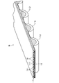
図1A及びBは、実施形態に係る歯付ベルトBを示す。実施形態に係る歯付ベルトBは、噛み合い伝動ベルトであり、例えば、工作機械、印刷機械、繊維機械、射出成形機等の高負荷伝動用途に好適に用いられる。実施形態に係る歯付ベルトBのベルト長さは、例えば500mm以上3000mm以下である。ベルト幅は、例えば10mm以上200mm以下である。ベルト厚さ(最大)は、例えば3mm以上20mm以下である。 1A and 1B show a toothed belt B according to an embodiment. The toothed belt B according to the embodiment is a meshing transmission belt, and is suitably used for high load transmission applications such as machine tools, printing machines, textile machines, and injection molding machines. The belt length of the toothed belt B according to the embodiment is, for example, 500 mm or more and 3000 mm or less. The belt width is, for example, 10 mm or more and 200 mm or less. The belt thickness (maximum) is, for example, 3 mm or more and 20 mm or less.
実施形態に係る歯付ベルトBは、ポリウレタン樹脂で形成されたエラストマー製のエンドレスの歯付ベルト本体11を備える。歯付ベルト本体11は、断面横長矩形の平帯部111と、その内周側に一体に設けられた複数の歯部112とを有する。複数の歯部112は、ベルト長さ方向に一定ピッチで間隔をおいて設けられている。
The toothed belt B according to the embodiment includes an endless toothed belt
歯部112の側面視の歯形としては、例えば、両側が外側に円弧状に膨出したSTS歯形や台形歯形等が挙げられる。歯部112の歯数は、例えば30個以上400個以下である。歯幅(ベルト長さ方向の最大寸法)は、例えば2mm以上10mm以下である。歯高さは、例えば2mm以上8mm以下である。配設ピッチは、例えば8mm以上14mm以下である。
Examples of the tooth profile in the side view of the
歯付ベルト本体11を形成するポリウレタン樹脂は、ウレタンプレポリマーに、硬化剤、可塑剤等の配合剤が配合されたウレタン組成物が加熱及び加圧されて硬化したものである。
The polyurethane resin forming the toothed belt
ウレタンプレポリマーは、イソシアネート成分とポリオール成分との反応により得られる末端に複数のNCO基を有する比較的低分子量のウレタン化合物である。イソシアネート成分としては、例えば、トリレンジイソシアネート(TDI)、ジフェニルメタンジイソシアネート(MDI)等が挙げられる。ポリオール成分としては、例えばポリテトラメチレンエーテルグリコール(PTMG)等が挙げられる。ウレタンプレポリマーは、単一のウレタン化合物で構成されていても、複数のウレタン化合物が混合されて構成されていても、どちらでもよい。 The urethane prepolymer is a relatively low molecular weight urethane compound having a plurality of NCO groups at the terminal obtained by the reaction of the isocyanate component and the polyol component. Examples of the isocyanate component include tolylene diisocyanate (TDI) and diphenylmethane diisocyanate (MDI). Examples of the polyol component include polytetramethylene ether glycol (PTMG) and the like. The urethane prepolymer may be composed of a single urethane compound or a mixture of a plurality of urethane compounds.
硬化剤としては、例えば、1,4-フェニレンジアミン、2,6-ジアミノトルエン、1,5-ナフタレンジアミン、4,4’-ジアミノジフェニルメタン、3,3’-ジクロロ-4,4’-ジアミノジフェニルメタン(MOCA)などのアミン化合物等が挙げられる。硬化剤は、これらのうちの1種又は2種以上を含むことが好ましい。アミン化合物の硬化剤は、硬化剤中のNH2基のモル数のウレタンプレポリマー中のNCO基のモル数に対する比であるα値(NH2基/NCO基)が0.70以上1.10以下となるように配合されていることが好ましい。Examples of the curing agent include 1,4-phenylenediamine, 2,6-diaminotoluene, 1,5-naphthalenediamine, 4,4'-diaminodiphenylmethane, and 3,3'-dichloro-4,4'-diaminodiphenylmethane. Examples thereof include amine compounds such as (MOCA). The curing agent preferably contains one or more of these. The curing agent of the amine compound has an α value (NH 2 groups / NCO groups) of 0.70 or more and 1.10, which is the ratio of the number of moles of NH 2 groups in the curing agent to the number of moles of NCO groups in the urethane prepolymer. It is preferable that the mixture is formulated as follows.
可塑剤としては、例えば、ジブチルフタレート(DBP)やジオクチルフタレート(DOP)などのジアルキルフタレート;ジオクチルアジペート(DOA)などのジアルキルアジペート;ジオクチルセバケート(DOS)などのジアルキルセバケート等が挙げられる。可塑剤は、これらのうちの1種又は2種以上を含むことが好ましい。可塑剤の配合量は、ウレタンプレポリマー100質量部に対して例えば3質量部以上20質量部以下である。 Examples of the plasticizer include dialkyl phthalates such as dibutyl phthalate (DBP) and dioctyl phthalate (DOP); dialkyl adipates such as dioctyl adipate (DOA); and dialkyl sebacates such as dioctyl sebacate (DOS). The plasticizer preferably contains one or more of these. The blending amount of the plasticizer is, for example, 3 parts by mass or more and 20 parts by mass or less with respect to 100 parts by mass of the urethane prepolymer.
なお、その他の配合剤としては、例えば、着色剤、消泡剤、安定剤等が挙げられる。 Examples of other compounding agents include colorants, antifoaming agents, stabilizers and the like.
歯付ベルト本体11を形成するポリウレタン樹脂の硬度は、例えば70°以上100°以下である。このポリウレタン樹脂の硬度は、JIS K7312:1996に基づいて測定される。
The hardness of the polyurethane resin forming the toothed belt
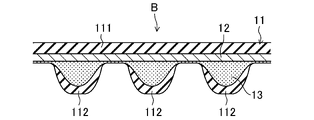
実施形態に係る歯付ベルトBは、歯付ベルト本体11の平帯部111に埋設されたカーボン繊維製の心線12を備える。心線12の外径は、高負荷伝動での優れた耐久性を得る観点から、好ましくは0.6mm以上2.2mm以下、より好ましくは0.8mm以上1.2mm以下である。
The toothed belt B according to the embodiment includes a carbon
心線12を構成するカーボン繊維は、高負荷伝動での優れた耐久性を得る観点から、PAN系カーボン繊維であることが好ましい。カーボン繊維のフィラメント径は、同様の観点から、好ましくは4μm以上9μm以下、より好ましくは6μm以上8μm以下である。
The carbon fiber constituting the
心線12を構成するカーボン繊維の総フィラメント本数は、高負荷伝動での優れた耐久性を得る観点から、好ましくは6000本(6K)以上48000本(48K)以下、より好ましくは9000本(9K)以上18000本(18K)、更に好ましくは12000本(12K)である。心線12を構成するカーボン繊維の繊度は、同様の観点から、好ましくは400tex以上3200tex以下、より好ましくは600tex以上1200tex以下、更に好ましくは800texである。
The total number of carbon fibers constituting the
心線12は、高負荷伝動での優れた耐久性を得る観点から、撚り糸であることが好ましい。心線12を構成する撚り糸としては、片撚り糸、諸撚り糸、及びラング撚り糸が挙げられる。撚り糸の心線12は、同様の観点から、カーボン繊維のフィラメント束を一方向に撚った片撚り糸であることが好ましい。片撚り糸の心線12の撚り数は、同様の観点から、好ましくは4回/10cm以上12回/10cm以下、より好ましくは6回/10cm以上10回/10cm以下である。片撚り糸の心線12には、S撚り糸が用いられても、Z撚り糸が用いられても、それらの両方が用いられても、いずれでもよい。
The
心線12は、ベルト幅方向にピッチを有する螺旋を形成するように設けられている。心線12は、S撚り糸及びZ撚り糸の2本で構成され、それらが二重螺旋を形成するように設けられていてもよい。心線12は、ベルト幅方向に間隔をおいて並行に延びるように配置されることとなるが、このとき、心線12のベルト幅10mm当たりの本数は、高負荷伝動での優れた耐久性を得る観点から、好ましくは6本/10mm以上10本/10mm以下、より好ましくは7本/10mm以上9本/10mm以下である。
The
心線12には、成形前に予め液状の接着剤に浸漬した後に乾燥させる等の接着処理が施されていることが好ましい。
It is preferable that the
実施形態に係る歯付ベルトBは、歯付ベルト本体11におけるベルト厚さ方向の心線12の埋設位置よりも内周側にベルト長さ方向に沿って埋設された不織布13を備える。不織布13は、一枚で構成されていても、複数枚で構成されていても、どちらでもよい。
The toothed belt B according to the embodiment includes a
不織布13は、歯付ベルト本体11を形成するポリウレタン樹脂を含んで、側面視において層を形成するように設けられている。不織布13の歯部112に対応する部分は、側面視において内周側に膨出するように歯部112に入り込んでベルト厚さ方向に厚く広がっている。不織布13の歯部112間に対応する部分は、心線12に接触してベルト厚さ方向に薄く圧縮されている。
The
不織布13を構成する繊維材料としては、例えば、ナイロン繊維、ポリエステル繊維、アラミド繊維、ポリケトン繊維、カーボン繊維等が挙げられる。不織布13は、単一種の繊維で形成されていても、また、複数種の繊維で形成されていても、どちらでもよい。
Examples of the fiber material constituting the
不織布13には、成形前に予め液状の接着剤に浸漬した後に乾燥させる等の接着処理が施されていることが好ましい。
It is preferable that the
実施形態に係る歯付ベルトBは、ベルト伸張率0.2%時のベルト幅1mm当たりのベルト張力T0.2が70N/mm以上である。このベルト張力T0.2は、高負荷伝動での優れた耐久性を得る観点から、好ましくは80N/mm以上、より好ましくは90N/mm以上である。ベルト張力T0.2は、曲げ剛性が高くなって耐屈曲疲労性が損なわれるのを回避する観点から、好ましくは140N/mm以下、より好ましくは120N/mm以下である。The toothed belt B according to the embodiment has a belt tension T 0.2 of 70 N / mm or more per 1 mm of belt width when the belt extension rate is 0.2%. The belt tension T 0.2 is preferably 80 N / mm or more, more preferably 90 N / mm or more, from the viewpoint of obtaining excellent durability in high load transmission. The belt tension T 0.2 is preferably 140 N / mm or less, more preferably 120 N / mm or less, from the viewpoint of avoiding high bending rigidity and impairing bending fatigue resistance.
実施形態に係る歯付ベルトBは、ベルト伸張率0.5%時のベルト幅1mm当たりのベルト張力T0.5が220N/mm以上である。このベルト張力T0.5は、高負荷伝動での優れた耐久性を得る観点から、好ましくは230N/mm以上、より好ましくは240N/mm以上である。ベルト張力T0.5は、曲げ剛性が高くなって耐屈曲疲労性が損なわれるのを回避する観点から、好ましくは440N/mm以下、より好ましくは300N/mm以下である。In the toothed belt B according to the embodiment, the belt tension T 0.5 per 1 mm of the belt width when the belt extension rate is 0.5% is 220 N / mm or more. The belt tension T 0.5 is preferably 230 N / mm or more, more preferably 240 N / mm or more, from the viewpoint of obtaining excellent durability in high load transmission. The belt tension T 0.5 is preferably 440 N / mm or less, more preferably 300 N / mm or less, from the viewpoint of avoiding high bending rigidity and impairing bending fatigue resistance.
ここで、これらのベルト張力T0.2及びベルト張力T0.5は、次のようにして求められる。Here, these belt tensions T 0.2 and belt tensions T 0.5 are obtained as follows.
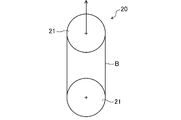
まず、25℃の雰囲気下において、図2に示すように、実施形態に係る歯付ベルトBを、ベルト引張試験機20のそれぞれプーリ径が95.4mmの一対の平プーリ21に、ベルト背面が接触するように巻き掛ける。
First, in an atmosphere of 25 ° C., as shown in FIG. 2, the toothed belt B according to the embodiment is attached to a pair of
次いで、一方の平プーリ21を他方の平プーリ21から50mm/分の速度で離間させる。このとき、一対の平プーリ21間の変位と、一対の平プーリ21のいずれかを介して検出される張力との関係を記録する。
Next, one
続いて、一対の平プーリ21間の変位を2倍してベルト伸び量を算出し、それを無負荷状態での実施形態に係る歯付ベルトBのベルト長さで除すことにより、一対の平プーリ21間の変位をベルト伸張率に換算する。また、検出される張力を2で除してベルト張力を算出し、それを実施形態に係る歯付ベルトBのベルト幅で除すことにより、検出される張力をベルト幅1mm当たりのベルト張力に換算する。
Subsequently, the displacement between the pair of
そして、これらのベルト伸張率とベルト張力との関係から、ベルト幅1mm当たりのベルト張力が50Nとなる点が起点となるようにゼロ補正し、ベルト張力T0.2及びベルト張力T0.5を求める。Then, based on the relationship between these belt extension rates and the belt tension, zero correction is made so that the starting point is the point where the belt tension per 1 mm of the belt width is 50 N, and the belt tension T 0.2 and the belt tension T 0.5 . Ask for.
実施形態に係る歯付ベルトBでは、ベルト張力T0.2のベルト張力T0.5に対する比(ベルト張力T0.2/ベルト張力T0.5)が0.33以上である。このベルト張力T0.2/ベルト張力T0.5は、高負荷伝動での優れた耐久性を得る観点から、好ましくは0.35以上、より好ましくは0.38以上である。ベルト張力T0.2/ベルト張力T0.5は、実用上の観点から、好ましくは0.55以下、より好ましくは0.50以下、更に好ましくは0.45以下である。In the toothed belt B according to the embodiment, the ratio of the belt tension T 0.2 to the belt tension T 0.5 (belt tension T 0.2 / belt tension T 0.5 ) is 0.33 or more. The belt tension T 0.2 / belt tension T 0.5 is preferably 0.35 or more, more preferably 0.38 or more, from the viewpoint of obtaining excellent durability in high load transmission. From a practical point of view, the belt tension T 0.2 / belt tension T 0.5 is preferably 0.55 or less, more preferably 0.50 or less, still more preferably 0.45 or less.
以上の構成の実施形態に係る歯付ベルトBによれば、ベルト張力T0.2が70N/mm以上であるとともに、ベルト張力T0.5が220N/mm以上であり、且つベルト張力T0.2のベルト張力T0.5に対する比が0.33以上であることにより、高負荷伝動での優れた耐久性を得ることができる。これは、ベルト張力T0.2が70N/mm以上であるとともに、ベルト張力T0.5が220N/mm以上であることにより、広範な高負荷での使用において、優れた寸法安定性が得られるのに加え、ベルト張力T0.2/ベルト張力T0.5が0.33以上であることにより、例えばプーリの熱膨張によりベルト伸張率が上昇しても、過張力の発生が抑えられ、それにより摩耗の進行を抑制することができるためであると推測される。According to the toothed belt B according to the embodiment of the above configuration, the belt tension T 0.2 is 70 N / mm or more, the belt tension T 0.5 is 220 N / mm or more, and the belt tension T 0 . When the ratio of the belt tension T of 0.2 to 0.5 is 0.33 or more, excellent durability in high load transmission can be obtained. This is because the belt tension T 0.2 is 70 N / mm or more and the belt tension T 0.5 is 220 N / mm or more, so that excellent dimensional stability can be obtained in use under a wide range of high loads. In addition, since the belt tension T 0.2 / belt tension T 0.5 is 0.33 or more, the occurrence of overtension is suppressed even if the belt extension rate increases due to thermal expansion of the pulley, for example. It is presumed that this is because the progress of wear can be suppressed.
次に、実施形態に係る歯付ベルトBの製造方法について説明する。 Next, a method for manufacturing the toothed belt B according to the embodiment will be described.
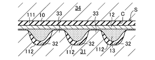
まず、図3Aに示すように、円柱状の内金型31に不織布13を被せ、その上から心線12を螺旋状に巻き付ける。このとき、内金型31の外周には、断面が歯部112に対応した形状の軸方向に延びる凹溝32が周方向に間隔をおいて一定ピッチで設けられているとともに、各凹溝32間に軸方向に延びる突条33が構成されていることから、不織布13及び心線12を、それらが突条33で支持されるように設ける。
First, as shown in FIG. 3A, the
次いで、図3Bに示すように、内金型31を円筒状の外金型34の中に収容する。このとき、内金型31と外金型34との間に歯付ベルト本体成形用のキャビティCが構成される。
Next, as shown in FIG. 3B, the
続いて、図3Cに示すように、密閉したキャビティCにウレタンプレポリマーに配合剤を配合した液状のウレタン組成物を注入して充填するとともに加熱する。このとき、ウレタン組成物が流動して硬化することによりポリウレタン樹脂の歯付ベルト本体11が形成される。また、凹溝32では歯部112が形成される。心線12は、その歯付ベルト本体11に接着して埋設される。さらに、不織布13は、ウレタン組成物が含浸して硬化するとともに、歯付ベルト本体11に接着して埋設される。以上のようにして、歯付ベルト本体11、心線12、及び不織布13が一体化して円筒状のベルトスラブSが成型される。
Subsequently, as shown in FIG. 3C, a liquid urethane composition in which a compounding agent is mixed with a urethane prepolymer is injected into the closed cavity C, filled, and heated. At this time, the urethane composition flows and hardens to form the
最後に、内金型31及び外金型34からベルトスラブSを脱型し、それを輪切りすることにより実施形態に係る歯付ベルトBが得られる。
Finally, the belt slab S is removed from the
なお、上記実施形態では、歯付ベルト本体11、心線12、及び不織布13で構成された歯付ベルトBとしたが、特にこれに限定されるものではなく、歯付ベルト本体の内周側の歯部側表面、及び/又は、歯付ベルト本体の外周側の背面に補強布が設けられていてもよい。
In the above embodiment, the toothed belt B composed of the toothed belt
上記実施形態では、歯付ベルト本体がポリウレタン樹脂で形成された歯付ベルトBとしたが、特にこれに限定されるものではなく、ベルト本体が架橋ゴム組成物で形成されていてもよい。 In the above embodiment, the toothed belt body is the toothed belt B made of polyurethane resin, but the present invention is not particularly limited, and the belt body may be formed of a crosslinked rubber composition.
上記実施形態では、伝動ベルトとして歯付ベルトBを示したが、特にこれに限定されるものではなく、平ベルト、Vベルト、Vリブドベルト等であってもよい。 In the above embodiment, the toothed belt B is shown as the transmission belt, but the present invention is not particularly limited to this, and a flat belt, a V-belt, a V-ribbed belt, or the like may be used.
(歯付ベルト)
実施例及び比較例1~3の歯付ベルトを作製した。それぞれの構成は表1にも示す。(Toothed belt)
Toothed belts of Examples and Comparative Examples 1 to 3 were produced. Each configuration is also shown in Table 1.
<実施例>
上記実施形態と同様の構成のSTS歯形の歯付ベルトを実施例とした。<Example>
An example is a toothed belt having an STS tooth profile having the same configuration as that of the above embodiment.
実施例の歯付ベルトは、ベルト長さが800mm、ベルト幅が8mm、ベルト厚さ(最大)が4.8mmであった。歯部は、ISO13050:2014(E)で規定されるS8Mであった。 The toothed belt of the example had a belt length of 800 mm, a belt width of 8 mm, and a belt thickness (maximum) of 4.8 mm. The tooth portion was S8M defined by ISO13050: 2014 (E).
歯付ベルト本体を形成するためのウレタン組成物には、ウレタンプレポリマー100質量部に対して、硬化剤の3,3’-ジクロロ-4,4’-ジアミノジフェニルメタン13質量部及び可塑剤のジオクチルフタレート10質量部を配合したものを用いた。歯付ベルト本体を形成するポリウレタン樹脂のJIS K7312に基づいて測定した硬度は92°であった。
The urethane composition for forming the main body of the toothed belt contains 13 parts by mass of the
心線には、フィラメント本数が12000本のカーボン繊維(Tenax-J UTS50 F22 帝人社製、12K、800tex、フィラメント径:7.0μm)のフィラメント束を、長さ10cm当たりの撚り数を6回/10cmとして一方向に撚った片撚り糸を用いた。片撚り糸の心線は、S撚り糸及びZ撚り糸を準備し、それらには、接着剤に浸漬した後に乾燥させる接着処理を施した。S撚り糸及びZ撚り糸の片撚り糸の心線は、それらがベルト幅方向に交互に並んで二重螺旋を形成するように設けた。心線のベルト幅10mm当たりの本数は8本とした。心線の外径は0.9mmであった。 For the core wire, a filament bundle of carbon fiber (Tenax-J UTS50 F22 Teijin, 12K, 800tex, filament diameter: 7.0 μm) with 12,000 filaments was twisted 6 times per 10 cm in length. A single twisted yarn twisted in one direction at 10 cm was used. For the core wire of the single-twisted yarn, S-twisted yarn and Z-twisted yarn were prepared, and they were subjected to an adhesive treatment to be dipped in an adhesive and then dried. The core wires of the single twisted yarns of the S twisted yarn and the Z twisted yarn were provided so as to form a double helix by arranging them alternately in the belt width direction. The number of core wires per 10 mm belt width was set to eight. The outer diameter of the core wire was 0.9 mm.
不織布として、ニードルパンチ法により無加圧で製造されたナイロン繊維製のものを用いた。不織布には、接着処理を施さなかった。 As the non-woven fabric, a non-woven fabric made of nylon fiber manufactured by the needle punching method without pressure was used. The non-woven fabric was not subjected to an adhesive treatment.
実施例の歯付ベルトのベルト張力T0.2は100N/mm、及びベルト張力T0.5は250N/mmであった。したがって、ベルト張力T0.2/ベルト張力T0.5は0.40である。The belt tension T 0.2 of the toothed belt of the example was 100 N / mm, and the belt tension T 0.5 was 250 N / mm. Therefore, the belt tension T 0.2 / belt tension T 0.5 is 0.40.
<比較例1>
心線のベルト幅10mm当たりの本数を6本としたことを除いて実施例と同一構成の歯付ベルトを比較例1とした。<Comparative Example 1>
Comparative Example 1 was a toothed belt having the same configuration as that of the example except that the number of core wires per 10 mm belt width was six.
比較例1の歯付ベルトのベルト張力T0.2は65N/mm、及びベルト張力T0.5は200N/mmであった。したがって、ベルト張力T0.2/ベルト張力T0.5は0.33である。The belt tension T 0.2 of the toothed belt of Comparative Example 1 was 65 N / mm, and the belt tension T 0.5 was 200 N / mm. Therefore, the belt tension T 0.2 / belt tension T 0.5 is 0.33.
<比較例2>
心線の長さ10cm当たりの撚り数を12回/10cmとし、心線のベルト幅10mm当たりの本数を10本としたことを除いて実施例と同一構成の歯付ベルトを比較例2とした。心線の外径は1.0mmであった。<Comparative Example 2>
Comparative Example 2 was a toothed belt having the same configuration as that of the example except that the number of twists per 10 cm of the core wire was 12 times / 10 cm and the number of twists per 10 mm of the core wire was 10. .. The outer diameter of the core wire was 1.0 mm.
比較例2の歯付ベルトのベルト張力T0.2は80N/mm、及びベルト張力T0.5は260N/mmであった。したがって、ベルト張力T0.2/ベルト張力T0.5は0.31である。The belt tension T 0.2 of the toothed belt of Comparative Example 2 was 80 N / mm, and the belt tension T 0.5 was 260 N / mm. Therefore, the belt tension T 0.2 / belt tension T 0.5 is 0.31.
<比較例3>
心線の長さ10cm当たりの撚り数を9回/10cmとしたことを除いて実施例と同一構成の歯付ベルトを比較例3とした。心線の外径は1.0mmであった。<Comparative Example 3>
Comparative Example 3 was a toothed belt having the same configuration as that of the example except that the number of twists per 10 cm of the core wire was 9 times / 10 cm. The outer diameter of the core wire was 1.0 mm.
比較例3の歯付ベルトのベルト張力T0.2は80N/mm、及びベルト張力T0.5は210N/mmであった。したがって、ベルト張力T0.2/ベルト張力T0.5は0.38である。The belt tension T 0.2 of the toothed belt of Comparative Example 3 was 80 N / mm, and the belt tension T 0.5 was 210 N / mm. Therefore, the belt tension T 0.2 / belt tension T 0.5 is 0.38.

(高負荷耐久試験)
図4は、高負荷耐久試験で用いたベルト走行試験機40のプーリレイアウトを示す。このベルト走行試験機40は、歯数が22の駆動プーリ41と、その右側方に設けられた歯数が33の従動プーリ42とを有する。従動プーリ42は、左右に可動に設けられて軸荷重を負荷できるように構成されているとともに、負荷トルクも負荷できるように構成されている。(High load durability test)
FIG. 4 shows the pulley layout of the
実施例及び比較例1~3のそれぞれの歯付ベルトBについて、60℃の雰囲気下において、駆動プーリ41及び従動プーリ42間に巻き掛けるとともに、従動プーリ42に608Nの固定軸荷重(SW)を負荷して歯付ベルトBに張力を与えるとともに、34.24N・mの負荷トルクを負荷し、その状態で、駆動プーリ41を4212rpmの回転数で回転させた。そして、歯付ベルトBが切断するまでの時間を計測し、その時間を高負荷耐久寿命とした。
Each of the toothed belts B of Examples 1 to 3 is wound between the
(試験結果)
表1に試験結果を示す。これによれば、実施例が比較例1~3よりも高負荷伝動での耐久性が非常に優れることが分かる。(Test results)
Table 1 shows the test results. According to this, it can be seen that the examples are much more durable in high load transmission than the comparative examples 1 to 3.
本発明は、伝動ベルトの技術分野について有用である。 The present invention is useful in the art of transmission belts.
B 歯付ベルト(伝動ベルト)
C キャビティ
S ベルトスラブ
11 歯付ベルト本体
111 平帯部
112 歯部
12 心線
13 不織布
20 ベルト引張試験機
21 平プーリ
31 内金型
32 凹溝
33 突条
34 外金型
40 ベルト走行試験機
41 駆動プーリ
42 従動プーリB Toothed belt (transmission belt)
C Cavity
Claims (12)
ベルト伸張率0.2%時のベルト幅1mm当たりのベルト張力T0.2が70N/mm以上であるとともに、ベルト伸張率0.5%時のベルト幅1mm当たりのベルト張力T0.5が220N/mm以上であり、且つ前記ベルト張力T0.2の前記ベルト張力T0.5に対する比が0.33以上である伝動ベルト。A transmission belt comprising an elastomer belt body and a carbon fiber core wire embedded in the belt body and provided to form a spiral having a pitch in the belt width direction.
The belt tension T 0.2 per 1 mm of belt width when the belt extension rate is 0.2% is 70 N / mm or more, and the belt tension T 0.5 per 1 mm of belt width when the belt extension rate is 0.5% is A transmission belt having a belt tension of 220 N / mm or more and a ratio of the belt tension T 0.2 to the belt tension T 0.5 of 0.33 or more.
前記ベルト本体がポリウレタン樹脂で形成されている伝動ベルト。In the transmission belt according to claim 1,
A transmission belt whose main body is made of polyurethane resin.
前記心線を構成する前記カーボン繊維がPAN系カーボン繊維である伝動ベルト。In the transmission belt according to claim 1 or 2.
A transmission belt in which the carbon fibers constituting the core wire are PAN-based carbon fibers.
前記カーボン繊維のフィラメント径が4μm以上9μm以下である伝動ベルト。In the transmission belt according to any one of claims 1 to 3, the transmission belt
A transmission belt having a filament diameter of 4 μm or more and 9 μm or less of the carbon fiber.
前記心線を構成する前記カーボン繊維の総フィラメント本数が6000本以上48000本以下である伝動ベルト。In the transmission belt according to any one of claims 1 to 4, the transmission belt
A transmission belt in which the total number of filaments of the carbon fibers constituting the core wire is 6000 or more and 48,000 or less.
前記心線が前記カーボン繊維のフィラメント束を一方向に撚った片撚り糸である伝動ベルト。In the transmission belt according to any one of claims 1 to 5, the transmission belt
A transmission belt in which the core wire is a single-twisted yarn obtained by twisting a filament bundle of carbon fibers in one direction.
前記片撚り糸の心線の長さ10cm当たりの撚り数が4回/10cm以上12回/10cm以下である伝動ベルト。In the transmission belt according to claim 6,
A transmission belt in which the number of twists per 10 cm length of the core wire of the single twisted yarn is 4 times / 10 cm or more and 12 times / 10 cm or less.
前記心線のベルト幅10mm当たりの本数が6本/10mm以上10本/10mm以下である伝動ベルト。In the transmission belt according to any one of claims 1 to 7.
A transmission belt in which the number of core wires per 10 mm belt width is 6/10 mm or more and 10/10 mm or less.
前記ベルト伸張率0.2%時のベルト幅1mm当たりのベルト張力T0.2が140N/mm以下である伝動ベルト。In the transmission belt according to any one of claims 1 to 8, the transmission belt
A transmission belt having a belt tension T 0.2 per 1 mm of belt width at a belt extension rate of 0.2% of 140 N / mm or less.
前記ベルト伸張率0.5%時のベルト幅1mm当たりのベルト張力T0.5が440N/mm以下である伝動ベルト。In the transmission belt according to any one of claims 1 to 9, the transmission belt
A transmission belt having a belt tension T 0.5 per 1 mm of belt width at a belt extension rate of 0.5% of 440 N / mm or less.
前記ベルト張力T0.2/ベルト張力T0.5が0.55以下である伝動ベルト。In the transmission belt according to any one of claims 1 to 10.
A transmission belt in which the belt tension T 0.2 / belt tension T 0.5 is 0.55 or less.
前記ベルト本体が歯付ベルト本体である伝動ベルト。In the transmission belt according to any one of claims 1 to 11.
A transmission belt in which the belt body is a toothed belt body.
Priority Applications (1)
| Application Number | Priority Date | Filing Date | Title |
|---|---|---|---|
| JP2022039836A JP2022091819A (en) | 2020-07-03 | 2022-03-15 | Transmission belt |
Applications Claiming Priority (3)
| Application Number | Priority Date | Filing Date | Title |
|---|---|---|---|
| JP2020115523 | 2020-07-03 | ||
| JP2020115523 | 2020-07-03 | ||
| PCT/JP2021/024894 WO2022004835A1 (en) | 2020-07-03 | 2021-07-01 | Transmission belt |
Related Child Applications (1)
| Application Number | Title | Priority Date | Filing Date |
|---|---|---|---|
| JP2022039836A Division JP2022091819A (en) | 2020-07-03 | 2022-03-15 | Transmission belt |
Publications (2)
| Publication Number | Publication Date |
|---|---|
| JPWO2022004835A1 JPWO2022004835A1 (en) | 2022-01-06 |
| JP7043690B1 true JP7043690B1 (en) | 2022-03-29 |
Family
ID=79316353
Family Applications (2)
| Application Number | Title | Priority Date | Filing Date |
|---|---|---|---|
| JP2022506968A Active JP7043690B1 (en) | 2020-07-03 | 2021-07-01 | Transmission belt |
| JP2022039836A Pending JP2022091819A (en) | 2020-07-03 | 2022-03-15 | Transmission belt |
Family Applications After (1)
| Application Number | Title | Priority Date | Filing Date |
|---|---|---|---|
| JP2022039836A Pending JP2022091819A (en) | 2020-07-03 | 2022-03-15 | Transmission belt |
Country Status (5)
| Country | Link |
|---|---|
| US (1) | US11644082B2 (en) |
| EP (1) | EP4141286A4 (en) |
| JP (2) | JP7043690B1 (en) |
| CN (1) | CN115461558B (en) |
| WO (1) | WO2022004835A1 (en) |
Families Citing this family (1)
| Publication number | Priority date | Publication date | Assignee | Title |
|---|---|---|---|---|
| JP7085699B1 (en) * | 2021-01-25 | 2022-06-16 | 三ツ星ベルト株式会社 | Toothed belt |
Citations (3)
| Publication number | Priority date | Publication date | Assignee | Title |
|---|---|---|---|---|
| JP2001090789A (en) * | 1999-09-21 | 2001-04-03 | Bando Chem Ind Ltd | V ribbed belt |
| JP2004347111A (en) * | 2003-04-28 | 2004-12-09 | Hokushin Ind Inc | Toothed driving belt |
| JP2011133029A (en) * | 2009-12-24 | 2011-07-07 | Nitta Corp | Flat belt |
Family Cites Families (35)
| Publication number | Priority date | Publication date | Assignee | Title |
|---|---|---|---|---|
| AT268791B (en) * | 1965-05-29 | 1969-02-25 | Continental Gummi Werke Ag | Drive belt |
| JPH0642120Y2 (en) * | 1986-06-19 | 1994-11-02 | 芦森工業株式会社 | Timing belt |
| JP3007371B2 (en) * | 1990-02-23 | 2000-02-07 | バンドー化学株式会社 | Fiber reinforced rubber products |
| US5268221A (en) * | 1990-02-23 | 1993-12-07 | Bando Chemical Industries, Ltd. | Fiber reinforced rubber articles |
| JPH0425643A (en) * | 1990-05-15 | 1992-01-29 | Bando Chem Ind Ltd | Fiber reinforced rubber goods |
| JP2545208Y2 (en) * | 1992-10-13 | 1997-08-25 | 株式会社椿本チエイン | Toothed belt |
| DE69404571T2 (en) * | 1993-02-23 | 1998-02-26 | Unitta Co Ltd | TIMING BELT |
| JPH07208558A (en) * | 1994-01-13 | 1995-08-11 | Bando Chem Ind Ltd | Toothed belt |
| JP2869025B2 (en) * | 1995-07-24 | 1999-03-10 | バンドー化学株式会社 | Tensile body and belt for belt |
| US5807194A (en) * | 1996-10-31 | 1998-09-15 | The Gates Corporation | Toothed belt |
| JP3441987B2 (en) * | 1998-12-04 | 2003-09-02 | ゲイツ・ユニッタ・アジア株式会社 | Toothed belt |
| GB2349113B (en) * | 1999-04-21 | 2003-07-02 | Gates Corp | Wear resistant belts and a process for their manufacture |
| EP1150034B1 (en) * | 2000-04-28 | 2005-01-19 | Mitsuboshi Belting Ltd. | Power transmission belt and a method of forming a power transmission belt |
| ES2244645T3 (en) * | 2000-08-18 | 2005-12-16 | The Gates Corporation | POWER DRIVE BELT PROVIDED WITH A HIGH MODULE ADHESIVE RUBBER ELEMENT. |
| US7235028B2 (en) * | 2001-04-12 | 2007-06-26 | The Gates Corporation | Thermoplastic jacket belt |
| JP3964725B2 (en) * | 2002-01-21 | 2007-08-22 | 本田技研工業株式会社 | Toothed belt drive |
| JP2005024075A (en) | 2003-07-03 | 2005-01-27 | Mitsuboshi Belting Ltd | Toothed belt |
| WO2005080821A1 (en) * | 2004-02-23 | 2005-09-01 | Dayco Europe S.R.L. | Toothed belt |
| JP2006097787A (en) * | 2004-09-29 | 2006-04-13 | Tsubakimoto Chain Co | Toothed belt |
| CN101133261A (en) * | 2006-03-24 | 2008-02-27 | 阪东化学株式会社 | Transmission belt |
| US8142316B2 (en) * | 2006-12-05 | 2012-03-27 | Veyance Technologies, Inc. | Power transmission belts |
| RU2429397C1 (en) * | 2007-07-03 | 2011-09-20 | Дзе Гейтс Корпорейшн | Drive belt |
| JP5204611B2 (en) * | 2008-10-15 | 2013-06-05 | バンドー化学株式会社 | Toothed belt |
| RU2508485C2 (en) * | 2009-06-23 | 2014-02-27 | Чжэцзян Кинглэнд Трансмишн Индастри Ко., Лтд. | System of composite v-belt drive composed of friction gearing and engagement gearing |
| JP5002043B2 (en) * | 2009-11-13 | 2012-08-15 | 三ツ星ベルト株式会社 | Rubber toothed belt and rubber composition for toothed belt |
| JP5465346B1 (en) * | 2013-01-22 | 2014-04-09 | 株式会社椿本チエイン | Toothed belt |
| DE102013104757A1 (en) * | 2013-05-08 | 2014-11-13 | Contitech Antriebssysteme Gmbh | Method for producing a belt with prepared tension members with a cover layer |
| JP6371763B2 (en) * | 2013-05-15 | 2018-08-08 | バンドー化学株式会社 | Manufacturing method of toothed belt |
| JP6530276B2 (en) * | 2015-08-20 | 2019-06-12 | 三ツ星ベルト株式会社 | Belt system and its toothed belt |
| US10220545B2 (en) * | 2016-04-30 | 2019-03-05 | Contitech Antriebssysteme Gmbh | Water based urethane as predip for carbon fiber cord |
| JP6640921B2 (en) * | 2017-06-20 | 2020-02-05 | 三ツ星ベルト株式会社 | V-ribbed belt and method of manufacturing the same |
| WO2019013232A1 (en) * | 2017-07-11 | 2019-01-17 | 三ツ星ベルト株式会社 | Helical belt and belt transmission gear |
| WO2019182949A1 (en) * | 2018-03-19 | 2019-09-26 | Exxonmobil Chemical Patents Inc. | Elastomeric propylene-alpha-olefin-diene terpolymer compositions |
| JP6603008B1 (en) * | 2018-03-19 | 2019-11-06 | 日本板硝子株式会社 | Rubber reinforcing cord, manufacturing method thereof, and rubber product |
| JP6641513B2 (en) * | 2018-04-06 | 2020-02-05 | 三ツ星ベルト株式会社 | Helical belt and belt transmission |
-
2021
- 2021-07-01 EP EP21831812.9A patent/EP4141286A4/en active Pending
- 2021-07-01 WO PCT/JP2021/024894 patent/WO2022004835A1/en unknown
- 2021-07-01 JP JP2022506968A patent/JP7043690B1/en active Active
- 2021-07-01 CN CN202180031931.6A patent/CN115461558B/en active Active
-
2022
- 2022-03-15 JP JP2022039836A patent/JP2022091819A/en active Pending
- 2022-11-25 US US17/994,270 patent/US11644082B2/en active Active
Patent Citations (3)
| Publication number | Priority date | Publication date | Assignee | Title |
|---|---|---|---|---|
| JP2001090789A (en) * | 1999-09-21 | 2001-04-03 | Bando Chem Ind Ltd | V ribbed belt |
| JP2004347111A (en) * | 2003-04-28 | 2004-12-09 | Hokushin Ind Inc | Toothed driving belt |
| JP2011133029A (en) * | 2009-12-24 | 2011-07-07 | Nitta Corp | Flat belt |
Also Published As
| Publication number | Publication date |
|---|---|
| JPWO2022004835A1 (en) | 2022-01-06 |
| JP2022091819A (en) | 2022-06-21 |
| CN115461558A (en) | 2022-12-09 |
| EP4141286A4 (en) | 2023-10-25 |
| WO2022004835A1 (en) | 2022-01-06 |
| US20230088538A1 (en) | 2023-03-23 |
| EP4141286A1 (en) | 2023-03-01 |
| US11644082B2 (en) | 2023-05-09 |
| CN115461558B (en) | 2023-03-28 |
Similar Documents
| Publication | Publication Date | Title |
|---|---|---|
| JP7233461B2 (en) | toothed belt | |
| JP5204611B2 (en) | Toothed belt | |
| JP7043690B1 (en) | Transmission belt | |
| US20230332671A1 (en) | Transmission belt | |
| KR101907156B1 (en) | Toothed belt | |
| US11719309B2 (en) | Toothed belt | |
| JP7406051B1 (en) | toothed belt | |
| WO2024024435A1 (en) | Toothed belt | |
| JP2022013158A (en) | Toothed belt | |
| JP7381417B2 (en) | power transmission belt | |
| JP7285374B2 (en) | toothed belt | |
| JP2000009185A (en) | Toothed belt | |
| JP2017040316A (en) | Belt system and synchronous belt | |
| JP2002349636A (en) | Transmission belt | |
| JP2022171350A (en) | Synchronous belt | |
| JP2003294086A (en) | Drive belt | |
| JP2000074148A (en) | Core wire untwining preventing method for synchronous belt |
Legal Events
| Date | Code | Title | Description |
|---|---|---|---|
| A621 | Written request for application examination |
Free format text: JAPANESE INTERMEDIATE CODE: A621 Effective date: 20220203 |
|
| A871 | Explanation of circumstances concerning accelerated examination |
Free format text: JAPANESE INTERMEDIATE CODE: A871 Effective date: 20220203 |
|
| TRDD | Decision of grant or rejection written | ||
| A01 | Written decision to grant a patent or to grant a registration (utility model) |
Free format text: JAPANESE INTERMEDIATE CODE: A01 Effective date: 20220301 |
|
| A61 | First payment of annual fees (during grant procedure) |
Free format text: JAPANESE INTERMEDIATE CODE: A61 Effective date: 20220316 |
|
| R150 | Certificate of patent or registration of utility model |
Ref document number: 7043690 Country of ref document: JP Free format text: JAPANESE INTERMEDIATE CODE: R150 |