JP7041682B2 - Overcoming acoustic field and skull heterogeneity - Google Patents
Overcoming acoustic field and skull heterogeneity Download PDFInfo
- Publication number
- JP7041682B2 JP7041682B2 JP2019536831A JP2019536831A JP7041682B2 JP 7041682 B2 JP7041682 B2 JP 7041682B2 JP 2019536831 A JP2019536831 A JP 2019536831A JP 2019536831 A JP2019536831 A JP 2019536831A JP 7041682 B2 JP7041682 B2 JP 7041682B2
- Authority
- JP
- Japan
- Prior art keywords
- hotspot
- image data
- location
- region
- controller
- Prior art date
- Legal status (The legal status is an assumption and is not a legal conclusion. Google has not performed a legal analysis and makes no representation as to the accuracy of the status listed.)
- Active
Links
Images


Classifications
-
- A—HUMAN NECESSITIES
- A61—MEDICAL OR VETERINARY SCIENCE; HYGIENE
- A61N—ELECTROTHERAPY; MAGNETOTHERAPY; RADIATION THERAPY; ULTRASOUND THERAPY
- A61N7/00—Ultrasound therapy
- A61N7/02—Localised ultrasound hyperthermia
-
- A—HUMAN NECESSITIES
- A61—MEDICAL OR VETERINARY SCIENCE; HYGIENE
- A61B—DIAGNOSIS; SURGERY; IDENTIFICATION
- A61B5/00—Measuring for diagnostic purposes; Identification of persons
- A61B5/05—Detecting, measuring or recording for diagnosis by means of electric currents or magnetic fields; Measuring using microwaves or radio waves
- A61B5/055—Detecting, measuring or recording for diagnosis by means of electric currents or magnetic fields; Measuring using microwaves or radio waves involving electronic [EMR] or nuclear [NMR] magnetic resonance, e.g. magnetic resonance imaging
-
- A—HUMAN NECESSITIES
- A61—MEDICAL OR VETERINARY SCIENCE; HYGIENE
- A61B—DIAGNOSIS; SURGERY; IDENTIFICATION
- A61B8/00—Diagnosis using ultrasonic, sonic or infrasonic waves
- A61B8/48—Diagnostic techniques
- A61B8/485—Diagnostic techniques involving measuring strain or elastic properties
-
- A—HUMAN NECESSITIES
- A61—MEDICAL OR VETERINARY SCIENCE; HYGIENE
- A61B—DIAGNOSIS; SURGERY; IDENTIFICATION
- A61B18/00—Surgical instruments, devices or methods for transferring non-mechanical forms of energy to or from the body
- A61B2018/00636—Sensing and controlling the application of energy
- A61B2018/00696—Controlled or regulated parameters
- A61B2018/00714—Temperature
-
- A—HUMAN NECESSITIES
- A61—MEDICAL OR VETERINARY SCIENCE; HYGIENE
- A61B—DIAGNOSIS; SURGERY; IDENTIFICATION
- A61B18/00—Surgical instruments, devices or methods for transferring non-mechanical forms of energy to or from the body
- A61B2018/00636—Sensing and controlling the application of energy
- A61B2018/00696—Controlled or regulated parameters
- A61B2018/00761—Duration
-
- A—HUMAN NECESSITIES
- A61—MEDICAL OR VETERINARY SCIENCE; HYGIENE
- A61B—DIAGNOSIS; SURGERY; IDENTIFICATION
- A61B18/00—Surgical instruments, devices or methods for transferring non-mechanical forms of energy to or from the body
- A61B2018/00636—Sensing and controlling the application of energy
- A61B2018/00773—Sensed parameters
- A61B2018/00791—Temperature
-
- A—HUMAN NECESSITIES
- A61—MEDICAL OR VETERINARY SCIENCE; HYGIENE
- A61B—DIAGNOSIS; SURGERY; IDENTIFICATION
- A61B90/00—Instruments, implements or accessories specially adapted for surgery or diagnosis and not covered by any of the groups A61B1/00 - A61B50/00, e.g. for luxation treatment or for protecting wound edges
- A61B90/36—Image-producing devices or illumination devices not otherwise provided for
- A61B90/37—Surgical systems with images on a monitor during operation
- A61B2090/374—NMR or MRI
-
- A—HUMAN NECESSITIES
- A61—MEDICAL OR VETERINARY SCIENCE; HYGIENE
- A61N—ELECTROTHERAPY; MAGNETOTHERAPY; RADIATION THERAPY; ULTRASOUND THERAPY
- A61N7/00—Ultrasound therapy
- A61N2007/0078—Ultrasound therapy with multiple treatment transducers
-
- A—HUMAN NECESSITIES
- A61—MEDICAL OR VETERINARY SCIENCE; HYGIENE
- A61N—ELECTROTHERAPY; MAGNETOTHERAPY; RADIATION THERAPY; ULTRASOUND THERAPY
- A61N7/00—Ultrasound therapy
- A61N2007/0086—Beam steering
- A61N2007/0095—Beam steering by modifying an excitation signal
Description
本発明の分野は、概して、熱エネルギー治療システムに関し、より詳細には、頭蓋骨などの不均一な組織を通って伝達される音響場における不均一性を克服するためのシステムおよび方法に関する。 The field of the present invention relates generally to thermal energy therapy systems, and more particularly to systems and methods for overcoming inhomogeneities in acoustic fields transmitted through non-uniform tissues such as skulls.
癌患者の治療は、しばしば組織または組織界面に熱エネルギーを印加することを含む。例えば、腫瘍制御、すなわち腫瘍の大きさおよび/または成長速度の低減は、局所的に加熱し、それによって腫瘍組織を凝固または切除することによって達成することができる。熱はまた、腫瘍帯付近の疼痛を軽減するために使用される場合がある。特に骨痛緩和は、腫瘍に隣接する骨表面の温度を、その領域における神経を切除するレベルまで上昇させることによってしばしば達成される。 Treatment of cancer patients often involves applying thermal energy to the tissue or tissue interface. For example, tumor control, i.e., reduction of tumor size and / or growth rate, can be achieved by locally heating, thereby coagulating or excising the tumor tissue. Fever may also be used to relieve pain near the tumor zone. Bone pain relief in particular is often achieved by raising the temperature of the bone surface adjacent to the tumor to the level of excision of nerves in the area.
一般的に使用されている熱処理方法は、治療されるべき組織(「標的(target)」)への超音波(すなわち、約20kHzより高い周波数を有する音波)の集束である。集束超音波法は、例えば、患者の外部に位置するが、標的にごく近接して配置される圧電セラミック・トランスデューサを利用する場合がある。トランスデューサは、電子駆動信号を機械的振動に変換し、その結果音波が放射される(以後「超音波処理(sonication)」と称されるプロセス)。トランスデューサは、波が焦点ゾーンに収束するように成形されてもよい。代替的または付加的に、トランスデューサは、位相(およびオプションとして振幅)がそれぞれ互いに独立して制御することができ、したがって、焦点ゾーンのおける個々の音波の構造的干渉をもたらすように設定することができる複数の個別駆動トランスデューサ素子によって規定されてよい。そのような「フェーズドアレイ(phased-array)」トランスデューサは、トランスデューサ間の相対位相を調整することによって焦点ゾーンを異なる位置に誘導することを容易にする。超音波ビームをガイドし、潜在的に超音波集束を改善するために、磁気共鳴映像法(MRI)を利用して焦点および標的を視覚化してもよい。 A commonly used heat treatment method is the focusing of ultrasound (ie, sound waves with frequencies above about 20 kHz) onto the tissue to be treated (“target”). Focused ultrasound may utilize, for example, a piezoelectric ceramic transducer that is located outside the patient but very close to the target. Transducers convert electronically driven signals into mechanical vibrations that result in the emission of sound waves (a process commonly referred to as "sonication"). The transducer may be shaped so that the wave converges on the focal zone. Alternatively or additionally, the transducer can be configured so that the phases (and optionally the amplitudes) can be controlled independently of each other, thus resulting in structural interference of the individual sound waves in the focal zone. It may be specified by a plurality of individually driven transducer elements capable of. Such "phased-array" transducers facilitate guiding the focal zone to different positions by adjusting the relative phase between the transducers. Focus and target may be visualized using magnetic resonance imaging (MRI) to guide the ultrasound beam and potentially improve ultrasound focusing.
超音波を用いて組織に熱エネルギーを印加する場合、標的領域を均一に加熱すること、すなわち焦点ゾーンにおいて均一な温度分布を生成することが重要である。さもなければ、不均一な温度分布の局所的な「ホットスポット(hot spot)」は、計画外の標的の加熱、および超音波処理の達成(例えば、表面領域における疼痛緩和、または腫瘍の切除)の前に、かなりの、時には耐えられないほどの疼痛を引き起こし、治療を急いて中止する必要が生じる場合がある。しかしながら、均一な加熱はしばしば達成が困難である。例えば、標的に対するトランスデューサ・アレイの配置に関する生理学的制約は、ビームステアリングの必要性を伴う場合があり、その結果、組織界面に対する垂直から離れた超音波伝播方向をもたらす場合があり、高次ビームモード、または細長い焦点、これらのすべてはビームの均一性に悪影響を及ぼす場合がある。 When applying thermal energy to a tissue using ultrasound, it is important to heat the target area uniformly, i.e. to produce a uniform temperature distribution in the focal zone. Otherwise, local "hot spots" of non-uniform temperature distribution are unplanned heating of the target, and achievement of sonication (eg, pain relief in the surface area, or tumor resection). Before, it may cause considerable and sometimes intolerable pain, requiring urgent discontinuation of treatment. However, uniform heating is often difficult to achieve. For example, physiological constraints on the placement of the transducer array with respect to the target can be associated with the need for beam steering, which can result in ultrasonic propagation directions away from perpendicular to the tissue interface, higher order beam modes. , Or elongated focal points, all of which can adversely affect beam uniformity.
さらに、トランスデューサ・アレイと標的領域との間に位置する介在組織の不均一性は、超音波ビームを歪ませる場合があり、意図された焦点ゾーン以外の場所に1または複数のホットスポットを作り出す場合がある。上述のように、そのようなホットスポットは、望ましくない加熱、患者への痛み、および/または非標的組織の壊死を引き起こす場合がある。たとえ標的組織内であっても、ホットスポットは、例えば標的領域の外側で組織壊死を引き起こすことによって問題となる場合がある。各トランスデューサは有限個の素子から構成されているので、素子間の位相を変えるために使用される離散的な位相変化もまた二次ホットスポットの発生に寄与する場合がある。 In addition, the non-uniformity of the intervening tissue located between the transducer array and the target area can distort the ultrasonic beam and create one or more hotspots outside the intended focal zone. There is. As mentioned above, such hotspots can cause unwanted heating, pain to the patient, and / or necrosis of non-target tissue. Hotspots can be problematic, for example, by causing tissue necrosis outside the target area, even within the target tissue. Since each transducer is composed of a finite number of elements, the discrete phase changes used to change the phase between the elements may also contribute to the generation of secondary hotspots.
したがって、標的領域における超音波強度を実質的に減少させることなく、標的領域および非標的領域における望ましくないホットスポットを減少させるシステムおよび方法が必要とされている。 Therefore, there is a need for systems and methods that reduce unwanted hotspots in the target and non-target areas without substantially reducing the ultrasonic intensity in the target area.
本発明の実施形態は、最初に局所的なホットスポットの位置を識別し(または特定し、identifying)、ホットスポットを最小とするように識別された位置に基づいてトランスデューサ・アレイのパラメータを調整することによって、標的領域(target region)および/または非標的領域における望ましくない局所的なホットスポットを最小にする。(「ホットスポット(hot spot)」という用語は、本明細書では、それが生じる組織の温度を臨床的に許容できないレベルまで上昇させる超音波エネルギーの集中領域を暗示するために使用される。)例えば、不均質な介在組織を横切るビーム、トランスデューサの幾何学形状および/または音響場設計(例えば、再焦点合わせの目的のための音響場設計)に起因する超音波場の収差をシミュレートする物理モデルを使用して、望ましくないホットスポットの位置を予測し得る。あるいは、温度感受性デバイス(例えば、磁気共鳴画像法(MRI)デバイス)を使用して、ホットスポットの位置を測定し得る。一実施形態では、標的組織および/または周囲組織の材料特性を特徴付ける組織モデルを使用して、ホットスポットの予測位置の近くにあり、熱感度が低いおよび/またはホットスポットの予測位置における組織よりも高い熱エネルギーを許容する、1または複数の領域を識別する。次いで、物理モデルは、識別された低熱感度(low-heat sensitive)領域および/または高熱エネルギー耐性(high-thermal-energy tolerant)領域にホットスポットを生成するように、少なくとも1つのトランスデューサ素子に関連する必要な周波数を逆計算することができる。物理モデル(およびいくらかの実施形態では、組織モデル)に応答して、トランスデューサ素子のコントローラは、計算された周波数に基づいてトランスデューサ素子の周波数を調整し得る。種々の実施形態において、組織の損傷を回避するために、ホットスポットの位置がそれらの予測される位置と識別された低熱感度領域および/または高熱エネルギー耐性領域との間でシフトされるように、トランスデューサ素子のコントローラは、トランスデューサ周波数の動的に変化するパターンを決定する。あるいは、トランスデューサ素子のコントローラは、トランスデューサ素子の周波数をランダムに変化させ得る。送信波(または透過波、もしくは伝達波、transmitted wave)の周波数が変化すると、ホットスポットの位置が変化する場合がある。これは超音波エネルギーを予測されたホットスポットの位置から他のいくつかの位置に分散させ、それによって標的において十分に高い温度を保ちながら、結果として生じる温度分布を均一にする。 An embodiment of the invention first identifies (or identifies) the location of a local hotspot and then adjusts the parameters of the transducer array based on the location identified to minimize the hotspot. This minimizes unwanted local hotspots in the target region and / or non-target region. (The term "hot spot" is used herein to imply a region of concentration of ultrasonic energy that raises the temperature of the tissue in which it occurs to clinically unacceptable levels.) For example, physics that simulate ultrasonic field aberrations due to beams across heterogeneous intervening tissues, transducer geometry and / or acoustic field design (eg, acoustic field design for refocusing purposes). The model can be used to predict the location of unwanted hotspots. Alternatively, a temperature sensitive device (eg, a magnetic resonance imaging (MRI) device) can be used to measure the location of the hotspot. In one embodiment, a tissue model that characterizes the material properties of the target and / or surrounding tissue is used to be closer to the predicted hotspot location and less thermally sensitive and / or than the tissue at the predicted hotspot location. Identify one or more regions that tolerate high thermal energy. The physical model is then associated with at least one transducer element to generate hotspots in the identified low-heat sensitive and / or high-thermal-energy tolerant regions. The required frequency can be calculated back. In response to the physical model (and, in some embodiments, the tissue model), the transducer element controller may adjust the transducer element frequency based on the calculated frequency. In various embodiments, the hotspot locations are shifted between their predicted location and the identified low thermal sensitivity and / or high thermal energy resistant regions to avoid tissue damage. The controller of the transducer element determines the dynamically changing pattern of the transducer frequency. Alternatively, the controller of the transducer element may randomly change the frequency of the transducer element. When the frequency of the transmitted wave (or transmitted wave, or transmitted wave) changes, the position of the hotspot may change. This disperses the ultrasonic energy from the predicted hotspot location to several other locations, thereby maintaining a sufficiently high temperature at the target while homogenizing the resulting temperature distribution.
代替的または付加的に、物理モデルは、ホットスポットを制御するように他のトランスデューサ・パラメータの値を調整してもよい。例えば、ホットスポットの予測される位置に基づいて、物理モデルは、少なくともいくつかのトランスデューサ素子に関連する強度(振幅)を変化させることによって、ホットスポットにおける最大強度と、標的における焦点ゾーンにおける最大強度との強度比(または、標的における焦点ゾーンにおける最大強度に対するホットスポットにおける最大強度の強度比)に対する影響をシミュレートしてもよい。シミュレートされた効果に基づいて、いくつかのトランスデューサ素子の波強度は、強度比を減少させるように調整され、それによって望ましくないホットスポットにおける温度を下げながら、標的における温度を最大にする。 Alternatively or additionally, the physical model may adjust the values of other transducer parameters to control the hotspot. For example, based on the predicted position of the hotspot, the physical model changes the intensity (amplitude) associated with at least some transducer elements to maximize the intensity at the hotspot and the maximum intensity at the focal zone at the target. The effect on the intensity ratio with and (or the intensity ratio of the maximum intensity at the hotspot to the maximum intensity at the focal zone at the target) may be simulated. Based on the simulated effect, the wave intensity of some transducer elements is adjusted to reduce the intensity ratio, thereby maximizing the temperature at the target while lowering the temperature at the undesired hotspot.
ホットスポットの補正(または補償、compensation)は、少なくともいくつかのトランスデューサ素子を選択的に活性化(または作動、activating)および非活性化(または停止、deactivating)することによって達成されてもよい。例えば、トランスデューサ・アレイは複数のサブ領域に分割されてもよい。異なるサブ領域の活性化は、焦点ゾーンの内側および/または外側の様々な位置に望ましくないホットスポットを有する共通の焦点ゾーンを標的領域に生成してもよい。いくらかの実施形態では、トランスデューサ素子の各サブ領域は、ホットスポットの位置を変えるように選択的に活性化および非活性化される。これもまた、比較的少数のホットスポットの位置からより多数のホットスポットの位置へのエネルギー分散をもたらし、それによって、結果として生じる温度分布の均一性を改善する。 Hotspot correction (or compensation) may be achieved by selectively activating (or activating, activating) and deactivating (or deactivating) at least some transducer elements. For example, the transducer array may be divided into multiple subregions. Activation of different subregions may create a common focal zone in the target region with unwanted hotspots at various locations inside and / or outside the focal zone. In some embodiments, each subregion of the transducer element is selectively activated and deactivated to change the location of the hotspot. This also results in energy distribution from a relatively small number of hotspot locations to a larger number of hotspot locations, thereby improving the resulting temperature distribution uniformity.
さらに他の実施形態では、送信された超音波の干渉パターンを制御することによって、ホットスポットを補正するためにビームフォーミングが使用される。例えば、各トランスデューサ素子に関連する時間遅延(time delay)(または、位相として記載される)を調整することは、様々な干渉パターンをもたらし得る。各干渉パターンは、異なる位置において、それぞれホットスポットに対応する波増幅を有し得る。したがって、トランスデューサ素子のうちの少なくともいくつかに関連する時間遅延(または位相)を動的に変化させることも、これらのホットスポットを空間的に分散させ得、それによって、温度分布の均一性を改善するように、一時的にホットスポットを減じ得る。 In yet another embodiment, beamforming is used to correct hot spots by controlling the interference pattern of the transmitted ultrasonic waves. For example, adjusting the time delay (or described as phase) associated with each transducer element can result in various interference patterns. Each interference pattern may have a wave amplification corresponding to a hotspot at different locations. Therefore, dynamically changing the time delay (or phase) associated with at least some of the transducer elements can also spatially disperse these hotspots, thereby improving the uniformity of the temperature distribution. As you can, you can temporarily reduce the hotspots.
それに応じて、一態様では、本発明は、複数のトランスデューサ素子を有する超音波トランスデューサを使用して標的領域を加熱する方法に関する。種々の実施形態では、方法は、超音波処理プロセス(ultrasound sonication process)中に、標的領域および/または標的領域の周囲領域(もしくは、標的領域を囲む領域、region surrounding the target region)内の所定の許容レベルを超える時間平均エネルギー密度(time-averaged energy density)を有する1または複数のホットスポットの1または複数の位置を識別すること、ホットスポットの識別された位置に少なくとも部分的に基づいて、ホットスポットの時間平均エネルギー密度を所定の許容レベルまで減少させる1または複数のトランスデューサ素子の出力パラメータ(例えば、周波数、振幅、移送および/または時間遅延)に対する時間的変動(または、一時的変動、temporal variation)を計算すること、ならびに、出力パラメータの時間的変動を達成するように、少なくとも1つのトランスデューサ素子を動作させることを含む。一実施態様では、時間的変動は、標的領域において実質的に均一な温度分布を形成する(または作り出す、create)。 Accordingly, in one aspect, the invention relates to a method of heating a target region using an ultrasonic transducer having a plurality of transducer elements. In various embodiments, the method is a predetermined region within the target region and / or the region surrounding the target region (or the region surrounding the target region) during the ultimate sonication process. Identifying one or more locations of one or more hotspots with a time-averaged energy density that exceeds an acceptable level, hot based at least in part on the identified locations of the hotspots. Temporal variation (or transient variation) with respect to the output parameters (eg, frequency, amplitude, transfer and / or time delay) of one or more transducer elements that reduce the time average energy density of the spot to a given tolerance level. ), As well as operating at least one transducer element to achieve temporal variation in output parameters. In one embodiment, temporal variability creates (or creates) a substantially uniform temperature distribution in the target region.
上記方法は、標的領域および/または周囲領域の画像データ(例えば、ARFIデータ)を取得することをさらに含んでよい。標的領域および/または周囲領域における温度分布は、取得された画像データに基づいて決定されてもよい。さらに、ホットスポットの位置は、温度分布に基づいて識別されてもよい。種々の実施形態において、標的領域および/または周囲領域における音響場分布(acoustic field distribution)は、取得された画像データに基づいて決定される。さらに、ホットスポットの位置は、音響場分布に基づいて識別されてもよい。いくらかの実施形態では、取得された画像データに基づいて、標的領域および周囲領域における予測温度分布が予測モデルを使用して生成される。ホットスポットの位置は、予測温度分布に基づいて識別されてもよい。 The method may further include acquiring image data (eg, ARFI data) of the target area and / or the surrounding area. The temperature distribution in the target area and / or the surrounding area may be determined based on the acquired image data. In addition, hotspot locations may be identified based on temperature distribution. In various embodiments, the acoustic field distribution in the target region and / or the surrounding region is determined based on the acquired image data. In addition, hotspot locations may be identified based on acoustic field distribution. In some embodiments, based on the acquired image data, predicted temperature distributions in the target and surrounding areas are generated using predictive models. The location of the hotspot may be identified based on the predicted temperature distribution.
ホットスポットの位置は、予測モデルに少なくとも部分的に基づいて識別されてもよい。時間的変動は連続的であってよく、または超音波処理プロセス中の別々の(または離散的な、discrete)ステップを含んでもよい。 Hotspot locations may be identified at least in part based on predictive models. The temporal variation may be continuous or may include separate (or discrete, discrete) steps during the sonication process.
別の態様では、本発明は、複数のトランスデューサ素子を有する超音波トランスデューサを使用して標的領域を加熱する方法に関する。種々の実施形態において、方法は、超音波トランスデューサを、各々が複数のトランスデューサ素子を含む複数のサブ領域に分割すること、音波処理プロセス中に、標的領域および/または当該標的領域の周囲領域における所定の許容レベルを超えるエネルギー密度を有する1または複数のホットスポットの1または複数の位置を識別すること、識別されたホットスポットの位置に少なくとも部分的に基づいて、ホットスポットのエネルギー密度を所定の許容レベルまで減少させる各サブ領域の活性化パターンおよび非活性化パターンを計算すること、ならびに活性化パターンおよび非活性化パターンに少なくとも部分的に基づいて、トランスデューサ素子の各サブ領域を動作させることを含む。一実施態様では、活性化および非活性化パターンは、標的領域において実質的に均一な温度分布を形成する。 In another aspect, the invention relates to a method of heating a target region using an ultrasonic transducer having a plurality of transducer elements. In various embodiments, the method is to divide the ultrasonic transducer into multiple sub-regions, each containing a plurality of transducer elements, a predetermined region in a target region and / or a region surrounding the target region during a sonic processing process. Identifying one or more locations of one or more hotspots with energy densities above the permissible level of hotspots, at least in part based on the location of the identified hotspots. Includes calculating the activation and deactivation patterns of each subregion to reduce to a level, and operating each subregion of the transducer element based at least in part on the activation and deactivation patterns. .. In one embodiment, the activated and deactivated patterns form a substantially uniform temperature distribution in the target region.
上記方法は、標的領域および/または周囲領域の画像データ(例えば、ARFIデータ)を取得することをさらに含んでよい。標的領域および/または周囲領域における温度分布は、取得された画像データに基づいて決定されてもよい。さらに、ホットスポットの位置は、温度分布に基づいて識別されてもよい。種々の実施形態において、標的領域および/または周囲領域における音響場分布は、取得された画像データに基づいて決定される。さらに、ホットスポットの位置は、音響場分布に基づいて識別されてもよい。いくらかの実施形態では、取得された画像データに基づいて、標的領域および周囲領域における予測温度分布が予測モデルを使用して生成される。ホットスポットの位置は、予測温度分布に基づいて識別されてもよい。さらに、ホットスポットの位置は、予測モデルに少なくとも部分的に基づいて識別されてもよい。 The method may further include acquiring image data (eg, ARFI data) of the target area and / or the surrounding area. The temperature distribution in the target area and / or the surrounding area may be determined based on the acquired image data. In addition, hotspot locations may be identified based on temperature distribution. In various embodiments, the acoustic field distribution in the target region and / or the surrounding region is determined based on the acquired image data. In addition, hotspot locations may be identified based on acoustic field distribution. In some embodiments, based on the acquired image data, predicted temperature distributions in the target and surrounding areas are generated using predictive models. The location of the hotspot may be identified based on the predicted temperature distribution. In addition, hotspot locations may be identified at least in part based on predictive models.
本発明の別の態様は、標的領域を加熱するためのシステムに関する。種々の実施形態では、システムは、超音波トランスデューサおよびコントローラを含み、超音波トランスデューサは複数のトランスデューサ素子を有し、コントローラは、(a)超音波処理プロセス中に、標的領域および/または当該標的領域の周囲領域において所定の許容レベルを超える時間平均エネルギー密度を有する1または複数のホットスポットの1または複数の位置を識別するようになっており、(b)ホットスポットの識別された位置に少なくとも部分的に基づいて、ホットスポットの時間平均エネルギー密度を所定の許容レベルまで減少させる1または複数のトランスデューサ素子の出力パラメータに対する時間的変動を計算するようになっており、ならびに出力パラメータの時間的変動を達成するように、トランスデューサ素子を動作させるようになっている。一実施態様では、時間的変動は、標的領域において実質的に均一な温度分布を形成する。 Another aspect of the invention relates to a system for heating a target area. In various embodiments, the system comprises an ultrasonic transducer and a controller, the ultrasonic transducer has a plurality of transducer elements, the controller (a) during the ultrasonic processing process, the target region and / or the target region. It is designed to identify one or more locations of one or more hotspots having a time average energy density above a predetermined permissible level in the surrounding region of (b) at least a portion of the identified location of the hotspot. Based on the above, the time variation with respect to the output parameter of one or more transducer elements that reduces the time average energy density of the hotspot to a predetermined tolerance level is calculated, as well as the time variation of the output parameter. The transducer element is designed to operate to achieve this. In one embodiment, the temporal variation forms a substantially uniform temperature distribution in the target region.
上記システムは、標的領域および/または周囲領域の画像データを取得するために、コントローラに結合されたイメージャ(または撮像機、imager)(例えば、ARFIデバイス)をさらに含んでもよい。コントローラは、画像データに基づいて標的領域および/または周囲領域における温度分布を決定し、温度分布に基づいてホットスポットの位置を識別するようにさらになっていてもよい。種々の実施形態では、コントローラは、画像データに基づいて標的領域および/または周囲領域における音響場分布を決定し、音響場分布に基づいてホットスポットの位置を識別するようにさらになっている。いくらかの実施形態では、コントローラは、画像データおよび物理モデルに基づいて標的領域および周囲領域における予測温度分布を生成し、予測温度分布に基づいてホットスポットの位置を識別するようにさらになっている。 The system may further include an imager (or imager, imager) (eg, an ARFI device) coupled to the controller to acquire image data in the target area and / or surrounding area. The controller may further determine the temperature distribution in the target area and / or the surrounding area based on the image data and further identify the location of the hotspot based on the temperature distribution. In various embodiments, the controller is further adapted to determine the acoustic field distribution in the target region and / or the surrounding region based on the image data and to identify the hotspot location based on the acoustic field distribution. In some embodiments, the controller is further adapted to generate predicted temperature distributions in the target and surrounding areas based on image data and physical models, and to identify hotspot locations based on the predicted temperature distributions.
また、コントローラは、予測モデルに少なくとも部分的に基づいて、ホットスポットの位置を識別するようにさらになっていてもよい。いくらかの実施形態では、出力パラメータは、トランスデューサ素子を駆動する信号の周波数、振幅、位相、および/または時間遅延を含む。一実施形態では、コントローラは、時間的変動に基づいて出力パラメータを連続的に変動させるようにさらになっている。別の実施形態では、コントローラは、時間的変動に基づいて別々のステップでトランスデューサ素子の出力パラメータを変動させるようにさらになっている。 The controller may also be further adapted to identify the location of the hotspot based at least in part on the predictive model. In some embodiments, the output parameters include frequency, amplitude, phase, and / or time delay of the signal driving the transducer element. In one embodiment, the controller is further adapted to continuously vary output parameters based on temporal variation. In another embodiment, the controller is further adapted to vary the output parameters of the transducer element in separate steps based on temporal variation.
さらに別の態様では、本発明は標的領域を加熱するためのシステムに関する。種々の実施形態において、システムは、超音波トランスデューサおよびコントローラを含み、超音波トランスデューサは複数のトランスデューサ素子を有し、コントローラは、(a)超音波トランスデューサを、各々が複数のトランスデューサ素子を有する複数のサブ領域に分割するようになっており、(b)超音波処理プロセス中に、標的領域および/または当該標的領域の周囲領域における所定の許容レベルを超えるエネルギー密度を有する1または複数のホットスポットの1または複数の位置を識別するようになっており、(c)識別されたホットスポットの位置に少なくとも部分的に基づいて、ホットスポットのエネルギー密度を所定の許容レベルまで減少させる各サブ領域の活性化パターンおよび非活性化パターンを計算するようになっており、ならびに(d)活性化パターンおよび非活性化パターンに少なくとも部分的に基づいて、トランスデューサ素子の各サブ領域を動作させるようになっている。一実施態様では、活性化パターンおよび非活性化パターンは、標的領域において実質的に均一な温度分布を形成する。 In yet another aspect, the invention relates to a system for heating a target region. In various embodiments, the system comprises an ultrasonic transducer and a controller, the ultrasonic transducer having a plurality of transducer elements, the controller (a) a plurality of ultrasonic transducers, each having a plurality of transducer elements. It is designed to be subdivided into subregions (b) of one or more hotspots having an energy density above a predetermined acceptable level in the target region and / or the region surrounding the target region during the ultrasonic treatment process. The activity of each subregion is designed to identify one or more locations and (c) reduce the energy density of the hotspot to a predetermined acceptable level, at least partially based on the location of the identified hotspot. It is designed to calculate activation and deactivation patterns, and (d) to operate each subregion of the transducer element based at least in part on the activation and deactivation patterns. .. In one embodiment, the activated and deactivated patterns form a substantially uniform temperature distribution in the target region.
上記システムは、標的領域および/または周囲領域の画像データを取得するための、コントローラに結合されたイメージャ(例えば、ARFIデバイス)をさらに含んでもよい。コントローラは、画像データに基づいて標的領域および/または周囲領域における温度分布を決定し、温度分布に基づいてホットスポットの位置を識別するようにさらになっていてもよい。種々の実施形態では、コントローラは、画像データに基づいて標的領域および/または周囲領域における音響場分布を決定し、音響場分布に基づいてホットスポットの位置を識別するようにさらになっている。いくらかの実施形態では、コントローラは、画像データおよび物理モデルに基づいて標的領域および周囲領域における予測温度分布を生成し、予測温度分布に基づいてホットスポットの位置を識別するようにさらになっている。また、コントローラは、予測モデルに少なくとも部分的に基づいて、ホットスポットの位置を識別するようにさらになっていてもよい。 The system may further include a controller-coupled imager (eg, an ARFI device) for acquiring image data in the target area and / or the surrounding area. The controller may further determine the temperature distribution in the target area and / or the surrounding area based on the image data and further identify the location of the hotspot based on the temperature distribution. In various embodiments, the controller is further adapted to determine the acoustic field distribution in the target region and / or the surrounding region based on the image data and to identify the hotspot location based on the acoustic field distribution. In some embodiments, the controller is further adapted to generate predicted temperature distributions in the target and surrounding areas based on image data and physical models, and to identify hotspot locations based on the predicted temperature distributions. The controller may also be further adapted to identify the location of the hotspot based at least in part on the predictive model.
本明細書で使用する「実質的に(substantially)」という用語は、±10%を意味し、ある実施形態において±5%を意味する。本明細書を通して、「一例(one example、またはan example)」、「一実施形態(one embodiment、またはan embodiment)」とは、例に関連して記載される特定の特徴、構造、または特性が、本技術の少なくとも一例を含むことを意味する。したがって、本明細書全体の様々な箇所における「一例において(in one example、またはin an example)」、「一実施形態(one embodiment、またはan embodiment)」という語句は必ずしも全て同じ例を指しているわけではない。さらに、特定の特徴、構造、ルーチン、ステップ、または特性は、技術の1以上の例において、あらゆる適切な方法で組み合わせてもよい。本明細書で供される見出しは、便宜上のものであり、請求される技術の範囲または意味を限定または解釈することを意図するものではない。 As used herein, the term "substantially" means ± 10%, and in certain embodiments ± 5%. Throughout the specification, "one example, or an example", "one embodiment, or an embodiment" is defined as a particular feature, structure, or characteristic described in connection with an example. , Means to include at least one example of the present technology. Therefore, the terms "in one example" and "one embodiment" in various parts of the specification do not necessarily refer to the same example. Do not mean. Moreover, specific features, structures, routines, steps, or properties may be combined in any suitable manner in one or more examples of the technique. The headings provided herein are for convenience only and are not intended to limit or interpret the scope or meaning of the claimed technology.
図面において、同様の参照符号は、概して、異なる図を通して同じ部分を指す。また、図面は必ずしも原寸に比例するものではなく、その代わりに本発明の原理を例示することに重点が置かれている。以下の記載では、本発明の種々の実施形態を以下の図面を参照して記載する。 In drawings, similar reference numerals generally refer to the same part through different figures. Also, the drawings are not necessarily proportional to the actual size, but instead the emphasis is on exemplifying the principles of the invention. In the following description, various embodiments of the present invention will be described with reference to the following drawings.
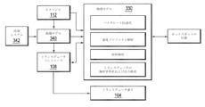
図1は、頭蓋骨を通して患者の脳に超音波を集束させるための例示的な超音波治療システム100を示す。しかしながら、当業者であれば、本明細書に記載の超音波システム100を人体のあらゆる部分に適用できることを理解するであろう。種々の実施形態では、システム100は、トランスデューサ素子104のフェーズドアレイ102、フェーズドアレイ102を駆動するビーム形成機106、ビーム形成機106と連通するコントローラ108、およびビーム形成機106に入力電子信号を供給する周波数発生機110を含む。種々の実施形態において、システムはさらに、患者116の頭蓋骨114の解剖学的特徴を決定するために、共鳴画像(MRI)デバイス、コンピュータ断層撮影(CT)デバイス、陽電子放出断層撮影(PET)デバイス、単光子放出コンピュータ断層撮影(SPECT)、または超音波検査デバイスなどのイメージャ112を含む。
FIG. 1 shows an exemplary
アレイ102は、頭蓋骨114の表面または頭蓋骨以外の身体部分に位置付けるのに適した湾曲した形状(例えば、球状または放物線状)を有してよく、または1または複数の平面もしくは他の形状の部分を含んでもよい。用途に応じて、その寸法は、ミリメートルから数十センチメートルの間で変えてもよい。アレイ102のトランスデューサ素子104は、圧電セラミック素子としてもよく、素子104間の機械的結合を減衰させるのに適した任意の材料に取り付けてもよい。圧電複合材料、または一般に電気エネルギーを音響エネルギーに変換できる材料を使用してもよい。トランスデューサ素子104への最大電力伝達を確実にするために、素子104は入力インピーダンスと電気的に整合するようになっていてよい。
The
トランスデューサ・アレイ102はビーム形成機106に結合され、ビーム形成機106は個々のトランスデューサ素子104を駆動して集束超音波ビームまたは集束超音波場を標的領域117で集中的に生成する。n個のトランスデューサ素子の場合、ビーム形成機106はn個のドライバ回路を含んでいてよい。各回路は増幅機118および位相遅延回路120を含むかまたはそれらから成る。ドライバ回路は、トランスデューサ素子104の1つを駆動する。ビーム形成機106は、周波数発生機110から、典型的には0.1MHzから5.0MHzの範囲における無線周波数(RF)入力信号を受信する。入力信号は、ビーム形成機106のn個の増幅機118および遅延回路120のために、n個のチャネルに分割されてもよい。いくらかの実施形態では、周波数発生機110はビーム形成機106と一体化されている。無線周波数発生機110およびビーム形成機106は、トランスデューサ・アレイ102の個々のトランスデューサ素子104を、同じ周波数であるが、異なる位相および/または異なる振幅にて駆動するようになっている。
The
ビーム形成機106によって課される増幅係数または減衰係数α1~αnおよび位相シフトa1~anは、超音波エネルギーを患者の頭蓋骨114を通して患者の脳の選択された領域に伝達および集束させるように働き、頭蓋骨114および柔らかい脳組織において誘発される波の歪みを説明する。増幅係数および位相シフトは、ソフトウェア、ハードウェア、ファームウェア、ハードワイヤリング、またはそれらの任意の組み合わせを通じて計算機能を提供し得るコントローラ108を使用して計算される。例えば、コントローラ108は、所望の焦点または他の望ましい空間場パターンを得るように必要な位相シフトおよび増幅係数を決定するために、過度の実験なしに従来の方法においてソフトウェアでプログラムされた汎用または専用デジタルデータプロセッサを利用してよい。特定の実施形態では、計算は、頭蓋骨114の特性(例えば、構造、厚さ、密度など)および音響エネルギーの伝播に対するそれらの既知の効果に関する詳細な情報に基づく。そのような情報は、以下でさらに記載されるようにイメージャ112から取得されてよい。画像取得は三次元であってもよく、あるいはその代わりに、イメージャ112は、頭蓋骨114の三次元画像を再構成するのに適した一組の二次元画像を提供してもよく、そこから厚さおよび密度を推測してもよい。従来の画像操作機能は、イメージャ112、コントローラ108、または別個のデバイスに実装してもよい。
Amplification or attenuation coefficients α 1 to α n and phase shifts a 1 to an imposed by the
システム100は、本発明の範囲内で様々な方法で変更してよい。例えば、診断用途のために、システムは、送信または反射された超音波を測定し、さらなる処理のために受信した信号をコントローラ108に提供することができる検出機デバイス122をさらに含んでもよい。反射信号および送信信号はまた、ビーム形成機106の位相および振幅調整のためのフィードバックとして使用されてもよい。システム100は、患者の頭蓋骨114に対してトランスデューサ素子104のアレイ102を配置するためのポジショナを含んでもよい。脳以外の身体部分に対する超音波治療に適用するために、トランスデューサ・アレイ102は異なる形状(例えば、シリンダ状、平坦形状など)をとってもよい。いくらかの実施形態では、トランスデューサ素子104は、移動可能および回転可能に取り付けられ、集束特性を改善するために利用することができる機械的自由度を提供する。そのような可動トランスデューサは、コントローラ108の構成要素によって、または別個の機械的コントローラによって駆動され得る従来のアクチュエータによって調整されてよい。
The
種々の実施形態において、イメージャ112はMRIデバイスである。図2を参照して、MRI装置200は、電磁石204のボア(bore)206内に必要な静磁場を発生させるシリンダ状の電磁石204を含んでいてよい。医療処置中、患者は可動支持クレードル208上のボア206の内側に位置付けられる。患者内の対象210の領域(例えば、患者の頭部)は、電磁石204が実質的に均一な場を生成する撮像領域212内に位置付けられてよい。一組のシリンダ状の磁場勾配コイル213もまた、ボア206内に設けて患者を囲んでよい。傾斜磁場コイル213は、所定の時間に、互いに直交する3つの方向に所定の大きさの磁場勾配を発生させる。磁場勾配により、異なる空間位置を異なる歳差運動周波数と関連付けることができ、それによってMR画像にその空間分解能を与える。撮像領域212を囲むRF送信機コイル214は、撮像領域212へとRFパルスを放射し、対象210の領域から放射されたMR応答信号を受信する(あるいは、別々のMR送信機コイルおよび受信機コイルを使用してもよい)。
In various embodiments, the
MRI装置200は一般に、パルスシーケンス、すなわち磁場勾配およびRF励起パルスの相対的なタイミングおよび強度、ならびに応答検出期間を制御するMRIコントローラ216を含む。MRIコントローラ216は、トランスデューサ・コントローラ108と組み合わされて統合システム制御設備にしてもよい。
The
MR応答信号は、画像処理システムを使用して増幅され、調整され、および生データにデジタル化され、ならびに、さらに当業者に公知の方法によって画像データのアレイに変換される。画像処理システムは、MRIコントローラ216の一部であってよく、またはMRIコントローラ216および/もしくはトランスデューサ・コントローラ108と連通する別個のデバイス(例えば、画像処理ソフトウェアを含む汎用コンピュータ)であってもよい。応答信号は組織および温度に依存するので、画像における治療標的領域117を識別すること、ならびに画像から温度マップを計算することを容易にする。さらに、超音波印加から生じる音響場を、例えばサーマルMRIまたはMRベースの音響放射力イメージングを使用して、リアルタイムで監視してもよい。したがって、MRIデータを使用して、標的組織および周囲組織の温度ならびに/または音響場強度を監視しながら、超音波を治療領域117内(またはその付近)に集束させるように超音波トランスデューサ102を駆動させてもよい。
The MR response signal is amplified, tuned, and digitized into raw data using an image processing system, and further converted into an array of image data by methods known to those of skill in the art. The image processing system may be part of the
図3Aを参照して、集束超音波処置中に、トランスデューサ素子104は、標的組織領域304に対応する(またはその内部の)焦点ゾーン302で集合的に焦点に集束する波を送信するように活性化される。焦点ゾーン302におけるエネルギー密度(強度)は均一であってもなくてもよい。例えば、1または複数の「ホットスポット」306が発生する場合がある。焦点ゾーン302におけるホットスポット306は、患者に過度の熱および著しい痛みを引き起こし得る。さらに、組織の不均一性に起因して、焦点ゾーン302以外の位置にホットスポット306が存在する場合がある。例えば、ホットスポット306は「近距離場(near field)」(すなわち、トランスデューサ・アレイ102と焦点ゾーン302との間の領域308)、ならびに「遠距離場(far field)」(すなわち、焦点ゾーン302を超えた領域310)に発生する場合がある。そのようなホットスポットは、近距離場および/または遠距離場において、非標的組織の望ましくない壊死を引き起こす場合がある。
With reference to FIG. 3A, during focused ultrasound treatment, the
焦点ゾーンおよび/または非焦点ゾーンにおける望ましくないホットスポット306を最小限に抑えるために、種々の実施形態では、イメージャ112(例えば、MRI装置200)は、標的組織および周囲組織における温度分布および/または音響場強度分布を監視し、監視する情報に基づいて、ホットスポットの位置を識別することができる。一実施形態では、識別されたホットスポットの位置に基づいて、ホットスポット306を最小限に抑えるために、トランスデューサ・パラメータ(例えば、トランスデューサ素子104の周波数、振幅、および/または位相、ならびに超音波処理時間)をさらに後述するように調整してもよい。それによって、焦点ゾーンおよび/または非焦点ゾーンにおいて実質的に均一な温度分布を達成してもよい。本明細書で使用される場合、所定の体積(volume)における「実質的に均一な(substantially uniform)」または「均一な(uniform)」温度分布は、所定の均一な体積内のポイント間の最大温度差が設定体積における平均温度の20%未満、好ましくは10%未満、より好ましくは5%未満であることを意味する。
In order to minimize
図3Bを参照して、種々の実施形態では、予測物理モデル330は、トランスデューサの活性化前にホットスポットの位置を予測するために使用される。予測モデルは、コントローラ108に実装されるか、またはシステム100内で、もしくはシステム100と連通する別の計算エンティティ(適切なプロセッサおよびメモリを含む計算エンティティ)内に実装されてよく、イメージャ112を使用して取得した情報を利用してもよい。例えば、MRI装置200は、ホットスポットの形成前の集束超音波処置の最初の数回の超音波処理中に、近距離場における温度および/または音響場強度分布を監視してもよい。この情報に基づいて、物理モデル330は、近距離場におけるホットスポットの予測される位置を予測し、その予測を焦点ゾーンおよび/または遠距離場へと拡張してもよい。一実施形態では、物理モデル330は、例えば、熱伝導または血液灌流による熱伝達、代謝熱の発生、および/または組織に加わったエネルギーの吸収を考慮して、組織内の温度変化および/または加熱過程を記述する少なくとも1つの微分(または積分)方程式(例えば、既知のPennesバイオヒート伝達式)を利用する。適切な初期条件および/または境界条件(例えば、治療開始時の既知の温度プロファイル、または対象ゾーンの境界の固定温度)によって補完された微分方程式は、対象ゾーンにおける温度変化および加熱過程をシミュレートするように、数値的に(場合によっては、特定の場合には解析的に)簡単に解くことができ、それによって、時間および/または空間の関数として(または時間および空間内の1または複数の選択された離散点で)温度を予測する。組織および血流パラメータならびに異なる組織における音速などのモデルパラメータにおける不確実性は、一般に予測の不正確さをもたらす場合がある。いくらかの実施形態において、これらの不確実性は、温度予測と連続超音波処理における測定された温度分布との比較に基づいてモデルパラメータを調整することによって(例えば、その差を最小にするための推定理論または回帰を用いて)低減される。
With reference to FIG. 3B, in various embodiments, the
物理モデル330は、必ずしも生物物理学的に組織内の温度変化および/または加熱過程をシミュレートする必要はない。むしろ、いくらかの実施形態において、物理モデル330は、調整可能な係数を有する解析的温度プロファイル(例えば、多項式の組合せまたは他の関数)を利用する。イメージャ112から測定温度および/または近距離場における音響場強度分布を取得すると、プロファイルを測定値に適合させるように、すなわち、測定温度と予測温度との間の誤差を最小にするようにモデル係数が調整される。
The
集束超音波処置中に温度および/または音響場強度分布に関する情報を取得することは、ホットスポットの位置を予測するために必要ではない場合があることを強調しておくべきである。種々の実施形態では、物理モデル330は、トランスデューサ素子104から伝達されるトランスデューサ素子104の幾何学形状、ならびに標的領域304に対するそれらの位置および配向、ならびに超音波の振幅、周波数および移送に関する保存された情報に基づいて、焦点ゾーンおよび非焦点ゾーンにおける温度分布を予測する。さらに、物理モデル330は、例えば、推定値/測定値からの電気インピーダンスの偏差、またはトランスデューサ素子104の製造中、使用中および修理中における、ならびに/もしくは素子104が熱によって変形する結果として、それらの予測される位置から移動または移動することから生じるトランスデューサの出力誤差(335で示す)を考慮に入れてもよい。トランスデューサの出力誤差を決定するためのアプローチは、例えば、米国特許第7535794号に提供されている。その内容は、参照により本明細書に組み込まれる。
It should be emphasized that obtaining information about temperature and / or acoustic field intensity distribution during focused ultrasound treatment may not be necessary to predict the location of hotspots. In various embodiments, the
さらに、物理モデル330は、ビーム経路に沿って材料特性(例えば、使用周波数における組織のエネルギー吸収または音速)などのパラメータを利用してもよい。材料特性は、上述のようなイメージャ112、および/または他の適切なデバイスを使用して収集してもよい。例えば、標的を取り囲みかつ超音波によって横断される組織が患者の頭蓋骨である場合、CTイメージングを使用して、頭蓋骨の解剖学的特徴(例えば、頭蓋骨の厚さ、頭蓋骨層、局所的骨密度、および/または表面領域もしくは近似曲率に対する法線を含む方向的特徴もしくは幾何学的特徴)を抽出してもよい。頭蓋骨領域216の局所幾何学モデルを作成する、または頭蓋骨領域216をマッピングする方法は、例えば、米国特許公開第2010/0179425号に記載されており、その全開示は参照により本明細書に組み込まれる。さらに、頭蓋骨の構造的不均一性は、頭蓋骨の微細構造レベルで定量化することができるインジケータ(または指標、indicator)を用いて特徴付けてもよい。インジケータは、イメージャ112を用いて取得された画像において測定された頭蓋骨密度に基づいて決定される。適切な方法は、米国特許公開第2016/0184026号に記載されており、その全開示は参照により本明細書に組み込まれる。
In addition, the
物理モデル330は、様々な頭蓋骨領域を通る音響経路を解析し、異なる頭蓋骨領域が異なる量のエネルギーをどのように反射および/または吸収し、異なる加熱プロファイルを有するかを推定し、焦点ゾーンの位置、焦点ゾーンおよび非焦点ゾーンにおける温度分布、ならびにホットスポット306の位置を予測する熱シミュレーションを実行してもよい。
The
ホットスポット306の予測される位置が(物理モデル330による測定および/または予測によって)識別された後、ホットスポットを補正または最小化するために種々のアプローチを利用してもよい。例えば、標的組織および/または周囲組織の材料特性を特徴付ける組織モデル340を使用して、より低い熱感度を有し、および/またはホットスポットの予測される位置付近の他の組織と比べてより高い熱エネルギーを許容できる予測されるホットスポットの位置付近の1または複数の領域を識別してもよい。組織モデル340は、標的組織および周囲組織を表すボクセルに対応するセルの三次元テーブル(three-dimensional table of cells)の形態をとってもよい。セルの値は、ホットスポットの管理に関連する、耐熱性などの組織の特性を表す。ボクセルは、イメージャ112によって断層撮影的に得られ、各ボクセルが表す組織のタイプは、従来の組織分析ソフトウェアによって自動的に決定することができる。決定された組織のタイプおよび組織パラメータのルックアップテーブル(例えば、組織のタイプによる耐熱性)を使用して、組織モデル340のセルが実装される(populated)。様々な組織の熱感度および/または熱エネルギー許容度を識別する組織モデルの作成に関するさらなる詳細は、米国特許公開第2012/0029396号に見出すことができ、その全開示は参照により本明細書に組み込まれる。
After the predicted location of the
種々の実施形態において、トランスデューサ・アレイ102と一体化した(または統合された、integral with)冷却システム(例えば、熱交換機)342を使用して、組織を能動的に冷却することによって、熱に対するより高い組織耐性が達成される。一体化冷却システム342は、熱交換機(または熱源)、好ましくは、冷却(または加熱)すべき組織の近くに配置された熱交換機と接しているアクセス可能な組織インターフェース(典型的には、皮膚または体外からアクセス可能な腔)を含んでいてもよい。熱交換機は、例えば、冷却しようとする表面に適合するバルーンの形態、または体表面と接触している水中に浸漬された固定形状の形態をとってもよい。冷却速度は、例えば、熱交換機を通るクーラントの流量を介して、またはクーラントの温度を介して制御してもよい。冷却システムはまた、皮膚と接触して配置され、温度が電子的に制御され得るバイメタルプレートまたはストライプなどの固体熱伝導部品によって提供されてもよい。冷却要素342は手動でまたは自動的に制御することができる。
In various embodiments, an integrated cooling system (eg, a heat exchanger) 342 integrated with (or integrated with) the
比較的高い温度に耐える組織領域が組織モデル340において識別されると、物理モデルは、ホットスポットがこれらの組織内に発生するように、少なくとも1つのトランスデューサ素子に関連する要求周波数を逆計算してもよい。第1超音波の周波数を変えることによって、第1超音波と他の超音波との干渉パターンを変えることができるので、この逆計算が可能である。干渉パターンを変えると、ホットスポットが発生する位置が変化する。例えば、図4を参照して、トランスデューサ素子104から放射された超音波が同じ周波数f0を有する場合、ホットスポットの位置は、上述のような測定および/またはモデル予測に基づいて位置402~408で発生すると予測され得る。トランスデューサ素子410の周波数をf0からf1に調整することによって、ホットスポットは異なる位置412~418で発生すると予測され得る。同様に、トランスデューサ素子420の周波数を変更することは、ホットスポットを他の位置422~428に移動させ得る。ホットスポットの位置の移動は、特定の点(ホットスポット)での吸収エネルギーを現象させ得る。したがって、種々の実施形態では、物理モデル330は、より低い熱感度を有し得る、および/または高温の熱に耐えることができる識別された再分配位置412~418、422~428に基づいてトランスデューサ素子410、420に関連する動的に変化する周波数を逆計算する。それによって、特定のホットスポットにおける蓄積エネルギー(つまり、温度上昇)を減少させるようにホットスポットの移動を引き起こす。それ故に、このアプローチは、いくつかのホットスポットにわたってエネルギーを平均するか、またはホットスポットを低い熱感度および/または高い熱エネルギー耐性を有する領域に向けることによって、標的領域および/または非標的領域における組織損傷を最小限に抑える。
Once the tissue regions that withstand relatively high temperatures have been identified in the
上述のように、トランスデューサ・コントローラ108は、物理モデル330および/または組織モデル340を実装してもよく、または代わりに物理モデルに応答してよく、必要に応じて組織モデルをアドレス指定してもよい。いずれの場合も、トランスデューサ・コントローラ108は、位置412~418、422~428にホットスポットを生成する超音波周波数(単数の超音波周波数、または複数の超音波周波数)を計算し得るだけでなく、この周波数(単数の周波数、または複数の周波数)を時間とともに動的に変化させ得る。このようにして、トランスデューサ・コントローラ108は、ホットスポットの位置を予測される位置の間で前後にシフトさせる。これは、標的組織内およびその周囲の組織の特性に適応する別の制御因子を表し、ホットスポットが、組織に臨床的に悪影響を及ぼすような時間量の間、どの場所にも持続しないことを確実にする。したがって、所定の時間間隔内にホットスポットが異なる位置間をジャンプし得るので、特定のホットスポットでの蓄積エネルギー(およびその結果生じる温度上昇)が減少する。
As mentioned above, the
代替的に、トランスデューサ・コントローラ108は、トランスデューサ素子の周波数をランダムに変化させてよい。それによって、ホットスポットを様々な場所、すなわち、位置402~408から位置412~418、および位置422~428に発生させ得る。本実施形態での再分配ホットスポットの位置412~418、422~428における組織は、予測ホットスポットの位置402~408における組織よりも必ずしも熱感度が低いおよび/またはより高い熱エネルギーを許容するわけではないが、それらは互いに異なり、測定された/予測されたホットスポットの位置402~408とは異なることが好ましい。超音波周波数の時間的調整は、比較的少数のホットスポットの位置402~408から、より多数のホットスポットの位置402~408、412~418および422~428に超音波エネルギーを分散させてもよい。このアプローチは、エネルギーを複数のスポット間に分散させることによって特定のホットスポットでのエネルギー蓄積を減少させ得る。トランスデューサ素子に関連する周波数は、離散的にまたは連続的に変化させてもよい。さらに、それらは集束超音波処置の超音波処理中に周期的に変化させてもよい。
Alternatively, the
焦点ゾーン302の位置は、送信波の周波数を変化させることによって変化させてもよい。いくらかの実施形態では、標的組織領域304に焦点を維持するために、トランスデューサ素子104に供給される駆動信号の位相および/または振幅は、周波数で同時に調整される。再度、位相および/または振幅の調整は、物理モデルを使用して決定されてもよい。
The position of the
付加的または代替的に、物理モデル330は、ホットスポットを説明するために、トランスデューサ素子104に関連する他のパラメータ値を調整してもよい(または結果として他のパラメータ値の調整をもたらしてもよい)。例えば、図4B参照をして、物理モデル330は、少なくともいくつかのトランスデューサ素子104の出力強度におけるシミュレートされた変動に基づいて、焦点ゾーン302における最大強度I2に対するホットスポット430における最大強度I1の比の影響をシミュレートし得る。シミュレートされた影響に基づいて、計算された強度比を減少させるために、いくつかのトランスデューサ要素104の波強度および/または波位相を調整し、それによって、ホットスポットによって引き起こされる温度不均一性の影響を減少させ得る。例えば、物理モデル330は、焦点において最小強度を維持する必要性によって制約されるトランスデューサ強度における可能性のある変動の空間を調査してもよい。シンプレックス・アルゴリズムまたは他の従来の線形計画法を使用して、この制約はシミュレーションを計算上扱いやすくし、解が見つかるかどうかを保証する。
Additional or alternative, the
さらに他の実施形態では、図4Cを参照して、物理モデル330は、周囲組織を横断した後、各トランスデューサ素子104から寄与される焦点ゾーン302での音響エネルギーを推定する。付加的または代替的に、素子104からのエネルギー寄与は、例えば、音響放射力インパルス(ARFI)イメージングを使用して測定してもよい。焦点ゾーンにおけるトランスデューサ素子440からの寄与が閾値を下回る場合、それは、標的304を取り囲む横断組織による素子440から放出されたエネルギーの過度の反射および/または吸収によるものとなる。したがって、一実施形態では、焦点ゾーン302でのエネルギー寄与が閾値を下回るトランスデューサ素子104から送信される波の強度は、介在するホットスポットが発生する可能性を低減するように減少させてもよい。
In yet another embodiment, with reference to FIG. 4C, the
種々の実施形態では、ビームフォーミングを使用してホットスポットを減少もしくは除去するか、または(上述のようにビーム経路内の組織の耐熱性に対して)平均エネルギーが臨床上許容される最大値を下回るように動的にシフトする。特に、ビーム形成を使用して、送信された超音波の干渉パターンを制御する。例えば、いくつかのトランスデューサ素子に関連する時間遅延は、時変干渉パターンを生成するように調整されてもよい。やはり、各干渉パターンは、異なる位置で波増幅(例えば、ホットスポットとしてみなすのに十分に大きい波増幅)を有する場合があるので、少なくともいくつかのトランスデューサ素子に関連する時間遅延を動的に変えることは、望ましくないホットスポットのエネルギーを様々な場所に再分配し得る。例えば、図4Dを参照して、2つのトランスデューサ素子から放射される超音波450、452がそれらの間に時間遅延d1を有する場合、ホットスポットの位置は位置454、456で発生し得る。d1からd2までの時間遅延を調整することによって、ホットスポットの位置は、異なる位置458、460に発生する。したがって、ホットスポットを様々な場所に分配することは、結果として生じる温度分布を均等にし得る。
In various embodiments, beamforming is used to reduce or eliminate hotspots, or the average energy (with respect to the heat resistance of the tissue in the beam path as described above) is the maximum clinically acceptable value. Dynamically shift below. In particular, beam formation is used to control the interference pattern of transmitted ultrasonic waves. For example, the time delay associated with some transducer elements may be adjusted to produce a time-varying interference pattern. Again, each interference pattern may have wave amplification at different locations (eg, wave amplification large enough to be considered as a hotspot), thus dynamically changing the time delay associated with at least some transducer elements. That can redistribute the energy of unwanted hotspots to various locations. For example, with reference to FIG. 4D, if the
ホットスポットの補正は、少なくともいくつかのトランスデューサ素子を選択的に活性化および非活性化することによっても達成してもよい。図4Eを参照して、種々の実施形態では、トランスデューサ・アレイ102は、複数のサブ領域470~478に分割されている。各サブ領域は、トランスデューサ素子104の一次元または二次元アレイ(すなわち、行または行列)を含んで成る。サブ領域470~478は、別々に制御可能であり得る。すなわち、サブ領域はそれぞれ、他のサブ領域470~478の振幅、周波数、および/または位相とは独立している振幅、周波数、および/または位相にて超音波を放射することができる。一実施形態では、サブ領域470~478は、超音波を標的領域に送信するために、一度に1つずつ選択的に活性化および非活性化される。各サブ領域は、物理モデルによって決定されるように、互いに異なる振幅、周波数、および/または位相を割り当てられてもよい。図4Eに示すように、サブ領域470の活性化は、標的領域304に焦点ゾーン302を、また位置482、484に望ましくないホットスポットを発生させる場合がある。一方、別のサブ領域474の活性化は、同じ焦点ゾーン302であるが、位置482、484とは異なる位置486、488に望ましくないホットスポットを有する焦点ゾーン302に集束ビームを生成し得る。したがって、異なるサブ領域の活性化は、標的領域304に共通の焦点領域302を生成し得るが、周囲組織の異なる位置482~488には望ましくないホットスポットを伴う。したがって、トランスデューサ素子104の異なるサブ領域470~478を選択的に活性化および非活性化することによって、ホットスポットは様々な場所に分配され、かかるホットスポットがいずれの1箇所の位置に、非標的組織に対して臨床的に有害な影響を引き起こす時間量では存続しない。このエネルギー分散は、結果として生じる温度分布の均一性を改善し、ホットスポットに起因する組織損傷を防ぐ。
Hotspot correction may also be achieved by selectively activating and deactivating at least some transducer devices. With reference to FIG. 4E, in various embodiments, the
図5は、種々の実施形態による集束超音波処置中に標的組織および周囲組織におけるホットスポットを最小限に抑えるためのアプローチを示すフローチャート500である。第1ステップ502において、ホットスポットの位置は超音波処置中に識別される。例えば、ホットスポットの位置は、イメージャを使用して識別され位置特定されてもよい。代替的に、イメージャは、最初の数回の超音波処理中に近距離場における温度および/または音響場強度分布を測定してもよい。測定温度および/または音響場強度分布に基づいて、物理モデルは、近距離場、焦点ゾーン、および/または遠距離場におけるホットスポットの位置を予測してもよい。いくらかの実施形態では、イメージャは標的(および/またはトランスデューサ素子)の位置を識別するために使用される。つまり、温度および/または音響場強度分布の測定は必要とされない。物理モデルは、トランスデューサ素子の幾何学形状、ならびに標的領域に対するそれらの位置および配向、振幅、周波数、ならびに超音波の位相、および/または標的組織および周囲組織の材料特性に基づいて、ホットスポットの位置を予測することができる。第2ステップ504において、ホットスポットの測定位置および/または予測位置に基づいて、物理モデルは、ホットスポットを補正するために、トランスデューサ素子に関連する1または複数のパラメータ値(例えば、周波数、振幅、および/または時間遅延)を変えるための時間的パターンを決定してもよい。第3ステップにおいて、トランスデューサ素子のパラメータ値は、決定された時間的パターンに基づいて調整される(ステップ506)。いくらかの実施形態では、物理モデルは、識別されたホットスポットの位置に基づいて、ホットスポットを補正するためにトランスデューサ素子の各サブ領域を活性化および非活性化するための時間的パターンを決定する(ステップ508)。次に、トランスデューサ素子は、決定された時間的パターンに基づいて活性化および非活性化される(ステップ510)。したがって、本発明は、焦点ゾーンおよび非焦点ゾーンに発生するホットスポットを効果的に最小限に抑える様々なアプローチを提供する。これは、周囲の健康な組織が損傷を受けることを回避しながら、標的領域が均一に加熱されることを有利に可能にする。
FIG. 5 is a
一般に、上述するように、イメージャを使用して取得された標的組織および周囲組織の画像データを分析すること、画像データに基づいて、標的組織および/または周囲組織における温度および/または音響場強度分布を決定すること標的組織および/または周囲組織に位置するホットスポットを識別すること、(予測物理モデル、イメージャ、ならびに/または頭蓋骨からの超音波送信および/もしくは超音波反射の測定値を使用して)標的組織および/または周囲組織の材料特性を取得すること、標的組織および周囲組織におけるホットスポットの位置を予測すること、時間的に変化するパターンを計算すること、またはトランスデューサのパラメータ値(例えば、周波数、振幅、時間遅延など)の調整、ならびに/またはトランスデューサ・アレイのサブ領域の活性化および非活性化を含む、標的組織および/または周囲組織におけるホットスポットを最小限に抑える機能は、
イメージャのコントローラ内に、および/もしくは超音波システム内に一体化されているか、または別個の外部コントローラもしくは他の計算エンティティ(単数の計算エンティティ、もしくは複数の計算エンティティ)によって提供されるかどうかにかかわらず、ハードウェア、ソフトウェア、またはその両方の組合せで実装される1または複数のモジュールで構成してもよい。機能が1または複数のソフトウェアプログラムとして提供される実施形態では、プログラムは、FORTRAN、PASCAL、JAVA(登録商標)、C、C++、C#、BASIC、様々なスクリプト言語および/またはHTMLなどのいくらかの高レベル言語のいずれかで書かれてもよい。さらに、ソフトウェアは、対象コンピュータ(例えば、コントローラ)に存するマイクロプロセッサに向けられたアセンブリ言語で実装することができる。例えば、ソフトウェアが、IBM PCまたはPCクローンにおいて動作するように構成されている場合、インテル80x86アセンブリ言語で実装してもよい。ソフトウェアは、限定されないが、フロッピー(登録商標)ディスク、ジャンプドライブ、ハードディスク、光ディスク、磁気テープ、PROM、EPROM、EEPROM、フィールド-プログラマブル・ゲートアレイまたはCD-ROMを含む製品で具体的に表現されてもよい。ハードウェア回路を使用する態様は、例えば、1または複数のFPGA、CPLDまたはASICプロセッサを使用して実装してもよい。
In general, as described above, the image data of the target and surrounding tissues obtained using an imager is analyzed, and the temperature and / or acoustic field intensity distribution in the target tissue and / or the surrounding tissue is based on the image data. To identify hotspots located in the target tissue and / or surrounding tissue (using predictive physical models, imagers, and / or measurements of ultrasonic transmission and / or ultrasonic reflection from the skull). ) Obtaining material properties of the target and / or surrounding tissue, predicting the location of hotspots in the target and surrounding tissue, calculating temporally changing patterns, or transducer parameter values (eg,). Ability to minimize hotspots in the target and / or surrounding tissue, including tuning (frequency, amplitude, time delay, etc.) and / or activating and deactivating subregions of the transducer array.
Whether integrated within the imager's controller and / or within the ultrasound system, or provided by a separate external controller or other computing entity (single or multiple computing entities). Instead, it may consist of one or more modules implemented in hardware, software, or a combination of both. In embodiments where the function is provided as one or more software programs, the program may have some such as FORTRAN, PASCAL, JAVA®, C, C ++, C #, BASIC, various scripting languages and / or HTML. It may be written in any of the higher level languages. In addition, the software can be implemented in assembly language directed to the microprocessor present on the target computer (eg, controller). For example, if the software is configured to work on an IBM PC or PC clone, it may be implemented in Intel 80x86 assembly language. Software is specifically represented by products including, but not limited to, floppy (registered trademark) disks, jump drives, hard disks, optical discs, magnetic tapes, PROMs, EPROMs, EEPROMs, field-programmable gate arrays or CD-ROMs. May be good. The embodiment using a hardware circuit may be implemented using, for example, one or more FPGAs, CPLDs or ASIC processors.
さらに、本明細書で使用される「コントローラ(controller)」という用語は、上述するような任意の機能を実行するために利用されるすべての必要なハードウェア構成要素および/またはソフトウェアモジュールを広く含む。コントローラは、複数のハードウェア構成要素および/またはソフトウェアモジュールを含んでもよく、機能は、異なる構成要素および/またはモジュール間で展開することができる。 Further, the term "controller" as used herein broadly includes all necessary hardware components and / or software modules utilized to perform any function as described above. .. The controller may include multiple hardware components and / or software modules, and functionality can be deployed between different components and / or modules.
本発明の特定の実施形態が上記に記載されている。しかしながら、本発明は、これらの実施形態に限定されないことに明確に留意されたい。むしろ、本明細書に明示的に記載されているものに対する追加および変更もまた、本発明の範囲内に含まれる。 Specific embodiments of the invention are described above. However, it should be clearly noted that the invention is not limited to these embodiments. Rather, additions and modifications to those expressly described herein are also included within the scope of the invention.
Claims (14)
(a)前記超音波トランスデューサを、各々が複数のトランスデューサ素子を含んで成る複数のサブ領域に分割すること、
(b)超音波処理プロセス中に、前記標的領域または該標的領域の周囲領域のうちの少なくとも一方における所定の許容レベルを超えるエネルギー密度を有する少なくとも1つのホットスポットの位置を識別すること、
(b)前記識別されたホットスポットの位置に少なくとも部分的に基づいて、前記ホットスポットの時間平均エネルギー密度を前記所定の許容レベルまで減少させる少なくとも1つのトランスデューサ素子の出力パラメータに対する時間的変動を計算し、各サブ領域の活性化パターンおよび非活性化パターンを計算すること、ならびに
(d)前記出力パラメータの時間的変動を達成するように、前記活性化パターンおよび前記非活性化パターンに少なくとも部分的に基づいて、超音波処理を停止することなく前記トランスデューサ素子の各サブ領域を動作させることを含んで成る方法。 A method of operating a system that heats a target area using an ultrasonic transducer having multiple transducer elements.
(A) Dividing the ultrasonic transducer into a plurality of subregions each comprising a plurality of transducer elements.
(B) Identifying the location of at least one hotspot having an energy density above a predetermined acceptable level in at least one of the target area or the surrounding area of the target area during the sonication process.
(B) Calculate the temporal variation with respect to the output parameter of at least one transducer element that reduces the time average energy density of the hotspot to the predetermined permissible level, at least partially based on the location of the identified hotspot. And calculate the activation and deactivation patterns of each subregion, and (d) at least partially to the activation and deactivation patterns to achieve temporal variation of the output parameters. A method comprising operating each subregion of the transducer element based on, without stopping the sonication.
超音波トランスデューサおよびコントローラを有して成り、
前記超音波トランスデューサは、複数のトランスデューサ素子を有して成り、
前記コントローラは、
(a)前記超音波トランスデューサを、各々が複数のトランスデューサ素子を含んで成る複数のサブ領域に分割するようになっており、
(b)超音波処理プロセス中に、前記標的領域または該標的領域の周囲領域のうちの少なくとも一方における所定の許容レベルを超えるエネルギー密度を有する少なくとも1つのホットスポットの位置を識別するようになっており、
(c)前記識別されたホットスポットの位置に少なくとも部分的に基づいて、前記ホットスポットの時間平均エネルギー密度を前記所定の許容レベルまで減少させる少なくとも1つのトランスデューサ素子の出力パラメータに対する時間的変動を計算し、各サブ領域の活性化パターンおよび非活性化パターンを計算するようになっており、ならびに
(d)前記出力パラメータの時間的変動を達成するように、前記活性化パターンおよび前記非活性化パターンに少なくとも部分的に基づいて、超音波処理を停止することなく前記トランスデューサ素子の各サブ領域を動作させるようになっている、システム。 A system for heating the target area
Consists of having an ultrasonic transducer and controller
The ultrasonic transducer is composed of a plurality of transducer elements.
The controller
(A) The ultrasonic transducer is divided into a plurality of subregions each including a plurality of transducer elements.
(B) During the sonication process, the location of at least one hotspot having an energy density above a predetermined permissible level in at least one of the target region or the surrounding region of the target region has been identified. Ori,
(C) Calculate the temporal variation with respect to the output parameter of at least one transducer element that reduces the time average energy density of the hotspot to the predetermined permissible level, at least partially based on the location of the identified hotspot. The activation and deactivation patterns of each subregion are then calculated, and (d) the activation and deactivation patterns to achieve temporal variation of the output parameters. A system that is adapted to operate each subregion of the transducer element without stopping sonication, at least in part.
Priority Applications (1)
| Application Number | Priority Date | Filing Date | Title |
|---|---|---|---|
| JP2022000522A JP7335367B2 (en) | 2017-01-12 | 2022-01-05 | Overcoming Acoustic Field and Skull Heterogeneity |
Applications Claiming Priority (3)
| Application Number | Priority Date | Filing Date | Title |
|---|---|---|---|
| US15/404,412 US11103731B2 (en) | 2017-01-12 | 2017-01-12 | Overcoming acoustic field and skull non-uniformities |
| US15/404,412 | 2017-01-12 | ||
| PCT/IB2017/001689 WO2018130867A1 (en) | 2017-01-12 | 2017-12-13 | Overcoming acoustic field and skull non-uniformities |
Related Child Applications (1)
| Application Number | Title | Priority Date | Filing Date |
|---|---|---|---|
| JP2022000522A Division JP7335367B2 (en) | 2017-01-12 | 2022-01-05 | Overcoming Acoustic Field and Skull Heterogeneity |
Publications (3)
| Publication Number | Publication Date |
|---|---|
| JP2020505095A JP2020505095A (en) | 2020-02-20 |
| JP2020505095A5 JP2020505095A5 (en) | 2020-10-08 |
| JP7041682B2 true JP7041682B2 (en) | 2022-03-24 |
Family
ID=61258564
Family Applications (3)
| Application Number | Title | Priority Date | Filing Date |
|---|---|---|---|
| JP2019536831A Active JP7041682B2 (en) | 2017-01-12 | 2017-12-13 | Overcoming acoustic field and skull heterogeneity |
| JP2022000522A Active JP7335367B2 (en) | 2017-01-12 | 2022-01-05 | Overcoming Acoustic Field and Skull Heterogeneity |
| JP2023097063A Withdrawn JP2023116673A (en) | 2017-01-12 | 2023-06-13 | Overcoming acoustic field and skull non-uniformities |
Family Applications After (2)
| Application Number | Title | Priority Date | Filing Date |
|---|---|---|---|
| JP2022000522A Active JP7335367B2 (en) | 2017-01-12 | 2022-01-05 | Overcoming Acoustic Field and Skull Heterogeneity |
| JP2023097063A Withdrawn JP2023116673A (en) | 2017-01-12 | 2023-06-13 | Overcoming acoustic field and skull non-uniformities |
Country Status (5)
| Country | Link |
|---|---|
| US (2) | US11103731B2 (en) |
| EP (1) | EP3568202A1 (en) |
| JP (3) | JP7041682B2 (en) |
| CN (1) | CN110177599B (en) |
| WO (1) | WO2018130867A1 (en) |
Families Citing this family (14)
| Publication number | Priority date | Publication date | Assignee | Title |
|---|---|---|---|---|
| CN107427695B (en) | 2015-03-09 | 2019-08-16 | 纽约州立大学研究基金会 | For organizational protection, reparation and the regenerated system and method for promoting cell activity |
| US11103731B2 (en) * | 2017-01-12 | 2021-08-31 | Insightec, Ltd. | Overcoming acoustic field and skull non-uniformities |
| US11123575B2 (en) | 2017-06-29 | 2021-09-21 | Insightec, Ltd. | 3D conformal radiation therapy with reduced tissue stress and improved positional tolerance |
| CN111712301B (en) | 2017-12-11 | 2022-07-22 | 医视特有限公司 | Adaptive closed-loop ultrasound therapy |
| US11813484B2 (en) | 2018-11-28 | 2023-11-14 | Histosonics, Inc. | Histotripsy systems and methods |
| JP7201819B2 (en) * | 2018-12-18 | 2023-01-10 | インサイテック・リミテッド | Echo-based focus correction |
| US11684807B2 (en) * | 2018-12-27 | 2023-06-27 | Insightec Ltd. | Optimization of transducer configurations in ultrasound procedures |
| US20200384292A1 (en) * | 2019-06-07 | 2020-12-10 | The Board Of Trustees Of The Leland Stanford Junior University | Pattern Interference Radiation Force (PIRF) neural stimulators |
| WO2021014221A1 (en) | 2019-07-25 | 2021-01-28 | Insightec, Ltd. | Aberration corrections for dynamically changing media during ultrasound therapy |
| WO2021123906A1 (en) * | 2019-12-18 | 2021-06-24 | Insightec, Ltd. | Adaptive single-bubble-based autofocusing and power adjustment in ultrasound procedures |
| AU2021213168A1 (en) | 2020-01-28 | 2022-09-01 | The Regents Of The University Of Michigan | Systems and methods for histotripsy immunosensitization |
| CN111589001B (en) * | 2020-06-10 | 2022-03-01 | 浙江大学 | Array type ultrasonic therapy system |
| WO2022106891A1 (en) * | 2020-11-18 | 2022-05-27 | Insightec, Ltd. | Multiparametric optimization for ultrasound procedures |
| WO2023105290A1 (en) | 2021-12-10 | 2023-06-15 | Insightec, Ltd. | Short-pulse sonodynamic treatment apparatus |
Citations (2)
| Publication number | Priority date | Publication date | Assignee | Title |
|---|---|---|---|---|
| US20110270136A1 (en) | 2010-04-28 | 2011-11-03 | Shuki Vitek | Efficient ultrasound focusing |
| JP2013544552A (en) | 2010-10-15 | 2013-12-19 | コーニンクレッカ フィリップス エヌ ヴェ | Therapy device for heating a subject |
Family Cites Families (19)
| Publication number | Priority date | Publication date | Assignee | Title |
|---|---|---|---|---|
| US4620546A (en) * | 1984-06-30 | 1986-11-04 | Kabushiki Kaisha Toshiba | Ultrasound hyperthermia apparatus |
| JPH06315541A (en) * | 1993-03-12 | 1994-11-15 | Toshiba Corp | Medical treatment device using image diagnostic device |
| EP0627206B1 (en) | 1993-03-12 | 2002-11-20 | Kabushiki Kaisha Toshiba | Apparatus for ultrasound medical treatment |
| US6419648B1 (en) * | 2000-04-21 | 2002-07-16 | Insightec-Txsonics Ltd. | Systems and methods for reducing secondary hot spots in a phased array focused ultrasound system |
| US6613005B1 (en) | 2000-11-28 | 2003-09-02 | Insightec-Txsonics, Ltd. | Systems and methods for steering a focused ultrasound array |
| CN1966108A (en) * | 2005-11-16 | 2007-05-23 | 上海爱申科技发展股份有限公司 | HIFU tumour ablation system |
| US7652410B2 (en) * | 2006-08-01 | 2010-01-26 | Insightec Ltd | Ultrasound transducer with non-uniform elements |
| US7535794B2 (en) | 2006-08-01 | 2009-05-19 | Insightec, Ltd. | Transducer surface mapping |
| US8556888B2 (en) * | 2006-08-04 | 2013-10-15 | INTIO, Inc. | Methods and apparatuses for performing and monitoring thermal ablation |
| US20100179425A1 (en) | 2009-01-13 | 2010-07-15 | Eyal Zadicario | Systems and methods for controlling ultrasound energy transmitted through non-uniform tissue and cooling of same |
| US9174065B2 (en) * | 2009-10-12 | 2015-11-03 | Kona Medical, Inc. | Energetic modulation of nerves |
| CN103180014B (en) * | 2010-07-29 | 2016-12-28 | 因赛泰克有限公司 | Motion compensation for the treatment therapy of Noninvasive |
| CN104244818B (en) * | 2012-02-06 | 2017-04-12 | 因赛泰克有限公司 | Reference-based motion tracking during non-invasive therapy |
| US20130296743A1 (en) | 2012-05-02 | 2013-11-07 | Siemens Medical Solutions Usa, Inc. | Ultrasound for Therapy Control or Monitoring |
| DK3446742T3 (en) * | 2013-03-15 | 2023-09-04 | Carewear Corp | Light therapy unit |
| CA3177417A1 (en) * | 2014-04-18 | 2015-10-22 | Ulthera, Inc. | Band transducer ultrasound therapy |
| US10456603B2 (en) | 2014-12-10 | 2019-10-29 | Insightec, Ltd. | Systems and methods for optimizing transskull acoustic treatment |
| US9941542B1 (en) * | 2016-09-16 | 2018-04-10 | Kitty Hawk Corporation | Battery assembly techniques |
| US11103731B2 (en) * | 2017-01-12 | 2021-08-31 | Insightec, Ltd. | Overcoming acoustic field and skull non-uniformities |
-
2017
- 2017-01-12 US US15/404,412 patent/US11103731B2/en active Active
- 2017-12-13 JP JP2019536831A patent/JP7041682B2/en active Active
- 2017-12-13 WO PCT/IB2017/001689 patent/WO2018130867A1/en unknown
- 2017-12-13 CN CN201780083190.XA patent/CN110177599B/en active Active
- 2017-12-13 EP EP17844605.0A patent/EP3568202A1/en active Pending
-
2021
- 2021-05-12 US US17/318,428 patent/US20210268316A1/en active Pending
-
2022
- 2022-01-05 JP JP2022000522A patent/JP7335367B2/en active Active
-
2023
- 2023-06-13 JP JP2023097063A patent/JP2023116673A/en not_active Withdrawn
Patent Citations (2)
| Publication number | Priority date | Publication date | Assignee | Title |
|---|---|---|---|---|
| US20110270136A1 (en) | 2010-04-28 | 2011-11-03 | Shuki Vitek | Efficient ultrasound focusing |
| JP2013544552A (en) | 2010-10-15 | 2013-12-19 | コーニンクレッカ フィリップス エヌ ヴェ | Therapy device for heating a subject |
Also Published As
| Publication number | Publication date |
|---|---|
| JP2023116673A (en) | 2023-08-22 |
| WO2018130867A1 (en) | 2018-07-19 |
| US20210268316A1 (en) | 2021-09-02 |
| JP2022046743A (en) | 2022-03-23 |
| JP2020505095A (en) | 2020-02-20 |
| US20180193675A1 (en) | 2018-07-12 |
| EP3568202A1 (en) | 2019-11-20 |
| US11103731B2 (en) | 2021-08-31 |
| CN110177599B (en) | 2022-01-25 |
| JP7335367B2 (en) | 2023-08-29 |
| CN110177599A (en) | 2019-08-27 |
Similar Documents
| Publication | Publication Date | Title |
|---|---|---|
| JP7041682B2 (en) | Overcoming acoustic field and skull heterogeneity | |
| CN109091768B (en) | Ultrasound focusing using cross-point switch matrix | |
| US20180361174A1 (en) | High Intensity Focused Ultrasound Transducer Optimization | |
| US9205282B2 (en) | System and method for control and monitoring of conformal thermal therapy | |
| JP6442788B2 (en) | Frequency optimization in ultrasonic treatment | |
| US7699780B2 (en) | Focused ultrasound system with adaptive anatomical aperture shaping | |
| EP2950737B1 (en) | Simulation-based focused-ultrasound treatment planning | |
| US20120191020A1 (en) | Uniform thermal treatment of tissue interfaces | |
| CN113329788B (en) | Optimization of transducer configuration in ultrasound surgery | |
| JP2022541604A (en) | Aberration correction for dynamically changing media during ultrasound therapy | |
| CN115135381A (en) | Adaptive single bubble based autofocus and power adjustment in ultrasound procedures | |
| JP2022501080A (en) | Improved automatic reflex focusing | |
| WO2020058757A1 (en) | Ultrasound focusing utilizing a 3d-printed skull replica | |
| US10765892B1 (en) | Systems and methods for optimizing transcranial ultrasound focusing | |
| US20230398381A1 (en) | Multiparametric optimization for ultrasound procedures | |
| Arora et al. | Thermal dose control of ultrasound therapies using MR thermometry images: an in-vitro phantom study |
Legal Events
| Date | Code | Title | Description |
|---|---|---|---|
| A521 | Request for written amendment filed |
Free format text: JAPANESE INTERMEDIATE CODE: A523 Effective date: 20200826 |
|
| A621 | Written request for application examination |
Free format text: JAPANESE INTERMEDIATE CODE: A621 Effective date: 20200826 |
|
| A977 | Report on retrieval |
Free format text: JAPANESE INTERMEDIATE CODE: A971007 Effective date: 20210618 |
|
| A131 | Notification of reasons for refusal |
Free format text: JAPANESE INTERMEDIATE CODE: A131 Effective date: 20210622 |
|
| A521 | Request for written amendment filed |
Free format text: JAPANESE INTERMEDIATE CODE: A523 Effective date: 20210831 |
|
| A02 | Decision of refusal |
Free format text: JAPANESE INTERMEDIATE CODE: A02 Effective date: 20211019 |
|
| A521 | Request for written amendment filed |
Free format text: JAPANESE INTERMEDIATE CODE: A523 Effective date: 20220105 |
|
| C60 | Trial request (containing other claim documents, opposition documents) |
Free format text: JAPANESE INTERMEDIATE CODE: C60 Effective date: 20220105 |
|
| C11 | Written invitation by the commissioner to file amendments |
Free format text: JAPANESE INTERMEDIATE CODE: C11 Effective date: 20220118 |
|
| A911 | Transfer to examiner for re-examination before appeal (zenchi) |
Free format text: JAPANESE INTERMEDIATE CODE: A911 Effective date: 20220215 |
|
| C21 | Notice of transfer of a case for reconsideration by examiners before appeal proceedings |
Free format text: JAPANESE INTERMEDIATE CODE: C21 Effective date: 20220222 |
|
| TRDD | Decision of grant or rejection written | ||
| A01 | Written decision to grant a patent or to grant a registration (utility model) |
Free format text: JAPANESE INTERMEDIATE CODE: A01 Effective date: 20220308 |
|
| A61 | First payment of annual fees (during grant procedure) |
Free format text: JAPANESE INTERMEDIATE CODE: A61 Effective date: 20220311 |
|
| R150 | Certificate of patent or registration of utility model |
Ref document number: 7041682 Country of ref document: JP Free format text: JAPANESE INTERMEDIATE CODE: R150 |