JP7041605B2 - Systems and methods for pivoting the printhead in a direct-to-object printer while printing an object - Google Patents
Systems and methods for pivoting the printhead in a direct-to-object printer while printing an object Download PDFInfo
- Publication number
- JP7041605B2 JP7041605B2 JP2018199741A JP2018199741A JP7041605B2 JP 7041605 B2 JP7041605 B2 JP 7041605B2 JP 2018199741 A JP2018199741 A JP 2018199741A JP 2018199741 A JP2018199741 A JP 2018199741A JP 7041605 B2 JP7041605 B2 JP 7041605B2
- Authority
- JP
- Japan
- Prior art keywords
- actuator
- print head
- controller
- printhead
- frame
- Prior art date
- Legal status (The legal status is an assumption and is not a legal conclusion. Google has not performed a legal analysis and makes no representation as to the accuracy of the status listed.)
- Active
Links
Images


Classifications
-
- B—PERFORMING OPERATIONS; TRANSPORTING
- B41—PRINTING; LINING MACHINES; TYPEWRITERS; STAMPS
- B41J—TYPEWRITERS; SELECTIVE PRINTING MECHANISMS, i.e. MECHANISMS PRINTING OTHERWISE THAN FROM A FORME; CORRECTION OF TYPOGRAPHICAL ERRORS
- B41J25/00—Actions or mechanisms not otherwise provided for
- B41J25/001—Mechanisms for bodily moving print heads or carriages parallel to the paper surface
-
- B—PERFORMING OPERATIONS; TRANSPORTING
- B41—PRINTING; LINING MACHINES; TYPEWRITERS; STAMPS
- B41J—TYPEWRITERS; SELECTIVE PRINTING MECHANISMS, i.e. MECHANISMS PRINTING OTHERWISE THAN FROM A FORME; CORRECTION OF TYPOGRAPHICAL ERRORS
- B41J3/00—Typewriters or selective printing or marking mechanisms characterised by the purpose for which they are constructed
- B41J3/407—Typewriters or selective printing or marking mechanisms characterised by the purpose for which they are constructed for marking on special material
- B41J3/4073—Printing on three-dimensional objects not being in sheet or web form, e.g. spherical or cubic objects
-
- B—PERFORMING OPERATIONS; TRANSPORTING
- B41—PRINTING; LINING MACHINES; TYPEWRITERS; STAMPS
- B41J—TYPEWRITERS; SELECTIVE PRINTING MECHANISMS, i.e. MECHANISMS PRINTING OTHERWISE THAN FROM A FORME; CORRECTION OF TYPOGRAPHICAL ERRORS
- B41J29/00—Details of, or accessories for, typewriters or selective printing mechanisms not otherwise provided for
- B41J29/02—Framework
-
- B—PERFORMING OPERATIONS; TRANSPORTING
- B41—PRINTING; LINING MACHINES; TYPEWRITERS; STAMPS
- B41J—TYPEWRITERS; SELECTIVE PRINTING MECHANISMS, i.e. MECHANISMS PRINTING OTHERWISE THAN FROM A FORME; CORRECTION OF TYPOGRAPHICAL ERRORS
- B41J3/00—Typewriters or selective printing or marking mechanisms characterised by the purpose for which they are constructed
- B41J3/407—Typewriters or selective printing or marking mechanisms characterised by the purpose for which they are constructed for marking on special material
- B41J3/4073—Printing on three-dimensional objects not being in sheet or web form, e.g. spherical or cubic objects
- B41J3/40733—Printing on cylindrical or rotationally symmetrical objects, e. g. on bottles
Description
本開示は、概して、3次元(3D)物体上に印刷するためのシステムに関し、より具体的には、卵形または不規則形状の物体上に印刷するシステムに関する。 The present disclosure relates generally to systems for printing on three-dimensional (3D) objects, and more specifically to systems for printing on oval or irregularly shaped objects.
商業用物品印刷は、物品の製造中に典型的に発生する。例えば、ボールの表皮は、ボールが完成して膨らまされる前にパターンまたはロゴが印刷される。その結果、例えば、潜在的な製品顧客が複数のプロフェッショナルチームまたは大学チームを支持する地域において、物流現場または小売店等の非製造組織は、その領域内で人気のある種々のチームのロゴを有する製品の在庫を保管する必要がある。在庫を維持するため、各異なるロゴ用に正確な数の製品を発注することが、問題となり得る。 Commercial article printing typically occurs during the manufacture of an article. For example, the skin of a ball is printed with a pattern or logo before the ball is completed and inflated. As a result, for example, in an area where potential product customers endorse multiple professional or university teams, non-manufacturing organizations such as logistics sites or retailers have the logos of various teams that are popular within that area. You need to keep an inventory of your products. Ordering the exact number of products for each different logo can be a problem in order to maintain inventory.
非生産直販店においてこれらの問題に対処する1つの方法が、印刷されていないバージョンの製品を保管し、物流現場または小売店でそれらにパターンまたはロゴを印刷することである。ダイレクトトゥオブジェクト(DTO)プリンタとして既知のプリンタが、個々の物体を印刷するために、開発されている。これらのDTOプリンタは、別の印刷ヘッド毎に1つの印刷ヘッドを伴う垂直構造で典型的に配置される、複数の印刷ヘッドを有する。これらの印刷ヘッドは、配向が固定される。ボール、水ボトル、及び同様のもの等、印刷される物体が卵形であるとき、物体の表面の一部が印刷ヘッドの平面から外れるため、完全な画像を表面に印刷することはできない。DTOプリンタが卵形物体の全部または一部上に画像を印刷することが可能になることは、有益であろう。 One way to address these issues in non-production retailers is to store unprinted versions of the product and print patterns or logos on them at distribution sites or retail stores. Printers known as direct-to-object (DTO) printers have been developed to print individual objects. These DTO printers have a plurality of printheads, typically arranged in a vertical structure with one printhead per another printhead. The orientation of these printheads is fixed. When an object to be printed, such as a ball, a water bottle, and the like, is oval, a complete image cannot be printed on the surface because part of the surface of the object deviates from the plane of the printhead. It would be beneficial for a DTO printer to be able to print an image on all or part of an oval object.
新規の3次元(3D)物体印刷システムは、卵形または不規則な形状の物体の表面の大部分または全てが印刷されることを可能にするために、システム内の印刷ヘッドの柔軟性のある配向を提供する。印刷システムは、フレームと、フレームに取り付けられ、マーキング材料を吐出するように構成された少なくとも1つの印刷ヘッドと、フレームに操作可能に接続され、フレームを枢軸を中心に回転させるように構成されている第1のアクチュエータと、フレーム及び少なくとも1つの印刷ヘッドの反対側の物体を保持するように構成されているホルダと、第1のアクチュエータ及び少なくとも1つの印刷ヘッドに操作可能に接続されたコントローラと、を含む。コントローラは、第1のアクチュエータを操作して、フレーム及び少なくとも1つの印刷ヘッドを枢軸を中心に枢動させ、少なくとも1つの印刷ヘッドを操作して、ホルダによって保持された物体上にマーキング材料を吐出するように構成される。 The new three-dimensional (3D) object printing system has the flexibility of a printhead in the system to allow printing of most or all of the surface of an oval or irregularly shaped object. Provides orientation. The printing system is configured to be operably connected to the frame and rotate the frame around an axis with a frame and at least one print head attached to the frame and configured to eject marking material. A first actuator, a holder configured to hold an object opposite the frame and at least one printhead, and a controller operably connected to the first actuator and at least one printhead. ,including. The controller operates the first actuator to pivot the frame and at least one printhead around the axis, and operates at least one printhead to eject the marking material onto the object held by the holder. It is configured to do.
卵形または不規則形状の物体の表面の大部分または全てを印刷することを可能とする、3D物体印刷システムを操作する3D物体印刷システム及び方法の前述の態様及び他の特徴が、以下の説明において、添付の図面に関連して説明される。 The above-mentioned embodiments and other features of a 3D object printing system and method for operating a 3D object printing system, which allows printing of most or all of the surface of an oval or irregularly shaped object, are described below. In the context of the accompanying drawings.
本実施形態の一般的な理解のために、図面を参照する。図面において、同様の参照番号は、同様の要素を示すために全体を通して使用されている。 Refer to the drawings for a general understanding of this embodiment. In the drawings, similar reference numbers are used throughout to indicate similar elements.
図1は、システムの後部を通して印刷されている物体に向かうダイレクトトゥオブジェクト(DTO)印刷システム100の図を図示する。システム100は、物体回転サブシステム108内に固定される物体104の表面を印刷するための印刷ヘッド118のアレイを伴って構成される。本文書内で使用される場合、「印刷ヘッド」という用語は、マーキング材料を吐出するように構成された複数のイジェクタを有する構成部品を意味する。イジェクタによって吐出されるマーキング材料は、イジェクタが流体接続されるマーキング材料源に依存する。本文書内で使用される場合、「サブシステム」という用語は、より大きなシステム内で特定の機能を実行するように操作される2つ以上の構成部品を指す。印刷ヘッド118は、互いに対して平行であり、物体104の縦軸に対して平行な縦軸を有する。物体回転サブシステム108は、2つの垂直部材158が取り付けられてU字型フレームの脚部を形成するベース部材154を有するU字型フレームを含む。各垂直部材158は、開口部162を含み、その各々はシャフト126を支持する。開口部162は、開口部内のシャフト126の回転を容易にするベアリングまたは他の構成部品を含むことができる。各シャフト126の端部には、印刷のための物体104の1つの端部または側面を保持するように構成された把持部166がある。把持部166は、シャフト126から着脱可能であり、異なる形状の物体を保持するための異なる構成を有する把持部はシャフトから取り外し及びシャフトに取り付けることができる。少なくとも1つのシャフト126は、図内の矢印によって示されるように少なくとも1つのシャフト126を双方向に回転させ、及びシャフト126を双方向に並進させるように構成された1つ以上のアクチュエータ122に操作可能に接続される。把持部166が物体104の一部を保持するとき、駆動シャフト126もまた回転し、2つの軸と整列した軸に沿って他方のシャフト126を並進させる。コントローラ124は、アクチュエータ122に操作可能に接続され、アクチュエータ122を操作して、物体104がサブシステム108内に取り付けられた後に、物体回転サブシステム108を移動させるように構成される。コントローラ124によるアクチュエータ122の操作は、印刷ヘッド118を基準として物体を横方向及び回転方向に位置決めする。
FIG. 1 illustrates a diagram of a direct-to-object (DTO)
印刷ヘッド118は、キャリッジフレーム130内に取り付けられる。クロスフレーム部材は、平行な側面部材132に対して垂直であり、長方形のフレームを形成するが、他のフレーム構成も可能である。クロスフレーム部材138は、ねじ付き開口部142を伴って構成され、各対の開口部は、リードスクリュー134を受容する。リードスクリュー134は、リードスクリュー134上でフレーム130を上下させるために双方向に回転するように構成された1つ以上のアクチュエータ146に操作可能に接続される。代替的に、フレーム130は、無端ベルト及びフレームの各側面上に一対のプーリを伴って構成され、プーリはベルトを回転させるためにアクチュエータによって駆動されて、フレーム130を上下させる。このフレーム130の垂直方向の調整は、印刷及びUV材料の硬化のために、物体104の表面の反対側の種々の位置において、印刷ヘッド118及び紫外線(UV)光硬化装置150を位置決めする。キャリッジフレーム130は、枢動フレーム170内に取り付けられる。フレーム170は、横部材174及び垂直部材178を含む。下部横部材174は、双方向回転のためにアクチュエータ186に操作可能に接続される回転シャフト182に取り付けられる。コントローラ124はまた、アクチュエータ186に操作可能に接続され、アクチュエータ186を操作して、フレーム170及びフレーム130をシャフト182を中心に枢動させて、印刷ヘッド118を物体104の表面を基準とする角度で配向させるように構成される。コントローラ124はまた、アレイ内の印刷ヘッド118を操作して、マーキング材料を物体104の表面上に吐出するように構成される。アレイ112内の1つ以上の印刷ヘッド118が紫外線(UV)マーキング材料を吐出する場合、次いでUV硬化装置150が、UV材料を硬化させるためにコントローラ124によって操作される。本文書内で使用される場合、「UV光線」は、可視光よりも短いが、X線よりも長い波長を有する光を指す。このような光の波長は、約10nm~400nmである。ユーザインターフェース120は、以下でより十分に説明される目的のためにコントローラ124に操作可能に接続される。
The
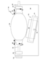
図2は、図1に示されるシステム100の側面図である。この図は、印刷ヘッド118の下方の位置に取り付けられた距離測定センサ190を示し、センサは、コントローラ124に操作可能に接続される。この距離センサは、センサ190とセンサの反対側の物体104の一部との間の距離を示すデータを生成するように構成される。センサによって作成された距離測定のための基準点が、印刷ヘッド118の整列面に対応するので、センサと物体との間の距離を示すデータは、印刷ヘッド面と物体との間の距離を判定するために有用である。フレーム130が物体104の反対側に垂直移動する際、コントローラ124は、センサと物体104の表面との間の距離を示すデータを受信し、コントローラは、印刷ヘッド118の各フェースプレートと各フェースプレートの反対側の物体104の一部との間の距離を識別するように構成される。これらの距離は、印刷ヘッド118を操作し、印刷ヘッドによって吐出されたマーキング材料を伴い、物体の表面上に画像を形成するためにコントローラ124によって使用される。
FIG. 2 is a side view of the
引き続き図2を参照すると、印刷ヘッド118及びUV硬化装置150は、フレーム130の側部部材内のスライドまたはチャネル198内に取り付けられる。1つ以上のアクチュエータ194は、印刷ヘッド118及びUV硬化装置150に操作可能に接続されて、印刷ヘッド及びUV硬化装置をスライドまたはチャネル内で、物体104に向かってまたは物体104から離れて双方向に移動させる。付加的に、1つ以上のアクチュエータ194は、印刷ヘッド118及びUV硬化装置150を互いに独立して移動させて、各印刷ヘッド118またはUV硬化装置150と物体表面との間の距離を、物体104の曲率または特性を基準にして調整するように構成される。
With reference to FIG. 2, the
図3は、システムの上方から物体104上を見下ろす印刷システム100の図を提供する。矢印は、印刷システム100によって可能にされた種々の運動の程度を示す。コントローラ124は、アクチュエータ122を操作することによって物体104を双方向に横方向に移動させることができ、物体を同様に双方向に回転させることができる。アクチュエータ186を操作することにより、コントローラ124は、フレーム170を枢動シャフト182(図1)を中心に双方向に枢動させることができる。この移動は、図内の曲線矢印によって示される。コントローラ124はまた、アクチュエータ194(図2)操作して、印刷ヘッド118及びUV硬化装置150を、物体104の表面に向かって、及び物体104の表面から離れて移動させる。付加的に、コントローラ124は、アクチュエータ146(図1)を操作して、フレーム130をフレーム170内で垂直に移動させて、印刷ヘッド118及びUV硬化装置の垂直位置を物体104の表面を基準として調整する。
FIG. 3 provides a diagram of a
フットボール等の長方形の物体を印刷するためのプロセスは、図4A~4Cに示される。物体104は、上記で説明されたように、シャフト126上の把持部166によって保持される。コントローラ124は、アクチュエータ122を操作して、物体104の1つの端部を印刷ヘッド118の反対側に並進させ、コントローラは、アクチュエータ186を操作して、フレーム170及び印刷ヘッド118を図4Aに示される位置に枢動させる。一度物体及び印刷ヘッド位置が確立されると、印刷ヘッドは、コントローラを伴って操作される。画像が、印刷ヘッド118のすぐ反対側の部分よりも大きい物体の一部分を覆う場合、コントローラは、アクチュエータ122を操作して、印刷ヘッドが、ボールのその部分の外周の周囲に画像を印刷し続けるように操作される際、ボールを適切に回転させることができる。物体の第1の端部が印刷された後、コントローラ124は、アクチュエータ186を操作して、フレーム170及び印刷ヘッド118を、印刷ヘッドアレイについてのホーム位置である、図4Bに示される角度に枢動させ、コントローラ124は、アクチュエータ122を操作して、物体を図4Bに示される位置に並進させる。一度この第2の位置が確立されると、印刷ヘッド118は、コントローラ124を伴って操作される。再び、画像が、印刷ヘッド118のすぐ反対側の部分よりも大きい物体の一部分を覆う場合、コントローラは、アクチュエータ122を操作して、ボールのその部分の外周の周囲に画像を続けるように、ボールを適切に回転させることができる。物体のこの部分が印刷された後、コントローラ124は、アクチュエータ186を操作して、フレーム170及び印刷ヘッド118を、図4Cに示される角度に枢動させ、コントローラ124は、アクチュエータ122を操作して、図4Cに示される位置で印刷ヘッド118にボールの他方の端部を提示するために物体を並進させる。一度この位置が確立されると、印刷ヘッド118は、コントローラ124を伴って操作される。画像が、印刷ヘッド118のすぐ反対側の部分よりも大きい物体の一部分を覆う場合、コントローラは、アクチュエータ122を操作して、印刷ヘッドが、ボールのその部分の外周の周囲に画像を印刷し続けるように操作される際、ボールを適切に回転させることができる。物体のこの端部が印刷された後、コントローラ124は、アクチュエータ186を操作させて、フレーム170及び印刷ヘッド118を図4Cに示される角度まで枢動させて、印刷ヘッドアレイをそのホーム位置に戻す。把持部166は、ここで解放されて、システム100から物体104を取り外すことが可能にすることができる。
The process for printing a rectangular object such as football is shown in FIGS. 4A-4C. The
図5は、図4A~4Cに関して上述されたものと同様の様式において印刷システム100を操作することによって印刷することができる他の卵形形状の実施例を例解する。これらの形状を識別するデータは、ユーザインターフェース122(図1)内へ入力することができ、コントローラ124は、印刷ヘッドをどのように垂直に移動し、位置決めするか、物体をどのように水平に移動し、位置決めするか、物体をどのように回転させるか、印刷ヘッドをどのように物体に向かって、または物体から離して移動させるか、及び物体を種々の印刷ヘッドアレイ位置で印刷するためにフレーム170ならびに印刷ヘッド118をどのように枢動させるかを判定するために、物体保持サブシステム108内に取り付けられた物体の形状及び寸法を識別するコード等、これらのデータを使用することができる。代替的または付加的に、ユーザインターフェースは、物体の形状及び位置を物体上またはタグ上の印、ならびに物体に取り付けられた、別様に物体に関連付けられたラベルから識別するデータを得ることができる、バーコード読み取り機等の印読み取り機を含む。
FIG. 5 illustrates examples of other oval shapes that can be printed by operating the
プリンタ100を操作するためのプロセスが、図6に示される。プロセスの説明において、プロセスがいくつかのタスクまたは機能を実行しているという記述は、コントローラまたはプロセッサに操作可能に接続されて、データを操作するか、プリンタ内の1つ以上の構成部品を操作してタスクまたは機能を実行するために、非一時的コンピュータ可読記憶媒体内に格納されたプログラム命令を実行するコントローラまたは汎用プロセッサを指す。上述されたコントローラ124は、そのようなコントローラまたはプロセッサであり得る。代替的に、コントローラは、2つ以上のプロセッサ及び関連付けられた回路ならびに構成部品を伴って実装することができ、その各々は、本明細書で説明された1つ以上のタスクまたは機能を形成するように構成される。付加的に、本方法のステップは、図に示される順序または処理が説明される順序に関わらず、任意の実現可能な経時的順序において実行されてもよい。
The process for operating the
図6は、物体保持サブシステム108内に保持された物体104を印刷するためにフレーム170及び印刷ヘッド118を枢動させるために印刷システム100を操作するプロセス500のフロー図である。プロセス500は、物体保持サブシステム108が物体104を固定するように操作されることから始まる(ブロック504)。コントローラ124は、センサ190を操作して、物体がホーム位置内の印刷ヘッドアレイの反対側にあるとき、コントローラが印刷ヘッド118の面と物体の部分との間の距離を識別することを可能にするようにアクチュエータ146を操作する(ブロック508)。コントローラ124はまた、ユーザインターフェースからデータを受信し、印刷される物体の形状及び寸法を識別する(ブロック512)。コントローラ124は、形状及び寸法データならびに識別された距離を基準としてアクチュエータ122、146、186、及び194を操作して、物体及び印刷ヘッド118を物体の輪郭及び特性に対応するように移動させる(ブロック516)。コントローラ124は、次いでインク画像データを基準として印刷ヘッドを操作して、印刷ヘッドに面する物体の部分を印刷する(ブロック520)。この物体の印刷は、印刷ヘッドに面する物体の部分の外周に沿って印刷するための物体の回転を含むことができ、また、任意の印刷ヘッドが物体上に画像を形成するためにUV硬化性マーキング材料を吐出する場合、UV硬化装置150の反対側に物体を移動させること及びUVインクを硬化させるために装置150を操作することを含む。 物体の別の部分が印刷される場合(ブロック524)、次いでコントローラ124は、アクチュエータ122、146、186、及び194を操作して、物体104及び印刷ヘッド118を次の物体部分を印刷するために再度位置決めする(ブロック516)。プロセスは、次いで印刷ヘッドを操作して、物体の別の部分を印刷する(ブロック520)。プロセスのこの部分は、物体の印刷が完了するまで続く(ブロック524)。印刷が完了するとき、コントローラ124は、アクチュエータ146、186、及び194を操作して、印刷ヘッド118をそれらのホーム位置に戻し(ブロック528)、物体を、物体保持サブシステム108から解放することができる。
FIG. 6 is a flow diagram of a
Claims (9)
枢動フレームであって、
一対の第1の横部材であって、各第1の横部材が前記少なくとも1つの印刷ヘッドの縦軸に平行である、一対の第1の横部材と、
前記一対の第1の横部材に対して垂直であり、前記枢動フレームを長方形として形成する一対の第1の垂直部材と、
前記第1の横部材のうちの少なくとも1つに操作可能に接続された、前記第1の横部材のうちの前記少なくとも1つ内のねじ穴を通じて延在するリードスクリューと、
前記リードスクリューに操作可能に接続された第1のアクチュエータと、を含む前記枢動フレームと、
前記枢動フレーム内に取り付けられたキャリッジフレームと、
少なくとも1つの印刷ヘッドであって、前記キャリッジフレームに取り付けられ、マーキング材料を吐出するように構成されている少なくとも1つの印刷ヘッドと、
前記枢動フレームに操作可能に接続された第2のアクチュエータであって、前記枢動フレームを、枢軸を中心に回転させるように構成されている第2のアクチュエータと、
前記キャリッジフレーム及び前記少なくとも1つの印刷ヘッドの反対側の物体を保持するように構成されているホルダと、
前記第1のアクチュエータ、前記第2のアクチュエータ及び前記少なくとも1つの印刷ヘッドに操作可能に接続されたコントローラであって、前記第1のアクチュエータを操作して、前記リードスクリューを回転させて、前記キャリッジフレーム及び前記少なくとも一つの印刷ヘッドを前記枢動フレームに対して平行な平面において双方向に移動させ、前記第2のアクチュエータを操作して、前記枢動フレーム及び前記少なくとも1つの印刷ヘッドを前記枢軸を中心に枢動させ、前記少なくとも1つの印刷ヘッドを操作して、前記ホルダによって保持された前記物体上にマーキング材料を吐出するように構成されているコントローラと、を備える、印刷システム。 It ’s a printing system.
It ’s a pivotal frame.
A pair of first horizontal members, each of which is parallel to the vertical axis of the at least one print head, and a pair of first horizontal members.
A pair of first vertical members that are perpendicular to the pair of first lateral members and form the pivot frame as a rectangle.
A lead screw operably connected to at least one of the first transverse members and extending through a screw hole in the at least one of the first transverse members .
A pivot frame comprising a first actuator operably connected to the lead screw .
The carriage frame mounted in the pivot frame and
At least one print head, the at least one print head attached to the carriage frame and configured to eject marking material.
A second actuator operably connected to the pivot frame, the second actuator configured to rotate the pivot frame about a pivot axis.
A holder configured to hold an object on the opposite side of the carriage frame and the at least one print head.
A controller operably connected to the first actuator, the second actuator, and the at least one printhead, the first actuator being operated to rotate the lead screw to rotate the carriage . The frame and the at least one print head are bidirectionally moved in a plane parallel to the pivot frame, and the second actuator is operated to move the pivot frame and the at least one print head to the pivot axis. A printing system comprising a controller configured to pivot around and operate the at least one print head to eject marking material onto the object held by the holder.
前記少なくとも1つの印刷ヘッド内の各印刷ヘッド用の一対のチャネルであって、前記少なくとも1つの印刷ヘッド内の各印刷ヘッドは、前記印刷ヘッドに対応する前記一対のチャネル内で双方向に摺動するように構成されている、一対のチャネルと、
前記少なくとも1つの印刷ヘッドに操作可能に接続された第3のアクチュエータと、をさらに備え、
前記コントローラが、前記第3のアクチュエータに操作可能に接続されており、前記コントローラが、前記第3のアクチュエータを操作して、前記印刷ヘッドに対応する前記チャネル内で前記少なくとも1つの印刷ヘッド内の各印刷ヘッドを双方向に移動させるようにさらに構成されている、請求項1に記載の印刷システム。 The carriage frame
A pair of channels for each printhead in the at least one printhead, wherein each printhead in the at least one printhead slides bidirectionally in the pair of channels corresponding to the printhead. A pair of channels that are configured to
Further comprising a third actuator operably connected to the at least one print head.
The controller is operably connected to the third actuator, and the controller operates the third actuator in the channel corresponding to the print head and in the at least one print head. The printing system of claim 1 , further configured to move each print head in both directions.
複数の印刷ヘッドをさらに備え、各印刷ヘッドが前記印刷ヘッドに対応する前記一対のチャネル内に位置決めされており、
前記コントローラが、前記第3のアクチュエータを操作して、各印刷ヘッドを前記複数の印刷ヘッド内の他の印刷ヘッドから独立して移動させるようにさらに構成されている、請求項2に記載の印刷システム。 The at least one print head
A plurality of print heads are further provided, and each print head is positioned in the pair of channels corresponding to the print head.
The printing according to claim 2 , wherein the controller is further configured to operate the third actuator to move each print head independently of the other print heads in the plurality of print heads. system.
前記コントローラが、前記センサによって生成された前記データを受信するために前記センサに操作可能に接続されており、前記コントローラが、前記センサによって生成された前記データを基準として、前記複数の印刷ヘッド内の各印刷ヘッドと各印刷ヘッドの反対側の前記物体の一部との間の距離を識別し、前記第3のアクチュエータを操作して、各印刷ヘッドについて前記識別された距離を基準として、前記複数の印刷ヘッド内の各印刷ヘッドを移動させるように構成されている、請求項3に記載の印刷システム。 Further comprising a sensor configured to generate data, the data indicates the distance between the sensor and a portion of the object in the holder opposite the sensor.
The controller is operably connected to the sensor to receive the data generated by the sensor, and the controller is in the plurality of printheads with reference to the data generated by the sensor. The distance between each print head and a portion of the object on the opposite side of each print head is identified, and the third actuator is operated to refer to the identified distance for each print head. The printing system according to claim 3 , wherein each print head is configured to move within a plurality of print heads.
第2の横部材と、
前記第2の横部材に対して垂直であり、U字型フレームを形成する一対の第2の垂直部材であって、各第2の垂直部材が開口部を有する、一対の第2の垂直部材と、
一対のシャフトであって、各シャフトが第1の端部及び第2の端部を有し、各シャフトの前記第2の端部が、把持部内で終端し、各シャフトの前記第1の端部が、互いに排他的な様式で前記第2の垂直部材のうちの1つ内の前記開口部を通じて延在し、各把持部が前記物体を前記ホルダ内で固定するために前記物体の一部を保持するように構成されている、一対のシャフトと、
前記シャフトのうちの1つの前記第1の端部に操作可能に接続された第4のアクチュエータであって、前記1つのシャフトを回転させるように構成されている、第4のアクチュエータと、をさらに備え、
前記コントローラが、前記第4のアクチュエータに操作可能に接続され、前記コントローラが、前記第4のアクチュエータを操作して、前記1つのシャフト及び前記把持部の間に保持された前記物体を回転させるようにさらに構成されている、請求項5に記載の印刷システム。 The holder
The second horizontal member and
A pair of second vertical members that are perpendicular to the second horizontal member and form a U-shaped frame, wherein each second vertical member has an opening . When,
A pair of shafts, each shaft having a first end and a second end, the second end of each shaft terminating in a grip and the first end of each shaft. The portions extend through the opening in one of the second vertical members in an mutually exclusive manner and each grip portion is a portion of the object for fixing the object within the holder. A pair of shafts, which are configured to hold
Further, a fourth actuator operably connected to the first end of one of the shafts, the fourth actuator configured to rotate the one shaft. Prepare,
The controller is operably connected to the fourth actuator so that the controller operates the fourth actuator to rotate the object held between the one shaft and the grip. The printing system according to claim 5 , further configured in.
前記コントローラが、前記第4のアクチュエータを操作して、前記シャフト及び前記物体を前記2つのシャフトと整列した軸に沿って双方向に移動させるようにさらに構成されている、請求項6に記載の印刷システム。 The fourth actuator is further configured to move the one shaft towards and away from the other shaft.
6. The sixth aspect of claim 6 , wherein the controller is further configured to operate the fourth actuator to bidirectionally move the shaft and the object along an axis aligned with the two shafts. Printing system.
前記コントローラが、前記ユーザインターフェースから受信した前記ホルダ内の前記物体の前記形状及び寸法を識別する前記データを基準として、前記第1のアクチュエータ、前記第2のアクチュエータ、前記第3のアクチュエータ、及び前記第4のアクチュエータを操作するようにさらに構成されている、請求項7に記載の印刷システム。 Further comprising a user interface operably connected to the controller, the user interface is configured to receive data identifying the shape and dimensions of the object between the grips.
The first actuator, the second actuator, the third actuator, and the third actuator, based on the data that the controller receives from the user interface to identify the shape and dimensions of the object in the holder. The printing system of claim 7 , further configured to operate a fourth actuator.
前記物体に関連付けられた印の読み取り機をさらに備え、前記印が、前記ホルダ内の前記物体の前記形状及び寸法を識別する前記データに対応する、請求項8に記載の印刷システム。 The user interface
The printing system of claim 8 , further comprising a reader for markings associated with the object, wherein the markings correspond to the data identifying the shape and dimensions of the object in the holder.
Applications Claiming Priority (2)
| Application Number | Priority Date | Filing Date | Title |
|---|---|---|---|
| US15/812,097 US10226951B1 (en) | 2017-11-14 | 2017-11-14 | System and method for pivoting a printhead in a direct-to-object printer during printing of an object |
| US15/812,097 | 2017-11-14 |
Publications (3)
| Publication Number | Publication Date |
|---|---|
| JP2019089320A JP2019089320A (en) | 2019-06-13 |
| JP2019089320A5 JP2019089320A5 (en) | 2021-11-25 |
| JP7041605B2 true JP7041605B2 (en) | 2022-03-24 |
Family
ID=65633156
Family Applications (1)
| Application Number | Title | Priority Date | Filing Date |
|---|---|---|---|
| JP2018199741A Active JP7041605B2 (en) | 2017-11-14 | 2018-10-24 | Systems and methods for pivoting the printhead in a direct-to-object printer while printing an object |
Country Status (3)
| Country | Link |
|---|---|
| US (1) | US10226951B1 (en) |
| JP (1) | JP7041605B2 (en) |
| DE (1) | DE102018128226A1 (en) |
Families Citing this family (2)
| Publication number | Priority date | Publication date | Assignee | Title |
|---|---|---|---|---|
| EP3953184B1 (en) * | 2019-04-08 | 2024-03-13 | Lsinc Corporation | Method for ink pressure modulation in a printer for axially symmetric objects |
| CN116922960B (en) * | 2023-07-18 | 2024-01-26 | 浙江龙游大微机电有限公司 | UV color ring printing device for steel pipe |
Citations (2)
| Publication number | Priority date | Publication date | Assignee | Title |
|---|---|---|---|---|
| JP2001010032A (en) | 1999-06-30 | 2001-01-16 | Canon Inc | Stereoscopic surface printer, contact type printhead and method for printing by stereoscopic surface printer |
| DE102016204123A1 (en) | 2015-04-16 | 2016-10-20 | Heidelberger Druckmaschinen Ag | Method for printing an object with a printed image |
Family Cites Families (7)
| Publication number | Priority date | Publication date | Assignee | Title |
|---|---|---|---|---|
| JPH05318715A (en) * | 1992-05-18 | 1993-12-03 | Olympus Optical Co Ltd | Curved surface printer |
| JP2004272086A (en) * | 2003-03-11 | 2004-09-30 | Seiko Epson Corp | Device for manufacturing electrooptical device, electrooptical device and electronic appliance |
| US7424851B2 (en) | 2006-09-21 | 2008-09-16 | Landesman David A | Screen printer with platen equalizer and method of printing |
| CN101790460A (en) | 2007-08-29 | 2010-07-28 | 应用材料股份有限公司 | Methods and apparatus for modular print head and adapter and rotation thereof with inkjet printer systems |
| KR101174878B1 (en) | 2010-02-16 | 2012-08-17 | 삼성디스플레이 주식회사 | Printing method and printer |
| US20160325498A1 (en) | 2015-05-04 | 2016-11-10 | Daniel Gelbart | 3D Printer Based on a Staggered Nozzle Array |
| IL241219A (en) | 2015-09-06 | 2016-07-31 | Shmuel Ur Innovation Ltd | Print-head for a 3d printer |
-
2017
- 2017-11-14 US US15/812,097 patent/US10226951B1/en active Active
-
2018
- 2018-10-24 JP JP2018199741A patent/JP7041605B2/en active Active
- 2018-11-12 DE DE102018128226.5A patent/DE102018128226A1/en active Pending
Patent Citations (2)
| Publication number | Priority date | Publication date | Assignee | Title |
|---|---|---|---|---|
| JP2001010032A (en) | 1999-06-30 | 2001-01-16 | Canon Inc | Stereoscopic surface printer, contact type printhead and method for printing by stereoscopic surface printer |
| DE102016204123A1 (en) | 2015-04-16 | 2016-10-20 | Heidelberger Druckmaschinen Ag | Method for printing an object with a printed image |
Also Published As
| Publication number | Publication date |
|---|---|
| DE102018128226A1 (en) | 2019-05-16 |
| US10226951B1 (en) | 2019-03-12 |
| JP2019089320A (en) | 2019-06-13 |
Similar Documents
| Publication | Publication Date | Title |
|---|---|---|
| KR102148641B1 (en) | System for printing on three-dimensional (3d) objects | |
| JP7041605B2 (en) | Systems and methods for pivoting the printhead in a direct-to-object printer while printing an object | |
| KR101860989B1 (en) | Vacuum cylinder with recessed portions for holding articles for printing | |
| US7547081B2 (en) | Methods and apparatus for image transfer | |
| US9421692B2 (en) | Methods and computer program products for processing of coverings such as leather hides and fabrics for furniture and other products | |
| JP6951288B2 (en) | Systems and methods for coordinating printhead behavior in direct-to-object printers with fixed printhead arrays | |
| JP6336936B2 (en) | System for detecting inoperable inkjets during printing of a three-dimensional object using an optical sensor and a reversible thermal substrate | |
| US9302519B1 (en) | System for detecting malfunctioning ejectors in three-dimensional object printing using specular reflectance | |
| US10807354B2 (en) | Active light emitting diode ultra violet curing system for a three dimensional object printer | |
| US11142014B2 (en) | Module for a three-dimensional (3D) object printer to prepare 3D objects for surface printing | |
| JP6997684B2 (en) | A system and method for rotating a three-dimensional (3D) object while printing the object. | |
| US11225066B2 (en) | In-line detection and correction of underperforming light emitting diodes in a curing station of a three dimensional object printer | |
| US10899142B2 (en) | Digital printing apparatus and method for printing of irregular shaped three dimensional items | |
| JP6466215B2 (en) | A system that detects inoperable inkjets in a print head that ejects transparent ink using a thermal substrate. | |
| JP7005472B2 (en) | Systems and equipment for evaluating ink performance and alignment in direct-to-object printers | |
| US11491806B2 (en) | Cure confirmation system and method for three dimensional object printer | |
| JP6722611B2 (en) | Profile printing by cam follower and template guide | |
| KR102390744B1 (en) | System and method for identifying a location for printing an image on an object and operating printheads to print the image on the object | |
| JP2018176736A5 (en) | ||
| US10464346B2 (en) | Ink jet recording apparatus |
Legal Events
| Date | Code | Title | Description |
|---|---|---|---|
| RD02 | Notification of acceptance of power of attorney |
Free format text: JAPANESE INTERMEDIATE CODE: A7422 Effective date: 20181106 |
|
| RD04 | Notification of resignation of power of attorney |
Free format text: JAPANESE INTERMEDIATE CODE: A7424 Effective date: 20190125 |
|
| RD03 | Notification of appointment of power of attorney |
Free format text: JAPANESE INTERMEDIATE CODE: A7423 Effective date: 20210226 |
|
| RD04 | Notification of resignation of power of attorney |
Free format text: JAPANESE INTERMEDIATE CODE: A7424 Effective date: 20210415 |
|
| A521 | Request for written amendment filed |
Free format text: JAPANESE INTERMEDIATE CODE: A523 Effective date: 20211018 |
|
| A621 | Written request for application examination |
Free format text: JAPANESE INTERMEDIATE CODE: A621 Effective date: 20211018 |
|
| A871 | Explanation of circumstances concerning accelerated examination |
Free format text: JAPANESE INTERMEDIATE CODE: A871 Effective date: 20211018 |
|
| A131 | Notification of reasons for refusal |
Free format text: JAPANESE INTERMEDIATE CODE: A131 Effective date: 20211102 |
|
| A521 | Request for written amendment filed |
Free format text: JAPANESE INTERMEDIATE CODE: A523 Effective date: 20220201 |
|
| TRDD | Decision of grant or rejection written | ||
| A01 | Written decision to grant a patent or to grant a registration (utility model) |
Free format text: JAPANESE INTERMEDIATE CODE: A01 Effective date: 20220209 |
|
| A61 | First payment of annual fees (during grant procedure) |
Free format text: JAPANESE INTERMEDIATE CODE: A61 Effective date: 20220311 |
|
| R150 | Certificate of patent or registration of utility model |
Ref document number: 7041605 Country of ref document: JP Free format text: JAPANESE INTERMEDIATE CODE: R150 |