JP7040485B2 - Display control device and display control program - Google Patents
Display control device and display control program Download PDFInfo
- Publication number
- JP7040485B2 JP7040485B2 JP2019047420A JP2019047420A JP7040485B2 JP 7040485 B2 JP7040485 B2 JP 7040485B2 JP 2019047420 A JP2019047420 A JP 2019047420A JP 2019047420 A JP2019047420 A JP 2019047420A JP 7040485 B2 JP7040485 B2 JP 7040485B2
- Authority
- JP
- Japan
- Prior art keywords
- drawing data
- posture
- display
- specific
- correction
- Prior art date
- Legal status (The legal status is an assumption and is not a legal conclusion. Google has not performed a legal analysis and makes no representation as to the accuracy of the status listed.)
- Active
Links
- 238000012937 correction Methods 0.000 claims description 313
- 238000000034 method Methods 0.000 claims description 73
- 230000008569 process Effects 0.000 claims description 66
- 230000008859 change Effects 0.000 claims description 65
- 230000015572 biosynthetic process Effects 0.000 claims description 64
- 238000003786 synthesis reaction Methods 0.000 claims description 64
- 239000002131 composite material Substances 0.000 claims description 62
- 239000008186 active pharmaceutical agent Substances 0.000 claims description 51
- 239000000203 mixture Substances 0.000 claims description 25
- 230000006870 function Effects 0.000 claims description 23
- 238000002360 preparation method Methods 0.000 claims description 22
- 230000002194 synthesizing effect Effects 0.000 claims description 17
- 230000015654 memory Effects 0.000 description 98
- 238000012545 processing Methods 0.000 description 53
- 230000004048 modification Effects 0.000 description 27
- 238000012986 modification Methods 0.000 description 27
- 238000003860 storage Methods 0.000 description 19
- 238000004891 communication Methods 0.000 description 17
- 230000003287 optical effect Effects 0.000 description 16
- 206010034719 Personality change Diseases 0.000 description 9
- 230000001133 acceleration Effects 0.000 description 9
- 238000005259 measurement Methods 0.000 description 9
- 238000004364 calculation method Methods 0.000 description 6
- 230000000694 effects Effects 0.000 description 6
- 238000006243 chemical reaction Methods 0.000 description 5
- 230000010354 integration Effects 0.000 description 4
- 239000000725 suspension Substances 0.000 description 4
- 238000004590 computer program Methods 0.000 description 3
- 238000010586 diagram Methods 0.000 description 3
- 238000005401 electroluminescence Methods 0.000 description 3
- 239000000284 extract Substances 0.000 description 3
- 229910052782 aluminium Inorganic materials 0.000 description 2
- XAGFODPZIPBFFR-UHFFFAOYSA-N aluminium Chemical compound [Al] XAGFODPZIPBFFR-UHFFFAOYSA-N 0.000 description 2
- 230000003190 augmentative effect Effects 0.000 description 2
- 230000005540 biological transmission Effects 0.000 description 2
- 239000011521 glass Substances 0.000 description 2
- 239000004973 liquid crystal related substance Substances 0.000 description 2
- 230000007246 mechanism Effects 0.000 description 2
- 229910052751 metal Inorganic materials 0.000 description 2
- 239000002184 metal Substances 0.000 description 2
- 239000000758 substrate Substances 0.000 description 2
- 238000002834 transmittance Methods 0.000 description 2
- 230000003936 working memory Effects 0.000 description 2
- 230000003044 adaptive effect Effects 0.000 description 1
- 230000006399 behavior Effects 0.000 description 1
- 230000004397 blinking Effects 0.000 description 1
- 238000005520 cutting process Methods 0.000 description 1
- 230000007423 decrease Effects 0.000 description 1
- 238000001514 detection method Methods 0.000 description 1
- 238000006073 displacement reaction Methods 0.000 description 1
- 238000005286 illumination Methods 0.000 description 1
- 239000000463 material Substances 0.000 description 1
- 230000002093 peripheral effect Effects 0.000 description 1
- 230000004044 response Effects 0.000 description 1
- 238000005096 rolling process Methods 0.000 description 1
- 229910052710 silicon Inorganic materials 0.000 description 1
- 239000010703 silicon Substances 0.000 description 1
- 230000007480 spreading Effects 0.000 description 1
- 238000003892 spreading Methods 0.000 description 1
- 230000001360 synchronised effect Effects 0.000 description 1
- 229920003002 synthetic resin Polymers 0.000 description 1
- 239000000057 synthetic resin Substances 0.000 description 1
- 239000012780 transparent material Substances 0.000 description 1
- 238000007740 vapor deposition Methods 0.000 description 1
Images


Classifications
-
- Y—GENERAL TAGGING OF NEW TECHNOLOGICAL DEVELOPMENTS; GENERAL TAGGING OF CROSS-SECTIONAL TECHNOLOGIES SPANNING OVER SEVERAL SECTIONS OF THE IPC; TECHNICAL SUBJECTS COVERED BY FORMER USPC CROSS-REFERENCE ART COLLECTIONS [XRACs] AND DIGESTS
- Y02—TECHNOLOGIES OR APPLICATIONS FOR MITIGATION OR ADAPTATION AGAINST CLIMATE CHANGE
- Y02E—REDUCTION OF GREENHOUSE GAS [GHG] EMISSIONS, RELATED TO ENERGY GENERATION, TRANSMISSION OR DISTRIBUTION
- Y02E60/00—Enabling technologies; Technologies with a potential or indirect contribution to GHG emissions mitigation
- Y02E60/10—Energy storage using batteries
Description
この明細書による開示は、虚像の表示を制御する表示制御装置及び表示制御プログラムに関する。 The disclosure according to this specification relates to a display control device and a display control program for controlling the display of a virtual image.
従来、例えば特許文献1には、車両の進行方向を示す矢印の虚像を、車両前方の路面上に重畳表示させる虚像生成システムが開示されている。この虚像生成システムは、車両にピッチ変化が生じても、矢印の虚像の路面上への重畳表示が維持されるように、スクリーンにおける映像の投影位置を、フロントカメラの映像やサスペンションの動作情報を用いて算出する。こうして算出された映像の表示位置を示す情報は、ヘッドアップディスプレイ(以下、「HUD」)に送信される。その結果、HUDは、矢印の虚像として結像される映像の投影位置を、車両のピッチ変化に合わせて変更できる。
Conventionally, for example,
特許文献1では、虚像として結像される映像のデータがCPUにて生成された後に、車両のピッチ変化に対応した位置に映像の投影位置を変化させる制御がHUDにて実施される。こうした制御によれば、路面への虚像の追従性が確保され易くなる一方で、映像は、データの生成時には想定されていない位置に投影されるようになる。その結果、例えばスクリーンの湾曲形状等に起因する歪みが、虚像に生じ易くなり得た。こうした歪みは、進行方向を示す矢印の虚像に加えて、車速を示す虚像をさらに表示する場合でも、生じ得た。
In
本開示は、車両の姿勢変化に対応する補正が実施されても、歪みの抑制された虚像を表示可能な表示制御装置及び表示制御プログラムの提供を目的とする。 It is an object of the present disclosure to provide a display control device and a display control program capable of displaying a virtual image in which distortion is suppressed even when a correction corresponding to a change in the posture of a vehicle is performed.
上記目的を達成するため、開示された一つの態様は、投影領域(PA)への光の投影によって虚像(Vi)が表示される車両(A)において用いられ、虚像の表示を制御する表示制御装置であって、車両の前景中にある特定物体に関連づけて虚像表示される特定表示物(11)の特定描画データ(DS1)を準備する描画データ準備部(51)と、車両の姿勢に関連する姿勢情報を取得する姿勢情報取得部(52)と、車両の姿勢変化に伴う特定表示物の特定物体に対する表示ずれが低減されるように、特定描画データの準備後に取得された姿勢情報を用いて、特定描画データに対して行う姿勢補正の内容を設定する姿勢補正設定部(53)と、投影領域への光の投影に伴う虚像の歪みが低減されるように、姿勢補正設定部にて姿勢補正の内容が設定された後に、特定描画データに対して行う歪み補正の内容を設定する歪み補正設定部(54)と、を備える表示制御装置とされる。 In order to achieve the above object, one disclosed embodiment is used in a vehicle (A) in which a virtual image (Vi) is displayed by projecting light onto a projection region (PA), and a display control for controlling the display of the virtual image is used. A device related to the posture of the vehicle and the drawing data preparation unit (51) that prepares the specific drawing data (DS1) of the specific display object (11) that is displayed as a virtual image in relation to the specific object in the foreground of the vehicle. Using the posture information acquisition unit (52) that acquires the posture information to be performed, and the posture information acquired after the preparation of the specific drawing data so as to reduce the display deviation of the specific display object with respect to the specific object due to the change in the posture of the vehicle. In the posture correction setting unit (53) that sets the content of the posture correction performed for the specific drawing data, and in the posture correction setting unit so that the distortion of the virtual image due to the projection of light on the projection area is reduced. It is a display control device including a distortion correction setting unit (54) for setting the content of distortion correction to be performed on specific drawing data after the content of posture correction is set.
また開示された一つの態様は、投影領域(PA)への光の投影によって虚像(Vi)が表示される車両(A)において用いられ、虚像の表示を制御する表示制御プログラムであって、少なくとも一つのプロセッサ(50a,550a,650a)を、車両の前景中にある特定物体に関連づけて虚像表示される特定表示物(11)の特定描画データ(DS1)を準備する描画データ準備部(51)と、車両の姿勢に関連する姿勢情報を取得する姿勢情報取得部(52)と、車両の姿勢変化に伴う特定表示物の特定物体に対するずれが低減されるように、特定描画データの準備後に取得された姿勢情報を用いて、特定描画データに対して行う姿勢補正の内容を設定する姿勢補正設定部(53)と、投影領域への光の投影に伴う虚像の歪みが低減されるように、姿勢補正設定部にて姿勢補正の内容が設定された後に、特定描画データに対して行う歪み補正の内容を設定する歪み補正設定部(54)と、を含む構成として機能させる表示制御プログラムとされる。 Further, one disclosed embodiment is a display control program used in a vehicle (A) in which a virtual image (Vi) is displayed by projecting light onto a projection region (PA), and controls the display of the virtual image, at least. A drawing data preparation unit (51) that prepares a specific drawing data (DS1) of a specific display object (11) that is displayed as a virtual image in association with a specific object in the foreground of a vehicle by one processor (50a, 550a, 650a). And, the attitude information acquisition unit (52) that acquires the attitude information related to the attitude of the vehicle, and the acquisition after preparing the specific drawing data so that the deviation of the specific display object with respect to the specific object due to the change in the attitude of the vehicle is reduced. The posture correction setting unit (53) that sets the content of the posture correction to be performed on the specific drawing data using the obtained posture information, and the distortion of the virtual image due to the projection of light on the projection area are reduced. It is a display control program that functions as a configuration including a distortion correction setting unit (54) that sets the content of distortion correction to be performed on specific drawing data after the content of posture correction is set in the attitude correction setting unit. To.
これらの態様では、特定物体に対する特定表示物の表示ずれが低減されるように、特定描画データに対して行う姿勢補正の内容が設定された後で、虚像の歪みを低減させる歪み補正の内容が、さらに設定される。そのため、車両の姿勢変化に対応する補正が、特定描画データの準備後に実施されても、特定描画データに基づく虚像は、歪みを抑制された態様にて、表示可能となる。 In these aspects, the content of the distortion correction that reduces the distortion of the virtual image is set after the content of the posture correction to be performed for the specific drawing data is set so that the display deviation of the specific display object with respect to the specific object is reduced. , Further set. Therefore, even if the correction corresponding to the posture change of the vehicle is performed after the preparation of the specific drawing data, the virtual image based on the specific drawing data can be displayed in a mode in which the distortion is suppressed.
さらに、開示された一つの態様は、投影領域(PA)への光の投影によって虚像(Vi)が表示される車両(A)において用いられ、虚像の表示を制御する表示制御装置であって、車両の前景中にある特定物体に関連づけて虚像表示される特定表示物(11)の特定描画データ(DS1)、及び特定表示物とは異なる別表示物(12)の別描画データ(DS2,DS3)を準備する描画データ準備部(51)と、車両の姿勢に関連する姿勢情報を取得する姿勢情報取得部(52)と、車両の姿勢変化に伴う特定表示物の特定物体に対する表示ずれが低減されるように、姿勢情報を用いて、特定描画データに対して行う姿勢補正の内容を設定する姿勢補正設定部(53)と、姿勢補正設定部にて設定された内容の姿勢補正が適用された特定描画データと、別描画データとを合成する画像合成部(55)と、投影領域への光の投影に伴う虚像の歪みが低減されるように、姿勢補正が適用された特定描画データ及び姿勢補正が適用されない別描画データの両方に纏めて適用される歪み補正の内容を設定する歪み補正設定部(54)と、を備える表示制御装置とされる。 Further, one disclosed aspect is a display control device used in a vehicle (A) in which a virtual image (Vi) is displayed by projecting light onto a projection region (PA) to control the display of the virtual image. The specific drawing data (DS1) of the specific display object (11) that is displayed as a virtual image in relation to the specific object in the foreground of the vehicle, and the separate drawing data (DS2, DS3) of the separate display object (12) that is different from the specific display object. ) Is prepared, the drawing data preparation unit (51), the attitude information acquisition unit (52) that acquires the attitude information related to the attitude of the vehicle, and the display deviation of the specific display object due to the change in the attitude of the vehicle are reduced. The posture correction setting unit (53) that sets the content of the posture correction performed for the specific drawing data using the posture information and the posture correction of the content set by the posture correction setting unit are applied. The image compositing unit (55) that synthesizes the specific drawing data and another drawing data, the specific drawing data to which the posture correction is applied so that the distortion of the virtual image due to the projection of light on the projection area is reduced, and the specific drawing data. It is a display control device including a distortion correction setting unit (54) that sets the content of distortion correction that is collectively applied to both separate drawing data to which posture correction is not applied .
また開示された一つの態様は、投影領域(PA)への光の投影によって虚像(Vi)が表示される車両(A)において用いられ、虚像の表示を制御する表示制御プログラムであって、少なくとも一つのプロセッサ(50a,550a,650a)を、車両の前景中にある特定物体に関連づけて虚像表示される特定表示物(11)の特定描画データ(DS1)、及び特定表示物とは異なる別表示物(12)の別描画データ(DS2,DS3)を準備する描画データ準備部(51)と、車両の姿勢に関連する姿勢情報を取得する姿勢情報取得部(52)と、車両の姿勢変化に伴う特定表示物の特定物体に対するずれが低減されるように、姿勢情報を用いて、特定描画データに対して行う姿勢補正の内容を設定する姿勢補正設定部(53)と、姿勢補正設定部にて設定された内容の姿勢補正が適用された特定描画データと、別描画データとを合成する画像合成部(55)と、投影領域への光の投影に伴う虚像の歪みが低減されるように、姿勢補正が適用された特定描画データ及び姿勢補正が適用されない別描画データの両方に纏めて適用される歪み補正の内容を設定する歪み補正設定部(54)と、を含む構成として機能させる表示制御プログラムとされる。 Further, one aspect disclosed is a display control program used in a vehicle (A) in which a virtual image (Vi) is displayed by projecting light onto a projection region (PA) to control the display of the virtual image, at least. The specific drawing data (DS1) of the specific display object (11), which is displayed as a virtual image in association with a specific object in the foreground of the vehicle, by one processor (50a, 550a, 650a), and a separate display different from the specific display object. A drawing data preparation unit (51) that prepares separate drawing data (DS2, DS3) for an object (12), an attitude information acquisition unit (52) that acquires attitude information related to the attitude of the vehicle, and a change in the attitude of the vehicle. In order to reduce the deviation of the specific display object with respect to the specific object, the attitude correction setting unit (53) that sets the content of the attitude correction to be performed on the specific drawing data using the attitude information and the attitude correction setting unit The image compositing unit (55) that synthesizes the specific drawing data to which the posture correction of the contents set in the above is applied and the different drawing data, and the distortion of the imaginary image due to the projection of light on the projection area are reduced. , A display that functions as a configuration including a distortion correction setting unit (54) that sets the content of distortion correction that is collectively applied to both specific drawing data to which posture correction is applied and separate drawing data to which posture correction is not applied . It is a control program.
これらの態様による特定描画データは、特定物体に対する特定表示物の表示ずれを低減させる姿勢補正の内容を適用されて、別描画データと合成される。そして、虚像の歪みを低減させる歪み補正の内容は、合成の対象となる特定描画データ及び別描画データの両方への適用を前提に設定される。以上によれば、車両の姿勢変化に対応する補正及び別描画データとの合成が、特定描画データの準備後に実施されても、特定描画データに基づく虚像は、歪みを抑制された態様にて、表示可能となる。 The specific drawing data according to these aspects is combined with another drawing data by applying the content of posture correction for reducing the display deviation of the specific display object with respect to the specific object. The content of the distortion correction for reducing the distortion of the virtual image is set on the premise that it is applied to both the specific drawing data to be synthesized and another drawing data. According to the above, even if the correction corresponding to the posture change of the vehicle and the synthesis with the different drawing data are performed after the preparation of the specific drawing data, the virtual image based on the specific drawing data is in a manner in which the distortion is suppressed. It can be displayed.
尚、上記括弧内の参照番号は、後述する実施形態における具体的な構成との対応関係の一例を示すものにすぎず、技術的範囲を何ら制限するものではない。 The reference numbers in parentheses are merely examples of the correspondence with the specific configuration in the embodiment described later, and do not limit the technical scope at all.
以下、本開示の複数の実施形態を図面に基づいて説明する。尚、各実施形態において対応する構成要素には同一の符号を付すことにより、重複する説明を省略する場合がある。各実施形態において構成の一部分のみを説明している場合、当該構成の他の部分については、先行して説明した他の実施形態の構成を適用することができる。また、各実施形態の説明において明示している構成の組み合わせばかりではなく、特に組み合わせに支障が生じなければ、明示していなくても複数の実施形態の構成同士を部分的に組み合わせることができる。そして、複数の実施形態及び変形例に記述された構成同士の明示されていない組み合わせも、以下の説明によって開示されているものとする。 Hereinafter, a plurality of embodiments of the present disclosure will be described with reference to the drawings. By assigning the same reference numerals to the corresponding components in each embodiment, duplicate description may be omitted. When only a part of the configuration is described in each embodiment, the configuration of the other embodiment described above can be applied to the other parts of the configuration. Further, not only the combination of the configurations specified in the description of each embodiment but also the configurations of a plurality of embodiments can be partially combined even if the combination is not specified. Further, an unspecified combination of the configurations described in the plurality of embodiments and modifications is also disclosed by the following description.
(第一実施形態)
図1に示す本開示の第一実施形態による表示制御装置の機能は、ヘッドアップディスプレイ(以下、「HUD」)100に実装されている。HUD100は、描画ECU(Electronic Control Unit)30等と共に、車両Aにおいて用いられる虚像表示システム10を構成している。
(First Embodiment)
The function of the display control device according to the first embodiment of the present disclosure shown in FIG. 1 is implemented in the head-up display (hereinafter, “HUD”) 100. The
虚像表示システム10は、車両Aの前景に重畳される虚像Viを用いた表示により、車両Aに関連する種々の情報を運転者に提示する。虚像表示システム10は、図1及び図2に示すように、ウィンドシールドWSに規定された投影領域PAへの光の投影により、複数の表示物を含む虚像Viを、運転者から視認可能に表示する。虚像Viには、AR(Augmented Reality)表示物11及び非AR表示物12が含まれ得る。
The virtual
AR表示物11は、拡張現実表示に用いられる虚像Viである。虚像Viとして表示された状態でのAR表示物11の表示位置は、投影領域PAを通して視認される前景中にある特定物体、例えば、前走車、歩行者及び路面等の重畳対象に関連付けられている。AR表示物11は、こうした重畳対象に相対固定されているように、重畳対象を追って、運転者の見た目上で移動可能である。このように、運転者のアイポイントと、前景中の重畳対象と、投影領域PA中の投影位置との位置関係が決まっているため、車両Aの姿勢が変化した場合でも、AR表示物11が重畳対象に重畳表示された状態は、維持される(図3参照)。換言すれば、AR表示物11の表示位置は、HUD100の画角内で随時移動している。一例として、走行すべき車線の範囲を示す虚像Viが、前景中における左右の区画線の間の路面上に、運転者から見て奥行き方向に延びる態様で、AR表示物11として重畳表示される。
The
非AR表示物12は、特定の重畳対象には重畳されず、単に前景に重畳表示される。非AR表示物12は、運転者からの見た目上にて、AR表示物11の下側に表示される。非AR表示物12は、主に車両Aの状態を通知する表示物であり、車両Aの構成であるウィンドシールドWS等に相対固定されているように表示される。即ち、非AR表示物12の表示位置は、HUD100の画角内で実質的に移動しない。そのため、車両Aの姿勢が変化した場合には、非AR表示物12と運転者からの視認される前景との位置関係は、変化する(図3参照)。
The
非AR表示物12を用いた表示には、車両Aが走行可能な状態において常に表示される常時表示と、車両Aに関連した特定の状況下においてのみ表示されるイベント表示とが含まれる。一例として、車両Aの走行速度を示すスピード表示は、常時表示に相当する。一方、ACC(Adaptive Cruise Control)及びLTC(Lane Trace Control)のような運転支援機能等の作動状態を示すインジケータ表示は、イベント表示に相当する。
The display using the
図1に示す虚像表示システム10は、車両Aに生じた姿勢変化に起因し、重畳対象、投影領域PA、及び運転者のアイポイントの相対的な位置関係が変化した場合でも、重畳対象に重畳したAR表示物11の表示状態を維持させるための制御を行う。詳記すると、ピッチ、ロール及びヒーブ等の姿勢変化が車両Aに生じた場合、虚像Viとして結像される光(以下、「虚像光Lvi」)の態様を変化させないと、運転者からの見た目上にて、AR表示物11は、重畳対象に対してずれた表示となってしまう。そのため虚像表示システム10は、車両Aの姿勢変化に応じて、AR表示物11の重畳対象に対する表示ずれが低減されるように、投影領域PAを通して見える重畳対象の状態に合わせて、虚像光Lviの形状を逐次補正する。
The virtual
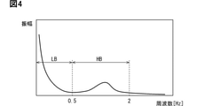
ここで、図4に示すように、車両Aの姿勢変化の振動は、一定の周波数で生じるわけではなく、例えば主に2Hz程度までの周波数帯域の成分を含んだ振動となっている。虚像表示システム10では、0から0.5Hz程度までの周波数帯域が、低周波数帯域LBとされており、低周波数帯域LBよりも周波数の高い0.5~2Hzまでの周波数帯域が、高周波数帯域HBとされている。一例として、車両Aをゆっくりと加減速させる場合等には、低周波数帯域LBの振動が発生する。一方、ブレーキ操作を複数回入力した場合、車両Aを急発進又は急減速させる場合、及び悪路走行中等では、高周波数帯域HBの振動が発生する。
Here, as shown in FIG. 4, the vibration of the posture change of the vehicle A does not occur at a constant frequency, but is mainly a vibration including a component in a frequency band up to about 2 Hz, for example. In the imaginary
図1に示す虚像表示システム10では、低周波数帯域LBの姿勢変化による虚像Viの表示ずれを低減する機能が描画ECU30によって実現されている。一方、高周波数帯域HBの姿勢変化による虚像Viの表示ずれを低減する機能は、HUD100によって実現されている。以下、描画ECU30及びHUD100の詳細を、図1及び図5に基づき説明する。
In the virtual
描画ECU30は、HUD100を含む複数の車載表示器と接続されており、各車載表示器の表示を統合的に制御する機能を有している。描画ECU30は、各車載表示器の表示内容を決定し、各車載表示器へ向けて映像信号を逐次出力する。HUD100に出力される映像信号も、描画ECU30によって生成される。
The drawing
描画ECU30は、映像信号の生成に必要なデータを取得するため、車載ネットワークの通信バス29を介して、他の車載構成と相互に通信可能である。通信バス29には、外界センサ21、ロケータ22、3次元地図データベース23、ハイトセンサ24、車両制御ECU26等が直接的又は間接的に電気接続されている。
In order to acquire the data necessary for generating the video signal, the drawing
外界センサ21は、歩行者及び他の車両等の移動物体、さらに路上の縁石、道路標識、道路標示、及び区画線等の静止物体を検出する。これら移動物体及び静止物体の少なくとも一部が、AR表示物11を重畳される重畳対象とされる。車両Aには、例えばカメラユニット、ライダ及びミリ波レーダ等が外界センサ21として搭載されている。外界センサ21は、検出した移動物体及び静止物体の相対位置及び種別等を示す物体情報を、通信バス29に逐次出力する。
The
ロケータ22は、GPS、GLONASS、Galileo、IRNSS、QZSS、Beidou等の衛星測位システムのうちで、少なくとも一つの衛星測位システムの各測位衛星から、測位信号を受信可能である。ロケータ22は、受信した測位信号に基づき、車両Aの位置を計測する。ロケータ22は、計測した車両Aの位置情報を通信バス29へ向けて逐次出力する。尚、ロケータ22は、位置情報を補正するための慣性センサを有していてもよい。
The
3次元地図データベース(以下、「3次元地図DB」)23は、多数の3次元地図データを格納した大容量の記憶媒体を主体とする構成である。3次元地図データは、例えば自動運転を可能にするような高精度な地図データであって、道路の緯度、経度、高度を示す情報を含んでいる。3次元地図DB23は、ネットワークを通じて、3次元地図データを最新の情報に更新可能である。3次元地図DB23は、描画ECU30からの要求に応じて、車両Aの周辺及び進行方向の3次元地図データを描画ECU30に提供可能である。
The three-dimensional map database (hereinafter, “three-dimensional map DB”) 23 is mainly composed of a large-capacity storage medium that stores a large amount of three-dimensional map data. The three-dimensional map data is high-precision map data that enables automatic driving, for example, and includes information indicating the latitude, longitude, and altitude of the road. The
ハイトセンサ24は、車両Aが置かれた路面からボディまでの高さを計測するため、車両Aに生じる上下方向の変位を検出するセンサである。ハイトセンサ24は、例えば左右いずれか一方のリヤサスペンションに設置されている。ハイトセンサ24は、ボディに懸架されたサスペンションアームの動作によって上下方向に変位する特定の車輪について、ボディに対する沈み込み量を計測する。具体的に、ハイトセンサ24は、ボディとサスペンションアームとの間の相対距離を計測し、通信バス29に計測結果を逐次出力する。
The
車両制御ECU26は、マイクロコントローラを主体に構成された演算装置である。車両制御ECU26は、外界センサ21にて検出される物体情報、及び運転者の運転操作等に基づいて、車両Aの挙動を制御する。車両制御ECU26には、ペダルセンサ25が電気的に接続されている。ペダルセンサ25には、アクセルポジションセンサ及びブレーキ踏力センサが少なくとも含まれる。
The
車両制御ECU26は、ペダルセンサ25の検出信号に基づき、車両Aに発生させる前後方向の加速度、即ち、車軸トルク及びブレーキ力を制御する。加えて車両制御ECU26は、運転者の加減速操作及び路面の凹凸等の外乱に伴う車両Aの振動が抑制されるように、車軸トルク及びブレーキ力をフィードフォワード制御する。車両制御ECU26は、フィードフォワード制御における車軸トルク及びブレーキ力の各目標値を、制御情報として通信バス29に逐次出力する。
The
描画ECU30は、処理部、RAM、記憶装置及び入出力インターフェースを有するコンピュータを主体に構成されている。処理部は、CPU(Central Processing Unit)、GPU(Graphics Processing Unit)及びFPGA(Field-Programmable Gate Array)等の少なくとも一つを含む構成である。記憶装置には、処理部によって実行される種々のプログラムが格納されている。記憶装置に記憶された複数のプログラムには、描画データDSを生成する描画プログラム、及び車両Aの姿勢変化を推定する姿勢推定プログラム等が含まれている。
The drawing
描画ECU30は、描画プログラム及び姿勢推定プログラムを処理部により実行し、センサ値取得部31、コンテンツ選定部34、対象情報取得部35、描画補正量算出部36及び描画データ生成部37等の機能部を備える。センサ値取得部31、コンテンツ選定部34及び対象情報取得部35は、通信バス29から情報を取得可能な機能部である。
The drawing
センサ値取得部31は、ハイトセンサ24及び車両制御ECU26から出力される出力信号であって、車高の計測結果、並びに車軸トルク及びブレーキ力についての制御情報を受信する。センサ値取得部31は、これらの出力信号を処理し、低周波数帯域LBの姿勢変化に関連した姿勢変化情報を取得する。
The sensor
コンテンツ選定部34は、通信バス29から取得する各種情報に基づき、虚像表示を行うコンテンツの選択及び調停を行う。具体的に、コンテンツ選定部34は、AR表示、常時表示及びイベント表示等の各要否と、それぞれの優先度等とを総合的に判定し、虚像Viを用いて運転者に通知すべき情報のコンテンツを選定する。コンテンツ選定部34は、選定したコンテンツを指定する指令と、選定したコンテンツの描画に必要な情報とを、描画データ生成部37に逐次提供する。
The
対象情報取得部35は、外界センサ21によって出力された物体情報を通信バス29から取得し、移動物体及び静止物体の中から、虚像Viを重畳させる重畳対象を選別する。対象情報取得部35は、選別した重畳対象の相対位置を、描画データ生成部37に逐次提供する。一例として、走行中の車線の路面を重畳対象とし、当該路面上にAR表示物11を重畳させる場合(図2参照)、対象情報取得部35は、左右両側の区画線の相対位置を、描画データ生成部37に逐次提供する。
The object
描画補正量算出部36は、センサ値取得部31にて取得される低周波数帯域LBの姿勢変化情報を用いて、車両Aの現在姿勢を特定する。描画補正量算出部36は、特定した車両姿勢から、低周波数帯域LBの姿勢変化に伴う虚像Viの表示ずれを補正する補正量(以下、「低周波補正量」)を算出する。描画補正量算出部36は、算出した低周波補正量の値を、描画データ生成部37に逐次提供する。
The drawing correction
描画データ生成部37は、描画データDSを生成する。描画データDSは、HUD100へ向けて出力する映像信号において、個々のフレームを構成する画像データである。描画データ生成部37は、映像出力線38によってHUD100と電気的に接続されている。描画データ生成部37は、生成した描画データDSを、予め規定された映像フォーマットにて、HUD100へ向けて逐次出力する。
The drawing
描画データDSは、コンテンツ選定部34にて選定されたコンテンツに対応する複数の描画物を、仮の状態として、一つに纏めてなる仮合成データである。描画データDSには、複数の描画物として、AR表示物11の元画像となるAR描画物DS1と、各非AR表示物12の元画像となる非AR描画物DS2,DS3とが含まれている。
The drawing data DS is tentatively synthesized data in which a plurality of drawn objects corresponding to the contents selected by the
描画データ生成部37は、各コンテンツに対応する各描画物DS1~DS3を個別に描画したうえで、互いに重ならないように配置する。こうしたプレ合成の処理により、描画データ生成部37は、一つの描画データDSを生成する。描画データDSにおいて、各描画物DS1~DS3の各描画位置P1~P3、横解像度及び縦解像度は、予め規定された値に固定されている。一つの描画データDSに含まれる描画物DS1~DS3の数は、コンテンツ選定部34にて選定されるコンテンツの数に対応している。各描画物DS1~DS3は、LCD制御基板50による本合成(後述する)の処理により、正規の位置関係で再び合成される。
The drawing
描画データ生成部37は、重畳対象の相対位置及び形状と、低周波数帯域LBの姿勢変化とを考慮した態様のAR描画物DS1を描画する。具体的に、描画データ生成部37は、予め設定されたアイポイント及び投影領域PAの各設定位置を、記憶装置等から読み出す。加えて描画データ生成部37は、対象情報取得部35から重畳対象の相対位置を取得すると共に、描画補正量算出部36から低周波補正量を取得する。描画データ生成部37は、アイポイント、投影領域PA及び重畳対象の相対的な位置関係を把握したうえで、これらの位置関係を低周波補正量で補正し、重畳対象に表示ずれなく重なり得る態様のAR描画物DS1を描画する。AR描画物DS1は、後述する高周波数帯域HBの姿勢変化を考慮し、本合成にて必要とされる(切り出される)画像サイズに対して、少なくとも上下方向に余裕代を確保された画像サイズに描画される。
The drawing
HUD100は、ウィンドシールドWSの下方にて、インスツルメントパネルに設けられた収容空間に収容される車載表示器である。HUD100からウィンドシールドWSの投影領域PAへ向けて射出された虚像光Lviは、投影領域PAによってアイポイント側へ向けて反射され、運転者によって知覚される。運転者は、投影領域PAを通して見える前景に、虚像Viが重畳された表示を視認する。HUD100は、例えばアイポイントから車両Aの前方向に10~20m程度の空間中に虚像Viを結像させる。
The HUD100 is an in-vehicle display that is housed in a storage space provided in an instrument panel below the windshield WS. The virtual image light Lvi emitted from the
HUD100は、虚像表示のための構成として、投影ユニット70、慣性センサ41、フィルタ回路42、LCD制御基板50及びBL制御基板60を備えている。
The
投影ユニット70は、虚像光Lviを投影領域PAに投影する光学的な構成である。投影ユニット70は、LCD(Liquid Crystal Display)71、バックライト72及び反射光学系73等によって構成されている。これらの光学要素は、HUD100の筐体40に収容されている。筐体40は、各光学要素の相対的な位置関係を高精度に規定している。
The
LCD71は、多数の画素が配列されてなる表示面を有している。LCD71は、各画素に設けられた赤色、緑色、及び青色等のサブ画素の光の透過率を増減させ、表示面に種々の画像をカラー表示する。各サブ画素における光の透過率は、LCD制御基板50によって制御される。LCD71の表示面には、本合成にて生成される出力データDScに基づいた元画像Piが表示される。
The
バックライト72は、多数の発光ダイオードを有する構成である。多数の発光ダイオードは、LCD71の背面側に配置されており、LCD71の表示面に沿って所定の間隔で2次元配列されている。バックライト72は、個々の発光ダイオードにて照明されるエリア毎に、発光輝度を調整可能な構成とされている。そして、各発光ダイオードの発光輝度は、BL制御基板60によって個別に制御される。バックライト72は、LCD71を背面側から透過照明し、表示面に描画された元画像Piを発光表示させる。その結果、元画像Piの光が、虚像光Lviとして表示面から射出される。
The
反射光学系73は、例えば凸面鏡及び凹面鏡等を含む構成とされている。凸面鏡及び凹面鏡は、合成樹脂又はガラス等からなる無色透明な基材の表面に、アルミニウム等の金属を蒸着させた反射鏡である。凸面鏡及び凹面鏡は、LCD71から射出された虚像光Lviを反射によって広げつつ、投影領域PAに投影し、元画像Piを拡大させてなる虚像Viを表示させる。尚、反射光学系73には、例えば回折によって元画像Piを拡大する回折光学素子(Diffractive Optical Element:DOE)等が用いられてもよい。
The reflective
慣性センサ41は、車両Aの姿勢変化を計測する計測部であって、ジャイロセンサ及び加速度センサを組み合わせた構成である。慣性センサ41は、ハイトセンサ24及び車両制御ECU26とは別に車両Aに搭載されている。慣性センサ41は、車両Aにおけるピッチ方向及びロール方向の各角速度と、車両Aのヨー軸に沿った上下方向の加速度とを計測する。
The
慣性センサ41には、ローパスフィルタ及びAD変換部が設けられている。ローパスフィルタは、ジャイロセンサ及び加速度センサの各出力から、高周波ノイズを除去する。AD変換部は、ローパスフィルタを通過したアナログ信号を、デジタル信号に変換する。慣性センサ41は、例えばI2C(Inter-Integrated Circuit:登録商標)及びSPI(Serial Peripheral Interface)等の通信規格にて、フィルタ回路42に信号を送信できる。慣性センサ41は、上記の通信規格に従うデジタル形式とされた計測信号を、フィルタ回路42に出力する。
The
フィルタ回路42は、慣性センサ41から出力される計測信号を取得する。計測信号がフィルタ回路42に取得されるまでの遅延時間(以下、「計測遅延時間」)は、通信バス29にて生じる通信遅延時間よりも短くなっている。フィルタ回路42は、ハイパスフィルタ及び積分処理部等を少なくとも含む構成である。
The
ハイパスフィルタは、高周波数帯域HB(図4参照)の信号を概ね通過させ、低周波数帯域LB(図4参照)以下の信号を減衰させる。ハイパスフィルタのカットオフ周波数は、高周波数帯域HB及び低周波数帯域LBの境界値となるように設定されている。こうした設定により、ハイパスフィルタは、計測信号に含まれる周波帯域のうちで低周波数帯域LBと重複する帯域の信号を減衰させる。加えて、ハイパスフィルタの通過により、慣性センサ41のジャイロセンサに生じるドリフト成分が計測信号から除去される。
The high-pass filter generally passes signals in the high frequency band HB (see FIG. 4) and attenuates signals in the low frequency band LB (see FIG. 4) and below. The cutoff frequency of the high-pass filter is set to be a boundary value between the high frequency band HB and the low frequency band LB. With such a setting, the high-pass filter attenuates the signal in the frequency band included in the measurement signal that overlaps with the low frequency band LB. In addition, by passing through the high-pass filter, the drift component generated in the gyro sensor of the
積分処理部は、例えばローパスフィルタを主体とした構成である。積分処理部は、姿勢変化の角速度を示す計測信号を時間積分する信号処理により、車両姿勢(ピッチ角,ロール角等)を示す信号を生成する。フィルタ回路42は、ハイパスフィルタ及び積分処理部を順に通過した信号を、高周波数帯域HBの姿勢変化情報として生成し、LCD制御基板50に逐次提供する。
The integration processing unit is mainly composed of, for example, a low-pass filter. The integration processing unit generates a signal indicating the vehicle attitude (pitch angle, roll angle, etc.) by signal processing that time-integrates the measurement signal indicating the angular velocity of the attitude change. The
図1、図5及び図6に示すLCD制御基板50は、投影ユニット70による虚像表示を制御する電気構成である。LCD制御基板50に形成された制御回路は、処理部50a、RAM、記憶装置、入出力インターフェース、及びこれらを接続するデータバスを備えたコンピュータ等を主体として含む構成である。
The
処理部50aは、RAMと結合された演算処理のためのハードウェアである。処理部50aは、RAMへのアクセスを制御するメモリコントローラを含んでいる。処理部50aは、CPU、GPU、FPGA及び他の専用機能を備えたIPコア等を少なくとも一つ含む構成である。
The
RAMは、処理部50aと結合されて、処理部50aのワーキングメモリとして機能する。LCD制御基板50には、RAMとして、第一メモリ151及び第二メモリ152が設けられている。第一メモリ151及び第二メモリ152は、例えばDDR(Dynamic Random Access Memory)2又はDDR3等の規格に準じたSDRAMのメモリモジュールを主体に構成されている。第一メモリ151及び第二メモリ152は、互いに実質同一構成の揮発性メモリであり、容量及びアクセス速度等も実質同一となるように揃えられている。第一メモリ151及び第二メモリ152は、それぞれ個別にデータバスに接続されている。
The RAM is combined with the
第一メモリ151及び第二メモリ152は、互いに独立した状態で、処理部50aのワーキングメモリとして機能可能である。具体的には、第一メモリ151及び第二メモリ152は、物理的に独立したメモリ構成として、データバスに繋がる回路基板上のメモリスロットに組み付けられている。さらに、処理部50aは、第一メモリ151へのアクセス期間中でも併行して第二メモリ152にアクセス可能である。同様に、処理部50aは、第二メモリ152へのアクセス期間中でも併行して第一メモリ151にアクセス可能である。即ち、処理部50aは、第一メモリ151及び第二メモリ152のうちの一方のアクセスに制限されることなく、他方のメモリにもアクセス可能である。
The
記憶装置は、ROM又はフラッシュメモリ等の不揮発性の記憶媒体を主体に構成されている。記憶装置には、処理部50aによって実行される表示制御プログラムが格納されている。LCD制御基板50は、表示制御プログラムを処理部50aによって実行し、描画データ取得部51、姿勢情報取得部52、姿勢補正設定部53、歪み補正設定部54及び出力生成部55等の機能部を備える。
The storage device is mainly composed of a non-volatile storage medium such as a ROM or a flash memory. The storage device stores a display control program executed by the
描画データ取得部51は、映像出力線38を介して、描画データ生成部37と電気的に接続されている。描画データ取得部51には、虚像表示のための描画データDSが、描画データ生成部37から伝送される。描画データ取得部51は、映像出力線38を通じた受信によって描画データDSを準備する。
The drawing
姿勢情報取得部52は、車両Aの姿勢に関連する姿勢情報として、高周波数帯域HB(図4参照)の姿勢変化情報を、フィルタ回路42から取得する。
The posture
姿勢補正設定部53は、姿勢情報取得部52にて取得された高周波数帯域HBの姿勢変化情報を用いて、高周波数帯域HB(図4参照)の姿勢変化に伴うAR表示物11のずれが低減されるように、AR描画物DS1に対して行う姿勢補正の内容を設定する。姿勢補正の内容は、最新の姿勢変化情報に基づき、描画データDS毎(1フレーム毎)に設定される。姿勢補正は、主にピッチングに起因する重畳対象からの虚像Viの位置ずれを低減(相殺)させるピッチ補正である。こうしたピッチ補正の対象は、車両Aに生じるピッチ方向の振動のうちで、上述の高周波数帯域HB(図4参照)の周波数帯域の振動とされる。
The attitude
具体的に、姿勢補正設定部53は、姿勢補正において、AR描画物DS1における描画位置P1を、姿勢変化の方向に対応する側へオフセットさせる。姿勢補正設定部53は、予め規定された変換係数を、姿勢変化情報の示す姿勢変化量に適用(乗算)する処理により、オフセットさせるピクセル数(以下、「オフセットピクセル数」)を算出する。オフセットピクセル数は、車両Aの姿勢変化量(車両ピッチ角)が増えるほど、大きな値となる。姿勢補正設定部53は、描画位置P1にオフセットピクセル数を適用した位置を、切出基準位置P1cとする。AR描画物DS1のうちで、切出基準位置P1cを基準とした画像範囲が、後述する本合成の処理において使用される。以上のように、オフセットピクセル数及び切出基準位置P1cを決定する処理が、姿勢補正の内容を設定する処理に相当する。
Specifically, the posture
尚、AR描画物DS1より切り出される画像範囲のサイズ(例えば1280×480ピクセル)は、AR描画物DS1のサイズ(例えば1280×720ピクセル)よりも小さく、且つ、出力データDScに用いられるサイズと同程度とされる。また、高周波数帯域HBの姿勢変化が無い場合、オフセットピクセル数がゼロとなり、切出基準位置P1cは、描画位置P1と一致する。 The size of the image range cut out from the AR drawing object DS1 (for example, 1280 × 480 pixels) is smaller than the size of the AR drawing object DS1 (for example, 1280 × 720 pixels), and is the same as the size used for the output data DSc. It is said to be a degree. Further, when there is no change in the posture of the high frequency band HB, the number of offset pixels becomes zero, and the cutout reference position P1c coincides with the drawing position P1.
歪み補正設定部54は、姿勢補正設定部53にてAR描画物DS1から切り出される画像範囲が設定された後に、投影領域PAへの光の投影に伴う虚像Viの歪みが低減されるように、各描画物DS1~DS3に対して行う歪み補正の内容を設定する。歪み補正の内容は、投影領域PAにおけるウィンドシールドWSの湾曲形状に依拠している。歪み補正は、投影領域PA及び反射光学系73での反射に起因する虚像Viの変形を考慮し、歪みを低減(相殺)させた状態で虚像Viが表示されるように、出力データDScの形状を予め変形させておく補正となる。
The distortion
歪み補正設定部54は、予め準備された複数種類の歪み補正テーブルTBc(図6の「合成&歪み補正テーブル」参照)の中から、出力生成部55での出力データDScの生成に用いられる一つを選択する。歪み補正テーブルTBcは、各描画物DS1~DS3の歪み補正に必要な歪み補正情報だけでなく、各描画物DS1~DS3の合成に必要な合成利用情報をさらに含む内容である。歪み補正テーブルTBcは、出力データDScの各画素が、描画データDSのどの画素に対応しているのかを紐付けている情報である。
The distortion
一例として、歪み補正テーブルTBcは、出力画像座標及び元画像座標を含む一組のデータセットを多数連続させてなるファイル構成である。出力画像座標は、出力データDScにおける画素のX座標及びY座標を示す値である。元画像座標は、描画データDS(後述のプレ合成画像DSi)における画素のX座標及びY座標を示す情報である。 As an example, the distortion correction table TBc is a file structure in which a large number of a set of data sets including the output image coordinates and the original image coordinates are continuous. The output image coordinates are values indicating the X and Y coordinates of the pixels in the output data DSc. The original image coordinates are information indicating the X and Y coordinates of the pixels in the drawing data DS (pre-synthesized image DSi described later).
尚、描画データDS及び出力データDScにおける画素の並びは、一例として、左上が1ピクセル目の座標(0,0)とされており、右方向に行くに従い2ピクセル目、3ピクセル目・・・nピクセル目となる。そして、一つ下の行の左端の画素が、n+1ピクセル目となる。 As an example, the arrangement of pixels in the drawing data DS and the output data DSc has the coordinates (0,0) of the first pixel in the upper left, and the second pixel, the third pixel, and so on as it goes to the right. It is the nth pixel. Then, the leftmost pixel in the line below is the n + 1th pixel.
複数種類の歪み補正テーブルTBcは、合成後における各描画物DS1~DS3のレイアウトに応じて設定されている。具体的には、AR描画物DS1に非AR描画物DS2,DS3を合成させない場合の(合成無し用の)歪み補正テーブルTBcが、少なくとも準備されている。加えて歪み補正設定部54は、合成を行う場合の歪み補正テーブルTBcとして、合成後の各描画物DS1~DS3のレイアウト(位置及びサイズ)が互いに異なる複数種類を、予め準備できる。
The plurality of types of distortion correction tables TBc are set according to the layout of the drawn objects DS1 to DS3 after composition. Specifically, at least a distortion correction table TBc (for no composition) in the case where the non-AR drawing objects DS2 and DS3 are not combined with the AR drawing object DS1 is prepared. In addition, the distortion
歪み補正設定部54は、描画データ取得部51にて取得される描画データDSに基づき、歪み補正テーブルTBcを選択する。尚、選択すべき歪み補正テーブルTBcを指示する指令が、描画データ生成部37によって提供されてもよい。こうして選択された歪み補正テーブルTBcの内容を、描画データDSに適用可能に読み出す処理が、歪み補正の内容を設定する処理に相当する。具体的に、第一実施形態では、補正回路154(後述する)による歪み補正テーブルTBcの読み出しが、歪み補正の内容の設定に相当する。歪み補正の内容も、姿勢補正の内容と同様に、描画データDS毎(フレーム毎)に設定される。歪み補正の内容は、補正回路154により、各描画物DS1~DS3に対し、纏めて適用される。
The distortion
出力生成部55は、フレームバッファ内での信号処理により、描画データDSから出力データDScを生成する。出力生成部55は、姿勢補正設定部53にて設定された内容の姿勢補正の適用により、切出基準位置P1cを基準としてAR描画物DS1から切り出された画像範囲に、各非AR描画物DS2,DS3を合成する本合成の処理を実施する。
The
出力生成部55は、各描画物DS1~DS3を合成する処理に併行して、歪み補正設定部54にて設定された内容の歪み補正を、各描画物DS1~DS3に反映させる処理を実行する。出力生成部55は、合成後の各描画物DS1~DS3の配置に合わせて、切り出した個々の画像における画素の2次元配列を並び替える処理により、変形させた各描画物DS1~DS3を一つの画像に纏めてなる出力データDScを生成する。
The
BL(Backlight)制御基板60に設けられた駆動回路は、バックライト72の各発光ダイオードを個別に制御する部分駆動(ローカルデミング)により、バックライト72の発光輝度を複数のエリア毎に制御する。BL制御基板60は、姿勢補正設定部53による補正内容の設定後に、バックライト72のエリア制御の内容を決定する。
The drive circuit provided on the BL (Backlight)
具体的に、BL制御基板60は、出力データDScを、出力生成部55から取得する。BL制御基板60は、歪み補正が反映された各描画物DS1~DS3の態様、即ち、出力データDScにおけるAR表示物11及び非AR表示物12の位置及び形状等に合わせて、バックライト72における各エリアの発光輝度を決定する。BL制御基板60は、決定した発光輝度にて各エリアを発光させる駆動信号を、バックライト72の各発光ダイオードへ向けて出力する。
Specifically, the
図6に示すように、LCD制御基板50には、ここまで説明した機能部の各機能を実現する処理回路として、入力回路153及び補正回路154が設けられている。入力回路153及び補正回路154は、処理部50a(図1参照)に含まれる構成であり、データバスを通じて、それぞれ第一メモリ151及び第二メモリ152に高速アクセス可能である。
As shown in FIG. 6, the
入力回路153は、描画データ取得部51(図1参照)の機能の少なくとも一部を含む回路部である。入力回路153は、第一メモリ151及び第二メモリ152のそれぞれに、データを書き込む処理を実行する。入力回路153は、LCD制御基板50の起動直後、虚像表示の開始前に、記憶装置に格納された複数種類の歪み補正テーブルTBcを読み出し、第一メモリ151及び第二メモリ152の両方に書き込む。第一メモリ151及び第二メモリ152には、実質同一の情報が、歪み補正テーブルTBcとして格納される。その結果、複数種類の歪み補正テーブルTBcが、第一メモリ151及び第二メモリ152に予め準備された状態となる。第一メモリ151及び第二メモリ152は、LCD制御基板50への給電が停止されるまで、歪み補正テーブルTBcのデータを消去することなく保持し続ける。
The
入力回路153は、描画ECU30からLCD制御基板50への描画データDSの出力が開始されると、映像出力線38を通じて伝送される描画データDSを受信する。入力回路153は、連続的に取得する描画データDSを、プレ合成画像DSiとして、第一メモリ151及び第二メモリ152に交互に書き込む処理を実施する。以上により、プレ合成画像DSiが準備された状態となる。
When the output of the drawing data DS from the drawing
入力回路153は、n-1番目のフレームを第一メモリ151にプレ合成画像DSiとして書き込んだ場合、n番目のフレームを第二メモリ152にプレ合成画像DSiとして書き込む。プレ合成画像DSiは、第一メモリ151及び第二メモリ152のそれぞれにて、各歪み補正テーブルTBcの格納領域とは異なるアドレスに書き込まれる。こうしたスイッチングにより、第一メモリ151及び第二メモリ152は、補正回路154によって読み出し可能に、異なるプレ合成画像DSiを記憶した状態となる。
When the n-1st frame is written in the
補正回路154は、姿勢補正設定部53、歪み補正設定部54及び出力生成部55(図1参照)の各機能の少なくとも一部を含む回路部である。補正回路154は、プレ合成画像DSiに対して、姿勢補正、本合成及び歪み補正の各処理を実質同時に適用し、出力データDScを生成する。補正回路154は、生成した出力データDScを、LCD71及びBL制御基板60へ向けて逐次出力する。
The
補正回路154は、出力データDScの生成に際して、第一メモリ151及び第二メモリ152の一方からプレ合成画像DSiを読み出しつつ、第一メモリ151及び第二メモリ152の他方から歪み補正テーブルTBcを読み出す。補正回路154は、他方のメモリから読み出す歪み補正テーブルTBcに従い、一方のメモリからのプレ合成画像DSiの読み出しを制御することで、出力データDScを生成する。
When generating the output data DSc, the
ここで、補正回路154は、入力回路153によってプレ合成画像DSiが書き込まれているメモリを、歪み補正テーブルTBcを読み出すメモリとする(図6の第二メモリ152に相当)。以上により、ランダムアクセスの発生し易いプレ合成画像DSiの読み出しに専従するメモリ(図6の第一メモリ151に相当)が確保される。
Here, the
補正回路154は、読み出し対象とする歪み補正テーブルTBcを複数種類の中から選択する。補正回路154は、歪み補正テーブルTBcの元画像座標におけるY座標の値に対し、オフセットピクセル数を加算又は減算する処理を行いつつ、歪み補正テーブルTBcの値を順次読み出していく。歪み補正テーブルTBcにオフセットピクセル数が適用されることで、AR描画物DS1は、切出基準位置P1c(図5参照)を基準として、出力データDScに切り出されるようになる。
The
補正回路154は、歪み補正テーブルTBcの示す出力画像座標及び元画像座標間の位置関係に基づき、元画像座標の示す画素の画素データをプレ合成画像DSiから抽出し、出力画像座標の示す画素の画素データとして、逐次出力する。以上により、補正回路154より出力される出力データDScは、AR描画物DS1に対する姿勢補正処理、各描画物DS1~DS3の合成処理、及び各描画物DS1~DS3に対する歪み補正処理が全て適用された態様となる。
The
以上の虚像表示を実現するために、描画ECU30及びLCD制御基板50によって実施される各処理の詳細を、図7及び図8に基づき、図1、図5及び図6を参照しつつ説明する。図7及び図8に示す各処理は、例えば車両電源のオン状態への切り替えに基づき開始され、車両電源がオフ状態となるまで繰り替えされる。
The details of each process performed by the drawing
図7に示す描画処理は、描画ECU30によって実施される。描画処理のS101では、通信バス29から取得される情報に基づき、虚像Viによって運転者に情報提示するコンテンツを選定し、S102に進む。S102では、S101にて選定したコンテンツに対応する描画物DS1~DS3を描画し、S103に進む。S103では、S102にて描画した各描画物DS1~DS3をプレ合成する処理により、一つの描画データDSを生成し、S104に進む。S104では、S103にて生成した描画データDSを、描画データ取得部51へ向けて出力する。
The drawing process shown in FIG. 7 is performed by the drawing
図8に示す補正処理は、LCD制御基板50によって実施される。補正処理のS111では、描画ECU30にて描画された描画データDSを、通信での取得によって準備し、S112に進む。S112では、高周波数帯域HB(図4参照)の姿勢変化情報を取得し、S113に進む。S113では、AR描画物DS1について、姿勢補正の内容を設定する。具体的に、S114では、S112にて取得した姿勢変化情報を考慮してオフセットピクセル数を算出し、切り出しの基準となる座標であり、画像を読み始めるアドレスとしての切出基準位置P1cを決定する。
The correction process shown in FIG. 8 is carried out by the
S114では、各描画物DS1~DS3に適用する歪み補正テーブルTBcを選択する。そして、S113にて設定した姿勢補正の内容を適用しつつ、選択した歪み補正テーブルTBcを読み出すことで、歪み補正の内容を設定し、S115に進む。S115では、S114にて読み出しを開始した歪み補正テーブルTBcの内容に従い、プレ合成画像DSiから出力データDScを生成する本合成の処理を開始し、S116に進む。S115は、描画データDSの画素を、出力データDScの画素として再配列する処理となる。S116では、S115にて生成した出力データDScを、LCD71及びBL制御基板60へ向けて出力する。第一実施形態では、1フレームとなる描画データDS及び出力データDScに対し、S114、S115及びS116の処理が一体的に実施される。BL制御基板60は、S116にて出力される出力データDScに基づき、各描画物DS1~DS3の態様に対応するバックライト72のエリア制御を実施する。
In S114, the distortion correction table TBc applied to each of the drawn objects DS1 to DS3 is selected. Then, while applying the content of the posture correction set in S113, the content of the distortion correction is set by reading the selected distortion correction table TBc, and the process proceeds to S115. In S115, according to the contents of the distortion correction table TBc started to be read out in S114, the processing of the main synthesis for generating the output data DSc from the pre-combined image DSi is started, and the process proceeds to S116. S115 is a process of rearranging the pixels of the drawing data DS as the pixels of the output data DSc. In S116, the output data DSc generated in S115 is output to the
ここまで説明した第一実施形態では、重畳対象に対するAR表示物11の表示ずれが低減されるように、AR描画物DS1に対して行う姿勢補正の内容が設定された後で、その虚像Viの歪みを低減させる歪み補正の内容が、さらに設定される。そのため、車両Aの姿勢変化に対応するための補正がAR描画物DS1の準備後に実施されても、AR描画物DS1に基づくAR表示物11の虚像Viは、歪みを抑制された態様にて、表示可能となる。
In the first embodiment described so far, after the content of the posture correction to be performed on the AR drawing object DS1 is set so as to reduce the display deviation of the
具体的に第一実施形態では、一つのプレ合成画像DSiに対し、姿勢補正の内容として、まず切出基準位置P1cが設定される。その後、このプレ合成画像DSiに対し適用される歪み補正テーブルTBcが選択され、補正回路154に設定される。そして、補正回路154は、歪み補正テーブルTBcの内容に従い、切出基準位置P1cに基づく画像範囲を変形させて、出力データDScのAR描画物DS1を生成する。以上の処理によれば、描画ECU30での描画後、且つ、LCD71による表示直前にて姿勢補正を行ったとしても、AR表示物11の虚像Viは、適切に歪みを抑制された態様となり得る。
Specifically, in the first embodiment, the cutout reference position P1c is first set as the content of the posture correction for one pre-composite image DSi. After that, the distortion correction table TBc applied to the pre-combined image DSi is selected and set in the
加えて第一実施形態では、AR描画物DS1と非AR描画物DS2,DS3とを本合成する処理が、姿勢補正の内容の設定後に実施される。この本合成において、AR描画物DS1は、重畳対象に対するAR表示物11の表示ずれが低減されるような姿勢補正の内容が適用されたうえで、非AR描画物DS2,DS3と合成される。そして、虚像Viの歪みを低減させる歪み補正の内容は、これらAR描画物DS1及び非AR描画物DS2,DS3への適用を前提に設定される。
In addition, in the first embodiment, the process of mainly synthesizing the AR drawn objects DS1 and the non-AR drawn objects DS2 and DS3 is performed after the content of the posture correction is set. In this synthesis, the AR drawing object DS1 is combined with the non-AR drawing objects DS2 and DS3 after applying the content of the posture correction so as to reduce the display deviation of the
以上によれば、車両の姿勢変化に対応するための補正及び非AR描画物DS2,DS3との合成が、AR描画物DS1の準備後に実施されたとしても、AR表示物11の虚像Viは、歪みを抑制された態様にて、表示可能となる。さらに、AR描画物DS1に基づくAR表示物11だけでなく、非AR描画物DS2,DS3に基づく非AR表示物12も、歪みを抑制された状態で、虚像表示され得る。
According to the above, even if the correction for responding to the posture change of the vehicle and the synthesis with the non-AR drawing objects DS2 and DS3 are performed after the preparation of the AR drawing object DS1, the virtual image Vi of the
また第一実施形態では、歪み補正テーブルTBcに規定されたプレ合成画像DSi及び出力データDSc間の画素位置の対応関係に基づき、補正回路154が、歪み補正の内容を適用しつつ、各描画物DS1~DS3の本合成を実施する。このように、歪み補正と本合成とがひと纏まりの処理として実行されれば、出力データDScの生成は、低負荷且つ高速で実施され易くなる。
Further, in the first embodiment, the
さらに第一実施形態では、本合成に合わせて、姿勢補正の内容をAR描画物DS1データに適用する処理が実施される。このように、姿勢補正の実施が本合成と併行して実施されれば、姿勢補正の実施から出力データDScの出力までの遅延時間が短縮され得る。したがって、各描画物DS1~DS3を合成する虚像表示を行ったとしても、AR表示物11の虚像Viは、重畳対象に適切に追従し得る。
Further, in the first embodiment, a process of applying the content of the posture correction to the AR drawing object DS1 data is performed according to the present synthesis. As described above, if the posture correction is performed in parallel with the present synthesis, the delay time from the posture correction to the output of the output data DSc can be shortened. Therefore, even if the virtual image display in which the drawn objects DS1 to DS3 are combined is performed, the virtual image Vi of the
ここで、本合成を行うことなく、描画データ生成部37より提供される描画データDSに対して姿勢補正を実施してしまうと、AR表示物11の表示ずれが低減できたとしても、非AR表示物12,13は、投影ユニット70の画角から見切れてしまい得る。故に、第一実施形態のように、姿勢補正の適用後に本合成を実施すれば、AR表示物11の表示ずれを低減したうえで、非AR表示物12,13の見切れも、回避可能となる。したがって、虚像Viとして結像されるAR表示物11及び非AR表示物12は共に、運転者にとって違和感の無い態様にて、表示可能となる。
Here, if the posture correction is performed on the drawing data DS provided by the drawing
加えて第一実施形態では、テーブル形式で作成された歪み補正テーブルTBcが、合成利用情報を含む内容で、予め準備されている。故に、出力生成部55は、歪み補正テーブルTBcに基づくことで、本合成を歪み補正と並行して実行し得る。したがって、テーブル形式での合成利用情報の準備によれば、出力データDScの生成に伴う演算負荷の軽減が可能になる。
In addition, in the first embodiment, the distortion correction table TBc created in the table format is prepared in advance with the content including the composite utilization information. Therefore, the
さらに第一実施形態では、低周波数帯域LBの姿勢変化に起因するAR表示物11の表示ずれは、描画データ生成部37でのAR描画物DS1の描画段階にて、予め補正され得る。そのためLCD制御基板50は、高周波数帯域HBの姿勢変化に起因するAR表示物11の表示ずれが低減されるように、姿勢補正の内容を設定すればよくなる。こうした高周波数帯域HBの姿勢変化は、低周波数帯域LBの姿勢変化よりも、振幅の小さな動きとなる(図4参照)。故に、LCD制御基板50での姿勢補正を高周波数帯域HBに特化させれば、AR描画物DS1に確保された余裕代の最大範囲内で、AR表示物11を重畳対象に追従させることができる。
Further, in the first embodiment, the display deviation of the
加えて第一実施形態では、出力データDScを取得するBL制御基板60が、歪み補正を反映されてなるAR描画物DS1の態様に合わせて、バックライト72におけるエリア毎の発光輝度を制御する。故に、出力データDScの生成の実質最終段階にて、歪み補正が実施されても、バックライト72の照明と、各表示物11,12との間にずれが生じる事態は、回避され得る。
In addition, in the first embodiment, the
また第一実施形態では、合成利用情報を含む複数の歪み補正テーブルTBcがテーブル形式で準備されている。故に、歪み補正テーブルTBcの数を増やすことで、合成後での各描画物DS1~DS3の配置のバリエーションを増やすことができる。 Further, in the first embodiment, a plurality of distortion correction tables TBc including synthetic utilization information are prepared in a table format. Therefore, by increasing the number of distortion correction tables TBc, it is possible to increase the variation in the arrangement of the drawings DS1 to DS3 after composition.
尚、第一実施形態において、描画データDS及びプレ合成画像DSiが「仮合成データ」に相当し、出力データDScが「再合成データ」に相当し、AR描画物DS1が「特定描画データ」に相当し、非AR描画物DS2,DS3が「別描画データ」に相当する。また、歪み補正テーブルTBcが「合成利用情報」に相当し、AR表示物11が「特定表示物」に相当し、非AR表示物12が「別表示物」に相当し、処理部50aが「プロセッサ」に相当する。さらに、描画データ取得部51が「描画データ準備部」に相当し、出力生成部55が「画像合成部」に相当し、BL制御基板60が「輝度制御部」に相当し、HUD100が「表示制御装置」に相当する。
In the first embodiment, the drawing data DS and the pre-synthesized image DSi correspond to the "temporary composite data", the output data DSc corresponds to the "recombined data", and the AR drawing object DS1 corresponds to the "specific drawing data". The non-AR drawing objects DS2 and DS3 correspond to "separate drawing data". Further, the distortion correction table TBc corresponds to "composite use information", the
(第二実施形態)
図9~図11に示す第二実施形態は、第一実施形態の変形例である。第二実施形態の虚像表示システムにおいて、描画ECU30は、映像出力線38に加えて、コード出力線39によってもLCD制御基板50と接続されている。加えてLCD制御基板50は、描画プログラムに基づく機能部として、コンテンツ選定部34及び描画データ生成部37等に加えて、合成利用情報生成部237をさらに備える。
(Second embodiment)
The second embodiment shown in FIGS. 9 to 11 is a modification of the first embodiment. In the virtual image display system of the second embodiment, the drawing
合成利用情報生成部237は、LCD制御基板50での本合成にて用いられる合成利用情報を含んだコードCDを生成する。第二実施形態における合成利用情報は、合成利用情報生成部237にて逐次生成され、コード出力線39を通じてLCD制御基板50にメッセージデータとして提供される。コードCDは、一つの描画データDSに含まれるコンテンツ(描画物)の数と、各描画物DS1~DS3の詳細を示す詳細情報とが記述されてなる1次元的な文字列の情報である。
The synthesis use
詳細情報は、各描画物DS1~DS3の本合成に用いられる情報である。コードCDでは、コンテンツの数を示す情報の後に、AR描画物DS1について詳細情報が記述されており、その後に、二つ目の非AR描画物DS2についての詳細情報、三つ目の非AR描画物DS3についての詳細情報が、順に記述されている。 The detailed information is information used for the main synthesis of the drawings DS1 to DS3. In the code CD, detailed information about the AR drawing object DS1 is described after the information indicating the number of contents, and then detailed information about the second non-AR drawing object DS2 and the third non-AR drawing object. Detailed information about the object DS3 is described in order.
各描画物DS1~DS3の詳細情報には、スイッチ情報、対応座標情報、補正要否情報及び調整範囲情報が含まれている。スイッチ情報は、各描画物DS1~DS3を出力データDScに描画するか否かを指示する情報であり、換言すれば、各表示物11~13の表示及び非表示を指示する情報である。スイッチ情報がオン状態を指示している場合、対応する描画物DS1~DS3は、出力データDScに描画される。一方で、スイッチ情報がオフ状態を指示している場合、対応する描画物DS1~DS3は、出力データDScに描画されない。合成利用情報生成部237は、スイッチ情報として記述するオン及びオフの値を一定の時間間隔で切り替えることにより、各表示物11~13の虚像Vi(図2参照)を点滅表示させることができる。
The detailed information of the drawn objects DS1 to DS3 includes switch information, corresponding coordinate information, correction necessity information, and adjustment range information. The switch information is information for instructing whether or not to draw each drawing object DS1 to DS3 on the output data DSc, in other words, information for instructing display or non-display of each
対応座標情報は、描画データDSにおける各描画物DS1~DS3の各座標と、出力データDScにおける各描画物DS1~DS3の各座標との対応関係を規定する情報である。補正要否情報は、各描画物DS1~DS3について、姿勢変化に伴う補正の要否を示す情報である。AR描画物DS1の詳細情報には、補正が必要なことを示す補正要否情報が記述されている。一方、非AR描画物DS2,DS3の詳細情報には、補正が不要なことを示す補正要否情報が記述されている。調整範囲情報は、AR描画物DS1に対して実施可能な姿勢補正の最大範囲を示す情報である。 The corresponding coordinate information is information that defines the correspondence between the coordinates of the drawings DS1 to DS3 in the drawing data DS and the coordinates of the drawings DS1 to DS3 in the output data DSc. The correction necessity information is information indicating the necessity of correction due to the posture change for each of the drawn objects DS1 to DS3. In the detailed information of the AR drawing object DS1, correction necessity information indicating that correction is necessary is described. On the other hand, the detailed information of the non-AR drawn objects DS2 and DS3 describes the correction necessity information indicating that the correction is unnecessary. The adjustment range information is information indicating the maximum range of posture correction that can be performed on the AR drawing object DS1.
こうしたコードCDについてのさらに詳細な具体例が図11には記載されている。図11に示すコードCDの各詳細情報には、上述のスイッチ情報、プレ合成時の描画位置P1~P3、プレ合成時の横解像度、プレ合成時の縦解像度、本合成時の表示位置P1s~P3sが順に記述されている。さらに、本合成時の横解像度、本合成時の縦解像度、ピッチング等の姿勢変化に対する位置補正の要否、姿勢変化に追従して補正可能な上側への余裕代となる解像度、下側への余裕代となる解像度が、続けて記述されている。そして、姿勢変化量とオフセットピクセル数との対応関係を規定した変換係数が、さらに続けて記述されている。 A more detailed example of such a code CD is shown in FIG. The detailed information of the code CD shown in FIG. 11 includes the above-mentioned switch information, drawing positions P1 to P3 at the time of pre-combination, horizontal resolution at the time of pre-combination, vertical resolution at the time of pre-combination, and display positions P1s to at the time of main synthesis. P3s are described in order. Furthermore, the horizontal resolution at the time of the main composition, the vertical resolution at the time of the main composition, the necessity of position correction for the posture change such as pitching, the resolution that can be corrected according to the posture change, and the resolution that is the margin to the upper side, to the lower side. The resolution that is a margin is described continuously. Then, the conversion coefficient that defines the correspondence between the amount of change in posture and the number of offset pixels is further described.
これらの詳細情報うちで、プレ合成時の描画位置P1~P3及び本合成時の表示位置P1s~P3sが、上述の対応座標情報に相当する。また、姿勢変化に対する位置補正の要否が、上述の補正要否情報に相当する。さらに、補正可能な上側及び下側への余裕代となる各解像度が、上述の調整範囲情報に相当する。尚、非AR描画物DS2,DS3の詳細情報では、余裕代となる各解像度が記述される部分は、ブランクの状態とされている。 Among these detailed information, the drawing positions P1 to P3 at the time of pre-combination and the display positions P1s to P3s at the time of the main composition correspond to the above-mentioned corresponding coordinate information. Further, the necessity of position correction for the posture change corresponds to the above-mentioned correction necessity information. Further, each resolution that is a margin for the upper side and the lower side that can be corrected corresponds to the above-mentioned adjustment range information. In the detailed information of the non-AR drawing objects DS2 and DS3, the portion where each resolution as a margin is described is in a blank state.
LCD制御基板50には、第一実施形態と実質同一の各機能部(図1参照)が設けられている。描画データ取得部51は、合成利用情報生成部237よりコード出力線39を通じて送信されるコードCDを取得する。姿勢補正設定部53は、コードCDにおけるAR描画物DS1の詳細情報に記述された変換係数に、姿勢変化情報の示す姿勢変化量を適用する処理により、オフセットピクセル数を算出する。姿勢補正設定部53は、詳細情報にある描画位置P1を、オフセットピクセル数に基づきシフトさせる処理により、切出基準位置P1cを設定する。
The
出力生成部55は、姿勢補正設定部53にて設定された切出基準位置P1c、コードCDの詳細情報に記述された描画位置P2,P3、及びプレ合成時におけるそれぞれの解像度を参照する。加えて出力生成部55は、コードCDの詳細情報に記述された各描画物DS1~DS3の各表示位置P1s~P3s及びプレ合成時におけるそれぞれの解像度を参照する。出力生成部55は、これらの対応関係に基づき、描画データDSから各描画物DS1~DS3を切り出し、個々の解像度を調整したうえで、一つの画像データ(後述の合成画像DSm)に合成する。但し、出力生成部55は、スイッチ情報にてオフ状態が指示されている描画物を、合成後の画像データに含めないようにする。
The
以上の画像処理を実施するため、第二実施形態によるLCD制御基板50には、第一実施形態と実質同一の入力回路153に加えて、合成回路254及び歪み補正回路255が設けられている。合成回路254及び歪み補正回路255は、処理部50a(図1参照)に含まれる構成であり、データバスを通じて、それぞれ第一メモリ151及び第二メモリ152に高速アクセス可能である。
In order to carry out the above image processing, the
合成回路254は、姿勢補正設定部53及び出力生成部55(図1参照)の各機能の少なくとも一部を含む回路部である。合成回路254は、プレ合成画像DSiに対して、姿勢補正及び本合成の各処理を実質同時に適用し、合成画像DSmを生成する。合成回路254は、第一メモリ151及び第二メモリ152の一方からプレ合成画像DSiを読み出しつつ、コードCDの各詳細情報を参照する。そして合成回路254は、一つのプレ合成画像DSiに含まれる各描画物DS1~DS3を、各表示位置P1s~P3sを基準として再配置し、一つの合成画像DSmを生成する。合成回路254は、第一メモリ151及び第二メモリ152のうちで、プレ合成画像DSiを読み出しているメモリに、生成した合成画像DSmを書き込んでいく。
The
歪み補正回路255は、歪み補正設定部54及び出力生成部55(図1参照)の各機能の少なくとも一部を含む回路部である。第二実施形態でも、第一メモリ151及び第二メモリ152のそれぞれに同一内容の歪み補正テーブルTBcが、歪み補正回路255によって読み出し可能に予め準備されている。第二実施形態の歪み補正テーブルTBcは、第一実施形態とは異なり、合成利用情報を含んでいない。歪み補正テーブルTBcは、出力データDSc及びプレ合成画像DSiの間における画素の位置関係を規定した情報となっている。
The
歪み補正回路255は、合成画像DSmに対する歪み補正の適用により、出力データDScを生成する。歪み補正回路255は、生成した出力データDScを、LCD71及びBL制御基板60へ向けて逐次出力する。歪み補正回路255は、合成回路254による合成画像DSmの書き込みが行われているメモリ(図9の第一メモリ151に相当)を、歪み補正テーブルTBcの読み出し対象とする。加えて歪み補正回路255は、入力回路153によるプレ合成画像DSiの書き込みが行われているメモリ(図9の第二メモリ152に相当)を、合成画像DSmの読み出し対象とする。歪み補正回路255は、歪み補正テーブルTBcの内容に基づき、合成画像DSmから画素データを抽出し、出力データDScの画素データとして、LCD71及びBL制御基板60に逐次出力する。
The
以上のLCD制御基板50にて実施される補正処理(図11参照)のS211では、描画データ生成部37にて生成された描画データDSと、合成利用情報生成部237にて生成されたコードCDとを、通信による取得によって準備し、S212に進む。S212では、姿勢変化情報を取得し、S213に進む。S213では、S211にて取得したコードCDを参照する。そして、各描画物DS1~DS3について、出力データDScへの描画の要否を、スイッチ情報に基づき判定する。さらに、各描画物DS1~DS3について、姿勢補正の要否を、補正要否情報に基づき判定する。
In S211 of the correction process (see FIG. 11) performed on the
S214では、姿勢補正が必要であると判定されたAR描画物DS1について、姿勢補正の内容を設定する。具体的に、S214では、S212にて取得した姿勢変化情報に基づき、切出基準位置P1cを設定する。一方で、非AR描画物DS2,DS3については、コードCDに記述されたプレ合成時の各描画位置P2,P3の参照により、画像を読み始めるアドレスを決定する。そしてS215にて、合成画像DSmを生成し、S216に進む。 In S214, the content of the posture correction is set for the AR drawing object DS1 determined to require the posture correction. Specifically, in S214, the cutout reference position P1c is set based on the posture change information acquired in S212. On the other hand, for the non-AR drawing objects DS2 and DS3, the address to start reading the image is determined by referring to the drawing positions P2 and P3 at the time of pre-combination described in the code CD. Then, in S215, a composite image DSm is generated, and the process proceeds to S216.
S216では、各描画物DS1~DS3に適用する歪み補正テーブルTBcを選択する。そして、歪み補正の内容を設定するため、選択した歪み補正テーブルTBcの読み出しを開始し、S217に進む。S217では、S216にて読み出しを開始した歪み補正テーブルTBcの内容に従い、合成画像DSmから出力データDScを生成する処理を開始し、S218に進む。S218では、S217にて生成した出力データDScを、LCD71及びBL制御基板60へ向けて出力する処理を開始する。
In S216, the distortion correction table TBc applied to each of the drawn objects DS1 to DS3 is selected. Then, in order to set the content of the distortion correction, the reading of the selected distortion correction table TBc is started, and the process proceeds to S217. In S217, the process of generating the output data DSc from the composite image DSm is started according to the contents of the distortion correction table TBc started to be read in S216, and the process proceeds to S218. In S218, the process of outputting the output data DSc generated in S217 to the
ここまで説明した第二実施形態では、一つの描画データDSに対し、姿勢補正の内容設定及び適用が実施された後に、歪み補正の内容設定及び適用が実施される。こうした第二実施形態でも、第一実施形態と同様の効果を奏し、AR表示物11の虚像Viは、歪みを抑制された態様にて、表示可能となる。加えて、各非AR表示物12,13の各虚像Viも、歪みを抑制された態様であり、且つ、HUD100の画角から見切れることなく、表示可能となる。
In the second embodiment described so far, the content of the posture correction is set and applied to one drawing data DS, and then the content of the distortion correction is set and applied. Even in such a second embodiment, the same effect as that of the first embodiment is obtained, and the virtual image Vi of the
加えて第二実施形態では、各描画物DS1~DS3の本合成後に、歪み補正が実施される。このように、歪み補正の処理を、本合成の処理と切り分ける設定によれば、本合成にて実施可能な処理のバリエーションが確保容易となる。一例として、描画ECU30は、非AR描画物DS2,DS3を、合成画像DSmの複数の箇所に配置する設定を、コードCDに記述することができる。また別の一例として、描画ECU30は、対応座標情報として記述する表示位置P2s,P3sの座標設定により、複数の描画物を重ねた状態で合成画像DSmに再配置させ得る。
In addition, in the second embodiment, distortion correction is performed after the main synthesis of the drawings DS1 to DS3. As described above, according to the setting that separates the distortion correction process from the process of the present composition, it becomes easy to secure the variation of the process that can be performed in the present composition. As an example, the drawing
また第二実施形態では、本合成に用いられる合成利用情報を含んだコードCDが、合成利用情報生成部237にて生成され、LCD制御基板50に提供される。その結果、本合成の実施に伴うLCD制御基板50の処理負荷は、コードCDが準備されない場合と比較して、軽減可能となる。
Further, in the second embodiment, a code CD containing the synthesis utilization information used for the present synthesis is generated by the synthesis utilization
さらに第二実施形態の合成利用情報生成部237は、非AR描画物DS2,DS3の詳細情報に対応座標情報として記述する表示位置P2s,P3sの座標を経時的に変化させることができる。以上によれば、非AR表示物12,13の虚像Viを表示上で移動させるような動的なアニメーションの表示が可能になる。
Further, the synthesis utilization
加えて第二実施形態では、姿勢補正の要否を示す補正要否情報が、コードCDの中に含まれている。故に、出力生成部55は、AR表示物11及び非AR表示物12が混在していても、AR表示物11に紐づくAR描画物DS1を適切に選別できる。その結果、出力生成部55は、選別したAR描画物DS1に対し姿勢補正を行いつつ、他の非AR描画物DS2,DS3と合成する。以上によれば、出力データDScに、AR表示物11及び非AR表示物12,13が混在していても、各虚像Viは、見切れ等がない適切な態様で表示され得る。
In addition, in the second embodiment, the correction necessity information indicating the necessity of the posture correction is included in the code CD. Therefore, the
また第二実施形態では、AR描画物DS1について、実施可能な姿勢補正の最大範囲を示す調整範囲情報が、コードCDの中に含まれている。故に、振幅の大きな姿勢変化が生じた場合、出力生成部55は、重畳対象に追従させる補正を一時的に中断できる。以上によれば、姿勢変化を補正するために、AR表示物11の一部が見切れてしまい、違和感ある虚像Viが表示されてしまう事態は、回避され得る。
Further, in the second embodiment, the code CD contains the adjustment range information indicating the maximum range of the posture correction that can be performed for the AR drawing object DS1. Therefore, when a posture change having a large amplitude occurs, the
また第二実施形態では、合成利用情報が、文字列で記述されている。こうした形式であれば、描画ECU30は、プレ合成画像DSiから合成画像DSmを生成する際の詳細な指示を、LCD制御基板50に与え易くなる。その結果、LCD制御基板50にて生成される出力データDScのバリエーションが確保され易くなるため、ユーザの利便性の高い虚像表示が実現され得る。尚、第二実施形態では、コードCDが「合成利用情報」に相当し、合成画像DSmが「再合成データ」に相当し、スイッチ情報が「表示設定情報」に相当する。
Further, in the second embodiment, the synthetic utilization information is described by a character string. With such a format, the drawing
(第三実施形態)
図12に示す第三実施形態は、第二実施形態の変形例である。第三実施形態では、描画データ生成部37が、第二実施形態の合成利用情報生成部237(図9参照)の機能を含んでいる。即ち、描画ECU30において、合成利用情報を含むコードCDが、描画データ生成部37によって生成される。描画データ生成部37は、プレ合成(図7 S103参照)の処理にて、描画データDSに紐付くコードCDを逐次生成する。描画データ生成部37は、各描画物DS1~DS3にコードCDを含ませた態様にて、描画データDSを生成し、映像出力線38を通じてLCD制御基板50に伝送する。コードCDは、例えば一つの描画データDSのうちの最上段の一行の画素に埋め込まれている。描画データ取得部51(図1参照)は、描画データDSの取得により、本合成のためのコードCDも合わせて取得可能となる。
(Third embodiment)
The third embodiment shown in FIG. 12 is a modification of the second embodiment. In the third embodiment, the drawing
加えて第三実施形態では、合成回路254及び歪み補正回路255によるデータの読み出し及び書き込みの手法が、第二実施形態とは異なっている。具体的に、合成回路254は、第一メモリ151及び第二メモリ152のうちで、プレ合成画像DSiを読み出していないメモリ(図12の第二メモリ152に相当)に、生成した合成画像DSmを書き込んでいく。その結果、歪み補正回路255は、合成回路254によるプレ合成画像DSiの書き込みが行われていないメモリ(図12の第一メモリ151に相当)を、一つ前の合成画像DSmを読み出す対象とする。加えて歪み補正回路255は、合成回路254による合成画像DSmの書き込みが行われているメモリ(図12の第二メモリ152に相当)を、歪み補正テーブルTBcを読み出す対象とする。歪み補正回路255は、歪み補正テーブルTBcの内容に従い、合成画像DSmを変形させてなる出力データDScを生成する。
In addition, in the third embodiment, the method of reading and writing data by the
ここまで説明した第三実施形態でも、第二実施形態と同様の効果を奏し、AR表示物11及び非AR表示物12,13の各虚像Viは、歪みを抑制された態様にて、表示可能となる。
Even in the third embodiment described so far, the same effect as that of the second embodiment is obtained, and each virtual image Vi of the
(第四実施形態)
図13に示す第四実施形態は、第二実施形態の別の変形例である。第四実施形態のLCD制御基板50には、入力合成回路453が、第二実施形態と実質同一の歪み補正回路255と共に設けられている。入力合成回路453は、処理部50a(図1参照)に含まれる構成であり、第一メモリ151及び第二メモリ152に高速アクセス可能である。
(Fourth Embodiment)
The fourth embodiment shown in FIG. 13 is another modification of the second embodiment. The
入力合成回路453は、描画データ取得部51、姿勢補正設定部53及び出力生成部55(図1参照)の各機能の少なくとも一部を含む回路部である。第四実施形態にて、入力合成回路453の取得する描画データDSでは、AR描画物DS1の下方に各非AR描画物DS2,DS3が並べられている。入力合成回路453は、コード出力線39を通じて取得するコードCD(図10参照)の各詳細情報に基づき、映像出力線38を通じて入力される描画データDSから合成画像DSmを生成する。具体的に、入力合成回路453は、コードCDの各詳細情報と、姿勢変化情報とも基づき、描画データDSに対して姿勢補正及び本合成の各処理を実質同時に適用する。その結果、入力合成回路453は、第二実施形態の合成回路254(図9参照)と同様に、一つの描画データDSに含まれる各描画物DS1~DS3を、各表示位置P1s~P3sを基準として再配置し、合成画像DSmを生成する。入力合成回路453は、生成した合成画像DSmを書き込むメモリを、第一メモリ151及び第二メモリ152のうちで、1フレーム毎に、交互に切り替える。
The
歪み補正回路255は、入力合成回路453によって合成画像DSmの書き込みが行われていないメモリ(図13の第一メモリ151に相当)を、1フレーム前の合成画像DSmを読み出す対象とする。加えて歪み補正回路255は、入力合成回路453によって合成画像DSmが書き込まれているメモリ(図13の第二メモリ152に相当)を、歪み補正テーブルTBcを読み出す対象とする。歪み補正回路255は、合成画像DSmを歪み補正テーブルTBcの内容に基づき変形させ、出力データDScとして、LCD71及びBL制御基板60に逐次出力する。
The
ここまで説明した第四実施形態でも、第二実施形態と同様の効果を奏し、AR表示物11及び非AR表示物12,13の各虚像Viは、歪みを抑制された態様にて、表示可能となる。
Also in the fourth embodiment described so far, the same effect as that of the second embodiment is obtained, and each virtual image Vi of the
加えて第四実施形態でも、第二実施形態のように、非AR描画物DS2,DS3を合成画像DSmの複数の箇所に配置すること、各描画物DS1~DS3を互いに重ねた状態で合成画像DSmに再配置させること等が可能である。さらに第四実施形態では、各表示物11~13の点滅表示及び動的なアニメーション表示等も実施可能となる。
In addition, also in the fourth embodiment, as in the second embodiment, the non-AR drawn objects DS2 and DS3 are arranged at a plurality of places of the composite image DSm, and the composite images are in a state where the drawn objects DS1 to DS3 are overlapped with each other. It is possible to relocate to DSm. Further, in the fourth embodiment, it is possible to carry out blinking display of each
また第四実施形態の入力合成回路453は、描画データDSを取得する処理において、プレ合成画像DSi(図9参照)のRAMへの一時保存を実施しない。入力合成回路453は、姿勢補正及び本合成を適用した合成画像DSmをRAMに保存できる。以上によれば、プレ合成画像DSiを保存する場合と比較して、1フレーム分の遅延低減が可能になる。
Further, the
さらに第四実施形態の描画データDSでは、AR描画物DS1の下方に非AR描画物DS2,DS3が配置されているため、描画データDSのうちで、ブランクとなる画素の数が少なくなる。以上によれば、描画ECU30及びLCD制御基板50にて出力データDScの生成に用いられる演算資源が低減され得る。
Further, in the drawing data DS of the fourth embodiment, since the non-AR drawing objects DS2 and DS3 are arranged below the AR drawing object DS1, the number of blank pixels in the drawing data DS is reduced. Based on the above, the computational resources used to generate the output data DSc in the drawing
(第五実施形態)
図14及び図15に示す第五実施形態は、第一実施形態の別の変形例である。第五実施形態の虚像表示システムは、描画ECU30、HUD570及び表示制御装置500等によって構成されている。
(Fifth Embodiment)
The fifth embodiment shown in FIGS. 14 and 15 is another modification of the first embodiment. The virtual image display system of the fifth embodiment is composed of a
描画ECU30の描画データ生成部37は、映像出力線38及びコード出力線39によって表示制御装置500と接続されている。描画データ生成部37は、第一実施形態と同様に、コンテンツ選定部34にて選定されたコンテンツに対応する複数の描画物DS1~DS3を描画する。一方で、描画データ生成部37は、これらの描画物DS1~DS3のプレ合成処理を実施しない。描画データ生成部37は、各描画物DS1~DS3を、映像出力線38を通じて、個別に表示制御装置500へ向けて送信する。
The drawing
加えて描画データ生成部37は、第二実施形態と同様に、各描画物DS1~DS3の描画に併行して、本合成に用いられるコードCDを生成する。一方で、第五実施形態のコードCDは、2次元的なテーブル形式で生成される。一つの行には、一つの描画物の詳細情報が記載されている。描画データ生成部37は、テーブルにおける行数を増やすことで、プレ合成される描画物の数の増加に対応する。描画データ生成部37は、生成したコードCDを、コード出力線39を通じて、表示制御装置500へ向けて送信する。尚、第五実施形態のコードCDからは、スイッチ情報が省略されている(図15参照)。
In addition, the drawing
HUD570は、第一実施形態の投影ユニット70(図1参照)に相当する構成であり、ウィンドシールドWSの投影領域PAへ向けて、AR表示物11及び非AR表示物12として結像される虚像光Lviを投影する。HUD570は、反射光学系73に加えて、レーザモジュール(以下「LSM」)571及びスクリーン572を備えている。
The
LSM571は、例えばレーザ光源及びMEMS(Micro Electro Mechanical Systems)スキャナ等を含む構成である。LSM571は、レーザ光源の発光と、MEMSスキャナのミラー部の走査とを、表示制御装置500のLSM制御基板550によって制御される。LSM571は、スクリーン572へ向けて照射するレーザ光の走査により、スクリーン572に元画像Piを描画する。
The LSM571 is configured to include, for example, a laser light source, a MEMS (Micro Electro Mechanical Systems) scanner, and the like. The LSM571 controls the light emission of the laser light source and the scanning of the mirror portion of the MEMS scanner by the
スクリーン572は、例えばガラス等の無色透明な材料によって横長の矩形板状に形成されている。スクリーン572は、例えばマイクロミラーアレイである。スクリーン572には、レーザ光を反射するスクリーン反射面が設けられている。スクリーン反射面には、アルミニウム等の金属の蒸着によって形成された多数の微小な反射凸面が2次元配列されている。スクリーン反射面には、出力データDScに基づく元画像PiがLSM571レーザの走査によって表示される。
The
表示制御装置500は、慣性センサ41及びフィルタ回路42に加えて、LSM制御基板550を備えている。LSM制御基板550は、第一実施形態のLCD制御基板50(図1参照)に相当する構成であって、HUD570による虚像表示を制御する電気構成である。LSM制御基板550は、表示制御プログラムを処理部550aによって実行し、第一実施形態と実質同一の描画データ取得部51、姿勢情報取得部52、姿勢補正設定部53、歪み補正設定部54及び出力生成部55等の機能部を有する。
The
描画データ取得部51は、映像出力線38及びコード出力線39を介して、描画データ生成部37と電気的に接続されている。描画データ取得部51には、各描画物DS1~DS3と、これらの合成に必要なコードCDとが、同期可能な状態で、描画データ生成部37より提供される。描画データ取得部51は、映像出力線38及びコード出力線39を通じた受信により、各描画物DS1~DS3及びコードCDを準備する。
The drawing
出力生成部55は、各描画物DS1~DS3から出力データDScを生成する。出力生成部55は、AR描画物DS1から切り出される画像範囲が姿勢補正設定部53にて設定された後に、コードCDに記述された本合成時の表示位置及び解像度等の情報を参照し、各描画物DS1~DS3を一つの画像データに本合成する処理を実施する。出力生成部55は、各描画物DS1~DS3の描画と併行して、又は各描画物DS1~DS3を合成した後に、歪み補正設定部54にて設定された歪み補正の内容を合成画像に反映させ、出力データDScを生成する。出力生成部55は、出力データDScに基づく元画像Piがスクリーン572に描画されるように、LSM571を制御する。
The
ここまで説明した第五実施形態でも、第一実施形態と同様の効果を奏することが可能である。即ち、車両Aの姿勢変化に対応するための補正が、AR描画物DS1の準備後に実施されても、AR表示物11の虚像Viは、歪みを抑制された態様にて、表示可能となる。尚、第五実施形態では、処理部550aが「プロセッサ」に相当する。
Even in the fifth embodiment described so far, it is possible to obtain the same effect as in the first embodiment. That is, even if the correction for responding to the posture change of the vehicle A is performed after the preparation of the AR drawing object DS1, the virtual image Vi of the
(第六実施形態)
図16に示す第六実施形態は、第一実施形態のさらに別の変形例である。第六実施形態の虚像表示システムは、HUD670及び表示制御装置600等によって構成されている。
(Sixth Embodiment)
The sixth embodiment shown in FIG. 16 is still another modification of the first embodiment. The virtual image display system of the sixth embodiment is composed of a HUD670, a
HUD670は、第五実施形態のHUD570(図14参照)と同様に、投影領域PAへ向けた虚像光Lviの投影により、AR表示物11及び非AR表示物12を運転者から視認可能に表示する。HUD670は、反射光学系73及びスクリーン572に加えて、DLP(Digital Light Processing,登録商標)プロジェクタ671を備えている。
Similar to the HUD570 (see FIG. 14) of the fifth embodiment, the HUD670 visually displays the
DLPプロジェクタ671は、多数のマイクロミラーが設けられたデジタルミラーデバイス(以下、「DMD」)と、DMDに向けて光を投射する投射光源とを有している。DMD及び投射光源は、表示制御装置600のDLP制御基板650に電気的に接続されている。DMDによる光の走査と投射光源の発光とは、DLP制御基板650によって統合的に制御される。DLPプロジェクタ671は、DLP制御基板650の制御により、出力データDScに基づく元画像Piを、スクリーン572に描画する。スクリーン572に表示された元画像Piの光は、反射光学系73により、虚像光Lviとして投影領域PAに投影される。
The
表示制御装置600は、第五実施形態の描画ECU30(図14参照)及び表示制御装置500(図14参照)の各機能を一体的に有した電気構成である。表示制御装置600は、慣性センサ41及びフィルタ回路42に加えて、描画基板630及びDLP制御基板650を備えている。
The
描画基板630は、描画ECU30(図15参照)と実質同一の機能を有しており、描画データ生成部37において、予め規定されたフォーマットで、複数の描画物DS1~DS3を描画する。描画データ生成部37は、映像出力線38を通じて、各描画物DS1~DS3を、個別にDLP制御基板650へ向けて送信する。第六実施形態の描画データ生成部37は、第一実施形態と同様に、コードCDの生成及び送信を実施しない。
The
DLP制御基板650は、第一実施形態のLCD制御基板50(図1参照)に相当する構成であって、HUD670による虚像表示を制御する電気構成である。DLP制御基板650は、表示制御プログラムを処理部650aによって実行し、第一実施形態と実質同一の描画データ取得部51、姿勢情報取得部52、姿勢補正設定部53、歪み補正設定部54及び出力生成部55等の機能部を有する。
The
描画データ取得部51は、映像出力線38を介して、描画データ生成部37と電気的に接続されている。描画データ取得部51には、各描画物DS1~DS3が、描画データ生成部37より提供される。
The drawing
出力生成部55は、描画物DS1~DS3から出力データDScを生成する。出力生成部55は、記憶装置に予め記憶された合成利用情報を参照し、各描画物DS1~DS3を一つの画像データに本合成する。さらに出力生成部55は、歪み補正設定部54にて設定された歪み補正の内容を反映させる処理を、本合成後又は本合成と同時に実施して、出力データDScを生成する。出力生成部55は、出力データDScに基づく元画像Piがスクリーン572に描画されるように、DLPプロジェクタ671を制御する。
The
ここまで説明した第六実施形態でも、第一実施形態と同様の効果を奏することが可能である。即ち、車両Aの姿勢変化に対応するための補正が、AR描画物DS1の準備後に実施されても、AR表示物11の虚像Viは、歪みを抑制された態様にて、表示可能となる。尚、第六実施形態では、処理部650aが「プロセッサ」に相当する。
Even in the sixth embodiment described so far, it is possible to obtain the same effect as in the first embodiment. That is, even if the correction for responding to the posture change of the vehicle A is performed after the preparation of the AR drawing object DS1, the virtual image Vi of the
(他の実施形態)
以上、本開示の複数の実施形態について説明したが、本開示は、上記実施形態に限定して解釈されるものではなく、本開示の要旨を逸脱しない範囲内において種々の実施形態及び組み合わせに適用することができる。
(Other embodiments)
Although the plurality of embodiments of the present disclosure have been described above, the present disclosure is not construed as being limited to the above embodiments, and is applied to various embodiments and combinations without departing from the gist of the present disclosure. can do.
上記実施形態の本合成では、複数の描画物は、互いに重ならないようなレイアウトにて、一つ画像データに再配置されていた。しかし、本合成にて生成される出力データにおいて、各描画物の配置は、適宜変更されてよい。例えば、図17に示す変形例1のように、複数の描画物DS1~DS3は、出力データDScにて、AR描画物DS1に二つの非AR描画物DS2,DS3が重ねられるように合成されてもよい。この場合、AR描画物DS1から切り出される画像のうちで、各非AR描画物DS2,DS3と重なる範囲は、画素データの読み出しをスキップされてよい。又は、AR描画物DS1から切り出される画像の画素データが、非AR描画物DS2,DS3の画素データによって上書きされてよい。 In the present composition of the above embodiment, the plurality of drawn objects are rearranged in one image data in a layout so as not to overlap each other. However, in the output data generated by this synthesis, the arrangement of each drawing object may be changed as appropriate. For example, as in the first modification shown in FIG. 17, a plurality of drawn objects DS1 to DS3 are combined so that two non-AR drawn objects DS2 and DS3 are superimposed on the AR drawn object DS1 in the output data DSc. May be good. In this case, in the image cut out from the AR drawing object DS1, the pixel data reading may be skipped in the range overlapping with the non-AR drawing objects DS2 and DS3. Alternatively, the pixel data of the image cut out from the AR drawing object DS1 may be overwritten by the pixel data of the non-AR drawing objects DS2 and DS3.
上記各実施形態のように、描画データ生成部から描画データ取得部への情報の伝送方法は、適宜変更されてよい。例えば図18に示す変形例2では、描画データ生成部37及び描画データ取得部51が、映像出力線38によって接続されている。そして、複数の描画物DS1~DS3のうちの一つ(例えばAR描画物DS1)に、コードCDが埋め込まれている。こうした構成であっても、出力生成部55において出力データDScを生成する本合成の処理は、コードCDによって円滑化され得る。
As in each of the above embodiments, the method of transmitting information from the drawing data generation unit to the drawing data acquisition unit may be appropriately changed. For example, in the
また図19に示す変形例3では、描画データ生成部37及び描画データ取得部51は、映像出力線38及びコード出力線39の両方によって接続されている。描画データ生成部37は、各描画物DS1~DS3をプレ合成し、仮合成データとしての描画データDSを生成したうえで、映像出力線38を通じて、描画データ取得部51に描画データDSを送信する。さらに、描画データ生成部37は、プレ合成に併行して、コードCDを生成し、コード出力線39を通じて、描画データ取得部51に送信する。
Further, in the modification 3 shown in FIG. 19, the drawing
さらに変形例4では、上記第一実施形態と同様に、描画データ生成部及び描画データ取得部は、映像出力線によって接続されている。そして、描画データ生成部は、予め規定された解像度及びレイアウトにて、複数の描画物をプレ合成し、描画データ(プレ合成画像)を生成する。描画データは、映像出力線及び描画データ取得部を通じて、出力生成部に取得される。出力生成部は、記憶装置から読み出され、各RAMに準備された合成利用情報を参照し、描画データの特定位置に描画された各描画物を切り出し、本合成された出力データを生成する。 Further, in the fourth modification, the drawing data generation unit and the drawing data acquisition unit are connected by a video output line, as in the first embodiment. Then, the drawing data generation unit pre-synthesizes a plurality of drawn objects with a predetermined resolution and layout, and generates drawing data (pre-synthesized image). The drawing data is acquired by the output generation unit through the video output line and the drawing data acquisition unit. The output generation unit refers to the synthetic use information read from the storage device and prepared in each RAM, cuts out each drawing object drawn at a specific position of the drawing data, and generates the combined output data.
描画データ又は各描画物の画素にコードを埋め込む場合、コードの保存に使用する画素の態様は、上記実施形態のような最上段の一行でなくてもよい。例えば変形例5では、描画データ又は各描画物の四隅のいずれか一画素が、コードを保存する領域として、使用される。また変形例6では、最上段の一行のうちの一部の画素のみが、コードを保存する領域として使用される。 When the code is embedded in the drawing data or the pixels of each drawing object, the aspect of the pixels used for storing the code does not have to be one line in the uppermost row as in the above embodiment. For example, in the modification 5, any one pixel of the drawing data or the four corners of each drawing object is used as an area for storing the code. Further, in the modification 6, only a part of the pixels in the top row is used as the area for storing the code.
上記実施形態の変形例7では、AR表示物及び非AR表示物の一方のみが、虚像として表示される。こうした構成では、出力生成部での本合成は、実施されない。変形例7では、姿勢補正設定部にて、姿勢変化情報に基づき、切出基準位置、即ち、AR描画物から出力データに切り出される範囲が設定される。そして、切出基準位置のアドレスから順に、AR描画物の画素データを引き抜きつつ、歪み補正設定部にて設定された歪み補正の内容を適用する処理が、出力生成部(歪み補正回路)にて実施される。尚、複数のAR表示物を表示する出力データが、出力生成部にて生成されてもよい。即ち、「別表示物」は、AR表示物であってもよい。 In the modification 7 of the above embodiment, only one of the AR display object and the non-AR display object is displayed as a virtual image. In such a configuration, the main composition in the output generation unit is not performed. In the modification 7, the posture correction setting unit sets the cutout reference position, that is, the range cut out from the AR drawing object to the output data based on the posture change information. Then, the process of applying the distortion correction content set in the distortion correction setting unit while extracting the pixel data of the AR drawing object in order from the address of the cutout reference position is performed by the output generation unit (distortion correction circuit). Will be implemented. The output data for displaying a plurality of AR display objects may be generated by the output generation unit. That is, the "separate display object" may be an AR display object.
上記実施形態の変形例8では、反射光学系又はスクリーン等の光学素子の姿勢を変位可能な補正機構が投影ユニットに設けられている。表示制御装置は、補正機構の制御により、光学素子の姿勢を変化させ、重畳対象に対するAR表示物の表示ずれを補正する。こうした変形例8でも、光学素子の姿勢補正の内容を決定したうえで、当該姿勢補正に対応する歪み補正の内容が設定される。 In the modification 8 of the above embodiment, the projection unit is provided with a correction mechanism capable of displacing the posture of an optical element such as a reflective optical system or a screen. The display control device changes the posture of the optical element by controlling the correction mechanism, and corrects the display deviation of the AR display object with respect to the superimposed object. Also in such a modification 8, after determining the content of the posture correction of the optical element, the content of the distortion correction corresponding to the posture correction is set.
上記第三実施形態の変形例9では、描画基板及びDLP制御基板が一体的に構成されている。その結果、描画データ取得部が省略されたうえで、描画データ生成部及び出力生成部の機能を兼ねた表示生成部が設けられる。表示生成部は、プレ合成処理及び本合成処理の両方を実施可能であり、各描画物及コードを、自ら生成することによって準備する。 In the modification 9 of the third embodiment, the drawing substrate and the DLP control substrate are integrally configured. As a result, the drawing data acquisition unit is omitted, and a display generation unit that also functions as a drawing data generation unit and an output generation unit is provided. The display generation unit can perform both the pre-combination process and the main composition process, and prepares each drawing object and code by generating it by itself.
上記実施形態では、低周波数帯域の振動を相殺するための補正は、描画データ生成部にて実施されていた。しかし、変形例10のLCD制御基板には、高い演算能力を有する処理部が設けられている。変形例10では、低周波数帯域及び高周波数帯域の両方の帯域の振動が、LCD制御基板によって補正される。このように、処理部の演算能力が十分であれば、実質全ての帯域の振動に対する補正が、LCD制御基板によって実施されてよい。
In the above embodiment, the correction for canceling the vibration in the low frequency band is performed by the drawing data generation unit. However, the LCD control board of the modified example 10 is provided with a processing unit having a high computing power. In the
上記実施形態では、ピッチング、ローリング及びヒーブ等の姿勢変化が補正の対象とされていたが、補正対象とされる姿勢変化は、ピッチングのみであってもよい。尚、ロール変化に対しては、AR描画物から切り出す画像範囲を、AR描画物に対して傾斜させる補正が実施される。また、ヒーブ変化に対しては、AR描画物から切り出す画像範囲を、ピッチ変化と同様に、上下に変位させる補正が実施される。 In the above embodiment, posture changes such as pitching, rolling, and heave are targeted for correction, but the posture change targeted for correction may be only pitching. For the roll change, the correction is performed so that the image range cut out from the AR drawing object is tilted with respect to the AR drawing object. Further, for the heave change, a correction is performed in which the image range cut out from the AR drawing object is displaced up and down in the same manner as the pitch change.
虚像光を射出するプロジェクタの構成は、上記実施形態の構成に限定されず、適宜変更可能である。例えば、上記第一実施形態の変形例11では、LCD及びバックライトに替えて、EL(Electro Luminescence)パネルが設けられている。さらに、ELパネルに替えて、プラズマディスプレイパネル、ブラウン管及びLED等の表示器を用いたプロジェクタが採用可能である。また、LSM及びDLP等に替えて、LCOS(Liquid Crystal On Silicon)等を用いたプロジェクタが採用されてもよい。 The configuration of the projector that emits virtual image light is not limited to the configuration of the above embodiment, and can be appropriately changed. For example, in the modified example 11 of the first embodiment, an EL (Electro Luminescence) panel is provided in place of the LCD and the backlight. Further, instead of the EL panel, a projector using a display such as a plasma display panel, a cathode ray tube and an LED can be adopted. Further, a projector using LCOS (Liquid Crystal On Silicon) or the like may be adopted instead of LSM, DLP or the like.
上記実施形態では、表示光像が投影される投影領域は、ウィンドシールドに規定されていた。しかし、表示光像を投影される投影部材(例えばコンバイナ等)が、ウィンドシールドとは別体で設けられていてもよい。 In the above embodiment, the projection area on which the display light image is projected is defined by the windshield. However, a projection member (for example, a combiner or the like) on which the display light image is projected may be provided separately from the windshield.
上記第一~第四実施形態の変形例12のLCD制御基板は、一つのメモリ構成のみをRAMとして備えている。変形例12のメモリ構成は、第一メモリ151及び第二メモリ152(図6参照)のうちの一方のみに相当する。こうした変形例12のように、RAMの容量及び読み書きの速度が十分であれば、複数単位のメモリモジュールがバスに接続されていなくてもよい。変形例12では、入力回路及び補正回路による各メモリ構成を反転させるような動作は、実施されない。
The LCD control board of the
さらに、上記第一~第四実施形態の変形例13のLCD制御基板には、変形例12のメモリ構成を三つ以上備えている。各データのアクセス速度が不足する場合、変形例12のように、データバスに多数のメモリ構成が接続されていてもよい。変形例13では、入力回路及び補正回路は、複数のメモリ構成をサイクリックにスイッチングし、データの書き込み及び読み出しを実施する。 Further, the LCD control board of the modified example 13 of the first to fourth embodiments is provided with three or more memory configurations of the modified example 12. When the access speed of each data is insufficient, a large number of memory configurations may be connected to the data bus as in the modified example 12. In the modification 13, the input circuit and the correction circuit cyclically switch a plurality of memory configurations to write and read data.
上記実施形態の慣性センサは、ジャイロセンサ及び加速度センサを組み合わせた構成であった。しかし、慣性センサの構成は、適宜変更可能である。例えば慣性センサは、ヨー方向、ピッチ方向、ロール方向の各角速度を検出する3軸のジャイロセンサと、車両の前後方向、上下方向、左右方向の各加速度を検出する3軸の加速度センサとを備えた6軸のモーションセンサであってもよい。さらに、慣性センサは、ジャイロセンサ及び加速度センサのうちで、加速度センサのみを備える構成であってもよく、又はジャイロセンサのみを備える構成であってもよい。 The inertial sensor of the above embodiment has a configuration in which a gyro sensor and an acceleration sensor are combined. However, the configuration of the inertial sensor can be changed as appropriate. For example, the inertial sensor includes a 3-axis gyro sensor that detects each angular velocity in the yaw direction, pitch direction, and roll direction, and a 3-axis acceleration sensor that detects each acceleration in the front-rear direction, the vertical direction, and the left-right direction of the vehicle. It may be a 6-axis motion sensor. Further, the inertial sensor may be configured to include only the acceleration sensor among the gyro sensor and the acceleration sensor, or may have a configuration including only the gyro sensor.
上記第一実施形態の変形例14では、姿勢補正を適用する処理が、補正回路154ではなく、入力回路153にて実施される。入力回路153は、姿勢変化情報に基づき、AR描画物DS1のうちで、切出基準位置P1cに基づく画像範囲のみを、第一メモリ151及び第二メモリ152のいずれかに書き込む。
In the modification 14 of the first embodiment, the process of applying the posture correction is performed not by the
さらに、慣性センサは、HUDに内蔵されたセンサ構成でなくてもよい。慣性センサは、通信バスに接続されずに、フィルタ回路又はLSM制御基板等に直接的に接続された構成であれば、車両に搭載された既存の構成であってもよい。 Further, the inertial sensor does not have to be the sensor configuration built in the HUD. The inertial sensor may have an existing configuration mounted on a vehicle as long as it is not connected to the communication bus but is directly connected to the filter circuit, the LSM control board, or the like.
合成利用情報は、上記第一実施形態のように歪み補正テーブルTBcに含まれていてもよく、上記第二実施形態のようにコードCDとして送信されてもよい。また、歪み補正テーブルTBcは、上記第一実施形態のようなテーブル形式であってもよく、又は1次元的な文字列であってもよい。さらに、コードCDも、上記第五実施形態のようなテーブル形式であってもよく、又は上記第二実施形態のような文字列であってもよい。尚、行及び列に従って情報を2次元配列させたものをテーブルとし、情報が1次元的に並べたものを文字列とする。 The synthetic utilization information may be included in the strain correction table TBc as in the first embodiment, or may be transmitted as a code CD as in the second embodiment. Further, the distortion correction table TBc may be in a table format as in the first embodiment, or may be a one-dimensional character string. Further, the code CD may also be in a table format as in the fifth embodiment, or may be a character string as in the second embodiment. A table is a table in which information is two-dimensionally arranged according to rows and columns, and a character string is a one-dimensional arrangement of information.
描画ECU及び各制御基板に設けられる各機能部の少なくとも一部は、複数の電気素子等を組み合わせてなるハードウェア(電気回路部)によって実現されてもよい。或いは、ソフトウェア及びハードウェアの組み合わせによって実現された各機能部が、描画ECU及び各制御基板に設けられていてもよい。 At least a part of each functional unit provided on the drawing ECU and each control board may be realized by hardware (electric circuit unit) formed by combining a plurality of electric elements and the like. Alternatively, each functional unit realized by a combination of software and hardware may be provided in the drawing ECU and each control board.
描画ECU及び各制御基板に設けられた記憶装置には、フラッシュメモリ及びハードディスク等の種々の非遷移的実体的記憶媒体(non-transitory tangible storage medium)が採用可能である。加えて、虚像表示に関連するプログラムを記憶する記憶媒体は、車載された各構成の記憶媒体に限定されず、当該記憶媒体へのコピー元となる光学ディスク及び汎用コンピュータのハードディスクドライブ等であってもよい。 Various non-transitory tangible storage media such as flash memory and hard disk can be adopted for the storage device provided in the drawing ECU and each control board. In addition, the storage medium for storing the program related to the virtual image display is not limited to the storage medium having each configuration mounted on the vehicle, such as an optical disk as a copy source to the storage medium and a hard disk drive of a general-purpose computer. May be good.
本開示に記載の制御部及びその手法は、コンピュータプログラムにより具体化された一つ乃至は複数の機能を実行するようにプログラムされたプロセッサを構成する専用コンピュータにより、実現されてもよい。あるいは、本開示に記載の装置及びその手法は、専用ハードウェア論理回路により、実現されてもよい。もしくは、本開示に記載の装置及びその手法は、コンピュータプログラムを実行するプロセッサと一つ以上のハードウェア論理回路との組み合わせにより構成された一つ以上の専用コンピュータにより、実現されてもよい。また、コンピュータプログラムは、コンピュータにより実行されるインストラクションとして、コンピュータ読み取り可能な非遷移有形記録媒体に記憶されていてもよい。 The control unit and method thereof described in the present disclosure may be realized by a dedicated computer constituting a processor programmed to perform one or more functions embodied by a computer program. Alternatively, the apparatus and method thereof described in the present disclosure may be realized by a dedicated hardware logic circuit. Alternatively, the apparatus and method thereof described in the present disclosure may be realized by one or more dedicated computers configured by a combination of a processor for executing a computer program and one or more hardware logic circuits. Further, the computer program may be stored in a computer-readable non-transitional tangible recording medium as an instruction executed by the computer.
A 車両、CD コード(合成利用情報)、DS 描画データ(仮合成データ)、DSi プレ合成画像(仮合成データ)、DS1 AR描画物(特定描画データ)、DS2 非AR描画物(別描画データ)、DSc 出力データ(再合成データ)、DSm 合成画像(再合成データ)、HB 高周波数帯域、PA 投影領域、TBc 歪み補正テーブル(合成利用情報)、Vi 虚像、11 AR表示物(特定表示物)、12 非AR表示物(別表示物)、50a,550a,650a, 処理部(プロセッサ)、51 描画データ取得部(描画データ準備部)、52 姿勢情報取得部、53 姿勢補正設定部、54 歪み補正設定部、55 出力生成部(画像合成部)、60 BL制御基板(輝度制御部)、70 投影ユニット、570,570 HUD、72 バックライト、100 HUD(表示制御装置)、500,600 表示制御装置 A vehicle, CD code (composite usage information), DS drawing data (temporary composite data), DSi pre-composite image (temporary composite data), DS1 AR drawing (specific drawing data), DS2 non-AR drawing (separate drawing data) , DSc output data (recombined data), DSm composite image (resynthesized data), HB high frequency band, PA projection area, TBc distortion correction table (composite usage information), Vi imaginary image, 11 AR display (specific display) , 12 Non-AR display object (separate display object), 50a, 550a, 650a, Processing unit (processor), 51 Drawing data acquisition unit (drawing data preparation unit), 52 Attitude information acquisition unit, 53 Attitude correction setting unit, 54 Distortion Correction setting unit, 55 output generation unit (image composition unit), 60 BL control board (brightness control unit), 70 projection unit, 570,570 HUD, 72 backlight, 100 HUD (display control device), 500,600 display control Device
Claims (17)
前記車両の前景中にある特定物体に関連づけて虚像表示される特定表示物(11)の特定描画データ(DS1)を準備する描画データ準備部(51)と、
前記車両の姿勢に関連する姿勢情報を取得する姿勢情報取得部(52)と、
前記車両の姿勢変化に伴う前記特定表示物の前記特定物体に対する表示ずれが低減されるように、前記特定描画データの準備後に取得された前記姿勢情報を用いて、前記特定描画データに対して行う姿勢補正の内容を設定する姿勢補正設定部(53)と、
前記投影領域への光の投影に伴う前記虚像の歪みが低減されるように、前記姿勢補正設定部にて前記姿勢補正の内容が設定された後に、前記特定描画データに対して行う歪み補正の内容を設定する歪み補正設定部(54)と、を備える表示制御装置。 It is a display control device used in a vehicle (A) in which a virtual image (Vi) is displayed by projecting light onto a projection area (PA), and controls the display of the virtual image.
A drawing data preparation unit (51) that prepares specific drawing data (DS1) of a specific display object (11) that is displayed as a virtual image in association with a specific object in the foreground of the vehicle.
A posture information acquisition unit (52) that acquires posture information related to the posture of the vehicle, and
The posture information acquired after the preparation of the specific drawing data is used for the specific drawing data so that the display deviation of the specific display object with respect to the specific object due to the change in the posture of the vehicle is reduced. Posture correction setting unit (53) that sets the content of posture correction,
Distortion correction performed on the specific drawing data after the content of the posture correction is set by the posture correction setting unit so that the distortion of the virtual image due to the projection of light on the projection region is reduced. A display control device including a distortion correction setting unit (54) for setting the contents.
前記姿勢補正設定部にて前記姿勢補正の内容が設定された後に、前記特定描画データと前記別描画データとを合成する画像合成部(55)、をさらに備える請求項1に記載の表示制御装置。 The drawing data preparation unit further prepares separate drawing data (DS2, DS3) of another display object (12) different from the specific display object.
The display control device according to claim 1, further comprising an image synthesizing unit (55) that synthesizes the specific drawing data and the separate drawing data after the contents of the posture correction are set by the posture correction setting unit. ..
前記車両の前景中にある特定物体に関連づけて虚像表示される特定表示物(11)の特定描画データ(DS1)、及び前記特定表示物とは異なる別表示物(12)の別描画データ(DS2,DS3)を準備する描画データ準備部(51)と、
前記車両の姿勢に関連する姿勢情報を取得する姿勢情報取得部(52)と、
前記車両の姿勢変化に伴う前記特定表示物の前記特定物体に対する表示ずれが低減されるように、前記姿勢情報を用いて、前記特定描画データに対して行う姿勢補正の内容を設定する姿勢補正設定部(53)と、
前記姿勢補正設定部にて設定された内容の前記姿勢補正が適用された前記特定描画データと、前記別描画データとを合成する画像合成部(55)と、
前記投影領域への光の投影に伴う前記虚像の歪みが低減されるように、前記姿勢補正が適用された前記特定描画データ及び前記姿勢補正が適用されない前記別描画データの両方に纏めて適用される歪み補正の内容を設定する歪み補正設定部(54)と、を備える表示制御装置。 It is a display control device used in a vehicle (A) in which a virtual image (Vi) is displayed by projecting light onto a projection area (PA), and controls the display of the virtual image.
The specific drawing data (DS1) of the specific display object (11) that is displayed as a virtual image in relation to the specific object in the foreground of the vehicle, and the separate drawing data (DS2) of the separate display object (12) that is different from the specific display object. , DS3) and the drawing data preparation unit (51),
A posture information acquisition unit (52) that acquires posture information related to the posture of the vehicle, and
Posture correction setting that sets the content of posture correction performed on the specific drawing data using the posture information so that the display deviation of the specific display object with respect to the specific object due to the posture change of the vehicle is reduced. Part (53) and
An image synthesizing unit (55) that synthesizes the specific drawing data to which the posture correction of the contents set by the posture correction setting unit is applied and the separate drawing data, and the image synthesizing unit (55).
In order to reduce the distortion of the virtual image due to the projection of light onto the projection area, it is collectively applied to both the specific drawing data to which the posture correction is applied and the separate drawing data to which the posture correction is not applied. A display control device including a distortion correction setting unit (54) for setting the content of distortion correction.
前記画像合成部は、前記仮合成データから切り出した前記特定描画データ及び前記別描画データを、前記姿勢補正の内容に基づく位置関係にて再び合成してなる再合成データ(DSc,DSm)を生成し、
前記合成利用情報には、前記仮合成データにおける前記別描画データの座標と、前記再合成データにおける前記別描画データの座標との対応関係を規定する対応座標情報が、少なくとも含まれる請求項7に記載の表示制御装置。 The drawing data preparation unit prepares temporary composite data (DS, DSi) that combines the specific drawing data and the separate drawing data into one.
The image synthesizing unit generates resynthesis data (DSc, DSm) obtained by recombining the specific drawing data and the separate drawing data cut out from the tentative composition data in a positional relationship based on the content of the posture correction. death,
Claim 7 includes at least the corresponding coordinate information that defines the correspondence between the coordinates of the separate drawing data in the provisional composite data and the coordinates of the separate drawing data in the resynthesis data. The display control device described.
前記画像合成部は、前記特定描画データ及び前記別描画データのうちで、前記表示設定情報にて非表示が指定された描画データを、合成の対象に含めない請求項7~11のいずれか一項に記載の表示制御装置。 The synthetic use information includes at least display setting information for setting display and non-display for at least one of the specific drawing data and the separate drawing data.
Any one of claims 7 to 11 in which the image synthesizing unit does not include the drawing data designated to be hidden in the display setting information among the specific drawing data and the separate drawing data. The display control device described in the section.
前記姿勢補正設定部は、前記高周波数帯域(HB)の前記姿勢情報を用いて、前記特定表示物のずれが低減されるように、前記姿勢補正の内容を設定する請求項1~13のいずれか一項に記載の表示制御装置。 The posture information acquisition unit acquires the posture information about a posture change belonging to a high frequency band (HB) exceeding a specific frequency, and obtains the posture information.
Any of claims 1 to 13, wherein the posture correction setting unit sets the content of the posture correction so as to reduce the deviation of the specific display object by using the posture information in the high frequency band (HB). The display control device according to item 1.
前記バックライトにおける前記エリア毎の発光輝度を、前記歪み補正が反映された前記特定描画データの態様に合わせて制御する輝度制御部(60)、をさらに備える請求項1~14のいずれか一項に記載の表示制御装置。 The light of the virtual image is projected by a projection unit (70) having a backlight (72) whose emission brightness can be adjusted for each area.
One of claims 1 to 14, further comprising a luminance control unit (60) that controls the emission brightness of each area in the backlight according to the mode of the specific drawing data to which the distortion correction is reflected. The display control device described in.
少なくとも一つのプロセッサ(50a,550a,650a)を、
前記車両の前景中にある特定物体に関連づけて虚像表示される特定表示物(11)の特定描画データ(DS1)を準備する描画データ準備部(51)と、
前記車両の姿勢に関連する姿勢情報を取得する姿勢情報取得部(52)と、
前記車両の姿勢変化に伴う前記特定表示物の前記特定物体に対するずれが低減されるように、前記特定描画データの準備後に取得された前記姿勢情報を用いて、前記特定描画データに対して行う姿勢補正の内容を設定する姿勢補正設定部(53)と、
前記投影領域への光の投影に伴う前記虚像の歪みが低減されるように、前記姿勢補正設定部にて前記姿勢補正の内容が設定された後に、前記特定描画データに対して行う歪み補正の内容を設定する歪み補正設定部(54)と、を含む構成として機能させる表示制御プログラム。 A display control program used in a vehicle (A) in which a virtual image (Vi) is displayed by projecting light onto a projection area (PA) to control the display of the virtual image.
At least one processor (50a, 550a, 650a),
A drawing data preparation unit (51) that prepares specific drawing data (DS1) of a specific display object (11) that is displayed as a virtual image in association with a specific object in the foreground of the vehicle.
A posture information acquisition unit (52) that acquires posture information related to the posture of the vehicle, and
The posture performed for the specific drawing data using the posture information acquired after the preparation of the specific drawing data so that the deviation of the specific display object with respect to the specific object due to the change in the posture of the vehicle is reduced. Posture correction setting unit (53) that sets the content of correction,
Distortion correction performed on the specific drawing data after the content of the posture correction is set by the posture correction setting unit so that the distortion of the virtual image due to the projection of light on the projection region is reduced. A display control program that functions as a configuration including a distortion correction setting unit (54) for setting the contents.
少なくとも一つのプロセッサ(50a,550a,650a)を、
前記車両の前景中にある特定物体に関連づけて虚像表示される特定表示物(11)の特定描画データ(DS1)、及び前記特定表示物とは異なる別表示物(12)の別描画データ(DS2,DS3)を準備する描画データ準備部(51)と、
前記車両の姿勢に関連する姿勢情報を取得する姿勢情報取得部(52)と、
前記車両の姿勢変化に伴う前記特定表示物の前記特定物体に対するずれが低減されるように、前記姿勢情報を用いて、前記特定描画データに対して行う姿勢補正の内容を設定する姿勢補正設定部(53)と、
前記姿勢補正設定部にて設定された内容の前記姿勢補正が適用された前記特定描画データと、前記別描画データとを合成する画像合成部(55)と、
前記投影領域への光の投影に伴う前記虚像の歪みが低減されるように、前記姿勢補正が適用された前記特定描画データ及び前記姿勢補正が適用されない前記別描画データの両方に纏めて適用される歪み補正の内容を設定する歪み補正設定部(54)と、を含む構成として機能させる表示制御プログラム。 A display control program used in a vehicle (A) in which a virtual image (Vi) is displayed by projecting light onto a projection area (PA) to control the display of the virtual image.
At least one processor (50a, 550a, 650a),
The specific drawing data (DS1) of the specific display object (11) that is displayed as a virtual image in relation to the specific object in the foreground of the vehicle, and the separate drawing data (DS2) of the separate display object (12) that is different from the specific display object. , DS3) and the drawing data preparation unit (51),
A posture information acquisition unit (52) that acquires posture information related to the posture of the vehicle, and
A posture correction setting unit that sets the content of posture correction performed on the specific drawing data using the posture information so that the deviation of the specific display object with respect to the specific object due to the posture change of the vehicle is reduced. (53) and
An image synthesizing unit (55) that synthesizes the specific drawing data to which the posture correction of the contents set by the posture correction setting unit is applied and the separate drawing data, and the image synthesizing unit (55).
In order to reduce the distortion of the virtual image due to the projection of light onto the projection area, it is collectively applied to both the specific drawing data to which the posture correction is applied and the separate drawing data to which the posture correction is not applied. A display control program that functions as a configuration including a distortion correction setting unit (54) that sets the content of distortion correction.
Priority Applications (1)
| Application Number | Priority Date | Filing Date | Title |
|---|---|---|---|
| PCT/JP2019/033452 WO2020059441A1 (en) | 2018-09-21 | 2019-08-27 | Display control device, display control program, and computer-readable non-transitory recording medium |
Applications Claiming Priority (2)
| Application Number | Priority Date | Filing Date | Title |
|---|---|---|---|
| JP2018177691 | 2018-09-21 | ||
| JP2018177691 | 2018-09-21 |
Publications (3)
| Publication Number | Publication Date |
|---|---|
| JP2020050328A JP2020050328A (en) | 2020-04-02 |
| JP2020050328A5 JP2020050328A5 (en) | 2020-08-13 |
| JP7040485B2 true JP7040485B2 (en) | 2022-03-23 |
Family
ID=69995538
Family Applications (1)
| Application Number | Title | Priority Date | Filing Date |
|---|---|---|---|
| JP2019047420A Active JP7040485B2 (en) | 2018-09-21 | 2019-03-14 | Display control device and display control program |
Country Status (1)
| Country | Link |
|---|---|
| JP (1) | JP7040485B2 (en) |
Families Citing this family (3)
| Publication number | Priority date | Publication date | Assignee | Title |
|---|---|---|---|---|
| WO2021251115A1 (en) * | 2020-06-08 | 2021-12-16 | パナソニックIpマネジメント株式会社 | Display system |
| JP2022056649A (en) | 2020-09-30 | 2022-04-11 | セイコーエプソン株式会社 | Circuit arrangement, display system, and image processing method |
| JP2023057564A (en) * | 2021-10-12 | 2023-04-24 | セイコーエプソン株式会社 | Circuit device and head-up display device |
Citations (3)
| Publication number | Priority date | Publication date | Assignee | Title |
|---|---|---|---|---|
| WO2018079559A1 (en) | 2016-10-24 | 2018-05-03 | マクセル株式会社 | Head-up display system |
| JP2018140714A (en) | 2017-02-28 | 2018-09-13 | 株式会社デンソー | Display control device and display control method |
| WO2018167844A1 (en) | 2017-03-14 | 2018-09-20 | マクセル株式会社 | Head-up display device and image display method thereof |
-
2019
- 2019-03-14 JP JP2019047420A patent/JP7040485B2/en active Active
Patent Citations (3)
| Publication number | Priority date | Publication date | Assignee | Title |
|---|---|---|---|---|
| WO2018079559A1 (en) | 2016-10-24 | 2018-05-03 | マクセル株式会社 | Head-up display system |
| JP2018140714A (en) | 2017-02-28 | 2018-09-13 | 株式会社デンソー | Display control device and display control method |
| WO2018167844A1 (en) | 2017-03-14 | 2018-09-20 | マクセル株式会社 | Head-up display device and image display method thereof |
Also Published As
| Publication number | Publication date |
|---|---|
| JP2020050328A (en) | 2020-04-02 |
Similar Documents
| Publication | Publication Date | Title |
|---|---|---|
| US11646000B2 (en) | Image display system, image display method, movable object including the image display system, and non-transitory computer-readable medium | |
| JP6724886B2 (en) | Virtual image display | |
| US11247565B2 (en) | Virtual image display device | |
| JP7040485B2 (en) | Display control device and display control program | |
| JP7194906B2 (en) | Video display system, video display method, program, and moving body provided with video display system | |
| US11215819B2 (en) | Head-up display | |
| JP6753428B2 (en) | Head-up display device | |
| JP7396404B2 (en) | Display control device and display control program | |
| JP6911868B2 (en) | Head-up display device | |
| JP6838626B2 (en) | Display control device and display control program | |
| JP2018103697A (en) | Display device for vehicle | |
| JP2019202589A (en) | Display device | |
| JP7310560B2 (en) | Display control device and display control program | |
| KR20220032448A (en) | Method and apparatus of correcting crosstalk | |
| JP2021037917A (en) | Display control device, display control program, and head-up display | |
| WO2020059441A1 (en) | Display control device, display control program, and computer-readable non-transitory recording medium | |
| JP7145509B2 (en) | VIDEO DISPLAY SYSTEM, VIDEO DISPLAY METHOD, PROGRAM AND MOBILE BODY | |
| JP7047730B2 (en) | Display control device and display control program | |
| JP7415516B2 (en) | display control device | |
| WO2020039855A1 (en) | Display control device, display control program, and continuous tangible computer-readable medium thereof | |
| JP2022113292A (en) | Display control device, head-up display device, and display control method | |
| JP2020158014A (en) | Head-up display device, display control device, and display control program |
Legal Events
| Date | Code | Title | Description |
|---|---|---|---|
| A521 | Request for written amendment filed |
Free format text: JAPANESE INTERMEDIATE CODE: A523 Effective date: 20200701 |
|
| A621 | Written request for application examination |
Free format text: JAPANESE INTERMEDIATE CODE: A621 Effective date: 20200701 |
|
| A131 | Notification of reasons for refusal |
Free format text: JAPANESE INTERMEDIATE CODE: A131 Effective date: 20210720 |
|
| TRDD | Decision of grant or rejection written | ||
| A01 | Written decision to grant a patent or to grant a registration (utility model) |
Free format text: JAPANESE INTERMEDIATE CODE: A01 Effective date: 20220208 |
|
| A61 | First payment of annual fees (during grant procedure) |
Free format text: JAPANESE INTERMEDIATE CODE: A61 Effective date: 20220221 |
|
| R151 | Written notification of patent or utility model registration |
Ref document number: 7040485 Country of ref document: JP Free format text: JAPANESE INTERMEDIATE CODE: R151 |