1.遊技機の構造
本発明の一実施形態であるパチンコ遊技機について、図面に基づいて説明する。なお、以下の説明において遊技機の一例としてのパチンコ遊技機の各部の左右方向は、そのパチンコ遊技機に対面する遊技者にとっての左右方向に一致させて説明する。また、パチンコ遊技機の各部の前方向をパチンコ遊技機に対面する遊技者に近づく方向とし、パチンコ遊技機の各部の後方向をパチンコ遊技機に対面する遊技者から離れる方向として説明する。
1. 1. Structure of a gaming machine A pachinko gaming machine according to an embodiment of the present invention will be described with reference to the drawings. In the following description, the left-right direction of each part of the pachinko gaming machine as an example of the gaming machine will be described so as to coincide with the left-right direction for the player facing the pachinko gaming machine. Further, the front direction of each part of the pachinko gaming machine will be described as a direction approaching the player facing the pachinko gaming machine, and the rear direction of each part of the pachinko gaming machine will be described as a direction away from the player facing the pachinko gaming machine.
図1に示すように、第1形態のパチンコ遊技機1は、当該パチンコ遊技機1の外郭を構成する遊技機枠50と、遊技機枠50の内部に取付けられた遊技盤2(図8参照)とを備えている。遊技機枠50は、外枠(基枠に相当)51と開閉枠KWとを備えている。開閉枠KWは、内枠(保持枠部に相当)52と前枠(装飾枠部に相当、ガラス扉枠ともいう)53とを備えている。外枠51は、遊技機枠50の外郭を構成する縦長方形状の枠体である。内枠52は、外枠51の内側に配置されていて、遊技盤2を取付ける縦長方形状の枠体である。前枠53は、内枠52の前方側に配置されていて、遊技盤2を保護する縦長方形状のものである。なお外枠51の下端の前面側には、左右方向に長い長方形状の幕板51aが配されている。
As shown in FIG. 1, the pachinko gaming machine 1 of the first embodiment has a gaming machine frame 50 constituting the outer shell of the pachinko gaming machine 1 and a gaming board 2 mounted inside the gaming machine frame 50 (see FIG. 8). ) And. The gaming machine frame 50 includes an outer frame (corresponding to a base frame) 51 and an opening / closing frame KW. The opening / closing frame KW includes an inner frame (corresponding to the holding frame portion) 52 and a front frame (corresponding to the decorative frame portion, also referred to as a glass door frame) 53. The outer frame 51 is a vertically rectangular frame that constitutes the outer shell of the gaming machine frame 50. The inner frame 52 is arranged inside the outer frame 51, and is a vertically rectangular frame body to which the game board 2 is attached. The front frame 53 is arranged on the front side of the inner frame 52 and has a vertical rectangular shape that protects the game board 2. A rectangular curtain plate 51a long in the left-right direction is arranged on the front side of the lower end of the outer frame 51.
遊技機枠50は、左端側にヒンジ部54を備えている。図2に示すように、ヒンジ部54により、開閉枠KWは、外枠51に対して回動自在になっている。具体的には、前枠53は外枠51および内枠52に対してそれぞれ回動自在になっていて、内枠52は外枠51および前枠53に対してそれぞれ回動自在になっている。なお、開閉枠KWが開いているとは、内枠52および前枠53の少なくとも一方が開いていることをいう。また、開閉枠KWが閉じているとは、内枠52も前枠53も閉じていることをいう。
The gaming machine frame 50 is provided with a hinge portion 54 on the left end side. As shown in FIG. 2, the hinge portion 54 makes the opening / closing frame KW rotatable with respect to the outer frame 51. Specifically, the front frame 53 is rotatable with respect to the outer frame 51 and the inner frame 52, and the inner frame 52 is rotatable with respect to the outer frame 51 and the front frame 53, respectively. .. The opening / closing frame KW is open means that at least one of the inner frame 52 and the front frame 53 is open. Further, when the opening / closing frame KW is closed, it means that both the inner frame 52 and the front frame 53 are closed.
前枠53の中央には開口部分53aが形成されていて、この開口部分53aに透明のガラス板が取付けられる。これにより遊技者は、ガラス板を通して、後述する遊技領域3を視認できるようになっている。
An opening portion 53a is formed in the center of the front frame 53, and a transparent glass plate is attached to the opening portion 53a. As a result, the player can visually recognize the game area 3 described later through the glass plate.
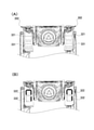
また、遊技機枠50は、上部に押圧機構PKを備えている。押圧機構PKは、開閉枠KWが閉じている場合に、後述の左側可動体253を第2位置に配置させることが可能なものである。押圧機構PKは、図3(A)および図3(B)に示すように、外枠51に設けられた姿勢保持部材(基枠押圧機構に相当)57、内枠52に設けられた押圧部材(変位機構に相当)58および可動部材59からなる。なお、図3(A)は、内枠52が閉じているときの押圧機構PKの状態を示した図であり、図3(B)は、内枠52が開いているときの押圧機構PKの状態を示した図である。
Further, the gaming machine frame 50 is provided with a pressing mechanism PK on the upper portion. The pressing mechanism PK can arrange the left movable body 253, which will be described later, at the second position when the opening / closing frame KW is closed. As shown in FIGS. 3A and 3B, the pressing mechanism PK is a posture holding member (corresponding to the base frame pressing mechanism) 57 provided on the outer frame 51 and a pressing member provided on the inner frame 52. It is composed of 58 (corresponding to a displacement mechanism) and a movable member 59. 3A is a diagram showing the state of the pressing mechanism PK when the inner frame 52 is closed, and FIG. 3B is a diagram showing the state of the pressing mechanism PK when the inner frame 52 is open. It is a figure which showed the state.
姿勢保持部材57は、L字形状の部材であり、外枠51の上部内側に固定されている(図2参照)。この姿勢保持部材57は、図3に示すように、本体部57Aと、この本体部57Aの図3中の右端から、内枠52側(図中、奥側)に延出する壁部57Bとを備えている。本体部57Aは、外枠51に当接して固定される部位である。壁部57Bは、内枠52の閉塞時に可動部材59の左方から可動部材59に当接させるためのものである(図3(A)参照)。
The posture holding member 57 is an L-shaped member and is fixed to the inside of the upper part of the outer frame 51 (see FIG. 2). As shown in FIG. 3, the posture holding member 57 includes a main body portion 57A and a wall portion 57B extending from the right end of the main body portion 57A to the inner frame 52 side (in the figure, the back side). It is equipped with. The main body portion 57A is a portion that abuts and is fixed to the outer frame 51. The wall portion 57B is for contacting the movable member 59 from the left side of the movable member 59 when the inner frame 52 is closed (see FIG. 3A).
押圧部材58は、内枠52の上端に配置されている(図2参照)。この押圧部材58は、図3(A)中、上下方向に伸びる板状の本体部58Aと、その本体部58Aの、図3(A)中、下側の先端に位置する先端部58Bとを備えている。本体部58Aの中央には、図中、上下方向に延びる長穴58Cが設けられている。本体部58Aは、長穴58Cを挿通しつつ内枠52の上部に固定された2個のリベットRVによって、図3(A)中、上下方向にスライド移動可能になっている。また、本体部58Aの図3(A)中、右上側には、貫通孔58Dが設けられている。この貫通孔58Dは、可動部材59の第1アーム部59Aの先端を挿通させるためのものである。
The pressing member 58 is arranged at the upper end of the inner frame 52 (see FIG. 2). The pressing member 58 has a plate-shaped main body portion 58A extending in the vertical direction in FIG. 3A and a tip portion 58B of the main body portion 58A located at the lower tip in FIG. 3A. I have. In the center of the main body portion 58A, an elongated hole 58C extending in the vertical direction is provided in the drawing. The main body portion 58A is slidable in the vertical direction in FIG. 3A by two rivet RVs fixed to the upper part of the inner frame 52 while inserting the elongated hole 58C. Further, in FIG. 3A of the main body portion 58A, a through hole 58D is provided on the upper right side. The through hole 58D is for inserting the tip of the first arm portion 59A of the movable member 59.
可動部材59は、上記押圧部材58と同じく、内枠52の上端に配置されている。この可動部材59は、図3(A)中、左右方向に延びる板状の第1アーム部59Aと、この第1アーム部59Aの左側の端部から、図3(A)中、前後方向に延びる板状の第2アーム部59Bとを備えている。第1アーム部59Aは、図3(A)および図3(B)に示すように、押圧部材58の上方に重なって配置される。そして、第1アーム部59Aの右側の先端が、押圧部材58の貫通孔58Dを挿通している。なお、可動部材59は、図3(A)に示すように、第1アーム部59Aと第2アーム部59Bとの間の位置に回動軸AXがある。この回動軸AXを中心にして、可動部材59が回動可能となっている。
The movable member 59 is arranged at the upper end of the inner frame 52 like the pressing member 58. The movable member 59 has a plate-shaped first arm portion 59A extending in the left-right direction in FIG. 3A and a left end portion of the first arm portion 59A in the front-rear direction in FIG. 3A. It is provided with a plate-shaped second arm portion 59B that extends. As shown in FIGS. 3A and 3B, the first arm portion 59A is arranged so as to overlap above the pressing member 58. The tip on the right side of the first arm portion 59A inserts the through hole 58D of the pressing member 58. As shown in FIG. 3A, the movable member 59 has a rotation shaft AX at a position between the first arm portion 59A and the second arm portion 59B. The movable member 59 can rotate around the rotation shaft AX.
図3を用いて、内枠52が閉じているときの押圧機構PKの状態、および、内枠52が開いているときの押圧機構PKの状態を以下に説明する。図3(A)に示すように、内枠52が閉じているときには、姿勢保持部材57の壁部57Bが可動部材59の第2アーム部59Bを図中、左側から当接する。このため、可動部材59の第2アーム部59Bが、回動軸AXを中心として反時計周りにそれ以上回動できず、第1アーム部59Aも回動できない。つまり、姿勢保持部材57によって、回動できない姿勢で可動部材59が固定されることになる。従って、第1アーム部59Aの先端が挿通する押圧部材58の本体部58Aもまた、後方(図3(A)中、上方)に移動することなく、その位置に固定される。よって、内枠52が閉じているときには、押圧部材58の先端部58Bは、内枠52の縁から前方に距離F1突出した状態に固定されることになる。かくして、開閉枠KWの閉塞時には、そのような押圧部材58の押圧によって、左第1アーム266、左第2アーム271および左第3アーム276は押圧されて、左側可動体253は第2位置に配置可能となっている。なお、姿勢保持部材57は、開閉枠KWの閉塞時に、押圧部材58が左第1アーム266、左第2アーム271および左第3アーム276を押圧する状態にその押圧部材58をさせ得るものである。また、左第1アーム266、左第2アーム271、左第3アーム276および左側可動体253については、後ほど詳述する。
With reference to FIG. 3, the state of the pressing mechanism PK when the inner frame 52 is closed and the state of the pressing mechanism PK when the inner frame 52 is open will be described below. As shown in FIG. 3A, when the inner frame 52 is closed, the wall portion 57B of the posture holding member 57 abuts on the second arm portion 59B of the movable member 59 from the left side in the drawing. Therefore, the second arm portion 59B of the movable member 59 cannot rotate further counterclockwise around the rotation shaft AX, and the first arm portion 59A cannot rotate either. That is, the posture holding member 57 fixes the movable member 59 in a posture that cannot be rotated. Therefore, the main body portion 58A of the pressing member 58 through which the tip of the first arm portion 59A is inserted is also fixed at that position without moving backward (upward in FIG. 3A). Therefore, when the inner frame 52 is closed, the tip portion 58B of the pressing member 58 is fixed in a state of protruding forward by a distance F1 from the edge of the inner frame 52. Thus, when the opening / closing frame KW is closed, the left first arm 266, the left second arm 271 and the left third arm 276 are pressed by the pressing of the pressing member 58, and the left movable body 253 is moved to the second position. It can be placed. The posture holding member 57 can make the pressing member 58 press the left first arm 266, the left second arm 271 and the left third arm 276 when the opening / closing frame KW is closed. be. The left first arm 266, the left second arm 271, the left third arm 276, and the left movable body 253 will be described in detail later.
一方、図3(B)に示すように、内枠52が開いている場合には、可動部材59の第2アーム部59Bが姿勢保持部材57の壁部57Bから離れている。具体的には、内枠52の閉塞時よりも、姿勢保持部材57の壁部57Bと回動軸AXとの間に隙間が生じることになる。このため、可動部材59の第2アーム部59Bが、回動軸AXを中心として反時計周りに回動可能となり、それに伴って第1アーム部59Aも回動可能となる。この回動によって、第1アーム部59Aの先端が挿通する押圧部材58の本体部58Aもまた、後方に移動可能になる。従って、内枠52が開くと、押圧部材58の先端部58Bは、内枠52の縁から前方に距離F2だけ突出した状態になる。この距離F2は、内枠52の閉塞時の距離F1よりも短いため(F2<F1)、内枠52が開くと押圧部材58の突出量が相対的に小さくなり、押圧部材58が左側可動体ユニット202Lに届かなくなる。かくして、内枠52が開いている場合には、押圧部材58によって、後述の左側可動体253を第2位置に配置させることができない。
On the other hand, as shown in FIG. 3B, when the inner frame 52 is open, the second arm portion 59B of the movable member 59 is separated from the wall portion 57B of the posture holding member 57. Specifically, a gap is formed between the wall portion 57B of the posture holding member 57 and the rotation shaft AX than when the inner frame 52 is closed. Therefore, the second arm portion 59B of the movable member 59 can rotate counterclockwise about the rotation shaft AX, and the first arm portion 59A can also rotate accordingly. By this rotation, the main body portion 58A of the pressing member 58 through which the tip of the first arm portion 59A is inserted can also be moved rearward. Therefore, when the inner frame 52 is opened, the tip portion 58B of the pressing member 58 is in a state of protruding forward by a distance F2 from the edge of the inner frame 52. Since this distance F2 is shorter than the distance F1 when the inner frame 52 is closed (F2 <F1), when the inner frame 52 is opened, the amount of protrusion of the pressing member 58 becomes relatively small, and the pressing member 58 is a left movable body. It will not reach the unit 202L. Thus, when the inner frame 52 is open, the pressing member 58 cannot arrange the left movable body 253, which will be described later, at the second position.
図2に戻り、前枠53は、後方側にベース枠56を備えている。また前枠53は、図4に示すように、前方側に上側装飾部200と左側装飾部410と右側装飾部420と操作機構部430とを備えている。ベース枠56は、前面側で上側装飾部200と左側装飾部410と右側装飾部420と操作機構部430とを着脱可能に取付ける枠体である。
Returning to FIG. 2, the front frame 53 includes a base frame 56 on the rear side. Further, as shown in FIG. 4, the front frame 53 includes an upper decorative portion 200, a left decorative portion 410, a right decorative portion 420, and an operation mechanism portion 430 on the front side. The base frame 56 is a frame body to which the upper decorative portion 200, the left decorative portion 410, the right decorative portion 420, and the operation mechanism portion 430 are detachably attached on the front side.
上側装飾部(上部装飾部)200は、遊技機枠50(前枠53)の上部を装飾するものである(図4参照)。上側装飾部200は、図4に示すように、左右方向の中央に中央可動体ユニット201を備え、その中央可動体ユニット201の左方に左側可動体ユニット202L、右方に右側可動体ユニット202Rを備えている。中央可動体ユニット201は、枠可動体15を移動可能に組付けるユニットであり、前後方向に長いものである。本形態では左側可動体ユニット202Lおよび右側可動体ユニット202Rの構成に特徴があり、これら左側可動体ユニット202Lおよび右側可動体ユニット202Rの詳細な構成については後述する。
The upper decorative portion (upper decorative portion) 200 decorates the upper portion of the gaming machine frame 50 (front frame 53) (see FIG. 4). As shown in FIG. 4, the upper decorative portion 200 includes a central movable body unit 201 in the center in the left-right direction, a left movable body unit 202L on the left side of the central movable body unit 201, and a right movable body unit 202R on the right side. It is equipped with. The central movable body unit 201 is a unit for assembling the frame movable body 15 so as to be movable, and is long in the front-rear direction. The present embodiment is characterized by the configuration of the left movable body unit 202L and the right movable body unit 202R, and the detailed configurations of the left movable body unit 202L and the right movable body unit 202R will be described later.
この上側装飾部200(中央可動体ユニット201)は、図5に示すように、ベース枠56に取付けられている他のどの部分(左側装飾部410,右側装飾部420,操作機構部430)よりも、前方に突出している。具体的には、図5に示すように、上側装飾部200の前方側の先端P1と上記幕板51aの前表面P2との間の距離L1が、操作機構部430の前方側の先端P3と幕板51aの上記前表面P2との間の距離L2の2倍以上になっている。これにより、上側装飾部200による前方への突出が非常に強調されていて、従来の遊技機枠に比べて大きなインパクトを与えることが可能である。
As shown in FIG. 5, the upper decorative portion 200 (central movable body unit 201) is from any other portion (left decorative portion 410, right decorative portion 420, operating mechanism portion 430) attached to the base frame 56. Also protrudes forward. Specifically, as shown in FIG. 5, the distance L1 between the front tip P1 of the upper decorative portion 200 and the front surface P2 of the curtain plate 51a is the front tip P3 of the operation mechanism portion 430. The distance between the curtain plate 51a and the front surface P2 is more than twice the distance L2. As a result, the protrusion of the upper decorative portion 200 to the front is greatly emphasized, and it is possible to give a large impact as compared with the conventional gaming machine frame.
左側装飾部410は、遊技機枠50(前枠53)の左部を装飾するものである(図4参照)。右側装飾部420は、遊技機枠50の右部を装飾するものであり、剣役物ユニット321を備えている。剣役物ユニット321には、剣の形を模した剣役物322が押込操作可能に設けられている。これにより遊技の進行に伴って実行される演出時に、遊技者に対して剣役物322への押込操作が促されるようになっている。
The left decorative portion 410 decorates the left portion of the gaming machine frame 50 (front frame 53) (see FIG. 4). The right side decoration unit 420 decorates the right part of the gaming machine frame 50, and includes a sword accessory unit 321. The sword accessory unit 321 is provided with a sword accessory 322 that imitates the shape of a sword so that it can be pushed in. As a result, the player is urged to push the sword character into the sword character 322 at the time of the production performed as the game progresses.
操作機構部430は、遊技や演出を進行するための操作機構を備えるものである。操作機構部430は、図1に示すように、右側の下部に回転角度に応じた発射強度で遊技球を発射させるためのハンドル60を備え、上側の後部に遊技球を貯留する打球供給皿(上皿)61を備え、ハンドル60よりも左方に打球供給皿61に収容しきれない遊技球を貯留する余剰球受皿(下皿)62を備えている。また、操作機構部430のうち上皿61よりも前方には、遊技の進行に伴って実行される演出時等に遊技者が操作し得る演出ボタン63や十字キー68が設けられている(図1参照)。
The operation mechanism unit 430 includes an operation mechanism for advancing a game or an effect. As shown in FIG. 1, the operation mechanism unit 430 is provided with a handle 60 for launching a game ball at a firing intensity according to a rotation angle at the lower part on the right side, and a hitting ball supply dish (a ball feeding plate) for storing the game ball at the upper rear part. The upper plate) 61 is provided, and a surplus ball tray (lower plate) 62 for storing game balls that cannot be accommodated in the hit ball supply plate 61 is provided to the left of the handle 60. Further, in front of the upper plate 61 of the operation mechanism unit 430, an effect button 63 and a cross key 68 that can be operated by the player at the time of the effect executed as the game progresses are provided (FIG. FIG. See 1).
本形態のパチンコ遊技機1では、図4に正面図が示され、図5に右側面図が示され、図6に平面図が示されている。ここで、図4および図5に示すように、遊技場の島設備において鉛直方向に起立した垂直壁面SHのうち遊技機1の上方には、データカウンタ160が配されている。データカウンタ160は、垂直壁面SHに固定されている固定部材161と、この固定部材161に対して前傾姿勢になるように傾動可能に取付けられているデータ表示装置162とを備えている。
In the pachinko gaming machine 1 of the present embodiment, a front view is shown in FIG. 4, a right side view is shown in FIG. 5, and a plan view is shown in FIG. Here, as shown in FIGS. 4 and 5, a data counter 160 is arranged above the gaming machine 1 among the vertical wall surface SHs standing in the vertical direction in the island equipment of the gaming field. The data counter 160 includes a fixing member 161 fixed to the vertical wall surface SH, and a data display device 162 attached so as to be tilted forward with respect to the fixing member 161.
データ表示装置162は、後述する大当たり遊技状態の発生回数や高確率状態の発生回数等を表示する略直方体形状のものである。またデータ表示装置162は、遊技者がホールの従業員を呼ぶための呼び出しボタン等を有している。このデータカウンタ160では、垂直壁面SHに対するデータ表示装置162の前傾角度θ1を15度から25度まで可変できるようになっている。なお、図5では、データ表示装置162の前傾角度θ1が最大の25度になっている状態が示されている。
The data display device 162 has a substantially rectangular parallelepiped shape that displays the number of occurrences of the jackpot gaming state and the number of occurrences of the high probability state, which will be described later. Further, the data display device 162 has a call button or the like for the player to call an employee of the hall. In this data counter 160, the forward tilt angle θ1 of the data display device 162 with respect to the vertical wall surface SH can be changed from 15 degrees to 25 degrees. Note that FIG. 5 shows a state in which the forward tilt angle θ1 of the data display device 162 is the maximum of 25 degrees.
また本形態のパチンコ遊技機1では、図7に示すように、遊技機枠50のうち上側装飾部200の後方の下側に、左右一対の左側スピーカ67Lおよび右側スピーカ67Rが設けられている。また上側装飾部200、左側装飾部410、右側装飾部420および操作機構部430には、様々な発光色で発光可能な枠ランプ66(図37参照)が多数設けられている。
Further, in the pachinko gaming machine 1 of the present embodiment, as shown in FIG. 7, a pair of left and right left speakers 67L and a right side speaker 67R are provided on the lower side behind the upper decorative portion 200 of the gaming machine frame 50. Further, the upper decorative portion 200, the left decorative portion 410, the right decorative portion 420, and the operation mechanism portion 430 are provided with a large number of frame lamps 66 (see FIG. 37) capable of emitting light in various emission colors.
次に、図8を参照して遊技盤2について説明する。図8に示すように、遊技盤2の前面側には、鉛直方向に起立した遊技面2aが形成されている。この遊技面2aの前方に、ハンドル60の操作により発射された遊技球が流下する遊技領域3が、レール部材4で囲まれて形成されている。また遊技盤2には、様々な発光色で発光可能な盤ランプ5(図37参照)が多数設けられている。なお遊技盤2は、前側に配されている板状部材と、後側に配されている裏ユニット(後述する各種制御基板、第1画像表示装置6、第2画像表示装置7、ハーネス等を取付けるユニット)とが一体化されたものである。
Next, the game board 2 will be described with reference to FIG. As shown in FIG. 8, a game surface 2a standing upright in the vertical direction is formed on the front surface side of the game board 2. In front of the game surface 2a, a game area 3 into which a game ball launched by the operation of the handle 60 flows down is formed by being surrounded by a rail member 4. Further, the game board 2 is provided with a large number of board lamps 5 (see FIG. 37) capable of emitting light in various emission colors. The game board 2 includes a plate-shaped member arranged on the front side and a back unit (various control boards described later, a first image display device 6, a second image display device 7, a harness, etc.) arranged on the rear side. The unit to be mounted) is integrated.
遊技盤2の遊技面2aには、遊技球を誘導する複数の遊技釘(図示省略)が突設されている。また遊技面2aよりも内側であって且つ遊技面2aよりも後方には、液晶表示装置である第1画像表示装置(第1表示手段)6が配されている。第1画像表示装置6は、鉛直方向に起立した状態で固定されている。
A plurality of game nails (not shown) for guiding the game ball are projected on the game surface 2a of the game board 2. Further, a first image display device (first display means) 6 which is a liquid crystal display device is arranged inside the game surface 2a and behind the game surface 2a. The first image display device 6 is fixed in an upright state in the vertical direction.
第1画像表示装置6の表示画面6aには、後述の第1特別図柄および第2特別図柄の変動表示(可変表示)に同期した装飾図柄(演出図柄)8L,8C,8Rの変動表示を行う装飾図柄表示領域がある。装飾図柄表示領域は、例えば「左」「中」「右」の3つの図柄表示エリアからなる。左の図柄表示エリアには左演出図柄8Lが表示され、中の図柄表示エリアには中演出図柄8Cが表示され、右の図柄表示エリアには右演出図柄8Rが表示される。装飾図柄はそれぞれ、例えば「1」~「9」までの数字をあらわした複数の図柄からなる。第1画像表示装置6は、左、中、右の装飾図柄の組み合わせによって、後述の第1特別図柄表示器41aおよび第2特別図柄表示器41b(図10参照)にて表示される第1特別図柄および第2特別図柄の変動表示の結果(つまりは大当たり抽選の結果)を、わかりやすく表示する。
On the display screen 6a of the first image display device 6, variable display of decorative symbols (effect symbols) 8L, 8C, 8R synchronized with variable display (variable display) of the first special symbol and the second special symbol described later is performed. There is a decorative pattern display area. The decorative symbol display area is composed of, for example, three symbol display areas of "left", "middle", and "right". The left effect symbol 8L is displayed in the left symbol display area, the middle effect symbol 8C is displayed in the middle symbol display area, and the right effect symbol 8R is displayed in the right symbol display area. Each decorative pattern is composed of a plurality of patterns representing numbers from "1" to "9", for example. The first image display device 6 is a first special displayed by a combination of left, middle, and right decorative symbols on a first special symbol display 41a and a second special symbol display 41b (see FIG. 10), which will be described later. The result of the variable display of the symbol and the second special symbol (that is, the result of the jackpot lottery) is displayed in an easy-to-understand manner.
例えば、大当たりに当選した場合には「777」などのゾロ目で装飾図柄を停止表示する。また、はずれであった場合には「263」などのバラケ目で装飾図柄を停止表示する。これにより、遊技者にとっては遊技の進行状況の把握が容易となる。つまり遊技者は、一般的には大当たり抽選の結果を第1特別図柄表示器41aや第2特別図柄表示器41bにより把握するのではなく、第1画像表示装置6にて把握する。なお、図柄表示エリアの位置は固定的でなくてもよい。また、装飾図柄の変動表示の態様としては、例えば上下方向にスクロールする態様がある。また、各抽選結果に応じてどのような装飾図柄の組み合わせを停止表示するかは任意に変更可能である。
For example, if a big hit is won, the decorative pattern is stopped and displayed with doublets such as "777". In addition, if it is out of alignment, the decorative pattern is stopped and displayed with a random stitch such as "263". This makes it easier for the player to grasp the progress of the game. That is, the player generally does not grasp the result of the jackpot lottery by the first special symbol display 41a or the second special symbol display 41b, but by the first image display device 6. The position of the symbol display area does not have to be fixed. Further, as a mode of variable display of the decorative pattern, for example, there is a mode of scrolling in the vertical direction. In addition, it is possible to arbitrarily change what kind of decorative pattern combination is stopped and displayed according to each lottery result.
第1画像表示装置6は、上記のような装飾図柄を用いた装飾図柄変動演出(「演出図柄変動演出」や単に「変動演出」ともいう)のほか、大当たり遊技に並行して行われる大当たり演出や、客待ち用のデモ演出などを表示画面6aに表示する。なお装飾図柄変動演出では、数字等の装飾図柄のほか、背景画像やキャラクタ画像などの装飾図柄以外の演出画像も表示される。
In the first image display device 6, in addition to the decorative symbol variation effect (also referred to as "effect symbol variation effect" or simply "variation effect") using the decorative pattern as described above, the jackpot effect performed in parallel with the jackpot game. Or, a demonstration effect for waiting for customers is displayed on the display screen 6a. In the decorative pattern variation effect, in addition to decorative patterns such as numbers, effect images other than decorative patterns such as background images and character images are also displayed.
また第1画像表示装置6の表示画面6aには、後述の第1特図保留の記憶数に応じて演出保留画像9Aを表示する第1演出保留表示エリア9aと、後述の第2特図保留の記憶数に応じて演出保留画像9Bを表示する第2演出保留表示エリア9bとがある。演出保留画像9A,9Bの表示により、後述の第1特図保留表示器43a(図10参照)にて表示される第1特図保留の記憶数および第2特図保留表示器43b(図10参照)にて表示される第2特図保留の記憶数を、遊技者にわかりやすく示すことが可能となっている。
Further, on the display screen 6a of the first image display device 6, a first effect hold display area 9a for displaying the effect hold image 9A according to the number of stored first special figure hold described later, and a second special figure hold described later are displayed. There is a second effect hold display area 9b that displays the effect hold image 9B according to the number of stored images. By displaying the effect hold images 9A and 9B, the number of stored first special figure hold and the second special figure hold display 43b (FIG. 10) displayed on the first special figure hold display 43a (see FIG. 10) described later. It is possible to show the player the number of stored memories of the second special figure hold displayed in (see) in an easy-to-understand manner.
また本形態のパチンコ遊技機1には、図8に示すように、第1画像表示装置6よりも上方に第2画像表示装置(第2表示手段)7が設けられている。第2画像表示装置7の表示画面7aでは、第1画像表示装置6の表示画面6aで実行される装飾図柄変動演出、大当たり演出、客待ち用のデモ演出などに合わせて、背景画像やキャラクタ画像など様々な演出画像が表示されるようになっている。
Further, as shown in FIG. 8, the pachinko gaming machine 1 of the present embodiment is provided with a second image display device (second display means) 7 above the first image display device 6. On the display screen 7a of the second image display device 7, a background image or a character image is used in accordance with the decorative pattern variation effect, the jackpot effect, the demo effect for waiting for customers, etc. executed on the display screen 6a of the first image display device 6. Various production images such as are displayed.
この第2画像表示装置7は、前方に向かって斜め上方に傾斜した状態で固定されている。そして、第2画像表示装置7の表示画面7aの上部7bは、遊技盤2の遊技面2aよりも前方に飛び出ている。これにより遊技者には、より近い位置で表示画面7aの上部7bを見せることが可能である。更に、第2画像表示装置7の表示画面7aの上部7bは、図8に示すように、遊技領域3の上端部よりも上方に飛び出ている。これにより遊技者には、遊技領域3の外側でも表示画面7aの上部7bを見せることが可能である。こうして本形態では、第1画像表示装置6の表示画面6aと第2画像表示装置7の表示画面7aとにより、斬新な表示画面が形成されていて、遊技者には広範囲且つ近い距離で演出画像を見せることが可能である。その結果、表示画面6a,7aで表示される演出画像のインパクトを高めることが可能である。
The second image display device 7 is fixed in a state of being inclined diagonally upward toward the front. The upper portion 7b of the display screen 7a of the second image display device 7 protrudes forward from the game surface 2a of the game board 2. This makes it possible for the player to show the upper portion 7b of the display screen 7a at a closer position. Further, as shown in FIG. 8, the upper portion 7b of the display screen 7a of the second image display device 7 protrudes above the upper end portion of the game area 3. As a result, it is possible for the player to show the upper portion 7b of the display screen 7a even outside the gaming area 3. In this way, in this embodiment, the display screen 6a of the first image display device 6 and the display screen 7a of the second image display device 7 form a novel display screen, and the player can see the effect image over a wide range and at a short distance. It is possible to show. As a result, it is possible to enhance the impact of the effect images displayed on the display screens 6a and 7a.
図8に示すように、遊技領域3の中央付近であって第1画像表示装置6の前方には、センター装飾体10が配されている。センター装飾体10の下部には、上面を転動する遊技球を、後述の第1始動口20へと誘導可能なステージ部11が形成されている。またセンター装飾体10の左下方には、入口から遊技球を流入させ、出口からステージ部11へ遊技球を流出させるワープ部12が設けられている。
As shown in FIG. 8, a center decorative body 10 is arranged near the center of the game area 3 and in front of the first image display device 6. At the lower part of the center decorative body 10, a stage portion 11 that can guide a game ball that rolls on the upper surface to the first starting port 20, which will be described later, is formed. Further, at the lower left of the center decoration body 10, a warp portion 12 is provided, which allows the game ball to flow in from the entrance and flow out from the exit to the stage portion 11.
遊技領域3における第1画像表示装置6の下方には、第1始動口(第1始動入賞口、第1入球口、固定始動口)20を備える固定入賞装置19が設けられている。第1始動口20は、遊技球の入球し易さが常に変わらない入賞口である。第1始動口20への遊技球の入賞は、第1特別図柄の抽選(大当たり抽選、すなわち大当たり乱数等の取得と判定)の契機となっている。
Below the first image display device 6 in the game area 3, a fixed winning device 19 including a first starting opening (first starting winning opening, first ball entry opening, fixed starting opening) 20 is provided. The first starting opening 20 is a winning opening in which the ease of entering a game ball does not always change. The winning of the game ball to the first starting port 20 is an opportunity for the first special symbol lottery (big hit lottery, that is, determination of acquisition of a big hit random number or the like).
また第1始動口20の下方には、第2始動口(第2始動入賞口、第2入球口、可変始動口)21を備える普通可変入賞装置(いわゆる電チュー)22が設けられている。第2始動口21は、遊技球の入球し易さが変化可能な入賞口である。なお本形態の第2始動口21は、上下方向且つ前後方向に延びる平面で形成される開口部分である。第2始動口21への遊技球の入賞は、第2特別図柄の抽選の契機となっている。
Further, below the first starting port 20, a normal variable winning device (so-called electric chew) 22 provided with a second starting opening (second starting winning opening, second ball entry opening, variable starting opening) 21 is provided. .. The second starting port 21 is a winning opening in which the ease of entering the game ball can be changed. The second starting port 21 of the present embodiment is an opening portion formed by a plane extending in the vertical direction and the front-rear direction. The winning of the game ball to the second starting port 21 is an opportunity for the lottery of the second special symbol.
電チュー22は、前後方向に進退可能な可動部材(入球口開閉部材)23を備え、可動部材23の作動によって第2始動口21を開閉するものである。可動部材23は、電チューソレノイド24(図36参照)により駆動される。第2始動口21は、可動部材23が前方に進出しているとき(つまり開状態であるとき)だけ遊技球が入球可能となる。つまり、可動部材23が前方に進出しているときには、流下する遊技球が可動部材23の上側に当接すると、左方へ誘導される。これにより、遊技球が第2始動口21に入球可能となる。
The electric chew 22 includes a movable member (ball entry opening / closing member) 23 that can move forward and backward, and opens / closes the second starting port 21 by the operation of the movable member 23. The movable member 23 is driven by an electric chew solenoid 24 (see FIG. 36). The second starting port 21 allows a game ball to enter only when the movable member 23 is advanced forward (that is, when it is in the open state). That is, when the movable member 23 is advanced forward, when the flowing game ball comes into contact with the upper side of the movable member 23, it is guided to the left. As a result, the game ball can enter the second starting port 21.
一方、第2始動口21は、後方に退避しているとき(つまり閉状態であるとき)には遊技球が入球不可能となる。つまり、可動部材23が後方に退避しているときには、流下する遊技球が可動部材23に当接しない。これにより、遊技球は第2始動口21に入球することなく、後述するアウト口16へ向かう。なお、第2始動口21は、可動部材23が閉状態にあるときには開状態にあるときよりも遊技球が入球困難となるものであれば、可動部材23が閉状態であるときに完全に入球不可能となるものでなくても良い。
On the other hand, when the second starting port 21 is retracted backward (that is, when it is in the closed state), the game ball cannot enter the ball. That is, when the movable member 23 is retracted backward, the flowing game ball does not come into contact with the movable member 23. As a result, the game ball goes to the out port 16 described later without entering the second starting port 21. The second starting port 21 is completely closed when the movable member 23 is closed, as long as the game ball is more difficult to enter when the movable member 23 is in the closed state than when the movable member 23 is in the open state. It does not have to be something that makes it impossible to enter the ball.
また第1始動口20の右斜め上方には、第1大入賞口(第1特別入賞口)30を備えた第1大入賞装置(第1特別可変入賞装置)31が設けられている。第1大入賞装置31は、開状態と閉状態とをとる開閉部材(第1特別入賞口開閉部材)32を備え、開閉部材32の作動により第1大入賞口30を開閉するものである。開閉部材32は、第1大入賞口ソレノイド33(図36参照)により駆動される。第1大入賞口30は、開閉部材32が開いているとき(つまり開状態であるとき)だけ遊技球が入球可能となる。
Further, a first large winning device (first special variable winning device) 31 provided with a first large winning opening (first special winning opening) 30 is provided diagonally upward to the right of the first starting opening 20. The first special winning device 31 includes an opening / closing member (first special winning opening opening / closing member) 32 that takes an open state and a closed state, and opens and closes the first special winning opening 30 by the operation of the opening / closing member 32. The opening / closing member 32 is driven by the first large winning opening solenoid 33 (see FIG. 36). The first large winning opening 30 allows a game ball to enter only when the opening / closing member 32 is open (that is, when it is in the open state).
また第1大入賞口30の上方には、遊技球が通過可能なゲート(通過領域)28が設けられている。ゲート28への遊技球の通過は、電チュー22を開放するか否かを決める普通図柄抽選(すなわち普通図柄乱数(当たり乱数)の取得と判定)の実行契機となっている。
Further, above the first large winning opening 30, a gate (passing area) 28 through which a game ball can pass is provided. The passage of the game ball to the gate 28 is an opportunity to execute a normal symbol lottery (that is, acquisition and determination of a normal symbol random number (hit random number)) for determining whether or not to open the electric chew 22.
また、ゲート28の右斜め上方には、第2大入賞口(第2特別入賞口)35を備えた第2大入賞装置(第2特別可変入賞装置)36が設けられている。第2大入賞装置36は、開状態と閉状態とをとる開閉部材(第2特別入賞口開閉部材)37を備え、開閉部材37の作動により第2大入賞口35を開閉するものである。開閉部材37は、第2大入賞口ソレノイド38(図36参照)により駆動される。第2大入賞口35は、開閉部材37が開いているときだけ(つまり開状態であるとき)だけ遊技球が入球可能となる。
Further, a second large winning device (second special variable winning device) 36 provided with a second large winning opening (second special winning opening) 35 is provided diagonally above the right side of the gate 28. The second special winning device 36 includes an opening / closing member (second special winning opening opening / closing member) 37 that takes an open state and a closed state, and opens and closes the second special winning opening 35 by the operation of the opening / closing member 37. The opening / closing member 37 is driven by the second large winning opening solenoid 38 (see FIG. 36). The second large winning opening 35 allows a game ball to enter only when the opening / closing member 37 is open (that is, when it is in the open state).
より詳細には、図9(A)に示すように、第2大入賞装置36の内部には、第2大入賞口35を通過した遊技球が通過可能な特定領域(V領域)39および非特定領域70が形成されている。なお、第2大入賞装置36において、特定領域39および非特定領域70の上流には、第2大入賞口35への遊技球の入賞を検知する第2大入賞口センサ35aが配されている。また、特定領域39には、特定領域39への遊技球の通過を検知する特定領域センサ39aが配されている。また、非特定領域70には、非特定領域70への遊技球の通過を検知する非特定領域センサ70aが配されている。また、第2大入賞装置36は、第2大入賞口35を通過した遊技球を特定領域39または非特定領域70のいずれかに振り分ける振分部材71と、振分部材71を駆動する振分部材ソレノイド73とを備えている。振分部材71は、左右方向に進退するものであり、左方に進出した進出状態(第1の状態)又は右方に退避した退避状態(第2の状態)をとる。
More specifically, as shown in FIG. 9A, the inside of the second special winning device 36 includes a specific area (V area) 39 through which a game ball passing through the second big winning opening 35 can pass and a non-region (V area) 39. A specific region 70 is formed. In the second large winning device 36, a second large winning opening sensor 35a for detecting the winning of a game ball to the second large winning opening 35 is arranged upstream of the specific area 39 and the non-specific area 70. .. Further, in the specific area 39, a specific area sensor 39a for detecting the passage of the game ball to the specific area 39 is arranged. Further, in the non-specific area 70, a non-specific area sensor 70a for detecting the passage of a game ball to the non-specific area 70 is arranged. Further, the second prize-winning device 36 has a distribution member 71 that distributes the game ball that has passed through the second prize-winning opening 35 to either the specific area 39 or the non-specific area 70, and the distribution member 71 that drives the distribution member 71. It is provided with a member solenoid 73. The distribution member 71 advances and retreats in the left-right direction, and takes an advanced state (first state) advanced to the left or a retracted state (second state) retracted to the right.
図9(A)は、振分部材ソレノイド73の通電時を示している。図9(A)に示すように、振分部材ソレノイド73の通電時には、振分部材71は特定領域39への遊技球の通過を許容する第1の状態にある。振分部材71が第1の状態にあるときは、第2大入賞口35に入賞した遊技球は、第2大入賞口センサ35aを通過したあと特定領域39を通過する。この遊技球のルートを第1のルートという。
FIG. 9A shows the time when the distribution member solenoid 73 is energized. As shown in FIG. 9A, when the distribution member solenoid 73 is energized, the distribution member 71 is in the first state of allowing the game ball to pass through the specific area 39. When the distribution member 71 is in the first state, the game ball that has won the second special winning opening 35 passes through the specific area 39 after passing through the second special winning opening sensor 35a. The route of this game ball is called the first route.
図9(B)は、振分部材ソレノイド73の非通電時を示している。図9(B)に示すように、振分部材ソレノイド73の非通電時には、振分部材71は特定領域39への遊技球の通過を妨げる第2の状態にある。振分部材71が第2の状態にあるときは、第2大入賞口35に入賞した遊技球は、第2大入賞口センサ35aを通過したあと振分部材71の上面を転動して非特定領域70を通過する。この遊技球のルートを第2のルートという。
FIG. 9B shows the non-energized state of the distribution member solenoid 73. As shown in FIG. 9B, when the distribution member solenoid 73 is not energized, the distribution member 71 is in a second state of hindering the passage of the game ball to the specific area 39. When the distribution member 71 is in the second state, the game ball that has won the second special winning opening 35 passes through the second large winning opening sensor 35a and then rolls on the upper surface of the distribution member 71 to be non-delivered. It passes through the specific area 70. The route of this game ball is called the second route.
なお本パチンコ遊技機1では、特定領域39への遊技球の通過が後述の高確率状態への移行の契機となっている。つまり特定領域39は、確変作動口となっている。これに対して非特定領域70は、確変作動口ではない。また、第1大入賞装置31には、確変作動口としての特定領域は設けられていない。すなわち非特定領域しか設けられていない。
In the pachinko gaming machine 1, the passage of the gaming ball to the specific area 39 triggers the transition to the high probability state described later. That is, the specific area 39 is a probabilistic operation port. On the other hand, the non-specific region 70 is not a probabilistic actuation port. Further, the first prize-winning device 31 is not provided with a specific area as a probabilistic operating port. That is, only a non-specific area is provided.
図8に戻り、遊技領域3の左下部や右下部には、普通入賞口27が設けられている。また遊技領域3の最下部には、遊技領域3へ打込まれたもののいずれの入賞口にも入賞しなかった遊技球を遊技領域3外へ排出するアウト口16が設けられている。
Returning to FIG. 8, ordinary winning openings 27 are provided in the lower left and lower right of the game area 3. Further, at the lowermost portion of the game area 3, an out port 16 is provided to discharge a game ball that has been driven into the game area 3 but has not won a prize in any of the winning openings to the outside of the game area 3.
このように各種の入賞口等が配されている遊技領域3には、左右方向の中央より左側の左遊技領域(第1遊技領域)3Aと、右側の右遊技領域(第2遊技領域)3Bとがある。左遊技領域3Aを遊技球が流下するように遊技球を発射する打方を、左打ちという。一方、右遊技領域3Bを遊技球が流下するように遊技球を発射する打方を、右打ちという。本形態のパチンコ遊技機1では、左打ちにて遊技したときに遊技球が流下し得る流路を、第1流路R1といい、右打ちにて遊技したときに遊技球が流下する流路を、第2流路R2という。
In the game area 3 in which various winning openings and the like are arranged, the left game area (first game area) 3A on the left side of the center in the left-right direction and the right game area (second game area) 3B on the right side are arranged. There is. The method of launching a game ball so that the game ball flows down in the left game area 3A is called left-handed. On the other hand, a method of launching a game ball so that the game ball flows down in the right game area 3B is called right-handed hitting. In the pachinko gaming machine 1 of the present embodiment, the flow path through which the game ball can flow down when playing left-handed is called the first flow path R1, and the flow path through which the game ball flows down when playing right-handed. Is referred to as a second flow path R2.
第1流路R1上には、普通入賞口27と、第1始動口20と、第2始動口21と、アウト口16とが設けられている。遊技者は左打ちをすることで、第1始動口20への入賞を狙う。なお、第1流路R1を流下した遊技球が第2始動口21へ入賞することは、ほとんどないように構成されている。
A normal winning opening 27, a first starting opening 20, a second starting opening 21, and an out opening 16 are provided on the first flow path R1. The player aims to win a prize in the first starting port 20 by hitting left. It should be noted that the game ball flowing down the first flow path R1 is configured so as to hardly win a prize in the second starting port 21.
一方、第2流路R2上には、第2大入賞装置36と、第1大入賞装置31と、普通入賞口27と、第2始動口21と、アウト口16とが設けられている。遊技者は右打ちをすることで、第2大入賞口35への入賞(特定領域39への通過)、ゲート28への通過、又は第1大入賞口30への入賞を狙う。
On the other hand, on the second flow path R2, a second big winning device 36, a first big winning device 31, a normal winning opening 27, a second starting opening 21, and an out opening 16 are provided. By hitting right, the player aims to win a prize in the second big winning opening 35 (passing through the specific area 39), passing through the gate 28, or winning a prize in the first big winning opening 30.
また図8に示すように、遊技盤2の左下部には表示器類40が配置されている。表示器類40には、図10に示すように、第1特別図柄(第1識別図柄)を可変表示する第1特別図柄表示器41a、第2特別図柄(第2識別図柄)を可変表示する第2特別図柄表示器41b、および、普通図柄を可変表示する普通図柄表示器42が含まれている。また表示器類40には、第1特別図柄表示器41aの作動保留(第1特図保留)の記憶数を表示する第1特図保留表示器43a、第2特別図柄表示器41bの作動保留(第2特図保留)の記憶数を表示する第2特図保留表示器43b、および、普通図柄表示器42の作動保留(普図保留)の記憶数を表示する普図保留表示器44が含まれている。
Further, as shown in FIG. 8, display devices 40 are arranged at the lower left of the game board 2. As shown in FIG. 10, the display devices 40 variably display the first special symbol display 41a and the second special symbol (second identification symbol) that variably display the first special symbol (first identification symbol). A second special symbol display 41b and a normal symbol display 42 that variably displays a normal symbol are included. Further, in the indicators 40, the operation hold of the first special symbol display 43a and the second special symbol display 41b for displaying the number of stored operations of the first special symbol display 41a (first special symbol hold) is displayed. The second special figure hold indicator 43b that displays the stored number of (second special figure hold) and the normal figure hold indicator 44 that displays the stored number of the operation hold (normal figure hold) of the normal symbol display 42 include.
第1特別図柄の可変表示は、第1始動口20への遊技球の入賞を契機として行われる。第2特別図柄の可変表示は、第2始動口21への遊技球の入賞を契機として行われる。なお以下の説明では、第1特別図柄および第2特別図柄を総称して特別図柄(識別図柄)ということがある。また第1特図保留および第2特図保留を総称して特図保留ということがある。また、第1特別図柄表示器41aおよび第2特別図柄表示器41bを総称して特別図柄表示器41ということがある。また、第1特図保留表示器43aおよび第2特図保留表示器43bを総称して特図保留表示器43ということがある。
The variable display of the first special symbol is performed with the winning of the game ball to the first starting port 20 as an opportunity. The variable display of the second special symbol is performed with the winning of the game ball to the second starting port 21 as a trigger. In the following description, the first special symbol and the second special symbol may be collectively referred to as a special symbol (identification symbol). In addition, the first special figure hold and the second special figure hold may be collectively referred to as a special figure hold. Further, the first special symbol display 41a and the second special symbol display 41b may be collectively referred to as a special symbol display 41. Further, the first special figure hold indicator 43a and the second special figure hold indicator 43b may be collectively referred to as a special figure hold indicator 43.
特別図柄表示器41では、特別図柄を可変表示したあと停止表示することにより、第1始動口20又は第2始動口21への入賞に基づく抽選(特別図柄抽選、大当たり抽選)の結果を報知する。停止表示される特別図柄(停止図柄、可変表示の表示結果として導出表示される特別図柄)は、特別図柄抽選によって複数種類の特別図柄の中から選択された一つの特別図柄である。停止図柄が予め定めた特定特別図柄(特定の停止態様の特別図柄すなわち大当たり図柄)である場合には、停止表示された特定特別図柄の種類に応じた開放パターンにて第1大入賞口30又は第2大入賞口35を開放させる特別遊技(大当たり遊技)が行われる。なお、特別遊技における大入賞口(第1大入賞口30および第2大入賞口35)の開放パターンについては後述する。
The special symbol display 41 notifies the result of a lottery (special symbol lottery, jackpot lottery) based on winning a prize in the first starting port 20 or the second starting port 21 by variably displaying the special symbol and then displaying the stop. .. The stop-displayed special symbol (stop symbol, special symbol derived and displayed as a display result of variable display) is one special symbol selected from a plurality of types of special symbols by a special symbol lottery. If the stop symbol is a predetermined special symbol (a special symbol of a specific stop mode, that is, a jackpot symbol), the first big winning opening 30 or the opening pattern corresponding to the type of the specific special symbol displayed as stopped is used. A special game (big hit game) that opens the second big winning opening 35 is performed. The opening pattern of the large winning openings (first large winning opening 30 and second large winning opening 35) in the special game will be described later.
特別図柄表示器41は、例えば横並びに配された8個のLEDから構成されており、その点灯態様によって大当たり抽選の結果に応じた特別図柄を表示するものである。例えば大当たり(後述の複数種類の大当たりのうちの一つ)に当選した場合には、「○○●●○○●●」(○:点灯、●:消灯)というように左から1,2,5,6番目にあるLEDが点灯した大当たり図柄を表示する。また、ハズレである場合には、「●●●●●●●○」というように一番右にあるLEDのみが点灯したハズレ図柄を表示する。ハズレ図柄として全てのLEDを消灯させる態様を採用してもよい。また、特別図柄が停止表示される前には所定の変動時間にわたって特別図柄の変動表示(可変表示)がなされるが、その変動表示の態様は、例えば左から右へ光が繰り返し流れるように各LEDが点灯するという態様である。なお変動表示の態様は、各LEDが停止表示(特定の態様での点灯表示)されていなければ、全LEDが一斉に点滅するなどなんでもよい。
The special symbol display 41 is composed of, for example, eight LEDs arranged side by side, and displays a special symbol according to the result of the jackpot lottery depending on the lighting mode thereof. For example, if you win a jackpot (one of the multiple types of jackpots described below), you will see "○○ ●● ○○ ●●" (○: lit, ●: off) from the left 1, 2, The jackpot symbol with the 5th and 6th LEDs lit is displayed. If there is a loss, a lost pattern such as "●●●●●●● ○" is displayed, in which only the LED on the far right is lit. A mode in which all the LEDs are turned off may be adopted as a lost pattern. Further, before the special symbol is stopped and displayed, the variable display (variable display) of the special symbol is performed over a predetermined fluctuation time, and the mode of the variation display is, for example, so that light repeatedly flows from left to right. It is an aspect that the LED is turned on. It should be noted that the variable display mode may be any mode such that all the LEDs blink at the same time unless each LED is stopped display (lighting display in a specific mode).
本パチンコ遊技機1では、第1始動口20又は第2始動口21への遊技球の入賞(入球)があると、その入賞に対して取得した大当たり乱数等の各種乱数の値(入賞情報)は、特図保留記憶部85(図36参照)に一旦記憶される。詳細には、第1始動口20への入賞であれば第1特図保留として第1特図保留記憶部85a(図36参照)に記憶され、第2始動口21への入賞であれば第2特図保留として第2特図保留記憶部85b(図36参照)に記憶される。各々の特図保留記憶部85に記憶可能な特図保留の数には上限があり、本形態における上限値はそれぞれ4個となっている。
In this pachinko gaming machine 1, if there is a winning (winning) of a game ball in the first starting port 20 or the second starting port 21, the value of various random numbers such as the jackpot random number acquired for the winning (winning information). ) Is temporarily stored in the special figure reservation storage unit 85 (see FIG. 36). Specifically, if the prize is won in the first starting port 20, it is stored in the first special figure holding storage unit 85a (see FIG. 36) as the first special figure holding, and if the winning is in the second starting port 21, the first special figure is held. 2 As a special figure hold, it is stored in the second special figure hold storage unit 85b (see FIG. 36). There is an upper limit to the number of special figure reservations that can be stored in each special figure reservation storage unit 85, and the upper limit value in this embodiment is four each.
特図保留記憶部85に記憶された特図保留は、その特図保留に基づく特別図柄の可変表示が可能となったときに消化される。特図保留の消化とは、その特図保留に対応する大当たり乱数等を判定して、その判定結果を示すための特別図柄の可変表示を実行することをいう。従って本パチンコ遊技機1では、第1始動口20又は第2始動口21への遊技球の入賞に基づく特別図柄の可変表示がその入賞後にすぐに行えない場合、すなわち特別図柄の可変表示の実行中や特別遊技の実行中に入賞があった場合であっても、所定個数を上限として、その入賞に対する大当たり抽選の権利を留保することができるようになっている。
The special figure hold stored in the special figure hold storage unit 85 is digested when the special symbol can be variably displayed based on the special figure hold. The digestion of the special figure hold means that the jackpot random number or the like corresponding to the special figure hold is determined, and the variable display of the special symbol for showing the determination result is executed. Therefore, in the pachinko gaming machine 1, when the variable display of the special symbol based on the winning of the game ball to the first starting opening 20 or the second starting opening 21 cannot be performed immediately after the winning, that is, the variable display of the special symbol is executed. Even if a prize is won during the middle or special game, the right to the jackpot lottery for the prize can be reserved up to a predetermined number.
そしてこのような特図保留の数は、特図保留表示器43に表示される。具体的には特図保留表示器43は、例えば4個のLEDで構成されており(図10参照)、特図保留の数だけLEDを点灯させることにより特図保留の数を表示する。
Then, the number of such special figure hold is displayed on the special figure hold indicator 43. Specifically, the special figure hold indicator 43 is composed of, for example, four LEDs (see FIG. 10), and displays the number of special figure hold by turning on the LEDs as many as the number of special figure hold.
普通図柄の可変表示は、ゲート28への遊技球の通過を契機として行われる。普通図柄表示器42では、普通図柄を可変表示したあと停止表示することにより、ゲート28への遊技球の通過に基づく普通図柄抽選の結果を報知する。停止表示される普通図柄(普図停止図柄、可変表示の表示結果として導出表示される普通図柄)は、普通図柄抽選によって複数種類の普通図柄の中から選択された一つの普通図柄である。停止表示された普通図柄が予め定めた特定普通図柄(所定の停止態様の普通図柄すなわち普通当たり図柄)である場合には、現在の遊技状態に応じた開放パターンにて第2始動口21を開放させる補助遊技が行われる。なお、第2始動口21の開放パターンについては後述する。
The variable display of the normal symbol is performed when the game ball passes through the gate 28. The normal symbol display 42 notifies the result of the normal symbol lottery based on the passage of the game ball to the gate 28 by displaying the normal symbol in a variable manner and then stopping the display. The normal symbol that is stopped and displayed (normal symbol, normal symbol that is derived and displayed as a display result of variable display) is one ordinary symbol selected from a plurality of types of ordinary symbols by the ordinary symbol lottery. When the normal symbol displayed as stopped is a predetermined specific normal symbol (normal symbol in a predetermined stop mode, that is, a normal hit symbol), the second start opening 21 is opened with an opening pattern according to the current gaming state. Auxiliary games are played. The opening pattern of the second starting port 21 will be described later.
普通図柄表示器42は、例えば2個のLEDから構成されており(図10参照)、その点灯態様によって普通図柄抽選の結果に応じた普通図柄を表示するものである。例えば抽選結果が当たりである場合には、「○○」(○:点灯、●:消灯)というように両LEDが点灯した普通当たり図柄を表示する。また抽選結果がハズレである場合には、「●○」というように右のLEDのみが点灯した普通ハズレ図柄を表示する。普通ハズレ図柄として全てのLEDを消灯させる態様を採用してもよい。普通図柄が停止表示される前には所定の変動時間にわたって普通図柄の変動表示(可変表示)がなされるが、その変動表示の態様は、例えば両LEDが交互に点灯するという態様である。なお変動表示の態様は、各LEDが停止表示(特定の態様での点灯表示)されていなければ、全LEDが一斉に点滅するなどなんでもよい。
The ordinary symbol display 42 is composed of, for example, two LEDs (see FIG. 10), and displays an ordinary symbol according to the result of the ordinary symbol lottery depending on the lighting mode thereof. For example, when the lottery result is a hit, a normal hit symbol in which both LEDs are lit is displayed, such as "○○" (○: on, ●: off). If the lottery result is lost, a normal lost symbol such as "● ○" in which only the right LED is lit is displayed. A mode in which all the LEDs are turned off may be adopted as a normal loss pattern. Before the normal symbol is stopped and displayed, the fluctuation display (variable display) of the normal symbol is performed over a predetermined fluctuation time, and the mode of the fluctuation display is, for example, that both LEDs are turned on alternately. It should be noted that the variable display mode may be any mode such that all the LEDs blink at the same time unless each LED is stopped display (lighting display in a specific mode).
本パチンコ遊技機1では、ゲート28への遊技球の通過があると、その通過に対して取得した普通図柄乱数(当たり乱数)の値は、普図保留記憶部86(図36参照)に普図保留として一旦記憶される。普図保留記憶部86に記憶可能な普図保留の数には上限があり、本形態における上限値は4個となっている。
In the pachinko gaming machine 1, when the game ball passes through the gate 28, the value of the normal symbol random number (winning random number) acquired for the passage is normally stored in the normal symbol holding storage unit 86 (see FIG. 36). It is temporarily stored as a figure hold. There is an upper limit to the number of normal figure reservations that can be stored in the normal figure hold storage unit 86, and the upper limit value in this embodiment is four.
普図保留記憶部86に記憶された普図保留は、その普図保留に基づく普通図柄の可変表示が可能となったときに消化される。普図保留の消化とは、その普図保留に対応する普通図柄乱数(当たり乱数)を判定して、その判定結果を示すための普通図柄の可変表示を実行することをいう。従って本パチンコ遊技機1では、ゲート28への遊技球の通過に基づく普通図柄の可変表示がその通過後にすぐに行えない場合、すなわち普通図柄の可変表示の実行中や補助遊技の実行中に入賞があった場合であっても、所定個数を上限として、その通過に対する普通図柄抽選の権利を留保することができるようになっている。
The normal figure hold stored in the normal figure hold storage unit 86 is digested when the variable display of the normal symbol based on the normal figure hold becomes possible. The digestion of the normal symbol hold means to determine a normal symbol random number (hit random number) corresponding to the normal symbol hold and execute variable display of the normal symbol to show the determination result. Therefore, in the pachinko gaming machine 1, if the variable display of the normal symbol based on the passage of the game ball to the gate 28 cannot be performed immediately after the passage, that is, the prize is won during the execution of the variable display of the normal symbol or the execution of the auxiliary game. Even if there is, it is possible to reserve the right of the ordinary symbol lottery for the passage up to the predetermined number.
そしてこのような普図保留の数は、普図保留表示器44に表示される。具体的には普図保留表示器44は、例えば4個のLEDで構成されており(図10参照)、普図保留の数だけLEDを点灯させることにより普図保留の数を表示するものである。
Then, the number of such a normal figure hold is displayed on the normal figure hold indicator 44. Specifically, the normal figure hold indicator 44 is composed of, for example, four LEDs (see FIG. 10), and displays the number of normal figure hold by turning on the LEDs as many as the number of normal figure hold. be.
2.右側可動体ユニットの構成
次に図11~図26に基づいて、右側可動体ユニット202Rおよび左側可動体ユニット202Lの構成を説明する。右側可動体ユニット202Rは、前枠53のベース枠56に図示しないビスにより着脱可能になっている。こうして、本形態の右側可動体ユニット202Rは、他の部材と連係(係合)せずに着脱可能であるため、故障や点検の際に容易に交換することが可能である。
2. 2. Configuration of Right Movable Unit Unit Next, the configurations of the right movable body unit 202R and the left movable body unit 202L will be described with reference to FIGS. 11 to 26. The right movable body unit 202R can be attached to and detached from the base frame 56 of the front frame 53 by a screw (not shown). In this way, since the right movable body unit 202R of the present embodiment can be attached and detached without being linked (engaged) with other members, it can be easily replaced in the event of a failure or inspection.
右側可動体ユニット202Rは、図12に示すように、右側ベース部210と右側可動体(可動体,演出装置に相当)203と外側カバー204とを備え、これらが一体としてユニット化されたものである。本形態の右側可動体ユニット202Rでは、後述するように右側可動体203が、手動で前後方向に変位可能に構成されている点に特徴がある(図16参照)。
As shown in FIG. 12, the right movable body unit 202R includes a right base portion 210, a right movable body (corresponding to a movable body and a directing device) 203, and an outer cover 204, which are integrated into a unit. be. The right-side movable body unit 202R of the present embodiment is characterized in that the right-side movable body 203 is manually configured to be displaceable in the front-rear direction as described later (see FIG. 16).
まず外側カバー204について、図11および図12に基づいて説明する。図11は外側カバー204を右斜め上方から見たときの斜視図である。また、図12は外側カバー204を右方から見た側面図である。樹脂部材からなる板状の外側カバー204は、図11および図12に示すように、上部から下部にかけて前後方向の幅が徐々に狭くなっている。そのため、例えば図16に示す、右側可動体203が第2位置にあるときのような、右側可動体203の後方と右側ベース部との間に隙間が生じている場合には、右方の外部から指や異物などが入ってしまうのを防ぐことが可能となっている。
First, the outer cover 204 will be described with reference to FIGS. 11 and 12. FIG. 11 is a perspective view of the outer cover 204 when viewed from diagonally above to the right. Further, FIG. 12 is a side view of the outer cover 204 as viewed from the right. As shown in FIGS. 11 and 12, the plate-shaped outer cover 204 made of the resin member gradually narrows in the front-rear direction from the upper part to the lower part. Therefore, when there is a gap between the rear of the right movable body 203 and the right base portion, for example, when the right movable body 203 is in the second position as shown in FIG. 16, the outside on the right side. It is possible to prevent fingers and foreign substances from entering.
右側可動体203は、図11に示すように、筒状の形態をなしている。本パチンコ遊技機1では、特別図柄の変動中や、大当たり遊技中に表示演出が実行可能となっている(図47参照)。なお、右側可動体203の詳細構造については、後ほど説明する。
As shown in FIG. 11, the right movable body 203 has a cylindrical shape. In the pachinko gaming machine 1, the display effect can be executed while the special symbol is changing or during the jackpot game (see FIG. 47). The detailed structure of the right movable body 203 will be described later.
右側ベース部210は、図14に示すように、右ベース本体211と、右第1アーム221と、右第2アーム226と、右ベースカバー231と、ラッチ構造体(ラッチ機構に相当)240とを備えている。右ベース本体211と、右第1アーム221と、右第2アーム226とは金属からなり、右ベースカバー231は樹脂からなる。
As shown in FIG. 14, the right base portion 210 includes a right base main body 211, a right first arm 221, a right second arm 226, a right base cover 231 and a latch structure (corresponding to a latch mechanism) 240. It is equipped with. The right base body 211, the right first arm 221 and the right second arm 226 are made of metal, and the right base cover 231 is made of resin.
右ベース本体211は、図14に示すように、略L字形状をなしている。具体的には、右ベース本体211は、図14中、左上側から右下側に延びる第1ベース本体部212と、その第1ベース本体部212の下端から、図14中、左下側に延びる第2ベース本体部213とからなる。第1ベース本体部212の背面(図14中、右上側を向く面)には、前枠53が当接する。また、第1ベース本体部212の上部には、アーム接続部212Xが設けられている。このアーム接続部212Xには、右第1アーム221が回動可能に接続される。
As shown in FIG. 14, the right base main body 211 has a substantially L-shape. Specifically, the right base main body 211 extends from the first base main body 212 extending from the upper left side to the lower right side in FIG. 14 and the lower end of the first base main body 212 to the lower left side in FIG. It is composed of a second base main body portion 213. The front frame 53 abuts on the back surface of the first base main body 212 (the surface facing the upper right side in FIG. 14). Further, an arm connecting portion 212X is provided on the upper portion of the first base main body portion 212. The right first arm 221 is rotatably connected to the arm connecting portion 212X.
第2ベース本体部213の先端には、可動体接続部213Xが設けられている。この可動体接続部213Xには、右側可動体203が回動可能に接続される。具体的には、右側可動体203の下方に設けられた挿通孔と、可動体接続部213Xに設けられた挿通孔とを、軸部(不図示)が連結している。このため、右側可動体203は、第2ベース本体部213の可動体接続部213Xを中心にして回動可能になっている。
A movable body connecting portion 213X is provided at the tip of the second base main body portion 213. The right movable body 203 is rotatably connected to the movable body connecting portion 213X. Specifically, a shaft portion (not shown) connects the insertion hole provided below the right movable body 203 and the insertion hole provided in the movable body connecting portion 213X. Therefore, the right movable body 203 is rotatable around the movable body connecting portion 213X of the second base main body portion 213.
右第1アーム221は、中央部の断面がコの字形状になった棒状部材である(図14参照)。右第1アーム221には、図14に示すように、図中、上側にある第1端部221Sと、下側にある第2端部221Tとがある。右第1アーム221は、右ベース本体211および右第2アーム226と回動可能に連結している。なお、右第2アーム226については、後ほど説明する。
The right first arm 221 is a rod-shaped member having a U-shaped cross section at the center (see FIG. 14). As shown in FIG. 14, the right first arm 221 has a first end portion 221S on the upper side and a second end portion 221T on the lower side in the drawing. The right first arm 221 is rotatably connected to the right base main body 211 and the right second arm 226. The right second arm 226 will be described later.
また、この右第1アーム221には、図中、左側を向く側面221Jに、図中、左上側から右下側に延びる長穴221Cが設けられている。長穴221Cは、ラッチ構造体240の回動アーム243の先端に設けられた突出部243Tを挿通させるためのものである。このため、右第1アーム221が可動すると、それにあわせて突出部243Tを長穴221Cに沿って移動させることが可能となっている。そして、突出部243Tを移動させることによって回動アーム243を回動させることが可能となっている。回動アーム243の突出部243Tについては、後ほど説明する。
Further, the right first arm 221 is provided with an elongated hole 221C extending from the upper left side to the lower right side in the drawing on the side surface 221J facing the left side in the drawing. The elongated hole 221C is for inserting a protruding portion 243T provided at the tip of the rotating arm 243 of the latch structure 240. Therefore, when the right first arm 221 is movable, the protrusion 243T can be moved along the elongated hole 221C accordingly. Then, the rotation arm 243 can be rotated by moving the protrusion 243T. The protrusion 243T of the rotating arm 243 will be described later.
右第2アーム226は、略L字形状をなしている(図14参照)。具体的には、右第2アーム226は、図中、左上側から右下側に延びる係合部227と、その係合部227の上端から、図中、左下側に延びる補助係合部228とからなる(図14参照)。係合部227には、右側可動体203の背面部301B(図13参照)が当接する。なお、補助係合部228は、右側可動体203の内部に配置される。つまり、右第2アーム226は、係合部227および補助係合部228を通じて右側可動体203を固定している。
The right second arm 226 has a substantially L-shape (see FIG. 14). Specifically, the right second arm 226 has an engaging portion 227 extending from the upper left side to the lower right side in the drawing, and an auxiliary engaging portion 228 extending from the upper end of the engaging portion 227 to the lower left side in the drawing. (See FIG. 14). The back surface portion 301B (see FIG. 13) of the right movable body 203 abuts on the engaging portion 227. The auxiliary engaging portion 228 is arranged inside the right movable body 203. That is, the right second arm 226 fixes the right movable body 203 through the engaging portion 227 and the auxiliary engaging portion 228.
この右第2アーム226には、係合部227の、図中、右下部に、接続部227Nが設けられている。接続部227Nには、図中、左上側から右下側に延びる長穴227Cがある。この長穴227Cには、右第1アーム221の上記第2端部221Tの挿通孔を挿通する軸部(不図示)が挿通する。よって、右第1アーム221と右第2アーム226とは、回動可能であるとともに、長穴227Cに沿って移動可能になっている。このため、右第2アーム226が可動すると、それにあわせて軸部を接続部227Nの長穴227Cに沿って移動させるとともに、右第1アーム221を移動(可動)させることが可能となっている。
The right second arm 226 is provided with a connecting portion 227N at the lower right portion of the engaging portion 227 in the drawing. The connection portion 227N has an elongated hole 227C extending from the upper left side to the lower right side in the drawing. A shaft portion (not shown) through which the insertion hole of the second end portion 221T of the right first arm 221 is inserted is inserted into the elongated hole 227C. Therefore, the right first arm 221 and the right second arm 226 are rotatable and movable along the elongated hole 227C. Therefore, when the right second arm 226 is movable, the shaft portion can be moved along the elongated hole 227C of the connecting portion 227N, and the right first arm 221 can be moved (movable) accordingly. ..
右ベースカバー231は、右ベース本体211の上記第1ベース本体部212の前方に配置されている。右側可動体203が、直立する状態の位置である第1位置の場合には、右第2アーム226の係合部227が右ベースカバー231のすぐ前方に位置することになる。
The right base cover 231 is arranged in front of the first base main body portion 212 of the right base main body 211. When the right movable body 203 is in the first position in which it is in an upright position, the engaging portion 227 of the right second arm 226 is located immediately in front of the right base cover 231.
本形態では、図14に示すように、この右ベースカバー231の内部、かつ、右ベース本体211の前方、かつ、右第1アーム221の左方にラッチ構造体240を配置している。ラッチ構造体240から露出している回動アーム243の突出部243Tが、上述したように右第1アーム221の長穴212Cに左方から挿入されている。
In this embodiment, as shown in FIG. 14, the latch structure 240 is arranged inside the right base cover 231 and in front of the right base main body 211 and on the left side of the right first arm 221. The protruding portion 243T of the rotating arm 243 exposed from the latch structure 240 is inserted from the left into the elongated hole 212C of the right first arm 221 as described above.
次に、ラッチ構造体240について、図15を用いて説明する。ラッチ構造体240は、図15に示すように、ケース基板部241とケース包囲部242と回動アーム243と板部材244と軸部材245とコイルスプリング246とを備えている。
Next, the latch structure 240 will be described with reference to FIG. As shown in FIG. 15, the latch structure 240 includes a case substrate portion 241, a case surrounding portion 242, a rotating arm 243, a plate member 244, a shaft member 245, and a coil spring 246.
ケース基板部241は、ケース包囲部242とともにラッチ構造体240のケースをなしている。ケース基板部241の内側には、図中、左上から右下に延びる円柱棒状の第1固定部241Aおよび第2固定部241Bが設けられている。具体的には、これら第1固定部241Aおよび第2固定部241Bは、ラッチ構造体240における軸部材245の軸心方向に平行に延びている。第1固定部241Aは、ラッチ構造体240にて板部材244の第1挿通孔244Aに挿通されるものである。第2固定部241Bは、ラッチ構造体240にて板部材244の第2挿通孔244Bに挿通されるものである。
The case substrate portion 241 together with the case surrounding portion 242 form the case of the latch structure 240. Inside the case substrate portion 241, a cylindrical rod-shaped first fixing portion 241A and a second fixing portion 241B extending from the upper left to the lower right are provided in the figure. Specifically, the first fixing portion 241A and the second fixing portion 241B extend parallel to the axial direction of the shaft member 245 in the latch structure 240. The first fixing portion 241A is inserted into the first insertion hole 244A of the plate member 244 by the latch structure 240. The second fixing portion 241B is inserted into the second insertion hole 244B of the plate member 244 by the latch structure 240.
またケース基板部241には、第1固定部241Aと第2固定部241Bとの間の位置に基板側軸受241Cが設けられている。この基板側軸受241Cは、有底円筒状に窪んだ形状であり、軸部材245の先端が進入可能になっている。
Further, the case substrate portion 241 is provided with a substrate side bearing 241C at a position between the first fixing portion 241A and the second fixing portion 241B. The substrate-side bearing 241C has a shape recessed in a bottomed cylindrical shape so that the tip of the shaft member 245 can enter.
ケース包囲部242には、ケース基板部241の上記第1固定部241Aの先端を挿通させるための第1挿通孔242Aと、上記第2固定部241Bの先端を挿通させるための第2挿通孔242Bとを備えている。また、第1挿通孔242Aと第2挿通孔242Bとの間の位置の、ケース包囲部242の内側には、包囲側軸受242Cが設けられている。この包囲側軸受242Cは、有底円筒状に窪んだ形状であり、軸部材245の先端が進入可能になっている。
The case surrounding portion 242 has a first insertion hole 242A for inserting the tip of the first fixing portion 241A of the case substrate portion 241 and a second insertion hole 242B for inserting the tip of the second fixing portion 241B. And have. Further, an enclosing side bearing 242C is provided inside the case enclosing portion 242 at a position between the first insertion hole 242A and the second insertion hole 242B. The surrounding side bearing 242C has a shape recessed in a bottomed cylindrical shape so that the tip of the shaft member 245 can enter.
板部材244には、図15中、左上側に第1挿通孔244Aが、右下側に第2挿通孔244Bがそれぞれ設けられている。第1挿通孔244Aは、ケース基板部241の上記第1固定部241Aを挿通させるためのものであり、第2挿通孔244Bは、上記第2固定部241Bを挿通させるためのものである。
The plate member 244 is provided with a first insertion hole 244A on the upper left side and a second insertion hole 244B on the lower right side in FIG. The first insertion hole 244A is for inserting the first fixing portion 241A of the case substrate portion 241 and the second insertion hole 244B is for inserting the second fixing portion 241B.
板部材244は、図15に示すように、ラッチ構造体240において、軸部材245の軸心方向に直交する状態で配置される。このような板部材244の複数の挿通孔(第1挿通孔244A,第2挿通孔244B)にそれぞれ固定部(第1固定部241A,第2固定部241B)を挿通させることで、軸部材245を中心とした回動アーム243の回動に伴って、その軸部材245の直交方向に板部材244が移動するのを防止可能となっている。
As shown in FIG. 15, the plate member 244 is arranged in the latch structure 240 in a state orthogonal to the axial direction of the shaft member 245. By inserting the fixing portions (first fixing portion 241A, second fixing portion 241B) into the plurality of insertion holes (first insertion hole 244A, second insertion hole 244B) of the plate member 244, respectively, the shaft member 245 It is possible to prevent the plate member 244 from moving in the orthogonal direction of the shaft member 245 with the rotation of the rotation arm 243 around the above.
また、板部材244には、第1挿通孔244Aと第2挿通孔244Bとの間の位置に、図中、左上側から右下側に円盤状に隆起した隆起部244Rが設けられている。この隆起部244Rの中央には、軸部材245を貫通可能な板側貫通孔244Cが、また、隆起部244Rの周縁表面には、複数の板側表面突起244Kが形成されている(図15参照)。
Further, the plate member 244 is provided with a disc-shaped raised portion 244R from the upper left side to the lower right side in the drawing at a position between the first insertion hole 244A and the second insertion hole 244B. A plate-side through hole 244C capable of penetrating the shaft member 245 is formed in the center of the raised portion 244R, and a plurality of plate-side surface protrusions 244K are formed on the peripheral surface of the raised portion 244R (see FIG. 15). ).
板側表面突起244Kは、図15に示すように、回動アーム243側に突出したものである。具体的には、2つの斜面部244Sと頂部244Tとからなる山形形状をなしている。
As shown in FIG. 15, the plate-side surface protrusion 244K protrudes toward the rotating arm 243. Specifically, it has a chevron shape consisting of two slope portions 244S and a top portion 244T.
なお、上記板部材244では、第1挿通孔244Aの内径を、円柱棒状の第1固定部241Aの外径よりも大きく、第2挿通孔244Bの内径を、円柱棒状の第2固定部241Bの外径よりも大きくしている。また、板側貫通孔244Cの内径を、軸部材245の外径よりも大きくしている。このため、板部材244は、ラッチ構造体240内にて、軸部材245の軸心方向に沿って移動可能になっている。
In the plate member 244, the inner diameter of the first insertion hole 244A is larger than the outer diameter of the first fixing portion 241A having a cylindrical rod shape, and the inner diameter of the second insertion hole 244B is set to the inner diameter of the second fixing portion 241B having a cylindrical rod shape. It is larger than the outer diameter. Further, the inner diameter of the plate-side through hole 244C is made larger than the outer diameter of the shaft member 245. Therefore, the plate member 244 can move along the axial direction of the shaft member 245 in the latch structure 240.
回動アーム243は、図15中、上下方向に延びるアーム部243Xと、アーム部243Xの下端に位置し、アーム部243Xから図15中、右下側に突出する突出部243Tと、アーム部243Xの上端に位置する当接端部243Zとを備えている。突出部243Tは、上述した右第1アーム221の長穴221Cに挿通可能な円柱形状をなしている。
The rotating arm 243 is located at the lower end of the arm portion 243X extending in the vertical direction in FIG. 15, and the protruding portion 243T protruding from the arm portion 243X to the lower right side in FIG. 15, and the arm portion 243X. It is provided with a contact end portion 243Z located at the upper end of the. The protrusion 243T has a cylindrical shape that can be inserted into the elongated hole 221C of the right first arm 221 described above.
当接端部243Zは、上記板部材244の隆起部244Rに当接する部位である。この当接端部243Zは、板部材244の隆起部244Rと同径の円形形状をなしている。当接端部243Zの中央には、上記軸部材245を貫通可能なアーム側貫通孔243Cが形成されている。また、板部材244に面する表面の周縁には、複数のアーム側表面突起243Kが形成されている(図15参照)。
The contact end portion 243Z is a portion that abuts on the raised portion 244R of the plate member 244. The contact end portion 243Z has a circular shape having the same diameter as the raised portion 244R of the plate member 244. An arm-side through hole 243C capable of penetrating the shaft member 245 is formed in the center of the contact end portion 243Z. Further, a plurality of arm-side surface protrusions 243K are formed on the peripheral edge of the surface facing the plate member 244 (see FIG. 15).
アーム側表面突起243Kは、図15に示すように、板部材244側に突出したものである。具体的には、上述した板側表面突起244Kと同様、2つの斜面部243Mと頂部243Nとからなる山形形状をなしている。
As shown in FIG. 15, the arm-side surface protrusion 243K protrudes toward the plate member 244. Specifically, like the plate-side surface protrusion 244K described above, it has a chevron shape composed of two slope portions 243M and a top portion 243N.
本形態では、板側表面突起244Kとアーム側表面突起243Kとが互いに噛み合う構成になっている。すなわち、隣り合う板側表面突起244Kの間にアーム側表面突起243Kが、また、隣り合うアーム側表面突起243Kの間に板側表面突起244Kが配置されるようになっている。このように板側表面突起244Kとアーム側表面突起243Kとが噛み合っている場合には、噛み合っていない場合よりも、軸部材245を中心に回動アーム243が回動し難くなっている。
In this embodiment, the plate side surface protrusion 244K and the arm side surface protrusion 243K are configured to mesh with each other. That is, the arm-side surface protrusion 243K is arranged between the adjacent plate-side surface protrusions 244K, and the plate-side surface protrusion 244K is arranged between the adjacent plate-side surface protrusions 243K. When the plate-side surface protrusion 244K and the arm-side surface protrusion 243K are engaged with each other in this way, it is more difficult for the rotating arm 243 to rotate around the shaft member 245 than when the plate-side surface projection 243K is engaged.
コイルスプリング246は、板部材244を付勢するためのものである。このコイルスプリング246は、ラッチ構造体240においては、軸部材245を挿通した状態でケース基板部241と板部材244との間に配置される。このとき、軸部材245の軸心方向に圧縮された状態(具体的には、図15中に示す自然長よりも圧縮された状態)で配置されることになる。よって、ラッチ構造体240において、コイルスプリング246は、板部材244について、図中、左上側から右下側に付勢可能となる。従って、ラッチ構造体240において、アーム側表面突起243Kと板側表面突起244Kとが噛み合っているときには、コイルスプリング246の付勢によって、板部材244が回動アーム243側に寄せられて、アーム側表面突起243Kと板側表面突起244Kとの噛み合いが解除され難くなっている。
The coil spring 246 is for urging the plate member 244. In the latch structure 240, the coil spring 246 is arranged between the case substrate portion 241 and the plate member 244 with the shaft member 245 inserted. At this time, the shaft member 245 is arranged in a compressed state in the axial direction (specifically, a more compressed state than the natural length shown in FIG. 15). Therefore, in the latch structure 240, the coil spring 246 can be urged from the upper left side to the lower right side of the plate member 244 in the drawing. Therefore, in the latch structure 240, when the arm-side surface protrusion 243K and the plate-side surface protrusion 244K are engaged with each other, the plate member 244 is moved toward the rotating arm 243 by the urging of the coil spring 246, and the plate member 244 is moved toward the arm side. It is difficult to disengage the surface protrusion 243K and the plate side surface protrusion 244K.
なお、本形態では、アーム側表面突起243Kとアーム側表面突起244Kとが噛み合っているときのコイルスプリング246は、軸部材245の軸心方向に沿ってさらに圧縮可能になっている。具体的には、ラッチ構造体240において、アーム側表面突起243Kと板側表面突起244Kとが噛み合っているときの板部材244とケース基板部241との離間距離を、コイルスプリング246がさらに圧縮可能な距離にしている。
In this embodiment, the coil spring 246 when the arm-side surface protrusion 243K and the arm-side surface protrusion 244K are engaged with each other can be further compressed along the axial direction of the shaft member 245. Specifically, in the latch structure 240, the coil spring 246 can further compress the separation distance between the plate member 244 and the case substrate portion 241 when the arm side surface protrusion 243K and the plate side surface protrusion 244K are engaged with each other. The distance is great.
アーム側表面突起243Kと板側表面突起244Kとが噛み合っているときに、回動アーム243が軸部材245を中心に回動し始めると、アーム側表面突起243Kの斜面部243Mが板側表面突起244Kの斜面部244Mを押圧することになる。なお、アーム側表面突起243Kの斜面部243Mおよび板側表面突起244Kの斜面部244Mはいずれも、回動アームの移動方向(回動方向)に対して傾いた面をなしている。また、上述したように、板側表面突起244Kを備える板部材244は軸心方向に移動可能である。さらに、表面突起243K,244K同士が噛み合っているときのコイルスプリング246は、軸部材245の軸心方向に沿ってさらに圧縮可能となっている。従って、アーム側表面突起243Kの斜面部243Mによる板側表面突起244Kの斜面部244Mへの押圧力が、コイルスプリング246の付勢力に抗して、板部材244をケース基板部241側に移動させながら、回動アーム243が回動することになる。
When the rotation arm 243 starts to rotate around the shaft member 245 when the arm side surface protrusion 243K and the plate side surface protrusion 244K are engaged, the slope portion 243M of the arm side surface protrusion 243K becomes the plate side surface protrusion. The slope portion 244M of 244K will be pressed. Both the slope portion 243M of the arm-side surface protrusion 243K and the slope portion 244M of the plate-side surface protrusion 244K form an inclined surface with respect to the movement direction (rotation direction) of the rotation arm. Further, as described above, the plate member 244 provided with the plate side surface protrusion 244K can move in the axial direction. Further, the coil spring 246 when the surface protrusions 243K and 244K are engaged with each other can be further compressed along the axial direction of the shaft member 245. Therefore, the pressing force of the plate side surface protrusion 244K on the slope portion 244M by the slope portion 243M of the arm side surface protrusion 243K moves the plate member 244 to the case substrate portion 241 side against the urging force of the coil spring 246. However, the rotation arm 243 will rotate.
さらに、回動アーム243の回動が続いて、アーム側表面突起243Kの頂部243Nが板側表面突起244Kの頂部244Nを超えると、アーム側表面突起243Kの斜面部243Mによる板側表面突起244Kの斜面部243Mへの押圧力は無くなり、コイルスプリング246の付勢力によって、アーム側表面突起243Kと板側表面突起244Kとが噛み合うよう回動アーム243を回動させる。かくして、ラッチ構造体240は、アーム側表面突起243Kの突起1つ分の移動が可能となっている。
Further, when the rotation of the rotating arm 243 continues and the top portion 243N of the arm side surface protrusion 243K exceeds the top portion 244N of the plate side surface protrusion 244K, the plate side surface protrusion 244K by the slope portion 243M of the arm side surface protrusion 243K The pressing force on the slope portion 243M is eliminated, and the urging force of the coil spring 246 rotates the rotating arm 243 so that the arm-side surface protrusion 243K and the plate-side surface protrusion 244K mesh with each other. Thus, the latch structure 240 can be moved by one protrusion of the arm-side surface protrusion 243K.
本形態で、右側可動体203は、図16に示すように、第1位置、第2位置又は第3位置に配置される。第1位置とは、右側可動体203が、直立した状態になる位置である。すなわち、前面部301Fが前方を向く状態になる位置である。第2位置とは、右側可動体203が、後方から前方にかけて下向きに傾斜した状態となる位置である。すなわち、第1位置から角度θ2(具体的には24度)、後方から前方にかけて下向きに傾倒した位置である。第3位置とは、第1位置と第2位置との間の中間位置にあたる。すなわち、第1位置から角度θ3(具体的には12度)、後方から前方にかけて傾倒した位置である。また、第2位置から角度θ4(具体的には12度)、前方から後方にかけて上向きに立ち上がった位置である。
In this embodiment, the right movable body 203 is arranged at the first position, the second position, or the third position as shown in FIG. The first position is a position where the right movable body 203 is in an upright state. That is, it is a position where the front surface portion 301F faces forward. The second position is a position in which the right movable body 203 is tilted downward from the rear to the front. That is, the angle θ2 (specifically, 24 degrees) from the first position, and the position tilted downward from the rear to the front. The third position corresponds to an intermediate position between the first position and the second position. That is, the angle θ3 (specifically, 12 degrees) from the first position, and the position tilted from the rear to the front. Further, the angle is θ4 (specifically, 12 degrees) from the second position, and the position rises upward from the front to the rear.
なお本形態では、ラッチ構造体240のアーム側表面突起243K(板側表面突起244K)の突起1つ分の移動で、右側可動体203について第1位置と第3位置との間を変位可能となっている。また、右側可動体203について第2位置と第3位置との間を変位可能となっている。また、ラッチ構造体240のアーム側表面突起243K(板側表面突起244K)の突起2つ分の移動で、右側可動体203について第1位置と第2位置との間を変位可能となっている。
In this embodiment, the right movable body 203 can be displaced between the first position and the third position by moving one protrusion of the arm side surface protrusion 243K (plate side surface protrusion 244K) of the latch structure 240. It has become. Further, the right movable body 203 can be displaced between the second position and the third position. Further, by moving two protrusions of the arm side surface protrusion 243K (plate side surface protrusion 244K) of the latch structure 240, the right movable body 203 can be displaced between the first position and the second position. ..
遊技場(ホール)では通常、図17に示すように、複数の本パチンコ遊技機1が横に並んでいる。そして、図18に示すように、2台のパチンコ遊技機1のうち、右隣のものの開閉枠KWが開いた場合には、左隣のものの右側可動体203が第2位置(二点鎖線)にあると、右隣の例えば中央可動体ユニット201が右側可動体203に衝突してしまう場合がある。
In a game hall, as shown in FIG. 17, a plurality of pachinko gaming machines 1 are usually arranged side by side. Then, as shown in FIG. 18, when the opening / closing frame KW of the two pachinko gaming machines 1 on the right side is opened, the right movable body 203 of the one on the left side is in the second position (dashed line). If it is, for example, the central movable body unit 201 on the right side may collide with the right movable body 203.
これに対し、右側可動体203は、第2位置から第1位置又は第3位置に変位させることで、右隣のパチンコ遊技機1の開閉枠KWが開いたときに、右側可動体203への衝突を回避可能となっている。
On the other hand, the right movable body 203 is displaced from the second position to the first position or the third position, so that when the opening / closing frame KW of the pachinko gaming machine 1 on the right side is opened, the right movable body 203 is moved to the right movable body 203. It is possible to avoid collisions.
また、右側可動体203が変位可能な複数の位置として、第1位置と第2位置との間の中間位置にあたる第3位置がある(図16参照)。よって、右側可動体203を第1位置に配置すると右側可動体203の後方にあるホール設備に干渉してしまう場合には、第1位置を除いた、第2位置と第3位置との間で右側可動体203を変位させることが可能となっている。従って、右隣のパチンコ遊技機1の開閉枠KWが開くときに、第2位置から第3位置に右側可動体203を変位させることで、その右側可動体203への衝突を回避可能となっている。
Further, as a plurality of positions where the right movable body 203 can be displaced, there is a third position which is an intermediate position between the first position and the second position (see FIG. 16). Therefore, if the right movable body 203 is placed in the first position and interferes with the hall equipment behind the right movable body 203, it is between the second position and the third position excluding the first position. It is possible to displace the right movable body 203. Therefore, when the opening / closing frame KW of the pachinko gaming machine 1 on the right side is opened, the right movable body 203 can be displaced from the second position to the third position to avoid a collision with the right movable body 203. There is.
また、遊技機枠50は、第1位置および第2位置を含む複数の位置に右側可動体203を固定し得るラッチ構造体240を備えているので、右側可動体203を変位させる際に、第1位置、第2位置又は第3位置といった所定の位置に右側可動体203を配置させ易い。
Further, since the gaming machine frame 50 includes a latch structure 240 capable of fixing the right movable body 203 at a plurality of positions including the first position and the second position, the right movable body 203 is displaced when the right movable body 203 is displaced. It is easy to arrange the right movable body 203 at a predetermined position such as the first position, the second position, or the third position.
ところで、左側に配された回動軸を中心として開閉枠KWが開く場合に、左側可動体253および右側可動体203のうち、回動軸に遠い遊技機枠50の右側に配置されている右側可動体203の方が、左側可動体253よりも、右隣のパチンコ遊技機1の開いた開閉枠KWが衝突しやすい。
By the way, when the opening / closing frame KW opens around the rotation axis arranged on the left side, the right side of the left movable body 253 and the right side movable body 203 arranged on the right side of the gaming machine frame 50 far from the rotation axis. The movable body 203 is more likely to collide with the open opening / closing frame KW of the pachinko gaming machine 1 on the right side than the left movable body 253.
これに対し、本パチンコ遊技機1では、回動軸に遠い右側に配置された右側可動体203について、第2位置から第3位置、又は第1位置に変位可能になっている。このため、右隣のパチンコ遊技機1の開閉枠KWが開くときに第2位置から第1位置に右側可動体203を変位させることで、右側可動体203への衝突を回避可能となっている。
On the other hand, in the pachinko gaming machine 1, the right movable body 203 arranged on the right side far from the rotation axis can be displaced from the second position to the third position or the first position. Therefore, by shifting the right movable body 203 from the second position to the first position when the opening / closing frame KW of the pachinko gaming machine 1 on the right side is opened, it is possible to avoid a collision with the right movable body 203. ..
3.左側可動体ユニットの構成
次に左側可動体ユニット202Lの構成を説明する。左側可動体ユニット202Lは、前枠53のベース枠56に図示しないビスにより着脱可能になっている。こうして、本形態の左側可動体ユニット202Lは、他の部材と連係(係合)せずに着脱可能であるため、故障や点検の際に容易に交換することが可能である。
3. 3. Configuration of the left movable body unit Next, the configuration of the left movable body unit 202L will be described. The left movable body unit 202L can be attached to and detached from the base frame 56 of the front frame 53 by a screw (not shown). In this way, since the left movable body unit 202L of the present embodiment can be attached and detached without being linked (engaged) with other members, it can be easily replaced in the event of a failure or inspection.
左側可動体ユニット202Lは、図19に示すように、左側ベース部(変位機構に相当)260と左側可動体(可動体,演出装置に相当)253と外側カバー254とを備え、これらが一体としてユニット化されたものである。本形態の左側可動体ユニット202Lでは、後述するように左側可動体253が、開閉枠KWの開閉によって前後方向に変位可能に構成されている点に特徴がある(図26参照)。
As shown in FIG. 19, the left movable body unit 202L includes a left base portion (corresponding to a displacement mechanism) 260, a left movable body (corresponding to a movable body and a directing device) 253, and an outer cover 254, which are integrated. It is a unitized one. The left movable body unit 202L of the present embodiment is characterized in that the left movable body 253 is configured to be displaceable in the front-rear direction by opening and closing the opening / closing frame KW (see FIG. 26).
まず外側カバー254について、図20に基づいて説明する。図20は外側カバー254を左方から見た側面図である。樹脂部材からなる板状の外側カバー254は、図20に示すように、上部から下部にかけて前後方向の幅が徐々に狭くなっている。そのため、例えば図24に示す、左側可動体253が第2位置にあるときのような、左側可動体253の後方と左側ベース部との間に隙間が生じている場合には、左方の外部から指や異物などが入ってしまうのを防ぐことが可能となっている。
First, the outer cover 254 will be described with reference to FIG. FIG. 20 is a side view of the outer cover 254 as viewed from the left. As shown in FIG. 20, the plate-shaped outer cover 254 made of a resin member gradually narrows in the front-rear direction from the upper part to the lower part. Therefore, when there is a gap between the rear of the left movable body 253 and the left base portion, for example, when the left movable body 253 is in the second position as shown in FIG. 24, the left outside It is possible to prevent fingers and foreign substances from entering.
左側可動体253は、図19に示すように、筒状の形態をなしている。本パチンコ遊技機1では、特別図柄の変動中や、大当たり遊技中に表示演出が実行可能となっている(図47参照)。なお、左側可動体253の構造については、後ほど詳述する。
As shown in FIG. 19, the left movable body 253 has a cylindrical shape. In the pachinko gaming machine 1, the display effect can be executed while the special symbol is changing or during the jackpot game (see FIG. 47). The structure of the left movable body 253 will be described in detail later.
左側ベース部260は、図21および図22に示すように、左ベース本体261と、左第1アーム266と、左第2アーム271と、左第3アーム276と、第1補強アーム281と、第2補強アーム286と、左ベースカバー291と、台座295と、コイルスプリング299とを備えている。左第1アーム266、左第2アーム271および左第3アーム276は位置変更部材、コイルスプリング299は、誘導部材,付勢部材にそれぞれ相当する。左ベース本体261と、左第2アーム271と、左第3アーム276と、第1補強アーム281と、第2補強アーム286と、台座295とは金属からなり、左ベースカバー291は樹脂からなる。
As shown in FIGS. 21 and 22, the left base portion 260 includes a left base main body 261, a left first arm 266, a left second arm 271, a left third arm 276, and a first reinforcing arm 281. It includes a second reinforcing arm 286, a left base cover 291 and a pedestal 295, and a coil spring 299. The left first arm 266, the left second arm 271 and the left third arm 276 correspond to the position changing member, and the coil spring 299 corresponds to the guiding member and the urging member, respectively. The left base body 261 and the left second arm 271, the left third arm 276, the first reinforcing arm 281 and the second reinforcing arm 286, and the pedestal 295 are made of metal, and the left base cover 291 is made of resin. ..
左ベース本体261は、略L字形状をなしている(図22参照)。具体的には、左ベース本体261は、上下方向に延びる第1ベース本体部262と、その第1ベース本体部262の下端から前方に延びる第2ベース本体部263とからなる(図22参照)。第1ベース本体部262は、前枠53のベース枠56と当接する。また、第1ベース本体部262の上部には、アーム接続部262Xが設けられている。このアーム接続部262Xには、左第1アーム266および第1補強アーム281が回動可能に接続される。具体的には、アーム接続部262Xに設けられた挿通孔と、左第1アーム266の先端部266Sに設けられた挿通孔と、第1補強アーム281の第1先端部281Xに設けられた挿通孔とを、軸部(不図示)で連結している。このため、第1ベース本体部262のアーム接続部262Xは、左第1アーム266および第1補強アーム281の回動中心になっている。つまり、そのアーム接続部262Xを中心にして、左第1アーム266および第1補強アーム281が回動可能になっている。
The left base body 261 has a substantially L-shape (see FIG. 22). Specifically, the left base main body 261 includes a first base main body portion 262 extending in the vertical direction and a second base main body portion 263 extending forward from the lower end of the first base main body portion 262 (see FIG. 22). .. The first base main body portion 262 comes into contact with the base frame 56 of the front frame 53. Further, an arm connecting portion 262X is provided on the upper portion of the first base main body portion 262. The left first arm 266 and the first reinforcing arm 281 are rotatably connected to the arm connecting portion 262X. Specifically, an insertion hole provided in the arm connection portion 262X, an insertion hole provided in the tip portion 266S of the left first arm 266, and an insertion hole provided in the first tip portion 281X of the first reinforcing arm 281. The holes are connected by a shaft portion (not shown). Therefore, the arm connecting portion 262X of the first base main body portion 262 is the rotation center of the left first arm 266 and the first reinforcing arm 281. That is, the left first arm 266 and the first reinforcing arm 281 are rotatable around the arm connecting portion 262X.
また、第2ベース本体部263の先端には、台座接続部263Xが設けられている。この台座接続部263Xには、台座295および左第3アーム276が回動可能に接続される。具体的には、台座接続部263Xに設けられた挿通孔と、台座295の支持部295Eに設けられた挿通孔と、左第3アーム276の第1接続部276Fに設けられた挿通孔とを、軸部(不図示)を用いて連結している。このため、第2ベース本体部263の台座接続部263Xは、台座295および左第3アーム276の回動中心になっている。つまり、その台座接続部263Xを中心にして、台座295および左第3アーム276が回動可能になっている。
Further, a pedestal connecting portion 263X is provided at the tip of the second base main body portion 263. The pedestal 295 and the left third arm 276 are rotatably connected to the pedestal connecting portion 263X. Specifically, the insertion hole provided in the pedestal connection portion 263X, the insertion hole provided in the support portion 295E of the pedestal 295, and the insertion hole provided in the first connection portion 276F of the left third arm 276 are provided. , Shafts (not shown) are used for connection. Therefore, the pedestal connecting portion 263X of the second base main body portion 263 is the rotation center of the pedestal 295 and the left third arm 276. That is, the pedestal 295 and the left third arm 276 are rotatable around the pedestal connecting portion 263X.
また、第2ベース本体部263には、図22に示すように、図中、左上側の後端から、図中、左下側に延出した係止部263Wが設けられている。この係止部263Wは、図23および図24に示すように、コイルスプリング299の一端部を取り付けるための部位である。
Further, as shown in FIG. 22, the second base main body portion 263 is provided with a locking portion 263W extending from the rear end on the upper left side in the drawing to the lower left side in the drawing. As shown in FIGS. 23 and 24, the locking portion 263W is a portion for attaching one end portion of the coil spring 299.
左第1アーム266は、図22中、上下方向に延びる部材である。この左第1アーム266は、図22中、下側に先端部266Sを備えている。この先端部266Sは、上述したように、第1ベース本体部262および第1補強アーム281に対して回動可能になっている。
The left first arm 266 is a member extending in the vertical direction in FIG. 22. The left first arm 266 is provided with a tip portion 266S on the lower side in FIG. 22. As described above, the tip portion 266S is rotatable with respect to the first base main body portion 262 and the first reinforcing arm 281.
また、左第1アーム266は、図22中、上側に被押圧部266Tを備えている。被押圧部266Tは、内枠52に設けられた上記の押圧部材58によって押圧され得る。本形態では、左第1アーム266の被押圧部266Tが押圧部材58に押圧されると、それに伴い左第1アーム266が可動する構成になっている。具体的には、押圧部材58の被押圧部266Tへの押圧によって、左第1アーム266が前方に可動する構成になっている。
Further, the left first arm 266 is provided with a pressed portion 266T on the upper side in FIG. 22. The pressed portion 266T can be pressed by the pressing member 58 provided on the inner frame 52. In this embodiment, when the pressed portion 266T of the left first arm 266 is pressed by the pressing member 58, the left first arm 266 is configured to move accordingly. Specifically, the left first arm 266 is configured to move forward by pressing the pressed member 58 against the pressed portion 266T.
さらに、左第1アーム266には、先端部266Sと被押圧部266Tとの中間の位置に押圧部266Rが形成されている。押圧部266Rは、左第2アーム271の被押圧部271Rを押圧可能な部位である。本形態では、押圧部材58の押圧によって、左第1アーム266が前方に可動した場合には、その左第1アーム266の押圧部266Rが左第2アーム271の被押圧部271Rを前方に押圧する。なお、左側ベース部260において、押圧部材58の押圧に伴う、被押圧部266Tや押圧部266Rを含んだ左第1アーム266の動きについては、後ほど詳述する。
Further, on the left first arm 266, a pressing portion 266R is formed at a position intermediate between the tip portion 266S and the pressed portion 266T. The pressing portion 266R is a portion capable of pressing the pressed portion 271R of the left second arm 271. In the present embodiment, when the left first arm 266 is moved forward by the pressing of the pressing member 58, the pressing portion 266R of the left first arm 266 presses the pressed portion 271R of the left second arm 271 forward. do. The movement of the left first arm 266 including the pressed portion 266T and the pressing portion 266R with the pressing of the pressing member 58 in the left base portion 260 will be described in detail later.
左第2アーム271は、図22中、上下方向に延びる部材である。この左第2アーム271は、図22中、上側に第1先端部271P、および、図中、下側に第2先端部271Qを備えている。また、これら第1先端部271Pおよび第2先端部271Qとの間に、左第1アーム266に押圧され得る被押圧部271Rがある。
The left second arm 271 is a member extending in the vertical direction in FIG. 22. The left second arm 271 is provided with a first tip portion 271P on the upper side in FIG. 22 and a second tip portion 271Q on the lower side in the drawing. Further, between the first tip portion 271P and the second tip portion 271Q, there is a pressed portion 271R that can be pressed by the left first arm 266.
第1先端部271Pは、左ベースカバー291に回動可能に接続されている。具体的には、第1先端部271Pに設けられた挿通孔と、左ベースカバー291に設けられた挿通孔とを、軸部(不図示)を用いて連結している。なおこのとき、図23に示すように、左ベースカバー291の内側に第1先端部271Pが配置されている。かくして、第1先端部271Pを中心にして、左ベースカバー291に対して左第2アーム271が回動可能になっている。
The first tip portion 271P is rotatably connected to the left base cover 291. Specifically, the insertion hole provided in the first tip portion 271P and the insertion hole provided in the left base cover 291 are connected by using a shaft portion (not shown). At this time, as shown in FIG. 23, the first tip portion 271P is arranged inside the left base cover 291. Thus, the left second arm 271 is rotatable with respect to the left base cover 291 around the first tip portion 271P.
また、左第2アーム271の第2先端部271Qには、図中、左上側から右下側に延びる長穴271Cが設けられている。この長穴271Cは、左第3アーム276の第2接続部276Jの挿通孔とともに軸部(不図示)を用いて連結される。よって、左第2アーム271と左第3アーム276とは、回動可能であるとともに、長穴271Cに沿って移動可能になっている。このため、左第2アーム271が可動すると、それにあわせて軸部を長穴271Cに沿って移動させるとともに、左第3アーム276を移動(可動)させることが可能となっている。なお、左側ベース部260において、押圧部材58の押圧に伴う左第2アーム271の動きについては、後ほど詳述する。
Further, the second tip portion 271Q of the left second arm 271 is provided with an elongated hole 271C extending from the upper left side to the lower right side in the drawing. The elongated hole 271C is connected together with the insertion hole of the second connection portion 276J of the left third arm 276 by using a shaft portion (not shown). Therefore, the left second arm 271 and the left third arm 276 are rotatable and movable along the elongated hole 271C. Therefore, when the left second arm 271 is movable, the shaft portion can be moved along the elongated hole 271C and the left third arm 276 can be moved (movable) accordingly. The movement of the left second arm 271 accompanying the pressing of the pressing member 58 in the left base portion 260 will be described in detail later.
左第3アーム276は、図22中、左上側から右下側に延びる部材である。左第3アーム276には、図中、右下側の先端に位置する先端部276Gと、その先端部276Gよりも、図中、左上側に位置する第1接続部276Fと、図中、左上側の後端から上方に突出する第2接続部276Jと、後端から、図中、左側に延出した係止部276Uとがある。
The left third arm 276 is a member extending from the upper left side to the lower right side in FIG. 22. The left third arm 276 has a tip portion 276G located at the lower right tip in the figure, a first connection portion 276F located on the upper left side in the figure, and an upper left portion in the figure. There is a second connecting portion 276J protruding upward from the rear end on the side, and a locking portion 276U extending upward from the rear end to the left side in the drawing.
先端部276Gは、台座295の前方の部位を下方から支持可能な部位である。この先端部276Gがどの位置にあるかによって、台座295がとれる姿勢(第1姿勢,第2姿勢)が決まる。また、係止部276Uは、図23および図24に示すように、コイルスプリング299の一端部を取り付けるための部位である。なお、左側ベース部260において、先端部276Gの位置による台座295の姿勢については、後ほど詳述する。
The tip portion 276G is a portion capable of supporting the portion in front of the pedestal 295 from below. The posture (first posture, second posture) in which the pedestal 295 can be taken is determined by the position of the tip portion 276G. Further, as shown in FIGS. 23 and 24, the locking portion 276U is a portion for attaching one end portion of the coil spring 299. The posture of the pedestal 295 depending on the position of the tip portion 276G in the left base portion 260 will be described in detail later.
また、第1接続部276Fは、上述したように、第1ベース本体部262および台座295に対して回動可能に配置されている。また、第2接続部276Jは、上述したように、軸部(不図示)を用いて、左第2アーム271の長穴271Cに連結されている。よって、第2接続部276Jは、左第2アーム271の長穴271C内を移動したり回動したりすることが可能である。なお、左側ベース部260において、押圧部材58の押圧に伴う左第3アーム276の動きについては、後ほど詳述する。
Further, as described above, the first connection portion 276F is rotatably arranged with respect to the first base main body portion 262 and the pedestal 295. Further, as described above, the second connecting portion 276J is connected to the elongated hole 271C of the left second arm 271 by using a shaft portion (not shown). Therefore, the second connecting portion 276J can move or rotate in the elongated hole 271C of the left second arm 271. The movement of the left third arm 276 accompanying the pressing of the pressing member 58 in the left base portion 260 will be described in detail later.
第1補強アーム281は、図22中、左上側から右下側に延びる部材である。この第1補強アーム281は、図22に示すように、第1先端部281X、および、第2先端部281Yを備えている。第1先端部281Xは、上述したように、第1ベース本体部262および左第1アーム266に対して回動可能になっている。
The first reinforcing arm 281 is a member extending from the upper left side to the lower right side in FIG. 22. As shown in FIG. 22, the first reinforcing arm 281 includes a first tip portion 281X and a second tip portion 281Y. As described above, the first tip portion 281X is rotatable with respect to the first base main body portion 262 and the left first arm 266.
また、第2先端部281Yには、第2補強アーム286が回動可能に接続される。具体的には、第2先端部281Yに設けられた挿通孔と、第2補強アーム286の第1先端部286Mに設けられた挿通孔とを、軸部(不図示)を用いて連結している。このため、第1補強アーム281の第2先端部281Yを中心にして、第2補強アーム286が回動可能になっている。
Further, a second reinforcing arm 286 is rotatably connected to the second tip portion 281Y. Specifically, the insertion hole provided in the second tip portion 281Y and the insertion hole provided in the first tip portion 286M of the second reinforcing arm 286 are connected by using a shaft portion (not shown). There is. Therefore, the second reinforcing arm 286 is rotatable around the second tip portion 281Y of the first reinforcing arm 281.
第2補強アーム286は、図22中、左上側から右下側に延びる部材である。この第2補強アーム286は、図22に示すように、第2先端部286M、および、第2先端部286Nを備えている。第1先端部286Mは、上述したように、第1補強アーム281に対して回動可能になっている。また、第2先端部286Nは、左側可動体253の背面253Yに設けられた接続部(不図示)に回動可能に接続されている。
The second reinforcing arm 286 is a member extending from the upper left side to the lower right side in FIG. 22. As shown in FIG. 22, the second reinforcing arm 286 includes a second tip portion 286M and a second tip portion 286N. As described above, the first tip portion 286M is rotatable with respect to the first reinforcing arm 281. Further, the second tip portion 286N is rotatably connected to a connection portion (not shown) provided on the back surface 253Y of the left movable body 253.
なお、本形態では、第1補強アーム281の第2先端部281Yと、第2補強アーム286の第1先端部286Mとを連結する軸部に、図22に示すねじれスプリングSPを挿通させた構成になっている。具体的には、第1補強アーム281の第2先端部281Yの内側にねじれスプリングSPを配置した状態で、軸部が、第2先端部281Yの挿通孔、第1先端部286Mの挿通孔、および、ねじれスプリングSPをいずれも挿通している。このとき、ねじれスプリングSPの一端部が第1補強アーム281の内側に係止され、他端部が第2補強アーム286の内側に係止される。このようなねじれスプリングSPによって、第1補強アーム281と第2補強アーム286とは、第2先端部281Yおよび第1先端部286Mで屈曲している状態よりも屈曲していない状態になり易い。すなわち、第1補強アーム281と第2補強アーム286とは、第2先端部281Yおよび第1先端部286Mで屈曲している場合には、ねじれスプリングSPの付勢力が第1補強アーム281および第2補強アーム286に働いて、第2先端部281Yおよび第1先端部286Mで屈曲していない状態になる。
In this embodiment, the torsional spring SP shown in FIG. 22 is inserted through a shaft portion connecting the second tip portion 281Y of the first reinforcing arm 281 and the first tip portion 286M of the second reinforcing arm 286. It has become. Specifically, in a state where the twist spring SP is arranged inside the second tip portion 281Y of the first reinforcing arm 281, the shaft portion has an insertion hole of the second tip portion 281Y and an insertion hole of the first tip portion 286M. And, both the twist spring SP is inserted. At this time, one end of the torsion spring SP is locked inside the first reinforcing arm 281 and the other end is locked inside the second reinforcing arm 286. Due to such a torsional spring SP, the first reinforcing arm 281 and the second reinforcing arm 286 are more likely to be in a non-bent state than in a state in which the second tip portion 281Y and the first tip portion 286M are bent. That is, when the first reinforcing arm 281 and the second reinforcing arm 286 are bent at the second tip portion 281Y and the first tip portion 286M, the urging force of the torsion spring SP is the first reinforcing arm 281 and the first reinforcing arm 281. 2 Acting on the reinforcing arm 286, the second tip portion 281Y and the first tip portion 286M are not bent.
よって、例えば図23や図24に示す、第1補強アーム281および第2補強アーム286が第2先端部281Yおよび第1先端部286Mで屈曲している状態では、ねじれスプリングSPが、第1補強アーム281と第2補強アーム286とが屈曲しない状態になるよう、第1補強アーム281および第2補強アーム286を付勢する。このため、図23や図24に示すように、第1補強アーム281および第2補強アーム286が屈曲した状態では、第2補強アーム286が左側可動体253を後方から前方に向けて押圧することになる。つまり、本形態では、図23に示す状態でも図24に示す状態でも、左側可動体253には、前方に倒れて第2位置になるような力がかかっている。
Therefore, for example, in a state where the first reinforcing arm 281 and the second reinforcing arm 286 shown in FIGS. 23 and 24 are bent at the second tip portion 281Y and the first tip portion 286M, the torsion spring SP is the first reinforcing. The first reinforcing arm 281 and the second reinforcing arm 286 are urged so that the arm 281 and the second reinforcing arm 286 do not bend. Therefore, as shown in FIGS. 23 and 24, when the first reinforcing arm 281 and the second reinforcing arm 286 are bent, the second reinforcing arm 286 presses the left movable body 253 from the rear to the front. become. That is, in this embodiment, in both the state shown in FIG. 23 and the state shown in FIG. 24, the left movable body 253 is subjected to a force that causes it to fall forward and reach the second position.
図22に戻り、左ベースカバー291は、左ベース本体261の上記第1ベース本体部262の上部を包囲しつつ配置されている。左側可動体253が、直立する状態の位置である第1位置の場合には、その左側可動体253の背面253Yが左ベースカバー291のすぐ前方に位置することになる。
Returning to FIG. 22, the left base cover 291 is arranged so as to surround the upper portion of the first base main body portion 262 of the left base main body 261. When the left movable body 253 is in the first position which is the upright position, the back surface 253Y of the left movable body 253 is located immediately in front of the left base cover 291.
本形態では、図21や図23や図24に示すように、この左ベースカバー291の内部に左第1アーム266の被押圧部266Tおよび左第2アーム271の第1先端部271Pを配置している。
In this embodiment, as shown in FIGS. 21, 23, and 24, the pressed portion 266T of the left first arm 266 and the first tip portion 271P of the left second arm 271 are arranged inside the left base cover 291. ing.
台座295は、板状形状の台座本体部295Bと、この台座本体部295Bから、図22中、下方に延出する支持部295Eとを備えている。台座本体部295Bの、図中、上側には、左側可動体253が固定配置される。また、支持部295Eは、上述したように、第1ベース本体部261および左第3アーム276に対して回動可能になっている。よって、台座295は、左側可動体253の変位(移動)とともに、姿勢を変えることが可能となっている。なお、左側可動体253の変位(移動)による台座295の姿勢については、後ほど詳述する。
The pedestal 295 includes a plate-shaped pedestal main body 295B and a support portion 295E extending downward from the pedestal main body 295B in FIG. 22. The left movable body 253 is fixedly arranged on the upper side of the pedestal main body portion 295B in the drawing. Further, as described above, the support portion 295E is rotatable with respect to the first base main body portion 261 and the left third arm 276. Therefore, the pedestal 295 can change its posture along with the displacement (movement) of the left movable body 253. The posture of the pedestal 295 due to the displacement (movement) of the left movable body 253 will be described in detail later.
図23および図24を用いて、押圧部材58によって被押圧部266Tが押圧されないとき、および、押圧されるときの左側ベース部260の状態を説明する。図23に示すように、内枠52が開いていて、押圧部材58によって被押圧部266Tが押圧されないときには、左第1アーム266のうち、被押圧部266Tが最も後方に配置される。このため、左第1アーム266が左第2アーム271を前方に押圧しないので、左第2アーム271がコイルスプリング299によって下方にひっぱられた状態になる。この状態では、左第3アーム276の第2接続部276Jが上方に持ち上げられないため、左第3アーム276の先端部276Gが台座295を第1姿勢に保持する。第1姿勢とは、左側可動体253を直立した状態になる第1位置にする姿勢をさす。また、図23に示す左第1アーム266、左第2アーム271および左第3アーム276の状態を「第1状態」ともいう。
23 and 24 will be used to describe the state of the left base portion 260 when the pressed portion 266T is not pressed by the pressing member 58 and when the pressed portion 266T is pressed. As shown in FIG. 23, when the inner frame 52 is open and the pressed portion 266T is not pressed by the pressing member 58, the pressed portion 266T is arranged at the rearmost position among the left first arm 266. Therefore, since the left first arm 266 does not press the left second arm 271 forward, the left second arm 271 is pulled downward by the coil spring 299. In this state, since the second connecting portion 276J of the left third arm 276 cannot be lifted upward, the tip portion 276G of the left third arm 276 holds the pedestal 295 in the first posture. The first posture refers to a posture in which the left movable body 253 is placed in the first position in an upright position. Further, the state of the left first arm 266, the left second arm 271 and the left third arm 276 shown in FIG. 23 is also referred to as a “first state”.
一方、図24に示すように、内枠52が閉じて、押圧部材58によって被押圧部266Tが押圧されると、それに伴い、左第1アーム266が前方に移動して、左第2アーム271を前方に押圧する。そして、コイルスプリング299の張力に抗して、左第2アーム271が前方に移動するとともに、左第3アーム276の第2接続部276Jが上方に持ち上げられる(図24参照)。これにより、左第3アーム276の先端部276Gが台座295を第2姿勢に変化させる。第2姿勢とは、左側可動体253を後方から前方にかけて下向きに傾斜した状態になる第2位置にする姿勢をさす。なお、図24に示す左第1アーム266、左第2アーム271および左第3アーム276の状態を「第2状態」ともいう。また、第2位置とは、左側可動体253が、第1位置から角度θ5(具体的には24度)、後方から前方にかけて下向きに傾倒した位置である。
On the other hand, as shown in FIG. 24, when the inner frame 52 is closed and the pressed portion 266T is pressed by the pressing member 58, the left first arm 266 moves forward accordingly, and the left second arm 271 Press forward. Then, the left second arm 271 moves forward against the tension of the coil spring 299, and the second connecting portion 276J of the left third arm 276 is lifted upward (see FIG. 24). As a result, the tip portion 276G of the left third arm 276 changes the pedestal 295 to the second posture. The second posture refers to a posture in which the left movable body 253 is placed in a second position in which the left movable body 253 is tilted downward from the rear to the front. The state of the left first arm 266, the left second arm 271 and the left third arm 276 shown in FIG. 24 is also referred to as a “second state”. The second position is a position where the left movable body 253 is tilted downward from the first position at an angle θ5 (specifically, 24 degrees) from the rear to the front.
なお本形態では、台座295は、左第1アーム266、左第2アーム271および左第3アーム276が図24に示す第2状態のときに、第2位置から第1位置に左側可動体253が変位した場合には、その変位とともに、第2姿勢から第1姿勢に変更され得る。具体的には、図25に示すように、左側可動体253が後方に移動しても、台座295は、台座接続部263Xを中心に回動して、左第3アーム276の先端部276Gから離間する。このとき、左第1アーム266、左第2アーム271および左第3アーム276について第2状態を保持できる(図25参照)。また、押圧部材58も被押圧部266Tを押圧した状態を保持できる。
In this embodiment, the pedestal 295 is the left movable body 253 from the second position to the first position when the left first arm 266, the left second arm 271 and the left third arm 276 are in the second state shown in FIG. When is displaced, it can be changed from the second posture to the first posture with the displacement. Specifically, as shown in FIG. 25, even if the left movable body 253 moves rearward, the pedestal 295 rotates about the pedestal connecting portion 263X and starts from the tip portion 276G of the left third arm 276. Separate. At this time, the second state can be held for the left first arm 266, the left second arm 271 and the left third arm 276 (see FIG. 25). Further, the pressing member 58 can also hold the pressed state of the pressed portion 266T.
従って、例えば遊技者によって、第2位置にある左側可動体253が第1位置に故意に変位させられたとしても、左第1アーム266、左第2アーム271および左第3アーム276について第2状態のままとし、押圧部材58について左第1アーム266の被押圧部266Tを押圧した状態のままとすることが可能となっている。つまり、第2位置にある左側可動体253にそのような変位が生じた場合でも、左第1アーム266、左第2アーム271および左第3アーム276や押圧部材58に無理な力が掛かって不具合が発生するのを防止可能となっている。
Thus, for example, even if the left movable body 253 in the second position is intentionally displaced to the first position by the player, the second left arm 266, the left second arm 271 and the left third arm 276 are second. It is possible to keep the pressed member 58 in the pressed state and press the pressed portion 266T of the left first arm 266. That is, even if such a displacement occurs in the left movable body 253 in the second position, an unreasonable force is applied to the left first arm 266, the left second arm 271, the left third arm 276, and the pressing member 58. It is possible to prevent problems from occurring.
次に、開閉枠KWの開閉に伴う左側可動体253の変位について、図26を用いて説明する。図26(D)に示すように、開閉枠KWのうちの前枠53が開いている場合には、左側可動体253は第1位置にある(図26(A)参照)。これは、前枠53が開いていることで、左第1アーム266の被押圧部266Tが押圧部材58に押圧されず、左第1アーム266、左第2アーム271および左第3アーム276が第1状態(図23)になっているためである。
Next, the displacement of the left movable body 253 due to the opening and closing of the opening / closing frame KW will be described with reference to FIG. 26. As shown in FIG. 26 (D), when the front frame 53 of the opening / closing frame KW is open, the left movable body 253 is in the first position (see FIG. 26 (A)). This is because the front frame 53 is open, so that the pressed portion 266T of the left first arm 266 is not pressed by the pressing member 58, and the left first arm 266, the left second arm 271 and the left third arm 276 are This is because it is in the first state (FIG. 23).
図26(E)に示すように、開いていた前枠53が閉じると(但し、内枠52も閉じているときには)、左側可動体253は、第1位置から第2位置に変位する(図26(B)参照)。これは、前枠53が閉じることで、左第1アーム266の被押圧部266Tが押圧部材58によって押圧されることになり、左第1アーム266、左第2アーム271および左第3アーム276が第2状態(図24)になるためである。
As shown in FIG. 26 (E), when the open front frame 53 is closed (however, when the inner frame 52 is also closed), the left movable body 253 is displaced from the first position to the second position (FIG. 26). 26 (B)). This is because when the front frame 53 is closed, the pressed portion 266T of the left first arm 266 is pressed by the pressing member 58, and the left first arm 266, the left second arm 271 and the left third arm 276 are pressed. Is in the second state (FIG. 24).
左側可動体253が第2位置にあるときに前枠53が開くと(図26(F)参照)、左側可動体253は、第2位置から第1位置に変位する(図26(C)参照)。これは、前枠53が開くことで、左第1アーム266の被押圧部266Tが押圧部材58に押圧されなくなり、左第1アーム266、左第2アーム271および左第3アーム276が第1状態(図23)になるためである。
If the front frame 53 opens when the left movable body 253 is in the second position (see FIG. 26 (F)), the left movable body 253 is displaced from the second position to the first position (see FIG. 26 (C)). ). This is because when the front frame 53 is opened, the pressed portion 266T of the left first arm 266 is not pressed by the pressing member 58, and the left first arm 266, the left second arm 271 and the left third arm 276 are the first. This is because it is in a state (FIG. 23).
なお、図26を用いて、開閉枠KWのうちの前枠53の開閉に伴う左側可動体253の変位について説明したが、開閉枠KWのうちの内枠52の開閉に伴う左側可動体253の変位は、以下の通りである。
Although the displacement of the left movable body 253 due to the opening / closing of the front frame 53 of the opening / closing frame KW has been described with reference to FIG. 26, the left movable body 253 accompanying the opening / closing of the inner frame 52 of the opening / closing frame KW has been described. The displacement is as follows.
すなわち、前枠53の開閉によらず、内枠52が開いている場合には、左側可動体253は第1位置にある(図26(A)参照)。これは、内枠52が開いていることで、左第1アーム266の被押圧部266Tが押圧部材58に押圧されず、左第1アーム266、左第2アーム271および左第3アーム276が第1状態(図23)になっているためである。
That is, the left movable body 253 is in the first position when the inner frame 52 is open regardless of whether the front frame 53 is opened or closed (see FIG. 26 (A)). This is because the inner frame 52 is open, so that the pressed portion 266T of the left first arm 266 is not pressed by the pressing member 58, and the left first arm 266, the left second arm 271 and the left third arm 276 are This is because it is in the first state (FIG. 23).
開いていた内枠52が閉じると(但し、前枠53も閉じているときには)、左側可動体253は、第1位置から第2位置に変位する(図26(B)参照)。これは、内枠52が閉じることで、左第1アーム266の被押圧部266Tが押圧部材58によって押圧されることになり、左第1アーム266、左第2アーム271および左第3アーム276が第2状態(図24)になるためである。
When the open inner frame 52 is closed (provided that the front frame 53 is also closed), the left movable body 253 is displaced from the first position to the second position (see FIG. 26B). This is because when the inner frame 52 is closed, the pressed portion 266T of the left first arm 266 is pressed by the pressing member 58, and the left first arm 266, the left second arm 271 and the left third arm 276 are pressed. Is in the second state (FIG. 24).
左側可動体253が第2位置にあるときに内枠52が開くと、左側可動体253は、第1位置に変位する(図26(C)参照)。これは、内枠52が開くことで、左第1アーム266の被押圧部266Tが押圧部材58に押圧されなくなり、左第1アーム266、左第2アーム271および左第3アーム276が第1状態(図23)になるためである。
If the inner frame 52 is opened while the left movable body 253 is in the second position, the left movable body 253 is displaced to the first position (see FIG. 26C). This is because when the inner frame 52 is opened, the pressed portion 266T of the left first arm 266 is not pressed by the pressing member 58, and the left first arm 266, the left second arm 271 and the left third arm 276 are the first. This is because it is in a state (FIG. 23).
4.可動体(右側可動体203,左側可動体253)の構成
次に、図27~図35を用いて、可動体(右側可動体203,左側可動体253)について説明する。本形態では、右側可動体203および左側可動体253は、ほぼ同じ構造になっているため、以下では、右側可動体203を中心に説明する。
4. Configuration of Movable Body (Right Right Movable Body 203, Left Movable Body 253) Next, the movable body (right side movable body 203, left side movable body 253) will be described with reference to FIGS. 27 to 35. In the present embodiment, the right side movable body 203 and the left side movable body 253 have substantially the same structure, and therefore, the right side movable body 203 will be mainly described below.
右側可動体203は、回転体310と、回転体310の内側に配置された光源部340と、回転体310の下方に配置された台座部305と、台座部305とともに回転体310を包囲する外周部300とを備えている。
The right movable body 203 includes a rotating body 310, a light source portion 340 arranged inside the rotating body 310, a pedestal portion 305 arranged below the rotating body 310, and an outer circumference surrounding the rotating body 310 together with the pedestal portion 305. It is provided with a unit 300.
外周部300は、プラスチック製であり、筒状をなしている側面部301と、この側面部301の上方に位置し、側面部301を閉塞する天井部302とを備えている(図11、図12および図13参照)。天井部302は、回転体310を軸支可能な構造になっている。すなわち、天井部302の内側には、回転体310の上側回転体320の円形突出部326X(図29参照)を軸支可能な軸受部(不図示)が形成されている。このため、回転体310の上側回転体320が、回転軸を中心にして回転可能になっている。上側回転体320および円形突出部326Xについては、後ほど説明する。
The outer peripheral portion 300 is made of plastic and includes a side surface portion 301 having a cylindrical shape and a ceiling portion 302 located above the side surface portion 301 and closing the side surface portion 301 (FIG. 11, FIG. 12 and FIG. 13). The ceiling portion 302 has a structure capable of axially supporting the rotating body 310. That is, a bearing portion (not shown) capable of pivotally supporting the circular protrusion 326X (see FIG. 29) of the upper rotating body 320 of the rotating body 310 is formed inside the ceiling portion 302. Therefore, the upper rotating body 320 of the rotating body 310 can rotate about the rotation axis. The upper rotating body 320 and the circular protrusion 326X will be described later.
また、側面部301には、前側に配置された前面部301Fと、後側に配置された背面部301Bとがある(図11参照)。前面部301Fは、無色透明な部材からなる。よって、この前面部301Fを通して、外周部300内の回転体310の各表示部を遊技者に視認させることが可能となっている。また、回転体310が回転移動するのを遊技者に視認させることが可能となっている。回転体310の表示部については、後ほど説明する。
Further, the side surface portion 301 includes a front surface portion 301F arranged on the front side and a back surface portion 301B arranged on the rear side (see FIG. 11). The front surface portion 301F is made of a colorless and transparent member. Therefore, it is possible for the player to visually recognize each display unit of the rotating body 310 in the outer peripheral portion 300 through the front portion 301F. Further, it is possible for the player to visually recognize that the rotating body 310 rotates and moves. The display unit of the rotating body 310 will be described later.
また、背面部301Bには、上述した本体210の右第2アーム226が係合する(図12および図13参照)。
Further, the right second arm 226 of the main body 210 described above is engaged with the back surface portion 301B (see FIGS. 12 and 13).
回転体310は、2つの回転体(上側回転体320および下側回転体330)からなる。具体的には、図27および図28に示すように、上側回転体(構造体、第1構造体に相当)320は、外見上、回転体310の上側半分をなしているものであり、下側回転体(構造体、第2構造体に相当)330は、外見上、回転体310の下側半分をなしているものである。
The rotating body 310 is composed of two rotating bodies (upper rotating body 320 and lower rotating body 330). Specifically, as shown in FIGS. 27 and 28, the upper rotating body (structure, corresponding to the first structure) 320 apparently forms the upper half of the rotating body 310, and is lower. The side rotating body (structure, corresponding to the second structure) 330 apparently forms the lower half of the rotating body 310.
上側回転体320は、図29に示すように筒状をなしている。本体部325と、この本体部325の上部に配置された4つの上側表示部(上側第1表示部321、上側第2表示部322、上側第3表示部323および上側第4表示部324)と、これら上側表示部321,322,323,324の上方に配置された板状の固定部326とを備えている。
The upper rotating body 320 has a cylindrical shape as shown in FIG. 29. A main body 325 and four upper display units (upper first display unit 321, upper second display unit 322, upper third display unit 323, and upper fourth display unit 324) arranged above the main body 325. , A plate-shaped fixing portion 326 arranged above these upper display portions 321, 322, 323, 324 is provided.
4つの上側表示部321,322,323,324はいずれも、透光可能な部位を備えている。よって、上側表示部321,322,323,324は、その透光可能な部位を通じて、背後側からの光が透過可能になっている。
All of the four upper display units 321, 322, 323, 324 have a translucent portion. Therefore, the upper display unit 3211, 322, 323, 324 is capable of transmitting light from the back side through the translucent portion.
具体的に、上側第1表示部(第1表示部に相当)321は、図27に示すように、透光可能な概矩形状のレンズ部(第1レンズ部に相当)321Xと、このレンズ部321Xの外周に位置し、透光不能な不透光部321Yとを備えている。このレンズ部321Xは、上側第1表示部321において概矩形状の窓を模した表示形態をなしている。
Specifically, as shown in FIG. 27, the upper first display unit (corresponding to the first display unit) 321 is a translucent approximately rectangular lens unit (corresponding to the first lens unit) 321X and this lens. It is located on the outer periphery of the portion 321X and includes a translucent portion 321Y that cannot transmit light. The lens unit 321X has a display form imitating a substantially rectangular window in the upper first display unit 321.
上側第2表示部(第2表示部に相当)322は、図28に示すように、透光可能な第1部分レンズ部322D、第2部分レンズ部322E、第3部分レンズ部322Fおよび第4部分レンズ部322Gと、これら部分レンズ部322D,322E,322F,322Gの外周をなす、透光不能な不透光部322Yとを備えている。第1部分レンズ部322D、第2部分レンズ部322E、第3部分レンズ部322Fおよび第4部分レンズ部322Gは、「第2レンズ部」、「レンズ部」にそれぞれ相当する。
As shown in FIG. 28, the upper second display unit (corresponding to the second display unit) 322 includes a translucent first partial lens portion 322D, a second partial lens portion 322E, a third partial lens portion 322F, and a fourth. It includes a partial lens portion 322G and a translucent non-transmissive portion 322Y that forms the outer periphery of these partial lens portions 322D, 322E, 322F, and 322G. The first partial lens section 322D, the second partial lens section 322E, the third partial lens section 322F, and the fourth partial lens section 322G correspond to the "second lens section" and the "lens section", respectively.
これら第1部分レンズ部322D、第2部分レンズ部322E、第3部分レンズ部322Fおよび第4部分レンズ部322Gは、上側第2表示部322において「7セグメント」の4つ分のセグメントを模した表示形態をなしている。つまり、上側第1表示部321におけるレンズ部321Xの表示態様とは異なっている。なお、表示形態が異なるとは、形状、色彩および大きさの少なくともいずれかが異なることをいう。
The first partial lens unit 322D, the second partial lens unit 322E, the third partial lens unit 322F, and the fourth partial lens unit 322G imitate four segments of "7 segments" in the upper second display unit 322. It has a display form. That is, it is different from the display mode of the lens unit 321X in the upper first display unit 321. In addition, the difference in the display form means that at least one of the shape, the color, and the size is different.
上側第3表示部323は、図28に示すように、透光可能なレンズ部323Xと、このレンズ部323Xの外周に位置し、透光不能な不透光部323Yとを備えている。このレンズ部323Xは、上側第3表示部323において文字「激」を模した表示形態をなしている。
As shown in FIG. 28, the upper third display unit 323 includes a translucent lens unit 323X and a translucent non-transmissive unit 323Y located on the outer periphery of the lens unit 323X. The lens unit 323X has a display form imitating the character "super" in the upper third display unit 323.
上側第4表示部324は、図27に示すように、透光可能なレンズ部324Xと、このレンズ部324Xの外周に位置し、透光不能な不透光部324Yとを備えている。このレンズ部324Xは、上側第4表示部324において文字「V」の上半分を模した表示形態をなしている。
As shown in FIG. 27, the upper fourth display unit 324 includes a translucent lens unit 324X and a translucent non-transmissive unit 324Y located on the outer periphery of the lens unit 324X. The lens unit 324X has a display form imitating the upper half of the character "V" in the upper fourth display unit 324.
また、本体部325は、無色透明のプラスチックからなる筒状のものである。この本体部325は、後述の切替機構370によって、回転軸を中心に回転可能となっている。この本体部325は、図29に示すように、その回転軸を含む内側に光源部340を配置している。このため、光源部340のLED365から光が発光されると、その光は本体部325の内側から外側に向けて照射される。
The main body 325 is a cylinder made of colorless and transparent plastic. The main body portion 325 can be rotated about a rotation axis by a switching mechanism 370 described later. As shown in FIG. 29, the main body portion 325 has a light source portion 340 arranged inside including its axis of rotation. Therefore, when light is emitted from the LED 365 of the light source unit 340, the light is emitted from the inside to the outside of the main body unit 325.
なお、本体部325の外側の上部には、4つの上側表示部321,322,323,324がそれぞれ固定されている。図27および図28に示すように、上側回転体320は、4つの上側表示部321,322,323,324を四方に配置した構造になっている。つまり、4つの上側表示部321,322,323,324が、上側回転体320の上部の周壁UWをなしている。
In addition, four upper display portions 3211, 322, 323, 324 are fixed to the upper part outside the main body portion 325, respectively. As shown in FIGS. 27 and 28, the upper rotating body 320 has a structure in which four upper display units 321, 322, 323, and 324 are arranged in all directions. That is, the four upper display units 321, 322, 323, 324 form the peripheral wall UW on the upper part of the upper rotating body 320.
よって、上側回転体320の上側表示部321,322,323,324のいずれかの上側表示部が、光源部340のLED365の前方に配置された場合には、その上側表示部の背後からの光がその上側表示部の透光部に透過し得る。
Therefore, when any of the upper display units 321, 322, 323, 324 of the upper rotating body 320 is arranged in front of the LED 365 of the light source unit 340, the light from behind the upper display unit is arranged. Can be transmitted through the translucent portion of the upper display portion.
また、本体部325の突出部325Xが、後述の上側回転盤377の本体部377Aに嵌合可能となっている。よって、上側回転盤377の回転動作に伴って、上側回転体320が回転可能となっている。
Further, the protruding portion 325X of the main body portion 325 can be fitted to the main body portion 377A of the upper rotary disk 377 described later. Therefore, the upper rotating body 320 can rotate with the rotating operation of the upper rotating disk 377.
また、固定部326は、上側表示部321,322,323,324を本体部325に固定するための部材である。この固定部326には、下方から上方に、円管状に突出する円形突出部326Xが設けられている。この円形突出部326Xは、上述の外周部300の天井部302に軸支される。
Further, the fixing portion 326 is a member for fixing the upper display portion 321, 322, 323, 324 to the main body portion 325. The fixed portion 326 is provided with a circular protruding portion 326X that protrudes in a circular tubular shape from the lower side to the upper side. The circular protrusion 326X is pivotally supported by the ceiling portion 302 of the outer peripheral portion 300 described above.
次に、下側回転体330について説明する。この下側回転体330は、図29に示すように、有底筒状をなしている。矩形板状の底部335と、この底部335の4つの端に配置された4つの下側表示部(下側第1表示部331、下側第2表示部332、下側第3表示部333および下側第4表示部334)とを備えている。
Next, the lower rotating body 330 will be described. As shown in FIG. 29, the lower rotating body 330 has a bottomed tubular shape. A rectangular plate-shaped bottom 335 and four lower display units (lower first display unit 331, lower second display unit 332, lower third display unit 333 and lower third display units 333) arranged at four ends of the bottom portion 335. It is provided with a lower fourth display unit 334).
4つの下側表示部331,332,333,334はいずれも、透光可能な部位を備えている。よって、上述した上側表示部321,322,323,324と同じく、下側表示部331,332,333,334は、その透光可能な部位を通じて、背後側からの光が透過可能になっている。
All four lower display units 331, 332, 333, 334 have a translucent portion. Therefore, like the above-mentioned upper display unit 321, 322, 323, 324, the lower display unit 331, 332, 333, 334 can transmit light from the back side through the translucent portion. ..
具体的に、下側第1表示部(第1表示部に相当)331は、図27に示すように、透光可能な概矩形状のレンズ部(第1レンズ部に相当)331Xと、このレンズ部331Xの外周に位置し、透光不能な不透光部331Yとを備えている。このレンズ部331Xは、下側第1表示部331において概矩形状の窓を模した表示形態をなしている。下側第1表示部331については、後ほど詳述する。
Specifically, as shown in FIG. 27, the lower first display unit (corresponding to the first display unit) 331 is a translucent approximately rectangular lens unit (corresponding to the first lens unit) 331X. It is located on the outer periphery of the lens portion 331X and includes a translucent translucent portion 331Y that cannot transmit light. The lens unit 331X has a display form imitating a substantially rectangular window in the lower first display unit 331. The lower first display unit 331 will be described in detail later.
下側第2表示部(第2表示部、表示部に相当)332は、図28に示すように、透光可能な第1部分レンズ部332D、第2部分レンズ部332Eおよび第3部分レンズ部332Fと、これら部分レンズ332D,332E,332Fの外周をなす、透光不能な不透光部材332Yとを備えている。第1部分レンズ部332D、第2部分レンズ部332Eおよび第3部分レンズ部332Fは、「第2レンズ部」,「レンズ部」に相当する。
As shown in FIG. 28, the lower second display unit (corresponding to the second display unit and the display unit) 332 is a translucent first partial lens unit 332D, a second partial lens unit 332E, and a third partial lens unit. It includes a 332F and a translucent non-transmissive member 332Y that forms the outer periphery of these partial lenses 332D, 332E, and 332F. The first partial lens section 332D, the second partial lens section 332E, and the third partial lens section 332F correspond to the "second lens section" and the "lens section".
これら第1部分レンズ部332D、第2部分レンズ部332Eおよび第3部分レンズ部332Fは、下側第2表示部332において「7セグメント」の3つ分のセグメントを模した表示形態をなしている。つまり、上述した下側第1表示部331におけるレンズ部331Xの表示態様とは異なっている。下側第2表示部332については、後ほど詳述する。
The first partial lens unit 332D, the second partial lens unit 332E, and the third partial lens unit 332F have a display form imitating three segments of "7 segments" in the lower second display unit 332. .. That is, it is different from the display mode of the lens unit 331X in the lower first display unit 331 described above. The lower second display unit 332 will be described in detail later.
下側第3表示部333は、図27に示すように、透光可能なレンズ部333Xと、このレンズ部333Xの外周に位置し、透光不能な不透光部333Yとを備えている。このレンズ部333Xは、下側第3表示部333において文字列「アツ」を模した表示形態をなしている。
As shown in FIG. 27, the lower third display unit 333 includes a translucent lens unit 333X and a translucent non-transmissive unit 333Y located on the outer periphery of the lens unit 333X. The lens unit 333X has a display form imitating the character string "Atsu" in the lower third display unit 333.
下側第4表示部334は、図28に示すように、透光可能なレンズ部334Xと、このレンズ部334Xの外周に位置し、透光不能な不透光部334Yとを備えている。このレンズ部334Xは、下側第4表示部334において文字「V」の下半分を模した表示形態をなしている。
As shown in FIG. 28, the lower fourth display unit 334 includes a translucent lens unit 334X and a translucent non-transmissive unit 334Y located on the outer periphery of the lens unit 334X. The lens unit 334X has a display form imitating the lower half of the character "V" in the lower fourth display unit 334.
また、底部335は、下側表示部331,332,333,334とともに下側回転体330を構成する部材である。この底部335には、図29に示すように、上方から下方に、切り欠き円管状に突出する突出部335Xが設けられている。この突出部335Xは、後述の下側回転盤374に嵌合可能となっている。よって、下側回転盤374の回転動作に伴って、下側回転体330が回転可能となっている。
Further, the bottom portion 335 is a member constituting the lower rotating body 330 together with the lower display portion 331, 332, 333, 334. As shown in FIG. 29, the bottom portion 335 is provided with a protruding portion 335X that protrudes in a notched circular tube from above to below. The protruding portion 335X can be fitted to the lower rotating disk 374 described later. Therefore, the lower rotating body 330 can rotate with the rotating operation of the lower rotating disk 374.
下側回転体330は、図27および図28に示すように、4つの下側表示部331,332,333,334を四方に配置した構造になっている。つまり、4つの下側表示部331,332,333,334が、下側回転体330の周壁DWをなしている。
As shown in FIGS. 27 and 28, the lower rotating body 330 has a structure in which four lower display units 331, 332, 333, 334 are arranged in all directions. That is, the four lower display units 331, 332, 333, 334 form the peripheral wall DW of the lower rotating body 330.
本形態では、この下側回転体330を、上述の上側回転体320の本体部325の下部の外側に配置している。よって、下側回転体330の下側表示部331,332,333,334のいずれかの下側表示部が、光源部340のLED365の前方に配置された場合には、その下側表示部の背後から光がその下側表示部の透光部に透過し得る。
In this embodiment, the lower rotating body 330 is arranged outside the lower part of the main body portion 325 of the upper rotating body 320 described above. Therefore, when any of the lower display units of the lower display units 331, 332, 333, and 334 of the lower rotating body 330 is arranged in front of the LED 365 of the light source unit 340, the lower display unit thereof. Light from behind can pass through the translucent portion of its lower display.
本パチンコ遊技機1では、上側回転体320の上側表示部321,322,323,324と下側回転体330の下側表示部331,332,333,334とで1つのモチーフを形成している。モチーフとは、思想や思いを表現(シンボル化)したものをさす。
In the pachinko gaming machine 1, one motif is formed by the upper display unit 321, 322, 323, 324 of the upper rotating body 320 and the lower display unit 331, 332, 333, 334 of the lower rotating body 330. .. A motif is an expression (symbolization) of thoughts and thoughts.
具体的には、上側第1表示部321と下側第1表示部331とで、図47(A)に示すような「メータ」を形成する。また、上側第2表示部322と下側第2表示部332とで、図47(B)に示すような「7セグメント(7セグ)」を形成する。また、上側第3表示部323と下側第3表示部333とで、図47(C)に示すような文字列「激アツ」を形成する。また、上側第4表示部324と下側第4表示部334とで、図47(D)に示すような文字「V」を形成する。
Specifically, the upper first display unit 321 and the lower first display unit 331 form a "meter" as shown in FIG. 47 (A). Further, the upper second display unit 322 and the lower second display unit 332 form a "7 segment (7 segment)" as shown in FIG. 47 (B). Further, the upper third display unit 323 and the lower third display unit 333 form a character string "super hot" as shown in FIG. 47 (C). Further, the upper fourth display unit 324 and the lower fourth display unit 334 form the character "V" as shown in FIG. 47 (D).
なお、上側回転体320の上側表示部321,322,323,324と、それに対応する下側回転体330の下側表示部331,332,333,334とを組み合わせた表示部は、上側回転体320の上側表示部321,322,323,324のみや、下側回転体330の下側表示部331,332,333,334のみよりも広面積となっている。よって、そのような表示部を用いて各種演出を行った場合には、上側回転体320の上側表示部321,322,323,324だけを用いた場合や、下側回転体330の下側表示部331,332,333,334を用いた場合よりも、遊技者にインパクトを与えることが可能となっている。
The display unit in which the upper display unit 321, 322, 323, 324 of the upper rotating body 320 and the lower display unit 331, 332, 333, 334 of the lower rotating body 330 corresponding to the upper display unit 321, 322, 323, 324 are combined is the upper rotating body. The area is larger than that of only the upper display unit 321, 322, 323, 324 of 320 and the lower display unit 331, 332, 333, 334 of the lower rotating body 330. Therefore, when various effects are performed using such a display unit, only the upper display unit 3211, 322, 323, 324 of the upper rotating body 320 is used, or the lower display of the lower rotating body 330 is performed. It is possible to give an impact to the player as compared with the case of using the portions 331, 332, 333, 334.
図29に戻り、台座部305には、上述の2つの回転体(上側回転体320,下側回転体330)を回転させて、各回転体の外周部をなしている各種表示部を切り替える切替機構370がある。切替機構370は、駆動モータ371、第1ギヤ372、第2ギヤ373、第3ギヤ375、第4ギヤ376、下側回転盤374および上側回転盤377からなる。駆動モータ371は、サブ制御基板90の制御に基づいて回転駆動する。この駆動モータ371は、その出力軸に第1ギヤ372を取付けていて、駆動によってその第1ギヤ372を回転させるものである。
Returning to FIG. 29, the pedestal portion 305 is switched by rotating the above-mentioned two rotating bodies (upper rotating body 320 and lower rotating body 330) to switch various display units forming the outer peripheral portion of each rotating body. There is a mechanism 370. The switching mechanism 370 includes a drive motor 371, a first gear 372, a second gear 373, a third gear 375, a fourth gear 376, a lower rotary disc 374, and an upper rotary disc 377. The drive motor 371 is rotationally driven based on the control of the sub control board 90. The drive motor 371 has a first gear 372 attached to its output shaft, and drives the first gear 372 to rotate the first gear 372.
なお、第1ギヤ372は、2段歯車である。図29に示すように、第1ギヤ372には、図29中、上側の上段ギヤ部372Aと、この上段ギヤ372Aよりも下側の下段ギヤ部(不図示)とがある。上段ギヤ部372Aおよび下段ギヤ部はいずれも同軸を中心にして回転する。
The first gear 372 is a two-stage gear. As shown in FIG. 29, the first gear 372 has an upper upper gear portion 372A and a lower gear portion (not shown) below the upper gear 372A in FIG. 29. Both the upper gear portion 372A and the lower gear portion rotate around the same axis.
第2ギヤ373は、上記第1ギヤ372の上段ギヤ部372Aに噛み合う(図29参照)。また、下側回転盤374は、円盤形状をなしており、本体部374Aと本体部374Aの外周に設けられたギヤ部374Bとを備えている。このギヤ部374Bは、第2ギヤ373に噛み合う。また、本体部374Aには、上述した底部335の突出部335Xが嵌合する。よって、駆動モータ371により第1ギヤ372と第2ギヤ373とが回動することで、下側回転盤374が回動するとともに、下側回転体330が回動するようになっている。
The second gear 373 meshes with the upper gear portion 372A of the first gear 372 (see FIG. 29). Further, the lower rotary disk 374 has a disk shape and includes a main body portion 374A and a gear portion 374B provided on the outer periphery of the main body portion 374A. The gear portion 374B meshes with the second gear 373. Further, the protruding portion 335X of the bottom portion 335 described above is fitted to the main body portion 374A. Therefore, the drive motor 371 rotates the first gear 372 and the second gear 373, so that the lower rotating disk 374 rotates and the lower rotating body 330 rotates.
なお、本形態で、下側回転盤374には、本体部374Aの中心位置に、上下方向に沿って延びる貫通孔374Cが設けられている。この貫通孔374Cには、上側回転盤377の本体部377Aが挿通可能になっている。よって、下側回転盤374にかかわらず、上側回転盤377への上側回転体320の嵌合が可能となっている。
In this embodiment, the lower rotary disk 374 is provided with a through hole 374C extending in the vertical direction at the center position of the main body portion 374A. The main body portion 377A of the upper turntable 377 can be inserted into the through hole 374C. Therefore, regardless of the lower rotating disk 374, the upper rotating body 320 can be fitted to the upper rotating disk 377.
第3ギヤ375は、上記第1ギヤ372の下段ギヤ部に噛み合う。また、第4ギヤ376は、第3ギヤ375に噛み合う。また、上側回転盤377は、円盤形状をなしており、本体部377Aと、この本体部377Aの下部の外周に設けられたギヤ部377Bとを備えている。このギヤ部377Bは、第4ギヤ376に噛み合う。また、本体部377Aには、上述した上側回転体320の本体部325の突出部325Xが嵌合する。よって、駆動モータ371により第1ギヤ372と第3ギヤ375と第4ギヤ376とが回動することで、上側回転盤377が回動するとともに、上側回転体320が回動するようになっている。
The third gear 375 meshes with the lower gear portion of the first gear 372. Further, the 4th gear 376 meshes with the 3rd gear 375. Further, the upper rotary disk 377 has a disk shape, and includes a main body portion 377A and a gear portion 377B provided on the outer periphery of the lower portion of the main body portion 377A. This gear portion 377B meshes with the fourth gear 376. Further, the protruding portion 325X of the main body portion 325 of the above-mentioned upper rotating body 320 is fitted to the main body portion 377A. Therefore, the drive motor 371 rotates the first gear 372, the third gear 375, and the fourth gear 376, so that the upper rotating disk 377 rotates and the upper rotating body 320 rotates. There is.
なお、本形態では、上側回転盤377には、本体部377Aの中心位置に、上下方向に沿って延びる貫通孔377Cが設けられている。この貫通孔377Cには、光源部340の下端部368が挿通可能になっている。よって、この貫通孔377Cを通じて、光源部340の下端部368を台座部305に到達させることが可能となっている。つまり、光源部340の下端部368を台座部305に固定可能となっている。
In this embodiment, the upper turntable 377 is provided with a through hole 377C extending in the vertical direction at the center position of the main body portion 377A. The lower end portion 368 of the light source portion 340 can be inserted into the through hole 377C. Therefore, the lower end portion 368 of the light source portion 340 can reach the pedestal portion 305 through the through hole 377C. That is, the lower end portion 368 of the light source portion 340 can be fixed to the pedestal portion 305.
また、本形態では、上側回転体320と下側回転体330とは互いに逆の方向に回転する。駆動モータ371から上側回転盤377までのギヤの数と、駆動モータ371から下側回転盤374までのギヤの数とを、1つだけ異ならせている。これにより、上側回転盤377の回転方向と下側回転盤374の回転方向とを逆にすることが可能となっている。よって、上側回転体320の回転動作と下側回転体330の回転動作とを互いに異ならせることが可能であり、遊技者の注目度を向上可能となっている。
Further, in the present embodiment, the upper rotating body 320 and the lower rotating body 330 rotate in opposite directions to each other. The number of gears from the drive motor 371 to the upper turntable 377 and the number of gears from the drive motor 371 to the lower turntable 374 are different by one. This makes it possible to reverse the rotation direction of the upper rotary disk 377 and the rotation direction of the lower rotary disk 374. Therefore, it is possible to make the rotational operation of the upper rotating body 320 and the rotating operation of the lower rotating body 330 different from each other, and it is possible to improve the degree of attention of the player.
光源部340は、図30に示すように、基板上に配置した複数(本形態では46個)のLED(光源に相当)365と、複数のLED365を仕切る光源側仕切部材366とを備えている。光源側仕切部材366は、図30中、奥側から手前側に延出する板状のものである。
As shown in FIG. 30, the light source unit 340 includes a plurality of (46 in this embodiment) LEDs (corresponding to a light source) 365 arranged on a substrate, and a light source side partition member 366 for partitioning the plurality of LEDs 365. .. The light source side partition member 366 is a plate-shaped member extending from the back side to the front side in FIG. 30.
光源側仕切部材366には、上下方向中央に位置し、左右方向に延びる第1横仕切部341と、第1横仕切部341よりも下側に位置し、左右方向に延びる第2横仕切部342と、第2横仕切部342よりも下側に位置し、左右方向に延びる第3横仕切部343と、第3横仕切部343よりも下側に位置する第4横仕切部344とがある(図30参照)。また、第1横仕切部341よりも上側に位置する第5横仕切部345と、第5横仕切部345よりも上側に位置し、左右方向に延びる第6横仕切部346と、第6横仕切部346よりも上側に位置する第7横仕切部347とがある(図30参照)。
The light source side partition member 366 has a first horizontal partition portion 341 located in the center in the vertical direction and extending in the left-right direction, and a second horizontal partition portion 341 located below the first horizontal partition portion 341 and extending in the left-right direction. 342, a third horizontal partition 343 located below the second horizontal partition 342 and extending in the left-right direction, and a fourth horizontal partition 344 located below the third horizontal partition 343. There is (see FIG. 30). Further, a fifth horizontal partition portion 345 located above the first horizontal partition portion 341, a sixth horizontal partition portion 346 located above the fifth horizontal partition portion 345 and extending in the left-right direction, and a sixth horizontal partition portion 346. There is a seventh horizontal partition 347 located above the partition 346 (see FIG. 30).
また、第1横仕切部341と第2横仕切部342の間にそれぞれ位置し、上下方向に延びる第1縦仕切部351および第2縦仕切部352と、第2横仕切部342と第3横仕切部343の間にそれぞれ位置し、上下方向に延びる第3縦仕切部353および第4縦仕切部354と、第3横仕切部343と第4横仕切部344の間にそれぞれ位置し、上下方向に延びる第5縦仕切部355および第6縦仕切部356とがある(図30参照)。また、第5横仕切部345と第6横仕切部346の間にそれぞれ位置し、上下方向に延びる第7縦仕切部351および第8縦仕切部358と、第6横仕切部346と第7横仕切部347の間にそれぞれ位置し、上下方向に延びる第9縦仕切部359および第10縦仕切部360とがある(図30参照)。
Further, the first vertical partition 351 and the second vertical partition 352, which are located between the first horizontal partition 341 and the second horizontal partition 342 and extend in the vertical direction, and the second horizontal partition 342 and the third. It is located between the horizontal partition 343, the third vertical partition 353 and the fourth vertical partition 354 extending in the vertical direction, and the third horizontal partition 343 and the fourth horizontal partition 344, respectively. There are a fifth vertical partition portion 355 and a sixth vertical partition portion 356 extending in the vertical direction (see FIG. 30). Further, the seventh vertical partition 351 and the eighth vertical partition 358, which are located between the fifth horizontal partition 345 and the sixth horizontal partition 346, respectively, and extend in the vertical direction, and the sixth horizontal partition 346 and the seventh. There are a ninth vertical partition 359 and a tenth vertical partition 360, which are located between the horizontal partitions 347 and extend in the vertical direction (see FIG. 30).
光源部340は、上述したように、上側回転体320の内側に配置されている(図29参照)。そして、光源部340の複数のLED365はいずれも前方を向いて固定されている。具体的には、光源部340の下端部368が底部305に、上端部369が外周部300の天井部302にそれぞれ固定されている。しかも、上述したように、光源側仕切部材366は、図30中、奥側から手前側に延出する板状部材であるため、LED365から発光された光が後方から前方に進行しや易くなっている。
As described above, the light source unit 340 is arranged inside the upper rotating body 320 (see FIG. 29). The plurality of LEDs 365 of the light source unit 340 are all fixed facing forward. Specifically, the lower end portion 368 of the light source portion 340 is fixed to the bottom portion 305, and the upper end portion 369 is fixed to the ceiling portion 302 of the outer peripheral portion 300. Moreover, as described above, since the light source side partition member 366 is a plate-shaped member extending from the back side to the front side in FIG. 30, the light emitted from the LED 365 easily travels from the rear to the front. ing.
また、本形態では、図31に示すように、上側第1表示部321の背後側に上側仕切部材(第1表示部側仕切部材に相当)321S、下側第1表示部331の背後側に下側仕切部材(第1表示部側仕切部材に相当)331Sを設けている。
Further, in the present embodiment, as shown in FIG. 31, the upper partition member (corresponding to the first display unit side partition member) 321S is behind the upper first display unit 321 and the lower side is behind the first display unit 331. A lower partition member (corresponding to the first display unit side partition member) 331S is provided.
上側仕切部材321Sは、左右方向に延びる仕切部321Lと、仕切部321Lの左右両端に位置し、上側仕切部材321Sを上側第1表示部321の背後に固定するための固定部321Tとを備えている(図31参照)。仕切部321Lは、図31中、左下側から右上側に延出する板状である。仕切部321Lは、レンズ部321Xの背後側に配置される。また、固定部321Tは、不透光部321Yの背後側に当接する。
The upper partition member 321S includes a partition portion 321L extending in the left-right direction and a fixing portion 321T located at both left and right ends of the partition portion 321L for fixing the upper partition member 321S behind the upper first display portion 321. (See Fig. 31). The partition portion 321L has a plate shape extending from the lower left side to the upper right side in FIG. 31. The partition portion 321L is arranged behind the lens portion 321X. Further, the fixed portion 321T abuts on the back side of the translucent portion 321Y.
また、下側仕切部材331Sは、いずれも左右方向に延びる第1仕切部331L、第2仕切部331Mおよび第3仕切部331Nと、これら仕切部331L,331M,331Nの左右両端に位置する固定部331Tとを備えている(図31参照)。第1仕切部331L、第2仕切部331Mおよび第3仕切部331Nは、上側仕切部材321Sの仕切部321Lと同じく、図31中、左下側から右上側に延出する板状である。第1仕切部331L、第2仕切部331Mおよび第3仕切部331Nは、レンズ部331Xの背後側に配置される。また、固定部331Tは、不透光部331Yの背後側に当接する。
Further, the lower partition member 331S includes a first partition portion 331L, a second partition portion 331M, and a third partition portion 331N extending in the left-right direction, and fixing portions located at both left and right ends of these partition portions 331L, 331M, and 331N. It is equipped with 331T (see FIG. 31). The first partition portion 331L, the second partition portion 331M, and the third partition portion 331N have a plate shape extending from the lower left side to the upper right side in FIG. 31, like the partition portion 321L of the upper partition member 321S. The first partition portion 331L, the second partition portion 331M, and the third partition portion 331N are arranged behind the lens portion 331X. Further, the fixed portion 331T abuts on the back side of the translucent portion 331Y.
図32を用いて、光源部340の複数のLED365の前方に上側第1表示部321および下側第1表示部331が配置された場合について説明する。図32(A)は、光源部340の複数のLED365の前方に上側第1表示部321および下側第1表示部331が配置されたときの、光源部340と上側仕切部材321Sおよび下側仕切部材331Sとの位置関係を示す説明図である。図32(B)は、光源部340の複数のLED365の前方に上側第1表示部321および下側第1表示部331が配置されたときの、上側第1表示部321のレンズ部321Xと上側仕切部材321S、および、下側第1表示部331のレンズ部331Xと下側仕切部材331Sとの位置関係を示す説明図である。なお、図32(A)および図32(B)では、図中、奥側がパチンコ遊技機1の「後方」であり、図中、手前側が「前方」である。
A case where the upper first display unit 321 and the lower first display unit 331 are arranged in front of the plurality of LEDs 365 of the light source unit 340 will be described with reference to FIG. 32. FIG. 32A shows the light source unit 340, the upper partition member 321S, and the lower partition when the upper first display unit 321 and the lower first display unit 331 are arranged in front of the plurality of LEDs 365 of the light source unit 340. It is explanatory drawing which shows the positional relationship with a member 331S. FIG. 32B shows the lens unit 321X and the upper side of the upper first display unit 321 when the upper first display unit 321 and the lower first display unit 331 are arranged in front of the plurality of LEDs 365 of the light source unit 340. It is explanatory drawing which shows the positional relationship between the partition member 321S, the lens part 331X of the lower first display part 331, and the lower partition member 331S. In FIGS. 32 (A) and 32 (B), the back side in the figure is the “rear” of the pachinko gaming machine 1, and the front side in the figure is the “front”.
上述したように、上側仕切部材321Sの仕切部321Lは、図31中、左下側から右上側に延出する板状であるので、光源部340の複数のLED365の前方に上側第1表示部321が配置されたときには、仕切部321Lは、光源側仕切部材366と同じく、奥側から手前側に延出していることになる(図32(A)参照)。下側仕切部材331Sの各仕切部331L,331M,331Nもまた、光源部340の前方に下側第1表示部331が配置されたときには、光源側仕切部材366と同じく、奥側から手前側に延出していることになる(図32(A)参照)。
As described above, since the partition portion 321L of the upper partition member 321S has a plate shape extending from the lower left side to the upper right side in FIG. 31, the upper first display unit 321 is in front of the plurality of LEDs 365 of the light source unit 340. When is arranged, the partition portion 321L extends from the back side to the front side like the light source side partition member 366 (see FIG. 32 (A)). When the lower first display unit 331 is arranged in front of the light source unit 340, the partition portions 331L, 331M, and 331N of the lower partition member 331S also move from the back side to the front side like the light source side partition member 366. This means that it has been extended (see FIG. 32 (A)).
また、本形態では、図32(A)に示すように、光源部340の前方に上側第1表示部321が配置されたときには、上側仕切部材321Sの仕切部321Lが、光源部340の第6横仕切部346の前方に配置される。つまり、光源部340の前方に上側第1表示部321が配置されたときには、仕切部321Lと第6横仕切部346とが前後方向に並ぶことになる。
Further, in the present embodiment, as shown in FIG. 32 (A), when the upper first display unit 321 is arranged in front of the light source unit 340, the partition portion 321L of the upper partition member 321S is the sixth of the light source unit 340. It is arranged in front of the horizontal partition portion 346. That is, when the upper first display unit 321 is arranged in front of the light source unit 340, the partition portion 321L and the sixth horizontal partition portion 346 are arranged in the front-rear direction.
また、光源部340の前方に下側第1表示部331が配置されたときには、第1仕切部331Lが第2横仕切部342の前方に、第2仕切部331Mが第3横仕切部343の前方に、第3仕切部331Nが第4横仕切部344の一部の前方にそれぞれ配置される。つまり、光源部340の前方に下側第1表示部331が配置されたときには、第1仕切部331Lと第2横仕切部342、第2仕切部331Mと第3横仕切部343、および、第3仕切部331Nと第4横仕切部344の一部とが前後方向に並ぶことになる。
Further, when the lower first display unit 331 is arranged in front of the light source unit 340, the first partition portion 331L is in front of the second horizontal partition portion 342, and the second partition portion 331M is in the third horizontal partition portion 343. A third partition portion 331N is arranged in front of a part of the fourth horizontal partition portion 344, respectively. That is, when the lower first display unit 331 is arranged in front of the light source unit 340, the first partition portion 331L and the second horizontal partition portion 342, the second partition portion 331M and the third horizontal partition portion 343, and the second The 3 partition portion 331N and a part of the 4th horizontal partition portion 344 are arranged in the front-rear direction.
よって、上側仕切部材321Sの仕切部321Lと光源側仕切部材366の第6横仕切部346とは、第6横仕切部346よりも上側に位置するLED365から上側第1表示部321のレンズ部321Xまでの光の進路を区画している。さらに、第6横仕切部346と第1横仕切部341との間に位置するLED365から上側第1表示部321のレンズ部321Xまでの光の進路を区画している。
Therefore, the partition portion 321L of the upper partition member 321S and the sixth horizontal partition portion 346 of the light source side partition member 366 are located above the sixth horizontal partition portion 346 from the LED 365 to the lens portion 321X of the upper first display unit 321. It divides the path of light up to. Further, the light path is partitioned from the LED 365 located between the sixth horizontal partition portion 346 and the first horizontal partition portion 341 to the lens portion 321X of the upper first display unit 321.
また、下側仕切部材331Sの第1仕切部331Lと光源側仕切部材366の第2横仕切部342とは、第1横仕切部341と第2横仕切部342との間に位置するLED365から下側第1表示部331のレンズ部331Xまでの光の進路を区画している。また、下側仕切部材331Sの第2仕切部331Mと光源側仕切部材366の第3横仕切部343とは、第2横仕切部342と第3横仕切部343との間に位置するLED365から下側第1表示部331のレンズ部331Xまでの光の進路を区画している。また、下側仕切部材331Sの第3仕切部331Nと光源側仕切部材366の第4横仕切部344とは、第3横仕切部343と第4横仕切部344との間に位置するLED365から下側第1表示部331のレンズ部331Xまでの光の進路、さらに、第4横仕切部344よりも下側に位置するLED365から下側第1表示部331のレンズ部331Xまでの光の進路を区画している。
Further, the first partition portion 331L of the lower partition member 331S and the second horizontal partition portion 342 of the light source side partition member 366 are from the LED 365 located between the first horizontal partition portion 341 and the second horizontal partition portion 342. The path of light up to the lens unit 331X of the lower first display unit 331 is partitioned. Further, the second partition portion 331M of the lower partition member 331S and the third horizontal partition portion 343 of the light source side partition member 366 are from the LED 365 located between the second horizontal partition portion 342 and the third horizontal partition portion 343. The path of light up to the lens unit 331X of the lower first display unit 331 is partitioned. Further, the third partition portion 331N of the lower partition member 331S and the fourth horizontal partition portion 344 of the light source side partition member 366 are from the LED 365 located between the third horizontal partition portion 343 and the fourth horizontal partition portion 344. The path of light to the lens unit 331X of the lower first display unit 331, and the path of light from the LED 365 located below the fourth horizontal partition portion 344 to the lens unit 331X of the lower first display unit 331. Is partitioned.
なお、第6横仕切部346よりも上側に配置されたLED365からの光は、上側第1表示部321のレンズ部321Xの上側の部位に到達する。すなわち、図32(B)に示す上位レンズ部321Dに達する。また、第6横仕切部346と第1横仕切部341との間に配置されたLED365からの光は、レンズ部321Xの下側の部位に到達する。すなわち、図32(B)に示す下位レンズ部321Eに達する。
The light from the LED 365 arranged above the sixth horizontal partition portion 346 reaches the upper portion of the lens portion 321X of the upper first display unit 321. That is, it reaches the upper lens unit 321D shown in FIG. 32 (B). Further, the light from the LED 365 arranged between the sixth horizontal partition portion 346 and the first horizontal partition portion 341 reaches the lower portion of the lens portion 321X. That is, it reaches the lower lens portion 321E shown in FIG. 32 (B).
また、第1横仕切部341と第2横仕切部342との間に配置されたLED365からの光は、下側第1表示部331のレンズ部331Xの最上部に到達する。すなわち、図32(B)に示す最上位レンズ部331Dに達する。また、第2横仕切部342と第3横仕切部343との間に配置されたLED365からの光は、最上位レンズ部331Dよりも下側の上位レンズ部331Eに達する(図32(B)参照)。また、第3横仕切部343と第4横仕切部344との間に配置されたLED365からの光は、上位レンズ部331Eよりも下側の下位レンズ部331Fに達する(図32(B)参照)。また、第4横仕切部344よりも下側に配置されたLED365からの光は、下位レンズ部331Fよりも下側の最下位レンズ部331Gに達する(図32(B)参照)。
Further, the light from the LED 365 arranged between the first horizontal partition portion 341 and the second horizontal partition portion 342 reaches the uppermost portion of the lens portion 331X of the lower first display unit 331. That is, it reaches the highest lens portion 331D shown in FIG. 32 (B). Further, the light from the LED 365 arranged between the second horizontal partition portion 342 and the third horizontal partition portion 343 reaches the upper lens portion 331E below the uppermost lens portion 331D (FIG. 32 (B)). reference). Further, the light from the LED 365 arranged between the third horizontal partition portion 343 and the fourth horizontal partition portion 344 reaches the lower lens portion 331F below the upper lens portion 331E (see FIG. 32 (B)). ). Further, the light from the LED 365 arranged below the fourth horizontal partition portion 344 reaches the lowest lens portion 331G below the lower lens portion 331F (see FIG. 32B).
かくして、光源部340の光源側仕切部材366と上側仕切部材321Sとは、第1横仕切部341よりも上側にあるLED365から、上側第1表示部321のレンズ部321Xまでの光の進路を区画する仕切部材(第1仕切部材に相当)SB1を構成している。仕切部材SB1は、上側仕切部材321Sの仕切部321L、および、光源側仕切部材366の第6横仕切部346からなる(図32(A)参照)。
Thus, the light source side partition member 366 and the upper partition member 321S of the light source unit 340 divide the light path from the LED 365 above the first horizontal partition portion 341 to the lens portion 321X of the upper first display unit 321. The partition member (corresponding to the first partition member) SB1 is configured. The partition member SB1 includes a partition portion 321L of the upper partition member 321S and a sixth horizontal partition portion 346 of the light source side partition member 366 (see FIG. 32 (A)).
また、光源部340の光源側仕切部材366と下側仕切部材331Sとは、第1横仕切部341よりも下側にあるLED365から、下側第1表示部331のレンズ部331Xまでの光の進路を区画する仕切部材SB2,SB3,SB4を構成している。仕切部材(第1仕切部材に相当)SB2は、下側仕切部材331Sの第1仕切部331L、および、光源側仕切部材366の第2横仕切部342からなる(図32(A)参照)。また、仕切部材(第1仕切部材に相当)SB3は、下側仕切部材331Sの第2仕切部331M、および、光源側仕切部材366の第3横仕切部343からなる(図32(A)参照)。また、仕切部材(第1仕切部材に相当)SB4は、下側仕切部材331Sの第3仕切部331N、および、光源側仕切部材366の第4横仕切部344からなる(図32(A)参照)。
Further, the light source side partition member 366 and the lower partition member 331S of the light source unit 340 are the light from the LED 365 below the first horizontal partition portion 341 to the lens portion 331X of the lower first display unit 331. It constitutes the partition members SB2, SB3, and SB4 that divide the course. The partition member (corresponding to the first partition member) SB2 includes a first partition portion 331L of the lower partition member 331S and a second horizontal partition portion 342 of the light source side partition member 366 (see FIG. 32 (A)). Further, the partition member (corresponding to the first partition member) SB3 includes a second partition portion 331M of the lower partition member 331S and a third horizontal partition portion 343 of the light source side partition member 366 (see FIG. 32 (A)). ). Further, the partition member (corresponding to the first partition member) SB4 includes a third partition portion 331N of the lower partition member 331S and a fourth horizontal partition portion 344 of the light source side partition member 366 (see FIG. 32 (A)). ).
本パチンコ遊技機1では、仕切部材SB1によって、第6横仕切部346よりも上側に配置されたLED365からの光を、上位レンズ部321Dに好適に到達させることが可能となっている。すなわち、下位レンズ部321D等、他のレンズ部に入射(分散)させることなく、上位レンズ部321Dに入射させることが可能となっている。さらに、第6横仕切部346と第1横仕切部341との間に配置されたLED365からの光を、下位レンズ部321Eに好適に到達させることが可能となっている。すなわち、上位レンズ部321D等、他のレンズ部に入射(分散)させることなく、上下位レンズ部321Eに入射させることが可能となっている。
In the pachinko gaming machine 1, the partition member SB1 makes it possible to suitably allow the light from the LED 365 arranged above the sixth horizontal partition portion 346 to reach the upper lens portion 321D. That is, it is possible to make it incident on the upper lens portion 321D without incident (dispersing) it on other lens portions such as the lower lens portion 321D. Further, the light from the LED 365 arranged between the sixth horizontal partition portion 346 and the first horizontal partition portion 341 can be suitably reached to the lower lens portion 321E. That is, it is possible to incident on the upper and lower lens portions 321E without incident (dispersing) on other lens portions such as the upper lens portion 321D.
また、仕切部材SB2によって、第1横仕切部341と第2横仕切部342との間に配置されたLED365からの光を、最上位レンズ部331Dに好適に到達させることが可能となっている。さらに、第2横仕切部342と第3横仕切部343との間に配置されたLED365からの光を、上位レンズ部331Eに好適に到達させることが可能となっている。
Further, the partition member SB2 makes it possible to suitably allow the light from the LED 365 arranged between the first horizontal partition portion 341 and the second horizontal partition portion 342 to reach the uppermost lens portion 331D. .. Further, the light from the LED 365 arranged between the second horizontal partition portion 342 and the third horizontal partition portion 343 can be suitably reached to the upper lens portion 331E.
また、仕切部材SB3によって、第2横仕切部342と第3横仕切部343との間に配置されたLED365からの光を、上位レンズ部331Eに好適に到達させることが可能となっている。さらに、第3横仕切部343と第4横仕切部344との間に配置されたLED365からの光を、下位レンズ部331Fに好適に到達させることが可能となっている。
Further, the partition member SB3 makes it possible to suitably allow the light from the LED 365 arranged between the second horizontal partition portion 342 and the third horizontal partition portion 343 to reach the upper lens portion 331E. Further, the light from the LED 365 arranged between the third horizontal partition portion 343 and the fourth horizontal partition portion 344 can be suitably reached to the lower lens portion 331F.
また、仕切部材SB4によって、第3横仕切部343と第4横仕切部344との間に配置されたLED365からの光を、下位レンズ部331Fに好適に到達させることが可能となっている。さらに、第4横仕切部344よりも下側に配置されたLED365からの光を、最下位レンズ部331Gに好適に到達させることが可能となっている。
Further, the partition member SB4 makes it possible to suitably allow the light from the LED 365 arranged between the third horizontal partition portion 343 and the fourth horizontal partition portion 344 to reach the lower lens portion 331F. Further, the light from the LED 365 arranged below the fourth horizontal partition portion 344 can be suitably reached to the lowermost lens portion 331G.
なお、本形態で、光源部340の前方に上側第1表示部321および下側第1表示部331が配置された場合には、光源部340のLED365全部を発光させる。つまり、この場合、LED365全部からなる光源群が第1光源群に相当する。
In this embodiment, when the upper first display unit 321 and the lower first display unit 331 are arranged in front of the light source unit 340, all the LEDs 365 of the light source unit 340 are made to emit light. That is, in this case, the light source group including all the LEDs 365 corresponds to the first light source group.
次に、上側第2表示部322および下側第2表示部332の構造について、図33を用いて説明する。上側第2表示部322は、図33に示すように、透光可能な透光部材322Xと、透光不能な不透光部材322Yとを備えている。
Next, the structure of the upper second display unit 322 and the lower second display unit 332 will be described with reference to FIG. 33. As shown in FIG. 33, the upper second display unit 322 includes a translucent member 322X capable of transmitting light and a translucent member 322Y capable of transmitting light.
透光部材322Xは、無色透明なプラスチック製の部材であり、上述した第1部分レンズ部322D、第2部分レンズ部322E、第3部分レンズ部322Fおよび第4部分レンズ部322Gと、これら部分レンズ部322D,322E,322F,322Gの間に介在する、板状の介在部322Hとからなる。つまり、透光部材322Xは、図33に示すように、部分レンズ部322D,322E,322F,322Gと介在部322Hとを備える1部材からなる。介在部322Hの中央には、図中、上下方向に延びる長穴状の嵌合部322Jが設けられている。
The translucent member 322X is a colorless and transparent plastic member, and includes the first partial lens portion 322D, the second partial lens portion 322E, the third partial lens portion 322F, and the fourth partial lens portion 322G described above, and these partial lenses. It is composed of a plate-shaped intervening portion 322H interposed between the portions 322D, 322E, 322F, and 322G. That is, as shown in FIG. 33, the translucent member 322X is composed of one member including the partial lens portions 322D, 322E, 322F, 322G and the intervening portion 322H. In the center of the intervening portion 322H, an elongated hole-shaped fitting portion 322J extending in the vertical direction is provided in the drawing.
不透光部材322Yは、黒色のプラスチック製の板状部材である。この不透光部材322Yには、4つの挿通孔がある。すなわち、図33中、上下方向に延びる第1挿通孔322Y1および第3挿通孔322Y3と、図中、左右方向に延びる第2挿通孔322Y2および第4挿通孔322Y4とがある。第1挿通孔322Y1には第1部分レンズ部322Dが、第2挿通孔322Y2には第2部分レンズ部322Eが、第3挿通孔322Y3には第3部分レンズ部322Fが、そして、第4挿通孔322Y4には第4部分レンズ部322Gが、それぞれ配置される。
The translucent member 322Y is a black plastic plate-shaped member. The impermeable member 322Y has four insertion holes. That is, in FIG. 33, there are a first insertion hole 322Y1 and a third insertion hole 322Y3 extending in the vertical direction, and a second insertion hole 322Y2 and a fourth insertion hole 322Y4 extending in the left-right direction in the figure. The first insertion hole 322Y1 has a first partial lens portion 322D, the second insertion hole 322Y2 has a second partial lens portion 322E, the third insertion hole 322Y3 has a third partial lens portion 322F, and the fourth insertion hole 322Y3 has a third partial lens portion 322F. A fourth partial lens portion 322G is arranged in each of the holes 322Y4.
本形態では、不透光部材322Yは、背後側に突出する凸部322Wを備えている(図33参照)。この凸部322Wは、透光部材322Xの嵌合部322Jに嵌合する。よって、不透光部材322Yに対する透光部材322Xの位置ズレを防止可能となっている。また、透光不能な凸部322Wと、透光部材322Xの介在部322Hに設けられた嵌合部322Jとが嵌合するので、部分レンズ部322D,322E,322F,322Gから介在部322Hの嵌合部322J付近まで、透光部材322X内を光が移動してきた場合には、その光について凸部322Wで遮蔽することが可能となっている。
In this embodiment, the translucent member 322Y has a convex portion 322W projecting to the rear side (see FIG. 33). The convex portion 322W is fitted to the fitting portion 322J of the translucent member 322X. Therefore, it is possible to prevent the position shift of the translucent member 322X with respect to the translucent member 322Y. Further, since the convex portion 322W that cannot transmit light and the fitting portion 322J provided in the intervening portion 322H of the translucent member 322X are fitted, the intervening portion 322H is fitted from the partial lens portions 322D, 322E, 322F, 322G. When light moves in the translucent member 322X to the vicinity of the joint portion 322J, the light can be shielded by the convex portion 322W.
下側第2表示部332もまた、上側第2表示部322と同じく、透光可能な透光部材332Xと、透光不能な不透光部材332Yとを備えている(図33参照)。
The lower second display unit 332, like the upper second display unit 322, also includes a translucent member 332X that is translucent and a translucent member 332Y that is not translucent (see FIG. 33).
透光部材332Xは、無色透明なプラスチック製の部材であり、上述した第1部分レンズ部332D、第2部分レンズ部332Eおよび第3部分レンズ部332Fと、これら部分レンズ部332D,332E,332Fの間に介在する、板状の介在部332Hとからなる。つまり、下側第2表示部332の透光部材322Xも、部分レンズ部332D,332E,332Fと介在部332Hとを備える1部材からなる。介在部332Hの中央には、図中、上下方向に延びる嵌合部332Jが設けられている。
The translucent member 332X is a colorless and transparent plastic member, and is the above-mentioned first partial lens portion 332D, second partial lens portion 332E, third partial lens portion 332F, and these partial lens portions 332D, 332E, 332F. It is composed of a plate-shaped intervening portion 332H intervening between them. That is, the translucent member 322X of the lower second display unit 332 is also composed of one member including the partial lens portions 332D, 332E, 332F and the intervening portion 332H. In the center of the intervening portion 332H, a fitting portion 332J extending in the vertical direction is provided in the drawing.
不透光部材332Yは、黒色のプラスチック製の板状部材である。この不透光部材332Yには、3つの挿通孔がある。すなわち、図33中、上下方向に延びる第1挿通孔332Y1および第3挿通孔332Y3と、図中、左右方向に延びる第2挿通孔332Y2とがある。第1挿通孔332Y1には第1部分レンズ部332Dが、第2挿通孔332Y2には第2部分レンズ部332Eが、第3挿通孔332Y3には第3部分レンズ部332Fがそれぞれ配置される。
The translucent member 332Y is a black plastic plate-shaped member. The impermeable member 332Y has three insertion holes. That is, in FIG. 33, there are a first insertion hole 332Y1 and a third insertion hole 332Y3 extending in the vertical direction, and a second insertion hole 332Y2 extending in the left-right direction in the figure. The first partial lens portion 332D is arranged in the first insertion hole 332Y1, the second partial lens portion 332E is arranged in the second insertion hole 332Y2, and the third partial lens portion 332F is arranged in the third insertion hole 332Y3.
本形態では、不透光部材332Yは、背後側に突出する凸部332Wを備えている(図33参照)。この凸部332Wは、透光部材332Xの嵌合部332Jに嵌合する。よって、不透光部材332Yに対する透光部材332Xの位置ズレを防止可能となっている。また、部分レンズ部332D,332E,332Fから介在部332Hの嵌合部332J付近まで、透光部材332X内を光が移動してきた場合には、その光について凸部332Wで遮蔽することが可能となっている。
In this embodiment, the translucent member 332Y includes a convex portion 332W projecting to the rear side (see FIG. 33). The convex portion 332W fits into the fitting portion 332J of the translucent member 332X. Therefore, it is possible to prevent the position shift of the translucent member 332X with respect to the translucent member 332Y. Further, when light moves in the translucent member 332X from the partial lens portions 332D, 332E, 332F to the vicinity of the fitting portion 332J of the intervening portion 332H, the light can be shielded by the convex portion 332W. It has become.
なお、本形態では、図34(A)に示すように、下側第2表示部332において、第1部分レンズ部332Dと第2部分レンズ部332Eとの距離(第1距離Z1)は、第1部分レンズ部332Dと第3部分レンズ部332Fとの距離(第2距離Z2)よりも近くなっている。そこで、図34(A)に示す第1距離Z1で、第1部分レンズ部332Dと第2部分レンズ部332Eとを結ぶような介在部を設けずに、第1部分レンズ部332Dから第2部分レンズ部332Eまでの介在部332Hを通しての距離(第3距離Z3)が第1距離Z1よりも長くなるよう、第1部分レンズ部332Dと第2部分レンズ部332Eとの間の介在部332Hを設けている。第3距離Z3が第1距離Z1よりも長くなっている分、第1部分レンズ部332Dと第2部分レンズ部332Eとの間の距離を稼ぐことが可能であり、第1部分レンズ部332Dと第2部分レンズ部332Eとの間で光の移動(透光)が生じ難いパチンコ遊技機1とすることが可能となっている。
In this embodiment, as shown in FIG. 34 (A), in the lower second display unit 332, the distance (first distance Z1) between the first partial lens unit 332D and the second partial lens unit 332E is the first. It is closer than the distance between the first partial lens portion 332D and the third partial lens portion 332F (second distance Z2). Therefore, in the first distance Z1 shown in FIG. 34 (A), the first partial lens portion 332D to the second portion are provided without providing an intervening portion for connecting the first partial lens portion 332D and the second partial lens portion 332E. An intervening portion 332H between the first partial lens portion 332D and the second partial lens portion 332E is provided so that the distance (third distance Z3) through the intervening portion 332H to the lens portion 332E is longer than the first distance Z1. ing. Since the third distance Z3 is longer than the first distance Z1, it is possible to increase the distance between the first partial lens portion 332D and the second partial lens portion 332E, and the first partial lens portion 332D and the like. It is possible to make the pachinko gaming machine 1 in which light movement (transmission) is unlikely to occur between the second partial lens portion 332E and the pachinko gaming machine 1.
また、凸部332Wを、第1部分レンズ部332Dと第3部分レンズ部332Fとの間に配置している(図34(A)参照)。よって、第1部分レンズ部332D又は第3部分レンズ部332Fからその凸部332Wまでの透光部材332X内を光が移動してきた場合には、その光を凸部332Wで遮蔽可能である。よって、第1部分レンズ部332Dと第3部分レンズ部332Fとの間で光の移動(透光)が生じるのを抑えることが可能となっている。
Further, the convex portion 332W is arranged between the first partial lens portion 332D and the third partial lens portion 332F (see FIG. 34 (A)). Therefore, when light moves in the translucent member 332X from the first partial lens portion 332D or the third partial lens portion 332F to the convex portion 332W, the light can be shielded by the convex portion 332W. Therefore, it is possible to suppress the movement (transmission) of light between the first partial lens portion 332D and the third partial lens portion 332F.
しかも、図34(B)に示すように、凸部332Wは、嵌合部332Jの厚み方向(図中、上下方向)の全域に嵌合しているので、各部分レンズ部332D,332Fから介在部332Hの嵌合部332J付近まで透光部材332X内を光が移動してきた場合には、その光が凸部332Wの反対側に届くのを抑制可能となっている。
Moreover, as shown in FIG. 34 (B), since the convex portion 332W is fitted in the entire area of the fitting portion 332J in the thickness direction (vertical direction in the drawing), it is interposed from the partial lens portions 332D and 332F. When the light moves in the translucent member 332X to the vicinity of the fitting portion 332J of the portion 332H, it is possible to suppress the light from reaching the opposite side of the convex portion 332W.
図33に戻り、本形態では、上側第2表示部322の不透光部材322Y、および、透光部材322Xの背後側に上側仕切部材(第2表示部側仕切部材に相当)322S、下側第2表示部332の不透光部材332Y、および、透光部材332Xの背後側に下側仕切部材(第2表示部側仕切部材に相当)332Sを設けている。
Returning to FIG. 33, in the present embodiment, the impermeable member 322Y of the upper second display unit 322, the upper partition member (corresponding to the second display unit side partition member) 322S behind the translucent member 322X, and the lower side. A translucent member 332Y of the second display unit 332 and a lower partition member (corresponding to the second display unit side partition member) 332S are provided behind the translucent member 332X.
上側仕切部材322Sには、3つの仕切孔がある。すなわち、図33中、上下方向に延びる第1仕切孔322S1および第2仕切孔322S3と、図中、左右方向に延びる第3仕切孔322S4とがある。また、下端には、切欠部322S2がある。
The upper partition member 322S has three partition holes. That is, in FIG. 33, there are a first partition hole 322S1 and a second partition hole 322S3 extending in the vertical direction, and a third partition hole 322S4 extending in the left-right direction in the figure. Further, there is a notch portion 322S2 at the lower end.
第1仕切孔322S1は、透光部材322Xの第1部分ガラス部322Dの背後に配置される。この第1仕切孔322S1は、第1部分ガラス部322Dの後方からの光が進入できる空間を設けるためのものである。また、第2仕切孔322S3は、透光部材322Xの第3部分ガラス部322Fの背後に配置される。この第2仕切孔322S3は、第3部分ガラス部322Fの後方からの光が進入できる空間を設けるためのものである。また、第3仕切孔322S4は、透光部材322Xの第4部分ガラス部322Gの背後に配置される。この第3仕切孔322S4は、第4部分ガラス部322Gの後方からの光が進入できる空間を設けるためのものである。また、切欠部322S2は、透光部材322Xの第2部分ガラス部322Eの背後に配置される。この切欠部322S2は、第2部分ガラス部322Eの後方からの光が進入できる空間を設けるためのものである。
The first partition hole 322S1 is arranged behind the first partial glass portion 322D of the translucent member 322X. The first partition hole 322S1 is for providing a space through which light from the rear of the first partial glass portion 322D can enter. Further, the second partition hole 322S3 is arranged behind the third partial glass portion 322F of the translucent member 322X. The second partition hole 322S3 is for providing a space through which light from the rear of the third partial glass portion 322F can enter. Further, the third partition hole 322S4 is arranged behind the fourth partial glass portion 322G of the translucent member 322X. The third partition hole 322S4 is for providing a space through which light from the rear of the fourth partial glass portion 322G can enter. Further, the notch portion 322S2 is arranged behind the second partial glass portion 322E of the translucent member 322X. The cutout portion 322S2 is for providing a space through which light from the rear of the second partial glass portion 322E can enter.
また、下側仕切部材332Sには、3つの仕切孔がある。すなわち、図33中、上下方向に延びる第1仕切孔332S1および第3仕切孔332S3と、図中、左右方向に延びる第2仕切孔332S2とがある。
Further, the lower partition member 332S has three partition holes. That is, in FIG. 33, there are a first partition hole 332S1 and a third partition hole 332S3 extending in the vertical direction, and a second partition hole 332S2 extending in the left-right direction in the figure.
第1仕切孔332S1は、透光部材332Xの第1部分ガラス部332Dの背後に配置される。この第1仕切孔332S1は、第1部分ガラス部332Dの後方からの光が進入できる空間を設けるためのものである。また、第2仕切孔332S2は、透光部材332Xの第2部分ガラス部332Eの背後に配置される。この第2仕切孔332S2は、第2部分ガラス部332Eの後方からの光が進入できる空間を設けるためのものである。また、第3仕切孔332S3は、透光部材332Xの第3部分ガラス部332Fの背後に配置される。この第3仕切孔332S3は、第3部分ガラス部332Fの後方からの光が進入できる空間を設けるためのものである。
The first partition hole 332S1 is arranged behind the first partial glass portion 332D of the translucent member 332X. The first partition hole 332S1 is for providing a space through which light from the rear of the first partial glass portion 332D can enter. Further, the second partition hole 332S2 is arranged behind the second partial glass portion 332E of the translucent member 332X. The second partition hole 332S2 is for providing a space through which light from the rear of the second partial glass portion 332E can enter. Further, the third partition hole 332S3 is arranged behind the third partial glass portion 332F of the translucent member 332X. The third partition hole 332S3 is for providing a space through which light from the rear of the third partial glass portion 332F can enter.
図35を用いて、光源部340の複数のLED365の前方に上側第2表示部322および下側第2表示部332が配置された場合について説明する。図35(A)は、光源部340の複数のLED365の前方に上側第2表示部322および下側第2表示部332が配置されたときの、光源部340と上側仕切部材322Sおよび下側仕切部材332Sとの位置関係を示す説明図である。図35(B)は、光源部340の複数のLED365の前方に上側第2表示部322および下側第2表示部332が配置されたときの、上側第2表示部322の部分レンズ部322D,322E,322F,322Gと上側仕切部材322S、および、下側第2表示部332の部分レンズ部332D,332E,332Fと下側仕切部材332Sとの位置関係を示す説明図である。なお、図35(A)および図35(B)では、図中、奥側がパチンコ遊技機1の「後方」であり、図中、手前側が「前方」である。
A case where the upper second display unit 322 and the lower second display unit 332 are arranged in front of the plurality of LEDs 365 of the light source unit 340 will be described with reference to FIG. 35. FIG. 35A shows the light source unit 340, the upper partition member 322S, and the lower partition when the upper second display unit 322 and the lower second display unit 332 are arranged in front of the plurality of LEDs 365 of the light source unit 340. It is explanatory drawing which shows the positional relationship with a member 332S. FIG. 35B shows the partial lens unit 322D of the upper second display unit 322 when the upper second display unit 322 and the lower second display unit 332 are arranged in front of the plurality of LEDs 365 of the light source unit 340. It is explanatory drawing which shows the positional relationship between 322E, 322F, 322G and the upper partition member 322S, and the partial lens part 332D, 332E, 332F of the lower second display part 332, and the lower partition member 332S. In FIGS. 35 (A) and 35 (B), the back side in the figure is the “rear” of the pachinko gaming machine 1, and the front side in the figure is the “front”.
光源部340の複数のLED365の前方に上側第2表示部322が配置されたときには、上側仕切部材322Sの各仕切孔322S1,322S3,322S4は、奥側から手前側に貫通している(図35(A)参照)。下側仕切部材332Sの各仕切孔332S1,332S2,332S3もまた、光源部340の前方に下側第2表示部332が配置されたときには、奥側から手前側に貫通している(図35(A)参照)。
When the upper second display unit 322 is arranged in front of the plurality of LEDs 365 of the light source unit 340, the partition holes 322S1, 322S3, 322S4 of the upper partition member 322S penetrate from the back side to the front side (FIG. 35). See (A)). Each partition hole 332S1, 332S2, 332S3 of the lower partition member 332S also penetrates from the back side to the front side when the lower second display unit 332 is arranged in front of the light source unit 340 (FIG. 35 (FIG. 35). A) See).
また、本形態では、図35(A)に示すように、光源部340の前方に上側第2表示部322が配置されたときには、上側仕切部材322Sの第1仕切孔322S1の周囲の部位が、光源部340の第5横仕切部345、第7横仕切部347、第7縦仕切部357および第9縦仕切部359の前方に配置される。つまり、光源部340の前方に上側第2表示部322が配置されたときには、上側仕切部材322Sと第5横仕切部345、第7横仕切部347、第7縦仕切部357および第9縦仕切部359とが前後方向に並ぶことになる。
Further, in the present embodiment, as shown in FIG. 35 (A), when the upper second display unit 322 is arranged in front of the light source unit 340, the portion around the first partition hole 322S1 of the upper partition member 322S is formed. It is arranged in front of the fifth horizontal partition portion 345, the seventh horizontal partition portion 347, the seventh vertical partition portion 357, and the ninth vertical partition portion 359 of the light source unit 340. That is, when the upper second display unit 322 is arranged in front of the light source unit 340, the upper partition member 322S and the fifth horizontal partition portion 345, the seventh horizontal partition portion 347, the seventh vertical partition portion 357, and the ninth vertical partition The portions 359 and the portions are lined up in the front-rear direction.
また、光源部340の前方に上側第2表示部322が配置されたときには、上側仕切部材322Sのうちの切欠部322S2をなしている部位が、光源部340の第5横仕切部345の前方に配置される。つまり、光源部340の前方に上側第2表示部322が配置されたときには、上側仕切部材322Sと第5横仕切部345とが前後方向に並ぶことになる。
Further, when the upper second display unit 322 is arranged in front of the light source unit 340, the portion of the upper partition member 322S forming the notch portion 322S2 is in front of the fifth horizontal partition portion 345 of the light source unit 340. Be placed. That is, when the upper second display unit 322 is arranged in front of the light source unit 340, the upper partition member 322S and the fifth horizontal partition unit 345 are arranged in the front-rear direction.
また、上側仕切部材322Sの第2仕切孔322S3の周囲の部位が、光源部340の第5横仕切部345、第7横仕切部347、第8縦仕切部358および第10縦仕切部360の前方に配置される。つまり、光源部340の前方に上側第2表示部322が配置されたときには、上側仕切部材322Sと第5横仕切部345、第7横仕切部347、第8縦仕切部358および第10縦仕切部360とが前後方向に並ぶことになる。
Further, the portions around the second partition hole 322S3 of the upper partition member 322S are the fifth horizontal partition 345, the seventh horizontal partition 347, the eighth vertical partition 358, and the tenth vertical partition 360 of the light source unit 340. Placed in front. That is, when the upper second display unit 322 is arranged in front of the light source unit 340, the upper partition member 322S and the fifth horizontal partition portion 345, the seventh horizontal partition portion 347, the eighth vertical partition portion 358, and the tenth vertical partition The portions 360 are lined up in the front-rear direction.
また、上側仕切部材322Sの第3仕切孔322S4の周囲の部位が、光源部340の第7横仕切部347の前方に配置される。つまり、光源部340の前方に上側第2表示部322が配置されたときには、上側仕切部材322Sと第7横仕切部347とが前後方向に並ぶことになる。
Further, a portion around the third partition hole 322S4 of the upper partition member 322S is arranged in front of the seventh horizontal partition portion 347 of the light source portion 340. That is, when the upper second display unit 322 is arranged in front of the light source unit 340, the upper partition member 322S and the seventh horizontal partition portion 347 are arranged in the front-rear direction.
また、光源部340の前方に下側第2表示部332が配置されたときには、下側仕切部材332Sの第1仕切孔332S1の周囲の部位が、光源部340の第1横仕切部341、第4横仕切部344、第1縦仕切部351、第3縦仕切部353および第5縦仕切部355の前方に配置される。つまり、光源部340の前方に下側第2表示部332が配置されたときには、下側仕切部材332Sと第1横仕切部341、第4横仕切部344、第1縦仕切部351、第3縦仕切部353および第5縦仕切部355とが前後方向に並ぶことになる。
Further, when the lower second display unit 332 is arranged in front of the light source unit 340, the portion around the first partition hole 332S1 of the lower partition member 332S is the first horizontal partition portion 341 and the first of the light source unit 340. 4 It is arranged in front of the horizontal partition portion 344, the first vertical partition portion 351 and the third vertical partition portion 353 and the fifth vertical partition portion 355. That is, when the lower second display unit 332 is arranged in front of the light source unit 340, the lower partition member 332S and the first horizontal partition portion 341, the fourth horizontal partition portion 344, the first vertical partition portion 351 and the third The vertical partition portion 353 and the fifth vertical partition portion 355 are arranged in the front-rear direction.
また、下側仕切部材332Sの第2仕切孔332S2の周囲の部位が、光源部340の第4横仕切部344の前方に配置される。つまり、光源部340の前方に下側第2表示部332が配置されたときには、下側仕切部材332Sと第4横仕切部344とが前後方向に並ぶことになる。
Further, a portion around the second partition hole 332S2 of the lower partition member 332S is arranged in front of the fourth horizontal partition portion 344 of the light source portion 340. That is, when the lower second display unit 332 is arranged in front of the light source unit 340, the lower partition member 332S and the fourth horizontal partition portion 344 are arranged in the front-rear direction.
また、下側仕切部材332Sの第3仕切孔332S3の周囲の部位が、光源部340の第1横仕切部341、第4横仕切部344、第2縦仕切部352、第4縦仕切部354および第6縦仕切部356の前方に配置される。つまり、光源部340の前方に下側第2表示部332が配置されたときには、下側仕切部材332Sと第1横仕切部341、第4横仕切部344、第2縦仕切部352、第4縦仕切部354および第6縦仕切部356とが前後方向に並ぶことになる。
Further, the portions around the third partition hole 332S3 of the lower partition member 332S are the first horizontal partition 341, the fourth horizontal partition 344, the second vertical partition 352, and the fourth vertical partition 354 of the light source unit 340. And is arranged in front of the sixth vertical partition 356. That is, when the lower second display unit 332 is arranged in front of the light source unit 340, the lower partition member 332S and the first horizontal partition portion 341, the fourth horizontal partition portion 344, the second vertical partition portion 352, and the fourth The vertical partition portion 354 and the sixth vertical partition portion 356 are arranged in the front-rear direction.
よって、上側仕切部材322Sの第1仕切孔322S1と光源側仕切部材366の第5横仕切部345、第7横仕切部347、第7縦仕切部357および第9縦仕切部359とは、これら第5横仕切部345、第7横仕切部347、第7縦仕切部357および第9縦仕切部359で仕切られたLED365から上側第2表示部322の第1部分レンズ部322Dまでの光の進路を区画している。
Therefore, the first partition hole 322S1 of the upper partition member 322S and the fifth horizontal partition portion 345, the seventh horizontal partition portion 347, the seventh vertical partition portion 357, and the ninth vertical partition portion 359 of the light source side partition member 366 are these. Light from the LED 365 partitioned by the 5th horizontal partition 345, the 7th horizontal partition 347, the 7th vertical partition 357, and the 9th vertical partition 359 to the 1st partial lens portion 322D of the upper 2nd display unit 322. The course is divided.
また、上側仕切部材322Sの切欠部322S2と光源側仕切部材366の第5横仕切部345とは、第5横仕切部345と第1横仕切部341との間に配置されたLED365から上側第2表示部322の第2部分レンズ部322Eまでの光の進路を区画している。
Further, the notch portion 322S2 of the upper partition member 322S and the fifth horizontal partition portion 345 of the light source side partition member 366 are located above the LED 365 arranged between the fifth horizontal partition portion 345 and the first horizontal partition portion 341. 2 The path of light up to the second partial lens unit 322E of the display unit 322 is partitioned.
また、上側仕切部材322Sの第2仕切孔322S3と光源側仕切部材366の第5横仕切部345、第7横仕切部347、第8縦仕切部358および第10縦仕切部360とは、これら第5横仕切部345、第7横仕切部347、第8縦仕切部358および第10縦仕切部360で仕切られたLED365から上側第2表示部322の第3部分レンズ部322Fまでの光の進路を区画している。
Further, the second partition hole 322S3 of the upper partition member 322S and the fifth horizontal partition portion 345, the seventh horizontal partition portion 347, the eighth vertical partition portion 358 and the tenth vertical partition portion 360 of the light source side partition member 366 are these. Light from the LED 365 partitioned by the 5th horizontal partition 345, the 7th horizontal partition 347, the 8th vertical partition 358, and the 10th vertical partition 360 to the 3rd partial lens portion 322F of the upper 2nd display unit 322. The course is divided.
また、上側仕切部材322Sの第3仕切孔322S4と光源側仕切部材366の第7横仕切部347とは、第7横仕切部347よりも上側に配置されたLED365から上側第2表示部322の第4部分レンズ部322Gまでの光の進路を区画している。
Further, the third partition hole 322S4 of the upper partition member 322S and the seventh horizontal partition portion 347 of the light source side partition member 366 are from the LED 365 arranged above the seventh horizontal partition portion 347 to the upper second display unit 322. The path of light up to the fourth partial lens portion 322G is partitioned.
また、下側仕切部材332Sの第1仕切孔332S1と光源側仕切部材366の第1横仕切部341、第4横仕切部344、第1縦仕切部351、第3縦仕切部353および第5縦仕切部355とは、これら第1横仕切部341、第4横仕切部344、第1縦仕切部351、第3縦仕切部353および第5縦仕切部355で仕切られたLED365から下側第2表示部332の第1部分レンズ部332Dまでの光の進路を区画している。
Further, the first partition hole 332S1 of the lower partition member 332S and the first horizontal partition portion 341, the fourth horizontal partition portion 344, the first vertical partition portion 351 and the third vertical partition portion 353 and the fifth of the light source side partition member 366. The vertical partition portion 355 is a lower side from the LED 365 partitioned by the first horizontal partition portion 341, the fourth horizontal partition portion 344, the first vertical partition portion 351, the third vertical partition portion 353, and the fifth vertical partition portion 355. The path of light up to the first partial lens unit 332D of the second display unit 332 is partitioned.
また、下側仕切部材332Sの第2仕切孔332S2と光源側仕切部材366の第4横仕切部344とは、第4横仕切部344よりも下側に配置されたLED365から下側第2表示部332の第2部分レンズ部332Eまでの光の進路を区画している。
Further, the second partition hole 332S2 of the lower partition member 332S and the fourth horizontal partition portion 344 of the light source side partition member 366 are the lower second display from the LED 365 arranged below the fourth horizontal partition portion 344. The path of light to the second partial lens portion 332E of the portion 332 is partitioned.
また、下側仕切部材332Sの第3仕切孔332S3と光源側仕切部材366の第1横仕切部341、第4横仕切部344、第2縦仕切部352、第4縦仕切部354および第6縦仕切部356とは、これら第1横仕切部341、第4横仕切部344、第2縦仕切部352、第4縦仕切部354および第6縦仕切部356で仕切られたLED365から下側第2表示部332の第3部分レンズ部332Fまでの光の進路を区画している。
Further, the third partition hole 332S3 of the lower partition member 332S and the first horizontal partition portion 341, the fourth horizontal partition portion 344, the second vertical partition portion 352, the fourth vertical partition portion 354 and the sixth of the light source side partition member 366. The vertical partition portion 356 is the lower side from the LED 365 partitioned by the first horizontal partition portion 341, the fourth horizontal partition portion 344, the second vertical partition portion 352, the fourth vertical partition portion 354, and the sixth vertical partition portion 356. The path of light up to the third partial lens unit 332F of the second display unit 332 is partitioned.
かくして、光源部340の光源側仕切部材366と上側仕切部材322Sとは、光源部340のLED365から、上側第2表示部322の各部分レンズ部322D,322E,322F,322Gまでの光の進路を区画する仕切部材SC1,SC2,SC3,SC4を構成している。
Thus, the light source side partition member 366 and the upper partition member 322S of the light source unit 340 guide the path of light from the LED 365 of the light source unit 340 to each partial lens unit 322D, 322E, 322F, 322G of the upper second display unit 322. It constitutes a partition member SC1, SC2, SC3, SC4 to be partitioned.
仕切部材(第2仕切部材に相当)SC1は、上側仕切部材322Sの第1仕切孔322S1の壁部、および、光源側仕切部材366の第5横仕切部345、第7横仕切部347、第7縦仕切部357および第9縦仕切部359からなる(図35(A)参照)。また、仕切部材(第2仕切部材に相当)SC2は、上側仕切部材322Sの切欠部322S2、および、光源側仕切部材366の第5横仕切部345からなる(図35(A)参照)。また、仕切部材(第2仕切部材に相当)SC3は、上側仕切部材322Sの第2仕切孔322S3の壁部、および、光源側仕切部材366の第5横仕切部345、第7横仕切部347、第8縦仕切部358および第10縦仕切部360からなる(図35(A)参照)。また、仕切部材(第2仕切部材に相当)SC4は、上側仕切部材322Sの第3仕切孔322S4の壁部、および、光源側仕切部材366の第7横仕切部347からなる(図35(A)参照)。
The partition member (corresponding to the second partition member) SC1 includes a wall portion of the first partition hole 322S1 of the upper partition member 322S, and a fifth horizontal partition portion 345, a seventh horizontal partition portion 347, and a second of the light source side partition member 366. It is composed of 7 vertical partition portions 357 and a 9th vertical partition portion 359 (see FIG. 35 (A)). Further, the partition member (corresponding to the second partition member) SC2 includes a notch portion 322S2 of the upper partition member 322S and a fifth horizontal partition portion 345 of the light source side partition member 366 (see FIG. 35 (A)). Further, the partition member (corresponding to the second partition member) SC3 includes the wall portion of the second partition hole 322S3 of the upper partition member 322S, and the fifth horizontal partition portion 345 and the seventh horizontal partition portion 347 of the light source side partition member 366. , 8th vertical partition 358 and 10th vertical partition 360 (see FIG. 35 (A)). Further, the partition member (corresponding to the second partition member) SC4 includes a wall portion of the third partition hole 322S4 of the upper partition member 322S and a seventh horizontal partition portion 347 of the light source side partition member 366 (FIG. 35 (A). )reference).
また、光源部340の光源側仕切部材366と下側仕切部材332Sとは、光源部340のLED365から、下側第2表示部332の各部分レンズ部332D,332E,332Fまでの光の進路を区画する仕切部材SC5,SC6,SC7を構成している。
Further, the light source side partition member 366 and the lower partition member 332S of the light source unit 340 guide the path of light from the LED 365 of the light source unit 340 to the partial lens units 332D, 332E, 332F of the lower second display unit 332. It constitutes the partition members SC5, SC6, and SC7 to be partitioned.
仕切部材(第2仕切部材に相当)SC5は、下側仕切部材332Sの第1仕切孔332S1の壁部、および、光源側仕切部材366の第1横仕切部341、第4横仕切部344、第1縦仕切部351、第3縦仕切部353および第5縦仕切部355からなる(図35(A)参照)。また、仕切部材(第2仕切部材に相当)SC6は、下側仕切部材332Sの第2仕切孔332S2の壁部、および、光源側仕切部材366の第4横仕切部344からなる(図35(A)参照)。また、仕切部材(第2仕切部材に相当)SC7は、下側仕切部材332Sの第3仕切孔332S3の壁部、および、光源側仕切部材366の第1横仕切部341、第4横仕切部344、第2縦仕切部352、第4縦仕切部354および第6縦仕切部356からなる(図35(A)参照)。
The partition member (corresponding to the second partition member) SC5 includes the wall portion of the first partition hole 332S1 of the lower partition member 332S, and the first horizontal partition portion 341 and the fourth horizontal partition portion 344 of the light source side partition member 366. It is composed of a first vertical partition portion 351 and a third vertical partition portion 353 and a fifth vertical partition portion 355 (see FIG. 35 (A)). Further, the partition member (corresponding to the second partition member) SC6 includes a wall portion of the second partition hole 332S2 of the lower partition member 332S and a fourth horizontal partition portion 344 of the light source side partition member 366 (FIG. 35 (FIG. 35). A) See). Further, the partition member (corresponding to the second partition member) SC7 includes the wall portion of the third partition hole 332S3 of the lower partition member 332S, and the first horizontal partition portion 341 and the fourth horizontal partition portion of the light source side partition member 366. It is composed of 344, a second vertical partition portion 352, a fourth vertical partition portion 354, and a sixth vertical partition portion 356 (see FIG. 35 (A)).
本パチンコ遊技機1では、仕切部材SC1によって、第5横仕切部345、第7横仕切部347、第7縦仕切部357および第9縦仕切部359で仕切られたLED365からの光を、他の部分レンズ部に達することなく、第1部分レンズ部322Dに好適に到達させることが可能となっている。すなわち、他の部分レンズ部に入射(分散)させることなく、第1部分レンズ部322Dに入射させることが可能となっている。また、仕切部材SC2によって、第5横仕切部345と第1横仕切部341との間に配置されたLED365からの光を、第2部分レンズ部322Eに好適に到達させることが可能となっている。また、仕切部材SC3によって、第5横仕切部345、第7横仕切部347、第8縦仕切部358および第10縦仕切部360で仕切られたLED365からの光を、第3部分レンズ部322Fに好適に到達させることが可能となっている。また、仕切部材SC4によって、第7横仕切部347よりも上側に配置されたLED365からの光を、第4部分レンズ部322Gに好適に到達させることが可能となっている。
In the pachinko gaming machine 1, the light from the LED 365 partitioned by the fifth horizontal partition portion 345, the seventh horizontal partition portion 347, the seventh vertical partition portion 357, and the ninth vertical partition portion 359 by the partition member SC1 is emitted from the other. It is possible to suitably reach the first partial lens portion 322D without reaching the partial lens portion of the above. That is, it is possible to make it incident on the first partial lens portion 322D without incident (dispersing) it on another partial lens portion. Further, the partition member SC2 makes it possible to suitably allow the light from the LED 365 arranged between the fifth horizontal partition portion 345 and the first horizontal partition portion 341 to reach the second partial lens portion 322E. There is. Further, the light from the LED 365 partitioned by the fifth horizontal partition portion 345, the seventh horizontal partition portion 347, the eighth vertical partition portion 358, and the tenth vertical partition portion 360 by the partition member SC3 is emitted from the third partial lens portion 322F. It is possible to reach the optimum. Further, the partition member SC4 makes it possible to suitably allow the light from the LED 365 arranged above the seventh horizontal partition portion 347 to reach the fourth partial lens portion 322G.
また、仕切部材SC5によって、第1横仕切部341、第4横仕切部344、第1縦仕切部351、第3縦仕切部353および第5縦仕切部355で仕切られたLED365からの光を、第1部分レンズ部332Dに好適に到達させることが可能となっている。また、仕切部材SC6によって、第4横仕切部344よりも下側に配置されたLED365からの光を、他の部分レンズ部に達することなく、第2部分レンズ部332Eに好適に到達させることが可能となっている。また、仕切部材SC7によって、第1横仕切部341、第4横仕切部344、第2縦仕切部352、第4縦仕切部354および第6縦仕切部356で仕切られたLED365からの光を、第3部分レンズ部332Fに好適に到達させることが可能となっている。
Further, the light from the LED 365 partitioned by the first horizontal partition portion 341, the fourth horizontal partition portion 344, the first vertical partition portion 351 and the third vertical partition portion 353 and the fifth vertical partition portion 355 by the partition member SC5 is emitted. , It is possible to suitably reach the first partial lens portion 332D. Further, the partition member SC6 can suitably allow the light from the LED 365 arranged below the fourth horizontal partition portion 344 to reach the second partial lens portion 332E without reaching the other partial lens portion. It is possible. Further, the light from the LED 365 partitioned by the first horizontal partition portion 341, the fourth horizontal partition portion 344, the second vertical partition portion 352, the fourth vertical partition portion 354, and the sixth vertical partition portion 356 by the partition member SC7 is emitted. , It is possible to suitably reach the third partial lens portion 332F.
本形態では、光源部340の前方に上側第2表示部322および下側第2表示部332が配置された場合には、光源部340のLED365のうち、上述したLED365を発光させる。換言すると、第1縦仕切部351と第2縦仕切部352との間のLED365、第3縦仕切部353と第4縦仕切部354との間のLED365、第5縦仕切部355と第6縦仕切部356との間のLED365、第7縦仕切部357と第8縦仕切部358との間のLED365、および、第9縦仕切部359と第10縦仕切部360との間のLED365は、発光させない。よって、上側第2表示部322および下側第2表示部332を用いる場合には、上側第1表示部321および下側第1表示部331を用いる場合とは異なり、消費電力を抑えることが可能となっている。
In the present embodiment, when the upper second display unit 322 and the lower second display unit 332 are arranged in front of the light source unit 340, the above-mentioned LED 365 among the LED 365 of the light source unit 340 is made to emit light. In other words, the LED 365 between the first vertical partition 351 and the second vertical partition 352, the LED 365 between the third vertical partition 353 and the fourth vertical partition 354, the fifth vertical partition 355 and the sixth. The LED 365 between the vertical partition 356, the LED 365 between the 7th vertical partition 357 and the 8th vertical partition 358, and the LED 365 between the 9th vertical partition 359 and the 10th vertical partition 360 are , Do not emit light. Therefore, when the upper second display unit 322 and the lower second display unit 332 are used, the power consumption can be suppressed unlike the case where the upper first display unit 321 and the lower first display unit 331 are used. It has become.
なお本形態では、第5横仕切部345、第7横仕切部347、第7縦仕切部357および第9縦仕切部359で仕切られたLED365と、第5横仕切部345と第1横仕切部341との間に配置されたLED365と、第5横仕切部345、第7横仕切部347、第8縦仕切部358および第10縦仕切部360で仕切られたLED365と、第7横仕切部347よりも上側に配置されたLED365と、第1横仕切部341、第4横仕切部344、第1縦仕切部351、第3縦仕切部353および第5縦仕切部355で仕切られたLED365と、第4横仕切部344よりも下側に配置されたLED365と、第1横仕切部341、第4横仕切部344、第2縦仕切部352、第4縦仕切部354および第6縦仕切部356で仕切られたLED365とからなる光源群が第2光源群に相当する。
In this embodiment, the LED 365 partitioned by the 5th horizontal partition 345, the 7th horizontal partition 347, the 7th vertical partition 357, and the 9th vertical partition 359, the 5th horizontal partition 345, and the 1st horizontal partition are used. An LED 365 arranged between the portions 341, an LED 365 partitioned by a fifth horizontal partition 345, a seventh horizontal partition 347, an eighth vertical partition 358, and a tenth vertical partition 360, and a seventh horizontal partition. The LED 365 arranged above the portion 347 was partitioned by the first horizontal partition 341, the fourth horizontal partition 344, the first vertical partition 351 and the third vertical partition 353 and the fifth vertical partition 355. The LED 365, the LED 365 arranged below the fourth horizontal partition 344, the first horizontal partition 341, the fourth horizontal partition 344, the second vertical partition 352, the fourth vertical partition 354, and the sixth. The light source group including the LED 365 partitioned by the vertical partition portion 356 corresponds to the second light source group.
また、第1横仕切部341、第4横仕切部344、第1縦仕切部351、第3縦仕切部353および第5縦仕切部355で仕切られたLED365が、第1部分レンズ部332Dに透過させる光を発光可能な第1光源に相当する。また、第4横仕切部344よりも下側に配置されたLED365が、第2部分レンズ部332Eに透過させる光を発光可能な第2光源に相当する。また、第1横仕切部341、第4横仕切部344、第2縦仕切部352、第4縦仕切部354および第6縦仕切部356で仕切られたLED365が、第3部分レンズ部332Fに透過させる光を発光可能な第3光源に相当する。
Further, the LED 365 partitioned by the first horizontal partition portion 341, the fourth horizontal partition portion 344, the first vertical partition portion 351 and the third vertical partition portion 353 and the fifth vertical partition portion 355 is attached to the first partial lens portion 332D. It corresponds to a first light source capable of emitting light to be transmitted. Further, the LED 365 arranged below the fourth horizontal partition portion 344 corresponds to a second light source capable of emitting light transmitted through the second partial lens portion 332E. Further, the LED 365 partitioned by the first horizontal partition 341, the fourth horizontal partition 344, the second vertical partition 352, the fourth vertical partition 354, and the sixth vertical partition 356 is attached to the third partial lens section 332F. It corresponds to a third light source capable of emitting light to be transmitted.
また本形態で、光源側仕切部材366は、前方に上側第1表示部321および下側第1表示部331を配置した場合には、仕切部材SB1,SB2,SB3,SB4を構成し(図32参照)、前方に上側第2表示部322および下側第2表示部332を配置した場合には、仕切部材SC1,SC2,SC3,SC4,SC5,SC6,SC7を構成する(図35参照)。すなわち、光源側仕切部材366は、各横仕切部341,342,343,344,345,346,347および各縦仕切部351,352,353,354,355,356,357,358,359,360で、上側仕切部材321Sと上側仕切部材322Sとの両方に対応する仕切パターンと、下側仕切部材331Sと下側仕切部材332Sとの両方に対応する仕切パターンとを有している。つまり、光源側仕切部材366は、第1表示部(上側第1表示部321,下側第1表示部331)および第2表示部(上側第2表示部322,下側第2表示部332)の両方に対応した仕切パターンを有している。
Further, in the present embodiment, when the upper first display unit 321 and the lower first display unit 331 are arranged in front of the light source side partition member 366, the light source side partition member 366 constitutes the partition members SB1, SB2, SB3, and SB4 (FIG. 32). (See), when the upper second display unit 322 and the lower second display unit 332 are arranged in the front, the partition members SC1, SC2, SC3, SC4, SC5, SC6, SC7 are configured (see FIG. 35). That is, the light source side partition member 366 includes each horizontal partition portion 341, 342, 343, 344, 345, 346, 347 and each vertical partition portion 351, 352, 353, 354, 355, 356, 357, 358, 359, 360. It has a partition pattern corresponding to both the upper partition member 321S and the upper partition member 322S, and a partition pattern corresponding to both the lower partition member 331S and the lower partition member 332S. That is, the light source side partition member 366 includes a first display unit (upper first display unit 321 and lower first display unit 331) and a second display unit (upper second display unit 322 and lower second display unit 332). It has a partition pattern corresponding to both.
5.遊技機の電気的構成
次に、図36および図37に基づいて、本パチンコ遊技機1における電気的な構成を説明する。図36および図37に示すようにパチンコ遊技機1は、大当たり抽選や遊技状態の移行などの遊技利益に関する制御を行う主制御基板(遊技制御手段に相当)80、遊技の進行に伴って実行する演出に関する制御を行うサブ制御基板(演出制御手段,発光制御手段に相当)90、遊技球の払い出しに関する制御を行う払出制御基板110等を備えている。主制御基板80は、メイン制御部を構成し、サブ制御基板90は、後述する画像制御基板100、音声制御基板106およびランプ制御基板107とともにサブ制御部DKを構成する。なお、サブ制御部DKは、少なくともサブ制御基板90を備え、演出手段(画像表示装置6,7や盤ランプ5、枠ランプ66、スピーカ67、中央可動体ユニット201の枠可動体15等)を用いた遊技演出を制御可能であればよい。
5. Electrical configuration of the gaming machine Next, the electrical configuration of the pachinko gaming machine 1 will be described with reference to FIGS. 36 and 37. As shown in FIGS. 36 and 37, the pachinko gaming machine 1 executes a main control board (corresponding to a gaming control means) 80 that controls game profits such as a jackpot lottery and a transition of a gaming state, as the game progresses. It includes a sub-control board (corresponding to the effect control means and the light emission control means) 90 that controls the effect, a payout control board 110 that controls the payout of the game ball, and the like. The main control board 80 constitutes a main control unit, and the sub control board 90 constitutes a sub control unit DK together with an image control board 100, a voice control board 106, and a lamp control board 107, which will be described later. The sub control unit DK includes at least a sub control board 90, and provides effect means (image display devices 6 and 7, panel lamp 5, frame lamp 66, speaker 67, frame movable body 15 of the central movable body unit 201, etc.). It suffices if the game effect used can be controlled.
またパチンコ遊技機1は、電源基板150を備えている。電源基板150には、電源回路(電源手段)151およびバックアップ電源回路152が設けられている。電源回路151は、主制御基板80、サブ制御基板90および払出制御基板110に対して電力を供給するとともに、これらの基板を介してその他の機器に対して必要な電力を供給する。バックアップ電源回路152は、本パチンコ遊技機1に対して電力が供給されていない場合に、後述する主制御基板80のRAM84やサブ制御基板90のRAM94に対して電力を供給する。従って、主制御基板80のRAM84やサブ制御基板90のRAM94に記憶されている情報は、パチンコ遊技機1の電断時であっても保持される。また、電源基板150には、電源スイッチ155が接続されている。電源スイッチ155のON/OFF操作により、電源の投入/遮断が切替えられる。なお、主制御基板80のRAM84に対するバックアップ電源回路を主制御基板80に設けたり、サブ制御基板90のRAM94に対するバックアップ電源回路をサブ制御基板90に設けたりしてもよい。
Further, the pachinko gaming machine 1 includes a power supply board 150. The power supply board 150 is provided with a power supply circuit (power supply means) 151 and a backup power supply circuit 152. The power supply circuit 151 supplies electric power to the main control board 80, the sub control board 90, and the payout control board 110, and supplies necessary electric power to other devices via these boards. When the power is not supplied to the pachinko gaming machine 1, the backup power supply circuit 152 supplies power to the RAM 84 of the main control board 80 and the RAM 94 of the sub control board 90, which will be described later. Therefore, the information stored in the RAM 84 of the main control board 80 and the RAM 94 of the sub control board 90 is retained even when the pachinko gaming machine 1 is turned off. Further, a power switch 155 is connected to the power supply board 150. By turning the power switch 155 on and off, the power can be turned on / off. The backup power supply circuit for the RAM 84 of the main control board 80 may be provided on the main control board 80, or the backup power supply circuit for the RAM 94 of the sub control board 90 may be provided on the sub control board 90.
図36に示すように、主制御基板80には、プログラムに従ってパチンコ遊技機1の遊技の進行を制御する遊技制御用ワンチップマイコン(以下「遊技制御用マイコン」)81が実装されている。遊技制御用マイコン81には、遊技の進行を制御するためのプログラム等を記憶したROM83、ワークメモリとして使用されるRAM84、ROM83に記憶されたプログラムを実行するCPU82、データや信号の入出力を行うためのI/Oポート部(入出力回路)87が含まれている。なお、ROM83は外付けであってもよい。
As shown in FIG. 36, a game control one-chip microcomputer (hereinafter referred to as “game control microcomputer”) 81 that controls the progress of the game of the pachinko gaming machine 1 according to a program is mounted on the main control board 80. The game control microcomputer 81 inputs / outputs data and signals, a ROM 83 that stores a program for controlling the progress of the game, a RAM 84 that is used as a work memory, a CPU 82 that executes a program stored in the ROM 83, and the game control microcomputer 81. I / O port unit (input / output circuit) 87 for this purpose is included. The ROM 83 may be externally attached.
RAM84には、上述した特図保留記憶部85(第1特図保留記憶部85aおよび第2特図保留記憶部85b)が設けられている。第1特図保留記憶部85aは、記憶可能な第1特図保留の数に対応した4つの記憶領域からなる。また、第2特図保留記憶部85bは記憶可能な第2特図保留の数に対応した4つの記憶領域からなる。記憶領域とは、後述の大当たり乱数を記憶する領域、当たり種別乱数を記憶する領域、リーチ乱数を記憶する領域、および、変動パターン乱数を記憶する領域である。
The RAM 84 is provided with the above-mentioned special figure holding storage unit 85 (first special figure holding storage unit 85a and second special figure holding storage unit 85b). The first special figure reservation storage unit 85a is composed of four storage areas corresponding to the number of storable first special figure reservations. Further, the second special figure reservation storage unit 85b is composed of four storage areas corresponding to the number of storable second special figure reservations. The storage area is an area for storing a jackpot random number, which will be described later, an area for storing a hit type random number, an area for storing a reach random number, and an area for storing a variation pattern random number.
また主制御基板80には、図36に示すように、中継基板88を介して各種センサやソレノイドが接続されている。そのため、主制御基板80には各センサから信号が入力され、各ソレノイドには主制御基板80から信号が出力される。具体的にはセンサ類としては、第1始動口センサ20a、第2始動口センサ21a、ゲートセンサ28a、第1大入賞口センサ30a、第2大入賞口センサ35a、特定領域センサ39a、非特定領域センサ70aおよび普通入賞口センサ27aが接続されている。
Further, as shown in FIG. 36, various sensors and solenoids are connected to the main control board 80 via the relay board 88. Therefore, a signal is input to the main control board 80 from each sensor, and a signal is output to each solenoid from the main control board 80. Specifically, the sensors include a first starting port sensor 20a, a second starting port sensor 21a, a gate sensor 28a, a first large winning opening sensor 30a, a second large winning opening sensor 35a, a specific area sensor 39a, and non-specific. The area sensor 70a and the normal winning opening sensor 27a are connected.
第1始動口センサ20aは、第1始動口20内に設けられて第1始動口20に入賞した遊技球を検出するものである。第2始動口センサ21aは、第2始動口21内に設けられて第2始動口21に入賞した遊技球を検出するものである。ゲートセンサ28aは、ゲート28内に設けられており、ゲート28を通過した遊技球を検出するものである。第1大入賞口センサ30aは、第1大入賞口30内に設けられて第1大入賞口30に入賞した遊技球を検出するものである。第2大入賞口センサ35aは、第2大入賞口35内に設けられて第2大入賞口35に入賞した遊技球を検出するものである。特定領域センサ39aは、第2大入賞口35内の特定領域39に設けられて特定領域39を通過した遊技球を検出するものである。非特定領域センサ70aは、第2大入賞口35内の非特定領域70に設けられて非特定領域70を通過した遊技球を検出するものである。普通入賞口センサ27aは、各普通入賞口27内にそれぞれ設けられて普通入賞口27に入賞した遊技球を検出するものである。
The first start port sensor 20a is provided in the first start port 20 and detects a game ball that has won a prize in the first start port 20. The second starting port sensor 21a is provided in the second starting port 21 and detects a game ball that has won a prize in the second starting port 21. The gate sensor 28a is provided in the gate 28 and detects a game ball that has passed through the gate 28. The first large winning opening sensor 30a is provided in the first large winning opening 30 and detects a game ball that has won a prize in the first large winning opening 30. The second large winning opening sensor 35a is provided in the second large winning opening 35 and detects a game ball that has won a prize in the second large winning opening 35. The specific area sensor 39a is provided in the specific area 39 in the second large winning opening 35 and detects a game ball that has passed through the specific area 39. The non-specific area sensor 70a is provided in the non-specific area 70 in the second large winning opening 35 and detects a game ball that has passed through the non-specific area 70. The ordinary winning opening sensor 27a is provided in each ordinary winning opening 27, and detects a game ball that has won a prize in the ordinary winning opening 27.
またソレノイド類としては、電チューソレノイド24、第1大入賞口ソレノイド33、第2大入賞口ソレノイド38および振分部材ソレノイド73が接続されている。電チューソレノイド24は、電チュー22の可動部材23を駆動するものである。第1大入賞口ソレノイド33は、第1大入賞装置31の開閉部材32を駆動するものである。第2大入賞口ソレノイド38は、第2大入賞装置36の開閉部材37を駆動するものである。振分部材ソレノイド73は、第2大入賞装置36の振分部材71を駆動するものである。
Further, as the solenoids, an electric chew solenoid 24, a first special winning opening solenoid 33, a second special winning opening solenoid 38, and a distribution member solenoid 73 are connected. The electric chew solenoid 24 drives the movable member 23 of the electric chew 22. The first prize-winning opening solenoid 33 drives the opening / closing member 32 of the first prize-winning device 31. The second prize-winning port solenoid 38 drives the opening / closing member 37 of the second prize-winning device 36. The distribution member solenoid 73 drives the distribution member 71 of the second prize-winning device 36.
さらに主制御基板80には、第1特別図柄表示器41a、第2特別図柄表示器41b、普通図柄表示器42、第1特図保留表示器43aおよび第2特図保留表示器43bが接続されている。すなわち、これらの表示器類40の表示制御は、遊技制御用マイコン81によりなされる。
Further, the first special symbol display 41a, the second special symbol display 41b, the normal symbol display 42, the first special symbol hold indicator 43a, and the second special symbol hold indicator 43b are connected to the main control board 80. ing. That is, the display control of these indicators 40 is performed by the game control microcomputer 81.
また主制御基板80は、払出制御基板110に各種コマンドを送信するとともに、払い出し監視のために払出制御基板110から信号を受信する。払出制御基板110には、賞球払出装置120、貸球払出装置130およびカードユニット135(パチンコ遊技機1に隣接して設置され、挿入されたプリペイドカード等の情報に基づいて球貸しを可能にするもの)が接続されているとともに、発射制御回路111を介して発射装置112が接続されている。発射装置112には、ハンドル60(図1参照)が含まれる。
Further, the main control board 80 transmits various commands to the payout control board 110, and also receives a signal from the payout control board 110 for payout monitoring. On the payout control board 110, a prize ball payout device 120, a ball rental payout device 130, and a card unit 135 (installed adjacent to the pachinko gaming machine 1 and capable of ball lending based on information such as an inserted prepaid card). The launcher 112 is connected via the launch control circuit 111. The launcher 112 includes a handle 60 (see FIG. 1).
払出制御基板110は、遊技制御用マイコン81からの信号や、パチンコ遊技機1に接続されたカードユニット135からの信号に基づいて、賞球払出装置120の賞球モータ121を駆動して賞球の払い出しを行ったり、貸球払出装置130の球貸モータ131を駆動して貸球の払い出しを行ったりする。払い出される賞球は、その計数のため賞球センサ122により検知される。また払い出される貸球は、その計数のため球貸センサ132により検知される。なお遊技者による発射装置112のハンドル60(図1参照)の操作があった場合には、タッチスイッチ114がハンドル60への接触を検知し、発射ボリューム115がハンドル60の回転量を検知する。そして、発射ボリューム115の検知信号の大きさに応じた強さで遊技球が発射されるよう発射モータ113が駆動されることとなる。なお本パチンコ遊技機1においては、0.6秒程度で一発の遊技球が発射されるようになっている。
The payout control board 110 drives the prize ball motor 121 of the prize ball payout device 120 based on the signal from the game control microcomputer 81 and the signal from the card unit 135 connected to the pachinko gaming machine 1. Is paid out, or the ball rental motor 131 of the ball rental payout device 130 is driven to pay out the ball rental. The prize balls to be paid out are detected by the prize ball sensor 122 for the counting. Further, the ball lending sensor to be paid out is detected by the ball lending sensor 132 for the counting. When the player operates the handle 60 (see FIG. 1) of the launching device 112, the touch switch 114 detects contact with the handle 60, and the firing volume 115 detects the amount of rotation of the handle 60. Then, the launch motor 113 is driven so that the game ball is launched with a strength corresponding to the magnitude of the detection signal of the launch volume 115. In the pachinko gaming machine 1, one gaming ball is launched in about 0.6 seconds.
また主制御基板80は、サブ制御基板90に対し各種コマンドを送信する。主制御基板80とサブ制御基板90との接続は、主制御基板80からサブ制御基板90への信号の送信のみが可能な単方向通信接続となっている。すなわち、主制御基板80とサブ制御基板90との間には、通信方向規制手段としての図示しない単方向性回路(例えばダイオードを用いた回路)が介在している。
Further, the main control board 80 transmits various commands to the sub control board 90. The connection between the main control board 80 and the sub control board 90 is a unidirectional communication connection capable of only transmitting a signal from the main control board 80 to the sub control board 90. That is, a unidirectional circuit (for example, a circuit using a diode) (not shown) as a communication direction regulating means is interposed between the main control board 80 and the sub control board 90.
図37に示すように、サブ制御基板90には、プログラムに従ってパチンコ遊技機1の演出を制御する演出制御用ワンチップマイコン(以下「演出制御用マイコン」)91が実装されている。演出制御用マイコン91には、遊技の進行に伴って演出を制御するためのプログラム等を記憶したROM93、ワークメモリとして使用されるRAM94、ROM93に記憶されたプログラムを実行するCPU92、データや信号の入出力を行うためのI/Oポート部(入出力回路)97が含まれている。なお、ROM93は外付けであってもよい。
As shown in FIG. 37, a one-chip microcomputer for effect control (hereinafter referred to as “microcomputer for effect control”) 91 that controls the effect of the pachinko gaming machine 1 according to a program is mounted on the sub control board 90. The effect control microcomputer 91 includes a ROM 93 that stores a program for controlling the effect as the game progresses, a RAM 94 that is used as a work memory, a CPU 92 that executes a program stored in the ROM 93, and data and signals. An I / O port unit (input / output circuit) 97 for performing input / output is included. The ROM 93 may be externally attached.
サブ制御基板90には、図37に示すように、画像制御基板100、音声制御基板106、ランプ制御基板107および枠中継基板99が接続されている。サブ制御基板90の演出制御用マイコン91は、主制御基板80から受信したコマンドに基づいて、画像制御基板100のCPU102に第1画像表示装置6および第2画像表示装置7の表示制御を行わせる。画像制御基板100のRAM104は、画像データを展開するためのメモリである。画像制御基板100のROM103には、第1画像表示装置6および第2画像表示装置7に表示される静止画データや動画データ、具体的にはキャラクタ、アイテム、図形、文字、数字および記号等(装飾図柄を含む)や背景画像等の画像データが格納されている。画像制御基板100のCPU102は、演出制御用マイコン91からの指令に基づいてROM103から画像データを読み出す。そして、読み出した画像データに基づいて表示制御を実行する。
As shown in FIG. 37, the image control board 100, the voice control board 106, the lamp control board 107, and the frame relay board 99 are connected to the sub control board 90. The effect control microcomputer 91 of the sub control board 90 causes the CPU 102 of the image control board 100 to perform display control of the first image display device 6 and the second image display device 7 based on the command received from the main control board 80. .. The RAM 104 of the image control board 100 is a memory for expanding image data. In the ROM 103 of the image control board 100, still image data and moving image data displayed on the first image display device 6 and the second image display device 7, specifically, characters, items, figures, characters, numbers, symbols, etc. ( Image data such as (including decorative patterns) and background images are stored. The CPU 102 of the image control board 100 reads image data from the ROM 103 based on a command from the effect control microcomputer 91. Then, display control is executed based on the read image data.
また演出制御用マイコン91は、主制御基板80から受信したコマンドに基づいて、音声制御基板106を介してスピーカ67(左側スピーカ67L,右側スピーカ67R)から音声、楽曲、効果音等を出力する。スピーカ67から出力する音声等の音響データは、サブ制御基板90のROM93に格納されている。なお、音声制御基板106にCPUを実装してもよく、その場合、そのCPUに音声制御を実行させてもよい。さらにこの場合、音声制御基板106にROMを実装してもよく、そのROMに音響データを格納してもよい。また、スピーカ67を画像制御基板100に接続し、画像制御基板100のCPU102に音声制御を実行させてもよい。さらにこの場合、画像制御基板100のROM103に音響データを格納してもよい。
Further, the effect control microcomputer 91 outputs voice, music, sound effects, etc. from the speaker 67 (left side speaker 67L, right side speaker 67R) via the voice control board 106 based on the command received from the main control board 80. Acoustic data such as voice output from the speaker 67 is stored in the ROM 93 of the sub-control board 90. A CPU may be mounted on the voice control board 106, and in that case, the CPU may be made to execute voice control. Further, in this case, the ROM may be mounted on the voice control board 106, or the acoustic data may be stored in the ROM. Further, the speaker 67 may be connected to the image control board 100, and the CPU 102 of the image control board 100 may execute voice control. Further, in this case, the acoustic data may be stored in the ROM 103 of the image control board 100.
また、演出制御用マイコン91は、主制御基板80から受信したコマンドに基づいて、ランプ制御基板107を介して枠ランプ66や盤ランプ5等のランプの点灯制御を行う。詳細には演出制御用マイコン91は、枠ランプ66や盤ランプ5等のランプの発光態様を決める発光パターンデータ(点灯/消灯や発光色等を決めるデータ、ランプデータともいう)を作成し、発光パターンデータに従って枠ランプ66や盤ランプ5などのランプの発光を制御する。なお、発光パターンデータの作成にはサブ制御基板90のROM93に格納されているデータを用いる。
Further, the effect control microcomputer 91 controls the lighting of lamps such as the frame lamp 66 and the panel lamp 5 via the lamp control board 107 based on the command received from the main control board 80. In detail, the effect control microcomputer 91 creates light emission pattern data (data that determines lighting / extinguishing, emission color, etc., also referred to as lamp data) that determines the light emission mode of lamps such as the frame lamp 66 and the panel lamp 5. The light emission of lamps such as the frame lamp 66 and the panel lamp 5 is controlled according to the pattern data. The data stored in the ROM 93 of the sub-control board 90 is used to create the light emission pattern data.
また、演出制御用マイコン91は、主制御基板80から受信したコマンドに基づいて、枠中継基板99に接続された枠可動体15(図37参照)を動作させる。演出制御用マイコン91は、枠可動体15の動作態様を決める動作パターンデータ(駆動データともいう)を作成し、動作パターンデータに従って枠可動体15の動作を制御する。動作パターンデータの作成にはサブ制御基板90のROM93に格納されているデータを用いる。
Further, the effect control microcomputer 91 operates the frame movable body 15 (see FIG. 37) connected to the frame relay board 99 based on the command received from the main control board 80. The effect control microcomputer 91 creates operation pattern data (also referred to as drive data) that determines the operation mode of the frame movable body 15, and controls the operation of the frame movable body 15 according to the operation pattern data. The data stored in the ROM 93 of the sub control board 90 is used to create the operation pattern data.
また、枠中継基板99には、演出ボタン検出スイッチ(SW)63aおよび十字キー検出スイッチ68aが接続されている。演出ボタン検出スイッチ63aは、演出ボタン63(図1参照)が押下操作されたことを検出するものである。演出ボタン63が押されると演出ボタン検出スイッチ63aからサブ制御基板90に対して検知信号が出力される。また、十字キー検出スイッチ68aは、十字キー68(図1参照)が操作されたことを検出するものである。十字キー68をなす各種ボタン(「上ボタン」,「下ボタン」,「右ボタン」,「左ボタン」)が操作されると、その操作に応じた検知信号が、十字キー検出スイッチ68aからサブ制御基板90に対して出力される。
Further, the effect button detection switch (SW) 63a and the cross key detection switch 68a are connected to the frame relay board 99. The effect button detection switch 63a detects that the effect button 63 (see FIG. 1) has been pressed. When the effect button 63 is pressed, a detection signal is output from the effect button detection switch 63a to the sub control board 90. Further, the cross key detection switch 68a detects that the cross key 68 (see FIG. 1) has been operated. When various buttons (“up button”, “down button”, “right button”, “left button”) that make up the cross key 68 are operated, the detection signal corresponding to the operation is subordinated from the cross key detection switch 68a. It is output to the control board 90.
なお、ランプ制御基板107にCPUを実装してもよく、その場合、そのCPUにランプの点灯制御を実行させてもよい。また、ランプ制御基板107に枠可動体600を接続して、ランプ制御基板107に枠可動体15の動作制御をさせてもよい。さらにこの場合、ランプ制御基板107にROMを実装してもよく、そのROMに発光パターンや動作パターンに関するデータを格納してもよい。
A CPU may be mounted on the lamp control board 107, and in that case, the CPU may be made to execute lamp lighting control. Further, the frame movable body 600 may be connected to the lamp control board 107, and the lamp control board 107 may control the operation of the frame movable body 15. Further, in this case, a ROM may be mounted on the lamp control board 107, and data related to a light emission pattern or an operation pattern may be stored in the ROM.
6.大当たり等の説明
本形態のパチンコ遊技機1では、大当たり抽選(特別図柄抽選)の結果として、「大当たり」と「はずれ」がある。「大当たり」のときには、特別図柄表示器41に「大当たり図柄」が停止表示される。「はずれ」のときには、特別図柄表示器41に「ハズレ図柄」が停止表示される。大当たりに当選すると、停止表示された特別図柄の種類(大当たりの種類)に応じた開放パターンにて、大入賞口(第1大入賞口30および第2大入賞口35)を開放させる「大当たり遊技」が実行される。大当たり遊技は、特別遊技の一例である。
6. Explanation of jackpots, etc. In the pachinko gaming machine 1 of this embodiment, there are "big hits" and "missing" as a result of the jackpot lottery (special symbol lottery). At the time of "big hit", the "big hit symbol" is stopped and displayed on the special symbol display 41. When it is "off", the "missing symbol" is stopped and displayed on the special symbol display 41. When a big hit is won, the big winning opening (1st big winning opening 30 and 2nd big winning opening 35) is opened with an opening pattern according to the type of special symbol (type of big hit) that is stopped and displayed. Is executed. The jackpot game is an example of a special game.
大当たり遊技は、本形態では、複数回のラウンド遊技(単位開放遊技)と、初回のラウンド遊技が開始される前のオープニング(OPとも表記する)と、最終回のラウンド遊技が終了した後のエンディング(EDとも表記する)とを含んでいる。各ラウンド遊技は、OPの終了又は前のラウンド遊技の終了によって開始し、次のラウンド遊技の開始又はEDの開始によって終了する。ラウンド遊技間の大入賞口の閉鎖の時間(インターバル時間)は、その閉鎖前の開放のラウンド遊技に含まれる。
In this form, the jackpot game consists of multiple round games (unit open game), an opening before the first round game is started (also referred to as OP), and an ending after the final round game is completed. (Also referred to as ED) and is included. Each round game starts with the end of the OP or the end of the previous round game, and ends with the start of the next round game or the start of the ED. The closing time (interval time) of the large winning opening between round games is included in the open round game before the closing.
大当たりには複数の種別がある。大当たりの種別については図38に示す通りである。図38に示すように、本形態では大当たりの種別としては、大きく分けて2つ(Vロング大当たりとVショート大当たり)ある。「Vロング大当たり」は、その大当たり遊技中に特定領域39への遊技球の通過が容易に可能な第1開放パターン(Vロング開放パターン)で開閉部材32および開閉部材37を作動させる大当たりである。「Vショート大当たり」は、その大当たり遊技中に特定領域39への遊技球の通過が不可能又は困難な第2開放パターン(Vショート開放パターン)で開閉部材32および開閉部材37を作動させる大当たりである。
There are multiple types of jackpots. The types of jackpots are as shown in FIG. 38. As shown in FIG. 38, in this embodiment, there are roughly two types of jackpots (V long jackpot and V short jackpot). The "V long jackpot" is a jackpot that operates the opening / closing member 32 and the opening / closing member 37 in a first opening pattern (V long opening pattern) that allows the game ball to easily pass through the specific area 39 during the jackpot game. .. The "V short jackpot" is a jackpot that operates the opening / closing member 32 and the opening / closing member 37 in a second opening pattern (V short opening pattern) in which the game ball cannot or is difficult to pass through the specific area 39 during the jackpot game. be.
より具体的には、「Vロング大当たり」は、総ラウンド数が16Rである(図38参照)。1Rから13Rまでと15Rは第1大入賞口30を1R当たり最大29.5秒にわたって開放する。14Rと16Rは第2大入賞口35を1R当たり最大29.5秒にわたって開放する。この14Rおよび16Rでは、第2大入賞口35内の特定領域39への通過が容易に可能である。
More specifically, the total number of rounds of the "V long jackpot" is 16R (see FIG. 38). From 1R to 13R and 15R, the first big winning opening 30 is opened for a maximum of 29.5 seconds per 1R. 14R and 16R open the second big winning opening 35 for a maximum of 29.5 seconds per 1R. In the 14R and 16R, it is possible to easily pass through the specific area 39 in the second large winning opening 35.
これに対して、「Vショート大当たり」は、総ラウンド数は16Rであるものの、実質的な総ラウンド数は13Rである(図39参照)。つまり、1Rから13Rまでは第1大入賞口30を1R当たり最大29.5秒にわたって開放するが、15Rでは第1大入賞口30を1R当たり0.1秒しか開放せず、また、14Rと16Rでも第2大入賞口35を1R当たり0.1秒しか開放しない。従って、このVショート大当たりでは14Rから16Rまでは、大入賞口の開放時間が極めて短く、賞球の見込めないラウンドとなっている。つまり、Vショート大当たりは実質13Rの大当たりとなっている。
On the other hand, in the "V short jackpot", the total number of rounds is 16R, but the actual total number of rounds is 13R (see FIG. 39). That is, from 1R to 13R, the first big winning opening 30 is opened for a maximum of 29.5 seconds per 1R, but in 15R, the first big winning opening 30 is opened only for 0.1 seconds per 1R, and 14R. Even at 16R, the second big prize opening 35 is opened only for 0.1 seconds per 1R. Therefore, in this V-short jackpot, from 14R to 16R, the opening time of the big winning opening is extremely short, and it is a round in which a prize ball cannot be expected. That is, the V short jackpot is actually a jackpot of 13R.
また、Vショート大当たりにおける14Rと16Rでは第2大入賞口35が開放されるものの、その開放時間が極めて短く、第2大入賞口35内の特定領域39に遊技球が通過することはほぼ不可能となっている。なお、Vショート大当たりにおける14Rおよび16Rでは、第2大入賞口35の開放時間が短いことだけでなく、第2大入賞口35の開放タイミングと振分部材71の作動タイミング(第2の状態(図9(B)参照)から第1の状態(図9(A)参照)に制御されるタイミング)との関係からも、特定領域39に遊技球が通過することはほぼ不可能となっている。
Further, although the second big winning opening 35 is opened in 14R and 16R in the V short jackpot, the opening time is extremely short, and it is almost impossible for the game ball to pass through the specific area 39 in the second big winning opening 35. It is possible. In the 14R and 16R in the V short jackpot, not only the opening time of the second big winning opening 35 is short, but also the opening timing of the second big winning opening 35 and the operation timing of the distribution member 71 (second state (second state (second state)). It is almost impossible for the game ball to pass through the specific area 39 from the relationship with the first state (timing controlled from FIG. 9B) to the first state (see FIG. 9A). ..
本形態のパチンコ遊技機1では、大当たり遊技中の特定領域39への遊技球の通過に基づいて、その大当たり遊技の終了後の遊技状態を、後述の高確率状態に移行させる。従って、上記のVロング大当たりに当選した場合には、大当たり遊技の実行中に特定領域39へ遊技球を通過させることで、大当たり遊技後の遊技状態を高確率状態に移行させ得る。これに対して、Vショート大当たりに当選した場合には、その大当たり遊技の実行中に特定領域39へ遊技球を通過させることができないため、その大当たり遊技後の遊技状態は、後述の通常確率状態(非高確率状態)となる。
In the pachinko gaming machine 1 of the present embodiment, based on the passage of the gaming ball to the specific area 39 during the jackpot game, the gaming state after the end of the jackpot game is shifted to the high probability state described later. Therefore, when the above-mentioned V-long jackpot is won, the gaming state after the jackpot game can be shifted to the high probability state by passing the game ball to the specific area 39 during the execution of the jackpot game. On the other hand, when the V short jackpot is won, the gaming ball cannot be passed to the specific area 39 during the execution of the jackpot game, so that the gaming state after the jackpot game is the normal probability state described later. (Non-high probability state).
なお、図38に示すように、第1特別図柄(特図1)の抽選における大当たりの振分率は、Vロング大当たりが50%、Vショート大当たりが50%となっている。これに対して、第2特別図柄(特図2)の抽選において当選した大当たりは、全てVロング大当たりとなっている。すなわち、後述の電サポ制御の実行により入球可能となる第2始動口21への入賞に基づく抽選により大当たりに当選した場合には、必ずVロング大当たりとなる。このように本パチンコ遊技機1では、第1始動口20に遊技球が入賞して行われる大当たり抽選(第1特別図柄の抽選)よりも、第2始動口21に遊技球が入賞して行われる大当たり抽選(第2特別図柄の抽選)の方が、遊技者にとって有利となるように設定されている。
As shown in FIG. 38, the distribution rate of the jackpot in the lottery of the first special symbol (special figure 1) is 50% for the V long jackpot and 50% for the V short jackpot. On the other hand, the jackpots won in the lottery for the second special symbol (special figure 2) are all V-long jackpots. That is, if a big hit is won by a lottery based on a prize in the second starting port 21 that can be entered by executing the electric support control described later, the V long big hit is always obtained. In this way, in the pachinko gaming machine 1, the game ball wins in the second starting port 21 rather than the big hit lottery (lottery of the first special symbol) in which the game ball wins in the first starting port 20. The jackpot lottery (lottery of the second special symbol) is set to be more advantageous to the player.
ここで本パチンコ遊技機1では、大当たりか否かの抽選は「大当たり乱数」に基づいて行われ、当選した大当たりの種別の抽選は「大当たり種別乱数」に基づいて行われる。図40(A)に示すように、大当たり乱数は0~65535までの範囲で値をとる。大当たり種別乱数は、0~9までの範囲で値をとる。なお、第1始動口20又は第2始動口21への入賞に基づいて取得される乱数には、大当たり乱数および大当たり種別乱数の他に、「リーチ乱数」および「変動パターン乱数」がある。
Here, in the pachinko gaming machine 1, the lottery for whether or not the jackpot is a big hit is performed based on the "big hit random number", and the lottery for the winning jackpot type is performed based on the "big hit type random number". As shown in FIG. 40 (A), the jackpot random number takes a value in the range of 0 to 65535. The jackpot type random number takes a value in the range of 0 to 9. The random numbers acquired based on the winning of the first starting port 20 or the second starting port 21 include "reach random numbers" and "variable pattern random numbers" in addition to the jackpot random numbers and the jackpot type random numbers.
リーチ乱数は、大当たり判定の結果がはずれである場合に、その結果を示す演出図柄変動演出においてリーチを発生させるか否かを決める乱数である。リーチとは、複数の演出図柄(装飾図柄)のうち変動表示されている演出図柄が残り一つとなっている状態であって、変動表示されている演出図柄がどの図柄で停止表示されるか次第で大当たり当選を示す演出図柄の組み合わせとなる状態(例えば「7↓7」の状態)のことである。なお、リーチ状態において停止表示されている演出図柄は、表示画面7a内で多少揺れているように表示されていてもよい。このリーチ乱数は、0~127までの範囲で値をとる。
The reach random number is a random number that determines whether or not to generate reach in the effect symbol variation effect indicating the result when the result of the jackpot determination is out of order. Reach is a state in which there is only one effect symbol that is variablely displayed out of a plurality of effect symbols (decorative symbols), and it depends on which symbol the variable display effect symbol is stopped and displayed. It is a state (for example, a state of "7 ↓ 7") in which a combination of effect symbols indicating a big hit is won. It should be noted that the effect symbol that is stopped and displayed in the reach state may be displayed as if it is slightly shaken in the display screen 7a. This reach random number takes a value in the range of 0 to 127.
また、変動パターン乱数は、変動時間を含む変動パターンを決めるための乱数である。変動パターン乱数は、0~127までの範囲で値をとる。また、ゲート28の通過に基づいて取得される乱数には、図40(B)に示す普通図柄乱数(当たり乱数)がある。普通図柄乱数は、電チュー22を開放させる補助遊技を行うか否かの抽選(普通図柄抽選)のための乱数である。普通図柄乱数は、0~255までの範囲で値をとる。
Further, the fluctuation pattern random number is a random number for determining the fluctuation pattern including the fluctuation time. The fluctuation pattern random number takes a value in the range of 0 to 127. Further, the random numbers acquired based on the passage of the gate 28 include ordinary symbol random numbers (hit random numbers) shown in FIG. 40 (B). The ordinary symbol random number is a random number for a lottery (ordinary symbol lottery) as to whether or not to perform an auxiliary game for opening the electric chew 22. Ordinary symbol random numbers take a value in the range of 0 to 255.
7.遊技状態の説明
次に、本形態のパチンコ遊技機1の遊技状態に関して説明する。パチンコ遊技機1の特別図柄表示器41および普通図柄表示器42には、それぞれ、確率変動機能と変動時間短縮機能がある。特別図柄表示器41の確率変動機能が作動している状態を「高確率状態」といい、作動していない状態を「通常確率状態(非高確率状態)」という。高確率状態では、大当たり確率が通常確率状態よりも高くなっている。すなわち、大当たりと判定される大当たり乱数の値が通常確率状態で用いる大当たり判定テーブルよりも多い大当たり判定テーブルを用いて、大当たり判定を行う(図41(A)参照)。つまり、特別図柄表示器41の確率変動機能が作動すると、作動していないときに比して、特別図柄表示器41による特別図柄の可変表示の表示結果(すなわち停止図柄)が大当たり図柄となる確率が高くなる。
7. Description of the gaming state Next, the gaming state of the pachinko gaming machine 1 of the present embodiment will be described. The special symbol display 41 and the normal symbol display 42 of the pachinko gaming machine 1 each have a probability variation function and a variation time shortening function. The state in which the probability fluctuation function of the special symbol display 41 is operating is called a "high probability state", and the state in which it is not operating is called a "normal probability state (non-high probability state)". In the high probability state, the jackpot probability is higher than in the normal probability state. That is, the jackpot determination is performed using a jackpot determination table in which the value of the jackpot random number determined to be a jackpot is larger than the jackpot determination table used in the normal probability state (see FIG. 41 (A)). That is, when the probability fluctuation function of the special symbol display 41 is activated, the probability that the display result (that is, the stop symbol) of the variable display of the special symbol by the special symbol display 41 becomes a jackpot symbol as compared with the case where it is not activated. Will be higher.
また、特別図柄表示器41の変動時間短縮機能が作動している状態を「時短状態」といい、作動していない状態を「非時短状態」という。時短状態では、特別図柄の変動時間(変動表示開始時から表示結果の導出表示時までの時間)が、非時短状態よりも短くなっている。すなわち、変動時間の短い変動パターンが選択されることが非時短状態よりも多くなるように定められた変動パターンテーブルを用いて、変動パターンの判定を行う(図42参照)。つまり、特別図柄表示器41の変動時間短縮機能が作動すると、作動していないときに比して、特別図柄の可変表示の変動時間として短い変動時間が選択されやすくなる。その結果、時短状態では、特図保留の消化のペースが速くなり、始動口への有効な入賞(特図保留として記憶され得る入賞)が発生しやすくなる。そのため、スムーズな遊技の進行のもとで大当たりを狙うことができる。
Further, the state in which the fluctuation time shortening function of the special symbol display 41 is operating is referred to as a "time saving state", and the state in which the special symbol display 41 is not operating is referred to as a "non-time saving state". In the time-reduced state, the fluctuation time of the special symbol (the time from the start of the fluctuation display to the derivation display of the display result) is shorter than in the non-time-reduced state. That is, the fluctuation pattern is determined using the fluctuation pattern table in which the fluctuation pattern having a short fluctuation time is selected more often than in the non-time reduction state (see FIG. 42). That is, when the variable time shortening function of the special symbol display 41 is activated, it becomes easier to select a short variable time as the variable time of the variable display of the special symbol as compared with the case where the special symbol display 41 is not activated. As a result, in the time-saving state, the pace of digestion of the special figure hold becomes faster, and an effective prize (a prize that can be memorized as the special figure hold) to the starting port is likely to occur. Therefore, it is possible to aim for a big hit with the smooth progress of the game.
特別図柄表示器41の確率変動機能と変動時間短縮機能とは同時に作動することもあるし、片方のみが作動することもある。そして、普通図柄表示器42の確率変動機能および変動時間短縮機能は、特別図柄表示器41の変動時間短縮機能に同期して作動するようになっている。すなわち、普通図柄表示器42の確率変動機能および変動時間短縮機能は、時短状態において作動し、非時短状態において作動しない。よって、時短状態では、普通図柄抽選における当選確率が非時短状態よりも高くなっている。すなわち、当たりと判定される普通図柄乱数(当たり乱数)の値が非時短状態で用いる普通図柄当たり判定テーブルよりも多い普通図柄当たり判定テーブルを用いて、当たり判定(普通図柄の判定)を行う(図41(C)参照)。つまり、普通図柄表示器42の確率変動機能が作動すると、作動していないときに比して、普通図柄表示器42による普通図柄の可変表示の表示結果が、普通当たり図柄となる確率が高くなる。
The probability fluctuation function and the fluctuation time shortening function of the special symbol display 41 may be operated at the same time, or only one of them may be operated. The probability fluctuation function and the fluctuation time shortening function of the normal symbol display 42 operate in synchronization with the fluctuation time shortening function of the special symbol display 41. That is, the probability fluctuation function and the fluctuation time shortening function of the normal symbol display 42 operate in the time saving state and do not operate in the non-time saving state. Therefore, in the time saving state, the winning probability in the normal symbol lottery is higher than in the non-time saving state. That is, the hit judgment (judgment of the normal symbol) is performed using the normal symbol hit judgment table in which the value of the normal symbol random number (hit random number) judged to be a hit is larger than the normal symbol hit judgment table used in the non-time saving state (judgment of the normal symbol). See FIG. 41 (C). That is, when the probability fluctuation function of the normal symbol display 42 is activated, the probability that the display result of the variable display of the normal symbol by the normal symbol display 42 becomes a normal hit symbol is higher than when it is not activated. ..
また時短状態では、普通図柄の変動時間が非時短状態よりも短くなっている。本形態では、普通図柄の変動時間は非時短状態では30秒であるが、時短状態では1秒である(図41(D)参照)。さらに時短状態では、補助遊技における電チュー22の開放時間が、非時短状態よりも長くなっている(図43参照)。すなわち、電チュー22の開放時間延長機能が作動している。加えて時短状態では、補助遊技における電チュー22の開放回数が非時短状態よりも多くなっている(図43参照)。すなわち、電チュー22の開放回数増加機能が作動している。
Also, in the time-saving state, the fluctuation time of the normal symbol is shorter than in the non-time-saving state. In this embodiment, the fluctuation time of the normal symbol is 30 seconds in the non-time saving state, but 1 second in the time saving state (see FIG. 41 (D)). Further, in the time saving state, the opening time of the electric chew 22 in the auxiliary game is longer than in the non-time saving state (see FIG. 43). That is, the opening time extension function of the electric chew 22 is operating. In addition, in the time-saving state, the number of times the electric chew 22 is opened in the auxiliary game is larger than in the non-time-saving state (see FIG. 43). That is, the function of increasing the number of times of opening of the electric chew 22 is operating.
普通図柄表示器42の確率変動機能と変動時間短縮機能、および、電チュー22の開放時間延長機能と開放回数増加機能が作動している状況下では、これらの機能が作動していない場合に比して、電チュー22が頻繁に開放され、第2始動口21へ遊技球が頻繁に入賞することとなる。その結果、発射球数に対する賞球数の割合であるベースが高くなる。従って、これらの機能が作動している状態を「高ベース状態」といい、作動していない状態を「低ベース状態」という。高ベース状態では、手持ちの遊技球を大きく減らすことなく大当たりを狙うことができる。なお、高ベース状態とは、いわゆる電サポ制御(電チュー22により第2始動口21への入賞をサポートする制御)が実行されている状態である。
In the situation where the probability fluctuation function and the fluctuation time shortening function of the normal symbol display 42, and the opening time extension function and the opening number of times increasing function of the electric chew 22 are operating, compared with the case where these functions are not activated. Then, the electric chew 22 is frequently opened, and the game ball frequently wins a prize at the second starting port 21. As a result, the base, which is the ratio of the number of prize balls to the number of fired balls, becomes high. Therefore, the state in which these functions are operating is referred to as a "high base state", and the state in which these functions are not operating is referred to as a "low base state". In the high base state, you can aim for a big hit without significantly reducing the number of game balls you have. The high base state is a state in which so-called electric support control (control for supporting winning of the second starting port 21 by the electric chew 22) is being executed.
高ベース状態(電サポ制御状態)は、上記の全ての機能が作動するものでなくてもよい。すなわち、普通図柄表示器42の確率変動機能、普通図柄表示器42の変動時間短縮機能、電チュー22の開放時間延長機能、および、電チュー22の開放回数増加機能のうち一つ以上の機能の作動によって、その機能が作動していないときよりも電チュー22が開放され易くなっていればよい。また、高ベース状態(電サポ制御状態)は、時短状態に付随せずに独立して制御されるようにしてもよい。
The high base state (electric support control state) does not have to operate all the above functions. That is, one or more of the probability fluctuation function of the normal symbol display 42, the fluctuation time shortening function of the normal symbol display 42, the opening time extension function of the electric chew 22, and the opening frequency increasing function of the electric chew 22. It suffices that the operation makes it easier for the electric chew 22 to be released than when the function is not operating. Further, the high base state (electric support control state) may be controlled independently without being accompanied by the time saving state.
本形態のパチンコ遊技機1では、Vロング大当たりへの当選による大当たり遊技後の遊技状態は、その大当たり遊技中に特定領域39への通過がなされていれば、高確率状態かつ時短状態かつ高ベース状態である。この遊技状態を特に「高確高ベース状態」という。高確高ベース状態は、所定回数(本形態では160回)の特別図柄の可変表示が実行されるか、又は、大当たりに当選してその大当たり遊技が実行されることにより終了する。
In the pachinko gaming machine 1 of the present embodiment, the gaming state after the jackpot game by winning the V-long jackpot is a high probability state, a time saving state, and a high base if the passage to the specific area 39 is made during the jackpot game. It is a state. This gaming state is particularly called "high accuracy and high base state". The high-accuracy high-base state ends when the variable display of the special symbol is executed a predetermined number of times (160 times in this embodiment), or when the jackpot is won and the jackpot game is executed.
また、Vショート大当たりへの当選による大当たり遊技後の遊技状態は、その大当たり遊技中に特定領域39の通過がなされていなければ(なされることは略ない)、通常確率状態(非高確率状態すなわち低確率の状態)かつ時短状態かつ高ベース状態である。この遊技状態を特に「低確高ベース状態」という。低確高ベース状態は、所定回数(本形態では100回)の特別図柄の可変表示が実行されるか、又は、大当たりに当選してその大当たり遊技が実行されることにより終了する。
In addition, the gaming state after the jackpot game by winning the V-short jackpot is a normal probability state (non-high probability state, that is, if the specific area 39 is not passed during the jackpot game (it is not abbreviated)). It is a low-probability state), a short-time state, and a high-base state. This gaming state is particularly called a "low accuracy high base state". The low accuracy and high base state ends when the variable display of the special symbol is executed a predetermined number of times (100 times in this embodiment), or when the jackpot is won and the jackpot game is executed.
なお、パチンコ遊技機1を初めて遊技する場合において電源投入後の遊技状態は、通常確率状態かつ非時短状態かつ低ベース状態(非電サポ制御状態)である。この遊技状態を特に「低確低ベース状態」という。低確低ベース状態を「通常遊技状態」と称することもある。また、特別遊技(大当たり遊技)の実行中の状態を「特別遊技状態(大当たり遊技状態)」と称することとする。さらに、高確率状態および高ベース状態のうち少なくとも一方の状態に制御されている状態を「特定遊技状態」という。
When playing the pachinko gaming machine 1 for the first time, the gaming state after the power is turned on is a normal probability state, a non-time saving state, and a low base state (non-electric support control state). This gaming state is particularly called a "low probability low base state". The low probability low base state may be referred to as a "normal gaming state". Further, the state in which the special game (big hit game) is being executed is referred to as a "special game state (big hit game state)". Further, a state controlled by at least one of a high probability state and a high base state is referred to as a "specific gaming state".
高確高ベース状態や低確高ベース状態といった高ベース状態では、右打ちにより右遊技領域3B(図8参照)へ遊技球を進入させた方が有利に遊技を進行できる。電サポ制御により低ベース状態と比べて電チュー22が開放されやすくなっており、第1始動口20への入賞よりも第2始動口21への入賞の方が容易となっているからである。そのため、普通図柄抽選の契機となるゲート28へ遊技球を通過させつつ、第2始動口21へ遊技球を入賞させるべく右打ちを行う。これにより左打ちをするよりも、多数の始動入賞(始動口への入賞)を得ることができる。なお本パチンコ遊技機1では、大当たり遊技中も右打ちにて遊技を行う。
In a high base state such as a high accuracy high base state or a low accuracy high base state, it is more advantageous to allow the game ball to enter the right game area 3B (see FIG. 8) by hitting right. This is because the electric support control makes it easier to open the electric chew 22 than in the low base state, and it is easier to win the second starting port 21 than to win the first starting port 20. .. Therefore, while passing the game ball through the gate 28, which is a trigger for the normal symbol lottery, the game ball is hit right to win the second starting port 21. As a result, it is possible to obtain a large number of starting prizes (winning to the starting port) rather than hitting left. In this pachinko gaming machine 1, the game is played by right-handed even during the jackpot game.
これに対して、低ベース状態では、左打ちにより左遊技領域3A(図8参照)へ遊技球を進入させた方が有利に遊技を進行できる。電サポ制御が実行されていないため、高ベース状態と比べて電チュー22が開放されにくくなっており、第2始動口21への入賞よりも第1始動口20への入賞の方が容易となっているからである。そのため、第1始動口20へ遊技球を入賞させるべく左打ちを行う。これにより右打ちするよりも、多数の始動入賞を得ることができる。
On the other hand, in the low base state, it is more advantageous to allow the game ball to enter the left game area 3A (see FIG. 8) by hitting the left side. Since the electric support control is not executed, it is difficult to open the electric chew 22 compared to the high base state, and it is easier to win the first starting port 20 than to win the second starting port 21. Because it has become. Therefore, a left-handed strike is performed so that the game ball can be won in the first starting port 20. This allows you to get more start-up prizes than right-handed.
8.パチンコ遊技機1の動作
次に、図44に基づいて遊技制御用マイコン81の動作について説明し、図45~図46に基づいて演出制御用マイコン91の動作について説明する。まず、遊技制御用マイコン81の動作について説明する。
8. Operation of Pachinko Game Machine 1 Next, the operation of the game control microcomputer 81 will be described with reference to FIG. 44, and the operation of the effect control microcomputer 91 will be described with reference to FIGS. 45 to 46. First, the operation of the game control microcomputer 81 will be described.
[メイン側タイマ割り込み処理]遊技制御用マイコン81は、図44に示すメイン側タイマ割り込み処理を例えば4msecといった短時間毎に繰り返す。まず、遊技制御用マイコン81は、大当たり抽選に用いる大当たり乱数、大当たりの種別を決めるための当たり種別乱数、装飾図柄変動演出においてリーチ状態とするか否か決めるためのリーチ乱数、変動パターンを決めるための変動パターン乱数、普通図柄抽選に用いる普通図柄乱数(当たり乱数)等を更新する乱数更新処理を行う(S101)。なお各乱数の少なくとも一部は、カウンタIC等からなる公知の乱数生成回路を利用して生成される、いわゆるハードウェア乱数であってもよい。全ての乱数をハードウェア乱数とする場合、ソフトウェアによる乱数の更新処理は必要ない。また乱数発生回路は、遊技制御用マイコン81に内蔵されていてもよい。
[Main-side timer interrupt processing] The game control microcomputer 81 repeats the main-side timer interrupt processing shown in FIG. 44 every short time, for example, 4 msec. First, the game control microcomputer 81 determines a jackpot random number used for the jackpot lottery, a hit type random number for determining the jackpot type, a reach random number for determining whether or not to reach the decorative symbol variation effect, and a variation pattern. Random number update processing is performed to update the fluctuation pattern random number of the above, the ordinary symbol random number (winning random number) used for the ordinary symbol lottery, and the like (S101). At least a part of each random number may be a so-called hardware random number generated by using a known random number generation circuit including a counter IC or the like. If all random numbers are hardware random numbers, software does not need to update the random numbers. Further, the random number generation circuit may be built in the game control microcomputer 81.
次に、遊技制御用マイコン81は、入力処理を行う(S102)。入力処理(S102)では、主にパチンコ遊技機1に取り付けられている各種センサ(第1始動口センサ20a、第2始動口センサ21a、第1大入賞口センサ30a、第2大入賞口センサ35a、普通入賞口センサ27a等(図36参照))が検知した検出信号を読み込み、入賞口の種類に応じた賞球を払い出すための払い出しデータをRAM84の所定の記憶領域にセットする。
Next, the game control microcomputer 81 performs an input process (S102). In the input process (S102), various sensors mainly attached to the pachinko gaming machine 1 (first starting port sensor 20a, second starting port sensor 21a, first large winning opening sensor 30a, second large winning opening sensor 35a). , The detection signal detected by the normal winning slot sensor 27a or the like (see FIG. 36) is read, and the payout data for paying out the winning ball according to the type of the winning slot is set in the predetermined storage area of the RAM 84.
続いて、遊技制御用マイコン81は、始動口センサ検出処理(S103)、特別動作処理(S104)および普通動作処理(S105)を実行する。始動口センサ検出処理(S103)では、第1始動口センサ20aによる入賞検知があれば、保留記憶が4個未満であることを条件に大当たり乱数等の乱数(図40(A)参照)を取得する。また、第2始動口センサ21aによる入賞検知があれば、保留記憶が4個未満であることを条件に大当たり乱数等の乱数(図40(A)参照)を取得する。また、ゲートセンサ28aによる通過検知があれば、すでに記憶されている当たり乱数が4個未満であることを条件に普通図柄乱数(図40(B)参照)を取得する。
Subsequently, the game control microcomputer 81 executes the start port sensor detection process (S103), the special operation process (S104), and the normal operation process (S105). In the start port sensor detection process (S103), if there is a winning detection by the first start port sensor 20a, random numbers such as jackpot random numbers (see FIG. 40 (A)) are acquired on condition that the number of reserved memories is less than four. do. Further, if the winning detection is detected by the second start port sensor 21a, a random number such as a jackpot random number (see FIG. 40 (A)) is acquired on condition that the number of reserved memories is less than four. Further, if the passage is detected by the gate sensor 28a, a normal symbol random number (see FIG. 40 (B)) is acquired on condition that the number of hit random numbers already stored is less than four.
特別動作処理(S104)では、始動口センサ検出処理にて取得した大当たり乱数等の乱数を所定の判定テーブルを用いて判定する。そして、大当たり抽選の結果を示すための特別図柄の表示(変動表示と停止表示)を行う。この特別図柄の表示に際しては、特別図柄の変動表示の変動パターンの情報を含む変動開始コマンドをRAM84の所定の記憶領域にセットする。そして、大当たり乱数の判定の結果、大当たりに当選していた場合には、大当たりの種別に応じた所定の開放パターン(開放時間や開放回数、図39参照)に従って第1大入賞口30,第2大入賞口35を開放させる大当たり遊技(特別遊技)を行う。この大当たり遊技の実行に際しては、当選した大当たり図柄の種別の情報を含むオープニングコマンドをRAM84の所定の記憶領域にセットする。なお特別動作処理(S104)において、大当たり乱数等の乱数の記憶がない場合には、演出制御用マイコン91に客待ち演出を実行させるための客待ち待機コマンドをセットする。
In the special operation process (S104), a random number such as a jackpot random number acquired in the start port sensor detection process is determined using a predetermined determination table. Then, a special symbol (variable display and stop display) for showing the result of the big hit lottery is displayed. When displaying this special symbol, a variation start command including information on the variation pattern of the variation display of the special symbol is set in a predetermined storage area of the RAM 84. Then, as a result of the determination of the jackpot random number, if the jackpot is won, the first jackpot 30 and the second prize opening 30 and the second are according to a predetermined opening pattern (opening time and number of opening times, see FIG. 39) according to the type of jackpot. A big hit game (special game) that opens the big winning opening 35 is performed. When executing this jackpot game, an opening command including information on the type of the winning jackpot symbol is set in a predetermined storage area of the RAM 84. In the special operation process (S104), when a random number such as a big hit random number is not stored, a customer waiting wait command for executing the customer waiting effect is set in the effect control microcomputer 91.
普通動作処理(S105)では、始動口センサ検出処理にて取得した普通図柄乱数を所定の判定テーブルを用いて判定する。そして、その判定結果を報知するための普通図柄の表示(変動表示と停止表示)を行う。普通図柄乱数の判定の結果、普通当たり図柄に当選していた場合には、遊技状態に応じた所定の開放パターン(開放時間や開放回数、図39参照)に従って電チュー22を開放させる補助遊技を行う。
In the normal operation process (S105), the normal symbol random number acquired in the start port sensor detection process is determined using a predetermined determination table. Then, a normal symbol (variation display and stop display) for notifying the determination result is displayed. As a result of the determination of the normal symbol random number, if the normal winning symbol is won, the auxiliary game of opening the electric chew 22 according to a predetermined opening pattern (opening time, opening number of times, see FIG. 39) according to the game state is performed. conduct.
次に、遊技制御用マイコン81は、上述の各処理においてセットしたコマンド等をサブ制御基板90等に出力する出力処理(S106)を行う。
Next, the game control microcomputer 81 performs an output process (S106) for outputting the command or the like set in each of the above processes to the sub control board 90 or the like.
以上の遊技制御用マイコン81における処理と並行して、演出制御用マイコン91は図45~図46に示す処理を行う。演出制御用マイコン91の動作について、以下に説明する。
In parallel with the above processing in the game control microcomputer 81, the effect control microcomputer 91 performs the processing shown in FIGS. 45 to 46. The operation of the effect control microcomputer 91 will be described below.
[サブ側タイマ割り込み処理]演出制御用マイコン91は、図45に示すようなサブ側タイマ割り込み処理を所定の短時間毎に繰り返す。サブ側タイマ割り込み処理ではまず、受信コマンド解析処理(S1001)を行う。
[Sub-side timer interrupt processing] The effect control microcomputer 91 repeats the sub-side timer interrupt processing as shown in FIG. 45 at predetermined short time intervals. In the sub-side timer interrupt processing, first, the received command analysis processing (S1001) is performed.
[受信コマンド解析処理]図46に示すように、受信コマンド解析処理(S1001)では演出制御用マイコン91はまず、遊技制御用マイコン81から変動開始コマンドを受信しているか否かを判定する(S1101)。受信していなければ、ステップS1104に進むが、受信していれば、変動演出パターン選択処理(S1102)を行う。
[Received command analysis process] As shown in FIG. 46, in the received command analysis process (S1001), the effect control microcomputer 91 first determines whether or not a fluctuation start command is received from the game control microcomputer 81 (S1101). ). If it has not been received, the process proceeds to step S1104, but if it has been received, the variation effect pattern selection process (S1102) is performed.
変動演出パターン選択処理(S1102)では、変動演出パターン決定用乱数を取得するとともに、変動開始コマンドの解析結果等に基づいて一つのテーブルを選択し、その選択したテーブルを用いて、取得した変動演出パターン決定用乱数を判定することにより、変動演出パターンを選択する。なお、選択した変動演出パターンを示すデータはRAM94の所定の記憶領域に格納される。この変動演出パターンの選択により、盤ランプ5を発光させる演出の実行の有無やそのタイミング、枠ランプ66を発光させる演出の実行の有無やそのタイミング、枠可動体15を動作させる演出の実行の有無やそのタイミング、さらに、右側可動体ユニット202Rの右側可動体203のLED365、および、左側可動体ユニット202Lの左側可動体253のLED365を発光させる演出(第1表示演出)の実行の有無やそのタイミングといった詳細までを含めて演出の内容が決定される。
In the variation effect pattern selection process (S1102), a random number for determining the variation effect pattern is acquired, one table is selected based on the analysis result of the variation start command, etc., and the acquired variation effect is used using the selected table. A variation effect pattern is selected by determining a random number for pattern determination. The data indicating the selected variation effect pattern is stored in a predetermined storage area of the RAM 94. By selecting this variable effect pattern, whether or not the effect of causing the board lamp 5 to emit light and its timing, whether or not the effect of causing the frame lamp 66 to emit light and its timing, and whether or not the effect of operating the frame movable body 15 is executed are executed. And its timing, and whether or not to execute the effect (first display effect) of causing the LED 365 of the right movable body 203 of the right movable body unit 202R and the LED 365 of the left movable body 253 of the left movable body unit 202L to emit light, and the timing thereof. The content of the production is decided including details such as.
本形態では、右側可動体203のLED365、および、左側可動体253のLED365を発光させる演出として、図48(A)に示すような第1表示演出がある。第1表示演出は、変動表示中の特別図柄の抽選結果(判定結果)について、メータを用いて示す表示演出である。具体的には、6つの領域の色を白色から他の色に変更表示して、当選の期待度を遊技者に示す演出である。
In the present embodiment, there is a first display effect as shown in FIG. 48 (A) as an effect of causing the LED 365 of the right movable body 203 and the LED 365 of the left movable body 253 to emit light. The first display effect is a display effect using a meter to show the lottery result (determination result) of the special symbol during the variable display. Specifically, it is an effect of changing the color of the six areas from white to another color and displaying the expected degree of winning to the player.
次に演出制御用マイコン91は、ステップS1102で選択した変動演出パターンで変動演出を開始させるための変動演出開始コマンドを、RAM94の所定の記憶領域にセットする(S1103)。そしてステップS1104に進む。
Next, the effect control microcomputer 91 sets a variation effect start command for starting the variation effect with the variation effect pattern selected in step S1102 in a predetermined storage area of the RAM 94 (S1103). Then, the process proceeds to step S1104.
なお、決定された演出に上記第1表示演出がある場合には、サブ側タイマ割り込み処理(図45)のステップS1004の可動体処理にて、各可動体203,253の上側回転体320および下側回転体330の表示部を、上側第1表示部321および下側第1表示部331に切り替える。さらに、ステップS1005のランプ処理にて、第1表示演出を実行する。すなわち、各可動体203,253のLED365を発光させる。このように、RAM94の所定の記憶領域に、上記第1表示演出に関する変動演出開始コマンドがセットされた場合が、第1表示演出の実行条件の成立に該当する。つまり、このような場合が、「第1の実行条件が成立した場合」に相当する。
If the determined effect includes the first display effect, the upper rotating body 320 and the lower of the movable bodies 203 and 253 are processed in the movable body process in step S1004 of the sub-side timer interrupt process (FIG. 45). The display unit of the side rotating body 330 is switched to the upper first display unit 321 and the lower first display unit 331. Further, the first display effect is executed by the lamp processing in step S1005. That is, the LED 365 of each movable body 203, 253 is made to emit light. As described above, when the variable effect start command related to the first display effect is set in the predetermined storage area of the RAM 94, the execution condition of the first display effect is satisfied. That is, such a case corresponds to "when the first execution condition is satisfied".
ステップS1104では演出制御用マイコン91は、遊技制御用マイコン81からオープニングコマンドを受信しているか否かを判定する。受信していなければ、ステップS1107に進むが、受信していれば、大当たり演出パターン選択処理(S1105)を行う。
In step S1104, the effect control microcomputer 91 determines whether or not an opening command has been received from the game control microcomputer 81. If it has not been received, the process proceeds to step S1107, but if it has been received, the jackpot effect pattern selection process (S1105) is performed.
大当たり演出パターン選択処理(S1105)では、オープニングコマンドの解析結果に基づいて、大当たり遊技中に実行する大当たり演出の演出パターン(大当たり演出パターン)を選択する。なお、ここで選択した大当たり演出パターンを示すデータはRAM94の所定の記憶領域に格納される。この大当たり演出パターンの選択により、大当たり遊技中における盤ランプ発光演出の実行の有無やそのタイミング、可動体駆動演出の実行の有無やそのタイミング、さらに、右側可動体ユニット202Rの右側可動体203のLED365、および、左側可動体ユニット202Lの左側可動体253のLED365を発光させる演出(第2表示演出)の実行の有無やそのタイミングといった詳細までを含めて演出の内容が決定される。
In the jackpot effect pattern selection process (S1105), the jackpot effect effect pattern (big hit effect pattern) to be executed during the jackpot game is selected based on the analysis result of the opening command. The data indicating the jackpot effect pattern selected here is stored in a predetermined storage area of the RAM 94. By selecting this jackpot effect pattern, whether or not the board lamp light emission effect is executed and its timing during the jackpot game, whether or not the movable body drive effect is executed and its timing, and further, the LED 365 of the right movable body 203 of the right movable body unit 202R , And the content of the effect is determined including details such as whether or not the effect (second display effect) of causing the LED 365 of the left movable body 253 of the left movable body unit 202L to be executed and its timing.
本形態では、右側可動体203のLED365、および、左側可動体253のLED365を発光させる演出として、図48(B)に示すような第2表示演出がある。第2表示演出は、装飾図柄表示演出である。すなわち、大当たり遊技の間、大当たり時にゾロ目で停止した装飾図柄の数字を表示する演出である。
In the present embodiment, there is a second display effect as shown in FIG. 48 (B) as an effect of causing the LED 365 of the right movable body 203 and the LED 365 of the left movable body 253 to emit light. The second display effect is a decorative pattern display effect. That is, during the jackpot game, the number of the decorative pattern stopped by doublet at the time of the jackpot is displayed.
次に演出制御用マイコン91は、ステップS1105で選択した大当たり演出パターンで大当たり演出を開始させるための大当たり演出開始コマンドを、RAM94の所定の記憶領域にセットする(S1106)。その後、その他の処理として他の受信コマンドに基づく処理を行って(S1107)、受信コマンド解析処理を終える。
Next, the effect control microcomputer 91 sets a jackpot effect start command for starting the jackpot effect with the jackpot effect pattern selected in step S1105 in a predetermined storage area of the RAM 94 (S1106). After that, as another process, a process based on another received command is performed (S1107), and the received command analysis process is completed.
本形態では、決定された演出に上記第2表示演出がある場合には、サブ側タイマ割り込み処理(図45)のステップS1004の可動体処理にて、各可動体203,253の上側回転体320および下側回転体330の表示部を、上側第2表示部322および下側第2表示部332に切り替える。さらに、ステップS1005のランプ処理にて、第2表示演出を実行する。すなわち、各可動体203,253の所望のLED365を発光させる。このように、RAM94の所定の記憶領域に、第2表示演出に関する変動演出開始コマンドがセットされた場合が、第2表示演出の実行条件の成立に該当する。つまり、このような場合が、「第2の実行条件が成立した場合」や「表示演出の実行条件が成立した場合」に相当する。
In the present embodiment, when the determined effect includes the second display effect, the upper rotating body 320 of each of the movable bodies 203 and 253 is processed by the movable body process in step S1004 of the sub-side timer interrupt process (FIG. 45). And the display unit of the lower rotating body 330 is switched to the upper second display unit 322 and the lower second display unit 332. Further, the second display effect is executed by the lamp processing in step S1005. That is, the desired LED 365 of each movable body 203, 253 is made to emit light. As described above, the case where the variable effect start command related to the second display effect is set in the predetermined storage area of the RAM 94 corresponds to the establishment of the execution condition of the second display effect. That is, such a case corresponds to "when the second execution condition is satisfied" or "when the execution condition of the display effect is satisfied".
図45に戻り、演出制御用マイコン91は、受信コマンド解析処理(S1001)に続いてコマンド送信処理(S1002)を行う。コマンド送信処理(S1002)では、受信コマンド解析処理でセットした各種コマンドを画像制御基板100に送信する。コマンド送信処理が実行されると、コマンドを受信した画像制御基板100は、画像表示装置6,7を用いて各種の演出(変動演出や大当たり演出、客待ち演出など)を実行する。例えば、ステップS1103でセットされた変動演出開始コマンドを受信した画像制御基板100は、変動演出開始コマンドに指定された内容の変動演出を実行する。
Returning to FIG. 45, the effect control microcomputer 91 performs command transmission processing (S1002) following reception command analysis processing (S1001). In the command transmission process (S1002), various commands set in the received command analysis process are transmitted to the image control board 100. When the command transmission process is executed, the image control board 100 that has received the command executes various effects (variation effect, jackpot effect, customer waiting effect, etc.) using the image display devices 6 and 7. For example, the image control board 100 that has received the variation effect start command set in step S1103 executes the variation effect of the content specified in the variation effect start command.
続いて演出制御用マイコン91は、音声処理(S1003)を行う。音声処理(S1003)では、受信コマンド解析処理で選択した演出パターンの演出に合うタイミングでスピーカ67から音声等を出力させるべく、音データ(スピーカ67からの音声等の出力を制御するデータ)を作成したり、音声制御基板106に出力したりする。次に演出制御用マイコン91は、可動体処理(S1004)およびランプ処理(S1005)を行う。
Subsequently, the effect control microcomputer 91 performs voice processing (S1003). In the voice processing (S1003), sound data (data for controlling the output of the voice etc. from the speaker 67) is created in order to output the voice etc. from the speaker 67 at the timing matching the production of the production pattern selected in the reception command analysis processing. Or output to the voice control board 106. Next, the effect control microcomputer 91 performs movable body processing (S1004) and lamp processing (S1005).
可動体処理(S1004)では、RAM94にセットされた変動演出開始コマンドや大当たり演出開始コマンドに基づいて、各可動体203,253の上側回転体320および下側回転体330をそれぞれ回転移動させて、遊技者に示す表示部(上側表示部,下側表示部)を切り替える処理を行う。
In the movable body processing (S1004), the upper rotating body 320 and the lower rotating body 330 of the movable bodies 203 and 253 are rotated and moved, respectively, based on the variable effect start command and the jackpot effect start command set in the RAM 94. Performs a process of switching the display unit (upper display unit, lower display unit) shown to the player.
例えば、RAM94にセットされた変動演出開始コマンドに上記第1表示演出に関するものがある場合には、各可動体203,253の上側回転体320および下側回転体330をそれぞれ回転移動させて、遊技者に示す表示部を、上側第1表示部321および下側第1表示部331に切り替える(図48(A)参照)。また例えば、大当たり演出開始コマンドがRAM94にセットされた場合には、各可動体203,253の上側回転体320および下側回転体330をそれぞれ回転移動させて、遊技者に示す表示部を、上側第2表示部322および下側第2表示部332に切り替える(図48(B)参照)。なお回転移動の際、下側回転体330を、上側回転体320の回転方向とは逆方向に回転させる。
For example, when the variation effect start command set in the RAM 94 includes the command related to the first display effect, the upper rotating body 320 and the lower rotating body 330 of the movable bodies 203 and 253 are rotated and moved, respectively, to play a game. The display unit shown to the person is switched to the upper first display unit 321 and the lower first display unit 331 (see FIG. 48 (A)). Further, for example, when the jackpot effect start command is set in the RAM 94, the upper rotating body 320 and the lower rotating body 330 of the movable bodies 203 and 253 are rotated and moved, respectively, and the display unit shown to the player is displayed on the upper side. Switching to the second display unit 322 and the lower second display unit 332 (see FIG. 48 (B)). At the time of rotational movement, the lower rotating body 330 is rotated in the direction opposite to the rotating direction of the upper rotating body 320.
ランプ処理(S1005)では、例えば、RAM94にセットされた変動演出開始コマンドに上記第1表示演出に関するものがある場合には、各可動体203,253のLED365を用いて上述した第1表示演出を実行する(図48(A)参照)。また例えば、大当たり演出開始コマンドがRAM94にセットされた場合には、各可動体203,253のLED365を用いて上述した第2表示演出を実行する(図48(B)参照)。
In the lamp processing (S1005), for example, when the variation effect start command set in the RAM 94 includes a command related to the first display effect, the LED 365 of each movable body 203, 253 is used to perform the above-mentioned first display effect. Execute (see FIG. 48 (A)). Further, for example, when the jackpot effect start command is set in the RAM 94, the above-mentioned second display effect is executed using the LEDs 365 of the movable bodies 203 and 253 (see FIG. 48 (B)).
9.本形態の効果等
以上詳細に説明したように本形態のパチンコ遊技機1では、遊技機枠50は、図23に示す第1位置と、図24に示す第2位置との間で変位可能な左側可動体253を備えているので、複数の態様に変化可能な遊技機枠50を備えたパチンコ遊技機1とすることが可能となっている。
9. Effects of the present embodiment As described in detail above, in the pachinko gaming machine 1 of the present embodiment, the gaming machine frame 50 can be displaced between the first position shown in FIG. 23 and the second position shown in FIG. 24. Since the left movable body 253 is provided, it is possible to make the pachinko gaming machine 1 provided with the gaming machine frame 50 that can be changed in a plurality of modes.
左側可動体253が第2位置にある状態で内枠52が開いた場合には、第1位置にある場合よりも、左側可動体253の上部の先端部が前方にある分、小さい回転角度で当該パチンコ遊技機1の外部に到達し易い。左側可動体253がパチンコ遊技機1の外部に到達してしまうと、隣のパチンコ遊技機など遊技場(ホール)の設備との間で接触や衝突が発生し易くなる。
When the inner frame 52 is opened while the left movable body 253 is in the second position, the rotation angle is smaller because the upper tip of the left movable body 253 is in the front than in the case where the left movable body 253 is in the first position. It is easy to reach the outside of the pachinko gaming machine 1. When the left movable body 253 reaches the outside of the pachinko gaming machine 1, contact or collision is likely to occur with the equipment of the gaming hall (hall) such as the adjacent pachinko gaming machine.
これに対し、本パチンコ遊技機1の左側可動体253は、開閉枠KWが開く場合には、前方に傾いた状態となる第2位置から、直立した状態となる第1位置に変位し得る(図26参照)。よって、左側可動体253が第2位置にある状態、すなわち前方に傾いた状態で開閉枠KWが開いてしまうのを防ぐことが可能となっている。従って、左側可動体253が前方にある状態で開閉枠KWが開いた場合に生じ得る不具合(例えば、左側可動体253への衝突等)の発生を抑えることが可能となっている。
On the other hand, when the opening / closing frame KW is opened, the left movable body 253 of the pachinko gaming machine 1 may be displaced from the second position in which the opening / closing frame KW is tilted forward to the first position in which the pachinko gaming machine 1 is in an upright state (the second position). See FIG. 26). Therefore, it is possible to prevent the opening / closing frame KW from opening when the left movable body 253 is in the second position, that is, when the left movable body 253 is tilted forward. Therefore, it is possible to suppress the occurrence of a problem (for example, a collision with the left movable body 253) that may occur when the opening / closing frame KW is opened with the left movable body 253 in front.
また、変位機構をなす左側ベース部260には、開閉枠KWが開く場合に左側可動体253を第1位置に配置させ得るコイルスプリング299が設けられている(図23参照)。しかも、そのコイルスプリング299は、開閉枠KWが開く場合には左第3アーム276を付勢して第1状態にさせ得るものである。このため、開閉枠KWが開く場合には、コイルスプリング299の付勢によって、左側可動体253を第1位置に配置させることが可能となっている。かくして、左側可動体253が第2位置にある状態で開閉枠KWが開いてしまうのを確実に防ぐことが可能となっている。
Further, the left base portion 260 forming the displacement mechanism is provided with a coil spring 299 capable of arranging the left movable body 253 in the first position when the opening / closing frame KW is opened (see FIG. 23). Moreover, the coil spring 299 can urge the left third arm 276 to be in the first state when the opening / closing frame KW is opened. Therefore, when the opening / closing frame KW is opened, the left movable body 253 can be arranged at the first position by the urging of the coil spring 299. Thus, it is possible to reliably prevent the opening / closing frame KW from opening while the left movable body 253 is in the second position.
また、左側に配された回動軸を中心として開閉枠KWが開く場合に、左側可動体253および右側可動体203のうち、回動軸に近い遊技機枠50の左側に配置されている左側可動体253の方が、右側可動体203よりも小さい回転角度でパチンコ遊技機1の外部に到達し易い。
Further, when the opening / closing frame KW opens around the rotation axis arranged on the left side, the left side of the left movable body 253 and the right movable body 203 arranged on the left side of the gaming machine frame 50 close to the rotation axis. The movable body 253 can easily reach the outside of the pachinko gaming machine 1 at a rotation angle smaller than that of the right movable body 203.
これに対し、本パチンコ遊技機1では、回動軸に近い左側に配置された左側可動体253について、開閉枠KWが開く場合に第2位置から第1位置に変位させるため、開閉枠KWが開いたときの左側可動体253への衝突の発生を確実に抑えることが可能になっている。
On the other hand, in the pachinko gaming machine 1, the left opening / closing frame KW is displaced from the second position to the first position when the opening / closing frame KW is opened with respect to the left movable body 253 arranged on the left side near the rotation axis. It is possible to reliably suppress the occurrence of a collision with the left movable body 253 when opened.
また、遊技機枠50の上部に配置された左側可動体253は、第2位置にある場合には後方から前方にかけて下向きに傾斜した状態である。そのため、第2位置に変位させることで、遊技者に見やすい位置に左側可動体253を配置可能となっている。よって、開閉枠KWを閉じた遊技可能な状態のパチンコ遊技機1では、左側可動体253に設けた左側可動体ランプ69Lを用いた演出(第1表示演出,第2表示演出)を、遊技者に見やすい位置で実行可能となっている。
Further, the left movable body 253 arranged at the upper part of the gaming machine frame 50 is in a state of being inclined downward from the rear to the front when it is in the second position. Therefore, by displacing it to the second position, the left movable body 253 can be arranged at a position that is easy for the player to see. Therefore, in the pachinko gaming machine 1 in a playable state in which the opening / closing frame KW is closed, the player can perform an effect (first display effect, second display effect) using the left movable body lamp 69L provided on the left movable body 253. It can be executed in a position that is easy to see.
また、本形態のパチンコ遊技機1では、左側可動体253は、開閉枠KWが閉じる場合には図23に示す第1位置から、その第1位置よりも遊技者に視認させ易い、図24に示す第2位置に変位可能である。よって、開閉枠KWが閉じ終えたときには、そのような第2位置に左側可動体253を自動的に配置させることが可能となっている。従って、開閉枠KWを閉じる際に、遊技者にとって見やすい位置(第2位置)に左側可動体253を変位し忘れてしまうのを防止可能となっている。
Further, in the pachinko gaming machine 1 of the present embodiment, the left movable body 253 is easier for the player to see from the first position shown in FIG. 23 when the opening / closing frame KW is closed, as shown in FIG. 24. It can be displaced to the second position shown. Therefore, when the opening / closing frame KW is completely closed, the left movable body 253 can be automatically arranged at such a second position. Therefore, when closing the opening / closing frame KW, it is possible to prevent the left movable body 253 from being forgotten to be displaced to a position (second position) that is easy for the player to see.
特に、本形態のパチンコ遊技機1では、左側可動体253の第2位置とは第1位置よりも遊技者に視認させ易い位置である。よって、開閉枠KWを閉じる際に、遊技者にとって見やすい位置(第2位置)に左側可動体253を変位し忘れてしまうのを防止可能となっている。
In particular, in the pachinko gaming machine 1 of the present embodiment, the second position of the left movable body 253 is a position that is easier for the player to see than the first position. Therefore, when closing the opening / closing frame KW, it is possible to prevent the left movable body 253 from being forgotten to be displaced to a position (second position) that is easy for the player to see.
また、押圧部材58は、開閉枠KWが閉じる場合には、左第1アーム266を押圧して第2状態にさせ得る(図24参照)。よって、開閉枠KWが閉じ終えたときには、左側可動体253を第2位置に確実に配置させることが可能となっている。
Further, the pressing member 58 may press the left first arm 266 to bring it into the second state when the opening / closing frame KW is closed (see FIG. 24). Therefore, when the opening / closing frame KW is completely closed, the left movable body 253 can be reliably arranged at the second position.
また、左側ベース部260は、左第3アーム276を付勢して第1状態にさせ得るコイルスプリング299を備えている。そして、左第1アーム266、左第2アーム271および左第3アーム276は、開閉枠KWが開いているときには、そのコイルスプリング299の付勢によって第1状態になり得る一方、開閉枠KWが閉じているときには、押圧部材58の押圧によって第2状態になり得る。よって、開閉枠KWが開いているときには左側可動体253を第1位置に確実に配置させ、閉じているときには第2位置に確実に配置させることが可能となっている。
Further, the left base portion 260 includes a coil spring 299 that can urge the left third arm 276 to be in the first state. The left first arm 266, the left second arm 271 and the left third arm 276 can be in the first state by the urging of the coil spring 299 when the opening / closing frame KW is open, while the opening / closing frame KW is opened. When closed, the second state can be achieved by pressing the pressing member 58. Therefore, when the opening / closing frame KW is open, the left movable body 253 can be reliably arranged at the first position, and when the opening / closing frame KW is closed, the left movable body 253 can be reliably arranged at the second position.
また、台座295は、左第1アーム266、左第2アーム271および左第3アーム276が第2状態のときに、第2位置から第1位置に左側可動体253が変位した場合には、その変位とともに、第2姿勢から第1姿勢に変更され得る(図25参照)。このため、例えば遊技者によって、第2位置にある左側可動体253が第1位置に故意に変位させられたとしても、左第1アーム266、左第2アーム271および左第3アーム276について第2状態のままとし、押圧部材58について左第1アーム266の被押圧部266Tを押圧した状態のままとすることが可能となっている。つまり、第2位置にある左側可動体253にそのような変位が生じた場合でも、左第1アーム266、左第2アーム271および左第3アーム276や押圧部材58に無理な力がかかって不具合が発生するのを防止可能となっている。
Further, in the pedestal 295, when the left first arm 266, the left second arm 271 and the left third arm 276 are in the second state, and the left movable body 253 is displaced from the second position to the first position, the pedestal 295 is displaced. With the displacement, the second posture can be changed to the first posture (see FIG. 25). Therefore, for example, even if the left movable body 253 in the second position is intentionally displaced to the first position by the player, the left first arm 266, the left second arm 271 and the left third arm 276 are the first. It is possible to keep the two states and keep the pressed portion 266T of the left first arm 266 pressed against the pressing member 58. That is, even if such a displacement occurs in the left movable body 253 in the second position, an unreasonable force is applied to the left first arm 266, the left second arm 271, the left third arm 276, and the pressing member 58. It is possible to prevent problems from occurring.
また、押圧部材58は、前枠53が閉じる場合も内枠52が閉じる場合も、姿勢保持部材57によって左第1アーム266の被押圧部266Tを押圧し得る。よって、左第1アーム266の被押圧部266Tを押圧する押圧部材58を内枠52に設けた本パチンコ遊技機1について、前枠53が閉じる場合も内枠52が閉じる場合も、第2位置に左側可動体253を配置させることが可能となっている。
Further, the pressing member 58 can press the pressed portion 266T of the left first arm 266 by the posture holding member 57 regardless of whether the front frame 53 is closed or the inner frame 52 is closed. Therefore, regarding the pachinko gaming machine 1 provided with the pressing member 58 for pressing the pressed portion 266T of the left first arm 266 in the inner frame 52, the second position regardless of whether the front frame 53 is closed or the inner frame 52 is closed. It is possible to arrange the left movable body 253 on the left side.
また、左側可動体253に設けた左側可動体ランプ69Lを用いて演出(第1表示演出,第2表示演出)を実行し得る。よって、開閉枠KWが閉じているときの第2位置を演出位置とすることが可能であり、開閉枠KWが閉じ終えたときには、その演出位置に左側可動体253を自動的に配置させることが可能となっている。
Further, the effect (first display effect, second display effect) can be executed by using the left movable body lamp 69L provided on the left movable body 253. Therefore, it is possible to set the second position when the opening / closing frame KW is closed as the effect position, and when the opening / closing frame KW is completed, the left movable body 253 can be automatically arranged at the effect position. It is possible.
また、遊技機枠50の上部に配置された左側可動体253は、第2位置にある場合には後方から前方にかけて下向きに傾斜した状態である。そのため、第2位置に変位させることで、遊技者に見やすい位置に可動体を配置することが可能である。よって、開閉枠KWが閉じた遊技可能な状態の遊技機では、左側可動体253に設けた左側可動体ランプ69Lを用いた上記演出を、遊技者に見やすい位置で実行可能となっている。
Further, the left movable body 253 arranged at the upper part of the gaming machine frame 50 is in a state of being inclined downward from the rear to the front when it is in the second position. Therefore, by displacing the movable body to the second position, it is possible to arrange the movable body at a position that is easy for the player to see. Therefore, in the gaming machine in which the opening / closing frame KW is closed, the above-mentioned effect using the left movable body lamp 69L provided on the left movable body 253 can be executed at a position that is easy for the player to see.
また、本形態のパチンコ遊技機1では、遊技機枠50は、開閉枠KWが閉じているときには複数の位置に変位可能な右側可動体203を備えているので、開閉枠KWの閉塞時に複数の態様に変化可能な遊技機枠50を備えたパチンコ遊技機1とすることが可能となっている。
Further, in the pachinko gaming machine 1 of the present embodiment, since the gaming machine frame 50 includes a right movable body 203 that can be displaced to a plurality of positions when the opening / closing frame KW is closed, a plurality of pachinko gaming machines 1 are provided when the opening / closing frame KW is closed. It is possible to provide a pachinko gaming machine 1 provided with a gaming machine frame 50 that can be changed in any mode.
なお、例えば、第1位置よりも前方の第2位置に右側可動体203がある状態で、隣のパチンコ遊技機1の開閉枠KWが開いて当該パチンコ遊技機1の前方に移動してきた場合には、その開閉枠KWが右側可動体203に衝突し易いため、好ましくない。
For example, when the right side movable body 203 is located at the second position in front of the first position, the opening / closing frame KW of the adjacent pachinko gaming machine 1 opens and moves to the front of the pachinko gaming machine 1. Is not preferable because the opening / closing frame KW easily collides with the right movable body 203.
これに対し、右側可動体203は、第1位置又は第2位置に変位され得るものなので、隣のパチンコ遊技機1の開閉枠KWが開くときに、第2位置から第1位置に右側可動体203を変位させることで、その右側可動体203への衝突を回避可能となっている。
On the other hand, since the right movable body 203 can be displaced to the first position or the second position, the right movable body is moved from the second position to the first position when the opening / closing frame KW of the adjacent pachinko gaming machine 1 is opened. By displacing the 203, it is possible to avoid a collision with the movable body 203 on the right side.
また、右側可動体203が変位可能な複数の位置には、第1位置と第2位置との間の中間位置にあたる第3位置がある(図16参照)。よって、右側可動体203を第1位置に配置すると右側可動体203の後方にあるホール設備に干渉してしまう場合には、第1位置を除いた、第2位置と第3位置との間で右側可動体203を変位させることが可能となっている。従って、隣のパチンコ遊技機1の開閉枠KWが開くときに、第2位置から第3位置に右側可動体203を変位させることで、その右側可動体203への衝突を回避可能となっている。
Further, at the plurality of positions where the right movable body 203 can be displaced, there is a third position which is an intermediate position between the first position and the second position (see FIG. 16). Therefore, if the right movable body 203 is placed in the first position and interferes with the hall equipment behind the right movable body 203, it is between the second position and the third position excluding the first position. It is possible to displace the right movable body 203. Therefore, when the opening / closing frame KW of the adjacent pachinko gaming machine 1 is opened, the right movable body 203 is displaced from the second position to the third position, so that the collision with the right movable body 203 can be avoided. ..
また、遊技機枠50は、右側可動体203は手動にて変位され得るものであるため、遊技者や遊技場の関係者が必要に応じてすぐにその右側可動体203を変位させることが可能となっている。しかも、遊技機枠50は、第1位置および第2位置を含む複数の位置に右側可動体203を固定し得るラッチ構造体240を備えているので、右側可動体203を手動で変位させる際に、第1位置や第2位置といった所定の位置にその右側可動体203を配置させ易い。
Further, in the gaming machine frame 50, since the right movable body 203 can be manually displaced, the player or a person concerned with the game hall can immediately displace the right movable body 203 as needed. It has become. Moreover, since the gaming machine frame 50 includes a latch structure 240 capable of fixing the right movable body 203 to a plurality of positions including the first position and the second position, when the right movable body 203 is manually displaced. , It is easy to arrange the right movable body 203 at a predetermined position such as the first position or the second position.
ところで、左側に配された回動軸を中心として開閉枠KWが開く場合に、左側可動体253および右側可動体203のうち、回動軸に遠い遊技機枠50の右側に配置されている右側可動体203の方が、左側可動体253よりも、隣のパチンコ遊技機1の開いた開閉枠KWが衝突しやすい。
By the way, when the opening / closing frame KW opens around the rotation axis arranged on the left side, the right side of the left movable body 253 and the right side movable body 203 arranged on the right side of the gaming machine frame 50 far from the rotation axis. The movable body 203 is more likely to collide with the open opening / closing frame KW of the adjacent pachinko gaming machine 1 than the left movable body 253.
これに対し、本パチンコ遊技機1では、回動軸に遠い右側に配置された右側可動体203について、第2位置から第1位置に変位可能になっている。このため、隣のパチンコ遊技機1の開閉枠KWが開くときに第2位置から第1位置に右側可動体203を変位させることで、右側可動体203への衝突を回避可能となっている。
On the other hand, in the pachinko gaming machine 1, the right movable body 203 arranged on the right side far from the rotation axis can be displaced from the second position to the first position. Therefore, by displacing the right movable body 203 from the second position to the first position when the opening / closing frame KW of the adjacent pachinko gaming machine 1 opens, it is possible to avoid a collision with the right movable body 203.
また、本パチンコ遊技機1では、上側第1表示部321でレンズ部321Xがなす表示形態と、上側第2表示部322でレンズ部322D,322E,322F,322Gがなす表示形態とが互いに異なっている。また、下側第1表示部331でレンズ部331Xがなす表示形態と、下側第2表示部332でレンズ部332D,332E,332Fがなす表示形態とが互いに異なっている。よって、複数種類の表示部を切り替えて遊技者に示すことが可能であり、遊技興趣の向上が可能となっている。
Further, in the pachinko gaming machine 1, the display form formed by the lens unit 321X on the upper first display unit 321 and the display form formed by the lens units 322D, 322E, 322F, 322G on the upper second display unit 322 are different from each other. There is. Further, the display form formed by the lens unit 331X on the lower first display unit 331 and the display form formed by the lens units 332D, 332E, 332F on the lower second display unit 332 are different from each other. Therefore, it is possible to switch between a plurality of types of display units to show the player, and it is possible to improve the interest of the game.
また、複数のLED365を仕切る光源側仕切部材366は、上側仕切部材321Sとともに、第1光源群に属するLED365からレンズ部321Xまでの光の進路を区画する仕切部材SB1を構成する一方、上側仕切部材322Sとともに、第2光源群に属するLED365からレンズ部322D,322E,322F,322Gまでの光の進路を区画する仕切部材SC1,SC2,SC3,SC4を構成する。すなわち、光源側仕切部材366は、上側仕切部材321Sと上側仕切部材322Sとの両方に対応する仕切パターンを有している。
Further, the light source side partition member 366 that partitions the plurality of LEDs 365, together with the upper partition member 321S, constitutes the partition member SB1 that partitions the light path from the LED 365 belonging to the first light source group to the lens portion 321X, while the upper partition member. Together with the 322S, it constitutes the partition members SC1, SC2, SC3, and SC4 that partition the light path from the LED 365 belonging to the second light source group to the lens portions 322D, 322E, 322F, and 322G. That is, the light source side partition member 366 has a partition pattern corresponding to both the upper partition member 321S and the upper partition member 322S.
よって、共通部材(光源側仕切部材)を用いて、第1光源群からの光をレンズ部321Xに確実に透過させたり、第2光源群からの光をレンズ部322D,322E,322F,322Gに確実に透過させたりすることが可能である。従って、LED365を仕切る光源側仕切部材として、各仕切部材321S,322Sに対応する複数の仕切部材を設けなくて済むため、コンパクト化と低コスト化を図ることが可能となっている。
Therefore, by using a common member (light source side partition member), the light from the first light source group is surely transmitted to the lens unit 321X, and the light from the second light source group is transmitted to the lens units 322D, 322E, 322F, 322G. It is possible to make it transparent. Therefore, it is not necessary to provide a plurality of partition members corresponding to the respective partition members 321S and 322S as the light source side partition member for partitioning the LED 365, so that it is possible to achieve compactness and cost reduction.
また、仕切部材SB1によって、第1光源群に属するLED365からレンズ部321Xまでの光の進路が区画され、また、仕切部材SC1によって、第2光源群に属するLED365からレンズ部322Dまでの光の進路が区画されるので、複数のLED365の前方に配置される表示部に合わせて、複数のLED365を効率良く発光可能となっている。
Further, the partition member SB1 partitions the light path from the LED 365 belonging to the first light source group to the lens unit 321X, and the partition member SC1 divides the light path from the LED 365 belonging to the second light source group to the lens unit 322D. Is partitioned, so that the plurality of LEDs 365 can efficiently emit light according to the display unit arranged in front of the plurality of LEDs 365.
また、上側第1表示部321と下側第1表示部331、また、上側第2表示部322と下側第2表示部332とで1つのモチーフを形成するので、1つのモチーフが完成したときに遊技者に驚きを与えることが可能となっている。
Further, since the upper first display unit 321 and the lower first display unit 331, and the upper second display unit 322 and the lower second display unit 332 form one motif, when one motif is completed. It is possible to surprise the player.
また、上側回転体320は、上側表示部321,322,323,324の切り替え時に、下側回転体330とは逆の方向に回転させられる。よって、上側回転体320および下側回転体330での表示部の切り替え動作をそれぞれ異ならせることが可能であり、遊技者の注目度を向上可能となっている。
Further, the upper rotating body 320 is rotated in the direction opposite to that of the lower rotating body 330 when the upper display units 321, 322, 323, 324 are switched. Therefore, it is possible to make the switching operation of the display unit different between the upper rotating body 320 and the lower rotating body 330, and it is possible to improve the degree of attention of the player.
また、本形態のパチンコ遊技機1では、上側第2表示部322の透光部材322Xは、複数の部分レンズ部322D,322E,322F,322Gと介在部322Hとを備える1部材である。よって、部分レンズ部322D,322E,322F,322Gが複数あるにもかかわらず透光部材322Xの部品点数を少なく抑えることが可能となっている。
Further, in the pachinko gaming machine 1 of the present embodiment, the translucent member 322X of the upper second display unit 322 is one member including a plurality of partial lens units 322D, 322E, 322F, 322G and an intervening portion 322H. Therefore, it is possible to reduce the number of parts of the translucent member 322X even though there are a plurality of partial lens portions 322D, 322E, 322F, and 322G.
また、不透光部材322Yの凸部322Wと介在部322Hの嵌合部322Jとが嵌合しているので、不透光部材322Yに対する透光部材322Xの位置ズレを防止可能となっている。
Further, since the convex portion 322W of the translucent member 322Y and the fitting portion 322J of the intervening portion 322H are fitted to each other, it is possible to prevent the translucent member 322X from being displaced with respect to the translucent member 322Y.
また、透光不能な凸部322Wと、透光部材322Xの介在部322Hに設けられた嵌合部322Jとが嵌合するので、部分レンズ部322D,322E,322F,322Gから介在部322Hの嵌合部322J付近まで、透光部材322X内を光が移動してきた場合には、その光について凸部322Wで遮蔽することが可能となっている。
Further, since the convex portion 322W that cannot transmit light and the fitting portion 322J provided in the intervening portion 322H of the translucent member 322X are fitted, the intervening portion 322H is fitted from the partial lens portions 322D, 322E, 322F, 322G. When light moves in the translucent member 322X to the vicinity of the joint portion 322J, the light can be shielded by the convex portion 322W.
また、凸部322Wは、嵌合部322Jの厚み方向の全域に嵌合しているので、部分レンズ部322D,322E,322F,322Gから介在部322Hの嵌合部322J付近まで透光部材322X内を光が移動してきた場合には、その光が凸部322Wの反対側に届くのを抑制可能となっている。
Further, since the convex portion 322W is fitted in the entire area of the fitting portion 322J in the thickness direction, the inside of the translucent member 322X is from the partial lens portions 322D, 322E, 322F, 322G to the vicinity of the fitting portion 322J of the intervening portion 322H. When the light moves, it is possible to suppress the light from reaching the opposite side of the convex portion 322W.
また、図34に示したように、透光部材332Xは、第1部分レンズ部332Dから第2部分レンズ部332Eまでの介在部332Hを通しての第3距離Z3が第1距離Z1よりも長くなっている。その分(第1部分レンズ部332Dから第2部分レンズ部332Eまでの介在部332Hを通しての第3距離Z3が第1距離Z1よりも長くなっている分)、第1部分レンズ部332Dと第2部分レンズ部332Eとの間の距離を稼ぐことが可能であり、第1部分レンズ部332Dと第2部分レンズ部332Eとの間で光の移動(透光)が生じ難いパチンコ遊技機1とすることが可能となっている。
Further, as shown in FIG. 34, in the translucent member 332X, the third distance Z3 through the intervening portion 332H from the first partial lens portion 332D to the second partial lens portion 332E becomes longer than the first distance Z1. There is. The first partial lens portion 332D and the second portion (the portion in which the third distance Z3 through the intervening portion 332H from the first partial lens portion 332D to the second partial lens portion 332E is longer than the first distance Z1). It is a pachinko game machine 1 that can increase the distance between the partial lens unit 332E and is unlikely to cause light movement (transmission) between the first partial lens unit 332D and the second partial lens unit 332E. It is possible.
さらに、凸部332Wは、第1部分レンズ部332Dと第3部分レンズ部332Fとの間に配置されているので、第1部分レンズ部332D又は第3部分レンズ部332Fからその凸部332Wまで、透光部材332X内を光が移動してきた場合には、その光を凸部332Wで遮蔽可能である。よって、第1部分レンズ部332Dと第3部分レンズ部332Fとの間で光の移動(透光)が生じるのを抑えることが可能となっている。
Further, since the convex portion 332W is arranged between the first partial lens portion 332D and the third partial lens portion 332F, the convex portion 332W from the first partial lens portion 332D or the third partial lens portion 332F to the convex portion 332W. When the light moves in the translucent member 332X, the light can be shielded by the convex portion 332W. Therefore, it is possible to suppress the movement (transmission) of light between the first partial lens portion 332D and the third partial lens portion 332F.
10.変更例
以下、変更例について説明する。なお、変更例の説明において、上記の第1形態のパチンコ遊技機1と同様の構成については、同じ符号を付して説明を省略する。
10. Modification example The modification example will be described below. In the description of the modified example, the same components as those of the pachinko gaming machine 1 of the first embodiment are designated by the same reference numerals and the description thereof will be omitted.
上記形態では、直立した状態(上下方向に平行な状態)にある左側可動体253の位置を第1位置とし、角度θ5が24度の状態にある左側可動体253の位置を第2位置とした。しかしながら、例えば、0度よりも大きく、且つ180度以下の角度のうち、24度以外の角度θ5になる状態にある左側可動体253を第2位置としてもよい。
In the above embodiment, the position of the left movable body 253 in the upright state (parallel in the vertical direction) is set as the first position, and the position of the left movable body 253 in the state of the angle θ5 of 24 degrees is set as the second position. .. However, for example, the left movable body 253, which is in a state of having an angle θ5 other than 24 degrees among the angles larger than 0 degrees and 180 degrees or less, may be set as the second position.
また、右側可動体203についても同様である。直立した状態(上下方向に平行な状態)にある右側可動体203の位置を第1位置とし、角度θ2が24度の状態にある右側可動体203の位置を第2位置とした。しかしながら、例えば、0度よりも大きく、且つ180度以下の角度のうち、24度以外の角度θ2になる状態にある右側可動体203を第2位置としてもよい。
The same applies to the right movable body 203. The position of the right movable body 203 in the upright state (parallel to the vertical direction) was set as the first position, and the position of the right movable body 203 in the state of the angle θ2 of 24 degrees was set as the second position. However, for example, the right movable body 203 in a state where the angle θ2 is other than 24 degrees among the angles larger than 0 degrees and 180 degrees or less may be set as the second position.
また、右側可動体203について、角度θ3が12度の状態にある右側可動体203の位置を第3位置とした。しかしながら、例えば、0度よりも大きく、90度よりも小さい角度のうち、12度以外の角度θ3になる状態にある右側可動体203を第3位置としてもよい。また、角度θ2の半分にあたる角度をθ3としたが、第3位置を第1位置と第2位置との間の位置となる角度であれば、角度θ3を12度以外のものとしてもよい。
Further, regarding the right movable body 203, the position of the right movable body 203 in which the angle θ3 is 12 degrees is set as the third position. However, for example, the right-angled movable body 203 in a state where the angle θ3 is other than 12 degrees among the angles larger than 0 degrees and smaller than 90 degrees may be set as the third position. Further, although the angle corresponding to half of the angle θ2 is set to θ3, the angle θ3 may be other than 12 degrees as long as the third position is an angle between the first position and the second position.
上記形態では、直立した状態(上下方向に平行な状態)にある左側可動体253,右側可動体203の位置を第1位置とした。しかしながら、第1位置を、後方から前方にかけて下向きに傾斜した状態にある左側可動体253,右側可動体203の位置としてもよい。その場合に、例えば、第2位置を、直立した状態(上下方向に平行な状態)にある位置としてもよい。つまり、上記形態の第1位置と第2位置とを入れ替えた構成でもよい。すなわち、可動体の少なくとも一部について、第2位置にあるときの可動体よりも前方に配置させる位置を第1位置としてもよい。また、第1位置および第2位置の少なくとも一方を、前方から後方にかけて上向きに傾斜した状態にある左側可動体253,右側可動体203の位置としてもよい。
In the above embodiment, the position of the left movable body 253 and the right side movable body 203 in an upright state (a state parallel to the vertical direction) is set as the first position. However, the first position may be the position of the left movable body 253 and the right movable body 203 that are inclined downward from the rear to the front. In that case, for example, the second position may be a position in an upright state (a state parallel to the vertical direction). That is, the configuration may be such that the first position and the second position of the above-described form are interchanged. That is, at least a part of the movable body may be arranged in front of the movable body when it is in the second position as the first position. Further, at least one of the first position and the second position may be the positions of the left movable body 253 and the right movable body 203 in a state of being inclined upward from the front to the rear.
また上記形態では、第1位置にある左側可動体253の状態と、第1位置にある右側可動体203の状態とを同じにした。つまり、どちらの状態についても直立した状態とした。しかしながら、第1位置にある左側可動体253の状態と、第1位置にある右側可動体203の状態とが互いに異なっていてもよい。また、第2位置にある左側可動体253の状態と、第2位置にある右側可動体203の状態とを同じにした。つまり、どちらの状態についても角度θ2および角度θ5を24度とした。しかしながら、第2位置にある左側可動体253の状態と、第2位置にある右側可動体203の状態とを互いに異ならせてもよい。
Further, in the above embodiment, the state of the left movable body 253 in the first position and the state of the right side movable body 203 in the first position are the same. In other words, it was set upright in both states. However, the state of the left movable body 253 in the first position and the state of the right movable body 203 in the first position may be different from each other. Further, the state of the left movable body 253 in the second position and the state of the right movable body 203 in the second position are made the same. That is, the angle θ2 and the angle θ5 were set to 24 degrees in both states. However, the state of the left movable body 253 in the second position and the state of the right movable body 203 in the second position may be different from each other.
また上記形態では、左側可動体253,右側可動体203を回動させて、第1位置と第2位置との間を変位させる構成とした。しかしながら、左側可動体253,右側可動体203をスライド(平行移動)させて、第1位置と第2位置との間を変位させる構成でもよい。具体的に例えば、左側可動体253の第2位置を、第1位置から前方に移動させた位置としてもよい。この構成の場合、通常時(開閉枠の閉塞時)の可動体の位置を、遊技者により近い位置にすることができ、遊技中の遊技者に可動体の存在感を与えることが可能であるとともに、開閉枠の開放時には、第1位置に可動体を自動的に収容可能である。
Further, in the above embodiment, the left movable body 253 and the right movable body 203 are rotated to displace between the first position and the second position. However, the left movable body 253 and the right movable body 203 may be slid (translated) to displace between the first position and the second position. Specifically, for example, the second position of the left movable body 253 may be a position moved forward from the first position. In the case of this configuration, the position of the movable body in the normal state (when the opening / closing frame is closed) can be set closer to the player, and it is possible to give the player the presence of the movable body during the game. At the same time, when the opening / closing frame is opened, the movable body can be automatically accommodated in the first position.
また例えば、左側可動体253について、第1位置から左方に移動させた位置としてもよい。具体的に例えば、図49に示すように、パチンコ遊技機には、押圧部材58の押圧によって、前後方向に可動できる可動部材500と、左側可動体253を第1位置から左方に変位可能な直動機構510と、レール部520とがある。
Further, for example, the left movable body 253 may be moved from the first position to the left. Specifically, for example, as shown in FIG. 49, in the pachinko gaming machine, the movable member 500 that can be moved in the front-rear direction and the left movable body 253 can be displaced to the left from the first position by pressing the pressing member 58. There is a linear motion mechanism 510 and a rail portion 520.
可動部材500は、上記実施形態の押圧部材58に後方から押圧される被押圧部501、および、前後方向に延びるラック502からなる。なお、可動部材500は、押圧部材58からの押圧がない場合には、ラック502を後方に移動させる構造になっている。つまり、この可動部材500では、被押圧部501が押圧部材58に押圧されると、それに伴ってラック502が前方に移動し、被押圧部501が押圧部材58に押圧されなくなると、ラック502が後方に移動する。
The movable member 500 includes a pressed portion 501 pressed from behind by the pressing member 58 of the above embodiment, and a rack 502 extending in the front-rear direction. The movable member 500 has a structure in which the rack 502 is moved rearward when there is no pressing from the pressing member 58. That is, in this movable member 500, when the pressed portion 501 is pressed by the pressing member 58, the rack 502 moves forward accordingly, and when the pressed portion 501 is no longer pressed by the pressing member 58, the rack 502 is pressed. Move backwards.
直動機構510は、ギヤ511と、ネジ軸512と、組付部材514とを備えている。ギヤ511は、ネジ軸512の右端に一体回転可能に取付けられている。また、上記ラック502と噛合している。そのため、ラック502が前後方向に移動するとギヤ511およびネジ軸512が回転するようになっている。ネジ軸512の周面には、螺旋状で且つ溝状の雄ネジ513が形成されている。また、組付部材514は、左側可動体253に組付けるためのものである。すなわち、左側可動体253は、組付部材514を介してネジ軸512に組付けられる。組付部材514は、ネジ軸512を挿通可能な挿通部514Xを有し、この挿通部514Xの内周面に螺旋状で且つ突状の雌ネジ(不図示)が形成されている。このため、ネジ軸512が組付部材514の挿通部514Xに挿通されると、挿通部514Xの雌ネジとネジ軸512の雄ネジ513とが螺着して、いわゆる送りネジ機構が構成される。この送りネジ機構により、ネジ軸512が正方向に回転すると、組付部材514がネジ軸512に沿って左方に移動(直動)し、ネジ軸512が正方向と逆である逆方向に回転すると、組付部材514がネジ軸512に沿って右方に移動するようになっている。
The linear motion mechanism 510 includes a gear 511, a screw shaft 512, and an assembly member 514. The gear 511 is integrally rotatably attached to the right end of the screw shaft 512. Further, it meshes with the rack 502. Therefore, when the rack 502 moves in the front-rear direction, the gear 511 and the screw shaft 512 rotate. A spiral and groove-shaped male screw 513 is formed on the peripheral surface of the screw shaft 512. Further, the assembly member 514 is for assembling to the left movable body 253. That is, the left movable body 253 is assembled to the screw shaft 512 via the assembly member 514. The assembly member 514 has an insertion portion 514X through which the screw shaft 512 can be inserted, and a spiral and protruding female screw (not shown) is formed on the inner peripheral surface of the insertion portion 514X. Therefore, when the screw shaft 512 is inserted into the insertion portion 514X of the assembly member 514, the female screw of the insertion portion 514X and the male screw 513 of the screw shaft 512 are screwed together to form a so-called feed screw mechanism. .. By this feed screw mechanism, when the screw shaft 512 rotates in the forward direction, the assembly member 514 moves (linearly) to the left along the screw shaft 512, and the screw shaft 512 moves in the opposite direction to the forward direction. When rotated, the assembly member 514 moves to the right along the screw shaft 512.
レール部520は、左側可動体253の底部の直下に配置されており、左右方向に沿って延びている。なお、左側可動体253の底部には、レール部520上を転動可能な車輪(不図示)が設けられている。このため、左側可動体253は、車輪によって、レール部520上を左右方向に移動することが可能となっている。
The rail portion 520 is arranged directly below the bottom portion of the left movable body 253 and extends along the left-right direction. A wheel (not shown) capable of rolling on the rail portion 520 is provided at the bottom of the left movable body 253. Therefore, the left movable body 253 can move in the left-right direction on the rail portion 520 by the wheels.
開閉枠KWが開いている場合には、上記実施形態と同じく、左側可動体253は第1位置にある。そして、開いていた開閉枠KWが閉じると、可動部材500の被押圧部501が押圧部材58によって押圧されることになり、ラック502が前方に移動することになる。すると、そのラック502に噛合するギヤ511が回動して、ネジ軸512も正方向に回転する。これにより、組付部材514がネジ軸512に沿って左方に移動(直動)するとともに、組付部材514に組み付けられた、レール部520上の左側可動体253もまた左方に移動する。かくして、第1位置に左側可動体253があるときに開閉枠KWが閉じると、その左側可動体253は、第1位置から、その左方にあたる第2位置に変位することになる。
When the opening / closing frame KW is open, the left movable body 253 is in the first position as in the above embodiment. Then, when the open opening / closing frame KW is closed, the pressed portion 501 of the movable member 500 is pressed by the pressing member 58, and the rack 502 moves forward. Then, the gear 511 that meshes with the rack 502 rotates, and the screw shaft 512 also rotates in the positive direction. As a result, the assembly member 514 moves (linearly) to the left along the screw shaft 512, and the left movable body 253 on the rail portion 520 assembled to the assembly member 514 also moves to the left. .. Thus, if the opening / closing frame KW is closed when the left movable body 253 is in the first position, the left movable body 253 is displaced from the first position to the second position corresponding to the left side thereof.
そのような第2位置に左側可動体253があるときに開閉枠KWが開くと、可動部材500の被押圧部501が押圧部材58によって押圧されなくなるため、ラック502が後方に移動することになる。これにより、ギヤ511およびネジ軸512が逆方向に回転する。従って、組付部材514がネジ軸512に沿って右方に移動(直動)するとともに左側可動体253もまた右方に移動する。かくして、第2位置に左側可動体253があるときに開閉枠KWが開くと、その左側可動体253は、第2位置から第1位置に変位することになる。
If the opening / closing frame KW is opened when the left movable body 253 is in such a second position, the pressed portion 501 of the movable member 500 is not pressed by the pressing member 58, so that the rack 502 moves backward. .. As a result, the gear 511 and the screw shaft 512 rotate in the opposite directions. Therefore, the assembly member 514 moves to the right (linearly) along the screw shaft 512, and the left movable body 253 also moves to the right. Thus, if the opening / closing frame KW is opened when the left movable body 253 is in the second position, the left movable body 253 is displaced from the second position to the first position.
この構成の場合、通常時(開閉枠の閉塞時)の遊技機枠をより広く遊技者に見せることが可能であるとともに、開閉枠の開放時には、第1位置に可動体を自動的に収容可能である。
In the case of this configuration, it is possible to show the gaming machine frame more widely to the player in the normal state (when the opening / closing frame is closed), and when the opening / closing frame is opened, the movable body can be automatically accommodated in the first position. Is.
また例えば、左側可動体253の第2位置を、左側可動体253の少なくとも一部が第1位置から左方、且つ、基枠の左外方に移動させた位置としてもよい。また例えば、左側可動体253の少なくとも一部が第1位置から右方に移動させた位置としてもよい。また例えば、左側可動体253の少なくとも一部が第1位置から右方、且つ、基枠の右外方に移動させた位置に移動させた位置としてもよい。また例えば、左側可動体253の少なくとも一部が第1位置から前方且つ左方に移動させた位置としてもよい。また例えば、左側可動体253の少なくとも一部が第1位置から前方且つ右方に移動させた位置としてもよい。また例えば、左側可動体253の少なくとも一部が第1位置から上方又は下方に移動させた位置としてもよい。
Further, for example, the second position of the left movable body 253 may be a position where at least a part of the left movable body 253 is moved to the left from the first position and to the left outer side of the base frame. Further, for example, at least a part of the left movable body 253 may be moved from the first position to the right. Further, for example, at least a part of the left movable body 253 may be moved from the first position to the right and to a position moved to the right outer side of the base frame. Further, for example, at least a part of the left movable body 253 may be moved forward and to the left from the first position. Further, for example, at least a part of the left movable body 253 may be moved forward and to the right from the first position. Further, for example, at least a part of the left movable body 253 may be moved upward or downward from the first position.
また例えば、右側可動体203の第2位置を、右側可動体203の少なくとも一部が第1位置から右方に移動させた位置としてもよい。また例えば、右側可動体203の少なくとも一部が第1位置から右方、且つ、基枠の右外方に移動させた位置としてもよい。また例えば、右側可動体203の少なくとも一部が第1位置から左方に移動させた位置としてもよい。また例えば、右側可動体203の少なくとも一部が第1位置から左方、且つ、基枠の左外方に移動させた位置に移動させた位置としてもよい。また例えば、右側可動体203の少なくとも一部が第1位置から前方且つ左方に移動させた位置としてもよい。また例えば、右側可動体203の少なくとも一部が第1位置から前方且つ右方に移動させた位置としてもよい。また例えば、右側可動体203の少なくとも一部が第1位置から上方又は下方に移動させた位置としてもよい。
Further, for example, the second position of the right movable body 203 may be a position where at least a part of the right movable body 203 is moved to the right from the first position. Further, for example, at least a part of the right movable body 203 may be moved to the right from the first position and to the right outer side of the base frame. Further, for example, at least a part of the right movable body 203 may be moved from the first position to the left. Further, for example, at least a part of the right movable body 203 may be moved to the left from the first position and to the position moved to the left outer side of the base frame. Further, for example, at least a part of the right movable body 203 may be moved forward and to the left from the first position. Further, for example, at least a part of the right movable body 203 may be moved forward and to the right from the first position. Further, for example, at least a part of the right movable body 203 may be moved upward or downward from the first position.
また上記形態では、光が透過する表示部を演出手段として左側可動体253に設けた。しかしながら、ランプ以外の演出手段を設けてもよい。具体的に例えば、スピーカを設けてもよい。この構成の場合、通常時にスピーカを遊技者に向けて配置可能であり、遊技者による聞き逃しを防いで音声演出を実行することが可能である。
Further, in the above embodiment, a display unit through which light is transmitted is provided on the left movable body 253 as an effect means. However, an effect means other than the lamp may be provided. Specifically, for example, a speaker may be provided. In the case of this configuration, the speaker can be arranged toward the player at normal times, and it is possible to prevent the player from overhearing and execute the voice effect.
また例えば、遊技盤の中央に位置する画像表示装置6,7に加えて、サブ液晶を設けてもよい。この構成の場合、通常時(開閉枠の閉塞時)にサブ液晶を用いた演出を、遊技者に見やすい位置で実行可能である。しかも、左側可動体253が直立した状態の場合、遊技機の正面に着席している遊技者にとってはサブ液晶上の表示は見づらいけれども、開閉枠の開放作業を行うホール関係者には近い位置にある。つまり、上記画像表示装置6,7よりも、直立状態の左側可動体253の前側面に設けられたサブ液晶の画面の方が、起立しているホール関係者には見やすい位置にある。そこで、例えば、サブ液晶にホール関係者に向けた表示(具体的には、エラーメッセージや、エラーを取り除くための作業手順など)を開閉枠の開放時に第1位置にある左側可動合い253のサブ液晶に表示させる構成としてもよい。
Further, for example, a sub liquid crystal display may be provided in addition to the image display devices 6 and 7 located in the center of the game board. In the case of this configuration, it is possible to perform an effect using the sub liquid crystal display at a position that is easy for the player to see during normal times (when the opening / closing frame is closed). Moreover, when the left movable body 253 is in an upright position, the display on the sub-LCD is difficult for the player sitting in front of the gaming machine, but the position is close to the hall personnel who open the opening / closing frame. be. That is, the screen of the sub-liquid crystal display provided on the front side surface of the left movable body 253 in the upright state is in a position that is easier to see for those involved in the standing hall than the image display devices 6 and 7. Therefore, for example, a display for people involved in the hall (specifically, an error message, a work procedure for removing an error, etc.) is displayed on the sub liquid crystal display on the sub of the left movable fit 253, which is in the first position when the opening / closing frame is opened. It may be configured to be displayed on a liquid crystal display.
また上記形態では、左側可動体253に設けた演出手段(回転体の表示部)を用いて演出を実行し得る形態としたが、左側可動体253自体を用いて演出を実行し得る形態でもよい。すなわち、左側可動体253を用いた駆動演出を実行し得る形態でもよい。なお、駆動演出の態様としては、例えば、第1位置と第2位値との間で変位駆動する態様でもよい。また例えば、第2位置と、第1位置とは異なる1又は複数の位置との間を変位駆動する態様でもよい。また、例えば回動軸を中心に回転駆動する態様でもよい。
Further, in the above embodiment, the effect can be executed by using the effect means (display portion of the rotating body) provided on the left movable body 253, but the effect can be executed by using the left movable body 253 itself. .. That is, it may be in a form in which a drive effect using the left movable body 253 can be executed. The mode of the drive effect may be, for example, a mode of displacement driving between the first position and the second position value. Further, for example, a mode may be used in which displacement drive is performed between the second position and one or a plurality of positions different from the first position. Further, for example, a mode in which the rotation is driven around the rotation shaft may be used.
また上記形態では、内枠52が開く場合に変位機構によって変位可能な可動体を1つ設けた形態としたが、そのような変位可能な可動体を複数設けてもよい。例えば、左側可動体253に加え、右側可動体203についても、開閉枠が開く場合に変位機構によって変位可能な可動体としてもよい。また例えば、そのような変位可能な可動体として、左側可動体353および右側可動体203とは異なる可動体を1又は複数設けてもよい。
Further, in the above embodiment, one movable body that can be displaced by the displacement mechanism is provided when the inner frame 52 is opened, but a plurality of such movable bodies that can be displaced may be provided. For example, in addition to the left movable body 253, the right movable body 203 may also be a movable body that can be displaced by the displacement mechanism when the opening / closing frame is opened. Further, for example, as such a displaceable movable body, one or a plurality of movable bodies different from the left side movable body 353 and the right side movable body 203 may be provided.
また上記形態では、内枠52が開く場合に変位機構によって変位可能な可動体を、遊技機枠50の回動軸に近い側の部位、すなわち左側の部位に設けた。しかしながら、左側に限らず、例えば、右側や左右中央に設けてもよい。
Further, in the above embodiment, a movable body that can be displaced by the displacement mechanism when the inner frame 52 is opened is provided at a portion on the side close to the rotation axis of the gaming machine frame 50, that is, a portion on the left side. However, it is not limited to the left side, and may be provided on the right side or the center of the left and right, for example.
また上記形態では、左第1アーム、左第2アームおよび左第3アームを位置変更部材とした。つまり、3つの部材からなるものを位置変更部材とした。しかしながら、3つの部材からなるもの以外の構成のものを位置変更部材としてもよい。すなわち、例えば、1つの部材からなるものや、2つの部材からなるものや、4つ以上の部材からなるものを位置変更部材としてもよい。また、位置変更部材を設けない構成でもよい。すなわち、例えば、押圧部材が可動体を直接押圧して第1位置から第2位置に変位させる構成でもよい。また例えば、押圧部材が台座を押圧して姿勢を変更することで、可動体を第1位置から第2位置に変位させる構成でもよい。
Further, in the above embodiment, the left first arm, the left second arm and the left third arm are used as position changing members. That is, a member composed of three members is used as a position changing member. However, a member having a structure other than the one composed of the three members may be used as the position changing member. That is, for example, a member composed of one member, a member composed of two members, or a member composed of four or more members may be used as a position changing member. Further, the configuration may be such that the position changing member is not provided. That is, for example, the pressing member may directly press the movable body to displace it from the first position to the second position. Further, for example, the movable body may be displaced from the first position to the second position by the pressing member pressing the pedestal to change the posture.
また上記形態では、コイルスプリング299によって左第3アーム276を付勢する構成とした。しかしながら、左第3アーム以外の、左第1アームや左第2アームを付勢する構成でもよい。
Further, in the above embodiment, the left third arm 276 is urged by the coil spring 299. However, a configuration in which the left first arm and the left second arm other than the left third arm may be urged may be used.
また上記形態では、コイルスプリング299を、開閉枠KWが開く場合に左側可動体253を第1位置に配置させ得る誘導部材とした。つまり、コイルスプリング299の付勢力を利用して、開閉枠KWが開く場合に左側可動体253を第1位置に配置させ得る構成とした。しかしながら、付勢力以外の力を用いて、開閉枠KWが開く場合に左側可動体253を第1位置に配置させ得る構成としてもよい。
Further, in the above embodiment, the coil spring 299 is a guiding member capable of arranging the left movable body 253 in the first position when the opening / closing frame KW is opened. That is, the left movable body 253 can be arranged at the first position when the opening / closing frame KW is opened by using the urging force of the coil spring 299. However, the left movable body 253 may be arranged at the first position when the opening / closing frame KW is opened by using a force other than the urging force.
具体的に例えば、図50に示すように、左側可動体253の後方にあたる外枠51の部位に永久磁石601を配置し、その永久磁石601の磁力を利用する構成が挙げられる。なお、左側可動体253の後部に金属体602を設けておく。また、永久磁石601による磁力がない場合には、第2位置に配置される構成になっている。
Specifically, for example, as shown in FIG. 50, there is a configuration in which a permanent magnet 601 is arranged at a portion of an outer frame 51 behind the left movable body 253 and the magnetic force of the permanent magnet 601 is used. A metal body 602 is provided at the rear of the left movable body 253. Further, when there is no magnetic force due to the permanent magnet 601, the permanent magnet 601 is arranged at the second position.
図50(A)に示すように、開閉枠KWが閉じているときには、左側可動体253に設けた金属体602を永久磁石601の所定の強さの磁場内に配置させることで、左側可動体253を直立させることが可能となっている。よって、開閉枠KWが閉じているときには、左側可動体253を第1位置にすることが可能である。
As shown in FIG. 50 (A), when the opening / closing frame KW is closed, the metal body 602 provided on the left movable body 253 is arranged in a magnetic field of a predetermined strength of the permanent magnet 601 to cause the left movable body. It is possible to make the 253 stand upright. Therefore, when the opening / closing frame KW is closed, the left movable body 253 can be set to the first position.
一方、図50(B)に示すように、開閉枠KWが開くと、外枠51の永久磁石601と左側可動体253の金属体602とが離間されて、金属体602が上記所定の強さの磁場から外れることになる。かくして、開閉枠KWが開くと、左側可動体253を第2位置にする配置させることになる。
On the other hand, as shown in FIG. 50 (B), when the opening / closing frame KW is opened, the permanent magnet 601 of the outer frame 51 and the metal body 602 of the left movable body 253 are separated from each other, and the metal body 602 has the above-mentioned predetermined strength. Will be out of the magnetic field of. Thus, when the opening / closing frame KW is opened, the left movable body 253 is arranged to be in the second position.
また上記形態では、左側可動体253について、遊技機枠50の上部に配置した。しかしながら遊技機枠の上部に限らず、例えば、上下方向の中央や下部に配置してもよい。右側可動体203についても同じく、遊技機枠の上部に限らず、例えば、上下方向の中央や下部に配置してもよい。
Further, in the above embodiment, the left movable body 253 is arranged on the upper part of the gaming machine frame 50. However, it is not limited to the upper part of the gaming machine frame, and may be arranged in the center or the lower part in the vertical direction, for example. Similarly, the right movable body 203 may be arranged not only in the upper part of the gaming machine frame but also in the center or the lower part in the vertical direction, for example.
また上記形態では、内枠52に押圧部材58を設けたが、内枠に代えて外枠51に押圧部材を設けてもよい。
Further, in the above embodiment, the pressing member 58 is provided on the inner frame 52, but the pressing member may be provided on the outer frame 51 instead of the inner frame.
また上記形態では、変位機構に押圧部材58を用いたものとしたが、例えば、開閉枠の開閉を検知可能な枠開閉検知センサと駆動モータとを用いて可動体を変位させる変位機構としてもよい。具体的には、枠開閉検知センサの信号に基づき、開閉枠が開いたときには、可動体を第1位置から第2位置に変位させ、開閉枠が閉じたときには、第2位置から第1位置に変位させるよう前枠に設けた駆動モータを駆動させる。
Further, in the above embodiment, the pressing member 58 is used for the displacement mechanism, but for example, the displacement mechanism may be used to displace the movable body by using the frame opening / closing detection sensor capable of detecting the opening / closing of the opening / closing frame and the drive motor. .. Specifically, based on the signal of the frame open / close detection sensor, the movable body is displaced from the first position to the second position when the open / close frame is opened, and from the second position to the first position when the open / close frame is closed. The drive motor provided on the front frame is driven so as to be displaced.
また上記形態では、左側ベース部260に台座295を設けた構成としたが、台座がない構成でもよい。つまり例えば、第2ベース本体部263の台座接続部263Xに、左側可動体253の底部を回動可能に接続させる構成でもよい。
Further, in the above embodiment, the pedestal 295 is provided on the left base portion 260, but a configuration without a pedestal may be used. That is, for example, the bottom portion of the left movable body 253 may be rotatably connected to the pedestal connecting portion 263X of the second base main body portion 263.
また上記形態では、内枠52の開放によらず変位可能な右側可動体203を3つの位置に変位可能なものとした。しかしながら、4つ以上の位置に変位可能なものとしてもよい。また、そのような内枠52の開放によらず変位可能な可動体を1つ設けた形態としたが、そのような可動体を複数設けてもよい。例えば、右側可動体203に加え、左側可動体253についても、開閉枠の開放によらず変位可能な可動体としてもよい。また例えば、そのような可動体として、左側可動体353および右側可動体203とは異なる可動体を1又は複数設けてもよい。
Further, in the above embodiment, the right movable body 203, which can be displaced regardless of the opening of the inner frame 52, can be displaced to three positions. However, it may be displaceable to four or more positions. Further, although one movable body that can be displaced regardless of the opening of the inner frame 52 is provided, a plurality of such movable bodies may be provided. For example, in addition to the right movable body 203, the left movable body 253 may be a movable body that can be displaced regardless of the opening and closing of the opening / closing frame. Further, for example, as such a movable body, one or a plurality of movable bodies different from the left side movable body 353 and the right side movable body 203 may be provided.
また上記形態では、例えば隣のパチンコ遊技機1の内枠52が開く場合に、手動で右側可動体203を変位させる。しかしながら、例えば、隣の遊技機の開閉枠の開閉を検知可能な枠開閉検知センサと駆動モータとを用いて可動体を変位させる変位機構を備えた構成でもよい。具体的には、枠開閉検知センサの信号に基づき、隣の遊技機の開閉枠が開いたときには、可動体を第2位置から第1位置(又は第3位置)に変位させ、開閉枠が閉じたときには、第1位置に変位させるよう前枠に設けた駆動モータを駆動させる。
Further, in the above embodiment, for example, when the inner frame 52 of the adjacent pachinko gaming machine 1 is opened, the right movable body 203 is manually displaced. However, for example, it may be configured to include a displacement mechanism that displaces the movable body by using a frame opening / closing detection sensor capable of detecting the opening / closing of the opening / closing frame of the adjacent gaming machine and a drive motor. Specifically, when the opening / closing frame of the adjacent gaming machine is opened based on the signal of the frame opening / closing detection sensor, the movable body is displaced from the second position to the first position (or the third position), and the opening / closing frame is closed. At that time, the drive motor provided in the front frame is driven so as to be displaced to the first position.
上記形態では、可動体(右側可動体203,左側可動体253)の回転体320,330をなす表示部を4種類とした。しかしながら、4種類以外の複数の表示部を備える可動体でもよい。
In the above embodiment, there are four types of display units forming the rotating bodies 320 and 330 of the movable body (right side movable body 203, left side movable body 253). However, a movable body having a plurality of display units other than the four types may be used.
また、上記形態では、第1光源群をLED365全部とし、第2光源群を図35に示すLED365とした。しかしながら、第2光源群は、第1光源群とは異なっていればよく、図35に示すLED365以外のLED(光源)を用いたものとしてもよい。
Further, in the above embodiment, the first light source group is the entire LED 365, and the second light source group is the LED 365 shown in FIG. 35. However, the second light source group may be different from the first light source group, and an LED (light source) other than the LED 365 shown in FIG. 35 may be used.
また、上記形態では、上側第1表示部321のレンズ部321Xの形態を、図31に示すようなものとした。しかしながら、この形態に限定されるものではない。また、上側第2表示部322の部分レンズ部322D,322E,322F,322Gの形態を図33に示すようなものとしたが、そのような形態に限定されるものではない。
Further, in the above embodiment, the form of the lens unit 321X of the upper first display unit 321 is as shown in FIG. 31. However, it is not limited to this form. Further, although the form of the partial lens unit 322D, 322E, 322F, 322G of the upper second display unit 322 is as shown in FIG. 33, the form is not limited to such a form.
また、上記形態では、上側第1表示部321のレンズ部321X、および、下側第1表示部331のレンズ部331Xの形態について、6段階のメータ表示とした。しかしながら、6段階以外のメータ表示、例えば、1段階~5段階のいずれかの段階としたメータ表示や、7段階以上の段階としたメータ表示としてもよい。また、上下方向に並んだメータ表示としたが、横方向(左右方向)に並んだメータ表示としてもよい。
Further, in the above-described embodiment, the lens unit 321X of the upper first display unit 321 and the lens unit 331X of the lower first display unit 331 have a six-step meter display. However, a meter display other than 6 steps, for example, a meter display having any one of 1 to 5 steps or a meter display having 7 or more steps may be used. Further, although the meter display is arranged in the vertical direction, the meter display may be arranged in the horizontal direction (horizontal direction).
また、上記形態では、上側回転体320の上側第2表示部322に「7セグメント」のうちの「4セグメント」を配置し、下側回転体330の下側第2表示部332に「3セグメント」を配置した。しかしながら、上側回転体320の上側第2表示部322に「3セグメント」を配置して、下側回転体330の下側第2表示部332に「4セグメント」を配置してもよい。
Further, in the above embodiment, the "4 segments" of the "7 segments" are arranged on the upper second display unit 322 of the upper rotating body 320, and the "3 segments" are arranged on the lower second display unit 332 of the lower rotating body 330. Was placed. However, the "3 segments" may be arranged on the upper second display unit 322 of the upper rotating body 320, and the "4 segments" may be arranged on the lower second display unit 332 of the lower rotating body 330.
また、上記形態では、上側第1表示部321側に配置した上側仕切部材321Sと、光源側仕切部材366とからなる仕切部材SB1とした。しかしながら、上側仕切部材321S、光源側仕切部材366に、新たな仕切部材を加えて仕切部材SB1としてもよい。つまり、2部材からなる仕切部材SB1を、上側仕切部材321Sおよび光源側仕切部材366を含む3部材以上からなる部材でもよい。また、上側仕切部材321Sだけからなる第1仕切部材でもよい。また、光源側仕切部材366だけからなる第1仕切部材でもよい。
Further, in the above embodiment, the partition member SB1 is composed of the upper partition member 321S arranged on the upper side first display unit 321 side and the light source side partition member 366. However, a new partition member may be added to the upper partition member 321S and the light source side partition member 366 to form the partition member SB1. That is, the partition member SB1 composed of two members may be a member composed of three or more members including the upper partition member 321S and the light source side partition member 366. Further, the first partition member composed of only the upper partition member 321S may be used. Further, the first partition member composed of only the light source side partition member 366 may be used.
また、上記形態では、右側可動体203について、構造体の数を2つ(上側回転体320および下側回転体330)とした。しかしながら、1つの回転体(構造体)からなるものとしてもよい。また、3つ以上の構造体(回転体)からなるものとしてもよい。左側可動体253についても同様に、1つの構造体(回転体)としても、また、3つ以上の構造体(回転体)としてもよい。
Further, in the above embodiment, the number of structures of the right movable body 203 is set to two (upper rotating body 320 and lower rotating body 330). However, it may be composed of one rotating body (structure). Further, it may be composed of three or more structures (rotating bodies). Similarly, the left movable body 253 may be one structure (rotating body) or three or more structures (rotating body).
また、上記形態では、右側可動体203の上側回転体320および下側回転体330をいずれも回転移動によってLED365の前方に表示部を配置させる構成とした。しかしながら、構造体を回転体以外の構成としてもよい。具体的には、図51(A)に示すように、光源部340の前方左側に回転軸を設け、光源部340を開閉可能に配置した上側第1表示部321と、光源部340の前方右側に回転軸を設け、光源部340を開閉可能に配置した第2表示部とを備える構造体としてもよい。
Further, in the above embodiment, both the upper rotating body 320 and the lower rotating body 330 of the right movable body 203 are configured to arrange the display unit in front of the LED 365 by rotational movement. However, the structure may be configured other than the rotating body. Specifically, as shown in FIG. 51 (A), an upper first display unit 321 having a rotation axis provided on the front left side of the light source unit 340 and the light source unit 340 arranged to be openable and closable, and a front right side of the light source unit 340. A structure may be provided in which a rotation shaft is provided in the center and a second display unit in which the light source unit 340 is arranged so as to be openable and closable is provided.
この構造体では、切替機構を用いて光源部340の光源365の前方の表示部を上側第1表示部321に切り替える場合には、まず光源部340の前方にある上側第2表示部322を、上方から見て反時計回りに回動(90度回動)させて、上側第21表示部322を光源部340の右前方に配置させる。その後、光源部340の左前方にある上側第1表示部321を、上方から見て反時計回りに回動(90度回動)させて、光源部340の前方に配置させる(図51(B)参照)。
In this structure, when the display unit in front of the light source 365 of the light source unit 340 is switched to the upper first display unit 321 by using the switching mechanism, the upper second display unit 322 in front of the light source unit 340 is first displayed. The upper 21st display unit 322 is arranged on the right front side of the light source unit 340 by rotating it counterclockwise (rotating 90 degrees) when viewed from above. After that, the upper first display unit 321 on the left front side of the light source unit 340 is rotated counterclockwise (rotated 90 degrees) when viewed from above, and is arranged in front of the light source unit 340 (FIG. 51 (B). )reference).
また、切替機構を用いて光源部340の光源365の前方の表示部を上側第2表示部322を切り替える場合には、まず光源部340の前方にある上側第1表示部321を、上方から見て時計回りに回動(90度回動)させて、上側第1表示部321を光源部340の左前方に配置させる。その後、光源部340の右前方にある上側第2表示部322を、上方から見て時計回りに回動(90度回動)させて、光源部340の前方に配置させる(図51(C)参照)。
Further, when switching the upper second display unit 322 for the display unit in front of the light source 365 of the light source unit 340 by using the switching mechanism, first, the upper first display unit 321 in front of the light source unit 340 is viewed from above. The upper first display unit 321 is arranged on the left front side of the light source unit 340 by rotating it clockwise (rotating 90 degrees). After that, the upper second display unit 322 on the right front side of the light source unit 340 is rotated clockwise (turned 90 degrees) when viewed from above, and is arranged in front of the light source unit 340 (FIG. 51 (C)). reference).
また、上記形態では、可動体(右側可動体203,左側可動体253)について、上側回転体320の回転方向を下側回転体330の回転方向とは逆にした。しかしながら、上側回転体320の回転方向と下側回転体330の回転方向とを同じ方向にしてもよい。
Further, in the above embodiment, for the movable body (right side movable body 203, left side movable body 253), the rotation direction of the upper rotating body 320 is opposite to the rotation direction of the lower rotating body 330. However, the rotation direction of the upper rotating body 320 and the rotation direction of the lower rotating body 330 may be the same direction.
また、上記形態では、可動体(右側可動体203,左側可動体253)の第2表示部332の透光部材332Xを無色透明な部材としたが、有色透明な部材としてもよい。つまり、色の有無によらず、透光可能な部材であればよい。
Further, in the above embodiment, the translucent member 332X of the second display unit 332 of the movable body (right side movable body 203, left side movable body 253) is a colorless and transparent member, but a colored transparent member may be used. That is, any member may be used as long as it can transmit light regardless of the presence or absence of color.
また、上記形態では、凸部332Wを、嵌合部332Jの厚み方向の全域に嵌合しているものとした。しかしながら、嵌合部332Jの厚み方向の一部の範囲にて嵌合する凸部でもよい。
Further, in the above embodiment, it is assumed that the convex portion 332W is fitted in the entire area of the fitting portion 332J in the thickness direction. However, a convex portion that fits in a part of the thickness direction of the fitting portion 332J may be used.
また、上記形態では、不透光部材332Yを透光不能なものとした。しかしながら、不透光部材を、透光部材よりも透光困難なものとしてもよい。
Further, in the above embodiment, the translucent member 332Y is made non-transmissive. However, the non-transmissive member may be made more difficult to transmit light than the translucent member.
また、上記形態では、図33中、上下方向に延びる1条の凸部322Wとした。しかしながら、複数の凸部、具体的に例えば、2条の凸部701W,702Wを備える不透光部材とし、図52(A)に示す嵌合部701J,702Jを備える透光部材としてもよい。特に、嵌合部701J,702J(凸部701W,702W)を、図52(A)に示すように、介在部332Hのうち第1部分レンズ部332D側および第3部分レンズ部332F側にそれぞれ配置する形態がより好ましい。介在部332Hの中央よりも第1部分レンズ部332D側に配置することで、第1部分レンズ部332Dから光が漏れた場合には、その第1部分レンズ部332Dにより近い位置で漏れた光を遮断することが可能なためである。また、介在部332Hの中央よりも第2部分レンズ部332F側に配置することで、第2レンズ部332Fから光が漏れた場合には、その第2部分レンズ部332Fにより近い位置でその漏れた光を遮断することが可能なためである。
Further, in the above embodiment, in FIG. 33, a single convex portion 322W extending in the vertical direction is used. However, a translucent member having a plurality of convex portions, specifically, for example, two convex portions 701W and 702W, and a translucent member including the fitting portions 701J and 702J shown in FIG. 52 (A) may be used. In particular, the fitting portions 701J and 702J (convex portions 701W and 702W) are arranged on the first partial lens portion 332D side and the third partial lens portion 332F side of the intervening portion 332H, respectively, as shown in FIG. 52 (A). The form to be used is more preferable. By arranging it on the side of the first partial lens portion 332D from the center of the intervening portion 332H, when light leaks from the first partial lens portion 332D, the leaked light is emitted at a position closer to the first partial lens portion 332D. This is because it can be blocked. Further, by arranging the light on the second partial lens portion 332F side from the center of the intervening portion 332H, when light leaks from the second lens portion 332F, the light leaks at a position closer to the second partial lens portion 332F. This is because it is possible to block light.
また、平面視で直線形状以外の形状の凸部、具体的に例えばX字形状の凸部703を備える不透光部材とし、図52(B)に示す嵌合部703Jを備える透光部材としてもよい。また、例えば、平面視でY字形状、U字形状、O字形状、V字形状としてもよい。
Further, as a translucent member having a convex portion having a shape other than a linear shape in a plan view, specifically, for example, an X-shaped convex portion 703, and as a translucent member having a fitting portion 703J shown in FIG. 52 (B). May be good. Further, for example, a Y-shape, a U-shape, an O-shape, or a V-shape may be formed in a plan view.
また上記形態では、遊技機をパチンコ遊技機1としたが、スロットマシン(回胴式遊技機,パチスロ遊技機)としてもよい。このような構成の場合、前面が開口する筐体における上下左右の壁部が基枠に、その筐体の左側端に回動自在に取り付けられた前面扉が開閉枠にそれぞれ該当する。
Further, in the above embodiment, the gaming machine is the pachinko gaming machine 1, but it may be a slot machine (rotating drum type gaming machine, pachislot gaming machine). In such a configuration, the upper, lower, left, and right wall portions of the housing having an open front correspond to the base frame, and the front door rotatably attached to the left end of the housing corresponds to the opening / closing frame.
11.上記した実施の形態に示されている発明
上記した実施の形態には、以下の各手段の発明が示されている。以下に記す手段の説明では、上記した実施の形態における対応する構成名や表現、図面に使用した符号を参考のためにかっこ書きで付記している。但し、各発明の構成要素はこの付記に限定されるものではない。
11. Inventions Shown in the Above Embodiments The inventions of the following means are shown in the above-mentioned embodiments. In the description of the means described below, the corresponding configuration names and expressions in the above-described embodiment and the reference numerals used in the drawings are added in parentheses for reference. However, the components of each invention are not limited to this appendix.
〈手段A〉
手段A1に係る発明は、
基枠(外枠51)と、前記基枠に対して開閉可能に取り付けられた開閉枠(KW)と、を含む遊技機枠(50)を備え、
前記遊技機枠は、
第1位置(図23参照)と第2位置(図24参照)との間で変位可能な可動体(左側可動体253)を備えていることを特徴とする遊技機(パチンコ遊技機1)である。
<Means A>
The invention according to means A1 is
A gaming machine frame (50) including a base frame (outer frame 51), an opening / closing frame (KW) that can be opened and closed with respect to the base frame, and a gaming machine frame (50).
The gaming machine frame is
A gaming machine (pachinko gaming machine 1) characterized by having a movable body (left movable body 253) displaceable between a first position (see FIG. 23) and a second position (see FIG. 24). be.
この構成の遊技機によれば、遊技機枠は、第1位置と第2位置との間で変位可能な可動体を備えているので、複数の態様に変化可能な遊技機枠を備えた遊技機とすることが可能である。
According to the gaming machine having this configuration, since the gaming machine frame includes a movable body that can be displaced between the first position and the second position, the gaming machine frame provided with the gaming machine frame that can be changed in a plurality of modes. It is possible to use it as an opportunity.
手段A2に係る発明は、
手段A1に記載の遊技機であって、
前記第2位置とは、前記可動体の少なくとも一部を、前記第1位置にあるときよりも前方、左方および右方の少なくともいずれかに配置させる位置であり、
前記可動体は、
前記開閉枠が開く場合には、前記第2位置から前記第1位置に変位可能なものであることを特徴とする遊技機である。
The invention according to means A2 is
The gaming machine according to means A1.
The second position is a position where at least a part of the movable body is arranged at least one of the front, the left side, and the right side of the position when the movable body is in the first position.
The movable body is
When the opening / closing frame is opened, the gaming machine is characterized in that it can be displaced from the second position to the first position.
可動体は、可動体の少なくとも一部を第1位置よりも前方に配置させる第2位置にある状態で開閉枠が開いた場合には、第1位置にある場合よりも小さい回転角度で遊技機の外部に到達し易い。また、可動体の少なくとも一部を第1位置よりも左方又は右方に配置させる第2位置にある状態で開閉枠が開いた場合には、第1位置にある場合よりも小さい回転角度で遊技機の外部に到達してしまう場合がある。可動体が遊技機の外部に到達してしまうと、隣の遊技機など遊技場の設備との間で接触や衝突が発生し易くなる。
When the open / close frame is opened in the state where the movable body is in the second position where at least a part of the movable body is arranged in front of the first position, the movable body is a gaming machine at a smaller rotation angle than in the case where it is in the first position. Easy to reach the outside of. Further, when the opening / closing frame is opened in the state where at least a part of the movable body is arranged to the left or right of the first position in the second position, the rotation angle is smaller than that in the first position. It may reach the outside of the gaming machine. When the movable body reaches the outside of the gaming machine, contact or collision with the equipment of the gaming field such as the adjacent gaming machine is likely to occur.
これに対し、上記構成の遊技機によれば、可動体は、開閉枠が開く場合には第2位置から第1位置に変位可能であるため、可動体が第2位置にある状態で開閉枠が開くのを防止可能である。従って、可動体が第2位置にある状態で開閉枠が開いた場合に生じ得る不具合(例えば、可動体への衝突等)の発生を抑えることが可能である。
On the other hand, according to the gaming machine having the above configuration, the movable body can be displaced from the second position to the first position when the opening / closing frame is opened, so that the opening / closing frame is in the state where the movable body is in the second position. Can be prevented from opening. Therefore, it is possible to suppress the occurrence of problems (for example, collision with the movable body) that may occur when the opening / closing frame is opened while the movable body is in the second position.
手段A3に係る発明は、
手段A2に記載の遊技機であって、
前記遊技機枠は、
前記第1位置と前記第2位置との間で前記可動体を変位させる変位機構(押圧部材58,左側ベース部260)を備え、
前記変位機構は、
前記開閉枠が開く場合に前記可動体を前記第1位置に配置させ得る誘導部材(コイルスプリング299)を備えていることを特徴とする遊技機である。
The invention according to means A3 is
The gaming machine described in means A2.
The gaming machine frame is
A displacement mechanism (pressing member 58, left side base portion 260) for displacing the movable body between the first position and the second position is provided.
The displacement mechanism is
The gaming machine is provided with a guiding member (coil spring 299) capable of arranging the movable body at the first position when the opening / closing frame is opened.
この構成の遊技機によれば、変位機構は、開閉枠が開く場合に可動体を第1位置に配置させ得る誘導部材を備えているので、可動体が第2位置にある状態で開閉枠が開くのを確実に防ぐことが可能である。
According to the gaming machine having this configuration, the displacement mechanism is provided with a guiding member capable of arranging the movable body in the first position when the opening / closing frame is opened, so that the opening / closing frame is in the state where the movable body is in the second position. It is possible to reliably prevent it from opening.
手段A4に係る発明は、
手段A3に記載の遊技機であって、
前記変位機構は、
前記開閉枠に設けられ、前記可動体の位置を変更可能に可動し得る位置変更部材(左第1アーム266,左第2アーム271,左第3アーム276)を備え、
前記位置変更部材は、
可動に伴って、前記可動体を前記第1位置にさせる第1状態(図23参照)、又は、前記可動体を前記第2位置にさせ得る第2状態(図24参照)になり得るものであり、
前記誘導部材は、
前記開閉枠が開く場合には、前記位置変更部材を付勢して前記第1状態にさせ得る付勢部材であることを特徴とする遊技機である。
The invention according to means A4 is
The gaming machine according to means A3.
The displacement mechanism is
A position changing member (left first arm 266, left second arm 271, left third arm 276) provided on the opening / closing frame and capable of changing the position of the movable body is provided.
The position changing member is
Along with the movement, the movable body may be in the first state (see FIG. 23) in which the movable body is moved to the first position, or the second state (see FIG. 24) in which the movable body can be moved to the second position. can be,
The guiding member is
The gaming machine is characterized in that it is an urging member capable of urging the position changing member to bring it into the first state when the opening / closing frame is opened.
この構成の遊技機によれば、変位機構の誘導部材は、開閉枠が開く場合には位置変更部材を付勢して第1状態にさせ得る付勢部材である。このため、開閉枠が開く場合には、付勢部材の付勢によって可動体を第1位置に配置させることが可能であり、可動体が第2位置にある状態で開閉枠が開くのを確実に防ぐことが可能である。
According to the gaming machine having this configuration, the guide member of the displacement mechanism is an urging member that can urge the position changing member to be in the first state when the opening / closing frame is opened. Therefore, when the opening / closing frame is opened, the movable body can be arranged in the first position by the urging of the urging member, and the opening / closing frame is surely opened in the state where the movable body is in the second position. It is possible to prevent it.
手段A5に係る発明は、
手段A2、手段A3および手段A4のいずれかに記載の遊技機であって、
前記開閉枠は、
左側又は右側に配された回動軸を中心に回動し得るものであり、
前記可動体は、
前記開閉枠における左側および右側のうち、前記回動軸に近い側に配置されていることを特徴とする遊技機である。
The invention according to means A5 is
The gaming machine according to any one of means A2, means A3, and means A4.
The opening / closing frame is
It can rotate around a rotation axis arranged on the left side or the right side.
The movable body is
The gaming machine is characterized in that it is arranged on the left side and the right side of the opening / closing frame, which are closer to the rotation axis.
左側又は右側に配された回動軸を中心として開閉枠が開く場合に、左右方向のうち、回動軸に近い側の遊技機枠の部位に可動体が配置されている方が、回動軸に遠い側に配置される場合よりも小さい回転角度で可動体が当該遊技機の外部に到達し易い。
When the opening / closing frame opens around the rotation axis arranged on the left or right side, the one in which the movable body is placed in the part of the gaming machine frame closer to the rotation axis in the left-right direction rotates. The movable body can easily reach the outside of the gaming machine at a smaller rotation angle than when it is arranged on the side far from the axis.
これに対し、上記構成の遊技機によれば、開閉枠における左側および右側のうち、回動軸に近い側に配置された可動体について、開閉枠が開く場合には、第2位置から第1位置に変位させ得ることになる。従って、開閉枠が開いたときの可動体への衝突の発生を確実に抑えることが可能である。
On the other hand, according to the gaming machine having the above configuration, when the opening / closing frame is opened, the movable body arranged on the left side and the right side of the opening / closing frame closer to the rotation axis is the first from the second position. It can be displaced to a position. Therefore, it is possible to reliably suppress the occurrence of a collision with the movable body when the opening / closing frame is opened.
手段A6に係る発明は、
手段A2、手段A3、手段A4および手段A5のいずれかに記載の遊技機であって、
遊技に伴う演出を実行可能な演出制御手段(サブ制御基板90)を備え、
前記可動体は、
前記遊技機枠の上部に配置されたものであり、
前記可動体が前記第2位置にある場合には、後方から前方にかけて下向きに傾斜した状態であり、
前記演出制御手段は、
前記可動体を用いて、又は、前記可動体に設けた演出手段(上側第1表示部321)を用いて前記演出を実行し得るものであることを特徴とする遊技機である。
The invention according to means A6 is
The gaming machine according to any one of means A2, means A3, means A4 and means A5.
Equipped with an effect control means (sub control board 90) capable of executing an effect accompanying a game,
The movable body is
It is placed on the upper part of the gaming machine frame, and is
When the movable body is in the second position, it is in a state of being inclined downward from the rear to the front.
The effect control means is
It is a gaming machine characterized in that the effect can be executed by using the movable body or by using the effect means (upper first display unit 321) provided on the movable body.
この構成の遊技機によれば、遊技機枠の上部に配置された可動体は、第2位置にある場合には後方から前方にかけて下向きに傾斜した状態である。そのため、第2位置に変位させることで、遊技者に見やすい位置に可動体を配置可能である。よって、開閉枠を閉じた遊技可能な状態の遊技機では、可動体又は可動体に設けた演出手段を用いた演出を、遊技者に見やすい位置で実行可能である。
According to the gaming machine having this configuration, the movable body arranged at the upper part of the gaming machine frame is in a state of being inclined downward from the rear to the front when it is in the second position. Therefore, by displacing the movable body to the second position, the movable body can be arranged at a position that is easy for the player to see. Therefore, in a gaming machine in a game-playable state with the opening / closing frame closed, it is possible to perform an effect using a movable body or an effect means provided on the movable body at a position that is easy for the player to see.
手段A7に係る発明は、
基枠(外枠51)と、前記基枠に対して開閉可能に取り付けられた開閉枠(KW)と、を含む遊技機枠(50)と、
遊技に伴う演出を実行可能な演出制御手段(サブ制御基板90)と、を備え、
前記遊技機枠は、
第1位置(図23参照)と第2位置(図24参照)との間で変位可能な可動体(左側可動体253)を備え、
前記第2位置とは、前記可動体の少なくとも一部を、前記第1位置にあるときよりも前方、左方および右方の少なくともいずれかに配置させる位置であり、
前記可動体は、
前記演出制御手段による前記演出の実行によらず、前記第1位置と前記第2位置との間で変位可能なものであり、
前記開閉枠が開く場合には、前記第2位置から前記第1位置に変位可能なものであることを特徴とする遊技機(パチンコ遊技機1)である。
The invention according to means A7 is
A gaming machine frame (50) including a base frame (outer frame 51), an opening / closing frame (KW) that can be opened / closed with respect to the base frame, and a pachinko / pachislot machine frame (50).
It is equipped with an effect control means (sub-control board 90) capable of executing an effect associated with a game.
The gaming machine frame is
A movable body (left movable body 253) that can be displaced between the first position (see FIG. 23) and the second position (see FIG. 24) is provided.
The second position is a position where at least a part of the movable body is arranged at least one of the front, the left side, and the right side of the position when the movable body is in the first position.
The movable body is
It is displaceable between the first position and the second position regardless of the execution of the effect by the effect control means.
It is a gaming machine (pachinko gaming machine 1) characterized in that when the opening / closing frame is opened, it can be displaced from the second position to the first position.
この構成の遊技機によれば、可動体は、開閉枠が開く場合には第2位置から第1位置に変位可能である。そのため、可動体が第2位置にある状態で開閉枠が開くのを防止可能である。従って、可動体が第2位置にある状態で開閉枠が開いた場合に生じ得る衝突(干渉)の発生を抑えることが可能である。
According to the gaming machine having this configuration, the movable body can be displaced from the second position to the first position when the opening / closing frame is opened. Therefore, it is possible to prevent the opening / closing frame from opening when the movable body is in the second position. Therefore, it is possible to suppress the occurrence of collision (interference) that may occur when the opening / closing frame is opened while the movable body is in the second position.
〈手段B〉
手段B1に係る発明は、
基枠(外枠51)と、前記基枠に対して開閉可能に取り付けられた開閉枠(KW)と、を含む遊技機枠(50)を備え、
前記遊技機枠は、
第1位置(図23参照)と第2位置(図24参照)との間で変位可能な可動体(左側可動体253)を備え、
前記可動体は、
前記開閉枠が閉じているときには、前記第1位置および前記第2位置の少なくとも一方の位置に配置されるものであることを特徴とする遊技機(パチンコ遊技機1)である。
<Means B>
The invention according to means B1 is
A gaming machine frame (50) including a base frame (outer frame 51), an opening / closing frame (KW) that can be opened and closed with respect to the base frame, and a gaming machine frame (50).
The gaming machine frame is
A movable body (left movable body 253) that can be displaced between the first position (see FIG. 23) and the second position (see FIG. 24) is provided.
The movable body is
The pachinko gaming machine 1 is characterized in that it is arranged at at least one of the first position and the second position when the opening / closing frame is closed.
この構成の遊技機によれば、遊技機枠は、第1位置と第2位置との間で変位可能な可動体を備えているので、複数の態様に変化可能な遊技機枠を備えた遊技機とすることが可能である。
According to the gaming machine having this configuration, since the gaming machine frame includes a movable body that can be displaced between the first position and the second position, the gaming machine frame provided with the gaming machine frame that can be changed in a plurality of modes. It is possible to use it as an opportunity.
手段B2に係る発明は、
手段B1に記載の遊技機であって、
前記可動体は、
前記開閉枠が閉じる場合には、前記第1位置から前記第2位置に変位可能なものであることを特徴とする遊技機である。
The invention according to means B2 is
The gaming machine described in means B1.
The movable body is
When the opening / closing frame is closed, the gaming machine is characterized in that it can be displaced from the first position to the second position.
この構成の遊技機によれば、可動体は、開閉枠が閉じる場合には第1位置から第2位置に変位可能なので、開閉枠が閉じ終えたときには、第2位置に可動体を自動的に配置させることが可能である。よって、開閉枠を閉じる際に、可動体を変位し忘れてしまうのを防止可能である。
According to the gaming machine having this configuration, the movable body can be displaced from the first position to the second position when the opening / closing frame is closed, so that the movable body is automatically moved to the second position when the opening / closing frame is closed. It is possible to arrange it. Therefore, it is possible to prevent the movable body from being forgotten to be displaced when the opening / closing frame is closed.
手段B3に係る発明は、
手段B2に記載の遊技機であって、
前記遊技機枠は、
前記第1位置と前記第2位置との間で前記可動体を変位させる変位機構(押圧部材58,左側ベース部260)を備え、
前記変位機構は、
前記開閉枠に設けられ、前記可動体の位置を変更可能に可動し得る位置変更部材(左第1アーム266,左第2アーム271,左第3アーム276)と、
前記開閉枠に設けられ、前記位置変更部材を押圧可能な押圧部材(58)と、を備え、
前記位置変更部材は、
可動に伴って、前記可動体を前記第1位置にさせる第1状態(図23参照)、又は、前記可動体を前記第2位置にさせる第2状態(図24参照)になり得るものであり、
前記押圧部材は、
前記開閉枠が閉じる場合には、前記位置変更部材を押圧して、前記第2状態にさせ得るものであることを特徴とする遊技機である。
The invention according to means B3 is
The gaming machine described in means B2.
The gaming machine frame is
A displacement mechanism (pressing member 58, left side base portion 260) for displacing the movable body between the first position and the second position is provided.
The displacement mechanism is
A position changing member (left first arm 266, left second arm 271, left third arm 276) provided on the opening / closing frame and capable of changing the position of the movable body, and
A pressing member (58) provided on the opening / closing frame and capable of pressing the position changing member is provided.
The position changing member is
Along with the movement, it is possible to be in a first state (see FIG. 23) in which the movable body is moved to the first position, or a second state (see FIG. 24) in which the movable body is moved to the second position. ,
The pressing member is
The gaming machine is characterized in that when the opening / closing frame is closed, the position changing member can be pressed to bring it into the second state.
この構成の遊技機によれば、変位機構の押圧部材は、開閉枠が閉じる場合には、位置変更部材を押圧して第2状態にさせ得る。よって、開閉枠が閉じ終えたときには、可動体を第2位置に確実に配置させることが可能である。
According to the gaming machine having this configuration, the pressing member of the displacement mechanism can press the position changing member to bring it into the second state when the opening / closing frame is closed. Therefore, when the opening / closing frame is completely closed, the movable body can be reliably arranged at the second position.
手段B4に係る発明は、
手段B3に記載の遊技機であって、
前記変位機構は、
前記位置変更部材を付勢して前記第1状態にさせることが可能な付勢部材(コイルスプリング299)を備え、
前記位置変更部材は、
前記開閉枠が開いているときには、前記付勢部材の付勢によって前記第1状態になり得る一方、
前記開閉枠が閉じているときには、前記押圧部材の押圧によって前記第2状態になり得るものであることを特徴とする遊技機である。
The invention according to means B4 is
The gaming machine described in means B3.
The displacement mechanism is
A urging member (coil spring 299) capable of urging the position changing member to bring it into the first state is provided.
The position changing member is
When the opening / closing frame is open, the first state can be achieved by the urging of the urging member.
The gaming machine is characterized in that when the opening / closing frame is closed, the second state can be achieved by pressing the pressing member.
この構成の遊技機によれば、変位機構は、位置変更部材を付勢して第1状態にさせ得る付勢部材を備えており、位置変更部材は、開閉枠が開いているときには、付勢部材の付勢によって第1状態になり得る一方、開閉枠が閉じているときには、押圧部材の押圧によって第2状態になり得る。よって、開閉枠が開いているときには可動体を第1位置に確実に配置させ、閉じているときにはその可動体を第2位置に確実に配置させることが可能である。
According to the gaming machine of this configuration, the displacement mechanism is provided with an urging member capable of urging the position changing member to the first state, and the position changing member is urged when the opening / closing frame is open. The first state can be achieved by the urging of the member, while the second state can be achieved by pressing the pressing member when the opening / closing frame is closed. Therefore, when the opening / closing frame is open, the movable body can be reliably arranged in the first position, and when the opening / closing frame is closed, the movable body can be reliably arranged in the second position.
手段B5に係る発明は、
手段B3又は手段B4に記載の遊技機であって、
前記変位機構は、
前記可動体を搭載し、その可動体を前記第1位置に配置する第1姿勢(図23参照)、又は、前記第2位置に配置する第2姿勢(図24参照)になり得る台座(295)を備え、
前記位置変更部材は、
前記第1状態のときには前記台座を前記第1姿勢にさせ、前記第2状態のときには前記台座を前記第2姿勢にさせ得るものであり、
前記台座は、
前記位置変更部材が前記第2状態のときに前記第2位置から前記第1位置に前記可動体が変位した場合には、その変位とともに、前記第2姿勢から前記第1姿勢に変更され得るものであることを特徴とする遊技機である。
The invention according to means B5 is
The gaming machine according to means B3 or means B4.
The displacement mechanism is
A pedestal (295) that can be in a first posture (see FIG. 23) in which the movable body is mounted and the movable body is placed in the first position, or a second posture (see FIG. 24) in which the movable body is placed in the second position. )
The position changing member is
In the first state, the pedestal can be made to be in the first posture, and in the second state, the pedestal can be made to be in the second posture.
The pedestal is
When the movable body is displaced from the second position to the first position when the position changing member is in the second state, the movable body can be changed from the second posture to the first posture together with the displacement. It is a gaming machine characterized by being.
この構成の遊技機によれば、台座は、位置変更部材が第2状態のときに第2位置から第1位置に可動体が変位した場合には、その変位とともに、第2姿勢から第1姿勢に変更され得る。このため、例えば遊技者によって、第2位置にある可動体が第1位置に故意に変位させられたとしても、位置変更部材について第2状態のままとし、押圧部材について位置変更部材を押圧した状態のままとすることが可能である。つまり、第2位置にある可動体にそのような変位が生じた場合でも、位置変更部材や押圧部材に無理な力が掛かって不具合が発生するのを防止可能である。
According to the gaming machine having this configuration, when the movable body is displaced from the second position to the first position when the position changing member is in the second state, the pedestal is displaced from the second posture to the first posture. Can be changed to. Therefore, for example, even if the movable body in the second position is intentionally displaced to the first position by the player, the position changing member remains in the second state and the pressing member is pressed. It is possible to leave it as it is. That is, even when such a displacement occurs in the movable body at the second position, it is possible to prevent the position changing member and the pressing member from being subjected to an unreasonable force and causing a problem.
手段B6に係る発明は、
手段B3、手段B4および手段B5のいずれかに記載の遊技機であって、
前記開閉枠は、
遊技盤(2)を保持する保持枠部(内枠52)と、
前記保持枠部の前方に位置する装飾枠部(前枠53)と、を備え、
前記装飾枠部には、前記可動体と前記台座と前記位置変更部材とが設けられ、
前記保持枠部には、前記押圧部材が設けられ、
前記基枠には、前記押圧部材に前記位置変更部材を押圧させる基枠押圧機構(姿勢保持部材57)が設けられ、
前記押圧部材は、
前記装飾枠部が閉じる場合も前記保持枠部が閉じる場合も、前記基枠押圧機構によって、前記位置変更部材を押圧し得るものであることを特徴とする遊技機である。
The invention according to means B6 is
The gaming machine according to any one of means B3, means B4, and means B5.
The opening / closing frame is
A holding frame portion (inner frame 52) for holding the game board (2),
A decorative frame portion (front frame 53) located in front of the holding frame portion is provided.
The decorative frame portion is provided with the movable body, the pedestal, and the position changing member.
The holding frame portion is provided with the pressing member.
The base frame is provided with a base frame pressing mechanism (posture holding member 57) that presses the position changing member against the pressing member.
The pressing member is
It is a gaming machine characterized in that the position changing member can be pressed by the base frame pressing mechanism regardless of whether the decorative frame portion is closed or the holding frame portion is closed.
この構成の遊技機によれば、押圧部材は、装飾枠部が閉じる場合も保持枠部が閉じる場合も、基枠押圧機構によって位置変更部材を押圧し得る。よって、位置変更部材を押圧する押圧部材を保持枠部に設けた遊技機において、装飾枠部が閉じる場合も保持枠部が閉じる場合も、第2位置に可動体を配置させることが可能である。
According to the gaming machine having this configuration, the pressing member can press the position changing member by the base frame pressing mechanism regardless of whether the decorative frame portion is closed or the holding frame portion is closed. Therefore, in a gaming machine provided with a pressing member for pressing the position changing member in the holding frame portion, the movable body can be arranged at the second position regardless of whether the decorative frame portion is closed or the holding frame portion is closed. ..
手段B7に係る発明は、
手段B3、手段B4、手段B5および手段B6のいずれかに記載の遊技機であって、
遊技に伴う演出を実行可能な演出制御手段(サブ制御基板90)を備え、
前記演出制御手段は、
前記可動体を用いて、又は、前記可動体に設けた演出手段(上側第1表示部321)を用いて前記演出を実行し得るものであることを特徴とする遊技機である。
The invention according to means B7 is
The gaming machine according to any one of means B3, means B4, means B5, and means B6.
Equipped with an effect control means (sub control board 90) capable of executing an effect accompanying a game,
The effect control means is
It is a gaming machine characterized in that the effect can be executed by using the movable body or by using the effect means (upper first display unit 321) provided on the movable body.
この構成の遊技機によれば、可動体を用いて、又は、可動体に設けた演出手段を用いて演出を実行し得る。よって、開閉枠が閉じているときの第2位置を演出位置とすることが可能である。すなわち、開閉枠が閉じ終えたときには、演出位置に可動体を自動的に配置させることが可能である。
According to the gaming machine having this configuration, the effect can be executed by using the movable body or by using the effect means provided on the movable body. Therefore, it is possible to set the second position when the opening / closing frame is closed as the effect position. That is, when the opening / closing frame is completely closed, the movable body can be automatically arranged at the effect position.
手段B8に係る発明は、
手段B7に記載の遊技機であって、
前記可動体は、
前記遊技機枠の上部に配置されたものであり、
前記可動体が前記第2位置にある場合には、後方から前方にかけて下向きに傾斜した状態であることを特徴とする遊技機である。
The invention according to means B8 is
The gaming machine described in means B7.
The movable body is
It is placed on the upper part of the gaming machine frame, and is
When the movable body is in the second position, the gaming machine is characterized in that it is tilted downward from the rear to the front.
この構成の遊技機によれば、遊技機枠の上部に配置された可動体は、第2位置にある場合には後方から前方にかけて下向きに傾斜した状態である。そのため、第2位置に変位させることで、遊技者に見やすい位置に可動体を配置することが可能である。よって、開閉枠を閉じた遊技可能な状態の遊技機では、可動体又は可動体に設けた演出手段を用いた演出を、遊技者に見やすい位置で実行可能である。
According to the gaming machine having this configuration, the movable body arranged at the upper part of the gaming machine frame is in a state of being inclined downward from the rear to the front when it is in the second position. Therefore, by displacing the movable body to the second position, it is possible to arrange the movable body at a position that is easy for the player to see. Therefore, in a gaming machine in a game-playable state with the opening / closing frame closed, it is possible to perform an effect using a movable body or an effect means provided on the movable body at a position that is easy for the player to see.
手段B9に係る発明は、
基枠(外枠51)と、前記基枠に対して開閉可能に取り付けられた開閉枠(KW)と、を含む遊技機枠(50)と、
遊技制御手段(主制御基板80)と、
遊技に伴う演出を実行可能な演出制御手段(サブ制御基板90)と、を備え、
前記遊技機枠は、
第1位置(図23参照)と第2位置(図24参照)との間で変位可能な可動体(左側可動体253)を備え、
前記演出制御手段は、
前記遊技制御手段から出力される情報(コマンド)を受信可能、かつ、その情報に基づいた前記演出を実行可能なものであり、
前記可動体は、
前記演出制御手段による前記演出の実行によらず、前記第1位置と前記第2位置との間で変位可能なものであり、
前記開閉枠が閉じる場合には、前記第1位置から前記第2位置に変位可能なものであることを特徴とする遊技機(パチンコ遊技機1)である。
The invention according to means B9 is
A gaming machine frame (50) including a base frame (outer frame 51), an opening / closing frame (KW) that can be opened / closed with respect to the base frame, and a pachinko / pachislot machine frame (50).
Game control means (main control board 80) and
It is equipped with an effect control means (sub-control board 90) capable of executing an effect associated with a game.
The gaming machine frame is
A movable body (left movable body 253) that can be displaced between the first position (see FIG. 23) and the second position (see FIG. 24) is provided.
The effect control means is
Information (command) output from the game control means can be received, and the effect based on the information can be executed.
The movable body is
It is displaceable between the first position and the second position regardless of the execution of the effect by the effect control means.
It is a gaming machine (pachinko gaming machine 1) characterized in that when the opening / closing frame is closed, it can be displaced from the first position to the second position.
この構成の遊技機によれば、可動体は、開閉枠が閉じる場合には第1位置から第2位置に変位可能なので、開閉枠が閉じ終えたときには、第2位置に可動体を自動的に配置させることが可能である。よって、開閉枠を閉じる際に、可動体を変位し忘れてしまうのを防止可能である。
According to the gaming machine having this configuration, the movable body can be displaced from the first position to the second position when the opening / closing frame is closed, so that the movable body is automatically moved to the second position when the opening / closing frame is closed. It is possible to arrange it. Therefore, it is possible to prevent the movable body from being forgotten to be displaced when the opening / closing frame is closed.
〈手段C〉
手段C1に係る発明は、
基枠(外枠51)と、前記基枠に対して開閉可能に取り付けられた開閉枠(KW)と、を含む遊技機枠(50)を備え、
前記遊技機枠は、
複数の位置に変位可能な可動体(右側可動体203)を備えていることを特徴とする遊技機(パチンコ遊技機1)である。
<Means C>
The invention according to means C1 is
A gaming machine frame (50) including a base frame (outer frame 51), an opening / closing frame (KW) that can be opened and closed with respect to the base frame, and a gaming machine frame (50).
The gaming machine frame is
It is a gaming machine (pachinko gaming machine 1) characterized by having a movable body (right side movable body 203) that can be displaced at a plurality of positions.
この構成の遊技機によれば、遊技機枠は、複数の位置に変位可能な可動体を備えているので、開閉枠の閉塞時に複数の態様に変化可能な遊技機枠を備えた遊技機とすることが可能である。
According to the gaming machine having this configuration, since the gaming machine frame is provided with a movable body that can be displaced at a plurality of positions, the gaming machine frame is provided with a gaming machine frame that can be changed into a plurality of modes when the opening / closing frame is closed. It is possible to do.
手段C2に係る発明は、
手段C1に記載の遊技機であって、
前記複数の位置は、
第1位置(図16参照)と、
前記可動体の少なくとも一部を、前記第1位置にあるときの前記可動体よりも前方、左方および右方の少なくともいずれかに配置させる第2位置(図16参照)と、を含むことを特徴とする遊技機である。
The invention according to the means C2 is
The gaming machine described in means C1.
The plurality of positions are
First position (see FIG. 16) and
Includes a second position (see FIG. 16) that places at least a portion of the movable body in at least one of the front, left, and right sides of the movable body when in the first position. It is a characteristic gaming machine.
例えば、第1位置よりも前方の第2位置に可動体がある状態で、隣の遊技機の開閉枠が開いて当該遊技機の前方に移動してきた場合には、その開閉枠が可動体に衝突し易いため、好ましくない。また、可動体の少なくとも一部を第1位置よりも左方又は右方に配置させる第2位置にある状態で、隣の遊技機の開閉枠が開いた場合にも、その開閉枠が可動体に衝突してしまう場合がある。
For example, if the opening / closing frame of the adjacent gaming machine opens and moves to the front of the gaming machine while the movable body is in the second position in front of the first position, the opening / closing frame becomes the movable body. It is not preferable because it easily collides. Further, even when the opening / closing frame of the adjacent gaming machine is opened in the state where at least a part of the movable body is arranged to the left or right of the first position, the opening / closing frame is the movable body. May collide with.
これに対し、上記構成の遊技機によれば、可動体の複数の位置には、第1位置と第2位置とを含む。よって、隣の遊技機の開閉枠が開くときに、第2位置から第1位置に可動体を変位させることで、可動体への衝突を回避させることが可能である。
On the other hand, according to the gaming machine having the above configuration, the plurality of positions of the movable body include the first position and the second position. Therefore, it is possible to avoid a collision with the movable body by displacing the movable body from the second position to the first position when the opening / closing frame of the adjacent gaming machine is opened.
手段C3に係る発明は、
手段C2に記載の遊技機であって、
前記複数の位置には、前記第1位置と前記第2位置との中間にあたる中間位置(図16に示す第3位置)が少なくとも1つあることを特徴とする遊技機である。
The invention according to the means C3 is
The gaming machine described in means C2.
The gaming machine is characterized in that the plurality of positions have at least one intermediate position (third position shown in FIG. 16) that is intermediate between the first position and the second position.
この構成の遊技機によれば、複数の位置には、中間位置が少なくとも1つあるので、可動体を第1位置に配置すると可動体の後方にあるホール設備に干渉してしまう場合に、第2位置と中間位置との間で可動体を変位させることが可能である。よって、隣の遊技機の開閉枠が開くときに、第2位置から中間位置に可動体を変位させることで、可動体への衝突を回避可能である。
According to the gaming machine having this configuration, since there is at least one intermediate position in the plurality of positions, if the movable body is placed in the first position, it interferes with the hall equipment behind the movable body. It is possible to displace the movable body between the two positions and the intermediate position. Therefore, when the opening / closing frame of the adjacent gaming machine is opened, the movable body is displaced from the second position to the intermediate position, so that the collision with the movable body can be avoided.
手段C4に係る発明は、
手段C2又は手段C3に記載の遊技機であって、
前記可動体は、
手動にて変位され得るものであり、
前記遊技機枠は、
前記第1位置および前記第2位置を含む複数の位置に前記可動体を固定し得るラッチ機構(ラッチ構造体240)を備えていることを特徴とする遊技機である。
The invention according to the means C4 is
The gaming machine according to means C2 or means C3.
The movable body is
It can be manually displaced and can be displaced.
The gaming machine frame is
The gaming machine is provided with a latch mechanism (latch structure 240) capable of fixing the movable body at a plurality of positions including the first position and the second position.
この構成の遊技機によれば、可動体は手動にて変位され得るものであるため、遊技者や遊技場の関係者が必要に応じてすぐに可動体を変位させることが可能である。しかも、遊技機枠は、第1位置および第2位置を含む複数の位置に可動体を固定し得るラッチ機構を備えているので、可動体を手動で変位させる際に、第1位置や第2位置といった所定の位置に可動体を配置させ易い。
According to the gaming machine having this configuration, since the movable body can be manually displaced, it is possible for the player or a person concerned with the game hall to immediately displace the movable body as needed. Moreover, since the gaming machine frame is provided with a latch mechanism capable of fixing the movable body to a plurality of positions including the first position and the second position, the first position and the second position are used when the movable body is manually displaced. It is easy to place the movable body in a predetermined position such as a position.
手段C5に係る発明は、
手段C2、手段C3および手段C4のいずれかに記載の遊技機であって、
前記開閉枠は、
左側又は右側に配された回動軸を中心に回動し得るものであり、
前記可動体は、
前記開閉枠における左側および右側のうち、前記回動軸に遠い側に配置されていることを特徴とする遊技機である。
The invention according to the means C5 is
The gaming machine according to any one of means C2, means C3, and means C4.
The opening / closing frame is
It can rotate around a rotation axis arranged on the left side or the right side.
The movable body is
It is a gaming machine characterized in that it is arranged on the left side and the right side of the opening / closing frame on the side farther from the rotation axis.
回動軸を中心として開閉枠が開く場合に、回動軸に遠い側の遊技機枠の部位に配置された可動体の方が、回動軸に近い側に配置された可動体よりも、開いた隣の開閉枠が衝突しやすい。また例えば、可動体の少なくとも一部を、第1位置にあるときよりも前方に配置させる位置が第2位置の場合には、可動体が第2位置にある方が、第1位置にあるときよりも、開いた隣の遊技機の開閉枠が衝突しやすい。また例えば、可動体の少なくとも一部を、第1位置にあるときよりも左方又は右方に配置させる位置が第2位置の場合には、可動体が第2位置にある方が、第1位置にあるときよりも、開いた隣の遊技機の開閉枠が衝突してしまう場合がある。
When the opening / closing frame opens around the rotation axis, the movable body arranged at the portion of the gaming machine frame far from the rotation axis is larger than the movable body arranged at the side closer to the rotation axis. The opening and closing frame next to the open one is likely to collide. Further, for example, when the position where at least a part of the movable body is arranged in front of the position in the first position is the second position, the one in which the movable body is in the second position is in the first position. It is easier for the opening and closing frames of the next open gaming machine to collide with each other. Further, for example, when the position where at least a part of the movable body is arranged to the left or right than when it is in the first position is the second position, the one in which the movable body is in the second position is the first. The opening / closing frame of the next open gaming machine may collide with the opening / closing frame more than when it is in the position.
これに対し、上記構成の遊技機によれば、開閉枠における左側および右側のうち回動軸に遠い側に配置された可動体について、第2位置から第1位置に変位可能になっているので、隣の遊技機の開閉枠が開くときに第2位置から第1位置に可動体を変位させることで、可動体への衝突を回避可能である。
On the other hand, according to the gaming machine having the above configuration, the movable body arranged on the left side and the right side of the opening / closing frame far from the rotation axis can be displaced from the second position to the first position. By displacing the movable body from the second position to the first position when the opening / closing frame of the adjacent game machine is opened, it is possible to avoid a collision with the movable body.
手段C6に係る発明は、
基枠(外枠51)と、前記基枠に対して開閉可能に取り付けられた開閉枠(KW)と、を含む遊技機枠(50)と、
遊技に伴う演出を実行可能な演出制御手段(サブ制御基板90)と、を備え、
前記遊技機枠は、
複数の位置に変位可能な可動体を備え、
前記複数の位置には、
第1位置(図16参照)と、
前記可動体の少なくとも一部を、前記第1位置にあるときの前記可動体よりも前方、左方および右方の少なくともいずれかに配置させる第2位置(図16参照)と、
前記第1位置と前記第2位置との中間にあたる、少なくとも1つの中間位置(図16に示す第3位置)と、があり、
前記可動体は、
前記開閉枠が閉じているときには、前記演出制御手段による前記演出の実行によらず、変位可能なものであることを特徴とする遊技機である。
The invention according to the means C6 is
A gaming machine frame (50) including a base frame (outer frame 51), an opening / closing frame (KW) that can be opened / closed with respect to the base frame, and a pachinko / pachislot machine frame (50).
It is equipped with an effect control means (sub-control board 90) capable of executing an effect associated with a game.
The gaming machine frame is
Equipped with a movable body that can be displaced to multiple positions
At the multiple positions,
First position (see FIG. 16) and
A second position (see FIG. 16) in which at least a part of the movable body is arranged at least one of the front, left, and right sides of the movable body when it is in the first position.
There is at least one intermediate position (third position shown in FIG. 16), which is intermediate between the first position and the second position.
The movable body is
When the opening / closing frame is closed, the gaming machine is characterized in that it can be displaced regardless of the execution of the effect by the effect control means.
この構成の遊技機によれば、複数の位置には、中間位置が少なくとも1つあるので、可動体を第1位置に配置すると可動体の後方にあるホール設備に干渉してしまう場合に、第2位置と中間位置との間で可動体を変位させることが可能である。よって、隣の遊技機の開閉枠が開くときに、第2位置から中間位置に可動体を変位させることで、可動体への衝突を回避可能である。
According to the gaming machine having this configuration, since there is at least one intermediate position in the plurality of positions, if the movable body is placed in the first position, it interferes with the hall equipment behind the movable body. It is possible to displace the movable body between the two positions and the intermediate position. Therefore, when the opening / closing frame of the adjacent gaming machine is opened, the movable body is displaced from the second position to the intermediate position, so that the collision with the movable body can be avoided.
〈手段D〉
手段D1に係る発明は、
複数の光源(LED365)と、第1表示部(上側第1表示部321)および第2表示部(上側第2表示部322)を含む複数の表示部を備える構造体(上側回転体320)と、前記複数の表示部のうち、前記複数の光源の前方に配置する表示部を切り替え可能な切替機構(340)と、を有する演出装置(右側可動体203)と、
前記複数の光源の発光を制御可能な発光制御手段(サブ制御基板90)と、を備え、
前記第1表示部は、透光可能な第1レンズ部(レンズ部321X)を備え、
前記第2表示部は、透光可能な第2レンズ部(第1部分レンズ部322D,第2部分レンズ部322E,第3部分レンズ部322F,第4部分レンズ部322G)を備え、
前記第1表示部で前記第1レンズ部がなす表示形態(図47(A)に示す表示態様)と、前記第2表示部で前記第2レンズ部がなす表示形態(図47(B)に示す表示態様)とが互いに異なっていることを特徴とする遊技機(パチンコ遊技機1)である。
<Means D>
The invention according to means D1 is
A structure (upper rotating body 320) including a plurality of light sources (LED365) and a plurality of display units including a first display unit (upper first display unit 321) and a second display unit (upper second display unit 322). A production device (right movable body 203) having a switching mechanism (340) capable of switching the display unit arranged in front of the plurality of light sources among the plurality of display units.
A light emission control means (sub control board 90) capable of controlling the light emission of the plurality of light sources is provided.
The first display unit includes a translucent first lens unit (lens unit 321X).
The second display unit includes a translucent second lens unit (first partial lens unit 322D, second partial lens unit 322E, third partial lens unit 322F, fourth partial lens unit 322G).
The display mode formed by the first lens unit in the first display unit (display mode shown in FIG. 47 (A)) and the display mode formed by the second lens unit in the second display unit (FIG. 47 (B)). It is a gaming machine (pachinko gaming machine 1) characterized in that the display modes shown) are different from each other.
この構成の遊技機によれば、第1表示部で第1レンズ部がなす表示形態と、第2表示部で第2レンズ部がなす表示形態とが互いに異なっている。よって、複数種類の表示部を切り替えて遊技者に示すことが可能であり、遊技興趣の向上が可能である。
According to the gaming machine having this configuration, the display form formed by the first lens unit in the first display unit and the display form formed by the second lens unit in the second display unit are different from each other. Therefore, it is possible to switch between a plurality of types of display units to show the player, and it is possible to improve the interest of the game.
手段D2に係る発明は、
手段D1に記載の遊技機であって、
前記演出装置は、
前記複数の光源を仕切る光源側仕切部材(光源側仕切部材366)と、
第1表示部側仕切部材(上側仕切部材321S)と、
第2表示部側仕切部材(上側仕切部材322S)と、を備え、
前記光源側仕切部材は、
前記第1表示部側仕切部材とともに、前記複数の光源のうち第1光源群に属する光源から前記第1レンズ部までの光の進路を区画する第1仕切部材(仕切部材SB1)を構成する一方、
前記第2表示部側仕切部材とともに、前記複数の光源のうち第2光源群に属する光源から前記第2レンズ部までの光の進路を区画する第2仕切部材(仕切部材SC1,SC2,SC3,SC4)を構成するものであることを特徴とする遊技機である。
The invention according to means D2 is
The gaming machine according to means D1.
The production device is
A light source side partition member (light source side partition member 366) that partitions the plurality of light sources, and
The first display unit side partition member (upper partition member 321S) and
A second display unit side partition member (upper partition member 322S) is provided.
The light source side partition member is
Along with the first display unit side partition member, one of the plurality of light sources constitutes a first partition member (partition member SB1) that divides the path of light from a light source belonging to the first light source group to the first lens unit. ,
Along with the second display unit side partition member, a second partition member (partition member SC1, SC2, SC3) that divides the path of light from a light source belonging to the second light source group to the second lens unit among the plurality of light sources. It is a gaming machine characterized in that it constitutes SC4).
この構成の遊技機によれば、複数の光源を仕切る光源側仕切部材は、第1表示部側仕切部材とともに、第1光源群に属する光源から第1レンズ部までの光の進路を区画する第1仕切部材を構成する一方、第2表示部側仕切部材とともに、第2光源群に属する光源から第2レンズ部までの光の進路を区画する第2仕切部材を構成する。よって、共通部材(光源側仕切部材)を用いて、第1光源群からの光を第1レンズ部に確実に透過させたり、第2光源群からの光を第2レンズ部に確実に透過させたりすることが可能であり、部品点数を抑えた演出装置とすることが可能である。
According to the gaming machine having this configuration, the light source side partition member that partitions the plurality of light sources, together with the first display unit side partition member, divides the path of light from the light source belonging to the first light source group to the first lens unit. While constituting one partition member, together with the second display unit side partition member, a second partition member for partitioning the path of light from a light source belonging to the second light source group to the second lens unit is configured. Therefore, by using a common member (light source side partition member), the light from the first light source group is surely transmitted to the first lens portion, and the light from the second light source group is surely transmitted to the second lens portion. It is possible to make a production device with a reduced number of parts.
また、第1仕切部材によって、第1光源群に属する光源から第1レンズ部までの光の進路が区画され、また、第2仕切部材によって、第2光源群に属する光源から第2レンズ部までの光の進路が区画されるので、複数の光源の前方に配置される表示部に合わせて、複数の光源を効率良く発光可能である。
Further, the first partition member partitions the path of light from the light source belonging to the first light source group to the first lens portion, and the second partition member divides the light path from the light source belonging to the second light source group to the second lens portion. Since the path of the light is partitioned, it is possible to efficiently emit a plurality of light sources according to the display unit arranged in front of the plurality of light sources.
手段D3に係る発明は、
手段D1又は手段D2に記載の遊技機であって、
前記構造体として、第1構造体(上側回転体320)および第2構造体(下側回転体330)を備え、
前記第1構造体の前記第1表示部と前記第2構造体の前記第1表示部とで、1つのモチーフ(図47(A)に示すモチーフ)を形成することを特徴とする遊技機である。
The invention according to means D3 is
The gaming machine according to means D1 or means D2.
As the structure, a first structure (upper rotating body 320) and a second structure (lower rotating body 330) are provided.
A gaming machine characterized in that one motif (the motif shown in FIG. 47 (A)) is formed by the first display unit of the first structure and the first display unit of the second structure. be.
この構成の遊技機によれば、第1構造体の第1表示部と第2構造体の第1表示部とで1つのモチーフを形成するので、それら2つの表示部によって1つのモチーフが完成したときに、遊技者に驚きを与えることが可能である。
According to the gaming machine having this configuration, one motif is formed by the first display unit of the first structure and the first display unit of the second structure, so that one motif is completed by these two display units. Sometimes it is possible to surprise the player.
手段D4に係る発明は、
手段D3に記載の遊技機であって、
前記第1構造体は、
前記複数の表示部が周壁(UW)をなす回転体であり、前記複数の光源の前方に配置する表示部の切り替え時に回転させられるものであり、
前記第2構造体は、
前記複数の表示部が周壁(DW)をなす回転体であり、前記複数の光源の前方に配置する表示部の切り替え時に、前記第1構造体とは逆の方向に回転させられるものであることを特徴とする遊技機である。
The invention according to means D4 is
The gaming machine described in means D3.
The first structure is
The plurality of display units are rotating bodies forming a peripheral wall (UW), and are rotated when switching display units arranged in front of the plurality of light sources.
The second structure is
The plurality of display units are rotating bodies forming a peripheral wall (DW), and are rotated in the direction opposite to that of the first structure when switching the display units arranged in front of the plurality of light sources. It is a gaming machine characterized by.
この構成の遊技機によれば、第2構造体は、表示部の切り替え時に、第1構造体とは逆の方向に回転させられる。よって、第1構造体および第2構造体での表示部の切り替え動作をそれぞれ異ならせることが可能であり、遊技者の注目度を向上可能である。
According to the gaming machine having this configuration, the second structure is rotated in the direction opposite to that of the first structure when the display unit is switched. Therefore, it is possible to make the switching operation of the display unit in the first structure and the second structure different from each other, and it is possible to improve the degree of attention of the player.
手段D5に係る発明は、
複数の光源(LED365)と、第1表示部(上側第1表示部321)および第2表示部(上側第2表示部322)を含む複数の表示部を備える構造体(上側回転体320)と、前記複数の表示部のうち、前記複数の光源の前方に配置する表示部を切り替え可能な切替機構(340)と、を有する演出装置(右側可動体203)と、
遊技に伴う演出を実行可能な演出制御手段(サブ制御基板90)と、を備え、
前記第1表示部は、透光可能な第1レンズ部(レンズ部321X)を備え、
前記第2表示部は、透光可能な第2レンズ部(第1部分レンズ部322D,第2部分レンズ部322E,第3部分レンズ部322F,第4部分レンズ部322G)を備え、
前記第1表示部で前記第1レンズ部がなす表示形態(図47(A)に示す表示態様)と、前記第2表示部で前記第2レンズ部がなす表示形態(図47(B)に示す表示態様)とが互いに異なっており、
前記演出装置は、
前記複数の光源を仕切る光源側仕切部材(光源側仕切部材366)と、
第1表示部側仕切部材(上側仕切部材321S)と、
第2表示部側仕切部材(上側仕切部材322S)と、を備え、
前記光源側仕切部材は、
前記第1表示部側仕切部材とともに、前記複数の光源のうち第1光源群に属する光源から前記第1レンズ部までの光の進路を区画する第1仕切部材(仕切部材SB1)を構成する一方、
前記第2表示部側仕切部材とともに、前記複数の光源のうち第2光源群に属する光源から前記第2レンズ部までの光の進路を区画する第2仕切部材(仕切部材SC1,SC2,SC3,SC4)を構成するものであり、
前記演出制御手段は、
前記演出装置を用いた演出を実行し得るものであり、
第1の実行条件が成立した場合には、前記複数の光源の前方に前記第1表示部を配置して、前記第1光源群に属する光源を発光し得るものであり、
第2の実行条件が成立した場合には、前記複数の光源の前方に前記第2表示部を配置して、前記第2光源群に属する光源を発光し得るものであることを特徴とする遊技機である。
The invention according to means D5 is
A structure (upper rotating body 320) including a plurality of light sources (LED365) and a plurality of display units including a first display unit (upper first display unit 321) and a second display unit (upper second display unit 322). A production device (right movable body 203) having a switching mechanism (340) capable of switching the display unit arranged in front of the plurality of light sources among the plurality of display units.
It is equipped with an effect control means (sub-control board 90) capable of executing an effect associated with a game.
The first display unit includes a translucent first lens unit (lens unit 321X).
The second display unit includes a translucent second lens unit (first partial lens unit 322D, second partial lens unit 322E, third partial lens unit 322F, fourth partial lens unit 322G).
The display mode formed by the first lens unit in the first display unit (display mode shown in FIG. 47 (A)) and the display mode formed by the second lens unit in the second display unit (FIG. 47 (B)). The display mode shown) is different from each other.
The production device is
A light source side partition member (light source side partition member 366) that partitions the plurality of light sources, and
The first display unit side partition member (upper partition member 321S) and
A second display unit side partition member (upper partition member 322S) is provided.
The light source side partition member is
Along with the first display unit side partition member, one of the plurality of light sources constitutes a first partition member (partition member SB1) that divides the path of light from a light source belonging to the first light source group to the first lens unit. ,
Along with the second display unit side partition member, a second partition member (partition member SC1, SC2, SC3) that divides the path of light from a light source belonging to the second light source group to the second lens unit among the plurality of light sources. It constitutes SC4) and constitutes
The effect control means is
It is possible to perform an effect using the effect device.
When the first execution condition is satisfied, the first display unit is arranged in front of the plurality of light sources, and the light source belonging to the first light source group can emit light.
When the second execution condition is satisfied, the second display unit is arranged in front of the plurality of light sources so that the light sources belonging to the second light source group can emit light. It is a machine.
この構成の遊技機によれば、複数の光源を仕切る光源側仕切部材は、第1表示部側仕切部材とともに、第1光源群に属する光源から第1レンズ部までの光の進路を区画する第1仕切部材を構成する一方、第2表示部側仕切部材とともに、第2光源群に属する光源から第2レンズ部までの光の進路を区画する第2仕切部材を構成する。よって、共通部材(光源側仕切部材)を用いて、第1光源群からの光を第1レンズ部に確実に透過させたり、第2光源群からの光を第2レンズ部に確実に透過させたりすることが可能であり、部品点数を抑えた演出装置とすることが可能である。
According to the gaming machine having this configuration, the light source side partition member that partitions the plurality of light sources, together with the first display unit side partition member, divides the path of light from the light source belonging to the first light source group to the first lens unit. While constituting one partition member, together with the second display unit side partition member, a second partition member for partitioning the path of light from a light source belonging to the second light source group to the second lens unit is configured. Therefore, by using a common member (light source side partition member), the light from the first light source group is surely transmitted to the first lens portion, and the light from the second light source group is surely transmitted to the second lens portion. It is possible to make a production device with a reduced number of parts.
さらに、第1の実行条件が成立した場合には、複数の光源の前方に第1表示部を配置して、第1光源群に属する光源を発光し、第2の実行条件が成立した場合には、複数の光源の前方に第2表示部を配置して、第2光源群に属する光源を発光し得る。よって、光源の前方に第1表示部を配置しても第2表示部を配置しても、レンズ部から好適な光輝を放つ表示部を演出に用いることが可能である。
Further, when the first execution condition is satisfied, the first display unit is arranged in front of the plurality of light sources to emit light from the light sources belonging to the first light source group, and when the second execution condition is satisfied. Can arrange a second display unit in front of a plurality of light sources to emit light sources belonging to the second light source group. Therefore, regardless of whether the first display unit is arranged in front of the light source or the second display unit is arranged, it is possible to use the display unit that emits a suitable brilliance from the lens unit for the effect.
〈手段E〉
手段E1に係る発明は、
光源(LED365)と、
透光可能な透光部材(332X)、および、透光不能又は透光困難な不透光部材(332Y)を含む表示部(下側第2表示部332)と、
前記光源の発光を制御可能な発光制御手段(サブ制御基板90)と、を備え、
前記透光部材は、
複数のレンズ部(第1部分レンズ部332D,第2部分レンズ部332E,第3部分レンズ部332F)と、これら複数のレンズ部の間を介在する介在部(332H)とを備え、
前記複数のレンズ部は、
前記発光制御手段によって前記光源の発光がなされた場合には、その光源からの光を透過させ得るものである遊技機(パチンコ遊技機1)であって、
前記透光部材は1部材からなることを特徴とする遊技機である。
<Means E>
The invention according to means E1 is
Light source (LED365) and
A display unit (lower second display unit 332) including a translucent member (332X) capable of transmitting light and a translucent member (332Y) that cannot or is difficult to transmit light.
A light emission control means (sub control board 90) capable of controlling the light emission of the light source is provided.
The translucent member is
A plurality of lens portions (first partial lens portion 332D, second partial lens portion 332E, third partial lens portion 332F) and an intervening portion (332H) interposed between the plurality of lens portions are provided.
The plurality of lens units are
A gaming machine (pachinko gaming machine 1) capable of transmitting light from the light source when the light source emits light by the light emission control means.
The translucent member is a gaming machine characterized by being composed of one member.
この構成の遊技機によれば、透光部材は、複数のレンズ部と介在部とを備える1部材であるので、レンズ部が複数あるにもかかわらず透光部材の部品点数を少なく抑えることが可能である。
According to the gaming machine having this configuration, since the translucent member is one member including a plurality of lens portions and intervening portions, the number of parts of the translucent member can be kept small even though there are a plurality of lens portions. It is possible.
手段E2に係る発明は、
手段E1に記載の遊技機であって、
前記不透光部材は、背後側に突設した凸部(332W)を備え、
前記介在部は、前記凸部に嵌合可能な嵌合部(332J)を備え、
前記凸部と前記嵌合部とが嵌合していることを特徴とする遊技機である。
The invention according to means E2 is
The gaming machine described in means E1.
The non-transmissive member includes a convex portion (332W) projecting to the rear side, and has a convex portion (332W).
The intervening portion includes a fitting portion (332J) that can be fitted to the convex portion.
The gaming machine is characterized in that the convex portion and the fitting portion are fitted to each other.
この構成の遊技機によれば、不透光部材の凸部と介在部の嵌合部とが嵌合しているので、不透光部材に対する透光部材(レンズ部)の位置ズレを防止可能である。また、透光不能な凸部と、透光部材の介在部に設けられた嵌合部とが嵌合するので、レンズ部から介在部の嵌合部付近まで、透光部材内を光が移動してきた場合には、その光について凸部で遮蔽することが可能である。
According to the gaming machine having this configuration, since the convex portion of the translucent member and the fitting portion of the intervening portion are fitted, it is possible to prevent the positional deviation of the translucent member (lens portion) with respect to the translucent member. Is. Further, since the convex portion that cannot transmit light and the fitting portion provided in the intervening portion of the translucent member are fitted, light moves in the translucent member from the lens portion to the vicinity of the fitting portion of the intervening portion. If so, it is possible to shield the light with a convex portion.
手段E3に係る発明は、
手段E2に記載の遊技機であって、
前記凸部は、
前記嵌合部の厚み方向の全域に嵌合していることを特徴とする遊技機である。
The invention according to means E3 is
The gaming machine described in means E2.
The convex part is
It is a gaming machine characterized in that it is fitted in the entire area of the fitting portion in the thickness direction.
この構成の遊技機によれば、凸部は、嵌合部の厚み方向の全域に嵌合しているので、レンズ部から介在部の嵌合部付近まで透光部材内を光が移動してきた場合には、その光が凸部の反対側に届くのを抑制可能である。
According to the gaming machine having this configuration, since the convex portion is fitted in the entire area in the thickness direction of the fitting portion, light has moved in the translucent member from the lens portion to the vicinity of the fitting portion of the intervening portion. In some cases, it is possible to prevent the light from reaching the opposite side of the convex portion.
手段E4に係る発明は、
手段E2又は手段B3に記載の遊技機であって、
前記複数のレンズ部には、第1部分レンズ部(332D)と第2部分レンズ部(332E)と第3部分レンズ部(332F)とがあり、
前記光源には、前記第1部分レンズ部に透過させる光を発光可能な第1光源(第1横仕切部341、第4横仕切部344、第1縦仕切部351、第3縦仕切部353および第5縦仕切部355で仕切られたLED365)と、前記第2部分レンズ部に透過させる光を発光可能な第2光源(第4横仕切部344よりも下側に配置されたLED365)と、前記第3部分レンズ部に透過させる光を発光可能な第3光源(第1横仕切部341、第4横仕切部344、第2縦仕切部352、第4縦仕切部354および第6縦仕切部356で仕切られたLED365)と、があり、
前記発光制御手段は、
前記第1光源、前記第2光源、および、前記第3光源を同時に発光可能なものであり、
前記透光部材は、
前記第1部分レンズ部と前記第2部分レンズ部との第1距離(Z1)が、前記第1部分レンズ部と前記第3部分レンズ部との第2距離(Z2)よりも近くなっており、
前記第1部分レンズ部から前記第2部分レンズ部までの前記介在部を通しての距離(第3距離Z3)が、前記第1距離よりも長くなっており、
前記凸部は、
前記第1部分レンズ部と前記第3部分レンズ部との間に配置されているものであることを特徴とする遊技機である。
The invention according to means E4 is
The gaming machine according to means E2 or means B3.
The plurality of lens portions include a first partial lens portion (332D), a second partial lens portion (332E), and a third partial lens portion (332F).
The light source is a first light source (first horizontal partition 341, fourth horizontal partition 344, first vertical partition 351 and third vertical partition 353) capable of emitting light transmitted through the first partial lens portion. And the LED 365) partitioned by the fifth vertical partition 355) and the second light source (LED 365 arranged below the fourth horizontal partition 344) capable of emitting light transmitted through the second partial lens portion. , A third light source capable of emitting light transmitted through the third partial lens portion (first horizontal partition portion 341, fourth horizontal partition portion 344, second vertical partition portion 352, fourth vertical partition portion 354, and sixth vertical partition). There is an LED365) partitioned by the partition 356, and there is
The light emission control means is
The first light source, the second light source, and the third light source can emit light at the same time.
The translucent member is
The first distance (Z1) between the first partial lens portion and the second partial lens portion is closer than the second distance (Z2) between the first partial lens portion and the third partial lens portion. ,
The distance (third distance Z3) from the first partial lens portion to the second partial lens portion through the intervening portion is longer than the first partial distance.
The convex part is
It is a gaming machine characterized in that it is arranged between the first partial lens portion and the third partial lens portion.
この構成の遊技機によれば、透光部材は、第1部分レンズ部から第2部分レンズ部までの介在部を通しての距離が第1距離よりも長くなっている。その分(第1部分レンズ部から第2部分レンズ部までの介在部を通しての距離が第1距離よりも長くなっている分)、第1部分レンズ部と第2部分レンズ部との間の距離を稼ぐことが可能であり、第1部分レンズ部と第2部分レンズ部との間で光の移動(透光)が生じ難い遊技機とすることが可能である。
According to the gaming machine having this configuration, the distance of the translucent member from the first partial lens portion to the second partial lens portion through the intervening portion is longer than the first distance. The distance between the first part lens part and the second part lens part by that amount (the distance through the intervening part from the first part lens part to the second part lens part is longer than the first part). It is possible to make a gaming machine in which movement of light (transmission) is unlikely to occur between the first partial lens portion and the second partial lens portion.
さらに、凸部は、第1部分レンズ部と第3部分レンズ部との間に配置されているので、第1部分レンズ部又は第3部分レンズ部からその凸部までの透光部材内を光が移動してきた場合には、その光を凸部で遮蔽可能である。よって、第1部分レンズ部と第3部分レンズ部との間で光の移動(透光)が生じるのを抑えることが可能である。
Further, since the convex portion is arranged between the first partial lens portion and the third partial lens portion, light is emitted in the translucent member from the first partial lens portion or the third partial lens portion to the convex portion. When the lens moves, the light can be shielded by the convex portion. Therefore, it is possible to suppress the movement (transmission) of light between the first partial lens portion and the third partial lens portion.
手段E5に係る発明は、
光源(LED365)と、
透光可能な透光部材(332X)、および、透光不能又は透光困難な不透光部材(332Y)を含む表示部(下側第2表示部332)と、
遊技に伴う演出を実行可能な演出制御手段(サブ制御基板90)と、を備え、
前記透光部材は、
複数のレンズ部(第1部分レンズ部332D,第2部分レンズ部332E,第3部分レンズ部332F)と、これら複数のレンズ部の間を介在する介在部(332H)とを備える遊技機(パチンコ遊技機1)であって、
前記透光部材は1部材からなり、
前記不透光部材は、背後側に突設した凸部(332W)を備え、
前記介在部は、前記凸部に嵌合可能な嵌合部(332J)を備え、
前記凸部と前記嵌合部とが嵌合しており、
前記演出制御手段は、
前記表示部を用いた表示演出(図48(B)に示す表示演出)を実行し得るものであり、
前記表示演出の実行条件が成立した場合には、前記複数の光源の少なくとも一部の光源を発光し得るものであることを特徴とする遊技機である。
The invention according to means E5 is
Light source (LED365) and
A display unit (lower second display unit 332) including a translucent member (332X) capable of transmitting light and a translucent member (332Y) that cannot or is difficult to transmit light.
It is equipped with an effect control means (sub-control board 90) capable of executing an effect associated with a game.
The translucent member is
A gaming machine (pachinko machine) including a plurality of lens portions (first partial lens portion 332D, second partial lens portion 332E, third partial lens portion 332F) and an intervening portion (332H) interposed between the plurality of lens portions. It ’s a gaming machine 1),
The translucent member is composed of one member.
The non-transmissive member includes a convex portion (332W) projecting to the rear side, and has a convex portion (332W).
The intervening portion includes a fitting portion (332J) that can be fitted to the convex portion.
The convex portion and the fitting portion are fitted, and the convex portion and the fitting portion are fitted to each other.
The effect control means is
A display effect (display effect shown in FIG. 48 (B)) using the display unit can be executed.
The gaming machine is characterized in that it can emit light from at least a part of the plurality of light sources when the execution condition of the display effect is satisfied.
この構成の遊技機によれば、不透光部材の凸部と介在部の嵌合部とが嵌合しているので、不透光部材に対する透光部材(レンズ部)の位置ズレを防止可能である。また、透光不能な凸部と、透光部材の介在部に設けられた嵌合部とが嵌合するので、レンズ部から介在部の嵌合部付近まで、透光部材内を光が移動してきた場合には、その光について凸部で遮蔽することが可能である。
According to the gaming machine having this configuration, since the convex portion of the translucent member and the fitting portion of the intervening portion are fitted, it is possible to prevent the positional deviation of the translucent member (lens portion) with respect to the translucent member. Is. Further, since the convex portion that cannot transmit light and the fitting portion provided in the intervening portion of the translucent member are fitted, light moves in the translucent member from the lens portion to the vicinity of the fitting portion of the intervening portion. If so, it is possible to shield the light with a convex portion.