JP7037440B2 - Equipment unit - Google Patents
Equipment unit Download PDFInfo
- Publication number
- JP7037440B2 JP7037440B2 JP2018106042A JP2018106042A JP7037440B2 JP 7037440 B2 JP7037440 B2 JP 7037440B2 JP 2018106042 A JP2018106042 A JP 2018106042A JP 2018106042 A JP2018106042 A JP 2018106042A JP 7037440 B2 JP7037440 B2 JP 7037440B2
- Authority
- JP
- Japan
- Prior art keywords
- characteristic data
- recording medium
- recorded
- devices
- casing
- Prior art date
- Legal status (The legal status is an assumption and is not a legal conclusion. Google has not performed a legal analysis and makes no representation as to the accuracy of the status listed.)
- Active
Links
Images


Classifications
-
- G—PHYSICS
- G05—CONTROLLING; REGULATING
- G05B—CONTROL OR REGULATING SYSTEMS IN GENERAL; FUNCTIONAL ELEMENTS OF SUCH SYSTEMS; MONITORING OR TESTING ARRANGEMENTS FOR SUCH SYSTEMS OR ELEMENTS
- G05B15/00—Systems controlled by a computer
- G05B15/02—Systems controlled by a computer electric
-
- F—MECHANICAL ENGINEERING; LIGHTING; HEATING; WEAPONS; BLASTING
- F04—POSITIVE - DISPLACEMENT MACHINES FOR LIQUIDS; PUMPS FOR LIQUIDS OR ELASTIC FLUIDS
- F04B—POSITIVE-DISPLACEMENT MACHINES FOR LIQUIDS; PUMPS
- F04B23/00—Pumping installations or systems
- F04B23/04—Combinations of two or more pumps
-
- F—MECHANICAL ENGINEERING; LIGHTING; HEATING; WEAPONS; BLASTING
- F04—POSITIVE - DISPLACEMENT MACHINES FOR LIQUIDS; PUMPS FOR LIQUIDS OR ELASTIC FLUIDS
- F04B—POSITIVE-DISPLACEMENT MACHINES FOR LIQUIDS; PUMPS
- F04B49/00—Control, e.g. of pump delivery, or pump pressure of, or safety measures for, machines, pumps, or pumping installations, not otherwise provided for, or of interest apart from, groups F04B1/00 - F04B47/00
- F04B49/06—Control using electricity
- F04B49/065—Control using electricity and making use of computers
-
- F—MECHANICAL ENGINEERING; LIGHTING; HEATING; WEAPONS; BLASTING
- F04—POSITIVE - DISPLACEMENT MACHINES FOR LIQUIDS; PUMPS FOR LIQUIDS OR ELASTIC FLUIDS
- F04B—POSITIVE-DISPLACEMENT MACHINES FOR LIQUIDS; PUMPS
- F04B49/00—Control, e.g. of pump delivery, or pump pressure of, or safety measures for, machines, pumps, or pumping installations, not otherwise provided for, or of interest apart from, groups F04B1/00 - F04B47/00
- F04B49/22—Control, e.g. of pump delivery, or pump pressure of, or safety measures for, machines, pumps, or pumping installations, not otherwise provided for, or of interest apart from, groups F04B1/00 - F04B47/00 by means of valves
-
- F—MECHANICAL ENGINEERING; LIGHTING; HEATING; WEAPONS; BLASTING
- F04—POSITIVE - DISPLACEMENT MACHINES FOR LIQUIDS; PUMPS FOR LIQUIDS OR ELASTIC FLUIDS
- F04B—POSITIVE-DISPLACEMENT MACHINES FOR LIQUIDS; PUMPS
- F04B53/00—Component parts, details or accessories not provided for in, or of interest apart from, groups F04B1/00 - F04B23/00 or F04B39/00 - F04B47/00
- F04B53/10—Valves; Arrangement of valves
-
- F—MECHANICAL ENGINEERING; LIGHTING; HEATING; WEAPONS; BLASTING
- F16—ENGINEERING ELEMENTS AND UNITS; GENERAL MEASURES FOR PRODUCING AND MAINTAINING EFFECTIVE FUNCTIONING OF MACHINES OR INSTALLATIONS; THERMAL INSULATION IN GENERAL
- F16K—VALVES; TAPS; COCKS; ACTUATING-FLOATS; DEVICES FOR VENTING OR AERATING
- F16K27/00—Construction of housing; Use of materials therefor
- F16K27/04—Construction of housing; Use of materials therefor of sliding valves
-
- F—MECHANICAL ENGINEERING; LIGHTING; HEATING; WEAPONS; BLASTING
- F16—ENGINEERING ELEMENTS AND UNITS; GENERAL MEASURES FOR PRODUCING AND MAINTAINING EFFECTIVE FUNCTIONING OF MACHINES OR INSTALLATIONS; THERMAL INSULATION IN GENERAL
- F16K—VALVES; TAPS; COCKS; ACTUATING-FLOATS; DEVICES FOR VENTING OR AERATING
- F16K37/00—Special means in or on valves or other cut-off apparatus for indicating or recording operation thereof, or for enabling an alarm to be given
-
- G—PHYSICS
- G06—COMPUTING; CALCULATING OR COUNTING
- G06K—GRAPHICAL DATA READING; PRESENTATION OF DATA; RECORD CARRIERS; HANDLING RECORD CARRIERS
- G06K19/00—Record carriers for use with machines and with at least a part designed to carry digital markings
- G06K19/06—Record carriers for use with machines and with at least a part designed to carry digital markings characterised by the kind of the digital marking, e.g. shape, nature, code
- G06K19/06009—Record carriers for use with machines and with at least a part designed to carry digital markings characterised by the kind of the digital marking, e.g. shape, nature, code with optically detectable marking
- G06K19/06018—Record carriers for use with machines and with at least a part designed to carry digital markings characterised by the kind of the digital marking, e.g. shape, nature, code with optically detectable marking one-dimensional coding
- G06K19/06028—Record carriers for use with machines and with at least a part designed to carry digital markings characterised by the kind of the digital marking, e.g. shape, nature, code with optically detectable marking one-dimensional coding using bar codes
-
- G—PHYSICS
- G06—COMPUTING; CALCULATING OR COUNTING
- G06K—GRAPHICAL DATA READING; PRESENTATION OF DATA; RECORD CARRIERS; HANDLING RECORD CARRIERS
- G06K19/00—Record carriers for use with machines and with at least a part designed to carry digital markings
- G06K19/06—Record carriers for use with machines and with at least a part designed to carry digital markings characterised by the kind of the digital marking, e.g. shape, nature, code
- G06K19/06009—Record carriers for use with machines and with at least a part designed to carry digital markings characterised by the kind of the digital marking, e.g. shape, nature, code with optically detectable marking
- G06K19/06037—Record carriers for use with machines and with at least a part designed to carry digital markings characterised by the kind of the digital marking, e.g. shape, nature, code with optically detectable marking multi-dimensional coding
-
- G—PHYSICS
- G06—COMPUTING; CALCULATING OR COUNTING
- G06K—GRAPHICAL DATA READING; PRESENTATION OF DATA; RECORD CARRIERS; HANDLING RECORD CARRIERS
- G06K7/00—Methods or arrangements for sensing record carriers, e.g. for reading patterns
- G06K7/10—Methods or arrangements for sensing record carriers, e.g. for reading patterns by electromagnetic radiation, e.g. optical sensing; by corpuscular radiation
- G06K7/14—Methods or arrangements for sensing record carriers, e.g. for reading patterns by electromagnetic radiation, e.g. optical sensing; by corpuscular radiation using light without selection of wavelength, e.g. sensing reflected white light
- G06K7/1404—Methods for optical code recognition
- G06K7/1408—Methods for optical code recognition the method being specifically adapted for the type of code
- G06K7/1413—1D bar codes
-
- G—PHYSICS
- G06—COMPUTING; CALCULATING OR COUNTING
- G06K—GRAPHICAL DATA READING; PRESENTATION OF DATA; RECORD CARRIERS; HANDLING RECORD CARRIERS
- G06K7/00—Methods or arrangements for sensing record carriers, e.g. for reading patterns
- G06K7/10—Methods or arrangements for sensing record carriers, e.g. for reading patterns by electromagnetic radiation, e.g. optical sensing; by corpuscular radiation
- G06K7/14—Methods or arrangements for sensing record carriers, e.g. for reading patterns by electromagnetic radiation, e.g. optical sensing; by corpuscular radiation using light without selection of wavelength, e.g. sensing reflected white light
- G06K7/1404—Methods for optical code recognition
- G06K7/1408—Methods for optical code recognition the method being specifically adapted for the type of code
- G06K7/1417—2D bar codes
-
- F—MECHANICAL ENGINEERING; LIGHTING; HEATING; WEAPONS; BLASTING
- F04—POSITIVE - DISPLACEMENT MACHINES FOR LIQUIDS; PUMPS FOR LIQUIDS OR ELASTIC FLUIDS
- F04B—POSITIVE-DISPLACEMENT MACHINES FOR LIQUIDS; PUMPS
- F04B2205/00—Fluid parameters
- F04B2205/05—Pressure after the pump outlet
-
- F—MECHANICAL ENGINEERING; LIGHTING; HEATING; WEAPONS; BLASTING
- F04—POSITIVE - DISPLACEMENT MACHINES FOR LIQUIDS; PUMPS FOR LIQUIDS OR ELASTIC FLUIDS
- F04B—POSITIVE-DISPLACEMENT MACHINES FOR LIQUIDS; PUMPS
- F04B2205/00—Fluid parameters
- F04B2205/09—Flow through the pump
Description
本発明は、互いに連結された2つ以上の機器を含む機器ユニットに関する。 The present invention relates to an equipment unit including two or more equipment connected to each other.
例えば、特許文献1の図3には、1つのケーシングに3つの比例電磁弁が組み込まれた機器(弁装置)が開示されている。この機器では、ケーシングの側面に、3つの比例電磁弁の特性データ(指令電流と出力圧との関係)をバーコードにより記録した記録媒体が取り付けられている。
For example, FIG. 3 of
このような構成であれば、比例電磁弁の特性にばらつきがあっても、記録媒体に記録された特性データを読取装置(例えば、バーコードリーダ)で読み取り、それらの比例電磁弁へ指令電流を送給する制御装置へ読み取った特性データを入力することで、比例電磁弁の特性のばらつきを電子的にキャリブレーションすることができる。 With such a configuration, even if the characteristics of the proportional solenoid valves vary, the characteristic data recorded on the recording medium is read by a reader (for example, a barcode reader), and the command current is sent to those proportional solenoid valves. By inputting the read characteristic data to the control device to be fed, it is possible to electronically calibrate the variation in the characteristics of the proportional solenoid valve.
しかしながら、2つ以上の機器を互いに連結して機器ユニットを構成する場合は、各機器の特性データを記録した記録媒体をどのように取り付けるべきかが問題となる。なお、記録媒体に特性データを記録する代わりに、特性データをサーバや端末などに保存し、その保存先IP(Internet Protocol)アドレスを記録媒体に記録することも可能である。 However, when two or more devices are connected to each other to form a device unit, the problem is how to attach a recording medium on which characteristic data of each device is recorded. Instead of recording the characteristic data on the recording medium, it is also possible to store the characteristic data in a server, a terminal, or the like and record the storage destination IP (Internet Protocol) address on the recording medium.
そこで、本発明は、2つ以上の機器の特性データを効率的に読み込むことができる機器ユニットを提供することを目的とする。 Therefore, an object of the present invention is to provide a device unit capable of efficiently reading characteristic data of two or more devices.
前記課題を解決するために、本発明の機器ユニットは、互いに連結された、独立したケーシングをそれぞれ含む2つ以上の機器を備え、前記2つ以上の機器のうちの1つの機器のケーシングの1つの側面に、前記2つ以上の機器の特性データまたは当該特性データの保存先IPアドレスをそれぞれ記録した2つ以上の記録媒体が互いに隣接して取り付けられている、ことを特徴とする。 In order to solve the above problems, the equipment unit of the present invention includes two or more devices including independent casings connected to each other, and one of the casings of one of the two or more devices. It is characterized in that two or more recording media on which the characteristic data of the two or more devices or the storage destination IP address of the characteristic data are recorded are attached adjacent to each other on one side surface.
上記の構成によれば、各記録媒体に対応する機器の特性データが記録されている場合は直接的に、各記録媒体に対応する機器の特性データの保存先IPアドレスが記録されている場合はインターネットを介して、2つ以上の機器の特性データを読み込むことができる。しかも、それらの記録媒体は1つの機器のケーシングの1つの側面に互いに隣接して取り付けられているので、2つ以上の機器の特性データを短時間で効率的に読み込むことができる。 According to the above configuration, when the characteristic data of the device corresponding to each recording medium is recorded directly, when the storage destination IP address of the characteristic data of the device corresponding to each recording medium is recorded. Characteristic data of two or more devices can be read via the Internet. Moreover, since these recording media are attached adjacent to each other on one side surface of the casing of one device, the characteristic data of two or more devices can be efficiently read in a short time.
例えば、前記2つ以上の機器のそれぞれは、指令電流に応じて吐出流量が変化するポンプであり、前記機器の特性データは、特定の吐出圧での前記指令電流と前記吐出流量との関係であってもよい。 For example, each of the two or more devices is a pump whose discharge flow rate changes according to a command current, and the characteristic data of the device is the relationship between the command current and the discharge flow rate at a specific discharge pressure. There may be.
前記特定の吐出圧は、互いに異なる2つの吐出圧であってもよい。この構成によれば、ポンプの吐出圧に応じたキャリブレーションも行うことができる。 The specific discharge pressure may be two discharge pressures different from each other. According to this configuration, calibration according to the discharge pressure of the pump can also be performed.
あるいは、前記2つ以上の機器のそれぞれは、指令電流に応じて通過流量を変更する複数のスプールを内蔵するマルチコントロールバルブであり、前記機器の特性データは、前記複数のスプールのそれぞれにおける前記指令電流と前記通過流量との関係であってもよい。 Alternatively, each of the two or more devices is a multi-control valve having a built-in plurality of spools that change the passing flow rate according to a command current, and the characteristic data of the device is the command in each of the plurality of spools. It may be the relationship between the current and the passing flow rate.
前記2つ以上の記録媒体のそれぞれには、対応する前記機器の特性データを計測した日付も目視可能に記録されていてもよい。機器が修理(例えば、部品交換など)された際には特性データも再計測される。その再計測された日付は対応する記録媒体に目視可能に記録されているので、使用者は、記録媒体を見れば機器の修理来歴を把握することができる。従って、現場でのメンテナンス性が向上する。 The date on which the characteristic data of the corresponding device is measured may also be visually recorded on each of the two or more recording media. When the equipment is repaired (for example, parts replacement), the characteristic data is also remeasured. Since the remeasured date is visually recorded on the corresponding recording medium, the user can grasp the repair history of the device by looking at the recording medium. Therefore, on-site maintainability is improved.
前記2つ以上の記録媒体は、一体となっていてもよい。この構成によれば、2つ以上の記録媒体として単一物を用いることができる。 The two or more recording media may be integrated. According to this configuration, a single object can be used as two or more recording media.
本発明によれば、2つ以上の機器の特性データを効率的に読み込むことができる。 According to the present invention, characteristic data of two or more devices can be efficiently read.
(第1実施形態)
図1に、本発明の第1実施形態に係る機器ユニット1Aを示す。この機器ユニット1Aは、互いに連結された第1機器2Aおよび第2機器2Bを含む。ただし、機器ユニット1Aは、互いに連結された3つ以上の機器を含んでもよい。
(First Embodiment)
FIG. 1 shows the
本実施形態では、第1機器2Aおよび第2機器2Bのそれぞれが、指令電流に応じて吐出流量が変化する可変容量型の斜板ポンプである。ただし、第1機器2Aおよび第2機器2Bのそれぞれは斜軸ポンプであってもよい。
In the present embodiment, each of the
具体的に、第1機器2Aおよび第2機器2Bのそれぞれは、互いに独立したケーシング21を含む。各ケーシング21は、例えば6つの側面を有する六面体である。第1機器2Aのケーシング21の1つの側面と第2機器2Bのケーシング21の1つの側面とが中間ケーシング25を挟んで対向している。
Specifically, each of the
図示は省略するが、第1機器2Aのケーシング21内には、回転軸22に固定されたシリンダと、このシリンダに保持された複数のピストンと、各ピストンの先端に取り付けられたシューと摺動する斜板が配置されている。
Although not shown, in the
同様に、第2機器2Bのケーシング21内には、回転軸(図示せず)に固定されたシリンダと、このシリンダに保持された複数のピストンと、各ピストンの先端に取り付けられたシューと摺動する斜板が配置されている。第2機器2Bの回転軸は、中間ケーシング25内で第1機器2Aの回転軸22と連結されている。
Similarly, in the
第1機器2Aのケーシング21および第2機器2Bのケーシング21のそれぞれには、回転軸の中心線と直交する面に対する斜板の角度を指令電流に応じて変更するサーボ機構が組み込まれている。例えば、サーボ機構は、斜板と連結されたサーボピストンに作用する油圧を電気的に変更するように構成されてもよいし、斜板と連結された電動アクチュエータを含んでもよい。
Each of the
第1機器2Aのケーシング21の1つの側面には、第1記録媒体31および第2記録媒体32が互いに隣接して取り付けられている。ただし、第1記録媒体31および第2記録媒体32は、第2機器2Bのケーシング21の1つの側面に互いに隣接して取り付けられてもよい。
A
本実施形態では、第1記録媒体31に第1機器2Aの特性データがバーコードにより記録され、第2記録媒体32に第2機器2Bの特性データがバーコードにより記録されている。例えば、バーコードは、マトリクス型の二次元コード(QRコード(登録商標))である。
In the present embodiment, the characteristic data of the
また、本実施形態では、第1記録媒体31と第2記録媒体32とが別体となっている。ただし、第1記録媒体31と第2記録媒体32とが一体となってもよい。この場合には、2つの記録媒体31,32として単一物を用いることができる。
Further, in the present embodiment, the
第1記録媒体31および第2記録媒体32のケーシング21への取り付けは、例えば、接着剤や両面テープによる貼り付けであってもよいし、ビス止めであってもよい。
The
上述した第1機器2Aの特性データおよび第2機器2Bの特性データのそれぞれは、図2に示すように、特定の吐出圧での指令電流と吐出流量との関係である。特性データは、図2中に複数の点で示すように離散的なデータであり、対応する機器(2Aまたは2B)の出荷前に工場で計測される。また、機器が修理(例えば、部品交換など)された際には特性データも再計測される。
As shown in FIG. 2, each of the characteristic data of the
第1記録媒体31および第2記録媒体32のそれぞれには、対応する機器(2Aまたは2B)の特性データを計測した日付も目視可能に記録されている。また、第1記録媒体31および第2記録媒体32のそれぞれには、対応する機器(2Aまたは2B)の識別データ(個別製品番号)も記録されている。
The date on which the characteristic data of the corresponding device (2A or 2B) is measured is also visually recorded on each of the
第1機器2Aおよび第2機器2Bであるポンプの特性は、ポンプの吐出圧に応じて変化する。そこで、本実施形態では、上述した特定の吐出圧が互いに異なる2つの吐出圧である。すなわち、第1記録媒体31に記録された第1機器2Aの特性データは、相対的に低い第1吐出圧(例えば、8MPa)での指令電流と吐出流量との関係と、相対的に高い第2吐出圧(例えば、15MPa)での指令電流と吐出流量との関係を含む。同様に、第2記録媒体32に記録された第2機器2Bの特性データは、相対的に低い第1吐出圧(例えば、8MPa)での指令電流と吐出流量との関係と、相対的に高い第2吐出圧(例えば、15MPa)での指令電流と吐出流量との関係を含む。ただし、第1記録媒体31および第2記録媒体32のそれぞれに記録される特性データは、1つの吐出圧での指令電流と吐出流量との関係だけであってもよい。
The characteristics of the pumps of the
機器ユニット1Aは、例えば、建設機械(油圧ショベルや油圧クレーンなど)または産業機械に搭載される。そして、第1機器2Aおよび第2機器2Bは、それらの機械の制御装置により制御される。例えば、制御装置は、使用者により操作される操作装置の操作量に応じて、第1機器2Aおよび第2機器2Bへ指令電流を送給する。
The
第1記録媒体31に記録された第1機器2Aの特性データおよび第2記録媒体32に記録された第2機器2Bの特性データは、バーコードリーダで読み取られて上述した機械の制御装置へ入力される。制御装置は、第1機器2Aおよび第2機器2Bの特性のばらつきを電子的にキャリブレーションする。例えば、制御装置は、使用者により操作される操作装置の操作量に対応する設定吐出流量が得られるように、第1機器2Aおよび第2機器2Bへ送給する指令電流を調整する。
The characteristic data of the
以上説明したように、本実施形態の機器ユニット1Aでは、第1記録媒体31に第1機器2Aの特性データが記録され、第2記録媒体32に第2機器2Bの特性データが記録されているので、第1機器2Aおよび第2機器2Bの特性データを直接的に読み込むことができる。しかも、第1記録媒体31および第2記録媒体32は第1機器2Aのケーシングの1つの側面に互いに隣接して取り付けられているので、第1機器2Aおよび第2機器2Bの特性データを短時間で効率的に読み込むことができる。
As described above, in the
また、本実施形態では、各記録媒体(31または32)に記録された特性データが、互いに異なる2つの吐出圧での指令電流と吐出流量との関係であるので、ポンプの吐出圧に応じたキャリブレーションも行うことができる。 Further, in the present embodiment, since the characteristic data recorded on each recording medium (31 or 32) is the relationship between the command current and the discharge flow rate at two different discharge pressures, it corresponds to the discharge pressure of the pump. Calibration can also be performed.
さらに、本実施形態では、各記録媒体(31または32)に対応する機器(2Aまたは2B)の特性データを計測した日付が目視可能に記録されているので、使用者は、記録媒体を見れば機器の修理来歴を把握することができる。従って、現場でのメンテナンス性が向上する。 Further, in the present embodiment, the date on which the characteristic data of the device (2A or 2B) corresponding to each recording medium (31 or 32) is measured is visually recorded, so that the user can see the recording medium. It is possible to grasp the repair history of the equipment. Therefore, on-site maintainability is improved.
(第2実施形態)
図3に、本発明の第2実施形態に係る機器ユニット1Bを示す。この機器ユニット1Bは、互いに連結された第1機器4Aおよび第2機器4Bを含む。ただし、機器ユニット1Bは、互いに連結された3つ以上の機器を含んでもよい。
(Second Embodiment)
FIG. 3 shows the
本実施形態では、第1機器4Aおよび第2機器4Bのそれぞれが、図5に示すように、指令電流に応じて通過流量を変更する複数のスプール42を内蔵するマルチコントロールバルブである。
In the present embodiment, each of the
具体的に、第1機器4Aおよび第2機器4Bのそれぞれは、互いに独立したケーシング41を含む。各ケーシング41は、例えば6つの側面を有する六面体である。第1機器4Aのケーシング41の1つの側面と第2機器4Bのケーシング41の1つの側面とが面接触している。
Specifically, each of the
図5に示すように、各スプール42は、液圧ポンプから液圧アクチュエータへの作動液の供給量および液圧アクチュエータからタンクへの作動液の排出量を制御するものである。液圧アクチュエータは、液圧シリンダであってもよいし液圧ポンプであってもよい。
As shown in FIG. 5, each
第1機器4Aおよび第2機器4Bのそれぞれのケーシング41には、スプール42と同数の駆動機構対が組み込まれている。各駆動機構対は、指令電流に応じて対応するスプール42を一方向および他方向に作動させる。各駆動機構対のそれぞれは、対応するスプール42へパイロット圧として二次圧を出力する電磁比例弁であってもよい。あるいは、各駆動機構対のそれぞれは、対応するスプール42を押圧するソレノイドであってもよい。
Each
第1機器4Aおよび第2機器4Bのそれぞれのケーシング41の1つの側面(図3では下面)には、ポンプポート43およびタンクポート44(図5参照)が設けられている。また、第1機器4Aおよび第2機器4Bのそれぞれのケーシング41の2つの側面(図3では右面および左面)には、複数のアクチュエータポート45が設けられている。ただし、図5に記載した液圧回路およびアクチュエータポート45の数は適宜変更可能である。
A
図3に示すように、第1機器4Aのケーシング41の1つの側面(図1では前面)には、第1記録媒体33および第2記録媒体34が互いに隣接して取り付けられている。ただし、第1記録媒体33および第2記録媒体34は、第2機器4Bのケーシング41の1つの側面に互いに隣接して取り付けられてもよい。
As shown in FIG. 3, a
本実施形態では、第1記録媒体33に第1機器4Aの特性データがバーコードにより記録され、第2記録媒体34に第2機器4Bの特性データがバーコードにより記録されている。例えば、バーコードは、マトリクス型の二次元コード(QRコード(登録商標))である。
In the present embodiment, the characteristic data of the
また、本実施形態では、第1記録媒体33と第2記録媒体34とが別体となっている。ただし、第1記録媒体33と第2記録媒体34とが一体となってもよい。この場合には、2つの記録媒体33,34として単一物を用いることができる。
Further, in the present embodiment, the
第1記録媒体33および第2記録媒体34のケーシング41への取り付けは、例えば、接着剤や両面テープによる貼り付けであってもよいし、ビス止めであってもよい。
The
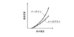
上述した第1機器4Aの特性データおよび第2機器4Bの特性データのそれぞれは、図4に示すように、各スプール42における指令電流と通過流量との関係である。この指令電流と通過流量との関係は、スプール42の作動方向ごとに存在する。また、通過流量は、メータインの通過流量とメータアウトの通過流量の2種類である。
As shown in FIG. 4, each of the characteristic data of the
特性データは、図4中に複数の点で示すように離散的なデータであり、対応する機器(4Aまたは4B)の出荷前に工場で計測される。また、機器が修理(例えば、部品交換など)された際には特性データも再計測される。 The characteristic data is discrete data as shown by a plurality of points in FIG. 4, and is measured at the factory before the corresponding equipment (4A or 4B) is shipped. In addition, characteristic data is also remeasured when the device is repaired (for example, parts replacement).
第1記録媒体33および第2記録媒体34のそれぞれには、対応する機器(4Aまたは4B)の特性データを計測した日付も目視可能に記録されている。また、第1記録媒体33および第2記録媒体34のそれぞれには、対応する機器(4Aまたは4B)の識別データ(個別製品番号)も記録されている。
The date on which the characteristic data of the corresponding device (4A or 4B) is measured is also visually recorded on each of the
機器ユニット1Bは、例えば、建設機械(油圧ショベルや油圧クレーンなど)または産業機械に搭載される。そして、第1機器4Aおよび第2機器4Bは、それらの機械の制御装置により制御される。例えば、制御装置は、使用者により操作される操作装置の操作量に応じて、第1機器4Aの駆動機構対および第2機器4Bの駆動機構対へ指令電流を送給する。
The
第1記録媒体33に記録された第1機器4Aの特性データおよび第2記録媒体34に記録された第2機器4Bの特性データは、バーコードリーダで読み取られて上述した機械の制御装置へ入力される。制御装置は、第1機器4Aおよび第2機器4Bの特性のばらつきを電子的にキャリブレーションする。例えば、制御装置は、使用者により操作される操作装置の操作量に対応する設定通過流量が得られるように、第1機器4Aの駆動機構対および第2機器4Bの駆動機構対へ送給する指令電流を調整する。
The characteristic data of the
以上説明したように、本実施形態の機器ユニット1Bでは、第1記録媒体33に第1機器4Aの特性データが記録され、第2記録媒体34に第2機器4Bの特性データが記録されているので、第1機器4Aおよび第2機器4Bの特性データを直接的に読み込むことができる。しかも、第1記録媒体33および第2記録媒体34は第1機器4Aのケーシングの1つの側面に互いに隣接して取り付けられているので、第1機器4Aおよび第2機器4Bの特性データを短時間で効率的に読み込むことができる。
As described above, in the
さらに、本実施形態では、各記録媒体(33または34)に対応する機器(4Aまたは4B)の特性データを計測した日付が目視可能に記録されているので、使用者は、記録媒体を見れば機器の修理来歴を把握することができる。従って、現場でのメンテナンス性が向上する。 Further, in the present embodiment, the date on which the characteristic data of the device (4A or 4B) corresponding to each recording medium (33 or 34) is measured is visually recorded, so that the user can see the recording medium. It is possible to grasp the repair history of the equipment. Therefore, on-site maintainability is improved.
(その他の実施形態)
本発明は上述した実施形態に限定されるものではなく、本発明の要旨を逸脱しない範囲で種々の変形が可能である。
(Other embodiments)
The present invention is not limited to the above-described embodiment, and various modifications can be made without departing from the gist of the present invention.
例えば、第1実施形態においては、各記録媒体(31または32)に対応する機器(2Aまたは2B)の特性データを記録する代わりに、第1機器2Aの特性データおよび第2機器2Bの特性データをサーバや端末などに保存し、第1機器2Aの特性データの保存先IPアドレスを第1記録媒体31に記録するとともに第2機器2Bの特性データの保存先IPアドレスを第2記録媒体32に記録することも可能である。この場合、各記録媒体への保存先IPアドレスの記録は、バーコードにより行われる必要はなく、例えば印字により行われてもよい。
For example, in the first embodiment, instead of recording the characteristic data of the device (2A or 2B) corresponding to each recording medium (31 or 32), the characteristic data of the
上記の構成であれば、インターネットを介して各機器の特性データを読み込むことができる。さらに、この構成であれば、サーバまたは端末に大量の特性データが保存できるので、機器の特性のばらつきを正確にキャリブレーションすることができる。なお、記録媒体に特性データの保存先IPアドレスを記録するという変形は、第2実施形態でも適用可能である。 With the above configuration, the characteristic data of each device can be read via the Internet. Further, with this configuration, a large amount of characteristic data can be stored in the server or the terminal, so that the variation in the characteristics of the device can be accurately calibrated. The modification of recording the storage destination IP address of the characteristic data on the recording medium is also applicable to the second embodiment.
1A,1B 機器ユニット
2A,2B 機器
21 ケーシング
4A,4B 機器
41 ケーシング
31~34 記録媒体
1A,
Claims (5)
前記2つ以上の機器のうちの1つの機器のケーシングの1つの側面に、前記2つ以上の機器の特性データまたは当該特性データの保存先IPアドレスをそれぞれ記録した2つ以上の記録媒体が互いに隣接して取り付けられており、
前記2つ以上の機器のそれぞれは、指令電流に応じて吐出流量が変化するポンプであり、
前記機器の特性データは、特定の吐出圧での前記指令電流と前記吐出流量との関係である、機器ユニット。 Equipped with two or more devices, each containing a separate casing connected to each other,
On one side of the casing of one of the two or more devices, two or more recording media on which the characteristic data of the two or more devices or the storage destination IP address of the characteristic data are recorded, respectively. It is installed next to each other and
Each of the two or more devices is a pump whose discharge flow rate changes according to a command current.
The characteristic data of the device is the device unit, which is the relationship between the command current and the discharge flow rate at a specific discharge pressure.
前記2つ以上の機器のうちの1つの機器のケーシングの1つの側面に、前記2つ以上の機器の特性データまたは当該特性データの保存先IPアドレスをそれぞれ記録した2つ以上の記録媒体が互いに隣接して取り付けられており、
前記2つ以上の機器のそれぞれは、指令電流に応じて通過流量を変更する複数のスプールを内蔵するマルチコントロールバルブであり、
前記機器の特性データは、前記複数のスプールのそれぞれにおける前記指令電流と前記通過流量との関係である、機器ユニット。 Equipped with two or more devices, each containing a separate casing connected to each other,
On one side of the casing of one of the two or more devices, two or more recording media on which the characteristic data of the two or more devices or the storage destination IP address of the characteristic data are recorded, respectively. It is installed next to each other and
Each of the two or more devices is a multi-control valve with a built-in plurality of spools that change the passing flow rate according to the command current.
The characteristic data of the device is the device unit, which is the relationship between the command current and the passing flow rate in each of the plurality of spools.
Priority Applications (4)
| Application Number | Priority Date | Filing Date | Title |
|---|---|---|---|
| JP2018106042A JP7037440B2 (en) | 2018-06-01 | 2018-06-01 | Equipment unit |
| US15/734,161 US20210216051A1 (en) | 2018-06-01 | 2019-05-28 | Apparatus unit |
| PCT/JP2019/020995 WO2019230681A1 (en) | 2018-06-01 | 2019-05-28 | Apparatus unit |
| CN201980027106.1A CN111989515B (en) | 2018-06-01 | 2019-05-28 | Machine unit |
Applications Claiming Priority (1)
| Application Number | Priority Date | Filing Date | Title |
|---|---|---|---|
| JP2018106042A JP7037440B2 (en) | 2018-06-01 | 2018-06-01 | Equipment unit |
Publications (3)
| Publication Number | Publication Date |
|---|---|
| JP2019210974A JP2019210974A (en) | 2019-12-12 |
| JP2019210974A5 JP2019210974A5 (en) | 2021-05-06 |
| JP7037440B2 true JP7037440B2 (en) | 2022-03-16 |
Family
ID=68696975
Family Applications (1)
| Application Number | Title | Priority Date | Filing Date |
|---|---|---|---|
| JP2018106042A Active JP7037440B2 (en) | 2018-06-01 | 2018-06-01 | Equipment unit |
Country Status (4)
| Country | Link |
|---|---|
| US (1) | US20210216051A1 (en) |
| JP (1) | JP7037440B2 (en) |
| CN (1) | CN111989515B (en) |
| WO (1) | WO2019230681A1 (en) |
Families Citing this family (2)
| Publication number | Priority date | Publication date | Assignee | Title |
|---|---|---|---|---|
| JP2023131855A (en) * | 2022-03-10 | 2023-09-22 | 川崎重工業株式会社 | Controller and calibration system |
| JP2022140429A (en) * | 2022-03-28 | 2022-09-26 | 川崎重工業株式会社 | program |
Citations (2)
| Publication number | Priority date | Publication date | Assignee | Title |
|---|---|---|---|---|
| JP2002180897A (en) | 2000-12-13 | 2002-06-26 | Denso Corp | Adjusting method of internal combustion engine |
| JP2006114525A (en) | 2004-09-15 | 2006-04-27 | Nachi Fujikoshi Corp | Solenoid member and characteristic correction device thereof |
Family Cites Families (12)
| Publication number | Priority date | Publication date | Assignee | Title |
|---|---|---|---|---|
| US6097171A (en) * | 1998-01-30 | 2000-08-01 | A. O. Smith Corporation | Method and apparatus for controlling an induction motor |
| DE10153625A1 (en) * | 2000-11-02 | 2002-07-11 | Denso Corp | Combustion engine controller has control program and data memory that can be electrically updated, communications circuit, memory device for communications program and processor |
| US6986646B2 (en) * | 2002-04-12 | 2006-01-17 | Caterpillar Inc. | Electronic trim for a variable delivery pump in a hydraulic system for an engine |
| JP2006083959A (en) * | 2004-09-16 | 2006-03-30 | Fujikin Inc | Joint member with sensor |
| WO2011145715A1 (en) * | 2010-05-20 | 2011-11-24 | 株式会社小松製作所 | Work vehicle and work vehicle control method |
| DE102012105951A1 (en) * | 2012-03-30 | 2013-10-02 | Pfeiffer Vacuum Gmbh | Pump system for evacuating gas from a plurality of chambers and methods for controlling the pump system |
| TWI496096B (en) * | 2012-05-31 | 2015-08-11 | Toshiba Global Commerce Solutions Holdings Corp | System, method, and storage unit for managing multiple objects in an object zone |
| EP2923283B1 (en) * | 2012-11-26 | 2020-05-27 | Fisher & Paykel Healthcare Limited | Transfer of breathing assistance apparatus data |
| US10316849B2 (en) * | 2014-10-15 | 2019-06-11 | Grundfos Holding A/S | Method and system for detection of faults in pump assembly via handheld communication device |
| WO2017040825A1 (en) * | 2015-09-02 | 2017-03-09 | Project Phoenix, LLC | System to pump fluid and control thereof |
| CA2930323C (en) * | 2016-05-17 | 2023-11-14 | Op-Hygiene Ip Gmbh | Superimposed qr code for dispenser and replaceable reservoir |
| CN207246512U (en) * | 2017-09-15 | 2018-04-17 | 广州智特信息科技有限公司 | The angle valve of having electronic information labels |
-
2018
- 2018-06-01 JP JP2018106042A patent/JP7037440B2/en active Active
-
2019
- 2019-05-28 WO PCT/JP2019/020995 patent/WO2019230681A1/en active Application Filing
- 2019-05-28 CN CN201980027106.1A patent/CN111989515B/en active Active
- 2019-05-28 US US15/734,161 patent/US20210216051A1/en active Pending
Patent Citations (2)
| Publication number | Priority date | Publication date | Assignee | Title |
|---|---|---|---|---|
| JP2002180897A (en) | 2000-12-13 | 2002-06-26 | Denso Corp | Adjusting method of internal combustion engine |
| JP2006114525A (en) | 2004-09-15 | 2006-04-27 | Nachi Fujikoshi Corp | Solenoid member and characteristic correction device thereof |
Also Published As
| Publication number | Publication date |
|---|---|
| CN111989515A (en) | 2020-11-24 |
| JP2019210974A (en) | 2019-12-12 |
| US20210216051A1 (en) | 2021-07-15 |
| CN111989515B (en) | 2022-09-16 |
| WO2019230681A1 (en) | 2019-12-05 |
Similar Documents
| Publication | Publication Date | Title |
|---|---|---|
| JP7037440B2 (en) | Equipment unit | |
| Lindler et al. | Piezoelectric direct drive servovalve | |
| US7487707B2 (en) | Hydraulic valve assembly with a pressure compensated directional spool valve and a regeneration shunt valve | |
| JP2003184807A (en) | Electrohydraulic valve control system and method for electrohydraulic valve control | |
| US9443188B2 (en) | Operation number-counting piezoelectric dispenser | |
| EP2573407A1 (en) | Hydraulic control valve for construction machinery | |
| JP2019027410A (en) | Fluid pressure drive unit | |
| WO2019087565A1 (en) | Hydraulic device | |
| GB2577000A (en) | Flow control assembly having localized non-volatile memory | |
| WO2010021203A1 (en) | Position detecting device and controller used for the same | |
| KR102425743B1 (en) | Construction machinery and method for controlling the construction machinery | |
| JP2013530345A (en) | Hydraulic double axial piston machine | |
| US20230136445A1 (en) | Servoless motor | |
| JP5284539B2 (en) | Digital hydraulic pressure control device | |
| JP5347512B2 (en) | Variable displacement piston pump | |
| JP2018084286A (en) | Manipulating device and hydraulic system | |
| JP7370854B2 (en) | Actuator control device | |
| JP2007321890A (en) | Rotary servo valve | |
| US6640685B2 (en) | Closed loop electrohydraulic actuator control circuit | |
| US4561470A (en) | Servo valve control device | |
| US8096228B1 (en) | Bent axis dual yoke hydromodule | |
| WO2023171029A1 (en) | Controller and calibration system | |
| CN113454338A (en) | Hydraulic actuator with overpressure compensation | |
| RU2780434C1 (en) | Proportional electrohydraulic distributor of indirect action | |
| JP5453356B2 (en) | Hydraulic device and control method of hydraulic device |
Legal Events
| Date | Code | Title | Description |
|---|---|---|---|
| A521 | Request for written amendment filed |
Free format text: JAPANESE INTERMEDIATE CODE: A523 Effective date: 20210324 |
|
| A621 | Written request for application examination |
Free format text: JAPANESE INTERMEDIATE CODE: A621 Effective date: 20210324 |
|
| A131 | Notification of reasons for refusal |
Free format text: JAPANESE INTERMEDIATE CODE: A131 Effective date: 20211221 |
|
| A521 | Request for written amendment filed |
Free format text: JAPANESE INTERMEDIATE CODE: A523 Effective date: 20220131 |
|
| TRDD | Decision of grant or rejection written | ||
| A01 | Written decision to grant a patent or to grant a registration (utility model) |
Free format text: JAPANESE INTERMEDIATE CODE: A01 Effective date: 20220208 |
|
| A61 | First payment of annual fees (during grant procedure) |
Free format text: JAPANESE INTERMEDIATE CODE: A61 Effective date: 20220304 |
|
| R150 | Certificate of patent or registration of utility model |
Ref document number: 7037440 Country of ref document: JP Free format text: JAPANESE INTERMEDIATE CODE: R150 |