JP7036498B2 - Fuel cell and fuel cell stack containing it - Google Patents
Fuel cell and fuel cell stack containing it Download PDFInfo
- Publication number
- JP7036498B2 JP7036498B2 JP2020543030A JP2020543030A JP7036498B2 JP 7036498 B2 JP7036498 B2 JP 7036498B2 JP 2020543030 A JP2020543030 A JP 2020543030A JP 2020543030 A JP2020543030 A JP 2020543030A JP 7036498 B2 JP7036498 B2 JP 7036498B2
- Authority
- JP
- Japan
- Prior art keywords
- fuel cell
- diffusion layer
- gas diffusion
- membrane
- electrode assembly
- Prior art date
- Legal status (The legal status is an assumption and is not a legal conclusion. Google has not performed a legal analysis and makes no representation as to the accuracy of the status listed.)
- Active
Links
Images

Classifications
-
- H—ELECTRICITY
- H01—ELECTRIC ELEMENTS
- H01M—PROCESSES OR MEANS, e.g. BATTERIES, FOR THE DIRECT CONVERSION OF CHEMICAL ENERGY INTO ELECTRICAL ENERGY
- H01M8/00—Fuel cells; Manufacture thereof
- H01M8/02—Details
- H01M8/0202—Collectors; Separators, e.g. bipolar separators; Interconnectors
- H01M8/023—Porous and characterised by the material
-
- H—ELECTRICITY
- H01—ELECTRIC ELEMENTS
- H01M—PROCESSES OR MEANS, e.g. BATTERIES, FOR THE DIRECT CONVERSION OF CHEMICAL ENERGY INTO ELECTRICAL ENERGY
- H01M8/00—Fuel cells; Manufacture thereof
- H01M8/02—Details
- H01M8/0202—Collectors; Separators, e.g. bipolar separators; Interconnectors
- H01M8/0258—Collectors; Separators, e.g. bipolar separators; Interconnectors characterised by the configuration of channels, e.g. by the flow field of the reactant or coolant
-
- H—ELECTRICITY
- H01—ELECTRIC ELEMENTS
- H01M—PROCESSES OR MEANS, e.g. BATTERIES, FOR THE DIRECT CONVERSION OF CHEMICAL ENERGY INTO ELECTRICAL ENERGY
- H01M8/00—Fuel cells; Manufacture thereof
- H01M8/02—Details
- H01M8/0202—Collectors; Separators, e.g. bipolar separators; Interconnectors
- H01M8/0267—Collectors; Separators, e.g. bipolar separators; Interconnectors having heating or cooling means, e.g. heaters or coolant flow channels
-
- H—ELECTRICITY
- H01—ELECTRIC ELEMENTS
- H01M—PROCESSES OR MEANS, e.g. BATTERIES, FOR THE DIRECT CONVERSION OF CHEMICAL ENERGY INTO ELECTRICAL ENERGY
- H01M8/00—Fuel cells; Manufacture thereof
- H01M8/02—Details
- H01M8/0271—Sealing or supporting means around electrodes, matrices or membranes
- H01M8/0273—Sealing or supporting means around electrodes, matrices or membranes with sealing or supporting means in the form of a frame
-
- H—ELECTRICITY
- H01—ELECTRIC ELEMENTS
- H01M—PROCESSES OR MEANS, e.g. BATTERIES, FOR THE DIRECT CONVERSION OF CHEMICAL ENERGY INTO ELECTRICAL ENERGY
- H01M8/00—Fuel cells; Manufacture thereof
- H01M8/02—Details
- H01M8/0271—Sealing or supporting means around electrodes, matrices or membranes
- H01M8/0276—Sealing means characterised by their form
-
- H—ELECTRICITY
- H01—ELECTRIC ELEMENTS
- H01M—PROCESSES OR MEANS, e.g. BATTERIES, FOR THE DIRECT CONVERSION OF CHEMICAL ENERGY INTO ELECTRICAL ENERGY
- H01M8/00—Fuel cells; Manufacture thereof
- H01M8/04—Auxiliary arrangements, e.g. for control of pressure or for circulation of fluids
- H01M8/04007—Auxiliary arrangements, e.g. for control of pressure or for circulation of fluids related to heat exchange
- H01M8/04029—Heat exchange using liquids
-
- H—ELECTRICITY
- H01—ELECTRIC ELEMENTS
- H01M—PROCESSES OR MEANS, e.g. BATTERIES, FOR THE DIRECT CONVERSION OF CHEMICAL ENERGY INTO ELECTRICAL ENERGY
- H01M8/00—Fuel cells; Manufacture thereof
- H01M8/10—Fuel cells with solid electrolytes
- H01M8/1004—Fuel cells with solid electrolytes characterised by membrane-electrode assemblies [MEA]
-
- H—ELECTRICITY
- H01—ELECTRIC ELEMENTS
- H01M—PROCESSES OR MEANS, e.g. BATTERIES, FOR THE DIRECT CONVERSION OF CHEMICAL ENERGY INTO ELECTRICAL ENERGY
- H01M8/00—Fuel cells; Manufacture thereof
- H01M8/24—Grouping of fuel cells, e.g. stacking of fuel cells
- H01M8/241—Grouping of fuel cells, e.g. stacking of fuel cells with solid or matrix-supported electrolytes
- H01M8/242—Grouping of fuel cells, e.g. stacking of fuel cells with solid or matrix-supported electrolytes comprising framed electrodes or intermediary frame-like gaskets
-
- Y—GENERAL TAGGING OF NEW TECHNOLOGICAL DEVELOPMENTS; GENERAL TAGGING OF CROSS-SECTIONAL TECHNOLOGIES SPANNING OVER SEVERAL SECTIONS OF THE IPC; TECHNICAL SUBJECTS COVERED BY FORMER USPC CROSS-REFERENCE ART COLLECTIONS [XRACs] AND DIGESTS
- Y02—TECHNOLOGIES OR APPLICATIONS FOR MITIGATION OR ADAPTATION AGAINST CLIMATE CHANGE
- Y02E—REDUCTION OF GREENHOUSE GAS [GHG] EMISSIONS, RELATED TO ENERGY GENERATION, TRANSMISSION OR DISTRIBUTION
- Y02E60/00—Enabling technologies; Technologies with a potential or indirect contribution to GHG emissions mitigation
- Y02E60/30—Hydrogen technology
- Y02E60/50—Fuel cells
Landscapes
- Life Sciences & Earth Sciences (AREA)
- Engineering & Computer Science (AREA)
- Manufacturing & Machinery (AREA)
- Sustainable Development (AREA)
- Sustainable Energy (AREA)
- Chemical & Material Sciences (AREA)
- Chemical Kinetics & Catalysis (AREA)
- Electrochemistry (AREA)
- General Chemical & Material Sciences (AREA)
- Fuel Cell (AREA)
Description
本発明は燃料電池セルおよびこれを含む燃料電池スタックに関する。 The present invention relates to a fuel cell and a fuel cell stack including the fuel cell.
本出願は2018年2月22日付韓国特許出願第10-2018-0020840号に基づいた優先権の利益を主張し、該当韓国特許出願の文献に開示されたすべての内容は本明細書の一部として含まれる。 This application claims the benefit of priority under Korean Patent Application No. 10-2018-0020840 dated February 22, 2018, and all content disclosed in the literature of the relevant Korean patent application is part of this specification. Included as.
一般的に燃料電池(fuel cell)は、酸化剤(燃料)および還元剤の電気化学反応を通じて電気エネルギーを発生させるエネルギー変換装置であって、燃料が継続して供給される限り持続的に発電が可能な長所がある。 Generally, a fuel cell is an energy conversion device that generates electric energy through an electrochemical reaction between an oxidizing agent (fuel) and a reducing agent, and continuously generates electricity as long as fuel is continuously supplied. There are possible advantages.
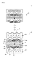
図1および図2は、従来の燃料電気スタック1を示す概略図である。
1 and 2 are schematic views showing a conventional fuel-
燃料電池スタック1は複数個の燃料電池セル10を含み、複数個の燃料電池セルは積層されてスタックを形成する。
The
燃料電池スタック1は、高分子物質で構成された電解質膜を中心としてアノード11a(anode)とカソード11b(cathode)がそれぞれ塗布されて形成された電極層を具備する膜-電極接合体11(Membrane Electrode Assembly、MEA)、電極層領域の外周にプラスチックフィルム素材の熱粘着保護フィルム17(subgasket)、反応ガスを反応領域の全体に亘って等しく分布させ、アノード電極の酸化反応によって発生した電子をカソード電極側に伝達する役割をするガス拡散層12(Gas Diffusion Layer、GDL)、反応ガスをガス拡散層に供給し、同様の役割をするグラファイト(graphite)および金属素材の分離板13(bipolar plate)、分離板または膜-電極接合体の反応領域の外周に配置されて反応気体および冷却水の漏出を防止する、弾性を有するゴム素材のガスケット18(gasket)を含むことができる。
The
前記分離板13はガス拡散層12と接触する複数個のリブ14および反応ガスの流れを案内する複数個のチャネル15を含む。また、分離板13は内部に冷却水の流動を案内するための冷却水チャネル16を有する。
The
また、イオンの移動方向は膜厚方向Fに沿ってなされる。 Further, the moving direction of the ions is along the film thickness direction F.
特に、高分子電解質燃料電池は高分子電解質のイオン伝導度の確保のために燃料の加湿が必要である。具体的には、水素燃料電池は駆動は水素ガスと酸素(空気)ガスの酸化還元反応を通じて電気エネルギーに切り替える装置であり、電気化学的反応のために反応表面である触媒層とイオン伝導の媒介体である電解質膜に水(加湿)が必ず必要である。 In particular, the polyelectrolyte fuel cell requires humidification of the fuel in order to secure the ionic conductivity of the polyelectrolyte. Specifically, a hydrogen fuel cell is a device that switches to electrical energy through a redox reaction between hydrogen gas and oxygen (air) gas, and is a mediator between the catalyst layer, which is the reaction surface, and ionic conduction for an electrochemical reaction. Water (humidification) is absolutely necessary for the electrolyte membrane, which is the body.
このような理由で、反応物である水素と空気の反応のために加湿が必要であり、加湿器の容量の低減とシステム費用の低減のために、低加湿または無加湿で駆動する燃料電池技術が必要である。これに伴い、低加湿環境で加湿量の確保のための多様な自家加湿方式に対する技術が開発されている。 For this reason, humidification is required for the reaction of the reactant hydrogen and air, and fuel cell technology driven with low or no humidification to reduce the capacity of the humidifier and the system cost. is necessary. Along with this, technologies for various self-humidifying methods for securing the amount of humidification in a low humidification environment have been developed.
本発明は、反応燃料の低加湿または無加湿で駆動する燃料電池スタックを提供することを解決しようとする課題とする。 It is an object of the present invention to solve the problem of providing a fuel cell stack driven by low humidification or no humidification of a reactive fuel.
前記のような課題を解決するために、本発明の一側面によると、第1面および第1面と反対方向の第2面を有し、第1面にアノード電極およびカソード電極がそれぞれ配置された膜-電極接合体;第2面上に所定の間隔で離隔配置されるエンドプレート;アノード電極上に配置された第1ガス拡散層;カソード電極上に配置された第2ガス拡散層;第1ガス拡散層上に配置され、複数個の流動チャネルを有する第1分離板;および第2ガス拡散層上に配置され、複数個の流動チャネルを有する第2分離板を含む燃料電池セルが提供される。 In order to solve the above-mentioned problems, according to one aspect of the present invention, it has a first surface and a second surface in a direction opposite to the first surface, and an anode electrode and a cathode electrode are arranged on the first surface, respectively. Film-electrode junction; end plates spaced apart at predetermined intervals on the second surface; first gas diffusion layer placed on the anode electrode; second gas diffusion layer placed on the cathode electrode; second Provided is a fuel cell including a first separation plate arranged on one gas diffusion layer and having a plurality of flow channels; and a second separation plate arranged on a second gas diffusion layer and having a plurality of flow channels. Will be done.
本発明の一実施例と関連した燃料電池スタックは下記のような効果を有する。 The fuel cell stack associated with one embodiment of the present invention has the following effects.
低加湿または無加湿で駆動し得、燃料電池の駆動時に無加湿反応物(水素、酸素(空気))の使用が可能である。 It can be driven with low or no humidification, and non-humidified reactants (hydrogen, oxygen (air)) can be used when driving the fuel cell.
特に、反応物を無加湿状態で注入(dray gas)し、燃料電池スタックに必須的に供給されて運用される冷却水を膜-電極接合体(MEA)の加湿の用途で使用できる構造を有する。 In particular, it has a structure that can be used for humidifying a membrane-electrode assembly (MEA) by injecting a reactant in a non-humidified state (dry gas) and using cooling water that is indispensably supplied to and operated in a fuel cell stack. ..
この時、反応物は無加湿状態で供給されるが、膜-電極接合体の一面が冷却水に露出するため、従来のように反応物の助けがなくても膜-電極接合体の加湿が可能となる。 At this time, the reactant is supplied in a non-humidified state, but since one surface of the membrane-electrode assembly is exposed to the cooling water, the membrane-electrode assembly can be humidified without the help of the reactant as in the conventional case. It will be possible.
また、従来にはガスの透過が膜の薄い厚さ方向になされていたため耐久性に影響を及ぼしていたが、本発明の場合、ガスの透過が膜の面方向に沿ってなされるため、距離と抵抗が大きくなり、ガス透過度の低減によるOCVおよび耐久性が向上する。 Further, in the past, the permeation of gas was performed in the thin thickness direction of the membrane, which affected the durability. However, in the case of the present invention, the permeation of gas is performed along the surface direction of the membrane, so that the distance is reached. The resistance increases, and the OCV and durability are improved by reducing the gas permeability.
以下、本発明の一実施例に係る燃料電池セルおよびこれを含む燃料電気スタックを、添付された図面を参照して詳細に説明する。 Hereinafter, the fuel cell according to an embodiment of the present invention and the fuel electric stack including the fuel cell will be described in detail with reference to the attached drawings.
また、図面符号にかかわらず、同一または対応する構成要素は同一または類似する参照番号を付与してこれに対する重複説明は省略し、説明の便宜のために図示された各構成部材の大きさおよび形状は誇張または縮小され得る。 Further, regardless of the drawing reference numerals, the same or corresponding components are given the same or similar reference numbers, duplicate explanations thereof are omitted, and the sizes and shapes of the respective components shown for convenience of explanation are omitted. Can be exaggerated or reduced.
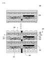
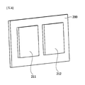
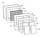
図3は本発明の一実施例と関連した燃料電池スタック100を示す概略図であり、図4は図3に図示された膜-電極接合体210を示す図面であり、図5は本発明の一実施例と関連した燃料電池セル200の分離斜視図である。
FIG. 3 is a schematic view showing a
また、図6は膜-電極接合体の多様な実施例を示す概略図である。 Further, FIG. 6 is a schematic view showing various examples of the membrane-electrode assembly.
図3~図5を参照すると、燃料電池スタック100は複数個の燃料電池セル200を含む。
Referring to FIGS. 3-5, the
燃料電池セル200は、膜-電極接合体210、エンド(end)プレート240、第1ガス拡散層221、第2ガス拡散層222、第1分離板231および第2分離板232を含む。
The
具体的には、燃料電池セル200は第1面および第1面と反対方向の第2面を有し、第1面にアノード(anode)電極211およびカソード(cathode)電極212がそれぞれ配置された膜-電極接合体210を含む。また、燃料電池セル200は膜-電極接合体210の第2面上に所定の間隔で離隔配置されるエンドプレート240を含む。冷却水の漏水を防止するガスケット260により前記エンドプレート240および膜-電極接合体210の第2面間に所定の空間部Sが形成され、膜-電極接合体210の第2面は前記空間部Sに露出する。
Specifically, the
また、燃料電池セル200は、アノード電極211上に配置された第1ガス拡散層221およびカソード電極212上に配置された第2ガス拡散層222を含む。すなわち、第1ガス拡散層221および第2ガス拡散層222はいずれも膜-電極接合体210の第1面上に配置される。
Further, the
また、燃料電池セル200は第1ガス拡散層221上に配置され、複数個の流動チャネルを有する第1分離板231および第2ガス拡散層222上に配置され、複数個の流動チャネルを有する第2分離板232を含む。第1および第2分離板231、232は、それぞれのガス拡散層に接触する複数個のリブおよび反応ガスが流動する複数個の流動チャネルを有する。また、第1および第2分離板231、232は内部に冷却水の流動を案内するための冷却水チャネルを有することができる。
Further, the
このような構造において、イオンの移動方向は膜-電極接合体210の面方向Fである。
In such a structure, the moving direction of the ions is the plane direction F of the membrane-
また、エンドプレート240と膜-電極接合体210の第2面との間の空間に冷却水が供給され得る。これに伴い、膜-電極接合体210の第2面は冷却水に露出し、加湿がなされることになる。また、いずれか一つの燃料電池セル200のエンドプレート240は隣接して積層された他の燃料電池セルの第1および第2分離板と接触する。この時、エンドプレート240を媒介として、隣接した燃料電池セルの第1および第2分離板の冷却がなされる。
Further, cooling water may be supplied to the space between the
すなわち、膜-電極接合体210の第2面とエンドプレート240との間の空間に冷却水を供給することによって、燃料電池セル200の冷却および膜-電極接合体への加湿が同時になされ得る。
That is, by supplying cooling water to the space between the second surface of the membrane-
また、エンドプレート240と膜-電極接合体210の第2面との間の空間には、冷却水の流れを案内するためのチャネル部材が配置され得る。この時、チャネル部材はメッシュ(mesh)部材250を含むことができる。また、チャネル部材は流路および多孔性メッシュ部材を含むことができる。
Further, a channel member for guiding the flow of cooling water may be arranged in the space between the
また、燃料電池セル200は第1ガス拡散層221および第2ガス拡散層222を個別にシーリングするための一つ以上の第1ガスケット270を含むことができる。例えば、第1ガス拡散層221および第2ガス拡散層222を個別にシーリングするために、第1ガスケット270は第1ガス拡散層221が収容される第1開口部271および第2ガス拡散層222が収容される第2開口部272を含むことができる。
Further, the
前記第1分離板231および第2分離板232は電気伝導性を有し、第1分離板231と第2分離板232を電気的に絶縁させるために、燃料電池セル200は第1分離板231および第2分離板232の間に配置された絶縁部材280をさらに含むことができる。前記絶縁部材280は、アクリル、ポリカーボネート、テフロン(登録商標)、およびポリビニルクロライドなどのプラスチック系列の素材を含み、前記絶縁部材280はエンドプレート240と同じ素材で、一体に形成されてもよい。
The
また、燃料電池セル200はエンドプレート240と膜-電極接合体210の第2面との間に配置される第2ガスケット260をさらに含むことができる。第2ガスケット260は中央領域に開口部を有することができ、前記開口部には前述したメッシュ部材250が挿入され得る。
Further, the
また、エンドプレート240は絶縁エンドプレートであって、電気絶縁性を有することができる。前記エンドプレート240は電気絶縁性を有する素材で形成され得る。例えば、エンドプレート240は、アクリル、ポリカーボネート、テフロン、およびポリビニルクロライドなどのプラスチック系列の素材で形成され得、前記エンドプレート240は絶縁部材280と同じ素材で形成され得、前記絶縁部材280と一体に形成され得る。
Further, the
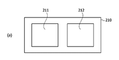
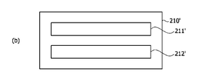
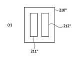
図6を参照すると、膜-電極接合体210、210'、210''でアノード電極211、211'、211''およびカソード電極221、221'、221''は多様な形状および大きさを有することができる。
Referring to FIG. 6, in the membrane-
以上で説明された本発明の好ましい実施例は例示の目的のために開示されたものであって、本発明に対する通常の知識を有する当業者であれば、本発明の思想と範囲内で多様な修正、変更、付加が可能であり、このような修正、変更および付加は下記の特許請求の範囲に属するものと見なされるべきである。 Preferred embodiments of the present invention described above are disclosed for purposes of illustration, and a person skilled in the art having ordinary knowledge of the present invention will have a variety of ideas and scope of the present invention. Modifications, changes and additions are possible and such modifications, changes and additions should be considered to be within the scope of the claims below.
本発明の一実施例と関連した燃料電池スタックは低加湿または無加湿で駆動し得、燃料電池の駆動時に無加湿反応物(水素、酸素(空気))の使用が可能な構造を有する。 The fuel cell stack associated with one embodiment of the present invention can be driven with low or no humidification and has a structure capable of using a non-humidified reactant (hydrogen, oxygen (air)) when driving the fuel cell.
Claims (9)
前記第2面上に離隔して配置されるエンドプレート;
前記アノード電極上に配置された第1ガス拡散層;
前記カソード電極上に配置された第2ガス拡散層;
前記第1ガス拡散層上に配置され、複数個の流動チャネルを有する第1分離板;および
前記第2ガス拡散層上に配置され、複数個の流動チャネルを有する第2分離板を含み、
前記エンドプレートと前記膜-電極接合体の前記第2面との間の空間に冷却水が供給される、燃料電池セル。 A membrane-electrode assembly having a first surface and a second surface in the direction opposite to the first surface, and an anode electrode and a cathode electrode arranged on the first surface, respectively;
End plates isolated on the second surface;
The first gas diffusion layer arranged on the anode electrode;
A second gas diffusion layer arranged on the cathode electrode;
A first separation plate located on the first gas diffusion layer and having a plurality of flow channels; and a second separation plate arranged on the second gas diffusion layer and having a plurality of flow channels.
A fuel cell in which cooling water is supplied to the space between the end plate and the second surface of the membrane-electrode assembly .
Applications Claiming Priority (3)
| Application Number | Priority Date | Filing Date | Title |
|---|---|---|---|
| KR1020180020840A KR102236530B1 (en) | 2018-02-22 | 2018-02-22 | Fuel cell and Fuel cell stack comprising the same |
| KR10-2018-0020840 | 2018-02-22 | ||
| PCT/KR2019/001361 WO2019164151A1 (en) | 2018-02-22 | 2019-01-31 | Fuel cell and fuel cell stack comprising same |
Publications (2)
| Publication Number | Publication Date |
|---|---|
| JP2021514522A JP2021514522A (en) | 2021-06-10 |
| JP7036498B2 true JP7036498B2 (en) | 2022-03-15 |
Family
ID=67687802
Family Applications (1)
| Application Number | Title | Priority Date | Filing Date |
|---|---|---|---|
| JP2020543030A Active JP7036498B2 (en) | 2018-02-22 | 2019-01-31 | Fuel cell and fuel cell stack containing it |
Country Status (6)
| Country | Link |
|---|---|
| US (1) | US11489173B2 (en) |
| EP (1) | EP3751650B1 (en) |
| JP (1) | JP7036498B2 (en) |
| KR (1) | KR102236530B1 (en) |
| CN (1) | CN111837275B (en) |
| WO (1) | WO2019164151A1 (en) |
Families Citing this family (1)
| Publication number | Priority date | Publication date | Assignee | Title |
|---|---|---|---|---|
| CN115189007B (en) * | 2022-08-08 | 2024-09-24 | 中汽创智科技有限公司 | End structure of fuel cell stack and fuel cell stack |
Citations (3)
| Publication number | Priority date | Publication date | Assignee | Title |
|---|---|---|---|---|
| JP2005158739A (en) | 2003-11-24 | 2005-06-16 | Xerox Corp | Fuel cell |
| JP2006128047A (en) | 2004-11-01 | 2006-05-18 | Toyota Motor Corp | Fuel cell and manufacturing method thereof |
| JP2014192095A (en) | 2013-03-28 | 2014-10-06 | Toppan Printing Co Ltd | Membrane electrode assembly and solid polymer fuel cell |
Family Cites Families (11)
| Publication number | Priority date | Publication date | Assignee | Title |
|---|---|---|---|---|
| JP3424223B2 (en) | 1995-03-29 | 2003-07-07 | マツダ株式会社 | Fuel cell stack structure |
| US6403249B1 (en) * | 2000-01-12 | 2002-06-11 | Humboldt State University Foundation | Humidification of a PEM fuel cell by air-air moisture exchange |
| DE10304657B4 (en) * | 2002-02-08 | 2015-07-02 | General Motors Llc ( N. D. Ges. D. Staates Delaware ) | A fuel cell stack and system and method of operating a fuel cell system having such a fuel cell stack |
| JP2003263995A (en) | 2002-03-12 | 2003-09-19 | Suzuki Motor Corp | Fuel cell |
| JP4423498B2 (en) | 2003-11-27 | 2010-03-03 | 大日本印刷株式会社 | Solid oxide fuel cell |
| US20060093890A1 (en) * | 2004-10-29 | 2006-05-04 | Steinbroner Matthew P | Fuel cell stack compression systems, and fuel cell stacks and fuel cell systems incorporating the same |
| JP2007066767A (en) * | 2005-08-31 | 2007-03-15 | Nissan Motor Co Ltd | Fuel cell and fuel cell stack |
| US20110229785A1 (en) * | 2010-03-17 | 2011-09-22 | Kah-Young Song | Fuel cell stack and fuel cell system having the same |
| KR101372027B1 (en) | 2012-12-28 | 2014-03-07 | 현대자동차주식회사 | Fuel cell stack |
| KR20180020840A (en) | 2016-08-20 | 2018-02-28 | 지서윤 | fruit vinegar Jelly |
| KR102371604B1 (en) * | 2017-05-26 | 2022-03-07 | 현대자동차주식회사 | Fuel cell stack |
-
2018
- 2018-02-22 KR KR1020180020840A patent/KR102236530B1/en active Active
-
2019
- 2019-01-31 EP EP19757757.0A patent/EP3751650B1/en active Active
- 2019-01-31 JP JP2020543030A patent/JP7036498B2/en active Active
- 2019-01-31 CN CN201980015127.1A patent/CN111837275B/en active Active
- 2019-01-31 WO PCT/KR2019/001361 patent/WO2019164151A1/en not_active Ceased
- 2019-01-31 US US15/733,531 patent/US11489173B2/en active Active
Patent Citations (3)
| Publication number | Priority date | Publication date | Assignee | Title |
|---|---|---|---|---|
| JP2005158739A (en) | 2003-11-24 | 2005-06-16 | Xerox Corp | Fuel cell |
| JP2006128047A (en) | 2004-11-01 | 2006-05-18 | Toyota Motor Corp | Fuel cell and manufacturing method thereof |
| JP2014192095A (en) | 2013-03-28 | 2014-10-06 | Toppan Printing Co Ltd | Membrane electrode assembly and solid polymer fuel cell |
Also Published As
| Publication number | Publication date |
|---|---|
| US11489173B2 (en) | 2022-11-01 |
| EP3751650B1 (en) | 2025-05-07 |
| EP3751650A1 (en) | 2020-12-16 |
| JP2021514522A (en) | 2021-06-10 |
| KR102236530B1 (en) | 2021-04-06 |
| CN111837275A (en) | 2020-10-27 |
| US20210083302A1 (en) | 2021-03-18 |
| EP3751650A4 (en) | 2021-04-07 |
| WO2019164151A1 (en) | 2019-08-29 |
| CN111837275B (en) | 2023-06-30 |
| KR20190101000A (en) | 2019-08-30 |
Similar Documents
| Publication | Publication Date | Title |
|---|---|---|
| JP2000100457A (en) | Fuel cell | |
| JP2004031134A (en) | Solid polymer cell assembly | |
| US9231257B2 (en) | Bipolar plate for fuel cell including non-electrochemical reaction region comprising a non-conductive material | |
| JP2001110432A (en) | Polymer electrolyte fuel cell | |
| CN114142058A (en) | Fuel cell membrane electrode sealing frame | |
| US20100285386A1 (en) | High power fuel stacks using metal separator plates | |
| JP2000277132A (en) | Fuel cell | |
| US8691471B2 (en) | Polymer electrolyte fuel cell and fuel cell stack comprising the same | |
| JP7036498B2 (en) | Fuel cell and fuel cell stack containing it | |
| JP2002170581A (en) | Polymer electrolyte fuel cell | |
| CN101479876B (en) | Improved electrochemical device | |
| WO2005050766A1 (en) | Fuel cell | |
| JP2000251901A (en) | Cell for fuel cell and fuel cell using it | |
| US20190067720A1 (en) | Method for producing a membrane-electrode assembly and membrane-electrode assembly | |
| JP2001126743A (en) | Polymer electrolyte fuel cell | |
| CN1326279C (en) | polymer electrolyte fuel cell | |
| JP2004349013A (en) | Fuel cell stack | |
| JP2004158379A (en) | Polymer electrolyte fuel cell | |
| KR101337453B1 (en) | Combined parts for fuel cell separator | |
| KR20250035761A (en) | Flat solid oxide fuel cell stack | |
| JP2003203649A (en) | Fuel cell | |
| CN116134645A (en) | Heating device for electrochemical cell stack, fuel cell stack and method for heating | |
| JP2001093548A (en) | Method for manufacturing polymer electrolyte fuel cell | |
| JP2004349015A (en) | Polymer electrolyte fuel cell | |
| KR20170063225A (en) | Fuel cell stack |
Legal Events
| Date | Code | Title | Description |
|---|---|---|---|
| A621 | Written request for application examination |
Free format text: JAPANESE INTERMEDIATE CODE: A621 Effective date: 20200820 |
|
| A131 | Notification of reasons for refusal |
Free format text: JAPANESE INTERMEDIATE CODE: A131 Effective date: 20211005 |
|
| A521 | Request for written amendment filed |
Free format text: JAPANESE INTERMEDIATE CODE: A523 Effective date: 20211228 |
|
| TRDD | Decision of grant or rejection written | ||
| A01 | Written decision to grant a patent or to grant a registration (utility model) |
Free format text: JAPANESE INTERMEDIATE CODE: A01 Effective date: 20220201 |
|
| A61 | First payment of annual fees (during grant procedure) |
Free format text: JAPANESE INTERMEDIATE CODE: A61 Effective date: 20220225 |
|
| R150 | Certificate of patent or registration of utility model |
Ref document number: 7036498 Country of ref document: JP Free format text: JAPANESE INTERMEDIATE CODE: R150 |
|
| R250 | Receipt of annual fees |
Free format text: JAPANESE INTERMEDIATE CODE: R250 |
|
| R250 | Receipt of annual fees |
Free format text: JAPANESE INTERMEDIATE CODE: R250 |