JP7032797B2 - Pachinko machine - Google Patents
Pachinko machine Download PDFInfo
- Publication number
- JP7032797B2 JP7032797B2 JP2018037797A JP2018037797A JP7032797B2 JP 7032797 B2 JP7032797 B2 JP 7032797B2 JP 2018037797 A JP2018037797 A JP 2018037797A JP 2018037797 A JP2018037797 A JP 2018037797A JP 7032797 B2 JP7032797 B2 JP 7032797B2
- Authority
- JP
- Japan
- Prior art keywords
- special
- effect
- game
- notice
- symbol
- Prior art date
- Legal status (The legal status is an assumption and is not a legal conclusion. Google has not performed a legal analysis and makes no representation as to the accuracy of the status listed.)
- Active
Links
Images


Landscapes
- Display Devices Of Pinball Game Machines (AREA)
Description
本発明は、パチンコ遊技機等の遊技機に関する。 The present invention relates to a gaming machine such as a pachinko gaming machine.
従来、遊技機では、遊技が実行されているときに様々な演出を実行することが可能である。特許文献1に記載の遊技機では、特別図柄の変動表示が実行されているときに、エネルギーを段階的に上昇させることが可能なエネルギー上昇演出が実行されることがある。
Conventionally, in a gaming machine, it is possible to perform various effects while a game is being executed. In the gaming machine described in
そして、エネルギー上昇演出でエネルギーがゲージ最大値に到達した場合は、相対的に遊技者に有利な大当たり遊技が実行される。一方、エネルギー上昇演出でエネルギーがゲージ最大値に到達しない場合は、相対的に遊技者に不利な大当たり遊技が実行される。 Then, when the energy reaches the maximum gauge value in the energy increase effect, a jackpot game that is relatively advantageous to the player is executed. On the other hand, when the energy does not reach the maximum gauge value due to the energy increase effect, a jackpot game that is relatively disadvantageous to the player is executed.
しかしながら、段階的に進行可能な演出を実行可能な遊技機について、遊技興趣の向上を図るために未だ改善の余地がある。 However, there is still room for improvement in order to improve the interest of gaming machines, which can perform effects that can be progressed step by step.
本発明は上記事情に鑑みてなされたものである。すなわち、その課題とするところは、遊技興趣を向上させることが可能な遊技機を提供することである。 The present invention has been made in view of the above circumstances. That is, the subject is to provide a gaming machine capable of improving the gaming interest.
本発明の遊技機は、上記課題を解決するために、
第1条件の成立により、遊技者に有利な特別遊技状態にするか否かの判定を行うための判定情報を取得する取得手段と、
前記取得手段によって取得された前記判定情報を記憶可能な記憶手段と、
第2条件の成立により、前記記憶手段に記憶された前記判定情報に基づいて、前記判定を行う判定手段と、
所定の表示手段を含む演出手段を用いて所定の演出を実行可能な演出実行手段と、を備え、
前記所定の演出には、前記特別遊技状態になる可能性があることを示唆する特別演出、および特定の段階まで進行可能な進行演出が含まれ、
前記演出実行手段は、前記進行演出を前記特定の段階まで進行させることに応じて前記特別演出を実行することがあり、
前記進行演出には、第1進行演出と、前記第1進行演出とは異なる第2進行演出と、があり、
前記特別演出には、第1特別演出と、前記第1特別演出とは異なり、前記判定情報が前記記憶手段に記憶されたことに応じて前記表示手段に表示される特定図柄の表示態様を通常表示態様とは異なる特殊表示態様に変化させる第2特別演出と、があり、
前記第1進行演出が前記特定の段階まで進行した場合は、前記第1特別演出が実行されるときと、前記第2特別演出が実行されるときと、があり、
前記第2進行演出が前記特定の段階まで進行した場合は、前記第2特別演出が実行されることはあるが、前記第1特別演出が実行されることはなく、
前記特殊表示態様には、前記特別遊技状態になる可能性が相対的に高いことを示唆する高期待度特殊表示態様と、前記特別遊技状態になる可能性が相対的に低いことを示唆する低期待度特殊表示態様と、があり、
前記第1進行演出が前記特定の段階に至るまでの過程内容には、第1過程内容と、前記第1過程内容とは異なる第2過程内容と、があり、
前記第1進行演出が前記第1過程内容で実行された場合と前記第2過程内容で実行された場合とで、前記高期待度特殊表示態様の前記第2特別演出が実行される確率が異なり、
前記第2進行演出が前記特定の段階に至るまでの過程内容には、第3過程内容と、前記第3過程内容とは異なる第4過程内容と、があり、
前記第2進行演出が前記第3過程内容で実行された場合と前記第4過程内容で実行された場合とで、前記高期待度特殊表示態様の前記第2特別演出が実行される確率が異なることを特徴とする。
The gaming machine of the present invention is used to solve the above problems.
An acquisition means for acquiring determination information for determining whether or not to enter a special gaming state advantageous to the player when the first condition is satisfied.
A storage means that can store the determination information acquired by the acquisition means, and a storage means that can store the determination information.
Upon the establishment of the second condition, the determination means for making the determination based on the determination information stored in the storage means, and the determination means.
It is provided with an effect executing means capable of executing a predetermined effect by using an effect means including a predetermined display means.
The predetermined effect includes a special effect suggesting that the special gaming state may occur, and a progress effect that can be progressed to a specific stage.
The effect executing means may execute the special effect in response to advancing the progress effect to the specific stage.
The progress effect includes a first progress effect and a second progress effect different from the first progress effect.
Unlike the first special effect and the first special effect, the special effect usually includes a display mode of a specific symbol displayed on the display means according to the determination information stored in the storage means. There is a second special effect that changes to a special display mode that is different from the display mode.
When the first progress effect has progressed to the specific stage, there are times when the first special effect is executed and times when the second special effect is executed.
When the second progress effect has progressed to the specific stage, the second special effect may be executed, but the first special effect is not executed.
The special display mode has a high expectation special display mode suggesting that the possibility of entering the special gaming state is relatively high, and a low suggestion that the possibility of becoming the special gaming state is relatively low. There is a special display mode of expectation,
The process content until the first progress effect reaches the specific stage includes a first process content and a second process content different from the first process content.
The probability that the second special effect of the high expectation special display mode is executed differs depending on whether the first progress effect is executed in the first process content or the second process content. ,
The process content until the second progress effect reaches the specific stage includes a third process content and a fourth process content different from the third process content.
The probability that the second special effect of the high expectation special display mode is executed differs depending on whether the second progress effect is executed in the third process content or the fourth process content. It is characterized by that.
本発明によれば、遊技興趣の低下を抑えることが可能である。 According to the present invention, it is possible to suppress a decrease in the entertainment interest.
<基本的な実施形態>
最初に、本発明の遊技機の特徴部分の前提となる本発明の基本的な実施形態を、図面を参照して具体的に説明する。参照される各図において、同一の部分には同一の符号を付し、同一の部分に関する重複する説明を原則として省略する。なお、以下において、記述の簡略化上、情報、信号、物理量又は部材等を参照する記号又は符号を記すことによって、該記号又は符号に対する情報、信号、物理量又は部材等の名称を省略又は略記することがある。
<Basic embodiment>
First, a basic embodiment of the present invention, which is a premise of the characteristic portion of the gaming machine of the present invention, will be specifically described with reference to the drawings. In each of the referenced figures, the same parts are designated by the same reference numerals, and duplicate explanations regarding the same parts will be omitted in principle. In the following, for the sake of simplicity of description, by describing a symbol or a code that refers to an information, a signal, a physical quantity, a member, etc., the name of the information, a signal, a physical quantity, a member, etc. for the symbol or the code is omitted or abbreviated. Sometimes.
1.遊技機の構造
本発明の遊技機の基本的な実施形態であるパチンコ遊技機PY1について説明する。最初に、パチンコ遊技機PY1の構造について図1~図3を用いて説明する。なお、以下の説明において、パチンコ遊技機PY1の各部の左右上下方向は、そのパチンコ遊技機PY1に対面する遊技者にとっての(正面視の)左右上下方向のことである。また、「前方」とはパチンコ遊技機PY1から当該パチンコ遊技機PY1に対面する遊技者に近づく方向とし、「後方」をパチンコ遊技機PY1に対面する遊技者から当該パチンコ遊技機PY1に近づく方向として、説明する。
1. 1. Structure of the gaming machine The pachinko gaming machine PY1 which is a basic embodiment of the gaming machine of the present invention will be described. First, the structure of the pachinko gaming machine PY1 will be described with reference to FIGS. 1 to 3. In the following description, the left-right and up-down directions of each part of the pachinko gaming machine PY1 are the left-right and up-down directions (front view) for the player facing the pachinko gaming machine PY1. Further, "front" is the direction from the pachinko gaming machine PY1 toward the player facing the pachinko gaming machine PY1, and "rear" is the direction from the player facing the pachinko gaming machine PY1 toward the pachinko gaming machine PY1. ,explain.
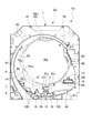
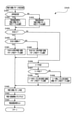
図1に示すように、パチンコ遊技機PY1は、遊技盤1を含む遊技盤ユニットYUと、遊技盤ユニットYUを内部に収納した遊技機枠2とを備えている。遊技機枠2は、遊技店に固定される枠状の外枠21と、外枠21に取り付けられ、遊技盤ユニットYUが取り付けられる内枠22と、内枠22に回転自在に支持される前扉23と、を備える。
As shown in FIG. 1, the pachinko gaming machine PY1 includes a gaming board unit YU including the
外枠21、内枠、および前扉23の正面視外周形状は大体同一である。そして、外枠21の前面に内枠22が取り付けられている。
The
前扉23は内枠22に対して開閉が可能である。前扉23は、大体中央に略縦長矩形状の大きな開口部が形成された枠状の前枠23mと、その開口部に嵌め込まれた透明板23tと、を備える。前扉23が閉じられているとき、遊技盤ユニットYUに含まれる遊技盤1と透明板23tとが対面する。透明板23tは、透明な合成樹脂板で略縦長矩形状に成形されている。よって、パチンコ遊技機PY1が遊技店に設置されると、当該パチンコ遊技機PY1の前方にいる遊技者は、透明板23tを通して、遊技盤1に形成された遊技領域6を視認することができる。なお、透明板23tとして、透明な合成樹脂板の代わりに透明なガラス板を用いてもよい。パチンコ遊技機PY1の前方から透明板23tを通して遊技領域6を視認可能であればよい。
The
前枠23mの前面の右下部には、遊技球を発射させるための回転操作が可能なハンドル72kが設けられている。ハンドル72kが操作された量(回転角度)が、遊技球を発射させるために遊技球に与えられる力の大きさ(発射強度)に対応付けられている。よって、遊技球は、ハンドル72kの回転操作に応じた発射強度で発射される。
At the lower right of the front surface of the
また、前枠23mの前面の下部には、前方に大きく突出した上皿34と、上皿34の直下に配された下皿35が設けられている。上皿34の前方側中央には、下方に押下操作可能な第1演出ボタン40kが設けられている。第1演出ボタン40kの操作部分は半球形に成形されている。さらに、上皿34の上面の後方側には、ハンドル72kに供給される遊技球を貯留するための供給球貯留穴34Aが第1演出ボタン装置40を避けるように形成されている。また、下皿35の上面には、供給球貯留穴34Aに収容しきれない余剰の遊技球を貯留するための余剰球貯留穴35Aが設けられている。
Further, at the lower part of the front surface of the
さらに、前枠23mの前面の透明板23tの上側、右側、および左側には、前方に突出した上側装飾体31、右側装飾体32、および左側装飾体33が設けられている。上側装飾体31の底面には、音を出力可能な一対の2つのスピーカ52、具体的には左側に配されたスピーカ52Lと右側に配されたスピーカ52R、が下方を向いて左右方向に所定距離をおいて並設されている。また、右側装飾体32の下部には、下方に押下操作可能な第2演出ボタン41kが設けられている。第2演出ボタン41kの操作部分は棒状に成形されている。さらに、右側装飾体32から上皿34の正面右部分にかけて、および左側装飾体33から上皿34の正面左部分にかけて、発光可能な枠ランプ53が設けられている。
Further, on the upper side, the right side, and the left side of the
なお、遊技機枠2に設けられる部材や装置の位置や数は、遊技に支障をきたさない範囲で適宜に変更可能である。
The positions and numbers of the members and devices provided in the
次に、遊技盤ユニットYUについて、図1に加えて図2を用いて説明する。遊技盤ユニットYUは、遊技盤1と、遊技盤1の背面に取り付けられた盤用演出ユニットEUと、を有する。最初に、遊技盤1について説明する。遊技盤1は、透明な合成樹脂板で構成されている。遊技盤1の略中央には正面視略円形の開口部1Aが形成されている。
Next, the game board unit YU will be described with reference to FIG. 2 in addition to FIG. The game board unit YU has a
遊技盤1の前面には、開口部1Aに沿って、略リング状のセンター装飾体61が前方に突出して形成されている。また、センター装飾体61の外側には、センター装飾体61を大きく取り囲むように略リング状に形成された外レール62と、外レール62の左側部分とセンター装飾体61との間で、外レール62およびセンター装飾体61に沿った湾曲状の内レール63と、が形成されている。
On the front surface of the
そして、遊技盤1の前面において、センター装飾体61、外レール62および内レール63などで囲まれた領域が遊技領域6を形成している。すなわち、遊技盤1の前面が、センター装飾体61、外レール62および内レール63によって、遊技領域6とそれ以外の領域とに区切られている。また、外レール62と内レール63とで囲まれた領域は、発射された遊技球が遊技領域6へ向かうために通過可能な発射領域7を形成している。
Then, on the front surface of the
遊技領域6は、ハンドル72kの操作によって発射された遊技球が流下可能な領域であり、パチンコ遊技機PY1で遊技を行うために設けられている。なお、遊技領域6には、多数の遊技用くぎ(図示なし)が突設されている。遊技用くぎは、遊技領域6に進入して遊技領域6を流下する遊技球を、一般入賞口10、第1始動口11、第2始動口12、ゲート13、および大入賞口14などに適度に誘導する経路を構成している。
The
遊技領域6の所定位置に一般入賞装置10Dが設けられている。一般入賞装置10Dには、一般入賞口10が遊技球の入球が可能に形成されている。遊技球が一般入賞口10へ入球すると、所定個数(第1実施形態では、3個)の遊技球が賞球として払い出される。なお、一般入賞口10に入球した遊技球はそのまま遊技領域6の外部へ排出される。
A
また、遊技領域6におけるセンター装飾体61の中央直下には第1始動入賞装置11Dが設けられている。第1始動入賞装置11Dには、第1始動口11が遊技球の入球が可能に形成されている。第1始動入賞装置11Dは作動しない非作動構造からなる。そのため、第1始動口11は、遊技球の入球のし易さが変化せずに一定(不変)である。遊技球が第1始動口11へ入球すると、所定個数(第1実施形態では、4個)の遊技球が賞球として払い出される。なお、第1始動口11に入球した遊技球はそのまま遊技領域6の外部へ排出される。
Further, a first start winning device 11D is provided immediately below the center of the center
なお、センター装飾体61の左側部から下端部にかけて、遊技球を内部に通すワープ部61wが形成されている。ワープ部61wへの入口はセンター装飾体61の左側部に形成されている。ワープ部61wに入った遊技球はワープ部61wの内部を通って出口から出る。ワープ部61wの出口付近であってセンター装飾体61の下端部上面には、遊技球が転動可能なステージ61Sが設けられている。ステージ61Sの先端には、遊技球を下方に導く下方誘導部61yが設けられている。この下方誘導部61yの直下には第1始動口11が設けられている。
From the left side portion to the lower end portion of the center
遊技領域6における第1始動口11の直下には、第2始動入賞装置(所謂「電チュー」)12Dが設けられている。電チュー12Dには、遊技球が入球不可能な閉態様と入球可能な開態様とに変化可能な第2始動口12が形成されている。第2始動口12は、電チュー12Dが具備する電チュー開閉部材12kによって閉態様と開態様とをとる。すなわち、電チュー開閉部材12kの作動によって第2始動口12が開閉する。
A second start winning device (so-called "electric chew") 12D is provided immediately below the first start opening 11 in the
電チュー開閉部材12kは正面視略L字状部材からなり、通常は第2始動口12を閉鎖している。電チュー開閉部材12kは、前方先端面が遊技領域6と面一状態になる退避状態から前方に突出することができる。電チュー開閉部材12kが前方に突出すると、電チュー開閉部材12kが遊技領域6に垂直に突出した状態になり、第2始動口12が入球可能に開放する。具体的には、電チュー開閉部材12kの水平部の左端に立設された垂直部分が遊技球を受けとめられ、水平部から第2始動口12へと導かれる。このように、電チュー開閉部材12kが開状態であるときだけ遊技球の第2始動口12への入球が可能となる。遊技球が第2始動口12へ入球すると、所定個数(第1実施形態では、4個)の遊技球が賞球として払い出される。なお、第2始動口12に入球した遊技球はそのまま遊技領域6の外部へ排出される。
The electric chew opening / closing
また、センター装飾体61の右側にゲート13が設けられている。ゲート13は、遊技球が通過可能に構成されている。遊技球がゲート13を通過しても賞球が払い出されない。なお、ゲート13を通過した遊技球はそのまま遊技領域6を流下する。
Further, a
遊技領域6における第1始動入賞装置11Dの右側でゲート13の下流側には、大入賞装置14Dが設けられている。大入賞装置14Dには、遊技球が入球不可能な閉態様と入球可能な開態様とに変化可能な大入賞口14が形成されている。大入賞口14は、大入賞装置14Dが具備するAT開閉部材14kによって閉態様と開態様とをとる。すなわち、AT開閉部材14kの作動によって大入賞口14が開閉する。
A
AT開閉部材14kは正面視略横長矩形状の平板からなる可動部材であり、通常は大入賞口14を閉鎖している。AT開閉部材14kの下端部には、水平な回転軸が設けられている。AT開閉部材14kはその回転軸を中心に、上端が前方へ倒れるように略90度回転することができる。AT開閉部材14kが回転すると、AT開閉部材14kが遊技領域6に垂直に突出した状態になり、大入賞口14が入球可能に開放する。このように、AT開閉部材14kが開状態であるときだけ遊技球の大入賞口14への入球が可能となる。遊技球が大入賞口14へ入球すると、所定個数(第1実施形態では、14個)の遊技球が賞球として払い出される。なお、大入賞口14に入球した遊技球はそのまま遊技領域6の外部へ排出される。
The AT opening /
また、遊技領域6における大入賞装置14Dの下方には、その上面が左斜め下方に形成され、遊技球を第2始動口12へ誘導する誘導経路64が遊技領域6(遊技盤1の前面)から前方に突出して設けられている。なお、誘導経路64の上面を転動する遊技球は、第2始動口12の方へ向かって流下可能であるが、基本的には第1始動口11へ入球することはできない。
Further, below the
なお、第1始動口11、第2始動口12、大入賞口14、および一般入賞口10への遊技球の入球や、遊技球のゲート13の通過をまとめて、第1始動口11、第2始動口12、大入賞口14、一般入賞口10、およびゲート13への「入賞」と総称する。
It should be noted that the
ところで、遊技球が流下可能な遊技領域6は、左右方向の中央より左側の左遊技領域6Aと、右側の右遊技領域6Bと、に分けることができる。遊技球が左遊技領域6Aを流下するように遊技球を発射させるハンドル72kの操作態様を「左打ち」という。一方、遊技球が右遊技領域6Bを流下するように遊技球を発射させるハンドル72kの操作態様を「右打ち」という。遊技領域6において、左打ちにて遊技球を発射したときに遊技球が流下可能な流路を、第1流路R1といい、右打ちにて遊技球を発射したときに遊技球が流下可能な流路を、第2流路R2という。第1流路R1および第2流路R2には、不図示の多数の遊技用くぎなども構成されている。
By the way, the
第1流路R1上には、第1始動口11と、2つの一般入賞口10と、が設けられている。よって、遊技者は、左打ちにより第1流路R1を流下するように遊技球を発射させることで、第1始動口11、または、一般入賞口10への入賞を狙うことができる。一方、第2流路R2上には、第2始動口12と、ゲート13と、大入賞口14と、が設けられている。よって、遊技者は、右打ちにより第2流路R2を流下するように遊技球を発射させることで、ゲート13、第2始動口12、または大入賞口14への入賞を狙うことができる。
A
なお、遊技領域6の略最下部には、遊技領域6へ打ち込まれたもののいずれの入賞口にも入賞しなかった遊技球を遊技領域6の外部へ排出する2つのアウト口19が設けられている。また、各入賞口への入賞による賞球数は、適宜に設定することが可能である。
It should be noted that, at the substantially lowermost portion of the
次に、遊技盤1の背面に取り付けられた盤用演出ユニットEUについて説明する。盤用演出ユニットEUは、主に演出を行う複数の装置をユニット化したものである。盤用演出ユニットEUには、画像表示装置50、および盤可動装置55が取り付けられている。
Next, the board production unit EU attached to the back surface of the
画像表示装置50は、20インチの3D液晶ディスプレイで構成されており、3D画像を表示可能な表示部50aを具備する。
The
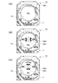
盤可動装置55は、動作可能な盤可動体55kを備える。盤可動体55kは、水平状態を保持された横長で板状の昇降部材55k2と、昇降部材55k2の左右方向中央に設けられた略楕円形状の回転部材55k1と、を有する。盤可動体55kは、初期位置に配されている待機状態では、遊技盤1と画像表示装置50との間で隠れている。待機状態において、盤可動体55kの下端部分、具体的に回転部材55k1の下端部分が、遊技盤1の開口部1Aの上端から少しだけ下方に位置している。よって、回転部材55k1の下端部の一部のみが遊技者から視認できるよう配されている(図3(A)参照)。そして、盤可動体55kは、全体的に初期位置から所定の作動位置まで下降し、その作動位置から上昇して初期位置に戻ることができる(図3(B)参照)。所定の作動位置としては、正面視で盤可動体55kが開口部1Aの略中央につく位置である。ここで、所定の作業位置は適宜に設定可能であり、正面視で盤可動体55kが開口部1Aの略中央より上方側におかれる位置であっても下方側におかれる位置であってもよい。
The board
また、回転部材55k1は、中心に設けられた回転軸を中心に回転運動することが可能である(図3(C)参照)。なお、回転部材55k1の回転運動は、盤可動体55kが待機位置から作動位置に移動するとき、作動位置に保持されているとき、および作動位置から待機位置に移動するときに実行可能である。 Further, the rotating member 55k1 can rotate about a rotation axis provided at the center (see FIG. 3C). The rotational movement of the rotating member 55k1 can be executed when the board movable body 55k moves from the standby position to the operating position, is held at the operating position, and moves from the operating position to the standby position.
なお、遊技盤ユニットYUに設けられる部材や装置の位置や数は、遊技に支障をきたさない範囲で適宜に変更可能である。 The positions and numbers of the members and devices provided in the game board unit YU can be appropriately changed as long as they do not interfere with the game.
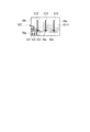
次に、遊技盤1の前面に形成された遊技領域6の上下方向略中央の右隣(遊技領域6以外の部分)に配置されている表示器類8について説明する。図4に示すように、表示器類には、第1特別図柄(以下、「特図1」という)を可変表示する特図1表示器81a、第2特別図柄(以下、「特図2」という)を可変表示する特図2表示器81b、及び、普通図柄(以下、「普図」という)を可変表示する普図表示器82が含まれている。また、表示器類には、後述する特図1保留数を表示する特図1保留表示器83a、および後述する特図2保留数を表示する特図2保留表示器83bが含まれている。
Next, the
特図1の可変表示は、遊技球の第1始動口11への入賞を契機とした特図1抽選が行われると実行される。また、特図2の可変表示は、遊技球の第2始動口12への入賞を契機とした特図2抽選が行われると実行される。特図1抽選、および特図2抽選については後述する。なお、以下の説明では、特図1、および特図2を総称して「特図」といい、特図1抽選、および特図2抽選を総称して「特図抽選」という。また、特図1表示器81a、および特図2表示器81bを総称して「特図表示器81」という。さらに、特図1保留表示器83a、および特図2保留表示器83bを総称して「特図保留表示器83」という。
The variable display of the special figure 1 is executed when the special figure 1 lottery triggered by the winning of the game ball to the
特図の可変表示は、特図抽選の結果を報知する。特図の可変表示では、特図が変動表示した後に停止表示する。停止表示された特図(停止特図)は、可変表示の表示結果として導出された特図抽選の結果を表す識別情報である。停止表示された特図が予め定めた特定の特図である場合には、大入賞口14の開放を伴う大当たり遊技が行われる。
The variable display of the special figure informs the result of the special figure lottery. In the variable display of the special figure, the special figure is displayed in a variable manner and then stopped. The stop-displayed special figure (stop special figure) is identification information representing the result of the special figure lottery derived as the display result of the variable display. If the stop-displayed special figure is a predetermined special figure, a big hit game is performed with the opening of the big winning
特図1表示器81a、および特図2表示器81bはそれぞれ、横並びに配された8個のLEDから構成されている。特図1表示器81a、および特図2表示器81bの点灯態様は、特図抽選の結果に応じた特図、すなわち特図抽選の結果を表す。例えば特図抽選の結果が大当たりである場合には、最終的に「□□■■□□■■」(□:点灯、■:消灯)というように左から1,2,5,6番目にあるLEDが点灯する。この点灯態様が大当たり図柄であり、大当たりを表す。また、特図抽選の結果がハズレである場合には、最終的に「■■■■■■■□」というように一番右にあるLEDのみが点灯する。この点灯態様がハズレ図柄であり、ハズレを表す。なお、特図抽選の結果に対応するLEDの点灯態様は限定されず、適宜に設定することができる。よって、例えば、ハズレ図柄として全てのLEDを消灯させてもよい。
The special figure 1
また、特図の可変表示において、特図が停止表示される前には所定の変動時間にわたって特図の変動表示がなされる。特図の変動表示の態様は、例えば左から右へ光が繰り返し流れるように各LEDが点灯する態様である。なお、変動表示の態様は、特に限定されず、各LEDが停止表示(特定の態様での点灯表示)されていなければ、全LEDが一斉に点滅するなど適宜に設定してよい。 Further, in the variable display of the special map, the variable display of the special map is performed over a predetermined fluctuation time before the special map is stopped and displayed. The mode of the variable display of the special figure is, for example, a mode in which each LED is turned on so that light repeatedly flows from left to right. The mode of the variable display is not particularly limited, and if each LED is not stopped and displayed (lighting display in a specific mode), all the LEDs may be appropriately set such as blinking all at once.
ところで、パチンコ遊技機PY1では、遊技球が第1始動口11または第2始動口12へ入賞してもすぐに特図抽選および特図の可変表示が行われない場合がある。具体的には、特図の可変表示の実行中や大当たり遊技の実行中に遊技球の第1始動口11または第2始動口12への入賞があった場合である。この場合、所定個数を上限として、その入賞に基づいて特図抽選および特図の可変表示を実行する権利が留保される。この留保された権利のことを「特図保留」という。
By the way, in the pachinko gaming machine PY1, the special drawing lottery and the variable display of the special drawing may not be performed immediately even if the gaming ball wins a prize in the first starting opening 11 or the second starting opening 12. Specifically, it is a case where a prize is given to the
特図保留には、第1始動口11への入賞に基づいて留保された特図1抽選、および特図1の可変表示を実行する権利を表す「特図1保留」と、第2始動口12への入賞に基づいて留保された特図2抽選、および特図2の可変表示を実行する権利を表す「特図2保留」と、がある。そして、特図1保留の数、すなわち留保されている特図1抽選および特図1の可変表示を実行する権利の数を特図1保留表示器83aが表示する。一方、特図2保留の数、すなわち留保されている特図2抽選、および特図2の可変表示を実行する権利の数を特図2保留表示器83bが表示する。
The special figure hold includes the special figure 1 lottery reserved based on the winning of the
特図1保留表示器83aおよび特図2保留表示器83bのそれぞれは、4個のLEDで構成されており、特図1保留および特図2保留の数の分だけLEDを点灯させることにより特図1保留および特図2保留の数を表示する。なお、以下において、特図1保留の数を「特図1保留数(U1)」といい、特図2保留数の数を「特図2保留数(U2)」という。また、「特図1保留数」や「特図2保留数」を総称して「特図保留数」という。さらに、「特図1保留表示器83a」と「特図2保留表示器83b」とを総称して「特図保留表示器83」という。
Each of the special figure 1
また、普図の可変表示は、遊技球のゲート13の通過を契機とした普図抽選が行われると実行される。そして、普図の可変表示は、普図抽選の結果を報知する。普図の可変表示では、普図が変動表示した後に停止表示する。停止表示された普図(停止普図)は、可変表示の表示結果として導出された普図抽選の結果を表す識別情報である。停止表示された普図が予め定めた特定の普図である場合には、第2始動口12の開放を伴う補助遊技が行われる。
Further, the variable display of the normal map is executed when the normal map lottery triggered by the passage of the
普図表示器82は、例えば2個のLEDから構成されている。普図表示器82の点灯態様は、普図抽選の結果に応じた普図、すなわち普図抽選の結果を表す。普図抽選の結果が当たりである場合には、最終的には、「□□」(□:点灯、■:消灯)というように両LEDが点灯する。この点灯態様が当たり図柄であり、当たりを表す。また普図抽選の結果がハズレである場合には、最終的には、「■□」というように右のLEDのみが点灯する。この点灯態様がハズレ図柄であり、ハズレを表す。なお、普図抽選の結果に対応するLEDの点灯態様は限定されず、適宜に設定することができる。例えば、ハズレ図柄として全てのLEDを消灯させる態様を採用してもよい。
The
また、普図が停止表示される前には所定の変動時間にわたって普図の変動表示が行われる。普図の変動表示の態様は、第1実施形態では、両LEDが交互に点灯するという態様である。なお、普図の変動表示の態様は、特に限定されず、各LEDが停止表示(特定の態様での点灯表示)されていなければ、全LEDが一斉に点滅するなど適宜に設定してもよい。 Further, before the normal map is stopped and displayed, the variable display of the normal map is performed for a predetermined fluctuation time. In the first embodiment, the variation display of the normal diagram is an embodiment in which both LEDs are turned on alternately. It should be noted that the mode of variable display in the normal drawing is not particularly limited, and if each LED is not stopped display (lighting display in a specific mode), all LEDs may be appropriately set such as blinking all at once. ..
2.遊技機の電気的構成
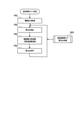
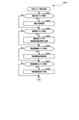
次に、図5~図6に基づいて、パチンコ遊技機PY1の電気的な構成を説明する。パチンコ遊技機PY1は、遊技利益を得ることが可能な遊技に関する制御(遊技の進行)を行う遊技制御基板100、遊技制御基板100による遊技の進行に応じた演出に関する制御を行う演出制御基板120、および、遊技球の払い出しに関する制御などを行う払出制御基板170等を備えている。遊技制御基板100、演出制御基板120、および払出制御基板170等は、ユニット化されて盤用演出ユニットEUの背面側に設置されている。
2. 2. Electrical configuration of the gaming machine Next, the electrical configuration of the pachinko gaming machine PY1 will be described with reference to FIGS. 5 to 6. The pachinko gaming machine PY1 has a
なお、遊技制御基板100の制御対象となる遊技利益を獲得可能な遊技には、特図抽選、特図の可変表示、大当たり遊技、後述する遊技状態の設定、普図抽選、普図の可変表示、補助遊技などが含まれる。また、演出制御基板120の制御対象となる演出には、遊技演出(特図変動演出、保留演出、大当たり遊技演出など)、客待ち演出、第1演出ボタン40kや第2演出ボタン41kの操作が有効な期間(操作有効期間)において操作を促す操作促進演出などが含まれている。
In addition, the game that can acquire the game profit to be controlled by the
また、遊技制御基板100は、遊技の制御を行う遊技制御部と位置づけることができる。一方、演出制御基板120は、後述する画像制御基板140、音声制御回路161、およびサブドライブ基板162と共に、演出の制御を行う演出制御部と位置づけることができる。なお、演出制御部は、少なくとも演出制御基板120を備え、演出装置(画像表示装置50、スピーカ52、枠ランプ53、および盤可動体55k等)を用いた遊技演出、客待ち演出、および操作促進演出などを制御可能であればよい。
Further, the
また、パチンコ遊技機PY1は、電源基板190を備えている。電源基板190は、遊技制御基板100、演出制御基板120、及び払出制御基板170に対して電力を供給するとともに、これらの基板を介してその他の機器に対して必要な電力を供給する。電源基板190には、電源スイッチ191が接続されている。電源スイッチ191のONOFF操作により、電源の投入/遮断が切り換えられる。
Further, the pachinko gaming machine PY1 includes a
図5に示すように、遊技制御基板100には、プログラムに従ってパチンコ遊技機PY1の遊技の進行を制御する遊技制御用ワンチップマイコン(以下「遊技制御用マイコン」)101が実装されている。遊技制御用マイコン101には、遊技の進行を制御するためのプログラムやテーブル等を記憶した遊技用ROM(Read Only Memory)103、ワークメモリとして使用される遊技用RAM(Random Access Memory)104、遊技用ROM103に記憶されたプログラムを実行する遊技用CPU(Central Processing Unit)102が含まれている。
As shown in FIG. 5, a game control one-chip microcomputer (hereinafter referred to as “game control microcomputer”) 101 that controls the progress of the game of the pachinko gaming machine PY1 according to a program is mounted on the
遊技用ROM103には、後述する遊技制御メイン処理や遊技制御側タイマ割り込み処理などを行うためのプログラムが格納されている。また、遊技用ROM103には、後述する大当たり判定テーブル、大当たり図柄種別判定テーブル、リーチ判定テーブル、特図変動パターン判定テーブル、先読み判定テーブル、大当たり遊技制御テーブル、遊技状態設定テーブル、当たり判定テーブル、補助遊技制御テーブルなどが格納されている。なお、遊技用ROM103は外付けであってもよい。
The
また、遊技用RAM104には、特図保留記憶部105が設けられている。ここで、特図保留記憶部105について説明する。前述の通り、遊技球の第1始動口11または第2始動口12への入賞があると、特図保留が発生可能であるが、特図保留が可能な場合、すなわち、特図保留数が上限値に達していないときには、この入賞に基づいて、特図抽選などを行うための各種乱数からなる判定情報が取得される。そして、この判定情報は、特図保留として特図保留記憶部105に一旦記憶される。なお、以下において、遊技球の第1始動口11への入賞により取得される判定情報のことを「特図1関連判定情報」といい、遊技球の第2始動口12への入賞により取得される判定情報のことを「特図2関連判定情報」という。また、特図1関連判定情報と特図2関連判定情報とを総称して「特図関連判定情報」という。
Further, the
そして、特図1関連判定情報は、特図1保留として、特図保留記憶部105の中の特図1保留記憶部105aに記憶される。一方、特図2関連判定情報は、特図2保留として、特図保留記憶部105の中の特図2保留記憶部105bに記憶される。特図1保留記憶部105aに記憶可能な特図1関連判定情報の数、すなわち、特図1保留数の上限数は「4」に設定されている。また、特図2保留記憶部105bに記憶可能な特図2関連判定情報の数、すなわち、特図2保留数の上限数は「4」に設定されている。なお、特図1保留数の上限数および特図2保留数の上限数は適宜に設定しても良い。また特図1保留数の上限数および特図2保留数の上限数を設けなくても良い。
Then, the special figure 1 related determination information is stored in the special figure 1 hold storage unit 105a in the special figure
また、遊技制御基板100には、所定の中継基板(図示なし)を介して各種センサ類やソレノイド類が接続されている。そのため、遊技制御基板100には、各種センサ類が出力した信号が入力する。また、遊技制御基板100は、各種アクチュエータ類に信号を出力する。
Further, various sensors and solenoids are connected to the
遊技制御基板100に接続されている各種センサ類には、一般入賞口センサ10a、第1始動口センサ11a、第2始動口センサ12a、ゲートセンサ13a、および大入賞口センサ14aが含まれている。
Various sensors connected to the
一般入賞口センサ10aは、一般入賞口10に入賞した遊技球を検知する。第1始動口センサ11aは、第1始動口11に入賞した遊技球を検知する。第2始動口センサ12aは、第2始動口12に入賞した遊技球を検知する。ゲートセンサ13aは、ゲート13を通過した遊技球を検知する。大入賞口センサ14aは、大入賞口14に入賞した遊技球を検知する。
The general winning
また、遊技制御基板100に接続されている各種アクチュエータ類には、電チューソレノイド12s、およびATソレノイド14sが含まれている。電チューソレノイド12sは、電チュー12Dの電チュー開閉部材12kを駆動する。ATソレノイド14sは、大入賞装置14DのAT開閉部材14kを駆動する。
Further, various actuators connected to the
なお、遊技制御基板100に接続されるセンサの種類や数は、遊技に支障をきたさない範囲で適宜に変更可能である。また、遊技制御基板100に接続されるアクチュエータの種類や数は、遊技に支障をきたさない範囲で適宜に変更可能である。
The type and number of sensors connected to the
さらに遊技制御基板100には、表示器類8(特図表示器81、普図表示器82、および、特図保留表示器83)が接続されている。これらの表示器類8の表示制御は、遊技制御用マイコン101によりなされる。
Further, the
また遊技制御基板100は、払出制御基板170に各種コマンドを送信するとともに、払い出し監視のために払出制御基板170から信号を受信する。払出制御基板170には、カードユニットCU、および払出装置73が接続されているとともに、発射装置72が接続されている。また、カードユニットCUは、パチンコ遊技機PY1に隣接して設置され、挿入されているプリペイドカード等の情報に基づいて球貸しを可能にする装置である。
Further, the
払出制御基板170は、遊技制御用マイコン101からの信号や、接続されたカードユニットCUからの信号に基づいて、払出装置73の払出モータ73mを駆動して賞球や貸球の払い出しを行う。払い出される賞球や貸球は、その計数のための払出センサ73aにより検知される。
The
また、発射装置72は遊技球を発射する装置である。ハンドル72kが、発射装置72に遊技球を発射させるための操作を受け付ける操作部または入力部を構成しており、発射装置72に含まれる。ハンドル72kには、遊技者などの人のハンドル72kへの接触を検知可能なタッチスイッチ72aが設けられている。遊技者によるハンドル72kの操作があった場合には、タッチスイッチ72aが遊技者のハンドル72kへの接触を検知し、発射制御回路175を介して検知信号を払出制御基板170に出力する。
Further, the launching
さらに、ハンドル72kには、ハンドル72kの回転角度(操作量)を検出可能な発射ボリュームのつまみ72bが接続されている。発射装置72は、発射ボリュームのつまみ72bが検出したハンドル72kの回転角度に応じた強さで遊技球が発射されるよう発射モータ72mを駆動させる。なお、パチンコ遊技機PY1においては、ハンドル72kへの回転操作が維持されている状態では、約0.6秒毎に1球の遊技球が発射されるようになっている。
Further, a
また遊技制御基板100は、遊技の進行に応じて、演出制御基板120に対し、遊技に関する情報を含んだ各種コマンドを送信する。演出制御基板120は、遊技制御基板100から送られてきた各種コマンドに基づいて、遊技制御基板100による遊技の進行状況(遊技の制御内容)を把握することができる。なお、遊技制御基板100と演出制御基板120との接続は、遊技制御基板100から演出制御基板120への信号の送信のみが可能な単方向通信接続となっている。すなわち、遊技制御基板100と演出制御基板120との間には、通信方向規制手段としての図示しない単方向性回路(例えばダイオードを用いた回路)が介在している。
Further, the
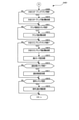
図6に示すように、演出制御基板120には、プログラムに従ってパチンコ遊技機PY1の演出を制御する演出制御用ワンチップマイコン(以下「演出制御用マイコン」)121が実装されている。演出制御用マイコン121には、遊技制御基板100による遊技の進行に伴って演出を制御するためのプログラム等を記憶した演出用ROM123、ワークメモリとして使用される演出用RAM124、演出用ROM123に記憶されたプログラムを実行する演出用CPU122が含まれている。
As shown in FIG. 6, the
また、演出用ROM123には、後述する演出制御メイン処理、受信割り込み処理、1msタイマ割り込み処理、および、10msタイマ割り込み処理などを行うためのプログラムが格納されている。なお、演出用ROM123は外付けであってもよい。また、演出用RAM124には、始動入賞コマンドを記憶する始動入賞コマンド保留記憶部125が設けられている。
Further, the
演出制御基板120には、画像制御基板140が接続されている。演出制御基板120の演出制御用マイコン121は、遊技制御基板100から受信したコマンドに基づいて、すなわち、遊技制御基板100による遊技の進行に応じて、画像制御基板140の画像用CPU141に画像表示装置50の表示制御を行わせる。なお、演出制御基板120と画像制御基板140との接続は、演出制御基板120から画像制御基板140への信号の送信と、画像制御基板140から演出制御基板120への信号の送信の双方が可能な双方向通信接続となっている。
An
画像制御基板140は、画像制御のためのプログラム等を記憶した画像用ROM142、ワークメモリとして使用される画像用RAM143、及び、画像用ROM142に記憶されたプログラムを実行する画像用CPU141を備えている。また、画像制御基板140は、画像表示装置50に表示される画像のデータを記憶したCGROM(Character Generator Read Only Memory)145、CGROM145に記憶されている画像データの展開等に使用されるVRAM(Video Random Access Memory)146、及び、VDP(Video Display Processor)144を備えている。勿論、これらの電子部品の全部又は一部がワンチップで構成されていてもよい。CGROM145には、例えば、画像表示装置50に表示される画像を表示するための画像データ(静止画データや動画データ、具体的にはキャラクタ、アイテム、図柄、図形、文字、数字および記号等(演出図柄を含む)や背景画像等の画像データ)が格納されている。
The
VDP144は、演出制御用マイコン121からの指令に基づき画像用CPU141によって作成されるディスプレイリストに従って、CGROM145から画像データを読み出してVRAM146内の展開領域に展開する。そして、展開した画像データを適宜合成してVRAM146内のフレームバッファに画像を描画する。そしてフレームバッファに描画した画像をRGB信号として画像表示装置50に出力する。これにより、種々の演出画像が表示部50aに表示される。
The
なお、ディスプレイリストは、フレーム単位で描画の実行を指示するためのコマンド群で構成されている。ディスプレイリストには、描画する画像の種類、画像を描画する位置、表示の優先順位、表示倍率、画像の透過率等の種々のパラメータの情報が含まれている。 The display list is composed of a group of commands for instructing the execution of drawing on a frame-by-frame basis. The display list contains information on various parameters such as the type of image to be drawn, the position where the image is drawn, the display priority, the display magnification, and the transmittance of the image.
演出制御用マイコン121は、遊技制御基板100から受信したコマンドに基づいて、すなわち、遊技制御基板100による遊技の進行に応じて、音声制御回路161を介してスピーカ52から音声、楽曲、効果音等を出力する。
The
スピーカ52から出力する音声等の音声データは、演出制御基板120の演出用ROM123に格納されている。なお、音声制御回路161を、基板にしてCPUを実装してもよい。この場合、そのCPUに音声制御を実行させてもよい。さらにこの場合、基板にROMを実装し、そのROMに音声データを格納してもよい。また、スピーカ52を画像制御基板140に接続し、画像制御基板140の画像用CPU141に音声制御を実行させてもよい。さらにこの場合、画像制御基板140の画像用ROM142に音声データを格納してもよい。
Audio data such as audio output from the
また、演出制御基板120には、所定の中継基板(図示なし)を介して、入力部となる各種センサ類や駆動源となる各種アクチュエータ類が接続されている。演出制御基板120には、各種センサ類が出力した信号が入力する。また、演出制御基板120は、各種アクチュエータ類に信号を出力する。
Further, various sensors serving as an input unit and various actuators serving as a drive source are connected to the
演出制御基板120に接続されている各種スイッチ類には、第1演出ボタン検知センサ40a、および第2演出ボタン検知センサ41aが含まれている。第1演出ボタン検知センサ40aは、第1演出ボタン40kが押下操作されたことを検出する。第2演出ボタン検知センサ41aは、第2演出ボタン41kが押下操作されたことを検出する。第1演出ボタン検知センサ40a、および第2演出ボタン検知センサ41aは、それぞれが操作されたことを検知すると、その検出内容に応じた信号を演出制御基板120に出力する。
The various switches connected to the
なお、演出制御基板120に接続されるスイッチの種類や数は、遊技に支障をきたさない範囲で適宜に変更可能である。また、演出制御基板120に接続されるアクチュエータの種類や数は、遊技に支障をきたさない範囲で適宜に変更可能である。
The type and number of switches connected to the
演出制御基板120に接続された各種アクチュエータ類には、回転部材用モータ55m1、および昇降部材用モータ55m2が含まれている。回転部材用モータ55m1は、回転部材55k1を駆動して、回転部材55k1を回転させることが可能である。昇降部材用モータ55m2は、昇降部材55k2を上昇または下降させることが可能である。詳細には、演出制御用マイコン121は、回転部材55k1や昇降部材55k2の動作態様を決める動作パターンデータを作成し、サブドライブ基板162を介して、回転部材55k1や昇降部材55k2の動作を制御する。なお、以下において、「回転部材55k1や昇降部材55k2」の動作を「盤可動体55kの動作」と総称することもある。また、回転部材55k1を回転させることや昇降部材55k2を下降または上昇させることについて「盤可動体55kを回転させる、または下降もしくは上昇させる」ともいう。
The various actuators connected to the
また、演出制御用マイコン121は、遊技制御基板100から受信したコマンドなどに基づいて、サブドライブ基板162を介して枠ランプ53などの点灯制御を行う。詳細には演出制御用マイコン121は、枠ランプ53の発光態様を決める発光パターンデータ(点灯/消灯や発光色等を決めるデータ、ランプデータともいう)を作成し、発光パターンデータに従って枠ランプ53の発光を制御する。なお、発光パターンデータの作成には演出制御基板120の演出用ROM123に格納されているデータを用いる。
Further, the
なお、サブドライブ基板162を基板にしてCPUを実装してもよい。この場合、そのCPUに、枠ランプ53等の点灯制御、および、盤可動体55kの動作制御を実行させてもよい。さらにこの場合、基板にROMを実装して、そのROMに発光パターンや動作パターンに関するデータを格納してもよい。
The CPU may be mounted using the
3.遊技機による主な遊技
次に、パチンコ遊技機PY1により行われる主な遊技について、図7~図14を用いて説明する。
3. 3. Main games by the gaming machine Next, the main games played by the pachinko gaming machine PY1 will be described with reference to FIGS. 7 to 14.
3-1.普図に関わる遊技
最初に、普図に関わる遊技について説明する。パチンコ遊技機PY1は、発射された遊技球がゲート13を通過すると、普図抽選を実行することができる。普図抽選を行うと、普図表示器82において、普図の可変表示(変動表示を行った後に停止表示)を行う。ここで、停止表示される普図には、当たり図柄とハズレ図柄とがある。なお、普図のハズレ図柄については、後述する特図のハズレ図柄と区別をするために「ハズレ普図」ともいう。当たり図柄が停止表示されると補助遊技が実行されて、当該ゲート13の通過に係る遊技が終了する。一方、ハズレ普図が停止表示されると、補助遊技は行われず、当該ゲート13の通過に係る遊技が終了する。また、以下において、普図の可変表示または補助遊技が行われていないときに遊技球がゲート13を通過することを「普図変動始動条件の成立」という。
3-1. Games related to Fuzu First, we will explain the games related to Fuzu. The pachinko gaming machine PY1 can execute a general drawing lottery when the launched gaming ball passes through the
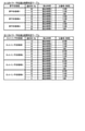
パチンコ遊技機PY1は、このような一連の遊技(普図抽選、普図の可変表示、補助遊技)を行うにあたり、普図変動始動条件の成立により、普図関連判定情報を取得する。取得する普図関連判定情報には、図7(A)に示すように、普通図柄乱数がある。普通図柄乱数は当たり判定を行うための乱数(判定情報)である。各乱数には、適宜に範囲が設けられている。 The pachinko gaming machine PY1 acquires the normal map-related determination information when the normal map variation start condition is satisfied when performing such a series of games (normal map lottery, variable display of the normal map, auxiliary game). As shown in FIG. 7A, the acquired general map-related determination information includes a normal symbol random number. Ordinary symbol random numbers are random numbers (judgment information) for performing collision detection. A range is appropriately provided for each random number.
3-1-1.当たり判定
当たり判定は、例えば図8(A)に示すような当たり判定テーブルを用いて、当たりか否か(補助遊技を実行するか否か)を決定するための判定である。当たり判定テーブルは、後述する遊技状態に関連付けることが可能である。すなわち、当たり判定テーブルには、非時短状態で用いる当たり判定テーブル(非時短用当たり判定テーブル)と、時短状態で用いる当たり判定テーブル(時短用当たり判定テーブル)と、がある。各当たり判定テーブルでは、当たり判定の結果である当たりとハズレに、普通図柄乱数の判定値(普通図柄乱数判定値)が振り分けられている。よって、パチンコ遊技機PY1は、取得した普通図柄乱数を当たり判定テーブルに照合して、当たりかハズレかの当たり判定を行う。当たり判定の結果が当たりであると、基本的には、普図の可変表示で当たり図柄が停止表示される。一方、当たり判定の結果がハズレであると、基本的には、普図の可変表示でハズレ普図が停止表示される。なお、当たりの当選確率については、適宜に変更することが可能である。
3-1-1. Hit determination The hit determination is a determination for determining whether or not to hit (whether or not to execute an auxiliary game) using, for example, a hit determination table as shown in FIG. 8A. The hit determination table can be associated with the gaming state described later. That is, the hit determination table includes a hit determination table (non-time reduction hit determination table) used in the non-time reduction state and a hit determination table (time reduction hit determination table) used in the time reduction state. In each hit determination table, the determination value of the normal symbol random number (ordinary symbol random number determination value) is assigned to the hit and the loss which are the results of the hit determination. Therefore, the pachinko gaming machine PY1 collates the acquired ordinary symbol random numbers with the hit determination table, and determines whether the hit or miss is a hit. If the result of the hit determination is a hit, the hit symbol is basically stopped and displayed in the variable display of the normal figure. On the other hand, if the result of the hit determination is a loss, the lost normal map is basically stopped and displayed in the variable display of the normal map. The winning probability can be changed as appropriate.
3-1-2.普図変動パターン判定・普図可変表示
普図変動パターン判定は、例えば図8(B)に示すような普図変動パターン判定テーブルを用いて、普図変動パターンを決定するための判定である。普図変動パターンとは、普図変動時間などの普図の可変表示に関する所定事項に関する識別情報である。
3-1-2. Normal map fluctuation pattern determination / normal map variable display The normal map fluctuation pattern determination is a judgment for determining the normal map fluctuation pattern using, for example, the normal map fluctuation pattern determination table as shown in FIG. 8 (B). The normal map fluctuation pattern is identification information related to predetermined items related to the variable display of the normal map such as the normal map fluctuation time.
普図変動パターン判定テーブルは、遊技状態(非時短状態/時短状態)に関連付けることが可能である。すなわち、普図変動パターン判定テーブルには、非時短状態のときに用いられる普図変動パターン判定テーブル(非時短普図変動パターン判定テーブル)と時短状態のときに用いられる普図変動パターン判定テーブル(時短普図変動パターン判定テーブル)とがある。 The normal figure fluctuation pattern determination table can be associated with a gaming state (non-time saving state / time saving state). That is, the normal map fluctuation pattern judgment table includes the normal map fluctuation pattern judgment table (non-time saving normal map fluctuation pattern judgment table) used in the non-time saving state and the normal map fluctuation pattern judgment table used in the time saving state (non-time saving normal map fluctuation pattern judgment table). There is a time-saving normal map fluctuation pattern judgment table).
各普図変動パターン判定テーブルには、普図変動パターン判定の結果である普図変動パターンが、停止される普図毎に1つ格納されている。すなわち、パチンコ遊技機PY1は、非時短状態と時短状態とで、普図変動時間を異ならせることが可能である。例えば、非時短状態においては、ハズレの普図(ハズレ普図)を停止表示する場合の普図の可変表示については普図変動時間が例えば30秒となる普図変動パターンに決定し、当たり図柄を停止表示する場合の普図の可変表示については普図変動時間が例えば30秒となる普図変動パターンに決定する。また、時短状態においては、ハズレ普図を停止表示する場合の普図の可変表示については普図変動時間が例えば5秒となる普図変動パターンに決定し、当たり図柄を停止表示する場合の普図の可変表示については普図変動時間が例えば5秒となる普図変動パターンに決定する。なお、これら普図変動時間については、適宜に変更することが可能である。 In each normal map fluctuation pattern determination table, one normal map fluctuation pattern, which is the result of the normal map fluctuation pattern determination, is stored for each normal map to be stopped. That is, the pachinko gaming machine PY1 can make the fluctuation time of the normal map different between the non-time saving state and the time saving state. For example, in the non-time saving state, for the variable display of the normal map when the lost normal map (lost normal map) is stopped and displayed, the normal map fluctuation time is determined to be, for example, 30 seconds, and the winning symbol is determined. The variable display of the normal map when the display is stopped is determined to be a normal map fluctuation pattern in which the normal map fluctuation time is, for example, 30 seconds. In addition, in the time saving state, the variable display of the normal map when the lost normal map is stopped and displayed is determined to be the normal map fluctuation pattern in which the normal map fluctuation time is, for example, 5 seconds, and the winning symbol is stopped and displayed. The variable display of the figure is determined to be a normal map fluctuation pattern in which the normal map fluctuation time is, for example, 5 seconds. It should be noted that these fluctuation times of the normal map can be changed as appropriate.
そして、普図変動パターン判定で決定された普図変動パターンに対応付けられた普図変動時間の普図の可変表示が、普図表示器82で行われる。このように、当たり判定、および、普図変動パターン判定が行われることによって、普図表示器82において普図の可変表示が行われる。
Then, the variable display of the normal map variation time associated with the normal map fluctuation pattern determined by the normal map fluctuation pattern determination is performed by the
3-1-3.補助遊技
補助遊技は、普図の可変表示で、表示結果(普図抽選の結果)として、当たり図柄が停止表示(導出)されると実行される。
3-1-3. Auxiliary game Auxiliary game is a variable display of a normal map, and is executed when the winning symbol is stopped and displayed (derived) as a display result (result of the general map lottery).
補助遊技を構成する要素(補助遊技構成要素)、すなわち、電チュー12Dが開放する回数、および各開放についての開放時間などの様々な要素が含まれている。そして、これらの各要素は、遊技状態(非時短状態/時短状態)に対応付けることが可能である。パチンコ遊技機PY1は、遊技状態(非時短状態/時短状態)に基づいて、例えば図8(C)に示すような補助遊技制御テーブルを用いて補助遊技を制御する。補助遊技制御テーブルは、遊技状態(非時短状態/時短状態)に対応付けられている。各補助遊技制御テーブルには、補助遊技構成要素が格納されている。なお、開放回数や開放時間などの各要素については、適宜に変更することが可能である。
Elements constituting the auxiliary game (auxiliary game component), that is, various elements such as the number of times the
パチンコ遊技機PY1は、非時短状態における補助遊技と時短状態における補助遊技とで、電チュー12Dの開放時間を異ならせることが可能である。例えば、非時短状態における補助遊技では、0.2秒などの遊技球を電チュー12Dに入賞させるのが困難な第1の開放時間だけ電チュー12Dが開放する。一方、時短状態における補助遊技では、例えば、1.0秒のインターバル(閉鎖)を挟んだ2.5秒の2回開放などの第1の開放時間よりも長く、遊技球を電チュー12Dに入賞させるのが容易な第2の開放時間だけ電チュー12Dが開放する。
The pachinko gaming machine PY1 can make the opening time of the
なお、以下において、非時短状態における補助遊技のことを「ショート開放補助遊技」ともいう。一方、時短状態における補助遊技のことを「ロング開放補助遊技」ともいう。また、各補助遊技における開放時間は、その補助遊技での合計時間であり、例えば、一度開放した後に一旦閉鎖するインターバルを挟んで再度開放するなど、1回の補助遊技の中で複数回開放するように構成しても良い。 In the following, the auxiliary game in the non-time saving state is also referred to as "short open auxiliary game". On the other hand, the auxiliary game in the short time state is also called "long open auxiliary game". Further, the opening time in each auxiliary game is the total time in the auxiliary game, and is opened a plurality of times in one auxiliary game, for example, opening once and then opening again with an interval of closing once. It may be configured as follows.
3-2.特図に関わる遊技
次に、特図に関わる遊技について説明する。パチンコ遊技機PY1は、発射された遊技球が第1始動口11に入賞すると、特図1抽選を実行することができる。特図1抽選が行われると、特図1表示器81aにおいて、特図1の可変表示(変動表示を行った後に停止表示)を行って、特図1抽選の結果を報知する。ここで、停止表示される特図1には、大当たり図柄、およびハズレ図柄がある。すなわち、特図1抽選の結果には大当たり、およびハズレがある。
3-2. Games related to special figures Next, games related to special figures will be described. The pachinko gaming machine PY1 can execute the
大当たり図柄が停止表示されると大当たり遊技が実行され、新たな遊技状態が設定されて、当該入賞に基づく遊技が終了する。また、ハズレ図柄が停止表示されると、大当たり遊技が行われず、当該入賞に基づく遊技が終了する。 When the jackpot symbol is stopped and displayed, the jackpot game is executed, a new game state is set, and the game based on the winning is completed. In addition, when the lost symbol is stopped and displayed, the jackpot game is not performed, and the game based on the prize is terminated.
同様に、パチンコ遊技機PY1は、発射された遊技球が第2始動口12に入賞すると、特図2抽選を実行することができる。特図2抽選が行われると、特図2表示器81bにおいて、特図2の可変表示(変動表示を行った後に停止表示)を行って、特図2抽選の結果を報知する。ここで、停止表示される特図2には、大当たり図柄、およびハズレ図柄がある。すなわち、特図2抽選の結果には、大当たり、およびハズレがある。
Similarly, the pachinko gaming machine PY1 can execute the special figure 2 lottery when the launched gaming ball wins a prize in the
大当たり図柄が停止表示されると大当たり遊技が実行され、新たな遊技状態が設定されて、当該入賞に基づく遊技が終了する。さらに、ハズレ図柄が停止表示されると大当たり遊技が行われず、当該入賞に基づく遊技が終了する。 When the jackpot symbol is stopped and displayed, the jackpot game is executed, a new game state is set, and the game based on the winning is completed. Further, when the lost symbol is stopped and displayed, the jackpot game is not performed, and the game based on the prize is ended.
また、以下において、第1始動口11に遊技球が入賞することを「第1始動条件の成立」といい、第2始動口12に遊技球が入賞することを「第2始動条件の成立」という。また、「第1始動条件の成立」と「第2始動条件の成立」をまとめて「始動条件の成立」と総称する。また、特別図柄のハズレ図柄については、前述の普図のハズレ図柄と区別するために「ハズレ特図」ともいう。
Further, in the following, the winning of the game ball in the
パチンコ遊技機PY1は、このような一連の遊技(特図抽選、特図の可変表示、大当たり遊技、および遊技状態の設定)を行うために、始動条件の成立により、特図関連判定情報を取得し、当該特図関連判定情報について種々の判定を行う。取得する特図関連判定情報には、図7(B)に示すように、特別図柄乱数、大当たり図柄種別乱数、リーチ乱数および特図変動パターン乱数がある。特別図柄乱数は大当たり判定を行うための乱数(判定情報)である。大当たり図柄種別乱数は大当たり図柄種別判定を行うための乱数(判定情報)である。リーチ乱数はリーチ判定を行うための乱数(判定情報)である。特図変動パターン乱数は特別図柄の変動パターン判定を行うための乱数(判定情報)である。各乱数には、適宜に範囲が設けられている。次に、特図関連判定情報を用いて行われる各判定について説明する。 In order to perform such a series of games (special figure lottery, variable display of special figures, jackpot game, and setting of game state), the pachinko gaming machine PY1 acquires special figure-related determination information when the start condition is satisfied. Then, various judgments are made on the special figure-related judgment information. As shown in FIG. 7B, the special symbol-related determination information to be acquired includes a special symbol random number, a jackpot symbol type random number, a reach random number, and a special symbol variation pattern random number. The special symbol random number is a random number (judgment information) for making a jackpot judgment. The jackpot symbol type random number is a random number (judgment information) for determining the jackpot symbol type. The reach random number is a random number (judgment information) for performing reach determination. The special symbol variation pattern random number is a random number (determination information) for determining the variation pattern of the special symbol. A range is appropriately provided for each random number. Next, each determination made using the special figure-related determination information will be described.
3-2-1.大当たり判定
大当たり判定は、例えば図9(A)、図9(B)に示すような大当たり判定テーブルを用いて、大当たりか否か(大当たり遊技を実行するか否か)、言い換えると、大当たり、またはハズレの何れかを決定することである。大当たり判定テーブルは、第1始動口11への入賞に基づく大当たり判定で用いる大当たり判定テーブル(以下、「第1大当たり判定テーブル」という)と、第2始動口12への入賞に基づく大当たり判定で用いる大当たり判定テーブル(以下、「第2大当たり判定テーブル」という)と、がある。そして、始動口の種別に関連付けられた大当たり判定テーブルのそれぞれには、さらに通常確率状態で用いる大当たり判定テーブル(通常確率用第1大当たり判定テーブル、通常確率用第2大当たり判定テーブル)と、高確率状態で用いる大当たり判定テーブル(高確率用第1大当たり判定テーブル、高確率用第2大当たり判定テーブル)と、がある。
3-2-1. Jackpot determination The jackpot determination uses, for example, a jackpot determination table as shown in FIGS. 9 (A) and 9 (B) to determine whether or not the jackpot is a jackpot (whether or not to execute a jackpot game), in other words, a jackpot or a jackpot. It is to decide one of the losses. The jackpot determination table is used in the jackpot determination table (hereinafter referred to as "first jackpot determination table") used in the jackpot determination based on the winning of the
なお、パチンコ遊技機PY1では、第1始動口11に入賞すると特図1の可変表示が実行され、第2始動口12に入賞すると特図2の可変表示が実行される。よって、第1大当たり判定テーブルは特図1用の大当たり判定テーブル、第2大当たり判定テーブルは特図2用の大当たり判定テーブルということができる。
In the pachinko gaming machine PY1, when the
遊技状態に関連付けられた各第1大当たり判定テーブルでは、大当たり判定の結果である大当たり、およびハズレに、特別図柄乱数の判定値(特別図柄乱数判定値)が振り分けられている。パチンコ遊技機PY1は、取得した特別図柄乱数を第1大当たり判定テーブルに照合して、大当たり、またはハズレの何れであるかを判定する。図9(A)に示すように、高確率用第1大当たり判定テーブルの方が、通常確率用第1大当たり判定テーブルよりも、大当たりと判定される特別図柄乱数判定値が多く設定されている。 In each first jackpot determination table associated with the game state, the determination value of the special symbol random number (special symbol random number determination value) is assigned to the jackpot and the loss which are the results of the jackpot determination. The pachinko gaming machine PY1 collates the acquired special symbol random numbers with the first jackpot determination table, and determines whether it is a jackpot or a loss. As shown in FIG. 9A, the high probability first jackpot determination table has more special symbol random number determination values determined to be jackpots than the normal probability first jackpot determination table.
また、遊技状態に関連付けられた各第2大当たり判定テーブルでは、大当たり判定の結果である大当たり、およびハズレに、特別図柄乱数の判定値(特別図柄乱数判定値)が振り分けられている。パチンコ遊技機PY1は、取得した特別図柄乱数を第2大当たり判定テーブルに照合して、大当たり、またはハズレの何れであるかを判定する。図9(B)に示すように、高確率用第2大当たり判定テーブルの方が、通常確率用第2大当たり判定テーブルよりも、大当たりと判定される特別図柄乱数判定値が多く設定されている。 Further, in each of the second jackpot determination tables associated with the game state, the determination value of the special symbol random number (special symbol random number determination value) is distributed to the jackpot and the loss which are the results of the jackpot determination. The pachinko gaming machine PY1 collates the acquired special symbol random numbers with the second jackpot determination table, and determines whether it is a jackpot or a loss. As shown in FIG. 9B, the high probability second jackpot determination table has more special symbol random number determination values determined to be jackpots than the normal probability second jackpot determination table.
なお、大当たりの当選確率や各種大当たり判定の判定結果に対する特別図柄乱数判定値の振り分け方については、適宜に変更することが可能である。 It is possible to appropriately change the winning probability of the jackpot and the method of allocating the special symbol random number determination value to the determination results of various jackpot determinations.
3-2-2.大当たり図柄種別判定
大当たり図柄種別判定は、大当たり判定の結果が大当たりである場合に、例えば図9(C)に示すような大当たり図柄種別判定テーブルを用いて大当たり図柄の種別(大当たり図柄種別)を決定することである。大当たり図柄の種別に、大当たりの内容、換言すれば、遊技者に付与される遊技特典などで構成される大当たりの構成要素(遊技者に有利な内容)を対応付けることが可能である。
3-2-2. Jackpot symbol type determination In the jackpot symbol type determination, when the result of the jackpot determination is a jackpot, for example, the jackpot symbol type (big hit symbol type) is determined using the jackpot symbol type determination table as shown in FIG. 9 (C). It is to be. It is possible to associate the jackpot symbol type with the jackpot content, in other words, the jackpot component (content advantageous to the player) composed of the game privilege given to the player.
大当たり図柄種別判定テーブルは、可変表示される特別図柄の種別(特図1/特図2)、言い換えれば、当該大当たり図柄種別判定が起因する(当該大当たり図柄種別判定を発生させた)入賞が行われた始動口の種別(第1始動口11/第2始動口12)に関連付けられている。すなわち、大当たり図柄種別判定テーブルには、特図1の可変表示を行うときに用いられる大当たり図柄種別判定テーブル(第1大当たり図柄種別判定テーブル)と特図2の可変表示を行うときに用いられる大当たり図柄種別判定テーブル(第2大当たり図柄種別判定テーブル)とがある。
In the jackpot symbol type determination table, the type of special symbol that is variably displayed (special figure 1 / special figure 2), in other words, the prize is awarded due to the jackpot symbol type determination (causing the jackpot symbol type determination). It is associated with the type of starting port (first starting
大当たり図柄は複数種類設定可能である。各大当たり図柄種別判定テーブルでは、大当たり図柄種別判定の結果である大当たり図柄種別に、大当たり図柄種別乱数の判定値(大当たり図柄種別乱数判定値)が振り分けられている。よって、パチンコ遊技機PY1は、取得した大当たり図柄種別乱数を大当たり図柄種別判定テーブルに照合して、大当たり図柄の種別を判定する。そして、第1大当たり図柄種別判定テーブルおよび第2大当たり図柄種別判定テーブルでは、大当たり図柄種別乱数判定値が各種大当たり図柄に適宜に振り分けられている。 Multiple types of jackpot symbols can be set. In each jackpot symbol type determination table, the determination value of the jackpot symbol type random number (the jackpot symbol type random number determination value) is assigned to the jackpot symbol type which is the result of the jackpot symbol type determination. Therefore, the pachinko gaming machine PY1 collates the acquired jackpot symbol type random numbers with the jackpot symbol type determination table to determine the type of jackpot symbol. Then, in the first jackpot symbol type determination table and the second jackpot symbol type determination table, the jackpot symbol type random number determination values are appropriately distributed to various jackpot symbols.
特図1の大当たり図柄、および特図2の大当たり図柄の種類は適宜に設定することができるが、例えば、図9(C)に示す大当たり図柄種別判定テーブルのように、特図1の大当たり図柄として、大当たり図柄A、大当たり図柄B、および大当たり図柄Cの3種類の大当たり図柄を設け、特図2の大当たり図柄として、大当たり図柄D、大当たり図柄E、および大当たり図柄Fの3種類の大当たり図柄を設けることができる。そして、図9(C)に示す大当たり図柄種別判定テーブルのように、第1大当たり図柄種別判定テーブルおよび第2大当たり図柄種別判定テーブルでは、大当たり図柄種別乱数判定値が各種大当たり図柄に適宜に振り分けられている。なお、大当たり図柄種別の振分率については、適宜に変更することが可能である。また、大当たり図柄の種別については、適宜に増加したり減少したりすることが可能である。 The type of the jackpot symbol of the special figure 1 and the type of the jackpot symbol of the special figure 2 can be appropriately set. For example, as in the jackpot symbol type determination table shown in FIG. 9C, the jackpot symbol of the special figure 1 is used. As a jackpot symbol A, a jackpot symbol B, and a jackpot symbol C, three types of jackpot symbols are provided, and as a jackpot symbol of special figure 2, three types of jackpot symbols D, a jackpot symbol E, and a jackpot symbol F are used. Can be provided. Then, as in the jackpot symbol type determination table shown in FIG. 9C, in the first jackpot symbol type determination table and the second jackpot symbol type determination table, the jackpot symbol type random number determination values are appropriately distributed to various jackpot symbols. ing. The distribution rate for each jackpot symbol type can be changed as appropriate. In addition, the types of jackpot symbols can be increased or decreased as appropriate.
3-2-3.リーチ判定
リーチ判定は、大当たり判定の結果がハズレである場合に、例えば図9(D)に示すようなリーチ判定テーブルを用いて、後述する特図変動演出でリーチを発生させるか否かを決定することである。
3-2-3. Reach judgment In the reach judgment, when the result of the jackpot judgment is a loss, for example, using the reach judgment table as shown in FIG. 9 (D), it is determined whether or not to generate the reach by the special figure variation effect described later. It is to be.
リーチ判定テーブルは、遊技状態(非時短状態/時短状態)に関連付けることが可能である。すなわち、リーチ判定テーブルには、非時短状態のときに用いられるリーチ判定テーブル(非時短用リーチ判定テーブル)と時短状態のときに用いられるリーチ判定テーブル(時短用リーチ判定テーブル)とがある。 The reach determination table can be associated with a gaming state (non-time saving state / time saving state). That is, the reach determination table includes a reach determination table (non-time reduction reach determination table) used in the non-time reduction state and a reach determination table (time reduction reach determination table) used in the time reduction state.
各リーチ判定テーブルでは、リーチ判定の結果である「リーチ有り(リーチを発生させる)」と「リーチ無し(リーチを発生させない)」に、リーチ乱数の判定値(リーチ乱数判定値)が振り分けられている。よって、パチンコ遊技機PY1は、取得したリーチ乱数をリーチ判定テーブルに照合して、リーチ有りかリーチ無しか(リーチを発生させる否か)を判定する。 In each reach judgment table, the judgment value of the reach random number (reach random number judgment value) is divided into "with reach (generate reach)" and "without reach (do not generate reach)" which are the results of reach judgment. There is. Therefore, the pachinko gaming machine PY1 collates the acquired reach random numbers with the reach determination table, and determines whether or not there is reach (whether or not to generate reach).
図9(D)に示すように、非時短用リーチ判定テーブルと時短用リーチ判定テーブルとで、「リーチ有り(リーチを発生させる)」と判定されるリーチ乱数判定値の数を異ならせることが可能である。なお、以下において、大当たり判定の結果が「ハズレ」であることを前提に行われるリーチ判定の結果「リーチ有り(リーチを発生させる)」のことを「リーチ有りハズレ」といい、「リーチ無し(リーチを発生させない)」のことを「リーチ無しハズレ」ということもある。 As shown in FIG. 9D, it is possible to make the number of reach random number determination values determined to be "reachable (generate reach)" different between the non-time reduction reach determination table and the time reduction reach determination table. It is possible. In the following, the result of the reach judgment "with reach (generate reach)" performed on the premise that the result of the jackpot judgment is "miss" is referred to as "loss with reach", and "without reach (without reach). "Does not generate reach)" is sometimes referred to as "loss without reach".
3-2-4.特図変動パターン判定・特図可変表示
特図変動パターン判定は、大当たり判定の結果が大当たり、およびハズレの何れの場合にも、例えば図10~図11に示すような特別図柄の変動パターン判定テーブル(特図変動パターン判定テーブル)を用いて、特図の可変表示の変動パターン(特図変動パターン)を決定することである。
3-2-4. Special figure fluctuation pattern judgment / special figure variable display In the special figure fluctuation pattern judgment, the fluctuation pattern judgment table of the special symbol as shown in FIGS. 10 to 11, for example, regardless of whether the result of the big hit judgment is a big hit or a loss. (Special figure variation pattern determination table) is used to determine the variation pattern (special map variation pattern) of the variable display of the special map.
特図変動パターンとは、特図変動時間や後述する特図変動演出の演出フロー(演出内容)などに関する所定事項を識別するための識別情報である。なお、特図変動パターンには、特図変動時間や特図変動演出の演出フロー(演出内容)の他、大当たり判定の結果とリーチ判定の結果に関する識別情報を含ませることが可能である。特図変動パターンとして、それぞれ識別情報が異なる複数種類の特図変動パターンを用いることが可能であり、その数は適宜に変更することが可能である。 The special figure fluctuation pattern is identification information for identifying predetermined items related to the special figure fluctuation time and the effect flow (effect content) of the special figure variation effect described later. It should be noted that the special figure variation pattern can include identification information regarding the result of the jackpot determination and the result of the reach determination, in addition to the effect flow (effect content) of the special figure variation effect and the special figure variation effect. As the special figure fluctuation pattern, it is possible to use a plurality of types of special figure fluctuation patterns having different identification information, and the number thereof can be appropriately changed.
特図変動パターン判定テーブルは、判定対象となる可変表示を行う特別図柄の種別(特図1/特図2)、言い換えれば、当該特図変動パターン判定が起因する入賞が行われた始動口の種別(第1始動口11/第2始動口12)に関連付けることが可能である。すなわち、特図変動パターン判定テーブルには、特図1の可変表示を行うときに用いられる特図変動パターン判定テーブル(特図1変動パターン判定テーブル:図10)と、特図2の可変表示を行うときに用いられる特図変動パターン判定テーブル(特図2変動パターン判定テーブル:図11)とがある。
The special figure fluctuation pattern judgment table is the type of special symbol (special figure 1 / special figure 2) that performs variable display to be judged, in other words, the starting port where a prize is given due to the special figure fluctuation pattern judgment. It can be associated with the type (first starting
そして、各特図変動パターン判定テーブルは、遊技状態(非時短状態/時短状態)に関連付けることが可能である。すなわち、特図1変動パターン判定テーブルには、非時短状態のときに用いられる特図1変動パターン判定テーブル(非時短用特図1変動パターン判定テーブル)と時短状態のときに用いられる特図1変動パターン判定テーブル(時短用特図1変動パターン判定テーブル)とがある。一方、特図2変動パターン判定テーブルについても同様に、非時短状態のときに用いられる特図2変動パターン判定テーブル(非時短用特図2変動パターン判定テーブル)と、時短状態のときに用いられる特図2変動パターン判定テーブル(時短用特図2変動パターン判定テーブル)と、がある。 Then, each special figure variation pattern determination table can be associated with a gaming state (non-time saving state / time saving state). That is, the special figure 1 fluctuation pattern determination table includes the special figure 1 fluctuation pattern determination table (non-time reduction special figure 1 fluctuation pattern determination table) used in the non-time reduction state and the special figure 1 used in the non-time reduction state. There is a variation pattern determination table (special figure 1 variation pattern determination table for time saving). On the other hand, similarly, the special figure 2 fluctuation pattern judgment table is also used in the special figure 2 fluctuation pattern judgment table (non-time saving special figure 2 fluctuation pattern judgment table) used in the non-time saving state and in the time saving state. There is a special figure 2 variation pattern determination table (special figure 2 variation pattern determination table for time saving).
また、遊技状態(非時短状態/時短状態)に関連付けられた各特図変動パターン判定テーブルは、さらに、大当たり判定結果、大当たり種別判定結果、およびリーチ判定結果にも関連付けることが可能である。すなわち、非時短用特図1変動パターン判定テーブルおよび時短用特図1変動パターン判定テーブルにはそれぞれ、大当たり図柄A用、大当たり図柄B,C用、リーチ有りハズレ用、およびリーチ無しハズレ用がある。同様に、非時短用特図2変動パターン判定テーブルおよび時短用特図2変動パターン判定テーブルにもそれぞれ、大当たり図柄D用、大当たり図柄E,F用、リーチ有りハズレ用、およびリーチ無しハズレ用がある。 Further, each special figure variation pattern determination table associated with the gaming state (non-time saving state / time saving state) can be further associated with the jackpot determination result, the jackpot type determination result, and the reach determination result. That is, the non-time saving special figure 1 fluctuation pattern judgment table and the time saving special figure 1 fluctuation pattern judgment table have a jackpot symbol A, a jackpot symbols B and C, a loss with reach, and a loss without reach, respectively. .. Similarly, the non-time saving special figure 2 fluctuation pattern judgment table and the time saving special figure 2 fluctuation pattern judgment table also have jackpot symbols D, jackpot symbols E and F, reach loss, and reachless loss, respectively. be.
さらに、遊技状態に関連付けられた各リーチ無しハズレ用の特図1変動パターン判定テーブルは、特図1保留数にも関連付けることが可能である。例えば、特図1保留数(U1)が0~2のときに用いられるリーチ無しハズレ用の特図1変動パターン判定テーブルと、特図1保留数(U1)が3~4のときに用いられるリーチ無しハズレ用の特図1変動パターン判定テーブルと、がある。また、同様に、遊技状態に関連付けられた各リーチ無しハズレ用の特図2変動パターン判定テーブルも、特図2保留数にも関連付けることが可能である。具体的には、特図2保留数(U2)が0~2のときに用いられるリーチ無しハズレ用の特図2変動パターン判定テーブルと、特図2保留数(U2)が3~4のときに用いられるリーチ無しハズレ用の特図2変動パターン判定テーブルと、がある。
Further, the special figure 1 variation pattern determination table for each reachless loss associated with the gaming state can also be associated with the special figure 1 hold number. For example, it is used when the special figure 1 holding number (U1) is 0 to 2 and the
そして、各特図変動パターン判定で決定された特図変動パターンに応じた特図変動時間の特図の可変表示が、特図表示器81で行われる。そして、特図の可変表示で、表示結果(特別図柄抽選の結果)として、大当たり図柄が停止表示されると、即座に次の特図の可変表示が行われず、引き続いて、大当たり遊技が実行される。 Then, the special map display 81 performs variable display of the special map variation time according to the special map variation pattern determined by each special map variation pattern determination. Then, when the jackpot symbol is stopped and displayed as the display result (result of the special symbol lottery) in the variable display of the special symbol, the variable display of the next special symbol is not immediately performed, and the jackpot game is subsequently executed. To.
また、各特図変動パターンに、図10~図11の表の右から3番目の欄に示すような特図変動演出の演出フローを関連付けることが可能である。ここで、特図変動パターンに関連づけられた特図変動演出の演出フローを構成する代表的な演出について説明する。 Further, it is possible to associate each special figure variation pattern with an effect flow of the special figure variation effect as shown in the third column from the right in the table of FIGS. 10 to 11. Here, a typical effect constituting the effect flow of the special figure variation effect associated with the special figure variation pattern will be described.
特図変動演出の演出フローを構成する演出として、通常変動、リーチ、ノーマルリーチ(Nリーチ)、ロングリーチ(Lリーチ)、およびスペシャルリーチ(SPリーチ)、バトル演出、がある。 There are normal fluctuation, reach, normal reach (N reach), long reach (L reach), special reach (SP reach), and battle production as the effects that make up the effect flow of the special figure variation effect.
通常変動は、停止表示していた演出図柄が変動を開始し、各演出図柄を構成する1つ1つが認識困難な程度に高速で変動表示して特図の可変表示が開始されたことを示唆する演出である。そして、リーチ無しハズレ変動に係る特図変動演出(演出図柄の変動開始から変動停止までの部分)、および、リーチが発生する特図変動演出におけるリーチが成立(確定)するまでの部分が通常変動で構成されることがある。 The normal fluctuation suggests that the effect symbols that had been stopped and displayed started to change, and each of the effect symbols constituting each effect display changed and displayed at a high speed to the extent that it was difficult to recognize, and the variable display of the special figure was started. It is a production to do. Then, the special figure fluctuation effect (the part from the start of the change of the effect symbol to the stop of the change) related to the loss change without reach, and the part until the reach is established (determined) in the special figure change effect where the reach occurs are normal fluctuations. May consist of.
Nリーチは、通常変動を経てリーチが成立(確定)した直後に、例えば当該リーチを構成する演出図柄が仮停止したその位置で所定時間(例えば、10秒)維持された状態で、残り1つの演出図柄が減速していき、通常変動より低速で変動する演出である。Nリーチが示唆する大当たりの期待度は、通常変動より高く、後述するLリーチおよびSPリーチよりも低い。Nリーチで特図変動演出が終了する場合、その低速で変動する残りの1つの演出図柄が停止する。ハズレの場合、残りの1つの演出図柄は、リーチを構成する演出図柄とは異なる演出図柄で停止する。Nリーチで特図変動演出が終了しない場合、残りの1つの演出図柄が再び高速で変動し、リーチが維持されたままNリーチからLリーチまたはSPリーチに発展する(切り替わる)。 Immediately after the reach is established (determined) through normal fluctuation, the N reach is maintained for a predetermined time (for example, 10 seconds) at the position where, for example, the effect symbols constituting the reach are temporarily stopped, and the remaining one. It is a production in which the production symbol slows down and fluctuates at a lower speed than the normal fluctuation. The jackpot expectation suggested by N reach is higher than normal fluctuations and lower than the L reach and SP reach described below. When the special figure variation effect ends at N reach, the remaining one effect symbol that fluctuates at the low speed stops. In the case of loss, the remaining one effect symbol stops at an effect symbol different from the effect symbols constituting the reach. If the special symbol variation effect is not completed in N reach, the remaining one effect symbol changes at high speed again, and develops (switches) from N reach to L reach or SP reach while the reach is maintained.
Lリーチは、Nリーチの後に実行可能な演出であり、Nリーチよりも長時間行われ、Nリーチよりも大当たり期待度が高いことを示唆する。Lリーチでも、成立したリーチが維持されるが、当該リーチを構成する演出図柄が縮小されると共に、Nリーチのときよりも背景画像の支障にならない所定位置(例えば、後述する左演出図柄EZ1が表示部50aの左上で、右演出図柄EZ3が表示部50aの右上)に移動した状態で、Lリーチ専用の背景画像に切り替わる(Lリーチ専用の映像が流れる)。なお、Lリーチでは、主に表示部50aにおいて2DCGによるアニメーション画像が表示される。Lリーチの演出内容としては、主人公キャラクタが必殺技を習得するために特訓を行うシーンが表示される(特訓する映像が表示部50aで流れる)。
L-reach is a feasible effect after N-reach, suggesting that it takes longer than N-reach and has higher jackpot expectations than N-reach. Even in the L reach, the established reach is maintained, but the effect symbols constituting the reach are reduced, and the predetermined position (for example, the left effect symbol EZ1 described later) that does not interfere with the background image is smaller than in the N reach. At the upper left of the
SPリーチは、Nリーチの後に実行可能な演出であり、Lリーチよりも長時間行われ、Lリーチよりも大当たり期待度が高いことを示唆する。SPリーチでも、成立したリーチが維持されるが、当該リーチを構成する演出図柄が縮小されると共に、Nリーチのときよりも背景画像の支障にならない所定位置(例えば、後述する左演出図柄EZ1が表示部50aの左上で、右演出図柄EZ3が表示部50aの右上)に移動した状態で、SPリーチ専用の背景画像に切り替わる(SPリーチ専用の映像が流れる)。なお、SPリーチでは、主に表示部50aにおいて3DCG画像が表示される。そして、SPリーチの演出内容としては、主人公キャラクタが所属するAチームと、主人公キャラクタのライバルが所属するBチームとが試合を行うシーンが表示される(試合する映像が表示部50aで流れる)。
The SP reach is an effect that can be performed after the N reach, and it is performed for a longer time than the L reach, suggesting that the jackpot expectation is higher than the L reach. Even in the SP reach, the established reach is maintained, but the effect symbols constituting the reach are reduced, and the predetermined position (for example, the left effect symbol EZ1 described later) that does not interfere with the background image is smaller than that in the N reach. At the upper left of the
バトル演出は、時短状態においてリーチ後に実行可能な演出であり、通常変動よりも大当たり期待度が高いことを示唆する演出である。バトル演出でも、成立したリーチが維持されるが、当該リーチを構成する演出図柄が縮小されると共に所定位置(例えば、左演出図柄EZ1が表示部50aの左上で、右演出図柄EZ3が表示部50aの右上)に移動した状態で、バトル演出専用の背景画像に切り替わる(バトル演出専用の映像が流れる)。また、バトル演出では、主に表示部50aにおいて3DCG画像が表示される。そして、SPリーチの演出内容としては、主人公キャラクタが所属するAチームと、主人公キャラクタのライバルが所属するBチームとが試合を行うシーンが表示される(試合する映像が表示部50aで流れる)。
The battle production is a production that can be executed after reaching in a short time state, and is a production that suggests that the jackpot expectation is higher than the normal fluctuation. Even in the battle effect, the established reach is maintained, but the effect symbols constituting the reach are reduced and the predetermined position (for example, the left effect symbol EZ1 is on the upper left of the
なお、Nリーチ、Lリーチ、SPリーチ、およびバトル演出における「リーチが維持された状態」には、当該Nリーチ、Lリーチ、SPリーチ、およびバトル演出においてリーチを構成する演出図柄が表示部50aで視認可能である状態だけではなく、例えば、専用の背景画像との関係で所定期間、当該リーチを構成する演出図柄が表示部50aから視認困難または視認不可能な状態も含むものとする。また、通常変動、Nリーチ、Lリーチ、SPリーチ、およびバトル演出の演出内容は適宜に変更可能である。さらに、特図変動演出を構成する演出は、これらに限られず、適宜に加え、あるいは減らすことが可能である。
In addition, in the "state in which the reach is maintained" in the N reach, the L reach, the SP reach, and the battle production, the effect symbols constituting the reach in the N reach, the L reach, the SP reach, and the battle production are displayed in the
また、図10~図11の表の右から2番目の欄に示すように、特図変動パターンについて、特図(大当たり判定結果)および特図変動演出の演出内容などに関連付けて名称を付すことがある。そして、大当たりに係る特図変動パターンのことを「大当たり変動」、ハズレに係る特図変動パターンのことを「ハズレ変動」と総称することもある。 In addition, as shown in the second column from the right of the table of FIGS. 10 to 11, the special figure fluctuation pattern is given a name in association with the special figure (big hit judgment result) and the effect content of the special figure fluctuation effect. There is. The special map fluctuation pattern related to the jackpot may be collectively referred to as "big hit fluctuation", and the special map fluctuation pattern related to the loss may be collectively referred to as "loss variation".
さらに、大当たり判定結果に関わらずSPリーチが行われる特図変動パターンのことを「SPリーチ変動」、Lリーチが行われる特図変動パターンのことを「Lリーチ変動」、Nリーチで特図変動演出が終わる特図変動パターンのことを「Nリーチ変動」と総称することもある。また、リーチ有りのハズレ変動のことを「リーチ有りハズレ変動」といい、リーチ無しのハズレ変動のことを「通常ハズレ変動」と総称することもある。 Furthermore, the special map fluctuation pattern in which SP reach is performed regardless of the jackpot judgment result is "SP reach variation", the special map fluctuation pattern in which L reach is performed is "L reach variation", and the special map variation in N reach. The special figure fluctuation pattern at which the production ends is sometimes collectively referred to as "N reach fluctuation". In addition, the loss fluctuation with reach is referred to as "loss fluctuation with reach", and the loss fluctuation without reach may be collectively referred to as "normal loss fluctuation".
3-2-5.先読み判定
パチンコ遊技機PY1は、大当たり判定を行う前に、取得した特図関連判定情報に基づいて、例えば図12~図13に示すような先読み判定テーブルを用いて先読み判定を行う。先読み判定テーブルは、その始動入賞に係る始動口の種別(第1始動口11/第2始動口12)、言い換えると、その始動入賞によって可変表示される特図の種類(特図1/特図2)に関連付けることが可能である。すなわち、先読み判定テーブルには、第1始動口11に入賞し、特図1の可変表示が行われる場合の第1先読み判定テーブル(図12)と、第2始動口12に入賞し、特図2の可変表示が行われる場合の第2先読み判定テーブル(図13)と、がある。なお、第1先読み判定テーブルに基づいて行う先読み判定を「第1先読み判定」、第2先読み判定テーブルに基づいて行う先読み判定を「第2先読み判定」ともいう。
3-2-5. Pre-reading determination The pachinko gaming machine PY1 performs pre-reading determination using, for example, a pre-reading determination table as shown in FIGS. 12 to 13 based on the acquired special figure-related determination information before performing the jackpot determination. The look-ahead determination table is the type of start port (
また、先読み判定テーブルは、後述する遊技状態(通常遊技状態/高確率高ベース遊技状態/低確率高ベース遊技状態)にも関連付けることが可能である。すなわち、先読み判定テーブルには、通常遊技状態のときに用いられる先読み判定テーブル(通常遊技状態用先読み判定テーブル)と、高確率高ベース遊技状態のときに用いられる先読み判定テーブル(高確率高ベース遊技状態用先読み判定テーブル)と、低確率高ベース遊技状態のときに用いられる先読み判定テーブル(低確率高ベース遊技状態用先読み判定テーブル)と、がある。 Further, the look-ahead determination table can also be associated with a gaming state (normal gaming state / high-probability high-base gaming state / low-probability high-base gaming state) described later. That is, the look-ahead judgment table includes a look-ahead judgment table (a look-ahead judgment table for a normal game state) used in a normal gaming state and a look-ahead judgment table (a high-probability high-base game) used in a high-probability high-base game state. There is a pre-reading determination table for a state) and a pre-reading determination table (a pre-reading determination table for a low-probability high-base gaming state) used in a low-probability high-based gaming state.
つまり、先読み判定テーブルには、通常遊技状態のときに用いられる第1先読み判定テーブルと、高確率高ベース遊技状態のときに用いられる第1先読み判定テーブルと、低確率高ベース遊技状態のときに用いられる第1先読み判定テーブルと、通常遊技状態のときに用いられる第2先読み判定テーブルと、高確率高ベース遊技状態のときに用いられる第2先読み判定テーブルと、低確率高ベース遊技状態のときに用いられる第2先読み判定テーブルと、がある。 That is, the look-ahead determination table includes a first look-ahead determination table used in a normal gaming state, a first look-ahead determination table used in a high-probability high-base gaming state, and a low-probability high-base gaming state. The first look-ahead determination table used, the second look-ahead determination table used in the normal gaming state, the second look-ahead determination table used in the high-probability high-base gaming state, and the low-probability high-base gaming state. There is a second look-ahead determination table used in.
なお、図12~図13に示す先読み判定テーブルを用いる先読み判定によって、当該始動入賞によって行われる特図の可変表示に係る特図変動パターンが特定される。すなわち、当該入賞に基づく特図の可変表示が行われるよりも前にその特図の可変表示に係る特図変動パターンが先読み判定結果として特定される。そして、その特図変動パターンに関する情報が含まれる先読み判定結果は始動入賞コマンドに対応付けられている。なお、先読み判定結果としてどのような情報を特定させるかは適宜に変更可能である。 By the look-ahead determination using the look-ahead determination table shown in FIGS. 12 to 13, the special figure fluctuation pattern related to the variable display of the special figure performed by the start winning is specified. That is, the special figure fluctuation pattern related to the variable display of the special figure is specified as the look-ahead determination result before the variable display of the special figure based on the prize is performed. Then, the look-ahead determination result including the information about the special figure fluctuation pattern is associated with the start winning command. It should be noted that what kind of information is specified as the look-ahead determination result can be appropriately changed.
以上のように、大当たり判定、大当たり図柄種別判定、リーチ判定、および特図変動パターン判定が行われることによって、特図表示器81において特図の可変表示が行われる。そして、特図の可変表示で、表示結果(特別図柄抽選の結果)として、大当たり図柄が停止表示されると、次の特図の可変表示が行われず、引き続いて、大当たり遊技が実行される。次に、大当たり遊技について説明する。 As described above, the special figure display 81 performs variable display of the special figure by performing the big hit determination, the big hit symbol type determination, the reach determination, and the special figure fluctuation pattern determination. Then, when the jackpot symbol is stopped and displayed as the display result (result of the special symbol lottery) in the variable display of the special symbol, the next variable display of the special symbol is not performed, and the jackpot game is subsequently executed. Next, the jackpot game will be described.
3-3.大当たり遊技 3-3. Jackpot game
大当たり遊技は、大入賞口14の開閉を伴う複数回のラウンド遊技と、大当たり遊技が開始してから初回のラウンド遊技が開始されるまでのオープニング(OPとも表記する)と、最終回のラウンド遊技が終了してから大当たり遊技が終了するまでのエンディング(EDとも表記する)とを含んでいる。各ラウンド遊技は、オープニングの終了又は前のラウンド遊技の終了によって開始し、次のラウンド遊技の開始又はエンディングの開始によって終了する。
The jackpot game consists of multiple round games involving the opening and closing of the big winning
なお、OPやEDを設けないようすることが可能である。また、以下において、所定回数目(所定の順番)のラウンド遊技を、単に「ラウンド」という。例えば、初回(1回目)のラウンド遊技のことを「1ラウンド(1R)」ともいい、10回目のラウンド遊技のことを「10ラウンド(10R)」ともいう。 It is possible not to provide OP or ED. Further, in the following, the round game of a predetermined number of times (predetermined order) is simply referred to as a "round". For example, the first (first) round game is also referred to as "1 round (1R)", and the 10th round game is also referred to as "10 round (10R)".
そして、パチンコ遊技機PY1は、大当たり遊技制御テーブルを用いて大当たり遊技を制御する。大当たり遊技は1種類、または複数種類設定可能であり、大当たり遊技の種別毎に大当たり遊技制御テーブルが設定されている。 Then, the pachinko gaming machine PY1 controls the jackpot game by using the jackpot game control table. One type or a plurality of types of jackpot games can be set, and a jackpot game control table is set for each type of jackpot game.
大当たり遊技制御テーブルには、大当たり遊技を構成する要素(大当たり遊技構成要素)が格納されている。大当たり遊技構成要素には、ラウンド遊技の回数、各回のラウンド遊技における大入賞口14の開放回数、各開放が行われる大入賞口の種別および開放時間(開放パターン)、次回の開放まで閉鎖させる時間(閉鎖時間)、オープニングの時間(オープニング時間)、およびエンディングの時間(エンディング時間)などが含まれている。そして、パチンコ遊技機PY1は、例えば図14(A)に示すような大当たり遊技制御テーブルを用いて大当たり遊技を制御することが可能である。すなわち、図14(A)に示すような大当たり遊技の種別および各大当たり遊技に対する大当たり遊技構成要素を設定することが可能である。ここで、図14(A)で設定されている大当たり遊技について説明する。
The jackpot game control table stores elements constituting the jackpot game (big hit game components). The jackpot game components include the number of round games, the number of times the
大当たり図柄Aに対応付けられた大当たり遊技(以下、「第1大当たり遊技」ともいう)では、ラウンド遊技が8回行われる。そして、1Rから10Rまでの各ラウンド遊技では、1回のラウンド遊技あたり最大で29.5秒にわたって大入賞口14が開放する。また、第1大当たり遊技が開始されてから最初のラウンド遊技が開始されるまでの間、10.0秒間にわたり大入賞口14の閉鎖状態が保持されたオープニングがある。さらに、最後のラウンド遊技が終了してから第1大当たり遊技が終了するまでの間、15.0秒間にわたり大入賞口14の閉鎖状態が保持されたエンディングがある。
In the jackpot game associated with the jackpot symbol A (hereinafter, also referred to as "first jackpot game"), a round game is performed eight times. Then, in each round game from 1R to 10R, the big winning
大当たり図柄B,Cに対応付けられた大当たり遊技(以下、「第2大当たり遊技」ともいう)では、ラウンド遊技が5回行われる。そして、1Rから5Rまでの各ラウンド遊技では、1回のラウンド遊技あたり最大で29.5秒にわたって大入賞口14が開放する。また、第1大当たり遊技が開始されてから最初のラウンド遊技が開始されるまでの間、10.0秒間にわたり大入賞口14の閉鎖状態が保持されたオープニングがある。さらに、最後のラウンド遊技が終了してから第1大当たり遊技が終了するまでの間、15.0秒間にわたり大入賞口14の閉鎖状態が保持されたエンディングがある。
In the jackpot game associated with the jackpot symbols B and C (hereinafter, also referred to as "second jackpot game"), a round game is performed five times. Then, in each round game from 1R to 5R, the big winning
大当たり図柄Dに対応付けられた大当たり遊技(以下、「第3大当たり遊技」ともいう)では、ラウンド遊技が16回行われる。そして、1Rから16Rまでの各ラウンド遊技では、1回のラウンド遊技あたり最大で29.5秒にわたって大入賞口14が開放する。また、第1大当たり遊技が開始されてから最初のラウンド遊技が開始されるまでの間、10.0秒間にわたり大入賞口14の閉鎖状態が保持されたオープニングがある。さらに、最後のラウンド遊技が終了してから第1大当たり遊技が終了するまでの間、15.0秒間にわたり大入賞口14の閉鎖状態が保持されたエンディングがある。
In the jackpot game associated with the jackpot symbol D (hereinafter, also referred to as “third jackpot game”), a round game is performed 16 times. Then, in each round game from 1R to 16R, the big winning
大当たり図柄E,Fに対応付けられた大当たり遊技(以下、「第4大当たり遊技」ともいう)では、ラウンド遊技が5回行われる。そして、1Rから5Rまでの各ラウンド遊技では、1回のラウンド遊技あたり最大で29.5秒にわたって大入賞口14が開放する。また、第1大当たり遊技が開始されてから最初のラウンド遊技が開始されるまでの間、10.0秒間にわたり大入賞口14の閉鎖状態が保持されたオープニングがある。さらに、最後のラウンド遊技が終了してから第4大当たり遊技が終了するまでの間、15.0秒間にわたり大入賞口14の閉鎖状態が保持されたエンディングがある。
In the jackpot game associated with the jackpot symbols E and F (hereinafter, also referred to as "fourth jackpot game"), a round game is performed five times. Then, in each round game from 1R to 5R, the big winning
なお、各ラウンド遊技では、予め定めた所定個数(例えば10個)の遊技球が大入賞口センサ14aによって検出されると、大入賞口14の最大開放時間が経過する前であっても、大入賞口14を閉鎖してラウンド遊技が終了する。また、大当たり遊技構成要素の種類や具体的な内容については、適宜に変更することが可能である。
In each round game, when a predetermined number (for example, 10) of game balls is detected by the large winning
さらに、何れの種類の大当たり遊技が実行されるかは、例えば大当たり図柄の種類によって決定されるようにしても良い。また、例えば、遊技領域6に2つの入賞口に振分け可能な装置を設け、一方の入賞口に入賞すると所定数のラウンド遊技からなる大当たり遊技のみが実行される一方、他方の入賞口に入賞すると、所定数より多いラウンド遊技からなる大当たり遊技と所定数より少ないラウンド遊技からなる大当たり遊技の何れかが抽選などによって所定の確率で実行されるようにしても良い。
Further, which type of jackpot game is executed may be determined, for example, by the type of jackpot symbol. Further, for example, if a device capable of distributing to two winning openings is provided in the
3-4.遊技状態
次に、パチンコ遊技機PY1が制御可能な遊技状態について説明する。パチンコ遊技機PY1は、大入賞口14の開放を伴う大当たり遊技が実行されている状態である大当たり遊技状態と、大当たり遊技が実行されていない非大当たり遊技状態がある。非大当たり遊技状態には、基本的なベースとなる遊技状態である通常遊技状態と、通常遊技状態よりも遊技者に有利な特定遊技状態と、がある。この特定遊技状態に係る「遊技者に有利」となる要素には大当たり当選確率と、第2始動口12の開放の容易性とがある。すなわち、特定遊技状態に大当たり当選確率と、第2始動口12の開放の容易性を関連付けることができる。
3-4. Game state Next, a game state in which the pachinko gaming machine PY1 can be controlled will be described. The pachinko gaming machine PY1 has a big hit game state in which a big hit game accompanied by opening of the big winning
大当たり当選確率について遊技者に有利とは、通常遊技状態よりも大当たり当選確率が高くなり、大当たり当選し易くなるということである。また、第2始動口12の開放の容易性について遊技者に有利とは、通常遊技状態よりも第2始動口12の開放の容易性が高くなり、単位時間あたりの第2始動口12の開放時間が長くなるということである。
Regarding the jackpot winning probability, the advantage to the player is that the jackpot winning probability is higher than that in the normal gaming state, and it becomes easier to win the jackpot. Further, regarding the ease of opening the
そして、特定遊技状態としては、大当たり当選確率および第2始動口12の単位時間あたりの開放時間の何れもが遊技者に有利な第1特定遊技状態と、大当たり当選確率のみが遊技者に有利な第2特定遊技状態と、第2始動口12の単位時間あたりの開放時間のみが遊技者に有利な第3特定遊技状態の3種類を設定可能である。なお、これらの3種類の特定遊技状態の全てをパチンコ遊技機PY1に搭載せずに、3種類の特定遊技状態の中の一部を搭載することができる。
As the specific gaming state, only the first specific gaming state in which both the jackpot winning probability and the opening time per unit time of the
ここで、大当たり当選確率に注目した局所的な遊技状態として、大当たり当選確率が通常遊技状態よりも高くなり、大当たり当選確率について遊技者に有利な状態を「高確率状態」という。これに対して、大当たり当選確率が通常遊技状態での通常確率であり、大当たり当選確率について遊技者に有利ではない状態を「通常確率状態」という。 Here, as a local gaming state focusing on the jackpot winning probability, a state in which the jackpot winning probability is higher than the normal gaming state and the jackpot winning probability is advantageous to the player is called a “high probability state”. On the other hand, the jackpot winning probability is the normal probability in the normal gaming state, and the state in which the jackpot winning probability is not advantageous to the player is called the "normal probability state".
また、単位時間あたりの第2始動口12の開放時間に注目した局所的な遊技状態として、単位時間あたりの第2始動口12の開放時間が通常遊技状態よりも長く、第2始動口12の開放の容易性が遊技者に有利な状態を「時短状態」という。これに対して、単位時間あたりの第2始動口12の開放時間が通常遊技状態での開放時間であり、第2始動口12の開放の容易性が遊技者に有利ではない状態を「非時短状態」という。
Further, as a local gaming state focusing on the opening time of the
ここで、非時短状態と時短状態について詳細に説明する。前述のように、時短状態は、非時短状態に比べて、単位時間当たりの電チュー12Dの開放時間が長くなる。すなわち、時短状態は非時短状態よりも第2始動口12に入賞させ易い状態である。ここで、非時短状態よりも時短状態で第2始動口12に入賞させ易くするための具体的な方法について説明する。
Here, the non-time saving state and the time saving state will be described in detail. As described above, in the time saving state, the opening time of the
例えば、時短状態を、非時短状態に比べて普図変動時間が短くなり易い状態にすることで、時短状態では第2始動口12に入賞させ易くすることができる。例えば、前述の通り、当たり判定の結果に関わらず、時短状態においては、非時短状態において決定される普図変動時間(30.0秒)よりも短い普図変動時間(5.0秒)が決定されるようにする。その結果、時短状態の方が、単位時間当たりにおける普図抽選の実行回数が多くなる。この場合、非時短状態と時短状態の違いに関わらず、当たり判定で当たりに当選する確率と1回の補助遊技における電チュー12Dの開放時間が同一であると、単位時間あたりにおける普図抽選の実行回数が多い分、単位時間あたりの電チュー12Dの開放時間が長くなる。
For example, by setting the time-reduced state to a state in which the fluctuation time of the normal figure is likely to be shorter than that of the non-time-reduced state, it is possible to make it easier for the
また、時短状態を、非時短状態に比べて1回の補助遊技における電チュー12Dの開放時間が長くなり易い状態にすることで、時短状態では第2始動口12に入賞させ易くすることができる。例えば、前述の通り、非時短状態では、1回の補助遊技で電チュー12Dが0.2秒開放するのに対し、時短状態では、1回の補助遊技で電チュー12Dが合計で5.0秒開放するようにする。この場合、非時短状態と時短状態の違いに関わらず、当たり判定で当たりに当選する確率と普図変動時間が同一であると、単位時間あたりの補助遊技の実行回数が等しくなるため、1回の補助遊技での電チュー12Dの開放時間が長い分、単位時間あたりの電チュー12Dの開放時間が長くなる。
Further, by setting the time saving state to a state in which the opening time of the
さらに、時短状態を、非時短状態に比べて当たり判定で当たりと判定され易い状態にすることで、時短状態では第2始動口12に入賞させ易くすることができる。例えば、前述の通り、非時短状態では、当たり判定において6600/65536の確率で当たりと判定されるのに対し、時短状態では、当たり判定において59936/65536の確率で当たりと判定されるようにする。この場合、非時短状態と時短状態の違いに関わらず、1回の補助遊技における電チュー12Dの開放時間と普図変動時間が同一であると、当たり判定で当たりと判定される確率が高い分、単位時間あたりの当たり判定の回数が多くなるため、単位時間あたりの電チュー12Dの開放時間が長くなる。
Further, by setting the time-reduced state to a state in which it is easier to determine that the hit is a hit than in the non-time-reduced state, it is possible to make it easier for the
このように、時短状態においては非時短状態よりも当たりに当選し易いこと、普図変動時間が短くなり易いこと、および1回の補助遊技における電チュー12Dの開放時間が長くなり易いことからなる3つの条件が成立することによって、時短状態では、非時短状態に比べて、単位時間あたりの電チュー12Dの開放時間が長くなり、第2始動口12への入賞を容易にすることができる。この結果、発射球数に対する賞球数の割合である所謂「ベース」が高くなる。そのため、ベースの高い時短状態では、通常遊技状態に比べて所持する遊技球を大きく減らすことなく大当たり当選を狙うことができる。すなわち、時短状態の方が非時短状態よりも遊技者にとって有利であるといえる。
In this way, it is easier to win in the time-saving state than in the non-time-saving state, the fluctuation time of the normal figure is likely to be short, and the opening time of the
なお、時短状態においては、第2始動口12の単位時間あたりの開放時間が長くなるための3つの条件が全て揃わずに一部の条件のみが揃うようにしても良い。最終的に、時短状態では、非時短状態に比べて、単位時間当たりの電チュー12Dの開放時間が長くなり、第2始動口12への入賞が容易になればよい。
In the time saving state, not all three conditions for increasing the opening time per unit time of the
また、時短状態では、非時短状態に比べて特図変動時間の短い特図変動パターンが選択され易くなるようにするなどして、単位時間あたりにおける特図可変表示の実行回数が少ない、または特図変動時間の平均が低くなるようにしても良い。その結果、時短状態では、特図保留が消化されるペースが速くなり、始動口への有効な入賞(特図保留として記憶され得る入賞)が発生しやすくなる。そのため、スムーズな遊技の進行のもとで大当たりを狙うことができる。 In addition, in the time-reduced state, the number of executions of the special figure variable display per unit time is small, or special, by making it easier to select a special figure fluctuation pattern with a shorter special figure fluctuation time than in the non-time-reduced state. The average of the fluctuation times may be set to be low. As a result, in the time-saving state, the pace at which the special figure hold is digested becomes faster, and an effective prize (a prize that can be stored as a special figure hold) to the starting port is likely to occur. Therefore, it is possible to aim for a big hit with the smooth progress of the game.
なお、以下において、各特定遊技状態について遊技者に対する有利性の内容に関連付けて、第1特定遊技状態のことを「高確率高ベース遊技状態」、第2特定遊技状態のことを「高確率低ベース遊技状態」、および第3特定遊技状態のことを「低確率高ベース遊技状態」ともいう。さらに、通常遊技状態のことを「低確率低ベース遊技状態」ともいう。 In the following, the first specific game state is referred to as a "high probability high base game state" and the second specific game state is referred to as a "high probability low" in relation to the content of the advantage to the player for each specific game state. The "base game state" and the third specific game state are also referred to as "low probability high base game state". Further, the normal gaming state is also referred to as a "low probability low base gaming state".
よって、低確率低ベース遊技状態は、通常確率状態且つ非時短状態で制御されている遊技状態といえる。同様に、低確率高ベース遊技状態は通常確率状態且つ時短状態、高確率低ベース遊技状態は高確率状態且つ非時短状態、および高確率高ベース遊技状態は高確率状態且つ時短状態で制御されている遊技状態といえる。 Therefore, it can be said that the low-probability low-base gaming state is a gaming state controlled in a normal probability state and a non-time saving state. Similarly, the low-probability high-base gaming state is controlled by the normal probability state and time-saving state, the high-probability low-base gaming state is controlled by the high-probability state and non-time-saving state, and the high-probability high-base gaming state is controlled by the high-probability state and time-saving state. It can be said that the game is in a state of being.
このように、パチンコ遊技機PY1は、低確率低ベース遊技状態、低確率高ベース遊技状態、高確率低ベース遊技状態、高確率高ベース遊技状態、および大当たり遊技状態で制御可能である。なお、大当たり遊技状態では、大入賞口14が長時間開放し、遊技球を多量に獲得することができるので、大当たり遊技状態も遊技者に有利な遊技状態ということができる。よって、大当たり遊技状態と、特定遊技状態は、通常遊技状態よりも遊技者に有利な「有利遊技状態」ということもできる。
As described above, the pachinko gaming machine PY1 can be controlled in a low-probability low-base gaming state, a low-probability high-base gaming state, a high-probability low-base gaming state, a high-probability high-base gaming state, and a jackpot gaming state. In the big hit game state, the big winning
なお、高確率高ベース遊技状態、および高確率低ベース遊技状態は、大当たり当選確率が通常確率状態よりも高確率となっている点で低確率低ベース遊技状態よりも遊技者に有利な遊技状態である。また、高確率高ベース遊技状態、および低確率高ベース遊技状態は、第2始動口12への入賞容易性が非時短状態よりも高い点で低確率低ベース遊技状態よりも遊技者に有利な遊技状態である。さらには、大当たり遊技状態では、1回の入賞による賞球数が第1始動口11、および第2始動口12よりも多い大入賞口14が開放するので、大当たり遊技状態は低確率低ベース遊技状態よりも遊技者に有利な遊技状態である。
The high-probability high-base game state and the high-probability low-base game state are more advantageous to the player than the low-probability low-base game state in that the jackpot winning probability is higher than the normal probability state. Is. Further, the high-probability high-base gaming state and the low-probability high-base gaming state are more advantageous to the player than the low-probability low-base gaming state in that the ease of winning the
また、パチンコ遊技機PY1の電源が投入されると最初に通常遊技状態が設定される。また、大当たり遊技状態は、大当たり図柄の停止表示が行われることによって設定される。一方、特定遊技状態は、大当たり当選して大当たり遊技が実行されることによって設定される。次に、特定遊技状態の設定について説明する。 Further, when the power of the pachinko gaming machine PY1 is turned on, the normal gaming state is first set. In addition, the jackpot game state is set by displaying the stop of the jackpot symbol. On the other hand, the specific game state is set by winning the big hit and executing the big hit game. Next, the setting of the specific gaming state will be described.
3-5.特定遊技状態の設定
パチンコ遊技機PY1は、大当たり遊技の終了に伴って、新たに特定遊技状態を設定することができる。すなわち、大当たり遊技の後に、特定遊技状態にて遊技を制御・進行させることができる。この特定遊技状態の継続期間は適宜に設定可能である。例えば、特定遊技状態を次回大当たり当選するまで継続させることができる。また、特定遊技状態が継続できる期間を制限することもできる。
3-5. Setting of specific gaming state The pachinko gaming machine PY1 can newly set a specific gaming state with the end of the jackpot game. That is, after the jackpot game, the game can be controlled and advanced in a specific game state. The duration of this specific gaming state can be set as appropriate. For example, the specific game state can be continued until the next big hit is won. It is also possible to limit the period during which the specific gaming state can be continued.
特定遊技状態の継続期間を制限させる場合は、継続期間に対する終了条件が成立することを契機に特定遊技状態を終了させることができる。そして、特定遊技状態が終了すると通常遊技状態が設定されるようにすることができる。また、高確率高ベース遊技状態については、終了条件が成立すると、低確率高ベース遊技状態または高確率低ベース遊技状態が設定されるようにすることもできる。この場合、新たに設定された低確率高ベース遊技状態または高確率低ベース遊技状態は次回大当たり当選するまで継続するようにしても良い。また、新たに設定された低確率高ベース遊技状態または高確率低ベース遊技状態についても同一または異なる終了条件を設け、当該終了条件が成立すると通常遊技状態が設定されるようにしても良い。 When limiting the duration of the specific gaming state, the specific gaming state can be terminated when the termination condition for the continuation period is satisfied. Then, when the specific gaming state ends, the normal gaming state can be set. Further, regarding the high-probability high-base gaming state, when the end condition is satisfied, the low-probability high-base gaming state or the high-probability low-base gaming state can be set. In this case, the newly set low-probability high-base gaming state or high-probability low-base gaming state may be continued until the next big hit is won. Further, the same or different end conditions may be set for the newly set low-probability high-base gaming state or high-probability low-base gaming state, and when the end condition is satisfied, the normal gaming state may be set.
また、特定遊技状態の継続期間に対する終了条件は適宜に設定することができる。終了条件として、例えば特図可変表示の実行回数を設定することができる。また、特図可変表示の実行回数に限られず、大当たり遊技後の経過時間、大当たり遊技後の遊技球の発射球数、大当たり遊技後のゲート13への通過回数、または特定遊技状態を終了させるか否かの抽選において終了させるという結果の導出などを終了条件に設定することができる。さらには、これらの要素を単独で終了条件に設定しても良く、また複合的に設定しても良い。
In addition, the end condition for the duration of the specific gaming state can be set as appropriate. As the end condition, for example, the number of executions of the variable display of the special figure can be set. In addition, the number of times the special figure variable display is executed is not limited to the elapsed time after the big hit game, the number of launched balls of the game ball after the big hit game, the number of passages to the
なお、これらの終了条件は、大当たり遊技後に設定可能な全ての特定遊技状態に対して同一に設定しても良く、また設定可能な特定遊技状態の中の一部の特定遊技状態に対して設定しても良い。さらに、特定遊技状態毎に終了条件を異ならせても良い。 In addition, these end conditions may be set to be the same for all the specific game states that can be set after the big hit game, and may be set for some of the specific game states that can be set. You may. Further, the end condition may be different for each specific game state.
また、大当たり遊技の後に制御される特定遊技状態、終了条件の有無、および終了条件の内容は、その大当たり遊技に係る大当たり図柄種別に対応付けることができる。例えば、前述のように大当たり図柄種別が設定されている場合、図14(B)に示すように、大当たり図柄A、大当たり図柄B、大当たり図柄D、または大当たり図柄Eに係る大当たり遊技の終了後に高確率高ベース遊技状態で遊技が制御されるようにしても良い。ここで、この高確率高ベース遊技状態については終了条件を設けずに、大当たり当選するまで継続可能にすることができる。さらに、大当たり図柄C、および大当たり図柄Fに係る大当たり遊技の終了後に低確率高ベース遊技状態で遊技が制御されるようにしても良い。ここで、この低確率高ベース遊技状態については終了条件を設け、終了条件として100回の特図可変表示に設定することができる。なお、この大当たり種別図柄と大当たり遊技の後に制御される特定遊技状態、終了条件の有無、および終了条件の内容との関係は一例であって、これに限られない。 Further, the specific game state controlled after the jackpot game, the presence / absence of the end condition, and the content of the end condition can be associated with the jackpot symbol type related to the jackpot game. For example, when the jackpot symbol type is set as described above, as shown in FIG. 14 (B), the jackpot symbol A, the jackpot symbol B, the jackpot symbol D, or the jackpot symbol E is high after the jackpot game is completed. The game may be controlled in a high probability base game state. Here, this high-probability, high-base game state can be continued until the jackpot is won without setting an end condition. Further, the game may be controlled in a low probability and high base game state after the end of the big hit game related to the big hit symbol C and the big hit symbol F. Here, an end condition can be set for this low-probability high-base game state, and the special figure variable display can be set 100 times as the end condition. The relationship between the jackpot type symbol and the specific game state controlled after the jackpot game, the presence or absence of the end condition, and the content of the end condition is an example, and is not limited to this.
なお、大当たりの遊技利益に着目し、大当たり遊技後に高確率状態で遊技が進行する大当たりのことを「高確率大当たり」ともいう。さらに、大当たり遊技後に高確率状態且つ時短状態で遊技が進行する大当たりのことを「確変大当たり」ともいう。加えて、大当たり遊技後に通常確率状態且つ時短状態で遊技が進行する大当たりのことを「時短大当たり」ともいう。 In addition, paying attention to the game profit of the big hit, the big hit in which the game progresses in a high probability state after the big hit game is also called "high probability big hit". Further, a jackpot in which the game progresses in a high probability state and a short time state after the jackpot game is also referred to as a "probability change jackpot". In addition, a jackpot in which the game progresses in a normal probability state and a time-saving state after the jackpot game is also referred to as a "time-saving jackpot".
4.遊技機による主な演出
次に、パチンコ遊技機PY1により行われる主な演出について、図15~図28を用いて説明する。
4. Main effects by the gaming machine Next, the main effects performed by the pachinko gaming machine PY1 will be described with reference to FIGS. 15 to 28.
4-1.演出モード
最初に、演出モードについて説明する。演出モードは、演出の区分(あるいは、上位概念的な属性)のことである。パチンコ遊技機PY1は、演出モードとして、客待ち演出モード、通常演出モードと、確変演出モード、時短演出モードおよび大当たり演出モードを設定することが可能である。
4-1. Production mode First, the production mode will be described. The effect mode is a division (or a higher-level conceptual attribute) of the effect. The pachinko gaming machine PY1 can set a customer waiting effect mode, a normal effect mode, a probability variation effect mode, a time saving effect mode, and a jackpot effect mode as the effect modes.
客待ち演出モードは、「低確率低ベース遊技状態」、「低確率高ベース遊技状態」、「高確率低ベース遊技状態」および「高確率高ベース遊技状態」において特図可変表示が行われていないときに設定可能であり、特図可変表示が行われていない待機状態であることを示す演出モードである。客待ち演出モードが設定されているときに客待ち演出が行われる。客待ち演出では、例えば、図15(A)に示すように、表示部50aにおいてパチンコ遊技機PY1を紹介する客待ちデモ動画G100が表示される。また、客待ちデモ動画G100が表示されているときに第1演出ボタン40kが操作されると、図15(B)に示すように、パチンコ遊技機PY1の演出に関する設定を行うための設定画面G101が表示される。演出に関する設定には、スピーカ52から出力される音の音量設定、表示部50aの輝度設定、および実行される演出の頻度設定などがある。なお、演出に関する設定の項目は適宜に設定することができる。また、客待ちデモ動画G100から遊技者の操作によって設定画面G101が表示されないようにすることもできる。
In the customer waiting effect mode, the special figure variable display is performed in "low probability low base game state", "low probability high base game state", "high probability low base game state" and "high probability high base game state". This is an effect mode that can be set when there is no special figure and indicates that the standby state is in which the variable display of the special figure is not performed. The customer waiting effect is performed when the customer waiting effect mode is set. In the customer waiting effect, for example, as shown in FIG. 15A, a customer waiting demo video G100 introducing the pachinko gaming machine PY1 is displayed on the
通常演出モードは、「低確率低ベース遊技状態」において設定可能であり、通常遊技状態であることを示す演出モードである。そして、さらに通常演出モードに属する下位の演出モードを複数設けることができる。例えば、通常演出モードに属する下位の階層の演出モードとして、表示部50aにおいて街の景色を表す背景画像(図16(A):第1通常用背景画像G111)が表示される第1通常演出モード、表示部50aにおいて野球場のグラウンドを表す背景画像(図16(B):第2通常用背景画像G112)が表示される第2通常演出モード、および表示部50aにおいて飲食店内を表す背景画像(図16(C):第3通常用背景画像G113)が表示される第3通常演出モードなどを設けることができる。なお、以下において、演出モードに属する下位の階層の演出モードを「演出ステージ」ともいう。
The normal effect mode can be set in the "low probability low base game state", and is an effect mode indicating that the game is in the normal game state. Further, a plurality of lower production modes belonging to the normal production mode can be provided. For example, as a lower-level effect mode belonging to the normal effect mode, a first normal effect mode in which a background image (FIG. 16 (A): first normal background image G111) representing a city view is displayed on the
このように通常演出モードに属する複数の演出ステージを設けた場合、所定の切替条件が成立すると演出ステージを順番に繰り返して切り替えていくことができる。切替条件は適宜に設定可能であるが、例えば、切替条件として、大当たりに当選することなく1回または複数回の特図可変演出が行われることに設定することができる。さらに、切替条件として、SPリーチ変動に基づく特図変動演出など、特定の演出が実行されることに設定することもできる。 When a plurality of production stages belonging to the normal production mode are provided in this way, the production stages can be repeatedly switched in order when a predetermined switching condition is satisfied. The switching condition can be set as appropriate, but for example, the switching condition can be set so that the special figure variable effect is performed once or a plurality of times without winning the jackpot. Further, as the switching condition, it is possible to set that a specific effect such as a special figure variation effect based on the SP reach variation is executed.
また、後述するように特図変動演出においてリーチが発生することがあるが、特図変動演出を、リーチが発生しない場合の特図変動演出の全区間、およびリーチが発生する場合のリーチが成立する前の前段部分と、リーチが発生する場合のリーチが成立した後の後段部分と、に分けることができる。なお、前段部分は、前述の「通常変動」で構成される。 In addition, as will be described later, a reach may occur in the special figure variation effect, but the special figure variation effect is established for the entire section of the special figure variation effect when the reach does not occur, and the reach when the reach occurs. It can be divided into a front part before reaching and a rear part after reaching when reach occurs. The front part is composed of the above-mentioned "normal fluctuation".
そして、通常演出モードが設定されているとき、第1通常用背景画像G111、第2通常用背景画像G112、および第3通常用背景画像G113は前段部分において表示される。一方、後段部分においては、第1通常用背景画像G111、第2通常用背景画像G112および第3通常用背景画像G113が表示されず、通常演出モードにおけるリーチの種類に応じた専用の背景画像が表示される。 Then, when the normal effect mode is set, the first normal background image G111, the second normal background image G112, and the third normal background image G113 are displayed in the front stage portion. On the other hand, in the latter part, the first normal background image G111, the second normal background image G112, and the third normal background image G113 are not displayed, and a dedicated background image corresponding to the type of reach in the normal effect mode is displayed. Is displayed.
なお、通常演出モードにおけるリーチの種類に応じた専用の背景画像は、演出ステージの種別に関係なく通常演出モードに共通の背景画像としても良く、また、演出ステージ毎に異なる背景画像としても良い。 The dedicated background image according to the type of reach in the normal effect mode may be a background image common to the normal effect mode regardless of the type of the effect stage, or may be a different background image for each effect stage.
また、「高確率低ベース遊技状態」においても通常演出モードを設定可能にし、通常演出モードは非時短状態であることを示す演出モードにしても良い。あるいは「高確率低ベース遊技状態」においてのみ設定され、通常演出モードとは異なる所定の演出モードを設けても良い。さらに、ある条件で発生した低確率低ベース遊技状態、および高確率低ベース遊技状態において、通常演出モードと異なる所定の演出モードを設定しても良い。 Further, the normal effect mode may be set even in the "high probability low base game state", and the normal effect mode may be set to the effect mode indicating that the non-time saving state is set. Alternatively, a predetermined effect mode that is set only in the "high probability low base game state" and is different from the normal effect mode may be provided. Further, in the low-probability low-base gaming state and the high-probability low-base gaming state generated under certain conditions, a predetermined effect mode different from the normal effect mode may be set.
確変演出モードは、「高確率高ベース遊技状態」において設定可能であり、高確率高ベース遊技状態であることを示す演出モードである。確変演出モードでは、例えば、図16(D)に示すように、表示部50aにおいて宇宙を表す背景画像(確変用背景画像G120)が表示され、確変用BGMがスピーカ52から出力される。さらに、確変演出モードでも通常演出モードと同様に、確変用背景画像G120は特図変動演出の前段部分において表示される。そして、特図変動演出の後段部分では、確変演出モードにおけるリーチの種類に応じた専用の背景画像が表示される。
The probability variation effect mode can be set in the "high probability high base game state", and is an effect mode indicating that the state is a high probability high base game state. In the probability variation effect mode, for example, as shown in FIG. 16D, a background image (probability variation background image G120) representing the universe is displayed on the
時短演出モードは、「低確率高ベース遊技状態」または「高確率高ベース遊技状態」において設定可能であり、低確率高ベース遊技状態、または高確率高ベース遊技状態の何れかであり、少なくとも時短状態であることを示す演出モードである。時短演出モードでは、例えば、図16(E)に示すように、表示部50aにおいて空を表す背景画像(時短用背景画像G130)が表示され、時短用BGMがスピーカ52から出力される。さらに、時短演出モードでも通常演出モードと同様に、時短用背景画像G130は特図変動演出の前段部分において、表示される。そして、特図変動演出の後段部分においては、時短演出モードにおけるリーチの種類に応じた専用の背景画像が表示される。
The time saving effect mode can be set in the "low probability high base game state" or the "high probability high base game state", and is either the low probability high base game state or the high probability high base game state, and at least the time reduction. This is an effect mode indicating that the state is in a state. In the time saving effect mode, for example, as shown in FIG. 16E, a background image representing the sky (time saving background image G130) is displayed on the
なお、時短演出モードは、低確率高ベース遊技状態においてのみ設定され、低確率高ベース遊技状態であることを示す演出モードにすることもできる。 The time-saving effect mode is set only in the low-probability high-base game state, and can be set to the effect mode indicating that the time-saving effect mode is the low-probability high-base game state.
また、確変演出モードおよび時短演出モードの何れもまたは何れか一方について、通常演出モードと同様に、さらにその演出モード用の演出ステージを複数設け、所定の切替条件が成立すると、演出ステージが切り替わるようにしても良い。 Further, for either or either of the probabilistic effect mode and the time-saving effect mode, a plurality of effect stages for the effect mode are further provided as in the normal effect mode, and the effect stage is switched when a predetermined switching condition is satisfied. You can do it.
大当たり演出モードは、「大当たり遊技状態」において大当たり遊技が行われているときに設定可能な演出モードであり、大当たり遊技が行われていることを示す演出モードである。大当たり演出モードでは、例えば、大当たり遊技におけるオープニング中に、図17(A)に示すように、表示部50aにおいて、大当たり遊技の開始を示唆するオープニング画像G1や「右打ち」を促す右打ち画像G2が表示される大当たりオープニング演出が行われる。また、大当たり遊技におけるラウンド遊技中には、図17(B)に示すように、表示部50aにおいて、ラウンド数を示すラウンド画像G3や払い出された賞球数を示唆する賞球数画像G4が表示されるラウンド演出が行われる。さらに、大当たり遊技におけるエンディング中には、図17(C)に示すように、表示部50aにおいて、大当たり遊技後に設定される演出モードを示唆するエンディング画像G5や払い出された総賞球数を示唆する総賞球数画像G6が表示される大当たりエンディング演出が行われる。
The jackpot effect mode is an effect mode that can be set when the jackpot game is being performed in the "big hit game state", and is an effect mode indicating that the jackpot game is being performed. In the jackpot effect mode, for example, during the opening of the jackpot game, as shown in FIG. 17 (A), the opening image G1 suggesting the start of the jackpot game and the right-handed image G2 prompting "right-handed" are displayed on the
なお、以下において、大当たりオープニング演出、ラウンド演出、および大当たりエンディング演出を合わせて、大当たり遊技において実行される演出として「大当たり遊技演出」ともいう。すなわち、大当たり演出モードにおいて大当たり遊技演出が行われる。 In the following, the jackpot opening effect, the round effect, and the jackpot ending effect are collectively referred to as a "big hit game effect" as an effect performed in the jackpot game. That is, the jackpot game effect is performed in the jackpot effect mode.
4-2.特図変動演出
次に、特図変動演出について説明する。パチンコ遊技機PY1は、特図の可変表示が開始されると、特図の可変表示に係る特図変動パターンおよび特図抽選結果(大当たり判定結果、大当たり図柄種別判定結果、リーチ判定結果、および、特図変動パターン判定結果)などに基づいて、特図変動演出を実行する。
4-2. Special figure fluctuation effect Next, the special figure variation effect will be described. When the variable display of the special figure is started, the pachinko gaming machine PY1 has a special figure fluctuation pattern and a special figure lottery result (big hit judgment result, big hit symbol type judgment result, reach judgment result, and The special figure fluctuation effect is executed based on the special figure fluctuation pattern determination result) and the like.
特図変動演出では、表示部50aにおいて、所定の背景画像に重畳的に、演出図柄の変動表示が行われる。演出図柄の変動表示では、演出図柄が変動した後に停止する。すなわち、特図変動時間、演出図柄の変動表示が行われた後に、当該変動が停止して、演出図柄の停止表示が行われる。そして、演出図柄の停止表示によって特図抽選の結果が報知される。
In the special figure variation effect, the
なお、表示部50aで行われる特図変動演出では、演出図柄の変動表示以外の画像を用いることも可能である。さらに、表示部50aを含む画像表示装置50以外に、スピーカ52、枠ランプ53、盤可動装置55、第1演出ボタン装置40、および第2演出ボタン装置41などの様々な演出装置を用いた特図変動演出を行うことが可能である。
In the special figure variation effect performed by the
最初に、特図可変表示に応じて実行される特図変動演出において表示部50aに表示される演出図柄、および演出図柄を表示するための演出図柄表示領域について説明する。演出図柄の具体的な構成は適宜に設定可能である。例えば、画像表示装置50の表示部50aを、演出図柄を表示する領域として、図18(A)に示すように、表示部50aを水平方向に略均等に3つに分けた左側、中央および右側それぞれに、左演出図柄領域50b1、中演出図柄領域50b2、および右演出図柄領域50b3を設ける。左演出図柄領域50b1は、主に特図変動演出における演出図柄の停止表示のときに、左演出図柄EZ1を表示する領域である。同様に、中演出図柄領域50b2および右演出図柄領域50b3は、主に中演出図柄EZ2および右演出図柄EZ3を表示する領域である。このように、特図変動演出において表示部50aに表示する演出図柄を、3つの演出図柄EZ1~EZ3で構成することができる。
First, the effect symbol displayed on the
また、図18(A)に示すように、表示部50aの下端部の左端(左下隅)の一区画に、小図柄領域50cを設けることが可能である。そして、特図の可変表示が行われているときに小図柄領域50cにおいて、特図の可変表示に応じて小図柄KZ1~KZ3を可変表示させることができる。
Further, as shown in FIG. 18A, it is possible to provide the
なお、図18(A)において、左演出図柄領域50b1、中演出図柄領域50b2、右演出図柄領域50b3、および小図柄領域50cは一点鎖線で明示されているが、これは左演出図柄領域50b1、中演出図柄領域50b2、右演出図柄領域50b3、および小図柄領域50cの範囲を表すために記載したものであり、実際には表示されていない。
In FIG. 18A, the left effect symbol area 50b1, the middle effect symbol area 50b2, the right effect symbol area 50b3, and the
また、前述したように、特図変動演出の演出フローを構成する演出として、通常変動、Nリーチ、Lリーチ、SPリーチ、およびバトル演出がある。ここで、これらの一部について説明する。 Further, as described above, as the effects constituting the effect flow of the special figure variation effect, there are normal variation, N reach, L reach, SP reach, and battle effect. Here, some of these will be described.
4-2-1.通常変動
パチンコ遊技機PY1は、特図変動演出において、先ず通常変動を行うことが可能である。通常変動は、特図の可変表示が開始されたことを示唆する演出として機能する。次に、通常変動を具体的に説明する。
4-2-1. Normal variation The pachinko gaming machine PY1 can first perform normal variation in the special figure variation effect. The normal fluctuation functions as an effect suggesting that the variable display of the special figure has started. Next, the normal fluctuation will be specifically described.
例えば、図18(A)に示すように、表示部50aにおいて、左演出図柄EZ1、中演出図柄EZ2および右演出図柄EZ3が停止表示されていると共に、左小図柄KZ1、中小図柄KZ2および右小図柄KZ3が停止表示されており、特図の可変表示が行われておらず、特図の可変表示を待機している状態から、特図の可変表示が開始されると、図18(B)に示すように、その開始に伴って特図変動演出が開始される。具体的には、演出図柄EZ1~EZ3の変動表示が開始されると共に、左小図柄KZ1、中小図柄KZ2および右小図柄KZ3の変動表示が開始される。
For example, as shown in FIG. 18A, the left effect symbol EZ1, the middle effect symbol EZ2, and the right effect symbol EZ3 are stopped and displayed on the
そして、この特図の可変表示の特図変動パターンがリーチ無しハズレの特図変動パターン(例えば、通常ハズレ変動)であると、リーチが発生することなく、特図の可変表示の終了(特図の停止表示)に伴って、リーチ無しハズレに特有なハズレ目(所謂「バラケ目」)で演出図柄EZ1~EZ3の停止表示が行われる。 Then, if the special figure fluctuation pattern of the variable display of the special figure is the special figure fluctuation pattern of the loss without reach (for example, the normal loss fluctuation), the variable display of the special figure ends without the reach occurring (special figure). Along with the stop display), the stop display of the effect symbols EZ1 to EZ3 is performed with the loss stitches (so-called “separate stitches”) peculiar to the loss without reach.
演出図柄EZ1~EZ3の停止表示に向けて、例えば、最初に図18(C)に示すように、左演出図柄EZ1が上下方向略中央位置で仮停止し、次に図18(D)に示すように、右演出図柄EZ3が上下方向略中央位置で仮停止し、さらに、図18(E)に示すように、中演出図柄EZ2が上下方向略中央位置で仮停止する。 Toward the stop display of the effect symbols EZ1 to EZ3, for example, first, as shown in FIG. 18C, the left effect symbol EZ1 temporarily stops at a substantially central position in the vertical direction, and then is shown in FIG. 18D. As shown in FIG. 18E, the right effect symbol EZ3 temporarily stops at a substantially central position in the vertical direction, and further, as shown in FIG. 18E, the middle effect symbol EZ2 temporarily stops at a substantially central position in the vertical direction.
そして、最後に、上下方向略中央位置で水平方向に並んだ状態で仮停止している演出図柄EZ1~EZ3が、図18(F)に示すように、そのまま一斉に完全に停止し、停止が確定する(演出図柄EZ1~EZ3の停止表示が行われる)。仮停止していた演出図柄EZ1~EZ3がバラケ目で完全に停止するとき、すなわち、演出図柄EZ1~EZ3の停止表示が行われるとき、3つの小図柄KZ1~KZ3が、演出図柄EZ1~EZ3と同一のバラケ目で一斉に停止し、小図柄KZ1~KZ3の停止表示も行われる。 Finally, as shown in FIG. 18 (F), the effect symbols EZ1 to EZ3, which are temporarily stopped in a state of being lined up in the horizontal direction at a substantially central position in the vertical direction, are completely stopped all at once as they are, and the stop is stopped. Confirm (stop display of effect symbols EZ1 to EZ3 is performed). When the temporarily stopped effect symbols EZ1 to EZ3 are completely stopped at the random stitches, that is, when the stop display of the effect symbols EZ1 to EZ3 is performed, the three small symbols KZ1 to KZ3 become the effect symbols EZ1 to EZ3. The small symbols KZ1 to KZ3 are also stopped and displayed at the same time.
なお、図18の例では、演出図柄EZ1~EZ3の停止表示が行われる際に、左演出図柄EZ1→右演出図柄EZ3→中演出図柄EZ2の順で演出図柄が仮停止したが、仮停止する態様はこれに限られず、適宜に設定することができる。 In the example of FIG. 18, when the stop display of the effect symbols EZ1 to EZ3 is performed, the effect symbols are temporarily stopped in the order of the left effect symbol EZ1 → the right effect symbol EZ3 → the middle effect symbol EZ2, but the effect temporarily stops. The embodiment is not limited to this, and can be appropriately set.
一方、特図の可変表示の特図変動パターンがリーチ有りハズレの特図変動パターン(例えば、Nハズレ変動)であると、前述のリーチ無しの場合と同様に、表示部50aにおいて、図19(A)に示すように、左演出図柄EZ1、中演出図柄EZ2および右演出図柄EZ3が停止表示されていると共に、左小図柄KZ1、中小図柄KZ2および右小図柄KZ3が停止表示されている状態から、特図の可変表示が開始されて、図19(B)に示すように、演出図柄EZ1~EZ3の変動表示が開始すると共に、左小図柄KZ1、中小図柄KZ2および右小図柄KZ3の変動表示が開始するとする。 On the other hand, if the special map fluctuation pattern of the variable display of the special map is the special map fluctuation pattern of the loss with reach (for example, the N loss variation), FIG. As shown in A), from the state where the left effect symbol EZ1, the middle effect symbol EZ2 and the right effect symbol EZ3 are stopped and displayed, and the left small symbol KZ1, the small and medium size symbol KZ2 and the right small symbol KZ3 are stopped and displayed. , The variable display of the special symbol is started, and as shown in FIG. 19B, the variable display of the effect symbols EZ1 to EZ3 is started, and the variable display of the left small symbol KZ1, the small and medium-sized symbol KZ2, and the right small symbol KZ3 is started. Suppose that starts.
そして、例えば図19(C)に示すように、数字「5」からなる左演出図柄EZ1が上下方向略中央位置で仮停止し、次に、図19(D)に示すように、同一の数字「5」からなる右演出図柄EZ3が上下方向略中央位置で水平方向に並んで仮停止して、リーチになる(リーチが発生または成立する)。演出図柄でリーチが成立しても、左小図柄KZ1、中小図柄KZ2および右小図柄KZ3の変動表示は継続して行われている。 Then, for example, as shown in FIG. 19 (C), the left effect symbol EZ1 composed of the number “5” temporarily stops at a substantially central position in the vertical direction, and then, as shown in FIG. 19 (D), the same number. The right effect symbol EZ3 consisting of "5" is temporarily stopped side by side in the horizontal direction at a substantially central position in the vertical direction to reach (reach is generated or established). Even if the reach is established in the effect symbol, the variable display of the left small symbol KZ1, the small and medium-sized symbol KZ2, and the right small symbol KZ3 is continuously performed.
なお、図19の例では、リーチが成立する際に、左演出図柄EZ1→右演出図柄EZ3の順で演出図柄が仮停止したが、仮停止する態様はこれに限られず、適宜に設定することができる。また、リーチを構成する演出図柄の数字も「5」に限られない。また、仮停止する位置も上下方向略中央位置に限られない。また、リーチを構成する演出図柄が並ぶ方向も水平方向に限られず斜め方向など他の方向であってもよい。 In the example of FIG. 19, when the reach is established, the effect symbols are temporarily stopped in the order of the left effect symbol EZ1 → the right effect symbol EZ3. Can be done. Further, the number of the effect symbol constituting the reach is not limited to "5". Further, the position of temporary stop is not limited to the substantially central position in the vertical direction. Further, the direction in which the effect symbols constituting the reach are lined up is not limited to the horizontal direction, and may be another direction such as an oblique direction.
このように、リーチ無しハズレである場合の特図変動演出の全期間と、リーチが発生する場合の特図変動演出の開始時からリーチ成立時までの区間が通常変動となる。 In this way, the entire period of the special map fluctuation effect when there is no reach loss and the section from the start of the special map variation effect when reach occurs to the time when the reach is established are usually fluctuations.
4-2-2.Nリーチ
パチンコ遊技機PY1は、通常変動の後にリーチが成立するとNリーチを行うことが可能である。Nリーチは、特図抽選の抽選結果が「大当たり」であった可能性があることを示唆する演出であり、遊技者に大当たりを期待させるための演出として機能する。次に、Nリーチを具体的に説明する。
4-2-2. The N-reach pachinko gaming machine PY1 can perform N-reach when the reach is established after the normal fluctuation. The N reach is a production that suggests that the lottery result of the special drawing lottery may have been a "big hit", and functions as a production for making the player expect a big hit. Next, N reach will be specifically described.
リーチが成立すると、例えば、図19(D)に示すように、その時点からNリーチが行われる。Nリーチでは、図20(A)に示すように、リーチが成立した状態が所定時間(例えば、10秒)維持される。Nリーチが開始されると、図20(B)に示すように、通常態様の高速で変動表示(スクロール)をしている中演出図柄EZ2が徐々に減速していく。 When the reach is established, for example, as shown in FIG. 19 (D), N reach is performed from that point. In N reach, as shown in FIG. 20 (A), the state in which reach is established is maintained for a predetermined time (for example, 10 seconds). When the N reach is started, as shown in FIG. 20 (B), the medium effect symbol EZ2, which is displaying (scrolling) at high speed in the normal mode, gradually decelerates.
特図の可変表示の特図変動パターンがリーチ有りハズレの特図変動パターン(例えば、Nハズレ変動)であると、リーチが成立した状態から、中演出図柄EZ2が上下方向略中央位置で仮停止してハズレを示す演出図柄の停止表示が行われる。このとき、リーチが成立しているので、図20(C)に示すように、リーチを構成する数字とは異なる数字(図20(C)において「4」)からなる中演出図柄EZ2が仮停止する。そして、特図の可変表示の終了(特図の停止表示)に伴って、図20(D)に示すように、仮停止状態が完全な停止状態になり、リーチ有りハズレに特有なハズレ目で左演出図柄EZ1、中演出図柄EZ2および右演出図柄EZ3の停止表示が行われる。 If the special figure fluctuation pattern of the variable display of the special figure is the special figure fluctuation pattern of loss with reach (for example, N loss fluctuation), the middle effect symbol EZ2 temporarily stops at the substantially center position in the vertical direction from the state where the reach is established. Then, the stop display of the effect symbol indicating the loss is performed. At this time, since the reach is established, as shown in FIG. 20 (C), the middle effect symbol EZ2 composed of numbers different from the numbers constituting the reach (“4” in FIG. 20 (C)) is temporarily stopped. do. Then, with the end of the variable display of the special figure (stop display of the special figure), as shown in FIG. 20 (D), the temporary stop state becomes a complete stop state, and the loss is peculiar to the loss with reach. The left effect symbol EZ1, the middle effect symbol EZ2, and the right effect symbol EZ3 are stopped and displayed.
また、仮停止していた演出図柄EZ1~EZ3がリーチ有りハズレに特有なハズレ目で完全に停止するとき、すなわち、演出図柄EZ1~EZ3の停止表示が行われるとき、3つの小図柄KZ1~KZ3が、演出図柄EZ1~EZ3と同一のリーチ有りハズレに特有なハズレ目で一斉に停止し、小図柄KZ1~KZ3の停止表示も行われる。なお、Nリーチの内容は、適宜に変更または追加することが可能である。 Further, when the temporarily stopped effect symbols EZ1 to EZ3 are completely stopped due to the loss peculiar to the loss with reach, that is, when the effect symbols EZ1 to EZ3 are stopped and displayed, the three small symbols KZ1 to KZ3 are displayed. However, it stops all at once with the same loss eyes peculiar to the loss with reach as the effect symbols EZ1 to EZ3, and the stop display of the small symbols KZ1 to KZ3 is also performed. The contents of N reach can be changed or added as appropriate.
Nリーチで特図変動演出が終了しない場合、残りの1つの演出図柄が再び高速で変動し、リーチが維持されたままNリーチからLリーチまたはSPリーチに発展する(切り替わる)。 If the special symbol variation effect is not completed in N reach, the remaining one effect symbol changes at high speed again, and develops (switches) from N reach to L reach or SP reach while the reach is maintained.
4-2-3.SPリーチ
パチンコ遊技機PY1は、Nリーチの後にSPリーチを行うことが可能である。SPリーチは、特図抽選の抽選結果が「大当たり」であった可能性が、NリーチおよびLリーチよりも高いことを示唆する演出であり、遊技者に大当たりを期待させるための演出として機能する。なお、SPリーチでも、成立したリーチが維持されるが、例えば、図21(A)に示すように、SPリーチ開始時に、当該リーチを構成する演出図柄が縮小されると共に、表示部50aにおける小図柄領域50cに重複しない所定位置(例えば、左演出図柄EZ1は表示部50aの左上で、右演出図柄EZ3は表示部50aの右上)に移動する。
4-2-3. SP reach The pachinko gaming machine PY1 can perform SP reach after N reach. SP reach is a production that suggests that the possibility that the lottery result of the special drawing lottery was "big hit" is higher than N reach and L reach, and functions as a production to make the player expect a big hit. .. Although the established reach is maintained even in the SP reach, for example, as shown in FIG. 21 (A), at the start of the SP reach, the effect symbols constituting the reach are reduced and the
また、SPリーチ開始時に、例えば、図21(A)に示すように、表示部50aにSPリーチ専用の背景画像(SPリーチ用背景画像G115)が表示され、敵キャラクタが出現し、続いて、図21(B)に示すように、表示部50aの中央にSPリーチが開始されたことを表す画像(SPリーチ開始タイトル画像)G10が表示される。SPリーチ開始タイトル画像G10は、SPリーチのタイトルを表すタイトル画像G10a「図21(B)において「敵バッター○○を打ち取れ!」」と、タイトル画像G10aを引き立てるエフェクト画像G10bとで構成される。
Further, at the start of SP reach, for example, as shown in FIG. 21A, a background image dedicated to SP reach (background image G115 for SP reach) is displayed on the
次に、図21(C)に示すように、主人公キャラクタと主人公キャラクタのライバルである敵キャラクタが対峙しているシーンが表示される。SPリーチの内容は野球のピッチャーとバッターの対決シーンで構成される。ここでは、主人公キャラクタがピッチャーであり、敵キャラクタがバッターである。 Next, as shown in FIG. 21C, a scene in which the main character and the enemy character, which is a rival of the main character, are facing each other is displayed. The content of SP reach consists of a confrontation scene between a baseball pitcher and a batter. Here, the main character is the pitcher and the enemy character is the batter.
その後、SPリーチ用背景画像G115にて、図22(A)に示すように、主人公キャラクタがボールを投げ、図22(B)に示すように、ボールが敵キャラクタに向かって進み、図22(C)に示すように、敵キャラクタAがバットを振り始める。続いて、図22(D)に示すように、ボールとバットとが接近し、主人公キャラクタと敵キャラクタとの対決に決着がつこうとする場面を迎える。この場面は、ピッチャーとバッターの対決で主人公キャラクタが勝利するか敗北するかの分岐点(勝敗分岐点)を構成する。 After that, in the background image G115 for SP reach, the main character throws the ball as shown in FIG. 22 (A), and the ball advances toward the enemy character as shown in FIG. 22 (B). As shown in C), the enemy character A begins to swing the bat. Then, as shown in FIG. 22 (D), the ball and the bat approach each other, and the confrontation between the main character and the enemy character is about to be settled. This scene constitutes a turning point (winning or losing turning point) of whether the main character wins or loses in the confrontation between the pitcher and the batter.
この勝敗分岐点後、特図の可変表示の特図変動パターンが大当たりの特図変動パターン(例えば、SP大当たり変動)であると、図23(A-1)に示すように、表示部50aに、敵キャラクタAが空振りをして対決に勝利した後、図23(B-1)に示すように、敵キャラクタAを三振に取ってマウンド上で雄叫びを上げる主人公キャラクタが表示されると共に、スピーカ52から所定の効果音が出力される。このとき、演出図柄EZ1~EZ3は大当たりを示す態様で仮停止表示している。
After this victory / defeat branch point, if the special map fluctuation pattern of the variable display of the special map is the special map fluctuation pattern of the jackpot (for example, the SP jackpot fluctuation), as shown in FIG. 23 (A-1), the
このように、対決に勝利して雄叫びを上げている主人公キャラクタの表示と、所定の効果音の出力とが、大当たりを報知する演出(大当たり報知演出)を構成する。その後、図23(C-1)に示すように、演出図柄EZ1~EZ3および小図柄KZ1~KZ3の停止表示が行われる。 In this way, the display of the main character who wins the confrontation and raises a scream and the output of a predetermined sound effect constitute an effect of notifying the jackpot (big hit notification effect). After that, as shown in FIG. 23 (C-1), the stop display of the effect symbols EZ1 to EZ3 and the small symbols KZ1 to KZ3 is performed.
一方、勝敗分岐点後、特図の可変表示の特図変動パターンがリーチ有りハズレの特図変動パターン(例えば、SPハズレ変動)であると、大当たり報知演出が行われることなく、SPリーチ用背景画像G115にて、図23(A-2)に示すように、敵キャラクタAがホームランを打って対決に敗北し、図23(B-2)に示すように、主人公キャラクタがマウンド上で落胆する映像が流れるハズレ報知演出が行われる。 On the other hand, after the winning / losing branch point, if the special map fluctuation pattern of the variable display of the special map is the special map fluctuation pattern of the loss with reach (for example, the SP loss fluctuation), the background for SP reach is not performed without the jackpot notification effect. In image G115, as shown in FIG. 23 (A-2), the enemy character A hits a home run and loses the confrontation, and as shown in FIG. 23 (B-2), the main character is discouraged on the mound. A loss notification effect is performed in which the image flows.
その後、図23(C-2)に示すように、ハズレ目で演出図柄EZ1~EZ3および小図柄KZ1~KZ3の停止表示が行われる。なお、SPリーチの内容は、キャラクタ同士が野球で対決する内容に限られず、適宜に変更または追加することが可能である。 After that, as shown in FIG. 23 (C-2), the stop display of the effect symbols EZ1 to EZ3 and the small symbols KZ1 to KZ3 is performed with lost stitches. The content of the SP reach is not limited to the content in which the characters confront each other in baseball, and can be changed or added as appropriate.
次に、特図変動演出において行われる可動体演出と操作演出について説明する。可動体演出と操作演出は、前述のSPリーチやNリーチ、さらには大当たり遊技演出などに組み込まれる形でこれらの演出の一部として行われる場合と、これらの演出とは独立して行われる場合とがある。最初に可動体演出について説明する。 Next, the movable body effect and the operation effect performed in the special figure variation effect will be described. The movable body effect and the operation effect are performed as a part of these effects in the form of being incorporated into the above-mentioned SP reach, N reach, and the jackpot game effect, and when they are performed independently of these effects. There is. First, the movable body production will be described.
なお、演出図柄EZ1~EZ3および小図柄KZ1~KZ3が高速で変動表示されている間は、演出図柄EZ1~EZ3および小図柄KZ1~KZ3は、基本的に背景画像G111~G115などのその背景側の画像が視認容易な透明性を持って表示される。 While the effect symbols EZ1 to EZ3 and the small symbols KZ1 to KZ3 are variablely displayed at high speed, the effect symbols EZ1 to EZ3 and the small symbols KZ1 to KZ3 are basically the background side of the background images G111 to G115 and the like. The image of is displayed with transparency that is easy to see.
4-3.可動体演出
パチンコ遊技機PY1は、特図変動演出や大当たり遊技演出などの所定の演出における所定のタイミングで可動体の動作を伴う可動体演出を行うことが可能である。可動体演出は、例えば盤可動装置55などの可動装置を用いた演出であり、大当たり期待度やSPリーチへの発展を示唆する演出として機能する。
4-3. Movable body effect The pachinko gaming machine PY1 can perform a movable body effect accompanied by an operation of a movable body at a predetermined timing in a predetermined effect such as a special figure variation effect or a jackpot game effect. The movable body effect is an effect using a movable device such as a board
例えば、図24(A)に示すように、特図変動演出において、NリーチからSPリーチに発展する際に、まずは図24(B)に示すように、盤可動装置55が作動し、盤可動体55kが正面視で作動位置まで下降し、所定時間その位置で保持される。そして、図24(C)に示すように、盤可動体55kが待機位置まで上昇して、盤可動装置55が通常の待機状態に戻る。盤可動装置55が通常の待機状態に戻ると、主人公キャラクタが表示部50aに大きく表示されているシーンが表示され、SPリーチに発展する。なお、可動体演出における可動装置の作動内容は、適宜に変更または追加することが可能である。
For example, as shown in FIG. 24 (A), when developing from N reach to SP reach in the special figure variation effect, first, as shown in FIG. 24 (B), the board
4-4.操作演出
次に操作演出について説明する。パチンコ遊技機PY1は、特図変動演出や大当たり遊技演出などの所定の演出における所定のタイミングで、第1演出ボタン40kや第2演出ボタン41k等の操作手段を用いた操作促進演出および操作手段の操作に応じた操作結果演出を含む操作演出を行うことが可能である。操作促進演出は、遊技者に操作手段の操作を促す演出であり、操作結果演出は、操作促進演出における操作手段の操作に応じて行われる演出であり、それぞれ遊技者に大当たりを期待させるための演出として機能する。
4-4. Operation effect Next, the operation effect will be described. The pachinko gaming machine PY1 is an operation promotion effect and an operation means using operation means such as the
例えば、前述のように、SPリーチにおいて勝敗分岐点に達すると、第1演出ボタン40kの押下操作が有効な期間(第1演出ボタン操作有効期間)が発生し、この第1演出ボタン操作有効期間の発生に伴って、図25(A)に示すように、第1演出ボタン40kの操作を促す演出(第1演出ボタン操作促進演出)が行われる。
For example, as described above, when the winning / losing branch point is reached in the SP reach, a period during which the pressing operation of the
第1演出ボタン操作促進演出において、表示部50aに、第1演出ボタン操作促進画像G11が表示される。第1演出ボタン操作促進画像G11は、第1演出ボタン40kを表す画像(第1演出ボタン画像)G11aと、第1演出ボタン40kの操作態様(すなわち、押下操作)を表す画像(押下操作画像)G11bと、第1演出ボタン40kの操作に係る操作有効期間(第1演出ボタン操作有効期間)の残り時間を表す画像(第1演出ボタン操作有効期間残り時間画像)G11cと、を含む。
In the first effect button operation promotion effect, the first effect button operation promotion image G11 is displayed on the
なお、第1演出ボタン操作有効期間残り時間画像G11cは、おおむね曲線状のプログレスバーからなり、時間の経過に伴って、遊技者が第1演出ボタン操作有効期間の残り時間を容易に理解できるように変化する。なお、図25(B)は、第1演出ボタン操作有効期間が発生して、第1演出ボタン操作有効時間の1/3の時間が経過した様子を表している。 The first effect button operation valid period remaining time image G11c is composed of a generally curved progress bar so that the player can easily understand the remaining time of the first effect button operation valid period with the passage of time. Changes to. Note that FIG. 25B shows a state in which the first effect button operation valid period has occurred and one-third of the first effect button operation valid time has elapsed.
そして、特図の可変表示の特図変動パターンが大当たりの特図変動パターン(例えば、SP大当たり変動)であると、第1演出ボタン操作有効期間において第1演出ボタン40kが押下操作された後、または、第1演出ボタン操作有効期間において第1演出ボタン40kが操作されることなく第1演出ボタン操作有効期間の残り時間がなくなった後、操作結果演出が行われる。
Then, if the special figure fluctuation pattern of the variable display of the special figure is the special figure fluctuation pattern of the jackpot (for example, the SP jackpot fluctuation), after the
操作結果演出としては、例えば図25(C)に示すように、盤可動装置55が作動して、盤可動体55kが作動位置まで下降し、所定時間その位置で保持されると共に、回転部材55k1が所定時間回転する。すなわち、操作結果演出に可動体演出も含まれている。さらに、このとき、操作結果演出として盤可動体55kの動作に伴うエフェクト画像G12も表示される。そして、図25(D)に示すように、エフェクト画像G12が消去され、回転部材55k1の回転が止まり、盤可動体55kが上昇することによって操作結果演出が終了する。操作結果演出が終了すると大当たり報知演出が行われる。
As an operation result effect, for example, as shown in FIG. 25 (C), the board
一方、特図の可変表示の特図変動パターンがリーチ有りハズレの特図変動パターン(例えば、SPハズレ変動)であると、第2演出ボタン操作有効期間において第2演出ボタン41kが押下操作されても、または、第2演出ボタン41kが押下操作されることなく演出ボタン操作有効期間の残り時間がなくなっても、操作結果演出が行われることがなく、ハズレ報知演出が行われる。
On the other hand, if the special figure fluctuation pattern of the variable display of the special figure is the special figure fluctuation pattern of reach loss (for example, SP loss fluctuation), the
なお、操作結果演出は、盤可動装置55の作動やエフェクト画像G12の表示に限られず、適宜に変更または追加することが可能である。また、操作演出は特図変動演出に限られず大当たり演出においても実行可能である。
The operation result effect is not limited to the operation of the panel
4-5.先読み演出
次に、特図保留の対象となる特図可変表示が実行される前に実行可能な先読み演出について説明する。パチンコ遊技機PY1は、特図変動演出の任意のタイミングで、先読み判定の結果に基づいて、特図抽選が行われていない特図1保留または特図2保留に対する先読み演出を行うことが可能である。先読み演出は、特図1保留または特図2保留に対する大当たり期待度を示唆する演出であり、その保留に対応する特図の可変表示の前から大当たりを期待させる演出として機能する。先読み演出の一例として、特図保留を表す保留演出を用いた保留アイコン変化予告がある。ここで、通常演出モードにおいて行われる保留演出、および保留アイコン変化予告について説明する。
4-5. Look-ahead effect Next, a look-ahead effect that can be executed before the variable display of the special figure, which is the target of the special figure hold, is executed will be described. The pachinko gaming machine PY1 can perform a look-ahead effect for the special figure 1 hold or the special figure 2 hold for which the special figure lottery has not been performed, based on the result of the look-ahead determination at any timing of the special figure variation effect. be. The look-ahead effect is an effect that suggests the degree of expectation of a big hit for the special figure 1 hold or the special figure 2 hold, and functions as an effect that makes the big hit expected even before the variable display of the special figure corresponding to the hold. As an example of the look-ahead effect, there is a hold icon change notice using a hold effect indicating a special figure hold. Here, the hold effect and the hold icon change notice performed in the normal effect mode will be described.
保留演出は、図26(A)に示すように、表示部50aの下端部における略中央の一区画において横長矩形状に形成された保留表示領域50dにおいて行われる。保留表示領域50dは、保留表示領域50dを左右方向に略均等に4つに分割した第1領域50d1、第2領域50d2、第3領域50d3、および、第4領域50d4で構成されている。すなわち、保留表示領域50dにおいて、第1領域50d1~第4領域50d4が左端から右端に向けて順に並んで設けられている。
As shown in FIG. 26A, the hold effect is performed in the
第1領域50d1には、保留されている特図1保留の中で最も先に発生し、その特図1保留に対応する特図1関係乱数に基づいて最も先に特図1可変表示が行われる特図1保留を表す保留アイコンが表示される。同様に、第2領域50d2~第4領域50d4には、保留されている特図1保留の中で2~4番目に発生し、その特図1保留に対応する特図1関係乱数に基づいて2~4番目に特図1可変表示が行われる特図1保留を表す保留アイコンが表示される。 In the first region 50d1, the special figure 1 variable display is the first to occur in the special figure 1 hold, and the special figure 1 variable display is the first to occur based on the special figure 1 related random number corresponding to the special figure 1 hold. The hold icon representing the special figure 1 hold is displayed. Similarly, in the second region 50d2 to the fourth region 50d4, it occurs second to fourth in the reserved special figure 1 hold, and is based on the special figure 1 related random number corresponding to the special figure 1 hold. The hold icon indicating the hold of the special figure 1 in which the special figure 1 variable display is performed is displayed in the 2nd to 4th positions.
なお、以下において、第1領域50d1に表示される保留アイコンに対応する特図1保留のことを「保留順1の特図1保留」と称する。同様に、第2領域50d2、第3領域50d3、および第4領域50d4に表示される保留アイコンに対応する特図1保留のことを「保留順2の特図1保留」、「保留順3の特図1保留」、および「保留順4の特図1保留」と称する。すなわち、存在している特図1保留について、発生した順に「保留順1」~「保留順4」と称する。
In the following, the special figure 1 hold corresponding to the hold icon displayed in the first area 50d1 is referred to as "special figure 1 hold in the
また、保留表示領域50dの左隣には、当該変動表示領域50eが形成されている。当該変動表示領域50eには、現在実行中の特図1変動表示を表す変動アイコンが表示される。よって、当該変動表示領域50eに表示される変動アイコンが示す対象は、保留表示領域50dに表示される保留アイコンが示す対象と異なり、厳密には、特図1保留に応じた「保留演出」には含まれないが、保留アイコンの表示と変動アイコンの表示とは関連性を有しているので、以下においては、保留アイコンの表示と変動アイコンの表示とをまとめて、「保留演出」とする。また、保留アイコンと変動アイコンとをまとめて、「アイコン」と称する。
Further, the
なお、図26(A)において保留表示領域50dおよび当該変動表示領域50eは一点鎖線で明示され、第1領域50d1~第4領域50d4は破線で明示されているが、これは保留表示領域50d、第1領域50d1~第4領域50d4、および当該変動表示領域50eの範囲を表すために記載したものであり、実際には表示されていない。
In FIG. 26A, the
次に、保留演出の具体例について説明する。なお、以降の説明では、小図柄KZ1~KZ3の表示は省略する。前提として、特図1変動表示中(特図変動演出中)であり、特図1保留数(U1)が「2」であるとする。この状況下において、図26(B)に示すように、前述した不図示の第1領域50d1において、現在保留されている特図1保留の中で最も先に発生した特図1保留(保留順1の特図1保留)を表した保留アイコンHA2が表示され、前述した不図示の第2領域50d2において、保留アイコンHA2が表す特図1保留の次に発生した特図1保留(保留順2の特図1保留)を表した保留アイコンHA3が表示されている。また、前述した不図示の当該変動表示領域50eには、現在実行中の特図1変動表示を表す変動アイコンHA1が表示されている。なお、図26(B)で表示されているアイコンHA1~HA3の表示態様は通常態様である。
Next, a specific example of the hold effect will be described. In the following description, the display of the small symbols KZ1 to KZ3 will be omitted. As a premise, it is assumed that the special figure 1 change is being displayed (the special figure change is being produced), and the special figure 1 hold number (U1) is "2". Under this circumstance, as shown in FIG. 26 (B), in the above-mentioned first area 50d1 (not shown), the special figure 1 hold (holding order) that occurred first among the special figure 1 hold currently held. The hold icon HA2 representing the special figure 1 hold of 1 is displayed, and in the above-mentioned second area 50d2 (not shown), the special figure 1 hold (hold order 2) that occurs after the special figure 1 hold represented by the hold icon HA2 is displayed. The hold icon HA3 indicating the special figure 1 hold) is displayed. Further, in the above-mentioned
このように、保留演出においては、特図1保留が発生した順に保留表示領域50dの左端から右に並んで表示される。すなわち、保留されている特別図柄の可変表示、言い換えれば、特図保留記憶部105に記憶されている特図関連判定情報に基づく未実行の特別図柄の可変表示は、個別に保留アイコンで表示される。
As described above, in the hold effect, the
そして、図26(C)に示すように、演出図柄EZ1~EZ3の停止表示が行われると、その直前まで実行中の特図変動表示を表していた変動アイコンHA1が消去される。続けて、保留アイコンHA2を表す特図1保留に基づいて特別図柄の可変表示(特図変動演出)が開始されると、保留アイコンHA2と保留アイコンHA3がシフトする。具体的には、不図示の第1領域50d1に表示されていた保留アイコンHA2は不図示の当該変動表示領域50eに移動し、不図示の第2領域50d2に表示されていた保留アイコンHA3は不図示の第1領域50d1に移動する。すなわち、表示されていた保留アイコンHA2および保留アイコンHA3がそれぞれ1つずつ左にシフトする。これは、保留アイコンHA2に対応する特別図柄の可変表示が開始され、保留アイコンHA3が表す特図1保留が、現在保留されている特図1保留の中で最も先に発生した特図1保留になり、次に開始される特図可変表示になったことに応じて、保留アイコンHA2および保留アイコンHA3をその状況に適応させるためである。
Then, as shown in FIG. 26 (C), when the stop display of the effect symbols EZ1 to EZ3 is performed, the variation icon HA1 representing the special figure variation display being executed until immediately before that is deleted. Subsequently, when the variable display of the special symbol (special figure variation effect) is started based on the special figure 1 hold representing the hold icon HA2, the hold icon HA2 and the hold icon HA3 shift. Specifically, the hold icon HA2 displayed in the first area 50d1 (not shown) moves to the
また、当該変動表示領域50eに表示されている保留アイコンHA2は、実行中の特図1変動表示を表しているので、当該変動表示領域50eに表示される際に変動アイコンHA2となる。すなわち、「アイコン」の前に付く言葉として、保留表示領域50dに表示されているアイコンについては「保留」とし、当該変動表示領域50eに表示されているアイコンについては「変動」とする。換言すれば、保留アイコンが表示されているときに、該保留アイコンが示す特図保留に対して特別図柄の変動表示の開始条件が成立すると、該開始条件の成立に係る特別図柄の変動表示に対応する保留アイコンが変動アイコンとして表示される。また、保留アイコンから変動アイコンになる際に、言い換えると、アイコンは保留表示領域50dから当該変動表示領域50eに移動する際に、約2倍に拡大する。
Further, since the hold icon HA2 displayed in the
そして、この状況から第1始動口11に遊技球が入賞して、特図1保留が発生すると、図26(E)に示すように、当該特図1保留の発生に応じて、新たな保留アイコンHA4が前述した不図示の第2領域50d2に表示される。
Then, when the game ball wins a prize in the
ところで、前述のとおり、始動入賞コマンドには当否情報および特図変動パターン情報が含まれている。そして、パチンコ遊技機PY1は、この当否情報および特図変動パターン情報に基づいて、保留アイコンを通常態様、または特別態様で表示することができる。この保留アイコンを特別態様で表示することを「保留アイコン変化予告」という。 By the way, as described above, the start winning command includes the winning / failing information and the special figure fluctuation pattern information. Then, the pachinko gaming machine PY1 can display the hold icon in a normal mode or a special mode based on the pass / fail information and the special figure fluctuation pattern information. Displaying this hold icon in a special manner is called "hold icon change notice".
保留アイコンの表示態様が特別態様である、すなわち保留アイコン変化予告が行われると、遊技者は、その保留アイコンに対応した特別図柄の可変表示で大当たりに当選できるかもしれないという期待を持つことができる。次に、保留アイコン変化予告の具体例について説明する。保留アイコン変化予告の具体例として、図26(E)に示す保留アイコンHA4の表示態様が特別態様になるとする。 When the display mode of the hold icon is a special mode, that is, when the hold icon change notice is given, the player may have the expectation that the jackpot may be won by the variable display of the special symbol corresponding to the hold icon. can. Next, a specific example of the hold icon change notice will be described. As a specific example of the hold icon change notice, it is assumed that the display mode of the hold icon HA4 shown in FIG. 26 (E) is a special mode.
保留アイコン変化予告の1つの種別として、保留アイコンが表示された直後に特別態様になる、言い換えれば、特図1保留の発生時(第1始動口11への入賞時)に保留アイコン変化予告が行われる保留アイコン変化予告種別がある。例えば、図27(A)に示すように、保留アイコンHA4が表示される前の状況(図26(D)の状況)から、第1始動口11に遊技球が入賞して、特図1保留が発生すると、図26(E)の場合と同様に、当該特図1保留の発生に応じて、通常態様の保留アイコンHA4が前述した不図示の第2領域50d2に表示される。
As one type of hold icon change notice, a special mode is set immediately after the hold icon is displayed, in other words, the hold icon change notice is given when the special figure 1 hold occurs (when the
そして、その直後に、図27(B)に示すように、保留アイコンHA4の表示態様が通常態様から特別態様(図27(B)において灰色)に変化する(保留アイコン変化予告が行われる)。なお、図27の例では保留アイコンHA4は表示直後に一瞬通常態様で表示されるが、特別態様で表示されるようにし、通常態様で表示される期間をなくしてもよい。 Immediately after that, as shown in FIG. 27 (B), the display mode of the hold icon HA4 changes from the normal mode to the special mode (gray in FIG. 27 (B)) (the hold icon change notice is given). In the example of FIG. 27, the hold icon HA4 is displayed in the normal mode for a moment immediately after the display, but it may be displayed in the special mode and the period displayed in the normal mode may be eliminated.
別の保留アイコン変化予告の種別として、保留アイコンが移動する際に特別態様になる、言い換えれば、特図1保留のシフト時に保留アイコン変化予告が行われる保留アイコン変化予告種別がある。例えば、図28(A)に示すように、保留アイコンHA4が表示される前の状況(図26(D)の状況)から、第1始動口11に遊技球が入賞して、特図1保留が発生すると、図28(B)に示すように、当該特図1保留の発生に応じて、通常態様(図28(B)において白色)の保留アイコンHA4が前述した不図示の第2領域50d2に表示される。
As another type of hold icon change notice, there is a hold icon change notice type in which the hold icon change notice is given when the hold icon moves, in other words, the hold icon change notice is given when the hold icon is shifted. For example, as shown in FIG. 28 (A), from the situation before the hold icon HA4 is displayed (the situation in FIG. 26 (D)), the game ball wins a prize in the
そして、図28(C)に示すように、演出図柄EZ1~EZ3の停止表示が行われると、その直前まで実行中の特図変動表示を表していた変動アイコンHA2が消去される。続けて、保留アイコンHA3が表す特図1保留に基づいて特別図柄の可変表示(特図変動演出)が開始されると、図28(D)に示すように、第1領域50d1に表示されていた保留アイコンHA3は不図示の当該変動表示領域50eに移動し、第2領域50d2に表示されていた保留アイコンHA4は不図示の第1領域50d1に移動する。ここで、保留アイコンHA4が第2領域50d2から第1領域50d1に移動する際に、その表示態様が通常態様から特別態様(図28(D)において灰色)に変化する(保留アイコン変化予告が行われる)。
Then, as shown in FIG. 28 (C), when the stop display of the effect symbols EZ1 to EZ3 is performed, the variation icon HA2 representing the special figure variation display being executed until immediately before that is deleted. Subsequently, when the variable display of the special symbol (special figure variation effect) is started based on the special figure 1 hold represented by the hold icon HA3, it is displayed in the first area 50d1 as shown in FIG. 28 (D). The hold icon HA3 is moved to the
また、保留アイコン変化予告に係る特別態様を複数種類設けて、特別態様の種類によって大当たり期待度が異なるようにすることができる。例えば、保留アイコンの表示態様を、保留アイコンの色に関連付け、保留アイコンの表示態様として白色、青色、赤色、および金色が設定されているとする。ここで、白色が通常態様であり、青色、赤色、および金色が特別態様とする。そして、保留アイコンの表示態様が示す大当たり期待度は、白色<青色<赤色<金色の順で高くなるように設定することができる。 Further, it is possible to provide a plurality of types of special modes related to the hold icon change notice so that the jackpot expectation degree differs depending on the type of the special mode. For example, it is assumed that the display mode of the hold icon is associated with the color of the hold icon, and white, blue, red, and gold are set as the display mode of the hold icon. Here, white is a normal embodiment, and blue, red, and gold are special embodiments. Then, the jackpot expectation degree indicated by the display mode of the hold icon can be set so as to increase in the order of white <blue <red <gold.
なお、先読み演出は、特図1保留および特図2保留の両方または一方に対して行うことが可能である。また、先読み演出は、保留アイコンHAの表示態様に限られず、例えば背景画像などの表示部50aにおける保留アイコンHA以外の画像や、スピーカ52から出力される音、枠ランプ53による発光、および盤可動装置55による動作などの画像表示装置50以外の演出装置を用いて実行することが可能である。さらには、先読み演出の演出態様として、保留アイコンHAによる保留アイコン変化予告などのように実行されてから特図変動表示が開始されるまで途切れることなく継続する演出態様の他に、演出図柄の停止表示が行われる度または演出図柄の変動表示が開始される度など、断続的且つ連続的に実行する演出態様にしても良い。
The look-ahead effect can be performed on both or one of the special figure 1 hold and the special figure 2 hold. Further, the look-ahead effect is not limited to the display mode of the hold icon HA, for example, an image other than the hold icon HA on the
5.遊技制御用マイコン101による遊技の制御
[遊技制御メイン処理]
次に図29~図38に基づいて遊技制御用マイコン101による遊技の制御について説明する。なお、以下に説明する遊技を制御するためのフローチャートは、一例である。そして、フローチャートにおける複数の処理については、処理内容に矛盾が生じない範囲で、適宜に実行順序を変更し、または並列に実行することができる。
5. Game control by the game control microcomputer 101 [Game control main processing]
Next, the game control by the
また、以下において説明する遊技制御用マイコン101による遊技の制御において登場するカウンタ、タイマ、フラグ、ステータス、バッファ等は、遊技用RAM104に設けられている。また、カウンタの初期値は「0」であり、フラグの初期値は「0」つまり「OFF」であり、ステータスの初期値は「1」である。
Further, a counter, a timer, a flag, a status, a buffer, and the like appearing in the game control by the
遊技制御基板100に備えられた遊技制御用マイコン101は、パチンコ遊技機PY1が電源投入されると、遊技用ROM103から図29に示した遊技制御メイン処理のプログラムを読み出して実行する。同図に示すように、遊技制御メイン処理では、まず、電源投入時処理(S001)を行う。電源投入時処理では、遊技用RAM104へのアクセスの許可設定、遊技用CPU102の設定、SIO(System Input/Output)、PIO(Parallel Input/Output)、CTC(Counter/Timer Circuit:割り込み時間の管理のための回路)の設定等が行われる。
When the pachinko gaming machine PY1 is turned on, the
電源投入時処理に次いで、割り込みを禁止し(S002)、普通図柄・特別図柄主要乱数更新処理(S003)を実行する。この普通図柄・特別図柄主要乱数更新処理(S003)では、普図関連判定情報および特図関連判定情報に係る種々の乱数のカウンタ値を1加算して更新する。各乱数のカウンタ値は上限値に達すると「0」に戻って再び加算される。なお各乱数のカウンタの初期値は「0」以外の値であってもよく、ランダムに変更されるものであってもよい。また各乱数のうちの少なくとも一部は、カウンタIC等からなる公知の乱数生成回路を利用して生成される所謂ハードウェア乱数であってもよい。 Following the power-on processing, interrupts are disabled (S002), and normal symbol / special symbol main random number update processing (S003) is executed. In this normal symbol / special symbol main random number update process (S003), the counter values of various random numbers related to the normal symbol-related determination information and the special symbol-related determination information are added by 1 and updated. When the counter value of each random number reaches the upper limit value, it returns to "0" and is added again. The initial value of the counter of each random number may be a value other than "0" or may be changed at random. Further, at least a part of each random number may be a so-called hardware random number generated by using a known random number generation circuit including a counter IC or the like.
普通図柄・特別図柄主要乱数更新処理(S003)が終了すると、割り込みを許可する(S004)。割り込み許可中は、遊技制御側タイマ割り込み処理(S005)の実行が可能となる。遊技制御側タイマ割り込み処理(S005)は、例えば4msec周期で遊技用CPU102に繰り返し入力される割り込みパルスに基づいて実行される。すなわち、遊技制御側タイマ割り込み処理(S005)は4msec周期で実行される。そして、遊技制御側タイマ割り込み処理(S005)が終了してから、次に遊技制御側タイマ割り込み処理(S005)が開始されるまでの間に、普通図柄・特別図柄主要乱数更新処理(S003)による種々の乱数のカウンタ値の更新処理が繰り返し実行される。なお、割り込み禁止状態のときに遊技用CPU102に割り込みパルスが入力された場合は、遊技制御側タイマ割り込み処理(S005)はすぐには開始されず、割り込み許可(S004)がされてから開始される。
When the normal symbol / special symbol main random number update process (S003) is completed, an interrupt is permitted (S004). While the interrupt is enabled, the game control side timer interrupt process (S005) can be executed. The game control side timer interrupt process (S005) is executed based on an interrupt pulse repeatedly input to the
[遊技制御側タイマ割り込み処理]
次に、遊技制御側タイマ割り込み処理(S005)について説明する。図30に示すように、遊技制御側タイマ割り込み処理(S005)では、まず出力処理(S101)を実行する。出力処理(S101)では、以下に説明する各処理において遊技制御基板100の遊技用RAM104に設けられた出力バッファにセットされたコマンド等を、演出制御基板120や払出制御基板170等に出力する。
[Game control side timer interrupt processing]
Next, the game control side timer interrupt processing (S005) will be described. As shown in FIG. 30, in the game control side timer interrupt process (S005), the output process (S101) is first executed. In the output process (S101), in each process described below, commands and the like set in the output buffer provided in the
出力処理(S101)に次いで行われる入力処理(S102)では、遊技制御用マイコン101は、余剰球貯留穴35Aの満杯を検出する下皿満杯スイッチからの検出信号を取り込み、下皿満杯データとして遊技用RAM104の出力バッファに記憶する。
In the input process (S102) performed after the output process (S101), the
次に行われる普通図柄・特別図柄主要乱数更新処理(S103)は、図29の主制御メイン処理で行う普通図柄・特別図柄主要乱数更新処理(S003)と同じである。即ち、普図関連判定情報および特図関連判定情報に係る各種乱数のカウンタ値の更新処理は、遊技制御側タイマ割り込み処理(S005)の実行期間と、それ以外の期間(メイン側タイマ割り込み処理(S005)の終了後、次の遊技制御側タイマ割り込み処理(S005)が開始されるまでの期間)との両方で行われている。 The normal symbol / special symbol main random number update process (S103) performed next is the same as the normal symbol / special symbol main random number update process (S003) performed in the main control main process of FIG. 29. That is, the counter value update processing of various random numbers related to the normal figure-related judgment information and the special figure-related judgment information includes the execution period of the game control side timer interrupt processing (S005) and the other period (main side timer interrupt processing (main side timer interrupt processing). After the end of S005), it is performed both in the period until the next game control side timer interrupt process (S005) is started).
普通図柄・特別図柄主要乱数更新処理(S103)に次いで、遊技制御用マイコン101は、センサ検出処理(S104)を行い、続いて普通動作処理(S105)を行い、さらに特別動作処理(S106)を行う。センサ検出処理、普通動作処理および特別動作処理については後述する。
Following the normal symbol / special symbol main random number update process (S103), the
次に、遊技制御用マイコン101は、その他の処理(S107)を実行して、遊技制御側タイマ割り込み処理(S005)を終了する。その他の処理(S107)としては、電源が断たれる際の電源断監視処理、遊技用RAM104に設けられているタイマの更新などが行われる。また、その他の処理(S107)として、遊技者に賞球を払い出す払出制御処理が行われる。払出制御処理では、第1始動口11用の賞球カウンタ、第2始動口12用の賞球カウンタ、大入賞口14用の賞球カウンタ、及び、一般入賞口10用の賞球カウンタが「0」を超えているか否かのチェックを行い、「0」を超えていると、賞球要求信号を払出制御基板170に送信する。そして、賞球信号を送信するとき、その信号に係る賞球カウンタを「1」減算する更新処理を行う。
Next, the
そして、遊技制御用マイコン101は、次に遊技用CPU102に割り込みパルスが入力されるまでは遊技制御メイン処理のステップS002~S004の処理を繰り返し実行し、割り込みパルスが入力されると(約4msec後)、再び遊技制御側タイマ割り込み処理(S005)を実行する。遊技制御用マイコン101は、再び実行された遊技制御側タイマ割り込み処理(S005)の出力処理(S101)において、前回の遊技制御側タイマ割り込み処理(S005)にて遊技用RAM104の出力バッファにセットされたコマンド等を出力する。
Then, the
[センサ検出処理]
次に、図31~図32を用いてセンサ検出処理について説明する。センサ検出処理(S104)ではまず、一般入賞口10に遊技球が入賞したか否か、即ち、一般入賞口センサ10aによって遊技球が検出されたか否か判定する(S201)。一般入賞口10に遊技球が入賞していない場合(S201でNO)にはステップS203に進み、一般入賞口10に遊技球が入賞した場合には(S201でYES)、遊技球に所定個数の賞球を払い出すための一般入賞口賞球処理を行う(S202)。一般入賞口賞球処理では、一般入賞口10用の賞球カウンタに、一般入賞口10への入賞に応じた賞球個数(第1実施形態において「3」)を加算する。
[Sensor detection processing]
Next, the sensor detection process will be described with reference to FIGS. 31 to 32. In the sensor detection process (S104), first, it is determined whether or not the game ball has won a prize in the general winning
ステップS203では、遊技球がゲート13を通過したか否か、即ち、ゲートセンサ13aによって遊技球が検出されたか否か判定する。遊技球がゲート13を通過していなければ(S203でNO)、ステップS207に進む。一方、遊技球がゲート13を通過していれば(S203でYES)、後述する普通動作ステータス=1であるか否か、言い換えれば、普図可変表示または補助遊技の何れも行われていないか否かを判定する(S204)。普通動作ステータス=1でない場合には(S204でNO)、ステップS207に進み、普通動作ステータス=1である場合(S204でYES)には、普通図柄乱数カウンタ(ラベル-TRND-F)のカウンタ値が示す普通図柄乱数を普図関連判定情報として取得し(S205)、取得した普図関連判定情報を、遊技用RAM104に設けられた普図保留記憶部86に記憶して(S206)、ステップS207に進む。
In step S203, it is determined whether or not the game ball has passed through the
ステップS207では、第2始動口12に遊技球が入賞したか否か、即ち、第2始動口センサ12aによって遊技球が検出されたか否か判定する。第2始動口12に遊技球が入賞していない場合(S207でNO)にはステップS214に進み、第2始動口12に遊技球が入賞した場合には(S207でYES)、遊技球に所定個数の賞球を払い出すための第2始動口賞球処理を行う(S208)。第2始動口賞球処理では、第2始動口12用の賞球カウンタに、第2始動口12への入賞に応じた賞球個数(第1実施形態において「4」)を加算する。
In step S207, it is determined whether or not the game ball has won a prize in the
次に、特図2保留数(具体的には遊技用RAM104に設けた特図2保留数をカウントするカウンタ(特図2保留数カウンタ)の数値)が「4」(上限記憶数)以上であるか否か判定する(S209)。特図2保留数が「4」以上である場合(S209でYES)には、ステップS214に進むが、特図2保留数が「4」以上でない(「4」未満である)場合には(S209でNO)、特図2保留数加算処理を行う(S210)。特図2保留数加算処理では、特図2保留数カウンタを「1」加算し、特図2保留表示器83bが示す特図2保留数を「1」増加させる。
Next, when the special figure 2 hold number (specifically, the numerical value of the counter (special figure 2 hold number counter) for counting the special figure 2 hold number provided in the gaming RAM 104) is "4" (upper limit storage number) or more. It is determined whether or not there is (S209). If the number of special figure 2 hold is "4" or more (YES in S209), the process proceeds to step S214, but if the number of special figure 2 hold is not "4" or more (less than "4"), the process proceeds to step S214. NO in S209), special figure 2 holding number addition processing is performed (S210). In the special figure 2 hold number addition process, the special figure 2 hold number counter is added by "1", and the special figure 2 hold number indicated by the special figure 2
続いて、特別図柄乱数カウンタ(ラベル-TRND-T)、大当たり図柄種別乱数カウンタ(ラベル-TRND-OS)、リーチ乱数カウンタ(ラベル-TRND-RC)及び特図変動パターン乱数カウンタ(ラベル-TRND-HP)からなる特図2関連判定情報を取得し、遊技用RAM104に設けられた特図関連判定情報用バッファに記憶する(S211)。 Subsequently, a special symbol random number counter (label-TRND-T), a jackpot symbol type random number counter (label-TRND-OS), a reach random number counter (label-TRND-RC), and a special symbol variation pattern random number counter (label-TRND-). The special figure 2 related determination information composed of HP) is acquired and stored in the special figure related determination information buffer provided in the gaming RAM 104 (S211).
次に、第2先読み判定処理を行う(S212)。第2先読み判定処理では、図13に示す第2先読み判定テーブルに、現在の遊技状態とステップS211で取得した特図2関連判定情報とを照合して第2始動入賞コマンドを特定し、特定した第2始動入賞コマンドを遊技用RAM104の出力バッファにセットする。
Next, the second look-ahead determination process is performed (S212). In the second look-ahead determination process, the second start-up winning command is specified and specified by collating the current gaming state with the special figure 2 related determination information acquired in step S211 in the second look-ahead determination table shown in FIG. The second start winning command is set in the output buffer of the
続いて、遊技制御用マイコン101は、ステップS211で取得した特図2関連判定情報を特図2保留記憶部105bに記憶する(S213)。
Subsequently, the
続いて、ステップS214では、第1始動口11に遊技球が入賞したか否か、即ち、第1始動口センサ11aによって遊技球が検出されたか否か判定する。第1始動口11に遊技球が入賞していない場合(S214でNO)にはステップS221に進み、第1始動口11に遊技球が入賞した場合には(S214でYES)、遊技球に所定個数の賞球を払い出すための第1始動口賞球処理を行う(S215)。第1始動口賞球処理では、第1始動口11用の賞球カウンタに、第1始動口11への入賞に応じた賞球個数(第1実施形態において「4」)を加算する。
Subsequently, in step S214, it is determined whether or not the game ball has won a prize in the
次に、特図1保留数(具体的には遊技用RAM104に設けた特図1保留の数をカウントするカウンタ(特図1保留数カウンタ)の数値)が「4」(上限記憶数)以上であるか否か判定する(S216)。特図1保留数が「4」以上である場合(S216でYES)には、ステップS221に進むが、特図1保留数が「4」以上でない(未満である)場合には(S216でNO)、特図1保留数加算処理を行う(S217)。特図1保留数加算処理では、特図1保留数カウンタを「1」加算し、特図1保留表示器83aが示す特図1保留数を「1」増加させる。
Next, the number of special figure 1 hold (specifically, the numerical value of the counter for counting the number of special figure 1 hold provided in the gaming RAM 104 (special figure 1 hold number counter)) is "4" (upper limit storage number) or more. It is determined whether or not it is (S216). If the number of special figure 1 hold is "4" or more (YES in S216), the process proceeds to step S221, but if the number of special figure 1 hold is not (less than) "4" or more (NO in S216). ), The special figure 1 hold number addition process is performed (S217). In the special figure 1 hold number addition process, the special figure 1 hold number counter is added by "1", and the special figure 1 hold number indicated by the special figure 1
続いて、特別図柄乱数カウンタ(ラベル-TRND-T)、大当たり図柄種別乱数カウンタ(ラベル-TRND-OS)、リーチ乱数カウンタ(ラベル-TRND-RC)及び特図変動パターン乱数カウンタ(ラベル-TRND-HP)からなる特図1関連判定情報を取得し、遊技用RAM104に設けられた特図関連判定情報用バッファに記憶する(S218)。 Subsequently, a special symbol random number counter (label-TRND-T), a jackpot symbol type random number counter (label-TRND-OS), a reach random number counter (label-TRND-RC), and a special symbol variation pattern random number counter (label-TRND-). The special figure 1 related determination information composed of HP) is acquired and stored in the special figure related determination information buffer provided in the gaming RAM 104 (S218).
次に、第1先読み判定処理を行う(S219)。第1先読み判定処理では、図12に示す第1先読み判定テーブルに、現在の遊技状態とステップS218で取得した特図1関連判定情報とを照合して第1始動入賞コマンドを特定し、特定した第1始動入賞コマンドを遊技用RAM104の出力バッファにセットする。
Next, the first look-ahead determination process is performed (S219). In the first look-ahead determination process, the first start winning command is specified and specified by collating the current gaming state with the special figure 1 related determination information acquired in step S218 in the first look-ahead determination table shown in FIG. The first start winning command is set in the output buffer of the
続いて、遊技制御用マイコン101は、ステップS218で取得した特図1関連判定情報を特図1保留記憶部105aのうち現在の特図1保留数に応じた記憶領域に記憶する(S220)。
Subsequently, the
ステップS221では、大入賞口14に遊技球が入賞したか否か、即ち、大入賞口センサ14aによって遊技球が検出されたか否か判定する。大入賞口14に遊技球が入賞していない場合(S221でNO)にはセンサ検出処理を終了し、大入賞口14に遊技球が入賞した場合には(S221でYES)、遊技用RAM104に設けられた大入賞口入賞カウンタのカウンタ値が「9」以上であるか否かを判定する(S222)。大入賞口入賞カウンタは、大当たり遊技の1回のラウンド遊技において大入賞口14に入賞した個数を計数するためのカウンタである。なお、大入賞口入賞カウンタは各ラウンド遊技が終了するたびにクリアされる。第1実施形態では、入賞規定個数は「8」に設定されている。よって、ステップS222の処理が行われる。
In step S221, it is determined whether or not the game ball has won a prize in the large winning
大入賞口入賞カウンタのカウンタ値が「9」以上であると(S222でYES)、センサ検出処理を終了し、大入賞口入賞カウンタのカウンタ値が「9」以上でない、すなわち、「9」未満であると(S222でNO)、大入賞口入賞カウンタのカウンタ値を「1」加算し(S223)、遊技者に所定個数の賞球を払い出すための大入賞口賞球処理を行い(S224)、センサ検出処理を終了する。なお、大入賞口賞球処理では、大入賞口14用の賞球カウンタに、大入賞口14への入賞に応じた賞球個数(第1実施形態において「14」)を加算する。
When the counter value of the big prize opening winning counter is "9" or more (YES in S222), the sensor detection process is terminated and the counter value of the big winning opening winning counter is not "9" or more, that is, less than "9". If (NO in S222), the counter value of the large prize opening prize counter is added by "1" (S223), and the large winning opening prize ball processing for paying out a predetermined number of prize balls to the player is performed (S224). ), End the sensor detection process. In the large prize opening prize ball processing, the number of prize balls (“14” in the first embodiment) corresponding to the winning of the large winning
[普通動作処理]
次に、普図表示器82および電チュー12Dの制御に関する普通動作処理について説明する。図33に示すように、普図表示器82および電チュー12Dに関する処理が4つのステータス(段階)に分けられている。そして、それらの各ステータスに「普通動作ステータス=1,2,3,4」が割り当てられている。遊技制御用マイコン101は、普通動作処理(S105)において、最初に、「普通動作ステータス」を確認する(S1101)。「普通動作ステータス」が「1」である場合には、普通図柄待機処理(S1102)を行い、「普通動作ステータス」が「2」である場合には、普通図柄変動処理(S1103)を行い、「普通動作ステータス」が「3」である場合には、普通図柄確定処理(S1104)を行い、「普通動作ステータス」が「4」である場合には、補助遊技制御処理(S1105)を行う。なお「普通動作ステータス」は初期設定で「1」に設定される。
[Normal operation processing]
Next, the normal operation processing related to the control of the
普通図柄待機処理(S1102)は、普図の可変表示および補助遊技が行われていない待機中に行われる処理である。普通図柄待機処理(S1102)では、普図保留記憶部86に記憶された普通図柄乱数に基づいて当たり判定を行う。さらに、現在の遊技状態に基づいて普図変動パターン判定を行って普図変動パターンを決定し、決定した普図変動パターンに応じた普図変動時間の普図の変動表示を普図表示器82に開始させて、普通動作ステータスを「2」に変更する。また、遊技制御用マイコン101は、普図の変動表示の開始時に、普図変動パターン判定結果に応じた普図変動開始コマンドを遊技用RAM104の出力バッファにセットする。
The normal symbol standby process (S1102) is a process performed during standby in which the variable display of the normal map and the auxiliary game are not performed. In the normal symbol standby process (S1102), a hit determination is performed based on the normal symbol random number stored in the normal symbol hold storage unit 86. Further, the normal map fluctuation pattern is determined based on the current gaming state, and the normal map fluctuation pattern is determined, and the normal map fluctuation display of the normal map fluctuation time according to the determined normal map fluctuation pattern is displayed on the
普通図柄変動処理(S1103)は、普図が変動表示しているときに行われる処理である。普通図柄変動処理(S1103)では、実行中の普図の変動表示が開始してから普図変動時間が経過したか否か(普図の変動表示を終了させるか否か)を判定し、普図変動時間が経過したと判定されれば、当たり判定結果に基づいて普図の停止表示を行って、普通動作ステータスを「3」に変更する。また、遊技制御用マイコン101は、普図の変動表示の開始時に、普図変動停止コマンドを遊技用RAM104の出力バッファにセットする。
The normal symbol variation process (S1103) is a process performed when the normal symbol is variablely displayed. In the normal symbol variation processing (S1103), it is determined whether or not the normal map fluctuation time has elapsed since the execution of the normal map variation display started (whether or not the normal map variation display is terminated), and the normal symbol variation processing is performed. If it is determined that the figure fluctuation time has elapsed, the stop display of the normal figure is performed based on the hit determination result, and the normal operation status is changed to "3". Further, the
普通図柄確定処理(S1104)は、普図が停止表示しているときに行われる処理である。普通図柄確定処理(S1104)では、実行中の普図の停止表示が開始してから所定の停止時間(例えば、0.8秒)が経過したか否か(普図の停止表示を終了させるか否か)を判定し、所定の停止時間が経過したと判定されれば、停止表示している普図が当たり図柄であるか否かを判定する。当たり図柄でなければ(停止表示している普図がハズレ図柄であれば)、普通動作ステータスを「1」に変更する。一方、当たり図柄が停止表示していれば、普通動作ステータスを「4」に変更して、現在の遊技状態および補助遊技制御テーブルに基づいて補助遊技を開始させる。さらに、遊技制御用マイコン101は、補助遊技の開始時に、補助遊技開始コマンドを遊技用RAM104の出力バッファにセットする。
The normal symbol determination process (S1104) is a process performed when the normal symbol is stopped and displayed. In the normal symbol confirmation process (S1104), whether or not a predetermined stop time (for example, 0.8 seconds) has elapsed since the stop display of the running normal figure started (whether to end the stop display of the normal figure). Whether or not) is determined, and if it is determined that the predetermined stop time has elapsed, it is determined whether or not the normal figure displayed as stopped is a winning symbol. If it is not a winning symbol (if the stopped symbol is a lost symbol), the normal operation status is changed to "1". On the other hand, if the winning symbol is stopped and displayed, the normal operation status is changed to "4", and the auxiliary game is started based on the current game state and the auxiliary game control table. Further, the
補助遊技制御処理(S1105)は、補助遊技が行われているときに行われる処理である。補助遊技制御処理(S1105)では、現在の遊技状態および補助遊技制御テーブルに基づいて補助遊技を制御する。そして、補助遊技が終了すれば、普通動作ステータスを「1」に変更する。 The auxiliary game control process (S1105) is a process performed when the auxiliary game is being performed. In the auxiliary game control process (S1105), the auxiliary game is controlled based on the current game state and the auxiliary game control table. Then, when the auxiliary game is completed, the normal operation status is changed to "1".
[特別動作処理]
次に、特図表示器81、特図保留表示器83および大入賞装置14Dの制御に関する特別動作処理について説明する。図34に示すように、特図表示器81、特図保留表示器83および大入賞装置14Dに関する処理は、6つのステータス(段階)に分けられている。そして、それらの各ステータスに「特別動作ステータス=1,2,3,4,5,6」が割り当てられている。遊技制御用マイコン101は、最初に「特別動作ステータス」を確認する(S1501)。
[Special operation processing]
Next, a special operation process relating to the control of the special figure display 81, the special figure hold display 83, and the
遊技制御用マイコン101は、「特別動作ステータス」が「1」である場合には、特別図柄待機処理(S1502)を行い、「特別動作ステータス」が「2」である場合には、特別図柄変動処理(S1503)を行い、「特別動作ステータス」が「3」である場合には、特別図柄確定処理(S1504)を行い、「特別動作ステータス」が「4」である場合には、大当たり遊技制御処理(S1505)を行い、「特別動作ステータス」が「5」である場合には、遊技状態設定処理(S1506)を行う。なお「特別動作ステータス」は初期設定で「1」に設定される。
The
特別図柄待機処理(S1502)は、特別図柄の可変表示、大当たり遊技が行われていない待機中に行われる処理である。特別図柄待機処理については後に詳述する。 The special symbol standby process (S1502) is a process performed during standby in which the variable display of the special symbol and the jackpot game are not performed. The special symbol standby process will be described in detail later.
特別図柄変動処理(S1503)は、特別図柄が変動表示しているときに行われる処理である。特別図柄変動処理については後に詳述する。 The special symbol variation process (S1503) is a process performed when the special symbol is variablely displayed. The special symbol variation processing will be described in detail later.
特別図柄確定処理(S1504)は、特別図柄が停止表示しているときに行われる処理である。特別図柄確定処理については後に詳述する。 The special symbol determination process (S1504) is a process performed when the special symbol is stopped and displayed. The special symbol determination process will be described in detail later.
大当たり遊技制御処理(S1505)は、大当たり遊技において行われる処理である。遊技制御用マイコン101が、大当たり遊技制御処理を行うことによって、大当たり遊技制御テーブルに応じた大当たり遊技を行う。大当たり遊技が終了する際に特別動作ステータスを「5」に変更する。なお、各ラウンド遊技が開始される際には、そのラウンド数を示すラウンド数指定コマンドを遊技用RAM104の出力バッファにセットする。また、全てのラウンド遊技が終了してエンディングが開始される際には、当該大当たり遊技に係る大当たり図柄に応じたエンディングを示すエンディングコマンドを遊技用RAM104の出力バッファにセットする。
The jackpot game control process (S1505) is a process performed in the jackpot game. The
遊技状態設定処理(S1506)は、大当たり遊技が終了する際に、大当たり遊技後に制御する遊技状態を設定する処理である。例えば、大当たり遊技後に高確率状態で制御する場合は、高確率フラグを遊技用RAM104の高確率フラグ領域にONして高確率状態を設定する。さらにこのときに、高確率状態の継続期間を制限する場合、継続期間も併せて設定する。例えば、高確率状態の終了条件が特図可変表示の実行回数である場合、その回数(以下において、「高確率規定回数」という)を遊技用RAM104に設けられた高確率残り回数カウンタにセットする。また、大当たり遊技後に時短状態で制御する場合は、時短フラグを遊技用RAM104の時短フラグ領域にONして時短状態を設定する。さらにこのときに、時短状態の継続期間を制限する場合、継続期間も併せて設定する。例えば、時短状態の終了条件が特図可変表示の実行回数である場合、その回数(以下において、「時短規定回数」という)を遊技用RAM104に設けられた時短残り回数カウンタにセットする。
The game state setting process (S1506) is a process of setting a game state to be controlled after the big hit game when the big hit game ends. For example, when controlling in a high probability state after a big hit game, the high probability flag is turned ON in the high probability flag area of the
また、遊技制御用マイコン101は、遊技状態設定処理において、大当たり遊技後の遊技状態を示す遊技状態コマンドを遊技用RAM104の出力バッファにセットする。
Further, in the game state setting process, the
[特別図柄待機処理]
次に図35を用いて特別図柄待機処理について説明する。特別図柄待機処理(S1502)ではまず、特図2保留数が「0」であるか否かを判定する(S1601)。特図2保留数が「0」である場合(S1601でYES)、即ち、第2始動口12への入賞に起因して取得した特図2関連判定情報の記憶がない場合には、特図1保留数が「0」であるか否かを判定する(S1608)。そして、特図1保留数も「0」である場合(S1608でYES)、即ち、第1始動口11への入賞に起因して取得した特図1関連判定情報の記憶もない場合には、客待ちフラグがONか否かを判定する(S1618)。ここで、客待ちフラグがONであれば(S1618でYES)、特別図柄待機処理を終え、客待ちフラグがONでなければ(S1618でNO)、客待ちコマンドを出力バッファにセットし(S1619)、客待ちフラグをONにし(S1620)、特別図柄待機処理を終える。
[Special symbol standby processing]
Next, the special symbol standby process will be described with reference to FIG. 35. In the special symbol standby process (S1502), first, it is determined whether or not the number of reserved special figures 2 is "0" (S1601). When the number of reserved special figures 2 is "0" (YES in S1601), that is, when there is no memory of the special figure 2 related determination information acquired due to the winning of the
また、特図2保留数が「0」であるが特図1保留数が「0」でない場合(S1601でYES且つS1608でNO)、即ち、特図2関連判定情報はないが、第1始動口11への入賞に起因して取得した特図1関連判定情報の記憶が1つ以上ある場合には、特図1判定処理(S1609)及び特図1変動パターン判定処理(S1610)を行う。
Further, when the special figure 2 hold number is "0" but the special figure 1 hold number is not "0" (YES in S1601 and NO in S1608), that is, there is no special figure 2 related determination information, but the first start. When there is one or more stores of the special figure 1 related determination information acquired due to the winning of the
特図1判定処理(S1609)では、特図1保留記憶部105aに記憶されている特別図柄乱数の中で最も先に記憶されたものを読み出して、現在の遊技状態に応じた大当たり判定テーブルに基づいて、大当たり、またはハズレの何れであるかの判定(大当たり判定)を行う。現在、通常確率状態であれば通常確率状態用第1大当たり判定テーブルを用いて大当たり判定を行い、高確率状態であれば高確率状態用第1大当たり判定テーブルを用いて大当たり判定を行う。 In the special figure 1 determination process (S1609), among the special symbol random numbers stored in the special figure 1 hold storage unit 105a, the earliest stored one is read out and displayed in the jackpot determination table according to the current gaming state. Based on this, it is determined whether it is a big hit or a loss (big hit judgment). Currently, in the case of the normal probability state, the jackpot determination is performed using the first jackpot determination table for the normal probability state, and in the case of the high probability state, the jackpot determination is performed using the first jackpot determination table for the high probability state.
ここで、大当たり判定の結果が大当たりであれば、大当たり図柄種別乱数を読み出して第1大当たり図柄種別判定テーブルに基づいて大当たり図柄種別の判定(大当たり図柄種別判定)を行う。そして、大当たり図柄種別を表す大当たり図柄データを遊技用RAM104に設けられた特図バッファにセットすると共に、大当たり図柄種別を表す図柄指定コマンドを遊技用RAM104に設けられた出力バッファにセットする。
Here, if the result of the jackpot determination is a jackpot, the jackpot symbol type random number is read out and the jackpot symbol type is determined based on the first jackpot symbol type determination table (big hit symbol type determination). Then, the jackpot symbol data representing the jackpot symbol type is set in the special symbol buffer provided in the
また、大当たり判定の結果が「ハズレ」であれば、ハズレを表すハズレ図柄データを特図バッファにセットすると共に、ハズレを表す図柄指定コマンドを出力バッファにセットする。 If the result of the jackpot determination is "loss", the loss symbol data representing the loss is set in the special symbol buffer, and the symbol designation command indicating the loss is set in the output buffer.
次に、特図1変動パターン判定処理(S1610)について図36を用いて説明する。特図1変動パターン判定処理では、まず、現在非時短状態であるか否かを判定する(S1651)。非時短状態であれば(S1651でYES)、非時短状態用の特図1変動パターン判定テーブルを選択(S1652)してからステップS1654に進み、非時短状態でなければ(S1651でNO)、時短状態用の特図1変動パターン判定テーブルを選択(S1653)してからステップS1654に進む。 Next, the special figure 1 variation pattern determination process (S1610) will be described with reference to FIG. 36. In the special figure 1 fluctuation pattern determination process, first, it is determined whether or not the state is currently in a non-time saving state (S1651). If it is in the non-time saving state (YES in S1651), the special figure 1 fluctuation pattern determination table for the non-time saving state is selected (S1652), and then the process proceeds to step S1654. After selecting the special figure 1 fluctuation pattern determination table for the state (S1653), the process proceeds to step S1654.
ステップS1654において、遊技制御用マイコン101は、大当たり判定結果が「大当たり」であるか否かを判定する。大当たりでなければ(S1654でNO)、ステップS1656に進み、大当たりであれば(S1654でYES)、大当たり図柄種別判定の結果が「大当たり図柄A」であるか否かを判定する(S1655)。遊技制御用マイコン101は、大当たり図柄Aであれば(S1655でYES)、ステップS1652またはステップS1653の何れかで選択した特図1変動パターン判定テーブルの中から大当たり図柄A用の特図1変動パターン判定テーブルを選択(S1663)してからステップS1662に進み、大当たり図柄Aでなければ(S1655でNO)、ステップS1652またはステップS1653の何れかで選択した特図1変動パターン判定テーブルの中から大当たり図柄B,C用の特図1変動パターン判定テーブルを選択(S1662)してからステップS1662に進む。
In step S1654, the
ステップS1656において、遊技制御用マイコン101は、リーチ判定を行う。リーチ判定では、リーチ乱数を読み出して、そのリーチ乱数を現在の遊技状態(非時短状態/時短状態)に応じたリーチ判定テーブルに照合して、リーチ有りかリーチ無しかを判定する。
In step S1656, the
遊技制御用マイコン101は、次に、ステップS1656のリーチ判定の結果が「リーチ有り」であるか否かを判定する(S1657)。リーチ有りであれば(S1657でYES)、ステップS1652またはステップS1653の何れかで選択した特図1変動パターン判定テーブルの中からリーチ有りハズレ用の特図1変動パターン判定テーブルを選択(S1659)してからステップS1662に進み、リーチ有りでなければ(S1657でNO)、現在の特図1保留数を確認して、ステップS1652またはステップS1653の何れかで選択した特図1変動パターン判定テーブルの中から特図1保留数に応じたリーチ無しハズレ用の特図1変動パターン判定テーブルを選択(S1658)してからステップS1662に進む。
Next, the
遊技制御用マイコン101は、ステップS1662において、特図変動パターン乱数を読み出して、その特図変動パターン乱数をステップS1658~ステップS1661の何れかで選択した特図1変動パターン判定テーブルに照合して、特図1変動パターンを判定する特図1変動パターン判定を行う。続けて、遊技制御用マイコン101は、決定された特図1変動パターンを示す特図1変動開始コマンドを出力バッファにセットし(S1663)、決定された特図1変動パターンに応じた特図変動時間を特別動作用タイマにセットし(S1664)、特図1変動パターン判定処理を終了して、特別図柄待機処理に処理を戻す。
In step S1662, the
なお、特別動作用タイマは、遊技制御側タイマ割り込み処理(S005)におけるその他の処理(S107)において、4ms分、更新される。また、セットされる特図1変動開始コマンドには、特別図柄の種別(特図1であるということ)に関する情報や特図1変動パターン判定処理(S1610)で行われた特図変動パターン判定の結果に関する情報(リーチの有無や特図変動時間の情報を含む特図変動パターンの情報)が含まれている。 The special operation timer is updated for 4 ms in the other processing (S107) in the game control side timer interrupt processing (S005). In addition, the set special figure 1 fluctuation start command includes information on the type of special symbol (that is, special figure 1) and the special figure fluctuation pattern determination performed in the special figure 1 fluctuation pattern determination process (S1610). Information on the result (information on the special map fluctuation pattern including information on the presence or absence of reach and the special map fluctuation time) is included.
続いて、遊技制御用マイコン101は、ステップS1610で決定された特図1変動パターンに応じた特図変動時間に基づいて特図1表示器81aに特図1の変動表示を開始させる(S1611)。
Subsequently, the
次に、遊技制御用マイコン101は、特図1保留記憶部105aにおける各種カウンタ値の格納場所(記憶領域)を現在の位置から読み出される側に一つシフトするとともに、特図1保留記憶部105aにおける保留1個目に対応する記憶領域(読み出される側から最も遠い記憶領域)をクリアする特図1保留記憶部シフト処理を行う(S1612)。このようにして、特図1保留が保留された順に消化される。
Next, the
次に、遊技制御用マイコン101は、特図1保留数カウンタを「1」減算し(S1613)、特図1保留表示器83aが示す特図1保留数を「1」減少させて変更し(S1614)、特別動作ステータスを「2」に変更する(S1615)。
Next, the
遊技制御用マイコン101は、続いて、客待ちフラグがONか否かを判定し(S1616)、ONであれば(S1616でYES)、客待ちフラグをOFFして(S1617)、特別図柄待機処理を終え、ONでなければ(S1616でNO)、ステップS1617を実行することなく特別図柄待機処理を終える。
The
また、ステップS1601において特図2保留数が「0」でない場合(S1601でNO)、即ち、第2始動口12への入賞に起因して取得した特図2関連判定情報の記憶が1つ以上ある場合には、特図2判定処理(S1602)及び特図2変動パターン判定処理(S1603)を行う。特図2判定処理(S1602)及び特図2変動パターン判定処理(S1603)は、特図1判定処理(S1609)および特図1変動パターン判定処理(S1610)と基本的には同じ処理内容である。
Further, when the special figure 2 hold number is not "0" in step S1601 (NO in S1601), that is, one or more of the special figure 2 related determination information acquired due to the winning of the
特図2判定処理(S1602)は、大当たり判定で用いるテーブルが第2大当たり判定テーブルであること、および大当たり図柄種別判定で用いるテーブルが第2大当たり図柄種別判定テーブルであることを除いて、基本的には特図1判定処理(S1609)と同様の処理であるため説明を省略する。また、特図2変動パターン判定処理(S1603)も、基本的には、特図2変動パターン判定で用いるテーブルが特図2変動パターン判定テーブルであることを除いて特図1変動パターン判定処理(S1610)と同様の処理であるため説明を省略する。 The special figure 2 determination process (S1602) is basically performed except that the table used for the jackpot determination is the second jackpot determination table and the table used for the jackpot symbol type determination is the second jackpot symbol type determination table. Since the process is the same as that of the special figure 1 determination process (S1609), the description thereof will be omitted. Further, the special figure 2 fluctuation pattern determination process (S1603) is also basically a special figure 1 fluctuation pattern determination process (S1603) except that the table used in the special figure 2 fluctuation pattern determination is the special figure 2 fluctuation pattern determination table. Since the process is the same as S1610), the description thereof will be omitted.
次に、遊技制御用マイコン101は、ステップS1603で決定された特図変動パターンに応じた特図変動時間に基づいて特図2表示器81bに特図2の変動表示を開始させる(S1604)。
Next, the
次に、遊技制御用マイコン101は、特図2保留記憶部105bにおける各種カウンタ値の格納場所(記憶領域)を現在の位置から読み出される側に一つシフトするとともに、特図2保留記憶部105bにおける保留4個目に対応する記憶領域(読み出される側から最も遠い記憶領域)をクリアする特図2保留記憶部シフト処理を行う(S1605)。このようにして、特図2保留が保留された順に消化される。
Next, the
続いて遊技制御用マイコン101は、特図2保留数カウンタを「1」減算し(S1606)、特図2保留表示器83bが示す特図2保留数を「1」減少させて変更し(S1607)、特別動作ステータスを「2」に変更し(S1615)、ステップS1616に進む。
Subsequently, the
上記のように第1実施形態では、特図1保留に基づく特別図柄の変動表示は、特図2保留が「0」の場合(S1601でYESの場合)に限って行われる。すなわち特図2保留の消化は、特図1保留の消化に優先して実行される。そして第1実施形態では、特図2保留に基づく抽選の方が、特図1保留に基づく抽選よりも、遊技者にとって利益の大きい大当たり図柄に当選しやすくなっている。なお、特図1保留の消化を特図2保留の消化に優先して実行されるようにしても良い。また、特図1保留の消化と特図2保留の消化を、特図の種別に関わらず保留が発生した順に行っても良い。 As described above, in the first embodiment, the variable display of the special symbol based on the special figure 1 hold is performed only when the special figure 2 hold is "0" (YES in S1601). That is, the digestion of the special figure 2 hold is executed in preference to the digestion of the special figure 1 hold. In the first embodiment, the lottery based on the special figure 2 hold is easier to win the jackpot symbol that is more profitable for the player than the lottery based on the special figure 1 hold. It should be noted that the digestion of the special figure 1 hold may be executed in preference to the digestion of the special figure 2 hold. Further, the digestion of the special figure 1 hold and the digestion of the special figure 2 hold may be performed in the order in which the hold occurs regardless of the type of the special figure.
[特別図柄変動処理]
次に図37を用いて特別図柄変動処理について説明する。遊技制御用マイコン101は、特別図柄変動処理(S1503)ではまず、特別図柄の変動表示を終了させるか否か、即ち、ステップS1603又はステップS1610で特別動作用タイマにセットした特図変動時間が経過した(特別動作カウンタ=0)か否かを判定する(S1701)。特別図柄の変動表示を終了させない場合(S1701でNO)、特別図柄変動処理を終了し、特別図柄の変動表示を終了させる場合(S1701でYES)、特図表示器81に、特別図柄の変動表示を終了させるとともに、ステップS1602又はステップS1609で特図バッファにセットした図柄データ(大当たり図柄データ、またはハズレ特図データ)に応じた特別図柄の停止表示をさせる(S1702)。
[Special symbol change processing]
Next, the special symbol variation processing will be described with reference to FIG. 37. In the special symbol variation processing (S1503), the
続いて、予め設定された特図確定時間(例えば、0.8秒)を特別動作用タイマにセットし(S1703)、特別図柄の変動表示が終了することを示す特図変動停止コマンドを出力バッファにセットし(S1704)、特別動作ステータスを「3」に変更し(S1705)、特別図柄変動処理を終了する。 Subsequently, a preset special figure confirmation time (for example, 0.8 seconds) is set in the special operation timer (S1703), and a special figure change stop command indicating that the change display of the special symbol ends is output as an output buffer. (S1704), the special operation status is changed to "3" (S1705), and the special symbol change processing is terminated.
[特別図柄確定処理]
次に図38を用いて特別図柄確定処理について説明する。遊技制御用マイコン101は、特別図柄確定処理(S1504)ではまず、特別図柄の停止表示を終了させるか否か、即ち、ステップS1703で特別動作用タイマにセットした特図確定時間が経過した(特別動作カウンタ=0)か否かを判定する(S1751)。特別図柄の停止表示を終了させない場合(S1751でNO)、特別図柄確定処理を終了し、特別図柄の停止表示を終了させる場合(S1751でYES)、現在、通常確率状態(高確率フラグがOFF)であるか否かを判定する(S1752)。
[Special symbol confirmation process]
Next, the special symbol determination process will be described with reference to FIG. 38. In the special symbol determination process (S1504), the
遊技制御用マイコン101は、現在、通常確率状態でなければ(S1752でNO)、ステップS1757に進み、現在、通常確率状態であれば(S1752でYES)、時短状態(時短フラグがON)であるか否かを判定する(S1753)。遊技制御用マイコン101は、時短状態でなければ(S1753でNO)、ステップS1757に進み、現在、時短状態であれば(S1753でYES)、時短状態で実行可能な特別図柄の可変表示の残りの回数(時短残り回数)を計測する時短残り回数カウンタの値を「1」減算し(S1754)、時短残り回数カウンタの値が「0」であるか否かを判定する(S1755)。時短残り回数カウンタの値(時短残り回数)が「0」でなければ(S1755でNO)、ステップS1757に進み、時短残り回数カウンタの値(時短残り回数)が「0」であれば(S1755でYES)、時短状態から非時短状態に移行させて(時短フラグをOFFする)(S1756)、ステップS1757に進む。
If the
次に、遊技制御用マイコン101は、現在の遊技状態を確認し、その遊技状態を示した遊技状態コマンドを出力バッファにセットし(S1757)、現在停止表示している特別図柄が大当たり図柄か否かを判定する(S1758)。大当たり図柄でなければ(S1758でNO)、特別動作ステータスを「1」に変更して(S1762)、特別図柄確定処理を終え、大当たり図柄であれば(S1758でYES)、遊技状態をリセットする(通常遊技状態を設定する。具体的には、高確率フラグおよび時短フラグをOFFし、高確率残り回数カウンタおよび時短残り回数カウンタの値を「0」にする)(S1759)。
Next, the
続いて、遊技制御用マイコン101は、大当たり遊技準備処理を行い(S1760)、特別動作ステータスを「4」に変更し(S1761)、特別図柄確定処理を終了する。遊技制御用マイコン101は、大当たり遊技準備処理において、大当たり図柄の種別に応じた大当たり遊技制御テーブルを遊技用RAM104の所定領域にセットする。また、停止表示している大当たり図柄に応じたオープニング中であることを示す大当たりオープニングフラグを遊技用RAM104の所定領域にONし、大当たり図柄の種別に応じて、所定のオープニング時間(大当たり遊技が開始されてから1ラウンドを開始するまでの時間)を特別動作用タイマにセットする。さらには、大当たり図柄の種別に応じ、大当たり図柄の種別を示すオープニングコマンドを遊技用RAM104の出力バッファにセットする。大当たり図柄の種別に応じたオープニングコマンドは、その停止表示した大当たり図柄の種別に応じた大当たり遊技(大当たり遊技のオープニング)が開始されることを表す。
Subsequently, the
6.演出制御基板120による演出の制御
[演出制御メイン処理]
次に図39のフローチャートを用いて、演出制御基板120による演出の制御について説明する。なお、以下に説明する演出を制御するためのフローチャートは、一例である。そして、フローチャートにおける複数の処理については、処理内容に矛盾が生じない範囲で、適宜に実行順序を変更し、または並列に実行することができる。
6. Production control by production control board 120 [Production control main processing]
Next, the control of the effect by the
また、以下の演出制御基板120による演出の制御の説明において登場するカウンタ、タイマ、フラグ、バッファ等は、演出用RAM124に設けられている。演出制御基板120に備えられた演出制御用マイコン121は、パチンコ遊技機PY1が電源投入されると、図39に示したサブ制御メイン処理のプログラムを演出用ROM123から読み出して実行する。
Further, the counter, timer, flag, buffer and the like appearing in the following description of the effect control by the
同図に示すように、サブ制御メイン処理では、最初に、電源投入に応じた電源投入時処理を行う(S4001)。電源投入時処理では、例えば、演出用CPU122の設定、SIO、PIO、CTC(割り込み時間の管理のための回路)等の設定等を行う。
As shown in the figure, in the sub-control main process, first, the power-on process according to the power-on process is performed (S4001). In the power-on processing, for example, the
次に、割り込みを禁止し(S4002)、乱数シード更新処理を実行する(S4003)。乱数シード更新処理(S4003)では、種々の演出に関する判定を行うための種々の演出判定用乱数カウンタの値を更新する。なお、演出判定用乱数には、後述する特図変動演出パターン判定用乱数、SPリーチ種別判定用乱数、発展演出種別判定用乱数、最終パネル判定用乱数、昇格シナリオ判定用乱数、および昇格演出態様判定用乱数等の演出内容を決定するための様々な乱数がある。 Next, the interrupt is disabled (S4002) and the random number seed update process is executed (S4003). In the random number seed update process (S4003), the values of various effect determination random number counters for making determinations related to various effects are updated. The random numbers for the effect determination include a random number for determining the special figure variation effect pattern, a random number for determining the SP reach type, a random number for determining the development effect type, a random number for determining the final panel, a random number for determining the promotion scenario, and a promotion mode. There are various random numbers for determining the production content such as a random number for judgment.
種々の演出についての判定用乱数カウンタの更新方法は、一例として、前述の遊技制御基板100が行う乱数更新処理と同様の方法をとることができる。更新に際して乱数値を1ずつ加算するのではなく、2ずつ加算するなどしてもよい。これは、前述の遊技制御基板100が行う乱数更新処理においても同様である。
As an example, the method for updating the random number counter for determination for various effects can be the same as the random number update process performed by the
乱数シード更新処理が終了すると、コマンド送信処理を実行する(S4004)。コマンド送信処理では、演出制御基板120の演出用RAM124内の出力バッファに格納されている各種のコマンド(例えば、後述する特図変動演出開始コマンド、客待ち開始コマンド、オープニング演出開始コマンド、ラウンド演出開始コマンド、およびエンディング演出開始コマンドなど)を、画像制御基板140に送信する。
When the random number seed update process is completed, the command transmission process is executed (S4004). In the command transmission process, various commands stored in the output buffer in the
コマンドを受信した画像制御基板140は、受信したコマンドに従って、表示部50aに画像を表示する(画像による種々の演出を実行する)。また、演出制御基板120は、画像制御基板140によって行われる種々の演出とともに、音声制御回路161を介してスピーカ52から音声を出力させたり(音声による種々の演出を実行したり)、サブドライブ基板162を介して枠ランプ53を発光させたり(発光による種々の演出を実行したり)、盤可動体55kを作動させたり(動作による種々の演出を実行したり)する。なお、種々の演出としては、特図変動演出、大当たり遊技演出(大当たりオープニング演出、ラウンド演出、大当たりエンディング演出)、客待ち演出、操作演出、および先読み演出等がある。
The
演出制御用マイコン121は続いて、割り込みを許可する(S4005)。以降、ステップS4002~ステップS4005をループさせる。割り込み許可中においては、受信割り込み処理(S4010)、1msタイマ割り込み処理(S4011)、および10msタイマ割り込み処理(S4012)の実行が可能となる。1msタイマ割り込み処理(S4011)、および10msタイマ割り込み処理(S4012)については後述する。
The
受信割り込み処理(S4010)は、ストローブ信号、すなわち、遊技制御基板100から送られた各種のコマンドが演出制御用マイコン121の外部INT入力部に入力される度に実行される。受信割り込み処理(S4010)では、演出制御用マイコン121は遊技制御基板100の出力処理(S101)により送信されてきて受信した各種のコマンドを演出用RAM124の受信バッファに格納する。この受信割り込み処理は、他の割り込み処理(S4011、S4012)に優先して実行される。
The reception interrupt process (S4010) is executed every time a strobe signal, that is, various commands sent from the
[1msタイマ割り込み処理]
次に図40を用いて1msタイマ割り込み処理について説明する。1msタイマ割り込み処理(S4011)は、演出制御基板120に1msec周期の割り込みパルスが入力される度に実行される。演出制御用マイコン121は、1msタイマ割り込み処理(S4011)ではまず、入力処理を行う(S4101)。入力処理では、演出制御用マイコン121は、第1演出ボタン検知センサ40aからの検出信号に基づいて第1演出ボタンスイッチデータを作成する。演出制御用マイコン121は、第2演出ボタン検知センサ41aからの検出信号に基づいて第2演出ボタンスイッチデータを作成する。
[1ms timer interrupt processing]
Next, the 1 ms timer interrupt process will be described with reference to FIG. 40. The 1 ms timer interrupt process (S4011) is executed every time an interrupt pulse having a 1 msec cycle is input to the
続いて、演出制御用マイコン121は、発光データ出力処理を行う(S4102)。発光データ出力処理では、演出制御用マイコン121は、画像による演出等に合うタイミングなどで枠ランプ53を発光させるべく、後述の10msタイマ割り込み処理における発光データ作成処理(S4207)で作成された発光データをサブドライブ基板162に出力する。つまり、演出制御用マイコン121は、発光データに従って枠ランプ53を所定の発光態様で発光させる。
Subsequently, the
次いで、演出制御用マイコン121は、可動装置制御処理を行う(S4103)。可動装置制御処理では、演出制御用マイコン121は、所定のタイミングで盤可動体55kを駆動させるべく、駆動データ(盤可動体55kの駆動のためのデータ)を作成し、または、出力する。つまり、演出制御用マイコン121は、駆動データに従って、盤可動体55kを所定の動作態様で駆動させる。
Next, the
そして、演出制御用マイコン121は、ウォッチドッグタイマのリセット設定を行うウォッチドッグタイマ処理を行って(S4104)、1msタイマ割り込み処理を終える。
Then, the
[10msタイマ割り込み処理]
次に図41を用いて10msタイマ割り込み処理について説明する。10msタイマ割り込み処理(S4012)は、演出制御基板120に10msec周期の割り込みパルスが入力される度に実行される。演出制御用マイコン121は、10msタイマ割り込み処理ではまず、ステップS4010で受信バッファに格納したコマンドなどを解析する受信コマンド解析処理を行う(S4201)。受信コマンド解析処理については後述の第1実施形態で詳細に説明する。
[10ms timer interrupt processing]
Next, the 10 ms timer interrupt process will be described with reference to FIG. 41. The 10 ms timer interrupt process (S4012) is executed every time an interrupt pulse having a cycle of 10 msec is input to the
次いで、演出制御用マイコン121は、音声制御処理を行う(S4202)。音声制御処理では、演出用RAM124にセットされる特図変動演出データなどが示す演出内容などに基づいて、音声データ(スピーカ52からの音声の出力を制御するデータ)の作成と音声制御回路161への出力が行われる。
Next, the
次いで、演出制御用マイコン121は、発光データ作成処理を行う(S4203)。発光データ作成処理では、演出用RAM124にセットされる特図変動演出データなどが示す演出内容などに基づいて、発光データの作成が行われる。
Next, the
<第1実施形態>
次に、前述の本発明に係る基本的な実施形態に基づいて、本発明の特徴的な構成を表す第1実施形態について説明する。
<First Embodiment>
Next, a first embodiment showing a characteristic configuration of the present invention will be described based on the above-mentioned basic embodiment of the present invention.
前述のように、特図変動演出においてSPリーチやLリーチといった、遊技者に大当たりを期待させることができる、すなわち、大当たり遊技状態になる可能性があることを示唆する演出が行われる。パチンコ遊技機PY1では、SPリーチやLリーチ以外にも大当たり遊技状態になる可能性があることを示唆する演出が実行可能である。具体的には、大当たり遊技状態になる可能性があることを示唆する演出として、タイマー予告、タイマー発動予告、および、群予告が実行可能である。以下に、各演出について説明する。 As described above, in the special figure variation effect, an effect such as SP reach or L reach is performed, which suggests that the player can expect a big hit, that is, there is a possibility of a big hit gaming state. In the pachinko gaming machine PY1, it is possible to perform an effect suggesting that there is a possibility of a big hit gaming state other than SP reach and L reach. Specifically, a timer notice, a timer activation notice, and a group notice can be executed as an effect suggesting that a big hit game state may occur. Each effect will be described below.
最初に、タイマー予告について説明する。タイマー予告はSPリーチまたはLリーチの実行前に実行可能な演出である。すなわち、タイマー予告は、SPリーチまたはLリーチが実行されることを示唆する演出である。よって、結果的には、タイマー予告が実行されると、遊技者に大当たりを期待させることができる。SPリーチおよびLリーチがハズレの場合だけでなく大当たりの場合にも実行可能であり、タイマー予告も同様にハズレの場合だけでなく大当たりの場合にも実行可能であるからである。 First, the timer notice will be described. The timer notice is an effect that can be executed before the execution of SP reach or L reach. That is, the timer notice is an effect suggesting that SP reach or L reach is executed. Therefore, as a result, when the timer notice is executed, the player can expect a big hit. This is because the SP reach and the L reach can be executed not only in the case of a loss but also in the case of a big hit, and the timer notice can also be executed not only in the case of a loss but also in the case of a big hit.
詳細は後述するが、タイマー予告は、表示部50aにおいて、タイマーを表す画像(以下、タイマー予告画像G20)が表示されることによって行われる。タイマー予告画像G20には時間が表示される。そして、時間の経過に伴って、そのタイマー予告画像G20に表示されている時間が減少していき、その時間が「0」になると、すなわちタイムアップすると、SPリーチまたはLリーチが実行されることがある。つまり、タイマー予告が特定の段階まで進行したことに応じてSPリーチまたはLリーチが実行されることがある。このように、タイマー予告は、タイムアップという特定の段階まで進行可能な演出である。そして、最初に表示される数字は、タイマー予告が進行可能な長さを表している。
Although the details will be described later, the timer notice is performed by displaying an image representing the timer (hereinafter, timer notice image G20) on the
タイマー予告を実行するか否かはタイマー予告実行判定によって決定される。タイマー予告実行判定は、演出制御用マイコン121によって行われる。演出制御用マイコン121は、特図変動パターンに関連付けられているタイマー予告実行判定テーブルに基づいてタイマー予告実行判定を行う。図42(A)に示すように、各タイマー予告実行判定テーブルは、タイマー予告の実行と不実行のそれぞれが所定の確率で選択されるように構成されている。
Whether or not to execute the timer advance notice is determined by the timer advance notice execution determination. The timer advance notice execution determination is performed by the
図42(A)に示すように、同一の大当たり判定結果に対して、Lリーチ変動よりもSPリーチ変動のときの方が、「タイマー予告を実行する」と判定する確率が高い。また、同一のリーチ種別に対して、ハズレよりも大当たりのときの方が、「タイマー予告を実行する」と判定する確率が高い。 As shown in FIG. 42 (A), with respect to the same jackpot determination result, the probability of determining that "timer advance notice is executed" is higher in the case of SP reach variation than in the case of L reach variation. In addition, for the same reach type, there is a higher probability that it will be determined that "timer notice is executed" when a big hit is made rather than a loss.
また、タイマー予告の演出態様として、タイマー予告態様1と、タイマー予告態様2とが設定されている。タイマー予告の演出態様は、タイマー予告画像G20に関連付けられている。タイマー予告態様1のタイマー予告では、色が赤であり、最初に表示される時間が「15」のタイマー予告画像G20が表示される。一方、タイマー予告態様2のタイマー予告では、色が青であり、最初に表示される時間が「5」のタイマー予告画像G20が表示される。タイマー予告が実行されている間、タイマー予告画像G20に表示されている数字が「0」になるまで、時間の経過に伴って「1」ずつ減少していく。よって、タイマー予告は、数字が「0」になるまで、すなわちタイムアップという特定の段階まで進行可能な演出である。
Further, as the effect mode of the timer notice, the
タイマー予告の演出態様であるタイマー予告態様を何れにするか否かはタイマー予告態様判定によって決定される。タイマー予告態様判定は、タイマー予告判定でタイマー予告を実行すると判定された場合に、演出制御用マイコン121によって行われる。演出制御用マイコン121は、特図変動パターンに関連付けられたタイマー予告態様判定テーブルに基づいてタイマー予告態様判定を行う。図42(B)に示すように、各タイマー予告態様判定テーブルは、複数のタイマー予告態様のそれぞれが所定の確率で選択されるように構成されている。
Whether or not to use the timer notice mode, which is the effect mode of the timer notice, is determined by the timer notice mode determination. The timer advance notice mode determination is performed by the
図42(B)に示すように、同一の大当たり判定結果に対して、Lリーチ変動よりもSPリーチ変動のときの方が、「タイマー予告態様1」の選択率が高い。すなわち、タイマー予告態様1のタイマー予告が実行されると、その後にLリーチよりもSPリーチの方が高確率で実行される。また、同一のリーチ種別に対して、ハズレよりも大当たりのときの方が、「タイマー予告態様1」の選択率が高い。
As shown in FIG. 42 (B), with respect to the same jackpot determination result, the selection rate of "
次に、タイマー発動予告について説明する。タイマー発動予告は、タイマー予告の前に実行可能であり、タイマー予告が実行される可能性があることを示唆する演出である。よって、結果的に、タイマー発動予告が実行されると、遊技者に大当たりを期待させることができる。タイマー予告がハズレの場合だけでなく大当たりの場合にも実行可能であり、タイマー発動予告も同様にハズレの場合だけでなく大当たりの場合にも実行可能であるからである。 Next, the timer activation notice will be described. The timer activation notice is an effect that can be executed before the timer notice and suggests that the timer notice may be executed. Therefore, as a result, when the timer activation notice is executed, the player can expect a big hit. This is because the timer notice can be executed not only in the case of a loss but also in the case of a big hit, and the timer activation notice can also be executed not only in the case of a loss but also in the case of a big hit.
タイマー発動予告を実行するか否かはタイマー発動予告実行判定によって決定される。タイマー発動予告実行判定は、タイマー予告実行判定でタイマー予告を実行すると判定された場合に演出制御用マイコン121によって行われる。演出制御用マイコン121は、特図変動パターンおよびタイマー予告態様に関連付けられたタイマー発動予告実行判定テーブルに基づいてタイマー発動予告実行判定を行う。図43(A)に示すように、各タイマー発動予告実行判定テーブルは、タイマー発動予告の実行と不実行のそれぞれが所定の確率で選択されるように構成されている。
Whether or not to execute the timer activation notice is determined by the timer activation notice execution determination. The timer activation advance notice execution determination is performed by the
図43(A)に示すように、同一の特図変動パターンに対して、タイマー予告態様2よりもタイマー予告態様1のときの方が、「タイマー発動予告を実行する」と判定する可能性が高い。よって、タイマー発動予告が実行されるとタイマー予告態様1のタイマー予告の方が高確率で実行される。また、同一の大当たり判定結果とタイマー予告態様の組み合わせに対して、Lリーチ変動よりもSPリーチ変動のときの方が、「タイマー発動予告を実行する」と判定する可能性が高い。
As shown in FIG. 43 (A), with respect to the same special figure fluctuation pattern, there is a possibility that it is determined that "timer activation notice is executed" in the
また、タイマー発動予告の演出種別として、タイマー調整中予告と、ドラム予告とがある。タイマー発動予告の演出種別の違いによって、全体的な演出構成が異なる。 In addition, as the production type of the timer activation notice, there are a timer adjustment notice and a drum notice. The overall production configuration differs depending on the production type of the timer activation notice.
詳細は後述するが、タイマー調整中予告は、表示部50aにおいて、タイマーを表す画像(以下、タイマー調整中予告画像G21)が表示されることによって行われる。タイマー調整中予告画像G21の時計と、タイマー予告画像G20の時計とは同一に構成されているが、タイマー調整中予告画像G21には、時間が表示されずに「調整中」という文字が表示される。そして、時間の経過に伴って表示内容が変化しない。特図変動表示中、表示部50aにタイマー調整中予告画像G21が表示されているときに、所定のタイミングでタイマー調整中予告画像G21からタイマー予告画像G20に切り替わる。すなわち、タイマー調整中予告から発展的にタイマー予告が実行される。なお、タイマー調整中予告が実行されると必ずタイマー予告が実行される。すなわち、タイマー調整中予告は、タイマー予告が実行されることを示唆している。
Although the details will be described later, the timer adjusting advance notice is performed by displaying an image representing the timer (hereinafter, timer adjusting notice image G21) on the
ドラム予告は、表示部50aにおいて、スロットマシーンを構成する1つのリールのような円柱状の回転体を表す画像(以下、ドラム予告画像G22)が表示されることによって行われ、その後に実行される演出内容や所定事項などを示唆する。ドラム予告画像G22には、回転体の回転方向、具体的には周方向に沿って複数の示唆図柄が配されている。複数の示唆図柄として、タイマー予告の実行を示唆するタイマー示唆図柄と、後述する群予告の実行を示唆する群示唆図柄と、大当たり期待度が高いことを示唆する高期待度示唆図柄と、リーチの成立を示唆するリーチ示唆図柄と、ハズレであることを示唆するハズレ示唆図柄と、がある。
The drum notice is performed by displaying an image (hereinafter, drum notice image G22) representing a columnar rotating body such as one reel constituting the slot machine on the
ドラム予告では、最初にドラム予告画像G22が出現し、次にドラム予告画像G22が所定時間回転し、最終的に停止する。ドラム予告でドラム予告画像G22が停止する際には、1つの示唆図柄が視認可能に表示される。その視認可能な示唆図柄が、「停止した示唆図柄」となる。すなわち、その視認可能な示唆図柄で停止表示したということになる。そして、その停止表示された示唆図柄が示唆する内容が、当該ドラム予告で導出された結果、すなわち、予告演出の予告内容となる。 In the drum notice, the drum notice image G22 first appears, then the drum notice image G22 rotates for a predetermined time, and finally stops. When the drum notice image G22 is stopped due to the drum notice, one suggestion symbol is visually displayed. The visible suggestion symbol becomes a "stopped suggestion symbol". That is, it means that the stop display is performed with the visible suggestion symbol. Then, the content suggested by the stop-displayed suggestion symbol becomes the result derived from the drum notice, that is, the notice content of the notice effect.
よって、例えば、ドラム予告でタイマー示唆図柄が停止表示されると、その直後にタイマー予告が実行される。すなわち、タイマー示唆図柄が停止表示するドラム予告がタイマー発動予告を構成する。また、ドラム予告で群示唆図柄が停止表示されると、その直後に群予告が実行される。さらに、ドラム予告でリーチ示唆図柄が停止表示されると、その直後にリーチが成立する。加えて、ドラム予告でハズレ示唆図柄が停止表示されると、その直後に、ハズレを示す態様で演出図柄EZ1~EZ3の停止表示が行われる。なお、高期待度示唆図柄の停止表示はその特図変動表示の大当たり期待度が高いということを示唆しており、他の示唆図柄のように、高期待度示唆図柄の停止表示に連動して演出内容に関連する演出が行われるわけではない。このように、ドラム予告にタイマー発動予告が含まれるが、ドラム予告が実行されるとタイマー発動予告が実行されることがあるので、ドラム予告は、タイマー予告が実行される可能性があることを示唆する演出と位置づけることができる。 Therefore, for example, when the timer suggestion symbol is stopped and displayed in the drum notice, the timer notice is executed immediately after that. That is, the drum notice in which the timer suggestion symbol is stopped and displayed constitutes the timer activation notice. In addition, when the group suggestion symbol is stopped and displayed in the drum notice, the group notice is executed immediately after that. Furthermore, when the reach suggestion symbol is stopped and displayed in the drum notice, the reach is established immediately after that. In addition, when the loss suggestion symbol is stopped and displayed in the drum notice, immediately after that, the stop display of the effect symbols EZ1 to EZ3 is performed in a manner indicating the loss. In addition, the stop display of the high expectation suggestion symbol suggests that the jackpot expectation of the special figure fluctuation display is high, and like other suggestion symbols, it is linked to the stop display of the high expectation suggestion symbol. The production related to the production content is not performed. In this way, the drum notice includes the timer activation notice, but when the drum notice is executed, the timer activation notice may be executed, so that the drum notice may execute the timer notice. It can be positioned as a suggestive production.
タイマー発動予告の演出種別であるタイマー発動予告種別を何れにするか否かはタイマー発動予告種別判定によって決定される。タイマー発動予告種別判定は、タイマー発動予告判定でタイマー発動予告を実行すると判定された場合に、演出制御用マイコン121によって行われる。演出制御用マイコン121は、特図変動パターンおよびタイマー予告態様に関連付けられたタイマー発動予告種別判定テーブルに基づいてタイマー発動予告種別判定を行う。図43(B)に示すように、各タイマー発動予告種別判定テーブルは、複数のタイマー発動予告種別のそれぞれが所定の確率で選択されるように構成されている。
Whether or not to select the timer activation notice type, which is the effect type of the timer activation notice, is determined by the timer activation notice type determination. The timer activation notice type determination is performed by the
図43(B)に示すように、同一の特図変動パターンに対して、タイマー予告態様2よりもタイマー予告態様1のときの方が、「タイマー発動予告種別1」の選択率が高い。よって、タイマー発動予告種別1のタイマー発動予告が実行されると、タイマー予告態様1のタイマー予告の方が高確率で実行される。タイマー予告態様1の方がタイマー予告態様2よりもSPリーチが実行され易いことから、タイマー発動予告種別1のタイマー発動予告が実行されるとSPリーチが実行され易いということもできる。
As shown in FIG. 43 (B), for the same special figure fluctuation pattern, the selection rate of "timer
さらに、タイマー発動予告を構成するドラム予告(以下、「タイマードラム予告」という)の演出態様として、ドラム予告態様1と、ドラム予告態様2とが設定されている。ドラム予告の演出態様であるドラム予告態様は、ドラム予告画像G22に関連付けられている。ドラム予告態様1およぼドラム予告態様2の何れの場合であっても、ドラム予告画像G22に含まれる複数の示唆図柄は文字で構成されているが、ドラム予告態様1の場合はタイマー示唆図柄が他の示唆図柄よりも大きく構成され、ドラム予告態様2の場合はタイマー示唆図柄が他の示唆図柄と大体同じ大きさで構成されている。
Further, as the effect mode of the drum notice (hereinafter referred to as "timer drum notice") constituting the timer activation notice, the
ドラム予告の演出態様を何れにするか否かはドラム予告態様判定によって決定される。ドラム予告態様判定は、タイマー発動予告判定でドラム予告を実行すると判定された場合に、演出制御用マイコン121によって行われる。演出制御用マイコン121は、タイマー予告態様に関連付けられたドラム予告態様判定テーブルに基づいてドラム予告態様判定を行う。図43(C)に示すように、各ドラム予告態様判定テーブルは、複数のドラム予告態様のそれぞれが所定の確率で選択されるように構成されている。
Whether or not to use the drum notice mode is determined by the drum notice mode determination. The drum advance notice mode determination is performed by the
図43(C)に示すように、タイマー予告態様2よりもタイマー予告態様1のときの方が、「ドラム予告態様1」の選択率が高い。すなわち、ドラム予告態様1のドラム予告が実行されると、その後にタイマー予告態様2よりもタイマー予告態様1の方が高確率で実行される。なお、ドラム予告態様1、およびドラム予告態様2のドラム予告画像G22の展開図を図44に図示する。
As shown in FIG. 43 (C), the selection rate of the "
次に群予告について説明する。群予告は、Nリーチ中に、大当たり遊技状態になる可能性があることを示唆し、遊技者に大当たりを期待させることができる演出である。ハズレの場合だけでなく大当たりの場合にも群予告が実行可能であるからである。詳細は後述するが、群予告は、表示部50aにおいて、複数の野球のボールの群を表す画像(以下、群予告画像G23)が表示されることによって行われる。群予告画像G23が表示部50aの左端から右端に移動するように出現して消えていく。
Next, the group notice will be described. The group notice is a production that suggests that there is a possibility of a big hit game state during N reach, and the player can expect a big hit. This is because the group notice can be executed not only in the case of loss but also in the case of a big hit. Although the details will be described later, the group notice is performed by displaying an image representing a group of a plurality of baseball balls (hereinafter referred to as a group notice image G23) on the
群予告を実行するか否かは群予告実行判定によって決定される。群予告実行判定は、タイマー予告判定でタイマー予告を実行しないと判定された場合に演出制御用マイコン121によって行われる。演出制御用マイコン121は、特図変動パターンに関連付けられた群予告実行判定テーブルに基づいて群予告実行判定を行う。図45(A)に示すように、各群予告実行判定テーブルは、群予告の実行と不実行のそれぞれが所定の確率で選択されるように構成されている。
Whether or not to execute the group notice is determined by the group notice execution determination. The group advance notice execution determination is performed by the
図45(A)に示すように、各大当たり判定結果に対して、Lリーチ変動よりもSPリーチ変動のときの方が、「群予告を実行する」と判定する可能性が高い。よって、群予告が実行されるとLリーチよりもSPリーチの方が高確率で実行される。また、同一のリーチ種別に対して、ハズレのときよりも大当たりのときの方が、「群予告を実行する」と判定する可能性が高い。 As shown in FIG. 45 (A), for each jackpot determination result, there is a higher possibility that it is determined that the SP reach variation is "execution of the group notice" rather than the L reach variation. Therefore, when the group notice is executed, the SP reach is executed with a higher probability than the L reach. In addition, for the same reach type, there is a higher possibility that it is determined that "the group notice is executed" in the case of a big hit than in the case of a loss.
さらに、群予告の演出態様である群予告態様として、群予告態様1、群予告態様2、および群予告態様3が設定されている。群予告態様は、群予告画像G23を構成するボールの数に関連付けられている。群予告態様1の群予告では、30個の野球のボールの群を表す群予告画像G23が表示される。また、群予告態様2の群予告では、15個の野球のボールの群を表す群予告画像G23が表示される。さらに、群予告態様3の群予告では、3個の野球のボールの群を表す群予告画像G23が表示される。
Further, as the group notice mode, which is the effect mode of the group notice, the
群予告の演出態様を何れにするか否かは群予告態様判定によって決定される。群予告態様判定は、群予告判定で群予告を実行すると判定された場合に、演出制御用マイコン121によって行われる。演出制御用マイコン121は、特図変動パターンに関連付けられた群予告態様判定テーブルに基づいて群予告態様判定を行う。図45(B)に示すように、各群予告態様判定テーブルは、複数の群予告態様のそれぞれが所定の確率で選択されるように構成されている。図45(B)に示すように、群予告態様1>群予告態様2>群予告態様3の順序で、大当たりおよびSPリーチに対する期待度が高い。
Whether or not to select the effect mode of the group notice is determined by the group notice mode determination. The group notice mode determination is performed by the
また、前述の通り、ドラム予告では、群予告を示唆する群示唆図柄の停止表示が行われることがある。このドラム予告は、群予告が実行される場合に、群予告の前に実行可能である。そして、この群示唆図柄の停止表示を伴うドラム予告(以下、「群ドラム予告」という)を実行するか否かは群ドラム予告実行判定によって決定される。群ドラム予告は、群予告判定で群予告を実行すると判定された場合に演出制御用マイコン121によって行われる。演出制御用マイコン121は、特図変動パターンに関連付けられた群ドラム予告実行判定テーブルに基づいて群ドラム予告判定を行う。図46(A)に示すように、各群ドラム予告実行判定テーブルは、群ドラム予告の実行と不実行のそれぞれが所定の確率で選択されるように構成されている。
Further, as described above, in the drum notice, the stop display of the group suggestion symbol suggesting the group notice may be performed. This drum notice can be executed before the group notice if the group notice is executed. Then, whether or not to execute the drum notice (hereinafter referred to as "group drum notice") accompanied by the stop display of the group suggestion symbol is determined by the group drum notice execution determination. The group drum notice is performed by the
図46(A)に示すように、各大当たり判定結果に対して、Lリーチ変動よりもSPリーチ変動のときの方が、「群ドラム予告を実行する」と判定する可能性が高い。よって、群ドラム予告が実行されるとLリーチよりもSPリーチの方が高確率で実行される。また、同一のリーチ種別に対して、ハズレのときよりも大当たりのときの方が、「群ドラム予告を実行する」と判定する可能性が高い。 As shown in FIG. 46 (A), for each jackpot determination result, there is a higher possibility that it is determined that the SP reach variation is "execution of the group drum notice" rather than the L reach variation. Therefore, when the group drum notice is executed, the SP reach is executed with a higher probability than the L reach. In addition, for the same reach type, there is a higher possibility that it is determined that "the group drum notice is executed" in the case of a big hit than in the case of a loss.
また、ドラム予告は、タイマー予告や群予告が実行されない場合にも実行可能である。具体的には、タイマー予告や群予告が実行されない場合に、高期待度示唆図柄、リーチ示唆図柄、または、ハズレ示唆図柄を停止表示させるドラム予告(以下、「非特定ドラム予告」と総称する)を実行可能である。そして、この非特定ドラム予告を実行するか否かは非特定ドラム予告実行判定によって決定される。非特定ドラム予告は、非特定ドラム予告判定で非特定ドラムを実行すると判定された場合に演出制御用マイコン121によって行われる。演出制御用マイコン121は、特図変動パターンに関連付けられた非特定ドラム予告実行判定テーブルに基づいて非特定ドラム予告実行判定を行う。
In addition, the drum notice can be executed even when the timer notice or the group notice is not executed. Specifically, when the timer notice or the group notice is not executed, the high expectation suggestion symbol, the reach suggestion symbol, or the loss suggestion symbol is stopped and displayed (hereinafter collectively referred to as "non-specific drum notice"). Is feasible. Then, whether or not to execute this non-specific drum advance notice is determined by the non-specific drum advance notice execution determination. The non-specific drum advance notice is performed by the
図46(B)に示すように、各非特定ドラム予告実行判定テーブルは、高期待度示唆図柄の停止表示が行われる非特定ドラム予告の実行(実行1)、リーチ示唆図柄の停止表示が行われる非特定ドラム予告の実行(実行2)、リーチ示唆図柄の停止表示が行われる非特定ドラム予告の実行(実行3)、および非特定ドラムの不実行のそれぞれが所定の確率で選択されるように構成されている。よって、非特定ドラム予告実行判定では、非特定ドラム予告を実行すか否かが決定されると共に、実行する場合の非特定ドラム予告の演出内容、すなわち、何れの示唆図柄の停止表示を行うかも決定される。図46(B)に示すように、高期待度示唆図柄を停止表示させる態様>リーチ示唆図柄を停止表示させる態様>ハズレ示唆図柄を停止表示させる態様の順序で、大当たりおよびSPリーチに対する期待度が高い。 As shown in FIG. 46 (B), in each non-specific drum advance notice execution determination table, the non-specific drum advance notice execution (execution 1) in which the stop display of the high expectation suggestion symbol is performed, and the stop display of the reach suggestion symbol are performed. Execution of the non-specific drum notice (execution 2), execution of the non-specific drum notice (execution 3) in which the stop display of the reach suggestion symbol is performed, and non-execution of the non-specific drum are selected with a predetermined probability. It is configured in. Therefore, in the non-specific drum advance notice execution determination, it is determined whether or not to execute the non-specific drum advance notice, and also the effect content of the non-specific drum advance notice when the non-specific drum advance notice is executed, that is, which suggestion symbol is to be stopped and displayed. Will be done. As shown in FIG. 46 (B), the degree of expectation for the jackpot and the SP reach is in the order of the mode in which the high expectation suggestion symbol is stopped and displayed> the mode in which the reach suggestion symbol is stopped and displayed> the mode in which the loss suggestion symbol is stopped and displayed. high.
さらに、第1実施形態のパチンコ遊技機PY1は、タイマー発動予告、およびドラム予告を行わない場合であっても、タイマー調整中予告ガセを実行可能である。タイマー調整中予告ガセは、タイマー調整中予告が開始しそうになるが、開始されない演出である。具体的には、タイマー調整中予告ガセは、タイマー調整中予告画像G21が半分程度出現するが、完全には出現しないまま消える演出である。 Further, the pachinko gaming machine PY1 of the first embodiment can execute the timer adjustment advance notice gas even when the timer activation notice and the drum notice are not given. The timer adjusting notice Gase is a production in which the timer adjusting notice is about to start, but it does not start. Specifically, the timer adjusting notice gas is an effect in which about half of the timer adjusting notice image G21 appears, but disappears without appearing completely.
タイマー調整中予告ガセを実行するか否かはタイマー調整中予告ガセ実行判定によって決定される。タイマー調整中予告ガセ実行判定は、タイマー発動予告、およびドラム予告を実行しないと判定された場合に演出制御用マイコン121によって行われる。演出制御用マイコン121は、特図変動パターンに関連付けられたタイマー調整中予告ガセ実行判定テーブルに基づいてタイマー調整中予告ガセ実行判定を行う。図46(C)に示すように、各タイマー調整中予告ガセ実行判定テーブルは、タイマー調整中予告ガセの実行と不実行のそれぞれが所定の確率で選択されるように構成されている。
Whether or not to execute the timer adjusting advance notice gas is determined by the timer adjusting advance notice gas execution determination. The timer adjusting advance notice gassing execution determination is performed by the
図46(C)に示すように、大当たりのときよりもハズレのときの方がタイマー調整中予告ガセを実行すると判定される確率が高いが、大当たりのときにもタイマー調整中予告ガセを実行すると判定される可能性はあるので、タイマー調整中予告ガセが実行されると大当たりである可能性はある。 As shown in FIG. 46 (C), there is a higher probability that it will be determined that the timer adjusting notice gas will be executed when there is a loss than when the jackpot is hit. Since there is a possibility that it will be judged, there is a possibility that it will be a big hit if the advance notice is executed during timer adjustment.
次に、タイマー予告、タイマー調整中予告、タイマードラム予告、群ドラム予告、非特定ドラム予告、群予告、およびタイマー調整中予告ガセなどの具体例について説明する。なお、以下に説明する具体例は一例であるので、各種演出の演出内容は以下に説明する具体例に限られず適宜に設定可能である。最初に、タイマー調整中予告ガセ、タイマー調整中予告、および、タイマー予告について説明する。 Next, specific examples such as timer notice, timer adjustment notice, timer drum notice, group drum notice, non-specific drum notice, group notice, and timer adjustment notice ghost will be described. Since the specific examples described below are examples, the production contents of various effects are not limited to the specific examples described below and can be appropriately set. First, the timer adjustment notice gas, the timer adjustment notice, and the timer notice will be described.
例えば、図47(A)に示すように、演出図柄EZ1~EZ3の停止表示が行われている状態から、図47(B)に示すように、演出図柄EZ1~EZ3の変動表示が開始されたとする。それから所定時間(例えば、5秒)が経過すると、図47(C)に示すように、表示部50aの左端から、タイマー調整中予告画像G21が右端側から出現してきてその右半分が現れた状態で止まり、さらに右方に移動して完全に出現しようとするが反対方向から抑えられて完全なる出現が阻止されているような状態になる。このタイマー調整中予告画像G21の状態は、タイマー調整中予告画像G21が完全に出現してタイマー調整中予告が開始されるか、タイマー調整中予告画像G21が完全に出現せずに結果的にタイマー調整中予告ガセとして終了するかの分岐点となる。
For example, as shown in FIG. 47 (A), from the state in which the effect symbols EZ1 to EZ3 are stopped and displayed, the variable display of the effect symbols EZ1 to EZ3 is started as shown in FIG. 47 (B). do. After a predetermined time (for example, 5 seconds) has elapsed, as shown in FIG. 47 (C), a timer adjusting notice image G21 appears from the right end side of the
そして、タイマー調整中予告ガセであれば、図47(D-1)に示すように、タイマー調整中予告画像G21が左方へ移動して表示部50aから消えて、タイマー調整中予告ガセが終了し、引き続き、特図変動演出が行われる。一方、タイマー調整中予告であれば、図47(D-2)に示すように、タイマー調整中予告画像G21がさらに右方に移動し、完全に出現した状態となり、タイマー調整中予告が本格的に開始する。
If the timer is being adjusted, the timer adjusting notice image G21 moves to the left and disappears from the
続けて、図48(A)に示すように、タイマー調整中予告が継続され、タイマー調整中予告画像G21が表示部50aに表示されているときに、図48(B)に示すように、タイマー調整中予告からタイマー予告に発展し、あるいは切り替わり、タイマー調整中予告画像G21からタイマー予告画像G20に切り替わる。タイマー予告画像G20に切り替わると、タイマー予告画像G20に表示されている時計のカウントダウンが開始する。なお、タイマー予告画像G20は全体的に円形であり、その中央部に時間を表す数字が表示され、図48(B)~図48(C)に示すように、その縁部分がプログレスメーターを構成し、1秒間で1周して最初の状態に戻るように構成されている。よって、プログレスメーターが1周するごとに、数字部分が1ずつ減少していく。
Subsequently, as shown in FIG. 48 (A), the timer adjusting notice is continued, and when the timer adjusting notice image G21 is displayed on the
そして、例えば、特図変動演出が進行して、図49(A)に示すように、リーチが成立してNリーチに突入する。さらにNリーチが進行して、Nリーチ中もタイマー予告が継続して実行される。この間、図49(B)~図49(C)に示すように、時間の経過に伴って、タイマー予告画像G20に表示されている部分の数字は徐々に減少していく。そこで、図49(D)に示すように、タイマー予告画像G20の数字が「0」になると、タイマー予告が終了してタイマー予告画像G20が消えて、図49(E)に示すように可動体演出が実行されてから、SPリーチまたはLリーチに突入する。 Then, for example, the special figure variation effect progresses, and as shown in FIG. 49 (A), the reach is established and the N reach is entered. Further, the N reach progresses, and the timer notice is continuously executed even during the N reach. During this period, as shown in FIGS. 49 (B) to 49 (C), the numbers in the portion displayed on the timer advance notice image G20 gradually decrease with the passage of time. Therefore, as shown in FIG. 49 (D), when the number of the timer notice image G20 becomes "0", the timer notice ends and the timer notice image G20 disappears, and as shown in FIG. 49 (E), the movable body. After the production is executed, the SP reach or L reach is entered.
なお、図49に図示するように、タイマー予告画像G20が終了すると可動体演出が実行されてからLリーチまたはSPリーチが実行されるようにしても良いが、可動体演出が実行されずにLリーチやSPリーチに突入するようにしても良い。例えば、タイマー予告画像G20の数字が「0」になって、タイマー予告が終了してタイマー予告画像G20が消えると、例えば、図21(A)に示すような画面に切り替わるようにしても良い。 As shown in FIG. 49, when the timer preview image G20 ends, the movable body effect may be executed and then the L reach or the SP reach may be executed, but the movable body effect is not executed and the L reach is executed. You may try to rush into reach or SP reach. For example, when the number of the timer notice image G20 becomes "0", the timer notice ends, and the timer notice image G20 disappears, the screen may be switched to, for example, as shown in FIG. 21 (A).
次に、タイマードラム予告について説明する。例えば、図50(A)に示すように、演出図柄EZ1~EZ3の停止表示が行われている状態から、図50(B)に示すように、演出図柄EZ1~EZ3の変動表示が開始されたとする。それから所定時間(例えば、5秒)が経過すると、ドラム予告が開始され、図50(C)に示すように、表示部50aにドラム予告画像G22が出現し、図50(D)に示すように、回転し始める。このドラム予告画像G22の回転、すなわちドラム予告は所定時間行われる。ドラム予告画像G22の回転によって遊技者に何れの示唆図柄で停止するのかをドキドキさせることができる。また、ドラム予告画像G22の回転は、タイマー予告が実行される可能性があることを示唆する演出でもある。
Next, the timer drum notice will be described. For example, as shown in FIG. 50 (A), from the state in which the stop display of the effect symbols EZ1 to EZ3 is performed, the variable display of the effect symbols EZ1 to EZ3 is started as shown in FIG. 50 (B). do. After that, when a predetermined time (for example, 5 seconds) has elapsed, the drum notice is started, the drum notice image G22 appears on the
そして、図51(A)に示すように、ドラム予告画像G22の回転が停止してタイマー示唆図柄の停止表示が行われ、その直後に図51(B)に示すように、停止表示の確定を示す確定示唆画像G24がドラム予告画像G22に重畳的に表示されて、タイマードラム予告が実行されることが示唆されると、図51(C)に示すように、ドラム予告画像G22が消えると共に、タイマー予告が開始して、タイマー予告画像G20が表示される。その後は、タイマー調整中予告後にタイマー予告が実行された具体例の場合と同様に、タイマー予告が進行する。そして、タイマー予告の終了に伴って、SPリーチまたはLリーチが実行される。 Then, as shown in FIG. 51 (A), the rotation of the drum preview image G22 is stopped, the stop display of the timer suggestion symbol is performed, and immediately after that, the stop display is confirmed as shown in FIG. 51 (B). When the confirmation suggestion image G24 shown is superimposed on the drum notice image G22 and it is suggested that the timer drum notice is executed, as shown in FIG. 51 (C), the drum notice image G22 disappears and the drum notice image G22 disappears. The timer notice starts, and the timer notice image G20 is displayed. After that, the timer advance notice proceeds as in the case of the specific example in which the timer advance notice is executed after the timer adjustment advance notice. Then, with the end of the timer notice, SP reach or L reach is executed.
なお、図48~図51の例示では、タイマー予告の開始時に数字部分が「15」のタイマー予告画像G20が表示されたので、このタイマー予告態様はタイマー予告態様1である。タイマー予告態様2のタイマー予告のタイマー予告画像G20の数字は「5」、言い換えると、タイマー予告態様2のタイマー予告の演出時間は5秒であるから、タイマー予告態様2のタイマー予告の場合は、タイマー予告の開始タイミングを、タイマー予告態様1の場合よりも10秒遅らせることになる。この前にタイマー調整中予告やドラム予告を実行する場合、開始タイミングを遅らせる分、タイマー調整中予告やドラム予告の開始タイミングを遅らせても良い。また、タイマー調整中予告やドラム予告の開始タイミングは変わらないようにする代わりに、タイマー調整中予告やドラム予告の演出時間を長くしてリーチを跨ぐようにしても良い。
In the examples of FIGS. 48 to 51, the timer notice image G20 having the numerical value “15” is displayed at the start of the timer notice, so this timer notice mode is the
次に、群ドラム予告について説明する。例えば、図52(A)に示すように、演出図柄EZ1~EZ3の停止表示が行われている状態から、図52(B)に示すように、演出図柄EZ1~EZ3の変動表示が開始されたとする。それから所定時間(例えば、10秒)が経過すると、ドラム予告が開始され、図52(C)に示すように表示部50aにドラム予告画像G22が出現して回転し始める。そして、図52(D)に示すように、リーチが成立した後に、図52(E)に示すように、ドラム予告画像G22の回転が停止して群示唆図柄が停止表示され、確定示唆画像G24がドラム予告画像G22に重畳的に表示されて、群ドラム予告が実行されることが示唆されると、ドラム予告が終了してドラム予告画像G22が消えると共に、群予告が開始して、図52(F)~図52(G)に示すように、群予告画像G23が表示部50aの左側から出現してきて右方に進む。そして、図52(H)に示すように、右側から群予告画像G23が消えていき、群予告が終了する。その後は、図20(C)~図20(D)に示すように、ハズレを示す演出図柄EZ1~EZ3の停止表示が行われるか、LリーチまたはSPリーチに発展する。
Next, the group drum notice will be described. For example, as shown in FIG. 52 (A), from the state in which the stop display of the effect symbols EZ1 to EZ3 is performed, the variable display of the effect symbols EZ1 to EZ3 is started as shown in FIG. 52 (B). do. Then, when a predetermined time (for example, 10 seconds) has elapsed, the drum notice is started, and the drum notice image G22 appears on the
次に、非特定ドラム予告の具体例について説明する。例えば、図53(A)に示すように、演出図柄EZ1~EZ3の停止表示が行われている状態から、図53(B)に示すように、演出図柄EZ1~EZ3の変動表示が開始されたとする。それから所定時間(例えば、5秒)が経過すると、ドラム予告が開始され、図53(C)に示すように、表示部50aにドラム予告画像G22が出現して回転し始める。そして、例えば、図53(D-1)に示すように、左演出図柄EZ1の仮停止表示が行われるタイミングで、ドラム予告画像G22の回転が停止してハズレ示唆図柄の停止表示が行われて確定示唆画像G24が表示されると、ドラム予告が終了してドラム予告画像G22が消えると共に、図53(E-1)に示すように、ハズレを示す演出図柄EZ1~EZ3の停止表示が行われる。
Next, a specific example of the non-specific drum notice will be described. For example, as shown in FIG. 53 (A), from the state in which the stop display of the effect symbols EZ1 to EZ3 is performed, the variable display of the effect symbols EZ1 to EZ3 is started as shown in FIG. 53 (B). do. Then, when a predetermined time (for example, 5 seconds) has elapsed, the drum notice is started, and as shown in FIG. 53 (C), the drum notice image G22 appears on the
また、例えば図53(D-2)に示すように、左演出図柄EZ1の仮停止表示が行われるタイミングで、ドラム予告画像G22の回転が停止してリーチ示唆図柄が停止表示され、確定示唆画像G24が表示されると、ドラム予告が終了してドラム予告画像G22が消えると共に、図53(E-2)に示すように、リーチが成立する。 Further, as shown in FIG. 53 (D-2), for example, at the timing when the temporary stop display of the left effect symbol EZ1 is performed, the rotation of the drum preview image G22 is stopped and the reach suggestion symbol is stopped and displayed, and the confirmed suggestion image is displayed. When G24 is displayed, the drum notice ends, the drum notice image G22 disappears, and reach is established as shown in FIG. 53 (E-2).
あるいは、例えば図53(D-3)に示すように、ドラム予告画像G22の回転が停止して高期待度示唆図柄の停止表示が行われて確定示唆画像G24が表示されると、ドラム予告が終了してドラム予告画像G22が消えると共に、図53(E-3)に示すように、リーチが成立し、その直後に図24の可動体演出が実行される。なお、図53(E-2)および図53(E-3)の後は、Nリーチを経由して、LリーチまたはSPリーチに発展する。 Alternatively, as shown in FIG. 53 (D-3), for example, when the rotation of the drum notice image G22 is stopped, the stop display of the high expectation suggestion symbol is performed, and the confirmed suggestion image G24 is displayed, the drum notice is announced. When the drum preview image G22 disappears, the reach is established as shown in FIG. 53 (E-3), and immediately after that, the movable body effect of FIG. 24 is executed. After FIG. 53 (E-2) and FIG. 53 (E-3), it develops into L reach or SP reach via N reach.
[受信コマンド解析処理]
次に図54~図55を用いて受信コマンド解析処理について説明する。演出制御用マイコン121は、受信コマンド解析処理ではまず、遊技制御基板100から始動入賞コマンド(第1始動入賞コマンド又は第2始動入賞コマンド)を受信したか否か、言い換えれば、始動入賞コマンドを受信バッファに格納したか否かを判定する(S4301)。演出制御用マイコン121は、始動入賞コマンドを受信していれば(S4301でYES)、ステップS4302に進む一方、始動入賞コマンドを受信していなければ(S4301でNO)、ステップS4303に進む。
[Received command analysis processing]
Next, the received command analysis process will be described with reference to FIGS. 54 to 55. In the reception command analysis process, the
ステップS4302において、演出制御用マイコン121は、第1始動口11や第2始動口12に遊技球が入賞することに応じた始動入賞時処理を行う。始動入賞時処理では、受信した始動入賞コマンドを演出用RAM124にある始動入賞コマンド保留記憶部125に記憶する。次に、演出制御用マイコン121は、その記憶した始動入賞コマンドを解析して、大当たり期待度を示す先読み演出を実行するか否かの判定を行う。先読み演出には、保留演出を特別態様で行う保留アイコン変化予告表示の他に、連続する複数回の特別図柄の変動表示にわたって相互に関連する連続予告演出等がある。これらの先読み演出を実行すると決定した場合には、決定した演出を実行するための先読み演出開始コマンドを演出用RAM124の出力バッファにセットする。
In step S4302, the
演出用RAM124の出力バッファにセットされた先読み演出開始コマンドが、コマンド送信処理(S4004)により画像制御基板140に送信されると、画像制御基板140の画像用CPU141は、画像用ROM142から所定の演出画像を読み出して、画像表示装置50の表示部50aにて画像による先読み演出を行う。また、演出制御用マイコン121は、画像制御基板140によって行われる画像による先読み演出が行われている間、画像制御基板140に送信された先読み演出開始コマンドが示す先読み演出内容に応じて、音声制御回路161を介してスピーカ52から音声を出力させ(音声による先読み演出を実行し)、また、サブドライブ基板162を介して枠ランプ53を発光させ(発光による先読み演出を実行し)、盤可動体55kを作動させる(動作による先読み演出を実行する)事が可能である。
When the pre-reading effect start command set in the output buffer of the
ステップS4303において、演出制御用マイコン121は、遊技制御基板100から図柄指定コマンドを受信したか否か、言い換えれば、図柄指定コマンドを受信バッファに格納したか否かを判定する。演出制御用マイコン121は、図柄指定コマンドを受信していなければ(S4303でNO)、ステップS4305に進む一方、図柄指定コマンドを受信していれば(S4303でYES)、図柄指定コマンドを演出用RAM124にある図柄指定コマンド記憶部126に記憶する(S4304)。
In step S4303, the
ステップS4305において、演出制御用マイコン121は、遊技制御基板100から特図変動開始コマンドを受信したか否か、言い換えれば、特図変動開始コマンドを受信バッファに格納したか否かを判定する。特図変動開始コマンドを受信していなければ(S4305でNO)、ステップS4307に進む一方、特図変動開始コマンドを受信していれば(S4305でYES)、特図変動演出の演出内容を決定し、特図変動演出を開始させるための特図変動演出開始処理(S4306)を行う。
In step S4305, the
演出制御用マイコン121は、特図変動演出開始処理では、まず、特図変動開始コマンドを演出用RAM124にある特図変動開始コマンド記憶部127に記憶する。次いで、ステップS4304で既に記憶した図柄指定コマンドが示す停止特図の内容(大当たり図柄の種別、ハズレ特図)と特図変動開始コマンドが示す特図変動パターンに基づいて、停止演出図柄を判定する停止図柄判定を行うための停止図柄パターン判定テーブルを選択する。停止図柄パターン判定テーブルは、特図および特図変動パターンに関連づけられて複数設けられている。よって、演出制御用マイコン121は、停止特図および特図変動パターンに対応付けられた停止図柄パターン判定テーブルを1つ選択する。各停止図柄パターン判定テーブルには、所定の振分率(%)となるように、複数の停止演出図柄に停止図柄パターン判定用乱数の値(停止図柄パターン判定値)が振り分けられている。次に、演出制御用マイコン121は、停止図柄パターン判定用乱数カウンタが示す値を停止図柄パターン判定用乱数として取得し、取得した停止図柄パターン判定用乱数に基づいて停止図柄パターン判定を行う。
In the special figure variation effect start process, the
演出制御用マイコン121は、停止図柄パターン判定において、選択した停止図柄パターンテーブルに、取得した停止図柄パターン判定用乱数を照合し、停止演出図柄を決定して、決定した停止演出図柄を表すデータを演出用RAM124の所定領域にセットする。例えば、特図変動パターンがリーチ無しハズレ変動であれば所謂「バラケ目」となるように演出図柄EZ1~EZ3、および小図柄KZ1~KZ3の組み合わせが選択される。また、特図変動パターンがリーチ有りハズレ変動であれば、左演出図柄EZ1と右演出図柄EZ3とが同一で、中演出図柄EZ2がそれらと異なるように演出図柄EZ1~EZ3、および小図柄KZ1~KZ3の組み合わせが選択される。さらに、特図変動パターンが大当たり変動であれば、演出モードおよび大当たり図柄の種別に応じて所謂「ゾロ目」となるように演出図柄EZ1~EZ3、および小図柄KZ1~KZ3の組み合わせが選択される。
In the stop symbol pattern determination, the
次に、演出制御用マイコン121は、滞在している演出モードと特図変動開始コマンドが示す特図変動パターンに基づいて、特図変動演出の演出内容である特図変動演出パターンを判定する特図変動演出パターン判定を行うための特図変動演出パターン判定テーブルを選択する。特図変動演出パターン判定テーブルは、演出モードおよび特図変動パターンに関連づけられて複数設けられている。よって、演出制御用マイコン121は、特図変動パターンに対応付けられた特図変動演出パターン判定テーブルを1つ選択する。各特図変動演出パターン判定テーブルには、所定の振分率(%)となるように、1又は複数の特図変動演出パターンに特図変動演出パターン判定用乱数の値(特図変動演出パターン判定値)が振り分けられている。続いて、演出制御用マイコン121は、特図変動演出パターン判定用乱数カウンタが示す値を特図変動演出パターン判定用乱数として取得し、取得した特図変動演出パターン判定用乱数に基づいて特図変動演出パターン判定を行う。
Next, the
演出制御用マイコン121は、特図変動演出パターン判定において、選択した特図変動演出パターンテーブルに、取得した特図変動演出パターン判定用乱数を照合し、特図変動演出パターンを決定して、決定した特図変動演出パターンを表すデータを演出用RAM124の所定領域にセットする。
The
また、演出制御用マイコン121は、特図変動パターンがLリーチまたはSPリーチ変動であれば、タイマー予告実行判定テーブルに基づいてタイマー予告実行判定を行う。前述の通り、タイマー予告実行判定テーブルは、特図変動パターンに関連付けられている。そして、各タイマー予告実行判定テーブルでは、所定の選択率となるように、タイマー予告の実行の可否にタイマー予告実行判定用乱数の値(タイマー予告実行判定値)が割り当てられている。
Further, if the special figure variation pattern is L reach or SP reach variation, the
よって、演出制御用マイコン121は、まず、特図変動パターンに関連付けられたタイマー予告実行判定テーブルを選択する。次に、演出制御用マイコン121は、タイマー予告実行判定用乱数カウンタが示す値をタイマー予告実行判定用乱数として取得し、取得したタイマー予告実行判定用乱数に基づいてタイマー予告実行判定を行う。演出制御用マイコン121は、タイマー予告実行判定において、選択したタイマー予告実行判定テーブルに、取得したタイマー予告実行判定用乱数を照合し、タイマー予告の実行の可否を決定する。タイマー予告を実行する場合は、そのことを表すデータを演出用RAM124の所定領域にセットする。
Therefore, the
演出制御用マイコン121は、タイマー予告実行判定でタイマー予告を実行すると判定した場合は、次に、タイマー予告態様判定テーブルに基づいて、タイマー予告態様判定を行う。前述の通り、タイマー予告態様判定テーブルは、特図変動パターンに関連付けられている。そして、各タイマー予告態様判定テーブルでは、所定の選択率となるように、タイマー予告態様にタイマー予告態様判定用乱数の値(タイマー予告態様判定値)が割り当てられている。
When the
よって、演出制御用マイコン121は、まず、特図変動パターンに関連付けられたタイマー予告態様判定テーブルを選択する。次に、演出制御用マイコン121は、タイマー予告態様判定用乱数カウンタが示す値をタイマー予告態様判定用乱数として取得し、取得したタイマー予告態様判定用乱数に基づいてタイマー予告態様判定を行う。演出制御用マイコン121は、タイマー予告態様判定において、選択したタイマー予告態様判定テーブルに、取得したタイマー予告態様判定用乱数を照合し、タイマー予告態様を決定して、決定したタイマー予告態様を表すデータを演出用RAM124の所定領域にセットする。
Therefore, the
演出制御用マイコン121は、タイマー予告態様判定を行った場合は、さらに、前述のタイマー発動予告実行判定テーブルに基づいてタイマー発動予告実行判定を行う。前述の通り、タイマー発動予告実行判定テーブルは、特図変動パターンとタイマー予告の演出態様に関連付けられている。タイマー発動予告実行判定テーブルでは、所定の選択率となるように、タイマー発動予告の実行の可否にタイマー発動予告実行判定用乱数の値(タイマー発動予告実行判定値)が割り当てられている。
When the timer advance notice mode determination is performed, the
よって、演出制御用マイコン121は、まず、特図変動パターンおよびタイマー予告の演出態様に関連付けられたタイマー発動予告実行判定テーブルを選択する。次に、演出制御用マイコン121は、タイマー発動予告実行判定用乱数カウンタが示す値をタイマー発動予告実行判定用乱数として取得し、取得したタイマー発動予告実行判定用乱数に基づいてタイマー発動予告実行判定を行う。演出制御用マイコン121は、タイマー発動予告実行判定において、選択したタイマー発動予告実行判定テーブルに、取得したタイマー発動予告実行判定用乱数を照合し、タイマー発動予告の実行の可否を決定する。タイマー発動予告を実行する場合は、そのことを表すデータを演出用RAM124の所定領域にセットする。
Therefore, the
また、演出制御用マイコン121は、タイマー発動予告実行判定でタイマー発動予告を実行すると判定した場合は、続いて、前述のタイマー発動予告種別判定テーブルに基づいて、タイマー発動予告種別判定を行う。前述の通り、タイマー発動予告種別判定テーブルは、特図変動パターンとタイマー予告態様に関連付けられている。そして、各タイマー発動予告種別判定テーブルでは所定の選択率となるように、タイマー発動予告種別にタイマー発動予告種別判定用乱数の値(タイマー発動予告種別判定値)が割り当てられている。
Further, when the
よって、演出制御用マイコン121は、まず、特図変動パターンおよびタイマー予告の演出態様に関連付けられたタイマー発動予告種別判定テーブルを選択する。次に、演出制御用マイコン121は、タイマー発動予告種別判定用乱数カウンタが示す値をタイマー発動予告種別判定用乱数として取得し、取得したタイマー発動予告種別判定用乱数に基づいてタイマー発動予告種別判定を行う。演出制御用マイコン121は、タイマー発動予告種別判定において、選択したタイマー発動予告種別判定テーブルに、取得したタイマー発動予告種別判定用乱数を照合し、タイマー発動予告種別を決定して、決定したタイマー発動予告種別を表すデータを演出用RAM124の所定領域にセットする。
Therefore, the
演出制御用マイコン121は、タイマー発動予告種別判定でタイマー発動予告の演出種別2、すなわちドラム予告と判定した場合は、次に、前述のドラム予告態様判定テーブルに基づいて、ドラム予告態様判定を行う。前述の通り、ドラム予告態様判定テーブルは、タイマー予告態様に関連付けられている。そして、各ドラム予告態様判定テーブルでは、所定の選択率となるように、ドラム予告態様にドラム予告態様判定用乱数の値(ドラム予告態様判定値)が割り当てられている。
When the
よって、演出制御用マイコン121は、まず、タイマー予告態様に関連付けられたドラム予告態様判定テーブルを選択する。次に、演出制御用マイコン121は、ドラム予告態様判定用乱数カウンタが示す値をドラム予告態様判定用乱数として取得し、取得したドラム予告態様判定用乱数に基づいてドラム予告態様判定を行う。演出制御用マイコン121は、ドラム予告態様判定において、選択したドラム予告態様判定テーブルに、取得したドラム予告態様判定用乱数を照合し、ドラム予告態様を決定して、決定したドラム予告態様を表すデータを演出用RAM124の所定領域にセットする。
Therefore, the
また、演出制御用マイコン121は、特図変動パターンが、Nリーチ変動である場合、または、Lリーチ変動、またはSPリーチ変動であって、タイマー予告を実行しない場合は、群予告実行判定テーブルに基づいて群予告実行判定を行う。前述の通り、群予告実行判定テーブルは、特図変動パターンに関連付けられている。そして、各群予告実行判定テーブルでは、所定の選択率となるように、群予告の実行の可否に群予告実行判定用乱数の値(群予告実行判定値)が割り当てられている。
Further, when the special figure variation pattern is N reach variation, L reach variation, or SP reach variation and the timer advance is not executed, the
よって、演出制御用マイコン121は、まず、特図変動パターンに関連付けられた群予告実行判定テーブルを選択する。次に、演出制御用マイコン121は、群予告実行判定用乱数カウンタが示す値を群予告実行判定用乱数として取得し、取得した群予告実行判定用乱数に基づいて群予告実行判定を行う。演出制御用マイコン121は、群予告実行判定において、選択した群予告実行判定テーブルに、取得した群予告実行判定用乱数を照合し、群予告の実行の可否を決定する。群予告を実行する場合は、そのことを表すデータを演出用RAM124の所定領域にセットする。
Therefore, the
演出制御用マイコン121は、群予告実行判定で群予告を実行すると判定した場合は、次に、前述の群予告演出態様判定テーブルに基づいて、群予告演出態様判定を行う。前述の通り、群予告演出態様判定テーブルは、特図変動パターンに関連付けられている。そして、各群予告演出態様判定テーブルでは、所定の選択率となるように、群予告態様に群予告態様判定用乱数の値(群予告態様判定値)が割り当てられている。よって、演出制御用マイコン121は、まず、特図変動パターンに関連付けられた群予告態様判定テーブルを選択する。次に、演出制御用マイコン121は、群予告態様判定用乱数カウンタが示す値を群予告態様判定用乱数として取得し、取得した群予告態様判定用乱数に基づいて群予告態様判定を行う。演出制御用マイコン121は、群予告態様判定において、選択した群予告態様判定テーブルに、取得した群予告態様判定用乱数を照合し、群予告態様を決定して、決定した群予告態様を表すデータを演出用RAM124の所定領域にセットする。
When the
演出制御用マイコン121は、群予告態様判定を行った場合は、さらに群ドラム予告実行判定テーブルに基づいて群ドラム予告実行判定を行う。前述の通り、群ドラム予告実行判定テーブルは、特図変動パターンに関連付けられている。そして、各群ドラム予告実行判定テーブルでは、所定の選択率となるように、群ドラム予告の実行の可否に群ドラム予告実行判定用乱数の値(群ドラム予告実行判定値)が割り当てられている。
When the group announcement mode determination is performed, the
よって、演出制御用マイコン121は、まず、特図変動パターンに関連付けられた群ドラム予告実行判定テーブルを選択する。次に、演出制御用マイコン121は、群ドラム予告実行判定用乱数カウンタが示す値を群ドラム予告実行判定用乱数として取得し、取得した群ドラム予告実行判定用乱数に基づいて群ドラム予告実行判定を行う。演出制御用マイコン121は、群ドラム予告実行判定において、選択した群ドラム予告実行判定テーブルに、取得した群ドラム予告実行判定用乱数を照合し、群ドラム予告の実行の可否を決定する。群ドラム予告を実行する場合は、そのことを表すデータを演出用RAM124の所定領域にセットする。
Therefore, the
また、演出制御用マイコン121は、タイマー予告、または群ドラム予告を実行しない場合は、非特定ドラム予告実行判定テーブルに基づいて非特定ドラム予告実行判定を行う。前述の通り、非特定ドラム予告実行判定テーブルは、特図変動パターンに関連付けられている。そして、各非特定ドラム予告実行判定テーブルでは、所定の選択率となるように、非特定ドラム予告の実行の可否を含む各判定結果(実行1、実行2、実行3、および非実行)に非特定ドラム予告実行判定用乱数の値(非特定ドラム予告実行判定値)が割り当てられている。
Further, when the
よって、演出制御用マイコン121は、まず、特図変動パターンに関連付けられた非特定ドラム予告実行判定テーブルを選択する。次に、演出制御用マイコン121は、非特定ドラム予告実行判定用乱数カウンタが示す値を非特定ドラム予告実行判定用乱数として取得し、取得した非特定ドラム予告実行判定用乱数に基づいて非特定ドラム予告実行判定を行う。演出制御用マイコン121は、非特定ドラム予告実行判定において、選択した非特定ドラム予告実行判定テーブルに、取得した非特定ドラム予告実行判定用乱数を照合し、非特定ドラム予告の実行の可否や演出内容を決定する。非特定ドラム予告を実行する場合は、そのことを表すデータを演出用RAM124の所定領域にセットする。
Therefore, the
また、演出制御用マイコン121は、タイマー予告、またはドラム予告を実行しない場合は、タイマー調整中予告ガセ実行判定テーブルに基づいてタイマー調整中予告ガセ実行判定を行う。前述の通り、タイマー調整中予告ガセ実行判定テーブルは、特図変動パターンに関連付けられている。そして、各タイマー調整中予告ガセ実行判定テーブルでは、例えば、所定の選択率となるように、タイマー調整中予告ガセの実行の可否を含む各判定結果にタイマー調整中予告ガセ実行判定用乱数の値(タイマー調整中予告ガセ実行判定値)が割り当てられている。
Further, when the
よって、演出制御用マイコン121は、まず、特図変動パターンに関連付けられたタイマー調整中予告ガセ実行判定テーブルを選択する。次に、演出制御用マイコン121は、タイマー調整中予告ガセ実行判定用乱数カウンタが示す値をタイマー調整中予告ガセ実行判定用乱数として取得し、取得したタイマー調整中予告ガセ実行判定用乱数に基づいてタイマー調整中予告ガセ実行判定を行う。演出制御用マイコン121は、タイマー調整中予告ガセ実行判定において、選択したタイマー調整中予告ガセ実行判定テーブルに、取得したタイマー調整中予告ガセ実行判定用乱数を照合し、タイマー調整中予告ガセの実行の可否や演出内容を決定する。タイマー調整中予告ガセを実行する場合は、そのことを表すデータを演出用RAM124の所定領域にセットする。
Therefore, the
そして、演出制御用マイコン121は、当該特図変動演出開始処理における各種判定結果に基づいて、特図変動演出の演出内容を表す特図変動演出開始コマンドを演出用RAM124の出力バッファにセットする。なお、特図変動演出開始コマンドのデータ構造は限定されずに適宜に設定して良い。例えば、特図変動演出の演出内容を1つの特図変動演出開始コマンドに集約させても良い。また、特図変動演出の演出内容を複数の特図変動演出開始コマンドで構成させても良い。建夫ば、SPリーチ、Lリーチ、Nリーチ、タイマー予告、タイマー発動予告、群予告、およびタイマー調整中予告ガセなどの演出毎に、その演出内容を表す演出開始コマンドを生成し、まとめて、出力バッファにセットするようにしても良い。
Then, the
演出用RAM124の出力バッファにセットされた特図変動演出開始コマンドが、コマンド送信処理(S4004)により画像制御基板140に送信されると、画像制御基板140の画像用CPU141は、画像用ROM142から所定の演出画像を読み出して、画像表示装置50の表示部50aにて画像による特図変動演出を行う。画像用CPU141は、例えば、タイマー予告を実行するという内容の演出開始コマンドを受信すると、SPリーチや群予告などのタイマー予告の後に連動するように実行される演出が開始されるタイミングから、そのタイマー予告の演出時間分、前に開始させる。さらに、画像用CPU141は、例えば、タイマー予告の前にタイマー発動予告を実行するという内容の演出開始コマンドを受信すると、タイマー予告の開始タイミングから、タイマー発動予告の演出時間分、前にタイマー発動予告を開始させる。また、画像用CPU141は、例えば、群予告の前にドラム予告を実行するという内容の演出開始コマンドを受信すると、群予告の開始タイミングから、ドラム予告の演出時間分、前にドラム予告を開始させる。さらに、画像用CPU141は、例えば、高期待度示唆図柄、またはリーチ示唆図画を停止表示させるドラム予告を実行するという内容の演出開始コマンドを受信すると、リーチの成立タイミングから、ドラム予告の演出時間分、前にドラム予告を開始させる。また、画像用CPU141は、例えば、ハズレ示唆図画を停止表示させるドラム予告を実行するという内容の演出開始コマンドを受信すると、演出図柄EZ1~EZ3の仮停止表示のタイミングから、ドラム予告の演出時間分、前にドラム予告を開始させる。さらに、画像用CPU141は、例えば、タイマー調整中予告ガセを実行するという内容の演出開始コマンドを受信すると、特図変動演出が開始してから、タイマー予告の実行前にタイマー調整中予告を実行させる場合のタイマー調整中予告の開始タイミングと同じまたは大体同じタイミングで、タイマー調整中予告ガセを開始させる。
When the special figure variation effect start command set in the output buffer of the
また、特図変動演出開始コマンドには、画像表示装置50で行われる画像による特図変動演出の他に、スピーカ52から出力される音声による特図変動演出、枠ランプ53で行われる発光による特図変動演出の演出内容、および、盤可動体55kで行われる動作による特図変動演出の演出内容が含まれている。
Further, in addition to the special figure variation effect by the image performed by the
また、演出制御用マイコン121は、画像制御基板140によって行われる画像による特図変動演出が行われている間、画像制御基板140に送信された特図変動演出開始コマンドが示す特図変動演出内容に応じて、音声制御回路161を介してスピーカ52から音声を出力させ(音声による特図変動演出を実行し)、また、サブドライブ基板162を介して枠ランプ53を発光させ(発光による特図変動演出を実行し)、盤可動体55kを作動させる(動作による特図変動演出を実行する)。
Further, in the
ステップS4307において、演出制御用マイコン121は、遊技制御基板100から特図変動停止コマンドを受信したか否か、言い換えれば、特図変動停止コマンドを受信バッファに格納したか否かを判定する。演出制御用マイコン121は、特図変動停止コマンドを受信していなければ(S4307でNO)、ステップS4309に進む一方、特図変動停止コマンドを受信していれば(S4307でYES)、特図変動演出を終了させる(演出図柄の変動表示を停止し、停止表示を行う)ための特図変動演出終了処理(S4308)を行う。
In step S4307, the
演出制御用マイコン121は、特図変動演出終了処理では、特図変動停止コマンドを解析し、その解析結果に基づいて、特図変動演出を適宜に終了(演出図柄EZ1~EZ3、および小図柄KZ1~KZ3の変動表示を停止)させるための特図変動演出終了コマンドを演出用RAM124の出力バッファにセットする。画像制御基板140は、特図変動演出終了コマンドを受信すると、実行中の特図変動演出を終了(変動中の演出図柄EZ1~EZ3、および小図柄KZ1~KZ3を停止)する。
The
ステップS4309において、演出制御用マイコン121は、遊技制御基板100から大当たりオープニングコマンドを受信したか否か、言い換えれば、大当たりオープニングコマンドを受信バッファに格納したか否かを判定する。演出制御用マイコン121は、大当たりオープニングコマンドを受信していなければ(S4309でNO)、ステップS4311に進む一方、大当たりオープニングコマンドを受信していれば(S4309でYES)、大当たり遊技のオープニングの開始に伴う大当たりオープニング演出開始処理を行う(S4310)。演出制御用マイコン121は、大当たりオープニング演出開始処理では、大当たりオープニングコマンドを解析して、その解析結果に基づいて、これから実行される大当たり遊技のオープニングに応じた大当たりオープニング演出を実行するか否かを判定し、実行するのであれば大当たりオープニング演出の演出内容(大当たりオープニング演出パターン)を選択し、選択した大当たりオープニング演出パターンにて大当たりオープニング演出を開始するための大当たりオープニング演出開始コマンドを演出用RAM124の出力バッファにセットする。
In step S4309, the
ステップS4311において、演出制御用マイコン121は、遊技制御基板100からラウンド数指定コマンドを受信したか否か、言い換えれば、ラウンド数指定コマンドを受信バッファに格納したか否かを判定する。ラウンド数指定コマンドを受信していなければ(S4311でNO)、ステップS4313に進む一方、ラウンド数指定コマンドを受信していれば(S4311でYES)、ラウンド遊技の開始に伴うラウンド演出開始処理を行う(S4312)。演出制御用マイコン121は、ラウンド演出開始処理では、ラウンド数指定コマンドを解析して、これから開始されるラウンド遊技に応じたラウンド演出を実行するか否かを判定し、実行するのであればラウンド演出の演出内容(ラウンド演出パターン)を選択し、選択したラウンド演出パターンに応じたラウンド演出開始コマンドを演出用RAM124の出力バッファにセットする。
In step S4311, the
ステップS4313において、演出制御用マイコン121は、遊技制御基板100から大当たりエンディングコマンドを受信したか否か、言い換えれば、大当たりエンディングコマンドを受信バッファに格納したか否かを判定する。大当たりエンディングコマンドを受信していなければ(S4313でNO)、ステップS4316に進む一方、大当たりエンディングコマンドを受信していれば(S4313でYES)、大当たり遊技のエンディングの開始に伴う大当たりエンディング演出開始処理(S4314)、および演出モード設定処理(S4315)を行う。
In step S4313, the
演出制御用マイコン121は、大当たりエンディング演出開始処理において、大当たりエンディングコマンドを解析して、これから実行される大当たり遊技のエンディングに応じた大当たりエンディング演出を実行するか否かを判定し、実行するのであれば大当たりエンディング演出の演出内容(大当たりエンディング演出パターン)を選択し、選択した大当たりエンディング演出パターンに応じた大当たりエンディング演出開始コマンドを演出用RAM124の出力バッファにセットする。
The
また、演出制御用マイコン121は、演出モード設定処理において、大当たりエンディングコマンドの解析結果、具体的には、大当たりエンディングコマンドが示す大当たり図柄に基づいて、大当たり遊技後の演出モードを設定する処理(演出モードを制御するための処理)を行う。
Further, the
例えば、演出制御用マイコン121は、大当たりエンディングコマンドが示す大当たり図柄が、大当たり図柄A、または大当たり図柄Dであると、高確率高ベース遊技状態を示唆する確変演出モードに設定する。そして、確変演出モードを示す演出モードフラグを演出用RAM124の所定領域にONすると共に、確変演出モードを設定することを示す確変演出モード開始コマンドを演出用RAM124の出力バッファにセットする。演出用RAM124の出力バッファにセットされた確変演出モード開始コマンドが、コマンド送信処理(S4004)により画像制御基板140に送信されると、画像制御基板140の画像用CPU141は、エンディングが終了するタイミングで、背景画像として確変用背景画像G120を表示し、BGMとして確変用BGMを出力する。
For example, if the jackpot symbol indicated by the jackpot ending command is the jackpot symbol A or the jackpot symbol D, the
また、演出制御用マイコン121は、大当たりエンディングコマンドが示す大当たり図柄が、大当たり図柄B、大当たり図柄C、大当たり図柄E、または大当たり図柄Fであると、高確率高ベース遊技状態、または低確率高ベース遊技状態の何れであるか判別困難、または判別不可能な時短演出モードを設定する。そして、演出制御用マイコン121は、時短演出モードを示す演出モードフラグを演出用RAM124の所定領域にONすると共に、時短演出モードを設定することを示す時短演出モード開始コマンドを演出用RAM124の出力バッファにセットする。演出用RAM124の出力バッファにセットされた時短演出モード開始コマンドが、コマンド送信処理(S4004)により画像制御基板140に送信されると、画像制御基板140の画像用CPU141は、エンディングが終了するタイミングで、背景画像として時短用背景画像G130を表示し、BGMとして時短用BGMを出力する。
Further, in the
ステップS4316において、演出制御用マイコン121は、遊技制御基板100から遊技状態コマンドを受信したか否か、言い換えれば、遊技状態コマンドを受信バッファに格納したか否かを判定する。演出制御用マイコン121は、遊技状態コマンドを受信していなければ(S4316でNO)、ステップS4318に進む一方、遊技状態コマンドを受信していれば(S4316でYES)、遊技状態コマンドを解析して、遊技状態コマンドが表す遊技状態を特定し、遊技状態を設定するための遊技状態設定処理を行う(S4317)。
In step S4316, the
演出制御用マイコン121は、遊技状態設定処理において、遊技状態コマンドが示す遊技状態に応じた遊技状態フラグを演出用RAM124の遊技状態フラグ領域に設定する。例えば、演出制御用マイコン121は、遊技状態コマンドが示す遊技状態が通常遊技状態であれば遊技状態フラグ「00H」を演出用RAM124の遊技状態フラグ領域に設定する。また、演出制御用マイコン121は、遊技状態コマンドが示す遊技状態が高確率高ベース遊技状態であれば遊技状態フラグ「01H」を演出用RAM124の遊技状態フラグ領域に設定する。さらに、演出制御用マイコン121は、遊技状態コマンドが示す遊技状態が低確率高ベース遊技状態であれば遊技状態フラグ「02H」を演出用RAM124の遊技状態フラグ領域に設定する。
In the game state setting process, the
ステップS4318において、演出制御用マイコン121は、遊技制御基板100から客待ちコマンドを受信したか否か、言い換えれば、客待ちコマンドを受信バッファに格納したか否かを判定する。演出制御用マイコン121は、客待ちコマンドを受信していなければ(S4318でNO)、受信コマンド解析処理を終える一方、客待ちコマンドを受信していれば(S4318でYES)、客待ち演出待機処理を行い(S4319)、受信コマンド解析処理を終える。
In step S4318, the
演出制御用マイコン121は、客待ち演出待機処理では、演出図柄の停止表示が行われてから客待ち演出を開始させるまでの待機時間(客待ち演出待機時間:例えば、20秒)を客待ち演出タイマにセットする。なお、演出制御用マイコン121は、この待機時間が経過したか否かを判定可能であり、待機時間が経過したと判定すると、客待ち演出を開始させるための客待ち演出開始コマンドを演出用RAM124の出力バッファにセットする。
In the customer waiting effect waiting process, the
以上のようにパチンコ遊技機PY1によれば、特定の段階まで進行可能な進行演出であるタイマー予告を実行することがあり、タイマー予告をその時間が「0」になるまで、すなわち、タイムアップという特定の段階まで進行させることに応じて、遊技者に有利な大当たり遊技状態になる可能性が高いことを示唆するSPリーチやLリーチを実行することがある。ここで、タイマー予告が実行される前に、タイマー予告が実行されることを示唆するタイマー発動予告を実行することがある。そして、タイマー発動予告には、タイマー調整中予告と、ドラム予告に含まれるタイマー示唆図柄の停止表示とがある。このように、「特定の段階まで進行可能な進行演出→SPリーチやLリーチ」という一連の演出が、タイマー調整中予告、およびタイマー示唆図柄の停止表示といった種類の異なるタイマー発動予告を経由して実行されることがあるので、遊技の単調化を抑えつつ、遊技興趣を向上させることができる。ここで、タイマー調整中予告が実行される場合と、タイマー示唆図柄の停止表示が実行される場合とで、タイマー予告が実行される可能性が異なるので、遊技者にタイマー予告への発展に対して期待させ、また不安を抱かせることができ、さらに遊技興趣を向上させることができる。 As described above, according to the pachinko gaming machine PY1, a timer notice, which is a progress effect that can proceed to a specific stage, may be executed, and the timer notice is set until the time reaches "0", that is, the time is up. Depending on the progress to a specific stage, SP reach or L reach may be performed, which suggests that the player is likely to be in a jackpot gaming state in favor of the player. Here, before the timer notice is executed, the timer activation notice suggesting that the timer notice is executed may be executed. The timer activation notice includes a timer adjustment notice and a stop display of the timer suggestion symbol included in the drum notice. In this way, a series of productions such as "progressive production that can proceed to a specific stage → SP reach and L reach" is performed via different types of timer activation notifications such as timer adjustment notification and timer suggestion symbol stop display. Since it may be executed, it is possible to improve the interest of the game while suppressing the monotony of the game. Here, the possibility that the timer notice will be executed differs depending on whether the timer adjustment notice is executed or the timer suggestion symbol stop display is executed. It can be expected and anxious, and the game entertainment can be further improved.
また、パチンコ遊技機PY1によれば、タイマー予告を示唆するタイマー発動予告の後に、段階的に進行可能なタイマー予告が実行され、タイマー予告が特定の段階まで進行したことに応じて、大当たり遊技状態になる可能性が相対的に高いことを示唆するSPリーチを実行するときと、大当たり遊技状態になる可能性が相対的に低いことを示唆するLリーチを実行するときがある。このように、タイマー発動予告→タイマー予告というように段階的に演出が発展した後に、さらにタイマー予告が特定の段階まで進行したことに応じて大当たり遊技状態になる可能性が異なるSPリーチおよびLリーチの何れかが実行される可能性があるので、遊技者の大当たり遊技状態に対する期待感を持続させ、遊技興趣を向上させることができる。さらに、タイマー発動予告には、タイマー調整中予告と、タイマー示唆図柄の停止表示と、があり、タイマー調整中予告が実行されたときの方が、タイマー予告がタイムアップまで進行した場合にSPリーチが実行される確率が高い。このように、タイマー予告が特定の段階まで進行したとしても、その前に実行されたタイマー発動予告の種別によって、SPリーチへの発展の期待度が異なるので、遊技の面白みが増大し、遊技興趣を向上させることができる。 Further, according to the pachinko gaming machine PY1, after the timer activation notice suggesting the timer notice, the timer notice that can be progressed step by step is executed, and the jackpot game state is changed according to the progress of the timer notice to a specific stage. There are times when SP reach is executed, which suggests that the possibility of becoming a player is relatively high, and times when L reach, which suggests that the possibility of becoming a jackpot gaming state is relatively low, is executed. In this way, SP reach and L reach, which are different in the possibility of becoming a big hit game state depending on the progress of the timer notice to a specific stage after the production is gradually developed such as timer activation notice → timer notice. Since there is a possibility that any of the above will be executed, it is possible to maintain the player's expectation for the jackpot game state and improve the game entertainment. Furthermore, the timer activation notice includes a timer adjustment notice and a stop display of the timer suggestion symbol, and when the timer adjustment notice is executed, SP reach when the timer notice progresses to the time-up. Is likely to be executed. In this way, even if the timer notice progresses to a specific stage, the degree of expectation of development to SP reach differs depending on the type of timer activation notice executed before that, so the fun of the game increases and the game is fun. Can be improved.
また、パチンコ遊技機PY1によれば、タイマー予告を示唆するタイマー発動予告の後に、段階的に進行可能なタイマー予告が実行され、タイマー予告が特定の段階まで進行したことに応じて、大当たり遊技状態になる可能性が高いことを示唆するSPリーチを実行することがある。ここで、タイマー予告には、相対的に大当たり遊技状態になる可能性が高いことを示唆する態様1(赤色+秒数「15」)と、相対的に大当たり遊技状態になる可能性が低いことを示唆する態様2(青色+秒数「5」)と、がある。よって、タイマー予告において、SPリーチへの発展を期待させつつ、さらにタイマー予告に注目させて、タイマー予告の演出効果を高め、遊技興趣を向上させることができる。ここで、タイマー調整中予告が実行される場合と、タイマー示唆図柄の停止表示が実行される場合とで、タイマー予告態様1のタイマー予告が実行される可能性、さらには大当たり遊技状態になる可能性が異なるので、遊技者にタイマー予告への発展、さらには大当たり遊技状態になることに対して期待させ、また不安を抱かせることができ、さらに遊技興趣を向上させることができる。
Further, according to the pachinko gaming machine PY1, after the timer activation notice suggesting the timer notice, the timer notice that can be progressed step by step is executed, and the jackpot game state is changed according to the progress of the timer notice to a specific stage. May perform SP reach, suggesting that it is likely to be. Here, in the timer notice, there is a mode 1 (red + number of seconds "15") that suggests that there is a relatively high possibility of becoming a big hit game state, and a relatively low possibility of becoming a big hit game state. There is an aspect 2 (blue + number of seconds “5”) suggesting. Therefore, in the timer notice, while expecting the development to SP reach, it is possible to further pay attention to the timer notice, enhance the effect of the timer notice, and improve the game entertainment. Here, depending on whether the timer adjustment notice is executed or the timer suggestion symbol stop display is executed, the timer notice of the
また、パチンコ遊技機PY1によれば、タイマー予告を示唆するタイマー発動予告の後に、段階的に進行可能なタイマー予告が実行され、タイマー予告が特定の段階まで進行したことに応じて、大当たり遊技状態になる可能性が相対的に高いことを示唆するSPリーチを実行することがある。ここで、タイマー発動予告には、タイマー調整中予告と、ドラム予告に含まれるタイマー示唆図柄の停止表示とがある。タイマー示唆図柄は、ドラム予告において、何れかの示唆図柄が停止表示することを示唆する、すなわち、タイマー予告が実行される可能性があることを示唆するドラム予告画像G22の回転表示の後に行われる。そして、ドラム予告画像G22の回転表示を経て、タイマー示唆図柄の停止表示が行われて、それに連動するようにタイマー予告が実行するときと、ドラム予告画像G22の回転表示が行われたが、タイマー示唆図柄の停止表示およびタイマー予告が実行されないときとがある。このように、ドラム予告画像G22の回転表示の後に、タイマー示唆図柄の停止表示が行われた後に発展的にタイマー予告が実行され、タイマー予告が特定の段階まで進行したことに応じてSPリーチが実行される場合と、ドラム予告画像G22の回転表示の後にタイマー示唆図柄の停止表示およびタイマー予告が実行されない場合があるので、遊技興趣を向上させることができる。 Further, according to the pachinko gaming machine PY1, after the timer activation notice suggesting the timer notice, the timer notice that can be progressed step by step is executed, and the jackpot game state is changed according to the progress of the timer notice to a specific stage. May perform SP reach, suggesting that it is relatively likely to become. Here, the timer activation notice includes a timer adjustment notice and a stop display of the timer suggestion symbol included in the drum notice. The timer suggestion symbol is performed after the rotation display of the drum notice image G22 suggesting that any suggestion symbol is stopped and displayed in the drum notice, that is, the timer notice may be executed. .. Then, after the rotation display of the drum notice image G22, the stop display of the timer suggestion symbol is performed, and when the timer notice is executed so as to be interlocked with it, and the rotation display of the drum notice image G22 is performed. There are times when the stop display of the suggestion symbol and the timer notice are not executed. In this way, after the rotation display of the drum notice image G22, the timer notice is executed progressively after the stop display of the timer suggestion symbol is performed, and the SP reach is increased according to the progress of the timer notice to a specific stage. Since there are cases where it is executed and cases where the stop display of the timer suggestion symbol and the timer advance notice are not executed after the rotation display of the drum notice image G22, it is possible to improve the game entertainment.
さらに、ドラム予告画像G22の回転表示の後に、タイマー示唆図柄の停止表示およびタイマー予告を実行しない場合、リーチ示唆図柄や群示唆図柄などの停止表示が行われて、その示唆図柄の停止表示に伴って、リーチの成立や群予告といったSPリーチとは異なる大当たり遊技状態になる可能性があることを示唆する演出が実行されることがある。そのため、演出のバリエーションが増えると共に、タイマー示唆図柄が停止表示しなかった場合にも遊技者の期待感を持続させ、遊技興趣を向上させることができる。ここで、タイマー予告後に実行可能なSPリーチの方が、リーチの成立や群予告よりも大当たり遊技状態になる可能性が高いことを示唆しているので、ドラム予告にメリハリを効かせ、遊技興趣を向上させることができる。 Further, after the rotation display of the drum notice image G22, the stop display of the timer suggestion symbol and the stop display of the reach suggestion symbol, the group suggestion symbol, etc. are performed when the timer notice is not executed, and the stop display of the suggestion symbol is accompanied. Therefore, a production suggesting that there is a possibility of a jackpot game state different from the SP reach, such as the establishment of the reach and the group notice, may be executed. Therefore, as the variation of the production increases, the player's expectation can be maintained even when the timer suggestion symbol is not stopped and displayed, and the game entertainment can be improved. Here, it is suggested that the SP reach that can be executed after the timer notice is more likely to be in the big hit game state than the reach establishment or the group notice, so the drum notice is sharpened and the game is fun. Can be improved.
ここで、第1実施形態の変更例について説明する。第1実施形態では、タイマー予告の後に実行される演出として、SPリーチやLリーチが設定されているが、この他に、所謂「疑似連」や「全回転リーチ」を設定しても良い。また、SPリーチやLリーチ、あるいは疑似連や全回転リーチのように、特図変動パターンに組み込まれている、言い換えると、特図変動演出の演出フローを構成し、特図変動演出の演出時間(所謂「尺」)が割り当てられる演出ではなく、後述するカットイン予告や群予告、さらには所謂「ゾーン予告」や「ステップアップ予告」などのように、大当たり判定結果や特図変動パターンに基づいて実行されるが、特図変動演出の演出フローを構成する演出からは独立して実行され、大当たり遊技状態になる可能性があることを示唆する演出をタイマー予告の後に実行される演出にしても良い。 Here, an example of modification of the first embodiment will be described. In the first embodiment, SP reach and L reach are set as the effect executed after the timer notice, but in addition to this, so-called "pseudo-ream" and "full rotation reach" may be set. Also, like SP reach, L reach, pseudo-ream, and full rotation reach, it is incorporated in the special figure fluctuation pattern, in other words, it constitutes the production flow of the special figure fluctuation effect, and the effect time of the special figure variation effect. It is not a production to which (so-called "scale") is assigned, but based on the jackpot judgment result and special figure fluctuation pattern, such as the cut-in notice and group notice described later, as well as the so-called "zone notice" and "step-up notice". However, it is executed independently of the effect that constitutes the effect flow of the special figure fluctuation effect, and the effect that suggests that there is a possibility of a big hit game state is made into an effect that is executed after the timer notice. Is also good.
さらに、タイマー発動予告として、タイマー調整中予告とタイマー示唆図柄の停止表示を行うドラム予告が設けられているが、タイマー発動予告の演出内容はこれらに限られず適宜に変更しても良い。また、タイマー発動予告の種類も3種類以上にしても良い。この場合、タイマー発動予告の種類によって、タイマー予告が実行される確率が異なるようにすることが望ましい。 Further, as the timer activation notice, a drum notice for displaying the timer adjustment progress notice and the timer suggestion symbol stop display is provided, but the effect content of the timer activation notice is not limited to these and may be changed as appropriate. In addition, the number of types of timer activation notice may be three or more. In this case, it is desirable that the probability that the timer notice is executed differs depending on the type of timer activation notice.
また、第1実施形態では、タイマー調整中予告ガセが実行されるが、タイマー調整中予告ガセが設けられていなくても良い。すなわち、タイマー調整中予告画像G21が出現すると必ずタイマー調整中予告が実行されるようにしても良い。 Further, in the first embodiment, the timer adjusting notice ghost is executed, but the timer adjusting notice ghost may not be provided. That is, the timer adjusting notice may be executed whenever the timer adjusting notice image G21 appears.
また、ドラム予告で、タイマー示唆図柄の停止表示が行われると、タイマー予告が実行されるが、タイマー調整中予告が実行されるようにしても良い。さらに、ドラム予告に含まれる示唆図柄の種類も適宜に設定しても良い。また、ドラム予告の演出態様をルーレットのような演出構成に変更しても良い。また、ドラム予告は、ドラム予告画像G22の回転が行われた後に示唆図柄の停止表示が行われるが、ドラム予告の演出内容はこれに限られず適宜に設定しても良い。すなわち、例えば、中演出図柄EZ2に複数の示唆図柄を含ませて、奥側から手前側に向けて回転しながら示唆図柄が次々に入れ替わり、何れの示唆図柄が停止表示されるのかを煽る演出を行った後に何れかの示唆図柄を正面で停止表示するようにしても良い。この煽る演出は、ドラム予告画像G22の回転に対応するものであり、タイマー予告が実行される可能性があることを示唆している。 Further, when the stop display of the timer suggestion symbol is performed in the drum notice, the timer notice is executed, but the timer adjustment notice may be executed. Further, the type of the suggestion symbol included in the drum notice may be appropriately set. Further, the effect mode of the drum notice may be changed to an effect configuration such as roulette. Further, in the drum notice, the stop display of the suggestion symbol is performed after the rotation of the drum notice image G22 is performed, but the effect content of the drum notice is not limited to this and may be appropriately set. That is, for example, a plurality of suggestion symbols are included in the middle effect symbol EZ2, and the suggestion symbols are replaced one after another while rotating from the back side to the front side, and an effect of inciting which suggestion symbol is stopped and displayed is produced. After that, one of the suggested symbols may be stopped and displayed in front. This fanning effect corresponds to the rotation of the drum notice image G22, and suggests that the timer notice may be executed.
さらに、タイマー予告の実行の可否、タイマー予告態様、タイマー発動予告の実行の可否、およびタイマー発動予告種別を、先読み判定結果が含まれる始動入賞コマンドに基づいて決定し、タイマー予告が実行される特図変動演出よりも前の特図変動演出からタイマー発動予告を実行できるようにしても良い。 Furthermore, whether or not to execute the timer notice, the mode of the timer notice, whether or not to execute the timer activation notice, and the type of the timer activation notice are determined based on the start winning command including the look-ahead judgment result, and the timer notice is executed. It may be possible to execute the timer activation notice from the special figure fluctuation effect prior to the figure variation effect.
<第2実施形態>
次に、前述の本発明に係る基本的な実施形態に基づいて、本発明の特徴的な構成を表す第2実施形態について説明する。
<Second Embodiment>
Next, a second embodiment showing a characteristic configuration of the present invention will be described based on the above-mentioned basic embodiment of the present invention.
前述のように、特図変動演出においてSPリーチやLリーチ、さらには保留アイコン変化予告といった、遊技者に大当たりを期待させることができる、すなわち、大当たりになる可能性があることを示唆する演出が行われる。パチンコ遊技機PY1では、SPリーチやLリーチ以外にも大当たりになる可能性があることを示唆する演出が実行可能である。具体的には、保留アイコン変化予告、変動アイコン変化予告、カットイン予告、群予告、およびタイマー予告が実行可能である。以下に、各演出について説明する。なお、第2実施形態の群予告は、第1実施形態の群予告と同一であるので、単独の説明を省略する。 As mentioned above, in the special figure fluctuation production, SP reach, L reach, and even the hold icon change notice can make the player expect a big hit, that is, a production suggesting that there is a possibility of becoming a big hit. Will be done. In the pachinko gaming machine PY1, it is possible to perform an effect suggesting that there is a possibility of a big hit other than SP reach and L reach. Specifically, the hold icon change notice, the change icon change notice, the cut-in notice, the group notice, and the timer notice can be executed. Each effect will be described below. Since the group notice of the second embodiment is the same as the group notice of the first embodiment, a single description will be omitted.
最初に、保留アイコン変化予告について説明する。保留アイコン変化予告は、前述の基本的な実施形態で説明したとおり、保留アイコンを特別態様で表示させる演出であり、大当たり期待度を示唆する。すなわち、大当たり遊技状態になる可能性があることを示唆する。保留アイコンが特別態様で表示されると、通常態様で表示されるよりも大当たり期待度が高い。 First, the hold icon change notice will be described. The hold icon change notice is an effect of displaying the hold icon in a special mode as described in the above-mentioned basic embodiment, and suggests a jackpot expectation. That is, it is suggested that there is a possibility of a big hit game state. When the hold icon is displayed in a special mode, the jackpot expectation is higher than that displayed in the normal mode.
保留アイコン変化予告を実行するか否かは保留アイコン変化予告実行判定によって決定される。保留アイコン変化予告実行判定は、演出制御用マイコン121によって行われる。演出制御用マイコン121は、例えば、始動入賞コマンドに含まれる特図変動パターン情報が示す特図変動パターンに関連付けられた保留アイコン変化予告実行判定テーブルに基づいて保留アイコン変化予告実行判定を行う。図56(A)に示すように、各保留アイコン変化予告実行判定テーブルは、保留アイコン変化予告の実行と不実行のそれぞれが所定の確率で選択されるように構成されている。
Whether or not to execute the hold icon change notice is determined by the hold icon change notice execution determination. The hold icon change notice execution determination is performed by the
図56(A)に示すように、特図変動パターン情報が示す特図変動パターンが大当たり変動の場合は、Lリーチ変動よりもSPリーチ変動のときの方が、「保留アイコン変化予告を実行する」と判定する可能性が高い。また、特図変動パターン情報が示す特図変動パターンがハズレ変動の場合は、SPハズレ変動>Lリーチ変動>Nハズレ変動>通常ハズレ変動の順番で、「保留アイコン変化予告を実行する」と判定する可能性が高い。さらに、同一のリーチ種別に対しては、ハズレよりも大当たりのときの方が、「保留アイコン変化予告を実行する」と判定する可能性が高い。 As shown in FIG. 56 (A), when the special figure fluctuation pattern indicated by the special figure fluctuation pattern information is a jackpot fluctuation, the “hold icon change notice is executed” in the case of the SP reach fluctuation rather than the L reach fluctuation. There is a high possibility that it will be determined. If the special figure fluctuation pattern indicated by the special figure fluctuation pattern information is a loss fluctuation, it is determined that "hold icon change notice is executed" in the order of SP loss fluctuation> L reach fluctuation> N loss fluctuation> normal loss fluctuation. There is a high possibility that it will be done. Further, for the same reach type, there is a higher possibility that it is determined that "the hold icon change notice is executed" when the jackpot is hit rather than the loss.
また、保留アイコン変化予告の演出態様である保留アイコン変化予告態様、すなわち保留アイコン変化予告に係る特別態様は複数設定されている。特別態様には、特別態様1~特別態様4がある。特別態様は保留アイコンに関連付けられている。特別態様1の保留アイコンは青色の円形で構成され、特別態様2の保留アイコンは緑色の円形で構成され、特別態様3の保留アイコンは赤色の円形で構成され、特別態様4の保留アイコンは金色の円形で構成されている。
Further, a plurality of hold icon change notice modes, that is, a special mode related to the hold icon change notice, which is an effect mode of the hold icon change notice, are set. Special embodiments include
保留アイコン変化予告に係る特別態様を何れにするか否かは保留アイコン変化予告態様判定によって決定される。保留アイコン変化予告態様判定は、保留アイコン変化予告判定で保留アイコン変化予告を実行すると判定された場合に、演出制御用マイコン121によって行われる。演出制御用マイコン121は、始動入賞コマンドに含まれる特図変動パターン情報が示す特図変動パターンに関連付けられた保留アイコン変化予告態様判定テーブルに基づいて、保留アイコン変化予告態様判定を行う。図56(B)に示すように、各保留アイコン変化予告態様判定テーブルは、複数の特別態様のそれぞれが所定の確率で選択されるように構成されている。
Whether or not to use the special mode related to the hold icon change notice is determined by the hold icon change notice mode determination. The hold icon change notice mode determination is performed by the
図56(B)に示すように、特別態様4>特別態様3>特別態様2>特別態様1の順序で大当たり当選およびSPリーチの実行に対する期待度が高い。なお、特別態様4はSPリーチの実行を示唆する。さらに、特別態様3~特別態様4は、SPリーチまたはLリーチの実行を示唆する。
As shown in FIG. 56B, there are high expectations for the jackpot winning and the execution of SP reach in the order of
次に、変動アイコン変化予告について説明する。変動アイコン変化予告は、変動アイコンを何れかの特別態様に変化させる演出であり、大当たり遊技状態になる可能性があることを示唆する。変動アイコンが何れかの特別態様に変化すると、変化しない場合よりも大当たり期待度が高い。すなわち、変動アイコンが何れかの特別態様に変化して変動アイコン変化予告が実行されると、大当たりに対するチャンスアップとなる。 Next, the variable icon change notice will be described. The variable icon change notice is an effect of changing the variable icon to any special mode, and suggests that there is a possibility of a big hit game state. When the variable icon changes to any special mode, the jackpot expectation is higher than when it does not change. That is, when the variable icon changes to any special mode and the variable icon change notice is executed, the chance for a big hit is increased.
前述の基本的な実施形態で説明した通り、保留アイコンは、当該保留アイコンに係る特図保留が開始してもそのまま継続的に表示され続けて変動アイコンとなる。そして、前述の通り、保留アイコン変化予告が実行される場合と実行されない場合がある。すなわち、保留アイコンが通常態様のまま特図変動演出の開始を迎えて変動アイコンが通常態様で表示される場合と、保留アイコンが特別態様になって特図変動演出の開始を迎えて変動アイコンが特別態様で表示される場合と、がある。ここで、変動アイコン変化予告には、前者の場合に、特図変動演出の開始時に通常態様の変動アイコンがその後に何れかの特別態様に変化する変動アイコン変化予告と、後者の場合に、特図変動演出の開始時に特別態様の変動アイコンがその後に別の特別態様に変化する変動アイコン変化予告と、がある。 As described in the above-mentioned basic embodiment, the hold icon continues to be displayed as it is even when the special figure hold related to the hold icon starts, and becomes a variable icon. Then, as described above, the hold icon change notice may or may not be executed. That is, there is a case where the hold icon is displayed in the normal mode when the special figure fluctuation effect is started while the hold icon is in the normal mode, and the change icon is displayed when the hold icon is in the special mode and the special figure change effect is started. It may or may not be displayed in a special mode. Here, the change icon change notice includes a change icon change notice in which the change icon in the normal mode changes to any special mode at the start of the special figure change effect in the former case, and a special case in the latter case. Figure There is a variation icon change notice in which the variation icon of the special aspect changes to another special aspect at the start of the variation effect.
変動アイコン変化予告を実行するか否かは変動アイコン変化予告実行判定によって決定される。変動アイコン変化予告実行判定は、演出制御用マイコン121によって行われる。演出制御用マイコン121は、例えば、特図変動パターン、ならびに変動アイコンの当該特図可変表示の開始時の表示態様(通常態様、特別態様1~特別態様4)、すなわち変動アイコンに対応する保留アイコンに係る保留アイコン変化予告実行判定および保留アイコン変化予告態様判定結果に関連付けられた変動アイコン変化予告実行判定テーブルに基づいて変動アイコン変化予告実行判定を行う。図57(A)に示すように、各変動アイコン変化予告実行判定テーブルは、変動アイコン変化予告の実行と不実行のそれぞれが所定の確率で選択されるように構成されている。
Whether or not to execute the variable icon change notice is determined by the variable icon change notice execution determination. The variable icon change advance notice execution determination is performed by the
図57(A)に示すように、同一の大当たり判定結果に対して、Lリーチ変動よりもSPリーチ変動のときの方が、「変動アイコン変化予告を実行する」と判定する可能性が高い。また、同一のリーチ種別に対して、ハズレよりも大当たりのときの方が、「変動アイコン変化予告を実行する」と判定する可能性が高い。 As shown in FIG. 57 (A), with respect to the same jackpot determination result, there is a higher possibility that it is determined that "the variation icon change notice is executed" in the case of the SP reach variation rather than the L reach variation. In addition, for the same reach type, there is a higher possibility that it is determined that "the variable icon change notice is executed" when the jackpot is hit rather than the loss.
なお、特図変動パターンと変動アイコンの当該特図可変表示の開始時の表示態様(通常態様、特別態様1~特別態様4)との組み合わせが特定の組み合わせの場合に実行される。すなわち、非特定の組み合わせの場合は変動アイコン変化予告実行判定が実行されない。非特定の組み合わせは、図57において「-」で図示された組み合わせである。
It should be noted that the combination of the special figure fluctuation pattern and the display mode (normal mode,
また、変動アイコン変化予告に係る特別態様、すなわち変動アイコンが変動アイコン変化予告を経て変化可能な特別態様は複数設定されている。特別態様には、特別態様1~特別態様5がある。特別態様1~特別態様4は前述の保留アイコンの特別態様1~特別態様4と同じであり、特別態様5の変動アイコンは、野球のボールで構成されており、保留アイコンの特別態様にはない特殊な特別態様となっている。
Further, a plurality of special modes related to the change notice of the change icon, that is, a special mode in which the change icon can be changed through the change notice of the change icon are set. Special embodiments include
変動アイコン変化予告に係る特別態様を何れにするか否かは変動アイコン変化予告態様判定によって決定される。変動アイコン変化予告態様判定は、変動アイコン変化予告判定で変動アイコン変化予告を実行すると判定された場合に、演出制御用マイコン121によって行われる。演出制御用マイコン121は、特図変動パターン、ならびに変動アイコンの当該特図可変表示の開始時の表示態様(通常態様、特別態様1~特別態様4)、すなわち変動アイコンに対応する保留アイコンに係る保留アイコン変化予告実行判定および保留アイコン変化予告態様判定結果に関連付けられた変動アイコン変化予告態様判定テーブルに基づいて、変動アイコン変化予告態様判定を行う。図57(B)に示すように、各変動アイコン変化予告態様判定テーブルは、複数の特別態様のそれぞれが所定の確率で選択されるように構成されている。
Whether or not to use the special mode related to the variable icon change notice is determined by the variable icon change notice mode determination. The variable icon change notice mode determination is performed by the
図57(B)に示すように、特別態様5>特別態様4>特別態様3>特別態様2>特別態様1の順序で大当たり当選およびSPリーチの実行に対する期待度が高い。なお、特別態様5は大当たり当選を示唆する。また、特別態様4はSPリーチの実行を示唆する。さらに、特別態様3~特別態様5は、SPリーチまたはLリーチの実行を示唆する。
As shown in FIG. 57 (B), there are high expectations for the jackpot winning and the execution of SP reach in the order of
次に、カットイン予告について説明する。カットイン予告は、Lリーチ、またはSPリーチの所定タイミングにて、表示部50aの全体に、LリーチやSPリーチに係る映像とは異なるカットイン予告画像が突然、Lリーチ用背景画像G114やSPリーチ用背景画像G115に重畳的に一瞬表示される演出であり、大当たり状態になる可能性があることを示唆する。カットイン予告が実行されると、カットイン予告が実行されない場合よりも大当たり期待度が高い。すなわち、カットイン予告が実行されることが自体が、大当たりに対するチャンスアップとなる。
Next, the cut-in notice will be described. As for the cut-in notice, at a predetermined timing of L reach or SP reach, a cut-in notice image different from the image related to L reach or SP reach suddenly appears on the
カットイン予告を実行するか否かはカットイン予告実行判定によって決定される。カットイン予告実行判定は、演出制御用マイコン121によって行われる。演出制御用マイコン121は、例えば、特図変動パターンに関連付けられているカットイン予告実行判定テーブルに基づいてカットイン予告実行判定を行う。図58(A)に示すように、各カットイン予告実行判定テーブルは、カットイン予告の実行と不実行のそれぞれが所定の確率で選択されるように構成されている。
Whether or not to execute the cut-in notice is determined by the cut-in notice execution determination. The cut-in notice execution determination is performed by the
図58(A)に示すように、同一の大当たり判定結果に対して、Lリーチ変動よりもSPリーチ変動のときの方が、「カットイン予告を実行する」と判定する可能性が高い。また、同一のリーチ種別に対して、ハズレよりも大当たりのときの方が、「カットイン予告を実行する」と判定する可能性が高い。 As shown in FIG. 58 (A), with respect to the same jackpot determination result, there is a higher possibility that it is determined that “the cut-in notice is executed” in the case of the SP reach variation rather than the L reach variation. In addition, for the same reach type, there is a higher possibility that it is determined that "cut-in notice is executed" when a big hit is made rather than a loss.
また、カットイン予告の演出態様であるカットイン予告態様は複数設定されている。具体的には、カットイン予告態様として、カットイン予告態様1~カットイン予告態様4がある。カットイン予告態様は、カットイン予告画像に関連付けられている。具体的には、カットイン予告態様は、カットイン予告画像に含まれるキャラクタの種類に関連付けられている。カットイン予告態様1は弱敵キャラクタで構成され、カットイン予告態様2は通常キャラクタで構成され、カットイン予告態様3は強敵キャラクタで構成され、カットイン予告態様4はレアキャラクタで構成されている。
In addition, a plurality of cut-in notice modes, which are cut-in notice effect modes, are set. Specifically, as the cut-in notice mode, there are a cut-in
カットイン予告態様を何れにするか否かはカットイン予告態様判定によって決定される。カットイン予告態様判定は、カットイン予告判定でカットイン予告を実行すると判定された場合に、演出制御用マイコン121によって行われる。演出制御用マイコン121は、特図変動パターンに関連付けられたカットイン予告態様判定テーブルに基づいて、カットイン予告態様判定を行う。図58(B)に示すように、各カットイン予告態様判定テーブルは、複数のカットイン予告態様のそれぞれが所定の確率で選択されるように構成されている。
Whether or not to use the cut-in notice mode is determined by the cut-in notice mode determination. The cut-in notice mode determination is performed by the
図58(B)に示すように、カットイン予告態様4>カットイン予告態様3>カットイン予告態様2>カットイン予告態様1の順序で大当たりに対する期待度が高い。
As shown in FIG. 58 (B), the expectation for a big hit is high in the order of cut-in
次に、タイマー予告について説明する。第2実施形態のタイマー予告は、第1実施形態のタイマー予告と異なる。タイマー予告は、群予告、カットイン予告、または変動アイコン変化予告の実行前に実行可能な演出である。すなわち、タイマー予告は、群予告、カットイン予告、または変動アイコン変化予告が実行される可能性があることを示唆する演出である。よって、結果的には、タイマー予告が実行されると、遊技者に大当たりを期待させることができる。群予告、カットイン予告、および変動アイコン変化予告がハズレの場合だけでなく大当たりの場合にも実行可能であり、タイマー予告も同様にハズレの場合だけでなく大当たりの場合にも実行可能であるからである。 Next, the timer notice will be described. The timer notice of the second embodiment is different from the timer notice of the first embodiment. The timer notice is an effect that can be executed before executing the group notice, the cut-in notice, or the change icon change notice. That is, the timer notice is an effect suggesting that a group notice, a cut-in notice, or a variable icon change notice may be executed. Therefore, as a result, when the timer notice is executed, the player can expect a big hit. Because the group notice, cut-in notice, and change icon change notice can be executed not only in the case of a loss but also in the case of a big hit, and the timer notice can also be executed not only in the case of a loss but also in the case of a big hit. Is.
詳細は後述するが、タイマー予告は、表示部50aにおいて、タイマーを表すタイマー予告画像が表示されることによって行われる。タイマー予告画像には時間、具体的には秒数を表す数字が表示される。そして、時間の経過に伴ってその時間が減少していき、タイマー予告画像に表示される時間が「0」になると、群予告、カットイン予告、または変動アイコン変化予告が実行される。よって、タイマー予告は、時間が「0」、すなわちタイムアップという特定の段階まで進行可能な演出とういことができる。また、最初に表示される数字は、タイマー予告が進行可能な長さを表している。これらの点については、第2実施形態のタイマー予告は第1実施形態のタイマー予告と共通している。そして、タイマー予告の終了に応じて群予告、カットイン予告、または変動アイコン変化予告が実行されることがある。すなわち、群予告、カットイン予告、または変動アイコン変化予告は、タイマー予告が特定の段階まで進行したことに応じて実行されることがある。
Although the details will be described later, the timer notice is performed by displaying the timer notice image representing the timer on the
タイマー予告を実行するか否かはタイマー予告実行判定によって決定される。タイマー予告実行判定は、群予告に対するタイマー予告実行判定(以下、「Gタイマー予告実行判定」という)と、カットイン予告に対するタイマー予告実行判定(以下、「Cタイマー予告実行判定」という)と、変動アイコン変化予告に対するタイマー予告実行判定(以下、「Hタイマー予告実行判定」という)と、に分かれる。各タイマー予告実行判定は、演出制御用マイコン121によって行われる。
Whether or not to execute the timer advance notice is determined by the timer advance notice execution determination. The timer notice execution judgment varies from the timer notice execution judgment for the group notice (hereinafter referred to as "G timer notice execution judgment") and the timer notice execution judgment for the cut-in notice (hereinafter referred to as "C timer notice execution judgment"). It is divided into timer advance notice execution determination (hereinafter referred to as "H timer advance notice execution determination") for icon change advance notice. Each timer advance notice execution determination is performed by the
演出制御用マイコン121は、群予告判定で群予告を実行すると判定していれば、群予告演出態様判定の判定結果、すなわち実行される群予告の演出態様に関連付けられたGタイマー予告実行判定テーブル基づいてGタイマー予告実行判定を行う。図59(A)に示すように、各Gタイマー予告実行判定テーブルは、タイマー予告の実行と不実行のそれぞれが所定の確率で選択されるように構成されている。図59(A)に示すように、群予告態様3>群予告態様2>群予告態様1の順序で「タイマー予告を実行する」と判定する確率が高い。
If the
また、演出制御用マイコン121は、カットイン予告判定でカットイン予告を実行すると判定していれば、カットイン予告演出態様判定の判定結果、すなわち実行されるカットイン予告の演出態様に関連付けられたCタイマー予告実行判定テーブルに基づいてCタイマー予告実行判定を行う。図59(B)に示すように、各Cタイマー予告実行判定テーブルは、タイマー予告の実行と不実行のそれぞれが所定の確率で選択されるように構成されている。図59(B)に示すように、カットイン予告態様4>カットイン予告態様3>カットイン予告態様2>カットイン予告態様1の順序で「タイマー予告を実行する」と判定する確率が高い。
Further, if the
さらに、演出制御用マイコン121は、変動アイコン変化予告判定で変動アイコン変化予告を実行すると判定していれば、変動アイコン変化予告に係る特別態様の種類に関連付けられたHタイマー予告実行判定テーブルに基づいてHタイマー予告実行判定を行う。図59(C)に示すように、各Hタイマー予告実行判定テーブルは、タイマー予告の実行と不実行のそれぞれが所定の確率で選択されるように構成されている。図59(C)に示すように、特別態様5>特別態様4>特別態様3>特別態様2>特別態様1の順序で「タイマー予告を実行する」と判定する確率が高い。
Further, if the
ところで、タイマー予告の演出種別であるタイマー予告種別として、第1タイマー予告と、第2タイマー予告とが設定されている。タイマー予告種別は、タイマー予告画像の大きさと表示位置に関連付けられている。第1タイマー予告と第2タイマー予告とで、タイマー予告画像のデザインは同一であるが、第1タイマー予告の方が、第2タイマー予告よりも大きい。以下において、第1タイマー予告に係るタイマー予告画像を「第1タイマー予告が画像」と称し、第2タイマー予告に係るタイマー予告画像を「第2タイマー予告画像」と称する場合がある。 By the way, as the timer notice type which is the effect type of the timer notice, the first timer notice and the second timer notice are set. The timer notice type is associated with the size and display position of the timer notice image. The design of the timer notice image is the same for the first timer notice and the second timer notice, but the first timer notice is larger than the second timer notice. In the following, the timer notice image related to the first timer notice may be referred to as "the first timer notice is an image", and the timer notice image related to the second timer notice may be referred to as "the second timer notice image".
また、第1タイマー予告では第1タイマー予告画像が表示部50aの左側の下端部より上側に表示されるのに対して、第2タイマー予告では第2タイマー予告画像が表示部50aの下端部で変動表示領域50eの左隣りに表示される。さらに、第2タイマー予告よりも第1タイマー予告の方が、タイマー予告画像に最初に表示される数字が全体的に大きくなり易い。すなわち、第1タイマー予告の方が第2タイマー予告よりも演出時間が長くなり易い。なお、変動アイコン変化予告に対するタイマー予告では、第1タイマー予告または第2タイマー予告の何れか一方が実行される。しかし、群予告およびカットイン予告に対するタイマー予告では、第1タイマー予告のみが実行される。
Further, in the first timer notice, the first timer notice image is displayed above the lower end portion on the left side of the
変動アイコン変化予告に対するタイマー予告について、タイマー予告種別を何れにするか否かはタイマー予告種別判定によって決定される。タイマー予告種別判定は、Hタイマー予告判定でタイマー予告を実行すると判定された場合に、演出制御用マイコン121によって行われる。演出制御用マイコン121は、変動アイコン変化予告に係る特別態様の種類に関連付けられたタイマー予告種別判定テーブルに基づいてタイマー予告種別判定を行う。。図59(D)に示すように、各タイマー予告種別判定テーブルは、複数のタイマー予告種別のそれぞれが所定の確率で選択されるように構成されている。図59(D)に示すように、特別態様5>特別態様4>特別態様3>特別態様2>特別態様1の順序で「第2タイマー予告の実行」の選択率が高い。よって、第2タイマー予告が実行された方が、大当たり期待度の高い変動アイコン変化予告が実行され易いということになる。
Regarding the timer notice for the change icon change notice, whether or not to set the timer notice type is determined by the timer notice type determination. The timer advance notice type determination is performed by the
また、第1タイマー予告、および第2タイマー予告のそれぞれには複数の演出時間が設定されている。第1タイマー予告の演出時間には、演出時間1(30秒)と、演出時間2(15秒)と、演出時間3(10秒)と、演出時間4(5秒)が設定されている。第2タイマー予告の演出時間には、演出時間3(10秒)と、演出時間4(5秒)と、演出時間5(3秒)が設定されている。 Further, a plurality of effect times are set for each of the first timer notice and the second timer notice. The effect time of the first timer notice is set to the effect time 1 (30 seconds), the effect time 2 (15 seconds), the effect time 3 (10 seconds), and the effect time 4 (5 seconds). The effect time 3 (10 seconds), the effect time 4 (5 seconds), and the effect time 5 (3 seconds) are set as the effect time of the second timer notice.
タイマー予告の演出時間を何れにするか否かはタイマー予告演出時間判定によって決定される。タイマー予告演出時間判定は、群予告に対する第1タイマー予告のタイマー予告演出時間判定(以下、「Gタイマー予告演出時間判定」という)と、カットイン予告に対する第1タイマー予告のタイマー予告演出時間判定(以下、「Cタイマー予告演出時間判定」という)と、変動アイコン変化予告に対する第1タイマー予告のタイマー予告演出時間判定(以下、「H1タイマー予告演出時間判定」という)と、変動アイコン変化予告に対する第2タイマー予告のタイマー予告演出時間判定(以下、「H2タイマー予告演出時間判定」という)と、に分かれている。 Whether or not to set the timer advance notice effect time is determined by the timer advance notice effect time determination. The timer advance notice effect time determination is the timer advance notice effect time determination of the first timer advance notice for the group advancement (hereinafter referred to as "G timer advance notice effect time determination") and the timer advance notice effect time determination of the first timer advance notice for the cut-in advance notice (hereinafter referred to as "G timer advance notice effect time determination"). Hereinafter, "C timer advance notice effect time determination"), timer advance notice effect time determination of the first timer advance notice for the variable icon change notice (hereinafter referred to as "H1 timer advance notice effect time determination"), and the first for the variable icon change advance notice. It is divided into 2 timer advance notice effect time determination (hereinafter referred to as "H2 timer advance advance effect time determination").
Gタイマー予告演出時間判定は、Gタイマー予告判定でタイマー予告を実行すると判定された場合に、演出制御用マイコン121によって行われる。演出制御用マイコン121は、特図変動パターンに関連付けられたGタイマー予告演出時間判定テーブルに基づいてGタイマー予告演出時間判定を行う。図60(A)に示すように、各Gタイマー予告演出時間判定テーブルは、複数のタイマー予告の演出時間のそれぞれが所定の確率で選択されるように構成されている。図60(A)に示すように、演出時間2>演出時間3>演出時間4の順序で大当たり期待度が高い。すなわち、第1タイマー予告の演出時間が長くなるにつれて大当たり期待度が高くなる。また、演出時間2>演出時間3>演出時間4の順序で、大当たり期待度の高い演出態様の群予告が実行される可能性が高くなる。すなわち、第1タイマー予告の演出時間が長くなるにつれて大当たり期待度が高い群予告が実行され易くなる。
The G timer advance notice effect time determination is performed by the
Cタイマー予告演出時間判定は、Cタイマー予告判定でタイマー予告を実行すると判定された場合に、演出制御用マイコン121によって行われる。演出制御用マイコン121は、特図変動パターンに関連付けられたCタイマー予告演出時間判定テーブルに基づいてCタイマー予告演出時間判定を行う。図60(B)に示すように、各Cタイマー予告演出時間判定テーブルは、複数のタイマー予告の演出時間のそれぞれが所定の確率で選択されるように構成されている。図60(B)に示すように、演出時間1>演出時間2>演出時間3>演出時間4の順序で大当たり期待度が高い。すなわち、第1タイマー予告の演出時間が長くなるにつれて大当たり期待度が高くなる。また、演出時間1>演出時間2>演出時間3>演出時間4の順序で、大当たり期待度の高い演出態様のカットイン予告が実行される可能性が高くなる。すなわち、第1タイマー予告の演出時間が長くなるにつれて大当たり期待度が高い群予告が実行され易くなる。
The C timer advance notice effect time determination is performed by the
また、H1タイマー予告演出時間判定は、タイマー予告種別判定で第1タイマー予告を実行すると判定された場合に演出制御用マイコン121によって行われる。演出制御用マイコン121は変動アイコン変化予告に係る特別態様の種類に関連付けられたH1タイマー予告演出時間判定テーブルに基づいてH1タイマー予告演出時間判定を行う。図61(A)に示すように、各H1タイマー予告演出時間判定テーブルは、複数のタイマー予告の演出時間のそれぞれが所定の確率で選択されるように構成されている。図61(A)に示すように、演出時間2>演出時間3>演出時間4の順序で、大当たり期待度の高い変動アイコン変化予告が実行され易い。すなわち、変動アイコンは、第1タイマー予告の演出時間が長くなるにつれて、大当たり期待度の高い表示態様に変化し易くなる。
Further, the H1 timer advance notice effect time determination is performed by the
さらに、H2タイマー予告演出時間判定は、タイマー予告種別判定で第2タイマー予告を実行すると判定された場合に、演出制御用マイコン121によって行われる。演出制御用マイコン121は変動アイコン変化予告に係る特別態様の種類に関連付けられたH2タイマー予告演出時間判定テーブルに基づいてH2タイマー予告演出時間判定を行う。図61(B)に示すように、各H2タイマー予告演出時間判定テーブルは、複数のタイマー予告の演出時間のそれぞれが所定の確率で選択されるように構成されている。図61(B)に示すように、演出時間3>演出時間4>演出時間5の順序で、大当たり期待度の高い変動アイコン変化予告が実行され易い。すなわち、変動アイコンは、第2タイマー予告の演出時間が長くなるにつれて、大当たり期待度の高い表示態様に変化し易くなる。
Further, the H2 timer advance notice effect time determination is performed by the
次に、第1タイマー予告がタイムアップまで進行したことに応じて変動アイコン変化予告、群予告、カットイン予告が実行される具体例や、第2タイマー予告がタイムアップまで進行したことに応じて変動アイコン変化予告が実行される具体例について説明する。なお、以下に説明する具体例は一例であるので、各種演出の演出内容は以下に説明する具体例に限られず適宜に設定可能である。最初に、表示部50aにおいて、第1タイマー予告、および第2タイマー予告が実行される領域について説明する。
Next, there is a specific example in which the variable icon change notice, group notice, and cut-in notice are executed according to the progress of the first timer notice until the time is up, and according to the progress of the second timer notice until the time is up. A specific example in which the variable icon change notice is executed will be described. Since the specific examples described below are examples, the production contents of various effects are not limited to the specific examples described below and can be appropriately set. First, the area where the first timer notice and the second timer notice are executed on the
図62に示すように、第1タイマー予告を実行することが可能な第1タイマー予告領域50fは、表示部50aの下端部より上側であって、表示部50aを左右方向に大体均等に3分割したうちの左側に形成されている。また、第2タイマー予告を実行することが可能な第2タイマー予告領域50gは、当該変動表示領域50eの左隣に形成されている。なお、第2タイマー予告領域50gは、ほとんど小図柄領域50c(図示なし)と重複しているが、後述するように、小図柄KZ1~KZ3は第2タイマー予告に係る第2タイマー予告画像G60よりも優先的に表示される。具体的には、第2タイマー予告画像G60の上に重なって小図柄KZ1~KZ3が表示される。ただし、前述したように、小図柄KZ1~KZ3が高速で変動表示されている間は、小図柄KZ1~KZ3は、その背景側の画像が視認容易な透明性を持って表示されているので、第2タイマー予告画像G60は遊技者から視認可能である。
As shown in FIG. 62, the first timer
次に、第1タイマー予告がタイムアップまで進行したことに応じて変動アイコン変化予告が実行される具体例について説明する。例えば、図63(A)に示すように、演出図柄EZ1~EZ3の停止表示が行われ、通常態様の保留アイコンHA1~保留アイコンHA3が不図示の第1領域50d1~第3領域50d3に表示されているとする。ここで、新たな特図1可変表示が開始すると、それに伴って、図63(B)に示すように、演出図柄EZ1~EZ3の変動表示が開始すると共に、保留アイコンHA1~保留アイコンHA3がそれぞれシフトする。ここで、保留順1の特図1保留を表示していた保留アイコンHA1は、変動アイコンHA1となる。
Next, a specific example in which the variable icon change notice is executed according to the progress of the first timer notice until the time is up will be described. For example, as shown in FIG. 63 (A), the effect symbols EZ1 to EZ3 are stopped and displayed, and the hold icons HA1 to the hold icons HA3 in the normal mode are displayed in the first area 50d1 to the third area 50d3 (not shown). Suppose you are. Here, when a new special figure 1 variable display is started, as shown in FIG. 63 (B), the variable display of the effect symbols EZ1 to EZ3 is started, and the hold icons HA1 to the hold icon HA3 are respectively started. shift. Here, the hold icon HA1 displaying the special figure 1 hold in the
それから所定時間(例えば、5秒)が経過すると、図63(C)に示すように、表示部50aの第1タイマー予告領域50fにおいて、第1タイマー予告画像G30が出現し、続いて、図63(D)に示すように、第1タイマー予告画像G30における上下で一対のシャッターが開いて数字、すなわちタイマー予告が進行可能な長さを表す残り時間が出現し、第1タイマー予告が本格的に開始する。この数字はH1タイマー予告演出時間判定で決定された演出時間となる。
After a predetermined time (for example, 5 seconds) has elapsed, as shown in FIG. 63 (C), the first timer advance notice image G30 appears in the first timer
第1タイマー予告では、第1実施形態の場合と同様に、時間の経過に応じて、第1タイマー予告画像G30の数字部分が減少していく。そして、図64(A)に示すように、第1タイマー予告画像G30の数字が「0」になり、すなわちタイムアップになると第1タイマー予告が終了する。そして、このタイムアップに応じて、図64(B)に示すように、第1タイマー予告画像G30が消去されると共に、閃光を表す閃光画像G40が変動アイコンHA1の真上から変動アイコンHA1に向かって急降下して変動アイコンHA1に突き刺さる。そうすると、図64(C)に示すように、変動アイコンHA1が、前述の変動アイコン変化予告態様判定で決定された特別態様に変化する変動アイコン変化予告が行われる。 In the first timer notice, as in the case of the first embodiment, the number portion of the first timer notice image G30 decreases with the passage of time. Then, as shown in FIG. 64 (A), when the number of the first timer advance notice image G30 becomes "0", that is, when the time is up, the first timer advance notice ends. Then, in response to this time-up, as shown in FIG. 64 (B), the first timer advance notice image G30 is erased, and the flash image G40 representing the flash is directed toward the variable icon HA1 from directly above the variable icon HA1. It plunges and pierces the variable icon HA1. Then, as shown in FIG. 64 (C), the variable icon change notice in which the variable icon HA1 changes to the special mode determined in the above-mentioned variable icon change notice mode determination is performed.
次に、第1タイマー予告がタイムアップまで進行したことに応じて群予告が実行される具体例について説明する。例えば、図65(A)に示すように、演出図柄EZ1~EZ3の変動表示が開始してから、所定時間(例えば、5秒)が経過すると、図65(B)に示すように、表示部50aの第1タイマー予告領域50fにおいて、第1タイマー予告画像G30が出現し、続いて、図65(C)に示すように、第1タイマー予告画像G30における上下で一対のシャッターが開いて数字、すなわちタイマー予告が進行可能な長さを表す残り時間が出現し、第1タイマー予告が本格的に開始する。
Next, a specific example in which the group notice is executed according to the progress of the first timer notice until the time is up will be described. For example, as shown in FIG. 65 (A), when a predetermined time (for example, 5 seconds) has elapsed from the start of the variable display of the effect symbols EZ1 to EZ3, as shown in FIG. 65 (B), the display unit. In the first
その後、図65(D)に示すように、時間の経過に応じて、第1タイマー予告画像G30の数字部分が減少していっている中で、リーチが成立したとする。そして、図66(A)に示すように、第1タイマー予告画像G30の数字が「0」になり、第1タイマー予告が終了すると、第1タイマー予告画像G30が消えて、例えば、図66(B)~図66(C)に示すように群予告画像G23が表示される群予告が実行される。 After that, as shown in FIG. 65 (D), it is assumed that the reach is established while the numerical portion of the first timer advance notice image G30 is decreasing with the passage of time. Then, as shown in FIG. 66 (A), the number of the first timer notice image G30 becomes "0", and when the first timer notice ends, the first timer notice image G30 disappears, for example, FIG. 66 (A). B) -As shown in FIG. 66 (C), the group notice in which the group notice image G23 is displayed is executed.
次に、第1タイマー予告がタイムアップまで進行したことに応じてカットイン予告が実行される具体例について説明する。例えば、図67(A)に示すように、演出図柄EZ1~EZ3の変動表示が開始してから、所定時間(例えば、5秒)が経過すると、図67(B)に示すように、表示部50aの第1タイマー予告領域50fにおいて、第1タイマー予告画像G30が出現し、続いて、図67(C)に示すように、第1タイマー予告画像G30における上下で一対のシャッターが開いて数字、すなわちタイマー予告が進行可能な長さを表す残り時間が出現し、第1タイマー予告が本格的に開始する。
Next, a specific example in which the cut-in notice is executed according to the progress of the first timer notice until the time is up will be described. For example, as shown in FIG. 67 (A), when a predetermined time (for example, 5 seconds) has elapsed from the start of the variable display of the effect symbols EZ1 to EZ3, as shown in FIG. 67 (B), the display unit. In the first timer
その後、図67(D)に示すように、時間の経過に応じて、特図変動演出が進行しながら第1タイマー予告画像G30の数字部分が減少していっている中で、リーチが成立したとする。そして、さらに特図変動演出が進行して図68(A)に示すように、SPリーチに突入し、その後、SPリーチが進行していく中で、図68(B)に示すように、第1タイマー予告画像G30の数字が「0」になり、第1タイマー予告が終了すると、第1タイマー予告画像G30が消えて、例えば、図68(C)~図68(D)に示すように、表示部50aにおいて、カットイン画像G50がSPリーチ用背景画像G115に割り込むように一瞬表示されるカットイン予告が実行される。なお、ここでは、カットイン予告態様4のカットイン予告が実行されている。
After that, as shown in FIG. 67 (D), it is said that the reach was established while the numerical portion of the first timer notice image G30 was decreasing while the special figure fluctuation effect was progressing with the passage of time. do. Then, as the special figure fluctuation effect further progresses and the SP reach is entered as shown in FIG. 68 (A), and then the SP reach progresses, as shown in FIG. 68 (B), the second When the number of the 1-timer notice image G30 becomes "0" and the 1st timer notice ends, the 1st timer notice image G30 disappears, for example, as shown in FIGS. 68 (C) to 68 (D). On the
また、第1タイマー予告がタイムアップまで進行したことに応じてカットイン予告が実行される別の具体例について説明する。例えば、図69(A)に示すように、リーチが成立した後に、図69(B)に示すように、表示部50aの第1タイマー予告領域50fにおいて、第1タイマー予告画像G30が出現し、続いて、図69(C)に示すように、第1タイマー予告画像G30における上下で一対のシャッターが開いて数字が出現し、第1タイマー予告が本格的に開始する。
Further, another specific example in which the cut-in notice is executed according to the progress of the first timer notice until the time is up will be described. For example, as shown in FIG. 69A, after the reach is established, as shown in FIG. 69B, the first timer advance notice image G30 appears in the first timer
その後、図69(D)に示すように、時間の経過に応じて、特図変動演出が進行しながら第1タイマー予告画像G30の数字部分が減少していっている中で、SPリーチに突入したとする。その後、SPリーチが進行していく中で、図70(A)に示すように、第1タイマー予告画像G30の数字が「0」になり、第1タイマー予告が終了すると、第1タイマー予告画像G30が消えて、例えば、図70(B)~図70(C)に示すように、表示部50aにおいて、カットイン画像G50がSPリーチ用背景画像G115に割り込むように一瞬表示されるカットイン予告が実行される。なお、ここでは、カットイン予告態様1のカットイン予告が実行されている。
After that, as shown in FIG. 69 (D), the number part of the first timer notice image G30 is decreasing while the special figure fluctuation effect is progressing, and the SP reach is entered. And. After that, as the SP reach progresses, as shown in FIG. 70 (A), the number of the first timer notice image G30 becomes "0", and when the first timer notice ends, the first timer notice image G30 disappears, and for example, as shown in FIGS. 70B to 70C, a cut-in notice is momentarily displayed on the
次に、第2タイマー予告がタイムアップまで進行したことに応じて変動アイコン変化予告が実行される具体例について説明する。第1タイマー予告の場合と同様に、例えば、図71(A)に示すように、演出図柄EZ1~EZ3の停止表示が行われ、通常態様の保留アイコンHA1~保留アイコンHA3が不図示の第1領域50d1~第3領域50d3に表示されているとする。ここで、新たな特図1可変表示が開始すると、それに伴って、図71(B)に示すように、演出図柄EZ1~EZ3の変動表示が開始すると共に、保留アイコンHA1~保留アイコンHA3がそれぞれシフトする。 Next, a specific example in which the variable icon change notice is executed according to the progress of the second timer notice until the time is up will be described. Similar to the case of the first timer notice, for example, as shown in FIG. 71 (A), the stop display of the effect symbols EZ1 to EZ3 is performed, and the hold icon HA1 to the hold icon HA3 in the normal mode are not shown. It is assumed that the display is performed in the areas 50d1 to the third area 50d3. Here, when a new special figure 1 variable display is started, as shown in FIG. 71 (B), the variable display of the effect symbols EZ1 to EZ3 is started, and the hold icons HA1 to the hold icon HA3 are respectively started. shift.
それから所定時間(例えば、5秒)が経過すると、図71(C)に示すように、表示部50aの第2タイマー予告領域50gにおいて、第2タイマー予告画像G50が出現し、続いて図71(D)に示すように、第2タイマー予告画像G50における上下で一対のシャッターが開いて数字が出現し、第2タイマー予告が本格的に開始する。なお、ここでは、第2タイマー予告画像G50は、正面視で小図柄KZ1~KZ3に重なって表示されている。ただし、小図柄KZ1~KZ3が第2タイマー予告画像G60に重畳的に優先して表示されている。また、第1タイマー予告の場合と同様に、最初に第2タイマー予告画像G50に現れた数字はH2タイマー予告演出時間判定で決定された演出時間となる。
After that, when a predetermined time (for example, 5 seconds) has elapsed, as shown in FIG. 71 (C), the second timer notice image G50 appears in the second
第2タイマー予告でも、第1タイマー予告と同様に、時間の経過に応じて、第2タイマー予告画像G60の数字部分が減少していく。そして、図72(A)に示すように、第2タイマー予告画像G50の数字が「0」になり、第2タイマー予告が終了すると、図72(B)に示すように、第2タイマー予告画像G50が消去されると共に、閃光画像G40が変動アイコンHA1の真上から変動アイコンHA1に向かって急降下して変動アイコンHA1に突き刺さる。そうすると、図72(C)に示すように、変動アイコンHA1が、前述の変動アイコン変化予告態様判定で決定された特別態様に変化する変動アイコン変化予告が行われる。 In the second timer notice as well, the number portion of the second timer notice image G60 decreases with the passage of time, as in the case of the first timer notice. Then, as shown in FIG. 72 (A), the number of the second timer notice image G50 becomes “0”, and when the second timer notice ends, as shown in FIG. 72 (B), the second timer notice image. As G50 is erased, the flash image G40 plummets from directly above the variable icon HA1 toward the variable icon HA1 and pierces the variable icon HA1. Then, as shown in FIG. 72 (C), the variable icon change notice in which the variable icon HA1 changes to the special mode determined in the above-mentioned variable icon change notice mode determination is performed.
[受信コマンド解析処理]
演出制御用マイコン121は、ステップS4201の受信コマンド解析処理において、ステップS4302の始動入賞時処理、およびステップS4306の特図変動演出開始処理以外の処理については第1実施形態と同じような制御を行う。以下において、第2実施形態における始動入賞時処理、および特図変動演出開始処理について説明する。最初に始動入賞時処理について説明する。
[Received command analysis processing]
In the reception command analysis process of step S4201, the
演出制御用マイコン121は、ステップS4302において、まずは受信した始動入賞コマンドを演出用RAM124にある始動入賞コマンド保留記憶部125に記憶する。次に、演出制御用マイコン121は、その記憶した始動入賞コマンドを解析して、保留アイコン変化予告実行判定テーブルに基づいて保留アイコン変化予告実行判定を行う。前述の通り、保留アイコン変化予告実行判定テーブルは、始動入賞コマンドに含まれる特図変動パターン情報が示す特図変動パターンに関連付けられている。そして、各保留アイコン変化予告実行判定テーブルでは、所定の選択率となるように、保留アイコン変化予告の実行の可否に保留アイコン変化予告実行判定用乱数の値(保留アイコン変化予告実行判定値)が割り当てられている。
In step S4302, the
よって、演出制御用マイコン121は、まず、特図変動パターンに関連付けられた保留アイコン変化予告実行判定テーブルを選択する。次に、演出制御用マイコン121は、保留アイコン変化予告実行判定用乱数カウンタが示す値を保留アイコン変化予告実行判定用乱数として取得し、取得した保留アイコン変化予告実行判定用乱数に基づいて保留アイコン変化予告実行判定を行う。演出制御用マイコン121は、保留アイコン変化予告実行判定において、選択した保留アイコン変化予告実行判定テーブルに、取得した保留アイコン変化予告実行判定用乱数を照合し、保留アイコン変化予告の実行の可否を決定する。保留アイコン変化予告を実行する場合は、そのことを表すデータを演出用RAM124の所定領域にセットする。なお、ここで、保留アイコン変化予告を実行しないと判定した場合は、通常態様で保留アイコンを表示することを表す先読み演出開始コマンドを演出用RAM124の出力バッファにセットする。
Therefore, the
演出制御用マイコン121は、保留アイコン変化予告実行判定で保留アイコン変化予告を実行すると判定した場合は、次に、前述の保留アイコン変化予告態様判定テーブルに基づいて、保留アイコン変化予告態様判定を行う。前述の通り、保留アイコン変化予告態様判定テーブルは、始動入賞コマンドに含まれる特図変動パターン情報が示す特図変動パターンに関連付けられている。そして、各保留アイコン変化予告態様判定テーブルでは、所定の選択率となるように、保留アイコン変化予告態様である特別態様に保留アイコン変化予告態様判定用乱数の値(保留アイコン変化予告態様判定値)が割り当てられている。
When the
よって、演出制御用マイコン121は、まず、特図変動パターンに関連付けられた保留アイコン変化予告態様判定テーブルを選択する。次に、演出制御用マイコン121は、保留アイコン変化予告態様判定用乱数カウンタが示す値を保留アイコン変化予告態様判定用乱数として取得し、取得した保留アイコン変化予告態様判定用乱数に基づいて保留アイコン変化予告態様判定を行う。演出制御用マイコン121は、保留アイコン変化予告態様判定において、選択した保留アイコン変化予告態様判定テーブルに、取得した保留アイコン変化予告演出態様用乱数を照合し、保留アイコン変化予告態様を決定して、決定した保留アイコン変化予告態様を表すデータを演出用RAM124の所定領域にセットすると共に、決定した保留アイコン変化予告態様を表す先読み演出開始コマンドを演出用RAM124の出力バッファにセットする。
Therefore, the
演出用RAM124の出力バッファにセットされた先読み演出開始コマンドが、コマンド送信処理(S4004)により画像制御基板140に送信されると、画像制御基板140の画像用CPU141は、画像用ROM142から所定の演出画像を読み出して、画像表示装置50の表示部50aに、先読み演出開始コマンドが示す表示態様の保留アイコンを保留順に応じた位置に表示する。
When the pre-reading effect start command set in the output buffer of the
次に、ステップS4306の特図変動演出開始処理について説明する。演出制御用マイコン121は、特図変動演出開始処理において、第1実施形態の場合と同様に、停止図柄パターンおよび特図変動演出パターンを決定する。
Next, the special figure variation effect start processing in step S4306 will be described. The
また、演出制御用マイコン121は、特図変動パターンと特図変動演出の開始時の変動アイコンの表示態様との組み合わせが特定の組み合わせの場合、変動アイコン変化予告実行判定テーブルに基づいて変動アイコン変化予告実行判定を行う。前述の通り、変動アイコン変化予告実行判定テーブルは、特図変動パターン、ならびに特図変動演出の開始時の変動アイコンの表示態様、すなわち、当該変動アイコンに対応する保留アイコンに係る保留アイコン変化予告実行判定および保留アイコン変化予告態様判定の結果に関連付けられている。そして、各変動アイコン変化予告実行判定テーブルでは、所定の選択率となるように、変動アイコン変化予告の実行の可否に変動アイコン変化予告実行判定用乱数の値(変動アイコン変化予告実行判定値)が割り当てられている。
Further, in the
よって、演出制御用マイコン121は、まず、特図変動パターン、および特図変動演出の開始時の変動アイコンの表示態様に関連付けられた変動アイコン変化予告実行判定テーブルを選択する。次に、演出制御用マイコン121は、変動アイコン変化予告実行判定用乱数カウンタが示す値を変動アイコン変化予告実行判定用乱数として取得し、取得した変動アイコン変化予告実行判定用乱数に基づいて変動アイコン変化予告実行判定を行う。演出制御用マイコン121は、変動アイコン変化予告実行判定において、選択した変動アイコン変化予告実行判定テーブルに、取得した変動アイコン変化予告実行判定用乱数を照合し、変動アイコン変化予告の実行の可否を決定する。変動アイコン変化予告を実行する場合は、そのことを表すデータを演出用RAM124の所定領域にセットする。
Therefore, the
演出制御用マイコン121は、変動アイコン変化予告実行判定で変動アイコン変化予告を実行すると判定した場合は、次に、前述の変動アイコン変化予告態様判定テーブルに基づいて、変動アイコン変化予告態様判定を行う。前述の通り、変動アイコン変化予告態様判定テーブルは、特図変動パターン、ならびに特図変動演出の開始時の変動アイコンの表示態様、すなわち、当該変動アイコンに対応する保留アイコンに係る保留アイコン変化予告実行判定および保留アイコン変化予告態様判定の結果に関連付けられている。そして、各変動アイコン変化予告態様判定テーブルでは、所定の選択率となるように、変動アイコン変化予告態様に変動アイコン変化予告態様判定用乱数の値(変動アイコン変化予告態様判定値)が割り当てられている。
When the
よって、演出制御用マイコン121は、まず、特図変動パターン、および特図変動演出の開始時の変動アイコンの表示態様に関連付けられた変動アイコン変化予告態様判定テーブルを選択する。次に、演出制御用マイコン121は、変動アイコン変化予告態様判定用乱数カウンタが示す値を変動アイコン変化予告態様判定用乱数として取得し、取得した変動アイコン変化予告態様判定用乱数に基づいて変動アイコン変化予告態様判定を行う。演出制御用マイコン121は、変動アイコン変化予告態様判定において、選択した変動アイコン変化予告態様判定テーブルに、取得した変動アイコン変化予告態様用乱数を照合し、変動アイコン変化予告態様を決定して、決定した変動アイコン変化予告態様を表すデータを演出用RAM124の所定領域にセットする。
Therefore, the
次に、演出制御用マイコン121は、Hタイマー予告実行判定テーブルに基づいてHタイマー予告実行判定を行う。前述の通り、Hタイマー予告実行判定テーブルは、変動アイコン変化予告態様に関連付けられている。そして、各Hタイマー予告実行判定テーブルでは、例えば、所定の選択率となるように、変動アイコン変化予告に向かたタイマー予告の実行の可否にHタイマー予告実行判定用乱数の値(Hタイマー予告実行判定値)が割り当てられている。
Next, the
よって、演出制御用マイコン121は、まず、特図変動パターンに関連付けられたHタイマー予告実行判定テーブルを選択する。次に、演出制御用マイコン121は、Hタイマー予告実行判定用乱数カウンタが示す値をHタイマー予告実行判定用乱数として取得し、取得したHタイマー予告実行判定用乱数に基づいてHタイマー予告実行判定を行う。演出制御用マイコン121は、Hタイマー予告実行判定において、選択したHタイマー予告実行判定テーブルに、取得したHタイマー予告実行判定用乱数を照合し、変動アイコン変化予告に向けたタイマー予告の実行の可否を決定する。
Therefore, the
演出制御用マイコン121は、変動アイコン変化予告に向けたタイマー予告を実行すると判定した場合、タイマー予告種別判定テーブルに基づいてタイマー予告種別判定を行う。前述の通り、タイマー予告種別判定テーブルは、変動アイコン変化予告態様に関連付けられている。そして、各タイマー予告種別判定テーブルでは、所定の選択率となるように、変動アイコン変化予告に向けたタイマー予告種別にタイマー予告種別判定用乱数の値(タイマー予告種別判定値)が割り当てられている。
When it is determined that the
よって、演出制御用マイコン121は、まず、変動アイコン変化予告態様に関連付けられたタイマー予告種別判定テーブルを選択する。次に、演出制御用マイコン121は、タイマー予告種別判定用乱数カウンタが示す値をタイマー予告種別判定用乱数として取得し、取得したタイマー予告種別判定用乱数に基づいてタイマー予告種別判定を行う。演出制御用マイコン121は、タイマー予告種別判定において、選択したタイマー予告種別判定テーブルに、取得したタイマー予告種別判定用乱数を照合し、変動アイコン変化予告に向けたタイマー予告の演出種別を決定し、その演出種別を表すデータを演出用RAM124の所定領域にセットする。
Therefore, the
演出制御用マイコン121は、タイマー予告種別判定で第1演出種別(第1タイマー予告)と判定した場合、次に、前述のH1タイマー予告演出時間判定テーブルに基づいて、H1タイマー予告演出時間判定を行う。前述の通り、H1タイマー予告演出時間判定テーブルは、変動アイコン変化予告態様に関連付けられている。そして、各H1タイマー予告演出時間判定テーブルでは、所定の選択率となるように、タイマー予告演出時間にHタイマー予告演出時間判定用乱数の値(Hタイマー予告演出時間判定値)が割り当てられている。
When the
よって、演出制御用マイコン121は、まず、変動アイコン変化予告態様に関連付けられたH1タイマー予告用演出時間判定テーブルを選択する。次に、演出制御用マイコン121は、Hタイマー予告演出時間判定用乱数カウンタが示す値をHタイマー予告演出時間判定用乱数として取得し、取得したHタイマー予告演出時間判定用乱数に基づいて変動アイコン変化予告に対するH1タイマー予告演出時間判定を行う。演出制御用マイコン121は、このH1タイマー予告演出時間判定において、選択したH1タイマー予告用演出時間判定テーブルに、取得したHタイマー予告演出時間判定用乱数を照合し、タイマー予告演出時間を決定して、決定したタイマー予告演出時間を表すデータを演出用RAM124の所定領域にセットする。
Therefore, the
一方、演出制御用マイコン121は、タイマー予告種別判定で第2演出種別(第2タイマー予告)と判定した場合、次に、前述のH2タイマー予告演出時間判定テーブルに基づいて、H2タイマー予告演出時間判定を行う。前述の通り、H2タイマー予告用演出時間判定テーブルは、変動アイコン変化予告態様に関連付けられている。そして、各第2タイマー予告演出時間判定テーブルでは、所定の選択率となるように、タイマー予告演出時間にHタイマー予告演出時間判定用乱数の値(Hタイマー予告演出時間判定値)が割り当てられている。
On the other hand, when the
よって、演出制御用マイコン121は、まず、変動アイコン変化予告態様に関連付けられたH2タイマー予告用演出時間判定テーブルを選択する。次に、演出制御用マイコン121は、Hタイマー予告演出時間判定用乱数カウンタが示す値をHタイマー予告演出時間判定用乱数として取得し、取得したHタイマー予告演出時間判定用乱数に基づいて変動アイコン変化予告に対するタイマー予告演出時間判定を行う。演出制御用マイコン121は、このH2タイマー予告演出時間判定において、選択したH2タイマー予告用演出時間判定テーブルに、取得したHタイマー予告演出時間判定用乱数を照合し、タイマー予告演出時間を決定して、決定したタイマー予告演出時間を表すデータを演出用RAM124の所定領域にセットする。
Therefore, the
また、演出制御用マイコン121は、特図変動パターンがLリーチまたはSPリーチ変動であれば、カットイン予告実行判定テーブルに基づいてカットイン予告実行判定を行う。前述の通り、カットイン予告実行判定テーブルは、特図変動パターンに関連付けられている。そして、各カットイン予告実行判定テーブルでは、所定の選択率となるように、カットイン予告の実行の可否にカットイン予告実行判定用乱数の値(カットイン予告実行判定値)が割り当てられている。
Further, if the special figure variation pattern is L reach or SP reach variation, the
よって、演出制御用マイコン121は、まず、特図変動パターンに関連付けられたカットイン予告実行判定テーブルを選択する。次に、演出制御用マイコン121は、カットイン予告実行判定用乱数カウンタが示す値をカットイン予告実行判定用乱数として取得し、取得したカットイン予告実行判定用乱数に基づいてカットイン予告実行判定を行う。演出制御用マイコン121は、カットイン予告実行判定において、選択したカットイン予告実行判定テーブルに、取得したカットイン予告実行判定用乱数を照合し、カットイン予告の実行の可否を決定する。カットイン予告を実行する場合は、そのことを表すデータを演出用RAM124の所定領域にセットする。
Therefore, the
演出制御用マイコン121は、カットイン予告実行判定でカットイン予告を実行すると判定した場合は、次に、前述のカットイン予告態様判定テーブルに基づいて、カットイン予告態様判定を行う。前述の通り、カットイン予告態様判定テーブルは、特図変動パターンに関連付けられている。そして、各カットイン予告態様判定テーブルでは、所定の選択率となるように、カットイン予告態様にカットイン予告態様判定用乱数の値(カットイン予告態様判定値)が割り当てられている。
When the
よって、演出制御用マイコン121は、まず、特図変動パターンに関連付けられたカットイン予告態様判定テーブルを選択する。次に、演出制御用マイコン121は、カットイン予告態様判定用乱数カウンタが示す値をカットイン予告態様判定用乱数として取得し、取得したカットイン予告態様判定用乱数に基づいてカットイン予告態様判定を行う。演出制御用マイコン121は、カットイン予告態様判定において、選択したカットイン予告態様判定テーブルに、取得したカットイン予告態様用乱数を照合し、カットイン予告態様を決定して、決定したカットイン予告態様を表すデータを演出用RAM124の所定領域にセットする。
Therefore, the
演出制御用マイコン121は、カットイン予告態様を決定すると、次に、Cタイマー予告実行判定テーブルに基づいてCタイマー予告実行判定を行う。前述の通り、Cタイマー予告実行判定テーブルは、カットイン予告態様に関連付けられている。そして、各Cタイマー予告実行判定テーブルでは、所定の選択率となるように、カットイン予告に向けたタイマー予告の実行の可否にCタイマー予告実行判定用乱数の値(Cタイマー予告実行判定値)が割り当てられている。
After the
よって、演出制御用マイコン121は、まず、カットイン予告態様に関連付けられたタイマー予告実行判定テーブルを選択する。次に、演出制御用マイコン121は、Cタイマー予告実行判定用乱数カウンタが示す値をCタイマー予告実行判定用乱数として取得し、取得したCタイマー予告実行判定用乱数に基づいてCタイマー予告実行判定を行う。演出制御用マイコン121は、タイマー予告実行判定において、選択したCタイマー予告実行判定テーブルに、取得したCタイマー予告実行判定用乱数を照合し、カットイン予告に向けたタイマー予告の実行の可否を決定する。
Therefore, the
演出制御用マイコン121は、カットイン予告に向けたタイマー予告を実行すると判定した場合、次に、前述のCタイマー予告演出時間判定テーブルに基づいて、Cタイマー予告演出時間判定を行う。前述の通り、Cタイマー予告演出時間判定テーブルは、カットイン予告態様に関連付けられている。そして、各Cタイマー予告演出時間判定テーブルでは、所定の選択率となるように、タイマー予告演出時間にCタイマー予告演出時間判定用乱数の値(Cタイマー予告演出時間判定値)が割り当てられている。
When the
よって、演出制御用マイコン121は、まず、カットイン予告態様に関連付けられたタイマー予告演出時間判定テーブルを選択する。次に、演出制御用マイコン121は、Cタイマー予告演出時間判定用乱数カウンタが示す値をCタイマー予告演出時間判定用乱数として取得し、取得したCタイマー予告演出時間判定用乱数に基づいてCタイマー予告演出時間判定を行う。演出制御用マイコン121は、このCタイマー予告演出時間判定において、選択したCタイマー予告演出時間判定テーブルに、取得したCタイマー予告演出時間判定用乱数を照合し、タイマー予告演出時間を決定して、決定したタイマー予告演出時間を表すデータを演出用RAM124の所定領域にセットする。
Therefore, the
さらに、演出制御用マイコン121は、特図変動パターンが、Nハズレ変動、Lリーチ変動、またはSPリーチ変動であれば、群予告実行判定テーブルに基づいて群予告実行判定を行う。前述の通り、群予告実行判定テーブルは、特図変動パターンに関連付けられている。そして、各群予告実行判定テーブルでは、所定の選択率となるように、群予告の実行の可否に群予告実行判定用乱数の値(群予告実行判定値)が割り当てられている。
Further, if the special figure variation pattern is N loss variation, L reach variation, or SP reach variation, the
よって、演出制御用マイコン121は、まず、特図変動パターンに関連付けられた群予告実行判定テーブルを選択する。次に、演出制御用マイコン121は、群予告実行判定用乱数カウンタが示す値を群予告実行判定用乱数として取得し、取得した群予告実行判定用乱数に基づいて群予告実行判定を行う。演出制御用マイコン121は、群予告実行判定において、選択した群予告実行判定テーブルに、取得した群予告実行判定用乱数を照合し、群予告の実行の可否を決定する。群予告を実行する場合は、そのことを表すデータを演出用RAM124の所定領域にセットする。
Therefore, the
演出制御用マイコン121は、群予告実行判定で群予告を実行すると判定した場合は、次に、前述の群予告態様判定テーブルに基づいて、群予告態様判定を行う。前述の通り、群予告態様判定テーブルは、特図変動パターンに関連付けられている。そして、各群予告態様判定テーブルでは、所定の選択率となるように、群予告態様に群予告態様判定用乱数の値(群予告態様判定値)が割り当てられている。
When the
よって、演出制御用マイコン121は、まず、特図変動パターンに関連付けられた群予告態様判定テーブルを選択する。次に、演出制御用マイコン121は、群予告態様判定用乱数カウンタが示す値を群予告態様判定用乱数として取得し、取得した群予告態様判定用乱数に基づいて群予告態様判定を行う。演出制御用マイコン121は、群予告態様判定において、選択した群予告態様判定テーブルに、取得した群予告演出態様用乱数を照合し、群予告態様を決定して、決定した群予告態様を表すデータを演出用RAM124の所定領域にセットする。
Therefore, the
演出制御用マイコン121は、群予告態様を決定すると、次に、Gタイマー予告実行判定テーブルに基づいてタイマー予告実行判定を行う。前述の通り、Gタイマー予告実行判定テーブルは、群予告態様に関連付けられている。そして、各群予告実行判定テーブルでは、所定の選択率となるように、Gタイマー予告の実行の可否にGタイマー予告実行判定用乱数の値(Gタイマー予告実行判定値)が割り当てられている。
When the
よって、演出制御用マイコン121は、まず、群予告態様に関連付けられた群予告実行判定テーブルを選択する。次に、演出制御用マイコン121は、Gタイマー予告実行判定用乱数カウンタが示す値をGタイマー予告実行判定用乱数として取得し、取得したGタイマー予告実行判定用乱数に基づいてタイマー予告実行判定を行う。演出制御用マイコン121は、Gタイマー予告実行判定において、選択したGタイマー予告実行判定テーブルに、取得したGタイマー予告実行判定用乱数を照合し、群予告に向けたタイマー予告の実行の可否を決定する。
Therefore, the
演出制御用マイコン121は、群予告に向けたタイマー予告を実行すると判定した場合、次に、前述のGタイマー予告演出時間判定テーブルに基づいて、Gタイマー予告演出時間判定を行う。前述の通り、Gタイマー予告演出時間判定テーブルは、群予告態様に関連付けられている。そして、各Gタイマー予告演出時間判定テーブルでは、所定の選択率となるように、タイマー予告演出時間にGタイマー予告演出時間判定用乱数の値(群予告に係るタイマー予告演出時間判定値)が割り当てられている。
When the
よって、演出制御用マイコン121は、まず、群予告態様に関連付けられたGタイマー予告演出時間判定テーブルを選択する。次に、演出制御用マイコン121は、Gタイマー予告演出時間判定用乱数カウンタが示す値をGタイマー予告演出時間判定用乱数として取得し、取得したGタイマー予告演出時間判定用乱数に基づいてGタイマー予告演出時間判定を行う。演出制御用マイコン121は、このGタイマー予告演出時間判定において、選択したGタイマー予告演出時間判定テーブルに、取得したGタイマー予告演出時間判定用乱数を照合し、群予告演出時間を決定して、決定したタイマー予告演出時間を表すデータを演出用RAM124の所定領域にセットする。
Therefore, the
そして、演出制御用マイコン121は、当該特図変動演出開始処理における各種判定結果に基づいて、特図変動演出の演出内容を表す特図変動演出開始コマンドを演出用RAM124の出力バッファにセットする。なお、特図変動演出開始コマンドのデータ構造は限定されずに適宜に設定して良い。例えば、特図変動演出の演出内容を1つの特図変動演出開始コマンドに集約させても良い。また、特図変動演出の演出内容を複数の特図変動演出開始コマンドで構成させても良い。具体的には、SPリーチ、Lリーチ、Nリーチ、タイマー予告、変動アイコン変化予告、および群予告などの演出毎に、その演出内容を表す演出開始コマンドを生成し、まとめて、出力バッファにセットするようにしても良い。
Then, the
演出用RAM124の出力バッファにセットされた特図変動演出開始コマンドが、コマンド送信処理(S4004)により画像制御基板140に送信されると、画像制御基板140の画像用CPU141は、画像用ROM142から所定の演出画像を読み出して、画像表示装置50の表示部50aにて画像による特図変動演出を行う。画像用CPU141は、例えば、タイマー予告を実行するという内容の演出開始コマンドを受信すると、変動アイコン変化予告、カットイン予告、および群予告などのタイマー予告の後に連動するように実行される演出が開始されるタイミングから、そのタイマー予告の演出時間分、前に開始させる。すなわち、タイマー予告のタイムアップに応じて変動アイコン変化予告、カットイン予告、および群予告が実行されるようにタイマー予告を開始させる。さらに、画像用CPU141は、複数の第1タイマー予告を同じ時間帯に実行する場合は、表示部50aの第1タイマー予告領域50fにおいて、それぞれが重ならないように適宜に調整して各第1タイマー予告に係る第1タイマー予告画像G30を表示する(図73参照)。
When the special figure variation effect start command set in the output buffer of the
以上により、第2実施形態に係るパチンコ遊技機PY2によれば、特定の段階まで進行可能な進行演出であるタイマー予告を実行することがあり、タイマー予告を表示されている数字である残り時間が「0」になるまで、すなわち、タイムアップという特定の段階まで進行させることに応じて、遊技者に有利な大当たり遊技状態になる可能性があることを示唆する複数種類の特別演出を実行することがある。ここで、特別演出には、変動アイコン変化予告、カットイン予告、および群予告などの複数種類がある。また、タイマー予告には、第1タイマー予告と、第2タイマー予告と、がある。そして、第1タイマー予告が特定の段階まで進行した場合は、変動アイコン変化予告よりもカットイン予告や群予告の方が実行され易く、第2タイマー予告が特定の段階まで進行した場合は、カットイン予告や群予告よりも変動アイコン変化予告の方が実行され易い。このように、特定の段階まで進行可能なタイマー予告の種別によって、その後に発展する特別演出の傾向が異なるので、遊技興趣を向上させることができる。また、第1タイマー予告と第2タイマー予告とで演出態様が異なるので、タイマー予告の種別の違いを遊技者に認識させ易くすることができる。 As described above, according to the pachinko gaming machine PY2 according to the second embodiment, the timer notice, which is a progress effect that can proceed to a specific stage, may be executed, and the remaining time, which is the number displayed on the timer notice, may be executed. Performing multiple types of special effects that suggest that there is a possibility of a jackpot gaming state that is advantageous to the player, depending on the progress to "0", that is, to a specific stage of time-up. There is. Here, there are a plurality of types of special effects such as a variable icon change notice, a cut-in notice, and a group notice. Further, the timer notice includes a first timer notice and a second timer notice. If the first timer notice has progressed to a specific stage, the cut-in notice or group notice is easier to execute than the variable icon change notice, and if the second timer notice has progressed to a specific stage, the cut-in notice is cut. It is easier to execute the variable icon change notice than the in-notice or group notice. In this way, the tendency of the special production that develops after that differs depending on the type of timer notice that can be advanced to a specific stage, so that the game entertainment can be improved. Further, since the effect mode is different between the first timer notice and the second timer notice, it is possible to make it easier for the player to recognize the difference in the type of the timer notice.
また、パチンコ遊技機PY1によれば、段階的に進行可能なタイマー予告が実行され、タイマー予告が特定の段階まで進行したことに応じて、大当たり遊技状態になる可能性があることを示唆するカットイン予告を実行することがある。ここで、タイマー予告の段階数、具体的には演出時間は複数種類あり、段階数が最も多い特別な段階数、具体的には演出時間が30秒(演出時間3)である場合、他の段階数よりも、カットイン予告の中でも相対的に大当たり遊技状態になる可能性が高いことを示唆するカットイン予告態様3やカットイン予告態様4のカットイン予告が実行され易い。このように、タイマー予告の段階数が多い場合の方が、遊技者に大当たり遊技状態に対する期待感を持たすことができるので、タイマー予告の演出効果を高めて、遊技興趣を向上させることができる。
In addition, according to the pachinko gaming machine PY1, a timer notice that can be progressed in stages is executed, and a cut suggesting that there is a possibility that a jackpot game state may occur depending on the progress of the timer notice to a specific stage. In-notice may be executed. Here, there are a plurality of types of timer advance notice stages, specifically, the production time, and if the special stage number with the largest number of stages, specifically, the production time is 30 seconds (production time 3), another The cut-in notice of the cut-in
また、パチンコ遊技機PY1によれば、段階的に進行可能なタイマー予告が実行され、タイマー予告が特定の段階まで進行したことに応じて、大当たり遊技状態になる可能性があることを示唆する変動アイコン変化予告を実行することがある。ここで、タイマー予告には第1タイマー予告と第2タイマー予告とがあり、第1タイマー予告がタイムアップして特定の段階まで進行した場合と、第2タイマー予告がタイムアップして特定の段階まで進行した場合とで、変動アイコン変化予告が実行され、変動アイコンの表示態様が変化する確率が異なる。すなわち、同一の変動アイコン変化予告に向けたタイマー予告の種別によって、変動アイコン変化予告の実行確率が異なる。よって、タイマー予告全般の面白さが増大し、遊技興趣を向上させることができる。ここで、変動アイコン変化予告の中でも、変動アイコンが相対的に大当たり期待度の高い赤色(特別態様3)に変化する変動アイコン変化予告に対する実行確率が異なるので、さらに遊技興趣を向上させることができる。 Further, according to the pachinko gaming machine PY1, a timer notice that can be progressed step by step is executed, and a fluctuation suggesting that a jackpot gaming state may occur depending on the progress of the timer notice to a specific stage. Icon change notice may be executed. Here, the timer notice includes the first timer notice and the second timer notice. When the first timer notice is timed up and progresses to a specific stage, and when the second timer notice is timed up and progresses to a specific stage, the timer notice is timed up and the specific stage. The probability that the variable icon change notice is executed and the display mode of the variable icon changes differs depending on whether the progress has been made up to. That is, the execution probability of the variable icon change notice differs depending on the type of the timer notice for the same variable icon change notice. Therefore, the fun of the timer notice in general is increased, and the game entertainment can be improved. Here, among the variable icon change notices, the execution probability for the variable icon change notice in which the variable icon changes to red (special mode 3), which has a relatively high expectation of a big hit, is different, so that the game entertainment can be further improved. ..
ここで、第2実施形態の変更例について説明する。第2実施形態では、タイマー予告の後に実行される演出として、変動アイコン変化予告、カットイン予告や群予告が設定されているが、この他に、所謂「ゾーン予告」、「ステップアップ予告」、および「台詞予告」などのような他の予告アクションを設定しても良い。また、第1実施形態のようにSPリーチやLリーチ、あるいは所謂「疑似連」や「全回転リーチ」のように、特図変動パターンに組み込まれている、言い換えると、特図変動演出の演出フローを構成し、特図変動演出の演出時間が割り当てられる演出であって、大当たり遊技状態になる可能性があることを示唆する演出をタイマー予告の後に実行される演出にしても良い。 Here, an example of modification of the second embodiment will be described. In the second embodiment, the fluctuation icon change notice, the cut-in notice, and the group notice are set as the effects to be executed after the timer notice, but in addition to this, the so-called "zone notice", "step-up notice", and the like. And other warning actions such as "line notice" may be set. Further, as in the first embodiment, SP reach and L reach, or so-called "pseudo-ream" and "full rotation reach" are incorporated in the special figure fluctuation pattern, in other words, the production of the special figure fluctuation effect. An effect that constitutes a flow and allocates the effect time of the special figure variation effect and suggests that there is a possibility of a big hit game state may be an effect that is executed after the timer notice.
さらに、タイマー予告の後に、変動アイコン変化予告のように変動アイコンが変化する予告ではなく、保留アイコンが変化する保留アイコン変化予告が実行されるようにしても良い。この場合、演出制御用マイコン121は、保留アイコン変化予告に対してタイマー予告を実行するか否かは、始動入賞コマンドが有する当否情報、図柄情報、または特図変動パターン情報に基づいて決定する。また、タイマー予告の後に保留アイコン変化予告を実行するタイミングは、演出図柄の変動表示が開始されるとき、演出図柄の変動表示と停止表示の間、および演出図柄の停止表示のときなど適宜に設定しても良い。この場合、タイマー予告は、1つの演出図柄の可変表示において実行しても、複数の演出図柄の可変表示にまたがって実行しても良い。また、始動入賞時処理において、始動入賞コマンドに含まれる先読み判定結果に基づいて、変動アイコンの最終的な表示態様、さらには変動アイコン変化予告の実行の可否を決定するようにしても良い。この場合、さらに始動入賞コマンドに含まれる先読み判定結果に基づいて、変動アイコン変化予告に対するタイマー予告実行判定、タイマー予告種別判定、およびタイマー予告演出時間判定を行っても良い。そして、変動アイコン変化予告が行われる特図変動演出が開始される前から先読み演出として、変動アイコン変化予告に向けたタイマー予告を実行しても良い。
Further, after the timer notice, the hold icon change notice in which the hold icon changes may be executed instead of the notice in which the change icon changes as in the change icon change notice. In this case, the
また、第2実施形態では、第1実施形態のタイマー調整中予告のようにタイマー予告の実行を示唆する演出や、第1実施形態のドラム予告のようにタイマー予告が実行される可能性があることを示唆する演出が実行されないが、タイマー予告の前にこれらの演出が実行されるようにしても良い。 Further, in the second embodiment, there is a possibility that an effect suggesting the execution of the timer notice such as the timer adjustment notice of the first embodiment or the timer notice is executed like the drum notice of the first embodiment. Although the effects suggesting that are not executed, these effects may be executed before the timer notice.
さらに、第2実施形態では、第1タイマー予告の後に変動アイコン変化予告が実行されることがあるが、実行されないようにしても良い。また、第2タイマー予告の後にカットイン予告や群予告が実行されないが、実行されることがあるようにしても良い。 Further, in the second embodiment, the change icon change notice may be executed after the first timer notice, but it may not be executed. Further, although the cut-in notice and the group notice are not executed after the second timer notice, they may be executed.
7.第1実施形態および第2実施形態のその他の変更例
また、第1実施形態および第2実施形態に係るパチンコ遊技機PY1について、前述した変更例以外のその他の変更例を以下に説明する。
7. Other modified examples of the first embodiment and the second embodiment Further, regarding the pachinko gaming machine PY1 according to the first embodiment and the second embodiment, other modified examples other than the above-mentioned modified examples will be described below.
例えば、第1実施形態および第2実施形態のタイマー予告の後に、大当たり遊技状態になる可能性があることを示唆する演出が実行されているが、この演出の示唆対象は大当たり遊技状態の他に、高確率状態や時短状態などのような遊技者に有利な遊技状態であっても良い。また、大当たり遊技状態の中でも、第1大当たり遊技や第3大当たり遊技のように相対的にラウンド数の多い特定の大当たり遊技状態であっても良い。さらに、高確率状態や時短状態の中でも、当該遊技状態の継続期間が相対的に長い特定の高確率状態や時短状態にしても良い。さらには、例えば、非時短状態において、第2始動口12の開放時間が長い所謂「ロング開放」の補助遊技を実行可能にし、当該「ロング開放」の補助遊技に向けてタイマー予告が実行されるようにしても良い。
For example, after the timer notices of the first embodiment and the second embodiment, an effect suggesting that a jackpot gaming state may occur is executed, but the suggestion target of this effect is other than the jackpot gaming state. , It may be a gaming state that is advantageous to the player, such as a high probability state or a time saving state. Further, among the jackpot game states, a specific jackpot game state in which the number of rounds is relatively large, such as the first jackpot game and the third jackpot game, may be used. Further, among the high-probability states and the time-saving states, a specific high-probability state or a time-saving state in which the duration of the gaming state is relatively long may be set. Further, for example, in a non-time saving state, it is possible to execute a so-called "long opening" auxiliary game in which the opening time of the
また、第1実施形態および第2実施形態のタイマー予告の具体的な演出内容や演出態様の種類は、適宜に設定しても良い。具体的な演出内容には、画像内容や表示領域が含まれる。さらに、タイマー予告の演出時間や演出時間の種類も、第1実施形態や第2実施形態に限られず適宜に設定しても良い。また、タイマー予告の後に行われる演出として、画像による演出の他に、音声による演出、盤可動体55kのように作動可能な可動体の動作による演出、および照射による演出を設定しても良い。 Further, the specific effect contents and the type of the effect mode of the timer notice of the first embodiment and the second embodiment may be appropriately set. The specific production content includes an image content and a display area. Further, the effect time of the timer notice and the type of the effect time are not limited to the first embodiment and the second embodiment, and may be appropriately set. Further, as the effect performed after the timer notice, in addition to the effect by the image, the effect by the sound, the effect by the operation of the movable body such as the movable board 55k, and the effect by the irradiation may be set.
さらに、第1実施形態および第2実施形態において、タイマー予告は、時間がカウントダウンされていき、残り時間が「0」になる、すなわちタイムアップすると終了するという内容の演出である。要するに、タイマー予告は、タイムアップという特定の段階まで進行可能な演出である。しかし、この特定の段階まで進行するという態様は第1実施形態や第2実施形態に限られず、適宜に設定しても良い。 Further, in the first embodiment and the second embodiment, the timer notice is an effect in which the time is counted down and the remaining time becomes "0", that is, it ends when the time is up. In short, the timer notice is a production that can proceed to a specific stage of time-up. However, the mode of proceeding to this specific stage is not limited to the first embodiment and the second embodiment, and may be appropriately set.
例えば、特定の段階まで進行するという態様を、複数の目盛りを有するゲージにおいてエネルギーをゲージ最大値に向けて段階的に貯めていくような内容にしても良い。すなわち、タイマー予告は、段階的に減少していく形で進行するが、段階的に増加していく形で進行するようにしても良い。この場合、最大値の数を複数設定し、最大値をタイマー予告において最初に表示される数値、すなわち、タイマー予告の演出時間に見立てて、ゲージ最大値が大きいほど、大当たり遊技状態になる可能性が高くなるようにしても良い。また、ゲージ最大値が大きいほど、SPリーチやカットイン予告態様3~カットイン予告態様5のカットイン予告などのように相対的に大当たり遊技状態になる可能性が高いことを示唆する演出が実行され易くなるようにしても良い。
For example, the mode of progressing to a specific stage may be such that energy is gradually stored toward the maximum gauge value in a gauge having a plurality of scales. That is, the timer notice progresses in a form of gradually decreasing, but may proceed in a form of gradually increasing. In this case, multiple maximum values are set, and the maximum value is regarded as the first displayed value in the timer notice, that is, the production time of the timer notice. May be higher. In addition, the larger the gauge maximum value, the higher the possibility that the game will be in a relatively big hit game state, such as SP reach and cut-in notice of cut-in
また、特定の段階まで進行するという態様を、爆弾に接続された導火線の先端が点火されて、火が爆弾に向けて燃え進んでいって導火線が短くなっていくような内容にしても良い。すなわち、タイマー予告は、段階的に減少していく形で進行するが、連続的に減少していく形で進行するようにしても良い。この場合、例えば、導火線の長さを複数設定し、導火線の長さをタイマー予告における最初に表示される数値、すなわち、タイマー予告の演出時間に見立てて、導火線の長さが長くなるにつれて、大当たり遊技状態になる可能性が高くなるようにしても良い。あるいは、導火線の長さが長くなるにつれて、SPリーチやカットイン予告態様3~カットイン予告態様5のカットイン予告などのように相対的に大当たり遊技状態になる可能性が高いことを示唆する演出が実行され易くなるようにしても良い。また、導火線の長さを火が進行する速度に置き換え、その速度が遅くなるにつれて、大当たり遊技状態になる可能性が高くなるようにしても良い。あるいは、その速度が遅くなるにつれて、SPリーチやカットイン予告態様3~カットイン予告態様5のカットイン予告などのように大当たり遊技状態になる可能性が相対的に高いことを示唆する演出が実行され易くなるようにしても良い。
Further, the mode of proceeding to a specific stage may be such that the tip of the squib connected to the bomb is ignited, the fire burns toward the bomb, and the squib becomes shorter. That is, the timer notice progresses in a form of gradually decreasing, but may proceed in a form of continuously decreasing. In this case, for example, a plurality of fuse lengths are set, and the length of the fuse is regarded as the first displayed numerical value in the timer notice, that is, the effect time of the timer notice, and as the length of the fuse becomes longer, a big hit. The possibility of being in a gaming state may be increased. Alternatively, as the length of the fuse becomes longer, there is a high possibility that the game will be in a relatively big hit game state, such as SP reach and the cut-in notice of the cut-in
さらに、第1実施形態や第2実施形態のタイマー予告では、カウントダウンされる時間、すなわち、タイマー予告の進行が停止することはないが、進行が一旦停止するようにしても良い。よって、タイマー予告で最初に表示される数字である秒数がタイマー予告の演出時間を構成しない場合があることになるが、結果的には一旦停止する期間がある分、タイマー予告の演出時間が長くなる。また、カウントダウンされている途中で秒数が増加、すなわち、タイマー予告の進行が戻るようにしても良い。そして、最初に表示される秒数が同一であっても、進行が一旦停止するあるいは進行が戻る方が、大当たり遊技状態になる可能性が高くなるようにしても良い。 Further, in the timer notice of the first embodiment and the second embodiment, the countdown time, that is, the progress of the timer notice does not stop, but the progress may be temporarily stopped. Therefore, the number of seconds, which is the number first displayed in the timer notice, may not constitute the timer notice production time, but as a result, the timer notice production time is due to the period of temporary stoppage. become longer. Further, the number of seconds may be increased during the countdown, that is, the progress of the timer advance may be returned. Then, even if the number of seconds displayed at the beginning is the same, it may be possible to increase the possibility of entering the jackpot game state when the progress is temporarily stopped or the progress is returned.
また、パチンコ遊技機PY1では、大当たり遊技で大入賞口14が開放可能であるが、大入賞口14以外にも大当たり遊技で開放可能な入賞領域を設けても良い。
Further, in the pachinko gaming machine PY1, the big winning
また、パチンコ遊技機PY1では、特定の大当たり図柄種別に判定されると、必ず大当たり遊技後に高確率状態にて遊技が進行する。すなわち、高確率状態の設定が大当たり図柄種別に対応付けられている。しかしながら、高確率状態の設定条件を変更してもよい。例えば、大入賞装置14Dとは別に、開閉可能であり、開放時に遊技球が入球可能な第2大入賞装置を遊技領域6の遊技球が到達可能な位置に設けておき、大当たり遊技中の所定のラウンド遊技において第2大入賞装置が開放して第2大入賞装置に入球した遊技球が、その下流側に設けられた特定領域を通過すると、大当たり遊技の終了に伴って高確率状態が設定されるようにしてもよい。
Further, in the pachinko gaming machine PY1, when it is determined to be a specific jackpot symbol type, the game always proceeds in a high probability state after the jackpot game. That is, the setting of the high probability state is associated with the jackpot symbol type. However, the setting condition of the high probability state may be changed. For example, apart from the
この場合、例えば第2大入賞装置が入球容易な時間(例えば、29.5秒)開放する特定の大当たり図柄(高確率状態を設定させ易い大当たり図柄)と、第2大入賞装置が入球艱難な時間(例えば、0.5秒)開放する非特定の大当たり図柄(高確率状態を設定させ難い大当たり図柄)と、を設けることができる。また、第2大入賞装置に入賞した遊技球が通過可能な領域として特定領域と非特定領域があり、遊技球を特定領域と非特定領域に振り分ける振分装置を設けておく。そして、第2大入賞装置の開放時間は同じであるが、第2大入賞装置の開放態様と振分装置の作動態様との組み合わせで、高確率状態を設定させ易い大当たり図柄と高確率状態を設定させ難い大当たり図柄を設けることも可能である。 In this case, for example, a specific jackpot symbol (a jackpot symbol that makes it easy to set a high probability state) that the second prize winning device opens for a time (for example, 29.5 seconds) that makes it easy to enter the ball, and the second prize winning device wins the ball. A non-specific jackpot symbol (a jackpot symbol that makes it difficult to set a high probability state) that opens for a difficult time (for example, 0.5 seconds) can be provided. Further, there are a specific area and a non-specific area as areas through which the game ball won in the second big prize device can pass, and a distribution device for distributing the game ball to the specific area and the non-specific area is provided. Then, although the opening time of the second prize-winning device is the same, the jackpot symbol and the high-probability state that make it easy to set the high-probability state can be obtained by combining the opening mode of the second prize-winning device and the operating mode of the distribution device. It is also possible to provide a jackpot symbol that is difficult to set.
また、パチンコ遊技機PY1では、遊技の進行に係る基本的な制御を遊技制御基板100が行い、遊技の進行(遊技の制御)に応じた演出の進行に係る基本的な制御を演出制御基板120が行うというように、遊技の制御と演出の制御とを異なる基板で行っているが、一つの基板で行うよう構成しても良い。この場合、画像制御基板140を、その一つの基板に含めても良く、また、その一つの基板とは別に設けても良い。
Further, in the pachinko gaming machine PY1, the
また、本発明の遊技機を、アレンジボール機、雀球遊技機等の他の弾球遊技機や回胴式遊技機(所謂「スロットマシーン」)などに適用することも可能である。 Further, the gaming machine of the present invention can be applied to other ball gaming machines such as an arrange ball machine and a sparrow ball gaming machine, a rotating body type gaming machine (so-called "slot machine"), and the like.
8.実施形態に開示されている他の発明
この[発明を実施するための形態]における前段落までには、以下の発明A~発明Gが開示されている。発明A~発明Gの説明では、前述した発明を実施する形態における対応する構成の名称や表現、図面に使用した符号を参考のためにかっこ書きで付記している。但し、各発明を構成する手段などの要素はこの付記に限定されるものではない。なお、発明Aは、以下の発明A1~A2の総称であり、発明Bは、以下の発明B1~B2の総称であり、発明Cは、以下の発明C1~C2の総称であり、発明Dは、以下の発明D1~D4の総称であり、発明Eは、以下の発明E1~E3の総称であり、発明Fは、以下の発明F1~F3の総称であり、発明Gは、以下の発明G1~G3の総称である。
8. Other Inventions Disclosed in Embodiments The following inventions A to G are disclosed up to the preceding paragraph in this [mode for carrying out the invention]. In the description of the inventions A to G, the names and expressions of the corresponding configurations in the embodiment of the above-mentioned invention and the reference numerals used in the drawings are added in parentheses for reference. However, the elements such as the means constituting each invention are not limited to this appendix. Invention A is a general term for the following inventions A1 to A2, invention B is a general term for the following inventions B1 to B2, invention C is a general term for the following inventions C1 to C2, and invention D is a general term for the following inventions C1 to C2. , The following inventions D1 to D4, invention E is a general term for the following inventions E1 to E3, invention F is a general term for the following inventions F1 to F3, and invention G is the following invention G1. It is a general term for G3.
8-1-1.発明A1
発明A1に係る遊技機は、
遊技者に有利な特別遊技状態(大当たり遊技状態/高ベース遊技状態)にすることが可能な遊技機において、
所定の演出を実行可能な演出実行手段(演出制御用マイコン121など)を備え、
前記所定の演出には、前記特別遊技状態になる可能性が高いことを示唆する特別演出(SPリーチ、Lリーチなど)、特定の段階(タイムアップなど)まで進行可能な進行演出(タイマー予告など)、および前記進行演出が実行される可能性があることを示唆する示唆演出(タイマー調整中予告、タイマー示唆図柄の停止表示など)が含まれ、
前記演出実行手段は、前記進行演出を前記特定の段階まで進行させることに応じて前記特別演出を実行することがあり、
を実行することがあり、
前記示唆演出には、第1示唆演出(タイマー調整中予告など)と、前記第1示唆演出とは異なる第2示唆演出(タイマー示唆図柄の停止表示など)とがあることを特徴とする。
8-1-1. Invention A1
The gaming machine according to the invention A1
In a gaming machine that can be in a special gaming state (big hit gaming state / high-base gaming state) that is advantageous to the player.
Equipped with an effect execution means (such as an effect control microcomputer 121) capable of executing a predetermined effect.
The predetermined effect includes a special effect (SP reach, L reach, etc.) that suggests that the special gaming state is likely to occur, and a progress effect (timer notice, etc.) that can proceed to a specific stage (time-up, etc.). ), And suggestion effects (timer adjustment in progress notice, timer suggestion symbol stop display, etc.) suggesting that the progress effect may be executed.
The effect executing means may execute the special effect in response to advancing the progress effect to the specific stage.
May run,
The suggestion effect includes a first suggestion effect (such as a notice during timer adjustment) and a second suggestion effect (such as a stop display of a timer suggestion symbol) that is different from the first suggestion effect.
8-1-2.発明A2
発明A2に係る遊技機は、
発明A1に係る遊技機であって、
前記第1示唆演出が実行されたときと前記第2示唆演出が実行されたときとで、前記進行演出が実行される確率が異なることを特徴とする。
8-1-2. Invention A2
The gaming machine according to the invention A2 is
A gaming machine according to the invention A1.
It is characterized in that the probability that the progress effect is executed differs between when the first suggestion effect is executed and when the second suggestion effect is executed.
8-2-1.発明B1
発明B1に係る遊技機は、
遊技者に有利な特別遊技状態(大当たり遊技/高ベース遊技状態)にすることが可能な遊技機において、
所定の演出を実行可能な演出実行手段(演出制御用マイコン121など)を備え、
前記所定の演出には、前記特別遊技状態になる可能性が高いことを示唆する特別演出(SPリーチ、Lリーチなど)、特定の段階(タイムアップなど)まで進行可能な進行演出(タイマー予告など)、および前記進行演出が実行される可能性があることを示唆する示唆演出(タイマー調整中予告、タイマー示唆図柄の停止表示など)が含まれ、
前記演出実行手段は、前記進行演出を前記特定の段階まで進行させることに応じて前記特別演出を実行することがあり、
前記特別演出には、前記特別遊技状態になる可能性が相対的に高いことを示唆する第1特別演出(SPリーチなど)と、前記特別遊技状態になる可能性が相対的に低いことを示唆する第2特別演出(Lリーチなど)と、があることを特徴とする。
8-2-1. Invention B1
The gaming machine according to the invention B1 is
In a gaming machine that can be in a special gaming state (big hit game / high-base gaming state) that is advantageous to the player.
Equipped with an effect execution means (such as an effect control microcomputer 121) capable of executing a predetermined effect.
The predetermined effect includes a special effect (SP reach, L reach, etc.) that suggests that the special gaming state is likely to occur, and a progress effect (timer notice, etc.) that can proceed to a specific stage (time-up, etc.). ), And suggestion effects (timer adjustment in progress notice, timer suggestion symbol stop display, etc.) suggesting that the progress effect may be executed.
The effect executing means may execute the special effect in response to advancing the progress effect to the specific stage.
The special effects include a first special effect (SP reach, etc.) that suggests that the possibility of entering the special gaming state is relatively high, and a suggestion that the possibility of entering the special gaming state is relatively low. It is characterized by having a second special production (L reach, etc.).
8-2-2.発明B2
発明B2に係る遊技機は、
発明B1に係る遊技機であって、
前記示唆演出には、第1示唆演出(タイマー調整中予告など)と、前記第1示唆演出とは異なる第2示唆演出(タイマー示唆図柄の停止表示など)と、があり、
前記第1示唆演出が実行されたときと前記第2示唆演出が実行されたときとで、前記進行演出が前記特定の段階まで進行した場合に、前記第1特別演出が実行される確率が異なることを特徴とする。
8-2-2. Invention B2
The gaming machine according to the invention B2 is
A gaming machine according to invention B1.
The suggestion effect includes a first suggestion effect (such as a notice during timer adjustment) and a second suggestion effect (such as a stop display of a timer suggestion symbol) that is different from the first suggestion effect.
When the first suggestion effect is executed and when the second suggestion effect is executed, the probability that the first special effect is executed differs when the progress effect progresses to the specific stage. It is characterized by that.
8-3-1.発明C1
発明C1に係る遊技機は、
遊技者に有利な特別遊技状態(大当たり遊技/高ベース遊技状態)にすることが可能な遊技機において、
所定の演出を実行可能な演出実行手段(演出制御用マイコン121など)を備え、
前記所定の演出には、前記特別遊技状態になる可能性が高いことを示唆する特別演出(SPリーチ、Lリーチなど)、特定の段階(タイムアップなど)まで進行可能な進行演出(タイマー予告など)、および前記進行演出が実行される可能性があることを示唆する示唆演出(タイマー調整中予告、タイマー示唆図柄の停止表示など)が含まれ、
前記演出実行手段は、
前記進行演出を前記特定の段階まで進行させることに応じて前記特別演出を実行することがあり、
前記進行演出には、前記特別遊技状態になる可能性が相対的に高いことを示唆する第1進行演出(タイマー予告態様1のタイマー予告など)と、前記特別遊技状態になる可能性が相対的に低いことを示唆する第2進行演出(タイマー予告態様2のタイマー予告など)と、があることを特徴とする。
8-3-1. Invention C1
The gaming machine according to the invention C1 is
In a gaming machine that can be in a special gaming state (big hit game / high-base gaming state) that is advantageous to the player.
Equipped with an effect execution means (such as an effect control microcomputer 121) capable of executing a predetermined effect.
The predetermined effect includes a special effect (SP reach, L reach, etc.) that suggests that the special gaming state is likely to occur, and a progress effect (timer notice, etc.) that can proceed to a specific stage (time-up, etc.). ), And suggestion effects (timer adjustment in progress notice, timer suggestion symbol stop display, etc.) suggesting that the progress effect may be executed.
The effect executing means is
The special effect may be executed in response to the progress of the progress effect to the specific stage.
The progress effect is relative to the first progress effect (such as the timer notice of the timer notice mode 1), which suggests that the possibility of being in the special game state is relatively high, and the possibility of being in the special game state. It is characterized in that there is a second progress effect (such as a timer notice of the timer notice mode 2) that suggests that the value is low.
8-3-2.発明C2
発明C2に係る遊技機は、
発明C1に係る遊技機であって、
前記示唆演出には、第1示唆演出(タイマー調整中予告など)と、前記第1示唆演出とは異なる第2示唆演出(タイマー示唆図柄の停止表示など)と、があり、
前記第1示唆演出が実行されたときと前記第2示唆演出が実行されたときとで、前記第1進行演出が実行される確率が異なることを特徴とする。
8-3-2. Invention C2
The gaming machine according to the invention C2 is
A gaming machine according to invention C1.
The suggestion effect includes a first suggestion effect (such as a notice during timer adjustment) and a second suggestion effect (such as a stop display of a timer suggestion symbol) that is different from the first suggestion effect.
It is characterized in that the probability that the first progress effect is executed differs between when the first suggestion effect is executed and when the second suggestion effect is executed.
8-4-1.発明D1
発明D1に係る遊技機は、
遊技者に有利な特別遊技状態(大当たり遊技/高ベース遊技状態)にすることが可能な遊技機において、
所定の演出を実行可能な演出実行手段(演出制御用マイコン121など)を備え、
前記所定の演出には、前記特別遊技状態になる可能性が高いことを示唆する特別演出(SPリーチ、Lリーチなど)、特定の段階(タイムアップ)まで進行可能な進行演出(タイマー予告など)、前記進行演出が実行される可能性があることを示唆する特定演出(ドラム予告など)、および前記進行演出が実行されることを示唆する示唆演出(タイマー調整中予告、タイマー示唆図柄の停止表示など)が含まれ、
前記演出実行手段は、
前記進行演出を実行する場合、前記特定演出を実行し、さらにその後に前記示唆演出を実行することがあり、
前記進行演出を実行しない場合、前記特定演出を実行することがあるが、当該特定演出を実行した後には前記示唆演出を実行しないことを特徴とする。
8-4-1. Invention D1
The gaming machine according to the invention D1 is
In a gaming machine that can be in a special gaming state (big hit game / high-base gaming state) that is advantageous to the player.
Equipped with an effect execution means (such as an effect control microcomputer 121) capable of executing a predetermined effect.
The predetermined effect includes a special effect (SP reach, L reach, etc.) that suggests that the special gaming state is likely to occur, and a progress effect (timer notice, etc.) that can proceed to a specific stage (time up). , A specific effect suggesting that the progress effect may be executed (drum notice, etc.), and a suggestion effect suggesting that the progress effect is executed (timer adjustment notice, timer suggestion symbol stop display). Etc.) are included,
The effect executing means is
When the progress effect is executed, the specific effect may be executed, and then the suggestion effect may be executed.
When the progress effect is not executed, the specific effect may be executed, but the suggestion effect is not executed after the specific effect is executed.
8-4-2.発明D2
発明D2に係る遊技機は、
発明D1に係る遊技機であって、
前記演出実行手段は、前記進行演出を実行しない場合、前記特定演出を実行してから前記示唆演出を実行しないで所定の予告演出(リーチや群予告など)を実行することがあることを特徴とする。
8-4-2. Invention D2
The gaming machine according to the invention D2 is
A gaming machine according to invention D1.
The effect executing means is characterized in that, when the progress effect is not executed, a predetermined advance notice effect (reach, group notice, etc.) may be executed without executing the suggestion effect after executing the specific effect. do.
8-4-3.発明D3
発明D3に係る遊技機は、
発明D2に係る遊技機であって、
前記予告演出は、前記特別演出よりも前記特別遊技状態になる可能性が低いことを示唆する演出であることを特徴とする。
8-4-3. Invention D3
The gaming machine according to the invention D3 is
A gaming machine according to invention D2.
The advance notice effect is characterized in that it is an effect suggesting that the possibility of the special gaming state is lower than that of the special effect.
8-4-4.発明D4
発明D4に係る遊技機は、
発明D1乃至発明D3の何れか1つに係る遊技機であって、
前記進行演出には、前記特別遊技状態になる可能性が相対的に高いことを示唆する第1進行演出と、前記特別遊技状態になる可能性が相対的に低いことを示唆する第2進行演出と、があり、
前記示唆演出には、第1示唆演出(タイマー調整中予告など)と、前記第1示唆演出とは異なる第2示唆演出(タイマー示唆図柄の停止表示など)と、があり、
前記第1示唆演出が実行されたときと前記第2示唆演出が実行されたときとで、前記第1進行演出が実行される確率が異なることを特徴とする。
8-4-4. Invention D4
The gaming machine according to the invention D4 is
A gaming machine according to any one of the inventions D1 to D3.
The progress effect includes a first progress effect that suggests that the possibility of becoming the special gaming state is relatively high, and a second progress effect that suggests that the possibility of becoming the special game state is relatively low. And there is
The suggestion effect includes a first suggestion effect (such as a notice during timer adjustment) and a second suggestion effect (such as a stop display of a timer suggestion symbol) that is different from the first suggestion effect.
It is characterized in that the probability that the first progress effect is executed differs between when the first suggestion effect is executed and when the second suggestion effect is executed.
8-5-1.発明E1
発明E1に係る遊技機は、
遊技者に有利な特別遊技状態(大当たり遊技/高ベース遊技状態)にすることがある遊技機において、
所定の演出を実行可能な演出実行手段(演出制御用マイコン121など)を備え、
前記所定の演出には、前記特別遊技状態になる可能性があることを示唆する特別演出(カットイン予告、群予告、変動アイコン変化予告など)、および特定の段階(タイムアップなど)まで進行可能な進行演出(タイマー予告など)が含まれ、
前記演出実行手段は、前記進行演出を前記特定の段階まで進行させることに応じて前記特別演出を実行することがあり、
前記進行演出には、第1進行演出(第1タイマー予告など)と、前記第1進行演出とは異なる第2進行演出(第2タイマー予告など)と、があり、
前記特別演出には、第1特別演出(カットイン予告、群予告)と、前記第1特別演出とは異なる第2特別演出(変動アイコン変化予告)と、があり、
前記第1進行演出が前記特定の段階まで進行した場合は、前記第2特別演出よりも前記第1特別演出が実行され易く、
前記第2進行演出が前記特定の段階まで進行した場合は、前記第1特別演出よりも前記第2特別演出が実行され易いことを特徴とする。
8-5-1. Invention E1
The gaming machine according to the invention E1 is
In a gaming machine that may be in a special gaming state (big hit game / high-base gaming state) that is advantageous to the player.
Equipped with an effect execution means (such as an effect control microcomputer 121) capable of executing a predetermined effect.
The predetermined effect can proceed to a special effect (cut-in notice, group notice, change icon change notice, etc.) that suggests that the special gaming state may occur, and a specific stage (time-up, etc.). Includes progress effects (timer notice, etc.)
The effect executing means may execute the special effect in response to advancing the progress effect to the specific stage.
The progress effect includes a first progress effect (first timer notice, etc.) and a second progress effect (second timer notice, etc.) different from the first progress effect.
The special effect includes a first special effect (cut-in notice, group notice) and a second special effect (variable icon change notice) different from the first special effect.
When the first progress effect has progressed to the specific stage, the first special effect is more likely to be executed than the second special effect.
When the second progress effect has progressed to the specific stage, the second special effect is more likely to be executed than the first special effect.
8-5-2.発明E2
発明E2に係る遊技機は、
発明E1に係る遊技機であって、
前記第2進行演出が前記特定の段階まで進行した場合は、前記第1特別演出が実行されないことを特徴とする。
8-5-2. Invention E2
The gaming machine according to the invention E2 is
A gaming machine according to the invention E1.
When the second progress effect has progressed to the specific stage, the first special effect is not executed.
8-5-3.発明E3
発明E3に係る遊技機は、
発明E1に係る遊技機であって、
前記第1進行演出の演出態様と前記第2進行演出の演出態様とが異なることを特徴とする。
8-5-3. Invention E3
The gaming machine according to the invention E3 is
A gaming machine according to the invention E1.
It is characterized in that the effect mode of the first progress effect and the effect mode of the second progress effect are different.
8-6-1.発明F1
発明F1に係る遊技機は、
遊技者に有利な特別遊技状態(大当たり遊技/高ベース遊技状態)にすることがある遊技機において、
所定の演出を実行可能な演出実行手段(演出制御用マイコン121など)を備え、
前記所定の演出には、前記特別遊技状態になる可能性があることを示唆する特別演出(カットイン予告、群予告、変動アイコン変化予告など)、および特定の段階(タイムアップなど)まで進行可能な進行演出(タイマー予告など)が含まれ、
前記演出実行手段は、前記進行演出を前記特定の段階まで進行させることに応じて前記特別演出を実行することがあり、
前記進行演出において前記特定の段階に至るまでの過程内容(タイマー予告の演出時間)が複数種類あり、
前記特別演出には、前記特別遊技状態になる可能性が高いことを示唆する高期待度特別演出(カットイン予告態様3~5のカットイン予告、群予告態様3の群予告、特別態様3~5の変動アイコン変化予告など)を含む複数の種類があり、
前記特定の段階に至るまでの過程内容が特別な過程内容であった場合、他の過程内容であった場合に比べて前記高期待度特別演出が実行され易く、
前記進行演出には、第1進行演出(第1タイマー予告など)と、前記第1進行演出とは異なる第2進行演出(第2タイマー予告など)と、があり、
前記第2進行演出よりも前記第1進行演出の方が前記特別な過程内容になり易いことを特徴とする。
8-6-1. Invention F1
The gaming machine according to the invention F1 is
In a gaming machine that may be in a special gaming state (big hit game / high-base gaming state) that is advantageous to the player.
Equipped with an effect execution means (such as an effect control microcomputer 121) capable of executing a predetermined effect.
The predetermined effect can proceed to a special effect (cut-in notice, group notice, change icon change notice, etc.) that suggests that the special gaming state may occur, and a specific stage (time-up, etc.). Includes progress effects (timer notice, etc.)
The effect executing means may execute the special effect in response to advancing the progress effect to the specific stage.
There are a plurality of types of process contents (timer notice production time) up to the specific stage in the progress production.
The special effect is a high-expectation special effect (cut-in notice of cut-in
When the process content up to the specific stage is a special process content, the high expectation special effect is more likely to be executed than when the process content is another process content.
The progress effect includes a first progress effect (first timer notice, etc.) and a second progress effect (second timer notice, etc.) different from the first progress effect.
The first progress effect is more likely to have the special process content than the second progress effect.
8-6-2.発明F2
発明F2に係る遊技機は、
発明F1に係る遊技機であって、
前記過程内容は、前記進行演出において前記特定の段階に至るまでの段階数であることを特徴とする。
8-6-2. Invention F2
The gaming machine according to the invention F2 is
A gaming machine according to the invention F1.
The process content is characterized by the number of stages leading up to the specific stage in the progress effect.
8-6-3.発明F3
発明F3に係る遊技機は、
発明F1に係る遊技機であって、
前記過程内容は、前記進行演出において前記特定の段階に至るまでの長さであることを特徴とする。
8-6-3. Invention F3
The gaming machine according to the invention F3 is
A gaming machine according to the invention F1.
The process content is characterized in that it is the length to reach the specific stage in the progress effect.
8-7-1.発明G1
発明G1に係る遊技機は、
第1条件の成立(始動口11、12への入賞)により、遊技者に有利な特別遊技状態(大当たり遊技/高ベース遊技状態)にするか否かの判定を行うための判定情報(特別図柄乱数、大当たり図柄乱数、リーチ乱数、特図変動パターン乱数など)を取得する取得手段(ステップS211、ステップS218を行う遊技制御用マイコン101)と、
前記取得手段によって取得された前記判定情報を記憶可能な記憶手段(ステップS213、ステップS220を行う遊技制御用マイコン101)と、
第2条件の成立(保留順1のときに特図可変表示の終了)により、前記記憶手段に記憶された前記判定情報に基づいて、前記判定を行う判定手段(ステップS1602、1603、1609、1610を行う遊技制御用マイコン101)と、
所定の表示手段(画像表示装置50、スピーカ52、枠ランプ53、盤可動装置55、など)を含む演出手段を用いて所定の演出を実行可能な演出実行手段(演出制御用マイコン121など)と、を備え、
前記所定の演出には、前記判定情報が前記記憶手段に記憶されたことに応じて前記表示手段に表示される特定図柄(変動アイコンなど)の表示態様を通常表示態様とは異なる特殊表示態様(特別態様など)に変化させる特殊演出(変動アイコン変化予告など)、および特定の段階(タイムアップなど)まで進行可能な進行演出(タイマー予告など)が含まれ、
前記演出実行手段は、前記進行演出を前記特定の段階まで進行させることに応じて前記特殊演出を実行することがあり、
前記進行演出には、第1進行演出(第1タイマー予告など)と、前記第1進行演出とは異なる第2進行演出(第2タイマー予告など)と、があり、
前記第1進行演出が前記特定の段階まで進行した場合と、前記第2進行演出が前記特定の段階まで進行した場合とで、前記特殊演出が実行される確率が異なることを特徴とする。
8-7-1. Invention G1
The gaming machine according to the invention G1 is
Judgment information (special symbol) for determining whether or not to enter a special gaming state (big hit game / high base gaming state) advantageous to the player by the establishment of the first condition (winning of the starting
A storage means (
When the second condition is satisfied (the end of the variable display of the special figure when the holding order is 1), the determination means (steps S1602, 1603, 1609, 1610) for making the determination based on the determination information stored in the storage means. Game control microcomputer 101)
With an effect executing means (such as an effect control microcomputer 121) that can execute a predetermined effect by using an effect means including a predetermined display means (
In the predetermined effect, the display mode of the specific symbol (variable icon or the like) displayed on the display means according to the determination information stored in the storage means is a special display mode different from the normal display mode (the display mode is different from the normal display mode. Includes special effects (such as variable icon change notices) that change to special modes, and progress effects (timer notices, etc.) that can be progressed to a specific stage (time-up, etc.).
The effect executing means may execute the special effect in response to advancing the progress effect to the specific stage.
The progress effect includes a first progress effect (first timer notice, etc.) and a second progress effect (second timer notice, etc.) different from the first progress effect.
It is characterized in that the probability that the special effect is executed differs depending on whether the first progress effect has progressed to the specific stage or the second progress effect has progressed to the specific stage.
8-7-2.発明G2
発明G2に係る遊技機は、
発明G1に係る遊技機であって、
前記演出実行手段は、前記判定手段による判定結果に基づいて、前記進行演出を実行することがあり、
前記特殊演出は、前記特別遊技状態になる可能性が高いことを示唆する演出であることを特徴とする。
8-7-2. Invention G2
The gaming machine according to the invention G2 is
A gaming machine according to the invention G1.
The effect executing means may execute the progress effect based on the determination result by the determination means.
The special effect is characterized in that it is an effect that suggests that there is a high possibility that the special gaming state will occur.
8-7-3.発明G3
発明G3に係る遊技機は、
発明G1に係る遊技機であって、
前記第2条件が成立する前に、前記取得手段によって取得された前記判定情報に基づいて、前記特別遊技が実行されるか否かの事前判定(先読み判定)を行う事前判定手段(ステップS212、ステップS219を行う遊技制御用マイコン101など)を更に備え、
前記演出実行手段は、前記事前判定の結果に基づいて、前記進行演出を実行することがあり、
前記特殊演出は、前記特別遊技状態になる可能性が高いことを示唆する演出であることを特徴とする。
8-7-3. Invention G3
The gaming machine according to the invention G3 is
A gaming machine according to the invention G1.
Prior determination means (step S212, step S212) that predetermines (pre-reading determination) whether or not the special game is executed based on the determination information acquired by the acquisition means before the second condition is satisfied. Further equipped with a
The effect executing means may execute the progress effect based on the result of the preliminary determination.
The special effect is characterized in that it is an effect that suggests that there is a high possibility that the special gaming state will occur.
PY1…パチンコ遊技機
1…遊技盤
11…第1始動口
11a…第1始動口センサ
12…第2始動口
12a…第2始動口センサ
14…大入賞口
14a…大入賞口センサ
50…画像表示装置
50a…表示部
52…スピーカ
53…枠ランプ
55…盤可動装置
55k…盤可動体
100…遊技制御基板
101…遊技制御用マイコン
120…演出制御基板
121…演出制御用マイコン
140…画像制御基板
PY1 ...
Claims (1)
前記取得手段によって取得された前記判定情報を記憶可能な記憶手段と、
第2条件の成立により、前記記憶手段に記憶された前記判定情報に基づいて、前記判定を行う判定手段と、
所定の表示手段を含む演出手段を用いて所定の演出を実行可能な演出実行手段と、を備え、
前記所定の演出には、前記特別遊技状態になる可能性があることを示唆する特別演出、および特定の段階まで進行可能な進行演出が含まれ、
前記演出実行手段は、前記進行演出を前記特定の段階まで進行させることに応じて前記特別演出を実行することがあり、
前記進行演出には、第1進行演出と、前記第1進行演出とは異なる第2進行演出と、があり、
前記特別演出には、第1特別演出と、前記第1特別演出とは異なり、前記判定情報が前記記憶手段に記憶されたことに応じて前記表示手段に表示される特定図柄の表示態様を通常表示態様とは異なる特殊表示態様に変化させる第2特別演出と、があり、
前記第1進行演出が前記特定の段階まで進行した場合は、前記第1特別演出が実行されるときと、前記第2特別演出が実行されるときと、があり、
前記第2進行演出が前記特定の段階まで進行した場合は、前記第2特別演出が実行されることはあるが、前記第1特別演出が実行されることはなく、
前記特殊表示態様には、前記特別遊技状態になる可能性が相対的に高いことを示唆する高期待度特殊表示態様と、前記特別遊技状態になる可能性が相対的に低いことを示唆する低期待度特殊表示態様と、があり、
前記第1進行演出が前記特定の段階に至るまでの過程内容には、第1過程内容と、前記第1過程内容とは異なる第2過程内容と、があり、
前記第1進行演出が前記第1過程内容で実行された場合と前記第2過程内容で実行された場合とで、前記高期待度特殊表示態様の前記第2特別演出が実行される確率が異なり、
前記第2進行演出が前記特定の段階に至るまでの過程内容には、第3過程内容と、前記第3過程内容とは異なる第4過程内容と、があり、
前記第2進行演出が前記第3過程内容で実行された場合と前記第4過程内容で実行された場合とで、前記高期待度特殊表示態様の前記第2特別演出が実行される確率が異なることを特徴とする遊技機。 An acquisition means for acquiring determination information for determining whether or not to enter a special gaming state advantageous to the player when the first condition is satisfied.
A storage means that can store the determination information acquired by the acquisition means, and a storage means that can store the determination information.
Upon the establishment of the second condition, the determination means for making the determination based on the determination information stored in the storage means, and the determination means.
It is provided with an effect executing means capable of executing a predetermined effect by using an effect means including a predetermined display means.
The predetermined effect includes a special effect suggesting that the special gaming state may occur, and a progress effect that can be progressed to a specific stage.
The effect executing means may execute the special effect in response to advancing the progress effect to the specific stage.
The progress effect includes a first progress effect and a second progress effect different from the first progress effect.
Unlike the first special effect and the first special effect, the special effect usually includes a display mode of a specific symbol displayed on the display means according to the determination information stored in the storage means. There is a second special effect that changes to a special display mode that is different from the display mode.
When the first progress effect has progressed to the specific stage, there are times when the first special effect is executed and times when the second special effect is executed.
When the second progress effect has progressed to the specific stage, the second special effect may be executed, but the first special effect is not executed.
The special display mode has a high expectation special display mode suggesting that the possibility of becoming the special gaming state is relatively high, and a low suggestion that the possibility of becoming the special gaming state is relatively low. There is a special display mode of expectation,
The process content until the first progress effect reaches the specific stage includes a first process content and a second process content different from the first process content.
The probability that the second special effect of the high expectation special display mode is executed differs depending on whether the first progress effect is executed in the first process content or the second process content. ,
The process content until the second progress effect reaches the specific stage includes a third process content and a fourth process content different from the third process content.
The probability that the second special effect of the high expectation special display mode is executed differs depending on whether the second progress effect is executed in the third process content or the fourth process content. A gaming machine characterized by that.
Priority Applications (1)
| Application Number | Priority Date | Filing Date | Title |
|---|---|---|---|
| JP2018037797A JP7032797B2 (en) | 2018-03-02 | 2018-03-02 | Pachinko machine |
Applications Claiming Priority (1)
| Application Number | Priority Date | Filing Date | Title |
|---|---|---|---|
| JP2018037797A JP7032797B2 (en) | 2018-03-02 | 2018-03-02 | Pachinko machine |
Publications (3)
| Publication Number | Publication Date |
|---|---|
| JP2019150328A JP2019150328A (en) | 2019-09-12 |
| JP2019150328A5 JP2019150328A5 (en) | 2021-04-22 |
| JP7032797B2 true JP7032797B2 (en) | 2022-03-09 |
Family
ID=67947088
Family Applications (1)
| Application Number | Title | Priority Date | Filing Date |
|---|---|---|---|
| JP2018037797A Active JP7032797B2 (en) | 2018-03-02 | 2018-03-02 | Pachinko machine |
Country Status (1)
| Country | Link |
|---|---|
| JP (1) | JP7032797B2 (en) |
Families Citing this family (6)
| Publication number | Priority date | Publication date | Assignee | Title |
|---|---|---|---|---|
| JP7146329B2 (en) * | 2019-11-25 | 2022-10-04 | サミー株式会社 | ball game machine |
| JP7146326B2 (en) * | 2019-11-25 | 2022-10-04 | サミー株式会社 | ball game machine |
| JP7146328B2 (en) * | 2019-11-25 | 2022-10-04 | サミー株式会社 | ball game machine |
| JP7146324B2 (en) * | 2019-11-25 | 2022-10-04 | サミー株式会社 | ball game machine |
| JP7146325B2 (en) * | 2019-11-25 | 2022-10-04 | サミー株式会社 | ball game machine |
| JP7146327B2 (en) * | 2019-11-25 | 2022-10-04 | サミー株式会社 | ball game machine |
Citations (5)
| Publication number | Priority date | Publication date | Assignee | Title |
|---|---|---|---|---|
| JP2016198237A (en) | 2015-04-09 | 2016-12-01 | 株式会社三共 | Game machine |
| JP2017060765A (en) | 2015-09-25 | 2017-03-30 | 株式会社三共 | Game machine |
| JP2017136341A (en) | 2016-08-31 | 2017-08-10 | 株式会社大都技研 | Game machine |
| JP2017192713A (en) | 2017-03-28 | 2017-10-26 | 株式会社大都技研 | Game machine |
| JP6542415B2 (en) | 2018-03-02 | 2019-07-10 | 株式会社サンセイアールアンドディ | Gaming machine |
-
2018
- 2018-03-02 JP JP2018037797A patent/JP7032797B2/en active Active
Patent Citations (5)
| Publication number | Priority date | Publication date | Assignee | Title |
|---|---|---|---|---|
| JP2016198237A (en) | 2015-04-09 | 2016-12-01 | 株式会社三共 | Game machine |
| JP2017060765A (en) | 2015-09-25 | 2017-03-30 | 株式会社三共 | Game machine |
| JP2017136341A (en) | 2016-08-31 | 2017-08-10 | 株式会社大都技研 | Game machine |
| JP2017192713A (en) | 2017-03-28 | 2017-10-26 | 株式会社大都技研 | Game machine |
| JP6542415B2 (en) | 2018-03-02 | 2019-07-10 | 株式会社サンセイアールアンドディ | Gaming machine |
Also Published As
| Publication number | Publication date |
|---|---|
| JP2019150328A (en) | 2019-09-12 |
Similar Documents
| Publication | Publication Date | Title |
|---|---|---|
| JP7032797B2 (en) | Pachinko machine | |
| JP6542415B2 (en) | Gaming machine | |
| JP6503547B2 (en) | Gaming machine | |
| JP6875753B2 (en) | Pachinko machine | |
| JP6844851B2 (en) | Game machine | |
| JP6771240B2 (en) | Game machine | |
| JP6781929B2 (en) | Game machine | |
| JP7085200B2 (en) | Pachinko machine | |
| JP6503550B2 (en) | Gaming machine | |
| JP7055341B2 (en) | Pachinko machine | |
| JP6542414B2 (en) | Gaming machine | |
| JP7082791B2 (en) | Pachinko machine | |
| JP2021020013A (en) | Game machine | |
| JP6810326B2 (en) | Game machine | |
| JP6503548B2 (en) | Gaming machine | |
| JP7055373B2 (en) | Pachinko machine | |
| JP7007713B2 (en) | Pachinko machine | |
| JP7054173B2 (en) | Pachinko machine | |
| JP7032796B2 (en) | Pachinko machine | |
| JP7085189B2 (en) | Pachinko machine | |
| JP2021083837A (en) | Game machine | |
| JP2020178887A (en) | Game machine | |
| JP7118397B2 (en) | game machine | |
| JP7048098B2 (en) | Pachinko machine | |
| JP6503549B2 (en) | Gaming machine |
Legal Events
| Date | Code | Title | Description |
|---|---|---|---|
| A621 | Written request for application examination |
Free format text: JAPANESE INTERMEDIATE CODE: A621 Effective date: 20210301 |
|
| A521 | Request for written amendment filed |
Free format text: JAPANESE INTERMEDIATE CODE: A523 Effective date: 20210305 |
|
| A977 | Report on retrieval |
Free format text: JAPANESE INTERMEDIATE CODE: A971007 Effective date: 20220120 |
|
| TRDD | Decision of grant or rejection written | ||
| A01 | Written decision to grant a patent or to grant a registration (utility model) |
Free format text: JAPANESE INTERMEDIATE CODE: A01 Effective date: 20220125 |
|
| A61 | First payment of annual fees (during grant procedure) |
Free format text: JAPANESE INTERMEDIATE CODE: A61 Effective date: 20220217 |
|
| R150 | Certificate of patent or registration of utility model |
Ref document number: 7032797 Country of ref document: JP Free format text: JAPANESE INTERMEDIATE CODE: R150 |