JP7032312B2 - Surface mount connector - Google Patents
Surface mount connector Download PDFInfo
- Publication number
- JP7032312B2 JP7032312B2 JP2018522417A JP2018522417A JP7032312B2 JP 7032312 B2 JP7032312 B2 JP 7032312B2 JP 2018522417 A JP2018522417 A JP 2018522417A JP 2018522417 A JP2018522417 A JP 2018522417A JP 7032312 B2 JP7032312 B2 JP 7032312B2
- Authority
- JP
- Japan
- Prior art keywords
- axis
- terminal
- reinforcing plate
- board
- wall
- Prior art date
- Legal status (The legal status is an assumption and is not a legal conclusion. Google has not performed a legal analysis and makes no representation as to the accuracy of the status listed.)
- Active
Links
Images


Classifications
-
- H—ELECTRICITY
- H01—ELECTRIC ELEMENTS
- H01R—ELECTRICALLY-CONDUCTIVE CONNECTIONS; STRUCTURAL ASSOCIATIONS OF A PLURALITY OF MUTUALLY-INSULATED ELECTRICAL CONNECTING ELEMENTS; COUPLING DEVICES; CURRENT COLLECTORS
- H01R12/00—Structural associations of a plurality of mutually-insulated electrical connecting elements, specially adapted for printed circuits, e.g. printed circuit boards [PCB], flat or ribbon cables, or like generally planar structures, e.g. terminal strips, terminal blocks; Coupling devices specially adapted for printed circuits, flat or ribbon cables, or like generally planar structures; Terminals specially adapted for contact with, or insertion into, printed circuits, flat or ribbon cables, or like generally planar structures
- H01R12/70—Coupling devices
- H01R12/71—Coupling devices for rigid printing circuits or like structures
- H01R12/712—Coupling devices for rigid printing circuits or like structures co-operating with the surface of the printed circuit or with a coupling device exclusively provided on the surface of the printed circuit
- H01R12/716—Coupling device provided on the PCB
-
- H—ELECTRICITY
- H01—ELECTRIC ELEMENTS
- H01R—ELECTRICALLY-CONDUCTIVE CONNECTIONS; STRUCTURAL ASSOCIATIONS OF A PLURALITY OF MUTUALLY-INSULATED ELECTRICAL CONNECTING ELEMENTS; COUPLING DEVICES; CURRENT COLLECTORS
- H01R12/00—Structural associations of a plurality of mutually-insulated electrical connecting elements, specially adapted for printed circuits, e.g. printed circuit boards [PCB], flat or ribbon cables, or like generally planar structures, e.g. terminal strips, terminal blocks; Coupling devices specially adapted for printed circuits, flat or ribbon cables, or like generally planar structures; Terminals specially adapted for contact with, or insertion into, printed circuits, flat or ribbon cables, or like generally planar structures
- H01R12/70—Coupling devices
- H01R12/7005—Guiding, mounting, polarizing or locking means; Extractors
- H01R12/7011—Locking or fixing a connector to a PCB
- H01R12/707—Soldering or welding
-
- H—ELECTRICITY
- H01—ELECTRIC ELEMENTS
- H01R—ELECTRICALLY-CONDUCTIVE CONNECTIONS; STRUCTURAL ASSOCIATIONS OF A PLURALITY OF MUTUALLY-INSULATED ELECTRICAL CONNECTING ELEMENTS; COUPLING DEVICES; CURRENT COLLECTORS
- H01R12/00—Structural associations of a plurality of mutually-insulated electrical connecting elements, specially adapted for printed circuits, e.g. printed circuit boards [PCB], flat or ribbon cables, or like generally planar structures, e.g. terminal strips, terminal blocks; Coupling devices specially adapted for printed circuits, flat or ribbon cables, or like generally planar structures; Terminals specially adapted for contact with, or insertion into, printed circuits, flat or ribbon cables, or like generally planar structures
- H01R12/70—Coupling devices
- H01R12/71—Coupling devices for rigid printing circuits or like structures
-
- H—ELECTRICITY
- H01—ELECTRIC ELEMENTS
- H01R—ELECTRICALLY-CONDUCTIVE CONNECTIONS; STRUCTURAL ASSOCIATIONS OF A PLURALITY OF MUTUALLY-INSULATED ELECTRICAL CONNECTING ELEMENTS; COUPLING DEVICES; CURRENT COLLECTORS
- H01R12/00—Structural associations of a plurality of mutually-insulated electrical connecting elements, specially adapted for printed circuits, e.g. printed circuit boards [PCB], flat or ribbon cables, or like generally planar structures, e.g. terminal strips, terminal blocks; Coupling devices specially adapted for printed circuits, flat or ribbon cables, or like generally planar structures; Terminals specially adapted for contact with, or insertion into, printed circuits, flat or ribbon cables, or like generally planar structures
- H01R12/50—Fixed connections
- H01R12/51—Fixed connections for rigid printed circuits or like structures
- H01R12/55—Fixed connections for rigid printed circuits or like structures characterised by the terminals
- H01R12/57—Fixed connections for rigid printed circuits or like structures characterised by the terminals surface mounting terminals
-
- H—ELECTRICITY
- H01—ELECTRIC ELEMENTS
- H01R—ELECTRICALLY-CONDUCTIVE CONNECTIONS; STRUCTURAL ASSOCIATIONS OF A PLURALITY OF MUTUALLY-INSULATED ELECTRICAL CONNECTING ELEMENTS; COUPLING DEVICES; CURRENT COLLECTORS
- H01R12/00—Structural associations of a plurality of mutually-insulated electrical connecting elements, specially adapted for printed circuits, e.g. printed circuit boards [PCB], flat or ribbon cables, or like generally planar structures, e.g. terminal strips, terminal blocks; Coupling devices specially adapted for printed circuits, flat or ribbon cables, or like generally planar structures; Terminals specially adapted for contact with, or insertion into, printed circuits, flat or ribbon cables, or like generally planar structures
- H01R12/70—Coupling devices
- H01R12/71—Coupling devices for rigid printing circuits or like structures
- H01R12/72—Coupling devices for rigid printing circuits or like structures coupling with the edge of the rigid printed circuits or like structures
- H01R12/722—Coupling devices for rigid printing circuits or like structures coupling with the edge of the rigid printed circuits or like structures coupling devices mounted on the edge of the printed circuits
- H01R12/727—Coupling devices presenting arrays of contacts
Description
本発明は、表面実装型コネクタに関し、更に詳細には、端子列を2列有する多極の表面実装型コネクタに関する。 The present invention relates to a surface mount type connector, and more particularly to a multi-pole surface mount type connector having two rows of terminals.
プリント基板の表面に実装される表面実装型コネクタとして、矩形(長方形)の端子取付壁及び前記端子取付壁の各辺から立設された4個の側壁を含む一方開口の箱形の電気絶縁材製の基板側ハウジングと、前記端子取付壁部に取り付けられた複数の金属製の端子と、前記基板側ハウジングの前記側壁に装着されて外辺をプリント基板に半田付けされる板片状の補強金具とを有し、基板側ハウジングの開口(プラグ側ハウジングの差込口)がプリント基板の上方に位置するストレートタイプ(縦置き)と前記開口がプリント基板の側方に位置するライトアングルタイプ(横置き)とで共用できるものが知られている(例えば、特許文献1~3)。 As a surface mount type connector mounted on the surface of a printed circuit board, a box-shaped electric insulating material having a one-sided opening including a rectangular terminal mounting wall and four side walls erected from each side of the terminal mounting wall. Board-side housing, a plurality of metal terminals mounted on the terminal mounting wall, and a piece-shaped reinforcement mounted on the side wall of the board-side housing and the outer side being soldered to a printed circuit board. A straight type (vertical installation) in which the opening of the board side housing (the insertion port of the plug side housing) is located above the printed circuit board and a right angle type (horizontal) in which the opening is located on the side of the printed circuit board. It is known that it can be shared with (for example, Patent Documents 1 to 3).
このような表面実装型コネクタに用いられる補強金具の大きさは、端子の配置が1列の基板側ハウジングの側壁の大きさに略等しく、ストレートタイプとしての使用でもライトアングルタイプとしての使用でも補強金具の一つの外辺がプリント基板の表面に当接して半田付けされるようになっている。 The size of the reinforcing metal fittings used for such surface mount type connectors is approximately equal to the size of the side wall of the board-side housing in one row, and the reinforcing metal fittings are used both as a straight type and as a right angle type. One of the outer sides of the printed circuit board comes into contact with the surface of the printed circuit board and is soldered.
表面実装型コネクタには端子の配置が1列のものと2列のものとがあり、2列配置の基板側ハウジングの側壁の幅は、当然のことながら1列配置の基板側ハウジングの側壁の2倍近くなる。2列配置の基板側ハウジングにおいて、2列配置の基板側ハウジングの側壁の大きさに略等しい大きさの補強金具(補強板)が用いられると、1列配置のものと同様に、ストレートタイプとしての使用でもライトアングルタイプとしての使用でも補強金具の一つの外辺がプリント基板の表面に当接して半田付けされる。しかし、2列配置の基板側ハウジングにおいて、部品の共用や材料費削減のために、1列配置の基板側ハウジングの側壁の大きさに略等しい大きさの補強金具が用いられると、ライトアングルタイプとしての使用において、補強金具はプリント基板の表面に近い側(下部側)に偏って配置される必要が生じる。 There are two types of surface mount type connectors, one with one row of terminals and the other with two rows. It will be nearly doubled. In the two-row board-side housing, if a reinforcing metal fitting (reinforcing plate) having a size substantially equal to the size of the side wall of the two-row board-side housing is used, it can be used as a straight type as in the one-row board housing. Whether used as a right angle type or used, one outer side of the reinforcing metal fittings comes into contact with the surface of the printed circuit board and is soldered. However, in the two-row board-side housing, if a reinforcing metal fitting having a size substantially equal to the size of the side wall of the one-row board-side housing is used for sharing parts and reducing material costs, it is a right-angle type. The reinforcing metal fittings need to be unevenly arranged on the side closer to the surface (lower side) of the printed circuit board.
基板側ハウジングに、プラグ側ハウジングを差し込み位置に係脱可能に係止するロック部が設けられる場合、ライトアングルタイプとしての使用では、ロック部は上側からロック解除操作が行われ得るように、基板側ハウジングの上部側に位置する配置になる。したがって、ライトアングルタイプとしての使用では、補強金具がプリント基板の表面に近い側に偏って配置されても、ロック解除の操作力やプラグ側コネクタに接続されているケーブルから作用するテンションに耐える十分な固定強度を確保することができる。 When the board side housing is provided with a lock part that locks the plug side housing to the insertion position so that the lock part can be unlocked from above when used as a right angle type, the board can be unlocked. It will be located on the upper side of the side housing. Therefore, when used as a right-angle type, even if the reinforcing metal fittings are placed unevenly toward the surface of the printed circuit board, it is sufficient to withstand the unlocking operation force and the tension acting from the cable connected to the plug-side connector. It is possible to secure a stable fixing strength.
しかし、そのような補強金具の配置であると、ストレートタイプとしての使用では、補強金具は基板側ハウジングの前側に位置するロック部より離れた後側に配置されることになり、ロック部の側において基板側ハウジングが補強金具によってプリント基板に固定されていないため、ロック解除の操作力やプラグ側コネクタに接続されているケーブルから作用するテンションに耐える十分な固定強度を確保することが難しい。このため、板厚が厚い補強金具を用いて補強金具とプリント基板との半田付け面積を大きくする必要が生じ、材料費削減に矛盾を生じる。 However, with such an arrangement of the reinforcing metal fittings, when used as a straight type, the reinforcing metal fittings are arranged on the rear side away from the lock portion located on the front side of the substrate side housing, and on the lock portion side. Since the board-side housing is not fixed to the printed circuit board by the reinforcing metal fittings, it is difficult to secure sufficient fixing strength to withstand the unlocking operation force and the tension acting from the cable connected to the plug-side connector. For this reason, it becomes necessary to increase the soldering area between the reinforcing metal fittings and the printed circuit board by using the reinforcing metal fittings having a thick plate thickness, which causes a contradiction in reducing the material cost.
本発明が解決しようとする課題は、端子配置が2列配置のコネクタにおいて、補強板の材料費削減と補強板による十分な固定強度の確保とを両立することである。 The problem to be solved by the present invention is to achieve both reduction of the material cost of the reinforcing plate and ensuring sufficient fixing strength by the reinforcing plate in the connector in which the terminals are arranged in two rows.
本発明の一つの実施形態による表面実装型コネクタは、矩形の端子取付壁(14)及び前記端子取付壁(14)の各辺から立設された4個の側壁(16、18、20、22)を含む一方が開口した箱形の電気絶縁性の基板側ハウジング(12)と、前記端子取付壁(14)に取り付けられた複数の導電性の端子(30、32、34、36)とを有し、基板側ハウジング(12)の開口(24)が上方に位置するストレートタイプと前記開口(24)が側方に位置するライトアングルタイプとの何れか一方の取付姿勢をもって前記基板側ハウジング(12)がプリント基板(100)に装着可能であり、前記基板側ハウジング(12)内にプラグ側コネクタ(70)のプラグ側ハウジング(72)を抜き差し可能に差し込まれる表面実装型コネクタであって、前記端子取付壁(14)は互いに直交するX軸とY軸によって定義される一つの仮想平面に沿って延在する壁によって構成されており、前記端子(30、32、34、36)は、前記X軸の方向に間隔をおいて2列に各々前記Y軸の方向に整列して配置され、前記基板側ハウジング(12)は、前記X軸の方向に離れた2個の前記側壁(16、18)のうちの一方に、前記プラグ側ハウジング(72)を差し込み位置に係脱可能に係止するロック部(60)を有し、前記Y軸の方向に離れた2個の前記側壁(20、22)の各々の、前記X軸の方向に異なる2箇所に、補強板(62)を取付可能な補強板取付部(46、48)を有し、前記2箇所の補強板取付部(46、48)の少なくとも一方に取り付けられた前記補強板(62)の外辺が前記プリント基板に当接して固着される。 The surface-mounted connector according to one embodiment of the present invention has four side walls (16, 18, 20, 22) erected from each side of a rectangular terminal mounting wall (14) and the terminal mounting wall (14). ), A box-shaped electrically insulating substrate-side housing (12) having an opening on one side, and a plurality of conductive terminals (30, 32, 34, 36) attached to the terminal mounting wall (14). The substrate-side housing (12) has a mounting posture of either a straight type in which the opening (24) of the substrate-side housing (12) is located upward or a right-angle type in which the opening (24) is located laterally. ) Is a surface-mounted connector that can be mounted on the printed circuit board (100) and the plug-side housing (72) of the plug-side connector (70) can be inserted and removed into the board-side housing (12). The terminal mounting wall (14) is composed of a wall extending along one virtual plane defined by an X-axis and a Y-axis orthogonal to each other, and the terminals (30, 32, 34, 36) are the above-mentioned terminals. The substrate-side housing (12) is arranged in two rows at intervals in the direction of the X-axis so as to be aligned in the direction of the Y-axis, and the substrate-side housing (12) has two side walls (16,) separated in the direction of the X-axis. One of the 18) has a lock portion (60) for engaging and detaching the plug-side housing (72) at the insertion position, and the two side walls (20) separated in the direction of the Y axis. , 22) each of the reinforcing plate mounting portions (46, 48) to which the reinforcing plate (62) can be mounted is provided at two locations different in the direction of the X-axis, and the reinforcing plate mounting portions (46) are provided at the two locations. , 48), the outer side of the reinforcing plate (62) attached to at least one of the above is abutted against the printed circuit board and fixed.
この構成によれば、補強板(62)の取付位置を、ストレートタイプでの使用とライトアングルタイプとで、異なる2箇所の補強板取付部(46、48)の何れか一方に選択することにより、補強板(62)の外辺がプリント基板(100)に当接して固着されるから、ストレートタイプでの使用とライトアングルタイプでの使用の何れにおいても表面実装型コネクタ(10)のプリント基板(100)に対する固定が適切に補強される。また、補強板(62)はX軸の方向の幅は基板側ハウジング(12)のX軸の方向の幅より小さくてよく、このことにより、補強板(62)の材料費を削減できる。 According to this configuration, the mounting position of the reinforcing plate (62) is selected to be one of two different reinforcing plate mounting portions (46, 48) depending on whether the straight type is used or the right angle type is used. Since the outer edge of the reinforcing plate (62) abuts on the printed circuit board (100) and is fixed, the printed circuit board (100) of the surface mount type connector (10) can be used in both the straight type and the right angle type. ) Is properly reinforced. Further, the width of the reinforcing plate (62) in the X-axis direction may be smaller than the width of the substrate-side housing (12) in the X-axis direction, whereby the material cost of the reinforcing plate (62) can be reduced.
上記表面実装型コネクタの好ましい一つの実施形態として、前記補強板(62)は、前記X軸の方向の幅寸法が前記Y軸の方向に離れた前記側壁(20、22)の外壁面の前記X軸の方向の寸法の略1/2である。 As one preferred embodiment of the surface mount type connector, the reinforcing plate (62) is the outer wall surface of the side wall (20, 22) whose width dimension in the X-axis direction is separated from the Y-axis direction. It is approximately 1/2 of the dimension in the direction of the X axis.
この構成によれば、補強板(62)を2箇所の補強板取付部(46、48)の何れかに取り付けられるもので共用できる。 According to this configuration, the reinforcing plate (62) can be shared by those attached to any of the two reinforcing plate mounting portions (46, 48).
上記表面実装型コネクタの好ましい一つの実施形態として、前記端子(34、36)と前記プリント基板(100)との導通接続が前記X軸の方向の片側において前記Y軸の方向に一列に等ピッチに配置された接続点で行われるシングルインライン型の表面実装型コネクタであり、前記端子(34、36)は、前記端子取付壁(14)を貫通して前記基板側ハウジング(12)内に位置し、前記プラグ側ハウジング(72)側の端子と導通されるコンタクト部(34A、36A)と、前記コンタクト部(34A、36A)に接続された一端を有し、前記端子取付壁(14)に沿って延在した基板側延長部(34B、36B)と、前記基板側延長部(34B、36B)の他端に設けられ、前記プリント基板(100)に形成された端子接続用ランド部(106)に導通接続される基板側接続部(34C、36C)とを有し、前記2列の端子(34、36)のうち、前記接続点に近い側の端子(34)の前記基板側延長部(34B)は、前記X軸の方向に延在する部分のみによって直線状に構成されており、前記接続点から遠い側の端子(36)の前記基板側延長部(36B)は、前記X軸の方向に延在する部分(36Ba)及び隣り合う前記接続点のピッチ分の長さだけ前記Y軸の方向に延在する部分(36Bb)を含んでフック状或いは鉤状に構成されている。 As one preferred embodiment of the surface mount type connector, the conduction connection between the terminal (34, 36) and the printed circuit board (100) is evenly pitched in a row in the direction of the Y axis on one side in the direction of the X axis. It is a single-in-line type surface mount type connector performed at the connection point arranged in the above, and the terminal (34, 36) is located in the substrate side housing (12) through the terminal mounting wall (14). The terminal mounting wall (14) has a contact portion (34A, 36A) conducting with the terminal on the plug side housing (72) and one end connected to the contact portion (34A, 36A). A terminal connection land portion (106) provided on the other ends of the substrate side extension portion (34B, 36B) extending along the substrate side extension portion (34B, 36B) and formed on the printed circuit board (100). ), And the board-side extension portion of the terminal (34) on the side closer to the connection point among the terminals (34, 36) in the two rows. (34B) is formed in a linear shape only by a portion extending in the direction of the X-axis, and the substrate-side extension portion (36B) of the terminal (36) on the side far from the connection point is the X-axis. It is configured in a hook shape or a hook shape including a portion extending in the direction of the Y axis (36Bb) and a portion extending in the direction of the Y axis by the length corresponding to the pitch of the adjacent connection points.
この構成によれば、端子配置が2列のものであっても、ストレートタイプとライトアングルタイプとの何れにおいてもシングルインライン仕様を実現できる。 According to this configuration, even if the terminal arrangement is two rows, a single in-line specification can be realized in both the straight type and the right angle type.
本発明による表面実装型コネクタによれば、端子配置は2列のコネクタにおいて、補強板の共用や材料費削減と補強板による十分な固定強度の確保とを両立する。 According to the surface mount type connector according to the present invention, the terminal arrangement is compatible with the sharing of the reinforcing plate, the reduction of the material cost, and the securing of sufficient fixing strength by the reinforcing plate in the two rows of connectors.
以下に、本発明による表面実装型コネクタの一つの実施形態を、図1~図7を参照して説明する。 Hereinafter, one embodiment of the surface mount type connector according to the present invention will be described with reference to FIGS. 1 to 7.
本実施形態の表面実装型コネクタは全体を符号10によって示されている。表面実装型コネクタ10は、プリント基板100上に実装されるコネクタであり、一方のみが開口した箱形の電気絶縁性を有する樹脂製の基板側ハウジング12を含む。表面実装型コネクタ10には、図1に示されているように、プラグ側コネクタ70が接続される。 The entire surface mount type connector of this embodiment is indicated by
プリント基板100は絶縁基板102の表面に金属層による導体パターン104及び端子接続用の端子接続用ランド部(接続点)106を形成されたものである。 The printed
表面実装型コネクタ10は、プリント基板100上においてプラグ側コネクタ70(図1参照)の抜き差しが上下方向のストレートタイプでの使用(図1~図3参照)と、プリント基板100上においてプラグ側コネクタ70の抜き差しが横方向のライトアングルタイプでの使用(図4、図5参照)の何れか一方の取付姿勢をもってプリント基板100に装着可能である。 The surface
基板側ハウジング12は、表面実装型コネクタ10の端子(デュアルインライン用端子30、32)とプリント基板100との導通接続が、図1~図3に示されているように、後述するX軸の方向の両側において各々後述するY軸の方向に一列に等ピッチに配置された接続点(端子接続用ランド部106)で行われるデュアルインライン型の表面実装型コネクタと、表面実装型コネクタ10の端子(シングルインライン用端子34、36)とプリント基板100との導通接続が、図4、図5に示されているように、後述するX軸の方向の片側において後述するY軸の方向に一列に等ピッチに配置された接続点(端子接続用ランド部106)で行われるシングルインライン型の表面実装型コネクタとで兼用である。 In the board-
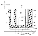
基板側ハウジング12は、矩形の端子取付壁14(図3参照)及び端子取付壁14の各辺(4辺)から同じ側に立設された4個の側壁16、18、20、22を含み、側壁16、18、20、22の端子取付壁14との接続側とは反対の側が開口した直方体形状をした樹脂成形品であり、端子取付壁14とは反対の側にある開口24から複数(本実施形態では4個)のプラグ側コネクタ70を抜き差し可能に挿入される一つの直方状空間のコネクタ挿入室26を画定している。 The board-
表面実装型コネクタ10は、ストレートタイプでの使用では、図1~図3に示されているように、開口24がプリント基板100の上側に位置してプラグ側コネクタ70がコネクタ挿入室26に上方から挿入され、ライトアングルタイプでの使用では、図4、図5に示されているように、開口24がプリント基板100の前側に位置してプラグ側コネクタ70がコネクタ挿入室26に前方から挿入される。 When the surface
プラグ側コネクタ70は、図1に示されているように、左右方向に配列されて4個あり、各々、電気絶縁性を有する箱形の樹脂製のプラグ側ハウジング72を含み、側壁16、18の内壁面に形成されたガイドレール部44、45に案内されてコネクタ挿入室26に差し込まれる。プラグ側ハウジング72は、各々、2個の雌型端子(不図示)を内蔵しており、当該雌型端子は、プラグ側ハウジング72がコネクタ挿入室26に差し込まれることにより、表面実装型コネクタ10に設けられている後述するX軸方向に離間した2列の雄型端子(デュアルインライン用端子30、32或いはシングルインライン用端子34、36)と導通接続される。 As shown in FIG. 1, there are four plug-
各プラグ側ハウジング72は、ストレートタイプでの使用ではプリント基板100の前側に位置し、ライトアングルタイプでの使用ではプリント基板100の上側に位置する部位に、両持ち梁構造の樹脂製の弾性変形板部74を一体に有する。弾性変形板部74の中間部には係合用突部76が一体成形されている。係合用突部76は、弾性変形板部74の円弧状の弾性変形のもとに変位し、基板側ハウジング12の側壁16に貫通形成された係止用開口60に係脱可能に係合する。 Each plug-
このように、基板側ハウジング12は、後述するX軸方向に離れた2個の側壁16、18のうちの一方の側壁16に、係止用開口60によってプラグ側ハウジング72を差し込み位置に係脱可能に係止するロック部を構成する。 In this way, the substrate-
弾性変形板部74の上部には係脱操作部78が突出形成されている。係脱操作部78は、指先操作によって押圧されることにより、弾性変形板部74を円弧状に弾性変形させ、係止用開口60に対する係合用突部76の係合を離脱させる操作部をなす。 An engagement /
表面実装型コネクタ10の説明に戻り、端子取付壁14は互いに直交するX軸とY軸によって定義される直交座標による一つの仮想平面に沿って延在する壁によって構成されている。本実施形態では、ストレートタイプでの使用では、図1~図3に示されているように、X軸が前後方向に延在してY軸が左右方向に延在し、ライトアングルタイプでの使用では、図4、図5に示されているように、X軸が上下方向に延在してY軸が左右方向に延在する。 Returning to the description of the surface
端子取付壁14の外壁面には、図3に示されているように、複数個の端子装着孔28が貫通形成されている。端子装着孔28には、デュアルインライン用端子30、32(図1~図3参照)或いはシングルインライン用端子34、36(図4、図5参照)が挿入される。デュアルインライン用端子30、32或いはシングルインライン用端子34、36の配置は、端子装着孔28の配置に従って、何れにおいても、X軸の方向に所定の間隔をおいて2列に、Y軸の方向に等ピッチで4個ずつ整列して配置される。これにより、デュアルインライン用端子30、32或いはシングルインライン用端子34、36は、ストレートタイプでの使用では前後方向に離れた2列になり、ライトアングルタイプでの使用では上下に離れた2列になる。 As shown in FIG. 3, a plurality of terminal mounting
デュアルインライン用端子30、32及びシングルインライン用端子34、36は、各々、金属等の導電性の材料によって構成され、コネクタ挿入室26内に突出してプラグ側コネクタ70の雌端子のコンタクト部(不図示)と導通接続される四角柱状のコンタクト部30A、32A、34A、36Aと、コンタクト部30A、32A、34A、36Aの基端に接続された一端を有して端子取付壁14の背面(コネクタ挿入室26とは反対側の面)に形成されている端子装着溝38、40、42に嵌合する横断面形状が四角形の基板側延長部30B、32B、34B、36Bと、基板側延長部30B、32B、34B、36Bの他端(先端)に設けられた基板側接続部30C、32C、34C、36Cとを一体に有する。 The dual in-
端子装着溝38と40とは、図5に示されているように、基板側ハウジング12に一体成形されていて、横断面形状が四角形で、Y方向位置において各々X軸方向に直線状に延在している。端子装着溝38は基板側ハウジング12の側壁16の側にあり、端子装着溝40は基板側ハウジング12の側壁18の側にあって端子装着溝38より短い。端子装着溝42は、基板側ハウジング12に一体成形されていて、横断面形状が四角形で、端子装着溝38及び40に対してY方向に離れた位置にあって端子装着溝38及び40に平行にX軸方向に直線状に延在するX軸方向部分42Aと、当該X軸方向部分42Aの一端よりY方向に延在して端子装着溝38の中間部に連通するY方向部分42Bとを含んで鉤形をなしている。 As shown in FIG. 5, the
デュアルインライン用端子30、32の基板側延長部30B、32Bは、各々、図2、図3に示されているように、全長に亘ってコンタクト部30A、32Aの基端からコンタクト部30A、32Aに対して直交する方向(X軸方向)に直線状に延在している。基板側延長部30B、32Bは、各々、端子装着溝38、40に嵌め込まれることにより、端子取付壁14の背面に沿って延在する形態で基板側ハウジング12に固定される。 As shown in FIGS. 2 and 3, the
デュアルインライン用端子30は係止用開口60が形成されている基板側ハウジング12の側壁16の側に配置されるものであり、コンタクト部30Aと側壁16とのX軸方向の距離がもう一つのデュアルインライン用端子32のコンタクト部32Aと側壁18とのX軸方向の距離より長いことにより、基板側延長部30Bは基板側延長部32Bより長い。 The dual in-
デュアルインライン用端子30、32の基板側接続部30C、32Cは、長方体形状をしていて、ストレートタイプでの使用で、プリント基板100の表面に対向して端子接続用ランド部106に半田付けされる表面30D、32Dと、ライトアングルタイプでの使用で、プリント基板100の表面に対向して端子接続用ランド部106に半田付けされる表面32Eとを有する。表面30D、32Dと表面32Eとは長方体の表面であって、互いに直交する方向に延在する平面である。 The board-
シングルインライン用端子34は、図4、図5に示されているように、コンタクト部36AがX軸方向で見てもう一つのシングルインライン用端子36のコンタクト部36Aよりも端子接続用ランド部106(接続点)に近い側(ライトアングルタイプでの使用で下側)に配置されるものである。シングルインライン用端子34の基板側延長部34Bは、全長に亘ってコンタクト部34Aの基端からコンタクト部34Aに対して直交する方向(X軸方向)に直線状に延在している。基板側延長部34Bは、端子装着溝40に嵌め込まれることにより、端子取付壁14の背面に沿って延在する形態で基板側ハウジング12に固定される。 As shown in FIGS. 4 and 5, the single in-
シングルインライン用端子34の基板側接続部34Cは、立方体形状をしていて、ストレートタイプでの使用で、プリント基板100の表面に対向して端子接続用ランド部106に半田付けされる表面34Dと、ライトアングルタイプでの使用で、プリント基板100の表面に対向して端子接続用ランド部106に半田付けされる表面34Eとを有する。表面34Dと表面34Eとは立方体の表面であって、互いに直交する方向に延在する平面である。 The board-
してみれば、シングルインライン用端子34と短寸のデュアルインライン用端子32とは、同一形状、同一寸法の同一の部品であり、この二つの端子32、34は、共用で、一つの共通部品であってよい。 Then, the single in-
シングルインライン用端子36は、図4、図5に示されているように、コンタクト部34AがX軸方向で見てもう一つのシングルインライン用端子34のコンタクト部34Aよりも端子接続用ランド部106(接続点)から遠い側(ライトアングルタイプでの使用で上側)に配置されるものである。シングルインライン用端子36の基板側延長部36Bは、X軸の方向に延在する第1のX軸方向部分36Ba、当該第1のX軸方向部分36Baの先端から隣り合う接続点のピッチ分の長さだけY軸の方向に延在するY方向部分36Bb及びY方向部分36Bbから折り返すようにX軸の方向に延在する第2のX軸方向部分36Bcを含んで鉤状に形成されている。基板側延長部36Bは、その端子装着溝42及び38に嵌め込まれることにより、端子取付壁14の背面に沿って延在する形態で基板側ハウジング12に固定される。 As shown in FIGS. 4 and 5, the single in-
シングルインライン用端子36の基板側接続部36Cは、長方体形状をしていて、ストレートタイプでの使用で、プリント基板100の表面に対向して端子接続用ランド部106に半田付けされる表面36Dと、ライトアングルタイプでの使用で、プリント基板100の表面に対向して端子接続用ランド部106に半田付けされる表面36Eとを有する。表面36Dと表面36Eとは長方体の表面であって、互いに直交する方向に延在する平面である。 The substrate
基板側ハウジング12のY軸の方向に離れた2個の側壁20、22の外壁面には、図1、図2、図4、図5に示されているように、各々、X軸の方向に異なる2箇所に、補強板62を取り付けるための第1の補強板取付部46及び第2の補強板取付部48が設けられている。第1の補強板取付部46及び第2の補強板取付部48は、各々、側壁20、22の外壁面のX軸方向(ストレートタイプでの使用で前後方向)に、側壁20、22のX軸方向の寸法の略1/2の間隔をおいて対をなす取付溝46A、48Aを有する。取付溝46A、48Aは、ストレートタイプでの使用では上下方向に互いに平行に延在する。このような構成において、第1の補強板取付部46は第2の補強板取付部48より係止用開口60の側にある。 As shown in FIGS. 1, 2, 4, and 5, the outer wall surfaces of the two
補強板62は、図2、図5に示されているように、側壁20、22の外壁面のX軸方向(ストレートタイプでの使用で前後方向)の寸法の略1/2の短寸幅寸法(X軸方向の幅寸法)で、ストレートタイプでの使用での側壁20、22の外壁面の上下方向の寸法に略等しい長寸幅寸法の長方形状の主部62Aと、主部62Aの短寸幅の側の両縁部に略90度の折曲によって形成された長寸幅方向に延在する係合片部62Bと、主部62Aの長寸幅の側の一方の縁部に略180度の折曲によって形成された係合片部62Bと同じ側に折り返されたばね性を有するクリップ片部62Cとを含む。補強板62は、係合片部62Bが第1の補強板取付部46或いは第2の補強板取付部48の取付溝46A、48Aに係合することによりX軸方向の位置決めを行われ、主部62Aとクリップ片部62Cとで側壁20、22を挟み込むことにより基板側ハウジング12に固定される。なお、取付溝46A、48Aと係合片部62Bとの係合は、あり溝係合にすることができる。 As shown in FIGS. 2 and 5, the reinforcing
この補強板62は特開2014-165091号公報に示されているような1列配置の表面実装型コネクタのための補強板と共用できる。 This reinforcing
図1~図3に示されているストレートタイプでの使用における表面実装型コネクタ10ではデュアルインライン用端子30、32が用いられている。デュアルインライン用端子30、32の基板側接続部30C、32Cの表面30D、32Dが各々対応する端子接続用ランド部106に半田付けされることにより、表面実装型コネクタ10上に固定される。 The surface
更に、このストレートタイプでの使用では、係止用開口60の側の第1の補強板取付部46に補強板62が取り付けられ、補強板62の下辺がプリント基板100の表面に当接する。この当接部分の絶縁基板102上には導体パターン104及び端子接続用ランド部106と同じ金属層による半田付け部108が形成されており、補強板62は下辺を半田付け部108に半田付けによって固着される。これにより、表面実装型コネクタ10のプリント基板100に対する固定が補強される。 Further, in this straight type use, the reinforcing
ストレートタイプでの使用では、補強板62は第1の補強板取付部46或いは第2の補強板取付部48の何れに装着しても下辺をプリント基板100に固着することが可能であるが、表面実装型コネクタ10のプリント基板100に対する固定の補強は、ロック解除の操作力やプラグ側コネクタ70に接続されているケーブル(不図示)からのテンション(引っ張り力)が作用する側壁16の側で行われるべきである。このため、補強板62は側壁16に近い第1の補強板取付部46に装着され、表面実装型コネクタ10のプリント基板100に対する固定強度の補強が側壁16の側で行われるようにしている。 When used in the straight type, the reinforcing
このことにより、板厚が厚い補強板62を用いる必要がなく、補強板62の幅寸法が側壁20、22の外壁面のX軸方向の寸法の略1/2であること(小型化)と相まって材料費を削減することができる。 As a result, it is not necessary to use the reinforcing
ライトアングルタイプでの使用における表面実装型コネクタ10では、図4、図5に示されているように、シングルインライン用端子34、36が用いられ、シングルインライン用端子34、36の基板側接続部34C、36Cの表面34E、36Eが各々対応する端子接続用ランド部106に半田付けされることにより、表面実装型コネクタ10上に固定される。 In the surface
更に、ライトアングルタイプでの使用では、プリント基板100に近い側にある第2の補強板取付部48に補強板62が取り付けられ、補強板62の下辺(長辺)がプリント基板100の表面に当接する。この当接部分の絶縁基板102上には導体パターン104及び端子接続用ランド部106と同じ金属層による半田付け部110が形成されており、補強板62は下辺を半田付け部108に半田付けによって固着される。これにより、X軸方向の幅寸法が側壁20、22の外壁面のX軸方向の寸法の略1/2の補強板62でも表面実装型コネクタ10のプリント基板100に対する固定が適切に補強される。 Further, when used in the right angle type, the reinforcing
上述したように、補強板62の取り付けを、ストレートタイプでの使用とアングルタイプでの使用とで、第1の補強板取付部46及び第2の補強板取付部48の何れか一方に選択することにより、ストレートタイプでの使用とアングルタイプでの使用の何れにおいても表面実装型コネクタ10のプリント基板100に対する固定が適切に補強される。補強板62の幅寸法が側壁20、22の外壁面のX軸方向の寸法の略1/2であることにより、第1の補強板取付部46に取り付ける補強板62と第2の補強板取付部48に取り付ける補強板62とを同一形状及び同一寸法の共通部品とすることができ、複数種類の補強板62を準備する必要がなくなる。 As described above, the mounting of the reinforcing
ストレートタイプでは、上述したデュアルインライン仕様以外に、図6、図7に示されているように、シングルインライン仕様にすることもできる。シングルインライン仕様ではシングルインライン用端子34、36が用いられる。補強板62はロック部に近い第1の補強板取付部46に取り付けられればよい。 In the straight type, in addition to the dual in-line specification described above, a single in-line specification can be used as shown in FIGS. 6 and 7. In the single inline specification, the single
このように、端子配置は2列のものであっても、直線状のシングルインライン用端子34とフック形状のシングルインライン用端子36とが用いられることにより、ストレートタイプとライトアングルタイプとの何れにおいてもシングルインライン仕様を実現することができる。 As described above, even if the terminal arrangement is two rows, the straight single
以上、本発明を、その好適な実施形態について説明したが、当業者であれば容易に理解できるように、本発明はこのような実施形態により限定されるものではなく、本発明の趣旨を逸脱しない範囲で適宜変更可能である。例えば、シングルインライン用端子36は、図8に示されているように、基板側延長部36BがX軸の方向に延在する第1のX軸方向部分36Baと第1のX軸方向部分36Baの先端から隣り合う接続点のピッチ分の長さだけY軸の方向に延在するY方向部分36Bbとによって鉤状をなすものであってもよい。端子の個数は、2×4に限られることなく、2列配置を守って2×N(但しNは1以上の整数)であればよい。 The present invention has been described above with respect to preferred embodiments thereof, but as can be easily understood by those skilled in the art, the present invention is not limited to such embodiments and deviates from the gist of the present invention. It can be changed as appropriate to the extent that it does not. For example, as shown in FIG. 8, the single in-
また、上記実施形態に示した構成要素は必ずしも全てが必須なものではなく、本発明の趣旨を逸脱しない限りにおいて適宜取捨選択することが可能である。 In addition, not all of the components shown in the above embodiments are indispensable, and they can be appropriately selected as long as they do not deviate from the gist of the present invention.
10 表面実装型コネクタ
12 基板側ハウジング
14 端子取付壁
16 側壁
18 側壁
20 側壁
22 側壁
24 開口
26 コネクタ挿入室
28 端子装着孔
30 デュアルインライン用端子
30A コンタクト部
30B 基板側延長部
30C 基板側接続部
30D 表面
30E 表面
32 デュアルインライン用端子
32A コンタクト部
32B 基板側延長部
34 シングルインライン用端子
34A コンタクト部
34B 基板側延長部
34C 基板側接続部
34D 表面
34E 表面
36 シングルインライン用端子
36A コンタクト部
36B 基板側延長部
36Ba 第1のX軸方向部分
36Bb Y方向部分
36Bc 第2のX軸方向部分
36C 基板側接続部
36D 表面
36E 表面
38 端子装着溝
40 端子装着溝
42 端子装着溝
42A X軸方向部分
42B Y方向部分
44 ガイドレール部
45 ガイドレール部
46 第1の補強板取付部
46A 取付溝
48 第2の補強板取付部
48A 取付溝
60 係止用開口
62 補強板
62A 主部
62B 係合片部
62C クリップ片部
70 プラグ側コネクタ
72 プラグ側ハウジング
74 弾性変形板部
76 係合用突部
78 係脱操作部
100 プリント基板
102 絶縁基板
104 導体パターン
106 端子接続用ランド部
108 半田付け部
110 半田付け部10 Surface-mounted
Claims (2)
前記端子取付壁は互いに直交するX軸とY軸によって定義される一つの仮想平面に沿って延在する壁によって構成されており、
前記端子は、前記X軸の方向に間隔をおいて2列に各々前記Y軸の方向に整列して配置され、
前記基板側ハウジングは、前記X軸の方向に離れた2個の前記側壁のうちの一方に、前記プラグ側ハウジングを差し込み位置に係脱可能に係止するロック部を有し、前記Y軸の方向に離れた2個の前記側壁の各々の、前記X軸の方向に異なる2箇所に、補強板を取付可能な補強板取付部を有し、
前記ライトアングルタイプでの使用では、前記2箇所の補強板取付部のうち前記プリント基板に近い前記補強板取付部に取り付けられた前記補強板の外辺が前記プリント基板に当接して固着され、前記ストレートタイプでの使用では、前記2箇所の補強板取付部のうち前記ロック部が形成された前記側壁に近い前記補強板取付部に取り付けられた前記補強板の外辺が前記プリント基板に当接して固着されており、
前記補強板取付部は前記側壁の前記X軸の方向の寸法の略1/2の間隔をおいて互いに平行に延在し、
前記補強板は、長方形状で、前記X軸の方向の幅寸法が前記Y軸の方向に離れた前記側壁の外壁面の前記X軸の方向の寸法の略1/2である表面実装型コネクタ。 A box-shaped electrically insulating board-side housing with one open side, including a rectangular terminal mounting wall and four side walls erected from each side of the terminal mounting wall, and a plurality of mounted on the terminal mounting wall. Either the straight type or the right angle type, which has a conductive terminal and can be shared by the straight type in which the opening of the substrate side housing is located upward and the right angle type in which the opening is located sideways. It is a surface mount type connector in which the board-side housing can be mounted on a printed circuit board even with the mounting posture of, and the plug-side housing of the plug-side connector can be inserted and removed into the board-side housing.
The terminal mounting wall is composed of a wall extending along one virtual plane defined by an X-axis and a Y-axis orthogonal to each other.
The terminals are arranged in two rows at intervals in the direction of the X axis, respectively, aligned in the direction of the Y axis.
The substrate-side housing has a lock portion on one of the two side walls separated in the direction of the X-axis to engage and disengage the plug-side housing at the insertion position, and the Y-axis has a lock portion. Each of the two side walls separated in the direction has a reinforcing plate mounting portion to which a reinforcing plate can be mounted at two positions different in the direction of the X-axis.
In the use in the right angle type, the outer side of the reinforcing plate attached to the reinforcing plate mounting portion close to the printed circuit board among the two reinforcing plate mounting portions abuts on the printed circuit board and is fixed. In the straight type use, the outer side of the reinforcing plate attached to the reinforcing plate mounting portion near the side wall on which the lock portion is formed of the two reinforcing plate mounting portions abuts on the printed circuit board. Is stuck ,
The reinforcing plate mounting portions extend parallel to each other at a distance of approximately ½ of the dimension of the side wall in the direction of the X axis.
The reinforcing plate has a rectangular shape, and the width dimension in the direction of the X axis is approximately ½ of the dimension in the direction of the X axis of the outer wall surface of the side wall separated in the direction of the Y axis. ..
前記端子は、前記端子取付壁を貫通して前記基板側ハウジング内に位置し、前記プラグ側ハウジング側の端子と導通されるコンタクト部と、前記コンタクト部に接続された一端を有し、前記端子取付壁に沿って延在した基板側延長部と、前記基板側延長部の他端に設けられ、前記プリント基板に形成された端子接続用ランド部に導通接続される基板側接続部とを有し、
前記2列の端子のうち、
前記接続点に近い側の端子の前記基板側延長部は、前記X軸の方向に延在する部分のみによって直線状に構成されており、
前記接続点から遠い側の端子の前記基板側延長部は、前記X軸の方向に延在する部分及び隣り合う前記接続点のピッチ分の長さだけ前記Y軸の方向に延在する部分を含んでフック状或いは鉤状に構成されている請求項1に記載の表面実装型コネクタ。 It is a single-in-line type surface mount type connector in which conduction connection between the terminal and the printed circuit board is performed at connection points arranged at equal pitches in a row in the direction of the Y axis on one side in the direction of the X axis.
The terminal is located in the substrate-side housing through the terminal mounting wall, has a contact portion conductive to the terminal on the plug-side housing side, and has one end connected to the contact portion. It has a board-side extension extending along the mounting wall and a board-side connection portion provided at the other end of the board-side extension and conductively connected to a terminal connection land portion formed on the printed circuit board. death,
Of the two rows of terminals,
The substrate-side extension portion of the terminal on the side close to the connection point is formed linearly only by the portion extending in the direction of the X-axis.
The board-side extension portion of the terminal on the side far from the connection point includes a portion extending in the direction of the X-axis and a portion extending in the direction of the Y-axis by the length of the pitch of the adjacent connection points. The surface mount type connector according to claim 1, which includes a hook shape or a hook shape.
Priority Applications (1)
| Application Number | Priority Date | Filing Date | Title |
|---|---|---|---|
| JP2021198744A JP7245892B2 (en) | 2016-06-06 | 2021-12-07 | surface mount connector |
Applications Claiming Priority (3)
| Application Number | Priority Date | Filing Date | Title |
|---|---|---|---|
| JP2016112523 | 2016-06-06 | ||
| JP2016112523 | 2016-06-06 | ||
| PCT/JP2017/019601 WO2017212940A1 (en) | 2016-06-06 | 2017-05-25 | Surface mounting type connector |
Related Child Applications (1)
| Application Number | Title | Priority Date | Filing Date |
|---|---|---|---|
| JP2021198744A Division JP7245892B2 (en) | 2016-06-06 | 2021-12-07 | surface mount connector |
Publications (2)
| Publication Number | Publication Date |
|---|---|
| JPWO2017212940A1 JPWO2017212940A1 (en) | 2019-04-04 |
| JP7032312B2 true JP7032312B2 (en) | 2022-03-08 |
Family
ID=60578592
Family Applications (2)
| Application Number | Title | Priority Date | Filing Date |
|---|---|---|---|
| JP2018522417A Active JP7032312B2 (en) | 2016-06-06 | 2017-05-25 | Surface mount connector |
| JP2021198744A Active JP7245892B2 (en) | 2016-06-06 | 2021-12-07 | surface mount connector |
Family Applications After (1)
| Application Number | Title | Priority Date | Filing Date |
|---|---|---|---|
| JP2021198744A Active JP7245892B2 (en) | 2016-06-06 | 2021-12-07 | surface mount connector |
Country Status (6)
| Country | Link |
|---|---|
| US (1) | US10411377B2 (en) |
| EP (1) | EP3467946A4 (en) |
| JP (2) | JP7032312B2 (en) |
| CN (1) | CN109314330B (en) |
| TW (1) | TWI715774B (en) |
| WO (1) | WO2017212940A1 (en) |
Families Citing this family (7)
| Publication number | Priority date | Publication date | Assignee | Title |
|---|---|---|---|---|
| DE102017108430B4 (en) * | 2017-04-20 | 2021-09-30 | Harting Electric Gmbh & Co. Kg | Holding frame for a heavy connector and system |
| EP3637562B1 (en) * | 2017-06-06 | 2022-09-07 | Nippon Tanshi Co., Ltd. | Connector structure |
| KR102082207B1 (en) * | 2018-05-02 | 2020-02-27 | 엘에스산전 주식회사 | Device for driving motor |
| JP7219018B2 (en) * | 2018-05-18 | 2023-02-07 | モレックス エルエルシー | Connectors, connector assemblies, and circuit devices |
| CN111081585B (en) | 2018-10-18 | 2022-08-16 | 北京北方华创微电子装备有限公司 | Spray device and cleaning equipment |
| JP2021157883A (en) * | 2020-03-25 | 2021-10-07 | 住友電装株式会社 | Terminal, board connector, and terminal manufacturing method |
| JP7467248B2 (en) | 2020-06-11 | 2024-04-15 | モレックス エルエルシー | Connector and connector assembly |
Citations (4)
| Publication number | Priority date | Publication date | Assignee | Title |
|---|---|---|---|---|
| JP2006100231A (en) | 2004-09-29 | 2006-04-13 | Sumitomo Wiring Syst Ltd | Connector for circuit board |
| JP2006339000A (en) | 2005-06-01 | 2006-12-14 | Sumitomo Wiring Syst Ltd | Connector for substrate |
| JP2012123939A (en) | 2010-12-06 | 2012-06-28 | Tdk Corp | Modular jack |
| JP2014165091A (en) | 2013-02-27 | 2014-09-08 | Nippon Tanshi Co Ltd | Connector |
Family Cites Families (31)
| Publication number | Priority date | Publication date | Assignee | Title |
|---|---|---|---|---|
| US3399374A (en) * | 1966-07-14 | 1968-08-27 | Amp Inc | Disengageable electrical connections |
| JPS5931784U (en) * | 1982-08-23 | 1984-02-28 | ソニー株式会社 | Flexible board connector |
| US4504108A (en) * | 1983-09-19 | 1985-03-12 | Challenger Circle F, Inc. | Wiring device for mounting on sheet metal |
| US4668040A (en) * | 1985-02-25 | 1987-05-26 | Hirose Electric Co., Ltd. | Electrical connector receptacle |
| US4732565A (en) * | 1985-05-28 | 1988-03-22 | Mg Company, Ltd. | Electric connector |
| US5120256A (en) * | 1991-07-16 | 1992-06-09 | Walden John D | Retention system for a connector housing |
| US5232379A (en) * | 1992-02-28 | 1993-08-03 | Foxconn International, Inc. | Connector with mounting means for SMT |
| DE19536276A1 (en) * | 1995-09-28 | 1997-04-03 | Siemens Ag | Device for connecting a coaxial connector to a printed circuit board in SM technology |
| US5803765A (en) * | 1996-04-02 | 1998-09-08 | Molex Incorporated | Electrical connector with universal boardlock |
| US6053767A (en) * | 1998-12-18 | 2000-04-25 | The Whitaker Corporation | Hold down for an electrical connector |
| TW427560U (en) * | 1999-02-05 | 2001-03-21 | Hon Hai Prec Ind Co Ltd | Electrical connector assembly |
| JP3330559B2 (en) | 1999-03-15 | 2002-09-30 | 日本圧着端子製造株式会社 | Printed wiring board connector |
| US6471544B1 (en) * | 2001-06-25 | 2002-10-29 | Ovilux Corporation | Fixing structure for connecting a connector and a printed circuit board |
| JP3951777B2 (en) * | 2002-04-04 | 2007-08-01 | 住友電装株式会社 | Board connector |
| US7134910B2 (en) * | 2003-12-03 | 2006-11-14 | Sumitomo Wiring Systems, Ltd. | Circuit board connector |
| DE102004009071B4 (en) * | 2004-02-23 | 2006-06-14 | Phoenix Contact Gmbh & Co. Kg | Electrical connector |
| WO2006035767A1 (en) * | 2004-09-29 | 2006-04-06 | Autonetworks Technologies, Ltd. | Connector for substrate |
| DE602005003527T2 (en) * | 2004-09-29 | 2008-10-23 | Sumitomo Wiring Systems, Ltd., Yokkaichi | A connector and plug contact |
| JP4504801B2 (en) * | 2004-12-22 | 2010-07-14 | 矢崎総業株式会社 | connector |
| JP4556135B2 (en) * | 2005-08-22 | 2010-10-06 | 住友電装株式会社 | Board connector |
| JP2008059856A (en) * | 2006-08-30 | 2008-03-13 | Sumitomo Wiring Syst Ltd | Board connector |
| JP5006618B2 (en) * | 2006-10-25 | 2012-08-22 | イリソ電子工業株式会社 | connector |
| JP4983387B2 (en) * | 2007-05-16 | 2012-07-25 | 住友電装株式会社 | Board connector |
| TWM368907U (en) * | 2009-01-20 | 2009-11-11 | Hon Hai Prec Ind Co Ltd | Electrical connector and contact thereof |
| DE202010015046U1 (en) * | 2010-11-05 | 2011-02-17 | Erni Electronics Gmbh | plug |
| CN202084684U (en) * | 2011-05-17 | 2011-12-21 | 格稜股份有限公司 | Side-plug-in type electrical connector |
| JP5214798B1 (en) * | 2011-12-27 | 2013-06-19 | 株式会社東芝 | Electronics |
| US8641455B2 (en) * | 2012-07-03 | 2014-02-04 | Cheng Uei Precision Industry Co., Ltd. | Universal serial bus connector perpendicularly mounted on a printed circuit board |
| JP6095412B2 (en) | 2013-02-27 | 2017-03-15 | 日本端子株式会社 | connector |
| DE102013103446A1 (en) * | 2013-04-05 | 2014-10-09 | Phoenix Contact Gmbh & Co. Kg | Connector device |
| JP6120168B2 (en) * | 2013-06-25 | 2017-04-26 | パナソニックIpマネジメント株式会社 | Connector and header and socket used for the connector |
-
2017
- 2017-05-25 WO PCT/JP2017/019601 patent/WO2017212940A1/en unknown
- 2017-05-25 JP JP2018522417A patent/JP7032312B2/en active Active
- 2017-05-25 CN CN201780035315.1A patent/CN109314330B/en active Active
- 2017-05-25 US US16/306,210 patent/US10411377B2/en active Active
- 2017-05-25 EP EP17810120.0A patent/EP3467946A4/en active Pending
- 2017-06-01 TW TW106118063A patent/TWI715774B/en active
-
2021
- 2021-12-07 JP JP2021198744A patent/JP7245892B2/en active Active
Patent Citations (4)
| Publication number | Priority date | Publication date | Assignee | Title |
|---|---|---|---|---|
| JP2006100231A (en) | 2004-09-29 | 2006-04-13 | Sumitomo Wiring Syst Ltd | Connector for circuit board |
| JP2006339000A (en) | 2005-06-01 | 2006-12-14 | Sumitomo Wiring Syst Ltd | Connector for substrate |
| JP2012123939A (en) | 2010-12-06 | 2012-06-28 | Tdk Corp | Modular jack |
| JP2014165091A (en) | 2013-02-27 | 2014-09-08 | Nippon Tanshi Co Ltd | Connector |
Also Published As
| Publication number | Publication date |
|---|---|
| CN109314330A (en) | 2019-02-05 |
| TW201803218A (en) | 2018-01-16 |
| WO2017212940A1 (en) | 2017-12-14 |
| JPWO2017212940A1 (en) | 2019-04-04 |
| EP3467946A1 (en) | 2019-04-10 |
| EP3467946A4 (en) | 2020-01-08 |
| US10411377B2 (en) | 2019-09-10 |
| CN109314330B (en) | 2020-11-20 |
| TWI715774B (en) | 2021-01-11 |
| JP7245892B2 (en) | 2023-03-24 |
| US20190173210A1 (en) | 2019-06-06 |
| JP2022027850A (en) | 2022-02-14 |
Similar Documents
| Publication | Publication Date | Title |
|---|---|---|
| JP7032312B2 (en) | Surface mount connector | |
| US6655966B2 (en) | Modular connector with grounding interconnect | |
| KR101013687B1 (en) | Circuit board mounted electrical connector | |
| US7824187B1 (en) | High density connector | |
| JP6703900B2 (en) | Connectors and connector systems | |
| KR20150110333A (en) | Connector | |
| JP2012160474A (en) | Electric connector | |
| US7491083B2 (en) | Electrical connector assembly | |
| JP2022027850A5 (en) | ||
| JP5356621B1 (en) | connector | |
| JP2021174770A (en) | Board side connector and connector assembly | |
| JP2015516109A (en) | System for interconnecting printed circuit boards | |
| JP4623735B2 (en) | connector | |
| JP5356620B1 (en) | connector | |
| JP5134943B2 (en) | connector | |
| US8342874B2 (en) | Electrical connector with improved locking member having latch structure thereof | |
| TWI396336B (en) | Connector | |
| US9601884B2 (en) | Connector | |
| KR200473302Y1 (en) | Connector | |
| JP2007115538A (en) | Mounting device of electric connector for board | |
| JP5044483B2 (en) | Electrical connector | |
| JP7283971B2 (en) | BOARD CONNECTOR AND BOARD CONNECTOR STRUCTURE | |
| JP5473638B2 (en) | Electrical connector | |
| JP5521845B2 (en) | Card edge connector | |
| JP7248453B2 (en) | joint connector |
Legal Events
| Date | Code | Title | Description |
|---|---|---|---|
| A621 | Written request for application examination |
Free format text: JAPANESE INTERMEDIATE CODE: A621 Effective date: 20200415 |
|
| A131 | Notification of reasons for refusal |
Free format text: JAPANESE INTERMEDIATE CODE: A131 Effective date: 20210316 |
|
| A521 | Request for written amendment filed |
Free format text: JAPANESE INTERMEDIATE CODE: A523 Effective date: 20210511 |
|
| A02 | Decision of refusal |
Free format text: JAPANESE INTERMEDIATE CODE: A02 Effective date: 20210907 |
|
| A521 | Request for written amendment filed |
Free format text: JAPANESE INTERMEDIATE CODE: A523 Effective date: 20211207 |
|
| C60 | Trial request (containing other claim documents, opposition documents) |
Free format text: JAPANESE INTERMEDIATE CODE: C60 Effective date: 20211207 |
|
| A911 | Transfer to examiner for re-examination before appeal (zenchi) |
Free format text: JAPANESE INTERMEDIATE CODE: A911 Effective date: 20211216 |
|
| C21 | Notice of transfer of a case for reconsideration by examiners before appeal proceedings |
Free format text: JAPANESE INTERMEDIATE CODE: C21 Effective date: 20211221 |
|
| TRDD | Decision of grant or rejection written | ||
| A01 | Written decision to grant a patent or to grant a registration (utility model) |
Free format text: JAPANESE INTERMEDIATE CODE: A01 Effective date: 20220215 |
|
| A61 | First payment of annual fees (during grant procedure) |
Free format text: JAPANESE INTERMEDIATE CODE: A61 Effective date: 20220224 |
|
| R150 | Certificate of patent or registration of utility model |
Ref document number: 7032312 Country of ref document: JP Free format text: JAPANESE INTERMEDIATE CODE: R150 |