JP7031473B2 - Coil parts - Google Patents
Coil parts Download PDFInfo
- Publication number
- JP7031473B2 JP7031473B2 JP2018084254A JP2018084254A JP7031473B2 JP 7031473 B2 JP7031473 B2 JP 7031473B2 JP 2018084254 A JP2018084254 A JP 2018084254A JP 2018084254 A JP2018084254 A JP 2018084254A JP 7031473 B2 JP7031473 B2 JP 7031473B2
- Authority
- JP
- Japan
- Prior art keywords
- coil
- mounting surface
- lower coil
- core
- upper coil
- Prior art date
- Legal status (The legal status is an assumption and is not a legal conclusion. Google has not performed a legal analysis and makes no representation as to the accuracy of the status listed.)
- Active
Links
- 238000004804 winding Methods 0.000 claims description 13
- 238000010586 diagram Methods 0.000 description 3
- 238000005452 bending Methods 0.000 description 1
- 238000000034 method Methods 0.000 description 1
- 238000012986 modification Methods 0.000 description 1
- 230000004048 modification Effects 0.000 description 1
- 229910000679 solder Inorganic materials 0.000 description 1
Images


Classifications
-
- H—ELECTRICITY
- H01—ELECTRIC ELEMENTS
- H01F—MAGNETS; INDUCTANCES; TRANSFORMERS; SELECTION OF MATERIALS FOR THEIR MAGNETIC PROPERTIES
- H01F27/00—Details of transformers or inductances, in general
- H01F27/28—Coils; Windings; Conductive connections
- H01F27/2823—Wires
- H01F27/2828—Construction of conductive connections, of leads
-
- H—ELECTRICITY
- H01—ELECTRIC ELEMENTS
- H01F—MAGNETS; INDUCTANCES; TRANSFORMERS; SELECTION OF MATERIALS FOR THEIR MAGNETIC PROPERTIES
- H01F17/00—Fixed inductances of the signal type
- H01F17/04—Fixed inductances of the signal type with magnetic core
- H01F17/045—Fixed inductances of the signal type with magnetic core with core of cylindric geometry and coil wound along its longitudinal axis, i.e. rod or drum core
-
- H—ELECTRICITY
- H01—ELECTRIC ELEMENTS
- H01F—MAGNETS; INDUCTANCES; TRANSFORMERS; SELECTION OF MATERIALS FOR THEIR MAGNETIC PROPERTIES
- H01F27/00—Details of transformers or inductances, in general
- H01F27/28—Coils; Windings; Conductive connections
- H01F27/2804—Printed windings
-
- H—ELECTRICITY
- H01—ELECTRIC ELEMENTS
- H01F—MAGNETS; INDUCTANCES; TRANSFORMERS; SELECTION OF MATERIALS FOR THEIR MAGNETIC PROPERTIES
- H01F27/00—Details of transformers or inductances, in general
- H01F27/28—Coils; Windings; Conductive connections
- H01F27/29—Terminals; Tapping arrangements for signal inductances
- H01F27/292—Surface mounted devices
-
- H—ELECTRICITY
- H01—ELECTRIC ELEMENTS
- H01F—MAGNETS; INDUCTANCES; TRANSFORMERS; SELECTION OF MATERIALS FOR THEIR MAGNETIC PROPERTIES
- H01F27/00—Details of transformers or inductances, in general
- H01F27/28—Coils; Windings; Conductive connections
- H01F27/30—Fastening or clamping coils, windings, or parts thereof together; Fastening or mounting coils or windings on core, casing, or other support
- H01F27/306—Fastening or mounting coils or windings on core, casing or other support
-
- H—ELECTRICITY
- H01—ELECTRIC ELEMENTS
- H01F—MAGNETS; INDUCTANCES; TRANSFORMERS; SELECTION OF MATERIALS FOR THEIR MAGNETIC PROPERTIES
- H01F3/00—Cores, Yokes, or armatures
- H01F3/10—Composite arrangements of magnetic circuits
-
- H—ELECTRICITY
- H01—ELECTRIC ELEMENTS
- H01F—MAGNETS; INDUCTANCES; TRANSFORMERS; SELECTION OF MATERIALS FOR THEIR MAGNETIC PROPERTIES
- H01F17/00—Fixed inductances of the signal type
- H01F2017/0093—Common mode choke coil
-
- H—ELECTRICITY
- H01—ELECTRIC ELEMENTS
- H01F—MAGNETS; INDUCTANCES; TRANSFORMERS; SELECTION OF MATERIALS FOR THEIR MAGNETIC PROPERTIES
- H01F17/00—Fixed inductances of the signal type
- H01F17/04—Fixed inductances of the signal type with magnetic core
- H01F17/045—Fixed inductances of the signal type with magnetic core with core of cylindric geometry and coil wound along its longitudinal axis, i.e. rod or drum core
- H01F2017/046—Fixed inductances of the signal type with magnetic core with core of cylindric geometry and coil wound along its longitudinal axis, i.e. rod or drum core helical coil made of flat wire, e.g. with smaller extension of wire cross section in the direction of the longitudinal axis
Description
本発明はコイル部品に関し、特に、実装面を有するコアに下部コイルと上部コイルが重ねて配置された構造を有するコイル部品に関する。 The present invention relates to a coil component, and more particularly to a coil component having a structure in which a lower coil and an upper coil are arranged on a core having a mounting surface.
コモンモードフィルタは、一般的に差動信号線路に重畳するコモンモードノイズを除去するために使用されるが、電源ラインにもコモンモードフィルタが挿入されることがある。電源用のコモンモードフィルタは、コイルに流れる電流量が大きいため、断面積の大きい平角ワイヤなどを巻回したコイルが用いられる。例えば、特許文献1には、平角ワイヤを巻回してなる2つのコイルをコア上に重ねて配置した構造を有する電源用のコモンモードフィルタが開示されている。 The common mode filter is generally used to remove the common mode noise superimposed on the differential signal line, but the common mode filter may also be inserted in the power supply line. Since the amount of current flowing through the coil is large as the common mode filter for power supply, a coil wound with a flat wire having a large cross-sectional area is used. For example, Patent Document 1 discloses a common mode filter for a power source having a structure in which two coils formed by winding a flat wire are overlapped on a core.
しかしながら、特許文献1に記載されたコイル部品は、実装面を有するコア上に2つのコイルが重ねて配置されていることから、コアに近い下部コイルの線路長よりも、コアから遠い上部コイルの線路長の方が長くなってしまう。その結果、下部コイルの直流抵抗よりも上部コイルの直流抵抗が高くなり、線路間における特性バランスが崩れてしまうという問題があった。 However, in the coil component described in Patent Document 1, since the two coils are arranged so as to overlap on the core having the mounting surface, the upper coil farther from the core than the line length of the lower coil near the core. The track length will be longer. As a result, there is a problem that the DC resistance of the upper coil becomes higher than the DC resistance of the lower coil, and the characteristic balance between the lines is lost.
したがって、本発明は、実装面を有するコア上に下部コイルと上部コイルが重ねて配置された構造を有するコイル部品において、下部コイルと上部コイルの直流抵抗の差を低減することを目的とする。 Therefore, it is an object of the present invention to reduce the difference in DC resistance between the lower coil and the upper coil in a coil component having a structure in which the lower coil and the upper coil are overlapped on a core having a mounting surface.
本発明によるコイル部品は、実装面及び実装面の反対側に位置するコイル搭載面を有する第1のコアと、コイル軸がコイル搭載面に対して垂直となるようコイル搭載面上に配置され、一端が実装面の第1の領域に引き出され、他端が実装面の第2の領域に引き出された下部コイルと、第1のコイルと同軸となるよう第1のコイル上に重ねて配置され、一端が実装面の第3の領域に引き出され、他端が実装面の第4の領域に引き出された上部コイルとを備え、下部コイルのコイル径は、上部コイルのコイル径よりも大きいことを特徴とする。 The coil component according to the present invention is arranged on the coil mounting surface so that the first core having the coil mounting surface located on the opposite side of the mounting surface and the mounting surface and the coil axis are perpendicular to the coil mounting surface. One end is drawn out to the first region of the mounting surface, and the other end is placed on the first coil so as to be coaxial with the lower coil drawn out to the second region of the mounting surface. The lower coil has a coil diameter larger than the coil diameter of the upper coil, with one end drawn to a third region of the mounting surface and the other end drawn to a fourth region of the mounting surface. It is characterized by.
本発明によれば、下部コイルのコイル径が上部コイルのコイル径よりも大きいことから、1ターン当たりの線路長が上部コイルよりも下部コイルの方が長くなる。これにより、下部コイルの線路長と上部コイルの線路長の差が縮小し、理想的には一致することから、下部コイルと上部コイルの直流抵抗の差を低減することが可能となる。 According to the present invention, since the coil diameter of the lower coil is larger than the coil diameter of the upper coil, the line length per turn is longer in the lower coil than in the upper coil. As a result, the difference between the line length of the lower coil and the line length of the upper coil is reduced and ideally matches, so that the difference in DC resistance between the lower coil and the upper coil can be reduced.
本発明において、第1及び第2の領域は、コイル軸と直交する第1の方向に配列され、第3及び第4の領域は、第1の方向に配列され、第1及び第3の領域は、コイル軸及び第1の方向と直交する第2の方向に配列され、第2及び第4の領域は、第2の方向に配列され、コイル軸方向から見た下部コイルの一端から他端に向かう巻回方向と、コイル軸方向から見た上部コイルの一端から他端に向かう巻回方向は同じであり、下部コイルのターン数は、上部コイルのターン数よりも1ターン未満多くても構わない。これによれば、コモンモードフィルタとして好ましく用いることができるとともに、下部コイルのターン数が上部コイルのターン数よりも1ターン未満多いことから、下部コイルの線路長と上部コイルの線路長の差をより縮小することが可能となる。 In the present invention, the first and second regions are arranged in the first direction orthogonal to the coil axis, the third and fourth regions are arranged in the first direction, and the first and third regions are arranged. Are arranged in a second direction orthogonal to the coil axis and the first direction, the second and fourth regions are arranged in the second direction, from one end to the other end of the lower coil as seen from the coil axis direction. The winding direction toward is the same as the winding direction from one end to the other end of the upper coil as seen from the coil axis direction, and the number of turns of the lower coil may be less than one turn more than the number of turns of the upper coil. I do not care. According to this, it can be preferably used as a common mode filter, and since the number of turns of the lower coil is less than one turn more than the number of turns of the upper coil, the difference between the line length of the lower coil and the line length of the upper coil can be set. It can be further reduced.
本発明によるコイル部品は、下部コイル及び上部コイルの内径部に配置された第2のコアをさらに備え、第2のコアの径は、下部コイルの内径部に位置する部分よりも、上部コイルの内径部に位置する部分の方が大きくても構わない。これによれば、ターン数の少ない上部コイルのインダクタンスが高められることから、下部コイルと上部コイルのインダクタンスの差を低減することが可能となる。 The coil component according to the present invention further comprises a second core arranged in the inner diameter portion of the lower coil and the upper coil, and the diameter of the second core is larger than that of the portion located in the inner diameter portion of the lower coil. The portion located in the inner diameter portion may be larger. According to this, since the inductance of the upper coil having a small number of turns is increased, it is possible to reduce the difference between the inductances of the lower coil and the upper coil.
本発明において、下部コイルは、折り返し構造を有する迂回パターンを有するものであっても構わない。下部コイルの線路長と上部コイルの線路長の差をより縮小することが可能となる。 In the present invention, the lower coil may have a detour pattern having a folded structure. It is possible to further reduce the difference between the line length of the lower coil and the line length of the upper coil.
このように、本発明によれば、実装面を有するコア上に下部コイルと上部コイルが重ねて配置された構造を有するコイル部品において、下部コイルと上部コイルの直流抵抗の差を低減することが可能となる。 As described above, according to the present invention, it is possible to reduce the difference in DC resistance between the lower coil and the upper coil in a coil component having a structure in which the lower coil and the upper coil are overlapped on a core having a mounting surface. It will be possible.
以下、添付図面を参照しながら、本発明の好ましい実施形態について詳細に説明する。 Hereinafter, preferred embodiments of the present invention will be described in detail with reference to the accompanying drawings.
図1は、本発明の好ましい実施形態によるコイル部品10の外観構造を示す略斜視図である。また、図2は、本実施形態によるコイル部品10の内部構造を説明するための図である。
FIG. 1 is a schematic perspective view showing an external structure of a
図1及び図2に示すように、本実施形態によるコイル部品10は、実装面11aを有する板状のコア11と、コア11のコイル搭載面11b上に配置された下部コイル20及び上部コイル30と、下部コイル20及び上部コイル30を覆う箱形のコア12と、下部コイル20及び上部コイル30の内径部に配置された棒状のコア13とを備えている。尚、図2は、下部コイル20及び上部コイル30が視認できるよう、箱形のコア12の側面(xz面及びyz面)を全て省略した状態を示している。図1に示す例では、側面(xz面及びyz面)が全てコア12によって構成されているが、これらの一部又は全部がコア11によって構成されていても構わない。また、棒状のコア13は、コア11,12と別部材であっても構わないし、コア11,12の一方と同一部材であっても構わない。
As shown in FIGS. 1 and 2, the
実装面11aはxy面を構成し、実装面11aのそれぞれ異なる領域(第1~第4の領域)に、下部コイル20の端部21,22と上部コイル30の端部31,32が配置されている。実装面11aは、実装時において回路基板と向かい合う面であり、本実施形態によるコイル部品10が回路基板に実装されると、回路基板上のランドパターンと端部21,22,31,32がそれぞれハンダを介して接続される。ここで、端部21と端部22はy方向に配列され、端部31と端部32はy方向に配列され、端部21と端部31はx方向に配列され、端部22と端部32はx方向に配列されている。本実施形態においては、端部21,31がx方向に延在する同じ辺に沿って設けられ、端部22,32がx方向に延在する同じ辺に沿って設けられているが、本発明においてこの点は必須でない。例えば、端部21,22をy方向に延在する同じ辺に沿って配置し、端部31,32をy方向に延在する同じ辺に沿って配置しても構わない。
The
図2に示すように、下部コイル20及び上部コイル30のコイル軸はz方向を向いており、互いに同軸となるよう、コイル搭載面11b上に下部コイル20及び上部コイル30の順に重ねて配置されている。本実施形態においては、下部コイル20及び上部コイル30が平角ワイヤによって構成されており、それぞれの端部を折り曲げることによって、実装面11aのそれぞれ異なる領域に4つの端部21,22,31,32を配置している。
As shown in FIG. 2, the coil axes of the
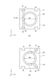
図3(a)は下部コイル20の平面図であり、図3(b)は上部コイル30の平面図である。
FIG. 3A is a plan view of the
図3(a)に示すように、下部コイル20の端部21,22は、コア11に設けられた切り欠き41,42を介して実装面11a側に折り曲げられており、端部21から端部22に向かう巻回方向は、z方向から見て反時計回り(左回り)である。同様に、図3(b)に示すように、上部コイル30の端部31,32は、コア11に設けられた切り欠き43,44を介して実装面11a側に折り曲げられており、端部31から端部32に向かう巻回方向は、z方向から見て反時計回り(左回り)である。このため、例えば、端部21,31を一対の入力側端子とし、端部22,32を一対の出力側端子としたコモンモードフィルタとして使用する場合に、入力側の差動信号線路と出力側の差動信号線路の極性が反転することがない。
As shown in FIG. 3A, the
そして、本実施形態においては、下部コイル20のコイル径W1が上部コイル30のコイル径W2よりも大きく、これにより、1ターン当たりの線路長が上部コイル30よりも下部コイル20の方が長くなるように設計されている。これは、下部コイル20と上部コイル30のコイル径を一致させた場合、上部コイル30の方が実装面11aから離れている分、線路長が長くなる点を考慮したものであり、下部コイル20のコイル径W1を上部コイル30のコイル径W2よりも大きく設計することにより、線路長の差を縮小している。
Then, in the present embodiment, the coil diameter W1 of the
このように、本実施形態によるコイル部品10は、実装面11aから遠い上部コイル30のコイル径W2よりも、実装面11aに近い下部コイル20のコイル径W1を大きくしていることから、実装面11aからの距離の差に起因する下部コイル20と上部コイル30の線路長の差を縮小することが可能となる。これにより、下部コイル20と上部コイル30の直流抵抗の差が低減することから、線路間における特性バランスを確保することが可能となる。
As described above, the
また、図3(a)に示すように、下部コイル20については端部21を始点とした巻き始め位置51と巻き終わり位置52がほぼ一致しているのに対し、図3(b)に示すように、上部コイル30については端部31を始点とした巻き始め位置53と巻き終わり位置54が約0.5ターンずれてしまう。このことは、下部コイル20と上部コイル30のターン数を完全に一致させることが困難であることを意味し、両者間には1ターン未満の差が生じる。このような特徴を利用し、ターン数が1ターン未満多くなる側を下部コイル20に割り当てることにより、下部コイル20と上部コイル30の線路長の差を縮小することも可能である。この方法によって下部コイル20と上部コイル30の線路長の差を十分に縮小可能であれば、必ずしも、下部コイル20のコイル径W1と上部コイル30のコイル径W2に差を設ける必要はない。
Further, as shown in FIG. 3A, for the
さらに、ターン数が1ターン未満多くなる側を下部コイル20に割り当てた場合、ターン数の僅かな差によって、下部コイル20と上部コイル30のインダクタンスに差が生じる。このようなインダクタンス差を低減するためには、断面図である図4に示すように、棒状のコア13のうち、下部コイル20の内径部に位置する部分の径W3よりも、上部コイル30の内径部に位置する部分の径W4を大きくすることができる。これによれば、1ターン当たりのインダクタンスが下部コイル20よりも上部コイル30の方が大きくなることから、ターン数の差に起因するインダクタンス差を低減することが可能となる。
Further, when the side where the number of turns increases by less than one turn is assigned to the
また、図5に示す変形例のように、下部コイル20に折り返し構造を有する迂回パターン23を設け、これによって下部コイル20の線路長を増大させることも可能である。さらに、図示しないが、上部コイル30を構成するワイヤよりも細いワイヤを下部コイル20に用いることによって、直流抵抗の差を低減しても構わない。
Further, as in the modified example shown in FIG. 5, it is also possible to provide the
以上、本発明の好ましい実施形態について説明したが、本発明は、上記の実施形態に限定されることなく、本発明の主旨を逸脱しない範囲で種々の変更が可能であり、それらも本発明の範囲内に包含されるものであることはいうまでもない。 Although the preferred embodiment of the present invention has been described above, the present invention is not limited to the above embodiment, and various modifications can be made without departing from the gist of the present invention, and these are also the present invention. Needless to say, it is included in the range.
10 コイル部品
11~13 コア
11a 実装面
11b コイル搭載面
20 下部コイル
30 上部コイル
21,22,31,32 端部
23 迂回パターン
41~44 切り欠き
51,53 巻き始め位置
52,54 巻き終わり位置
10
Claims (4)
コイル軸が前記コイル搭載面に対して垂直となるよう前記コイル搭載面上に配置され、一端が前記実装面の第1の領域に引き出され、他端が前記実装面の第2の領域に引き出された下部コイルと、
前記第1のコイルと同軸となるよう前記第1のコイル上に重ねて配置され、一端が前記実装面の第3の領域に引き出され、他端が前記実装面の第4の領域に引き出された上部コイルと、を備え、
前記下部コイルのコイル径は、前記上部コイルのコイル径よりも大きいことを特徴とするコイル部品。 A first core having a mounting surface and a coil mounting surface located on the opposite side of the mounting surface,
The coil shaft is arranged on the coil mounting surface so as to be perpendicular to the coil mounting surface, one end thereof is drawn out to the first region of the mounting surface, and the other end is drawn out to the second region of the mounting surface. With the lower coil
It is placed so as to be coaxial with the first coil so as to be overlapped on the first coil, one end thereof is drawn out to a third region of the mounting surface, and the other end is drawn out to a fourth region of the mounting surface. With an upper coil,
A coil component characterized in that the coil diameter of the lower coil is larger than the coil diameter of the upper coil.
前記第3及び第4の領域は、前記第1の方向に配列され、
前記第1及び第3の領域は、前記コイル軸及び前記第1の方向と直交する第2の方向に配列され、
前記第2及び第4の領域は、前記第2の方向に配列され、
前記コイル軸方向から見た前記下部コイルの前記一端から前記他端に向かう巻回方向と、前記コイル軸方向から見た前記上部コイルの前記一端から前記他端に向かう巻回方向は同じであり、
前記下部コイルのターン数は、前記上部コイルのターン数よりも1ターン未満多いことを特徴とする請求項1に記載のコイル部品。 The first and second regions are arranged in a first direction orthogonal to the coil axis.
The third and fourth regions are arranged in the first direction.
The first and third regions are arranged in a second direction orthogonal to the coil axis and the first direction.
The second and fourth regions are arranged in the second direction.
The winding direction from one end of the lower coil to the other end as seen from the coil axis direction is the same as the winding direction from one end of the upper coil to the other end as seen from the coil axis direction. ,
The coil component according to claim 1, wherein the number of turns of the lower coil is less than one turn more than the number of turns of the upper coil.
前記第2のコアの径は、前記下部コイルの内径部に位置する部分よりも、前記上部コイルの内径部に位置する部分の方が大きいことを特徴とする請求項2に記載のコイル部品。 Further comprising a second core located at the inner diameter of the lower coil and the upper coil.
The coil component according to claim 2, wherein the diameter of the second core is larger in the portion located in the inner diameter portion of the upper coil than in the portion located in the inner diameter portion of the lower coil.
Priority Applications (3)
| Application Number | Priority Date | Filing Date | Title |
|---|---|---|---|
| JP2018084254A JP7031473B2 (en) | 2018-04-25 | 2018-04-25 | Coil parts |
| US16/394,209 US11322294B2 (en) | 2018-04-25 | 2019-04-25 | Coil component |
| CN201910337386.8A CN110400685B (en) | 2018-04-25 | 2019-04-25 | Coil component |
Applications Claiming Priority (1)
| Application Number | Priority Date | Filing Date | Title |
|---|---|---|---|
| JP2018084254A JP7031473B2 (en) | 2018-04-25 | 2018-04-25 | Coil parts |
Publications (2)
| Publication Number | Publication Date |
|---|---|
| JP2019192791A JP2019192791A (en) | 2019-10-31 |
| JP7031473B2 true JP7031473B2 (en) | 2022-03-08 |
Family
ID=68291317
Family Applications (1)
| Application Number | Title | Priority Date | Filing Date |
|---|---|---|---|
| JP2018084254A Active JP7031473B2 (en) | 2018-04-25 | 2018-04-25 | Coil parts |
Country Status (3)
| Country | Link |
|---|---|
| US (1) | US11322294B2 (en) |
| JP (1) | JP7031473B2 (en) |
| CN (1) | CN110400685B (en) |
Citations (7)
| Publication number | Priority date | Publication date | Assignee | Title |
|---|---|---|---|---|
| JP2001085232A (en) | 1999-09-16 | 2001-03-30 | Tdk Corp | Common-mode choke coil for surface mounting |
| JP2004179314A (en) | 2002-11-26 | 2004-06-24 | Murata Mfg Co Ltd | Wire-wound common mode choke coil and method for manufacturing the same |
| US20080303621A1 (en) | 2007-06-08 | 2008-12-11 | Tdk Corporation | Common mode choke coil |
| JP2011124553A (en) | 2009-11-10 | 2011-06-23 | Hitachi Metals Ltd | Noise filter |
| WO2013018755A1 (en) | 2011-08-04 | 2013-02-07 | 株式会社村田製作所 | Coil part and method for manufacturing same |
| WO2015005129A1 (en) | 2013-07-08 | 2015-01-15 | 株式会社村田製作所 | Coil component |
| JP2019195052A (en) | 2018-04-25 | 2019-11-07 | Tdk株式会社 | Coil component |
Family Cites Families (25)
| Publication number | Priority date | Publication date | Assignee | Title |
|---|---|---|---|---|
| US2511662A (en) * | 1945-01-19 | 1950-06-13 | Gen Electric | Permeability tuned loop antenna circuit |
| JP2941484B2 (en) * | 1991-05-31 | 1999-08-25 | 株式会社東芝 | Plane transformer |
| US5473299A (en) * | 1993-12-13 | 1995-12-05 | Matsushita Electric Industrial Co., Ltd. | Horizontal linearity correction coil |
| JPH0945533A (en) * | 1995-07-31 | 1997-02-14 | Tokin Corp | Winding chip inductor |
| JP3337108B2 (en) * | 1995-11-07 | 2002-10-21 | オリジン電気株式会社 | Common mode choke coil |
| US6114932A (en) * | 1997-12-12 | 2000-09-05 | Telefonaktiebolaget Lm Ericsson | Inductive component and inductive component assembly |
| JP3197530B2 (en) * | 1998-02-27 | 2001-08-13 | ティーディーケイ株式会社 | Surface mount components using pot type core |
| JP2000124043A (en) * | 1998-10-13 | 2000-04-28 | Toko Inc | Inverter transformer |
| DE60135949D1 (en) * | 2000-03-24 | 2008-11-13 | Tabuchi Denki Kk | Electromagnetic induction device |
| JP2004111528A (en) * | 2002-09-17 | 2004-04-08 | Matsushita Electric Ind Co Ltd | Step-up transformer for magnetron drive |
| CN2615837Y (en) * | 2003-05-12 | 2004-05-12 | 川部股份有限公司 | Magnetic core of micro-electric inductance element |
| JP4490698B2 (en) | 2004-02-05 | 2010-06-30 | コーア株式会社 | Chip coil |
| JP4791270B2 (en) | 2006-06-28 | 2011-10-12 | スミダコーポレーション株式会社 | Magnetic element |
| JP4992926B2 (en) * | 2008-04-22 | 2012-08-08 | 株式会社デンソー | Ignition coil for internal combustion engine |
| US8350659B2 (en) * | 2009-10-16 | 2013-01-08 | Crane Electronics, Inc. | Transformer with concentric windings and method of manufacture of same |
| CN103823579B (en) * | 2012-11-15 | 2017-01-04 | Tdk株式会社 | electronic pen coil device |
| JP3186898U (en) * | 2013-08-09 | 2013-10-31 | スミダコーポレーション株式会社 | Magnetic core and magnetic element using the magnetic core |
| US9355770B2 (en) * | 2014-04-22 | 2016-05-31 | Transformers, LLC | Transformer with improved power handling capacity |
| CN104240898A (en) * | 2014-09-30 | 2014-12-24 | 黄伟嫦 | Integrally formed inducer and manufacturing method thereof |
| US9734941B2 (en) * | 2014-10-31 | 2017-08-15 | Murata Manufacturing Co., Ltd. | Surface-mount inductor |
| JP6520187B2 (en) * | 2015-02-18 | 2019-05-29 | Tdk株式会社 | Coil parts |
| JP6547373B2 (en) * | 2015-03-31 | 2019-07-24 | Tdk株式会社 | Coil device and method of manufacturing coil device |
| JP6964971B2 (en) * | 2016-05-20 | 2021-11-10 | 株式会社神戸製鋼所 | core |
| CN206022066U (en) * | 2016-08-26 | 2017-03-15 | 安徽华林磁电科技有限公司 | A kind of novel transformer core assembly |
| EP3651168B1 (en) * | 2017-07-04 | 2023-06-14 | Daegu Gyeongbuk Institute of Science and Technology | Linear variable differential transformer |
-
2018
- 2018-04-25 JP JP2018084254A patent/JP7031473B2/en active Active
-
2019
- 2019-04-25 CN CN201910337386.8A patent/CN110400685B/en active Active
- 2019-04-25 US US16/394,209 patent/US11322294B2/en active Active
Patent Citations (8)
| Publication number | Priority date | Publication date | Assignee | Title |
|---|---|---|---|---|
| JP2001085232A (en) | 1999-09-16 | 2001-03-30 | Tdk Corp | Common-mode choke coil for surface mounting |
| JP2004179314A (en) | 2002-11-26 | 2004-06-24 | Murata Mfg Co Ltd | Wire-wound common mode choke coil and method for manufacturing the same |
| US20080303621A1 (en) | 2007-06-08 | 2008-12-11 | Tdk Corporation | Common mode choke coil |
| JP2008306014A (en) | 2007-06-08 | 2008-12-18 | Tdk Corp | Common mode choke coil |
| JP2011124553A (en) | 2009-11-10 | 2011-06-23 | Hitachi Metals Ltd | Noise filter |
| WO2013018755A1 (en) | 2011-08-04 | 2013-02-07 | 株式会社村田製作所 | Coil part and method for manufacturing same |
| WO2015005129A1 (en) | 2013-07-08 | 2015-01-15 | 株式会社村田製作所 | Coil component |
| JP2019195052A (en) | 2018-04-25 | 2019-11-07 | Tdk株式会社 | Coil component |
Also Published As
| Publication number | Publication date |
|---|---|
| JP2019192791A (en) | 2019-10-31 |
| US20190333685A1 (en) | 2019-10-31 |
| CN110400685B (en) | 2021-09-10 |
| CN110400685A (en) | 2019-11-01 |
| US11322294B2 (en) | 2022-05-03 |
Similar Documents
| Publication | Publication Date | Title |
|---|---|---|
| JP6680037B2 (en) | Common mode filter | |
| JP7139666B2 (en) | coil parts | |
| JP5558609B1 (en) | Common mode choke coil | |
| JP6733179B2 (en) | Coil component and circuit board including the same | |
| TW200540888A (en) | Inductor | |
| JP6642006B2 (en) | Coil component and circuit board having the same | |
| JP2008186996A (en) | Coil component | |
| US10102963B2 (en) | Coil component | |
| JP7251279B2 (en) | coil parts | |
| JP6637834B2 (en) | Electromagnetic inductor and method of manufacturing electromagnetic inductor | |
| JP2007150139A (en) | Inductor | |
| JP7031473B2 (en) | Coil parts | |
| JP6593069B2 (en) | Coil parts | |
| JP4793663B2 (en) | Coil parts | |
| JP2007043527A (en) | Coil antenna | |
| CN110400686B (en) | Coil component | |
| JP6495807B2 (en) | Common mode choke coil | |
| JP2013168476A (en) | Common mode choke coil | |
| JP2019186709A (en) | Composite filter component and power superposition circuits | |
| JP6729223B2 (en) | Coil component and manufacturing method thereof | |
| JP2007266140A (en) | Line filter having flat structure | |
| JP6595924B2 (en) | Composite electronic components | |
| JP6586370B2 (en) | Lead frame and coil unit for coil mounting | |
| JP6218302B2 (en) | choke coil | |
| JP2014056905A (en) | Choke coil |
Legal Events
| Date | Code | Title | Description |
|---|---|---|---|
| A621 | Written request for application examination |
Free format text: JAPANESE INTERMEDIATE CODE: A621 Effective date: 20210224 |
|
| A977 | Report on retrieval |
Free format text: JAPANESE INTERMEDIATE CODE: A971007 Effective date: 20211221 |
|
| TRDD | Decision of grant or rejection written | ||
| A01 | Written decision to grant a patent or to grant a registration (utility model) |
Free format text: JAPANESE INTERMEDIATE CODE: A01 Effective date: 20220125 |
|
| A61 | First payment of annual fees (during grant procedure) |
Free format text: JAPANESE INTERMEDIATE CODE: A61 Effective date: 20220207 |
|
| R150 | Certificate of patent or registration of utility model |
Ref document number: 7031473 Country of ref document: JP Free format text: JAPANESE INTERMEDIATE CODE: R150 |