JP7031205B2 - OCT device - Google Patents
OCT device Download PDFInfo
- Publication number
- JP7031205B2 JP7031205B2 JP2017191601A JP2017191601A JP7031205B2 JP 7031205 B2 JP7031205 B2 JP 7031205B2 JP 2017191601 A JP2017191601 A JP 2017191601A JP 2017191601 A JP2017191601 A JP 2017191601A JP 7031205 B2 JP7031205 B2 JP 7031205B2
- Authority
- JP
- Japan
- Prior art keywords
- light
- optical path
- optical
- oct
- optical system
- Prior art date
- Legal status (The legal status is an assumption and is not a legal conclusion. Google has not performed a legal analysis and makes no representation as to the accuracy of the status listed.)
- Active
Links
Images


Classifications
-
- A—HUMAN NECESSITIES
- A61—MEDICAL OR VETERINARY SCIENCE; HYGIENE
- A61B—DIAGNOSIS; SURGERY; IDENTIFICATION
- A61B3/00—Apparatus for testing the eyes; Instruments for examining the eyes
- A61B3/10—Objective types, i.e. instruments for examining the eyes independent of the patients' perceptions or reactions
- A61B3/102—Objective types, i.e. instruments for examining the eyes independent of the patients' perceptions or reactions for optical coherence tomography [OCT]
-
- A—HUMAN NECESSITIES
- A61—MEDICAL OR VETERINARY SCIENCE; HYGIENE
- A61B—DIAGNOSIS; SURGERY; IDENTIFICATION
- A61B3/00—Apparatus for testing the eyes; Instruments for examining the eyes
- A61B3/10—Objective types, i.e. instruments for examining the eyes independent of the patients' perceptions or reactions
- A61B3/14—Arrangements specially adapted for eye photography
-
- G—PHYSICS
- G01—MEASURING; TESTING
- G01B—MEASURING LENGTH, THICKNESS OR SIMILAR LINEAR DIMENSIONS; MEASURING ANGLES; MEASURING AREAS; MEASURING IRREGULARITIES OF SURFACES OR CONTOURS
- G01B9/00—Measuring instruments characterised by the use of optical techniques
- G01B9/02—Interferometers
- G01B9/02001—Interferometers characterised by controlling or generating intrinsic radiation properties
- G01B9/02002—Interferometers characterised by controlling or generating intrinsic radiation properties using two or more frequencies
- G01B9/02004—Interferometers characterised by controlling or generating intrinsic radiation properties using two or more frequencies using frequency scans
-
- G—PHYSICS
- G01—MEASURING; TESTING
- G01B—MEASURING LENGTH, THICKNESS OR SIMILAR LINEAR DIMENSIONS; MEASURING ANGLES; MEASURING AREAS; MEASURING IRREGULARITIES OF SURFACES OR CONTOURS
- G01B9/00—Measuring instruments characterised by the use of optical techniques
- G01B9/02—Interferometers
- G01B9/02015—Interferometers characterised by the beam path configuration
- G01B9/02027—Two or more interferometric channels or interferometers
- G01B9/02028—Two or more reference or object arms in one interferometer
-
- G—PHYSICS
- G01—MEASURING; TESTING
- G01B—MEASURING LENGTH, THICKNESS OR SIMILAR LINEAR DIMENSIONS; MEASURING ANGLES; MEASURING AREAS; MEASURING IRREGULARITIES OF SURFACES OR CONTOURS
- G01B9/00—Measuring instruments characterised by the use of optical techniques
- G01B9/02—Interferometers
- G01B9/0209—Low-coherence interferometers
- G01B9/02091—Tomographic interferometers, e.g. based on optical coherence
-
- A—HUMAN NECESSITIES
- A61—MEDICAL OR VETERINARY SCIENCE; HYGIENE
- A61B—DIAGNOSIS; SURGERY; IDENTIFICATION
- A61B3/00—Apparatus for testing the eyes; Instruments for examining the eyes
- A61B3/0016—Operational features thereof
- A61B3/0025—Operational features thereof characterised by electronic signal processing, e.g. eye models
-
- A—HUMAN NECESSITIES
- A61—MEDICAL OR VETERINARY SCIENCE; HYGIENE
- A61B—DIAGNOSIS; SURGERY; IDENTIFICATION
- A61B3/00—Apparatus for testing the eyes; Instruments for examining the eyes
- A61B3/10—Objective types, i.e. instruments for examining the eyes independent of the patients' perceptions or reactions
- A61B3/1025—Objective types, i.e. instruments for examining the eyes independent of the patients' perceptions or reactions for confocal scanning
-
- A—HUMAN NECESSITIES
- A61—MEDICAL OR VETERINARY SCIENCE; HYGIENE
- A61B—DIAGNOSIS; SURGERY; IDENTIFICATION
- A61B3/00—Apparatus for testing the eyes; Instruments for examining the eyes
- A61B3/10—Objective types, i.e. instruments for examining the eyes independent of the patients' perceptions or reactions
- A61B3/117—Objective types, i.e. instruments for examining the eyes independent of the patients' perceptions or reactions for examining the anterior chamber or the anterior chamber angle, e.g. gonioscopes
- A61B3/1173—Objective types, i.e. instruments for examining the eyes independent of the patients' perceptions or reactions for examining the anterior chamber or the anterior chamber angle, e.g. gonioscopes for examining the eye lens
-
- G—PHYSICS
- G01—MEASURING; TESTING
- G01B—MEASURING LENGTH, THICKNESS OR SIMILAR LINEAR DIMENSIONS; MEASURING ANGLES; MEASURING AREAS; MEASURING IRREGULARITIES OF SURFACES OR CONTOURS
- G01B2290/00—Aspects of interferometers not specifically covered by any group under G01B9/02
- G01B2290/70—Using polarization in the interferometer
-
- G—PHYSICS
- G01—MEASURING; TESTING
- G01N—INVESTIGATING OR ANALYSING MATERIALS BY DETERMINING THEIR CHEMICAL OR PHYSICAL PROPERTIES
- G01N21/00—Investigating or analysing materials by the use of optical means, i.e. using sub-millimetre waves, infrared, visible or ultraviolet light
- G01N21/17—Systems in which incident light is modified in accordance with the properties of the material investigated
- G01N21/47—Scattering, i.e. diffuse reflection
- G01N21/4795—Scattering, i.e. diffuse reflection spatially resolved investigating of object in scattering medium
-
- G—PHYSICS
- G02—OPTICS
- G02B—OPTICAL ELEMENTS, SYSTEMS OR APPARATUS
- G02B27/00—Optical systems or apparatus not provided for by any of the groups G02B1/00 - G02B26/00, G02B30/00
- G02B27/10—Beam splitting or combining systems
- G02B27/106—Beam splitting or combining systems for splitting or combining a plurality of identical beams or images, e.g. image replication
Description
本開示は、被検物(例えば、眼)のOCTデータを得るOCT装置に関する。 The present disclosure relates to an OCT device that obtains OCT data of a subject (for example, an eye).
眼科分野では、近年、例えば、OCT光学系から出力されるスペクトル干渉信号を処理して断層像を取得するOCT装置が注目されている。例えば、特許文献1には、光スキャナの光学的な位置を対物光学系の焦点位置に設定して、前眼部の断層像を取得する装置が開示されている。
In the field of ophthalmology, for example, an OCT device that processes a spectral interference signal output from an OCT optical system to acquire a tomographic image has attracted attention in recent years. For example,
また、特許文献2には、スペクトル干渉信号のうち、干渉成分に関連しない信号成分をノイズとし、深さ毎のノイズの平均スペクトルを除去することで、ノイズを軽減する手法が開示されている。 Further, Patent Document 2 discloses a method of reducing noise by treating a signal component not related to the interference component as noise in the spectrum interference signal and removing the average spectrum of noise for each depth.
本発明者は、深さ方向に関して広い範囲を撮影範囲とする前眼部の断層像の取得を試み、その結果、以下に例示する技術課題を見出した。 The present inventor has attempted to acquire a tomographic image of the anterior segment of the eye in a wide range in the depth direction, and as a result, has found the technical problems illustrated below.
例えば、測定光の集光位置がある深さで一定となる(つまり、集光面が平面となる)場合、角膜から水晶体までの広い範囲が良好に描写された断層像を得ることは難しかった。詳細には、水晶体を基準として深い位置に集光面を設定した場合は、虹彩および隅角などの周辺部へ照射する光は、これらの領域には集光しないため、相対的に感度が低くなる。その結果、明瞭な断層像を得ることができない。また集光するより前に虹彩によって光が遮られるため、光量が無駄となり、アーチファクトなどのノイズ信号を発生しやすくなる。また一方で、隅角等の浅い位置に集光面を設定した場合は、組織による散乱等の影響を受けて元々到達光量の少ない水晶体の写りが更に悪くなってしまう。 For example, when the condensing position of the measured light is constant at a certain depth (that is, the condensing surface is flat), it is difficult to obtain a tomographic image in which a wide range from the cornea to the crystalline lens is well depicted. .. Specifically, when the condensing surface is set at a deep position with respect to the crystalline lens, the light irradiating the peripheral parts such as the iris and the angle is not focused on these areas, so the sensitivity is relatively low. Become. As a result, a clear tomographic image cannot be obtained. In addition, since the light is blocked by the iris before it is focused, the amount of light is wasted and noise signals such as artifacts are likely to be generated. On the other hand, when the condensing surface is set at a shallow position such as an angle, the image of the crystalline lens, which originally has a small amount of light reaching, is further deteriorated due to the influence of scattering by the tissue and the like.
また、干渉成分の信号強度がノイズの信号強度と比較的接近した領域においては、特許文献2に開示された処理が行われる結果、干渉成分が微弱になってしまう。なお、このような領域の典型例は、前述の通り光が到達しづらい水晶体が存在する深さ領域である。 Further, in a region where the signal intensity of the interference component is relatively close to the signal intensity of noise, the interference component becomes weak as a result of the processing disclosed in Patent Document 2. As described above, a typical example of such a region is a depth region in which a crystalline lens that is difficult for light to reach exists.
本開示は、従来技術の問題点の少なくとも1つを解決し、深さ方向に関して前眼部の広い範囲において良好な画質または解像度を持つ断層像を取得すること、を技術課題とする。 The technical subject of the present disclosure is to solve at least one of the problems of the prior art and to acquire a tomographic image having good image quality or resolution in a wide range of the anterior eye portion in the depth direction.
本開示の第1態様係るOCT装置は、OCT光源からの光を測定光路と参照光路に分割するための光分割器、および、前記測定光路を介して被検眼に導かれた測定光と前記参照光路からの参照光とのスペクトル干渉信号を検出する検出器、を有するOCT光学系と、前記OCT光学系から出力されるスペクトル干渉信号を処理して被検眼のOCTデータを取得する画像処理器と、を有するOCT装置であって、前記光分割器からの前記測定光を偏向し、被検眼の組織上で走査する光スキャナと、前記測定光の集光面が眼底側に凸となって湾曲するように正の湾曲を有する対物光学系を持ち、測定光の集光面を前記被検眼の前眼部に形成する導光光学系と、を備える。 The OCT apparatus according to the first aspect of the present disclosure includes an optical divider for dividing the light from the OCT light source into a measurement light path and a reference light path, and the measurement light guided to the eye to be inspected through the measurement light path and the reference. An OCT optical system having a detector that detects a spectral interference signal with a reference light from an optical path, and an image processor that processes a spectral interference signal output from the OCT optical system to acquire OCT data of the eye to be inspected. An OCT apparatus having the It has an objective optical system having a positive curve so as to be provided, and includes a light guide optical system that forms a condensing surface of measurement light on the anterior segment of the eye to be inspected.
本開示によれば、従来技術の少なくとも一つの問題点を解決し、深さ方向に関して前眼部の広い範囲において良好な画質または解像度を持つ断層像を取得できる。 According to the present disclosure, it is possible to solve at least one problem of the prior art and obtain a tomographic image having good image quality or resolution in a wide range of the anterior eye portion in the depth direction.
「概要」
以下に、本開示の実施形態を説明する。以下、OCT装置、および、眼科画像処理プログラム、及び方法に関する実施形態を開示する。なお、以下の<>にて分類された項目は、独立又は関連して利用されうる。
"Overview"
Hereinafter, embodiments of the present disclosure will be described. Hereinafter, embodiments relating to an OCT apparatus, an ophthalmologic image processing program, and a method will be disclosed. The items classified by <> below can be used independently or in relation to each other.
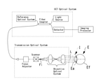
<OCT装置の概略構成>
図17に、本実施形態のOCT装置の概略構成を示す。本実施形態のOCT装置は、OCT光学系と、画像処理器と、を少なくとも備える。OCT光学系によって検出されたスペクトル干渉信号が、画像処理器で処理されることによって、被検眼のOCTデータが取得される。また、OCT装置は、光スキャナと、導光光学系と、を更に有していてもよい。光スキャナと、対物光学系とは、測定光路上に配置される。このとき、光スキャナは、導光光学系の一部であってもよい。
<Outline configuration of OCT device>
FIG. 17 shows a schematic configuration of the OCT apparatus of this embodiment. The OCT apparatus of this embodiment includes at least an OCT optical system and an image processor. The spectral interference signal detected by the OCT optical system is processed by the image processor to acquire OCT data of the eye to be inspected. Further, the OCT apparatus may further include an optical scanner and a light guide optical system. The optical scanner and the objective optical system are arranged on the measurement optical path. At this time, the optical scanner may be a part of the light guide optical system.
<OCT光学系>
OCT光学系は、例えば、フーリエドメインOCT光学系(SS-OCT光学系、SD-OCT光学系)であってもよい。OCT光学系は、OCT光源からの光を測定光路と参照光路に分割するための光分割器、および、測定光路を介して被検眼に導かれた測定光と参照光路からの参照光とのスペクトル干渉信号を検出する検出器、を有してもよい。
<OCT optical system>
The OCT optical system may be, for example, a Fourier domain OCT optical system (SS-OCT optical system, SD-OCT optical system). The OCT optical system is an optical divider for dividing the light from the OCT light source into a measurement optical path and a reference optical path, and a spectrum of the measurement light guided to the eye to be inspected through the measurement optical path and the reference light from the reference optical path. It may have a detector, which detects an interference signal.
<画像処理器>
画像処理器は、OCT光学系から出力されるスペクトル干渉信号を処理して被検眼のOCTデータを取得する。画像処理器は、OCT装置における装置全体の動作を司る制御部によって兼用されていてもよいし、制御部とは別体の画像処理装置であってもよい。画像処理器は、断層画像(Bスキャン画像)、3次元画像、および、OCTモーションコントラスト画像、等の各種画像を、OCTデータに基づいて生成してもよい。
<Image processor>
The image processor processes the spectral interference signal output from the OCT optical system to acquire the OCT data of the eye to be inspected. The image processor may be shared by a control unit that controls the operation of the entire device in the OCT device, or may be an image processing device separate from the control unit. The image processor may generate various images such as a tomographic image (B scan image), a three-dimensional image, and an OCT motion contrast image based on the OCT data.
<光スキャナ>
光スキャナは、光分割器からの測定光を偏向し、被検眼の組織上で走査するためのデバイスである。光スキャナによって測定光が組織上で2次元的に走査可能であることが好ましい。光スキャナは、複数個設けられていてもよい。この場合、1方向に測定光を走査する光スキャナを2つ以上組み合わせて設けてもよい。このような光スキャナの具体例としては、ガルバノミラー、レゾナントミラー、ポリゴンミラー、音響光学素子、MEMSスキャナ等が挙げられる。また、2自由度の光スキャナ(単体で2次元的な走査が可能なデバイス)が、本実施形態へ適用されてもよい。
<Optical scanner>
An optical scanner is a device that deflects the measured light from an optical divider and scans it on the tissue of the eye to be inspected. It is preferable that the measured light can be scanned two-dimensionally on the tissue by an optical scanner. A plurality of optical scanners may be provided. In this case, two or more optical scanners that scan the measurement light in one direction may be provided in combination. Specific examples of such an optical scanner include a galvano mirror, a resonant mirror, a polygon mirror, an acoustic optical element, a MEMS scanner and the like. Further, a two-degree-of-freedom optical scanner (a device capable of two-dimensional scanning by itself) may be applied to the present embodiment.
<導光光学系>
導光光学系は、対物光学系を含み、光分割器から被検眼まで測定光を導く。また、測定光の散乱・反射光のうち、導光光学系へ入射するものを、戻り光としてOCT光学系の検出器へ導く。
<Light guide optical system>
The light guide optical system includes an objective optical system and guides the measurement light from the optical divider to the eye to be inspected. Further, among the scattered / reflected light of the measurement light, the light incident on the light guide optical system is guided to the detector of the OCT optical system as return light.
対物光学系は、測定光路上において光スキャナと被検眼との間に配置される。本実施形態において、対物光学系を経由した測定光の集光面(図17において、符号Iで示す)は、被検眼の前眼部に形成される。このとき、対物光学系を経由した測定光は、測定光路の光軸と交差させることなく第1集光面まで導かれてもよい。導光光学系は、例えば、フォーカシングレンズ等の集光位置調整光学系を有していてもよく、測定光の集光面が被検眼の前眼部に設定されるように、集光位置調整光学系が調整されてもよい。 The objective optical system is arranged between the optical scanner and the eye to be inspected on the measurement optical path. In the present embodiment, the condensing surface of the measurement light passing through the objective optical system (indicated by reference numeral I in FIG. 17) is formed on the anterior segment of the eye to be inspected. At this time, the measurement light passing through the objective optical system may be guided to the first condensing surface without crossing the optical axis of the measurement optical path. The light guide optical system may have, for example, a focusing position adjusting optical system such as a focusing lens, and the focusing position adjustment is made so that the focusing surface of the measurement light is set on the anterior segment of the eye to be inspected. The optical system may be adjusted.
光スキャナおよび対物光学系によって実現される、前眼部での横断方向の走査範囲は、例えば、角膜の直径程度であってもよい。更に好ましくは、眼軸を挟んで対向する隅角領域にまで及んでいてもよい。 The transverse scanning range in the anterior segment of the eye realized by the optical scanner and the objective optical system may be, for example, about the diameter of the cornea. More preferably, it may extend to the opposite corner regions across the ocular axis.
また、対物光学系は、正の湾曲を有していてもよい。即ち、対物光学系によって形成される測定光の集光面が、眼底側に凸となって湾曲される。図17に示すように、前眼部に形成される集光面が、眼底側に凸となって湾曲していることで、水晶体が、良好な解像度で撮影されやすくなる。更に、虹彩および隅角等の周辺部側では、集光位置が、水晶体領域に対して浅い位置に設定されるので、光量の無駄が抑制される。これによって、深さ方向に関して前眼部の広い範囲において良好な画質または解像度を持つ断層像が、取得されやすくなる。 Further, the objective optical system may have a positive curve. That is, the condensing surface of the measurement light formed by the objective optical system is convex and curved toward the fundus side. As shown in FIG. 17, the condensing surface formed on the anterior eye portion is convex and curved toward the fundus side, so that the crystalline lens can be easily photographed with good resolution. Further, on the peripheral side such as the iris and the angle, the condensing position is set to a position shallow with respect to the crystalline lens region, so that waste of light amount is suppressed. This facilitates the acquisition of a tomographic image having good image quality or resolution over a wide range of the anterior eye portion in the depth direction.
対物光学系が持つ湾曲は、より好ましくは、前眼部に形成される集光面の曲率半径(R)がR≦28.5mmとなる範囲であってもよい。なお、集光面の曲率Rは、次の式(6)で表される。 The curvature of the objective optical system may be more preferably in the range where the radius of curvature (R) of the condensing surface formed on the anterior eye portion is R ≦ 28.5 mm. The curvature R of the condensing surface is expressed by the following equation (6).

但し、nkは、対物光学系を構成する各要素(例えばレンズ)の屈折率であり、fkは、各要素の焦点距離である。右辺の値が正となる場合に、対物光学系は、正の湾曲を有する。添え字であるkは、各レンズに対応する。 However, n k is the refractive index of each element (for example, a lens) constituting the objective optical system, and f k is the focal length of each element. When the value on the right side is positive, the objective optical system has a positive curve. The subscript k corresponds to each lens.
R≦28.5mmであることで、角膜による湾曲が、更に加わることにより、水晶体像と隅角像とを感度良く得ることができる。角膜は、屈折率1.377程度、曲率半径7.8程度の曲面であるので、上記(6)としては、次の式(7)で表される曲率を、加えるような作用を持つ。
1/nf = (n-1)/nr = 0.035・・・(7)
ところで、従来の前眼部OCTは、導光光学系がテレセントリック光学系であり、且つ、集光面が平面となるものが知られているが、このような装置において一度に撮影される範囲は、角膜表面から水晶体前面までがせいぜいであり、角膜表面から水晶体後面までを撮影することはできなかった。集光面の集光面の曲率半径(R)を、R≦28.5mmとした場合、角膜で生じる湾曲と同程度、および、それよりも大きな湾曲を、角膜以外で、更に生じさせることができる。その結果、角膜表面から水晶体後面までが一度に撮影されやすくなる。
When R ≦ 28.5 mm, the lens image and the angle angle image can be obtained with high sensitivity by further adding the curvature due to the cornea. Since the cornea is a curved surface having a refractive index of about 1.377 and a radius of curvature of about 7.8, the above (6) has an action of adding a curvature represented by the following equation (7).
1 / nf = (n-1) / nr = 0.035 ... (7)
By the way, in the conventional anterior segment OCT, it is known that the light guide optical system is a telecentric optical system and the condensing surface is a flat surface. It was not possible to photograph from the surface of the cornea to the posterior surface of the crystalline lens because the area from the surface of the cornea to the anterior surface of the crystalline lens was at most. When the radius of curvature (R) of the condensing surface of the condensing surface is R≤28.5 mm, the curvature of the condensing surface may be as large as or larger than that of the cornea. can. As a result, it becomes easier to photograph from the surface of the cornea to the posterior surface of the crystalline lens at one time.
本実施形態において、対物光学系は、1つ以上のレンズによるレンズ系である。但し、必ずしもこれに限られるものではなく、対物光学系は、1つ以上のミラーによるミラー系であってもよいし、レンズ系とミラー系とを組み合わせたものであってもよい。 In the present embodiment, the objective optical system is a lens system consisting of one or more lenses. However, the present invention is not limited to this, and the objective optical system may be a mirror system with one or more mirrors, or may be a combination of a lens system and a mirror system.
<測定光のテレセン性>
光スキャナは、対物光学系の焦点(光源側に形成される焦点であり、図17において、符号Fiで示す)に対して対物光学系から離れた位置に配置されてもよい。その結果、対物光学系から被検眼へ出射する測定光の主光線が、光軸に近づく方向に傾斜してもよい。対物光学系が正の湾曲を有することによって、角膜および強膜におけるスペクトル干渉信号は、周辺部側ほど感度が低下しやすくなってしまうことが考えられる。これに対し、対物光学系から被検眼へ出射する測定光の主光線が光軸に近づく方向に傾斜していることで、角膜、強膜、または、その両方、からの測定光の戻り光を、回収しやすくなる。換言すれば、角膜、強膜、または、その両方、からの戻り光のうち、測定光路外へ反射・散乱されるものの割合が低減される。結果、対物光学系が正の湾曲を有することのデメリットを克服し、角膜、強膜、または、その両方と、水晶体とが、良好に描写された断層像を取得できる。すなわち、前眼部の広範囲において良好な断層像を取得できる。
<Telecentability of measurement light>
The optical scanner may be arranged at a position away from the objective optical system with respect to the focal point of the objective optical system (a focal point formed on the light source side, which is indicated by the reference numeral Fi in FIG. 17). As a result, the main ray of the measurement light emitted from the objective optical system to the eye to be inspected may be inclined in a direction approaching the optical axis. It is conceivable that the sensitivity of the spectral interference signal in the cornea and sclera tends to decrease toward the peripheral side due to the positive curvature of the objective optical system. On the other hand, since the main ray of the measurement light emitted from the objective optical system to the eye to be inspected is inclined in a direction approaching the optical axis, the return light of the measurement light from the cornea, sclera, or both is emitted. , Easy to collect. In other words, the proportion of return light from the cornea, sclera, or both that is reflected and scattered out of the measurement optical path is reduced. As a result, it is possible to overcome the disadvantage that the objective optical system has a positive curvature, and obtain a well-depicted tomographic image of the cornea, sclera, or both, and the crystalline lens. That is, a good tomographic image can be obtained in a wide range of the anterior segment of the eye.
また、このような光スキャナの配置は、深い領域になるほど画角が狭まることを意味するが、これは前眼部を水晶体後面のような深い領域まで撮影する場合においてはむしろ都合がよい。虹彩などによってケラれずに水晶体後面を含むAスキャンの数が相対的に大きくなり、精度を上げることにもつながる。 Further, such an arrangement of the optical scanner means that the angle of view becomes narrower as the area becomes deeper, which is rather convenient when the anterior eye portion is photographed to a deep area such as the posterior surface of the crystalline lens. The number of A scans including the posterior surface of the crystalline lens is relatively large without being eclipsed by the iris, which leads to an increase in accuracy.
但し、光スキャナは、必ずしも対物光学系の焦点距離よりも対物光学系から離間して配置される必要は無い。焦点に配置されていてもよいし、焦点よりも対物光学系の近くに配置されていてもよい。 However, the optical scanner does not necessarily have to be arranged farther from the objective optical system than the focal length of the objective optical system. It may be located at the focal point or may be located closer to the objective optical system than the focal point.
光スキャナは、対物光学系に関して瞳共役な位置と、対物光学系の像側焦点と、の間に配置されることが好ましい。より好ましくは、測定光の主光線が光軸となす角度の範囲は、次の第1角度以下であることが好ましい。第1角度は、適正作動距離に置かれた角膜相当半径を持つ球体を用いて定義される。即ち、球体の法線のうち1つと一致する主光線である第1主光線と光軸と,がなす角度が、第1角度である。更に好ましくは、測定光の主光線が光軸となす角度の範囲は、次の第2角度以上であることが好ましい。第2角度は、適正作動距離に置かれた強膜相当半径を持つ球体を用いて定義される。即ち、球体の法線のうち1つと一致する主光線である第2主光線と光軸と,がなす角度が、第2角度である。なお、角膜相当半径は、略8mm(より詳細には、7.8mm)であり、強膜相当半径は略14mmであってもよい。なお、適正作動距離の位置は、例えば、OCT装置の集光面の位置、および、参照光路と測定光路とが一致するゼロディレイ位置等のいずれかに基づいて、適宜設定される。 The optical scanner is preferably placed between the pupil-conjugated position with respect to the objective optical system and the image side focal point of the objective optical system. More preferably, the range of the angle formed by the main ray of the measurement light with the optical axis is preferably the following first angle or less. The first angle is defined using a sphere with a corneal equivalent radius placed at an appropriate working distance. That is, the angle formed by the first main ray, which is the main ray that coincides with one of the normals of the sphere, and the optical axis is the first angle. More preferably, the range of the angle formed by the main ray of the measurement light with the optical axis is preferably the following second angle or more. The second angle is defined using a sphere with a scleral equivalent radius placed at an appropriate working distance. That is, the angle formed by the second main ray, which is the main ray that coincides with one of the normals of the sphere, and the optical axis is the second angle. The corneal equivalent radius may be approximately 8 mm (more specifically, 7.8 mm), and the sclera equivalent radius may be approximately 14 mm. The position of the appropriate working distance is appropriately set based on, for example, the position of the condensing surface of the OCT device, the zero delay position where the reference optical path and the measurement optical path coincide with each other, and the like.
<前眼部/眼底切換え>
図16を参照し、後述するように、OCT装置は、更に、撮影する深さ位置を切換えるための切換機構を有していてもよい。上記のような前眼部のOCTデータを取得する構成において、更に、次のような切換機構を有してもよい。即ち、切換機構は、対物光学系に関して走査部が瞳共役な位置に配置されるように光学系を切換るものであってもよい。より詳細には、切換機構は、対物光学系と走査部との位置関係を変更することで、対物光学系に対してレンズを挿脱することで、または、その両方を行うことで、対物光学系に関して走査部が瞳共役な位置に配置させてもよい。走査部が瞳共役な位置に配置されることで、測定光は、走査部の動作に伴って瞳上の一点を中心として旋回される。これにより、虹彩による測定光のケラレを抑制しつつ、眼底上で良好に測定光を走査することができる。
<Foreground / fundus switching>
As will be described later with reference to FIG. 16, the OCT apparatus may further have a switching mechanism for switching the depth position to be imaged. In the configuration for acquiring OCT data of the anterior eye portion as described above, the following switching mechanism may be further provided. That is, the switching mechanism may switch the optical system so that the scanning unit is arranged at a position conjugate to the pupil with respect to the objective optical system. More specifically, the switching mechanism changes the positional relationship between the objective optical system and the scanning unit, and by inserting and removing the lens from the objective optical system, or by performing both of them, the objective optical system is used. The scanning unit may be arranged at a position coupled to the pupil with respect to the system. By arranging the scanning unit at a position conjugate to the pupil, the measurement light is swirled around one point on the pupil as the scanning unit operates. This makes it possible to scan the measurement light satisfactorily on the fundus while suppressing vignetting of the measurement light due to the iris.
眼底上で測定光を走査する場合において、眼底面のカーブに沿って、測定光の集光面が湾曲していることが好ましい。つまり、眼底撮影時においても、測定光の集光面の湾曲が眼底側に凸となるように、対物光学系が正の湾曲を有することが好ましい。これにより、中央部と周辺部とのそれぞれにおいて、解像度または画質の良好な眼底の断層像が取得されやすくなる。 When scanning the measurement light on the fundus, it is preferable that the condensing surface of the measurement light is curved along the curve of the fundus. That is, it is preferable that the objective optical system has a positive curvature so that the curvature of the condensing surface of the measurement light is convex toward the fundus even during fundus photography. As a result, it becomes easy to obtain a tomographic image of the fundus with good resolution or image quality in each of the central portion and the peripheral portion.
なお、切換機構が、対物光学系の焦点と走査部との位置関係を変更することで、撮影する深さ位置を切換えるものである場合、対物光学系における湾曲の曲率値(ペッツバール和)は、切換の前後で変わらないので、眼底撮影時においても測定光の集光面の湾曲を、自ずと眼底側に凸とすることができ、有利である。 When the switching mechanism switches the shooting depth position by changing the positional relationship between the focal point of the objective optical system and the scanning unit, the curvature value (Petzval sum) of the curvature in the objective optical system is Since it does not change before and after switching, it is advantageous that the curvature of the condensing surface of the measured light can be naturally made convex toward the fundus even during fundus photography.
現在、市販されている眼底用OCTの中で、画角が広いもの(例えば、カール・ツァイス社製 商品名「PLEX Elite 9000」)でも、眼底は16mm程度の画角であって、深さは(空気換算で)3mm程度に収まる範囲である。 Among the OCTs for fundus currently on the market, even those with a wide angle of view (for example, the product name "PLEX Elite 9000" manufactured by Carl Zeiss) have a fundus with an angle of view of about 16 mm and a depth of about 16 mm. It is within the range of about 3 mm (in terms of air).
この場合、眼底撮影に必要な湾曲の曲率半径は、サグ量の計算から式(8)の値として算出される。
(82+32)/(2×3)=12.167・・・(8)
この値は、角膜によって発生する湾曲の影響を含むから、角膜による湾曲を、式(9)に示すように除くことで、前眼撮影と眼底撮影とを切換え可能なOCT装置において、望ましい集光面の曲率を求めることができる。
In this case, the radius of curvature of the curve required for fundus photography is calculated as the value of equation (8) from the calculation of the sag amount.
(82 + 32) / (2 × 3) = 12.167 ... (8)
Since this value includes the influence of the curvature generated by the cornea, it is desirable in an OCT device capable of switching between anterior ocular imaging and fundus imaging by removing the curvature due to the cornea as shown in the equation (9). The curvature of the surface can be obtained.
1/12.167=1/R+(1.337-1)/(1.377×7.8)・・・(9)
その結果、R=21.2354が、対物光学系による集光面の湾曲として、生じることが好ましい。即ち、R≦21の範囲であることが好ましい。
1 / 12.167 = 1 / R + (1.337-1) / (1.377 × 7.8) ... (9)
As a result, it is preferable that R = 21.254 occurs as the curvature of the condensing surface by the objective optical system. That is, it is preferably in the range of R ≦ 21.
<ノイズ除去処理>
OCT装置は、ノイズ除去部を更に有してもよい。ノイズ除去部は、画像処理器によって兼用されてもよい。ノイズ除去部は、OCTデータにおける直流成分によるノイズを除去する。直流成分は、干渉成分に関連しない信号成分に相当する。
<Noise reduction processing>
The OCT device may further have a noise reducing unit. The noise reduction unit may also be used by an image processor. The noise reduction unit removes noise due to a DC component in the OCT data. The DC component corresponds to a signal component that is not related to the interference component.
ノイズ除去処理の手法には、種々の手法がありうる。例えば、ノイズ除去処理として、いわゆるDCサブトラクションが利用されてもよい。DCサブトラクションでは、複数のAスキャンデータの生データであるスペクトルデータ(少なくともフーリエ変換前のデータ),の平均(平均スペクトルという)が算出され、その後、走査位置毎のスペクトルデータから上記の平均スペクトルを、差し引くことで、各スペクトルデータに共通する直流成分(ノイズ成分の一つ)が少なくとも除去される。残ったスペクトルデータをフーリエ変換等することで、直流成分が低減されたOCTデータを取得することができる。 There may be various methods for noise reduction processing. For example, so-called DC subtraction may be used as the noise reduction processing. In DC subtraction, the average (referred to as the average spectrum) of the spectral data (at least the data before Fourier conversion), which is the raw data of a plurality of A scan data, is calculated, and then the above average spectrum is obtained from the spectral data for each scan position. By subtracting, at least the DC component (one of the noise components) common to each spectral data is removed. By performing a Fourier transform or the like on the remaining spectral data, it is possible to acquire OCT data in which the DC component is reduced.
但し、上述のDCサブトラクションは、その処理上どうしても信号成分まで一緒に除去が行われてしまう。その際、角膜など、十分に感度の高い信号ならば多少の信号成分が失われても断層像の質は十分維持されるが、前眼部のOCTデータのうち、水晶体が位置する深さ領域(換言すれば、虹彩よりも深い領域)においては、水晶体での干渉信号の強度と、直流成分の強度とが、近接しており、当該深さ領域における平均スペクトルを、当該深さ領域から一律に除去してしまうと、伴って失われる信号成分の影響が顕著である。即ち水晶体の領域におけるS/N比が改善されない場合があり得る。ところで、虹彩の直下の領域は、虹彩によって遮光され、測定光が到達していない領域であるので、当該領域に生じているのは信号成分の混入のない、直流成分そのものである。 However, the above-mentioned DC subtraction is inevitably removed together with the signal component due to its processing. At that time, if the signal is sufficiently sensitive such as the cornea, the quality of the tomographic image is sufficiently maintained even if some signal components are lost, but in the OCT data of the anterior segment of the eye, the depth region where the crystalline lens is located. In (in other words, the region deeper than the iris), the intensity of the interference signal in the crystalline lens and the intensity of the DC component are close to each other, and the average spectrum in the depth region is uniformly distributed from the depth region. If it is removed, the effect of the signal component lost along with it is remarkable. That is, the S / N ratio in the region of the crystalline lens may not be improved. By the way, since the region directly under the iris is a region shaded by the iris and the measurement light does not reach, what is generated in the region is the DC component itself without the mixing of the signal component.
そこで、本実施形態において、ノイズ除去部は、少なくとも虹彩よりも深い領域については、虹彩の直下の領域における直流成分が、水晶体領域における直流成分でもあるものとみなして、ノイズ除去処理を行う。 Therefore, in the present embodiment, the noise removing unit performs noise removing processing on the assumption that the DC component in the region immediately below the iris is also the DC component in the crystalline lens region, at least in the region deeper than the iris.
詳細には、画像処理器によって、走査位置毎の複数のスペクトルデータが、測定光の走査に基づく前眼部のOCTデータとして取得される(図18(a)参照)。ノイズ除去部は、複数のスペクトルデータを、第1スペクトルデータと、第2スペクトルデータとに分別する。第1スペクトルデータは、測定光が水晶体に照射された測定光に基づくデータであり、第2スペクトルデータは、水晶体の周辺組織(例えば、虹彩およびその外側)に照射された測定光に基づくデータである。第1スペクトルデータと、第2スペクトルデータとの間には、虹彩およびそれよりも深い領域において、明確な強度の違いが見られるので、例えば、強度分布に基づいて、第1スペクトルデータと、第2スペクトルデータとが分別され得る。これに限られず、例えば角膜から水晶体前面までと、水晶体後面とを2つの検出器でそれぞれ分けて撮影し断層像を合成する場合に、各検出器における検出信号の処理方法を変えることで、これを実現してもよい。そして、虹彩よりも深い領域については、第1スペクトルデータと第2スペクトルデータとのうち、第2スペクトルデータにおけるノイズ成分を第1スペクトルデータにおける前記虹彩よりも深い領域でのノイズ成分とみなしてノイズ除去処理が実行される(図18(b)参照)。DCサブトラクションでは、複数の第2スペクトルデータにおけるスペクトル干渉信号の平均(平均スペクトル)を、深さ毎に算出し、その平均を、第1スペクトルデータおよび第2スペクトルデータの各々から差し引く処理を、虹彩よりも深い領域において行う。 Specifically, the image processor acquires a plurality of spectral data for each scanning position as OCT data of the anterior eye portion based on the scanning of the measurement light (see FIG. 18A). The noise reduction unit separates a plurality of spectral data into first spectral data and second spectral data. The first spectrum data is data based on the measurement light that the measurement light irradiates the crystal body, and the second spectrum data is the data based on the measurement light that irradiates the peripheral tissue of the crystal body (for example, the iris and its outside). be. Since there is a clear difference in intensity between the first spectrum data and the second spectrum data in the iris and deeper regions, for example, based on the intensity distribution, the first spectrum data and the first spectrum data 2 Spectral data can be separated. Not limited to this, for example, when the cornea to the anterior surface of the crystalline lens and the posterior surface of the crystalline lens are photographed separately by two detectors and a tomographic image is synthesized, the processing method of the detection signal in each detector can be changed. May be realized. Then, in the region deeper than the iris, the noise component in the second spectrum data of the first spectrum data and the second spectrum data is regarded as the noise component in the region deeper than the iris in the first spectrum data, and the noise is generated. The removal process is executed (see FIG. 18B). In DC subtraction, the process of calculating the average (average spectrum) of the spectral interference signals in a plurality of second spectrum data for each depth and subtracting the average from each of the first spectrum data and the second spectrum data is performed in the iris. Do it in deeper areas.
これにより、水晶体領域において、良好にS/N比が改善される(図18(c)参照)。結果、例えば、水晶体内の混濁の分布が良好に描写された断層像を取得できる。 As a result, the S / N ratio is satisfactorily improved in the crystalline lens region (see FIG. 18 (c)). As a result, for example, a tomographic image in which the distribution of opacity in the quartz body is well described can be obtained.
なお、OCTデータにおける直流成分によるノイズを除去する手法は、上記のDCサブトラクションに必ずしも限定されない。例えば、複数の第1スペクトルデータの虹彩よりも深い領域における深さ毎の信号強度の平均値および分散値を用いて、複数のスペクトルデータに基づく各点がノイズであるか否かを推定する推定処理を行ってもよい。ノイズと推定された点については、強度を減じる処理を行うことで、直流成分によるノイズが除去される。 The method for removing noise due to the DC component in the OCT data is not necessarily limited to the above DC subtraction. For example, an estimation that estimates whether or not each point based on the plurality of spectral data is noise by using the mean value and the variance value of the signal strength for each depth in the region deeper than the iris of the plurality of first spectral data. Processing may be performed. For the points estimated to be noise, noise due to the DC component is removed by performing a process of reducing the intensity.
このとき、平均値および分散値を求める第1スペクトルデータは、直流成分のみを含む既知の領域であってもよい。例えば、深さ方向および横断方向に近接した数画素分の平均値および分散値を、同じ深さで比較し、同様の分布を持つ点が、ノイズと推定される。 At this time, the first spectrum data for obtaining the mean value and the dispersion value may be a known region containing only the DC component. For example, the average value and the dispersion value of several pixels close to each other in the depth direction and the transverse direction are compared at the same depth, and points having the same distribution are estimated to be noise.
ここで、既知の領域は、前述の虹彩の直下の領域であってもよい。また、それ以外の領域(例えば、角膜より上部の領域)であってもよい。更に、周辺画素との比較の例を示したが、複数枚撮影する場合は複数枚撮影した断層像間の平均や分散であっても、もちろんよい。 Here, the known region may be a region directly below the above-mentioned iris. Further, it may be a region other than that (for example, a region above the cornea). Further, although an example of comparison with peripheral pixels is shown, in the case of taking a plurality of images, the average or dispersion between the tomographic images taken by the plurality of images may be of course acceptable.
<複数の参照光路>
また、上記実施形態におけるOCT装置は、以下のような構成を備えてもよい。
<Multiple reference optical paths>
Further, the OCT device in the above embodiment may have the following configuration.
例えば、OCT光学系は、複数の参照光路を備えてもよい。例えば、OCT光学系は、異なる光路長に設定される第1の参照光路と第2の参照光路とを有してもよい。この場合、第1の参照光路と第2の参照光路の一方は、被検眼の角膜(例えば、角膜及び水晶体前面)を含むOCTデータを得るための光路長に設定され、第1の参照光路と第2の参照光路の他方は、被検眼の水晶体(例えば、水晶体後面)を含むOCTデータを得るための光路長に設定されてもよい。 For example, the OCT optical system may include a plurality of reference optical paths. For example, the OCT optical system may have a first reference optical path and a second reference optical path set to different optical path lengths. In this case, one of the first reference optical path and the second reference optical path is set to the optical path length for obtaining OCT data including the cornea of the eye to be examined (for example, the cornea and the anterior surface of the crystalline body), and the first reference optical path and the optical path. The other side of the second reference optical path may be set to an optical path length for obtaining OCT data including the crystal body of the eye to be inspected (for example, the posterior surface of the crystal body).
また、参照光路毎に、測定光の戻り光と参照光とを合波させるカップラーが更に設けられていてもよく、これによって、互いに異なる深さ領域に対応する干渉信号を同時に取得し、結果として、前眼部の広範囲におけるOCTデータを、良好な強度で取得できる。 Further, a coupler for combining the return light of the measurement light and the reference light may be further provided for each reference optical path, whereby interference signals corresponding to different depth regions are simultaneously acquired, and as a result, interference signals are simultaneously acquired. , OCT data over a wide area of the anterior segment can be obtained with good intensity.
<実施例>
本実施例では、OCT装置として、図1に示される光コヒーレンストモグラフィー(OCT)装置が用いられる。本実施例に係るOCT装置は、例えば、波長掃引式OCT(SS-OCT:Swept Source-OCT)を基本的構成とし、波長可変光源102、干渉光学系(OCT光学系)100、演算制御器(演算制御部)70と、を含む。その他、OCT装置には、メモリ72、表示部75、図示無き正面像観察系及び固視標投影系が設けられてもよい。演算制御器(以下、制御部)70は、波長可変光源102、干渉光学系100、メモリ72、表示部75に接続されている。
<Example>
In this embodiment, the optical coherence tomography (OCT) device shown in FIG. 1 is used as the OCT device. The OCT apparatus according to this embodiment has, for example, a wavelength sweep type OCT (SS-OCT: Swept Source-OCT) as a basic configuration, and has a wavelength variable
干渉光学系100は、導光光学系150によって測定光を眼Eに導く。干渉光学系100は、参照光学系110に参照光を導く。干渉光学系100は、眼Eによって反射された測定光と参照光との干渉、によって取得される干渉信号光を検出器(受光素子)120に受光させる。さらに、本実施例の干渉光学系100は、FPN生成光学系200を備える(詳しくは後述する)。なお、干渉光学系100は、図示無き筐体(装置本体)内に搭載され、ジョイスティック等の操作部材を介して周知のアライメント移動機構により眼Eに対して筐体を3次元的に移動させることによって被検眼に対するアライメントが行われてもよい。
The interference
干渉光学系100には、SS-OCT方式が用いられ、光源102として出射波長を時間的に高速で変化させる波長可変光源(波長走査型光源)が用いられる。光源102は、例えば、レーザ媒体、共振器、及び波長選択フィルタによって構成される。そして、波長選択フィルタとして、例えば、回折格子とポリゴンミラーの組み合わせ、ファブリー・ペローエタロンを用いたフィルタが挙げられる。また、光源102として、VCSEL式波長可変光源が用いられてもよい。
The SS-OCT method is used for the interference
カップラ(スプリッタ)104は、第1の光分割器として用いられ、光源102から出射された光を測定光路と参照光路に分割する。カップラー104は、例えば、光源102からの光を測定光路側の光ファイバー105に導光すると共に、参照光路側の参照光学系110に導光する。
The
カップラ(スプリッタ)130は、第2の光分割器として用いられ、光ファイバー105からの光(測定光)を、導光光学系150の光路とFPN生成光学系200の光路に分割する。つまり、測定光路には、導光光学系150とFPN生成光学系200が設けられている。カップラ(スプリッタ)130は、ビームスプリッタであってもよいし、サーキュレータであってもよい。
The
<導光光学系>
導光光学系150は、測定光を眼Eに導くために設けられる。導光光学系150には、例えば、光ファイバー152、カップラー153、コリメータレンズ154、光スキャナ156、及び対物レンズ系158が順次設けられてもよい。この場合、測定光は、光ファイバー152、カップラー153を介して、コリメータレンズ154によって平行ビームとなり、光スキャナ156に向かう。光スキャナ156を通過した光は、対物レンズ系158を介して、眼Eに照射される。測定光は、前眼部及び後眼部の両方に照射され、各組織にて散乱・反射される。
<Light guide optical system>
The light guide
光スキャナ156は、眼E上でXY方向(横断方向)に測定光を走査させてもよい。光スキャナ156は、例えば、2つのガルバノミラーであり、その反射角度が駆動機構によって任意に調整される。光源102から出射された光束は、その反射(進行)方向が変化され、眼底上で任意の方向に走査される。光スキャナ156としては、例えば、反射ミラー(ガルバノミラー、ポリゴンミラー、レゾナントスキャナ)の他、光の進行(偏向)方向を変化させる音響光学素子(AOM)等が用いられてもよい。
The
この場合、測定光による眼Eからの散乱光(反射光)は、対物レンズ系158、光スキャナ156、コリメータレンズ154、カップラー153、光ファイバー152を経た後、カップラ―130に達する。カップラ130は、光ファイバー152からの光を、第1の検出器120aに向かう光路(例えば、光ファイバー115~カップラー350a)と、第2の検出器120bに向かう光路(例えば、光ファイバー105~カップラー104~光ファイバー117~カップラー350b)に分割する。
In this case, the scattered light (reflected light) from the eye E by the measurement light reaches the
カップラー130によって分割された測定光のうち、第1の検出器120aに向かう光路を経由した測定光は、カップラ350aにて、第1の参照光路110aからの参照光と合波されて干渉する。また、第2の検出器120bに向かう光路を経由した測定光は、カップラ350bにて、第2の参照光路110bからの参照光と合波されて干渉する。
Of the measurement light divided by the
<参照光学系>
参照光学系110は、眼Eでの測定光の反射によって取得される反射光と合成される参照光を生成する。参照光学系110を経由した参照光は、カップラ(例えば、カップラ350a、350b)にて測定光路からの光と合波されて干渉する。参照光学系110は、マイケルソンタイプであってもよいし、マッハツェンダタイプであってもよい。
<Reference optical system>
The reference
参照光学系110は、例えば、反射光学系によって形成され、カップラー104からの光を反射光学系により反射することにより検出器120に導いてもよい。参照光学系110は、透過光学系によって形成されてもよい。この場合、参照光学系110は、カップラー104からの光を戻さず透過させることにより検出器120へと導く。
The reference
なお、測定光路と参照光路の少なくともいずれかには、測定光と参照光との光路長差を調整するための光学部材が配置されてもよい。例えば、コリメータレンズ154とカップラー153とが一体的に移動されることで、測定光の光路長が調整され、結果として、測定光と参照光との光路長差が調整されてもよい。もちろん、参照光路に配置された光学部材が移動されることによって、結果として、測定光と参照光との光路長差が調整されてもよい。
An optical member for adjusting the optical path length difference between the measurement light and the reference light may be arranged in at least one of the measurement optical path and the reference optical path. For example, by integrally moving the
本実施例において、参照光学系110として、複数の参照光路が設けられてもよく、例えば、第1の参照光路110aと、第2の参照光路110bとが設けられてもよい。
In this embodiment, a plurality of reference optical paths may be provided as the reference
参照光学系110は、例えば、参照光路を第1の参照光路110aと、第2の参照光路110bに分割するための光分割器(例えば、カップラ111)が設けられてもよい。第1の参照光路110aと、第2の参照光路110bの少なくともいずれかには、例えば、参照光の光路長を変更するために移動される光学部材112が設けられてもよい。光学部材112は、制御部70によって制御される図示なき駆動部によって移動されてもよい。
The reference
例えば、カップラ104からの参照光は、カップラ111によって第1の参照光路110aと第2の参照光路110bに分割される。第1の参照光路110aを経由した参照光は、カップラ350aにて、光ファイバ115からの測定光と合波されて干渉する。第2の参照光路110bを経由した参照光は、カップラ350bにて、光ファイバ117からの測定光と合波されて干渉する。
For example, the reference light from the
第1の参照光路110aと、第2の参照光路110bは、互いに異なる光路長に設定されてもよい。これによって、例えば、互いに異なる深さ領域に対応する干渉信号を同時に取得でき、結果として、広範囲のOCTデータを同時に取得できる。
The first reference
例えば、第1の参照光路110aが、被検眼における第1の深さ領域(例えば、水晶体、眼底)に対応する干渉信号を得るために設けられ、第2の参照光路110bは、被検眼における第2の深さ領域(例えば、角膜)に対応する干渉信号を得るために設けられてもよい。この場合、第2の深さ領域は、第1の深さ領域に対して異なる領域に設定される(図面としては、第2の参照光路の方が長く、眼底用に見えますが、実際は異なる旨を説明しておけばよいですか?)。この場合、第1の深さ領域と第2の深さ領域は、互いに分離した領域であってもよいし、互いに隣接した領域であってもよいし、一部が重複した領域であってもよい。
For example, a first reference
なお、第1の参照光路110aと、第2の参照光路110bは、同じ光路長に設定されてもよい。これによって、例えば、同一の深さ領域に対応する干渉信号を同時に取得でき、結果として、同一領域に関する複数のOCTデータを同時に取得できる。
The first reference
<光検出器>
検出器120は、測定光路からの光と参照光路からの光による干渉を検出するために設けられている。なお、検出器120は、受光素子であってもよく、例えば、受光部が一つのみからなるポイントセンサであって、例えば、アバランシェ・フォト・ダイオードが用いられてもよい。
<Photodetector>
The
本実施例では、検出器120として、第1の検出器120aと、第1の検出器120aとは異なる第2の検出器120bと、が設けられてもよい。第1の検出器120aは、第1の参照光路110aからの参照光と光ファイバー115からの測定光との第1の干渉信号を検出するための検出器として設けられてもよい。第2の検出器120bは、第2の参照光路110bからの参照光と光ファイバ117からの測定光との第2の干渉信号を検出するための検出器として設けられてもよい。この場合、第1の検出器120aにて第1の干渉信号を検出すると同時に、第2の検出器120bにて第2の干渉信号を検出することによって、第1の干渉信号と第2の干渉信号を同時に検出可能である。
In this embodiment, as the
なお、第1の検出器120a、第2の検出器120bは、それぞれ平衡検出器であってもよい。この場合、第1の検出器120a、第2の検出器120bは、複数の受光素子をそれぞれ備え、第1受光素子からの干渉信号と第2受光素子からの干渉信号との差分を得て、干渉信号に含まれる不要なノイズを削減できる。
The
<FPN生成光学系>
FPN生成光学系200は、FPN信号を生成するために設けられてもよい。FPN生成光学系200は、FPNを発生させる光学部材(例えば、第1の光学部材204又は第2の光学部材206)を少なくとも一つ備えてもよい。本実施例において、FPN生成光学系200は、測定光が被検眼に向かう光路から分岐された位置に配置されている。
<FPN generation optical system>
The FPN generation
FPN生成光学系200としては、例えば、反射光学系であってもよく、FPN発生用光学部材としては、例えば、光反射部材(例えば、ミラー)が用いられてもよい。なお、本実施例においては、FPNを発生させる光学部材を複数設けたが、これに限定されず、FPN生成光学系200は、FPNを発生させる光学部材を一つ備える構成であってもよい。
The FPN generation
第1の検出器120aには、第1の干渉信号と共にFPN信号が検出され、第2の検出器120bには、第2の干渉信号と共にFPN信号が検出される。FPN信号は、例えば、第1の干渉信号に基づく第1のOCTデータと、第2の干渉信号に基づく第2のOCTデータとの合成(詳しくは後述する)、各干渉信号の波数マッピング補正、偏光調整等に用いられてもよい。
The
例えば、FPN生成光学系200は、第1のFPN信号と第2のFPN信号を生成するために設けられてもよい。例えば、FPN生成光学系200は、第1のFPNを発生させる第1の光学部材204と、第2のFPNを発生させる第2の光学部材206と、を少なくとも備えてもよい。第2の光学部材206は、第2の光学部材を経由した光が、第1の光学部材204を経由した光による光路長とは異なるように配置されてもよい。これによって、第2のFPNは、第1のFPNに対して異なる位置に発生される。なお、後述するゼロディレイ位置は、OCTデータ上において、測定光の光路長と参照光の光路長とが一致する位置に対応する。
For example, the FPN generation
第1の光学部材204と第2の光学部材206とが同時に使用されることによって、2つのFPN信号を同時に生成することが可能であり、これによって、2つのFPN信号を処理する際の時間的なずれの影響を軽減できる。なお、FPN光学系200は、3つ以上のFPN発生用光学部材を備えてもよく、これらが同時に使用されることによって、3つ以上のFPN信号を同時に生成することが可能である。
By using the first
FPN生成光学系200としては、例えば、反射光学系であってもよく、FPN発生用光学部材としては、例えば、光反射部材(例えば、ミラー)が用いられてもよい。本実施例では、第1のFPN発生用光学部材204、第2のFPN発生用光学部材206としてミラーが用いられているが、これに限定されない。
The FPN generation
この場合、カップラ130からの光は、第1の光学部材204又は第2の光学部材206を経由した後、カップラ130に戻され、導光光学系150からの光と同様の経路を経て、カップラ350a,カップラ350bに達する。FPN生成光学系200からの光は、カップラ350a,350bにて参照光と合波されて干渉する。なお、光源102~FPN生成光学系200~カップラ350a,350bの光路長と、光源102~参照光学系110~カップラ350a,350bまでの光路長は、ほぼ同じ長さに設定されてもよい。
In this case, the light from the
例えば、第1の光学部材204を経由した光が参照光と干渉することによって、第1のFPNに対応する干渉信号光が生成され、検出器120には第1のFPN信号が生成され、第2の光学部材206を経由した光が参照光と干渉することによって、第2のFPNに対応する干渉信号光が生成され、検出器120には第2のFPN信号が生成される。結果として、例えば、検出器120には、第1のFPN信号と第2のFPN信号の両方が同時に検出される。
For example, when the light passing through the first
FPN信号を所定の処理に用いる場合、検出器120a、検出器120bのそれぞれにおいて、第1のFPN信号と第2のFPN信号の両方が同時に検出されてもよいし、検出器120aにおいて一方のFPN信号が検出され、検出器120bにおいて他方のFPN信号が検出されてもよい。また、検出器120a、検出器120bの一方において、第1のFPN信号と第2のFPN信号の両方が同時に検出され、検出器120a、検出器120bの他方において第1のFPN信号と第2のFPN信号の一方が検出されてもよい。また、検出器120a、検出器120bの一方において、少なくとも一つのFPN信号が検出され、また、検出器120a、検出器120bの他方において、FPN信号が検出されなくてもよい。
When the FPN signal is used for a predetermined process, both the first FPN signal and the second FPN signal may be detected simultaneously in each of the
なお、FPN生成光学系200には、光量モニタ210が配置されてもよく、光源102からの光は、ビームスプリッタ208を介して光量モニタ120によって検出される。光量モニタ120からの出力信号は、光源102の出射光量が適正か否かを判定するために用いられてもよい。
A
<光量分岐比>
ここで、カップラー130は、カップラー104からの光を、導光光学系150の光路とFPN生成光学系200の光路に分割すると共に、導光光学系150及びFPN生成光学系200からの光を、第1の検出器350aへと向かう光路(例えば、光ファイバー115~カップラー350a)と、カップラー104へと向かう光路(例えば、光ファイバー105~カップラー104~光ファイバー117~カップラー350b)と、に分割する。
<Light intensity branch ratio>
Here, the
ファイバー105からの光を分割する際のカップラー130の光量分割比S1は、導光光学系150よりもFPN生成光学系200に多くの光が導かれるように設定されてもよい。この場合、ファイバー105からの光がカップラ130―によって分割される光量比は、導光光学系150<FPN生成光学系200となる。
The light amount division ratio S1 of the
導光光学系150からの光を分割する際のカップラー130の光量分割比S2は、光量分割比S1に依存する。この結果、導光光学系150からの光に関し、第1の検出器120aに向かう光路よりも、第2の検出器120aに向かう光路に、多くの光が導かれる。この場合、導光光学系150からの光がカップラー130によって分割される光量比は、第1の検出器120aに向かう光路<カップラー104に向かう光路となる。
The light amount division ratio S2 of the
第1の検出器120aに向かう光路を経由した測定光は、第1の参照光路110aからの光と干渉した後、第1の検出器120aにて第1の干渉信号として検出される。一方、カップラー104に向かう測定光は、カップラー104によって、光源102に向かう光路と、第2の検出器120bに向かう光路(例えば、光ファイバー117~カップラー350b)に分割される。カップラー130からの光を分割する際の光量分割比S4は、光源102からの光を測定光路と参照光路とに分割する際の光量分割比S3に依存する。光量分割比S3が、測定光路よりも参照光路に多くの光が導かれるように設定された場合、カップラー130からの光がカップラー104によって分割される光量比は、光源102に向かう光路<第2の検出器120bに向かう光路となる。この結果、カップラ130からの光に関し、光源102に向かう光路よりも、第2の検出器120bに向かう光路に多くの光が導かれる。第2の検出器120bに向かう光路を経由した測定光は、第2の参照光路110bからの光と干渉した後、第2の検出器120bにて第2の干渉信号として検出される。
The measured light passing through the optical path toward the
上記構成をまとめると、カップラー130の光量分割比S2に関して、第1の検出器120aに向かう光路<カップラー104に向かう光路であり、カップラー104の光量分割比S4に関して、光源102に向かう光路<第2の検出器120bに向かう光路にて設定されている。
Summarizing the above configuration, regarding the light amount division ratio S2 of the
この結果として、第1の検出器120aにて検出される第1の干渉信号と、第2の検出器120bにて検出される第2の干渉信号と、を適度なバランスにて検出できる。つまり、カップラー104を経由して第2の検出器120bに向かう光路の場合、導光光学系150からの光は、複数の光分割器(例えば、カップラ130、カップラー104)を経由するので、光量減衰の回数が多いのに対し、第1の検出器120aに向かう光路の場合、導光光学系150からの光は、カップラー130を経由して第1の検出器120aに達するので、光量減衰の回数が相対的に少ない。
As a result, the first interference signal detected by the
そこで、カップラー130の光量分割比S2に関して、第1の検出器120aに向かう光路<カップラー104に向かう光路であり、カップラー104の光量分割比S4に関して、光源102に向かう光路<第2の検出器120bに向かう光路であることで、光量減衰が複数回行われたとしても、光量減衰を軽減でき、結果として、第1の検出器120aと第2の検出器120bとの間で信号強度の差異を少なくできる。したがって、第1の検出器120aによって得られるOCTデータと第2の検出器120bによって得られるOCTデータとの信号強度の差異が少なくなり、それぞれ適正なOCTデータを取得できる。
Therefore, regarding the light amount division ratio S2 of the
なお、カップラー130の光量分割比S2と、カップラー104の光量分割比S4に関して、第1の検出器120aに向かう光路と第2の検出器120bに向かう光路との光量比が同一となるように設定されてもよい。その一例としては、カップラー130の光量分割比S2に関して、第1の検出器120aに向かう光路:カップラー104に向かう光路=6:4、カップラー102の光量分割比S4に関して、光源102に向かう光路:第2の検出器120bに向かう光路=1:2となるように設定されてもよい。
Regarding the light amount division ratio S2 of the
上記限定されず、カップラー130の光量分割比S2と、カップラー104の光量分割比S4に関して、第1の検出器120aと第2の検出器120bによって検出されるOCTデータの撮影部位での反射光量の違いを考慮して、光量分割比が設定されてもよい。つまり、被検眼の角膜からの反射光は、反射光量が大きいが、水晶体及び眼底からの光は、反射光量が相対的に少ない。そこで、撮影部位による反射光量比を考慮して、結果として、第1の検出器120aと第2の検出器120bとの間でのOCTデータの信号強度が同一となるように、カップラー130の光量分割比S2と、カップラー104の光量分割比S4が設定されてもよい。
Not limited to the above, with respect to the light amount division ratio S2 of the
なお、本実施例において、導光光学系150からの光を複数の検出器に導光させる際、1つの光分割器(例えば、カップラー130)を介して第1の検出器120aに向かう光と、複数のカップラー(例えば、カップラー130、カップラー104)を介して第2の検出器120bに向かう光に分けたのは、導光光学系150からの光をより多く効率的に各検出器に導かれるためである。このような光学配置は、光源120の出射光量が限られており、被検眼からの反射光が微弱であるような場合に、特に有利である。
In this embodiment, when the light from the light guide
図2は、本実施例に係るFPN生成光学系の一例を示す図である。FPN生成光学系200は、例えば、第1の光学部材204を備える第1の光路203と、第2の光学部材206を備える第2の光路205とを少なくとも備えてもよい。ここで、第1の光路203と第2の光路205との間において、第1の光路203の光路長と第2の光路205の光路長が異なることによって、第2のFPNは、第1のFPNとは異なる位置に生成される。例えば、第2の光路205の光路長が第1の光路203の光路長よりも長いことによって、第1のFPNよりもゼロディレイから離れた位置に生成される。
FIG. 2 is a diagram showing an example of the FPN generation optical system according to this embodiment. The FPN-generating
FPN生成光学系200は、光路分割部材202(例えば、ビームスプリッタ)を備えてもよく、光路分割部材202は、光源側の光路を、第1の光路203と第2の光路205とに分割するために設けられてもよい。第1の光学部材204は、光路分割部材202によって分割された第1の光路203に配置されており、第2の光学部材206は、光路分割部材202によって分割された第2の光路に配置されている。
The FPN generation
第1の光路203と第2の光路205は、互いに異なる光路長を持つ。つまり、光路分割部材202の分岐位置から第1の光学部材204までの光路長と、光路分割部材202の分岐位置から第2の光学部材206までの光路長は異なる。この結果として、第1の光学部材204によって形成される第1のFPNと、第2の光学部材206によって形成される第2のFPNは、OCT画像上において深さ方向に異なる位置に形成される。なお、深さ方向における第1のFPNと第2のFPNとの間の距離は、第1の光路203と第2の光路205との間の光路長差に起因する。
The first
また、第1の光路203と第2の光路205は、互いに等しい光学的分散量に設定(構築)されている。この結果として、第1のFPNを用いて算出される各波数成分のマッピング情報(以下、第1の波数マッピング情報)と、第2のFPNを用いて算出される各波数成分のマッピング情報(以下、第2の波数マッピング情報)との間の差分に基づいて、各波数成分のマッピング状態を補正するための補正情報を演算により求める際、各マッピング情報に含まれる分散成分を適正にキャンセルできるので、補正情報を精度よく求めることができる(詳しくは、後述する)。この場合、互いに等しい分散量としては、厳密に同一である必要は必ずしもなく、一定の精度を確保し、分散成分を適正にキャンセルできればよい。
Further, the first
<偏波調整機構>
本実施例のOCT光学系100において、複数の偏光調整部が設けられてもよく、例えば、OCT光学系100の光路には、第1の偏光調整部300、第2の偏光調整部302、第3の偏光調整部304が設けられてもよい(図1参照)。
<Polarization adjustment mechanism>
In the OCT
第1の偏光調整部300は、第1の参照光路110aの光路に配置され、第1の参照光路110aを経由する参照光の偏光状態を調整するために設けられてもよい。第2の偏光調整部302は、第2の参照光路110bの光路に配置され、第2の参照光路110bを経由する参照光の偏光状態を調整するために設けられてもよい。第3の偏光調整部304は、FPN生成光学系200の光路に配置され、FPN生成光学系200の光路を経由する光の偏光状態を調整するために設けられてもよい。
The first
<深さ情報の取得>
光源102により出射波長が変化されると、これに対応する干渉信号光が検出器120に受光され、結果的に、スペクトル信号として検出器120によって検出される。制御部70は、検出器120によって検出されたスペクトル信号を処理(フーリエ解析)し、被検眼のOCTデータを得る。
<Acquisition of depth information>
When the emission wavelength is changed by the
スペクトル信号(スペクトルデータ)は、波長λの関数として書き換えられ、波数k(=2π/λ)に関して等間隔な関数I(k)に変換されてもよい。あるいは、初めから波数kに関して等間隔な関数I(k)として取得されてもよい(K―CLOCK技術)。演算制御器は、波数k空間でのスペクトル信号をフーリエ変換することにより深さ(Z)領域におけるOCTデータを得てもよい。 The spectral signal (spectral data) may be rewritten as a function of wavelength λ and converted into a function I (k) at equal intervals with respect to the wave number k (= 2π / λ). Alternatively, it may be acquired as a function I (k) at equal intervals with respect to the wave number k from the beginning (K-CLOCK technique). The arithmetic controller may obtain OCT data in the depth (Z) region by Fourier transforming the spectral signal in the wave number k-space.
さらに、フーリエ変換後の情報は、Z空間での実数成分と虚数成分を含む信号として表されてもよい。制御部70は、Z空間での信号における実数成分と虚数成分の絶対値を求めることによりOCTデータを得てもよい。
Further, the information after the Fourier transform may be represented as a signal including a real number component and an imaginary number component in the Z space. The
本実施例では、制御部70は、第1の検出器120aによって検出された第1の干渉信号を処理して第1のOCTデータを得ると共に、第2の検出器120bによって検出された第2の干渉信号を処理して第2のOCTデータを得てもよい。ここで、第1の参照光路110aと第2の参照光路120bとが異なる光路長に設定される場合、第1のOCTデータと第2のOCTデータは、深さ方向に関して少なくとも一部が異なる領域のOCTデータが取得され、第1の参照光路110aと第2の参照光路120bとが同じ光路長に設定される場合、第1のOCTデータと第2のOCTデータは、深さ方向に関して同じ領域のOCTデータが取得される。
In this embodiment, the
<制御系>
制御部70は、CPU(プロセッサ)、RAM、ROM等を備えてもよい(図1参照)。例えば、制御部70のCPUは、OCT装置の制御を司ってもよい。RAMは、各種情報を一時的に記憶する。制御部70のROMには、OCT装置の動作を制御するための各種プログラム、初期値等が記憶されてもよい。
<Control system>
The
制御部70には、記憶部としての不揮発性メモリ(以下、メモリに省略する)72、表示部75等が電気的に接続されてもよい。メモリ72には、電源の供給が遮断されても記憶内容を保持できる非一過性の記憶媒体が用いられてもよい。例えば、ハードディスクドライブ、フラッシュROM、および、OCT装置に着脱可能に装着されるUSBメモリ等をメモリ72として使用することができる。メモリ72には、OCTデータの取得及びOCT画像の撮影を制御するための制御プログラムが記憶されてもよいし、FPNを用いてOCT画像を合成するための演算処理プログラム、各波数成分のマッピング状態を補正するための補正情報を得る演算処理プログラム等が記憶されてもよい。また、メモリ72には、OCTデータから生成されるOCT画像の他、撮影に関する各種情報が記憶されてもよい。表示部75は、OCTデータから生成されるOCT画像を表示してもよい。
A non-volatile memory (hereinafter abbreviated as memory) 72 as a storage unit, a
<FPNを用いた画像合成>
制御部70は、第1の干渉信号に基づく第1のOCTデータと、第2の干渉信号に基づく第2のOCTデータとを、第1の検出器120aによって検出されたFPN信号と第2の検出器120bによって検出されたFPN信号とに基づいて合成することによって合成OCTデータを得てもよい(図3~図5参照)。つまり、FPN信号は、複数のOCTデータを合成するための基準信号として用いられてもよい。ここで、第2のOCTデータは、第1のOCTデータに対して被検眼上の深さ領域の少なくとも一部が異なってもよい。
<Image composition using FPN>
The
一例としては、FPN生成光学系200においてFPN発生用の光学部材(例えば、光学部材204、206)の配置位置は既知であるから、第1のOCTデータと第2のOCTデータとの位置関係をFPN信号を用いて設定してもよい。
As an example, since the arrangement position of the optical member for generating FPN (for example, the
これによって、第1のOCTデータと第2のOCTデータとの位置関係を適正に設定できる。なお、本実施例では、第1のOCTデータが第1の検出器120aにて検出されると同時に、第2のOCTデータが第2の検出器120bにて検出されるので、被検眼の移動などによる位置ズレも軽減できる。
Thereby, the positional relationship between the first OCT data and the second OCT data can be appropriately set. In this embodiment, the first OCT data is detected by the
例えば、FPN生成光学系200は、第1のFPNを発生させる第1の光学部材(例えば、第1の光学部材204)と、第1のFPNとは異なる位置に第2のFPNを発生させる第2の光学部材(例えば、第2の光学部材206)と、を少なくとも備え、少なくとも2つのFPN信号を生成するためのFPN生成光学系であってもよい。
For example, the FPN generation
制御部70は、第1の干渉信号に基づく第1のOCTデータと、第2の干渉信号に基づく第2のOCTデータとを、第1の検出器120aによって検出された第1の光学部材によるFPNと第2の検出器120bによって検出された第2の光学部材によるFPNとに基づいて合成することによって合成OCTデータを得てもよい。
The
図3、4はFPN信号を用いて複数のOCTデータを合成する場合のデータの一例を示す図であり、図3は合成前、図4は合成後のイメージ図である。FPN1は、第1の光学部材204によって生成されたFPN信号であり、FPN2は、第2の光学部材206によって生成されたFPN信号である(参照光路との関係で図面が正しいか確認願います)。
3 and 4 are diagrams showing an example of data when a plurality of OCT data are synthesized using an FPN signal, FIG. 3 is an image diagram before synthesis, and FIG. 4 is an image diagram after synthesis. FPN1 is an FPN signal generated by the first
図3においては、第1のOCTデータには、FPN1が形成され、第2のOCTデータ
には、FPN2が形成される。第1のOCTデータは、第1の参照光路110a及び第1の検出器110aを用いて取得され、第2のOCTデータは、第2の参照光路110b及び第2の検出器110bを用いて取得されてもよい。
In FIG. 3, FPN1 is formed in the first OCT data, and FPN2 is formed in the second OCT data. The first OCT data is acquired using the first reference
FPN信号を用いてOCTデータ間の位置関係を設定する場合、制御部70は、例えば、第1のOCTデータに含まれるFPN1と第2のOCTデータに含まれるFPN2を用いてOCTデータ間の位置関係を設定してもよい。ここで、制御部70は、深さ方向におけるFPNの位置を検出し、FPNの検出位置を基準として複数のOCTデータを合成してもよい(図4参照)。
When setting the positional relationship between the OCT data using the FPN signal, the
ここで、第1の光学部材204と第2の光学部材204との間の位置関係は既知であるから(例えば、光路長ΔD)、制御部70は、第1のOCTデータと第2のOCTデータとを合成する場合、FPN1とFPN2の位置を検出し、FPN1の検出位置とFPN2の検出位置とが光路長ΔD分離間するように合成してもよい。なお、複数のOCTデータ間の重複部分に関する合成について、いずれか一方のOCTデータを用いるようにしてもよいし、両方のOCTデータの平均を求めるようにしてもよい。
Here, since the positional relationship between the first
制御部70は、上記のようにして合成された合成OCTデータに基づいて被検眼の寸法(例えば、前房深度、眼軸長等)を測定してもよく、さらに、得られた測定結果を表示部75上に表示してもよい。
The
図5は、FPN信号を用いて複数のOCTデータを合成する場合のデータの変容例を示す図であり、第3のOCTデータには、FPN1とFPN2が形成されている。ここで、第3のOCTデータは、第1の参照光路110a及び第1の検出器110aを用いて取得されてもよく、第1の参照光路110aの光路長が調整されることで、第3のOCTデータが取得されてもよい。
FIG. 5 is a diagram showing an example of data transformation when synthesizing a plurality of OCT data using an FPN signal, and FPN1 and FPN2 are formed in the third OCT data. Here, the third OCT data may be acquired by using the first reference
ここで、制御部70は、第3のOCTデータを利用して、第1のOCTデータと第2のOCTデータとの位置関係を設定してもよい。この場合、制御部70は、例えば、第1のOCTデータ上でのFPN1の検出位置と、第3のOCTデータ上でのFPN1の検出位置が、深さ方向に関して同じ位置となるように位置関係を設定してもよく、さらに、制御部70は、例えば、第2のOCTデータ上でのFPN2の検出位置と、第3のOCTデータ上でのFPN2の検出位置が、深さ方向に関して同じ位置となるように位置関係を設定してもよい。これによれば、仮に、FPN発生用の光学部材の位置が経年変化によって変動したとしても、実際の位置関係を利用できるので、第1のOCTデータと第2のOCTデータとの位置関係をより安定的に設定可能である。
Here, the
なお、深さ方向におけるFPNの位置を検出する場合、例えば、制御部70は、検出器120a、120bにて取得されたOCTデータを処理し、FPN発生用の光学部材(例えば、第1の光学部材204又は第2の光学部材206)によるFPN信号を抽出してもよい。FPN信号の信号強度は既知であるから、制御部70は、例えば、OCTデータの各輝度信号に対し、FPN信号を得るために設定された閾値を超えるか否を判定することによって、FPN発生用の光学部材に対応するFPN信号(基準信号)を抽出できる。なお、FPN1とFPN2は、既知の配置を利用して判別可能である。
When detecting the position of the FPN in the depth direction, for example, the
なお、上記手法に限定されず、図5の第3のOCTデータを第1のOCTデータとし、図5の第2のOCTデータとして、これらを合成するようにしてもよい(図6参照)。この場合、第1のOCTデータには、FPN1とFPN2が形成され、第2のOCTデータには、FPN2が形成される。第1のOCTデータは、第1の参照光路110a及び第1の検出器110aを用いて取得され、第2のOCTデータは、第2の参照光路110b及び第2の検出器110bを用いて取得されてもよい。
The method is not limited to the above method, and the third OCT data in FIG. 5 may be used as the first OCT data, and these may be combined as the second OCT data in FIG. 5 (see FIG. 6). In this case, FPN1 and FPN2 are formed in the first OCT data, and FPN2 is formed in the second OCT data. The first OCT data is acquired using the first reference
この場合、制御部70は、FPN2の位置を検出し、その検出位置を利用してOCTデータ間の位置関係を設定してもよいし、第1のOCTデータのFPN2と、第2のOCTデータのFPN2とを画像処理によってマッチングさせることによって位置関係を設定してもよい。この場合、制御部70は、合成OCTデータにおいて、第1のOCTデータのFPN1と第2のOCTデータのFPN1とが深さ方向において一致するように合成を行ってもよい。
In this case, the
なお、本実施例において、FPN生成光学系200について、第1の光学部材204が配置された第1の光路203と、第2の光学部材206が配置された第2の光路205は、互いに等しい光学的分散量に設定(構築)されている。この結果として、FPNの信号強度(SNR)の低下を軽減できるので、FPNを用いたOCTデータの合成を正確に行うことができる。
In this embodiment, in the FPN generation
図6は、一つのFPNを用いて画像合成を行う一例として考えることも可能である。FPN1の生成は必ずしも必須ではない。つまり、本実施例のFPN光学系200が、一つのFPN発生用の光学部材を備える場合であっても、画像合成は可能であり、装置の構成の簡略化が可能だが、複数のFPN信号を用いる場合と比較して深さ方向の撮像レンジが狭くなると共に、異なるOCTデータ間での重複領域が多くなる。一方、複数のFPN信号を用いることで、深さ方向の撮像レンジが広くできると共に、異なるOCTデータ間での重複領域を少なくできる。
FIG. 6 can be considered as an example of performing image composition using one FPN. Generation of FPN1 is not always essential. That is, even when the FPN
なお、本実施例に係るFPN生成光学系200について、OCTデータの合成に用いるFPN発生用の光学部材(例えば、第1の光学部材204、第2の光学部材206)は空気中に配置されており、その表面反射によって生成されたFPNが画像合成に利用されるので、この結果として、FPNの信号強度(SNR)の低下等を軽減できるので、FPNを用いたOCTデータの合成を正確に行うことができる。
Regarding the FPN generation
なお、FPN信号を得るタイミングとしては、例えば、電源投入時に実施されてもよいし、被検者が変更される毎に実施されてもよい。また、OCT光学系における撮影条件を最適化する最適化制御の際に実施されてもよい。もちろん、これに限定されず、常時実施されてもよい。例えば、制御部は、FPN信号を含むOCTデータを予め取得しておき、予め取得されたFPN信号を用いて、後に取得されたOCTデータの合成、マッピング状態の補正、偏光調整等を行うようにしてもよい。 The timing of obtaining the FPN signal may be, for example, performed at the time of turning on the power, or may be performed every time the subject is changed. Further, it may be carried out at the time of optimization control for optimizing the imaging conditions in the OCT optical system. Of course, the present invention is not limited to this, and it may be carried out at all times. For example, the control unit acquires OCT data including the FPN signal in advance, and uses the acquired FPN signal to synthesize the OCT data acquired later, correct the mapping state, adjust the polarization, and the like. You may.
<遮光部材>
なお、FPN生成光学系200の光路に遮光部材又は減光部材が配置されることによって、被検眼の観察又は撮影に用いるOCTデータのFPN信号を軽減するようにしてもよい。この場合、第1の光路と第2の光路との少なくともいずれかが遮光又は減光されることで、OCTデータ上でのFPN信号を軽減するようにしてもよい。これらは、診断・観察等に用いるOCTデータを得る場合において有効である。また、これに限定されず、OCTデータに含まれるFPN信号を信号処理によって除去するようにしてもよい。
<Shading member>
By arranging a light-shielding member or a dimming member in the optical path of the FPN-generating
<波数マッピングの補正>
図7は、本実施例に係るOCT画像データの一例を示す図であり、OCTデータ上には、第1のFPN信号と第2のFPN信号とが同時に形成されている。なお、OCTデータ上には、被検眼のOCT画像が含まれていてもよい。
<Correction of wave number mapping>
FIG. 7 is a diagram showing an example of OCT image data according to this embodiment, and a first FPN signal and a second FPN signal are simultaneously formed on the OCT data. The OCT data may include an OCT image of the eye to be inspected.
この場合、制御部70は、第1のFPNと第2のFPNの両方を同時に含む信号を処理して、各波数成分のマッピング状態を補正するための補正情報を取得しても追い。つまり、制御部70は、例えば、補正情報を得る演算処理器として用いられてもよい。また、OCT光学系を駆動させる制御部とは異なるプロセッサによって、補正情報が取得されてもよい。なお、制御部70は、例えば、OCT画像の撮影中ないし撮影前に、光源102により波長が掃引されることに伴う少なくとも2つのFPN信号の位相差情報を利用して、補正情報を生成してもよい。
In this case, even if the
より詳細には、制御部70は、サンプリングポイントpに対する各波長成分(波数成分)のマッピング状態(波数サンプリングマッピング)を、FPN生成光学系200によって生成される少なくとも2つのFPN信号に基づいて補正してもよい。
More specifically, the
制御部70は、例えば、FPNの強度レベルを解析することによって、FPNに対応する位置でのスペクトル信号におけるφ(k)を求めてもよい。φ(k)は、掃引波長(波数)に応じたスペクトル信号の位相φの変化を示す。φ(k)は、横軸:波数k、縦軸:位相φである関数で表されてもよい。信号強度(振幅)の大きい波数k領域でのφ(k)に関して多項式フィッティングを行い、信号強度が小さい波数k領域でのφ(k)を外挿又は内挿によって求めてもよい。例えば、φ(k)は、FPNに対応する深さ位置におけるフーリエ変換値(強度値)Fの実数部RealFと虚数部ImagFの比のArc Tangent(逆正接)から求められてもよい。ここで、Arc Tangent処理によってフーリエ変換値の実数部と虚数部の比の逆正接が算出され、φ(k)が得られる。
The
少なくとも2つのFPN信号を同時に得た場合、制御部70は、第1のFPNを処理して第1の波数マッピング情報φ1(k)を求めると共に、第2のFPNを処理して第2の波数マッピング情報φ2(k)を求めてもよい(図8参照)。この場合、各波数マッピング情報は、各波数成分の位相情報として求められてもよい。
When at least two FPN signals are obtained at the same time, the
さらに、制御部70は、第1の波数マッピング情報φ1(k)と第2の波数マッピング情報φ2(k)との間の差分情報Δφ(k)を求めてもよい(図5参照)。なお、差分情報は、各波数成分の位相差情報として求められてもよい。差分情報Δφ(k)を得る場合、第2のFPNの方が位相の進みが早いので、Δφ(k)=φ2(k)-φ1(k)にて差分情報が得られてもよい。なお、差分情報を求めることで、各波数マッピング情報に含まれる分散成分をキャンセルできる。この場合、前述したように、第1の光路203と第2の光路205との間の分散量を等しくしておくことが好ましい。
Further, the
ここで、第1のFPNと第2のFPNとの間の光学的距離(光路長差)をΔZとし、仮に、差分情報Δφ(k)が理想的であれば、以下の式(1) Here, if the optical distance (optical path length difference) between the first FPN and the second FPN is ΔZ and the difference information Δφ (k) is ideal, the following equation (1)

に示されるような直線となるはずである。 It should be a straight line as shown in.
ここでΔZは次のように求められる。干渉成分はexp(ikz)と一般化でき、kとzにはkz=2πの関係がある。これから、zはNをサンプリングポイント数、kmaxとkminを各サンプリングポイントで検出されるk値の最大・最小値として、以下の式(2) Here, ΔZ is obtained as follows. The interference component can be generalized as exp (ikz), and there is a relationship of kz = 2π between k and z. From this, in z, N is the number of sampling points, and kmax and kmin are the maximum and minimum values of the k value detected at each sampling point, and the following equation (2) is used.

として、表すことができる。なお、i=0,1,2,・・・,N/2
ここで、ΔZに相当する干渉信号が、i(ΔZ)に対応するサンプリングポイントで検出されるとすると、ΔZは以下の式(3)
Can be expressed as. In addition, i = 0,1,2, ..., N / 2
Here, assuming that the interference signal corresponding to ΔZ is detected at the sampling point corresponding to i (ΔZ), ΔZ is expressed by the following equation (3).

と表すことができる。 It can be expressed as.
Δφ(k)は理想的には傾きΔZ、切片0の直線になるはずなので、2次、3次の非線形項をσとすると、kは以下の式(4) Ideally, Δφ (k) should be a straight line with a slope of ΔZ and an intercept of 0. Therefore, assuming that the second-order and third-order nonlinear terms are σ, k is the following equation (4).

と補正される。これから補正された波長λ´がλ´=2π/k´と決まる。ここでσは以下の式(5) Is corrected. The corrected wavelength λ'is determined to be λ'= 2π / k'. Where σ is the following equation (5)

と展開したときの非線形項σ=b2k2+b3k3である。なお、上記例では、非線形項が3次となっているが、これに限定されず、さらに多い非線形項であってもよい。例えば、9次程度であってもよい。あるいは、他のフィット方法(チャープされた正弦波によるフィット方法)が用いられてもよい。 The nonlinear term σ = b2k2 + b3k3 when expanded to. In the above example, the non-linear term is cubic, but the term is not limited to this, and more non-linear terms may be used. For example, it may be about 9th order. Alternatively, another fitting method (fitting method using a chirped sine wave) may be used.
なお、図9は、補正演算を行うことにより、補正されるスペクトル信号のマッピングを模式的に示した図である。また、補正されたΔφ(kmin)、Δφ(kmax)の値が、理想値であるz(peak)・kmin、z(peak)・kmaxから所定の許容範囲内(例えば、1E-5程度)であれば収束したと判断し、この条件が満たされなければ、上述の補正されたλ´を用いて再度同様の演算を繰り返す。 Note that FIG. 9 is a diagram schematically showing the mapping of the spectral signal corrected by performing the correction calculation. Further, the corrected values of Δφ (kmin) and Δφ (kmax) are within a predetermined allowable range (for example, about 1E-5) from the ideal values z (peak) · kmin and z (peak) · kmex. If there is, it is determined that the convergence has occurred, and if this condition is not satisfied, the same operation is repeated again using the above-corrected λ'.
上記のようにして、制御部70は、FPN生成光学系200を用いて生成される少なくとも2つのFPN信号から補正情報を演算により求め、得られた補正情報をメモリ72に記憶させてもよい。これにより、検出器120にて検出された各波長成分と、各サンプリングポイントとの対応関係がより正確に求められる。得られた補正情報は、OCTデータの取得に用いられてもよい。なお、FPNからφ(k)を求める手法、波数マッピング情報を求める手法については、特開2013-156229号、特開2015-68775号公報等を参考になされたい。
As described above, the
なお、上記説明においては、SS-OCTにおいて波数マッピング情報を補正する場合を示したが、これに限定されず、SD-OCTにおいて波数マッピング情報を補正する場合においても、本実施例の適用は可能である。この場合、例えば、制御部70は、スペクトロメータの各受光素子に対する各波長(波数)分のマッピング状態を、FPN生成光学系200によって生成される少なくとも2つのFPN信号に基づいて補正してもよい。この場合、特開2010-220774号公報が参考されてもよい。
In the above description, the case where the wave number mapping information is corrected in SS-OCT is shown, but the present invention is not limited to this, and the present embodiment can be applied even in the case where the wave number mapping information is corrected in SD-OCT. Is. In this case, for example, the
なお、本実施例に係る波数マッピング補正については、特願2017-017156を参照されたい。 Please refer to Japanese Patent Application No. 2017-017156 for the wave number mapping correction according to this embodiment.
なお、各波数成分のマッピング状態を補正するための補正情報を取得するタイミングとしては、例えば、電源投入時に実施されてもよいし、被検者が変更される毎に実施されてもよい。また、OCT光学系における撮影条件を最適化する最適化制御の際に実施されてもよい。もちろん、これに限定されず、常時実施されてもよい。なお、マッピング状態の補正後、ノイズ除去処理によってOCT画像上のFPNが除去されてもよい。 The timing for acquiring the correction information for correcting the mapping state of each wave number component may be, for example, performed at the time of turning on the power, or may be performed every time the subject is changed. Further, it may be carried out at the time of optimization control for optimizing the imaging conditions in the OCT optical system. Of course, the present invention is not limited to this, and it may be carried out at all times. After the mapping state is corrected, the FPN on the OCT image may be removed by the noise reduction process.
また、上記説明においては、測定光路から分岐した位置にFPN生成光学系が設けられたが、これに限定されず、OCT光学系の光路中であれば、これに限定されない。例えば、OCT光学系の参照光路から分岐した位置にFPN生成光学系が配置されてもよい。この場合、例えば、FPN生成光学系からの光と参照光(又は測定光)との干渉によるFPN信号が得られてもよい。また、例えば、測定光路と参照光路とが合流した後の光路から分岐した位置にFPN生成光学系が配置されてもよい。この場合、例えば、干渉光の光路に直接向かう干渉光と、干渉光の光路から分岐された位置に設けられたFPN生成光学系からの干渉光との干渉によるFPN信号が得られ、検出器120によって検出されてもよい。なお、検出器120が第1の検出器120aと第2の検出器120bを備える場合、各検出器の光路に分割される前に、FPN生成光学系が配置されることで、各検出器に同様のFPN信号が検出されてもよい。
Further, in the above description, the FPN generation optical system is provided at a position branched from the measurement optical path, but the present invention is not limited to this, and is not limited to this as long as it is in the optical path of the OCT optical path. For example, the FPN generation optical system may be arranged at a position branched from the reference optical path of the OCT optical system. In this case, for example, an FPN signal may be obtained due to interference between the light from the FPN generation optical system and the reference light (or measurement light). Further, for example, the FPN generation optical system may be arranged at a position branched from the optical path after the measurement optical path and the reference optical path merge. In this case, for example, an FPN signal is obtained by interference between the interference light directly directed to the optical path of the interference light and the interference light from the FPN generation optical system provided at a position branched from the optical path of the interference light, and the
<被検眼への適用例>
本装置は、被検眼のOCTデータを取得するための眼科用OCT装置であってもよい。例えば、眼科用OCT装置としては、眼底のOCTデータと、角膜及び水晶体を含む前眼部のOCTデータと、を取得可能な構成であってもよく、さらに、角膜及び眼底のOCTデータに基づいて眼軸長を測定可能な構成であってもよい。
<Example of application to the eye to be inspected>
This device may be an ophthalmic OCT device for acquiring OCT data of the eye to be inspected. For example, the ophthalmic OCT apparatus may have a configuration capable of acquiring OCT data of the fundus and OCT data of the anterior segment of the eye including the cornea and the crystalline lens, and further, based on the OCT data of the cornea and the fundus. It may be configured so that the axial length can be measured.
例えば、眼科用OCT装置は、自動又は手動によるモード切換信号に応じて、OCT光学系100の光学配置を切換可能な構成であってもよい。以下、眼底撮影モード、前眼部撮影モード、眼軸長測定モードとの間でモード切換を行う場合の一例について説明する。
For example, the ophthalmic OCT apparatus may have a configuration in which the optical arrangement of the OCT
<眼底撮影モード>
眼底撮影モードに設定された場合、制御部70は、導光光学系150を制御し、眼底のOCTデータを得るための光学配置に切り替えてもよい。この場合、例えば、制御部70は、被検眼瞳孔上に測定光の旋回点が形成されると共に、測定光の集光位置が眼底上に形成されるように、導光光学系150の光学配置を切り換えてもよい。なお、導光光学系150の光学配置の切替に係る構成については、後述の<導光光学系の光学配置の切替に係る構成>の他、例えば、特開2016-209577号公報を参照されたい。
<Fundus photography mode>
When the fundus photography mode is set, the
眼底撮影モードに設定された場合、制御部70は、測定光と参照光の少なくともいずれかの光路長を調整し、OCTデータの取得領域を眼底に設定してもよい。この場合、例えば、制御部70は、複数の参照光路の少なくともいずれかを経由した参照光の光路長が、眼底を経由した測定光の光路長と一致するように、測定光と参照光との間の光路長差を調整してもよい。なお、光路長差が調整される場合、ゼロディレイ位置よりも網膜が奥側に形成された状態でOCTデータが取得されるように調整されてもよいし、ゼロディレイ位置よりも脈絡膜が前側に形成された状態でOCTデータが取得されるように調整されてもよい。
When set to the fundus photography mode, the
本実施例では、例えば、眼底からの測定光の光路長と、第1の参照光路110aからの参照光とが一致するように、測定光路に配置された光学部材が移動されることによって、測定光の光路長が調整されてもよい。これによって、少なくとも、第1の検出器110aからの出力信号に基づいて得られる第1のOCTデータには、眼底のOCTデータが含まれる。
In this embodiment, for example, the optical path arranged in the measurement optical path is moved so that the optical path length of the measurement light from the fundus and the reference light from the first reference
図10は眼底撮影モードにおいて取得されるOCTデータの一例を示す図である。制御部70は、光学部材112を移動させ、第1の参照光路110aと同一の光路長となるように、第2の参照光路110bの光路長を調整してもよい。この結果、第1の検出器110aに基づく第1のOCTデータと、第2の検出器110bに基づく第2のOCTデータとが、眼底の同一領域となる。この場合、制御部70は、第1のOCTデータと第2のOCTデータとに基づく合成OCTデータ(例えば、加算平均画像、超解像画像、等)を得てもよい。これによって、短時間で、所定の撮像領域に関する良好な眼底のOCTデータが得られる。
FIG. 10 is a diagram showing an example of OCT data acquired in the fundus photography mode. The
<眼軸長測定モード>
眼軸長測定モードに設定された場合、制御部70は、導光光学系150を制御し、前述の眼底撮影モードと同一の光学配置に切り替えてもよい。この場合、例えば、制御部70は、瞳孔上に測定光の旋回点が形成される共に、測定光の集光位置が眼底上に形成されるように、導光光学系150の光学配置を切り換えられてもよい。これによって、眼軸長測定の際に得られるOCTデータにおいて、眼底の形態情報(例えば、黄斑付近の情報)を詳細に取得でき、結果として、被検眼の眼軸長を精度よく測定可能となる。
<Axial axis length measurement mode>
When set to the axial length measurement mode, the
眼軸長測定モードに設定された場合、制御部70は、測定光と参照光の少なくともいずれかの光路長を調整し、第1の検出器120aと第2の検出器120bの一方によるOCTデータの取得領域を眼底に設定し、第1の検出器120aと第2の検出器120bの他方によるOCTデータの取得領域を角膜に設定してもよい。
When set to the axial length measurement mode, the
図11は眼軸長撮影モードにおいて取得されるOCTデータの一例を示す図である。本実施例では、例えば、眼底からの測定光の光路長と、第1の参照光路110aからの参照光とが一致するように、測定光路に配置された光学部材が移動されることによって、測定光の光路長が調整されてもよい。これによって、少なくとも、第1の検出器110aからの出力信号に基づいて得られる第1のOCTデータには、眼底のOCTデータが含まれる。
FIG. 11 is a diagram showing an example of OCT data acquired in the axial length photographing mode. In this embodiment, for example, the optical path arranged in the measurement optical path is moved so that the optical path length of the measurement light from the fundus and the reference light from the first reference
第1のOCTデータに眼底のOCTデータが含まれるように、測定光路に配置された光学部材の位置が調整された状態において、例えば、制御部70は、角膜からの測定光の光路長と、第2の参照光路110bからの参照光とが一致するように、第2の参照光路110bに配置された光学部材112が移動されることによって、第2の参照光路110bの参照光の光路長が調整されてもよい。これによって、第2の検出器110bからの出力信号に基づいて得られる第2のOCTデータには、角膜のOCTデータが含まれる。
In a state where the position of the optical member arranged in the measurement optical path is adjusted so that the first OCT data includes the OCT data of the fundus, for example, the
眼底のOCTデータと角膜のOCTデータが取得されると、制御部70は、眼底のOCTデータに基づいて網膜位置を検出すると共に、角膜のOCTデータに基づいて角膜位置を検出してもよい。制御部70は、網膜位置の検出結果と、角膜位置の検出結果と、第1の参照光路110aと第2の参照光路110bとの光路長差を利用して眼軸長を測定してもよい。
When the OCT data of the fundus and the OCT data of the cornea are acquired, the
この場合、例えば、第1の参照光路110aと第2の参照光路110bとの光路長差は、光学部材112を移動させるための駆動部の駆動位置によって求められてもよいし、光学部材112の位置に基づいて検出されてもよい。なお、第1の参照光路110aと第2の参照光路110bとの光路長差が固定の場合、既知の光路長差が用いられてもよい。また、これに限定されず、FPN生成光学系200において、角膜に対応するFPN信号を生成するためのFPN発生用光学部材と眼底に対応するFPN信号を生成するFPN発生用光学部材を備える構成とし、既知の光学部材の位置を利用して、光路長差を取得してもよい。この場合、光路長差に対応すべく、3つ以上のFPN発生用光学部材が用いられてもよい。
In this case, for example, the optical path length difference between the first reference
<前眼部撮影モード>
前眼部撮影モードに設定された場合、制御部70は、導光光学系150を制御し、角膜及び水晶体を含む前眼部のOCTデータを得るための光学配置に切り替えてもよい。この場合、被検眼瞳孔よりも装置側に測定光の旋回点が形成されると共に、測定光の集光位置が前眼部上に形成されるように、導光光学系150の光学配置を切り換えてもよい。なお、導光光学系150の光学配置の切換に係る構成については、例えば、特開2016-209577号公報を参照されたい。
<Front eye shooting mode>
When set to the anterior segment imaging mode, the
前眼部撮影モードに設定された場合、制御部70は、制御部70は、測定光と参照光の少なくともいずれかの光路長を調整し、第1の検出器120aと第2の検出器120bの一方によるOCTデータの取得領域を水晶体に設定し、第1の検出器120aと第2の検出器120bの他方によるOCTデータの取得領域を角膜に設定してもよい。ここで、第1の検出器120aによって取得されるOCTデータと、第2の検出器120bによって取得されるOCTデータとは、被検眼上の取得領域の少なくとも一部が深さ方向に関して異なる。これによって、角膜領域を含むOCTデータと、水晶体領域を含むOCTデータが取得されてもよい。この場合、角膜領域を含むOCTデータに、角膜及び水晶体前面が少なくとも含まれ、水晶体領域を含むOCTデータに、水晶体後面が少なくとも含まれてもよい。つまり、前眼部領域における前側領域のOCTデータと、前眼部領域における後側領域のOCTデータとが、それぞれ別々に取得されてもよい。
When set to the anterior ocular segment imaging mode, the
なお、制御部70は、例えば、水晶体領域を含むOCTデータと、角膜領域を含むOCTデータとを合成してもよい。この場合、前述のFPN信号を用いた合成処理が用いられてもよく、角膜及び水晶体からの測定光の光路長と、FPN生成光学系200を経由した測定光の光路長が一致するように、FPN生成光学系200の光路長が設定されてもよい。いいかえれば、角膜領域を含むOCTデータと水晶体領域を含むOCTデータとを取得できるように導光光学系150の測定光と参照光との光路長差が設定された状態において、各OCTデータにFPN信号が含まれるように、FPN生成光学系200が設定されてもよい。
The
なお、光路長差が調整される場合、ゼロディレイ位置よりも角膜前面が奥側に形成された状態で角膜領域を含むOCTデータが取得されるように調整され、ゼロディレイ位置よりも水晶体後面が前側に形成された状態で水晶体領域を含むOCTデータが取得されるように調整されてもよい。これにより、画像合成時のミラーイメージによる影響を回避できる。また、第1のOCTデータと第2のOCTデータとの間において、深さ方向において被検眼上の取得領域の一部が重複するように、第1の参照光路110aと第2の参照光路110bの光路長差が設定されてもよい。これによって、画像合成における連結をスムーズに行うことができる。
When the optical path length difference is adjusted, the OCT data including the corneal region is adjusted so that the front surface of the cornea is formed behind the zero delay position, and the rear surface of the crystalline lens is larger than the zero delay position. It may be adjusted so that the OCT data including the crystalline lens region is acquired in the state of being formed on the anterior side. This makes it possible to avoid the influence of the mirror image at the time of image composition. Further, the first reference
図12は前眼部撮影モードにおいて取得されるOCTデータの一例を示す図である。本実施例では、例えば、水晶体からの測定光の光路長と、第1の参照光路110aからの参照光とが一致するように、測定光路に配置された光学部材が移動されることによって、測定光の光路長が調整されてもよい。これによって、少なくとも、第1の検出器110aからの出力信号に基づいて得られる第1のOCTデータには、水晶体領域のOCTデータが含まれる。
FIG. 12 is a diagram showing an example of OCT data acquired in the anterior ocular segment imaging mode. In this embodiment, for example, the optical path arranged in the measurement optical path is moved so that the optical path length of the measurement light from the crystal body and the reference light from the first reference
第1のOCTデータに水晶体のOCTデータが含まれるように、測定光路に配置された光学部材の位置が調整された状態において、例えば、制御部70は、角膜からの測定光の光路長と、第2の参照光路110bからの参照光とが一致するように、第2の参照光路110bに配置された光学部材112が移動されることによって、第2の参照光路110bの参照光の光路長が調整されてもよい。これによって、第2の検出器110bからの出力信号に基づいて得られる第2のOCTデータには、角膜のOCTデータが含まれる。
In a state where the position of the optical member arranged in the measurement optical path is adjusted so that the first OCT data includes the OCT data of the crystalline body, for example, the
水晶体のOCTデータと角膜のOCTデータが取得されると、例えば、制御部70は、水晶体のOCTデータと角膜のOCTデータを合成し、合成OCTデータを取得してもよい。さらに、制御部70は、合成OCTデータに基づいて角膜位置、水晶体位置等を検出し、被検眼の前房深度、水晶体厚等を測定してもよい。
When the OCT data of the crystalline lens and the OCT data of the cornea are acquired, for example, the
<他のOCTデータに含まれるFPN信号を用いたOCTデータの補正>
制御部70は、第1のOCTデータと第2のOCTデータの一方にてFPN信号を含むOCTデータを取得し、第1のOCTデータと第2のOCTデータの他方においてFPN信号を含まないOCTデータを取得してもよい。また、制御部70は、FPN信号を含むOCTデータにおけるFPN信号に基づいて波数マッピング情報を得て、FPN信号を含まないOCTデータを補正するようにしてもよい。当該構成によれば、複数の検出器を用いる場合において、各検出器に応じてFPN生成光学系を設ける必要が必ずしもなくなる。この場合、制御部70は、FPN信号を含まないOCTデータをリアルタイムで補正するようにしてもよく、これによれば、OCTデータの補正をさらに精度よく補正できる。
<Correction of OCT data using FPN signal included in other OCT data>
The
この場合、例えば、制御部70は、測定光と参照光の少なくともいずれかの光路長を調整し、第1の検出器120aと第2の検出器120bの一方によるOCTデータの取得領域を所定の撮影部位(例えば、眼底、角膜、水晶体)に設定してもよい。また、制御部70は、第1の検出器120aと第2の検出器120bの他方によるOCTデータの取得領域をFPN生成光学系200の光学部材(例えば、光学部材204、光学部材206)に設定する。
In this case, for example, the
図13は眼底撮影モードにおいてリアルタイム補正を適用する場合の一例を示す図である。例えば、制御部70は、測定光と参照光の少なくともいずれかの光路長を調整し、第1の検出器120aと第2の検出器120bの一方によるOCTデータの取得領域を眼底に設定する(上記眼底撮影モード参照)。
FIG. 13 is a diagram showing an example of a case where real-time correction is applied in the fundus photography mode. For example, the
また、制御部70は、第1の検出器120aと第2の検出器120bの他方によるOCTデータの取得領域をFPN生成光学系200の光学部材(例えば、光学部材204、光学部材206)に設定する。この場合、FPN生成光学系200の光路長は、眼底を経由して検出器120aに達した測定光の光路長とは異なる長さに設定される。例えば、制御部70は、複数の参照光路の少なくともいずれかを経由した参照光の光路長が、FPN生成光学系200を経由した測定光の光路長と一致するように、測定光と参照光との間の光路長差を調整してもよい。
Further, the
本実施例では、例えば、眼底からの測定光の光路長と、第1の参照光路110aからの参照光とが一致するように、測定光路に配置された光学部材が移動されることによって、測定光の光路長が調整されてもよい。これによって、少なくとも、第1の検出器110aからの出力信号に基づいて得られる第1のOCTデータには、眼底のOCTデータが含まれる。
In this embodiment, for example, the optical path arranged in the measurement optical path is moved so that the optical path length of the measurement light from the fundus and the reference light from the first reference
また、制御部70は、第1のOCTデータに眼底のOCTデータが含まれるように、測定光路に配置された光学部材の位置が調整された状態において、例えば、制御部70は、FPN生成光学系200の光学部材からの測定光の光路長と、第2の参照光路110bからの参照光とが一致するように、第2の参照光路110bに配置された光学部材112が移動されることによって、第2の参照光路110bの参照光の光路長が調整されてもよい。これによって、第2の検出器110bからの出力信号に基づいて得られる第2のOCTデータには、FPN信号を含むOCTデータが含まれる。この場合、結果として、FPN信号に加えて、角膜、水晶体等の信号が含まれてもよい。
Further, in a state where the position of the optical member arranged in the measurement optical path is adjusted so that the OCT data of the fundus is included in the first OCT data, the
なお、上記説明においては、眼底撮影モードでの適用例を示したが、これに限定されず、他の撮影モードにおいて、上記構成が適用されてもよい。 In the above description, an application example in the fundus photography mode is shown, but the present invention is not limited to this, and the above configuration may be applied in other photography modes.
<OCT信号を用いたアライメント検出>
例えば、制御部70は、測定光と参照光の少なくともいずれかの光路長を調整し、第1の検出器120aと第2の検出器120bの一方によるOCTデータの取得領域を、角膜と瞳孔(又は虹彩)の少なくともいずれかを含む前眼部に設定すると共に、OCTデータ上の特徴部位の位置に基づいて被検眼に対する装置本体の相対位置情報を検出してもよい。この場合、OCT光学系100における測定光と参照光の光路長差は、予め取得可能であり(予めメモリに記憶されてもよいし、光学部材の位置等に基づいて検出されてもよい。)ゼロディレイ位置は既知であるから、ゼロディレイ位置に対する特徴部位の位置を検出することによって、被検眼に対する装置本体の相対位置情報を検出可能である。
<Alignment detection using OCT signal>
For example, the
相対位置情報としては、例えば、被検眼に対する装置本体の作動距離が検出されてもよいし、被検眼に対する装置本体の上下左右方向に関する距離が検出されてもよいし、被検眼に対する装置本体の位置が3次元的に検出されてもよい。この場合、例えば、適正なアライメント位置からのずれ量が検出されてもよい。 As the relative position information, for example, the operating distance of the device main body with respect to the eye to be inspected may be detected, the distance of the device main body in the vertical and horizontal directions with respect to the eye to be inspected may be detected, or the position of the main body of the device with respect to the inspected eye. May be detected three-dimensionally. In this case, for example, the amount of deviation from the proper alignment position may be detected.
例えば、制御部70は、前眼部のOCTデータを解析して被検眼の特徴部位(例えば、角膜頂点、瞳孔中心)の位置を検出し、検出された特徴部位に対して装置本体を自動的に移動させる自動アライメントを行うようにしてもよい。この場合、制御部70は、特徴部位の位置を3次元的に検出し、検出された特徴部位に対する3次元的な自動アライメントを行うようにしてもよい。これによれば、OCTデータにて3次元的な位置を精度よく検出できるので、被検眼に対するアライメントを精度よく行うことができる。
For example, the
特徴部位を検出する場合、例えば、エッジ検出等の画像処理を行った上で、特徴部位に対応する画像領域を探索し、特徴部位に対応する画像領域が検出された位置を、特徴部位の位置として検出してもよい。なお、自動アライメント制御においては、装置本体を3次元的に移動させるための駆動機構が設けられてもよい。 When detecting a feature part, for example, after performing image processing such as edge detection, the image area corresponding to the feature part is searched, and the position where the image area corresponding to the feature part is detected is the position of the feature part. It may be detected as. In the automatic alignment control, a drive mechanism for moving the main body of the device three-dimensionally may be provided.
OCT信号を用いたアライメント検出を行う場合、第1の検出器120aと第2の検出器120bの他方によるOCTデータの取得領域として、例えば、眼底が設定されてもよい。これによって、眼底に対するアライメントを精度よく行うことができる。その他、制御部70は、前述のように検出される前眼部に対する装置本体の相対位置情報と、第1の参照光路110aと第2の参照光路110bとの光路長差を利用して、被検眼眼底に対する装置本体の相対位置情報を検出してもよい。この場合、OCTデータ上での眼底の位置が検出されてもよい。また、眼底に限定されず、第1の検出器120aと第2の検出器120bの他方によるOCTデータの取得領域として、眼底とは異なる撮像部位が設定されてもよく、例えば、水晶体が設定されてもよい。
When performing alignment detection using an OCT signal, for example, the fundus may be set as an OCT data acquisition region by the other of the
<偏光調整>
制御部70は、偏光調整部(例えば、第1の偏光調整部300、第2の偏光調整部302、第3の偏光調整部304)を制御し、OCTデータを得る際の偏光状態を調整するようにしてもよい。なお、偏光状態を調整するタイミングとしては、例えば、電源投入時に実施されてもよいし、被検者が変更される毎に実施されてもよい。また、OCT光学系における撮影条件を最適化する最適化制御の際に実施されてもよい。
<Polarity adjustment>
The
以下、前眼部撮影モードにおける偏光状態の調整を例として説明する。図14は、前眼部撮影モードにおいて偏光調整を行う場合のOCTデータの一例を示す図である。まず、制御部70は、第2の偏光調整部302を制御し、第2のOCTデータにおける角膜像の信号強度が最大となるように偏光状態を調整する。これによって、第2のOCTデータにおける角膜像が良好な信号強度で取得される。
Hereinafter, the adjustment of the polarization state in the anterior ocular segment imaging mode will be described as an example. FIG. 14 is a diagram showing an example of OCT data in the case of performing polarization adjustment in the anterior eye portion photographing mode. First, the
図15はFPNの信号強度の一例を示す図である。次に、制御部70は、第3の偏光調整部304を制御し、第2のOCTデータにおけるFPN信号の信号強度が最大となるように偏光状態を調整する。これによって、第2のOCTデータにおけるFPN信号が良好な信号強度で取得される。この結果、第2のOCTデータにおける角膜像とFPN信号とが良好な信号強度で取得される。
FIG. 15 is a diagram showing an example of the signal strength of FPN. Next, the
次に、制御部70は、第1の偏光調整部300を制御し、第2のOCTデータにおけるFPN信号と第1のOCTデータにおけるFPN信号との間の信号強度比が、所定の信号強度比(例えば、互いの信号強度比が等しい状態)となるように偏光状態を調整する。これによって、第1のOCTデータにおけるFPN信号が良好な信号強度で取得されると共に、第1のOCTデータにおける水晶体像が良好な信号強度で取得される。
Next, the
上記のような制御によれば、第1のOCTデータと第2のOCTデータとの間での信号強度のバランスを調整できる。さらに、水晶体を含むOCTデータに関する偏光状態の調整において、第2のOCTデータにおけるFPN信号と第1のOCTデータにおけるFPN信号との間の信号強度比を用いることで、水晶体像を用いて偏光状態を調整するよりも、精度よく偏光状態が調整される。つまり、この場合の水晶体像は、水晶体後面の情報のみに限定される可能性があり、画像としての情報量が比較的少ないため、信号評価値としての精度が低くなる可能性がある。その結果、良好な偏光状態に調整できない場合がある。これに対し、FPN信号が用いられることで、安定的な信号強度を確保できるので、信号評価値としての精度を確保でき、偏光状態を良好に調整できる。 According to the control as described above, the balance of the signal strength between the first OCT data and the second OCT data can be adjusted. Further, in adjusting the polarization state of the OCT data including the crystalline lens, the polarization state is used by using the crystalline lens image by using the signal intensity ratio between the FPN signal in the second OCT data and the FPN signal in the first OCT data. The polarization state is adjusted more accurately than adjusting. That is, the crystalline lens image in this case may be limited to the information on the rear surface of the crystalline lens, and the amount of information as an image is relatively small, so that the accuracy as a signal evaluation value may be low. As a result, it may not be possible to adjust to a good polarization state. On the other hand, by using the FPN signal, stable signal strength can be ensured, so that accuracy as a signal evaluation value can be ensured and the polarization state can be satisfactorily adjusted.
また、上記説明において、FPN生成光学系の偏光状態が調整されることで、FPN信号を精度よく検出できるので、FPN信号を用いた各種処理を適正に行うことができる。 Further, in the above description, since the FPN signal can be detected accurately by adjusting the polarization state of the FPN generation optical system, various processes using the FPN signal can be appropriately performed.
なお、上記説明においては、FPN信号を用いて水晶体を含むOCTデータに関する偏光状態を調整したが、これに限定されず、OCTデータにおける水晶体像の信号強度を用いて偏光状態を調整してもよい。 In the above description, the polarization state of the OCT data including the crystalline lens is adjusted by using the FPN signal, but the present invention is not limited to this, and the polarization state may be adjusted by using the signal intensity of the crystalline lens image in the OCT data. ..
なお、上記説明においては、第1の検出器120aと第2の検出器120bを用いる場合に、第1の検出器120aによって得られるOCTデータと、第2の検出器120bによって得られるOCTデータのそれぞれに関して、偏光状態を調整することで、各OCTデータを良好な信号強度にて取得できる。もちろん、これに限定されず、一方のOCTデータに関してのみ、偏光状態が調整されてもよい。
In the above description, when the
また、第1の検出器120aと第2の検出器120bのいずれか一方を用いる場合には、例えば、使用される検出器によって得られるOCTデータに関して、偏光状態が調整されてもよい。
Further, when either one of the
<導光光学系に関する実施例>
ここで、導光光学系150に関する実施例を、図16を参照して説明する。
<Examples of light guide optical system>
Here, an embodiment of the light guide
図16に示す導光光学系150は、撮影する深さ位置に応じて、光学配置が切り替えられる。詳細には、眼底撮影モードと、前眼部撮影モードと、のモード切替に応じて光学配置を切り替えるための切換機構として、第1切替部410と第2切替部420とが、設けられている。
In the light guide
一例として、図16に示した第1切替部410は、ミラー411,412を含み、ミラー411,412を移動させることで、対物光学系158と光スキャナ156との間の光路長を変更する(図16A⇔図16B)。対物光学系158と光スキャナ156との間の光路長が変更された結果として、対物光学系158における焦点と、光スキャナ156との相対位置が切り替えられる。
As an example, the
図16に示した第1切替部410におけるミラー411,412は、ステージ440上に配置されており、駆動部430がステージ440を駆動することによって移動され、対物光学系158と光スキャナ156との間の光路長を変更する。なお、駆動部430は、制御部70によって駆動される。光路長の変更に伴って、相対位置は、第1位置(光スキャナ156が対物光学系156の焦点と略一致して配置される位置、図16A参照)と、第2位置(対物光学系158に関して光スキャナ156と前眼部とが共役関係になる位置、図16B参照)との2つの間で切替る。
The
相対位置が第1位置の場合、光スキャナ156を経て、対物光学系158を通過した測定光は、物体側にテレセントリックな光またはテレセントリックに近い光として、被検眼Eへ照射される。結果、前眼部Eaの広範囲において、OCTデータを取得可能になる。
When the relative position is the first position, the measurement light that has passed through the objective
本実施例では、第1位置は、光スキャナ156が対物光学系158の焦点(光源側の焦点)の位置に対して、若干離れて配置されている。その結果、測定光は、主光線が光軸に近づく方向に傾斜して対物光学系156から被検眼Eへ出射される。
In this embodiment, the
このとき、本実施例では、測定光の主光線が光軸となす角度の範囲は、次の第1角度と第2角度との間となっている。適正作動距離に置かれた角膜相当半径(例えば、7.8mm)を持つ球体の法線のうち1つと一致する主光線である第1主光線と光軸と,がなす角度が、第1角度である。また、適正作動距離に置かれた強膜相当半径(例えば、14mm)を持つ球体の法線のうち1つと一致する主光線である第2主光線と光軸と,がなす角度が、第2角度である。 At this time, in this embodiment, the range of the angle formed by the main ray of the measurement light with the optical axis is between the next first angle and the second angle. The first angle is the angle formed by the first main ray, which is the main ray that coincides with one of the normals of a sphere with a corneal equivalent radius (for example, 7.8 mm) placed at an appropriate working distance, and the optical axis. Is. Further, the angle formed by the second main ray, which is the main ray that coincides with one of the normals of a sphere having a radius equivalent to a strong film (for example, 14 mm) placed at an appropriate working distance, and the optical axis is the second. The angle.
その結果、本実施例では、角膜、強膜、または、その両方、で反射・散乱された測定光のうち、より正反射に近い成分を(つまりは、より多くの光量を)、戻り光として回収し、検出器120a,120bに受光させることができる。結果、角膜、強膜、または、その両方において、強度が良好な前眼部のOCTデータを、前眼部Eaの広範囲にわたって得ることができる。
As a result, in this embodiment, of the measured light reflected / scattered by the cornea, sclera, or both, a component closer to specular reflection (that is, a larger amount of light) is used as return light. It can be collected and received by the
また、対物光学系158における焦点と光スキャナ156との相対位置が第2位置の場合、測定光は、前眼部の一点を通過し、瞳を通過して、眼底へ照射される。その結果、眼底のOCTデータが良好に取得される。
When the relative position between the focal point and the
このように、対物光学系158における焦点位置と光スキャナ156との相対位置が、第1切替部410によって切り替えられることで、前眼部と眼底のそれぞれにおいて、OCTデータを取得できる。
In this way, by switching the relative position between the focal position in the objective
ここで、本実施例において、対物光学系156は、集光面が眼底側に凸となって湾曲させる正の湾曲を有する。対物光学系158における焦点と光スキャナ156との相対位置を切換えることで、眼底撮影モードと、前眼部撮影モードと、に応じた光学系に切り替える、本実施形態の方式では、前眼部OCTと眼底OCTの両方を、広範囲に得ることが容易となる。
Here, in the present embodiment, the objective
例えば、集光面の曲率半径(R)は、対物光学系158における焦点と光スキャナ156との相対位置が第1位置の場合において、R≦28.5mmとなる範囲で、異なる深さにある水晶体と隅角とのそれぞれに対して良好に集光位置が設定されるように、適宜選択してもよい。これにより、画質または解像度が良好な前眼部のOCTデータを、深さ方向および横断方向の各方向に関して広範囲に得ることができる。
For example, the radius of curvature (R) of the condensing surface is at different depths in the range where R ≦ 28.5 mm when the relative position between the focal point and the
また、集光面の曲率半径(R)は、対物光学系158における焦点と光スキャナ156との相対位置が第1位置の場合において、眼底の湾曲に沿うように適宜選択されてもよい。この場合、良好な眼底OCTデータを、広範囲に得ることができる。
前眼部撮影時と眼底撮影時で集光面の曲率半径が変らない場合は、前述のようにR≦21とすると、前眼部に加え眼底も好適な構成とすることができ、更によい。
Further, the radius of curvature (R) of the condensing surface may be appropriately selected so as to follow the curvature of the fundus when the relative position between the focal point and the
If the radius of curvature of the condensing surface does not change between the anterior segment imaging and the fundus imaging, setting R≤21 as described above allows the fundus to have a suitable configuration in addition to the anterior segment, which is even better. ..
なお、本実施例では、相対位置を第1位置と第2位置と切り替える際に、集光位置調整光学系を、連動して駆動される。本実施例において、集光位置調整光学系は、光スキャナ156と、OCT光学系のカップラーとの間に設けられた、屈折力可変レンズ(例えば、液晶レンズ)155である。相対位置が第1位置である場合、制御部70は、前眼部に集光面が形成されるように、屈折力可変レンズ155の屈折力を調整する。この場合の屈折力は、例えば、予め定められていてもよい。また、相対位置が第2位置である場合、制御部70は、眼底に集光面が形成されるように、屈折力可変レンズ155の屈折力を調整する。被検眼E毎の視度を考慮して、第2位置における屈折力は、被検眼Eごとに個別に設定されてもよい。
In this embodiment, when the relative position is switched between the first position and the second position, the condensing position adjusting optical system is driven in conjunction with each other. In this embodiment, the condensing position adjusting optical system is a variable refractive power lens (for example, a liquid crystal lens) 155 provided between the
対物光学系158における焦点と光スキャナ156との相対位置が第1切替部410によって切り替えられる場合、測定光路と参照光路との光路長差が変化される。これに対し、図16では、この光路長差の変動の少なくとも一部が、第2切替部420によって相殺される。
When the relative position between the focal point and the
図16において、第2切替部420は、ミラー421~424を有している。第2切替部420は、ミラー421~424が測定光路上から退避される退避状態と、測定光路上に配置される挿入状態と、に切替えられる。ミラー421~424のうち、ミラー421,422は、ステージ440上に配置されており、駆動部430がステージ440を駆動することによって、測定光路に対して挿脱される。ミラー421,422が測定光路に対して挿入されることにより、ミラー421~424は迂回光路を形成し、挿入前に対して、カップラー153と光スキャナ156との間における光路長を増大させる。このようにして、第2切替部420によって、光スキャナ156とカップラー153との間における測定光路の光路長が変更される。
In FIG. 16, the
ここでは、第1切替部410のミラー411,414、および、第2切替部420のミラー421,422が、1つのステージ440の上に配置されており、各ミラー411,414,421,422が一体的に変位することによって、第1切替部410と第2切替部420とが、連動される。即ち、第1切替部410によって光スキャナ156と被検眼Eとの間の光路が短縮される場合に、第2切替部420において、ミラー421~424による迂回光路が形成され、その結果、光スキャナ156からカップラー153までの光路は延長される(図16B→図16A)。このとき、測定光路と参照光路の光路長差は、ステージ440の駆動の前後で増大される。その結果として、駆動後において参照光学系の調整を省略、或いは、簡略化できる。反対に、第1切替部410によって光スキャナ156と被検眼Eとの間の光路が短縮される場合には、第2切替部420において、ミラー421,422が測定光路から退避されることに伴って、測定光の迂回は解消され、その結果、光スキャナ156からカップラー153までの光路は短縮される(図16A→図16B)。このとき、測定光路と参照光路の光路調査は、ステージ440の駆動の前後で減少される。その結果として、駆動後において参照光学系の調整を省略、或いは、簡略化できる。また、第2切換部420は、折り返された2つの光路において、光路長が調整されるので、駆動量が少なく済み、装置のコンパクト化に貢献できる。
Here, the
このようにして、第1切替部410による旋回点の位置変更に伴う測定光路における光路長変化(換言すれば、測定光路と参照光路との光路長差の変化)が、第2切替部420によって軽減される。
In this way, the change in the optical path length in the measured optical path (in other words, the change in the optical path length difference between the measured optical path and the reference optical path) due to the change in the position of the turning point by the
なお、図16において、第1切替部410におけるミラー411,412および第2切替部420におけるミラー421~424は、例えば、プリズム等に置き換えられてもよい。
In FIG. 16, the
<ノイズ除去処理>
以上のようにして取得された前眼部のOCTデータに対し、ノイズ除去処理が施されてもよい。例えば、本実施例では、前眼部OCTデータのうち、水晶体領域を除く領域に対して、DCサブトラクションによるノイズ除去処理が実行される。
<Noise reduction processing>
Noise reduction processing may be applied to the OCT data of the anterior eye portion acquired as described above. For example, in this embodiment, noise reduction processing by DC subtraction is executed for a region of the anterior eye portion OCT data excluding the crystalline lens region.
水晶体が位置する深さ領域(虹彩よりも深い領域)においては、測定光が水晶体に照射され取得されたスペクトルデータと、それ以外(つまり、虹彩、隅角に照射された)スペクトルデータとが区別され、それ以外のスペクトルデータのみによって直流成分を特定し、DCサブトラクションによるノイズ除去が行われる。虹彩およびそれよりも浅い領域については、走査位置毎のすべてのスペクトルデータを用いてDCサブトラクションによるノイズ除去が行われてもよい。これにより、S/N比が良好に改善された前眼部OCTデータを得ることができる。 In the depth region where the crystalline lens is located (the region deeper than the iris), the spectral data acquired by irradiating the crystalline lens with the measurement light is distinguished from the other spectral data (that is, the iris and the corners are irradiated). Then, the DC component is specified only by the other spectral data, and noise is removed by DC subtraction. For the iris and shallower regions, noise reduction by DC subtraction may be performed using all spectral data for each scan position. As a result, it is possible to obtain anterior ocular segment OCT data in which the S / N ratio is satisfactorily improved.
<変形例>
上記実施形態のOCT装置は、PS-OCTの構成を備えていてもよい。PS-OCTとは、偏光感受OCT(polarization sensitive OCT)であり、被検物の内部の複屈折性(リタデーション)、偏光軸(アクシスオリエンテーション)、複減衰(ダイアッテネーション)等の少なくともいずれかを取得することができる。
<Modification example>
The OCT apparatus of the above embodiment may have a PS-OCT configuration. PS-OCT is a polarization sensitive OCT (polarization sensitive OCT), and acquires at least one of birefringence (retamination), polarization axis (axis orientation), double attenuation (diitation), etc. inside the subject. can do.
70 演算制御器
100 OCT光学系
110 参照光学系
120 検出器
70
Claims (4)
前記光分割器からの前記測定光を偏向し、被検眼の組織上で走査する光スキャナと、
前記測定光の集光面が眼底側に凸となって湾曲するように正の湾曲を有する対物光学系を持ち、測定光の集光面を前記被検眼の前眼部に形成する導光光学系と、
を備えるOCT装置。 An optical divider for dividing the light from the OCT light source into a measurement optical path and a reference optical path, and a spectral interference signal between the measurement light guided to the eye to be inspected through the measurement optical path and the reference light from the reference optical path. An OCT apparatus having an OCT optical system having a detector for detecting, and an image processor having an image processor for processing the spectral interference signal output from the OCT optical system and acquiring OCT data of the eye to be inspected.
An optical scanner that deflects the measurement light from the optical divider and scans it on the tissue of the eye to be inspected.
A light guide optical system having an objective optical system having a positive curve so that the light condensing surface of the measurement light is convex and curved toward the fundus side, and the condensing surface of the measurement light is formed on the anterior segment of the eye to be inspected. System and
An OCT device comprising.
前記画像処理部は、各走査位置での複数のスペクトルデータを、前記測定光の走査に基づいて取得し、
前記ノイズ除去部は、前記複数のスペクトルデータを、水晶体に照射された前記測定光に基づく第1スペクトルデータと、水晶体の周辺組織へ照射された前記測定光に基づく第2スペクトルデータとに分別し、前記複数のスペクトルデータにおいて前記虹彩よりも深い領域については、前記第1スペクトルデータと前記第2スペクトルデータとのうち、前記第2スペクトルデータにおける直流成分を第1スペクトルデータにおける前記虹彩よりも深い領域での直流成分とみなしてノイズ除去処理を行う、請求項1~3のいずれかに記載のOCT装置。 Further, it has a noise removing unit for removing noise due to a DC component in the OCT data acquired by the image processor.
The image processing unit acquires a plurality of spectral data at each scanning position based on the scanning of the measurement light.
The noise removing unit separates the plurality of spectral data into first spectral data based on the measured light applied to the crystal body and second spectral data based on the measured light applied to the surrounding tissue of the crystalline body. For a region deeper than the iris in the plurality of spectral data, the DC component in the second spectral data of the first spectral data and the second spectral data is deeper than the iris in the first spectral data. The OCT apparatus according to any one of claims 1 to 3 , which is regarded as a DC component in a region and performs noise removal processing.
Priority Applications (3)
| Application Number | Priority Date | Filing Date | Title |
|---|---|---|---|
| JP2017191601A JP7031205B2 (en) | 2017-09-29 | 2017-09-29 | OCT device |
| EP18197439.5A EP3461398A3 (en) | 2017-09-29 | 2018-09-28 | Oct apparatus |
| US16/145,982 US11129528B2 (en) | 2017-09-29 | 2018-09-28 | OCT apparatus |
Applications Claiming Priority (1)
| Application Number | Priority Date | Filing Date | Title |
|---|---|---|---|
| JP2017191601A JP7031205B2 (en) | 2017-09-29 | 2017-09-29 | OCT device |
Publications (3)
| Publication Number | Publication Date |
|---|---|
| JP2019063242A JP2019063242A (en) | 2019-04-25 |
| JP2019063242A5 JP2019063242A5 (en) | 2020-10-15 |
| JP7031205B2 true JP7031205B2 (en) | 2022-03-08 |
Family
ID=64331592
Family Applications (1)
| Application Number | Title | Priority Date | Filing Date |
|---|---|---|---|
| JP2017191601A Active JP7031205B2 (en) | 2017-09-29 | 2017-09-29 | OCT device |
Country Status (3)
| Country | Link |
|---|---|
| US (1) | US11129528B2 (en) |
| EP (1) | EP3461398A3 (en) |
| JP (1) | JP7031205B2 (en) |
Families Citing this family (8)
| Publication number | Priority date | Publication date | Assignee | Title |
|---|---|---|---|---|
| JP2021104282A (en) * | 2019-12-27 | 2021-07-26 | 株式会社ニコン | Ophthalmologic apparatus |
| CN111257282B (en) * | 2020-01-22 | 2022-11-15 | 杭州捷诺飞生物科技股份有限公司 | OCT imaging system, electronic device, and machine-readable storage medium |
| JP2021137322A (en) * | 2020-03-05 | 2021-09-16 | 株式会社トプコン | Ophthalmologic apparatus, control method thereof, program, and recording medium |
| CN112244756B (en) * | 2020-10-19 | 2024-03-15 | 深圳市斯尔顿科技有限公司 | Multifunctional full-automatic ophthalmic measurement method and system |
| CN113576396B (en) * | 2021-07-30 | 2023-11-24 | 中山大学中山眼科中心南昌眼科医院 | Device for evaluating removal amount of cornea in refractive surgery through optical coherence elastography |
| CN113545744B (en) * | 2021-08-20 | 2022-06-21 | 图湃(北京)医疗科技有限公司 | Ophthalmic optical imaging diagnostic system |
| CN114343564B (en) * | 2022-03-17 | 2022-05-17 | 北京大学 | OCT imaging device in ultra-large range and imaging method thereof |
| CN115634098B (en) * | 2022-10-25 | 2023-08-01 | 重庆贝奥新视野医疗设备有限公司 | High-speed ophthalmic surgery navigation OCT system and implementation method |
Citations (5)
| Publication number | Priority date | Publication date | Assignee | Title |
|---|---|---|---|---|
| JP2005525893A (en) | 2002-05-22 | 2005-09-02 | カール ツアイス メディテック アクチエンゲゼルシャフト | Optical coherence tomography scanner using negative image surface curvature |
| WO2008000078A1 (en) | 2006-06-30 | 2008-01-03 | Oti Ophthalmic Technologies Inc. | Compact high resolution imaging apparatus |
| JP2011215134A (en) | 2010-03-16 | 2011-10-27 | Nidek Co Ltd | Optical tomographic image photographing device |
| JP2016032578A (en) | 2014-07-31 | 2016-03-10 | 株式会社ニデック | Ophthalmologic apparatus |
| JP2016209577A (en) | 2015-05-01 | 2016-12-15 | 株式会社ニデック | Ophthalmologic imaging device |
Family Cites Families (14)
| Publication number | Priority date | Publication date | Assignee | Title |
|---|---|---|---|---|
| US4867555A (en) | 1987-12-26 | 1989-09-19 | Minnesota Mining And Manufacturing Company | Retrofocus lens for overhead projector |
| DE69528024T2 (en) * | 1994-08-18 | 2003-10-09 | Zeiss Carl | Surgical apparatus controlled with optical coherence tomography |
| US5493109A (en) | 1994-08-18 | 1996-02-20 | Carl Zeiss, Inc. | Optical coherence tomography assisted ophthalmologic surgical microscope |
| US8783866B2 (en) * | 2008-04-24 | 2014-07-22 | Bioptigen, Inc. | Optical coherence tomography (OCT) imaging systems having adaptable lens systems and related methods and computer program products |
| JP5242473B2 (en) | 2009-03-23 | 2013-07-24 | 株式会社ニデック | Ophthalmic photographing apparatus and calibration method for ophthalmic photographing apparatus |
| US8348427B2 (en) | 2009-09-22 | 2013-01-08 | Bioptigen, Inc. | Systems for extended depth fourier domain optical coherence tomography (FDOCT) and related methods |
| WO2011050249A1 (en) | 2009-10-23 | 2011-04-28 | Bioptigen, Inc. | Systems for comprehensive fourier domain optical coherence tomography (fdoct) and related methods |
| JP5545630B2 (en) | 2010-01-21 | 2014-07-09 | 株式会社ニデック | Ophthalmic imaging equipment |
| US9050027B2 (en) | 2010-07-30 | 2015-06-09 | Adventus Technologies, Inc. | Intraoperative imaging system and apparatus |
| JP5938926B2 (en) | 2012-01-31 | 2016-06-22 | 株式会社ニデック | Optical tomography apparatus and noise removal method |
| EP3003123B1 (en) * | 2013-06-04 | 2020-08-19 | Bioptigen, Inc. | Optical coherence tomography imaging system and optical laser scanning system comprising a beam shaping optical system with a +-+ lens triplet, where second and third lens are movable, and method |
| JP6160827B2 (en) | 2013-09-30 | 2017-07-12 | 株式会社ニデック | Optical coherence tomography device |
| JP6528933B2 (en) | 2014-12-26 | 2019-06-12 | 株式会社ニデック | Fundus imaging device |
| JP2017017156A (en) | 2015-06-30 | 2017-01-19 | アオイ電子株式会社 | Wiring board, thermal head, and method for producing wiring board |
-
2017
- 2017-09-29 JP JP2017191601A patent/JP7031205B2/en active Active
-
2018
- 2018-09-28 EP EP18197439.5A patent/EP3461398A3/en not_active Withdrawn
- 2018-09-28 US US16/145,982 patent/US11129528B2/en active Active
Patent Citations (6)
| Publication number | Priority date | Publication date | Assignee | Title |
|---|---|---|---|---|
| JP2005525893A (en) | 2002-05-22 | 2005-09-02 | カール ツアイス メディテック アクチエンゲゼルシャフト | Optical coherence tomography scanner using negative image surface curvature |
| WO2008000078A1 (en) | 2006-06-30 | 2008-01-03 | Oti Ophthalmic Technologies Inc. | Compact high resolution imaging apparatus |
| US20100067020A1 (en) | 2006-06-30 | 2010-03-18 | Oti Ophthalmic Technologies Inc. | Compact high resolution imaging apparatus |
| JP2011215134A (en) | 2010-03-16 | 2011-10-27 | Nidek Co Ltd | Optical tomographic image photographing device |
| JP2016032578A (en) | 2014-07-31 | 2016-03-10 | 株式会社ニデック | Ophthalmologic apparatus |
| JP2016209577A (en) | 2015-05-01 | 2016-12-15 | 株式会社ニデック | Ophthalmologic imaging device |
Also Published As
| Publication number | Publication date |
|---|---|
| JP2019063242A (en) | 2019-04-25 |
| EP3461398A3 (en) | 2019-04-10 |
| US20190099074A1 (en) | 2019-04-04 |
| US11129528B2 (en) | 2021-09-28 |
| EP3461398A2 (en) | 2019-04-03 |
Similar Documents
| Publication | Publication Date | Title |
|---|---|---|
| JP7031205B2 (en) | OCT device | |
| US9820645B2 (en) | Ophthalmologic apparatus | |
| JP6805539B2 (en) | Ophthalmic imaging device | |
| EP2141447B1 (en) | Optical tomographic image photographing apparatus | |
| EP2141446B1 (en) | Optical tomographic image photographing apparatus | |
| US10674905B2 (en) | OCT apparatus | |
| JP6616704B2 (en) | Ophthalmic apparatus and ophthalmic examination system | |
| US20190059723A1 (en) | Ophthalmologic apparatus and method of controlling the same | |
| US10667684B2 (en) | OCT apparatus | |
| JP6221516B2 (en) | Ophthalmic photographing apparatus and ophthalmic photographing program | |
| US10772498B2 (en) | Ophthalmological imaging device | |
| JP6552200B2 (en) | Optical tomographic imaging apparatus, control method thereof, and program | |
| JP7243023B2 (en) | OCT device | |
| US20200037872A1 (en) | Oct apparatus | |
| US9931034B2 (en) | Optical coherence tomography | |
| JP2017029483A (en) | Ophthalmologic imaging device | |
| JP7009846B2 (en) | OCT device | |
| JP2018171168A (en) | Oct apparatus | |
| JP7279379B2 (en) | OCT device and OCT image processing program | |
| JP2018023675A (en) | Optical tomographic imaging apparatus | |
| JP7329308B2 (en) | OCT device and optical attachment | |
| JP7043790B2 (en) | OCT device | |
| JP2019097944A (en) | Ophthalmologic imaging apparatus | |
| JP6988133B2 (en) | OCT device | |
| JP7119286B2 (en) | OCT device |
Legal Events
| Date | Code | Title | Description |
|---|---|---|---|
| A521 | Request for written amendment filed |
Free format text: JAPANESE INTERMEDIATE CODE: A523 Effective date: 20200825 |
|
| A621 | Written request for application examination |
Free format text: JAPANESE INTERMEDIATE CODE: A621 Effective date: 20200825 |
|
| A977 | Report on retrieval |
Free format text: JAPANESE INTERMEDIATE CODE: A971007 Effective date: 20210622 |
|
| A131 | Notification of reasons for refusal |
Free format text: JAPANESE INTERMEDIATE CODE: A131 Effective date: 20210629 |
|
| A601 | Written request for extension of time |
Free format text: JAPANESE INTERMEDIATE CODE: A601 Effective date: 20210830 |
|
| A521 | Request for written amendment filed |
Free format text: JAPANESE INTERMEDIATE CODE: A523 Effective date: 20210903 |
|
| TRDD | Decision of grant or rejection written | ||
| A01 | Written decision to grant a patent or to grant a registration (utility model) |
Free format text: JAPANESE INTERMEDIATE CODE: A01 Effective date: 20220125 |
|
| A61 | First payment of annual fees (during grant procedure) |
Free format text: JAPANESE INTERMEDIATE CODE: A61 Effective date: 20220207 |
|
| R150 | Certificate of patent or registration of utility model |
Ref document number: 7031205 Country of ref document: JP Free format text: JAPANESE INTERMEDIATE CODE: R150 |