JP7030607B2 - Distance measurement processing device, distance measurement module, distance measurement processing method, and program - Google Patents
Distance measurement processing device, distance measurement module, distance measurement processing method, and program Download PDFInfo
- Publication number
- JP7030607B2 JP7030607B2 JP2018087513A JP2018087513A JP7030607B2 JP 7030607 B2 JP7030607 B2 JP 7030607B2 JP 2018087513 A JP2018087513 A JP 2018087513A JP 2018087513 A JP2018087513 A JP 2018087513A JP 7030607 B2 JP7030607 B2 JP 7030607B2
- Authority
- JP
- Japan
- Prior art keywords
- distance measurement
- detection signal
- unit
- detection
- depth
- Prior art date
- Legal status (The legal status is an assumption and is not a legal conclusion. Google has not performed a legal analysis and makes no representation as to the accuracy of the status listed.)
- Active
Links
Images


Classifications
-
- G—PHYSICS
- G01—MEASURING; TESTING
- G01S—RADIO DIRECTION-FINDING; RADIO NAVIGATION; DETERMINING DISTANCE OR VELOCITY BY USE OF RADIO WAVES; LOCATING OR PRESENCE-DETECTING BY USE OF THE REFLECTION OR RERADIATION OF RADIO WAVES; ANALOGOUS ARRANGEMENTS USING OTHER WAVES
- G01S17/00—Systems using the reflection or reradiation of electromagnetic waves other than radio waves, e.g. lidar systems
- G01S17/02—Systems using the reflection of electromagnetic waves other than radio waves
- G01S17/06—Systems determining position data of a target
- G01S17/08—Systems determining position data of a target for measuring distance only
- G01S17/32—Systems determining position data of a target for measuring distance only using transmission of continuous waves, whether amplitude-, frequency-, or phase-modulated, or unmodulated
- G01S17/36—Systems determining position data of a target for measuring distance only using transmission of continuous waves, whether amplitude-, frequency-, or phase-modulated, or unmodulated with phase comparison between the received signal and the contemporaneously transmitted signal
-
- G—PHYSICS
- G01—MEASURING; TESTING
- G01S—RADIO DIRECTION-FINDING; RADIO NAVIGATION; DETERMINING DISTANCE OR VELOCITY BY USE OF RADIO WAVES; LOCATING OR PRESENCE-DETECTING BY USE OF THE REFLECTION OR RERADIATION OF RADIO WAVES; ANALOGOUS ARRANGEMENTS USING OTHER WAVES
- G01S17/00—Systems using the reflection or reradiation of electromagnetic waves other than radio waves, e.g. lidar systems
- G01S17/02—Systems using the reflection of electromagnetic waves other than radio waves
- G01S17/06—Systems determining position data of a target
- G01S17/08—Systems determining position data of a target for measuring distance only
- G01S17/32—Systems determining position data of a target for measuring distance only using transmission of continuous waves, whether amplitude-, frequency-, or phase-modulated, or unmodulated
-
- G—PHYSICS
- G01—MEASURING; TESTING
- G01S—RADIO DIRECTION-FINDING; RADIO NAVIGATION; DETERMINING DISTANCE OR VELOCITY BY USE OF RADIO WAVES; LOCATING OR PRESENCE-DETECTING BY USE OF THE REFLECTION OR RERADIATION OF RADIO WAVES; ANALOGOUS ARRANGEMENTS USING OTHER WAVES
- G01S17/00—Systems using the reflection or reradiation of electromagnetic waves other than radio waves, e.g. lidar systems
- G01S17/02—Systems using the reflection of electromagnetic waves other than radio waves
- G01S17/50—Systems of measurement based on relative movement of target
-
- G—PHYSICS
- G01—MEASURING; TESTING
- G01S—RADIO DIRECTION-FINDING; RADIO NAVIGATION; DETERMINING DISTANCE OR VELOCITY BY USE OF RADIO WAVES; LOCATING OR PRESENCE-DETECTING BY USE OF THE REFLECTION OR RERADIATION OF RADIO WAVES; ANALOGOUS ARRANGEMENTS USING OTHER WAVES
- G01S17/00—Systems using the reflection or reradiation of electromagnetic waves other than radio waves, e.g. lidar systems
- G01S17/88—Lidar systems specially adapted for specific applications
- G01S17/89—Lidar systems specially adapted for specific applications for mapping or imaging
- G01S17/894—3D imaging with simultaneous measurement of time-of-flight at a 2D array of receiver pixels, e.g. time-of-flight cameras or flash lidar
-
- G—PHYSICS
- G01—MEASURING; TESTING
- G01S—RADIO DIRECTION-FINDING; RADIO NAVIGATION; DETERMINING DISTANCE OR VELOCITY BY USE OF RADIO WAVES; LOCATING OR PRESENCE-DETECTING BY USE OF THE REFLECTION OR RERADIATION OF RADIO WAVES; ANALOGOUS ARRANGEMENTS USING OTHER WAVES
- G01S7/00—Details of systems according to groups G01S13/00, G01S15/00, G01S17/00
- G01S7/48—Details of systems according to groups G01S13/00, G01S15/00, G01S17/00 of systems according to group G01S17/00
- G01S7/4808—Evaluating distance, position or velocity data
-
- G—PHYSICS
- G01—MEASURING; TESTING
- G01S—RADIO DIRECTION-FINDING; RADIO NAVIGATION; DETERMINING DISTANCE OR VELOCITY BY USE OF RADIO WAVES; LOCATING OR PRESENCE-DETECTING BY USE OF THE REFLECTION OR RERADIATION OF RADIO WAVES; ANALOGOUS ARRANGEMENTS USING OTHER WAVES
- G01S7/00—Details of systems according to groups G01S13/00, G01S15/00, G01S17/00
- G01S7/48—Details of systems according to groups G01S13/00, G01S15/00, G01S17/00 of systems according to group G01S17/00
- G01S7/491—Details of non-pulse systems
- G01S7/4912—Receivers
- G01S7/4913—Circuits for detection, sampling, integration or read-out
- G01S7/4914—Circuits for detection, sampling, integration or read-out of detector arrays, e.g. charge-transfer gates
-
- G—PHYSICS
- G01—MEASURING; TESTING
- G01S—RADIO DIRECTION-FINDING; RADIO NAVIGATION; DETERMINING DISTANCE OR VELOCITY BY USE OF RADIO WAVES; LOCATING OR PRESENCE-DETECTING BY USE OF THE REFLECTION OR RERADIATION OF RADIO WAVES; ANALOGOUS ARRANGEMENTS USING OTHER WAVES
- G01S7/00—Details of systems according to groups G01S13/00, G01S15/00, G01S17/00
- G01S7/48—Details of systems according to groups G01S13/00, G01S15/00, G01S17/00 of systems according to group G01S17/00
- G01S7/491—Details of non-pulse systems
- G01S7/4912—Receivers
- G01S7/4915—Time delay measurement, e.g. operational details for pixel components; Phase measurement
-
- G—PHYSICS
- G01—MEASURING; TESTING
- G01S—RADIO DIRECTION-FINDING; RADIO NAVIGATION; DETERMINING DISTANCE OR VELOCITY BY USE OF RADIO WAVES; LOCATING OR PRESENCE-DETECTING BY USE OF THE REFLECTION OR RERADIATION OF RADIO WAVES; ANALOGOUS ARRANGEMENTS USING OTHER WAVES
- G01S7/00—Details of systems according to groups G01S13/00, G01S15/00, G01S17/00
- G01S7/48—Details of systems according to groups G01S13/00, G01S15/00, G01S17/00 of systems according to group G01S17/00
- G01S7/497—Means for monitoring or calibrating
Description
本開示は、測距処理装置、測距モジュール、測距処理方法、およびプログラムに関し、特に、より高性能化を図ることができるようにした測距処理装置、測距モジュール、測距処理方法、およびプログラムに関する。 The present disclosure relates to a range-finding processing device, a range-finding module, a range-finding processing method, and a program. And about the program.
近年、半導体技術の進歩により、物体までの距離を測定する測距モジュールの小型化が進んでいる。これにより、例えば、通信機能を備えた小型の情報処理装置である、いわゆるスマートフォンなどのモバイル端末に測距モジュールを搭載することが実現されている。 In recent years, advances in semiconductor technology have led to miniaturization of distance measuring modules that measure the distance to an object. As a result, for example, it has been realized that a distance measuring module is mounted on a mobile terminal such as a so-called smartphone, which is a small information processing device having a communication function.
一般的に、測距モジュールにおける測距方法としては、Indirect TOF(Time of Flight)方式およびStructured Light方式の2種類がある。Indirect ToF方式では、光を物体に向かって照射して物体の表面で反射してくる光を検出し、その光の飛行時間を測定した測定値に基づいて物体までの距離が算出される。Structured Light方式では、パターン光を物体に向かって照射し、物体の表面におけるパターンの歪みを撮像した画像に基づいて物体までの距離が算出される。 Generally, there are two types of distance measuring methods in the distance measuring module, the Indirect TOF (Time of Flight) method and the Structured Light method. In the Indirect ToF method, light is emitted toward an object to detect the light reflected on the surface of the object, and the distance to the object is calculated based on the measured value obtained by measuring the flight time of the light. In the Structured Light method, the pattern light is emitted toward the object, and the distance to the object is calculated based on the image obtained by capturing the distortion of the pattern on the surface of the object.
例えば、特許文献1には、ToF方式で測距する測距システムにおいて、検出期間内における物体の移動を判定することにより、距離を正確に測定する技術が開示されている。
For example,
ところで、上述したように、測距モジュールをモバイル端末で利用する際には、フレームレートや消費電力、データ転送帯域などの性能を向上させることが求められる。 By the way, as described above, when the ranging module is used in a mobile terminal, it is required to improve the performance such as frame rate, power consumption, and data transfer band.
本開示は、このような状況に鑑みてなされたものであり、より高性能化を図ることができるようにするものである。 This disclosure has been made in view of such a situation, and is intended to enable higher performance.
本開示の一側面の測距処理装置は、所定数の位相の異なる照射光を物体に照射して、前記物体で反射した反射光を受光することにより発生する電荷が、前記物体までの距離に応じて第1のタップと第2のタップとに振り分けられ、前記所定数の照射光について2つずつ検出される前記所定数の2倍の検出信号を全て用いて、前記物体までの距離を表すデプスを求める演算を行う第1の測距演算部と、前記所定数の2倍の前記検出信号のうち、前段半分の照射光に基づく前記所定数の前記検出信号と、後段半分の照射光に基づく前記所定数の前記検出信号とを交互に用いて、前記物体までの距離を表すデプスを求める演算を行う第2の測距演算部と、前記検出信号に基づいた条件判断を行い、前記第1の測距演算部および前記第2の測距演算部を切り替えて用いる条件判断部とを備える。 In the ranging processing device according to one aspect of the present disclosure, the charge generated by irradiating an object with a predetermined number of irradiation lights having different phases and receiving the reflected light reflected by the object is the distance to the object. It is divided into a first tap and a second tap according to the situation, and the distance to the object is represented by using all the detection signals that are twice the predetermined number detected for each of the predetermined number of irradiation lights. The first ranging calculation unit that performs the calculation to obtain the depth, the predetermined number of detection signals based on the irradiation light of the front half of the detection signals twice the predetermined number, and the irradiation light of the rear half. A second ranging calculation unit that performs an operation to obtain a depth representing the distance to the object by alternately using the predetermined number of the detection signals based on the detection signal, and a condition determination based on the detection signal are performed. It is provided with a distance measurement calculation unit of 1 and a condition determination unit for switching and using the second distance measurement calculation unit.
本開示の一側面の測距モジュールは、所定数の位相の異なる照射光を物体に照射する発光部と、前記物体で反射した反射光を受光することにより発生する電荷が、前記物体までの距離に応じて第1のタップと第2のタップとに振り分けられ、前記所定数の位相の照射光について2つずつ検出される前記所定数の2倍の検出信号を出力する受光部と、前記所定数の2倍の前記検出信号を全て用いて、前記物体までの距離を表すデプスを求める演算を行う第1の測距演算部と、前記所定数の2倍の前記検出信号のうち、前段半分の照射光に基づく前記所定数の前記検出信号と、後段半分の照射光に基づく前記所定数の前記検出信号とを交互に用いて、前記物体までの距離を表すデプスを求める演算を行う第2の測距演算部と、前記検出信号に基づいた条件判断を行い、前記第1の測距演算部および前記第2の測距演算部を切り替えて用いる条件判断部とを備える。 In the ranging module on one side of the present disclosure, a light emitting unit that irradiates an object with a predetermined number of irradiation lights having different phases, and a charge generated by receiving the reflected light reflected by the object are the distances to the object. A light receiving unit that is divided into a first tap and a second tap according to the above-mentioned conditions and outputs a detection signal that is twice the predetermined number of irradiation lights having a predetermined number of phases and is detected twice. The first half of the detection signal, which is twice the predetermined number, is the first distance measurement calculation unit that performs the calculation to obtain the depth representing the distance to the object by using all the detection signals that are twice the number. A second calculation is performed to obtain the depth representing the distance to the object by alternately using the predetermined number of the detection signals based on the irradiation light of the above and the predetermined number of the detection signals based on the irradiation light of the latter half. It is provided with a distance measurement calculation unit and a condition determination unit that performs condition determination based on the detection signal and switches between the first distance measurement calculation unit and the second distance measurement calculation unit.
本開示の一側面の測距処理方法は、測距処理を行う測距処理装置が、所定数の位相の異なる照射光を物体に照射して、前記物体で反射した反射光を受光することにより発生する電荷が、前記物体までの距離に応じて第1のタップと第2のタップとに振り分けられ、前記所定数の照射光について2つずつ検出される前記所定数の2倍の検出信号を全て用いて、前記物体までの距離を表すデプスを求める演算を行う第1の測距演算処理を行うことと、前記所定数の2倍の前記検出信号のうち、前段半分の照射光に基づく前記所定数の前記検出信号と、後段半分の照射光に基づく前記所定数の前記検出信号とを交互に用いて、前記物体までの距離を表すデプスを求める演算を行う第2の測距演処理を行うことと、前記検出信号に基づいた条件判断を行い、前記第1の測距演算処理および前記第2の測距演算処理を切り替えて用いることとを含む。 In the distance measuring processing method of one aspect of the present disclosure, a distance measuring processing device that performs distance measuring processing irradiates an object with a predetermined number of irradiation lights having different phases and receives the reflected light reflected by the object. The generated charge is distributed to the first tap and the second tap according to the distance to the object, and a detection signal twice the predetermined number is detected for each of the predetermined number of irradiation lights. Using all of them, the first ranging calculation process for calculating the depth representing the distance to the object is performed, and the detection signal twice the predetermined number is based on the irradiation light of the previous half. A second ranging performance process for performing an operation to obtain a depth representing the distance to the object by alternately using the predetermined number of the detection signals and the predetermined number of the detection signals based on the irradiation light of the latter half. This includes performing a condition determination based on the detection signal, and switching between the first distance measurement calculation process and the second distance measurement calculation process.
本開示の一側面のプログラムは、測距処理を行う測距処理装置のコンピュータに、所定数の位相の異なる照射光を物体に照射して、前記物体で反射した反射光を受光することにより発生する電荷が、前記物体までの距離に応じて第1のタップと第2のタップとに振り分けられ、前記所定数の照射光について2つずつ検出される前記所定数の2倍の検出信号を全て用いて、前記物体までの距離を表すデプスを求める演算を行う第1の測距演算処理を行うことと、前記所定数の2倍の前記検出信号のうち、前段半分の照射光に基づく前記所定数の前記検出信号と、後段半分の照射光に基づく前記所定数の前記検出信号とを交互に用いて、前記物体までの距離を表すデプスを求める演算を行う第2の測距演処理を行うことと、前記検出信号に基づいた条件判断を行い、前記第1の測距演算処理および前記第2の測距演算処理を切り替えて用いることとを含む測距処理を実行させる。 The program of one aspect of the present disclosure is generated by irradiating a computer of a distance measuring processing device that performs distance measuring processing with a predetermined number of irradiation lights having different phases and receiving the reflected light reflected by the object. The charge to be applied is distributed to the first tap and the second tap according to the distance to the object, and all the detection signals that are twice the predetermined number are detected for each of the predetermined number of irradiation lights. The first distance measurement calculation process for calculating the depth representing the distance to the object is performed, and the predetermined number based on the irradiation light of the first half of the detection signals twice the predetermined number is performed. A second distance measurement process is performed in which the number of detection signals and the predetermined number of detection signals based on the irradiation light of the latter half are alternately used to perform an operation for obtaining a depth representing the distance to the object. That, the condition determination based on the detection signal is performed, and the distance measurement processing including the switching between the first distance measurement calculation processing and the second distance measurement calculation processing is executed.
本開示の一側面においては、所定数の位相の異なる照射光を物体に照射して、物体で反射した反射光を受光することにより発生する電荷が、物体までの距離に応じて第1のタップと第2のタップとに振り分けられ、所定数の照射光について2つずつ検出される所定数の2倍の検出信号を全て用いて、物体までの距離を表すデプスを求める演算を行う第1の測距演算処理が行われ、所定数の2倍の検出信号のうち、前段半分の照射光に基づく所定数の検出信号と、後段半分の照射光に基づく所定数の検出信号とを交互に用いて、物体までの距離を表すデプスを求める演算を行う第2の測距演処理が行われ、検出信号に基づいた条件判断を行い、第1の測距演算処理および第2の測距演算処理が切り替えられて用いられる。 In one aspect of the present disclosure, the charge generated by irradiating an object with a predetermined number of irradiation lights having different phases and receiving the reflected light reflected by the object is a first tap according to the distance to the object. The first is divided into a second tap and a second tap, and a calculation is performed to obtain a depth representing the distance to an object by using all the detection signals that are twice the predetermined number detected for each predetermined number of irradiation lights. Distance measurement calculation processing is performed, and out of the detection signals that are twice the predetermined number, the predetermined number of detection signals based on the irradiation light of the first half and the predetermined number of detection signals based on the irradiation light of the second half are alternately used. Then, a second distance measurement performance process for calculating the depth representing the distance to the object is performed, a condition determination is performed based on the detection signal, and a first range measurement calculation process and a second range measurement calculation process are performed. Is switched and used.
本開示の一側面によれば、より高性能化を図ることができる。 According to one aspect of the present disclosure, higher performance can be achieved.
なお、ここに記載された効果は必ずしも限定されるものではなく、本開示中に記載されたいずれかの効果であってもよい。 The effects described herein are not necessarily limited, and may be any of the effects described in the present disclosure.
以下、本技術を適用した具体的な実施の形態について、図面を参照しながら詳細に説明する。 Hereinafter, specific embodiments to which the present technology is applied will be described in detail with reference to the drawings.
<測距モジュールの構成例>
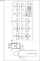
図1は、本技術を適用した測距モジュールの一実施の形態の構成例を示すブロック図である。
<Configuration example of ranging module>
FIG. 1 is a block diagram showing a configuration example of an embodiment of a ranging module to which the present technology is applied.
図1に示すように、測距モジュール11は、発光部12、発光制御部13、受光部14、および測距演算処理部15を備えて構成される。例えば、測距モジュール11は、物体に対して光を照射し、その光(照射光)が物体で反射した光(反射光)を受光して、物体までの距離を表すデプスを測定する。
As shown in FIG. 1, the
発光部12は、発光制御部13による制御に従って、発光制御部13から供給される発光制御信号に応じたタイミングで変調しながら発光し、物体に対して照射光を照射する。
The
発光制御部13は、所定の周波数(例えば、20MHzなど)の発光制御信号を発光部12に供給し、発光部12の発光を制御する。また、発光部12における発光のタイミングに合わせて受光部14を駆動させるために、発光制御部13は、受光部14にも発光制御信号を供給する。
The light
受光部14は、複数の画素がアレイ状に配置されたセンサ面で、物体からの反射光を受光する。そして、受光部14は、それぞれの画素が受光した反射光の受光量に応じた検出信号で構成される画像データを、測距演算処理部15に供給する。
The
測距演算処理部15は、受光部14から供給される画像データに基づいて、測距モジュール11から物体までのデプスを求める演算を行う。そして、測距演算処理部15は、物体までのデプスが画素ごとに表されたデプスマップと、それぞれのデプスに対する信頼度が画素ごとに表された信頼度マップとを生成して、図示しない後段の制御ユニット(例えば、図25のアプリケーション処理部121やオペレーションシステム処理部122など)へ出力する。なお、測距演算処理部15の詳細な構成については、図12を参照して後述する。
The distance measurement
また、受光部14には、複数の画素回路21がアレイ状に配置された画素アレイ部22が設けられており、画素アレイ部22の周辺領域に駆動制御回路23が配置されている。画素アレイ部22は、反射光を受光するセンサ面である。駆動制御回路23は、例えば、発光制御部13から供給される発光制御信号などに基づいて、画素回路21の駆動を制御するための制御信号(例えば、後述する振り分け信号DIMIXや、選択信号ADDRESS DECODE、リセット信号RSTなど)を出力する。
Further, the
画素回路21は、1つのフォトダイオード31で発生した電荷がタップ32Aおよびタップ32Bに振り分けられるように構成されている。そして、フォトダイオード31で発生した電荷のうち、タップ32Aに振り分けられた電荷が信号線33Aから読み出されて検出信号Aとして用いられ、タップ32Bに振り分けられた電荷が信号線33Bから読み出されて検出信号Bとして用いられる。
The
タップ32Aは、転送トランジスタ41A、FD(Floating Diffusion)部42A、選択トランジスタ43A、およびリセットトランジスタ44Aにより構成される。同様に、タップ32Bは、転送トランジスタ41B、FD部42B、選択トランジスタ43B、およびリセットトランジスタ44Bにより構成される。
The
図2を参照して、画素回路21における電荷の振り分けについて説明する。
With reference to FIG. 2, the distribution of electric charges in the
図2に示すように、照射時間Tで照射のオン/オフを繰り返すように変調(1周期=2T)された照射光が発光部12から出力され、物体までの距離に応じた遅延時間TRTだけ遅れて、フォトダイオード31において反射光が受光される。また、振り分け信号DIMIX_Aは、転送トランジスタ41Aのオン/オフを制御し、振り分け信号DIMIX_Bは、転送トランジスタ41Bのオン/オフを制御する。図示するように、振り分け信号DIMIX_Aが、照射光と同一の位相である一方で、振り分け信号DIMIX_Bは、振り分け信号DIMIX_Aを反転した位相となっている。
As shown in FIG. 2, the irradiation light modulated (1 cycle = 2T) so as to repeat the irradiation on / off at the irradiation time T is output from the
従って、フォトダイオード31が反射光を受光することにより発生する電荷は、振り分け信号DIMIX_Aに従って転送トランジスタ41Aがオンとなっている間ではFD部42Aに転送され、振り分け信号DIMIX_Bに従って転送トランジスタ41Bのオンとなっている間ではFD部42Bに転送される。これにより、照射時間Tの照射光の照射が周期的に行われる所定の期間において、転送トランジスタ41Aを介して転送された電荷はFD部42Aに順次蓄積され、転送トランジスタ41Bを介して転送された電荷はFD部42Bに順次蓄積される。
Therefore, the electric charge generated by the
そして、電荷を蓄積する期間の終了後、選択信号ADDRESS DECODE_Aに従って選択トランジスタ43Aがオンとなると、FD部42Aに蓄積されている電荷が信号線33Aを介して読み出され、その電荷量に応じた検出信号Aが受光部14から出力される。同様に、選択信号ADDRESS DECODE_Bに従って選択トランジスタ43Bがオンとなると、FD部42Bに蓄積されている電荷が信号線33Bを介して読み出され、その電荷量に応じた検出信号Bが受光部14から出力される。また、FD部42Aに蓄積されている電荷は、リセット信号RST_Aに従ってリセットトランジスタ44Aがオンになると排出され、FD部42Bに蓄積されている電荷は、リセット信号RST_Bに従ってリセットトランジスタ44Bがオンになると排出される。
Then, when the
このように、画素回路21は、フォトダイオード31が受光した反射光により発生する電荷を、遅延時間TRTに応じてタップ32Aおよびタップ32Bに振り分けて、検出信号Aおよび検出信号Bを出力することができる。そして、遅延時間TRTは、発光部12で発光した光が物体まで飛行し、物体で反射した後に受光部14まで飛行する時間に応じたもの、即ち、物体までの距離に応じたものである。従って、測距モジュール11は、検出信号Aおよび検出信号Bに基づき、遅延時間TRTに従って物体までの距離(デプス)を求めることができる。
In this way, the
ところで、測距モジュール11では、個々の画素回路21が有するフォトダイオード31などの各素子の特性のズレによって、画素回路21ごとに異なる影響が検出信号Aおよび検出信号Bに与えられることになる。従って、一般的に、位相の異なる照射光が用いられ、複数回、それぞれの位相の照射光による反射光から検出される検出信号Aおよび検出信号Bに基づいて、個々の特性のズレによる影響を打ち消すような演算が行われる。
By the way, in the
ここで、図3乃至図9を参照して、従来、タップ32Aとタップ32Bとの特性のズレによる影響を打ち消すために必要としている検出信号について説明する。
Here, with reference to FIGS. 3 to 9, a detection signal conventionally required for canceling the influence of the difference in characteristics between the
例えば、図3に示すように、90°ごとに位相が遅れた4通りの照射光が用いられる。即ち、位相遅れ0°の照射光を基準として、位相遅れ90°の照射光、位相遅れ180°の照射光、および、位相遅れ270°の照射光を用いて、それぞれ検出信号Aおよび検出信号Bを検出する期間(quad)が4回設けられる。 For example, as shown in FIG. 3, four types of irradiation light whose phases are delayed by 90 ° are used. That is, the detection signal A and the detection signal B are used with the irradiation light having a phase delay of 0 ° as a reference, the irradiation light having a phase delay of 90 °, the irradiation light having a phase delay of 180 °, and the irradiation light having a phase delay of 270 °, respectively. The period (quad) for detecting is provided four times.
即ち、図4に示すように、例えば、位相遅れ0°の照射光による反射光を検出する検出期間Q0、位相遅れ90°の照射光による反射光を検出する検出期間Q1、位相遅れ180°の照射光による反射光を検出する検出期間Q2、および、位相遅れ270°の照射光による反射光を検出する検出期間Q3が連続的に設けられる。また、検出期間Q0、検出期間Q1、検出期間Q2、および検出期間Q3では、電荷をリセットするリセット期間、電荷を蓄積するインテグレーション期間、電荷を読み出すリードアウト期間がそれぞれ設けられている。 That is, as shown in FIG. 4, for example, the detection period Q0 for detecting the reflected light due to the irradiation light with a phase delay of 0 °, the detection period Q1 for detecting the reflected light due to the irradiation light with a phase delay of 90 °, and the phase delay of 180 °. A detection period Q2 for detecting the reflected light due to the irradiation light and a detection period Q3 for detecting the reflected light due to the irradiation light having a phase delay of 270 ° are continuously provided. Further, in the detection period Q0, the detection period Q1, the detection period Q2, and the detection period Q3, a reset period for resetting the electric charge, an integration period for accumulating the electric charge, and a read-out period for reading the electric charge are provided.
そして、検出期間Q0、検出期間Q1、検出期間Q2、および検出期間Q3からなる検出期間と、その後の待機期間(dead time / idle time)とにより、1枚のデプスマップを出力するための1デプスフレームが構成される。このような1デプスフレームが繰り返され、フレーム番号tのデプスフレーム、フレーム番号t+1のデプスフレーム、フレーム番号t+2のデプスフレームのように、所定のフレームレートで連続的にデプスフレームが出力される。
Then, one depth for outputting one depth map is determined by the detection period consisting of the detection period Q0, the detection period Q1, the detection period Q2, and the detection period Q3, and the subsequent waiting period (dead time / idle time). The frame is composed. Such one depth frame is repeated, and depth frames are continuously output at a predetermined frame rate, such as a depth frame having a frame number t, a depth frame having a frame number t + 1, and a depth frame having a frame
図5には、検出期間Q0における照射光、反射光、振り分け信号DIMIX_AおよびDIMIX_B、並びに、検出信号AおよびBの一例が示されている。図5に示すように、遅延時間TRTに応じた電荷量でタップ32Aおよびタップ32Bに電荷が振り分けられ、インテグレーション期間において電荷がそれぞれ蓄積される。その後、リードアウト期間において、それぞれインテグレーション期間で蓄積された電荷量の電荷が読み出されて、検出期間Q0における検出信号A0および検出信号B0が出力される。
FIG. 5 shows an example of the irradiation light, the reflected light, the distribution signals DIMIX_A and DIMIX_B, and the detection signals A and B in the detection period Q0. As shown in FIG. 5, the electric charge is distributed to the
図6には、検出期間Q1における照射光、反射光、振り分け信号DIMIX_AおよびDIMIX_B、並びに、検出信号AおよびBの一例が示されている。図6に示すように、遅延時間TRTに応じた電荷量でタップ32Aおよびタップ32Bに電荷が振り分けられ、インテグレーション期間において電荷がそれぞれ蓄積される。その後、リードアウト期間において、それぞれインテグレーション期間で蓄積された電荷量の電荷が読み出されて、検出期間Q1における検出信号A90および検出信号B90が出力される。
FIG. 6 shows an example of the irradiation light, the reflected light, the distribution signals DIMIX_A and DIMIX_B, and the detection signals A and B in the detection period Q1. As shown in FIG. 6, the electric charge is distributed to the
図7には、検出期間Q2における照射光、反射光、振り分け信号DIMIX_AおよびDIMIX_B、並びに、検出信号AおよびBの一例が示されている。図7に示すように、遅延時間TRTに応じた電荷量でタップ32Aおよびタップ32Bに電荷が振り分けられ、インテグレーション期間において電荷がそれぞれ蓄積される。その後、リードアウト期間において、それぞれインテグレーション期間で蓄積された電荷量の電荷が読み出されて、検出期間Q2における検出信号A180および検出信号B180が出力される。
FIG. 7 shows an example of the irradiation light, the reflected light, the distribution signals DIMIX_A and DIMIX_B, and the detection signals A and B in the detection period Q2. As shown in FIG. 7, the electric charge is distributed to the
図8には、検出期間Q3における照射光、反射光、振り分け信号DIMIX_AおよびDIMIX_B、並びに、検出信号AおよびBの一例が示されている。図8に示すように、遅延時間TRTに応じた電荷量でタップ32Aおよびタップ32Bに電荷が振り分けられ、インテグレーション期間において電荷がそれぞれ蓄積される。その後、リードアウト期間において、それぞれインテグレーション期間で蓄積された電荷量の電荷が読み出されて、検出期間Q3における検出信号A270および検出信号B270が出力される。
FIG. 8 shows an example of the irradiation light, the reflected light, the distribution signals DIMIX_A and DIMIX_B, and the detection signals A and B in the detection period Q3. As shown in FIG. 8, the electric charge is distributed to the
このように、検出期間Q0では位相遅れ0°の照射光を用いて検出信号A0および検出信号B0が検出され、検出期間Q1では位相遅れ90°の照射光を用いて検出信号A90および検出信号B90が検出される。同様に、検出期間Q2では位相遅れ180°の照射光を用いて検出信号A180および検出信号B180が検出され、検出期間Q3では位相遅れ270°の照射光を用いて検出信号A270および検出信号B270が検出される。 As described above, in the detection period Q0, the detection signal A0 and the detection signal B0 are detected using the irradiation light having a phase delay of 0 °, and in the detection period Q1, the detection signal A90 and the detection signal B90 are detected using the irradiation light having a phase delay of 90 °. Is detected. Similarly, in the detection period Q2, the detection signal A180 and the detection signal B180 are detected using the irradiation light with a phase delay of 180 °, and in the detection period Q3, the detection signal A270 and the detection signal B270 are detected using the irradiation light with a phase delay of 270 °. Detected.
ここで、図9には、位相遅れを横軸とし、信号の強度(Intensity)を縦軸としたときの、検出信号A0乃至A270および検出信号B0乃至B270の関係が示されている。 Here, FIG. 9 shows the relationship between the detection signals A0 to A270 and the detection signals B0 to B270 when the phase lag is on the horizontal axis and the signal intensity is on the vertical axis.
そして、検出信号A0および検出信号B0の関係、検出信号A90および検出信号B90の関係、検出信号A180および検出信号B180の関係、並びに、検出信号A270および検出信号B270の関係は、次の式(1)に示すようにモデル化される。 The relationship between the detection signal A0 and the detection signal B0, the relationship between the detection signal A90 and the detection signal B90, the relationship between the detection signal A180 and the detection signal B180, and the relationship between the detection signal A270 and the detection signal B270 are as follows (1). ) Is modeled.

このようなモデル化を行って、この式(1)からオフセットOffset、ゲインGain、および角度θを求めることで、例えば、タップ32Aとタップ32Bとの特性のズレによる影響をキャンセルした測距を行うことができる。即ち、タップ32Aとタップ32BとにおけるオフセットOffsetおよびゲインGainの違いを打ち消すために、4回の検出期間Q0乃至Q3で検出される8つの検出信号(検出信号A0乃至A270および検出信号B0乃至B270)が必要とされる。
By performing such modeling and obtaining the offset Offset, the gain Gain, and the angle θ from this equation (1), for example, distance measurement is performed by canceling the influence of the characteristic deviation between the
このように、従来、タップ32Aとタップ32Bとの特性のズレによる影響をキャンセルした測距を行うために、検出信号A0乃至A270および検出信号B0乃至B270を検出する必要があった。
As described above, conventionally, it has been necessary to detect the detection signals A0 to A270 and the detection signals B0 to B270 in order to perform distance measurement in which the influence of the difference in characteristics between the
これに対し、測距モジュール11では、タップ32Aのオフセットおよびゲインと、タップ32Bのオフセットおよびゲインとを求め、それらのズレを補償する。これにより、測距モジュール11は、2回の検出期間Q0およびQ1(または検出期間Q2およびQ3)それぞれで検出信号Aと検出信号Bとを検出するだけで、タップ32Aとタップ32Bとの特性のズレによる影響をキャンセルした測距を行うことができる。
On the other hand, in the
例えば、タップ32AのオフセットOffset_AおよびゲインGain_A、並びに、タップ32BのオフセットOffset_BおよびゲインGain_Bには、次の式(2)に示すような関係がある。
For example, the offset Offset_A and the gain Gain_A of the

ここで、オフセットOffset_AおよびOffset_Bについては、画素回路21ごとに固定の値となり、事前に求めることができる。一方、ゲインGain_AおよびGain_Bについては、画素回路21の構造によっては光の入射角に従って変動することがあるため、デプスフレームごとに算出する必要がある。
Here, the offset Offset_A and Offset_B are fixed values for each
即ち、測距モジュール11では、事前に、または、測距を行う初期の処理で、検出信号A0乃至A270および検出信号B0乃至B270を検出し、次の式(3)に示す連立方程式を解くことで、オフセットOffset_AおよびOffset_Bが求められる。
That is, the

そして、測距モジュール11では、オフセットOffset_AおよびOffset_Bがオフセットパラメータとして格納される。
Then, in the
その後、測距モジュール11では、検出信号A0、検出信号B0、検出信号A90、および検出信号B90が検出されたタイミングで、次の式(4)に示すようなゲインパラメータ(Gain_A / Gain_B)が求められる。
After that, in the

また、測距モジュール11では、検出信号A180およびA270並びに検出信号B180およびB270が検出されたタイミングで、次の式(5)に示すようなゲインパラメータ(Gain_A / Gain_B)が求められる。
Further, in the

従って、測距モジュール11では、検出信号A0、検出信号B0、検出信号A90、および検出信号B90が検出されたタイミングで、次の式(6)に従って、オフセットパラメータ(Offset_A , Offset_B)およびゲインパラメータ(Gain_A / Gain_B)を用いた補正を施すことができる。
Therefore, in the

これにより、測距モジュール11では、検出信号Aを基準とする場合には、補正検出信号A’180およびA’270が求められ、検出信号Bを基準とする場合には、補正検出信号B’180およびB’270が求められる。
As a result, in the ranging
即ち、図10に示すように、検出信号B0に対する補正により補正検出信号A’180が求められるとともに、検出信号B90に対する補正により補正検出信号A’270が求められる。または、検出信号A0に対する補正により補正検出信号B’180が求められるとともに、検出信号A90に対する補正により補正検出信号B’270が求められる。 That is, as shown in FIG. 10, the correction detection signal A'180 is obtained by the correction for the detection signal B0, and the correction detection signal A'270 is obtained by the correction for the detection signal B90. Alternatively, the correction detection signal B'180 is obtained by the correction for the detection signal A0, and the correction detection signal B'270 is obtained by the correction for the detection signal A90.
従って、測距モジュール11は、検出信号A0、検出信号A90、補正検出信号A’180、および補正検出信号A’270を用い、タップ32Aとタップ32Bとの特性のズレによる影響をキャンセルして、デプスと信頼度とを求めることができる。または、測距モジュール11は、検出信号B0、検出信号B90、補正検出信号B’180、および補正検出信号B’270を用い、タップ32Aとタップ32Bとの特性のズレによる影響をキャンセルして、デプスと信頼度とを求めることができる。
Therefore, the ranging
同様に、測距モジュール11では、検出信号A180、検出信号B270、検出信号A180、および検出信号B270が検出されたタイミングで、次の式(7)に従って、オフセットパラメータ(Offset_A , Offset_B)およびゲインパラメータ(Gain_A / Gain_B)を用いた補正を施すことができる。
Similarly, in the

これにより、測距モジュール11では、検出信号Aを基準とする場合には、補正検出信号A’0およびA’90が求められ、検出信号Bを基準とする場合には、補正検出信号B’0およびB’90が求められる。
As a result, in the ranging
従って、測距モジュール11は、補正検出信号A’0、補正検出信号A’90、検出信号A180、および検出信号A270を用い、タップ32Aとタップ32Bとの特性のズレによる影響をキャンセルして、デプスと信頼度とを求めることができる。または、測距モジュール11は、補正検出信号B’0、補正検出信号B’90、検出信号B180、および検出信号B270を用い、タップ32Aとタップ32Bとの特性のズレによる影響をキャンセルして、デプスと信頼度とを求めることができる。
Therefore, the ranging
このように、測距モジュール11では、オフセットパラメータ(Offset_A , Offset_B)を事前に求め、ゲインパラメータ(Gain_A / Gain_B)をデプスフレームごとに求めることにより、タップ32Aとタップ32Bとの特性のズレによる影響をキャンセルした測距が行われる。
In this way, in the ranging
例えば、図11に示すように、測距モジュール11は、2回の検出期間Q0およびQ1において、4つの検出信号(検出信号A0、検出信号B0、検出信号A90、および検出信号B90)を検出して、フレーム番号tのデプスフレームを出力する。続けて、測距モジュール11は、2回の検出期間Q2およびQ3において、4つの検出信号(検出信号A180、検出信号B180、検出信号A270、および検出信号B270)を検出して、フレーム番号t+1のデプスフレームを出力する。
For example, as shown in FIG. 11, the
従って、図4を参照して上述したような4回の検出期間Q0乃至Q3により1デプスフレームが出力されるような測距方法と比較して、測距モジュール11は、1デプスフレームを出力するのに必要となる時間を半分に短縮することができる。即ち、測距モジュール11は、従来よりもフレームレートを2倍とすることができる。
Therefore, the
<測距演算処理部の構成例>
図12は、測距演算処理部15の第1の構成例を示すブロック図である。
<Configuration example of distance measurement processing unit>
FIG. 12 is a block diagram showing a first configuration example of the distance measurement
測距演算処理部15は、受光部14から画像データとして供給される検出信号A(t)および検出信号B(t)を用いて、フレーム番号tのデプスマップを構成するデプスd(t)と、フレーム番号tの信頼度マップを構成する信頼度c(t)を出力する。
The distance measurement
まず、測距演算処理部15は、位相遅れ0°および90°の照射光で検出される4つの検出信号(検出信号A0(t)、検出信号B0(t)、検出信号A90(t)、および検出信号B90(t))が供給されると、フレーム番号tのデプスフレームのデプスd(t)および信頼度c(t)を出力する。続けて、測距演算処理部15は、位相遅れ180°および270°の照射光で検出される4つの検出信号(検出信号A180(t+1)、検出信号B180(t+1)、検出信号A270(t+1)、および検出信号B270(t+1))が供給されると、フレーム番号t+1のデプスフレームを構成するデプスd(t+1)および信頼度c(t+1)を出力する。
First, the distance measurement
図12に示すように、測距演算処理部15は、補正パラメータ算出部51および測距部52を備えて構成される。補正パラメータ算出部51は、ズレ補正パラメータ計算部61およびズレ補正パラメータ格納部62を有しており、オフセットパラメータおよびオフセットパラメータを算出する。測距部52は、補正演算部71および測距演算部72を有しており、オフセットパラメータおよびオフセットパラメータに基づいて検出信号を補正し、デプスを求める。
As shown in FIG. 12, the distance measurement
ズレ補正パラメータ計算部61は、例えば、測距開始時の数フレームにおいて、次の式(8)を、オフセットOffset_AおよびOffset_Bについて解く。
The deviation correction

これにより、ズレ補正パラメータ計算部61は、オフセットOffset_AおよびOffset_Bを求めて、ズレ補正パラメータ格納部62に格納する。なお、オフセットOffset_AおよびOffset_Bついては、例えば、測距モジュール11の検査時などにおいて事前に求めておき、測距モジュール11の出荷時にはズレ補正パラメータ格納部62に格納されているようにしてもよい。
As a result, the deviation correction
そして、ズレ補正パラメータ計算部61は、位相遅れ0°および90°の照射光で検出される4つの検出信号(検出信号A0(t)、検出信号B0(t)、検出信号A90(t)、および検出信号B90(t))が供給されると、次の式(9)を計算する。これにより、ズレ補正パラメータ計算部61は、ゲインパラメータ(Gain_A / Gain_B(t))を求めて、測距部52の補正演算部71に供給する。
Then, the deviation correction

続けて、ズレ補正パラメータ計算部61は、位相遅れ180°および270°の照射光で検出される4つの検出信号(検出信号A180(t+1)、検出信号B180(t+1)、検出信号A270(t+1)、および検出信号B270(t+1))が供給されると、次の式(10)を計算する。これにより、ズレ補正パラメータ計算部61は、ゲインパラメータ(Gain_A / Gain_B(t+1))を求めて、測距部52の補正演算部71に供給する。
Subsequently, the deviation correction

ズレ補正パラメータ格納部62は、ズレ補正パラメータ計算部61により計算されたオフセットパラメータ(Offset_A , Offset_B)を格納し、測距部52の補正演算部71に供給する。なお、ズレ補正パラメータ計算部61は、画素回路21ごとにゲインパラメータおよびオフセットパラメータを求め、ズレ補正パラメータ格納部62は、画素回路21ごとにオフセットパラメータを保持する。
The deviation correction
補正演算部71には、位相遅れ0°および90°の照射光で検出される4つの検出信号(検出信号A0(t)、検出信号B0(t)、検出信号A90(t)、および検出信号B90(t))が供給されるタイミングで、ズレ補正パラメータ計算部61からゲインパラメータ(Gain_A / Gain_B(t))が供給される。従って、このタイミングで、補正演算部71は、次の式(11)に示す演算を行うことで、補正検出信号A’180(t)およびA’270(t)、または、補正検出信号B’180(t)およびB’270(t)を求めることができる。
The

これにより、補正演算部71は、位相遅れ0°および90°の照射光で検出される4つの検出信号が供給されるタイミングで、補正検出信号A’180(t)およびA’270(t)、または、補正検出信号B’180(t)およびB’270(t)を測距演算部72に供給する。
As a result, the
続けて、補正演算部71には、位相遅れ180°および270°の照射光で検出される4つの検出信号(検出信号A180(t+1)、検出信号B180(t+1)、検出信号A270(t+1)、および検出信号B270(t+1))が供給されるタイミングで、ズレ補正パラメータ計算部61からゲインパラメータ(Gain_A / Gain_B(t+1))が供給される。従って、このタイミングで、補正演算部71は、次の式(12)に示す演算を行うことで、補正検出信号A’0(t+1)およびA’90(t+1)、または、補正検出信号B’0(t+1)およびB’90(t+1)を求めることができる。
Subsequently, the

これにより、補正演算部71は、位相遅れ180°および270°の照射光で検出される4つの検出信号が供給されるタイミングで、補正検出信号A’0(t+1)およびA’90(t+1)、または、補正検出信号B’0(t+1)およびB’90(t+1)を測距演算部72に供給する。
As a result, the
測距演算部72には、位相遅れ0°および90°の照射光で検出される4つの検出信号(検出信号A0(t)、検出信号B0(t)、検出信号A90(t)、および検出信号B90(t))が供給されるタイミングで、補正演算部71から補正検出信号A’180(t)およびA’270(t)、または、補正検出信号B’180(t)およびB’270(t)が供給される。そして、測距演算部72は、次の式(13)に示す演算を行うことで、フレーム番号tのデプスフレームのデプスd(t)および信頼度c(t)を求めることができる。
The distance

但し、測距演算部72は、この式(13)において、D0(t)=A0(t) , D2(t)=A'180(t) , D1(t)=A90(t) , D3(t)=A'270(t)、および、D2(t)=B'180(t) , D0(t)=B0(t) , D1(t)=B'270(t) , D3(t)=B90(t)のうちの、どちらか一方を用いることができる。または、測距演算部72は、この式(13)において、D0(t)=A0(t) , D2(t)=A'180(t) , D1(t)=A90(t) , D3(t)=A'270(t)と、D2(t)=B'180(t) , D0(t)=B0(t) , D1(t)=B'270(t) , D3(t)=B90(t)との平均を用いてもよい。
However, in this equation (13), the
続いて、測距演算部72には、位相遅れ180°および270°の照射光で検出される4つの検出信号(検出信号A180(t+1)、検出信号B180(t+1)、検出信号A270(t+1)、および検出信号B270(t+1))が供給されるタイミングで、補正演算部71から補正検出信号A’0(t+1)およびA’90(t+1)、または、補正検出信号B’0(t+1)およびB’90(t+1)が供給される。そして、測距演算部72は、次の式(14)に示す演算を行うことで、フレーム番号t+1のデプスフレームのデプスd(t+1)および信頼度c(t+1)を求めることができる。
Subsequently, the distance measuring

但し、測距演算部72は、この式(14)において、D2(t+1)=A180(t+1) , D0(t+1)=A'0(t+1) , D3(t+1)=A270(t+1) , D1(t+1)=A'90(t+1)、および、D0(t+1)=B'0(t+1) , D2(t+1)=B180(t+1) , D1(t+1)=B'90(t+1) , D3(t+1)=B270(t+1)のうちの、どちらか一方を用いることができる。または、測距演算部72は、この式(14)において、D0(t+1)=A0(t+1) , D2(t+1)=A'180(t+1) , D1(t+1)=A90(t+1) , D3(t+1)=A'270(t+1)と、D2(t+1)=B'180(t+1) , D0(t+1)=B0(t+1) , D1(t+1)=B'270(t+1) , D3(t+1)=B90(t+1)との平均を用いてもよい。
However, in this equation (14), the
以上のように構成される測距演算処理部15は、位相遅れ0°および90°の照射光で検出される4つの検出信号からデプスを求めること、または、位相遅れ180°および270°の照射光で検出される4つの検出信号からデプスを求めることができる。従って、例えば、従来のように8つの検出信号からデプスを求める場合と比較して、フレームレートを2倍に向上させることができる。
The ranging
また、測距演算処理部15は、フレームレートを向上させないときには、2回の照射光の発光で済むため、従来のように4回の照射光の発光を行う場合と比較して、消費電力を低下させることができる。さらに、測距演算処理部15は、1デプスフレームを出力するのに検出することが必要な検出信号を、従来の1/2にすることができるので、データ転送帯域の削減を図ることができる。
Further, since the distance measuring
従って、測距演算処理部15を備える測距モジュール11は、従来よりも高性能化を図ることができる。
Therefore, the
<測距演算処理の第1の処理例>
図13は、測距演算処理部15において実行される測距演算処理の第1の処理例を説明するフローチャートである。
<First processing example of distance measurement calculation processing>
FIG. 13 is a flowchart illustrating a first processing example of the distance measurement calculation processing executed by the distance measurement
例えば、図示しない上位の制御ユニットにより測距演算処理を実行するように制御されると処理が開始される。ステップS11において、測距演算処理部15は、位相遅れの異なる2つの照射光それぞれで、2つの検出信号を取得する。即ち、測距演算処理部15は、例えば、位相遅れ0°の照射光で検出される2つの検出信号A0および検出信号B0と、位相遅れ90°の照射光を用いて検出される2つの検出信号A90および検出信号B90とを取得する。または、測距演算処理部15は、例えば、位相遅れ180°の照射光で検出される2つの検出信号A180および検出信号B180と、位相遅れ270°の照射光を用いて検出される2つの検出信号A270および検出信号B270とを取得する。
For example, the processing is started when the distance measurement calculation processing is controlled to be executed by a higher-level control unit (not shown). In step S11, the distance measurement
ステップS12において、ズレ補正パラメータ計算部61は、オフセットパラメータ(Offset_A , Offset_B)がズレ補正パラメータ格納部62に格納済みであるか否かを判定する。
In step S12, the offset correction
ステップS12において、ズレ補正パラメータ計算部61が、オフセットパラメータ(Offset_A , Offset_B)がズレ補正パラメータ格納部62に格納済みでないと判定した場合、処理はステップS13に進む。
If the offset correction
ステップS13において、ズレ補正パラメータ計算部61は、オフセットパラメータ(Offset_A , Offset_B)の計算に必要な、位相遅れの異なる4つの照射光それぞれで、2つの検出信号が取得されているか否かを判定する。例えば、ズレ補正パラメータ計算部61は、検出信号A0乃至A270および検出信号B0乃至B270の8つの検出信号を取得している場合、位相遅れの異なる4つの照射光それぞれで、2つの検出信号が取得されていると判定する。
In step S13, the shift correction
ステップS13において、ズレ補正パラメータ計算部61が、位相遅れの異なる4つの照射光それぞれで、2つの検出信号が取得されていないと判定した場合、処理はステップS11に戻る。例えば、この場合、検出信号A0およびA90並びに検出信号B0およびB90が取得された状態であり、ズレ補正パラメータ計算部61は、次のステップS11で、検出信号A180およびA270並びに検出信号B180およびB270を取得する。
If the shift correction
一方、ステップS13において、ズレ補正パラメータ計算部61が、位相遅れの異なる4つの照射光それぞれで、2つの検出信号が取得されていると判定した場合、処理はステップS14に進む。
On the other hand, if the shift correction
ステップS14において、ズレ補正パラメータ計算部61は、上述した式(3)に示す連立方程式を解くことで、オフセットOffset_AおよびOffset_Bを算出する。
In step S14, the deviation correction
そして、ズレ補正パラメータ計算部61は、オフセットOffset_AおよびOffset_Bをズレ補正パラメータ格納部62に格納した後、処理はステップS15に進む。一方、ステップS12において、ズレ補正パラメータ計算部61が、オフセットパラメータ(Offset_A , Offset_B)がズレ補正パラメータ格納部62に格納済みであると判定した場合、処理はステップS15に進む。
Then, the deviation correction
ステップS15において、ズレ補正パラメータ計算部61は、上述した式(4)または式(5)に従ってゲインパラメータ(Gain_A / Gain_B)を算出する。そして、ズレ補正パラメータ計算部61は、算出したゲインパラメータ(Gain_A / Gain_B)を補正演算部71に供給し、ズレ補正パラメータ格納部62は、格納しているオフセットパラメータ(Offset_A , Offset_B)を補正演算部71に供給する。
In step S15, the deviation correction
ステップS16において、補正演算部71は、ステップS11で取得された4つの検出信号に対する補正演算を行って、4つの補正検出信号を取得し、測距演算部72に供給する。
In step S16, the
例えば、補正演算部71は、ステップS11で検出信号A0およびA90並びに検出信号B0およびB90が取得されている場合、上述した式(6)に従った補正演算を行って、補正検出信号A’180およびA’270、または、補正検出信号B’180およびB’270を取得する。また、補正演算部71は、ステップS11で検出信号A180およびA270並びに検出信号B180およびB270が取得されている場合、上述した式(7)に従った補正演算を行って、補正検出信号A’0およびA’90、または、補正検出信号B’0およびB’90を取得する。
For example, when the detection signals A0 and A90 and the detection signals B0 and B90 are acquired in step S11, the
ステップS17において、測距演算部72は、ステップS11で取得された4つの検出信号と、ステップS16の補正演算により取得された4つの補正検出信号とを用いて、デプスおよび信頼度を算出する。
In step S17, the distance measuring
例えば、ステップS11で検出信号A0およびA90並びに検出信号B0およびB90が取得され、ステップS16で補正検出信号A’180およびA’270、または、補正検出信号B’180およびB’270が取得されているとする。このとき、測距演算部72は、上述した式(13)に示す演算を行うことで、デプスおよび信頼度を算出する。また、ステップS11で検出信号A180およびA270並びに検出信号B180およびB270が取得され、ステップS16で補正検出信号A’0およびA’90、または、補正検出信号B’0およびB’90が取得されているとする。このとき、測距演算部72は、上述した式(14)に示す演算を行うことで、デプスおよび信頼度を算出する。
For example, the detection signals A0 and A90 and the detection signals B0 and B90 are acquired in step S11, and the correction detection signals A'180 and A'270 or the correction detection signals B'180 and B'270 are acquired in step S16. Suppose you are. At this time, the distance measuring
ステップS18において、測距演算処理部15は、例えば、例えば、図示しない上位の制御ユニットによる測距演算処理についての制御に従って、測距を継続するか否かを判定する。
In step S18, the distance measurement
ステップS18において、測距演算処理部15が、測距を継続すると判定した場合、処理はステップS11に戻り、以下、同様の処理が繰り返される。一方、ステップS18において、測距演算処理部15が、測距を継続しないと判定した場合、測距演算処理は終了される。
If the distance measurement
以上のように、測距演算処理部15は、検出信号A0およびA90並びに検出信号B0およびB90を取得して、または、検出信号A180およびA270並びに検出信号B180およびB270を取得して、デプスおよび信頼度を算出することができる。従って、測距演算処理部15は、デプスおよび信頼度の算出に必要な検出信号の検出に要する時間を短くすることができ、例えば、ロバスト性を高めることができる。
As described above, the distance
<測距演算処理部の第2の構成例>
図14は、測距演算処理部15の第2の構成例を示すブロック図である。なお、図14に示す測距演算処理部15Aについて、図12の測距演算処理部15と共通する構成については同一の符号を付し、その詳細な説明は省略する。
<Second configuration example of distance measurement processing unit>
FIG. 14 is a block diagram showing a second configuration example of the distance measurement
即ち、測距演算処理部15Aは、補正パラメータ算出部51および測距部52Aを備えて構成され、補正パラメータ算出部51は、図12の測距演算処理部15と同様に、ズレ補正パラメータ計算部61およびズレ補正パラメータ格納部62を有している。
That is, the distance measurement
測距部52Aは、図12の測距演算処理部15と同様に、補正演算部71および測距演算部72を有する一方で、測距結果格納部73および結果合成部74を有している点で、図12の測距演算処理部15と異なる構成となっている。
The range-finding
また、測距部52Aは、上述したように測距演算部72により求められたデプスd(t)および信頼度c(t)が、測距結果として測距結果格納部73および結果合成部74に供給されるように構成される。そして、測距部52Aは、測距結果格納部73から結果合成部74に1フレーム前の測距結果、即ち、デプスd(t-1)および信頼度c(t-1)が供給されるように構成される。
Further, in the
測距結果格納部73は、測距演算部72から供給されるデプスd(t)および信頼度c(t)を、1フレーム分だけ格納することができ、1フレーム前のデプスd(t-1)および信頼度c(t-1)を結果合成部74に供給する。
The distance measurement result storage unit 73 can store the depth d (t) and the reliability c (t) supplied from the distance
結果合成部74は、測距演算部72から供給されるデプスd(t)および信頼度c(t)と、測距結果格納部73から供給されるデプスd(t-1)および信頼度c(t-1)を合成し、その合成結果として求められるデプスd(t)および信頼度c(t)を出力する。
The
ここで、測距演算部72から測距結果格納部73および結果合成部74に供給されるデプスd(t)および信頼度c(t)をデプスd’(t)および信頼度c’(t)として、結果合成部74による合成結果をデプスd(t)および信頼度c(t)とする。この場合、結果合成部74は、信頼度c’(t)に基づく重みgを用いて、次の式(15)に示すような重み付け演算により測距結果を合成することができる。
Here, the depth d (t) and the reliability c (t) supplied from the distance

このように、測距演算処理部15Aでは、現在のフレームの測距結果と1フレーム前の測距結果との合成(以下、スライドウィンドウとも称する)を行うことにより、SN(Signal Noise)比を向上させて、合成結果を低ノイズ化させることができる。
In this way, the distance measurement
例えば、スライドウィンドウを行わない場合と検出期間Q0乃至Q3が等しい場合、4回の検出期間Q0乃至Q3で検出される8つの検出信号を用いた測距結果と比較して、2回の検出期間Q0乃至Q1で検出される4つの検出信号を用いた測距結果は、SN比が低下することになる。そこで、測距演算処理部15Aでは、スライドウィンドウを行うことで、1フレーム前も含めた8つの検出信号を用いた測距結果を行うことになるので、SN比の低下を抑制することができる。
For example, when the sliding window is not performed and the detection periods Q0 to Q3 are the same, the two detection periods are compared with the distance measurement results using the eight detection signals detected in the four detection periods Q0 to Q3. In the distance measurement result using the four detection signals detected in Q0 to Q1, the SN ratio is lowered. Therefore, in the distance measurement
また、測距演算処理部15Aでは、1デプスフレームにおける検出期間を短縮しても、スライドウィンドウを行うことで、1デプスフレームで検出信号の取得に必要なパワーあたりのSN比(frame × SNR / power)の向上を図ることができる。
Further, in the distance
従って、測距演算処理部15Aは、スライドウィンドウを行うことにより低ノイズ化を図ることができるため、図15に示すように、図4と比較して検出期間Q0乃至Q3を半分の時間にすることができる。即ち、測距演算処理部15Aは、検出信号AおよびBの取得速度を2倍に向上させて、フレームレートを2倍にすることができる。
Therefore, since the distance measurement
ここで、例えば、スライドウィンドウが行われない場合、1デプスフレームについて検出信号の取得に必要なパワーを変更せず、かつ、フレームレートを2倍にする条件では、検出期間Q0乃至Q3が短縮される分だけSN比が低下することになる。これに対し、測距演算処理部15Aでは、1デプスフレームで検出信号の取得に必要なパワーを変えずに、フレームレートを2倍にしても、スライドウィンドウを行うことによって、SN比が低下することを回避することができる。
Here, for example, when the sliding window is not performed, the detection periods Q0 to Q3 are shortened under the condition that the power required for acquiring the detection signal for one depth frame is not changed and the frame rate is doubled. The SN ratio will decrease by that amount. On the other hand, in the distance
または、図16に示すように、図4と同一の時間の検出期間Q0乃至Q3としてフレームレートを変更せず、かつ、SN比を変更させない条件では、1デプスフレームで検出信号の取得に必要なパワーを低下させることができる。即ち、測距演算処理部15Aは、スライドウィンドウを行うことによって、低消費電力化を図ることができる。
Alternatively, as shown in FIG. 16, under the condition that the frame rate is not changed and the SN ratio is not changed during the detection periods Q0 to Q3 at the same time as in FIG. 4, it is necessary to acquire the detection signal in one depth frame. The power can be reduced. That is, the distance measurement
なお、測距演算処理部15Aでは、結果合成部74が、信頼度に基づいた重み付け演算を行って測距結果を合成する処理を行う他、例えば、単純平均により測距結果を合成してもよいし、信頼度以外の基準に基づく重み付けにより測距結果を合成してもよい。
In the distance measurement
さらに、例えば、結果合成部74により測距結果を合成する処理を、図4を参照して上述したような4回の検出期間Q0乃至Q3により1デプスフレームが出力されるような構成に適用してもよい。即ち、2回の検出期間Q0およびQ1により検出される4つの検出信号、または、2回の検出期間Q2およびQ3により検出される4つの検出信号に基づいて、1デプスフレームが出力されるような構成に適用するのに限定されることはない。さらに、例えば、4回の検出期間Q0乃至Q3のうちの1回が行われるごとに、取得済みの3つの検出信号と、新たに取得されたフレームの1つの検出信号とを合成するようにスライドウィンドウを行ってもよい。
Further, for example, the process of synthesizing the distance measurement result by the
<測距演算処理の第2の処理例>
図17は、測距演算処理部15Aにおいて実行される測距演算処理の第2の処理例を説明するフローチャートである。
<Second processing example of distance measurement calculation processing>
FIG. 17 is a flowchart illustrating a second processing example of the distance measurement calculation processing executed by the distance measurement
ステップS21乃至S27において、図13のステップS11乃至S17と同様の処理が行われる。 In steps S21 to S27, the same processing as in steps S11 to S17 of FIG. 13 is performed.
そして、ステップS27では、算出されたデプスおよび信頼度が測距結果格納部73および結果合成部74に供給され、ステップS28において、結果合成部74は、測距結果格納部73に測距結果が格納されているか否かが判定される。
Then, in step S27, the calculated depth and reliability are supplied to the distance measurement result storage unit 73 and the
ステップS28において、結果合成部74が、測距結果格納部73に測距結果が格納されていないと判定した場合、処理はステップS21に戻る。即ち、この場合、測距結果格納部73には1フレーム前のデプスおよび信頼度が格納されておらず、結果合成部74は、測距結果を合成する処理を行わない。
If the
一方、ステップS28において、結果合成部74が、測距結果格納部73に測距結果が格納されていると判定した場合、処理はステップS29に進む。
On the other hand, if the
ステップS29において、結果合成部74は、1フレーム前のデプスおよび信頼度を測距結果格納部73から読み出す。そして、結果合成部74は、ステップS27で供給されたデプスおよび信頼度と、測距結果格納部73から読み出した1フレーム前のデプスおよび信頼度とを、信頼度に基づいた重み付け演算することにより測定結果を合成した合成測距結果を出力する。
In step S29, the
その後、ステップS30において、図13のステップS18と同様の処理が行われ、測距を継続しないと判定された場合、測距演算処理は終了される。 After that, in step S30, the same processing as in step S18 of FIG. 13 is performed, and when it is determined that the distance measurement is not continued, the distance measurement calculation processing is terminated.
以上のように、測距演算処理部15Aは、信頼度に基づいた重み付け演算により測定結果を合成することで、測定結果のSN比の低減を図ることができ、より正確な測距を行うことができる。また、測距演算処理部15Aは、フレームレートの向上(図15参照)、または、消費電力の低減(図16参照)を図ることができる。
As described above, the distance measurement
<発光部および受光部の動作>
図18乃至図21を参照して、発光部12および受光部14の動作について説明する。
<Operation of light emitting part and light receiving part>
The operation of the
図18には、1枚のデプスマップを出力するための発光および受光のタイミングの一例が示されている。 FIG. 18 shows an example of the timing of light emission and light reception for outputting one depth map.
例えば、測距モジュール11は、デプスマップを出力する1フレームを1サブフレームと設定することができ、1サブフレームが、検出期間Q0、検出期間Q1、検出期間Q2、および検出期間Q3に4分割される。また、検出期間Q0、検出期間Q1、検出期間Q2、および検出期間Q3それぞれのインテグレーション期間において、発光部12は、変調信号に従ったタイミングで照射光を発光し、その反射光を受光部14が受光する。図1を参照して説明したように、振り分け信号DIMIX_AおよびDIMIX_Bに従って、1つのフォトダイオード31で発生した電荷がタップ32Aおよびタップ32Bに振り分けられ、インテグレーション期間において受光した光量に応じた電荷が蓄積される。
For example, the ranging
ここで、上述の図4に示した例では、検出期間Q0、検出期間Q1、検出期間Q2、および検出期間Q3の後に、1デプスフレーム分の待機期間が設けられている。これに対し、図18に示す例では、検出期間Q0、検出期間Q1、検出期間Q2、および検出期間Q3それぞれの後に4分割された待機期間が設けられる。 Here, in the example shown in FIG. 4 above, a waiting period for one depth frame is provided after the detection period Q0, the detection period Q1, the detection period Q2, and the detection period Q3. On the other hand, in the example shown in FIG. 18, a waiting period divided into four is provided after each of the detection period Q0, the detection period Q1, the detection period Q2, and the detection period Q3.
このように、検出期間Q0、検出期間Q1、検出期間Q2、および検出期間Q3ごとに待機期間を設けることで、それぞれのインテグレーション期間の間隔を均等にすることができる。 In this way, by providing a waiting period for each of the detection period Q0, the detection period Q1, the detection period Q2, and the detection period Q3, the intervals of the respective integration periods can be made equal.
即ち、図19に示すように、位相遅れ0°の照射光の発光タイミング、位相遅れ90°の照射光の発光タイミング、位相遅れ180°の照射光の発光タイミング、および位相遅れ270°の照射光の発光タイミングが、等間隔に設定される。このように、互いに等間隔となる発光タイミングを採用することで、例えば、測距演算処理部15Aのようにスライドウィンドウを行う際に、それらの間隔が異なることによる悪影響を抑制することができる。
That is, as shown in FIG. 19, the emission timing of the irradiation light with a phase delay of 0 °, the emission timing of the irradiation light with a phase delay of 90 °, the emission timing of the irradiation light with a phase delay of 180 °, and the irradiation light with a phase delay of 270 °. The light emission timing of is set at equal intervals. In this way, by adopting light emission timings that are evenly spaced from each other, it is possible to suppress adverse effects due to differences in the spacing when performing a sliding window, for example, as in the distance measuring
また、図20に示すような発光タイミングを採用してもよい。上述したように、測距演算処理部15は、4つの検出信号A0、検出信号B0、検出信号A90、および検出信号B90から1デプスフレームを取得し、4つの検出信号A180、検出信号B180、検出信号A270、および検出信号B270から1デプスフレームを取得する。
Further, the light emission timing as shown in FIG. 20 may be adopted. As described above, the distance
従って、図20に示すように、ある1デプスフレームを取得するための位相遅れ0°の照射光の発光タイミングと位相遅れ90°の照射光の発光タイミングとが近接するとともに、次の1デプスフレームを取得するための位相遅れ180°の照射光の発光タイミングと位相遅れ270°の照射光の発光タイミングとが近接することが好ましい。例えば、1デプスフレームを取得するための発光タイミングを近接させることで、物体が動いている場合、その動きにより、発光タイミングが離れていることに与えられる影響を抑制することができる。 Therefore, as shown in FIG. 20, the emission timing of the irradiation light having a phase delay of 0 ° and the emission timing of the irradiation light having a phase delay of 90 ° for acquiring a certain one depth frame are close to each other, and the next one depth frame is formed. It is preferable that the emission timing of the irradiation light having a phase delay of 180 ° and the emission timing of the irradiation light having a phase delay of 270 ° are close to each other. For example, by bringing the light emission timings for acquiring one depth frame close to each other, when the object is moving, it is possible to suppress the influence of the movement on the fact that the light emission timings are separated.
また、測距演算処理部15Aのようにスライドウィンドウを行う際に、ある1デプスフレームを取得するための発光タイミングと、次の1デプスフレームを取得するための発光タイミングとが等間隔となることで、それらの間隔が異なることによる悪影響を抑制することができる。
Further, when the sliding window is performed as in the distance measurement
また、図21に示すような発光タイミングを採用してもよい。即ち、測距演算処理部15は、オフセットOffset_AおよびOffset_Bが事前に求められていれば、位相遅れ0°の照射光と、位相遅れ90°の照射光とだけを用いてデプスフレームを取得することができる。
Further, the light emission timing as shown in FIG. 21 may be adopted. That is, if the offset Offset_A and Offset_B are obtained in advance, the distance measuring
なお、発光部12の発光タイミングは、図18乃至図21に示す例に限定されることなく、その他の様々な発光タイミングを採用することができる。
The light emitting timing of the
<測距演算処理部の第3の構成例>
図22は、測距演算処理部15の第3の構成例を示すブロック図である。
<Third configuration example of distance measurement processing unit>
FIG. 22 is a block diagram showing a third configuration example of the distance measurement
図22に示す測距演算処理部15Bは、検出信号格納部81、動き検知部82、4位相測距演算部83、2位相測距演算部84、測距結果格納部85、および結果合成部86を備えて構成される。
The distance measurement
また、測距演算処理部15Bには、図12を参照して説明したのと同様に、位相遅れ0°および90°の照射光で検出される4つの検出信号が供給されるとともに、位相遅れ180°および270°の照射光で検出される4つの検出信号が供給される。つまり、測距演算処理部15Bには、検出信号A0(t)、検出信号B0(t)、検出信号A90(t)、および検出信号B90(t)が供給され、続けて、検出信号A180(t+1)、検出信号B180(t+1)、検出信号A270(t+1)、および検出信号B270(t+1)が供給される。
Further, as described with reference to FIG. 12, the distance measurement
検出信号格納部81は、4つの検出信号を格納することができ、4つの検出信号が供給されるたびに、格納していた1つ前の4つの検出信号を動き検知部82に供給する。
The detection
即ち、検出信号格納部81は、検出信号A0(t)、検出信号B0(t)、検出信号A90(t)、および検出信号B90(t)が供給されるタイミングでは、検出信号A180(t-1)、検出信号B180(t-1)、検出信号A270(t-1)、および検出信号B270(t-1)を格納しており、それらを動き検知部82に供給する。また、検出信号格納部81は、検出信号A180(t+1)、検出信号B180(t+1)、検出信号A270(t+1)、および検出信号B270(t+1)が供給されるタイミングでは、検出信号A0(t)、検出信号B0(t)、検出信号A90(t)、および検出信号B90(t)を格納しており、それらを動き検知部82に供給する。
That is, at the timing when the detection signal A0 (t), the detection signal B0 (t), the detection signal A90 (t), and the detection signal B90 (t) are supplied, the detection
動き検知部82は、受光部14の画素ごとに被写体の動きを検知し、所定の閾値thに基づいて、動被写体が映されているか否かの判断を行う。
The
即ち、動き検知部82は、検出信号A0(t)、検出信号B0(t)、検出信号A90(t)、および検出信号B90(t)が供給されるタイミングでは、次の式(16)に示す判定条件に従った判断を行う。
That is, at the timing when the detection signal A0 (t), the detection signal B0 (t), the detection signal A90 (t), and the detection signal B90 (t) are supplied, the

例えば、動き検知部82は、式(16)の判定条件が満たされている場合、検出信号A0(t)、検出信号B0(t)、検出信号A90(t)、および検出信号B90(t)に基づいて取得されるデプスフレームには動被写体が映されていないと判断する。この場合、動き検知部82は、動被写体が映されていないことを示す動被写体検出信号M(t)=0を出力し、検出信号A0(t)、検出信号B0(t)、検出信号A90(t)、および検出信号B90(t)を4位相測距演算部83に供給する。さらに、この場合、動き検知部82は、検出信号格納部81から供給される検出信号A180(t-1)、検出信号B180(t-1)、検出信号A270(t-1)、および検出信号B270(t-1)を4位相測距演算部83に供給する。
For example, when the determination condition of the equation (16) is satisfied, the
一方、動き検知部82は、式(16)の判定条件を満たされていない場合、検出信号A0(t)、検出信号B0(t)、検出信号A90(t)、および検出信号B90(t)に基づいて取得されるデプスフレームには動被写体が映されていると判断する。この場合、動き検知部82は、動被写体が映されていることを示す動被写体検出信号M(t)=1を出力し、検出信号A0(t)、検出信号B0(t)、検出信号A90(t)、および検出信号B90(t)を2位相測距演算部84に供給する。
On the other hand, when the
同様に、動き検知部82は、検出信号A180(t+1)、検出信号B180(t+1)、検出信号A270(t+1)、および検出信号B270(t+1)が供給されるタイミングでは、次の式(17)に示す判定条件に従った判断を行う。
Similarly, the

例えば、動き検知部82は、式(17)の判定条件が満たされている場合、検出信号A180(t+1)、検出信号B180(t+1)、検出信号A270(t+1)、および検出信号B270(t+1)に基づいて取得されるデプスフレームには動被写体が映されていないと判断する。この場合、動き検知部82は、動被写体が映されていないことを示す動被写体検出信号M(t)=0を出力し、検出信号A180(t+1)、検出信号B180(t+1)、検出信号A270(t+1)、および検出信号B270(t+1)を4位相測距演算部83に供給する。さらに、この場合、動き検知部82は、検出信号格納部81から供給される検出信号A0(t)、検出信号B0(t)、検出信号A90(t)、および検出信号B90(t)を4位相測距演算部83に供給する。
For example, when the determination condition of the equation (17) is satisfied, the
一方、動き検知部82は、式(17)の判定条件を満たされていない場合、検出信号A180(t+1)、検出信号B180(t+1)、検出信号A270(t+1)、および検出信号B270(t+1)に基づいて取得されるデプスフレームには動被写体が映されていると判断する。この場合、動き検知部82は、動被写体が映されていることを示す動被写体検出信号M(t)=1を出力し、検出信号A180(t+1)、検出信号B180(t+1)、検出信号A270(t+1)、および検出信号B270(t+1)を2位相測距演算部84に供給する。
On the other hand, when the determination condition of the equation (17) is not satisfied, the
4位相測距演算部83は、動き検知部82により動被写体が映されていないと判断された場合に、位相遅れ0°の照射光、位相遅れ90°の照射光、位相遅れ180°の照射光、および位相遅れ270°の照射光により検出される8つの検出信号を用いた演算により測距する処理(以下、4位相測距演算処理と称する)を行う。
When the
例えば、この場合、動き検知部82から4位相測距演算部83に、検出信号A180(t-1)、検出信号B180(t-1)、検出信号A270(t-1)、検出信号B270(t-1)、検出信号A0(t)、検出信号B0(t)、検出信号A90(t)、および検出信号B90(t)が供給される。 For example, in this case, the detection signal A180 (t-1), the detection signal B180 (t-1), the detection signal A270 (t-1), and the detection signal B270 ( t-1), the detection signal A0 (t), the detection signal B0 (t), the detection signal A90 (t), and the detection signal B90 (t) are supplied.
従って、4位相測距演算部83は、次の式(18)に従った演算を行うことにより、デプスd(t)および信頼度c(t)を求め、測距結果格納部85および結果合成部86に供給する。
Therefore, the four-phase ranging

同様に、4位相測距演算部83は、検出信号A0(t)、検出信号B0(t)、検出信号A90(t)、検出信号B90(t)、検出信号A180(t+1)、検出信号B180(t+1)、検出信号A270(t+1)、および検出信号B270(t+1)を用いて、デプスd(t+1)および信頼度c(t+1)を求めることができる。
Similarly, the four-phase ranging
2位相測距演算部84は、図12の測距演算処理部15と同一の機能を備えており、図12に示した補正パラメータ算出部51および測距部52を有している。
The two-phase distance
即ち、2位相測距演算部84は、動き検知部82により動被写体が映されていると判断された場合に、位相遅れ0°の照射光および位相遅れ90°の照射光により検出される4つの検出信号、または、位相遅れ180°の照射光および位相遅れ270°の照射光により検出される4つの検出信号を用いた演算により測距する処理(以下、2位相測距演算処理と称する)を行う。そして、2位相測距演算部84は、2位相測距演算処理を行って求めたデプスdおよび信頼度cを、測距結果格納部85および結果合成部86に供給する。
That is, when the
測距結果格納部85および結果合成部86は、図14の測距結果格納部73および結果合成部74と同一の機能を備えている。即ち、測距結果格納部85は、1フレーム前の測距結果を結果合成部74に供給し、結果合成部86は、現在のフレームの測距結果と1フレーム前の測距結果との合成することができる。
The distance measurement
このように構成される測距演算処理部15Bは、図23に示すように、フレームごとに動き検知の結果に従って、連続する2つのデプスフレームを合成して、1デプスフレームとして出力することができる。
As shown in FIG. 23, the distance measurement
例えば、測距演算処理部15Bは、フレーム番号tのデプスフレームを出力するタイミングで、測距結果が合成される前のフレーム番号t-1の測距結果との動き検知の結果、動被写体が映されている場合には、フレーム番号tの測距結果をそのままデプスフレームとして出力する。一方、測距演算処理部15Bは、フレーム番号tのデプスフレームを出力するタイミングで、測距結果が合成される前のフレーム番号t-1のデプスフレームとの動き検知の結果、動被写体が映されていない場合には、そのフレーム番号t-1の測距結果との合成を行った合成測距結果をフレーム番号tのデプスフレームとして出力する。なお、このようにフレームごとに4位相測距演算部83と2位相測距演算部84との処理を切り替える他、動き検知部82は、画素ごとに動き検知を行い、4位相測距演算部83と2位相測距演算部84との処理の切り替えを画素ごとに行ってもよい。
For example, the distance measurement
以上のように、測距演算処理部15Bは、動き検知の結果に従って、4位相測距演算処理と2位相測距演算処理とを切り替えることができる。従って、測距演算処理部15Bは、例えば、動被写体が映されている場合には2位相測距演算処理を行うことで、より高フレームレートにデプスフレームを求めることで、動被写体に対する測定精度を向上させることができる。これにより、測距演算処理部15Bは、動被写体に対しするロバスト性を向上させることができる。また、測距演算処理部15Bは、動被写体が映されていない場合には4位相測距演算処理を行うことで、より低ノイズ化を図ることができる。なお、動き検知部82は、検出信号から求められる明るさに基づいて条件判断を行ったり、1フレーム前の信頼度に基づいて条件判断を行ったりして、4位相測距演算部83と2位相測距演算部84との処理を切り替えてもよい。
As described above, the range-finding
<測距演算処理の第3の処理例>
図24は、測距演算処理部15Bにおいて実行される測距演算処理の第3の処理例を説明するフローチャートである。
<Third processing example of distance measurement calculation processing>
FIG. 24 is a flowchart illustrating a third processing example of the distance measurement calculation processing executed by the distance measurement
ステップS41において、図13のステップS11と同様の処理が行われ、測距演算処理部15Bは、位相遅れの異なる2つの照射光それぞれで、2つの検出信号を取得する。
In step S41, the same processing as in step S11 of FIG. 13 is performed, and the distance measuring
ステップS42において、動き検知部82は、検出信号が検出信号格納部81に格納済みであるか否かを判定する。
In step S42, the
ステップS42において、動き検知部82が、検出信号が検出信号格納部81に格納済みでないと判定した場合、処理はステップS41に戻る。即ち、この場合、検出信号格納部81には1フレーム前の検出信号が格納されておらず、動き検知部82は、動きを検出する処理を行わない。
If the
一方、ステップS42において、動き検知部82が、検出信号が検出信号格納部81に格納済みであると判定した場合、処理はステップS43に進む。ステップS43において、動き検知部82は、上述した式(16)または式(17)に示す判定条件に従って、動被写体が映されているか否かを判定する。
On the other hand, if the
ステップS43において、動き検知部82が、動被写体が映されていないと判定した場合、処理はステップS44に進む。ステップS44において、4位相測距演算部83は、上述したような4位相測距演算処理を行うことによりデプスおよび信頼度を求めて、測距結果として測距結果格納部85および結果合成部86に供給し、処理はステップS46に進む。
If the
一方、ステップS43において、動き検知部82が、動被写体が映されていると判定した場合、処理はステップS45に進む。ステップS45において、2位相測距演算部84は、上述したような2位相測距演算処理を行うことによりデプスおよび信頼度を求めて、測距結果として測距結果格納部85および結果合成部86に供給し、処理はステップS46に進む。
On the other hand, if the
ステップS46乃至S48において、図17のステップS28乃至S30と同様の処理が行われ、ステップS48において、測距を継続しないと判定された場合、測距演算処理は終了される。 In steps S46 to S48, the same processing as in steps S28 to S30 of FIG. 17 is performed, and when it is determined in step S48 that the distance measurement is not continued, the distance measurement calculation processing is terminated.
以上のように、測距演算処理部15Bは、動き検知の結果に従って、4位相測距演算処理と2位相測距演算処理とを切り替えることで、動被写体に対応して適切な測距を行うことができる。
As described above, the distance
なお、本技術は、Indirect ToF方式の中でもContinuous-Wave方式と称する、物体へ投光する光を振幅変調する方式に適用することができる。また、受光部14のフォトダイオード31の構造としては、CAPD(Current Assisted Photonic Demodulator)構造の深度センサに限定されることはなく、2つのタップ32Aおよびタップ32Bに電荷を振り分ける構造の深度センサに適用することができる。
In addition, this technique can be applied to the continuous-Wave method, which is a method of amplitude-modulating the light projected onto an object among the Indirect ToF methods. Further, the structure of the
また、測距モジュール11から物体に照射される照射光は、上述したような90°ごとに位相が遅れた4通りの照射光以外を用いてよく、それらの照射光に応じて、測距に用いられる検出信号の個数も4つ以外の任意の個数とすることができる。また、補正演算に用いるパラメータも、タップ32Aとタップ32Bとの特性のズレによる影響をキャンセルすることができれば、オフセットパラメータおよびゲインパラメータ以外を採用してもよい。
Further, as the irradiation light emitted from the
<電子機器の構成例>
上述したような測距モジュール11は、例えば、スマートフォンなどの電子機器に搭載することができる。
<Example of electronic device configuration>
The ranging
図25は、電子機器に搭載される撮像装置の構成例を示すブロック図である。 FIG. 25 is a block diagram showing a configuration example of an image pickup device mounted on an electronic device.
図25に示すように、電子機器101は、測距モジュール102、撮像装置103、ディスプレイ104、スピーカ105、マイクロフォン106、通信モジュール107、センサユニット108、タッチパネル109、および制御ユニット110が、バス111を介して接続されて構成される。また、制御ユニット110では、CPUがプログラムを実行することによって、アプリケーション処理部121およびオペレーションシステム処理部122としての機能を備える。
As shown in FIG. 25, in the
測距モジュール102には、図1の測距モジュール11が適用される。例えば、測距モジュール102は、電子機器101の前面に配置され、電子機器101のユーザを対象とした測距を行うことにより、そのユーザの顔や手、指などの表面形状のデプスを測距結果として出力することができる。
The
撮像装置103は、電子機器101の前面に配置され、電子機器101のユーザを被写体とした撮像を行うことにより、そのユーザが写された画像を取得する。なお、図示しないが、電子機器101の背面にも撮像装置103が配置された構成としてもよい。
The
ディスプレイ104は、アプリケーション処理部121およびオペレーションシステム処理部122による処理を行うための操作画面や、撮像装置103が撮像した画像などを表示する。スピーカ105およびマイクロフォン106は、例えば、電子機器101により通話を行う際に、相手側の音声の出力、および、ユーザの音声の収音を行う。
The
通信モジュール107は、通信ネットワークを介した通信を行う。センサユニット108は、速度や加速度、近接などをセンシングし、タッチパネル109は、ディスプレイ104に表示されている操作画面に対するユーザによるタッチ操作を取得する。
The
アプリケーション処理部121は、電子機器101によって様々なサービスを提供するための処理を行う。例えば、アプリケーション処理部121は、測距モジュール102から供給されるデプスに基づいて、ユーザの表情をバーチャルに再現したコンピュータグラフィックスによる顔を作成し、ディスプレイ104に表示する処理を行うことができる。また、アプリケーション処理部121は、測距モジュール102から供給されるデプスに基づいて、例えば、任意の立体的な物体の三次元形状データを作成する処理を行うことができる。
The application processing unit 121 performs processing for providing various services by the
オペレーションシステム処理部122は、電子機器101の基本的な機能および動作を実現するための処理を行う。例えば、オペレーションシステム処理部122は、測距モジュール102から供給されるデプスに基づいて、ユーザの顔を認証し、電子機器101のロックを解除する処理を行うことができる。また、オペレーションシステム処理部122は、測距モジュール102から供給されるデプスに基づいて、例えば、ユーザのジェスチャを認識する処理を行い、そのジェスチャに従った各種の操作を入力する処理を行うことができる。
The operation system processing unit 122 performs processing for realizing the basic functions and operations of the
このように構成されている電子機器101では、上述した測距モジュール11を適用することで、例えば、フレームレートの向上や、消費電力の低減、データ転送帯域の削減を実現することができる。これにより、電子機器101は、より滑らかに動く顔をコンピュータグラフィックスで作成したり、高精度に顔認証を行ったり、バッテリの消費を抑制したり、データ転送を狭帯域で行うことができる。
In the
<コンピュータの構成例>
次に、上述した一連の処理は、ハードウェアにより行うこともできるし、ソフトウェアにより行うこともできる。一連の処理をソフトウェアによって行う場合には、そのソフトウェアを構成するプログラムが、汎用のコンピュータ等にインストールされる。
<Computer configuration example>
Next, the series of processes described above can be performed by hardware or software. When a series of processes is performed by software, the programs constituting the software are installed on a general-purpose computer or the like.
図26は、上述した一連の処理を実行するプログラムがインストールされるコンピュータの一実施の形態の構成例を示すブロック図である。 FIG. 26 is a block diagram showing a configuration example of an embodiment of a computer in which a program for executing the above-mentioned series of processes is installed.
コンピュータにおいて、CPU(Central Processing Unit)201,ROM(Read Only Memory)202,RAM(Random Access Memory)203、およびEEPROM(Electronically Erasable and Programmable Read Only Memory)204は、バス205により相互に接続されている。バス205には、さらに、入出力インタフェース206が接続されており、入出力インタフェース206が外部に接続される。
In a computer, a CPU (Central Processing Unit) 201, a ROM (Read Only Memory) 202, a RAM (Random Access Memory) 203, and an EEPROM (Electronically Erasable and Programmable Read Only Memory) 204 are connected to each other by a bus 205. .. An input /
以上のように構成されるコンピュータでは、CPU201が、例えば、ROM202およびEEPROM204に記憶されているプログラムを、バス205を介してRAM203にロードして実行することにより、上述した一連の処理が行われる。また、コンピュータ(CPU201)が実行するプログラムは、ROM202に予め書き込んでおく他、入出力インタフェース206を介して外部からEEPROM204にインストールしたり、更新したりすることができる。
In the computer configured as described above, the
これにより、CPU201は、上述したフローチャートにしたがった処理、あるいは上述したブロック図の構成により行われる処理を行う。そして、CPU201は、その処理結果を、必要に応じて、例えば、入出力インタフェース206を介して、外部へ出力することができる。
As a result, the
ここで、本明細書において、コンピュータがプログラムに従って行う処理は、必ずしもフローチャートとして記載された順序に沿って時系列に行われる必要はない。すなわち、コンピュータがプログラムに従って行う処理は、並列的あるいは個別に実行される処理(例えば、並列処理あるいはオブジェクトによる処理)も含む。 Here, in the present specification, the processes performed by the computer according to the program do not necessarily have to be performed in chronological order in the order described as the flowchart. That is, the processing performed by the computer according to the program includes processing executed in parallel or individually (for example, processing by parallel processing or processing by an object).
また、プログラムは、1のコンピュータ(プロセッサ)により処理されるものであっても良いし、複数のコンピュータによって分散処理されるものであっても良い。さらに、プログラムは、遠方のコンピュータに転送されて実行されるものであっても良い。 Further, the program may be processed by one computer (processor) or may be distributed processed by a plurality of computers. Further, the program may be transferred to a distant computer and executed.
さらに、本明細書において、システムとは、複数の構成要素(装置、モジュール(部品)等)の集合を意味し、すべての構成要素が同一筐体中にあるか否かは問わない。したがって、別個の筐体に収納され、ネットワークを介して接続されている複数の装置、及び、1つの筐体の中に複数のモジュールが収納されている1つの装置は、いずれも、システムである。 Further, in the present specification, the system means a set of a plurality of components (devices, modules (parts), etc.), and it does not matter whether or not all the components are in the same housing. Therefore, a plurality of devices housed in separate housings and connected via a network, and a device in which a plurality of modules are housed in one housing are both systems. ..
また、例えば、1つの装置(または処理部)として説明した構成を分割し、複数の装置(または処理部)として構成するようにしてもよい。逆に、以上において複数の装置(または処理部)として説明した構成をまとめて1つの装置(または処理部)として構成されるようにしてもよい。また、各装置(または各処理部)の構成に上述した以外の構成を付加するようにしてももちろんよい。さらに、システム全体としての構成や動作が実質的に同じであれば、ある装置(または処理部)の構成の一部を他の装置(または他の処理部)の構成に含めるようにしてもよい。 Further, for example, the configuration described as one device (or processing unit) may be divided and configured as a plurality of devices (or processing units). On the contrary, the configurations described above as a plurality of devices (or processing units) may be collectively configured as one device (or processing unit). Further, of course, a configuration other than the above may be added to the configuration of each device (or each processing unit). Further, if the configuration and operation of the entire system are substantially the same, a part of the configuration of one device (or processing unit) may be included in the configuration of another device (or other processing unit). ..
また、例えば、本技術は、1つの機能を、ネットワークを介して複数の装置で分担、共同して処理するクラウドコンピューティングの構成をとることができる。 Further, for example, the present technology can have a cloud computing configuration in which one function is shared by a plurality of devices via a network and jointly processed.
また、例えば、上述したプログラムは、任意の装置において実行することができる。その場合、その装置が、必要な機能(機能ブロック等)を有し、必要な情報を得ることができるようにすればよい。 Further, for example, the above-mentioned program can be executed in any device. In that case, the device may have necessary functions (functional blocks, etc.) so that necessary information can be obtained.
また、例えば、上述のフローチャートで説明した各ステップは、1つの装置で実行する他、複数の装置で分担して実行することができる。さらに、1つのステップに複数の処理が含まれる場合には、その1つのステップに含まれる複数の処理は、1つの装置で実行する他、複数の装置で分担して実行することができる。換言するに、1つのステップに含まれる複数の処理を、複数のステップの処理として実行することもできる。逆に、複数のステップとして説明した処理を1つのステップとしてまとめて実行することもできる。 Further, for example, each step described in the above-mentioned flowchart can be executed by one device or can be shared and executed by a plurality of devices. Further, when a plurality of processes are included in one step, the plurality of processes included in the one step can be executed by one device or shared by a plurality of devices. In other words, a plurality of processes included in one step can be executed as processes of a plurality of steps. On the contrary, the processes described as a plurality of steps can be collectively executed as one step.
なお、コンピュータが実行するプログラムは、プログラムを記述するステップの処理が、本明細書で説明する順序に沿って時系列に実行されるようにしても良いし、並列に、あるいは呼び出しが行われたとき等の必要なタイミングで個別に実行されるようにしても良い。つまり、矛盾が生じない限り、各ステップの処理が上述した順序と異なる順序で実行されるようにしてもよい。さらに、このプログラムを記述するステップの処理が、他のプログラムの処理と並列に実行されるようにしても良いし、他のプログラムの処理と組み合わせて実行されるようにしても良い。 In the program executed by the computer, the processes of the steps for describing the program may be executed in chronological order in the order described in the present specification, or may be called in parallel or called. It may be executed individually at the required timing such as when. That is, as long as there is no contradiction, the processes of each step may be executed in an order different from the above-mentioned order. Further, the processing of the step for describing this program may be executed in parallel with the processing of another program, or may be executed in combination with the processing of another program.
なお、本明細書において複数説明した本技術は、矛盾が生じない限り、それぞれ独立に単体で実施することができる。もちろん、任意の複数の本技術を併用して実施することもできる。例えば、いずれかの実施の形態において説明した本技術の一部または全部を、他の実施の形態において説明した本技術の一部または全部と組み合わせて実施することもできる。また、上述した任意の本技術の一部または全部を、上述していない他の技術と併用して実施することもできる。 It should be noted that the present techniques described above and below in the present specification can be independently implemented independently as long as there is no contradiction. Of course, any plurality of the present technologies can be used in combination. For example, some or all of the techniques described in any of the embodiments may be combined with some or all of the techniques described in other embodiments. In addition, a part or all of any of the above-mentioned techniques may be carried out in combination with other techniques not described above.
<移動体への応用例>
本開示に係る技術(本技術)は、様々な製品へ応用することができる。例えば、本開示に係る技術は、自動車、電気自動車、ハイブリッド電気自動車、自動二輪車、自転車、パーソナルモビリティ、飛行機、ドローン、船舶、ロボット等のいずれかの種類の移動体に搭載される装置として実現されてもよい。
<Application example to mobile>
The technology according to the present disclosure (the present technology) can be applied to various products. For example, the technology according to the present disclosure is realized as a device mounted on a moving body of any kind such as an automobile, an electric vehicle, a hybrid electric vehicle, a motorcycle, a bicycle, a personal mobility, an airplane, a drone, a ship, and a robot. You may.
図27は、本開示に係る技術が適用され得る移動体制御システムの一例である車両制御システムの概略的な構成例を示すブロック図である。 FIG. 27 is a block diagram showing a schematic configuration example of a vehicle control system, which is an example of a mobile control system to which the technique according to the present disclosure can be applied.
車両制御システム12000は、通信ネットワーク12001を介して接続された複数の電子制御ユニットを備える。図27に示した例では、車両制御システム12000は、駆動系制御ユニット12010、ボディ系制御ユニット12020、車外情報検出ユニット12030、車内情報検出ユニット12040、及び統合制御ユニット12050を備える。また、統合制御ユニット12050の機能構成として、マイクロコンピュータ12051、音声画像出力部12052、及び車載ネットワークI/F(interface)12053が図示されている。
The
駆動系制御ユニット12010は、各種プログラムにしたがって車両の駆動系に関連する装置の動作を制御する。例えば、駆動系制御ユニット12010は、内燃機関又は駆動用モータ等の車両の駆動力を発生させるための駆動力発生装置、駆動力を車輪に伝達するための駆動力伝達機構、車両の舵角を調節するステアリング機構、及び、車両の制動力を発生させる制動装置等の制御装置として機能する。
The drive
ボディ系制御ユニット12020は、各種プログラムにしたがって車体に装備された各種装置の動作を制御する。例えば、ボディ系制御ユニット12020は、キーレスエントリシステム、スマートキーシステム、パワーウィンドウ装置、あるいは、ヘッドランプ、バックランプ、ブレーキランプ、ウィンカー又はフォグランプ等の各種ランプの制御装置として機能する。この場合、ボディ系制御ユニット12020には、鍵を代替する携帯機から発信される電波又は各種スイッチの信号が入力され得る。ボディ系制御ユニット12020は、これらの電波又は信号の入力を受け付け、車両のドアロック装置、パワーウィンドウ装置、ランプ等を制御する。
The body
車外情報検出ユニット12030は、車両制御システム12000を搭載した車両の外部の情報を検出する。例えば、車外情報検出ユニット12030には、撮像部12031が接続される。車外情報検出ユニット12030は、撮像部12031に車外の画像を撮像させるとともに、撮像された画像を受信する。車外情報検出ユニット12030は、受信した画像に基づいて、人、車、障害物、標識又は路面上の文字等の物体検出処理又は距離検出処理を行ってもよい。
The vehicle outside
撮像部12031は、光を受光し、その光の受光量に応じた電気信号を出力する光センサである。撮像部12031は、電気信号を画像として出力することもできるし、測距の情報として出力することもできる。また、撮像部12031が受光する光は、可視光であっても良いし、赤外線等の非可視光であっても良い。
The
車内情報検出ユニット12040は、車内の情報を検出する。車内情報検出ユニット12040には、例えば、運転者の状態を検出する運転者状態検出部12041が接続される。運転者状態検出部12041は、例えば運転者を撮像するカメラを含み、車内情報検出ユニット12040は、運転者状態検出部12041から入力される検出情報に基づいて、運転者の疲労度合い又は集中度合いを算出してもよいし、運転者が居眠りをしていないかを判別してもよい。
The in-vehicle
マイクロコンピュータ12051は、車外情報検出ユニット12030又は車内情報検出ユニット12040で取得される車内外の情報に基づいて、駆動力発生装置、ステアリング機構又は制動装置の制御目標値を演算し、駆動系制御ユニット12010に対して制御指令を出力することができる。例えば、マイクロコンピュータ12051は、車両の衝突回避あるいは衝撃緩和、車間距離に基づく追従走行、車速維持走行、車両の衝突警告、又は車両のレーン逸脱警告等を含むADAS(Advanced Driver Assistance System)の機能実現を目的とした協調制御を行うことができる。
The
また、マイクロコンピュータ12051は、車外情報検出ユニット12030又は車内情報検出ユニット12040で取得される車両の周囲の情報に基づいて駆動力発生装置、ステアリング機構又は制動装置等を制御することにより、運転者の操作に拠らずに自律的に走行する自動運転等を目的とした協調制御を行うことができる。
Further, the
また、マイクロコンピュータ12051は、車外情報検出ユニット12030で取得される車外の情報に基づいて、ボディ系制御ユニット12020に対して制御指令を出力することができる。例えば、マイクロコンピュータ12051は、車外情報検出ユニット12030で検知した先行車又は対向車の位置に応じてヘッドランプを制御し、ハイビームをロービームに切り替える等の防眩を図ることを目的とした協調制御を行うことができる。
Further, the
音声画像出力部12052は、車両の搭乗者又は車外に対して、視覚的又は聴覚的に情報を通知することが可能な出力装置へ音声及び画像のうちの少なくとも一方の出力信号を送信する。図27の例では、出力装置として、オーディオスピーカ12061、表示部12062及びインストルメントパネル12063が例示されている。表示部12062は、例えば、オンボードディスプレイ及びヘッドアップディスプレイの少なくとも一つを含んでいてもよい。
The audio-
図28は、撮像部12031の設置位置の例を示す図である。
FIG. 28 is a diagram showing an example of the installation position of the
図28では、車両12100は、撮像部12031として、撮像部12101,12102,12103,12104,12105を有する。
In FIG. 28, the
撮像部12101,12102,12103,12104,12105は、例えば、車両12100のフロントノーズ、サイドミラー、リアバンパ、バックドア及び車室内のフロントガラスの上部等の位置に設けられる。フロントノーズに備えられる撮像部12101及び車室内のフロントガラスの上部に備えられる撮像部12105は、主として車両12100の前方の画像を取得する。サイドミラーに備えられる撮像部12102,12103は、主として車両12100の側方の画像を取得する。リアバンパ又はバックドアに備えられる撮像部12104は、主として車両12100の後方の画像を取得する。撮像部12101及び12105で取得される前方の画像は、主として先行車両又は、歩行者、障害物、信号機、交通標識又は車線等の検出に用いられる。
The
なお、図28には、撮像部12101ないし12104の撮影範囲の一例が示されている。撮像範囲12111は、フロントノーズに設けられた撮像部12101の撮像範囲を示し、撮像範囲12112,12113は、それぞれサイドミラーに設けられた撮像部12102,12103の撮像範囲を示し、撮像範囲12114は、リアバンパ又はバックドアに設けられた撮像部12104の撮像範囲を示す。例えば、撮像部12101ないし12104で撮像された画像データが重ね合わせられることにより、車両12100を上方から見た俯瞰画像が得られる。
Note that FIG. 28 shows an example of the photographing range of the
撮像部12101ないし12104の少なくとも1つは、距離情報を取得する機能を有していてもよい。例えば、撮像部12101ないし12104の少なくとも1つは、複数の撮像素子からなるステレオカメラであってもよいし、位相差検出用の画素を有する撮像素子であってもよい。
At least one of the
例えば、マイクロコンピュータ12051は、撮像部12101ないし12104から得られた距離情報を基に、撮像範囲12111ないし12114内における各立体物までの距離と、この距離の時間的変化(車両12100に対する相対速度)を求めることにより、特に車両12100の進行路上にある最も近い立体物で、車両12100と略同じ方向に所定の速度(例えば、0km/h以上)で走行する立体物を先行車として抽出することができる。さらに、マイクロコンピュータ12051は、先行車の手前に予め確保すべき車間距離を設定し、自動ブレーキ制御(追従停止制御も含む)や自動加速制御(追従発進制御も含む)等を行うことができる。このように運転者の操作に拠らずに自律的に走行する自動運転等を目的とした協調制御を行うことができる。
For example, the
例えば、マイクロコンピュータ12051は、撮像部12101ないし12104から得られた距離情報を元に、立体物に関する立体物データを、2輪車、普通車両、大型車両、歩行者、電柱等その他の立体物に分類して抽出し、障害物の自動回避に用いることができる。例えば、マイクロコンピュータ12051は、車両12100の周辺の障害物を、車両12100のドライバが視認可能な障害物と視認困難な障害物とに識別する。そして、マイクロコンピュータ12051は、各障害物との衝突の危険度を示す衝突リスクを判断し、衝突リスクが設定値以上で衝突可能性がある状況であるときには、オーディオスピーカ12061や表示部12062を介してドライバに警報を出力することや、駆動系制御ユニット12010を介して強制減速や回避操舵を行うことで、衝突回避のための運転支援を行うことができる。
For example, the
撮像部12101ないし12104の少なくとも1つは、赤外線を検出する赤外線カメラであってもよい。例えば、マイクロコンピュータ12051は、撮像部12101ないし12104の撮像画像中に歩行者が存在するか否かを判定することで歩行者を認識することができる。かかる歩行者の認識は、例えば赤外線カメラとしての撮像部12101ないし12104の撮像画像における特徴点を抽出する手順と、物体の輪郭を示す一連の特徴点にパターンマッチング処理を行って歩行者か否かを判別する手順によって行われる。マイクロコンピュータ12051が、撮像部12101ないし12104の撮像画像中に歩行者が存在すると判定し、歩行者を認識すると、音声画像出力部12052は、当該認識された歩行者に強調のための方形輪郭線を重畳表示するように、表示部12062を制御する。また、音声画像出力部12052は、歩行者を示すアイコン等を所望の位置に表示するように表示部12062を制御してもよい。
At least one of the
以上、本開示に係る技術が適用され得る車両制御システムの一例について説明した。本開示に係る技術は、以上説明した構成のうち、車内情報検出ユニット12040に適用され得る。具体的には、測距モジュール11による測距を利用することで、より正確に運転者の状態を検出することができる。また、測距モジュール11による測距を利用して、運転者のジェスチャを認識する処理を行い、そのジェスチャに従った各種の操作を実行するようにしてもよい。
The example of the vehicle control system to which the technique according to the present disclosure can be applied has been described above. The technique according to the present disclosure can be applied to the in-vehicle
<構成の組み合わせ例>
なお、本技術は以下のような構成も取ることができる。
(1)
所定数の位相の異なる照射光を物体に照射して、前記物体で反射した反射光を受光することにより発生する電荷が、前記物体までの距離に応じて第1のタップと第2のタップとに振り分けられ、前記所定数の照射光について2つずつ検出される前記所定数の2倍の検出信号を全て用いて、前記物体までの距離を表すデプスを求める演算を行う第1の測距演算部と、
前記所定数の2倍の前記検出信号のうち、前段半分の照射光に基づく前記所定数の前記検出信号と、後段半分の照射光に基づく前記所定数の前記検出信号とを交互に用いて、前記物体までの距離を表すデプスを求める演算を行う第2の測距演算部と、
前記検出信号に基づいた条件判断を行い、前記第1の測距演算部および前記第2の測距演算部を切り替えて用いる条件判断部と
を備える測距処理装置。
(2)
第1の位相の照射光の前記反射光が受光される第1の検出期間において、前記第1のタップと前記第2のタップとに交互に電荷が複数振り分けられ、前記第1のタップに振り分けられて蓄積した電荷に応じた第1の検出信号と、前記第2のタップに振り分けられて蓄積した電荷に応じた第2の検出信号とが検出され、
第2の位相の照射光の前記反射光が受光される第2の検出期間において、前記第1のタップと前記第2のタップとに交互に電荷が複数振り分けられ、前記第1のタップに振り分けられて蓄積した電荷に応じた第3の検出信号と、前記第2のタップに振り分けられて蓄積した電荷に応じた第4の検出信号とが検出される
第3の位相の照射光の前記反射光が受光される第3の検出期間において、前記第1のタップと前記第2のタップとに交互に電荷が複数振り分けられ、前記第1のタップに振り分けられて蓄積した電荷に応じた第5の検出信号と、前記第2のタップに振り分けられて蓄積した電荷に応じた第6の検出信号とが検出され、
第4の位相の照射光の前記反射光が受光される第4の検出期間において、前記第1のタップと前記第2のタップとに交互に電荷が複数振り分けられ、前記第1のタップに振り分けられて蓄積した電荷に応じた第7の検出信号と、前記第2のタップに振り分けられて蓄積した電荷に応じた第8の検出信号とが検出される
上記(1)に記載の測距処理装置。
(3)
前記第1の測距演算部は、前記第1の検出信号と前記第2の検出信号との差分、前記第3の検出信号と前記第4の検出信号との差分、前記第5の検出信号と前記第6の検出信号との差分、および前記第7の検出信号と前記第8の検出信号との差分を用いて、前記第1のタップと前記第2のタップとの特性のズレによる影響をキャンセルさせて前記デプスを求める
上記(2)に記載の測距処理装置。
(4)
前記第2の測距演算部は、
前記第1乃至第4の検出信号を用いて前記第1のタップと前記第2のタップとの特性のズレを補正する補正パラメータを算出し、前記第1乃至第4の検出信号と前記補正パラメータに基づいて前記デプスを求めることと、
前記第5乃至第8の検出信号を用いて前記第1のタップと前記第2のタップとの特性のズレを補正する補正パラメータを算出し、前記第5乃至第8の検出信号と前記補正パラメータに基づいて前記デプスを求めることと
を交互に行う
上記(3)に記載の測距処理装置。
(5)
前記第1の測距演算部または前記第2の測距演算部により求められた前記デプスを格納する測距結果格納部と、
前記測距結果格納部に格納された1フレーム前の前記デプスと、現在のフレームの前記デプスとを合成して出力する結果合成部と
をさらに備える上記(1)から(4)までのいずれかに記載の測距処理装置。
(6)
前記第1の測距演算部および前記第2の測距演算部は、前記デプスとともに、前記デプスに対する信頼度を求め、
前記測距結果格納部には、前記デプスとともに前記信頼度が格納され、
前記結果合成部は、前記信頼度に応じた重み付け加算を行うことにより、1フレーム前の前記デプスと、現在のフレームの前記デプスとを合成する
上記(5)に記載の測距処理装置。
(7)
前記結果合成部は、前記第1の測距演算部により前記所定数の前記検出信号を全て用いて求められた1フレーム前の前記デプスと、前記第1の測距演算部により前記所定数の前記検出信号を全て用いて求められた現在のフレームの前記デプスとを合成する
上記(5)または(6)に記載の測距処理装置。
(8)
前記結果合成部は、前記第2の測距演算部により前記前段半分の照射光に基づく前記所定数の前記検出信号を用いて求められたデプスと、前記第2の測距演算部により前記後段半分の照射光に基づく前記所定数の前記検出信号を用いて求められたデプスとのうちの、一方を1フレーム前とし、他方を現在のフレームとして、前記デプスの合成を行う
上記(5)または(6)に記載の測距処理装置。
(9)
前記条件判断部は、前記反射光を受光する受光部の画素ごとに条件判断を行って、前記第1の測距演算部および前記第2の測距演算部により前記デプスを求める演算を前記画素ごとに切り替える
上記(1)から(8)までのいずれかに記載の測距処理装置。
(10)
前記条件判断部は、
前記第1の位相の照射光および前記第2の位相の照射光に基づく4つの前記検出信号と、前記第3の位相の照射光および前記第4の位相の照射光に基づく4つの前記検出信号とを比較することで検知される前記物体の動きに基づいて前記条件判断を行い、
前記物体に動きがあることが検知された場合には、前記第2の測距演算部により前記デプスを求める演算を行い
前記物体に動きがないことが検知された場合には、前記第1の測距演算部により前記デプスを求める演算を行う
上記(2)から(9)までのいずれかに記載の測距処理装置。
(11)
前記条件判断部は、
前記第1の位相の照射光および前記第2の位相の照射光に基づく4つの前記検出信号から求められる明るさと、前記第3の位相の照射光および前記第4の位相の照射光に基づく4つの前記検出信号から求められる明るさとに基づいて前記条件判断を行い、
前記明るさに応じて、前記第1の測距演算部および前記第2の測距演算部を切り替える
上記(2)から(9)までのいずれかに記載の測距処理装置。
(12)
前記4位相測距演算部および前記2位相測距演算部は、前記デプスとともに、前記デプスに対する信頼度を求め、
前記条件判断部は、1フレーム前に求められた前記信頼度に基づいて前記条件判断を行い、前記信頼度に応じて、前記4位相測距演算部および前記2位相測距演算部を切り替える
上記(2)から(9)までのいずれかに記載の測距処理装置。
(13)
前記第1の検出期間、前記第2の検出期間、前記第3の検出期間、前記第4の検出期間が略等間隔に設定される
上記(2)から(12)までのいずれかに記載の測距処理装置。
(14)
所定数の位相の異なる照射光を物体に照射する発光部と、
前記物体で反射した反射光を受光することにより発生する電荷が、前記物体までの距離に応じて第1のタップと第2のタップとに振り分けられ、前記所定数の位相の照射光について2つずつ検出される前記所定数の2倍の検出信号を出力する受光部と、
前記所定数の2倍の前記検出信号を全て用いて、前記物体までの距離を表すデプスを求める演算を行う第1の測距演算部と、
前記所定数の2倍の前記検出信号のうち、前段半分の照射光に基づく前記所定数の前記検出信号と、後段半分の照射光に基づく前記所定数の前記検出信号とを交互に用いて、前記物体までの距離を表すデプスを求める演算を行う第2の測距演算部と、
前記検出信号に基づいた条件判断を行い、前記第1の測距演算部および前記第2の測距演算部を切り替えて用いる条件判断部と
を備える測距モジュール。
(15)
測距処理を行う測距処理装置が、
所定数の位相の異なる照射光を物体に照射して、前記物体で反射した反射光を受光することにより発生する電荷が、前記物体までの距離に応じて第1のタップと第2のタップとに振り分けられ、前記所定数の照射光について2つずつ検出される前記所定数の2倍の検出信号を全て用いて、前記物体までの距離を表すデプスを求める演算を行う第1の測距演算処理を行うことと、
前記所定数の2倍の前記検出信号のうち、前段半分の照射光に基づく前記所定数の前記検出信号と、後段半分の照射光に基づく前記所定数の前記検出信号とを交互に用いて、前記物体までの距離を表すデプスを求める演算を行う第2の測距演処理を行うことと、
前記検出信号に基づいた条件判断を行い、前記第1の測距演算処理および前記第2の測距演算処理を切り替えて用いることと
を含む測距処理方法。
(16)
測距処理を行う測距処理装置のコンピュータに、
所定数の位相の異なる照射光を物体に照射して、前記物体で反射した反射光を受光することにより発生する電荷が、前記物体までの距離に応じて第1のタップと第2のタップとに振り分けられ、前記所定数の照射光について2つずつ検出される前記所定数の2倍の検出信号を全て用いて、前記物体までの距離を表すデプスを求める演算を行う第1の測距演算処理を行うことと、
前記所定数の2倍の前記検出信号のうち、前段半分の照射光に基づく前記所定数の前記検出信号と、後段半分の照射光に基づく前記所定数の前記検出信号とを交互に用いて、前記物体までの距離を表すデプスを求める演算を行う第2の測距演処理を行うことと、
前記検出信号に基づいた条件判断を行い、前記第1の測距演算処理および前記第2の測距演算処理を切り替えて用いることと
を含む測距処理を実行させるためのプログラム。
<Example of configuration combination>
The present technology can also have the following configurations.
(1)
The charge generated by irradiating an object with a predetermined number of irradiation lights having different phases and receiving the reflected light reflected by the object is the first tap and the second tap according to the distance to the object. A first ranging operation that performs an operation to obtain a depth representing the distance to the object by using all the detection signals that are twice the predetermined number and are detected for each of the predetermined number of irradiation lights. Department and
Of the detection signals that are twice the predetermined number, the predetermined number of the detection signals based on the irradiation light of the first half and the predetermined number of the detection signals based on the irradiation light of the latter half are alternately used. A second ranging calculation unit that performs an operation to obtain the depth representing the distance to the object, and
A distance measurement processing device including a condition determination unit that makes a condition determination based on the detection signal and switches between the first distance measurement calculation unit and the second distance measurement calculation unit.
(2)
In the first detection period in which the reflected light of the irradiation light of the first phase is received, a plurality of charges are alternately distributed to the first tap and the second tap, and the charges are distributed to the first tap. A first detection signal corresponding to the accumulated charge and a second detection signal corresponding to the accumulated charge distributed to the second tap are detected.
In the second detection period in which the reflected light of the irradiation light of the second phase is received, a plurality of charges are alternately distributed to the first tap and the second tap, and the charges are distributed to the first tap. The reflection of the irradiation light of the third phase in which the third detection signal corresponding to the accumulated charge and the fourth detection signal corresponding to the accumulated charge distributed to the second tap are detected. In the third detection period in which light is received, a plurality of electric charges are alternately distributed to the first tap and the second tap, and a fifth charge corresponding to the electric charges distributed and accumulated in the first tap is distributed. And the sixth detection signal corresponding to the charge distributed and accumulated in the second tap are detected.
In the fourth detection period in which the reflected light of the irradiation light of the fourth phase is received, a plurality of charges are alternately distributed to the first tap and the second tap, and the charges are distributed to the first tap. The distance measuring process according to (1) above, wherein a seventh detection signal corresponding to the accumulated charge and an eighth detection signal corresponding to the accumulated charge distributed to the second tap are detected. Device.
(3)
The first distance measurement calculation unit includes a difference between the first detection signal and the second detection signal, a difference between the third detection signal and the fourth detection signal, and the fifth detection signal. The effect of the difference in characteristics between the first tap and the second tap using the difference between the sixth detection signal and the sixth detection signal and the difference between the seventh detection signal and the eighth detection signal. The distance measuring processing device according to (2) above, wherein the depth is obtained by canceling.
(4)
The second distance measurement calculation unit is
Using the first to fourth detection signals, a correction parameter for correcting the difference in characteristics between the first tap and the second tap is calculated, and the first to fourth detection signals and the correction parameter are calculated. To find the depth based on
Using the fifth to eighth detection signals, a correction parameter for correcting the difference in characteristics between the first tap and the second tap is calculated, and the fifth to eighth detection signals and the correction parameter are calculated. The distance measuring processing device according to (3) above, which alternately obtains the depth based on the above.
(5)
A distance measurement result storage unit that stores the depth obtained by the first distance measurement calculation unit or the second distance measurement calculation unit, and
Any of the above (1) to (4) further including the depth one frame before stored in the distance measurement result storage unit and the result composition unit that synthesizes and outputs the depth of the current frame. The ranging processing device described in 1.
(6)
The first distance measurement calculation unit and the second distance measurement calculation unit obtain the reliability for the depth together with the depth.
The distance measurement result storage unit stores the reliability together with the depth.
The distance measuring processing device according to (5) above, wherein the result synthesizing unit synthesizes the depth one frame before and the depth of the current frame by performing weighting addition according to the reliability.
(7)
The result synthesis unit has the depth one frame before obtained by using all of the detection signals of the predetermined number by the first distance measurement calculation unit, and the predetermined number by the first distance measurement calculation unit. The ranging processing apparatus according to (5) or (6) above, which synthesizes the depth of the current frame obtained by using all the detection signals.
(8)
The result synthesis unit includes the depth obtained by the second distance measurement calculation unit using the predetermined number of detection signals based on the irradiation light of the first half, and the rear stage by the second distance measurement calculation unit. Of the depths obtained by using the predetermined number of detection signals based on half the irradiation light, one of them is one frame before and the other is the current frame, and the depth is synthesized. The ranging processing device according to (6).
(9)
The condition determination unit performs a condition determination for each pixel of the light receiving unit that receives the reflected light, and the pixel performs an operation to obtain the depth by the first distance measurement calculation unit and the second distance measurement calculation unit. The ranging processing device according to any one of (1) to (8) above, which is switched every time.
(10)
The condition judgment unit
The four detection signals based on the first phase irradiation light and the second phase irradiation light, and the four detection signals based on the third phase irradiation light and the fourth phase irradiation light. The condition is determined based on the movement of the object detected by comparing with and.
When it is detected that the object has movement, the second distance measurement calculation unit performs an operation to obtain the depth, and when it is detected that the object has no movement, the first The distance measuring processing apparatus according to any one of (2) to (9) above, which performs an operation for obtaining the depth by the distance measuring calculation unit.
(11)
The condition judgment unit
4 based on the brightness obtained from the four detection signals based on the irradiation light of the first phase and the irradiation light of the second phase, and the irradiation light of the third phase and the irradiation light of the fourth phase. The condition judgment is made based on the brightness obtained from the two detection signals, and the condition is determined.
The distance measurement processing device according to any one of (2) to (9) above, which switches between the first distance measurement calculation unit and the second distance measurement calculation unit according to the brightness.
(12)
The four-phase distance measurement calculation unit and the two-phase distance measurement calculation unit obtain the reliability for the depth together with the depth.
The condition determination unit makes the condition determination based on the reliability obtained one frame before, and switches between the four-phase distance measurement calculation unit and the two-phase distance measurement calculation unit according to the reliability. The ranging processing device according to any one of (2) to (9).
(13)
The above (2) to (12), wherein the first detection period, the second detection period, the third detection period, and the fourth detection period are set at substantially equal intervals. Distance measurement processing device.
(14)
A light emitting part that irradiates an object with a predetermined number of irradiation lights with different phases,
The electric charge generated by receiving the reflected light reflected by the object is distributed to the first tap and the second tap according to the distance to the object, and there are two irradiation lights having the predetermined number of phases. A light receiving unit that outputs a detection signal that is twice the predetermined number detected one by one, and a light receiving unit.
A first ranging calculation unit that performs an operation to obtain a depth representing the distance to the object by using all the detection signals that are twice the predetermined number.
Of the detection signals that are twice the predetermined number, the predetermined number of the detection signals based on the irradiation light of the first half and the predetermined number of the detection signals based on the irradiation light of the latter half are alternately used. A second ranging calculation unit that performs an operation to obtain the depth representing the distance to the object, and
A distance measurement module including a condition determination unit that makes a condition determination based on the detection signal and switches between the first distance measurement calculation unit and the second distance measurement calculation unit.
(15)
The range-finding processing device that performs range-finding processing
The electric charge generated by irradiating an object with a predetermined number of irradiation lights having different phases and receiving the reflected light reflected by the object is the first tap and the second tap according to the distance to the object. A first ranging operation that performs an operation to obtain a depth representing the distance to the object by using all the detection signals that are twice the predetermined number and are detected for each of the predetermined number of irradiation lights. To do the processing and
Of the detection signals that are twice the predetermined number, the predetermined number of the detection signals based on the irradiation light of the first half and the predetermined number of the detection signals based on the irradiation light of the latter half are alternately used. Performing a second ranging performance process that performs an operation to obtain the depth representing the distance to the object, and
A distance measurement processing method including performing a condition determination based on the detection signal and switching between the first distance measurement calculation processing and the second distance measurement calculation processing.
(16)
To the computer of the distance measurement processing device that performs distance measurement processing,
The electric charge generated by irradiating an object with a predetermined number of irradiation lights having different phases and receiving the reflected light reflected by the object is the first tap and the second tap according to the distance to the object. A first ranging operation that performs an operation to obtain a depth representing the distance to the object by using all the detection signals that are twice the predetermined number and are detected for each of the predetermined number of irradiation lights. To do the processing and
Of the detection signals that are twice the predetermined number, the predetermined number of the detection signals based on the irradiation light of the first half and the predetermined number of the detection signals based on the irradiation light of the latter half are alternately used. Performing a second ranging performance process that performs an operation to obtain the depth representing the distance to the object, and
A program for performing condition determination based on the detection signal and executing distance measurement processing including switching between the first distance measurement calculation processing and the second distance measurement calculation processing.
なお、本実施の形態は、上述した実施の形態に限定されるものではなく、本開示の要旨を逸脱しない範囲において種々の変更が可能である。また、本明細書に記載された効果はあくまで例示であって限定されるものではなく、他の効果があってもよい。 The present embodiment is not limited to the above-described embodiment, and various modifications can be made without departing from the gist of the present disclosure. Further, the effects described in the present specification are merely exemplary and not limited, and other effects may be used.
11 測距モジュール, 12 発光部, 13 発光制御部, 14 受光部, 15 測距演算処理部, 21 画素回路, 22 画素アレイ部, 23 駆動制御回路, 31 フォトダイオード, 32Aおよび32B タップ, 33Aおよび33B 信号線, 41Aおよび41B 転送トランジスタ, 42Aおよび42B FD部, 43Aおよび43B 選択トランジスタ, 44Aおよび44B リセットトランジスタ, 51 補正パラメータ算出部, 52 測距部, 61 ズレ補正パラメータ計算部, 62 ズレ補正パラメータ格納部, 71 補正演算部, 72 測距演算部, 73 測距結果格納部, 74 結果合成部, 81 検出信号格納部, 82 動き検知部, 83 4位相測距演算部, 84 2位相測距演算部, 85 測距結果格納部, 86 結果合成部 11 Distance measurement module, 12 Light emitting unit, 13 Light emission control unit, 14 Light receiving unit, 15 Distance measurement calculation processing unit, 21 pixel circuit, 22 pixel array unit, 23 Drive control circuit, 31 photodiode, 32A and 32B tap, 33A and 33B signal line, 41A and 41B transfer transistor, 42A and 42B FD unit, 43A and 43B selection transistor, 44A and 44B reset transistor, 51 correction parameter calculation unit, 52 ranging unit, 61 deviation correction parameter calculation unit, 62 deviation correction parameter Storage unit, 71 Correction calculation unit, 72 Distance measurement calculation unit, 73 Distance measurement result storage unit, 74 Result synthesis unit, 81 Detection signal storage unit, 82 Motion detection unit, 83 4 Phase distance measurement calculation unit, 84 2 Phase distance measurement unit Calculation unit, 85 distance measurement result storage unit, 86 result synthesis unit
Claims (16)
前記所定数の2倍の前記検出信号のうち、前段半分の照射光に基づく前記所定数の前記検出信号と、後段半分の照射光に基づく前記所定数の前記検出信号とを交互に用いて、前記物体までの距離を表すデプスを求める演算を行う第2の測距演算部と、
前記検出信号に基づいた条件判断を行い、前記第1の測距演算部および前記第2の測距演算部を切り替えて用いる条件判断部と
を備える測距処理装置。 The charge generated by irradiating an object with a predetermined number of irradiation lights having different phases and receiving the reflected light reflected by the object is the first tap and the second tap according to the distance to the object. A first ranging operation that performs an operation to obtain a depth representing the distance to the object by using all the detection signals that are twice the predetermined number and are detected for each of the predetermined number of irradiation lights. Department and
Of the detection signals that are twice the predetermined number, the predetermined number of the detection signals based on the irradiation light of the first half and the predetermined number of the detection signals based on the irradiation light of the latter half are alternately used. A second ranging calculation unit that performs an operation to obtain the depth representing the distance to the object, and
A distance measurement processing device including a condition determination unit that makes a condition determination based on the detection signal and switches between the first distance measurement calculation unit and the second distance measurement calculation unit.
第2の位相の照射光の前記反射光が受光される第2の検出期間において、前記第1のタップと前記第2のタップとに交互に電荷が複数振り分けられ、前記第1のタップに振り分けられて蓄積した電荷に応じた第3の検出信号と、前記第2のタップに振り分けられて蓄積した電荷に応じた第4の検出信号とが検出される
第3の位相の照射光の前記反射光が受光される第3の検出期間において、前記第1のタップと前記第2のタップとに交互に電荷が複数振り分けられ、前記第1のタップに振り分けられて蓄積した電荷に応じた第5の検出信号と、前記第2のタップに振り分けられて蓄積した電荷に応じた第6の検出信号とが検出され、
第4の位相の照射光の前記反射光が受光される第4の検出期間において、前記第1のタップと前記第2のタップとに交互に電荷が複数振り分けられ、前記第1のタップに振り分けられて蓄積した電荷に応じた第7の検出信号と、前記第2のタップに振り分けられて蓄積した電荷に応じた第8の検出信号とが検出される
請求項1に記載の測距処理装置。 In the first detection period in which the reflected light of the irradiation light of the first phase is received, a plurality of charges are alternately distributed to the first tap and the second tap, and the charges are distributed to the first tap. A first detection signal corresponding to the accumulated charge and a second detection signal corresponding to the accumulated charge distributed to the second tap are detected.
In the second detection period in which the reflected light of the irradiation light of the second phase is received, a plurality of charges are alternately distributed to the first tap and the second tap, and the charges are distributed to the first tap. The reflection of the irradiation light of the third phase in which the third detection signal corresponding to the accumulated charge and the fourth detection signal corresponding to the accumulated charge distributed to the second tap are detected. In the third detection period in which light is received, a plurality of electric charges are alternately distributed to the first tap and the second tap, and a fifth charge corresponding to the electric charges distributed and accumulated in the first tap is distributed. And the sixth detection signal corresponding to the charge distributed and accumulated in the second tap are detected.
In the fourth detection period in which the reflected light of the irradiation light of the fourth phase is received, a plurality of charges are alternately distributed to the first tap and the second tap, and the charges are distributed to the first tap. The distance measuring processing apparatus according to claim 1, wherein a seventh detection signal corresponding to the accumulated charge and an eighth detection signal corresponding to the accumulated charge distributed to the second tap are detected. ..
請求項2に記載の測距処理装置。 The first distance measurement calculation unit includes a difference between the first detection signal and the second detection signal, a difference between the third detection signal and the fourth detection signal, and the fifth detection signal. And the difference between the sixth detection signal and the seventh detection signal and the eighth detection signal, the influence of the characteristic deviation between the first tap and the second tap. The distance measuring processing device according to claim 2, wherein the depth is obtained by canceling.
前記第1乃至第4の検出信号を用いて前記第1のタップと前記第2のタップとの特性のズレを補正する補正パラメータを算出し、前記第1乃至第4の検出信号と前記補正パラメータに基づいて前記デプスを求めることと、
前記第5乃至第8の検出信号を用いて前記第1のタップと前記第2のタップとの特性のズレを補正する補正パラメータを算出し、前記第5乃至第8の検出信号と前記補正パラメータに基づいて前記デプスを求めることと
を交互に行う
請求項2に記載の測距処理装置。 The second distance measurement calculation unit is
Using the first to fourth detection signals, a correction parameter for correcting the difference in characteristics between the first tap and the second tap is calculated, and the first to fourth detection signals and the correction parameter are calculated. To find the depth based on
Using the fifth to eighth detection signals, a correction parameter for correcting the difference in characteristics between the first tap and the second tap is calculated, and the fifth to eighth detection signals and the correction parameter are calculated. The distance measuring processing apparatus according to claim 2, wherein the depth is obtained alternately based on the above.
前記測距結果格納部に格納された1フレーム前の前記デプスと、現在のフレームの前記デプスとを合成して出力する結果合成部と
をさらに備える請求項1に記載の測距処理装置。 A distance measurement result storage unit that stores the depth obtained by the first distance measurement calculation unit or the second distance measurement calculation unit, and
The distance measuring processing apparatus according to claim 1, further comprising a result combining unit that synthesizes and outputs the depth one frame before stored in the distance measuring result storage unit and the depth of the current frame.
前記測距結果格納部には、前記デプスとともに前記信頼度が格納され、
前記結果合成部は、前記信頼度に応じた重み付け加算を行うことにより、1フレーム前の前記デプスと、現在のフレームの前記デプスとを合成する
請求項5に記載の測距処理装置。 The first distance measurement calculation unit and the second distance measurement calculation unit obtain the reliability for the depth together with the depth.
The distance measurement result storage unit stores the reliability together with the depth.
The distance measuring processing device according to claim 5, wherein the result synthesizing unit synthesizes the depth one frame before and the depth of the current frame by performing weighting addition according to the reliability.
請求項5に記載の測距処理装置。 The result synthesis unit has the depth one frame before obtained by using all of the detection signals of the predetermined number by the first distance measurement calculation unit, and the predetermined number by the first distance measurement calculation unit. The distance measuring processing apparatus according to claim 5, wherein the depth of the current frame obtained by using all the detection signals is combined.
請求項5に記載の測距処理装置。 The result synthesis unit includes the depth obtained by the second distance measurement calculation unit using the predetermined number of detection signals based on the irradiation light of the first half, and the rear stage by the second distance measurement calculation unit. The fifth aspect of the present invention in which the depth is synthesized by using one of the depths obtained by using the predetermined number of the detection signals based on the half irradiation light as one frame before and the other as the current frame. Distance measurement processing device.
請求項1に記載の測距処理装置。 The condition determination unit performs a condition determination for each pixel of the light receiving unit that receives the reflected light, and the pixel performs an operation to obtain the depth by the first distance measurement calculation unit and the second distance measurement calculation unit. The distance measuring processing device according to claim 1, which is switched every time.
前記第1の位相の照射光および前記第2の位相の照射光に基づく4つの前記検出信号と、前記第3の位相の照射光および前記第4の位相の照射光に基づく4つの前記検出信号とを比較することで検知される前記物体の動きに基づいて前記条件判断を行い、
前記物体に動きがあることが検知された場合には、前記第2の測距演算部により前記デプスを求める演算を行い
前記物体に動きがないことが検知された場合には、前記第1の測距演算部により前記デプスを求める演算を行う
請求項2に記載の測距処理装置。 The condition judgment unit
The four detection signals based on the first phase irradiation light and the second phase irradiation light, and the four detection signals based on the third phase irradiation light and the fourth phase irradiation light. The condition is determined based on the movement of the object detected by comparing with and.
When it is detected that the object has movement, the second distance measurement calculation unit performs an operation to obtain the depth, and when it is detected that the object has no movement, the first The distance measuring processing device according to claim 2, wherein the distance measuring calculation unit performs an operation for obtaining the depth.
前記第1の位相の照射光および前記第2の位相の照射光に基づく4つの前記検出信号から求められる明るさと、前記第3の位相の照射光および前記第4の位相の照射光に基づく4つの前記検出信号から求められる明るさとに基づいて前記条件判断を行い、
前記明るさに応じて、前記第1の測距演算部および前記第2の測距演算部を切り替える
請求項2に記載の測距処理装置。 The condition judgment unit
4 based on the brightness obtained from the four detection signals based on the irradiation light of the first phase and the irradiation light of the second phase, and the irradiation light of the third phase and the irradiation light of the fourth phase. The condition judgment is made based on the brightness obtained from the two detection signals, and the condition is determined.
The distance measurement processing device according to claim 2, wherein the first distance measurement calculation unit and the second distance measurement calculation unit are switched according to the brightness.
前記条件判断部は、1フレーム前に求められた前記信頼度に基づいて前記条件判断を行い、前記信頼度に応じて、前記第1の測距演算部および前記第2の測距演算部を切り替える
請求項2に記載の測距処理装置。 The first distance measurement calculation unit and the second distance measurement calculation unit obtain the reliability for the depth together with the depth.
The condition determination unit makes the condition determination based on the reliability obtained one frame before, and the first distance measurement calculation unit and the second distance measurement calculation unit are set according to the reliability. The ranging processing device according to claim 2.
請求項2に記載の測距処理装置。 The distance measuring processing apparatus according to claim 2, wherein the first detection period, the second detection period, the third detection period, and the fourth detection period are set at substantially equal intervals.
前記物体で反射した反射光を受光することにより発生する電荷が、前記物体までの距離に応じて第1のタップと第2のタップとに振り分けられ、前記所定数の位相の照射光について2つずつ検出される前記所定数の2倍の検出信号を出力する受光部と、
前記所定数の2倍の前記検出信号を全て用いて、前記物体までの距離を表すデプスを求める演算を行う第1の測距演算部と、
前記所定数の2倍の前記検出信号のうち、前段半分の照射光に基づく前記所定数の前記検出信号と、後段半分の照射光に基づく前記所定数の前記検出信号とを交互に用いて、前記物体までの距離を表すデプスを求める演算を行う第2の測距演算部と、
前記検出信号に基づいた条件判断を行い、前記第1の測距演算部および前記第2の測距演算部を切り替えて用いる条件判断部と
を備える測距モジュール。 A light emitting part that irradiates an object with a predetermined number of irradiation lights with different phases,
The electric charge generated by receiving the reflected light reflected by the object is distributed to the first tap and the second tap according to the distance to the object, and there are two irradiation lights having the predetermined number of phases. A light receiving unit that outputs a detection signal that is twice the predetermined number detected one by one, and a light receiving unit.
A first distance measurement calculation unit that performs a calculation to obtain a depth representing the distance to the object by using all the detection signals that are twice the predetermined number.
Of the detection signals that are twice the predetermined number, the predetermined number of the detection signals based on the irradiation light of the first half and the predetermined number of the detection signals based on the irradiation light of the latter half are alternately used. A second ranging calculation unit that performs an operation to obtain the depth representing the distance to the object, and
A distance measurement module including a condition determination unit that makes a condition determination based on the detection signal and switches between the first distance measurement calculation unit and the second distance measurement calculation unit.
所定数の位相の異なる照射光を物体に照射して、前記物体で反射した反射光を受光することにより発生する電荷が、前記物体までの距離に応じて第1のタップと第2のタップとに振り分けられ、前記所定数の照射光について2つずつ検出される前記所定数の2倍の検出信号を全て用いて、前記物体までの距離を表すデプスを求める演算を行う第1の測距演算処理を行うことと、
前記所定数の2倍の前記検出信号のうち、前段半分の照射光に基づく前記所定数の前記検出信号と、後段半分の照射光に基づく前記所定数の前記検出信号とを交互に用いて、前記物体までの距離を表すデプスを求める演算を行う第2の測距演算処理を行うことと、
前記検出信号に基づいた条件判断を行い、前記第1の測距演算処理および前記第2の測距演算処理を切り替えて用いることと
を含む測距処理方法。 The range-finding processing device that performs range-finding processing
The electric charge generated by irradiating an object with a predetermined number of irradiation lights having different phases and receiving the reflected light reflected by the object is the first tap and the second tap according to the distance to the object. A first ranging operation that performs an operation to obtain a depth representing the distance to the object by using all the detection signals that are twice the predetermined number and are detected for each of the predetermined number of irradiation lights. To do the processing and
Of the detection signals that are twice the predetermined number, the predetermined number of the detection signals based on the irradiation light of the first half and the predetermined number of the detection signals based on the irradiation light of the latter half are alternately used. Performing a second ranging calculation process for calculating the depth representing the distance to the object, and
A distance measurement processing method including performing a condition determination based on the detection signal and switching between the first distance measurement calculation processing and the second distance measurement calculation processing.
所定数の位相の異なる照射光を物体に照射して、前記物体で反射した反射光を受光することにより発生する電荷が、前記物体までの距離に応じて第1のタップと第2のタップとに振り分けられ、前記所定数の照射光について2つずつ検出される前記所定数の2倍の検出信号を全て用いて、前記物体までの距離を表すデプスを求める演算を行う第1の測距演算処理を行うことと、
前記所定数の2倍の前記検出信号のうち、前段半分の照射光に基づく前記所定数の前記検出信号と、後段半分の照射光に基づく前記所定数の前記検出信号とを交互に用いて、前記物体までの距離を表すデプスを求める演算を行う第2の測距演算処理を行うことと、
前記検出信号に基づいた条件判断を行い、前記第1の測距演算処理および前記第2の測距演算処理を切り替えて用いることと
を含む測距処理を実行させるためのプログラム。 To the computer of the distance measurement processing device that performs distance measurement processing,
The electric charge generated by irradiating an object with a predetermined number of irradiation lights having different phases and receiving the reflected light reflected by the object is the first tap and the second tap according to the distance to the object. A first ranging operation that performs an operation to obtain a depth representing the distance to the object by using all the detection signals that are twice the predetermined number and are detected for each of the predetermined number of irradiation lights. To do the processing and
Of the detection signals that are twice the predetermined number, the predetermined number of the detection signals based on the irradiation light of the first half and the predetermined number of the detection signals based on the irradiation light of the latter half are alternately used. Performing a second ranging calculation process for calculating the depth representing the distance to the object, and
A program for performing condition determination based on the detection signal and executing distance measurement processing including switching between the first distance measurement calculation processing and the second distance measurement calculation processing.
Priority Applications (6)
| Application Number | Priority Date | Filing Date | Title |
|---|---|---|---|
| JP2018087513A JP7030607B2 (en) | 2018-04-27 | 2018-04-27 | Distance measurement processing device, distance measurement module, distance measurement processing method, and program |
| CN201910248398.3A CN110412598A (en) | 2018-04-27 | 2019-03-29 | Ranging processing unit, range finder module, ranging processing method and program |
| TW108111643A TWI798408B (en) | 2018-04-27 | 2019-04-02 | Ranging processing device, ranging module, ranging processing method, and program |
| US16/375,896 US11561303B2 (en) | 2018-04-27 | 2019-04-05 | Ranging processing device, ranging module, ranging processing method, and program |
| KR1020190040503A KR20190125171A (en) | 2018-04-27 | 2019-04-07 | Ranging processing device, ranging module, ranging processing method and program |
| EP19170343.8A EP3561544A1 (en) | 2018-04-27 | 2019-04-18 | Ranging processing device, ranging module, ranging processing method, and program |
Applications Claiming Priority (1)
| Application Number | Priority Date | Filing Date | Title |
|---|---|---|---|
| JP2018087513A JP7030607B2 (en) | 2018-04-27 | 2018-04-27 | Distance measurement processing device, distance measurement module, distance measurement processing method, and program |
Publications (3)
| Publication Number | Publication Date |
|---|---|
| JP2019191119A JP2019191119A (en) | 2019-10-31 |
| JP2019191119A5 JP2019191119A5 (en) | 2021-04-30 |
| JP7030607B2 true JP7030607B2 (en) | 2022-03-07 |
Family
ID=66239947
Family Applications (1)
| Application Number | Title | Priority Date | Filing Date |
|---|---|---|---|
| JP2018087513A Active JP7030607B2 (en) | 2018-04-27 | 2018-04-27 | Distance measurement processing device, distance measurement module, distance measurement processing method, and program |
Country Status (6)
| Country | Link |
|---|---|
| US (1) | US11561303B2 (en) |
| EP (1) | EP3561544A1 (en) |
| JP (1) | JP7030607B2 (en) |
| KR (1) | KR20190125171A (en) |
| CN (1) | CN110412598A (en) |
| TW (1) | TWI798408B (en) |
Families Citing this family (3)
| Publication number | Priority date | Publication date | Assignee | Title |
|---|---|---|---|---|
| US11561085B2 (en) | 2019-06-05 | 2023-01-24 | Qualcomm Incorporated | Resolving multipath interference using a mixed active depth system |
| WO2021177045A1 (en) * | 2020-03-04 | 2021-09-10 | ソニーグループ株式会社 | Signal processing device, signal processing method, and range-finding module |
| US11563873B2 (en) * | 2020-04-14 | 2023-01-24 | Qualcomm Incorporated | Wide-angle 3D sensing |
Citations (3)
| Publication number | Priority date | Publication date | Assignee | Title |
|---|---|---|---|---|
| US20120062705A1 (en) | 2010-09-03 | 2012-03-15 | Ilia Ovsiannikov | Overlapping charge accumulation depth sensors and methods of operating the same |
| JP2016050832A (en) | 2014-08-29 | 2016-04-11 | 株式会社デンソー | Light-flight-type distance measuring device |
| JP2017032342A (en) | 2015-07-30 | 2017-02-09 | 株式会社デンソー | Time-of-flight type range-finding device |
Family Cites Families (9)
| Publication number | Priority date | Publication date | Assignee | Title |
|---|---|---|---|---|
| WO2006030989A1 (en) * | 2004-09-17 | 2006-03-23 | Matsushita Electric Works, Ltd. | A range image sensor |
| JP2008209298A (en) * | 2007-02-27 | 2008-09-11 | Fujifilm Corp | Ranging device and ranging method |
| EP2477043A1 (en) * | 2011-01-12 | 2012-07-18 | Sony Corporation | 3D time-of-flight camera and method |
| DE102011081567B4 (en) * | 2011-08-25 | 2023-08-31 | pmdtechnologies ag | Receiver for an optical range finder |
| KR102194233B1 (en) | 2014-05-19 | 2020-12-22 | 삼성전자주식회사 | Apparatus and method for generating a depth image |
| US10061029B2 (en) * | 2015-01-06 | 2018-08-28 | Samsung Electronics Co., Ltd. | Correction of depth images from T-O-F 3D camera with electronic-rolling-shutter for light modulation changes taking place during light integration |
| EP3185037B1 (en) * | 2015-12-23 | 2020-07-08 | STMicroelectronics (Research & Development) Limited | Depth imaging system |
| JP2017150893A (en) | 2016-02-23 | 2017-08-31 | ソニー株式会社 | Ranging module, ranging system, and control method of ranging module |
| JP7214363B2 (en) | 2018-04-27 | 2023-01-30 | ソニーセミコンダクタソリューションズ株式会社 | Ranging processing device, ranging module, ranging processing method, and program |
-
2018
- 2018-04-27 JP JP2018087513A patent/JP7030607B2/en active Active
-
2019
- 2019-03-29 CN CN201910248398.3A patent/CN110412598A/en active Pending
- 2019-04-02 TW TW108111643A patent/TWI798408B/en active
- 2019-04-05 US US16/375,896 patent/US11561303B2/en active Active
- 2019-04-07 KR KR1020190040503A patent/KR20190125171A/en active Search and Examination
- 2019-04-18 EP EP19170343.8A patent/EP3561544A1/en active Pending
Patent Citations (3)
| Publication number | Priority date | Publication date | Assignee | Title |
|---|---|---|---|---|
| US20120062705A1 (en) | 2010-09-03 | 2012-03-15 | Ilia Ovsiannikov | Overlapping charge accumulation depth sensors and methods of operating the same |
| JP2016050832A (en) | 2014-08-29 | 2016-04-11 | 株式会社デンソー | Light-flight-type distance measuring device |
| JP2017032342A (en) | 2015-07-30 | 2017-02-09 | 株式会社デンソー | Time-of-flight type range-finding device |
Also Published As
| Publication number | Publication date |
|---|---|
| TW201945758A (en) | 2019-12-01 |
| US20200025924A1 (en) | 2020-01-23 |
| CN110412598A (en) | 2019-11-05 |
| US11561303B2 (en) | 2023-01-24 |
| KR20190125171A (en) | 2019-11-06 |
| TWI798408B (en) | 2023-04-11 |
| JP2019191119A (en) | 2019-10-31 |
| EP3561544A1 (en) | 2019-10-30 |
Similar Documents
| Publication | Publication Date | Title |
|---|---|---|
| JP7214363B2 (en) | Ranging processing device, ranging module, ranging processing method, and program | |
| US10746874B2 (en) | Ranging module, ranging system, and method of controlling ranging module | |
| WO2021085128A1 (en) | Distance measurement device, measurement method, and distance measurement system | |
| JP7030607B2 (en) | Distance measurement processing device, distance measurement module, distance measurement processing method, and program | |
| CN110832346A (en) | Electronic device and control method of electronic device | |
| WO2020241294A1 (en) | Signal processing device, signal processing method, and ranging module | |
| WO2017195459A1 (en) | Imaging device and imaging method | |
| JP2020134463A (en) | Distance measuring apparatus, distance measuring method and program | |
| WO2020209079A1 (en) | Distance measurement sensor, signal processing method, and distance measurement module | |
| JP2020134464A (en) | Distance measuring apparatus, distance measuring method and program | |
| US20220113410A1 (en) | Distance measuring device, distance measuring method, and program | |
| WO2021065500A1 (en) | Distance measurement sensor, signal processing method, and distance measurement module | |
| WO2021065494A1 (en) | Distance measurement sensor, signal processing method, and distance measurement module | |
| WO2021177045A1 (en) | Signal processing device, signal processing method, and range-finding module | |
| WO2020203331A1 (en) | Signal processing device, signal processing method, and ranging module | |
| WO2022004441A1 (en) | Ranging device and ranging method | |
| CN114424084A (en) | Lighting apparatus, lighting apparatus control method, and distance measurement module | |
| JP2021085822A (en) | Ranging sensor, ranging system, and electronic device | |
| WO2021065495A1 (en) | Ranging sensor, signal processing method, and ranging module | |
| WO2021124918A1 (en) | Signal processing device, signal processing method, and range finding device | |
| WO2022190848A1 (en) | Distance measuring device, distance measuring system, and distance measuring method | |
| JP2023009480A (en) | Distance measurement device and distance measurement method | |
| JP2021099271A (en) | Distance measuring device, control method therefor, and electronic apparatus |
Legal Events
| Date | Code | Title | Description |
|---|---|---|---|
| A521 | Request for written amendment filed |
Free format text: JAPANESE INTERMEDIATE CODE: A523 Effective date: 20210322 |
|
| A621 | Written request for application examination |
Free format text: JAPANESE INTERMEDIATE CODE: A621 Effective date: 20210322 |
|
| A977 | Report on retrieval |
Free format text: JAPANESE INTERMEDIATE CODE: A971007 Effective date: 20211227 |
|
| TRDD | Decision of grant or rejection written | ||
| A01 | Written decision to grant a patent or to grant a registration (utility model) |
Free format text: JAPANESE INTERMEDIATE CODE: A01 Effective date: 20220125 |
|
| A61 | First payment of annual fees (during grant procedure) |
Free format text: JAPANESE INTERMEDIATE CODE: A61 Effective date: 20220222 |
|
| R150 | Certificate of patent or registration of utility model |
Ref document number: 7030607 Country of ref document: JP Free format text: JAPANESE INTERMEDIATE CODE: R150 |