JP7030050B2 - Pseudo-CT generation from MR data using tissue parameter estimation - Google Patents
Pseudo-CT generation from MR data using tissue parameter estimation Download PDFInfo
- Publication number
- JP7030050B2 JP7030050B2 JP2018519467A JP2018519467A JP7030050B2 JP 7030050 B2 JP7030050 B2 JP 7030050B2 JP 2018519467 A JP2018519467 A JP 2018519467A JP 2018519467 A JP2018519467 A JP 2018519467A JP 7030050 B2 JP7030050 B2 JP 7030050B2
- Authority
- JP
- Japan
- Prior art keywords
- image
- pseudo
- images
- training
- model
- Prior art date
- Legal status (The legal status is an assumption and is not a legal conclusion. Google has not performed a legal analysis and makes no representation as to the accuracy of the status listed.)
- Active
Links
Images


Classifications
-
- A—HUMAN NECESSITIES
- A61—MEDICAL OR VETERINARY SCIENCE; HYGIENE
- A61N—ELECTROTHERAPY; MAGNETOTHERAPY; RADIATION THERAPY; ULTRASOUND THERAPY
- A61N5/00—Radiation therapy
- A61N5/10—X-ray therapy; Gamma-ray therapy; Particle-irradiation therapy
- A61N5/103—Treatment planning systems
- A61N5/1039—Treatment planning systems using functional images, e.g. PET or MRI
-
- G—PHYSICS
- G01—MEASURING; TESTING
- G01R—MEASURING ELECTRIC VARIABLES; MEASURING MAGNETIC VARIABLES
- G01R33/00—Arrangements or instruments for measuring magnetic variables
- G01R33/20—Arrangements or instruments for measuring magnetic variables involving magnetic resonance
- G01R33/44—Arrangements or instruments for measuring magnetic variables involving magnetic resonance using nuclear magnetic resonance [NMR]
- G01R33/48—NMR imaging systems
- G01R33/4808—Multimodal MR, e.g. MR combined with positron emission tomography [PET], MR combined with ultrasound or MR combined with computed tomography [CT]
- G01R33/4812—MR combined with X-ray or computed tomography [CT]
-
- G—PHYSICS
- G06—COMPUTING; CALCULATING OR COUNTING
- G06F—ELECTRIC DIGITAL DATA PROCESSING
- G06F16/00—Information retrieval; Database structures therefor; File system structures therefor
- G06F16/50—Information retrieval; Database structures therefor; File system structures therefor of still image data
- G06F16/51—Indexing; Data structures therefor; Storage structures
-
- G—PHYSICS
- G06—COMPUTING; CALCULATING OR COUNTING
- G06F—ELECTRIC DIGITAL DATA PROCESSING
- G06F18/00—Pattern recognition
- G06F18/20—Analysing
- G06F18/21—Design or setup of recognition systems or techniques; Extraction of features in feature space; Blind source separation
- G06F18/214—Generating training patterns; Bootstrap methods, e.g. bagging or boosting
-
- G—PHYSICS
- G06—COMPUTING; CALCULATING OR COUNTING
- G06N—COMPUTING ARRANGEMENTS BASED ON SPECIFIC COMPUTATIONAL MODELS
- G06N20/00—Machine learning
-
- G—PHYSICS
- G06—COMPUTING; CALCULATING OR COUNTING
- G06N—COMPUTING ARRANGEMENTS BASED ON SPECIFIC COMPUTATIONAL MODELS
- G06N5/00—Computing arrangements using knowledge-based models
- G06N5/04—Inference or reasoning models
-
- G—PHYSICS
- G06—COMPUTING; CALCULATING OR COUNTING
- G06T—IMAGE DATA PROCESSING OR GENERATION, IN GENERAL
- G06T5/00—Image enhancement or restoration
-
- G—PHYSICS
- G06—COMPUTING; CALCULATING OR COUNTING
- G06T—IMAGE DATA PROCESSING OR GENERATION, IN GENERAL
- G06T7/00—Image analysis
- G06T7/0002—Inspection of images, e.g. flaw detection
- G06T7/0012—Biomedical image inspection
-
- A—HUMAN NECESSITIES
- A61—MEDICAL OR VETERINARY SCIENCE; HYGIENE
- A61B—DIAGNOSIS; SURGERY; IDENTIFICATION
- A61B5/00—Measuring for diagnostic purposes; Identification of persons
- A61B5/05—Detecting, measuring or recording for diagnosis by means of electric currents or magnetic fields; Measuring using microwaves or radio waves
- A61B5/055—Detecting, measuring or recording for diagnosis by means of electric currents or magnetic fields; Measuring using microwaves or radio waves involving electronic [EMR] or nuclear [NMR] magnetic resonance, e.g. magnetic resonance imaging
-
- A—HUMAN NECESSITIES
- A61—MEDICAL OR VETERINARY SCIENCE; HYGIENE
- A61B—DIAGNOSIS; SURGERY; IDENTIFICATION
- A61B6/00—Apparatus for radiation diagnosis, e.g. combined with radiation therapy equipment
- A61B6/02—Devices for diagnosis sequentially in different planes; Stereoscopic radiation diagnosis
- A61B6/03—Computerised tomographs
- A61B6/032—Transmission computed tomography [CT]
-
- A—HUMAN NECESSITIES
- A61—MEDICAL OR VETERINARY SCIENCE; HYGIENE
- A61B—DIAGNOSIS; SURGERY; IDENTIFICATION
- A61B6/00—Apparatus for radiation diagnosis, e.g. combined with radiation therapy equipment
- A61B6/52—Devices using data or image processing specially adapted for radiation diagnosis
- A61B6/5205—Devices using data or image processing specially adapted for radiation diagnosis involving processing of raw data to produce diagnostic data
-
- G—PHYSICS
- G06—COMPUTING; CALCULATING OR COUNTING
- G06T—IMAGE DATA PROCESSING OR GENERATION, IN GENERAL
- G06T2207/00—Indexing scheme for image analysis or image enhancement
- G06T2207/10—Image acquisition modality
- G06T2207/10072—Tomographic images
- G06T2207/10081—Computed x-ray tomography [CT]
-
- G—PHYSICS
- G06—COMPUTING; CALCULATING OR COUNTING
- G06T—IMAGE DATA PROCESSING OR GENERATION, IN GENERAL
- G06T2207/00—Indexing scheme for image analysis or image enhancement
- G06T2207/10—Image acquisition modality
- G06T2207/10072—Tomographic images
- G06T2207/10088—Magnetic resonance imaging [MRI]
-
- G—PHYSICS
- G06—COMPUTING; CALCULATING OR COUNTING
- G06T—IMAGE DATA PROCESSING OR GENERATION, IN GENERAL
- G06T2207/00—Indexing scheme for image analysis or image enhancement
- G06T2207/20—Special algorithmic details
- G06T2207/20081—Training; Learning
-
- G—PHYSICS
- G06—COMPUTING; CALCULATING OR COUNTING
- G06T—IMAGE DATA PROCESSING OR GENERATION, IN GENERAL
- G06T2207/00—Indexing scheme for image analysis or image enhancement
- G06T2207/30—Subject of image; Context of image processing
- G06T2207/30004—Biomedical image processing
- G06T2207/30096—Tumor; Lesion
-
- G—PHYSICS
- G06—COMPUTING; CALCULATING OR COUNTING
- G06T—IMAGE DATA PROCESSING OR GENERATION, IN GENERAL
- G06T7/00—Image analysis
Description
(関連出願との相互参照)
[001]
本出願は、2015年10月13日に提出され、「特徴回帰モデルを用いたMRデータからの疑似CT生成」と題された代理人整理番号12475.0043-00000に関連し、その全内容は参照により本明細書に組み込まれる。(Cross-reference with related applications)
[001]
This application was filed on October 13, 2015 and is related to Agent Reference No. 12475.0043-00000 entitled " Pseudo- CT Generation from MR Data Using Feature Regression Model", the entire contents of which are: Incorporated herein by reference.
(技術分野)
[002]
本開示は、一般に、放射線治療(radiation therapy)又は放射線療法(radiotherapy)に関する。より詳しくは、本開示は、放射線治療中に使用される放射線治療計画を開発する際に使用するために、MRデータから疑似CT画像を生成するためのシステム及び方法に関する。
(Technical field)
[002]
The present disclosure generally relates to radiation therapy or radiotherapy. More specifically, the present disclosure relates to systems and methods for generating pseudo-CT images from MR data for use in developing radiotherapy plans used during radiotherapy.
[003]
放射線療法は、哺乳動物(例えば、ヒト及び動物)組織における癌及び他の病気を治療するために使用される。そのような放射線治療技術のひとつはガンマナイフであり、それによって患者は標的(例えば、腫瘍)において高強度かつ高精度に収束する多数の低強度ガンマ線によって照射される。別の実施形態では、線形加速器を使用して放射線療法が提供され、それによって腫瘍が高エネルギー粒子(例えば、電子、プロトン、イオンなど)によって照射される。腫瘍が所定の放射線を確実に受けるように、放射線ビームの配置及び線量を正確に制御しなければならず、ビームの配置は周囲の健康な組織(しばしばリスク臓器(OARs)と呼ばれる)への損傷を最小限に抑えるようなものでなければならない。医学の処方箋と同様に、医師が、腫瘍及び周囲の器官に所定量の放射線を指示するので、放射線は「処方された」と呼ばれる。
[003]
Radiation therapy is used to treat cancer and other diseases in mammalian (eg, human and animal) tissues. One such radiotherapy technique is the gamma knife, which causes the patient to be irradiated with a large number of low intensity gamma rays that converge with high intensity and precision at the target (eg, tumor). In another embodiment, a linear accelerator is used to provide radiation therapy, which causes the tumor to be irradiated with high energy particles (eg, electrons, protons, ions, etc.). The placement and dose of the radiation beam must be precisely controlled to ensure that the tumor receives the required radiation, and the placement of the beam damages the surrounding healthy tissue (often referred to as risk organs (OARs)). Must be something that minimizes. Radiation is called "prescribed" because, like a medical prescription, the doctor directs a prescribed amount of radiation to the tumor and surrounding organs.
[004]
従来、臨床及び線量測定の目的及び制約(例えば、腫瘍及び重要な器官への放射線の最大、最小及び平均線量)に基づく最適化技術を使用して、各患者について、放射線療法治療計画(「治療計画」)を作成することができる。治療計画手順は、標的領域(例えば、腫瘍)を同定し、腫瘍の近くの重要な器官を同定するために、患者の三次元画像を使用することを含むことができる。治療計画の作成は、計画作成者が個々の重要性(例えば、重み付け)を考慮して、臨床的に許容される治療計画を生成するために、様々な治療目的又は制約(例えば、線量量ヒストグラム(DVH)目的)に従うことを試みる時間のかかるプロセスとなり得る。この作業は、リスク臓器(OARs)の数が増える(例えば、頭頸部治療では13個まで)につれてプロセスの複雑さが増すので、様々なリスク臓器(OARs)によって複雑になり時間のかかる試行錯誤のプロセスとなり得る。腫瘍から離れたリスク臓器(OARs)は、放射線から容易に逃げることができ、一方、標的腫瘍に近いか又は重複するリスク臓器(OARs)は、逃げることが困難である。
[004]
Traditionally, for each patient, a radiation therapy treatment plan (“Treatment”) using optimization techniques based on clinical and dosimetric objectives and constraints (eg, maximum, minimum and average doses of radiation to tumors and critical organs). Plan ") can be created. Treatment planning procedures can include the use of three-dimensional images of the patient to identify target areas (eg, tumors) and identify important organs near the tumor. Treatment planning creates various treatment objectives or constraints (eg, dose histograms) in order for the planner to consider individual importance (eg, weighting) and generate a clinically acceptable treatment plan. (DVH) Objectives) can be a time consuming process attempting to follow. This task is complicated and time-consuming by trial and error due to the increasing complexity of the process as the number of risk organs (OARs) increases (eg, up to 13 for head and neck treatment). It can be a process. Risk organs that are distant from the tumor (OARs) can easily escape from radiation, while risk organs that are close to or overlap with the target tumor (OARs) are difficult to escape.
[005]
コンピュータ断層撮影(CT)画像は、伝統的に、放射線治療の治療計画のための画像データの主要なソースとして役立つ。CT画像は患者の幾何形状の正確な表現を提供し、CT値は放射線量計算のために電子密度(例えば、ハウンスフィールド単位(Hounsfield units))に直接変換することができる。しかし、CTを使用すると、患者は追加の放射線量にさらされる。CT画像に加えて、磁気共鳴画像(MRI)スキャンは、CT画像と比較してより優れた軟組織コントラストのために、放射線療法で使用することができる。MRIは電離放射線を含まず、組織代謝及び機能性などの人体の機能情報を捕捉するために使用することができる。
[005]
Computed tomography (CT) images traditionally serve as the primary source of image data for treatment planning of radiation therapy. CT images provide an accurate representation of the patient's geometry, and CT values can be directly converted to electron densities (eg, Hounsfield units) for radiation dose calculations. However, with CT, the patient is exposed to additional radiation doses. In addition to CT images, magnetic resonance imaging (MRI) scans can be used in radiation therapy for better soft tissue contrast compared to CT images. MRI does not include ionizing radiation and can be used to capture functional information of the human body such as tissue metabolism and functionality.
[006]
したがって、より正確な構造輪郭形成のためにCTを補完するMRIを使用することができる。しかしながら、MRIの強度値は電子密度に直接関係せず、線量計算に直接使用することはできない。したがって、MR画像を対応する導出画像、通常はCT画像(しばしば「疑似CT画像(pseudo-CT image)」と呼ばれる)に変換することが望ましい。実際のCT画像のような疑似CT画像は、線量計算のために電子密度に直接変換可能なCT値を示すデータ点の集合を有する。したがって、MR画像から得られた疑似CT画像を用いて、放射線療法治療計画における患者線量計算を容易にすることができる。従って、CT撮像から生じる追加の放射線被曝から患者を守るためには、MR画像データを用いて疑似CT画像を正確に生成することが望ましい。必要なことは、疑似CT画像が「実際の」CT画像に置き換えることができることである。
[006]
Therefore, MRIs that complement CT can be used for more accurate structural contouring. However, the intensity value of MRI is not directly related to electron density and cannot be used directly for dose calculation. Therefore, it is desirable to convert the MR image into a corresponding derived image, usually a CT image (often referred to as a "pseudo-CT image"). A pseudo CT image, such as an actual CT image, has a set of data points showing CT values that can be directly converted to electron density for dose calculation. Therefore, the pseudo CT image obtained from the MR image can be used to facilitate the patient dose calculation in the radiotherapy treatment plan. Therefore, in order to protect the patient from the additional radiation exposure resulting from CT imaging, it is desirable to accurately generate pseudo CT images using MR image data. What is needed is that the pseudo CT image can be replaced with a "real" CT image.
[007]
典型的には、疑似CT画像を生成するために、アトラス画像が使用される。アトラス画像は、派生画像を生成するために新しい画像をどのように変換するかを容易にするために参照として使用される既存の画像である。例えば、疑似CT画像生成コンテキストでは、アトラスMR画像及びアトラスCT画像を、新しいMR画像から誘導CT画像を生成するための基準として使用することができる。新しいMR画像の対象となる同じ患者の同じ関心領域のアトラス画像を事前に生成することができ、そこではこれらのアトラス画像を解析して関心のある構造を識別する。例えば、多くの治療又は診断状況では、患者は、治療又は診断の過程にわたって異なる時間に撮像に供される必要がある。しかしながら、これは必ずしも真実である必要はなく、例えば、アトラス画像は同じ人物の画像である必要はない。
[007]
Typically, atlas images are used to generate pseudo CT images. An atlas image is an existing image used as a reference to facilitate how to transform a new image to generate a derivative image. For example, in a pseudo CT image generation context, an atlas MR image and an atlas CT image can be used as a reference for generating a guided CT image from a new MR image. Atlas images of the same patient and region of interest of interest in the new MR image can be pre-generated, where these atlas images are analyzed to identify structures of interest. For example, in many treatment or diagnostic situations, the patient needs to be subjected to imaging at different times throughout the course of treatment or diagnosis. However, this does not necessarily have to be true, for example, the atlas image does not have to be the image of the same person.
[008]
アトラスMR画像とアトラスCT画像は、位置合わせ技術によって互いに位置合わせされる(アトラスMR画像とアトラスCT画像とが互いに「位置合わせ」されるか、アトラスMR画像とアトラスCT画像双方が「位置合わせ」するか)ことが好ましい。そのような位置合わせでは、被検体の特定の位置についてのアトラスMR画像内のポイントを、同じ特定の位置についてのアトラスCT画像内の所定のポイントにマッピングすることができる(逆もまた同様である)。しかしながら、この位置合わせにはある程度の誤差が存在する可能性がある。それ自体、アトラスMR画像とアトラスCT画像との間の位置合わせは完全ではない可能性がある。
[008]
The atlas MR image and the atlas CT image are aligned with each other by the alignment technique (either the atlas MR image and the atlas CT image are "aligned" with each other, or both the atlas MR image and the atlas CT image are "aligned". Do) is preferable. In such alignment, a point in the atlas MR image for a particular position of the subject can be mapped to a given point in the atlas CT image for the same particular position (and vice versa). ). However, there may be some error in this alignment. As such, the alignment between the Atlas MR image and the Atlas CT image may not be perfect.
[009]
実際のCT画像を置換するためには、疑似CT画像は、放射線療法治療計画における線量計算の目的で、又は画像のデジタル再構成放射線写真(DRR)を生成するために、患者の実際のCT画像に可能な限り近接しているべきである。しかしながら、CT画像強度値(CT値)とMR強度値との間には単純な数学的関係はない。MR強度値は標準化されておらず、またMR強度値は異なるMRスキャナ設定又は異なるMR画像シーケンスパラメータに応じて大きく変化する可能性があるので、困難が生じる。したがって、MR画像の組織セグメンテーションに基づくCT値を割り当てる、又は点比較及び重み付けされた組み合わせに基づくCT値を割り当てるなどの既存の技法は非常に粗い割り当てのみを提供するだけで、結果的に真の解剖学的詳細を欠く疑似CT画像をもたらすことなる。
[009]
To replace the actual CT image, the pseudo CT image is the actual CT image of the patient for the purpose of dose calculation in a radiotherapy treatment plan or to generate a digitally reconstructed radiograph (DRR) of the image. Should be as close as possible to. However, there is no simple mathematical relationship between the CT image intensity value (CT value) and the MR intensity value. Difficulties arise because MR intensity values are not standardized and MR intensity values can vary significantly depending on different MR scanner settings or different MR image sequence parameters. Therefore, existing techniques such as assigning CT values based on tissue segmentation of MR images, or assigning CT values based on point comparisons and weighted combinations, only provide very coarse assignments, resulting in true true. It will result in a pseudo CT image lacking anatomical details.
[010]
したがって、治療計画の線量計算のために実際のCT画像を置き換えることが可能な改良された品質の疑似CT画像を生成し、画像誘導などのためにデジタル再構成放射線写真(DRRs:Digitally Reconstructed Radiographs)を生成する必要がある。
[010]
Therefore, it produces improved quality pseudo-CT images that can replace actual CT images for dose calculation in treatment plans, and Digitally Reconstructed Radiographs (DRRs) for image guidance and the like. Need to be generated.
[011]
一態様において、本開示は、疑似CT予測モデルを生成するシステムを含む。システムは、複数の訓練対象のMRデータ及びCTデータを含む訓練データを格納するように構成されたデータベースを含むことができる。各訓練対象は、少なくともひとつのMR画像及び少なくともひとつのCT画像を有することができる。システムはまた、データベースに格納された情報にアクセスするためにデータベースに通信可能に結合されたプロセッサを含むことができる。システムは、プロセッサに通信可能に結合されたメモリをさらに含むことができる。メモリは、プロセッサによって実行されると、プロセッサが様々な操作を実行するように構成する命令を格納することができる。この操作は、データベースにアクセスして、複数の訓練対象のそれぞれについて少なくともひとつのMR画像及び少なくともひとつのCT画像を含む訓練データを取り出すことを含むことができる。この操作は、各訓練対象について、少なくともひとつのMR画像の各画像点から複数の特徴を抽出すること、抽出された特徴に基づいて各画像点の特徴ベクトルを作成すること、及び少なくともひとつのCT画像の各画像点からCT値を抽出することを含むことができる。この操作は、また、複数の訓練対象の特徴ベクトル及びCT値に基づいて疑似CT予測モデルを生成することを含むことができる。
[011]
In one aspect, the disclosure includes a system that produces a pseudo-CT prediction model. The system can include a database configured to store training data including a plurality of training target MR data and CT data. Each training subject can have at least one MR image and at least one CT image. The system can also include a processor communicatively coupled to the database to access the information stored in the database. The system may further include memory communicatively coupled to the processor. When executed by the processor, the memory can store instructions that configure the processor to perform various operations. This operation can include accessing the database and retrieving training data containing at least one MR image and at least one CT image for each of the plurality of training subjects. This operation extracts a plurality of features from each image point of at least one MR image for each training target, creates a feature vector of each image point based on the extracted features, and at least one CT. It can include extracting CT values from each image point of the image. This operation can also include generating a pseudo-CT prediction model based on multiple training target feature vectors and CT values.
[012]
他の一態様において、本開示は、疑似CT画像を生成するためのシステムに関する。システムは、プロセッサと、プロセッサに通信可能に結合されたメモリとを含むことができる。メモリは、プロセッサによって実行されると、プロセッサが様々な操作を実行するように構成する命令を格納することができる。この操作は、患者のMR画像を受信し、MR画像の各画像点から複数の特徴を抽出することを含むことができる。この操作は、また、抽出された特徴に基づいて各画像点の特徴ベクトルを生成することを含むことができる。この操作は、予測モデルを使用してその画像ポイントに対して作成された特徴ベクトルに基づいて各画像ポイントのCT値を決定することをさらに含むことができる。この操作は、さらに、全ての画像点に対して決定されたCT値に基づいて疑似CT画像を生成することを含むことができる。
[012]
In another aspect, the present disclosure relates to a system for generating pseudo CT images. The system can include a processor and memory communicatively coupled to the processor. When executed by the processor, the memory can store instructions that configure the processor to perform various operations. This operation can include receiving an MR image of the patient and extracting a plurality of features from each image point of the MR image. This operation can also include generating a feature vector for each image point based on the extracted features. This operation can further include determining the CT value of each image point based on the feature vector created for that image point using the predictive model. This operation can further include generating a pseudo CT image based on the CT values determined for all image points.
[013]
更なる一態様において、本開示は、患者の疑似CT予測画像を生成するシステムを含む。システムは、プロセッサと、プロセッサに通信可能に結合されたメモリとを含むことができる。メモリは、プロセッサによって実行されると、プロセッサが様々な操作を実行するように構成する命令を格納することができる。この操作は、患者のMR画像を受信し、MR画像から複数の特徴を抽出することを含むことができる。この操作は、また、抽出された特徴に基づいて予測モデルを使用して中間画像を生成することを含むことができる。この操作は、中間画像からひとつ又はそれ以上の特徴を抽出することをさらに含むことができる。操作は、さらに、MR画像から抽出された複数の特徴及び中間画像から抽出されたひとつ又はそれ以上の特徴に基づいて患者の疑似CT画像を生成することを含むことができる。
[013]
In a further aspect, the disclosure includes a system that produces a pseudo CT predictive image of a patient. The system can include a processor and memory communicatively coupled to the processor. When executed by the processor, the memory can store instructions that configure the processor to perform various operations. This operation can include receiving an MR image of the patient and extracting multiple features from the MR image. This operation can also include generating an intermediate image using a predictive model based on the extracted features. This operation can further include extracting one or more features from the intermediate image. The operation can further include generating a pseudo CT image of the patient based on a plurality of features extracted from the MR image and one or more features extracted from the intermediate image.
[014]
更なる一態様において、本開示は、疑似CT予測モデルを生成するためのシステムを含む。システムは、複数の訓練対象のマルチチャネルMRデータ及びCTデータを含む訓練データを格納するように構成されたデータベースを含むことができる。各訓練対象は、複数のMR画像及び少なくともひとつのCT画像を有することができる。システムは、また、データベースに格納された情報にアクセスするためにデータベースに通信可能に結合されたプロセッサを含むことができる。システムは、プロセッサに通信可能に結合されたメモリをさらに含むことができる。メモリは、プロセッサによって実行されると、プロセッサが様々な操作を実行するように構成する命令を格納することができる。この操作は、データベースにアクセスして、複数のMR画像を含む訓練データ及び複数の訓練対象のそれぞれのための少なくともひとつのCT画像を取り出すことを含むことができる。この操作は、各訓練対象について、複数のMR画像に基づいて少なくともひとつの組織パラメータマップを決定し、少なくともひとつのCT画像に基づいてCT値を取得することを含むことができる。この操作は、また、組織パラメータマップ及び複数の訓練対象のCT値に基づいて疑似CT予測モデルを生成することを含むことができる。
[014]
In a further aspect, the present disclosure includes a system for generating a pseudo-CT prediction model. The system can include a database configured to store training data including multiple training target multi-channel MR data and CT data. Each training subject can have a plurality of MR images and at least one CT image. The system can also include a processor communicatively coupled to the database to access the information stored in the database. The system may further include memory communicatively coupled to the processor. When executed by the processor, the memory can store instructions that configure the processor to perform various operations. This operation can include accessing the database and retrieving training data containing multiple MR images and at least one CT image for each of the plurality of training subjects. This operation can include determining at least one tissue parameter map based on a plurality of MR images and acquiring CT values based on at least one CT image for each training subject. This operation can also include generating a pseudo-CT prediction model based on the tissue parameter map and the CT values of multiple training subjects.
[015]
更なる一態様において、本開示は、疑似CT画像を生成するためのシステムに関する。システムは、プロセッサと、プロセッサに通信可能に結合されたメモリとを含むことができる。メモリは、プロセッサによって実行されると、プロセッサが様々な操作を実行するように構成する命令を格納することができる。この操作は、患者の複数のマルチチャネルMR画像を受信し、複数のマルチチャネルMR画像を少なくともひとつの組織パラメータマップに変換することを含むことができる。この操作は、また、少なくともひとつの組織パラメータマップに予測モデルを適用することによってCT値を生成することを含むことができる。この操作は、予測モデルによって生成されたCT値に基づいて疑似CT画像を生成することをさらに含むことができる。
[015]
In a further aspect, the present disclosure relates to a system for generating pseudo CT images. The system can include a processor and memory communicatively coupled to the processor. When executed by the processor, the memory can store instructions that configure the processor to perform various operations. This operation can include receiving multiple multi-channel MR images of the patient and converting the multiple multi-channel MR images into at least one tissue parameter map. This operation can also include generating CT values by applying a predictive model to at least one tissue parameter map. This operation can further include generating a pseudo CT image based on the CT values generated by the predictive model.
[016]
更なる一態様において、本開示は、疑似CT予測モデルを生成するためのコンピュータ実装方法を含む。この方法は、複数のマルチチャネルMR画像を含む訓練データと、複数の訓練対象のそれぞれについての少なくともひとつのCT画像とを取り出すことを含むことができる。この方法は、各訓練対象について、複数のマルチチャネルMR画像に基づいて少なくともひとつの組織パラメータマップを決定し、少なくともひとつのCT画像に基づいてCT値を取得することを含むことができる。この方法は、また、組織パラメータマップ及び複数の訓練対象のCT値に基づいて疑似CT予測モデルを生成することを含むことができる。
[016]
In a further aspect, the present disclosure includes computer implementation methods for generating pseudo-CT prediction models. The method can include extracting training data including a plurality of multi-channel MR images and at least one CT image for each of the plurality of training subjects. The method can include determining at least one tissue parameter map based on a plurality of multi-channel MR images for each training subject and acquiring CT values based on at least one CT image. The method can also include generating a pseudo-CT prediction model based on a tissue parameter map and CT values for multiple training subjects.
[017]
前述の一般的な説明及び以下の詳細な説明は、例示的及び説明的なものに過ぎず、特許請求されるような開示された実施形態を限定するものではないことを理解されたい。本開示のこれら及び他の特徴及び利点は、以下の説明、図面及び特許請求の範囲に記載される教示を検討することにより、当業者には明らかであろう。
[017]
It should be understood that the general description described above and the detailed description below are merely exemplary and descriptive and do not limit the disclosed embodiments as claimed. These and other features and advantages of the present disclosure will be apparent to those skilled in the art by examining the teachings described in the following description, drawings and claims.
[018]
添付の図面は、本明細書に組み込まれ、本明細書の一部を構成し、開示された実施形態を説明し、説明及び請求項とともに開示された実施形態を説明する役割を果たす。そのような実施形態は例証的であり、本装置、システム、又は方法の網羅的又は排他的な実施形態であることを意図するものではない。必ずしも一定の縮尺で描かれていない図面では、同様の参照番号は異なる図で類似の構成要素を示すことがある。文字の接尾辞又は異なる文字の接尾辞を有する同様の数字は、同様の構成要素の異なる例を表すことがある。
[018]
The accompanying drawings are incorporated herein and constitute a portion of the specification, serve to explain the disclosed embodiments, and to explain the embodiments disclosed with the description and claims. Such embodiments are exemplary and are not intended to be exhaustive or exclusive embodiments of the device, system, or method. In drawings that are not necessarily drawn to a certain scale, similar reference numbers may indicate similar components in different figures. Similar numbers with letter suffixes or different letter suffixes may represent different examples of similar components.
[019]
[020]
[021]
[022]
[023]
[024]
[025]
[026]
[027]
[028]
[029]
[030]
[031]
[032]
[033]
ここで、開示された実施形態を詳細に参照し、その例を添付図面に示す。便宜上、図面全体を通して同じ又は同様の部分を指すために同じ参照番号が使用される。
[033]
Here, the disclosed embodiments are referred to in detail, examples of which are shown in the accompanying drawings. For convenience, the same reference numbers are used to refer to the same or similar parts throughout the drawing.
[034]
一実施形態では、MR画像から疑似CT画像(合成CT画像又は誘導CT画像とも称される)を作成するために、訓練モジュール及び予測モジュールを含む学習ベースの手法が提供される。訓練モジュールは、選択された位置についてひとつ又はそれ以上のMR画像から抽出された特徴に基づいて任意の所与のボクセルのCT値を予測するのに使用できる予測モデル(回帰モデルとも呼ばれる)を構築する。訓練中、複数の既存の患者からMRスキャン及びCTスキャンを収集して訓練データを形成する。訓練データは、既存の患者からの事前に整列されたCT画像及びMR画像の対を含む。CT画像及びMR画像の各対について、対応するMR値及びCT値は既知であり、各ピクセル又はボクセル(2D及び3Dシナリオの両方を含む画像ポイントとも呼ばれる)について登録される。
[034]
In one embodiment, a learning-based method including a training module and a prediction module is provided for creating a pseudo CT image (also referred to as a synthetic CT image or a guided CT image) from an MR image. The training module builds a predictive model (also called a regression model) that can be used to predict the CT value of any given voxel based on features extracted from one or more MR images for a selected location. do. During training, MR scans and CT scans are collected from multiple existing patients to form training data. Training data includes pairs of pre-aligned CT and MR images from existing patients. For each pair of CT and MR images, the corresponding MR and CT values are known and registered for each pixel or voxel (also referred to as an image point containing both 2D and 3D scenarios).
[035]
予測モデルは、訓練データを使用して訓練することができる。訓練段階の間、収集された訓練データに回帰法(例えば、統計学習、回帰分析、機械学習など)を使用してモデルを訓練することができる。予測モデルが訓練された後、そのモデルは、予測モジュールによって使用されて、患者画像の各画像ポイントのCT値を予測することができる。したがって、訓練されたモデルを使用して、同じ又は異なる患者に対して、任意の将来のスキャンのMRデータからの疑似CT画像を作成することができる。
[035]
Predictive models can be trained using training data. During the training phase, regression methods (eg, statistical learning, regression analysis, machine learning, etc.) can be used to train the model on the collected training data. After the prediction model is trained, the model can be used by the prediction module to predict the CT value of each image point in the patient image. Therefore, the trained model can be used to create pseudo CT images from MR data of any future scan for the same or different patients.
[036]
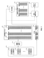
図1は、開示された実施形態と一致する、疑似CT予測モデル150を構築するための例示的なプロセスのフローチャートを示す。図に示すように、一実施形態は、訓練モジュールと予測モジュールとを含む学習ベースのアプローチである。訓練モジュールは、ひとつ又はそれ以上の新しいMRスキャンに基づいて疑似CT値を予測するために予測モジュールによって使用されることができる回帰モデル(例えば、疑似CTモデル150)を作成する。
[036]
FIG. 1 shows a flow chart of an exemplary process for constructing a pseudo
[037]
一実施形態では、訓練データ110は、既存の患者又は対象(総称して「訓練対象」と呼ばれる)から収集することができる。訓練対象は、疑似CT予測モデル150を構築するために使用される、以前に撮影されたMRスキャン及び対応するCTスキャンの両方を有することができる。訓練データ110は、少なくともひとつのMRスキャン及び少なくともひとつのCTスキャン(例えば、訓練対象データ110a-110N)を有する複数の訓練対象のデータを含むことができる。訓練データを提供する訓練対象の数が多いほど(例えば、データセットが大きいほど)、
より小さいデータセットからなるモデルと比較して、より良好な疑似CT予測モデルが生成される。訓練対象データ110a-110Nは、予め整列されたMR画像及びCT画像の対を含む。MR画像とCT画像は別々に取得することができる。したがって、画像が互いに重ね合わされている場合、それらは通常一致しない。したがって、当技術分野で知られているように、MR画像及びCT画像を事前に整列させるために画像位置合わせが使用される。いくつかの実施形態によれば、訓練対象に関連するMRスキャンは、疑似CT画像が所望される新しい患者のMRスキャンのものと同じMRスキャナによって生成することができる。他の実施形態では、訓練対象に関連するMRスキャンは、異なるMRスキャナによって生成されてもよい。さらに、単一の訓練対象に関連する複数のMRスキャンは、より正確な疑似CT生成結果を提供するために、異なるコントラスト特性(例えば、T1加重、T2加重など)のMRスキャンを含むことができる。
[037]
In one embodiment, the
A better pseudo-CT prediction model is generated compared to a model consisting of smaller datasets. The
[038]
画像特徴抽出モジュール111を使用して、訓練データ110に関連するMR画像から画像特徴を抽出することができる。画像特徴は、MRボクセルの数値(例えば、強度値、特徴の座標位置など)又はカテゴリ特性(例えば、組織タイプ、構造ラベルなど)を参照することができる。例えば、「濃淡特徴」は、MRボクセルの強度値を参照することができる。しかしながら、単一のMR特徴は、疑似CT画像を生成するためにMRボクセルを適切に表現するには不十分である可能性がある。例えば、単独で取られたMRボクセルの強度値は、CT推定のためのあいまいな表現を提供する。単一強度値は、とりわけ、同じ強度レベルの2つのMRボクセルが、異なるCT値を有する異なる組織(例えば、骨及び空気)に属し得るため、曖昧である。本明細書で使用される用語「組織」は分類を参照し、単に特定のタイプの組織を示唆するものではない。例えば、空気は組織ではない。したがって、MRボクセルのより明確な記述を提供するために、MRスキャンの各MRボクセルの複数の特徴タイプが抽出される。
[038]
The image
[039]
複数のMR画像又はマルチチャネルMR画像では、豊富な一連の画像ベースの特徴を抽出することができ、より多くの情報を提供し、より正確な疑似CT予測に導かれる。画像特徴抽出モジュール111を使用して、各画像又は各チャネルから別々に特徴(例えば、MR特徴ベクトル120)を抽出することができる。
[039]
With multiple MR images or multi-channel MR images, a rich set of image-based features can be extracted, providing more information and leading to more accurate pseudo-CT predictions. The image
[040]
結果として得られるMR特徴ベクトル120は、各々が訓練対象のMRスキャン(例えば、画像ベクトルセット120a-120N)に関連する収集された画像特徴ベクトルの複数のセットを含むことができる。各画像特徴ベクトルセット120a-120Nは、複数の特徴ベクトルを含むことができる。例えば、所与の特徴ベクトルセット(例えば、120a)の各列は、ベクトルのエレメントとして複数の特徴を含む特徴ベクトルを表すことができる。特徴ベクトルの複数の特徴は、例えば、訓練対象のMR走査/画像の画像ポイント(例えば、ボクセル)に関連する異なるタイプの画像特徴を表す。特徴ベクトル内の特徴要素の数(例えば、列内のエレメントの数)は、特徴ベクトルの次元に参照される。いくつかの実施形態では、特徴ベクトルを、行又は他の適切な形態で配置することもできる。開示された実施形態による特徴抽出は、図2を参照して、以下でさらに詳細に説明される。
[040]
The resulting
[041]
図2は、開示された実施形態と一致する特徴抽出プロセスを示す。患者(例えば、MR対象210)のMRスキャンの各MRボクセルについて複数の画像特徴を抽出することができる。図2に示すように、抽出された画像特徴は、局所パターン特徴212、ランドマーク特徴214、コンテキスト特徴216、及び様々な他のタイプの特徴218を含むことができる。これらの特徴の各々は、集合的に図2の特徴ベクトル列を形成する小さなブロックとして示されるひとつ又はそれ以上の特徴要素によって表されてもよい。特徴は、画像ピクセル(2D)、画像ボクセル(3D)、又は画像ポイントの集合(例えば、2D又は3Dの画像パッチ)に関連付けることができる。例えば、図2は、ボクセルi、ボクセルi+1、...、ボクセルMに関連する特徴ベクトル(例えば、列)を示す。複数の特徴ベクトル、例えば、MR画像の複数のボクセル(例えば、ボクセルi~M)に関連する特徴ベクトルの集合は、訓練対象aに対応する特徴ベクトル集合120aを形成することができる。
[041]
FIG. 2 shows a feature extraction process consistent with the disclosed embodiments. Multiple image features can be extracted for each MR voxel in an MR scan of a patient (eg, MR subject 210). As shown in FIG. 2, the extracted image features can include local pattern features 212, landmark features 214, context features 216, and various other types of
[042]
潜在的な画像特徴の非限定的なリストは次のものを含む。
・強度の特徴:複数のスケールでのMR画像強度値-生の強度値、又はMR強度バイアス補正及び/又はMR強度標準化・正規化のような前処理の後のいずれか。
・ランドマークベースの特徴:ひとつ又はそれ以上のランドマーク点に関して所与のボクセルについて計算される相対位置、距離または他の幾何学的特徴(例えば、脳の前交連-後交連(anterior commissure-posterior commissure)(AC-PC)点、各眼球の中心など)。
・コンテキストの特徴:所与の点の特定の近傍位置で計算される任意の他の画像特徴。
・位置の特徴:各ボクセルの正規化された座標。正規化は、例えば、線形又は非線形の画像位置合わせのいずれかを使用して、各画像を共通の基準フレームに位置合わせすることによって達成することができる。
・パッチの特徴:パッチは、いくつかの実施形態では、特徴が計算される画像ボクセルを取り囲む画像のサブ領域またはサブセットを参照することができる。例えば、パッチは5×5×5ボクセルのサイズを含み、125ボクセル位置の画像強度値はパッチの中心の点の125個の特徴要素に関連させることができる。
・高レベルの特徴はひとつ又はそれ以上のパッチから導き出すことができる:これらのタイプの特徴は、SIFT(スケール不変特徴変換:Scale-invariant feature transform)、SURF(スピードアップロバスト特徴:Speeded Up Robust Features)、GLOH(勾配位置及びオリエンテーションヒストグラム:Gradient Location and Orientation Histogram)、LBP(ローカルバイナリパターン:local binary patterns)、又はHOG(指向勾配のヒストグラム:Histogram of Oriented Gradients)などのような当該技術分野で知られている様々な特徴記述子を含むことができる。そのような特徴は、考慮中のボクセルを含む各2D画像スライスについて計算されてもよく、さらに、そのような特徴は、一実施形態では3D画像に拡張されてもよい、
・テクスチャの特徴:エネルギー、エントロピー、コントラスト、均質性、及び局所画像のグレースケール共出現行列の相関性、及びガボールフィルタ(Gabor filters)などで画像をフィルタリングすることによって計算されたものなど。
・ジョイントの特徴:複数のMR画像(例えば、T1強調、T2強調など)が所定の訓練対象に関連付けられている場合など。そのような場合、強度、パッチ、テクスチャなどの特徴は、その後の組み合わせのために各MRスキャンから独立して抽出することができる。さらに、複数のMRスキャン間の相関を特徴付ける特徴は、各ボクセル位置、例えば局所関節ヒストグラム及び/又は局所相互相関、又は複数のMRチャネルの共分散で計算することができる。
・少なくともひとつの線形又は非線形フィルタ(例えば、局部位相、勾配、曲率、エッジ検出器、又はコーナー検出器など)を有する画像の畳み込みから得られる特徴。
・画像の変換(例えば、フーリエ変換、ヒルベルト変換、ラドン変換、距離変換、離散コサイン変換、ウェーブレット変換など)によって得られる特徴。
・領域共分散特徴:局所的な小領域内の上記の点ごとの特徴のいずれかの共分散。
・分類ベースの特徴。これについては、以下で詳しく説明する。
[042]
A non-limiting list of potential image features includes:
Intensity characteristics : MR image intensity values on multiple scales-raw intensity values, or either after MR intensity bias correction and / or pretreatment such as MR intensity standardization / normalization.
Landmark-based features : Relative positions, distances or other geometric features calculated for a given voxel with respect to one or more landmark points (eg, anterior commissure-posterior of the brain). commissure) (AC-PC) point, center of each eyeball, etc.).
• Contextual features : Any other image feature calculated at a particular neighborhood position at a given point.
-Position features : Normalized coordinates for each voxel. Normalization can be achieved by aligning each image to a common reference frame, for example, using either linear or non-linear image alignment.
Patch Features : In some embodiments, the patch may refer to a subregion or subset of the image surrounding the image voxel from which the feature is calculated. For example, a patch contains a size of 5 × 5 × 5 voxels, and an image intensity value at 125 voxel positions can be associated with 125 feature elements at a point in the center of the patch.
High-level features can be derived from one or more patches : These types of features are SIFT (Scale-invariant feature transform), SURF (Speeded Up Robust Features). ), GLOH (Gradient Location and Orientation Histogram), LBP (local binary patterns), or HOG (Histogram of Oriented Gradients). It can contain various feature descriptors that have been created. Such features may be calculated for each 2D image slice containing the voxels under consideration, and further, such features may be extended to a 3D image in one embodiment.
-Texture features : energy, entropy, contrast, homogeneity, and correlation of grayscale co-appearance matrices of local images, and those calculated by filtering the image with Gabor filters, etc.
-Joint features : When multiple MR images (eg, T1 weighted, T2 weighted, etc.) are associated with a given training target. In such cases, features such as strength, patches, textures, etc. can be extracted independently from each MR scan for subsequent combinations. In addition, the features that characterize the correlation between multiple MR scans can be calculated for each voxel position, such as a local joint histogram and / or local cross-correlation, or the covariance of multiple MR channels.
-Features obtained from image convolution with at least one linear or non-linear filter (eg, local phase, gradient, curvature, edge detector, or corner detector, etc.).
-Features obtained by image transformation (for example, Fourier transform, Hilbert transform, Radon transform, distance transform, discrete cosine transform, wavelet transform, etc.).
Region covariance feature: The covariance of any of the above pointwise features within a local subregion.
-Classification-based features. This will be described in detail below.
[043]
図2に示すように、MR画像ボクセルに関連する特徴の集合は、単一のベクトル(例えば、ボクセルi、ボクセルi+1、...、ボクセルMに関連するベクトル)で表すことができる。
[043]
As shown in FIG. 2, the set of features related to MR image voxels can be represented by a single vector (eg, voxel i, voxel i + 1, ..., vector related to voxel M).
[044]
図1に戻ると、画像特徴の抽出に際して、MR特徴ベクトル120は、複数の次元を有することができる(例えば、図2に示すように、特徴ベクトル内の各特徴要素は次元と見なすことができる)。しかしながら、MR画像からの抽出された特徴の数が増加すると、予測モデルを作成するタスクを達成することがより困難になる。これは、各患者の画像が通常何百万ものボクセルを含み、各ボクセルが多数の特徴と関連している可能性があるからである。したがって、複数の既存の全ての患者からの全ての画像の全てのボクセルから抽出された特徴が予測モデルを構築するために使用される場合、そのような莫大な量のデータを処理するための計算コストは非常に高価になる。その結果、実用的な次元数は、計算コストと比較して利用可能なコンピュータの処理能力に依存する。さらに、抽出された特徴を処理することから生じる予測モデルの性能は、特徴の次元の数に比例しないことがある。場合によっては、特徴の次元の数が増えるにつれて、両方の特徴が処理に含まれると、ある特徴の影響が他の特徴によりキャンセルされたり、弱められたりすることがあるので、予測モデルの性能が低下することがある。多数の特徴は、また、新しいMRデータに基づいて疑似CT画像を決定するために予測モデルを使用する際に容認できない計算コストを引き起こす可能性がある。したがって、一実施形態では、次元低減モジュール132を使用して、MR特徴によって提供される識別情報を実質的に失うことなく、低減された次元特徴ベクトル140を生成することができる。次元低減モジュール132は、元の次元数を減らすときに、元の特徴ベクトルから関連情報の大部分を取得するために使用する。例えば、MR特徴ベクトル120のいくつかの次元は、除去可能な疑似CT画像を生成することと無関係なノイズ又は他の情報を含む。他の次元には、特徴によって提供される特有の情報のよりコンパクトな表現のために組み合わせる、又は合理化できる冗長な情報が含まれている場合がある。例えば、元のデータがガウス分布に適合する場合、元のデータの平均及び標準偏差を用いて元のデータを表すことによって、元のデータの全体的な寸法を縮小することができる。このような次元削減方法により、元のデータが変換される。いくつかの実施形態では、次元数の削減のレベルは、元の特徴ベクトルを使用すること(すなわち削減なし)から任意の所定のレベルの次元を使用すること(例えば、特徴ベクトルの削減されたセットを使用すること)までに及ぶことができる。したがって、一実施形態では、次元削減モジュール132はオプションであり、元の特徴ベクトルを使用して疑似CTモデル150を生成することができる。
[044]
Returning to FIG. 1, when extracting image features, the
[045]
次元削減モジュール132が利用される場合、次元削減モジュール132によって使用される次元削減技法には、(1)教師なし次元削減と(2)教師あり次元削減の少なくとも2つのタイプの技法を含むことができる。典型的には、教師あり次元削減は、後述するように、教師なし次元削減よりも優れている。
[045]
When
[046]
教師なし次元削減は、重要でない雑音及びデータ冗長性を除去し、入力としてMR特徴ベクトル120のみを必要とすることができる。一般的な教師なし次元削減技法には、例えば、主成分分析(PCA)及びその非線形バージョン、カーネル主成分分析(KPCA)が含まれる。
[046]
Unsupervised dimensionality reduction eliminates non-essential noise and data redundancy and can require only
[047]
教師なし次元削減は、他の関心あるデータを利用して、疑似CT画像を生成するのに無関係な次元をさらに除くことができる。例えば、CT値130は、次元削減のために使用されてもよい。訓練データ110のCTスキャンデータからCT値130(例えば、元のCT値又はCT数)を得ることができる。教師あり次元削減は、MR特徴ベクトル120とCT値130の両方を入力とすることができる。教師あり次元削減技法には、例えば、正準成分分析(CCA)、メトリック学習(ML)、主成分分析(SPCA)、局所感性ハッシング(LSH)、局所感性弁別分析(LSDA)などがある。関心のあるデータを離散クラスラベルに関連付けることを必要とする次元削減技法では、訓練データ110のCTスキャン又はMRスキャンに画像セグメンテーションを適用して、クラスラベルとして使用できるセグメンテーションクラスを得ることができる。
[047]
Unsupervised dimensionality reduction can utilize other data of interest to further eliminate dimensions irrelevant to the generation of pseudo CT images. For example, the
[048]
CT値130は、次元削減モジュール132によって利用されて、訓練データ110内のどの信号が基礎となるCT値に関連するかを決定することができる。元のCT値を使用すると、無関係な信号を抑制し、関連する信号を維持することができる。一般に、各訓練対象について少なくともひとつのCT画像が利用可能であるべきである。いくつかの実施形態では、複数のCT画像が利用可能であってもよい。画像ノイズを低減するために、より多くのCTスキャンを平均化することができ、それによって、次元削減モジュール132の有効性が改善される。次元削減モジュール132の出力は、縮小次元特徴ベクトル140である。
[048]
The
[049]
訓練データが収集され、処理されると(例えば、画像特徴抽出、次元削減技術などに供されると)、疑似CT予測モデル150は、統計学習又は機械学習技術のいずれかを使用して構築することができる。ひとつの実施形態では、回帰分析を使用して、疑似CT予測モデル150を構築することができる。回帰分析は、変数間の関係を推定するための統計的プロセスである。回帰分析を行うための多くの既知の方法がある。例えば、線形回帰又は一般最小二乗回帰は、回帰関数が訓練データから推定できる有限数の未知モデルパラメータに関して定義される点で「パラメトリック」である。疑似CT画像生成の場合、回帰モデル(例えば、式1)は、例えば、以下のように定義することができる。
[049]
Once the training data has been collected and processed (eg, for image feature extraction, dimensionality reduction techniques, etc.), the pseudo

ここで、「H」はCT値を示し、「X」は入力変数のベクトル(例えば、MR特徴ベクトル120又は削減された次元特徴ベクトル140のいずれか)を示し、「β」は回帰モデルに対する決定又は訓練された未知のパラメータのベクトルを示す。ある実施形態では、CT値は、CTスキャンのハウンスフィールド値( Hounsfield values)であってもよい。
Here, "H" indicates the CT value, "X" indicates the vector of the input variable (for example, either the
[050]
MRスキャン及びCTスキャンを含む訓練データ110は、対応するX値(例えば、同じ訓練対象のMRスキャンから抽出された特徴ベクトル)を有する既知のH値のセット(例えば、訓練対象のCTスキャンに関連するCT値)を提供する。これらのデータを使用して、モデルパラメータβは、最小2乗、最大尤度などのデータフィッティング技法を使用して計算できる。βが推定されると、モデルは新しいX値の集合(例えば、新しいMRスキャンから抽出された特徴ベクトル)についてH(例えば疑似CT値)を計算することができる。
[050]
The
[051]
別の実施形態では、疑似CT予測モデル150を構築するために、機械学習及び教師あり学習を使用することができる。教師あり学習は、学習データのセットを与えられた予測モデルを推定する機械学習の分派である。訓練データの各サンプルは、入力データ(例えば、測定値又は特徴のベクトル)と所望の出力値(教室信号とも呼ばれる)からなるペアである。教師あり学習アルゴリズムは、訓練データを分析し、出力変数が数値又は連続であるときの回帰関数である予測関数を生成する。開示された実施形態として、多くの異なるアルゴリズムを適用することができる。アルゴリズムは、kNN(k最近傍)回帰(kNN (k-nearest neighbors) regression)、サポートベクトルマシン(support vector machines)、ニューラルネットワーク(neural networks)、決定木(decision trees)、ランダムフォレスト(random forests)、勾配ブースティングマシン(gradient boosting machines)を含むがそれらに限定されない。
[051]
In another embodiment, machine learning and supervised learning can be used to build the
[052]
図3は、開示された実施形態として、疑似CTモデル150を使用することができる予測モジュールの例示的なプロセスのフローチャートを示す。疑似CTモデル150が作成されて訓練されると、その疑似CTモデル150は、同じ患者又は新しい患者のいずれかについて、新しいMRスキャンから疑似CT画像を生成するために、適用段階の予測モジュール301によって使用される。図3に示すように、疑似CT画像350を生成するプロセスは、先に生成され訓練された疑似CT予測モデル150が適用段階で利用されることを除いて、図1について上述したプロセスと同様である。このプロセスでは、新しいMRスキャン310が予測モジュール301に入力される。一実施形態では、予測モジュール301は、画像特徴抽出モジュール311及び疑似CT予測モデル150を含むことができる。この実施形態では、MRスキャン301は対応するCTスキャンを有さない。特徴は、MRスキャン301から抽出され、MR特徴ベクトル120の生成について上述と同様の方法で、患者MR特徴ベクトル320を生成することができる。次元削減モジュール321が含まれて、患者MR特徴ベクトル320の大きさを縮小することができる。あるいは、患者MR特徴ベクトル320は、破線331により示されるように、次元の削減なしに疑似CT予測モデル150によって使用されてもよい。
[052]
FIG. 3 shows a flow chart of an exemplary process of a prediction module that can use the
[053]
このように、予測モジュール301は、訓練段階中に作成された疑似CT予測モデル150を使用して、新しいMRスキャンに対応してもともとCTスキャンが提供されなかったので、患者MR画像310の各位置で疑似CT値を予測する 。疑似CT予測モデル150は、例えば各画像位置で「点ごと」に動作することができるので、疑似CT値は、MRスキャン310内の特定の位置における特定のボクセルの特徴ベクトルに基づいて導出された値を表す。したがって、予測モデル301は、疑似CT値340を生成することができる。疑似CT値340は、疑似CT画像350の複数の強度値を表す。疑似CT画像350を生成するために、疑似CT値340は、典型的には、ボクセルのグリッド上のそれらの適切な位置に配置される。一実施形態では、予測モデル301は、画像がボクセルのグリッドであるため(例えば、すべての画像ボクセルが予測されるわけではない)、ボクセルグリッドのいくつかの値(例えば、疑似CT値340)を予測することができ、患者の解剖学的詳細の正確な視覚的表現を示すために疑似CT画像350を生成するために補間を使用することができる。
[053]
Thus, the
[054]
疑似CT予測モデル150は、全ての利用可能な患者の訓練データ110を使用して一度訓練され、そして、疑似CT予測モデル150は、全ての将来の新しい患者に使用され得る。あるいは、同じ疑似CT予測モデル150をすべての患者に使用することはできない。疑似CT予測モデル150は、特定の患者のためにカスタマイズすることができる。例えば、訓練データは、新しい患者に最も類似又は関連するデータを含むように選択されてもよく、モデルは、新しい患者に対して特異的に構築されてもよい。
[054]
The pseudo
[055]
図4Aは、本開示のいくつかの実施形態による、例示的な放射線治療システム400を示す。放射線療法システム400は、訓練モジュール412、予測モジュール414、訓練データベース422、検査データベース424、放射線治療装置430、及び画像取得装置440を含むことができる。放射線療法システム400は、患者情報を提供することができる治療計画システム(TPS)442及び腫瘍学情報システム(OIS)444に接続することもできる。さらに、放射線治療システム400は、表示装置及びユーザインターフェース(図示せず)を含むことができる。
[055]
FIG. 4A shows an
[056]
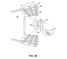
図4Bは、本開示のいくつかの実施形態による、放射線治療装置430ひとつのタイプの例(例えば、スウエーデン、ストックホルムのエレクタ アクチボラゲット(パブル)(Elekta、AB、Stockholm、Sweden)によって製造されたLeksell Gamma Knife)を示す。図4Bに示すように、放射線治療セッションでは、患者452は、手術又は放射線療法を受けている患者の体部分(例えば、頭部)を安定に保つために座標フレーム454を着用してもよい。座標フレーム454及び患者位置決めシステム456は、患者を撮像している間、又は放射線手術中に使用することができる空間座標系を確立することができる。放射線治療装置430は、複数の放射線源462を囲む保護ハウジング464を含むことができる。放射源462は、ビームチャネル466を介して複数の放射ビーム(例えば、ビームレット)を生成することができる。複数の放射ビームは、異なる方向からアイソセンタ458に集束するように構成することができる。個々の放射ビームの強度は比較的低いが、アイソセンタ458は、異なる放射ビームからの複数の線量がアイソセンタ458に蓄積するとき、相対的に高いレベルの放射を受け取ることができる。特定の実施形態では、アイソセンタ458は、腫瘍などの外科手術又は治療下の標的に対応し得る。放射線治療装置430(例えば、スウエーデン、ストックホルムのエレクタ アクチボラゲット(パブル)(Elekta、AB、Stockholm、Sweden)によって製造されたLeksell Gamma Knife)は、一実施形態では、割り当てられたバルク密度を有するMR画像、又はMR画像と融合されたCT画像を利用し、開示された実施形態として生成される。
[056]
FIG. 4B is manufactured by an example of one type of
[057]
図4Cは、本開示のいくつかの実施形態による、放射線治療装置430(例えば、線形加速器470)の別の例を示す。線形加速器470を使用して、患者472を患者テーブル473上に配置して、治療計画によって決定された放射線量を受けることができる。線形加速器470は、放射ビーム476を生成する放射ヘッド475を含むことができる。放射ヘッド475全体は、水平軸477の周りを回転可能であってもよい。さらに、患者テーブル473の下には、アイソセンタ471の周りで放射線ヘッド475と同期して回転するフラットパネルシンチレータ検出器474が設けられてもよい。放射ヘッド475によって生成された軸477とビーム476の中心との交差点は、通常アイソセンタと呼ばれる。患者テーブル473は、患者472がアイソセンタ471又はその近くに腫瘍部位とともに配置されるように電動化されてもよい。放射線ヘッド475は、ガントリ478の周りを回転して、治療計画に従って複数の変化する放射線量を患者472に提供することができる。別の実施形態では、線形加速器470は、MR線形加速器(「MR-LINAC」)であってもよい。線形加速器10及びMR-LINACは、一実施形態では、MR画像、CT画像を利用することができ、開示された実施形態により生成された疑似CT画像を使用することができる。
[057]
FIG. 4C shows another example of a radiation therapy apparatus 430 (eg, a linear accelerator 470) according to some embodiments of the present disclosure. A
[058]
図5は、開示された実施形態と一致して、疑似CT予測モデルを構築し、疑似CT画像を生成するための例示的なシステム500である。いくつかの実施形態によれば、システム500は、開示された実施形態と一致する大量のデータを識別、分析、維持、生成、及び/又は提供することができるひとつ又はそれ以上の高性能コンピューティングデバイスであってもよい。システム500は、スタンドアローンでもよいし、サブシステムの一部であってもよく、サブシステムは、より大きなシステムの一部であってもよい。例えば、システム500は、遠隔地に位置し、インターネットなどのネットワーク又はLAN又はWANなどの専用ネットワークを介して通信する分散型高性能サーバを表すことができる。いくつかの実施形態では、システム500は、ひとつ又はそれ以上の遠隔配置された高性能コンピューティングデバイスと通信する組み込みシステム、MRスキャナ、及び/又はタッチスクリーンディスプレイデバイスを含むことができる。
[058]
FIG. 5 is an
[059]
一実施形態では、システム500は、ひとつ又はそれ以上のプロセッサ514、ひとつ又はそれ以上のメモリ510、及びひとつ又はそれ以上の通信インターフェース515を含むことができる。プロセッサ514は、処理装置であってもよく、マイクロプロセッサ、中央処理装置(CPU)、グラフィック処理装置(GPU)などのようなひとつ以上の汎用処理装置を含む。より詳細には、プロセッサ514は、CISCマイクロプロセッサ、RISCマイクロプロセッサ、VLIWマイクロプロセッサ、他の命令セットを実装するプロセッサ、又は命令セットの組み合わせを実装するプロセッサであってもよい。プロセッサ514は、特定用途向け集積回路(ASIC)、フィールドプログラマブルゲートアレイ(FPGA)、デジタル信号プロセッサ(DSP)、システムオンチップ(SoC)などのひとつ以上の専用処理装置であってもよい。当業者に理解されるように、いくつかの実施形態では、プロセッサ514は、汎用プロセッサではなく、専用プロセッサであってもよい。プロセッサ514は、Intel(登録商標)によって製造された、Pentium(登録商標)又はXeon(登録商標)ファミリーや、AMD(登録商標)によって製造されたTurion(登録商標)ファミリーからのマイクロプロセッサ、Sun Microsystemsによって製造された様々なプロセッサのような、ひとつ又はそれ以上の既知の処理デバイスを含むことができる。プロセッサ514はまたNvidia(登録商標)により製造されたグラフィカル処理ユニットを含むことができる。開示された実施形態は、大量のイメージングデータ、又は開示された実施形態と一致する任意の他のタイプのデータの識別、分析、維持、生成、及び/又は提供の計算命令を満たすように構成された任意のタイプのプロセッサに限定されない。
[059]
In one embodiment, the
[060]
メモリ510は、開示された実施形態に関連する機能を実行するためにプロセッサ514によって使用されるコンピュータ実行可能命令を格納するように構成されたひとつ又はそれ以上の記憶装置を含むことができる。
例えば、メモリ510は、治療計画ソフトウェア511、オペレーティングシステムソフトウェア512、及び訓練/予測ソフトウェア513のためのコンピュータ実行可能ソフトウェア命令を格納することができる。プロセッサ514は、メモリ/記憶装置510に通信可能に結合されてもよく、プロセッサ514は、開示された実施形態によるひとつ又はそれ以上の動作を実行するために記憶されたコンピュータ実行可能命令を実行するように構成されてもよい。例えば、プロセッサ514は、訓練/予測ソフトウェア513を実行して、訓練モジュール412及び予測モジュール414の機能を実装することができる。さらに、プロセッサ装置514は、訓練/予測ソフトウェア513にインターフェースされる治療計画ソフトウェア511(例えば、Elektaによって製造されたMonaco(登録商標)ソフトウェアなど)を実行することができる。
[060]
For example,
[061]
開示された実施形態は、専用のタスクを実行するように構成された別々のプログラム又はコンピュータに限定されない。例えば、メモリ510は、システム500又は複数のプログラム(例えば、治療計画ソフトウェア511及び/又は訓練/予測ソフトウェア513)の機能を実行する単一のプログラムを含むことができる。さらに、プロセッサ514は、データベース520に格納されたプログラムなど、システム500から遠隔に位置するひとつ又はそれ以上のプログラムを実行してもよく、このような遠隔プログラムは、腫瘍情報システムソフトウェア又は治療計画ソフトウェアを含むことができる。メモリ510はまた開示された実施形態による動作を実行するためにシステムが使用することができる任意のフォーマットの画像データ又は任意の他のタイプのデータ/情報を格納することができる。
[061]
The disclosed embodiments are not limited to separate programs or computers configured to perform dedicated tasks. For example, the
[062]
通信インターフェース515は、データがシステム500によって受信及び/又は送信されるように構成されたひとつ又はそれ以上のデバイスであってもよい。通信インターフェース515は、システム500がシステム500の遠隔に位置するコンポーネント、データベース520、又は病院データベース530などの他の機械及びデバイスと通信することを可能にするひとつ又はそれ以上のデジタル及び/又はアナログ通信デバイスを含むことができる。例えば、プロセッサ514は、通信インターフェース515を介してデータベース520又は病院データベース530に通信可能に接続されてもよい。例えば、通信インターフェース515は、インターネットなどのコンピュータネットワーク、又はLAN又はWANなどの専用ネットワークとすることができる。あるいは、通信インターフェース515は、プロセッサ514がデータベース520、530のいずれかとの間でデータを送受信することを可能にする衛星通信リンク又は任意の形式のデジタル又はアナログ通信リンクであってもよい。
[062]
The
[063]
データベース520及び病院データベース530は、情報を記憶し、システム500を介してアクセス及び管理されるひとつ又はそれ以上のメモリデバイスを含むことができる。例えば、データベース520、病院データベース530、又はその両方は、Oracle(登録商標)データベース、Sybase(登録商標)データベースなどのリレーショナルデータベース、又は、Hadoopシーケンスファイル、HBase、Cassandraなどの非リレーショナルデータベースを含むことができる。データベース又は他のファイルは、例えば、訓練対象に関連するMRスキャン又はCTスキャンからの生データ、MR特徴ベクトル120、CT値130、縮小次元特徴ベクトル140、疑似CT予測モデル150、疑似CT値340、疑似CT画像350、DICOMデータ等を含む。しかしながら、開示された実施形態のシステム及び方法は、別々のデータベースに限定されない。一態様では、システム500は、データベース520又は病院データベース530を含むことができる。あるいは、データベース520及び/又は病院データベース530は、システム500から遠隔に位置してもよい。データベース520及び病院データベース530は、データベース520又は病院データベースのメモリデバイスに格納されたデータの要求を受信及び処理し、データベース530又は病院データベース530からデータを提供するように構成された計算コンポーネント(例えば、データベース管理システム、データベースサーバなど)を含むことができる。
[063]
[064]
システム500は、ネットワーク(図示せず)を介してシステム500の他のデバイス及びコンポーネントと通信することができる。ネットワークは、通信を提供し、情報を交換し、又は情報の交換を容易にし、ネットワーク(図示せず)を介して他のデバイス及び/又はシステム500のコンポーネント間で情報の送受信を可能にする任意のタイプのネットワーク(インフラストラクチャを含む)であることができる。他の実施形態では、システム500のひとつ又はそれ以上のコンポーネントは、システム500とデータベース520と病院データベース530との間のリンク(例えば、有線リンク、無線リンク、又は衛星リンク、又は他の通信リンク)のような専用通信リンクを介して直接的に通信することができる。
[064]
The
[065]
システム500の機能構築ブロックの構成及び境界は、ここでは説明の便宜のために定義されている。指定された機能及びそれらの関係が適切に実行される限り、代替の境界を定義することができる。本明細書に含まれる教示に基づいて、当業者には代替物(本明細書に記載されているものの均等物、拡張物、変形物、偏差などを含む)は明らかであろう。そのような代替案は、開示された実施形態の範囲及び精神の範囲内に入る。
[065]
The configurations and boundaries of the functional building blocks of the
[066]
図6は、開示された実施形態による、疑似CT予測モデルを訓練及び構築するための例示的なプロセス600のフローチャートである。プロセス600は、複数のステップを含み、そのいくつかは任意であってもよい。ステップ610において、システム500は、例えば、データベース520及び/又は病院データベース530から、複数の訓練対象に関連する訓練データ110にアクセスする。訓練データ110は、各訓練対象(例えば、図1に示すような、訓練対象データ110a-110N)について、少なくともひとつのMRスキャン及び少なくともひとつのCTスキャンを含むことができる。いくつかの実施形態では、訓練データ110は、同じ患者に対する少なくともひとつのMRスキャン及び複数のCTスキャンを含むことができる。
[066]
FIG. 6 is a flow chart of an
[067]
いくつかの実施形態によれば、システム500は、疑似CT予測モデル150を訓練及び構築するために使用される前に、訓練データ110のいくつか又はすべてが前処理を必要とするか否かを決定することができる。ステップ620において、プロセッサ514は、訓練データ内のひとつ又はそれ以上の訓練対象について、MRスキャン及び対応するCTスキャンが整列されているかどうかを判定する(例えば、各MRボクセルについて、対応するCTボクセルからのCT値は、知られている)。MR画像及びCT画像が整列していない場合、プロセス600は、ステップ624で走査を整列させるために分岐621(例えば「NO」)に進む。システム600は、必要に応じて、当業者に公知の方法に従ってMRスキャン及び対応するCTスキャンを整列させることができる。あるいは、MR画像及びCT画像が整列されている場合、プロセス600は分岐622(例えば「YES」)に進み、ステップ630に続く。
[067]
According to some embodiments, the
[068]
任意に、ステップ630において、プロセッサ514は、訓練データ110が同じ訓練対象について複数のCTスキャンを含むかどうかを検証する。複数のCTスキャンがある場合、プロセッサ514は、同じ患者の画像ノイズを低減するために、複数のCTスキャン間の対応するCTボクセルの平均CT値を決定する。そうでない場合、プロセス600は、ステップ620からステップ640に直接進む。
[068]
Optionally, at
[069]
ステップ640において、前処理の一部として、プロセッサ514は、例えば、治療計画ソフトウェア511又は訓練/予測ソフトウェア513に反映されたシステム設定に基づいて、MRスキャンから画像アーチファクトを低減するか又は消滅させるかを決定する。画像アーチファクトの低減が所望される場合、プロセス600は、分岐642(「YES」)からステップ644に進む。ステップ644において、プロセッサ514は、前処理の一部として、画像アーチファクト低減技術を適用する。MR走査を前処理することにより、プロセッサ514は、強度不均一性(MR画像バイアスフィールドとしても知られている)及び画像ノイズなどの画像アーチファクトを除去又は低減することができる。さらに、前処理は、異なるMRスキャナタイプ(例えば、GE、Siemensなどによって製造されたもの、又は0.5テスラ、1.5テスラなどの様々な磁場強度)によってMR画像強度値を正規化/標準化することができる。前処理技術は、新しい特許MRスキャン310(図3に示す)の画像アーチファクトを除去又は低減するために使用することもできる。画像アーチファクト低減が行われない場合、プロセス600は、特徴を抽出するためにステップ650に進む。いくつかの実施形態では、前処理のひとつ又はそれ以上のステップ(例えば、図6の破線で囲まれた)を省略することができる。
[069]
In
[070]
ステップ650では、訓練データ110から特徴を抽出する。いくつかの実施形態では、システム500は、訓練データ110内の各MRスキャンの各ボクセルから特徴を抽出することができる。例えば、MR画像自体を使用することができ、MR画像からの各ボクセル又は選択されたボクセルを使用して特徴を抽出することができる。あるいは、プロセッサ514は、MR画像を異なる組織タイプにセグメント化し、組織タイプに基づいて各MRスキャンの画像ボクセルをセグメント化することができる。これは、例えば、他の抽出された特徴に加えて、追加の特徴として組織タイプを使用することができるので、場合によっては有利であり得る。
[070]
In
[071]
ステップ660において、システム500は、MRスキャンの各ボクセルについて抽出された画像特徴に基づいてMR特徴ベクトルを作成する。したがって、MRスキャンの各ボクセルについて複数の特徴を含むベクトルをプロセッサ514によって生成することができる。複数のMR特徴ベクトル120は、MR走査の複数のボクセルに対してプロセッサ514によって生成され得る。
[071]
In
[072]
ステップ670において、システム500は、訓練データ内の各CTスキャンの各ボクセルからCT値を抽出する。
[072]
In
[073]
ステップ680において、システム500は、MR特徴ベクトル120に関連する次元の数を減らすかどうかを決定する。
[073]
In
[074]
例えば、システム500のプロセッサ514は、疑似CT予測モデル150によって処理されたときに、MR特徴ベクトル120に関連する次元の数が高い計算コストをもたらすか、又は潜在的に性能問題を引き起こすと判断することができる。別の例では、システム500は、MR特徴ベクトル120が、疑似CT予測モデル150の精度に影響を及ぼすと考えられる閾値を超えるノイズ又は複製データを含むと判断することができる。別の実施形態では、システム500は、性能及び/又は出力品質に影響を及ぼす要因に基づいて次元削減を行うかどうかを決定することができる。従って、プロセッサ514が、次元削減が必要であると判定した場合、プロセス600は、分岐682(例えば「YES」)からステップ686に進み、プロセッサ514は、MR特徴ベクトル120に関連する次元を縮小することができる。代替的に、いくつかの実施形態では、システム500は、MR特徴ベクトル120の次元削減を行わないように(例えば、ユーザからの)入力を受け取ることができる。
[074]
For example, the
[075]
次元削減が必要ない場合、プロセス600は分岐684から直接ステップ690に進むことができる。ステップ690において、システム500は、MR特徴ベクトル(例えば、120)及び抽出されたCT値に基づいて疑似CT予測モデル150を生成するために、統計又は機械学習技術を利用することができる。いくつかの実施形態では、次元削減された特徴ベクトル140を利用することができる。
[075]
If no dimensionality reduction is required,
[076]
いくつかの実施形態によれば、訓練データ110のサブセットは、疑似CT予測モデル150を訓練して構築するための基礎として使用することができる。したがって、システム500は、疑似CT予測モデル150を訓練及び構築するために、訓練データ110のサブセットを(例えば、治療計画ソフトウェア511及び/又は訓練/予測ソフトウェア513に反映されたユーザ入力及び/又はシステム設定に基づいて)決定することができる。別の実施形態では、訓練データ110のサブセットは、特定の画像領域に基づいて分類することができる。例えば、訓練データ110のサブセットは、1)特定の解剖学的領域に関して、2)様々な組織分類に関して、又は3)訓練対象の特徴に関して、であることができる。
[076]
According to some embodiments, the subset of
[077]
例えば、ひとつ又はそれ以上の特徴は、所与の患者のMRスキャンのための基礎となる解剖学的構造の優れた解釈を提供することができる。したがって、疑似CT予測モデル150を訓練する際に使用するために、訓練データ110から上位の特徴のサブセットのみを抽出することができる。優れた特徴を使用して、所与の患者のMRスキャンに対する対応する疑似CT値340を推定する疑似CT予測モデル150の予測力を改善することができる。特徴のサブセットは、ひとつ又はそれ以上の疑似CTモデルを生成及び訓練するために使用することができる。
[077]
For example, one or more features can provide an excellent interpretation of the underlying anatomy for an MR scan of a given patient. Therefore, only a subset of the top features can be extracted from the
[078]
一実施形態では、特定の解剖学的領域に関して疑似CT予測モデルを構築する場合、訓練データ110のサブセット(例えば、関心のある身体領域に関連する訓練データ110のみ)を使用して、疑似-CT予測モデル150を訓練し、構築することができる。ひとつの疑似CT予測モデルの代わりに、プロセッサ514は、身体の特定の解剖学的領域(例えば、頭部、上半身、下半身など)に関して複数の疑似CT予測モデルを生成することができる。したがって、プロセッサ514は、MR特徴ベクトル120(又は削減次元特徴ベクトル140)及び所定の解剖学的位置のCT値130を利用して、MRスキャン内に表れた所定の解剖学的関心位置の疑似CT予測モデル150を生成することができる。
[078]
In one embodiment, when constructing a pseudo-CT prediction model for a particular anatomical region, a subset of training data 110 (eg, only training
[079]
例えば、システム500は、患者MRスキャン310が、患者の前立腺のMR画像を含むと判断することができる。したがって、開示された実施形態により、システム500は、訓練データとして前立腺のひとつ又はそれ以上のMRスキャン及びCTスキャンを利用して訓練データ110に基づいて構築及び訓練された疑似CT予測モデルを特定することができる。一実施形態では、複数の疑似CT予測モデルが利用可能であり、各モデルは、例えば、前立腺の様々な解剖学的側面を表すことができる。したがって、複数の疑似CT予測モデルを生成することができ、各疑似CT予測モデルは、特定の解剖学的領域(例えば、前立腺の疑似CT予測モデル、右肺の疑似CT予測モデル、左肺の疑似CT予測モデル、脳の疑似CT予測モデルなど)に対するものである。
[079]
For example, the
[080]
別の実施形態では、疑似CT予測モデル150は、組織分類のような分類ベースの特徴に基づいて生成されてもよい。例えば、システム500は、画像特徴抽出モジュール111を使用して、組織クラス(例えば、骨、脂肪、筋肉、水分、空気、及び、心臓組織、肺組織、肝臓組織、脳組織などのような構造クラス)に従って、訓練データ110内の各MRスキャンの画像ボクセルをセグメント化することができる。セグメント化された画像ボクセルに基づいて、各MRスキャンに対する複数のセグメント化マップを生成することができる。画像特徴は、セグメンテーションマップから抽出することができる。セグメンテーションマップ抽出画像特徴は、各ボクセルのMRスキャン抽出画像特徴と組み合わせることができる。MR特徴ベクトルは、結合された画像特徴に基づいて各訓練対象について決定されてもよい。合成されたMR特徴ベクトルと抽出されたCT値に基づく疑似CT予測モデルを生成することができる。上述のように、用語「組織」は、単に特定のタイプの組織(例えば、空気は組織ではない)を示唆するためではなく、分類として使用されている。
[080]
In another embodiment, the pseudo
[081]
さらに別の実施形態では、疑似CT画像を生成するプロセスは、訓練対象の特性に従って選択された訓練データを使用することに基づくことができる。例えば、システム500は、訓練対象のサブセットのうちのひとつ又はそれ以上の共通特性を識別することができる。例えば、システム500は、各訓練対象に関連する年齢、性別、体重クラス等を特定し、ひとつ以上の共通特性を有する訓練対象を選択してもよい。他の例では、システム500は、訓練データ110内のMR及びCTスキャンに基づいて訓練対象のひとつ又はそれ以上の特性を識別することができる。さらに、システム500は、訓練対象のサブセットと共通の患者(例えば、新しい患者)のひとつ又はそれ以上の特性を識別することができる。例えば、システム500は、患者のひとつ又はそれ以上の特性を識別し、患者の特性を、共通特性を識別するために訓練対象について識別された特性と比較することができる。次いで、システム500は、疑似CT予測モデル150を訓練し構築するために、訓練データとしてひとつ又はそれ以上の共通の特性を有する訓練対象を選択することができる。
[081]
In yet another embodiment, the process of generating a pseudo CT image can be based on using training data selected according to the characteristics of the training target. For example, the
[082]
画像特徴は、訓練対象の特徴に関連するCTスキャンからのMRスキャン及びCT番号から抽出することができる。例えば、システム500は、新しい患者と共通の特性を有する訓練対象のサブセットに関連する訓練データ110のCTスキャンからMRスキャン及びCT値130から画像特徴を抽出することができる。次に、抽出された画像特徴に基づいて、サブセットの各訓練対象についてMR特徴ベクトルを決定することができる。これらのMR特徴ベクトルと抽出されたCT値とに基づいて疑似CT予測モデルを生成することができる。
[082]
Image features can be extracted from MR scans and CT numbers from CT scans related to the feature to be trained. For example,
[083]
疑似CT予測モデル150は、すべての訓練データ110を使用して訓練され、次いで、新しい患者のための新しいMRスキャンのために利用され得る。疑似CT予測モデル150は、すべての将来の新しい患者にも使用することができる。いくつかの実施形態では、同じ疑似CT予測モデル150をすべての患者に使用することはできない。疑似CT予測モデル150は、特定の患者についてカスタム生成されてもよい。例えば、訓練データは、新しい患者に類似又は関連する訓練対象に基づいて選択されてもよく、モデルは新しい患者のために特別に構築されてもよい。
[083]
[084]
医療従事者は、最適な治療又は診断を決定するために、患者の関心領域のMR特性及びCT特性の両方を評価することが有用であることが分かる。さらに、疑似CTモデルを使用して、MR画像からCT画像を導出して、放射線療法治療計画における患者線量計算を容易にすることができる。これは、CT画像から生じる追加の放射線被曝から患者を守るために、MR画像から疑似CT画像を正確に生成するために望ましい。実際のCT画像を置換するためには、疑似CT画像は、放射線療法治療計画における線量計算の目的で、又は画像ガイダンスに対するデジタル再構成放射線写真(DRR)を生成するために、患者の実際のCT画像にできるだけ近づけるべきである。しかし、CT画像強度値(CT値)とMR強度値との間には単純な数学的関係はない。MR強度値は標準化されておらず、異なるMRスキャナ設定又は異なるMR画像シーケンスパラメータに応じて大きく変化し得るので、困難が生じる。
[084]
Healthcare professionals find it useful to evaluate both MR and CT characteristics of the patient's area of interest in order to determine the optimal treatment or diagnosis. In addition, pseudo-CT models can be used to derive CT images from MR images to facilitate patient dose calculations in radiation therapy treatment plans. This is desirable to accurately generate pseudo CT images from MR images in order to protect the patient from additional radiation exposure resulting from CT images. To replace the actual CT image, the pseudo CT image is the patient's actual CT for the purpose of dose calculation in a radiotherapy treatment plan or to generate a digitally reconstructed radiograph (DRR) for image guidance. It should be as close to the image as possible. However, there is no simple mathematical relationship between the CT image intensity value (CT value) and the MR intensity value. Difficulties arise because MR intensity values are not standardized and can vary significantly depending on different MR scanner settings or different MR image sequence parameters.
[085]
図7は、開示された実施形態のように、モデルが(図3に記載されているように)疑似CT値および疑似CT画像を生成するように訓練された後、(図1及び図6により説明されるように)疑似CT予測モデルを使用するための例示的なプロセス700のフローチャートである。ステップ710において、システム500は、患者(例えば、新しい患者)に関連する少なくともひとつのMRスキャン(例えば、MRスキャン310)を受信することができる。少なくともひとつのMRスキャンは、対応するCTスキャンを有していなくてもよい。MRスキャンは、疑似CT画像を生成するために使用される。
[085]
FIG. 7 shows, as in the disclosed embodiment, after the model has been trained to generate pseudo-CT values and pseudo- CT images (as described in FIG. 3) and then (according to FIGS. 1 and 6). It is a flowchart of an
[086]
ステップ720において、プロセッサ514は、MR画像ボクセルがセグメント化されるべきかどうかを決定することができる。MRスキャンをセグメント化することは任意である。プロセッサ514は、治療計画ソフトウェア511(図5に示す)又はユーザインターフェース(図示せず)から命令を受信して、MRスキャンを分割すべきかどうかを示すことができる。そうである場合、プロセス700は、分岐722(例えば「YES」)に進み、MRスキャンを分割する。ステップ730では、MRスキャンの画像ボクセルが、例えば、組織分類に従ってセグメント化される。セグメント化は、当業者に知られているセグメント化技術に従って実施することができる。例えば、プロセッサ514は、ひとつ又はそれ以上のセグメンテーションマップを作成するために、k-meansクラスタリングセグメンテーション法(k-means clustering segmentation method)、ファジーc-meansセグメンテーション法(fuzzy C-means segmentation method)などを採用することができる。
[086]
At
[087]
プロセッサ514はさらに進んだセグメンテーション方法を使用することができる。例えば、プロセッサ514は、セグメンテーションを実行するための学習ベースまたは特徴ベースのアプローチを採用することができ、それは、例えば、アルゴリズム(例えば、局所パターン特徴、ランドマーク特徴、コンテキスト特徴など)を使用して分類予測モデルを構築することを含み、画像ボクセルの特徴に基づいて各画像ボクセルの組織ラベルを予測することができる。
[087]
[088]
ステップ732において、プロセッサ514は、分類された画像ボクセルに基づいて各MRスキャンについて複数のセグメント化マップを生成して、分類予測モデルを作成することができる。例えば、バイナリボーンセグメンテーションマップ(binary bone segmentation map)は、ボーンとしてラベル付けされたボクセルでは「1」に等しい値を有し、他のすべてのボクセルでは「0」である画像であってもよい。プロセッサ514は、セグメンテーションマップを使用して元のMR画像から追加の特徴を抽出することができる。開示された実施形態による、上記に開示された学習ベースの方法を用いて、ひとつ又はそれ以上のセグメンテーションマップを生成するための予測モデルを訓練し構築することができる。あるいは、MRスキャンのセグメンテーションが必要でない場合、プロセス700は、分岐724(例えば「NO」)に進む。
[088]
In
[089]
ステップ740において、プロセッサ514は、患者のMRスキャンから画像特徴を抽出することができる。上記で説明したMRスキャンをセグメント化する任意の経路が実行された場合、抽出された画像特徴を経路722に沿って提供することができる。ステップ734において、プロセッサ514は、MR画像からセグメンテーションマップを使用して抽出された追加の特徴と、MR画像から直接抽出された特徴とを組み合わせて、各データポイント(例えば、ボクセル)の特徴の組合せセットを形成する。
[089]
At step 740,
[090]
MRスキャンが分割されているかどうかにかかわらず、画像特徴が抽出された後、プロセス700は(例えば、経路744又は736に沿って)ステップ750に進む。ステップ750において、プロセッサ514は、抽出された画像特徴から各訓練対象についての特徴ベクトル120を決定することができる。
[090]
After the image features have been extracted,
[091]
ステップ760において、プロセッサ514は、MR特徴ベクトル120を疑似CT予測モデル150に入力することができる。ステップ770において、プロセッサ514は、疑似CT予測モデル150を入力MR特徴ベクトル120に適用して、患者MR画像310の各ボクセルのCT数(例えば、疑似CT値340)を決定することができる。
[091]
In
[092]
ステップ780において、プロセッサ514は、疑似CT値340に基づいて、患者の疑似CT画像350を生成することができる。得られた疑似CT画像350は、治療計画における線量計算、画像誘導のためのDRRの生成などのために使用されてもよい。
[092]
In
[093]
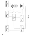
図8は、開示された実施形態と一致する、疑似CT予測モデルを構築するための訓練データを増強するための例示的な方法の図を示す。図8に示す方法は、カスケード訓練技法又は多段階訓練技法とも呼ばれ、最初に訓練された予測モデルが中間予測結果を生成するために使用され、中間予測結果は、データを訓練して、述語モデルをさらに洗練させる。カスケード訓練技術は、複数の訓練段階を含むことができる。各段階において、予測モデルは、前の段階で生成された予測モデルによって生成された予測結果と組み合わされた初期データ(例えば、訓練データ110)を用いて訓練される。
[093]
FIG. 8 shows a diagram of an exemplary method for enhancing training data to build a pseudo-CT prediction model, consistent with the disclosed embodiments. The method shown in FIG. 8, also called a cascade training technique or a multi-step training technique, is that the first trained prediction model is used to generate the intermediate prediction results, which are used to train the data and predicate. Further refine the model. Cascade training techniques can include multiple training stages. At each stage, the prediction model is trained with initial data (eg, training data 110) combined with the prediction results generated by the prediction model generated in the previous step.
[094]
一実施形態では、図1に関して上述したように、疑似CT予測モデル150は、当初構築され、訓練データの初期セットを使用して訓練されてもよい。最初の訓練プロセスの一部として、複数の画像走査から画像特徴が抽出され、抽出された画像特徴から特徴ベクトルが決定される。さらに、CTスキャンから対応するCT値を決定することができる。例えば、各訓練主題のための少なくともひとつのCT画像が利用可能であるべきである。一実施形態では、複数のCT画像が利用可能であってもよい。複数のCT画像が利用可能であれば、CT画像を平均して画像ノイズを低減することができる。疑似CTモデルは、カスケード訓練プロセスの任意の段階で訓練され得る。
[094]
In one embodiment, as described above with respect to FIG. 1, the pseudo
[095]
別の実施形態では、分類予測モデルは、初期モデル又は任意の中間モデルとして訓練されてもよい。上述のように、分類予測モデルは、分類ベースの特徴を抽出して次の訓練段階で使用することができるひとつ以上の区分マップを予測するために使用されてもよい。
[095]
In another embodiment, the classification prediction model may be trained as an initial model or any intermediate model. As mentioned above, the classification prediction model may be used to extract classification-based features and predict one or more classification maps that can be used in the next training stage.
[096]
例示的なカスケード訓練プロセスでは、疑似CT予測モデルが最終段階で訓練され構築されている限り、疑似CT予測モデル及び分類予測モデルを複数のステージ間の任意の組み合わせで使用することができる。
[096]
In the exemplary cascade training process, the pseudo-CT prediction model and the classification prediction model can be used in any combination between multiple stages as long as the pseudo-CT prediction model is trained and constructed in the final stage.
[097]
図8に示すように、最初に構築された予測モデルはモデル#1として示されている。モデル#1は、訓練段階#1の間、各MRスキャン、各CTスキャン、又はMR及びCTスキャンの各ペア(例えば、110a、110b)のような元の訓練データを処理することによって生成される。上述したように、モデル#1は、疑似CT予測モデル又は分類予測モデルであってもよい。モデル#1は、次の段階の訓練プロセスで使用できる。例えば、モデル#1は、複数の予測結果(例えば、予測結果1、ステージ1;予測結果2、ステージ1;...;予測結果N、ステージ1)を生成するために使用することができる。例えば、モデル#1が疑似CT予測モデルである場合、訓練対象aのMRスキャンをモデル#1への入力として使用して(例えば、訓練対象aが新しい患者であり、訓練対象aのMRスキャンが新しいMRスキャンであるかのように)、疑似CT予測結果1120a:予測結果1、ステージ1を生成することができる。別の例では、モデル#1が分類予測モデルである場合、モデル#1の予測結果はセグメントマップであってもよい。他の予測結果1120b...1120Nも同様に生成することができる。次いで、これらの予測結果は、初期訓練データに増強されて、拡張訓練データ1120を形成することができる。例えば、モデル#1から生成された対応する予測結果(例えば、1120a、1120b、...1120N)とMR及びCTスキャンのペア(例えば、110a、110b、...110N)を関連付けることによって、拡張された訓練データ1120を作成することができる。拡張訓練データ1120は、別のモデル(例えば、モデル#2)を生成するために、次の訓練段階で訓練モジュール(例えば、訓練モジュール412)によって使用され得る。
[097]
As shown in FIG. 8, the initially constructed predictive model is shown as
[098]
このようにして、各段階で、新しく洗練された訓練されたモデル(例えば、モデル#2、モデル#3、...モデル#M)を生成することができる。前段階で開発されたモデルは、拡張訓練データ(例えば、拡張訓練データ1120,1130など)を訓練モジュールに適用することによって改良することができる。例えば、モデル#2は、モデル#1によって生成された予測結果を含む拡張訓練データ1120を使用して生成することができる。モデル#2を生成するために、拡張された訓練データ1120は、訓練段階#2において訓練モジュール(例えば、訓練モジュール412)に入力され得る。いくつかの実施形態では、モデル#1によって生成される予測結果は、各訓練対象についての画像(例えば、疑似CT画像)又はマップ(例えば、セグメンテーションマップ)であってもよい。次いで、画像特徴は、例えば、画像特徴抽出モジュール111を使用して、予測結果(例えば、画像又はマップ)から抽出することができる。予測結果から抽出することができる画像特徴は、輝度特徴、文脈特徴、パッチ特徴、局所パターン特徴、ランドマーク特徴など、従来の文章で論じた任意の特徴を含むことができる。予測結果から抽出された特徴は、元のMR画像から抽出された特徴と組み合わされて、各画像点のための新たな拡張特徴ベクトルを形成することができる。拡張特徴ベクトルは、例えばモデル#2を訓練するために次の訓練段階で使用されてもよい。各後続の予測モデル(例えば、モデル#2)は、その以前の予測モデル(例えば、モデル#1)の予測結果を使用して構築され、訓練されるので、予測結果から明らかにされた新しい情報を訓練プロセスに加え、後続の予測モデルを改善することができる。各逐次モデル(例えば、モデル#1、モデル#2、...など)を訓練するために拡張訓練データ(例えば、拡張されたトレーニングデータ1120、1130など)を使用するこのプロセスは、最終予測モデルモデル#Mが訓練され構築されるまで続く。カスケード訓練プロセスの目標が疑似CT予測モデルを構築することである場合、最後のモデルであるモデル#Mは疑似CT予測モデルであり、中間ステージの他のモデルはいずれのモデルでもよい。利用される段階の数は、CT値を正確に予測するためのモデル#Mの検証に依存し得る。例えば、最新のモデルによって生成された疑似CT予測値と元のCT値との間の差が所定の閾値未満である場合、この反復プロセスは停止することができる。別の例では、反復プロセスは、連続する疑似CT予測モデルの予測結果の間の差が所定の閾値未満であるときに停止することができる。
[098]
In this way, new and sophisticated trained models (eg,
[099]
上述したように、カスケード訓練技術は、疑似CT予測モデル及び/又は組織分類モデルの訓練及び構築に適用可能である。組織分類モデルを訓練及び構築する場合、各中間予測モデル(例えば、モデル#1、モデル#2、...モデル#M-1)は、例えば組織ラベルを反映するセグメントマップを提供することができる組織分類モデルであり得る疑似CT値を生成する。上述の多段階訓練プロセスを使用して、各組織分類モデルは、以前のモデルの予測結果を含む拡張データを使用して構築され、訓練され、各段階でモデルを絶えず改良することができる。さらに、組織分類及び疑似CT予測は、多段階プロセスに混在させることができる。例えば、最初のK段階では、訓練されたモデルは組織分類モデルであってもよく、予測結果は組織分類結果であってもよい。組織分類モデルが訓練されると、K+1段階で組織分類結果を使用して疑似CT値を予測することができ、ここで組織分類結果を使用して、抽出された他の特徴と共に特徴の集合をMRスキャンから抽出することができる。M段階に達するまで(例えば、M>K+1の場合)、単一の余分な段階を実行することができる(例えば、M=K+1である場合)又は追加の段階を実行することができる。プロセスの最後に、最終的な予測モデルであるモデル#Mが疑似CT値を生成するように訓練され構築される。
[099]
As mentioned above, cascade training techniques are applicable for training and construction of pseudo-CT prediction models and / or tissue classification models. When training and building a tissue classification model, each intermediate prediction model (eg,
[0100]
図9は、開示された実施形態により、疑似CT値を予測するために多段階モデルを適用する例示的プロセスの図を示す。
[0100]
FIG. 9 illustrates an exemplary process of applying a multi-step model to predict pseudo-CT values according to the disclosed embodiments.
[0101]
図9に示すように、プロセッサ(例えば、図5に示すプロセッサ514)は、画像取得装置440又はデータベース520,530(図5に示す)からひとつ又はそれ以上の患者のMRスキャン310を取得することができる。
[0101]
As shown in FIG. 9, the processor (eg,
[0102]
患者のMRスキャンが取得されると、複数の画像特徴をMRスキャンの各MRボクセルについて抽出することができる。図2に関して上述したように、抽出された画像特徴は、局所パターン特徴212、ランドマーク特徴214、コンテキスト特徴216、及び様々な他のタイプの特徴218を含むことができる。特徴は、画像ポイント、画像ボクセル、又は画像サンプルに関連付けることができる。図9に示すように、画像特徴抽出モジュール311を使用して、MR走査から画像特徴を抽出することができる。画像特徴は、MRボクセルの数値(例えば、強度値、特徴の座標位置など)又はカテゴリ特性(例えば、組織タイプ、構造ラベルなど)を参照することができる。上述したように、各画像点について抽出された画像特徴は、特徴ベクトルを形成することができる。例えば、MRスキャン310のすべての画像ポイントに対する特徴ベクトルのセット(例えば320)は、モデル#1(図8の訓練段階1で生成されたモデル)に入力されてもよい。言い換えれば、プロセッサ514は、図8の多段階訓練プロセスにおける訓練段階1で生成されたモデル#1をMRスキャン310から抽出された一連の特徴ベクトルに適用することができる。モデル#1は、予測結果#1 940(例えば、モデル#1のタイプに応じて、疑似CT値、セグメンテーションマップなど)を出力することができる。その後、予測結果#1 940とMRスキャン310とを組み合わせて別の画像特徴抽出311を行うことができる。より多くの情報が予測結果#1 940によって提供されるので、より多くの画像特徴が第2の抽出から生じ得るか、又は第2の抽出からの画像特徴結果が第1の抽出からの結果よりも優れた品質を有し得る。第2の抽出からの画像特徴結果は、図8の訓練段階2で生成されたモデル#2に入力されて予測結果#2 950を生成することができるMR特徴ベクトルのセットを形成することができ、MRスキャン310と組み合わせることができる。画像特徴抽出モジュール311は、組み合わされた予測結果#2 950及びMRスキャン310からMR特徴ベクトルのセットを再び抽出することができる。このプロセスは、最終予測モデルモデル#Mが疑似CT値340を生成するために適用されるまで繰り返される。いくつかの実施形態によれば、モデル#1からモデル#Mの予測モデルは、訓練プロセスで生成されたモデルと同じ順序で適用されるべきである。疑似CT値340は、患者の解剖学的形状の正確な視覚的表現を示す疑似CT画像350を生成するために使用することができる。
[0102]
Once the patient's MR scan is acquired, multiple image features can be extracted for each MR voxel in the MR scan. As mentioned above with respect to FIG. 2, the extracted image features can include local pattern features 212, landmark features 214, context features 216, and various other types of
[0103]
いくつかの実施形態では、予測モデルのモデル#1、モデル#2、モデル#M-1のうちの任意のひとつは、組織分類モデルであってもよい。例えば、モデル#1は分類モデルであってもよい。MRスキャン310から抽出された特徴ベクトルにモデル#1を適用することにより、分類マップ(例えば、組織分類マップ)を生成することができる。モデル分類マップは、MRスキャン310と共に、画像特徴抽出モジュール311への入力として使用されて、モデル#2が適用され得るより多くの情報又は改善された品質を有する特徴ベクトルを生成することができる。特徴ベクトルをさらに精細化するために、同様のステップを繰り返すことができる。一連の分類モデルは、多段階訓練プロセスから提供されてもよい(図8)。例えば、モデル#1は、分類モデルAであってもよく、モデル#2は、分類モデルBであってもよい。分類モデルA及び分類モデルBは、同一の組織クラスであるが異なる精緻に関連してもよく、又は異なる組織クラスに関連してもよい。上述のように、最終予測モデル#Mは、開示された実施形態により、疑似CT値340を生成する疑似CT予測モデルである。
[0103]
In some embodiments, any one of
[0104]
いくつかの実施形態では、予測モデルは、マルチチャネルMRスキャン及び対応するCT値を含む訓練データ110(図1に示す)で構築及び訓練することができる。マルチチャネルMRスキャンは、シングルチャネルMRスキャンより多くの情報を提供する。マルチチャネルMR画像で利用可能な情報の増加は、疑似CT画像を生成するためにCT値のより正確でより堅牢な予測を可能にする。例えば、マルチチャネルMR画像は、MR強度値から固有の組織パラメータ値への変換を可能にする。
[0104]
In some embodiments, the predictive model can be constructed and trained with training data 110 (shown in FIG. 1) containing multi-channel MR scans and corresponding CT values. Multi-channel MR scans provide more information than single-channel MR scans. The increase in information available in multi-channel MR images allows for more accurate and more robust predictions of CT values to generate pseudo CT images. For example, a multi-channel MR image allows conversion of MR intensity values to unique tissue parameter values.
[0105]
MRIは、磁気及び無線周波数(RF)フィールドの操作を通じて、人体の様々な特性(例えば、構造的及び機能的の両方)の研究を可能にする、非常に汎用性の高いイメージング技術である。標準的な構造(又は解剖学的)イメージングのために、測定されたMR信号(例えば、MR画像強度)は、いくつかの固有の組織パラメータ、すなわちプロトン密度(P)、縦緩和時間(T1)及び横緩和時間(T2又はT*
2(磁場の不均一性の影響を考慮した場合))の関数である。例えば、FLASH及びSPGRイメージングプロトコル(例えばイメージングシーケンスとしても知られている)の両方について、MR信号強度(S)は、式2に従って固有の組織パラメータ(P、T1、及びT*
2)の関数として表すことができる。
[0105]
MRI is a highly versatile imaging technique that allows the study of various properties of the human body (eg, both structural and functional) through manipulation of magnetic and radio frequency (RF) fields. For standard structural (or anatomical) imaging, the measured MR signal (eg, MR image intensity) has some unique tissue parameters: proton density (P), longitudinal relaxation time (T 1 ). ) And the lateral relaxation time (T 2 or T * 2 (when considering the effect of magnetic field non-uniformity)). For example, for both FLASH and SPGR imaging protocols (eg, also known as imaging sequences), the MR signal strength (S) is a function of the unique tissue parameters (P, T 1 , and T * 2 ) according to

ここで、TR、TE、及びαは、ユーザが自由に変更できるMR取得パラメータである。異なるパラメータを使用して、異なる画像コントラストを生成することができる。 Here, TR, TE, and α are MR acquisition parameters that can be freely changed by the user. Different parameters can be used to generate different image contrasts.
[0106]
MR画像からCT数を予測するために、予測モデルは、シーケンスパラメータ(TR、TE、及びα)に依存するMR信号強度Sの代わりに、主に固有組織パラメータ(P、T1、及びT*
2)に依存してもよい。何故ならシーケンスパラメータ(TR、TE、及びα)は患者の解剖学的特性を少なくとも直接には表していないからである。
[0106]
To predict the number of CTs from MR images, the prediction model is predominantly specific tissue parameters (P, T 1 , and T * ) instead of MR signal strength S, which depends on sequence parameters (TR, TE, and α). You may depend on 2 ). This is because the sequence parameters (TR, TE, and α) do not at least directly represent the patient's anatomical characteristics.
[0107]
マルチチャネルMR画像を使用すると、シーケンスパラメータ(TR、TE、及びα)の異なる設定を有する各画像を有する複数の画像を提供することができるため、これらの固有の組織パラメータの推定を可能にする。したがって、マルチチャネルMR画像は、Sの複数の値とシーケンスパラメータ(TR、TE、及びα)が既知である式2を解くことによって、固有の組織パラメータ(P、T1、及びT*
2)の推定を可能にする。例えば、3つの未知のパラメータ(P、T1、及びT*
2)すべて推定するために、3つのMR画像(例えば、3つのチャネル)が必要とされる。追加のチャネルを使用することは、画像ノイズを低減することによってパラメータ推定のロバスト性(robustness)を改善する。
[0107]
Multi-channel MR images can be used to provide multiple images with each image having different settings of sequence parameters (TR, TE, and α), thus allowing estimation of these unique tissue parameters. .. Therefore, the multi-channel MR image has unique tissue parameters (P, T 1 , and T * 2 ) by solving
[0108]
いくつかの実施形態では、開示された方法を実施するためのワークフローは、訓練(例えば、モデル構築)ステージと適用(例えば、疑似CT生成)ステージの2つのステージを含む。いくつかの実施形態では、訓練ステージは、訓練データが収集された後に一度計算されるだけでよい。(c)
予測モデルを訓練した後、適用ステージで、訓練されたモデルを新しいマルチチャネルMRスキャンに適用して、マルチチャネルMRスキャンのみを有する新しい患者の疑似CT画像を生成することができる。以下の説明では、図10及び図11は訓練ステージについてでありし、図12は予測ステージについてである。
[0108]
In some embodiments, the workflow for implementing the disclosed method comprises two stages: a training (eg, model building) stage and an application (eg, pseudo-CT generation) stage. In some embodiments, the training stage only needs to be calculated once after the training data has been collected. (c)
After training the predictive model, at the application stage, the trained model can be applied to a new multi-channel MR scan to generate a pseudo-CT image of a new patient with only a multi-channel MR scan. In the following description, FIGS. 10 and 11 are for the training stage and FIG. 12 is for the prediction stage.
[0109]
図10は、マルチチャネルMRスキャンから推定された組織パラメータを用いて疑似CT予測モデルを訓練するための例示的プロセスの図を示す。図1に示すプロセスと同様に、CTスキャンとマルチチャネルMRスキャンの両方を有する複数の訓練対象からの訓練データを収集することができる。例えば、図10に示すように、被検体aに対して、マルチチャンネルMR画像データ1010a及びCT画像データ1014aを収集することができる。マルチチャネルMRデータ1010aは、異なるシーケンスパラメータセットを使用して得られた複数のMR画像を含むことができる。同様に、被検体bについて、マルチチャネルMR画像データ1010b、CT画像データ1014bを取得することができる。マルチチャネルMR画像データ及びCT画像データは、画像取得装置(例えば、440)又は画像データベース(例えば、520,530)から収集することができる。データ取得/収集のプロセスは、n番目のデータセット(例えば1010nと1014n)が訓練データに含まれるまで続きます。一実施形態では、図10に示す訓練データは、図10のMR画像データがマルチチャネルMRデータであることを除いて、図1の訓練データ110と同様であるが、一方、図1のMRデータは、チャネル又はマルチチャネルのMRデータのいずれかである。
[0109]
FIG. 10 shows a diagram of an exemplary process for training a pseudo-CT prediction model using tissue parameters estimated from multi-channel MR scans. Similar to the process shown in FIG. 1, training data from multiple training subjects with both CT scans and multi-channel MR scans can be collected. For example, as shown in FIG. 10, multi-channel
[0110]
いくつかの実施形態では、CTスキャン(例えば、1014a)及びマルチチャネルMRスキャン(例えば、1010a)が整列される。そうでない場合には、自動又は半自動画像登録又は整列手順を適用してそれらを整列させることができる。上述のように、CT画像とMR画像の位置合わせされたペアは、各ボクセル(例えば、画像の空間的位置を示す)について、対応するCT及びMR画像値が既知であるか、又は対応関係が分かっていることを意味する。加えて、MR画像は、幾何学的歪みを補正するために何らかの手順を経ることもある。
[0110]
In some embodiments, CT scans (eg, 1014a) and multi-channel MR scans (eg, 1010a) are aligned. If not, automatic or semi-automatic image registration or alignment procedures can be applied to align them. As mentioned above, the aligned pair of CT and MR images has a known or correspondence relationship with the corresponding CT and MR image values for each voxel (eg, indicating the spatial position of the image). It means that you know. In addition, MR images may undergo some steps to correct for geometric distortion.
[0111]
本出願は、訓練データを使用して予測モデルを構築して訓練する学習ベースのアプローチを開示する。一実施形態では、予測モデルは、予測モデルの出力が連続変数(例えば、CT値)であり得るように、回帰モデル又は回帰関数であり得る。
[0111]
This application discloses a learning-based approach to build and train predictive models using training data. In one embodiment, the predictive model can be a regression model or a regression function, just as the output of the predictive model can be a continuous variable (eg, CT value).
[0112]
MR画像から得られた特徴に基づいてCT画像強度(CT値又はCT数としても知られている)を予測することができる予測モデルを構築及び/又は訓練するために、多くの統計学的又は機械学習法を使用することができる。例えば、教師付き学習は、学習データの集合に基づいて予測モデルを決定するために使用することができる機械学習のブランチである。訓練データの各サンプルは、入力データ(例えば、測定値又は特徴のベクトル)及び所望の出力値(例えば、監視信号)を含むペアである。教師付き学習アルゴリズムは、疑似CT画像を生成するアプリケーションにおいて、通常、出力変数が数値又は連続である場合、訓練データを分析して予測関数(例えば、回帰関数)を生成することができる。様々なアルゴリズムを適用して、サポートベクトルマシン、ニューラルネットワーク、決定木、及びランダムフォレストを含むが、これらに限定されない予測モデルを決定することができる。
[0112]
Many statistical or training to build and / or train a predictive model capable of predicting CT image intensity (also known as CT value or CT number) based on features obtained from MR images. Machine learning methods can be used. For example, supervised learning is a branch of machine learning that can be used to determine predictive models based on a set of training data. Each sample of training data is a pair containing input data (eg, a measured value or a vector of features) and a desired output value (eg, a monitoring signal). In an application that produces a pseudo CT image, a supervised learning algorithm can typically analyze training data to generate a predictive function (eg, a regression function) when the output variables are numerical or continuous. Various algorithms can be applied to determine predictive models, including, but not limited to, support vector machines, neural networks, decision trees, and random forests.
[0113]
訓練データを用いて訓練された予測モデルは、同一又は異なる患者の任意の新しいマルチチャネルMRスキャンセットに対して疑似CT画像を生成するために使用することができる。
[0113]
Predictive models trained with training data can be used to generate pseudo-CT images for any new multi-channel MR scan set of the same or different patients.
[0114]
本願の実施形態は、MR強度値(例えば、S)を固有の組織パラメータ(例えば、P、T1、T*
2、又はT*
2)に変換し、固有の組織パラメータに基づいて予測モデルを構築することができる。上述のように、MRイメージングを使用する能力は、CTイメージングよりも大きなフレキシビリティとより少ない放射線被曝を提供するが、MR強度値は、シーケンス依存性であるため、投与量計算に直接使用することはできない。生のMR強度値を使用する代わりに、固有の組織パラメータを使用して予測モデルを訓練することは、シーケンスに依存しない予測モデルを提供することができる。配列に依存しないことは、画像化配列又は配列パラメータが容易に変更可能であり、しばしば異なる診療所間で著しく異なるため、有利であり得る。予測モデルを配列に依存しないように設計することにより、MRシーケンスを用いて固有の組織パラメータを推定することができるならば、異なるMRスキャナ、異なるMR画像シーケンス、又は異なる診療所から取得したデータを一緒に使用することができる。さらに、新しい患者のMRイメージングシーケンスは、訓練データによって使用されるMRイメージングシーケンスと同じである必要はない。したがって、ユーザは、予測モデルを訓練するために新たな訓練データを取得する必要なく、将来の患者のために新しいMR画像シーケンスを自由に設計することができる。
[0114]
An embodiment of the present application converts MR intensity values (eg, S) into unique tissue parameters (eg, P, T 1 , T * 2 , or T * 2 ) and creates a predictive model based on the unique tissue parameters. Can be built. As mentioned above, the ability to use MR imaging provides greater flexibility and less radiation exposure than CT imaging, but MR intensity values are sequence-dependent and should be used directly in dose calculations. Can't. Training predictive models with unique tissue parameters instead of using raw MR intensity values can provide sequence-independent predictive models. Sequence independence can be advantageous as the imaging sequences or sequence parameters are easily modifiable and often significantly different between different clinics. Data obtained from different MR scanners, different MR image sequences, or different clinics, if unique tissue parameters can be estimated using MR sequences by designing the prediction model to be sequence independent. Can be used together. Moreover, the MR imaging sequence of the new patient does not have to be the same as the MR imaging sequence used by the training data. Therefore, the user is free to design new MR image sequences for future patients without having to acquire new training data to train the predictive model.
[0115]
組織パラメータに基づいて予測モデルを構築するには、MR画像強度を各患者の組織パラメータ値に変換する必要がある。これは、患者のMR画像の各画像点(例えば、ボクセル)においてMR画像化方程式(例えば、式2)を解くことによって達成することができる。組織パラメータ画像(組織パラメータマップとも呼ばれる)のセットを生成することができる。このセットは、各組織パラメータのひとつの組織パラメータマップを含むことができる。例えば、セットは、Pのマップと、T1のマップと、T2又はT*
2のマップを含むことができる。組織パラメータ値は、患者の体の下にある組織又は器官の特性を反映する固有の値である。さらに、CT画像は各訓練対象についてMR画像と整列されるので、CT画像はMR画像から生成された組織パラメータマップとさらに整列する。
[0115]
To build a predictive model based on tissue parameters, MR image intensities need to be converted to tissue parameter values for each patient. This can be achieved by solving the MR imaging equation (eg, Equation 2) at each image point (eg, voxel) of the patient's MR image. A set of tissue parameter images (also called tissue parameter maps) can be generated. This set can include one tissue parameter map for each tissue parameter. For example, the set can include a map of P, a map of T 1 , and a map of T 2 or T * 2 . Tissue parameter values are unique values that reflect the characteristics of the tissues or organs beneath the patient's body. Further, since the CT image is aligned with the MR image for each training object, the CT image is further aligned with the tissue parameter map generated from the MR image.
[0116]
図10に示すように、各訓練対象の組織パラメータマップは、マルチチャネルMR画像データに基づいて生成されてもよい。例えば、被験体aの組織パラメータマップ1012aは、3つの組織パラメータマップのすべてのセットを含むことができる。いくつかの実施形態では、マルチチャネルMR画像からのすべての組織パラメータの推定が困難な場合、モデルは、組織パラメータのサブセットのみを使用して構築することもできる。各訓練対象の組織パラメータマップ(例えば、1012b、...、1012n)が得られると、訓練モジュール1045を使用して疑似CT予測モデル1050を構築して訓練するために、組織パラメータマップを対応するCT画像と共に使用することができる(例えば、統計的又は機械的学習技術を使用して)。いくつかの実施形態では、各画像点(例えば、ボクセル)について、組織パラメータのセットは、図1で説明したように特徴ベクトルに含まれる特徴として扱うことができる。例えば、3つの組織パラメータのすべてが使用される場合、[P、T1、T*
2]の特徴ベクトルを構成することができる。この組織パラメータ特徴ベクトルは、予測モデルを構築し訓練するために、図2に関連して説明したように、単独で、又は他の特徴と組み合わせて使用することができる。上述の予測モデル150を構築し訓練する開示された技術は、予測モデル1050を構築し訓練するプロセスにも適用可能である。
[0116]
As shown in FIG. 10, the tissue parameter map for each training target may be generated based on the multi-channel MR image data. For example, the
[0117]
図11は、マルチチャネルMRデータを使用して疑似CT予測モデルを構築する例示的な方法1100のフローチャートである。方法1100は、システム500によって実装することができる。ステップ1110において、プロセッサ514は、マルチチャネルMRデータ(例えば、1010a、1010bなど)及びCTデータ(例えば、1014a、1014bなど)を含む訓練データを受信することができる。マルチチャネルMRデータは、1人又はそれ以上の患者のマルチチャネルMR画像を含むことができる。いくつかの実施形態では、マルチチャネルMRデータは、各患者について少なくとも2つのマルチチャネルMR画像を含むことができる。同じ患者のマルチチャネルMR画像は、異なる撮像シーケンスパラメータを使用して得ることができる。CTデータは、1人以上の患者のCT画像を含むことができる。いくつかの実施形態では、CTデータは、各患者について少なくともひとつのCT画像を含むことができる。複数のCT画像が利用可能であれば、それらを平均して画像ノイズを低減することができる。所与の患者に対して、CT画像及びマルチチャネルMR画像は整列され得る。いくつかの実施形態では、CT画像及びマルチチャネルMR画像が位置合わせされていない場合、画像位置合わせ技術を使用してそれらを位置合わせすることができる。
[0117]
FIG. 11 is a flowchart of an
[0118]
ステップ1120において、プロセッサ514は、マルチチャネルMRデータからのMR強度に基づいて、少なくともひとつの組織パラメータマップ(例えば、1012a、1012bなど)を決定することができる。P、T1、T*
2の少なくともひとつの組織パラメータマップは、数式2を解くことによって患者の複数のMR画像のMR強度値を用いて推定することができる。数式2は非線形方程式であるので、フィッティング技法を使用して、マルチチャネルMRデータに基づいて既知である複数のMR強度(S)及びシーケンスパラメータ(TR、TE、及びα)に基づいて組織パラメータ値を推定することができる。上述のように、3つの組織パラメータマップのすべてが好ましいが、組織パラメータマップのサブセットが使用されてもよい。
[0118]
In
[0119]
いくつかの実施形態では、組織パラメータマップは、個々の画像点を推定することによって生成することができる。例えば、いくつかの種類の組織パラメータ(例えば、P、T1、T*
2、又はT*
2)を含む組織パラメータ値のセットは、あらゆる画像ポイントで推定されてもよい。対応する組織パラメータマップは、特定の種類の全ての組織パラメータ値の集合として形成することができる。
[0119]
In some embodiments, the tissue parameter map can be generated by estimating individual image points. For example, a set of tissue parameter values including several types of tissue parameters (eg, P, T 1 , T * 2 , or T * 2 ) may be estimated at any image point. The corresponding tissue parameter map can be formed as a set of all tissue parameter values of a particular type.
[0120]
ステップ1130において、プロセッサ514は、ステップ1120で生成された組織パラメータマップに対応するCT値を取得することができる。いくつかの実施形態では、CT値は、組織パラメータマップと同じ患者のCT画像のCT強度値であってもよい。上述したように、CT画像はMR画像と位置合わせされるので、CT画像はまた、MR画像から変換された組織パラメータマップと位置合わせされる。
[0120]
In
[0121]
ステップ1140において、プロセッサ514は、CT値及び組織パラメータマップに基づいて疑似CT予測モデル(例えば、1050)を生成することができる。いくつかの実施形態では、疑似CTモデル1050を訓練するために、CT値及び組織パラメータマップを訓練モジュール(例えば、1045)に入力することができる。統計的学習又は機械学習技術のような回帰方法は、予測モデルを訓練するために訓練モジュール1045によって使用されてもよい。訓練された予測モデル1050は、ひとつ又はそれ以上の組織パラメータ値(例えば、P、T1、T*
2、T*
2)に基づいてCT値を予測するために使用され得る数学的又は統計的モデルであり得る。上述のように、全ての組織パラメータを使用することが好ましいが、組織パラメータのサブセットのみを使用してモデルを構築することもできる。
[0121]
In step 1140,
[0122]
図12は、マルチチャネルMR画像を用いて患者の疑似CT画像を生成するための方法例1200のフローチャートである。方法1200は、システム500によって実施され、方法1100によって構築された予測モデル(例えば、1050)を使用して新しい患者の疑似CT画像を生成するために使用されてもよい。
[0122]
FIG. 12 is a flowchart of a method example 1200 for generating a pseudo CT image of a patient using a multi-channel MR image.
[0123]
ステップ1210において、プロセッサ514は、例えば画像取得装置440又はデータベース520,530から患者(例えば、新しい患者)のマルチチャネルMR画像を受信することができる。受信されたマルチチャネルMR画像は、対応するCT画像を有していなくてもよい。ステップ1220において、プロセッサ514は、マルチチャネルMR画像を少なくともひとつの組織パラメータマップに変換することができる。例えば、プロセッサ514は、フィッティング技術などを用いて数式2を解くことによって、マルチチャネルMR画像を組織パラメータマップに変換することができる。P、T1、T*
2、及び/又はT*
2のマップのような、ひとつ又はそれ以上の組織パラメータマップが、変換プロセス1220によって生成されてもよい。上述のように、すべての組織パラメータマップを有することが好ましいが、いくつかの実施形態では、マップのサブセットもまた使用され得る。
[0123]
In
[0124]
ステップ1230において、プロセッサ514は、組織パラメータマップに予測モデル(例えば、1050)を適用することができる。例えば、変換された組織パラメータマップは、予測モデルへの入力として使用されてもよい。いくつかの実施形態では、予測モデルは、ポイントモデル方式で動作することができ、ここで、予測モデルは、その場所で計算された組織パラメータ値に基づいて患者画像の各位置(例えば、疑似CT画像)でのCT値を予測する。より複雑な予測モデルを使用することもできる。例えば、モデルは、各点について近傍の組織パラメータ値を考慮に入れることができ、データノイズに関する頑健性を改善することができる。モデルはまた、組織パラメータ値と、画像ポイント位置のような他の情報、又は、例えば、テクスチャ、グラジエントなどの組織パラメータマップから導き出され得る他の特徴との組み合わせに基づいて予測を行うことができる。
[0124]
At
[0125]
ステップ1240において、患者の疑似CT画像は、ステップ1230から得られた疑似CT値を組み立てることによって生成することができる。
[0125]
At
[0126]
予測モデルを訓練し、モデルを使用して疑似CT値を予測するには、線形回帰又は一般最小二乗回帰などのパラメトリック手法を使用することができる。これらのパラメトリック法では、回帰関数は、入力データから推定できる有限数の未知モデルパラメータによって定義される。例えば、回帰モデルは次のように定義できる。
[0126]
Parametric techniques such as linear regression or general least-squares regression can be used to train a predictive model and use the model to predict pseudo-CT values. In these parametric methods, the regression function is defined by a finite number of unknown model parameters that can be estimated from the input data. For example, the regression model can be defined as:
![]()
![]()
ここで、Hは予測されるCT値を示し、Xは入力変数のベクトル、例えば組織パラメータ値(P、T1、及びT* 2(又はT2))を示し、βは回帰モデルの未知モデルパラメータのベクトルを示す。ひとつの例示的なモデルは次のように定義される線形回帰モデルである。 Here, H indicates the predicted CT value, X indicates the vector of the input variable, for example, the tissue parameter value (P, T 1 , and T * 2 (or T 2 )), and β indicates an unknown model of the regression model. Shows a vector of parameters. One exemplary model is a linear regression model defined as follows.
![]()
![]()
[0127]
訓練ステージでは、訓練データは多数の観測、例えば、(例えば、ステップ1130でのCTスキャンにより提供される)既知のH値と、(例えば、ステップ1120でのMRスキャンを変換することにより提供される)対応するP、T1、及びT*
2値、を提供することができる。これらの観測データを使用して、モデルパラメータを(例えば、最小二乗フィッティングを使用して)計算又は訓練することができる。訓練後にβが得られると、モデルは、(例えば、方法1200を使用して予測ステージにおいて)P、T1、及びT*
2値の新しいセットに対するHを計算するために使用することができる。
[0127]
At the training stage, training data is provided by converting a number of observations, eg, known H values (eg, provided by a CT scan in step 1130), and MR scans (eg, provided by a CT scan in
[0128]
いくつかの実施形態では、予測モデルの入力データとして組織パラメータを使用する代わりに、又はそれに加えて、他の情報も収集することができる。たとえば、計算又は収集できる余分な特徴には、以下のものが含まれるが、これらに限定されない。
・イメージポイントの座標、又は外部参照空間又はひとつ又はいくつかの内部ランドマークポイントに対する正規化座標。
・サンプルポイント位置で計算された組織パラメータマップの曲率。
・サンプルポイント位置で計算された組織パラメータマップのテクスチャ測定値。
・局所組織パラメータ値のパッチ、例えば、サンプル点の5×5×5近傍内の組織パラメータ値。
[0128]
In some embodiments, other information can be collected instead of or in addition to using organizational parameters as input data for the predictive model. For example, extra features that can be calculated or collected include, but are not limited to:
-Coordinates of image points, or normalized coordinates for external reference space or one or several internal landmark points.
-Curvature of the tissue parameter map calculated at the sample point position.
-Texture measurements of the tissue parameter map calculated at the sample point location.
• A patch of local tissue parameter values, eg, tissue parameter values within the 5x5x5 neighborhood of the sample point.
[0129]
本明細書の記述及び方法に基づいたコンピュータプログラムは、ソフトウェア開発者の技術の範囲内である。様々なプログラム又はプログラムモジュールは、様々なソフトウェアプログラミング技術を使用して作成することができる。例えば、プログラムセクション又はプログラムモジュールは、Java、Python、C、C++、アセンブリ言語、又は既知のプログラミング言語で設計することができる。このようなソフトウェアのセクション又はモジュールのひとつ又はそれ以上は、コンピュータシステム及び/又はコンピュータ読み土地可能媒体に統合することができる。
[0129]
Computer programs based on the descriptions and methods herein are within the skill of the software developer. Various programs or program modules can be created using various software programming techniques. For example, a program section or program module can be designed in Java, Python, C, C ++, assembly language, or a known programming language. One or more sections or modules of such software may be integrated into computer systems and / or computer-readable landable media.
[0130]
さらに、例示的な実施形態が本明細書において説明したが、本開示に基づく等価な要素、修正、省略、(様々な実施形態にわたる態様の)組み合わせ、適合又は変更を有する任意の及びすべての実施形態を含む。特許請求の範囲の要素は、特許請求の範囲で使用されている言語に基づいて広く解釈されるべきであり、本明細書に記載された実施例に限定されるものではなく、アプリケーションの実行中に限定されるものではない。したがって、明細書及び実施例は、単なる例示としてみなされ、真の範囲及び精神は、添付の特許請求の範囲及びそれらの等価物の全範囲によって示されるものである。
[0130]
Moreover, although exemplary embodiments have been described herein, any and all embodiments having equivalent elements, modifications, omissions, combinations (in aspects across various embodiments), conformances or modifications under the present disclosure. Including morphology. The elements of the claims should be broadly construed based on the language used in the claims and are not limited to the embodiments described herein and are running the application. Not limited to. Therefore, the specification and examples are taken as mere examples, and the true scope and spirit are shown by the scope of the appended claims and their equivalents in their entirety.
Claims (13)
複数の訓練対象に対する磁気共鳴(MR)データ及びコンピュータ断層撮影(CT)データを含む訓練データを格納するように構成されたデータベースであって、ひとつの訓練対象はひとつの訓練データに対応しており、前記ひとつの訓練データは複数のMR画像及びひとつのCT画像を有し、前記複数のMR画像は異なるMRイメージングプロトコルパラメータを用いて取得されたものであるデータベースと、
前記データベースに格納された情報にアクセスするために前記データベースに通信可能に結合されたプロセッサと、
前記プロセッサに通信可能に結合されたメモリを有し、
前記メモリは、前記プロセッサによって実行されると、前記プロセッサが操作を実行するように構成された命令を格納しており、
前記操作は、
前記データベースにアクセスして、前記訓練データを取り出すステップと、
前記訓練対象に対して、前記MR画像に関連するMRイメージングプロトコルパラメータを取得し、前記MRイメージングプロトコルパラメータに基づいて組織パラメータマップを決定し、前記ひとつのCT画像から、前記組織パラメータマップに対応するCT値を計算するステップと、
前記組織パラメータマップと前記計算されたCT値とに基づいて疑似CT予測モデルを生成するステップとを含む
ことを特徴とする疑似CT予測モデルを生成するシステム。 A system that generates a pseudo CT prediction model,
It is a database configured to store training data including magnetic resonance (MR) data and computer tomography (CT) data for multiple training subjects, and one training target corresponds to one training data. A database in which the one training data has a plurality of MR images and one CT image, and the plurality of MR images are acquired using different MR imaging protocol parameters.
With a processor communicatively coupled to the database to access information stored in the database.
It has a memory communicatively coupled to the processor and has
The memory stores instructions configured to perform an operation on the processor when executed by the processor.
The above operation is
The step of accessing the database and retrieving the training data,
For the training target, MR imaging protocol parameters related to the MR image are acquired, a tissue parameter map is determined based on the MR imaging protocol parameters, and the tissue parameter map corresponds to the tissue parameter map from the one CT image. Steps to calculate the CT value and
A system for generating a pseudo CT prediction model, comprising: a step of generating a pseudo CT prediction model based on the tissue parameter map and the calculated CT value.
前記組織パラメータマップは、陽子密度マップと縦緩和時間マップと横緩和時間マップとを含むグループから選択されている
ことを特徴とする疑似CT予測モデルを生成するシステム。 In the system according to claim 1,
The tissue parameter map is a system that generates a pseudo-CT prediction model characterized in that it is selected from a group including a proton density map, a longitudinal relaxation time map, and a lateral relaxation time map.
前記組織パラメータマップを決定することは、前記MRイメージングプロトコルパラメータと、画像点に対応するそれぞれの画像位置における前記MR画像のMR画像強度値とに基づいて、前記組織パラメータマップの画像点の組織パラメータ値を推定することを含む
ことを特徴とする疑似CT予測モデルを生成するシステム。 In the system according to claim 1,
Determining the tissue parameter map is based on the MR imaging protocol parameters and the MR image intensity value of the MR image at each image position corresponding to the image point. A system that produces a pseudo-CT prediction model, characterized in that it involves estimating parameter values.
前記複数のMR画像の数は3以上である
ことを特徴とする疑似CT予測モデルを生成するシステム。 In the system according to claim 1,
The number of the plurality of MR images is 3 or more.
A system that generates a pseudo-CT prediction model.
前記操作は、
前記MR画像と前記CT画像とを整列させるステップを含む
ことを特徴とする疑似CT予測モデルを生成するシステム。 In the system according to claim 1,
The above operation is
A system for generating a pseudo CT prediction model, which comprises a step of aligning the MR image and the CT image.
前記訓練データは、第1の訓練対象の複数のMR画像の第1のセットと第2の訓練対象の複数のMR画像の第2のセットとを含み、前記第1のセットのMR画像と前記第2のセットのMR画像とは異なるMRイメージングプロトコルパラメータを用いて取得されたものであり、
前記操作は、
前記第1のセットのMR画像と前記第2のセットのMR画像の両方からのデータを用いて前記疑似CT予測モデルを生成するステップを含む
ことを特徴とする疑似CT予測モデルを生成するシステム。 In the system according to claim 1,
The training data includes a first set of a plurality of MR images of a first training target and a second set of a plurality of MR images of a second training target, and the MR images of the first set and the said. Obtained using MR imaging protocol parameters different from the second set of MR images.
The above operation is
A system for generating a pseudo CT prediction model, comprising the step of generating the pseudo CT prediction model using data from both the first set of MR images and the second set of MR images.
前記操作は、
前記MR画像、及び前記組織パラメータマップから特徴を抽出するステップと、
前記組織パラメータマップと、前記抽出された特徴と、前記CT値とに基づいて前記疑似CT予測モデルを生成するステップを含む
ことを特徴とする疑似CT予測モデルを生成するシステム。 In the system according to claim 1,
The above operation is
A step of extracting features from the MR image and the tissue parameter map,
A system for generating a pseudo CT prediction model, which comprises a step of generating the pseudo CT prediction model based on the tissue parameter map, the extracted features, and the CT value.
前記抽出された特徴は、
画像点の座標、
前記MR画像の外部の基準点に対して正規化された座標、
前記MR画像内のひとつ又はそれ以上のランドマーク点に対して正規化された座標、
サンプルポイント位置で計算された前記組織パラメータマップの曲率、
前記組織パラメータマップのテクスチャ測定値、又は
前記組織パラメータマップ内の画像パッチ
のうちの少なくともひとつを含む
ことを特徴とする疑似CT予測モデルを生成するシステム。 In the system according to claim 7 ,
The extracted features are
Image point coordinates,
Coordinates normalized to a reference point outside the MR image,
Coordinates normalized to one or more landmark points in the MR image,
Curvature of the tissue parameter map calculated at the sample point position,
A system that generates a pseudo-CT prediction model comprising at least one of the texture measurements in the tissue parameter map or the image patches in the tissue parameter map.
プロセッサと、
前記プロセッサに通信可能に結合されたメモリを有し、
前記メモリは、前記プロセッサによって実行されると、前記プロセッサが操作を実行するように構成された命令を格納しており、
前記操作は、
患者の磁気共鳴(MR)画像を受信するステップであって、複数の前記MR画像は異なるMRイメージングプロトコルパラメータを用いて取得されたものであるステップと、
前記MR画像を取得するために用いられたMRイメージングプロトコルパラメータを取得するステップと、
前記MRイメージングプロトコルパラメータに基づいて組織パラメータマップを決定するステップと、
前記組織パラメータマップに予測モデルを適用することによってCT値を生成するステップと、
前記生成されたCT値に基づいて前記疑似CT画像を生成するステップを含み、
前記予測モデルは、MRイメージングプロトコルパラメータの第1のセットを用いて取得されたMR画像の第1のセットによって訓練され、
前記受信されたMR画像は、前記MRイメージングプロトコルパラメータの第1のセットとは異なるMRイメージングプロトコルパラメータの第2のセットを用いて取得されたものである
ことを特徴とする疑似CT画像を生成するシステム。 A system that generates pseudo-Computed Tomography (CT) images.
With the processor
It has a memory communicatively coupled to the processor and has
The memory stores instructions configured to perform an operation on the processor when executed by the processor.
The above operation is
A step of receiving a magnetic resonance (MR) image of a patient, wherein the plurality of MR images are obtained using different MR imaging protocol parameters.
The step of acquiring the MR imaging protocol parameters used to acquire the MR image, and
Steps to determine the tissue parameter map based on the MR imaging protocol parameters,
A step of generating CT values by applying a predictive model to the tissue parameter map,
Including the step of generating the pseudo CT image based on the generated CT value.
The predictive model is trained by a first set of MR images acquired using the first set of MR imaging protocol parameters.
The received MR image produces a pseudo CT image characterized by being acquired using a second set of MR imaging protocol parameters that is different from the first set of MR imaging protocol parameters. system.
コンピュータープロセッサを用いて、データベースから、複数の訓練対象に対する磁気共鳴(MR)画像と第1のコンピュータ断層撮影(CT)画像とを含む訓練データを取り出すステップであって、ひとつの訓練対象はひとつの訓練データに対応しており、前記MR画像は異なるMRイメージングプロトコルパラメータを用いて取得されたものであるステップと、
前記コンピュータープロセッサを用いて、前記訓練対象に対して、前記MR画像を取得するのに用いられたMRイメージングプロトコルパラメータを取得し、前記MRイメージングプロトコルパラメータに基づいて組織パラメータマップを決定し、前記第1のCT画像から、前記組織パラメータマップに対応するCT値を計算するステップと、
前記コンピュータープロセッサを用いて、前記訓練対象の前記組織パラメータマップと前記計算されたCT値とに基づいて疑似CT予測モデルを生成するステップとを含む
ことを特徴とするコンピュータに実装された方法。 A computer-implemented method for generating pseudo-CT prediction models.
It is a step of extracting training data including a magnetic resonance (MR) image and a first computer tomography (CT) image for a plurality of training objects from a database using a computer processor, and one training target is one. The steps that correspond to the training data and the MR images were acquired using different MR imaging protocol parameters,
Using the computer processor, the MR imaging protocol parameters used to acquire the MR image are acquired for the training target, the tissue parameter map is determined based on the MR imaging protocol parameters, and the tissue parameter map is determined. A step of calculating a CT value corresponding to the tissue parameter map from the CT image of 1.
A method implemented in a computer comprising the steps of using the computer processor to generate a pseudo-CT prediction model based on the tissue parameter map of the training target and the calculated CT values.
前記組織パラメータマップは、陽子密度マップと縦緩和時間マップと横緩和時間マップとを含むグループから選択されている
ことを特徴とするコンピュータに実装された方法。 In the method of claim 10 ,
A computer-implemented method characterized in that the tissue parameter map is selected from a group that includes a proton density map, a longitudinal relaxation time map, and a horizontal relaxation time map.
固有の組織パラメータに対する組織パラメータマップを決定することは、前記MRイメージングプロトコルパラメータと、画像点に対応するそれぞれの画像位置における前記MR画像のMR画像強度値とに基づいて、前記組織パラメータマップの画像点の組織パラメータ値を推定することを含む
ことを特徴とするコンピュータに実装された方法。 In the method of claim 10 ,
Determining the tissue parameter map for the unique tissue parameter is based on the MR imaging protocol parameter and the MR image intensity value of the MR image at each image position corresponding to the image point. A computer-implemented method comprising estimating the tissue parameter values of an image point of.
前記訓練データは、第1の訓練対象のMR画像の第1のセットと第2の訓練対象のMR画像の第2のセットとを含み、前記第1のセットのMR画像と前記第2のセットのMR画像とは異なるMRイメージングプロトコルパラメータを用いて取得されたものであり、
前記方法は、
前記第1のセットのMR画像と前記第2のセットのMR画像の両方からのデータを用いて前記疑似CT予測モデルを生成するステップを含む
ことを特徴とするコンピュータに実装された方法。 In the method of claim 10 ,
The training data includes a first set of MR images to be trained first and a second set of MR images to be trained second, the MR images of the first set and the second set. It was obtained using MR imaging protocol parameters different from the MR image of.
The method is
A computer-implemented method comprising the step of generating the pseudo CT prediction model using data from both the first set of MR images and the second set of MR images.
Applications Claiming Priority (3)
| Application Number | Priority Date | Filing Date | Title |
|---|---|---|---|
| US14/881,939 US10102451B2 (en) | 2015-10-13 | 2015-10-13 | Pseudo-CT generation from MR data using tissue parameter estimation |
| US14/881,939 | 2015-10-13 | ||
| PCT/US2016/056635 WO2017066317A1 (en) | 2015-10-13 | 2016-10-12 | Pseudo-ct generation from mr data using tissue parameter estimation |
Related Child Applications (1)
| Application Number | Title | Priority Date | Filing Date |
|---|---|---|---|
| JP2020216068A Division JP2021049424A (en) | 2015-10-13 | 2020-12-25 | Pseudo-CT generation from MR data using tissue parameter estimation |
Publications (3)
| Publication Number | Publication Date |
|---|---|
| JP2018535732A JP2018535732A (en) | 2018-12-06 |
| JP2018535732A5 JP2018535732A5 (en) | 2020-02-20 |
| JP7030050B2 true JP7030050B2 (en) | 2022-03-04 |
Family
ID=57178551
Family Applications (2)
| Application Number | Title | Priority Date | Filing Date |
|---|---|---|---|
| JP2018519467A Active JP7030050B2 (en) | 2015-10-13 | 2016-10-12 | Pseudo-CT generation from MR data using tissue parameter estimation |
| JP2020216068A Pending JP2021049424A (en) | 2015-10-13 | 2020-12-25 | Pseudo-CT generation from MR data using tissue parameter estimation |
Family Applications After (1)
| Application Number | Title | Priority Date | Filing Date |
|---|---|---|---|
| JP2020216068A Pending JP2021049424A (en) | 2015-10-13 | 2020-12-25 | Pseudo-CT generation from MR data using tissue parameter estimation |
Country Status (7)
| Country | Link |
|---|---|
| US (2) | US10102451B2 (en) |
| EP (1) | EP3362146B1 (en) |
| JP (2) | JP7030050B2 (en) |
| CN (1) | CN108778416B (en) |
| AU (1) | AU2016339009B2 (en) |
| RU (1) | RU2018117507A (en) |
| WO (1) | WO2017066317A1 (en) |
Families Citing this family (32)
| Publication number | Priority date | Publication date | Assignee | Title |
|---|---|---|---|---|
| US10102451B2 (en) * | 2015-10-13 | 2018-10-16 | Elekta, Inc. | Pseudo-CT generation from MR data using tissue parameter estimation |
| CN108430578B (en) * | 2015-12-18 | 2020-12-01 | 皇家飞利浦有限公司 | Method for determining patient-specific local change boundaries |
| WO2018085788A1 (en) * | 2016-11-04 | 2018-05-11 | The University Of North Carolina At Chapel Hill Office Of Commercialization And Economic Development | Methods, systems, and computer readable media for smart image protocoling |
| EP3441003B1 (en) * | 2017-08-08 | 2020-07-22 | Siemens Healthcare GmbH | Method for performing digital subtraction angiography, hybrid imaging device, computer program and electronically readable storage medium |
| TWI637187B (en) * | 2017-09-19 | 2018-10-01 | 臺北榮民總醫院 | Magnetic resonance image analysis method and method for assessing the risk of radiation therapy |
| US11517197B2 (en) * | 2017-10-06 | 2022-12-06 | Canon Medical Systems Corporation | Apparatus and method for medical image reconstruction using deep learning for computed tomography (CT) image noise and artifacts reduction |
| US10803984B2 (en) | 2017-10-06 | 2020-10-13 | Canon Medical Systems Corporation | Medical image processing apparatus and medical image processing system |
| JP6810675B2 (en) * | 2017-11-16 | 2021-01-06 | 東京エレクトロンデバイス株式会社 | Information processing equipment and programs |
| US10878529B2 (en) * | 2017-12-22 | 2020-12-29 | Canon Medical Systems Corporation | Registration method and apparatus |
| US11410086B2 (en) * | 2018-02-22 | 2022-08-09 | General Electric Company | System and method for class specific deep learning |
| EP3543911A1 (en) * | 2018-03-22 | 2019-09-25 | Koninklijke Philips N.V. | Anomaly detection using magnetic resonance fingerprinting |
| US10453224B1 (en) * | 2018-03-27 | 2019-10-22 | Ziwei Lin | Pseudo-CT generation with multi-variable regression of multiple MRI scans |
| US10657410B2 (en) * | 2018-04-13 | 2020-05-19 | Siemens Healthcare Gmbh | Method and system for abnormal tissue detection using z-scores in a joint histogram |
| EP3617733A1 (en) * | 2018-08-30 | 2020-03-04 | Max-Planck-Gesellschaft zur Förderung der Wissenschaften e.V. | Method and apparatus for processing magnetic resonance data using machine learning |
| US10594027B1 (en) * | 2018-08-31 | 2020-03-17 | Hughes Networks Systems, Llc | Machine learning models for detecting the causes of conditions of a satellite communication system |
| WO2020082207A1 (en) | 2018-10-22 | 2020-04-30 | Shanghai United Imaging Healthcare Co., Ltd. | Systems and methods for attenuation correction |
| CN109697741B (en) * | 2018-12-28 | 2023-06-16 | 上海联影智能医疗科技有限公司 | PET image reconstruction method, device, equipment and medium |
| CN109785405A (en) * | 2019-01-29 | 2019-05-21 | 子威·林 | The method for generating quasi- CT image using the multivariate regression of multiple groups magnetic resonance image |
| JP7467145B2 (en) | 2019-02-08 | 2024-04-15 | キヤノンメディカルシステムズ株式会社 | Radiation Therapy Planning Equipment |
| JP7195961B2 (en) * | 2019-02-08 | 2022-12-26 | キヤノンメディカルシステムズ株式会社 | Medical processing equipment, X-ray CT system and processing program |
| JP2022530108A (en) * | 2019-04-26 | 2022-06-27 | スペクトロニク エービー | Generation of synthetic electron density images from magnetic resonance images |
| CN110270015B (en) * | 2019-05-08 | 2021-03-09 | 中国科学技术大学 | sCT generation method based on multi-sequence MRI |
| US11282218B2 (en) * | 2019-11-25 | 2022-03-22 | Shanghai United Imaging Intelligence Co., Ltd. | Systems and methods for providing medical guidance using a patient depth image |
| US11348243B2 (en) | 2020-01-24 | 2022-05-31 | GE Precision Healthcare LLC | Systems and methods for medical image style transfer using deep neural networks |
| US11562482B2 (en) * | 2020-03-30 | 2023-01-24 | Varian Medical Systems International Ag | Systems and methods for pseudo image data augmentation for training machine learning models |
| US11554496B2 (en) * | 2020-04-03 | 2023-01-17 | Fanuc Corporation | Feature detection by deep learning and vector field estimation |
| JP6989860B2 (en) * | 2020-05-02 | 2022-01-12 | Arithmer株式会社 | Image inspection equipment, image inspection methods and programs |
| CN111626972B (en) * | 2020-06-02 | 2023-06-02 | 上海鹰瞳医疗科技有限公司 | CT image reconstruction method, model training method and equipment |
| KR20220128505A (en) * | 2021-03-11 | 2022-09-21 | 한국과학기술연구원 | Method for converting mri to ct image based on artificial intelligence, and ultrasound treatment device using the same |
| CN113255756A (en) * | 2021-05-20 | 2021-08-13 | 联仁健康医疗大数据科技股份有限公司 | Image fusion method and device, electronic equipment and storage medium |
| CN114882996B (en) * | 2022-03-17 | 2023-04-07 | 深圳大学 | Hepatocellular carcinoma CK19 and MVI prediction method based on multitask learning |
| US20230377721A1 (en) * | 2022-05-19 | 2023-11-23 | Elekta Ltd. | Jointly trained machine learning models for automatic contouring in radiotherapy applications |
Citations (4)
| Publication number | Priority date | Publication date | Assignee | Title |
|---|---|---|---|---|
| US20110286649A1 (en) | 2010-05-20 | 2011-11-24 | Siemens Corporation | Generating pseudo-ct image volumes from ultra-short echo time mr |
| WO2013144799A1 (en) | 2012-03-29 | 2013-10-03 | Koninklijke Philips N.V. | Mri method for assigning individual pixels or voxels tissue - specific pet attenuation values |
| WO2015144540A1 (en) | 2014-03-28 | 2015-10-01 | Koninklijke Philips N.V. | Method and device for generating one or more computer tomography images based on magnetic resonance images with the help of tissue class separation |
| WO2015150065A1 (en) | 2014-04-01 | 2015-10-08 | Koninklijke Philips N.V. | A method estimating a pseudo hounsfield unit value |
Family Cites Families (11)
| Publication number | Priority date | Publication date | Assignee | Title |
|---|---|---|---|---|
| EP2252204B1 (en) * | 2008-03-07 | 2017-10-04 | Koninklijke Philips N.V. | Ct surrogate by auto-segmentation of magnetic resonance images |
| US8218848B2 (en) * | 2008-07-23 | 2012-07-10 | Siemens Aktiengesellschaft | System and method for the generation of attenuation correction maps from MR images |
| US9135695B2 (en) * | 2012-04-04 | 2015-09-15 | Siemens Aktiengesellschaft | Method for creating attenuation correction maps for PET image reconstruction |
| US9392958B2 (en) * | 2012-05-30 | 2016-07-19 | Siemens Aktiengesellschaft | Method of attenuation correction of positron emission tomography data and combined positron emission tomography and magnetic resonance tomography system |
| FR2994481B1 (en) * | 2012-08-07 | 2014-08-29 | Snecma | METHOD FOR CHARACTERIZING AN OBJECT IN COMPOSITE MATERIAL |
| US9256965B2 (en) * | 2013-01-30 | 2016-02-09 | Impac Medical Systems, Inc. | Method and apparatus for generating a derived image using images of different types |
| EP2991546B1 (en) | 2013-04-02 | 2016-11-30 | Koninklijke Philips N.V. | Detection of bone tissue using magnetic resonance imaging |
| WO2015081079A1 (en) | 2013-11-26 | 2015-06-04 | Henry Ford Innovation Institute | Software for using magnetic resonance images to generate a synthetic computed tomography image |
| WO2015103184A1 (en) | 2013-12-31 | 2015-07-09 | The Medical College Of Wisconsin, Inc. | Adaptive replanning based on multimodality imaging |
| US10307108B2 (en) * | 2015-10-13 | 2019-06-04 | Elekta, Inc. | Pseudo-CT generation from MR data using a feature regression model |
| US10102451B2 (en) | 2015-10-13 | 2018-10-16 | Elekta, Inc. | Pseudo-CT generation from MR data using tissue parameter estimation |
-
2015
- 2015-10-13 US US14/881,939 patent/US10102451B2/en active Active
-
2016
- 2016-10-12 AU AU2016339009A patent/AU2016339009B2/en active Active
- 2016-10-12 RU RU2018117507A patent/RU2018117507A/en not_active Application Discontinuation
- 2016-10-12 WO PCT/US2016/056635 patent/WO2017066317A1/en active Application Filing
- 2016-10-12 CN CN201680072849.7A patent/CN108778416B/en active Active
- 2016-10-12 JP JP2018519467A patent/JP7030050B2/en active Active
- 2016-10-12 EP EP16784722.7A patent/EP3362146B1/en active Active
-
2018
- 2018-09-05 US US16/122,331 patent/US10664723B2/en active Active
-
2020
- 2020-12-25 JP JP2020216068A patent/JP2021049424A/en active Pending
Patent Citations (4)
| Publication number | Priority date | Publication date | Assignee | Title |
|---|---|---|---|---|
| US20110286649A1 (en) | 2010-05-20 | 2011-11-24 | Siemens Corporation | Generating pseudo-ct image volumes from ultra-short echo time mr |
| WO2013144799A1 (en) | 2012-03-29 | 2013-10-03 | Koninklijke Philips N.V. | Mri method for assigning individual pixels or voxels tissue - specific pet attenuation values |
| WO2015144540A1 (en) | 2014-03-28 | 2015-10-01 | Koninklijke Philips N.V. | Method and device for generating one or more computer tomography images based on magnetic resonance images with the help of tissue class separation |
| WO2015150065A1 (en) | 2014-04-01 | 2015-10-08 | Koninklijke Philips N.V. | A method estimating a pseudo hounsfield unit value |
Non-Patent Citations (2)
| Title |
|---|
| Adam Johansson et al.,"CT substitute derived from MRI sequences with ultrashort echo time",2011,Medical Physics,Vol.38,No.5,p.2708-2714 |
| Matthias Hofmann et al.,"MRI-Based Attenuation Correction for PET/MRI:A Novel Approach Combining Pattern Recognition and Atlas Registration",The Journal of Nuclear Medicine,2008,Vol.49,No.11,p.1875-1883 |
Also Published As
| Publication number | Publication date |
|---|---|
| AU2016339009A1 (en) | 2018-04-26 |
| WO2017066317A1 (en) | 2017-04-20 |
| EP3362146A1 (en) | 2018-08-22 |
| CN108778416B (en) | 2020-06-19 |
| RU2018117507A (en) | 2019-11-14 |
| US20190042885A1 (en) | 2019-02-07 |
| AU2016339009B2 (en) | 2020-02-06 |
| US10102451B2 (en) | 2018-10-16 |
| RU2018117507A3 (en) | 2020-02-27 |
| EP3362146B1 (en) | 2020-03-25 |
| JP2018535732A (en) | 2018-12-06 |
| US10664723B2 (en) | 2020-05-26 |
| US20170103287A1 (en) | 2017-04-13 |
| CN108778416A (en) | 2018-11-09 |
| JP2021049424A (en) | 2021-04-01 |
Similar Documents
| Publication | Publication Date | Title |
|---|---|---|
| JP7030050B2 (en) | Pseudo-CT generation from MR data using tissue parameter estimation | |
| US11944463B2 (en) | Pseudo-CT generation from MR data using a feature regression model | |
| US11386557B2 (en) | Systems and methods for segmentation of intra-patient medical images | |
| US10149987B2 (en) | Method and system for generating synthetic electron density information for dose calculations based on MRI | |
| US20190251694A1 (en) | Atlas-based segmentation using deep-learning | |
| Nasief et al. | Predicting necessity of daily online adaptive replanning based on wavelet image features for MRI guided adaptive radiation therapy | |
| Opposits et al. | Population based ranking of frameless CT-MRI registration methods | |
| Wodzinski et al. | Application of B-splines FFD image registration in breast cancer radiotherapy planning | |
| Wodzinski et al. | Usage of ICP algorithm for initial alignment in B-splines FFD image registration in breast cancer radiotherapy planning |
Legal Events
| Date | Code | Title | Description |
|---|---|---|---|
| A521 | Request for written amendment filed |
Free format text: JAPANESE INTERMEDIATE CODE: A523 Effective date: 20191007 |
|
| A621 | Written request for application examination |
Free format text: JAPANESE INTERMEDIATE CODE: A621 Effective date: 20191007 |
|
| A521 | Request for written amendment filed |
Free format text: JAPANESE INTERMEDIATE CODE: A523 Effective date: 20191007 |
|
| A521 | Request for written amendment filed |
Free format text: JAPANESE INTERMEDIATE CODE: A523 Effective date: 20200110 |
|
| A871 | Explanation of circumstances concerning accelerated examination |
Free format text: JAPANESE INTERMEDIATE CODE: A871 Effective date: 20200110 |
|
| A975 | Report on accelerated examination |
Free format text: JAPANESE INTERMEDIATE CODE: A971005 Effective date: 20200207 |
|
| A131 | Notification of reasons for refusal |
Free format text: JAPANESE INTERMEDIATE CODE: A131 Effective date: 20200225 |
|
| A521 | Request for written amendment filed |
Free format text: JAPANESE INTERMEDIATE CODE: A523 Effective date: 20200522 |
|
| A02 | Decision of refusal |
Free format text: JAPANESE INTERMEDIATE CODE: A02 Effective date: 20200825 |
|
| A521 | Request for written amendment filed |
Free format text: JAPANESE INTERMEDIATE CODE: A523 Effective date: 20201225 |
|
| C60 | Trial request (containing other claim documents, opposition documents) |
Free format text: JAPANESE INTERMEDIATE CODE: C60 Effective date: 20201225 |
|
| A911 | Transfer to examiner for re-examination before appeal (zenchi) |
Free format text: JAPANESE INTERMEDIATE CODE: A911 Effective date: 20210107 |
|
| C21 | Notice of transfer of a case for reconsideration by examiners before appeal proceedings |
Free format text: JAPANESE INTERMEDIATE CODE: C21 Effective date: 20210112 |
|
| A912 | Re-examination (zenchi) completed and case transferred to appeal board |
Free format text: JAPANESE INTERMEDIATE CODE: A912 Effective date: 20210305 |
|
| C211 | Notice of termination of reconsideration by examiners before appeal proceedings |
Free format text: JAPANESE INTERMEDIATE CODE: C211 Effective date: 20210309 |
|
| C22 | Notice of designation (change) of administrative judge |
Free format text: JAPANESE INTERMEDIATE CODE: C22 Effective date: 20210608 |
|
| C13 | Notice of reasons for refusal |
Free format text: JAPANESE INTERMEDIATE CODE: C13 Effective date: 20211026 |
|
| A521 | Request for written amendment filed |
Free format text: JAPANESE INTERMEDIATE CODE: A523 Effective date: 20211119 |
|
| C23 | Notice of termination of proceedings |
Free format text: JAPANESE INTERMEDIATE CODE: C23 Effective date: 20220111 |
|
| C03 | Trial/appeal decision taken |
Free format text: JAPANESE INTERMEDIATE CODE: C03 Effective date: 20220215 |
|
| C30A | Notification sent |
Free format text: JAPANESE INTERMEDIATE CODE: C3012 Effective date: 20220215 |
|
| A61 | First payment of annual fees (during grant procedure) |
Free format text: JAPANESE INTERMEDIATE CODE: A61 Effective date: 20220221 |
|
| R150 | Certificate of patent or registration of utility model |
Ref document number: 7030050 Country of ref document: JP Free format text: JAPANESE INTERMEDIATE CODE: R150 |