JP7027736B2 - Projection type image display device - Google Patents
Projection type image display device Download PDFInfo
- Publication number
- JP7027736B2 JP7027736B2 JP2017169219A JP2017169219A JP7027736B2 JP 7027736 B2 JP7027736 B2 JP 7027736B2 JP 2017169219 A JP2017169219 A JP 2017169219A JP 2017169219 A JP2017169219 A JP 2017169219A JP 7027736 B2 JP7027736 B2 JP 7027736B2
- Authority
- JP
- Japan
- Prior art keywords
- lens group
- lens
- correction
- optical system
- projection optical
- Prior art date
- Legal status (The legal status is an assumption and is not a legal conclusion. Google has not performed a legal analysis and makes no representation as to the accuracy of the status listed.)
- Active
Links
Images


Classifications
-
- G—PHYSICS
- G03—PHOTOGRAPHY; CINEMATOGRAPHY; ANALOGOUS TECHNIQUES USING WAVES OTHER THAN OPTICAL WAVES; ELECTROGRAPHY; HOLOGRAPHY
- G03B—APPARATUS OR ARRANGEMENTS FOR TAKING PHOTOGRAPHS OR FOR PROJECTING OR VIEWING THEM; APPARATUS OR ARRANGEMENTS EMPLOYING ANALOGOUS TECHNIQUES USING WAVES OTHER THAN OPTICAL WAVES; ACCESSORIES THEREFOR
- G03B21/00—Projectors or projection-type viewers; Accessories therefor
- G03B21/14—Details
- G03B21/142—Adjusting of projection optics
-
- G—PHYSICS
- G02—OPTICS
- G02B—OPTICAL ELEMENTS, SYSTEMS OR APPARATUS
- G02B15/00—Optical objectives with means for varying the magnification
- G02B15/14—Optical objectives with means for varying the magnification by axial movement of one or more lenses or groups of lenses relative to the image plane for continuously varying the equivalent focal length of the objective
- G02B15/146—Optical objectives with means for varying the magnification by axial movement of one or more lenses or groups of lenses relative to the image plane for continuously varying the equivalent focal length of the objective having more than five groups
- G02B15/1465—Optical objectives with means for varying the magnification by axial movement of one or more lenses or groups of lenses relative to the image plane for continuously varying the equivalent focal length of the objective having more than five groups the first group being negative
-
- G—PHYSICS
- G02—OPTICS
- G02B—OPTICAL ELEMENTS, SYSTEMS OR APPARATUS
- G02B13/00—Optical objectives specially designed for the purposes specified below
- G02B13/16—Optical objectives specially designed for the purposes specified below for use in conjunction with image converters or intensifiers, or for use with projectors, e.g. objectives for projection TV
-
- G—PHYSICS
- G02—OPTICS
- G02B—OPTICAL ELEMENTS, SYSTEMS OR APPARATUS
- G02B15/00—Optical objectives with means for varying the magnification
- G02B15/14—Optical objectives with means for varying the magnification by axial movement of one or more lenses or groups of lenses relative to the image plane for continuously varying the equivalent focal length of the objective
- G02B15/142—Optical objectives with means for varying the magnification by axial movement of one or more lenses or groups of lenses relative to the image plane for continuously varying the equivalent focal length of the objective having two groups only
-
- G—PHYSICS
- G02—OPTICS
- G02B—OPTICAL ELEMENTS, SYSTEMS OR APPARATUS
- G02B27/00—Optical systems or apparatus not provided for by any of the groups G02B1/00 - G02B26/00, G02B30/00
- G02B27/09—Beam shaping, e.g. changing the cross-sectional area, not otherwise provided for
- G02B27/0938—Using specific optical elements
- G02B27/095—Refractive optical elements
- G02B27/0955—Lenses
Description
本発明は、温度変化に起因して発生する収差を補正することが容易な投写光学系、および、かかる投写光学系を備える投写型画像表示装置に関する。 The present invention relates to a projection optical system in which aberrations generated due to temperature changes can be easily corrected, and a projection type image display device including such a projection optical system.
プロジェクターなどの投写型画像表示装置では、高輝度化に伴って、投写光学系を通過する光線密度が上昇している。従って、画像投写時に投写光学系を構成するレンズの温度が上昇して、投写光学系の光学特性が変化する場合がある。 In a projection type image display device such as a projector, the density of light rays passing through the projection optical system is increasing as the brightness is increased. Therefore, the temperature of the lens constituting the projection optical system may rise during image projection, and the optical characteristics of the projection optical system may change.
特許文献1には、投写光学系を構成する複数のレンズ群のうち、少なくとも2つのレンズ群を光軸方向に移動させることにより、温度変化に起因する光学特性の変化を補正する技術が開示されている。2つのレンズ群のうちの一方のレンズ群は、光軸方向に移動することにより、温度変化に起因して劣化した投写画像の像面湾曲を補正する。他方のレンズ群は、光軸方向に移動することにより温度に起因して変動した投写光学系のバックフォーカスの位置を補正する。
ここで、画像投写時に投写光学系を構成するレンズの温度が上昇した場合には、投写光学系の光学特性のうち非点収差が劣化する場合がある。 Here, if the temperature of the lens constituting the projection optical system rises during image projection, astigmatism in the optical characteristics of the projection optical system may deteriorate.
本発明の課題は、このような点に鑑みて、温度変化に起因して劣化した非点収差を補正できる投写光学系を提供することにある。また、このような投写光学系を組み込んだ投写型画像表示装置を提供することにある。 In view of these points, an object of the present invention is to provide a projection optical system capable of correcting astigmatism deteriorated due to a temperature change. Another object of the present invention is to provide a projection type image display device incorporating such a projection optical system.
上記の課題を解決するために、本発明は、画像表示素子に表示された所定の画素ピッチの画像をスクリーンに投写するとともに、投写倍率を変化させるズーム機能を備える投写光学系において、最も前記スクリーンの側に位置し、前記ズーム機能により投写倍率を変化させる際に光軸方向に移動しない第1レンズ群を有し、前記第1レンズ群は、前記光軸方向への移動により温度変化に応じて発生する収差の変動を補正する補正レンズ群と、前記補正レンズ群の前記スクリーンとは反対の側で前記光軸方向に移動することがない固定レンズ群と、を備え、前記補正レンズ群は、前記スクリーンの側から1枚または複数枚のレンズからなり、前記画像の画素ピッチをP、レンズ全系のFナンバーをFNO、レンズ全系の焦点距離をf、前記補正レンズ群の焦点距離をf1、温度が20℃変動した時に変動した収差を補正する移動量だけ前記補正レンズ群を移動させたときのバックフォーカスの移動量をΔBFとしたときに、次の条件式(1)、(2)を満足することを特徴とする。
|ΔBF20| < P×FNO×√2 ・・・(1)
1.5 < |f1/f| ・・・(2)
In order to solve the above problems, the present invention is the most said screen in a projection optical system having a zoom function for projecting an image having a predetermined pixel pitch displayed on an image display element on a screen and changing the projection magnification. It has a first lens group that is located on the side of the lens and does not move in the optical axis direction when the projection magnification is changed by the zoom function, and the first lens group responds to a temperature change by moving in the optical axis direction. The correction lens group includes a correction lens group that corrects the fluctuation of the aberration generated by the correction lens group and a fixed lens group that does not move in the optical axis direction on the side of the correction lens group opposite to the screen. It consists of one or a plurality of lenses from the side of the screen, the pixel pitch of the image is P, the F number of the entire lens system is FNO, the focal distance of the entire lens system is f, and the focal distance of the correction lens group is. f1, when the amount of movement of the back focus when the correction lens group is moved by the amount of movement to correct the fluctuation when the temperature fluctuates by 20 ° C. is ΔBF, the following conditional equations (1) and (2) ) Is satisfied.
| ΔBF20 | < P × FNO × √2 ・ ・ ・ (1)
1.5 << | f1 / f | ... (2)
本発明は、最もスクリーンに近い位置にある補正レンズ群を移動させて光学特性の劣化を補正する。従って、非点収差の劣化を補正しやすい。また、補正レンズ群の焦点距離とレンズ全系の焦点距離との関係が条件式(2)を満たすので、補正レンズ群を光軸方向に移動させたときに非点収差を補正しやすい。 In the present invention, the correction lens group located closest to the screen is moved to correct the deterioration of the optical characteristics. Therefore, it is easy to correct the deterioration of astigmatism. Further, since the relationship between the focal length of the correction lens group and the focal length of the entire lens system satisfies the conditional equation (2), it is easy to correct astigmatism when the correction lens group is moved in the optical axis direction.
ここで、条件式(1)は、温度が20℃変動した時に劣化(変動)した非点収差を補正する移動量だけ補正レンズ群を移動させたときに、バックフォーカスの移動量が投写光学系の焦点深度よりも小さいことを規定するものである。従って、条件式(1)を満たす本発明では、温度が20℃変動した時に変動した非点収差を補正する移動量だけ補正レンズ群を移動させたときのバックフォーカスの移動量が、投写画像の画質に影響がでることを回避できるほどに僅かなものとなる。ここで、温度変化に起因して発生する投写光学系のバックフォーカスの変動は設計によって抑制することができる。従って、補正レンズ群を移動させたときのバックフォーカスの移動量が投写光学系の焦点深度より小さければ、補正レンズ群とは別にバックフォーカスの位置を補正するための第2の補正レンズ群を備える必要がない。よって、温度変化に起因する非点収差の劣化を補正するために光軸方向に移動させるレンズ群の数を少なくすることができる。 Here, in the conditional expression (1), when the correction lens group is moved by the movement amount for correcting the astigmatism deteriorated (variable) when the temperature fluctuates by 20 ° C., the movement amount of the back focus is the projection optical system. It stipulates that it is smaller than the depth of focus of. Therefore, in the present invention satisfying the conditional expression (1), the amount of movement of the back focus when the correction lens group is moved by the amount of movement for correcting the astigmatism that fluctuates when the temperature fluctuates by 20 ° C. is the amount of movement of the projected image. The image quality is so small that it can be avoided to affect the image quality. Here, the fluctuation of the back focus of the projection optical system caused by the temperature change can be suppressed by the design. Therefore, if the amount of movement of the back focus when the correction lens group is moved is smaller than the depth of focus of the projection optical system, a second correction lens group for correcting the position of the back focus is provided separately from the correction lens group. There is no need. Therefore, it is possible to reduce the number of lens groups to be moved in the optical axis direction in order to correct the deterioration of astigmatism caused by the temperature change.
本発明において、前記固定レンズ群の最も前記スクリーンの側に位置する固定レンズ群第1レンズは、負レンズであり、前記固定レンズ群第1レンズの焦点距離をf2としたときに、次の条件式(3)を満足することが望ましい。
0.1 < |f2/f1| < 0.9 ・・・(3)
条件式(3)の上限および下限を超える場合には、補正レンズ群を移動させて温度変化に起因して発生した非点収差を補正したときに、歪曲収差が大きくなる場合がある。これに対して、負レンズである固定レンズ群第1レンズの焦点距離f2と、補正レンズ群の焦点距離f1との関係が条件式(3)を満たせば、歪曲収差が大きくなることを抑制できるまた、条件式(3)を満たせば、像面湾曲の増大を抑制できる。
In the present invention, the first lens of the fixed lens group located closest to the screen of the fixed lens group is a negative lens, and when the focal length of the first lens of the fixed lens group is f2, the following conditions are met. It is desirable to satisfy the equation (3).
0.1 << | f2 / f1 | <0.9 ... (3)
When the upper limit and the lower limit of the conditional expression (3) are exceeded, the distortion may become large when the correction lens group is moved to correct the astigmatism generated due to the temperature change. On the other hand, if the relationship between the focal length f2 of the first lens of the fixed lens group, which is a negative lens, and the focal length f1 of the correction lens group satisfies the conditional equation (3), it is possible to suppress the increase in distortion. Further, if the conditional expression (3) is satisfied, an increase in curvature of field can be suppressed.
本発明において、前記補正レンズ群が1枚のレンズからなる場合には、当該レンズの屈折率をnd1、アッベ数をνd1としたときに、次の条件式(4)、(5)を満足し、前記補正レンズ群が複数枚のレンズからなる場合には、前記補正レンズ群のなかで最も前記固定レンズ群の側に位置する補正レンズ群最終レンズの屈折率をnd1、アッベ数をνd1としたときに、次の条件式(4)、(5)を満足することが望ましい。
1.45 < nd1 < 1.60 ・・・(4)
50 < νd1 < 85 ・・・(5)
条件式(4)を満たせば、補正レンズ群が光軸方向に移動したときに像面湾曲が増大することを抑制できる。また、条件式(5)を満たせば、補正レンズ群が光軸方向に移動したときに、倍率色収差が増大することを抑制できる。
In the present invention, when the correction lens group consists of one lens, the following conditional equations (4) and (5) are satisfied when the refractive index of the lens is nd1 and the Abbe number is νd1. When the correction lens group consists of a plurality of lenses, the refractive index of the final lens of the correction lens group located closest to the fixed lens group in the correction lens group is set to nd1 and the Abbe number is set to νd1. Occasionally, it is desirable to satisfy the following conditional equations (4) and (5).
1.45 <nd1 <1.60 ... (4)
50 <νd1 <85 ... (5)
If the conditional expression (4) is satisfied, it is possible to suppress an increase in curvature of field when the correction lens group moves in the optical axis direction. Further, if the conditional expression (5) is satisfied, it is possible to suppress an increase in chromatic aberration of magnification when the correction lens group moves in the optical axis direction.
本発明において、レンズ全系を保持する鏡筒と、前記鏡筒の内部の温度を検出する温度センサーと、前記補正レンズ群を前記光軸方向に移動させる移動機構と、前記温度センサーからの出力に基づいて前記移動機構を駆動する補正制御部と、を備えることが望ましい。このようにすれば、温度センサーからの出力に基づいて制御部が移動機構を駆動することにより、温度変化に起因する非点収差の劣化を自動で補正することができる。 In the present invention, a lens barrel that holds the entire lens system, a temperature sensor that detects the temperature inside the lens barrel, a moving mechanism that moves the correction lens group in the optical axis direction, and an output from the temperature sensor. It is desirable to include a correction control unit that drives the movement mechanism based on the above. By doing so, the control unit drives the moving mechanism based on the output from the temperature sensor, so that the deterioration of astigmatism due to the temperature change can be automatically corrected.
次に、本発明の投写型画像表示装置は、上記の投写光学系と、前記所定の画素ピッチを備え、前記投写光学系のバックフォーカスの位置に配置された画像表示素子を有することを特徴とする。 Next, the projection type image display device of the present invention is characterized by having the above-mentioned projection optical system and an image display element having the predetermined pixel pitch and arranged at the back focus position of the projection optical system. do.
本発明の投写型画像表示装置によれば、投写光学系の一つの補正レンズ群を光軸方向に移動させるだけで、温度変化に起因した非点収差を補正できる。従って、温度変化に起因した非点収差の補正が容易である。また、補正レンズ群を移動させて温度変化に起因した非点収差を補正したときの投写光学系のバックフォーカスの位置の変動が投写光学系の焦点深度よりも小さい。従って、バックフォーカスの変動によって、ピントがずれるのを回避できる。 According to the projection type image display device of the present invention, astigmatism caused by a temperature change can be corrected only by moving one correction lens group of the projection optical system in the optical axis direction. Therefore, it is easy to correct astigmatism caused by the temperature change. Further, the fluctuation of the back focus position of the projection optical system when the correction lens group is moved to correct the astigmatism caused by the temperature change is smaller than the depth of focus of the projection optical system. Therefore, it is possible to avoid out of focus due to fluctuations in the back focus.
また、本発明の投写型画像表示装置は、投写する光の光束が20klm以上のものとすることができる。かかる明るさを備える投写型画像表示装置では、画像投写時に投写光学系を構成するレンズの温度が上昇して非点収差などが発生しやすい。これに対して、本発明では、投写光学系の一つの補正レンズ群を光軸方向に移動させるだけで、温度変化に起因した非点収差を補正できる。従って、投写画像の画質を維持できる。なお、lm(ルーメン)とは、光束を表す単位であり、全ての方向に対して1カンデラの光度を持つ標準の点光源が1ステラジアンの立体角内に放出する光束である。
本発明の投写型画像表示装置は、画像表示素子と前記画像表示に表示された画像を拡大して投写する投写光学系とを備える投写型画像表示装置であって、前記画像表示装置は、前記投写光学系のバックフォーカスの位置に配置され、所定の画素ピッチを有し、前記投写光学系は、投写倍率を変化させる際に光軸方向に移動する移動レンズ群と、前記移動レンズ群の拡大側に配置され、前記投写倍率を変化させる際に前記光軸方向に移動しない倍率変化時固定レンズ群と、を備え、前記倍率変化時固定レンズ群は、1以上のレンズからなり、前記光軸方向への移動により温度変化に応じて発生する収差の変動を補正する補正レンズ群と、前記補正レンズ群の縮小側に配置され、前記光軸方向に移動しない固定レンズ群と、を有し、レンズ全系を保持する鏡筒と、前記鏡筒の内部の温度を検出する温度センサーと、前記補正レンズ群を前記光軸方向に移動させる移動機構と、前記温度センサーからの出力に基づいて前記移動機構を駆動する補正制御部と、を備え、前記補正制御部は、温度変化に起因して発生する前記非点収差を補正する前記補正レンズ群の前記光軸方向の補正位置関係をあらかじめ記憶保持している記憶部を有し、前記温度変化に基づいて前記記憶部を参照して前記移動機構を駆動させ、前記画像表示素子の画素ピッチをP、レンズ全系のFナンバーをFNO、レンズ全系の焦点距離をf、前記補正レンズ群の焦点距離をf1、温度が20℃変動した時に変動した、非点収差を補正する移動量だけ前記補正レンズ群を移動させたときのバックフォーカスの移動量をΔBF20としたときに、次の条件式(1)、(2)を満足することを特徴とする。
|ΔBF20| < P×FNO×√2 ・・・(1)
1.5 < |f1/f| ・・・(2)
Further, in the projection type image display device of the present invention, the luminous flux of the projected light can be 20 km or more. In a projection type image display device having such brightness, the temperature of the lens constituting the projection optical system rises at the time of image projection, and astigmatism or the like is likely to occur. On the other hand, in the present invention, astigmatism caused by a temperature change can be corrected only by moving one correction lens group of the projection optical system in the optical axis direction. Therefore, the image quality of the projected image can be maintained. The lm (lumen) is a unit representing a luminous flux, and is a luminous flux emitted by a standard point light source having a luminous intensity of 1 candela in all directions within a solid angle of 1 steradian.
The projection-type image display device of the present invention is a projection-type image display device including an image display element and a projection optical system for enlarging and projecting an image displayed on the image display, and the image display device is a projection-type image display device . The projection optical system is arranged at the back focus position of the projection optical system, has a predetermined pixel pitch, and the projection optical system includes a moving lens group that moves in the optical axis direction when the projection magnification is changed, and the moving lens group. It is provided with a fixed lens group at the time of magnification change which is arranged on the magnifying side and does not move in the optical axis direction when the projection magnification is changed, and the fixed lens group at the time of magnification change is composed of one or more lenses and the light. It has a correction lens group that corrects fluctuations in aberrations that occur in response to temperature changes due to movement in the axial direction, and a fixed lens group that is arranged on the reduction side of the correction lens group and does not move in the optical axis direction. Based on the lens barrel that holds the entire lens system, the temperature sensor that detects the temperature inside the lens barrel, the moving mechanism that moves the correction lens group in the optical axis direction, and the output from the temperature sensor. The correction control unit includes a correction control unit that drives the movement mechanism, and the correction control unit previously determines a correction position relationship in the optical axis direction of the correction lens group that corrects the non-point aberration caused by a temperature change. It has a storage unit that holds storage, and drives the movement mechanism with reference to the storage unit based on the temperature change, the pixel pitch of the image display element is P, the F number of the entire lens system is FNO, and so on. The focal distance of the entire lens system is f, the focal distance of the correction lens group is f1, and the back focus when the correction lens group is moved by the amount of movement for correcting non-point aberration, which fluctuates when the temperature fluctuates by 20 ° C. When the amount of movement of the lens is ΔBF20, the following conditional equations (1) and (2) are satisfied.
| ΔBF20 | < P × FNO × √2 ・ ・ ・ (1)
1.5 << | f1 / f | ... (2)
以下に図面を参照して、本発明の実施形態に係る投写光学系、および、これを備える投写型画像表示装置について詳細に説明する。 Hereinafter, the projection optical system according to the embodiment of the present invention and the projection type image display device including the projection optical system will be described in detail with reference to the drawings.
(投写型画像表示装置)
図1は本発明の投写光学系を備えるプロジェクターの概略構成図である。図1に示すように、プロジェクター1(投写型画像表示装置)は、スクリーンSに投写する画像光を生成する画像光生成光学系2と、画像光を拡大して投写する投写光学系3と、制御部4とを備える。プロジェクター1は、投写する光の光束が20klm以上である。
(Projection type image display device)
FIG. 1 is a schematic configuration diagram of a projector provided with the projection optical system of the present invention. As shown in FIG. 1, the projector 1 (projection type image display device) includes an image light generation
(画像光生成光学系および制御部)
画像光生成光学系2は、光源10、第1インテグレーターレンズ11、第2インテグレーターレンズ12、偏光変換素子13、重畳レンズ14を備える。光源10は、例えば、超高圧水銀ランプ、固体光源等で構成される。第1インテグレーターレンズ11および第2インテグレーターレンズ12は、アレイ状に配列された複数のレンズ素子をそれぞれ有する。第1インテグレーターレンズ11は、光源10からの光束を複数に分割する。第1インテグレーターレンズ11の各レンズ素子は、光源10からの光束を第2インテグレーターレンズ12の各レンズ素子の近傍に集光させる。
(Image light generation optical system and control unit)
The image light generation
偏光変換素子13は、第2インテグレーターレンズ12からの光を所定の直線偏光に変換させる。重畳レンズ14は、第1インテグレーターレンズ11の各レンズ素子の像を、第2インテグレーターレンズ12を介して、後述する液晶パネル18R、液晶パネル18G、および、液晶パネル18Bの表示領域上で重畳させる。
The
また、画像光生成光学系2は、第1ダイクロイックミラー15、反射ミラー16およびフィールドレンズ17R、および、液晶パネル18Rを備える。第1ダイクロイックミラー15は、重畳レンズ14から入射した光線の一部であるR光を反射させ、重畳レンズ14から入射した光線の一部であるG光およびB光を透過させる。第1ダイクロイックミラー15で反射されたR光は、反射ミラー16およびフィールドレンズ17Rを経て、液晶パネル18Rへ入射する。液晶パネル18RはR光を画像信号に応じて変調することにより、赤色の画像を形成する。
Further, the image light generation
さらに、画像光生成光学系2は、第2ダイクロイックミラー21、フィールドレンズ17G、および、液晶パネル18Gを備える。第2ダイクロイックミラー21は、第1ダイクロイックミラー15からの光線の一部であるG光を反射させ、第1ダイクロイックミラー15からの光線の一部であるB光を透過させる。第2ダイクロイックミラー21で反射されたG光は、フィールドレンズ17Gを経て、液晶パネル18Gへ入射する。液晶パネル18GはG光を画像信号に応じて変調することにより、緑色の画像を形成する。
Further, the image light generation
また、画像光生成光学系2は、リレーレンズ22、反射ミラー23、リレーレンズ24、反射ミラー25、およびフィールドレンズ17B、および、液晶パネル18Bを備える。第2ダイクロイックミラー21を透過したB光は、リレーレンズ22、反射ミラー23、リレーレンズ24、反射ミラー25、およびフィールドレンズ17Bを経て、液晶パネル18Bへ入射する。液晶パネル18BはB光を画像信号に応じて変調することにより、青色の画像を形成する。
Further, the image light generation
液晶パネル18R、液晶パネル18G、および、液晶パネル18Bは、それぞれ所定の画素ピッチPを備える画像表示素子である。液晶パネル18R、液晶パネル18G、および、液晶パネル18Bは、クロスダイクロイックプリズム19を3方向から囲んでいる。クロスダイクロイックプリズム19は、光合成用のプリズムであり、各液晶パネル18R、18G、18Bで変調された光を合成して画像光を生成する。
The
ここで、クロスダイクロイックプリズム19は投写光学系3の一部分を構成する。投写光学系3は、クロスダイクロイックプリズム19が合成した画像光(各液晶パネル18R、18G、18Bが形成した画像)をスクリーンSに拡大して投写する。投写光学系3は投写倍率を変化させるズーム機能を備える。投写光学系3は鏡筒30に収容されている。
Here, the cross
また、投写光学系3は、投写光学系3の温度変化に応じて発生する収差の変動を補正する収差補正機構31を備える。収差補正機構31は、鏡筒30の内部の温度を検出する温度センサー32と、投写光学系3を構成する複数のレンズ群のうち最もスクリーンの側に位置する補正レンズ群LG11(図1、図3、図7、図8、図12、図13参照)を光軸L方向に移動させる移動機構33を備える。移動機構33は、不図示の支持機構によって光軸L方向に移動可能に支持された補正レンズ群LG11をスクリーンSの側、或いは、スクリーンSとは反対側に移動させる。移動機構33はモーターなどの駆動源を備える。また、収差補正機構31は、温度センサー32からの出力に基づいて移動機構33を駆動して補正レンズ群LG11を光軸L方向に移動させる補正制御部34を備える。投写光学系3の具体的な構成例は後述する。
Further, the projection
制御部4は、ビデオ信号等の外部画像信号が入力される画像処理部6と、画像処理部6から出力される画像信号に基づいて液晶パネル18R、液晶パネル18Gおよび液晶パネル18Bを駆動する表示駆動部7とを備える。
The
画像処理部6は、外部の機器から入力された画像信号を各色の諧調等を含む画像信号に変換する。表示駆動部7は、画像処理部6から出力された各色の画像信号に基づいて液晶パネル18R、液晶パネル18Gおよび液晶パネル18を動作させる。これにより、画像処理部6は、画像信号に対応した画像を液晶パネル18R、液晶パネル18Gおよび液晶パネル18Gに表示する。
The
(投写光学系)
次に、投写光学系3を説明する。以下では、プロジェクター1に搭載される投写光学系3の構成例として実施例1~3を説明する。
(Projection optical system)
Next, the projection
(実施例1)
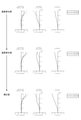
図2および図3は実施例1の投写光学系の構成図である。図2では、実施例1の投写光学系を構成する各レンズは焦点距離を最短とするワイド位置に配置されている。図3では実施例1の投写光学系を構成する各レンズは、焦点距離を最長とするテレ位置に配置されている。図4は実施例1の投写光学系のレンズデータを示す図である。図5は実施例1の投写光学系がワイド位置にある場合の収差図(球面収差、非点収差および歪曲収差)である。図6は実施例1の投写光学系がテレ位置にある場合の収差図(球面収差、非点収差および歪曲収差)である。図5および図6では、投写光学系が基準温度である場合(温度変化前)の収差図と、投写光学系が基準温度よりも20℃上昇した温度状態となった場合(温度変化後)の収差図と、補正レンズ群LG11を基準位置から補正位置に移動させて、温度変化に起因して劣化した非点収差を補正した場合(補正後)の収差図を示す。
(Example 1)
2 and 3 are block diagrams of the projection optical system of the first embodiment. In FIG. 2, each lens constituting the projection optical system of the first embodiment is arranged at a wide position having the shortest focal length. In FIG. 3, each lens constituting the projection optical system of the first embodiment is arranged at a tele position having the longest focal length. FIG. 4 is a diagram showing lens data of the projection optical system of the first embodiment. FIG. 5 is an aberration diagram (spherical aberration, astigmatism, and distortion) when the projection optical system of the first embodiment is in a wide position. FIG. 6 is an aberration diagram (spherical aberration, astigmatism, and distortion) when the projection optical system of the first embodiment is in the tele position. 5 and 6 show an aberration diagram when the projection optical system is at the reference temperature (before the temperature change) and when the projection optical system is in a
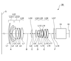
図2および図3に示すように、本例の投写光学系3Aは、第1レンズL1~第16レンズL16の16枚のレンズを備える。投写光学系3Aは、スクリーンSの側から液晶パネル18の側に向かって、順に、第1レンズ群LG1、第2レンズ群LG2、第3レンズ群LG3、第4レンズ群LG4、第5レンズ群LG5、第6レンズ群LG6、および、第7レンズ群LG7を備える。液晶パネル18は、投写光学系3Aのバックフォーカスの位置にある。第7レンズ群LG7と液晶パネル18との間には、クロスダイクロイックプリズム19が位置する。
As shown in FIGS. 2 and 3, the projection
第1レンズ群LG1と第7レンズ群LG7とは、ズーム機能により投写倍率を変化させる際に、光軸L方向に移動しないレンズ群である。すなわち、第1レンズ群LG1と第7レンズ群LG7とは、変倍に際して、動かないレンズ群である。第1レンズ群LG1は、第1レンズL1、第2レンズL2、第3レンズL3の3枚のレンズからなる。第1レンズ群LG1は、光軸L方向への移動により温度変化に応じて発生する非点収差の劣化を補正する補正レンズ群LG11と、補正レンズ群LG11のスクリーンSとは反対の側で光軸L方向に移動することがない固定レンズ群LG12と、を備える。補正レンズ群LG11は第1レンズL1からなる。固定レンズ群LG12は第2レンズL2および第3レンズL3からなる。第1レンズL1はスクリーンSの側および液晶パネル18の側の両面が非球面である。固定レンズ群LG12において最もスクリーンSの側に位置する第2レンズL2(固定レンズ群第1レンズ)は負レンズである。第7レンズ群LG7は第16レンズL16からなる。
The first lens group LG1 and the seventh lens group LG7 are lens groups that do not move in the optical axis L direction when the projection magnification is changed by the zoom function. That is, the first lens group LG1 and the seventh lens group LG7 are lens groups that do not move at the time of scaling. The first lens group LG1 is composed of three lenses, a first lens L1, a second lens L2, and a third lens L3. The first lens group LG1 is a correction lens group LG11 that corrects deterioration of astigmatism generated in response to a temperature change due to movement in the optical axis L direction, and light on the side opposite to the screen S of the correction lens group LG11. It includes a fixed lens group LG12 that does not move in the L direction of the axis. The correction
第2レンズ群LG2、第3レンズ群LG3、第4レンズ群LG4、第5レンズ群LG5、および、第6レンズ群LG6は、ズーム機能により投写倍率を変化させる際に(すなわち、変倍に際して)、それぞれが光軸L方向に移動するレンズ群である。第2レンズ群LG2は、第4レンズL4、第5レンズL5、第6レンズL6の3枚のレンズからなる。第4レンズL4と第5レンズL5とは互いに接合された接合レンズである。第3レンズ群LG3は、第7レンズL7からなる。第4レンズ群LG4は、第8レンズL8と第9レンズL9とからなる。第5レンズ群LG5は第10レンズL10、第11レンズL11、第12レンズL12の3枚のレンズからなる。第6レンズ群LG6は第13レンズL13、第14レンズL14、第15レンズL15の3枚のレンズからなる。第13レンズL13と第14レンズL14とは互いに接合された接合レンズである。 The second lens group LG2, the third lens group LG3, the fourth lens group LG4, the fifth lens group LG5, and the sixth lens group LG6 change the projection magnification by the zoom function (that is, at the time of scaling). , Each is a lens group that moves in the L direction of the optical axis. The second lens group LG2 is composed of three lenses, a fourth lens L4, a fifth lens L5, and a sixth lens L6. The fourth lens L4 and the fifth lens L5 are bonded lenses bonded to each other. The third lens group LG3 is composed of the seventh lens L7. The fourth lens group LG4 includes an eighth lens L8 and a ninth lens L9. The fifth lens group LG5 is composed of three lenses, a tenth lens L10, an eleventh lens L11, and a twelfth lens L12. The sixth lens group LG6 is composed of three lenses, a 13th lens L13, a 14th lens L14, and a 15th lens L15. The thirteenth lens L13 and the fourteenth lens L14 are bonded lenses bonded to each other.
投写光学系3Aのデータは以下のとおりである。本例では、基準波長λを587.56nmとする。
The data of the projection
ズーム比:1.34
焦点距離:71.11mm(ワイド位置) / 95.62mm(テレ位置)
Fナンバー:1.96(ワイド位置) / 2.29(テレ位置)
バックフォーカス(in air):90.16mm
有効像円径:φ70mm
最大画角(半画角):26.5°(ワイド位置) / 20.2°(テレ位置)
Zoom ratio: 1.34
Focal length: 71.11 mm (wide position) / 95.62 mm (tele position)
F number: 1.96 (wide position) / 2.29 (tele position)
Back focus (in air): 90.16 mm
Effective image circle diameter: φ70 mm
Maximum angle of view (half angle of view): 26.5 ° (wide position) / 20.2 ° (tele position)
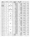
また、投写光学系3Aを構成する各レンズL1~L16のレンズデータは図4に示すとおりである。図4において、厚み・間隔の欄のOBJは、第1レンズL1からスクリーンSまでの軸上面間距離(m)を表す。厚み・間隔の欄の間隔Aは、温度変化に起因して発生した収差を補正した場合に変化する値である。間隔Aは補正レンズ群LG11と固定レンズ群LG12との間の軸上面間距離(mm)である。厚み・間隔の欄の間隔B、間隔C、間隔D、間隔E、間隔F、間隔Gは、各レンズL1~L16がワイド位置に配置された場合と、各レンズL1~L16がテレ位置に配置された場合とで変化する値である。間隔B、間隔C、間隔D、間隔E、間隔F、間隔Gは、隣り合うレンズ群の軸上面間距離(mm)である。ndは各レンズL1~L16の屈折率である。νdは各レンズL1~L16のアッベ数である。
The lens data of the lenses L1 to L16 constituting the projection
なお、非球面とされている第1レンズL1の第1面および第2面の非球面係数は、以下のとおりである。
第1面 第2面
曲率半径 216.922 128.975
コーニック定数(K) -1.467 -1.719
4次の係数(A) 9.66234E-08 5.66419E-09
6次の係数(B) -5.13267E-12 -2.31131E-11
8次の係数(C) -2.19282E-15 2.68541E-15
10次の係数(D) 9.21819E-19 4.12250E-20
12次の係数(E) 8.65528E-23 1.68220E-22
14次の係数(F) -8.21895E-27 4.96701E-26
16次の係数(G) 2.01043E-30 -2.61118E-30
The aspherical coefficients of the first surface and the second surface of the first lens L1, which are considered to be aspherical, are as follows.
1st surface 2nd surface radius of curvature 216.922 128.975
Conic constant (K) -1467 -1.719
Fourth-order coefficient (A) 9.662234E-08 5.66419E-09
6th order coefficient (B) -5.13267E-12 -2.31131E-11
8th order coefficient (C) -2.19282E-15 2.68541E-15
10th order coefficient (D) 9.21819E-19 4.12250E-20
12th order coefficient (E) 8.65528E-23 1.68220E-22
14th order coefficient (F) -8.21895E-27 4.96701E-26
16th order coefficient (G) 2.01043E-30 -2.61118E-30
また、OBJ、間隔B、間隔C、間隔D、間隔E、間隔F、間隔Gの値は、以下のとおりである。
OBJ 7.5 (ワイド位置) 10.125(テレ位置)
間隔B 37.982(ワイド位置) 15.581(テレ位置)
間隔C 18.787(ワイド位置) 16.376(テレ位置)
間隔D 3.524(ワイド位置) 21.455(テレ位置)
間隔E 53.109(ワイド位置) 22.849(テレ位置)
間隔F 10.109(ワイド位置) 10.629(テレ位置)
間隔G 0.200(ワイド位置) 36.820(テレ位置)
The values of OBJ, interval B, interval C, interval D, interval E, interval F, and interval G are as follows.
OBJ 7.5 (wide position) 10.125 (tele position)
Interval B 37.982 (wide position) 15.581 (tele position)
Interval C 18.787 (wide position) 16.376 (tele position)
Interval D 3.524 (wide position) 21.455 (tele position)
Interval E 53.109 (wide position) 22.849 (tele position)
Interval F 10.109 (wide position) 10.629 (tele position)
Interval G 0.200 (wide position) 36.820 (tele position)
(補正レンズ群)
ここで、補正レンズ群LG11について、詳細に説明する。図5および図6の上段に位置する温度変化前の収差図と、中段に位置する温度変化後(温度が20℃上昇した状態)の収差図を比較すれば分かるように、画像投写時に投写光学系3Aの温度が予め想定された基準温度から20℃上昇した場合には、投写光学系3Aの光学特性が変化し、非点収差が劣化(変動)する。このような問題に対して、投写光学系3Aでは、ズーム機能により投写倍率を変化させる際に移動しない第1レンズ群LG1のなかに非点収差の劣化を補正するための補正レンズ群LG11を備え、この補正レンズ群LG11を光軸L方向に移動させて、非点収差の劣化を補正する。
(Correction lens group)
Here, the correction
補正レンズ群LG11は基準位置と補正位置との間で移動する。基準位置は、投写光学系3Aの温度が予め想定した基準温度の場合に補正レンズ群LG11が配置されている位置である。図5および図6の温度変化前の収差図および温度変化後の収差図は、補正レンズ群LG11が基準位置に配置されている状態におけるものである。補正位置は、投写光学系3Aの温度が基準温度から20℃上昇したときに、補正レンズ群LG11を光軸L方向に移動させて温度変化に起因する非点収差の劣化を補正した状態における補正レンズ群LG11の位置である。補正レンズ群LG11が補正位置に配置された状態では、図5および図6の下段に位置する補正後の収差図に示すように、非点収差の劣化(変動)は補正され、温度変化前の収差図に近い状態となる。
The correction
ここで、図4における厚み・間隔の欄の間隔Aは、補正レンズ群LG11が基準位置に配置されている場合と、補正レンズ群LG11が補正位置に配置されている場合とで変化する。間隔Aの値は、以下の通りである。
基準位置 補正位置
間隔A(ワイド位置) 36.061 36.761
間隔A(テレ位置) 36.061 36.761
Here, the spacing A in the thickness / spacing column in FIG. 4 changes depending on whether the correction
Reference position Correction position interval A (wide position) 36.061 36.761
Interval A (tele position) 36.061 36.761
本例では、温度が20℃上昇した時に劣化した非点収差を補正する補正レンズ群LG11の移動量(基準位置と補正位置との間の距離)をΔM20としたときに、ワイド位置、テレ位置ともに、ΔM20=+0.7mmである。ΔM20は、投写光学系3Aにおいて実際に補正レンズ群LG11を移動させた実験、或いは、シミュレーションにより求められる。なお、基準位置から補正位置に移動する際に補正レンズ群LG11がスクリーンSの側に移動する場合にはΔM20はプラスの値となる。基準位置から補正位置に移動する際に補正レンズ群LG11がスクリーンSとは反対側に移動する場合にはΔM20はマイナスの値となる。
In this example, when the movement amount (distance between the reference position and the correction position) of the correction lens group LG11 for correcting the astigmatism deteriorated when the temperature rises by 20 ° C. is set to ΔM20, the wide position and the tele position Both are ΔM20 = + 0.7 mm. ΔM20 is obtained by an experiment or a simulation in which the correction lens group LG11 is actually moved in the projection
また、本例では、補正レンズ群LG11を基準位置と補正位置との間で移動させたときのバックフォーカスの移動量をΔBFとしたときに、ワイド位置およびテレ位置のそれぞれにおいて、ΔBFは以下のとおりである。
ΔBF 0.01(ワイド位置) / 0.018(テレ位置)
Further, in this example, when the amount of movement of the back focus when the correction lens group LG11 is moved between the reference position and the correction position is ΔBF, ΔBF is as follows at each of the wide position and the tele position. That's right.
ΔBF 0.01 (wide position) / 0.018 (tele position)
なお、投写光学系3Aの温度として、各レンズL1~L16を保持する鏡筒30の内部の温度を用いることができる。すなわち、温度センサー32により検出される温度を、投写光学系3Aの温度とすることができる。
As the temperature of the projection
ここで、補正レンズ群LG11の焦点距離をf1としたときに、f1=-636.811である。また、第2レンズL2の焦点距離をf2としたときに、f2=-338.014である。 Here, when the focal length of the correction lens group LG11 is f1, f1 = −636.811. Further, when the focal length of the second lens L2 is f2, f2 = 338.014.
次に、投写光学系3Aは、液晶パネル18が表示する画像の画素ピッチをP、レンズ全系のFナンバーをFNO、温度が20℃変動した時に変動した収差を補正する移動量(ΔM20)だけ補正レンズ群LG11を移動させたときのバックフォーカスの移動量をΔBFとしたときに、次の条件式(1)を満足する。条件式(1)は、温度が20℃変動した時に劣化した収差を補正する移動量(ΔM20=+0.7mm)だけ補正レンズ群LG11を移動させたときに、バックフォーカスの移動量ΔBFが、投写光学系3Aの焦点深度よりも小さいことを規定している。
|ΔBF20| < P×FNO×√2 ・・・(1)
Next, in the projection
| ΔBF20 | < P × FNO × √2 ・ ・ ・ (1)
具体的に、本例では、P=0.010mmである。ワイド位置において、FNO=1.96である。テレ位置において、FNO=2.29である。また、ワイド位置において、ΔBF=0.01である。テレ位置において、ΔBF=0.018である。従って、投写光学系3Aは、以下のとおり、条件式(1)を満足する。
(ワイド位置) |0.010| < 0.010×1.96×√2=0.028
(テレ位置) |0.018| < 0.010×2.29×√2=0.032
Specifically, in this example, P = 0.010 mm. At the wide position, FNO = 1.96. At the tele position, FNO = 2.29. Further, at the wide position, ΔBF = 0.01. At the tele position, ΔBF = 0.018. Therefore, the projection
(Wide position) | 0.010 | <0.010 x 1.96 x √2 = 0.028
(Tele position) | 0.018 | <0.010 x 2.29 x √2 = 0.032
また、投写光学系3Aは、レンズ全系の焦点距離をf、補正レンズ群LG11の焦点距離をf1としたときに、以下の条件式(2)を満足する。
1.5 < |f1/f| ・・・(2)
Further, the projection
1.5 << | f1 / f | ... (2)
具体的に、本例では、ワイド位置においてf=71.11である。テレ位置においてf=95.62である。また、f1=-636.811である。よって、投写光学系3Aは、以下のとおり、条件式(2)を満足する。
(ワイド位置) 1.5 < |-636.811/71.11|=9.0
(テレ位置) 1.5 < |-636.811/95.62|=6.7
Specifically, in this example, f = 71.11 at the wide position. At the tele position, f = 95.62. Further, f1 = −636.811. Therefore, the projection
(Wide position) 1.5 <| -636.811 / 71.11 | = 9.0
(Tele position) 1.5 <| -636.81 / 95.62 | = 6.7
ここで、本例では、最もスクリーンSに近い位置にある補正レンズ群LG11を光軸L方向に移動させて光学特性の劣化を補正する。従って、非点収差の劣化を補正しやすい。また、本例は、補正レンズ群LG11の焦点距離f1とレンズ全系の焦点距離fとの関係が条件式(2)を満たすので、補正レンズ群LG11を光軸L方向に移動させることにより、温度変化に起因して劣化した非点収差を補正しやすい。
Here, in this example, the correction
さらに、投写光学系3Aは条件式(1)を満たすので、温度が20℃変動した時に変動した収差を補正する移動量ΔM20だけ補正レンズ群LG11を移動させたときのバックフォーカスの移動量ΔBF20が、投写光学系3Aの焦点深度以下である。換言すれば、投写光学系3Aは条件式(1)を満たすので、補正レンズ群LG11を基準位置から補正位置に移動させたときのバックフォーカスの移動量ΔBF20は、投写画像の画質に影響がでることを回避できるほどに僅かなものとなる。換言すれば、補正レンズ群LG11を基準位置から補正位置に移動させたときのピントずれを回避できる。ここで、温度変化に起因して発生する投写光学系3Aのバックフォーカスの変動は設計によって抑制できる。従って、補正レンズ群LG11を移動させたときのバックフォーカスの移動量ΔBF20が投写光学系3Aの焦点深度より小さければ、補正レンズ群LG11を移動させたときに、バックフォーカスの位置を補正するための第2の補正レンズ群を備える必要がない。よって、温度変化に起因する非点収差の劣化を補正するために光軸L方向に移動させるレンズ群の数を少なくすることができる。
Further, since the projection
次に、本例は、固定レンズ群LG12の最もスクリーンSの側に位置する第2レンズL2は、負レンズであり、第2レンズL2の焦点距離をf2としたときに、次の条件式(3)を満足する。
0.1 < |f2/f1| < 0.9 ・・・(3)
Next, in this example, the second lens L2 located closest to the screen S of the fixed lens group LG12 is a negative lens, and when the focal length of the second lens L2 is f2, the following conditional expression ( Satisfy 3).
0.1 << | f2 / f1 | <0.9 ... (3)
具体的に、本例では、f1=-636.811であり、f2=-338.014である。よって、投写光学系3Aは、以下のとおり、本例は条件式(3)を満足する。
0.1 < |-338.014/-636.811|=0.5 < 0.9
Specifically, in this example, f1 = −636.811 and f2 = 338.014. Therefore, the projection
0.1 <| 338.014 / -636.811 | = 0.5 <0.9
ここで、条件式(3)の上限および下限を超える場合には、補正レンズ群LG11を移動させて温度変化に起因して発生した非点収差を補正したときに、歪曲収差が大きくなる場合がある。これに対して、負レンズである第2レンズL2の焦点距離f2と、補正レンズ群LG11の焦点距離f1との関係が条件式(3)を満たせば、歪曲収差が大きくなることを抑制できる。また、条件式(3)を満たせば、像面湾曲の増大を抑制できる。
Here, when the upper limit and the lower limit of the conditional expression (3) are exceeded, the distortion may become large when the correction
さらに、本例は、補正レンズ群LG11を構成する第1レンズL1の屈折率をnd1、第1レンズL1のアッベ数をνd1としたときに、次の条件式(4)、(5)を満足する。
1.45 < nd1 < 1.60 ・・・(4)
50 < νd1 < 85 ・・・(5
Further, in this example, the following conditional expressions (4) and (5) are satisfied when the refractive index of the first lens L1 constituting the correction
1.45 <nd1 <1.60 ... (4)
50 <νd1 <85 ・ ・ ・ (5)
すなわち、本例では、図4に示すように、nd1=1.509415であり、νd1=55.9である。従って、本例は条件式(4)および条件式(5)を満足する。ここで、条件式(4)を満たせば、補正レンズ群LG11が光軸L方向に移動したときに像面湾曲が増大することを抑制できる。また、条件式(5)を満たせば、補正レンズ群LG11が光軸L方向に移動したときに、倍率色収差が増大することを抑制できる。
That is, in this example, as shown in FIG. 4, nd1 = 1.509415 and νd1 = 55.9. Therefore, this example satisfies the conditional expression (4) and the conditional expression (5). Here, if the conditional expression (4) is satisfied, it is possible to suppress an increase in curvature of field when the correction
また、投写光学系3Aは、レンズ全系を保持する鏡筒30と、鏡筒30の内部の温度を検出する温度センサー32と、補正レンズ群LG11を光軸L方向に移動させる移動機構33と、温度センサー32からの出力に基づいて移動機構33を駆動する補正制御部34を備える。従って、温度センサー32からの出力に基づいて補正制御部34が移動機構33を駆動することにより、温度変化に起因する非点収差の劣化を自動で補正できる。
Further, the projection
ここで、本例では、予め、鏡筒30の内部の温度変化(基準温度からの上昇温度)と、温度変化に起因して発生する非点収差を補正できる補正レンズ群LG11の光軸L上の位置(補正位置)との関係を、実験、或いは、シミュレーションにより求めている。また、投写光学系3Aの補正制御部34は、基準温度からの上昇温度と補正位置との関係を、テーブル等の形態で記憶保持している。従って、補正制御部34は、基準温度からの上昇温度に基づいて記憶部を参照して移動機構33を駆動して、補正レンズ群LG11を補正位置に配置する。
Here, in this example, the temperature change inside the lens barrel 30 (rising temperature from the reference temperature) and the astigmatism generated due to the temperature change can be corrected in advance on the optical axis L of the correction lens group LG11. The relationship with the position (correction position) of is obtained by experiment or simulation. Further, the
また、本例では、投写光学系3Aにおいて、温度変化に起因する非点収差の劣化を容易に補正できるので、プロジェクター1の投写する光の光束が20klm以上であり、画像投写時に投写光学系3Aを構成する各レンズL1~L16の温度が上昇しやすく、非点収差が劣化しやすい場合でも、投写画像の画質を維持できる。
Further, in this example, in the projection
なお、補正レンズ群LG11は、手動によって、基準位置から補正位置に移動させてもよい。
The correction
また、上記の例では、温度変化に起因して非点収差が劣化した場合に補正レンズ群LG11を光軸L方向に移動させているが、投写倍率を変化させるのに伴って非点収差が劣化した場合などに、補正レンズ群LG11を光軸L方向に移動させて、非点収差を補正してすることもできる。
Further, in the above example, when the astigmatism deteriorates due to the temperature change, the correction
(実施例2)
図7および図8は実施例2の投写光学系の構成図である。図7では、実施例2の投写光学系を構成する各レンズは焦点距離を最短とするワイド位置に配置されている。図8では実施例2の投写光学系を構成する各レンズは、焦点距離を最長とするテレ位置に配置されている。図9は実施例2の投写光学系のレンズデータを示す図である。図10は実施例2の投写光学系がワイド位置にある場合の収差図(球面収差、非点収差および歪曲収差)である。図11は実施例2の投写光学系がテレ位置にある場合の収差図(球面収差、非点収差および歪曲収差)である。図10および図11では、投写光学系が基準温度である場合(温度変化前)の収差図と、投写光学系が基準温度よりも20℃上昇した温度状態となった場合(温度変化後)の収差図と、補正レンズ群LG11を基準位置から補正位置に移動させて、温度変化に起因して劣化した非点収差を補正した場合(補正後)の収差図を示す。
(Example 2)
7 and 8 are block diagrams of the projection optical system of the second embodiment. In FIG. 7, each lens constituting the projection optical system of the second embodiment is arranged at a wide position having the shortest focal length. In FIG. 8, each lens constituting the projection optical system of the second embodiment is arranged at a tele position having the longest focal length. FIG. 9 is a diagram showing lens data of the projection optical system of the second embodiment. FIG. 10 is an aberration diagram (spherical aberration, astigmatism, and distortion) when the projection optical system of the second embodiment is in a wide position. FIG. 11 is an aberration diagram (spherical aberration, astigmatism, and distortion) when the projection optical system of the second embodiment is in the tele position. 10 and 11 show an aberration diagram when the projection optical system is at the reference temperature (before the temperature change) and when the projection optical system is in a
図7および図8に示すように、本例の投写光学系3Bは、第1レンズL1~第18レンズL18の18枚のレンズを備える。投写光学系3Bは、スクリーンSの側から液晶パネル18の側に向かって、順に、第1レンズ群LG1、第2レンズ群LG2、第3レンズ群LG3、第4レンズ群LG4、第5レンズ群LG5、第6レンズ群LG6、および、第7レンズ群LG7を備える。液晶パネル18は、投写光学系3Bのバックフォーカスの位置にある。第7レンズ群LG7と液晶パネル18との間には、クロスダイクロイックプリズム19が位置する。
As shown in FIGS. 7 and 8, the projection
第1レンズ群LG1、第2レンズ群LG2および第7レンズ群LG7は、ズーム機能により投写倍率を変化させる際に、光軸L方向に移動しないレンズ群である。すなわち、第1レンズ群LG1、第2レンズ群LG2および第7レンズ群LG7は、変倍に際して、動かないレンズ群である。第1レンズ群LG1は、第1レンズL1、第2レンズL2、第3レンズL3、第4レンズL4、第5レンズL5の5枚のレンズからなる。第1レンズ群LG1は、光軸L方向への移動により温度変化に応じて発生する非点収差の劣化を補正する補正レンズ群LG11と、補正レンズ群LG11のスクリーンSとは反対の側で光軸L方向に移動することがない固定レンズ群LG12と、を備える。補正レンズ群LG11は第1レンズL1と第2レンズL2からなる。固定レンズ群LG12は第3レンズL3、第4レンズL4および第5レンズL5からなる。第2レンズL2はスクリーンSの側および液晶パネル18の側の両面が非球面である。固定レンズ群LG12において最もスクリーンSの側に位置する第3レンズL3(固定レンズ群第1レンズ)は負レンズである。
The first lens group LG1, the second lens group LG2, and the seventh lens group LG7 are lens groups that do not move in the optical axis L direction when the projection magnification is changed by the zoom function. That is, the first lens group LG1, the second lens group LG2, and the seventh lens group LG7 are lens groups that do not move at the time of scaling. The first lens group LG1 is composed of five lenses, a first lens L1, a second lens L2, a third lens L3, a fourth lens L4, and a fifth lens L5. The first lens group LG1 is a correction lens group LG11 that corrects deterioration of astigmatism generated in response to a temperature change due to movement in the optical axis L direction, and light on the side opposite to the screen S of the correction lens group LG11. It includes a fixed lens group LG12 that does not move in the L direction of the axis. The correction
第2レンズ群LG2は、第6レンズL6および第7レンズL7の2枚のレンズからなる。第7レンズ群LG7は第18レンズL18からなる。 The second lens group LG2 is composed of two lenses, a sixth lens L6 and a seventh lens L7. The seventh lens group LG7 is composed of the eighteenth lens L18.
第3レンズ群LG3、第4レンズ群LG4、第5レンズ群LG5、および、第6レンズ群LG6は、ズーム機能により投写倍率を変化させる際に(すなわち、変倍に際して)、それぞれが光軸L方向に移動するレンズ群である。第3レンズ群LG3は、第8レンズL8からなる。第4レンズ群LG4は、第9レンズL9と第10レンズL10とからなる。第5レンズ群LG5は、第11レンズL11、第12レンズL12、第13レンズL13、および、第14レンズL14の4枚のレンズからなる。第6レンズ群LG6は第15レンズL15、第16レンズL16、第17レンズL17の3枚のレンズからなる。 The third lens group LG3, the fourth lens group LG4, the fifth lens group LG5, and the sixth lens group LG6 each have an optical axis L when the projection magnification is changed by the zoom function (that is, when the magnification is changed). A group of lenses that move in the direction. The third lens group LG3 is composed of the eighth lens L8. The fourth lens group LG4 includes a ninth lens L9 and a tenth lens L10. The fifth lens group LG5 includes four lenses, an eleventh lens L11, a twelfth lens L12, a thirteenth lens L13, and a fourteenth lens L14. The sixth lens group LG6 is composed of three lenses, a 15th lens L15, a 16th lens L16, and a 17th lens L17.
投写光学系3Bのデータは以下のとおりである。本例では、基準波長λを587.56nmとする。
The data of the projection
ズーム比:1.20
焦点距離:29.87mm(ワイド位置) / 35.83mm(テレ位置)
Fナンバー:2.40(ワイド位置) / 2.62(テレ位置)
バックフォーカス(in air):70.98mm
有効像円径:φ50mm
最大画角(半画角):40.2°(ワイド位置) / 35.1°(テレ位置)
Zoom ratio: 1.20
Focal length: 29.87 mm (wide position) / 35.83 mm (tele position)
F number: 2.40 (wide position) / 2.62 (tele position)
Back focus (in air): 70.98 mm
Effective image circle diameter: φ50 mm
Maximum angle of view (half angle of view): 40.2 ° (wide position) / 35.1 ° (tele position)
また、投写光学系3Bを構成する各レンズL1~L18のレンズデータは図9に示すとおりである。図9において、厚み・間隔の欄のOBJは、第1レンズL1からスクリーンSまでの軸上面間距離(m)を表す。厚み・間隔の欄の間隔Aは、温度変化に起因して発生した収差を補正した場合に変化する値である。間隔Aは補正レンズ群LG11と固定レンズ群LG12との間の軸上面間距離(mm)である。厚み・間隔の欄の間隔B、間隔C、間隔D、間隔E、間隔F、は、各レンズL1~L18がワイド位置に配置された場合と、各レンズL1~L18がテレ位置に配置された場合とで変化する値である。間隔B、間隔C、間隔D、間隔E、間隔F、は、隣り合うレンズ群の軸上面間距離(mm)である。ndは各レンズL1~L18の屈折率である。νdは各レンズL1~L18のアッベ数である。
The lens data of the lenses L1 to L18 constituting the projection
なお、非球面とされている第2レンズL2の両面(第3面および第4面)の非球面係数は、以下のとおりである。
第3面 第4面
曲率半径 84.350 57.275
コーニック定数(K) -1.002 -0.335
4次の係数(A) 6.17595E-07 2.32600E-07
6次の係数(B) -6.93154E-11 -2.39935E-10
8次の係数(C) -1.54068E-14 1.46172E-13
10次の係数(D) -1.64525E-18 -2.18608E-16
12次の係数(E) 8.98913E-22 1.01396E-19
14次の係数(F) -6.43365E-25 -2.50322E-23
16次の係数(G) 7.00618E-29 2.65938E-27
The aspherical coefficients of both sides (third surface and fourth surface) of the second lens L2, which is regarded as an aspherical surface, are as follows.
3rd surface 4th surface radius of curvature 84.350 57.275
Conic constant (K) -1.002 -0.335
Fourth-order coefficient (A) 6.17595E-07 2.32600E-07
6th order coefficient (B) -6.93154E-11 -2.39935E-10
8th order coefficient (C) -1.540668E-14 1.46172E-13
10th order coefficient (D) -1.64525E-18 -2.18608E-16
12th order coefficient (E) 8.98913E-22 1.01396E-19
14th order coefficient (F) -6.43365E-25-2.50322E-23
16th order coefficient (G) 7.00618E-29 2.655938E-27
また、OBJ、間隔B、間隔C、間隔D、間隔E、間隔Fの値は、以下のとおりである。
OBJ 3.9 (ワイド位置) 3.9(テレ位置)
間隔B 114.535(ワイド位置) 85.282(テレ位置)
間隔C 18.675(ワイド位置) 28.296(テレ位置)
間隔D 10.934(ワイド位置) 12.857(テレ位置)
間隔E 0.640(ワイド位置) 2.506(テレ位置)
間隔F 16.560(ワイド位置) 32.404(テレ位置)
The values of OBJ, interval B, interval C, interval D, interval E, and interval F are as follows.
OBJ 3.9 (wide position) 3.9 (tele position)
Interval B 114.535 (wide position) 85.282 (tele position)
Interval C 18.675 (wide position) 28.296 (tele position)
Interval D 10.934 (wide position) 12.857 (tele position)
Interval E 0.640 (wide position) 2.506 (tele position)
Interval F 16.560 (wide position) 32.404 (tele position)
(補正レンズ群)
ここで、補正レンズ群LG11について、詳細に説明する。図10および図11の上段に位置する温度変化前の収差図と、中段に位置する温度変化後(温度が20℃上昇した状態)の収差図を比較すれば分かるように、画像投写時に投写光学系3Bの温度が予め想定された基準温度から20℃上昇した場合には、投写光学系3Bの光学特性が変化し、非点収差が劣化(変動)する。このような問題に対して、投写光学系3Bでは、ズーム機能により投写倍率を変化させる際に移動しない第1レンズ群LG1のなかに非点収差の劣化を補正するための補正レンズ群LG11を備え、この補正レンズ群LG11を光軸L方向に移動させて、非点収差の劣化を補正する。
(Correction lens group)
Here, the correction
補正レンズ群LG11は基準位置と補正位置との間で移動する。基準位置は、投写光学系3Bの温度が予め想定した基準温度の場合に補正レンズ群LG11が配置されている位置である。図10および図11の温度変化前の収差図および温度変化後の収差図は、補正レンズ群LG11が基準位置に配置されている状態におけるものである。補正位置は、投写光学系3Bの温度が基準温度から20℃上昇したときに、補正レンズ群LG11を光軸L方向に移動させて温度変化に起因する非点収差の劣化を補正した状態における補正レンズ群LG11の位置である。補正レンズ群LG11が補正位置に配置された状態では、図10および図11の下段に位置する補正後の収差図に示すように、非点収差の劣化(変動)は補正され、温度変化前の収差図に近い状態となる。
The correction
ここで、図9における厚み・間隔の欄の間隔Aは、補正レンズ群LG11が基準位置に配置されている場合と、補正レンズ群LG11が補正位置に配置されている場合とで変化する。間隔Aの値は、以下の通りである。
基準位置 補正位置
間隔A(ワイド位置) 10.333 10.476
間隔A(テレ位置) 10.333 10.524
Here, the spacing A in the thickness / spacing column in FIG. 9 changes depending on whether the correction
Reference position Correction position interval A (wide position) 10.333 10.476
Interval A (tele position) 10.333 10.524
本例では、温度が20℃上昇した時に劣化した非点収差を補正する補正レンズ群LG11の移動量(基準位置と補正位置との間の距離)をΔM20としたときに、ワイド位置において、ΔM20=+0.143mmであり、テレ位置において、ΔM20=+0.191mmである。ΔM20は、投写光学系3Bにおいて実際に補正レンズ群LG11を移動させた実験、或いは、シミュレーションにより求められる。なお、基準位置から補正位置に移動する際に補正レンズ群LG11がスクリーンSの側に移動する場合にはΔM20はプラスの値となる。基準位置から補正位置に移動する際に補正レンズ群LG11がスクリーンSとは反対側に移動する場合にはΔM20はマイナスの値となる。
In this example, when the movement amount (distance between the reference position and the correction position) of the correction lens group LG11 for correcting the astigmatism deteriorated when the temperature rises by 20 ° C. is set to ΔM20, ΔM20 is set at the wide position. = +0.143 mm, and ΔM20 = +0.191 mm at the tele position. ΔM20 is obtained by an experiment or a simulation in which the correction lens group LG11 is actually moved in the projection
また、本例では、補正レンズ群LG11を基準位置と補正位置との間で移動させたときのバックフォーカスの移動量をΔBFとしたときに、ワイド位置およびテレ位置のそれぞれにおいて、ΔBFは以下のとおりである。
ΔBF -0.0005(ワイド位置) / -0.0005(テレ位置)
Further, in this example, when the amount of movement of the back focus when the correction lens group LG11 is moved between the reference position and the correction position is ΔBF, ΔBF is as follows at each of the wide position and the tele position. That's right.
ΔBF -0.0005 (wide position) / -0.0005 (tele position)
なお、投写光学系3Bの温度として、各レンズL1~L18を保持する鏡筒30の内部の温度を用いることができる。すなわち、温度センサー32により検出される温度を、投写光学系3Bの温度とすることができる。
As the temperature of the projection
ここで、補正レンズ群LG11の焦点距離をf1としたときに、f1=-568.733である。また、第3レンズL3の焦点距離をf2としたときに、f2=-102.670である。 Here, when the focal length of the correction lens group LG11 is f1, f1 = −568.733. Further, when the focal length of the third lens L3 is f2, f2 = −102.670.
次に、投写光学系3Bは、液晶パネル18が表示する画像の画素ピッチをP、レンズ全系のFナンバーをFNO、温度が20℃変動した時に変動した収差を補正する移動量(ΔM20)だけ補正レンズ群LG11を移動させたときのバックフォーカスの移動量をΔBFとしたときに、次の条件式(1)を満足する。条件式(1)は、温度が20℃変動した時に劣化した収差を補正する移動量(ΔM20=+0.147mmまたは+0.191mm)だけ補正レンズ群LG11を移動させたときに、バックフォーカスの移動量ΔBFが、投写光学系3Bの焦点深度よりも小さいことを規定している。
|ΔBF20| < P×FNO×√2 ・・・(1)
Next, in the projection
| ΔBF20 | < P × FNO × √2 ・ ・ ・ (1)
具体的に、本例では、P=0.010mmである。ワイド位置において、FNO=2.40である。テレ位置において、FNO=2.62である。また、ワイド位置において、ΔBF=-0.0005である。テレ位置において、ΔBF=-0.0005である。従って、投写光学系3Bは、以下のとおり、条件式(1)を満足する。
(ワイド位置) |-0.0005| < 0.010×2.40×√2=0.034
(テレ位置) |-0.0005| < 0.010×2.62×√2=0.037
Specifically, in this example, P = 0.010 mm. At the wide position, FNO = 2.40. At the tele position, FNO = 2.62. Further, at the wide position, ΔBF = −0.0005. At the tele position, ΔBF = −0.0005. Therefore, the projection
(Wide position) | -0.0005 | <0.010 x 2.40 x √2 = 0.034
(Tele position) | -0.00 05 | <0.010 x 2.62 x √2 = 0.037
また、投写光学系3Bは、レンズ全系の焦点距離をf、補正レンズ群LG11の焦点距離をf1としたときに、以下の条件式(2)を満足する。
1.5 < |f1/f| ・・・(2)
Further, the projection
1.5 << | f1 / f | ... (2)
具体的に、本例では、ワイド位置においてf=29.87である。テレ位置においてf=35.83である。また、f1=-568.733である。よって、投写光学系3Bは、以下のとおり、条件式(2)を満足する。
(ワイド位置) 1.5 < |-568.733/29.87|=19.1
(テレ位置) 1.5 < |-568.733/35.83|=15.9
Specifically, in this example, f = 29.87 at the wide position. At the tele position, f = 35.83. Further, f1 = −568.733. Therefore, the projection
(Wide position) 1.5 <| -568.733 / 29.87 | = 19.1
(Tele position) 1.5 <| -568.733 / 35.83 | = 15.9
ここで、本例では、最もスクリーンSに近い位置にある補正レンズ群LG11を光軸L方向に移動させて光学特性の劣化を補正する。従って、非点収差の劣化を補正しやすい。また、本例は、補正レンズ群LG11の焦点距離f1とレンズ全系の焦点距離fとの関係が条件式(2)を満たすので、補正レンズ群LG11を光軸L方向に移動させることにより、温度変化に起因して劣化した非点収差を補正しやすい。
Here, in this example, the correction
さらに、投写光学系3Bは条件式(1)を満たすので、温度が20℃変動した時に変動した収差を補正する移動量ΔM20だけ補正レンズ群LG11を移動させたときのバックフォーカスの移動量ΔBF20が、投写光学系3Bの焦点深度以下である。換言すれば、投写光学系3Bは条件式(1)を満たすので、補正レンズ群LG11を基準位置から補正位置に移動させたときのバックフォーカスの移動量ΔBF20は、投写画像の画質に影響がでることを回避できるほどに僅かなものとなる。換言すれば、補正レンズ群LG11を基準位置から補正位置に移動させたときのピントずれを回避できる。ここで、温度変化に起因して発生する投写光学系3Bのバックフォーカスの変動は設計によって抑制できる。従って、補正レンズ群LG11を移動させたときのバックフォーカスの移動量ΔBF20が投写光学系3Bの焦点深度より小さければ、補正レンズ群LG11を移動させたときに、バックフォーカスの位置を補正するための第2の補正レンズ群を備える必要がない。よって、温度変化に起因する非点収差の劣化を補正するために光軸L方向に移動させるレンズ群の数を少なくすることができる。
Further, since the projection
次に、本例は、固定レンズ群LG12の最もスクリーンSの側に位置する第3レンズL3は、負レンズであり、第3レンズL3の焦点距離をf2としたときに、次の条件式(3)を満足する。
0.1 < |f2/f1| < 0.9 ・・・(3)
Next, in this example, the third lens L3 located closest to the screen S of the fixed lens group LG12 is a negative lens , and when the focal length of the third lens L3 is f2 , the following conditions are met. Equation (3) is satisfied.
0.1 << | f2 / f1 | <0.9 ... (3)
具体的に、本例では、f1=-568.733であり、f2=-102.670である。よって、投写光学系3Bは、以下のとおり、本例は条件式(3)を満足する。
0.1 < |-102.670/-568.733|=0.2< 0.9
Specifically, in this example, f1 = −568.733 and f2 = −102.670. Therefore, the projection
0.1 <| -102.670 / -568 8 . 733 | = 0.2 <0.9
ここで、条件式(3)の上限および下限を超える場合には、補正レンズ群LG11を移動させて温度変化に起因して発生した非点収差を補正したときに、歪曲収差が大きくなる場合がある。これに対して、負レンズである第3レンズL3の焦点距離f2と、補正レンズ群LG11の焦点距離f1との関係が条件式(3)を満たせば、歪曲収差が大きくなることを抑制できる。また、条件式(3)を満たせば、像面湾曲の増大を抑制できる。
Here, when the upper limit and the lower limit of the conditional expression (3) are exceeded, the distortion may become large when the correction
さらに、本例は、補正レンズ群LG11の最も固定レンズ群LG12の側に位置する第2レンズL2の屈折率をnd1、第2レンズL2のアッベ数をνd1としたときに、次の条件式(4)、(5)を満足する。
1.45 < nd1 < 1.60 ・・・(4)
50 < νd1 < 85 ・・・(5
Further, in this example, when the refractive index of the second lens L2 located on the side of the fixed lens group LG12 of the correction lens group LG11 is nd1 and the Abbe number of the second lens L2 is νd1, the following conditional expression ( 4) and (5) are satisfied.
1.45 <nd1 <1.60 ... (4)
50 <νd1 <85 ・ ・ ・ (5)
すなわち、本例では、図9に示すように、nd1=1.53116であり、νd1=56.0である。従って、本例は条件式(4)および条件式(5)を満足する。ここで、条件式(4)を満たせば、補正レンズ群LG11が光軸L方向に移動したときに像面湾曲が増大することを抑制できる。また、条件式(5)を満たせば、補正レンズ群LG11が光軸L方向に移動したときに、倍率色収差が増大することを抑制できる。
That is, in this example, as shown in FIG. 9, nd1 = 1.53116 and νd1 = 56.0. Therefore, this example satisfies the conditional expression (4) and the conditional expression (5). Here, if the conditional expression (4) is satisfied, it is possible to suppress an increase in curvature of field when the correction
また、投写光学系3Bは、レンズ全系を保持する鏡筒30と、鏡筒30の内部の温度を検出する温度センサー32と、補正レンズ群LG11を光軸L方向に移動させる移動機構33と、温度センサー32からの出力に基づいて移動機構33を駆動する補正制御部34を備える。従って、温度センサー32からの出力に基づいて補正制御部34が移動機構33を駆動することにより、温度変化に起因する非点収差の劣化を自動で補正できる。
Further, the projection
ここで、本例においても、予め、鏡筒30の内部の温度変化(基準温度からの上昇温度)と、温度変化に起因して発生する非点収差を補正できる補正レンズ群LG11の光軸L上の位置(補正位置)との関係を、実験、或いは、シミュレーションにより求めている。また、投写光学系3Bの補正制御部34は、基準温度からの上昇温度と補正位置との関係を、テーブル等の形態で記憶保持している。従って、補正制御部34は、基準温度からの上昇温度に基づいて記憶部を参照して移動機構33を駆動して、補正レンズ群LG11を補正位置に配置する。
Here, also in this example, the optical axis L of the correction
また、本例では、投写光学系3Bにおいて、温度変化に起因する非点収差の劣化を容易に補正できるので、プロジェクター1の投写する光の光束が20klm以上であり、画像投写時に投写光学系3Bを構成する各レンズL1~L18の温度が上昇しやすく、非点収差が劣化しやすい場合でも、投写画像の画質を維持できる。
Further, in this example, in the projection
なお、補正レンズ群LG11は、手動によって、基準位置から補正位置に移動させてもよい。
The correction
また、上記の例では、温度変化に起因して非点収差が劣化した場合に補正レンズ群LG11を光軸L方向に移動させているが、投写倍率を変化させるのに伴って非点収差が劣化した場合などに、補正レンズ群LG11を光軸L方向に移動させて、非点収差を補正してすることもできる。
Further, in the above example, when the astigmatism deteriorates due to the temperature change, the correction
(実施例3)
図12および図13は実施例3の投写光学系の構成図である。図12では、実施例3の投写光学系を構成する各レンズは焦点距離を最短とするワイド位置に配置されている。図13では実施例3の投写光学系を構成する各レンズは、焦点距離を最長とするテレ位置に配置されている。図14は実施例3の投写光学系のレンズデータを示す図である。図15は実施例3の投写光学系がワイド位置にある場合の収差図(球面収差、非点収差および歪曲収差)である。図16は実施例3の投写光学系がテレ位置にある場合の収差図(球面収差、非点収差および歪曲収差)である。図15および図16では、投写光学系が基準温度である場合(温度変化前)の収差図と、投写光学系が基準温度よりも20℃上昇した温度状態となった場合(温度変化後)の収差図と、補正レンズ群LG11を基準位置から補正位置に移動させて、温度変化に起因して劣化した非点収差を補正した場合(補正後)の収差図を示す。
(Example 3)
12 and 13 are block diagrams of the projection optical system of the third embodiment. In FIG. 12, each lens constituting the projection optical system of the third embodiment is arranged at a wide position having the shortest focal length. In FIG. 13, each lens constituting the projection optical system of the third embodiment is arranged at a tele position having the longest focal length. FIG. 14 is a diagram showing lens data of the projection optical system of the third embodiment. FIG. 15 is an aberration diagram (spherical aberration, astigmatism, and distortion) when the projection optical system of Example 3 is in a wide position. FIG. 16 is an aberration diagram (spherical aberration, astigmatism, and distortion) when the projection optical system of Example 3 is in the tele position. 15 and 16 show an aberration diagram when the projection optical system is at the reference temperature (before the temperature change) and when the projection optical system is in a
図12および図13に示すように、本例の投写光学系3Cは、第1レンズL1~第14レンズL14の14枚のレンズを備える。投写光学系3Cは、スクリーンSの側から液晶パネル18の側に向かって、順に、第1レンズ群LG1、第2レンズ群LG2、第3レンズ群LG3、第4レンズ群LG4、第5レンズ群LG5、第6レンズ群LG6、および、第7レンズ群LG7を備える。液晶パネル18は、投写光学系3Cのバックフォーカスの位置にある。第7レンズ群LG7と液晶パネル18との間には、クロスダイクロイックプリズム19が位置する。
As shown in FIGS. 12 and 13, the projection
第1レンズ群LG1と第7レンズ群LG7とは、ズーム機能により投写倍率を変化させる際に、光軸L方向に移動しないレンズ群である。すなわち、第1レンズ群LG1と第7レンズ群LG7とは、変倍に際して、動かないレンズ群である。第1レンズ群LG1は、第1レンズL1、第2レンズL2、第3レンズL3の3枚のレンズからなる。第1レンズ群LG1は、光軸L方向への移動により温度変化に応じて発生する非点収差の劣化を補正する補正レンズ群LG11と、補正レンズ群LG11のスクリーンSとは反対の側で光軸L方向に移動することがない固定レンズ群LG12と、を備える。補正レンズ群LG11は第1レンズL1および第2レンズL2からなる。固定レンズ群LG12は第3レンズL3からなる。第1レンズL1はスクリーンSの側および液晶パネル18の側の両面が非球面(奇数次非球面)である。第2レンズは負レンズである。第7レンズ群LG7は第14レンズL14からなる。
The first lens group LG1 and the seventh lens group LG7 are lens groups that do not move in the optical axis L direction when the projection magnification is changed by the zoom function. That is, the first lens group LG1 and the seventh lens group LG7 are lens groups that do not move at the time of scaling. The first lens group LG1 is composed of three lenses, a first lens L1, a second lens L2, and a third lens L3. The first lens group LG1 is a correction lens group LG11 that corrects deterioration of astigmatism generated in response to a temperature change due to movement in the optical axis L direction, and light on the side opposite to the screen S of the correction lens group LG11. It includes a fixed lens group LG12 that does not move in the L direction of the axis. The correction
第2レンズ群LG2、第3レンズ群LG3、第4レンズ群LG4、第5レンズ群LG5、および、第6レンズ群LG6は、ズーム機能により投写倍率を変化させる際に(すなわち、変倍に際して)、それぞれが光軸L方向に移動するレンズ群である。第2レンズ群LG2は、第4レンズL4、第5レンズL5および第6レンズL6の3枚のレンズからなる。第4レンズL4と第5レンズL5とは互いに接合された接合レンズである。第3レンズ群LG3は、第7レンズL7および第8レンズL8からなる。第7レンズL7と第8レンズL8とは互いに接合された接合レンズである。第4レンズ群LG4は、第9レンズL9からなる。第5レンズ群LG5は、第10レンズL10からなる。第10レンズL10はスクリーンSの側および液晶パネル18の側の両面が非球面である。第6レンズ群LG6は、第11レンズL11、第12レンズL12および第13レンズL13の3枚のレンズからなる。第11レンズL11と第12レンズL12とは互いに接合された接合レンズである。
The second lens group LG2, the third lens group LG3, the fourth lens group LG4, the fifth lens group LG5, and the sixth lens group LG6 change the projection magnification by the zoom function (that is, at the time of scaling). , Each is a lens group that moves in the L direction of the optical axis. The second lens group LG2 is composed of three lenses, a fourth lens L4, a fifth lens L5, and a sixth lens L6. The fourth lens L4 and the fifth lens L5 are bonded lenses bonded to each other. The third lens group LG3 includes a seventh lens L7 and an eighth lens L8. The seventh lens L7 and the eighth lens L8 are bonded lenses bonded to each other. The fourth lens group LG4 is composed of the ninth lens L9. The fifth lens group LG5 is composed of the tenth lens L10. The tenth lens L10 has aspherical surfaces on both sides of the screen S and the
投写光学系3Cのデータは以下のとおりである。本例では、基準波長λを587.56nmとする。
The data of the projection
ズーム比:1.59
焦点距離:18.51mm(ワイド位置) / 29.39mm(テレ位置)
Fナンバー:1.50(ワイド位置) / 1.98(テレ位置)
バックフォーカス(in air):29.82mm
有効像円径:φ22.1mm
最大画角(半画角):31.0°(ワイド位置) / 20.5°(テレ位置)
Zoom ratio: 1.59
Focal length: 18.51mm (wide position) / 29.39mm (tele position)
F number: 1.50 (wide position) / 1.98 (tele position)
Back focus (in air): 29.82 mm
Effective image circle diameter: φ22.1 mm
Maximum angle of view (half angle of view): 31.0 ° (wide position) / 20.5 ° (tele position)
また、投写光学系3Cを構成する各レンズL1~L14のレンズデータは図14に示すとおりである。図14において、厚み・間隔の欄のOBJは、第1レンズL1からスクリーンSまでの軸上面間距離(m)を表す。厚み・間隔の欄の間隔Aは、温度変化に起因して発生した収差を補正した場合に変化する値である。間隔Aは補正レンズ群LG11と固定レンズ群LG12との間の軸上面間距離(mm)である。厚み・間隔の欄の間隔B、間隔C、間隔D、間隔E、間隔F、間隔Gは、各レンズL1~L14がワイド位置に配置された場合と、各レンズL1~L14がテレ位置に配置された場合とで変化する値である。間隔B、間隔C、間隔D、間隔E、間隔F、間隔Gは、隣り合うレンズ群の軸上面間距離(mm)である。ndは各レンズL1~L14の屈折率である。νdは各レンズL1~L14のアッベ数である。
The lens data of the lenses L1 to L14 constituting the projection
なお、奇数次非球面とされている第1レンズL1の第1面および第2面の非球面係数は、以下のとおりである。
第1面 第2面
Y曲率半径 -52.187 -47.248
正規化半径 0 0
コーニック定数(K) 2.160 2.049
3次の非球面係数(C4) 5.850395E-06 1.008325E-07
4次の非球面係数(C5) 2.916604E-05 2.755164E-05
5次の非球面係数(C6) 2.784228E-08 1.157410E-08
6次の非球面係数(C7) -4.929371E-08 -4.701720E-08
7次の非球面係数(C8) -2.032565E-11 -5.322946E-11
8次の非球面係数(C9) 9.028234E-11 9.406703E-11
9次の非球面係数(C10) -3.206681E-15 -3.616954E-14
10次の非球面係数(C11) -1.140366E-13 -1.214511E-13
11次の非球面係数(C12) 2.354084E-17 -1.220552E-18
12次の非球面係数(C13) 9.714881E-17 1.285790E-16
13次の非球面係数(C14) 5.963628E-21 6.336274E-21
14次の非球面係数(C15) -8.972642E-21 -2.112134E-20
15次の非球面係数(C16) -3.153100E-23 -3.166408E-23
16次の非球面係数(C17) -2.951592E-23 -6.248856E-23
17次の非球面係数(C18) -6.727139E-26 -2.036477E-25
18次の非球面係数(C19) -3.241867E-26 -3.482153E-26
19次の非球面係数(C20) -8.604023E-30 -1.850030E-28
20次の非球面係数(C21) 6.808065E-29 1.604326E-28
The aspherical coefficients of the first surface and the second surface of the first lens L1, which are considered to be odd-order aspherical surfaces, are as follows.
1st surface 2nd surface Y radius of curvature -52.187-47.248
Conic constant (K) 2.160 2.049
Third-order aspherical coefficient (C4) 5.850395E-06 1.0083325E-07
Fourth-order aspherical coefficient (C5) 2.196604E-05 2.755164E-05
5th order aspherical coefficient (C6) 2.784228E-08 1.157410E-08
6th-order aspherical coefficient (C7) -4.929371E-08 -4.701720E-08
7th-order aspherical coefficient (C8) -2.032565E-11-5.322946E-11
8th order aspherical coefficient (C9) 9.028234E-11 9.406703E-11
9th-order aspherical coefficient (C10) -3.206681E-15 -3.616954E-14
10th-order aspherical coefficient (C11) -1.1403666E-13-1.214511E-13
11th-order aspherical coefficient (C12) 2.354084E-17-1.220552E-18
12th-order aspherical coefficient (C13) 9.714881E-17 1.285790E-16
13th-order aspherical coefficient (C14) 5.963628E-21 6.336274E-21
14th-order aspherical coefficient (C15) -8.972642E-21-2.112134E-20
15th-order aspherical coefficient (C16) -3.153100E-23 -3.166408E-23
16th-order aspherical coefficient (C17) -2.951592E-23-6.248856E-23
17th-order aspherical coefficient (C18) -6.727139E-26 -2.036477E-25
18th-order aspherical coefficient (C19) -3.241867E-26 -3.482153E-26
19th-order aspherical coefficient (C20) -8.604023E-30 -1.850030E-28
20th-order aspherical coefficient (C21) 6.808065E-29 1.604326E-28
また、非球面とされている第10レンズLG10の第17面および第18面の非球面係数は、以下のとおりである。
S17面 S18面
曲率半径 68.259 -24.277
コーニック定数(K) 15.848 -0.267
4次の係数(A) -1.28555E-05 3.05938E-06
6次の係数(B) -6.41978E-09 -2.48006E-08
8次の係数(C) -5.40488E-12 3.36996E-10
10次の係数(D) -2.92973E-12 -3.63281E-12
12次の係数(E) 1.52239E-14 7.31354E-15
14次の係数(F) -3.35705E-17 -8.46287E-17
16次の係数(G) 5.22138E-20 1.35021E-18
18次の係数(H) -2.87241E-21 -7.02776E-21
The aspherical coefficients of the 17th and 18th planes of the 10th lens LG10, which are considered to be aspherical, are as follows.
S17 plane S18 plane radius of curvature 68.259-24.277
Conic constant (K) 15.848-0.267
Fourth-order coefficient (A) -1.28555E-05 3.05938E-06
6th order coefficient (B) -6.41978E-09 -2.48006E-08
Eighth-order coefficient (C) -540488E-12 3.36996E-10
10th order coefficient (D) -2.92973E-12 -3.63281E-12
12th order coefficient (E) 1.52239E-14 7.31354E-15
14th order coefficient (F) -3.35705E-17-8.46287E-17
16th order coefficient (G) 5.22138E-20 1.35021E-18
18th order coefficient (H) -2.87241E-21-7.02776E-21
また、OBJ、間隔B、間隔C、間隔D、間隔E、間隔F、間隔Gの値は、以下のとおりである。
OBJ 1.63 (ワイド位置) 1.63 (テレ位置)
間隔B 9.652(ワイド位置) 3.111(テレ位置)
間隔C 19.842(ワイド位置) 1.200(テレ位置)
間隔D 3.475(ワイド位置) 18.980(テレ位置)
間隔E 6.198(ワイド位置) 2.458(テレ位置)
間隔F 1.514(ワイド位置) 5.168(テレ位置)
間隔G 4.967(ワイド位置) 14.649(テレ位置)
The values of OBJ, interval B, interval C, interval D, interval E, interval F, and interval G are as follows.
OBJ 1.63 (wide position) 1.63 (tele position)
Interval B 9.652 (wide position) 3.111 (tele position)
Interval C 19.842 (wide position) 1.200 (tele position)
Interval D 3.475 (wide position) 18.980 (tele position)
Interval E 6.198 (wide position) 2.458 (tele position)
Interval F 1.514 (wide position) 5.168 (tele position)
Interval G 4.967 (wide position) 14.649 (tele position)
(補正レンズ群)
ここで、補正レンズ群LG11について、詳細に説明する。図15および図16の上段に位置する温度変化前の収差図と、中段に位置する温度変化後(温度が20℃上昇した状態)の収差図を比較すれば分かるように、画像投写時に投写光学系3Cの温度が予め想定された基準温度から20℃上昇した場合には、投写光学系3Cの光学特性が変化し、非点収差が劣化(変動)する。このような問題に対して、投写光学系3Cでは、ズーム機能により投写倍率を変化させる際に移動しない第1レンズ群LG1のなかに非点収差の劣化を補正するための補正レンズ群LG11を備え、この補正レンズ群LG11を光軸L方向に移動させて、非点収差の劣化を補正する。
(Correction lens group)
Here, the correction
補正レンズ群LG11は基準位置と補正位置との間で移動する。基準位置は、投写光学系3Cの温度が予め想定した基準温度の場合に補正レンズ群LG11が配置されている位置である。図15および図16の温度変化前の収差図および温度変化後の収差図は、補正レンズ群LG11が基準位置に配置されている状態におけるものである。補正位置は、投写光学系3Cの温度が基準温度から20℃上昇したときに、補正レンズ群LG11を光軸L方向に移動させて温度変化に起因する非点収差の劣化を補正した状態における補正レンズ群LG11の位置である。補正レンズ群LG11が補正位置に配置された状態では、図15および図16の下段に位置する補正後の収差図に示すように、非点収差の劣化(変動)は補正され、温度変化前の収差図に近い状態となる。
The correction
ここで、図14における厚み・間隔の欄の間隔Aは、補正レンズ群LG11が基準位置に配置されている場合と、補正レンズ群LG11が補正位置に配置されている場合とで変化する。間隔Aの値は、以下の通りである。
基準位置 補正位置
間隔A(ワイド位置) 13.81 13.73
間隔A(テレ位置) 13.81 13.76
Here, the spacing A in the thickness / spacing column in FIG. 14 changes depending on whether the correction
Reference position Correction position interval A (wide position) 13.81 13.73
Interval A (tele position) 13.81 13.76
本例では、温度が20℃上昇した時に劣化した非点収差を補正する補正レンズ群LG11の移動量(基準位置と補正位置との間の距離)をΔM20としたときに、ワイド位置において、ΔM20=-0.080mmであり、テレ位置において、ΔM20=-0.050mmである。ΔM20は、投写光学系3Cにおいて実際に補正レンズ群LG11を移動させた実験、或いは、シミュレーションにより求められる。なお、基準位置から補正位置に移動する際に補正レンズ群LG11がスクリーンSの側に移動する場合にはΔM20はプラスの値となる。基準位置から補正位置に移動する際に補正レンズ群LG11がスクリーンSとは反対側に移動する場合にはΔM20はマイナスの値となる。
In this example, when the movement amount (distance between the reference position and the correction position) of the correction lens group LG11 for correcting the astigmatism deteriorated when the temperature rises by 20 ° C. is set to ΔM20, ΔM20 is set at the wide position. = −0.080 mm, and ΔM20 = −0.050 mm at the tele position. ΔM20 is obtained by an experiment or a simulation in which the correction lens group LG11 is actually moved in the projection
また、本例では、補正レンズ群LG11を基準位置と補正位置との間で移動させたときのバックフォーカスの移動量をΔBFとしたときに、ワイド位置およびテレ位置のそれぞれにおいて、ΔBFは以下のとおりである。
ΔBF 0.0128(ワイド位置) / 0.0200(テレ位置)
Further, in this example, when the amount of movement of the back focus when the correction lens group LG11 is moved between the reference position and the correction position is ΔBF, ΔBF is as follows at each of the wide position and the tele position. That's right.
ΔBF 0.0128 (wide position) / 0.0200 (tele position)
なお、投写光学系3Cの温度として、各レンズL1~L14を保持する鏡筒30の内部の温度を用いることができる。すなわち、温度センサー32により検出される温度を、投写光学系3Cの温度とすることができる。
As the temperature of the projection
ここで、補正レンズ群LG11の焦点距離をf1としたときに、f1=-47.071ある。固定レンズ群LG12において最もスクリーンSの側に位置する第3レンズL3の焦点距離をf2としたときに、f2=-41.071である。 Here, when the focal length of the correction lens group LG11 is f1, f1 = −47.071. When the focal length of the third lens L3 located closest to the screen S in the fixed lens group LG12 is f2, f2 = -41.071.
次に、投写光学系3Cは、液晶パネル18が表示する画像の画素ピッチをP、レンズ全系のFナンバーをFNO、温度が20℃変動した時に変動した収差を補正する移動量(ΔM20)だけ補正レンズ群LG11を移動させたときのバックフォーカスの移動量をΔBFとしたときに、次の条件式(1)を満足する。条件式(1)は、温度が20℃変動した時に劣化した収差を補正する移動量(ワイド位置において、ΔM20=-0.080mmであり、テレ位置において、ΔM20=-0.050mmである。)だけ補正レンズ群LG11を移動させたときに、バックフォーカスの移動量ΔBFが、投写光学系3Cの焦点深度よりも小さいことを規定している。
|ΔBF20| < P×FNO×√2 ・・・(1)
Next, in the projection
| ΔBF20 | < P × FNO × √2 ・ ・ ・ (1)
具体的に、本例では、P=0.010mmである。ワイド位置において、FNO=1.50ある。テレ位置において、FNO=1.98である。また、ワイド位置において、ΔBF=0.0128である。テレ位置において、ΔBF=0.0200である。従って、投写光学系3Cは、以下のとおり、条件式(1)を満足する。
(ワイド位置) |0.0128| < 0.010×1.50×√2=0.021
(テレ位置) |0.0200| < 0.010×1.98×√2=0.028
Specifically, in this example, P = 0.010 mm. At the wide position, FNO = 1.50. At the tele position, FNO = 1.98. Further, at the wide position, ΔBF = 0.0128. At the tele position, ΔBF = 0.0200. Therefore, the projection
(Wide position) | 0.0128 | <0.010 x 1.50 x √2 = 0.021
(Tele position) | 0.0200 | <0.010 x 1.98 x √2 = 0.028
また、投写光学系3Cは、レンズ全系の焦点距離をf、補正レンズ群LG11の焦点距離をf1としたときに、以下の条件式(2)を満足する。
1.5 < |f1/f| ・・・(2)
Further, the projection
1.5 << | f1 / f | ... (2)
具体的に、本例では、ワイド位置においてf=18.51である。テレ位置においてf=29.39である。また、f1=-47.071である。よって、投写光学系3Cは、以下のとおり、条件式(2)を満足する。
(ワイド位置) 1.5 < |-47.071/18.51|=2.5
(テレ位置) 1.5 < |-47.071/29.39|=1.6
Specifically, in this example, f = 18.51 at the wide position. At the tele position, f = 29.39. Further, f1 = −47.071. Therefore, the projection
(Wide position) 1.5 <| -47.071 / 18.51 | = 2.5
(Tele position) 1.5 <| -47.071 / 29.39 | = 1.6
ここで、本例では、最もスクリーンSに近い位置にある補正レンズ群LG11を光軸L方向に移動させて光学特性の劣化を補正する。従って、非点収差の劣化を補正しやすい。また、本例は、補正レンズ群LG11の焦点距離f1とレンズ全系の焦点距離fとの関係が条件式(2)を満たすので、補正レンズ群LG11を光軸L方向に移動させることにより、温度変化に起因して劣化した非点収差を補正しやすい。
Here, in this example, the correction
さらに、投写光学系3Cは条件式(1)を満たすので、温度が20℃変動した時に変動した収差を補正する移動量ΔM20だけ補正レンズ群LG11を移動させたときのバックフォーカスの移動量ΔBF20が、投写光学系3Cの焦点深度以下である。換言すれば、投写光学系3Cは条件式(1)を満たすので、補正レンズ群LG11を基準位置から補正位置に移動させたときのバックフォーカスの移動量ΔBF20は、投写画像の画質に影響がでることを回避できるほどに僅かなものとなる。換言すれば、補正レンズ群LG11を基準位置から補正位置に移動させたときのピントずれを回避できる。ここで、温度変化に起因して発生する投写光学系3Cのバックフォーカスの変動は設計によって抑制できる。従って、補正レンズ群LG11を移動させたときのバックフォーカスの移動量ΔBF20が投写光学系3Cの焦点深度より小さければ、補正レンズ群LG11を移動させたときに、バックフォーカスの位置を補正するための第2の補正レンズ群を備える必要がない。よって、温度変化に起因する非点収差の劣化を補正するために光軸L方向に移動させるレンズ群の数を少なくすることができる。
Further, since the projection
次に、本例は、固定レンズ群LG12の最もスクリーンSの側に位置する第3レンズL3は、負レンズであり、第3レンズL3の焦点距離をf2としたときに、次の条件式(3)を満足する。
0.1 < |f2/f1| < 0.9 ・・・(3)
Next, in this example, the third lens L3 located closest to the screen S of the fixed lens group LG12 is a negative lens, and when the focal length of the third lens L3 is f2, the following conditional expression ( Satisfy 3).
0.1 << | f2 / f1 | <0.9 ... (3)
具体的に、本例では、f1=-47.071であり、f2=-41.071である。よって、投写光学系3Cは、以下のとおり、本例は条件式(3)を満足する。
0.1 < |-41.071/-47.071|=0.88 < 0.9
Specifically, in this example, f1 = −47.071 and f2 = -41.071. Therefore, the projection
0.1 <| -41.071 / -47.071 | = 0.88 <0.9
ここで、条件式(3)の上限および下限を超える場合には、補正レンズ群LG11を移動させて温度変化に起因して発生した非点収差を補正したときに、歪曲収差が大きくなる場合がある。これに対して、負レンズである第3レンズL3の焦点距離f2と、補正レンズ群LG11の焦点距離f1との関係が条件式(3)を満たせば、歪曲収差が大きくなることを抑制できる。また、条件式(3)を満たせば、像面湾曲の増大を抑制できる。
Here, when the upper limit and the lower limit of the conditional expression (3) are exceeded, the distortion may become large when the correction
さらに、本例は、補正レンズ群LG11のうち最も固定レンズ群LG12に近い第2レンズL2(補正レンズ群最終レンズ)の屈折率をnd1、第2レンズL2のアッベ数をνd1としたときに、次の条件式(4)、(5)を満足する。
1.45 < nd1 < 1.60 ・・・(4)
50 < νd1 < 85 ・・・(5
Further, in this example, when the refractive index of the second lens L2 (the final lens of the correction lens group) closest to the fixed lens group LG12 of the correction lens group LG11 is nd1 and the Abbe number of the second lens L2 is νd1. The following conditional equations (4) and (5) are satisfied.
1.45 <nd1 <1.60 ... (4)
50 <νd1 <85 ・ ・ ・ (5)
すなわち、本例では、図14に示すように、nd1=1.49700であり、νd1=81.5である。従って、本例は条件式(4)および条件式(5)を満足する。ここで、条件式(4)を満たせば、補正レンズ群LG11が光軸L方向に移動したときに像面湾曲が増大することを抑制できる。また、条件式(5)を満たせば、補正レンズ群LG11が光軸L方向に移動したときに、倍率色収差が増大することを抑制できる。
That is, in this example, as shown in FIG. 14, nd1 = 1.49700 and νd1 = 81.5. Therefore, this example satisfies the conditional expression (4) and the conditional expression (5). Here, if the conditional expression (4) is satisfied, it is possible to suppress an increase in curvature of field when the correction
また、投写光学系3Cは、レンズ全系を保持する鏡筒30と、鏡筒30の内部の温度を検出する温度センサー32と、補正レンズ群LG11を光軸L方向に移動させる移動機構33と、温度センサー32からの出力に基づいて移動機構33を駆動する補正制御部34を備える。従って、温度センサー32からの出力に基づいて補正制御部34が移動機構33を駆動することにより、温度変化に起因する非点収差の劣化を自動で補正できる。
Further, the projection
ここで、本例では、予め、鏡筒30の内部の温度変化(基準温度からの上昇温度)と、温度変化に起因して発生する非点収差を補正できる補正レンズ群LG11の光軸L上の位置(補正位置)との関係を、実験、或いは、シミュレーションにより求めている。また、投写光学系3Cの補正制御部34は、基準温度からの上昇温度と補正位置との関係を、テーブル等の形態で記憶保持している。従って、補正制御部34は、基準温度からの上昇温度に基づいて記憶部を参照して移動機構33を駆動して、補正レンズ群LG11を補正位置に配置する。
Here, in this example, the temperature change inside the lens barrel 30 (rising temperature from the reference temperature) and the astigmatism generated due to the temperature change can be corrected in advance on the optical axis L of the correction lens group LG11. The relationship with the position (correction position) of is obtained by experiment or simulation. Further, the
また、本例では、投写光学系3Cにおいて、温度変化に起因する非点収差の劣化を容易に補正できるので、プロジェクター1の投写する光の光束が20klm以上であり、画像投写時に投写光学系3Cを構成する各レンズL1~L14の温度が上昇しやすく、非点収差が劣化しやすい場合でも、投写画像の画質を維持できる。
Further, in this example, in the projection
なお、補正レンズ群LG11は、手動によって、基準位置から補正位置に移動させてもよい。
The correction
また、上記の例では、温度変化に起因して非点収差が劣化した場合に補正レンズ群LG11を光軸L方向に移動させているが、投写倍率を変化させるのに伴って非点収差が劣化した場合などに、補正レンズ群LG11を光軸L方向に移動させて、非点収差を補正してすることもできる。
Further, in the above example, when the astigmatism deteriorates due to the temperature change, the correction
1…プロジェクター(投写型画像表示装置)、2…画像光生成光学系、3・3A・3B・3C…投写光学系、4…制御部、6…画像処理部、7…表示駆動部、10…光源、11…第1インテグレーターレンズ、12…第2インテグレーターレンズ、13…偏光変換素子、14…重畳レンズ、15…ダイクロイックミラー、16…反射ミラー、17R・17G・17B…フィールドレンズ、18・18R・18G・18B…液晶パネル、19…クロスダイクロイックプリズム、21…ダイクロイックミラー、22…リレーレンズ、23…反射ミラー、24…リレーレンズ、25…反射ミラー、30…鏡筒、31…収差補正機構、32…温度センサー、33…移動機構、34…補正制御部、L…光軸、L1~L16…レンズ、LG1~LG7…レンズ群、LG11…補正レンズ群、LG12…固定レンズ群、S…スクリーン。 1 ... Projector (projection type image display device), 2 ... Image light generation optical system, 3.3A, 3B, 3C ... Projection optical system, 4 ... Control unit, 6 ... Image processing unit, 7 ... Display drive unit, 10 ... Light source, 11 ... 1st integrator lens, 12 ... 2nd integrator lens, 13 ... polarization conversion element, 14 ... superimposition lens, 15 ... dichroic mirror, 16 ... reflection mirror, 17R / 17G / 17B ... field lens, 18 / 18R ... 18G / 18B ... LCD panel, 19 ... Cross dichroic prism, 21 ... Dycroic mirror, 22 ... Relay lens, 23 ... Reflection mirror, 24 ... Relay lens, 25 ... Reflection mirror, 30 ... Lens tube, 31 ... Abrasive correction mechanism, 32 ... Temperature sensor, 33 ... Movement mechanism, 34 ... Correction control unit, L ... Optical axis, L1 to L16 ... Lens, LG1 to LG7 ... Lens group, LG11 ... Correction lens group, LG12 ... Fixed lens group, S ... Screen.
Claims (4)
前記画像表示装置は、前記投写光学系のバックフォーカスの位置に配置され、所定の画素ピッチを有し、
前記投写光学系は、
投写倍率を変化させる際に光軸方向に移動する移動レンズ群と、
前記移動レンズ群の拡大側に配置され、前記投写倍率を変化させる際に前記光軸方向に移動しない倍率変化時固定レンズ群と、
を備え、
前記倍率変化時固定レンズ群は、
1以上のレンズからなり、前記光軸方向への移動により温度変化に応じて発生する収差の変動を補正する補正レンズ群と、
前記補正レンズ群の縮小側に配置され、前記光軸方向に移動しない固定レンズ群と、
を有し、
レンズ全系を保持する鏡筒と、
前記鏡筒の内部の温度を検出する温度センサーと、
前記補正レンズ群を前記光軸方向に移動させる移動機構と、
前記温度センサーからの出力に基づいて前記移動機構を駆動する補正制御部と、
を備え、
前記補正制御部は、温度変化に起因して発生する前記非点収差を補正する前記補正レンズ群の前記光軸方向の補正位置関係をあらかじめ記憶保持している記憶部を有し、前記温度変化に基づいて前記記憶部を参照して前記移動機構を駆動させ、
前記画像表示素子の画素ピッチをP、レンズ全系のFナンバーをFNO、レンズ全系の焦点距離をf、前記補正レンズ群の焦点距離をf1、温度が20℃変動した時に変動した、非点収差を補正する移動量だけ前記補正レンズ群を移動させたときのバックフォーカスの移動量をΔBF20としたときに、次の条件式(1)、(2)を満足することを特徴とする投写型画像表示装置。
|ΔBF20| < P×FNO×√2 ・・・(1)
1.5 < |f1/f| ・・・(2) A projection type image display device including an image display element and a projection optical system for enlarging and projecting an image displayed on the image display.
The image display device is arranged at the back focus position of the projection optical system, has a predetermined pixel pitch, and has a predetermined pixel pitch.
The projection optical system is
A group of moving lenses that move in the optical axis direction when changing the projection magnification,
A fixed lens group at the time of magnification change, which is arranged on the magnified side of the moving lens group and does not move in the optical axis direction when the projection magnification is changed.
Equipped with
The fixed lens group when the magnification changes
A correction lens group consisting of one or more lenses that corrects fluctuations in aberrations that occur in response to temperature changes due to movement in the optical axis direction.
A fixed lens group arranged on the reduction side of the correction lens group and not moving in the optical axis direction, and a fixed lens group.
Have,
The lens barrel that holds the entire lens system and
A temperature sensor that detects the temperature inside the lens barrel, and
A moving mechanism that moves the correction lens group in the optical axis direction,
A correction control unit that drives the movement mechanism based on the output from the temperature sensor,
Equipped with
The correction control unit has a storage unit that previously stores and holds the correction position relationship in the optical axis direction of the correction lens group that corrects the astigmatism caused by the temperature change, and the temperature change. To drive the moving mechanism with reference to the storage unit based on
The pixel pitch of the image display element is P, the F number of the entire lens system is FNO, the focal length of the entire lens system is f, the focal length of the correction lens group is f1, and the astigmatism fluctuates when the temperature fluctuates by 20 ° C. A projection type characterized in that the following conditional equations (1) and (2) are satisfied when the movement amount of the back focus when the correction lens group is moved by the movement amount for correcting the aberration is set to ΔBF20. Image display device .
| ΔBF20 | < P × FNO × √2 ・ ・ ・ (1)
1.5 << | f1 / f | ... (2)
前記固定レンズ群のうち最も前記拡大側に位置するレンズは、負レンズであり、
前記負レンズの焦点距離をf2としたときに、次の条件式(3)を満足することを特徴とする投写型画像表示装置。
0.1 < |f2/f1| < 0.9 ・・・(3) The projection optical system according to claim 1.
The lens located on the magnifying side of the fixed lens group is a negative lens.
A projection type image display device characterized in that the following conditional expression (3) is satisfied when the focal length of the negative lens is f2.
0.1 << | f2 / f1 | <0.9 ... (3)
前記補正レンズ群が1つの補正レンズからなる場合、前記補正レンズの屈折率をnd1、アッベ数をνd1としたときに、次の条件式(4)、(5)を満足し、
前記補正レンズ群が複数の補正レンズからなる場合、前記複数の補正レンズのうち最も前記縮小側に位置するレンズの屈折率をnd1、アッベ数をνd1としたときに、次の条件式(4)、(5)を満足することを特徴とする投写型画像表示装置。
1.45 < nd1 < 1.60 ・・・(4)
50 < νd1 < 85 ・・・(5) The projection optical system according to claim 1 or 2.
When the correction lens group consists of one correction lens, the following conditional expressions (4) and (5) are satisfied when the refractive index of the correction lens is nd1 and the Abbe number is νd1.
When the correction lens group is composed of a plurality of correction lenses, the following conditional expression (4) is used when the refractive index of the lens located on the reduction side of the plurality of correction lenses is nd1 and the Abbe number is νd1. , (5) is a projection type image display device characterized by satisfying.
1.45 <nd1 <1.60 ... (4)
50 <νd1 <85 ... (5)
投写する光の光束が20klm以上であることを特徴とする投写型画像表示装置。 The projection type image display device according to any one of claims 1 to 3 .
A projection type image display device characterized in that the luminous flux of the projected light is 20 klm or more.
Priority Applications (2)
| Application Number | Priority Date | Filing Date | Title |
|---|---|---|---|
| JP2017169219A JP7027736B2 (en) | 2017-09-04 | 2017-09-04 | Projection type image display device |
| US16/119,422 US10571786B2 (en) | 2017-09-04 | 2018-08-31 | Projection system and projection-type image display apparatus |
Applications Claiming Priority (1)
| Application Number | Priority Date | Filing Date | Title |
|---|---|---|---|
| JP2017169219A JP7027736B2 (en) | 2017-09-04 | 2017-09-04 | Projection type image display device |
Publications (3)
| Publication Number | Publication Date |
|---|---|
| JP2019045708A JP2019045708A (en) | 2019-03-22 |
| JP2019045708A5 JP2019045708A5 (en) | 2020-08-06 |
| JP7027736B2 true JP7027736B2 (en) | 2022-03-02 |
Family
ID=65517590
Family Applications (1)
| Application Number | Title | Priority Date | Filing Date |
|---|---|---|---|
| JP2017169219A Active JP7027736B2 (en) | 2017-09-04 | 2017-09-04 | Projection type image display device |
Country Status (2)
| Country | Link |
|---|---|
| US (1) | US10571786B2 (en) |
| JP (1) | JP7027736B2 (en) |
Families Citing this family (2)
| Publication number | Priority date | Publication date | Assignee | Title |
|---|---|---|---|---|
| CN105974561B (en) * | 2016-07-08 | 2018-08-24 | 浙江舜宇光学有限公司 | Wide-angle camera |
| JP6740873B2 (en) * | 2016-11-22 | 2020-08-19 | セイコーエプソン株式会社 | Projection optical system and projector |
Citations (6)
| Publication number | Priority date | Publication date | Assignee | Title |
|---|---|---|---|---|
| US20140347740A1 (en) | 2012-02-09 | 2014-11-27 | Fujifilm Corporation | Optical system for projection and projection-type display apparatus |
| JP2015049340A (en) | 2013-08-30 | 2015-03-16 | 株式会社リコー | Projection optical system, image display device including the same, and method for adjusting image display device |
| JP2016080823A (en) | 2014-10-15 | 2016-05-16 | 日東光学株式会社 | Projection lens barrel and projection display device |
| JP2017049422A (en) | 2015-09-01 | 2017-03-09 | キヤノン株式会社 | Projection optical device and projection type image display apparatus using the same |
| JP2017126036A (en) | 2016-01-15 | 2017-07-20 | キヤノン株式会社 | Projection optical system and projection type display device |
| JP2019015829A (en) | 2017-07-06 | 2019-01-31 | キヤノン株式会社 | Optical system and image projection device |
Family Cites Families (7)
| Publication number | Priority date | Publication date | Assignee | Title |
|---|---|---|---|---|
| JPH06273670A (en) * | 1993-03-18 | 1994-09-30 | Minolta Camera Co Ltd | Zoom lens using plastic lens |
| JP3414499B2 (en) | 1994-06-24 | 2003-06-09 | オリンパス光学工業株式会社 | Zoom lens |
| JP4321056B2 (en) | 2001-12-17 | 2009-08-26 | パナソニック株式会社 | Magnification imaging apparatus having temperature compensation function and video camera using the same |
| US6710932B2 (en) | 2001-12-17 | 2004-03-23 | Matsushita Electric Industrial Co., Ltd. | Zoom lens system with temperature compensation function and video camera using the same |
| US7646543B2 (en) | 2006-05-05 | 2010-01-12 | Corning Incorporated | Distortion tuning of quasi-telecentric lens |
| JP2015087535A (en) | 2013-10-30 | 2015-05-07 | キヤノン株式会社 | Zoom lens and imaging apparatus including the same |
| KR20180032057A (en) * | 2016-09-21 | 2018-03-29 | 삼성전자주식회사 | Fisheye lens assembly and electronic apparatus having the same |
-
2017
- 2017-09-04 JP JP2017169219A patent/JP7027736B2/en active Active
-
2018
- 2018-08-31 US US16/119,422 patent/US10571786B2/en active Active
Patent Citations (6)
| Publication number | Priority date | Publication date | Assignee | Title |
|---|---|---|---|---|
| US20140347740A1 (en) | 2012-02-09 | 2014-11-27 | Fujifilm Corporation | Optical system for projection and projection-type display apparatus |
| JP2015049340A (en) | 2013-08-30 | 2015-03-16 | 株式会社リコー | Projection optical system, image display device including the same, and method for adjusting image display device |
| JP2016080823A (en) | 2014-10-15 | 2016-05-16 | 日東光学株式会社 | Projection lens barrel and projection display device |
| JP2017049422A (en) | 2015-09-01 | 2017-03-09 | キヤノン株式会社 | Projection optical device and projection type image display apparatus using the same |
| JP2017126036A (en) | 2016-01-15 | 2017-07-20 | キヤノン株式会社 | Projection optical system and projection type display device |
| JP2019015829A (en) | 2017-07-06 | 2019-01-31 | キヤノン株式会社 | Optical system and image projection device |
Also Published As
| Publication number | Publication date |
|---|---|
| JP2019045708A (en) | 2019-03-22 |
| US10571786B2 (en) | 2020-02-25 |
| US20190072838A1 (en) | 2019-03-07 |
Similar Documents
| Publication | Publication Date | Title |
|---|---|---|
| JP5949975B1 (en) | Projection optical system | |
| JP5930101B1 (en) | Projection optical system and projector | |
| US10908484B2 (en) | Projection optical system and projector | |
| US9110277B2 (en) | Projection zoom lens | |
| JP4855024B2 (en) | Two-group zoom projection lens and projection display device | |
| US8503098B2 (en) | Zoom lens for projection and projection-type display apparatus | |
| JP2001324675A (en) | Retrofocus type lens and projection type display device | |
| JP5275758B2 (en) | Projection zoom lens and projection display device | |
| JP4222408B2 (en) | Zoom lens and projector | |
| US9001429B2 (en) | Optical system for projection and projection-type display apparatus | |
| JP2010122505A (en) | Projection lens and projection type display apparatus using the same | |
| JP7027736B2 (en) | Projection type image display device | |
| CN110927941B (en) | Projection optical system and projection type image display device | |
| JP6939469B2 (en) | Projection optics and projection type image display device | |
| JP2015075627A (en) | Projection optical system and projection image display device | |
| JP2023081508A (en) | Projection optical system and projector | |
| JP2007079108A (en) | Two-group zoom projection lens and projection type display device | |
| JP7081966B2 (en) | Projection zoom lens and projection type image display device | |
| JP5118584B2 (en) | Projection lens and projection display device using the same | |
| JP6167651B2 (en) | Projection zoom lens and image display device | |
| JP6197354B2 (en) | Projection zoom lens and image display device | |
| JP6418482B2 (en) | Projection zoom lens and projection-type image display device | |
| JP7088217B2 (en) | Projection optics and projector | |
| JP2009222982A (en) | Zoom lens and projector | |
| JP5596500B2 (en) | Projection zoom lens |
Legal Events
| Date | Code | Title | Description |
|---|---|---|---|
| RD05 | Notification of revocation of power of attorney |
Free format text: JAPANESE INTERMEDIATE CODE: A7425 Effective date: 20180910 |
|
| RD03 | Notification of appointment of power of attorney |
Free format text: JAPANESE INTERMEDIATE CODE: A7423 Effective date: 20190920 |
|
| A521 | Request for written amendment filed |
Free format text: JAPANESE INTERMEDIATE CODE: A523 Effective date: 20200623 |
|
| A621 | Written request for application examination |
Free format text: JAPANESE INTERMEDIATE CODE: A621 Effective date: 20200623 |
|
| RD07 | Notification of extinguishment of power of attorney |
Free format text: JAPANESE INTERMEDIATE CODE: A7427 Effective date: 20200806 |
|
| A977 | Report on retrieval |
Free format text: JAPANESE INTERMEDIATE CODE: A971007 Effective date: 20210616 |
|
| A131 | Notification of reasons for refusal |
Free format text: JAPANESE INTERMEDIATE CODE: A131 Effective date: 20210803 |
|
| RD04 | Notification of resignation of power of attorney |
Free format text: JAPANESE INTERMEDIATE CODE: A7424 Effective date: 20210916 |
|
| A521 | Request for written amendment filed |
Free format text: JAPANESE INTERMEDIATE CODE: A523 Effective date: 20210930 |
|
| A131 | Notification of reasons for refusal |
Free format text: JAPANESE INTERMEDIATE CODE: A131 Effective date: 20211102 |
|
| RD03 | Notification of appointment of power of attorney |
Free format text: JAPANESE INTERMEDIATE CODE: A7423 Effective date: 20211108 |
|
| A521 | Request for written amendment filed |
Free format text: JAPANESE INTERMEDIATE CODE: A523 Effective date: 20211222 |
|
| TRDD | Decision of grant or rejection written | ||
| A01 | Written decision to grant a patent or to grant a registration (utility model) |
Free format text: JAPANESE INTERMEDIATE CODE: A01 Effective date: 20220118 |
|
| A61 | First payment of annual fees (during grant procedure) |
Free format text: JAPANESE INTERMEDIATE CODE: A61 Effective date: 20220131 |
|
| R150 | Certificate of patent or registration of utility model |
Ref document number: 7027736 Country of ref document: JP Free format text: JAPANESE INTERMEDIATE CODE: R150 |