JP7027708B2 - Battery module and battery pack - Google Patents
Battery module and battery pack Download PDFInfo
- Publication number
- JP7027708B2 JP7027708B2 JP2017129263A JP2017129263A JP7027708B2 JP 7027708 B2 JP7027708 B2 JP 7027708B2 JP 2017129263 A JP2017129263 A JP 2017129263A JP 2017129263 A JP2017129263 A JP 2017129263A JP 7027708 B2 JP7027708 B2 JP 7027708B2
- Authority
- JP
- Japan
- Prior art keywords
- side wall
- battery
- heat transfer
- battery module
- housing
- Prior art date
- Legal status (The legal status is an assumption and is not a legal conclusion. Google has not performed a legal analysis and makes no representation as to the accuracy of the status listed.)
- Active
Links
Images


Classifications
-
- Y—GENERAL TAGGING OF NEW TECHNOLOGICAL DEVELOPMENTS; GENERAL TAGGING OF CROSS-SECTIONAL TECHNOLOGIES SPANNING OVER SEVERAL SECTIONS OF THE IPC; TECHNICAL SUBJECTS COVERED BY FORMER USPC CROSS-REFERENCE ART COLLECTIONS [XRACs] AND DIGESTS
- Y02—TECHNOLOGIES OR APPLICATIONS FOR MITIGATION OR ADAPTATION AGAINST CLIMATE CHANGE
- Y02E—REDUCTION OF GREENHOUSE GAS [GHG] EMISSIONS, RELATED TO ENERGY GENERATION, TRANSMISSION OR DISTRIBUTION
- Y02E60/00—Enabling technologies; Technologies with a potential or indirect contribution to GHG emissions mitigation
- Y02E60/10—Energy storage using batteries
Description
本発明は、電池モジュール及び電池パックに関する。 The present invention relates to a battery module and a battery pack.
特許文献1には、例えば電気自動車等に搭載される電池モジュールが記載されている。この電池モジュールは、複数の電池セルを配列して組み付けた組電池と、組電池を冷却するための冷却プレートと、組電池と冷却プレートとの間に介在する熱伝導シートと、互いに隣接する電池セルを絶縁するセパレータと、を備えている。セパレータには、電池セルが露出する切り欠き部が形成されており、この切り欠き部を通じて伝熱シートが電池セルに当接されている。
特許文献1に記載の電池モジュールは、電池セルの放熱性を高めるために、電池セルの切り欠き部から露出した部分に伝熱シートを接触させる構造を有している。しかしながら、このような構造においては、電池セルの切り欠き部から露出した部分の全面に伝熱シートを接触させることが困難である。故に、切り欠き部において、電池セルが伝熱シートに覆われずに露出する部分が形成される。このため、電池セルと電池セルを冷却する他の部品(例えば、電池モジュールを収容する筐体等)との間の絶縁の信頼性低下が懸念される。
The battery module described in
本発明は、電池セルの放熱性を確保しつつ、電池セルと筐体との絶縁の信頼性を高めることが可能な電池モジュール及び電池パックを提供することを目的とする。 An object of the present invention is to provide a battery module and a battery pack capable of increasing the reliability of insulation between a battery cell and a housing while ensuring heat dissipation of the battery cell.
本発明の一形態に係る電池モジュールは、セルホルダによって保持された複数の電池セルが所定の方向に配列された配列体を備え、筐体内の固定面に固定される電池モジュールであって、セルホルダは、電池セルにおける配列方向に直交する面を保持する隔壁と、隔壁の一縁部に設けられ、固定面に対向すると共に電池セルの側面を保持する側壁と、を含んで構成される保持部を有し、側壁は、電池セルの側面の一部を露出させる露出部を有し、露出部において露出した側面の一部には、絶縁性を有し、前記側面と前記固定面との間で伝熱可能な伝熱部材が固着されており、セルホルダが固定面に固定された際に、露出部によって画成される側面と固定面との間の空間内の気体の汚損度に依存する係数をA、電池セルと筐体との間の電圧差に依存する係数をV、空間内の温度に依存する係数をT、空間内の気圧に依存する係数をPとしたとき、側壁の厚さは、A×V×T/Pにより算出される値に比例する絶縁距離L以上且つ2mm以下である。 The battery module according to one embodiment of the present invention is a battery module having an array in which a plurality of battery cells held by a cell holder are arranged in a predetermined direction and is fixed to a fixed surface in a housing. A holding portion including a partition wall for holding a surface orthogonal to the arrangement direction in the battery cell, and a side wall provided on one edge of the partition wall and facing the fixed surface and holding the side surface of the battery cell. The side wall has an exposed portion that exposes a part of the side surface of the battery cell, and a part of the exposed side surface in the exposed portion has an insulating property between the side surface and the fixed surface. A coefficient that depends on the degree of contamination of the gas in the space between the side surface and the fixed surface defined by the exposed portion when the heat transfer member that can transfer heat is fixed and the cell holder is fixed to the fixed surface. Is A, the coefficient depending on the voltage difference between the battery cell and the housing is V, the coefficient depending on the temperature in the space is T, and the coefficient depending on the pressure pressure in the space is P, the thickness of the side wall. Is an insulation distance L or more and 2 mm or less, which is proportional to the value calculated by A × V × T / P.
上記の電池モジュールでは、露出部において露出した側面の一部に、絶縁性を有し、側面と固定面との間で伝熱可能な伝熱部材が固着されている。これにより、電池セルで発生した熱が、伝熱部材を介して効率よく筐体に伝達されるので、電池セルの放熱性を確保することができる。また、上記の電池モジュールでは、セルホルダの側壁の厚さは絶縁距離L以上である。これにより、電池セルの側面と筐体の固定面との間に絶縁距離L以上の距離が確保されている。したがって、露出部から露出した一側面のうち、伝熱部材が接触していない部分においても、電池セルと筐体との絶縁の信頼性を高めることが可能である。さらに、側壁の厚さを2mm以下にすることにより、側壁の厚さを小さくすることができる。これにより、電池モジュールが固定面に固定された際に、側面と固定面との間に配置された伝熱部材の厚さも2mm以下となる。このように、伝熱部材の厚さが低減されるので、電池セルで発生した熱を効率よく筐体に伝達することができる。したがって、電池セルの放熱性を高めることが可能である。 In the above battery module, a heat transfer member having insulating properties and capable of transferring heat is fixed to a part of the exposed side surface in the exposed portion. As a result, the heat generated in the battery cell is efficiently transferred to the housing via the heat transfer member, so that the heat dissipation of the battery cell can be ensured. Further, in the above battery module, the thickness of the side wall of the cell holder is the insulation distance L or more. As a result, a distance of an insulation distance L or more is secured between the side surface of the battery cell and the fixed surface of the housing. Therefore, it is possible to improve the reliability of the insulation between the battery cell and the housing even in the portion of one side surface exposed from the exposed portion where the heat transfer member is not in contact. Further, by reducing the thickness of the side wall to 2 mm or less, the thickness of the side wall can be reduced. As a result, when the battery module is fixed to the fixed surface, the thickness of the heat transfer member arranged between the side surface and the fixed surface is also 2 mm or less. As described above, since the thickness of the heat transfer member is reduced, the heat generated in the battery cell can be efficiently transferred to the housing. Therefore, it is possible to improve the heat dissipation of the battery cell.
一形態において、側壁の厚さは1mm以上であってもよい。側壁の厚さを1mm以上とすることにより、電池セルの側面と筐体の固定面との間の距離を絶縁距離L以上とすることができる。したがって、露出部から露出した側面のうち、伝熱部材が接触していない部分においても、電池セルと筐体との絶縁の信頼性を高めることが可能である。 In one embodiment, the thickness of the side wall may be 1 mm or more. By setting the thickness of the side wall to 1 mm or more, the distance between the side surface of the battery cell and the fixed surface of the housing can be set to the insulation distance L or more. Therefore, it is possible to improve the reliability of the insulation between the battery cell and the housing even in the portion of the side surface exposed from the exposed portion where the heat transfer member is not in contact.
一形態において、各セルホルダの側壁には接続部が設けられ、隣り合う側壁の接続部は互いに嵌合してもよい。この場合、隣り合う側壁の接続部が互いに嵌合することにより、隣り合う側壁の間の密閉性が高められている。故に、汚染の原因となる物質が、隣り合う側壁の間から露出部によって画成される側面と固定面との間の空間内に侵入することを抑制できる。したがって、汚損度の上昇により絶縁距離Lが大きくなることを抑制することができるので、電池セルと筐体との間の絶縁の信頼性を更に高めることが可能である。 In one embodiment, a connecting portion may be provided on the side wall of each cell holder, and the connecting portions of adjacent side walls may be fitted to each other. In this case, the connecting portions of the adjacent side walls are fitted to each other, so that the airtightness between the adjacent side walls is enhanced. Therefore, it is possible to prevent substances that cause contamination from entering the space between the side surface and the fixed surface defined by the exposed portion from between the adjacent side walls. Therefore, since it is possible to suppress an increase in the insulation distance L due to an increase in the degree of contamination, it is possible to further improve the reliability of the insulation between the battery cell and the housing.
一形態において、伝熱部材の少なくとも一部は、側壁と離間していてもよい。この構成によれば、伝熱部材と側壁との間に隙間が形成されるので、電池モジュールを筐体に固定した際に、伝熱部材が押しつぶされて露出部から側壁と固定面との間にはみ出すことがより確実に抑制される。したがって、電池モジュールを筐体に固定した際に、電池モジュールに荷重が加わることを抑制することができる。 In one embodiment, at least a portion of the heat transfer member may be separated from the side wall. According to this configuration, a gap is formed between the heat transfer member and the side wall, so that when the battery module is fixed to the housing, the heat transfer member is crushed and between the exposed portion and the side wall and the fixed surface. The protrusion is more reliably suppressed. Therefore, when the battery module is fixed to the housing, it is possible to prevent the load from being applied to the battery module.
一形態において、伝熱部材は、側面に直交する方向及び配列方向に交差する方向における露出部の両端にそれぞれ配置され、隣り合う側壁の接触部分と空間との間を埋めていてもよい。この場合、伝熱部材が隣り合う側壁の接触部分と空間との間を埋めることにより、隣り合う側壁の接触部分の密閉性が高められている。これにより、汚染の原因となる物質が、接触部分から露出部によって画成される側面と固定面との間の空間内に侵入することを抑制できる。したがって、電池セルと筐体との絶縁の信頼性を更に高めることが可能である。 In one embodiment, the heat transfer members may be arranged at both ends of the exposed portion in the direction orthogonal to the side surface and the direction intersecting the arrangement direction, respectively, and may fill the space between the contact portion of the adjacent side wall and the space. In this case, the heat transfer member fills the space between the contact portion of the adjacent side wall and the space, so that the airtightness of the contact portion of the adjacent side wall is enhanced. This makes it possible to prevent substances that cause contamination from entering the space between the side surface and the fixed surface defined by the exposed portion from the contact portion. Therefore, it is possible to further improve the reliability of the insulation between the battery cell and the housing.
一形態において、露出部は、側面に直交する方向から見て側壁の中央部に設けられていてもよい。この構成によれば、露出部は隣り合う側壁の間から離間しているので、汚染の原因となる物質が、隣り合う側壁の間から露出部によって画成される側面と固定面との間の空間内に侵入することを抑制できる。したがって、電池セルと筐体との絶縁の信頼性を更に高めることが可能である。 In one embodiment, the exposed portion may be provided at the center of the side wall when viewed from a direction orthogonal to the side surface. According to this configuration, the exposed portion is separated from the adjacent side walls, so that the substance causing contamination is separated from the adjacent side walls between the side surface defined by the exposed portion and the fixed surface. It is possible to suppress invasion into the space. Therefore, it is possible to further improve the reliability of the insulation between the battery cell and the housing.
一形態において、電池モジュールは、配列体を挟むように配置され、配列方向に拘束荷重を付加する一対の拘束部材と、拘束部材と配列体との間に配置され、配列体と共に拘束される弾性部材と、を更に備えてもよい。この構成によれば、例えば電池セルが膨張した場合に、弾性部材によって電池セルの膨張を吸収することができる。したがって、電池セルが膨張した際に、電池モジュールに撓みが生じることを抑制することができる。 In one embodiment, the battery module is arranged so as to sandwich the array, a pair of constraining members that apply a constraining load in the array direction, and elasticity arranged between the constraining member and the array and constrained together with the array. A member may be further provided. According to this configuration, for example, when the battery cell expands, the expansion of the battery cell can be absorbed by the elastic member. Therefore, it is possible to prevent the battery module from bending when the battery cell expands.
本発明の一形態に係る電池パックは、上記の電池モジュールと、電池モジュールが固定される筐体と、伝熱部材と筐体との間に配置され、伝熱部材と筐体との摩擦を低減する摩擦低減部材と、を備えてもよい。この構成によれば、例えば電池セルが膨張した場合に、伝熱部材が筐体に対して配列方向に移動しやすくなる。したがって、電池セルが膨張した場合であっても、摩擦による伝熱部材の変形等が抑制されるので、伝熱部材と筐体との間で熱が伝達される面積を一定に保つことができる。よって、電池セルの放熱性を保つことが可能である。 The battery pack according to one embodiment of the present invention is arranged between the above-mentioned battery module, the housing to which the battery module is fixed, and the heat transfer member and the housing, and causes friction between the heat transfer member and the housing. A friction reducing member for reducing may be provided. According to this configuration, for example, when the battery cell expands, the heat transfer member easily moves in the arrangement direction with respect to the housing. Therefore, even when the battery cell expands, deformation of the heat transfer member due to friction is suppressed, so that the area where heat is transferred between the heat transfer member and the housing can be kept constant. .. Therefore, it is possible to maintain the heat dissipation of the battery cell.
本発明によれば、電池セルの放熱性を確保しつつ、電池セルと筐体との絶縁の信頼性を高めることが可能な電池モジュール及び電池パックが提供される。 According to the present invention, there is provided a battery module and a battery pack capable of increasing the reliability of insulation between a battery cell and a housing while ensuring heat dissipation of the battery cell.
以下、図面を参照して種々の実施形態について詳細に説明する。なお、各図面において同一又は相当の部分に対しては同一の符号を付し、重複する説明を省略する。 Hereinafter, various embodiments will be described in detail with reference to the drawings. In each drawing, the same or corresponding parts are designated by the same reference numerals, and duplicate description will be omitted.
図1は、本実施形態に係る電池パックを示す斜視図である。図1に示されるように、本実施時形態の電池パック100は、複数(例えば4つ)の電池モジュール1と、箱状の筐体50と、を備えている。電池モジュール1は、筐体50の内部に収容されている。電池モジュール1は、例えば複数のボルト44(図2参照)等の固定部材によって筐体50内の固定面50aに固定されている。筐体50は、例えば鉄又はアルミ等の金属によって形成されている。
FIG. 1 is a perspective view showing a battery pack according to the present embodiment. As shown in FIG. 1, the
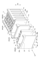
図2は、図1の電池モジュール1を示す断面図である。図3は、電池モジュール1を構成する配列体3を示す斜視図である。図3では、配列体3が部分的に分解された状態で示されている。図2及び図3に示されるように、電池モジュール1は、セルホルダ20によって保持された複数(例えば7つ)の電池セル10が所定の方向(配列方向D1)に配列された配列体3を備えている。
FIG. 2 is a cross-sectional view showing the
電池セル10は、例えばリチウムイオン二次電池等の非水電解質二次電池である。電池セル10は、非水系の電解液が注入されたケース内に電極組立体を収容して構成されている。電極組立体は、正極、負極、及びセパレータを所定の順序で積層したものである。本実施形態では、例えば袋状のセパレータ内にシート状の正極が収容されており、正極が収容された袋状のセパレータとシート状の負極とが交互に積層されている。電池セル10は、略直方体形状をなしており、上面11aと、下面11bと、一対の側面11cと、配列方向D1に直交する一対の面11dとを有している。電池セル10の上面11aからは、正負一対の電極端子13が突出している。隣り合う電池セル10の電極端子13は、バスバーによって互いに電気的に接続され得る。これにより、隣り合う電池セル10は電気的に直列に接続される。
The
配列体3は、拘束部材40によって拘束されている。拘束部材40は、電池セル10の配列方向D1において、配列体3を挟むように配置されており、電池セル10の配列方向D1に拘束荷重を付加する。本実施形態では、拘束部材40は、配列体3を配列方向D1から挟む一対のブラケット41と、一対のブラケット41同士を連結する複数(例えば4つ)の連結部材46と、を有している。
The
ブラケット41は、例えば金属材料からなる板状部材が折り曲げられて形成されている。ブラケット41には、折曲部41aを挟んで挟持部42と固定部43とが形成されている。一方のブラケット41の挟持部42と配列体3との間には、弾性部材30が配置されている。弾性部材30は、例えば電池セル10が膨張した場合に、電池セル10の膨張を吸収するように圧縮される。弾性部材30は、例えばゴム等によって構成されている。
The
挟持部42には、連結部材46が挿通される複数の挿通孔42aが設けられている。挟持部42は、配列体3及び弾性部材30を挟んだ状態で、連結部材46によって締結される。連結部材46は、例えば鉄等の金属により形成されたボルト46aである。各連結部材46は、一方のブラケット41の挿通孔42a、後述する各セルホルダ20の挿通孔23b,24b、及び他方のブラケット41の挿通孔42aに順次挿通され、一対のブラケット41の外側でナット46bにより締結されている。この締結によって配列体3及び弾性部材30に対して配列方向D1に拘束荷重が負荷されている。固定部43は、例えば筐体50内の固定面50aに対してボルト44によって固定される部分である。
The sandwiching
セルホルダ20は、セルホルダ20Aと、セルホルダ20Bとの2種類を含む。セルホルダ20Aは、配列方向D1に隣り合う電池セル10同士の間に配置されて、電池セル10を保持する。セルホルダ20Bは、配列された電池セル10のうちの両端部に配置された電池セル10とブラケット41との間に配置されて、電池セル10を保持する。図4は、セルホルダ20Aを示す斜視図である。セルホルダ20Aは、樹脂材料によって形成されており、隔壁21と、保持部22とを有している。隔壁21は、電池セル10の配列方向D1に直交(交差)する方向に延在する矩形の平板形状を有している。隔壁21は、電池セル10における配列方向D1に直交する面11dを保持し得る。保持部22は、隔壁21の周縁に形成された矩形の枠状をなしており、上壁23、下壁24、第1側壁(側壁)26、及び第2側壁27を有する。上壁23、下壁24、第1側壁26、及び第2側壁27は、何れも平板状を有している。
The
上壁23は、電池セル10における電極端子13が形成された上面11aに対向し、当該上面11aを保持し得る。上壁23は、隔壁21の上端縁から電池セル10の配列方向D1に突出している。本実施形態では、上壁23は、配列方向D1において、隔壁21の一面側21a及び他面側21bにそれぞれ設けられている。また、配列方向D1における上壁23の幅は、例えば電池セル10の幅の半分よりも小さくなっている。上壁23の上部には、筒状部23aが設けられている。筒状部23aには、連結部材46が挿通される挿通孔23bが形成されている。筒状部23aは、例えば上壁23の両端部に形成されており、上側に突出している。
The
下壁24は、電池セル10における下面11bに対向し、当該下面11bを保持し得る。下壁24は、隔壁21の下端縁から電池セル10の配列方向D1に突出している。本実施形態では、下壁24は、配列方向D1において、隔壁21の一面側21a及び他面側21bにそれぞれ設けられている。また、配列方向D1における下壁24の幅は、例えば電池セル10の幅の略半分となっている。すなわち、一対のセルホルダ20の間に電池セル10が保持されている状態では、一方のセルホルダ20に形成された下壁24と、他方のセルホルダ20に形成された下壁24とによって、電池セル10の下面11bの全体が保持され得る。下壁24の下部には、連結部材46が挿通される挿通孔24bが形成された筒状部24aが設けられている。筒状部24aは、例えば下壁24の両端部に形成されており、下側に突出している。
The
第1側壁26は、筐体50の固定面50aに対向し、電池セル10における一方の側面11cを保持し得る。第1側壁26は、隔壁21の固定面50a側の一縁部21cに設けられており、配列方向D1に突出している。本実施形態では、第1側壁26は、配列方向D1において、隔壁21の一面側21a及び他面側21bにそれぞれ設けられている。第1側壁26は、電池セル10における一方の側面11cの一部を露出させる露出部26aを有する。露出部26aは、例えば配列方向D1に交差する上下方向D2に延在する矩形の切り欠き状の部分である。本実施形態において、露出部26aは、配列方向D1における第1側壁26の両端側にそれぞれ設けられている。配列方向D1における第1側壁26の幅は、第1側壁26の上端及び下端において下壁24の幅と略同一であり、電池セル10の幅の略半分となっている。露出部26aが形成されている部分における第1側壁26の幅は、第1側壁26の上端及び下端における第1側壁26の幅よりも小さくなっている。
The
第1側壁26の厚さ(配列方向D1及び上下方向D2に直交し、第1側壁26と固定面50aとが対向する方向D3における寸法)Nは、A×V×T/Pによって算出される値に比例する絶縁距離L以上、且つ、2mm以下である。
The thickness N of the first side wall 26 (dimension in the direction D3 orthogonal to the arrangement direction D1 and the vertical direction D2 and facing the
式(1)において、Aは、セルホルダ20が固定面50aに固定された際に、露出部26aによって画成される一方の側面11cと固定面50aとの間の空間S内の気体の汚損度に依存する係数である。汚損度に依存する係数Aは、例えば公知の手法により算出され得る。なお、汚損度は、規格JIS60664-1(IEC60664-1)によって規定された汚損度1~汚損度4の4つの等級に分類することができる。汚損度1とは、どのような汚染も発生しないか又は乾燥状態で非導電性の汚染だけが発生する状態である。汚損度2とは、非導電性の汚染は発生するが、時には結露によって一時的に導電性が引き起こされることが予想される状態である。汚損度3とは、導電性の汚染が発生する、又は乾燥した非導電性の汚染だが予想される結露のために導電性となる汚染が発生する状態である。汚損度4とは、導電性のほこり、又は雨若しくはその他の湿潤状態によって連続的な導電性を発生させる状態である。空間S内の気体の汚染の原因になる物質としては、例えば塩分、水分、ほこり、及び錆等が挙げられる。一般的に、空間S内の汚損度の等級が高くなるほど絶縁距離Lは大きくなり、空間S内の汚損度の等級が低くなるほど絶縁距離Lは小さくなる。
In the formula (1), A is the degree of gas contamination in the space S between the one
式(1)において、Vは電池セル10と筐体50との間の電圧差に依存する係数である。一般的に、電池セル10と筐体50との間の電圧差が大きくなるほど係数Vは大きくなり、電池セル10と筐体50との間の電圧差が小さくなるほど係数Vは小さくなる。したがって、電池セル10と筐体50との間の電圧差が大きくなるほど絶縁距離Lは大きくなり、電池セル10と筐体50との間の電圧差が小さくなるほど、絶縁距離Lは小さくなる。
In equation (1), V is a coefficient depending on the voltage difference between the
式(1)において、Tは空間S内の温度に依存する係数である。温度に依存する係数Tは、例えば公知の手法により算出され得る。一般的に、温度が高くなるほど係数Tは大きくなり、温度が低くなるほど係数Tは小さくなる。したがって、温度が高くなるほど絶縁距離Lは大きくなり、温度が低くなるほど絶縁距離Lは小さくなる。 In equation (1), T is a coefficient that depends on the temperature in the space S. The temperature-dependent coefficient T can be calculated, for example, by a known method. Generally, the higher the temperature, the larger the coefficient T, and the lower the temperature, the smaller the coefficient T. Therefore, the higher the temperature, the larger the insulation distance L, and the lower the temperature, the smaller the insulation distance L.
式(1)において、Pは空間S内の気圧に依存する係数である。気圧に依存する係数Pは、例えば公知の手法により算出され得る。一般的に、気圧が高くなるほど係数Pは大きくなり、気圧が低くなるほど係数Pは小さくなる。したがって、気圧が低くなるほど絶縁距離Lは大きくなり、気圧が高くなるほど絶縁距離Lは小さくなる。 In equation (1), P is a coefficient depending on the atmospheric pressure in the space S. The coefficient P depending on the atmospheric pressure can be calculated by, for example, a known method. In general, the higher the atmospheric pressure, the larger the coefficient P, and the lower the atmospheric pressure, the smaller the coefficient P. Therefore, the lower the atmospheric pressure, the larger the insulation distance L, and the higher the atmospheric pressure, the smaller the insulation distance L.
通常の使用条件下(例えば、電池セル10と筐体50との間の電圧差が300V程度、温度が60℃~80℃程度、気圧が50kPa~100kPa程度の大気圧環境下である場合)における絶縁距離Lは、例えば1mmよりも小さい。したがって、第1側壁26の厚さを1mm以上とすることにより、電池セル10の一方の側面11cと固定面50aとの間に絶縁距離L以上の距離を確保することができる。
Under normal operating conditions (for example, when the voltage difference between the
図2に示されるように、一対のセルホルダ20によって1つの電池セル10が保持されている状態では、一方のセルホルダ20の、隔壁21の一面側21aの露出部26aと、他方のセルホルダ20の、隔壁21の他面側21bの露出部26aとが一体となっている。一体となった露出部26aからは、一対のセルホルダ20に保持された電池セル10の一方の側面11cの一部が露出している。電池セル10の側面11cのうち、露出部26aから露出していない部分は、第1側壁26に接触している。
As shown in FIG. 2, in a state where one
各セルホルダ20の第1側壁26には、接続部28が設けられている。隣り合う他の第1側壁26の接続部28は互いに嵌合する(図5参照)。接続部28は、配列方向D1における第1側壁26の両端部にそれぞれ設けられている。また、接続部28は、上下方向D2における第1側壁26の上端及び下端(すなわち、露出部26a以外の部分)に設けられている。本実施形態において、接続部28は、配列方向D1における第1側壁26の一端部に形成された凸部28aと、配列方向D1における第1側壁26の他端部に形成された凹部28bとを含む。一の第1側壁26に設けられた接続部28の凸部28aは、一端部側において隣り合う他の第1側壁26に設けられた接続部28の凹部28bに嵌合する。一方、一の第1側壁26に設けられた接続部28の凹部28bには、他端部側において隣り合う他の第1側壁26に設けられた接続部28の凸部28aが嵌合する。このように、接続部28は、いわゆるインロー構造となっている。
A connecting
第2側壁27は、方向D3において第1側壁26の反対側に位置しており、電池セル10における他方の側面11cを保持し得る。第2側壁27は、隔壁21の他縁部21dに設けられており、配列方向D1に突出している。本実施形態では、第2側壁27は、配列方向D1において、隔壁21の一面側21a及び他面側21bにそれぞれ設けられている。配列方向D1における第2側壁27の幅は、下壁24の幅と略同一であり、電池セル10の幅の略半分となっている。一対のセルホルダ20の間に電池セル10が保持されている状態では、一方のセルホルダ20の第2側壁27と、他方のセルホルダ20の第2側壁27とによって、電池セル10の他方の側面11cの全体が保持され得る。
The
図2及び図6に示されるように、電池モジュール1は伝熱部材7として、TIM(Thermal Interface Material)を備えている。伝熱部材7は絶縁性を有し、一方の側面11cと固定面50aとの間で伝熱可能である。伝熱部材7は、一方の側面11cの一部に固着されている。電池モジュール1を固定面50aに固定した際に、伝熱部材7は電池セル10の一方の側面11cと固定面50aとの間に配置された状態となる。すなわち、電池セル10の一方の側面11cは、伝熱部材7を介して固定面50aに接触する。伝熱部材7は、露出部26aから露出した一方の側面11cの一部に接触している。本実施形態において、伝熱部材7は、露出部26aの縁部(すなわち、第1側壁26)と離間して配置されている。すなわち、伝熱部材7と第1側壁26との間には隙間(空間S)が形成されている。このように伝熱部材7が配置されることにより、露出部26aから露出し、且つ、伝熱部材7が接触していない非接触部11eが伝熱部材7を囲むように形成されている。このように伝熱部材7が配置されている場合、空間Sは、非接触部11eと固定面50aとの間に形成される空間である。伝熱部材7は、例えば弾性を有する長尺の弾性シートであり、シリコンゴム又はアクリルゴム等から構成される。
As shown in FIGS. 2 and 6, the
伝熱部材7と筐体50の固定面50aとの間には、伝熱部材7と筐体50との摩擦を低減するスリップシート8(摩擦低減部材)が配置されている。スリップシート8は、例えば伝熱部材7に密着し、伝熱部材7を筐体50に対して配列方向D1に移動しやすくする。スリップシート8は、例えばポリエチレンテレフタレート(PET)等の伝熱性を有し、且つ、摩擦係数が小さい樹脂材料によって構成されている。
A slip sheet 8 (friction reducing member) for reducing friction between the
以上説明したように、電池モジュール1では、露出した一方の側面11cの一部に、一方の側面11cと固定面50aとの間で伝熱可能な伝熱部材7が固着されている(図2参照)。これにより、電池セル10で発生した熱を効率よく筐体50に伝達することができるので、電池セル10の放熱性を確保することができる。また、上記の電池モジュール1では、セルホルダ20の第1側壁26の厚さNは、A×V×T/Pにより算出される値に比例する絶縁距離L以上である。これにより、電池セル10の一方の側面11cと筐体50の固定面50aとの間に絶縁距離L以上の距離が確保されている。したがって、露出部26aから露出した一方の側面11cのうち、伝熱部材7が接触していない部分(非接触部11e(図6参照))においても、電池セル10と筐体50との絶縁の信頼性を高めることが可能である。さらに、第1側壁26の厚さを2mm以下にすることにより、第1側壁26の厚さを小さくすることができる。これにより、電池モジュール1が固定面50aに固定された際に、一方の側面11cと固定面50aとの間に配置された伝熱部材7の厚さも2mm以下となる。このように、伝熱部材7の厚さが低減されるので、電池セル10で発生した熱を効率よく筐体50に伝達することができる。さらに、第1側壁26の露出部26a以外の部分においても、第1側壁26を介して電池セル10で発生した熱を効率よく筐体50に伝達することができる。したがって、電池セル10の放熱性を高めることができる。
As described above, in the
また、電池モジュール1を筐体50に固定した際には、空間Sが伝熱部材7の逃げ場となる隙間として機能する。したがって、伝熱部材7が押しつぶされて露出部26aから第1側壁26と固定面50aとの間にはみ出すことを抑制することができる。
Further, when the
また、第1側壁26の厚さは1mm以上である。このように第1側壁26の厚さを1mm以上とすることにより、電池セル10の一方の側面11cと筐体50の固定面50aとの間の距離を絶縁距離L以上とすることができる。したがって、露出部26aから露出した一方の側面11cのうち、伝熱部材7が接触していない非接触部11eにおいても、電池セル10と筐体50との絶縁の信頼性を高めることが可能である。
The thickness of the
また、図6に示されるように、伝熱部材7の少なくとも一部は、第1側壁26と離間している。これにより、伝熱部材7と第1側壁26との間に隙間が形成されるので、電池モジュール1を筐体50に固定した際に、伝熱部材7が押しつぶされて露出部26aから第1側壁26と固定面50aとの間にはみ出すことがより確実に抑制される。したがって、電池モジュール1を筐体50に固定した際に、電池モジュール1に荷重が加わることを抑制することができる。
Further, as shown in FIG. 6, at least a part of the
また、図5に示されるように、各セルホルダ20の第1側壁26には接続部28が設けられ、隣り合う第1側壁26の接続部28は互いに嵌合する。これにより、隣り合う第1側壁26の接続部28が互いに嵌合することにより、隣り合う第1側壁26の間の密閉性が高められている。故に、汚染の原因となる物質が、隣り合う第1側壁26の間から露出部26aによって画成される一方の側面11cと固定面50aとの間の空間S内に侵入することを抑制できる。したがって、汚損度の上昇により絶縁距離Lが大きくなることを抑制することができるので、電池セル10と筐体50との絶縁の信頼性を更に高めることが可能である。
Further, as shown in FIG. 5, a connecting
また、図2に示されるように、電池モジュール1は、配列体3を挟むように配置され、配列方向D1に拘束荷重を付加する一対の拘束部材40と、拘束部材40と配列体3との間に配置され、配列体3と共に拘束される弾性部材30と、を備えている。これにより、例えば電池セル10が膨張した場合に、弾性部材30によって電池セル10の膨張を吸収することができる。したがって、電池セル10が膨張した際に、電池モジュール1に撓みが生じることを抑制することができる。
Further, as shown in FIG. 2, the
また、図1に示されるように、電池パック100は、上記の電池モジュール1と、電池モジュール1が固定される筐体50と、伝熱部材7と筐体50との間に配置され、伝熱部材7と筐体50との摩擦を低減するスリップシート8と、を備えている。これにより、例えば電池セル10が膨張した場合に、伝熱部材7が筐体50に対して配列方向D1に移動しやすくなる。したがって、電池セル10が膨張した場合であっても、摩擦による伝熱部材7の変形等が抑制されるので、伝熱部材7と筐体50との間で熱が伝達される面積を一定に保つことができる。よって、電池セル10の放熱性を保つことが可能である。
Further, as shown in FIG. 1, the
以上、本発明の実施形態について説明してきたが、本発明は上記の実施形態に限定されず、種々の変更を行うことができる。 Although the embodiments of the present invention have been described above, the present invention is not limited to the above-described embodiments, and various modifications can be made.
例えば、上記の実施形態では、伝熱部材7は露出部26aの縁部と離間して配置されていたが、伝熱部材7の配置は適宜変更可能である。図7は、伝熱部材7の配置の変形例を示す図である。図7に示されるように、伝熱部材7の少なくとも一部は、第1側壁26と離間している。伝熱部材7は、上下方向D2における露出部26aの両端にそれぞれ配置され、隣り合う第1側壁26の接触部分と空間Sとの間を埋めている。非接触部11e及び空間Sは、上下方向D2における露出部26aの中央部に形成される。この場合、伝熱部材7が隣り合う第1側壁26の接触部分と空間Sとの間を埋めることにより、隣り合う第1側壁26の接触部分の密閉性が高められている。これにより、汚染の原因となる物質が、接触部分から露出部26aによって画成される一方の側面11cと固定面50aとの間の空間S内に、汚染の原因となる物質が侵入することを抑制できる。したがって、電池セル10と筐体50との絶縁の信頼性を更に高めることが可能である。
For example, in the above embodiment, the
また、セルホルダ20は、露出部26aを有していればよく、他の形状を有していてもよい。図8は、セルホルダ20の変形例を示す図である。図8に示されるように、セルホルダ120は、隔壁121と、上壁123と、下壁124と、第1側壁126と、第2側壁127と、第1側壁126形成された露出部126aとを有している。第1側壁126の厚さNは、絶縁距離L以上(又は1mm以上)且つ2mm以下である。セルホルダ120は、上壁123、下壁124、第1側壁126、及び第2側壁127が、配列方向D1において隔壁121の一面側121aのみに突出している点で、上記実施形態のセルホルダ20と相違している。この場合、配列方向D1における上壁123、下壁124、第1側壁126、及び第2側壁127のそれぞれの幅は、電池セル10の幅と略同一である。また、露出部126aは、隔壁121の一面側121aのみに形成されている。このようなセルホルダ120を有する電池モジュールにおいても、第1側壁126の厚さが絶縁距離L以上(又は1mm以上)且つ2mm以下であるため、上記実施形態の電池モジュール1と同様の効果を得ることができる。
Further, the
図9は、セルホルダ20の更なる変形例を示す図である。図9に示されるように、セルホルダ220は、隔壁221と、上壁223と、下壁224と、第1側壁226と、第2側壁227と、第1側壁226形成された露出部226aとを有している。第1側壁226の厚さNは、絶縁距離L以上(又は1mm以上)且つ2mm以下である。上壁223、下壁224、第1側壁226、及び第2側壁227は、セルホルダ120と同様に、配列方向D1において隔壁121の一面側121aのみに突出している。セルホルダ220がセルホルダ120と相違する点は、露出部226aが、方向D3から見て第1側壁226の中央部において窓状に設けられている点である。この構成によれば、露出部226aは隣り合う第1側壁226の間から離間しているので、汚染の原因となる物質が、隣り合う第1側壁226の間から露出部226aによって形成される一方の側面11cと筐体50との間の空間S内に侵入することを抑制できる。したがって、電池セル10と筐体50との絶縁の信頼性を更に高めることが可能である。
FIG. 9 is a diagram showing a further modification example of the
また、隔壁21、上壁23、下壁24、及び第2側壁27の厚さは任意に設定することができる。例えば、隔壁21、上壁23、下壁24、及び第2側壁27の厚さは、第1側壁26の厚さNと略同一であってもよいし、異なっていてもよい。
Further, the thicknesses of the
また、上記実施形態では、第1側壁26のみに接続部28が設けられていたが、上壁23、下壁24、及び第2側壁27にも接続部28が設けられていてもよい。また、接続部28の構成は上記実施形態に限定されず、適宜変更可能である。なお、第1側壁26には、接続部28が設けられていなくてもよい。
Further, in the above embodiment, the connecting
また、上記実施形態では、配列体3と拘束部材40との間に弾性部材30が配置されている例について説明したが、電池モジュール1は弾性部材30を有していなくてもよい。
Further, in the above embodiment, the example in which the
また、上記の実施形態では、伝熱部材7と筐体50との間にスリップシート8が配置されている例について説明したが、電池パック100はスリップシート8を有していなくてもよい。また、スリップシート8は、第1側壁26と筐体50との間にも配置されていてもよい。この場合、伝熱部材7と筐体50との間のスリップシート8と、第1側壁26と筐体50との間のスリップシート8とは一体であってもよい。すなわち、筐体50に対向する電池モジュール1の一面の全体を覆うように、1枚のスリップシート8を電池モジュール1と筐体50との間に配置してもよい。
Further, in the above embodiment, the example in which the
1…電池モジュール、3…配列体、7…伝熱部材、8…スリップシート(摩擦低減部材)、10…電池セル、11c…側面、20,120,220…セルホルダ、21…隔壁、21c…一縁部、22…保持部、26,126,226…第1側壁(側壁)、26a,126a,226a…露出部、28…接続部、30…弾性部材、40…拘束部材、50…筐体、50a…固定面、100…電池パック、D1…配列方向、D2…上下方向、D3…方向、L…絶縁距離、N…厚さ、S…空間。 1 ... Battery module, 3 ... Arrangement, 7 ... Heat transfer member, 8 ... Slip sheet (friction reduction member), 10 ... Battery cell, 11c ... Side surface, 20, 120, 220 ... Cell holder, 21 ... Bulk partition, 21c ... 1 Edge, 22 ... Holding, 26, 126, 226 ... First side wall (side wall), 26a, 126a, 226a ... Exposed, 28 ... Connecting, 30 ... Elastic member, 40 ... Restraining member, 50 ... Housing, 50a ... Fixed surface, 100 ... Battery pack, D1 ... Arrangement direction, D2 ... Vertical direction, D3 ... Direction, L ... Insulation distance, N ... Thickness, S ... Space.
Claims (8)
前記セルホルダは、
前記電池セルにおける配列方向に直交する面を保持する隔壁と、
前記隔壁の一縁部に設けられ、前記固定面に対向すると共に前記電池セルの側面を保持する側壁と、を含んで構成される保持部を有し、
前記側壁は、前記電池セルの前記側面の一部を露出させる露出部を有し、
前記露出部において露出した前記側面の一部には、絶縁性を有し、前記側面と前記固定面との間で伝熱可能な伝熱部材が固着されており、
前記側壁の厚さは、JIS規格に定められた絶縁距離L以上且つ2mm以下であり、
前記セルホルダが前記固定面に固定された際に、前記露出部によって画成される前記側面と前記固定面との間の空間は、複数の前記電池セルごとに前記側面の一部を露出させるように、前記配列方向に複数配列されており、
前記伝熱部材は、複数の前記空間のそれぞれに配置され、複数の前記電池セルごとに設けられている、電池モジュール。 A battery module in which a plurality of battery cells held by a cell holder are arranged in a predetermined direction and are fixed to a fixed surface in a housing.
The cell holder is
A partition wall that holds a plane orthogonal to the arrangement direction in the battery cell,
It has a holding portion provided on one edge of the partition wall, including a side wall facing the fixed surface and holding a side surface of the battery cell.
The side wall has an exposed portion that exposes a part of the side surface of the battery cell.
A heat transfer member having insulating properties and capable of transferring heat between the side surface and the fixed surface is fixed to a part of the side surface exposed in the exposed portion.
The thickness of the side wall is an insulation distance L or more and 2 mm or less specified in JIS standards .
When the cell holder is fixed to the fixed surface, the space between the side surface and the fixed surface defined by the exposed portion exposes a part of the side surface for each of the plurality of battery cells. In addition, a plurality of batteries are arranged in the above-mentioned arrangement direction.
The heat transfer member is a battery module arranged in each of the plurality of spaces and provided for each of the plurality of battery cells.
隣り合う前記側壁の前記接続部は互いに嵌合する、請求項1又は2に記載の電池モジュール。 A connection portion is provided on the side wall of each cell holder.
The battery module according to claim 1 or 2, wherein the connecting portions of the adjacent side walls are fitted to each other.
前記拘束部材と前記配列体との間に配置され、前記配列体と共に拘束される弾性部材と、を更に備える、請求項1~6の何れか一項に記載の電池モジュール。 A pair of constraint members arranged so as to sandwich the array and applying a constraint load in the array direction,
The battery module according to any one of claims 1 to 6, further comprising an elastic member arranged between the restraining member and the array and constrained together with the array.
前記電池モジュールが固定される前記筐体と、
前記伝熱部材と前記筐体との間に配置され、前記伝熱部材と前記筐体との摩擦を低減する摩擦低減部材と、を備える、電池パック。 The battery module according to any one of claims 1 to 7.
The housing to which the battery module is fixed and the housing
A battery pack comprising a friction reducing member arranged between the heat transfer member and the housing and reducing friction between the heat transfer member and the housing.
Priority Applications (1)
| Application Number | Priority Date | Filing Date | Title |
|---|---|---|---|
| JP2017129263A JP7027708B2 (en) | 2017-06-30 | 2017-06-30 | Battery module and battery pack |
Applications Claiming Priority (1)
| Application Number | Priority Date | Filing Date | Title |
|---|---|---|---|
| JP2017129263A JP7027708B2 (en) | 2017-06-30 | 2017-06-30 | Battery module and battery pack |
Publications (2)
| Publication Number | Publication Date |
|---|---|
| JP2019012652A JP2019012652A (en) | 2019-01-24 |
| JP7027708B2 true JP7027708B2 (en) | 2022-03-02 |
Family
ID=65226432
Family Applications (1)
| Application Number | Title | Priority Date | Filing Date |
|---|---|---|---|
| JP2017129263A Active JP7027708B2 (en) | 2017-06-30 | 2017-06-30 | Battery module and battery pack |
Country Status (1)
| Country | Link |
|---|---|
| JP (1) | JP7027708B2 (en) |
Families Citing this family (5)
| Publication number | Priority date | Publication date | Assignee | Title |
|---|---|---|---|---|
| EP3916832A4 (en) * | 2019-01-25 | 2022-02-16 | Kabushiki Kaisha Toshiba | Battery pack and battery system |
| EP4030541A1 (en) * | 2019-09-10 | 2022-07-20 | Vehicle Energy Japan Inc. | Battery pack |
| CN112542644B (en) * | 2019-09-19 | 2022-10-14 | 东莞新能源科技有限公司 | Battery pack |
| CN111430614A (en) * | 2020-04-02 | 2020-07-17 | 欣旺达电动汽车电池有限公司 | Battery core isolation sleeve and battery module |
| CN114927818B (en) * | 2022-05-16 | 2024-04-19 | 北京科易动力科技有限公司 | Battery module and battery pack |
Citations (6)
| Publication number | Priority date | Publication date | Assignee | Title |
|---|---|---|---|---|
| JP2010104146A (en) | 2008-10-23 | 2010-05-06 | Mitsubishi Electric Corp | Power converting apparatus |
| JP2011171029A (en) | 2010-02-17 | 2011-09-01 | Sanyo Electric Co Ltd | Battery module |
| JP2014192281A (en) | 2013-03-27 | 2014-10-06 | Nec Commun Syst Ltd | Transformer and method of manufacturing the same |
| JP2015220218A (en) | 2014-05-21 | 2015-12-07 | 日立オートモティブシステムズ株式会社 | Battery module |
| JP2016219243A (en) | 2015-05-20 | 2016-12-22 | 株式会社豊田自動織機 | Battery module |
| JP2017076581A (en) | 2015-10-16 | 2017-04-20 | 株式会社豊田自動織機 | Power storage pack |
Family Cites Families (1)
| Publication number | Priority date | Publication date | Assignee | Title |
|---|---|---|---|---|
| JPS6050461A (en) * | 1983-08-30 | 1985-03-20 | Mitsubishi Electric Corp | Method of non-destructive insulation test |
-
2017
- 2017-06-30 JP JP2017129263A patent/JP7027708B2/en active Active
Patent Citations (6)
| Publication number | Priority date | Publication date | Assignee | Title |
|---|---|---|---|---|
| JP2010104146A (en) | 2008-10-23 | 2010-05-06 | Mitsubishi Electric Corp | Power converting apparatus |
| JP2011171029A (en) | 2010-02-17 | 2011-09-01 | Sanyo Electric Co Ltd | Battery module |
| JP2014192281A (en) | 2013-03-27 | 2014-10-06 | Nec Commun Syst Ltd | Transformer and method of manufacturing the same |
| JP2015220218A (en) | 2014-05-21 | 2015-12-07 | 日立オートモティブシステムズ株式会社 | Battery module |
| JP2016219243A (en) | 2015-05-20 | 2016-12-22 | 株式会社豊田自動織機 | Battery module |
| JP2017076581A (en) | 2015-10-16 | 2017-04-20 | 株式会社豊田自動織機 | Power storage pack |
Also Published As
| Publication number | Publication date |
|---|---|
| JP2019012652A (en) | 2019-01-24 |
Similar Documents
| Publication | Publication Date | Title |
|---|---|---|
| JP7027708B2 (en) | Battery module and battery pack | |
| CN109478619B (en) | Battery module | |
| CN111052494B (en) | Battery module and battery pack | |
| JP7054867B2 (en) | Battery module | |
| JP5067171B2 (en) | Electrochemical storage element module | |
| JP6148202B2 (en) | Storage device cooling structure | |
| US7981538B2 (en) | Battery module with improved cell barrier between unit cells | |
| WO2019142645A1 (en) | Power storage device | |
| JP6286679B2 (en) | Battery block | |
| US10903462B2 (en) | Electric storage device | |
| US20110200862A1 (en) | Battery module | |
| JP6926630B2 (en) | Battery module | |
| JP6176085B2 (en) | Battery module | |
| CN111742442A (en) | Battery module and battery pack | |
| EP3255703B1 (en) | Battery pack | |
| US11233267B2 (en) | Separator, battery module and battery module production method | |
| JP6728576B2 (en) | Battery pack | |
| CN111081923B (en) | Power storage module and method for manufacturing power storage module | |
| JP2013222554A (en) | Power storage device | |
| JP2017103158A (en) | Battery pack | |
| JP6855789B2 (en) | Battery module | |
| JP7107912B2 (en) | Separator and solid state battery module | |
| WO2019124749A1 (en) | Battery module and battery pack comprising same | |
| JP6932978B2 (en) | Battery module | |
| US20200251695A1 (en) | Battery module and battery pack |
Legal Events
| Date | Code | Title | Description |
|---|---|---|---|
| A621 | Written request for application examination |
Free format text: JAPANESE INTERMEDIATE CODE: A621 Effective date: 20200306 |
|
| A977 | Report on retrieval |
Free format text: JAPANESE INTERMEDIATE CODE: A971007 Effective date: 20210125 |
|
| A131 | Notification of reasons for refusal |
Free format text: JAPANESE INTERMEDIATE CODE: A131 Effective date: 20210209 |
|
| A521 | Request for written amendment filed |
Free format text: JAPANESE INTERMEDIATE CODE: A523 Effective date: 20210412 |
|
| A131 | Notification of reasons for refusal |
Free format text: JAPANESE INTERMEDIATE CODE: A131 Effective date: 20210824 |
|
| A521 | Request for written amendment filed |
Free format text: JAPANESE INTERMEDIATE CODE: A523 Effective date: 20211006 |
|
| TRDD | Decision of grant or rejection written | ||
| A01 | Written decision to grant a patent or to grant a registration (utility model) |
Free format text: JAPANESE INTERMEDIATE CODE: A01 Effective date: 20220118 |
|
| A61 | First payment of annual fees (during grant procedure) |
Free format text: JAPANESE INTERMEDIATE CODE: A61 Effective date: 20220131 |
|
| R151 | Written notification of patent or utility model registration |
Ref document number: 7027708 Country of ref document: JP Free format text: JAPANESE INTERMEDIATE CODE: R151 |