JP7022628B2 - Spark plug for internal combustion engine - Google Patents

Spark plug for internal combustion engine Download PDF

Info

Publication number
JP7022628B2
JP7022628B2 JP2018052539A JP2018052539A JP7022628B2 JP 7022628 B2 JP7022628 B2 JP 7022628B2 JP 2018052539 A JP2018052539 A JP 2018052539A JP 2018052539 A JP2018052539 A JP 2018052539A JP 7022628 B2 JP7022628 B2 JP 7022628B2
Authority
JP
Japan
Prior art keywords
plug
insulator
tip
axial direction
outer peripheral
Prior art date
Legal status (The legal status is an assumption and is not a legal conclusion. Google has not performed a legal analysis and makes no representation as to the accuracy of the status listed.)
Active
Application number
JP2018052539A
Other languages
Japanese (ja)
Other versions
JP2018174132A (en
JP2018174132A5 (en
Inventor
晋太郎 伊藤
大介 田中
明光 杉浦
亮太 若杉
香 土井
文明 青木
金千代 寺田
哲也 三輪
Current Assignee (The listed assignees may be inaccurate. Google has not performed a legal analysis and makes no representation or warranty as to the accuracy of the list.)
Denso Corp
Original Assignee
Denso Corp
Priority date (The priority date is an assumption and is not a legal conclusion. Google has not performed a legal analysis and makes no representation as to the accuracy of the date listed.)
Filing date
Publication date
Application filed by Denso Corp filed Critical Denso Corp
Priority to PCT/JP2018/013102 priority Critical patent/WO2018181654A1/en
Priority to CN201880021380.3A priority patent/CN110462947B/en
Publication of JP2018174132A publication Critical patent/JP2018174132A/en
Publication of JP2018174132A5 publication Critical patent/JP2018174132A5/ja
Priority to US16/584,998 priority patent/US10886708B2/en
Application granted granted Critical
Publication of JP7022628B2 publication Critical patent/JP7022628B2/en
Active legal-status Critical Current
Anticipated expiration legal-status Critical

Links

Images

Classifications

    • HELECTRICITY
    • H01ELECTRIC ELEMENTS
    • H01TSPARK GAPS; OVERVOLTAGE ARRESTERS USING SPARK GAPS; SPARKING PLUGS; CORONA DEVICES; GENERATING IONS TO BE INTRODUCED INTO NON-ENCLOSED GASES
    • H01T13/00Sparking plugs
    • H01T13/20Sparking plugs characterised by features of the electrodes or insulation
    • H01T13/32Sparking plugs characterised by features of the electrodes or insulation characterised by features of the earthed electrode
    • HELECTRICITY
    • H01ELECTRIC ELEMENTS
    • H01TSPARK GAPS; OVERVOLTAGE ARRESTERS USING SPARK GAPS; SPARKING PLUGS; CORONA DEVICES; GENERATING IONS TO BE INTRODUCED INTO NON-ENCLOSED GASES
    • H01T13/00Sparking plugs
    • H01T13/20Sparking plugs characterised by features of the electrodes or insulation
    • HELECTRICITY
    • H01ELECTRIC ELEMENTS
    • H01TSPARK GAPS; OVERVOLTAGE ARRESTERS USING SPARK GAPS; SPARKING PLUGS; CORONA DEVICES; GENERATING IONS TO BE INTRODUCED INTO NON-ENCLOSED GASES
    • H01T13/00Sparking plugs
    • H01T13/52Sparking plugs characterised by a discharge along a surface

Description

本発明は、内燃機関用のスパークプラグに関する。 The present invention relates to a spark plug for an internal combustion engine.

例えば特許文献1に開示されているように、内燃機関用のスパークプラグとして、中心電極に高周波電圧を印加することによって、接地電極と中心電極との間に放電を生じさせるものがある。かかるスパークプラグは、絶縁碍子の表面を這うような沿面火花放電を、中心電極と接地電極との間に生じさせる。 For example, as disclosed in Patent Document 1, there is a spark plug for an internal combustion engine that causes a discharge between the ground electrode and the center electrode by applying a high frequency voltage to the center electrode. Such a spark plug causes a creeping spark discharge that crawls on the surface of the insulating insulator between the center electrode and the ground electrode.

ここで、特許文献1に開示されたスパークプラグは、筒状の接地電極の内側に絶縁碍子が配置されており、絶縁碍子の更に内側に中心電極が配置されている。絶縁碍子は、その先端が接地電極の先端側に突出するように配置されている。そして、中心電極は、その先端が絶縁碍子の先端側に突出するように配置されている。 Here, in the spark plug disclosed in Patent Document 1, an insulating insulator is arranged inside a tubular ground electrode, and a center electrode is arranged further inside the insulating insulator. The insulating insulator is arranged so that its tip protrudes toward the tip side of the ground electrode. The center electrode is arranged so that its tip protrudes toward the tip side of the insulating insulator.

特開昭61-292875号公報Japanese Unexamined Patent Publication No. 61-292875

しかしながら、特許文献1に記載のスパークプラグにおいては、絶縁碍子の先端部の角部(すなわち絶縁碍子の先端面と外周面との間の角)が露出している。それゆえ、中心電極と接地電極との間において、絶縁碍子の前記角部の表面を這うような沿面火花放電が形成される。これにより、中心電極と接地電極との間に生じた放電が、絶縁碍子の表面、特に前記角部の表面から剥離しにくい。それゆえ、前記スパークプラグは、中心電極と接地電極との間に生じる放電が、燃焼室内の気流によって大きく引き伸ばされにくく、混合気への着火性を確保し難い。 However, in the spark plug described in Patent Document 1, the corner portion of the tip portion of the insulating insulator (that is, the corner between the tip surface and the outer peripheral surface of the insulating insulator) is exposed. Therefore, a creeping spark discharge that crawls on the surface of the corner of the insulating insulator is formed between the center electrode and the ground electrode. As a result, the electric discharge generated between the center electrode and the ground electrode is unlikely to be separated from the surface of the insulating insulator, particularly the surface of the corner portion. Therefore, in the spark plug, the discharge generated between the center electrode and the ground electrode is difficult to be greatly extended by the air flow in the combustion chamber, and it is difficult to secure the ignitability of the air-fuel mixture.

本発明は、かかる課題に鑑みてなされたものであり、混合気への着火性の向上を図ることができる内燃機関用のスパークプラグを提供しようとするものである。 The present invention has been made in view of the above problems, and an object of the present invention is to provide a spark plug for an internal combustion engine capable of improving the ignitability of an air-fuel mixture.

本発明の第一の態様は、筒状の接地電極(2)と、
前記接地電極の内側に配されると共に、前記接地電極の先端よりもプラグ軸方向(Z)の先端側へ突出した碍子突出部(31)を有する筒状の絶縁碍子(3)と、
前記絶縁碍子の内側に保持されると共に、前記碍子突出部の先端から露出した露出部(41)を有する中心電極(4)と、を備え、
前記中心電極の前記露出部は、前記碍子突出部をプラグ軸方向の先端側から覆う第一部位(411)と、前記第一部位からプラグ軸方向の基端側に延設されると共に前記碍子突出部の外周面(31b)の全周を、プラグ径方向の外周側から覆う第二部位(412)とを有し、
プラグ軸方向における、前記第一部位と前記碍子突出部との間には、軸方向空隙(ac)が形成されている、内燃機関用のスパークプラグ(1)にある。
本発明の第二の態様は、筒状の接地電極(2)と、
前記接地電極の内側に配されると共に、前記接地電極の先端よりもプラグ軸方向(Z)の先端側へ突出した碍子突出部(31)を有する筒状の絶縁碍子(3)と、
前記絶縁碍子の内側に保持されると共に、前記碍子突出部の先端から露出した露出部(41)を有する中心電極(4)と、を備え、
前記中心電極の前記露出部は、前記碍子突出部をプラグ軸方向の先端側から覆う第一部位(411)と、前記第一部位からプラグ軸方向の基端側に延設されると共に前記碍子突出部の外周面(31b)の全周を、プラグ径方向の外周側から覆う第二部位(412)とを有し、
プラグ径方向における、前記碍子突出部の前記外周面と前記中心電極の前記第二部位の内周面(412b)との間には、径方向空隙(rc)が形成されており、
前記露出部には、前記露出部の内外を貫通するとともに、一端が前記径方向空隙に向かって開口する通気孔(40)が形成されている、内燃機関用のスパークプラグ(1)にある。
本発明の第三の態様は、筒状の接地電極(2)と、
前記接地電極の内側に配されると共に、前記接地電極の先端よりもプラグ軸方向(Z)の先端側へ突出した碍子突出部(31)を有する筒状の絶縁碍子(3)と、
前記絶縁碍子の内側に保持されると共に、前記碍子突出部の先端から露出した露出部(41)を有する中心電極(4)と、を備え、
前記中心電極の前記露出部は、前記碍子突出部をプラグ軸方向の先端側から覆う第一部位(411)と、前記第一部位からプラグ軸方向の基端側に延設されると共に前記碍子突出部の外周面(31b)の全周を、プラグ径方向の外周側から覆う第二部位(412)とを有し、
前記碍子突出部は、全体として、プラグ軸方向の先端側に向かうほど段階的に外径が小さくなる段形状を有し、
前記中心電極における前記碍子突出部の内側に配された部位は、プラグ径方向の外周側に突出した電極大径部(42)を有する、内燃機関用のスパークプラグ(1)にある。
本発明の第四の態様は、筒状の接地電極(2)と、
前記接地電極の内側に配されると共に、前記接地電極の先端よりもプラグ軸方向(Z)の先端側へ突出した碍子突出部(31)を有する筒状の絶縁碍子(3)と、
前記絶縁碍子の内側に保持されると共に、前記碍子突出部の先端から露出した露出部(41)を有する中心電極(4)と、を備え、
前記中心電極の前記露出部は、前記碍子突出部をプラグ軸方向の先端側から覆う第一部位(411)と、前記第一部位からプラグ軸方向の基端側に延設されると共に前記碍子突出部の外周面(31b)の全周を、プラグ径方向の外周側から覆う第二部位(412)とを有し、
前記中心電極の前記露出部は、プラグ軸方向から見たとき、前記接地電極の内側に収まるよう形成されている、内燃機関用のスパークプラグ(1)にある。
The first aspect of the present invention is a cylindrical ground electrode (2) and a tubular ground electrode (2).
A tubular insulating insulator (3) arranged inside the ground electrode and having an insulator protruding portion (31) protruding toward the tip side in the plug axial direction (Z) from the tip of the ground electrode.
It is provided with a center electrode (4) which is held inside the insulating insulator and has an exposed portion (41) exposed from the tip of the insulator protruding portion.
The exposed portion of the center electrode is a first portion (411) that covers the insulator protruding portion from the tip end side in the plug axial direction, and extends from the first portion to the base end side in the plug axial direction and the insulator. It has a second portion (412) that covers the entire circumference of the outer peripheral surface (31b) of the protrusion from the outer peripheral side in the radial direction of the plug.
A spark plug (1) for an internal combustion engine has an axial gap (ac) formed between the first portion and the insulator protruding portion in the plug axial direction .
The second aspect of the present invention is a cylindrical ground electrode (2) and a tubular ground electrode (2).
A tubular insulating insulator (3) arranged inside the ground electrode and having an insulator protruding portion (31) protruding toward the tip side in the plug axial direction (Z) from the tip of the ground electrode.
It is provided with a center electrode (4) which is held inside the insulating insulator and has an exposed portion (41) exposed from the tip of the insulator protruding portion.
The exposed portion of the center electrode is a first portion (411) that covers the insulator protruding portion from the tip end side in the plug axial direction, and extends from the first portion to the base end side in the plug axial direction and the insulator. It has a second portion (412) that covers the entire circumference of the outer peripheral surface (31b) of the protrusion from the outer peripheral side in the radial direction of the plug.
A radial gap (rc) is formed between the outer peripheral surface of the insulator protrusion and the inner peripheral surface (412b) of the second portion of the center electrode in the plug radial direction.
The exposed portion is a spark plug (1) for an internal combustion engine, which is formed with a ventilation hole (40) that penetrates the inside and outside of the exposed portion and has one end opened toward the radial gap.
A third aspect of the present invention is a cylindrical ground electrode (2) and a tubular ground electrode (2).
A tubular insulating insulator (3) arranged inside the ground electrode and having an insulator protruding portion (31) protruding toward the tip side in the plug axial direction (Z) from the tip of the ground electrode.
It is provided with a center electrode (4) which is held inside the insulating insulator and has an exposed portion (41) exposed from the tip of the insulator protruding portion.
The exposed portion of the center electrode is a first portion (411) that covers the insulator protruding portion from the tip end side in the plug axial direction, and extends from the first portion to the base end side in the plug axial direction and the insulator. It has a second portion (412) that covers the entire circumference of the outer peripheral surface (31b) of the protrusion from the outer peripheral side in the radial direction of the plug.
The insulator protruding portion as a whole has a stepped shape in which the outer diameter gradually decreases toward the tip side in the plug axis direction.
The portion of the center electrode arranged inside the insulator protrusion is in a spark plug (1) for an internal combustion engine having an electrode large diameter portion (42) protruding toward the outer peripheral side in the plug radial direction.
A fourth aspect of the present invention is a cylindrical ground electrode (2) and a tubular ground electrode (2).
A tubular insulating insulator (3) arranged inside the ground electrode and having an insulator protruding portion (31) protruding toward the tip side in the plug axial direction (Z) from the tip of the ground electrode.
It is provided with a center electrode (4) which is held inside the insulating insulator and has an exposed portion (41) exposed from the tip of the insulator protruding portion.
The exposed portion of the center electrode is a first portion (411) that covers the insulator protruding portion from the tip end side in the plug axial direction, and extends from the first portion to the base end side in the plug axial direction and the insulator. It has a second portion (412) that covers the entire circumference of the outer peripheral surface (31b) of the protrusion from the outer peripheral side in the radial direction of the plug.
The exposed portion of the center electrode is located in a spark plug (1) for an internal combustion engine, which is formed so as to fit inside the ground electrode when viewed from the plug axis direction.

本発明の第五の態様は、筒状の接地電極(2)と、
前記接地電極の内側に配されると共に、前記接地電極の先端よりもプラグ軸方向(Z)の先端側へ突出した碍子突出部(31)を有する筒状の絶縁碍子(3)と、
前記絶縁碍子の内側に保持されると共に、前記碍子突出部の先端から露出した露出部(41)を有する中心電極(4)と、を備え、
前記中心電極の前記露出部は、前記碍子突出部をプラグ軸方向の先端側から覆う第一部位(411)と、前記第一部位からプラグ軸方向の基端側に延設されると共に前記碍子突出部の外周面(31b)のプラグ周方向の一部を、プラグ径方向の外周側から覆う第二部位(412)とを有し、
前記碍子突出部の少なくともプラグ周方向の前記第二部位が形成された領域は、プラグ軸方向の全体において、プラグ軸方向の先端側に向かうほど段階的に外径が小さくなる段形状を有し、
プラグ軸方向から見たとき、前記中心電極の前記露出部は、前記接地電極の内側に収まるよう形成されている、内燃機関用のスパークプラグ(1)にある。
本発明の第六の態様は、筒状の接地電極(2)と、
前記接地電極の内側に配されると共に、前記接地電極の先端よりもプラグ軸方向(Z)の先端側へ突出した碍子突出部(31)を有する筒状の絶縁碍子(3)と、
前記絶縁碍子の内側に保持されると共に、前記碍子突出部の先端から露出した露出部(41)を有する中心電極(4)と、を備え、
前記中心電極の前記露出部は、前記碍子突出部をプラグ軸方向の先端側から覆う第一部位(411)と、前記第一部位からプラグ軸方向の基端側に延設されると共に前記碍子突出部の外周面(31b)のプラグ周方向の一部を、プラグ径方向の外周側から覆う第二部位(412)とを有し、
前記碍子突出部の少なくともプラグ周方向の前記第二部位が形成された領域は、プラグ軸方向の全体において、プラグ軸方向の先端側に向かうほど段階的に外径が小さくなる段形状を有し、
前記中心電極における前記碍子突出部の内側に配された部位は、プラグ径方向の外周側に突出した電極大径部(42)を有する、内燃機関用のスパークプラグ(1)にある。
A fifth aspect of the present invention is a cylindrical ground electrode (2) and a tubular ground electrode (2).
A tubular insulating insulator (3) arranged inside the ground electrode and having an insulator protruding portion (31) protruding toward the tip side in the plug axial direction (Z) from the tip of the ground electrode.
It is provided with a center electrode (4) which is held inside the insulating insulator and has an exposed portion (41) exposed from the tip of the insulator protruding portion.
The exposed portion of the center electrode is a first portion (411) that covers the insulator protruding portion from the tip end side in the plug axial direction, and extends from the first portion to the base end side in the plug axial direction and the insulator. It has a second portion (412) that covers a part of the outer peripheral surface (31b) of the protrusion in the peripheral direction of the plug from the outer peripheral side in the radial direction of the plug.
The region where the second portion is formed at least in the peripheral direction of the plug of the insulator protrusion has a stepped shape in which the outer diameter gradually decreases toward the tip side in the plug axial direction in the entire plug axial direction. ,
When viewed from the plug axis direction, the exposed portion of the center electrode is located in a spark plug (1) for an internal combustion engine, which is formed so as to fit inside the ground electrode .
A sixth aspect of the present invention is a tubular ground electrode (2) and a tubular ground electrode (2).
A tubular insulating insulator (3) arranged inside the ground electrode and having an insulator protruding portion (31) protruding toward the tip side in the plug axial direction (Z) from the tip of the ground electrode.
It is provided with a center electrode (4) which is held inside the insulating insulator and has an exposed portion (41) exposed from the tip of the insulator protruding portion.
The exposed portion of the center electrode is a first portion (411) that covers the insulator protruding portion from the tip end side in the plug axial direction, and extends from the first portion to the base end side in the plug axial direction and the insulator. It has a second portion (412) that covers a part of the outer peripheral surface (31b) of the protrusion in the peripheral direction of the plug from the outer peripheral side in the radial direction of the plug.
The region where the second portion is formed at least in the peripheral direction of the plug of the insulator protrusion has a stepped shape in which the outer diameter gradually decreases toward the tip side in the plug axial direction in the entire plug axial direction. ,
The portion of the center electrode arranged inside the insulator protrusion is in a spark plug (1) for an internal combustion engine having an electrode large diameter portion (42) protruding toward the outer peripheral side in the plug radial direction.

前記第一~第四の態様の内燃機関用のスパークプラグにおいて、中心電極の露出部は、前記第一部位と前記第二部位と、を有する。つまり、碍子突出部の先端部の角部は、中心電極の第一部位及び第二部位に覆われている。それゆえ、放電は、碍子突出部の先端部の角部上に生じることなく、中心電極の第二部位と接地電極との間で形成されることになる。これにより、燃焼室内の混合気の気流或いは電気的な反発作用により、放電を碍子突出部の表面から剥がして、下流側に引き伸ばしやすい。これにより、混合気への着火性の向上を図ることができる。また、碍子突出部の先端部全周を覆う中心電極の露出部と、碍子突出部の全周を覆う接地電極との間の全体が、放電形成可能な領域となる。そのため、碍子突出部の表面の特定の経路で沿面放電が繰り返し形成されることにより、碍子表面が溝状に削られるいわゆるチャネリングが特定の経路において集中して形成されることを防止できる。 In the spark plug for an internal combustion engine according to the first to fourth aspects, the exposed portion of the center electrode has the first portion and the second portion. That is, the corner portion of the tip portion of the insulator protruding portion is covered with the first portion and the second portion of the center electrode. Therefore, the discharge does not occur on the corner of the tip of the insulator protrusion, but is formed between the second portion of the center electrode and the ground electrode. As a result, the electric discharge is easily peeled off from the surface of the insulator protrusion and extended to the downstream side by the air flow of the air-fuel mixture in the combustion chamber or the electric repulsive action. This makes it possible to improve the ignitability of the air-fuel mixture. Further, the entire area between the exposed portion of the center electrode that covers the entire circumference of the tip of the insulator protrusion and the ground electrode that covers the entire circumference of the insulator protrusion is a region where discharge can be formed. Therefore, it is possible to prevent so-called channeling, in which the insulator surface is cut into a groove shape, is concentratedly formed in a specific path by repeatedly forming a creeping discharge in a specific path on the surface of the insulator protrusion.

前記第五、第六の態様の内燃機関用のスパークプラグにおいて、碍子突出部の先端部の角部の一部は、中心電極の第一部位および第二部位に覆われている。それゆえ、本態様においても、放電が碍子突出部の先端部の角部上に生じることがなく、中心電極の第二部位と接地電極との間で形成される。これにより燃焼室内の混合気の気流或いは電気的な反発作用により、放電を碍子突出部の表面から剥がして、下流側に引き伸ばしやすい。これにより、混合気への着火性の向上を図ることができる。 In the spark plug for the internal combustion engine of the fifth and sixth aspects, a part of the corner portion of the tip portion of the insulator protruding portion is covered with the first portion and the second portion of the center electrode. Therefore, also in this embodiment, the electric discharge does not occur on the corner of the tip of the insulator protrusion, and is formed between the second portion of the center electrode and the ground electrode. As a result, the electric discharge is easily peeled off from the surface of the insulator protrusion and extended to the downstream side by the air flow of the air-fuel mixture in the combustion chamber or the electric repulsive action. This makes it possible to improve the ignitability of the air-fuel mixture.

さらに、第五、第六の態様の内燃機関用のスパークプラグにおいては、碍子突出部の少なくともプラグ周方向の第二部位が形成された領域は、プラグ軸方向の全体において、プラグ軸方向の先端側に向かうほど段階的に外径が小さくなる段形状を有する。それゆえ、第二部位から接地電極までの、碍子突出部の表面に沿った経路を長くすることができる。これにより、碍子突出部をプラグ軸方向に伸ばすことなく、沿面放電の距離を確保することができ、着火性を高めることができる。さらに、碍子突出部の先端部のプラグ軸方向に直交する断面の面積が小さくなるため、スパークプラグの放電によって生じた火炎の熱が碍子突出部に奪われることによる冷損を低減することができる。これによっても、混合気への着火性の向上を図ることができる。 Further, in the spark plugs for internal combustion engines of the fifth and sixth aspects, the region where at least the second portion in the circumferential direction of the insulator is formed is the tip in the plug axial direction in the entire plug axial direction. It has a stepped shape in which the outer diameter gradually decreases toward the side. Therefore, the path from the second portion to the ground electrode along the surface of the insulator protrusion can be lengthened. As a result, the distance of creeping discharge can be secured without extending the insulator protruding portion in the direction of the plug axis, and the ignitability can be improved. Further, since the area of the cross section of the tip of the insulator protruding portion orthogonal to the plug axis direction becomes smaller, it is possible to reduce the cold loss caused by the heat of the flame generated by the discharge of the spark plug being taken away by the insulator protruding portion. .. This also makes it possible to improve the ignitability of the air-fuel mixture.

以上のごとく、前記各態様によれば、混合気への着火性の向上を図ることができる内燃機関用のスパークプラグを提供することができる。
なお、特許請求の範囲及び課題を解決する手段に記載した括弧内の符号は、後述する実施形態に記載の具体的手段との対応関係を示すものであり、本発明の技術的範囲を限定するものではない。
As described above, according to each of the above embodiments, it is possible to provide a spark plug for an internal combustion engine capable of improving the ignitability of the air-fuel mixture.
The reference numerals in parentheses described in the scope of claims and the means for solving the problem indicate the correspondence with the specific means described in the embodiments described later, and limit the technical scope of the present invention. It's not a thing.

実施形態1における、内燃機関用のスパークプラグの一部を正面図で表し、他の部位を断面図で表した図。FIG. 1 is a view showing a part of the spark plug for an internal combustion engine in the first embodiment in a front view and a cross-sectional view showing another part. 実施形態1における、スパークプラグの先端部周辺の拡大断面図。FIG. 3 is an enlarged cross-sectional view of the periphery of the tip of the spark plug in the first embodiment. 実施形態1における、スパークプラグの先端部周辺の拡大側面図。1 is an enlarged side view of the periphery of the tip of the spark plug in the first embodiment. 実施形態1における、中心電極及び接地電極を、プラグ軸方向の先端側からみた図。The figure which saw the center electrode and the ground electrode in Embodiment 1 from the tip side in the plug axis direction. 図3の、V-V線矢視断面図において、中心電極のみを表した図。FIG. 3 is a cross-sectional view taken along the line VV, showing only the center electrode. 実施形態1における、スパークプラグの先端部周辺の拡大断面図において、初期の放電火花を表した説明図。An explanatory view showing an initial discharge spark in an enlarged cross-sectional view around the tip of a spark plug in the first embodiment. 実施形態1における、スパークプラグの先端部周辺の拡大断面図において、放電火花が気流に押されて碍子露出部の表面から離れた様子を示す説明図。In the enlarged cross-sectional view around the tip portion of the spark plug in the first embodiment, the explanatory view showing how the discharge spark is pushed away from the surface of the exposed insulator portion by the air flow. 実施形態1における、スパークプラグの先端部周辺の拡大断面図において、放電火花が気流に押されて大きく引き伸ばされている様子を示す説明図。In the enlarged cross-sectional view around the tip of the spark plug in the first embodiment, the explanatory view showing how the discharge spark is pushed by the air flow and greatly stretched. 比較形態における、スパークプラグの先端部周辺の拡大断面図において、初期の放電火花を表した説明図。An explanatory view showing an initial discharge spark in an enlarged cross-sectional view around the tip of a spark plug in a comparative form. 比較形態における、スパークプラグの先端部周辺の拡大断面図において、放電火花が、気流に押された状態を示す説明図。An explanatory view showing a state in which a discharge spark is pushed by an air flow in an enlarged cross-sectional view around the tip of a spark plug in a comparative form. 実施形態2における、スパークプラグの先端部周辺の拡大断面図。FIG. 2 is an enlarged cross-sectional view of the periphery of the tip of the spark plug in the second embodiment. 実施形態3における、スパークプラグの先端部周辺の拡大断面図。FIG. 3 is an enlarged cross-sectional view of the periphery of the tip of the spark plug in the third embodiment. 実施形態4における、スパークプラグの先端部周辺の拡大断面図。FIG. 4 is an enlarged cross-sectional view of the periphery of the tip of the spark plug in the fourth embodiment. 実施形態4における、スパークプラグの先端部周辺の拡大側面図。An enlarged side view of the periphery of the tip of the spark plug in the fourth embodiment. 実施形態4における、スパークプラグの先端部周辺の拡大断面図において、初期の放電火花を表した説明図。An explanatory view showing an initial discharge spark in an enlarged cross-sectional view around the tip of a spark plug in the fourth embodiment. 実施形態4における、スパークプラグの先端部周辺の拡大断面図において、放電火花が気流に押されて碍子露出部の表面から離れた様子を示す説明図。In the enlarged cross-sectional view around the tip portion of the spark plug in the fourth embodiment, the explanatory view showing how the discharge spark is pushed away from the surface of the exposed insulator portion by the air flow. 実施形態4における、スパークプラグの先端部周辺の拡大断面図において、放電火花が気流に押されて大きく引き伸ばされている様子を示す説明図。In the enlarged cross-sectional view around the tip of the spark plug in the fourth embodiment, the explanatory view showing how the discharge spark is pushed by the air flow and greatly stretched. 実施形態5における、スパークプラグの先端部周辺の拡大断面図。FIG. 5 is an enlarged cross-sectional view of the periphery of the tip of the spark plug in the fifth embodiment. 実施形態5における、スパークプラグの先端部周辺の拡大側面図。An enlarged side view of the periphery of the tip of the spark plug in the fifth embodiment. 実施形態5における、スパークプラグの先端部周辺の拡大断面図において、初期の放電火花を表した説明図。An explanatory view showing an initial discharge spark in an enlarged cross-sectional view around the tip of a spark plug in the fifth embodiment. 実施形態5における、スパークプラグの先端部周辺の拡大断面図において、放電火花が気流に押されて碍子露出部の表面から離れた様子を示す説明図。In the enlarged cross-sectional view around the tip portion of the spark plug in the fifth embodiment, the explanatory view showing how the discharge spark is pushed away from the surface of the exposed insulator portion by the air flow. 実施形態5における、スパークプラグの先端部周辺の拡大断面図において、放電火花が気流に押されて大きく引き伸ばされている様子を示す説明図。In the enlarged cross-sectional view around the tip of the spark plug in the fifth embodiment, the explanatory view showing how the discharge spark is pushed by the air flow and greatly stretched. 実施形態6における、スパークプラグの先端部周辺の拡大断面図。FIG. 6 is an enlarged cross-sectional view of the periphery of the tip of the spark plug in the sixth embodiment. 実施形態6における、スパークプラグの先端部周辺の拡大側面図。FIG. 6 is an enlarged side view of the periphery of the tip of the spark plug in the sixth embodiment. 実施形態6における、中心電極及び接地電極を、プラグ軸方向の先端側からみた図。FIG. 6 is a view of the center electrode and the ground electrode in the sixth embodiment as viewed from the tip side in the plug axis direction. 実施形態7における、スパークプラグの先端部周辺の拡大断面図。FIG. 7 is an enlarged cross-sectional view of the periphery of the tip of the spark plug in the seventh embodiment. 実施形態7における、中心電極及び接地電極を、プラグ軸方向の先端側からみた図。FIG. 6 is a view of the center electrode and the ground electrode in the seventh embodiment as viewed from the tip side in the plug axis direction. 実施形態8における、スパークプラグの先端部周辺の拡大断面図。8 is an enlarged cross-sectional view of the periphery of the tip of the spark plug in the eighth embodiment. 実施形態8における、スパークプラグの先端部周辺の拡大側面図。8 is an enlarged side view of the periphery of the tip of the spark plug in the eighth embodiment. 実施形態8における、中心電極、絶縁碍子、及び接地電極を、プラグ軸方向の先端側からみた図。8 is a view of the center electrode, the insulating insulator, and the ground electrode in the eighth embodiment as viewed from the tip side in the plug axis direction. 実施形態8における、スパークプラグの先端部周辺の拡大断面図において、初期の放電火花を表した説明図。An explanatory view showing an initial discharge spark in an enlarged cross-sectional view around the tip of a spark plug in the eighth embodiment. 実施形態9における、スパークプラグの先端部周辺の拡大断面図。9 is an enlarged cross-sectional view of the periphery of the tip of the spark plug in the ninth embodiment. 実施形態10における、スパークプラグの先端部周辺の拡大断面図。10 is an enlarged cross-sectional view of the periphery of the tip of the spark plug in the tenth embodiment. 実施形態11における、スパークプラグの先端部周辺の拡大断面図。11 is an enlarged cross-sectional view of the periphery of the tip of the spark plug in the eleventh embodiment. 実施形態12における、スパークプラグの先端部周辺の拡大断面図。12 is an enlarged cross-sectional view of the periphery of the tip of the spark plug in the twelfth embodiment. 実施形態13における、スパークプラグの先端部周辺の拡大断面図。11 is an enlarged cross-sectional view of the periphery of the tip of the spark plug in the thirteenth embodiment. 実施形態13における、スパークプラグの先端部周辺の拡大側面図。11 is an enlarged side view of the periphery of the tip of the spark plug in the thirteenth embodiment. 実施形態13における、スパークプラグの先端部周辺の拡大正面図。11 is an enlarged front view of the periphery of the tip of the spark plug in the thirteenth embodiment. 実施形態13における、中心電極、絶縁碍子、及び接地電極を、プラグ軸方向の先端側からみた図。FIG. 3 is a view of the center electrode, the insulating insulator, and the ground electrode in the thirteenth embodiment as viewed from the tip side in the plug axis direction. 実施形態14における、スパークプラグの先端部周辺の拡大断面図。14 is an enlarged cross-sectional view of the periphery of the tip of the spark plug in the fourteenth embodiment. 実施形態14の変形形態を示す、スパークプラグの先端部周辺の拡大断面図。11 is an enlarged cross-sectional view around the tip of a spark plug showing a modified form of the fourteenth embodiment. 実施形態15における、スパークプラグの先端部周辺の拡大断面図。FIG. 15 is an enlarged cross-sectional view of the periphery of the tip of the spark plug in the fifteenth embodiment. 実施形態16における、スパークプラグの先端部周辺の拡大断面図。FIG. 16 is an enlarged cross-sectional view of the periphery of the tip of the spark plug in the sixteenth embodiment. 実施形態16における、スパークプラグの先端部周辺の拡大正面図。An enlarged front view of the periphery of the tip of the spark plug in the sixteenth embodiment. 実施形態16における、中心電極、絶縁碍子、及び接地電極を、プラグ軸方向の先端側からみた図。16 is a view of the center electrode, the insulating insulator, and the ground electrode in the 16th embodiment as viewed from the tip side in the plug axis direction. 実施形態17における、スパークプラグの先端部周辺の拡大断面図。11 is an enlarged cross-sectional view of the periphery of the tip of the spark plug in the seventeenth embodiment.

(実施形態1)
内燃機関用のスパークプラグの実施形態につき、図1~図8を用いて説明する。
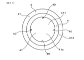
本実施形態の内燃機関用のスパークプラグ1は、図1に示すごとく、筒状の接地電極2と、接地電極2の内側に配された筒状の絶縁碍子3と、絶縁碍子3の内側に保持された中心電極4と、を有する。絶縁碍子3は、接地電極2よりもプラグ軸方向Zの先端側へ突出した碍子突出部31を有する。中心電極4は、碍子突出部31の先端から露出した露出部41を有する。なお、プラグ軸方向Zとは、スパークプラグ1の中心軸が延びる方向を意味する。また、図1において、中心電極4は、一部を断面図、他の一部を正面図で表している。
(Embodiment 1)
An embodiment of a spark plug for an internal combustion engine will be described with reference to FIGS. 1 to 8.
As shown in FIG. 1, the spark plug 1 for an internal combustion engine of the present embodiment has a tubular ground electrode 2, a tubular insulating insulator 3 arranged inside the ground electrode 2, and an insulating insulator 3 inside. It has a held center electrode 4. The insulating insulator 3 has an insulator protruding portion 31 protruding toward the tip end side in the plug axial direction Z from the ground electrode 2. The center electrode 4 has an exposed portion 41 exposed from the tip of the insulator protruding portion 31. The plug axis direction Z means a direction in which the central axis of the spark plug 1 extends. Further, in FIG. 1, a part of the center electrode 4 is shown in a cross-sectional view and the other part is shown in a front view.

図1、図2に示すごとく、中心電極4の露出部41は、第一部位411と第二部位412とを有する。第一部位411は、碍子突出部31をプラグ軸方向Zの先端側から覆っている。第二部位412は、第一部位411からプラグ軸方向Zの基端側に延設されると共に碍子突出部31の外周面31bの全周を、プラグ径方向の外周側から覆っている。なお、プラグ径方向とは、スパークプラグ1の径方向を意味するものとする。また、プラグ周方向といったときは、スパークプラグ1の周方向を意味するものとし、プラグ中心軸といったときは、スパークプラグ1の中心軸を意味するものとする。 As shown in FIGS. 1 and 2, the exposed portion 41 of the center electrode 4 has a first portion 411 and a second portion 412. The first portion 411 covers the insulator protruding portion 31 from the tip end side in the plug axial direction Z. The second portion 412 extends from the first portion 411 to the base end side in the plug axial direction Z and covers the entire circumference of the outer peripheral surface 31b of the insulator protruding portion 31 from the outer peripheral side in the plug radial direction. The radial direction of the plug means the radial direction of the spark plug 1. Further, the term "plug peripheral direction" means the circumferential direction of the spark plug 1, and the term "plug central axis" means the central axis of the spark plug 1.

本実施形態のスパークプラグ1は、例えば、自動車等の車両用の内燃機関における着火手段として用いることができる。内燃機関用のスパークプラグ1は、中心電極4に高電圧を印加することによって、接地電極2と中心電極4との間に放電を生じさせるよう構成されている。スパークプラグ1は、プラグ軸方向Zの一端側において図示しない高電圧電源部と接続され、他端側において内燃機関の燃焼室内に配される。高電圧電源部は、例えば、一般的な点火コイル、放電を持続制御可能な点火装置の電源、或いは中心電極4に200kHz~5MHzの高周波電圧を印加することができる高周波電源等とすることができる。 The spark plug 1 of the present embodiment can be used as an ignition means in an internal combustion engine for a vehicle such as an automobile, for example. The spark plug 1 for an internal combustion engine is configured to generate a discharge between the ground electrode 2 and the center electrode 4 by applying a high voltage to the center electrode 4. The spark plug 1 is connected to a high voltage power supply unit (not shown) on one end side in the plug axial direction Z, and is arranged in the combustion chamber of the internal combustion engine on the other end side. The high voltage power supply unit can be, for example, a general ignition coil, a power supply of an ignition device capable of continuously controlling discharge, a high frequency power supply capable of applying a high frequency voltage of 200 kHz to 5 MHz to the center electrode 4, or the like. ..

本明細書において、プラグ軸方向Zにおいて、スパークプラグ1が燃焼室に挿入される側を先端側、その反対側を基端側という。 In the present specification, the side in which the spark plug 1 is inserted into the combustion chamber in the plug axial direction Z is referred to as the distal end side, and the opposite side thereof is referred to as the proximal end side.

接地電極2は、筒状を呈している。接地電極2は、絶縁碍子3を全周から囲むように形成されている。図4に示すごとく、接地電極2の先端面21は、円環状を呈している。先端面21は、プラグ軸方向Zに直交する。接地電極2の先端面21は、その全体が、プラグ軸方向Zに直交する面上において面一に形成されている。図2に示すごとく、接地電極2の先端面21と内周面との間の角は、直角である。 The ground electrode 2 has a tubular shape. The ground electrode 2 is formed so as to surround the insulating insulator 3 from the entire circumference. As shown in FIG. 4, the tip surface 21 of the ground electrode 2 has an annular shape. The tip surface 21 is orthogonal to the plug axial direction Z. The entire tip surface 21 of the ground electrode 2 is formed flush with each other on a surface orthogonal to the plug axis direction Z. As shown in FIG. 2, the angle between the tip surface 21 of the ground electrode 2 and the inner peripheral surface is a right angle.

図1、図2に示すごとく、絶縁碍子3は、プラグ軸方向Zに貫通する貫通孔30を有する。絶縁碍子3は、プラグ軸方向Zに直交する断面形状が円環状を呈している。絶縁碍子3は、その一部を接地電極2の内側に配しつつ、碍子突出部31を接地電極2の先端面21よりも先端側へ突出させている。絶縁碍子3の外周面は、接地電極2の内周面と微小隙間を介してプラグ径方向に対向している。なお、当該微小隙間は、形成されていなくてもよい。つまり、絶縁碍子3の外周面と接地電極2の内周面とは、接していてもよい。 As shown in FIGS. 1 and 2, the insulating insulator 3 has a through hole 30 penetrating in the plug axial direction Z. The insulating insulator 3 has an annular cross-sectional shape orthogonal to the plug axial direction Z. A part of the insulating insulator 3 is arranged inside the ground electrode 2, and the insulator protruding portion 31 is projected toward the tip side of the tip surface 21 of the ground electrode 2. The outer peripheral surface of the insulating insulator 3 faces the inner peripheral surface of the ground electrode 2 in the plug radial direction via a minute gap. The minute gap may not be formed. That is, the outer peripheral surface of the insulating insulator 3 and the inner peripheral surface of the ground electrode 2 may be in contact with each other.

図2、図3に示すごとく、碍子突出部31の外周面31bは、プラグ軸方向Zの先端側へ向かうほどプラグ径方向の内周側へ向かうよう傾斜している。図2に示すごとく、碍子突出部31の外周面31bは、プラグ軸方向Zに平行な断面形状が、先端側へ向かうほどプラグ径方向の内周側へ向かうよう傾斜した直線形状を有する。これに伴い、碍子突出部31における中心電極4及び接地電極2の双方から露出した碍子露出部310の外周面も、プラグ軸方向Zの先端側へ向かうほどプラグ径方向の内周側へ向かうよう傾斜している。そして、碍子露出部310の外周面も、プラグ軸方向Zに平行な断面形状が、先端側へ向かうほどプラグ径方向の内周側へ向かうよう傾斜した直線形状を有する。本実施形態において、碍子露出部310は、碍子突出部31における、プラグ軸方向Zの、接地電極2の先端面21と、中心電極4の第二部位412におけるプラグ軸方向Zの基端側の端面412aとの間の部位である。 As shown in FIGS. 2 and 3, the outer peripheral surface 31b of the insulator protruding portion 31 is inclined toward the inner peripheral side in the plug radial direction toward the tip end side in the plug axial direction Z. As shown in FIG. 2, the outer peripheral surface 31b of the insulator protruding portion 31 has a linear shape in which the cross-sectional shape parallel to the plug axial direction Z is inclined toward the inner peripheral side in the plug radial direction toward the tip side. Along with this, the outer peripheral surface of the insulator exposed portion 310 exposed from both the center electrode 4 and the ground electrode 2 in the insulator protruding portion 31 also tends toward the inner peripheral side in the plug radial direction toward the tip end side in the plug axial direction Z. It is tilted. The outer peripheral surface of the insulator exposed portion 310 also has a linear shape in which the cross-sectional shape parallel to the plug axial direction Z is inclined toward the inner peripheral side in the plug radial direction toward the tip side. In the present embodiment, the insulator exposed portion 310 is located on the tip surface 21 of the ground electrode 2 in the plug axial direction Z in the insulator protruding portion 31 and on the proximal end side of the plug axial direction Z in the second portion 412 of the center electrode 4. It is a part between the end face 412a.

図2に示すごとく、碍子突出部31の先端面31aは、プラグ軸方向Zに直交するよう形成されている。碍子突出部31の先端面31aと外周面31bとの間の角は、鈍角に形成されている。碍子突出部31の先端面31aと外周面31bとの間の角は、第二部位412の端面412aよりも、プラグ軸方向Zにおける先端側に位置している。碍子突出部31の先端面31aと外周面31bとの間の角は、碍子露出部310の一部ではない。すなわち、碍子突出部31の先端面31aと外周面31bとの間の角は、中心電極4の第一部位411及び第二部位412に覆われており、中心電極4から露出していない。 As shown in FIG. 2, the tip surface 31a of the insulator protruding portion 31 is formed so as to be orthogonal to the plug axial direction Z. The angle between the tip surface 31a and the outer peripheral surface 31b of the insulator protruding portion 31 is formed to be an obtuse angle. The angle between the tip surface 31a and the outer peripheral surface 31b of the insulator protrusion 31 is located on the tip side in the plug axial direction Z with respect to the end surface 412a of the second portion 412. The angle between the tip surface 31a and the outer peripheral surface 31b of the insulator protruding portion 31 is not a part of the insulator exposed portion 310. That is, the corner between the tip surface 31a and the outer peripheral surface 31b of the insulator protruding portion 31 is covered with the first portion 411 and the second portion 412 of the center electrode 4, and is not exposed from the center electrode 4.

絶縁碍子3の貫通孔30における先端部に、中心電極4が挿通保持されている。中心電極4は、全体として略円柱形状を呈している。 The center electrode 4 is inserted and held at the tip of the through hole 30 of the insulating insulator 3. The center electrode 4 has a substantially cylindrical shape as a whole.

中心電極4の露出部41は、全体として、プラグ軸方向Zの基端側に向かって開口するカップ形状を呈している。露出部41は、図4に示すごとく、円盤状に形成された第一部位411と、図2に示すごとく、第一部位411の外縁部から基端側に向かって延設され、全体として円筒状に形成された第二部位412とを有する。図2に示すごとく、第一部位411は、碍子突出部31の先端面31aの全体と、プラグ軸方向Zに対向している。第二部位412は、碍子突出部31の外周面31bの全周を、碍子突出部31の外周側から覆っている。これにより、露出部41は、碍子突出部31の先端部の角全体を覆っている。なお、プラグ径方向において、碍子突出部31の外周面31bと第二部位412の内周面412bとの間には、径方向空隙rcが形成されている。すなわち、第二部位412の内周面412bは、碍子突出部31の外周面31bからプラグ径方向の外周側に離れた位置に形成されている。径方向空隙rcは、プラグ軸方向Zの基端側に向かって開口している。なお、径方向空隙rcは、形成されていなくてもよい。つまり、第二部位412の内周面412bが碍子突出部31の外周面31bに接触していてもよい。 The exposed portion 41 of the center electrode 4 has a cup shape that opens toward the proximal end side in the plug axial direction Z as a whole. As shown in FIG. 4, the exposed portion 41 is a first portion 411 formed in a disk shape, and as shown in FIG. 2, the exposed portion 41 extends from the outer edge portion of the first portion 411 toward the proximal end side, and is a cylinder as a whole. It has a second site 412 formed in a shape. As shown in FIG. 2, the first portion 411 faces the entire tip surface 31a of the insulator protruding portion 31 in the plug axial direction Z. The second portion 412 covers the entire circumference of the outer peripheral surface 31b of the insulator protruding portion 31 from the outer peripheral side of the insulator protruding portion 31. As a result, the exposed portion 41 covers the entire corner of the tip portion of the insulator protruding portion 31. In the plug radial direction, a radial gap rc is formed between the outer peripheral surface 31b of the insulator protruding portion 31 and the inner peripheral surface 412b of the second portion 412. That is, the inner peripheral surface 412b of the second portion 412 is formed at a position separated from the outer peripheral surface 31b of the insulator protruding portion 31 toward the outer peripheral side in the plug radial direction. The radial gap rc opens toward the proximal end side in the plug axial direction Z. The radial gap rc may not be formed. That is, the inner peripheral surface 412b of the second portion 412 may be in contact with the outer peripheral surface 31b of the insulator protruding portion 31.

図5に示すごとく、第二部位412におけるプラグ軸方向Zの基端側の端面412aは、円環状を呈している。また、第二部位412におけるプラグ軸方向Zの基端側の端面412aは、プラグ軸方向Zに直交する。図2に示すごとく、中心電極4の第二部位412と接地電極2との間の空間距離は、全周において一定である。つまり、中心電極4及び接地電極2の双方を通る断面であって、プラグ軸方向Zに平行なあらゆる断面において、中心電極4と接地電極2との間の空間距離は、略一定である。また、第二部位412の端面412aと接地電極2の先端面21とは、直接対向しており、これらの間に絶縁碍子3は介在していない。 As shown in FIG. 5, the end surface 412a on the proximal end side in the plug axial direction Z in the second portion 412 exhibits an annular shape. Further, the end surface 412a on the proximal end side of the plug axial direction Z in the second portion 412 is orthogonal to the plug axial direction Z. As shown in FIG. 2, the spatial distance between the second portion 412 of the center electrode 4 and the ground electrode 2 is constant over the entire circumference. That is, the space distance between the center electrode 4 and the ground electrode 2 is substantially constant in any cross section that passes through both the center electrode 4 and the ground electrode 2 and is parallel to the plug axial direction Z. Further, the end surface 412a of the second portion 412 and the tip surface 21 of the ground electrode 2 are directly opposed to each other, and the insulating insulator 3 is not interposed between them.

図2に示すごとく、碍子突出部31の先端面31aの直径を直径A[mm]、第二部位412の基端側の端面412aの内径を内径B[mm]、端面412aの外径を外径C[mm]、接地電極2と中心電極4との間の最短の空間距離を空間距離D[mm]、と定義する。このとき、直径A、内径B、及び外径Cは、A<B<C、の関係を満たしている。また、直径A及び内径Bは、A+0.25mm≦Bを満たすことが好ましい。また、内径B及び外径Cは、B+1.0mm≦Cを満たすことが好ましい。また、空間距離Dは、3.0mm≦D≦5.0mmを満たすことが好ましい。本実施形態において、直径Aは4.55mmであり、内径Bは5.55mmであり、外径Cは6.5mmであり、空間距離Dは5.0mmである。また、本実施形態において、第二部位412のプラグ軸方向Zの長さは、1.0mmである。 As shown in FIG. 2, the diameter of the tip surface 31a of the porcelain protrusion 31 is the diameter A [mm], the inner diameter of the end surface 412a on the base end side of the second portion 412 is the inner diameter B [mm], and the outer diameter of the end surface 412a is outside. The diameter C [mm] and the shortest space distance between the ground electrode 2 and the center electrode 4 are defined as the space distance D [mm]. At this time, the diameter A, the inner diameter B, and the outer diameter C satisfy the relationship of A <B <C. Further, it is preferable that the diameter A and the inner diameter B satisfy A + 0.25 mm ≦ B. Further, it is preferable that the inner diameter B and the outer diameter C satisfy B + 1.0 mm ≦ C. Further, the space distance D preferably satisfies 3.0 mm ≦ D ≦ 5.0 mm. In the present embodiment, the diameter A is 4.55 mm, the inner diameter B is 5.55 mm, the outer diameter C is 6.5 mm, and the space distance D is 5.0 mm. Further, in the present embodiment, the length of the second portion 412 in the plug axial direction Z is 1.0 mm.

露出部41は、中心電極4における碍子突出部31の内側の部位と別体で形成されていてもよいし、一体的に形成されていてもよい。 The exposed portion 41 may be formed separately from the inner portion of the insulator protruding portion 31 of the center electrode 4, or may be integrally formed.

図1に示すごとく、接地電極2は、ハウジング11の先端から、先端側に向かって延設されている。ハウジング11は、筒状を呈しており、絶縁碍子3を内側に保持している。ハウジング11の外周面には、内燃機関に螺合するための取付ネジ部111が形成されている。ハウジング11における、取付ネジ部111が設けられた部位の先端部に、接地電極2が接合されている。 As shown in FIG. 1, the ground electrode 2 extends from the tip of the housing 11 toward the tip side. The housing 11 has a cylindrical shape and holds the insulating insulator 3 inside. A mounting screw portion 111 for screwing into an internal combustion engine is formed on the outer peripheral surface of the housing 11. The ground electrode 2 is joined to the tip of the portion of the housing 11 where the mounting screw portion 111 is provided.

絶縁碍子3の貫通孔30における中心電極4の基端側には、導電性を有するガラスシール12を介して抵抗体13が配置されている。抵抗体13は、カーボン又はセラミック粉末等の抵抗材及びガラス粉末を含むレジスタ組成物を加熱封着することにより形成する、或いはカートリッジ型抵抗体を挿入することによって構成することができる。ガラスシール12は、ガラスに銅粉を混入させてなる銅ガラスからなる。また、抵抗体13の基端側には、銅ガラスからなるガラスシール14を介してステム15が配されている。ステム15は、例えば鉄合金からなる。ステム15は、その基端部が絶縁碍子3から突出している。そして、スパークプラグ1は、ステム15の突出部において、高電圧電源部に接続される。 A resistor 13 is arranged on the base end side of the center electrode 4 in the through hole 30 of the insulator 3 via a glass seal 12 having conductivity. The resistor 13 can be formed by heat-sealing a register composition containing a resistance material such as carbon or ceramic powder and glass powder, or by inserting a cartridge type resistor. The glass seal 12 is made of copper glass obtained by mixing copper powder with glass. Further, a stem 15 is arranged on the base end side of the resistor 13 via a glass seal 14 made of copper glass. The stem 15 is made of, for example, an iron alloy. The base end of the stem 15 protrudes from the insulating insulator 3. Then, the spark plug 1 is connected to the high voltage power supply unit at the protruding portion of the stem 15.

次に、本実施形態の作用効果につき、説明する。
本実施形態の内燃機関用のスパークプラグ1において、中心電極4の露出部41は、第一部位411と第二部位412と、を有する。つまり、碍子突出部31の先端部の角部は、中心電極4の第一部位411及び第二部位412に覆われている。それゆえ、碍子突出部31の先端部の角部上に、放電が生じ、維持、固定されることを防止することができる。これにより、燃焼室内の混合気の気流或いは電気的な反発作用により、放電を碍子突出部の表面から剥がして、下流側に引き伸ばしやすい。これにより、混合気への着火性の向上を図ることができる。さらに、碍子突出部31の先端部の角部に、チャネリングが生じることを防止することができる。また、碍子突出部の先端部全周を覆う中心電極の露出部と、碍子突出部の全周を覆う接地電極との間の全体が、放電形成可能な領域となる。そのため、碍子突出部の表面の特定の経路で沿面放電が繰り返し形成されることにより、碍子表面が溝状に削られるいわゆるチャネリングが特定の経路において集中して形成されることを防止できる。
Next, the action and effect of this embodiment will be described.
In the spark plug 1 for an internal combustion engine of the present embodiment, the exposed portion 41 of the center electrode 4 has a first portion 411 and a second portion 412. That is, the corner portion of the tip portion of the insulator protruding portion 31 is covered with the first portion 411 and the second portion 412 of the center electrode 4. Therefore, it is possible to prevent an electric discharge from being generated, maintained, and fixed on the corner portion of the tip portion of the insulator protruding portion 31. As a result, the electric discharge is easily peeled off from the surface of the insulator protrusion and extended to the downstream side by the air flow of the air-fuel mixture in the combustion chamber or the electric repulsive action. This makes it possible to improve the ignitability of the air-fuel mixture. Further, it is possible to prevent channeling from occurring at the corner portion of the tip portion of the insulator protruding portion 31. Further, the entire area between the exposed portion of the center electrode that covers the entire circumference of the tip of the insulator protrusion and the ground electrode that covers the entire circumference of the insulator protrusion is a region where discharge can be formed. Therefore, it is possible to prevent so-called channeling, in which the insulator surface is cut into a groove shape, is concentratedly formed in a specific path by repeatedly forming a creeping discharge in a specific path on the surface of the insulator protrusion.

また、第二部位412におけるプラグ軸方向Zの基端側の端面412aは、プラグ軸方向Zに直交する。さらに、接地電極2の先端面21も、プラグ軸方向Zに直交する。それゆえ、スパークプラグ1が取り付けられた内燃機関の燃焼室内の気流によって、中心電極4と接地電極2との間に生じる放電を、碍子露出部310の表面から引き離し、かつ、気流の下流側に大きく引き伸ばしやすい。このことにつき、以後説明する。 Further, the end surface 412a on the proximal end side of the plug axial direction Z in the second portion 412 is orthogonal to the plug axial direction Z. Further, the tip surface 21 of the ground electrode 2 is also orthogonal to the plug axial direction Z. Therefore, the electric discharge generated between the center electrode 4 and the ground electrode 2 due to the airflow in the combustion chamber of the internal combustion engine to which the spark plug 1 is attached is separated from the surface of the insulator exposed portion 310 and is on the downstream side of the airflow. Large and easy to stretch. This will be described below.

図6に示すごとく、本実施形態において、放電は、第二部位412におけるプラグ軸方向Zの基端側の端面412aにおける内周端と、接地電極2の先端面21における内周端とを起点として生じる。そして、当該放電により発生する放電火花Sの両起点間の部位は、碍子突出部31の碍子露出部310の外周面を這うように生じる。 As shown in FIG. 6, in the present embodiment, the discharge starts from the inner peripheral end of the end surface 412a on the proximal end side of the plug axial direction Z in the second portion 412 and the inner peripheral end of the tip surface 21 of the ground electrode 2. Occurs as. Then, the portion between the two starting points of the discharge spark S generated by the discharge is generated so as to crawl on the outer peripheral surface of the insulator exposed portion 310 of the insulator protruding portion 31.

そして、図6~図8に示すごとく、放電火花Sの両起点は、スパークプラグ1が取り付けられた内燃機関の燃焼室内において、プラグ軸方向Zに直交する方向に流れる気流Fに押され、第二部位412の端面412a上及び接地電極2の先端面21上を、プラグ径方向の外周側に向かって移動する。すなわち、放電火花Sの中心電極4側の起点S1は、第二部位412の端面412aの内周端部から外周端部に向かって移動し、放電火花Sの接地電極2側の起点S2は、接地電極2の先端面21の内周端部から外周端部に向かって移動する。これにより、放電火花Sの両起点が、プラグ径方向において、碍子露出部310から離れる方向に移動する。 Then, as shown in FIGS. 6 to 8, both starting points of the discharge spark S are pushed by the airflow F flowing in the direction orthogonal to the plug axial direction Z in the combustion chamber of the internal combustion engine to which the spark plug 1 is attached, and the second It moves on the end surface 412a of the two portions 412 and on the tip end surface 21 of the ground electrode 2 toward the outer peripheral side in the plug radial direction. That is, the starting point S1 on the center electrode 4 side of the discharge spark S moves from the inner peripheral end portion to the outer peripheral end portion of the end surface 412a of the second portion 412, and the starting point S2 on the ground electrode 2 side of the discharge spark S is. It moves from the inner peripheral end portion of the tip surface 21 of the ground electrode 2 toward the outer peripheral end portion. As a result, both starting points of the discharge spark S move in the direction away from the insulator exposed portion 310 in the plug radial direction.

放電火花Sの両起点が、プラグ径方向において、碍子露出部310から離れる方向に移動することに伴い、放電火花Sの両起点間の部位も、図6~図8に示すごとく、碍子露出部310の外周面から外周側に離れる。そして、図8に示すごとく、碍子露出部310の外周面から外周側に離れた放電火花Sの両起点間の部位は、燃焼室内の気流Fにより、当該気流Fの下流側に向かって大きく引き伸ばされる。これにより、本実施形態においては、放電火花Sと混合気との接触面積を稼ぎ、混合気への着火性を確保しやすい。また、混合気の着火点がスパークプラグ1から遠ざかるため、初期に形成される火炎、いわゆる初期火炎の熱が、スパークプラグ1に奪われることによる冷却損失を抑制できる。 As both starting points of the discharge spark S move in the direction away from the insulator exposed portion 310 in the plug radial direction, the portion between the two starting points of the discharge spark S also becomes the insulator exposed portion as shown in FIGS. 6 to 8. It is separated from the outer peripheral surface of 310 toward the outer peripheral side. Then, as shown in FIG. 8, the portion between the two starting points of the discharge spark S separated from the outer peripheral surface of the insulator exposed portion 310 to the outer peripheral side is greatly extended toward the downstream side of the airflow F by the airflow F in the combustion chamber. Is done. As a result, in the present embodiment, the contact area between the discharge spark S and the air-fuel mixture is increased, and it is easy to secure the ignitability of the air-fuel mixture. Further, since the ignition point of the air-fuel mixture is moved away from the spark plug 1, the cooling loss due to the heat of the initially formed flame, that is, the so-called initial flame, being taken away by the spark plug 1 can be suppressed.

次に、図9、図10に示すように、中心電極4が第一部位及び第二部位の双方を有していないスパークプラグ9につき、まずその構造を説明し、次いで放電の様子につき説明する。 Next, as shown in FIGS. 9 and 10, the structure of the spark plug 9 in which the center electrode 4 does not have both the first portion and the second portion will be described first, and then the state of discharge will be described. ..

スパークプラグ9は、碍子突出部31の先端側に突出する円柱状の中心電極突出部941を有する。中心電極突出部941は円柱状を呈している。プラグ軸方向Zからみたとき、中心電極突出部941は、絶縁碍子3の貫通孔30の内側に収まっている。中心電極突出部941の外周面941bは、プラグ軸方向Zに形成されている。また、絶縁碍子3の碍子突出部31の先端の角部319は、緩やかな曲面状に形成されている。 The spark plug 9 has a columnar center electrode protrusion 941 that protrudes toward the tip of the insulator protrusion 31. The central electrode protrusion 941 has a columnar shape. When viewed from the plug axial direction Z, the center electrode protrusion 941 is housed inside the through hole 30 of the insulating insulator 3. The outer peripheral surface 941b of the center electrode protrusion 941 is formed in the plug axial direction Z. Further, the corner portion 319 at the tip of the insulator protruding portion 31 of the insulating insulator 3 is formed in a gently curved surface shape.

図9に示すごとく、スパークプラグ9において、放電は、接地電極2の先端面21の内周端と、中心電極4の中心電極突出部941の外周面941bとを起点として生じる。そして、当該放電により発生する放電火花Sの両起点間の部位は、碍子突出部31の表面を這うように生じる。このとき、放電火花Sの両起点間の部位は、少なくとも碍子突出部31の先端の角部319上を這うように生じる。 As shown in FIG. 9, in the spark plug 9, the electric discharge starts from the inner peripheral end of the tip end surface 21 of the ground electrode 2 and the outer peripheral surface 941b of the center electrode protrusion 941 of the center electrode 4. Then, the portion between the two starting points of the discharge spark S generated by the discharge is generated so as to crawl on the surface of the insulator protruding portion 31. At this time, the portion between the two starting points of the discharge spark S is generated so as to crawl on at least the corner portion 319 of the tip of the insulator protruding portion 31.

そして、図9、図10に示すごとく、放電火花Sの接地電極2側の起点S2は、スパークプラグ9が取り付けられた内燃機関の燃焼室内において、プラグ軸方向Zに直交する方向に流れる気流Fに押され、接地電極2の先端面21上を、プラグ径方向の外周側に向かって移動する。 Then, as shown in FIGS. 9 and 10, the starting point S2 on the ground electrode 2 side of the discharge spark S is an air flow F flowing in a direction orthogonal to the plug axial direction Z in the combustion chamber of the internal combustion engine to which the spark plug 9 is attached. Pushed to move on the tip surface 21 of the ground electrode 2 toward the outer peripheral side in the plug radial direction.

一方、図9、図10に示すごとく、放電火花Sの接地電極2側の起点S2が移動している間、放電火花Sの中心電極4側の起点S1は、初期の位置からほとんど動かない。すなわち、放電火花Sの中心電極4側の起点S1は、碍子突出部31の表面から離れる方向に移動しない。これは、中心電極突出部941の外周面941bがプラグ軸方向Zに形成されているため、放電火花Sの中心電極4側の起点S1が、中心電極突出部941の外周面941b上をプラグ径方向の外周側に移動することができないことに起因する。 On the other hand, as shown in FIGS. 9 and 10, while the starting point S2 on the ground electrode 2 side of the discharge spark S is moving, the starting point S1 on the center electrode 4 side of the discharge spark S hardly moves from the initial position. That is, the starting point S1 on the center electrode 4 side of the discharge spark S does not move in the direction away from the surface of the insulator protruding portion 31. This is because the outer peripheral surface 941b of the center electrode protruding portion 941 is formed in the plug axial direction Z, so that the starting point S1 on the center electrode 4 side of the discharge spark S has a plug diameter on the outer peripheral surface 941b of the center electrode protruding portion 941. This is due to the inability to move to the outer peripheral side of the direction.

そのため、放電火花Sの両起点間の部位は、碍子突出部31の先端の角部319上から離れ難い。これに伴い、放電火花Sは、気流Fに押されても、両起点間の部位が下流側に大きく引き伸ばされにくい。そのため、スパークプラグ9は、燃焼室内の混合気への着火性が本実施形態のスパークプラグ1と比べて悪くなる。 Therefore, the portion between the two starting points of the discharge spark S is difficult to separate from the corner portion 319 at the tip of the insulator protruding portion 31. Along with this, even if the discharge spark S is pushed by the air flow F, the portion between the two starting points is hardly stretched to the downstream side. Therefore, the spark plug 9 has a worse ignitability to the air-fuel mixture in the combustion chamber than the spark plug 1 of the present embodiment.

また、スパークプラグ1の中心電極4の第二部位412と接地電極2との間の空間距離は、全周において一定である。それゆえ、中心電極4の第二部位412と、接地電極2との間に生じる放電が、プラグ周方向において偏った位置に集中して生じることを防止することができる。それゆえ、絶縁碍子3において、プラグ周方向において偏った位置にチャネリングが集中して生じることに起因して絶縁碍子3の消耗が促進されることを防止することができる。 Further, the spatial distance between the second portion 412 of the center electrode 4 of the spark plug 1 and the ground electrode 2 is constant over the entire circumference. Therefore, it is possible to prevent the discharge generated between the second portion 412 of the center electrode 4 and the ground electrode 2 from being concentrated at a position biased in the circumferential direction of the plug. Therefore, in the insulating insulator 3, it is possible to prevent the consumption of the insulating insulator 3 from being accelerated due to the concentration of channeling at a position biased in the circumferential direction of the plug.

また、プラグ径方向における碍子突出部31の外周面31bと中心電極4の第二部位412の内周面412bとの間には、径方向空隙rcが形成されている。それゆえ、燃焼室内の気流が、径方向空隙rc内にも流入する。そして、径方向空隙rcに流入された気流は、中心電極4と接地電極2との間において、プラグ径方向の外側に向かうよう、すなわち、碍子露出部310から遠ざかる側に向かうよう、流出される。それゆえ、放電火花を、碍子露出部310から遠ざけるように引き伸ばしやすい。 Further, a radial gap rc is formed between the outer peripheral surface 31b of the insulator protruding portion 31 in the plug radial direction and the inner peripheral surface 412b of the second portion 412 of the center electrode 4. Therefore, the airflow in the combustion chamber also flows into the radial void rc. Then, the airflow flowing into the radial gap rc is discharged between the center electrode 4 and the ground electrode 2 so as to be outward in the radial direction of the plug, that is, toward the side away from the insulator exposed portion 310. .. Therefore, it is easy to stretch the discharge spark so as to keep it away from the insulator exposed portion 310.

以上のごとく、本実施形態によれば、混合気への着火性の向上を図ることができる内燃機関用のスパークプラグを提供することができる。 As described above, according to the present embodiment, it is possible to provide a spark plug for an internal combustion engine capable of improving the ignitability of the air-fuel mixture.

(実施形態2)
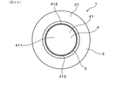
本実施形態は、図11に示すごとく、プラグ軸方向Zにおける第一部位411と碍子突出部31との間に軸方向空隙acを形成した実施形態である。すなわち、碍子突出部31の先端面31aは、第一部位411におけるプラグ軸方向Zの基端側の端面411aから基端側に離れた位置に形成されている。一方、碍子突出部31の先端面31aは、第二部位412におけるプラグ軸方向Zの基端側の端面412aよりもプラグ軸方向Zの先端側に位置している。これにより、碍子突出部31の角部は、中心電極4の第一部位411及び第二部位412によって覆われている。軸方向空隙acは、径方向空隙rcと連通している。
(Embodiment 2)
As shown in FIG. 11, the present embodiment is an embodiment in which an axial gap ac is formed between the first portion 411 and the insulator protrusion 31 in the plug axial direction Z. That is, the tip surface 31a of the insulator protruding portion 31 is formed at a position away from the end surface 411a on the base end side in the plug axis direction Z in the first portion 411. On the other hand, the tip surface 31a of the insulator protruding portion 31 is located on the tip end side in the plug axial direction Z with respect to the end surface 412a on the proximal end side in the plug axial direction Z in the second portion 412. As a result, the corner portion of the insulator protruding portion 31 is covered with the first portion 411 and the second portion 412 of the center electrode 4. The axial void ac communicates with the radial void rc.

なお、本実施形態において、直径Aは4.55mmであり、内径Bは4.85mmであり、外径Cは5.85mmであり、空間距離Dは5.0mmである。 In the present embodiment, the diameter A is 4.55 mm, the inner diameter B is 4.85 mm, the outer diameter C is 5.85 mm, and the space distance D is 5.0 mm.

その他は、実施形態1と同様である。
なお、実施形態2以降において用いた符号のうち、既出の実施形態において用いた符号と同一のものは、特に示さない限り、既出の実施形態におけるものと同様の構成要素等を表す。
Others are the same as those in the first embodiment.
In addition, among the reference numerals used in the second and subsequent embodiments, the same reference numerals as those used in the above-mentioned embodiments represent the same components and the like as those in the above-mentioned embodiments, unless otherwise specified.

本実施形態においては、燃焼室内の気流が、軸方向空隙ac内及び径方向空隙rc内にも流入する。そして、軸方向空隙ac及び径方向空隙rcに流入された気流は、中心電極4と接地電極2との間において、プラグ径方向の外側に向かうよう、すなわち、碍子露出部310から遠ざかる側に向かうよう、流出される。それゆえ、放電火花を、碍子露出部310から遠ざけるように引き伸ばしやすい。 In the present embodiment, the airflow in the combustion chamber also flows into the axial void ac and the radial void rc. Then, the airflow flowing into the axial gap ac and the radial gap rc is directed toward the outside in the plug radial direction between the center electrode 4 and the ground electrode 2, that is, toward the side away from the insulator exposed portion 310. It will be leaked. Therefore, it is easy to stretch the discharge spark so as to keep it away from the insulator exposed portion 310.

また、絶縁碍子3の線膨張係数と中心電極4の線膨張係数との差に起因して、絶縁碍子3及び中心電極4に生じる熱応力を低減することができる。
その他、実施形態1と同様の作用効果を有する。
Further, it is possible to reduce the thermal stress generated in the insulating insulator 3 and the center electrode 4 due to the difference between the linear expansion coefficient of the insulating insulator 3 and the linear expansion coefficient of the center electrode 4.
In addition, it has the same effect as that of the first embodiment.

(実施形態3)
本実施形態は、図12に示すごとく、実施形態2に対して、第一部位411におけるプラグ軸方向Zの基端側の端面411aと、第二部位412の内周面412bとの形状を変更した実施形態である。すなわち、本実施形態において、第一部位411の端面411aと第二部位412の内周面412bとは、曲面状に滑らかにつながっている。本実施形態において、第一部位411の端面411aと第二部位412の内周面412bとの間の曲面の曲率半径は、0.5mmである。
その他は、実施形態2と同様である。
(Embodiment 3)
As shown in FIG. 12, the present embodiment changes the shapes of the end surface 411a on the proximal end side of the plug axis direction Z in the first portion 411 and the inner peripheral surface 412b of the second portion 412 with respect to the second embodiment. This is the embodiment. That is, in the present embodiment, the end surface 411a of the first portion 411 and the inner peripheral surface 412b of the second portion 412 are smoothly connected in a curved surface shape. In the present embodiment, the radius of curvature of the curved surface between the end surface 411a of the first portion 411 and the inner peripheral surface 412b of the second portion 412 is 0.5 mm.
Others are the same as in the second embodiment.

本実施形態においては、軸方向空隙ac及び径方向空隙rcに流入された気流を、中心電極4と接地電極2との間に向かって、滑らかに送り出すことができる。それゆえ、軸方向空隙ac及び径方向空隙rcから流出された気流に乱れが生じにくく、一層放電火花を引き伸ばしやすい。
その他、実施形態2と同様の作用効果を有する。
In the present embodiment, the airflow flowing into the axial gap ac and the radial gap rc can be smoothly sent out between the center electrode 4 and the ground electrode 2. Therefore, the airflow flowing out from the axial void ac and the radial void rc is less likely to be turbulent, and the discharge spark is more likely to be stretched.
In addition, it has the same effect as that of the second embodiment.

(実施形態4)
本実施形態は、図13、図14に示すごとく、実施形態1に対して、露出部41の形状を変更した実施形態である。露出部41の外周面41bは、プラグ軸方向Zの先端側に向かうほどプラグ径方向の外周側に向かうよう傾斜した部位を有する。本実施形態において、露出部41の外周面41bの全体は、プラグ軸方向Zの先端側に向かうほどプラグ径方向の外周側に向かうよう傾斜している。すなわち、露出部41の外形は、プラグ軸方向Zの基端側に向かうほど縮径している。そして、図13に示すごとく、露出部41の外周面41bと、第二部位412の内周面412bとの間の角は、鋭角である。なお、本実施形態において、プラグ軸方向Zにおける露出部41の外周面41bの長さは、2.0mmである。また、直径A、内径B、外径C、空間距離Dのそれぞれの長さは、実施形態2と同様である。
その他は、実施形態1と同様である。
(Embodiment 4)
As shown in FIGS. 13 and 14, the present embodiment is an embodiment in which the shape of the exposed portion 41 is changed with respect to the first embodiment. The outer peripheral surface 41b of the exposed portion 41 has a portion inclined so as to be toward the outer peripheral side in the plug radial direction toward the tip end side in the plug axial direction Z. In the present embodiment, the entire outer peripheral surface 41b of the exposed portion 41 is inclined toward the outer peripheral side in the plug radial direction toward the tip end side in the plug axial direction Z. That is, the outer diameter of the exposed portion 41 is reduced toward the proximal end side in the plug axial direction Z. As shown in FIG. 13, the angle between the outer peripheral surface 41b of the exposed portion 41 and the inner peripheral surface 412b of the second portion 412 is an acute angle. In the present embodiment, the length of the outer peripheral surface 41b of the exposed portion 41 in the plug axial direction Z is 2.0 mm. Further, the respective lengths of the diameter A, the inner diameter B, the outer diameter C, and the space distance D are the same as those in the second embodiment.
Others are the same as those in the first embodiment.

本実施形態においては、スパークプラグ1が取り付けられた内燃機関の燃焼室内の気流によって、中心電極4と接地電極2との間に生じる放電を、碍子露出部310の表面から引き離し、かつ、気流の下流側に大きく引き伸ばしやすい。このことにつき、図15~16を用いて以後説明する。 In the present embodiment, the electric discharge generated between the center electrode 4 and the ground electrode 2 is separated from the surface of the insulator exposed portion 310 by the air flow in the combustion chamber of the internal combustion engine to which the spark plug 1 is attached, and the air flow is generated. It is easy to stretch to the downstream side. This will be described below with reference to FIGS. 15 to 16.

図15に示すごとく、本実施形態において、放電火花Sの中心電極4側の起点S1は、第二部位412におけるプラグ軸方向Zの基端側の端部の角に生じる。そして、図16、図17に示すごとく、放電火花Sの中心電極4側の起点S1は、燃焼室内においてプラグ軸方向Zに直交する方向に流れる気流Fに押され、露出部41の外周面41b上を、プラグ軸方向Zの先端側及びプラグ径方向の外周側に向かって移動する。なお、このとき、放電火花Sの接地電極2側の起点S2は、実施形態1と同様、接地電極2の先端面21をプラグ径方向の外周側に向かって移動する。これにより、放電火花Sの両起点が、プラグ径方向において碍子露出部310から離れる方向に移動するとともに、放電火花Sの両起点間の距離を、プラグ軸方向Zに拡大させるように移動する。 As shown in FIG. 15, in the present embodiment, the starting point S1 on the center electrode 4 side of the discharge spark S is generated at the corner of the end portion of the second portion 412 on the proximal end side in the plug axial direction Z. Then, as shown in FIGS. 16 and 17, the starting point S1 on the center electrode 4 side of the discharge spark S is pushed by the airflow F flowing in the direction orthogonal to the plug axial direction Z in the combustion chamber, and the outer peripheral surface 41b of the exposed portion 41 is pushed. It moves upward toward the tip end side in the plug axial direction Z and the outer peripheral side in the plug radial direction. At this time, the starting point S2 on the ground electrode 2 side of the discharge spark S moves the tip surface 21 of the ground electrode 2 toward the outer peripheral side in the plug radial direction, as in the first embodiment. As a result, both starting points of the discharge spark S move in the direction away from the insulator exposed portion 310 in the plug radial direction, and the distance between the two starting points of the discharge spark S moves so as to increase in the plug axial direction Z.

放電火花Sの両起点が、プラグ径方向において碍子露出部310から離れる方向に移動することに伴い、放電火花Sの両起点間の部位も、碍子露出部310の外周面から外周側に離れる。そして、碍子露出部310の外周面から外周側に離れた放電火花Sの両起点間の部位は、燃焼室内の気流Fにより、当該気流Fの下流側に向かって大きく引き伸ばされる。特に、本実施形態においては、放電火花Sの両起点間のプラグ軸方向Zの距離を拡大させるように、放電火花Sの両起点が移動するため、放電火花Sの両起点間の部位は、一層大きく引き伸ばされやすい。これにより、放電火花Sと混合気との接触面積を一層稼ぎやすく、混合気への着火性を一層確保しやすい。
その他、実施形態1と同様の作用効果を有する。
As both starting points of the discharge spark S move in the direction away from the insulator exposed portion 310 in the plug radial direction, the portion between the two starting points of the discharge spark S also moves away from the outer peripheral surface of the insulator exposed portion 310 toward the outer peripheral side. Then, the portion between the two starting points of the discharge spark S separated from the outer peripheral surface of the insulator exposed portion 310 to the outer peripheral side is greatly extended toward the downstream side of the airflow F by the airflow F in the combustion chamber. In particular, in the present embodiment, since both starting points of the discharge spark S move so as to increase the distance in the plug axial direction Z between the two starting points of the discharge spark S, the portion between the two starting points of the discharge spark S is It is easy to be stretched even more. As a result, it is easier to increase the contact area between the discharge spark S and the air-fuel mixture, and it is easier to secure the ignitability of the air-fuel mixture.
In addition, it has the same effect as that of the first embodiment.

(実施形態5)
本実施形態は、図18、図19に示すごとく、実施形態1に対して、接地電極2の形状を変更した実施形態である。接地電極2の先端面21は、プラグ径方向の外周側に向かうほどプラグ軸方向Zの基端側に向かうよう傾斜した部位を有する。本実施形態において、接地電極2の先端面21の全体は、プラグ径方向の外周側に向かうほどプラグ軸方向Zの基端側に向かうよう傾斜している。接地電極2の先端面21と内周面との間の角は、鋭角である。なお、直径A、内径B、外径C、空間距離Dのそれぞれの長さは、実施形態2と同様である。
その他は、実施形態1と同様である。
(Embodiment 5)
As shown in FIGS. 18 and 19, the present embodiment is an embodiment in which the shape of the ground electrode 2 is changed with respect to the first embodiment. The tip surface 21 of the ground electrode 2 has a portion inclined toward the proximal end side in the plug axial direction Z toward the outer peripheral side in the plug radial direction. In the present embodiment, the entire tip surface 21 of the ground electrode 2 is inclined toward the proximal end side in the plug axial direction Z toward the outer peripheral side in the plug radial direction. The angle between the tip surface 21 and the inner peripheral surface of the ground electrode 2 is an acute angle. The lengths of the diameter A, the inner diameter B, the outer diameter C, and the space distance D are the same as those in the second embodiment.
Others are the same as those in the first embodiment.

本実施形態においては、スパークプラグ1が取り付けられた内燃機関の燃焼室内の気流によって、中心電極4と接地電極2との間に生じる放電を、碍子露出部310の表面から引き離し、かつ、気流の下流側に大きく引き伸ばしやすい。このことにつき、図20~図22を用いて以後説明する。 In the present embodiment, the electric discharge generated between the center electrode 4 and the ground electrode 2 is separated from the surface of the insulator exposed portion 310 by the air flow in the combustion chamber of the internal combustion engine to which the spark plug 1 is attached, and the air flow is generated. It is easy to stretch to the downstream side. This will be described below with reference to FIGS. 20 to 22.

図20に示すごとく、本実施形態において、放電火花Sの接地電極2側の起点S2は、接地電極2の先端面21における内周端の角を起点として生じる。そして、図21、図22に示すごとく、放電火花Sの接地電極2側の起点S2は、燃焼室内においてプラグ軸方向Zに直交する方向に流れる気流Fに押され、接地電極2の先端面21上を、プラグ軸方向Zの基端側及びプラグ径方向の外周側に向かって移動する。なお、このとき、放電火花Sの中心電極4側の起点S1は、実施形態1と同様、第二部位412におけるプラグ軸方向Zの基端側の端面412a上を、プラグ径方向の外周側に向かって移動する。これにより、放電火花Sの両起点が、プラグ径方向において碍子露出部310から離れる方向に移動するとともに、放電火花Sの両起点間の距離をプラグ軸方向Zに拡大されるように移動する。 As shown in FIG. 20, in the present embodiment, the starting point S2 on the grounding electrode 2 side of the discharge spark S is generated from the corner of the inner peripheral end of the tip surface 21 of the grounding electrode 2. Then, as shown in FIGS. 21 and 22, the starting point S2 on the ground electrode 2 side of the discharge spark S is pushed by the airflow F flowing in the direction orthogonal to the plug axial direction Z in the combustion chamber, and the tip surface 21 of the ground electrode 2 is pushed. It moves upward toward the base end side in the plug axial direction Z and the outer peripheral side in the plug radial direction. At this time, the starting point S1 on the center electrode 4 side of the discharge spark S is on the end surface 412a on the base end side of the plug axial direction Z in the second portion 412 on the outer peripheral side in the plug radial direction, as in the first embodiment. Move towards. As a result, both starting points of the discharge spark S move in the direction away from the insulator exposed portion 310 in the plug radial direction, and the distance between the two starting points of the discharge spark S moves so as to be expanded in the plug axial direction Z.

放電火花Sの両起点が、プラグ径方向において碍子露出部310から離れる方向に移動することに伴い、放電火花Sの両起点間の部位も、碍子露出面の外周面から外周側に離れる。そして、碍子露出部310の外周面から外周側に離れた放電火花Sの両起点間の部位は、燃焼室内の気流により、当該気流の下流側に向かって大きく引き伸ばされる。特に、本実施形態においては、放電火花Sの両起点間のプラグ軸方向Zの距離を拡大させるように、放電火花Sの両起点が移動するため、放電火花Sの両起点間の部位は、一層大きく引き伸ばされやすい。これにより、放電火花Sと混合気との接触面積を一層稼ぎやすく、混合気への着火性を一層確保しやすい。
その他、実施形態1と同様の作用効果を有する。
As both starting points of the discharge spark S move in the direction away from the insulator exposed portion 310 in the plug radial direction, the portion between the two starting points of the discharge spark S also separates from the outer peripheral surface of the insulator exposed surface to the outer peripheral side. Then, the portion between the two starting points of the discharge spark S separated from the outer peripheral surface of the insulator exposed portion 310 to the outer peripheral side is greatly extended toward the downstream side by the air flow in the combustion chamber. In particular, in the present embodiment, since both starting points of the discharge spark S move so as to increase the distance in the plug axial direction Z between the two starting points of the discharge spark S, the portion between the two starting points of the discharge spark S is It is easy to be stretched even more. As a result, it is easier to increase the contact area between the discharge spark S and the air-fuel mixture, and it is easier to secure the ignitability of the air-fuel mixture.
In addition, it has the same effect as that of the first embodiment.

(実施形態6)
本実施形態は、図23~図25に示すごとく、露出部41に、露出部41の内外を貫通する通気孔40を形成した実施形態である。通気孔40は、一端が径方向空隙rcに向かって開口している。本実施形態において、通気孔40は、中心電極4の第二部位412に形成されている。図23に示すごとく、通気孔40は、第二部位412をプラグ径方向に貫通するよう形成されている。通気孔40の他端は、露出部41の外周面41bの外周側に向かって開口している。
(Embodiment 6)
As shown in FIGS. 23 to 25, this embodiment is an embodiment in which a ventilation hole 40 penetrating the inside and outside of the exposed portion 41 is formed in the exposed portion 41. One end of the ventilation hole 40 is open toward the radial gap rc. In the present embodiment, the ventilation hole 40 is formed in the second portion 412 of the center electrode 4. As shown in FIG. 23, the ventilation hole 40 is formed so as to penetrate the second portion 412 in the radial direction of the plug. The other end of the ventilation hole 40 is open toward the outer peripheral side of the outer peripheral surface 41b of the exposed portion 41.

図25に示すごとく、本実施形態において、通気孔40は複数、具体的には4つ形成されている。4つの通気孔40は、プラグ周方向において等間隔に配されている。すなわち、4つの通気孔40は、プラグ周方向の4箇所に、90°の間隔で形成されている。なお、図25においては、プラグ軸方向Zからみたときの通気孔40の外形位置を、破線にて表している。 As shown in FIG. 25, in the present embodiment, a plurality of ventilation holes 40, specifically four are formed. The four ventilation holes 40 are arranged at equal intervals in the circumferential direction of the plug. That is, the four ventilation holes 40 are formed at four locations in the circumferential direction of the plug at intervals of 90 °. In FIG. 25, the external position of the ventilation hole 40 when viewed from the plug axial direction Z is represented by a broken line.

図23、図24に示すごとく、露出部41の外周面41bは、内周側に向かって凹む形状を有する。具体的には、露出部41の外周面41bは、プラグ軸方向Zにおいて通気孔40から遠ざかるほど、プラグ径方向の外周側に向かうよう凹んでいる。すなわち、露出部41の外周面41bは、通気孔40が形成された部位が、最も小さい径を有する。なお、直径A、内径B、外径C、空間距離Dのそれぞれの長さは、実施形態2と同様である。
その他は、実施形態1と同様である。
As shown in FIGS. 23 and 24, the outer peripheral surface 41b of the exposed portion 41 has a shape recessed toward the inner peripheral side. Specifically, the outer peripheral surface 41b of the exposed portion 41 is recessed toward the outer peripheral side in the plug radial direction as the distance from the ventilation hole 40 increases in the plug axial direction Z. That is, the outer peripheral surface 41b of the exposed portion 41 has the smallest diameter at the portion where the ventilation hole 40 is formed. The lengths of the diameter A, the inner diameter B, the outer diameter C, and the space distance D are the same as those in the second embodiment.
Others are the same as those in the first embodiment.

本実施形態においては、中心電極4と接地電極2との間において、プラグ径方向の外側、すなわち碍子露出部310の表面から離れる側、に向かって気流を生じさせやすい。すなわち、本実施形態において、燃焼室内の気流の一部は、まず、通気孔40を介して、スパークプラグ1の外側から、径方向空隙rcに燃焼室内の気流を流入される。そして、径方向空隙rcに流入した気流は、中心電極4と接地電極2との間において、プラグ径方向の外周側に向かうよう、すなわち、碍子露出部310から遠ざかる側に向かうよう、流出される。それゆえ、放電火花を一層引き伸ばしやすい。
その他、実施形態1と同様の作用効果を有する。
In the present embodiment, an air flow is likely to be generated between the center electrode 4 and the ground electrode 2 toward the outside in the radial direction of the plug, that is, the side away from the surface of the insulator exposed portion 310. That is, in the present embodiment, a part of the airflow in the combustion chamber is first flowed into the radial void rc from the outside of the spark plug 1 through the ventilation hole 40. Then, the airflow flowing into the radial gap rc flows out between the center electrode 4 and the ground electrode 2 so as to be toward the outer peripheral side in the plug radial direction, that is, toward the side away from the insulator exposed portion 310. .. Therefore, it is easier to extend the discharge spark.
In addition, it has the same effect as that of the first embodiment.

(実施形態7)
本実施形態は、図26、図27に示すごとく、通気孔40を、中心電極4の第一部位411に形成した実施形態である。図26に示すごとく、通気孔40は、第一部位411をプラグ軸方向Zに貫通するよう形成されている。通気孔40の一端は、碍子突出部31の外周面31bと中心電極4の露出部41の第二部位412の内周面412bとの間の空間に向かって開口している。通気孔40の他端は、第一部位411におけるプラグ軸方向Zの先端側に向かって開口している。
(Embodiment 7)
As shown in FIGS. 26 and 27, the present embodiment is an embodiment in which the ventilation holes 40 are formed in the first portion 411 of the center electrode 4. As shown in FIG. 26, the ventilation hole 40 is formed so as to penetrate the first portion 411 in the plug axial direction Z. One end of the ventilation hole 40 opens toward the space between the outer peripheral surface 31b of the insulator protruding portion 31 and the inner peripheral surface 412b of the second portion 412 of the exposed portion 41 of the center electrode 4. The other end of the ventilation hole 40 is open toward the tip end side in the plug axial direction Z in the first portion 411.

図27に示すごとく、本実施形態においても、通気孔40は複数、具体的には4つ形成されている。4つの通気孔40は、プラグ周方向において等間隔に配されている。すなわち、4つの通気孔40は、プラグ周方向の4箇所に、90°の間隔で形成されている。 As shown in FIG. 27, also in this embodiment, a plurality of ventilation holes 40, specifically four are formed. The four ventilation holes 40 are arranged at equal intervals in the circumferential direction of the plug. That is, the four ventilation holes 40 are formed at four locations in the circumferential direction of the plug at intervals of 90 °.

図26に示すごとく、露出部41におけるプラグ軸方向Zの先端側の端面41aは、凹凸状に形成されている。露出部41の端面41aは、プラグ径方向において、通気孔40から遠ざかるほど、プラグ軸方向Zの先端側に突出するような凹凸状に形成されている。すなわち、露出部41の端面41aは、通気孔40が形成された部位が、最もプラグ軸方向Zの基端側に位置するよう凹んでいる。
その他は、実施形態6と同様である。
As shown in FIG. 26, the end surface 41a on the tip end side of the exposed portion 41 in the plug axial direction Z is formed in an uneven shape. The end surface 41a of the exposed portion 41 is formed in a concavo-convex shape so as to protrude toward the tip end side in the plug axial direction Z as the distance from the ventilation hole 40 increases in the plug radial direction. That is, the end surface 41a of the exposed portion 41 is recessed so that the portion where the ventilation hole 40 is formed is located most on the base end side in the plug axis direction Z.
Others are the same as in the sixth embodiment.

本実施形態においても、実施形態6と同様の作用効果を有する。 Also in this embodiment, it has the same effect as that of the sixth embodiment.

(実施形態8)
本実施形態は、図28~図30に示すごとく、実施形態1に対して、碍子突出部31の形状を変更した実施形態である。
(Embodiment 8)
As shown in FIGS. 28 to 30, the present embodiment is an embodiment in which the shape of the insulator protruding portion 31 is changed with respect to the first embodiment.

図28、図29に示すごとく、碍子突出部31は、プラグ軸方向Zの先端側が、基端側よりも小径となる碍子段部312を有する。また、碍子突出部31は、全体として、プラグ軸方向Zの先端側に向かうほど段階的に外径が小さくなる段形状を有する。これに伴い、碍子露出部310も、全体として、プラグ軸方向Zの先端側に向かうほど段階的に外径が小さくなる段形状を有する。 As shown in FIGS. 28 and 29, the insulator protruding portion 31 has an insulator step portion 312 whose tip side in the plug axial direction Z has a smaller diameter than the base end side. Further, the insulator protruding portion 31 has a stepped shape in which the outer diameter gradually decreases toward the tip end side in the plug axial direction Z as a whole. Along with this, the insulator exposed portion 310 also has a stepped shape in which the outer diameter gradually decreases toward the tip end side in the plug axial direction Z as a whole.

碍子突出部31は、プラグ軸方向Zの基端側に形成された碍子大径部311と、その先端側に形成された碍子小径部313と、これらを連結する碍子段部312とを有する。碍子小径部313の外径は、碍子大径部311の外径よりも小さい。碍子段部312は、プラグ軸方向Zにおける碍子突出部31のうちの碍子露出部310の中央に形成されている。碍子露出部310の外周面における、碍子小径部313と碍子段部312と碍子大径部311とは、滑らかな曲線状につながっている。すなわち、碍子露出部310の外周面における、碍子小径部313と碍子段部312との境界、碍子段部312と碍子大径部311との境界は、鋭利な角部になっていない。碍子突出部31において、碍子段部312は、プラグ軸方向Zの一か所に形成されている。すなわち、本実施形態における碍子突出部31は、一段の段形状である。碍子段部312は、中心電極4の第二部位412におけるプラグ軸方向Zの基端側の端面412aよりも、基端側に離れた位置にある。 The insulator protruding portion 31 has an insulator large diameter portion 311 formed on the base end side in the plug axial direction Z, an insulator small diameter portion 313 formed on the tip end side thereof, and an insulator step portion 312 connecting these. The outer diameter of the insulator small diameter portion 313 is smaller than the outer diameter of the insulator large diameter portion 311. The insulator step portion 312 is formed in the center of the insulator exposed portion 310 of the insulator protruding portions 31 in the plug axial direction Z. On the outer peripheral surface of the insulator exposed portion 310, the insulator small diameter portion 313, the insulator step portion 312, and the insulator large diameter portion 311 are connected in a smooth curved shape. That is, the boundary between the insulator step portion 312 and the insulator step portion 312 and the boundary between the insulator step portion 312 and the insulator large diameter portion 311 on the outer peripheral surface of the insulator exposed portion 310 are not sharp corners. In the insulator protruding portion 31, the insulator step portion 312 is formed at one place in the plug axial direction Z. That is, the insulator protruding portion 31 in the present embodiment has a one-step shape. The insulator step portion 312 is located at a position farther from the end surface 412a on the base end side in the plug axial direction Z in the second portion 412 of the center electrode 4.

図28に示すごとく、第二部位412は、碍子小径部313の外周面に沿うよう形成されている。また、図30に示すごとく、中心電極4の露出部41は、プラグ軸方向Zから見たとき、接地電極2の内側に収まるよう形成されている。すなわち、中心電極4の露出部41の最大外径は、接地電極2の最小内径よりも小さい。なお、図28の断面図をプラグ軸方向Zから見たときの露出部41の外形位置を一点鎖線にて表している。図28においても、露出部41の外形位置は、接地電極2の内側に収まっていることが分かる。 As shown in FIG. 28, the second portion 412 is formed along the outer peripheral surface of the insulator small diameter portion 313. Further, as shown in FIG. 30, the exposed portion 41 of the center electrode 4 is formed so as to fit inside the ground electrode 2 when viewed from the plug axial direction Z. That is, the maximum outer diameter of the exposed portion 41 of the center electrode 4 is smaller than the minimum inner diameter of the ground electrode 2. It should be noted that the external position of the exposed portion 41 when the cross-sectional view of FIG. 28 is viewed from the plug axial direction Z is represented by a alternate long and short dash line. Also in FIG. 28, it can be seen that the external position of the exposed portion 41 is contained inside the ground electrode 2.

図30に示すごとく、本実施形態において、中心電極4の露出部41は、プラグ軸方向Zから見たとき、接地電極2に加え、ハウジング(図1の符号11参照)の内側にも収まるよう形成されている。さらに、中心電極4の露出部41は、プラグ軸方向Zから見たとき、碍子段部312の外形よりも内側に収まるよう形成されている。なお、図30において、便宜上、碍子段部312にハッチングを施している。
その他は、実施形態1と同様である。
As shown in FIG. 30, in the present embodiment, the exposed portion 41 of the center electrode 4 is accommodated inside the housing (see reference numeral 11 in FIG. 1) in addition to the ground electrode 2 when viewed from the plug axial direction Z. It is formed. Further, the exposed portion 41 of the center electrode 4 is formed so as to fit inside the outer shape of the insulator step portion 312 when viewed from the plug axial direction Z. In FIG. 30, for convenience, the insulator step portion 312 is hatched.
Others are the same as those in the first embodiment.

本実施形態において、碍子突出部31は、全体として、プラグ軸方向Zの先端側に向かうほど段階的に外径が小さくなる段形状を有する。それゆえ、第二部位412から接地電極2までの、碍子露出部310の表面に沿った経路を長くすることができる。これにより、碍子露出部310をプラグ軸方向Zに伸ばすことなく、沿面放電の距離を確保することができ、着火性を高めることができる。すなわち、図31に示すごとく、放電は、第二部位412におけるプラグ軸方向Zの基端側の端面412aにおける内周端と、接地電極22の先端面21における内周端とを起点として生じ、当該放電により発生する放電火花Sの両起点間の部位は、碍子突出部31の碍子露出部310の外周面を這うよう段状に生じる。このように、放電が段状に生じることにより、放電が直線状に生じる場合よりも、沿面距離を確保することができる。 In the present embodiment, the insulator protruding portion 31 has a stepped shape in which the outer diameter gradually decreases toward the tip end side in the plug axial direction Z as a whole. Therefore, the path from the second portion 412 to the ground electrode 2 along the surface of the insulator exposed portion 310 can be lengthened. As a result, the distance of creeping discharge can be secured without extending the insulator exposed portion 310 in the plug axial direction Z, and the ignitability can be improved. That is, as shown in FIG. 31, the discharge occurs from the inner peripheral end of the end surface 412a on the base end side of the plug axial direction Z in the second portion 412 and the inner peripheral end of the tip end surface 21 of the ground electrode 22. The portion between the two starting points of the discharge spark S generated by the discharge is formed in a stepped manner so as to crawl on the outer peripheral surface of the insulator exposed portion 310 of the insulator protruding portion 31. As described above, when the discharge is generated in a stepped manner, the creepage distance can be secured as compared with the case where the discharge is generated in a linear shape.

さらに、碍子突出部31の先端部のプラグ軸方向Zに直交する断面の面積が小さくなるため、スパークプラグ1の放電によって生じた火炎の熱が碍子突出部31に奪われることによる冷損を低減することができる。これによっても、混合気への着火性の向上を図ることができる。 Further, since the area of the cross section of the tip of the insulator protruding portion 31 orthogonal to the plug axial direction Z becomes smaller, the cold loss due to the heat of the flame generated by the discharge of the spark plug 1 being taken away by the insulator protruding portion 31 is reduced. can do. This also makes it possible to improve the ignitability of the air-fuel mixture.

また、中心電極4の露出部41は、プラグ軸方向Zから見たとき、接地電極2の内側に収まるよう形成されている。それゆえ、スパークプラグ1の生産性を向上させやすい。すなわち、予めハウジング11及び接地電極2以外の構成部品を絶縁碍子3に組み付けた構造体を形成し、その構造体をハウジング11及び接地電極2に対しハウジング11及び接地電極2の基端側から挿通させることにより、容易にスパークプラグ1を製造することができる。逆に、中心電極4の露出部41が接地電極2よりも大径に形成されている場合、中心電極4の露出部41を接地電極2の内側に挿通させることはできないため、まず中心電極4の露出部41が組み付けられていない絶縁碍子3を接地電極2に挿通させ、その後中心電極4の露出部41を絶縁碍子3に対して先端側から組み付ける等する必要があり、製造工程の増加につながる。
その他、実施形態1と同様の作用効果を有する。
Further, the exposed portion 41 of the center electrode 4 is formed so as to fit inside the ground electrode 2 when viewed from the plug axial direction Z. Therefore, it is easy to improve the productivity of the spark plug 1. That is, a structure in which components other than the housing 11 and the ground electrode 2 are assembled to the insulating insulator 3 is formed in advance, and the structure is inserted into the housing 11 and the ground electrode 2 from the base end side of the housing 11 and the ground electrode 2. By doing so, the spark plug 1 can be easily manufactured. On the contrary, when the exposed portion 41 of the center electrode 4 is formed to have a larger diameter than the ground electrode 2, the exposed portion 41 of the center electrode 4 cannot be inserted inside the ground electrode 2, so that the center electrode 4 first. It is necessary to insert the insulating porcelain 3 to which the exposed portion 41 of the above is not assembled through the ground electrode 2, and then assemble the exposed portion 41 of the center electrode 4 to the insulating porcelain 3 from the tip side, which increases the manufacturing process. Connect.
In addition, it has the same effect as that of the first embodiment.

(実施形態9)
本実施形態は、図32に示すごとく、基本構造を実施形態8と同様としつつ、プラグ径方向における、碍子突出部31の外周面31bと第二部位412の内周面412bとの間に、実施形態1で説明した径方向空隙rcを形成した実施形態である。すなわち、第二部位412の内周面412bは、碍子突出部31の外周面31bからプラグ径方向の外周側に離れた位置に形成されている。径方向空隙rcは、プラグ周方向の全周に環状に形成されている。径方向空隙rcは、プラグ軸方向Zの基端側に向かって開口している。
(Embodiment 9)
As shown in FIG. 32, the present embodiment has the same basic structure as that of the eighth embodiment, but in the plug radial direction, between the outer peripheral surface 31b of the insulator protruding portion 31 and the inner peripheral surface 412b of the second portion 412. It is an embodiment in which the radial space rc described in the first embodiment is formed. That is, the inner peripheral surface 412b of the second portion 412 is formed at a position separated from the outer peripheral surface 31b of the insulator protruding portion 31 toward the outer peripheral side in the plug radial direction. The radial gap rc is formed in an annular shape on the entire circumference in the circumferential direction of the plug. The radial gap rc opens toward the proximal end side in the plug axial direction Z.

なお、本実施形態において、プラグ径方向における中心電極4の露出部41の外周面41bの位置は、接地電極2の内周面の位置と同等に形成されている。
その他は、実施形態8と同様である。
In the present embodiment, the position of the outer peripheral surface 41b of the exposed portion 41 of the center electrode 4 in the plug radial direction is formed to be the same as the position of the inner peripheral surface of the ground electrode 2.
Others are the same as in the eighth embodiment.

本実施形態においては、燃焼室内の気流が、径方向空隙rc内にも流入する。そして、径方向空隙rcに流入された気流は、中心電極4と接地電極2との間において、プラグ径方向の外側に向かうよう、すなわち、碍子露出部310から遠ざかる側に向かうよう、流出される。それゆえ、放電火花を、碍子露出部310から遠ざけるように引き伸ばしやすい。
その他、実施形態8と同様の作用効果を有する。
In the present embodiment, the airflow in the combustion chamber also flows into the radial void rc. Then, the airflow flowing into the radial gap rc is discharged between the center electrode 4 and the ground electrode 2 so as to be outward in the radial direction of the plug, that is, toward the side away from the insulator exposed portion 310. .. Therefore, it is easy to stretch the discharge spark so as to keep it away from the insulator exposed portion 310.
In addition, it has the same effect as that of the eighth embodiment.

(実施形態10)
本実施形態は、図33に示すごとく、基本構造を実施形態9と同様としつつ、中心電極4の第二部位412に貫通孔20を形成した実施形態である。貫通孔20の構成、形成位置等は、実施形態6で示した貫通孔20と同様である。
その他は、実施形態9と同様である。
(Embodiment 10)
As shown in FIG. 33, the present embodiment is an embodiment in which the through hole 20 is formed in the second portion 412 of the center electrode 4 while the basic structure is the same as that of the ninth embodiment. The structure, formation position, and the like of the through hole 20 are the same as those of the through hole 20 shown in the sixth embodiment.
Others are the same as in the ninth embodiment.

本実施形態においては、実施形態6、及び、実施形態9と同様の作用効果を有する。 In the present embodiment, it has the same effects as those in the sixth and ninth embodiments.

(実施形態11)
本実施形態は、図34に示すごとく、基本構造を実施形態9と同様としつつ、中心電極4の第一部位411に貫通孔20を形成した実施形態である。貫通孔20の構成、形成位置等は、実施形態7と同様である。
(Embodiment 11)
As shown in FIG. 34, the present embodiment is an embodiment in which a through hole 20 is formed in the first portion 411 of the center electrode 4 while the basic structure is the same as that of the ninth embodiment. The configuration, formation position, and the like of the through hole 20 are the same as those in the seventh embodiment.

本実施形態においては、実施形態7、及び実施形態9と同様の作用効果を有する。 In the present embodiment, it has the same effects as those of the seventh and ninth embodiments.

(実施形態12)
本実施形態は、図35に示すごとく、実施形態8に対し、中心電極4の形状を変更した実施形態である。
(Embodiment 12)
As shown in FIG. 35, this embodiment is an embodiment in which the shape of the center electrode 4 is changed from that of the eighth embodiment.

本実施形態において、中心電極4における碍子突出部31の内側に配された部位は、プラグ径方向の外周側に突出した電極大径部42を有する。すなわち、電極大径部42は、中心電極4における碍子突出部31の内側の部位における先端部に形成されている。プラグ軸方向Zにおいて、電極大径部42は、碍子段部312よりも先端側に位置している。すなわち、電極大径部42は、碍子突出部31の碍子小径部313の内側に形成されている。電極大径部42の先端側は、露出部41と接続している。 In the present embodiment, the portion of the center electrode 4 arranged inside the insulator protruding portion 31 has an electrode large diameter portion 42 protruding toward the outer peripheral side in the plug radial direction. That is, the large-diameter portion 42 of the electrode is formed at the tip portion of the central electrode 4 at the inner portion of the insulator protruding portion 31. In the plug axial direction Z, the large electrode diameter portion 42 is located on the tip side of the insulator step portion 312. That is, the electrode large diameter portion 42 is formed inside the insulator small diameter portion 313 of the insulator protruding portion 31. The tip end side of the large diameter portion 42 of the electrode is connected to the exposed portion 41.

電極大径部42は、プラグ中心軸を中心として回転対称の形状を有する。電極大径部42には、プラグ軸方向Zの基端側から先端側に向かって、電極拡径部421、電極同径部422、及び電極縮径部423が形成されている。電極拡径部421は、プラグ軸方向Zの先端側に向かうほど拡径する。電極同径部422は、電極拡径部421からプラグ軸方向Zの先端側に延設するようプラグ軸方向Zにまっすぐ形成された円柱状を呈している。電極縮径部423は、電極同径部422からプラグ軸方向Zの先端側に向かうほど縮径する。プラグ軸方向Zの変化に対する径の変化は、電極縮径部423の方が電極拡径部421よりも大きい。
その他は、実施形態8と同様である。
The large-diameter portion 42 of the electrode has a shape that is rotationally symmetric with respect to the central axis of the plug. The electrode large diameter portion 42 is formed with an electrode enlarged diameter portion 421, an electrode same diameter portion 422, and an electrode reduced diameter portion 423 from the proximal end side to the distal end side in the plug axial direction Z. The diameter of the electrode diameter-expanded portion 421 is increased toward the tip end side in the plug axial direction Z. The electrode same diameter portion 422 exhibits a columnar shape formed straight in the plug axial direction Z so as to extend from the electrode enlarged diameter portion 421 toward the tip end side in the plug axial direction Z. The diameter of the electrode reduced diameter portion 423 is reduced from the electrode same diameter portion 422 toward the tip end side in the plug axial direction Z. The change in diameter with respect to the change in the plug axial direction Z is larger in the electrode reduced diameter portion 423 than in the electrode enlarged diameter portion 421.
Others are the same as in the eighth embodiment.

本実施形態においては、碍子突出部31の内側に配された部位に電極大径部42を形成しているため、プレイグニッションの発生を防止しやすい。このことにつき以後説明する。
まず、本実施形態においては、碍子突出部31が、全体として、プラグ軸方向Zの先端側に向かうほど段階的に外径が小さくなる段形状を有するため、碍子突出部31の先端部の熱容量は小さくなり昇温しやすくなる。これに伴い、碍子突出部31の先端部周辺に位置する中心電極4の先端部も昇温しやすくなる。そこで、本実施形態のように、碍子突出部31の内側に配された部位に電極大径部42を形成し、中心電極4先端部の熱容量を確保することにより、中心電極4先端部が急激に昇温することを防止することができる。
その他、実施形態8と同様の作用効果を有する。
In the present embodiment, since the large electrode diameter portion 42 is formed in the portion arranged inside the insulator protruding portion 31, it is easy to prevent the occurrence of pre-ignition. This will be described below.
First, in the present embodiment, since the insulator protruding portion 31 has a stepped shape in which the outer diameter gradually decreases toward the tip end side in the plug axial direction Z as a whole, the heat capacity of the tip portion of the insulator protruding portion 31 Becomes smaller and the temperature rises more easily. Along with this, the temperature of the tip of the center electrode 4 located around the tip of the insulator protrusion 31 also tends to rise. Therefore, as in the present embodiment, the large-diameter portion 42 of the electrode is formed in the portion arranged inside the insulator protruding portion 31, and the heat capacity of the tip portion of the center electrode 4 is secured, so that the tip portion of the center electrode 4 is abruptly formed. It is possible to prevent the temperature from rising to a high temperature.
In addition, it has the same effect as that of the eighth embodiment.

(実施形態13)
本実施形態は、図36~図39に示すごとく、実施形態8に対して、中心電極4の露出部41の形状を変更した実施形態である。
(Embodiment 13)
As shown in FIGS. 36 to 39, the present embodiment is an embodiment in which the shape of the exposed portion 41 of the center electrode 4 is changed with respect to the eighth embodiment.

図36、図39に示すごとく、露出部41は、中心電極4における絶縁碍子3の内側の部位から先端側に延設された延設露出部413と、延設露出部413に取り付けられた取付露出部414とを有する。延設露出部413と取付露出部414とは別体である。延設露出部413は、円柱状を呈している。取付露出部414は、プラグ軸方向Zに貫通するとともに延設露出部413と略同径の取付孔410が形成されている。そして、取付露出部414は、取付孔410に延設露出部413を挿入し、延設露出部413に接合されている。 As shown in FIGS. 36 and 39, the exposed portion 41 is attached to the extended exposed portion 413 extending from the inner portion of the insulating insulator 3 in the center electrode 4 to the tip end side and the extended exposed portion 413. It has an exposed portion 414. The extended exposed portion 413 and the mounted exposed portion 414 are separate bodies. The extended exposed portion 413 has a columnar shape. The mounting exposed portion 414 penetrates in the plug axial direction Z, and a mounting hole 410 having substantially the same diameter as the extended exposed portion 413 is formed. Then, the mounting exposed portion 414 is joined to the extending exposed portion 413 by inserting the extended exposed portion 413 into the mounting hole 410.

図36に示すごとく、取付露出部414が第一部位411と第二部位412とを有する。第一部位411は、碍子突出部31をプラグ軸方向Zの先端側から覆う。第二部位412は、第一部位411からプラグ軸方向Zの基端側に延設されると共に碍子突出部31の外周面31bのプラグ周方向の一部を、プラグ径方向の外周側から覆う。 As shown in FIG. 36, the mounting exposed portion 414 has a first portion 411 and a second portion 412. The first portion 411 covers the insulator protruding portion 31 from the tip end side in the plug axial direction Z. The second portion 412 extends from the first portion 411 to the base end side in the plug axial direction Z and covers a part of the outer peripheral surface 31b of the insulator protruding portion 31 in the plug circumferential direction from the outer peripheral side in the plug radial direction. ..

図39に示すごとく、第一部位411は、プラグ軸方向Zに直交する横方向Xに長尺な角丸長方形状であり、かつプラグ軸方向Zに厚みを有する板状に形成されている。第一部位411には、前述の取付孔410が形成されている。図36、図37に示すごとく、第一部位411における横方向Xの一方の部分は、碍子突出部31の先端面31aの外周端よりも外周側にはみ出るよう形成されている。 As shown in FIG. 39, the first portion 411 has a rectangular shape with rounded corners long in the lateral direction X orthogonal to the plug axial direction Z, and is formed in a plate shape having a thickness in the plug axial direction Z. The above-mentioned mounting hole 410 is formed in the first portion 411. As shown in FIGS. 36 and 37, one portion of the lateral direction X in the first portion 411 is formed so as to protrude toward the outer peripheral side of the outer peripheral end of the tip surface 31a of the insulator protruding portion 31.

そして、第二部位412は、第一部位411における横方向Xの一方の端部から基端側に延設されている。第二部位412は、横方向Xに厚みを有する板状に形成されている。また、図38に示すごとく、第二部位412は、プラグ軸方向Zに短尺な角丸正方形状を呈している。 The second portion 412 extends from one end of the lateral direction X in the first portion 411 to the proximal end side. The second portion 412 is formed in a plate shape having a thickness in the lateral direction X. Further, as shown in FIG. 38, the second portion 412 has a short rounded square shape in the plug axial direction Z.

第一部位411及び第二部位412は、碍子突出部31の先端部の角のプラグ周方向の一部を覆っている。第二部位412は、碍子小径部313の外周面に沿うよう形成されている。また、本実施形態においても、第二部位412の基端側の端面412aは、碍子段部312から先端側に離れた位置に形成されている。 The first portion 411 and the second portion 412 cover a part of the corner of the tip portion of the insulator protrusion 31 in the plug circumferential direction. The second portion 412 is formed along the outer peripheral surface of the insulator small diameter portion 313. Further, also in the present embodiment, the end surface 412a on the proximal end side of the second portion 412 is formed at a position away from the insulator step portion 312 on the distal end side.

図39に示すごとく、プラグ軸方向Zから見たとき、スパークプラグ1の先端部を通る混合気の気流は、第二部位412とプラグ中心軸との並び方向(すなわち横方向X)に直交する方向に流れるよう構成されている。ここでいう気流は、エンジン点火時期においてスパークプラグ1の先端部を通す混合気の気流である。内燃機関におけるスパークプラグ1の取付姿勢は、燃焼室内におけるスパークプラグ1の先端部周辺の気流の流れを考慮してハウジング(図1の符号11参照)の取付ネジ部(図1の符号111参照)のネジの切り方等を調整することにより、調整することができる。
その他は、実施形態8と同様である。
As shown in FIG. 39, when viewed from the plug axial direction Z, the airflow of the air-fuel mixture passing through the tip of the spark plug 1 is orthogonal to the alignment direction (that is, the lateral direction X) between the second portion 412 and the plug central axis. It is configured to flow in the direction. The airflow referred to here is the airflow of the air-fuel mixture that passes through the tip of the spark plug 1 at the engine ignition timing. The mounting posture of the spark plug 1 in the internal combustion engine is the mounting screw portion of the housing (see reference numeral 11 in FIG. 1) (see reference numeral 111 in FIG. 1) in consideration of the flow of airflow around the tip portion of the spark plug 1 in the combustion chamber. It can be adjusted by adjusting the way of cutting the screw.
Others are the same as in the eighth embodiment.

本実施形態においては、碍子突出部31の先端部の角部の一部は、中心電極4の第一部位411および第二部位412に覆われている。それゆえ、放電が碍子突出部31の先端部の角部上に生じることがなく、中心電極4の第二部位412と接地電極2との間で形成される。これにより燃焼室内の混合気の気流或いは電気的な反発作用により、放電を碍子突出部31の表面から剥がして、下流側に引き伸ばしやすい。これにより、混合気への着火性の向上を図ることができる。 In the present embodiment, a part of the corner portion of the tip portion of the insulator protruding portion 31 is covered with the first portion 411 and the second portion 412 of the center electrode 4. Therefore, the electric discharge does not occur on the corner portion of the tip portion of the insulator protruding portion 31, and is formed between the second portion 412 of the center electrode 4 and the ground electrode 2. As a result, the electric discharge is easily peeled off from the surface of the insulator protruding portion 31 and extended to the downstream side by the air flow of the air-fuel mixture in the combustion chamber or the electric repulsive action. This makes it possible to improve the ignitability of the air-fuel mixture.

さらに、碍子突出部31の少なくともプラグ周方向の第二部位412が形成された領域は、プラグ軸方向Zの全体において、プラグ軸方向Zの先端側に向かうほど段階的に外径が小さくなる段形状を有する。それゆえ、第二部位412から接地電極2までの、碍子露出部310の表面に沿った経路を長くすることができる。これにより、碍子露出部310をプラグ軸方向Zに伸ばすことなく、沿面放電の距離を確保することができ、着火性を高めることができる。さらに、碍子突出部31の先端部のプラグ軸方向Zに直交する断面の面積が小さくなるため、スパークプラグ1の放電によって生じた火炎の熱が碍子突出部31に奪われることによる冷損を低減することができる。これによっても、混合気への着火性の向上を図ることができる。 Further, the region of the insulator protruding portion 31 where at least the second portion 412 in the peripheral direction of the plug is formed has a step in which the outer diameter gradually decreases toward the tip end side in the plug axial direction Z in the entire plug axial direction Z. Has a shape. Therefore, the path from the second portion 412 to the ground electrode 2 along the surface of the insulator exposed portion 310 can be lengthened. As a result, the distance of creeping discharge can be secured without extending the insulator exposed portion 310 in the plug axial direction Z, and the ignitability can be improved. Further, since the area of the cross section of the tip of the insulator protruding portion 31 orthogonal to the plug axial direction Z becomes smaller, the cold loss due to the heat of the flame generated by the discharge of the spark plug 1 being taken away by the insulator protruding portion 31 is reduced. can do. This also makes it possible to improve the ignitability of the air-fuel mixture.

また、プラグ軸方向Zから見たとき、スパークプラグ1の先端部を通る混合気の気流は、第二部位412とプラグ中心軸との並び方向(すなわち横方向X)に直交する向きに流れるよう構成されている。それゆえ、燃焼室内の気流は、直接的に第二部位412と接地電極2との間を通る。これにより、第二部位412と接地電極2との間を通る気流が、乱れることを防止することができ第二部位412と接地電極2との間に生じた放電火花を一層引き伸ばしやすい。
その他、実施形態8と同様の作用効果を有する。
Further, when viewed from the plug axial direction Z, the airflow of the air-fuel mixture passing through the tip of the spark plug 1 flows in a direction orthogonal to the alignment direction (that is, the lateral direction X) between the second portion 412 and the plug central axis. It is configured. Therefore, the airflow in the combustion chamber passes directly between the second portion 412 and the ground electrode 2. As a result, the airflow passing between the second portion 412 and the ground electrode 2 can be prevented from being disturbed, and the discharge spark generated between the second portion 412 and the ground electrode 2 can be further easily extended.
In addition, it has the same effect as that of the eighth embodiment.

(実施形態14)
本実施形態は、図40に示すごとく、実施形態13に対して、碍子突出部31の形状を変更した実施形態である。
(Embodiment 14)
As shown in FIG. 40, the present embodiment is an embodiment in which the shape of the insulator protrusion 31 is changed with respect to the thirteenth embodiment.

本実施形態において、碍子突出部31は、複数の碍子段部312を有する。具体的には、碍子突出部31は、2つの碍子段部312を有する。2つの碍子段部312は、プラグ軸方向Zにおいて、碍子露出部310を3等分するような位置に配されている。つまり、第二部位412の基端側の端面412aと2つの碍子段部312と接地電極2の先端面21とは、プラグ軸方向Zに等間隔に配されている。
その他は、実施形態13と同様である。
In the present embodiment, the insulator protruding portion 31 has a plurality of insulator step portions 312. Specifically, the insulator protruding portion 31 has two insulator step portions 312. The two insulator step portions 312 are arranged at positions that divide the insulator exposed portion 310 into three equal parts in the plug axial direction Z. That is, the end surface 412a on the base end side of the second portion 412, the two insulator step portions 312, and the tip surface 21 of the ground electrode 2 are arranged at equal intervals in the plug axial direction Z.
Others are the same as in the thirteenth embodiment.

本実施形態においては、碍子突出部31は複数の碍子段部312を有するため、碍子露出部310のプラグ軸方向Zの長さを短くしても、碍子露出部310の表面に沿った第二部位412から接地電極2までの沿面距離を確保できる。それゆえ、着火性に影響を及ぼすことなくスパークプラグ1の小型化を実現できる。
その他、実施形態13と同様の作用効果を有する。
In the present embodiment, since the insulator protruding portion 31 has a plurality of insulator step portions 312, even if the length of the insulator exposed portion 310 in the plug axial direction Z is shortened, the second insulator along the surface of the insulator exposed portion 310. The creepage distance from the portion 412 to the ground electrode 2 can be secured. Therefore, the size of the spark plug 1 can be reduced without affecting the ignitability.
In addition, it has the same effect as that of the thirteenth embodiment.

なお、本実施形態においては、碍子突出部31が2つの碍子段部312を有する例を示したがこれに限られず、例えば図41に示すごとく、3つの碍子段部312を形成したり、その他3つ以上の碍子段部を形成したりすることも可能である。 In the present embodiment, an example in which the insulator protruding portion 31 has two insulator step portions 312 is shown, but the present invention is not limited to this, and for example, as shown in FIG. 41, three insulator step portions 312 may be formed, or the like. It is also possible to form three or more insulator steps.

(実施形態15)
本実施形態は、図42に示すごとく、実施形態13に対して、碍子突出部31の形状を変更した実施形態である。
(Embodiment 15)
As shown in FIG. 42, the present embodiment is an embodiment in which the shape of the insulator protrusion 31 is changed with respect to the thirteenth embodiment.

本実施形態において、碍子小径部313の外周面は、プラグ軸方向Zに平行な断面が波形状(凹凸形状)を呈している。本実施形態の碍子小径部313は、ミクロに見ればプラグ軸方向Zにおいて外径が変動しているが、マクロに見ればプラグ軸方向Zにおいて一定の外径を有する。そして、碍子突出部31は、マクロに見た場合において、プラグ軸方向Zの全体が、プラグ軸方向Zの先端側に向かうほど段階的に外径が小さくなる段形状を有する。
その他は、実施形態13と同様である。
In the present embodiment, the outer peripheral surface of the insulator small diameter portion 313 has a wavy shape (concavo-convex shape) in a cross section parallel to the plug axial direction Z. The insulator small diameter portion 313 of the present embodiment has an outer diameter that varies in the plug axial direction Z when viewed microscopically, but has a constant outer diameter in the plug axial direction Z when viewed macroscopically. When viewed macroscopically, the insulator protruding portion 31 has a stepped shape in which the outer diameter of the entire plug axial direction Z gradually decreases toward the tip end side of the plug axial direction Z.
Others are the same as in the thirteenth embodiment.

本実施形態においては、碍子小径部313の外周面が波形状となっているため、碍子露出部310のプラグ軸方向Zの長さを短くしても、碍子露出部310の表面に沿った第二部位412から接地電極2までの沿面距離を確保できる。それゆえ、着火性に影響を及ぼすことなくスパークプラグ1の小型化を実現できる。
その他、実施形態13と同様の作用効果を有する。
In the present embodiment, since the outer peripheral surface of the insulator small diameter portion 313 has a wavy shape, even if the length of the insulator exposed portion 310 in the plug axial direction Z is shortened, the first portion along the surface of the insulator exposed portion 310. The creepage distance from the two parts 412 to the ground electrode 2 can be secured. Therefore, the size of the spark plug 1 can be reduced without affecting the ignitability.
In addition, it has the same effect as that of the thirteenth embodiment.

なお、本実施形態においては、碍子小径部313の外周面のみを波形状としたが、これに限られず、碍子大径部311の外周面のみを波形状にしたり、碍子小径部313の外周面と碍子大径部311の外周面との双方を波形状にしたりすることも可能である。 In the present embodiment, only the outer peripheral surface of the insulator small diameter portion 313 has a wavy shape, but the present invention is not limited to this, and only the outer peripheral surface of the insulator large diameter portion 311 has a wavy shape, or the outer peripheral surface of the insulator small diameter portion 313. It is also possible to make both the insulator and the outer peripheral surface of the insulator large diameter portion 311 into a wavy shape.

(実施形態16)
本実施形態は、図43~図45に示すごとく、実施形態13に対して、碍子突出部31の形状を変更した実施形態である。
(Embodiment 16)
As shown in FIGS. 43 to 45, the present embodiment is an embodiment in which the shape of the insulator protrusion 31 is changed with respect to the thirteenth embodiment.

図43、図44に示すごとく、本実施形態において、碍子突出部31の外周面の大部分は、先端側へ向かうほどやや縮径する形状を有する。そして、図43~図45に示すごとく、碍子突出部31の段形状は、プラグ周方向における第二部位412が配された領域にのみ形成されている。当該段形状は、後述の段形成凹部314により形成されている。段形成凹部314は、碍子突出部31の外周面31bにおけるプラグ周方向の第二部位412が配された領域が、内周側に凹むよう形成されている。段形成凹部314は、碍子突出部31におけるプラグ軸方向Zの中央から碍子突出部31の先端面31aにつながるよう形成されている。段形成凹部314のプラグ軸方向Zの基端側端面が、プラグ軸方向Zの先端側を向く碍子段部312となっている。 As shown in FIGS. 43 and 44, in the present embodiment, most of the outer peripheral surface of the insulator protruding portion 31 has a shape in which the diameter is slightly reduced toward the tip end side. As shown in FIGS. 43 to 45, the step shape of the insulator protruding portion 31 is formed only in the region where the second portion 412 is arranged in the peripheral direction of the plug. The step shape is formed by the step forming recess 314 described later. The step forming recess 314 is formed so that the region of the outer peripheral surface 31b of the insulator protruding portion 31 where the second portion 412 in the plug peripheral direction is arranged is recessed toward the inner peripheral side. The step forming recess 314 is formed so as to connect from the center of the insulator protruding portion 31 in the plug axial direction Z to the tip surface 31a of the insulator protruding portion 31. The end surface of the step forming recess 314 on the base end side in the plug axial direction Z is the insulator step portion 312 facing the tip end side in the plug axial direction Z.

また、図45に示すごとく、段形成凹部314のプラグ周方向の両端壁315は、プラグ径方向の外周側に向かうほど、互いにプラグ周方向に遠ざかるようテーパ状に形成されている。そして、図43、図44に示すごとく、第二部位412は、プラグ周方向、プラグ径方向のいずれにおいても、段形成凹部314内に収まるよう形成されている。
その他は、実施形態13と同様である。
Further, as shown in FIG. 45, both end walls 315 in the plug circumferential direction of the step forming recess 314 are formed in a tapered shape so as to be farther from each other in the plug circumferential direction toward the outer peripheral side in the plug radial direction. As shown in FIGS. 43 and 44, the second portion 412 is formed so as to fit in the step forming recess 314 in both the plug peripheral direction and the plug radial direction.
Others are the same as in the thirteenth embodiment.

本実施形態においては、プラグ周方向において、碍子突出部31の段形状は、第二部位412が配された領域にのみ形成されている。このように、沿面距離を確保するために必要な箇所にのみ段形状を形成することにより、絶縁碍子3の体積が過度に小さくなり、熱容量が過度に小さくなることを防止することができる。それゆえ、プレイグニッションの発生を防止しやすい。
その他、実施形態13と同様の作用効果を有する。
In the present embodiment, the step shape of the insulator protruding portion 31 is formed only in the region where the second portion 412 is arranged in the peripheral direction of the plug. As described above, by forming the step shape only at the place necessary for securing the creepage distance, it is possible to prevent the volume of the insulating insulator 3 from becoming excessively small and the heat capacity from becoming excessively small. Therefore, it is easy to prevent the occurrence of pre-ignition.
In addition, it has the same effect as that of the thirteenth embodiment.

(実施形態17)
本実施形態は、実施形態13に対して、中心電極4の形状を変更した実施形態である。
(Embodiment 17)
This embodiment is an embodiment in which the shape of the center electrode 4 is changed from that of the thirteenth embodiment.

本実施形態において、中心電極4における碍子突出部31の内側に配された部位は、プラグ径方向の外周側に突出した電極大径部42を有する。すなわち、電極大径部42は、中心電極4における碍子突出部31の内側の部位における先端部に形成されている。プラグ軸方向Zにおいて、電極大径部42は、碍子段部312よりも先端側に位置している。すなわち、電極大径部42は、碍子突出部31の碍子小径部313の内側に形成されている。電極大径部42の先端側は、露出部41と接続している。電極大径部42の形状は、実施形態12の電極大径部42と同様である。
その他は、実施形態13と同様である。
In the present embodiment, the portion of the center electrode 4 arranged inside the insulator protruding portion 31 has an electrode large diameter portion 42 protruding toward the outer peripheral side in the plug radial direction. That is, the large-diameter portion 42 of the electrode is formed at the tip portion of the central electrode 4 at the inner portion of the insulator protruding portion 31. In the plug axial direction Z, the large electrode diameter portion 42 is located on the tip side of the insulator step portion 312. That is, the electrode large diameter portion 42 is formed inside the insulator small diameter portion 313 of the insulator protruding portion 31. The tip end side of the large diameter portion 42 of the electrode is connected to the exposed portion 41. The shape of the electrode large diameter portion 42 is the same as that of the electrode large diameter portion 42 of the twelfth embodiment.
Others are the same as in the thirteenth embodiment.

本実施形態においては、碍子突出部31の内側に配された部位に電極大径部42を形成しているため、実施形態12と同様、プレイグニッションの発生を防止しやすい。
その他、実施形態13と同様の作用効果を有する。
In the present embodiment, since the electrode large diameter portion 42 is formed in the portion arranged inside the insulator protruding portion 31, it is easy to prevent the occurrence of pre-ignition as in the embodiment 12.
In addition, it has the same effect as that of the thirteenth embodiment.

本発明は、前記各実施形態に限定されるものではなく、その要旨を逸脱しない範囲において種々の実施形態に適用することが可能である。 The present invention is not limited to each of the above embodiments, and can be applied to various embodiments without departing from the gist thereof.

例えば、実施形態4と実施形態5とを組み合わせ、中心電極の形状を実施形態4で示したものとし、接地電極の形状を実施形態5で示したものとすることもできる。 For example, the shape of the center electrode may be the one shown in the fourth embodiment, and the shape of the ground electrode may be the one shown in the fifth embodiment by combining the fourth embodiment and the fifth embodiment.

また、露出部を、中心電極における碍子突出部の内側の部位と一体的に形成したが、これに限られず、露出部と、中心電極における碍子突出部の内側の部位とを別体とすることも可能である。 Further, the exposed portion is integrally formed with the inner portion of the insulator protruding portion of the center electrode, but the present invention is not limited to this, and the exposed portion and the inner portion of the insulator protruding portion of the center electrode are separated. Is also possible.

また、接地電極をハウジングの先端部に接合する形態を示したが、ハウジングと接地電極とを一体的に形成してもよい。すなわち、ハウジングの一部を接地電極とすることもできる。 Further, although the form in which the ground electrode is joined to the tip of the housing is shown, the housing and the ground electrode may be integrally formed. That is, a part of the housing can be used as a ground electrode.

また、実施形態6、実施形態7において、中心電極の露出部に、4つの通気孔を形成した形態を示したが、露出部における通気孔の数は、1つでも良いし、2つ以上でも良い。 Further, in the sixth and seventh embodiments, four ventilation holes are formed in the exposed portion of the center electrode, but the number of ventilation holes in the exposed portion may be one or two or more. good.

1 内燃機関用のスパークプラグ
2 接地電極
3 絶縁碍子
31 碍子突出部
31b 碍子突出部の外周面
4 中心電極
41 露出部
411 第一部位
412 第二部位
Z プラグ軸方向
1 Spark plug for internal combustion engine 2 Ground electrode 3 Insulator 31 Insulator protrusion 31b Outer surface of insulator protrusion 4 Center electrode 41 Exposed part 411 First part 412 Second part Z plug Axial direction

Claims (25)

筒状の接地電極(2)と、
前記接地電極の内側に配されると共に、前記接地電極の先端よりもプラグ軸方向(Z)の先端側へ突出した碍子突出部(31)を有する筒状の絶縁碍子(3)と、
前記絶縁碍子の内側に保持されると共に、前記碍子突出部の先端から露出した露出部(41)を有する中心電極(4)と、を備え、
前記中心電極の前記露出部は、前記碍子突出部をプラグ軸方向の先端側から覆う第一部位(411)と、前記第一部位からプラグ軸方向の基端側に延設されると共に前記碍子突出部の外周面(31b)の全周を、プラグ径方向の外周側から覆う第二部位(412)とを有し、
プラグ軸方向における、前記第一部位と前記碍子突出部との間には、軸方向空隙(ac)が形成されている、内燃機関用のスパークプラグ(1)。
Cylindrical ground electrode (2) and
A tubular insulating insulator (3) arranged inside the ground electrode and having an insulator protruding portion (31) protruding toward the tip side in the plug axial direction (Z) from the tip of the ground electrode.
It is provided with a center electrode (4) which is held inside the insulating insulator and has an exposed portion (41) exposed from the tip of the insulator protruding portion.
The exposed portion of the center electrode is a first portion (411) that covers the insulator protruding portion from the tip end side in the plug axial direction, and extends from the first portion to the base end side in the plug axial direction and the insulator. It has a second portion (412) that covers the entire circumference of the outer peripheral surface (31b) of the protrusion from the outer peripheral side in the radial direction of the plug.
A spark plug (1) for an internal combustion engine in which an axial gap (ac) is formed between the first portion and the insulator protruding portion in the plug axial direction .
プラグ径方向における、前記碍子突出部の前記外周面と前記中心電極の前記第二部位の内周面(412b)との間には、径方向空隙(rc)が形成されている、請求項1に記載の内燃機関用のスパークプラグ。 Claim 1 in which a radial gap (rc) is formed between the outer peripheral surface of the insulator protruding portion and the inner peripheral surface (412b) of the second portion of the center electrode in the plug radial direction. Spark plugs for internal combustion engines as described in . 前記露出部には、前記露出部の内外を貫通するとともに、一端が前記径方向空隙に向かって開口する通気孔(40)が形成されている、請求項2に記載の内燃機関用のスパークプラグ。 The spark plug for an internal combustion engine according to claim 2, wherein the exposed portion is formed with a ventilation hole (40) that penetrates the inside and outside of the exposed portion and has one end opened toward the radial gap. .. 前記碍子突出部は、全体として、プラグ軸方向の先端側に向かうほど段階的に外径が小さくなる段形状を有する、請求項1~3のいずれか一項に記載の内燃機関用のスパークプラグ。 The spark plug for an internal combustion engine according to any one of claims 1 to 3, wherein the insulator protruding portion has a stepped shape in which the outer diameter gradually decreases toward the tip end side in the plug axial direction as a whole. .. 前記中心電極における前記碍子突出部の内側に配された部位は、プラグ径方向の外周側に突出した電極大径部(42)を有する、請求項4に記載の内燃機関用のスパークプラグ。 The spark plug for an internal combustion engine according to claim 4, wherein the portion of the center electrode arranged inside the insulator protruding portion has an electrode large diameter portion (42) protruding toward the outer peripheral side in the plug radial direction . 前記中心電極の前記露出部は、プラグ軸方向から見たとき、前記接地電極の内側に収まるよう形成されている、請求項1~5のいずれか一項に記載の内燃機関用のスパークプラグ。 The spark plug for an internal combustion engine according to any one of claims 1 to 5, wherein the exposed portion of the center electrode is formed so as to fit inside the ground electrode when viewed from the plug axis direction . 筒状の接地電極(2)と、
前記接地電極の内側に配されると共に、前記接地電極の先端よりもプラグ軸方向(Z)の先端側へ突出した碍子突出部(31)を有する筒状の絶縁碍子(3)と、
前記絶縁碍子の内側に保持されると共に、前記碍子突出部の先端から露出した露出部(41)を有する中心電極(4)と、を備え、
前記中心電極の前記露出部は、前記碍子突出部をプラグ軸方向の先端側から覆う第一部位(411)と、前記第一部位からプラグ軸方向の基端側に延設されると共に前記碍子突出部の外周面(31b)の全周を、プラグ径方向の外周側から覆う第二部位(412)とを有し、
プラグ径方向における、前記碍子突出部の前記外周面と前記中心電極の前記第二部位の内周面(412b)との間には、径方向空隙(rc)が形成されており、
前記露出部には、前記露出部の内外を貫通するとともに、一端が前記径方向空隙に向かって開口する通気孔(40)が形成されている、内燃機関用のスパークプラグ(1)
Cylindrical ground electrode (2) and
A tubular insulating insulator (3) arranged inside the ground electrode and having an insulator protruding portion (31) protruding toward the tip side in the plug axial direction (Z) from the tip of the ground electrode.
It is provided with a center electrode (4) which is held inside the insulating insulator and has an exposed portion (41) exposed from the tip of the insulator protruding portion.
The exposed portion of the center electrode is a first portion (411) that covers the insulator protruding portion from the tip end side in the plug axial direction, and extends from the first portion to the base end side in the plug axial direction and the insulator. It has a second portion (412) that covers the entire circumference of the outer peripheral surface (31b) of the protrusion from the outer peripheral side in the radial direction of the plug.
A radial gap (rc) is formed between the outer peripheral surface of the insulator protrusion and the inner peripheral surface (412b) of the second portion of the center electrode in the plug radial direction.
A spark plug (1) for an internal combustion engine , in which a vent hole (40) is formed in the exposed portion so as to penetrate the inside and outside of the exposed portion and one end thereof opens toward the radial gap .
前記碍子突出部は、全体として、プラグ軸方向の先端側に向かうほど段階的に外径が小さくなる段形状を有する、請求項7に記載の内燃機関用のスパークプラグ。 The spark plug for an internal combustion engine according to claim 7, wherein the insulator protruding portion has a stepped shape in which the outer diameter gradually decreases toward the tip end side in the plug axial direction as a whole . 前記中心電極における前記碍子突出部の内側に配された部位は、プラグ径方向の外周側に突出した電極大径部(42)を有する、請求項8に記載の内燃機関用のスパークプラグ。 The spark plug for an internal combustion engine according to claim 8, wherein the portion of the center electrode arranged inside the insulator protruding portion has an electrode large diameter portion (42) protruding toward the outer peripheral side in the plug radial direction . 前記中心電極の前記露出部は、プラグ軸方向から見たとき、前記接地電極の内側に収まるよう形成されている、請求項7~9のいずれか一項に記載の内燃機関用のスパークプラグ。 The spark plug for an internal combustion engine according to any one of claims 7 to 9, wherein the exposed portion of the center electrode is formed so as to fit inside the ground electrode when viewed from the plug axis direction . 筒状の接地電極(2)と、
前記接地電極の内側に配されると共に、前記接地電極の先端よりもプラグ軸方向(Z)の先端側へ突出した碍子突出部(31)を有する筒状の絶縁碍子(3)と、
前記絶縁碍子の内側に保持されると共に、前記碍子突出部の先端から露出した露出部(41)を有する中心電極(4)と、を備え、
前記中心電極の前記露出部は、前記碍子突出部をプラグ軸方向の先端側から覆う第一部位(411)と、前記第一部位からプラグ軸方向の基端側に延設されると共に前記碍子突出部の外周面(31b)の全周を、プラグ径方向の外周側から覆う第二部位(412)とを有し、
前記碍子突出部は、全体として、プラグ軸方向の先端側に向かうほど段階的に外径が小さくなる段形状を有し、
前記中心電極における前記碍子突出部の内側に配された部位は、プラグ径方向の外周側に突出した電極大径部(42)を有する、内燃機関用のスパークプラグ(1)
Cylindrical ground electrode (2) and
A tubular insulating insulator (3) arranged inside the ground electrode and having an insulator protruding portion (31) protruding toward the tip side in the plug axial direction (Z) from the tip of the ground electrode.
It is provided with a center electrode (4) which is held inside the insulating insulator and has an exposed portion (41) exposed from the tip of the insulator protruding portion.
The exposed portion of the center electrode is a first portion (411) that covers the insulator protruding portion from the tip end side in the plug axial direction, and extends from the first portion to the base end side in the plug axial direction and the insulator. It has a second portion (412) that covers the entire circumference of the outer peripheral surface (31b) of the protrusion from the outer peripheral side in the radial direction of the plug.
The insulator protruding portion as a whole has a stepped shape in which the outer diameter gradually decreases toward the tip side in the plug axis direction.
The portion of the center electrode arranged inside the insulator protruding portion is a spark plug (1) for an internal combustion engine having an electrode large diameter portion (42) protruding toward the outer peripheral side in the plug radial direction.
プラグ径方向における、前記碍子突出部の前記外周面と前記中心電極の前記第二部位の内周面(412b)との間には、径方向空隙(rc)が形成されている、請求項11に記載の内燃機関用のスパークプラグ。 11. A radial gap (rc) is formed between the outer peripheral surface of the insulator protruding portion and the inner peripheral surface (412b) of the second portion of the center electrode in the plug radial direction. Spark plugs for internal combustion engines as described in . 前記中心電極の前記露出部は、プラグ軸方向から見たとき、前記接地電極の内側に収まるよう形成されている、請求項11又は12に記載の内燃機関用のスパークプラグ。 The spark plug for an internal combustion engine according to claim 11 or 12, wherein the exposed portion of the center electrode is formed so as to fit inside the ground electrode when viewed from the plug axis direction . 筒状の接地電極(2)と、
前記接地電極の内側に配されると共に、前記接地電極の先端よりもプラグ軸方向(Z)の先端側へ突出した碍子突出部(31)を有する筒状の絶縁碍子(3)と、
前記絶縁碍子の内側に保持されると共に、前記碍子突出部の先端から露出した露出部(41)を有する中心電極(4)と、を備え、
前記中心電極の前記露出部は、前記碍子突出部をプラグ軸方向の先端側から覆う第一部位(411)と、前記第一部位からプラグ軸方向の基端側に延設されると共に前記碍子突出部の外周面(31b)の全周を、プラグ径方向の外周側から覆う第二部位(412)とを有し、
前記中心電極の前記露出部は、プラグ軸方向から見たとき、前記接地電極の内側に収まるよう形成されている、内燃機関用のスパークプラグ(1)
Cylindrical ground electrode (2) and
A tubular insulating insulator (3) arranged inside the ground electrode and having an insulator protruding portion (31) protruding toward the tip side in the plug axial direction (Z) from the tip of the ground electrode.
It is provided with a center electrode (4) which is held inside the insulating insulator and has an exposed portion (41) exposed from the tip of the insulator protruding portion.
The exposed portion of the center electrode is a first portion (411) that covers the insulator protruding portion from the tip end side in the plug axial direction, and extends from the first portion to the base end side in the plug axial direction and the insulator. It has a second portion (412) that covers the entire circumference of the outer peripheral surface (31b) of the protrusion from the outer peripheral side in the radial direction of the plug.
A spark plug (1) for an internal combustion engine , in which the exposed portion of the center electrode is formed so as to fit inside the ground electrode when viewed from the plug axis direction .
プラグ径方向における、前記碍子突出部の前記外周面と前記中心電極の前記第二部位の内周面(412b)との間には、径方向空隙(rc)が形成されている、請求項14に記載の内燃機関用のスパークプラグ。 14. A radial gap (rc) is formed between the outer peripheral surface of the insulator protruding portion and the inner peripheral surface (412b) of the second portion of the center electrode in the plug radial direction. Spark plugs for internal combustion engines as described in . 前記碍子突出部は、全体として、プラグ軸方向の先端側に向かうほど段階的に外径が小さくなる段形状を有する、請求項14又は15に記載の内燃機関用のスパークプラグ。 The spark plug for an internal combustion engine according to claim 14 or 15, wherein the insulator protruding portion has a stepped shape in which the outer diameter gradually decreases toward the tip end side in the plug axial direction as a whole . 前記第二部位におけるプラグ軸方向の基端側の端面(412a)は、プラグ軸方向に直交する、請求項1~16のいずれか一項に記載の内燃機関用のスパークプラグ。 The spark plug for an internal combustion engine according to any one of claims 1 to 16, wherein the end surface (412a) on the proximal end side in the plug axial direction at the second portion is orthogonal to the plug axial direction. 前記露出部の外周面(41b)は、プラグ軸方向の先端側に向かうほどプラグ径方向の外周側に向かうよう傾斜した部位を有する、請求項1~17のいずれか一項に記載の内燃機関用のスパークプラグ。 The internal combustion engine according to any one of claims 1 to 17, wherein the outer peripheral surface (41b) of the exposed portion has a portion inclined toward the outer peripheral side in the plug radial direction toward the tip end side in the plug axial direction. Spark plug for. 前記接地電極の先端面(21)は、プラグ径方向の外周側に向かうほどプラグ軸方向の基端側に向かうよう傾斜した部位を有する、請求項1~18のいずれか一項に記載の内燃機関用のスパークプラグ。 The internal combustion engine according to any one of claims 1 to 18, wherein the tip surface (21) of the ground electrode has a portion inclined toward the proximal end side in the plug axial direction toward the outer peripheral side in the plug radial direction. Spark plug for engine. 前記中心電極の前記第二部位と前記接地電極との間の空間距離は、全周において一定である、請求項1~19のいずれか一項に記載の内燃機関用のスパークプラグ。The spark plug for an internal combustion engine according to any one of claims 1 to 19, wherein the space distance between the second portion of the center electrode and the ground electrode is constant over the entire circumference. 筒状の接地電極(2)と、 Cylindrical ground electrode (2) and
前記接地電極の内側に配されると共に、前記接地電極の先端よりもプラグ軸方向(Z)の先端側へ突出した碍子突出部(31)を有する筒状の絶縁碍子(3)と、 A tubular insulating insulator (3) arranged inside the ground electrode and having an insulator protruding portion (31) protruding toward the tip side in the plug axial direction (Z) from the tip of the ground electrode.
前記絶縁碍子の内側に保持されると共に、前記碍子突出部の先端から露出した露出部(41)を有する中心電極(4)と、を備え、 It is provided with a center electrode (4) which is held inside the insulating insulator and has an exposed portion (41) exposed from the tip of the insulator protruding portion.
前記中心電極の前記露出部は、前記碍子突出部をプラグ軸方向の先端側から覆う第一部位(411)と、前記第一部位からプラグ軸方向の基端側に延設されると共に前記碍子突出部の外周面(31b)のプラグ周方向の一部を、プラグ径方向の外周側から覆う第二部位(412)とを有し、 The exposed portion of the center electrode is a first portion (411) that covers the insulator protruding portion from the tip end side in the plug axial direction, and extends from the first portion to the base end side in the plug axial direction and the insulator. It has a second portion (412) that covers a part of the outer peripheral surface (31b) of the protrusion in the peripheral direction of the plug from the outer peripheral side in the radial direction of the plug.
前記碍子突出部の少なくともプラグ周方向の前記第二部位が形成された領域は、プラグ軸方向の全体において、プラグ軸方向の先端側に向かうほど段階的に外径が小さくなる段形状を有し、 The region where the second portion is formed at least in the peripheral direction of the plug of the insulator protrusion has a stepped shape in which the outer diameter gradually decreases toward the tip side in the plug axial direction in the entire plug axial direction. ,
プラグ軸方向から見たとき、前記中心電極の前記露出部は、前記接地電極の内側に収まるよう形成されている、内燃機関用のスパークプラグ(1)。 A spark plug (1) for an internal combustion engine, in which the exposed portion of the center electrode is formed so as to fit inside the ground electrode when viewed from the plug axis direction.
前記中心電極における前記碍子突出部の内側に配された部位は、プラグ径方向の外周側に突出した電極大径部(42)を有する、請求項21に記載の内燃機関用のスパークプラグ。 The spark plug for an internal combustion engine according to claim 21, wherein the portion of the center electrode arranged inside the insulator protruding portion has an electrode large diameter portion (42) protruding toward the outer peripheral side in the plug radial direction. 筒状の接地電極(2)と、 Cylindrical ground electrode (2) and
前記接地電極の内側に配されると共に、前記接地電極の先端よりもプラグ軸方向(Z)の先端側へ突出した碍子突出部(31)を有する筒状の絶縁碍子(3)と、 A tubular insulating insulator (3) arranged inside the ground electrode and having an insulator protruding portion (31) protruding toward the tip side in the plug axial direction (Z) from the tip of the ground electrode.
前記絶縁碍子の内側に保持されると共に、前記碍子突出部の先端から露出した露出部(41)を有する中心電極(4)と、を備え、 It is provided with a center electrode (4) which is held inside the insulating insulator and has an exposed portion (41) exposed from the tip of the insulator protruding portion.
前記中心電極の前記露出部は、前記碍子突出部をプラグ軸方向の先端側から覆う第一部位(411)と、前記第一部位からプラグ軸方向の基端側に延設されると共に前記碍子突出部の外周面(31b)のプラグ周方向の一部を、プラグ径方向の外周側から覆う第二部位(412)とを有し、 The exposed portion of the center electrode is a first portion (411) that covers the insulator protruding portion from the tip end side in the plug axial direction, and extends from the first portion to the base end side in the plug axial direction and the insulator. It has a second portion (412) that covers a part of the outer peripheral surface (31b) of the protrusion in the peripheral direction of the plug from the outer peripheral side in the radial direction of the plug.
前記碍子突出部の少なくともプラグ周方向の前記第二部位が形成された領域は、プラグ軸方向の全体において、プラグ軸方向の先端側に向かうほど段階的に外径が小さくなる段形状を有し、 The region where the second portion is formed at least in the peripheral direction of the plug of the insulator protrusion has a stepped shape in which the outer diameter gradually decreases toward the tip side in the plug axial direction in the entire plug axial direction. ,
前記中心電極における前記碍子突出部の内側に配された部位は、プラグ径方向の外周側に突出した電極大径部(42)を有する、内燃機関用のスパークプラグ(1)。 The portion of the center electrode arranged inside the insulator protruding portion is a spark plug (1) for an internal combustion engine having an electrode large diameter portion (42) protruding toward the outer peripheral side in the plug radial direction.
プラグ周方向において、前記碍子突出部の前記段形状は、前記第二部位が配された領域にのみ形成されている、請求項21~23のいずれか一項に記載の内燃機関用のスパークプラグ。 The spark plug for an internal combustion engine according to any one of claims 21 to 23, wherein the step shape of the insulator protruding portion is formed only in the region where the second portion is arranged in the peripheral direction of the plug. .. プラグ軸方向から見たとき、前記スパークプラグの先端部を通る混合気の気流は、前記第二部位とプラグ中心軸との並び方向に直交する向きに流れるよう構成されている、請求項21~24のいずれか一項に記載の内燃機関用のスパークプラグ。 21. To claim 21, the air-fuel mixture flowing through the tip of the spark plug when viewed from the plug axis direction is configured to flow in a direction orthogonal to the alignment direction of the second portion and the plug center axis. The spark plug for an internal combustion engine according to any one of 24.
JP2018052539A 2017-03-31 2018-03-20 Spark plug for internal combustion engine Active JP7022628B2 (en)

Priority Applications (3)

Application Number Priority Date Filing Date Title
PCT/JP2018/013102 WO2018181654A1 (en) 2017-03-31 2018-03-29 Spark plug for internal combustion engine
CN201880021380.3A CN110462947B (en) 2017-03-31 2018-03-29 Spark plug for internal combustion engine
US16/584,998 US10886708B2 (en) 2017-03-31 2019-09-27 Spark plug for internal combustion engine

Applications Claiming Priority (2)

Application Number Priority Date Filing Date Title
JP2017069872 2017-03-31

Publications (3)

Publication Number Publication Date
JP2018174132A JP2018174132A (en) 2018-11-08
JP2018174132A5 JP2018174132A5 (en) 2019-06-27
JP7022628B2 true JP7022628B2 (en) 2022-02-18

Family

ID=64108807

Family Applications (1)

Application Number Title Priority Date Filing Date
JP2018052539A Active JP7022628B2 (en) 2017-03-31 2018-03-20 Spark plug for internal combustion engine

Country Status (3)

Country Link
US (1) US10886708B2 (en)
JP (1) JP7022628B2 (en)
CN (1) CN110462947B (en)

Families Citing this family (2)

* Cited by examiner, † Cited by third party
Publication number Priority date Publication date Assignee Title
CN114704416B (en) * 2022-04-12 2023-04-28 山东大学 Multi-channel discharge large-area distributed ignition system and method
DE102022117210A1 (en) 2022-07-11 2024-01-11 Dürr Systems Ag Device for providing an electrical gas or spark discharge and method for igniting a burner

Citations (3)

* Cited by examiner, † Cited by third party
Publication number Priority date Publication date Assignee Title
JP2014501432A (en) 2010-12-14 2014-01-20 フェデラル−モーグル・イグニション・カンパニー Corona igniter with shaped insulator
JP2015129628A (en) 2013-12-26 2015-07-16 ジョン ジンク カンパニー,エルエルシー Improved high energy ignition spark igniter
JP6132978B2 (en) 2014-01-13 2017-05-24 三菱電機株式会社 A system for reconstructing scenes behind walls

Family Cites Families (17)

* Cited by examiner, † Cited by third party
Publication number Priority date Publication date Assignee Title
BR8405685A (en) 1983-11-18 1985-09-10 Ford Motor Co IGNITION CANDLE WITH AN ANNULAR SLACK AND SURFACE SPARK PATH
JPS6122589A (en) 1984-05-02 1986-01-31 日本特殊陶業株式会社 Ignition plug
JPS6132979A (en) 1984-07-25 1986-02-15 株式会社デンソー Small-sized spark plug
US4695758A (en) 1984-07-25 1987-09-22 Nippondenso Co., Ltd. Small-sized spark plug having a spark gap parallel to an axis running through the center electrode
JPS6132978A (en) * 1984-07-25 1986-02-15 株式会社デンソー Small-sized spark plug
JPH0775192B2 (en) 1985-06-19 1995-08-09 日本特殊陶業株式会社 Small spark plug
DE3533124A1 (en) 1985-09-17 1987-03-26 Bosch Gmbh Robert SPARK PLUG WITH GLIDING RANGE
DE3619854A1 (en) 1986-06-12 1987-12-17 Bosch Gmbh Robert SPARK PLUG WITH GLIDING RANGE
JPH0774631B2 (en) 1986-12-26 1995-08-09 日本特殊陶業株式会社 Ignition device
JPH01265476A (en) 1988-04-15 1989-10-23 Ngk Spark Plug Co Ltd Ignition plug
JP3424961B2 (en) 1993-09-06 2003-07-07 日本特殊陶業株式会社 Creepage discharge / semi-creep discharge spark plug
US20060082276A1 (en) * 2004-10-14 2006-04-20 Havard Karina C Ignition device having noble metal fine wire electrodes
JP2012256489A (en) 2011-06-08 2012-12-27 Ngk Insulators Ltd Ignition component
WO2013099672A1 (en) 2011-12-28 2013-07-04 日本碍子株式会社 Ignition device, ignition method, and engine
JP6366346B2 (en) 2014-03-04 2018-08-01 株式会社Soken Ignition device
JP6425949B2 (en) 2014-09-08 2018-11-21 株式会社Soken Spark plug for internal combustion engine
JP6382043B2 (en) 2014-09-18 2018-08-29 株式会社Soken Spark plug for internal combustion engine

Patent Citations (3)

* Cited by examiner, † Cited by third party
Publication number Priority date Publication date Assignee Title
JP2014501432A (en) 2010-12-14 2014-01-20 フェデラル−モーグル・イグニション・カンパニー Corona igniter with shaped insulator
JP2015129628A (en) 2013-12-26 2015-07-16 ジョン ジンク カンパニー,エルエルシー Improved high energy ignition spark igniter
JP6132978B2 (en) 2014-01-13 2017-05-24 三菱電機株式会社 A system for reconstructing scenes behind walls

Also Published As

Publication number Publication date
JP2018174132A (en) 2018-11-08
US10886708B2 (en) 2021-01-05
CN110462947A (en) 2019-11-15
CN110462947B (en) 2021-02-26
US20200028333A1 (en) 2020-01-23

Similar Documents

Publication Publication Date Title
JP6425949B2 (en) Spark plug for internal combustion engine
JP7022628B2 (en) Spark plug for internal combustion engine
US11515690B2 (en) Spark plug
JP6451148B2 (en) Spark plug for internal combustion engine and method for manufacturing the same
WO2018181654A1 (en) Spark plug for internal combustion engine
JP2018174132A5 (en)
JP7360922B2 (en) Spark plug
JP2016062769A (en) Ignition plug for internal combustion engine
JP7113714B2 (en) Spark plug for internal combustion engine
JP7093223B2 (en) How to make a spark plug and a spark plug
JP6442932B2 (en) Spark plug for internal combustion engine
JP7390240B2 (en) Spark plug
JP2010182536A (en) Plasma ignition device
WO2019138854A1 (en) Ignition plug for internal combustion engines, and internal combustion engine
JP2021170475A (en) Spark plug
EP3382829B1 (en) Spark plug
JP7447656B2 (en) Spark plug
JP7194550B2 (en) Spark plug for internal combustion engine
JP7330002B2 (en) Spark plug
JP5910604B2 (en) Spark plug for internal combustion engine
JP7228502B2 (en) Spark plug
JP6767938B2 (en) Spark plug
JP7390241B2 (en) Spark plug
JP7274320B2 (en) Spark plug for internal combustion engine
JP7058193B2 (en) Spark plug for internal combustion engine

Legal Events

Date Code Title Description
A521 Request for written amendment filed

Free format text: JAPANESE INTERMEDIATE CODE: A523

Effective date: 20190521

A621 Written request for application examination

Free format text: JAPANESE INTERMEDIATE CODE: A621

Effective date: 20210218

TRDD Decision of grant or rejection written
A01 Written decision to grant a patent or to grant a registration (utility model)

Free format text: JAPANESE INTERMEDIATE CODE: A01

Effective date: 20220111

A61 First payment of annual fees (during grant procedure)

Free format text: JAPANESE INTERMEDIATE CODE: A61

Effective date: 20220207

R150 Certificate of patent or registration of utility model

Ref document number: 7022628

Country of ref document: JP

Free format text: JAPANESE INTERMEDIATE CODE: R150