JP7022018B2 - Work machine - Google Patents

Work machine Download PDF

Info

Publication number
JP7022018B2
JP7022018B2 JP2018126113A JP2018126113A JP7022018B2 JP 7022018 B2 JP7022018 B2 JP 7022018B2 JP 2018126113 A JP2018126113 A JP 2018126113A JP 2018126113 A JP2018126113 A JP 2018126113A JP 7022018 B2 JP7022018 B2 JP 7022018B2
Authority
JP
Japan
Prior art keywords
work
ground
work machine
work accuracy
vehicle body
Prior art date
Legal status (The legal status is an assumption and is not a legal conclusion. Google has not performed a legal analysis and makes no representation as to the accuracy of the status listed.)
Active
Application number
JP2018126113A
Other languages
Japanese (ja)
Other versions
JP2020002751A (en
Inventor
麻里子 水落
陽平 鳥山
博史 坂本
Current Assignee (The listed assignees may be inaccurate. Google has not performed a legal analysis and makes no representation or warranty as to the accuracy of the list.)
Hitachi Construction Machinery Co Ltd
Original Assignee
Hitachi Construction Machinery Co Ltd
Priority date (The priority date is an assumption and is not a legal conclusion. Google has not performed a legal analysis and makes no representation as to the accuracy of the date listed.)
Filing date
Publication date
Application filed by Hitachi Construction Machinery Co Ltd filed Critical Hitachi Construction Machinery Co Ltd
Priority to JP2018126113A priority Critical patent/JP7022018B2/en
Publication of JP2020002751A publication Critical patent/JP2020002751A/en
Application granted granted Critical
Publication of JP7022018B2 publication Critical patent/JP7022018B2/en
Active legal-status Critical Current
Anticipated expiration legal-status Critical

Links

Images

Classifications

    • YGENERAL TAGGING OF NEW TECHNOLOGICAL DEVELOPMENTS; GENERAL TAGGING OF CROSS-SECTIONAL TECHNOLOGIES SPANNING OVER SEVERAL SECTIONS OF THE IPC; TECHNICAL SUBJECTS COVERED BY FORMER USPC CROSS-REFERENCE ART COLLECTIONS [XRACs] AND DIGESTS
    • Y02TECHNOLOGIES OR APPLICATIONS FOR MITIGATION OR ADAPTATION AGAINST CLIMATE CHANGE
    • Y02EREDUCTION OF GREENHOUSE GAS [GHG] EMISSIONS, RELATED TO ENERGY GENERATION, TRANSMISSION OR DISTRIBUTION
    • Y02E60/00Enabling technologies; Technologies with a potential or indirect contribution to GHG emissions mitigation
    • Y02E60/10Energy storage using batteries
    • YGENERAL TAGGING OF NEW TECHNOLOGICAL DEVELOPMENTS; GENERAL TAGGING OF CROSS-SECTIONAL TECHNOLOGIES SPANNING OVER SEVERAL SECTIONS OF THE IPC; TECHNICAL SUBJECTS COVERED BY FORMER USPC CROSS-REFERENCE ART COLLECTIONS [XRACs] AND DIGESTS
    • Y02TECHNOLOGIES OR APPLICATIONS FOR MITIGATION OR ADAPTATION AGAINST CLIMATE CHANGE
    • Y02EREDUCTION OF GREENHOUSE GAS [GHG] EMISSIONS, RELATED TO ENERGY GENERATION, TRANSMISSION OR DISTRIBUTION
    • Y02E60/00Enabling technologies; Technologies with a potential or indirect contribution to GHG emissions mitigation
    • Y02E60/30Hydrogen technology
    • Y02E60/50Fuel cells

Description

本発明は、土木工事等に使用される作業機械に関する。 The present invention relates to a work machine used for civil engineering work and the like.

土木工事等において作業対象物の掘削や整形等の作業を行う作業機械の一例として、地面を走行する走行体と、走行体の上部に旋回自在に取り付けられた旋回体と、旋回体に上下方向に揺動自在に取り付けられたフロント作業機と、を備えた油圧ショベルが知られている。フロント作業機は、一端が旋回体に揺動自在に連結されたブームと、一端がブームの先端に揺動自在に連結されたアームと、アームの先端に装着されたバケットと、を有する。走行体、旋回体、及びフロント作業機はそれぞれ、オペレータによる操作レバーの操作に応じて作動する油圧アクチュエータによって駆動される。 As an example of a work machine that excavates and shapes a work object in civil engineering work, a traveling body traveling on the ground, a rotating body rotatably attached to the upper part of the traveling body, and a rotating body in the vertical direction. A hydraulic excavator equipped with a front working machine that is swingably attached to is known. The front working machine has a boom having one end swingably connected to a swivel body, an arm having one end swingably connected to the tip of the boom, and a bucket attached to the tip of the arm. The traveling body, the swivel body, and the front working machine are each driven by a hydraulic actuator that operates in response to the operation of the operating lever by the operator.

油圧ショベルを用いた作業は様々な場所で行われるものであることから、油圧ショベルが設置される地面は必ずしも平坦かつ強固であるとは限らず、凹凸がある場合や軟弱な場合がある。このような場合には、油圧ショベルの動作に伴って車体が予期せずに傾く、あるいは油圧ショベルの設置位置がずれる可能性があり、作業対象面とフロント作業機との位置関係が予期せずに変化してバケットが作業対象面に接触したり、車体の傾きの変化に伴って車体が不安定になって作業精度が低下したりするおそれがある。 Since the work using the hydraulic excavator is performed in various places, the ground on which the hydraulic excavator is installed is not always flat and strong, and may be uneven or soft. In such a case, the vehicle body may tilt unexpectedly due to the operation of the hydraulic excavator, or the installation position of the hydraulic excavator may shift, and the positional relationship between the work target surface and the front work machine is unexpected. There is a risk that the bucket will come into contact with the work target surface, or the vehicle body will become unstable due to changes in the inclination of the vehicle body, and work accuracy will decrease.

そこで、例えば、特許文献1には、「バケットの現在位置と目標位置との偏差の大きさを視覚的に或いは聴覚的に知らせるマシンガイダンス装置が搭載されるショベルは、所定の事象が発生したと判定した場合に正確なガイダンスを継続できないおそれがある旨を通知するコントローラを備える。コントローラは、ショベルの下部走行体の位置又は姿勢に変化が生じたと判定した場合に、所定の事象が発生したと判定し、正確なガイダンスを継続できないおそれがある旨を操作者に通知する(要約抜粋)」といった技術が開示されている。 Therefore, for example, Patent Document 1 states that "a predetermined event has occurred in an excavator equipped with a machine guidance device that visually or audibly informs the magnitude of the deviation between the current position of the bucket and the target position. It is equipped with a controller that notifies that accurate guidance may not be continued when it is determined. The controller determines that a predetermined event has occurred when it is determined that the position or posture of the lower traveling body of the excavator has changed. A technique such as "determining and notifying the operator that there is a possibility that accurate guidance cannot be continued (summary excerpt)" is disclosed.

また、特許文献2には、「ショベルは、下部走行体と、下部走行体に搭載される上部旋回体と、上部旋回体に取り付けられる掘削アタッチメントと、操作内容を検出する操作内容検出装置と、ショベルの位置及び向きを測定する測位装置と、掘削アタッチメントの姿勢を検出する姿勢検出装置と、外部演算装置とを備える。外部演算装置は、地面形状情報取得部を有し、掘削アタッチメントの姿勢の推移と、地面形状情報取得部が取得した作業対象の地面の現在の形状に関する情報とショベルの位置とに基づいてショベルが安定な状態か不安定な状態かを判定し、不安定と判定した場合に当該ショベルの動きを制限する(要約抜粋)」といった技術が開示されている。 Further, in Patent Document 2, "the excavator includes a lower traveling body, an upper swivel body mounted on the lower traveling body, an excavation attachment attached to the upper swivel body, and an operation content detecting device for detecting the operation content. It includes a positioning device that measures the position and orientation of the excavator, a posture detection device that detects the posture of the excavation attachment, and an external calculation device. The external calculation device has a ground shape information acquisition unit and is of the posture of the excavation attachment. When it is determined whether the excavator is in a stable state or an unstable state based on the transition, the information on the current shape of the work target ground acquired by the ground shape information acquisition unit, and the position of the excavator, and it is determined to be unstable. (Excerpt from the summary), which limits the movement of the excavator.

国際公開第2016/043270号International Publication No. 2016/043270 特開2016-172963号公報Japanese Unexamined Patent Publication No. 2016-172963

特許文献1に開示されている技術を用いれば、正確なガイダンスを継続することができないおそれをオペレータへ通知することが可能である。しかしながら、このコントローラでは、下部走行体の位置又は姿勢の変化が、何らかの突発的な事象によって発生したものであるか、あるいは地面の状態に起因した継続的な事象によって発生したものであるかの判定がなされておらず、また、作業に与える影響の大きさについて通知がなされないため、正確なガイダンスを継続できないおそれがある旨の通知を受けたオペレータは、作業を継続しても特に問題がないかどうかの判断ができない。また、特許文献2に記載の外部演算装置では、ショベルの現在位置の地面形状によるショベルの安定度を演算しているだけであることから、オペレータは、作業中における地面の状態変化による車体への影響や作業精度への影響を知ることができない。 By using the technique disclosed in Patent Document 1, it is possible to notify the operator that accurate guidance may not be continued. However, this controller determines whether the change in the position or attitude of the lower vehicle is caused by some sudden event or by a continuous event caused by the condition of the ground. There is no particular problem even if the operator who receives the notification that accurate guidance may not be able to continue because the notification has not been made and the magnitude of the impact on the work is not given. I can't judge whether it is. Further, since the external arithmetic unit described in Patent Document 2 only calculates the stability of the excavator based on the ground shape of the current position of the excavator, the operator can perform the operation on the vehicle body due to the change in the state of the ground during the work. It is not possible to know the effect and the effect on work accuracy.

本発明は、上記の課題を鑑みてなされたものであり、地面の状態に起因する作業精度への影響の大きさを評価し、オペレータに通知することが可能な作業機械を提供することを目的とする。 The present invention has been made in view of the above problems, and an object of the present invention is to provide a work machine capable of evaluating the magnitude of the influence on work accuracy due to the condition of the ground and notifying the operator. And.

上記の目的を達成するために、本発明は、走行体を有する車体と、前記車体に対して回動可能に取り付けられた作業機と、前記作業機を駆動するアクチュエータと、前記アクチュエータを操作するための操作装置と、を備えた作業機械において、前記作業機の作業精度に応じた制御を行う制御装置と、前記制御装置からの指令に基づく通知を行う通知装置と、を有し、前記制御装置は、前記車体が設置された地面の状態を表す指標である地面不安定度を算出する地面状態算出部と、前記地面状態算出部で算出された地面不安定度を用いて前記作業機の先端位置の変動量を算出し、算出された前記作業機の先端位置の変動量に基づいて、前記車体が設置された地面の状態に起因した前記作業機の作業精度を判定する作業精度判定部と、前記作業精度判定部の判定結果に基づいて、前記通知装置に対する通知指令を生成する通知生成部と、を含むことを特徴とする。 In order to achieve the above object, the present invention operates a vehicle body having a traveling body, a work machine rotatably attached to the vehicle body, an actuator for driving the work machine, and the actuator. In a work machine equipped with an operation device for the purpose, the control device includes a control device that controls according to the work accuracy of the work machine, and a notification device that gives a notification based on a command from the control device. The device uses the ground condition calculation unit that calculates the ground instability, which is an index indicating the condition of the ground on which the vehicle body is installed, and the ground instability calculated by the ground condition calculation unit. A work accuracy determination unit that calculates the amount of change in the tip position and determines the work accuracy of the work machine due to the condition of the ground on which the vehicle body is installed based on the calculated amount of change in the tip position of the work machine. It is characterized by including a notification generation unit that generates a notification command to the notification device based on the determination result of the work accuracy determination unit.

本発明によれば、地面の状態に起因する作業精度への影響の大きさを評価し、オペレータに通知することができる。これにより、オペレータは、地面の状態やフロント作業機の作業精度を認識しながら操作を行うことが可能となり、地面の状態による予期しない作業精度の低下の防止につながる。上記した以外の課題、構成及び効果は、以下の実施形態の説明により明らかにされる。 According to the present invention, it is possible to evaluate the magnitude of the influence on the work accuracy due to the condition of the ground and notify the operator. As a result, the operator can perform the operation while recognizing the state of the ground and the work accuracy of the front work machine, which leads to the prevention of unexpected deterioration of the work accuracy due to the state of the ground. Issues, configurations and effects other than those described above will be clarified by the following description of the embodiments.

本発明の各実施形態に係る油圧ショベルの一構成例を示す側面図である。It is a side view which shows one structural example of the hydraulic excavator which concerns on each embodiment of this invention. 地面の状態による油圧ショベルへの影響を説明する図である。It is a figure explaining the influence on the hydraulic excavator by the condition of the ground. 本発明の第1実施形態に係る制御装置のハードウェア構成図である。It is a hardware block diagram of the control device which concerns on 1st Embodiment of this invention. 本発明の第1実施形態に係る制御装置が有する機能構成を示す図である。It is a figure which shows the functional structure which the control device which concerns on 1st Embodiment of this invention has. 傾斜変動検出センサから出力された出力信号の一例を示す図であり、(a)は地面の凹凸が微小である場合、(b)は地面の凹凸が大きい場合をそれぞれ示している。It is a figure which shows an example of the output signal output from the inclination fluctuation detection sensor, (a) shows the case where the unevenness of the ground is minute, and (b) shows the case where the unevenness of the ground is large. 表示装置における表示の一例を示す図である。It is a figure which shows an example of the display in a display device. 本発明の第1実施形態に係る制御装置内で実行される全体処理の流れを示すフローチャートである。It is a flowchart which shows the flow of the whole processing executed in the control apparatus which concerns on 1st Embodiment of this invention. 本発明の第1実施形態に係る制御装置内で実行される作業精度レベル決定処理の流れを示すフローチャートである。It is a flowchart which shows the flow of the work accuracy level determination process which is executed in the control apparatus which concerns on 1st Embodiment of this invention. 表示装置へのマシンガイダンス機能の表示例を示し、(a)は一般的なマシンガイダンス機能の表示例、(b)は制御装置の機能を反映させたマシンガイダンス機能の表示例である。An example of displaying the machine guidance function on the display device is shown, (a) is a display example of a general machine guidance function, and (b) is a display example of the machine guidance function reflecting the function of the control device. 本発明の第1実施形態の変形例に係る制御装置が有する機能構成を示す図である。It is a figure which shows the functional structure which the control device which concerns on the modification of 1st Embodiment of this invention has. 本発明の第1実施形態の変形例に係る制御装置内で実行される処理の流れを示すフローチャートである。It is a flowchart which shows the flow of the process executed in the control apparatus which concerns on the modification of 1st Embodiment of this invention. 本発明の第2実施形態に係る制御装置が有する機能構成を示す図である。It is a figure which shows the functional structure which the control device which concerns on 2nd Embodiment of this invention has. 本発明の第2実施形態に係る制御装置内で実行される処理の流れを示すフローチャートである。It is a flowchart which shows the flow of the process executed in the control apparatus which concerns on 2nd Embodiment of this invention. 本発明の第3実施形態に係る制御装置が有する機能構成を示す図である。It is a figure which shows the functional structure which the control device which concerns on 3rd Embodiment of this invention has. 本発明の第3実施形態に係る制御装置内で実行される全体処理の流れを示すフローチャートである。It is a flowchart which shows the flow of the whole processing executed in the control apparatus which concerns on 3rd Embodiment of this invention. 本発明の第3実施形態に係る制御装置内で実行される速度制限係数決定処理の流れを示すフローチャートである。It is a flowchart which shows the flow of the speed limit coefficient determination process executed in the control apparatus which concerns on 3rd Embodiment of this invention. 本発明の第4実施形態に係る制御装置が有する機能構成を示す図である。It is a figure which shows the functional structure which the control device which concerns on 4th Embodiment of this invention has. 本発明の第4実施形態に係る制御装置内で実行される処理の流れを示すフローチャートである。It is a flowchart which shows the flow of the process executed in the control apparatus which concerns on 4th Embodiment of this invention.

本発明の各実施形態に係る作業機械の一態様として、例えば、作業対象の地面に対して掘削や整形等の作業を行う油圧ショベルについて説明する。 As one aspect of the work machine according to each embodiment of the present invention, for example, a hydraulic excavator that performs work such as excavation or shaping on the ground to be worked on will be described.

<油圧ショベル1の全体構成>
まず、油圧ショベル1の全体構成について、図1及び図2を参照して説明する。
<Overall configuration of hydraulic excavator 1>
First, the overall configuration of the hydraulic excavator 1 will be described with reference to FIGS. 1 and 2.

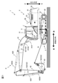
図1は、本発明の各実施形態に係る油圧ショベル1の一構成例を示す側面図である。図2は、地面の状態による油圧ショベル1への影響を説明する図である。 FIG. 1 is a side view showing a configuration example of a hydraulic excavator 1 according to each embodiment of the present invention. FIG. 2 is a diagram illustrating the influence of the ground condition on the hydraulic excavator 1.

油圧ショベル1は、地面を走行するための走行体2と、走行体2の上方に旋回装置10を介して旋回可能に取り付けられた旋回体3と、旋回体3の前部において俯仰動可能に連結された多関節型のリンク機構により構成される作業機であるフロント作業機4と、を備えている。 The hydraulic excavator 1 has a traveling body 2 for traveling on the ground, a swivel body 3 mounted above the traveling body 2 so as to be swivelable via a swivel device 10, and can be moved up and down at the front portion of the swivel body 3. It is equipped with a front working machine 4 which is a working machine configured by a connected articulated link mechanism.

走行体2は、その左右(車幅方向の両端)にクローラ21がそれぞれ配置されている。左右のクローラ21はそれぞれ、走行体2の左右それぞれに設けられた走行モータ22の駆動力によって独立して回転駆動する。これにより、油圧ショベル1は、左右それぞれのクローラ21を地面に接触させた状態で前後方向に走行する。なお、図1では、クローラ21及び走行モータ22はそれぞれ、左右のうちの一方側(左側)のみを図示している。 Crawlers 21 are arranged on the left and right sides (both ends in the vehicle width direction) of the traveling body 2. The left and right crawlers 21 are independently rotationally driven by the driving force of the traveling motors 22 provided on the left and right sides of the traveling body 2, respectively. As a result, the hydraulic excavator 1 travels in the front-rear direction with the left and right crawlers 21 in contact with the ground. Note that, in FIG. 1, the crawler 21 and the traveling motor 22 are shown on only one side (left side) of the left and right sides, respectively.

旋回体3は、旋回装置10内に設けられた旋回モータによって中心軸C(図1において一点鎖線で示す)を中心に走行体2に対して旋回駆動される。旋回体3は、オペレータが搭乗する運転室31と、フロント作業機4とのバランスを保つためのカウンタウェイト32と、エンジンや油圧ポンプ等の機器類を内部に収容する機械室33と、を備えている。旋回体3において、運転室31は前部に、カウンタウェイト32は後部に、機械室33は運転室31とカウンタウェイト32との間に、それぞれ配置されている。運転室31には、エンジンを始動させるためのエンジンキースイッチや、フロント作業機4を操作するための操作レバー310等の各種の操作装置が設けられている。 The swivel body 3 is swiveled with respect to the traveling body 2 about the central axis C (indicated by the alternate long and short dash line in FIG. 1) by a swivel motor provided in the swivel device 10. The swivel body 3 includes a driver's cab 31 on which the operator is boarded, a counter weight 32 for maintaining a balance between the front working machine 4, and a machine room 33 for internally accommodating equipment such as an engine and a hydraulic pump. ing. In the swivel body 3, the driver's cab 31 is arranged at the front, the counterweight 32 is arranged at the rear, and the machine room 33 is arranged between the driver's cab 31 and the counterweight 32. The driver's cab 31 is provided with various operating devices such as an engine key switch for starting the engine and an operating lever 310 for operating the front working machine 4.

フロント作業機4は、基端部が旋回体3に回動可能に連結されたブーム41と、ブーム41の先端部に回動可能に連結されたアーム42と、アーム42の先端部に回動可能に連結されたバケット43と、を備えている。 The front working machine 4 has a boom 41 whose base end is rotatably connected to the swivel body 3, an arm 42 rotatably connected to the tip of the boom 41, and rotation to the tip of the arm 42. It comprises a bucket 43 that is liable to be connected.

バケット43は、例えば土砂等を掘削したり、均したり、あるいは地面を締め固めたりするものである。このバケット43は、例えば、木材や岩石、廃棄物等を掴むグラップルや、岩盤を掘削するブレーカ等のアタッチメントに変更することが可能である。これにより、油圧ショベル1は、作業内容に適したアタッチメントを用いて、掘削や破砕等を含む様々な作業を行うことができる。 The bucket 43 is for excavating, leveling, or compacting the ground, for example, earth and sand. The bucket 43 can be changed to, for example, an attachment such as a grapple for grasping wood, rock, waste, or a breaker for excavating rock. As a result, the hydraulic excavator 1 can perform various operations including excavation and crushing by using an attachment suitable for the work content.

また、フロント作業機4は、旋回体3とブーム41とを連結するブームシリンダ410と、ブーム41とアーム42とを連結するアームシリンダ420と、アーム42とバケット43とを連結するバケットシリンダ430と、これらの各油圧シリンダ410,420,430へ作動油を導くための複数の配管(不図示)と、を有している。 Further, the front working machine 4 includes a boom cylinder 410 that connects the swivel body 3 and the boom 41, an arm cylinder 420 that connects the boom 41 and the arm 42, and a bucket cylinder 430 that connects the arm 42 and the bucket 43. , A plurality of pipes (not shown) for guiding hydraulic oil to each of these hydraulic cylinders 410, 420, 430.

ブームシリンダ410、アームシリンダ420、及びバケットシリンダ430はそれぞれ、油圧ポンプから吐出された作動油によって駆動される油圧アクチュエータの一態様である。なお、以下の説明において、「ブームシリンダ410、アームシリンダ420、及びバケットシリンダ430」を、単に「アクチュエータ410,420,430」とする場合がある。 The boom cylinder 410, the arm cylinder 420, and the bucket cylinder 430 are each one of the hydraulic actuators driven by the hydraulic oil discharged from the hydraulic pump. In the following description, the "boom cylinder 410, arm cylinder 420, and bucket cylinder 430" may be simply referred to as "actuator 410, 420, 430".

ブームシリンダ410は、操作レバー310の操作量に応じてロッド410Aが伸縮することによってブーム41を旋回体3に対して上下方向に回動させる。同様にして、アームシリンダ420は、操作レバー310の操作量に応じてロッド420Aが伸縮することによってアーム42をブーム41に対して前後方向に回動させる。また、同様にして、バケットシリンダ430は、操作レバー310の操作量に応じてロッド430Aが伸縮することによってバケット43をアーム42に対して前後方向に回動させる。すなわち、アクチュエータ410,420,430は、オペレータの操作レバー310の操作に伴って動作してフロント作業機4を駆動させる。 The boom cylinder 410 rotates the boom 41 in the vertical direction with respect to the swivel body 3 by expanding and contracting the rod 410A according to the operation amount of the operating lever 310. Similarly, the arm cylinder 420 rotates the arm 42 in the front-rear direction with respect to the boom 41 by expanding and contracting the rod 420A according to the operation amount of the operation lever 310. Similarly, the bucket cylinder 430 rotates the bucket 43 in the front-rear direction with respect to the arm 42 by expanding and contracting the rod 430A according to the operation amount of the operation lever 310. That is, the actuators 410, 420, 430 operate in accordance with the operation of the operator's operating lever 310 to drive the front working machine 4.

油圧ショベル1には、油圧ショベル1の状態を検出するための状態検出センサとして、車体の傾きの変動を検出する傾斜変動検出センサ51と、ブーム41の姿勢を検出するブーム姿勢検出センサ521と、アーム42の姿勢を検出するアーム姿勢検出センサ522と、バケット43の姿勢を検出するバケット姿勢検出センサ523と、が搭載されている。 The hydraulic excavator 1 includes a tilt fluctuation detection sensor 51 that detects fluctuations in the inclination of the vehicle body and a boom attitude detection sensor 521 that detects the posture of the boom 41 as state detection sensors for detecting the state of the hydraulic excavator 1. An arm posture detection sensor 522 that detects the posture of the arm 42 and a bucket posture detection sensor 523 that detects the posture of the bucket 43 are mounted.

傾斜変動検出センサ51は、旋回体3の上部に取り付けられており、例えば、車体の傾きを直接的に検出する傾斜センサや、車体の3次元の角速度(角度)及び加速度を検出する慣性計測装置(Inertial Measurement Unit;IMU)が用いられる。なお、図1では、傾斜変動検出センサ51は、機械室33の上部に取り付けられているが、これに限らず、旋回体3に取り付けられていればその位置については特に制限はない。 The tilt fluctuation detection sensor 51 is attached to the upper part of the swivel body 3, for example, a tilt sensor that directly detects the tilt of the vehicle body, or an inertial measurement unit that detects the three-dimensional angular velocity (angle) and acceleration of the vehicle body. (Inertial Measurement Unit; IMU) is used. In FIG. 1, the tilt fluctuation detection sensor 51 is attached to the upper part of the machine room 33, but the position is not particularly limited as long as it is attached to the swivel body 3.

図2に示すように、油圧ショベル1が凹凸の大きい地面に設置されている場合、油圧ショベル1の動作や姿勢に応じて油圧ショベル1の傾きが変動する。また、油圧ショベル1が設置された地面が軟弱である場合も、油圧ショベル1の重心の変化に伴って地面の形状が変化しやすくなり、油圧ショベル1の傾きが変動する。したがって、傾斜変動検出センサ51を用いて油圧ショベル1の傾きの変動を検出することにより、油圧ショベル1が設置された地面の状態を推定することができる。 As shown in FIG. 2, when the hydraulic excavator 1 is installed on the ground having a large unevenness, the inclination of the hydraulic excavator 1 fluctuates according to the operation and posture of the hydraulic excavator 1. Further, even when the ground on which the hydraulic excavator 1 is installed is soft, the shape of the ground tends to change as the center of gravity of the hydraulic excavator 1 changes, and the inclination of the hydraulic excavator 1 fluctuates. Therefore, by detecting the fluctuation of the inclination of the hydraulic excavator 1 using the inclination fluctuation detection sensor 51, the state of the ground on which the hydraulic excavator 1 is installed can be estimated.

ブーム姿勢検出センサ521はブーム41の側部に、アーム姿勢検出センサ522はアーム42の側部に、バケット姿勢検出センサ523はバケット43の側部に、それぞれ取り付けられており、例えば、各リンクの回動角度を検出する角度センサやIMUが用いられる。ブーム姿勢検出センサ521、アーム姿勢検出センサ522、及びバケット姿勢検出センサ523は、フロント作業機4の姿勢を検出する姿勢検出センサ52の一態様である。なお、以下では、ブーム姿勢検出センサ521、アーム姿勢検出センサ522、及びバケット姿勢検出センサ523のそれぞれを、単に各姿勢検出センサ52とする場合がある。 The boom attitude detection sensor 521 is attached to the side of the boom 41, the arm attitude detection sensor 522 is attached to the side of the arm 42, and the bucket attitude detection sensor 523 is attached to the side of the bucket 43. An angle sensor or IMU that detects the rotation angle is used. The boom posture detection sensor 521, the arm posture detection sensor 522, and the bucket posture detection sensor 523 are one aspect of the posture detection sensor 52 that detects the posture of the front working machine 4. In the following, each of the boom posture detection sensor 521, the arm posture detection sensor 522, and the bucket posture detection sensor 523 may be simply referred to as each posture detection sensor 52.

油圧ショベル1は、傾斜変動検出センサ51及び各姿勢検出センサ52からの検出データに基づいて、地面の状態に伴ったフロント作業機4の作業精度を判定し、判定結果にしたがって所定の制御を行う制御装置を備えている。以下、この制御装置の構成について実施形態ごとに説明する。 The hydraulic excavator 1 determines the work accuracy of the front work machine 4 according to the ground condition based on the detection data from the tilt fluctuation detection sensor 51 and each attitude detection sensor 52, and performs predetermined control according to the determination result. It is equipped with a control device. Hereinafter, the configuration of this control device will be described for each embodiment.

<第1実施形態>
本発明の第1実施形態に係る制御装置6について、図3~8を参照して説明する。
<First Embodiment>
The control device 6 according to the first embodiment of the present invention will be described with reference to FIGS. 3 to 8.

(制御装置6のハードウェア構成)
まず、制御装置6のハードウェア構成について、図3を参照して説明する。
(Hardware configuration of control device 6)
First, the hardware configuration of the control device 6 will be described with reference to FIG.

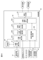
図3は、第1実施形態に係る制御装置6のハードウェア構成図である。 FIG. 3 is a hardware configuration diagram of the control device 6 according to the first embodiment.

制御装置6は、CPU601、RAM602、ROM603、入力I/F604、出力I/F605、及びバス606を含み、CPU601、RAM602、ROM603、入力I/F604、及び出力I/F605がバス606を介して互いに接続されて構成されている。 The control device 6 includes a CPU 601 and a RAM 602, a ROM 603, an input I / F 604, an output I / F 605, and a bus 606, and the CPU 601 and the RAM 602, the ROM 603, an input I / F 604, and an output I / F 605 are connected to each other via the bus 606. It is connected and configured.

そして、傾斜変動検出センサ51及び各姿勢検出センサ52等の各種センサが入力I/F604に接続され、表示装置71及び警報装置72等の各種装置が出力I/F605に接続されている。表示装置71及び警報装置72はそれぞれ、制御装置6からの指令に基づく通知を行う通知装置の一態様である。 Then, various sensors such as the tilt fluctuation detection sensor 51 and each attitude detection sensor 52 are connected to the input I / F 604, and various devices such as the display device 71 and the alarm device 72 are connected to the output I / F 605. Each of the display device 71 and the alarm device 72 is an aspect of a notification device that gives a notification based on a command from the control device 6.

表示装置71は、例えば液晶パネル等からなる装置であり、運転室31(図1参照)内に設けられている。表示装置71は、油圧ショベル1が設置された地面の状態やフロント作業機4の作業精度に関する情報をオペレータに対して視覚的に通知する。警報装置72は、音や音声等を発生させる装置であり、表示装置71と同様に運転室31内に設けられている。警報装置72は、油圧ショベル1が設置された地面の状態によるフロント作業機4の作業精度の低下をオペレータに対して聴覚的に通知する。 The display device 71 is, for example, a device including a liquid crystal panel or the like, and is provided in the cab 31 (see FIG. 1). The display device 71 visually notifies the operator of information regarding the state of the ground on which the hydraulic excavator 1 is installed and the work accuracy of the front work machine 4. The alarm device 72 is a device that generates a sound, a voice, or the like, and is provided in the driver's cab 31 like the display device 71. The alarm device 72 audibly notifies the operator of a decrease in work accuracy of the front work machine 4 due to the condition of the ground on which the hydraulic excavator 1 is installed.

図3に示すようなハードウェア構成において、ROM603や光学ディスク等の記録媒体に格納された演算プログラム(ソフトウェア)をCPU601が読み出してRAM602上に展開し、展開された演算プログラムを実行することにより、演算プログラムとハードウェアとが協働して、制御装置6の機能を実現する。 In the hardware configuration as shown in FIG. 3, the CPU 601 reads out the arithmetic program (software) stored in the recording medium such as the ROM 603 or the optical disk, expands it on the RAM 602, and executes the expanded arithmetic program. The arithmetic program and the hardware cooperate to realize the function of the control device 6.

なお、制御装置6は、必ずしもソフトウェアとハードウェアとの組み合わせによって構成されるコンピュータである必要はなく、例えば他のコンピュータの構成の一例として、油圧ショベル1の側で実行される演算プログラムの機能を実現する集積回路を用いてもよい。 The control device 6 does not necessarily have to be a computer composed of a combination of software and hardware. For example, as an example of the configuration of another computer, the function of an arithmetic program executed on the side of the hydraulic excavator 1 may be used. An integrated circuit to be realized may be used.

(制御装置6の機能構成)
次に、制御装置6の機能構成について、図4~図6を参照して説明する。
(Functional configuration of control device 6)
Next, the functional configuration of the control device 6 will be described with reference to FIGS. 4 to 6.

図4は、制御装置6が有する機能構成を示す図である。図5(a)及び図5(b)は、傾斜変動検出センサ51から出力された出力信号の一例を示す図であり、図5(a)は地面の凹凸が微小である場合、図5(b)は地面の凹凸が大きい場合をそれぞれ示している。図6(a)~(c)は、表示装置71における表示の一例を示す図である。 FIG. 4 is a diagram showing a functional configuration of the control device 6. 5 (a) and 5 (b) are diagrams showing an example of an output signal output from the tilt fluctuation detection sensor 51, and FIG. 5 (a) shows FIG. 5 (a) when the unevenness of the ground is minute. b) shows the case where the unevenness of the ground is large. 6 (a) to 6 (c) are diagrams showing an example of display in the display device 71.

図4に示すように、制御装置6は、地面状態算出部61と、作業精度判定部62と、通知生成部63と、記憶部60と、を含む。地面状態算出部61は、傾斜変動検出センサ51で検出された車体の傾きの変動データに基づいて車体が設置された地面の不安定度Sg(以下、「地面不安定度Sg」とする)を算出する。この「地面不安定度Sg」とは、凹凸の大きさや軟弱性を考慮した地面の状態を表す指標であり、本実施形態では、油圧ショベル1の所定の作業時間Td内における車体の傾きの変動量Iv(以下、「傾斜変動量Iv」とする)に相当する。 As shown in FIG. 4, the control device 6 includes a ground condition calculation unit 61, a work accuracy determination unit 62, a notification generation unit 63, and a storage unit 60. The ground condition calculation unit 61 determines the instability Sg of the ground on which the vehicle body is installed (hereinafter referred to as “ground instability Sg”) based on the inclination fluctuation data of the vehicle body detected by the inclination fluctuation detection sensor 51. calculate. This "ground instability Sg" is an index showing the state of the ground in consideration of the size and softness of the unevenness, and in the present embodiment, the fluctuation of the inclination of the vehicle body within the predetermined working time Td of the hydraulic excavator 1. It corresponds to the quantity Iv (hereinafter referred to as "inclination fluctuation amount Iv").

油圧ショベル1が設置された地面が平坦かつ強固である場合には、車体の傾斜角度Iの変動は小さく、図5(a)に示すように、傾斜変動検出センサ51で検出される波形データの振幅も小さい。一方、油圧ショベル1が設置された地面の凹凸が大きい場合には、車体の傾斜角度Iの変動は大きく、図5(b)に示すように、傾斜変動検出センサ51で検出される波形データの振幅が大きくなる。車体の傾斜角度Iは、地面の凹凸の大きさに応じて変動するが、傾斜角度Iの変動量が大きいほど地面の状態に起因したバケット43(図1参照)の位置の変化が大きくなり、フロント作業機4の作業精度に大きな影響を及ぼす。 When the ground on which the hydraulic excavator 1 is installed is flat and strong, the fluctuation of the tilt angle I of the vehicle body is small, and as shown in FIG. 5A, the waveform data detected by the tilt fluctuation detection sensor 51 The amplitude is also small. On the other hand, when the unevenness of the ground on which the hydraulic excavator 1 is installed is large, the fluctuation of the tilt angle I of the vehicle body is large, and as shown in FIG. 5 (b), the waveform data detected by the tilt fluctuation detection sensor 51 The amplitude increases. The tilt angle I of the vehicle body fluctuates according to the size of the unevenness of the ground, but the larger the fluctuation amount of the tilt angle I, the larger the change in the position of the bucket 43 (see FIG. 1) due to the condition of the ground. It greatly affects the work accuracy of the front work machine 4.

そこで、地面状態算出部61は、油圧ショベル1の所定の作業時間Td内における車体の傾斜角度Iの最大値Imax及び最小値Iminを抽出し、最大値Imaxと最小値Iminとの差分である傾斜変動量Iv(=Imax-Imin)を地面不安定度Sgとして算出する。なお、「所定の作業時間Td」とは、油圧ショベル1が行う作業サイクル(例えば、地面を掘削し、旋回体3を旋回させて放土する作業等)を参考にして定められた時間である。 Therefore, the ground condition calculation unit 61 extracts the maximum value Imax and the minimum value Imin of the inclination angle I of the vehicle body within the predetermined working time Td of the hydraulic excavator 1, and the inclination which is the difference between the maximum value Imax and the minimum value Imin. The fluctuation amount Iv (= Imax-Imin) is calculated as the ground instability Sg. The "predetermined work time Td" is a time determined with reference to the work cycle performed by the hydraulic excavator 1 (for example, the work of excavating the ground, turning the swivel body 3 and releasing the soil, etc.). ..

なお、地面不安定度Sgを算出するにあたって、傾斜変動検出センサ51で検出された傾斜角変動データに加え、各姿勢検出センサ52で検出された姿勢データを考慮してもよい。例えば、油圧ショベル1の起動時や停止時、急な動作時においては、油圧ショベル1が設置された地面が平坦かつ強固である場合であっても、慣性力の影響によって油圧ショベル1が傾く可能性がある。したがって、油圧ショベル1が設置された地面の状態をより正確に把握するためには、地面不安定度Sgの算出において油圧ショベル1の動作による影響を除外することが望ましい。 In calculating the ground instability Sg, in addition to the tilt angle fluctuation data detected by the tilt fluctuation detection sensor 51, the posture data detected by each posture detection sensor 52 may be taken into consideration. For example, when the hydraulic excavator 1 is started, stopped, or suddenly operated, the hydraulic excavator 1 can be tilted due to the influence of inertial force even when the ground on which the hydraulic excavator 1 is installed is flat and strong. There is sex. Therefore, in order to more accurately grasp the state of the ground on which the hydraulic excavator 1 is installed, it is desirable to exclude the influence of the operation of the hydraulic excavator 1 in the calculation of the ground instability Sg.

具体的には、地面状態算出部61は、各姿勢検出センサ52で検出されたブーム41、アーム42、及びバケット43の動作加速度が所定の閾値を超えた場合、油圧ショベル1において「起動」、「停止」、及び「急動作」のいずれかが行われていると判断し、その時刻における傾斜変動検出センサ51からの傾斜角変動データを、傾斜角度Iの最大値Imax及び最小値Iminの抽出対象から除外する。これにより、地面状態算出部61は、油圧ショベル1が設置された地面の状態に起因する傾斜角の変動のみに基づく精度の高い地面不安定度Sgを算出することができる。 Specifically, the ground condition calculation unit 61 "starts" in the hydraulic excavator 1 when the operating accelerations of the boom 41, the arm 42, and the bucket 43 detected by each posture detection sensor 52 exceed a predetermined threshold value. It is determined that either "stop" or "sudden operation" is being performed, and the tilt angle fluctuation data from the tilt fluctuation detection sensor 51 at that time is extracted from the maximum value Imax and the minimum value Imin of the tilt angle I. Exclude from the target. As a result, the ground condition calculation unit 61 can calculate the highly accurate ground instability Sg based only on the fluctuation of the inclination angle due to the condition of the ground on which the hydraulic excavator 1 is installed.

また、例えば、油圧ショベル1が走行等により移動した場合には、走行に伴って車体の傾斜角度が変動し、さらに油圧ショベル1の設置位置も変化する。そのため、地面状態算出部61で算出される地面不安定度Sgは移動の前後で値が異なる。そこで、制御装置6において油圧ショベル1の移動が検出された場合には、地面状態算出部61は、移動終了以降における傾斜角変動データのみに基づいて地面不安定度Sgを再度算出するように構成しても良い。 Further, for example, when the hydraulic excavator 1 moves due to traveling or the like, the inclination angle of the vehicle body changes with the traveling, and the installation position of the hydraulic excavator 1 also changes. Therefore, the value of the ground instability Sg calculated by the ground condition calculation unit 61 is different before and after the movement. Therefore, when the movement of the hydraulic excavator 1 is detected in the control device 6, the ground condition calculation unit 61 is configured to recalculate the ground instability Sg based only on the inclination angle fluctuation data after the end of the movement. You may.

また、本実施形態では、地面不安定度Sgとして車体の傾斜変動量Ivを用いたが、これに限らず、地面不安定度Sgは、車体の傾斜角度Iの変動周期や繰り返し性といった時間のパラメータ等を含んだ指標としてもよい。このように、車体の傾斜変動量Iv以外のパラメータを含めた指標を用いることにより、地面の凹凸による特徴と地面の軟弱性による特徴との間の違いが明確になり、地面の凹凸による影響と地面の軟弱性による影響とを分離することが可能となる。これにより、地面状態算出部61は、地面の状態変化の予測を含めた形で地面不安定度Sgを算出することができる。 Further, in the present embodiment, the inclination fluctuation amount Iv of the vehicle body is used as the ground instability Sg, but the ground instability Sg is not limited to this, and the ground instability Sg is the time such as the fluctuation cycle and repeatability of the inclination angle I of the vehicle body. It may be used as an index including parameters and the like. In this way, by using an index that includes parameters other than the tilt fluctuation amount Iv of the vehicle body, the difference between the characteristics due to the unevenness of the ground and the characteristics due to the softness of the ground becomes clear, and the influence of the unevenness of the ground It is possible to separate the effects of the softness of the ground. As a result, the ground condition calculation unit 61 can calculate the ground instability Sg including the prediction of the change of the ground condition.

また、本実施形態では、地面状態算出部61は、傾斜変動検出センサ51で検出された変動データに基づいて地面不安定度Sgを算出したが、これに限らず、現場管理等を行う外部システムから与えられる地面の形状及び地盤に関する情報を用いて地面不安定度Sgを算出してもよい。これにより、地面状態算出部61は、地面の状態をより詳細に把握した形で地面不安定度Sgを算出することができる。 Further, in the present embodiment, the ground condition calculation unit 61 calculates the ground instability Sg based on the fluctuation data detected by the tilt fluctuation detection sensor 51, but the present invention is not limited to this, and the external system that performs on-site management and the like is not limited to this. The ground instability Sg may be calculated using the information about the shape of the ground and the ground given from. As a result, the ground condition calculation unit 61 can calculate the ground instability Sg in a form in which the ground condition is grasped in more detail.

作業精度判定部62は、作業半径算出部62Aと、バケット位置変動量算出部62Bと、作業精度レベル決定部62Cと、作業精度低下判定部62Dと、を含み、地面状態算出部61で算出された地面不安定度Sgに基づいて、油圧ショベル1が設置された地面の状態に起因したフロント作業機4の作業精度を判定する。 The work accuracy determination unit 62 includes a work radius calculation unit 62A, a bucket position fluctuation amount calculation unit 62B, a work accuracy level determination unit 62C, and a work accuracy reduction determination unit 62D, and is calculated by the ground condition calculation unit 61. Based on the ground instability Sg, the work accuracy of the front work machine 4 due to the state of the ground on which the hydraulic excavator 1 is installed is determined.

作業半径算出部62Aは、各姿勢検出センサ52で検出された姿勢に基づいてフロント作業機4の作業半径rb(以下、単に「作業半径rb」とする)を算出する。具体的には、作業半径算出部62Aは、油圧ショベル1を構成する各部の寸法情報と、各姿勢検出センサ52で検出された姿勢とを用いてリンク演算を行い、油圧ショベルの原点Oからバケット43(フロント作業機4)の先端までの距離(図1参照)を作業半径rbとして算出する。すなわち、作業半径rbは、ブーム41、アーム42、及びバケット43それぞれの姿勢によって時々刻々と変化する値である。 The working radius calculation unit 62A calculates the working radius rb (hereinafter, simply referred to as “working radius rb”) of the front working machine 4 based on the posture detected by each posture detection sensor 52. Specifically, the working radius calculation unit 62A performs a link calculation using the dimensional information of each part constituting the hydraulic excavator 1 and the posture detected by each posture detection sensor 52, and performs a link calculation from the origin O of the hydraulic excavator to the bucket. The distance to the tip of 43 (front working machine 4) (see FIG. 1) is calculated as the working radius rb. That is, the working radius rb is a value that changes from moment to moment depending on the postures of the boom 41, the arm 42, and the bucket 43.

バケット位置変動量算出部62Bは、作業半径算出部62Aで算出されたフロント作業機4の作業半径rb及び地面状態算出部61で算出された地面不安定度Sgを用いて、油圧ショベル1が設置された地面の状態によるバケット43の先端位置の変動量ΔLb(以下、「バケット位置変動量ΔLb」とする)を算出する。 The bucket position fluctuation amount calculation unit 62B installs the hydraulic excavator 1 using the work radius rb of the front work machine 4 calculated by the work radius calculation unit 62A and the ground instability Sg calculated by the ground condition calculation unit 61. The fluctuation amount ΔLb of the tip position of the bucket 43 (hereinafter referred to as “bucket position fluctuation amount ΔLb”) depending on the state of the ground is calculated.

具体的には、バケット位置変動量算出部62Bは、まず、油圧ショベル1の所定の作業時間Td内における作業半径rbの最大値rbmaxを抽出し、続いて、抽出した最大値rbmax及び地面不安定度Sgを以下の数式(1)に代入することによりバケット位置変動量ΔLbを算出する。

Figure 0007022018000001
Specifically, the bucket position fluctuation amount calculation unit 62B first extracts the maximum value rbmax of the working radius rb within the predetermined working time Td of the hydraulic excavator 1, and then extracts the extracted maximum value rbmax and the ground instability. The bucket position fluctuation amount ΔLb is calculated by substituting the degree Sg into the following mathematical formula (1).
Figure 0007022018000001

本実施形態では、バケット位置変動量算出部62Bは、バケット位置変動量ΔLbの算出に、油圧ショベル1の所定の作業時間Td内における作業半径rbの最大値rbmaxを抽出して用いたが、これに限らず、例えば、フロント作業機4の取り得る最大の作業半径を用いてもよい。 In the present embodiment, the bucket position fluctuation amount calculation unit 62B extracts and uses the maximum value rbmax of the working radius rb within the predetermined working time Td of the hydraulic excavator 1 for calculating the bucket position fluctuation amount ΔLb. However, for example, the maximum working radius that the front working machine 4 can take may be used.

本実施形態のように、所定の作業時間Td内における作業半径rbの最大値rbmaxを用いた場合には、実作業に即したバケット位置変動量ΔLbを算出することができ、他方、フロント作業機4の取り得る最大の作業半径を用いた場合には、油圧ショベル1のあらゆる姿勢において発生し得るバケット位置変動量ΔLbの最大値を算出することができる。所定の作業時間Td内における作業半径rbの最大値rbmaxを用いるか、フロント作業機4の取り得る最大の作業半径を用いるかについては、バケット位置の変動によって作業全体に与える影響の度合いを考慮して決定すればよい。なお、フロント作業機4の取り得る最大の作業半径を用いる場合には、各姿勢検出センサ52で姿勢を検出する構成を省略することが可能となる。 When the maximum value rbmax of the working radius rb within the predetermined working time Td is used as in the present embodiment, the bucket position fluctuation amount ΔLb according to the actual work can be calculated, while the front working machine When the maximum possible working radius of 4 is used, the maximum value of the bucket position fluctuation amount ΔLb that can occur in any posture of the hydraulic excavator 1 can be calculated. Whether to use the maximum value rbmax of the work radius rb within the predetermined work time Td or the maximum work radius that the front work machine 4 can take is considered in consideration of the degree of influence on the entire work due to the fluctuation of the bucket position. You can decide. When the maximum working radius that the front work machine 4 can take is used, it is possible to omit the configuration in which the posture is detected by each posture detection sensor 52.

作業精度レベル決定部62Cは、バケット位置変動量算出部62Bで算出されたバケット位置変動量ΔLbに基づいてフロント作業機4の作業精度のレベルを決定する。 The work accuracy level determination unit 62C determines the work accuracy level of the front work machine 4 based on the bucket position fluctuation amount ΔLb calculated by the bucket position fluctuation amount calculation unit 62B.

本実施形態では、作業精度レベル決定部62Cは、バケット位置変動量ΔLbが10mm未満である場合に作業精度レベルを「5」とし、バケット位置変動量ΔLbが10mm以上100mm未満である場合に作業精度レベルを「4」とし、バケット位置変動量ΔLbが100mm以上200mm未満である場合に作業精度レベルを「3」とし、バケット位置変動量ΔLbが200mm以上400mm未満である場合に作業精度レベルを「2」とし、バケット位置変動量ΔLbが400mm以上である場合に作業精度レベルを「1」として、フロント作業機4の作業精度のレベルを決定する。この場合、作業精度レベルは、「5」、「4」、「3」、「2」、「1」の順で低下する。 In the present embodiment, the work accuracy level determination unit 62C sets the work accuracy level to "5" when the bucket position fluctuation amount ΔLb is less than 10 mm, and sets the work accuracy level when the bucket position fluctuation amount ΔLb is 10 mm or more and less than 100 mm. The level is set to "4", the work accuracy level is set to "3" when the bucket position fluctuation amount ΔLb is 100 mm or more and less than 200 mm, and the work accuracy level is set to "2" when the bucket position fluctuation amount ΔLb is 200 mm or more and less than 400 mm. When the bucket position fluctuation amount ΔLb is 400 mm or more, the work accuracy level is set to “1” and the work accuracy level of the front work machine 4 is determined. In this case, the work accuracy level decreases in the order of "5", "4", "3", "2", and "1".

フロント作業機4の作業精度レベルは、本実施形態のように数段階で表してもよいし、0~100までの数値で表してもよいし、バケット位置変動量ΔLbをそのまま用いて表してもよい。したがって、フロント作業機4の作業精度レベルの表し方は、油圧ショベル1の作業内容やオペレータの使い勝手等に応じて適宜変更可能である。 The work accuracy level of the front work machine 4 may be expressed in several stages as in the present embodiment, may be expressed by a numerical value from 0 to 100, or may be expressed by using the bucket position fluctuation amount ΔLb as it is. good. Therefore, the method of expressing the work accuracy level of the front work machine 4 can be appropriately changed according to the work content of the hydraulic excavator 1, the usability of the operator, and the like.

作業精度低下判定部62Dは、作業精度レベル決定部62Cで決定された作業精度レベルと所定の許容作業精度レベル(以下、単に「許容作業精度レベル」とする)とを比較し、作業精度レベル決定部62Cで決定された作業精度レベルが許容作業精度レベルを下回っている場合に「作業精度低下」と判定する。許容作業精度レベルは、油圧ショベル1が行う全ての作業に共通するものとして設定してもよいし、作業内容ごとに設定しておき油圧ショベル1の作業状態に応じて切り替えてもよい。 The work accuracy deterioration determination unit 62D compares the work accuracy level determined by the work accuracy level determination unit 62C with a predetermined allowable work accuracy level (hereinafter, simply referred to as “allowable work accuracy level”), and determines the work accuracy level. When the work accuracy level determined by the unit 62C is lower than the allowable work accuracy level, it is determined that the work accuracy has deteriorated. The allowable work accuracy level may be set to be common to all the work performed by the hydraulic excavator 1, or may be set for each work content and switched according to the work state of the hydraulic excavator 1.

通知生成部63は、作業精度レベル決定部62Cで決定された作業精度レベル、及び作業精度低下判定部62Dで判定された判定結果に基づいて、表示装置71に対して表示指令(通知指令)を、警報装置72に対して警報指令(通知指令)を、それぞれ生成する。なお、通知生成部63は、作業精度低下判定部62Dで「作業精度低下」と判定された場合に警報装置72に対して警報指令を生成し、作業精度低下判定部62Dで「作業精度低下」と判定されなかった場合には警報指令を生成しない。 The notification generation unit 63 issues a display command (notification command) to the display device 71 based on the work accuracy level determined by the work accuracy level determination unit 62C and the determination result determined by the work accuracy deterioration determination unit 62D. , An alarm command (notification command) is generated for the alarm device 72, respectively. The notification generation unit 63 generates an alarm command for the alarm device 72 when the work accuracy deterioration determination unit 62D determines that the work accuracy has decreased, and the work accuracy reduction determination unit 62D has "work accuracy reduction". If it is not determined, the alarm command is not generated.

そして、表示装置71は、通知生成部63で生成された表示指令にしたがった表示を行い、警報装置72は、通知生成部63で警報指令が生成された場合に警報を行う。表示装置71は、具体的には、図6(a)~(c)に示すように、作業精度レベル決定部62Cで決定された作業精度レベルをバー71Aに表示し、作業精度低下判定部62Dで「作業精度低下」と判定された場合には、図6(b)に示すように、「作業精度低下」の表示を行う。また、作業精度低下判定部62Dで「作業精度低下」と判定された場合には、図6(c)に示すように、「作業精度低下」の表示に加えて、地面の整備を指示する表示を行ってもよい。 Then, the display device 71 performs a display according to the display command generated by the notification generation unit 63, and the alarm device 72 issues an alarm when the warning command is generated by the notification generation unit 63. Specifically, as shown in FIGS. 6A to 6C, the display device 71 displays the work accuracy level determined by the work accuracy level determination unit 62C on the bar 71A, and displays the work accuracy level determined by the work accuracy level determination unit 62C on the bar 71A, and the work accuracy reduction determination unit 62D. If it is determined that "work accuracy has deteriorated", "work accuracy has deteriorated" is displayed as shown in FIG. 6 (b). Further, when the work accuracy deterioration determination unit 62D determines that the work accuracy has deteriorated, as shown in FIG. 6 (c), in addition to the display of "work accuracy deterioration", a display instructing the maintenance of the ground is displayed. May be done.

記憶部60は、油圧ショベル1の所定の作業時間Td、油圧ショベル1を構成する各部の寸法情報、フロント作業機4の作業精度レベルを決定するためのバケット位置変動量ΔLbに関する所定の閾値、及び所定の許容作業精度レベル等を記憶する。 The storage unit 60 has a predetermined working time Td of the hydraulic excavator 1, dimensional information of each part constituting the hydraulic excavator 1, a predetermined threshold value regarding the bucket position fluctuation amount ΔLb for determining the working accuracy level of the front working machine 4, and Stores a predetermined allowable work accuracy level and the like.

(制御装置6における処理)
次に、制御装置6内で実行される具体的な処理の流れについて、図7及び図8を参照して説明する。
(Processing in the control device 6)
Next, a specific flow of processing executed in the control device 6 will be described with reference to FIGS. 7 and 8.

図7は、制御装置6内で実行される全体処理の流れを示すフローチャートである。図8は、制御装置6内で実行される作業精度レベル決定処理の流れを示すフローチャートである。 FIG. 7 is a flowchart showing the flow of the entire process executed in the control device 6. FIG. 8 is a flowchart showing the flow of the work accuracy level determination process executed in the control device 6.

図7に示すように、制御装置6では、まず、地面状態算出部61が、傾斜変動検出センサ51で検出された傾斜角変動データ(図5(b)参照)に基づいて地面不安定度Sgを算出する(ステップS801)。 As shown in FIG. 7, in the control device 6, first, the ground condition calculation unit 61 first determines the ground instability Sg based on the tilt angle fluctuation data (see FIG. 5B) detected by the tilt fluctuation detection sensor 51. Is calculated (step S801).

次に、作業精度判定部62のバケット位置変動量算出部62Bが、作業半径算出部62Aで算出されたフロント作業機4の作業半径rbの中から、所定の作業時間Td内での最大値rbmaxを抽出する(ステップS802)。続いて、バケット位置変動量算出部62Bは、ステップS801で算出された地面不安定度Sg、及びステップS802で抽出された作業半径の最大値rbmaxに基づいて、バケット位置変動量ΔLbを算出する(ステップS803)。 Next, the bucket position fluctuation amount calculation unit 62B of the work accuracy determination unit 62 determines the maximum value rbmax within the predetermined work time Td from the work radius rb of the front work machine 4 calculated by the work radius calculation unit 62A. Is extracted (step S802). Subsequently, the bucket position fluctuation amount calculation unit 62B calculates the bucket position fluctuation amount ΔLb based on the ground instability Sg calculated in step S801 and the maximum value rbmax of the working radius extracted in step S802 (). Step S803).

次に、作業精度レベル決定部62Cは、ステップS803で算出されたバケット位置変動量ΔLbに基づいて作業精度レベル決定処理を実行する(ステップS804)。作業精度レベル決定処理では、図8に示すように、まず、ステップS803で算出されたバケット位置変動量ΔLbが10mm未満であるか否かを判定する(ステップS840)。 Next, the work accuracy level determination unit 62C executes the work accuracy level determination process based on the bucket position fluctuation amount ΔLb calculated in step S803 (step S804). In the work accuracy level determination process, as shown in FIG. 8, first, it is determined whether or not the bucket position fluctuation amount ΔLb calculated in step S803 is less than 10 mm (step S840).

ステップS840においてバケット位置変動量ΔLbが10mm未満である(ΔLb<10mm)と判定された場合(ステップS840/YES)、作業精度レベル決定部62Cは、フロント作業機4の作業精度レベルを「5」に決定する(ステップS841)。 When it is determined in step S840 that the bucket position fluctuation amount ΔLb is less than 10 mm (ΔLb <10 mm) (step S840 / YES), the work accuracy level determination unit 62C sets the work accuracy level of the front work machine 4 to “5”. (Step S841).

ステップS840においてバケット位置変動量ΔLbが10mm以上である(ΔLb≧10mm)と判定された場合(ステップS840/NO)、さらにバケット位置変動量ΔLbが100mm未満であるか否かを判定する(ステップS842)。 When it is determined in step S840 that the bucket position fluctuation amount ΔLb is 10 mm or more (ΔLb ≧ 10 mm) (step S840 / NO), it is further determined whether or not the bucket position fluctuation amount ΔLb is less than 100 mm (step S842). ).

ステップS842においてバケット位置変動量ΔLbが100mm未満である(ΔLb<100mm)と判定された場合(ステップS842/YES)、作業精度レベル決定部62Cは、フロント作業機4の作業精度レベルを「4」に決定する(ステップS843)。 When it is determined in step S842 that the bucket position fluctuation amount ΔLb is less than 100 mm (ΔLb <100 mm) (step S842 / YES), the work accuracy level determining unit 62C sets the work accuracy level of the front work machine 4 to “4”. (Step S843).

ステップS842においてバケット位置変動量ΔLbが100mm以上である(ΔLb≧100mm)と判定された場合(ステップS842/NO)、さらにバケット位置変動量ΔLbが200mm未満であるか否かを判定する(ステップS844)。 When it is determined in step S842 that the bucket position fluctuation amount ΔLb is 100 mm or more (ΔLb ≧ 100 mm) (step S842 / NO), it is further determined whether or not the bucket position fluctuation amount ΔLb is less than 200 mm (step S844). ).

ステップS844においてバケット位置変動量ΔLbが200mm未満である(ΔLb<200mm)と判定された場合(ステップS844/YES)、作業精度レベル決定部62Cは、フロント作業機4の作業精度レベルを「3」に決定する(ステップS845)。 When it is determined in step S844 that the bucket position fluctuation amount ΔLb is less than 200 mm (ΔLb <200 mm) (step S844 / YES), the work accuracy level determining unit 62C sets the work accuracy level of the front work machine 4 to “3”. (Step S845).

ステップS844においてバケット位置変動量ΔLbが200mm以上である(ΔLb≧200mm)と判定された場合(ステップS844/NO)、さらにバケット位置変動量ΔLbが400mm未満であるか否かを判定する(ステップS846)。 When it is determined in step S844 that the bucket position fluctuation amount ΔLb is 200 mm or more (ΔLb ≧ 200 mm) (step S844 / NO), it is further determined whether or not the bucket position fluctuation amount ΔLb is less than 400 mm (step S846). ).

ステップS846においてバケット位置変動量ΔLbが400mm未満である(ΔLb<400mm)と判定された場合(ステップS846/YES)、作業精度レベル決定部62Cは、フロント作業機4の作業精度レベルを「2」に決定する(ステップS847)。 When it is determined in step S846 that the bucket position fluctuation amount ΔLb is less than 400 mm (ΔLb <400 mm) (step S846 / YES), the work accuracy level determining unit 62C sets the work accuracy level of the front work machine 4 to “2”. (Step S847).

ステップS846においてバケット位置変動量ΔLbが400mm以上である(ΔLb≧400mm)と判定された場合(ステップS846/NO)、作業精度レベル決定部62Cは、フロント作業機4の作業精度レベルを「1」に決定する(ステップS848)。 When it is determined in step S846 that the bucket position fluctuation amount ΔLb is 400 mm or more (ΔLb ≧ 400 mm) (step S846 / NO), the work accuracy level determining unit 62C sets the work accuracy level of the front work machine 4 to “1”. (Step S848).

そして、作業精度レベル決定部62Cは、ステップS841、ステップS843、ステップ845、ステップS847、及びステップS848のいずれかにおいて決定されたフロント作業機4の作業精度レベルを作業精度低下判定部62D及び通知生成部63に出力し(ステップS849)、作業精度レベル決定処理が終了する。 Then, the work accuracy level determination unit 62C determines the work accuracy level of the front work machine 4 determined in any one of step S841, step S843, step 845, step S847, and step S848 to the work accuracy reduction determination unit 62D and notification generation. It is output to the unit 63 (step S849), and the work accuracy level determination process is completed.

次に、図7に示すように、作業精度低下判定部62Dは、ステップS804において決定された作業精度レベルが許容作業精度レベル未満であるか否かを判定する(ステップS805)。 Next, as shown in FIG. 7, the work accuracy reduction determination unit 62D determines whether or not the work accuracy level determined in step S804 is less than the allowable work accuracy level (step S805).

ステップS805において、決定された作業精度レベルが許容作業精度レベル未満である(作業精度レベル<許容作業精度レベル)と判定された場合(ステップS805/YES)、作業精度低下判定部62Dは、フロント作業機4の作業精度が低下している(「作業精度低下」=ON)と判定する(ステップS806)。 When it is determined in step S805 that the determined work accuracy level is less than the allowable work accuracy level (work accuracy level <allowable work accuracy level) (step S805 / YES), the work accuracy reduction determination unit 62D performs front work. It is determined that the work accuracy of the machine 4 has deteriorated (“decrease in work accuracy” = ON) (step S806).

そして、通知生成部63は、ステップS806における「作業精度低下」=ONの判定を受けて、表示装置71に対して作業精度レベル及び作業精度の低下に関する表示指令を生成すると共に、警報装置72に対して警報指令を生成し(ステップS807)、制御装置6における処理が終了する。 Then, the notification generation unit 63 receives the determination of "decrease in work accuracy" = ON in step S806, generates a display command regarding the decrease in work accuracy level and work accuracy to the display device 71, and causes the alarm device 72 to generate a display command. On the other hand, an alarm command is generated (step S807), and the process in the control device 6 ends.

一方、ステップS805において、決定された作業精度レベルが許容作業精度レベル以上である(作業精度レベル≧許容作業精度レベル)と判定された場合(ステップS805/NO)、作業精度低下判定部62Dは、フロント作業機4の作業精度が低下していない(「作業精度低下」=OFF)と判定する(ステップS808)。 On the other hand, when it is determined in step S805 that the determined work accuracy level is equal to or higher than the allowable work accuracy level (work accuracy level ≥ allowable work accuracy level) (step S805 / NO), the work accuracy reduction determination unit 62D determines. It is determined that the work accuracy of the front work machine 4 has not deteriorated (“decrease in work accuracy” = OFF) (step S808).

そして、通知生成部63は、ステップS808における「作業精度低下」=OFFの判定を受けて、表示装置71に対して作業精度レベルに関する表示指令を生成し(ステップS809)、制御装置6における処理が終了する。なお、ステップS808において「作業精度低下」=OFFと判定された場合には、警報装置72で警報を鳴らす必要がないため、ステップS809では警報装置72に対して警報指令を行わない。 Then, the notification generation unit 63 receives the determination of "decrease in work accuracy" = OFF in step S808, generates a display command regarding the work accuracy level to the display device 71 (step S809), and processes in the control device 6. finish. When it is determined in step S808 that "decrease in work accuracy" = OFF, it is not necessary for the alarm device 72 to sound an alarm, so that an alarm command is not given to the alarm device 72 in step S809.

このように、制御装置6において、油圧ショベル1が設置された地面の凹凸や軟弱性といった地面の状態に起因する作業精度への影響の大きさを評価し、その評価結果を表示装置71や警報装置72を介してオペレータに通知することにより、オペレータは地面の状態及びその状態によるフロント作業機4の作業精度レベルを認識しながら操作を行うことができる。これにより、地面の状態による予期しない作業精度の低下の防止を図れる。 In this way, in the control device 6, the magnitude of the influence on the work accuracy due to the condition of the ground such as the unevenness and the softness of the ground on which the hydraulic excavator 1 is installed is evaluated, and the evaluation result is displayed on the display device 71 and the alarm. By notifying the operator via the device 72, the operator can perform the operation while recognizing the state of the ground and the work accuracy level of the front work machine 4 according to the state. As a result, it is possible to prevent an unexpected decrease in work accuracy due to the condition of the ground.

(マシンガイダンス機能搭載機への適用)
次に、マシンガイダンス機能を搭載した油圧ショベル1に、本実施形態に係る制御装置6の機能を適用した場合について、図9(a)及び図9(b)を参照して説明する。
(Applicable to machines equipped with machine guidance function)
Next, a case where the function of the control device 6 according to the present embodiment is applied to the hydraulic excavator 1 equipped with the machine guidance function will be described with reference to FIGS. 9 (a) and 9 (b).

図9(a)及び図9(b)は、表示装置71へのマシンガイダンス機能の表示例を示し、図9(a)は一般的なマシンガイダンス機能の表示例、図9(b)は制御装置6の機能を反映させたマシンガイダンス機能の表示例である。 9 (a) and 9 (b) show an example of displaying the machine guidance function on the display device 71, FIG. 9 (a) shows an example of displaying a general machine guidance function, and FIG. 9 (b) shows a control. This is a display example of the machine guidance function that reflects the function of the device 6.

一般に、「マシンガイダンス機能」とは、作業機械が設置される地面が平坦かつ強固であることを前提として、図9(a)に示すように、作業対象の目標面100とバケット43との位置関係を算出し、表示装置71に表示させる機能である。 In general, the "machine guidance function" is based on the premise that the ground on which the work machine is installed is flat and strong, and as shown in FIG. 9A, the position of the target surface 100 and the bucket 43 of the work target. It is a function to calculate the relationship and display it on the display device 71.

しかしながら、地面の状態により車体が傾くような場合には、目標面100とバケット43との位置関係が変化して正確なマシンガイダンスを行うことができなくなり、バケット43が予期せずに目標面100の下方に侵入し、掘削してはいけない領域まで掘削してしまうおそれがある。 However, when the vehicle body is tilted due to the condition of the ground, the positional relationship between the target surface 100 and the bucket 43 changes and accurate machine guidance cannot be performed, and the bucket 43 unexpectedly receives the target surface 100. There is a risk of invading below the area and excavating areas that should not be excavated.

そこで、制御装置6のバケット位置変動量算出部62Bで算出されるバケット位置変動量ΔLbを用いたマシンガイダンスを行うことにより、油圧ショベル1が設置された地面の状態を考慮したガイダンスを行うことが可能となる。 Therefore, by performing machine guidance using the bucket position fluctuation amount ΔLb calculated by the bucket position fluctuation amount calculation unit 62B of the control device 6, guidance can be performed in consideration of the condition of the ground on which the hydraulic excavator 1 is installed. It will be possible.

具体的には、制御装置6において、バケット位置変動量ΔLbを考慮した上で、目標面100とバケット43との距離を算出する。そして、図9(b)に示すように、表示装置71は、目標面100に対するバケット43の現在位置(実線で示す)に加え、バケット位置変動量ΔLbを考慮したバケット43の位置(破線で示す)を表示する。 Specifically, in the control device 6, the distance between the target surface 100 and the bucket 43 is calculated in consideration of the bucket position fluctuation amount ΔLb. Then, as shown in FIG. 9B, the display device 71 has a position of the bucket 43 (indicated by a broken line) in consideration of the bucket position fluctuation amount ΔLb in addition to the current position (indicated by a solid line) of the bucket 43 with respect to the target surface 100. ) Is displayed.

このように、表示装置71が、地面の状態を考慮したバケット43の取り得る位置の範囲を表示することにより、オペレータは、地面の状態によるフロント作業機4の作業精度への影響の大きさを認識して操作を行うことができるため、予期せずバケット43を目標面100の下方に侵入させてしまうことを防止することが可能となる。 In this way, the display device 71 displays the range of possible positions of the bucket 43 in consideration of the ground condition, so that the operator can determine the magnitude of the influence of the ground condition on the work accuracy of the front work machine 4. Since it can be recognized and operated, it is possible to prevent the bucket 43 from unexpectedly invading below the target surface 100.

<第1実施形態の変形例>
次に、第1実施形態の変形例に係る油圧ショベル1について、図10及び図11を参照して説明する。なお、図10及び図11において、第1実施形態に係る油圧ショベル1について説明したものと共通する構成要素については、同一の符号を付してその説明を省略する。以下、第2~4実施形態においても同様とする。
<Modified example of the first embodiment>
Next, the hydraulic excavator 1 according to the modified example of the first embodiment will be described with reference to FIGS. 10 and 11. In FIGS. 10 and 11, the components common to those described for the hydraulic excavator 1 according to the first embodiment are designated by the same reference numerals and the description thereof will be omitted. Hereinafter, the same shall apply to the second to fourth embodiments.

本変形例に係る油圧ショベル1は、前述したマシンガイダンス機能に用いられる目標面情報設定装置53と、この目標面情報設定装置53と対で用いられる地形情報設定装置54と、をさらに備える。 The hydraulic excavator 1 according to this modification further includes a target surface information setting device 53 used for the machine guidance function described above, and a terrain information setting device 54 used in combination with the target surface information setting device 53.

目標面情報設定装置53は、作業対象の3次元目標面データが格納された外部の現場管理システム等と通信を行うことにより作業対象の目標面情報を取得して設定するものである。なお、目標面情報設定装置53は、作業対象の目標面情報をオペレータが直接的に入力して設定するものであってもよい。 The target surface information setting device 53 acquires and sets the target surface information of the work target by communicating with an external site management system or the like in which the three-dimensional target surface data of the work target is stored. The target surface information setting device 53 may be set by the operator directly inputting the target surface information of the work target.

地形情報設定装置54は、作業対象の地面の現在の形状(以下、「現況地形」とする)に関する情報を設定するものであり、例えば、バケット姿勢検出センサ523で検出されたバケット43の位置の過去の推移や、ステレオカメラ等の外部認識センサによる作業対象の地面の撮影データに基づいて、現況地形情報を取得する。 The terrain information setting device 54 sets information on the current shape of the ground to be worked on (hereinafter referred to as “current terrain”), and for example, the position of the bucket 43 detected by the bucket attitude detection sensor 523. The current topographical information is acquired based on the past transitions and the photographed data of the ground to be worked by an external recognition sensor such as a stereo camera.

図10に示すように、本変形例に係る制御装置6Aでは、作業精度判定部62が作業対象距離算出部62Eを含んで構成されている。図11に示すように、作業対象距離算出部62Eは、ステップS804においてフロント作業機4の作業精度レベルが決定されると、目標面情報設定装置53からの目標面情報、及び地形情報設定装置54からの現況地形情報に基づいて、現在の作業対象面から目標面までの距離L(以下、「作業対象距離L」とする)を算出する(ステップS811)。 As shown in FIG. 10, in the control device 6A according to the present modification, the work accuracy determination unit 62 is configured to include the work target distance calculation unit 62E. As shown in FIG. 11, when the work accuracy level of the front work machine 4 is determined in step S804, the work target distance calculation unit 62E receives the target surface information from the target surface information setting device 53 and the terrain information setting device 54. The distance L from the current work target surface to the target surface (hereinafter referred to as “work target distance L”) is calculated based on the current topographical information from (step S811).

そして、本変形例では、作業精度低下判定部62Dは、ステップS803で算出されたバケット位置変動量ΔLbが、作業対象距離Lに所定のマージンLmarginを加えた値よりも大きいか否かを判定する(ステップS812)。 Then, in this modification, the work accuracy reduction determination unit 62D determines whether or not the bucket position fluctuation amount ΔLb calculated in step S803 is larger than the value obtained by adding the predetermined margin Lmargin to the work target distance L. (Step S812).

ステップS812において、バケット位置変動量ΔLbが、作業対象距離Lに所定のマージンLmarginを加えた値よりも大きい(ΔLb>L+Lmargin)と判定された場合(ステップS812/YES)、作業精度低下判定部62Dは、フロント作業機4の作業精度が低下している(「作業精度低下」=ON)と判定する(ステップS806)。 When it is determined in step S812 that the bucket position fluctuation amount ΔLb is larger than the value obtained by adding the predetermined margin Lmargin to the work target distance L (ΔLb> L + Lmargin) (step S812 / YES), the work accuracy reduction determination unit 62D Determines that the work accuracy of the front work machine 4 has deteriorated (“decrease in work accuracy” = ON) (step S806).

一方、ステップS812において、バケット位置変動量ΔLbが、作業対象距離Lに所定のマージンLmarginを加えた値以下(ΔLb≦L+Lmargin)と判定された場合(ステップS812/NO)、作業精度低下判定部62Dは、フロント作業機4の作業精度が低下していない(「作業精度低下」=OFF)と判定する(ステップS808)。 On the other hand, when it is determined in step S812 that the bucket position fluctuation amount ΔLb is equal to or less than the value obtained by adding the predetermined margin Lmargin to the work target distance L (ΔLb ≦ L + Lmargin) (step S812 / NO), the work accuracy reduction determination unit 62D Determines that the work accuracy of the front work machine 4 has not deteriorated (“decrease in work accuracy” = OFF) (step S808).

第1実施形態では、作業精度低下判定部62Dは、記憶部60に予め記憶された許容作業精度レベルを用いてフロント作業機4の作業精度低下に関する判定を行っていたが、本変形例では、作業対象距離算出部62Eで算出された作業対象距離Lを用いてフロント作業機4の作業精度低下に関する判定を行っている。 In the first embodiment, the work accuracy reduction determination unit 62D determines the work accuracy reduction of the front work machine 4 by using the allowable work accuracy level stored in advance in the storage unit 60. The work target distance L calculated by the work target distance calculation unit 62E is used to determine the deterioration of the work accuracy of the front work machine 4.

例えば、油圧ショベル1における現在の作業対象面が目標面から遠く離れた位置である場合には、フロント作業機4の作業精度による影響を気にする必要はないが、現在の作業対象面が目標面に近い位置である場合には、フロント作業機4の作業精度の高さが求められる。したがって、作業対象距離Lを用いてフロント作業機4の作業精度低下に関する判定を行うことにより、状況に即したフロント作業機4の作業精度低下の判定が可能となるため、表示装置71及び警報装置72はオペレータに対して過度な作業低下の通知を行うことなく、適切なタイミングで通知を行うことができる。 For example, when the current work target surface of the hydraulic excavator 1 is located far away from the target surface, it is not necessary to worry about the influence of the work accuracy of the front work machine 4, but the current work target surface is the target. When the position is close to the surface, high work accuracy of the front work machine 4 is required. Therefore, by making a determination regarding the decrease in work accuracy of the front work machine 4 using the work target distance L, it is possible to determine the decrease in work accuracy of the front work machine 4 according to the situation. Therefore, the display device 71 and the alarm device 72 can notify the operator at an appropriate timing without notifying the operator of excessive work deterioration.

<第2実施形態>
次に、第2実施形態に係る油圧ショベル1について、図12及び図13を参照して説明する。
<Second Embodiment>
Next, the hydraulic excavator 1 according to the second embodiment will be described with reference to FIGS. 12 and 13.

図12は、第2実施形態に係る制御装置6Bが有する機能構成を示す図である。図13は、第2実施形態に係る制御装置6B内で実行される処理の流れを示すフローチャートである。 FIG. 12 is a diagram showing a functional configuration of the control device 6B according to the second embodiment. FIG. 13 is a flowchart showing a flow of processing executed in the control device 6B according to the second embodiment.

本実施形態に係る制御装置6Bは、速度制限値設定部64と、動作指令生成部65と、をさらに含んで構成されており、作業精度判定部62における判定結果に基づいてフロント作業機4の動作速度の制限を行う。 The control device 6B according to the present embodiment is further configured to include a speed limit value setting unit 64 and an operation command generation unit 65, and the front work machine 4 is configured based on the determination result in the work accuracy determination unit 62. Limit the operating speed.

油圧ショベル1は、アクチュエータ410,420,430を操作するための操作レバー310(図1参照)の操作量を、操作レバー310によるアクチュエータ410,420,430への動作指令値として検出するレバー操作量検出センサ55を備えている。制御装置6Bは、このレバー操作量検出センサ55で検出されたレバー操作量(操作レバー310による動作指令値)に対して制限をかけることにより、アクチュエータ410,420,430の各ロッド410A,420A,430Aは制限された速度で駆動する。 The hydraulic excavator 1 detects the operating amount of the operating lever 310 (see FIG. 1) for operating the actuators 410, 420, 430 as an operation command value for the actuators 410, 420, 430 by the operating lever 310. It is equipped with a detection sensor 55. The control device 6B limits the lever operation amount (operation command value by the operation lever 310) detected by the lever operation amount detection sensor 55, so that the rods 410A, 420A, of the actuators 410, 420, 430, respectively. The 430A is driven at a limited speed.

具体的には、速度制限値設定部64は、作業精度レベル決定部62Cで決定された作業精度レベルに対応する速度制限値を選択して設定する。ここで、「作業精度レベルに対応する速度制限値」とは、各アクチュエータ410,420,430について作業精度レベルごとに予め定められた速度制限値であり、記憶部60に記憶されている。 Specifically, the speed limit value setting unit 64 selects and sets the speed limit value corresponding to the work accuracy level determined by the work accuracy level determination unit 62C. Here, the "speed limit value corresponding to the work accuracy level" is a speed limit value predetermined for each work accuracy level for each actuator 410, 420, 430, and is stored in the storage unit 60.

例えば、ブームシリンダ410に対する速度制限値PMbmについては、作業精度レベルが「1」の場合には対応する速度制限値を「PMbmLv1」とし、作業精度レベルが「2」の場合には対応する速度制限値を「PMbmLv2」とし、作業精度レベルが「3」の場合には対応する速度制限値を「PMbmLv3」とし、作業精度レベルが「4」の場合には対応する速度制限値を「PMbmLv4」とし、作業精度レベルが「5」の場合には対応する速度制限値を「PMbmLv5」として定める。なお、各速度制限値の関係は、PMbmLv1≦PMbmLv2≦PMbmLv3≦PMbmLv4≦PMbmLv5を満たす。 For example, regarding the speed limit value PMbm for the boom cylinder 410, when the work accuracy level is "1", the corresponding speed limit value is set to "PMbmLv1", and when the work accuracy level is "2", the corresponding speed limit is set. The value is "PMbmLv2", the corresponding speed limit value is "PMbmLv3" when the work accuracy level is "3", and the corresponding speed limit value is "PMbmLv4" when the work accuracy level is "4". When the work accuracy level is "5", the corresponding speed limit value is set as "PMbmLv5". The relationship between the speed limit values satisfies PMbmLv1 ≦ PMbmLv2 ≦ PMbmLv3 ≦ PMbmLv4 ≦ PMbmLv5.

同様にして、アームシリンダ420に対する速度制限値PMamを「PMamLv1」、「PMamLv2」、「PMamLv3」、「PMamLv4」、「PMamLv5」とし、バケットシリンダ430に対する速度制限値PMbkを「PMbkLv1」、「PMbkLv2」、「PMbkLv3」、「PMbkLv4」、「PMbkLv5」として、それぞれ定める。 Similarly, the speed limit value PMam for the arm cylinder 420 is set to "PMamLv1", "PMamLv2", "PMamLv3", "PMamLv4", "PMamLv5", and the speed limit value PMbk for the bucket cylinder 430 is "PMbkLv1", "PMbkLv2". , "PMbkLv3", "PMbkLv4", and "PMbkLv5", respectively.

図13に示すように、ステップS804においてフロント作業機4の作業精度レベルが決定されると、速度制限値設定部64は、アクチュエータ410,420,430の速度制限値(PMbm,PMam,PMbk)をステップS804において決定された作業精度レベルに対応した速度制限値に設定する(ステップS821)。 As shown in FIG. 13, when the work accuracy level of the front work machine 4 is determined in step S804, the speed limit value setting unit 64 sets the speed limit values (PMbm, PMam, PMbk) of the actuators 410, 420, 430. The speed limit value corresponding to the work accuracy level determined in step S804 is set (step S821).

例えば、ステップS821においてフロント作業機4の作業精度レベルが「2」に決定された場合、速度制限値設定部64は、ブームシリンダ410の速度制限値を「PMbmLv2」に、アームシリンダ420の速度制限値を「PMamLv2」に、バケットシリンダ430の速度制限値を「PMbkLv2」に、それぞれ設定する。 For example, when the work accuracy level of the front work machine 4 is determined to be "2" in step S821, the speed limit value setting unit 64 sets the speed limit value of the boom cylinder 410 to "PMbmLv2" and the speed limit of the arm cylinder 420. The value is set to "PMamLv2", and the speed limit value of the bucket cylinder 430 is set to "PMbkLv2".

なお、速度制限値設定部64は、各アクチュエータ410,420,430に対する速度制限値として、必ずしも作業精度レベルごとに予め定められた速度制限値を用いて設定する必要はなく、例えば、フロント作業機4の動作速度による油圧ショベル1の安定性や作業精度への影響に関する試算を行い、試算結果に基づいた速度制限値を用いて設定してもよい。 The speed limit value setting unit 64 does not necessarily have to be set as a speed limit value for each actuator 410, 420, 430 using a speed limit value predetermined for each work accuracy level. For example, the front work machine. A trial calculation may be performed on the influence of the operating speed of 4 on the stability and work accuracy of the hydraulic excavator 1, and the speed limit value based on the trial calculation result may be used for setting.

具体的には、速度制限値設定部64は、ステップS801で算出された地面不安定度Sgを考慮した油圧ショベル1の重心位置や動的な重心位置を算出して、算出結果に基づく油圧ショベル1の安定性の判定を行い、油圧ショベル1が安定するフロント作業機4の動作速度の上限値を速度制限値として用いて設定してもよい。 Specifically, the speed limit value setting unit 64 calculates the position of the center of gravity and the dynamic center of gravity of the hydraulic excavator 1 in consideration of the ground instability Sg calculated in step S801, and the hydraulic excavator based on the calculation result. The stability of 1 may be determined, and the upper limit of the operating speed of the front working machine 4 in which the hydraulic excavator 1 is stabilized may be set as the speed limit value.

また、速度制限値設定部64は、本実施形態のようにアクチュエータ410,420,430ごとに速度制限値を設定してもよいし、ロッドが縮む方向と伸びる方向とで別個の速度制限値を設定してもよいし、アクチュエータ410,420,430全てに共通の速度制限値を設定してもよい。 Further, the speed limit value setting unit 64 may set the speed limit value for each of the actuators 410, 420, 430 as in the present embodiment, or set different speed limit values in the direction in which the rod contracts and the direction in which the rod expands. It may be set, or a speed limit value common to all the actuators 410, 420, 430 may be set.

動作指令生成部65は、レバー操作量検出センサ55で検出された操作レバー310による動作指令値、及び速度制限値設定部64で設定されたアクチュエータ410,420,430の速度制限値(PMbm,PMam,PMbk)に基づいて、各アクチュエータ410,420,430の動作指令値を補正する。 The operation command generation unit 65 is the operation command value by the operation lever 310 detected by the lever operation amount detection sensor 55, and the speed limit value (PMbm, PMam) of the actuators 410, 420, 430 set by the speed limit value setting unit 64. , PMbk), the operation command values of the actuators 410, 420, 430 are corrected.

具体的には、動作指令生成部65は、レバー操作量検出センサ55で検出された操作レバー310による動作指令値(Plbm,Plam,Plbk)と、速度制限値設定部64で設定された速度制限値(PMbm,PMam,PMbk)とを比較し、小さい方の値を採用して補正後動作指令値(Pbm,Pam,Pbk)を生成する(ステップS822)。すなわち、以下の数式(2)に基づいて、アクチュエータ410,420,430の動作指令値(補正後動作指令値)を生成する。

Figure 0007022018000002
Specifically, the operation command generation unit 65 has an operation command value (Plbm, Plam, Plbk) detected by the operation lever 310 detected by the lever operation amount detection sensor 55, and a speed limit set by the speed limit value setting unit 64. The values (PMbm, PMam, PMbk) are compared, and the smaller value is adopted to generate the corrected operation command value (Pbm, Pam, Pbk) (step S822). That is, the operation command values (corrected operation command values) of the actuators 410, 420, 430 are generated based on the following mathematical formula (2).
Figure 0007022018000002

したがって、ステップS821において速度制限値設定部64で設定された速度制限値(PMbm,PMam,PMbk)は、アクチュエータ410,420,430の動作指令値に対して上限を設けるものであり、動作指令生成部65は、操作レバー310による動作指令値(Plbm,Plam,Plbk)が速度制限値(PMbm,PMam,PMbk)を上回る場合に限り、操作レバー310による動作指令値(Plbm,Plam,Plbk)を速度制限値(PMbm,PMam,PMbk)に補正する。 Therefore, the speed limit values (PMbm, PMam, PMbk) set by the speed limit value setting unit 64 in step S821 set an upper limit for the operation command values of the actuators 410, 420, 430, and generate an operation command. The unit 65 sets the operation command value (Plbm, Plam, Plbk) by the operation lever 310 only when the operation command value (Plbm, Plam, Plbk) by the operation lever 310 exceeds the speed limit value (PMbm, PMam, PMbk). Correct to the speed limit value (PMbm, PMam, PMbk).

そして、動作指令生成部65は、生成された補正後動作指令値(Pbm,Pam,Pbk)に基づいて、各アクチュエータ410,420,430に対して動作指令を行う(ステップS823)。また、ステップS823において、通知生成部63は、表示装置71に対して作業精度レベルに関する表示指令を行う。 Then, the operation command generation unit 65 issues an operation command to the actuators 410, 420, 430 based on the generated corrected operation command values (Pbm, Pam, Pbk) (step S823). Further, in step S823, the notification generation unit 63 issues a display command regarding the work accuracy level to the display device 71.

油圧ショベル1は、フロント作業機4の動作速度が速いほど、動作切り替え時に大きな慣性力が発生する。仮に、油圧ショベル1が設置された地面が平坦かつ強固な場合であっても、フロント作業機4の動作速度に伴って発生する慣性力の影響により、車体の傾きが変動することがある。したがって、油圧ショベル1が設置された地面に凹凸がある場合や地面が軟弱である場合には、フロント作業機4が速い速度で動作を行うと、発生する慣性力や重心位置の変化に対して地面の状態が大きく影響し、油圧ショベル1が設置された地面が平坦かつ強固な場合と比べて車体の傾きの変動がより大きくなる。他方、フロント作業機4の動作速度が遅い場合には、比較的に地面の状態の影響を受けにくい。 As the operating speed of the front working machine 4 of the hydraulic excavator 1 is faster, a larger inertial force is generated at the time of switching the operation. Even if the ground on which the hydraulic excavator 1 is installed is flat and strong, the inclination of the vehicle body may fluctuate due to the influence of the inertial force generated with the operating speed of the front working machine 4. Therefore, when the ground on which the hydraulic excavator 1 is installed is uneven or the ground is soft, when the front work machine 4 operates at a high speed, the inertial force and the change in the position of the center of gravity are generated. The condition of the ground has a great influence, and the fluctuation of the inclination of the vehicle body becomes larger than the case where the ground on which the hydraulic excavator 1 is installed is flat and strong. On the other hand, when the operating speed of the front working machine 4 is slow, it is relatively less affected by the condition of the ground.

そこで、本実施形態では、地面の状態に起因してフロント作業機4の作業精度が低下している場合に、制御装置6Bによりアクチュエータ410,420,430の動作速度を制限することで、作業精度レベルが所定のレベル以下とならないように調整し、作業精度を向上させることができる。 Therefore, in the present embodiment, when the work accuracy of the front work machine 4 is lowered due to the condition of the ground, the work accuracy is limited by limiting the operation speeds of the actuators 410, 420, 430 by the control device 6B. It is possible to improve the work accuracy by adjusting the level so that it does not fall below a predetermined level.

なお、本実施形態に係る制御装置6Bでは、アクチュエータ410,420,430の動作速度を制限することにより作業精度の低下を防止していることから、通知生成部63は、作業精度低下判定部62Dによって作業精度が低下していると判定された場合であっても、ステップS823において警報装置72に対して警報指令は行わない。 Since the control device 6B according to the present embodiment prevents the work accuracy from deteriorating by limiting the operating speeds of the actuators 410, 420, 430, the notification generation unit 63 is the work accuracy decrease determination unit 62D. Even if it is determined that the work accuracy is lowered, the alarm command is not given to the alarm device 72 in step S823.

<第3実施形態>
次に、本発明の第3実施形態に係る油圧ショベル1について、図14~16を参照して説明する。
<Third Embodiment>
Next, the hydraulic excavator 1 according to the third embodiment of the present invention will be described with reference to FIGS. 14 to 16.

図14は、第3実施形態に係る制御装置6Cが有する機能構成を示す図である。図15は、第3実施形態に係る制御装置6C内で実行される全体処理の流れを示すフローチャートである。図16は、第3実施形態に係る制御装置6C内で実行される速度制限係数決定処理の流れを示すフローチャートである。 FIG. 14 is a diagram showing a functional configuration of the control device 6C according to the third embodiment. FIG. 15 is a flowchart showing the flow of the entire process executed in the control device 6C according to the third embodiment. FIG. 16 is a flowchart showing the flow of the speed limit coefficient determination process executed in the control device 6C according to the third embodiment.

本実施形態に係る油圧ショベル1には、マシンコントロール機能が搭載されている。「マシンコントロール機能」とは、作業対象の目標形状を示す目標面情報とフロント作業機4の先端(本実施形態ではバケット43の先端)との位置関係に基づいて各アクチュエータ410,420,430の制御を行うことにより、油圧ショベル1を用いて所定の目標形状を形成する作業を支援するものである。 The hydraulic excavator 1 according to the present embodiment is equipped with a machine control function. The "machine control function" is the positional relationship between the target surface information indicating the target shape of the work target and the tip of the front work machine 4 (the tip of the bucket 43 in this embodiment) of the actuators 410, 420, 430. By performing control, the work of forming a predetermined target shape by using the hydraulic excavator 1 is supported.

一般的なマシンコントロール機能では、オペレータにより操作レバー310の操作が行われた際、フロント作業機4の先端位置が目標面上あるいは目標面よりも上方の領域に保持されるように各アクチュエータ410,420,430への動作指令を生成する。これにより、バケット43が目標面の下方に侵入することを防止することができ、オペレータの技量によらず目標面に沿った掘削作業が可能となる。 In a general machine control function, when the operation lever 310 is operated by the operator, each actuator 410, so that the tip position of the front working machine 4 is held on the target surface or in a region above the target surface. Generate an operation command to 420,430. As a result, it is possible to prevent the bucket 43 from invading below the target surface, and it is possible to perform excavation work along the target surface regardless of the skill of the operator.

図14に示すように、本実施形態に係る制御装置6Cは、バケット先端位置算出部66Aと、目標面距離算出部66Bと、マシンコントロール動作指令値算出部66Cと、を含んで構成されるマシンコントロール部66を有している。 As shown in FIG. 14, the control device 6C according to the present embodiment is a machine including a bucket tip position calculation unit 66A, a target surface distance calculation unit 66B, and a machine control operation command value calculation unit 66C. It has a control unit 66.

バケット先端位置算出部66Aは、油圧ショベル1を構成する各部の寸法情報と、各姿勢検出センサ52で検出された姿勢とを用いてリンク演算を行い、バケット43の先端位置を算出する。 The bucket tip position calculation unit 66A performs a link calculation using the dimensional information of each part constituting the hydraulic excavator 1 and the posture detected by each posture detection sensor 52, and calculates the tip position of the bucket 43.

目標面距離算出部66Bは、図15に示すステップS804においてフロント作業機4の作業精度レベルが決定されると、バケット先端位置算出部66Aで算出されたバケット43の先端位置、及び目標面情報設定装置53からの目標面情報に基づいて、バケット43の先端から作業対象の目標面までの距離を目標面距離Ltとして算出する(ステップS831)。 When the work accuracy level of the front work machine 4 is determined in step S804 shown in FIG. 15, the target surface distance calculation unit 66B sets the tip position of the bucket 43 and the target surface information calculated by the bucket tip position calculation unit 66A. Based on the target surface information from the device 53, the distance from the tip of the bucket 43 to the target surface of the work target is calculated as the target surface distance Lt (step S831).

マシンコントロール動作指令値算出部66Cは、ステップS831において目標面距離算出部66Bにより算出された目標面距離Lt、及びレバー操作量検出センサ55で検出された操作レバー310による動作指令値Plに基づいて、各アクチュエータ410,420,430に対するマシンコントロール動作指令値Pmcを算出する(ステップS832)。なお、以下の説明において、「マシンコントロール動作指令値」を「MC動作指令値」とする。 The machine control operation command value calculation unit 66C is based on the target surface distance Lt calculated by the target surface distance calculation unit 66B in step S831 and the operation command value Pl by the operation lever 310 detected by the lever operation amount detection sensor 55. , The machine control operation command value Pmc for each actuator 410, 420, 430 is calculated (step S832). In the following description, the "machine control operation command value" is referred to as the "MC operation command value".

このMC動作指令値Pmcは、バケット43の先端が目標面の下方に侵入しないように、目標面距離算出部66Bで算出された目標面距離Ltに応じて、操作レバー310による動作指令値Plを補正したものである。例えば、目標面距離算出部66Bで算出された目標面距離Ltが小さい場合には、バケット43が目標面に接近する方向への動作速度を遅くし、バケット43が目標面上に位置している場合(目標面距離Lt=0の場合)には、目標面の下方へのバケット43の動作を停止するように、操作レバー310による動作指令値Plをそれぞれ補正する。 The MC operation command value Pmc sets the operation command value Pl by the operation lever 310 according to the target surface distance Lt calculated by the target surface distance calculation unit 66B so that the tip of the bucket 43 does not invade below the target surface. It is a corrected one. For example, when the target surface distance Lt calculated by the target surface distance calculation unit 66B is small, the operation speed of the bucket 43 in the direction approaching the target surface is slowed down, and the bucket 43 is located on the target surface. In the case (when the target surface distance Lt = 0), the operation command value Pl by the operation lever 310 is corrected so as to stop the operation of the bucket 43 downward on the target surface.

ここで、油圧ショベル1が設置された地面の状態により油圧ショベル1が傾く場合には、バケット43の先端位置と目標面との位置関係が変化し、バケット43が予期せず目標面の下方に侵入する可能性がある。そこで、本実施形態に係るMC動作指令値算出部66Cは、ステップS832で算出されたMC動作指令値Pmcに対してさらに補正を行い、補正後MC動作指令値を生成する(ステップS834)。 Here, when the hydraulic excavator 1 is tilted due to the condition of the ground on which the hydraulic excavator 1 is installed, the positional relationship between the tip position of the bucket 43 and the target surface changes, and the bucket 43 unexpectedly falls below the target surface. There is a possibility of intrusion. Therefore, the MC operation command value calculation unit 66C according to the present embodiment further corrects the MC operation command value Pmc calculated in step S832, and generates the corrected MC operation command value (step S834).

具体的には、ステップS834において、MC動作指令値算出部66Cは、ステップS832で算出されたMC動作指令値Pmcに速度制限係数βを乗じた値を補正後MC動作指令値として生成する(補正後MC動作指令値=MC動作指令値Pmc×速度制限係数β)。 Specifically, in step S834, the MC operation command value calculation unit 66C generates a value obtained by multiplying the MC operation command value Pmc calculated in step S832 by the speed limit coefficient β as the corrected MC operation command value (correction). Rear MC operation command value = MC operation command value Pmc x speed limit coefficient β).

この「速度制限係数β」は、図15に示す速度制限係数β決定処理(ステップS833)において、作業精度レベル決定部62Cで決定された作業精度レベル、及び目標面距離算出部66Bで算出された目標面距離Ltに基づいて決定される1以下の数である。 This "speed limit coefficient β" was calculated by the work accuracy level determined by the work accuracy level determination unit 62C and the target surface distance calculation unit 66B in the speed limit coefficient β determination process (step S833) shown in FIG. It is a number of 1 or less determined based on the target surface distance Lt.

図16に示すように、制御装置6Cにおける速度制限係数β決定処理では、まず、ステップS831で算出された目標面距離Ltが所定の第1閾値Lth1(以下、単に「第1閾値Lth1」とする)よりも大きいか否かを判定する(ステップS833A)。なお、第1閾値Lth1は、例えば2000mmといった値である。 As shown in FIG. 16, in the speed limit coefficient β determination process in the control device 6C, first, the target surface distance Lt calculated in step S831 is set to a predetermined first threshold value Lth1 (hereinafter, simply “first threshold value Lth1”). ) Is greater than (step S833A). The first threshold value Lth1 is, for example, a value of 2000 mm.

ステップS833Aにおいて目標面距離Ltが第1閾値Lth1よりも大きい(Lt>Lth1)と判定された場合(ステップS833A/YES)、ステップS804で決定された作業精度レベルによらず、速度制限係数βを「1」とする(ステップS833B)。 When it is determined in step S833A that the target surface distance Lt is larger than the first threshold value Lth1 (Lt> Lth1) (step S833A / YES), the speed limiting coefficient β is set regardless of the work accuracy level determined in step S804. It is set to "1" (step S833B).

一方、ステップS833Aにおいて目標面距離Ltが第1閾値Lth1以下(Lt≦Lth1)と判定された場合(ステップS833A/NO)、目標面距離Ltが所定の第2閾値Lth2(以下、単に「第2閾値Lth2」とする)よりも大きいか否かを判定する(ステップS833C)。なお、第2閾値Lth2は、例えば100mmといった値である。 On the other hand, when it is determined in step S833A that the target surface distance Lt is the first threshold value Lth1 or less (Lt ≦ Lth1) (step S833A / NO), the target surface distance Lt is a predetermined second threshold value Lth2 (hereinafter, simply “second”. It is determined whether or not it is larger than the threshold value (Lth2) (step S833C). The second threshold value Lth2 is, for example, a value of 100 mm.

ステップS833Cにおいて目標面距離Ltが第2閾値Lth2よりも大きい(Lt>Lth2)と判定された場合(ステップS833C/YES)、目標面距離Ltが短くなるほど小さい値になるように、かつ作業精度レベルに対応させて速度制限係数β(=f)を定める(ステップS833D)。 When it is determined in step S833C that the target surface distance Lt is larger than the second threshold value Lth2 (Lt> Lth2) (step S833C / YES), the shorter the target surface distance Lt, the smaller the value, and the work accuracy level. The speed limit coefficient β (= f) is determined in correspondence with (step S833D).

ステップ833Cにおいて目標面距離Ltが第2閾値Lth2以下(Lt≦Lth2)と判定された場合(ステップS833C/NO)、作業精度レベルが高い場合を除いて低速でフロント作業機4が動作するように、速度制限係数βを例えば0.1といった十分小さな値(固定値βmin)とする(ステップS833E)。 When it is determined in step 833C that the target surface distance Lt is equal to or less than the second threshold value Lth2 (Lt ≦ Lth2) (step S833C / NO), the front work machine 4 operates at a low speed except when the work accuracy level is high. , The speed limiting coefficient β is set to a sufficiently small value (fixed value βmin) such as 0.1 (step S833E).

制御装置6Cは、ステップS833B、ステップS833D、及びステップS833Eのいずれかにおいて決定された速度制限係数βを出力して(ステップS833F)、速度制限係数β決定処理(ステップS833)を終了する。 The control device 6C outputs the speed limit coefficient β determined in any one of step S833B, step S833D, and step S833E (step S833F), and ends the speed limit coefficient β determination process (step S833).

そして、図15に示すように、MC動作指令値算出部66Cは、ステップS834において生成した補正後MC動作指令値に基づき、各アクチュエータ410,420,430に対して動作指令を行う(ステップS835)。また、ステップS835において、通知生成部63は、表示装置71に対して表示指令を行うと共に、警報装置72に対して警報指令を行う。 Then, as shown in FIG. 15, the MC operation command value calculation unit 66C issues an operation command to each actuator 410, 420, 430 based on the corrected MC operation command value generated in step S834 (step S835). .. Further, in step S835, the notification generation unit 63 issues a display command to the display device 71 and an alarm command to the alarm device 72.

なお、油圧ショベル1が設置された地面の状態を考慮したMC動作指令値の算出方法の他の例としては、目標面距離Ltからバケット位置変動量ΔLbを減じた値を仮目標面距離Lte(=Lt-ΔLb)とし、この仮目標面距離Lteに基づいてMC動作指令値を算出する方法が挙げられる。 As another example of the method of calculating the MC operation command value in consideration of the state of the ground on which the hydraulic excavator 1 is installed, the value obtained by subtracting the bucket position fluctuation amount ΔLb from the target surface distance Lt is used as the provisional target surface distance Lte (Temporary target surface distance Lte). = Lt−ΔLb), and a method of calculating the MC operation command value based on this provisional target surface distance Lte can be mentioned.

このように、マシンコントロール機能が搭載された油圧ショベル1においても、地面の状態に起因する車体への影響によってバケット43が予期せず目標面の下方に侵入してしまうことを防止することができるため、油圧ショベル1が設置された地面に凹凸がある場合や地面が軟弱である場合であっても、適切なマシンコントロールを行うことが可能となる。 As described above, even in the hydraulic excavator 1 equipped with the machine control function, it is possible to prevent the bucket 43 from unexpectedly invading below the target surface due to the influence on the vehicle body due to the condition of the ground. Therefore, even when the ground on which the hydraulic excavator 1 is installed is uneven or the ground is soft, it is possible to perform appropriate machine control.

<第4実施形態>
次に、本発明の第4実施形態に係る油圧ショベル1について、図17及び図18を参照して説明する。
<Fourth Embodiment>
Next, the hydraulic excavator 1 according to the fourth embodiment of the present invention will be described with reference to FIGS. 17 and 18.

図17は、第4実施形態に係る制御装置6Dが有する機能構成を示す図である。図18は、第4実施形態に係る制御装置6D内で実行される処理の流れを示すフローチャートである。 FIG. 17 is a diagram showing a functional configuration of the control device 6D according to the fourth embodiment. FIG. 18 is a flowchart showing a flow of processing executed in the control device 6D according to the fourth embodiment.

本実施形態では、制御装置6Dで算出された地面不安定度Sgやフロント作業機4の作業精度レベルを作業現場管理に用いる場合について説明する。油圧ショベル1は、油圧ショベル1の位置を検出する車体位置検出センサ50と、外部に設けられた現場管理システム73Aとの間で通信を行うための通信装置73と、をさらに備えている。 In this embodiment, a case where the ground instability Sg calculated by the control device 6D and the work accuracy level of the front work machine 4 are used for work site management will be described. The hydraulic excavator 1 further includes a vehicle body position detection sensor 50 that detects the position of the hydraulic excavator 1 and a communication device 73 for communicating with the site management system 73A provided externally.

車体位置検出センサ50は、複数個の測位衛星から送信される信号に基づいて油圧ショベル1の3次元位置(緯度、経度、及び高度)及び向きを測定する全地球航法衛星システム(Global Navigation Satellite System;GNSS)を用いたセンサであり、旋回体3の上部に設けられている(図1参照)。 The vehicle body position detection sensor 50 measures the three-dimensional position (latitude, longitude, and altitude) and orientation of the hydraulic excavator 1 based on signals transmitted from a plurality of positioning satellites. It is a sensor using (GNSS) and is provided on the upper part of the swivel body 3 (see FIG. 1).

通信装置73は、油圧ショベル1の作業現場内の無線ネットワークや携帯電話網等の無線通信に接続されており、これらを介して現場管理システム73Aからの情報の受信、及び油圧ショベル1で取得した情報の現場管理システム73Aへの送信を行う。 The communication device 73 is connected to wireless communication such as a wireless network or a mobile phone network in the work site of the hydraulic excavator 1, and through these, information is received from the site management system 73A and acquired by the hydraulic excavator 1. Information is transmitted to the site management system 73A.

現場管理システム73Aは、油圧ショベル1の作業現場内の情報に基づいて現場の管理や施工の管理を行うシステムであり、例えば作業現場内の管理事務所等の油圧ショベル1の外部に設けられる。具体的には、現場管理システム73Aは、施工目標や作業工程等の情報を保管すると共に、作業現場内の情報を収集することによって、現場内における油圧ショベル1を含んだ複数の作業機械の位置及び作業員の位置や、作業の状況、現場内の作業環境、地形情報、作業の進捗等を管理する。 The site management system 73A is a system that manages the site and construction based on the information in the work site of the hydraulic excavator 1, and is provided outside the hydraulic excavator 1 such as a management office in the work site, for example. Specifically, the site management system 73A stores information such as construction goals and work processes, and collects information on the work site to position multiple work machines including the hydraulic excavator 1 in the site. And manage the position of workers, the status of work, the work environment in the site, topographical information, the progress of work, etc.

なお、現場管理システム73Aは、単一の現場管理サーバとして構成してもよいし、クラウド上に構成されるシステムとクラウドに接続されるコンピュータ等との組合せにより構成してもよい。 The site management system 73A may be configured as a single site management server, or may be configured by a combination of a system configured on the cloud and a computer connected to the cloud.

図17に示すように、本実施形態に係る制御装置6Dは、地面状態管理部67と、車体情報生成部68と、を含んで構成されている。地面状態管理部67は、油圧ショベル1が設置された位置における地面状態情報及び作業精度情報、すなわち油圧ショベル1が設置された位置における地面の状態管理に関する情報を生成する。 As shown in FIG. 17, the control device 6D according to the present embodiment includes a ground condition management unit 67 and a vehicle body information generation unit 68. The ground condition management unit 67 generates ground condition information and work accuracy information at the position where the hydraulic excavator 1 is installed, that is, information regarding ground condition management at the position where the hydraulic excavator 1 is installed.

具体的には、図18に示すように、地面状態管理部67は、まず、車体位置検出センサ50で検出された油圧ショベル1の車体位置情報を取得する(ステップS841)。続いて、地面状態管理部67は、ステップS841で取得した車体位置情報と、地面状態算出部61で算出された地面不安定度Sg及び作業精度判定部62で判定された作業精度に関する情報と、をそれぞれ紐付ける。これにより、地面状態算出部61で算出された地面不安定度Sg及び作業精度判定部62で判定された作業精度に関する情報を、油圧ショベル1が設置された位置における地面状態情報及び作業精度情報として生成する(ステップS842)。 Specifically, as shown in FIG. 18, the ground condition management unit 67 first acquires the vehicle body position information of the hydraulic excavator 1 detected by the vehicle body position detection sensor 50 (step S841). Subsequently, the ground condition management unit 67 contains the vehicle body position information acquired in step S841, the ground instability Sg calculated by the ground condition calculation unit 61, and the work accuracy determined by the work accuracy determination unit 62. Are linked to each other. As a result, the information on the ground instability Sg calculated by the ground condition calculation unit 61 and the work accuracy determined by the work accuracy determination unit 62 is used as the ground condition information and the work accuracy information at the position where the hydraulic excavator 1 is installed. Generate (step S842).

なお、現場管理システム73Aでは、作業現場内の全域における情報の収集及び管理が行われており、地面不安定度Sgや作業精度については作業現場内の各地点の情報として管理される。したがって、油圧ショベル1で取得した情報を作業現場管理向け情報として現場管理システム73Aに提供する際には、それぞれの情報と油圧ショベル1の位置情報とを紐付けた上で提供する必要がある。 The site management system 73A collects and manages information in the entire area of the work site, and the ground instability Sg and work accuracy are managed as information of each point in the work site. Therefore, when the information acquired by the hydraulic excavator 1 is provided to the site management system 73A as information for work site management, it is necessary to provide the information after associating the respective information with the position information of the hydraulic excavator 1.

車体情報生成部68は、地面状態管理部67で生成された油圧ショベル1が設置された位置における地面状態情報及び作業精度情報に基づいて、現場管理システム73Aに送信する車体情報を生成して通信装置73に出力する。 The vehicle body information generation unit 68 generates and communicates vehicle body information to be transmitted to the site management system 73A based on the ground condition information and work accuracy information at the position where the hydraulic excavator 1 generated by the ground condition management unit 67 is installed. Output to the device 73.

具体的には、図18に示すように、車体情報生成部68は、現場管理システム73Aとの通信周期Tcの間、地面状態管理部67で生成された油圧ショベル1が設置された位置における地面状態情報及び作業精度情報を保管し、経過時間が通信周期Tc以上(経過時間≧Tc)になると(ステップS843/YES)、車体情報として生成する(ステップS844)。なお、現場管理システム73Aとの通信周期Tcは、制御装置6D内における演算周期よりも長い周期に設定される。 Specifically, as shown in FIG. 18, the vehicle body information generation unit 68 has the ground at the position where the hydraulic excavator 1 generated by the ground condition management unit 67 is installed during the communication cycle Tc with the site management system 73A. The state information and the work accuracy information are stored, and when the elapsed time becomes the communication cycle Tc or more (elapsed time ≧ Tc) (step S843 / YES), it is generated as vehicle body information (step S844). The communication cycle Tc with the site management system 73A is set to be longer than the calculation cycle in the control device 6D.

続いて、車体情報生成部68は、経過時間をリセットし(ステップS845)、ステップS844において生成した車体情報を通信装置73に出力する(ステップS846)。一方、経過時間が通信周期Tcに達していない(経過時間<Tc)場合(ステップS843/NO)には、ステップS801に戻る。 Subsequently, the vehicle body information generation unit 68 resets the elapsed time (step S845), and outputs the vehicle body information generated in step S844 to the communication device 73 (step S846). On the other hand, if the elapsed time has not reached the communication cycle Tc (elapsed time <Tc) (step S843 / NO), the process returns to step S801.

なお、車体情報生成部68は、車体情報を生成するにあたり、車体情報を送信する際の通信量を削減するために、作業現場内における同一の位置に関する情報を集約した形で生成してもよい。例えば、通信周期Tcの間に同一の位置に関する地面状態情報及び作業精度情報が複数存在する場合には、複数のうちいずれか1つの時点の情報を代表情報として抽出し、抽出した代表情報のみを車体情報に含める。 In addition, when generating the vehicle body information, the vehicle body information generation unit 68 may generate information on the same position in the work site in a form of aggregating in order to reduce the amount of communication when transmitting the vehicle body information. .. For example, when there are a plurality of ground condition information and work accuracy information regarding the same position during the communication cycle Tc, the information at any one of the plurality of time points is extracted as the representative information, and only the extracted representative information is extracted. Included in vehicle body information.

また、代表情報の抽出方法としては、例えば、最新の情報を代表情報とする方法や、複数の地面不安定度Sgのうち最も値の大きいものを地面不安定度Sgの代表情報とすると共に、複数の作業精度情報のうち最も作業精度の低いものを作業精度情報の代表情報とする方法が挙げられる。 Further, as a method of extracting representative information, for example, a method of using the latest information as representative information, or a method of using a plurality of ground instability Sg having the largest value as representative information of ground instability Sg are used. A method of using the information having the lowest work accuracy among a plurality of work accuracy information as the representative information of the work accuracy information can be mentioned.

このように、地面不安定度Sgや作業精度レベルをオペレータに通知するだけでなく、車体情報として外部の現場管理システム73Aに提供することにより、油圧ショベル1が作業を行う現場の状態をより詳細に管理することができる。 In this way, by not only notifying the operator of the ground instability Sg and the work accuracy level, but also providing the external site management system 73A as vehicle body information, the state of the site where the hydraulic excavator 1 performs the work can be described in more detail. Can be managed.

以上、本発明の実施形態について説明した。なお、本発明は上記した実施形態に限定されるものではなく、様々な変形例が含まれる。例えば、上記した実施形態は本発明を分かりやすく説明するために詳細に説明したものであり、必ずしも説明した全ての構成を備えるものに限定されるものではない。また、本実施形態の構成の一部を他の実施形態の構成に置き換えることが可能であり、また、本実施形態の構成に他の実施形態の構成を加えることも可能である。またさらに、本実施形態の構成の一部について、他の構成の追加・削除・置換をすることが可能である。 The embodiment of the present invention has been described above. The present invention is not limited to the above-described embodiment, and includes various modifications. For example, the above-described embodiment has been described in detail in order to explain the present invention in an easy-to-understand manner, and is not necessarily limited to the one including all the described configurations. Further, it is possible to replace a part of the configuration of the present embodiment with the configuration of another embodiment, and it is also possible to add the configuration of another embodiment to the configuration of the present embodiment. Furthermore, it is possible to add / delete / replace a part of the configuration of the present embodiment with another configuration.

例えば、上記実施形態では、作業機械が油圧ショベル1である場合について説明したが、他の作業機械に適用してもよい。 For example, in the above embodiment, the case where the work machine is the hydraulic excavator 1 has been described, but it may be applied to other work machines.

また、上記実施形態では、操作レバー310は油圧式の操作レバーであり、操作レバー310の操作量に応じて油圧ポンプから吐出された作動油によりアクチュエータ410,420,430がそれぞれ動作したが、これに限らず、電気式のものであってもよい。 Further, in the above embodiment, the operation lever 310 is a hydraulic operation lever, and the actuators 410, 420, and 430 are operated by the hydraulic oil discharged from the hydraulic pump according to the operation amount of the operation lever 310, respectively. It is not limited to this, and may be an electric type.

1:油圧ショベル(作業機械)
2:走行体
4:フロント作業機(作業機)
6,6A,6B,6C,6D:制御装置
50:車体位置検出センサ
52:姿勢検出センサ
53:目標面情報設定装置
55:レバー操作量検出センサ(操作量検出センサ)
61:地面状態算出部
62:作業精度判定部
63:通知生成部
64:速度制限値設定部
65:動作指令生成部
66:マシンコントロール部
67:地面状態管理部
68:車体情報生成部
71:表示装置(通知装置)
72:警報装置(通知装置)
73:通信装置
310:操作レバー(操作装置)
410:ブームシリンダ(アクチュエータ)
420:アームシリンダ(アクチュエータ)
430:バケットシリンダ(アクチュエータ)
521:ブーム姿勢検出センサ
522:アーム姿勢検出センサ
523:バケット姿勢検出センサ
Sg:地面不安定度
1: Hydraulic excavator (working machine)
2: Traveling body 4: Front work machine (work machine)
6,6A, 6B, 6C, 6D: Control device 50: Vehicle body position detection sensor 52: Posture detection sensor 53: Target surface information setting device 55: Lever operation amount detection sensor (operation amount detection sensor)
61: Ground condition calculation unit 62: Work accuracy determination unit 63: Notification generation unit 64: Speed limit value setting unit 65: Operation command generation unit 66: Machine control unit 67: Ground condition management unit 68: Vehicle body information generation unit 71: Display Device (notification device)
72: Alarm device (notification device)
73: Communication device 310: Operation lever (operation device)
410: Boom cylinder (actuator)
420: Arm cylinder (actuator)
430: Bucket cylinder (actuator)
521: Boom posture detection sensor 522: Arm posture detection sensor 523: Bucket posture detection sensor Sg: Ground instability

Claims (5)

走行体を有する車体と、前記車体に対して回動可能に取り付けられた作業機と、を備えた作業機械において、
前記作業機の作業精度に応じた制御を行う制御装置と、
前記制御装置からの指令に基づく通知を行う通知装置と、を有し、
前記制御装置は、
前記車体が設置された地面の状態を表す指標である地面不安定度を算出する地面状態算出部と、
前記地面状態算出部で算出された地面不安定度を用いて前記作業機の先端位置の変動量を算出し、算出された前記作業機の先端位置の変動量に基づいて、前記車体が設置された地面の状態に起因した前記作業機の作業精度を判定する作業精度判定部と、
前記作業精度判定部の判定結果に基づいて、前記通知装置に対する通知指令を生成する通知生成部と、を含む
ことを特徴とする作業機械。
In a work machine including a vehicle body having a traveling body and a work machine rotatably attached to the vehicle body.
A control device that controls according to the work accuracy of the work machine, and
It has a notification device that gives notification based on a command from the control device, and has.
The control device is
A ground condition calculation unit that calculates ground instability, which is an index indicating the condition of the ground on which the vehicle body is installed, and a ground condition calculation unit.
The vehicle body is installed based on the calculated fluctuation amount of the tip position of the work machine using the ground instability calculated by the ground condition calculation unit. A work accuracy determination unit that determines the work accuracy of the work machine due to the condition of the ground,
A work machine including a notification generation unit that generates a notification command to the notification device based on a determination result of the work accuracy determination unit.
請求項1に記載の作業機械において、
前記作業精度判定部は、
算出された前記作業機の先端位置の変動量に基づいて前記作業機の作業精度レベルを決定し、前記作業機の作業精度レベルが所定の許容作業精度レベル未満である場合に前記作業機の作業精度が低下していると判定し、
前記通知生成部は、
前記作業精度判定部において前記作業機の作業精度が低下していると判定された場合に、前記作業機の作業精度が低下している旨の通知指令を生成する
ことを特徴とする作業機械。
In the work machine according to claim 1,
The work accuracy determination unit is
The work accuracy level of the work machine is determined based on the calculated fluctuation amount of the tip position of the work machine, and when the work accuracy level of the work machine is less than a predetermined allowable work accuracy level, the work of the work machine is performed. Judging that the accuracy has deteriorated,
The notification generation unit
A work machine characterized in that when the work accuracy determination unit determines that the work accuracy of the work machine is deteriorated, a notification command indicating that the work accuracy of the work machine is deteriorated is generated.
請求項2に記載の作業機械において、
前記作業機を操作するための操作装置と、
前記操作装置の操作に伴って動作して前記作業機を駆動させるアクチュエータと、
前記操作装置の操作量を前記操作装置による前記アクチュエータへの動作指令値として検出する操作量検出センサと、を有し、
前記制御装置は、
前記作業精度判定部において決定された作業精度レベルに対応して前記アクチュエータの動作速度の上限値を速度制限値として設定する速度制限値設定部と、
前記操作量検出センサで検出された動作指令値が前記速度制限値設定部において設定された速度制限値を上回る場合に、前記操作量検出センサで検出された動作指令値を前記速度制限値設定部において設定された速度制限値に補正して前記アクチュエータに対する動作指令を生成する動作指令生成部と、を含む
ことを特徴とする作業機械。
In the work machine according to claim 2,
An operating device for operating the work equipment and
An actuator that operates in association with the operation of the operating device to drive the working machine,
It has an operation amount detection sensor that detects the operation amount of the operation device as an operation command value to the actuator by the operation device.
The control device is
A speed limit value setting unit that sets an upper limit value of the operating speed of the actuator as a speed limit value corresponding to the work accuracy level determined by the work accuracy determination unit.
When the operation command value detected by the operation amount detection sensor exceeds the speed limit value set by the speed limit value setting unit, the operation command value detected by the operation amount detection sensor is set to the speed limit value setting unit. A work machine comprising: an operation command generation unit that corrects to a speed limit value set in the above and generates an operation command for the actuator.
請求項2に記載の作業機械において、
前記作業機を操作するための操作装置と、
前記操作装置の操作に伴って動作して前記作業機を駆動させるアクチュエータと、
前記操作装置の操作量を前記操作装置による前記アクチュエータへの動作指令値として検出する操作量検出センサと、
前記作業機の姿勢を検出する姿勢検出センサと、
作業対象の目標面に関する情報を設定する目標面情報設定装置と、を有し、
前記制御装置は、
前記姿勢検出センサで検出された姿勢及び前記目標面情報設定装置で設定された情報に基づいて、前記作業機の先端から前記目標面までの距離である目標面距離を算出し、算出された目標面距離及び前記作業精度判定部において決定された作業精度レベルに基づいて、前記操作量検出センサで検出された動作指令値を補正して前記アクチュエータに対する動作指令を生成するマシンコントロール部を含む
ことを特徴とする作業機械。
In the work machine according to claim 2,
An operating device for operating the work equipment and
An actuator that operates in association with the operation of the operating device to drive the working machine,
An operation amount detection sensor that detects the operation amount of the operation device as an operation command value to the actuator by the operation device, and
An attitude detection sensor that detects the attitude of the work equipment, and
It has a target surface information setting device that sets information about the target surface of the work target.
The control device is
Based on the posture detected by the attitude detection sensor and the information set by the target surface information setting device, the target surface distance, which is the distance from the tip of the work machine to the target surface, is calculated and the calculated target. It includes a machine control unit that corrects the operation command value detected by the operation amount detection sensor and generates an operation command for the actuator based on the surface distance and the work accuracy level determined by the work accuracy determination unit. A featured work machine.
請求項1に記載の作業機械において、
前記車体の位置を検出する車体位置検出センサと、
外部の現場管理システムとの間で通信を行うための通信装置と、を有し、
前記制御装置は、
前記車体位置検出センサで検出された前記車体の位置に基づいて、前記地面状態算出部で算出された地面不安定度及び前記作業精度判定部で判定された作業精度を、前記車体が設置された位置における地面の状態管理に関する情報として生成する地面状態管理部と、
前記地面状態管理部で生成された情報に基づいて前記現場管理システムに送信する車体情報を生成して前記通信装置に出力する車体情報生成部と、を含む
ことを特徴とする作業機械。
In the work machine according to claim 1,
The vehicle body position detection sensor that detects the position of the vehicle body and
Has a communication device for communicating with an external site management system,
The control device is
Based on the position of the vehicle body detected by the vehicle body position detection sensor, the vehicle body is installed with the ground instability calculated by the ground condition calculation unit and the work accuracy determined by the work accuracy determination unit. The ground condition management unit that generates information about the ground condition management at the position,
A work machine including a vehicle body information generation unit that generates vehicle body information to be transmitted to the site management system based on the information generated by the ground condition management unit and outputs the vehicle body information to the communication device.
JP2018126113A 2018-07-02 2018-07-02 Work machine Active JP7022018B2 (en)

Priority Applications (1)

Application Number Priority Date Filing Date Title
JP2018126113A JP7022018B2 (en) 2018-07-02 2018-07-02 Work machine

Applications Claiming Priority (1)

Application Number Priority Date Filing Date Title
JP2018126113A JP7022018B2 (en) 2018-07-02 2018-07-02 Work machine

Publications (2)

Publication Number Publication Date
JP2020002751A JP2020002751A (en) 2020-01-09
JP7022018B2 true JP7022018B2 (en) 2022-02-17

Family

ID=69099401

Family Applications (1)

Application Number Title Priority Date Filing Date
JP2018126113A Active JP7022018B2 (en) 2018-07-02 2018-07-02 Work machine

Country Status (1)

Country Link
JP (1) JP7022018B2 (en)

Families Citing this family (3)

* Cited by examiner, † Cited by third party
Publication number Priority date Publication date Assignee Title
EP4286597A1 (en) * 2021-01-29 2023-12-06 Hitachi Construction Machinery Co., Ltd. Work machine
CN116964281A (en) * 2021-03-29 2023-10-27 住友重机械工业株式会社 Shovel, and shovel support system
JP7377391B1 (en) 2023-04-28 2023-11-09 株式会社Earthbrain Estimation device, estimation method and program

Citations (6)

* Cited by examiner, † Cited by third party
Publication number Priority date Publication date Assignee Title
JP2000136090A (en) 1998-10-30 2000-05-16 Komatsu Ltd Sink judge device of working car provided with outrigger
JP2006265954A (en) 2005-03-24 2006-10-05 Hitachi Constr Mach Co Ltd Target work surface setting device of working machine
JP2016169572A (en) 2015-03-13 2016-09-23 住友重機械工業株式会社 Shovel
JP2016172963A (en) 2015-03-16 2016-09-29 住友重機械工業株式会社 Shovel
JP2016183534A (en) 2015-03-26 2016-10-20 住友建機株式会社 Construction machine
JP2017210817A (en) 2016-05-26 2017-11-30 日立建機株式会社 Work machine

Patent Citations (6)

* Cited by examiner, † Cited by third party
Publication number Priority date Publication date Assignee Title
JP2000136090A (en) 1998-10-30 2000-05-16 Komatsu Ltd Sink judge device of working car provided with outrigger
JP2006265954A (en) 2005-03-24 2006-10-05 Hitachi Constr Mach Co Ltd Target work surface setting device of working machine
JP2016169572A (en) 2015-03-13 2016-09-23 住友重機械工業株式会社 Shovel
JP2016172963A (en) 2015-03-16 2016-09-29 住友重機械工業株式会社 Shovel
JP2016183534A (en) 2015-03-26 2016-10-20 住友建機株式会社 Construction machine
JP2017210817A (en) 2016-05-26 2017-11-30 日立建機株式会社 Work machine

Also Published As

Publication number Publication date
JP2020002751A (en) 2020-01-09

Similar Documents

Publication Publication Date Title
US10443214B2 (en) Control system for work vehicle, control method, and work vehicle
CN103827400B (en) Excavation control system for hydraulic excavators
KR102025124B1 (en) Job support system of working machine
KR101790150B1 (en) Work machine safety device
JP5654144B1 (en) Construction machine control system and control method
KR101755739B1 (en) Operation machine
JP7022018B2 (en) Work machine
KR102430804B1 (en) working machine
KR101821470B1 (en) Excavating machinery control system and excavating machinery
JP6734485B2 (en) Work machine
CN107882080B (en) Excavator fine work control method and system and excavator
JP6703942B2 (en) Work vehicle control system, control method, and work vehicle
WO2020170687A1 (en) Safety device and construction machine
JP6841784B2 (en) Work machine
JP2018044415A (en) Construction time forecasting system for construction machine
JP2023004865A (en) Construction machine and construction machine management system
JP6781749B2 (en) Excavators and systems for excavators
US20230243130A1 (en) Excavation plan creation device, working machine, and excavation plan creation method
JP7235521B2 (en) working machine
CN112900519B (en) Control method and system for engineering machinery
JP2021156078A (en) Shovel
WO2020054078A1 (en) Construction machine
KR102643536B1 (en) hydraulic shovel
JP2022067548A (en) Work machine
JP2022154674A (en) Excavator

Legal Events

Date Code Title Description
A621 Written request for application examination

Free format text: JAPANESE INTERMEDIATE CODE: A621

Effective date: 20210316

TRDD Decision of grant or rejection written
A977 Report on retrieval

Free format text: JAPANESE INTERMEDIATE CODE: A971007

Effective date: 20220107

A01 Written decision to grant a patent or to grant a registration (utility model)

Free format text: JAPANESE INTERMEDIATE CODE: A01

Effective date: 20220118

A61 First payment of annual fees (during grant procedure)

Free format text: JAPANESE INTERMEDIATE CODE: A61

Effective date: 20220204

R150 Certificate of patent or registration of utility model

Ref document number: 7022018

Country of ref document: JP

Free format text: JAPANESE INTERMEDIATE CODE: R150