JP7020840B2 - Variable cross-section compliance mechanism - Google Patents
Variable cross-section compliance mechanism Download PDFInfo
- Publication number
- JP7020840B2 JP7020840B2 JP2017187793A JP2017187793A JP7020840B2 JP 7020840 B2 JP7020840 B2 JP 7020840B2 JP 2017187793 A JP2017187793 A JP 2017187793A JP 2017187793 A JP2017187793 A JP 2017187793A JP 7020840 B2 JP7020840 B2 JP 7020840B2
- Authority
- JP
- Japan
- Prior art keywords
- support structure
- base
- mounting arm
- axis
- array
- Prior art date
- Legal status (The legal status is an assumption and is not a legal conclusion. Google has not performed a legal analysis and makes no representation as to the accuracy of the status listed.)
- Active
Links
Images


Classifications
-
- B—PERFORMING OPERATIONS; TRANSPORTING
- B05—SPRAYING OR ATOMISING IN GENERAL; APPLYING FLUENT MATERIALS TO SURFACES, IN GENERAL
- B05B—SPRAYING APPARATUS; ATOMISING APPARATUS; NOZZLES
- B05B13/00—Machines or plants for applying liquids or other fluent materials to surfaces of objects or other work by spraying, not covered by groups B05B1/00 - B05B11/00
- B05B13/02—Means for supporting work; Arrangement or mounting of spray heads; Adaptation or arrangement of means for feeding work
- B05B13/0278—Arrangement or mounting of spray heads
-
- B—PERFORMING OPERATIONS; TRANSPORTING
- B05—SPRAYING OR ATOMISING IN GENERAL; APPLYING FLUENT MATERIALS TO SURFACES, IN GENERAL
- B05B—SPRAYING APPARATUS; ATOMISING APPARATUS; NOZZLES
- B05B13/00—Machines or plants for applying liquids or other fluent materials to surfaces of objects or other work by spraying, not covered by groups B05B1/00 - B05B11/00
- B05B13/02—Means for supporting work; Arrangement or mounting of spray heads; Adaptation or arrangement of means for feeding work
- B05B13/04—Means for supporting work; Arrangement or mounting of spray heads; Adaptation or arrangement of means for feeding work the spray heads being moved during spraying operation
- B05B13/0436—Installations or apparatus for applying liquid or other fluent material to elongated bodies, e.g. light poles, pipes
-
- B—PERFORMING OPERATIONS; TRANSPORTING
- B05—SPRAYING OR ATOMISING IN GENERAL; APPLYING FLUENT MATERIALS TO SURFACES, IN GENERAL
- B05B—SPRAYING APPARATUS; ATOMISING APPARATUS; NOZZLES
- B05B13/00—Machines or plants for applying liquids or other fluent materials to surfaces of objects or other work by spraying, not covered by groups B05B1/00 - B05B11/00
- B05B13/02—Means for supporting work; Arrangement or mounting of spray heads; Adaptation or arrangement of means for feeding work
- B05B13/04—Means for supporting work; Arrangement or mounting of spray heads; Adaptation or arrangement of means for feeding work the spray heads being moved during spraying operation
- B05B13/0447—Installation or apparatus for applying liquid or other fluent material to conveyed separate articles
- B05B13/0457—Installation or apparatus for applying liquid or other fluent material to conveyed separate articles specially designed for applying liquid or other fluent material to 3D-surfaces of the articles, e.g. by using several moving spray heads
-
- B—PERFORMING OPERATIONS; TRANSPORTING
- B05—SPRAYING OR ATOMISING IN GENERAL; APPLYING FLUENT MATERIALS TO SURFACES, IN GENERAL
- B05B—SPRAYING APPARATUS; ATOMISING APPARATUS; NOZZLES
- B05B15/00—Details of spraying plant or spraying apparatus not otherwise provided for; Accessories
- B05B15/60—Arrangements for mounting, supporting or holding spraying apparatus
- B05B15/68—Arrangements for adjusting the position of spray heads
-
- B—PERFORMING OPERATIONS; TRANSPORTING
- B05—SPRAYING OR ATOMISING IN GENERAL; APPLYING FLUENT MATERIALS TO SURFACES, IN GENERAL
- B05D—PROCESSES FOR APPLYING FLUENT MATERIALS TO SURFACES, IN GENERAL
- B05D7/00—Processes, other than flocking, specially adapted for applying liquids or other fluent materials to particular surfaces or for applying particular liquids or other fluent materials
-
- B—PERFORMING OPERATIONS; TRANSPORTING
- B24—GRINDING; POLISHING
- B24B—MACHINES, DEVICES, OR PROCESSES FOR GRINDING OR POLISHING; DRESSING OR CONDITIONING OF ABRADING SURFACES; FEEDING OF GRINDING, POLISHING, OR LAPPING AGENTS
- B24B19/00—Single-purpose machines or devices for particular grinding operations not covered by any other main group
- B24B19/26—Single-purpose machines or devices for particular grinding operations not covered by any other main group for grinding workpieces with arcuate surfaces, e.g. parts of car bodies, bumpers or magnetic recording heads
-
- B—PERFORMING OPERATIONS; TRANSPORTING
- B41—PRINTING; LINING MACHINES; TYPEWRITERS; STAMPS
- B41J—TYPEWRITERS; SELECTIVE PRINTING MECHANISMS, i.e. MECHANISMS PRINTING OTHERWISE THAN FROM A FORME; CORRECTION OF TYPOGRAPHICAL ERRORS
- B41J3/00—Typewriters or selective printing or marking mechanisms characterised by the purpose for which they are constructed
- B41J3/407—Typewriters or selective printing or marking mechanisms characterised by the purpose for which they are constructed for marking on special material
- B41J3/4073—Printing on three-dimensional objects not being in sheet or web form, e.g. spherical or cubic objects
-
- B—PERFORMING OPERATIONS; TRANSPORTING
- B41—PRINTING; LINING MACHINES; TYPEWRITERS; STAMPS
- B41M—PRINTING, DUPLICATING, MARKING, OR COPYING PROCESSES; COLOUR PRINTING
- B41M5/00—Duplicating or marking methods; Sheet materials for use therein
- B41M5/0082—Digital printing on bodies of particular shapes
- B41M5/0088—Digital printing on bodies of particular shapes by ink-jet printing
-
- G—PHYSICS
- G01—MEASURING; TESTING
- G01B—MEASURING LENGTH, THICKNESS OR SIMILAR LINEAR DIMENSIONS; MEASURING ANGLES; MEASURING AREAS; MEASURING IRREGULARITIES OF SURFACES OR CONTOURS
- G01B11/00—Measuring arrangements characterised by the use of optical techniques
- G01B11/02—Measuring arrangements characterised by the use of optical techniques for measuring length, width or thickness
- G01B11/06—Measuring arrangements characterised by the use of optical techniques for measuring length, width or thickness for measuring thickness ; e.g. of sheet material
- G01B11/0608—Height gauges
-
- G—PHYSICS
- G01—MEASURING; TESTING
- G01B—MEASURING LENGTH, THICKNESS OR SIMILAR LINEAR DIMENSIONS; MEASURING ANGLES; MEASURING AREAS; MEASURING IRREGULARITIES OF SURFACES OR CONTOURS
- G01B11/00—Measuring arrangements characterised by the use of optical techniques
- G01B11/24—Measuring arrangements characterised by the use of optical techniques for measuring contours or curvatures
- G01B11/25—Measuring arrangements characterised by the use of optical techniques for measuring contours or curvatures by projecting a pattern, e.g. one or more lines, moiré fringes on the object
- G01B11/2518—Projection by scanning of the object
-
- B—PERFORMING OPERATIONS; TRANSPORTING
- B64—AIRCRAFT; AVIATION; COSMONAUTICS
- B64F—GROUND OR AIRCRAFT-CARRIER-DECK INSTALLATIONS SPECIALLY ADAPTED FOR USE IN CONNECTION WITH AIRCRAFT; DESIGNING, MANUFACTURING, ASSEMBLING, CLEANING, MAINTAINING OR REPAIRING AIRCRAFT, NOT OTHERWISE PROVIDED FOR; HANDLING, TRANSPORTING, TESTING OR INSPECTING AIRCRAFT COMPONENTS, NOT OTHERWISE PROVIDED FOR
- B64F5/00—Designing, manufacturing, assembling, cleaning, maintaining or repairing aircraft, not otherwise provided for; Handling, transporting, testing or inspecting aircraft components, not otherwise provided for
Description
本開示は、概して、自動表面処理アセンブリ及び表面を処理するための方法に関し、より具体的には、自動表面処理支持構造アセンブリシステム及び外形表面を処理するための方法に関する。 The present disclosure relates generally to automatic surface treatment assemblies and methods for treating surfaces, and more specifically to automatic surface treatment support structure assembly systems and methods for treating outer surface surfaces.
民間航空機などの、機械の構造表面の処理及びコーティングは、長く且つ広範囲にわたる工程である。表面処理では、多くの場合、様々な広い外形表面を含む構造表面をコーティングする必要がある。更に、構造表面をコーティングすることは、装飾的塗装を施すことのみならず、工学的特性のために複数層のコーティングを施すことを含む。装飾的塗装は、後に着色塗料及びコーティングが必要な場所に施される一連のマスキング作業を必要とする複雑な工程により施される。これらのマスキング及び塗装作業は、外面処理が完了するまで連続的に繰り返される。それゆえ、様々な外形表面を有する広い領域でこれらの工程を実施するには、莫大な時間及び資源が必要となる。 Treatment and coating of structural surfaces of machines, such as commercial aircraft, is a long and extensive process. Surface treatments often require coating structural surfaces, including a variety of wide outer surfaces. Further, coating the structural surface involves not only applying a decorative coating, but also applying a multi-layer coating due to engineering properties. Decorative paint is applied by a complex process that requires a series of masking operations that are later applied where the color paint and coating are needed. These masking and painting operations are continuously repeated until the outer surface treatment is completed. Therefore, enormous time and resources are required to carry out these steps in a wide area with various outer surfaces.
本開示の一態様によれば、外形表面を処理するための表面処理支持構造アセンブリが開示される。表面処理支持構造アセンブリは、複数の基部構造で形成された支持構造アレイを含み、各基部構造は、互いに動作可能に結合されるとともに、長手方向軸線に沿って摺動し且つ長手方向軸線に直交する短手方向平行移動軸線を中心に回転するように構成される。支持構造アレイは、支持構造アレイの各基部構造に結合された少なくとも1つのアプリケーターヘッドを更に含み、少なくとも1つのアプリケーターヘッドの各々は、外形表面を処理するように構成される。追加的に、基部構造アクチュエーターは、各基部構造に動作可能に結合されるとともに、支持構造アレイが外形表面に対して調整されるように長手方向軸線及び短手方向平行移動軸線に沿って各基部構造を操作するように構成される。 According to one aspect of the present disclosure, a surface treated support structure assembly for treating an outer surface is disclosed. The surface-treated support structure assembly includes a support structure array formed of multiple base structures, each base structure operably coupled to each other and slid along the longitudinal axis and orthogonal to the longitudinal axis. It is configured to rotate around the parallel movement axis in the lateral direction. The support structure array further comprises at least one applicator head coupled to each base structure of the support structure array, each of which is configured to process the outer surface. In addition, the base structure actuator is operably coupled to each base structure and each base along the longitudinal axis and the lateral translation axis so that the support structure array is tuned to the outer surface. It is configured to manipulate the structure.
本開示の別の態様によれば、表面処理支持構造アセンブリを用いて外形表面を処理するための方法が開示される。方法は、複数の基部構造から支持構造アレイを形成するステップであって、各基部構造が、互いに動作可能に結合されるとともに、長手方向軸線に沿って摺動し且つ長手方向軸線に直交する短手方向平行移動軸線を中心に回転するように構成される、ステップを含む。方法は、少なくとも1つのアプリケーターヘッドを支持構造アレイの各基部構造に結合するステップであって、少なくとも1つのアプリケーターヘッドの各々が外形表面に表面処理を施すように構成される、ステップを更に含む。追加的に、方法は、基部構造アクチュエーターを各基部構造に結合するとともに、支持構造アレイが外形表面に対して調整されるように長手方向軸線及び短手方向平行移動軸線に沿って各基部構造を操作するステップを含む。 According to another aspect of the present disclosure, a method for treating an outer surface using a surface treated support structure assembly is disclosed. The method is a step of forming a support structure array from a plurality of base structures, in which the base structures are operably coupled to each other and are short that slides along the longitudinal axis and is orthogonal to the longitudinal axis. Includes steps configured to rotate around a manual translation axis. The method further comprises the step of coupling at least one applicator head to each base structure of the support structure array, wherein each of the at least one applicator head is configured to surface-treat the outer surface. Additionally, the method couples the base structure actuator to each base structure and attaches each base structure along the longitudinal axis and the lateral translation axis so that the support structure array is adjusted with respect to the outer surface. Includes steps to operate.
本開示の更に別の態様によれば、航空機の外面を処理するための表面処理支持構造アセンブリシステムが開示される。表面処理支持構造アセンブリシステムは、複数の基部構造で形成された複数の支持構造アレイを含み、各基部構造は、互いに動作可能に結合されるとともに、長手方向軸線に沿って摺動し且つ長手方向軸線に直交する短手方向平行移動軸線を中心に回転するように構成される。表面処理支持構造アセンブリシステムは、各基部構造に結合された少なくとも1つのアプリケーターヘッドを更に含み、且つ少なくとも1つのアプリケーターヘッドの各々は、航空機の外面に沿って外形表面を処理するように構成される。その上、基部構造アクチュエーターは、各基部構造に動作可能に結合されるとともに、長手方向軸線及び短手方向平行移動軸線に沿って各基部構造を操作するように構成される。追加的に、表面処理支持構造アセンブリシステムは、基部構造アクチュエーターに通信可能に結合されたコントローラーであって、航空機の外面に沿った外形表面に対して複数の支持構造アレイを操作するために基部構造アクチュエーターを動作させるようにプログラムされたコントローラーを含む。 According to yet another aspect of the present disclosure, a surface treated support structure assembly system for treating the outer surface of an aircraft is disclosed. The surface-treated support structure assembly system includes multiple support structure arrays formed of multiple base structures, each base structure operably coupled to each other and slid along the longitudinal axis and longitudinally. It is configured to rotate around the lateral translation axis perpendicular to the axis. The surface treatment support structure assembly system further comprises at least one applicator head coupled to each base structure, and each of the at least one applicator head is configured to treat the outer surface along the outer surface of the aircraft. .. Moreover, the base structure actuator is configured to be operably coupled to each base structure and to operate each base structure along the longitudinal axis and the lateral translation axis. In addition, a surface-treated support structure assembly system is a controller communicably coupled to a base structure actuator to operate a base structure for manipulating multiple support structure arrays against an outer surface along the outer surface of the aircraft. Includes a controller programmed to operate the actuator.
本明細書で開示する特徴、機能、及び利点は、種々の実施形態において個別に達成することができ、又は更に他の実施形態において組み合わせてもよく、これら実施形態の詳細については、以下の説明及び図面を参照してより良く確認され得る。 The features, functions, and advantages disclosed herein can be achieved individually in various embodiments, or may be combined in still other embodiments, and details of these embodiments are described below. And can be better confirmed with reference to the drawings.
図面が必ずしも原寸に比例したものではなく、開示の実施形態が、図式的に、概略的に、且つ場合により部分図で示されることを理解すべきである。ある特定の例では、開示の方法及び装置の理解に必ずしも必要でなく且つ他の詳細を理解し難くする詳細が省略されている場合がある。以下の詳細な説明が単に例示的なものであって用途又は使用を制限するように意図されたものではないことを更に理解すべきである。そのようなものとして、本開示が、単に説明の便宜上、例示的実施形態において描かれ説明されているが、本開示は、数多くの他の実施形態において、及び本明細書で示されない又は説明されない種々のシステム及び環境内において実行されてもよい。 It should be understood that the drawings are not necessarily proportional to their actual size and that the embodiments of the disclosure are shown graphically, schematically and optionally in partial views. In certain examples, details that are not necessarily necessary for understanding the methods and devices of disclosure and that make other details difficult to understand may be omitted. It should be further understood that the detailed description below is merely exemplary and is not intended to limit its use or use. As such, the present disclosure is illustrated and described in exemplary embodiments solely for convenience of explanation, but the present disclosure is not shown or described herein in many other embodiments. It may be performed in various systems and environments.
以下の詳細な説明は、本開示を実行するための方法と装置との両方を提供するように意図されたものである。本開示の実際の範囲は、添付の特許請求の範囲により定義される。 The following detailed description is intended to provide both a method and an apparatus for carrying out the present disclosure. The actual scope of the disclosure is defined by the appended claims.
図1を参照すると、ビークル20が図示されている。ビークル20の非限定的な一例は航空機の例である。しかしながら、本開示は、他の種類のビークル及び機械にも適用できる。図示のように、ビークル20は、胴体24と、翼部26と、尾部セクション28とを含む機体22を有するように構成される。追加的に、1つ又は複数の推進ユニット30は、ビークル20を進行方向に推進させるために各翼部26に結合される。更に、各翼部26は胴体24に固定して取り付けられ、且つ推進ユニット30は翼部26の下側表面に取り付けられるが、推進ユニット30の他の取付位置も可能である。いくつかの実施形態において、各翼部26は、胴体24に沿った略中央位置に位置決めされ、且つ各翼部26は、複数のフラップ32と、前縁装置34と、周縁装置36(すなわち、小翼)とを含むように構成される。その上、ビークル20の動作中に、フラップ32、前縁装置34及び周縁装置36は、ビークル20を制御し安定させるために複数の位置において調整されることが可能である。例えば、フラップ32及び前縁装置34は、翼部26の所望の揚力特性をもたらすためにいくつかの異なる位置において調整可能である。追加的に、機体22の尾部セクション28は、エレベーター38、方向舵40、垂直安定翼42、及び水平安定板44などの、ビークル20の他の安定及び操縦機能を提供する構成要素を含む。
With reference to FIG. 1, the
図2は、尾部セクション28が取り付けられた、胴体24の非限定的な一例を図示している。一般に、胴体24及びビークル20の他の構成要素は、アルミニウム、アルミニウム合金、チタン、炭素複合材、又は他の既知の材料から構築される。その上、胴体24は、胴体24の前部として表される機首部分46と、胴体24の後部として表される尾部セクション28とを含む、ビークル20の管状構造を形成する。胴体24の外側表面は、機首部分46と尾部セクション28との間の胴体24の長さに沿って変化する寸法及び凹凸形状を有する。結果として、胴体24は、多くの場合、外形表面48又は輪郭を有するものとして説明される。一実施形態において、外形表面48は、胴体24及び他のビークル20構成要素の一連の変化する表面幾何学形状により形成された様々な表面輪郭を含む。例えば、機首部分46から胴体24に沿って尾部セクション28に移動するにつれて、外形表面48は、限定されるものではないが、胴体24の直径の増加、胴体24の直径の減少、凸面、凹面、若しくは他のかかる表面幾何学形状、及び輪郭、又はこれらの組み合わせなどの、変化する幾何学形状及び輪郭を呈する。
FIG. 2 illustrates a non-limiting example of the
ビークル20の製造及び/又は保守点検の際に、胴体24及び他のビークル構成要素は、作業領域50内に位置決めされ、1つ又は複数の製造及び/又は定期的保守点検ステップのために準備される。いくつかの実施形態において、ビークル20の製造及び/又は保守点検は、胴体24、翼部26(図1)、尾部セクション28、又はビークル20の他の部分に沿って外形表面48上に表面処理層51を施すことを含む。一般に、外形表面48に沿って表面処理層51を施すことは、外形表面48の洗浄、研磨、下塗り、塗装、保護、硬化、検査、修理、又は他の既知の表面処理の1つ又は複数を含む。その上、表面処理層51の非限定的な一例は、ビークル20が遭遇する過酷な環境条件に対する表面保護を提供するだけでなく、あるビークル20と別のビークルとを識別し区別するのに役立つ装飾デザインを胴体24に付与する、装飾的塗装コーティングを施すことを含む。追加的に、いくつかの実施形態において、表面処理層51は、プライマーコーティング、接着促進剤、ベースコート、クリアコート、塗装コート、及び他の表面処理層などの複数層で構成され、且つ外形表面48に施される。
During the manufacturing and / or maintenance of the
図2に更に図示するように、ビークル20は、各翼部26(図1)及び他の構成要素をビークル20に取り付けるか又は別様に結合する前に、作業領域50内に胴体24を位置決めすることにより表面処理のために準備される。しかしながら、限定されるものではないが、ビークル20の保守点検又は整備の際になどの、代替的な実施形態では、翼部26(図1)、尾部セクション28及び他の構成要素が既に取り付けられた完全に組み立てられたビークル20において外形表面48の表面処理が可能である。例えば、いくつかの例では、ビークル20の外面が動作時に損傷を受け、損傷を修復するために外形表面48の修理が必要となる。結果として、完全に組み立てられたビークル20が、作業領域50内に位置決めされて、1回又は複数回の表面処理のために準備される。
As further illustrated in FIG. 2, the
表面処理の開始前に、胴体24は、複数の無人搬送車52(AGV)により作業領域50に搬送される。AGV52は、ビークル20を適切に支持するために胴体24の下側に沿って位置決めされ、且つ胴体24を所定位置に移動させるように構成される。図2は4つのAGV52の使用を示しているが、他の数の(すなわち、より少ない又は多い)AGV52も勿論可能である。AGV52が胴体24を作業領域50に移動させた時点で、1つ又は複数の構造は、表面処理の際に支持するために胴体24の下側に沿って位置決めされる。いくつかの実施形態において、ビークル機首支持構造54は、胴体24の機首部分46の下側に位置し、且つ少なくとも1つのビークル中央支持構造56は、胴体24の中央部分の真下に位置決めされる。追加的に、ビークル機首支持構造54及びビークル中央支持構造56が図2に示されているが、1つ又は複数の追加の支持構造は、限定されるものではないが、尾部セクション28の真下又はビークル機首支持構造54とビークル中央支持構造56との間の任意の場所などの、支持を必要とする胴体24に沿った他の場所に配置することができる。
Prior to the start of surface treatment, the
非限定的な一実施形態において、機首支持構造54及びビークル中央支持構造56は、1組のビークル支持構造レール58により作業領域50の床57に摺動可能に結合される。機首支持構造54及びビークル中央支持構造56は、ビークル支持構造レール58に沿って摺動し、且つ胴体24又はビークル20の他の構成要素が適切に支持されることを確実にするために胴体24の真下に位置決めされる。更に、機首支持構造54及びビークル中央支持構造56は、AGV52を妨害せずにビークル支持構造レール58に沿って移動できるように構成される。結果として、AGV52は、表面処理の際に胴体24又はビークル20の他の構成要素を支持するために機首支持構造54及びビークル中央支持構造56と共に使用することが可能である。図2は胴体24及びビークル20の他の構成要素を移送及び支持するためのAGV52並びに機首支持構造54及びビークル中央支持構造56の使用を図示しているが、胴体24及び他のビークル20構成要素を位置決めし、支持し、且つ移送する他の方法も可能であることが当業者に知られている。
In one non-limiting embodiment, the
更に図2に図示するように、作業領域50は、ビークル20の外形表面48に表面処理層51を施すか又は別様に表面処理層51を用いて外形表面48を処理するように構成される少なくとも1つの表面処理支持構造アセンブリ60を備える。いくつかの実施形態において、表面処理支持構造アセンブリ60は、作業領域50内において表面処理支持構造アセンブリ60を支持し移動させるように構成される、オーバーヘッドガントリー62に取り付けられる。非限定的な一例において、オーバーヘッドガントリー62は、表面処理の際に胴体24又はビークル20の他の構成要素を収容する作業領域50の長さL-Lにわたって延在するオーバーヘッドガントリー構造62に取り付けられる。オーバーヘッドガントリー62は、表面処理支持構造アセンブリ60がビークル20の外形表面48を処理するときにオーバーヘッドガントリー構造62に沿って表面処理支持構造アセンブリ60を移動させるように構成される。更に、非限定的な一例において、表面処理支持構造アセンブリ60は、表面処理支持構造アセンブリ60をオーバーヘッドガントリー62に結合する取付支柱64を含む。
Further, as illustrated in FIG. 2, the
追加的又は代替的に、表面処理支持構造アセンブリ60は、胴体24を作業領域50に出入りさせるために使用されるAGV52と同様に、表面処理支持アセンブリ無人搬送車(AGV)66に装着される。表面処理支持アセンブリAGV66は、表面処理支持構造アセンブリ60がビークル20の外形表面48を処理するときに作業領域50の床57の長さL-Lに沿って移動するように構成される。一実施形態において、表面処理支持アセンブリAGV66は、胴体24に並べて位置決めされるとともに、作業領域50の床57の長さL-Lの長さに沿って延在するように構成される、1組の表面処理AGVレール68に結合される。更に、いくつかの実施形態は、胴体24が2組の表面処理AGVレール68間に位置決めされて2組の表面処理AGVレール68間の略中央に位置することが可能であるように作業領域50内に離間して配置される2組の表面処理AGVレール68を含む。結果として、1つ又は複数の表面処理支持構造アセンブリ60は、外形表面48の表面処理の際に胴体24の両側に位置決めされることが可能である。代替的な実施形態において、表面処理支持アセンブリAGV66は、表面処理AGVレール68に装着される必要のない1組の車輪又は他の地面係合要素を有するように構成される。結果として、表面処理支持アセンブリAGV66は、表面処理支持構造アセンブリ60がビークル20の外形表面48を処理する間に1組の車輪又は他の地面係合要素により作業領域50の床57に沿って進む。いくつかの実施形態において、複数の表面処理支持構造アセンブリ60は、1つ又は複数の表面処理支持構造アセンブリ60がオーバーヘッドガントリー62と1つ又は複数の表面処理支持アセンブリAGV66との両方に装着されるように外形表面48の表面処理に使用される。オーバーヘッドガントリー62及び/又は表面処理支持アセンブリAGV66は、表面処理支持構造アセンブリ60の各々を外形表面48に隣接して位置決めするために胴体24の周りに配設される。結果として、オーバーヘッドガントリー62及び/又は表面処理支持アセンブリAGV66に装着された複数の表面処理支持構造アセンブリ60は、外形表面48の表面処理のために、管状胴体24の外周又は他の表面寸法を完全にカバーする。
Additional or alternative, the surface-treated
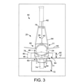
ここで図3~図4を参照すると、作業領域50の代替的な実施形態が図示されている。作業領域50は、床57に形成された床ピット72を含み、且つ床ピット72は、作業領域50の長さL-L(図2に示す)にわたって延在するように構成される。追加的に、床ピット72は、ピットガントリー74に動作可能に取り付けられる少なくとも1つの表面処理支持構造アセンブリ60を支持し移動させるように構成されたピットガントリー74を含む。一般に、ピットガントリー74は、床ピット72の底部から上方に延伸するように構成されるとともに、各表面処理支持構造アセンブリ60の取付支柱64に対して1つ又は複数の取付点76を提供する。更に、ピットガントリー74は、胴体24の外形表面48を処理しながら1つ又は複数の表面処理支持構造アセンブリ60を床ピット72の長さL-L(図2)に沿って移動させることが可能であるように、床ピット72内に配置された基底構造に取り付けられる。いくつかの実施形態において、ピットガントリー74は、胴体24又はビークル20の他の構成要素の下側に沿って外形表面48を処理するように位置決めされる1つ又は複数の表面処理支持構造アセンブリ60を支持する。しかしながら、ピットガントリー74及び1つ又は複数の表面処理支持構造アセンブリ60は、必要に応じて1つ又は複数の表面処理支持構造アセンブリ60を外形表面48に沿って位置決めするように調整可能である。
Here, with reference to FIGS. 3-4, an alternative embodiment of the
更に図3~図4に示すように、オーバーヘッドガントリー62及びピットガントリー74は両方とも、少なくとも1つの表面処理支持構造アセンブリ60に動作可能に結合するための少なくとも1つの取付点76を有するように構成される。いくつかの実施形態において、オーバーヘッドガントリー62及びピットガントリー74の各々は、2つ以上の表面処理支持構造アセンブリ60に動作可能に結合され、且つ各表面処理支持構造アセンブリ60は、表面処理支持構造アセンブリアレイ77を形成するように胴体24の外形表面48に隣接して位置決めされる。非限定的な一例において、複数の表面処理支持構造アセンブリアレイ77は、胴体24の外形表面48を実質的に取り囲む(すなわち、周方向に取り囲む)ように配設される。結果として、表面処理層51(図2)は、ピットガントリー74及びオーバーヘッドガントリー62が胴体24に沿って移動するときに外形表面48に周方向に施される。ピットガントリー74及びオーバーヘッドガントリー62は、互いに個別に制御され動作させられる。しかしながら、非限定的な一例において、ピットガントリー74及びオーバーヘッドガントリー62は、胴体24に沿って同時に移動して外形表面48を処理するように同期される。代替的な実施形態において、ピットガントリー74及びオーバーヘッドガントリー62は、互い違いに位置決めされるとともに、これらガントリーが胴体24に沿って移動するときに外形表面48の異なる部分を処理する。その上、更に追加の実施形態では、ピットガントリー74又はオーバーヘッドガントリー62の一方が静止位置に維持され、その間、ピットガントリー74又はオーバーヘッドガントリー62の他方を胴体24の外形表面48に沿って移動させる。
Further, as shown in FIGS. 3-4, both the
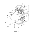
追加的に、ピットガントリー74及びオーバーヘッドガントリー62は、ビークル20及び作業領域50の構成要素との干渉を最小限に抑えるために、複数の表面処理支持構造アセンブリアレイ77を位置決めする。図4に図示するように、オーバーヘッドガントリー62及びピットガントリー74は各々、2つの表面処理支持構造アセンブリアレイ77を有するように構成され、各表面処理支持構造アセンブリアレイ77は、4つの表面処理支持構造アセンブリ60を含む。しかしながら、表面処理支持構造アセンブリアレイ77の各々において他の数及び構成の表面処理支持構造アセンブリ60も可能である。
In addition, the
非限定的な一例において、垂直安定翼42と、水平安定板44と、他の何らかの構成要素とを含む、尾部セクション28は、外形表面48の表面処理の際に胴体24に取り付けられる。ピットガントリー74及びオーバーヘッドガントリー62に取り付けられた複数の表面処理支持構造アセンブリアレイ77は、垂直安定翼42及び他のビークル20構成要素との干渉を最小限に抑える(すなわち、これらとの接触を避ける)ように配設される。その上、複数の表面処理支持構造アセンブリアレイ77は、ピットガントリー74が尾部セクション28を通り過ぎるときに、ピットガントリー74に取り付けられた複数の表面処理支持構造アセンブリ60が水平安定板44の真下を通過するように配設される。更に、複数の表面処理支持構造アセンブリアレイ77は、オーバーヘッドガントリー62が尾部セクション28を通り過ぎるときに、オーバーヘッドガントリー62に取り付けられた複数の表面処理支持構造アセンブリ60が垂直安定翼42の両側を通過するように配設される。図3は、尾部セクション28とピットガントリー74とオーバーヘッドガントリー62と複数の表面処理支持構造アセンブリアレイ77との相互作用を図示しているが、ピットガントリー74、オーバーヘッドガントリー62及び複数の表面処理支持構造アセンブリ60がまた、限定されるものではないが、各翼部26及び推進ユニット30及び他のかかる構成要素(図1を参照)などの、ビークル20の他の構成要素との干渉を最小限に抑えるように構成されることが理解される。
In a non-limiting example, the
更に、ピットガントリー74及びオーバーヘッドガントリー62は、ビークル中央支持構造56、ビークル機首支持構造54(図2)並びに作業領域50内に存在する他の構造及び設備との干渉を最小限に抑える(すなわち、これらとの接触を避ける)ために、複数の表面処理支持構造アセンブリ60を位置決めする。上で説明したように、ビークル中央支持構造56及びビークル機首支持構造54(図2)などの支持構造は、作業領域50に位置するとともに、外形表面48の表面処理の際に胴体24及びビークル20の他の構成要素を支持するように構成される。非限定的な一例において、ビークル中央支持構造56は、床57に略平行であるとともに胴体24の下側部分を支持する水平部分78を含む。ビークル中央支持構造56の水平部分78は、胴体24から離れる方向に、作業領域50の床57に支持されるか又は別様に固定されるビークル中央支持構造56の垂直部分80に短手方向に延伸する。その上、ビークル中央支持構造56の垂直部分80は、床ピット72の短手方向外側に位置決めされるとともに、ビークル中央支持構造56の領域84が胴体24の真下のビークル中央支持構造56の水平部分78及び垂直部分80により画定されるような高さ82を有するように構成される。ビークル中央支持構造56の領域84は、ピットガントリー74及び複数の表面処理支持構造アセンブリアレイ77が外形表面48の表面処理の際にビークル中央支持構造56を通過するときにピットガントリー74及び複数の表面処理支持構造アセンブリアレイ77に対して間隙を提供するように構成される。その上、オーバーヘッドガントリー62及び複数の表面処理支持構造アセンブリアレイ77は、これらが胴体24の外形表面48に沿って移動するときにビークル中央支持構造56との干渉を避けるように配置されて位置決めされる。
In addition, the
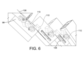
図5を参照すると、例示的な表面処理支持構造アセンブリ60の拡大部分が示されている。表面処理支持構造アセンブリ60は、9つの基部構造86を含む基部構造アレイ88を形成するために互いに動作可能に結合される複数の基部構造86を含む。しかしながら、代替的な数の基部構造86も可能である。追加的に、表面処理支持構造アセンブリ60は、第1のアーム端部92において基部構造アレイ88に結合され且つ第2のアーム端部94において取付支柱64に結合される少なくとも2つの取付アーム90を含む。いくつかの実施形態において、取付アームアクチュエーター95は、少なくとも第1の位置(すなわち、第1の湾曲部)と第2の位置(すなわち、第2の湾曲部)との間で基部構造アレイ88を操作するために取付アーム90が調整されるか又は別様に連接されるように、第2のアーム端部94及び取付支柱64に動作可能に結合される。例えば、図5において、取付アーム90は、各取付アーム90の第1のアーム端部92が互いに離間して広がるように調整され、その結果、基部構造アレイ88が展開位置にあり且つV字状構成で配設される。しかしながら、基部構造アレイ88の他の形状及び配置も可能である。追加的に、図5には2つの取付アーム90が図示されているが、複数の基部構造86を支持し連接するために代替数及び代替構成の取付アーム90が可能であることが理解される。
Referring to FIG. 5, an enlarged portion of an exemplary surface-treated
その上、取付アーム90の各々は、第1のアーム端部92における第1の回転継手96と、第2のアーム端部94における第2の回転継手98とを含む。いくつかの実施形態において、取付アーム90の各々はアーム長手方向軸線100を有し、第1の回転継手96の各々は第1の継手軸線102を有し、且つ第2の回転継手98の各々は第2の継手軸線104を有する。結果として、表面処理支持構造アセンブリ60は、外形表面48若しくは胴体24、又はビークル20の他の構成要素(図1)に沿って遭遇する様々な表面幾何学形状又は輪郭(すなわち、拡径部/縮径部及び凸面/凹面)と一致してこれらに追従するように、複数の軸線を中心に調整可能とされる。例えば、いくつかの実施形態において、第1の継手軸線102は、胴体24及びビークル20の他のかかる構成要素の外形表面48に対して複数の基部構造86を調整するために第1の回転継手96がアーム長手方向軸線100と第1の継手軸線102との両方を中心に回転するようにアーム長手方向軸線100に直交する向きに配置される。追加的に、第2の回転継手98は、基部構造アレイ88が外形表面48に対して適切な向き(すなわち、垂直な向き)を維持するように表面処理支持構造アセンブリ60が少なくとも第1の位置と第2の位置との間で調整可能となるように複数の基部構造86を更に調整し位置決めするためにアーム長手方向軸線100及び第2の継手軸線104を中心に回転する。
Moreover, each of the mounting
更に、基部構造アレイ88に含まれる複数の基部構造86の各々は、外形表面48に対して基部構造86の各々を個別に調整するための1つ又は複数の調整装置を有するように構成される。例えば、各基部構造86は、基部構造アレイ88の基部構造86の各々が外形表面48に対して適切な位置決め(すなわち、垂直な向き及び距離)を維持するように個別に調整可能である。図6に図示するように、引き続き図5を参照するに、基部構造86の各々は、互いに動作可能に結合されるとともに、長手方向スロット108又は各基部構造86の一部分に沿って形成された他のかかる開口により画定された基部構造長手方向軸線106に沿って摺動するように構成される。追加的に、各基部構造86は、限定されるものではないが、リニアアクチュエーター、ラジアルアクチュエーター、又は任意の他の既知のかかる作動装置などの、少なくとも1つの基部構造アクチュエーター110を有するように構成される。非限定的な一例において、各基部構造86は、基部構造長手方向軸線106に沿って各基部構造86を摺動させるように、基部構造長手方向軸線106を中心に各基部構造86を回転させるように、又は基部構造86の他のかかる作動のために構成された複数の基部構造アクチュエーター110を含む。例えば、複数の基部構造アクチュエーター110の少なくとも1つは、基部構造アレイ88を展開させる及び/又は折り畳むために表面処理支持構造アセンブリ60が少なくとも第1の位置と第2の位置との間に連接される場合に複数の各基部構造86を摺動させるリニアアクチュエーター装置として構成される。更に、複数の基部構造アクチュエーター110の少なくとも1つは、基部構造枢支点112を中心に回転するように構成された回転アクチュエーターとして構成される。いくつかの実施形態において、各基部構造86は、胴体24又はビークル20の他の構成要素の外形表面48に対して各基部構造86の適切な距離及び垂直な向きを維持するために、外形表面48の凹凸形状に基づいて回転作動させられる。
Further, each of the plurality of
表面処理支持構造アセンブリ60及び個々の各基部構造86の作動及び調整は、外形表面48に沿って遭遇する複雑な幾何学形状及び外形に対する多様な弾性応答を可能にする。更に図5に示すように、表面処理支持構造アセンブリ60のいくつかの実施形態は、基部構造86の各々に装着されるか又は別様に結合される少なくとも1つのセンサー114を含む。センサー114は、表面輪郭及び外形表面48を走査して表面輪郭のデータ及び外形表面48の他のかかるデータを収集するように構成され、且つ収集されたデータは、表面処理支持構造アセンブリ60の作動及び調整に使用される。限定されるものではないが、視覚センサー(すなわち、カメラ)、レーザー走査型の凹凸形状/表面高度検知センサー(すなわち、LIDAR)、及び他のかかる表面計測センサーなどの、センサー114は、基部構造86の各々が外形表面48に対して垂直な向き及び距離を維持するように、外形表面48の凹凸形状及び他の幾何学形状を走査し監視するように構成される。その上、複数の表面処理支持構造アセンブリ60の連続的な作動及び調整は、外形表面48を処理するのに必要とされる時間量を低減するのみならず、表面処理層51を施す上での精度の向上をもたらす。
The operation and adjustment of the surface-treated
再び図4を参照すると、複数の表面処理支持構造アセンブリアレイ77が、オーバーヘッドガントリー62及びピットガントリー74に取り付けられた状態で示されている。いくつかの実施形態において、複数の基部構造アレイ88を含む、表面処理支持構造アセンブリアレイ77は、胴体24の外形表面48を処理するように構成される。その上、個々の各基部構造86は、限定されるものではないが、研磨リング、塗料ノズル、インクジェットプリントヘッド、乾燥/硬化及び検査リング、ヒーター、UVエミッター、並びに他の既知のアプリケーターヘッドなどの少なくとも1つの表面処理アプリケーターヘッド116を保持し位置決めするようになされる。更に、いくつかの実施形態において、各表面処理アプリケーターヘッド116及び基部構造86は、個々の基部構造86に取り付けられる表面処理アプリケーターヘッド116のタイプが所望の表面処理によって決まるように交換可能に構成される。
Referring to FIG. 4 again, a plurality of surface-treated support
例えば、外形表面48を洗浄し研磨するために、各基部構造86に取り付けられる表面処理アプリケーターヘッド116は研磨リングであり、その一方で、プライマー、接着促進剤、ベースコート、及び/又はクリアコート層を外形表面48に施すために、各基部構造86に取り付けられる表面処理アプリケーターヘッド116は塗料ノズルである。更に、外形表面48に装飾的塗装コーティングを施すために、各基部構造86に取り付けられる表面処理アプリケーターヘッド116はインクジェットプリントヘッドであり、且つ外形表面48を乾燥/硬化させ外形表面48に沿って表面処理を検査するために、各基部構造86に取り付けられる表面処理アプリケーターヘッド116は乾燥/硬化及び検査リングである。研磨リング、塗料ノズル、インクジェットプリントヘッド、並びに乾燥/硬化及び検査リング、ヒーター、UVエミッター、及び他の既知のアプリケーターヘッドが、基部構造アレイ88に装着されるか又は別様に取り付けられる表面処理アプリケーターヘッド116の非限定的な例であることが理解される。他の既知の表面処理アプリケーターヘッド116は、所望の作業を完了するために複数の表面処理支持構造アセンブリ60により使用される。更に、いくつかの実施形態において、複数の表面処理支持構造アセンブリアレイ77及び/又は基部構造アレイ88は、種々の表面処理(すなわち、洗浄、研磨、下塗り、塗装、保護、硬化、検査、又は修理)のために組み立てられ、且つこれらアレイは、個々の表面処理アプリケーターヘッド116の代わりに、所望の表面処理に応じて交換される。いくつかの実施形態において、表面処理層51は、単一の表面コーティングで構成され、且つ外形表面48に沿った1回の通過で供給される。しかしながら、外形表面48に沿って表面処理層51を施すために、必要に応じて、追加回数の通過が実施される。非限定的な一例において、複数の表面処理支持構造アセンブリアレイ77は、表面処理層51を形成するために組み合わされる複数の処理及びコーティングを外形表面48に施すように構成される。表面処理支持構造アセンブリアレイ77及び選択された表面処理アプリケーターヘッド116は、胴体24の外形表面48に沿って1つの処理又はコーティングを1回で行う。結果として、表面処理支持構造アセンブリ60は、表面処理層51
を構成する複数のコーティングの各々を供給するために1回以上通過する。代替的に、2つ以上の表面処理支持構造アセンブリ60は、2つ以上の表面処理支持構造アセンブリ60の各々が表面処理層51を構成する複数のコーティングを供給するために胴体24の外形表面48に沿って移動するときに各々単一のコーティングを施すように構成される。
For example, the surface
Pass one or more times to supply each of the multiple coatings that make up the. Alternatively, the two or more surface treated
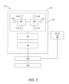
引き続き図2~図6を参照するに、図7は、オーバーヘッドガントリー62、ピットガントリー74及び少なくとも1つの表面処理支持構造アセンブリ60を動作させるように構成される制御及び通信システム118の概略図を図示している。制御及び通信システム118は、コントローラー120と、コントローラー120に通信可能に結合される入力/出力端末122とで構成される。更に、コントローラー120は、オーバーヘッドガントリー62、ピットガントリー74、及び表面処理支持構造アセンブリ60の動きを制御するようにプログラムされる。追加的又は代替的に、表面処理支持構造アセンブリ60は、作業領域50を動き回るように構成された1つ又は複数のAGV52に取り付けられる。このような場合、コントローラー120は、AGV52、表面処理支持構造アセンブリ60及び任意の他のかかる構成要素の動きを制御するようにプログラムされる。更に、コントローラー120は、基部構造アレイ88の各基部構造86及び複数の表面処理アプリケーターヘッド116の位置を監視し調整するようにプログラムされる。いくつかの実施形態において、コントローラー120及び入力/出力端末122は、作業領域50(図2)から遠く離れて位置する。結果として、コントローラー120、入力/出力端末122、表面処理支持構造アセンブリ60、並びに制御及び通信システム118の他のかかる構成要素の間の通信は、無線周波数ネットワーク、コンピューターデータネットワーク、Wi-Fiデータネットワーク、セルラーデータネットワーク、衛星データネットワーク、又は任意の他の既知のデータ通信ネットワークを使用して確立される。代替的に、コントローラー120及び入力/出力端末122は、作業領域50(図2)に近接して位置するように且つ表面処理支持構造アセンブリ60に隣接する位置に設置されるように構成される。近接して位置する構成において、コントローラー120及び入力/出力端末122はやはり、無線周波数ネットワーク、コンピューターデータネットワーク、Wi-Fiデータネットワーク、セルラーデータネットワーク、衛星データネットワーク、又は任意の他の既知の通信ネットワークを使用して通信するように構成される。
Continuing with reference to FIGS. 2-6, FIG. 7 illustrates a schematic of the control and
作業者、監督者、又は他の関係者などの、制御及び通信システム118の使用者は、入力/出力端末122を使用してコントローラー120にアクセスすることができる。いくつかの実施形態において、入力/出力端末122は、キーボード、マウス、ダイヤル、ボタン、タッチスクリーン、マイクロフォン、又は他の既知の入力装置を通じてコマンド及び他の命令が入力されることを可能にする。更に、制御及び通信システム118並びにコントローラー120により生成されたデータ及び他の情報は、モニター、タッチスクリーン、スピーカー、プリンター、又は使用者のための他の既知の出力装置を通じて入力/出力端末122に出力される。いくつかの実施形態において、入力/出力端末122は、有線接続によりコントローラー120に通信可能に結合される。代替的に、入力/出力端末122は、ブルートゥース(登録商標)、近距離無線通信、無線周波数ネットワーク、コンピューターデータネットワーク、Wi-Fiデータネットワーク、セルラーデータネットワーク、衛星データネットワーク、又は任意の他の既知のデータ通信ネットワークなどの無線通信ネットワークを通じてコントローラー120に通信可能に結合される。いくつかの実施形態において、入力/出力端末122は、タブレット型コンピューター、スマートフォン装置、又は他のかかるモバイル装置などの、可搬型モバイル装置であり、且つ可搬型モバイル装置は、コントローラー120に無線で結合される。結果として、制御及び通信システム118の1人又は複数の使用者は、コントローラー120にアクセスすることができ、各使用者は、コントローラー120及び/又は表面処理支持構造アセンブリ60から離れた場所に位置する異なる可搬型入力/出力端末122を有する。このような構成は、胴体24の外形表面48の処理の際に制御システム及び通信システム118を監視し動作させる上での融通性を実現する。
Users of the control and
いくつかの実施形態において、制御及び通信システム118のコントローラー120は、使用者が表面処理支持構造アセンブリ60を導き且つ制御することを可能にする制御機構及び/又はソフトウェアを実行することが可能である1つ又は複数の計算装置で構成される。コントローラー120の1つ又は複数の計算装置は、胴体24の外形表面48に沿って少なくとも1つの表面処理支持構造アセンブリ60を移動させ且つ位置決めするために、オーバーヘッドガントリー62、ピットガントリー74、表面処理AGV52、又は他の移動装置の動きを制御するようにプログラムされる。更に、コントローラー120の1つ又は複数の計算装置は、外形表面48に対して表面処理支持構造アセンブリ60を適切に位置決めするために、表面処理支持構造アセンブリ60の作動及び調整を制御するようにプログラムされる。制御及び通信システム118の例示的な一用途において、使用者は、外形表面48に沿って表面処理層51又は他のかかる処理を施しながら表面処理支持構造アセンブリ60が従うパターン又は工程をプログラムするために、コントローラー120及び入力/出力端末122を使用することができる。更に、通信ネットワークを使用してコントローラー120と入力/出力端末122と表面処理支持構造アセンブリ60とを通信可能に結合することにより、コントローラー120により送られたコマンドが表面処理支持構造アセンブリ60により受信され且つ表面処理支持構造アセンブリ60により収集されたデータがコントローラー120に送られてコントローラー120により受信されるような双方向通信が可能となる。
In some embodiments, the
実施形態において、限定されるものではないが、視覚センサー(すなわち、カメラ)、レーザー走査型の凹凸形状/表面高度検知センサー(すなわち、LIDAR)、及び他のかかる表面計測センサーなどの、少なくとも1つのセンサー114は、表面処理支持構造アセンブリ60に組み込まれるとともに、コントローラー120及び入力/出力端末122に通信可能に結合される。いくつかの実施形態において、表面処理支持構造アセンブリ60の各基部構造86は、外形表面48の表面凹凸形状及び他の幾何学形状を走査し監視するように構成されたセンサー114を含む。センサー114により収集されたデータは、コントローラー120に送信されてコントローラー120により利用される。更に、コントローラー120は、複数のセンサー114により収集されたデータを記憶し、解析し、これらデータから情報を抽出し、且つ個々の基部構造86のみならず表面処理支持構造アセンブリ60を制御し調整するために抽出された情報を使用する。
In embodiments, at least one, such as, but not limited to, a visual sensor (ie, a camera), a laser-scanning concavo-convex shape / surface altitude detection sensor (ie, LIDAR), and other such surface measurement sensors. The
更に、少なくとも1つのセンサー114及びコントローラー120が動作可能に結合され、このことにより、限定されるものではないが、胴体24の湾曲部の変化を検出する、外形表面48の画像及び視覚データを収集する、外形表面48の凹凸形状図及び表面輪郭を提供する、表面処理支持構造アセンブリ60の位置決め及び位置データを提供する、並びに少なくとも1つのセンサー114により収集された任意の他のかかる表面データを提供するなど、外形表面48に関するデータを収集するために、センサー114及びコントローラー120が協働できるようなる。そして、収集されたデータは、コントローラー120の制御機構及び/又はソフトウェアが、オーバーヘッドガントリー62、ピットガントリー74、表面処理支持構造アセンブリ60、個々の基部構造86、及び他のかかる構成要素の制御及び動作の調整を行うためにデータを利用できるように、少なくとも1つのセンサー114により送信されてコントローラー120により受信される。追加的に、使用者は、入力/出力端末122における少なくとも1つのセンサー114により収集されたデータを確認することができ、且つ必要であれば、コントローラー120から、オーバーヘッドガントリー62、ピットガントリー74、表面処理支持構造アセンブリ60、個々の基部構造86、及び他のかかる構成要素に送られた制御コマンドの調整を行うことができる。いくつかの実施形態において、制御及び通信システム118は、表面処理支持構造アセンブリ60と制御及び通信システム118との間に確立された双方向通信リンクを通じて、オーバーヘッドガントリー62、ピットガントリー74、表面処理支持構造アセンブリ60、個々の基部構造86、及び他のかかる構成要素のリアルタイム調整を行うことが可能である。
In addition, at least one
ここで図8を参照するとともに、引き続き先の図1~図7を参照するに、表面処理支持構造アセンブリ60を用いて外形表面48を処理する例示的な表面処理方法又は工程124を図示するフローチャートが図示されている。表面処理支持構造アセンブリ60を用いて外形表面48を処理する方法124の第1のブロック126では、胴体24などの、外形表面48を有する構造を作業領域50内での表面処理のために適所に移動させる。非限定的な一例において、胴体24は、1つ又は複数のAGV52により作業領域50内に移送され、且つビークル機首支持構造54、ビークル中央支持構造56、又は他の支持構造へと搬送される。表面処理の際に、胴体24は、機首支持構造54及びビークル中央支持構造56、1つ又は複数のAGV52、並びに必要とされ得る他の支持構造により支持される。
Here, with reference to FIG. 8 and continuing with reference to FIGS. 1-7, a flow chart illustrating an exemplary surface treatment method or step 124 for treating the
非限定的な一例において、表面処理は、外形表面48上の何らかの保護コーティング又は予め施されたコーティングの除去と、外形表面48の処理すべきでない特定の領域をマスキングすることと、外形表面48を研磨し、洗浄し、且つ乾燥させることと、表面保護コーティング、接着促進コーティング、プライマーコーティング、ベースコートコーティング、ゾルゲルコーティング、最上層コーティング、装飾的塗装コーティング、クリアコーティング、及び/若しくは他の保護コーティング並びに/又は準備処理を施すこととを含む。更に、外形表面48の処理の開始前に、次のブロック128では、少なくとも1つの表面処理支持構造アセンブリ60が、作業領域50内に位置決めされるとともに、胴体24の外形表面48に沿って調整され位置合わせされる。非限定的な一例において、複数の表面処理支持構造アセンブリ60は、オーバーヘッドガントリー62及び/又はピットガントリー74に取り付けられる1つ又は複数の表面処理支持構造アセンブリアレイ77内に配設される。その上、複数の表面処理支持構造アセンブリアレイ77の調整及び位置合わせの際に、少なくとも1つのセンサー114は、表面処理支持構造アセンブリアレイ77に取り付けられるとともに、外形表面48を走査して外形表面48の表面凹凸形状データを収集するように構成される。次いで、表面凹凸形状データ又は外形データセットは、制御及び通信システム118のコントローラー120に送信されてコントローラー120により受信され、且つ外形表面48に対する表面処理支持構造アセンブリアレイ77のコマンド及び制御パラメータを調整するために利用される。
In a non-limiting example, the surface treatment removes any protective or pre-applied coating on the
次のブロック130に従って、外形表面48の何らかの表面処理前に、個々の各基部構造86のみならず表面処理支持構造アセンブリ60の1つ又は複数の表面処理支持構造アセンブリアレイ77が外形表面48に対して適切に調整され位置合わせされることを確認するために、調整点検が実施される。いくつかの実施形態において、調整点検は、外形表面48と各基部構造86との間の適切な距離又は隙間の確認を含む。追加的に、調整点検は、各基部構造86が外形表面48に対して垂直な及び直交する向きにあることを確認する。外形表面48に対して表面処理支持構造アセンブリ60の各基部構造86を適切に調整し位置合わせすることができないことにより、表面処理層51が不均一に施されること、又は他のかかる表面処理欠陥などの、不完全な表面処理がもたらされる。それゆえ、検査が、コントローラー120に入力され記憶される所定の一連の調整基準を満たさない場合に、表面処理支持構造アセンブリ60は、何らかの調整エラーを修正するために1つ又は複数の表面処理支持構造アセンブリアレイ77及び各基部構造86の調整を続ける。いくつかの実施形態において、表面処理アセンブリの操作者又は他の使用者には、調整エラーが通知され、表面処理支持構造アセンブリ60の必要な調整及び位置合わせを行うように指示が与えられる。
According to the
表面処理支持構造アセンブリ60が適切に調整され位置合わせされた時点で、次のブロック132において、表面処理支持構造アセンブリ60が外形表面48の所望の処理を開始する。いくつかの実施形態において、表面処理支持構造アセンブリ60の基部構造86の各々は、限定されるものではないが、研磨リング、塗料ノズル、インクジェットプリントヘッド、乾燥/硬化及び検査リング、ヒーター、UVエミッター、並びに他の既知のアプリケーターヘッドなどの、少なくとも1つの表面処理アプリケーターヘッド116に交換可能に結合される。表面処理アプリケーターヘッド116は、外形表面48の所望の表面処理に基づいて選択される。典型的には、表面処理支持構造アセンブリ60は、ビークル20の尾部セクション28において外形表面48の処理を開始し、胴体24に沿って機首部分46に向かって移動する。代替的に、表面処理支持構造アセンブリ60は、尾部セクション28と機首部分46との間の中間位置において位置合わせされ調整され、且つ表面処理支持構造アセンブリ60は、導かれた場所で外形表面48の表面処理を実施する。
When the surface-treated
次のブロック134では、表面処理支持構造アセンブリ60が外形表面48に沿って移動し続け、且つ少なくとも1つのセンサー114が外形表面48の凹凸形状を走査して外形表面48の凹凸形状のデータを収集し続ける。いくつかの実施形態において、センサー114により収集されたデータは、表面処理支持構造アセンブリ60が外形表面48に沿って移動するときに表面処理支持構造アセンブリ60のリアルタイム調整を行うために、コントローラー120により利用される。例えば、表面処理支持構造アセンブリ60の各基部構造86は、外形表面48に対する垂直な及び直交する向きを維持するために連続的に調整される。更に、コントローラー120は、表面処理支持構造アセンブリ60が胴体24の外形表面48に沿って移動し続けるときに、少なくとも1つのセンサー114により収集された表面凹凸形状データを解析し続ける。
In the
結果として、次のブロック136において、コントローラー120を含む、制御及び通信システム118は、表面処理支持構造アセンブリ60の各基部構造86が、外形表面48に対して適切に調整され、位置合わせされ、且つ正しい向きに配置されることを確認するために調整点検を連続的に実施する。いくつかの実施形態において、基部構造86の1つ又は複数が調整されていない、位置合わせされていない、及び/又は正しい向きに配置されていない場合に、コントローラー120は、基部構造86の各々を調整又は再調整するために調整制御信号を表面処理支持構造アセンブリ60に送信する。次のブロック138において、1つ又は複数の基部構造86が位置合わせされていない状態であると判定された場合には、表面処理支持構造アセンブリ60は、再調整を実施するために胴体24の外形表面48に沿った移動を停止する。いくつかの実施形態において、外形表面48を処理する方法124は、表面処理支持構造アセンブリ60の基部構造86の再調整のためにブロック136に戻る。代替的な実施形態において、表面処理支持構造アセンブリ60は、基部構造86の再調整及び再位置合わせを実施するために外形表面48に沿ってより遅いペースで移動する。
As a result, in the
表面処理支持構造アセンブリ60が連続的な調整、位置合わせ、及び配向の点検に合格したならば、次のブロック140において、表面処理支持構造アセンブリ60が外形表面48に沿って移動し続ける。次のブロック142において、表面処理支持構造アセンブリ60が、機首部分46、又は胴体24に沿った他の所定の停止点に到達したときに、コントローラー120は、別の表面処理が必要であるかどうかの判定を行う。別の処理が必要である場合に、非例示的な一例では、外形表面48を処理する方法124がブロック128に戻り、且つ適切な表面処理アプリケーターヘッド116が各基部構造86に結合され、且つ表面処理支持構造アセンブリ60が、指定された開始位置(すなわち、機首部分46、尾部セクション28又は代替的な所定の開始点)に位置決めされるとともに、胴体24の外形表面48に沿って次の表面処理の準備をする。いくつかの実施形態では、同じ表面処理支持構造アセンブリ60がその後の表面処理に使用され、且つ表面処理アプリケーターヘッド116が所望の表面処理に応じて交換される。代替的に、その後の表面処理は、所望の表面処理アプリケーターヘッド116を有するように構成された1つ又は複数の追加の表面処理支持構造アセンブリ60を使用して外形表面48に対して実施される。所望の表面処理の全てが外形表面48に対して実施された時点で、次のブロック144において、表面処理方法124が終了し、胴体24が次の製造又は保守点検ステップへ移される。
If the surface-treated
さらに本開示は以下の例を含む。
第A1項. 外形表面を処理するための表面処理支持構造アセンブリであって、前記表面処理支持構造アセンブリが、複数の基部構造で形成された支持構造アレイであって、各基部構造が、互いに動作可能に結合されるとともに、長手方向軸線に沿って摺動し且つ前記長手方向軸線に直交する短手方向平行移動軸線を中心に回転する、支持構造アレイと;前記支持構造アレイの各基部構造に結合された少なくとも1つのアプリケーターヘッドであって、前記少なくとも1つのアプリケーターヘッドの各々が前記外形表面を処理するよう構成された、少なくとも1つのアプリケーターヘッドと、各基部構造に動作可能に結合されるとともに、前記支持構造アレイが前記外形表面に対して調整されるように前記長手方向軸線及び前記短手方向平行移動軸線に沿って各基部構造を操作するよう構成された、基部構造アクチュエーターとを備える、表面処理支持構造アセンブリ。
第A2項. 外形表面を処理するための表面処理支持構造アセンブリであって、前記表面処理支持構造アセンブリが、各それぞれの基部構造内に部分的に配置されたそれぞれの基部構造アクチュエーターを備えた複数の基部構造から形成された支持構造アレイであって、前記複数の基部構造における第1の基部構造が、前記複数の基部構造における第2の基部構造に対して第1の基部構造アクチュエーターを介して結合され、且つ、前記第1の基部構造アクチュエーターからの作動に応答して前記第1の基部構造の一部に沿って形成された長手方向軸線に沿って摺動し且つ前記長手方向軸線に直交する短手方向平行移動軸線を中心に回転するよう構成された、支持構造アレイと;前記支持構造アレイの各基部構造に結合された少なくとも1つのアプリケーターヘッドであって、前記少なくとも1つのアプリケーターヘッドの各々が前記外形表面を処理するよう構成された、少なくとも1つのアプリケーターヘッドと;前記複数の基部構造アクチュエーターであって、前記複数の基部構造アクチュエーターにおける少なくとも1つの基部構造アクチュエーターは、各基部構造に動作可能に結合されるとともに、前記支持構造アレイを形成する前記基部構造が前記外形表面に対して個々に調整されるように前記長手方向軸線及び前記短手方向平行移動軸線に沿って前記複数の基部構造における各基部構造を操作するよう構成された、複数の基部構造アクチュエーターとを備える、表面処理支持構造アセンブリ。
第A3項. 前記支持構造アレイが第1の取付アーム及び第2の取付アームに動作可能に結合され、且つ前記第1の取付アーム及び前記第2の取付アームが、第1の外形形状と第2の外形形状との間で前記支持構造アレイを調整するために操作される取付アームアクチュエーターを更に含む、第A1項又は第A2項に記載の表面処理支持構造アセンブリ。
第A4項. 前記第1の外形形状が第1の湾曲部を備え、且つ前記第2の外形形状が第2の湾曲部を備える、第A3項に記載の表面処理支持構造アセンブリ。
第A5項. 前記第1の取付アームが第1の基部構造継手を備え、且つ前記第2の取付アームが第2の基部構造継手を備え、且つ前記第1の基部構造継手及び第2の基部構造継手の各々が、前記支持構造アレイに回転可能に結合されるとともに、第1の取付アーム軸線、第1の基部構造継手軸線、第2の取付アーム軸線、及び第2の基部構造継手軸線を中心にそれぞれ回転するように構成される、第A3項又は第A4項に記載の表面処理支持構造アセンブリ。
第A6項. 前記第1の取付アームが第1の取付支柱継手を更に備え、且つ前記第2の取付アームが第2の取付支柱継手を更に備え、且つ前記第1の支柱継手及び前記第2の支柱継手の各々が、支持支柱に回転可能に取り付けられるとともに、それぞれの前記第1の取付アーム軸線及び前記第2の取付アーム軸線を中心に回転するように構成される、第A5項に記載の表面処理支持構造アセンブリ。
第A7項. 前記外形表面の既存の形状を検出し外形データセットを生成する、各基部構造に結合されたセンサーを更に備える、第A3項ないし第A6項のいずれか1項に記載の表面処理支持構造アセンブリ。
第A8項. 前記センサーと前記基部構造アクチュエーターと前記取付アームアクチュエーターとに通信可能に結合されたコントローラーを更に備え、前記コントローラーが、前記センサーから信号を受信するように且つ前記外形データセットに基づいて前記支持構造アレイを操作するために前記基部構造アクチュエーター及び前記取付アームアクチュエーターを制御するようにプログラムされる、第A7項に記載の表面処理支持構造アセンブリ。
第A9項. 前記少なくとも1つのアプリケーターヘッドが、前記外形表面に表面処理を施す、研磨ヘッド、検査ヘッド、ヒーター、UVエミッター、噴射ノズル、及びインクジェット印刷ヘッドのうちの1つを含む、第A1項ないし第A8項のいずれか1に記載の表面処理支持構造アセンブリ。
第B1項. 表面処理支持構造アセンブリを用いて外形表面を処理する方法であって、前記方法が、複数の基部構造から支持構造アレイを形成するステップであって、各基部構造が、互いに動作可能に結合されるとともに、長手方向軸線に沿って摺動し且つ前記長手方向軸線に直交する短手方向平行移動軸線を中心に回転する、ステップと;少なくとも1つのアプリケーターヘッドを前記支持構造アレイの各基部構造に結合するステップであって、前記少なくとも1つのアプリケーターヘッドの各々が前記外形表面に表面処理を施すよう構成される、ステップと;基部構造アクチュエーターを各基部構造に結合するとともに、前記支持構造アレイが前記外形表面に対して調整されるように前記長手方向軸線及び前記短手方向平行移動軸線に沿って各基部構造を操作するステップとを含む方法。
第B2項. 表面処理支持構造アセンブリを用いて外形表面を処理する方法であって、前記方法が、各それぞれの基部構造内に部分的に配置されたそれぞれの基部構造アクチュエーターを備えた複数の基部構造から支持構造アレイを形成するステップであって、前記複数の基部構造における第1の基部構造が、前記複数の基部構造における第2の基部構造に対して第1の基部構造アクチュエーターを介して結合され、且つ、前記第1の基部構造アクチュエーターからの作動に応答して前記第1の基部構造の一部に沿って形成された長手方向軸線に沿って摺動し且つ前記長手方向軸線に直交する短手方向平行移動軸線を中心に回転するよう構成され、前記第1の基部構造は前記第2の基部構造から個々に調整可能であるステップと;少なくとも1つのアプリケーターヘッドを前記支持構造アレイの各基部構造に結合するステップであって、前記少なくとも1つのアプリケーターヘッドの各々が前記外形表面に表面処理を施すよう構成されるステップと;前記複数の基部構造アクチュエーターを前記複数の基部構造に結合するステップであって、前記複数の基部構造アクチュエーターにおける少なくとも1つの基部構造アクチュエーターは、各基部構造に動作可能に結合されるとともに、前記支持構造アレイを形成する前記基部構造が前記外形表面に対して個々に調整されるように前記長手方向軸線及び前記短手方向平行移動軸線に沿って各基部構造を操作するよう構成されるステップとを含む方法。
第B3項. 前記支持構造アレイが第1の取付アーム及び第2の取付アームに動作可能に結合され、且つ前記支持構造アレイを調整するステップが、第1の外形形状と第2の外形形状との間で前記支持構造アレイを調整するために取付アームアクチュエーターを作動させるステップを含む、第B1項または第B2項に記載の方法。
第B4項. 前記第1の外形形状と前記第2の外形形状との間で前記支持構造アレイを調整するステップが、第1の湾曲部と第2の湾曲部との間で調整することを含む、第B3項に記載の方法。
第B5項. 前記第1の取付アームが第1の基部構造継手を備え、且つ前記第2の取付アームが第2の基部構造継手を備え、且つ前記第1の基部構造継手及び第2の基部構造継手の各々が前記支持構造アレイに回転可能に結合され、且つ前記支持構造アレイを調整するステップが、第1の取付アーム軸線、第1の基部構造継手軸線、第2の取付アーム軸線、及び第2の基部構造継手軸線を中心に前記第1の取付アーム及び前記第2の取付アームをそれぞれ回転させるステップを含む、第B3項または第B4項に記載の方法。
第B6項. 前記第1の取付アームが、支持支柱に回転可能に取り付けられた第1の取付支柱継手を更に備え、且つ前記第2の取付アームが、前記支持支柱に回転可能に取り付けられた第2の取付支柱継手を更に備え、且つ前記支持構造アレイを調整するステップが、それぞれの前記第1の取付アーム軸線及び前記第2の取付アーム軸線を中心に前記第1の取付支柱継手及び前記第2の取付支柱継手を回転させるステップを更に含む、第B5項に記載の方法。
第B7項. 各基部構造に結合されるセンサーを更に備え、各基部構造を操作するステップが、前記センサーが前記外形表面の既存の形状を検出し外形データセットを生成するステップを含む、第B3項ないし第B6項のいずれか1項に記載の方法。
第B8項. 前記センサーと前記基部構造アクチュエーターと前記取付アームアクチュエーターとに通信可能に結合されたコントローラーを更に備え、且つ前記支持構造アレイを操作するステップが、前記センサーから信号を受信するように前記コントローラーをプログラムするステップと、前記外形データセットに基づいて前記支持構造アレイを操作するために前記基部構造アクチュエーター及び前記取付アームアクチュエーターを制御するステップとを含む、第B7項に記載の方法。
第B9項. 前記少なくとも1つのアプリケーターヘッドを前記基部構造に結合するステップが、前記外形表面に表面処理を施すための、研磨ヘッド、検査ヘッド、ヒーター、UVエミッター、噴射ノズル、及びインクジェット印刷ヘッドのうちの1つを含む、第B1項ないし第B8項のいずれか1項に記載の方法。
第C1項. 航空機の外面を処理するための表面処理支持構造アセンブリシステムであって、前記表面処理支持構造アセンブリシステムが、複数の基部構造で形成された複数の支持構造アレイであって、各基部構造が、互いに動作可能に結合されるとともに、長手方向軸線に沿って摺動し且つ前記長手方向軸線に直交する短手方向平行移動軸線を中心に回転するよう構成された、複数の支持構造アレイと;各基部構造に結合された少なくとも1つのアプリケーターヘッドであって、前記少なくとも1つのアプリケーターヘッドの各々が航空機の外面に沿って外形表面を処理するよう構成された、少なくとも1つのアプリケーターヘッドと;各基部構造に動作可能に結合されるとともに、前記長手方向軸線及び前記短手方向平行移動軸線に沿って各基部構造を操作する、基部構造アクチュエーターと;前記基部構造アクチュエーターに通信可能に結合されたコントローラーであって、前記航空機の外面に沿った前記外形表面に対して前記複数の支持構造アレイを操作するために前記基部構造アクチュエーターを制御するようにプログラムされたコントローラーとを備える、表面処理支持構造アセンブリシステム。
第C2項. 航空機の外面を処理するための表面処理支持構造アセンブリシステムであって、前記表面処理支持構造アセンブリシステムが、各それぞれの基部構造内に部分的に配置されたそれぞれの基部構造アクチュエーターを備えた複数の基部構造から形成された支持構造アレイであって、各基部構造が第1の基部構造アクチュエーターを介して互いに結合され、且つ、各基部構造の一部に沿って形成された長手方向軸線に沿って摺動するとともに前記第1の基部構造アクチュエーターからの作動に応答して前記長手方向軸線に直交する短手方向平行移動軸線を中心に回転するよう構成された、支持構造アレイと;各基部構造に結合された少なくとも1つのアプリケーターヘッドであって、前記少なくとも1つのアプリケーターヘッドの各々が前記航空機の前記外面に沿って外形表面を処理するよう構成された、少なくとも1つのアプリケーターヘッドと;前記基部構造アクチュエーターであって、各基部構造に動作可能に結合されるとともに前記長手方向軸線及び前記短手方向平行移動軸線に沿って各基部構造を操作するよう構成された、複数の基部構造アクチュエーターと;前記基部構造アクチュエーターに通信可能に結合されたコントローラーであって、第1の湾曲部を有する第1の外形形状と第2の湾曲部を有する第2の外形形状との間で且つ前記航空機の外面に沿った前記外形表面に対して前記複数の支持構造アレイを操作するために前記基部構造アクチュエーターを制御するようにプログラムされたコントローラーとを備える、表面処理支持構造アセンブリシステム。
第C3項. 各支持構造アレイが第1の取付アーム及び第2の取付アームに動作可能に結合され、且つ前記第1の取付アーム及び前記第2の取付アームが、前記コントローラーに通信可能に結合されると共に前記外形表面の第1の湾曲部と第2の湾曲部との間で各支持構造アレイを調整するために操作される取付アームアクチュエーターを更に含む、第C1項又は第C2項に記載の表面処理支持構造アセンブリシステム。
第C4項. 前記第1の取付アームが第1の基部構造継手及び第1の取付支柱継手を備え、且つ前記第2の取付アームが第2の基部構造継手及び第2の取付支柱継手を備え、且つ前記第1の基部構造継手及び第2の基部構造継手の各々が、前記支持構造アレイに回転可能に結合されるとともに、第1の取付アーム軸線、それぞれの第1の基部構造継手、第2の基部構造継手を中心に回転するように構成され、前記第1及び第2の取付支柱継手のそれぞれが前記第1及び第2の取付アーム軸線を中心に回転するように構成された支持支柱に対して回転可能に取り付けられる、第C3項に記載の表面処理支持構造アセンブリシステム。
第C5項. 前記外形表面の既存の形状を検出し外形データセットを生成する、各基部構造に結合されたセンサーを更に備え、前記センサーは前記コントローラーに通信可能に結合され、前記コントローラーは、前記センサーから信号を受信するように且つ前記外形データセットに基づいて各支持構造アレイを操作するために前記基部構造アクチュエーター及び前記取付アームアクチュエーターを制御するようにプログラムされる、第C3項又はC4項に記載の表面処理支持構造アセンブリシステム。
前述の詳細な説明がある特定の具体的な実施形態に関して与えられ提供されているが、本開示の範囲がかかる実施形態に限定されるべきではなく、これら実施形態が単に実施可能性及び最良の形態のために提供されていることを理解されたい。本開示の広さ及び精神は、本明細書に添付された特許請求の範囲に具体的に開示され且つ包含される実施形態よりも広いものである。その上、いくつかの特徴がある特定の実施形態と併せて説明されているが、これらの特徴は、これらが説明される実施形態のみでの使用に限定されるものではなく、代替実施形態と併せて開示される他の特徴と一緒に又はこれら他の特徴とは別々に使用されてもよい。
Further, the present disclosure includes the following examples.
Item A1. A surface-treated support structure assembly for treating an outer surface, wherein the surface-treated support structure assembly is a support structure array formed of a plurality of base structures, and the base structures operate with each other. With a support structure array that is possible to be coupled and that slides along the longitudinal axis and rotates about the lateral parallel movement axis orthogonal to the longitudinal axis; to each base structure of the support structure array. With at least one applicator head coupled, each of said at least one applicator head being operably coupled to each base structure with at least one applicator head configured to process said outer surface. A base structure actuator configured to operate each base structure along the longitudinal axis and the lateral parallel movement axis such that the support structure array is adjusted with respect to the outer surface. Surface treatment support structure assembly.
Item A2. A surface-treated support structure assembly for treating an outer surface, wherein the surface-treated support structure assembly is provided with a respective base structure actuator partially arranged within each base structure. A support structure array formed from the base structure of the above, wherein the first base structure in the plurality of base structures is via a first base structure actuator with respect to the second base structure in the plurality of base structures. Coupled and slid along a longitudinal axis formed along a portion of the first baseline in response to operation from the first baseline actuator and orthogonal to the longitudinal axis. With a support structure array configured to rotate about a parallel movement axis in the lateral direction; at least one applicator head coupled to each base structure of the support structure array of the at least one applicator head. With at least one applicator head, each configured to process the outer surface; the plurality of base structure actuators, the at least one base structure actuator in the plurality of base structure actuators, operates on each base structure. The plurality of bases along the longitudinal axis and the lateral parallel movement axis so that the base structures that are possibly coupled and form the support structure array are individually adjusted with respect to the outer surface. A surface-treated support structure assembly with multiple base structure actuators configured to manipulate each base structure in the structure.
Item A3. The support structure array is operably coupled to the first mounting arm and the second mounting arm, and the first mounting arm and the second mounting arm are the first external shape and the first. 2. The surface-treated support structure assembly according to paragraph A1 or A2, further comprising a mounting arm actuator operated to adjust the support structure array to and from the outer shape of 2.
Item A4. The surface-treated support structure assembly according to Item A3, wherein the first outer shape comprises a first bend and the second outer shape comprises a second bend.
Item A5. The first mounting arm comprises a first base structural fitting, the second mounting arm comprises a second base structural fitting, and the first base structural fitting and the second base. Each of the structural joints is rotatably coupled to the support structure array and has a first mounting arm axis, a first base structural joint axis, a second mounting arm axis, and a second base structural joint axis. A surface-treated support structure assembly according to paragraph A3 or A4, each configured to rotate about a center.
Item A6. The first mounting arm further comprises a first mounting strut joint, the second mounting arm further comprises a second mounting strut joint, and the first strut joint and the second strut joint. A5, wherein each of the strut joints is rotatably attached to the support strut and is configured to rotate about the respective first mounting arm axis and the second mounting arm axis, respectively. Surface treatment support structure assembly.
Section A7. The surface treatment according to any one of Sections A3 to A6, further comprising a sensor coupled to each base structure that detects the existing shape of the outer surface and generates an outer data set. Support structure assembly.
Section A8. Further comprising a controller communicably coupled to the sensor, the base structure actuator and the mounting arm actuator so that the controller receives a signal from the sensor and is based on the contour data set. The surface-treated support structure assembly according to Section A7, which is programmed to control the base structure actuator and the mounting arm actuator to operate the support structure array.
Item A9. The A1. The at least one applicator head includes one of a polishing head, an inspection head, a heater, a UV emitter, an injection nozzle, and an inkjet printing head, which surface-treats the outer surface. Or the surface-treated support structure assembly according to any one of Section A8.
Item B1. Surface Treatment A method of treating an outer surface using a support structure assembly, wherein the method is a step of forming a support structure array from a plurality of base structures, in which the base structures can operate with each other. With a step that is coupled to and rotates about a lateral translation axis that slides along the longitudinal axis and is orthogonal to the longitudinal axis; at least one applicator head is attached to each of the support structure arrays. A step of coupling to a base structure, wherein each of the at least one applicator head is configured to perform a surface treatment on the outer surface; the base structure actuator is coupled to each base structure and the support structure. A method comprising manipulating each base structure along the longitudinal axis and the lateral translation axis such that the array is adjusted with respect to the outer surface.
Section B2. Surface Treatment A method of treating an outer surface using a support structure assembly, wherein the method comprises a plurality of bases comprising each base structure actuator partially located within each base structure. A step of forming a support structure array from a structure in which a first base structure in the plurality of base structures is coupled to a second base structure in the plurality of base structures via a first base structure actuator. And slides along the longitudinal axis formed along a portion of the first baseline in response to operation from the first baseline actuator and is orthogonal to the longitudinal axis. The first base structure is configured to rotate about a parallel moving axis in the lateral direction, and the first base structure is individually adjustable from the second base structure; at least one applicator head is attached to each of the support structure arrays. A step of joining to the base structure, wherein each of the at least one applicator head is configured to perform a surface treatment on the outer surface; and a step of joining the plurality of base structure actuators to the plurality of base structures. The at least one base structure actuator in the plurality of base structure actuators is operably coupled to each base structure, and the base structure forming the support structure array is individually attached to the outer surface. A method comprising a step configured to manipulate each base structure along the longitudinal axis and the lateral parallel movement axis to be coordinated.
Item B3. The support structure array is operably coupled to the first mounting arm and the second mounting arm, and the step of adjusting the support structure array is the first outer shape and the second outer shape. The method according to paragraph B1 or B2, comprising the step of activating the mounting arm actuator to adjust the support structure array between.
Item B4. The step of adjusting the support structure array between the first outer shape and the second outer shape is to adjust between the first bend and the second bend. The method described in Section B3, including.
Item B5. The first mounting arm comprises a first base structural fitting, the second mounting arm comprises a second base structural fitting, and the first base structural fitting and the second base. Each of the structural joints is rotatably coupled to the support structure array, and the steps for adjusting the support structure array are the first mounting arm axis, the first base structure joint axis, the second mounting arm axis, and the step. 2. The method according to paragraph B3 or B4, comprising a step of rotating the first mounting arm and the second mounting arm around a second base structure joint axis, respectively.
Item B6. The first mounting arm further comprises a first mounting strut joint rotatably mounted to the support strut, and the second mounting arm is rotatably mounted to the support strut. The step of further comprising a second mounting strut joint and adjusting the support structure array is the first mounting strut joint and the step centering on the first mounting arm axis and the second mounting arm axis, respectively. The method of paragraph B5, further comprising the step of rotating a second mounting post joint.
Section B7. Further comprising a sensor coupled to each base structure, the step of manipulating each base structure comprises the step of the sensor detecting an existing shape of the outer surface and generating an outer data set. Item 5. The method according to any one of Section B6.
Section B8. The step of further comprising a controller communicably coupled to the sensor, the base structure actuator and the mounting arm actuator and operating the support structure array so as to receive a signal from the sensor. 28. The method of paragraph B7, comprising programming a controller and controlling the base structure actuator and the mounting arm actuator to operate the support structure array based on the contour data set.
Item B9. The step of connecting the at least one applicator head to the base structure is of a polishing head, an inspection head, a heater, a UV emitter, an injection nozzle, and an inkjet printing head for surface treatment of the outer surface. The method according to any one of paragraphs B1 to B8, which comprises one of them.
Clause C1. A surface-treated support structure assembly system for treating the outer surface of an aircraft, wherein the surface-treated support structure assembly system is a plurality of support structure arrays formed of a plurality of base structures, each base. Multiple support structure arrays configured such that the structures are operably coupled to each other and that slide along the longitudinal axis and rotate about the lateral parallel movement axis orthogonal to the longitudinal axis. And; with at least one applicator head coupled to each base structure, wherein each of the at least one applicator head is configured to process an outer surface along the outer surface of the aircraft; With a base structure actuator that is operably coupled to each base structure and that operates each base structure along the longitudinal axis and the lateral parallel movement axis; communicably coupled to the base structure actuator. A surface-treated support structure comprising a controller programmed to control the base structure actuator to operate the plurality of support structure arrays with respect to the outer surface along the outer surface of the aircraft. Assembly system.
Section C2. A surface-treated support structure assembly system for treating the outer surface of an aircraft, wherein the surface-treated support structure assembly system is a base structure actuator partially arranged within each base structure. A support structure array formed from a plurality of base structures provided, each base structure coupled to each other via a first base structure actuator and longitudinally formed along a portion of each base structure. With a support structure array configured to slide along an axis and rotate about a lateral parallel movement axis orthogonal to the longitudinal axis in response to operation from the first base structure actuator; With at least one applicator head coupled to each base structure, wherein each of the at least one applicator head is configured to process an outer surface along the outer surface of the aircraft; A plurality of base structure actuators that are operably coupled to each base structure and configured to operate each base structure along the longitudinal axis and the lateral parallel movement axis. And; a controller communicably coupled to the base structure actuator, between a first contour having a first bend and a second contour having a second bend, and said aircraft. A surface-treated support structure assembly system comprising a controller programmed to control the base structure actuator to operate the support structure array with respect to the outer surface along the outer surface of the.
Section C3. Each support structure array is operably coupled to a first mounting arm and a second mounting arm, and the first mounting arm and the second mounting arm are communicably coupled to the controller. C1 or C2, further comprising a mounting arm actuator that is operated to coordinate each support structure array between the first and second bends of the outer surface. Surface treatment support structure assembly system.
Clause C4. The first mounting arm comprises a first base structural fitting and a first mounting strut joint, and the second mounting arm comprises a second base structural fitting and a second mounting strut fitting. And each of the first base structure joint and the second base structure joint is rotatably coupled to the support structure array, and the first mounting arm axis, the respective first base structure joint, the first. Support struts configured to rotate around the base structural joints of 2 and each of the first and second mounting stanchion joints to rotate about the first and second mounting arm axes. The surface treatment support structure assembly system according to Section C3, which is rotatably mounted against.
Section C5. Further comprises a sensor coupled to each base structure that detects the existing shape of the contour surface and generates a contour data set, the sensor communicably coupled to the controller, the controller said. In Section C3 or C4, programmed to control the base structure actuator and the mounting arm actuator to receive signals from the sensors and to operate each support structure array based on the contour data set. Described surface treatment support structure assembly system.
Although the above detailed description is given and provided with respect to certain specific embodiments, the scope of the present disclosure should not be limited to such embodiments, and these embodiments are merely feasibility and best. Please understand that it is provided for the form of. The breadth and spirit of the present disclosure is broader than the embodiments specifically disclosed and included in the claims attached herein. Moreover, although some features are described in conjunction with certain embodiments, these features are not limited to use solely in the embodiments in which they are described, but with alternative embodiments. It may be used with or separately from other features disclosed together.
20 ビークル
22 機体
24 胴体
26 翼部
28 尾部セクション
30 推進ユニット
32 フラップ
34 前縁装置
36 周縁装置
38 エレベーター
40 方向舵
42 垂直安定翼
44 水平安定板
46 機首部分
48 外形表面
50 作業領域
51 表面処理層
52 無人搬送車(AGV)
54 ビークル機首支持構造
56 ビークル中央支持構造
57 床
58 ビークル支持構造レール
60 表面処理支持構造アセンブリ
62 オーバーヘッドガントリー
64 取付支柱
66 表面処理支持アセンブリAGV
68 表面処理AGVレール
72 床ピット
74 ピットガントリー
76 取付点
77 表面処理支持構造アセンブリアレイ
78 水平部分
80 垂直部分
82 高さ
84 領域
86 基部構造
88 基部構造アレイ
90 取付アーム
92 第1のアーム端部
94 第2のアーム端部
95 取付アームアクチュエーター
96 第1の回転継手
98 第2の回転継手
100 アーム長手方向軸線
102 第1の継手軸線
104 第2の継手軸線
106 基部構造長手方向軸線
108 長手方向スロット
110 基部構造アクチュエーター
112 基部構造枢支点
114 センサー
116 表面処理アプリケーターヘッド
118 制御及び通信システム
120 コントローラー
122 入力/出力端末
20 vehicle
22 Aircraft
24 torso
26 Wings
28 Tail section
30 propulsion unit
32 flaps
34 Leading edge device
36 Peripheral device
38 elevator
40 rudder
42 Vertical stabilizing wings
44 Horizontal stabilizer
46 Nose part
48 External surface
50 work area
51 Surface treatment layer
52 Automated guided vehicle (AGV)
54 Vehicle nose support structure
56 Vehicle central support structure
57 floor
58 Vehicle support structure rail
60 Surface Treatment Support Structure Assembly
62 Overhead gantry
64 Mounting columns
66 Surface Treatment Support Assembly AGV
68 Surface treatment AGV rail
72 floor pit
74 Pit gantry
76 Mounting points
77 Surface Treatment Support Structure Assembly Array
78 horizontal part
80 vertical part
82 height
84 areas
86 base structure
88 base structure array
90 mounting arm
92 First arm end
94 Second arm end
95 mounting arm actuator
96 First rotary fitting
98 Second rotary fitting
100 Arm longitudinal axis
102 First fitting axis
104 Second fitting axis
106 Base structure Longitudinal axis
108 Longitudinal slot
110 Base structure actuator
112 Base structure pivotal fulcrum
114 sensor
116 Surface Treatment Applicator Head
118 Control and communication system
120 controller
122 Input / output terminal
Claims (10)
複数の基部構造で形成された支持構造アレイであって、各基部構造が、互いに動作可能に結合されるとともに、長手方向軸線に沿って摺動し且つ前記長手方向軸線に直交する短手方向平行移動軸線を中心に回転する、支持構造アレイと、
前記支持構造アレイの各基部構造に結合された少なくとも1つのアプリケーターヘッドであって、前記少なくとも1つのアプリケーターヘッドの各々が前記外形表面を処理する、少なくとも1つのアプリケーターヘッドと、
各基部構造に動作可能に結合されるとともに、前記支持構造アレイが前記外形表面に対して調整されるように前記長手方向軸線及び前記短手方向平行移動軸線に沿って各基部構造を操作する、基部構造アクチュエーターと
を備える、表面処理支持構造アセンブリ。 A surface-treated support structure assembly for treating an external surface, wherein the surface-treated support structure assembly is
A support structure array formed of a plurality of base structures, in which the base structures are operably coupled to each other, slid along the longitudinal axis, and are laterally parallel to the longitudinal axis. A support structure array that rotates around the moving axis,
An at least one applicator head coupled to each base structure of the support structure array, wherein each of the at least one applicator head processes the outer surface.
Operate each base structure along the longitudinal axis and the lateral translation axis so that the support structure array is operably coupled to each base structure and adjusted with respect to the outer surface. Surface-treated support structure assembly with base structure actuator.
複数の基部構造から支持構造アレイを形成するステップであって、各基部構造が、互いに動作可能に結合されるとともに、長手方向軸線に沿って摺動し且つ前記長手方向軸線に直交する短手方向平行移動軸線を中心に回転する、ステップと、
少なくとも1つのアプリケーターヘッドを前記支持構造アレイの各基部構造に結合するステップであって、前記少なくとも1つのアプリケーターヘッドの各々が前記外形表面に表面処理を施す、ステップと、
基部構造アクチュエーターを各基部構造に結合するとともに、前記支持構造アレイが前記外形表面に対して調整されるように前記長手方向軸線及び前記短手方向平行移動軸線に沿って各基部構造を操作するステップと
を含む方法。 Surface Treatment A method of treating the outer surface using a support structure assembly, wherein the method is:
A step of forming a support structure array from a plurality of base structures, in which the base structures are operably coupled to each other and slide along the longitudinal axis and in the lateral direction orthogonal to the longitudinal axis. Steps that rotate around the translation axis,
A step of joining at least one applicator head to each base structure of the support structure array, wherein each of the at least one applicator head surface-treats the outer surface.
A step of coupling a base structure actuator to each base structure and manipulating each base structure along the longitudinal axis and the lateral translation axis so that the support structure array is adjusted with respect to the outer surface. And how to include.
Applications Claiming Priority (2)
| Application Number | Priority Date | Filing Date | Title |
|---|---|---|---|
| US15/381,644 US10875045B2 (en) | 2016-12-16 | 2016-12-16 | Variable cross-section compliance mechanism |
| US15/381,644 | 2016-12-16 |
Publications (3)
| Publication Number | Publication Date |
|---|---|
| JP2018094547A JP2018094547A (en) | 2018-06-21 |
| JP2018094547A5 JP2018094547A5 (en) | 2020-11-12 |
| JP7020840B2 true JP7020840B2 (en) | 2022-02-16 |
Family
ID=60569608
Family Applications (1)
| Application Number | Title | Priority Date | Filing Date |
|---|---|---|---|
| JP2017187793A Active JP7020840B2 (en) | 2016-12-16 | 2017-09-28 | Variable cross-section compliance mechanism |
Country Status (4)
| Country | Link |
|---|---|
| US (1) | US10875045B2 (en) |
| EP (1) | EP3335800B1 (en) |
| JP (1) | JP7020840B2 (en) |
| CN (1) | CN108216678B (en) |
Families Citing this family (6)
| Publication number | Priority date | Publication date | Assignee | Title |
|---|---|---|---|---|
| US10379025B2 (en) * | 2014-12-31 | 2019-08-13 | Università Degli Studi “Mediterranea” Di Reggio Calabria | Apparatus for testing of water permeability of samples of building facades |
| US10668738B1 (en) * | 2018-12-19 | 2020-06-02 | The Boeing Company | Inkjet printed livery application process |
| US11472678B2 (en) * | 2020-06-16 | 2022-10-18 | The Boeing Company | Gantry system and method |
| US20220388684A1 (en) * | 2021-06-02 | 2022-12-08 | The Boeing Company | System and method for actuating a treatment device |
| JP2022185565A (en) * | 2021-06-02 | 2022-12-14 | ザ・ボーイング・カンパニー | Pitch-yaw actuation system and method for actuating device head |
| US20240109349A1 (en) * | 2022-09-30 | 2024-04-04 | The Boeing Company | Robotics for inkjet printing vehicle livery |
Citations (7)
| Publication number | Priority date | Publication date | Assignee | Title |
|---|---|---|---|---|
| JP2004508220A (en) | 2000-08-30 | 2004-03-18 | エル アンド ピー プロパティ マネジメント カンパニー | Method and apparatus for printing on rigid panels and on textured or textured surfaces |
| US20070062383A1 (en) | 2003-11-24 | 2007-03-22 | Universite De Poitiers | Robot for large-format, three dimensional digital printing on a fixed surface and printing method involving at least one such robot |
| US20130178134A1 (en) | 2010-07-09 | 2013-07-11 | Eltronic A/S | Abrading arrangement to abrade a surface of an item and method of use thereof |
| JP2013202781A (en) | 2012-03-29 | 2013-10-07 | Heiderberger Druckmaschinen Ag | System for printing on object |
| JP2015000580A (en) | 2013-06-13 | 2015-01-05 | 株式会社エアロ | Inspection system of airplane |
| JP2015027636A (en) | 2013-07-04 | 2015-02-12 | 株式会社エルエーシー | Printing apparatus |
| CN105473288A (en) | 2013-08-13 | 2016-04-06 | 杜尔系统有限责任公司 | Application system with cable-guided handling apparatus for moving an applicator |
Family Cites Families (13)
| Publication number | Priority date | Publication date | Assignee | Title |
|---|---|---|---|---|
| US4401699A (en) * | 1980-10-14 | 1983-08-30 | Baskett Theodore N | Surface processing method |
| JPS62234566A (en) * | 1986-04-01 | 1987-10-14 | Honda Motor Co Ltd | Coating device |
| NL8900803A (en) * | 1989-03-31 | 1990-10-16 | Praksis B V | APPARATUS FOR PERFORMING CLEANING AND SIMILAR MAINTENANCE WORK. |
| JP3922325B2 (en) * | 1998-06-02 | 2007-05-30 | 株式会社エルエーシー | Automatic drawing device |
| US5989644A (en) * | 1998-06-12 | 1999-11-23 | Adac Plastics, Inc. | Painting apparatus and method |
| US6523921B2 (en) * | 2000-08-30 | 2003-02-25 | L&P Property Management | Method and apparatus for printing on rigid panels and other contoured or textured surfaces |
| DE10337803A1 (en) | 2003-08-14 | 2005-03-17 | Eisenmann Lacktechnik KG (Komplementär: Eisenmann Stiftung) | Device for treating the surface of workpieces, in particular vehicle bodies |
| JP2011025392A (en) | 2009-07-29 | 2011-02-10 | Kyoto Seisakusho Co Ltd | Workpiece pitch variable device for parallel robot |
| FR2952579B1 (en) | 2009-11-17 | 2013-05-17 | Airbus Operations Sas | MACHINE FOR DRAPING CYLINDRICAL COMPOSITE PARTS |
| EP2867029B1 (en) * | 2012-06-29 | 2016-10-12 | Projecta Engineering S.r.l. | Machine for the decoration of tridimensional handworks |
| DE102014006991A1 (en) | 2013-06-06 | 2014-12-11 | Heidelberger Druckmaschinen Ag | Apparatus for printing with an ink jet printhead on a curved surface of an obiect |
| US20170174365A1 (en) | 2014-04-19 | 2017-06-22 | Valentin Luca | High-Speed Airplane Deicing Installation Systems and Methods |
| CN105413921B (en) | 2015-11-02 | 2017-11-14 | 清华大学 | A kind of five degree of freedom synchronous hybrid device suitable for large-scale curved spraying |
-
2016
- 2016-12-16 US US15/381,644 patent/US10875045B2/en active Active
-
2017
- 2017-09-28 JP JP2017187793A patent/JP7020840B2/en active Active
- 2017-11-16 CN CN201711134408.8A patent/CN108216678B/en active Active
- 2017-11-27 EP EP17203702.0A patent/EP3335800B1/en active Active
Patent Citations (7)
| Publication number | Priority date | Publication date | Assignee | Title |
|---|---|---|---|---|
| JP2004508220A (en) | 2000-08-30 | 2004-03-18 | エル アンド ピー プロパティ マネジメント カンパニー | Method and apparatus for printing on rigid panels and on textured or textured surfaces |
| US20070062383A1 (en) | 2003-11-24 | 2007-03-22 | Universite De Poitiers | Robot for large-format, three dimensional digital printing on a fixed surface and printing method involving at least one such robot |
| US20130178134A1 (en) | 2010-07-09 | 2013-07-11 | Eltronic A/S | Abrading arrangement to abrade a surface of an item and method of use thereof |
| JP2013202781A (en) | 2012-03-29 | 2013-10-07 | Heiderberger Druckmaschinen Ag | System for printing on object |
| JP2015000580A (en) | 2013-06-13 | 2015-01-05 | 株式会社エアロ | Inspection system of airplane |
| JP2015027636A (en) | 2013-07-04 | 2015-02-12 | 株式会社エルエーシー | Printing apparatus |
| CN105473288A (en) | 2013-08-13 | 2016-04-06 | 杜尔系统有限责任公司 | Application system with cable-guided handling apparatus for moving an applicator |
Also Published As
| Publication number | Publication date |
|---|---|
| EP3335800A1 (en) | 2018-06-20 |
| US10875045B2 (en) | 2020-12-29 |
| CN108216678B (en) | 2023-01-31 |
| JP2018094547A (en) | 2018-06-21 |
| US20180169687A1 (en) | 2018-06-21 |
| EP3335800B1 (en) | 2021-01-06 |
| CN108216678A (en) | 2018-06-29 |
Similar Documents
| Publication | Publication Date | Title |
|---|---|---|
| JP7020840B2 (en) | Variable cross-section compliance mechanism | |
| JP7001399B2 (en) | Driven printhead assembly for contoured surfaces | |
| CN108057543B (en) | Integrated automation of a coating process combining array coating and inkjet printing | |
| EP3290166B1 (en) | Adaptable surface treatment repair system | |
| JP7051317B2 (en) | Variable radius print head end effector | |
| JP7066397B2 (en) | Automatic maskless paint applicator | |
| US10953417B2 (en) | Adjustable cantilevered paint actuation system | |
| JP2018094547A5 (en) |
Legal Events
| Date | Code | Title | Description |
|---|---|---|---|
| A521 | Request for written amendment filed |
Free format text: JAPANESE INTERMEDIATE CODE: A523 Effective date: 20200925 |
|
| A621 | Written request for application examination |
Free format text: JAPANESE INTERMEDIATE CODE: A621 Effective date: 20200925 |
|
| A977 | Report on retrieval |
Free format text: JAPANESE INTERMEDIATE CODE: A971007 Effective date: 20210830 |
|
| A131 | Notification of reasons for refusal |
Free format text: JAPANESE INTERMEDIATE CODE: A131 Effective date: 20210906 |
|
| A521 | Request for written amendment filed |
Free format text: JAPANESE INTERMEDIATE CODE: A523 Effective date: 20211101 |
|
| TRDD | Decision of grant or rejection written | ||
| A01 | Written decision to grant a patent or to grant a registration (utility model) |
Free format text: JAPANESE INTERMEDIATE CODE: A01 Effective date: 20220104 |
|
| A61 | First payment of annual fees (during grant procedure) |
Free format text: JAPANESE INTERMEDIATE CODE: A61 Effective date: 20220203 |
|
| R150 | Certificate of patent or registration of utility model |
Ref document number: 7020840 Country of ref document: JP Free format text: JAPANESE INTERMEDIATE CODE: R150 |