JP7020743B2 - Medical push connector - Google Patents
Medical push connector Download PDFInfo
- Publication number
- JP7020743B2 JP7020743B2 JP2019510899A JP2019510899A JP7020743B2 JP 7020743 B2 JP7020743 B2 JP 7020743B2 JP 2019510899 A JP2019510899 A JP 2019510899A JP 2019510899 A JP2019510899 A JP 2019510899A JP 7020743 B2 JP7020743 B2 JP 7020743B2
- Authority
- JP
- Japan
- Prior art keywords
- medical device
- release member
- elongated
- lumen
- medical
- Prior art date
- Legal status (The legal status is an assumption and is not a legal conclusion. Google has not performed a legal analysis and makes no representation as to the accuracy of the status listed.)
- Active
Links
Images


Classifications
-
- A—HUMAN NECESSITIES
- A61—MEDICAL OR VETERINARY SCIENCE; HYGIENE
- A61M—DEVICES FOR INTRODUCING MEDIA INTO, OR ONTO, THE BODY; DEVICES FOR TRANSDUCING BODY MEDIA OR FOR TAKING MEDIA FROM THE BODY; DEVICES FOR PRODUCING OR ENDING SLEEP OR STUPOR
- A61M39/00—Tubes, tube connectors, tube couplings, valves, access sites or the like, specially adapted for medical use
- A61M39/22—Valves or arrangement of valves
- A61M39/26—Valves closing automatically on disconnecting the line and opening on reconnection thereof
-
- A—HUMAN NECESSITIES
- A61—MEDICAL OR VETERINARY SCIENCE; HYGIENE
- A61M—DEVICES FOR INTRODUCING MEDIA INTO, OR ONTO, THE BODY; DEVICES FOR TRANSDUCING BODY MEDIA OR FOR TAKING MEDIA FROM THE BODY; DEVICES FOR PRODUCING OR ENDING SLEEP OR STUPOR
- A61M39/00—Tubes, tube connectors, tube couplings, valves, access sites or the like, specially adapted for medical use
- A61M39/10—Tube connectors; Tube couplings
- A61M39/1011—Locking means for securing connection; Additional tamper safeties
-
- A—HUMAN NECESSITIES
- A61—MEDICAL OR VETERINARY SCIENCE; HYGIENE
- A61M—DEVICES FOR INTRODUCING MEDIA INTO, OR ONTO, THE BODY; DEVICES FOR TRANSDUCING BODY MEDIA OR FOR TAKING MEDIA FROM THE BODY; DEVICES FOR PRODUCING OR ENDING SLEEP OR STUPOR
- A61M39/00—Tubes, tube connectors, tube couplings, valves, access sites or the like, specially adapted for medical use
- A61M39/10—Tube connectors; Tube couplings
- A61M39/105—Multi-channel connectors or couplings, e.g. for connecting multi-lumen tubes
-
- A—HUMAN NECESSITIES
- A61—MEDICAL OR VETERINARY SCIENCE; HYGIENE
- A61M—DEVICES FOR INTRODUCING MEDIA INTO, OR ONTO, THE BODY; DEVICES FOR TRANSDUCING BODY MEDIA OR FOR TAKING MEDIA FROM THE BODY; DEVICES FOR PRODUCING OR ENDING SLEEP OR STUPOR
- A61M39/00—Tubes, tube connectors, tube couplings, valves, access sites or the like, specially adapted for medical use
- A61M39/10—Tube connectors; Tube couplings
- A61M2039/1077—Adapters, e.g. couplings adapting a connector to one or several other connectors
-
- A—HUMAN NECESSITIES
- A61—MEDICAL OR VETERINARY SCIENCE; HYGIENE
- A61M—DEVICES FOR INTRODUCING MEDIA INTO, OR ONTO, THE BODY; DEVICES FOR TRANSDUCING BODY MEDIA OR FOR TAKING MEDIA FROM THE BODY; DEVICES FOR PRODUCING OR ENDING SLEEP OR STUPOR
- A61M39/00—Tubes, tube connectors, tube couplings, valves, access sites or the like, specially adapted for medical use
- A61M39/10—Tube connectors; Tube couplings
- A61M2039/1083—Tube connectors; Tube couplings having a plurality of female connectors, e.g. Luer connectors
-
- A—HUMAN NECESSITIES
- A61—MEDICAL OR VETERINARY SCIENCE; HYGIENE
- A61M—DEVICES FOR INTRODUCING MEDIA INTO, OR ONTO, THE BODY; DEVICES FOR TRANSDUCING BODY MEDIA OR FOR TAKING MEDIA FROM THE BODY; DEVICES FOR PRODUCING OR ENDING SLEEP OR STUPOR
- A61M39/00—Tubes, tube connectors, tube couplings, valves, access sites or the like, specially adapted for medical use
- A61M39/22—Valves or arrangement of valves
- A61M39/24—Check- or non-return valves
- A61M2039/242—Check- or non-return valves designed to open when a predetermined pressure or flow rate has been reached, e.g. check valve actuated by fluid
Description
本出願は、2016年8月22日に出願された米国仮出願第62/377,944号、名称「Medical Push Connectors」に対する優先権を主張するものであり、その全体が参照により本明細書に援用される。 This application claims priority to US Provisional Application No. 62 / 377,944, entitled "Medical Push Directors," filed August 22, 2016, which is hereby incorporated by reference in its entirety. It will be used.
本開示は、概して、医療プッシュコネクタに関する。より具体的には、本開示は、第1の医療デバイスを第2の医療デバイスに連結するように構成された医療プッシュコネクタに関する。本開示はまた、1つ以上の医療デバイスと、1つ以上の医療デバイスに連結されているか、又は連結可能な医療プッシュコネクタと、を含む、医療プッシュコネクタシステムに関する。関連する方法も開示される。 The present disclosure relates generally to medical push connectors. More specifically, the present disclosure relates to a medical push connector configured to connect a first medical device to a second medical device. The present disclosure also relates to a medical push connector system comprising one or more medical devices and a medical push connector that is connected to or can be connected to one or more medical devices. Related methods are also disclosed.
本明細書に開示される実施形態は、添付の図面と併用して、以下の記載及び添付の特許請求の範囲からより完全に明白となるであろう。実施形態の様々な態様が図面で提示されるが、図面は典型的な実施形態のみを図示しており、以下の添付の図面を通して追加の特殊性及び詳細とともに説明される。 The embodiments disclosed herein, in combination with the accompanying drawings, will be more completely apparent from the following statements and the appended claims. Although various embodiments of the embodiments are presented in the drawings, the drawings illustrate only typical embodiments and are described with additional specificities and details through the accompanying drawings below.
本明細書に開示される様々な実施形態は、概して、医療プッシュコネクタ及び医療プッシュコネクタシステムに関する。いくつかの実施形態において、医療プッシュコネクタは、解放部材に動作可能に連結された係合部材を含む。係合部材は、医療デバイスを医療プッシュコネクタに解放可能に連結するように構成され得る。一定の実施形態において、医療プッシュコネクタシステムは、1つ以上の医療デバイス(例えば、高圧流体置換医療デバイス)と、1つ以上の医療デバイスに連結されているか、又は連結されるように構成された医療プッシュコネクタと、を含み得る。 The various embodiments disclosed herein generally relate to medical push connectors and medical push connector systems. In some embodiments, the medical push connector comprises an engaging member operably coupled to the release member. The engaging member may be configured to releasably connect the medical device to the medical push connector. In certain embodiments, the medical push connector system is linked to or configured to be coupled to or coupled with one or more medical devices (eg, high pressure fluid replacement medical devices). May include medical push connectors.
様々な特徴は、本開示を効率化する目的で、その1つの実施形態、図面、又は説明にまとめられる場合があることが認識される。多くのこれらの特徴は、単独及び/又は互いに組み合わされて使用されてもよい。 It is recognized that the various features may be summarized in one embodiment, drawing, or description for the purpose of streamlining the disclosure. Many of these features may be used alone and / or in combination with each other.
実施形態は、図面を参照して理解され得、同様の部分は、全体を通して同様の数字が割り当てられる。本開示の構成要素は、本明細書の図面において概して説明及び図示されるように、広範囲の異なる構成において配置及び設計することが可能であることが容易に理解される。よって、以下の、装置の実施形態のより詳細な記載は、本開示の範囲を限定する意図はなく、本開示の可能な実施形態の単なる代表的なものである。いくつかの場合では、周知の構造、材料、又は動作は、図示されないか、又は詳細に説明されていない。実施形態の様々な態様が図面で提示される一方で、図面は、具体的に示されない限りは縮尺に合わせて描かれているとは限らない。 The embodiments can be understood with reference to the drawings, and similar parts are assigned similar numbers throughout. It is readily appreciated that the components of the present disclosure can be arranged and designed in a wide variety of different configurations, as generally described and illustrated in the drawings herein. Therefore, the following, more detailed description of the embodiments of the apparatus is not intended to limit the scope of the present disclosure and is merely representative of the possible embodiments of the present disclosure. In some cases, well-known structures, materials, or operations are not shown or described in detail. While various embodiments of the embodiments are presented in drawings, the drawings are not always drawn to scale unless specifically indicated.
「接続される」、「連結される」、及び「連通される」の句は、2つ以上の実体間での機械、電気、磁気、電磁気、液体、及び熱的相互作用を含むがそれらに限定されない相互作用の任意の形態を指す。2つの構成要素は、それらが互いに直接接触していないとしても、互いに結合されている場合がある。例えば、2つの構成要素は、中間構成要素を介して互いに結合され得る。 The phrases "connected," "connected," and "communicated" include, but include, mechanical, electrical, magnetic, electromagnetic, liquid, and thermal interactions between two or more entities. Refers to any form of interaction that is not limited. The two components may be connected to each other, even if they are not in direct contact with each other. For example, two components may be coupled to each other via an intermediate component.
「近位」及び「遠位」という用語は、本明細書に開示されるデバイスを含む医療デバイスの両端を指す。本明細書において使用される際、医療デバイスの近位部分は、使用中に施術者に最も近い部分であり、遠位部分は、その反対側の端の部分である。例えば、医療プッシュコネクタの近位端は、医療プッシュコネクタの利用中、施術者に最も近い端として定義される。遠位端は、医療プッシュコネクタの長手方向に沿って、近位端の反対側の端である。 The terms "proximal" and "distal" refer to both ends of a medical device, including the devices disclosed herein. As used herein, the proximal portion of the medical device is the portion closest to the practitioner during use, and the distal portion is the portion of the opposite end. For example, the proximal end of a medical push connector is defined as the end closest to the practitioner during the use of the medical push connector. The distal end is the opposite end of the proximal end along the longitudinal direction of the medical push connector.
「弾性」という用語は、特定の形状を有し、次いで、異なる形状に弾性変形され得るが、非拘束時に拘束されていないときに元の形状に戻り得る、構成要素、デバイス、又は物体を指す。例えば、係合部材の弾性要素又はアームは、非拘束時(すなわち、解放部材と係合していないとき)に第1の形状を有し得、使用時に、弾性要素が、次いで、弾性要素を第2の形状に弾性変形させる(すなわち、解放部材の一部分との相互作用に起因して半径方向外側に変位される)ように制約され(すなわち、解放部材と一時的に係合される)、次いで、弾性要素がその第1の形状に戻るか、又はその第1の形状に実質的に戻るように、非拘束化され得る(すなわち、解放部材との係合から取り外される)。 The term "elasticity" refers to a component, device, or object that has a particular shape and can then be elastically deformed into a different shape, but can return to its original shape when unconstrained when unconstrained. .. For example, the elastic element or arm of the engaging member may have a first shape when unrestrained (ie, not engaged with the release member), and in use the elastic element then the elastic element. It is constrained to elastically deform to a second shape (ie, displaced outward radially due to interaction with a portion of the release member) (ie, temporarily engaged with the release member). The elastic element can then be unconstrained (ie, disengaged from engagement with the release member) so that it returns to its first shape or substantially returns to its first shape.
図1は、高圧流体置換医療デバイス150の側面図である。図示されるように、高圧流体置換医療デバイス150は、シリンジである。いくつかの実施形態において、高圧流体置換医療デバイス150は、心臓ポンプ、約5atm(大気)を超える圧力での使用のために構成された任意の医療デバイス、約10atmを超える圧力での使用のために構成された任意の医療デバイス、又は別の好適な医療デバイスであり得る。シリンジ150は、シリンジ本体155及びプランジャ160を含み得る。いくつかの実施形態において、プランジャ160は、シリンジ本体155のバレル165の少なくとも一部分の中に配設されるように、及び/又は変位可能であるように構成され得る。
FIG. 1 is a side view of the high pressure fluid replacement
本明細書では医療コネクタとも称され得る医療プッシュコネクタ100は、シリンジ150の遠位端153に連結又は配設され得る。図示されるように、医療コネクタ100は、近位端又は第1の端112、及び遠位端又は第2の端114を有する、本体110を含み得る。医療コネクタ100はまた、第1の解放部材120a及び第2の解放部材120bも含み得る。いくつかの他の実施形態において、医療コネクタ100は、1つのみの解放部材を含んでもよい。例えば、本体110は、Y字形状でなくてもよく(例えば、本体は、I字形状でもよい)、かつ単一の解放部材のみを含んでもよい。更にいくつかの他の実施形態において、医療コネクタ100は、3つ、4つ、又は別の好適な数の解放部材を含んでもよい。
The
図2は、図1のシリンジ150の断面図である。示されるように、プランジャ160は、シール部材170を含み得る。一定の実施形態において、シール部材170は、プランジャ160と一体成形され得る。一定の他の実施形態において、シール部材170は、シリンジ150の別個の構成要素であってもよく、シール部材170は、プランジャ160に(例えば、プランジャ160の遠位端に)連結されてもよい。容器175は、シリンジ本体155の少なくとも一部分の中に配設され得る。例えば、容器175は、シール部材170の各々と医療コネクタ100との間でシリンジ本体155内に配設され得る。
FIG. 2 is a cross-sectional view of the
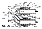
図3Aは、第1の構成における、線3A-3Aによって示される、図2のシリンジ150の医療コネクタ100の詳細図である。図3Bは、第2の構成における、医療コネクタ100の詳細図であり、図3Cは、第3の構成における、医療コネクタ100を図示する。上述のように、医療コネクタ100は、近位端112及び遠位端114を有する、本体110を含み得る。本体内腔116は、本体110の少なくとも一部分を通って延在し得る。例えば、本体内腔116は、近位端112と遠位端114との間に流体連通が存在するように、本体110の近位端112と遠位端114との間に延在し得る。
FIG. 3A is a detailed view of the
第1の解放部材120aは、本体110の遠位端114で、又はそれに隣接して本体110に連結され得る。示されるように、第1の解放部材120aは、第1の解放部材内腔122aを含み得、第1の解放部材内腔122aは、本体内腔116と連通(例えば、流体連通)している。第1の解放部材内腔122aは、第1の解放部材120aの少なくとも一部分を通って延在し得る。例えば、第1の解放部材内腔122aは、第1の解放部材120aの遠位端及び近位端の各々の間に延在し得る。
The
医療コネクタ100は、第1の係合部材130aを更に含み得る。いくつかの実施形態において、第1の係合部材130aは、第1の解放部材120aに動作可能に連結され得る。一定の実施形態において、第1の係合部材130aは、医療デバイスを医療コネクタ100に解放可能に連結するように構成され得る。例えば、施術者は、第1の細長い医療デバイス15aの少なくとも一部分を、第1の解放部材内腔122aの少なくとも一部分内に配設し得、第1の係合部材130aの少なくとも一部分は、第1の細長い医療デバイス15aが医療コネクタ100に連結されるように、第1の細長い医療デバイス15aの少なくとも一部分に係合するように構成され得る。
The
様々な実施形態において、第1の係合部材130aは、1つ以上の弾性要素又はアーム132aを含み得る。例えば、第1の係合部材130aは、1つ、2つ、3つ、4つ以上の弾性要素132aを含み得る。1つ以上の弾性要素132aは、医療デバイスが本体内腔116の少なくとも一部分内に配設されたときに(例えば、第1の解放部材内腔122aを介して)、医療デバイスに係合するように構成され得る。例えば、1つ以上の弾性要素132aは、第1の細長い医療デバイス15aの外面と係合/相互作用するように構成され得る。いくつかの実施形態において、弾性要素132aは、細長い医療デバイス15aの外径と摩擦係合する、及び/又は外径に咬合若しくは切り込むように構成された角度付きタブを備え得る。弾性要素132aは、この係合を容易にするために、細長い医療デバイス15aの長手方向軸に対してある角度で配設され得る。
In various embodiments, the first engaging
更に、弾性要素132aは、細長い医療デバイス15aが細長い医療デバイス15aに係合し、かつ細長い医療デバイス15aが医療コネクタ100から引き抜かれることを防止するように、医療コネクタ100内に挿入される際、半径方向外側に偏向するように構成され得る。
Further, when the
一定の実施形態において、医療コネクタ100は、第1の細長い医療デバイス15aを連結状態に連結するように構成され得る。更に、医療コネクタ100は、第1の細長い医療デバイス15aを連結解除状態に連結解除するように構成され得る。連結状態(図3B参照)において、第1の解放部材120aは、1つ以上弾性要素132aの各々の少なくとも一部分が、第1の解放部材内腔122aの長手方向軸に対して半径方向内側に偏向するように、1つ以上の弾性要素132aから係合解除され得るか、又はそれから係合解除されるように構成され得る。換言すると、第1の解放部材120aは、連結状態で、1つ以上の弾性要素132aと相互作用しないように配設され得る。
In certain embodiments, the
連結解除状態(図3C参照)において、第1の解放部材120aは、1つ以上の弾性要素132aの各々の少なくとも一部分が第1の解放部材内腔122aの長手方向軸に対して半径方向外側に偏向するように、1つ以上の弾性要素132aと係合又は相互作用するように構成され得る。換言すると、施術者は、第1の解放部材120aの少なくとも一部分が1つ以上の弾性要素132aと係合して、1つ以上の弾性要素132aを第1の細長い医療デバイス15aから係合解除させるように、第1の解放部材120aを「押す」又は作動させ得る。したがって、施術者による第1の解放部材120aの「押すこと」又は作動の際、第1の細長い医療デバイス15aは、医療コネクタ100から連結解除され得る。つまり、第1の解放部材120aの「押すこと」又は作動は、医療プッシュコネクタ100を連結状態から連結解除状態に遷移させ得る。
In the disconnected state (see FIG. 3C), in the
医療コネクタ100は、第1のシール118a(例えば、Oリングシール)を更に含み得る。第1のシール118aは、本体内腔116の少なくとも一部分内に配設され得る。図示されるように、第1のシール118aは、第1の解放部材内腔122aの近位端又はそれに隣接する位置で、本体内腔116内に配設される。更に、第1のシール118aは、第1の肩部117a上に、又はそれに隣接して配設され得る。様々な実施形態において、第1のシール118aは、第1の医療デバイスの少なくとも一部分が本体内腔116内に配設されたときに、医療デバイス(例えば、第1の細長い医療デバイス15a)に封止係合するように構成され得る。例えば、図3Bに示されるように、第1のシール118aは、細長い医療デバイス15aの外径に対して封止し得る。
The
図3Bを参照すると、施術者は、第1の細長い医療デバイス15aの少なくとも一部分を(矢印で示されるように)、第1の解放部材120aの第1の解放部材内腔122aを通して、本体内腔116の少なくとも一部分内に配設し得る。第1の細長い医療デバイス15aのかかる配設の際、第1のシール118aは、第1の細長い医療デバイス15aの少なくとも一部分(例えば、第1の細長い医療デバイス15aの外径)と係合及び/又は相互作用し、かつ第1のシール118a、医療コネクタ100、及び/又は第1の細長い医療デバイス15aの間にシールを形成し得る。
Referring to FIG. 3B, the practitioner passes at least a portion of the first elongated
様々な他の実施形態において、医療コネクタ100は、第1のシール118aを欠いてもよい。したがって、第1の肩部117aは、第1の細長い医療デバイス15aの少なくとも一部分が本体内腔116内に配設されたときに、第1の細長い医療デバイス15aに封止係合するように構成され得る。
In various other embodiments, the
図3A~図3Cに図示されるように、第2の解放部材120bはまた、本体110の遠位端114で、又はそれに隣接して本体110に連結され得る。図示されるように、第2の解放部材120bは、第1の解放部材120aが本体110に連結されている位置に隣接して、又はその位置から変位されて、本体110の遠位端114で、又はそれに隣接して本体110に連結され得る。第1の解放部材120aと類似して、第2の解放部材120bは、本体内腔116と連通する第2の解放部材内腔122bを含み得る。第2の解放部材内腔122bは、第2の解放部材120bの少なくとも一部分を通って延在し得る。
As illustrated in FIGS. 3A-3C, the
医療コネクタ100は、第2の係合部材130bを更に含み得る。いくつかの実施形態において、第2の係合部材130bは、第2の解放部材120bに動作可能に連結され得る。一定の実施形態において、第2の係合部材130bは、医療デバイス(例えば、第2の細長い医療デバイス15b)を医療コネクタ100に解放可能に連結するように構成され得る。
The
医療コネクタ100は、第2のシール118b(例えば、Oリングシール)を更に含み得る。第2の封止部118bは、本体内腔116の少なくとも一部分内に配設され得る。図示されるように、第2のシール118bは、第2の解放部材内腔122bの近位端に隣接する位置で本体内腔116内に配設される。更に、第1のシール118aは、第2の肩部117b上に、又はそれに隣接して配設され得る。図3Bを参照すると、施術者は、第2の細長い医療デバイス15bの少なくとも一部分を(矢印で示されるように)、第2の解放部材120bの第2の解放部材内腔122bを通して、本体内腔116の少なくとも一部分内に配設し得る。第2の細長い医療デバイス15bのかかる配設の際、第2のシール118bは、第2の細長い医療デバイス15aの少なくとも一部分と係合及び/又は相互作用し、かつ第2のシール118b、医療コネクタ100、及び/又は第2の細長い医療デバイス15bの間にシールを形成し得る。
The
様々な他の実施形態において、医療コネクタ100は、第2のシール118bを欠いてもよい。したがって、第2の肩部117bは、第2の細長い医療デバイス15bの少なくとも一部分が本体内腔116内に配設されたときに、第2の細長い医療デバイス15bに封止係合するように構成され得る。
In various other embodiments, the
医療コネクタ100は、第1の肩部117aの近位に配設された第1の近位肩部119a、及び第2の肩部117bの近位に配設された第2の近位肩部119bを更に含み得る。第1及び第2の近位肩部119a、119bは、細長い医療デバイス15a、15bの近位端と相互作用して、医療コネクタ100に対する、細長い医療デバイス15a、15bの確実な近位停止を提供し得る。例えば、図3Bに示される構成において、細長い医療デバイス15a、15bの近位端は、第1及び第2の近位肩部119a、119bと接触して配設される。
The
図示されるように、医療コネクタ100の本体内腔116は、実質的にY字形状である。換言すると、本体内腔116は、3つの開口を含み、2つの開口は、本体110の遠位端114に、又はそれに隣接して配設され、第3の開口は、本体110の近位端112に、又はそれに隣接して配設されている(例えば、第3の開口は、図示されるように、シリンジ150の本体内腔116と容器175との間に配設され得る(図2参照))。医療コネクタ100の他の構成もまた、本開示の範囲内である。例えば、いくつかの実施形態において、医療コネクタは、1つの解放部材、シール、及び/又は係合部材のみを含み得る。いくつかの他の実施形態において、医療コネクタは、3つ以上の解放部材、シール、及び/又は係合部材を含み得る。医療コネクタの他の実施形態もまた、以下に更に詳細に説明される。
As shown, the
図4及び図5は、医療コネクタシステムとも呼ばれる、医療プッシュコネクタシステム280を例示し、図1~図3Cに関連して説明された医療コネクタ100の構成要素に、一定の点において類似し得る、医療コネクタ200の一実施形態を含む。なお、全ての図示される実施形態は類似の特徴を有してもよいことが認識される。したがって、同様の特徴には、同様の参照番号が、先頭の桁を「2」に増分して割り当てられている。例えば、本体は、図1~図3Cで「110」として示され、類似の本体は、図4及び図5で「210」として示される。それゆえ、同様に特定される特徴に関して上述された、関連性のある開示は、以降では繰り返されない場合がある。更に、図1~図3Cに示される医療コネクタ100及び関連する構成要素の特有の特徴は、図面の参照番号で示されないか識別されない、又は具体的にそれ以降に記載される説明において取り上げられない場合がある。しかしながら、そのような特徴は、他の実施形態で示される特徴、及び/若しくは、そのような実施形態に関して説明される特徴と、明白に同じもの、又は実質的に同じものとすることができる。したがって、かかる特徴の関連する説明は、図4及び図5の医療コネクタ200の特徴に同等に適用される。図1~図3Cに図示された医療コネクタ100及び構成要素に対して説明される、特徴及びそれらの変形例の任意の好適な組み合わせは、図4及び図5の医療コネクタ200及び構成要素とともに使用可能であり、逆も同様である。このパターンでの開示は、続く図面及び以後に説明される更なる実施形態に同等に適用される。
4 and 5 exemplify a medical
図4は、医療コネクタシステム280の一部分を図示する。図5は、図4の医療コネクタシステム280の一部分の分解図である。いくつかの実施形態において、医療コネクタシステム280は、医療コネクタ200を含み得る。医療コネクタ200は、本体210を含み得、本体210は、近位端又は第1の端212、及び遠位端又は第2の端214を有する。本体内腔216はまた、本体210の少なくとも一部分を通って延在し得る。例えば、本体内腔216は、本体210及び/又は医療コネクタ200の近位端212と遠位端214との間に延在し得る。
FIG. 4 illustrates a portion of the
一定の実施形態において、第1の解放部材220aは、本体210の遠位端214に、又はそれに隣接して本体210に連結され得る。図示されるように、医療コネクタ200は、2つの解放部材220a、220bを含み得る。いくつかの実施形態において、医療コネクタ200は、1つのみの解放部材を含んでもよい。いくつかの他の実施形態において、医療コネクタ200は、3つ、4つ、5つ以上の解放部材を含んでもよい。更にいくつかの他の実施形態において、以下に更に詳細に論じられるように、医療コネクタ200は、解放部材を欠いてもよい。図4及び図5を参照すると、第1の解放部材220aは、本体内腔216と連通(例えば、流体連通)している第1の解放部材内腔222aを含み得る。同様に、第2の解放部材220bは、本体内腔216とも連通する第2の解放部材内腔222bを含み得る。
In certain embodiments, the
第1の解放部材220aは、第1の係合部材230aに動作可能に連結され得るか、又は動作可能に連結されるように構成され得る。同様に、第2の解放部材220bは、第2の係合部材230bに動作可能に連結され得るか、又は動作可能に連結されるように構成され得る。
The
医療コネクタシステム280はまた、1つ以上の細長い医療デバイス290a、290bを含み得る。図4及び図5は、細長い医療デバイス290a、290bの各々の一部分のみを図示する。第1の細長い医療デバイス290aは、細長い部材292aを含み得、細長い部材292aは、近位又は第1の端293a、及び遠位又は第2の端(図示せず)を有する。同様に、第2の細長い医療デバイス290bは、細長い部材292bを含んでもよく、細長い部材292bは、近位端又は第1の端293b、及び遠位又は第2の端(図示せず)を有する。更に、第1又は第2の細長い部材内腔295a、295bは、それぞれ、第1又は第2の細長い部材292a、292bの各々の一部分内に配設され得る。第1及び第2の細長い部材内腔295a、295bは、それぞれ、第1及び第2の細長い部材292a、292bの長さの少なくとも一部分に沿って、それぞれ、第1の端293a、293bから延在し得る。様々な実施形態において、第1の係合部材230aは、第1の細長い医療デバイス290aの第1の端293aに医療コネクタ200の少なくとも一部分を解放可能に連結し得るか、又は解放可能に連結するように構成され得る。同様に、第2の係合部材230bは、第2の細長い医療デバイス290bの第1の端293bに医療コネクタ200の少なくとも一部を解放可能に連結し得るか、又は解放可能に連結するように構成され得る。
The
いくつかの実施形態において、細長い医療デバイスは、薄壁の細長い医療デバイスであり得る。薄壁を含む細長い医療デバイスは、薄壁の細長い医療デバイスの内腔を通る流体流が、より厚い壁及び実質的に同様の外径を有する別の細長い医療デバイスよりも、大きいことを可能にし得る。薄壁の細長い医療デバイスは、薄壁の細長い医療デバイスが薄壁の細長い医療デバイスの完全性を損傷させること又は損なうことなく、医療コネクタに連結され得るように、硬化及び/又は補強された端を更に有し得る。 In some embodiments, the elongated medical device can be a thin-walled elongated medical device. Elongated medical devices, including thin walls, allow fluid flow through the lumen of thin-walled elongated medical devices to be greater than for thicker walls and other elongated medical devices with substantially similar outer diameters. obtain. The thin-walled elongated medical device is a hardened and / or reinforced end so that the thin-walled elongated medical device can be connected to the medical connector without damaging or impairing the integrity of the thin-walled elongated medical device. Can have more.
第1の係合部材230aは、1つ以上の弾性要素又はアーム232aを含み得る。いくつかの実施形態において、第1の係合部材230aは、1つ、2つ、3つ、4つ、5つ以上の弾性要素232aを含み得る。更に、第1の解放部材220aの少なくとも一部分は、1つ以上の弾性要素232aの少なくとも一部分が、連結解除状態(例えば、細長い医療デバイスが、医療コネクタから連結解除又は係合解除されている状態)で第1の解放部材内腔222aの長手方向軸線に対して半径方向外側に変位されるように、1つ以上の弾性要素232aの少なくとも一部分に係合するように構成され得る。第1の解放部材220aは、1つ以上の弾性要素232aの少なくとも一部分が、連結状態(例えば、細長い医療デバイスが、医療コネクタに連結又は係合されている状態)で、第1の解放部材内腔222aの長手方向軸線に対して半径方向内側に変位されるように、1つ以上の弾性要素232aの少なくとも一部分から係合解除されるように更に構成され得る。第2の係合部材230bは、上述のように、第1の係合部材230aに類似の様式で構成され得る。
The first engaging
図5を参照すると、第1のシール218aは、本体内腔216の少なくとも一部分内に配設され得る。いくつかの実施形態において、第1のシール218aは、第1の細長い医療デバイス290aが本体内腔216の少なくとも一部分内に配設されたときに、第1の細長い医療デバイス290aの第1の端293aに封止可能に係合するように構成され得る。例えば、第1の細長い医療デバイス290aの第1の端293aの少なくとも一部分は、第1のシール218aの少なくとも一部分を押圧して、又はそれに係合して、シールを形成し得る。更に、第2のシール218bは、本体内腔216の少なくとも別の部分内に配設されるように構成され得る。いくつかの実施形態において、第2のシール218bは、第2の細長い医療デバイス290bが本体内腔216の少なくとも一部分内に配設されたときに、第2の細長い医療デバイス290bの第1の端293bに封止可能に係合するように構成され得る。例えば、第2の細長い医療デバイス290bの第1の端293bの少なくとも一部分は、第2のシール218bの少なくとも一部分を押圧して、又はそれに係合して、シールを形成し得る。
Referring to FIG. 5, the
様々な実施形態において、医療コネクタ200は、第1のシール218a及び/又は第2のシール218bを欠いてもよい。したがって、第1の肩部及び/又は第2の肩部(図3A~図3Cを参照して上述された第1及び第2の肩部117a、117bに類似する)は、第1及び/又は第2の細長い医療デバイス290a、290bの少なくとも一部分が本体内腔216内に配設されたときに、第1及び/又は第2の細長い医療デバイス290a、290bに封止係合するように構成され得る。
In various embodiments, the
図6Aは、医療コネクタ300の一部分(例えば、医療コネクタシステムの一部として)に連結された細長い医療デバイス390の断面詳細図である。図示されるように、細長い医療デバイス390は、高摩擦ゾーン396を含み得る。いくつかの実施形態において、高摩擦ゾーン396は、細長い医療デバイス390の外面の少なくとも一部分上に配設され得る。例えば、高摩擦ゾーン396は、細長い医療デバイス390の近位若しくは第1の端393に、又はそれに隣接して細長い医療デバイス390の外面の周囲に配設されている環状高摩擦ゾーン396とすることができる。高摩擦ゾーン396は、例えば、細長い医療デバイス390の少なくとも一部分が解放部材内腔322の少なくとも一部分内に配設されたときに、係合部材330の少なくとも一部分に係合し得るか、又は係合するように構成され得る。連結状態において、上述のように、係合部材330の1つ以上の弾性要素又はアーム332は、細長い医療デバイス390の少なくとも一部分が解放部材内腔322及び/又は本体内腔316内に配設されたときに、高摩擦ゾーン396に係合するように構成され得る。高摩擦ゾーン396は、高摩擦ゾーンを欠く細長い医療デバイスと比較して、医療コネクタ300の細長い医療デバイス390への連結を強化するように構成され得る。例えば、高摩擦ゾーン396の1つ以上の半径方向に突出する表面は、係合部材330の1つ以上の弾性要素332と係合して、細長い医療デバイス390を医療コネクタ300にしっかりと連結し得る。
FIG. 6A is a detailed cross-sectional view of an elongated
上述したように、シール318はまた、本体内腔316の少なくとも一部分内に(例えば、肩部317上、又はそれに隣接して)配設され得、シール318は、細長い医療デバイス390の少なくとも一部分に係合するように構成されている(例えば、医療コネクタ300と細長い医療デバイス390との間に連結状態でシールを形成するように)。図示されるように、シール318は、シール318と細長い医療デバイス390との間にシールが形成されるように、細長い医療デバイス390との係合時に圧縮され得る。
As mentioned above, the
一定の実施形態において、医療コネクタ300は、シール318を欠いてもよい。したがって、肩部317は、細長い医療デバイス390の少なくとも一部分が本体内腔316内に配設されたときに、細長い医療デバイス390に封止係合するように構成され得る。医療コネクタ300は、医療コネクタ300に対する、細長い医療デバイス390の確実な停止を提供し得る近位肩部319を更に備え得る。示されるように、細長い医療デバイス390は、細長い医療デバイス390を医療コネクタ300に連結させ、かつそれと封止させるために、近位肩部319と接触する必要はない。
In certain embodiments, the
図6Bは、医療コネクタ400の一部分(例えば、医療コネクタシステムの一部として)に連結された細長い医療デバイス490の別の実施形態の断面図である。図示されるように、細長い医療デバイス490は、細長い医療デバイス490の外面の少なくとも一部分に沿って、又はその上に配設された通路又は陥凹497を含み得る。例えば、陥凹497は、細長い医療デバイス490の近位若しくは第1の端493に、又はそれに隣接して細長い医療デバイス490の外面の周囲に配設されている環状陥凹とすることができる。陥凹497は、例えば、細長い医療デバイス490の少なくとも一部分が解放部材内腔422の少なくとも一部分内に配設されたときに、係合部材430の少なくとも一部分に係合し得るか、又は係合するように構成され得る。連結状態において、上述のように、係合部材430の1つ以上の弾性要素又はアーム432は、細長い医療デバイス490の少なくとも一部分が解放部材内腔422及び/又は本体内腔416内に配設されたときに、陥凹497に係合するように構成され得る。高摩擦ゾーン396に類似して、陥凹497は、陥凹を欠く細長い医療デバイスと比較して、医療コネクタ400の細長い医療デバイス490への連結を強化するように構成され得る。例えば、陥凹497は、係合部材430の1つ以上の弾性要素432と係合して、細長い医療デバイス490を医療コネクタ400にしっかりと連結し得る。
FIG. 6B is a cross-sectional view of another embodiment of an elongated
上述したように、シール418はまた、本体内腔416の少なくとも一部分内に(例えば、肩部417上、又はそれに隣接して)配設され得、シール418は、細長い医療デバイス490に係合するように構成されている(例えば、医療コネクタ400と細長い医療デバイス490との間に連結状態でシールを形成するように)。
As mentioned above, the
一定の実施形態において、医療コネクタ400は、シール418を欠いてもよい。したがって、肩部417は、細長い医療デバイス490の少なくとも一部分が本体内腔416内に配設されたときに、細長い医療デバイス490に封止係合するように構成され得る。医療コネクタ400は、医療コネクタ400に対する、細長い医療デバイス490の確実な停止を提供し得る近位肩部419を更に備え得る。示されるように、細長い医療デバイス490は、細長い医療デバイス490を医療コネクタ400に連結させ、かつそれと封止させるために、近位肩部419と接触する必要はない。
In certain embodiments, the
図6Cは、医療コネクタ500の一部分(例えば、医療コネクタシステムの一部として)に連結された細長い医療デバイス590の更に別の実施形態の断面図である。図示されるように、細長い医療デバイス590は、細長い医療デバイス590の外面の少なくとも一部分上に配設されたリッジ598を含み得る。例えば、リッジ598は、細長い医療デバイス590の近位若しくは第1の端593に、又はそれに隣接して細長い医療デバイス590の外面の周囲に配設されている環状リッジとすることができる。リッジ598は、例えば、細長い医療デバイス590の少なくとも一部分が解放部材内腔522の少なくとも一部分内に配設されたとき、係合部材530の少なくとも一部分に係合し得るか、又は係合するように構成され得る。連結状態において、上述のように、係合部材530の1つ以上の弾性要素又はアーム532は、細長い医療デバイス590の少なくとも一部分が解放部材内腔522及び/又は本体内腔516内に配設されたときに、リッジ598に係合するように構成され得る。高摩擦ゾーン396及び/又は陥凹497に類似して、リッジ598は、リッジを欠く細長い医療デバイスと比較して、医療コネクタ500の細長い医療デバイス590への連結を強化するように構成され得る。例えば、リッジ598は、係合部材530の1つ以上の弾性要素532と係合して、細長い医療デバイス590を医療コネクタ500にしっかりと連結し得る。
FIG. 6C is a cross-sectional view of yet another embodiment of an elongated
上述したように、シール518はまた、本体内腔516の少なくとも一部分内に(例えば、肩部517上、又はそれに隣接して)配設され得、シール518は、細長い医療デバイス590に係合するように構成されている(例えば、医療コネクタ500と細長い医療デバイス590との間に連結状態でシールを形成するように)。
As mentioned above, the
一定の実施形態において、医療コネクタ500は、シール518を欠いてもよい。したがって、肩部517は、細長い医療デバイス590の少なくとも一部分が本体内腔516内に配設されたときに、細長い医療デバイス590に封止係合するように構成され得る。医療コネクタ500は、医療コネクタ5300に対する、細長い医療デバイス590の確実な停止を提供し得る、近位肩部519を更に備え得る。示されるように、細長い医療デバイス590は、細長い医療デバイス590を医療コネクタ500に連結させ、かつそれと封止させるために、近位肩部519と接触する必要はない。
In certain embodiments, the
図7は、医療コネクタ600の斜視図である。図示されるように、医療コネクタ600は、本体610に連結された第1の解放部材620aを含み得、第1の解放部材620aは、本体610の第1の端612で、又はそれに隣接して本体610に連結される。医療コネクタ600は、本体610に連結された第2の解放部材620bを更に含み得、第2の解放部材620bは、本体610の第2の端614で、又はそれに隣接して本体610に連結される。第1の解放部材620aは、医療コネクタ600の本体内腔616と連通する第1の解放部材内腔622aを含み得る。同様に、第2の解放部材620bは、本体内腔616と連通する第2の解放部材内腔622bを含み得る。換言すると、第1の解放部材内腔622a及び第2の解放部材内腔622bの各々は、本体内腔616を介して、互いに連通(例えば、流体連通)し得る。
FIG. 7 is a perspective view of the
上述の解放部材に類似して、第1及び第2の解放部材620a、620bの各々は、係合部材に動作可能に連結され得る。第1の解放部材620aは、第1の細長い医療デバイス690aを医療コネクタ600に解放可能に連結するように構成され得る。更に、第2の解放部材620bは、第2の細長い医療デバイス690bを医療コネクタ600に解放可能に連結するように構成され得る。
Similar to the release member described above, each of the first and
図示されるように、医療コネクタ600は、第1の外径OD1を有する第1の細長い医療デバイス690aを第2の外径OD2を有する第2の細長い医療デバイス690bに連結するように構成され得る。いくつかの実施形態において、第1の外径OD1は、第2の外径OD2未満であってもよく、又はその逆であってもよい。例えば、第1の細長い医療デバイス690aは、6フレンチカテーテルであってもよく、第2の細長い医療デバイス690bは、10フレンチカテーテルであってもよい。したがって、医療コネクタ600は、6フレンチカテーテルを10フレンチカテーテルに連結してもよく、又はその逆であってもよい。他の好適なサイズの細長い医療デバイスもまた、本開示の範囲内である。例えば、第1の細長い医療デバイスのサイズは、4フレンチ、6フレンチ、8フレンチ、10フレンチ、又は任意の他の好適なサイズであってもよい。同様に、第2の細長い医療デバイスのサイズは、8フレンチ、10フレンチ、12フレンチ、15フレンチ、又は任意の他の好適なサイズであってもよい。
As shown, the
換言すると、第1の解放部材620aは、第1の内径ID1を有し得るが、第2の解放部材620bは、第2の内径ID2を有し得る。様々な実施形態において、第1の内径ID1は、第2の内径ID2未満であってもよく、又はその逆であってもよい。例えば、第1の解放部材620aは、第1の細長い医療デバイス690aを受容及び/又は解放可能に連結するように構成され得、第1の細長い医療デバイス690aは、8フレンチカテーテルであり得、第2の解放部材620bは、第2の細長い医療デバイス690bを受容及び/又は解放可能に連結するように構成され得、第2の細長い医療デバイス690bは、12フレンチカテーテルであり得る。
In other words, the
図8Aは、第1の構成における、医療コネクタ700の一部分の部分破断図である。図8Bは、第2の構成における、医療コネクタ700であり、図8Cは、第3の構成における、医療コネクタ700を図示する。上述のように、医療コネクタ700は、近位端712及び遠位端714を有する本体710を含み得る。更に、本体内腔716は、本体710の少なくとも一部分を通って延在し得る。
FIG. 8A is a partially broken view of a part of the
連結部材720は、本体710の近位端714で、又はそれに隣接して本体710に連結され得る。示されるように、解放部材720は、解放部材内腔722を含み得、解放部材内腔722は、本体内腔716と連通している。医療コネクタ700は、係合部材730を更に含み得る。いくつかの実施形態において、係合部材730は、解放部材720に動作可能に連結され得る。一定の実施形態において、係合部材730は、医療デバイスを医療コネクタ700に解放可能に連結するように構成され得る。例えば、図8B及び図8Cを参照すると、施術者は、細長い医療デバイス15の少なくとも一部分を解放部材内腔722の少なくとも一部分内に配設し得、係合部材730の少なくとも一部分は、細長い医療デバイス15が医療コネクタ700に連結されるように、細長い医療デバイス15の少なくとも一部分に係合するように構成され得る。
The connecting
上記のように、係合部材730は、1つ以上の弾性要素732を含み得る。1つ以上の弾性要素732は、医療デバイスが本体内腔716の少なくとも一部内に配設されたときに(例えば、解放部材内腔722を介して)、医療デバイスに係合するように構成され得る。例えば、1つ以上の弾性要素732は、細長い医療デバイス15の外面と係合及び/又は相互作用するように構成され得る。
As mentioned above, the engaging
一定の実施形態において、医療コネクタ700は、細長い医療デバイス15を部分的な連結状態(図8B参照)で連結するように構成され得る。医療コネクタ700はまた、細長い医療デバイス15を完全な又は完成した連結状態(図8C参照)で連結するように構成され得る。部分的及び/又は完全な連結状態において、解放部材720は、1つ以上の弾性要素732の各々の少なくとも一部分が、解放部材内腔722の長手方向軸に対して半径方向内側に偏向するように、1つ以上の弾性要素732から係合解除され得るか、又は係合解除されるように構成され得る。
In certain embodiments, the
医療コネクタ700は、細長い医療デバイス15(又は別の医療デバイス)が医療コネクタ700内に完全に配設又は「着座」されていることを示す(例えば、施術者に)ための機構及び/又は構成要素を含み得る。いくつかの実施形態において、機構は、視認可能な機構であり得る。いくつかの他の実施形態において、機構は、可聴、触知可能等とすることができる。図8A~図8Cに示されるように、医療コネクタ700は、指示部材740を含み得る。指示部材740は、本体内腔716の少なくとも一部分内に配置され得る。更に、指示部材740は、本体内腔716内で変位可能(例えば、摺動可能に変位可能)であり得る。例えば、細長い医療デバイス15との係合の際、指示部材740は、本体710に対して変位(例えば、近位に変位)され得る。いくつかの実施形態において、指示部材740は、指示部材内腔742を含み得、指示部材内腔742は、本体内腔716及び/又は解放部材内腔722と連通(例えば、流体連通)している。更に、指示部材内腔742の少なくとも一部分は、細長い医療デバイス15の少なくとも一部分を受容するように構成され得る。
The
一定の実施形態において、シール718(例えば、Oリングシール)は、指示部材740の少なくとも一部分内に配設され得る。例えば、シール718は、指示部材内腔742の少なくとも一部内に配設され得る。様々な実施形態において、シール718は、細長い医療デバイス15の少なくとも一部分が指示部材内腔742内に配設されたときに、細長い医療デバイス15に封止係合するように構成され得る。例えば、図8B及び図8Cに示されるように、シール718は、細長い医療デバイス15の外径に対して封止し得る。
In certain embodiments, the seal 718 (eg, an O-ring seal) may be disposed within at least a portion of the
しるし744が、指示部材740の外面の一部分上に配設(例えば、印刷)され得る。図示されるように、しるし744は、印刷された対角バー又は線である。いくつかの実施形態において、しるし744は、円、正方形、三角形、数字、文字、又は任意の他の好適な形状若しくは記号であってもよい。更に、指示部材740は、第1の色であってもよく(例えば、指示部材740は、赤色の材料から形成されてもよく)、しるし744は、第2の色であってもよい(例えば、しるし744は、緑色の材料から形成されてもよい)。いくつかの実施形態において、指示部材740及びしるし744は、一体的であってもよく、いくつかの他の実施形態において、指示部材740及びしるし744は、別個であってもよい。指示部材740及びしるし744の色及び/又は材料の他の組み合わせもまた、本開示の範囲内である。例えば、指示部材740は、オレンジ色のインクで印刷されてもよく、しるしは、青色の材料から形成されてもよい。
The
引き続き図8A~図8Cを参照すると、医療コネクタ700は、窓711を更に含み得る。窓711は、本体710の壁の少なくとも一部分に配設された透明部材であり得る。いくつかの実施形態において、開口(窓の代わりに)は、本体710の壁の一部分に配設され得る。窓711は、指示部材740の近位の変位の際、しるし744が窓711を通して視認可能となり得るように、しるし744と整列され得る。例えば、施術者は、指示部材740が本体710に対して近位に変位されたときに、窓711を通してしるし744を視認することができ得る。
Continuing with reference to FIGS. 8A-8C, the
窓711としるし744との間の相互作用は、細長い医療デバイス15が医療コネクタ700内に単に部分的に配設されているかどうか(図8B参照)、又は細長い医療デバイス15が医療コネクタ700内に完全に配設されているかどうか(図8C参照)を、施術者に示し得る。一定の実施形態において、細長い医療デバイス15が医療コネクタ700内に単に部分的に配設されている場合、細長い医療デバイス15と医療コネクタ700との間に、完全なシールが形成されない場合がある。また、細長い医療デバイス15が医療コネクタ700内に単に部分的に配設されている場合、細長い医療デバイス15は、医療コネクタ700にしっかりと連結されない場合がある。したがって、指示部材740、しるし744、及び/又は窓711は、医療コネクタ700が完全な連結状態にある場合、施術者に伝達及び/又は指示するように構成され得る。
The interaction between the
いくつかの実施形態において、本体710の少なくとも一部分は、透明材料から形成されてもよく、透明材料の少なくとも一部分は、本体内に「窓」を形成するようにコーティング又は印刷されてもよい。つまり、窓は、コーティング又は印刷されていない本体710の一部分であってもよい。したがって、しるし744は、しるし744が本体710の非印刷窓部分と整列されない限り、本体710を介して(すなわち、印刷に起因して)視認可能でなくてもよい。
In some embodiments, at least a portion of the
図8Bを参照すると、施術者は、細長い医療デバイス15の少なくとも一部分を(矢印によって示されるように)、解放部材720の解放部材内腔722を通して、指示部材内腔742の少なくとも一部内に配設し得る。図8Bに示されるように、細長い医療デバイス15は、部分的な連結状態にある。細長い医療デバイス15のかかる配設の際、指示部材740は、本体710に対して近位に変位されるが、しるし744は、窓711を通して視認可能ではない。部分的な連結状態において、しるし744は、窓711を通して部分的に視認可能であり得る。換言すると、しるし744の一部分は、医療コネクタ700及び細長い医療デバイス15が部分的な連結状態にあるとき、窓711を通して視認可能であり得る。
Referring to FIG. 8B, the practitioner disposes at least a portion of the elongated medical device 15 (as indicated by an arrow) through the
図8Cを参照すると、施術者は、細長い医療デバイス15を解放部材720の解放部材内腔722を通して指示部材内腔742内に完全に(又は実質的に完全に)配設し得る。図8Cに示されるように、細長い医療デバイスは、完全な連結状態にある。細長い医療デバイス15のかかる配設の際、指示部材740は、しるし744が窓711を通して完全に(又は実質的に完全に)視認可能であるように、本体710に対して近位に変位される。完全な連結状態において、しるし744は、窓711を通して完全に視認可能であり、細長い医療デバイス15が医療コネクタ700内に完全に配設又は着座されていることを示し得る。換言すると、医療コネクタ700及び細長い医療デバイス15が完全な連結状態にあるとき、しるし744の実質的に全てが窓711を通して視認可能であり得る。
Referring to FIG. 8C, the practitioner may dispose the elongated
医療コネクタ700は、本体内腔716の一部内に配設された近位肩部719を更に含み得る。近位肩部719は、指示部材740の近位端と相互作用して、医療コネクタ700に対して指示部材740及び/又は細長い医療デバイス15のための確実な近位停止を提供し得る。例えば、図8Cに示される構成において、指示部材740の近位端は、近位肩部719と接触して配設される。
The
図示されるように、医療コネクタ700の本体内腔716は、実質的にI字形状である。換言すると、本体内腔716は、2つの開口を含み、1つの開口は、本体710の遠位端714に、又はそれに隣接して配設され、第2の開口は、本体710の近位端712に、又はそれに隣接して配設される。上述のように、医療コネクタ700の他の実施形態もまた本開示の範囲内である。例えば、いくつかの実施形態において、医療コネクタは、2つ以上の解放部材及び/又は指示部材を含んでもよい。
As shown, the
医療コネクタ100、200、300、400、500、600、700等の医療コネクタの他の構成もまた、本開示の範囲内である。一定の実施形態において、医療コネクタは、医療コネクタの第1の端上の第1の解放部材、及び医療コネクタの第2の端上の第2の解放部材を含み得、第1の解放部材及び第2の解放部材の各々は、実質的に同様の内径及び/又は外径を有し得る。いくつかの実施形態において、医療コネクタは、医療コネクタの一端(例えば、第1の端)上の解放部材のみを含み得るが、一方で医療コネクタの反対端(例えば、第2の端)は、ルアーコネクタ、圧入コネクタ、スナップコネクタ等の別のタイプのコネクタを含む。いくつかの他の実施形態において、医療コネクタは、医療コネクタの第1の端上の1つの解放部材、及び医療コネクタの第2の端上の2つの解放部材を含み得る。更にいくつかの他の実施形態において、医療コネクタは、4つのアームを有してもよく、解放部材は、4つのアームの各々の一端に連結されてもよい。
Other configurations of medical connectors such as
医療コネクタが解放部材を欠いている実施形態もまた、本開示の範囲内である。例えば、施術者は、患者が医療コネクタを1つ以上の医療デバイスから連結解除することを阻止又は防止することを所望し得る。換言すると、医療コネクタは、患者が医療コネクタを連結状態から非連結状態に遷移させることができないように、「患者安全性」であってもよい。 Embodiments in which the medical connector lacks a release member are also within the scope of the present disclosure. For example, the practitioner may wish to prevent or prevent the patient from disconnecting the medical connector from one or more medical devices. In other words, the medical connector may be "patient safety" so that the patient cannot transition the medical connector from the connected state to the unconnected state.
いくつかの実施形態において、医療コネクタは、1つ超の本体内腔を含み得る。例えば、医療コネクタは、2つ、3つ、4つ以上の内腔を含み得る。一定の実施形態において、医療コネクタは、1つ以上の弁を含み得る。例えば、弁は、医療コネクタの少なくとも一部分内に配設され得る。弁は、医療コネクタが別の医療デバイスから連結解除されたときに、医療コネクタを通る流体の流れを阻止又は防止するように構成され得る。医療デバイスへの医療コネクタの連結の際、弁は、閉状態から開状態に遷移するように構成され得る。したがって、弁は、医療コネクタが1つ以上の他の医療デバイスに連結されているときのみ開くように構成され得る。かかる弁は、医療コネクタが所望される医療デバイス(例えば、ドレナージバッグ等)に連結されていないとき、流体が医療コネクタを通って漏れることを制限又は防止し得る。医療コネクタ、解放部材等の他の構成もまた、本開示の範囲内である。 In some embodiments, the medical connector may include more than one body lumen. For example, a medical connector may include two, three, four or more lumens. In certain embodiments, the medical connector may include one or more valves. For example, the valve may be disposed within at least a portion of the medical connector. The valve may be configured to block or prevent fluid flow through the medical connector when the medical connector is disconnected from another medical device. Upon connecting the medical connector to the medical device, the valve may be configured to transition from a closed state to an open state. Therefore, the valve may be configured to open only when the medical connector is connected to one or more other medical devices. Such valves may limit or prevent fluid from leaking through the medical connector when the medical connector is not connected to the desired medical device (eg, drainage bag, etc.). Other configurations such as medical connectors, release members, etc. are also within the scope of this disclosure.
本開示の医療コネクタは、医療コネクタを介して連結されている、第1の医療デバイスと第2の医療デバイスとの間の連通(例えば、流体連通)を、他の連結機構を介して連結され得る、いくつかの他の第1及び第2の医療デバイスに対して、強化し得る。例えば、いくつかの他の連結機構は、返し部を含み得、返し部の第1の端が、第1の医療デバイスの一部分の内径内に配設され、返し部の第2の端が、第2の医療デバイスの一部分の内径内に配設される。かかる連結機構は、第1及び第2の医療デバイスの内径の少なくとも一部分の寸法を減少させ得る。したがって、流体連通は、第1の医療デバイスと第2の医療デバイスとの間で少なくとも部分的に妨害され得る。これに対して、本開示の医療コネクタは、第1の医療デバイスの一部分の外径及び/又は第2の医療デバイスの外径の周囲に配設され得、それにより、内径の寸法が実質的に変更又は変化されず、第1の医療デバイス及び第2の医療デバイスの各々の間の流体連通が、実質的に妨害及び又は阻止されない。 The medical connector of the present disclosure connects the communication (eg, fluid communication) between the first medical device and the second medical device, which is connected via the medical connector, via another connection mechanism. It may be enhanced against some other first and second medical devices to obtain. For example, some other coupling mechanism may include a barb so that the first end of the barb is disposed within the inner diameter of a portion of the first medical device and the second end of the barb is. It is disposed within the inner diameter of a part of the second medical device. Such a coupling mechanism may reduce the size of at least a portion of the inner diameter of the first and second medical devices. Therefore, fluid communication can be at least partially disrupted between the first medical device and the second medical device. In contrast, the medical connector of the present disclosure may be disposed around the outer diameter of a portion of the first medical device and / or the outer diameter of the second medical device, whereby the dimensions of the inner diameter are substantially. The fluid communication between each of the first medical device and the second medical device is substantially unobstructed and / or not blocked.
本開示による医療コネクタは、様々なサイズで形成され得る。例えば、上述のように、医療コネクタは、4フレンチ、5フレンチ、6フレンチ、7フレンチ、又は任意の他の好適なサイズである細長い医療デバイスに連結されるようにサイズ決めされ得る。医療コネクタはまた、2つ以上の解放部材及び/又は係合部材を含み得る。解放部材及び/又は係合部材の各々は、異なるサイズの細長い医療デバイスを連結するように構成され得る。つまり、医療コネクタの一端は、6フレンチである細長い医療デバイスを連結するようにサイズ決めされ得、医療コネクタの別の端は、10フレンチである細長い医療デバイスを連結するようにサイズ決めされ得る。これに対して、いくつかの他の連結機構(例えば、ルアーコネクタ)は、例えば、2つのサイズ又は別の限定された数のサイズのみで利用可能であり得る。 The medical connectors according to the present disclosure can be formed in various sizes. For example, as mentioned above, the medical connector may be sized to be connected to a 4 French, 5 French, 6 French, 7 French, or any other suitable size elongated medical device. The medical connector may also include more than one release member and / or an engagement member. Each of the release member and / or the engagement member may be configured to connect elongated medical devices of different sizes. That is, one end of the medical connector may be sized to connect an elongated medical device that is 6 French, and the other end of the medical connector may be sized to connect an elongated medical device that is 10 French. In contrast, some other coupling mechanism (eg, luer connector) may be available, for example, in only two sizes or another limited number of sizes.
医療コネクタを使用する方法もまた、本明細書に開示される。カテーテル(例えば、10フレンチカテーテル)は、ドレナージのために使用され得る。例えば、カテーテルは、患者の体腔から流体を排出するために施術者によって使用され得る。施術者は、カテーテルを切断し、カテーテルの切断端を医療コネクタの第1の端に連結し得る。第2のカテーテル(例えば、ドレナージバッグ内に移すように構成されているカテーテル)は、医療コネクタの第2の端に連結され得る。したがって、医療コネクタは、医療ドレナージ術での施術者による使用のために構成され得る。いくつかの実施形態において、ドレナージカテーテルは、高流量を有し得、ドレナージカテーテルは、医療コネクタを介して、ドレナージバッグ及び/又は吸引デバイス(例えば、バキューム)に連結され得る。 Methods of using medical connectors are also disclosed herein. Catheter (eg, 10 French catheter) can be used for drainage. For example, a catheter can be used by a practitioner to drain fluid from a patient's body cavity. The practitioner may cut the catheter and connect the cut end of the catheter to the first end of the medical connector. A second catheter (eg, a catheter configured to be transferred into a drainage bag) may be attached to the second end of the medical connector. Thus, the medical connector may be configured for use by the practitioner in medical drainage. In some embodiments, the drainage catheter may have a high flow rate and the drainage catheter may be connected to a drainage bag and / or a suction device (eg, vacuum) via a medical connector.
一定の実施形態において、本開示の医療コネクタとの使用のためのドレナージバッグは、ドレナージバッグを医療コネクタに連結するための接続部材を含み得る。様々な実施形態において、接続部材は、接続部材が医療コネクタに連結され得るように、標準的な外径を含み得る。様々な他の実施形態において、接続部材は、様々な標準化された外径(例えば、接続部材の外径の2つ、3つ以上の標準サイズが存在し得る)を含み得る。 In certain embodiments, the drainage bag for use with the medical connector of the present disclosure may include a connecting member for connecting the drainage bag to the medical connector. In various embodiments, the connecting member may include a standard outer diameter such that the connecting member may be connected to a medical connector. In various other embodiments, the connecting member may include various standardized outer diameters (eg, there may be two or more standard sizes of the outer diameter of the connecting member).
いくつかの実施形態において、施術者は、長さ調整のためにカテーテルを切断し得、施術者は、カテーテルの切断端を第2のカテーテル又は他の医療デバイス(例えば、シリンジ)に連結するために医療コネクタを使用し得る。これに対して、カテーテルが医療デバイスにカテーテルを連結するためのルアーコネクタを有する構成において、カテーテルは、カテーテルの切断がルアーコネクタを除去し得るため、長さ調整のために切断されるように構成されていない場合がある。しかしながら、本開示による医療コネクタは、切断された(例えば、長さ調整のために)カテーテルに連結され得る。 In some embodiments, the practitioner may cut the catheter for length adjustment and the practitioner may connect the cut end of the catheter to a second catheter or other medical device (eg, a syringe). Medical connectors can be used for. In contrast, in configurations where the catheter has a luer connector for connecting the catheter to a medical device, the catheter is configured to be cut for length adjustment so that cutting of the catheter can remove the luer connector. It may not have been done. However, the medical connector according to the present disclosure can be attached to a severed catheter (eg, for length adjustment).
様々な実施形態において、医療コネクタは、高圧ライン又はカテーテル(例えば、心臓ポンプとともに使用されるライン)とともに使用され得る。高圧ライン内の高圧は、高圧ラインの内面に力(例えば、高圧ラインの長手方向軸に対して外側に向けられた半径方向の力)を加え得る。かかる力は、高圧ラインの外径の寸法が増加するように、高圧ラインの壁を少なくともわずかに膨張させ得る。したがって、高圧ラインの外径の増加は、医療コネクタ内のラインの一端を「着座」させる傾向があり得る。換言すると、高圧ラインの外面は、医療コネクタの一部分の内面に対して押圧され得、医療コネクタ及び高圧ラインの各々の間の連結が、強化及び/又は増強され得る。本開示による医療コネクタはまた、高圧流体が第1のライン及び第2のラインの各々の間を流れているときに、第1のラインを第2のラインに連結するために十分な強度及び/又は耐久性であり得る。 In various embodiments, the medical connector can be used with a high pressure line or catheter (eg, a line used with a heart pump). The high pressure in the high pressure line may exert a force on the inner surface of the high pressure line (eg, a radial force directed outward with respect to the longitudinal axis of the high pressure line). The force can cause the walls of the high voltage line to expand at least slightly so that the dimensions of the outer diameter of the high voltage line increase. Therefore, an increase in the outer diameter of a high voltage line may tend to "sit" one end of the line within the medical connector. In other words, the outer surface of the high voltage line can be pressed against the inner surface of a portion of the medical connector, and the connection between each of the medical connector and the high voltage line can be strengthened and / or enhanced. The medical connector according to the present disclosure is also strong enough and / / to connect the first line to the second line when the high pressure fluid is flowing between each of the first line and the second line. Or it can be durable.
認識され得るように、追加の方法及び/又は方法のステップが、図1~図8C及び対応する開示から導かれ得る。本明細書に開示されるいかなる方法も、記載されている方法を実行する1つ以上のステップ又は操作を含む。それらの方法のステップ及び/又は行為は、互いに入れ替えることができる。換言すると、実施形態の適切な動作に関して、特定のステップ又は行為の順序が必要とされない限り、それら特定のステップ及び/若しくは行為の順序並びに/又は操作を、修正することができる。 As can be recognized, additional methods and / or steps of the method can be derived from FIGS. 1-8C and the corresponding disclosures. Any method disclosed herein comprises one or more steps or operations to carry out the methods described. The steps and / or actions of those methods can be interchanged with each other. In other words, as long as a particular step or sequence of actions is not required for the proper operation of the embodiment, those particular steps and / or sequence of actions and / or operations may be modified.
近似値への参照は、本明細書全体にわたって、例えば、「実質的に」という用語の使用によって行われる。かかる参照のそれぞれについて、いくつかの実施形態では、値、特徴、又は特性は、近似値なしで特定されてもよいことが理解される。例えば、「約」及び「実質的に」などの修飾句が用いられるところでは、これらの用語は、その範囲内に、それらの修飾句が不在の場合での修飾される言葉を含む。例えば、「実質的にY字形状」という用語が特徴に対して用いられるところでは、更なる実施形態において、その特徴は、正確にY字形状の構成を有し得るように理解される。 References to approximations are made throughout the specification, for example, by using the term "substantially". It is understood that for each of such references, in some embodiments, the value, feature, or property may be specified without approximation. For example, where modifiers such as "about" and "substantially" are used, these terms include, within their scope, the words that are modified in the absence of those modifiers. For example, where the term "substantially Y-shaped" is used for a feature, it is understood that, in a further embodiment, the feature may have exactly a Y-shaped configuration.
本明細書の全体にわたる、「ある実施形態」又は「その実施形態」への言及は、その実施形態に関連して説明されている特定の特徴、構造、又は特性が、少なくとも1つの実施形態に含まれていることを意味する。それゆえ、引用される句又はその変形は、本明細書の全体にわたって記載されている場合、必ずしも全てが、同じ実施形態に言及するものとは限らない。 References to "an embodiment" or "the embodiment" throughout this specification have specific features, structures, or properties described in connection with that embodiment in at least one embodiment. Means that it is included. Therefore, not all of the cited phrases or variations thereof, when described throughout the specification, refer to the same embodiment.
同様に、上の実施形態の記載において、様々な特徴は、本開示を効率化する目的で、その1つの実施形態、図面、又は説明にまとめられる場合がある。しかしながら、この開示の方法は、いずれの請求項も、その請求項において明示的に記載されている特徴以外の更なる特徴を必要とするという意図を反映するものとして解釈されるべきではない。むしろ、以下の請求項が反映するように、発明の態様は、上記で開示された任意の単一の実施形態の全ての特徴よりも、少ない特徴の組み合わせにある。 Similarly, in the description of the above embodiments, various features may be summarized in one embodiment, drawing, or description for the purpose of streamlining the present disclosure. However, this method of disclosure should not be construed as reflecting the intent that any claim requires additional features other than those explicitly stated in that claim. Rather, as the following claims reflect, the embodiment of the invention is in a combination of features that is less than all the features of any single embodiment disclosed above.
この記載に続く請求項は、本記載に明示的に組み込まれており、各請求項は、それぞれ個別に別々の実施形態として独立している。本開示は、独立請求項とそれらの従属請求項の、あらゆる並べ替えを含む。また、続く独立及び従属請求項から由来可能な追加の実施形態もまた、本記載に明示的に組み込まれている。 The claims that follow this description are expressly incorporated into this description, and each claim is independent as a separate embodiment. The present disclosure includes any sort of independent claims and their dependent claims. Further embodiments that can be derived from the following independent and dependent claims are also expressly incorporated herein.
更なる推敲なく、当業者であれば、前の記載を、本発明をその最大限まで活用するために用いることができると考えられる。本明細書に開示される請求項及び実施形態は、単に図示的かつ例示的であり、いかなる方法においても本開示の範囲の限定ではないように解釈されるものとする。当業者にとっては、本開示の助けをもって、上記の実施形態の詳細が本開示の根本にある原則から逸脱することなく変更可能であることが明白であろう。換言すると、上の記載に具体的に開示される実施形態の様々な修正及び改善は、添付の請求項の範囲内である。更に、本明細書で開示する方法のステップ又は操作の順序は、本開示の範囲から逸脱することなく、当業者によって変更され得る。換言すると、ステップ又は操作の特定の順序が実施形態の適切な実施に必要とされない限り、特定のステップ/又は操作の順序/又は使用を修正してもよい。したがって、本発明の範囲は、以下の請求項及びそれらの等価物によって定義される。 Without further elaboration, it is believed that one of ordinary skill in the art can use the previous description to make the best use of the present invention. The claims and embodiments disclosed herein are merely illustration and exemplary and are to be construed as not limiting the scope of the present disclosure in any way. It will be apparent to those skilled in the art that, with the help of this disclosure, the details of the above embodiments can be modified without departing from the underlying principles of this disclosure. In other words, the various modifications and improvements of the embodiments specifically disclosed above are within the scope of the appended claims. Moreover, the sequence of steps or operations of the methods disclosed herein may be modified by one of ordinary skill in the art without departing from the scope of this disclosure. In other words, the sequence / or use of a particular step / or operation may be modified as long as the particular sequence of steps or operations is not required for proper implementation of the embodiment. Therefore, the scope of the present invention is defined by the following claims and their equivalents.
Claims (21)
第1の端及び第2の端を有する本体と、
前記第1の端と前記第2の端との間で前記本体を通って延在する本体内腔と、
前記本体の前記第1の端に連結された第1の解放部材であって、前記本体内腔と連通している第1の解放部材内腔を備える、第1の解放部材と、
前記第1の解放部材に動作可能に連結された第1の係合部材であって、第1の医療デバイスを受容するために半径方向外側方向に偏向可能であり、前記第1の医療デバイスを前記医療コネクタに解放可能に連結するように構成されている、第1の係合部材と、
前記本体の前記第2の端に連結された第2の解放部材であって、前記本体内腔と連通している第2の解放部材内腔を備える、第2の解放部材と、
前記第2の解放部材に動作可能に連結された第2の係合部材であって、第2の医療デバイスを受容するために半径方向外側方向に偏向可能であり、前記第2の医療デバイスを前記医療コネクタに解放可能に連結するように構成されている、第2の係合部材と、を備え、
前記第1の解放部材内腔が、第1の内径を有し、前記第2の解放部材内腔が、第2の内径を有し、前記第1の内径が、前記第2の内径よりも大きい、医療コネクタ。 It ’s a medical connector,
A body with a first end and a second end,
A body lumen extending through the body between the first end and the second end,
A first release member, the first release member connected to the first end of the body, comprising a first release member lumen communicating with the body lumen.
A first engaging member operably coupled to the first release member, which is radially outwardly deflectable to receive the first medical device, the first medical device. A first engaging member configured to be releasably connected to the medical connector,
A second release member connected to the second end of the body and comprising a second release member lumen communicating with the body lumen.
A second engaging member operably coupled to the second release member, which is radially outwardly deflectable to receive the second medical device, the second medical device. A second engaging member, which is configured to be releasably connected to the medical connector, comprises.
The first release member lumen has a first inner diameter, the second release member lumen has a second inner diameter, and the first inner diameter is larger than the second inner diameter. Large, medical connector.
前記第2の解放部材に動作可能に連結された第2の係合部材であって、第2の医療デバイスを前記医療コネクタに解放可能に連結するように構成されている、第2の係合部材と、を更に備える、請求項1に記載の医療コネクタ。 A second release member connected to the first end of the body at a position adjacent to the first release member and comprising a second release member lumen communicating with the body lumen. , The second release member,
A second engagement member that is operably coupled to the second release member and is configured to operably connect the second medical device to the medical connector. The medical connector according to claim 1, further comprising a member.
前記第1の解放部材は、前記弾性要素の一部分が、連結解除状態で、前記第1の解放部材内腔の長手方向軸に対して半径方向外側に偏向するように、前記弾性要素に係合するように構成されており、前記第1の解放部材は、前記弾性要素の一部分が、連結状態で、前記第1の解放部材内腔の長手方向軸に対して半径方向内側に偏向するように、前記弾性要素から係合解除されるように更に構成されている、請求項1~6のいずれか一項に記載の医療コネクタ。 The first engaging member comprises an elastic element, which engages the first medical device when the first medical device is disposed in the lumen of the body. It is structured so that
The first release member engages with the elastic element so that a part of the elastic element is radially outwardly deflected with respect to the longitudinal axis of the lumen of the first release member in the disconnected state. In the first release member, a part of the elastic element is radially inwardly deflected with respect to the longitudinal axis of the lumen of the first release member in a connected state. The medical connector according to any one of claims 1 to 6 , further configured to be disengaged from the elastic element.
医療コネクタであって、
第1の端及び第2の端を有する本体と、
前記第1の端と前記第2の端との間で前記本体を通って延在する本体内腔と、
前記本体の前記第1の端に連結された第1の解放部材であって、前記本体内腔と連通している第1の解放部材内腔を備える、第1の解放部材と、
第1の係合部材であって、前記第1の解放部材が作動されているときに、前記第1の解放部材が前記第1の係合部材を半径方向に偏向させるように、前記第1の解放部材に動作可能に連結されている、第1の係合部材と、
前記本体の第3の端に連結された第2の解放部材であって、前記本体内腔と連通している第2の解放部材内腔を備える、第2の解放部材と、
第2の係合部材であって、前記第2の解放部材が作動されているときに、前記第2の解放部材が前記第2の係合部材を半径方向に偏向させるように、前記第2の解放部材に動作可能に連結されている、第2の係合部材と、
前記第1の解放部材内腔が、第1の内径を有し、前記第2の解放部材内腔が、第2の内径を有し、前記第1の内径が、前記第2の内径よりも大きく構成された、医療コネクタと、
第1の細長い医療デバイスであって、
第1の端及び第2の端を有する細長い部材と、
前記細長い部材の一部分内に配設され、前記第1の端から延在する細長い部材内腔と、を備え、
前記第1の係合部材が、前記医療コネクタを前記第1の細長い医療デバイスの前記第1の端に解放可能に連結するように構成されている、第1の細長い医療デバイスと、
第2の細長い医療デバイスであって、
第1の端及び第2の端を有する細長い部材と、
前記細長い部材の一部分内に配設され、前記第1の端から延在する細長い部材内腔と、を備え、
前記第2の係合部材が、前記医療コネクタを前記第2の細長い医療デバイスの前記第1の端に解放可能に連結するように構成されている、第2の細長い医療デバイスと、
を備え、
前記第1の細長い医療デバイスの外径が、前記第2の細長い医療デバイスの外径よりも大きい、医療コネクタシステム。 A medical connector system
It ’s a medical connector,
A body with a first end and a second end,
A body lumen extending through the body between the first end and the second end,
A first release member, the first release member connected to the first end of the body, comprising a first release member lumen communicating with the body lumen.
The first engaging member, said first, so that when the first releasing member is activated, the first releasing member deflects the first engaging member in the radial direction. The first engaging member, which is operably connected to the release member of the
A second release member, which is a second release member connected to the third end of the main body and includes a second release member lumen communicating with the main body lumen, and a second release member.
The second engaging member, the second engaging member, such that when the second releasing member is activated, the second releasing member deflects the second engaging member in the radial direction. A second engaging member, which is operably connected to the release member of the
The first release member lumen has a first inner diameter, the second release member lumen has a second inner diameter, and the first inner diameter is larger than the second inner diameter. Largely configured medical connector and
The first elongated medical device,
An elongated member with a first end and a second end,
It comprises an elongated member lumen disposed within a portion of the elongated member and extending from the first end.
A first elongated medical device, wherein the first engaging member is configured to releasably connect the medical connector to the first end of the first elongated medical device.
The second elongated medical device,
An elongated member with a first end and a second end,
It comprises an elongated member lumen disposed within a portion of the elongated member and extending from the first end .
A second elongated medical device, wherein the second engaging member is configured to releasably connect the medical connector to the first end of the second elongated medical device.
Equipped with
A medical connector system in which the outer diameter of the first elongated medical device is larger than the outer diameter of the second elongated medical device .
前記高圧流体置換医療デバイスの遠位端に連結された医療コネクタを備え、前記医療コネクタが、
近位端及び第1の遠位端を有する本体であって、前記近位端が、前記高圧流体置換医療デバイスの前記遠位端に連結されている、本体と、
前記近位端と前記第1の遠位端との間で前記本体を通って延在する本体内腔であって、前記高圧流体置換医療デバイスの容器と流体連通している、本体内腔と、
前記本体の前記第1の遠位端に連結された第1の解放部材であって、前記本体内腔と連通している第1の解放部材内腔を備える、第1の解放部材と、
前記第1の解放部材に動作可能に連結された第1の係合部材と、
前記本体の第2の遠位端に連結された第2の解放部材であって、前記本体内腔と連通している第2の解放部材内腔を備える、第2の解放部材と、
前記第2の解放部材に動作可能に連結された第2の係合部材と、を備え、
前記第1の解放部材内腔が、第1の内径を有し、前記第2の解放部材内腔が、第2の内径を有し、前記第1の内径が、前記第2の内径よりも大きく構成されており、
前記医療コネクタの前記第1の遠位端が、第1の細長い医療デバイスを受容するように構成されており、前記第1及び第2の細長い医療デバイスが、前記高圧流体置換医療デバイスに連結可能であるように、前記第2の細長い医療デバイスを受容するように構成されており、
前記第1の細長い医療デバイスの外径が、前記第2の細長い医療デバイスの外径よりも大きく構成された、高圧流体置換医療デバイス。 A high-pressure fluid replacement medical device
The medical connector comprising a medical connector connected to the distal end of the high pressure fluid replacement medical device.
A body having a proximal end and a first distal end, wherein the proximal end is connected to the distal end of the high pressure fluid replacement medical device.
A body lumen extending through the body between the proximal end and the first distal end and communicating fluid with the container of the high pressure fluid replacement medical device. ,
A first release member, the first release member connected to the first distal end of the body, comprising a first release member lumen communicating with the body lumen.
With the first engaging member operably connected to the first release member,
A second release member, the second release member connected to the second distal end of the body, comprising a second release member lumen communicating with the body lumen.
A second engaging member operably coupled to the second release member.
The first release member lumen has a first inner diameter, the second release member lumen has a second inner diameter, and the first inner diameter is larger than the second inner diameter. It is largely composed and
The first distal end of the medical connector is configured to receive a first elongated medical device, the first and second elongated medical devices being connectable to the high pressure fluid replacement medical device. Is configured to accept the second elongated medical device.
A high pressure fluid replacement medical device configured such that the outer diameter of the first elongated medical device is larger than the outer diameter of the second elongated medical device.
前記本体内腔内に配設された第1のシールを更に備え、前記第1のシールは、前記第1の細長い医療デバイスが前記本体内腔内に配設されているときに、前記第1の細長い医療デバイスに封止可能に係合するように構成されている、請求項18に記載の高圧流体置換医療デバイス。 The medical connector
Further comprising a first seal disposed in the lumen of the body, the first seal is the first when the first elongated medical device is disposed in the lumen of the body . 18. The high pressure fluid replacement medical device of claim 18 , which is configured to hermetically engage with an elongated medical device.
前記第1の解放部材は、前記弾性要素の一部分が、第1の状態で、前記第1の解放部材内腔の長手方向軸に対して半径方向外側に偏向するように、前記弾性要素に係合するように構成されており、前記第1の解放部材は、前記弾性要素の一部分が、第2の状態で、前記第1の解放部材内腔の長手方向軸に対して半径方向内側に偏向するように、前記弾性要素から係合解除されるように更に構成されている、請求項18又は19に記載の高圧流体置換医療デバイス。 The first engaging member comprises an elastic element, which is the outer surface of the first elongated medical device when the first elongated medical device is disposed in the lumen of the body. Is configured to engage with
The first release member engages with the elastic element so that a part of the elastic element is radially outwardly deflected with respect to the longitudinal axis of the first release member lumen in the first state. In the first release member, a part of the elastic element is deflected inward in the radial direction with respect to the longitudinal axis of the cavity of the first release member in the second state. The high pressure fluid replacement medical device according to claim 18 or 19 , further configured to disengage from the elastic element.
Applications Claiming Priority (3)
| Application Number | Priority Date | Filing Date | Title |
|---|---|---|---|
| US201662377944P | 2016-08-22 | 2016-08-22 | |
| US62/377,944 | 2016-08-22 | ||
| PCT/US2017/046511 WO2018038940A1 (en) | 2016-08-22 | 2017-08-11 | Medical push connectors |
Publications (2)
| Publication Number | Publication Date |
|---|---|
| JP2019526335A JP2019526335A (en) | 2019-09-19 |
| JP7020743B2 true JP7020743B2 (en) | 2022-02-16 |
Family
ID=61191102
Family Applications (1)
| Application Number | Title | Priority Date | Filing Date |
|---|---|---|---|
| JP2019510899A Active JP7020743B2 (en) | 2016-08-22 | 2017-08-11 | Medical push connector |
Country Status (5)
| Country | Link |
|---|---|
| US (2) | US10543355B2 (en) |
| EP (1) | EP3500332A4 (en) |
| JP (1) | JP7020743B2 (en) |
| CA (1) | CA3034822A1 (en) |
| WO (1) | WO2018038940A1 (en) |
Families Citing this family (3)
| Publication number | Priority date | Publication date | Assignee | Title |
|---|---|---|---|---|
| ES2756525T3 (en) | 2016-09-01 | 2020-04-27 | Abiomed Europe Gmbh | Blood pump with flow cannula |
| GB2584335A (en) * | 2019-05-31 | 2020-12-02 | Quanta Dialysis Technologies Ltd | Source container connector |
| WO2023154052A1 (en) * | 2022-02-11 | 2023-08-17 | Bard Peripheral Vascular, Inc. | Push connect catheter hub and related methods |
Citations (6)
| Publication number | Priority date | Publication date | Assignee | Title |
|---|---|---|---|---|
| US4895570A (en) | 1987-06-05 | 1990-01-23 | Abbott Laboratories | Locking port shroud for peritoneal dialysis tubing connector |
| US20020039714A1 (en) | 1997-01-24 | 2002-04-04 | Esrock Bernard S. | Fitting for dental syringe tip |
| US20060061101A1 (en) | 2004-09-20 | 2006-03-23 | Festo Ag & Co. | Connection device for fluid lines |
| US20080114308A1 (en) | 2006-11-13 | 2008-05-15 | Di Palma Giorgio | Vascular Access Port with Catheter Connector |
| US20080275403A1 (en) | 2007-05-04 | 2008-11-06 | Armand Maaskamp | Dual syringe assembly |
| JP2014517722A (en) | 2011-04-04 | 2014-07-24 | イデー インターナショナル アールアンドディー インコーポレイテッド | Needleless wand assembly |
Family Cites Families (14)
| Publication number | Priority date | Publication date | Assignee | Title |
|---|---|---|---|---|
| US4440424A (en) * | 1978-06-02 | 1984-04-03 | Nycoil Corporation | Releasable coupling device |
| US4508369A (en) * | 1978-06-02 | 1985-04-02 | Nycoil Corporation | Releasable coupling device |
| US4537183A (en) * | 1983-04-08 | 1985-08-27 | Mentor Corporation | Connector device for connecting elastic tubing of an implantable device |
| US4632435A (en) * | 1984-12-27 | 1986-12-30 | American Medical Systems, Inc. | Tubing connector system |
| DE3809127C1 (en) * | 1988-03-18 | 1989-04-13 | B. Braun Melsungen Ag, 3508 Melsungen, De | |
| US5215538A (en) | 1992-02-05 | 1993-06-01 | Abbott Laboratories | Connector-activated in-line valve |
| US5570910A (en) * | 1995-08-18 | 1996-11-05 | Aeroquip Corporation | Coupling assembly |
| JPH09196269A (en) * | 1996-01-19 | 1997-07-29 | Smc Corp | Joint |
| JPH1163347A (en) * | 1997-08-08 | 1999-03-05 | Nok Corp | Piping joint |
| US6238211B1 (en) * | 1999-09-21 | 2001-05-29 | Bernard S. Esrock | Fitting for dental syringe |
| US6250921B1 (en) * | 1999-12-22 | 2001-06-26 | Bernard S. Esrock | Fitting for dental syringe |
| US20120259291A1 (en) * | 2011-04-06 | 2012-10-11 | Navilyst Medical, Inc. | Medical flow device for multi-lumen catheters |
| US8974437B2 (en) | 2011-07-28 | 2015-03-10 | Applied Medical Technology, Inc. | Coupling for medical fluids |
| JP6376735B2 (en) * | 2013-08-13 | 2018-08-22 | 光陽産業株式会社 | Medical connection device |
-
2017
- 2017-08-11 WO PCT/US2017/046511 patent/WO2018038940A1/en active Application Filing
- 2017-08-11 CA CA3034822A patent/CA3034822A1/en not_active Abandoned
- 2017-08-11 EP EP17844126.7A patent/EP3500332A4/en not_active Withdrawn
- 2017-08-11 US US15/675,081 patent/US10543355B2/en active Active
- 2017-08-11 JP JP2019510899A patent/JP7020743B2/en active Active
-
2020
- 2020-01-27 US US16/773,537 patent/US11806499B2/en active Active
Patent Citations (6)
| Publication number | Priority date | Publication date | Assignee | Title |
|---|---|---|---|---|
| US4895570A (en) | 1987-06-05 | 1990-01-23 | Abbott Laboratories | Locking port shroud for peritoneal dialysis tubing connector |
| US20020039714A1 (en) | 1997-01-24 | 2002-04-04 | Esrock Bernard S. | Fitting for dental syringe tip |
| US20060061101A1 (en) | 2004-09-20 | 2006-03-23 | Festo Ag & Co. | Connection device for fluid lines |
| US20080114308A1 (en) | 2006-11-13 | 2008-05-15 | Di Palma Giorgio | Vascular Access Port with Catheter Connector |
| US20080275403A1 (en) | 2007-05-04 | 2008-11-06 | Armand Maaskamp | Dual syringe assembly |
| JP2014517722A (en) | 2011-04-04 | 2014-07-24 | イデー インターナショナル アールアンドディー インコーポレイテッド | Needleless wand assembly |
Also Published As
| Publication number | Publication date |
|---|---|
| US11806499B2 (en) | 2023-11-07 |
| EP3500332A4 (en) | 2020-04-08 |
| US20180050188A1 (en) | 2018-02-22 |
| US10543355B2 (en) | 2020-01-28 |
| WO2018038940A1 (en) | 2018-03-01 |
| EP3500332A1 (en) | 2019-06-26 |
| JP2019526335A (en) | 2019-09-19 |
| CA3034822A1 (en) | 2018-03-01 |
| US20200230394A1 (en) | 2020-07-23 |
Similar Documents
| Publication | Publication Date | Title |
|---|---|---|
| AU2002359895B2 (en) | Slit-type swabable valve | |
| JP7020743B2 (en) | Medical push connector | |
| US7329249B2 (en) | Needleless Luer activated medical connector | |
| US6585229B2 (en) | Medical nozzle securing apparatus | |
| US8511638B2 (en) | Neonatal Luer-activated medical connector | |
| US5405323A (en) | Catheter check valve assembly | |
| US7717884B2 (en) | Medical valve and method of use | |
| EP2331185B1 (en) | Luer activated medical connector having a low priming volume | |
| CZ187298A3 (en) | Medicinal valve | |
| KR20120003879A (en) | Closed male luer device for use with needleless access devices | |
| CZ187398A3 (en) | Medicinal valve | |
| US20060217679A1 (en) | Intravenous drug access system | |
| AU2002359895A1 (en) | Slit-type swabable valve | |
| EP3593852A1 (en) | Iv catheter assemblies with injection ports and related methods | |
| JP2024513110A (en) | Vent devices, post assemblies, and vascular access assemblies |
Legal Events
| Date | Code | Title | Description |
|---|---|---|---|
| A621 | Written request for application examination |
Free format text: JAPANESE INTERMEDIATE CODE: A621 Effective date: 20200612 |
|
| A977 | Report on retrieval |
Free format text: JAPANESE INTERMEDIATE CODE: A971007 Effective date: 20210319 |
|
| A131 | Notification of reasons for refusal |
Free format text: JAPANESE INTERMEDIATE CODE: A131 Effective date: 20210323 |
|
| A601 | Written request for extension of time |
Free format text: JAPANESE INTERMEDIATE CODE: A601 Effective date: 20210622 |
|
| RD02 | Notification of acceptance of power of attorney |
Free format text: JAPANESE INTERMEDIATE CODE: A7422 Effective date: 20210622 |
|
| RD04 | Notification of resignation of power of attorney |
Free format text: JAPANESE INTERMEDIATE CODE: A7424 Effective date: 20210701 |
|
| A521 | Request for written amendment filed |
Free format text: JAPANESE INTERMEDIATE CODE: A523 Effective date: 20210716 |
|
| TRDD | Decision of grant or rejection written | ||
| A01 | Written decision to grant a patent or to grant a registration (utility model) |
Free format text: JAPANESE INTERMEDIATE CODE: A01 Effective date: 20220104 |
|
| A61 | First payment of annual fees (during grant procedure) |
Free format text: JAPANESE INTERMEDIATE CODE: A61 Effective date: 20220128 |
|
| R150 | Certificate of patent or registration of utility model |
Ref document number: 7020743 Country of ref document: JP Free format text: JAPANESE INTERMEDIATE CODE: R150 |