JP7019729B2 - Improving the safety of UV application by monitoring changes in UV extraction - Google Patents
Improving the safety of UV application by monitoring changes in UV extraction Download PDFInfo
- Publication number
- JP7019729B2 JP7019729B2 JP2019564515A JP2019564515A JP7019729B2 JP 7019729 B2 JP7019729 B2 JP 7019729B2 JP 2019564515 A JP2019564515 A JP 2019564515A JP 2019564515 A JP2019564515 A JP 2019564515A JP 7019729 B2 JP7019729 B2 JP 7019729B2
- Authority
- JP
- Japan
- Prior art keywords
- radiation
- intensity
- light
- internal reflection
- predetermined
- Prior art date
- Legal status (The legal status is an assumption and is not a legal conclusion. Google has not performed a legal analysis and makes no representation as to the accuracy of the status listed.)
- Active
Links
- 238000012544 monitoring process Methods 0.000 title description 3
- 238000000605 extraction Methods 0.000 title 1
- 230000005855 radiation Effects 0.000 claims description 194
- 230000003287 optical effect Effects 0.000 claims description 102
- XLYOFNOQVPJJNP-UHFFFAOYSA-N water Substances O XLYOFNOQVPJJNP-UHFFFAOYSA-N 0.000 claims description 49
- 230000007423 decrease Effects 0.000 claims description 35
- 238000000034 method Methods 0.000 claims description 27
- 230000009467 reduction Effects 0.000 claims description 23
- 230000002829 reductive effect Effects 0.000 claims description 11
- 230000002265 prevention Effects 0.000 description 79
- 230000003373 anti-fouling effect Effects 0.000 description 22
- 230000035587 bioadhesion Effects 0.000 description 18
- 239000011888 foil Substances 0.000 description 12
- 230000006870 function Effects 0.000 description 11
- 230000004044 response Effects 0.000 description 10
- 239000007787 solid Substances 0.000 description 10
- 238000011144 upstream manufacturing Methods 0.000 description 10
- 230000000694 effects Effects 0.000 description 9
- 241000282412 Homo Species 0.000 description 7
- 238000009826 distribution Methods 0.000 description 7
- 238000004020 luminiscence type Methods 0.000 description 7
- 229920001296 polysiloxane Polymers 0.000 description 7
- 241000894006 Bacteria Species 0.000 description 6
- 241000237904 Lamellibrachia Species 0.000 description 6
- 239000000463 material Substances 0.000 description 6
- 230000003595 spectral effect Effects 0.000 description 6
- 238000001514 detection method Methods 0.000 description 5
- 230000004048 modification Effects 0.000 description 5
- 238000012986 modification Methods 0.000 description 5
- 244000005700 microbiome Species 0.000 description 4
- 230000036961 partial effect Effects 0.000 description 4
- 241000894007 species Species 0.000 description 4
- 229910000831 Steel Inorganic materials 0.000 description 3
- 238000009825 accumulation Methods 0.000 description 3
- 230000008901 benefit Effects 0.000 description 3
- 230000008859 change Effects 0.000 description 3
- 238000005520 cutting process Methods 0.000 description 3
- 239000007788 liquid Substances 0.000 description 3
- 239000013307 optical fiber Substances 0.000 description 3
- 239000013535 sea water Substances 0.000 description 3
- VYPSYNLAJGMNEJ-UHFFFAOYSA-N silicon dioxide Inorganic materials O=[Si]=O VYPSYNLAJGMNEJ-UHFFFAOYSA-N 0.000 description 3
- 239000010959 steel Substances 0.000 description 3
- 241001474374 Blennius Species 0.000 description 2
- 241001481833 Coryphaena hippurus Species 0.000 description 2
- 241000195493 Cryptophyta Species 0.000 description 2
- 206010015150 Erythema Diseases 0.000 description 2
- XEEYBQQBJWHFJM-UHFFFAOYSA-N Iron Chemical compound [Fe] XEEYBQQBJWHFJM-UHFFFAOYSA-N 0.000 description 2
- 241001544487 Macromiidae Species 0.000 description 2
- 241001465754 Metazoa Species 0.000 description 2
- 230000015572 biosynthetic process Effects 0.000 description 2
- 238000000576 coating method Methods 0.000 description 2
- 230000008878 coupling Effects 0.000 description 2
- 238000010168 coupling process Methods 0.000 description 2
- 238000005859 coupling reaction Methods 0.000 description 2
- 238000009795 derivation Methods 0.000 description 2
- 238000013461 design Methods 0.000 description 2
- 239000000446 fuel Substances 0.000 description 2
- 239000011521 glass Substances 0.000 description 2
- 238000005286 illumination Methods 0.000 description 2
- 230000000670 limiting effect Effects 0.000 description 2
- 229920000728 polyester Polymers 0.000 description 2
- 229920000642 polymer Polymers 0.000 description 2
- 230000008569 process Effects 0.000 description 2
- 230000011514 reflex Effects 0.000 description 2
- 230000035945 sensitivity Effects 0.000 description 2
- 0 CC1*CCC1 Chemical compound CC1*CCC1 0.000 description 1
- 241000251730 Chondrichthyes Species 0.000 description 1
- 241000238586 Cirripedia Species 0.000 description 1
- 206010010741 Conjunctivitis Diseases 0.000 description 1
- 241000196324 Embryophyta Species 0.000 description 1
- 241000283070 Equus zebra Species 0.000 description 1
- 229910000640 Fe alloy Inorganic materials 0.000 description 1
- YCKRFDGAMUMZLT-UHFFFAOYSA-N Fluorine atom Chemical compound [F] YCKRFDGAMUMZLT-UHFFFAOYSA-N 0.000 description 1
- 206010020112 Hirsutism Diseases 0.000 description 1
- 241000243320 Hydrozoa Species 0.000 description 1
- 206010061218 Inflammation Diseases 0.000 description 1
- 235000019738 Limestone Nutrition 0.000 description 1
- 241000131858 Siboglinidae Species 0.000 description 1
- 230000032912 absorption of UV light Effects 0.000 description 1
- 238000004026 adhesive bonding Methods 0.000 description 1
- XAGFODPZIPBFFR-UHFFFAOYSA-N aluminium Chemical compound [Al] XAGFODPZIPBFFR-UHFFFAOYSA-N 0.000 description 1
- 229910052782 aluminium Inorganic materials 0.000 description 1
- 230000000844 anti-bacterial effect Effects 0.000 description 1
- 238000013459 approach Methods 0.000 description 1
- 230000010065 bacterial adhesion Effects 0.000 description 1
- 238000009412 basement excavation Methods 0.000 description 1
- 239000003139 biocide Substances 0.000 description 1
- 230000032770 biofilm formation Effects 0.000 description 1
- 230000005540 biological transmission Effects 0.000 description 1
- 230000000903 blocking effect Effects 0.000 description 1
- 239000000969 carrier Substances 0.000 description 1
- 210000002421 cell wall Anatomy 0.000 description 1
- 239000003795 chemical substances by application Substances 0.000 description 1
- 238000004891 communication Methods 0.000 description 1
- 239000002131 composite material Substances 0.000 description 1
- 230000021615 conjugation Effects 0.000 description 1
- 238000011109 contamination Methods 0.000 description 1
- 238000001816 cooling Methods 0.000 description 1
- 230000003247 decreasing effect Effects 0.000 description 1
- 230000001419 dependent effect Effects 0.000 description 1
- 238000010586 diagram Methods 0.000 description 1
- 238000005553 drilling Methods 0.000 description 1
- 229920001971 elastomer Polymers 0.000 description 1
- 231100000321 erythema Toxicity 0.000 description 1
- 230000005284 excitation Effects 0.000 description 1
- 239000000284 extract Substances 0.000 description 1
- 239000000835 fiber Substances 0.000 description 1
- 239000011737 fluorine Substances 0.000 description 1
- 229910052731 fluorine Inorganic materials 0.000 description 1
- 239000013505 freshwater Substances 0.000 description 1
- 230000002070 germicidal effect Effects 0.000 description 1
- 239000003365 glass fiber Substances 0.000 description 1
- 238000003306 harvesting Methods 0.000 description 1
- 238000010438 heat treatment Methods 0.000 description 1
- 229920002681 hypalon Polymers 0.000 description 1
- 230000004054 inflammatory process Effects 0.000 description 1
- 229910052742 iron Inorganic materials 0.000 description 1
- 230000001788 irregular Effects 0.000 description 1
- 239000006028 limestone Substances 0.000 description 1
- 238000004519 manufacturing process Methods 0.000 description 1
- 239000011159 matrix material Substances 0.000 description 1
- 210000004400 mucous membrane Anatomy 0.000 description 1
- 231100000252 nontoxic Toxicity 0.000 description 1
- 230000003000 nontoxic effect Effects 0.000 description 1
- 238000011017 operating method Methods 0.000 description 1
- 229920000915 polyvinyl chloride Polymers 0.000 description 1
- 238000010248 power generation Methods 0.000 description 1
- 230000003449 preventive effect Effects 0.000 description 1
- 230000001681 protective effect Effects 0.000 description 1
- 238000005086 pumping Methods 0.000 description 1
- 239000010453 quartz Substances 0.000 description 1
- 239000000377 silicon dioxide Substances 0.000 description 1
- 238000005476 soldering Methods 0.000 description 1
- 238000010186 staining Methods 0.000 description 1
- 230000001954 sterilising effect Effects 0.000 description 1
- 235000000346 sugar Nutrition 0.000 description 1
- 150000008163 sugars Chemical class 0.000 description 1
- 230000002123 temporal effect Effects 0.000 description 1
- 238000002211 ultraviolet spectrum Methods 0.000 description 1
- 238000001429 visible spectrum Methods 0.000 description 1
- 230000002747 voluntary effect Effects 0.000 description 1
- 239000002699 waste material Substances 0.000 description 1
- 239000002023 wood Substances 0.000 description 1
Images


Classifications
-
- A—HUMAN NECESSITIES
- A61—MEDICAL OR VETERINARY SCIENCE; HYGIENE
- A61L—METHODS OR APPARATUS FOR STERILISING MATERIALS OR OBJECTS IN GENERAL; DISINFECTION, STERILISATION OR DEODORISATION OF AIR; CHEMICAL ASPECTS OF BANDAGES, DRESSINGS, ABSORBENT PADS OR SURGICAL ARTICLES; MATERIALS FOR BANDAGES, DRESSINGS, ABSORBENT PADS OR SURGICAL ARTICLES
- A61L2/00—Methods or apparatus for disinfecting or sterilising materials or objects other than foodstuffs or contact lenses; Accessories therefor
- A61L2/24—Apparatus using programmed or automatic operation
-
- A—HUMAN NECESSITIES
- A61—MEDICAL OR VETERINARY SCIENCE; HYGIENE
- A61L—METHODS OR APPARATUS FOR STERILISING MATERIALS OR OBJECTS IN GENERAL; DISINFECTION, STERILISATION OR DEODORISATION OF AIR; CHEMICAL ASPECTS OF BANDAGES, DRESSINGS, ABSORBENT PADS OR SURGICAL ARTICLES; MATERIALS FOR BANDAGES, DRESSINGS, ABSORBENT PADS OR SURGICAL ARTICLES
- A61L2/00—Methods or apparatus for disinfecting or sterilising materials or objects other than foodstuffs or contact lenses; Accessories therefor
- A61L2/02—Methods or apparatus for disinfecting or sterilising materials or objects other than foodstuffs or contact lenses; Accessories therefor using physical phenomena
- A61L2/08—Radiation
- A61L2/10—Ultraviolet radiation
-
- B—PERFORMING OPERATIONS; TRANSPORTING
- B08—CLEANING
- B08B—CLEANING IN GENERAL; PREVENTION OF FOULING IN GENERAL
- B08B13/00—Accessories or details of general applicability for machines or apparatus for cleaning
-
- B—PERFORMING OPERATIONS; TRANSPORTING
- B08—CLEANING
- B08B—CLEANING IN GENERAL; PREVENTION OF FOULING IN GENERAL
- B08B17/00—Methods preventing fouling
- B08B17/02—Preventing deposition of fouling or of dust
-
- B—PERFORMING OPERATIONS; TRANSPORTING
- B08—CLEANING
- B08B—CLEANING IN GENERAL; PREVENTION OF FOULING IN GENERAL
- B08B7/00—Cleaning by methods not provided for in a single other subclass or a single group in this subclass
- B08B7/0035—Cleaning by methods not provided for in a single other subclass or a single group in this subclass by radiant energy, e.g. UV, laser, light beam or the like
- B08B7/0057—Cleaning by methods not provided for in a single other subclass or a single group in this subclass by radiant energy, e.g. UV, laser, light beam or the like by ultraviolet radiation
-
- B—PERFORMING OPERATIONS; TRANSPORTING
- B63—SHIPS OR OTHER WATERBORNE VESSELS; RELATED EQUIPMENT
- B63B—SHIPS OR OTHER WATERBORNE VESSELS; EQUIPMENT FOR SHIPPING
- B63B59/00—Hull protection specially adapted for vessels; Cleaning devices specially adapted for vessels
- B63B59/04—Preventing hull fouling
-
- E—FIXED CONSTRUCTIONS
- E05—LOCKS; KEYS; WINDOW OR DOOR FITTINGS; SAFES
- E05B—LOCKS; ACCESSORIES THEREFOR; HANDCUFFS
- E05B1/00—Knobs or handles for wings; Knobs, handles, or press buttons for locks or latches on wings
- E05B1/0069—Sanitary doorknobs or handles, e.g. comprising a disinfectant
-
- G—PHYSICS
- G02—OPTICS
- G02B—OPTICAL ELEMENTS, SYSTEMS OR APPARATUS
- G02B6/00—Light guides; Structural details of arrangements comprising light guides and other optical elements, e.g. couplings
- G02B6/24—Coupling light guides
- G02B6/42—Coupling light guides with opto-electronic elements
- G02B6/4201—Packages, e.g. shape, construction, internal or external details
- G02B6/4286—Optical modules with optical power monitoring
-
- A—HUMAN NECESSITIES
- A61—MEDICAL OR VETERINARY SCIENCE; HYGIENE
- A61L—METHODS OR APPARATUS FOR STERILISING MATERIALS OR OBJECTS IN GENERAL; DISINFECTION, STERILISATION OR DEODORISATION OF AIR; CHEMICAL ASPECTS OF BANDAGES, DRESSINGS, ABSORBENT PADS OR SURGICAL ARTICLES; MATERIALS FOR BANDAGES, DRESSINGS, ABSORBENT PADS OR SURGICAL ARTICLES
- A61L2202/00—Aspects relating to methods or apparatus for disinfecting or sterilising materials or objects
- A61L2202/10—Apparatus features
- A61L2202/11—Apparatus for generating biocidal substances, e.g. vaporisers, UV lamps
-
- A—HUMAN NECESSITIES
- A61—MEDICAL OR VETERINARY SCIENCE; HYGIENE
- A61L—METHODS OR APPARATUS FOR STERILISING MATERIALS OR OBJECTS IN GENERAL; DISINFECTION, STERILISATION OR DEODORISATION OF AIR; CHEMICAL ASPECTS OF BANDAGES, DRESSINGS, ABSORBENT PADS OR SURGICAL ARTICLES; MATERIALS FOR BANDAGES, DRESSINGS, ABSORBENT PADS OR SURGICAL ARTICLES
- A61L2202/00—Aspects relating to methods or apparatus for disinfecting or sterilising materials or objects
- A61L2202/10—Apparatus features
- A61L2202/14—Means for controlling sterilisation processes, data processing, presentation and storage means, e.g. sensors, controllers, programs
-
- A—HUMAN NECESSITIES
- A61—MEDICAL OR VETERINARY SCIENCE; HYGIENE
- A61L—METHODS OR APPARATUS FOR STERILISING MATERIALS OR OBJECTS IN GENERAL; DISINFECTION, STERILISATION OR DEODORISATION OF AIR; CHEMICAL ASPECTS OF BANDAGES, DRESSINGS, ABSORBENT PADS OR SURGICAL ARTICLES; MATERIALS FOR BANDAGES, DRESSINGS, ABSORBENT PADS OR SURGICAL ARTICLES
- A61L2202/00—Aspects relating to methods or apparatus for disinfecting or sterilising materials or objects
- A61L2202/20—Targets to be treated
- A61L2202/24—Medical instruments, e.g. endoscopes, catheters, sharps
-
- A—HUMAN NECESSITIES
- A61—MEDICAL OR VETERINARY SCIENCE; HYGIENE
- A61L—METHODS OR APPARATUS FOR STERILISING MATERIALS OR OBJECTS IN GENERAL; DISINFECTION, STERILISATION OR DEODORISATION OF AIR; CHEMICAL ASPECTS OF BANDAGES, DRESSINGS, ABSORBENT PADS OR SURGICAL ARTICLES; MATERIALS FOR BANDAGES, DRESSINGS, ABSORBENT PADS OR SURGICAL ARTICLES
- A61L2202/00—Aspects relating to methods or apparatus for disinfecting or sterilising materials or objects
- A61L2202/20—Targets to be treated
- A61L2202/25—Rooms in buildings, passenger compartments
Landscapes
- Health & Medical Sciences (AREA)
- Public Health (AREA)
- Epidemiology (AREA)
- Physics & Mathematics (AREA)
- Optics & Photonics (AREA)
- Veterinary Medicine (AREA)
- General Health & Medical Sciences (AREA)
- Animal Behavior & Ethology (AREA)
- Life Sciences & Earth Sciences (AREA)
- Mechanical Engineering (AREA)
- Chemical & Material Sciences (AREA)
- Engineering & Computer Science (AREA)
- Ocean & Marine Engineering (AREA)
- General Physics & Mathematics (AREA)
- Combustion & Propulsion (AREA)
- Apparatus For Disinfection Or Sterilisation (AREA)
- Investigating Or Analysing Materials By Optical Means (AREA)
- Physical Water Treatments (AREA)
- Accommodation For Nursing Or Treatment Tables (AREA)
- Geophysics And Detection Of Objects (AREA)
- Exposure Of Semiconductors, Excluding Electron Or Ion Beam Exposure (AREA)
- Micro-Organisms Or Cultivation Processes Thereof (AREA)
- Preparation Of Compounds By Using Micro-Organisms (AREA)
- Spectrometry And Color Measurement (AREA)
Description
本発明は、(生物付着防止)システムに関する。本発明は、そのような(生物付着防止)システムを備える物体にも関する。本発明は、(そのような(生物付着防止)システムの)導波路からの紫外線の漏れを制御する方法も提供する。さらに、本発明は、そのような導波路又は(生物付着防止)システムを物体に設ける方法に関する。 The present invention relates to a (biofouling prevention) system. The present invention also relates to an object comprising such a (biofouling prevention) system. The present invention also provides a method of controlling UV leakage from a waveguide (of such a (biofouling prevention) system). Furthermore, the present invention relates to a method of providing such a waveguide or (biofouling prevention) system on an object.
生物付着防止方法は、当業界で知られている。例えば、WO2016192942A1(Koninklijke Philips N.V.)は、使用中に少なくとも一部が水中に沈められる物体を記載し、この物体は、紫外線の印加のための紫外線発光素子を備えた生物付着防止システムをさらに備えており、特に、紫外線発光素子は、1つ又は複数の光源、またさらに特に1つ又は複数の固体光源を備え、(i)外面の一部、及び(ii)外面の一部に隣接した水、のうちの1つ又は複数を(照射段階中に)紫外線で照射するように構成されており、物体は特に、船舶、及び下部構造物体からなる群から選択される。 Biofouling prevention methods are known in the art. For example, WO2016192942A1 (Koninklijke Phillips NV) describes an object that is at least partially submerged during use, which is a bioadhesion prevention system equipped with an ultraviolet light source for the application of ultraviolet light. Further comprising, in particular, the UV emitting element comprises one or more light sources, and more particularly one or more solid light sources, adjacent to (i) a portion of the outer surface and (ii) a portion of the outer surface. It is configured to irradiate one or more of the water with ultraviolet light (during the irradiation stage), and the object is selected in particular from the group consisting of ships and substructure objects.
特に、物体又は生物付着防止システムは、制御系を備える。したがって、物体は、生物付着防止システム又は物体のどこかに適宜統合されるそのような制御系を備える。 In particular, object or biofouling prevention systems include control systems. Therefore, the object comprises a biofouling prevention system or such a control system that is appropriately integrated somewhere in the object.
特定の実施形態では、制御系は、(i)物体の位置、(ii)物体の移動、(iii)物体(の一部)から第2の物体の距離(d)、及び(iv)水に対しての外面の一部の位置のうちの1つ又は複数の情報を含む入力情報の関数として紫外線を制御するように特に構成されている。したがって、特に、生物付着防止システムは、人間の紫外線曝露リスクの情報を含む入力情報の関数として紫外線を制御するように構成されている。 In certain embodiments, the control system is (i) the position of the object, (ii) the movement of the object, (iii) the distance from (a part of) the object to the second object (d), and (iv) water. It is specifically configured to control UV light as a function of input information, including information at one or more of the locations of a portion of the outer surface relative to it. Thus, in particular, bioadhesion prevention systems are configured to control UV radiation as a function of input information, including information on human UV exposure risk.
生物付着又は生物汚損(本明細書中では、「汚損」又は「生物付着」とも示される)は、表面上の微生物、植物、藻類、及び/又は動物の蓄積である。生物付着生物の中の多様性は、非常に多様であり、フジツボ及び海藻の付着をはるかに超えて広がる。いくつかの評価によれば、4000種を超える生物を含む1700を超える種が、生物付着の原因である。生物付着は、バイオフィルム形成及び細菌付着を含むミクロ汚損とより大きい生物の付着であるマクロ汚損とに分けられる。生物の定着を防ぐものを決定する化学及び生物学が異なることにより、これらの生物は、硬い汚損タイプ又は柔らかい汚損タイプとしても分類される、石灰質の(硬い)汚損生物には、フジツボ、堅い外殻のコケムシ、軟体動物、多毛類及び他のチューブワーム、並びにゼブラ貝が挙げられる。非石灰質の(柔らかい)汚損生物の例は、海藻、ヒドロ虫、藻類、及びバイオフィルム「スライム」である。合わせて、これらの生物は、汚損集団を形成する。本明細書中で、各実施形態において、「生物付着」は、細菌にも関連している。 Biofouling or biofouling (also referred to herein as "fouling" or "biofouling") is the accumulation of microorganisms, plants, algae, and / or animals on the surface. Bioattachment Diversity within organisms is very diverse and extends far beyond the attachment of barnacles and seaweeds. According to some assessments, more than 1700 species, including more than 4000 species, are responsible for biofouling. Biofouling is divided into microfouling, including biofilm formation and bacterial adhesion, and macrofouling, which is the attachment of larger organisms. Due to the different chemistry and biology that determine what prevents lamellibrachia colonization, these organisms are also classified as hard or soft lamellibrachia, lamellibrachia (hard) lamellibrachia, lamellibrachia, lamellibrachia. Shell moss, soft animals, hirsutism and other tubeworms, as well as zebra shells. Examples of non-limestone (soft) polluted organisms are seaweeds, hydrozoans, algae, and the biofilm "slime". Together, these organisms form a polluted population. As used herein, in each embodiment, "biofouling" is also associated with bacteria.
いくつかの状況では、生物付着は、大きな問題をもたらす。機械類は稼働を停止し、吸水口が閉塞することになり、船の船殻は、抵抗の増加に苦しむ。したがって、汚損防止のトピック、すなわち、汚損の形成の除去又は形成防止のプロセスは、よく知られている。工業プロセスでは、バイオ分散剤を使用して生物付着を制御することができる。あまり制御されていない環境では、生物は、殺生物剤、熱処理、又はエネルギーパルスを用いたコーティングを用いて殺される又は撃退される。生物が付着するのを防ぐ非毒性機械的ストラテジーは、滑りやすい表面を有する材料又はコーティングの選択、或いはサメ及びイルカの皮膚に類似するナノスケール表面トポロジーの生成を含み、これらは、乏しいアンカーポイントをもたらすにすぎない。船の船殻上の生物付着は、抵抗を大きく増加させ、したがって燃料消費量の増加を引き起こす。燃料消費の最大40%の増加は、生物付着に起因すると推定される。大型のオイルタンカー又はコンテナ輸送船は、一日に最大200.000ユーロを消費し得るので、生物付着防止の有効な方法を用いて大幅な節約が可能である。 In some situations, biofouling poses a major problem. The machinery will be shut down, the water inlets will be blocked, and the hull of the ship will suffer from increased resistance. Therefore, the topic of antifouling, i.e., the process of removing or preventing the formation of fouling, is well known. In industrial processes, biodispersible agents can be used to control biofouling. In less controlled environments, organisms are killed or repelled using biocides, heat treatments, or coatings with energy pulses. Non-toxic mechanical strategies that prevent the attachment of organisms include the selection of materials or coatings with slippery surfaces, or the generation of nanoscale surface topologies similar to shark and dolphin skin, which have poor anchor points. It only brings. Biofouling on the hull of a ship greatly increases resistance and thus causes increased fuel consumption. It is estimated that up to 40% increase in fuel consumption is due to biofouling. Large oil tankers or container carriers can consume up to € 200,000 a day, so significant savings can be made using effective methods of biofouling prevention.
驚くべきことに、海水、又は湖、川、運河などの水と接触している表面上の生物付着を大幅に防ぐために紫外線を有効に使用できるように思われる。これに関して、光学的方法に基づく、詳細には紫外光又は紫外線(UV)を用いる手法が示されている。十分な紫外光を用いると、大部分のマクロ生物が殺され、不活性にされ、又は再生できなくなるように思われる。この効果は、紫外光の総線量によって主に支配される。ある種のマクロ生物の90%を殺す典型的な線量は、10mW/h/m2である。 Surprisingly, it seems that UV light can be effectively used to significantly prevent biofouling on surfaces that are in contact with seawater or water such as lakes, rivers and canals. In this regard, techniques based on optical methods, in particular using ultraviolet light or ultraviolet light (UV), have been shown. With sufficient UV light, most macro-organisms appear to be killed, inactivated, or unable to regenerate. This effect is largely dominated by the total dose of UV light. A typical dose that kills 90% of certain macro organisms is 10 mW / h / m 2 .
紫外線LED又は紫外線源は、限られたウォールプラグ効率及び限られた寿命で動作する。これは、そのような光源の使用を制限する。 The UV LED or UV source operates with limited wall plug efficiency and limited lifetime. This limits the use of such light sources.
しかしながら、紫外線は、水に関連する物体(船舶など)の汚損防止以外の応用にも使用され得る。紫外線は、物体を洗浄する又は物体を細菌などで汚れないように保つために使用することもできる。 However, UV light can also be used for applications other than pollution control of water-related objects (such as ships). Ultraviolet light can also be used to clean an object or keep it clean from bacteria and the like.
用語「水に関連する」及び同様の用語は、淡水応用と塩水応用の両方(及びもちろん汽水応用も)を指す。 The term "water-related" and similar terms refer to both freshwater and saltwater applications (and of course brackish water applications).
全てのそのような例において、人間を含む高等生物がそのような紫外線を受けるときに、特に放射線発光面に物理的に接触する可能性があるときに、特定の措置をとる必要がある。 In all such cases, certain measures need to be taken when higher organisms, including humans, are exposed to such UV light, especially when they may be in physical contact with the radiation emitting surface.
したがって、本発明の一態様は、好ましくは上記の欠点のうちの1つ又は複数をさらに少なくとも一部未然に防ぐ生物付着の防止又は生物付着の減少のための代替システム又は方法を提供することである。本発明は、先行技術の不都合の少なくとも1つを克服する又は改良する、或いは役立つ代替を提供することを目的とする。 Accordingly, one aspect of the invention preferably provides an alternative system or method for preventing biofouling or reducing biofouling, preferably preventing one or more of the above drawbacks at least in part. be. It is an object of the present invention to provide an alternative that overcomes, improves, or serves at least one of the inconveniences of the prior art.
細菌及び/又は他の微生物を抹殺するために、或いは細菌及び/又は微生物の付着を防ぐために本システムが使用されるとき、生物付着防止システムは、概して「システム」とも示され、及び特定の各実施形態では、「ミクロ生物汚損防止システム」又は「衛生システム」などとも示される。本明細書中において、本システムは、「生物付着防止システム」又は「システム」としてさらに示される。 When the system is used to kill bacteria and / or other microorganisms, or to prevent the attachment of bacteria and / or microorganisms, the biofouling prevention system is also generally referred to as the "system" and each of the specific. In embodiments, it is also referred to as a "microbiofouling prevention system" or a "sanitary system". In the present specification, the present system is further referred to as a "biofouling prevention system" or "system".
本明細書中において、光学的手段に基づく新しい手法が提案される。とりわけ、この新しい手法は、以下の態様に基づいている。
「何か」が表面に触れる場合、光が表面から離れて導出される。この導出は、光が光ガイド内部にほとんど留まらないことを意味する。これは、監視され得る。
汚損は、高等生物及び物体、例えば、表面を触る人間の手と同様に、光を導出させる。
汚損は、徐々に表面を覆い、そこで手が表面に触れると、非常に急な即時の導出の変化を引き起こす。
In the present specification, a new method based on optical means is proposed. In particular, this new approach is based on the following aspects:
When "something" touches the surface, light is derived away from the surface. This derivation means that the light hardly stays inside the optical guide. This can be monitored.
Contamination causes light to be derived, similar to higher organisms and objects, such as the human hand touching a surface.
The fouling gradually covers the surface, where when the hand touches the surface, it causes a very sudden and immediate derivation change.
したがって、特に、本明細書中には、統合された紫外線センサによって光ガイド内に留まる光の総量を経時的に監視することが提案されている。取り出された光の量の変化が遅い(信号の一次微分係数が小さい)場合、これは、徐々のペースで表面全体にわたって汚損が生じていることを示唆する。しかしながら、この信号内に大きい段差が観察される場合(大きい一次微分係数)、大型物体が表面に触れている。これは、汚損ではあり得ず、したがって、(人間のような)何か他のものが表面に触れたと仮定されなければならない。これは、余分の光が取り出されることを示唆するとともに、同時に、人間が近くにいることを示唆するので、少なくとも一時的に光を遮断する決断がなされなければならない。 Therefore, in particular, it is proposed herein to monitor the total amount of light remaining in the light guide over time with an integrated UV sensor. A slow change in the amount of light extracted (smaller first derivative of the signal) suggests that fouling is occurring across the surface at a gradual pace. However, when a large step is observed in this signal (large first derivative), a large object is touching the surface. This cannot be fouling and therefore it must be assumed that something else (like a human) has touched the surface. This suggests that extra light is being taken out, and at the same time suggests that humans are nearby, so a decision must be made to block the light at least temporarily.
一態様では、本発明は、(i)放射線出口窓を備える導波路要素(又は「導波路」若しくは「光ガイド」)と、(ii)内部反射した放射線の内面反射強度(I)を検出するように構成された光学センサ(「センサ」)と、(iii)光学センサに機能的に結合された制御系とを備える生物付着防止システム(「システム」、「汚損防止システム」、又は「照明システム」)を提供する。特に、導波路要素は、紫外線を少なくとも含む放射線を(光源から)受け取るように構成されており、放射線の少なくとも一部を、放射線出口窓を介して導波路要素の外部へ放射するように構成され、放射線の一部を放射線出口窓で内面反射するように構成されている。さらに、制御系は、特に、経時的な内面反射強度(I)の減少が所定の第1の閾値に到達するのに応じて放射線の強度を減少させるように構成されている。したがって、本発明は、特に、(i)放射線出口窓を備えた導波路要素であって、導波路要素は、(a)紫外線を少なくとも含む放射線を(光源から)受け取るように構成され、(b)放射線の少なくとも一部を、放射線出口窓を介して導波路要素の外部へ放射するように構成され、(c)放射線の一部を放射線出口窓で内面反射するように構成されている、導波路要素と、(ii)内部反射した放射線の内面反射強度(I)を検出するように構成されている光学センサ(「センサ」)と、(iii)光学センサに機能的に結合され、経時的な内面反射強度(I)の減少が所定の第1の閾値に到達するのに応じて放射線の強度を減少させるように構成されている制御系とを備える生物付着防止システムを提供する。特に、そのようなシステムは、紫外線を少なくとも含む放射線を供給するように構成されている光源をさらに備える。 In one aspect, the invention detects (i) a waveguide element with a radiation outlet window (or "widge" or "optical guide") and (ii) the internal reflection intensity (I) of internally reflected radiation. A bioadhesion prevention system (“system”, “stain prevention system”, or “lighting system” with an optical sensor (“sensor”) configured as described above and (iii) a control system functionally coupled to the optical sensor. ")I will provide a. In particular, the waveguide element is configured to receive radiation (from a light source), including at least ultraviolet light, and to radiate at least a portion of the radiation to the outside of the waveguide element through a radiation outlet window. , A part of the radiation is configured to be internally reflected by the radiation outlet window. Further, the control system is configured to reduce the intensity of radiation in particular as the decrease in internal reflection intensity (I) over time reaches a predetermined first threshold. Therefore, the present invention is, in particular, (i) a waveguide element with a radiation outlet window, wherein the waveguide element is configured to (a) receive radiation (from a light source) containing at least ultraviolet light (b). ) At least a portion of the radiation is configured to radiate to the outside of the waveguide element through the radiation outlet window, and (c) a portion of the radiation is configured to be internally reflected by the radiation outlet window. It is functionally coupled to a waveguide element, an optical sensor (“sensor”) configured to detect (ii) the internal reflection intensity (I) of internally reflected radiation, and (iii) an optical sensor over time. Provided is a bioadhesion prevention system comprising a control system configured to reduce the intensity of radiation as the decrease in internal reflection intensity (I) reaches a predetermined first threshold. In particular, such systems further comprise a light source configured to deliver radiation, including at least ultraviolet light.
さらなる態様では、本発明は、(i)紫外線を少なくとも含む放射線を供給するように構成されている光源と、(ii)放射線出口窓を備えた導波路要素であって、導波路要素は、放射線の少なくとも一部を受け取り、放射線の少なくとも一部を、放射線出口窓を介して導波路要素の外部へ放射するように構成され、放射線の一部を放射線出口窓で内面反射するように構成されている、導波路要素と、(iii)内部反射した放射線の内面反射強度(I)を検出するように構成されている光学センサと、(iv)光学センサに機能的に結合された制御系とを備える生物付着防止システムを提供する。制御系は、センサによって検出される内面反射の強度が(突然の段差分)減少するときに、放射線(特に紫外線)の強度を減少させるように構成されている。したがって、特定の実施形態では、制御系は、経時的に内面反射強度(I)の減少が所定の第1の閾値に到達するのに応じて放射線の強度を減少させるように構成されている。 In a further aspect, the invention is a waveguide element comprising (i) a light source configured to deliver radiation, including at least ultraviolet radiation, and (ii) a radiation outlet window, wherein the waveguide element is radiation. At least a portion of the radiation is received and at least a portion of the radiation is configured to radiate out of the waveguide element through the radiation outlet window and a portion of the radiation is configured to be internally reflected by the radiation outlet window. A waveguide element, an optical sensor configured to detect (iii) the internal reflection intensity (I) of internally reflected radiation, and (iv) a control system functionally coupled to the optical sensor. Provide a bioadhesion prevention system to be equipped. The control system is configured to reduce the intensity of radiation (particularly ultraviolet light) when the intensity of internal reflection detected by the sensor decreases (by a sudden step). Therefore, in certain embodiments, the control system is configured to reduce the intensity of radiation as the decrease in internal reflection intensity (I) reaches a predetermined first threshold over time.
さらに他の態様では、本発明は、各実施形態では、使用中に少なくとも一部が水中に沈められる物体であって、この物体は、本明細書中定められた生物付着防止システムを備えており、導波路要素は、照射段階中に、(i)物体の外面の一部、及び(ii)外面の一部に隣接した水、のうちの1つ又は複数を放射線で照射するように構成される、物体も提供する。各実施形態では、物体は、船舶及び下部構造物体からなる群から選択される。さらに他の態様では、本発明は、本明細書中に定められた生物付着防止システムを含む物体であって、この物体は外面を備え、放射線出口窓は外面の少なくとも一部として構成され、物体は、ドアノブ、タップノブ、トイレノブ、手すり、台所のまな板、及び医療機器、又は(特に家で又はオフィスにおいてなどで使用できる)(他の)一般的な家庭用の物体など(例えば、いくつかの他の例は、本明細書中のどこかに記載されている)を含む群から選択されるようになっている、物体を提供する。本発明は、物体と組み合わされる生物付着防止システムを参照してさらに特に説明される。 In yet another aspect, the invention, in each embodiment, is an object that is at least partially submerged during use, which object comprises the bioadhesion prevention system defined herein. , The waveguide element is configured to irradiate one or more of (i) a portion of the outer surface of an object and (ii) water adjacent to a portion of the outer surface during the irradiation phase. Also provides objects. In each embodiment, the object is selected from the group consisting of ships and substructure objects. In yet another aspect, the invention is an object comprising the bioadhesion prevention system defined herein, the object comprising an outer surface, the radiation outlet window configured as at least a portion of the outer surface, the object. Doorknobs, tap knobs, toilet knobs, handrails, kitchen cutting boards, and medical equipment, or general household objects (especially those that can be used at home or in the office, etc.) (eg, some others). Examples provide an object, which is to be selected from the group containing) (described anywhere in the specification). The present invention is further described in particular with reference to a biofouling prevention system combined with an object.
本生物付着防止システムに関しては、汚損防止を安全なやり方で実行することが可能である。手が導波路の表面に触れたとき、又は例えばイルカが船の船殻における導波路の表面に触れたとき、システムは、紫外線を減少させる又はオフに切り換える。特に、システムは、高等生物が導波路に触れる場所で紫外線をオフに切り換える又は減少させる。もちろん、紫外線は、高等生物が導波路から離れたときに、再び増加させられ又はオンに切り換えられることができる。導波路との接触により、より多くの放射線が導出され、これにより内面反射の減少をもたらし、この影響は、無効にされる(全)内面反射の観点で説明される。したがって、センサは、(間接的なやり方で)窓上の要素の存在を検出する。もちろん、汚損の積み重ねは、(生物付着が汚損防止放射線によって除去されていないと仮定すると)内面反射の徐々の減少をもたらす。しかしながら、これは、徐々の積み重ねとなり、これに対して、高等生物との接触は、概して突然である。突然の放射線の漏洩によりそのような接触が検知されると、紫外線強度が、安全上の理由のために減少させられる。強度を減少させることは、オフに切り換えること、局所的にオフに切り換えること、強度を減少させることと(しかしゼロへ減少はしない)、又は強度を局所的に減少させること(しかし、ゼロへ局所的に減少はしない)を含む。 With respect to this biofouling prevention system, it is possible to carry out pollution prevention in a safe manner. When a hand touches the surface of the waveguide, or, for example, a dolphin touches the surface of the waveguide in the hull of a ship, the system reduces or switches off UV light. In particular, the system switches or diminishes UV light where higher organisms touch the waveguide. Of course, UV light can be increased or switched on again when the higher organism leaves the waveguide. Contact with the waveguide leads to more radiation, which results in a reduction in internal reflection, which effect is explained in terms of (total) internal reflection to be nullified. Therefore, the sensor detects the presence of an element on the window (in an indirect way). Of course, the accumulation of fouling results in a gradual decrease in internal reflections (assuming that biofouling has not been removed by antifouling radiation). However, this is a gradual buildup, whereas contact with higher organisms is generally sudden. When such contact is detected by a sudden radiation leak, the UV intensity is reduced for safety reasons. Decreasing intensity means switching off, switching off locally, reducing intensity (but not reducing to zero), or reducing intensity locally (but locally to zero). Does not decrease).
用語「導波路要素」の代わりに、紫外線発光素子という用語も使用される。特に、導波路要素は、システムの使用中、紫外線を供給するように構成されている。 Instead of the term "waveguide element", the term UV light emitting device is also used. In particular, the waveguide element is configured to supply ultraviolet light during use of the system.
特に、各実施形態では、制御系は、接触がごく一時的であるとき内面反射の量は以前のレベルに迅速に戻るので、紫外線強度を変化させる前に、短い遅延を考慮に入れてもよい。そのような例では、紫外線強度を減少させる必要がない。したがって、各実施形態において、制御系は、所定の制御期間内に(経時的な)内面反射強度(I)の増加が所定の第2の閾値に到達しないときにだけ放射線の強度を減少させるように構成される。特に、制御系は、減少した内面反射強度が、少なくとも0.1秒、少なくとも0.5秒など、少なくとも1秒などの間続くときだけ放射線の強度を変化させるだろう。すると、それは偶然の接触ではないことがより明らかである。しかしながら、内面反射が突然減少するが、(短い)所定の時間内に再び(実質的に元のレベルまで)増加するとき、これは偶然の接触であり、紫外線強度Iは、必ずしも減少させる必要はない。それにもかかわらず、安全上の理由のために、実施形態において、内面反射の何らかの(迅速な)減少が(直ちに)あれば、紫外線強度の減少が続いてもよい。 In particular, in each embodiment, the control system may take into account a short delay before changing the UV intensity, as the amount of internal reflection quickly returns to previous levels when the contact is very temporary. .. In such cases, it is not necessary to reduce the UV intensity. Therefore, in each embodiment, the control system is such that the radiation intensity is reduced only when the increase in internal reflection intensity (I) (over time) does not reach a predetermined second threshold within a predetermined control period. It is composed of. In particular, the control system will change the intensity of the radiation only if the reduced internal reflection intensity lasts for at least 0.1 seconds, at least 0.5 seconds, etc., at least 1 second, and so on. Then it is clearer that it is not a coincidence. However, when the internal reflection suddenly decreases, but increases again (substantially to the original level) within a (short) predetermined time, this is an accidental contact and the UV intensity I does not necessarily have to be reduced. do not have. Nevertheless, for safety reasons, in embodiments, if there is any (rapid) reduction in internal reflection (immediately), the reduction in UV intensity may continue.
例えば、放射線透過材料を備えたドアノブを仮定し、紫外線でノブがきれいに保たれているとすると、手でドアノブ(の透過材料)に触れると、紫外線は、オフに切り換えられる。握っていたのを放した後、強度は再び増加することができる。 For example, assuming a doorknob with a radiation transmitting material, and the knob is kept clean by UV light, touching the doorknob with your hand will switch the UV light off. After releasing the grip, the strength can be increased again.
制御系は、実質的に黒色の要素が導波路と接触させられたときに、制御系が紫外線強度を減少させるように構成されている。この要素は、例えば、導波路の10cm2に、導波路のわずか4cm2に、また、導波路のわずか1cm2に物理的に接触する。この種の参照は、どのように制御系がシステムを安全に動作させるように構成されているかを示す。したがって、特定の各実施形態では、物体が放射線出口窓との接触を生じ、且つ放射線出口窓の1cm2を覆うときに、少なくとも当該閾値が到達されるように所定の第1の閾値が定められ、放射線出口窓に接触する物体の一部は、放射線出口窓から離れて導出する放射線の少なくとも90%を吸収する。 The control system is configured such that the control system reduces the UV intensity when a substantially black element is brought into contact with the waveguide. This element physically contacts, for example, 10 cm 2 of the waveguide, only 4 cm 2 of the waveguide, and only 1 cm 2 of the waveguide. This type of reference shows how the control system is configured to operate the system safely. Therefore, in each particular embodiment, a predetermined first threshold is set so that at least the threshold is reached when the object makes contact with the radiation outlet window and covers 1 cm 2 of the radiation outlet window. , A portion of the object in contact with the radiation exit window absorbs at least 90% of the radiation elicited away from the radiation outlet window.
例えば、特定の各実施形態では、経時的な内面反射強度(I)の減少の所定の第1の閾値は、最大0.05秒(の時間期間)内、最大0.1秒内など、特に最大0.5秒内、最大1秒内、最大2秒内、最大5秒内、最大10秒内などで少なくとも1%、少なくとも2%、少なくとも5%、少なくとも10%、少なくとも15%、少なくとも20%のような光学センサによって検出される内面反射強度(I)の減少である。少なくともn%、例えば10%だけの内面反射強度の減少は、開始レベルに対して、内面反射がn%、例えば10%低下することを示唆する。 For example, in each particular embodiment, the predetermined first threshold for the decrease in internal reflection intensity (I) over time is, in particular, within a maximum of 0.05 seconds (time period), within a maximum of 0.1 seconds, and the like. Within 0.5 seconds, 1 second, 2 seconds, 5 seconds, 10 seconds, etc. at least 1%, at least 2%, at least 5%, at least 10%, at least 15%, at least 20 % Is a decrease in internal reflection intensity (I) detected by an optical sensor such as%. A decrease in internal reflection intensity of at least n%, eg, 10%, suggests that the internal reflection is reduced by n%, eg, 10%, with respect to the starting level.
本明細書中において、特に用語「閾値」は、影響がもたらされるように到達(又はこれを通過)しなければならないレベルを指す。したがって、一例として0.1秒内で1%(正確な第1の閾値の値)、又は((強度がより大きく且つ時間がより短いときに)第1の閾値の値よりも大きい)0.05秒内で5%のように、例えば、最大0.1秒内で少なくとも1%の減少の第1の閾値に到達(又はこれを通過)するとき、紫外線は、(制御系によって)減少させられる。一例は、100mWから90mWの減少(以下の例も参照)、又は50mWから45mWの減少であり、これらは共に、10%の減少である。 In the present specification, in particular, the term "threshold" refers to a level that must be reached (or passed) to have an effect. Thus, as an example, within 0.1 seconds 1% (exact first threshold value) or (greater than the first threshold value (when the intensity is greater and the time is shorter)). When reaching (or passing through) a first threshold of at least 1% reduction within a maximum of 0.1 seconds, such as 5% within 05 seconds, UV radiation is reduced (by the control system). Be done. One example is a decrease of 100 mW to 90 mW (see also example below), or a decrease of 50 mW to 45 mW, both of which are 10% reductions.
閾値に到達又は通過するとき、閾値は通過されて、(第1の閾値に到達するとき)紫外線を減少させることができ、又は(第2の閾値に到達するときに)増加させることができる。 When the threshold is reached or passed, the threshold is passed and the UV light can be reduced (when the first threshold is reached) or increased (when the second threshold is reached).
したがって、特定の各実施形態では、光学センサによって検出される内面反射強度(I)の減少ΔI、及びそのような減少が生じるはずである時間期間Δtは、0.1%/s≦|ΔI/Δt|≦100%/s(ただし、ΔI<0%)の範囲から選択される第1の閾値をもたらす。本明細書中において、ΔIは、最終的な強度から時間期間の開始時の強度を引いたものとして定められ、両者は割合で示されており、時間期間の開始時の強度は、定義により100%である。ほんの一例として、t=0で100mWの信号、及び時間期間の終わり(例えば0.5秒後)で90mWの信号を仮定する。このとき、ΔI=-10%である。したがって、定義によってセンサ信号の減少(すなわち、内面反射の減少)は、マイナスΔIをもたらす。0秒において100mWで開始し、0.5秒内で10mW減少の例示の減少は、|ΔI/Δt|=|-10%/0.5s|=20%/sを与え、これは、第1の閾値の選択のための範囲内である。したがって、これは、第1の閾値についての適切な選択であり得る。 Therefore, in each particular embodiment, the reduction ΔI of the internal reflection intensity (I) detected by the optical sensor and the time period Δt at which such a reduction should occur are 0.1% / s ≦ | ΔI /. It provides a first threshold selected from the range Δt | ≦ 100% / s (where ΔI <0%). In the present specification, ΔI is defined as the final intensity minus the intensity at the start of the time period, both are shown as a ratio, and the intensity at the start of the time period is 100 by definition. %. As just one example, assume a signal of 100 mW at t = 0 and a signal of 90 mW at the end of the time period (eg after 0.5 seconds). At this time, ΔI = −10%. Therefore, by definition, a decrease in the sensor signal (ie, a decrease in internal reflection) results in a minus ΔI. An exemplary reduction of 10 mW reduction within 0.5 seconds, starting at 100 mW at 0 seconds, gives | ΔI / Δt | = | -10% / 0.5s | = 20% / s, which is the first. It is within the range for selecting the threshold value of. Therefore, this may be a good choice for the first threshold.
閾値が示された範囲よりも大きく定められる場合、感度は十分に高くならない。 If the threshold is set higher than the indicated range, the sensitivity will not be high enough.
そのような所定の第1の閾値以上の任意の減少は、紫外線の強度の減少をもたらす。特にΔtが最大2秒、例えば最大1秒であることに留意されたい。したがって、第1の閾値に例えば10秒を超えた範囲で到達した場合、これは、汚損の徐々の積み重なり、又は少なくとも人間などの高等生物と放射線出口窓との物理的接触ではないとみなす。したがって、反射のそのような減少は、突然の段差とみなされない。したがって、例えば、|ΔI/Δt|=50%/sで決定される第1の閾値レベルを仮定すると、一例として1秒内で50%(正確な第1の閾値の値)、又は(第1の閾値の値よりも大きい)0.5秒内で80%のように、この第1の閾値に到達(又はこれを通過)するとき、紫外線は減少する。 Any reduction above such a predetermined first threshold results in a reduction in the intensity of UV light. In particular, note that Δt is up to 2 seconds, for example up to 1 second. Therefore, if the first threshold is reached, for example in the range of more than 10 seconds, it is considered that this is not a gradual accumulation of fouling, or at least physical contact between higher organisms such as humans and the radiation exit window. Therefore, such a reduction in reflexes is not considered a sudden step. Therefore, for example, assuming a first threshold level determined by | ΔI / Δt | = 50% / s, as an example, 50% (exact first threshold value) or (first threshold value) within 1 second. When the first threshold is reached (or passed), such as 80% within 0.5 seconds (greater than the value of the threshold), the UV light is reduced.
したがって、各実施形態では、所定の第1の閾値は、0.1%/s≦|ΔI/Δt|≦100%/sの範囲から選択され、ここで、ΔIは(光学センサによって検出される)百分率における内面反射強度(I)の減少であり、ΔI<0%であり、Δtはそのような減少ΔIが生じる時間期間であり、Δtは最大1秒などの上述した時間期間のうちの最大のものである。t=0での内面反射強度は、100%として定められる。 Therefore, in each embodiment, the predetermined first threshold is selected from the range 0.1% / s ≦ | ΔI / Δt | ≦ 100% / s, where ΔI (detected by the optical sensor). ) Decrease in internal reflection intensity (I) at a percentage, ΔI <0%, Δt is the time period during which such a decrease ΔI occurs, and Δt is the maximum of the time periods described above, such as up to 1 second. belongs to. The internal reflection intensity at t = 0 is defined as 100%.
そのようなデータを用いて、微分係数が推定される。これは、この場合も、それが徐々の汚損であるのか又は高等生物などの別の要素との接触であるのかを推定するために使用することができる。 Derivative coefficients are estimated using such data. This can also be used to estimate, again, whether it is a gradual fouling or contact with another element, such as a higher organism.
上に示したように、ドアノブを握っていたのを放した後のように高等生物が導波路の表面から再び離れると、強度は、再び増加することができる。したがって、特定の各実施形態では、制御系は、経時的な内面反射強度(I)の増加が所定の第2の閾値に到達したのに応じて放射線の強度を増大させるように構成されている。 As shown above, the intensity can increase again as the higher organism moves away from the surface of the waveguide again, such as after releasing the doorknob. Therefore, in each particular embodiment, the control system is configured to increase the intensity of radiation as the increase in internal reflection intensity (I) over time reaches a predetermined second threshold. ..
代替として又は加えて、内面反射強度Iの最小減少として、所定の最小センサ信号(低下)も定められる(一例として-1mV)。 Alternatively or additionally, a predetermined minimum sensor signal (decrease) is also defined as the minimum reduction in the internal reflection intensity I (-1 mV as an example).
第2の閾値について、上述したのと実質的に同じ数字が使用され得、表面に触れたことにより検出された内面反射の減少がもたらされ、表面の物体の除去により検出された内面反射の増加が(再び)もたらされることを考慮に入れる。 For the second threshold, substantially the same numbers as described above can be used, resulting in a reduction in internal reflections detected by touching the surface and of internal reflections detected by removal of objects on the surface. Take into account that the increase will be (again) brought about.
同様に、したがって、特定の各実施形態では、特定の実施形態において、光学センサによって検出される内面反射強度(I)の増加ΔI、及びそのような増加が生じるはずである時間期間Δtは、0.1%/s≦|ΔI/Δt|≦400%/s(ただし、ΔI>0%)の範囲から選択される第1の閾値をもたらす。上に示したように、本明細書中において、ΔIは、最終的な強度から時間期間の開始時の強度を引いたものとして定められ、両者は割合で示されており、時間期間の開始時の強度は、定義100%によるものである。ほんの一例として、t=0で100mWの信号、及び時間期間の終わり(例えば0.5秒後)で110mWの信号を仮定する。そして、定義によってセンサ信号の増加(すなわち、内面反射の増加)は、プラスΔIをもたらす。 Similarly, therefore, in each particular embodiment, in the particular embodiment, the increase ΔI of the internal reflection intensity (I) detected by the optical sensor, and the time period Δt where such an increase should occur, is 0. It provides a first threshold selected from the range of 1% / s ≦ | ΔI / Δt | ≦ 400% / s (where ΔI> 0%). As shown above, in the present specification, ΔI is defined as the final intensity minus the intensity at the start of the time period, both of which are shown as a percentage and at the start of the time period. The strength of is by definition 100%. As just one example, assume a signal of 100 mW at t = 0 and a signal of 110 mW at the end of the time period (eg after 0.5 seconds). And, by definition, an increase in the sensor signal (ie, an increase in internal reflection) results in a plus ΔI.
そのような所定の第1の閾値以上の任意の増加は、紫外線の強度の増大をもたらす。特にΔtが最大2秒、例えば最大1秒であることに留意されたい。したがって、第2の閾値に例えば10秒を超えた範囲で到達した場合、これは、汚損の徐々の除去とみなし、又は少なくとも放射線出口窓からの人間などの高等生物の退避とみなされない。したがって、反射のそのような増加は、突然の段差とみなされない。したがって、例えば、|ΔI/Δt|=50%/sで決定される第2の閾値レベルを仮定すると、一例として1秒内で50%(正確な第2の閾値の値)、又は(第2の閾値の値よりも大きい)0.5秒内で80%のように、この第1の閾値に到達(又はこれを通過)するとき、紫外線は(例えば、低下する前の以前の紫外線強度へ)(再び)増加する。t=0での内面反射強度は、(強度が0でない限り)100%として定められる。 Any increase above such a predetermined first threshold results in an increase in the intensity of UV light. In particular, note that Δt is up to 2 seconds, for example up to 1 second. Therefore, if the second threshold is reached, for example in the range of more than 10 seconds, this is not considered a gradual removal of fouling, or at least the evacuation of higher organisms such as humans from the radiation outlet window. Therefore, such an increase in reflection is not considered a sudden step. Therefore, for example, assuming a second threshold level determined by | ΔI / Δt | = 50% / s, as an example, 50% (exact second threshold value) or (second threshold value) within 1 second. When the first threshold is reached (or passed), such as 80% within 0.5 seconds (greater than the threshold value of), the UV light (eg, to the previous UV intensity before it drops). ) (Again) increase. The internal reflection intensity at t = 0 is defined as 100% (unless the intensity is 0).
したがって、内面反射強度Iの最小増加として、所定の最小センサ信号(増加)も定められる(一例として1mV)。 Therefore, a predetermined minimum sensor signal (increase) is also set as the minimum increase in the internal reflection intensity I (1 mV as an example).
したがって、各実施形態では、所定の第2の閾値は、0.1%/s≦|ΔI/Δt|≦400%/sの範囲から選択され、ただし、ΔIは(光学センサによって検出される)百分率における内面反射強度(I)の増加であり、ΔI>0%であり、Δtはそのような減少ΔIが生じる時間期間であり、Δtは最大1秒などの上述した時間期間のうちの最大のものである。低下は100%よりも大きくなり得ないが、その一方で、増加は100%より大きくなり得ることに留意されたい。 Therefore, in each embodiment, the predetermined second threshold is selected from the range 0.1% / s ≦ | ΔI / Δt | ≦ 400% / s, where ΔI is (detected by the optical sensor). The increase in internal reflection intensity (I) in percentage, ΔI> 0%, Δt is the time period during which such a decrease ΔI occurs, and Δt is the largest of the above-mentioned time periods, such as up to 1 second. It is a thing. Note that the decline cannot be greater than 100%, while the increase can be greater than 100%.
したがって、特に制御系は、経時的な内面反射強度(I)の減少が所定の第1の閾値に到達するのに応じて放射線をオフに切り換え、経時的な内面反射強度(I)の増加が所定の第2の閾値に到達するのに応じて放射線をオンに切り換えるように構成されている。 Therefore, in particular, the control system switches off the radiation as the decrease in the internal reflection intensity (I) over time reaches a predetermined first threshold value, and the increase in the internal reflection intensity (I) over time increases. It is configured to switch radiation on as it reaches a predetermined second threshold.
したがって、そのような実施形態では、(単一)光源の紫外線は、全体的にオフ(及びオン)に切り換えられる。しかしながら、50%以下のレベルなどへ強度を減少させることも可能である。したがって、各実施形態では、制御系は、経時的な内面反射強度(I)の減少が所定の第1の閾値に到達するのに応じて放射線を0Wよりも大きい放射線の第1の強度レベルまで減少させ、経時的な内面反射強度(I)の増加が所定の第2の閾値に到達するのに応じて放射線を放射線の所定の第2の強度レベルまで増加させるように構成されている。 Therefore, in such an embodiment, the ultraviolet light from the (single) light source is entirely switched off (and on). However, it is also possible to reduce the strength to a level of 50% or less. Therefore, in each embodiment, the control system directs the radiation to a first intensity level of radiation greater than 0 W as the decrease in internal reflection intensity (I) over time reaches a predetermined first threshold. It is configured to decrease and increase the radiation to a predetermined second intensity level of radiation as the increase in internal reflection intensity (I) over time reaches a predetermined second threshold.
システムが「単純な」オン/オフシステムであるとき、システムは、光源をその所定の一定レベルへ切り換える。しかしながら、光源の強度が制御可能であることも可能である。以下にさらに明らかにされるように、強度は、例えば、汚損の広がりの関数であり、したがってこれは、光学センサで測定される。これは、強度の減少後、光源が強度の減少前のその以前のレベルへ再び切り換えられることが望ましい場合も当てはまる。したがって、特定の各実施形態では、放射線の所定の第2の強度レベルは、+/-20%、例えば+/-10%の放射線の第1の強度レベルへの(直近の)減少(又は「低下」)前の放射線の強度レベルである。したがって、各実施形態では、放射線の所定の第2の強度レベルは、放射線の第1の強度レベルまでの減少前の放射線の強度レベルの+/-10%の範囲内である。 When the system is a "simple" on / off system, the system switches the light source to its predetermined constant level. However, it is also possible that the intensity of the light source is controllable. As further revealed below, intensity is, for example, a function of fouling spread, so it is measured with an optical sensor. This is also true if it is desirable to switch the light source back to the previous level before the decrease in intensity after the decrease in intensity. Thus, in each particular embodiment, the predetermined second intensity level of radiation is a (most recent) reduction (or "most recent") of +/- 20%, eg, +/- 10%, to the first intensity level of radiation. Decrease ") The intensity level of the previous radiation. Thus, in each embodiment, the predetermined second intensity level of radiation is within +/- 10% of the intensity level of radiation before reduction to the first intensity level of radiation.
もちろん、その間に、導波路の表面がさらに生物付着される、又は自発的な除去などにより汚損が除去される可能性もある。したがって、元の値への復帰は、そのような場合にはそこではあまり望ましくない。したがって、実施形態では、生物付着防止システムは、放射線の強度と光学センサによって検出される内面反射強度(I)との間の所定の関係に従って、放射線の少なくとも一部を導波路要素の外部へ放射するように構成される。これは、(間接的に)検出された生物付着の関数として紫外線の制御を可能にする。生物付着は、(間接的に)光学センサによって検出される。したがって、そのような実施形態では、放射線の所定の第2の強度レベルは、(放射線の強度と光学センサによって検出される内面反射強度(I)との間の所定の関係に従って)光学センサによって検出される内面反射強度(I)と(単純に)関係した放射線の強度レベルである。このため、制御系は、放射線の強度と光学センサによって検出される内面反射強度(I)との間の所定の関係を記憶するメモリを備えてもよい。 Of course, in the meantime, the surface of the waveguide may be further biofouled, or the fouling may be removed by voluntary removal or the like. Therefore, reverting to the original value is less desirable there in such cases. Thus, in embodiments, the bioadhesion prevention system radiates at least a portion of the radiation to the outside of the waveguide element according to a predetermined relationship between the intensity of the radiation and the internal reflection intensity (I) detected by the optical sensor. It is configured to do. This allows control of UV radiation as a function of (indirectly) detected biofouling. Biofouling is detected (indirectly) by an optical sensor. Therefore, in such an embodiment, a predetermined second intensity level of radiation is detected by the optical sensor (according to the predetermined relationship between the intensity of the radiation and the internal reflection intensity (I) detected by the optical sensor). It is the intensity level of radiation that is (simply) related to the internal reflection intensity (I) to be made. Therefore, the control system may include a memory that stores a predetermined relationship between the intensity of radiation and the intensity of internal reflection (I) detected by the optical sensor.
安全性が非常に重要である特定の応用については、人間の命令があったときのみ紫外線の増加が実行されることも可能である。したがって、特定の実施形態では、生物付着防止システムは、ユーザインタフェースを備えてもよく、制御系は、内面反射強度(I)の所定の第1の閾値への到達による放射線の強度の減少後に、放射線の強度が、ユーザインタフェースを介して命令があったときにのみ増加できるように、安全ルーチンをさらに備える。ここでも、第1の閾値は、強度閾値を指す。 For certain applications where safety is very important, it is also possible that an increase in UV light is performed only at the command of humans. Thus, in certain embodiments, the bioadhesion prevention system may include a user interface, the control system after the reduction in radiation intensity due to reaching a predetermined first threshold of internal reflection intensity (I). Further safety routines are provided so that the intensity of radiation can only be increased when instructed through the user interface. Again, the first threshold refers to the intensity threshold.
さらに他の実施形態では、既定の第1の閾値よりも上の任意の減少は、生物付着防止放射線の減少をもたらすことに留意されたい。例えば、そのような実施形態は、安全上の理由のために選ばれる。 Note that in still other embodiments, any reduction above the predetermined first threshold results in a reduction in biofouling-preventing radiation. For example, such embodiments are chosen for safety reasons.
上に示したように、生物付着防止システムは、紫外線発光素子を備える。用語「紫外線発光素子」は、複数の紫外線発光素子も指し得る。したがって、システムは、複数のそのような素子を含む。システムは、電気エネルギー源を備え、このシステムは、(使用中に)電気エネルギー源とも機能的に結合される。各実施形態では、各紫外線発光素子が、エネルギー源と機能的に結合される。これは、紫外線発光素子の分散電力供給を可能にする。このエネルギー源は、光源に電力を供給するために特に使用される。 As shown above, the biofouling prevention system comprises an ultraviolet light emitting device. The term "ultraviolet light emitting element" may also refer to a plurality of ultraviolet light emitting elements. Therefore, the system includes a plurality of such elements. The system is equipped with an electrical energy source, which is also functionally coupled (during use) to the electrical energy source. In each embodiment, each UV emitting device is functionally coupled to an energy source. This enables the distributed power supply of the ultraviolet light emitting element. This energy source is specifically used to power the light source.
本明細書中で、紫外線発光素子は、「照明モジュール」とも示される。紫外線発光素子は、(本明細書中で「光学媒体」としても示される)プレート状モジュールであり、1つ又は複数の関連素子が少なくとも部分的又はさらには全体的にその中に埋め込まれている。したがって、各実施形態では、紫外線発光素子は、シリコーンなどの光透過(固体)材料で構成される。しかしながら、紫外線素子は、少なくとも部分的又はさらには全体的に1つ又は複数の関連素子を取り囲むハウジングも含む。1つ又は複数の関連素子は、光源光、特に紫外線を供給するように構成されている光源を少なくとも備える。紫外線発光素子は、平坦又は湾曲した放射線出口窓を有する。用語「紫外線発光素子」は、特に、素子が、素子の使用中に紫外線を供給するように構成されていることを意味する。 In the present specification, the ultraviolet light emitting element is also referred to as a "lighting module". An ultraviolet light emitting device is a plate-like module (also referred to herein as an "optical medium") in which one or more related elements are embedded at least partially or even entirely. .. Therefore, in each embodiment, the ultraviolet light emitting device is composed of a light transmitting (solid) material such as silicone. However, the UV element also includes a housing that surrounds at least one or more related elements, partially or even entirely. One or more related elements include at least a light source configured to supply light from a light source, particularly ultraviolet light. The UV light emitting device has a flat or curved radiation outlet window. The term "ultraviolet light emitting device" specifically means that the device is configured to supply ultraviolet light during use of the device.
導波路要素は、プレートとして成形され、適宜、湾曲した形状として成形される。しかしながら、導波路要素は、他の形状を有してもよい。これは、例えば、用途に依存する。例えば、物体がドアノブ、タップノブ、トイレノブ、手すり、台所のまな板、又は医療機器であるとき、導波路要素の形状は、プレートと異なっていてもよく、又は異なっている必要があり、1つ又は複数の湾曲した面を有する。 The waveguide element is molded as a plate and, as appropriate, in a curved shape. However, the waveguide element may have other shapes. This depends, for example, on the application. For example, when an object is a doorknob, tap knob, toilet knob, railing, kitchen chopping board, or medical device, the shape of the waveguide element may or may be different from the plate, one or more. Has a curved surface.
紫外線発光素子は、紫外線出口窓を備える。紫外線出口窓は、光源の紫外線の少なくとも一部を透過するように構成されている。紫外線の少なくとも一部は、放射線出口窓を介して紫外線発光素子の外部へ漏れる。したがって、この出口窓は、紫外線に対して透過性である。概して、窓は、可視光に対しても透過性である。上に示したように、及び以下にさらに説明されるように、各実施形態では、要素は、放射線透過性プレートである。そのような例では、窓は、要素の面(又はプレート)である。 The ultraviolet light emitting element includes an ultraviolet outlet window. The UV exit window is configured to transmit at least a portion of the UV light from the light source. At least a part of the ultraviolet rays leaks to the outside of the ultraviolet light emitting element through the radiation outlet window. Therefore, this exit window is transparent to UV light. In general, windows are also transparent to visible light. As shown above, and as further described below, in each embodiment, the element is a radiation permeable plate. In such an example, the window is the face (or plate) of the element.
用語「放射線透過」は、放射線に対して透過、特に紫外線に対して透過、及び適宜、可視光線に対しても透過であることを意味する。 The term "radiation transmission" means transmitted to radiation, particularly to ultraviolet light, and optionally also to visible light.
紫外線出口窓は、上流窓側及び下流窓側を備える。用語「上流」及び「下流」は、光発生手段(ここでは、特に光源)からの光の伝搬に対しての特徴又は特色の配置を指し、光発生手段からの光のビームにおける第1の位置に対して、光発生手段のより近くの光のビームにおける第2の位置は、「上流」であり、光発生手段からさらに遠くに離れた光のビーム内の第3の位置は、「下流」である。したがって、上流窓側(「上流側」)は、特に素子の内部に向けられており、直接又は内面反射後、光源光を受け取る。下流窓側(「下流側」)は、特に素子の外部に向けられている。この窓側は、例えば(一時的に)システムの使用中に水と接触する。この素子のプレート状の実施形態において、上流窓側及び下流窓側は、(同じ)縁(又はプレート)の両側にあることに留意されたい。 The ultraviolet outlet window includes an upstream window side and a downstream window side. The terms "upstream" and "downstream" refer to the arrangement of features or features with respect to the propagation of light from the light generator (here, in particular the light source), the first position in the beam of light from the light generator. In contrast, the second position in the beam of light closer to the light generator is "upstream" and the third position in the beam of light further away from the light generator is "downstream". Is. Therefore, the upstream window side (“upstream side”) is specifically directed to the interior of the device and receives the light source light either directly or after internal reflection. The downstream window side (“downstream side”) is particularly directed to the outside of the device. This window side comes into contact with water, for example (temporarily) during use of the system. Note that in the plate-like embodiment of this device, the upstream window side and the downstream window side are on both sides of the (same) edge (or plate).
この素子は、特に、光学センサも備える。このセンサは、素子によって少なくとも一部取り囲まれるが、各実施形態では全体として内部に埋め込まれもする。したがって、光学センサは、素子の上流窓側で光源のように構成される。各実施形態では、光学センサ(「センサ」)は、下流窓側から(素子の中に)発する放射線を検出するように構成されている。さらに、用語「センサ」は、適宜2つ以上が異なる特性を検出するように構成される複数のセンサも指す。 This device also comprises, in particular, an optical sensor. The sensor is at least partially surrounded by the element, but in each embodiment it is also embedded internally as a whole. Therefore, the optical sensor is configured like a light source on the upstream window side of the element. In each embodiment, the optical sensor (“sensor”) is configured to detect radiation emitted (into the element) from the downstream window side. Further, the term "sensor" also refers to a plurality of sensors configured such that two or more are appropriately configured to detect different characteristics.
センサは、光源から生じる放射線を素子内で検出するように構成される。 The sensor is configured to detect the radiation generated by the light source within the device.
各実施形態では、システムは、反射、特にTIR(全反射)の原理に基づいている。光源は、内面反射の原理に基づいて紫外線(及び/又は他のタイプの放射線(以下参照))を放射線出口窓へ供給するように構成されている。したがって、各実施形態では、光学センサは、紫外線出口窓によって反射された紫外線(及び/又は他のタイプの放射線(以下参照))を検出するように構成されている。生物付着が、放射線出口窓で、特に下流窓側で利用できるとき、より多くの紫外線(及び/又は他のタイプの放射線(以下参照))は、素子から漏れる。したがって、より少ない紫外線(及び/又は他のタイプの放射線(以下参照))が、光学センサに到達する。より少ない紫外線(及び/又は他のタイプの放射線(以下参照))が、センサによって受け取られるときに、システムは、可能であれば、紫外線で生物付着防止の強度を増大させる。したがって、さらに多くの特に生物付着防止システムは、光学センサが紫外線(及び/又は他のタイプの放射線(以下参照))の減少を検出するときに紫外線の強度を増大させるように構成されている。(紫外)放射線は、(放射線出口窓の下流側における)生物付着により「無効にされたTIR」の結果として減少させられる。生物付着は、光出口窓から光を抽出する。したがって、各実施形態では、(検出された)放射線は、光源から生じる。 In each embodiment, the system is based on the principle of reflection, especially TIR (total internal reflection). The light source is configured to supply ultraviolet light (and / or other types of radiation (see below)) to the radiation outlet window based on the principle of internal reflection. Therefore, in each embodiment, the optical sensor is configured to detect UV light (and / or other types of radiation (see below)) reflected by the UV outlet window. More UV light (and / or other types of radiation (see below)) leaks from the device when biofouling is available at the radiation outlet window, especially on the downstream window side. Therefore, less UV light (and / or other types of radiation (see below)) reaches the optical sensor. When less UV light (and / or other types of radiation (see below)) is received by the sensor, the system increases the strength of biofouling protection with UV light, if possible. Therefore, even more, especially biofouling prevention systems, are configured to increase the intensity of UV light when the optical sensor detects a decrease in UV light (and / or other types of radiation (see below)). (Ultraviolet) radiation is reduced as a result of "neutralized TIR" by biofouling (downstream of the radiation outlet window). Biofouling extracts light from the light exit window. Therefore, in each embodiment, the (detected) radiation comes from a light source.
各実施形態では、素子は、紫外線用の光源を少なくとも備える。この紫外線は、生物付着防止に使用される。したがって、紫外線は、生物付着防止放射線として使用される。センサが反射紫外線、散乱紫外線、及び(放射線出口窓に隣接した又は放射線出口窓に付着された種からの)ルミネッセンスのうちの1つ又は複数を検出するように構成されるときに、この放射線は、センサの基礎ともなり得る。 In each embodiment, the device comprises at least a light source for ultraviolet light. This ultraviolet light is used to prevent biofouling. Therefore, ultraviolet light is used as biofouling prevention radiation. This radiation is when the sensor is configured to detect one or more of reflected UV, scattered UV, and luminescence (from species adjacent to or attached to the radiation exit window). , Can also be the basis of sensors.
したがって、各実施形態では、LEDを使用するとき、監視及び汚損防止のために同じLEDの波長が使用される。したがって、センサシステムの供給源は、各実施形態では、生物付着防止にも使用される紫外線LEDである。 Therefore, in each embodiment, when using an LED, the same LED wavelength is used for monitoring and fouling prevention. Therefore, the source of the sensor system is, in each embodiment, an ultraviolet LED that is also used to prevent biofouling.
しかしながら、代替として又は加えて、本明細書中で第2の光源としても示され、第2の光源放射線(「第2の放射線」)を発生させるように構成される別個の光源を、センサの基本とすることができる。そのような実施形態では、センサは、第2の反射放射線、第2の散乱放射線、及び第2の放射線を用いた励起による(放射線出口窓に隣接した又は放射線出口窓に付着された種からの)ルミネッセンスのうちの1つ又は複数を検出するように構成されている。 However, as an alternative or in addition, a separate light source, also shown herein as a second light source, configured to generate a second light source radiation (“second light”), of the sensor. Can be basic. In such an embodiment, the sensor is excited by a second reflected radiation, a second scattered radiation, and a second radiation (from a species adjacent to or attached to the radiation exit window). ) It is configured to detect one or more of the luminescences.
したがって、センサシステムの供給源は、生物付着防止に実質的に使用されない紫外線LED(又はレーザ)である。センサシステムの供給源は、可視LED(又はレーザ)でもある。代替として又は加えて、センサシステムの供給源は、赤外LED(又はレーザ)である。したがって、上述の本実施形態では、紫外線及び/又は他のタイプの放射線の参照がなされる。 Therefore, the source of the sensor system is an ultraviolet LED (or laser) that is not substantially used to prevent biofouling. The source of the sensor system is also a visible LED (or laser). As an alternative or in addition, the source of the sensor system is an infrared LED (or laser). Therefore, in this embodiment described above, reference is made to ultraviolet and / or other types of radiation.
特に、センサは、光源の放射線の反射、特に光出口窓における反射を検出するように構成されている。 In particular, the sensor is configured to detect the reflection of radiation from the light source, especially in the light exit window.
したがって、本明細書中で、光源の「光」という用語及び同様の用語は、紫外線及び/又は赤外線(及びもちろん可視光)も指す。これは、内容から明らかである。したがって、各実施形態では、紫外光源が使用される。他の実施形態では、1つ又は複数の紫外光源と可視及び赤外のうちの1つ又は複数のため1つ又は複数の光源とが適用される。 Accordingly, in the present specification, the term "light" of a light source and similar terms also refer to ultraviolet and / or infrared (and of course visible light). This is clear from the content. Therefore, in each embodiment, an ultraviolet light source is used. In other embodiments, one or more ultraviolet light sources and one or more light sources for one or more of visible and infrared are applied.
上に示したように、センサは、対応する光学センサ信号を供給するように構成されている。したがって、センサ信号は、特にセンサによって検出される放射線に関連しており、そのためにセンサが構成される。例えば、反射(紫外)放射線の増加は、例えばより大きいセンサ信号に関する。 As shown above, the sensor is configured to supply the corresponding optical sensor signal. Therefore, the sensor signal is particularly related to the radiation detected by the sensor, which constitutes the sensor. For example, an increase in reflected (ultraviolet) radiation relates to, for example, a larger sensor signal.
特に、生物付着防止システムは、光学センサ信号に応じて(生物付着防止のための)紫外線を供給するようにさらに構成されている。したがって、センサ信号に基づくとき、システムは、生物付着がある、又は生物付着(の量)が増加しているかを決定し、生物付着防止光は、(このシステムによって)供給及び/又は増加させられる。代替として又は加えて、生物付着防止光のスペクトル分布も、センサ信号に応じて変更される(以下も参照)。 In particular, the biofouling prevention system is further configured to supply ultraviolet light (to prevent biofouling) in response to the optical sensor signal. Therefore, based on the sensor signal, the system determines if there is biofouling or (amount) of biofouling, and biofouling prevention light is supplied and / or increased (by this system). .. Alternatively or in addition, the spectral distribution of biofouling-preventing light is also modified in response to the sensor signal (see also below).
本明細書中に記載された制御ループは、制御系を備えるか又は含み、この制御系は、素子内に組み込まれるか、又は素子の外に構成される。後者の実施形態では、これは、素子と制御系との間の有線及び無線通信を含む。したがって、特に、物体又は生物付着防止システムは、制御系をさらに備える。したがって、物体は、そのような制御系を備える。各実施形態では、生物付着防止システムは、制御系を備えるが、物体の外ではない。したがって、各実施形態では、生物付着防止システムは、紫外線発光素子によって適宜取り囲まれた制御系をさらに備える。制御系が2つ以上の素子を備えるとき、1つ又は複数の素子は、物体によって備えられ、及び/或いは1つ又は複数の素子は、物体の外で構成される。 The control loops described herein include or include a control system, which is either built into or configured outside the device. In the latter embodiment, this includes wired and wireless communication between the element and the control system. Therefore, in particular, the object or biofouling prevention system further comprises a control system. Therefore, the object comprises such a control system. In each embodiment, the biofouling prevention system comprises a control system, but not outside the object. Therefore, in each embodiment, the biofouling prevention system further comprises a control system appropriately surrounded by an ultraviolet light emitting element. When the control system comprises two or more elements, one or more elements are provided by the object and / or one or more elements are configured outside the object.
一実施形態では、制御系は、複数の制御系を備える。例えば、船舶は、マスター制御系として制御系を備えるとともに、各生物付着防止システムは、スレーブ制御系を備える。適宜、制御系は、物体の外に、すなわち物体から遠隔に構成される。特定の実施形態では、物体から遠隔のマスター制御系は、(生物付着防止システムなどの)物体によって備えられたスレーブ制御系を制御する。したがって、例えば、(マスター)制御系は、遠く離れていてもよく、又は船舶上ではなく、船会社の制御室内のように陸上にあってもよい。そのようなマスター制御系は、複数の物体の生物付着防止システムを制御するように構成されている。 In one embodiment, the control system comprises a plurality of control systems. For example, a ship is provided with a control system as a master control system, and each biofouling prevention system is provided with a slave control system. As appropriate, the control system is configured outside the object, i.e. remotely from the object. In certain embodiments, the master control system remote from the object controls the slave control system provided by the object (such as a biofouling prevention system). Thus, for example, the (master) control system may be far away, or it may be on land, such as in the control room of a shipping company, rather than on a ship. Such a master control system is configured to control a biofouling prevention system for multiple objects.
光学センサは、紫外線、可視光線、及び赤外線のうちの1つ又は複数に敏感である。そのような敏感さは、これらのうちの1つ(又は複数)の範囲内の波長の部分範囲を指し、例えば、光学センサは、200~300nmの波長範囲内で実質的に唯一敏感である。光学センサは、使用される放射線を検出するように構成されている。 Optical sensors are sensitive to one or more of ultraviolet light, visible light, and infrared light. Such sensitivity refers to a partial range of wavelengths within one (or more) of these, for example, an optical sensor is substantially the only sensitive within the wavelength range of 200-300 nm. Optical sensors are configured to detect the radiation used.
ここで以下に、いくつかのさらなる実施形態をより詳細に説明する。 Here, some further embodiments will be described in more detail below.
上に示したように、汚損防止に使用される紫外線は、放射線出口窓上の生物汚損の広がりを検出するのにも使用される。したがって、各実施形態では、生物付着防止システムは、光学センサ信号に応じて紫外線の強度を制御するようにさらに構成されている。 As shown above, the UV light used to prevent fouling is also used to detect the spread of biofouling on radiation outlet windows. Therefore, in each embodiment, the biofouling prevention system is further configured to control the intensity of ultraviolet light in response to an optical sensor signal.
上に示したように、紫外線だけが、センサの基本に使用されるのではなく、代替として又は加えて、他のタイプの放射線が適用される。この放射線は、紫外線を供給する同じ光源によって又は別個の光源(第2の光源)によって与えられる。したがって、各実施形態では、(i)光源は、紫外線、並びに可視光線及び赤外線のうちの1つ又は複数を供給するように構成されており、及び/又は(ii)紫外線発光素子は、可視光線及び赤外線のうちの1つ又は複数を発生させるように構成された第2の光源を備えており、光学センサは、可視光線及び赤外線のうちの1つ又は複数を検出し、対応するセンサ信号を供給するように構成されている。特に、各実施形態では、生物付着防止システムは、受信した放射線のスペクトル分布に応じて、紫外線(及び/或いは可視光線及び赤外線のうちの1つ又は複数)のスペクトル分布及び強度のうちの1つ又は複数を制御するようにさらに構成されている。このセンサは、散乱及び/又は反射された可視光線及び/又は赤外線を測定する。本明細書中に示されるように、センサがこの光源からの直接の光源光を受信するのを防ぐために、センサと光源との間に(物理的)障害物が存在する。 As shown above, UV light alone is not used as the basis of the sensor, but as an alternative or in addition, other types of radiation are applied. This radiation is given by the same light source that supplies the UV light or by a separate light source (second light source). Thus, in each embodiment, (i) the light source is configured to supply ultraviolet light and one or more of visible and infrared light, and / or (ii) the ultraviolet light emitting element is visible light. And a second light source configured to generate one or more of the infrared and the optical sensor detects one or more of the visible and infrared and the corresponding sensor signal. It is configured to supply. In particular, in each embodiment, the biofouling prevention system is one of the spectral distributions and intensities of ultraviolet light (and / or one or more of visible and infrared), depending on the spectral distribution of the received radiation. Or it is further configured to control more than one. This sensor measures scattered and / or reflected visible and / or infrared light. As shown herein, there is a (physical) obstacle between the sensor and the light source to prevent the sensor from receiving direct light from this light source.
したがって、各実施形態では、光学センサは、紫外線を検出するように構成されている。代替として又は加えて、各実施形態では、光学センサは、可視光線及び赤外線のうちの1つ又は複数を検出するように構成されている。 Therefore, in each embodiment, the optical sensor is configured to detect ultraviolet light. Alternatively or additionally, in each embodiment, the optical sensor is configured to detect one or more of visible and infrared light.
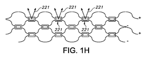
特に、システムは、複数の紫外光源を備える。さらに特には、これらは、規則的なパターンで実質的に配置される。同様に、システムは、(規則的なパターンで実質的に配置される)複数のセンサを備える。適宜、素子は、複数のセンサも備えるが、概して、素子は、複数の光源を備えるが、センサは単一であるなど、センサよりも多くの光源を備える。光源間の距離は、センサ間の距離よりも小さい。 In particular, the system comprises multiple ultraviolet light sources. More particularly, they are substantially arranged in a regular pattern. Similarly, the system comprises multiple sensors (substantially arranged in a regular pattern). As appropriate, the element also comprises a plurality of sensors, but generally the element comprises a plurality of light sources, but the element comprises more light sources than the sensor, such as a single sensor. The distance between the light sources is smaller than the distance between the sensors.
特に、システムは、複数のサブセットを備え、各サブセットは、複数の光源及び1つ又は複数のセンサである。したがって、各実施形態では、生物付着防止システムは、複数の光源を備え、隣り合う光源は、2~100mmのように0.5~200mmの範囲から選択される相互の光源の距離(d1)を有し、生物付着防止システムは、複数の光学センサをさらに備え、隣り合う光学センサは、0.5~200mmの範囲内のように、少なくとも0.5mm、少なくとも2mm、少なくとも1cm、少なくとも4cmのような範囲から選択される相互の光学センサの距離(d2)を有する。特定の各実施形態では、生物付着防止システムは、光源及び光学センサからなる複数のサブセットを備え、各サブセットは、1つ又は複数の光源と1つ又は複数の光学センサとを備え、各サブセットは、サブセット内の1つ又は複数の光学センサの光学センサ信号に応じて、サブセット内の1つ又は複数の光源の紫外線を供給するように構成されている。さらに他の実施形態では、生物付着システムは、複数のLEDを備え、LEDは、紫外線を発生させるように構成されており、LEDは、LEDダイを備え、隣り合うLEDのLEDダイは、0.5~200mmの範囲から選択される相互の光源の距離(d1)を有し、生物付着防止システムは、複数の光学センサをさらに備え、隣り合う光学センサは、0.5~200mmの範囲内のような少なくとも0.5mm、少なくとも2mm、少なくとも1cm、少なくとも4cmのような範囲から選択される相互の光学センサの距離(d2)を有し、生物付着防止システムは、光源及び光学センサからなる複数のサブセットを備え、各サブセットは、1つ又は複数の光源と1つ又は複数の光学センサとを備え、各サブセットは、サブセット内の1つ又は複数の光学センサの光学センサ信号に応じて、サブセット内の1つ又は複数の光源の紫外線を供給するように構成されている。特にd2>d1であり、例えば、d2/d1>2である。 In particular, the system comprises a plurality of subsets, each subset being a plurality of light sources and one or more sensors. Therefore, in each embodiment, the bioadhesion prevention system comprises a plurality of light sources, with adjacent light sources having a mutual light source distance (d1) selected from the range of 0.5 to 200 mm, such as 2 to 100 mm. The bioadhesion prevention system further comprises a plurality of optical sensors such that adjacent optical sensors are at least 0.5 mm, at least 2 mm, at least 1 cm, at least 4 cm, such as within the range of 0.5-200 mm. It has a mutual optical sensor distance (d2) selected from various ranges. In each particular embodiment, the bioadhesion prevention system comprises a plurality of subsets of light sources and optical sensors, each subset comprising one or more light sources and one or more optical sensors, each subset. , Is configured to supply ultraviolet light from one or more light sources within the subset, depending on the optical sensor signals of one or more optical sensors within the subset. In yet another embodiment, the bioattachment system comprises a plurality of LEDs, the LEDs being configured to generate ultraviolet light, the LEDs comprising an LED die, and the LED dies of adjacent LEDs being 0. Having a mutual light source distance (d1) selected from the range of 5 to 200 mm, the bioadhesion prevention system further comprises a plurality of optical sensors, and the adjacent optical sensors are within the range of 0.5 to 200 mm. Having a mutual optical sensor distance (d2) selected from a range such as at least 0.5 mm, at least 2 mm, at least 1 cm, at least 4 cm, the bio-adhesion prevention system comprises a plurality of light sources and optical sensors. It comprises a subset, each subset comprising one or more light sources and one or more optical sensors, each subset within the subset depending on the optical sensor signals of one or more optical sensors within the subset. It is configured to supply ultraviolet light from one or more of the light sources. In particular, d2> d1, for example, d2 / d1> 2.
したがって、特定の各実施形態では、システムは、複数の紫外線発光光源を備える。しかしながら、他の各実施形態では、システムは、1つ又は複数の紫外線発光光源と、可視又は赤外で発光する1つ又は複数の光源とを備える。特定の各実施形態では、後者は、内面反射の検出及び/又は他の目的のために使用される。しかしながら、さらに他の特定の実施形態では、システムは、複数の光源を備え、1つ又は複数の光源は、光の少なくとも一部が内面反射されるとともに光学センサによって検出できるように構成されている。 Therefore, in each particular embodiment, the system comprises a plurality of UV emitting light sources. However, in each of the other embodiments, the system comprises one or more ultraviolet light sources and one or more light sources that emit visible or infrared light. In each particular embodiment, the latter is used for detection of internal reflections and / or for other purposes. However, in yet another particular embodiment, the system comprises a plurality of light sources, one or more of which are configured such that at least a portion of the light is internally reflected and can be detected by an optical sensor. ..
したがって、特定の各実施形態では、システムは、複数の光源を備え、1つ又は複数の光源は、可視光線を供給するように構成されており、1つ又は複数の他の光源は、紫外線を供給するように構成されている。 Thus, in each particular embodiment, the system comprises multiple light sources, one or more light sources being configured to supply visible light, and one or more other light sources emitting ultraviolet light. It is configured to supply.
すでに上で示されたように、システムは、複数の光源を備え、各光源は、主に放射線出口窓の一部へ向けられている。このようにして、大きい導波路が適用される。そのような例では、複数の光学センサも適用され、これらの複数の光学センサは、導波路の放射線出口窓の専用照射を可能にするとともに、高等生物が出口窓に触れたか否かについて出口窓の一部の専用制御を可能にする。したがって、またさらなる特定の実施形態では、生物付着防止システムは、1つ又は複数の光源及び1つ又は複数の光学センサからなる複数のサブセット内に構成された複数の光源及び複数の光学センサを備えており、各サブセットの1つ又は複数の光源は、放射線出口窓のそれぞれの部分を介して放射線を放射するように構成されており、制御系は、1つ又は複数の他のサブセットから独立して1つ又は複数のサブセットを制御するように構成されている。 As already shown above, the system comprises multiple light sources, each light source directed primarily at a portion of the radiation exit window. In this way, a large waveguide is applied. In such an example, multiple optical sensors are also applied, which allow dedicated irradiation of the radiation exit window of the waveguide and also indicate whether or not the higher organism touched the exit window. Allows some dedicated control of. Therefore, and in a further specific embodiment, the bioadhesion prevention system comprises a plurality of light sources and a plurality of optical sensors configured within a plurality of subsets consisting of one or more light sources and one or more optical sensors. One or more light sources in each subset are configured to radiate radiation through their respective parts of the radiation outlet window, and the control system is independent of one or more other subsets. It is configured to control one or more subsets.
上に示したように、さらなる態様では、本発明は、使用中に少なくとも一部が水中に沈められる物体を提供し、この物体は、本明細書中に定められた生物付着防止システムを備えており、紫外線発光素子は、照射段階中に、(i)物体の外面の一部、及び(ii)外面の一部に隣接した水、のうちの1つ又は複数を紫外線で照射するように構成されている。上に示したように、物体は、特に、船舶及び下部構造物体からなる群から選択される。 As shown above, in a further aspect, the invention provides an object that is at least partially submerged during use, which object comprises the bioadhesion prevention system defined herein. The ultraviolet light emitting element is configured to irradiate one or more of (i) a part of the outer surface of the object and (ii) water adjacent to the part of the outer surface with ultraviolet rays during the irradiation stage. Has been done. As shown above, objects are selected in particular from the group consisting of ships and substructure objects.
本明細書において、「使用中に少なくとも一部が水中に沈められる物体」という言い回しは、特に、水関連応用を有する船舶及び下部構造物体などの物体を指す。したがって、使用中、そのような物体は、海、湖、運河、川、又は別の水路などにおける船舶のように、概して水と接触している。例えば、用語「船舶」は、ヨット、タンカー、クルーズ船、クルーザー、フェリー、潜水艦等などのような、例えば、ボート又は船等を指す。用語「下部構造物体」は、特に、ダム、堰、ポンツーン、石油掘削装置等などのような、概して、実質的に固定して配置される水関連応用を指す。用語「下部構造物体」は、(例えば、海洋水を例えばパワープラントに汲み上げるための)管、及び冷却システム、タービンなどの(水力発電)パワープラントの他の一部も指す。用語「下部構造物体」は、石油掘削装置も指す。用語「下部構造物体」は、潮汐エネルギー、波エネルギー、及び/又は海流から得られるエネルギーなど収穫する構造も指す。 As used herein, the phrase "objects that are at least partially submerged during use" specifically refers to objects such as ships and substructure objects that have water-related applications. Therefore, during use, such objects are generally in contact with water, such as ships in seas, lakes, canals, rivers, or other waterways. For example, the term "ship" refers to, for example, a boat or ship, such as a yacht, tanker, cruise ship, cruiser, ferry, submarine, etc. The term "substructure object" specifically refers to water-related applications that are generally placed substantially fixed, such as dams, weirs, pontoons, oil rigs, etc. The term "substructure object" also refers to pipes (eg, for pumping marine water to, for example, power plants) and other parts of power plants (hydroelectric power generation) such as cooling systems, turbines, etc. The term "substructure object" also refers to oil rigs. The term "substructure object" also refers to structures that harvest such as tidal energy, wave energy, and / or energy obtained from ocean currents.
用語「外面」は、特に、水と物理的に接触している表面を指す。管の場合には、これは、内側の管表面及び外側の管表面のうちの1つ又は複数に当てはまる。したがって、用語「外面」の代わりに、用語「汚損面」も適用される。さらに、そのような実施形態では、用語「喫水線」は、例えば、充填レベルも指す。特に、物体は、水関連(海洋など)の応用、すなわち、海又は大洋の中又は近くの応用のために構成された物体である。そのような物体は、それらの使用中、少なくとも一時的に又は実質的に常に、少なくとも一部が水と接触する。物体は、使用中、水(線)よりも下に少なくとも一部があり、又は潜水艦応用のように、その間中ずっと実質的に水(線)よりも下にある。本発明は、沖合の応用、海(中)の応用、掘削プラットホームなどのために、例えば、水関連(海洋など)の汚損防止のために適用され、濡れた面をきれいに保つ。 The term "outer surface" specifically refers to a surface that is in physical contact with water. In the case of tubing, this applies to one or more of the inner tubing surface and the outer tubing surface. Therefore, instead of the term "outer surface", the term "dirty surface" also applies. Further, in such embodiments, the term "waterline" also refers, for example, to the filling level. In particular, an object is an object constructed for water-related applications (such as the ocean), i.e., applications in or near the ocean or ocean. Such objects are in contact with water, at least in part, at least temporarily or substantially at all times during their use. The object is at least partly below the water (line) during use, or substantially below the water (line) throughout, as in submarine applications. The present invention is applied for offshore applications, ocean (middle) applications, excavation platforms, etc., for example, to prevent water-related (ocean, etc.) fouling, and keeps wet surfaces clean.
この水との接触により、生物付着が生じ、上述の不都合を伴う。生物付着は、そのような物体の外面の表面(「表面」)で生じる。保護される物体(の要素)の表面は、鋼鉄で構成されてもよいが、適宜、例えば、木材、ポリエステル、複合材、アルミニウム、ゴム、ハイパロン、PVC、ガラスファイバなどからなる群から選択されるような別の材料で構成されてもよい。したがって、鋼鉄の船殻の代わりに、船殻は、PVC船殻、又はポリエステル船殻などであってもよい。鋼鉄の代わりに、(他の)鉄合金などの別の鉄材料が使用されてもよい。 This contact with water causes biofouling, which is accompanied by the above-mentioned inconveniences. Biofouling occurs on the outer surface (“surface”) of such objects. The surface of the object to be protected may be made of steel, but is optionally selected from the group consisting of, for example, wood, polyester, composites, aluminum, rubber, hypalon, PVC, glass fiber and the like. It may be composed of another material such as. Therefore, instead of a steel hull, the hull may be a PVC hull, a polyester hull, or the like. Instead of steel, another iron material, such as (other) iron alloys, may be used.
本明細書において、用語「汚損」、「生物付着」、又は「生物汚損」は、交換可能に使用される。上には、汚損の一例が与えられている。生物付着は、水中の任意の表面、又は水の近くの任意の表面、及び水(又は別の導電性水性液体)に一時的に曝される任意の表面で生じる。そのような表面上で、生物付着は、喫水線の(すぐ)上など(例えば水しぶきによるように、例えば船首波によるように)、要素が水中又は水の近くにあるときに生じる。回帰線の間では、生物付着は、数時間以内に生じる。程よい温度でも、第1の汚損(の段階)は、糖及び細菌の第1の(分子)レベルとして、数時間以内に生じる。 As used herein, the terms "fouling", "biofouling", or "biofouling" are used interchangeably. Above is an example of fouling. Biofouling occurs on any surface in water, or on any surface near water, and on any surface that is temporarily exposed to water (or another conductive aqueous liquid). On such surfaces, biofouling occurs when the element is in or near water, such as (immediately) above the waterline (eg, by a splash, eg, by a bow wave). Between the regression lines, biofouling occurs within a few hours. Even at moderate temperatures, the first fouling (stage) occurs within a few hours as the first (molecular) level of sugars and bacteria.
生物付着防止システムは、少なくとも紫外線発光素子を備える。さらに、生物付着防止システムは、制御系(以下も参照)、電気エネルギー供給部などを備える。 The biofouling prevention system comprises at least an ultraviolet light emitting element. Further, the biofouling prevention system includes a control system (see also below), an electric energy supply unit, and the like.
用語「生物付着防止システム」は、例えば、単一制御系を介して制御されるような適宜互いに機能的に結合された複数のそのようなシステムも指す。さらに、生物付着防止システムは、複数のそのような紫外線発光素子を備える。本明細書において、(したがって)用語「紫外線発光素子」は、複数の紫外線発光素子を指す。例えば、一実施形態では、複数の紫外線発光素子は、船殻などの物体の外面へ関係付けられ、又はそのような表面によって備えられ(以下も参照)、これに対して、例えば、制御系は、船舶の制御室又は操舵室など物体内のどこかに構成される。 The term "biofouling prevention system" also refers to a plurality of such systems that are appropriately functionally coupled to each other, eg, controlled via a single control system. In addition, biofouling prevention systems include a plurality of such UV emitting devices. As used herein, the term "ultraviolet light emitting element" (hence) refers to a plurality of ultraviolet light emitting elements. For example, in one embodiment, a plurality of UV emitting elements are associated with or provided by such a surface of an object such as a hull (see also below), whereas, for example, a control system. , Somewhere in the object, such as the control room or wheelhouse of a ship.
汚損が発生する表面又は領域は、本明細書中では、汚損表面としても示される。それは、例えば、船の船殻、及び/又は光学媒体の発光面である(以下も参照)。このため、紫外線発光素子は、生物付着の形成を防ぐ及び/又は生物付着を除去するために適用される紫外線(汚損防止光)を与える。この紫外線(汚損防止光)は、特に、(「UV光」としても示される)紫外線で少なくとも構成される。したがって、紫外線発光素子は、特に紫外線を供給するように構成されている。そこに、紫外線発光素子は、光源を備える。用語「光源」は、2~200個の(固体)LED光源などの複数の光源にも関するが、ずっと多くの光源が適用されてもよい。したがって、用語LEDは、複数のLEDも指す。特に、紫外線発光素子は、複数の光源を備える。したがって、上に示したように、紫外線発光素子は、1つ又は複数の(固体)状態の光源を備える。LEDは、(OLED又は)固体LED(或いはこれらLEDの組み合わせ)である。特に、光源は、固体LEDを備える。したがって、特に、光源は、UV-A及びUVC光のうちの1つ又は複数を供給するように構成されている紫外線LEDを備える(以下も参照)。UV-Aは、細胞壁を損なうために使用されるのに対して、UVCは、DNAを損なうのに使用される。したがって、光源は、特に紫外線を供給するように構成されている。本明細書において、用語「光源」は、特に固体光源を指す。光源は、(a)固体レーザも含む。 The surface or area where the fouling occurs is also referred to herein as a fouling surface. It is, for example, the hull of a ship and / or the light emitting surface of an optical medium (see also below). Therefore, the ultraviolet light emitting device provides ultraviolet rays (antifouling light) applied to prevent the formation of biofouling and / or to remove the biofouling. This ultraviolet light (antifouling light) is particularly composed of at least ultraviolet light (also referred to as "UV light"). Therefore, the ultraviolet light emitting element is configured to supply ultraviolet rays in particular. There, the ultraviolet light emitting element includes a light source. The term "light source" also relates to multiple light sources, such as 2 to 200 (solid) LED light sources, but much more light sources may be applied. Therefore, the term LED also refers to a plurality of LEDs. In particular, the ultraviolet light emitting element includes a plurality of light sources. Therefore, as shown above, the UV light emitting device comprises one or more (solid) light sources. The LED is a (OLED or) solid LED (or a combination of these LEDs). In particular, the light source comprises a solid LED. Thus, in particular, the light source comprises an ultraviolet LED configured to supply one or more of UV-A and UVC light (see also below). UV-A is used to damage the cell wall, whereas UVC is used to damage DNA. Therefore, the light source is specifically configured to supply ultraviolet light. As used herein, the term "light source" specifically refers to a solid-state light source. The light source also includes (a) a solid-state laser.
特に、センサは、光源(又は複数の光源)と放射結合される。用語「放射結合される」は、特に、光源によって発せられる放射線の少なくとも一部が、(放射線出口窓における)内面反射を介してセンサによって受信されるように光源及びセンサが互いに関連していることを意味する。 In particular, the sensor is radiatively coupled to the light source (or multiple light sources). The term "radiation coupled" specifically means that the light source and the sensor are related to each other so that at least a portion of the radiation emitted by the light source is received by the sensor via internal reflection (in the radiation exit window). Means.
特に、1つ又は複数の光源は、LEDである。したがって、各実施形態では、生物付着防止システムは、複数の光源を備え、光源はLEDを備える。代替として又は加えて、光源は、固体レーザを備える。 In particular, the one or more light sources are LEDs. Therefore, in each embodiment, the biofouling prevention system comprises a plurality of light sources, the light source comprising an LED. Alternatively or additionally, the light source comprises a solid state laser.
紫外(UV)は、可視スペクトルの下側波長極限とX線放射線帯域によって境界が付けられる電磁光の一部である。紫外光のスペクトル範囲は、約100と400nmとの間の定義によって(1nm=10-9m)であり、人間の目に見えない。CIE分類を用いて、紫外スペクトルは、3つの帯域に分割され、すなわち、315から400nmまでのUVA(長波)、280から315nmまでのUVB(中波)、及び100から280nmまでのUVC(短波)である。実際には、多くの光生物学者は、紫外露光により生じる皮膚の影響について、320nmの上下の波長の重み付きの影響としてしばしば話し、したがって代替の定義を申し出る。 Ultraviolet (UV) is part of the electromagnetic light that is bounded by the lower wavelength limit of the visible spectrum and the X-ray radiation band. The spectral range of ultraviolet light is (1 nm = 10-9 m) by definition between about 100 and 400 nm and is invisible to the human eye. Using the CIE classification, the ultraviolet spectrum is divided into three bands, namely UVA (long wave) from 315 to 400 nm, UVB (medium wave) from 280 to 315 nm, and UVC (short wave) from 100 to 280 nm. Is. In practice, many photobiologists often talk about the effects of UV exposure on the skin as weighted effects of wavelengths above and below 320 nm, thus offering alternative definitions.
強力な殺菌効果は、短波UVC帯域内の光によって与えられる。さらに、紅斑(皮膚の赤み)と結膜炎(目の粘膜の炎症)もこの光の形態によって引き起こされ得る。このため、殺菌紫外光ランプが使用されるとき、UVCの漏れを除外し、そしてこれらの影響を避けるようにシステムを設計することが重要である。光源が沈められる場合、水による紫外光の吸収は、液体表面よりも上でUVCの漏れが人間にとって問題にならないくらい十分に強い。したがって、一実施形態では、紫外線(汚損防止光)は、UVC光を含む。さらに別の実施形態では、紫外線は、100~300nm、特に200~300nm、例えば230~300nmの範囲の波長から選択される放射線を含む。したがって、紫外線は、特に、波長約300nmまでのUVC及び他の紫外線から選択される。良好な結果は、100~300nm、例えば200~300nmの範囲内の波長で得られる。 The strong bactericidal effect is provided by the light in the short wave UVC band. In addition, erythema (redness of the skin) and conjunctivitis (inflammation of the mucous membranes of the eyes) can also be caused by this form of light. For this reason, it is important to design the system to rule out UVC leaks and avoid these effects when germicidal UV lamps are used. When the light source is submerged, the absorption of UV light by water is strong enough that UVC leakage is not a problem for humans above the liquid surface. Therefore, in one embodiment, the ultraviolet light (antifouling light) includes UVC light. In yet another embodiment, the ultraviolet light comprises radiation selected from wavelengths in the range of 100-300 nm, particularly 200-300 nm, eg 230-300 nm. Therefore, UV light is particularly selected from UVC and other UV light with wavelengths up to about 300 nm. Good results are obtained at wavelengths in the range of 100-300 nm, eg 200-300 nm.
上に示したように、各実施形態では、紫外線発光素子は、(照射段階中に)(i)外面の一部、及び(ii)外面の一部に隣接した水、のうちの1つ又は複数を紫外線で照射するように構成されている。用語「一部」は、例えば、船殻又は堰(ドア)などの物体の外面の一部を指す。しかしながら、用語「一部」は、船殻又は堰の外面などのほぼ外面全体も指す。特に、外面は、1つ又は複数の光源の紫外光で照射される又は1つ又は複数の紫外線発光素子の紫外線で照射される複数の部分を備える。各紫外線発光素子は、1つ又は複数の部分を照射する。さらに、適宜、2つ以上の紫外線発光素子の紫外線を受け取る部分がある。 As shown above, in each embodiment, the UV light emitting element is (during the irradiation step) one of (i) a part of the outer surface and (ii) water adjacent to a part of the outer surface. It is configured to irradiate more than one with ultraviolet light. The term "part" refers to a part of the outer surface of an object, such as a hull or a weir (door). However, the term "partial" also refers to almost the entire outer surface, such as the outer surface of a hull or weir. In particular, the outer surface comprises a plurality of portions illuminated by the ultraviolet light of one or more light sources or by the ultraviolet light of one or more ultraviolet light emitting elements. Each ultraviolet light emitting element irradiates one or more portions. Further, there is a portion that receives the ultraviolet rays of the two or more ultraviolet light emitting elements as appropriate.
概して、特に、水関連(海洋など)の応用を指すとき、2つの主要な実施形態の間で区別される。各実施形態の1つは、少なくとも照射段階中に、光源と紫外線発光素子との間で、海水などの水(又は喫水線の上にあるときの空気)とともに紫外線で照射される外面の一部を含む。そのような実施形態では、部分は、物体の「元の」外面によって特に構成されている。しかしながら、さらに別の実施形態では、「元の」外面は、(船舶の船殻などの)物体の「元の」外面に取り付けられるモジュール、特に比較的平坦なモジュールが広がっており、それによって、実際には、モジュール自体が外面を形成する。例えば、そのようなモジュールは、船舶の船殻に関連しており、それによってモジュールは、外面(の少なくとも一部)を形成する。両実施形態では、紫外線発光素子は、特に、放射出口面を備える(以下もさらに参照)。しかしながら、特に、紫外線発光素子が外面の一部を与える後者の実施形態では、そのような放射線出口窓は、(第1の一部及び放射線出口窓が実質的に一致する、特に、同じ表面にあるときに)上記一部を与える。 In general, a distinction is made between the two major embodiments, especially when referring to water-related (such as ocean) applications. One of the embodiments is to cover a part of the outer surface that is irradiated with UV light together with water such as seawater (or air when it is above the waterline) between the light source and the UV light emitting element, at least during the irradiation stage. include. In such embodiments, the portion is specifically composed of the "original" outer surface of the object. However, in yet another embodiment, the "original" outer surface is spread out with modules that attach to the "original" outer surface of an object (such as the hull of a ship), especially relatively flat modules. In reality, the module itself forms the outer surface. For example, such a module is associated with the hull of a ship, whereby the module forms (at least a portion of) the outer surface. In both embodiments, the UV light emitting device specifically comprises a radiation outlet surface (see also below). However, especially in the latter embodiment in which the UV light emitting element provides a portion of the outer surface, such a radiation outlet window is (especially on the same surface, where the first portion and the radiation outlet window are substantially identical. (At some point) give some of the above.
したがって、一実施形態では、紫外線発光素子は、外面に取り付けられる。さらに他の特定の実施形態では、生物付着防止システムの放射線出口窓は、外面の一部として構成されている。したがって、実施形態の一部では、物体は、船殻を備えた船舶を含み、紫外線発光素子は、船殻に取り付けられる。用語「放射線出口窓」は、複数の放射線出口窓も指す(以下も参照)。 Therefore, in one embodiment, the ultraviolet light emitting element is attached to the outer surface. In yet another particular embodiment, the radiation outlet window of the biofouling prevention system is configured as part of the outer surface. Therefore, in some of the embodiments, the object includes a ship with a hull and the UV emitting element is attached to the hull. The term "radiation outlet window" also refers to multiple radiation outlet windows (see also below).
両方の一般的な実施形態では、紫外線発光素子は、(照射段階中に)紫外線で外面の一部に隣接した水を照射するように構成されている。モジュール自体が実際に外面を形成する各実施形態では、紫外線発光素子は、それが実際には外面の一部である、及び適宜、外面の一部に隣接した水でもあるときに、(照射段階中に)紫外線で外面の一部を照射するように少なくとも構成されている。これによって、生物付着は、防がれる及び/又は減少させられる。 In both general embodiments, the UV light emitting device is configured to irradiate (during the irradiation step) with water adjacent to a portion of the outer surface with UV light. In each embodiment in which the module itself actually forms the outer surface, the UV light emitting device is (irradiation stage) when it is actually part of the outer surface and, as appropriate, also water adjacent to the part of the outer surface. At least configured to illuminate part of the outer surface with ultraviolet light (inside). This prevents and / or reduces biofouling.
一実施形態では、汚損からきれいに保たれている大幅な量の保護表面、好ましくは保護表面全体、例えば、船の船殻は、殺菌光(「汚損防止光」)、詳細には紫外光を発する層で覆われている。 In one embodiment, a significant amount of protective surface that is kept clean from fouling, preferably the entire protected surface, eg, the hull of a ship, emits sterilizing light (“staining prevention light”), and more specifically UV light. It is covered with layers.
さらに別の実施形態では、紫外線(汚損防止光)は、ファイバなどの導波路を介して保護される表面へ与えられる。 In yet another embodiment, ultraviolet light (antifouling light) is applied to a surface protected via a waveguide such as a fiber.
したがって、一実施形態では、汚損防止光システムは、光学媒体を備え、この光学媒体は、光ファイバなどの導波路で構成され、紫外線(汚損防止光)を汚損表面へ供給するように構成されている。例えば、紫外線(汚損防止光)が漏れる導波路の表面は、明細書において発光面としても示されている。概して、この導波路の一部は、少なくとも一時的に沈められる。紫外線(汚損防止光)が発光面から漏れることにより、使用中に(海水などの)液体に少なくとも一時的に曝される物体の要素は照射され、それによって汚損保護される。しかしながら、発光面それ自体も、汚損保護される、この効果は、以下に説明される光学媒体を備える紫外線発光素子の実施形態の一部において使用される。 Therefore, in one embodiment, the antifouling optical system comprises an optical medium, which is composed of a waveguide such as an optical fiber and is configured to supply ultraviolet light (antifouling light) to the fouled surface. There is. For example, the surface of a waveguide through which ultraviolet light (anti-fouling light) leaks is also indicated as a light emitting surface in the specification. In general, part of this waveguide is at least temporarily submerged. Leakage of ultraviolet light (antifouling light) from the light emitting surface irradiates elements of objects that are at least temporarily exposed to liquids (such as seawater) during use, thereby protecting them from fouling. However, the light emitting surface itself is also foul-protected, this effect being used in some embodiments of UV light emitting devices with the optical media described below.
光媒体を備える実施形態は、WO2014188347にも記載されている。WO2014188347の実施形態は、それらが制御ユニット及び/又は水スイッチ並びに本明細書中に記載される他の実施形態と組み合わされるときに、参照により本明細書に組み込まれる。 Embodiments comprising an optical medium are also described in WO2014188347. Embodiments of WO2014188347 are incorporated herein by reference when they are combined with control units and / or water switches and other embodiments described herein.
上に示したように、本発明は、(ドア)ノブ等のためのような水関連(海洋など)の応用とは異なる応用にも適用される。 As shown above, the present invention also applies to applications that differ from water-related (ocean, etc.) applications, such as for (door) knobs and the like.
上に示したように、紫外線発光素子は、特に紫外線出口窓を備える。したがって、特定の実施形態では、紫外線発光素子は、紫外線出口窓を備え、紫外線発光素子が、特に紫外線発光素子の紫外線出口窓より下流に紫外線を供給するように構成されている。そのような紫外線出口窓は、放射線が紫外線発光素子から漏れる光学的窓である。代替として又は加えて、紫外線出口窓は、導波路の表面である。したがって、紫外線は、導波路の中に紫外線発光素子の中で結合され、導波路の面(の一部)を介して素子から漏れる。上にやはり示されたように、各実施形態では、放射線出口窓は、適宜、物体の外面の一部として構成されている。「漏れ」について別の用語は、「取出し」であり得る。 As shown above, the UV light emitting device specifically comprises a UV outlet window. Therefore, in a specific embodiment, the ultraviolet light emitting element is provided with an ultraviolet outlet window, and the ultraviolet light emitting element is configured to supply ultraviolet rays particularly downstream from the ultraviolet outlet window of the ultraviolet light emitting element. Such an ultraviolet outlet window is an optical window through which radiation leaks from the ultraviolet light emitting element. As an alternative or in addition, the UV exit window is the surface of the waveguide. Therefore, the ultraviolet light is coupled into the waveguide in the ultraviolet light emitting device and leaks from the device through (a part of) the surface of the waveguide. As also shown above, in each embodiment the radiation outlet window is optionally configured as part of the outer surface of the object. Another term for "leakage" can be "removal".
特に、(固体)光源は、第1の紫外線レベルと第2の紫外線レベルとの間で少なくとも制御可能であり、第1の紫外線レベルは、第2の紫外線レベルよりも大きく(そして、第2の紫外線レベルは、第1の放射線レベルよりも小さく、又はゼロでさえある)。したがって、一実施形態では、光源は、オフに切り換えられ、(放射線段階中に)オンに切り換えられる。さらに、適宜、紫外線の強度はやはり、段階的又は連続的な紫外線強度制御のようにこれらの2つの段階の間で制御される。したがって、光源(したがってその紫外線強度I)は、特に制御可能である。 In particular, the (solid) light source is at least controllable between the first UV level and the second UV level, where the first UV level is greater than (and second) the second UV level. The UV level is less than or even zero than the first radiation level). Thus, in one embodiment, the light source is switched off and turned on (during the radiation stage). Moreover, as appropriate, the intensity of UV light is also controlled between these two steps, such as stepwise or continuous UV intensity control. Therefore, the light source (and thus its UV intensity I) is particularly controllable.
(水関連(海洋など))実施形態では、生物付着防止システムは、特に、物体の一部又はこの物体の一部に隣接した水へ紫外線を供給するように構成されている。これは、特に、照射段階中に紫外線が適用されることを示唆する。したがって、適宜、紫外線が全く適用されていない時間があってもよい。これは、(したがって)例えば、紫外線発光素子のうちの1つ又は複数の制御系切り換えによるものだけでなく、例えば、昼と夜、又は水温等など既定の設定によってもよい。例えば、一実施形態では、紫外線は、パルス状に加えられる。 In embodiments (water-related (such as the ocean)), the biofouling prevention system is specifically configured to supply UV light to a portion of an object or water adjacent to a portion of this object. This in particular suggests that UV light is applied during the irradiation stage. Therefore, there may be a time when the ultraviolet rays are not applied at all. This may be (hence) not only by switching the control system of one or more of the UV light emitting elements, but also by default settings such as day and night, water temperature and the like. For example, in one embodiment, the ultraviolet light is applied in a pulsed manner.
したがって、特定の実施形態又は態様では、生物付着防止システムは、汚損防止光(すなわち、紫外線)を汚損表面又はそこに隣接した水へ供給することによって使用中に少なくとも一時的に水に曝される物体の汚損表面上の生物付着を防ぐ又は減少させるように構成されている。特に、生物付着防止システムは、汚損防止光を光学媒体を介して汚損表面へ供給するように構成されており、紫外線発光素子は、(ii)紫外線(汚損防止光)の少なくとも一部を受け取るように構成されている光学媒体をさらに備え、この光学媒体は、紫外線(汚損防止光)の少なくとも一部を供給するように構成されている発光面を備える。さらに、特に、光学媒体は、導波路及び光ファイバのうちの1つ又は複数を備え、紫外線(汚損防止光)は、特に、UVB光及びUVC光のうちの1つ又は複数を含む。これらの導波路及び光媒体は、本明細書中においてさらに詳細に説明される。 Thus, in certain embodiments or embodiments, the biofouling prevention system is at least temporarily exposed to water during use by supplying antifouling light (ie, ultraviolet light) to the fouling surface or water adjacent thereto. It is configured to prevent or reduce biofouling on the surface of a polluted object. In particular, the bioadhesion prevention system is configured to supply antifouling light to the contaminated surface via an optical medium so that the ultraviolet light emitting element (ii) receives at least a portion of ultraviolet light (antifouling light). Further comprises an optical medium configured in, which comprises a light emitting surface configured to supply at least a portion of ultraviolet light (antifouling light). Further, in particular, the optical medium comprises one or more of a waveguide and an optical fiber, and the ultraviolet light (antifouling light) particularly comprises one or more of UVB light and UVC light. These waveguides and optical media are described in more detail herein.
光学媒体は、保護された表面に適用されるための(シリコーン)フォイルとして設けられてもよく、このフォイルは、汚損防止光を発生させる少なくとも1つの光源と、フォイルにわたって紫外線を分布させるシート状光学媒体とを備える。各実施形態では、フォイルは、数ミリメートルから数センチメートル、例えば、0.1~5cm、0.2~2cmの大きさの程度の厚さを有する。各実施形態では、フォイルは、数十又は数百平方メートルの大きさの程度のサイズを有する大幅に大きいフォイルを与えるように厚さ方向に直交する任意の方向に実質的に制限される。フォイルは、汚損防止タイルを与えるようにフォイルの厚さ方向に直交する2次元方向に実質的にサイズが限られており、別の実施形態では、フォイルは、汚損防止フォイルの細長いストリップを与えるようにフォイルの厚さ方向に直交する1つの方向だけに実質的にサイズが限られている。したがって、光学媒体及びさらに紫外線発光素子もが、タイル又はストリップとして与えられる。タイル又はストリップは、(シリコーン)フォイルで構成される。 The optical medium may be provided as a (silicone) foil for application to a protected surface, which is a sheet of optics that distributes UV light across the foil with at least one light source that produces antifouling light. Equipped with a medium. In each embodiment, the foil has a thickness of a few millimeters to a few centimeters, eg, 0.1-5 cm, 0.2-2 cm in size. In each embodiment, the foil is substantially restricted in any direction orthogonal to the thickness direction to give a significantly larger foil having a size of a degree of tens or hundreds of square meters. The foil is substantially limited in size in a two-dimensional direction orthogonal to the thickness direction of the foil to provide antifouling tiles, and in another embodiment the foil is to provide an elongated strip of antifouling foil. The size is substantially limited to only one direction orthogonal to the thickness direction of the foil. Therefore, the optical medium and further UV light emitting elements are also provided as tiles or strips. The tile or strip is composed of (silicone) foil.
したがって、特定の各実施形態では、導波路要素は、ガラス、シリコーン、及び光透過ポリマーのうちの1つ又は複数で構成される。 Thus, in each particular embodiment, the waveguide element is composed of one or more of glass, silicone, and a light-transmitting polymer.
一実施形態では、紫外線発光素子は、紫外線を発生させる光源の2次元グリッドを備え、光学媒体は、光源の2次元グリッドからの紫外線の少なくとも一部を光学媒体にわたって分布させるように配置され、光モジュールの光発光面から出る紫外線の2次元分布を与えるようになっている。光源の2次元グリッドは、金網構造、最密構造、行列構造、又は任意の他の適切な規則的又は不規則的構造で配置される。グリッド内の隣り合う光源間の物理的距離は、グリッドにわたって一定であり、又は例えば、汚損防止効果を与えるのに必要とされる光の出力パワーの関数として又は保護された表面/きれいに保たれる表面上の紫外線発光素子の位置(例えば、船の船殻の位置)の関数として変化する。光源の2次元グリッドを設ける利点は、紫外線が紫外線照明で保護される領域の近くに発生することと、それが光学媒体又は光ガイド内の損失を減少させることと、それが光分布の均一性を高めることとを含む。好ましくは、紫外線は、発光面にわたって概して均一に分布しており、これは、さもなければ汚損が生じる照明不足の領域を減少させ又はさらに防ぎ、一方、同時に、汚損防止に必要なものよりも大きい光による他の領域の過照明によるエネルギーの浪費を減少させる又はさらに防ぐ。一実施形態では、グリッドは、光学媒体で構成されている。さらに別の実施形態では、グリッドは、(シリコーン)フォイルによって構成されている。 In one embodiment, the ultraviolet light emitting element comprises a two-dimensional grid of light sources that generate ultraviolet light, and the optical medium is arranged such that at least a portion of the ultraviolet light from the two-dimensional grid of the light source is distributed over the optical medium. It is designed to give a two-dimensional distribution of ultraviolet rays emitted from the light emitting surface of the module. The two-dimensional grid of light sources is arranged in a wire mesh structure, a close-packed structure, a matrix structure, or any other suitable regular or irregular structure. The physical distance between adjacent light sources in the grid is constant across the grid, or, for example, as a function of the output power of light required to provide antifouling effect or on a protected surface / kept clean. It changes as a function of the position of the UV light emitting element on the surface (eg, the position of the hull of the ship). The advantage of providing a two-dimensional grid of light sources is that UV light is generated near the area protected by UV illumination, which reduces the loss in the optical medium or light guide, and it is the uniformity of the light distribution. Including to enhance. Preferably, the UV light is generally evenly distributed across the light emitting surface, which reduces or further prevents areas of under-illumination that would otherwise result in fouling, while at the same time being greater than what is required to prevent fouling. Reduces or even prevents energy waste from overilluminating other areas with light. In one embodiment, the grid is composed of an optical medium. In yet another embodiment, the grid is composed of (silicone) foil.
さらに、一実施形態では、光学媒体は、保護された表面の近位に配設され(適宜そこに取り付けられることを含む)、紫外光を受け取るように結合されている。光学媒体は、保護された表面に直交する厚さ方向を有し、厚さ方向に直交する光学媒体の2つの直交方向が、保護された表面に対して平行である。光学媒体は、厚さ方向に直交する2つの直交方向のうちの少なくとも1つの方向に紫外光が光学媒体内を進むように、及び光学媒体の表面に沿った点で、紫外光の各部分が光学媒体に漏れるように、紫外光の伝搬経路を与えるように構成されている。 Further, in one embodiment, the optical medium is disposed proximal to the protected surface (including being appropriately attached therein) and coupled to receive ultraviolet light. The optical medium has a thickness direction orthogonal to the protected surface, and the two orthogonal directions of the optical medium orthogonal to the thickness direction are parallel to the protected surface. The optical medium is such that each portion of the ultraviolet light travels through the optical medium in at least one of two orthogonal directions orthogonal to the thickness direction, and at points along the surface of the optical medium. It is configured to provide a propagation path for ultraviolet light so that it leaks into the optical medium.
さらなる態様では、本発明は、物体の外面(の一部)を(生物)汚損防止する方法も提供する。そのような物体は、導波路要素を備え、この導波路要素は、出術台又は台所用のまな板のようにプレートの形態であるが、ドアのノブ、トイレを操作する(トイレを流す)ためのトイレノブ、又はタップのノブ等などの別の形状も有する。また、便座は、導波路要素などを備える。本発明は、手術室の壁(の一部)の生物付着を減少させるためにも使用される。したがって、さらなる態様又は実施形態では、本発明は、本明細書中に定められたシステムを備える物体も提供し、この物体は外面を備え、放射線出口窓が外面の少なくとも一部として構成され、物体は、テーブル、手術台、クリーンルームの壁、手術室の壁、及び台所の壁を含む群から選択される。 In a further aspect, the invention also provides a method of preventing (bio) fouling on (a part of) the outer surface of an object. Such an object comprises a waveguide element, which is in the form of a plate, such as a cutting board for a surgical table or kitchen, but to operate a door knob, toilet (to flush the toilet). It also has other shapes such as toilet knobs, tap knobs, etc. Further, the toilet seat includes a waveguide element and the like. The present invention is also used to reduce biofouling on (part of) the walls of the operating room. Accordingly, in a further aspect or embodiment, the invention also provides an object comprising the system defined herein, the object comprising an outer surface, the radiation exit window configured as at least part of the outer surface, the object. Is selected from the group including tables, operating tables, clean room walls, operating room walls, and kitchen walls.
したがって、各実施形態では、テーブル、手術台、クリーンルームの壁、手術室の壁、又は台所の壁は、本明細書に記載された導波路要素を備える。 Thus, in each embodiment, the table, operating table, clean room wall, operating room wall, or kitchen wall comprises the waveguide elements described herein.
光源は、そのような物体の外に構成されてもよく、放射線は、例えば光ファイバを介して導波路要素に分割されてもよい。さらに他の各実施形態では、光源は、導波路要素内に埋め込まれる。 The light source may be configured outside of such an object, and the radiation may be split into waveguide elements, for example via an optical fiber. In yet each of the other embodiments, the light source is embedded within the waveguide element.
本明細書において、用語「物体」は、特定の各実施形態では、特に機能的に接続されている(異なる)物体の配置も指す。 As used herein, the term "object" also refers to the arrangement of (different) objects that are particularly functionally connected in each particular embodiment.
さらに他の態様では、本発明は、導波路要素から導波路要素の外部への放射線の漏れを制御する方法も提供する。上記放射線は、紫外線を少なくとも含み、この方法は、導波路要素内で内部反射した放射線の内面反射強度(I)を検出するステップと、経時的な内面反射強度(I)の減少の所定の第1の閾値に到達するのに応じて(紫外線を少なくとも含む放射線を与える光源の)放射線の強度を減少させるステップとを有する。 In yet another aspect, the invention also provides a method of controlling radiation leakage from the waveguide element to the outside of the waveguide element. The radiation comprises at least ultraviolet light, and the method comprises a step of detecting the internal reflection intensity (I) of the radiation internally reflected within the waveguide element and a predetermined number of reductions in the internal reflection intensity (I) over time. It has a step of reducing the intensity of radiation (of a light source that provides radiation, including at least ultraviolet light) in response to reaching a threshold of 1.
特定の実施形態では、物体は、使用中に水に少なくとも一時的に曝される物体であり、この方法は、本明細書中に定められた生物付着防止システムを物体に設けるステップと、適宜、(i)フィードバック信号、及び(ii)紫外線の強度(汚損防止光)を(周期的に)変化させるタイマのうちの1つ又は複数の関数として、(物体の使用中に)紫外線を発生させるステップと、(照射段階中に)紫外線を外面(の一部)へ供給するステップとを有する。そのようなフィードバック信号は、センサによって与えられる。したがって、この方法は、経時的な内面反射強度(I)の減少の所定の第1の閾値に到達するのに応じて放射線の強度を減少させるステップをさらに有するとともに、システムに関連して定められたさらなる活動を有する。 In certain embodiments, the object is an object that is at least temporarily exposed to water during use, and this method comprises providing the object with a bioadhesion prevention system as defined herein, as appropriate. (I) A step of generating UV light (during use of an object) as a function of one or more of the feedback signals and (ii) a timer that changes the intensity of the UV light (antifouling light) (periodically). And a step of supplying (part of) ultraviolet light (during the irradiation stage). Such a feedback signal is given by the sensor. Therefore, this method further comprises a step of reducing the intensity of radiation in response to reaching a predetermined first threshold of decrease in internal reflection intensity (I) over time, and is defined in relation to the system. Has more activity.
さらに他の態様では、本発明は、生物付着防止システムを物体に設ける方法も提供する。この方法は、生物付着防止システムに物体への導波路要素を備えるステップを有する。特に、物体は、物体の使用中に、細菌などの有害なミクロ生物に少なくとも一時的に曝されるように構成されている。したがって、各実施形態では、導波路要素は、物体に取り付けられ、導波路要素を備えた物体を与えるようになっている。 In yet another aspect, the invention also provides a method of providing a biofouling prevention system on an object. This method comprises the step of providing a waveguide element to the object in the biofouling prevention system. In particular, the object is configured to be at least temporarily exposed to harmful micro-organisms such as bacteria during the use of the object. Therefore, in each embodiment, the waveguide element is attached to an object to provide an object with the waveguide element.
各実施形態では、本発明は、使用中に少なくとも一時的に水に曝される物体に生物付着防止システムを設ける方法も提供する。この方法は、添付の特許請求の範囲にさらに定められるように、物体の外面の一部及び(使用中に)一部に隣接した水のうちの1つ又は複数に紫外線を供給するように構成されている導波路要素を有する生物付着防止システムを船舶などの物体に設けるステップ、例えば、物体に組み込むステップ及び/又は外面に取り付けるステップを有する。特に、導波路要素は、外面に取り付けられる、又は外面の(第1の)部分として構成もされる。 In each embodiment, the invention also provides a method of providing a biofouling prevention system on an object that is at least temporarily exposed to water during use. This method is configured to supply ultraviolet light to one or more of the water adjacent to a portion of the outer surface of the object and a portion (during use), as further defined in the appended claims. It has a step of providing a biofouling prevention system having a waveguide element on an object such as a ship, for example, a step of incorporating it into an object and / or a step of attaching it to an outer surface. In particular, the waveguide element is attached to the outer surface or is also configured as a (first) portion of the outer surface.
用語「可視」、「可視光」、又は「可視発光」は、約380~780nmの範囲内の波長を有する光を指す。 The term "visible", "visible light", or "visible light" refers to light having a wavelength in the range of about 380 to 780 nm.
さらなる実施形態では、汚損防止表面の様々な領域上の汚損レベルは、別々に検出及び制御することができる。 In a further embodiment, the levels of fouling on various areas of the antifouling surface can be detected and controlled separately.
さらに他の実施形態では、監視はリアルタイムで行われ、センサからの汚損信号は、汚損防止システムの紫外線を制御するために使用される。 In yet another embodiment, the monitoring is done in real time and the fouling signal from the sensor is used to control the UV light in the fouling prevention system.
したがって、生物付着防止放射線は、特に紫外線を含む。センサ(反射、散乱、ルミネッセンス)を用いた検出に使用される放射線は、紫外線、可視光線、及び赤外線のうちの1つ又は複数であり、すなわち、特に約200から1500nmの間の実質的に任意の放射線である。 Therefore, biofouling prevention radiation specifically includes ultraviolet light. The radiation used for detection using sensors (reflection, scattering, luminescence) is one or more of ultraviolet light, visible light, and infrared light, i.e., in particular virtually arbitrary between about 200 and 1500 nm. Radiation.
特に、本明細書中に記載された任意の行為は、人工の装置で実行される。例えば、用語「検出」は、センサを用いた検出を指し、又は「決定」のような用語は、プロセッサを用いた決定を指す。 In particular, any of the acts described herein are performed on artificial devices. For example, the term "detection" refers to detection using a sensor, or a term such as "decision" refers to a decision using a processor.
次に、添付の概略図を参照して本発明の各実施形態を例のみによって説明する。対応する参照符号は、対応する部分を示す。 Next, each embodiment of the present invention will be described by reference only with reference to the accompanying schematic diagram. The corresponding reference code indicates the corresponding part.
図面は、必ずしも原寸に比例していない。 Drawings are not always proportional to actual size.
図1aは、紫外線発光素子210を備える生物付着防止システム200の一実施形態を概略的に示す。紫外線発光素子210は、紫外線出口窓230を備える。紫外線発光素子210は、紫外線221を供給するように構成された光源220を少なくとも一部取り囲む。本明細書では、一例として、3つの光源220が示されている。ここでは、紫外線発光素子210は、導波路として構成され、その中に素子が埋め込まれている。したがって、光源220は、導波路内に埋め込まれている。紫外線出口窓230は、光源220の紫外線221の少なくとも一部を透過するように構成されている。紫外線出口窓230は、上流窓側231(ここで光源へ向けられる)と、下流窓側232とを備える。紫外線発光素子210は、下流窓側232から発する放射線421を検出するように構成されている光学センサ310も少なくとも一部取り囲む。ここで、センサ310も、導波路内に埋め込まれている。センサ310は、下流側から発する放射線421に応じて、対応する光学センサ信号を供給するように構成されている。さらに、生物付着防止システム200は、光学センサ信号に応じて紫外線221を供給するようにさらに構成されている。放射線421は、参照符号5で示される(下流窓側232における生物付着による)光源放射線221の散乱、(上流窓側231における)光源放射線221の反射、及び(下流窓側232における)生物付着のルミネッセンスのうちの1つ又は複数を含む。
FIG. 1a schematically shows an embodiment of a
特に、放射線421は、(全ての放射線が取り出されるのでない限り)光源放射線221の反射を含む。
In particular, the
ここで、この概略的に示された実施形態では、同じタイプの光源が、生物付着防止放射線221に使用されるとともに、センサ310を備えた制御ループに使用される。しかしながら、これは、必ずしもそうとは限らない。参照符号305は、光源220の放射線221を光学センサ310の関数として制御する電子機器又は制御要素を指す(以下も参照)。ここで、制御は、強度の制御、及びスペクトル分布の制御のうちの1つ又は複数を指す。センサ310と、反射、散乱、ルミネッセンスなどによって直接又は間接的に使用される放射線を発生させる光源との組み合わせは、本明細書中で、センサシステムとしても示されている。本明細書中において、光源は、センサシステムの供給源としても示されている。
Here, in this schematically shown embodiment, the same type of light source is used for the
用語「制御」は、特に光源の挙動を決定し又は稼働を監督する、したがって、特に強度とスペクトル分布とのうちの1つ又は複数、特に少なくとも強度の挙動を決定し又は稼働を監督することを指す。 The term "control" specifically determines the behavior or supervises the operation of a light source, and thus determines or supervises the behavior of one or more of, in particular the intensity and the spectral distribution, in particular at least the intensity. Point to.
図1bに概略的に示された実施形態では、本明細書中に説明及び/又は本明細書中に図示された他の実施形態も、放射線発光素子、したがって特にここでは紫外線発光素子220を備え、この紫外線発光素子220は、光源及びセンサを少なくとも一部、又はさらにはほぼ全体的に取り囲むことに留意されたい。
In the embodiments schematically shown in FIG. 1b, other embodiments described herein and / or illustrated herein also comprise a radiation emitting element, and thus, in particular here, an
図1b~図1dは、使用中に水2の中に少なくとも一部が沈められる物体10の各実施形態を概略的に示す(喫水線13参照)。船舶又は堰などの物体10(以下も参照)は、特に船殻又は船殻の一部などの物体10の外面11の部分111への紫外線221の応用向けに、紫外線発光素子210を備えた生物付着防止システム200をさらに備える。ここで、生物付着防止システム200、又はさらに特には紫外線発光素子210が外表面の一部であり、それによって実際に外表面の一部を形成する(図1a)、或いは紫外線発光素子210が外表面を照射するように構成され、必ずしも船の船殻などの外表面の一部を形成するとは限らない(図1c)2つの実施形態が示されている。例えば、物体10は、船舶1及び下部構造物体15からなる群から選択される(以下も参照)。
1b-1d schematically show each embodiment of an
紫外線発光素子210は、1つ又は複数の光源220を備え、特に、照射段階中に紫外線221で(i)外面11の部分111、及び(ii)外面11の部分111に隣接した水、のうちの1つ又は複数を照射するように構成されている。前者の変形例は、特に図1cの実施形態に当てはまり、後者の実施形態は、特に、図1b~図1cの両実施形態に当てはまる。しかしながら、紫外線発光素子210の外面が物体10の外面として構成されるとき、もちろん、部分111は、紫外線21でそれ自体照射されることに留意されたい。
The ultraviolet light emitting element 210 includes one or more
したがって、紫外線発光素子210は、紫外線出口窓230を備え、紫外線発光素子210は、紫外線発光素子210の紫外線出口窓230から下流に紫外線221を供給するように構成されている。
Therefore, the ultraviolet light emitting element 210 is provided with an
特に、光源220は、第1の紫外線レベルと第2の紫外線レベルとの間で少なくとも制御可能であり、第1の紫外線レベルは、第2の紫外線レベルよりも大きい(且つ第2の紫外線レベルは、第1の放射線レベルよりも小さい(例えばゼロを含む)。
In particular, the
上に示したように、参照符号1で示される用語「船舶」は、図1dに概略的に示されるような、例えば、ヨット、タンカー、クルーズ船、クルーザー、フェリー、潜水艦(図1dの10d参照)等などのような、例えば、ボート又は船(図1dの10a参照)などを指す。用語「下部構造物体」は、参照符号15で示され、特に、ダム/堰(図1dの参照符号10e/10f)、ポンツーン(図1dの参照符号10c)、石油掘削装置(図1dの参照符号10b)等などの概して実質的に固定して配置される水に関連する応用例を指す。 As shown above, the term "ship", indicated by reference numeral 1, is used, for example, yacht, tanker, cruise ship, cruiser, ferry, submarine (see 10d in FIG. 1d), as schematically shown in FIG. 1d. ) Etc., for example, a boat or a ship (see 10a in FIG. 1d). The term "substructure object" is indicated by reference numeral 15, in particular dam / dam (reference numeral 10e / 10f in FIG. 1d), pontoon (reference numeral 10c in FIG. 1d), oil drilling rig (reference numeral 10c in FIG. 1d). 10b) etc. Refers to an application example related to water that is generally substantially fixed and arranged.
図1eは、ここでは一例として統合された制御系300と統合されたセンサ310とを備える生物付着防止システム200の実施形態をより詳細に概略的に示す。
FIG. 1e schematically shows, in more detail, an embodiment of a
図1fは、(ここでは船舶1の船殻21に関連した)一例として複数の紫外線発光素子210を備える船舶の壁又は下部構造物体の壁などの物体10の外面11を概略的に示す。代替として又は加えて、複数の機能的に結合された又は独立して機能する生物付着防止システム200が適用される。
FIG. 1f schematically shows an
図1fは、生物付着防止システム200が(複数の光源を備えた)複数の紫外線発光素子210と、複数の放射線出口窓230と、複数の上記部分111とを備える実施形態も概略的に示している。複数の光源220は、紫外線221を複数の放射線出口窓23を介して複数の上記部分111へ供給するように構成されており、複数の上記部分111は、物体10の様々な高さに構成され、制御系300は、入力情報の関数として光源220を個々に制御するように構成されている。例えば、一実施形態では、制御系300は、水に対しての外面11の部分111の位置の関数として光源220を個々に制御するように構成されている。
FIG. 1f also schematically illustrates an embodiment in which the
図1gは、船舶1は、物体10の実施形態として、複数の生物付着防止システム200を備え、及び/又はそのような生物付着防止システム200のうちの1つ又は複数は、複数の紫外線発光素子210を備える一実施形態を概略的に示す。水(喫水線)などに対しての特定のそのような生物付着防止システム200の高さ及び/又は紫外線発光素子210の高さに応じて、それぞれの紫外線発光素子210は、オンに切り換えられる。
In FIG. 1g, the ship 1 comprises, as an embodiment of the
図1hは、紫外線LEDなどの光源210がグリッド状に配列され、並列接続の直列で接続されている金網の実施形態を示す。LEDは、LEDを金網に接続するためのはんだ付け、接着、又は任意の他の知られている電気的な接続技法のいずれかによってノードで取り付けられている。1つ又は複数のLEDは、各ノードに配置されている。直流又は交流駆動が実施される。交流が使用される場合、逆平行構成のLEDの結合が使用される。当業者は、各ノードにおいて、逆平行構成のLEDの2つ以上の結合が使用されることを知っている。金網グリッドの実際のサイズ及びこのグリッド内の紫外線LED間の距離は、ハーモニカ構造を伸ばすことによって調整することができる。金網グリッドは、光学媒体内に埋め込まれる。上で、水、センサの信号等などと接触することに応じて、生物付着防止システム200がオフに切り換わる又は特定の紫外線発光素子210若しくは特定の光源220をオフに切り換える特に能動的な防止応用を説明した。しかしながら、代替として又は加えて、警告信号又はメッセージを使用して、危険な人に警告してもよい。
FIG. 1h shows an embodiment of a wire mesh in which light sources 210 such as ultraviolet LEDs are arranged in a grid pattern and connected in parallel. The LEDs are attached at the node by any of the soldering, gluing, or any other known electrical connection technique for connecting the LEDs to the wire mesh. One or more LEDs are located at each node. DC or AC drive is performed. When alternating current is used, the coupling of LEDs in antiparallel configuration is used. One of ordinary skill in the art knows that at each node, two or more couplings of LEDs in an antiparallel configuration are used. The actual size of the wire mesh grid and the distance between the UV LEDs in this grid can be adjusted by stretching the harmonica structure. The wire mesh grid is embedded in the optical medium. Above, a particularly active preventive application that switches off the
図2aは、内面反射(又は全反射TIR)がセンサ310のための入力としてそれぞれ使用される変形例を概略的に示す。内面反射は、生物付着5が増加するにつれて減少する。ここで、一例として、生物付着防止光としての紫外線の発生のためにも使用される光源220が、(センサシステム内で)適用される。しかしながら、代替光源が適用されてもよい(図2cも参照)。図2aは、一例として、参照符号217で示されるブロッキング要素又は物理的障害物も備え、これらは、参照符号221で示される光源放射線が、センサ310に直接到達するのを防ぐように構成されている。
FIG. 2a schematically shows a variant in which internal reflection (or total internal reflection TIR) is used as an input for the
図2aに概略的に示されるように、導波路要素1210は、放射線221の少なくとも一部を受け入れ、放射線221の少なくとも一部を放射線出口窓230を介して導波路要素1210の外部へ放射するように構成されている。さらに、導波路要素は、放射線出口窓230で放射線221の一部を内面反射するように構成されている。この反射された放射線は、センサ310によって測定することができる。
As schematically shown in FIG. 2a, the
図2bは、生物付着5のルミネッセンスが使用される一実施形態を概略的に示す。このルミネッセンスは、可視及び/又は赤外における。励起は、光源220又は代替光源に関連している(図2cも参照)。
FIG. 2b schematically illustrates one embodiment in which the luminescence of
ここで、一例として、別個の放射線出口窓230を備えたハウジングが、他の概略図の多くに使用されるような導波路プレートの代わりに概略的に示されている。したがって、紫外線発光素子は、1つ又は複数の関連素子を少なくとも一部備えた又は全体として内部に埋め込んだプレート状モジュールである。しかしながら、紫外線素子は、少なくとも部分的又はさらには全体的に1つ又は複数の関連素子を取り囲むハウジングも備える。1つ又は複数の関連素子は、光源放射線、特に紫外線を供給するように構成されている光源を少なくとも備える。
Here, as an example, a housing with a separate
図2cは、システム200が、本明細書中で第2の光源光281として示される可視光線及び赤外線のうちの1つ又は複数を発生させるように構成された第2の光源280を備え、光学センサ310が、可視光線及び赤外線のうちの1つ又は複数を検出し、対応するセンサ信号を供給するように構成されている一実施形態を概略的に示す。ここで、一例として、2つの第2の光源280が、例えば、青色及び緑色、又は可視及び赤外線などのような異なるタイプの光を供給するように適用される。光学センサ310は、可視光線及び赤外線のうちの1つ又は複数を検出し、対応するセンサ信号を供給するように構成されている。
FIG. 2c comprises a second
さらに、可視光線又は赤外線がセンサシステムのための入力として所望されるとき、紫外線221、並びに可視光線及び赤外線のうちの1つ又は複数を供給するように構成されている光源220を使用することもできることに留意されたい。
Further, when visible or infrared light is desired as an input for the sensor system,
生物付着防止システム200は、光源220の紫外線強度の依存のためにセンサ信号を補正するように構成された制御要素320をさらに備える。図3aに概略的に示されるように、制御要素320は、光源220の紫外線強度の変動を最小にするようにも構成される。各実施形態では、制御要素320は、制御系300によって備えられる(この概略的な図面には図示せず)。
The
図2a~図2c及び図3a~図3b、並びに本明細書中に記載されているが図示されていない他の各実施形態を参照すると、光源及びセンサは、放射線出口窓230の同じ側に特に構成される。図2a~図2c及び図3a~図3b、並びに本明細書中に記載されているが図示されていない他の各実施形態を参照すると、光源及びセンサは、上流窓側231の同じ側に特に構成される。
With reference to FIGS. 2a-2c and 3a-3b, as well as other embodiments described herein but not shown, the light source and sensor are particularly on the same side of the
(したがって)光源及び光学センサは、光発光素子内に、さらにより特にはシリコーン導波路などの導波路内に、共に埋め込むことができることにさらに留意されたい。 It should be further noted that the light source and the optical sensor (thus) can be embedded together in the light emitting device, and more particularly in the waveguide such as the silicone waveguide.
導波路は、ガラス、石英、(溶融)シリカ、シリコーン、フッ素重合体等などの放射線透過材料で特に構成される。 The waveguide is particularly composed of a radiation permeable material such as glass, quartz, (molten) silica, silicone, a fluorine polymer and the like.
図4aは、複数の光源220を備えた生物付着防止システム200の一実施形態を概略的に示す。ここで、光源220は、LED225を備える。LEDは、LEDダイ226を備える。隣り合うLED225のLEDダイ226は、特に0.5~200mmの範囲から選択される相互の光源の距離d1を有する。図示されるように、生物付着防止システム200は、複数の光学センサ310をさらに備える。隣り合う光学センサは、10~100cmの範囲内などの特に少なくとも4cmの範囲から選択される相互の光学センサの距離d2を有する。ここで、生物付着防止システム200は、光源220及び光学センサ310からなる複数のサブセット330を備え、各サブセット330は、1つ又は複数の光源220と、1つ又は複数の光学センサ310とを備える。特に、各サブセット330は、サブセット330内の1つ又は複数の光学センサ310の光学センサ信号に応じて、サブセット330内の1つ又は複数の光源220の紫外線221を供給するように構成されている。制御系は、1つ又は複数の素子210に備えられ、又は例えば、破線の正方形で概略的に示される中央制御系300がある。制御系300は、素子210から遠隔であってもよいことに留意されたい。
FIG. 4a schematically shows an embodiment of a
図4bは、光源220、すなわちここでは固体光源がセンサとして構成される一実施形態を概略的に示す。このために、電子機器又は制御要素305は、センサ310としての固体光源の機能を有するように備えられる。適宜、この光源は、検出段階と放射段階との間で切り換える電子機器又は制御要素305により制御される。
FIG. 4b schematically illustrates an embodiment in which a
電子機器又は制御要素305は、制御系300(ここで図示せず)によって備えられる。
The electronic device or
図5aは、スキームを概略的に示しており、x軸上には時間、左y軸上にはF1で示される連続線を伴う汚損防止光の強度、右y軸上には参照符号I1で示される破線の曲線により示された反射光を検出するセンサ信号がある。人間などの物体がある時間にわたって放射線出口窓(導波路の表面)に触れると、t1などにおける内面反射光の突然の低下がある。その後すぐに、紫外線の強度が、制御系によって低下させられる。ここで、強度Iは、t2においてゼロに低下する。物体が導波路から離れるとき、ここではt3において、内面反射光は、実質的に元のレベルI1への増加として見られるように増加する。その後すぐにt4において、紫外線の強度は、実質的に元のレベルF1に増加する。経時的な差(t1とt2との間、又はt3とt4との間それぞれ)は、制御系が基本的にすぐに反応するため(例えば、制御時間が最小に維持されるとき)、非常に短い。 FIG. 5a schematically shows the scheme, with time on the x-axis, the intensity of the antifouling light with a continuous line indicated by F1 on the left y-axis, and reference numeral I on the right y-axis. There is a sensor signal that detects the reflected light indicated by the dashed line curve indicated by 1 . When an object such as a human touches the radiation outlet window (the surface of the waveguide) for a certain period of time, there is a sudden decrease in the internally reflected light at t1 or the like. Immediately thereafter, the intensity of the UV light is reduced by the control system. Here, the intensity I drops to zero at t2. As the object moves away from the waveguide, here at t3, the internally reflected light increases substantially as seen as an increase to the original level I1. Shortly thereafter, at t4, the intensity of the UV light is substantially increased to the original level F1. Differences over time (between t1 and t2, or between t3 and t4, respectively) are very large because the control system reacts essentially immediately (eg, when control time is kept to a minimum). short.
図5bは、同様の例を概略的に示すが、いくつかの変形例を有する。ここでは、内面反射I1が減少するにつれて、生物付着が明らかに増加する。これの増加は、紫外線の強度F1を増大させることでも停止するように試みられる(示された時間スケール上で、これは、所望の効果をまだ明らかには有していない)。人間又は他の物体との接触は、上と同じ結果を有する。しかしながら、この概略的な例では、一例として、紫外線強度F1は、ゼロに低下しない。物体が離れると、紫外線強度は、紫外線強度と内面反射強度との間の既定の関係に従って測定された内面反射強度I1と関係しているレベルへ増加する。 FIG. 5b schematically shows a similar example, but with some modifications. Here, as the internal reflection I 1 decreases, biofouling clearly increases. This increase is also attempted to be stopped by increasing the intensity F1 of UV light (on the time scale shown, this does not yet clearly have the desired effect). Contact with humans or other objects has the same results as above. However, in this schematic example, as an example, the UV intensity F1 does not drop to zero. As the object moves away, the UV intensity increases to a level related to the inner reflection intensity I1 measured according to the predetermined relationship between the UV intensity and the inner reflection intensity.
紫外線F1が変化するとき、図5a及び図5bの各例において第1及び第2の閾値に到達したことが明らかである。 It is clear that when the ultraviolet F1 changes, the first and second thresholds are reached in each of the examples of FIGS. 5a and 5b.
各実施形態では、第1の閾値に到達するとき、システムは、音響信号、光信号、及び振動信号のうちの1つ又は複数も与える。これは、放射線出口窓に触れるより高い生物を警告する。光信号は、特に、本質的に、可視光線及び赤外線のうちの1つ又は複数、特に少なくとも可視光線に関する。 In each embodiment, when the first threshold is reached, the system also provides one or more of an acoustic signal, an optical signal, and a vibration signal. This warns of higher organisms touching the radiation exit window. The optical signal specifically relates to, in essence, one or more of visible and infrared, especially at least visible light.
図6aは、ユーザインタフェース340も備えるシステムを概略的に示す。各実施形態では、ユーザインタフェースは、グラフィカルユーザインタフェースである。このユーザインタフェースは、必ずしもそうとは限らないが、特に、導波路要素1210の外にある。
FIG. 6a schematically shows a system that also includes a
図6bは、便座、タップノブ付きのタップを備えたシンク、及び内部ノブ及び外部ノブを備えたドアを備えるトイレを伴う浴室を大変概略的に示す。ここで、一例として、内部ノブ、外部ノブ、及びタップノブ、並びに便座は、全て、本明細書中に定められるような物体である。 FIG. 6b shows very schematically a bathroom with a toilet seat, a sink with taps with tap knobs, and a door with doors with internal and external knobs. Here, as an example, the internal knob, the external knob, the tap knob, and the toilet seat are all objects as defined in the present specification.
各実施形態では、光は、所定の時間の後に、又はさらに好適には、同様であるが負のステップが取出しに観察された後に再びオンに切り換えられてもよい。これは、表面に触れていた物体が離れたことを示唆する。 In each embodiment, the light may be turned on again after a predetermined time, or more preferably after a similar but negative step has been observed in the retrieval. This suggests that the object touching the surface has left.
各実施形態では、紫外線保護された表面のサイズに応じて、紫外線発光の部分的な駆動に加えて、複数のセンサが組み込まれてもよい。したがって、局所的な『外乱』に応じて、紫外線源をオフに切り換えることができる。 In each embodiment, a plurality of sensors may be incorporated in addition to the partial drive of UV emission, depending on the size of the UV protected surface. Therefore, the UV source can be switched off in response to a local "disturbance".
生物学的な「安全上の理由」のために紫外線発光を用いる任意の「能動的表面」は、このアイデアから利益を得ることができる。公衆トイレのドアノブ、台所のまな板、病院設備、又は手術室に用いられるテーブルなどが考えられる。 Any "active surface" that uses UV emission for biological "safety reasons" can benefit from this idea. Doorknobs in public toilets, cutting boards in kitchens, hospital equipment, or tables used in operating rooms can be considered.
本明細書において、「実質的に全ての光」又は「実質的に~からなる」などにおける「実質的に」という用語は、当業者に理解されるであろう。「実質的に」という用語は、「全体的に」、「完全に」、「全ての」等の実施形態も含み得る。したがって、実施形態では、実質的にという形容詞を削除することもできる。適用可能であれば、「実質的に」という用語は、90%以上、例えば95%以上、特に99%以上、さらに特に99.5%以上に関連し、また、100%を含む。用語「含む」は、用語「含む」が「からなる」を意味する実施形態も含む。「及び/又は」という用語は、特に、「及び/又は」の前後に記載されたアイテムの1つ以上に関連する。例えば、「アイテム1及び/又はアイテム2」というフレーズ、及び同様なフレーズは、アイテム1及びアイテム2の1つ以上に関連し得る。ある実施形態において、「含む」という用語は「からなる」を指し得るが、別の実施形態では、「少なくとも規定された種類、さらに場合により1つ以上の他の種類を含む」を指し得る。
As used herein, the term "substantially" in "substantially all light" or "substantially consisting of" and the like will be understood by those of skill in the art. The term "substantially" may also include embodiments such as "overall," "completely," and "all." Therefore, in the embodiment, the adjective "substantially" can be deleted. Where applicable, the term "substantially" relates to 90% or greater, eg 95% or greater, particularly 99% or greater, and even more particularly 99.5% or greater, and also includes 100%. The term "contains" also includes embodiments in which the term "contains" means "consisting of". The term "and / or" specifically relates to one or more of the items listed before and after "and / or". For example, the phrase "item 1 and / or
さらに、明細書及び特許請求の範囲における第1、第2、第3などの用語は、類似の要素を区別するために使用され、必ずしも逐次的又は時間的な順序を説明するものではない。そのように使用される用語は、適切な状況下で交換可能であり、本明細書に記載される発明の実施形態は、本明細書に記載又は図示されているもの以外の順序で動作可能であることを理解されたい。 Furthermore, terms such as first, second, and third in the specification and claims are used to distinguish similar elements and do not necessarily describe sequential or temporal order. The terms so used are interchangeable under appropriate circumstances, and embodiments of the invention described herein may operate in an order other than that described or illustrated herein. Please understand that there is.
本明細書の装置は、とりわけ、動作中の状態で説明されている。当業者には明らかなように、本発明は、動作方法又は動作中の装置に限定されない。 The devices herein are described, among other things, in the operating state. As will be apparent to those skilled in the art, the invention is not limited to operating methods or operating devices.
上記実施形態は本発明を限定するものではなく、当業者は添付の特許請求の範囲から逸脱することなく、多くの代替的実施形態を設計することができることに留意されたい。特許請求の範囲において、括弧間に置かれた参照符号は、請求項を限定するものとして解釈されるべきではない。「含む」という動詞及びその活用形の使用は、請求項に記載された要素又はステップ以外の要素又はステップの存在を排除するものではない。要素に先行する冠詞「a」又は「an」は、複数のかかる要素の存在を排除するものではない。本発明は、複数の別々の要素を含むハードウェアによって、及び適切にプログラムされたコンピュータによって実施され得る。いくつかの手段を列挙する装置クレームにおいて、これらの手段のうちのいくつかは、同一のハードウェアアイテムによって具現化されてもよい。複数の手段が互いに異なる従属請求項に記載されているからといって、これらの手段の組み合わせが好適に使用することができないとは限らない。 It should be noted that the above embodiments are not limiting the invention and one of ordinary skill in the art can design many alternative embodiments without departing from the appended claims. In the claims, the reference code placed between parentheses should not be construed as limiting the claim. The use of the verb "contains" and its conjugations does not preclude the existence of elements or steps other than those described in the claims. The article "a" or "an" preceding an element does not preclude the existence of a plurality of such elements. The present invention can be carried out by hardware containing a plurality of separate elements and by a properly programmed computer. In device claims enumerating several means, some of these means may be embodied by the same hardware item. Just because a plurality of means are described in different dependent claims does not mean that a combination of these means cannot be suitably used.
本発明はさらに、明細書に記載された及び/又は添付図面に示された特徴の1つ以上を備えた装置を含む。本発明はさらに、明細書に記載された及び/又は添付図面に示された特徴の1つ以上を含む方法又はプロセスに関する。 The invention further includes an apparatus comprising one or more of the features described herein and / or shown in the accompanying drawings. The invention further relates to a method or process comprising one or more of the features described herein and / or shown in the accompanying drawings.
本特許で議論される様々な態様は、さらなる利点を提供するために組み合わせることができる。さらに、一部の特徴が、1つ以上の分割出願の基礎を形成し得る。 The various aspects discussed in this patent can be combined to provide additional benefits. In addition, some features may form the basis of one or more divisional applications.
Claims (15)
内部反射した前記放射線の内面反射強度(I)を検出する光学センサと、
前記光学センサに機能的に結合され、経時的な前記内面反射強度(I)の減少が所定の第1の閾値に到達するのに応じて前記放射線の強度を減少させる制御系と
を備えるシステム。 A waveguide element with a radiation outlet window, wherein the waveguide element (a) receives radiation containing at least ultraviolet light and (b) guides at least a portion of the radiation through the radiation outlet window. A waveguide element that radiates to the outside of the waveguide element and (c) reflects a part of the radiation internally at the radiation outlet window.
An optical sensor that detects the internal reflection intensity (I) of the internally reflected radiation, and
A system that is functionally coupled to the optical sensor and comprises a control system that reduces the intensity of the radiation as the decrease in the internal reflection intensity (I) over time reaches a predetermined first threshold.
Applications Claiming Priority (3)
| Application Number | Priority Date | Filing Date | Title |
|---|---|---|---|
| EP17172508.8 | 2017-05-23 | ||
| EP17172508.8A EP3406269A1 (en) | 2017-05-23 | 2017-05-23 | Safety improvement for uv applications by monitoring changes in uv outcoupling |
| PCT/EP2018/062829 WO2018215272A1 (en) | 2017-05-23 | 2018-05-17 | Safety improvement for uv applications by monitoring changes in uv outcoupling |
Publications (3)
| Publication Number | Publication Date |
|---|---|
| JP2020521538A JP2020521538A (en) | 2020-07-27 |
| JP2020521538A5 JP2020521538A5 (en) | 2021-07-26 |
| JP7019729B2 true JP7019729B2 (en) | 2022-02-15 |
Family
ID=59067451
Family Applications (1)
| Application Number | Title | Priority Date | Filing Date |
|---|---|---|---|
| JP2019564515A Active JP7019729B2 (en) | 2017-05-23 | 2018-05-17 | Improving the safety of UV application by monitoring changes in UV extraction |
Country Status (13)
| Country | Link |
|---|---|
| US (1) | US11090401B2 (en) |
| EP (2) | EP3406269A1 (en) |
| JP (1) | JP7019729B2 (en) |
| KR (1) | KR102647280B1 (en) |
| CN (1) | CN110709107B (en) |
| AU (1) | AU2018272796B2 (en) |
| BR (1) | BR112019024387B1 (en) |
| CA (1) | CA3064316A1 (en) |
| DK (1) | DK3630206T3 (en) |
| ES (1) | ES2929056T3 (en) |
| MX (1) | MX2019013802A (en) |
| TW (1) | TWI780155B (en) |
| WO (1) | WO2018215272A1 (en) |
Cited By (3)
| Publication number | Priority date | Publication date | Assignee | Title |
|---|---|---|---|---|
| JP7503715B2 (en) | 2021-01-13 | 2024-06-20 | コーニンクレッカ フィリップス エヌ ヴェ | Method for setting a state of a UV radiation source in dependence on input from a detector device - Patents.com |
| JP7511092B2 (en) | 2021-01-13 | 2024-07-04 | コーニンクレッカ フィリップス エヌ ヴェ | Application of a safety algorithm in a system having a emitter and at least one radiation source - Patents.com |
| JP7552914B2 (en) | 2021-01-13 | 2024-09-18 | コーニンクレッカ フィリップス エヌ ヴェ | Use of polarized radiation to detect contact on a radiation exit window. |
Families Citing this family (12)
| Publication number | Priority date | Publication date | Assignee | Title |
|---|---|---|---|---|
| EP3718653A1 (en) * | 2019-04-02 | 2020-10-07 | Koninklijke Philips N.V. | Assessing at least one structural feature of an anti-biofouling arrangement |
| CN110454002B (en) * | 2019-09-11 | 2021-06-15 | 龙南恩嘉智能科技有限公司 | Fingerprint lock |
| US20210386886A1 (en) * | 2020-06-14 | 2021-12-16 | Brian Awara Shukri | Sterilization device, system, and method |
| TWI768623B (en) * | 2020-12-28 | 2022-06-21 | 財團法人工業技術研究院 | Head-mounted eye tracking system |
| CN114690403B (en) * | 2020-12-28 | 2024-07-23 | 财团法人工业技术研究院 | Head-wearing eye movement tracking system |
| EP4029527A1 (en) | 2021-01-13 | 2022-07-20 | Koninklijke Philips N.V. | Setting a state of uv radiation sources in dependence on input from a detector arrangement |
| EP4029525A1 (en) | 2021-01-13 | 2022-07-20 | Koninklijke Philips N.V. | Use of at least one color radiation source in a system comprising a radiation body |
| EP4029528A1 (en) | 2021-01-13 | 2022-07-20 | Koninklijke Philips N.V. | Exterior surface structure of a radiation exit window |
| EP4029531A1 (en) | 2021-01-13 | 2022-07-20 | Koninklijke Philips N.V. | Sterilization system |
| EP4029529A1 (en) | 2021-01-13 | 2022-07-20 | Koninklijke Philips N.V. | Sterilization system |
| EP4029530A1 (en) | 2021-01-13 | 2022-07-20 | Koninklijke Philips N.V. | Sterilization system |
| EP4129347A1 (en) | 2021-08-06 | 2023-02-08 | Koninklijke Philips N.V. | Disinfection system using uv light |
Citations (5)
| Publication number | Priority date | Publication date | Assignee | Title |
|---|---|---|---|---|
| JP2003518571A (en) | 1999-12-24 | 2003-06-10 | ジェニー エ アンヴィロネマン | Sanitary device and connection system for liquid bag used therefor |
| US20030170151A1 (en) | 2002-03-08 | 2003-09-11 | Hunter Charles Eric | Biohazard treatment systems |
| JP2014039876A (en) | 2010-05-25 | 2014-03-06 | Industrial Technology Research Inst | Sterilizing device and manufacturing method for the same |
| WO2016001227A1 (en) | 2014-06-30 | 2016-01-07 | Koninklijke Philips N.V. | System for anti-biofouling |
| WO2017167629A1 (en) | 2016-03-31 | 2017-10-05 | Koninklijke Philips N.V. | Integrated system for real-time anti-fouling and biofouling monitoring |
Family Cites Families (21)
| Publication number | Priority date | Publication date | Assignee | Title |
|---|---|---|---|---|
| EP0286374A3 (en) * | 1987-04-07 | 1990-05-16 | Qwikcall! Corporation | Apparatus and method for sensing and preventing incontinent episodes |
| JPH08164384A (en) * | 1994-12-13 | 1996-06-25 | Hitachi Zosen Corp | Method for preventing adhesion of aquatic at water pipe |
| EP0929803B1 (en) * | 1996-09-30 | 2002-04-03 | Celanese Ventures GmbH | Optical sensor for detecting chemical substances dissolved or dispersed in water |
| JP4277323B2 (en) * | 1998-03-31 | 2009-06-10 | 株式会社Ihi | Antifouling method for docks and ships |
| KR20000062691A (en) * | 1999-03-01 | 2000-10-25 | 존슨 앤드 존슨 비젼 케어, 인코포레이티드 | Method of sterilization |
| US20020013425A1 (en) * | 1999-08-05 | 2002-01-31 | Johnson Ronald E. | Polymerizable compositions |
| WO2005102401A2 (en) * | 2004-04-20 | 2005-11-03 | Guido Kohler | Sterilizing device and a method for sterilizing of fluids |
| EP1866627B1 (en) * | 2005-01-31 | 2013-09-11 | S. Edward Neister | Method and apparatus for sterilizing and disinfecting air and surfaces and protecting a zone from external microbial contamination |
| US7520978B2 (en) * | 2005-06-17 | 2009-04-21 | Philips Lumileds Lighting Co., Llc | Fluid purification system with ultra violet light emitters |
| WO2008157621A2 (en) * | 2007-06-18 | 2008-12-24 | E-Cube Technologies, Inc. | Methods and apparatuses for waveguiding luminescence generated in a scattering medium |
| DE102008063887A1 (en) * | 2008-12-19 | 2010-07-01 | Dorma Gmbh + Co. Kg | Window or door, has fitting with manually operated element e.g. door handle, and UV radiation sources formed for bactericidal UV irradiation of manually operated element and arranged at wing element |
| CN201450649U (en) | 2009-08-21 | 2010-05-05 | 甘戈 | Automatic control device for power supply of ultraviolet light |
| CA2891152C (en) * | 2012-11-13 | 2015-09-01 | Violet Defense Technology, Inc. | Device for ultraviolet light emission |
| US9523070B2 (en) * | 2013-03-11 | 2016-12-20 | Cornell University | Photobioreactor apparatus, method and application |
| BR112015028954B1 (en) | 2013-05-22 | 2023-12-12 | Koninklijke Philips N.V | Method for antifouling a protected surface, lighting module for antifouling a protected surface, and system for antifouling a protected surface |
| NO336039B1 (en) | 2013-09-06 | 2015-04-27 | Magseis As | Device for deployment and retrieval of seismic nodes |
| WO2015168768A1 (en) * | 2014-05-05 | 2015-11-12 | Sanuvox Technologies Inc. | Room decontamination system, method and controller |
| US10161886B2 (en) | 2014-06-27 | 2018-12-25 | Flatfrog Laboratories Ab | Detection of surface contamination |
| US10077194B2 (en) * | 2015-05-14 | 2018-09-18 | Kavo Dental Technologies, Llc | Treatment system for liquids and interior surfaces of a fixture |
| US9289527B1 (en) * | 2015-05-18 | 2016-03-22 | George J. Lichtblau | UV disinfection system with ballast current monitoring |
| EP3303117B1 (en) | 2015-06-03 | 2021-11-24 | Koninklijke Philips N.V. | Safety improvements for uv radiation in aquatic applications |
-
2017
- 2017-05-23 EP EP17172508.8A patent/EP3406269A1/en not_active Withdrawn
-
2018
- 2018-05-17 US US16/610,631 patent/US11090401B2/en active Active
- 2018-05-17 CN CN201880034043.8A patent/CN110709107B/en active Active
- 2018-05-17 CA CA3064316A patent/CA3064316A1/en active Pending
- 2018-05-17 EP EP18727721.5A patent/EP3630206B1/en active Active
- 2018-05-17 ES ES18727721T patent/ES2929056T3/en active Active
- 2018-05-17 BR BR112019024387-9A patent/BR112019024387B1/en active IP Right Grant
- 2018-05-17 DK DK18727721.5T patent/DK3630206T3/en active
- 2018-05-17 WO PCT/EP2018/062829 patent/WO2018215272A1/en active Application Filing
- 2018-05-17 JP JP2019564515A patent/JP7019729B2/en active Active
- 2018-05-17 AU AU2018272796A patent/AU2018272796B2/en active Active
- 2018-05-17 KR KR1020197037591A patent/KR102647280B1/en active IP Right Grant
- 2018-05-17 MX MX2019013802A patent/MX2019013802A/en unknown
- 2018-05-22 TW TW107117317A patent/TWI780155B/en active
Patent Citations (5)
| Publication number | Priority date | Publication date | Assignee | Title |
|---|---|---|---|---|
| JP2003518571A (en) | 1999-12-24 | 2003-06-10 | ジェニー エ アンヴィロネマン | Sanitary device and connection system for liquid bag used therefor |
| US20030170151A1 (en) | 2002-03-08 | 2003-09-11 | Hunter Charles Eric | Biohazard treatment systems |
| JP2014039876A (en) | 2010-05-25 | 2014-03-06 | Industrial Technology Research Inst | Sterilizing device and manufacturing method for the same |
| WO2016001227A1 (en) | 2014-06-30 | 2016-01-07 | Koninklijke Philips N.V. | System for anti-biofouling |
| WO2017167629A1 (en) | 2016-03-31 | 2017-10-05 | Koninklijke Philips N.V. | Integrated system for real-time anti-fouling and biofouling monitoring |
Cited By (3)
| Publication number | Priority date | Publication date | Assignee | Title |
|---|---|---|---|---|
| JP7503715B2 (en) | 2021-01-13 | 2024-06-20 | コーニンクレッカ フィリップス エヌ ヴェ | Method for setting a state of a UV radiation source in dependence on input from a detector device - Patents.com |
| JP7511092B2 (en) | 2021-01-13 | 2024-07-04 | コーニンクレッカ フィリップス エヌ ヴェ | Application of a safety algorithm in a system having a emitter and at least one radiation source - Patents.com |
| JP7552914B2 (en) | 2021-01-13 | 2024-09-18 | コーニンクレッカ フィリップス エヌ ヴェ | Use of polarized radiation to detect contact on a radiation exit window. |
Also Published As
| Publication number | Publication date |
|---|---|
| MX2019013802A (en) | 2020-01-30 |
| KR102647280B1 (en) | 2024-03-14 |
| AU2018272796B2 (en) | 2024-01-11 |
| WO2018215272A1 (en) | 2018-11-29 |
| TWI780155B (en) | 2022-10-11 |
| EP3406269A1 (en) | 2018-11-28 |
| BR112019024387B1 (en) | 2023-01-24 |
| EP3630206B1 (en) | 2022-08-03 |
| CN110709107B (en) | 2021-06-22 |
| US11090401B2 (en) | 2021-08-17 |
| EP3630206A1 (en) | 2020-04-08 |
| CN110709107A (en) | 2020-01-17 |
| JP2020521538A (en) | 2020-07-27 |
| RU2019142690A (en) | 2021-06-23 |
| KR20200010403A (en) | 2020-01-30 |
| DK3630206T3 (en) | 2022-10-03 |
| CA3064316A1 (en) | 2018-11-29 |
| RU2019142690A3 (en) | 2021-09-10 |
| BR112019024387A2 (en) | 2020-06-09 |
| TW201906639A (en) | 2019-02-16 |
| ES2929056T3 (en) | 2022-11-24 |
| US20210154344A1 (en) | 2021-05-27 |
| AU2018272796A1 (en) | 2020-01-16 |
Similar Documents
| Publication | Publication Date | Title |
|---|---|---|
| JP7019729B2 (en) | Improving the safety of UV application by monitoring changes in UV extraction | |
| JP6456526B2 (en) | Improved safety for UV irradiation in underwater applications | |
| AU2016269629B2 (en) | Safety improvements for UV radiation in aquatic applications | |
| JP6951359B2 (en) | Integrated system for real-time antifouling and biofouling monitoring | |
| JP2019531493A (en) | Light guide with low refractive coating used in water | |
| JP7345492B2 (en) | Planar biofouling prevention system using UV-C | |
| RU2772280C2 (en) | Improving safety when using ultraviolet radiation by tracking changes in output of ultraviolet radiation |
Legal Events
| Date | Code | Title | Description |
|---|---|---|---|
| A521 | Request for written amendment filed |
Free format text: JAPANESE INTERMEDIATE CODE: A523 Effective date: 20210513 |
|
| A621 | Written request for application examination |
Free format text: JAPANESE INTERMEDIATE CODE: A621 Effective date: 20210513 |
|
| TRDD | Decision of grant or rejection written | ||
| A977 | Report on retrieval |
Free format text: JAPANESE INTERMEDIATE CODE: A971007 Effective date: 20211221 |
|
| A01 | Written decision to grant a patent or to grant a registration (utility model) |
Free format text: JAPANESE INTERMEDIATE CODE: A01 Effective date: 20220105 |
|
| A61 | First payment of annual fees (during grant procedure) |
Free format text: JAPANESE INTERMEDIATE CODE: A61 Effective date: 20220202 |
|
| R150 | Certificate of patent or registration of utility model |
Ref document number: 7019729 Country of ref document: JP Free format text: JAPANESE INTERMEDIATE CODE: R150 |