JP7017697B2 - Vehicle seat - Google Patents

Vehicle seat Download PDF

Info

Publication number
JP7017697B2
JP7017697B2 JP2019160724A JP2019160724A JP7017697B2 JP 7017697 B2 JP7017697 B2 JP 7017697B2 JP 2019160724 A JP2019160724 A JP 2019160724A JP 2019160724 A JP2019160724 A JP 2019160724A JP 7017697 B2 JP7017697 B2 JP 7017697B2
Authority
JP
Japan
Prior art keywords
cushion
frame
duct
seat
pair
Prior art date
Legal status (The legal status is an assumption and is not a legal conclusion. Google has not performed a legal analysis and makes no representation as to the accuracy of the status listed.)
Active
Application number
JP2019160724A
Other languages
Japanese (ja)
Other versions
JP2019206340A (en
Inventor
祐一郎 星
和樹 小林
智久 田中
Current Assignee (The listed assignees may be inaccurate. Google has not performed a legal analysis and makes no representation or warranty as to the accuracy of the list.)
TS Tech Co Ltd
Original Assignee
TS Tech Co Ltd
Priority date (The priority date is an assumption and is not a legal conclusion. Google has not performed a legal analysis and makes no representation as to the accuracy of the date listed.)
Filing date
Publication date
Application filed by TS Tech Co Ltd filed Critical TS Tech Co Ltd
Priority to JP2019160724A priority Critical patent/JP7017697B2/en
Publication of JP2019206340A publication Critical patent/JP2019206340A/en
Priority to JP2022009800A priority patent/JP7445153B2/en
Application granted granted Critical
Publication of JP7017697B2 publication Critical patent/JP7017697B2/en
Priority to JP2024024232A priority patent/JP2024045674A/en
Active legal-status Critical Current
Anticipated expiration legal-status Critical

Links

Images

Landscapes

  • Seats For Vehicles (AREA)
  • Chair Legs, Seat Parts, And Backrests (AREA)
  • Air-Conditioning For Vehicles (AREA)

Description

本発明は、シートクッションおよびシートバックを備える乗物用シートに関する。 The present invention relates to a vehicle seat provided with a seat cushion and a seat back.

従来、吹出口と通気路が形成されたシートクッションおよびシートバックと、シートクッションの底面に取り付けられた送風装置と、送風装置とシートバックの通気路とを連通させるダクトとを備え、送風装置が、空調空気を通気路やダクトを介して吹出口へ送るように構成された車両シートが知られている(特許文献1)。 Conventionally, a seat cushion and a seat back in which an air outlet and an air passage are formed, a blower attached to the bottom surface of the seat cushion, and a duct for communicating the blower and the air passage of the seat back are provided, and the blower is provided. , A vehicle seat configured to send conditioned air to an air outlet through a ventilation path or a duct is known (Patent Document 1).

特開2009-023477号公報Japanese Unexamined Patent Publication No. 2009-023477

ところで、従来技術では、送風装置とシートバックの通気路とを連通させるダクトに後席の乗員の足が当たるおそれがあるので、後席の乗員の足がダクトに当たるのを抑制できる構成が望まれる。また、ダクトを備える構成においても、シートをコンパクト化できることが望まれる。 By the way, in the prior art, there is a possibility that the foot of the occupant in the rear seat may hit the duct connecting the blower and the ventilation path of the seat back. Therefore, a configuration capable of suppressing the foot of the occupant in the rear seat from hitting the duct is desired. .. Further, it is desired that the seat can be made compact even in a configuration provided with a duct.

そこで、本発明は、後席の乗員の足がダクトに当たるのを抑制することができる乗物用シートを提供することを目的とする。
また、本発明は、乗物用シートをコンパクト化することを目的とする。
また、本発明は、ダクトと他の部材との干渉を抑制することを目的とする。
また、本発明は、ダクトの剛性を向上させることを目的とする。
また、本発明は、ダクト内を流れる空気の流量を確保することを目的とする。
また、本発明は、ダクトの変形などを抑制することを目的とする。
また、本発明は、ダクトと他の部材が接触することによる影響を低減することを目的とする。
また、本発明は、通気路とダクトを容易に接続することを目的とする。
また、本発明は、ダクト内で空気を良好に流すことを目的とする。
Therefore, an object of the present invention is to provide a vehicle seat capable of suppressing the foot of a occupant in the rear seat from hitting the duct.
Another object of the present invention is to make the vehicle seat compact.
Another object of the present invention is to suppress interference between the duct and other members.
Another object of the present invention is to improve the rigidity of the duct.
Another object of the present invention is to secure the flow rate of air flowing through the duct.
Another object of the present invention is to suppress deformation of the duct and the like.
Another object of the present invention is to reduce the influence of contact between the duct and other members.
It is also an object of the present invention to easily connect the air passage and the duct.
Another object of the present invention is to allow air to flow well in the duct.

前記した目的を達成するための本発明は、シートクッションおよびシートバックを備える乗物用シートであって、一対のサイドフレームと、前記シートクッションのフレームの後側を通って前記シートクッションから前記シートバックに向かうように延び、前記シートクッションおよび前記シートバックの少なくとも一方に形成された通気路と送風装置を接続するダクトと、を備え、前記ダクトは、前記シートクッションのフレームの後方において、前記一対のサイドフレームの左右方向内側の位置であって、前記一対のサイドフレームの左右方向中央よりも一方のサイドフレームに近い位置に配置された退避部を有することを特徴とする。 The present invention for achieving the above object is a vehicle seat provided with a seat cushion and a seat back, the seat back from the seat cushion through a pair of side frames and the rear side of the frame of the seat cushion. The seat cushion and a duct formed in at least one of the seat backs and connecting a ventilation device are provided, and the ducts are provided at the rear of the frame of the seat cushions. It is characterized by having a retracting portion arranged at a position inside the side frame in the left-right direction and closer to one side frame than the center in the left-right direction of the pair of side frames.

このような構成によれば、シートクッションの後部においてダクトの退避部が一方のサイドフレームに寄せて配置されることになるので、後席の乗員の足がダクトに当たるのを抑制することができる。また、退避部が一対のサイドフレームの左右方向内側に配置されているので、左右方向外側に配置される場合と比較して、乗物用シートを左右にコンパクト化することができる。 According to such a configuration, since the retracting portion of the duct is arranged close to one side frame at the rear portion of the seat cushion, it is possible to prevent the feet of the occupants in the rear seats from hitting the duct. Further, since the retracting portion is arranged inside the pair of side frames in the left-right direction, the vehicle seat can be made compact left and right as compared with the case where the retracting portion is arranged outside in the left-right direction.

前記した乗物用シートにおいて、前記退避部は、下に向かうにつれて前に位置するように延びている構成とすることができる。 In the vehicle seat described above, the retracted portion may be configured to extend so as to be positioned forward as it goes downward.

これによれば、シートクッションの後部においてダクトの退避部が後席の乗員の足から離れるように配置されることになるので、後席の乗員の足がダクトに当たるのをより抑制することができる。 According to this, since the retracting portion of the duct is arranged so as to be separated from the foot of the occupant in the rear seat at the rear of the seat cushion, it is possible to further suppress the foot of the occupant in the rear seat from hitting the duct. ..

前記した乗物用シートにおいて、前記一対のサイドフレームは、前記シートクッションの左右のフレームを構成する一対のクッションサイドフレームを含み、乗物用シートは、前記一対のクッションサイドフレームの間に配置され、乗員からの荷重を受ける支持部材をさらに備え、前記ダクトは、前記支持部材の下側に配置され、後に向かうにつれて下に位置するように延びる下側傾斜部を有する構成とすることができる。 In the vehicle seat described above, the pair of side frames includes a pair of cushion side frames constituting the left and right frames of the seat cushion, and the vehicle seat is arranged between the pair of cushion side frames and is used by an occupant. The duct may be configured to further include a support member that receives a load from the support member, and the duct has a lower inclined portion that is arranged below the support member and extends downward toward the rear.

これによれば、ダクトと支持部材との干渉を抑制することができる。 According to this, the interference between the duct and the support member can be suppressed.

前記した乗物用シートにおいて、前記ダクトは、前記シートクッションの下側に配置されて前後に延び、左右方向の寸法が上下方向の寸法よりも大きい幅広部を有する構成とすることができる。 In the vehicle seat described above, the duct may be arranged under the seat cushion and extend back and forth, and may have a wide portion in which the dimension in the left-right direction is larger than the dimension in the up-down direction.

これによれば、シートクッションの下側に配置される幅広部は、上下方向の寸法が小さいので、上下に薄くすることができる。これにより、乗物用シートを上下にコンパクト化することができる。 According to this, since the wide portion arranged under the seat cushion has a small vertical dimension, it can be thinned vertically. As a result, the vehicle seat can be made compact up and down.

前記した乗物用シートにおいて、前記一対のサイドフレームは、前記シートクッションの左右のフレームを構成する一対のクッションサイドフレームを含み、乗物用シートは、前記一対のクッションサイドフレームの間に配置され、乗員からの荷重を受ける支持部材をさらに備え、前記幅広部は、前記支持部材の下側で、前記一対のサイドフレームの左右方向中央よりも前記一方のサイドフレームに近い位置に配置されている構成とすることができる。 In the vehicle seat described above, the pair of side frames includes a pair of cushion side frames constituting the left and right frames of the seat cushion, and the vehicle seat is arranged between the pair of cushion side frames and is used by an occupant. A support member that receives a load from the above is further provided, and the wide portion is arranged below the support member at a position closer to the one side frame than the center in the left-right direction of the pair of side frames. can do.

これによれば、支持部材は乗員から荷重を受けるとシートクッションの中央部分が左右の端部よりも大きく撓むことになるが、幅広部が一方のサイドフレームに寄った位置に配置されていることで、ダクトと支持部材との干渉を抑制することができる。 According to this, when the support member receives a load from the occupant, the central part of the seat cushion bends more than the left and right ends, but the wide part is arranged at a position closer to one side frame. This makes it possible to suppress interference between the duct and the support member.

前記した乗物用シートにおいて、前記退避部は、左右方向の寸法が左右方向に直交する方向の寸法よりも小さい幅狭部を有し、前記ダクトは、前記幅狭部と前記幅広部をつなぐ接続部を有し、前記接続部は、前記幅狭部から前記幅広部に向かうにつれて、左右方向の寸法が大きくなり、かつ、上下方向の寸法が小さくなる構成とすることができる。 In the vehicle seat described above, the retracted portion has a narrow portion whose left-right dimension is smaller than the dimension in the direction orthogonal to the left-right direction, and the duct connects the narrow portion and the wide portion. The connecting portion may have a portion, and the connecting portion may be configured such that the dimension in the left-right direction becomes larger and the dimension in the vertical direction becomes smaller toward the wide portion from the narrow portion.

これによれば、ダクトの断面形状が幅狭部から幅広部に向けて徐々に変化することになるので、断面形状が変化しない場合と比較して、ダクトの剛性を向上させることができる。また、接続部でダクトの流路断面積が小さくなるのを抑制することができるので、ダクト内を流れる空気の流量を確保することができる。また、幅狭部は左右方向に直交する方向からの荷重に強い形状となっているので、後席の乗員の足が幅狭部に当たった場合でも、ダクトの変形などを抑制することができる。 According to this, since the cross-sectional shape of the duct gradually changes from the narrow portion to the wide portion, the rigidity of the duct can be improved as compared with the case where the cross-sectional shape does not change. Further, since it is possible to suppress the reduction of the cross-sectional area of the flow path of the duct at the connection portion, it is possible to secure the flow rate of the air flowing in the duct. In addition, since the narrow portion has a shape that is strong against a load from a direction orthogonal to the left-right direction, deformation of the duct can be suppressed even when the foot of the occupant in the rear seat hits the narrow portion. ..

前記した乗物用シートは、前記一対のサイドフレームの間に配置され、乗員からの荷重を受ける支持部材を備え、前記ダクトは、前記支持部材の乗員側とは反対側に配置された部分を有し、前記支持部材は、配列された複数のワイヤ部材と、前記ワイヤ部材をつなぐ樹脂部材とを有し、前記樹脂部材は、乗員側から見て、前記ダクトと重なるように配置されている構成とすることができる。 The vehicle seat described above is arranged between the pair of side frames and includes a support member that receives a load from the occupant, and the duct has a portion arranged on the side opposite to the occupant side of the support member. However, the support member has a plurality of arranged wire members and a resin member connecting the wire members, and the resin member is arranged so as to overlap the duct when viewed from the occupant side. Can be.

これによれば、支持部材が撓んでダクトと干渉した場合であっても、まず樹脂部材がダクトに接触することになるので、ダクトと支持部材が接触することによる影響、例えば、音の発生や接触の際の衝撃などを低減することができる。 According to this, even if the support member bends and interferes with the duct, the resin member first comes into contact with the duct, so that the influence of the contact between the duct and the support member, for example, the generation of sound, is generated. It is possible to reduce the impact at the time of contact.

前記した乗物用シートにおいて、前記ダクトは、前記シートクッションの下側に配置された下側管部を有し、前記下側管部は、前後に延び、前端が前記送風装置に接続される第1部分と、前記第1部分の後端から左右方向外側に向けて斜め後方に延びる第2部分と、前記第2部分の後端から後方に延びる第3部分と、前記第3部分から上方に延び、前記シートクッションに形成された通気路に接続される分岐管部とを有する構成とすることができる。 In the vehicle seat described above, the duct has a lower pipe portion arranged under the seat cushion, the lower pipe portion extends back and forth, and the front end is connected to the blower. One part, a second part extending diagonally rearward from the rear end of the first part toward the outside in the left-right direction, a third part extending rearward from the rear end of the second part, and upward from the third part. It can be configured to have a branch pipe portion that extends and is connected to a ventilation path formed in the seat cushion.

これによれば、シートクッション内に配置された、例えば、ワイヤ部材などを避けた位置に分岐管部を設けることができるので、シートクッションに形成された通気路とダクトを容易に接続することができる。 According to this, since the branch pipe portion can be provided in the seat cushion at a position avoiding, for example, a wire member, the air passage formed in the seat cushion and the duct can be easily connected. can.

前記した乗物用シートにおいて、前記下側管部は、前記第3部分の後端から左右方向外側に向けて斜め後方に延びる第4部分と、前記第4部分の後端から後方に延びる第5部分とを有する構成とすることができる。 In the vehicle seat described above, the lower pipe portion has a fourth portion extending diagonally rearward from the rear end of the third portion toward the outside in the left-right direction, and a fifth portion extending rearward from the rear end of the fourth portion. It can be configured to have a portion.

これによれば、ダクトを一方のサイドフレームに徐々に近づけるように配置することができるので、流路の急激な変化を抑制することができ、ダクト内で空気を良好に流すことができる。 According to this, since the duct can be arranged so as to gradually approach one side frame, a sudden change in the flow path can be suppressed, and air can flow well in the duct.

本発明によれば、後席の乗員の足がダクトに当たるのを抑制することができる。また、乗物用シートをコンパクト化することができる。 According to the present invention, it is possible to prevent the feet of the occupants in the rear seats from hitting the duct. In addition, the vehicle seat can be made compact.

また、本発明によれば、退避部が下に向かうにつれて前に位置するように延びていることで、後席の乗員の足がダクトに当たるのをより抑制することができる。 Further, according to the present invention, since the evacuation portion extends so as to be positioned forward as it goes downward, it is possible to further suppress the foot of the occupant in the rear seat from hitting the duct.

また、本発明によれば、ダクトが支持部材の下側で後に向かうにつれて下に位置するように延びる下側傾斜部を有することで、ダクトと支持部材との干渉を抑制することができる。 Further, according to the present invention, it is possible to suppress the interference between the duct and the support member by having the lower inclined portion extending so as to be positioned downward as the duct moves backward on the lower side of the support member.

また、本発明によれば、ダクトがシートクッションの下側に幅広部を有することで、乗物用シートをコンパクト化することができる。 Further, according to the present invention, the duct has a wide portion under the seat cushion, so that the vehicle seat can be made compact.

また、本発明によれば、幅広部が支持部材の下側で左右方向中央よりも一方のサイドフレームに近い位置に配置されていることで、ダクトと支持部材との干渉を抑制することができる。 Further, according to the present invention, since the wide portion is arranged on the lower side of the support member at a position closer to one side frame than the center in the left-right direction, it is possible to suppress the interference between the duct and the support member. ..

また、本発明によれば、ダクトが幅広部、幅狭部および接続部を有することで、ダクトの剛性を向上させることができる。また、ダクト内を流れる空気の流量を確保することができる。また、ダクトの変形などを抑制することができる。 Further, according to the present invention, the rigidity of the duct can be improved by having the duct having a wide portion, a narrow portion and a connecting portion. In addition, the flow rate of air flowing in the duct can be secured. In addition, deformation of the duct can be suppressed.

また、本発明によれば、支持部材の樹脂部材が乗員側から見てダクトと重なるように配置されていることで、ダクトと支持部材が接触することによる影響を低減することができる。 Further, according to the present invention, since the resin member of the support member is arranged so as to overlap the duct when viewed from the occupant side, the influence of contact between the duct and the support member can be reduced.

また、本発明によれば、ダクトの下側管部が第1部分、第2部分、第3部分および第3部分から延びる分岐管部を有することで、シートクッションに形成された通気路とダクトを容易に接続することができる。 Further, according to the present invention, the lower pipe portion of the duct has a branch pipe portion extending from the first portion, the second portion, the third portion and the third portion, whereby the ventilation path and the duct formed in the seat cushion. Can be easily connected.

また、本発明によれば、下側管部がさらに第4部分と第5部分を有することで、ダクト内で空気を良好に流すことができる。 Further, according to the present invention, the lower pipe portion further has the fourth portion and the fifth portion, so that air can flow well in the duct.

実施形態に係る乗物用シートとしての車両用シートを示す図である。It is a figure which shows the vehicle seat as the vehicle seat which concerns on embodiment. 車両用シートの断面図である。It is sectional drawing of the vehicle seat. シートフレーム、支持部材および受圧部材を示す図である。It is a figure which shows the seat frame, the support member and the pressure receiving member. シートクッションを上から見た図である。It is the figure which looked at the seat cushion from the top. バックフレームと受圧部材を前から見た図である。It is the figure which looked at the back frame and a pressure receiving member from the front. ダクトを示す図である。It is a figure which shows the duct. クッションフレーム、支持部材、送風装置およびダクトを下から見た図である。It is the figure which looked at the cushion frame, the support member, the blower, and the duct from the bottom. バックフレーム、受圧部材およびダクトを後から見た図である。It is a figure which looked at the back frame, a pressure receiving member and a duct from the rear. カバー部材が取り付けられたバックフレームを後から見た図である。It is the figure which looked at the back frame which attached the cover member from the rear. サイドフレームカバーを左右方向内側から見た斜視図である。It is a perspective view which looked at the side frame cover from the inside in the left-right direction. サイドフレームカバーを左右方向外側から見た斜視図である。It is a perspective view which looked at the side frame cover from the outside in the left-right direction. クッションパッドの構成を示す図である。It is a figure which shows the structure of a cushion pad. クッションパッドを上から見た図である。It is the figure which looked at the cushion pad from the top. バックパッドの構成を示す図である。It is a figure which shows the structure of a back pad. バックパッドを前から見た図である。It is the figure which looked at the back pad from the front. 図15のX-X断面図である。FIG. 15 is a cross-sectional view taken along the line XX of FIG. サイドフレームカバーの変形例を示す図である。It is a figure which shows the modification of the side frame cover. 受圧部材とダクトの変形例を示す図である。It is a figure which shows the deformation example of a pressure receiving member and a duct.

以下、添付の図面を参照しながら、発明の一実施形態について説明する。なお、本明細書において、前後、左右、上下は、シートに座った者から見た、前後、左右、上下を基準とする。
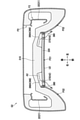
図1に示すように、本実施形態の乗物用シートは、自動車に搭載される車両用シートSとして構成されており、シートクッションS1およびシートバックS2を備えている。
Hereinafter, an embodiment of the invention will be described with reference to the accompanying drawings. In this specification, front-back, left-right, and up-down are based on front-back, left-right, and up-down as seen from the person sitting on the seat.
As shown in FIG. 1, the vehicle seat of the present embodiment is configured as a vehicle seat S mounted on an automobile, and includes a seat cushion S1 and a seat back S2.

図2に示すように、車両用シートSは、シートのフレームを構成するシートフレームF(図3参照)に、ウレタンフォームなどからなるパッドPと、布地や皮革などからなる表皮U1,U2を被せることで構成されている。詳細については後述するが、パッドPは、内部に形成された通気路A1,A2と、乗員側の面から通気路A1,A2に連通するように形成された第1通気穴H1,H2とを有しており、車両用シートSは、送風装置70から送風された空気を、ダクトDと通気路A1,A2を通して第1通気穴H1,H2からシートに座った乗員に向けて吹き出すように構成されている。 As shown in FIG. 2, in the vehicle seat S, the seat frame F (see FIG. 3) constituting the seat frame is covered with a pad P made of urethane foam or the like and skins U1 and U2 made of cloth or leather. It is composed of things. Although the details will be described later, the pad P has the ventilation passages A1 and A2 formed inside and the first ventilation holes H1 and H2 formed so as to communicate with the ventilation passages A1 and A2 from the surface on the occupant side. The vehicle seat S is configured to blow out the air blown from the blower device 70 from the first ventilation holes H1 and H2 toward the occupant sitting on the seat through the duct D and the ventilation passages A1 and A2. Has been done.

図3に示すように、シートフレームFは、シートクッションS1のフレームを構成するクッションフレームF1と、シートバックS2のフレームを構成するバックフレームF2とを有している。バックフレームF2は、クッションフレームF1に対してリクライニング機構RLを介して連結されている。リクライニング機構RLは、公知の構成を有するものであり、シートクッションS1に対してシートバックS2を回動可能に支持している。なお、本実施形態では、シートクッションS1については、上側が「乗員側」に相当し、下側が「乗員側とは反対側」に相当する。また、シートバックS2については、リクライニング機構RLによって倒されていない状態における前側が「乗員側」に相当し、後側が「乗員側とは反対側」に相当する。 As shown in FIG. 3, the seat frame F has a cushion frame F1 constituting the frame of the seat cushion S1 and a back frame F2 constituting the frame of the seat back S2. The back frame F2 is connected to the cushion frame F1 via a reclining mechanism RL. The reclining mechanism RL has a known configuration and rotatably supports the seat back S2 with respect to the seat cushion S1. In the present embodiment, regarding the seat cushion S1, the upper side corresponds to the "occupant side" and the lower side corresponds to the "opposite side to the occupant side". Further, regarding the seat back S2, the front side corresponds to the "occupant side" and the rear side corresponds to the "opposite side to the occupant side" in a state where the seat back S2 is not tilted by the reclining mechanism RL.

クッションフレームF1は、左右一対のクッションサイドフレーム11と、フロントフレームとしてのパンフレーム12と、リアフレームとしてのリアパイプ13と、連結パイプとしてのフロントパイプ14(図4参照)とを備えている。
一対のクッションサイドフレーム11は、シートクッションS1の左右のフレームを構成する部材であり、左右方向において対向した状態で離間して配置されている。クッションサイドフレーム11は、板金からなり、前後に長い長尺状に形成されている。
The cushion frame F1 includes a pair of left and right cushion side frames 11, a pan frame 12 as a front frame, a rear pipe 13 as a rear frame, and a front pipe 14 (see FIG. 4) as a connecting pipe.
The pair of cushion side frames 11 are members constituting the left and right frames of the seat cushion S1, and are arranged apart from each other in a state of facing each other in the left-right direction. The cushion side frame 11 is made of sheet metal and is formed in a long shape in the front and rear.

パンフレーム12は、一対のクッションサイドフレーム11の前部同士を連結する板状の部材であり、板金からなる。パンフレーム12は、左右の端部が、クッションサイドフレーム11の前端部に溶接により接続されている。
図4に示すように、リアパイプ13とフロントパイプ14は、金属製のパイプ材からなり、前後方向に離間して配置され、一対のクッションサイドフレーム11を連結するように設けられている。詳しくは、リアパイプ13は、パンフレーム12の後方でパンフレーム12に対し離間して配置され、一対のクッションサイドフレーム11の後部同士を連結している。また、フロントパイプ14は、リアパイプ13の前方でリアパイプ13に対し離間して配置され、一対のクッションサイドフレーム11の前部同士を連結している。フロントパイプ14は、パンフレーム12の下側に配置されている。
The pan frame 12 is a plate-shaped member that connects the front portions of the pair of cushion side frames 11 to each other, and is made of sheet metal. The left and right ends of the pan frame 12 are connected to the front end of the cushion side frame 11 by welding.
As shown in FIG. 4, the rear pipe 13 and the front pipe 14 are made of a metal pipe material, are arranged apart from each other in the front-rear direction, and are provided so as to connect a pair of cushion side frames 11. Specifically, the rear pipe 13 is arranged behind the pan frame 12 so as to be separated from the pan frame 12, and connects the rear portions of the pair of cushion side frames 11. Further, the front pipe 14 is arranged in front of the rear pipe 13 so as to be separated from the rear pipe 13, and connects the front portions of the pair of cushion side frames 11. The front pipe 14 is arranged below the pan frame 12.

クッションフレームF1の一対のクッションサイドフレーム11の間には、支持部材30が配置されている。支持部材30は、シートに座った乗員からの荷重を受ける部材であり、複数のワイヤ部材31と、樹脂部材32とを有している。 A support member 30 is arranged between the pair of cushion side frames 11 of the cushion frame F1. The support member 30 is a member that receives a load from an occupant sitting on the seat, and has a plurality of wire members 31 and a resin member 32.

ワイヤ部材31は、金属製の線材からなり、パンフレーム12とリアパイプ13に架設されている。ワイヤ部材31は、第1延在部31Aと、第2延在部31Bと、掛止部としての後側掛止部31Cとを主に有している。
第1延在部31Aは、左右方向に交互に屈曲しながら前後方向に延びている。第1延在部31Aの前端は、パンフレーム12に形成されたフック部12Hに掛止される前側掛止部31Dとなっている。前側掛止部31Dを含む第1延在部31Aの前端部は、樹脂で被覆されており、これによって、ワイヤ部材31(支持部材30)とパンフレーム12の接触による音の発生が抑制されている。
第2延在部31Bは、第1延在部31Aの後端から後斜め上方に向けて延びている。
後側掛止部31Cは、リアパイプ13に掛止される部分であり、第2延在部31Bの上端から延びて略円弧状をなすように湾曲している。
支持部材30は、ワイヤ部材31を4つ備えており、4つのワイヤ部材31は、左右方向に配列されている。
The wire member 31 is made of a metal wire and is erected on the pan frame 12 and the rear pipe 13. The wire member 31 mainly has a first extending portion 31A, a second extending portion 31B, and a rear hooking portion 31C as a hooking portion.
The first extending portion 31A extends in the front-rear direction while being bent alternately in the left-right direction. The front end of the first extending portion 31A is a front hooking portion 31D that is hooked on the hook portion 12H formed on the pan frame 12. The front end portion of the first extending portion 31A including the front hooking portion 31D is coated with a resin, whereby the generation of sound due to the contact between the wire member 31 (support member 30) and the pan frame 12 is suppressed. There is.
The second extending portion 31B extends diagonally upward from the rear end of the first extending portion 31A.
The rear side hooking portion 31C is a portion to be hooked on the rear pipe 13, and extends from the upper end of the second extending portion 31B and is curved so as to form a substantially arc shape.
The support member 30 includes four wire members 31, and the four wire members 31 are arranged in the left-right direction.

樹脂部材32は、ワイヤ部材31をつなぐ部材である。樹脂部材32は、樹脂からなり、インサート成形などによりワイヤ部材31の一部の全周を覆った状態でワイヤ部材31と一体に形成されている。樹脂部材32は、第1樹脂部材32Aと、第2樹脂部材32Bと、第3樹脂部材32Cと、第4樹脂部材32Dと、第5樹脂部材32Eとを含んで構成されている。 The resin member 32 is a member that connects the wire member 31. The resin member 32 is made of resin and is integrally formed with the wire member 31 in a state of covering the entire circumference of a part of the wire member 31 by insert molding or the like. The resin member 32 includes a first resin member 32A, a second resin member 32B, a third resin member 32C, a fourth resin member 32D, and a fifth resin member 32E.

第1樹脂部材32Aは、4つのワイヤ部材31の前後方向における中央部付近同士をつないでいる。
第2樹脂部材32Bは、第1樹脂部材32Aの後方に配置され、左右方向中央に配置された2つのワイヤ部材31の前後方向における中央部付近同士をつないでいる。
第3樹脂部材32Cは、第2樹脂部材32Bの左右両側に配置され、左右方向外側に配置されたワイヤ部材31の第1延在部31Aの、左右に延びる部分と、当該部分の左右方向外側の端から後方に延びる部分とをつないでいる。
樹脂部材32A~32Cには、上下に貫通する略矩形の貫通孔(符号省略)が形成されている。支持部材30は、当該貫通孔にワイヤハーネスを留めるためのクリップなどを係合することで、ワイヤハーネスなどの部材を保持可能な構成となっている。
The first resin member 32A connects the vicinity of the central portion of the four wire members 31 in the front-rear direction.
The second resin member 32B is arranged behind the first resin member 32A, and connects the vicinity of the central portion in the front-rear direction of the two wire members 31 arranged at the center in the left-right direction.
The third resin member 32C is arranged on both the left and right sides of the second resin member 32B, and extends to the left and right of the first extending portion 31A of the wire member 31 arranged outside in the left and right direction, and the outside of the portion in the left and right direction. It connects to the part that extends backward from the end of.
The resin members 32A to 32C are formed with substantially rectangular through holes (reference numerals omitted) that penetrate vertically. The support member 30 is configured to be able to hold a member such as a wire harness by engaging a clip or the like for fastening the wire harness to the through hole.

第4樹脂部材32Dは、樹脂部材32B,32Cの後方に配置され、4つのワイヤ部材31の第1延在部31Aの後端部同士をつないでいる。
第5樹脂部材32Eは、隣り合って配置された2つワイヤ部材31の後端同士、具体的には、後側掛止部31C同士をつないでいる。第5樹脂部材32Eは、後側掛止部31Cを覆っており、これによって、支持部材30とリアパイプ13の接触による音の発生が抑制されている。
The fourth resin member 32D is arranged behind the resin members 32B and 32C, and connects the rear ends of the first extending portions 31A of the four wire members 31 to each other.
The fifth resin member 32E connects the rear ends of the two wire members 31 arranged adjacent to each other, specifically, the rear hooking portions 31C. The fifth resin member 32E covers the rear side hooking portion 31C, whereby the generation of sound due to the contact between the support member 30 and the rear pipe 13 is suppressed.

図5に示すように、バックフレームF2は、左右一対の板金フレーム22と、パイプフレーム23と、連結フレームとしてのロアフレーム24と、架橋フレーム25とを備えている。
一対の板金フレーム22は、左右方向において対向した状態で離間して配置されている。板金フレーム22は、板金からなり、上下に長い長尺状に形成されている。
As shown in FIG. 5, the back frame F2 includes a pair of left and right sheet metal frames 22, a pipe frame 23, a lower frame 24 as a connecting frame, and a bridge frame 25.
The pair of sheet metal frames 22 are arranged apart from each other in a state of facing each other in the left-right direction. The sheet metal frame 22 is made of sheet metal and is formed in a long shape that is long in the vertical direction.

パイプフレーム23は、金属製のパイプ材からなり、略上下に延びる左右一対のアッパーサイドフレーム23Aと、アッパーサイドフレーム23Aの上端同士を連結するように延びるアッパーフレーム23Bとを有している。一対のアッパーサイドフレーム23Aは、下部が板金フレーム22の上部に溶接により接続されていることで、一対の板金フレーム22とともに一対のバックサイドフレーム21を構成している。一対のバックサイドフレーム21は、シートバックS2の左右のフレームを構成する。本実施形態では、「一対のサイドフレーム」は、一対のバックサイドフレーム21と、クッションフレームF1の一対のクッションサイドフレーム11を含んで構成されている。 The pipe frame 23 is made of a metal pipe material and has a pair of left and right upper side frames 23A extending substantially vertically and an upper frame 23B extending so as to connect the upper ends of the upper side frames 23A. The pair of upper side frames 23A constitutes a pair of backside frames 21 together with the pair of sheet metal frames 22 by connecting the lower portion to the upper part of the sheet metal frame 22 by welding. The pair of backside frames 21 constitutes the left and right frames of the seat back S2. In the present embodiment, the "pair of side frames" includes a pair of back side frames 21 and a pair of cushion side frames 11 of the cushion frame F1.

ロアフレーム24は、一対のバックサイドフレーム21の下部同士を連結する部材であり、板金からなる。ロアフレーム24は、左右の端部が、バックサイドフレーム21を構成する板金フレーム22の後端の左右内側に延出した部分に溶接により接続されている。
架橋フレーム25は、一対のバックサイドフレーム21の上部同士を連結する部材であり、板金からなる。架橋フレーム25は、左右の端部が、バックサイドフレーム21を構成するアッパーサイドフレーム23Aの上部に溶接などにより接続されている。架橋フレーム25は、下端に前方に延出した下側延出部25Aを有しており、下側延出部25Aの左右の端部には、後述するワイヤ部材60が挿入される上下に貫通した支持孔25B(図3参照)が形成されている。
The lower frame 24 is a member that connects the lower portions of the pair of backside frames 21 to each other, and is made of sheet metal. The left and right ends of the lower frame 24 are connected by welding to the left and right inward extending portions of the rear ends of the sheet metal frame 22 constituting the backside frame 21.
The crosslinked frame 25 is a member that connects the upper portions of the pair of backside frames 21 to each other, and is made of sheet metal. The left and right ends of the crosslinked frame 25 are connected to the upper portion of the upper side frame 23A constituting the backside frame 21 by welding or the like. The cross-linking frame 25 has a lower extending portion 25A extending forward at the lower end, and the left and right ends of the lower extending portion 25A penetrate vertically into which a wire member 60 described later is inserted. The support hole 25B (see FIG. 3) is formed.

バックフレームF2の一対のバックサイドフレーム21の間には、Sバネ40と、受圧部材50と、ワイヤ部材60が配置されている。
Sバネ40は、金属製の線材を上下方向に交互に屈曲させることにより形成されている。Sバネ40は、ロアフレーム24よりも上方に配置され、一対のバックサイドフレーム21に架設されている。詳しくは、Sバネ40は、左右の端部が、板金フレーム22の下部に設けられたバネ係合部22Aに上から差し込まれることで、一対のバックサイドフレーム21に架設された状態で連結されている。
An S spring 40, a pressure receiving member 50, and a wire member 60 are arranged between the pair of back side frames 21 of the back frame F2.
The S spring 40 is formed by alternately bending a metal wire in the vertical direction. The S spring 40 is arranged above the lower frame 24 and is erected on the pair of backside frames 21. Specifically, the S spring 40 is connected in a state of being erected on the pair of backside frames 21 by inserting the left and right ends into the spring engaging portion 22A provided at the lower part of the sheet metal frame 22 from above. ing.

受圧部材50は、シートに座った乗員からの荷重を受ける板状の部材であり、樹脂などからなる。受圧部材50は、乗員の背中と対向するように配置されている。また、受圧部材50は、下端部がSバネ40の前側に配置されている。受圧部材50は、前後に貫通した開口50Aを有している。開口50Aは、ダクトDを通すための穴であり、左右に長い略矩形状に形成されている。開口50Aは、受圧部材50の下側部分の左右方向における中央部に配置されている。詳しくは、開口50Aは、ワイヤ部材60の後述する一対の延在部61の間に配置されている。また、開口50Aは、前側から見て、Sバネ40と重ならない位置に配置されている。具体的には、開口50Aは、Sバネ40よりも上方に配置されている。 The pressure receiving member 50 is a plate-shaped member that receives a load from an occupant sitting on the seat, and is made of resin or the like. The pressure receiving member 50 is arranged so as to face the back of the occupant. Further, the lower end portion of the pressure receiving member 50 is arranged on the front side of the S spring 40. The pressure receiving member 50 has an opening 50A penetrating back and forth. The opening 50A is a hole for passing the duct D, and is formed in a substantially rectangular shape long to the left and right. The opening 50A is arranged at the center of the lower portion of the pressure receiving member 50 in the left-right direction. Specifically, the opening 50A is arranged between a pair of extending portions 61 of the wire member 60, which will be described later. Further, the opening 50A is arranged at a position that does not overlap with the S spring 40 when viewed from the front side. Specifically, the opening 50A is arranged above the S spring 40.

ワイヤ部材60は、受圧部材50をバックフレームF2に連結する部材であり、左右一対の延在部61と、傾斜部62と、上部連結部63と、下部連結部64とを主に有している。
延在部61は、所定方向としての上下方向(左右方向に直交する直交方向)に延びており、左右方向(所定方向に直交する方向)に並んで配置されている。
傾斜部62は、延在部61の上端から左右方向外側の斜め上方に向けて延びている。
上部連結部63は、傾斜部62の上端から上方に向けて延びている。
下部連結部64は、左右一対の延在部61、傾斜部62および上部連結部63を連結している。詳しくは、下部連結部64は、下端部が左右方向に延びており、当該下端部の左右両端から上方に向けて延びた後、屈曲して左右方向内側に向けて延びて延在部61の下端につながっている。
The wire member 60 is a member that connects the pressure receiving member 50 to the back frame F2, and mainly has a pair of left and right extending portions 61, an inclined portion 62, an upper connecting portion 63, and a lower connecting portion 64. There is.
The extending portions 61 extend in the vertical direction (orthogonal direction orthogonal to the left-right direction) as a predetermined direction, and are arranged side by side in the left-right direction (direction orthogonal to the predetermined direction).
The inclined portion 62 extends diagonally upward from the upper end of the extending portion 61 to the outside in the left-right direction.
The upper connecting portion 63 extends upward from the upper end of the inclined portion 62.
The lower connecting portion 64 connects a pair of left and right extending portions 61, an inclined portion 62, and an upper connecting portion 63. Specifically, the lower end portion of the lower connecting portion 64 extends in the left-right direction, and after extending upward from the left and right ends of the lower end portion, it bends and extends inward in the left-right direction of the extending portion 61. It is connected to the lower end.

ワイヤ部材60は、下部連結部64がロアフレーム24の前側に留められ、上部連結部63が架橋フレーム25の下側延出部25Aに形成された支持孔25B(図3参照)に挿入されることで、バックフレームF2に連結されている。受圧部材50は、ワイヤ部材60の一対の延在部61の前側に配置され、延在部61に図示しない結束バンドなどにより留められることで、ワイヤ部材60を介してバックフレームF2に連結されている。一対の延在部61は、前側から見て、受圧部材50と重なる位置に配置されている。 In the wire member 60, the lower connecting portion 64 is fastened to the front side of the lower frame 24, and the upper connecting portion 63 is inserted into the support hole 25B (see FIG. 3) formed in the lower extending portion 25A of the bridge frame 25. Therefore, it is connected to the back frame F2. The pressure receiving member 50 is arranged on the front side of the pair of extending portions 61 of the wire member 60, and is connected to the back frame F2 via the wire member 60 by being fastened to the extending portion 61 by a binding band or the like (not shown). There is. The pair of extending portions 61 are arranged at positions overlapping with the pressure receiving member 50 when viewed from the front side.

図2に示すように、車両用シートSは、送風装置70と、ダクトDを備えている。
送風装置70は、一例として、シロッコファンであり、パンフレーム12の下側に配置されている。具体的には、送風装置70は、パンフレーム12にブラケット71を介して取り付けられている。
As shown in FIG. 2, the vehicle seat S includes a blower 70 and a duct D.
The blower 70 is, for example, a sirocco fan, which is arranged under the pan frame 12. Specifically, the blower 70 is attached to the pan frame 12 via the bracket 71.

ダクトDは、シートクッションS1およびシートバックS2のパッドPに形成された通気路A1,A2と送風装置70を接続する部材であり、シートクッションS1の下側からクッションフレームF1の後側を通ってシートバックS2に向かうように延びている。図6に示すように、ダクトDは、第1ダクトD1と、第1ダクトD1の後端部に連結された第2ダクトD2とを有して構成されている。そして、第1ダクトD1は、下側管部110と、接続部120と、第1幅狭部131とを主に有し、第2ダクトD2は、第2幅狭部132と、フレキシブル部としての蛇腹部140と、第1平坦部150と、第2平坦部160と、バック接続部170とを主に有している。なお、本実施形態では、第1幅狭部131および第2幅狭部132が「幅狭部」に相当する。 The duct D is a member that connects the ventilation passages A1 and A2 formed in the pads P of the seat cushion S1 and the seat back S2 to the blower device 70, and passes from the lower side of the seat cushion S1 to the rear side of the cushion frame F1. It extends toward the seat back S2. As shown in FIG. 6, the duct D includes a first duct D1 and a second duct D2 connected to the rear end portion of the first duct D1. The first duct D1 mainly has a lower pipe portion 110, a connecting portion 120, and a first narrow portion 131, and the second duct D2 has a second narrow portion 132 and a flexible portion. It mainly has a bellows portion 140, a first flat portion 150, a second flat portion 160, and a back connection portion 170. In this embodiment, the first narrow portion 131 and the second narrow portion 132 correspond to the "narrow portion".

図7に示すように、下側管部110は、シートクッションS1の下側、より具体的には、支持部材30の下側に配置された部分であり、略前後に延びている。下側管部110は、第1部分としての送風装置接続部111と、第2部分112と、第3部分113と、第4部分114と、第5部分としての幅広部115と、分岐管部としてのクッション接続部116(図6も参照)とを有している。 As shown in FIG. 7, the lower pipe portion 110 is a portion arranged on the lower side of the seat cushion S1, more specifically, on the lower side of the support member 30, and extends substantially back and forth. The lower pipe portion 110 includes a blower connection portion 111 as a first portion, a second portion 112, a third portion 113, a fourth portion 114, a wide portion 115 as a fifth portion, and a branch pipe portion. It also has a cushion connection portion 116 (see also FIG. 6).

送風装置接続部111は、前端が送風装置70に接続される部分であり、前後に延びている。
第2部分112は、送風装置接続部111の後端から左右方向外側に向けて斜め後方に延びている。
第3部分113は、第2部分112の後端から後方に延びている。
本実施形態において、第2部分112は、送風装置接続部111の後端の位置から後に向かうにつれて、左右方向の寸法(幅)が徐々に大きくなっており、第3部分113は、送風装置接続部111よりも左右方向の寸法が大きくなっている。
The front end of the blower connection portion 111 is a portion connected to the blower device 70, and extends back and forth.
The second portion 112 extends diagonally rearward from the rear end of the blower connection portion 111 toward the outside in the left-right direction.
The third portion 113 extends rearward from the rear end of the second portion 112.
In the present embodiment, the second portion 112 gradually increases in dimension (width) in the left-right direction from the position of the rear end of the blower connection portion 111 to the rear, and the third portion 113 is connected to the blower device. The dimension in the left-right direction is larger than that of the portion 111.

図6に示すように、クッション接続部116は、シートクッションS1に形成された通気路A1に接続される部分であり、第3部分113の前端部から上方に突出するように延びている。クッション接続部116は、蛇腹部(符号省略)を有しており、可撓性を有するとともに上下に伸縮可能な構成となっている。図4に示すように、ダクトDは、クッション接続部116が右から2番目に配置されたワイヤ部材31のU字形状部を通って、後述するクッションパッドP1の下側から通気路A1に挿入されることで、クッションパッドP1に接続されている。クッション接続部116は、送風装置接続部111(図7参照)に対し右にずれた位置に配置された第3部分113から延びているので、本実施形態では、シートクッションS1内に配置されたワイヤ部材31などを避けた位置にクッション接続部116を設けることができる。これにより、シートクッションS1に形成された通気路A1とダクトDを容易に接続することができる。 As shown in FIG. 6, the cushion connecting portion 116 is a portion connected to the ventilation path A1 formed in the seat cushion S1 and extends upward from the front end portion of the third portion 113. The cushion connecting portion 116 has a bellows portion (reference numeral omitted), and has a structure that is flexible and can be expanded and contracted up and down. As shown in FIG. 4, the duct D is inserted into the ventilation passage A1 from the lower side of the cushion pad P1 described later through the U-shaped portion of the wire member 31 in which the cushion connecting portion 116 is arranged second from the right. By doing so, it is connected to the cushion pad P1. Since the cushion connecting portion 116 extends from the third portion 113 arranged at a position shifted to the right with respect to the blower connecting portion 111 (see FIG. 7), the cushion connecting portion 116 is arranged in the seat cushion S1 in the present embodiment. The cushion connecting portion 116 can be provided at a position avoiding the wire member 31 and the like. As a result, the ventilation passage A1 formed in the seat cushion S1 and the duct D can be easily connected.

また、本実施形態では、第3部分113の左右方向の寸法が、送風装置接続部111(図7参照)の左右方向の寸法よりも大きくなっているので、第3部分113から延びるクッション接続部116の左右方向の寸法を大きくすることができる。これにより、クッション接続部116の流路断面積を確保することができるので、ダクトD内とシートクッションS1に形成された通気路A1との間で空気を良好に流すことができる。 Further, in the present embodiment, the left-right dimension of the third portion 113 is larger than the left-right dimension of the blower connection portion 111 (see FIG. 7), so that the cushion connection portion extending from the third portion 113 is formed. The left-right dimension of 116 can be increased. As a result, the cross-sectional area of the flow path of the cushion connecting portion 116 can be secured, so that air can be satisfactorily flowed between the inside of the duct D and the ventilation passage A1 formed in the seat cushion S1.

図7に示すように、第4部分114は、第3部分113の後端から左右方向外側に向けて斜め後方に延びている。 As shown in FIG. 7, the fourth portion 114 extends diagonally rearward from the rear end of the third portion 113 toward the outside in the left-right direction.

幅広部115は、第4部分114の後端から後方に延びている。図6に示すように、幅広部115は、左右方向の寸法D11が上下方向の寸法D12よりも大きくなっている。言い換えると、幅広部115は、上下に扁平な断面形状を有している。また、本実施形態においては、幅広部115だけでなく、下側管部110の全体が上下に扁平な断面形状を有している。シートクッションS1の下側に配置される、幅広部115を含む下側管部110は、このように上下方向の寸法が小さいので、上下に薄くすることができる。これにより、車両用シートSを上下にコンパクト化することができる。 The wide portion 115 extends rearward from the rear end of the fourth portion 114. As shown in FIG. 6, in the wide portion 115, the dimension D11 in the left-right direction is larger than the dimension D12 in the up-down direction. In other words, the wide portion 115 has a vertically flat cross-sectional shape. Further, in the present embodiment, not only the wide portion 115 but also the entire lower pipe portion 110 has a vertically flat cross-sectional shape. Since the lower pipe portion 110 including the wide portion 115, which is arranged on the lower side of the seat cushion S1, has such a small vertical dimension, it can be thinned vertically. As a result, the vehicle seat S can be made compact up and down.

図7に戻って、幅広部115は、支持部材30の下側で、一対のクッションサイドフレーム11の左右方向中央の位置(一点鎖線参照)よりも、一方のクッションサイドフレーム11、具体的には、右のクッションサイドフレーム11に近い位置に配置されている。言い換えると、幅広部115は、右のクッションサイドフレーム11に寄った位置に配置されている。支持部材30は乗員から荷重を受けるとシートクッションS1の中央部分が左右の端部よりも下に大きく撓むことになるが、幅広部115が右に寄った位置に配置されていることで、ダクトDと支持部材30との干渉を抑制することができる。 Returning to FIG. 7, the wide portion 115 is located below the support member 30 and is located on one cushion side frame 11 rather than the center position in the left-right direction of the pair of cushion side frames 11 (see the alternate long and short dash line). , Is located near the cushion side frame 11 on the right. In other words, the wide portion 115 is arranged at a position closer to the cushion side frame 11 on the right side. When the support member 30 receives a load from the occupant, the central portion of the seat cushion S1 bends significantly below the left and right ends, but the wide portion 115 is arranged at a position closer to the right. Interference between the duct D and the support member 30 can be suppressed.

図2に示すように、本実施形態において、第4部分114と幅広部115は、下側傾斜部180を構成している。下側傾斜部180は、左右方向から見て、後に向かうにつれて下に位置するように傾斜して延びている。これにより、乗員がシートに座って支持部材30が下に撓んだ場合であっても、ダクトDと支持部材30との干渉を抑制することができる。 As shown in FIG. 2, in the present embodiment, the fourth portion 114 and the wide portion 115 constitute the lower inclined portion 180. The lower inclined portion 180 is inclined and extends so as to be positioned downward toward the rear when viewed from the left-right direction. As a result, even when the occupant sits on the seat and the support member 30 bends downward, the interference between the duct D and the support member 30 can be suppressed.

第1幅狭部131および第2幅狭部132は、クッションフレームF1の後方に配置された部分であり、略上下に延びている。第2幅狭部132は、内側の前後および左右の寸法が、第1幅狭部131の外側の前後および左右の寸法よりも若干大きくなっており、第1幅狭部131の上端部に嵌合している。これにより、第1ダクトD1と第2ダクトD2が連結されている。図6に示すように、第1幅狭部131および第2幅狭部132は、左右方向の寸法D21が、左右方向に直交する略前後方向の寸法D22よりも小さくなっている。言い換えると、第1幅狭部131および第2幅狭部132は、左右に扁平な断面形状を有している。なお、本実施形態においては、幅狭部131,132だけでなく、蛇腹部140も左右に扁平な断面形状を有している。 The first narrow portion 131 and the second narrow portion 132 are portions arranged behind the cushion frame F1 and extend substantially vertically. The front-rear and left-right dimensions of the second narrow portion 132 are slightly larger than the front-rear and left-right dimensions of the outside of the first narrow portion 131, and the second narrow portion 132 fits into the upper end portion of the first narrow portion 131. It fits. As a result, the first duct D1 and the second duct D2 are connected. As shown in FIG. 6, in the first narrow portion 131 and the second narrow portion 132, the dimension D21 in the left-right direction is smaller than the dimension D22 in the substantially front-rear direction orthogonal to the left-right direction. In other words, the first narrow portion 131 and the second narrow portion 132 have a flat cross-sectional shape on the left and right. In this embodiment, not only the narrow portions 131 and 132 but also the bellows portion 140 has a flat cross-sectional shape on the left and right.

接続部120は、第1幅狭部131(幅狭部)と幅広部115をつなぐ部分である。接続部120は、第1幅狭部131から幅広部115に向かうにつれて、左右方向の寸法が徐々に大きくなり、かつ、上下方向の寸法が徐々に小さくなるような形状を有している。これにより、ダクトDの断面形状が第1幅狭部131から幅広部115に向けて徐々に変化することになるので、断面形状が変化しない場合と比較して、ダクトDの剛性を向上させることができる。また、接続部120でダクトDの流路断面積が小さくなるのを抑制することができるので、ダクトD内を流れる空気の流量を確保することができる。 The connecting portion 120 is a portion connecting the first narrow portion 131 (narrow portion) and the wide portion 115. The connecting portion 120 has a shape in which the dimension in the left-right direction gradually increases and the dimension in the vertical direction gradually decreases toward the wide portion 115 from the first narrow portion 131. As a result, the cross-sectional shape of the duct D gradually changes from the first narrow portion 131 to the wide portion 115, so that the rigidity of the duct D is improved as compared with the case where the cross-sectional shape does not change. Can be done. Further, since it is possible to prevent the cross-sectional area of the flow path of the duct D from becoming small at the connection portion 120, it is possible to secure the flow rate of the air flowing in the duct D.

蛇腹部140は、第2幅狭部132の上端から略上方に延びている。蛇腹部140は、山部と谷部が交互に形成されたような形状をなし、可撓性を有するとともに伸縮自在となっている。図2に示すように、蛇腹部140は、クッションフレームF1の後方、詳しくは、リアパイプ13の後方に配置されている。さらに説明すると、蛇腹部140は、リアパイプ13の下端13Aよりも上に位置している。また、蛇腹部140は、上端が、ロアフレーム24の真後ろの位置、言い換えると、後側から見てロアフレーム24と重なる位置に配置されている。 The bellows portion 140 extends substantially upward from the upper end of the second narrow portion 132. The bellows portion 140 has a shape in which peaks and valleys are alternately formed, and is flexible and stretchable. As shown in FIG. 2, the bellows portion 140 is arranged behind the cushion frame F1, specifically behind the rear pipe 13. Further explaining, the bellows portion 140 is located above the lower end 13A of the rear pipe 13. Further, the bellows portion 140 is arranged at a position where the upper end thereof is directly behind the lower frame 24, in other words, at a position where the upper end overlaps with the lower frame 24 when viewed from the rear side.

本実施形態において、第1幅狭部131、第2幅狭部132および蛇腹部140は、退避部190を構成している。退避部190は、下に向かうにつれて前に位置するように傾斜して延びている。図8に示すように、退避部190は、一対のクッションサイドフレーム11の左右方向内側の位置に配置されている。これにより、退避部190が一対のクッションサイドフレーム11の左右方向外側の位置に配置される場合と比較して、車両用シートSを左右にコンパクト化することができる。また、退避部190は、クッションフレームF1の後方において、一対のクッションサイドフレーム11の左右方向中央の位置(一点鎖線参照)よりも、右(一方)のクッションサイドフレーム11に近い位置に配置されている。言い換えると、退避部190は、右のクッションサイドフレーム11に寄った位置に配置されている。 In the present embodiment, the first narrow portion 131, the second narrow portion 132, and the bellows portion 140 constitute a retracting portion 190. The retracting portion 190 is inclined and extended so as to be positioned forward as it goes downward. As shown in FIG. 8, the retracting portion 190 is arranged at a position inside the pair of cushion side frames 11 in the left-right direction. As a result, the vehicle seat S can be made compact to the left and right as compared with the case where the retracting portion 190 is arranged at a position outside the pair of cushion side frames 11 in the left-right direction. Further, the retracting portion 190 is arranged behind the cushion frame F1 at a position closer to the right (one) cushion side frame 11 than the position at the center in the left-right direction of the pair of cushion side frames 11 (see the alternate long and short dash line). There is. In other words, the retracting portion 190 is arranged at a position closer to the cushion side frame 11 on the right side.

また、ダクトDは、リアパイプ13の後側を通る部分である退避部190が、ワイヤ部材31の後側掛止部31Cに対して左右方向に異なる位置に配置されている。具体的には、退避部190が、最も右に位置する後側掛止部31Cよりも右側に配置されている。また、ダクトDは、後側から見て、ワイヤ部材31の第2延在部31Bに対しても左右方向に異なる位置に配置されている。具体的には、退避部190および幅広部115(図7参照)は、後側から見て、最も右に位置する第2延在部31Bよりも右側に配置されている。さらに言えば、本実施形態では、退避部190および幅広部115は、前後、左右および上下のいずれの方向から見ても、第2延在部31Bと重ならないように配置されている。これにより、乗員がシートに座ってワイヤ部材31(支持部材30)が下に撓んだ場合であっても、ダクトDとワイヤ部材31との干渉を抑制することができる。 Further, in the duct D, the retracting portion 190, which is a portion passing through the rear side of the rear pipe 13, is arranged at different positions in the left-right direction with respect to the rear hooking portion 31C of the wire member 31. Specifically, the retracting portion 190 is arranged on the right side of the rear hooking portion 31C located on the far right. Further, the duct D is arranged at a different position in the left-right direction with respect to the second extending portion 31B of the wire member 31 when viewed from the rear side. Specifically, the retracted portion 190 and the wide portion 115 (see FIG. 7) are arranged on the right side of the second extending portion 31B located on the far right when viewed from the rear side. Furthermore, in the present embodiment, the retracting portion 190 and the wide portion 115 are arranged so as not to overlap with the second extending portion 31B when viewed from any of the front-back, left-right, and up-down directions. As a result, even when the occupant sits on the seat and the wire member 31 (support member 30) bends downward, the interference between the duct D and the wire member 31 can be suppressed.

第1平坦部150は、退避部190(蛇腹部140)の上端から、一対のバックサイドフレーム21の左右方向中央に向けて斜め上方に延びている。第1平坦部150は、ロアフレーム24の後側に配置されている。図6に示すように、第1平坦部150は、前後方向(ロアフレーム24と対向する対向方向)の寸法D41が、当該前後方向に直交する略上下方向の寸法D42よりも小さくなっている。言い換えると、第1平坦部150は、前後に扁平な断面形状を有している。これにより、第1平坦部150を前後方向に薄くすることができるので、車両用シートSを前後方向にコンパクト化することができる。また、コンパクト化を図りつつ、第1平坦部150とロアフレーム24との間に隙間を確保できるので、ダクトDとロアフレーム24との干渉を抑制することができる。 The first flat portion 150 extends diagonally upward from the upper end of the retracting portion 190 (bellows portion 140) toward the center in the left-right direction of the pair of backside frames 21. The first flat portion 150 is arranged on the rear side of the lower frame 24. As shown in FIG. 6, the dimension D41 in the front-rear direction (opposite direction facing the lower frame 24) of the first flat portion 150 is smaller than the dimension D42 in the substantially vertical direction orthogonal to the front-rear direction. In other words, the first flat portion 150 has a flat cross-sectional shape in the front-rear direction. As a result, the first flat portion 150 can be thinned in the front-rear direction, so that the vehicle seat S can be made compact in the front-rear direction. Further, since a gap can be secured between the first flat portion 150 and the lower frame 24 while reducing the size, interference between the duct D and the lower frame 24 can be suppressed.

図8に戻って、第2平坦部160は、第1平坦部150の上端から上方に延びている。第2平坦部160は、一対のバックサイドフレーム21の左右方向中央で、Sバネ40の後側に配置されている。本実施形態において、第2平坦部160と第1平坦部150は、前後方向の寸法が、略同じ寸法となっている。第2平坦部160は、前後方向(Sバネ40と対向する対向方向)の寸法D41(図6参照)が、当該前後方向に直交する左右方向の寸法D43よりも小さくなっている。言い換えると、第2平坦部160は、前後に扁平な断面形状を有している。これにより、第2平坦部160を前後方向に薄くすることができるので、車両用シートSを前後方向にコンパクト化することができる。また、コンパクト化を図りつつ、第2平坦部160とSバネ40との間に隙間を確保できるので、ダクトDとSバネ40との干渉を抑制することができる。 Returning to FIG. 8, the second flat portion 160 extends upward from the upper end of the first flat portion 150. The second flat portion 160 is arranged at the center of the pair of backside frames 21 in the left-right direction and behind the S spring 40. In the present embodiment, the second flat portion 160 and the first flat portion 150 have substantially the same dimensions in the front-rear direction. The second flat portion 160 has a dimension D41 (see FIG. 6) in the front-rear direction (opposite direction facing the S spring 40) smaller than the dimension D43 in the left-right direction orthogonal to the front-rear direction. In other words, the second flat portion 160 has a flat cross-sectional shape in the front-rear direction. As a result, the second flat portion 160 can be thinned in the front-rear direction, so that the vehicle seat S can be made compact in the front-rear direction. Further, since a gap can be secured between the second flat portion 160 and the S spring 40 while reducing the size, interference between the duct D and the S spring 40 can be suppressed.

図2に示すように、バック接続部170は、シートバックS2に形成された通気路A2に接続される部分であり、第2平坦部160の上端から前斜め上方に延びている。ダクトDは、バック接続部170が受圧部材50に形成された開口50Aを通って、後述するバックパッドP2の後側から通気路A2に挿入されることで、バックパッドP2に接続されている。 As shown in FIG. 2, the back connecting portion 170 is a portion connected to the ventilation path A2 formed in the seat back S2, and extends diagonally upward and forward from the upper end of the second flat portion 160. The duct D is connected to the back pad P2 by inserting the back connecting portion 170 into the ventilation passage A2 from the rear side of the back pad P2, which will be described later, through the opening 50A formed in the pressure receiving member 50.

図4に示すように、一対のクッションサイドフレーム11の一方、具体的には、左のクッションサイドフレーム11の下側には、センサとしての公知のウェイトセンサWSが配置されている。本実施形態において、ダクトDは、左右方向において、一対のクッションサイドフレーム11のうちの一方である左のクッションサイドフレーム11よりも、一対のクッションサイドフレーム11の他方である右のクッションサイドフレーム11に近い位置に配置されている。言い換えると、ダクトDは、左右方向において、ウェイトセンサWSが配置されていないクッションサイドフレーム11に近い位置に配置されている。これにより、ダクトDと、ウェイトセンサWSや当該ウェイトセンサWSから延びる図示しない電線などとの干渉を抑制することができる。 As shown in FIG. 4, a known weight sensor WS as a sensor is arranged on one side of the pair of cushion side frames 11, specifically, on the lower side of the left cushion side frame 11. In the present embodiment, the duct D has a right cushion side frame 11 which is the other of the pair of cushion side frames 11 rather than the left cushion side frame 11 which is one of the pair of cushion side frames 11 in the left-right direction. It is located close to. In other words, the duct D is arranged at a position close to the cushion side frame 11 in which the weight sensor WS is not arranged in the left-right direction. As a result, it is possible to suppress interference between the duct D and the weight sensor WS, an electric wire (not shown) extending from the weight sensor WS, and the like.

また、支持部材30を構成する樹脂部材32は、上側から見て、ダクトDと重なるように配置されている。詳しくは、第1樹脂部材32Aは、右側部分が、上側から見てダクトDの第3部分113と重なるように、第3部分113の上側に配置されている。また、右の第3樹脂部材32Cは、上側から見てダクトDの幅広部115と重なるように、幅広部115の上側に配置されている。さらに、第4樹脂部材32Dは、右端部が、上側から見て幅広部115と重なるように、幅広部115の上側に配置されている。これにより、乗員がシートに座ったときに支持部材30が下に撓んでダクトDと干渉した場合であっても、まず樹脂部材32A,32C,32DがダクトDに接触することになるので、ダクトDと支持部材30が接触することによる影響、例えば、音の発生や接触の際の衝撃などを低減することができる。 Further, the resin member 32 constituting the support member 30 is arranged so as to overlap the duct D when viewed from above. Specifically, the first resin member 32A is arranged on the upper side of the third portion 113 so that the right side portion overlaps with the third portion 113 of the duct D when viewed from above. Further, the third resin member 32C on the right is arranged above the wide portion 115 so as to overlap the wide portion 115 of the duct D when viewed from above. Further, the fourth resin member 32D is arranged on the upper side of the wide portion 115 so that the right end portion overlaps with the wide portion 115 when viewed from above. As a result, even if the support member 30 bends downward and interferes with the duct D when the occupant sits on the seat, the resin members 32A, 32C, 32D first come into contact with the duct D, so that the duct It is possible to reduce the influence of contact between D and the support member 30, for example, the generation of sound and the impact at the time of contact.

また、図7に示すように、本実施形態では、下側管部110は、第2部分112が右斜め後方に延びて右のクッションサイドフレーム11に近づき、第3部分113で後方に略まっすぐ延びた後、第4部分114が右斜め後方に延びて右のクッションサイドフレーム11にさらに近づくように設けられているので、ダクトDを右のクッションサイドフレーム11に徐々に近づけるように配置することができる。これにより、ダクトD内における流路の急激な変化を抑制することができるので、ダクトD内で空気を良好に流すことができる。 Further, as shown in FIG. 7, in the present embodiment, in the lower pipe portion 110, the second portion 112 extends diagonally rearward to the right and approaches the cushion side frame 11 on the right, and the third portion 113 substantially straightens rearward. After extending, the fourth portion 114 extends diagonally rearward to the right and is provided so as to be closer to the right cushion side frame 11, so that the duct D is arranged so as to gradually approach the right cushion side frame 11. Can be done. As a result, abrupt changes in the flow path in the duct D can be suppressed, so that air can flow well in the duct D.

図9に示すように、バックフレームF2には、カバー部材80が配置されている。カバー部材80は、ダクトDがシートバックS2の通気路A2に接続する部分であるバック接続部170を後側から覆う部材である。カバー部材80は、樹脂などから左右に長い板状に形成されている。カバー部材80は、左右の端部が、一対のバックサイドフレーム21の後端の左右内側に延出した部分にボルト締結などにより固定されて取り付けられている。このようなカバー部材80を備えることで、カバー部材80によってダクトDとシートバックS2のパッドP(バックパッドP2)が接続する部分を保護することができる。 As shown in FIG. 9, a cover member 80 is arranged on the back frame F2. The cover member 80 is a member that covers the back connecting portion 170, which is a portion where the duct D connects to the ventilation path A2 of the seat back S2, from the rear side. The cover member 80 is made of resin or the like and is formed in a long plate shape on the left and right. The cover member 80 is attached by fixing the left and right ends to the left and right inwardly extending portions of the rear ends of the pair of backside frames 21 by bolting or the like. By providing such a cover member 80, it is possible to protect the portion where the duct D and the pad P (back pad P2) of the seat back S2 are connected by the cover member 80.

図10および図11に示すように、車両用シートSは、サイドフレームカバー90をさらに備えている。サイドフレームカバー90は、右のクッションサイドフレーム11の後端部を覆う部材である。サイドフレームカバー90は、樹脂からなり、サイドフレームカバー部91と、ダクトカバー部92と、リクライニング機構カバー部93とを有している。
サイドフレームカバー部91は、右のクッションサイドフレーム11の後端部の左右方向内側を覆う部分である。サイドフレームカバー部91は、バックサイドフレーム21の下端部の前側、下側および後側にわたるように配置されている。
As shown in FIGS. 10 and 11, the vehicle seat S further includes a side frame cover 90. The side frame cover 90 is a member that covers the rear end portion of the right cushion side frame 11. The side frame cover 90 is made of resin and has a side frame cover portion 91, a duct cover portion 92, and a reclining mechanism cover portion 93.
The side frame cover portion 91 is a portion that covers the inside of the rear end portion of the right cushion side frame 11 in the left-right direction. The side frame cover portion 91 is arranged so as to extend to the front side, the lower side, and the rear side of the lower end portion of the back side frame 21.

ダクトカバー部92は、クッションフレームF1の後方において、ダクトDの一部である退避部190を覆う部分である。詳しくは、ダクトカバー部92は、リアパイプ13の後方に配置され、第1幅狭部131、第2幅狭部132および蛇腹部140を覆っている。ダクトカバー部92は、サイドフレームカバー部91の後端から後方に向けて退避部190の後の位置まで延びる第1サイドカバー部92Aと、第1サイドカバー部92Aの後端から左右方向内側に向けて延びて退避部190を後から覆うリアカバー部92Bとを有している。リアカバー部92Bは、後斜め下方に凸となる弓状の断面形状を有し、退避部190に沿って下に向かうにつれて前に位置するように延びている。 The duct cover portion 92 is a portion behind the cushion frame F1 that covers the retracting portion 190 that is a part of the duct D. Specifically, the duct cover portion 92 is arranged behind the rear pipe 13 and covers the first narrow portion 131, the second narrow portion 132, and the bellows portion 140. The duct cover portion 92 has a first side cover portion 92A extending rearward from the rear end of the side frame cover portion 91 to a position behind the retracting portion 190, and the duct cover portion 92 inward in the left-right direction from the rear end of the first side cover portion 92A. It has a rear cover portion 92B that extends toward and covers the retracting portion 190 later. The rear cover portion 92B has a bow-shaped cross-sectional shape that is convex diagonally downward and rearward, and extends so as to be positioned forward along the retracting portion 190 toward the bottom.

リクライニング機構カバー部93は、リクライニング機構RLを覆う部分であり、左右方向内側および下側が開放された略カップ状に形成されている。リクライニング機構カバー部93は、サイドフレームカバー部91からリクライニング機構RLの周面に沿って延びるように形成されて、リクライニング機構RLの後側、上側および前側を覆う周面カバー部93Aと、リクライニング機構RLの左右方向外側を覆う第2サイドカバー部93Bとを主に有している。 The reclining mechanism cover portion 93 is a portion that covers the reclining mechanism RL, and is formed in a substantially cup shape with the inner side and the lower side in the left-right direction open. The reclining mechanism cover portion 93 is formed so as to extend from the side frame cover portion 91 along the peripheral surface of the reclining mechanism RL, and covers the rear side, the upper side, and the front side of the reclining mechanism RL, and the reclining mechanism. It mainly has a second side cover portion 93B that covers the outside of the RL in the left-right direction.

サイドフレームカバー部91、ダクトカバー部92およびリクライニング機構カバー部93は、一部品として一体に形成されていてもよいし、一部が別部品として構成されていてもよい。一例として、ダクトカバー部92は、サイドフレームカバー部91に対し、ダクトカバー部92が一体に形成され、リクライニング機構カバー部93が別体として形成されて、サイドフレームカバー部91の後端部に設けた穴に、リクライニング機構カバー部93に設けた爪を係合させることで、リクライニング機構カバー部93がサイドフレームカバー部91に取り付けられるような構成とすることができる。 The side frame cover portion 91, the duct cover portion 92, and the reclining mechanism cover portion 93 may be integrally formed as one component, or may be partially configured as a separate component. As an example, in the duct cover portion 92, the duct cover portion 92 is integrally formed with the side frame cover portion 91, the reclining mechanism cover portion 93 is formed as a separate body, and the duct cover portion 92 is formed at the rear end portion of the side frame cover portion 91. By engaging the claws provided in the reclining mechanism cover portion 93 with the holes provided, the reclining mechanism cover portion 93 can be configured to be attached to the side frame cover portion 91.

ダクトカバー部92とサイドフレームカバー部91を一体に設けることで、クッションサイドフレーム11のカバーと、ダクトDのカバーを別々に設ける必要がなくなるので、車両用シートSの部品点数を減らすことができる。また、サイドフレームカバー部91、ダクトカバー部92およびリクライニング機構カバー部93を一体に設けた場合には、サイドフレームカバー90に、ダクトDの保護だけではなく、リクライニング機構RLの保護という機能も持たせることができるので、車両用シートSの部品点数をより減らすことが可能となる。 By integrally providing the duct cover portion 92 and the side frame cover portion 91, it is not necessary to separately provide the cover of the cushion side frame 11 and the cover of the duct D, so that the number of parts of the vehicle seat S can be reduced. .. Further, when the side frame cover portion 91, the duct cover portion 92, and the reclining mechanism cover portion 93 are integrally provided, the side frame cover 90 has a function of not only protecting the duct D but also protecting the reclining mechanism RL. Therefore, the number of parts of the vehicle seat S can be further reduced.

図2に示すように、パッドPは、シートクッションS1のパッドを構成するクッションパッドP1と、シートバックS2のパッドを構成するバックパッドP2を含む。
図1に示すように、クッションパッドP1は、中央部P11と、中央部P11の左右両側に設けられて中央部P11よりも上側に張り出した左右一対の側部P12とを有しており、バックパッドP2は、中央部P21と、中央部P21の左右両側に設けられて中央部P21よりも前側に張り出した左右一対の側部P22とを有している。
As shown in FIG. 2, the pad P includes a cushion pad P1 constituting the pad of the seat cushion S1 and a back pad P2 constituting the pad of the seat back S2.
As shown in FIG. 1, the cushion pad P1 has a central portion P11 and a pair of left and right side portions P12 provided on both left and right sides of the central portion P11 and projecting above the central portion P11. The pad P2 has a central portion P21 and a pair of left and right side portions P22 provided on both left and right sides of the central portion P21 and projecting to the front side of the central portion P21.

図12に示すように、クッションパッドP1は、通気路A1を構成する溝211が形成された第1部材210と、第1通気穴H1が上下に貫通するように形成された板状の第2部材220とを含んで構成されている。また、第1部材210は、第1部材本体230と、溝211が上下に貫設された板状の溝形成部材240とを含む。溝形成部材240は、第1部材本体230の上側の面に重なって配置されており、第2部材220は、溝形成部材240(第1部材210)の上側の面に重なって配置されている。 As shown in FIG. 12, the cushion pad P1 has a plate-shaped second member 210 formed with a groove 211 forming the ventilation path A1 and a plate-shaped second member formed so that the first ventilation hole H1 penetrates vertically. It is configured to include the member 220. Further, the first member 210 includes a first member main body 230 and a plate-shaped groove forming member 240 in which a groove 211 is vertically penetrated. The groove forming member 240 is arranged so as to overlap the upper surface of the first member main body 230, and the second member 220 is arranged so as to overlap the upper surface of the groove forming member 240 (first member 210). ..

第1部材本体230は、溝形成部材240および第2部材220とともに中央部P11を構成する本体中央部231を有し、本体中央部231の左右両側に一対の側部P12が形成されている。本体中央部231は、前側部分に、溝形成部材240および第2部材220が重なって配置される凹部232を有している。凹部232の底面の後端部には、上下に貫通した第2通気穴250が形成されている。第2通気穴250は、第1部材本体230(クッションパッドP1)の下側の面から通気路A1に連通している。ダクトDは、クッション接続部116(図6参照)が第2通気穴250に下側から挿入されることで、クッションパッドP1に接続されている。図13に示すように、第2通気穴250は、クッションパッドP1の左右方向中央(一点鎖線参照)から右にずれた位置に配置されている。 The first member main body 230 has a main body central portion 231 constituting the central portion P11 together with the groove forming member 240 and the second member 220, and a pair of side portions P12 are formed on the left and right sides of the main body central portion 231. The central portion 231 of the main body has a recess 232 in the front side portion in which the groove forming member 240 and the second member 220 are arranged so as to overlap each other. A second vent hole 250 penetrating vertically is formed at the rear end of the bottom surface of the recess 232. The second ventilation hole 250 communicates with the ventilation passage A1 from the lower surface of the first member main body 230 (cushion pad P1). The duct D is connected to the cushion pad P1 by inserting the cushion connecting portion 116 (see FIG. 6) into the second ventilation hole 250 from below. As shown in FIG. 13, the second ventilation hole 250 is arranged at a position shifted to the right from the center in the left-right direction (see the alternate long and short dash line) of the cushion pad P1.

溝形成部材240は、通気路A1を構成する、上下に貫通した溝211を有している。クッションパッドP1の通気路A1は、第1部材本体230の凹部232の上に、溝形成部材240および第2部材220がこの順に重なって配置され、溝211の上下が第2部材220と第1部材本体230によって塞がれることで形成されている。通気路A1は、上側から見て、第1通気路261と、第2通気路262と、第3通気路263と、第4通気路264と、第5通気路265とを含んでいる。 The groove forming member 240 has a groove 211 penetrating vertically, which constitutes the ventilation path A1. In the ventilation passage A1 of the cushion pad P1, the groove forming member 240 and the second member 220 are arranged in this order on the recess 232 of the first member main body 230, and the upper and lower portions of the groove 211 are the second member 220 and the first. It is formed by being closed by the member main body 230. The air passage A1 includes a first air passage 261, a second air passage 262, a third air passage 263, a fourth air passage 264, and a fifth air passage 265 when viewed from above.

第1通気路261は、左右方向に交差する方向、具体的には、略前後方向に延びている。第1通気路261は、一端である後端が、第4通気路264、第5通気路265、第2通気穴250およびダクトDを介して送風装置70に連通している。
第2通気路262は、第1通気路261の他端である前端から第1通気路261が延びる方向とは異なる方向、具体的には、左右方向内側に向けて延びている。
第3通気路263は、第2通気路262の第1通気路261側とは反対側の端である左右方向内側の端から左右方向に交差する方向、具体的には、第1通気路261の後端側に向けて第1通気路261と略平行に延びている。
The first air passage 261 extends in a direction intersecting in the left-right direction, specifically, in a substantially front-rear direction. The rear end of the first air passage 261 communicates with the blower device 70 through the fourth air passage 264, the fifth air passage 265, the second air hole 250, and the duct D.
The second air passage 262 extends in a direction different from the direction in which the first air passage 261 extends from the front end, which is the other end of the first air passage 261, specifically, inward in the left-right direction.
The third air passage 263 is a direction that intersects in the left-right direction from the inner end in the left-right direction, which is the end opposite to the first air passage 261 side of the second air passage 262, specifically, the first air passage 261. It extends substantially parallel to the first air passage 261 toward the rear end side.

本実施形態では、第1通気路261、第2通気路262および第3通気路263からなる略U字状の流路が、クッションパッドP1の左右方向中央を基準として左右対称に2つ形成されている。これにより、クッションパッドP1の通気路A1が形成されていない部分で乗員をバランス良く支持することができるので、通気路A1が第1通気路261、第2通気路262および第3通気路263を含む構成においても、シートに座ったときの着座フィーリングを良好にすることができる。 In the present embodiment, two substantially U-shaped flow paths composed of the first air passage 261 and the second air passage 262 and the third air passage 263 are formed symmetrically with respect to the center in the left-right direction of the cushion pad P1. ing. As a result, the occupant can be supported in a well-balanced manner at the portion of the cushion pad P1 where the ventilation path A1 is not formed. Even in the configuration including the seat, the seating feeling when sitting on the seat can be improved.

第4通気路264は、左右の第1通気路261の後端同士をつなぐ流路であり、略左右に延びている。
第5通気路265は、第2通気穴250と第4通気路264をつなぐ流路であり、略前後に延びている。詳しくは、第5通気路265は、クッションパッドP1の左右方向中央から右にずれた位置に配置された第2通気穴250から、クッションパッドP1の左右方向中央に向けて斜め前方に延びて、第4通気路264の左右方向における中央部につながっている。
溝形成部材240は、第1部材本体230に接着剤などにより固着されている。
The fourth air passage 264 is a flow path connecting the rear ends of the left and right first air passages 261 and extends substantially to the left and right.
The fifth ventilation passage 265 is a flow path connecting the second ventilation hole 250 and the fourth ventilation passage 264, and extends substantially in the front-rear direction. Specifically, the fifth ventilation passage 265 extends diagonally forward toward the center of the cushion pad P1 in the left-right direction from the second ventilation hole 250 arranged at a position shifted to the right from the center of the cushion pad P1 in the left-right direction. It is connected to the central portion of the fourth air passage 264 in the left-right direction.
The groove forming member 240 is fixed to the first member main body 230 with an adhesive or the like.

第2部材220は、通気路A1に連通する複数の第1通気穴H1を有している。クッションパッドP1の第1通気穴H1は、第1穴271と、第2穴272と、第3穴273と、第4穴274とを含んでいる。 The second member 220 has a plurality of first ventilation holes H1 communicating with the ventilation passage A1. The first ventilation hole H1 of the cushion pad P1 includes a first hole 271, a second hole 272, a third hole 273, and a fourth hole 274.

第1穴271は、第1通気路261に連通する穴であり、略前後に延びる第1通気路261に沿って複数形成されている。具体的には、第1穴271は、第1通気路261に沿って略前後に並んで配置された2つの第1穴271Aと、後に位置する第1穴271Aの左右方向外側に並んで配置された1つの第1穴271Bとを含む。
第2穴272は、第3通気路263に連通する穴であり、略前後に延びる第3通気路263に沿って複数形成されている。具体的には、第2穴272は、第3通気路263に沿って略前後に並んで配置された2つからなる。
前後に並ぶ第1穴271Aの列と第2穴272の列は、第2通気路262が延びる方向、具体的には、左右方向に並んで配置されている。
The first hole 271 is a hole communicating with the first air passage 261 and is formed in plurality along the first air passage 261 extending substantially in the front-rear direction. Specifically, the first hole 271 is arranged side by side in the left-right direction of two first holes 271A arranged substantially front and back along the first air passage 261 and the first hole 271A located later. Includes one first hole 271B made.
The second hole 272 is a hole communicating with the third ventilation passage 263, and is formed in plurality along the third ventilation passage 263 extending substantially in the front-rear direction. Specifically, the second hole 272 is composed of two holes arranged substantially front and back along the third ventilation path 263.
The rows of the first holes 271A and the rows of the second holes 272 that are lined up in the front-rear direction are arranged side by side in the direction in which the second air passage 262 extends, specifically, in the left-right direction.

第3穴273は、第1通気路261の後端部に連通する穴であり、第4穴274は、第4通気路264の左右の端部に連通する穴である。
第2部材220は、溝形成部材240および第1部材本体230(第1部材210)に接着剤などにより固着されている。
The third hole 273 is a hole communicating with the rear end portion of the first ventilation passage 261, and the fourth hole 274 is a hole communicating with the left and right ends of the fourth ventilation passage 264.
The second member 220 is fixed to the groove forming member 240 and the first member main body 230 (first member 210) with an adhesive or the like.

図4に示すように、クッションパッドP1がクッションフレームF1を覆った状態で、フロントパイプ14は、クッションパッドP1の下側に配置されている。この状態において、フロントパイプ14は、上側から見て、第1通気路261、第2通気路262および第3通気路263と異なる位置に配置されている。具体的には、フロントパイプ14は、上側から見て、第1通気路261、第2通気路262および第3通気路263の後方に配置されている。 As shown in FIG. 4, the front pipe 14 is arranged under the cushion pad P1 in a state where the cushion pad P1 covers the cushion frame F1. In this state, the front pipe 14 is arranged at a position different from that of the first air passage 261 and the second air passage 262 and the third air passage 263 when viewed from above. Specifically, the front pipe 14 is arranged behind the first air passage 261 and the second air passage 262 and the third air passage 263 when viewed from above.

また、クッションパッドP1がクッションフレームF1を覆った状態で、パンフレーム12は、クッションパッドP1の前端部の下側に配置され、下側からクッションパッドP1を支持している。この状態において、パンフレーム12は、上側から見て、第1通気路261、第2通気路262および第3通気路263と重なるように配置されている。言い換えると、パンフレーム12は、第1通気路261、第2通気路262および第3通気路263が形成された部分の下側に配置されている。なお、本実施形態では、パンフレーム12が「パッド支持部材」に相当する。クッションパッドP1の通気路261~265が形成された部分は、通気路261~265が形成されていない部分と比較して変形しやすくなっているが、本実施形態では、通気路261~263が形成された部分をパンフレーム12によって支えることができるので、クッションパッドP1の過剰な変形を抑制することができる。特に本実施形態では、クッションパッドP1の通気路261~263が形成された変形しやすい部分を、板状のパンフレーム12によって面で支えることができるので、クッションパッドP1の過剰な変形をより抑制することができる。 Further, in a state where the cushion pad P1 covers the cushion frame F1, the pan frame 12 is arranged on the lower side of the front end portion of the cushion pad P1 and supports the cushion pad P1 from the lower side. In this state, the pan frame 12 is arranged so as to overlap the first air passage 261 and the second air passage 262 and the third air passage 263 when viewed from above. In other words, the pan frame 12 is arranged below the portion where the first air passage 261 and the second air passage 262 and the third air passage 263 are formed. In this embodiment, the pan frame 12 corresponds to the "pad support member". The portion of the cushion pad P1 in which the ventilation passages 261 to 265 are formed is more easily deformed than the portion in which the ventilation passages 261 to 265 are not formed, but in the present embodiment, the ventilation passages 261 to 263 are formed. Since the formed portion can be supported by the pan frame 12, excessive deformation of the cushion pad P1 can be suppressed. In particular, in the present embodiment, since the easily deformable portion where the ventilation passages 261 to 263 of the cushion pad P1 are formed can be supported by the plate-shaped pan frame 12 on the surface, excessive deformation of the cushion pad P1 is further suppressed. can do.

図14に示すように、バックパッドP2は、通気路A2を構成する溝311が形成された第1部材310と、第1通気穴H2が前後に貫通するように形成された板状の第2部材320および第3部材330とを含んで構成されている。第2部材320および第3部材330は、第1部材310の前側の面に重なって配置されている。なお、本実施形態では、バックパッドP2が「受圧部材の乗員側を覆うパッド部材」に相当する。 As shown in FIG. 14, the back pad P2 is a plate-shaped second member formed so that the first member 310 in which the groove 311 constituting the ventilation path A2 is formed and the first ventilation hole H2 penetrate in the front-rear direction. It is configured to include a member 320 and a third member 330. The second member 320 and the third member 330 are arranged so as to overlap the front surface of the first member 310. In this embodiment, the back pad P2 corresponds to "a pad member that covers the occupant side of the pressure receiving member".

第1部材310は、後方に向けて凹む形状の有底の溝311と、前後に貫通した第2通気穴350とを有している。
バックパッドP2の通気路A2は、第1部材310の前に、第2部材320および第3部材330が重なって配置され、溝311の前側が第2部材320および第3部材330によって塞がれることで形成されている。通気路A2は、第1路361と、一対の第2路362と、一対の第3通気路としての一対の第3路363と、第4通気路としての一対の第4路364および2つの第5路365と、第6路366と、第7路367と、第1通気路としての一対の分岐路368とを含んでいる。
The first member 310 has a bottomed groove 311 that is recessed toward the rear and a second ventilation hole 350 that penetrates back and forth.
In the ventilation path A2 of the back pad P2, the second member 320 and the third member 330 are arranged so as to overlap each other in front of the first member 310, and the front side of the groove 311 is closed by the second member 320 and the third member 330. It is formed by that. The ventilation passages A2 include a first passage 361, a pair of second passages 362, a pair of third passages 363 as a pair of third ventilation passages, a pair of fourth passages 364 as fourth ventilation passages, and two. It includes a fifth road 365, a sixth road 366, a seventh road 367, and a pair of branch roads 368 as a first air passage.

第1路361、第2路362、第3路363、第4路364および第5路365は、中央部P21の上下方向中央付近に形成されている。
第1路361は、左右方向に延びている。第2通気穴350は、第1部材310(バックパッドP2)の後側の面から通気路A2を構成する第1路361に連通している。ダクトDは、バック接続部170(図6参照)が第2通気穴350に後側から挿入されることで、バックパッドP2に接続されている。
The first road 361, the second road 362, the third road 363, the fourth road 364, and the fifth road 365 are formed near the center in the vertical direction of the central portion P21.
The first road 361 extends in the left-right direction. The second ventilation hole 350 communicates with the first passage 361 constituting the ventilation passage A2 from the rear surface of the first member 310 (back pad P2). The duct D is connected to the back pad P2 by inserting the back connecting portion 170 (see FIG. 6) into the second ventilation hole 350 from the rear side.

第2路362は、第1路361の左右の端から左右方向外側の斜め上方に向けて延びている。
第3路363は、第2路362の上端から上下方向(左右方向に直交する直交方向)、具体的には、上方に向けて延びている。一対の第3路363は、左右方向に並んで配置されている。
第4路364は、第3路363の上端から左右方向内側の斜め上方に向けて延びて、上端同士がつながっている。言い換えると、一対の第4路364は、一対の第3路363の上端同士をつないでいる。
The second road 362 extends diagonally upward from the left and right ends of the first road 361 to the outside in the left-right direction.
The third road 363 extends in the vertical direction (orthogonal direction orthogonal to the left-right direction), specifically, upward from the upper end of the second road 362. The pair of third roads 363 are arranged side by side in the left-right direction.
The fourth road 364 extends diagonally upward in the left-right direction from the upper end of the third road 363, and the upper ends are connected to each other. In other words, the pair of fourth roads 364 connect the upper ends of the pair of third roads 363 to each other.

第5路365は、一対の第3路363の左右方向内側の位置に配置され、左右方向に延びて一対の第3路363同士をつないでいる。2つの第5路365は、上下方向に並んで配置されている。第1路361、第2路362、第3路363および第4路364は、溝の前後方向の寸法(深さ)が略同じであるが、第5路365は、溝の前後方向の寸法がこれらよりも小さく(浅く)なっている。 The fifth road 365 is arranged at a position inside the pair of third roads 363 in the left-right direction, and extends in the left-right direction to connect the pair of third roads 363 to each other. The two fifth roads 365 are arranged side by side in the vertical direction. The first road 361, the second road 362, the third road 363, and the fourth road 364 have substantially the same dimensions (depth) in the front-rear direction of the groove, but the fifth road 365 has the dimensions in the front-rear direction of the groove. Is smaller (shallow) than these.

第6路366および第7路367は、中央部P21の上側部分に形成されている。
第7路367は、左右方向に延びている。
第6路366は、一対の第4路364の上端と第7路367の左右方向中央部とをつなぐ流路であり、略上下に延びている。
The sixth road 366 and the seventh road 367 are formed in the upper portion of the central portion P21.
The seventh road 367 extends in the left-right direction.
The sixth road 366 is a flow path connecting the upper ends of the pair of fourth roads 364 and the central portion in the left-right direction of the seventh road 367, and extends substantially vertically.

分岐路368は、第3路363の上下方向中央付近から、バックパッドP2の前側の面に沿って左右方向外側に向けて延びている。詳しくは、図15に示すように、分岐路368は、第3路363の上下方向中央付近から、バックパッドP2の左右方向外側に向かうにつれて上側(直交方向の他方側)に位置するように上下方向に対して斜めに延びている。言い換えると、分岐路368は、第3路363の上下方向中央付近から左右方向外側の斜め上方に向けて延びている。なお、本実施形態では、第3路363の分岐路368に接続する位置から下側(直交方向の一方側)に延びる部分と、第2路362と、第1路361が、分岐路368と第2通気穴350を連通する「第2通気路」に相当する。 The branch road 368 extends from the vicinity of the center of the third road 363 in the vertical direction toward the outside in the left-right direction along the front surface of the back pad P2. Specifically, as shown in FIG. 15, the branch road 368 moves up and down so as to be located on the upper side (the other side in the orthogonal direction) from the vicinity of the center of the third road 363 in the vertical direction toward the outer side in the left-right direction of the back pad P2. It extends diagonally to the direction. In other words, the branch road 368 extends from the vicinity of the center of the third road 363 in the vertical direction toward the diagonally upward side in the left-right direction. In this embodiment, the portion extending downward (one side in the orthogonal direction) from the position connected to the branch road 368 of the third road 363, the second road 362, and the first road 361 are the branch road 368. It corresponds to the "second ventilation path" that communicates with the second ventilation hole 350.

第2部材320および第3部材330は、通気路A2に連通する複数の第1通気穴H2(図14参照)を有している。バックパッドP2の第1通気穴H2は、第2部材320に形成された第1穴371、第2穴372、第3穴373、第4穴374および第5穴375と、第3部材330に形成された第6穴376とを含んでいる。 The second member 320 and the third member 330 have a plurality of first ventilation holes H2 (see FIG. 14) communicating with the ventilation passage A2. The first ventilation hole H2 of the back pad P2 is formed in the first hole 371, the second hole 372, the third hole 373, the fourth hole 374, the fifth hole 375, and the third member 330 formed in the second member 320. It includes a sixth hole 376 formed.

第1穴371は、第3路363の下端部付近に連通する穴である。
第2穴372は、第3路363の上下方向中央付近、言い換えると、第3路363の分岐路368が接続する位置に連通する穴である。
第3穴373は、第4路364の下端部付近に連通する穴である。
第4穴374は、第5路365に連通する穴であり、各第5路365の左右方向における中央と両端部付近に対向する位置に1つずつ、合計で6つ形成されている。
第5穴375は、分岐路368に連通する穴である。第5穴375は、左右方向における中央部P21の端部、詳しくは、第2部材320の左右の端部に配置されている。
第6穴376は、第7路367に連通する穴であり、第7路367の左右の端部に対向する位置に1つずつ形成されている。
The first hole 371 is a hole communicating with the vicinity of the lower end portion of the third road 363.
The second hole 372 is a hole that communicates with the vicinity of the center in the vertical direction of the third road 363, in other words, the position where the branch road 368 of the third road 363 is connected.
The third hole 373 is a hole communicating with the vicinity of the lower end portion of the fourth road 364.
The fourth hole 374 is a hole communicating with the fifth road 365, and is formed at a total of six holes, one at a position facing the center and near both ends in the left-right direction of each fifth road 365.
The fifth hole 375 is a hole communicating with the branch road 368. The fifth hole 375 is arranged at the end of the central portion P21 in the left-right direction, specifically, at the left and right ends of the second member 320.
The sixth hole 376 is a hole communicating with the seventh road 367, and is formed one by one at positions facing the left and right ends of the seventh road 367.

バックパッドP2は、通気穴形成部としての第2部材320の左右両側および上側(左右方向に直交する方向の一方側)に略U字状の吊り込み溝380を有している。バックパッドP2には、吊り込み溝380内に表皮U2(図16参照)を吊り込むための図示しない吊りワイヤがインサート成形により吊り込み溝380に沿うように埋設されており、吊りワイヤは、吊り込み溝380の底部に形成された複数の穴381から部分的に露出している。シートバックS2の表皮U2は、当該表皮U2に設けられたフックなどを吊りワイヤの穴381から露出した部分に係合させることでバックパッドP2に留められている。 The back pad P2 has a substantially U-shaped suspension groove 380 on both the left and right sides and the upper side (one side in the direction orthogonal to the left and right direction) of the second member 320 as a ventilation hole forming portion. In the back pad P2, a suspension wire (not shown) for suspending the skin U2 (see FIG. 16) is embedded in the suspension groove 380 along the suspension groove 380 by insert molding, and the suspension wire is suspended. It is partially exposed from a plurality of holes 381 formed in the bottom of the recess 380. The skin U2 of the seat back S2 is fastened to the back pad P2 by engaging a hook or the like provided on the skin U2 with a portion exposed from the hole 381 of the suspension wire.

図16に示すように、分岐路368は、吊り込み溝380に表皮U2を吊り込むことで、表皮U2によって一端である左右方向外側の端が閉じている。分岐路368は、第5穴375と対向する対向面368Aを有している。対向面368Aは、分岐路368の左右方向外側の端部に配置されている。詳しくは、対向面368Aは、分岐路368の左右方向における中央の位置よりも左右方向外側の位置に配置されている。対向面368Aは、前側から見たバックパッドP2の縁、具体的には、左右方向外側の縁に近づくにつれて前側に近づくように傾斜している。対向面368Aは、第1部材310に形成されている。
第2部材320および第3部材330(図14参照)は、第1部材310に接着剤などにより固着されている。
As shown in FIG. 16, in the branch path 368, the epidermis U2 is suspended in the suspension groove 380, so that the outer end in the left-right direction, which is one end, is closed by the epidermis U2. The branch path 368 has a facing surface 368A facing the fifth hole 375. The facing surface 368A is arranged at the outer end of the branch path 368 in the left-right direction. Specifically, the facing surface 368A is arranged at a position outside the left-right direction of the branch path 368 with respect to the center position in the left-right direction. The facing surface 368A is inclined so as to approach the front side as it approaches the edge of the back pad P2 viewed from the front side, specifically, the outer edge in the left-right direction. The facing surface 368A is formed on the first member 310.
The second member 320 and the third member 330 (see FIG. 14) are fixed to the first member 310 with an adhesive or the like.

図15に戻って、通気路A2は、前側から見て、ワイヤ部材60と交差するように配置されている。具体的には、斜めに延びる第2路362および第4路364は、前側から見て、ワイヤ部材60の延在部61と交差するように配置されている。また、第5路365は、左右の端部が延在部61と交差するように配置されている。一方で、第1路361および第3路363は、前側から見て、延在部61と異なる位置に配置されている。詳しくは、第1路361は、延在部61の左右方向内側の位置に配置されており、第3路363は、延在部61の左右方向外側の位置に配置されている。また、第6路366は、ワイヤ部材60の傾斜部62および上部連結部63の下端部の左右方向内側の位置に配置されており、第7路367は、上部連結部63の上端部の左右方向内側の位置に配置されている。 Returning to FIG. 15, the ventilation path A2 is arranged so as to intersect the wire member 60 when viewed from the front side. Specifically, the diagonally extending second road 362 and the fourth road 364 are arranged so as to intersect the extending portion 61 of the wire member 60 when viewed from the front side. Further, the fifth road 365 is arranged so that the left and right ends intersect with the extending portion 61. On the other hand, the first road 361 and the third road 363 are arranged at different positions from the extending portion 61 when viewed from the front side. Specifically, the first road 361 is arranged at a position inside the extending portion 61 in the left-right direction, and the third road 363 is arranged at a position outside the extending portion 61 in the left-right direction. Further, the sixth road 366 is arranged at a position inside in the left-right direction of the inclined portion 62 of the wire member 60 and the lower end portion of the upper connecting portion 63, and the seventh road 367 is left and right of the upper end portion of the upper connecting portion 63. It is located inside the direction.

クッションパッドP1およびバックパッドP2は、通気路A1,A2が形成された第1部材210,310と、第1通気穴H1,H2が形成された第2部材220,320を含んで構成されているので、通気路A1,A2と第1通気穴H1,H2を有するパッドを一体に形成する場合と比較して、パッドPを容易に形成することができる。さらに言えば、通気路261~263を含む通気路A1を有するクッションパッドP1や、傾斜した対向面368Aが形成された通気路A2を有するバックパッドP2を容易に形成することができる。また、クッションパッドP1については、第1部材210が、第1部材本体230と、溝形成部材240とから構成されているので、通気路261~263を含む複雑な形状の通気路A1を有する第1部材210を容易に形成することができる。これにより、クッションパッドP1をより容易に形成することができる。 The cushion pad P1 and the back pad P2 are configured to include the first members 210 and 310 in which the ventilation passages A1 and A2 are formed, and the second members 220 and 320 in which the first ventilation holes H1 and H2 are formed. Therefore, the pad P can be easily formed as compared with the case where the pad having the ventilation passages A1 and A2 and the first ventilation holes H1 and H2 is integrally formed. Further, it is possible to easily form the cushion pad P1 having the ventilation passage A1 including the ventilation passages 261 to 263 and the back pad P2 having the ventilation passage A2 in which the inclined facing surface 368A is formed. Further, regarding the cushion pad P1, since the first member 210 is composed of the first member main body 230 and the groove forming member 240, the first member 210 has a ventilation path A1 having a complicated shape including the ventilation paths 261 to 263. One member 210 can be easily formed. Thereby, the cushion pad P1 can be formed more easily.

以上説明した本実施形態によれば、図2に示すように、シートクッションS1の後部において、ダクトD(退避部190)をサイドフレームカバー90のダクトカバー部92によって保護することができるので、後席の乗員の足がダクトDに当たるのを抑制することができる。 According to the present embodiment described above, as shown in FIG. 2, the duct D (retracted portion 190) can be protected by the duct cover portion 92 of the side frame cover 90 at the rear portion of the seat cushion S1. It is possible to prevent the feet of the seat occupants from hitting the duct D.

また、ダクトカバー部92が蛇腹部140を覆っているので、後席の乗員の足がダクトDの軟らかい部分である蛇腹部140に当たるのを抑制することができる。 Further, since the duct cover portion 92 covers the bellows portion 140, it is possible to prevent the foot of the occupant in the rear seat from hitting the bellows portion 140, which is a soft portion of the duct D.

また、蛇腹部140がリアパイプ13の下端13Aよりも上に位置しているので、蛇腹部がリアパイプ13の下端13Aよりも下に位置する場合と比較して、後席の乗員の足がダクトDの蛇腹部140に当たるのをより抑制することができる。 Further, since the bellows portion 140 is located above the lower end 13A of the rear pipe 13, the foot of the occupant in the rear seat is duct D as compared with the case where the bellows portion is located below the lower end 13A of the rear pipe 13. It is possible to further suppress the contact with the bellows portion 140.

また、幅狭部131,132は左右方向の寸法(幅)が小さいので、後席の乗員の足がダクトDの幅狭部131,132に当たるのを抑制することができる。また、幅狭部131,132は、左右の寸法が小さく、略前後の寸法が大きい、略前後方向からの荷重に強い形状となっているので、仮に、後席の乗員の足が幅狭部131,132に当たった場合でも、ダクトDの変形などを抑制することができる。 Further, since the narrow portions 131 and 132 have small dimensions (width) in the left-right direction, it is possible to prevent the feet of the occupants in the rear seats from hitting the narrow portions 131 and 132 of the duct D. In addition, the narrow portions 131 and 132 have small left and right dimensions, large front and rear dimensions, and a shape that is strong against loads from the substantially front and rear directions. Even when it hits 131 and 132, deformation of the duct D and the like can be suppressed.

また、本実施形態によれば、シートクッションS1の後部において、図8に示したように、ダクトDの退避部190が右のクッションサイドフレーム11に寄せて配置されることになるので、後席の乗員の足がダクトDに当たるのを抑制することができる。 Further, according to the present embodiment, in the rear part of the seat cushion S1, as shown in FIG. 8, the retracting part 190 of the duct D is arranged closer to the right cushion side frame 11, so that the rear seat is arranged. It is possible to prevent the foot of the occupant from hitting the duct D.

また、退避部190が下に向かうにつれて前に位置するように傾斜して延びているので、シートクッションS1の後部において、ダクトDの退避部190が後席の乗員の足から離れるように配置されることになる。これにより、後席の乗員の足がダクトDに当たるのをより抑制することができる。 Further, since the retracting portion 190 is inclined and extended so as to be positioned forward as it goes downward, the retracting portion 190 of the duct D is arranged so as to be separated from the feet of the occupant in the rear seat at the rear portion of the seat cushion S1. Will be. As a result, it is possible to further prevent the feet of the occupants in the rear seats from hitting the duct D.

また、本実施形態によれば、ダクトDのバック接続部170を受圧部材50の開口50Aを通してバックパッドP2に形成された通気路A2に接続することができるので、車両用シートSが板状の受圧部材50を備える構成においてもバックパッドP2の通気路A2とダクトDを容易に接続することができる。 Further, according to the present embodiment, since the back connection portion 170 of the duct D can be connected to the ventilation path A2 formed in the back pad P2 through the opening 50A of the pressure receiving member 50, the vehicle seat S has a plate shape. Even in the configuration including the pressure receiving member 50, the ventilation passage A2 of the back pad P2 and the duct D can be easily connected.

また、開口50Aが後側から見てSバネ40と重ならない位置に配置されているので、ダクトDのバック接続部170を受圧部材50の開口50Aに簡単に通すことができる。これにより、バックパッドP2の通気路A2とダクトDをより容易に接続することができる。 Further, since the opening 50A is arranged at a position where it does not overlap with the S spring 40 when viewed from the rear side, the back connection portion 170 of the duct D can be easily passed through the opening 50A of the pressure receiving member 50. As a result, the ventilation path A2 of the back pad P2 and the duct D can be more easily connected.

また、本実施形態によれば、図13に示したように、クッションパッドP1の第1通気穴H1が、第1通気路261に連通する第1穴271と、第3通気路263に連通する第2穴272とを含むので、シート表面の広い範囲に空気を通すことができる。一方で、第1通気路261、第2通気路262および第3通気路263を連続した流路として形成することができるので、送風装置70に連通する流路の数を減らすことができる。これにより、通気路A1内で空気の流れが弱まるのを抑制することができるので、クッションパッドP1内で空気を良好に流すことができる。 Further, according to the present embodiment, as shown in FIG. 13, the first ventilation hole H1 of the cushion pad P1 communicates with the first hole 271 communicating with the first ventilation passage 261 and the third ventilation passage 263. Since it includes the second hole 272, air can pass through a wide range of the sheet surface. On the other hand, since the first air passage 261 and the second air passage 262 and the third air passage 263 can be formed as continuous flow paths, the number of flow paths communicating with the blower 70 can be reduced. As a result, it is possible to suppress the weakening of the air flow in the air passage A1, so that the air can flow well in the cushion pad P1.

また、第1穴271Aの列と第2穴272の列が左右方向に並んで配置されているので、シート表面のより広い範囲に空気を通すことができるとともに、複数の第1通気穴H1を効率良く配置することができる。 Further, since the row of the first hole 271A and the row of the second hole 272 are arranged side by side in the left-right direction, air can be passed over a wider range on the sheet surface, and a plurality of first ventilation holes H1 can be provided. It can be arranged efficiently.

また、第5通気路265が第2通気穴250から左右方向中央に向け斜め前方に延びて第4通気路264につながっているので、第2通気穴250と第4通気路264をつなぐ第5通気路265に急激に屈曲する部分がない。これにより、空気を、第2通気穴250から第5通気路265を通して第4通気路264へ、さらにはその先の第1通気路261、第2通気路262および第3通気路263を通して第1通気穴H1へ良好に流すことができる。 Further, since the fifth air passage 265 extends diagonally forward from the second air hole 250 toward the center in the left-right direction and is connected to the fourth air passage 264, the fifth air passage hole 250 and the fourth air passage 264 are connected to each other. There is no sharply bent portion in the ventilation path 265. As a result, the air is sent from the second ventilation hole 250 through the fifth ventilation passage 265 to the fourth ventilation passage 264, and further through the first ventilation passage 261 and the second ventilation passage 262 and the third ventilation passage 263. It can flow well to the ventilation hole H1.

また、本実施形態によれば、図16に示したように、バックパッドP2の分岐路368の対向面368Aが左右方向外側の縁に近づくにつれて前側に近づくように傾斜しているので、第5穴375を通る空気を対向面368Aの傾斜に沿って流すことができる。これにより、空気を良好に流すことができる。 Further, according to the present embodiment, as shown in FIG. 16, the facing surface 368A of the branch path 368 of the back pad P2 is inclined so as to approach the front side as it approaches the outer edge in the left-right direction. Air passing through the hole 375 can flow along the slope of the facing surface 368A. This allows air to flow satisfactorily.

また、対向面368Aが分岐路368の左右方向外側の端部に配置されているので、長く延びる分岐路368の途中に対向面が配置される場合と比較して、空気を流すのに対向面368Aの傾斜を効果的に利用することができる。これにより、空気をより良好に流すことができる。 Further, since the facing surface 368A is arranged at the outer end of the branch path 368 in the left-right direction, the facing surface allows air to flow as compared with the case where the facing surface is arranged in the middle of the long extending branch path 368. The inclination of 368A can be effectively used. This allows the air to flow better.

また、第5穴375が左右方向における中央部P21の端部に配置されているので、第5穴375から空気(破線参照)を吹き出したときに、対向面368Aの傾斜に沿って勢いよく流れる空気を、乗員の体をかすめるように第5穴375から吹き出すことができる。これにより、冷涼感を増すことができる。 Further, since the fifth hole 375 is arranged at the end of the central portion P21 in the left-right direction, when air (see the broken line) is blown out from the fifth hole 375, it flows vigorously along the inclination of the facing surface 368A. Air can be blown out of the fifth hole 375 so as to graze the occupant's body. This makes it possible to increase the feeling of coolness.

また、分岐路368が第2通気穴350から遠ざかるように左右方向外側の斜め上方に延びていることで、第2通気穴350から流入した空気を第1路361および第2路362を通して第3路363から分岐路368へ良好に流すことができる。 Further, since the branch passage 368 extends diagonally upward on the outer side in the left-right direction so as to be away from the second ventilation hole 350, the air flowing in from the second ventilation hole 350 is passed through the first passage 361 and the second passage 362 to the third. It can flow well from the road 363 to the branch road 368.

以上、発明の一実施形態について説明したが、本発明は前記実施形態に限定されるものではない。具体的な構成については、下記のように発明の趣旨を逸脱しない範囲で適宜変更が可能である。なお、以下では、前記実施形態と同様の構成については同一符号を付して適宜説明を省略し、前記実施形態と異なる点について詳細に説明する。
例えば、図17に示すように、サイドフレームカバー90は、ダクトカバー部92が、内側の面からダクトDに向けて突出するリブ状の凸部95を有し、凸部95が蛇腹部140の谷部に入り込んで係合する構成としてもよい。これによれば、ダクトDとダクトカバー部92の凸部95との係合によってダクトDの位置を規制することができるので、ダクトDの動きを抑制することができる。
Although one embodiment of the invention has been described above, the present invention is not limited to the above embodiment. The specific configuration can be appropriately changed as described below without departing from the spirit of the invention. In the following, the same configurations as those of the above-described embodiment will be designated by the same reference numerals, and description thereof will be omitted as appropriate, and differences from the above-described embodiments will be described in detail.
For example, as shown in FIG. 17, in the side frame cover 90, the duct cover portion 92 has a rib-shaped convex portion 95 in which the duct cover portion 92 projects from the inner surface toward the duct D, and the convex portion 95 is a bellows portion 140. It may be configured to enter the valley and engage with it. According to this, since the position of the duct D can be regulated by the engagement between the duct D and the convex portion 95 of the duct cover portion 92, the movement of the duct D can be suppressed.

また、図17に示すように、受圧部材50の開口50Aは、開口縁部でダクトDを保持できるように設けてもよい。このような構成によれば、受圧部材50によってダクトDを保持できるので、ダクトDを保持するための部材を別に設ける必要がなくなり、車両用シートSの部品点数を減らすことができる。また、図8に示したように、開口50Aがワイヤ部材60の一対の延在部61の間に配置されている構成で、受圧部材50によってダクトDを保持した場合には、受圧部材50の一対の延在部61の間の剛性が高い部分でダクトDを保持できるので、ダクトDを受圧部材50でしっかりと保持することができる。 Further, as shown in FIG. 17, the opening 50A of the pressure receiving member 50 may be provided so that the duct D can be held at the opening edge portion. According to such a configuration, since the duct D can be held by the pressure receiving member 50, it is not necessary to separately provide a member for holding the duct D, and the number of parts of the vehicle seat S can be reduced. Further, as shown in FIG. 8, when the opening 50A is arranged between the pair of extending portions 61 of the wire member 60 and the duct D is held by the pressure receiving member 50, the pressure receiving member 50 Since the duct D can be held at the portion having high rigidity between the pair of extending portions 61, the duct D can be firmly held by the pressure receiving member 50.

また、前記実施形態では、受圧部材50の開口50Aが一対の延在部61の間に配置されていたが、これに限定されず、例えば、開口は、左右方向(所定方向に直交する方向)において、延在部61よりも外側に配置されていてもよい。一例として、図18に示すように、ダクトDを通すための開口50Bは、延在部61の左右方向外側の位置、具体的には、右の延在部61の右側の位置に配置されている。受圧部材50の一対の延在部61の左右方向外側の部分は、一対の延在部61の間の部分よりも撓みやすいので、撓みやすい部分に開口50Bを配置することで、開口50BにダクトDを容易に接続することができる。なお、開口50Bは、左の延在部61の左側の位置に配置されていてもよい。 Further, in the above embodiment, the opening 50A of the pressure receiving member 50 is arranged between the pair of extending portions 61, but the present invention is not limited to this, and the opening is, for example, in the left-right direction (direction orthogonal to a predetermined direction). In, it may be arranged outside the extending portion 61. As an example, as shown in FIG. 18, the opening 50B for passing the duct D is arranged at a position outside the extending portion 61 in the left-right direction, specifically, at a position on the right side of the right extending portion 61. There is. The left-right outer portion of the pair of extending portions 61 of the pressure receiving member 50 is more likely to bend than the portion between the pair of extending portions 61. Therefore, by arranging the opening 50B in the easily flexible portion, a duct is formed in the opening 50B. D can be easily connected. The opening 50B may be arranged at a position on the left side of the left extending portion 61.

また、前記実施形態では、1本のワイヤ部材60で受圧部材50をバックフレームF2に連結したが、これに限定されず、2本のワイヤ部材で受圧部材50をバックフレームF2に連結してもよい。また、前記実施形態では、1本のワイヤ部材60が一対の延在部61を有していたが、2本のワイヤ部材で受圧部材50をバックフレームF2に連結する場合には、各ワイヤ部材が延在部を1つずつ有する構成としてもよい。 Further, in the above embodiment, the pressure receiving member 50 is connected to the back frame F2 by one wire member 60, but the present invention is not limited to this, and the pressure receiving member 50 may be connected to the back frame F2 by two wire members. good. Further, in the above embodiment, one wire member 60 has a pair of extending portions 61, but when the pressure receiving member 50 is connected to the back frame F2 by two wire members, each wire member May have a configuration having one extending portion at a time.

また、前記実施形態では、受圧部材50が動作しない構成であったが、これに限定されず、例えば、受圧部材50は、前後に移動したり、前側に弓なりに撓んだりすることで、乗員の腰部に当たる部分の形状を変化させて、乗員の腰部のサポート状態を変えることができるように構成されていてもよい。この場合、受圧部材50を動かすためのアクチュエータのような受圧部材駆動装置は、図8を参考にして説明すると、一対のバックサイドフレーム21の一方、具体的には、左のバックサイドフレーム21に配置されていることが望ましい。ダクトDは、左右方向において、一対のバックサイドフレーム21のうち、左(一方)のバックサイドフレーム21よりも右(他方)のバックサイドフレーム21に近い位置に配置されているので、ダクトDと、受圧部材駆動装置や当該受圧部材駆動装置から延びる電線などとの干渉を抑制することができる。また、受圧部材駆動装置は、一対のサイドフレームの左右方向内側に配置されていることが望ましい。これにより、車両用シートを左右にコンパクト化することができる。 Further, in the above-described embodiment, the pressure receiving member 50 does not operate, but the pressure receiving member 50 is not limited to this. It may be configured so that the shape of the portion corresponding to the waist portion of the occupant can be changed to change the support state of the waist portion of the occupant. In this case, the pressure receiving member driving device such as the actuator for moving the pressure receiving member 50 is described in reference to FIG. 8, in one of the pair of backside frames 21, specifically, the left backside frame 21. It is desirable that it is arranged. Since the duct D is arranged in the left-right direction at a position closer to the right (other) backside frame 21 than the left (one) backside frame 21 of the pair of backside frames 21, the duct D and the duct D It is possible to suppress interference with the pressure receiving member driving device and the electric wire extending from the pressure receiving member driving device. Further, it is desirable that the pressure receiving member driving device is arranged inside the pair of side frames in the left-right direction. As a result, the vehicle seat can be made compact to the left and right.

また、受圧部材駆動装置が、右のバックサイドフレーム21やクッションサイドフレーム11に配置されて、左右方向の位置がダクトDと重なる場合、受圧部材駆動装置は、前後方向の位置または上下方向の位置がダクトDと異なることが望ましい。例えば、受圧部材駆動装置を前に、ダクトDの後に配置することが望ましい。これによれば、ダクトDと受圧部材駆動装置との干渉を抑制することができる。また、シートクッションにおいてダクトを受圧部材駆動装置の下側に配置し、また、シートバックにおいてダクトを受圧部材駆動装置の後側に配置することで、ダクトとパッドとの干渉を抑制することができる。なお、受圧部材50が前後に動く場合には、図17に示すように、バック接続部170の後端部に前後に伸縮する蛇腹部171を設けることが望ましい。これによれば、受圧部材50が動いたときに、ダクトDがバックパッドP2から外れるのを抑制することができる。また、受圧部材駆動装置は、アクチュエータに限定されず、例えば、アクチュエータを制御する制御ユニットなどであってもよい。 Further, when the pressure receiving member driving device is arranged on the right back side frame 21 or the cushion side frame 11 and the position in the left-right direction overlaps with the duct D, the pressure receiving member driving device is positioned in the front-rear direction or the vertical direction. Is different from duct D. For example, it is desirable to arrange the pressure receiving member drive device in front and after the duct D. According to this, it is possible to suppress the interference between the duct D and the pressure receiving member driving device. Further, by arranging the duct on the lower side of the pressure receiving member driving device in the seat cushion and arranging the duct on the rear side of the pressure receiving member driving device in the seat back, it is possible to suppress the interference between the duct and the pad. .. When the pressure receiving member 50 moves back and forth, it is desirable to provide a bellows portion 171 that expands and contracts back and forth at the rear end portion of the back connecting portion 170, as shown in FIG. According to this, it is possible to prevent the duct D from coming off the back pad P2 when the pressure receiving member 50 moves. Further, the pressure receiving member driving device is not limited to the actuator, and may be, for example, a control unit that controls the actuator.

また、前記実施形態では、サイドフレームカバー90がクッションサイドフレーム11の一部である後端部を覆う構成であったが、これに限定されず、例えば、クッションサイドフレーム11の全体を覆う構成であってもよい。また、例えば、ダクトカバー部92は、フレキシブル部としての蛇腹部140の一部だけを覆う構成であってもよいし、全体を覆う構成であってもよい。 Further, in the above embodiment, the side frame cover 90 covers the rear end portion which is a part of the cushion side frame 11, but the present invention is not limited to this, and for example, the side frame cover 90 covers the entire cushion side frame 11. There may be. Further, for example, the duct cover portion 92 may be configured to cover only a part of the bellows portion 140 as a flexible portion, or may be configured to cover the whole.

また、前記実施形態では、図4に示したように、パッド支持部材としてのパンフレーム12が通気路261~263の全体と重なるように配置されていたが、これに限定されない。例えば、図4を参考にして説明すると、パンフレーム12は、上側から見て、第2通気路262の全体と、第1通気路261および第3通気路263の前側部分と重なるように配置されていてもよい。言い換えると、パッド支持部材は、第1通気路、第2通気路および第3通気路の少なくとも一部と重なるように配置されていてもよい。また、パッド支持部材は、パンフレーム12のような板状の部材に限定されず、例えば、パイプ材からなる部材などであってもよい。 Further, in the above-described embodiment, as shown in FIG. 4, the pan frame 12 as a pad support member is arranged so as to overlap the entire ventilation passages 261 to 263, but the present invention is not limited to this. For example, to explain with reference to FIG. 4, the pan frame 12 is arranged so as to overlap the entire second air passage 262 and the front side portions of the first air passage 261 and the third air passage 263 when viewed from above. May be. In other words, the pad support member may be arranged so as to overlap at least a part of the first air passage, the second air passage and the third air passage. Further, the pad support member is not limited to a plate-shaped member such as the pan frame 12, and may be, for example, a member made of a pipe material or the like.

また、前記実施形態では、クッションパッドP1に第1通気穴H1としての第1穴271および第2穴272がそれぞれ複数形成されていたが、これに限定されず、例えば、第1穴を複数形成し、第2穴を1つだけとした構成としてもよいし、逆であってもよい。言い換えると、第1穴および第2穴は、それぞれ少なくとも1つ形成されていればよい。また、前記実施形態では、クッションパッドP1の第2通気穴250が左右方向中央から右にずれた位置に配置されていたが、これに限定されず、例えば、クッションパッドP1の左右方向中央から左にずれた位置に配置されていてもよいし、左右方向中央に配置されていてもよい。また、前記実施形態では、通気路261~263からなる流路が2つ形成されていたが、これに限定されず、3つ以上であってもよいし、1つであってもよい。 Further, in the above embodiment, a plurality of first holes 271 and second holes 272 as first ventilation holes H1 are formed in the cushion pad P1, but the present invention is not limited to this, and for example, a plurality of first holes are formed. However, the configuration may have only one second hole, or vice versa. In other words, at least one first hole and one second hole may be formed. Further, in the above embodiment, the second ventilation hole 250 of the cushion pad P1 is arranged at a position shifted to the right from the center in the left-right direction, but the present invention is not limited to this, and for example, the cushion pad P1 is left from the center in the left-right direction. It may be arranged at a position shifted to the center, or may be arranged at the center in the left-right direction. Further, in the above-described embodiment, two flow paths composed of the ventilation passages 261 to 263 are formed, but the present invention is not limited to this, and the number may be three or more, or may be one.

また、前記実施形態では、分岐路368(第1通気路)の一端が閉じていたが、これに限定されず、閉じていない構成であってもよい。また、第1通気路に連通する第5穴375(第1通気穴)は、各第1通気路に対して複数設けられていてもよい。 Further, in the above-described embodiment, one end of the branch path 368 (first ventilation path) is closed, but the present invention is not limited to this, and a configuration in which the branch path 368 (first ventilation path) is not closed may be used. Further, a plurality of fifth holes 375 (first ventilation holes) communicating with the first ventilation passage may be provided for each first ventilation passage.

また、前記実施形態では、クッションパッドP1およびバックパッドP2が複数の部材を含んで構成されていたが、これに限定されず、例えば、各パッドは、1部材から構成されていてもよい。 Further, in the above embodiment, the cushion pad P1 and the back pad P2 are configured to include a plurality of members, but the present invention is not limited to this, and for example, each pad may be composed of one member.

また、前記実施形態では、ダクトDがフレキシブル部として蛇腹部140を有していたが、これに限定されず、フレキシブル部は、可撓性を有するものであれば、その構成は特に問わない。 Further, in the above-described embodiment, the duct D has a bellows portion 140 as a flexible portion, but the present invention is not limited to this, and the flexible portion is not particularly limited as long as it has flexibility.

また、前記実施形態では、支持部材として、複数のワイヤ部材31と、ワイヤ部材31をつなぐ樹脂部材32とを有するものを例示したが、これに限定されない。例えば、支持部材は、複数のワイヤ部材の略全体が樹脂部材(樹脂)で覆われて連結された構成であってもよい。また、支持部材は、Sバネなどのワイヤ状の部材だけからなる構成であってもよい。 Further, in the above embodiment, as the support member, a member having a plurality of wire members 31 and a resin member 32 connecting the wire members 31 is exemplified, but the support member is not limited thereto. For example, the support member may have a configuration in which substantially the entire wire member is covered with a resin member (resin) and connected. Further, the support member may be configured to consist only of a wire-shaped member such as an S spring.

また、前記実施形態では、送風装置70としてシロッコファンを例示したが、これに限定されず、例えば、プロペラファンやターボファンなどであってもよい。また、前記実施形態では、車両用シートSが第1通気穴H1,H2から空気を吹き出すように構成されていたが、これに限定されず、例えば、第1通気穴から空気を吸い込むように構成されていてもよい。また、送風装置は、例えば、羽根車の回転方向を切り替えることで、送風と吸引を切り替えることができるものであってもよい。また、前記実施形態では、車両用シートSが送風装置70を備えていたが、車両用シート自体は送風装置を備えない構成であってもよい。言い換えると、送風装置は、車両用シートが搭載される自動車の車体に設けられていてもよい。この場合、車両用シートは、ダクトが、例えば、車体に設けられた空気の吹出口または吸引口に接続される構成とすることができる。 Further, in the above embodiment, the sirocco fan is exemplified as the blower device 70, but the present invention is not limited to this, and for example, a propeller fan or a turbo fan may be used. Further, in the above embodiment, the vehicle seat S is configured to blow out air from the first ventilation holes H1 and H2, but the present invention is not limited to this, and for example, the vehicle seat S is configured to suck air from the first ventilation holes. It may have been done. Further, the blower device may be capable of switching between blower and suction by switching the rotation direction of the impeller, for example. Further, in the above-described embodiment, the vehicle seat S is provided with the blower device 70, but the vehicle seat itself may be configured not to be provided with the blower device. In other words, the blower may be provided on the vehicle body of the vehicle on which the vehicle seat is mounted. In this case, the vehicle seat may be configured such that the duct is connected to, for example, an air outlet or suction port provided in the vehicle body.

また、前記実施形態では、クッションサイドフレーム11の下側に配置されるセンサとして、シートの重量を検出するウェイトセンサWSを例示したが、これに限定されず、例えば、シートの前後位置を検出するポジションセンサなどであってもよい。 Further, in the above embodiment, the weight sensor WS for detecting the weight of the seat is exemplified as the sensor arranged under the cushion side frame 11, but the weight sensor WS is not limited to this, and for example, the front-rear position of the seat is detected. It may be a position sensor or the like.

また、前記実施形態で説明したシートクッションS1のフレームやパッドなどと同様の構成をシートバックに適用してもよいし、シートバックS2のフレームやパッドなどと同様の構成をシートクッションに適用してもよい。また、前記実施形態では、通気路が、シートクッションおよびシートバックの両方に形成されていたが、これに限定されず、シートクッションおよびシートバックのいずれか一方だけに形成された構成であってもよい。 Further, the same configuration as the frame or pad of the seat cushion S1 described in the above embodiment may be applied to the seat back, or the same configuration as the frame or pad of the seat back S2 may be applied to the seat cushion. May be good. Further, in the above-described embodiment, the ventilation passage is formed on both the seat cushion and the seat back, but the present invention is not limited to this, and the ventilation passage may be formed only on either the seat cushion or the seat back. good.

また、前記実施形態では、乗物用シートとして自動車に搭載される車両用シートSを例示したが、これに限定されず、自動車以外の乗物、例えば、鉄道車両や船舶、航空機などに搭載されるシートであってもよい。 Further, in the above-described embodiment, the vehicle seat S mounted on an automobile is exemplified as a vehicle seat, but the present invention is not limited to this, and the seat is mounted on a vehicle other than an automobile, for example, a railroad vehicle, a ship, or an aircraft. May be.

また、前記した実施形態および変形例で説明した各要素を、任意に組み合わせて実施してもよい。 Further, each element described in the above-described embodiment and modification may be arbitrarily combined and carried out.

11 クッションサイドフレーム
30 支持部材
31 ワイヤ部材
32 樹脂部材
70 送風装置
110 下側管部
111 送風装置接続部
112 第2部分
113 第3部分
114 第4部分
115 幅広部
116 クッション接続部
120 接続部
131 第1幅狭部
132 第2幅狭部
180 下側傾斜部
190 退避部
A1,A2 通気路
D ダクト
S 車両用シート
S1 シートクッション
S2 シートバック
11 Cushion side frame 30 Support member 31 Wire member 32 Resin member 70 Blower 110 Lower pipe part 111 Blower connection part 112 2nd part 113 3rd part 114 4th part 115 Wide part 116 Cushion connection part 120 Connection part 131 1 Narrow part 132 2nd narrow part 180 Lower inclined part 190 Retracting part A1, A2 Ventilation channel D Duct S Vehicle seat S1 Seat cushion S2 Seat back

Claims (9)

シートクッションおよびシートバックを備える乗物用シートであって、
一対のサイドフレームと、
前記一対のサイドフレームの間に配置され、乗員からの荷重を受ける支持部材と、
前記シートクッションから前記シートバックに向かうように延び、前記シートクッションおよび前記シートバックの少なくとも一方に形成された通気路と送風装置を接続するダクトと、を備え、
前記ダクトは、前記シートクッションの後部において、前記一対のサイドフレームの左右方向内側の位置であって、前記一対のサイドフレームの左右方向中央よりも一方のサイドフレームに近い位置に配置された退避部と、前記シートクッションの下側に配置されて前後に延び、左右方向の寸法が上下方向の寸法よりも大きい幅広部とを有し、
前記退避部は、左右方向の寸法が左右方向に直交する方向の寸法よりも小さい幅狭部を有し、
前記ダクトは、前記幅狭部と前記幅広部をつなぐ接続部を有し、
前記ダクトは、前記送風装置に接続される部分から左右方向外側に向けて斜め後方に延びて前記幅広部につながり、
前記支持部材の左右方向一方の端部は、上下方向から見て、前記幅広部と重なる位置に配置されていることを特徴とする乗物用シート。
A vehicle seat with a seat cushion and seat back,
A pair of side frames and
A support member arranged between the pair of side frames and receiving a load from an occupant,
A duct extending from the seat cushion toward the seat back and connecting a ventilation path and a blower formed on at least one of the seat cushion and the seat back is provided.
The duct is a retractable portion arranged at the rear portion of the seat cushion at a position inside the pair of side frames in the left-right direction and closer to one side frame than the center in the left-right direction of the pair of side frames. And has a wide portion that is arranged under the seat cushion and extends back and forth, and the dimension in the left-right direction is larger than the dimension in the up-down direction.
The retracted portion has a narrow portion whose dimension in the left-right direction is smaller than the dimension in the direction orthogonal to the left-right direction.
The duct has a connecting portion connecting the narrow portion and the wide portion.
The duct extends diagonally backward from the portion connected to the blower toward the outside in the left-right direction and connects to the wide portion.
A vehicle seat characterized in that one end of the support member in the left-right direction is arranged at a position overlapping the wide portion when viewed from the vertical direction .
前記一対のサイドフレームは、前記シートクッションの左右のフレームを構成する一対のクッションサイドフレームを含み、The pair of side frames includes a pair of cushion side frames constituting the left and right frames of the seat cushion.
乗物用シートは、Vehicle seats
前記一対のクッションサイドフレームの前部同士を連結するフロントフレームと、A front frame that connects the front parts of the pair of cushion side frames to each other,
前記一対のクッションサイドフレームの後部同士を連結するリアフレームと、を備え、A rear frame for connecting the rear portions of the pair of cushion side frames is provided.
前記支持部材は、金属製の線材からなり、前記フロントフレームと前記リアフレームに架設された複数のワイヤ部材を有することを特徴とする請求項1に記載の乗物用シート。The vehicle seat according to claim 1, wherein the support member is made of a metal wire and has a plurality of wire members erected on the front frame and the rear frame.
前記ダクトは、The duct is
前記シートクッションの下側から、前記シートクッションのフレームを構成するクッションフレームの後側を通って前記シートバックに向かうように延びており、It extends from the underside of the seat cushion through the rear side of the cushion frame constituting the frame of the seat cushion toward the seat back.
前記クッションフレームの後方に配置された、可撓性を有するフレキシブル部を有することを特徴とする請求項1または請求項2に記載の乗物用シート。The vehicle seat according to claim 1 or 2, wherein the cushion frame has a flexible portion arranged behind the cushion frame.
前記シートバックのフレームを構成するバックフレームは、前記クッションフレームに対してリクライニング機構を介して連結されており、The back frame constituting the seat back frame is connected to the cushion frame via a reclining mechanism.
乗物用シートは、Vehicle seats
前記リクライニング機構を覆うリクライニング機構カバー部と、The reclining mechanism cover portion that covers the reclining mechanism and
前記リクライニング機構カバー部に隣接する前記ダクトの前記フレキシブル部を覆うダクトカバー部と、を有することを特徴とする請求項3に記載の乗物用シート。The vehicle seat according to claim 3, further comprising a duct cover portion that covers the flexible portion of the duct adjacent to the reclining mechanism cover portion.
前記ダクトカバー部および前記リクライニング機構カバー部は、一体に形成されていることを特徴とする請求項4に記載の乗物用シート。The vehicle seat according to claim 4, wherein the duct cover portion and the reclining mechanism cover portion are integrally formed. 前記リクライニング機構カバー部から前側に延びるように設けられ、前記サイドフレームの一部を覆うサイドフレームカバー部を有することを特徴とする請求項4または請求項5に記載の乗物用シート。The vehicle seat according to claim 4 or 5, wherein the reclining mechanism cover portion is provided so as to extend forward and has a side frame cover portion that covers a part of the side frame. 前記一対のサイドフレームは、前記シートクッションの左右のフレームを構成する一対のクッションサイドフレームを含み、The pair of side frames includes a pair of cushion side frames constituting the left and right frames of the seat cushion.
前記一対のクッションサイドフレームの一方には、ウェイトセンサが配置されており、A weight sensor is arranged on one of the pair of cushion side frames.
前記ダクトは、左右方向において、前記ウェイトセンサが配置されていない、前記一対のクッションサイドフレームの他方に近い位置に配置されていることを特徴とする請求項1から請求項6のいずれか1項に記載の乗物用シート。One of claims 1 to 6, wherein the duct is arranged in the left-right direction at a position close to the other of the pair of cushion side frames to which the weight sensor is not arranged. The vehicle seat described in.
前記一対のサイドフレームは、前記シートクッションの左右のフレームを構成する一対のクッションサイドフレームを含み、The pair of side frames includes a pair of cushion side frames constituting the left and right frames of the seat cushion.
前記ダクトは、上下方向から見て、前記一対のクッションサイドフレームと重ならない位置に配置されていることを特徴とする請求項1から請求項7のいずれか1項に記載の乗物用シート。The vehicle seat according to any one of claims 1 to 7, wherein the duct is arranged at a position that does not overlap with the pair of cushion side frames when viewed from the vertical direction.
前記シートクッションのフレームを構成するクッションフレームと、前記シートバックのフレームを構成するバックフレームとを有するシートフレームと、A seat frame having a cushion frame constituting the frame of the seat cushion and a back frame constituting the frame of the seat back, and
前記クッションフレームと前記バックフレームを連結するリクライニング機構と、A reclining mechanism that connects the cushion frame and the back frame,
前記シートフレームに被せられるパッドおよび表皮と、The pad and skin that cover the seat frame,
ヘッドレストと、を備えることを特徴とする請求項1から請求項8のいずれか1項に記載の乗物用シート。The vehicle seat according to any one of claims 1 to 8, further comprising a headrest.
JP2019160724A 2019-09-03 2019-09-03 Vehicle seat Active JP7017697B2 (en)

Priority Applications (3)

Application Number Priority Date Filing Date Title
JP2019160724A JP7017697B2 (en) 2019-09-03 2019-09-03 Vehicle seat
JP2022009800A JP7445153B2 (en) 2019-09-03 2022-01-26 vehicle seat
JP2024024232A JP2024045674A (en) 2019-09-03 2024-02-21 vehicle seat

Applications Claiming Priority (1)

Application Number Priority Date Filing Date Title
JP2019160724A JP7017697B2 (en) 2019-09-03 2019-09-03 Vehicle seat

Related Parent Applications (1)

Application Number Title Priority Date Filing Date
JP2017038673A Division JP6583314B2 (en) 2017-03-01 2017-03-01 Vehicle seat

Related Child Applications (1)

Application Number Title Priority Date Filing Date
JP2022009800A Division JP7445153B2 (en) 2019-09-03 2022-01-26 vehicle seat

Publications (2)

Publication Number Publication Date
JP2019206340A JP2019206340A (en) 2019-12-05
JP7017697B2 true JP7017697B2 (en) 2022-02-09

Family

ID=68767399

Family Applications (3)

Application Number Title Priority Date Filing Date
JP2019160724A Active JP7017697B2 (en) 2019-09-03 2019-09-03 Vehicle seat
JP2022009800A Active JP7445153B2 (en) 2019-09-03 2022-01-26 vehicle seat
JP2024024232A Pending JP2024045674A (en) 2019-09-03 2024-02-21 vehicle seat

Family Applications After (2)

Application Number Title Priority Date Filing Date
JP2022009800A Active JP7445153B2 (en) 2019-09-03 2022-01-26 vehicle seat
JP2024024232A Pending JP2024045674A (en) 2019-09-03 2024-02-21 vehicle seat

Country Status (1)

Country Link
JP (3) JP7017697B2 (en)

Families Citing this family (1)

* Cited by examiner, † Cited by third party
Publication number Priority date Publication date Assignee Title
CN115666330A (en) 2020-03-06 2023-01-31 提爱思科技股份有限公司 Vehicle seat

Citations (6)

* Cited by examiner, † Cited by third party
Publication number Priority date Publication date Assignee Title
WO2004020231A1 (en) 2002-08-28 2004-03-11 Johnson Controls Automotive Systems Corporation Seat for vehcile
KR101284313B1 (en) 2011-11-14 2013-07-08 현대자동차주식회사 Frame integrated seat back cover for vehicle
JP2014036744A (en) 2012-08-16 2014-02-27 Toyota Boshoku Corp Duct assembling structure in vehicle seat
JP2014094622A (en) 2012-11-08 2014-05-22 Toyota Boshoku Corp Vehicle seat
JP2016078709A (en) 2014-10-17 2016-05-16 トヨタ自動車株式会社 Pipe connecting structure for vehicle
JP6583314B2 (en) 2017-03-01 2019-10-02 テイ・エス テック株式会社 Vehicle seat

Family Cites Families (1)

* Cited by examiner, † Cited by third party
Publication number Priority date Publication date Assignee Title
JP3666774B2 (en) * 1997-04-09 2005-06-29 本田技研工業株式会社 Automotive seat structure

Patent Citations (6)

* Cited by examiner, † Cited by third party
Publication number Priority date Publication date Assignee Title
WO2004020231A1 (en) 2002-08-28 2004-03-11 Johnson Controls Automotive Systems Corporation Seat for vehcile
KR101284313B1 (en) 2011-11-14 2013-07-08 현대자동차주식회사 Frame integrated seat back cover for vehicle
JP2014036744A (en) 2012-08-16 2014-02-27 Toyota Boshoku Corp Duct assembling structure in vehicle seat
JP2014094622A (en) 2012-11-08 2014-05-22 Toyota Boshoku Corp Vehicle seat
JP2016078709A (en) 2014-10-17 2016-05-16 トヨタ自動車株式会社 Pipe connecting structure for vehicle
JP6583314B2 (en) 2017-03-01 2019-10-02 テイ・エス テック株式会社 Vehicle seat

Also Published As

Publication number Publication date
JP2024045674A (en) 2024-04-02
JP2019206340A (en) 2019-12-05
JP7445153B2 (en) 2024-03-07
JP2022058748A (en) 2022-04-12

Similar Documents

Publication Publication Date Title
WO2018158987A1 (en) Vehicle seat
JP2024045674A (en) vehicle seat
JP7227449B2 (en) vehicle seat
EP2607181A1 (en) Vehicle seat
JP6836066B2 (en) Vehicle seat
JP6643726B2 (en) Vehicle seat
JP6583314B2 (en) Vehicle seat
JP7157300B2 (en) vehicle seat
JP2021066434A (en) Vehicle seat
JP6652713B2 (en) Vehicle seat
JP6643727B2 (en) Vehicle seat
JP7317459B2 (en) vehicle seat
JP7513922B2 (en) Vehicle seat and method of manufacturing same
JP7448768B2 (en) vehicle seat
WO2019026650A1 (en) Vehicle seat
JP7428885B2 (en) vehicle seat
JP2024076818A (en) Seat for vehicle
JP2019043293A (en) Vehicle seat
WO2024034493A1 (en) Vehicle seat
JP2023106272A (en) Vehicular seat

Legal Events

Date Code Title Description
A621 Written request for application examination

Free format text: JAPANESE INTERMEDIATE CODE: A621

Effective date: 20200228

A131 Notification of reasons for refusal

Free format text: JAPANESE INTERMEDIATE CODE: A132

Effective date: 20210420

A601 Written request for extension of time

Free format text: JAPANESE INTERMEDIATE CODE: A601

Effective date: 20210615

A521 Request for written amendment filed

Free format text: JAPANESE INTERMEDIATE CODE: A523

Effective date: 20210806

TRDD Decision of grant or rejection written
A01 Written decision to grant a patent or to grant a registration (utility model)

Free format text: JAPANESE INTERMEDIATE CODE: A01

Effective date: 20211228

A61 First payment of annual fees (during grant procedure)

Free format text: JAPANESE INTERMEDIATE CODE: A61

Effective date: 20220110

R150 Certificate of patent or registration of utility model

Ref document number: 7017697

Country of ref document: JP

Free format text: JAPANESE INTERMEDIATE CODE: R150