JP7017312B2 - Wireless base station and wireless communication method - Google Patents
Wireless base station and wireless communication method Download PDFInfo
- Publication number
- JP7017312B2 JP7017312B2 JP2017029375A JP2017029375A JP7017312B2 JP 7017312 B2 JP7017312 B2 JP 7017312B2 JP 2017029375 A JP2017029375 A JP 2017029375A JP 2017029375 A JP2017029375 A JP 2017029375A JP 7017312 B2 JP7017312 B2 JP 7017312B2
- Authority
- JP
- Japan
- Prior art keywords
- terminal
- base station
- user terminal
- selection unit
- terminals
- Prior art date
- Legal status (The legal status is an assumption and is not a legal conclusion. Google has not performed a legal analysis and makes no representation as to the accuracy of the status listed.)
- Active
Links
Images


Classifications
-
- H—ELECTRICITY
- H04—ELECTRIC COMMUNICATION TECHNIQUE
- H04B—TRANSMISSION
- H04B7/00—Radio transmission systems, i.e. using radiation field
- H04B7/02—Diversity systems; Multi-antenna system, i.e. transmission or reception using multiple antennas
- H04B7/04—Diversity systems; Multi-antenna system, i.e. transmission or reception using multiple antennas using two or more spaced independent antennas
- H04B7/06—Diversity systems; Multi-antenna system, i.e. transmission or reception using multiple antennas using two or more spaced independent antennas at the transmitting station
- H04B7/0686—Hybrid systems, i.e. switching and simultaneous transmission
- H04B7/0695—Hybrid systems, i.e. switching and simultaneous transmission using beam selection
-
- H—ELECTRICITY
- H04—ELECTRIC COMMUNICATION TECHNIQUE
- H04B—TRANSMISSION
- H04B7/00—Radio transmission systems, i.e. using radiation field
- H04B7/02—Diversity systems; Multi-antenna system, i.e. transmission or reception using multiple antennas
- H04B7/04—Diversity systems; Multi-antenna system, i.e. transmission or reception using multiple antennas using two or more spaced independent antennas
- H04B7/08—Diversity systems; Multi-antenna system, i.e. transmission or reception using multiple antennas using two or more spaced independent antennas at the receiving station
- H04B7/0868—Hybrid systems, i.e. switching and combining
- H04B7/088—Hybrid systems, i.e. switching and combining using beam selection
-
- H—ELECTRICITY
- H04—ELECTRIC COMMUNICATION TECHNIQUE
- H04B—TRANSMISSION
- H04B7/00—Radio transmission systems, i.e. using radiation field
- H04B7/02—Diversity systems; Multi-antenna system, i.e. transmission or reception using multiple antennas
- H04B7/04—Diversity systems; Multi-antenna system, i.e. transmission or reception using multiple antennas using two or more spaced independent antennas
- H04B7/0413—MIMO systems
- H04B7/0452—Multi-user MIMO systems
-
- H—ELECTRICITY
- H04—ELECTRIC COMMUNICATION TECHNIQUE
- H04B—TRANSMISSION
- H04B7/00—Radio transmission systems, i.e. using radiation field
- H04B7/02—Diversity systems; Multi-antenna system, i.e. transmission or reception using multiple antennas
- H04B7/04—Diversity systems; Multi-antenna system, i.e. transmission or reception using multiple antennas using two or more spaced independent antennas
- H04B7/06—Diversity systems; Multi-antenna system, i.e. transmission or reception using multiple antennas using two or more spaced independent antennas at the transmitting station
-
- H—ELECTRICITY
- H04—ELECTRIC COMMUNICATION TECHNIQUE
- H04B—TRANSMISSION
- H04B7/00—Radio transmission systems, i.e. using radiation field
- H04B7/02—Diversity systems; Multi-antenna system, i.e. transmission or reception using multiple antennas
- H04B7/04—Diversity systems; Multi-antenna system, i.e. transmission or reception using multiple antennas using two or more spaced independent antennas
- H04B7/08—Diversity systems; Multi-antenna system, i.e. transmission or reception using multiple antennas using two or more spaced independent antennas at the receiving station
- H04B7/0837—Diversity systems; Multi-antenna system, i.e. transmission or reception using multiple antennas using two or more spaced independent antennas at the receiving station using pre-detection combining
- H04B7/0842—Weighted combining
- H04B7/0848—Joint weighting
- H04B7/0857—Joint weighting using maximum ratio combining techniques, e.g. signal-to- interference ratio [SIR], received signal strenght indication [RSS]
-
- H—ELECTRICITY
- H04—ELECTRIC COMMUNICATION TECHNIQUE
- H04B—TRANSMISSION
- H04B7/00—Radio transmission systems, i.e. using radiation field
- H04B7/02—Diversity systems; Multi-antenna system, i.e. transmission or reception using multiple antennas
- H04B7/04—Diversity systems; Multi-antenna system, i.e. transmission or reception using multiple antennas using two or more spaced independent antennas
- H04B7/08—Diversity systems; Multi-antenna system, i.e. transmission or reception using multiple antennas using two or more spaced independent antennas at the receiving station
- H04B7/0837—Diversity systems; Multi-antenna system, i.e. transmission or reception using multiple antennas using two or more spaced independent antennas at the receiving station using pre-detection combining
- H04B7/0842—Weighted combining
- H04B7/0862—Weighted combining receiver computing weights based on information from the transmitter
-
- H—ELECTRICITY
- H04—ELECTRIC COMMUNICATION TECHNIQUE
- H04L—TRANSMISSION OF DIGITAL INFORMATION, e.g. TELEGRAPHIC COMMUNICATION
- H04L27/00—Modulated-carrier systems
- H04L27/26—Systems using multi-frequency codes
-
- H—ELECTRICITY
- H04—ELECTRIC COMMUNICATION TECHNIQUE
- H04B—TRANSMISSION
- H04B7/00—Radio transmission systems, i.e. using radiation field
- H04B7/02—Diversity systems; Multi-antenna system, i.e. transmission or reception using multiple antennas
- H04B7/04—Diversity systems; Multi-antenna system, i.e. transmission or reception using multiple antennas using two or more spaced independent antennas
- H04B7/06—Diversity systems; Multi-antenna system, i.e. transmission or reception using multiple antennas using two or more spaced independent antennas at the transmitting station
- H04B7/0613—Diversity systems; Multi-antenna system, i.e. transmission or reception using multiple antennas using two or more spaced independent antennas at the transmitting station using simultaneous transmission
- H04B7/0615—Diversity systems; Multi-antenna system, i.e. transmission or reception using multiple antennas using two or more spaced independent antennas at the transmitting station using simultaneous transmission of weighted versions of same signal
- H04B7/0617—Diversity systems; Multi-antenna system, i.e. transmission or reception using multiple antennas using two or more spaced independent antennas at the transmitting station using simultaneous transmission of weighted versions of same signal for beam forming
-
- H—ELECTRICITY
- H04—ELECTRIC COMMUNICATION TECHNIQUE
- H04W—WIRELESS COMMUNICATION NETWORKS
- H04W16/00—Network planning, e.g. coverage or traffic planning tools; Network deployment, e.g. resource partitioning or cells structures
- H04W16/24—Cell structures
- H04W16/28—Cell structures using beam steering
Description
本発明は、無線基地局、及び、無線通信方法に関する。 The present invention relates to a wireless base station and a wireless communication method.
UMTS(Universal Mobile Telecommunications System)ネットワークにおいて、更なる高速データレート、低遅延などを目的としてロングタームエボリューション(LTE:Long Term Evolution)が仕様化された。また、LTEからの更なる広帯域化及び高速化を目的として、LTEの後継システム(例えば、LTE-A(LTE-Advanced)、FRA(Future Radio Access)、5G(5th generation mobile communication system)、5G+(5G plus)、New-RAT(Radio Access Technology)などと呼ばれる)も検討されている。 In the UMTS (Universal Mobile Telecommunications System) network, Long Term Evolution (LTE) has been specified for the purpose of higher data rate and lower latency. In addition, for the purpose of further widening and speeding up from LTE, successor systems to LTE (for example, LTE-A (LTE-Advanced), FRA (Future Radio Access), 5G (5th generation mobile communication system), 5G + ( 5G plus), New-RAT (Radio Access Technology), etc.) are also being considered.
将来の無線通信システム(例えば、5G)では、信号伝送の更なる高速化及び干渉低減を図るために、高周波数帯(例えば、5GHz以上)において多数のアンテナ素子(例えば、100素子以上)を用いる大規模(Massive)MIMO(Multiple Input Multiple Output)を用いることが検討されている。 Future wireless communication systems (eg, 5G) will use a large number of antenna elements (eg, 100 elements or more) in the high frequency band (eg, 5 GHz or higher) in order to further speed up signal transmission and reduce interference. It is being considered to use Massive MIMO (Multiple Input Multiple Output).
MIMOにおいてビーム又はストリームを制御する技術として、デジタルプリコーディングと、アナログ固定ビームフォーミング(BF)と、チャネル情報(Channel Status Information:CSI)とを組み合わせる方法がある(例えば、非特許文献1を参照)。また、デジタルプリコーディングと、デジタル固定BFと、CSIとを組み合わせる方法がある(例えば、非特許文献2を参照)。 As a technique for controlling a beam or a stream in MIMO, there is a method of combining digital precoding, analog fixed beamforming (BF), and channel status information (CSI) (see, for example, Non-Patent Document 1). .. There is also a method of combining digital precoding, digital fixed BF, and CSI (see, for example, Non-Patent Document 2).
また、複数のストリームを複数のユーザ端末に対して分配し、多重に送信するマルチユーザMIMO(MU-MIMO)の技術が知られている。 Further, there is known a technique of multi-user MIMO (MU-MIMO) in which a plurality of streams are distributed to a plurality of user terminals and transmitted in multiplex.
しかしながら、MU-MIMOにおいて、同時期に接続するユーザ端末同士におけるチャネルの空間相関が大きい場合、ユーザ端末同士のストリームが干渉し、無線通信システム全体のスループットが低下してしまう。 However, in MU-MIMO, when the spatial correlation of channels between user terminals connected at the same time is large, the streams of the user terminals interfere with each other, and the throughput of the entire wireless communication system decreases.
本発明の一態様は、MU-MIMOにおいて、同時期に接続するユーザ端末を適切に選択することができる無線基地局及び無線通信方法を提供することである。 One aspect of the present invention is to provide a wireless base station and a wireless communication method that can appropriately select a user terminal to be connected at the same time in MU-MIMO.
本発明の一態様に係る、ユーザ端末とMIMO伝送を行う無線基地局は、各ユーザ端末から送信されたビーム情報に基づいてビーム選択基準パラメータを算出し、当該ビーム選択基準パラメータに基づいて複数のビームの中から使用ビームを選択するビーム選択部と、前記使用ビームを選択したユーザ端末の中から、前記使用ビームの対象とするユーザ端末を選択するユーザ端末選択部と、を備える。 A radio base station that performs MIMO transmission with a user terminal according to one aspect of the present invention calculates a beam selection reference parameter based on beam information transmitted from each user terminal, and a plurality of beam selection reference parameters are calculated based on the beam selection reference parameter. It includes a beam selection unit that selects a beam to be used from among the beams, and a user terminal selection unit that selects a user terminal that is the target of the beam to be used from the user terminals that have selected the beam to be used.
本発明の一態様によれば、MU-MIMOにおいて、同時期に接続するユーザ端末を適切に選択することができる。 According to one aspect of the present invention, in MU-MIMO, user terminals connected at the same time can be appropriately selected.
以下、本発明の各実施の形態について、図面を参照して詳細に説明する。 Hereinafter, embodiments of the present invention will be described in detail with reference to the drawings.
なお、同種の要素を区別して説明する場合には、「ユーザ端末20A」、「ユーザ端末20B」のように参照符号を使用し、同種の要素を区別しないで説明する場合には、「ユーザ端末20」のように参照符号のうちの共通番号のみを使用することがある。
In addition, when explaining by distinguishing the element of the same kind, the reference code is used like "
また、以下の実施の形態において、その構成要素(要素ステップなどを含む)は、特に明示した場合及び原理的に明らかに必須であると考えられる場合などを除き、必ずしも必須のものではない。 Further, in the following embodiments, the components (including element steps and the like) are not necessarily essential except when explicitly stated and when it is clearly considered to be essential in principle.
以下では、複数のユーザ端末に対してストリームを分配して多重送信するMU-MIMO(Multi-User MIMO)伝送を行う場合について説明する。また、以下では、Massive MIMOにおいて、BF(Beam Forming)を行う場合について説明する。 Hereinafter, a case of performing MU-MIMO (Multi-User MIMO) transmission in which a stream is distributed to a plurality of user terminals and multiplex transmission is performed will be described. Further, in the following, a case where BF (Beam Forming) is performed in Massive MIMO will be described.
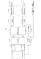
<無線基地局の構成>
図1は、MU-MIMOを行う無線基地局の構成を示すブロック図である。
<Configuration of wireless base station>
FIG. 1 is a block diagram showing a configuration of a radio base station that performs MU-MIMO.
図1において、無線基地局(以下「基地局」という)10Aは、ビーム選択部100と、ユーザ端末選択部(以下「端末選択部」という)102と、デジタルプリコーダ104と、D/A変換部106と、周波数変換部108と、固定アナログビームフォーマ110と、複数のアンテナ114と、を備える。
In FIG. 1, the radio base station (hereinafter referred to as “base station”) 10A includes a
基地局10は、複数の固定ビームからL本の固定ビームを選択し、複数のユーザ端末(以下「端末」という)からU個の端末を選択し、MIMO伝送を行う。L、Uは1以上の整数である。複数の固定ビームのそれぞれは、ビームの送信方向(角度)が固定されている。以下、固定ビームを、単に「ビーム」ということがある。
The
基地局10は、端末にM本のストリームが分配される。Mは1以上の整数であり、「M<L」である。
In the
ビーム選択部100は、送信方向が異なる複数のビームの中から、端末へのデータ伝送に使用するビーム(以下「使用ビーム」という)を選択する。ビーム選択部100は、その選択した使用ビームが送信されるように、固定アナログビームフォーマ110を制御する。
The
例えば、ビーム選択部100は、各端末から送信された、ビーム番号及びビームの受信電力等を含むビーム情報に基づいてビーム選択基準パラメータを算出し、当該ビーム選択基準パラメータに基づいて複数のビームの中から使用ビームを選択する。なお、ビーム選択基準パラメータの算出方法の詳細については後述する。
For example, the
ビーム選択部100は、後述の端末選択部102によって使用ビームの対象とする端末が選択された後、当該選択された端末が選択したビームのビーム情報から算出されるビーム選択基準パラメータに基づいて、複数のビームの中から使用ビームを再選択してもよい。
After the terminal to be used beam is selected by the
端末選択部102は、ビーム選択部100によって選択された使用ビームを選択した端末の中から、使用ビームの対象とする端末(対象端末)を選択する。端末選択部102は、その対象端末が受信可能なデータがデジタルプリコーダ104に入力されるように、制御する。
The
例えば、端末選択部102は、ビーム選択部100によって選択された使用ビームを選択した端末から送信された、ビーム番号及びビームの受信電力等を含むビーム情報に基づいて端末選択基準パラメータを算出し、当該端末選択基準パラメータに基づいて使用ビームの対象とする端末を選択する。なお、端末選択基準パラメータの算出方法の詳細については後述する。
For example, the
端末選択部102は、ユーザ端末選択基準パラメータに基づいて仮の端末を選択し、その選択した仮の端末のCSIに基づいて、使用ビームの対象とする端末を選択してもよい。
The
デジタルプリコーダ104は、各端末の受信品質を向上させるために、送信前の信号に無線伝搬路に応じた重みを予め乗算する処理を行う。デジタルプリコーダ104は、プリコーディング行列PをM系列のベースバンド信号に適用してL系列の信号を生成し、出力する。Lは送信されるビームの数である。ここでのプリコーディング行列Pは、L行M列の系列を有する。
The
デジタルプリコーダ104から出力されたL系列の信号は、それぞれ、D/A変換部106によってデジタル信号からアナログ信号に変換され、周波数変換部108によって周波数がアップコンバートされ、固定アナログビームフォーマ110に入力される。
Each of the L-series signals output from the
固定アナログビームフォーマ110は、その入力されたL系列の信号に対して、ビーム選択部100で選択された使用ビームに対応するビームフォーミング行列WTを適用し、NT系列の信号を生成する。NTは送信アンテナ素子の数である。ここでのビームフォーミング行列WTは、NT行L列を有する。NT系列の複数の信号は、複数のアンテナ114からそれぞれ送信される。
The fixed
<無線基地局の変形例>
図2は、MU-MIMOを行う基地局の変形例を示すブロック図である。
<Modification example of wireless base station>
FIG. 2 is a block diagram showing a modified example of a base station that performs MU-MIMO.
図2の基地局10Bは、図1の基地局10Aは固定アナログビームフォーマ110が周波数変換部108の後段に配置されているのに対して、固定デジタルビームフォーマ112がデジタルプリコーダ104の後段に配置されている点が相違する。
In the
ビーム選択部100は、送信方向が異なる複数のビームの中から、端末へのデータ伝送に使用する使用ビームを選択する。ビーム選択部100は、その選択した使用ビームが送信されるように、固定デジタルビームフォーマ112を制御する。固定デジタルビームフォーマ112は、デジタルプリコーダ104から入力されたL系列の信号に対して、ビーム選択部100で選択された使用ビームに対応するビームフォーミング行列WTを適用し、NT系列の信号を生成及び出力する。
The
固定デジタルビームフォーマ112から出力されたNT系列の信号は、それぞれ、D/A変換部106においてデジタル信号からアナログ信号に変換され、周波数変換部108において周波数がアップコンバートされ、アンテナ114から送信される。
Each of the NT series signals output from the fixed digital beam former 112 is converted from a digital signal to an analog signal by the D /
<動作>
図3は、使用ビームに基づいて対象端末20を選択する処理を示すシーケンスチャートである。図4は、そのときの無線通信システムの動作を示す模式図である。
<Operation>
FIG. 3 is a sequence chart showing a process of selecting a
基地局10は、ビームフォーマ110(又は112)を制御して、走査用参照信号を含む送信方向(角度)の異なるビーム30を順次送信する(ST100)。
The
各端末20は、ST100で順次送信されたビーム30を受信し、それら受信した複数のビーム30の番号(「ビーム番号」という)を受信電力の大きい順に並び替え、その1位からN位(Nは1以上の所定の整数)までのビーム番号を選択する(ST102)。
Each terminal 20 receives the
次に、各端末20は、ST102で選択したビーム番号と、それらビーム番号に対応する受信電力等を含むビーム情報を、基地局10へ送信(フィードバック)する(ST104)。
Next, each terminal 20 transmits (feedback) the beam information including the beam numbers selected in
基地局10(ビーム選択部100)は、ST104で送信されたビーム情報に基づいて、ビーム選択基準パラメータを算出する。そして、基地局10は、その算出したビーム選択基準パラメータに基づいて、複数のビーム30の中から、使用ビームを選択する(ST106)。図4において、塗りつぶしされているビーム30が、使用ビームに相当する。
The base station 10 (beam selection unit 100) calculates beam selection reference parameters based on the beam information transmitted in ST104. Then, the
基地局10(端末選択部102)は、ST106で選択した使用ビームの番号をST104でフィードバックしてきた端末20を、候補端末として選択する(ST108)。例えば、図4(a)に示すように、端末20A、20B、20C、20Dを候補端末として選択する。
The base station 10 (terminal selection unit 102) selects the terminal 20 that has fed back the number of the beam used selected in ST106 in ST104 as a candidate terminal (ST108). For example, as shown in FIG. 4A,
基地局10(端末選択部102)は、ST108で選択した複数の候補端末のそれぞれについて、端末選択基準パラメータを算出する。そして、基地局10の端末選択部102は、その算出した端末選択基準パラメータに基づいて、複数の候補端末の中から、使用ビームの送信対象の端末(「対象端末」という)を選択する(ST110)。例えば、図4(b)に示すように、端末20B、20C、20Dを、対象端末として選択する。
The base station 10 (terminal selection unit 102) calculates terminal selection reference parameters for each of the plurality of candidate terminals selected in ST108. Then, the
基地局10は、対象端末の識別信号である対象端末識別信号、及び、対象端末の重み付け後の等価チャネルを推定するための参照信号である対象端末チャネル推定参照信号を送信する(ST112)。これらの信号は、ST106で選択された使用ビームによって送信されてもよい。
The
対象端末識別信号に対応する端末(つまり対象端末)は、対象端末チャネル推定参照信号に基づいて、重み付け後の等価チャネルを推定する(ST114)。 The terminal corresponding to the target terminal identification signal (that is, the target terminal) estimates the weighted equivalent channel based on the target terminal channel estimation reference signal (ST114).
基地局10は、使用ビームを用いて、対象端末に対してデータを伝送する(ST116)。対象端末は、ST114で推定した等価チャネルを用いて、使用ビームのデータを受信する。
The
<ビーム選択基準パラメータ>
次に、ビーム選択基準パラメータの算出方法について説明する。
<Beam selection reference parameter>
Next, a method of calculating the beam selection reference parameter will be described.
上記ST106の処理に関するビーム選択基準パラメータは、下記の式(1)に示すように、受信電力の合計であってよい。 The beam selection reference parameter related to the processing of ST106 may be the total received power as shown in the following equation (1).

ここで、lはビーム番号、NUは端末数、Pr,u(l)は第u端末の第lビームにおける受信電力、αu(l)は第u端末が上記ST102の処理において第lビームを選択している場合は「1」、未選択の場合は「0」となる係数である。 Here, l is the beam number, NU is the number of terminals, Pr, u (l) is the received power in the l-beam of the u -th terminal, and α u (l) is the l-th in the processing of the ST102 by the u-th terminal. It is a coefficient that becomes "1" when the beam is selected and "0" when it is not selected.
又は、ビーム選択基準パラメータは、下記の式(2)に示すように、受信電力の最大値であってよい。 Alternatively, the beam selection reference parameter may be the maximum value of the received power as shown in the following equation (2).

又は、ビーム選択基準パラメータは、下記の式(3)に示すように、受信SIR(Signal-to-Interference Ratio)の合計であってよい。 Alternatively, the beam selection reference parameter may be the sum of the received SIRs (Signal-to-Interference Ratio) as shown in the following equation (3).

又は、ビーム選択基準パラメータは、下記の式(4)に示すように、受信SIRの最大値であってよい。 Alternatively, the beam selection reference parameter may be the maximum value of the received SIR as shown in the following equation (4).

ビーム選択部100は、ビーム選択基準パラメータとして受信電力の合計最大規範を用いる場合は式(1)によって、受信電力の最大値最大規範を用いる場合は式(2)によって、受信SIRの合計最大規範を用いる場合は式(3)によって、受信SIRの最大値最大規範を用いる場合は式(4)によって、ビーム選択基準パラメータをそれぞれ算出し、下記の式(5)にしたがって、ビーム選択基準パラメータの大きいものから順に所定数のビーム番号lを選択する。
The

なお、端末20が、上記ST104の処理において、基地局10に対して過去のスループット情報も合わせてフィードバックし、基地局10のビーム選択部100が、上記ST106の処理において、PF(Proportional Fairness)規範に基づいてビーム選択基準パラメータを算出し、使用ビームを選択してもよい。
The terminal 20 also feeds back the past throughput information to the
また、OFDM伝送を用いる場合、基地局10は、ビーム選択基準パラメータを全てのサブキャリアにおいて算出する必要はない。基地局10は、1又は複数のサブキャリアに着目してビーム選択基準パラメータを算出し、その算出結果に基づいて使用ビームを選択してもよい。
Further, when OFDM transmission is used, the
<端末選択基準パラメータ>
次に、端末選択基準パラメータの算出方法について説明する。
<Terminal selection criteria parameters>
Next, a method of calculating the terminal selection reference parameter will be described.
上記ST110の処理に関する端末選択基準パラメータは、下記の式(6)に示すように、受信電力の合計であってよい。

ここで、Bは、上記ST106の処理で基地局10が選択した使用ビームの番号の集合である。
Here, B is a set of numbers of used beams selected by the
端末選択部102は、端末選択基準パラメータとして上記の合計受信電力を用いる場合、式(5)によって算出した合計受信電力の大きいものから順に所定数の端末を選択し、その選択した端末を対象端末とする。
When the above total received power is used as the terminal selection reference parameter, the
又は、端末選択基準パラメータは、下記の式(7)に示すように、ビーム間干渉係数であってもよい。

ここで、

ただし、ATは行列Aの転置行列を表す。また、U~は第u端末以外の候補端末の集合、N~ Uは候補端末の数、Hu→u’は第u端末の使用ビームと第u’端末の使用ビームとの間の干渉行列、Hu→u’(n,m)は当該干渉行列の第n行第m列目の要素、η(l,l’)は第lビームと第l’ビームとの間の相互係数、βu(n)は第u端末の第n使用ビームの番号である。 However, AT represents the transposed matrix of the matrix A. U ~ is a set of candidate terminals other than the u terminal, N ~ U is the number of candidate terminals, and Hu → u'is an interference matrix between the beam used by the u terminal and the beam used by the u'terminal. , Hu → u' (n, m) is the element in the nth row and mth column of the interference matrix, η (l, l') is the mutual coefficient between the lth beam and the l'th beam, β u (n) is the number of the nth used beam of the uth terminal.
端末選択部102は、端末選択基準パラメータとして上記のビーム間干渉係数を用いる場合、式(7)によって算出したビーム間干渉係数の小さい(つまり干渉の低い)ものから順に所定数の端末を選択し、その選択した端末を対象端末とする。
When the above-mentioned inter-beam interference coefficient is used as the terminal selection reference parameter, the
なお、端末選択部102は、上記ST110の処理において、上記式(6)及び式(7)の両方を用いて対象端末を選択してもよい。例えば、端末選択部102は、合計受信電力が大きく、かつ、ビーム間干渉係数が小さいものから順に所定数の端末を選択し、その選択した端末を対象端末とする。
The
また、ビーム間の相互係数η(l,l’)は、例えば、ビーム30のビームパターンに基づいて設計されてもよいし、ビーム間の角度差に基づいて設計されてもよい。
Further, the mutual coefficient η (l, l') between the beams may be designed based on, for example, the beam pattern of the
また、ビーム間干渉係数を算出するにあたり、各端末20の受信電力Pr,u(l)を、全て「1」又は所定の実数等の一定数とみなして算出してもよい。 Further, in calculating the inter-beam interference coefficient, the received power Pr, u (l) of each terminal 20 may be regarded as “1” or a constant constant such as a predetermined real number.
また、端末20が、上記ST104の処理において、基地局10に対して過去のスループット情報も合わせてフィードバックし、基地局10が上記ST110の処理において、PF(Proportional Fairness)規範に基づいて対象端末を選択してもよい。
Further, the terminal 20 also feeds back the past throughput information to the
また、OFDM伝送を用いる場合、基地局10は、端末選択基準パラメータを全てのサブキャリアにおいて算出する必要はない。基地局10は、1又は複数のサブキャリアに着目して端末選択基準パラメータを算出し、その算出結果に基づいて対象端末を選択してよい。
Further, when OFDM transmission is used, the
また、基地局10は、候補端末数N~
Uから対象端末数N^
Uを選択する全ての組み合わせについて端末選択基準パラメータを算出し、その算出結果に基づいて対象端末数N^
Uを一度に選択してもよい。この方法は全探索法と呼ばれる。
Further, the
又は、基地局10は、未選択の端末から1つの端末を選択し、それを選択済みの端末の集合に追加した場合の端末選択基準パラメータを算出してもよい。そして、その算出処理を繰り返すことによって、対象端末数N^
Uを選択してもよい。この方法は逐次法と呼ばれる。
Alternatively, the
<ビーム間干渉係数の設計例>
次に、ビーム間干渉係数の設計例について説明する。
<Design example of inter-beam interference coefficient>
Next, a design example of the inter-beam interference coefficient will be described.
図5は、ビーム数が4つ、端末数が3つの場合におけるビーム間干渉係数の設計例を説明するための図である。 FIG. 5 is a diagram for explaining a design example of the inter-beam interference coefficient when the number of beams is four and the number of terminals is three.
図5は、基地局10が、ST104において、各端末20から以下の情報をフィードバックされたことを示している。
FIG. 5 shows that the
第1端末からは、ST102で選択されたビーム番号「#1」及び「#2」、並びに、それらビーム番号にそれぞれ対応する受信電力「1.0」及び「1.2」をフィードバックされた。 The beam numbers "# 1" and "# 2" selected in ST102 and the received powers "1.0" and "1.2" corresponding to those beam numbers were fed back from the first terminal.
第2端末からは、ST102で選択されたビーム番号「#2」及び「#3」、並びに、それらビーム番号にそれぞれ対応する受信電力「2.0」及び「1.5」をフィードバックされた。 From the second terminal, the beam numbers "# 2" and "# 3" selected in ST102, and the received powers "2.0" and "1.5" corresponding to those beam numbers were fed back.
第3端末からは、ST102で選択されたビーム番号「#2」及び「#3」、並びに、それらビーム番号にそれぞれ対応する受信電力「0.6」及び「0.7」をフィードバックされた。 From the third terminal, the beam numbers "# 2" and "# 3" selected in ST102, and the received powers "0.6" and "0.7" corresponding to those beam numbers were fed back.
ここで、一例として第nビームと第mビームとの間の相互係数をη(n,m)=0.5|n-m|とする。この場合、第1端末から、第2及び第3端末へのビーム間干渉行列は次の式(9)のようになる。 Here, as an example, the mutual coefficient between the nth beam and the mth beam is η (n, m) = 0.5 | nm | . In this case, the inter-beam interference matrix from the first terminal to the second and third terminals is as shown in the following equation (9).

式(9)において、第1列および第2列は、第1端末が選択したビーム番号「#1」及び「#2」が、第2端末が選択したビーム番号「#2」及び「#3」に与える影響に係る干渉行列を示す。また、第3列および第4列は、第1端末が選択したビーム番号「#1」及び「#2」が、第3端末が選択したビーム番号「#3」及び「#4」に与える影響に係る干渉行列を示す。例えば、このようにして、ビーム間干渉係数は設計される。ただし,上記の設計はあくまで一例であり,実際にはこの設計方法に限る必要はない。 In the formula (9), in the first and second columns, the beam numbers "# 1" and "# 2" selected by the first terminal are the beam numbers "# 2" and "# 3" selected by the second terminal. The interference matrix related to the influence on "" is shown. Further, in the third and fourth columns, the influence of the beam numbers "# 1" and "# 2" selected by the first terminal on the beam numbers "# 3" and "# 4" selected by the third terminal. The interference matrix related to is shown. For example, the inter-beam interference coefficient is designed in this way. However, the above design is just an example, and it is not necessary to limit it to this design method in practice.
<変形例1>
図6は、対象端末を選択した後で使用ビームを再選択する処理を示すシーケンスチャートである。図7は、そのときの無線通信システムの動作を示す模式図である。
<
FIG. 6 is a sequence chart showing a process of reselecting a beam to be used after selecting a target terminal. FIG. 7 is a schematic diagram showing the operation of the wireless communication system at that time.
基地局10及び端末20は、ST200~ST210において、上記図3のST100~ST110と同様の処理を行う。
The
次に、基地局10のビーム選択部100は、対象端末のみを考慮して、使用ビームを再選択する(ST212)。例えば、ビーム選択部100は、図7(b)に示すように、対象端末20B、20C、20Dのみを考慮して、ビーム選択基準パラメータを再算出し、その再算出の結果に基づいて、複数のビームの中から使用ビームを再選択する。図7(b)は再選択前の使用ビームを示し、図7(c)は再選択後の使用ビームを示している。
Next, the
基地局10の端末選択部102は、対象端末識別信号、及び、ST212で再選択された使用ビームの重み付けを行った対象端末チャネル推定参照信号を送信する(ST214)。これらの信号は、再選択された使用ビーム30によって送信されてもよい。
The
対象端末識別信号に対応する端末(つまり対象端末)は、上記対象端末チャネル推定参照信号に基づいて、重み付け後の等価チャネルを推定する(ST216)。 The terminal corresponding to the target terminal identification signal (that is, the target terminal) estimates the weighted equivalent channel based on the target terminal channel estimation reference signal (ST216).
基地局10は、再選択後の使用ビームを用いて、対象端末に対してデータを伝送する(ST218)。対象端末は、ST216で推定した等価チャネルを用いて、再選択後の使用ビームのデータを受信する。
The
<変形例2>
図8は、CSIに基づいて対象端末を選択する処理を示すシーケンスチャートである。図9は、そのときの無線通信システムの動作を示す模式図である。
<
FIG. 8 is a sequence chart showing a process of selecting a target terminal based on CSI. FIG. 9 is a schematic diagram showing the operation of the wireless communication system at that time.
基地局10及び各端末20は、ST300~ST308において、上記図3のST100~ST108と同様の処理を行う。
The
次に、基地局10の端末選択部102は、ST308で選択した複数の候補端末のそれぞれについて、端末選択基準パラメータを算出する。そして、基地局10の端末選択部102は、その算出した端末選択基準パラメータに基づいて、複数の候補端末の中から、ビーム30の送信対象の仮端末を選択する(ST310)。例えば、端末選択部102は、図9(b)に示すように、端末20B、20C、20Dを、仮端末として選択する。
Next, the
基地局10の端末選択部102は、仮端末の識別信号である仮端末識別信号、及び、仮端末の重み付け後の等価チャネルを推定するための参照信号である仮端末チャネル推定参照信号を送信する(ST312)。これらの信号は、ST306で選択された使用ビームによって送信されてもよい。
The
仮端末識別信号に対応する端末(つまり仮端末)は、仮端末チャネル推定参照信号に基づいて、重み付け後の等価チャネルを推定する(ST314)。 The terminal corresponding to the temporary terminal identification signal (that is, the temporary terminal) estimates the weighted equivalent channel based on the temporary terminal channel estimation reference signal (ST314).
仮端末は、CSIを基地局10に送信(フィードバック)する(ST316)。 The temporary terminal transmits (feedback) the CSI to the base station 10 (ST316).
基地局10の端末選択部102は、受信したCSIに基づいて、仮端末の中から、使用ビームの送信対象の端末(つまり対象端末)を選択する(ST318)。例えば、端末選択部102は、図9(c)に示すように、端末20B、20Cを、対象端末として選択する。
The
基地局10の端末選択部102は、対象端末の対象端末識別信号、及び、対象端末の対象端末チャネル推定参照信号を送信する(ST320)。
The
基地局10は、使用ビームを用いて、対象端末に対してデータを伝送する(ST322)。対象端末は、ST314で推定した等価チャネルを用いて、使用ビームのデータを受信する。
The
なお、ST318のCSIに基づく対象端末の決定は、Max-C/I規範、PF規範、及び/又はChordal Distance最大規範などによって決定されてよい。 The determination of the target terminal based on the CSI of ST318 may be determined by the Max-C / I norm, the PF norm, and / or the Chordal Distance maximum norm.
また、ST310の仮端末の選択と、ST318の対象端末の選択とは、必ずしも一連の処理(同じ周期)として実行される必要はない。例えば、ST318の対象端末の選択の周期が、ST310の仮端末の選択の周期よりも短くてもよいし、反対に、ST318の対象端末の選択の周期が、ST310の仮端末の選択の周期よりも長くてもよい。 Further, the selection of the temporary terminal of ST310 and the selection of the target terminal of ST318 do not necessarily have to be executed as a series of processes (same cycle). For example, the cycle of selecting the target terminal of ST318 may be shorter than the cycle of selecting the temporary terminal of ST310, and conversely, the cycle of selecting the target terminal of ST318 is shorter than the cycle of selecting the temporary terminal of ST310. May be long.
また、上述の端末20の選択方法をOFDM伝送に適用する場合は、必ずしもすべてのサブキャリアを考慮して端末を選択する必要はない。例えば、1又は複数のサブキャリアに着目して端末を選択してもよい。 Further, when the above-mentioned selection method of the terminal 20 is applied to OFDM transmission, it is not always necessary to select the terminal in consideration of all the subcarriers. For example, the terminal may be selected by focusing on one or a plurality of subcarriers.
また、CSIに基づく端末20の選択方法としては、上述の全探索法を用いてもよいし、逐次法を用いてもよい。 Further, as the selection method of the terminal 20 based on the CSI, the above-mentioned full search method may be used, or the successive method may be used.
CSIに基づいて端末20を選択する場合は、端末数を変化させて端末選択を行った場合の達成可能な端末合計スループットをそれぞれ算出し,最も高い端末合計スループットを達成可能な端末数および端末の組み合わせを採用する端末数選択を導入してもよい。 When the terminal 20 is selected based on the CSI, the total achievable terminal throughput when the terminal selection is performed by changing the number of terminals is calculated, and the highest total terminal throughput can be achieved for the number of terminals and the terminals. A selection of the number of terminals that adopts the combination may be introduced.
<変形例3>
図10は、CSIに基づいて対象端末を選択した後でビームを再選択する処理示すシーケンスチャートである。図11は、そのときの無線通信システムの動作を示す模式図である。
<
FIG. 10 is a sequence chart showing a process of reselecting a beam after selecting a target terminal based on CSI. FIG. 11 is a schematic diagram showing the operation of the wireless communication system at that time.
基地局10及び各端末20は、ST400~ST418において、上記図8のST300~ST318と同様の処理を行う。
The
次に、基地局10のビーム選択部100は、ST418でCSIに基づいて選択された対象端末のみを考慮して、上記図6のST212と同様に、使用ビームを再選択する(ST420)。図11(c)は再選択前の使用ビームを示し、図11(d)は対象端末20B、20Cのみを考慮して再選択された後の使用ビームを示す。
Next, the
次に、基地局10及び対象端末は、ST422~ST426において、上記図6のST214~ST218と同様の処理を行う。
Next, the
<効果>
上述の本実施の形態によれば、マルチユーザMassive MIMOに係る無線通信システムにおいて、基地局10が使用するビーム30と空間多重する端末20とを、適切に選択することができる。したがって、全ての端末20のスループットの合計であるシステムスループットを向上させることができる。
<Effect>
According to the above-described embodiment, in the wireless communication system according to the multi-user Massive MIMO, the
以上、各実施の形態について説明した。 The embodiments have been described above.
なお、上記実施の形態では、基地局から参照信号を送信してチャネル推定を行う場合について説明した。しかし、チャネル推定において、端末から参照信号を送信してチャネル推定を行ってもよいし、参照信号を使用しないでチャネル推定値(チャネル情報)を取得してもよい。すなわち、チャネル推定では、BFウェイトを含む等価チャネル行列(HW)を示すチャネル情報が取得されればよい。 In the above embodiment, a case where a reference signal is transmitted from the base station to perform channel estimation has been described. However, in channel estimation, a reference signal may be transmitted from the terminal to perform channel estimation, or a channel estimation value (channel information) may be acquired without using the reference signal. That is, in the channel estimation, it is sufficient that the channel information indicating the equivalent channel matrix (HW) including the BF weight is acquired.
(ハードウェア構成)
なお、上記実施の形態の説明に用いたブロック図は、機能単位のブロックを示している。これらの機能ブロック(構成部)は、ハードウェア及び/又はソフトウェアの任意の組み合わせによって実現される。また、各機能ブロックの実現手段は特に限定されない。すなわち、各機能ブロックは、物理的及び/又は論理的に結合した1つの装置により実現されてもよいし、物理的及び/又は論理的に分離した2つ以上の装置を直接的及び/又は間接的に(例えば、有線及び/又は無線)で接続し、これら複数の装置により実現されてもよい。
(Hardware configuration)
The block diagram used in the description of the above embodiment shows a block of functional units. These functional blocks (components) are realized by any combination of hardware and / or software. Further, the means for realizing each functional block is not particularly limited. That is, each functional block may be realized by one physically and / or logically coupled device, or directly and / or indirectly by two or more physically and / or logically separated devices. (For example, wired and / or wireless) may be connected and realized by these plurality of devices.
例えば、本発明の一実施の形態における無線基地局、ユーザ端末などは、本発明の無線通信方法の処理を行うコンピュータとして機能してもよい。図12は、本発明の一実施の形態に係る無線基地局及びユーザ端末のハードウェア構成の一例を示す図である。上述の無線基地局10及びユーザ端末20は、物理的には、プロセッサ1001、メモリ1002、ストレージ1003、通信装置1004、入力装置1005、出力装置1006、バス1007などを含むコンピュータ装置として構成されてもよい。
For example, the radio base station, the user terminal, and the like in one embodiment of the present invention may function as a computer that processes the wireless communication method of the present invention. FIG. 12 is a diagram showing an example of a hardware configuration of a radio base station and a user terminal according to an embodiment of the present invention. Even if the
なお、以下の説明では、「装置」という文言は、回路、デバイス、ユニットなどに読み替えることができる。無線基地局10及びユーザ端末20のハードウェア構成は、図に示した各装置を1つ又は複数含むように構成されてもよいし、一部の装置を含まずに構成されてもよい。
In the following description, the word "device" can be read as a circuit, a device, a unit, or the like. The hardware configuration of the
例えば、プロセッサ1001は1つだけ図示されているが、複数のプロセッサがあってもよい。また、処理は、1のプロセッサで実行されてもよいし、処理が同時に、逐次に、又はその他の手法で、一以上のプロセッサで実行されてもよい。なお、プロセッサ1001は、一以上のチップで実装されてもよい。
For example, although only one
無線基地局10及びユーザ端末20における各機能は、プロセッサ1001、メモリ1002などのハードウェア上に所定のソフトウェア(プログラム)を読み込ませることで、プロセッサ1001が演算を行い、通信装置1004による通信、又は、メモリ1002及びストレージ1003におけるデータの読み出し及び/又は書き込みを制御することで実現される。
For each function in the
プロセッサ1001は、例えば、オペレーティングシステムを動作させてコンピュータ全体を制御する。プロセッサ1001は、周辺装置とのインターフェース、制御装置、演算装置、レジスタなどを含む中央処理装置(CPU:Central Processing Unit)で構成されてもよい。例えば、上述のビーム選択部100、ユーザ端末選択部102、デジタルプリコーダ104、D/A変換部106、周波数変換部108、固定アナログビームフォーマ110、固定デジタルビームフォーマ112、などは、プロセッサ1001で実現されてもよい。
また、プロセッサ1001は、プログラム(プログラムコード)、ソフトウェアモジュール又はデータを、ストレージ1003及び/又は通信装置1004からメモリ1002に読み出し、これらに従って各種の処理を実行する。プログラムとしては、上述の実施の形態で説明した動作の少なくとも一部をコンピュータに実行させるプログラムが用いられる。例えば、無線基地局10及びユーザ端末20を構成する少なくとも一部の機能ブロックは、メモリ1002に格納され、プロセッサ1001で動作する制御プログラムによって実現されてもよく、他の機能ブロックについても同様に実現されてもよい。上述の各種処理は、1つのプロセッサ1001で実行される旨を説明してきたが、2以上のプロセッサ1001により同時又は逐次に実行されてもよい。プロセッサ1001は、1以上のチップで実装されてもよい。なお、プログラムは、電気通信回線を介してネットワークから送信されてもよい。
Further, the
メモリ1002は、コンピュータ読み取り可能な記録媒体であり、例えば、ROM(Read Only Memory)、EPROM(Erasable Programmable ROM)、EEPROM(Electrically Erasable Programmable ROM)、RAM(Random Access Memory)などの少なくとも1つで構成されてもよい。メモリ1002は、レジスタ、キャッシュ、メインメモリ(主記憶装置)などと呼ばれてもよい。メモリ1002は、本発明の一実施の形態に係る無線通信方法を実施するために実行可能なプログラム(プログラムコード)、ソフトウェアモジュールなどを保存することができる。
The
ストレージ1003は、コンピュータ読み取り可能な記録媒体であり、例えば、CD-ROM(Compact Disc ROM)などの光ディスク、ハードディスクドライブ、フレキシブルディスク、光磁気ディスク(例えば、コンパクトディスク、デジタル多用途ディスク、Blu-ray(登録商標)ディスク)、スマートカード、フラッシュメモリ(例えば、カード、スティック、キードライブ)、フロッピー(登録商標)ディスク、磁気ストリップなどの少なくとも1つで構成されてもよい。ストレージ1003は、補助記憶装置と呼ばれてもよい。上述の記憶媒体は、例えば、メモリ1002及び/又はストレージ1003を含むデータベース、サーバその他の適切な媒体であってもよい。
The
通信装置1004は、有線及び/又は無線ネットワークを介してコンピュータ間の通信を行うためのハードウェア(送受信デバイス)であり、例えばネットワークデバイス、ネットワークコントローラ、ネットワークカード、通信モジュールなどともいう。例えば、上述のアンテナ114などは、通信装置1004で実現されてもよい。
The
入力装置1005は、外部からの入力を受け付ける入力デバイス(例えば、キーボード、マウス、マイクロフォン、スイッチ、ボタン、センサなど)である。出力装置1006は、外部への出力を実施する出力デバイス(例えば、ディスプレイ、スピーカー、LEDランプなど)である。なお、入力装置1005及び出力装置1006は、一体となった構成(例えば、タッチパネル)であってもよい。
The
また、プロセッサ1001及びメモリ1002などの各装置は、情報を通信するためのバス1007で接続される。バス1007は、単一のバスで構成されてもよいし、装置間で異なるバスで構成されてもよい。
Further, each device such as the
また、無線基地局10及びユーザ端末20は、マイクロプロセッサ、デジタル信号プロセッサ(DSP:Digital Signal Processor)、ASIC(Application Specific Integrated Circuit)、PLD(Programmable Logic Device)、FPGA(Field Programmable Gate Array)などのハードウェアを含んで構成されてもよく、当該ハードウェアにより、各機能ブロックの一部又は全てが実現されてもよい。例えば、プロセッサ1001は、これらのハードウェアの少なくとも1つで実装されてもよい。
Further, the
(情報の通知、シグナリング)
また、情報の通知は、本明細書で説明した態様/実施形態に限られず、他の方法で行われてもよい。例えば、情報の通知は、物理レイヤシグナリング(例えば、DCI(Downlink Control Information)、UCI(Uplink Control Information))、上位レイヤシグナリング(例えば、RRC(Radio Resource Control)シグナリング、MAC(Medium Access Control)シグナリング、報知情報(MIB(Master Information Block)、SIB(System Information Block)))、その他の信号又はこれらの組み合わせによって実施されてもよい。また、RRCシグナリングは、RRCメッセージと呼ばれてもよく、例えば、RRC接続セットアップ(RRC Connection Setup)メッセージ、RRC接続再構成(RRC Connection Reconfiguration)メッセージなどであってもよい。
(Information notification, signaling)
Further, the notification of information is not limited to the embodiment / embodiment described in the present specification, and may be performed by other methods. For example, information notification includes physical layer signaling (eg, DCI (Downlink Control Information), UCI (Uplink Control Information)), higher layer signaling (eg, RRC (Radio Resource Control) signaling, MAC (Medium Access Control) signaling, etc. It may be carried out by broadcast information (MIB (Master Information Block), SIB (System Information Block)), other signals, or a combination thereof. Further, the RRC signaling may be referred to as an RRC message, and may be, for example, an RRC Connection Setup message, an RRC Connection Reconfiguration message, or the like.
(適応システム)
本明細書で説明した各態様/実施形態は、LTE(Long Term Evolution)、LTE-A(LTE-Advanced)、SUPER 3G、IMT-Advanced、4G、5G、FRA(Future Radio Access)、W-CDMA(登録商標)、GSM(登録商標)、CDMA2000、UMB(Ultra Mobile Broadband)、IEEE 802.11(Wi-Fi)、IEEE 802.16(WiMAX)、IEEE 802.20、UWB(Ultra-WideBand)、Bluetooth(登録商標)、その他の適切なシステムを利用するシステム及び/又はこれらに基づいて拡張された次世代システムに適用されてもよい。
(Adaptive system)
Each aspect / embodiment described herein includes LTE (Long Term Evolution), LTE-A (LTE-Advanced), SUPER 3G, IMT-Advanced, 4G, 5G, FRA (Future Radio Access), W-CDMA. (Registered Trademarks), GSM (Registered Trademarks), CDMA2000, UMB (Ultra Mobile Broadband), IEEE 802.11 (Wi-Fi), IEEE 802.16 (WiMAX), IEEE 802.20, UWB (Ultra-WideBand), It may be applied to Bluetooth®, other systems that utilize suitable systems and / or next-generation systems that are extended based on them.
(処理手順等)
本明細書で説明した各態様/実施形態の処理手順、シーケンス、フローチャートなどは、矛盾の無い限り、順序を入れ替えてもよい。例えば、本明細書で説明した方法については、例示的な順序で様々なステップの要素を提示しており、提示した特定の順序に限定されない。
(Processing procedure, etc.)
The processing procedures, sequences, flowcharts, and the like of each aspect / embodiment described in the present specification may be rearranged in order as long as there is no contradiction. For example, the methods described herein present elements of various steps in an exemplary order and are not limited to the particular order presented.
(基地局の操作)
本明細書において基地局(無線基地局)によって行われるとした特定動作は、場合によってはその上位ノード(upper node)によって行われることもある。基地局を有する1つまたは複数のネットワークノード(network nodes)からなるネットワークにおいて、端末との通信のために行われる様々な動作は、基地局および/または基地局以外の他のネットワークノード(例えば、MME(Mobility Management Entity)またはS-GW(Serving Gateway)などが考えられるが、これらに限られない)によって行われ得ることは明らかである。上記において基地局以外の他のネットワークノードが1つである場合を例示したが、複数の他のネットワークノードの組み合わせ(例えば、MMEおよびS-GW)であってもよい。
(Operation of base station)
In some cases, the specific operation performed by the base station (radio base station) in the present specification may be performed by its upper node. In a network consisting of one or more network nodes having a base station, various operations performed for communication with the terminal are performed on the base station and / or other network nodes other than the base station (eg, for example). It is clear that it can be done by MME (Mobility Management Entity), S-GW (Serving Gateway), etc., but not limited to these). Although the case where there is one network node other than the base station is illustrated above, it may be a combination of a plurality of other network nodes (for example, MME and S-GW).
(入出力の方向)
情報及び信号等は、上位レイヤ(または下位レイヤ)から下位レイヤ(または上位レイヤ)に出力され得る。複数のネットワークノードを介して入出力されてもよい。
(I / O direction)
Information, signals, etc. can be output from the upper layer (or lower layer) to the lower layer (or upper layer). Input / output may be performed via a plurality of network nodes.
(入出力された情報等の扱い)
入出力された情報等は特定の場所(例えば、メモリ)に保存されてもよいし、管理テーブルで管理してもよい。入出力される情報等は、上書き、更新、または追記され得る。出力された情報等は削除されてもよい。入力された情報等は他の装置に送信されてもよい。
(Handling of input / output information, etc.)
The input / output information and the like may be stored in a specific place (for example, a memory) or may be managed by a management table. Information to be input / output may be overwritten, updated, or added. The output information and the like may be deleted. The input information and the like may be transmitted to another device.
(判定方法)
判定は、1ビットで表される値(0か1か)によって行われてもよいし、真偽値(Boolean:trueまたはfalse)によって行われてもよいし、数値の比較(例えば、所定の値との比較)によって行われてもよい。
(Judgment method)
The determination may be made by a value represented by 1 bit (0 or 1), by a boolean value (Boolean: true or false), or by comparing numerical values (for example, a predetermined value). It may be done by comparison with the value).
(ソフトウェア)
ソフトウェアは、ソフトウェア、ファームウェア、ミドルウェア、マイクロコード、ハードウェア記述言語と呼ばれるか、他の名称で呼ばれるかを問わず、命令、命令セット、コード、コードセグメント、プログラムコード、プログラム、サブプログラム、ソフトウェアモジュール、アプリケーション、ソフトウェアアプリケーション、ソフトウェアパッケージ、ルーチン、サブルーチン、オブジェクト、実行可能ファイル、実行スレッド、手順、機能などを意味するよう広く解釈されるべきである。
(software)
Software, whether referred to as software, firmware, middleware, microcode, hardware description language, or other names, is an instruction, instruction set, code, code segment, program code, program, subprogram, software module. , Applications, software applications, software packages, routines, subroutines, objects, executable files, execution threads, procedures, features, etc. should be broadly interpreted.
また、ソフトウェア、命令などは、伝送媒体を介して送受信されてもよい。例えば、ソフトウェアが、同軸ケーブル、光ファイバケーブル、ツイストペア及びデジタル加入者回線(DSL)などの有線技術及び/又は赤外線、無線及びマイクロ波などの無線技術を使用してウェブサイト、サーバ、又は他のリモートソースから送信される場合、これらの有線技術及び/又は無線技術は、伝送媒体の定義内に含まれる。 Further, software, instructions, and the like may be transmitted and received via a transmission medium. For example, the software may use wired technology such as coaxial cable, fiber optic cable, twisted pair and digital subscriber line (DSL) and / or wireless technology such as infrared, wireless and microwave to website, server, or other. When transmitted from a remote source, these wired and / or wireless technologies are included within the definition of transmission medium.
(情報、信号)
本明細書で説明した情報、信号などは、様々な異なる技術のいずれかを使用して表されてもよい。例えば、上記の説明全体に渡って言及され得るデータ、命令、コマンド、情報、信号、ビット、シンボル、チップなどは、電圧、電流、電磁波、磁界若しくは磁性粒子、光場若しくは光子、又はこれらの任意の組み合わせによって表されてもよい。
(Information, signal)
The information, signals, etc. described herein may be represented using any of a variety of different techniques. For example, data, instructions, commands, information, signals, bits, symbols, chips, etc. that may be referred to throughout the above description are voltages, currents, electromagnetic waves, magnetic fields or magnetic particles, light fields or photons, or any of these. It may be represented by a combination of.
なお、本明細書で説明した用語及び/又は本明細書の理解に必要な用語については、同一の又は類似する意味を有する用語と置き換えてもよい。例えば、チャネル及び/又はシンボルは信号(シグナル)であってもよい。また、信号はメッセージであってもよい。また、コンポーネントキャリア(CC)は、キャリア周波数、セルなどと呼ばれてもよい。 The terms described herein and / or the terms necessary for understanding the present specification may be replaced with terms having the same or similar meanings. For example, the channel and / or symbol may be a signal. Also, the signal may be a message. Further, the component carrier (CC) may be referred to as a carrier frequency, a cell, or the like.
(「システム」、[ネットワーク])
本明細書で使用する「システム」および「ネットワーク」という用語は、互換的に使用される。
("System", [Network])
The terms "system" and "network" used herein are used interchangeably.
(パラメータ、チャネルの名称)
また、本明細書で説明した情報、パラメータなどは、絶対値で表されてもよいし、所定の値からの相対値で表されてもよいし、対応する別の情報で表されてもよい。例えば、無線リソースはインデックスで指示されるものであってもよい。
(Parameters, channel names)
Further, the information, parameters, etc. described in the present specification may be represented by an absolute value, a relative value from a predetermined value, or another corresponding information. .. For example, the radio resource may be indexed.
上述したパラメータに使用する名称はいかなる点においても限定的なものではない。さらに、これらのパラメータを使用する数式等は、本明細書で明示的に開示したものと異なる場合もある。様々なチャネル(例えば、PUCCH、PDCCHなど)及び情報要素(例えば、TPCなど)は、あらゆる好適な名称によって識別できるので、これらの様々なチャネル及び情報要素に割り当てている様々な名称は、いかなる点においても限定的なものではない。 The names used for the parameters described above are not limited in any way. Further, mathematical formulas and the like using these parameters may differ from those expressly disclosed herein. Since the various channels (eg, PUCCH, PDCCH, etc.) and information elements (eg, TPC, etc.) can be identified by any suitable name, the various names assigned to these various channels and information elements are in any respect. However, it is not limited.
(基地局)
基地局(無線基地局)は、1つまたは複数(例えば、3つ)の(セクタとも呼ばれる)セルを収容することができる。基地局が複数のセルを収容する場合、基地局のカバレッジエリア全体は複数のより小さいエリアに区分でき、各々のより小さいエリアは、基地局サブシステム(例えば、屋内用の小型基地局RRH:Remote Radio Head)によって通信サービスを提供することもできる。「セル」または「セクタ」という用語は、このカバレッジにおいて通信サービスを行う基地局、および/または基地局サブシステムのカバレッジエリアの一部または全体を指す。さらに、「基地局」、「eNB」、「セル」、および「セクタ」という用語は、本明細書では互換的に使用され得る。基地局は、固定局(fixed station)、NodeB、eNodeB(eNB)、アクセスポイント(access point)、フェムトセル、スモールセルなどの用語で呼ばれる場合もある。
(base station)
A base station (radio base station) can accommodate one or more (eg, three) cells (also referred to as sectors). When a base station accommodates multiple cells, the entire base station coverage area can be divided into multiple smaller areas, each smaller area being a base station subsystem (eg, a small indoor base station RRH: Remote). Communication services can also be provided by Radio Head). The term "cell" or "sector" refers to a part or all of the coverage area of a base station and / or base station subsystem that provides communication services in this coverage. In addition, the terms "base station,""eNB,""cell," and "sector" may be used interchangeably herein. A base station may also be referred to by terms such as fixed station, NodeB, eNodeB (eNB), access point, femtocell, and small cell.
(端末)
ユーザ端末は、当業者によって、移動局、加入者局、モバイルユニット、加入者ユニット、ワイヤレスユニット、リモートユニット、モバイルデバイス、ワイヤレスデバイス、ワイヤレス通信デバイス、リモートデバイス、モバイル加入者局、アクセス端末、モバイル端末、ワイヤレス端末、リモート端末、ハンドセット、ユーザエージェント、モバイルクライアント、クライアント、UE(User Equipment)、またはいくつかの他の適切な用語で呼ばれる場合もある。
(Terminal)
User terminals may be mobile stations, subscriber stations, mobile units, subscriber units, wireless units, remote units, mobile devices, wireless devices, wireless communication devices, remote devices, mobile subscriber stations, access terminals, mobiles, depending on the trader. It may also be referred to as a terminal, wireless terminal, remote terminal, handset, user agent, mobile client, client, UE (User Equipment), or some other suitable term.
(用語の意味、解釈)
本明細書で使用する「判断(determining)」、「決定(determining)」という用語は、多種多様な動作を包含する場合がある。「判断」、「決定」は、例えば、判定(judging)、計算(calculating)、算出(computing)、処理(processing)、導出(deriving)、調査(investigating)、探索(looking up)(例えば、テーブル、データベースまたは別のデータ構造での探索)、確認(ascertaining)した事を「判断」「決定」したとみなす事などを含み得る。また、「判断」、「決定」は、受信(receiving)(例えば、情報を受信すること)、送信(transmitting)(例えば、情報を送信すること)、入力(input)、出力(output)、アクセス(accessing)(例えば、メモリ中のデータにアクセスすること)した事を「判断」「決定」したとみなす事などを含み得る。また、「判断」、「決定」は、解決(resolving)、選択(selecting)、選定(choosing)、確立(establishing)、比較(comparing)などした事を「判断」「決定」したとみなす事を含み得る。つまり、「判断」「決定」は、何らかの動作を「判断」「決定」したとみなす事を含み得る。
(Meaning and interpretation of terms)
The terms "determining" and "determining" as used herein may include a wide variety of actions. "Judgment" and "decision" are, for example, judgment, calculation, computing, processing, deriving, investigating, looking up (for example, table). , Searching in a database or another data structure), ascertaining can be considered as a "judgment" or "decision". Also, "judgment" and "decision" are receiving (for example, receiving information), transmitting (for example, transmitting information), input (input), output (output), and access. It may include (for example, accessing data in memory) to be regarded as "judgment" or "decision". In addition, "judgment" and "decision" are considered to be "judgment" and "decision" when the things such as solving, selecting, choosing, establishing, and comparing are regarded as "judgment" and "decision". Can include. That is, "judgment" and "decision" may include considering some action as "judgment" and "decision".
「接続された(connected)」、「結合された(coupled)」という用語、又はこれらのあらゆる変形は、2又はそれ以上の要素間の直接的又は間接的なあらゆる接続又は結合を意味し、互いに「接続」又は「結合」された2つの要素間に1又はそれ以上の中間要素が存在することを含むことができる。要素間の結合又は接続は、物理的なものであっても、論理的なものであっても、或いはこれらの組み合わせであってもよい。本明細書で使用する場合、2つの要素は、1又はそれ以上の電線、ケーブル及び/又はプリント電気接続を使用することにより、並びにいくつかの非限定的かつ非包括的な例として、無線周波数領域、マイクロ波領域及び光(可視及び不可視の両方)領域の波長を有する電磁エネルギーなどの電磁エネルギーを使用することにより、互いに「接続」又は「結合」されると考えることができる。 The terms "connected", "coupled", or any variation thereof, mean any direct or indirect connection or connection between two or more elements and each other. It can include the presence of one or more intermediate elements between two "connected" or "combined" elements. The connection or connection between the elements may be physical, logical, or a combination thereof. As used herein, the two elements are by using one or more wires, cables and / or printed electrical connections, and, as some non-limiting and non-comprehensive examples, radio frequencies. By using electromagnetic energies such as electromagnetic energies with wavelengths in the region, microwave region and light (both visible and invisible) regions, they can be considered to be "connected" or "coupled" to each other.
参照信号は、RS(Reference Signal)と略称することもでき、適用される標準によってパイロット(Pilot)と呼ばれてもよい。また、補正用RSは、TRS(Tracking RS)、PC-RS(Phase Compensation RS)、PTRS(Phase Tracking RS)、Additional RSと呼ばれてもよい。また、復調用RS及び補正用RSは、それぞれに対応する別の呼び方であってもよい。また、復調用RS及び補正用RSは同じ名称(例えば復調RS)で規定されてもよい。 The reference signal may be abbreviated as RS (Reference Signal) and may be referred to as a pilot (Pilot) according to the applied standard. Further, the correction RS may be referred to as TRS (Tracking RS), PC-RS (Phase Compensation RS), PTRS (Phase Tracking RS), or Additional RS. Further, the demodulation RS and the correction RS may have different names corresponding to each. Further, the demodulation RS and the correction RS may be defined by the same name (for example, the demodulation RS).
本明細書で使用する「に基づいて」という記載は、別段に明記されていない限り、「のみに基づいて」を意味しない。言い換えれば、「に基づいて」という記載は、「のみに基づいて」と「に少なくとも基づいて」の両方を意味する。 The phrase "based on" as used herein does not mean "based on" unless otherwise stated. In other words, the statement "based on" means both "based only" and "at least based on".
上記の各装置の構成における「部」を、「手段」、「回路」、「デバイス」等に置き換えてもよい。 The "part" in the configuration of each of the above devices may be replaced with a "means", a "circuit", a "device" and the like.
「含む(including)」、「含んでいる(comprising)」、およびそれらの変形が、本明細書あるいは特許請求の範囲で使用されている限り、これら用語は、用語「備える」と同様に、包括的であることが意図される。さらに、本明細書あるいは特許請求の範囲において使用されている用語「または(or)」は、排他的論理和ではないことが意図される。 As long as "including", "comprising", and variations thereof are used herein or within the scope of the claims, these terms are as comprehensive as the term "comprising". Intended to be targeted. Moreover, the term "or" as used herein or in the claims is intended to be non-exclusive.
無線フレームは時間領域において1つまたは複数のフレームで構成されてもよい。時間領域において1つまたは複数の各フレームはサブフレーム、タイムユニット等と呼ばれてもよい。サブフレームは更に時間領域において1つまたは複数のスロットで構成されてもよい。スロットはさらに時間領域において1つまたは複数のシンボル(OFDM(Orthogonal Frequency Division Multiplexing)シンボル、SC-FDMA(Single Carrier-Frequency Division Multiple Access)シンボル等)で構成されてもよい。 The radio frame may be composed of one or more frames in the time domain. Each one or more frames in the time domain may be referred to as a subframe, a time unit, or the like. Subframes may further consist of one or more slots in the time domain. The slot may be further composed of one or more symbols (OFDM (Orthogonal Frequency Division Multiplexing) symbol, SC-FDMA (Single Carrier-Frequency Division Multiple Access) symbol, etc.) in the time domain.
無線フレーム、サブフレーム、スロット、ミニスロット、およびシンボルは、いずれも信号を伝送する際の時間単位を表す。無線フレーム、サブフレーム、スロット、ミニスロット、およびシンボルは、それぞれに対応する別の呼び方であってもよい。 Wireless frames, subframes, slots, minislots, and symbols all represent the unit of time in which a signal is transmitted. Wireless frames, subframes, slots, minislots, and symbols may have different names for each.
例えば、LTEシステムでは、基地局が各移動局に無線リソース(各移動局において使用することが可能な周波数帯域幅、送信電力等)を割り当てるスケジューリングを行う。スケジューリングの最小時間単位をTTI(Transmission Time Interval)と呼んでもよいし、1ミニスロットをTTIと呼んでもよい。 For example, in an LTE system, a base station schedules each mobile station to allocate radio resources (frequency bandwidth that can be used in each mobile station, transmission power, etc.). The minimum time unit of scheduling may be called TTI (Transmission Time Interval), or one minislot may be called TTI.
例えば、1サブフレームをTTIと呼んでもよいし、複数の連続したサブフレームをTTIと呼んでもよいし、1スロットをTTIと呼んでもよい。 For example, one subframe may be referred to as TTI, a plurality of consecutive subframes may be referred to as TTI, and one slot may be referred to as TTI.
リソースユニットは、時間領域および周波数領域のリソース割当単位であり、周波数領域では1つまたは複数個の連続した副搬送波(subcarrier)を含んでもよい。また、リソースユニットの時間領域では、1つまたは複数個のシンボルを含んでもよく、1スロット、1ミニスロット、1サブフレーム、または1TTIの長さであってもよい。1TTI、1サブフレームは、それぞれ1つまたは複数のリソースユニットで構成されてもよい。また、リソースユニットは、リソースブロック(RB:Resource Block)、物理リソースブロック(PRB:Physical RB)、PRBペア、RBペア、スケジューリングユニット、周波数ユニット、サブバンドと呼ばれてもよい。また、リソースユニットは、1つ又は複数のREで構成されてもよい。例えば、1REは、リソース割当単位となるリソースユニットより小さい単位のリソース(例えば、最小のリソース単位)であればよく、REという呼称に限定されない。 A resource unit is a resource allocation unit in the time domain and the frequency domain, and may include one or more consecutive subcarriers in the frequency domain. Further, the time domain of the resource unit may include one or more symbols, and may have a length of 1 slot, 1 mini slot, 1 subframe, or 1 TTI. Each 1TTI and 1 subframe may be composed of one or a plurality of resource units. Further, the resource unit may be referred to as a resource block (RB: Resource Block), a physical resource block (PRB: Physical RB), a PRB pair, an RB pair, a scheduling unit, a frequency unit, or a subband. Further, the resource unit may be composed of one or a plurality of REs. For example, 1RE may be a resource smaller than the resource unit that is the resource allocation unit (for example, the smallest resource unit), and is not limited to the name RE.
上述した無線フレームの構造は例示に過ぎず、無線フレームに含まれるサブフレームの数、サブフレームに含まれるスロットの数、サブフレームに含まれるミニスロットの数、スロットに含まれるシンボルおよびリソースブロックの数、および、リソースブロックに含まれるサブキャリアの数は様々に変更することができる。 The structure of the radio frame described above is merely an example, and the number of subframes contained in the radio frame, the number of slots contained in the subframe, the number of mini slots contained in the subframe, and the symbols and resource blocks contained in the slots. The number and the number of subcarriers contained in the resource block can be varied.
本開示の全体において、例えば、英語でのa, an, 及びtheのように、翻訳により冠詞が追加された場合、これらの冠詞は、文脈から明らかにそうではないことが示されていなければ、複数のものを含むものとする。 Throughout this disclosure, if articles are added by translation, for example, a, an, and the in English, these articles are not explicitly indicated by the context to be otherwise. It shall include more than one.
(態様のバリエーション等)
本明細書で説明した各態様/実施形態は単独で用いてもよいし、組み合わせて用いてもよいし、実行に伴って切り替えて用いてもよい。また、所定の情報の通知(例えば、「Xであること」の通知)は、明示的に行うものに限られず、暗黙的(例えば、当該所定の情報の通知を行わない)ことによって行われてもよい。
(Variations of aspects, etc.)
Each aspect / embodiment described in the present specification may be used alone, in combination, or may be switched and used according to the execution. Further, the notification of predetermined information (for example, the notification of "being X") is not limited to the explicit one, but is performed implicitly (for example, the notification of the predetermined information is not performed). May be good.
以上、本発明について詳細に説明したが、当業者にとっては、本発明が本明細書中に説明した実施形態に限定されるものではないということは明らかである。本発明は、特許請求の範囲の記載により定まる本発明の趣旨及び範囲を逸脱することなく修正及び変更態様として実施することができる。したがって、本明細書の記載は、例示説明を目的とするものであり、本発明に対して何ら制限的な意味を有するものではない。 Although the present invention has been described in detail above, it is clear to those skilled in the art that the present invention is not limited to the embodiments described in the present specification. The present invention can be implemented as modifications and modifications without departing from the spirit and scope of the present invention as determined by the description of the scope of claims. Therefore, the description of the present specification is for the purpose of exemplary explanation and does not have any limiting meaning to the present invention.
本発明の一態様は、移動通信システムに有用である。 One aspect of the invention is useful for mobile communication systems.
10 無線基地局
20 ユーザ端末
30 ビーム
100 ビーム選択部
102 ユーザ端末選択部
104 デジタルプリコーダ
108 周波数変換部
110 固定アナログビームフォーマ
112 固定デジタルビームフォーマ
114 アンテナ
10
Claims (5)
各ユーザ端末から送信されたビーム情報に基づいてビーム選択基準パラメータを算出し、当該ビーム選択基準パラメータに基づいて複数のビームの中から使用ビームを選択するビーム選択部と、
前記使用ビームに対応する前記ビーム情報を送信したユーザ端末のそれぞれについて、当該ユーザ端末から送信された前記ビーム情報に基づいてビーム間干渉係数を算出し、前記ビーム間干渉係数に基づいて、前記使用ビームに対応する前記ビーム情報を送信したユーザ端末の中から、前記使用ビームの対象とするユーザ端末を選択するユーザ端末選択部と、
を備える無線基地局。 A wireless base station that performs MIMO transmission with a user terminal.
A beam selection unit that calculates beam selection reference parameters based on beam information transmitted from each user terminal and selects a beam to be used from a plurality of beams based on the beam selection reference parameters.
For each of the user terminals that have transmitted the beam information corresponding to the beam to be used, the beam- to-beam interference coefficient is calculated based on the beam information transmitted from the user terminal, and the use is based on the beam-to-beam interference coefficient. A user terminal selection unit that selects a user terminal that is the target of the beam to be used from among the user terminals that have transmitted the beam information corresponding to the beam .
A wireless base station equipped with.
前記ビーム選択基準パラメータは、前記各ユーザ端末から送信された前記ビーム情報に基づいて算出される設計パラメータである、
請求項1に記載の無線基地局。 The beam information includes the received power of the beam received by the user terminal.
The beam selection reference parameter is a design parameter calculated based on the beam information transmitted from each user terminal.
The radio base station according to claim 1.
前記ビーム間干渉係数に基づいて仮のユーザ端末を選択し、
その選択した仮のユーザ端末のチャネル情報に基づいて、前記使用ビームの対象とするユーザ端末を選択する、
請求項1又は2に記載の無線基地局。 The user terminal selection unit is
A temporary user terminal is selected based on the inter-beam interference coefficient , and the temporary user terminal is selected.
Based on the channel information of the selected temporary user terminal, the user terminal targeted by the beam to be used is selected.
The radio base station according to claim 1 or 2 .
請求項1乃至3の何れか1項に記載の無線基地局。 The beam selection unit is based on a beam selection reference parameter calculated from beam information transmitted from the selected user terminal after the user terminal to be the target of the beam to be used is selected by the user terminal selection unit. , Reselect the beam to be used from the plurality of beams,
The radio base station according to any one of claims 1 to 3 .
各ユーザ端末から送信されたビーム情報に基づいてビーム選択基準パラメータを算出し、当該ビーム選択基準パラメータに基づいて複数のビームの中から使用ビームを選択し、
前記使用ビームに対応する前記ビーム情報を送信したユーザ端末のそれぞれについて、当該ユーザ端末から送信された前記ビーム情報に基づいてビーム間干渉係数を算出し、前記ビーム間干渉係数に基づいて、前記使用ビームに対応する前記ビーム情報を送信したユーザ端末の中から、前記使用ビームの対象とするユーザ端末を選択する、
無線通信方法。 In a wireless base station that performs MIMO transmission with a user terminal
The beam selection reference parameter is calculated based on the beam information transmitted from each user terminal, and the beam to be used is selected from a plurality of beams based on the beam selection reference parameter.
For each of the user terminals that have transmitted the beam information corresponding to the beam to be used, the beam- to-beam interference coefficient is calculated based on the beam information transmitted from the user terminal, and the use is based on the beam-to-beam interference coefficient. Select the target user terminal of the beam to be used from the user terminals that have transmitted the beam information corresponding to the beam .
Wireless communication method.
Priority Applications (3)
| Application Number | Priority Date | Filing Date | Title |
|---|---|---|---|
| JP2017029375A JP7017312B2 (en) | 2017-02-20 | 2017-02-20 | Wireless base station and wireless communication method |
| PCT/JP2018/005662 WO2018151288A1 (en) | 2017-02-20 | 2018-02-19 | Wireless base station, and wireless communication method |
| US16/486,984 US10917160B2 (en) | 2017-02-20 | 2018-02-19 | Wireless base station, and wireless communication method |
Applications Claiming Priority (1)
| Application Number | Priority Date | Filing Date | Title |
|---|---|---|---|
| JP2017029375A JP7017312B2 (en) | 2017-02-20 | 2017-02-20 | Wireless base station and wireless communication method |
Publications (2)
| Publication Number | Publication Date |
|---|---|
| JP2018137552A JP2018137552A (en) | 2018-08-30 |
| JP7017312B2 true JP7017312B2 (en) | 2022-02-08 |
Family
ID=63169532
Family Applications (1)
| Application Number | Title | Priority Date | Filing Date |
|---|---|---|---|
| JP2017029375A Active JP7017312B2 (en) | 2017-02-20 | 2017-02-20 | Wireless base station and wireless communication method |
Country Status (3)
| Country | Link |
|---|---|
| US (1) | US10917160B2 (en) |
| JP (1) | JP7017312B2 (en) |
| WO (1) | WO2018151288A1 (en) |
Families Citing this family (5)
| Publication number | Priority date | Publication date | Assignee | Title |
|---|---|---|---|---|
| JP7017312B2 (en) * | 2017-02-20 | 2022-02-08 | 株式会社Nttドコモ | Wireless base station and wireless communication method |
| EP3687081A4 (en) * | 2017-09-30 | 2020-07-29 | Beijing Xiaomi Mobile Software Co., Ltd. | Data transmission method and apparatus |
| JP7010168B2 (en) * | 2018-07-31 | 2022-01-26 | 日本電信電話株式会社 | Wireless communication system, communication method and transmitting station equipment |
| US11342973B1 (en) * | 2021-10-19 | 2022-05-24 | King Faisal University | System and method for maintaining link communications in millimeter wave cellular networks |
| JP7209899B1 (en) * | 2021-11-26 | 2023-01-20 | 三菱電機株式会社 | Radio communication control device, terminal and radio communication control method |
Citations (4)
| Publication number | Priority date | Publication date | Assignee | Title |
|---|---|---|---|---|
| WO2013024942A1 (en) | 2011-08-12 | 2013-02-21 | Samsung Electronics Co., Ltd. | Apparatus and method for adaptive beam-forming in wireless communication system |
| WO2013191517A1 (en) | 2012-06-22 | 2013-12-27 | Samsung Electronics Co., Ltd. | Communication method and apparatus using beamforming in a wireless communication system |
| WO2014020781A1 (en) | 2012-07-30 | 2014-02-06 | 富士通株式会社 | Wireless communication system, communication control method, control device, control method, control program, and wireless terminal |
| US20140254517A1 (en) | 2013-03-08 | 2014-09-11 | Electronics & Telecommunications Research Institute | Method for multi-input multi-output communication in large-scale antenna system |
Family Cites Families (37)
| Publication number | Priority date | Publication date | Assignee | Title |
|---|---|---|---|---|
| JP3946059B2 (en) * | 2002-03-06 | 2007-07-18 | 株式会社エヌ・ティ・ティ・ドコモ | Mobile station, communication system and communication method |
| US7457641B1 (en) * | 2004-11-24 | 2008-11-25 | Nortel Networks Limited | Method and apparatus for increasing capacity for wireless data transmissions |
| US8385939B2 (en) * | 2006-08-15 | 2013-02-26 | Telefonaktiebolaget Lm Ericsson (Publ) | Method and apparatus for scheduling resources and avoiding interference in a multi-cellular wireless communication system |
| US8588351B2 (en) * | 2007-08-22 | 2013-11-19 | Motorola Mobility Llc | Multi-band signal detection |
| US8542640B2 (en) * | 2008-08-28 | 2013-09-24 | Ntt Docomo, Inc. | Inter-cell approach to operating wireless beam-forming and user selection/scheduling in multi-cell environments based on limited signaling between patterns of subsets of cells |
| US8923844B2 (en) * | 2009-08-14 | 2014-12-30 | Futurewei Technologies, Inc. | Coordinated beam forming and multi-user MIMO |
| JP5066594B2 (en) * | 2010-07-27 | 2012-11-07 | 株式会社エヌ・ティ・ティ・ドコモ | Wireless communication apparatus and wireless communication method |
| JP5451680B2 (en) * | 2011-04-25 | 2014-03-26 | 株式会社Nttドコモ | Mobile communication terminal |
| KR102109655B1 (en) * | 2012-02-23 | 2020-05-12 | 한국전자통신연구원 | Method for multi-input multi-output communication in a large-scale antenna system |
| US9048894B2 (en) * | 2012-05-22 | 2015-06-02 | Mediatek Singapore Pte. Ltd. | Method and apparatus of beam training for MIMO operation |
| CN105027461B (en) * | 2013-03-29 | 2019-06-28 | 英特尔Ip公司 | Orthogonal beams for multi-user's multiple-input and multiple-output (MU-MIMO) shape |
| KR102043021B1 (en) * | 2013-04-15 | 2019-11-12 | 삼성전자주식회사 | A scheduling method and apparatus for beam forming in a mobile communication system |
| JP6275422B2 (en) * | 2013-09-06 | 2018-02-07 | 株式会社Nttドコモ | Wireless base station, user terminal, and wireless communication method |
| KR102012257B1 (en) * | 2015-06-04 | 2019-08-21 | 한국전자통신연구원 | Method and apparatus for controlling interference between adjacent beams |
| KR20180098592A (en) * | 2015-12-23 | 2018-09-04 | 노키아 솔루션스 앤드 네트웍스 오와이 | Feedback of sparse correlation matrix for multi-input and multiple-output (MIMO) wireless networks |
| WO2017135305A1 (en) * | 2016-02-05 | 2017-08-10 | 株式会社Nttドコモ | User equipment and base station |
| JP6542143B2 (en) * | 2016-03-11 | 2019-07-10 | 株式会社Nttドコモ | base station |
| NZ746231A (en) * | 2016-03-31 | 2020-03-27 | Ericsson Telefon Ab L M | Methods and devices for determining precoder parameters in a wireless communication network |
| WO2017179951A1 (en) * | 2016-04-14 | 2017-10-19 | Samsung Electronics Co., Ltd. | Method and apparatus for transmitting and receiving signal through beamforming in communication system |
| US20190158206A1 (en) * | 2016-05-13 | 2019-05-23 | Intel IP Corporation | Multi-user multiple input multiple ouput systems |
| US10541741B2 (en) * | 2016-05-26 | 2020-01-21 | Qualcomm Incorporated | System and method for beam switching and reporting |
| EP3465936A1 (en) * | 2016-05-27 | 2019-04-10 | Telefonaktiebolaget LM Ericsson (PUBL) | Reference signal tracking in a wireless communication system |
| JP7003111B2 (en) * | 2016-08-12 | 2022-01-20 | テレフオンアクチーボラゲット エルエム エリクソン(パブル) | Configurable codebook for advanced CSI feedback overhead reduction |
| WO2018054459A1 (en) * | 2016-09-21 | 2018-03-29 | Telefonaktiebolaget Lm Ericsson (Publ) | Beamforming of beams |
| US10951291B2 (en) * | 2016-09-28 | 2021-03-16 | Idac Holdings, Inc. | Systems and methods for beam management |
| WO2018064399A1 (en) * | 2016-09-28 | 2018-04-05 | Ntt Docomo, Inc. | Wireless communication method |
| CN109937540B (en) * | 2016-09-30 | 2022-04-08 | 诺基亚技术有限公司 | Determining, by an access node, an association between a fine beam index (BL) and a logical BL |
| WO2018085601A1 (en) * | 2016-11-02 | 2018-05-11 | Idac Holdings, Inc. | Group-based beam management |
| KR20180060882A (en) * | 2016-11-28 | 2018-06-07 | 삼성전자주식회사 | Apparatus and method for transmitting signal using beamforming in wireless communication system |
| EP3331304B1 (en) * | 2016-12-02 | 2020-04-01 | Nokia Technologies Oy | Scheduling lte user equipment in the unlicensed band reducing interference on other nodes |
| WO2018128384A1 (en) * | 2017-01-03 | 2018-07-12 | 엘지전자 주식회사 | Beam information reporting method for multi-user mimo transmission in wireless communication system and apparatus therefor |
| US11082286B2 (en) * | 2017-01-06 | 2021-08-03 | Sony Corporation | Beam failure recovery |
| CN108337065A (en) * | 2017-01-18 | 2018-07-27 | 索尼公司 | Electronic equipment and communication means |
| US10574308B2 (en) * | 2017-01-24 | 2020-02-25 | Telefonaktiebolaget Lm Ericsson (Publ) | Managing of channel state information in a multiple-antenna communication system |
| EP3579604B1 (en) * | 2017-02-03 | 2022-09-07 | NTT DoCoMo, Inc. | User terminal and wireless communication method |
| JP7017312B2 (en) * | 2017-02-20 | 2022-02-08 | 株式会社Nttドコモ | Wireless base station and wireless communication method |
| JP6967359B2 (en) * | 2017-03-03 | 2021-11-17 | 株式会社Nttドコモ | Wireless base station and scheduling method |
-
2017
- 2017-02-20 JP JP2017029375A patent/JP7017312B2/en active Active
-
2018
- 2018-02-19 US US16/486,984 patent/US10917160B2/en active Active
- 2018-02-19 WO PCT/JP2018/005662 patent/WO2018151288A1/en active Application Filing
Patent Citations (4)
| Publication number | Priority date | Publication date | Assignee | Title |
|---|---|---|---|---|
| WO2013024942A1 (en) | 2011-08-12 | 2013-02-21 | Samsung Electronics Co., Ltd. | Apparatus and method for adaptive beam-forming in wireless communication system |
| WO2013191517A1 (en) | 2012-06-22 | 2013-12-27 | Samsung Electronics Co., Ltd. | Communication method and apparatus using beamforming in a wireless communication system |
| WO2014020781A1 (en) | 2012-07-30 | 2014-02-06 | 富士通株式会社 | Wireless communication system, communication control method, control device, control method, control program, and wireless terminal |
| US20140254517A1 (en) | 2013-03-08 | 2014-09-11 | Electronics & Telecommunications Research Institute | Method for multi-input multi-output communication in large-scale antenna system |
Non-Patent Citations (2)
| Title |
|---|
| Qualcomm Incorporated,Beam management for NR[online],3GPP TSG RAN WG1 NR AdHoc R1-1700800,Internet<URL:http://www.3gpp.org/ftp/tsg_ran/WG1_RL1/TSGR1_AH/NR_AH_1701/Docs/R1-1700800.zip>,2017年01月20日 |
| ZTE, ZTE Microelectronics,Beam grouping evaluation for beam management[online],3GPP TSG RAN WG1 Meeting #88 R1-1701801,Internet<URL:http://www.3gpp.org/ftp/tsg_ran/WG1_RL1/TSGR1_88/Docs/R1-1701801.zip>,2017年02月17日 |
Also Published As
| Publication number | Publication date |
|---|---|
| JP2018137552A (en) | 2018-08-30 |
| WO2018151288A1 (en) | 2018-08-23 |
| US20200021352A1 (en) | 2020-01-16 |
| US10917160B2 (en) | 2021-02-09 |
Similar Documents
| Publication | Publication Date | Title |
|---|---|---|
| JP7017312B2 (en) | Wireless base station and wireless communication method | |
| JP7005190B2 (en) | Signal processing equipment, radio equipment, fronthaul multiplexers, beam control methods, and signal synthesis methods | |
| JPWO2018229958A1 (en) | User terminal and wireless communication method | |
| JPWO2018199135A1 (en) | Wireless base station | |
| US10742279B2 (en) | User terminal and wireless communication method | |
| US11197305B2 (en) | Wireless base station and scheduling method | |
| JP7338972B2 (en) | Network node and communication control method | |
| JP7141183B2 (en) | BASE STATION AND COMMUNICATION CONTROL METHOD BY BASE STATION | |
| US10848208B2 (en) | Wireless base station and wireless communication method | |
| JP6967358B2 (en) | Wireless base station and transmission power control method | |
| US11387872B2 (en) | Wireless base station and wireless communication method | |
| US11736956B2 (en) | Base station | |
| JP7261223B2 (en) | Base station and transmission method | |
| JP7068807B2 (en) | Evaluation device for wireless communication system | |
| JP2020182155A (en) | Base station and communication method of base station | |
| JP6850157B2 (en) | User terminals, wireless base stations, and wireless communication methods | |
| JP2019075692A (en) | Evaluation device of radio communication system | |
| JP6751420B2 (en) | Base station device and communication method | |
| JP7390283B2 (en) | Base station and transmission method by base station | |
| JP2022040211A (en) | Signal processing device, radio device, fronthaul multiplexer, beam control method and signal synthesis method | |
| JPWO2019159341A1 (en) | User terminal and wireless communication method | |
| CN111164919A (en) | Communication device and communication method |
Legal Events
| Date | Code | Title | Description |
|---|---|---|---|
| RD02 | Notification of acceptance of power of attorney |
Free format text: JAPANESE INTERMEDIATE CODE: A7422 Effective date: 20190621 |
|
| RD04 | Notification of resignation of power of attorney |
Free format text: JAPANESE INTERMEDIATE CODE: A7424 Effective date: 20191105 |
|
| A621 | Written request for application examination |
Free format text: JAPANESE INTERMEDIATE CODE: A621 Effective date: 20200210 |
|
| A131 | Notification of reasons for refusal |
Free format text: JAPANESE INTERMEDIATE CODE: A131 Effective date: 20210525 |
|
| A521 | Request for written amendment filed |
Free format text: JAPANESE INTERMEDIATE CODE: A523 Effective date: 20210709 |
|
| TRDD | Decision of grant or rejection written | ||
| A01 | Written decision to grant a patent or to grant a registration (utility model) |
Free format text: JAPANESE INTERMEDIATE CODE: A01 Effective date: 20220104 |
|
| A61 | First payment of annual fees (during grant procedure) |
Free format text: JAPANESE INTERMEDIATE CODE: A61 Effective date: 20220127 |
|
| R150 | Certificate of patent or registration of utility model |
Ref document number: 7017312 Country of ref document: JP Free format text: JAPANESE INTERMEDIATE CODE: R150 |