JP7014202B2 - Image forming device - Google Patents
Image forming device Download PDFInfo
- Publication number
- JP7014202B2 JP7014202B2 JP2019065282A JP2019065282A JP7014202B2 JP 7014202 B2 JP7014202 B2 JP 7014202B2 JP 2019065282 A JP2019065282 A JP 2019065282A JP 2019065282 A JP2019065282 A JP 2019065282A JP 7014202 B2 JP7014202 B2 JP 7014202B2
- Authority
- JP
- Japan
- Prior art keywords
- drum
- cartridge
- main body
- body housing
- developing
- Prior art date
- Legal status (The legal status is an assumption and is not a legal conclusion. Google has not performed a legal analysis and makes no representation as to the accuracy of the status listed.)
- Active
Links
Images


Classifications
-
- G—PHYSICS
- G03—PHOTOGRAPHY; CINEMATOGRAPHY; ANALOGOUS TECHNIQUES USING WAVES OTHER THAN OPTICAL WAVES; ELECTROGRAPHY; HOLOGRAPHY
- G03G—ELECTROGRAPHY; ELECTROPHOTOGRAPHY; MAGNETOGRAPHY
- G03G21/00—Arrangements not provided for by groups G03G13/00 - G03G19/00, e.g. cleaning, elimination of residual charge
- G03G21/16—Mechanical means for facilitating the maintenance of the apparatus, e.g. modular arrangements
- G03G21/1642—Mechanical means for facilitating the maintenance of the apparatus, e.g. modular arrangements for connecting the different parts of the apparatus
- G03G21/1647—Mechanical connection means
-
- G—PHYSICS
- G03—PHOTOGRAPHY; CINEMATOGRAPHY; ANALOGOUS TECHNIQUES USING WAVES OTHER THAN OPTICAL WAVES; ELECTROGRAPHY; HOLOGRAPHY
- G03G—ELECTROGRAPHY; ELECTROPHOTOGRAPHY; MAGNETOGRAPHY
- G03G21/00—Arrangements not provided for by groups G03G13/00 - G03G19/00, e.g. cleaning, elimination of residual charge
- G03G21/16—Mechanical means for facilitating the maintenance of the apparatus, e.g. modular arrangements
- G03G21/18—Mechanical means for facilitating the maintenance of the apparatus, e.g. modular arrangements using a processing cartridge, whereby the process cartridge comprises at least two image processing means in a single unit
- G03G21/1875—Mechanical means for facilitating the maintenance of the apparatus, e.g. modular arrangements using a processing cartridge, whereby the process cartridge comprises at least two image processing means in a single unit provided with identifying means or means for storing process- or use parameters, e.g. lifetime of the cartridge
- G03G21/1878—Electronically readable memory
- G03G21/1882—Electronically readable memory details of the communication with memory, e.g. wireless communication, protocols
- G03G21/1885—Electronically readable memory details of the communication with memory, e.g. wireless communication, protocols position of the memory; memory housings; electrodes
-
- G—PHYSICS
- G03—PHOTOGRAPHY; CINEMATOGRAPHY; ANALOGOUS TECHNIQUES USING WAVES OTHER THAN OPTICAL WAVES; ELECTROGRAPHY; HOLOGRAPHY
- G03G—ELECTROGRAPHY; ELECTROPHOTOGRAPHY; MAGNETOGRAPHY
- G03G21/00—Arrangements not provided for by groups G03G13/00 - G03G19/00, e.g. cleaning, elimination of residual charge
- G03G21/16—Mechanical means for facilitating the maintenance of the apparatus, e.g. modular arrangements
- G03G21/1661—Mechanical means for facilitating the maintenance of the apparatus, e.g. modular arrangements means for handling parts of the apparatus in the apparatus
- G03G21/1671—Mechanical means for facilitating the maintenance of the apparatus, e.g. modular arrangements means for handling parts of the apparatus in the apparatus for the photosensitive element
-
- G—PHYSICS
- G03—PHOTOGRAPHY; CINEMATOGRAPHY; ANALOGOUS TECHNIQUES USING WAVES OTHER THAN OPTICAL WAVES; ELECTROGRAPHY; HOLOGRAPHY
- G03G—ELECTROGRAPHY; ELECTROPHOTOGRAPHY; MAGNETOGRAPHY
- G03G21/00—Arrangements not provided for by groups G03G13/00 - G03G19/00, e.g. cleaning, elimination of residual charge
- G03G21/16—Mechanical means for facilitating the maintenance of the apparatus, e.g. modular arrangements
- G03G21/1661—Mechanical means for facilitating the maintenance of the apparatus, e.g. modular arrangements means for handling parts of the apparatus in the apparatus
- G03G21/1676—Mechanical means for facilitating the maintenance of the apparatus, e.g. modular arrangements means for handling parts of the apparatus in the apparatus for the developer unit
-
- G—PHYSICS
- G03—PHOTOGRAPHY; CINEMATOGRAPHY; ANALOGOUS TECHNIQUES USING WAVES OTHER THAN OPTICAL WAVES; ELECTROGRAPHY; HOLOGRAPHY
- G03G—ELECTROGRAPHY; ELECTROPHOTOGRAPHY; MAGNETOGRAPHY
- G03G21/00—Arrangements not provided for by groups G03G13/00 - G03G19/00, e.g. cleaning, elimination of residual charge
- G03G21/16—Mechanical means for facilitating the maintenance of the apparatus, e.g. modular arrangements
- G03G21/18—Mechanical means for facilitating the maintenance of the apparatus, e.g. modular arrangements using a processing cartridge, whereby the process cartridge comprises at least two image processing means in a single unit
- G03G21/1839—Means for handling the process cartridge in the apparatus body
- G03G21/1842—Means for handling the process cartridge in the apparatus body for guiding and mounting the process cartridge, positioning, alignment, locks
- G03G21/185—Means for handling the process cartridge in the apparatus body for guiding and mounting the process cartridge, positioning, alignment, locks the process cartridge being mounted parallel to the axis of the photosensitive member
Description
本開示は、ドラムカートリッジおよび現像カートリッジを備える画像形成装置に関する。 The present disclosure relates to an image forming apparatus including a drum cartridge and a developing cartridge.
従来、本体筐体に対してドラムカートリッジおよび現像カートリッジを、感光ドラムの回転軸に沿った方向である軸方向に着脱可能な画像形成装置が知られている(特許文献1参照)。また、画像形成装置に着脱可能なドラムカートリッジにおいて、ICチップ(メモリ)を備えるものが知られている(特許文献2参照)。この技術では、画像形成装置は、ドラムカートリッジが装着されたときにメモリからドラムカートリッジの情報を読み取ることが可能となっている。そして、メモリは、ドラムカートリッジの装着方向の奥側端面に位置している。 Conventionally, there is known an image forming apparatus in which a drum cartridge and a developing cartridge can be attached to and detached from a main body housing in an axial direction, which is a direction along the rotation axis of a photosensitive drum (see Patent Document 1). Further, a drum cartridge that can be attached to and detached from an image forming apparatus and has an IC chip (memory) is known (see Patent Document 2). In this technique, the image forming apparatus can read the information of the drum cartridge from the memory when the drum cartridge is attached. The memory is located on the back end surface in the mounting direction of the drum cartridge.
ところで、ドラムカートリッジまたは現像カートリッジの軸方向である装着方向の端面には、カップリングや電極など画像形成装置の本体筐体と接触する部品が複数位置する。そのため、ドラムカートリッジまたは現像カートリッジの軸方向である装着方向の端面に、さらにメモリを位置させることが困難であった。 By the way, on the end face in the mounting direction, which is the axial direction of the drum cartridge or the developing cartridge, a plurality of parts such as couplings and electrodes that come into contact with the main body housing of the image forming apparatus are located. Therefore, it is difficult to further position the memory on the end face in the mounting direction, which is the axial direction of the drum cartridge or the developing cartridge.
そこで、本開示は、感光ドラムの軸方向に着脱可能なドラムカートリッジおよび現像カートリッジを備える画像形成装置において、ドラムカートリッジまたは現像カートリッジの軸方向である装着方向の端面とは異なる面に、メモリを位置させるものを開示することを目的とする。 Therefore, in the present disclosure, in an image forming apparatus including a drum cartridge and a developing cartridge that can be attached and detached in the axial direction of a photosensitive drum, the memory is positioned on a surface different from the end face in the mounting direction, which is the axial direction of the drum cartridge or the developing cartridge. The purpose is to disclose what is to be done.
上述の背景に鑑み、本体筐体と、ドラムカートリッジと、現像カートリッジと、中間転写ベルトとを備える画像形成装置を開示する。ドラムカートリッジは、ドラムフレームと、軸方向に延びる第1軸について回転可能な感光ドラムと、感光ドラムに関する情報であるドラム情報を記憶する第1メモリとを有する。ドラムカートリッジは、本体筐体に対して、前記軸方向に着脱可能である。現像カートリッジは、トナーを収容する現像フレームと、前記軸方向に延びる第2軸について回転可能な現像ローラと、トナーおよび現像ローラの少なくとも一方に関する現像情報を記憶する第2メモリとを有する。現像カートリッジは、前記軸方向に直交する直交方向に沿って前記ドラムカートリッジと並ぶ。現像カートリッジは、本体筐体に対して、前記軸方向に着脱可能である。中間転写ベルトは、ドラムカートリッジおよび現像カートリッジが本体筐体に装着された状態で、ドラムカートリッジおよび現像カートリッジの上方に位置する。中間転写ベルトは、ドラムカートリッジおよび現像カートリッジが本体筐体に装着された状態で、感光ドラムの表面が接触する。ドラムフレームは、感光ドラムが位置する第1端部と、ドラムカートリッジが本体筐体に装着された状態で、上下方向において第1端部から離れて位置する第2端部とを有する。現像フレームは、現像ローラが位置する第3端部と、現像カートリッジが本体筐体に装着された状態で、上下方向において第3端部から離れて位置する第4端部とを有する。そして、この画像形成装置は、第1メモリが、ドラムフレームの第2端部に位置する、または、第2メモリが、現像カートリッジの第4端部に位置する。 In view of the above background, an image forming apparatus including a main body housing, a drum cartridge, a developing cartridge, and an intermediate transfer belt will be disclosed. The drum cartridge has a drum frame, a photosensitive drum that is rotatable about a first axis extending in the axial direction, and a first memory that stores drum information that is information about the photosensitive drum. The drum cartridge can be attached to and detached from the main body housing in the axial direction. The developing cartridge has a developing frame for accommodating toner, a developing roller rotatable about a second axis extending in the axial direction, and a second memory for storing development information regarding at least one of the toner and the developing roller. The developing cartridge is aligned with the drum cartridge along an orthogonal direction orthogonal to the axial direction. The developing cartridge can be attached to and detached from the main body housing in the axial direction. The intermediate transfer belt is located above the drum cartridge and the developing cartridge with the drum cartridge and the developing cartridge attached to the main body housing. The surface of the photosensitive drum comes into contact with the intermediate transfer belt with the drum cartridge and the developing cartridge attached to the main body housing. The drum frame has a first end portion on which the photosensitive drum is located, and a second end portion located away from the first end portion in the vertical direction with the drum cartridge mounted on the main body housing. The developing frame has a third end portion on which the developing roller is located, and a fourth end portion located away from the third end portion in the vertical direction with the developing cartridge mounted on the main body housing. Then, in this image forming apparatus, the first memory is located at the second end of the drum frame, or the second memory is located at the fourth end of the developing cartridge.
この構成によれば、第1メモリまたは第2メモリを、対応するフレームの軸方向の端面ではなく、直交方向において離れた外表面の一方に配置することになる。したがって、第1メモリまたは第2メモリを、軸方向の端面におけるスペースの制約を受けることなく配置することができるので、接点の接触領域を十分確保することができる。また、カートリッジの自重により、本体筐体側の端子との確実・安定的な電気的接触を確立することができる。 According to this configuration, the first memory or the second memory is arranged on one of the outer surfaces separated in the orthogonal direction, not on the axial end face of the corresponding frame. Therefore, since the first memory or the second memory can be arranged without being restricted by the space at the end face in the axial direction, it is possible to sufficiently secure the contact area of the contact. In addition, the weight of the cartridge makes it possible to establish reliable and stable electrical contact with the terminals on the main body housing side.
上述の画像形成装置において、第1メモリがドラムフレームの第2端部に位置し、かつ、第2メモリが現像フレームの第4端部に位置するものとしてもよい。 In the image forming apparatus described above, the first memory may be located at the second end of the drum frame, and the second memory may be located at the fourth end of the developing frame.
また、第1メモリおよび第2メモリのうち、第1メモリを、ドラムフレームの第2端部に位置するものとしてもよい。このとき、第2メモリは、ドラムフレームの第2端部に位置しなくてもよい。 Further, of the first memory and the second memory, the first memory may be located at the second end of the drum frame. At this time, the second memory does not have to be located at the second end of the drum frame.
第1メモリがドラムフレームの第2端部に位置する形態において、感光ドラムは、ドラムカートリッジが本体筐体に装着された状態で、上下方向において、中間転写ベルトと第1メモリとの間に位置するものとしてもよい。 In the form in which the first memory is located at the second end of the drum frame, the photosensitive drum is positioned between the intermediate transfer belt and the first memory in the vertical direction with the drum cartridge mounted on the main body housing. It may be the one to do.
第1メモリがドラムフレームの第2端部に位置する形態において、ドラムフレームは、ドラムフレームの第2端部に位置するドラム下端面を有し、第1メモリは、ドラム下端面に位置するものとしてもよい。 In the form in which the first memory is located at the second end of the drum frame, the drum frame has a drum lower end surface located at the second end of the drum frame, and the first memory is located at the lower end surface of the drum. May be.
本体筐体は、ドラムカートリッジを着脱可能な第1開口を有していてもよい。また、ドラムフレームは、第1ドラム外表面と、軸方向において第1ドラム外表面から離れて位置する第2ドラム外表面とを有するものとすることができる。そして、第2ドラム外表面は、前記ドラムカートリッジが前記本体筐体に装着された状態で、前記第1ドラム外表面よりも前記第1開口から離れて位置するものとしてもよい。ここで、第1メモリは、第1ドラム外表面よりも第2ドラム外表面の近くに位置するものとするのが好ましい。 The main body housing may have a first opening to which the drum cartridge can be attached and detached. Further, the drum frame may have a first drum outer surface and a second drum outer surface located away from the first drum outer surface in the axial direction. The outer surface of the second drum may be located farther from the first opening than the outer surface of the first drum with the drum cartridge mounted on the main body housing. Here, it is preferable that the first memory is located closer to the outer surface of the second drum than the outer surface of the first drum.
このように構成することで、第1メモリが第2ドラム外表面よりも第1ドラム外表面の近くに位置する場合に比べ、本体筐体側の第1メモリと接触する端子が、第1開口から離れた位置に配置されることになる。したがって、第1メモリと接触する端子にユーザが誤って触れてしまうことを抑止することができる。また、本体筐体側の端子とドラムフレームの接触、ひいては、そのような接触に伴う摩耗や破損を抑制することができる。 With this configuration, the terminal in contact with the first memory on the main body housing side is located from the first opening as compared with the case where the first memory is located closer to the outer surface of the first drum than the outer surface of the second drum. It will be placed in a distant position. Therefore, it is possible to prevent the user from accidentally touching the terminal in contact with the first memory. In addition, contact between the terminal on the main body housing side and the drum frame, and by extension, wear and damage due to such contact can be suppressed.
また、ドラムカートリッジが、感光ドラムを回転駆動する駆動力を入力するドラムカップリングをさらに有するものである場合、当該ドラムカップリングは、第2ドラム外表面に位置するものとすることができる。上述のように、第1メモリを第2端部もしくはドラム下端面に位置するものとし、第2ドラム外表面に配置しないので、第2ドラム外表面内の最適な位置に、ドラムカップリングの配置領域を確保することができる。 Further, when the drum cartridge further has a drum coupling for inputting a driving force for rotationally driving the photosensitive drum, the drum coupling can be located on the outer surface of the second drum. As described above, since the first memory is located at the second end or the lower end surface of the drum and is not arranged on the outer surface of the second drum, the drum coupling is arranged at the optimum position in the outer surface of the second drum. The area can be secured.
また、第1メモリおよび第2メモリのうち、第2メモリを、現像フレームの第4端部に位置するものとしてもよい。このとき、第1メモリは、ドラムフレームの第2端部に位置しなくてもよい。 Further, of the first memory and the second memory, the second memory may be located at the fourth end of the developing frame. At this time, the first memory does not have to be located at the second end of the drum frame.
第2メモリが第4端部に位置する形態において、現像ローラは、現像カートリッジが本体筐体に装着された状態で、上下方向において、中間転写ベルトと第2メモリの間に位置するものとしてもよい。 In the form in which the second memory is located at the fourth end, the developing roller may be located between the intermediate transfer belt and the second memory in the vertical direction with the developing cartridge mounted on the main body housing. good.
第2メモリが第4端部に位置する形態において、現像フレームは、現像フレームの第4端部に位置する現像下端面を有し、第2メモリは、現像下端面に位置するものとしてもよい。 In the form in which the second memory is located at the fourth end portion, the developing frame may have a developing lower end surface located at the fourth end portion of the developing frame, and the second memory may be located at the developing lower end surface. ..
本体筐体は、現像カートリッジを着脱可能な第2開口を有していてもよい。また、現像フレームは、第1現像外表面と、軸方向において第1現像外表面から離れて位置する第2現像外表面とを有するものとすることができる。そして、第2現像外表面は、現像カートリッジが本体筐体に装着された状態で、第1現像外表面よりも第2開口から離れて位置するものとしてもよい。ここで、第2メモリは、第1現像外表面よりも第2現像外表面の近くに位置するものとするのが好ましい。 The main body housing may have a second opening to which the developing cartridge can be attached and detached. Further, the developing frame may have a first developed outer surface and a second developed outer surface located away from the first developed outer surface in the axial direction. The second development outer surface may be located farther from the second opening than the first development outer surface with the development cartridge mounted on the main body housing. Here, it is preferable that the second memory is located closer to the second developed outer surface than to the first developed outer surface.
このように構成することで、第2メモリが第2現像外表面よりも第1現像外表面の近くに位置する場合に比べ、本体筐体側の第2メモリと接触する端子が、第2開口から離れた位置に配置されることになる。したがって、第2メモリと接触する端子にユーザが誤って触れてしまうことを抑止することができる。また、本体筐体側の端子と現像フレームの接触、ひいては、そのような接触に伴う摩耗や破損を抑制することができる。 With this configuration, the terminal in contact with the second memory on the main body housing side is located from the second opening as compared with the case where the second memory is located closer to the first development outer surface than the second development outer surface. It will be placed in a distant position. Therefore, it is possible to prevent the user from accidentally touching the terminal in contact with the second memory. In addition, contact between the terminal on the main body housing side and the developing frame, and by extension, wear and damage due to such contact can be suppressed.
現像カートリッジが、現像ローラを回転駆動する駆動力を入力する現像カップリングをさらに有するものである場合、当該現像カップリングは、第2現像外表面に位置するものとすることができる。上述のように、第2メモリを第4端部もしくは現像下端面に位置するものとし、第2現像外表面に配置しないので、第2現像外表面内の最適な位置に、現像カップリングの配置領域を確保することができる。 When the developing cartridge further has a developing coupling for inputting a driving force for rotationally driving the developing roller, the developing coupling may be located on the second developing outer surface. As described above, since the second memory is located at the fourth end or the lower end surface of development and is not arranged on the outer surface of the second development, the development coupling is arranged at the optimum position in the outer surface of the second development. The area can be secured.
また、現像カートリッジは、現像カートリッジを本体筐体に対して位置決めするための位置決めボスをさらに有するものであってもよい。このとき、位置決めボスは、第2現像外表面に位置するものとすることができる。上述のように、第2メモリを第4端部もしくは現像下端面に位置するものとし、第2現像外表面に配置しないので、第2現像外表面内の最適な位置に、位置決めボスの配置領域を確保することができる。 Further, the developing cartridge may further have a positioning boss for positioning the developing cartridge with respect to the main body housing. At this time, the positioning boss can be located on the second developed outer surface. As described above, since the second memory is located at the fourth end or the lower end surface of the development and is not arranged on the outer surface of the second development, the positioning boss placement area is located at the optimum position in the outer surface of the second development. Can be secured.
現像カートリッジは、現像ローラを回転駆動する駆動力を入力する現像カップリングと、現像カップリングの外周を覆う現像カップリングカバーとを有するものとすることができる。現像カップリングは、第2現像外表面に位置し、第2メモリは、現像カップリングカバーの下端面に位置するものとしてもよい。 The developing cartridge may have a developing coupling for inputting a driving force for rotationally driving the developing roller, and a developing coupling cover for covering the outer periphery of the developing coupling. The development coupling may be located on the outer surface of the second development, and the second memory may be located on the lower end surface of the development coupling cover.
また、上述した画像形成装置は、ドラムカートリッジが本体筐体に装着された状態で、ドラムカートリッジの下方に位置してドラムカートリッジを支持するドラム支持プレートをさらに備えるものであってもよい。そして、ドラム支持プレートは、感光ドラムを中間転写ベルトから離間させるドラム離間位置と、感光ドラムを中間転写ベルトに接触させるドラム接触位置とに上下方向に移動可能であってもよい。 Further, the image forming apparatus described above may further include a drum support plate that is located below the drum cartridge and supports the drum cartridge in a state where the drum cartridge is mounted on the main body housing. The drum support plate may be movable in the vertical direction between a drum separation position where the photosensitive drum is separated from the intermediate transfer belt and a drum contact position where the photosensitive drum is brought into contact with the intermediate transfer belt.
第1メモリは、第1接点を有し、本体筐体は、ドラムカートリッジが本体筐体に装着された状態で、第1接点と接触する第1端子を有し、第1端子は、前記ドラム支持プレート上に位置するものとしてもよい。 The first memory has a first contact, the main body housing has a first terminal that comes into contact with the first contact with the drum cartridge mounted on the main body housing, and the first terminal is the drum. It may be located on a support plate.
また、ドラム支持プレートがドラム離間位置にあるとき、第1端子が第1接点から離間し、ドラム支持プレートがドラム接触位置にあるとき、第1端子が第1接点と接触するものとしてもよい。このように構成することで、感光ドラムの中間転写ベルトに対する接触・離間動作と、第1接点の第1端子との接続・切断動作の切り替えとを連動させることができるため、機構と操作をシンプル化することができる。 Further, when the drum support plate is in the drum separation position, the first terminal is separated from the first contact, and when the drum support plate is in the drum contact position, the first terminal may be in contact with the first contact. With this configuration, the contact / separation operation of the photosensitive drum with respect to the intermediate transfer belt and the switching of the connection / disconnection operation with the first terminal of the first contact can be linked, so the mechanism and operation are simple. Can be transformed into.
上述のドラム支持プレートを備えた画像形成装置は、現像カートリッジが本体筐体に装着された状態で、現像カートリッジの下方に位置して現像カートリッジを支持する現像支持プレートをさらに備えていてもよい。そして、現像支持プレートは、ドラム支持プレートの上下方向の移動とともに移動可能であるように構成することができる。 The image forming apparatus provided with the drum support plate described above may further include a development support plate that is located below the development cartridge and supports the development cartridge in a state where the development cartridge is mounted on the main body housing. Then, the developing support plate can be configured to be movable with the vertical movement of the drum support plate.
上述の現像支持プレートを備えた形態において、第2メモリは、第2接点を有し、本体筐体は、現像カートリッジが本体筐体に対して装着された状態で、第2接点と接触する第2端子を有するものとしてもよい。ここで、第2端子は、現像支持プレート上に位置するものとすることができる。 In the form provided with the development support plate described above, the second memory has a second contact, and the main body housing is in contact with the second contact with the development cartridge mounted on the main body housing. It may have two terminals. Here, the second terminal can be located on the developing support plate.
また、ドラム支持プレートがドラム離間位置にあるとき、第2端子が第2接点から離間し、ドラム支持プレートがドラム接触位置にあるとき、第2端子が第2接点と接触するように構成してもよい。このように構成することで、感光ドラムの中間転写ベルトに対する接触・離間動作と、第2接点の第2端子との接続・切断動作の切り替えとを連動させることができるため、機構と操作をシンプル化することができる。 Further, when the drum support plate is in the drum separation position, the second terminal is separated from the second contact, and when the drum support plate is in the drum contact position, the second terminal is configured to be in contact with the second contact. May be good. With this configuration, the contact / separation operation of the photosensitive drum with respect to the intermediate transfer belt and the switching of the connection / disconnection operation with the second terminal of the second contact can be linked, so the mechanism and operation are simple. Can be transformed into.
画像形成装置は、第1メモリが、ドラムフレームの第2端部に位置し、かつ、第2メモリが、現像フレームの第4端部に位置していてもよい。 In the image forming apparatus, the first memory may be located at the second end of the drum frame, and the second memory may be located at the fourth end of the developing frame.
上述の画像形成装置によれば、ドラムカートリッジまたは現像カートリッジの軸方向である装着方向の端面とは異なる面に、メモリを位置させることができる。その結果、ドラムカートリッジまたは現像カートリッジの装着方向の端面における部品配置の自由度を高め、ドラムカートリッジまたは現像カートリッジの本体筐体への装着時にメモリの確実な接続を実現することができる。 According to the above-mentioned image forming apparatus, the memory can be positioned on a surface different from the end surface in the mounting direction, which is the axial direction of the drum cartridge or the developing cartridge. As a result, it is possible to increase the degree of freedom in arranging parts on the end face of the drum cartridge or the developing cartridge in the mounting direction, and to realize a reliable connection of the memory when the drum cartridge or the developing cartridge is mounted on the main body housing.
次に、本開示の実施形態について、適宜図面を参照しながら詳細に説明する。
図1に示すように、画像形成装置1は、カラープリンタである。画像形成装置1は、本体筐体2と、供給部3と、画像形成部4と、排出ローラ9と、制御部10とを備える。供給部3は、画像形成部4にシートSを供給する。画像形成部4は、シートSに画像を形成する。排出ローラ9は、シートSを排出する。
Next, the embodiments of the present disclosure will be described in detail with reference to the drawings as appropriate.
As shown in FIG. 1, the
本体筐体2は、上部に排出部20を有する。シートSは、排出部20に排出される。排出部20は、後述する中間転写ベルト63の上方に位置する。
The
供給部3は、本体筐体2内の下部に位置する。供給部3は、供給トレイ31と、供給機構32と、を備える。供給トレイ31は、本体筐体2に着脱可能である。供給機構32は、シートSを供給トレイ31から画像形成部4に搬送する。
The
画像形成部4は、ドラムカートリッジ400と、現像カートリッジ500と、露光装置SUと、転写ユニット60と、定着ユニット70と、を備える。ドラムカートリッジ400の数および現像カートリッジ500の数は、それぞれトナーの色の数に対応している。本実施形態では、ドラムカートリッジ400および現像カートリッジ500は、それぞれ4つ並んでいる。
The
各ドラムカートリッジ400は、感光ドラム410と、ドラムフレーム420と、図示せぬ帯電器と、第1メモリ430と、を有する。感光ドラム410は、軸方向に延びる第1軸X1について回転可能である。以下の説明では、感光ドラム410の回転軸である第1軸X1に平行な方向を単に「軸方向」という。4つの感光ドラム410は、軸方向および上下方向に直交する直交方向(以下の説明では単に「直交方向」という。)に並んでいる。ドラムフレーム420は、感光ドラム410を回転可能に支持している。
Each
第1メモリ430は、感光ドラム410に関する情報であるドラム情報を記憶する。ドラム情報は、例えば、感光ドラム410の累積回転数を表す情報である。
The
ドラムカートリッジ400および現像カートリッジ500が本体筐体2に装着された状態において、ドラムカートリッジ400は、直交方向に沿って、現像カートリッジ500と並んでいる。
In a state where the
各現像カートリッジ500は、それぞれ異なる色のトナーを収容する現像フレーム520と、現像ローラ510と、第2メモリ530と、を有している。現像ローラ510は、軸方向に延びる第2軸X2について回転可能である。4つの現像ローラ510は、直交方向に並んでいる。
Each developing
第2メモリ530は、トナーおよび現像ローラ510の少なくとも一方に関する現像情報を記憶する。現像情報は、例えば、現像ローラ510の累積回転数、および/または、現像フレーム520に収容されたトナー残量を表す情報である。なお、現像情報は、現像フレーム520に収容されたトナーの使用量を表す情報を含んでいても良い。例えば、印刷したドットカウントや、印刷に使用したトナー使用量を表す情報である。
The
露光装置SUは、各ドラムカートリッジ400の下に位置する。露光装置SUは、レーザ光(2点鎖線参照)を各感光ドラム410に出射する。
The exposure apparatus SU is located below each
転写ユニット60は、4つの感光ドラム410と排出部20との間に位置する。転写ユニット60は、駆動ローラ61と、従動ローラ62と、中間転写ベルト63と、4つの1次転写ローラ64と、2次転写ローラ65と、を備える。
The
中間転写ベルト63は、無端状のベルトである。中間転写ベルト63は、ドラムカートリッジ400および現像カートリッジ500が本体筐体2に装着された状態において、ドラムカートリッジ400および現像カートリッジ500の上方に位置する。中間転写ベルト63は、ドラムカートリッジ400および現像カートリッジ500が本体筐体2に装着された状態において、感光ドラム410の表面が接触する。中間転写ベルト63は、駆動ローラ61および従動ローラ62の間に張設されている。
The
1次転写ローラ64は、中間転写ベルト63の内側に位置する。1次転写ローラ64は、感光ドラム410との間で中間転写ベルト63を挟む。
The
2次転写ローラ65は、中間転写ベルト63の外側に位置する。2次転写ローラ65は、駆動ローラ61との間で中間転写ベルト63を挟む。
The
定着ユニット70は、中間転写ベルト63の上方に位置する。定着ユニット70は、加熱ローラ71と、加圧ローラ72と、を備える。加圧ローラ72は、加熱ローラ71に押圧される。
The fixing
制御部10は、例えば、CPU、RAM、ROMおよび入出力回路を備えており、装着されたカートリッジの情報やROMに記憶されたプログラムやデータなどに基づいて演算処理を行うことによって、印刷制御を実行する。
The
画像形成部4では、まず、感光ドラム410の表面が、帯電器で帯電される。その後、露光装置SUが、感光ドラム410の表面を露光する。これにより、感光ドラム410上に静電潜像が形成される。
In the
次いで、現像ローラ510が、感光ドラム410上の静電潜像にトナーを供給する。これにより、感光ドラム410上にトナー像が形成される。そして、感光ドラム410上のトナー像は、中間転写ベルト63上に転写される。
Next, the developing
シートSが中間転写ベルト63と2次転写ローラ65の間を通過するときに、中間転写ベルト63上のトナー像は、シートS上に転写される。その後、シートS上のトナー像は、定着ユニット70で定着される。次いで、シートSは、排出ローラ9によって排出部20に排出される。
When the sheet S passes between the
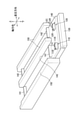
図2に示すように、本体筐体2は、開口21と、カバー22とを有している。開口21は、本体筐体2の軸方向における一方側を向いている。開口21は、ドラムカートリッジ400と現像カートリッジ500が軸方向に着脱することを許容する。言い換えると、ドラムカートリッジ400は、本体筐体2に対して、軸方向に着脱可能である。現像カートリッジ500は、本体筐体2に対して、軸方向に着脱可能である。カバー22は、開口21を開閉可能である。
As shown in FIG. 2, the
また、本体筐体2は、内部に、4つのドラムカートリッジ400と4つの現像カートリッジ500とを所定位置にそれぞれ収容可能に構成されている。本体筐体2の内部には、ドラムカートリッジ400および現像カートリッジ500のそれぞれの収容スペースを区画する9枚の案内壁150が固定されている。
Further, the
案内壁150は、開口21の下縁近傍から上に突出し本体筐体2の内部を軸方向奥側に延びる衝立状の隔壁であり、各カートリッジ収容スペースの直交方向における境界を画定する。ドラムカートリッジ400または現像カートリッジ500の着脱時には、案内壁150が、各カートリッジを案内するガイドレールとして機能する。
The
本体筐体2は、各ドラムカートリッジ400の収容スペースに、それぞれ、第1端子110と、第1連結プレート112と、2つの第1位置決め突起113と、ドラム駆動連結部115とを有している。
The
2つの第1位置決め突起113は、それぞれ、第1連結プレート112の所定位置に固定されている。第1連結プレート112およびドラム駆動連結部115は、本体筐体2内における開口21から離れた奥側の垂直な壁沿いに位置している。第1連結プレート112およびドラム駆動連結部115は、上下方向に移動可能である。
Each of the two
また、本体筐体2は、各現像カートリッジ500の収容スペースに、それぞれ、第2端子120と、第2連結プレート122と、2つの第2位置決め突起123と、現像駆動連結部125とを有している。
Further, the
2つの第2位置決め突起123は、それぞれ、第2連結プレート122の所定位置に固定されている。第2連結プレート122および現像駆動連結部125は、本体筐体2内における開口21から離れた奥側の垂直な壁沿いに位置している。第2連結プレート122および現像駆動連結部125は、上下方向および直交方向に移動可能である。
The two
4組の対応するドラムカートリッジ400と現像カートリッジ500の収容スペースの下には、それぞれ、その2つのカートリッジ収容スペースの間を区画する1枚の案内壁150を挟んで、支持プレート140が位置している。支持プレート140は、開口21の下縁近傍から奥側に向かって軸方向および直交方向に平行に延びている。第1端子110および第2端子120は、支持プレート140上に位置する。
Under the storage space of the four sets of
第1端子110は、各ドラムカートリッジ400に対応している。第2端子120は、各現像カートリッジ500に対応している。各第1端子110および各第2端子120は、支持プレート140を介して制御部10に接続される。図4に示すように、第1端子110は、第1端子接点11Cと、係合凹部11Rとを有する。また、第2端子120は、第2端子接点12Cと、係合凹部12Rとを有する。
The
図3(a)を参照して、ドラムカートリッジ400のドラムフレーム420の構成および位置と第1メモリ430の構成および位置について詳細に説明する。ドラムフレーム420は、感光ドラム410が位置する第1端部1Eと、ドラムカートリッジ400が本体筐体2に装着された状態で、上下方向において第1端部1Eから離れて位置する第2端部2Eとを有する。
The configuration and position of the
ドラムフレーム420は、軸方向に長い六面体であり、ドラム上端面42Uと、ドラム下端面42Lと、第1ドラム外表面421と、第2ドラム外表面422と、第3ドラム外表面423と、第4ドラム外表面424とを有する。ドラム上端面42Uは、第1端部1Eに位置する。ドラム下端面42Lは、第2端部2Eに位置する。第1ドラム外表面421、第2ドラム外表面422、第3ドラム外表面423および第4ドラム外表面424は、ドラム上端面42Uとドラム下端面42Lとを接続する外表面である。第1ドラム外表面421と第2ドラム外表面422とは、軸方向において離れて位置する。第3ドラム外表面423と第4ドラム外表面424とは、直交方向において離れて位置する。
The
第2ドラム外表面422は、ドラムカートリッジ400が本体筐体に装着された状態で、軸方向において、第1ドラム外表面421よりも開口21から離れて位置する外表面である。第3ドラム外表面423は、ドラムカートリッジ400および現像カートリッジ500が本体筐体2に装着された状態で、直交方向において、第4ドラム外表面424よりも、感光ドラム410が接触する現像ローラ510を有する対応する現像カートリッジ500から離れて位置する外表面である。
The second drum
ドラムカートリッジ400は、第2ドラム外表面422に、ドラムカップリング440と、2つの第1位置決め孔426とを有する。ドラムカップリング440は、ドラムカートリッジ400が本体筐体2に装着された状態で、本体筐体2のドラム駆動連結部115(図2参照)に連結され、感光ドラム410を回転駆動する駆動力を入力する。2つの第1位置決め孔426は、ドラムカートリッジ400が本体筐体2に装着された状態で、本体筐体2の第1連結プレート112に固定された第1位置決め突起113(図2参照)が嵌る。
The
第1メモリ430は、ドラムフレーム420の第2端部2Eに位置する。換言すれば、ドラムカートリッジ400が本体筐体2に装着された状態で、上下方向において、感光ドラム410が、中間転写ベルト63と第1メモリ430との間に位置する(図1参照)ように、第1メモリ430が位置している。本実施形態では、特に、第1メモリ430は、ドラム下端面42Lに位置する。もっとも、第2端部2Eの形状は、図示した形状に限らず、さまざまな他の形態が想定されうる。したがって、第1メモリ430は、第2端部2Eにおけるドラム下端面42Lから外れた凸部や凹部に位置するものであってもよいと理解される。
The
また、第1メモリ430は、ドラムフレーム420の第2端部2Eにおける、第1ドラム外表面421よりも第2ドラム外表面422の近く、すなわち、ドラムカートリッジ400が本体筐体2に装着された状態で、開口21から離れた奥側に位置している。
Further, the
第1メモリ430は、2つの第1接点431と、2つの係合突起435とを有する。ドラムカートリッジ400が本体筐体2に装着されると、係合突起435が第1端子110の係合凹部11Rに係合して第1端子110に対して位置決めされ、第1接点431が第1端子110と(詳しくは、第1端子接点11Cと)接触して電気的に接続される。
The
図3(a)に示すように、感光ドラム410は、ドラムフレーム420のドラム上端面42Uおよび第2ドラム外表面422の上部の開口から露出しており、中間転写ベルト63および対応する現像ローラ510と接触可能に位置する。ドラムフレーム420の第1ドラム外表面421には、軸方向に長いリブ428が位置している。また、ドラムフレーム420の第3ドラム外表面423にも、同様に、軸方向に長いリブ428が位置している(図5(a)、(b)参照)。リブ428については後述する。
As shown in FIG. 3A, the
図3(b)を参照して、現像カートリッジ500の現像フレーム520の構成および位置と第2メモリ530の構成および位置について詳細に説明する。現像フレーム520は、現像ローラ510が位置する第3端部3Eと、現像カートリッジ500が本体筐体2に装着された状態で、上下方向において第3端部3Eから離れて位置する第4端部4Eとを有する。
With reference to FIG. 3B, the configuration and position of the
現像フレーム520は、軸方向に長い六面体であり、現像上端面52Uと、現像下端面52Lと、第1現像外表面521と、第2現像外表面522と、第3現像外表面523と、第4現像外表面524とを有する。現像上端面52Uは、第3端部3Eに位置する。現像下端面52Lは、第4端部4Eに位置する。第1現像外表面521、第2現像外表面522、第3現像外表面523および第4現像外表面524は、現像上端面52Uと現像下端面52Lとを接続する外表面である。第1現像外表面521と第2現像外表面522とは、軸方向において離れて位置する。第3現像外表面523と第4現像外表面524とは、直交方向において離れて位置する。
The
第2現像外表面522は、現像カートリッジ500が本体筐体2に装着された状態で、軸方向において、第1現像外表面521よりも開口21から離れて位置する外表面である。第3現像外表面523は、ドラムカートリッジ400および現像カートリッジ500が本体筐体2に装着された状態で、直交方向において、第4現像外表面524よりも、現像ローラ510が接触する感光ドラム410を有する対応するドラムカートリッジ400の近くに位置する外表面である。
The second developed
現像カートリッジ500は、第2現像外表面522に、位置決めボス525と、現像カップリング540と、現像カップリングカバー545とを有する。現像カップリング540は、現像カートリッジ500が本体筐体2に装着された状態で、本体筐体2の現像駆動連結部125(図2参照)に連結され、現像ローラ510を回転駆動する駆動力を入力する。現像カップリングカバー545は、現像カップリング540の外周を覆っている。位置決めボス525および現像カップリングカバー545には、それぞれ1つずつ第2位置決め孔526が位置している。2つの第2位置決め孔526は、現像カートリッジ500が本体筐体2に装着された状態で、本体筐体2の第2連結プレート122に固定された第2位置決め突起123(図2参照)が嵌る。
The
第2メモリ530は、現像フレーム520の第4端部4Eに位置する。換言すれば、現像カートリッジ500が本体筐体2に装着された状態で、上下方向において、現像ローラ510が、中間転写ベルト63と第2メモリ530との間に位置する(図1参照)ように、第2メモリ530が位置している。本実施形態では、特に、第2メモリ530は、現像下端面52Lに位置する。もっとも、第4端部4Eの形状は、図示した形状に限らず、さまざまな他の形態が想定されうる。したがって、第2メモリ530は、第4端部4Eにおける現像下端面52Lから外れた凸部や凹部に位置するものであってもよいと理解される。
The
また、第2メモリ530は、現像フレーム520の第4端部4Eにおける、第1現像外表面521よりも第2現像外表面522の近く、すなわち、現像カートリッジ500が本体筐体2に装着された状態で、開口21から離れた奥側に位置している。本実施形態では、第2メモリ530は、現像カップリングカバー545の下端面に位置する。
Further, the
第2メモリ530は、2つの第2接点531と、2つの係合突起535とを有する。現像カートリッジ500が本体筐体2に装着されると、係合突起535が第2端子120の係合凹部12Rに係合して第2端子120に対して位置決めされ、第2接点531が第2端子120と(詳しくは第2端子接点12Cと)接触して電気的に接続される。
The
図3(b)に示すように、現像ローラ510は、ドラムフレームの第3現像外表面523の上部の開口から露出しており、対応する感光ドラム410と接触可能に位置する。現像フレーム520の第4ドラム外表面424には、軸方向に長いリブ528が位置している。また、ドラムフレーム420の第3ドラム外表面423にも、同様に、軸方向に長いリブ528が位置している(図5(a)参照)。
As shown in FIG. 3B, the developing
図4に示すように、支持プレート140は、リフトプレート130に対して軸方向に摺動可能である。支持プレート140は、中央に開口145を有する。開口145内には案内壁150が貫通している。リフトプレート130および支持プレート140は、直交方向の両側および中央の開口145内に位置する案内壁150により直交方向の移動が規制されている。支持プレート140は、中央の開口を貫通する案内壁150により軸方向の移動も規制されている。一方、リフトプレート130の図示せぬ中央開口は、中央の案内壁150よりも軸方向の寸法が大きく、後述する四節リンク機構による回動を許容する程度に軸方向の移動が可能である。
As shown in FIG. 4, the
リフトプレート130は、上下に移動可能である。本実施形態では、リフトプレート130を上下に移動することでドラム支持プレート116および現像支持プレート126を同時に上下に昇降させるように構成されている。リフトプレート130は、図示せぬ複数の開口を有し、露光装置SUから出射されたレーザ光が、各開口を通って、装着されたドラムカートリッジ400の感光ドラム410を露光できるように構成されている。
The
支持プレート140は、第1端子110よりも軸方向の開口21側(図2参照)に、互いに軸方向に離れて位置する2つの第1支持ブロック141を有する。支持プレート140は、第2端子120よりも軸方向の開口21側(図2参照)に、互いに軸方向に離れて位置する2つの第2支持ブロック142を有する。
The
支持プレート140は、ドラムカートリッジ400が本体筐体2に装着された状態で、ドラムカートリッジ400の下方に位置し、第1支持ブロック141によって、ドラムカートリッジ400を下から支持する。また、支持プレート140は、現像カートリッジ500が本体筐体2に装着された状態で、現像カートリッジ500の下方に位置し、第2支持ブロック142によって、現像カートリッジ500を下から支持する。第1支持ブロック141および第2支持ブロック142は、それぞれ、第1端子110および第2端子120とほぼ同じ高さ寸法を有する。
The
第1端子110は、ドラムカートリッジ400の第1メモリ430の第1接点431(図3(a)参照)と電気的に接触可能である。第1メモリ430に記憶されている情報は、第1端子110を介して制御部10に送られる。第2端子120は、現像カートリッジ500の第2メモリ530の第2接点531(図3(b)参照)と電気的に接触可能である。第2メモリ530に記憶されている情報は、第2端子120を介して制御部10に送られる。
The
次に、ドラムカートリッジ400および現像カートリッジ500を着脱するための構成について図5~図7を参照して説明する。
Next, the configuration for attaching / detaching the
支持プレート140は、感光ドラム410を中間転写ベルト63から離間させるドラム離間位置と、感光ドラム410を中間転写ベルト63に接触させるドラム接触位置とに上下方向に移動可能である。
The
支持プレート140が図5(a)、(b)に示すドラム離間位置にあるとき、ドラムカートリッジ400は、リブ428において案内壁150に支持され、第1メモリ430は、第1端子110から離間し、感光ドラム410は、中間転写ベルト63から離間している。また、現像カートリッジ500は、リブ528において案内壁150に支持され、第2メモリ530は、第2端子120から離間している。
When the
支持プレート140が図6(a)に示すドラム接触位置にあるとき、ドラムカートリッジは、支持プレート140の第1支持ブロック141(図4参照)に支持され、第1メモリ430は、第1端子110に接触し、感光ドラム410は、中間転写ベルト63に接触している。また、現像カートリッジ500は、支持プレート140の第2支持ブロック142(図4参照)に支持され、第2メモリ530は、第2端子120に接触している。
When the
そして、現像カートリッジ500は、図示せぬ現像離間機構により、第2支持ブロック142上を直交方向に摺動させることで、現像ローラ510が感光ドラム410に接触する現像接触位置(図6(a)参照)と、現像ローラ510が感光ドラム410から離間する現像離間位置(図6(b)参照)との間を移動可能に構成されている。
Then, the developing
なお、第2端子120は、支持プレート140に対して直交方向に移動可能に取り付けられている。したがって、本体筐体2に装着された現像カートリッジ500が、現像離間位置と現像接触位置との間を移動するとき、現像カートリッジ500の動きに追従して第2端子120がスライド移動することで、第2接点531の第2端子120との接触を維持することができる。
The
本実施形態では、支持プレート140のドラム離間位置とドラム接触位置との間の移動が、本体筐体2のカバー22の開閉動作と連動している。図7に示すように、本体筐体2のカバー22の内側には、カバー22と一体に回動するインナーカバー23が位置している。また、本体筐体2の内部には、リフトプレート130が位置している。支持プレート140は、リフトプレート130の上に位置している。
In the present embodiment, the movement of the
リフトプレート130は、直交方向の両側で、軸方向の開口21側と奥側の端部が、それぞれ第1リンク27と第2リンク28により本体筐体2に連結され、四節リンク機構を構成している。第1リンク27は、インナーカバー23に固定されている。したがって、カバー22を開いた位置から閉じられた位置まで回動させると、インナーカバー23および第1リンク27が一体に回動し、従動する第2リンク28とともに、リフトプレート130を図7(b)に示す位置まで持ち上げる。このとき、リフトプレート130上の支持プレート140は、図6(a)に示すドラム接触位置まで上昇する。
In the
このように、本実施形態では、カバー22を閉じることで、ドラムカートリッジ400および現像カートリッジ500が本体筐体2に装着され、図6(a)に示すように、第1メモリ430が第1端子110に接触し、第2メモリ530が第2端子120に接触する。さらに、このとき、感光ドラム410が中間転写ベルト63に接触する。
As described above, in the present embodiment, by closing the
ドラムカートリッジ400および現像カートリッジ500が装着されている状態が、図6(a)および図7(b)に示されている。このとき、支持プレート140は、ドラム接触位置に位置する。
The state in which the
この状態から、ドラムカートリッジ400または現像カートリッジ500を取り外すために、カバー22を開くと、図5に示すように、リフトプレート130が下がるとともに、支持プレート140が下方に移動する。すると、ドラムカートリッジ400および現像カートリッジ500が下降し、リブ428およびリブ528が案内壁150の上端に当接して、ドラムカートリッジ400および現像カートリッジ500が、案内壁150上に支持される。
When the
さらにリフトプレート130が下方に移動し、支持プレート140が下降すると、第1端子110が第1メモリ430の第1接点431から、そして、第2端子120が第2メモリ530の第2接点531から離間し、ドラムカートリッジ400および現像カートリッジ500の装着状態が解除される。このとき、支持プレート140は、ドラム接触位置に位置する(図5(a)、(b)参照)。
Further, when the
このとき、第1連結プレート112およびドラム駆動連結部115が、ドラムカートリッジ400とともに下に移動し、第2連結プレート122および現像駆動連結部125が、現像カートリッジ500とともに下に移動する。したがって、ドラムカップリング440のドラム駆動連結部115との連結、および、現像カップリング540の現像駆動連結部125との連結は維持される。
At this time, the first connecting
その後、ドラムカートリッジ400および/または現像カートリッジ500を引き出すことで、図7(a)に示すようにドラムカップリング440のドラム駆動連結部115との連結、および現像カップリング540の現像駆動連結部125との連結を解除し、リブ480,580を案内壁150に沿ってすべらせながら、開口21を通じてドラムカートリッジ400および/または現像カートリッジ500を取り出すことができる。
After that, by pulling out the
ドラムカートリッジ400の本体筐体2への装着時には、まず、第3ドラム外表面423と第4ドラム外表面424のリブ428が、第2ドラム外表面422側から、対応する本体筐体2の案内壁150上に位置し、案内壁150に沿って、図7(a)に示すように、本体筐体2の内部に押し込まれる。そして、ドラムカップリング440がドラム駆動連結部115(図2参照)に連結された状態で位置決めされる。この過程において、図5(a)に示すように、支持プレート140がドラム離間位置にあるので、感光ドラム410およびドラムフレーム420は中間転写ベルト63から離間しており、第1メモリ430が、第1端子110に接触することもない
When the
現像カートリッジ500の本体筐体2への装着時には、まず、第3現像外表面523と第4現像外表面524のリブ528が、第2現像外表面522側から、対応する本体筐体2の案内壁150上に位置し、案内壁150に沿って、図7(a)に示すように、本体筐体2の内部に押し込まれる、そして、ドラムカップリング440がドラム駆動連結部115(図2参照)に連結された状態で位置決めされる。この過程において、図5(a)に示すように、支持プレート140がドラム離間位置にあるので、現像フレーム520は中間転写ベルト63から離間しており、第2メモリ530が、第2端子120に接触することもない。
When the developing
最後に、図7(b)に示すように、カバー22が閉じられると、支持プレート140が、ドラム離間位置から上方に移動して、図6(a)に示すドラム接触位置に復帰し、ドラムカートリッジ400および現像カートリッジ500の装着が完了する。
Finally, as shown in FIG. 7 (b), when the
以上説明した実施形態によれば、次のような利点が得られる。
第1メモリ430をドラムフレーム420の第2端部2Eに位置するものとしているので、ドラムカートリッジ400の、ドラムカップリング440や第1位置決め孔426が位置する軸方向の奥側端面(第2ドラム外表面422)におけるスペースの制約を受けることがなく、第1接点431の接触領域を十分確保することができる。また、第2メモリ530を現像フレーム520の第4端部4Eに位置するものとしているので、現像カートリッジ500の、現像カップリング540や位置決めボス525や第2位置決め孔526が位置する軸方向の奥側端面(第2現像外表面522)におけるスペースの制約を受けることがなく、第2接点531の接触領域を十分確保することができる。
According to the embodiment described above, the following advantages can be obtained.
Since the
第1メモリ430を、第1ドラム外表面421よりも第2ドラム外表面422の近く、すなわち開口21から離れた位置に位置するものとしているので、ドラムカートリッジ400の本体筐体2への着脱時などの際に、本体筐体2側の第1端子110にユーザが誤って触れてしまうことを抑制することができる。また、第1端子110とドラムフレーム420が接触すること(ひいては、それにともなう摩耗や破損)を抑制することができる。
Since the
第2メモリ530も、第1現像外表面521よりも第2現像外表面522の近く、すなわち開口21から離れた位置に位置するものとしているので、現像カートリッジ500の本体筐体2への着脱時などの際に、本体筐体2側の第2端子120にユーザが誤って触れてしまうことを抑制することができる。また、第2端子120と現像フレーム520が接触すること(ひいては、それにともなう摩耗や破損)を抑制することができる。
Since the
支持プレート140がドラム離間位置にあるとき、第1端子110が第1接点431から離間し、第2端子120が第2接点531から離間し、支持プレート140がドラム接触位置にあるとき、第1端子110が第1接点431に接触し、第2端子120が第2接点531に接触するように構成されているので、感光ドラム410の中間転写ベルト63に対する接触離間動作と、メモリ(第1メモリ430、第2メモリ530)の筐体側端子(第1端子110、第2端子120)との接続または切断の切り替えとを連動させることができる。
When the
上述の具体的実施形態は、さまざまに変形して実施することができる。
たとえば、上述の実施形態において、本体筐体2は、1つの開口21を通じて、4つのドラムカートリッジ400および4つの現像カートリッジ500を着脱可能にする構成を例示したが、本体筐体は、対応するドラムカートリッジ400および現像カートリッジ500の1組ごとに1つの開口を有していてもよい。すなわち、本体筐体は、4つの開口を有していてもよい。あるいは、本体筐体が、1つのドラムカートリッジ400に対応する1つの第1開口と、1つの現像カートリッジ500に対応する1つの第2開口と、を有していてもよい。また、本体筐体は、対応するドラムカートリッジ400および現像カートリッジ500の1組ごとに1つのカバーを有していてもよい。すなわち、本体筐体が4つのカバーを有していてもよい。また、本体筐体が、1つの第1開口に対応する1つの第1カバーと、1つの第2開口に対応する1つの第2カバーと、を有していてもよい。すなわち、本体筐体が、4つの第1カバーと、4つの第2カバーと、を有していてもよい。
The above-mentioned specific embodiments can be variously modified and implemented.
For example, in the above-described embodiment, the
また、上述の実施形態において、ドラムカートリッジ400および現像カートリッジ500をカバー22の開閉に連動させて上下に移動させる形態を例示したが、支持プレート140のドラム接触位置およびドラム離間位置への移動は、カバーの開閉とは独立に実行可能としてもよい。
Further, in the above-described embodiment, the embodiment in which the
また、支持プレート140は、ドラムカートリッジ400および現像カートリッジ500の下方に位置してドラムカートリッジ400および現像カートリッジ500を支持する構成を例示したが、ドラムカートリッジの下方に位置してドラムカートリッジを支持するドラム支持プレートと、現像カートリッジの下方に位置して現像カートリッジを支持する現像支持プレートと、を有していてもよい。その場合、現像支持プレートは、ドラム支持プレートの上下方向の移動とともに移動可能としなくてもよい。もっとも、現像支持プレートを、ドラム支持プレートの上下方向の移動とともに移動可能とすることで、上述の実施形態同様、感光ドラムの中間転写ベルトに対する接触離間動作および第1メモリの第1端子との接続または切断の切り替えと、第2メモリの筐体側の第2端子との接続・切断の切り替えとを連動させることができる。
Further, the
上述の実施形態において、第1メモリ430が第2端部2E(具体的には、ドラム下端面42L)に位置し、第2メモリ530が第4端部4E(具体的には、現像下端面52L)に位置する場合を例示したが、第1メモリまたは第2メモリのいずれか一方のみを対応するドラムカートリッジ400の下端部または現像カートリッジ500の下端部に位置するように構成してもよい。
In the above-described embodiment, the
また、各ドラムカートリッジ400の下端部における第1メモリ430の位置も、例示した位置に限らず、開口に近い位置であってもよく、感光ドラムの第1軸よりも下方であれば、ドラムカートリッジ400の下端面よりも中間転写ベルトに近い位置を選択することもできる。また、現像カートリッジ500の下端部における第2メモリ530の位置も、例示した位置に限らず、開口に近い位置であってもよく、現像ローラの第2軸よりも下方であれば、現像カートリッジ500の下端面よりも中間転写ベルトに近い位置を選択することもできる。上述の実施形態において、第2メモリ530は、現像カップリングカバー545の下端面に位置する例を示したが、現像カップリングカバーよりも開口に近い位置に位置してもよい。
Further, the position of the
図示した実施形態において、「直交方向」は、軸方向および上下方向に直交する方向を例示したが、直交方向は、軸方向に直交し、上下方向に直交しない方向であってもよい。 In the illustrated embodiment, the "orthogonal direction" exemplifies the directions orthogonal to the axial direction and the vertical direction, but the orthogonal direction may be a direction orthogonal to the axial direction and not orthogonal to the vertical direction.
上述の各実施形態では、画像形成装置1がカラープリンタであったが、その他の画像形成装置、例えばモノクロのプリンタ、複写機、複合機などでもよい。
In each of the above-described embodiments, the
上述した実施形態および変形例で説明した各要素を、任意に組み合わせて実施してもよい。 Each element described in the above-described embodiment and modification may be arbitrarily combined and carried out.
1 画像形成装置
2 本体筐体
63 中間転写ベルト
21 開口
110 第1端子
120 第2端子
150 支持プレート
400 ドラムカートリッジ
410 感光ドラム
420 ドラムフレーム
421 第1ドラム外表面
422 第2ドラム外表面
42L ドラム下端面
430 第1メモリ
431 第1接点
440 ドラムカップリング
500 現像カートリッジ
510 現像ローラ
520 現像フレーム
521 第1現像外表面
522 第2現像外表面
525 位置決めボス
52L 現像下端面
530 第2メモリ
531 第2接点
540 現像カップリング
545 現像カップリングカバー
1E 第1端部
2E 第2端部
3E 第3端部
4E 第4端部
X1 第1軸
X2 第2軸
1 Image forming
Claims (21)
第1方向に延びる第1軸について回転可能な感光ドラムと、前記感光ドラムを回転可能に支持するドラムフレームと、ドラムカートリッジに関する情報を記憶する第1メモリと、を有するドラムカートリッジであって、前記本体筐体に対して、前記第1開口を通じて前記第1方向に着脱可能なドラムカートリッジと、
前記第1方向に延びる第2軸について回転可能な現像ローラと、トナーを収容する現像フレームと、現像カートリッジに関する情報を記憶する第2メモリと、を有する現像カートリッジであって、前記本体筐体に対して、前記第1開口を通じて前記第1方向に着脱可能な現像カートリッジと、
前記ドラムカートリッジおよび前記現像カートリッジが前記本体筐体に装着された状態で、前記ドラムカートリッジおよび前記現像カートリッジの上方に位置する中間転写ベルトと、を備え、
前記ドラムフレームは、第1端部と、上下方向において前記第1端部から離れて位置する第2端部とを有し、前記感光ドラムは、前記第1端部に位置し、前記第1メモリは、前記第2端部に位置し、
前記ドラムフレームは、第1ドラム外表面と、前記第1方向において前記第1ドラム外表面から離れて位置する第2ドラム外表面とを有し、前記第2ドラム外表面は、前記ドラムカートリッジが前記本体筐体に装着された状態で、前記第1方向において、前記第1ドラム外表面よりも前記第1開口から離れて位置し、
前記第1メモリは、前記第1方向において、前記第1ドラム外表面よりも前記第2ドラム外表面の近くに位置し、
前記第1メモリは、第1接点を有し、
前記本体筐体は、前記ドラムカートリッジが前記本体筐体に装着された状態で、前記第1接点と接触する第1端子を有し、
前記第1端子は、
前記ドラムカートリッジが前記本体筐体に装着された状態で前記第1接点から下方に離間した離間位置と、前記ドラムカートリッジが前記本体筐体に装着された状態で前記第1接点と接触する接触位置との間を前記上下方向に移動可能であり、
前記カバーの開閉動作に連動して前記カバーが前記開位置のときに前記離間位置に位置し、前記カバーが前記閉位置のときに前記接触位置に位置することを特徴とする画像形成装置。 A main body housing having a first opening and a cover that can rotate between an open position that opens the first opening and a closed position that closes the first opening .
A drum cartridge comprising a photosensitive drum that is rotatable about a first axis extending in a first direction, a drum frame that rotatably supports the photosensitive drum, and a first memory that stores information about the drum cartridge. A drum cartridge that can be attached to and detached from the main body housing in the first direction through the first opening .
A developing cartridge having a developing roller rotatable about a second axis extending in the first direction, a developing frame for accommodating toner, and a second memory for storing information about the developing cartridge, the main body housing thereof. On the other hand, a developing cartridge that can be attached and detached in the first direction through the first opening ,
With the drum cartridge and the developing cartridge mounted on the main body housing, the drum cartridge and the intermediate transfer belt located above the developing cartridge are provided.
The drum frame has a first end portion and a second end portion located away from the first end portion in the vertical direction, and the photosensitive drum is located at the first end portion and is located at the first end portion. The memory is located at the second end and
The drum frame has a first drum outer surface and a second drum outer surface located away from the first drum outer surface in the first direction, and the second drum outer surface is the drum cartridge. Is located in the first direction away from the first opening with respect to the outer surface of the first drum in a state of being mounted on the main body housing.
The first memory is located closer to the outer surface of the second drum than the outer surface of the first drum in the first direction .
The first memory has a first contact and has a first contact.
The main body housing has a first terminal that comes into contact with the first contact while the drum cartridge is mounted on the main body housing.
The first terminal is
A separation position downwardly separated from the first contact when the drum cartridge is mounted on the main body housing, and a contact position where the drum cartridge comes into contact with the first contact when the drum cartridge is mounted on the main body housing. It is possible to move in the vertical direction between and
An image forming apparatus, characterized in that , in conjunction with an opening / closing operation of the cover, the cover is located at the separated position when the cover is in the open position, and is located at the contact position when the cover is in the closed position .
前記第1端子は、前記交差する方向において、前記第1ガイドレールと前記第2ガイドレールの間に位置することを特徴とする請求項1に記載の画像形成装置。 The image forming apparatus according to claim 1, wherein the first terminal is located between the first guide rail and the second guide rail in the intersecting direction.
前記第1メモリは、前記下端面に位置することを特徴とする請求項1または請求項2に記載の画像形成装置。 The drum frame has a lower end surface located at the second end portion and has a lower end surface.
The image forming apparatus according to claim 1 or 2 , wherein the first memory is located on the lower end surface.
前記現像ローラは、前記第3端部に位置し、
前記第2メモリは、前記第4端部に位置することを特徴とする請求項1または請求項2に記載の画像形成装置。 The developing frame has a third end and a fourth end located away from the third end in the vertical direction.
The developing roller is located at the third end and
The image forming apparatus according to claim 1 or 2 , wherein the second memory is located at the fourth end portion.
前記現像カートリッジは、前記現像ローラを回転駆動する第2駆動力を入力する現像カップリングを有し、前記現像カップリングは、前記第2現像外表面に位置することを特徴とする請求項1または請求項2に記載の画像形成装置。 The developing frame has a first developed outer surface and a second developed outer surface located away from the first developed outer surface in the first direction, and the second developed outer surface is formed by the developing cartridge. In the state of being mounted on the main body housing, it is located in the first direction away from the first opening with respect to the first developed outer surface.
The development cartridge has a development coupling for inputting a second driving force for rotationally driving the development roller, and the development coupling is located on the second development outer surface. The image forming apparatus according to claim 2 .
前記第2メモリは、前記現像カップリングカバー上に位置することを特徴とする請求項11に記載の画像形成装置。 The development cartridge has a development coupling cover that covers the outer periphery of the development coupling.
The image forming apparatus according to claim 11 , wherein the second memory is located on the development coupling cover.
第1方向に延びる第1軸について回転可能な感光ドラムと、前記感光ドラムを回転可能に支持するドラムフレームと、ドラムカートリッジに関する情報を記憶する第1メモリと、を有するドラムカートリッジであって、前記本体筐体に対して、前記第1方向に着脱可能なドラムカートリッジと、
前記第1方向に延びる第2軸について回転可能な現像ローラと、トナーを収容する現像フレームと、現像カートリッジに関する情報を記憶する第2メモリと、を有する現像カートリッジであって、前記本体筐体に対して、前記第1方向に着脱可能な現像カートリッジと、
前記ドラムカートリッジおよび前記現像カートリッジが前記本体筐体に装着された状態で、前記ドラムカートリッジおよび前記現像カートリッジの上方に位置する中間転写ベルトと、
前記ドラムカートリッジを支持するドラム支持プレートであって、前記ドラム支持プレートが前記ドラムカートリッジを支持している状態で、前記ドラムカートリッジの下方に位置し、前記感光ドラムを前記中間転写ベルトから離間させるドラム離間位置と、前記感光ドラムを前記中間転写ベルトに接触させるドラム接触位置とに上下方向に移動可能であるドラム支持プレートと、を備え、
前記ドラムフレームは、第1端部と、上下方向において前記第1端部から離れて位置する第2端部とを有し、前記感光ドラムは、前記第1端部に位置し、前記第1メモリは、前記第2端部に位置し、
前記第1メモリは、第1接点を有し、
前記本体筐体は、前記ドラムカートリッジが前記本体筐体に装着された状態で、前記第1接点と接触する第1端子を有し、
前記第1端子は、前記ドラム支持プレートより上に突出し、
前記ドラム支持プレートは、前記カバーの開閉動作に連動して、前記カバーが前記開位置のときに前記ドラム離間位置に位置し、前記カバーが前記閉位置のときに前記ドラム接触位置に位置するように移動可能であり、
前記ドラム支持プレートが前記ドラム離間位置にあるとき、前記第1接点が前記第1端子から離間し、
前記ドラム支持プレートが前記ドラム接触位置にあるとき、前記第1接点が前記第1端子と接触することを特徴とする画像形成装置。 A main body housing having a first opening and a cover that can rotate between an open position that opens the first opening and a closed position that closes the first opening .
A drum cartridge comprising a photosensitive drum that is rotatable about a first axis extending in a first direction, a drum frame that rotatably supports the photosensitive drum, and a first memory that stores information about the drum cartridge. A drum cartridge that can be attached to and detached from the main body housing in the first direction,
A developing cartridge having a developing roller rotatable about a second axis extending in the first direction, a developing frame for accommodating toner, and a second memory for storing information about the developing cartridge, the main body housing thereof. On the other hand, the developing cartridge that can be attached and detached in the first direction,
With the drum cartridge and the developing cartridge mounted on the main body housing, the intermediate transfer belt located above the drum cartridge and the developing cartridge, and the intermediate transfer belt.
A drum support plate that supports the drum cartridge, which is located below the drum cartridge in a state where the drum support plate supports the drum cartridge, and separates the photosensitive drum from the intermediate transfer belt. A drum support plate that can move up and down between the separated position and the drum contact position that brings the photosensitive drum into contact with the intermediate transfer belt is provided.
The drum frame has a first end portion and a second end portion located away from the first end portion in the vertical direction, and the photosensitive drum is located at the first end portion and is located at the first end portion. The memory is located at the second end and
The first memory has a first contact and has a first contact.
The main body housing has a first terminal that comes into contact with the first contact while the drum cartridge is mounted on the main body housing.
The first terminal projects above the drum support plate and
The drum support plate is positioned at the drum separation position when the cover is in the open position and at the drum contact position when the cover is in the closed position in conjunction with the opening / closing operation of the cover. Can be moved to
When the drum support plate is in the drum separation position, the first contact is separated from the first terminal.
An image forming apparatus, characterized in that the first contact contacts the first terminal when the drum support plate is in the drum contact position.
前記ドラムフレームは、第1ドラム外表面と、前記第1方向において前記第1ドラム外表面から離れて位置する第2ドラム外表面とを有し、前記第2ドラム外表面は、前記ドラムカートリッジが前記本体筐体に装着された状態で、前記第1方向において、前記第1ドラム外表面よりも前記第1開口から離れて位置し、
前記第1メモリは、前記第1方向において、前記第1ドラム外表面よりも前記第2ドラム外表面の近くに位置することを特徴とする請求項20に記載の画像形成装置。 The drum cartridge can be attached to and detached from the main body housing in the first direction through the first opening.
The drum frame has a first drum outer surface and a second drum outer surface located away from the first drum outer surface in the first direction, and the second drum outer surface is formed by the drum cartridge. In the state of being mounted on the main body housing, it is located in the first direction away from the first opening with respect to the outer surface of the first drum.
The image forming apparatus according to claim 20 , wherein the first memory is located closer to the outer surface of the second drum than the outer surface of the first drum in the first direction.
Priority Applications (7)
| Application Number | Priority Date | Filing Date | Title |
|---|---|---|---|
| JP2019065282A JP7014202B2 (en) | 2019-03-29 | 2019-03-29 | Image forming device |
| PCT/JP2019/022115 WO2020202589A1 (en) | 2019-03-29 | 2019-06-04 | Image formation device |
| US16/788,878 US10935925B2 (en) | 2019-03-29 | 2020-02-12 | Image forming apparatus with a memory positioned on a drum frame |
| US17/176,259 US11294325B2 (en) | 2019-03-29 | 2021-02-16 | Image forming apparatus with a memory positioned on a drum frame |
| JP2022001772A JP7334807B2 (en) | 2019-03-29 | 2022-01-07 | image forming device |
| US17/686,582 US11853000B2 (en) | 2019-03-29 | 2022-03-04 | Image forming apparatus with a memory positioned on a drum frame |
| JP2023129017A JP2023145756A (en) | 2019-03-29 | 2023-08-08 | Image forming apparatus |
Applications Claiming Priority (1)
| Application Number | Priority Date | Filing Date | Title |
|---|---|---|---|
| JP2019065282A JP7014202B2 (en) | 2019-03-29 | 2019-03-29 | Image forming device |
Related Child Applications (1)
| Application Number | Title | Priority Date | Filing Date |
|---|---|---|---|
| JP2022001772A Division JP7334807B2 (en) | 2019-03-29 | 2022-01-07 | image forming device |
Publications (3)
| Publication Number | Publication Date |
|---|---|
| JP2020166090A JP2020166090A (en) | 2020-10-08 |
| JP2020166090A5 JP2020166090A5 (en) | 2021-08-19 |
| JP7014202B2 true JP7014202B2 (en) | 2022-02-01 |
Family
ID=72605867
Family Applications (1)
| Application Number | Title | Priority Date | Filing Date |
|---|---|---|---|
| JP2019065282A Active JP7014202B2 (en) | 2019-03-29 | 2019-03-29 | Image forming device |
Country Status (3)
| Country | Link |
|---|---|
| US (3) | US10935925B2 (en) |
| JP (1) | JP7014202B2 (en) |
| WO (1) | WO2020202589A1 (en) |
Families Citing this family (6)
| Publication number | Priority date | Publication date | Assignee | Title |
|---|---|---|---|---|
| JP7014202B2 (en) | 2019-03-29 | 2022-02-01 | ブラザー工業株式会社 | Image forming device |
| JP2021039173A (en) * | 2019-08-30 | 2021-03-11 | ブラザー工業株式会社 | Drum cartridge |
| US11112755B2 (en) | 2019-08-30 | 2021-09-07 | Brother Kogyo Kabushiki Kaisha | Drum cartridge including movable electrical contact surface, and image-forming apparatus using the same |
| JP2022151906A (en) * | 2021-03-29 | 2022-10-12 | 富士フイルムビジネスイノベーション株式会社 | Image forming apparatus |
| JP2023002265A (en) * | 2021-06-22 | 2023-01-10 | 京セラドキュメントソリューションズ株式会社 | Image forming apparatus |
| JP2023003446A (en) * | 2021-06-24 | 2023-01-17 | ブラザー工業株式会社 | process cartridge |
Citations (8)
| Publication number | Priority date | Publication date | Assignee | Title |
|---|---|---|---|---|
| JP2001092225A (en) | 1999-09-22 | 2001-04-06 | Canon Inc | Processing cartridge, developing cartridge and electrophotographic image forming device |
| JP2006119553A (en) | 2004-10-25 | 2006-05-11 | Ricoh Co Ltd | Image forming unit and image forming apparatus |
| JP2007171799A (en) | 2005-12-26 | 2007-07-05 | Fuji Xerox Co Ltd | Image forming apparatus, image forming unit, method of replacing image forming unit, and method for manufacturing image forming unit |
| JP2014119505A (en) | 2012-12-13 | 2014-06-30 | Canon Inc | Image forming apparatus |
| JP2016224221A (en) | 2015-05-29 | 2016-12-28 | キヤノン株式会社 | Photoreceptor cartridge and process cartridge |
| JP2017090692A (en) | 2015-11-11 | 2017-05-25 | 京セラドキュメントソリューションズ株式会社 | Image formation device |
| JP2018173480A (en) | 2017-03-31 | 2018-11-08 | ブラザー工業株式会社 | Developing cartridge, process cartridge, and image forming apparatus |
| JP2019128458A (en) | 2018-01-24 | 2019-08-01 | キヤノン株式会社 | Image forming apparatus |
Family Cites Families (15)
| Publication number | Priority date | Publication date | Assignee | Title |
|---|---|---|---|---|
| JPH04331959A (en) | 1991-05-07 | 1992-11-19 | Ricoh Co Ltd | Connector for image forming device |
| JP2000075767A (en) | 1998-08-31 | 2000-03-14 | Canon Inc | Process cartridge and electrophotographic image forming device |
| JP3970279B2 (en) * | 2004-07-30 | 2007-09-05 | キヤノン株式会社 | Process cartridge and electrophotographic image forming apparatus |
| WO2006062026A1 (en) * | 2004-12-09 | 2006-06-15 | Seiko Epson Corporation | Development apparatus, image forming apparatus, image forming system, cartridge, development unit and photoreceptor unit |
| JP2007052056A (en) * | 2005-08-15 | 2007-03-01 | Seiko Epson Corp | Image forming apparatus and image forming system |
| JP4803828B2 (en) | 2006-11-09 | 2011-10-26 | 株式会社リコー | Toner container, process cartridge, and image forming apparatus |
| US8050597B2 (en) | 2006-11-09 | 2011-11-01 | Ricoh Company, Limited | Toner container having a gear portion and image forming apparatus |
| JP6555967B2 (en) * | 2015-07-31 | 2019-08-07 | キヤノン株式会社 | Image forming apparatus |
| US9996052B2 (en) * | 2016-02-10 | 2018-06-12 | Canon Kabushiki Kaisha | Cartridge capable of being inserted in an apparatus main body of an image forming apparatus |
| JP6465906B2 (en) | 2016-02-29 | 2019-02-06 | キヤノン株式会社 | Developing device, process cartridge, and image forming apparatus |
| JP2017156441A (en) * | 2016-02-29 | 2017-09-07 | ブラザー工業株式会社 | Image forming apparatus |
| US10156825B2 (en) | 2016-02-29 | 2018-12-18 | Canon Kabushiki Kaisha | Developing apparatus with independently rotatable members supporting a developing frame body, process cartridge, and image forming apparatus |
| JP6849396B2 (en) | 2016-11-01 | 2021-03-24 | キヤノン株式会社 | Image forming device |
| JP6900250B2 (en) * | 2017-06-16 | 2021-07-07 | キヤノン株式会社 | Image forming apparatus equipped with an optical print head |
| JP7014202B2 (en) * | 2019-03-29 | 2022-02-01 | ブラザー工業株式会社 | Image forming device |
-
2019
- 2019-03-29 JP JP2019065282A patent/JP7014202B2/en active Active
- 2019-06-04 WO PCT/JP2019/022115 patent/WO2020202589A1/en active Application Filing
-
2020
- 2020-02-12 US US16/788,878 patent/US10935925B2/en active Active
-
2021
- 2021-02-16 US US17/176,259 patent/US11294325B2/en active Active
-
2022
- 2022-03-04 US US17/686,582 patent/US11853000B2/en active Active
Patent Citations (8)
| Publication number | Priority date | Publication date | Assignee | Title |
|---|---|---|---|---|
| JP2001092225A (en) | 1999-09-22 | 2001-04-06 | Canon Inc | Processing cartridge, developing cartridge and electrophotographic image forming device |
| JP2006119553A (en) | 2004-10-25 | 2006-05-11 | Ricoh Co Ltd | Image forming unit and image forming apparatus |
| JP2007171799A (en) | 2005-12-26 | 2007-07-05 | Fuji Xerox Co Ltd | Image forming apparatus, image forming unit, method of replacing image forming unit, and method for manufacturing image forming unit |
| JP2014119505A (en) | 2012-12-13 | 2014-06-30 | Canon Inc | Image forming apparatus |
| JP2016224221A (en) | 2015-05-29 | 2016-12-28 | キヤノン株式会社 | Photoreceptor cartridge and process cartridge |
| JP2017090692A (en) | 2015-11-11 | 2017-05-25 | 京セラドキュメントソリューションズ株式会社 | Image formation device |
| JP2018173480A (en) | 2017-03-31 | 2018-11-08 | ブラザー工業株式会社 | Developing cartridge, process cartridge, and image forming apparatus |
| JP2019128458A (en) | 2018-01-24 | 2019-08-01 | キヤノン株式会社 | Image forming apparatus |
Also Published As
| Publication number | Publication date |
|---|---|
| US11853000B2 (en) | 2023-12-26 |
| US20200310339A1 (en) | 2020-10-01 |
| US10935925B2 (en) | 2021-03-02 |
| US20210165360A1 (en) | 2021-06-03 |
| JP2020166090A (en) | 2020-10-08 |
| US11294325B2 (en) | 2022-04-05 |
| WO2020202589A1 (en) | 2020-10-08 |
| US20220187756A1 (en) | 2022-06-16 |
Similar Documents
| Publication | Publication Date | Title |
|---|---|---|
| JP7014202B2 (en) | Image forming device | |
| KR101215248B1 (en) | Process cartridge, electrophotographic image forming apparatus, and color electrophotographic image forming apparatus | |
| JP5137647B2 (en) | Image forming apparatus | |
| JP5836639B2 (en) | Image forming apparatus | |
| KR20080063017A (en) | Electrophotographic color image forming apparatus | |
| JP4453047B2 (en) | Image forming apparatus | |
| KR20080075913A (en) | Electrophotographic image forming apparatus | |
| US20150055974A1 (en) | Image forming apparatus and process cartridge | |
| US20240036507A1 (en) | Image forming apparatus | |
| JP2023171543A (en) | Image forming apparatus | |
| US20230213885A1 (en) | Image forming apparatus | |
| JP7334807B2 (en) | image forming device | |
| WO2020202588A1 (en) | Image forming device | |
| US9164476B2 (en) | Toner cartridge having structure for minimizing deformation when gripped | |
| JP3166408U (en) | Image forming apparatus and process cartridge | |
| JP2023023902A (en) | Image forming apparatus | |
| WO2020183744A1 (en) | Image forming apparatus | |
| JP2023053161A (en) | image forming device | |
| JP2000010456A (en) | Image forming device | |
| JP2009162910A (en) | Image forming apparatus and process cartridge | |
| US20060078350A1 (en) | Color image forming apparatus | |
| JP2001066971A (en) | Image forming device |
Legal Events
| Date | Code | Title | Description |
|---|---|---|---|
| A521 | Request for written amendment filed |
Free format text: JAPANESE INTERMEDIATE CODE: A523 Effective date: 20210707 |
|
| A621 | Written request for application examination |
Free format text: JAPANESE INTERMEDIATE CODE: A621 Effective date: 20210707 |
|
| A871 | Explanation of circumstances concerning accelerated examination |
Free format text: JAPANESE INTERMEDIATE CODE: A871 Effective date: 20210707 |
|
| A131 | Notification of reasons for refusal |
Free format text: JAPANESE INTERMEDIATE CODE: A131 Effective date: 20210907 |
|
| A521 | Request for written amendment filed |
Free format text: JAPANESE INTERMEDIATE CODE: A523 Effective date: 20211105 |
|
| TRDD | Decision of grant or rejection written | ||
| A01 | Written decision to grant a patent or to grant a registration (utility model) |
Free format text: JAPANESE INTERMEDIATE CODE: A01 Effective date: 20211221 |
|
| A61 | First payment of annual fees (during grant procedure) |
Free format text: JAPANESE INTERMEDIATE CODE: A61 Effective date: 20220103 |