JP7013465B2 - Accelerated drying of soft capsules in a controlled environment - Google Patents
Accelerated drying of soft capsules in a controlled environment Download PDFInfo
- Publication number
- JP7013465B2 JP7013465B2 JP2019530494A JP2019530494A JP7013465B2 JP 7013465 B2 JP7013465 B2 JP 7013465B2 JP 2019530494 A JP2019530494 A JP 2019530494A JP 2019530494 A JP2019530494 A JP 2019530494A JP 7013465 B2 JP7013465 B2 JP 7013465B2
- Authority
- JP
- Japan
- Prior art keywords
- relative humidity
- soft capsule
- drying
- temperature
- dryer
- Prior art date
- Legal status (The legal status is an assumption and is not a legal conclusion. Google has not performed a legal analysis and makes no representation as to the accuracy of the status listed.)
- Active
Links
- 238000001035 drying Methods 0.000 title claims description 197
- 239000007901 soft capsule Substances 0.000 title claims description 104
- 239000002775 capsule Substances 0.000 claims description 144
- 238000000034 method Methods 0.000 claims description 46
- 230000008018 melting Effects 0.000 claims description 31
- 238000002844 melting Methods 0.000 claims description 31
- 230000007423 decrease Effects 0.000 claims description 10
- 230000008569 process Effects 0.000 claims description 9
- 239000012530 fluid Substances 0.000 claims description 2
- XLYOFNOQVPJJNP-UHFFFAOYSA-N water Substances O XLYOFNOQVPJJNP-UHFFFAOYSA-N 0.000 description 45
- 239000011257 shell material Substances 0.000 description 27
- 238000001816 cooling Methods 0.000 description 25
- 108010010803 Gelatin Proteins 0.000 description 21
- 239000008273 gelatin Substances 0.000 description 21
- 229920000159 gelatin Polymers 0.000 description 21
- 235000019322 gelatine Nutrition 0.000 description 21
- 235000011852 gelatine desserts Nutrition 0.000 description 21
- 239000000203 mixture Substances 0.000 description 21
- 238000002474 experimental method Methods 0.000 description 20
- 238000009472 formulation Methods 0.000 description 20
- 238000001704 evaporation Methods 0.000 description 14
- 238000009792 diffusion process Methods 0.000 description 13
- 230000000694 effects Effects 0.000 description 13
- 238000012360 testing method Methods 0.000 description 13
- 230000004580 weight loss Effects 0.000 description 13
- 230000001276 controlling effect Effects 0.000 description 12
- 230000008020 evaporation Effects 0.000 description 12
- 239000002274 desiccant Substances 0.000 description 11
- 230000007547 defect Effects 0.000 description 10
- 230000000052 comparative effect Effects 0.000 description 9
- 150000001875 compounds Chemical class 0.000 description 9
- 239000000047 product Substances 0.000 description 9
- 238000010438 heat treatment Methods 0.000 description 8
- 239000012266 salt solution Substances 0.000 description 7
- PEDCQBHIVMGVHV-UHFFFAOYSA-N Glycerine Chemical compound OCC(O)CO PEDCQBHIVMGVHV-UHFFFAOYSA-N 0.000 description 6
- 108010025899 gelatin film Proteins 0.000 description 6
- 230000008901 benefit Effects 0.000 description 5
- 238000005243 fluidization Methods 0.000 description 5
- 230000004907 flux Effects 0.000 description 5
- 239000000463 material Substances 0.000 description 5
- 238000005259 measurement Methods 0.000 description 5
- 230000009467 reduction Effects 0.000 description 5
- 230000008859 change Effects 0.000 description 4
- 238000010586 diagram Methods 0.000 description 3
- 235000021323 fish oil Nutrition 0.000 description 3
- 239000000499 gel Substances 0.000 description 3
- 238000004519 manufacturing process Methods 0.000 description 3
- 238000010587 phase diagram Methods 0.000 description 3
- 239000004014 plasticizer Substances 0.000 description 3
- 238000009834 vaporization Methods 0.000 description 3
- 230000008016 vaporization Effects 0.000 description 3
- HEFNNWSXXWATRW-UHFFFAOYSA-N Ibuprofen Chemical compound CC(C)CC1=CC=C(C(C)C(O)=O)C=C1 HEFNNWSXXWATRW-UHFFFAOYSA-N 0.000 description 2
- 238000013459 approach Methods 0.000 description 2
- 230000009286 beneficial effect Effects 0.000 description 2
- 230000005540 biological transmission Effects 0.000 description 2
- 238000012937 correction Methods 0.000 description 2
- 238000013461 design Methods 0.000 description 2
- 230000007613 environmental effect Effects 0.000 description 2
- 239000012467 final product Substances 0.000 description 2
- 229960001680 ibuprofen Drugs 0.000 description 2
- 230000006872 improvement Effects 0.000 description 2
- 239000004615 ingredient Substances 0.000 description 2
- 238000007689 inspection Methods 0.000 description 2
- 238000012544 monitoring process Methods 0.000 description 2
- 230000000704 physical effect Effects 0.000 description 2
- 239000000902 placebo Substances 0.000 description 2
- 229940068196 placebo Drugs 0.000 description 2
- 230000003134 recirculating effect Effects 0.000 description 2
- 229920006395 saturated elastomer Polymers 0.000 description 2
- 241001465754 Metazoa Species 0.000 description 1
- 239000004677 Nylon Substances 0.000 description 1
- 229920002472 Starch Polymers 0.000 description 1
- 230000009471 action Effects 0.000 description 1
- 230000006978 adaptation Effects 0.000 description 1
- 238000004378 air conditioning Methods 0.000 description 1
- 230000033228 biological regulation Effects 0.000 description 1
- 230000015572 biosynthetic process Effects 0.000 description 1
- 239000007963 capsule composition Substances 0.000 description 1
- 239000000679 carrageenan Substances 0.000 description 1
- 235000010418 carrageenan Nutrition 0.000 description 1
- 229920001525 carrageenan Polymers 0.000 description 1
- 229940113118 carrageenan Drugs 0.000 description 1
- RNFNDJAIBTYOQL-UHFFFAOYSA-N chloral hydrate Chemical compound OC(O)C(Cl)(Cl)Cl RNFNDJAIBTYOQL-UHFFFAOYSA-N 0.000 description 1
- 235000019864 coconut oil Nutrition 0.000 description 1
- 239000003240 coconut oil Substances 0.000 description 1
- 238000004891 communication Methods 0.000 description 1
- 230000003247 decreasing effect Effects 0.000 description 1
- 230000002950 deficient Effects 0.000 description 1
- 230000003292 diminished effect Effects 0.000 description 1
- 239000003814 drug Substances 0.000 description 1
- 238000010981 drying operation Methods 0.000 description 1
- 230000005611 electricity Effects 0.000 description 1
- 238000005538 encapsulation Methods 0.000 description 1
- 230000002349 favourable effect Effects 0.000 description 1
- 239000000945 filler Substances 0.000 description 1
- 239000007903 gelatin capsule Substances 0.000 description 1
- 230000009477 glass transition Effects 0.000 description 1
- 230000036541 health Effects 0.000 description 1
- 238000009413 insulation Methods 0.000 description 1
- 229920002521 macromolecule Polymers 0.000 description 1
- 229920001778 nylon Polymers 0.000 description 1
- 238000012856 packing Methods 0.000 description 1
- 239000004033 plastic Substances 0.000 description 1
- 230000001105 regulatory effect Effects 0.000 description 1
- 230000004044 response Effects 0.000 description 1
- 238000010561 standard procedure Methods 0.000 description 1
- 239000008107 starch Substances 0.000 description 1
- 235000019698 starch Nutrition 0.000 description 1
- 239000000126 substance Substances 0.000 description 1
- 239000013589 supplement Substances 0.000 description 1
- 230000002277 temperature effect Effects 0.000 description 1
- 239000005439 thermosphere Substances 0.000 description 1
- 238000013519 translation Methods 0.000 description 1
- 230000000007 visual effect Effects 0.000 description 1
- 238000005303 weighing Methods 0.000 description 1
- 239000013585 weight reducing agent Substances 0.000 description 1
- UHVMMEOXYDMDKI-JKYCWFKZSA-L zinc;1-(5-cyanopyridin-2-yl)-3-[(1s,2s)-2-(6-fluoro-2-hydroxy-3-propanoylphenyl)cyclopropyl]urea;diacetate Chemical compound [Zn+2].CC([O-])=O.CC([O-])=O.CCC(=O)C1=CC=C(F)C([C@H]2[C@H](C2)NC(=O)NC=2N=CC(=CC=2)C#N)=C1O UHVMMEOXYDMDKI-JKYCWFKZSA-L 0.000 description 1
Images


Classifications
-
- F—MECHANICAL ENGINEERING; LIGHTING; HEATING; WEAPONS; BLASTING
- F26—DRYING
- F26B—DRYING SOLID MATERIALS OR OBJECTS BY REMOVING LIQUID THEREFROM
- F26B21/00—Arrangements or duct systems, e.g. in combination with pallet boxes, for supplying and controlling air or gases for drying solid materials or objects
- F26B21/06—Controlling, e.g. regulating, parameters of gas supply
- F26B21/10—Temperature; Pressure
-
- A—HUMAN NECESSITIES
- A61—MEDICAL OR VETERINARY SCIENCE; HYGIENE
- A61J—CONTAINERS SPECIALLY ADAPTED FOR MEDICAL OR PHARMACEUTICAL PURPOSES; DEVICES OR METHODS SPECIALLY ADAPTED FOR BRINGING PHARMACEUTICAL PRODUCTS INTO PARTICULAR PHYSICAL OR ADMINISTERING FORMS; DEVICES FOR ADMINISTERING FOOD OR MEDICINES ORALLY; BABY COMFORTERS; DEVICES FOR RECEIVING SPITTLE
- A61J3/00—Devices or methods specially adapted for bringing pharmaceutical products into particular physical or administering forms
- A61J3/07—Devices or methods specially adapted for bringing pharmaceutical products into particular physical or administering forms into the form of capsules or similar small containers for oral use
- A61J3/071—Devices or methods specially adapted for bringing pharmaceutical products into particular physical or administering forms into the form of capsules or similar small containers for oral use into the form of telescopically engaged two-piece capsules
- A61J3/077—Manufacturing capsule shells
-
- A—HUMAN NECESSITIES
- A61—MEDICAL OR VETERINARY SCIENCE; HYGIENE
- A61K—PREPARATIONS FOR MEDICAL, DENTAL OR TOILETRY PURPOSES
- A61K9/00—Medicinal preparations characterised by special physical form
- A61K9/48—Preparations in capsules, e.g. of gelatin, of chocolate
-
- A—HUMAN NECESSITIES
- A61—MEDICAL OR VETERINARY SCIENCE; HYGIENE
- A61K—PREPARATIONS FOR MEDICAL, DENTAL OR TOILETRY PURPOSES
- A61K9/00—Medicinal preparations characterised by special physical form
- A61K9/48—Preparations in capsules, e.g. of gelatin, of chocolate
- A61K9/4816—Wall or shell material
- A61K9/4825—Proteins, e.g. gelatin
-
- F—MECHANICAL ENGINEERING; LIGHTING; HEATING; WEAPONS; BLASTING
- F26—DRYING
- F26B—DRYING SOLID MATERIALS OR OBJECTS BY REMOVING LIQUID THEREFROM
- F26B11/00—Machines or apparatus for drying solid materials or objects with movement which is non-progressive
- F26B11/02—Machines or apparatus for drying solid materials or objects with movement which is non-progressive in moving drums or other mainly-closed receptacles
- F26B11/04—Machines or apparatus for drying solid materials or objects with movement which is non-progressive in moving drums or other mainly-closed receptacles rotating about a horizontal or slightly-inclined axis
-
- F—MECHANICAL ENGINEERING; LIGHTING; HEATING; WEAPONS; BLASTING
- F26—DRYING
- F26B—DRYING SOLID MATERIALS OR OBJECTS BY REMOVING LIQUID THEREFROM
- F26B21/00—Arrangements or duct systems, e.g. in combination with pallet boxes, for supplying and controlling air or gases for drying solid materials or objects
- F26B21/004—Nozzle assemblies; Air knives; Air distributors; Blow boxes
-
- F—MECHANICAL ENGINEERING; LIGHTING; HEATING; WEAPONS; BLASTING
- F26—DRYING
- F26B—DRYING SOLID MATERIALS OR OBJECTS BY REMOVING LIQUID THEREFROM
- F26B21/00—Arrangements or duct systems, e.g. in combination with pallet boxes, for supplying and controlling air or gases for drying solid materials or objects
- F26B21/02—Circulating air or gases in closed cycles, e.g. wholly within the drying enclosure
- F26B21/04—Circulating air or gases in closed cycles, e.g. wholly within the drying enclosure partly outside the drying enclosure
-
- F—MECHANICAL ENGINEERING; LIGHTING; HEATING; WEAPONS; BLASTING
- F26—DRYING
- F26B—DRYING SOLID MATERIALS OR OBJECTS BY REMOVING LIQUID THEREFROM
- F26B21/00—Arrangements or duct systems, e.g. in combination with pallet boxes, for supplying and controlling air or gases for drying solid materials or objects
- F26B21/06—Controlling, e.g. regulating, parameters of gas supply
- F26B21/08—Humidity
-
- F—MECHANICAL ENGINEERING; LIGHTING; HEATING; WEAPONS; BLASTING
- F26—DRYING
- F26B—DRYING SOLID MATERIALS OR OBJECTS BY REMOVING LIQUID THEREFROM
- F26B21/00—Arrangements or duct systems, e.g. in combination with pallet boxes, for supplying and controlling air or gases for drying solid materials or objects
- F26B21/06—Controlling, e.g. regulating, parameters of gas supply
- F26B21/12—Velocity of flow; Quantity of flow, e.g. by varying fan speed, by modifying cross flow area
-
- F—MECHANICAL ENGINEERING; LIGHTING; HEATING; WEAPONS; BLASTING
- F26—DRYING
- F26B—DRYING SOLID MATERIALS OR OBJECTS BY REMOVING LIQUID THEREFROM
- F26B3/00—Drying solid materials or objects by processes involving the application of heat
- F26B3/02—Drying solid materials or objects by processes involving the application of heat by convection, i.e. heat being conveyed from a heat source to the materials or objects to be dried by a gas or vapour, e.g. air
- F26B3/06—Drying solid materials or objects by processes involving the application of heat by convection, i.e. heat being conveyed from a heat source to the materials or objects to be dried by a gas or vapour, e.g. air the gas or vapour flowing through the materials or objects to be dried
-
- Y—GENERAL TAGGING OF NEW TECHNOLOGICAL DEVELOPMENTS; GENERAL TAGGING OF CROSS-SECTIONAL TECHNOLOGIES SPANNING OVER SEVERAL SECTIONS OF THE IPC; TECHNICAL SUBJECTS COVERED BY FORMER USPC CROSS-REFERENCE ART COLLECTIONS [XRACs] AND DIGESTS
- Y10—TECHNICAL SUBJECTS COVERED BY FORMER USPC
- Y10S—TECHNICAL SUBJECTS COVERED BY FORMER USPC CROSS-REFERENCE ART COLLECTIONS [XRACs] AND DIGESTS
- Y10S53/00—Package making
- Y10S53/90—Capsules
Description
本発明は、制御された環境においてソフトカプセルの乾燥時間を加速する方法および乾燥システムに関する。 The present invention relates to methods and drying systems for accelerating the drying time of soft capsules in a controlled environment.
典型的なソフトゲルカプセル化法では、カプセルは搬送され、回転乾燥され、トレイに積み重ねられ、カプセルの重量の減少、硬度、平衡相対湿度、フィル湿度のような特定の仕様に達するまで低湿度及び周囲温度の条件の乾燥トンネルまたは乾燥室に入れられる。ソフトゲルカプセルの製剤に応じて、乾燥時間は通常2~10日の範囲である。さらに、カプセルが適時に除去されないと、付着または漏出するカプセルなどの欠陥品が生じることがある。 In a typical softgel encapsulation method, the capsules are transported, spin dried, stacked in trays, low humidity and until certain specifications such as capsule weight reduction, hardness, equilibrium relative humidity, fill humidity are reached. Placed in a drying tunnel or drying chamber with ambient temperature conditions. Depending on the formulation of softgel capsules, the drying time is usually in the range of 2-10 days. In addition, if the capsules are not removed in a timely manner, defective products such as capsules that adhere or leak may occur.
ソフトゲル乾燥は広範囲の製品に対して低湿度で行われてきたが、乾燥条件は必ずしも特定の製品の最終仕様に基づくものではない。このアプローチは、非効率的な乾燥をもたらし、カプセルを過剰乾燥させる可能性があり、その結果、過度に脆くなり、カプセル破損をもたらす場合がある。さらに、低湿度の使用により、ゲル材料の外側が内側部分よりも速く乾燥し、これはよりシェル材がより硬いものになり、カプセル内に内部応力を生じさせる。そのような内部応力は最終製品の全体的な頑強性を低下させるものである。そのため、ソフトゲルカプセルの乾燥における欠陥および乾燥サイクル時間の減少が求められている。 Softgel drying has been performed on a wide range of products at low humidity, but the drying conditions are not necessarily based on the final specifications of a particular product. This approach results in inefficient drying and can overdry the capsule, resulting in excessive brittleness and possible capsule breakage. In addition, the use of low humidity causes the outside of the gel material to dry faster than the inner part, which makes the shell material harder and creates internal stress inside the capsule. Such internal stresses reduce the overall robustness of the final product. Therefore, it is required to reduce defects and drying cycle time in drying softgel capsules.
米国特許第8,621,764号は、ゼラチンカプセル製造および乾燥システムおよび方法を開示している。乾燥システムおよび方法は、3つの区域に分けられる乾燥構造を含む。各区域は、それぞれの区域に供給される空気を加熱または冷却することができる独自のエアハンドラを含む。1台のHVACユニットがすべてのエアハンドラに接続されている。一連の回転式乾燥機が前記乾燥構造にわたって第1の区域から第3の区域まで延びる。各区域は湿度と温度の異なる条件で維持される。各区域の温度は、空調ユニット内の加熱器とチラーを使用して制御され、湿度は温度の変化に基づいて変動される。第2の区域は最も暖かく、この区域の最高気温は87°Fである。第1の区域は全ての区域の中で最も高い相対湿度で維持され、この区域の最大相対湿度は23%である。本開示では乾燥時間の大幅な短縮が達成されることを示しているが、短縮の大部分は開始ゼラチンの含水量の減少に起因する。
この出願の発明に関連する先行技術文献情報としては、以下のものがある(国際出願日以降国際段階で引用された文献及び他国に国内移行した際に引用された文献を含む)。
(先行技術文献)
(特許文献)
(特許文献1) 米国特許第8,621,764号明細書
(特許文献2) 特開2007-192464号公報
(特許文献3) 韓国登録特許第10-0954481号公報
(特許文献4) 米国特許第7,957,842号明細書
(特許文献5) 米国特許出願公開第2008/0000099号明細書
(特許文献6) 米国特許第8,621,764号明細書
(特許文献7) 米国特許第7,957,842号明細書
(特許文献8) 米国特許出願公開第2008/0000099号明細書
(特許文献9) 特開2007-192464号公報
(特許文献10) 韓国登録特許第10-0954481号公報
(特許文献11) 米国特許第5,200,191号明細書
(特許文献12) 米国特許出願公開第2009/0210094号明細書
(特許文献13) 米国特許出願公開第2014/0093606号明細書
(特許文献14) 中国特許出願公開第105674699号明細書
(特許文献15) 中国特許出願公開第102283779号明細書
(特許文献16) 中国特許出願公開第104991591号明細書
(特許文献17) 中国特許出願公開第105987587号明細書
(特許文献18) 特開2012-006861号公報
(非特許文献)
(非特許文献1) International Search Report for International Patent Application No.PCT/US2017/065290; dated 2018-04-09
(非特許文献2) ISA Written Opinion for International Patent Application No.PCT/US2017/065290; dated 2018-04-09
(非特許文献3) COPPOLA M.,et al."Phase diagram of gelatin plasticized by water and glycerol." In Macromolecular symposia (Vol.273,No.1,pp.56-65).WILEY‐VCH Verlag.
(非特許文献4) First Office Action for corresponding Chinese application no.201780069164.1; dated 2020-05-18; Machine Translation (15 pages)
(非特許文献5) Extended European Search Report for corresponding European application no.17877660.5; dated 2020-05-04 (9 pages)
(非特許文献6) FULPER,David et al.,"Effect of Humidity and Water Content on Water Vapor Transmission through Gelatin Films", American Association of Pharmaceutical Scientists - Annual Meeting,Chicago,October 17th,2012,pp.1-6
U.S. Pat. No. 8,621,764 discloses a gelatin capsule manufacturing and drying system and method. The drying system and method comprises a drying structure divided into three areas. Each area contains its own air handler that can heat or cool the air supplied to each area. One HVAC unit is connected to all air handlers. A series of rotary dryers extend from the first zone to the third zone over the drying structure. Each area is maintained under different conditions of humidity and temperature. The temperature in each area is controlled using a heater and chiller in the air conditioning unit, and the humidity fluctuates based on changes in temperature. The second area is the warmest, with a maximum temperature of 87 ° F in this area. The first area is maintained at the highest relative humidity of all areas, with a maximum relative humidity of 23% in this area. Although the present disclosure shows that a significant reduction in drying time is achieved, most of the reduction is due to the reduced water content of the starting gelatin.
The prior art document information related to the invention of this application includes the following (including documents cited at the international stage after the international filing date and documents cited when domestically transferred to another country).
(Prior art document)
(Patent document)
(Patent Document 1) US Pat. No. 8,621,764
(Patent Document 2) Japanese Unexamined Patent Publication No. 2007-192464
(Patent Document 3) Korean Registered Patent No. 10-0954481A
(Patent Document 4) US Pat. No. 7,957,842
(Patent Document 5) U.S. Patent Application Publication No. 2008/00000909
(Patent Document 6) US Pat. No. 8,621,764
(Patent Document 7) US Pat. No. 7,957,842
(Patent Document 8) U.S. Patent Application Publication No. 2008/00000909
(Patent Document 9) Japanese Unexamined Patent Publication No. 2007-192464
(Patent Document 10) Korean Registered Patent No. 10-0954481A
(Patent Document 11) US Pat. No. 5,200,191
(Patent Document 12) US Patent Application Publication No. 2009/0210094
(Patent Document 13) U.S. Patent Application Publication No. 2014/093606
(Patent Document 14) Chinese Patent Application Publication No. 1056764699
(Patent Document 15) Chinese Patent Application Publication No. 102283779
(Patent Document 16) Chinese Patent Application Publication No. 104991591
(Patent Document 17) Chinese Patent Application Publication No. 1059857587
(Patent Document 18) Japanese Unexamined Patent Publication No. 2012-006861
(Non-patent document)
(Non-Patent Document 1) International Search Report for International Patent Application No. PCT / US2017 / 065290; dated 2018-04-09
(Non-Patent Document 2) ISA Written Opinion for International Patent Application No. PCT / US2017 / 065290; dated 2018-04-09
(Non-Patent Document 3) COPPOLA M. , Et al. "Phase diagram of gelatin plasticized by water and glycerol." In Macromolecule symposia (Vol.273, No.1, pp.56-65). WILEY-VCH Verlag.
(Non-Patent Document 4) First Office Action for corresponding Chinese application no. 201780069164.1; dated 2020-05-18; Machine Translation (15 pages)
(Non-Patent Document 5) Extended European Search Report for corresponding European application no. 1787660.5; dated 2020-05-04 (9 pages)
(Non-Patent Document 6) FULLPER, David et al. , "Effective of Humidity and Water Content on Water Vapor Transmission through Gelatin Films", American Association of Physical 1-6
温度を上昇させると、ソフトゲルカプセルの乾燥時間が短くなることが知られている。しかしながら、標準温度を超えて温度を上昇させるという以前の試みは、得られるカプセルに許容できない欠陥をもたらした。ソフトゲルがより高い温度から冷却する際に欠陥が生じる。冷却プロセスの間、水が除去されるゲル内の領域は、異なる大きさを有し、また異なる程度に縮まるので、カプセルの表面に窪みまたはへこみが生じる。 It is known that increasing the temperature shortens the drying time of softgel capsules. However, previous attempts to raise the temperature above standard temperatures have resulted in unacceptable defects in the resulting capsules. Defects occur as the softgel cools from higher temperatures. During the cooling process, the areas within the gel from which water is removed have different sizes and shrink to different degrees, resulting in depressions or dents on the surface of the capsule.
したがって、当技術分野で公知のより長い乾燥プロセスと同じ数のカプセル、または好ましくはより欠陥が少ないカプセルを製造するソフトゲルカプセルの乾燥時間を短縮するシステムおよび方法が必要とされる。 Therefore, there is a need for systems and methods that reduce the drying time of softgel capsules to produce as many capsules as there are longer drying processes known in the art, or preferably capsules with fewer defects.
第1の実施形態において、本発明は、ソフトカプセルを乾燥する方法に関するものであり、この方法は、
a)前記ソフトカプセルにわたって約0.15m/sから約13m/sの速度で前記ソフトカプセルに空気流を供給する工程と、
b)前記ソフトカプセルがさらされる乾燥温度を経時的に上昇させる工程であって、この乾燥温度は前記ソフトカプセルのカプセルシェルの融解温度より低い温度になるように維持されるものである、上昇させる工程と、
c)前記ソフトカプセルを約49%RHから約79%RHの初期相対湿度にさらす工程と、
d)前記ソフトカプセルの平衡相対湿度が所望の相対湿度に達するまで、前記ソフトカプセルが乾燥するにつれて前記ソフトカプセルがさらされる前記相対湿度を下げる工程と、
e)前記工程d)からの前記ソフトカプセルを20~25℃の温度にさらす工程と、を有するものである。
In a first embodiment, the present invention relates to a method of drying soft capsules, which method is:
a) A step of supplying an air flow to the soft capsule at a speed of about 0.15 m / s to about 13 m / s over the soft capsule.
b) A step of raising the drying temperature to which the soft capsule is exposed over time, which is maintained so as to be lower than the melting temperature of the capsule shell of the soft capsule. ,
c) The step of exposing the soft capsule to an initial relative humidity of about 49% RH to about 79% RH,
d) A step of lowering the relative humidity to which the soft capsule is exposed as the soft capsule dries until the equilibrium relative humidity of the soft capsule reaches the desired relative humidity.
e) It comprises a step of exposing the soft capsule from the step d) to a temperature of 20 to 25 ° C.
いくつかの実施形態において、前記方法は、前記ソフトカプセルがさらされる空気流の速度を前記ソフトカプセルが乾燥するにつれて減速させる工程をさらに有するものである。 In some embodiments, the method further comprises a step of slowing down the velocity of the airflow to which the soft capsule is exposed as the soft capsule dries.
前記実施形態の各々において、前記ソフトカプセルがさらされる相対湿度と前記ソフトカプセルの平衡相対湿度との差が約15%dRH~約35%dRHに維持されるように前記相対湿度が制御される。 In each of the embodiments, the relative humidity is controlled so that the difference between the relative humidity to which the soft capsule is exposed and the equilibrium relative humidity of the soft capsule is maintained at about 15% dRH to about 35% dRH.
前記実施形態の各々において、前記ソフトカプセルは親油性である。前記ソフトカプセルが親油性である前記実施形態において、前記初期相対湿度は約49%RHから約79%RHである。前記ソフトカプセルが親油性である前記実施形態において、前記ソフトカプセルがさらされる最低相対湿度は約10%RH~約24%RHである。 In each of the embodiments, the soft capsule is lipophilic. In the embodiment in which the soft capsule is lipophilic, the initial relative humidity is from about 49% RH to about 79% RH. In the embodiment in which the soft capsule is lipophilic, the minimum relative humidity to which the soft capsule is exposed is from about 10% RH to about 24% RH.
前記実施形態の各々において、前記ソフトカプセルは親油性である。前記ソフトカプセルが親水性である前記実施形態の各々において、前記初期相対湿度は約49%RH~約79%RHであり、前記ソフトカプセルがさらされる最低相対湿度は約23%RH~約57%RHである。 In each of the embodiments, the soft capsule is lipophilic. In each of the embodiments in which the soft capsule is hydrophilic, the initial relative humidity is from about 49% RH to about 79% RH and the minimum relative humidity to which the soft capsule is exposed is from about 23% RH to about 57% RH. be.
本発明の別の実施形態において、ソフトカプセルを乾燥させるための乾燥システムであって、少なくとも1つの乾燥機と、前記乾燥機に空気流を供給するための乾燥機と流体連通するユニットと、前記乾燥機内の相対湿度を上昇させることができるように構成された加湿器と、前記乾燥機内の空気の温度を上昇可能なように構成された加熱器と、を有する乾燥システムが提供される。 In another embodiment of the present invention, a drying system for drying soft capsules, wherein at least one dryer, a dryer for supplying an air flow to the dryer, and a unit for fluid communication with the dryer, and the drying. A drying system comprising a humidifier configured to be able to raise the relative humidity in the machine and a heater configured to be able to raise the temperature of the air in the dryer is provided.
前記乾燥システムは、前記乾燥機に空気流を提供する前記ユニットへ前記乾燥機の排気からの戻り気流を再循環させるように配置および構成された再循環ファンをさらに有するものである。前記乾燥システムの各々において、前記加湿器は前記再循環ファンを有するものである。 The drying system further comprises a recirculation fan arranged and configured to recirculate the return airflow from the dryer exhaust to the unit that provides the airflow to the dryer. In each of the drying systems, the humidifier has the recirculation fan.
前記乾燥システムのそれぞれは、さらに前記ユニットから前記乾燥機への前記空気流の量を制御するように構成された流量制御弁をさらに有するものである。 Each of the drying systems further comprises a flow control valve configured to control the amount of air flow from the unit to the dryer.
前記乾燥システムのそれぞれは、さらに前記乾燥機に空気流を提供する前記ユニットへ前記乾燥機の排気からの戻り気流を再循環させるように配置および構成された再循環ファンをさらに備えるものであり、前記流量制御弁は、前記ユニットから前記乾燥機への空気流の量を減らすと、前記乾燥機内の相対湿度が上がり、前記ユニットから前記乾燥機への空気流の量を増やすと、前記乾燥機内の相対湿度が下がるように構成されるものである。 Each of the drying systems further comprises a recirculation fan arranged and configured to recirculate the return airflow from the dryer exhaust to the unit that provides airflow to the dryer. In the flow control valve, when the amount of air flow from the unit to the dryer is reduced, the relative humidity in the dryer rises, and when the amount of air flow from the unit to the dryer is increased, the inside of the dryer is increased. It is configured to reduce the relative humidity of.
前記乾燥システムの各々において、前記加熱器は、前記ソフトカプセルのカプセルシェルの融点に基づく温度勾配にしたがって時間とともに温度を上昇させるように構成されているものである。この実施形態において、前記流量制御弁と前記加湿器との組み合わせは、前記乾燥機内の相対湿度を制御して、前記乾燥機内の相対湿度が約49%RH~約79%RHの初期相対湿度から約10%RH~約24%RHの終点相対湿度まで経時的に減少するように構成されるものである。前記実施形態において、前記流量制御弁と前記加湿器との組み合わせは、前記乾燥機内の相対湿度を制御して、前記乾燥機内の相対湿度が約49%RHから約79%RHの初期相対湿度から約23%RHから約57%RHの終点相対湿度まで経時的に減少するように構成されるものである。前記乾燥システムにおいて、前記相対湿度は前記乾燥器内の前記相対湿度と前記ソフトカプセルの平衡相対湿度との差が約15%dRH~約35%dRHに維持されるように前記相対湿度が減少されるものである。前記乾燥機内の相対湿度と前記ソフトカプセルの平衡相対湿度との間の差が約15%dRH~約35%dRHに維持されるように相対湿度が減少されるものである。 In each of the drying systems, the heater is configured to increase the temperature over time according to a temperature gradient based on the melting point of the capsule shell of the soft capsule. In this embodiment, the combination of the flow control valve and the humidifier controls the relative humidity in the dryer from the initial relative humidity of about 49% RH to about 79% RH in the dryer. It is configured to decrease over time from about 10% RH to about 24% RH end relative humidity. In the embodiment, the combination of the flow control valve and the humidifier controls the relative humidity in the dryer from an initial relative humidity of about 49% RH to about 79% RH in the dryer. It is configured to decrease over time from about 23% RH to about 57% RH end relative humidity. In the drying system, the relative humidity is reduced so that the difference between the relative humidity in the dryer and the equilibrium relative humidity of the soft capsule is maintained at about 15% dRH to about 35% dRH. It is a thing. The relative humidity is reduced so that the difference between the relative humidity in the dryer and the equilibrium relative humidity of the soft capsule is maintained at about 15% dRH to about 35% dRH.
さらに別の実施形態において、本発明はソフトカプセルを乾燥する方法に関するものであり、この方法は、a)前記ソフトカプセルにわたって約0.15m/sから約13m/sの速度で前記ソフトカプセルに空気流を供給する工程と、b)ソフトカプセルがさらされる乾燥温度を経時的に上昇させる工程であって、この乾燥温度はカプセルシェルの融解温度より低い温度になるように維持されるものである、上昇させる工程と、c)前記ソフトカプセルの平衡相対湿度が所望の相対湿度に達するまで、前記乾燥機内の相対湿度と前記ソフトカプセルの平衡相対湿度との差を約15%dRHから約35%dRHに 維持する工程と、d)前記工程c)からの前記ソフトカプセルを20~25℃の温度にさらす工程と、を有するものである。 In yet another embodiment, the invention relates to a method of drying a soft capsule, which a) supplies an air stream to the soft capsule at a rate of about 0.15 m / s to about 13 m / s over the soft capsule. And b) a step of raising the drying temperature to which the soft capsules are exposed over time, the drying temperature of which is maintained to be lower than the melting temperature of the capsule shell. , C) A step of maintaining the difference between the relative humidity in the dryer and the equilibrium relative humidity of the soft capsule from about 15% dRH to about 35% dRH until the equilibrium relative humidity of the soft capsule reaches the desired relative humidity. d) It comprises a step of exposing the soft capsule from the step c) to a temperature of 20 to 25 ° C.
例示の目的のために、本発明の原理が、様々な一例の実施形態を参照することによって記載されている。発明の特定の実施形態が具体的にここに記載されているが、当業者は、同じ原理を、他のシステムおよび方法に等しく適用することが可能であり、他のシステムおよび方法において利用することができることを容易に理解するであろう。本発明の開示される実施形態を詳細に説明する前に、本発明は、その用途が図示される任意の特定の実施形態の詳細に限定されないことを理解されたい。加えて、本明細書で使用される専門用語は、説明する目的であり、限定するためのものではない。さらに、特定の方法が、特定の順番で本明細書に提示される工程を参照して記載されているが、多くの例において、これらの工程は、当業者によって理解され得るような任意の順序で実施することができ、故にこの新規の方法は、本明細書に開示される工程の特定の構成に限定されるものではない。 For illustrative purposes, the principles of the invention are described by reference to various exemplary embodiments. Although specific embodiments of the invention are specifically described herein, one of ordinary skill in the art can apply the same principles equally to other systems and methods and will utilize them in other systems and methods. You will easily understand what you can do. Before describing in detail the disclosed embodiments of the invention, it should be understood that the invention is not limited to the details of any particular embodiment illustrated. In addition, the terminology used herein is for illustration purposes only and not intended to be limiting. Further, although specific methods are described with reference to the steps presented herein in a particular order, in many examples these steps are in any order as can be understood by one of ordinary skill in the art. Thus, this novel method is not limited to the particular configuration of the steps disclosed herein.
本明細書および添付の特許請求の範囲において使用される際、単数形「1つの(a)」、1つの(an)」および「その(the)」は、文脈がそうでないことをはっきりと指示しない限り、複数の指示語も含むことに留意されたい。さらに、用語「1つの(a)(または(an)」、「1若しくはそれ以上の」および「少なくとも1つの」は、相互に入れ替え可能に使用することができる。用語「有する(comprising)」、「含む」、「有する(having)」および「~構築される」もまた相互に入れ替え可能に使用することができる。 As used herein and in the appended claims, the singular forms "one (a)", "one (an)" and "the" clearly indicate that the context is not. Note that it also includes multiple directives unless it is included. Further, the terms "one (a) (or (an)", "one or more" and "at least one" can be used interchangeably. The term "comprising", "Contains", "having" and "to be constructed" can also be used interchangeably.
そうでないことが指摘されなければ、材料の分量、例えば明細書および特許請求の範囲において使用される分子量、パーセンテージ、比率、反応条件、温度などの特性を表す全ての数字は、用語「約」があるかどうかに関わらず、全ての例において用語「約」によって修飾されるように理解すべきである。したがって反対のことが指示されない限り、明細書および特許請求の範囲に記載される数値的パラメータは、本開示によって達成しようと試みる所望の特性に応じて変化し得る近似値である。少なくとも、および特許請求の範囲の範囲に対する等価物の教義の適用を制限しようとするのではなく、各々の数値的パラメータは、報告された有効数字に照らして、および通常の丸め技法を適用することによって解釈されるべきである。本開示の広範な範囲を説明する数値的範囲およびパラメータは近似値であるにもかかわらず、特有の例において述べられる数値は、可能な限り正確に報告されている。しかしながら任意の数値は本来、そのそれぞれのテスト測定において見られる標準偏差から必然的に生じる特定の誤差を含んでいる。 Unless otherwise noted, all numbers representing properties such as molecular weights, percentages, ratios, reaction conditions, temperatures, etc. used in the specification and claims are the term "about". It should be understood to be modified by the term "about" in all examples, with or without it. Therefore, unless the opposite is indicated, the numerical parameters described in the specification and claims are approximations that may vary depending on the desired characteristics attempted to be achieved by the present disclosure. At least, and rather than attempting to limit the application of the doctrine of equivalents to the scope of the claims, each numerical parameter shall be applied in light of the reported significant figures and the usual rounding techniques. Should be interpreted by. Although the numerical ranges and parameters that describe the broad scope of the present disclosure are approximations, the numbers given in the specific examples are reported as accurately as possible. However, any number inherently contains certain errors that inevitably arise from the standard deviation seen in each of its test measurements.
本明細書に開示される各々の成分、合成物、置換基またはパラメータは、単独で、または本明細書に開示される各々および全ての他の成分、合成物、置換基またはパラメータの1若しくはそれ以上と組み合わせて使用するように開示されるものと解釈されるべきであることを理解されたい。 Each component, compound, substituent or parameter disclosed herein may be alone or one or more of each and all other components, compounds, substituents or parameters disclosed herein. It should be understood that it should be construed as disclosed for use in combination with the above.
本明細書に開示される各々の成分、合成物、置換基またはパラメータに関する各々の量/値あるいは量/値の範囲は、本明細書に開示される任意の他の各々の成分(複数可)、合成物(複数可)、置換基(複数可)またはパラメータ(複数可)に関して開示される各々の量/値あるいは量/値の範囲と組み合わせて開示されるようにも解釈されるべきであること、ならびに、本明細書に開示される2つ以上の成分(複数可)、合成物(複数可)、置換基(複数可)またはパラメータ(複数可)に関する量/値あるいは量/値の範囲の任意の組み合わせは、この記述の目的のために互いと組み合わせて開示されることも理解されたい。 Each quantity / value or quantity / value range for each ingredient, compound, substituent or parameter disclosed herein is any other ingredient disclosed herein (s). , Should also be construed to be disclosed in combination with each quantity / value or quantity / value range disclosed for the compound (s), substituents (s) or parameters (s). And a range of quantities / values or quantities / values relating to the two or more components (s), compounds (s), substituents (s) or parameters (s) disclosed herein. It should also be appreciated that any combination of the above will be disclosed in combination with each other for the purposes of this description.
本明細書に開示される各々の範囲の各下限は、同一の成分、合成物、置換基またはパラメータに関して本明細書に開示される各々の範囲の各上限と組み合わせて開示されるように解釈されるべきであることをさらに理解されたい。よって、2つの範囲の開示は、各々の範囲の各下限と、各々の範囲の各上限を組み合わせることによって導き出された4つの範囲の開示として解釈すべきである。3つの範囲の開示は、各々の範囲の各下限と、各々の範囲の各上限を組み合わせることによって導き出された9つの範囲の開示として解釈すべきである。さらに記載または一例に開示される成分、合成物、置換基またはパラメータの特有の量/値は、特定の範囲の下限または上限のいずれかの開示として解釈すべきであり、よって本出願の他の場所に開示される同一の成分、合成物、置換基またはパラメータに関する範囲の任意の他の下限または上限、あるいはその特有の量/値と組み合わせることで、その成分、合成物、置換基またはパラメータに関する特定の範囲を形成することができる。 Each lower limit of each range disclosed herein is to be construed to be disclosed in combination with each upper limit of each range disclosed herein with respect to the same component, compound, substituent or parameter. Please understand further that it should be. Therefore, the disclosure of the two ranges should be construed as the disclosure of the four ranges derived by combining each lower limit of each range with each upper limit of each range. The disclosure of the three ranges should be construed as the disclosure of the nine ranges derived by combining each lower limit of each range with each upper limit of each range. Specific quantities / values of components, compounds, substituents or parameters disclosed further or disclosed in an example should be construed as disclosure of either the lower or upper bound of a particular range, and thus the other of the present application. With respect to any other lower or upper limit of the range for the same component, compound, substituent or parameter disclosed in place, or in combination with its specific quantity / value, with respect to that component, compound, substituent or parameter. A specific range can be formed.
本発明は、乾燥プロセス中にソフトカプセルがさらされる温度、湿度、および/または空気流の速度を制御することによってソフトカプセルの乾燥を加速するためのシステムおよび方法に関する。特に、ゼラチン含有カプセルシェル中の水の拡散またはフラックス率は、乾燥環境を制御することによって制御される。より具体的には、乾燥環境における相対湿度、温度および/または空気流は、ゼラチン含有カプセルシェル中の水の拡散またはフラックス率に影響を及ぼすように制御される。 The present invention relates to systems and methods for accelerating the drying of soft capsules by controlling the temperature, humidity, and / or rate of air flow to which the soft capsules are exposed during the drying process. In particular, the diffusion or flux ratio of water in the gelatin-containing capsule shell is controlled by controlling the dry environment. More specifically, the relative humidity, temperature and / or air flow in a dry environment is controlled to affect the diffusion or flux ratio of water in the gelatin-containing capsule shell.
乾燥温度の上昇により、より速い乾燥速度をもたらすことが知られている。しかしながら、上述したように、ソフトカプセル中に望ましくない欠陥が生じる可能性があるので、乾燥温度を上昇させるだけでは達成できる乾燥時間の短縮には限界がある。したがって、乾燥プロセス中の温度制御に加えて、乾燥環境を流れる空気の速度も制御して、ソフトカプセルの乾燥時間をさらに短縮しながら、高温から生じるいくつかの欠点を回避することができる。 It is known that an increase in drying temperature results in a faster drying rate. However, as mentioned above, there is a limit to the reduction in drying time that can be achieved by simply increasing the drying temperature, as unwanted defects can occur in the soft capsule. Therefore, in addition to controlling the temperature during the drying process, the speed of the air flowing through the drying environment can also be controlled to further reduce the drying time of the soft capsule while avoiding some of the drawbacks resulting from high temperatures.
乾燥環境内の空気流の速度を制御することはいくつかの利点を提供する。たとえば、フィックの法則から導き出される水の蒸発は、以下の通りである。 Controlling the velocity of airflow in a dry environment offers several advantages. For example, the evaporation of water derived from Fick's law is as follows.
NH2O = Dab*P/(RTz)*ln[(P-Psat)/(P-Pwet)]
ここで、NH2Oは水の流速、Dabは材料中の拡散係数、Pは大気圧、Rは理想気体定数、Tは周囲温度、zは停滞空気の長さ、Psatは相対湿度における水の飽和圧力、PwetはTwetにおける温球温度計を使用した飽和圧力である。
N H2O = D ab * P / (RTz) * ln [(PP sat ) / (PP wet )]
Here, NH2O is the flow velocity of water, D ab is the diffusion coefficient in the material, P is the atmospheric pressure, R is the ideal gas constant, T is the ambient temperature, z is the length of stagnant air, and P sat is water in relative humidity. Saturation pressure, P wet is the saturation pressure using a thermosphere thermometer in T wet .
フィックの法則は、カプセルシェルを越えた水の拡散は温度に正比例することを示す。従って、より高い温度では、より高い拡散率を維持することができる。さらに、フィックの法則は、停滞空気の長さ(z)が空気流の速度に比例することも示す。従って、カプセルシェル中の水の拡散もまた空気流の速度に比例する。 Fick's laws show that the diffusion of water beyond the capsule shell is directly proportional to temperature. Therefore, at higher temperatures, higher diffusivity can be maintained. Furthermore, Fick's law also shows that the length (z) of stagnant air is proportional to the velocity of the air flow. Therefore, the diffusion of water in the capsule shell is also proportional to the velocity of the air flow.
温度はソフトゲルカプセルを乾燥させる主な要因であるが、温度があるレベルを超えて上昇すると、完成品の品質は低下する。具体的には、カプセルシェルは硬化するが、乾燥が完了して温度が低下すると、熱膨張の逆転により充填物の体積が収縮する。硬化したシェルは、充填物の減量に伴って撓むことができず、その結果、許容できない窪みや凹みがシェルに形成される。 Temperature is a major factor in drying softgel capsules, but when the temperature rises above a certain level, the quality of the finished product deteriorates. Specifically, the capsule shell hardens, but when the drying is completed and the temperature drops, the volume of the filling shrinks due to the reversal of thermal expansion. The hardened shell cannot bend as the filling is reduced, resulting in unacceptable depressions and dents in the shell.
本システムおよび方法は、乾燥プロセス中に乾燥システムの温度および相対湿度の両方を制御することを含む。この組み合わせによって、カプセルの乾燥時間を有意に短縮するだけでなく、高い乾燥温度において生じる可能性がある最終製品における欠陥を有意に減少させるかまたは防止することが分かっている。 The system and method include controlling both the temperature and relative humidity of the drying system during the drying process. It has been found that this combination not only significantly reduces the drying time of the capsules, but also significantly reduces or prevents defects in the final product that can occur at high drying temperatures.
カプセルが乾燥するにつれて、カプセルシェルを通じた水の拡散によるカプセルからの水分除去を高率で維持するために温度が上げられる。温度上昇量は、特定の平衡相対湿度(ERH)におけるカプセルシェルの特定の配合物の融点に基づいて決定される。温度が上昇するにつれて、ゼラチン含有カプセルシェル中の水の拡散またはフラックス率は予想通りに加速する。 As the capsule dries, the temperature is raised to maintain a high rate of water removal from the capsule due to the diffusion of water through the capsule shell. The amount of temperature rise is determined based on the melting point of a particular formulation of the capsule shell at a particular equilibrium relative humidity (ERH). As the temperature rises, the diffusion or flux ratio of water in the gelatin-containing capsule shell accelerates as expected.
さらに、乾燥されたカプセルシェルの最終冷却時に窪みおよび/またはへこみなどの欠陥の形成を減少または防止するために、乾燥プロセス全体を通して環境湿度も制御される。また、湿度を制御することで、乾燥速度をさらに上げることができる。 In addition, environmental humidity is also controlled throughout the drying process to reduce or prevent the formation of defects such as depressions and / or dents during final cooling of the dried capsule shell. Moreover, by controlling the humidity, the drying speed can be further increased.
本発明の乾燥システムおよび方法は、乾燥時間を著しく短縮し、許容できる乾燥軟カプセル剤が製造できる。得られたソフトカプセルはまた、頑強性の向上など、ソフトカプセルに望まれるさらなる有益な物理的特性を有し得る。 The drying system and method of the present invention can significantly reduce the drying time and produce an acceptable dry soft capsule. The resulting soft capsule may also have the additional beneficial physical properties desired for the soft capsule, such as increased robustness.
論文「Phase Diagram of Gelatin Plasticized by Water and Glycerol」(フランス国パリのThermal Physics LaboratoryのMara Coppolaら、およびフランス国コルマールのCapsugelによって2008年Macromol Symposium第 273巻p56-65に掲載され、その開示は参照により本明細書に組み入れられる)は、異なるレベルの可塑剤におけるゼラチン収着曲線ならびに異なるレベルの水分および可塑剤における対応する融点およびガラス転移温度を研究した。ゼラチンおよび水に対する様々な濃度の可塑剤を有するフィルムの融解温度におけるゼラチン濃度の影響が測定されている。頁63、図7等を参照。データを補完して、可塑化ゼラチンの融点がその対応するERHで推定されている。結果から、カプセルが乾燥しゼラチンのERHが減少するにつれて、ゼラチン含有カプセルシェルの融解温度が上昇することが示唆される。カプセルが乾燥するにつれてカプセルシェルの融解温度が上昇することは、乾燥プロセス中に乾燥温度を上昇させて、より速い速度でカプセルから水分を取り除くことを可能にする。 The article "Phase Diagram of Gelatin Plasticized by Water and Glycerol" (Thermal Physics Laboratory in Paris, France, Mara Copperola et al., And published in Colmar, France, Volume 3 (Incorporated herein by) studied the gelatin phase diagram at different levels of plasticizer and the corresponding melting points and glass transition temperatures at different levels of moisture and plasticizer. The effect of gelatin concentration on the melting temperature of films with various concentrations of plasticizer on gelatin and water has been measured. See page 63, FIG. 7, etc. Complementing the data, the melting point of the plasticized gelatin is estimated at its corresponding ERH. The results suggest that the melting temperature of the gelatin-containing capsule shell increases as the capsule dries and the ERH of gelatin decreases. The increase in the melting temperature of the capsule shell as the capsule dries allows the drying temperature to be raised during the drying process to remove water from the capsule at a faster rate.
上述のようなソフトカプセルは、医薬品などの様々な材料用のカプセルとして長年使用されて成功しているが、これらの配合物におけるゼラチンの使用は、ある種の物質との不適合性、および 動物由来のゼラチンを使用しないことを望む声があるなどの欠点がある。これらの潜在的な欠点に応えて、ゼラチンを含まないソフトカプセルが開発された。ゼラチンを含まないソフトカプセルは、典型的にはゼラチンの代わりにカラギーナンおよび/またはデンプンを含む。そのようなソフトカプセルの例、および関連する製造方法は、米国特許第6,340,473号、第6,582,727号、および第6,884,060号に記載される。ゼラチンを含まない多数の他のソフトカプセル製剤もまた当該分野で公知であり、そして本発明の方法およびシステムによって乾燥させることができる。 Although soft capsules such as those mentioned above have been used successfully for many years as capsules for various materials such as pharmaceuticals, the use of gelatin in these formulations is incompatible with certain substances and of animal origin. There are drawbacks such as the desire not to use gelatin. In response to these potential shortcomings, gelatin-free soft capsules have been developed. Gelatin-free soft capsules typically contain carrageenan and / or starch instead of gelatin. Examples of such soft capsules, and related manufacturing methods, are described in US Pat. Nos. 6,340,473, 6,582,727, and 6,884,060. A number of other gelatin-free soft capsule formulations are also known in the art and can be dried by the methods and systems of the invention.
本システムおよび方法は、ゼラチン含有ソフトカプセル、ならびにゼラチンを含まない他の種類のソフトカプセルの両方を乾燥するのに適用可能である。ゼラチンを含まないカプセルについても、下記の乾燥工程で乾燥させる特定のカプセル配合物の融点および対応するERHを決定するために、同様の試験を用いることができる。本明細書を通して使用される「ソフトゲルカプセル」および「ソフトカプセル」の記載は、ゼラチンを含有するソフトカプセル、ならびにゼラチンを含有しないソフトカプセルの両方を指す。 The system and method are applicable for drying both gelatin-containing soft capsules, as well as other types of gelatin-free soft capsules. For gelatin-free capsules, similar tests can be used to determine the melting point and corresponding ERH of a particular capsule formulation to be dried in the drying step below. As used herein, the terms "softgel capsule" and "soft capsule" refer to both gelatin-containing soft capsules and gelatin-free soft capsules.
乾燥環境の相対湿度に対する調整もまた、乾燥時間を短縮するために使用することができる。具体的には、カプセルが乾燥システム内でさらされる相対湿度とカプセルの平衡相対湿度との間の差(以下、「差異的相対湿度またはdRH」と言及)を使用して、ソフトカプセルから水を除去することができる。このdRHは、この目的のために乾燥工程中に制御することができる。差異的相対湿度の制御は、ソフトカプセルの加速乾燥に通常関連する欠陥を回避しながら、従来の乾燥方法と比較してより速い乾燥時間を提供するために使用することができる。 Adjustments to the relative humidity of the dry environment can also be used to reduce the drying time. Specifically, the difference between the relative humidity at which the capsule is exposed in the drying system and the equilibrium relative humidity of the capsule (hereinafter referred to as "differential relative humidity or dRH") is used to remove water from the soft capsule. can do. This dRH can be controlled during the drying process for this purpose. Control of differential relative humidity can be used to provide faster drying times compared to conventional drying methods, while avoiding the defects normally associated with accelerated drying of soft capsules.
最大の安全乾燥温度に達した後でも、相対湿度を調整して、ソフトカプセルシェルを通じた水分のより高い拡散率を維持することができる。そのような最高乾燥温度は、特定のカプセルシェル配合物の融解温度、OSHA規制などの安全上の懸念事項、および/または他の要因に基づいて決定することができる。 Relative humidity can be adjusted to maintain a higher diffusion rate of moisture through the soft capsule shell even after reaching the maximum safe drying temperature. Such maximum drying temperature can be determined based on the melting temperature of a particular capsule shell formulation, safety concerns such as OSHA regulations, and / or other factors.
種々のレベルの相対湿度におけるゼラチンフィルム中の水の水蒸気透過度(MVTR)が測定されている。この目的のために、MVTRセルを過飽和塩溶液で満たしゼラチンフィルムで包囲した。次いで、塩溶液からの水がゼラチンフィルムを通して拡散するにつれて、MVTRセル、塩溶液、およびゼラチンフィルムの重量損失をモニターしながら、外部相対湿度を段階的に低下させた。各外部相対湿度において、質量損失の一定の傾きが測定された。各外部相対湿度に対する定常状態での質量損失の傾きを、内部塩溶液と外部相対湿度との間の相対湿度の差に対してプロットした。この比較の結果を図1に示す。結果は、過飽和塩溶液の相対湿度と外部相対湿度との間の約25%RHの差異的相対湿度がゼラチンフィルム中の水の移動速度の内で最も速いことを示す。 The water vapor transmission rate (MVTR) of water in gelatin films at various levels of relative humidity has been measured. For this purpose, the MVTR cell was filled with a supersaturated salt solution and surrounded by a gelatin film. The external relative humidity was then gradually reduced while monitoring the weight loss of the MVTR cell, salt solution, and gelatin film as the water from the salt solution diffused through the gelatin film. At each external relative humidity, a constant slope of mass loss was measured. The steady-state mass loss slope for each external relative humidity was plotted against the difference in relative humidity between the internal salt solution and the external relative humidity. The result of this comparison is shown in FIG. The results show that the differential relative humidity of about 25% RH between the relative humidity of the supersaturated salt solution and the external relative humidity is the fastest of the moving rates of water in the gelatin film.
同じ研究において、差異的相対湿度を変えることがさらなる利益をもたらすこともまた観察された。図2は、セルの外側の外部RHが変化したときの質量損失のプロットを示す。外部RHを変更すると、初期の高い質量損失があり、これは定常状態の質量損失に達するまで指数関数的に減少する。図2に示すように、初期質量損失率は他のRH差分の定常状態質量損失よりも高い。このように、外部RHを調整することで拡散速度をさらに上げることができるが、これは、質量損失率が定常状態に達する前に典型的な定常状態拡散速度を超える短期間の高い初期拡散速度を提供することによって行われる。 In the same study, it was also observed that changing the differential relative humidity would bring additional benefits. FIG. 2 shows a plot of mass loss when the external RH outside the cell changes. Changing the external RH results in an initial high mass loss, which decreases exponentially until steady-state mass loss is reached. As shown in FIG. 2, the initial mass loss rate is higher than the steady-state mass loss of other RH differences. In this way, the diffusion rate can be further increased by adjusting the external RH, which is a high initial diffusion rate for a short period of time that exceeds the typical steady state diffusion rate before the mass loss rate reaches the steady state. Is done by providing.
さらに、上述のように、空気流の速度はカプセルシェルを越えた水の拡散速度にも影響を与える。空気流はまた、乾燥システム内で所望の温度を維持するのを助けるが、これは、乾燥環境においてカプセルシェルから空気への水の蒸発から生じる気化冷却によって冷却されたシステムから空気を除去することによって可能になる。気化冷却は、乾燥トンネルなどの標準的な乾燥装置を使用した乾燥環境内の温度を下げるので、乾燥プロセスを遅らせる。 In addition, as mentioned above, the velocity of the air flow also affects the rate of diffusion of water beyond the capsule shell. The air flow also helps maintain the desired temperature within the drying system, which removes air from the system cooled by vaporization cooling resulting from the evaporation of water from the capsule shell to the air in a dry environment. Makes it possible. Evaporative cooling slows down the drying process by lowering the temperature in the drying environment using standard drying equipment such as drying tunnels.
例えば、トンネル乾燥機は、典型的には、トンネル内に挿入される高密度の大容量のトレイのスタックを含む。トンネルはトレイのスタックの周りではなくトレイのスタックの間に空気を導く。これは通常、屋外の乾燥室や乾燥室で行われる。しかしながら、これらのトンネル内の空気流の多くは依然としてスタックの周りを移動する。空気をスタックに戻す方法としてシュラウドが追加され、そのようなシュラウドの使用は好ましい結果をもたらしている。しかしながら、シュラウドを使用すると、気化冷却がトンネル乾燥機におけるソフトカプセル乾燥の制限要因となる。水がカプセルから蒸発すると、蒸発によって熱が失われ、これによってカプセルと周囲の空気が冷却される。乾燥が速いほど、気化冷却の効果はより顕著になる。 For example, a tunnel dryer typically includes a stack of high density, high capacity trays that are inserted into the tunnel. The tunnel guides air between the tray stacks rather than around the tray stacks. This is usually done in an outdoor drying room or drying room. However, much of the airflow in these tunnels still travels around the stack. Shrouds have been added as a way to return air to the stack, and the use of such shrouds has yielded favorable results. However, with shrouds, evaporative cooling is a limiting factor for soft capsule drying in tunnel dryers. When water evaporates from the capsule, the evaporation loses heat, which cools the capsule and the surrounding air. The faster the drying, the more pronounced the effect of evaporative cooling.
図3は、空気流を向け直すためのシュラウドを含むトンネル内のカプセルのスタックに対する気化冷却の効果のグラフを示す。トンネル内の前のスタック内の材料からの水の蒸発によって生成されたより冷たい空気は、その後のスタック内でより低い温度を生じさせる。開始時の温度とそれ以前のスタックの蒸発量によっては、トンネル内の最後のいくつかのスタックの温度が低くなり、湿球温度が約10℃に近づく、または到達することさえある。 FIG. 3 shows a graph of the effect of evaporative cooling on a stack of capsules in a tunnel containing a shroud for redirection of airflow. The cooler air produced by the evaporation of water from the material in the previous stack in the tunnel causes a lower temperature in the subsequent stack. Depending on the starting temperature and the amount of evaporation of the previous stacks, the temperature of the last few stacks in the tunnel may drop, and the wet-bulb temperature may approach or even reach about 10 ° C.
乾燥環境の湿度を下げても、気化冷却には影響がない。代わりに、湿度を下げると湿球温度が下がり、光熱費が上がる。データによると、蒸発はより低い温度でも続くが、蒸発速度は遅いことを示している。このように、乾燥システムの後のトレイに配置されたカプセルは、気化冷却によって引き起こされる温度および蒸発速度の低下のために湿度が低下し、より遅い乾燥時間になる。 Reducing the humidity in a dry environment does not affect evaporative cooling. Instead, lowering the humidity lowers the wet-bulb temperature and raises utility bills. The data show that evaporation continues at lower temperatures, but the rate of evaporation is slow. Thus, the capsules placed on the tray after the drying system have a slower drying time due to the reduced humidity due to the reduced temperature and evaporation rate caused by vaporization cooling.
さらに、システムに入る空気温度を上昇させることは有用であり得るが、それによって気化冷却は低減または防止されない。したがって、システムに入る空気の温度が初期スタック内のカプセルを乾燥させるのに許容可能な温度に維持されていても、気化冷却によって引き起こされる後続スタック内のより低い温度は依然としてこれらの後続スタックでカプセルを所望速度で乾燥することを困難にする。 In addition, it may be useful to raise the temperature of the air entering the system, but it does not reduce or prevent evaporative cooling. Therefore, even though the temperature of the air entering the system is maintained at a temperature acceptable to dry the capsules in the initial stack, the lower temperatures in the subsequent stack caused by evaporative cooling are still encapsulated in these subsequent stacks. Difficult to dry at the desired rate.
本発明においては、空気流、または再循環空気流を増加して、気化冷却の問題に対処することができる。より具体的には、気化冷却を補うために乾燥プロセス中に空気流に対する任意の調整を行うことができる。乾燥環境の相対湿度および温度を制御することに加えて、このような空気流調整を行うことができる。 In the present invention, the problem of evaporative cooling can be addressed by increasing the airflow or recirculated airflow. More specifically, any adjustment to the air flow can be made during the drying process to supplement the evaporative cooling. In addition to controlling the relative humidity and temperature of the dry environment, such airflow adjustments can be made.
いくつかの実施形態では、任意の再循環ファンを乾燥システムに含めることができる。そのような再循環ファンは、排気からの空気を乾燥システムに供給される供給空気に再循環させるように配置および構成することができる。再循環ファンは、乾燥システム内の空気流の速度を制御するためにも使用することができる。また、再循環ファンと湿度源との組み合わせを使用して、乾燥環境内の相対湿度を制御することができる。 In some embodiments, any recirculation fan can be included in the drying system. Such a recirculation fan can be arranged and configured to recirculate the air from the exhaust to the supply air supplied to the drying system. The recirculation fan can also be used to control the speed of airflow in the drying system. Also, a combination of a recirculation fan and a humidity source can be used to control relative humidity in a dry environment.
乾燥環境を通じて空気流を提供することは、冷却された空気をカプセルから遠ざけ、乾燥システムの排気口から外へ連続的に移動させることにより、蒸発冷却の影響を減らすことができる。除去された冷却空気は、気化冷却効果に対抗するためにより暖かい流入空気で置き換えることも可能である。再循環ファンは、同様の利点を提供するためにあらゆる種類の乾燥装置において使用することができる。 Providing airflow through a dry environment can reduce the effects of evaporative cooling by keeping the cooled air away from the capsule and continuously moving it out of the exhaust port of the drying system. The removed cooling air can also be replaced with warmer inflow air to counteract the evaporative cooling effect. Recirculation fans can be used in all types of drying equipment to provide similar benefits.
いくつかの実施形態では、最高速度の気化冷却が乾燥初期段階で起こるので、乾燥初期段階ではより高速の空気流が使用される。乾燥が進行するにつれて、蒸発速度が遅くなり、したがって気化冷却速度も遅くなる。その結果、気化冷却の効果に依然として効果的に対抗している状態で、乾燥の後期段階では空気流の速度を低下させることができる。 In some embodiments, a faster air flow is used in the early stages of drying, as the highest rate of evaporative cooling occurs in the early stages of drying. As the drying progresses, the evaporation rate slows down and therefore the vaporization cooling rate slows down. As a result, the velocity of the airflow can be reduced in the later stages of drying, while still effectively countering the effects of evaporative cooling.
したがって、いくつかの実施形態では、より少ない欠陥でソフトカプセルのより速い乾燥を確実にするために、温度および相対湿度の制御された変動が空気流速の任意の変化と共に使用される。 Therefore, in some embodiments, controlled variations in temperature and relative humidity are used with any change in air flow rate to ensure faster drying of the soft capsule with fewer defects.
図4は、本発明の一実施形態による乾燥システム100の概略図である。この実施形態では、システム100は、HVACユニット102、標準乾燥装置104、加熱器106、および加湿器108を備える。図5は、任意の再循環ファン250が追加された本発明の乾燥システム200の第2の実施形態を示す。
FIG. 4 is a schematic view of a
HVACユニット102は任意に除湿器を含むことができ、乾燥システムを通して冷たい乾燥空気を供給するために使用される。HVACユニット102は、乾燥システムに新鮮な空気のみを供給するためにダンパーに直接接続されてもよく、または乾燥装置を備える部屋から空気を引き込んで戻すこともできる。図5に示すように、再循環ファンを使用して乾燥装置を出る空気を再循環して乾燥装置に入る空気と混合することもできる。再循環空気のみ、新鮮な空気、HVACユニットによって提供される乾燥室からの空気、または前述の空気源の任意の組み合わせを乾燥装置で使用することができる。HVACユニットから供給される空気の湿度は、約5%RHから約30%RHの範囲であり得る。HVACユニットによって提供される空気のRHは、乾燥装置内の空気の所望のRHより低いことが好ましい。そのため、HVACユニットから供給される空気は「ドライエア」と見なされる。
The
HVACユニットからシステムに入る空気の温度は、約20℃~約29℃の範囲とすることができ、所望の温度は一般に、乾燥装置が配置されている部屋の快適レベルに基づいて選択することができる。。好ましくは、HVACユニットからの空気の温度は約22℃から約26℃の間であり、そして最も好ましくは温度は約23℃から約25℃である。 The temperature of the air entering the system from the HVAC unit can range from about 20 ° C to about 29 ° C, and the desired temperature can generally be selected based on the comfort level of the room in which the desiccant is located. can. .. Preferably, the temperature of the air from the HVAC unit is between about 22 ° C and about 26 ° C, and most preferably the temperature is between about 23 ° C and about 25 ° C.
HVACシステムと乾燥装置との間には、任意の流量制御弁110がある。システムに流入する乾燥空気を制限することが望ましい場合は、流量制御弁110を使用する場合、入口オリフィスを閉めるまたはそのサイズを縮小するために設定、手動調整、またはセンサの使用による制御を行うことができる。
There is an optional
HVACシステムと乾燥装置との間には、オプションの流量制御弁110がある。システムに流入する乾燥空気を制限することが望ましい場合に、流量制御弁110を使用する場合、入口オリフィスを閉めるまたはそのサイズを縮小するために設定、手動調整、またはセンサの使用による制御を行うことができる。
There is an optional
乾燥装置は、乾燥コンベヤー、回転式乾燥機、流動床乾燥機、乾燥トンネル、または乾燥室を含むがこれらに限定されない、当技術分野において公知の任意の標準的な乾燥装置であり得る。本明細書に開示されるシステムまたは方法は、使用される乾燥装置の種類とは独立している。 The drying device can be any standard drying device known in the art, including, but not limited to, a drying conveyor, a rotary dryer, a fluidized bed dryer, a drying tunnel, or a drying chamber. The system or method disclosed herein is independent of the type of drying device used.
乾燥装置は、任意の形態の乾燥コンベヤー、回転式乾燥機、流動床乾燥機、乾燥トンネル、または乾燥室を含むがこれらに限定されない、当技術分野において公知の任意の標準的な乾燥装置であり得る。本明細書に開示されるシステムまたは方法は、使用される乾燥装置の種類とは無関係である。 The drying device is any standard drying device known in the art, including, but not limited to, any form of drying conveyor, rotary dryer, fluidized bed dryer, drying tunnel, or drying chamber. obtain. The system or method disclosed herein is independent of the type of drying device used.
加湿器はシステムに湿度を供給する。加湿器は、蒸気発生、超音波ミスト、芯、またはパッキングを含み得る。上記のように、湿ったカプセル自体が、カプセルからの水の蒸発によって乾燥環境においていくらかの加湿を提供する。再循環空気流の任意の使用には、乾燥環境を出る湿気を捕獲し、それをシステムに戻すことができる。湿ったカプセルがシステムに導入されるとシステムの初期相対湿度は高くなり、カプセルが乾燥するにつれてシステムの相対湿度は時間の経過とともに減少する。加速乾燥に有用な相対湿度範囲は、乾燥されるカプセルの種類に応じて2~89%RHの範囲であり得る。例えば、親油性カプセルとも呼ばれる親油性フィルを有するカプセルは、親水性カプセルとも呼ばれる親水性フィルを有するカプセルよりも低い%RHを使用して乾燥させることが好ましい。 The humidifier supplies the system with humidity. The humidifier may include steam generators, ultrasonic mists, wicks, or packings. As mentioned above, the moist capsule itself provides some humidification in a dry environment by evaporation of water from the capsule. Any use of recirculated airflow can capture moisture leaving the dry environment and return it to the system. When a damp capsule is introduced into the system, the initial relative humidity of the system increases, and as the capsule dries, the relative humidity of the system decreases over time. A useful relative humidity range for accelerated drying can be in the range of 2 to 89% RH, depending on the type of capsule being dried. For example, capsules with a lipophilic fill, also called lipophilic capsules, are preferably dried using a lower% RH than capsules with a hydrophilic fill, also called hydrophilic capsules.
親油性カプセルの場合、初期相対湿度範囲は、好ましくは49%RH~79%RHであり、終点相対湿度範囲は、好ましくは約2%RH~約36%RHである。より好ましくは、親油性カプセルの初期相対湿度範囲は約59%RH~約69%RHであり、親油性カプセルの終点相対湿度範囲は約10%RH~約24%RHである。 For lipophilic capsules, the initial relative humidity range is preferably 49% RH to 79% RH, and the end point relative humidity range is preferably about 2% RH to about 36% RH. More preferably, the initial relative humidity range of the lipophilic capsule is from about 59% RH to about 69% RH, and the end point relative humidity range of the lipophilic capsule is from about 10% RH to about 24% RH.
親水性充填物を有するカプセルの場合、初期相対湿度範囲は、好ましくは約49%RH~約79%RHであり、終点相対湿度範囲は好ましくは約15%RH~約58%RHである。より好ましくは、親水性カプセルの初期相対湿度範囲は約59%RH~約69%RHであり、親水性カプセルの終点相対湿度範囲は約23%RH~約57%RHである。 For capsules with a hydrophilic filler, the initial relative humidity range is preferably from about 49% RH to about 79% RH, and the end point relative humidity range is preferably from about 15% RH to about 58% RH. More preferably, the initial relative humidity range of the hydrophilic capsule is from about 59% RH to about 69% RH, and the end point relative humidity range of the hydrophilic capsule is from about 23% RH to about 57% RH.
乾燥環境の温度は、加熱器を使用して維持してもよい。熱は、例えば、以下の方法のうちの1つまたは複数から選択できるが、加熱要素を介した加熱、モータからの散逸熱、ライト、またはプロセス自体によって発生する摩擦力によって提供することができる。乾燥温度は、乾燥させる特定のソフトカプセル配合物の融解温度より低く維持されなければならない。上述のように、カプセルが乾燥するにつれてカプセルシェルの融解温度は上昇するので、この融解温度が上昇するにつれて乾燥温度を経時的に上昇させることができる。加速乾燥システムに有用な全体の温度範囲は、約22℃から約68℃の範囲であり得る。好ましくは、温度範囲は、ほとんどの湿ったゼラチンシェルの溶融温度である約32℃から、労働安全衛生管理基準に従って使用することができる典型的な最高温度である約48℃までである。しかしながら、適切な断熱材および十分に高い融点を有するカプセルシェルを用いると、より速い乾燥を促進するためにさらに高い温度を使用することが可能であるこ。さらに、いくつかの特別な場合では、主にソフトカプセルの特定の調合に応じて、より低い温度を使用することができる。 The temperature of the dry environment may be maintained using a heater. The heat can be selected from, for example, one or more of the following methods, but can be provided by heating through a heating element, dissipated heat from a motor, lights, or frictional forces generated by the process itself. The drying temperature must be kept below the melting temperature of the particular soft capsule formulation to be dried. As described above, since the melting temperature of the capsule shell rises as the capsule dries, the drying temperature can be raised over time as the melting temperature rises. The overall temperature range useful for accelerated drying systems can range from about 22 ° C to about 68 ° C. Preferably, the temperature range is from about 32 ° C, which is the melting temperature of most moist gelatin shells, to about 48 ° C, which is a typical maximum temperature that can be used according to occupational health and safety management standards. However, with proper insulation and a capsule shell with a sufficiently high melting point, it is possible to use higher temperatures to promote faster drying. In addition, in some special cases, lower temperatures can be used, primarily depending on the particular formulation of the soft capsule.
任意の再循環ファンが使用される場合、ファンはHVACユニットの一部であり得るか、またはファンは乾燥システムの別個の部分であり得る。再循環は任意選択であるが、乾燥システム内で所望の温度および相対湿度を維持するのを助けるために使用することができ、またエネルギーコストを削減するために使用することもできる。再循環ファンのファン速度は、使用されているシステムに適合するように調整することができ、ファンは、ソフトカプセル上の空気速度が約0.15m/sから約13m/s、好ましくは約0.15m/sから約8.3m/s、最も好ましくは約0.35m/sから約2.5m/sになるように操作される。使用される乾燥装置の種類に応じて、ファンの速度を調整できる。例えば、流動床乾燥の場合、有益な効果を提供するためにより早いファン速度が必要とされるかもしれないが、これらのタイプの乾燥機では、電気コストが上がるのに対して、空気流の増大による乾燥への効果は限られたものである。そのため、送風量を増やすことの利点とファンの作動コストを比較検討する必要がある。 If any recirculation fan is used, the fan can be part of the HVAC unit, or the fan can be a separate part of the drying system. Recirculation is optional, but can be used to help maintain the desired temperature and relative humidity within the drying system, and can also be used to reduce energy costs. The fan speed of the recirculation fan can be adjusted to suit the system used, and the fan has an air speed on the soft capsule of about 0.15 m / s to about 13 m / s, preferably about 0. It is operated from 15 m / s to about 8.3 m / s, most preferably from about 0.35 m / s to about 2.5 m / s. The speed of the fan can be adjusted according to the type of drying device used. For example, in the case of fluidized bed drying, faster fan speeds may be required to provide a beneficial effect, but these types of dryers increase electricity costs while increasing airflow. Has a limited effect on drying. Therefore, it is necessary to weigh the advantages of increasing the air flow and the operating cost of the fan.
ファン速度の低下に起因するカプセル上の空気流の速度の低下は、カプセルからの水分が蒸発し続けるにつれて、カプセル周囲の相対湿度を増加させる。したがって、ファン速度の操作はまた、乾燥プロセスが進行するにつれて乾燥環境内の相対湿度を制御するために、ならびに蒸発冷却の効果を低減するために使用できる。したがって、いくつかの実施形態では、乾燥システム内の一貫した所望の相対湿度レベルを確保するファン速度を維持するために、ファン速度は時間の経過とともに、絶えずまたは断続的に低下される。 The slowdown in airflow over the capsule due to the slowdown in fan speed increases the relative humidity around the capsule as the water from the capsule continues to evaporate. Therefore, manipulating the fan speed can also be used to control the relative humidity in the dry environment as the drying process progresses, as well as to reduce the effect of evaporative cooling. Therefore, in some embodiments, the fan speed is constantly or intermittently reduced over time in order to maintain a fan speed that ensures a consistent and desired relative humidity level within the drying system.
本明細書に開示され、図4および5に示されるような乾燥システムを使用するために、そのような乾燥を必要とするソフトカプセルが最初に標準的な手順に従って製造される。次に湿ったカプセルを乾燥装置に入れ、乾燥システムを作動させる。温度、相対湿度および任意の空気流は、手動で調整、事前にプログラムされたシステムによって調節可能であり、あるいはシステムからリアルタイムで得られたデータに基づいて、または温度、相対湿度、任意に空気流速の範囲が乾燥する特定のソフトカプセルの配合物、局所的環境状態及び所望される乾燥時間に基づいて提供されるように予めプログラムされたコントローラによって調節可能である。 In order to use the drying system disclosed herein and shown in FIGS. 4 and 5, soft capsules requiring such drying are first manufactured according to standard procedures. The damp capsules are then placed in a drying device to activate the drying system. Temperature, relative humidity and any air flow can be manually adjusted, adjusted by a pre-programmed system, or based on real-time data obtained from the system, or temperature, relative humidity, optionally air flow velocity. The range is adjustable by a controller pre-programmed to provide based on the specific soft capsule formulation to dry, local environmental conditions and desired drying time.
乾燥装置内の初期温度は、カプセルシェルに使用される特定のソフトカプセル配合物に基づいて選択される。温度は、特定のソフトカプセル配合物の融点に近いが少なくとも2~3℃低くなるように選択されるべきである。例えば、温度は、乾燥プレセスの間、ソフトカプセルシェルの融点より2~10℃、または2~7℃または2~5℃、または3~8℃または3~6℃、または最も好ましくは2~3℃下に維持することができる。この温度差を維持するためには、乾燥によってカプセルシェルの融点が上昇するにつれて乾燥システム内の温度を上昇させる必要がある。ソフトカプセル配合物の融点は、実験室で様々な水分濃度で決定される。収着曲線は、水分濃度と平衡相対湿度を相関させるために作成することができる。したがって、そのような収着曲線を使用して、平衡相対湿度を監視することによって、乾燥プロセス中にカプセルの融点をリアルタイムで決定することができる。 The initial temperature in the desiccant is selected based on the particular soft capsule formulation used for the capsule shell. The temperature should be chosen to be close to the melting point of the particular soft capsule formulation but at least 2-3 ° C lower. For example, the temperature may be 2-10 ° C, or 2-7 ° C or 2-5 ° C, or 3-8 ° C or 3-6 ° C, or most preferably 2-3 ° C, from the melting point of the soft capsule shell during the drying process. Can be kept below. In order to maintain this temperature difference, it is necessary to raise the temperature in the drying system as the melting point of the capsule shell rises due to drying. The melting point of the soft capsule formulation is determined in the laboratory at various water concentrations. Convergence curves can be created to correlate moisture concentration with equilibrium relative humidity. Therefore, by using such an accretion curve to monitor the equilibrium relative humidity, the melting point of the capsule can be determined in real time during the drying process.
経時的に、カプセルが乾燥するにつれて、カプセルの平衡相対湿度は低下し、ソフトカプセル配合物の融点は上昇する。融点が上昇するにつれて、単位時間当たりのカプセルからの水分除去を最大にするために乾燥装置内の温度が上げられる。温度は、加熱器および任意のチラーを使用して制御するのが好ましい。 Over time, as the capsule dries, the equilibrium relative humidity of the capsule decreases and the melting point of the soft capsule formulation increases. As the melting point rises, the temperature inside the desiccant is raised to maximize the removal of water from the capsule per unit time. The temperature is preferably controlled using a heater and any chiller.
HVACユニットによりシステムに供給される空気の温度は、所望の乾燥温度より低い可能性が高いので、システム内の加熱器を使用して乾燥装置内の空気温度を所望の設定点まで上昇させる。さらに、オプションの再循環ファンが使用される場合、加熱装置を出る空気を加熱装置に入る空気に再循環させることは、熱を節約し、所望の設定温度を維持するのを助けるのに使用することができる。しばらくすると、安全上の問題やその他の要因によりシステム内の温度が水平状態になる。 Since the temperature of the air supplied to the system by the HVAC unit is likely to be lower than the desired drying temperature, a heater in the system is used to raise the temperature of the air in the drying device to the desired set point. In addition, if an optional recirculation fan is used, recirculating the air leaving the heating device to the air entering the heating device is used to save heat and help maintain the desired set temperature. be able to. After a while, safety issues and other factors cause the temperature inside the system to level.
乾燥プロセスが完了するか、またはほぼ終了したら、カプセルは室温または周囲温度に冷却される。この目的のために、任意の冷却器を含めるか、あるいはHVACシステムから追加のより冷たい空気を乾燥装置に入れてもよい。 When the drying process is complete or nearly complete, the capsules are cooled to room temperature or ambient temperature. For this purpose, any cooler may be included, or additional colder air from the HVAC system may be introduced into the dryer.
温度が調整されている間、乾燥装置内の相対湿度も制御されている。湿度制御は加熱されたカプセルの品質を保つために使用される。相対湿度は高い値から始まり、カプセルが乾燥するにつれて時間とともに低下される。 While the temperature is regulated, the relative humidity in the dryer is also controlled. Humidity control is used to maintain the quality of heated capsules. Relative humidity starts at a high value and decreases over time as the capsule dries.
好ましくは、相対湿度は加湿器および/または再循環ファンによって制御される。湿度は加湿器によって、またはカプセルから蒸発する水分によって、または再循環空気によってシステムに提供される。相対湿度をさらに制御するために、相対湿度がより低い空気の流れが乾燥装置に入るのを低減または防止するために、HVAC機器からの空気入口に流量制御弁110を使用することもできる。
Preferably, the relative humidity is controlled by a humidifier and / or a recirculation fan. Humidity is provided to the system by a humidifier, by the moisture evaporating from the capsule, or by recirculating air. To further control the relative humidity, a
相対湿度は、差異的相対湿度がカプセルシェルにわたって約15%dRH~約35%dRH、より好ましくは約20%dRH~約30%dRH、最も好ましくは約25%dRHに維持されるように調整される。乾燥システム内の相対湿度は、この差異的相対湿度を維持するためにカプセルが乾燥するにつれて低くされる。しかしながら、安全性または他の理由のために温度が上昇しなくなった場合、カプセルからの蒸発速度を変える(例えば増加させる)ために相対湿度を変えて差異的相対湿度を変えることができる。 Relative humidity is adjusted so that the differential relative humidity is maintained across the capsule shell from about 15% dRH to about 35% dRH, more preferably from about 20% dRH to about 30% dRH, and most preferably from about 25% dRH. Ru. The relative humidity in the drying system is reduced as the capsule dries to maintain this differential relative humidity. However, if the temperature does not rise for safety or other reasons, the relative humidity can be changed to change the differential relative humidity in order to change (eg, increase) the rate of evaporation from the capsule.
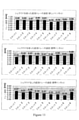
親油性カプセル用の湿度および温度勾配の一例を図6に示す。親水性カプセルについても同様の曲線を作成することができる。親水性カプセルについての曲線は、典型的には、親油性カプセルについての曲線よりも急勾配ではない。親水性カプセルの最終湿度は、充填製剤の内部の違いにより、通常53%から57%の間である。温度はソフトカプセル製剤の融解温度より低いままであり、これはカプセルが乾燥するにつれて上昇する。経時的な温度上昇は、カプセルから水分を蒸発させるのを助ける。 FIG. 6 shows an example of humidity and temperature gradients for lipophilic capsules. Similar curves can be created for hydrophilic capsules. The curve for hydrophilic capsules is typically not steeper than the curve for lipophilic capsules. The final humidity of the hydrophilic capsule is usually between 53% and 57% depending on the internal difference of the filled formulation. The temperature remains below the melting temperature of the soft capsule formulation, which rises as the capsule dries. The temperature rise over time helps evaporate the water from the capsule.
温度および/または湿度の各調整は、特定のソフトカプセル配合物の材料特性に基づくプログラムを通して行うことができ、あるいはシステム内に配置された1つまたは複数のセンサから受信したデータに基づくことができる。温度および/または相対湿度を経時的に選択する好ましい方法は、カプセルの平衡相対湿度に基づいているが、カプセルの重量損失を測定するなどの他の方法も使用することができる。 Each adjustment of temperature and / or humidity can be done through a program based on the material properties of a particular soft capsule formulation, or can be based on data received from one or more sensors located in the system. The preferred method of selecting temperature and / or relative humidity over time is based on the equilibrium relative humidity of the capsule, but other methods such as measuring the weight loss of the capsule can also be used.
カプセルのERHはリアルタイムで測定することができる。ソフトカプセルのERHと融解温度との間の相関に基づいて、相対湿度および温度勾配を示すグラフ上にERHがプロットされるか、または較正グラフに基づいて方程式に入力される。対応する値を使用して、経時的にシステムの温度および相対湿度の設定値を決定できる。 The ERH of the capsule can be measured in real time. ERH is plotted on a graph showing relative humidity and temperature gradients based on the correlation between ERH and melting temperature in soft capsules, or entered into an equation based on a calibration graph. The corresponding values can be used to determine system temperature and relative humidity settings over time.
初期の相対湿度は、製造されたカプセルの高いERHに基づいて高く、典型的には約45%RHから90%RHである。さらに、各ソフトカプセルの終点相対湿度が制御されるが、各配合物毎にカスタマイズが可能である。例えば、魚油カプセルについては、10%RH~24%RHの終点相対湿度が望ましい。イブプロフェンカプセル剤については、23%RH~57%RHの終点湿度が望ましい。 Initial relative humidity is high based on the high ERH of the manufactured capsules, typically from about 45% RH to 90% RH. Furthermore, the relative humidity at the end point of each soft capsule is controlled, but it can be customized for each formulation. For example, for fish oil capsules, an end point relative humidity of 10% RH to 24% RH is desirable. For ibuprofen capsules, end point humidity of 23% RH to 57% RH is desirable.
本システムを使用して、典型的な魚油カプセルを硬度が>8Nの硬度(9時間で)に乾燥させることができ、そして典型的なイブプロフェンカプセルは48時間以内に<7.5%の水分量に乾燥させることができる。これらの値は、特定の配合物に応じて通常2~10日かかる典型的なソフトゲル乾燥プロセスよりも60~80%乾燥時間が短いことを示す。 Using this system, typical fish oil capsules can be dried to a hardness of> 8N (in 9 hours), and typical ibuprofen capsules have a water content of <7.5% within 48 hours. Can be dried. These values indicate a 60-80% shorter drying time than a typical softgel drying process, which typically takes 2-10 days depending on the particular formulation.
カプセルが所望の含水量まで乾燥されると、乾燥装置から取り除かれる。乾燥工程の終点は、カプセル硬度、重量損失、カールフィッシャー法により決定される充填水分、乾燥減量(L.O.D.)により決定されるカプセル水分、または当技術分野において公知の他の方法によって決定することができる。 Once the capsules have been dried to the desired water content, they are removed from the drying device. The end point of the drying step is by capsule hardness, weight loss, filling moisture as determined by the Karl Fischer method, capsule moisture as determined by drying weight loss (LOD), or other methods known in the art. Can be decided.
図7は、乾燥装置としてトンネルドライヤーを使用した図5に示されるような乾燥システムのための好ましい制御システム300の概略図を示す。HVACシステムは、25℃、10%RHの空気を供給することが好ましい。しかしながら、空気温度および相対湿度のパラメータは、室内の快適性レベル、および特定の製品を乾燥させるための所望の相対湿度レベルに応じて変えることができる。
FIG. 7 shows a schematic diagram of a
この好ましいシステムでは、3つの異なる対のセンサを使用することができる。第1の対のセンサは、供給空気360と戻り空気362の相対湿度を測定する。好ましくは、乾燥装置内の差異的相対湿度は、約25%dRHに維持される。乾燥速度を上げるためにもっと高い温度を使用する場合は、必要ならば、供給空気の相対湿度をわずかに高いレベルに制御し維持して製品欠陥を最小限に抑えることができる。差異的相対湿度は、単一の値に設定することも、乾燥時間に影響するようにプロセス全体を通して変動させることもできる。
Three different pairs of sensors can be used in this preferred system. The first pair of sensors measures the relative humidity of the
相対湿度を制御するために、HVACユニット102からのダクトに流量制御弁112を使用することができる。HVACユニット102からシステムに入る空気の相対湿度は低く、この実施形態では約10% の相対湿度である。したがって、HVACからの流量を減らすことで、供給空気の相対湿度が上がる。供給空気相対湿度センサ360を使用して、単一ループコントローラに基づいた流量制御弁112を制御するための情報を提供する測定値を求め、乾燥装置内で所望の差異的相対相対湿度を維持することができる。
A
25%dRHの湿度差を維持し、15%RHの最低湿度(HVACバルブが閉じ始める最小値)を維持するためには、以下のアルゴリズムが使用される。
=IF(RH1>MIN, (IF(RH2<(DIFF+DIFF),(RH2-MIN),DIFF),(RH2-MIN))
RH1:供給センサーからの相対湿度
RH2:戻りセンサーからの相対湿度
DIFF:所望の差異的相対湿度
MIN:最低湿度設定点
この時点で、差異的相対湿度が再計算されて、RH1が最小設定点を下回らないようにする。
The following algorithm is used to maintain a humidity difference of 25% dRH and a minimum humidity of 15% RH (the minimum value at which the HVAC valve begins to close).
= IF (RH1> MIN, (IF (RH2 <(DIFF + DIFF), (RH2-MIN), DIFF), (RH2-MIN)))
RH1: Relative humidity from the supply sensor
RH2: Relative humidity from return sensor
DIFF: desired differential relative humidity
MIN: Minimum humidity setting point At this point, the differential relative humidity is recalculated so that RH1 does not fall below the minimum setting point.
第2の対のセンサは、温度制御センサ364および366を含む。熱交換器または他の加熱要素106が乾燥装置104の供給ダクト内に設置されている。供給側温度を維持および制御するために単一ループコントローラに基づいて空気供給温度センサ364が熱伝導を制御する。上述したように、温度値は、特定のソフトカプセル配合物の融解温度より低い状態で、ゲルからの水の拡散を増加させるために上昇するように設定することができる。
The second pair of sensors includes
制御システム300のこの実施形態で使用される第3の組のセンサ368、370は、1組の流量制御センサである。空気流の増大は、蒸発冷却の影響を最小にし、上述のように乾燥時間を減少させることが示されている。流量センサは、HVACシステムのみから来る流れを制御するために使用されるべき情報を得るために使用することができ、あるいは好ましくは再循環ファンもまたシステム内で使用される。再循環ファンを追加すると、カプセル上の空気の速度が上がる。再循環ファンの動作は、ファン速度を制御することによって温度センサが監視する供給温度と戻り温度との間の差を最小にするアルゴリズムに基づいている。

ここで、排気温度センサ366の温度が入口温度センサ364の温度より1℃低い場合、ファンが始動されるかまたはファン速度が上げられる。再循環ファンおよびHVACシステムは、それぞれ、約100m3/時から約2000m3/時の間の空気流を提供することが好ましい。HVACユニット、乾燥装置、および/または再循環ダクトへの逆流を防ぐために、システム全体にわたっていくつかのチェックバルブ372も配置されている。再循環ファンはまた、HVACユニットによって供給される空気と比較して、供給空気より高い湿度および温度を有する空気を供給する。
Here, when the temperature of the
上記の制御システムは、温度、相対湿度および空気流を変化させることに関して説明してきたが、乾燥時間の短縮は、これらの要素のうちの任意の1つまたは複数を使用して達成可能である。さらに、上記の要素のうちの2つの任意の組み合わせもまた、乾燥時間の短縮をもたらすことができる。好ましくは、システムは、ソフトカプセルの乾燥時間を短縮し、許容可能な物理的特性を有するカプセルを製造するために温度制御と湿度制御の組み合わせを使用する。 Although the control system described above has described varying temperature, relative humidity and airflow, reductions in drying time can be achieved using any one or more of these factors. In addition, any combination of two of the above factors can also result in a reduction in drying time. Preferably, the system uses a combination of temperature control and humidity control to reduce the drying time of soft capsules and produce capsules with acceptable physical properties.
以下の実施例は例示であり、本開示を限定するものではない。当分野で通常遭遇し、当業者に明らかである、様々な条件およびパラメーターの他の適切な変更および適合は、本開示の範囲内である。以下の実施例は、いくつかの好ましい実施形態における本発明の実施を例示する。
実施例
The following examples are exemplary and are not intended to limit this disclosure. Other suitable changes and adaptations of various conditions and parameters commonly encountered in the art and apparent to those of skill in the art are within the scope of this disclosure. The following examples illustrate the implementation of the invention in some preferred embodiments.
Example
(親油性カプセルの乾燥時間):
親油性カプセルのカプセル乾燥速度に対する相対湿度および温度の変化の影響を測定した。標準乾燥トンネルを使用して照査が行われた。標準乾燥トンネルの温度は22℃であり、標準乾燥トンネルの相対湿度はプロセスの開始時に12%RHであった。サンプルをトレイペーパーと共にトレイ上に置き、部分的に積み重ねた状態で作り、そしてトンネル中に置いた。硬さを試験するために6時間毎にカプセルのサンプルを採取した。
(Drying time of lipophilic capsules):
The effects of changes in relative humidity and temperature on the drying rate of lipophilic capsules were measured. Inspections were conducted using standard dry tunnels. The temperature of the standard dry tunnel was 22 ° C. and the relative humidity of the standard dry tunnel was 12% RH at the start of the process. The samples were placed on a tray with tray paper, made partially stacked, and placed in a tunnel. Capsule samples were taken every 6 hours to test hardness.
回転式乾燥機を用いて2つの比較実験を行った。タンブル乾燥機のベースラインは、CS-TJS-1大型バスケットの連続タンブル乾燥機を使用することによって得た。バスケットのロードは60kgと100kgに制限されたもので中点が80kgであった、また3rpmと6rpmの回転速度が採用され、中点は4.5rpmであった。ベースライン実験のために相対湿度を12%RHに保ち、温度は24℃に保った。2番目の比較実験は同じ装置と同じパラメーターを使用して、ただし温度を35°Cに維持して行った。 Two comparative experiments were performed using a rotary dryer. The baseline of the tumble dryer was obtained by using a continuous tumble dryer for the CS-TJS-1 large basket. The basket load was limited to 60 kg and 100 kg with a midpoint of 80 kg, and rotation speeds of 3 rpm and 6 rpm were adopted, with a midpoint of 4.5 rpm. Relative humidity was kept at 12% RH and temperature was kept at 24 ° C. for baseline experiments. The second comparative experiment was performed using the same equipment and the same parameters, but with the temperature maintained at 35 ° C.
データロガーを使用して、タンブル乾燥機のバスケット内、ならびにタンブル乾燥機の吸気フィルターおよび排気口の上の温度および相対湿度をキャプチャーした。2つの比較実験では、サンプルカプセルを採取して、各試験前にカプセル重量および平衡相対湿度(ERH)を測定し、硬度、重量損失、およびERHも最初の6時間は1~2時間ごとに、その後は6~12時間ごとに測定した。 A data logger was used to capture the temperature and relative humidity in the tumble dryer basket and above the tumble dryer intake filters and outlets. In two comparative experiments, sample capsules were taken and capsule weight and equilibrium relative humidity (ERH) were measured prior to each test, with hardness, weight loss, and ERH also every 1 to 2 hours for the first 6 hours. After that, it was measured every 6 to 12 hours.
実験研究のために、CS-TJS-1大型バスケット連続タンブル乾燥機を温度および相対湿度制御システムを含むように改造した。改造したタンブル乾燥機を図13に示す。他のパラメーターは全て比較実験と同じに保った。温度および相対湿度制御システムは、熱エネルギーを節約しシステムに湿度を加えるために再循環ダクト、ダンパー、および蒸気発生器を含めた。回転式乾燥機ハウジング内の温度および相対湿度は、較正されたヴァイサラ送信機を使用して測定した。回転式乾燥機の内側に配置された加熱要素を使用して空気流を加熱した。Nortec蒸気発生器を使用して湿気を加えた。カプセルのERHは、4つのカプセルを密閉容器に入れ、Aqualabs水分活性計を使用して測定し、相対湿度は、最小の湿度変化率が検出されるまで測定された。カプセル間の中間位置の温度および湿度は、ナイロンバッグ中のiButtonデータロガーを使用してモニターした。 For experimental studies, the CS-TJS-1 Large Basket Continuous Tumble Dryer was modified to include a temperature and relative humidity control system. The modified tumble dryer is shown in FIG. All other parameters were kept the same as in the comparative experiment. The temperature and relative humidity control system included recirculation ducts, dampers, and steam generators to save thermal energy and add humidity to the system. Temperature and relative humidity in the rotary dryer housing were measured using a calibrated Vaisala transmitter. The air stream was heated using a heating element located inside the rotary dryer. Moisture was added using a Nortec steam generator. ERH of capsules was measured using an Aqualabs water activity meter with 4 capsules in a closed container and relative humidity was measured until the minimum rate of change in humidity was detected. Temperature and humidity at intermediate positions between capsules were monitored using an iButton data logger in a nylon bag.
サンプルを1時間毎に採取し、10個のカプセルの重量を測定して平均した。減量は初期重量から計算した。重量損失を図8に示すグラフにプロットし、新たな温度および相対湿度の設定点を測定し入力した。この実験では、図6のグラフに示すように、特定のソフトカプセル配合物について以前に得られたデータからERHおよび温度の推定値を作成し、溶融温度は重量損失に関係なく、カプセルのERHから直接計算した。4つの異なる温度/湿度勾配を実施したが、全て図6に示すようなグラフの変形を使用した。 Samples were taken hourly and 10 capsules were weighed and averaged. Weight loss was calculated from the initial weight. Weight losses were plotted in the graph shown in FIG. 8 and new temperature and relative humidity settings were measured and entered. In this experiment, as shown in the graph of FIG. 6, ERH and temperature estimates were made from previously obtained data for a particular soft capsule formulation, and the melting temperature was directly from the ERH of the capsule, regardless of weight loss. Calculated. Four different temperature / humidity gradients were performed, all using graph variants as shown in FIG.
CS-TJS-1大型バスケット連続タンブル乾燥機を用いて追加の対照試験を実施した。対照試験は実験手順と同じプロトコールに従ったが、相対湿度制御なしで温度勾配のみを含んだ。温度のみを使用することによって、カプセルは冷却時にへこんだ。温度と湿度の両方を制御したカプセルは、カプセルの品質に影響がなかった。したがって、乾燥を促進するには温度と湿度の両方の制御が必要であると結論付けることができる。 Additional control tests were performed using a CS-TJS-1 large basket continuous tumble dryer. The control test followed the same protocol as the experimental procedure, but included only the temperature gradient without relative humidity control. By using only temperature, the capsules dented during cooling. Capsules with controlled temperature and humidity did not affect the quality of the capsules. Therefore, it can be concluded that both temperature and humidity control are required to promote drying.
この実施例の結果を図8に示す。サンプルの硬度は、Bareiss Digitest Gelomatを用いて測定した。この特定の製品の硬度仕様は7~10Nであった。結果は、温度および相対湿度制御の使用が乾燥トンネルでの乾燥時間を約36時間から約12時間に短縮することを示した。標準の回転式乾燥機の乾燥時間も50%以上短縮された。相対湿度と温度をより正確に制御することで、乾燥時間をさらに短縮することができる。 The results of this example are shown in FIG. The hardness of the sample was measured using the Barreiss Digitist Gelomat. The hardness specification for this particular product was 7-10N. The results showed that the use of temperature and relative humidity control reduced the drying time in the drying tunnel from about 36 hours to about 12 hours. The drying time of a standard rotary dryer has also been reduced by more than 50%. By controlling the relative humidity and temperature more accurately, the drying time can be further shortened.
(親水性カプセルの乾燥時間):
親水性カプセルのカプセル乾燥速度に対する湿度および温度の変化の影響を、図9に示すように実験室規模の流動床乾燥機を使用して試験した。この研究はまた、最終的な親水性生成物の品質を観察するためにも使用した。この実験のための温度および相対湿度制御は手動で行ない、それ自体は正確ではなかったが、結果は依然として対照乾燥運転に対する80%の乾燥改善が示され、乾燥時間が10日から2日に短縮することが達成された。2つの実験サンプルに対する対照および比較試料の乾燥時間の結果を図10に示す。以下の表1は、各試験に使用された温度、相対湿度および空気流のパラメータを示す。
(Drying time of hydrophilic capsules):
The effects of changes in humidity and temperature on the capsule drying rate of hydrophilic capsules were tested using a laboratory scale fluidized bed dryer as shown in FIG. This study was also used to observe the quality of the final hydrophilic product. Temperature and relative humidity controls for this experiment were performed manually and were not accurate in their own right, but the results still showed an 80% improvement in drying over the control drying operation, reducing the drying time from 10 days to 2 days. Was achieved. The results of the drying times of the control and comparative samples for the two experimental samples are shown in FIG. Table 1 below shows the temperature, relative humidity and airflow parameters used for each test.
対照実験のために、周囲条件で親水性カプセルをナプキンを上にして計量ボートに入れた。10カプセルの重量を測定し、各測定の時間を記録した。 For control experiments, hydrophilic capsules were placed in a weighing boat under ambient conditions with the napkin facing up. 10 capsules were weighed and the time of each measurement was recorded.
本発明の温度および相対湿度制御を使用した結果を2つの異なる温度(流動化22および流動化32)での流動床乾燥機の使用と比較するために比較実験を行った。比較流動床乾燥機実験では、実験を通して空気流を約12m/sに維持した。流動化22については、温度を約22℃に維持した。湿度は調整せず、10.9%RHと14.8%RHの間で変動した。これらの温度および湿度条件は、対照に使用された「周囲条件」と同じであった。 Comparative experiments were performed to compare the results of using the temperature and relative humidity controls of the present invention with the use of a fluidized bed dryer at two different temperatures (fluidization 22 and fluidization 32). In the comparative fluidized bed dryer experiment, the air flow was maintained at about 12 m / s throughout the experiment. For fluidization 22, the temperature was maintained at about 22 ° C. Humidity was not adjusted and fluctuated between 10.9% RH and 14.8% RH. These temperature and humidity conditions were the same as the "ambient conditions" used for the control.
流動化32については、湿度は制御されず、実験中5.2%RH~8.0%RHの間で測定された。温度は、加熱器を使用して約32℃に維持した。より低い相対湿度は、この比較実験で使用されたより高い温度によって説明できる。 For fluidization 32, humidity was uncontrolled and was measured between 5.2% RH and 8.0% RH during the experiment. The temperature was maintained at about 32 ° C. using a heater. Lower relative humidity can be explained by the higher temperatures used in this comparative experiment.
乾燥速度について、2つの異なる実験バッチを2つの対照試料および2つの比較例と比較した。2つの実験試験は表1において湿度2および湿度5と表示されている。温度および湿度制御を評価できるように空気流は流動化させず1m/s未満に維持された。温度および相対湿度は実験を通して調整された。各実験は、重量損失を次の湿度設定値に相関させるために、特定のソフトゲル配合物の融点およびERHに基づいて異なる式を利用した。最初の実験バッチでは、温度を約30℃から約45℃に上げ、その後温度を25℃に下げた。相対湿度は実験を通して高レベルに維持し、75%RH~30%RHの範囲であり、一般に温度が上昇するにつれて低下した。 For drying rates, two different experimental batches were compared with two control samples and two comparative examples. The two experimental tests are labeled Humidity 2 and Humidity 5 in Table 1. The air flow was kept below 1 m / s without fluidization so that temperature and humidity controls could be evaluated. Temperature and relative humidity were adjusted throughout the experiment. Each experiment utilized different formulas based on the melting point and ERH of a particular softgel formulation to correlate weight loss to the following humidity settings. In the first experimental batch, the temperature was raised from about 30 ° C to about 45 ° C and then lowered to 25 ° C. Relative humidity was maintained at high levels throughout the experiment, ranging from 75% RH to 30% RH, and generally decreased with increasing temperature.
第2の実験バッチでは、温度を約30℃から約42℃に上昇させ、その後温度を25℃に戻した。実験を通して相対湿度も高レベルに維持され、温度が上昇するにつれて相対湿度は70%RHから40%RHの範囲であった。第1の実験的試験と第2の実験的試験との間の違いは、各測定後に使用された特定の設定点であった。 In the second experimental batch, the temperature was raised from about 30 ° C to about 42 ° C and then returned to 25 ° C. Relative humidity was also maintained at high levels throughout the experiment, with relative humidity ranging from 70% RH to 40% RH as the temperature increased. The difference between the first experimental test and the second experimental test was the specific setting point used after each measurement.
重量減少を経時的に測定した。親水性カプセルは、10カプセル当たり1.9gの重量減少がある場合に乾燥していると見なした。 Weight loss was measured over time. Hydrophilic capsules were considered dry if there was a weight loss of 1.9 g per 10 capsules.
温度、流動化空気流および湿度を変えて、いくつかの追加のバッチも試験した。これらの実験のそれぞれに使用されたパラメータを表1に示す。各カプセルは、プロセスの完了時に視覚的に検査された。これらの目視観察の結果も表1に含まれる。


(トンネル乾燥機での管理システムの使用):
本発明の一実施形態は、標準的なトンネル乾燥装置を使用して試験された。ソフトゲルカプセルを乾燥させるために使用される乾燥トンネルに、既存のHVACシステムと等しい流量の再循環ファンを追加した。乾燥システムは、図7に示されるような、また上述のように、温度センサ、湿度センサ、流量センサ、加熱要素、および乾燥トンネルへの乾燥冷気の供給を制御するためのダンパ弁を含む。再循環ファンは空気流を増加させる。加熱要素がトンネル内の温度を上昇させる。流量制御弁は、HVACシステムから再循環ループへの乾燥空気の流れを制限することによってトンネル内の相対湿度に影響を及ぼすために使用される。カプセルから蒸発する水分が乾燥トンネル内に湿気を与えた。差異的相対湿度は、トンネルの前後に配置された湿度センサーによってモニターされ、HVACシステムからトンネル内への乾燥空気の増分量を許容するために使用される流量制御弁によって維持された。この特定の設計では、トンネル内への空気の速度を減速することができ、それによって蒸発冷却の効果が減少するにつれて相対湿度を増加させた。
エアハンドル実験
(Use of management system in tunnel dryer):
One embodiment of the invention was tested using a standard tunnel dryer. A recirculation fan with the same flow rate as the existing HVAC system was added to the drying tunnel used to dry the softgel capsules. The drying system includes a temperature sensor, a humidity sensor, a flow rate sensor, a heating element, and a damper valve for controlling the supply of dry cold air to the drying tunnel, as shown in FIG. 7 and as described above. The recirculation fan increases the air flow. The heating element raises the temperature inside the tunnel. The flow control valve is used to affect the relative humidity in the tunnel by limiting the flow of dry air from the HVAC system to the recirculation loop. Moisture evaporating from the capsule moistened the inside of the drying tunnel. The differential relative humidity was monitored by humidity sensors located in front of and behind the tunnel and maintained by a flow control valve used to allow the increment of dry air from the HVAC system into the tunnel. This particular design allowed the velocity of air into the tunnel to slow down, thereby increasing relative humidity as the effect of evaporative cooling diminished.
Air handle experiment
HVACエアハンドラは、各トンネルによって必要とされる空気流の合計に基づいて流れを調整した。これは、トンネルが不要なときにエネルギーを節約するためである。エアハンドラを通過する最大空気流は3500m3/時である。製造業者の推奨に基づくと、最大ダクト圧力は1200Paである。ダクトへの損傷を避けるために、960Paでバイパスダンパーを開き、1080Paでエアハンドラーをシャットダウンするようにインターロックを取り付けた。 The HVAC air handler adjusted the flow based on the total air flow required by each tunnel. This is to save energy when the tunnel is not needed. The maximum air flow through the air handler is 3500 m 3 / hour. Based on the manufacturer's recommendations, the maximum duct pressure is 1200 Pa. To avoid damage to the duct, an interlock was installed to open the bypass damper at 960 Pa and shut down the air handler at 1080 Pa.
すべてのダンパー、バルブ、バイパスを閉じた状態で、記録された最小空気流は1200m3/時であった。各トンネルを通して記録された最小空気流は、それぞれ220m3/時、260m3/時、および300m3/時であった。その結果、バイパスダンパーから推定420m3/時の空気流が漏洩し、損失は35%であった。 With all dampers, valves and bypass closed, the minimum airflow recorded was 1200 m 3 / hour. The minimum airflows recorded through each tunnel were 220 m 3 / hour and 260 m 3 / hour, respectively, and 300 m 3 / hour. As a result, an estimated 420 m 3 / hour air flow leaked from the bypass damper, and the loss was 35%.
100%のHVACを用いて、改造したトンネルのそれぞれを通る最大空気流は、それぞれ2221m3/時、2116m3/時、および2201m3/時と個別に測定された。各トンネルがAUTOで850m3/時に設定されている間、必要な空気流を得るのに十分な圧力を維持するために30%の補正係数をHVAC設定値に追加する必要があることが分かった。これは、バイパスダンパーを通して空気が漏れることで説明できる。 Using 100% HVAC, maximum airflow through each of the modified tunnels was measured individually at 2221 m 3 / hour, 2116 m 3 / hour, and 2201 m 3 / hour, respectively. It was found that a correction factor of 30% needs to be added to the HVAC setting to maintain sufficient pressure to obtain the required airflow while each tunnel is set to 850 m 3 / hour in AUTO. .. This can be explained by the air leaking through the bypass damper.
再循環空気流については、再循環ファンをオフにした状態で、再循環ダクトを通る最小空気流は、それぞれ18m3/時、20m3/時および46m3/時であった。再循環ファンとHVACの間にチェックバルブが取り付けられているため、これはゼロと見なす必要がある。モーターの損傷を避けるために、可変周波数ドライブ(VFD)に最低周波数の6Hzを設定した。同様に、エアハンドラーの最小周波数も6Hzに設定した。チェックバルブの重量のために、再循環空気流はファン速度が30~40Hzに達するまで増加しなかった。これは、260~290m3/時の空気流を表す。結果として、乾燥の終わり近くでいくらかの制御が失われた可能性がある。 Regarding the recirculation air flow, with the recirculation fan turned off, the minimum air flow through the recirculation duct was 18 m 3 / hour, 20 m 3 / hour and 46 m 3 / hour, respectively. This should be considered zero as a check valve is installed between the recirculation fan and the HVAC. To avoid damage to the motor, the variable frequency drive (VFD) was set to a minimum frequency of 6 Hz. Similarly, the minimum frequency of the air handler was also set to 6 Hz. Due to the weight of the check valve, the recirculated airflow did not increase until the fan speed reached 30-40 Hz. This represents an air flow of 260-290 m 3 / hour. As a result, some control may have been lost near the end of drying.
再循環ファンが100%で、トンネル内へのHVAC空気流がAUTOで850m3/時に設定されている間、トンネル内の最大再循環空気流はそれぞれ1685m3/時、2067m3/時、および1705m3/時であった。違いはHVACと再循環ファンの間の圧力の微妙なバランスによるものでる。再循環ファンの仕様は2400m3/時であった。したがって、再循環ファンは仕様を満たすことができなかった。その後のテストでは、再循環ファンの最大周波数は一時的に77Hzに設定された。
湿度制御
The maximum recirculation airflow in the tunnel is 1685m 3 / hour, 2067m 3 / hour, and 1705m, respectively, while the recirculation fan is 100% and the HVAC airflow into the tunnel is set to 850m 3 / hour in AUTO. It was 3 / hour. The difference is due to the delicate balance of pressure between the HVAC and the recirculation fan. The specification of the recirculation fan was 2400 m 3 / hour. Therefore, the recirculation fan could not meet the specifications. In subsequent tests, the maximum frequency of the recirculation fan was temporarily set to 77Hz.
Humidity control
空気流は、25%dRHの設定値で差異的相対湿度コントローラによってカスケードで制御された。以下のアルゴリズ
=IF(RH1>Min,(IF(RH2<(DIFF+DIFF),(RH2-MIN),DIFF),(RH2-MIN))
を使用して、差異的相対湿度を25%dRHに維持し、最小相対湿度を15%RHに維持した。
差異的相対湿度を再計算して、RH1が最低15%RHを下回らないようにした。
温度制御
Air flow was cascaded by a differential relative humidity controller at a setting of 25% dRH. The following algorithms = IF (RH1> Min, (IF (RH2 <(DIFF + DIFF), (RH2-MIN), DIFF), (RH2-MIN)))
The differential relative humidity was maintained at 25% dRH and the minimum relative humidity was maintained at 15% RH.
The differential relative humidity was recalculated so that RH1 did not fall below at least 15% RH.
Temperature control
最高温度は、40℃のセンサーによって制限された。AUTOで35°Cに設定された温度では、コントロールバルブは~30%まで開かず、~20%まで閉じないため、温度制御がより困難であった。
結果
The maximum temperature was limited by a 40 ° C sensor. At temperatures set to 35 ° C in AUTO, temperature control was more difficult because the control valves did not open up to ~ 30% and did not close up to ~ 20%.
result
分析の間、再循環ファンが仕様を満たすことができなかったために空気流が予想に至らなかった事例がいくつかあった。トンネル空気流の合計が十分でなかったので、補正係数をHVAC設定点に追加しなければならなかった。これはおそらくバイパスダンパーからの漏れによるものである。加えて、空気流は圧力降下のために制限されているように見えた。ドアの上の戻り口での平均空気流は1964m3/時であった。 During the analysis, there were some cases where the airflow was unpredictable because the recirculation fan failed to meet the specifications. The total tunnel airflow was not sufficient, so a correction factor had to be added to the HVAC set point. This is probably due to a leak from the bypass damper. In addition, the air flow appeared to be restricted due to the pressure drop. The average airflow at the return port above the door was 1964 m 3 / hour.
上述の1964m3/時の測定平均空気流を用いて、各スタック間にシュラウドを配置した状態でトレイを横切る空気流の速度を測定した。シュラウドは、空気流がスタックの周りに回るのを防ぎ、空気流がスタックを通るように方向づけするために、各スタックの間に配置されたプラスチック製の挿入物である。その結果、トレイの間の速度は高く安定していた。しかし、空気流の速度は仕様の1.53m/sよりはるかに小さかった。シュラウドは比較的消耗しており、一部はひび割れていた。したがって、別のシュラウド設計が必要になる場合がある。その結果、より良い速度が潜在的に達成されたかもしれない。予想よりも低い空気流にもかかわらず、トレイの速度は過去の測定値を上回る改善を示した。空気流速度の結果の比較を図11に示す。 Using the measured average airflow of 1964 m 3 / hour described above, the velocity of the airflow across the tray with the shrouds placed between each stack was measured. A shroud is a plastic insert placed between each stack to prevent the air flow from circling around the stack and direct the air flow through the stack. As a result, the speed between the trays was high and stable. However, the velocity of the air flow was much smaller than the specification of 1.53 m / s. The shroud was relatively exhausted and some were cracked. Therefore, another shroud design may be required. As a result, better speed may have been potentially achieved. Despite lower than expected airflow, tray velocities showed improvements over past measurements. A comparison of the results of air flow velocities is shown in FIG.
シュラウドのない標準的なトンネル内の空気流は平均0.29m/sであった。シュラウド付き標準トンネル内の空気流は平均0.41m/s、シュラウド付き改造トンネル内の空気流は平均0.86m/sであった。したがって、シュラウド付きの改造トンネル内の空気流は、シュラウド付きの標準トンネルの2倍以上、シュラウドなしの標準トンネルの3倍近くであった。 Airflow in a standard tunnel without shrouds averaged 0.29 m / s. The average airflow in the standard tunnel with shroud was 0.41 m / s, and the average airflow in the modified tunnel with shroud was 0.86 m / s. Therefore, the airflow in the modified tunnel with shroud was more than twice that of the standard tunnel with shroud and nearly three times that of the standard tunnel without shroud.
トンネル内の超浅スタックのトレイギャップ面積は、5360cm2と測定された。改造トンネル内のスタックの上方、側方、下方を通る空気の速度は平均0.69m/sであった。その結果、トンネル内のスタックを通る空気流は1330m3/時と測定され、予想された空気流は1964m3/時であった。これは32%の差異であった。 The tray gap area of the ultra-shallow stack in the tunnel was measured to be 5360 cm 2 . The average velocity of air passing above, to the side, and below the stack in the modified tunnel was 0.69 m / s. As a result, the air flow through the stack in the tunnel was measured at 1330 m 3 / hour and the expected air flow was 1964 m 3 / hour. This was a difference of 32%.
トンネル内の超浅スタックのトレイギャップ面積は、5360cm2と測定された。改造型トンネル内のスタックの上方、側方、下方を通る空気の速度は平均0.69m/sであった。その結果、トンネル内のスタックを通る空気流は1330m3/時と測定され、予想された空気流は1964m3/時であった。これは32%の差異であった。
ウェットテスト
The tray gap area of the ultra-shallow stack in the tunnel was measured to be 5360 cm 2 . The average velocity of air passing above, to the side, and below the stack in the modified tunnel was 0.69 m / s. As a result, the air flow through the stack in the tunnel was measured at 1330 m 3 / hour and the expected air flow was 1964 m 3 / hour. This was a difference of 32%.
Wet test
乾燥トンネル内のソフトゲルカプセルから蒸発した水の量をシミュレートするために、約15kgの水を各スタック(~約180ml/トレイ)に入れた。制御システムは、スタックがトンネルに入るとすぐに、最初のスタックから出てくる湿気と低い温度をすぐに検出した。再循環ファンは、>1℃の温度差を検知し、すぐにフルスピードでオンになった。2~3時間後、水を含む9つのスタックすべてがトンネル内に配置された。温度センサーと湿度センサーの両方が、トンネルに入ったときに各スタックを記録した。 About 15 kg of water was placed in each stack (~ about 180 ml / tray) to simulate the amount of water evaporated from the softgel capsules in the drying tunnel. The control system immediately detected the humidity and low temperature coming out of the first stack as soon as the stack entered the tunnel. The recirculation fan detected a temperature difference of> 1 ° C and immediately turned on at full speed. After a few hours, all nine stacks containing water were placed in the tunnel. Both the temperature and humidity sensors recorded each stack as they entered the tunnel.
水の蒸発は過剰であり、約4時間後の相対湿度は91%RHに達した。相対湿度が上昇するにつれて、25%dRHの差異的相対湿度を維持するために空気流制御弁が閉まった。 The evaporation of water was excessive and the relative humidity reached 91% RH after about 4 hours. As the relative humidity increased, the airflow control valve closed to maintain a differential relative humidity of 25% dRH.
テストの速度を上げるために、3時間後に温度を34℃まで上昇させた。この設定値を維持するために温水バルブを開閉した。供給温度が34℃に達したにもかかわらず、プロセスが冷却し始める前に戻り温度は28℃にほとんど到達しなかった。これは、最後のスタックにはまだ水分が含まれていたが、安全な温度で乾燥し続けたことを示す。さらに、湿球温度は通常9°Cであるが、蒸発冷却による戻り温度が18°Cを下回ることはなかった。結果として、カプセルは温かく保たれ、そしてより速く乾燥すると予想された。乾燥の終わりに向かって、戻り相対湿度は35%RH未満に低下したが、これは乾燥プロセスがほぼ完了し、温度は24℃で正常に戻り始めたことを示す。 To speed up the test, the temperature was raised to 34 ° C. after 3 hours. The hot water valve was opened and closed to maintain this set value. Despite the supply temperature reaching 34 ° C, the return temperature barely reached 28 ° C before the process began to cool. This indicates that the last stack was still moist but continued to dry at a safe temperature. Furthermore, the wet-bulb temperature was usually 9 ° C, but the return temperature due to evaporative cooling did not fall below 18 ° C. As a result, the capsules were expected to stay warm and dry faster. Towards the end of drying, the return relative humidity dropped below 35% RH, indicating that the drying process was almost complete and the temperature began to return to normal at 24 ° C.
温度差が1℃を下回ると、再循環ファンは減速した。再循環ファンの速度が低下すると、相対湿度が上昇し、相対湿度を下げるためにエアフローコントローラが開いた。15%RHの最低湿度設定点に到達した時点で、エアフローコントローラを閉じた。最終的には、再循環、温度および湿度制御の3つすべてが低下して停止し、乾燥プロセスが完了した。トレイを検査したところ、スタック上に水は残っていなかった。プロセスは自動的に開始および停止した。 When the temperature difference fell below 1 ° C, the recirculation fan slowed down. As the recirculation fan slowed down, the relative humidity increased and the airflow controller opened to reduce the relative humidity. The airflow controller was closed when the minimum humidity setting point of 15% RH was reached. Eventually, recirculation, temperature and humidity control all dropped and stopped, completing the drying process. Inspection of the tray revealed no water left on the stack. The process started and stopped automatically.
空気流が仕様を満たすことができなかったにもかかわらず、制御方式はドライヤーを自動的に開始および停止することができた。 The control method was able to automatically start and stop the dryer, even though the airflow could not meet the specifications.
L2ARB標準ゼラチンおよび分画ココナッツ油(FCO)から製造されたプラセボカプセルを標準製造方法を使用して製造し、35℃および48℃の2つの異なる高温で乾燥した。カプセルの硬度は、Bareiss Digitest Gelomatを使用してある範囲のERHにわたって測定した。結果を図12に示す。熱処理したカプセルは、同様の相対湿度でより柔らかく、脆さはさらに減少し、また漏れる可能性もより低い。 Placebo capsules made from L2ARB standard gelatin and fractionated coconut oil (FCO) were made using standard manufacturing methods and dried at two different temperatures, 35 ° C and 48 ° C. Capsule hardness was measured over a range of ERH using the Balless Digital Gelomat. The results are shown in FIG. Heat-treated capsules are softer at similar relative humidity, have further reduced brittleness, and are less likely to leak.
本発明の多くの特徴および利点が、本発明の構造および機能の詳細と共に上記の説明に記載したが、本開示は例示的なものに過ぎず、特に添付の特許請求の範囲に記載されている用語の広い一般的な意味によって示される全範囲まで、本発明の原理内において構成部分の形状、サイズおよび配置に関連して、詳細に変更を加えることができることを理解されたい。 Although many features and advantages of the invention have been described above along with details of the structure and function of the invention, the present disclosure is merely exemplary and is particularly described in the appended claims. It should be appreciated that changes can be made in detail in relation to the shape, size and arrangement of the components within the principles of the invention to the full extent indicated by the broad general meaning of the term.
Claims (15)
少なくとも1つの乾燥機(100、200)と、 With at least one dryer (100, 200),
前記乾燥機(100、200)に空気流を供給するための前記乾燥機(100、200)と流体連通するユニット(102)と、 A unit (102) that communicates fluid with the dryer (100, 200) for supplying an air flow to the dryer (100, 200).
前記乾燥機(100、200)内の相対湿度を上昇させることができるように構成された加湿器(108)と、 A humidifier (108) configured to increase the relative humidity in the dryer (100, 200), and a humidifier (108).
前記乾燥機(100、200)内の空気の温度を上昇可能なように構成された加熱器(106)と、 A heater (106) configured to be able to raise the temperature of the air in the dryers (100, 200), and a heater (106).
前記ユニット(102)から前記乾燥機(100、200)への前記空気流の量を制御するように構成された流量制御弁(110)と、 A flow control valve (110) configured to control the amount of air flow from the unit (102) to the dryers (100, 200).
を有し、Have,
前記流量制御弁(110)と前記加湿器(108)との組み合わせは、前記乾燥機(100、200)内の相対湿度を制御して、前記乾燥機(100、200)内の相対湿度が49%RHから79%RHの初期相対湿度から10%RHから24%RHの終点相対湿度まで、または49%RHから79%RHの初期相対湿度から23%RHから57%RHの終点相対湿度まで、経時的に減少するように構成され、前記乾燥機(100、200)内の相対湿度と前記ソフトカプセルの平衡相対湿度との間の差が15%dRH~35%dRHに維持されるように相対湿度が減少されるものである The combination of the flow control valve (110) and the humidifier (108) controls the relative humidity in the dryer (100, 200), and the relative humidity in the dryer (100, 200) is 49. From% RH to 79% RH initial relative humidity to 10% RH to 24% RH end point relative humidity, or from 49% RH to 79% RH initial relative humidity to 23% RH to 57% RH end point relative humidity, Relative humidity is configured to decrease over time so that the difference between the relative humidity in the dryer (100, 200) and the equilibrium relative humidity of the soft capsule is maintained at 15% dRH to 35% dRH. Is reduced
する乾燥システム。Drying system.
a)前記ソフトカプセルにわたって0.15m/sから13m/sの速度で前記ソフトカプセルに空気流を供給する工程と、
b)前記ソフトカプセルがさらされる乾燥温度を経時的に上昇させる工程であって、この乾燥温度は前記ソフトカプセルのカプセルシェルの融解温度より低い温度になるように維持されるものである、上昇させる工程と、
c)前記ソフトカプセルの平衡相対湿度が所望の相対湿度になるまで前記乾燥機中の相対湿度と前記ソフトカプセルの平衡相対湿度との差を15%dRH~35%dRHに維持する工程と、
d)前記工程c)からの前記ソフトカプセルを20~25℃の温度にさらす工程と、を有するものである。 A method of drying a soft capsule using the drying system according to claim 1 , wherein the method is:
a) Over the soft capsule 0 . The process of supplying an air flow to the soft capsule at a speed of 15 m / s to 13 m / s, and
b) A step of raising the drying temperature to which the soft capsule is exposed over time, which is maintained so as to be lower than the melting temperature of the capsule shell of the soft capsule. ,
c) A step of maintaining the difference between the relative humidity in the dryer and the equilibrium relative humidity of the soft capsule at 15% dRH to 35% dRH until the equilibrium relative humidity of the soft capsule reaches a desired relative humidity.
d ) It comprises a step of exposing the soft capsule from the step c ) to a temperature of 20 to 25 ° C.
a)前記ソフトカプセルにわたって0.15m/sから13m/sの速度で前記ソフトカプセルに空気流を供給する工程と、
b)ソフトカプセルがさらされる乾燥温度を経時的に上昇させる工程であって、この乾燥温度は前記ソフトカプセルのカプセルシェルの融解温度より低い温度になるように維持されるものである、上昇させる工程と、
c)前記ソフトカプセルを49%RHから79%RHの初期相対湿度にさらす工程と、
d)前記ソフトカプセルの平衡相対湿度が所望の相対湿度に達するまで、前記ソフトカプセルが乾燥するにつれて前記ソフトカプセルがさらされる前記相対湿度を下げる工程と、
e) 前記工程d)からの前記ソフトカプセルを20~25℃の温度にさらす工程と、を有し、
前記工程dの間、前記ソフトカプセルの平衡相対湿度が所望の相対湿度になるまでに前記乾燥機中の相対湿度と前記ソフトカプセルの平衡相対湿度との差が15%dRH~35%dRHに維持されるものである方法。 A method of drying a soft capsule using the drying system according to claim 1 , wherein the method is:
a) Over the soft capsule 0 . The process of supplying an air flow to the soft capsule at a speed of 15 m / s to 13 m / s, and
b) A step of raising the drying temperature to which the soft capsule is exposed over time, the step of raising the drying temperature, which is maintained so as to be lower than the melting temperature of the capsule shell of the soft capsule.
c) The step of exposing the soft capsule to an initial relative humidity of 49% RH to 79% RH, and
d) A step of lowering the relative humidity to which the soft capsule is exposed as the soft capsule dries until the equilibrium relative humidity of the soft capsule reaches the desired relative humidity.
e) It comprises a step of exposing the soft capsule from the step d ) to a temperature of 20 to 25 ° C.
During step d, the difference between the relative humidity in the dryer and the equilibrium relative humidity of the soft capsule is maintained at 15% dRH to 35% dRH until the equilibrium relative humidity of the soft capsule reaches the desired relative humidity. How to be a thing.
Applications Claiming Priority (3)
| Application Number | Priority Date | Filing Date | Title |
|---|---|---|---|
| US201662431569P | 2016-12-08 | 2016-12-08 | |
| US62/431,569 | 2016-12-08 | ||
| PCT/US2017/065290 WO2018107019A1 (en) | 2016-12-08 | 2017-12-08 | Accelerated drying of soft capsules in a controlled environment |
Publications (3)
| Publication Number | Publication Date |
|---|---|
| JP2020501101A JP2020501101A (en) | 2020-01-16 |
| JP2020501101A5 JP2020501101A5 (en) | 2020-12-24 |
| JP7013465B2 true JP7013465B2 (en) | 2022-01-31 |
Family
ID=62491357
Family Applications (2)
| Application Number | Title | Priority Date | Filing Date |
|---|---|---|---|
| JP2019531045A Active JP7129977B2 (en) | 2016-12-08 | 2017-12-08 | How to reduce capsule shell stress to reduce the likelihood of cracking and damage |
| JP2019530494A Active JP7013465B2 (en) | 2016-12-08 | 2017-12-08 | Accelerated drying of soft capsules in a controlled environment |
Family Applications Before (1)
| Application Number | Title | Priority Date | Filing Date |
|---|---|---|---|
| JP2019531045A Active JP7129977B2 (en) | 2016-12-08 | 2017-12-08 | How to reduce capsule shell stress to reduce the likelihood of cracking and damage |
Country Status (14)
| Country | Link |
|---|---|
| US (2) | US20200069524A1 (en) |
| EP (2) | EP3551158A4 (en) |
| JP (2) | JP7129977B2 (en) |
| KR (2) | KR102475555B1 (en) |
| CN (2) | CN110167510B (en) |
| AU (2) | AU2017374037B2 (en) |
| BR (2) | BR112019010069A2 (en) |
| CA (2) | CA3041560A1 (en) |
| CO (2) | CO2019005095A2 (en) |
| ES (1) | ES2927068T3 (en) |
| IL (2) | IL266694B2 (en) |
| MX (2) | MX2019005956A (en) |
| RU (2) | RU2765074C2 (en) |
| WO (2) | WO2018107019A1 (en) |
Families Citing this family (4)
| Publication number | Priority date | Publication date | Assignee | Title |
|---|---|---|---|---|
| CN110167510B (en) * | 2016-12-08 | 2021-12-14 | R·P·谢勒技术有限公司 | Method of relieving stress in capsule shells to reduce tendency to rupture |
| US20210154099A1 (en) * | 2019-11-22 | 2021-05-27 | Karl Wei Cao | Top liquid fill method and apparatus for hard capsules |
| WO2021118558A1 (en) | 2019-12-11 | 2021-06-17 | W.L. Gore & Associates, Inc, | Methods for evaluating vapor pump performance |
| CN115792141B (en) * | 2023-01-06 | 2023-05-02 | 广州兰泰仪器有限公司 | Method and system for improving balance detection efficiency of water activity meter |
Citations (7)
| Publication number | Priority date | Publication date | Assignee | Title |
|---|---|---|---|---|
| US5200191A (en) | 1991-09-11 | 1993-04-06 | Banner Gelatin Products Corp. | Softgel manufacturing process |
| JP2003116507A (en) | 2001-10-10 | 2003-04-22 | Akira Shibazaki | Method and apparatus for drying moisture-containing food |
| JP2007192464A (en) | 2006-01-19 | 2007-08-02 | Mayekawa Mfg Co Ltd | Lumber artificial drying method and system |
| KR100954481B1 (en) | 2008-01-10 | 2010-04-23 | 이승용 | Drying machine |
| US8621764B2 (en) | 2011-03-16 | 2014-01-07 | John PUCKETT | Gelatin capsule formulation and drying system |
| CN104991591A (en) | 2015-05-23 | 2015-10-21 | 浙江益立胶囊股份有限公司 | Control system used for capsule drying and storage |
| JP2020500643A (en) | 2016-12-08 | 2020-01-16 | アール.ピー.シェーラー テクノロジーズ、エルエルシー | How to reduce capsule shell stress to reduce the possibility of cracking and damage |
Family Cites Families (34)
| Publication number | Priority date | Publication date | Assignee | Title |
|---|---|---|---|---|
| US1330238A (en) * | 1918-06-03 | 1920-02-10 | Buffalo Forge Co | Method of and apparatus for drying, conditioning, and regulating the moisture content of hygroscopic materials |
| US4539060A (en) * | 1983-02-18 | 1985-09-03 | Warner-Lambert Company | Apparatus and method of sealing capsules |
| JPS61100519A (en) * | 1984-10-23 | 1986-05-19 | Shin Etsu Chem Co Ltd | Hard capsule for drug |
| CH674800A5 (en) * | 1986-03-12 | 1990-07-31 | Warner Lambert Co | |
| US4720924A (en) | 1986-11-03 | 1988-01-26 | R & J Engineering Corporation | Microwave drying of pharmaceutical gelatin capsules |
| AU682860B2 (en) * | 1994-01-07 | 1997-10-23 | Thermtech A/S | A process and a device in drying of organic and/or unorganic materials |
| US5960563A (en) * | 1998-01-12 | 1999-10-05 | Big Beans Holding, Ltd. | Extraction and drying apparatus |
| US8256135B2 (en) * | 1999-05-28 | 2012-09-04 | Thermapure, Inc. | Method for removing or treating harmful biological and chemical substances within structures and enclosures |
| US6340473B1 (en) | 1999-07-07 | 2002-01-22 | R.P. Scherer Technologies, Inc. | Film forming compositions comprising modified starches and iota-carrageenan and methods for manufacturing soft capsules using same |
| DE50015770D1 (en) * | 2000-12-29 | 2009-12-03 | Swiss Caps Rechte & Lizenzen | Method and device for producing moldings from a biopolymer material |
| US6884060B2 (en) | 2001-11-02 | 2005-04-26 | R.P. Scherer Technologies, Inc. | Apparatus for manufacturing encapsulated products |
| CA2510465A1 (en) | 2002-12-18 | 2004-07-08 | Pain Therapeutics | Oral dosage forms with therapeutically active agents in controlled release cores and immediate release gelatin capsule coats |
| NL1023720C2 (en) | 2003-06-23 | 2004-12-28 | Univ Eindhoven Tech | Method for changing the transport properties of a material, method for releasing a drug from an implant, as well as implant with drug. |
| US20050158198A1 (en) * | 2003-12-21 | 2005-07-21 | Albers Walter F. | Micro-cycle energy transfer systems and methods |
| US7246451B2 (en) * | 2004-09-30 | 2007-07-24 | Technophar Equipment & Service Limited | Tumbler-dryer for capsules |
| US7914573B2 (en) | 2005-12-13 | 2011-03-29 | Cordis Corporation | Polymeric stent having modified molecular structures |
| US7762006B2 (en) * | 2006-06-14 | 2010-07-27 | Siestamed, Technologies | Medical equipment drying device |
| DE602007011963D1 (en) | 2006-10-26 | 2011-02-24 | Pfizer Prod Inc | CAPSULE EDUCATION |
| US7957842B2 (en) | 2008-02-19 | 2011-06-07 | Honeywell International Inc. | Apparatus and method for controlling an air supply for drying painted vehicles and other objects |
| US8790692B2 (en) * | 2009-09-09 | 2014-07-29 | Patheon Pharmaceuticals Inc. | Break resistant gel capsule |
| JP5618402B2 (en) * | 2010-06-24 | 2014-11-05 | 三生医薬株式会社 | Method for producing chewable soft capsule |
| CN103282028B (en) * | 2010-08-10 | 2016-04-27 | R·P·舍勒科技有限责任公司 | The method of the stable Gelseal of preparation containing microencapsulation probiotic bacteria |
| JP5693116B2 (en) | 2010-09-26 | 2015-04-01 | 日本テトラパック株式会社 | Packaging filling apparatus and packaging filling method |
| CN102283779A (en) * | 2011-06-14 | 2011-12-21 | 贵州地道药业有限公司 | New technique for drying soft capsules |
| CN103256806B (en) * | 2012-02-20 | 2015-09-02 | 艾默生电气公司 | For the apparatus and method of drying material |
| EP2911654A1 (en) * | 2013-03-15 | 2015-09-02 | Capsugel Belgium NV | Enteric coating for soft capsule |
| CN103565647B (en) | 2013-10-28 | 2015-06-10 | 刘凯培 | Hollow soft capsule and preparation method thereof |
| DE102015205338A1 (en) * | 2015-03-24 | 2016-09-29 | Cefla Deutschland Gmbh | drying device |
| CN105674699B (en) | 2016-02-02 | 2018-04-20 | 安徽恒昊科技有限公司 | A kind of process of quick high humidity dry sterilization |
| CN105987587A (en) * | 2016-06-28 | 2016-10-05 | 无锡市中谊药化机械有限公司 | Drying method for soft capsules in rolling air-drying mode and device thereof |
| US10422579B2 (en) * | 2017-05-02 | 2019-09-24 | Auto Cure Llc | Automated drying and curing chamber |
| WO2019014722A1 (en) * | 2017-07-20 | 2019-01-24 | Commonwealth Scientific And Industrial Research Organisation | Drying process and apparatus |
| US10590594B2 (en) * | 2017-11-28 | 2020-03-17 | Elberto Berdut-Teruel | Magnetic induction heating system and dehydrator |
| CN210197946U (en) * | 2019-05-07 | 2020-03-27 | 于雄青 | Take soft capsule drying equipment of evaporimeter |
-
2017
- 2017-12-08 CN CN201780070689.7A patent/CN110167510B/en active Active
- 2017-12-08 IL IL266694A patent/IL266694B2/en unknown
- 2017-12-08 BR BR112019010069A patent/BR112019010069A2/en not_active Application Discontinuation
- 2017-12-08 EP EP17878382.5A patent/EP3551158A4/en active Pending
- 2017-12-08 EP EP17877660.5A patent/EP3551950B1/en active Active
- 2017-12-08 JP JP2019531045A patent/JP7129977B2/en active Active
- 2017-12-08 CA CA3041560A patent/CA3041560A1/en active Pending
- 2017-12-08 MX MX2019005956A patent/MX2019005956A/en unknown
- 2017-12-08 KR KR1020197014547A patent/KR102475555B1/en active IP Right Grant
- 2017-12-08 RU RU2019113369A patent/RU2765074C2/en active
- 2017-12-08 IL IL266695A patent/IL266695B/en unknown
- 2017-12-08 BR BR112019010644A patent/BR112019010644A2/en active Search and Examination
- 2017-12-08 JP JP2019530494A patent/JP7013465B2/en active Active
- 2017-12-08 MX MX2019005930A patent/MX2019005930A/en unknown
- 2017-12-08 KR KR1020197015395A patent/KR102328603B1/en active IP Right Grant
- 2017-12-08 WO PCT/US2017/065290 patent/WO2018107019A1/en unknown
- 2017-12-08 WO PCT/US2017/065398 patent/WO2018107080A1/en unknown
- 2017-12-08 AU AU2017374037A patent/AU2017374037B2/en active Active
- 2017-12-08 AU AU2017371180A patent/AU2017371180B2/en active Active
- 2017-12-08 CA CA3045127A patent/CA3045127A1/en active Pending
- 2017-12-08 ES ES17877660T patent/ES2927068T3/en active Active
- 2017-12-08 RU RU2019112049A patent/RU2745334C9/en active
- 2017-12-08 CN CN201780069164.1A patent/CN109923360B/en active Active
- 2017-12-08 US US16/467,408 patent/US20200069524A1/en active Pending
- 2017-12-08 US US16/467,436 patent/US11026865B2/en active Active
-
2019
- 2019-05-17 CO CONC2019/0005095A patent/CO2019005095A2/en unknown
- 2019-05-22 CO CONC2019/0005238A patent/CO2019005238A2/en unknown
Patent Citations (7)
| Publication number | Priority date | Publication date | Assignee | Title |
|---|---|---|---|---|
| US5200191A (en) | 1991-09-11 | 1993-04-06 | Banner Gelatin Products Corp. | Softgel manufacturing process |
| JP2003116507A (en) | 2001-10-10 | 2003-04-22 | Akira Shibazaki | Method and apparatus for drying moisture-containing food |
| JP2007192464A (en) | 2006-01-19 | 2007-08-02 | Mayekawa Mfg Co Ltd | Lumber artificial drying method and system |
| KR100954481B1 (en) | 2008-01-10 | 2010-04-23 | 이승용 | Drying machine |
| US8621764B2 (en) | 2011-03-16 | 2014-01-07 | John PUCKETT | Gelatin capsule formulation and drying system |
| CN104991591A (en) | 2015-05-23 | 2015-10-21 | 浙江益立胶囊股份有限公司 | Control system used for capsule drying and storage |
| JP2020500643A (en) | 2016-12-08 | 2020-01-16 | アール.ピー.シェーラー テクノロジーズ、エルエルシー | How to reduce capsule shell stress to reduce the possibility of cracking and damage |
Also Published As
Similar Documents
| Publication | Publication Date | Title |
|---|---|---|
| JP7013465B2 (en) | Accelerated drying of soft capsules in a controlled environment | |
| JP6153660B2 (en) | Fully automatic dynamic moisture analysis climate chamber for tobacco leaves | |
| JP6670146B2 (en) | Environmental test equipment | |
| TWI695668B (en) | Method of controlling cooling in server room and system implementing thereof | |
| CN106644811A (en) | Moisture content detector | |
| JP2010247041A (en) | Dehumidifier and method of controlling the same | |
| KR20210044710A (en) | Test chamber and method for conditioning air | |
| Poomsa-ad et al. | Investigations on head-rice yield and operating time in the fluidised-bed drying process: experiment and simulation | |
| US11828673B2 (en) | Environmental testing chamber and air-conditioning system | |
| CN105784926A (en) | Device and method used for measuring moisture content of high humidity gas flow | |
| CN105404338A (en) | Control system applied to preservation box for controlling temperature and relative humidity | |
| Babu et al. | Experimental Investigations of Thin-layer Drying of Leaves in a Heat-Pump Assisted Tray-type Batch Drying Chamber. | |
| CN210604470U (en) | Device and system for testing comfort level of clothes | |
| JPS61213648A (en) | Air enthalpy method testing instrument for air conditioner | |
| CN113439191B (en) | Air flow gel pack adjusting device | |
| JP2006064260A (en) | Drying method and drying equipment | |
| JPH04327783A (en) | Test drier and method for controlling the same | |
| KR101144710B1 (en) | Method for temperature and humidity detecting of a dryer | |
| CN208520795U (en) | A kind of high-low temperature tester | |
| JPS6120256B2 (en) | ||
| JPH04115137A (en) | Thermo-hygrostat | |
| Wongwises et al. | Performance of a heat pump dehumidifier dryer | |
| REGALADO et al. | Thin-layer Dehumidification Drying Studies on Rough Rice (Part 1) Closed Circulating Air System Including Dehumidifier | |
| BR102022010987A2 (en) | SEED DRYING SYSTEM WITH COOLED AND DEHUMIDIFIED AIR IN A CLOSED SYSTEM | |
| レガラドMJC et al. | Thin-layer Dehumidification Drying Studies on Rough Rice (Part 1)-Closed Circulating Air System Including Dehumidifier. |
Legal Events
| Date | Code | Title | Description |
|---|---|---|---|
| A521 | Request for written amendment filed |
Free format text: JAPANESE INTERMEDIATE CODE: A523 Effective date: 20201112 |
|
| A621 | Written request for application examination |
Free format text: JAPANESE INTERMEDIATE CODE: A621 Effective date: 20201112 |
|
| A977 | Report on retrieval |
Free format text: JAPANESE INTERMEDIATE CODE: A971007 Effective date: 20211214 |
|
| TRDD | Decision of grant or rejection written | ||
| A01 | Written decision to grant a patent or to grant a registration (utility model) |
Free format text: JAPANESE INTERMEDIATE CODE: A01 Effective date: 20211228 |
|
| A61 | First payment of annual fees (during grant procedure) |
Free format text: JAPANESE INTERMEDIATE CODE: A61 Effective date: 20220119 |
|
| R150 | Certificate of patent or registration of utility model |
Ref document number: 7013465 Country of ref document: JP Free format text: JAPANESE INTERMEDIATE CODE: R150 |