JP7011802B2 - Medical cap and its manufacturing method - Google Patents

Medical cap and its manufacturing method Download PDF

Info

Publication number
JP7011802B2
JP7011802B2 JP2017062048A JP2017062048A JP7011802B2 JP 7011802 B2 JP7011802 B2 JP 7011802B2 JP 2017062048 A JP2017062048 A JP 2017062048A JP 2017062048 A JP2017062048 A JP 2017062048A JP 7011802 B2 JP7011802 B2 JP 7011802B2
Authority
JP
Japan
Prior art keywords
mold
elastic
engaged
elastic plug
forming
Prior art date
Legal status (The legal status is an assumption and is not a legal conclusion. Google has not performed a legal analysis and makes no representation as to the accuracy of the status listed.)
Active
Application number
JP2017062048A
Other languages
Japanese (ja)
Other versions
JP2018164467A5 (en
JP2018164467A (en
Inventor
啓介 鈴木
Current Assignee (The listed assignees may be inaccurate. Google has not performed a legal analysis and makes no representation or warranty as to the accuracy of the list.)
Naigai Kasei Co Ltd
Original Assignee
Naigai Kasei Co Ltd
Priority date (The priority date is an assumption and is not a legal conclusion. Google has not performed a legal analysis and makes no representation as to the accuracy of the date listed.)
Filing date
Publication date
Application filed by Naigai Kasei Co Ltd filed Critical Naigai Kasei Co Ltd
Priority to JP2017062048A priority Critical patent/JP7011802B2/en
Publication of JP2018164467A publication Critical patent/JP2018164467A/en
Publication of JP2018164467A5 publication Critical patent/JP2018164467A5/ja
Application granted granted Critical
Publication of JP7011802B2 publication Critical patent/JP7011802B2/en
Active legal-status Critical Current
Anticipated expiration legal-status Critical

Links

Images

Description

本発明は、輸液容器、採血管、バイアル瓶等の薬剤容器等に用いる医療用キャップ及びその製造方法に関する。特に、医療用に於いて針刺し可能な弾性栓体を備えた医療用キャップ及びその製造方法に関する。 The present invention relates to a medical cap used for an infusion container, a blood collection tube, a drug container such as a vial, and a method for manufacturing the same. In particular, the present invention relates to a medical cap provided with an elastic plug that can be pierced by a needle for medical use, and a method for manufacturing the same.

医療分野に用いられる薬液ボトルや点滴用の輸液ボトル等の薬剤容器の口部には、針でその薬液を取り出せるようにするため、外枠体(例えば、熱可塑性合成樹脂等)の内側に、弾性栓体(例えば、ゴムや熱可塑性エラストマー樹脂等)を備えた医療用キャップが用いられている(例えば、下記特許文献1~3参照)。 At the mouth of a drug container such as a drug solution bottle used in the medical field or an infusion bottle for drip, the inside of an outer frame (for example, a thermoplastic synthetic resin, etc.) is placed so that the drug solution can be taken out with a needle. A medical cap provided with an elastic stopper (for example, rubber, a thermoplastic elastomer resin, etc.) is used (see, for example, Patent Documents 1 to 3 below).

このような医療用キャップは、外枠体を薬剤容器の口部に溶着等することにより取り付けられる。そして、使用の際には弾性栓体に、取り出し用チューブを備えた注射針を突き刺し、薬剤容器を上側にし、キャップを下側に配置することにより、当該取り出し用チューブを介して容器内の輸液を取り出す。また、この様な医療用キャップに対しては、薬液や輸液の漏洩防止や空気に触れることによる変質を防止するため、密閉性が求められる。 Such a medical cap is attached by welding an outer frame body to the mouth of a drug container or the like. Then, at the time of use, an injection needle provided with a take-out tube is pierced into the elastic plug, the drug container is placed on the upper side, and the cap is placed on the lower side, so that the infusion solution in the container is placed through the take-out tube. Take out. Further, such a medical cap is required to be hermetically sealed in order to prevent leakage of chemicals and infusions and to prevent deterioration due to contact with air.

また、医療用キャップの製造には、例えば、二色成形法やインサート成形法が用いられる。二色成形法の場合、共通金型(下金型)と上金型を用いて弾性栓体を成形した後、当該弾性栓体を共通金型に残した状態で、他の上金型と組み合わせて外枠体を成形する。この方法の場合、弾性栓体は外枠体との接触面で熱溶着した状態で密着している。 Further, for the production of the medical cap, for example, a two-color molding method or an insert molding method is used. In the case of the two-color molding method, after molding an elastic stopper using a common mold (lower mold) and an upper mold, the elastic stopper is left in the common mold and then with another upper mold. Combine to form the outer frame. In the case of this method, the elastic plug body is in close contact with the outer frame body in a heat-welded state on the contact surface.

また、インサート成形法の場合、射出成形法やコンプレッション成形法等で予め作成した弾性栓体を、外枠体を成形するための一対の金型内にインサートした後、外枠体を成形する。この方法の場合においても、弾性栓体は外枠体との接触面で熱溶着した状態で密着している。 Further, in the case of the insert molding method, the elastic stopper body prepared in advance by the injection molding method, the compression molding method or the like is inserted into a pair of molds for molding the outer frame body, and then the outer frame body is molded. Even in the case of this method, the elastic plug body is in close contact with the outer frame body in a heat-welded state on the contact surface.

ところで、弾性栓体の成形の際、金型の型開きのときに弾性栓体が金型内に取り残され、離型不良が発生する場合がある。特に、弾性栓体が熱可塑性エラストマー樹脂からなり、金型として雄型(コア)と雌型(キャビティ)の組み合わせからなるものを用いた場合、弾性栓体の密着性が大きい等の理由から、弾性栓体が雌型に密着して離型が困難になる場合がある。その結果、医療用キャップの製造効率が低下するという問題がある。 By the way, when molding an elastic stopper, the elastic stopper may be left behind in the mold when the mold is opened, and a mold release defect may occur. In particular, when the elastic plug is made of a thermoplastic elastomer resin and a mold consisting of a combination of a male mold (core) and a female mold (cavity) is used, the adhesiveness of the elastic stopper is high. The elastic plug may adhere to the female mold, making it difficult to remove the mold. As a result, there is a problem that the manufacturing efficiency of the medical cap is lowered.

特開2012-239529号公報Japanese Unexamined Patent Publication No. 2012-239529 特開2013-013585号公報Japanese Unexamined Patent Publication No. 2013-013585 特開2014-027980号公報Japanese Unexamined Patent Publication No. 2014-027980

本発明は前記問題点に鑑みなされたものであり、その目的は、金型の型開きの際に弾性栓体が、例えば雌型(キャビティ)側に密着する等して離型不良が発生するのを抑制し、製造効率が低減するのを防止することが可能な医療用キャップ及びその製造方法を提供することにある。 The present invention has been made in view of the above problems, and an object thereof is that when the mold is opened, the elastic stopper is in close contact with the female mold (cavity) side, for example, and a mold release defect occurs. It is an object of the present invention to provide a medical cap and a method for producing the same, which can suppress the above-mentioned problems and prevent the production efficiency from being reduced.

本発明に係る医療用キャップは、前記の課題を解決するために、弾性栓体と、前記弾性栓体を内部に保持する外枠体とを有する医療用キャップであって、前記弾性栓体と前記外枠体の接触面は熱溶着しており、前記弾性栓体の側周部及び/又は底面部には、当該弾性栓体を金型に係合させるための被係合部が少なくとも1つ設けられていることを特徴とする。 The medical cap according to the present invention is a medical cap having an elastic plug body and an outer frame body for holding the elastic plug body inside in order to solve the above-mentioned problems, and the elastic plug body and the elastic plug body. The contact surface of the outer frame body is heat-welded, and at least one engaged portion for engaging the elastic plug body with the mold is provided on the side peripheral portion and / or the bottom surface portion of the elastic plug body. It is characterized by being provided with one.

前記の構成に於いて、前記弾性栓体の側周部及び/又は底面部の表面が、微細な凹凸構造を有することが好ましい。 In the above configuration, it is preferable that the surface of the side peripheral portion and / or the bottom surface portion of the elastic plug has a fine uneven structure.

また、前記の構成に於いて、前記弾性栓体の側周部及び/又は底面部の表面が、前記被係合部を除き微細な凹凸構造を有することが好ましい。 Further, in the above configuration, it is preferable that the surface of the side peripheral portion and / or the bottom surface portion of the elastic plug body has a fine concavo-convex structure except for the engaged portion.

前記構成に於いては、前記弾性栓体の側周部には、前記被係合部に対し前記底面部とは反対側の任意の位置に、ーティングラインが設けられていてもよい。

In the above configuration, a parting line may be provided on the side peripheral portion of the elastic plug body at an arbitrary position on the side opposite to the bottom surface portion with respect to the engaged portion.

また、前記構成に於いては、前記弾性栓体の側周部にはパーティングラインが設けられていなくてもよい。 Further, in the above configuration, a parting line may not be provided on the side peripheral portion of the elastic plug body.

前記の構成に於いては、前記被係合部が凸部、凹部又はフランジ部の少なくとも何れかであることが好ましい。 In the above configuration, it is preferable that the engaged portion is at least one of a convex portion, a concave portion, and a flange portion.

さらに、前記構成に於いて、前記弾性栓体の被係合部は、当該弾性栓体を前記金型に係合させた場合に、当該金型から離れる方向に先細りのテーパ状となる縦断面形状を有することが好ましい。 Further, in the above configuration, the engaged portion of the elastic plug has a vertical cross section that becomes tapered in a direction away from the mold when the elastic plug is engaged with the mold. It is preferable to have a shape.

また、本発明に係る医療用キャップの製造方法は、前記の課題を解決するために、前記弾性栓体と、前記弾性栓体を内部で保持する外枠体とを有する医療用キャップの製造方法であって、前記弾性栓体の側周部及び/又は底面部に被係合部を形成するための係合部を少なくとも1つ備えた第1金型と、当該第1金型との型閉じにより弾性栓体成形用のキャビティを形成する第2金型とを用いて、前記被係合部を少なくとも1つ備えた弾性栓体を成形する弾性栓体成形工程を含むことを特徴とする。 Further, in the method for manufacturing a medical cap according to the present invention, in order to solve the above-mentioned problems, a method for manufacturing a medical cap having the elastic plug body and an outer frame body for internally holding the elastic plug body. A mold of a first mold provided with at least one engaging portion for forming an engaged portion on a side peripheral portion and / or a bottom surface portion of the elastic plug body, and a mold of the first mold. It is characterized by comprising an elastic stopper molding step of forming an elastic stopper provided with at least one engaged portion by using a second mold for forming a cavity for forming an elastic stopper by closing. ..

前記構成に於いて、前記弾性栓体成形工程で作製した弾性栓体を載置することが可能な第3金型と、当該第3金型との型閉じにより外枠体成形用のキャビティを形成する第4金型とを用いて外枠体を成形する外枠体成形工程をさらに含み、前記第3金型は、前記第1金型を共通金型として用いるものであり、前記外枠体成形工程は、第1金型の係合部に前記弾性栓体の被係合部を係合させ、成形後の弾性栓体を当該第1金型に固定した状態で行うものにすることができる。 In the above configuration, the cavity for forming the outer frame is formed by closing the third mold on which the elastic stopper produced in the elastic stopper forming step can be placed and the third mold. Further including an outer frame body forming step of forming an outer frame body using a fourth mold to be formed, the third mold uses the first mold as a common mold, and the outer frame. The body forming step is performed in a state where the engaged portion of the elastic stopper is engaged with the engaging portion of the first mold and the elastic stopper after molding is fixed to the first mold. Can be done.

また、前記構成に於いて、前記弾性栓体成形工程で作製した弾性栓体を載置することが可能な第3金型と、当該第3金型との型閉じにより外枠体成形用のキャビティを形成する第4金型とを用いて外枠体を成形する外枠体成形工程をさらに含み、前記第3金型は、前記弾性栓体の被係合部を係合させることが可能な他の係合部を備えるものであり、前記外枠体成形工程は、第3金型の他の係合部に前記弾性栓体の被係合部を係合させ、成形後の弾性栓体を当該第3金型に固定した状態で行うものにすることができる。 Further, in the above configuration, the outer frame is formed by closing the third mold on which the elastic stopper produced in the elastic stopper forming step can be placed and the third mold. Further including an outer frame body forming step of forming an outer frame body using a fourth mold for forming a cavity, the third mold can engage an engaged portion of the elastic stopper. In the outer frame molding step, the engaged portion of the elastic stopper is engaged with the other engagement portion of the third mold, and the elastic stopper after molding is provided. The body can be fixed to the third mold.

前記構成に於いては、前記第1金型の内壁面のうち、前記弾性栓体の側周部及び/又は底面部を成形する部分には、微細な凹凸構造が設けられていてもよい。 In the above configuration, the inner wall surface of the first mold may be provided with a fine uneven structure on the portion of the inner wall surface of the first mold that forms the side peripheral portion and / or the bottom surface portion of the elastic plug body.

また前記構成に於いては、前記第1金型の内壁面のうち、前記弾性栓体の前記被係合部を除く側周部及び/又は底面部を成形する部分には、微細な凹凸構造が設けられていてもよい。 Further, in the above configuration, the inner wall surface of the first mold has a fine uneven structure on the portion of the inner wall surface of the elastic stopper that forms the side peripheral portion and / or the bottom surface portion excluding the engaged portion of the elastic stopper. May be provided.

また前記構成に於いては、前記第1金型と前記第2金型とを型閉じした際に形成される接合面が、前記弾性栓体の被係合部の形成位置に対し前記底面部とは反対側に位置することが好ましい。 Further, in the above configuration, the joint surface formed when the first mold and the second mold are closed is the bottom surface portion with respect to the formation position of the engaged portion of the elastic plug body. It is preferably located on the opposite side of the.

また前記構成に於いては、前記第1金型と前記第2金型とを型閉じした際に形成される接合面が、前記弾性栓体の被係合部の形成位置に対し前記底面部よりも下方に位置することが好ましい。 Further, in the above configuration, the joint surface formed when the first mold and the second mold are closed is the bottom surface portion with respect to the formation position of the engaged portion of the elastic plug body. It is preferably located below.

前記構成に於いては、前記第1金型の係合部が、前記弾性栓体に対し凸部からなる被係合部を成形するための凸部成形用キャビティ部、前記弾性栓体に対し凹部からなる被係合部を成形するための凹部成形用凸部、又は前記弾性栓体に対しフランジ部からなる被係合部を成形するためのフランジ部成形用キャビティ部のいずれかであることが好ましい。 In the above configuration, the engaging portion of the first mold is for the convex portion forming cavity portion for forming the engaged portion formed of the convex portion with respect to the elastic plug body, with respect to the elastic plug body. It is either a concave portion forming convex portion for forming an engaged portion made of a concave portion, or a flange portion forming cavity portion for forming an engaged portion made of a flange portion with respect to the elastic stopper. Is preferable.

また、前記構成に於いて、前記第1金型の係合部は、型閉じする第2金型から離れる方向に先細りのテーパ状となる縦断面形状を有することが好ましい。 Further, in the above configuration, it is preferable that the engaging portion of the first mold has a vertical cross-sectional shape that tapers in a direction away from the second mold that closes the mold.

本発明によれば、弾性栓体は、その側周部や底面部において、金型に係合させるための被係合部を少なくとも1つ備える。これにより、例えば弾性栓体の成形後、金型の型開きの際に、成形された弾性栓体の被係合部を一方の金型に係合させ固定させることができる。その結果、弾性栓体が他方の金型に密着して離型不良が発生するのを防止することができる。すなわち、本発明によれば、金型の型開きの際に弾性栓体の離型不良が発生するのを抑制し、製造効率の低下を防止することが可能な医療用キャップ及びその製造方法を提供することができる。 According to the present invention, the elastic plug body includes at least one engaged portion for engaging with the mold on its side peripheral portion and bottom surface portion. Thereby, for example, after molding the elastic stopper body, when the mold is opened, the engaged portion of the molded elastic stopper body can be engaged with and fixed to one of the molds. As a result, it is possible to prevent the elastic plug from coming into close contact with the other mold and causing a mold release defect. That is, according to the present invention, there is a medical cap and a manufacturing method thereof that can suppress the occurrence of mold release failure of the elastic plug when the mold is opened and prevent the manufacturing efficiency from being lowered. Can be provided.

同図(a)は実施の形態1に係る医療用キャップを表す断面模式図であり、同図(b)は当該医療用キャップを薬剤容器に取り付けた様子を表す断面模式図である。FIG. (A) is a schematic cross-sectional view showing the medical cap according to the first embodiment, and FIG. 6 (b) is a schematic cross-sectional view showing a state in which the medical cap is attached to a drug container. 前記医療用キャップの弾性栓体を説明するための説明図であって、同図(a)は当該弾性栓体が図示された平面図であり、同図(b)は同図(a)のA-A線矢視断面図である。It is explanatory drawing for demonstrating the elastic plug body of the medical cap, FIG. It is a cross-sectional view taken along the line AA. 前記医療用キャップの製造方法を説明するための断面模式図であって、同図(a)は一対の金型が型閉じされ、弾性栓体成形用のキャビティが形成される様子を表し、同図(b)は弾性栓体が成形された後の金型を型開きする様子を表し、同図(c)は外枠体を成形する様子を表し、同図(d)は成形後の医療用キャップを表す。It is a cross-sectional schematic diagram for demonstrating the manufacturing method of the medical cap, and FIG. FIG. (B) shows how the mold is opened after the elastic stopper is molded, FIG. 3C shows how the outer frame is molded, and FIG. 3D shows medical treatment after molding. Represents a cap. 前記医療用キャップの他の弾性栓体を説明するための説明図であって、同図(a)は当該弾性栓体が図示された平面図であり、同図(b)は同図(a)のB-B線矢視断面図である。It is explanatory drawing for demonstrating the other elastic plug body of the medical cap, FIG. ) Is a cross-sectional view taken along the line BB. 前記医療用キャップの他の弾性栓体を説明するための説明図であって、同図(a)は当該弾性栓体が図示された平面図であり、同図(b)は同図(a)のC-C線矢視断面図である。It is explanatory drawing for demonstrating the other elastic plug body of the medical cap, FIG. It is a cross-sectional view taken along the line CC of). 前記医療用キャップの他の弾性栓体を説明するための説明図であって、同図(a)は当該弾性栓体が図示された平面図であり、同図(b)は同図(a)のD-D線矢視断面図である。It is explanatory drawing for demonstrating the other elastic plug body of the medical cap, FIG. ) Is a cross-sectional view taken along the line DD. 前記医療用キャップの他の弾性栓体を説明するための説明図であって、同図(a)は当該弾性栓体が図示された平面図であり、同図(b)は同図(a)のE-E線矢視断面図である。It is explanatory drawing for demonstrating the other elastic plug body of the medical cap, FIG. ) Is a cross-sectional view taken along the line EE. 前記医療用キャップの他の弾性栓体を説明するための説明図であって、同図(a)は当該弾性栓体が図示された平面図であり、同図(b)は同図(a)のF-F線矢視断面図である。It is explanatory drawing for demonstrating the other elastic plug body of the medical cap, FIG. ) Is a cross-sectional view taken along the line FF. 前記医療用キャップの他の弾性栓体を説明するための説明図であって、同図(a)は当該弾性栓体が図示された平面図であり、同図(b)は同図(a)のG-G線矢視断面図である。It is explanatory drawing for demonstrating the other elastic plug body of the medical cap, FIG. ) Is a cross-sectional view taken along the line GG. 前記医療用キャップの他の弾性栓体を説明するための説明図であって、同図(a)は当該弾性栓体が図示された平面図であり、同図(b)は同図(a)のH-H線矢視断面図である。It is explanatory drawing for demonstrating the other elastic plug body of the medical cap, FIG. ) Is a cross-sectional view taken along the line OH. 前記医療用キャップの他の弾性栓体を説明するための説明図であって、同図(a)は当該弾性栓体が図示された平面図であり、同図(b)は同図(a)のI-I線矢視断面図である。It is explanatory drawing for demonstrating the other elastic plug body of the medical cap, FIG. ) Is a cross-sectional view taken along the line I-I. 実施の形態2に係る医療用キャップの製造方法を説明するための断面模式図であって、同図(a)は一対の金型が型閉じされ、弾性栓体成形用のキャビティが形成される様子を表し、同図(b)は弾性栓体が成形された後の金型を型開きする様子を表し、同図(c)は弾性栓体を他の金型内にインサートする様子を表し、同図(d)は外枠体を成形する様子を表し、同図(e)は成形後の医療用キャップを表す。It is a cross-sectional schematic diagram for demonstrating the manufacturing method of the medical cap which concerns on Embodiment 2, and FIG. The figure (b) shows the state of opening the mold after the elastic plug is molded, and the figure (c) shows the state of inserting the elastic plug into another mold. , The figure (d) shows the state of molding the outer frame body, and the figure (e) shows the medical cap after molding. 同図(a)は実施の形態3に係る医療用キャップを表す断面模式図であり、同図(b)は当該医療用キャップを薬剤容器に取り付けた様子を表す断面模式図である。FIG. (A) is a schematic cross-sectional view showing the medical cap according to the third embodiment, and FIG. 6 (b) is a schematic cross-sectional view showing a state in which the medical cap is attached to a drug container. 前記医療用キャップの製造方法を説明するための断面模式図であって、同図(a)は一対の金型が型閉じされ、弾性栓体成形用のキャビティが形成される様子を表し、同図(b)は弾性栓体が成形された後の金型を型開きする様子を表し、同図(c)は外枠体を成形する様子を表し、同図(d)は成形後の医療用キャップを表す。It is a cross-sectional schematic diagram for demonstrating the manufacturing method of the medical cap, and FIG. FIG. (B) shows how the mold is opened after the elastic stopper is molded, FIG. 3C shows how the outer frame is molded, and FIG. 3D shows medical treatment after molding. Represents a cap. 前記医療用キャップの他の弾性栓体を説明するための説明図であって、同図(a)は当該弾性栓体が図示された平面図であり、同図(b)は同図(a)のJ-J線矢視断面図である。It is explanatory drawing for demonstrating the other elastic plug body of the medical cap, FIG. ) Is a cross-sectional view taken along the line JJ. 前記医療用キャップの他の弾性栓体を説明するための説明図であって、同図(a)は当該弾性栓体が図示された平面図であり、同図(b)は同図(a)のK-K線矢視断面図である。It is explanatory drawing for demonstrating the other elastic plug body of the medical cap, FIG. ) Is a cross-sectional view taken along the line KK. 前記医療用キャップの他の弾性栓体を説明するための説明図であって、同図(a)は当該弾性栓体が図示された平面図であり、同図(b)は同図(a)のL-L線矢視断面図である。It is explanatory drawing for demonstrating the other elastic plug body of the medical cap, FIG. ) Is a cross-sectional view taken along the line LL.

(実施の形態1)
[医療用キャップ]
本発明の実施の形態1に係る医療用キャップについて、図1及び図2を参照しながら以下に説明する。但し、説明に不要な部分は省略し、また説明を容易にするために拡大又は縮小等して図示した部分がある。
(Embodiment 1)
[Medical cap]
The medical cap according to the first embodiment of the present invention will be described below with reference to FIGS. 1 and 2. However, parts unnecessary for the explanation are omitted, and some parts are shown in an enlarged or reduced size for the sake of ease of explanation.

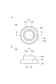
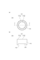
図1(a)は、本実施の形態1に係る医療用キャップを表す断面模式図であり、同図(b)は当該医療用キャップを薬剤容器に取り付けた様子を表す断面模式図である。図2は、同図(a)は前記医療用キャップにおける弾性栓体の針刺面を模式的に表す平面図であり、同図(b)は前記弾性栓体を表す断面模式図である。尚、図1(a)に於いては、図示したものの方向関係を明確にするために、適宜XYZ直交座標軸を表示する。図1に於いて、XY平面は水平面を表し、十Z方向は鉛直上向きを表す。 FIG. 1A is a schematic cross-sectional view showing a medical cap according to the first embodiment, and FIG. 1B is a schematic cross-sectional view showing a state in which the medical cap is attached to a drug container. 2A and 2B are plan views schematically showing the needle stick surface of the elastic plug in the medical cap, and FIG. 2B is a schematic cross-sectional view showing the elastic plug. In FIG. 1A, the XYZ orthogonal coordinate axes are appropriately displayed in order to clarify the directional relationship of the illustrated ones. In FIG. 1, the XY plane represents a horizontal plane, and the ten-Z direction represents a vertically upward direction.

図1に示すように、本実施の形態の医療用キャップ10は、弾性栓体11と、弾性栓体11を内部に保持する外枠体12とを少なくとも有する。弾性栓体11と外枠体12は、両者の接触面において熱溶着している(詳細については後述する。)。これにより、弾性栓体11が外枠体12から脱落するのを防止し、針刺しの際には弾性栓体11と外枠体12の位置ずれによる空隙の発生も防止することができる。その結果、密閉性を向上させ、薬液や輸液等の漏洩の防止、空気との接触による変質の防止も可能になる。 As shown in FIG. 1, the medical cap 10 of the present embodiment has at least an elastic plug 11 and an outer frame 12 that holds the elastic plug 11 inside. The elastic plug 11 and the outer frame 12 are heat-welded at the contact surface between them (details will be described later). As a result, it is possible to prevent the elastic plug 11 from falling off from the outer frame 12, and to prevent the generation of voids due to the misalignment between the elastic plug 11 and the outer frame 12 during needle sticking. As a result, it is possible to improve the airtightness, prevent leakage of chemicals and infusions, and prevent deterioration due to contact with air.

ここで、「熱溶着」とは、後述の通り、外枠体12を射出成形等により成形する際に注入される溶融樹脂の熱により、これに接した弾性栓体11の表面が溶融した結果、当該外枠体12の成形後に、外枠体12と弾性栓体11とがその接触面において結合した状態にあることを意味する。 Here, "heat welding" is a result of melting the surface of the elastic plug 11 in contact with the outer frame body 12 by the heat of the molten resin injected when the outer frame body 12 is molded by injection molding or the like, as described later. It means that the outer frame body 12 and the elastic plug 11 are in a state of being bonded at the contact surface thereof after the outer frame body 12 is molded.

弾性栓体11の全体形状は、図1及び図2に示す様に略円柱状である。但し、本発明は、これに限定されるものではなく、例えば略円錐台状であってもよい。またその他に、後述の種々の形状のものを採用することもできる。 The overall shape of the elastic plug 11 is substantially cylindrical as shown in FIGS. 1 and 2. However, the present invention is not limited to this, and may be, for example, a substantially truncated cone shape. In addition, various shapes described later can be adopted.

弾性栓体11は、外枠体12の内部に、天面部111を上側(図1(a)では+Z方向)にし、底面部112を下側にして収容されている。天面部111は、その周縁部111aを除き、針刺面111bとなっている。ここで「針刺面」とは、本実施の形態に係る医療用キャップ10が薬剤容器に装着され、薬液等を取り出す際に、穿刺針により針刺しが行われる面を意味する。尚、天面部111の周縁部111aは外枠体12の一部に覆われ、接触面で熱溶着している(図2(a)ではハッチングされた領域を表す。)。また、針刺面111bには、穿刺針により刺通する際の位置指標の役目を果たす凹部(図示しない)が少なくとも1つ設けられていてもよい。 The elastic plug 11 is housed inside the outer frame 12 with the top surface portion 111 on the upper side (+ Z direction in FIG. 1A) and the bottom surface portion 112 on the lower side. The top surface portion 111 has a needle stick surface 111b except for the peripheral portion 111a thereof. Here, the "needle puncture surface" means a surface on which the medical cap 10 according to the present embodiment is attached to the drug container and the needle puncture is performed by the puncture needle when taking out the drug solution or the like. The peripheral edge portion 111a of the top surface portion 111 is covered with a part of the outer frame body 12 and is heat-welded on the contact surface (in FIG. 2A, the hatched region is represented). Further, the needle puncture surface 111b may be provided with at least one recess (not shown) that serves as a position index when puncturing with a puncture needle.

底面部112は、その全面が接液面となっている。ここで「接液面」とは、薬剤容器に貯蔵されている薬液等が接する面を意味する。 The entire surface of the bottom surface portion 112 is a wetted surface. Here, the "contact surface" means a surface in contact with the chemical solution or the like stored in the pharmaceutical container.

弾性栓体11の側周部113には、弾性栓体11を金型に係合させるための被係合部114が設けられている。これにより、例えば弾性栓体11の成形後、金型の型開きの際に、成形された弾性栓体11を金型に係合させ固定させることができる。側周部113において、被係合部114の形成位置より上方(以下、「側周部上方」という)113aは、外枠体12の内壁面と熱溶着している。その一方、被係合部114及び当該被係合部114の形成位置より下方(以下、「側周部下方」という)113bは、外枠体12の内壁面と接しておらず、開口している(図1参照)。 The side peripheral portion 113 of the elastic plug 11 is provided with an engaged portion 114 for engaging the elastic plug 11 with the mold. Thereby, for example, after the elastic plug 11 is molded, the molded elastic plug 11 can be engaged with and fixed to the mold when the mold is opened. In the side peripheral portion 113, the portion 113a above the formation position of the engaged portion 114 (hereinafter referred to as “above the side peripheral portion”) 113a is heat-welded to the inner wall surface of the outer frame body 12. On the other hand, the engaged portion 114 and the portion 113b below the formed position of the engaged portion 114 (hereinafter referred to as "lower side peripheral portion") are not in contact with the inner wall surface of the outer frame body 12 and are open. (See Fig. 1).

本実施の形態において、側周部上方113aと被係合部114の境界には、パーティングラインPLが設けられている。パーティングラインPLは、後述の通り、弾性栓体11を成形するための一対の金型の接合面(あるいは分割位置)に対応して形成される。尚、本実施の形態において、パーティングラインPLは被係合部114よりも上方(図1(a)では、+Z方向)、すなわち、側周部上方113aにおける任意の位置に設けられることが必要となる。被係合部114や側周部下方113bにパーティングラインPLが設けられる場合であると、一対の金型の分割位置が当該被係合部114や側周部下方113bまで下がり、被係合部114を金型に係合させることが困難になるからである。 In the present embodiment, a parting line PL is provided at the boundary between the upper side peripheral portion 113a and the engaged portion 114. As will be described later, the parting line PL is formed corresponding to the joint surface (or division position) of the pair of molds for forming the elastic plug 11. In the present embodiment, the parting line PL needs to be provided above the engaged portion 114 (in the + Z direction in FIG. 1A), that is, at an arbitrary position above the side peripheral portion 113a. Will be. When the parting line PL is provided at the engaged portion 114 or the lower side peripheral portion 113b, the split position of the pair of molds is lowered to the engaged portion 114 or the lower peripheral portion 113b, and is engaged. This is because it becomes difficult to engage the portion 114 with the mold.

被係合部114は環状凹部からなる。被係合部114の深さh及び幅d(図2(b)参照)は、弾性栓体11を金型に係合させ固定させることができる程度であれば特に限定されず、適宜設定することができる。尚、弾性栓体11の高さ及び直径も特に限定されず、適宜必要に応じて設定することができる。 The engaged portion 114 is formed of an annular recess. The depth h and width d (see FIG. 2B) of the engaged portion 114 are not particularly limited as long as the elastic stopper 11 can be engaged and fixed to the mold, and are appropriately set. be able to. The height and diameter of the elastic plug 11 are not particularly limited, and can be appropriately set as needed.

側周部113は、微細な凹凸構造の表面を有する。これにより、弾性栓体11の成形の際に、キャビティ23内に存在する空気を外部に排出させることが可能になり、側周部113にエアベントの機能を付与することができる。また、側周部下方113b及び被係合部114の表面を微細な凹凸構造にすることで、被係合部114を金型に係合させ、弾性栓体11を当該金型に固定させる際に、金型との接触面での摩擦抵抗を増大させ、当該金型との係合を強くすることができる。ここで、側周部上方113aと、側周部下方113b及び被係合部114とでは、凹凸構造における凹凸の程度(表面粗さ)が異なる。具体的には、側周部上方113aの凹凸構造の方が、側周部下方113b及び被係合部114の凹凸構造と比較して、凹凸の程度(表面粗さ)が小さい。これにより、金型開きの際に、弾性栓体11が金型に固定されず、離型不良が発生するのを防止することができる。尚、表面を微細な凹凸構造とする部分は側周部下方113b又は被係合部114の何れか一方であってもよい。また、側周部上方113aは平滑面であってもよい。これにより、金型の型開きを一層容易にし、離型不良の発生をさらに低減することができる。 The side peripheral portion 113 has a surface having a fine uneven structure. As a result, when the elastic plug 11 is formed, the air existing in the cavity 23 can be discharged to the outside, and the side peripheral portion 113 can be provided with the function of an air vent. Further, when the surface of the lower side peripheral portion 113b and the engaged portion 114 has a fine uneven structure, the engaged portion 114 is engaged with the mold and the elastic plug 11 is fixed to the mold. In addition, the frictional resistance at the contact surface with the mold can be increased, and the engagement with the mold can be strengthened. Here, the degree of unevenness (surface roughness) in the uneven structure differs between the upper side peripheral portion 113a, the lower side peripheral portion 113b, and the engaged portion 114. Specifically, the uneven structure of the upper side peripheral portion 113a has a smaller degree of unevenness (surface roughness) than the uneven structure of the lower side peripheral portion 113b and the engaged portion 114. As a result, when the mold is opened, the elastic stopper 11 is not fixed to the mold, and it is possible to prevent a mold release defect from occurring. The portion having a fine concavo-convex structure on the surface may be either the lower side peripheral portion 113b or the engaged portion 114. Further, the upper 113a of the side peripheral portion may be a smooth surface. This makes it easier to open the mold and further reduces the occurrence of mold release defects.

また、天面部111及び底面部112の表面にも、微細な凹凸構造を設けてもよい。天面部111の表面に微細な凹凸構造を設けることにより、当該天面部111においてもキャビティ23内に存在する空気を外部に排出させることが可能になり、エアベントの機能を一層高めることができる。さらに天面部111の表面に微細な凹凸構造を設けることは、例えば、コンプレッション成形にて弾性栓体11を成形する際の外観不良の低減を可能にする。また、インジェクション成形にて弾性栓体11を成形する際にも、ウェルドラインの発生を低減し、外観不良も低減することができる。尚、天面部111及び底面部112の表面は微細な凹凸構造である場合のほか、平坦状であってもよい。 Further, fine uneven structures may be provided on the surfaces of the top surface portion 111 and the bottom surface portion 112. By providing a fine uneven structure on the surface of the top surface portion 111, the air existing in the cavity 23 can be discharged to the outside even in the top surface portion 111, and the function of the air vent can be further enhanced. Further, providing a fine uneven structure on the surface of the top surface portion 111 makes it possible to reduce appearance defects when the elastic plug 11 is formed by, for example, compression molding. Further, when the elastic stopper 11 is molded by injection molding, the generation of weld lines can be reduced and the appearance defect can be reduced. The surfaces of the top surface portion 111 and the bottom surface portion 112 may have a fine uneven structure or may be flat.

側周部上方113aの凹凸構造の表面粗さは、側周部下方113b及び被係合部114よりも凹凸の程度が小さく、かつ、エアベントとしての機能を果たすことが可能なものであれば特に限定されない。また、側周部下方113b及び被係合部114の凹凸構造の表面粗さは、金型との摩擦抵抗を増大させることが可能な程度であれば特に限定されず、適宜設定することができる。さらに、天面部111及び底面部112の凹凸構造の表面粗さについても特に限定されず、適宜必要に応じて設定すればよい。 The surface roughness of the uneven structure of the upper side peripheral portion 113a is particularly small as long as the degree of unevenness is smaller than that of the lower side peripheral portion 113b and the engaged portion 114 and can function as an air vent. Not limited. Further, the surface roughness of the uneven structure of the lower side peripheral portion 113b and the engaged portion 114 is not particularly limited as long as it can increase the frictional resistance with the mold, and can be appropriately set. .. Further, the surface roughness of the uneven structure of the top surface portion 111 and the bottom surface portion 112 is not particularly limited, and may be appropriately set as necessary.

前記弾性栓体11に用いる材料としては、例えば、ゴムや熱可塑性エラストマー樹脂が挙げられる。前記ゴムとしては特に限定されず、例えば、天然ゴム、イソプレンゴム、ブタジエンゴム、スチレン-ブタジエンゴム、イソプレン-イソブチレンゴム等が例示できる。また、熱可塑性エラストマー樹脂としては特に限定されず、例えば、オレフィン系、スチレン系、ポリウレタン系、ポリエステル系、ポリ塩化ビニル系、ポリブタジエン系、ポリアミド系、ポリウレタン系等が例示できる。中でも共役ジエン系の熱可塑性エラストマーに水素添加した熱可塑性エラストマー(SEBS、SEPS、HSBR、SEBR、CEBC)が好適である。これらの熱可塑性エラストマー樹脂は単独で又は2種以上を併用することができる。 Examples of the material used for the elastic stopper 11 include rubber and a thermoplastic elastomer resin. The rubber is not particularly limited, and examples thereof include natural rubber, isoprene rubber, butadiene rubber, styrene-butadiene rubber, and isoprene-isoprene rubber. The thermoplastic elastomer resin is not particularly limited, and examples thereof include olefin-based, styrene-based, polyurethane-based, polyester-based, polyvinyl chloride-based, polybutadiene-based, polyamide-based, and polyurethane-based resins. Of these, thermoplastic elastomers (SEBS, SEPS, HSBR, SEBR, CEBC) obtained by hydrogenating a conjugated diene-based thermoplastic elastomer are preferable. These thermoplastic elastomer resins can be used alone or in combination of two or more.

弾性栓体11の特性については特に限定されず、医療用注入針等が貫通できる程度の硬度を有していればよい。また、通常の保管の際に容易に変形したり、破損したりしない程度の形状保持性を有するものが好ましい。弾性栓体11の硬度は、JIS K6253法による測定に於いて、A5~A50であることが好ましく、A10~A45であることがより好ましい。 The characteristics of the elastic plug 11 are not particularly limited, and may be sufficient as long as it has a hardness enough to allow a medical injection needle or the like to penetrate. Further, it is preferable that the shape retainability is such that it is not easily deformed or damaged during normal storage. The hardness of the elastic plug 11 is preferably A5 to A50, more preferably A10 to A45 in the measurement by the JIS K6253 method.

外枠体12は、全体形状が略円筒状の本体部12aと、接合用フランジ部12bとを少なくとも備える。本体部12aは、弾性栓体11の側周部上方113aと熱溶着している本体部上方121と、当該本体部上方121よりも厚さが小さい本体部下方122と、当該本体部上方121と本体部下方122を接続する段差123とを有している。本体部上方121と本体部下方122の直径は略同一である。本体部上方121の内周面は弾性栓体11の側周部上方113aと熱溶着している。また、本体部上方121の端部には環状の張り出し部124が設けられており、当該張り出し部124は、弾性栓体11の天面部111における周縁部111aと熱溶着している。その一方、本体部下方122及び段差123は弾性栓体11と接していない。接合用フランジ部12bは、本体部12aの端部に設けられており、薬剤容器の口部との接合に用いられる(詳細については後述する。)。 The outer frame body 12 includes at least a main body portion 12a having a substantially cylindrical overall shape and a flange portion 12b for joining. The main body portion 12a includes an upper main body portion 121 that is heat-welded to the upper side peripheral portion 113a of the elastic plug 11, a lower main body portion 122 that is thinner than the upper main body portion 121, and the upper main body portion 121. It has a step 123 connecting the lower portion 122 of the main body. The diameters of the upper part 121 of the main body and the lower part 122 of the main body are substantially the same. The inner peripheral surface of the main body upper portion 121 is heat-welded to the side peripheral portion upper portion 113a of the elastic plug body 11. Further, an annular overhanging portion 124 is provided at the end of the upper portion 121 of the main body portion, and the overhanging portion 124 is heat-welded to the peripheral edge portion 111a of the top surface portion 111 of the elastic plug body 11. On the other hand, the lower portion 122 of the main body and the step 123 are not in contact with the elastic plug 11. The joining flange portion 12b is provided at the end of the main body portion 12a and is used for joining with the mouth portion of the drug container (details will be described later).

外枠体12を構成する材料としては、合成樹脂のうち、医療用途としての安全性が確立されたものであれば足りる。中でも熱可塑性樹脂を用いるのが一般的である。具体的には、ポリエチレン、ポリプロピレン、ポリエステル、ポリ塩化ビニル、ポリオレフィン、ポリエチレンテレフタレート樹脂等の従来医療用途に用いられている樹脂が好ましい。これらは単独で又は2種以上を併用することができる。 As the material constituting the outer frame body 12, any synthetic resin having established safety for medical use is sufficient. Of these, it is common to use a thermoplastic resin. Specifically, resins conventionally used for medical applications such as polyethylene, polypropylene, polyester, polyvinyl chloride, polyolefin, and polyethylene terephthalate resin are preferable. These can be used alone or in combination of two or more.

次に、本実施の形態の医療用キャップ10を輸液容器等の薬剤容器に適用する場合について説明する。図1(b)に示すように、薬剤容器の口部14は、全体が略円筒状を成しており、外周面に環状鍔14aを有している。医療用キャップ10を口部14に取り付ける際には、外枠体12の接合用フランジ部12bと、口部14の環状鍔14aとを超音波溶着や加熱溶着等の手法により接合する。口部14の構成材料は特に限定されず、例えば、外枠体12の構成材料と同様のものを採用することができる。 Next, a case where the medical cap 10 of the present embodiment is applied to a drug container such as an infusion container will be described. As shown in FIG. 1 (b), the mouth portion 14 of the drug container has a substantially cylindrical shape as a whole, and has an annular collar 14a on the outer peripheral surface. When the medical cap 10 is attached to the mouth portion 14, the joining flange portion 12b of the outer frame body 12 and the annular flange portion 14a of the mouth portion 14 are joined by a method such as ultrasonic welding or heat welding. The constituent material of the mouth portion 14 is not particularly limited, and for example, the same constituent material as that of the outer frame body 12 can be adopted.

[医療用キャップの製造方法]
次に、本実施の形態に係る医療用キャップの製造方法について、図3に基づき説明する。図3は、医療用キャップの製造方法を説明するための断面模式図であって、同図(a)は一対の金型が型閉じされ、弾性栓体成形用のキャビティが形成される様子を表し、同図(b)は弾性栓体が成形された後の金型を型開きする様子を表し、同図(c)は外枠体を成形する様子を表し、同図(d)は成形後の医療用キャップを表す。
[Manufacturing method of medical cap]
Next, a method for manufacturing the medical cap according to the present embodiment will be described with reference to FIG. FIG. 3 is a schematic cross-sectional view for explaining a method for manufacturing a medical cap, and FIG. 3A shows a state in which a pair of molds are closed to form a cavity for forming an elastic stopper. The figure (b) shows how the mold is opened after the elastic stopper is molded, the figure (c) shows the state of molding the outer frame, and the figure (d) shows the molding. Represents a later medical cap.

本実施の形態に係る医療用キャップの製造方法は2色成形法を利用するものであり、弾性栓体11を成形する弾性栓体成形工程と、当該弾性栓体11を内部に保持する外枠体12を成形する外枠体成形工程とを含む。 The method for manufacturing a medical cap according to the present embodiment uses a two-color molding method, and includes an elastic stopper molding step for molding the elastic stopper 11 and an outer frame for holding the elastic stopper 11 inside. It includes an outer frame body forming step of forming the body 12.

先ず、図3(a)に示すように、弾性栓体成形工程は、第1金型21と第2金型22を用いて、弾性栓体11を射出成形する。第1金型21はコア(雄型、可動側金型又は下金型)であり、第2金型22はキャビティ(雌型、固定側金型又は上金型)である。第1金型21と第2金型22は、両者を型閉じした際、弾性栓体11の成形が可能な弾性栓体成形用のキャビティ23が形成される構造となっている。また、第1金型21と第2金型22の型閉じにより形成される接合面212の位置は、弾性栓体11の側周部上方113aと被係合部114の境界にパーティングラインPLが形成されるように設定されている。 First, as shown in FIG. 3A, in the elastic stopper molding step, the elastic stopper 11 is injection-molded using the first mold 21 and the second mold 22. The first mold 21 is a core (male mold, movable side mold or lower mold), and the second mold 22 is a cavity (female mold, fixed side mold or upper mold). The first mold 21 and the second mold 22 have a structure in which a cavity 23 for forming an elastic plug 11 is formed when both are closed. Further, the position of the joint surface 212 formed by closing the first mold 21 and the second mold 22 is the parting line PL at the boundary between the upper side peripheral portion 113a of the elastic plug 11 and the engaged portion 114. Is set to be formed.

第1金型21は、弾性栓体11の被係合部114を成形することが可能な係合部211を有している。係合部211は、円筒状の内周面に環状の凸部が設けられた、凹部成形用凸部からなる。これにより、弾性栓体11の側周部113に環状凹部からなる被係合部114を形成することが可能になる。また、係合部211の内周面や、弾性栓体11の側周部下方113b及び底面部112を形成する内側面には粗面化処理がなされており、これにより当該係合部211の内周面等は微細な凹凸構造となっている。粗面化処理の方法としては特に限定されず、ブラストショットやエッチング、放電加工等のシボ加工が挙げられる。尚、第2金型22の内側面の全面(弾性栓体11の側周部上方113a及び天面部111を形成する面)も粗面化処理により微細な凹凸構造が設けられている。但し、弾性栓体11の側周部上方113a及び天面部111の表面を平坦にする場合は、第2金型22の内側面も平滑状にするのが好ましい。 The first mold 21 has an engaging portion 211 capable of forming the engaged portion 114 of the elastic plug 11. The engaging portion 211 is formed of a concave portion forming convex portion in which an annular convex portion is provided on a cylindrical inner peripheral surface. This makes it possible to form an engaged portion 114 formed of an annular recess in the side peripheral portion 113 of the elastic plug body 11. Further, the inner peripheral surface of the engaging portion 211 and the inner side surface forming the side peripheral portion lower 113b and the bottom surface portion 112 of the elastic plug 11 are roughened, whereby the engaging portion 211 of the engaging portion 211 is subjected to roughening treatment. The inner peripheral surface and the like have a fine uneven structure. The roughening treatment method is not particularly limited, and examples thereof include grain processing such as blast shot, etching, and electric discharge machining. The entire inner surface of the second mold 22 (the surface forming the upper side peripheral portion 113a and the top surface portion 111 of the elastic plug 11) is also provided with a fine uneven structure by roughening treatment. However, when the surfaces of the elastic stopper 11 above the side peripheral portion 113a and the top surface portion 111 are flattened, it is preferable that the inner side surface of the second mold 22 is also smoothed.

弾性栓体11の成形は、弾性栓体11の構成材料となる樹脂を溶融した溶融樹脂を、弾性栓体成形用のキャビティ23内に注入して行う。溶融樹脂の注入後、冷却し、これにより被係合部114を備えた弾性栓体11を成形することができる。さらに、成形された弾性栓体11の被係合部114及び側周部下方113bの表面には、微細な凹凸構造が設けられている。尚、第1金型21の係合部211の内周面等や第2金型22の内側面には微細な凹凸構造が設けられているため、弾性栓体11の成形の際には、キャビティ23内の空気を外部に排出させることができ、エアベントとしての機能を発揮させることができる。 The elastic plug 11 is formed by injecting a molten resin obtained by melting a resin that is a constituent material of the elastic plug 11 into a cavity 23 for forming the elastic plug. After the molten resin is injected, it is cooled, whereby the elastic plug 11 provided with the engaged portion 114 can be formed. Further, a fine uneven structure is provided on the surfaces of the engaged portion 114 and the lower peripheral portion 113b of the molded elastic plug 11. Since the inner peripheral surface of the engaging portion 211 of the first mold 21 and the inner side surface of the second mold 22 are provided with a fine uneven structure, when the elastic stopper 11 is molded, the elastic plug 11 is formed. The air in the cavity 23 can be discharged to the outside, and the function as an air vent can be exhibited.

前記溶融樹脂の射出圧力としては特に限定されず、適宜必要に応じて設定され得る。射出された溶融樹脂は、弾性栓体成形用のキャビティ23内で冷却される。冷却時間は特に限定されず、適宜必要に応じて設定され得る。 The injection pressure of the molten resin is not particularly limited and may be appropriately set as needed. The injected molten resin is cooled in the cavity 23 for forming an elastic plug. The cooling time is not particularly limited and may be set as needed.

次に、図3(b)に示すように、第1金型21と第2金型22の型開きを行う。このとき、弾性栓体11は、被係合部114を第1金型21の係合部211に係合させることにより第1金型21に固定されている。また、弾性栓体11の被係合部114及び側周部下方113bの表面には、微細な凹凸構造が設けられており、さらに被係合部114と係合している第1金型21の係合部211の内周面にも微細な凹凸構造が設けられている。そのため、被係合部114と係合部211の係合は容易に解除され難くなっている。その上、第2金型22の内側面の凹凸構造は、第1金型21の係合部211の凹凸構造よりも凹凸の程度が小さいことから、弾性栓体11と第2金型22との離型が容易となっている。これにより、本実施の形態においては、第1金型21と第2金型22との型開きの際に、弾性栓体11が第2金型22に密着して離型不良が発生するのを防止することができる。その結果、製造効率の低下を防止することができる。 Next, as shown in FIG. 3B, the first mold 21 and the second mold 22 are opened. At this time, the elastic plug 11 is fixed to the first mold 21 by engaging the engaged portion 114 with the engaging portion 211 of the first mold 21. Further, the surface of the engaged portion 114 and the lower peripheral portion 113b of the elastic plug 11 is provided with a fine uneven structure, and the first mold 21 is further engaged with the engaged portion 114. A fine uneven structure is also provided on the inner peripheral surface of the engaging portion 211 of the above. Therefore, the engagement between the engaged portion 114 and the engaging portion 211 is difficult to be easily disengaged. Moreover, since the uneven structure of the inner surface of the second mold 22 has a smaller degree of unevenness than the uneven structure of the engaging portion 211 of the first mold 21, the elastic plug 11 and the second mold 22 It is easy to release the mold. As a result, in the present embodiment, when the first mold 21 and the second mold 22 are opened, the elastic stopper 11 comes into close contact with the second mold 22 and a mold release defect occurs. Can be prevented. As a result, it is possible to prevent a decrease in manufacturing efficiency.

続いて、図3(c)に示すように、外枠体成形工程を行う。本工程は、弾性栓体11を第1金型21に固定させた状態で行う。また、本工程は、第1金型21と、当該第1金型21との型閉じにより外枠体成形用のキャビティ24を形成することが可能な第4金型25とを用いて行う。従って、第1金型21は外枠体12の成形にも適用可能な共通金型(第3金型)として機能する。具体的には、弾性栓体11を内部に収容した状態で、外枠体12の構成材料となる樹脂を溶融した溶融樹脂を、外枠体成形用のキャビティ24内に注入して行う。溶融樹脂の射出圧力としては特に限定されず、適宜必要に応じて設定され得る。射出された溶融樹脂は、型閉じされた状態で冷却される。冷却時間は特に限定されず、適宜必要に応じて設定され得る。 Subsequently, as shown in FIG. 3C, an outer frame body forming step is performed. This step is performed in a state where the elastic plug 11 is fixed to the first mold 21. Further, this step is performed using a first mold 21 and a fourth mold 25 capable of forming a cavity 24 for forming an outer frame by closing the mold 21 with the first mold 21. Therefore, the first mold 21 functions as a common mold (third mold) applicable to the molding of the outer frame body 12. Specifically, in a state where the elastic plug 11 is housed inside, a molten resin obtained by melting a resin that is a constituent material of the outer frame 12 is injected into a cavity 24 for forming the outer frame. The injection pressure of the molten resin is not particularly limited and may be appropriately set as needed. The injected molten resin is cooled in a closed state. The cooling time is not particularly limited and may be set as needed.

第1金型21と第4金型25との型開き後、図3(d)に示すように、弾性栓体11を内部に保持した外枠体12が得られる。また、外枠体12は弾性栓体11との接触面において熱溶着している。 After opening the molds of the first mold 21 and the fourth mold 25, as shown in FIG. 3D, an outer frame body 12 holding the elastic plug 11 inside is obtained. Further, the outer frame body 12 is heat-welded on the contact surface with the elastic plug body 11.

以上により、本実施の形態に係る医療用キャップ10を製造することができる。本実施の形態の医療用キャップの製造方法によれば、弾性栓体成形工程において、係合部211を有する第1金型21を用いて弾性栓体11に被係合部114を形成すると共に、当該被係合部114を第1金型21の係合部211に係合させて固定した状態で、第1金型21と第2金型22の型開きを行う。そのため、弾性栓体11がキャビティである第2金型22内に取り残されるのを防止することができる。その結果、製造効率の低下を抑制した医療用キャップの製造方法を提供することができる。 From the above, the medical cap 10 according to the present embodiment can be manufactured. According to the method for manufacturing a medical cap of the present embodiment, in the elastic stopper forming step, the engaged portion 114 is formed on the elastic stopper 11 by using the first mold 21 having the engaging portion 211. The first mold 21 and the second mold 22 are opened in a state where the engaged portion 114 is engaged with and fixed to the engaging portion 211 of the first mold 21. Therefore, it is possible to prevent the elastic plug 11 from being left behind in the second mold 22 which is a cavity. As a result, it is possible to provide a method for manufacturing a medical cap in which a decrease in manufacturing efficiency is suppressed.

[その他の事項]
本実施の形態においては、弾性栓体として、側周部113に環状凹部からなる被係合部114を備えた態様を例にして説明したが、本発明はこれに限定されない。例えば、図4~図11に示す形状の弾性栓体に適宜変更することができる。
[Other matters]
In the present embodiment, the embodiment in which the side peripheral portion 113 is provided with the engaged portion 114 composed of the annular recess is described as an example of the elastic plug, but the present invention is not limited thereto. For example, the elastic plug body having the shapes shown in FIGS. 4 to 11 can be appropriately changed.

例えば、本発明は、図4(a)及び4(b)に示すように、底面部112の周縁部(側周部113の端部)に環状凹部からなる被係合部132が設けられた弾性栓体131であってもよい。被係合部132は、天面部111に向かうに従い先細りのテーパ状(第1金型21に弾性栓体131を係合させた状態においては、当該第1金型21から離れる方向に先細りのテーパ状)となる縦断面形状を有している。これにより、弾性栓体131の被係合部132を第1金型21の係合部に強固に係合させることができ、弾性栓体131が第1金型21から脱離するのを一層規制することができる。また、このような形状の弾性栓体131の場合、パーティングラインPLは被係合部132に対し上方の天面部111側に設けられる。 For example, in the present invention, as shown in FIGS. 4A and 4B, an engaged portion 132 made of an annular recess is provided on the peripheral edge portion (end portion of the side peripheral portion 113) of the bottom surface portion 112. It may be an elastic plug 131. The engaged portion 132 has a tapered shape that tapers toward the top surface portion 111 (in a state where the elastic stopper 131 is engaged with the first mold 21, it tapers in a direction away from the first mold 21). It has a vertical cross-sectional shape. As a result, the engaged portion 132 of the elastic plug 131 can be firmly engaged with the engaging portion of the first mold 21, and the elastic plug 131 is further prevented from being disengaged from the first mold 21. Can be regulated. Further, in the case of the elastic plug body 131 having such a shape, the parting line PL is provided on the top surface portion 111 side above the engaged portion 132.

尚、被係合部132に係合する第1金型21の係合部は、型閉じする第2金型22から離れる方向に先細りのテーパ状となる縦断面形状を有するものとなる。また、被係合部132の表面を微細な凹凸構造にし、弾性栓体131の被係合部132を第1金型21の係合部にさらに強固に係合させるようにしてもよい。さらに、側周部113の表面を微細な凹凸構造にすることにより、当該側周部113の表面にエアベントとしての機能を付与してもよい。この場合、側周部113の表面を、被係合部132の凹凸構造よりも凹凸の程度が小さい凹凸構造にすることで、型開きの際に、弾性栓体131が第2金型22に密着して離型不良が発生するのを一層防止することができる。 The engaging portion of the first mold 21 that engages with the engaged portion 132 has a vertical cross-sectional shape that tapers in a direction away from the second mold 22 that closes the mold. Further, the surface of the engaged portion 132 may have a fine uneven structure so that the engaged portion 132 of the elastic plug 131 is more firmly engaged with the engaging portion of the first mold 21. Further, the surface of the side peripheral portion 113 may be provided with a function as an air vent by forming the surface of the side peripheral portion 113 into a fine uneven structure. In this case, by forming the surface of the side peripheral portion 113 into an uneven structure having a smaller degree of unevenness than the uneven structure of the engaged portion 132, the elastic plug 131 becomes the second mold 22 at the time of mold opening. It is possible to further prevent the occurrence of mold release defects due to close contact.

また、本発明は、図5(a)及び5(b)に示すように、側周部上方113aよりも直径の大きい側周部下方113bに環状凹部からなる被係合部134を備えた弾性栓体133であってもよい。このような場合でも、弾性栓体133の被係合部134を第1金型21の係合部に係合させることができ、弾性栓体133が第1金型21から脱離するのを規制することができる。また、このような形状の弾性栓体133の場合、パーティングラインPLは側周部上方113aと側周部下方113bの境界に設けられるのが好ましい。但し、パーティングラインPLの位置に関し、本発明はこの態様に限定されるものではなく、側周部上方113aと側周部下方113bの境界から被係合部134までの間の任意の位置に設けることが可能である。 Further, as shown in FIGS. 5 (a) and 5 (b), the present invention is elastic with an engaged portion 134 made of an annular recess in the lower side peripheral portion 113b having a larger diameter than the upper side peripheral portion 113a. It may be a plug 133. Even in such a case, the engaged portion 134 of the elastic stopper body 133 can be engaged with the engaging portion of the first mold 21, and the elastic stopper body 133 can be disengaged from the first mold 21. Can be regulated. Further, in the case of the elastic plug body 133 having such a shape, it is preferable that the parting line PL is provided at the boundary between the upper side peripheral portion 113a and the lower side peripheral portion 113b. However, the present invention is not limited to this aspect with respect to the position of the parting line PL, and the present invention is at an arbitrary position between the boundary between the upper side peripheral portion 113a and the lower side peripheral portion 113b and the engaged portion 134. It is possible to provide.

尚、弾性栓体133に被係合部134を形成し、かつ、当該被係合部134に係合可能にする第1金型21の係合部は、環状の凹部成形用凸部からなる。また、被係合部134は、天面部111に向かうに従い先細りのテーパ状(第1金型21に弾性栓体133を係合させた状態においては、当該第1金型21から離れる方向に先細りのテーパ状)となる縦断面形状を有していてもよい。さらに、被係合部134の表面を微細な凹凸構造にし、弾性栓体133の被係合部134を第1金型21の係合部にさらに強固に係合させるようにしてもよい。また、側周部上方113aの表面を微細な凹凸構造にすることにより、当該側周部上方113aの表面にもエアベントとしての機能を付与してもよい。この場合、側周部上方113aの表面を、被係合部134の凹凸構造よりも凹凸の程度が小さい凹凸構造にすることで、型開きの際に、弾性栓体133が第2金型22に密着して離型不良が発生するのを一層防止することができる。 The engaging portion of the first mold 21 that forms the engaged portion 134 on the elastic plug 133 and makes it engageable with the engaged portion 134 is composed of an annular concave portion forming convex portion. .. Further, the engaged portion 134 has a tapered shape that tapers toward the top surface portion 111 (in a state where the elastic stopper 133 is engaged with the first mold 21, it tapers in a direction away from the first mold 21). It may have a vertical cross-sectional shape (tapered). Further, the surface of the engaged portion 134 may have a fine uneven structure so that the engaged portion 134 of the elastic plug 133 is more firmly engaged with the engaging portion of the first mold 21. Further, by forming the surface of the upper side peripheral portion 113a into a fine uneven structure, the surface of the upper side peripheral portion 113a may also be provided with a function as an air vent. In this case, by forming the surface of the upper side peripheral portion 113a into a concave-convex structure having a smaller degree of unevenness than the concave-convex structure of the engaged portion 134, the elastic stopper 133 is used as the second mold 22 at the time of mold opening. It is possible to further prevent the mold release defect from occurring due to close contact with the mold.

また、本発明は、図6(a)及び6(b)に示すように、底面部112の周縁部(側周部下方113bの端部)に環状凹部からなる被係合部136が設けられた弾性栓体135であってもよい。被係合部136は、天面部111に向かうに従い先細りのテーパ状(第1金型21に弾性栓体135を係合させた状態においては、当該第1金型21から離れる方向に先細りのテーパ状)となる縦断面形状を有している。このような場合でも、弾性栓体135の被係合部136を第1金型21の係合部に係合させることができ、弾性栓体135が第1金型21から脱離するのを規制することができる。また、このような形状の弾性栓体135の場合、パーティングラインPLは側周部上方113aと側周部下方113bの境界に設けられるのが好ましい。但し、パーティングラインPLの位置に関し、本発明はこの態様に限定されるものではなく、側周部上方113aと側周部下方113bの境界から被係合部136までの間の任意の位置に設けることが可能である。 Further, in the present invention, as shown in FIGS. 6A and 6B, an engaged portion 136 composed of an annular recess is provided on the peripheral edge portion of the bottom surface portion 112 (the end portion of the side peripheral portion lower 113b). It may be an elastic plug body 135. The engaged portion 136 has a tapered shape that tapers toward the top surface portion 111 (in a state where the elastic stopper 135 is engaged with the first mold 21, the tapered portion is tapered in a direction away from the first mold 21). It has a vertical cross-sectional shape. Even in such a case, the engaged portion 136 of the elastic stopper body 135 can be engaged with the engaging portion of the first mold 21, and the elastic stopper body 135 can be disengaged from the first mold 21. Can be regulated. Further, in the case of the elastic plug body 135 having such a shape, it is preferable that the parting line PL is provided at the boundary between the upper side peripheral portion 113a and the lower side peripheral portion 113b. However, the present invention is not limited to this aspect with respect to the position of the parting line PL, and at an arbitrary position between the boundary between the upper side peripheral portion 113a and the lower peripheral portion 113b and the engaged portion 136. It is possible to provide.

尚、被係合部136に係合する第1金型21の係合部は、型閉じする第2金型22から離れる方向に先細りのテーパ状となる縦断面形状を有するものとなる。また、被係合部136の表面を微細な凹凸構造にし、弾性栓体135の被係合部136を第1金型21の係合部にさらに強固に係合させるようにしてもよい。さらに、側周部上方113aの表面を微細な凹凸構造にすることにより、当該側周部上方113aの表面にもエアベントとしての機能を付与してもよい。この場合、側周部上方113aの表面を、被係合部136の凹凸構造よりも凹凸の程度が小さい凹凸構造にすることで、型開きの際に、弾性栓体135が第2金型22に密着して離型不良が発生するのを一層防止することができる。 The engaging portion of the first mold 21 that engages with the engaged portion 136 has a vertical cross-sectional shape that tapers in a direction away from the second mold 22 that closes the mold. Further, the surface of the engaged portion 136 may have a fine uneven structure so that the engaged portion 136 of the elastic plug body 135 may be more firmly engaged with the engaging portion of the first mold 21. Further, by forming the surface of the upper side peripheral portion 113a into a fine uneven structure, the surface of the upper side peripheral portion 113a may also be provided with a function as an air vent. In this case, by forming the surface of the upper side peripheral portion 113a into an uneven structure having a smaller degree of unevenness than the uneven structure of the engaged portion 136, the elastic plug body 135 is used as the second mold 22 at the time of mold opening. It is possible to further prevent the mold release defect from occurring due to close contact with the mold.

また、本発明は、図7(a)及び7(b)に示すように、側周部113に環状凸部からなる被係合部138が設けられた弾性栓体137であってもよい。このような場合でも、弾性栓体137の被係合部138を第1金型21の係合部に係合させることができ、弾性栓体137が第1金型21から脱離するのを規制することができる。また、このような形状の弾性栓体137の場合、パーティングラインPLは被係合部138に対し上方の天面部111側に設けられる。 Further, as shown in FIGS. 7 (a) and 7 (b), the present invention may be an elastic plug 137 provided with an engaged portion 138 formed of an annular convex portion on the side peripheral portion 113. Even in such a case, the engaged portion 138 of the elastic stopper 137 can be engaged with the engaging portion of the first mold 21, and the elastic stopper 137 can be disengaged from the first mold 21. Can be regulated. Further, in the case of the elastic plug body 137 having such a shape, the parting line PL is provided on the top surface portion 111 side above the engaged portion 138.

尚、弾性栓体137に被係合部138を形成し、かつ、当該被係合部138に係合可能にする第1金型21の係合部は、環状の凸部成形用キャビティ部からなる。また、被係合部138は、天面部111に向かうに従い先細りのテーパ状(第1金型21に弾性栓体137を係合させた状態においては、当該第1金型21から離れる方向に先細りのテーパ状)となる縦断面形状を有していてもよい。さらに、被係合部138の表面を微細な凹凸構造にし、弾性栓体137の被係合部138を第1金型21の係合部にさらに強固に係合させるようにしてもよい。また、側周部上方113aの表面を微細な凹凸構造にすることにより、当該側周部上方113aの表面にもエアベントとしての機能を付与してもよい。この場合、側周部上方113aの表面を、被係合部138の凹凸構造よりも凹凸の程度が小さい凹凸構造にすることで、型開きの際に、弾性栓体137が第2金型22に密着して離型不良が発生するのを一層防止することができる。 The engaging portion of the first mold 21 that forms the engaged portion 138 on the elastic plug 137 and makes it engageable with the engaged portion 138 is from the annular convex portion forming cavity portion. Become. Further, the engaged portion 138 has a tapered shape that tapers toward the top surface portion 111 (in a state where the elastic stopper 137 is engaged with the first mold 21, it tapers in a direction away from the first mold 21). It may have a vertical cross-sectional shape (tapered). Further, the surface of the engaged portion 138 may have a fine uneven structure so that the engaged portion 138 of the elastic plug 137 is more firmly engaged with the engaging portion of the first mold 21. Further, by forming the surface of the upper side peripheral portion 113a into a fine uneven structure, the surface of the upper side peripheral portion 113a may also be provided with a function as an air vent. In this case, by forming the surface of the upper side peripheral portion 113a into a concave-convex structure having a smaller degree of unevenness than the concave-convex structure of the engaged portion 138, the elastic plug 137 becomes the second mold 22 at the time of mold opening. It is possible to further prevent the mold release defect from occurring due to close contact with the mold.

また、本発明は、図8(a)及び8(b)に示すように、底面部112の周縁部(側周部113の端部)にフランジ部からなる被係合部140が設けられた弾性栓体139であってもよい。このような場合でも、弾性栓体139の被係合部140を第1金型21の係合部に係合させることができ、弾性栓体139が第1金型21から脱離するのを規制することができる。また、このような形状の弾性栓体139の場合、パーティングラインPLは被係合部140に対し上方の天面部111側に設けられる。 Further, in the present invention, as shown in FIGS. 8A and 8B, an engaged portion 140 made of a flange portion is provided on the peripheral edge portion (end portion of the side peripheral portion 113) of the bottom surface portion 112. It may be an elastic plug body 139. Even in such a case, the engaged portion 140 of the elastic stopper body 139 can be engaged with the engaging portion of the first mold 21, and the elastic stopper body 139 can be disengaged from the first mold 21. Can be regulated. Further, in the case of the elastic plug body 139 having such a shape, the parting line PL is provided on the top surface portion 111 side above the engaged portion 140.

尚、弾性栓体139に被係合部140を形成し、かつ、当該被係合部140に係合可能にする第1金型21の係合部は、環状のフランジ部成形用キャビティ部からなる。また、被係合部140は、天面部111に向かうに従い先細りのテーパ状(第1金型21に弾性栓体139を係合させた状態においては、当該第1金型21から離れる方向に先細りのテーパ状)となる縦断面形状を有していてもよい。さらに、被係合部140の表面を微細な凹凸構造にし、弾性栓体139の被係合部140を第1金型21の係合部にさらに強固に係合させるようにしてもよい。さらに、側周部113の表面を微細な凹凸構造にすることにより、当該側周部113の表面にエアベントとしての機能を付与してもよい。この場合、側周部113の表面を、被係合部140の凹凸構造よりも凹凸の程度が小さい凹凸構造にすることで、型開きの際に、弾性栓体139が第2金型22に密着して離型不良が発生するのを一層防止することができる。 The engaging portion of the first mold 21 that forms the engaged portion 140 on the elastic plug body 139 and makes it engageable with the engaged portion 140 is from the annular flange portion forming cavity portion. Become. Further, the engaged portion 140 has a tapered shape that tapers toward the top surface portion 111 (in a state where the elastic stopper 139 is engaged with the first mold 21, it tapers in a direction away from the first mold 21). It may have a vertical cross-sectional shape (tapered). Further, the surface of the engaged portion 140 may have a fine uneven structure so that the engaged portion 140 of the elastic plug 139 is more firmly engaged with the engaging portion of the first mold 21. Further, the surface of the side peripheral portion 113 may be provided with a function as an air vent by forming the surface of the side peripheral portion 113 into a fine uneven structure. In this case, by forming the surface of the side peripheral portion 113 into an uneven structure having a smaller degree of unevenness than the uneven structure of the engaged portion 140, the elastic plug 139 becomes the second mold 22 at the time of mold opening. It is possible to further prevent the occurrence of mold release defects due to close contact.

また、本発明は、図9(a)及び9(b)に示すように、側周部上方113aよりも直径の大きい側周部下方113bに環状凸部からなる被係合部142を備えた弾性栓体141であってもよい。このような場合でも、弾性栓体141の被係合部142を第1金型21の係合部に係合させることができ、弾性栓体141が第1金型21から脱離するのを規制することができる。また、このような形状の弾性栓体141の場合、パーティングラインPLは側周部上方113aと側周部下方113bの境界に設けられるのが好ましい。但し、パーティングラインPLの位置に関し、本発明はこの態様に限定されるものではなく、側周部上方113aと側周部下方113bの境界から被係合部142までの間の任意の位置に設けることが可能である。 Further, as shown in FIGS. 9 (a) and 9 (b), the present invention is provided with an engaged portion 142 composed of an annular convex portion at the lower side peripheral portion 113b having a diameter larger than the upper side peripheral portion 113a. It may be an elastic plug 141. Even in such a case, the engaged portion 142 of the elastic stopper body 141 can be engaged with the engaging portion of the first mold 21, and the elastic stopper body 141 can be disengaged from the first mold 21. Can be regulated. Further, in the case of the elastic plug body 141 having such a shape, it is preferable that the parting line PL is provided at the boundary between the upper side peripheral portion 113a and the lower side peripheral portion 113b. However, the present invention is not limited to this aspect with respect to the position of the parting line PL, and at an arbitrary position between the boundary between the upper side peripheral portion 113a and the lower side peripheral portion 113b and the engaged portion 142. It is possible to provide.

尚、弾性栓体141に被係合部142を形成し、かつ、当該被係合部142に係合可能にする第1金型21の係合部は、環状の凹部成形用凸部からなる。また、被係合部142は、天面部111に向かうに従い先細りのテーパ状(第1金型21に弾性栓体141を係合させた状態においては、当該第1金型21から離れる方向に先細りのテーパ状)となる縦断面形状を有していてもよい。さらに、被係合部142の表面を微細な凹凸構造にし、弾性栓体141の被係合部142を第1金型21の係合部にさらに強固に係合させるようにしてもよい。また、側周部上方113aの表面を微細な凹凸構造にすることにより、当該側周部上方113aの表面にもエアベントとしての機能を付与してもよい。この場合、側周部上方113aの表面を、被係合部142の凹凸構造よりも凹凸の程度が小さい凹凸構造にすることで、型開きの際に、弾性栓体141が第2金型22に密着して離型不良が発生するのを一層防止することができる。 The engaging portion of the first mold 21 that forms the engaged portion 142 on the elastic plug 141 and makes it engageable with the engaged portion 142 is composed of an annular concave portion forming convex portion. .. Further, the engaged portion 142 has a tapered shape that tapers toward the top surface portion 111 (in a state where the elastic stopper 141 is engaged with the first mold 21, it tapers in a direction away from the first mold 21). It may have a vertical cross-sectional shape (tapered). Further, the surface of the engaged portion 142 may have a fine uneven structure so that the engaged portion 142 of the elastic plug 141 may be more firmly engaged with the engaging portion of the first mold 21. Further, by forming the surface of the upper side peripheral portion 113a into a fine uneven structure, the surface of the upper side peripheral portion 113a may also be provided with a function as an air vent. In this case, by forming the surface of the upper side peripheral portion 113a into a concave-convex structure having a smaller degree of unevenness than the concave-convex structure of the engaged portion 142, the elastic stopper 141 is used as the second mold 22 at the time of mold opening. It is possible to further prevent the mold release defect from occurring due to close contact with the mold.

また、本発明は、図10(a)及び10(b)に示すように、底面部112の周縁部(側周部113の端部)にフランジ部からなる被係合部144が設けられた弾性栓体143であってもよい。このような場合でも、弾性栓体143の被係合部144を第1金型21の係合部に係合させることができ、弾性栓体143が第1金型21から脱離するのを規制することができる。また、このような形状の弾性栓体143の場合、パーティングラインPLは側周部上方113aと側周部下方113bの境界に設けられるのが好ましい。但し、パーティングラインPLの位置に関し、本発明はこの態様に限定されるものではなく、側周部上方113aと側周部下方113bの境界から被係合部144までの間の任意の位置に設けることが可能である。 Further, in the present invention, as shown in FIGS. 10 (a) and 10 (b), an engaged portion 144 made of a flange portion is provided on the peripheral edge portion (end portion of the side peripheral portion 113) of the bottom surface portion 112. It may be an elastic plug body 143. Even in such a case, the engaged portion 144 of the elastic stopper body 143 can be engaged with the engaging portion of the first mold 21, and the elastic stopper body 143 can be disengaged from the first mold 21. Can be regulated. Further, in the case of the elastic plug body 143 having such a shape, it is preferable that the parting line PL is provided at the boundary between the upper side peripheral portion 113a and the lower side peripheral portion 113b. However, the present invention is not limited to this aspect with respect to the position of the parting line PL, and at an arbitrary position between the boundary between the upper side peripheral portion 113a and the lower peripheral portion 113b and the engaged portion 144. It is possible to provide.

尚、弾性栓体143に被係合部144を形成し、かつ、当該被係合部144に係合可能にする第1金型21の係合部は、環状のフランジ部成形用キャビティ部からなる。また、被係合部144は、天面部111に向かうに従い先細りのテーパ状(第1金型21に弾性栓体143を係合させた状態においては、当該第1金型21から離れる方向に先細りのテーパ状)となる縦断面形状を有していてもよい。さらに、被係合部144の表面を微細な凹凸構造にし、弾性栓体143の被係合部144を第1金型21の係合部にさらに強固に係合させるようにしてもよい。また、側周部上方113aの表面を微細な凹凸構造にすることにより、当該側周部上方113aの表面にもエアベントとしての機能を付与してもよい。この場合、側周部上方113aの表面を、被係合部144の凹凸構造よりも凹凸の程度が小さい凹凸構造にすることで、型開きの際に、弾性栓体143が第2金型22に密着して離型不良が発生するのを一層防止することができる。 The engaging portion of the first mold 21 that forms the engaged portion 144 on the elastic plug body 143 and makes it engageable with the engaged portion 144 is from the annular flange portion forming cavity portion. Become. Further, the engaged portion 144 has a tapered shape that tapers toward the top surface portion 111 (in a state where the elastic stopper 143 is engaged with the first mold 21, it tapers in a direction away from the first mold 21). It may have a vertical cross-sectional shape (tapered). Further, the surface of the engaged portion 144 may have a fine uneven structure so that the engaged portion 144 of the elastic plug 143 may be more firmly engaged with the engaging portion of the first mold 21. Further, by forming the surface of the upper side peripheral portion 113a into a fine uneven structure, the surface of the upper side peripheral portion 113a may also be provided with a function as an air vent. In this case, by forming the surface of the upper side peripheral portion 113a into a concave-convex structure having a smaller degree of unevenness than the concave-convex structure of the engaged portion 144, the elastic stopper 143 is used as the second mold 22 at the time of mold opening. It is possible to further prevent the mold release defect from occurring due to close contact with the mold.

また、本発明は、図11(a)及び11(b)に示すように、天面部111に向かうに従い先細りのテーパ状(第1金型21に弾性栓体145を係合させた状態においては、当該第1金型21から離れる方向に先細りのテーパ状)となる縦断面形状の側周部下方113b’からなる被係合部を備えた弾性栓体145であってもよい。このような場合でも、弾性栓体145の被係合部を第1金型21の係合部に係合させることができ、弾性栓体145が第1金型21から脱離するのを規制することができる。また、このような形状の弾性栓体145の場合、パーティングラインPLは側周部上方113aと側周部下方113b’の境界に設けられる。 Further, as shown in FIGS. 11 (a) and 11 (b), the present invention has a tapered shape (in a state where the elastic stopper 145 is engaged with the first mold 21) toward the top surface portion 111. , The elastic plug body 145 may be provided with an engaged portion having a vertical cross-sectional shape of 113b'below the side peripheral portion, which is tapered in the direction away from the first mold 21. Even in such a case, the engaged portion of the elastic stopper body 145 can be engaged with the engaging portion of the first mold 21, and the elastic stopper body 145 is restricted from being disengaged from the first mold 21. can do. Further, in the case of the elastic plug body 145 having such a shape, the parting line PL is provided at the boundary between the upper side peripheral portion 113a and the lower side peripheral portion 113b'.

尚、弾性栓体145に側周部下方113b’からなる被係合部を形成し、かつ、当該被係合部に係合可能にする第1金型21の係合部は、型閉じする第2金型22から離れる方向に先細りのテーパ状となる縦断面形状を有するものとなる。また、側周部下方113b’の表面を微細な凹凸構造にし、弾性栓体145の被係合部である側周部下方113b’を第1金型21の係合部にさらに強固に係合させるようにしてもよい。さらに、側周部上方113aの表面を微細な凹凸構造にすることにより、当該側周部上方113aの表面にもエアベントとしての機能を付与してもよい。この場合、側周部上方113aの表面を、側周部下方113b’の凹凸構造よりも凹凸の程度が小さい凹凸構造にすることで、型開きの際に、弾性栓体145が第2金型22に密着して離型不良が発生するのを一層防止することができる。 It should be noted that the engaging portion of the first mold 21 that forms an engaged portion consisting of the lower side peripheral portion 113b'on the elastic plug body 145 and makes it engageable with the engaged portion is closed. It has a vertical cross-sectional shape that tapers in the direction away from the second mold 22. Further, the surface of the lower side peripheral portion 113b'has a fine uneven structure, and the lower side peripheral portion 113b', which is the engaged portion of the elastic plug 145, is more firmly engaged with the engaging portion of the first mold 21. You may let it. Further, by forming the surface of the upper side peripheral portion 113a into a fine uneven structure, the surface of the upper side peripheral portion 113a may also be provided with a function as an air vent. In this case, by forming the surface of the upper side peripheral portion 113a into an uneven structure having a smaller degree of unevenness than the uneven structure of the lower side peripheral portion 113b', the elastic plug 145 becomes the second mold at the time of mold opening. It is possible to further prevent the mold release defect from occurring in close contact with 22.

(実施の形態2)
本発明の実施の形態2に係る医療用キャップ及びその製造方法について以下に説明する。
本実施の形態2は、実施の形態1と比較して、2色成形法に替えてインサート成形法を用いた点が異なる。この様な方法によっても、本実施の形態では、製造効率の低下を抑制した医療用キャップの製造方法を提供することができる。
(Embodiment 2)
The medical cap according to the second embodiment of the present invention and a method for manufacturing the same will be described below.
The second embodiment is different from the first embodiment in that the insert molding method is used instead of the two-color molding method. Also by such a method, in the present embodiment, it is possible to provide a method for manufacturing a medical cap in which a decrease in manufacturing efficiency is suppressed.

[医療用キャップ]
実施の形態2に係る医療用キャップは、実施の形態1に係る医療用キャップ10と同一の構成を有するものである(図12(e)参照)。従って、その説明は同一符号を付して省略する。
[Medical cap]
The medical cap according to the second embodiment has the same configuration as the medical cap 10 according to the first embodiment (see FIG. 12 (e)). Therefore, the description thereof will be omitted with the same reference numerals.

[医療用キャップの製造方法]
次に、本実施の形態2に係る医療用キャップの製造方法について、図12を参照しながら以下に説明する。
図12は、前記医療用キャップの製造方法を説明するための断面模式図であって、同図(a)は一対の金型が型閉じされ、弾性栓体成形用のキャビティが形成される様子を表し、同図(b)は弾性栓体が成形された後の金型を型開きする様子を表し、同図(c)は弾性栓体を他の金型内にインサートする様子を表し、同図(d)は外枠体を成形する様子を表し、同図(e)は成形後の医療用キャップを表す。尚、本実施の形態においては、図12(d)及び12(e)に示す外枠体形成工程は、実施の形態1と同様であるため、それらの説明を省略する。
[Manufacturing method of medical cap]
Next, the method for manufacturing the medical cap according to the second embodiment will be described below with reference to FIG.
FIG. 12 is a schematic cross-sectional view for explaining the method for manufacturing the medical cap, and FIG. 12A shows a pair of molds being closed to form a cavity for forming an elastic stopper. (B) shows how the mold is opened after the elastic stopper is molded, and FIG. 3C shows how the elastic stopper is inserted into another mold. The figure (d) shows the state of molding the outer frame body, and the figure (e) shows the medical cap after molding. In the present embodiment, the outer frame body forming steps shown in FIGS. 12 (d) and 12 (e) are the same as those in the first embodiment, and thus the description thereof will be omitted.

本実施の形態に係る医療用キャップの製造方法はインサート成形法を利用するものであり、弾性栓体11を成形する弾性栓体成形工程と、前記弾性栓体を金型内にインサートして外枠体を成形する外枠体成形工程とを含む。 The method for manufacturing a medical cap according to the present embodiment uses an insert molding method, and is a step of forming an elastic stopper body 11 for forming an elastic stopper body 11 and an external insertion of the elastic stopper body into a mold. It includes an outer frame body forming step of forming a frame body.

先ず、図12(a)に示すように、弾性栓体成形工程は、第1金型27と第2金型28を用いて、弾性栓体11を射出成形する。第1金型27はコア(雄型、可動側金型又は下金型)であり、第2金型28はキャビティ(雌型、固定側金型又は上金型)である。第1金型27と第2金型28は、両者を型閉じした際、弾性栓体11の成形が可能な弾性栓体成形用のキャビティ23が形成される構造となっている。また、第1金型27と第2金型28の型閉じにより形成される接合面272の位置は、弾性栓体11の側周部上方113aと被係合部114の境界にパーティングラインPLが形成されるように設定されている。 First, as shown in FIG. 12A, in the elastic stopper molding step, the elastic stopper 11 is injection-molded using the first mold 27 and the second mold 28. The first mold 27 is a core (male mold, movable side mold or lower mold), and the second mold 28 is a cavity (female mold, fixed side mold or upper mold). The first mold 27 and the second mold 28 have a structure in which a cavity 23 for forming an elastic plug 11 is formed when both are closed. Further, the position of the joint surface 272 formed by closing the first mold 27 and the second mold 28 is the parting line PL at the boundary between the upper side peripheral portion 113a of the elastic plug 11 and the engaged portion 114. Is set to be formed.

第1金型27は、弾性栓体11の被係合部114を成形することが可能な係合部271を有している。係合部271は、円筒状の内周面に環状の凸部が設けられた、凹部成形用凸部からなる。これにより、弾性栓体11の側周部113に環状凹部からなる被係合部114を形成することが可能になる。また、係合部271の内周面や、弾性栓体11の側周部下方113b及び底面部112を形成する内側面には粗面化処理がなされており、これにより当該係合部271の内周面は微細な凹凸構造となっている。粗面化処理の方法としては、実施の形態1で説明したのと同様である。尚、第2金型28の内側面も粗面化処理により微細な凹凸構造が設けられている。但し、弾性栓体11の側周部上方113a及び天面部111の表面を平坦にする場合は、第2金型28の内側面も平滑状にするのが好ましい。 The first mold 27 has an engaging portion 271 capable of forming the engaged portion 114 of the elastic plug 11. The engaging portion 271 is formed of a concave portion forming convex portion in which an annular convex portion is provided on a cylindrical inner peripheral surface. This makes it possible to form an engaged portion 114 formed of an annular recess in the side peripheral portion 113 of the elastic plug body 11. Further, the inner peripheral surface of the engaging portion 271 and the inner side surface forming the side peripheral portion lower 113b and the bottom surface portion 112 of the elastic plug 11 are roughened, whereby the engaging portion 271 is subjected to roughening treatment. The inner peripheral surface has a fine uneven structure. The roughening treatment method is the same as that described in the first embodiment. The inner surface of the second mold 28 is also provided with a fine uneven structure by roughening treatment. However, when the surfaces of the elastic stopper 11 above the side peripheral portion 113a and the top surface portion 111 are flattened, it is preferable that the inner surface of the second mold 28 is also smoothed.

弾性栓体11の成形は、実施の形態1の場合と同様、射出成形により行うことができる。また、本実施の形態においては、弾性栓体11をコンプレッション成形により作成してもよい。この場合、弾性栓体11は、予め計量した成形材料を金型(キャビティ)内に入れ、圧縮成形機で加圧して硬化させることにより得ることができる。尚、第1金型27の係合部271の内周面等や第2金型28の内側面には微細な凹凸構造が設けられているため、弾性栓体11の成形の際には、キャビティ23内の空気を外部に排出させることができ、エアベントとしての機能を発揮する。 The elastic plug 11 can be molded by injection molding as in the case of the first embodiment. Further, in the present embodiment, the elastic plug 11 may be produced by compression molding. In this case, the elastic stopper 11 can be obtained by putting a pre-weighed molding material into a mold (cavity) and pressurizing it with a compression molding machine to cure it. Since the inner peripheral surface of the engaging portion 271 of the first mold 27 and the inner side surface of the second mold 28 are provided with a fine uneven structure, when the elastic plug 11 is molded, it is necessary to form the elastic stopper body 11. The air in the cavity 23 can be discharged to the outside, and the function as an air vent is exhibited.

次に、図12(b)に示すように、第1金型27と第2金型28の型開きを行う。このとき、弾性栓体11は、被係合部114を第1金型27の係合部271に係合させることにより第1金型27に固定されている。また、弾性栓体11の被係合部114及び側周部下方113bの表面には、微細な凹凸構造が設けられており、さらに被係合部114と係合している係合部271の内周面にも微細な凹凸構造が設けられている。そのため、被係合部114と係合部271の係合は容易に解除され難くなっている。その上、第2金型28の内側面の凹凸構造は、第1金型21の係合部211の凹凸構造よりも凹凸の程度が小さいことから、弾性栓体11と第2金型28との離型が容易となっている。これにより、本実施の形態においては、第1金型27と第2金型28との型開きの際の弾性栓体11の離型不良の発生を防止し、製造効率の低下を抑制することができる。 Next, as shown in FIG. 12B, the first mold 27 and the second mold 28 are opened. At this time, the elastic plug 11 is fixed to the first mold 27 by engaging the engaged portion 114 with the engaging portion 271 of the first mold 27. Further, the surface of the engaged portion 114 and the lower peripheral portion 113b of the elastic plug 11 is provided with a fine uneven structure, and the engaging portion 271 engaged with the engaged portion 114 is further provided. A fine uneven structure is also provided on the inner peripheral surface. Therefore, the engagement between the engaged portion 114 and the engaging portion 271 is difficult to be easily disengaged. Moreover, since the uneven structure of the inner surface of the second mold 28 has a smaller degree of unevenness than the uneven structure of the engaging portion 211 of the first mold 21, the elastic plug 11 and the second mold 28 It is easy to release the mold. As a result, in the present embodiment, it is possible to prevent the occurrence of mold release failure of the elastic stopper 11 when the first mold 27 and the second mold 28 are opened, and to suppress a decrease in manufacturing efficiency. Can be done.

続いて、図12(c)に示すように、弾性栓体11を第3金型29に装填する。第3金型29は、第1金型27の係合部271と同様の形状の係合部(他の係合部)291を備える。また、第3金型29は、第4金型25との型閉じにより、外枠体成形用のキャビティ24を形成することが可能な内部構造を有しており、基本的には、実施の形態1における第1金型21と同様である。 Subsequently, as shown in FIG. 12 (c), the elastic plug 11 is loaded into the third mold 29. The third mold 29 includes an engaging portion (another engaging portion) 291 having the same shape as the engaging portion 271 of the first mold 27. Further, the third mold 29 has an internal structure capable of forming a cavity 24 for forming an outer frame by closing the mold with the fourth mold 25, and is basically carried out. This is the same as the first mold 21 in the first form.

弾性栓体11の第3金型29への装填は、当該弾性栓体11の被係合部114が第3金型29の係合部291に係合する様に行う。これにより、弾性栓体11を第3金型29に固定することができる。その後、第3金型29と第4金型25を型閉じし、実施の形態1と同様にして、外枠体12の射出成形を行う。 The elastic stopper 11 is loaded into the third mold 29 so that the engaged portion 114 of the elastic stopper 11 engages with the engaging portion 291 of the third mold 29. As a result, the elastic plug 11 can be fixed to the third mold 29. After that, the third mold 29 and the fourth mold 25 are closed, and the outer frame body 12 is injection-molded in the same manner as in the first embodiment.

以上により、本実施の形態に係る医療用キャップ10を製造することができる。本実施の形態の医療用キャップの製造方法によれば、弾性栓体成形工程において、係合部271を有する第1金型27を用いて弾性栓体11に被係合部114を形成すると共に、当該被係合部114を第1金型27の係合部271に係合させて固定した状態で、第1金型27と第2金型28の型開きを行う。そのため、弾性栓体11がキャビティである第2金型28内に取り残されるのを防止することができる。また、外枠体成形工程においては、第1金型27の係合部271と同様の形状の係合部291を備えた第3金型29を用いることで、当該工程でもインサートした弾性栓体11を第3金型29に固定した状態で外枠体12の成形を行うことができる。そのため、インサート後に弾性栓体11の位置ズレ等が発生するのを防止し、製造効率の低下を抑制することができる。 From the above, the medical cap 10 according to the present embodiment can be manufactured. According to the method for manufacturing a medical cap of the present embodiment, in the elastic stopper forming step, the engaged portion 114 is formed on the elastic stopper 11 by using the first mold 27 having the engaging portion 271. The first mold 27 and the second mold 28 are opened in a state where the engaged portion 114 is engaged with and fixed to the engaging portion 271 of the first mold 27. Therefore, it is possible to prevent the elastic plug 11 from being left behind in the second mold 28 which is a cavity. Further, in the outer frame body forming step, by using the third mold 29 having the engaging portion 291 having the same shape as the engaging portion 271 of the first mold 27, the elastic stopper inserted in the step is also used. The outer frame body 12 can be molded with the 11 fixed to the third mold 29. Therefore, it is possible to prevent the elastic plug 11 from being displaced after the insertion and to suppress a decrease in manufacturing efficiency.

[その他の事項]
本実施の形態においては、弾性栓体として、側周部113に環状凹部からなる被係合部114を備えた態様を例にして説明したが、本発明はこれに限定されない。例えば、前述の図4~図11に示す弾性栓体を用いることが可能である。
[Other matters]
In the present embodiment, the embodiment in which the side peripheral portion 113 is provided with the engaged portion 114 composed of the annular recess is described as an example of the elastic plug, but the present invention is not limited thereto. For example, it is possible to use the elastic plugs shown in FIGS. 4 to 11 described above.

(実施の形態3)
本発明の実施の形態3に係る医療用キャップ及びその製造方法について以下に説明する。
本実施の形態3は、実施の形態1及び2と比較して、弾性栓体として被係合部が底面部に設けられたものを用いる点が異なる。また、弾性栓体形成工程及び外枠体形成工程でそれぞれ使用する金型も異なる。
(Embodiment 3)
The medical cap according to the third embodiment of the present invention and a method for manufacturing the same will be described below.
The third embodiment is different from the first and second embodiments in that an elastic plug having an engaged portion provided on the bottom surface thereof is used. Further, the molds used in the elastic plug body forming step and the outer frame body forming step are also different.

[医療用キャップ]
実施の形態3に係る医療用キャップについて、図13を参照しながら以下に説明する。なお、前記実施の形態1及び2と同様の機能を有する構成要素については、同一の符号を付して詳細な説明を省略する。図13は、本実施の形態3に係る医療用キャップを表す断面模式図である。
[Medical cap]
The medical cap according to the third embodiment will be described below with reference to FIG. The components having the same functions as those of the first and second embodiments are designated by the same reference numerals and detailed description thereof will be omitted. FIG. 13 is a schematic cross-sectional view showing the medical cap according to the third embodiment.

図13に示すように、本実施の形態の医療用キャップ20は、弾性栓体31と、弾性栓体31を内部に保持する外枠体32とを少なくとも有する。 As shown in FIG. 13, the medical cap 20 of the present embodiment has at least an elastic plug 31 and an outer frame 32 that holds the elastic plug 31 inside.

弾性栓体31の全体形状は、図13に示す様に略円柱状である。但し、本発明は、これに限定されるものではなく、例えば略円錐台状であってもよい。またその他に、後述の種々の形状のものを採用することもできる。尚、弾性栓体31の側周部113には、パーティングラインが存在しない。 The overall shape of the elastic plug 31 is substantially cylindrical as shown in FIG. However, the present invention is not limited to this, and may be, for example, a substantially truncated cone shape. In addition, various shapes described later can be adopted. There is no parting line on the side peripheral portion 113 of the elastic plug body 31.

弾性栓体31の底面部112には、弾性栓体31を金型に係合させるための被係合部33が設けられている。これにより、例えば弾性栓体31の成形後、金型の型開きの際に、成形された弾性栓体31を金型に係合させ固定させることができる。被係合部33は底面部112の周縁部112aであって、外枠体32の本体部31の内壁面から一定の距離だけ離間した位置に設けられている。 The bottom surface portion 112 of the elastic plug body 31 is provided with an engaged portion 33 for engaging the elastic plug body 31 with the mold. Thereby, for example, after the elastic plug 31 is molded, the molded elastic plug 31 can be engaged with and fixed to the mold when the mold is opened. The engaged portion 33 is a peripheral edge portion 112a of the bottom surface portion 112, and is provided at a position separated from the inner wall surface of the main body portion 31 of the outer frame body 32 by a certain distance.

被係合部33は環状凹部からなる。被係合部33の深さh及び幅d(図13参照)は、弾性栓体31を金型に係合させ固定させることができる程度であれば特に限定されず、適宜設定することができる。尚、弾性栓体31の高さ及び直径も特に限定されず、適宜必要に応じて設定することができる。 The engaged portion 33 is formed of an annular recess. The depth h and width d (see FIG. 13) of the engaged portion 33 are not particularly limited as long as the elastic plug 31 can be engaged and fixed to the mold, and can be appropriately set. .. The height and diameter of the elastic plug 31 are not particularly limited, and can be appropriately set as needed.

環状凹部からなる被係合部33の内壁面には、微細な凹凸構造が設けられている。被係合部33は、これを金型に係合させ、弾性栓体31を当該金型に固定させる際に、金型との接触面となる。そのため、被係合部33の内壁面を微細な凹凸構造にすることで、金型との接触面での摩擦抵抗を増大させ、当該金型との係合を強固にすることができる。尚、弾性栓体31の底面部112の表面にも微細な凹凸構造を設けてもよい。 A fine uneven structure is provided on the inner wall surface of the engaged portion 33 formed of the annular recess. The engaged portion 33 becomes a contact surface with the mold when it is engaged with the mold and the elastic plug 31 is fixed to the mold. Therefore, by making the inner wall surface of the engaged portion 33 a fine uneven structure, the frictional resistance at the contact surface with the mold can be increased and the engagement with the mold can be strengthened. The surface of the bottom surface portion 112 of the elastic plug 31 may also be provided with a fine uneven structure.

弾性栓体31の側周部113の表面にも微細な凹凸構造が設けられている。そして、側周部113の全面が外枠体32の本体部31aにおける内壁面と熱溶着している。これにより、弾性栓体31が外枠体32から脱落するのを防止し、針刺しの際には弾性栓体31と外枠体32の位置ずれによる空隙の発生も防止することができる。その結果、密閉性を向上させ、薬液や輸液等の漏洩の防止、空気との接触による変質の防止も可能になる。尚、側周部113の表面は平滑状であってもよい。 A fine uneven structure is also provided on the surface of the side peripheral portion 113 of the elastic plug body 31. The entire surface of the side peripheral portion 113 is heat-welded to the inner wall surface of the main body portion 31a of the outer frame body 32. As a result, it is possible to prevent the elastic plug 31 from falling off from the outer frame 32, and to prevent the generation of voids due to the misalignment between the elastic plug 31 and the outer frame 32 during needle sticking. As a result, it is possible to improve the airtightness, prevent leakage of chemicals and infusions, and prevent deterioration due to contact with air. The surface of the side peripheral portion 113 may be smooth.

外枠体32は、全体形状が略円筒状の本体部31aと、接合用フランジ部12bとを少なくとも備える。本体部31aの内周面は、弾性栓体31の側周部113の全面と熱溶着している。また、本体部31の端部には環状の張り出し部124が設けられており、当該張り出し部124は、弾性栓体31の天面部111における周縁部111aと熱溶着している。 The outer frame body 32 includes at least a main body portion 31a having a substantially cylindrical overall shape and a flange portion 12b for joining. The inner peripheral surface of the main body portion 31a is heat-welded to the entire surface of the side peripheral portion 113 of the elastic plug body 31. Further, an annular overhanging portion 124 is provided at the end of the main body portion 31, and the overhanging portion 124 is heat-welded to the peripheral edge portion 111a of the top surface portion 111 of the elastic plug 31.

弾性栓体31及び外枠体32の構成材料は、実施の形態1の場合と同様である。 The constituent materials of the elastic plug 31 and the outer frame 32 are the same as in the case of the first embodiment.

次に、本実施の形態の医療用キャップ20を輸液容器等の薬剤容器に適用する場合について説明する。図13(b)に示すように、薬剤容器の口部15は、全体が略円筒状を成しており、外周面に環状鍔15aを有している。医療用キャップ20を口部15に取り付ける際には、口部15の先端部15bを、医療用キャップ20の底面部112側の開口部から挿入する。このとき、口部15の先端部15bは弾性栓体31の底面部112を押圧するようにしてもよい。さらに、外枠体32のフランジ部12bと、口部15の環状鍔15aとを超音波溶着や加熱溶着等の手法により接合する。口部15の構成材料は特に限定されず、例えば、外枠体12の構成材料と同様のものを採用することができる。 Next, a case where the medical cap 20 of the present embodiment is applied to a drug container such as an infusion container will be described. As shown in FIG. 13B, the mouth portion 15 of the drug container has a substantially cylindrical shape as a whole, and has an annular collar 15a on the outer peripheral surface. When the medical cap 20 is attached to the mouth 15, the tip 15b of the mouth 15 is inserted through the opening on the bottom surface 112 side of the medical cap 20. At this time, the tip portion 15b of the mouth portion 15 may press the bottom surface portion 112 of the elastic plug 31. Further, the flange portion 12b of the outer frame body 32 and the annular flange 15a of the mouth portion 15 are joined by a method such as ultrasonic welding or heat welding. The constituent material of the mouth portion 15 is not particularly limited, and for example, the same constituent material as that of the outer frame body 12 can be adopted.

[医療用キャップの製造方法]
次に、本実施の形態3に係る医療用キャップの製造方法について、図14を参照しながら以下に説明する。
図14は、前記医療用キャップの製造方法を説明するための断面模式図であって、同図(a)は一対の金型が型閉じされ、弾性栓体成形用のキャビティが形成される様子を表し、同図(b)は弾性栓体が成形された後の金型を型開きする様子を表し、同図(c)は外枠体を成形する様子を表し、同図(d)は成形後の医療用キャップを表す。
[Manufacturing method of medical cap]
Next, the method for manufacturing the medical cap according to the third embodiment will be described below with reference to FIG.
FIG. 14 is a schematic cross-sectional view for explaining the method for manufacturing the medical cap, and FIG. 14A shows a pair of molds being closed to form a cavity for forming an elastic stopper. (B) shows how the mold is opened after the elastic stopper is molded, (c) shows how the outer frame is molded, and (d) shows how the outer frame is molded. Represents a medical cap after molding.

本実施の形態に係る医療用キャップの製造方法は2色成形法を利用するものであり、弾性栓体31を成形する弾性栓体成形工程と、当該弾性栓体31を内部に保持する外枠体32を成形する外枠体成形工程とを含む。 The method for manufacturing a medical cap according to the present embodiment uses a two-color molding method, and includes an elastic stopper molding step for molding the elastic stopper 31 and an outer frame for holding the elastic stopper 31 inside. It includes an outer frame body forming step of forming the body 32.

先ず、図14(a)に示すように、弾性栓体成形工程は、第1金型41と第2金型42を用いて、弾性栓体31を射出成形する。第1金型41はコア(雄型、可動側金型又は下金型)であり、第2金型42はキャビティ(雌型、固定側金型又は上金型)である。第1金型41と第2金型42は、両者を型閉じした際、弾性栓体31の成形が可能な弾性栓体成形用のキャビティ43が形成される構造となっている。また、第1金型41と第2金型42の型閉じにより形成される接合面412の位置は、弾性栓体11の底面部112よりも下方となるように設定されている。 First, as shown in FIG. 14A, in the elastic stopper molding step, the elastic stopper 31 is injection-molded using the first mold 41 and the second mold 42. The first mold 41 is a core (male mold, movable side mold or lower mold), and the second mold 42 is a cavity (female mold, fixed side mold or upper mold). The first mold 41 and the second mold 42 have a structure in which a cavity 43 for forming an elastic plug 31 is formed when both are closed. Further, the position of the joint surface 412 formed by closing the first mold 41 and the second mold 42 is set to be lower than the bottom surface portion 112 of the elastic plug 11.

第1金型41は、弾性栓体31の被係合部33を成形することが可能な係合部411を有している。係合部411は、弾性栓体31を載置する載置部上に略円形状の突条部が設けられた、凹部成形用凸部からなる。これにより、弾性栓体11の底面部112に環状凹部からなる被係合部33を形成することが可能になる。また、係合部411の表面には粗面化処理がなされていてもよい。これにより、当該係合部411の表面は微細な凹凸構造を有している。粗面化処理の方法としては特に限定されず、ブラストショットやエッチング等のシボ加工が挙げられる。第2金型42の内側面も粗面化処理により微細な凹凸構造が設けられている。但し、弾性栓体11の側周部113及び天面部111の表面を平坦にする場合は、第2金型42の内側面も平滑状にするのが好ましい。 The first mold 41 has an engaging portion 411 capable of forming the engaged portion 33 of the elastic plug 31. The engaging portion 411 is formed of a convex portion for forming a concave portion, in which a substantially circular ridge portion is provided on the mounting portion on which the elastic plug 31 is placed. This makes it possible to form an engaged portion 33 formed of an annular recess on the bottom surface portion 112 of the elastic plug body 11. Further, the surface of the engaging portion 411 may be roughened. As a result, the surface of the engaging portion 411 has a fine uneven structure. The roughening treatment method is not particularly limited, and examples thereof include grain processing such as blast shot and etching. The inner surface of the second mold 42 is also provided with a fine uneven structure by roughening treatment. However, when the surfaces of the side peripheral portion 113 and the top surface portion 111 of the elastic plug 11 are flattened, it is preferable that the inner side surface of the second mold 42 is also smoothed.

弾性栓体31の成形は、弾性栓体31の構成材料となる樹脂を溶融した溶融樹脂を、弾性栓体成形用のキャビティ43内に注入して行う。溶融樹脂の注入後、冷却し、これにより被係合部33を備えた弾性栓体31を成形することができる。溶融樹脂の射出条件及び冷却条件は実施の形態1と同様である。尚、第1金型41の係合部411の内周面等や第2金型42の内側面には微細な凹凸構造が設けられているため、弾性栓体11の成形の際には、キャビティ43内の空気を外部に排出させることができ、エアベントとしての機能を発揮する。 The elastic plug 31 is formed by injecting a molten resin obtained by melting a resin that is a constituent material of the elastic plug 31 into a cavity 43 for forming the elastic plug. After the molten resin is injected, it is cooled, whereby the elastic plug 31 provided with the engaged portion 33 can be formed. The injection conditions and cooling conditions of the molten resin are the same as those in the first embodiment. Since the inner peripheral surface of the engaging portion 411 of the first mold 41 and the inner surface of the second mold 42 are provided with a fine concavo-convex structure, when the elastic stopper 11 is molded, the elastic plug 11 is formed. The air in the cavity 43 can be discharged to the outside, and the function as an air vent is exhibited.

次に、図14(b)に示すように、第1金型41と第2金型42の型開きを行う。このとき、弾性栓体11は、被係合部33を第1金型41の係合部411に係合させることにより第1金型41に固定されている。また、弾性栓体31の被係合部33の内壁面には、微細な凹凸構造が設けられており、さらに被係合部33と係合している係合部411の表面にも微細な凹凸構造が設けられている。そのため、被係合部33と係合部411の係合は容易に解除され難くなっている。その上、第2金型42の内側面の凹凸構造は、第1金型41の係合部411の凹凸構造よりも凹凸の程度が小さいことから、弾性栓体31と第2金型42との離型が容易となっている。これにより、本実施の形態においては、第1金型41と第2金型42との型開きの際に、弾性栓体31の離型不良が発生するのを防止し、製造効率の低下を抑制することができる。 Next, as shown in FIG. 14B, the first mold 41 and the second mold 42 are opened. At this time, the elastic plug 11 is fixed to the first mold 41 by engaging the engaged portion 33 with the engaging portion 411 of the first mold 41. Further, the inner wall surface of the engaged portion 33 of the elastic plug 31 is provided with a fine uneven structure, and the surface of the engaging portion 411 engaged with the engaged portion 33 is also fine. An uneven structure is provided. Therefore, the engagement between the engaged portion 33 and the engaging portion 411 is difficult to be easily disengaged. Moreover, since the uneven structure of the inner surface of the second mold 42 has a smaller degree of unevenness than the uneven structure of the engaging portion 411 of the first mold 41, the elastic plug 31 and the second mold 42 It is easy to release the mold. As a result, in the present embodiment, when the first mold 41 and the second mold 42 are opened, it is possible to prevent a mold release defect of the elastic stopper 31 from occurring, resulting in a decrease in manufacturing efficiency. It can be suppressed.

続いて、図14(c)に示すように、外枠体成形工程を行う。本工程は、弾性栓体31を第1金型41に固定させた状態で行う。また、本工程は、第1金型41と、当該第1金型41との型閉じにより外枠体成形用のキャビティ45を形成することが可能な第4金型44とを用いて行う。従って、第1金型41は外枠体42の成形にも適用可能な共通金型(第3金型)として機能する。具体的には、弾性栓体31を内部に収容した状態で、外枠体32の構成材料となる樹脂を溶融した溶融樹脂を、外枠体成形用のキャビティ45内に注入して行う。溶融樹脂の射出条件及び冷却条件は実施の形態1の場合と同様である。 Subsequently, as shown in FIG. 14 (c), an outer frame body forming step is performed. This step is performed in a state where the elastic plug 31 is fixed to the first mold 41. Further, this step is performed using a first mold 41 and a fourth mold 44 capable of forming a cavity 45 for forming an outer frame by closing the mold with the first mold 41. Therefore, the first mold 41 functions as a common mold (third mold) that can also be applied to the molding of the outer frame body 42. Specifically, with the elastic stopper 31 housed inside, a molten resin obtained by melting a resin that is a constituent material of the outer frame 32 is injected into a cavity 45 for forming the outer frame. The injection conditions and cooling conditions of the molten resin are the same as in the case of the first embodiment.

第1金型41と第4金型44との型開き後、図14(d)に示すように、弾性栓体31を内部に保持した外枠体32が得られる。また、外枠体32は弾性栓体31との接触面において熱溶着している。 After opening the molds of the first mold 41 and the fourth mold 44, as shown in FIG. 14D, an outer frame body 32 holding the elastic plug 31 inside is obtained. Further, the outer frame body 32 is heat-welded on the contact surface with the elastic plug body 31.

以上により、本実施の形態に係る医療用キャップ20を製造することができる。本実施の形態の医療用キャップの製造方法によれば、弾性栓体成形工程において、係合部411を有する第1金型41を用いて弾性栓体31に被係合部33を形成すると共に、当該被係合部33を第1金型41の係合部411に係合させて固定した状態で、第1金型41と第2金型42の型開きを行う。そのため、弾性栓体31がキャビティである第2金型42内に取り残されるのを防止することができる。その結果、製造効率の低下を抑制した医療用キャップの製造方法を提供することができる。 As described above, the medical cap 20 according to the present embodiment can be manufactured. According to the method for manufacturing a medical cap according to the present embodiment, in the elastic stopper forming step, the engaged portion 33 is formed on the elastic stopper 31 by using the first mold 41 having the engaging portion 411. In a state where the engaged portion 33 is engaged with and fixed to the engaging portion 411 of the first mold 41, the first mold 41 and the second mold 42 are opened. Therefore, it is possible to prevent the elastic plug 31 from being left behind in the second mold 42, which is a cavity. As a result, it is possible to provide a method for manufacturing a medical cap in which a decrease in manufacturing efficiency is suppressed.

[その他の事項]
本実施の形態においては、弾性栓体として、底面部112に環状凹部からなる被係合部33を備えた態様を例にして説明したが、本発明はこれに限定されない。例えば、図15~図17に示す形状の弾性栓体に適宜必要に応じて変更可能である。
[Other matters]
In the present embodiment, the embodiment in which the bottom surface portion 112 is provided with the engaged portion 33 having an annular recess as an example has been described as an example, but the present invention is not limited thereto. For example, the elastic plug body having the shapes shown in FIGS. 15 to 17 can be appropriately changed as needed.

例えば、本発明は、図15(a)及び15(b)に示すように、底面部112の中央部分に設けられた開口部からなる被係合部312を備えた弾性栓体131であってもよい。このような場合でも、弾性栓体311の被係合部312を第1金型41の係合部に係合させることができ、弾性栓体311が第1金型41から脱離するのを規制することができる。 For example, as shown in FIGS. 15 (a) and 15 (b), the present invention is an elastic plug 131 provided with an engaged portion 312 having an opening provided in the central portion of the bottom surface portion 112. May be good. Even in such a case, the engaged portion 312 of the elastic stopper body 311 can be engaged with the engaging portion of the first mold 41, and the elastic stopper body 311 can be disengaged from the first mold 41. Can be regulated.

尚、弾性栓体311に被係合部312を形成し、かつ、当該被係合部312に係合可能にする第1金型41の係合部は、円柱状の凹部成形用凸部からなる。また、被係合部312の内壁面は、天面部111に向かうに従い先細りのテーパ状(第1金型41に弾性栓体311を係合させた状態においては、当該第1金型41から離れる方向に先細りのテーパ状)となる縦断面形状を有していてもよい。さらに、被係合部312の内壁面を微細な凹凸構造にし、弾性栓体311の被係合部312を第1金型41の係合部にさらに強固に係合させるようにしてもよい。また、側周部113の表面を微細な凹凸構造にすることにより、当該側周部113の表面にエアベントとしての機能を付与してもよい。この場合、側周部113の表面を、被係合部312の内壁面の凹凸構造よりも凹凸の程度が小さい凹凸構造にすることで、型開きの際に、弾性栓体311が第2金型42に密着して離型不良が発生するのを一層防止することができる。 The engaging portion of the first mold 41 that forms the engaged portion 312 on the elastic plug 311 and makes it engageable with the engaged portion 312 is from a cylindrical concave portion forming convex portion. Become. Further, the inner wall surface of the engaged portion 312 is tapered toward the top surface portion 111 (when the elastic stopper 311 is engaged with the first mold 41, the inner wall surface is separated from the first mold 41. It may have a vertical cross-sectional shape that is tapered in the direction). Further, the inner wall surface of the engaged portion 312 may have a fine uneven structure, and the engaged portion 312 of the elastic plug 311 may be more firmly engaged with the engaging portion of the first mold 41. Further, the surface of the side peripheral portion 113 may be provided with a function as an air vent by forming the surface of the side peripheral portion 113 into a fine uneven structure. In this case, by forming the surface of the side peripheral portion 113 into an uneven structure having a smaller degree of unevenness than the uneven structure of the inner wall surface of the engaged portion 312, the elastic plug 311 becomes a second metal at the time of mold opening. It is possible to further prevent the mold 42 from being in close contact with the mold and causing a mold release defect.

また、本発明は、図16(a)及び16(b)に示すように、側周部上方113aよりも直径の大きい側周部下方113bを備えた弾性栓体313において、底面部112に環状凹部からなる被係合部314が設けられたものであってもよい。このような場合でも、弾性栓体313の被係合部314を第1金型41の係合部に係合させることができ、弾性栓体313が第1金型41から脱離するのを規制することができる。 Further, as shown in FIGS. 16 (a) and 16 (b), the present invention is an elastic plug body 313 provided with a side peripheral lower portion 113b having a diameter larger than that of the side peripheral portion upper 113a, and is annular to the bottom surface portion 112. An engaged portion 314 made of a recess may be provided. Even in such a case, the engaged portion 314 of the elastic stopper body 313 can be engaged with the engaging portion of the first mold 41, and the elastic stopper body 313 can be disengaged from the first mold 41. Can be regulated.

尚、弾性栓体313に被係合部314を形成し、かつ、当該被係合部314に係合可能にする第1金型41の係合部は、環状の凹部成形用凸部からなる。また、被係合部314の内壁面は、底面部112に向かうに従い先細りのテーパ状(第1金型41に弾性栓体313を係合させた状態においては、当該第1金型41に近づく方向に先細りのテーパ状)となる縦断面形状を有していてもよい。さらに、被係合部314の内壁面を微細な凹凸構造にし、弾性栓体313の被係合部314を第1金型41の係合部にさらに強固に係合させるようにしてもよい。また、側周部113(側周部上方113a及び側周部下方113b)の表面を微細な凹凸構造にすることにより、当該側周部113の表面にエアベントとしての機能を付与してもよい。この場合、側周部113の表面を、被係合部314の内壁面の凹凸構造よりも凹凸の程度が小さい凹凸構造にすることで、型開きの際に、弾性栓体313が第2金型42に密着して離型不良が発生するのを一層防止することができる。 The engaging portion of the first mold 41 having the engaged portion 314 formed on the elastic plug 313 and being engageable with the engaged portion 314 is composed of an annular concave portion forming convex portion. .. Further, the inner wall surface of the engaged portion 314 has a tapered shape (in a state where the elastic stopper 313 is engaged with the first mold 41, it approaches the first mold 41) toward the bottom surface portion 112. It may have a vertical cross-sectional shape that is tapered in the direction). Further, the inner wall surface of the engaged portion 314 may have a fine uneven structure, and the engaged portion 314 of the elastic plug 313 may be more firmly engaged with the engaging portion of the first mold 41. Further, the surface of the side peripheral portion 113 (the upper side peripheral portion 113a and the lower peripheral portion 113b) may have a fine uneven structure to impart a function as an air vent to the surface of the side peripheral portion 113. In this case, by forming the surface of the side peripheral portion 113 into an uneven structure having a smaller degree of unevenness than the uneven structure of the inner wall surface of the engaged portion 314, the elastic plug 313 becomes a second metal at the time of mold opening. It is possible to further prevent the mold 42 from being in close contact with the mold and causing a mold release defect.

また、本発明は、図17(a)及び17(b)に示すように、側周部上方113aよりも直径の大きい側周部下方113bを備えた弾性栓体313において、底面部112の中央部分に設けられた開口部からなる被係合部312が設けられたものであってもよい。このような場合でも、弾性栓体315の被係合部316を第1金型41の係合部に係合させることができ、弾性栓体315が第1金型41から脱離するのを規制することができる。 Further, as shown in FIGS. 17 (a) and 17 (b), the present invention is the center of the bottom surface portion 112 in the elastic plug body 313 provided with the side peripheral portion lower portion 113b having a diameter larger than that of the side peripheral portion upper portion 113a. An engaged portion 312 having an opening provided in the portion may be provided. Even in such a case, the engaged portion 316 of the elastic stopper body 315 can be engaged with the engaging portion of the first mold 41, and the elastic stopper body 315 can be disengaged from the first mold 41. Can be regulated.

尚、弾性栓体315に被係合部316を形成し、かつ、当該被係合部316に係合可能にする第1金型41の係合部は、円柱状の凹部成形用凸部からなる。また、被係合部316の内壁面は、天面部111に向かうに従い先細りのテーパ状(第1金型41に弾性栓体315を係合させた状態においては、当該第1金型41から離れる方向に先細りのテーパ状)となる縦断面形状を有していてもよい。さらに、被係合部316の内壁面を微細な凹凸構造にし、弾性栓体315の被係合部316を第1金型41の係合部にさらに強固に係合させるようにしてもよい。また、側周部113(側周部上方113a及び側周部下方113b)の表面を微細な凹凸構造にすることにより、当該側周部113の表面にエアベントとしての機能を付与してもよい。この場合、側周部113の表面を、被係合部316の内壁面の凹凸構造よりも凹凸の程度が小さい凹凸構造にすることで、型開きの際に、弾性栓体315が第2金型42に密着して離型不良が発生するのを一層防止することができる。 The engaging portion of the first mold 41 having the engaged portion 316 formed on the elastic stopper 315 and being engageable with the engaged portion 316 is from a cylindrical concave portion forming convex portion. Become. Further, the inner wall surface of the engaged portion 316 is tapered toward the top surface portion 111 (when the elastic stopper 315 is engaged with the first mold 41, the inner wall surface is separated from the first mold 41. It may have a vertical cross-sectional shape that is tapered in the direction). Further, the inner wall surface of the engaged portion 316 may have a fine uneven structure, and the engaged portion 316 of the elastic plug 315 may be more firmly engaged with the engaging portion of the first mold 41. Further, the surface of the side peripheral portion 113 (the upper side peripheral portion 113a and the lower peripheral portion 113b) may have a fine uneven structure to impart a function as an air vent to the surface of the side peripheral portion 113. In this case, by forming the surface of the side peripheral portion 113 into an uneven structure having a smaller degree of unevenness than the uneven structure of the inner wall surface of the engaged portion 316, the elastic plug 315 becomes a second metal at the time of mold opening. It is possible to further prevent the mold 42 from being in close contact with the mold and causing a mold release defect.

10、20 医療用キャップ
11、31、131、133、135、137、139、141、143、145、311、313、315 弾性栓体
12、32、42 外枠体
12a 本体部
12b 接合用フランジ部
14、15 口部
14a 環状鍔
15a 環状鍔
15b 先端部
21、27、41 第1金型
22、28、32、42 第2金型
23、43 弾性栓体成形用のキャビティ
24、45 外枠体成形用のキャビティ
25、44 第4金型
29 第3金型
31 本体部
31a 本体部
33、114、132、134、136、138、140、142、144、312、314、316 被係合部
111 天面部
111a 周縁部
111b 針刺面
112 底面部
112a 周縁部
113 側周部
113a 側周部上方
113b 側周部下方
121 本体部上方
122 本体部下方
123 段差
124 張り出し部
211、271、291、411 係合部
212、272、412 接合面

10, 20 Medical caps 11, 31, 131, 133, 135, 137, 139, 141, 143, 145, 311, 313, 315 Elastic stoppers 12, 32, 42 Outer frame 12a Main body 12b Joining flange 14,15 Mouth portion 14a Circular flange 15a Circular flange 15b Tip portion 21, 27, 41 First mold 22, 28, 32, 42 Second mold 23, 43 Cavities for forming elastic stoppers 24, 45 Outer frame Cavities for molding 25, 44 4th mold 29 3rd mold 31 Main body 31a Main body 33, 114, 132, 134, 136, 138, 140, 142, 144, 312, 314, 316 Engagement part 111 Top surface 111a Peripheral part 111b Needle piercing surface 112 Bottom part 112a Peripheral part 113 Side peripheral part 113a Side peripheral part upper 113b Side peripheral part lower side 121 Main body part upper part 122 Main body part lower part 123 Step 124 Overhanging part 211, 271, 291, 411 Joints 212, 272, 412 Joint surfaces

Claims (12)

弾性栓体と、前記弾性栓体を内部に保持する外枠体とを有する医療用キャップであって、
前記弾性栓体と前記外枠体の接触面は熱溶着しており、
前記弾性栓体を金型に係合させるための環状の被係合部が、前記弾性栓体の側周部にのみ全周にわたって、かつ、前記弾性栓体の底面部から離隔した位置に少なくとも1つ設けられており、
前記側周部の表面、又は前記側周部の表面と前記被係合部の表面は、微細な凹凸構造を有する医療用キャップ。
A medical cap having an elastic plug body and an outer frame body that holds the elastic plug body inside.
The contact surface between the elastic plug body and the outer frame body is heat-welded.
At least at a position where the annular engaged portion for engaging the elastic stopper with the mold extends over the entire circumference only on the side peripheral portion of the elastic stopper and is separated from the bottom surface portion of the elastic stopper. There is one,
The surface of the side peripheral portion, or the surface of the side peripheral portion and the surface of the engaged portion, is a medical cap having a fine uneven structure.
前記弾性栓体の底面部の表面が、微細な凹凸構造を有する請求項1に記載の医療用キャップ。 The medical cap according to claim 1, wherein the surface of the bottom surface of the elastic plug has a fine uneven structure. 前記弾性栓体の側周部には、前記被係合部に対し前記底面部とは反対側の任意の位置に、パーティングラインが設けられている請求項1又は2に記載の医療用キャップ。 The medical cap according to claim 1 or 2, wherein a parting line is provided on the side peripheral portion of the elastic plug at an arbitrary position on the side opposite to the bottom surface portion with respect to the engaged portion. .. 前記弾性栓体の側周部にはパーティングラインが設けられていない請求項1又は2に記載の医療用キャップ。 The medical cap according to claim 1 or 2, wherein a parting line is not provided on the side peripheral portion of the elastic plug. 前記被係合部が凸部、凹部又はフランジ部の少なくとも何れかである請求項1~4の何れか1項に記載の医療用キャップ。 The medical cap according to any one of claims 1 to 4, wherein the engaged portion is at least one of a convex portion, a concave portion, and a flange portion. 弾性栓体と、前記弾性栓体を内部で保持する外枠体とを有する医療用キャップの製造方法であって、
前記弾性栓体の側周部に環状の被係合部を形成するための環状の係合部を少なくとも1つ備えた第1金型と、当該第1金型との型閉じにより弾性栓体成形用のキャビティを形成する第2金型とを用いて、前記被係合部を少なくとも1つ備えた弾性栓体を成形する弾性栓体成形工程を含み、
前記第1金型の前記係合部は、前記環状の被係合部が当該弾性栓体の側周部にのみ全周にわたって、かつ、前記弾性栓体の底面部から離隔した位置に形成されるように、前記第1金型の内壁面に設けられており、
さらに、前記第1金型の内壁面のうち、前記弾性栓体の側周部を成形する部分、又は前記弾性栓体の側周部を成形する部分と前記係合部には、微細な凹凸構造が設けられている医療用キャップの製造方法。
A method for manufacturing a medical cap having an elastic plug body and an outer frame body that internally holds the elastic plug body.
An elastic stopper is formed by closing a first mold provided with at least one annular engaging portion for forming an annular engaged portion on a side peripheral portion of the elastic stopper and the first mold. It comprises an elastic plug forming step of forming an elastic plug provided with at least one engaged portion using a second mold for forming a molding cavity.
The engaging portion of the first mold is formed at a position where the annular engaged portion covers the entire circumference only on the side peripheral portion of the elastic plug body and is separated from the bottom surface portion of the elastic plug body. As described above, it is provided on the inner wall surface of the first mold.
Further, in the inner wall surface of the first mold, the portion for forming the side peripheral portion of the elastic stopper, or the portion for forming the side peripheral portion of the elastic stopper and the engaging portion have fine irregularities. A method of manufacturing a medical cap having a structure.
前記弾性栓体成形工程で作製した弾性栓体を載置することが可能な第3金型と、当該第3金型との型閉じにより外枠体成形用のキャビティを形成する第4金型とを用いて外枠体を成形する外枠体成形工程をさらに含み、
前記第3金型は、前記第1金型を共通金型として用いるものであり、
前記外枠体成形工程は、前記第1金型の係合部に前記弾性栓体の被係合部を係合させ、成形後の弾性栓体を当該第1金型に固定した状態で行うものである請求項に記載の医療用キャップの製造方法。
A fourth mold that forms a cavity for forming an outer frame by closing the third mold on which the elastic stopper produced in the elastic stopper molding step can be placed and the third mold. Further includes an outer frame body forming step of forming the outer frame body using and.
The third mold uses the first mold as a common mold, and is used as a common mold.
The outer frame forming step is performed in a state where the engaged portion of the elastic stopper is engaged with the engaging portion of the first mold and the elastic stopper after molding is fixed to the first mold. The method for manufacturing a medical cap according to claim 6 .
前記弾性栓体成形工程で作製した弾性栓体を載置することが可能な第3金型と、当該第3金型との型閉じにより外枠体成形用のキャビティを形成する第4金型とを用いて外枠体を成形する外枠体成形工程をさらに含み、
前記第3金型は、前記弾性栓体の被係合部を係合させることが可能な他の係合部を備えるものであり、
前記外枠体成形工程は、前記第3金型の他の係合部に前記弾性栓体の被係合部を係合させ、成形後の弾性栓体を当該第3金型に固定した状態で行うものである請求項に記載の医療用キャップの製造方法。
A fourth mold that forms a cavity for forming an outer frame by closing the third mold on which the elastic stopper produced in the elastic stopper molding step can be placed and the third mold. Further includes an outer frame body forming step of forming the outer frame body using and.
The third mold includes another engaging portion capable of engaging the engaged portion of the elastic stopper.
In the outer frame molding step, the engaged portion of the elastic stopper is engaged with another engaging portion of the third mold, and the molded elastic stopper is fixed to the third mold. The method for manufacturing a medical cap according to claim 6 , wherein the method is performed in 1.
前記第1金型の内壁面のうち、前記弾性栓体の底面部を成形する部分には、微細な凹凸構造が設けられている請求項の何れか1項に記載の医療用キャップの製造方法。 The medical cap according to any one of claims 6 to 8 , wherein a fine concavo-convex structure is provided on a portion of the inner wall surface of the first mold that forms the bottom surface of the elastic stopper. Manufacturing method. 前記第1金型と前記第2金型とを型閉じした際に形成される接合面が、前記弾性栓体の被係合部の形成位置に対し前記底面部とは反対側に位置する請求項の何れか1項に記載の医療用キャップの製造方法。 Claim that the joint surface formed when the first mold and the second mold are closed is located on the side opposite to the bottom surface portion with respect to the forming position of the engaged portion of the elastic plug body. Item 6. The method for manufacturing a medical cap according to any one of Items 6 to 9 . 前記第1金型と前記第2金型とを型閉じした際に形成される接合面が、前記弾性栓体の被係合部の形成位置に対し前記底面部よりも下方に位置する請求項の何れか1項に記載の医療用キャップの製造方法。 Claimed that the joint surface formed when the first mold and the second mold are closed is located below the bottom surface portion with respect to the formation position of the engaged portion of the elastic plug body. The method for manufacturing a medical cap according to any one of 6 to 9 . 前記第1金型の係合部が、前記弾性栓体に対し凸部からなる被係合部を成形するための凸部成形用キャビティ部、前記弾性栓体に対し凹部からなる被係合部を成形するための凹部成形用凸部、又は前記弾性栓体に対しフランジ部からなる被係合部を成形するためのフランジ部成形用キャビティ部のいずれかである請求項11の何れか1項に記載の医療用キャップの製造方法。
The engaging portion of the first mold is a convex molding cavity for forming an engaged portion having a convex portion with respect to the elastic plug, and an engaged portion having a concave portion with respect to the elastic plug. 6 . The method for manufacturing a medical cap according to item 1.
JP2017062048A 2017-03-28 2017-03-28 Medical cap and its manufacturing method Active JP7011802B2 (en)

Priority Applications (1)

Application Number Priority Date Filing Date Title
JP2017062048A JP7011802B2 (en) 2017-03-28 2017-03-28 Medical cap and its manufacturing method

Applications Claiming Priority (1)

Application Number Priority Date Filing Date Title
JP2017062048A JP7011802B2 (en) 2017-03-28 2017-03-28 Medical cap and its manufacturing method

Publications (3)

Publication Number Publication Date
JP2018164467A JP2018164467A (en) 2018-10-25
JP2018164467A5 JP2018164467A5 (en) 2020-02-27
JP7011802B2 true JP7011802B2 (en) 2022-02-10

Family

ID=63921845

Family Applications (1)

Application Number Title Priority Date Filing Date
JP2017062048A Active JP7011802B2 (en) 2017-03-28 2017-03-28 Medical cap and its manufacturing method

Country Status (1)

Country Link
JP (1) JP7011802B2 (en)

Citations (3)

* Cited by examiner, † Cited by third party
Publication number Priority date Publication date Assignee Title
JP2009090568A (en) 2007-10-10 2009-04-30 Bridgestone Corp Metallic mold for injection molding and manufacturing process of resin molded article using the same
JP2015147343A (en) 2014-02-06 2015-08-20 株式会社リコー Injection molding die, resin molding, and optical equipment
JP2016189966A (en) 2015-03-31 2016-11-10 テルモ株式会社 Manufacturing method of plug body for infusion container and the plug body for infusion container

Patent Citations (3)

* Cited by examiner, † Cited by third party
Publication number Priority date Publication date Assignee Title
JP2009090568A (en) 2007-10-10 2009-04-30 Bridgestone Corp Metallic mold for injection molding and manufacturing process of resin molded article using the same
JP2015147343A (en) 2014-02-06 2015-08-20 株式会社リコー Injection molding die, resin molding, and optical equipment
JP2016189966A (en) 2015-03-31 2016-11-10 テルモ株式会社 Manufacturing method of plug body for infusion container and the plug body for infusion container

Also Published As

Publication number Publication date
JP2018164467A (en) 2018-10-25

Similar Documents

Publication Publication Date Title
JP5594888B2 (en) Medical cap and method for manufacturing the same
JP5469515B2 (en) Medical cap
JP7011802B2 (en) Medical cap and its manufacturing method
JP4579576B2 (en) Resin container and manufacturing method thereof
JP6186895B2 (en) Medical cap
JP6257995B2 (en) Medical cap and method for manufacturing the same
JP5288969B2 (en) Medical cap and method for manufacturing the same
JP7016519B2 (en) Medical cap and its manufacturing method
JP5606688B2 (en) Medical cap and method for manufacturing the same
JP5606684B2 (en) Medical cap and method for manufacturing the same
JP4549729B2 (en) Medical cap and method for producing the same
JP2003118766A (en) Needlestick cap and its production
JP2020090324A (en) Medical cap and method for producing the same
JP2009022371A (en) Medical cap and its manufacturing method
JP5914207B2 (en) Medical cap and method for manufacturing the same
JP2010042203A (en) Manufacturing method for medical cap
JP5980021B2 (en) Medical cap and method for manufacturing the same
JP2021090730A (en) Medical cap and manufacturing method of the same
JP7274742B2 (en) Medical cap and manufacturing method thereof
JP5896632B2 (en) Manufacturing method of medical cap
JP5804613B2 (en) Medical cap and method for manufacturing the same
JP5924767B2 (en) Medical cap and method for manufacturing the same
JP6103891B2 (en) Medical cap
JP5235476B2 (en) Medical cap and method for manufacturing the same
JP5300790B2 (en) Medical cap and method for manufacturing the same

Legal Events

Date Code Title Description
A521 Request for written amendment filed

Free format text: JAPANESE INTERMEDIATE CODE: A523

Effective date: 20200116

A621 Written request for application examination

Free format text: JAPANESE INTERMEDIATE CODE: A621

Effective date: 20200116

A977 Report on retrieval

Free format text: JAPANESE INTERMEDIATE CODE: A971007

Effective date: 20201014

A131 Notification of reasons for refusal

Free format text: JAPANESE INTERMEDIATE CODE: A131

Effective date: 20201023

A601 Written request for extension of time

Free format text: JAPANESE INTERMEDIATE CODE: A601

Effective date: 20201210

A521 Request for written amendment filed

Free format text: JAPANESE INTERMEDIATE CODE: A523

Effective date: 20210216

A131 Notification of reasons for refusal

Free format text: JAPANESE INTERMEDIATE CODE: A131

Effective date: 20210817

A521 Request for written amendment filed

Free format text: JAPANESE INTERMEDIATE CODE: A523

Effective date: 20211006

TRDD Decision of grant or rejection written
A01 Written decision to grant a patent or to grant a registration (utility model)

Free format text: JAPANESE INTERMEDIATE CODE: A01

Effective date: 20220106

A61 First payment of annual fees (during grant procedure)

Free format text: JAPANESE INTERMEDIATE CODE: A61

Effective date: 20220107

R150 Certificate of patent or registration of utility model

Ref document number: 7011802

Country of ref document: JP

Free format text: JAPANESE INTERMEDIATE CODE: R150