JP7011517B2 - Long member fixing structure - Google Patents
Long member fixing structure Download PDFInfo
- Publication number
- JP7011517B2 JP7011517B2 JP2018069147A JP2018069147A JP7011517B2 JP 7011517 B2 JP7011517 B2 JP 7011517B2 JP 2018069147 A JP2018069147 A JP 2018069147A JP 2018069147 A JP2018069147 A JP 2018069147A JP 7011517 B2 JP7011517 B2 JP 7011517B2
- Authority
- JP
- Japan
- Prior art keywords
- mounting
- long
- angle
- frame
- long member
- Prior art date
- Legal status (The legal status is an assumption and is not a legal conclusion. Google has not performed a legal analysis and makes no representation as to the accuracy of the status listed.)
- Active
Links
Images


Landscapes
- Joining Of Corner Units Of Frames Or Wings (AREA)
Description
本発明は、建物の枠部材に長尺部材を固定するための長尺部材固定構造に関する。 The present invention relates to a long member fixing structure for fixing a long member to a frame member of a building.
建物の窓サッシを、サッシ本体部とアングル枠とに分けて構成したものがある。
例えば、特許文献1には、サッシ本体部とアングル枠とに分けて構成した窓サッシにおいて、アングル枠を、枠部材に対してネジを用いて固定し、さらにシール部材を設けてシール効果を向上させる構造について開示されている。
Some building window sashes are divided into a sash body and an angle frame.
For example, in
ところで直射日光の照射や季節変動による温度変化によってアングル枠は伸縮することがある。特にアングル枠を樹脂により構成した場合には伸縮率が大きくなり、上記の従来技術のように、アングル枠が枠部材に対してネジにより強固に固定されていると、アングルの継ぎ目等に隙間が空いたり、歪みが生じたりすることがある。 By the way, the angle frame may expand and contract due to direct sunlight and temperature changes due to seasonal fluctuations. In particular, when the angle frame is made of resin, the expansion / contraction rate becomes large, and when the angle frame is firmly fixed to the frame member by screws as in the above-mentioned conventional technique, there is a gap in the joint of the angle or the like. It may be vacant or distorted.
本発明は上記の課題に鑑みてなされたものであって、その目的は、長尺部材が長手方向に伸縮した場合にも、長尺部材に歪みが生じないように長尺部材を固定可能な長尺部材固定構造を提供することにある。 The present invention has been made in view of the above problems, and an object thereof is to be able to fix a long member so that the long member is not distorted even when the long member expands and contracts in the longitudinal direction. The purpose is to provide a long member fixing structure.
上記課題は、本発明に係る長尺部材固定構造によれば、建物の枠部材に長尺部材を固定するための長尺部材固定構造であって、前記長尺部材に当接し、前記長尺部材を介して前記枠部材に取り付けられる取付部材と、前記枠部材と前記取付部材の間に前記長尺部材を挟んだ状態で、前記取付部材を前記枠部材に締結するための締結部材と、を備え、前記長尺部材は、前記取付部材が取り付けられる被取付部を有し、前記被取付部は、前記締結部材に対して、前記長尺部材の長手方向に移動可能であることにより解決される。
こうすることで、長尺部材が長手方向に伸縮した場合にも、長尺部材を枠部材に締結するための締結部材が長尺部材の伸縮を拘束することがない。そのため、長尺部材が長手方向に伸縮した場合にも、長尺部材に歪みが生じないように長尺部材を枠部材に固定可能となる。
According to the long member fixing structure according to the present invention, the above-mentioned problem is a long member fixing structure for fixing a long member to a frame member of a building, which is in contact with the long member and has the long length. A mounting member attached to the frame member via the member, and a fastening member for fastening the mounting member to the frame member with the long member sandwiched between the frame member and the mounting member. The long member has a mounted portion to which the mounting member is mounted, and the mounted portion is movable in the longitudinal direction of the long member with respect to the fastening member. Will be done.
By doing so, even when the long member expands and contracts in the longitudinal direction, the fastening member for fastening the long member to the frame member does not restrain the expansion and contraction of the long member. Therefore, even when the long member expands and contracts in the longitudinal direction, the long member can be fixed to the frame member so that the long member is not distorted.
上記の長尺部材固定構造において、前記被取付部は、前記取付部材に当接して前記枠部材に向けて押圧される被押圧部と、前記長尺部材の長手方向に沿って形成されたスリットと、を有し、前記締結部材は、前記枠部材から前記スリットを貫通して前記取付部材に締結されるとよい。
こうすることで、簡易な構成により、長尺部材の被取付部を、締結部材に対して長尺部材の長手方向に移動可能とすることができる。
In the above-mentioned long member fixing structure, the attached portion has a pressed portion that abuts on the attached member and is pressed toward the frame member, and a slit formed along the longitudinal direction of the long member. The fastening member may be fastened to the mounting member through the slit from the frame member.
By doing so, it is possible to make the attached portion of the long member movable in the longitudinal direction of the long member with respect to the fastening member by a simple configuration.
上記の長尺部材固定構造において、前記取付部材は、前記スリットの中に配される凸部を有し、前記凸部は、前記長尺部材の長手方向と直交する短手方向の移動を規制するとよい。
こうすることで、長尺部材が短手方向に位置ずれすることを抑制できる。
In the above-mentioned long member fixing structure, the mounting member has a convex portion arranged in the slit, and the convex portion restricts movement in the lateral direction orthogonal to the longitudinal direction of the long member. It is good to do it.
By doing so, it is possible to prevent the long member from being displaced in the lateral direction.
上記の長尺部材固定構造において、前記スリットは、前記長尺部材の長手方向の端部から、前記長尺部材の長手方向に沿って形成され、前記取付部材は、前記長尺部材の長手方向の端部に近接して取り付けられるとよい。
こうすることで、長尺部材の長手方向端部に近いところで長尺部材を枠部材に対して固定することができる。これにより、長尺部材のがたつきを抑制することができる。
In the above-mentioned long member fixing structure, the slit is formed from the longitudinal end of the elongated member along the longitudinal direction of the elongated member, and the mounting member is formed in the longitudinal direction of the elongated member. It should be installed close to the end of the.
By doing so, the long member can be fixed to the frame member near the end in the longitudinal direction of the long member. As a result, rattling of the long member can be suppressed.
上記の長尺部材固定構造において、前記長尺部材は、前記枠部材の角部においてそれぞれ直交して配される第1長尺部材と第2長尺部材とを含み、前記取付部材は、前記第1長尺部材に取り付けられる第1取付部と、前記第2長尺部材に取り付けられる第2取付部と、前記第1取付部と前記第2取付部を連結する連結部と、を有し、前記締結部材は、前記枠部材と前記第1取付部の間に前記第1長尺部材を挟んだ状態で、前記第1取付部を前記枠部材に固定するための第1締結部材と、前記枠部材と前記第2取付部の間に前記第2長尺部材を挟んだ状態で、前記第2取付部を前記枠部材に固定するための第2締結部材と、を含み、前記第1長尺部材は、前記第1取付部が取り付けられる第1被取付部を有し、前記第2長尺部材は、前記第2取付部が取り付けられる第2被取付部を有し、前記第1被取付部は、前記第1締結部材に対して、前記第1長尺部材の長手方向に移動可能であり、前記第2被取付部は、前記第2締結部材に対して、前記第2長尺部材の長手方向に移動可能であるとよい。
こうすることで、枠部材の角部に沿うように長尺部材を設けることができる。これにより、取付部材を第1長尺部材と第2長尺部材のそれぞれの伸縮に追従させることができる。
In the above-mentioned long member fixing structure, the long member includes a first long member and a second long member arranged at right angles to each other at the corners of the frame member, and the mounting member is the above-mentioned mounting member. It has a first mounting portion to be attached to the first long member, a second mounting portion to be attached to the second long member, and a connecting portion for connecting the first mounting portion and the second mounting portion. The fastening member includes a first fastening member for fixing the first mounting portion to the frame member while the first long member is sandwiched between the frame member and the first mounting portion. The first fastening member includes a second fastening member for fixing the second mounting portion to the frame member with the second long member sandwiched between the frame member and the second mounting portion. The long member has a first attachment portion to which the first attachment portion is attached, and the second long member has a second attachment portion to which the second attachment portion is attached, and the first attachment portion is attached. The attached portion can move in the longitudinal direction of the first long member with respect to the first fastening member, and the second attached portion has the second length with respect to the second fastening member. It is preferable that the shaku member can be moved in the longitudinal direction.
By doing so, the long member can be provided along the corner portion of the frame member. As a result, the mounting member can be made to follow the expansion and contraction of each of the first long member and the second long member.
上記の長尺部材固定構造において、前記連結部は、折り曲げ可能な折り曲げ部を有するとよい。
こうすることで、取付部材を枠部材の角部に沿うように配置することができる。取付部材の設置スペースをコンパクトにすることができる。
In the above-mentioned long member fixing structure, the connecting portion may have a bendable portion.
By doing so, the mounting member can be arranged along the corner portion of the frame member. The installation space for the mounting member can be made compact.
上記の長尺部材固定構造において、前記取付部材と係合し、前記第1取付部と前記第2取付部を覆うカバー部材をさらに備えるとよい。
こうすることで、枠部材と長尺部材の固定箇所を保護することができる。また、取付部材を隠すことにより意匠性を向上できる。
In the above-mentioned long member fixing structure, it is preferable to further include a cover member that engages with the mounting member and covers the first mounting portion and the second mounting portion.
By doing so, it is possible to protect the fixed portion between the frame member and the long member. In addition, the design can be improved by hiding the mounting member.
上記の長尺部材固定構造において、前記長尺部材は、窓サッシを構成するアングル部材であり、前記枠部材は、前記アングル部材を取り付けるための板部材であるとよい。
こうすることで、日光による熱で長尺部材が伸縮しても、長尺部材に歪みが生じることを抑制できる。これにより、窓サッシに歪みが生じることを抑制できる。
In the above-mentioned long member fixing structure, the long member may be an angle member constituting a window sash, and the frame member may be a plate member for attaching the angle member.
By doing so, even if the long member expands and contracts due to the heat generated by sunlight, it is possible to prevent the long member from being distorted. As a result, it is possible to prevent the window sash from being distorted.
本発明によれば、長尺部材が長手方向に伸縮した場合にも、長尺部材に歪みが生じないように長尺部材を固定可能である。 According to the present invention, even when the long member expands and contracts in the longitudinal direction, the long member can be fixed so that the long member is not distorted.
以下、図1乃至図11を参照しながら、本発明の実施の形態(以下、本実施形態)に係る長尺部材固定構造を適用したアングル部材固定部10について説明する。アングル部材固定部10は、建物1の枠部材2にアングル部材4を固定するためのものである。
なお、以下に説明する実施形態は、本発明の理解を容易にするための一例に過ぎず、本発明を限定するものではない。すなわち、以下に説明する部材の形状、寸法、配置等については、本発明の趣旨を逸脱することなく、変更、改良され得るとともに、本発明にはその等価物が含まれる。
Hereinafter, the angle
It should be noted that the embodiments described below are merely examples for facilitating the understanding of the present invention, and do not limit the present invention. That is, the shapes, dimensions, arrangements, etc. of the members described below can be changed or improved without departing from the spirit of the present invention, and the present invention includes equivalents thereof.
図1には、建物1の開口部に取り付けられた窓サッシSを正面から見た状態を示す。図1に示されるように窓サッシSは、枠部材2の内側に配されている。
枠部材2は、例えば窓サッシSを設置する建物1の開口部に設けられた額縁や膳板である。具体的には、枠部材2は、窓サッシSの周囲に配される矩形枠状に構成される板部材である。以下、矩形状の枠部材2の各々の連結箇所を角部2Aとする。
FIG. 1 shows a state in which the window sash S attached to the opening of the
The
図1に示されるように、枠部材2の内面(すなわち窓サッシS側の面)に、長尺部材としてのアングル部材4が固定される。このアングル部材4は、窓サッシSを構成する部材である。
アングル部材4は、各辺の枠部材2に対して設けられ、アングル部材4の長手方向の端部においてそれぞれ固定される。ここで、アングル部材4を枠部材2に対して固定するための構造体をアングル部材固定部10とする。なお、アングル部材固定部10は、アングル部材4のそれぞれの長手方向の端部に設けられ、各アングル部材固定部10の構成は同じであるため、本実施形態では枠部材2の左下の角部2Aに設けられるアングル部材固定部10について説明する。
As shown in FIG. 1, the
The
以下、図2乃至図11に基づき、アングル部材固定部10の構成の詳細について説明する。
なお、以下において、「上下方向」とは、建物1の上下方向に相当する。例えば、窓サッシSのガラス3は面が上下に起立した状態で建物1に取り付けられる。
「内外方向」とは建物1の内と外の方向に相当する。例えば、窓サッシSのガラス3の法線方向が上記の「内外方向」に相当する。
「左右方向」とは、窓サッシSのガラス3の面における水平方向に相当する。なお、以下における「左右」は、窓サッシSのガラス3を正面から見た場合の左右に一致する。
Hereinafter, the details of the configuration of the angle
In the following, the "vertical direction" corresponds to the vertical direction of the
The "inside-out direction" corresponds to the inside and outside directions of the
The "left-right direction" corresponds to the horizontal direction on the surface of the
図2には、枠部材2の左下の角部2Aの斜視図を示した。図2に示されるように、建物1の開口部の内側には窓サッシSが固定されている。窓サッシSは、ガラス3と、ガラス3の外枠に取り付けられるサッシ本体部Saと、アングル部材であるアングル部材4とを有する。
ここでアングル部材4は、サッシ本体部Saとは別体に構成され、サッシ本体部Saに対して建物1の内方向に配される。また、アングル部材4は、枠部材2に対して固定されている。
なお、図2及び図3において、ガラス3に対し下側において左右方向に延出するアングル部材4を、第1長尺部材としての第1アングル部材4-1とする。また、ガラス3に対し左側において上下方向に延出するアングル部材4を、第2長尺部材としての第2アングル部材4-2とする。そして、第1アングル部材4-1と第2アングル部材4-2とが対向する角部2Aには、カバー部材40が設けられる。なお以下において、第1アングル部材4-1と第2アングル部材4-2とに共通する内容についてはアングル部材4と称して説明する。
FIG. 2 shows a perspective view of the lower
Here, the
In FIGS. 2 and 3, the
図4及び図5には、カバー部材40を取り外した状態のアングル部材固定部10を示した。アングル部材固定部10は、主要な構成として、取付部材20と、締結部材30とを備える。
4 and 5 show an angle
取付部材20は、アングル部材4に当接して設けられ、アングル部材4を介して枠部材2に取り付けられる。すなわち、取付部材20は、アングル部材4を枠部材2に対して取り付けるための部材である。具体的には、取付部材20は、アングル部材4の長手方向の端部に近接して設けられる被取付部5に取り付けられる。
The mounting
ここで、図6を参照しながら、アングル部材4の構成について説明する。
図6に示されるように、アングル部材4は、板状部4Aと、板状部4Aの短手方向の端部から垂直方向に延出する差込部8とを備える。すなわち、アングル部材4は、側面視において略L字形状をなしている。
そして、板状部4Aは、長尺の板状に構成され、板状部4Aの長手方向の端部4Bの付近には、取付部材20が取り付けられる被取付部5が設けられる。
Here, the configuration of the
As shown in FIG. 6, the
The plate-shaped
被取付部5においては、板状部4Aの短手方向の中間部(例えば中央部)に、板状部4Aの長手方向の端部4Bから長手方向に沿って内側に向けてスリット6が形成される。なお上記の短手方向の中央部とは、例えば板状部4Aにおいて差込部8が接続されている箇所を除く領域における短手方向の中央である。
すなわち、スリット6の内側端部6Aと外側端部6Bとは長手方向に沿っており、外側端部6Bは、板状部4Aの端部4Bと重なっている。これによりスリット6は一方が開口した形状をなしている。
なお、以下においては、第1アングル部材4-1に形成される被取付部5を第1被取付部5-1とし、第2アングル部材4-2に形成される被取付部5を第2被取付部5-2とする。
In the attached
That is, the
In the following, the attached
また、被取付部5において、スリット6が形成されていない箇所は取付部材20と当接し、取付部材20から押圧される被押圧部7となる。すなわち、被取付部5において、スリット6より内側及び外側の板状部4Aの領域が、被押圧部7となる。
Further, in the mounted
また、差込部8は、互いに平行に設けられる第1延出部8Aと第2延出部8Bとを有し、第1延出部8Aと第2延出部8Bの間に部材が差し込まれることにより、差込部8の取り付けが可能となっている。
なお、本実施形態では、差込部8は第1延出部8Aと第2延出部8Bの間に部材を挟む構造(所謂メス型の構造)としたが、第1延出部8Aと第2延出部8Bのうちいずれかを設け、枠部材2に差し込んで係合させる構造(所謂オス型の構造)としてもよい。また、アングル部材4に対し差込部8を設けないようにしてもよい。
Further, the
In the present embodiment, the
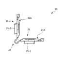
次に、図6乃至図8を参照しながら、取付部材20の構成について説明する。
図6乃至図8に示されるように、取付部材20は、第1取付部21、第2取付部22及び連結部23を備える。取付部材20は、例えば、樹脂や金属により構成される。そして、第1取付部21、第2取付部22、連結部23はそれぞれ一体として形成される。
Next, the configuration of the mounting
As shown in FIGS. 6 to 8, the mounting
第1取付部21は、第1アングル部材4-1の第1被取付部5-1に取り付けられる。具体的には、第1取付部21は、貫通孔21Aが形成される矩形状のプレートである。そして、第1取付部21には、貫通孔21Aに隣接して、第1取付部21の裏面側に突出した凸部25-1が形成される。
The first mounting
凸部25-1は、第1アングル部材4-1に形成されたスリット6と対向する位置に設けられ、スリット6の内部に入り込むように設置される。なお、凸部25-1とスリット6の壁(第1アングル部材4-1の短手方向側の壁)との間は僅かに空いており、第1取付部21はスリット6に対して、第1アングル部材4-1の長手方向に相対的に移動可能(摺動可能)である。
一方で、凸部25-1とスリット6の壁との隙間は僅かであるため、第1取付部21はスリット6に対して、第1アングル部材4-1の短手方向への移動は規制される。
The convex portion 25-1 is provided at a position facing the
On the other hand, since the gap between the convex portion 25-1 and the wall of the
なお、第1取付部21の貫通孔21Aには、ネジ等の第1締結部材30-1が挿通され、第1被取付部5-1のスリット6を通じて、枠部材2に先端が締結される。すなわち、第1締結部材30-1により、第1取付部21と枠部材2との間に、第1アングル部材4-1の第1被取付部5-1が挟み込まれるようにして固定される。この際、第1締結部材30-1を強く締結することにより、第1取付部21が第1被取付部5-1の被押圧部7を枠部材2に向けて押圧することとなる。それにより、第1被取付部5-1が第1取付部21と枠部材2に挟まれた状態で固定されることとなる。
A first fastening member 30-1 such as a screw is inserted into the through
一方で、第1締結部材30-1は、第1アングル部材4-1のスリット6を貫通しており、第1アングル部材4-1に直接取り付けられていない。そのため、第1アングル部材4-1が熱の影響で長手方向に伸縮した場合に、第1締結部材30-1がスリット6内での相対的に移動することが可能である。こうすることで、第1取付部21を、第1アングル部材4-1の伸縮に追従させることが可能となる。これにより、第1アングル部材4-1が長手方向に伸縮した場合にも、第1アングル部材4-1の歪みの発生を抑制することができる。
On the other hand, the first fastening member 30-1 penetrates the
第2取付部22は、第2アングル部材4-2の第2被取付部5-2に取り付けられる。具体的には、第2取付部22は、貫通孔22Aが形成される矩形状のプレートである。そして、第2取付部22には、貫通孔22Aに隣接して、第2取付部22の裏面側に突出した凸部25-2が形成される。
The second mounting
凸部25-2は、第2アングル部材4-2に形成されたスリット6と対向する位置に設けられ、スリット6の内部に入り込むように設置される。なお、凸部25-2とスリット6の壁(第2アングル部材4-2の短手方向側の壁)との間は僅かに空いており、凸部25-2はスリット6の中を、第1アングル部材4-1の長手方向について相対的に摺動可能である。
一方で、凸部25-2とスリット6の壁との隙間は僅かであるため、第2取付部22の凸部25-2がスリット6の壁に当接することで、第2アングル部材4-2の短手方向への移動は規制される。
The convex portion 25-2 is provided at a position facing the
On the other hand, since the gap between the convex portion 25-2 and the wall of the
なお、第2取付部22の貫通孔22Aには、ネジ等の第2締結部材30-2が挿通され、第2被取付部5-2のスリット6を通じて、枠部材2に先端が固定される。すなわち、第2締結部材30-2により、第2取付部22と枠部材2との間に、第2アングル部材4-2の第2被取付部5-2が挟み込まれるようにして固定される。この際、第2締結部材30-2を強く締結することにより、第2取付部22が第2被取付部5-2の被押圧部7を枠部材2に向けて押圧することとなる。それにより、第2被取付部5-2が第2取付部22と枠部材2に挟まれた状態で固定されることとなる。
A second fastening member 30-2 such as a screw is inserted into the through
一方で、第2締結部材30-2は、第2アングル部材4-2のスリット6を貫通しており、第2アングル部材4-2に直接取り付けられていない。そのため、第2アングル部材4-2が熱により長手方向に伸縮した場合に、第2締結部材30-2がスリット6内で相対的に移動することが可能である。こうすることで、第2取付部22を、第2アングル部材4-2の伸縮に追従させることが可能となる。これにより、第2アングル部材4-2が長手方向に伸縮した場合にも、第2アングル部材4-2の歪みの発生を抑制することができる。
On the other hand, the second fastening member 30-2 penetrates the
連結部23は、第1取付部21と第2取付部22を連結する部分である。連結部23は可撓性を有し、折り曲げ部23Aにおいて折り曲げ可能となっている。すなわち、取付部材20は、第1取付部21と第2取付部22を連結する連結部23の折り曲げ部23Aにおける折り曲げ角度が可変であるため、図8及び図9に示すように第1取付部21と第2取付部22との角度を多様に変えることができる。
The connecting
そして、取付部材20に対しては、取付部材20と係合し、第1取付部21と第2取付部22を覆うカバー部材40が取付可能となっている。
具体的には、図10及び図11に示すように、カバー部材40は、第1取付部21を覆う第1カバー部材41と、第2取付部22を覆う第2カバー部材42と、第1カバー部材41と第2カバー部材42を直交して接続する接続部43を有する。
そして、カバー部材40を取付部材20に取り付けることにより、図2及び図3に示すように、取付部材20を隠すことができる。これにより、窓サッシSの意匠性を向上することができる。
Then, the
Specifically, as shown in FIGS. 10 and 11, the
Then, by attaching the
なお、図4に示されるように、アングル部材4の長手方向の端部4Bは、アングル部材4の長手方向において対向する枠部材2から離間して向けられている。こうすることで、アングル部材4が長手方向に伸縮した場合にも端部4Bが枠部材2に当接することを抑制できる。
また、アングル部材4の端部4Bと枠部材2との間に取付部材20の連結部23を配置することができるため、アングル部材固定部10の大きさをコンパクトにすることができ、意匠性を向上できる。
As shown in FIG. 4, the
Further, since the connecting
<まとめ>
以上説明した本実施形態に係る長尺部材固定構造を適用したアングル部材固定部10の主な特徴は以下の通りである。
<Summary>
The main features of the angle
[1]本実施形態に係るアングル部材固定部10は、建物1の枠部材2にアングル部材4(長尺部材)を固定するための長尺部材固定構造を有する。アングル部材固定部10は、アングル部材4に当接して設けられ、アングル部材4を介して枠部材2に取り付けられる取付部材20と、枠部材2と取付部材20の間にアングル部材4を挟んだ状態で、取付部材20を枠部材2に締結するための締結部材30と、を備える。アングル部材4は、取付部材20が取り付けられる被取付部5を有し、被取付部5は、締結部材30に対して、アングル部材4の長手方向に移動可能である。
こうすることで、アングル部材4が長手方向に伸縮した場合にも、アングル部材4を枠部材2に締結するための締結部材30がアングル部材4の伸縮を拘束することがない。そのため、アングル部材4が長手方向に伸縮した場合にも、アングル部材4に歪みが生じないようにアングル部材4を枠部材2に固定可能となる。
[1] The angle
By doing so, even when the
[2]上記のアングル部材固定部10において、被取付部5は、取付部材20に当接して枠部材2に向けて押圧される被押圧部7と、アングル部材4の長手方向に沿って形成されたスリット6と、を有する。締結部材30は、枠部材2からスリット6を貫通して取付部材20に締結される。
こうすることで、簡易な構成により、アングル部材4の被取付部5を、締結部材30に対してアングル部材4の長手方向に移動可能とすることができる。
[2] In the angle
By doing so, the attached
[3]上記のアングル部材固定部10において、取付部材20は、スリット6の中に配される凸部25を有し、凸部25は、アングル部材4の長手方向と直交する短手方向の移動を規制する。
こうすることで、アングル部材4が短手方向に位置ずれすることを抑制できる。
[3] In the angle
By doing so, it is possible to prevent the
[4]上記のアングル部材固定部10において、スリット6は、アングル部材4の長手方向の端部4Bから内側に形成され、取付部材20は、アングル部材4の長手方向の端部4Bに近接して取り付けられる。
こうすることで、アングル部材4の長手方向端部に近いところでアングル部材4を枠部材2に対して固定することができる。これにより、アングル部材4のがたつきを抑制することができる。
[4] In the above-mentioned angle
By doing so, the
[5]上記のアングル部材固定部10において、アングル部材4は、枠部材2の角部2Aにおいてそれぞれ直交して配される第1アングル部材4-1と第2アングル部材4-2とを含む。取付部材20は、第1アングル部材4-1に取り付けられる第1取付部21と、第2アングル部材4-2に取り付けられる第2取付部22と、第1取付部21と第2取付部22を連結する連結部23と、を有する。締結部材30は、枠部材2と第1取付部21の間に第1アングル部材4-1を挟んだ状態で、第1取付部21を枠部材2に固定するための第1締結部材30-1と、枠部材2と第2取付部22の間に第2アングル部材4-2を挟んだ状態で、第2取付部22を枠部材2に固定するための第2締結部材30-2と、を含む。第1アングル部材4-1は、第1取付部21が取り付けられる第1被取付部5-1を有し、第2アングル部材4-2は、第2取付部22が取り付けられる第2被取付部5-2を有する。第1被取付部5-1は、第1締結部材30-1に対して、第1アングル部材4-1の長手方向に移動可能であり、第2被取付部5-2は、第2締結部材30-2に対して、第2アングル部材4-2の長手方向に移動可能である。
こうすることで、枠部材2の角部2Aに沿うようにアングル部材4を設けることができる。これにより、取付部材20を第1アングル部材4-1と第2アングル部材4-2のそれぞれの伸縮に追従させることができる。
[5] In the above-mentioned angle
By doing so, the
[6]上記のアングル部材固定部10において、連結部23は、折り曲げ可能な折り曲げ部23Aを有する。
こうすることで、取付部材20を枠部材2の角部2Aに沿うように配置することができる。取付部材20の設置スペースをコンパクトにすることができる。
[6] In the angle
By doing so, the mounting
[7]上記のアングル部材固定部10において、取付部材20と係合し、第1取付部21と第2取付部22を覆うカバー部材40をさらに備える。
こうすることで、枠部材2とアングル部材4の固定箇所を保護することができる。また、取付部材20を隠すことにより意匠性を向上できる。
[7] The angle
By doing so, it is possible to protect the fixed portion of the
[8]上記のアングル部材固定部10において、枠部材2は、建物1に窓サッシSを取り付けるための板部材であり、アングル部材4は、窓サッシSを構成するアングル部材である。
こうすることで、日光による熱でアングル部材4が伸縮しても、アングル部材4に歪みが生じることを抑制できる。これにより、窓サッシSに歪みが生じることを抑制できる。
[8] In the angle
By doing so, even if the
また、上記のアングル部材固定部10において、スリット6は、アングル部材4と直交する短手方向における中間部に形成される。
こうすることで、アングル部材4の被取付部5の強度低下を抑制できる。
Further, in the angle
By doing so, it is possible to suppress a decrease in the strength of the attached
また、上記のアングル部材固定部10において、アングル部材4は、樹脂製である。
こうすることで、アングル部材4が熱により伸縮しても、アングル部材4に歪みが生じることを抑制できる。
Further, in the angle
By doing so, even if the
<その他の実施形態>
本発明は上記の実施形態に限定されるものではない。
例えば、上記の実施形態では、取付部材20においては、第1取付部21と第2取付部22が連結部23により連結されることとしたが、第1取付部21と第2取付部22とをそれぞれ切り離して設けてもよい。
<Other embodiments>
The present invention is not limited to the above embodiment.
For example, in the above embodiment, in the mounting
また、上記の実施形態では、アングル部材4に対して被取付部5を、長手方向の端部4Bの近傍に設けることとしたが、被取付部5を長手方向の両端の中間領域に設けてもよい。
本発明は、窓サッシSに限られず、建物1の伸縮する長尺部材の取り付けに適用することができる。
Further, in the above embodiment, the attached
The present invention is not limited to the window sash S, and can be applied to the attachment of a long member that expands and contracts in a
S 窓サッシ
Sa サッシ本体部
1 建物
2 枠部材
2A 角部
3 ガラス
4 アングル部材
4A 板状部
4B 端部
4-1 第1アングル部材
4-2 第2アングル部材
5 被取付部
5-1 第1被取付部
5-2 第2被取付部
6 スリット
6A 内側端部
6B 外側端部
7 被押圧部
8 差込部
8A 第1延出部
8B 第2延出部
10 アングル部材固定部
20 取付部材
21 第1取付部
21A 貫通孔
22 第2取付部
22A 貫通孔
23 連結部
23A 折り曲げ部
25 凸部
25-1 凸部
25-2 凸部
30 締結部材
30-1 第1締結部材
30-2 第2締結部材
40 カバー部材
41 第1カバー部材
42 第2カバー部材
43 接続部
S window sash Sa sash
Claims (8)
前記長尺部材に当接し、前記長尺部材を介して前記枠部材に取り付けられる取付部材と、
前記枠部材と前記取付部材の間に前記長尺部材を挟んだ状態で、前記取付部材を前記枠部材に締結するための締結部材と、を備え、
前記長尺部材は、前記取付部材が取り付けられる被取付部を有し、
前記被取付部は、前記締結部材に対して、前記長尺部材の長手方向に移動可能であることを特徴とする長尺部材固定構造。 It is a long member fixing structure for fixing a long member to the frame member of a building.
A mounting member that comes into contact with the long member and is attached to the frame member via the long member.
A fastening member for fastening the mounting member to the frame member with the long member sandwiched between the frame member and the mounting member is provided.
The long member has a mounted portion to which the mounting member is mounted.
The attached portion is a long member fixing structure characterized in that it can move in the longitudinal direction of the long member with respect to the fastening member.
前記取付部材に当接して前記枠部材に向けて押圧される被押圧部と、
前記長尺部材の長手方向に沿って形成されたスリットと、を有し、
前記締結部材は、前記枠部材から前記スリットを貫通して前記取付部材に締結されることを特徴とする請求項1に記載の長尺部材固定構造。 The attached portion is
A pressed portion that comes into contact with the mounting member and is pressed toward the frame member,
With a slit formed along the longitudinal direction of the elongated member,
The long member fixing structure according to claim 1, wherein the fastening member is fastened to the mounting member through the slit from the frame member.
前記凸部は、前記長尺部材の長手方向と直交する短手方向の移動を規制することを特徴とする請求項2に記載の長尺部材固定構造。 The mounting member has a convex portion arranged in the slit and has a convex portion.
The long member fixing structure according to claim 2, wherein the convex portion restricts movement in the lateral direction orthogonal to the longitudinal direction of the long member.
前記取付部材は、前記長尺部材の長手方向の端部に近接して取り付けられることを特徴とする請求項2又は3に記載の長尺部材固定構造。 The slit is formed from the longitudinal end of the elongated member along the longitudinal direction of the elongated member.
The long member fixing structure according to claim 2 or 3, wherein the mounting member is mounted close to an end portion in the longitudinal direction of the long member.
前記取付部材は、
前記第1長尺部材に取り付けられる第1取付部と、
前記第2長尺部材に取り付けられる第2取付部と、
前記第1取付部と前記第2取付部を連結する連結部と、を有し、
前記締結部材は、
前記枠部材と前記第1取付部の間に前記第1長尺部材を挟んだ状態で、前記第1取付部を前記枠部材に固定するための第1締結部材と、
前記枠部材と前記第2取付部の間に前記第2長尺部材を挟んだ状態で、前記第2取付部を前記枠部材に固定するための第2締結部材と、を含み、
前記第1長尺部材は、前記第1取付部が取り付けられる第1被取付部を有し、
前記第2長尺部材は、前記第2取付部が取り付けられる第2被取付部を有し、
前記第1被取付部は、前記第1締結部材に対して、前記第1長尺部材の長手方向に移動可能であり、
前記第2被取付部は、前記第2締結部材に対して、前記第2長尺部材の長手方向に移動可能であることを特徴とする請求項1乃至4のいずれかに記載の長尺部材固定構造。 The long member includes a first long member and a second long member arranged orthogonally to each other at the corners of the frame member.
The mounting member is
The first mounting portion to be mounted on the first long member and
A second mounting portion to be mounted on the second long member,
It has a connecting portion for connecting the first mounting portion and the second mounting portion.
The fastening member is
With the first long member sandwiched between the frame member and the first mounting portion, a first fastening member for fixing the first mounting portion to the frame member, and
A second fastening member for fixing the second mounting portion to the frame member with the second long member sandwiched between the frame member and the second mounting portion is included.
The first long member has a first mounted portion to which the first mounting portion is mounted.
The second long member has a second mounted portion to which the second mounting portion is mounted.
The first attached portion can move in the longitudinal direction of the first long member with respect to the first fastening member.
The long member according to any one of claims 1 to 4, wherein the second attached portion is movable with respect to the second fastening member in the longitudinal direction of the second long member. Fixed structure.
前記枠部材は、前記アングル部材を取り付けるための板部材であることを特徴とする請求項1乃至7のいずれかに記載の長尺部材固定構造。 The long member is an angle member that constitutes a window sash, and is an angle member.
The long member fixing structure according to any one of claims 1 to 7, wherein the frame member is a plate member for attaching the angle member.
Priority Applications (1)
| Application Number | Priority Date | Filing Date | Title |
|---|---|---|---|
| JP2018069147A JP7011517B2 (en) | 2018-03-30 | 2018-03-30 | Long member fixing structure |
Applications Claiming Priority (1)
| Application Number | Priority Date | Filing Date | Title |
|---|---|---|---|
| JP2018069147A JP7011517B2 (en) | 2018-03-30 | 2018-03-30 | Long member fixing structure |
Publications (2)
| Publication Number | Publication Date |
|---|---|
| JP2019178565A JP2019178565A (en) | 2019-10-17 |
| JP7011517B2 true JP7011517B2 (en) | 2022-01-26 |
Family
ID=68278124
Family Applications (1)
| Application Number | Title | Priority Date | Filing Date |
|---|---|---|---|
| JP2018069147A Active JP7011517B2 (en) | 2018-03-30 | 2018-03-30 | Long member fixing structure |
Country Status (1)
| Country | Link |
|---|---|
| JP (1) | JP7011517B2 (en) |
Families Citing this family (1)
| Publication number | Priority date | Publication date | Assignee | Title |
|---|---|---|---|---|
| JP7185377B2 (en) * | 2018-09-06 | 2022-12-07 | 株式会社Lixil | fitting frame |
Citations (3)
| Publication number | Priority date | Publication date | Assignee | Title |
|---|---|---|---|---|
| JP2008169610A (en) | 2007-01-11 | 2008-07-24 | Ykk Ap株式会社 | Sash installing metal fitting and sash |
| JP2008190213A (en) | 2007-02-05 | 2008-08-21 | Shin Nikkei Co Ltd | Composite sash |
| JP2017218806A (en) | 2016-06-08 | 2017-12-14 | Ykk Ap株式会社 | Mullion attachment structure and sash |
-
2018
- 2018-03-30 JP JP2018069147A patent/JP7011517B2/en active Active
Patent Citations (3)
| Publication number | Priority date | Publication date | Assignee | Title |
|---|---|---|---|---|
| JP2008169610A (en) | 2007-01-11 | 2008-07-24 | Ykk Ap株式会社 | Sash installing metal fitting and sash |
| JP2008190213A (en) | 2007-02-05 | 2008-08-21 | Shin Nikkei Co Ltd | Composite sash |
| JP2017218806A (en) | 2016-06-08 | 2017-12-14 | Ykk Ap株式会社 | Mullion attachment structure and sash |
Also Published As
| Publication number | Publication date |
|---|---|
| JP2019178565A (en) | 2019-10-17 |
Similar Documents
| Publication | Publication Date | Title |
|---|---|---|
| RU2701384C1 (en) | Panel holder for panel fixation to distribution cabinet frame and distribution cabinet | |
| JP7011517B2 (en) | Long member fixing structure | |
| US6536855B2 (en) | Front cabinet and television set | |
| JP6174434B2 (en) | Joinery | |
| JP6611879B2 (en) | Unit house wall structure | |
| EP3021438B1 (en) | Electrical insulating box with two options of tightness degree for electricity, information technology and/or telephony | |
| US10602628B2 (en) | Enclosure with one-piece structural frame | |
| JP6595407B2 (en) | Shoji and joinery | |
| JP2018133872A (en) | Clip fixation structure and protector | |
| JP2579683Y2 (en) | Gap cover between panels | |
| JP5726337B2 (en) | Flexible cable deflection regulating structure and in-vehicle electronic device having the same | |
| KR20180080542A (en) | Curtain Wall with Improved Strength and Insulation Performance | |
| KR101164416B1 (en) | Chassis and doorframe using the same | |
| KR101913136B1 (en) | Finishing member for built-in furniture | |
| KR20180016808A (en) | An apparatus for door frame | |
| JP2002280770A (en) | Vertical frame of cabinet for housing electric/electronic apparatus | |
| JP5289985B2 (en) | Joinery | |
| KR101804545B1 (en) | Expansion Boat Having Bending Structure, and Thermal Expansion Absorbing Apparatus Having the Same | |
| JP4842894B2 (en) | Door with small window | |
| JP6403849B1 (en) | fence | |
| JP2539014Y2 (en) | Mounting structure of guide rail base frame in window shutter | |
| JP3340347B2 (en) | Blindfold mounting bracket | |
| KR101349341B1 (en) | supporting clip assembly for door having window | |
| JP2004003799A (en) | Slide panel | |
| JP2021147913A (en) | Fixture |
Legal Events
| Date | Code | Title | Description |
|---|---|---|---|
| RD01 | Notification of change of attorney |
Free format text: JAPANESE INTERMEDIATE CODE: A7426 Effective date: 20180410 |
|
| A521 | Request for written amendment filed |
Free format text: JAPANESE INTERMEDIATE CODE: A821 Effective date: 20180410 |
|
| A711 | Notification of change in applicant |
Free format text: JAPANESE INTERMEDIATE CODE: A712 Effective date: 20210120 |
|
| A621 | Written request for application examination |
Free format text: JAPANESE INTERMEDIATE CODE: A621 Effective date: 20210316 |
|
| TRDD | Decision of grant or rejection written | ||
| A977 | Report on retrieval |
Free format text: JAPANESE INTERMEDIATE CODE: A971007 Effective date: 20211213 |
|
| A01 | Written decision to grant a patent or to grant a registration (utility model) |
Free format text: JAPANESE INTERMEDIATE CODE: A01 Effective date: 20211221 |
|
| A61 | First payment of annual fees (during grant procedure) |
Free format text: JAPANESE INTERMEDIATE CODE: A61 Effective date: 20220114 |
|
| R150 | Certificate of patent or registration of utility model |
Ref document number: 7011517 Country of ref document: JP Free format text: JAPANESE INTERMEDIATE CODE: R150 |
|
| S531 | Written request for registration of change of domicile |
Free format text: JAPANESE INTERMEDIATE CODE: R313531 |
|
| R350 | Written notification of registration of transfer |
Free format text: JAPANESE INTERMEDIATE CODE: R350 |