JP7010705B2 - Systems and methods for refueling aircraft - Google Patents
Systems and methods for refueling aircraft Download PDFInfo
- Publication number
- JP7010705B2 JP7010705B2 JP2018001775A JP2018001775A JP7010705B2 JP 7010705 B2 JP7010705 B2 JP 7010705B2 JP 2018001775 A JP2018001775 A JP 2018001775A JP 2018001775 A JP2018001775 A JP 2018001775A JP 7010705 B2 JP7010705 B2 JP 7010705B2
- Authority
- JP
- Japan
- Prior art keywords
- refueling
- light source
- hose
- receiving aircraft
- light
- Prior art date
- Legal status (The legal status is an assumption and is not a legal conclusion. Google has not performed a legal analysis and makes no representation as to the accuracy of the status listed.)
- Active
Links
Images


Classifications
-
- B—PERFORMING OPERATIONS; TRANSPORTING
- B64—AIRCRAFT; AVIATION; COSMONAUTICS
- B64D—EQUIPMENT FOR FITTING IN OR TO AIRCRAFT; FLIGHT SUITS; PARACHUTES; ARRANGEMENTS OR MOUNTING OF POWER PLANTS OR PROPULSION TRANSMISSIONS IN AIRCRAFT
- B64D45/00—Aircraft indicators or protectors not otherwise provided for
-
- B—PERFORMING OPERATIONS; TRANSPORTING
- B64—AIRCRAFT; AVIATION; COSMONAUTICS
- B64D—EQUIPMENT FOR FITTING IN OR TO AIRCRAFT; FLIGHT SUITS; PARACHUTES; ARRANGEMENTS OR MOUNTING OF POWER PLANTS OR PROPULSION TRANSMISSIONS IN AIRCRAFT
- B64D39/00—Refuelling during flight
-
- B—PERFORMING OPERATIONS; TRANSPORTING
- B64—AIRCRAFT; AVIATION; COSMONAUTICS
- B64D—EQUIPMENT FOR FITTING IN OR TO AIRCRAFT; FLIGHT SUITS; PARACHUTES; ARRANGEMENTS OR MOUNTING OF POWER PLANTS OR PROPULSION TRANSMISSIONS IN AIRCRAFT
- B64D39/00—Refuelling during flight
- B64D39/06—Connecting hose to aircraft; Disconnecting hose therefrom
-
- B—PERFORMING OPERATIONS; TRANSPORTING
- B64—AIRCRAFT; AVIATION; COSMONAUTICS
- B64D—EQUIPMENT FOR FITTING IN OR TO AIRCRAFT; FLIGHT SUITS; PARACHUTES; ARRANGEMENTS OR MOUNTING OF POWER PLANTS OR PROPULSION TRANSMISSIONS IN AIRCRAFT
- B64D47/00—Equipment not otherwise provided for
- B64D47/02—Arrangements or adaptations of signal or lighting devices
-
- B—PERFORMING OPERATIONS; TRANSPORTING
- B64—AIRCRAFT; AVIATION; COSMONAUTICS
- B64D—EQUIPMENT FOR FITTING IN OR TO AIRCRAFT; FLIGHT SUITS; PARACHUTES; ARRANGEMENTS OR MOUNTING OF POWER PLANTS OR PROPULSION TRANSMISSIONS IN AIRCRAFT
- B64D2203/00—Aircraft or airfield lights using LEDs
Description
本開示は、広くには、航空機の燃料補給のためのシステムおよび方法に関し、より詳細には、空中給油の作業中に受け側航空機へと表示をもたらすための燃料補給システムおよび方法に関する。 The present disclosure relates broadly to systems and methods for refueling aircraft, and more particularly to refueling systems and methods for providing indications to the receiving aircraft during aerial refueling operations.
空中給油の作業中に、空中給油機は、飛行しながら受け側航空機へと燃料を供給する。空中給油の1つの手法が、プローブ・アンド・ドローグ方式の燃料補給として知られている。プローブ・アンド・ドローグ方式のシステムにおいて、空中給油機は、空中給油機の後方かつ下方へとたなびく可撓ホースを延ばす。受け側航空機は、プローブを有し、受け側航空機は、プローブを操作して、空中給油機のホースの自由端のドローグに係合させる。プローブがドローグおよびホースに結合した後に、空中給油機は、受け側航空機が空中給油機の燃料補給範囲に留まる限りにおいて、受け側航空機へと燃料を供給する。 During the aerial refueling operation, the aerial refueling aircraft supplies fuel to the receiving aircraft while flying. One method of aerial refueling is known as probe-and-drag refueling. In a probe-and-drag system, the aerial refueling aircraft extends a flexible hose that runs backwards and downwards from the aerial refueling aircraft. The receiving aircraft has a probe, and the receiving aircraft operates the probe to engage the drogue at the free end of the hose of the aerial refueling aircraft. After the probe is coupled to the draw and hose, the tanker aircraft will fuel the tanker aircraft as long as it remains within the tanker aircraft's refueling range.
空中給油の作業中に、受け側航空機が、一般的に、受け側航空機のプローブを空中給油機のホースおよびドローグに結合させるための空中給油機に対する移動を担当する。ひとたび結合が行われると、受け側航空機は、空中給油機からの安全な離間距離にて燃料を受け取ることができるように、空中給油機の燃料補給範囲の内側の位置を維持しようと試みる。受け側航空機がこれらのタスクを遂行するうえで助けとなるように、空中給油機は、空中給油の作業中に、受け側航空機に対して位置および/または作業についてのフィードバックを提供することができる。 During aerial refueling operations, the receiving aircraft is generally responsible for moving the probe of the receiving aircraft to the aerial refueling aircraft to connect it to the hose and drogue of the aerial refueling aircraft. Once coupled, the receiving aircraft attempts to maintain a position inside the refueling range of the tanker aircraft so that it can receive fuel at a safe distance from the tanker aircraft. To help the receiving aircraft perform these tasks, the aerial refueling aircraft can provide feedback on the position and / or work to the receiving aircraft during the aerial refueling operation. ..
1つの手法において、空中給油機は、受け側航空機に対して位置および/または作業についてのフィードバックの視覚的表示を提供するための表示システムを備える。表示システムは、典型的には、可視光スペクトルにおける表示を提供するために、赤色の光を発する単一の未準備光源、琥珀色の光を発する単一の待機光源、および緑色の光を発する単一の燃料補給光源で構成される。受け側航空機が空中給油機に結合する前に、表示システムは、未準備光源を作動させることで、空中給油機において受け側航空機との結合の準備ができていないことを知らせ、あるいは表示システムは、待機光源を作動させることで、空中給油機において受け側航空機との結合の準備ができたことを知らせる。 In one approach, the aerial refueling aircraft is equipped with a display system to provide a visual display of position and / or work feedback to the receiving aircraft. Display systems typically emit a single unprepared light source that emits red light, a single standby light source that emits amber light, and green light to provide a display in the visible light spectrum. Consists of a single refueling light source. Before the receiving aircraft couples to the tanker aircraft, the display system activates an unprepared light source to signal that the tanker aircraft is not ready to join the tanker aircraft, or the display system By activating the standby light, the aerial refueling aircraft is ready to connect with the receiving aircraft.
受け側航空機が空中給油機に結合した後に、表示システムは、燃料補給光源を作動させることで、受け側航空機が燃料補給範囲にあり、空中給油機から燃料を受け取っていることを知らせる。表示システムは、待機光源を点滅させることで、受け側航空機が空中給油機からの最小距離を超えたことを知らせることができ、あるいは待機光源を間断なく作動させることで、受け側航空機が空中給油機からの最大距離を超えたことを知らせる(すなわち、受け側航空機が燃料補給範囲の外に位置していることを知らせる)ことができる。どちらの状況においても、空中給油機は、受け側航空機が燃料補給範囲に戻るまで、受け側航空機への燃料の供給を直ちに停止する。また、どちらの状況においても、表示システムのランプは、受け側航空機に対して、燃料補給範囲の境界に近付いており、燃料供給の即座の遮断を回避するために位置を調整すべきであるという事前の警告をもたらすことがない。 After the receiving aircraft is coupled to the tanker aircraft, the display system activates the refueling light source to indicate that the receiving aircraft is in refueling range and is receiving fuel from the tanker aircraft. The display system can indicate that the receiving aircraft has exceeded the minimum distance from the aerial refueling aircraft by blinking the standby light source, or the receiving aircraft can be refueled in the air by operating the standby light source without interruption. It can signal that the maximum distance from the aircraft has been exceeded (ie, that the receiving aircraft is outside the refueling range). In either situation, the tanker aircraft will immediately stop supplying fuel to the receiving aircraft until the receiving aircraft returns to refueling range. Also, in both situations, the lamps in the display system are close to the boundaries of the refueling range for the receiving aircraft and should be repositioned to avoid an immediate interruption of fuel supply. Does not give advance warning.
受け側航空機にさらなる位置のフィードバックを提供するために、空中給油機は、ホース上の種々の位置にマーキングを備えることができる。例えば、ホースは、燃料補給範囲の境界を示すマーキングを備えることができる。したがって、受け側航空機のパイロットは、ホースを延ばしている空中給油機のハウジングに対するマーキングの位置を観察することによって、燃料補給範囲に対する受け側航空機の位置を判断することができる。1つの欠点は、パイロットが、位置および作業の両方についてのフィードバック表示を受け取るために、ホースのマーキングおよび表示システムのランプの両方に集中しなければならない可能性にある。ランプとマーキングとが異なる場所にあるため、パイロットは、燃料補給の作業中に、視線を空中給油機上の異なる場所の間で繰り返し移動させることになり得る。これが、いくつかの場合に、パイロットにとって困難をもたらす可能性がある。 To provide additional position feedback to the receiving aircraft, tanker aircraft can be equipped with markings at various positions on the hose. For example, the hose can be equipped with markings that indicate the boundaries of the refueling range. Therefore, the pilot of the receiving aircraft can determine the position of the receiving aircraft with respect to the refueling range by observing the position of the marking with respect to the housing of the aerial refueling aircraft extending the hose. One drawback is that the pilot may have to focus on both the hose marking and the ramp of the display system in order to receive feedback indications for both position and work. Due to the different locations of the ramps and markings, the pilot may repeatedly move his line of sight between different locations on the tanker aircraft during the refueling operation. This can be difficult for pilots in some cases.
さらに、表示システムが発する可視光信号およびホース上のマーキングは、例えば夜間の作業時および/または悪天候時などの低照度の状況下での作業時に、パイロットにとって観察が困難になり得る。低照度の状況に対処するために、空中給油機は、未準備光源、待機光源、および燃料補給光源のすぐ隣に配置された別個の一式の赤外線ランプを備えることができる。低照度の状況において、受け側航空機は、暗視画像化システム(例えば、暗視ゴーグル)を使用して、赤外線ランプのうちの1つがいつ作動するかを観察することができる。しかしながら、他の赤外線ランプは作動しないため、パイロットは、作動した赤外線ランプの相対位置を判断して、伝達されている指示を確認しようとするために、空中給油機上の他の基準点を特定しなければならない。低照度の状況において、そのようにすることは、作動したランプの相対位置を判断するために使用することができる基準点を正確に特定することがパイロットにとって困難であることが多いため、難題となり得る。 In addition, the visible light signals emitted by the display system and markings on the hose can be difficult for the pilot to observe when working in low light conditions, such as when working at night and / or in bad weather. To deal with low light conditions, tanker aircraft can be equipped with a separate set of infrared lamps located right next to an unprepared light source, a standby light source, and a refueling light source. In low light conditions, the receiving aircraft can use a night-vision imaging system (eg, night-vision goggles) to observe when one of the infrared lamps is activated. However, since the other infrared lamps do not work, the pilot identifies other reference points on the aerial refueling aircraft in order to determine the relative position of the activated infrared lamps and try to confirm the transmitted instructions. Must. In low light conditions, doing so can be a challenge as it is often difficult for the pilot to pinpoint the exact reference point that can be used to determine the relative position of the activated lamp. obtain.
一例において、燃料補給システムと共に使用される表示システムが説明される。燃料補給システムは、受け側航空機へと燃料を供給するためのホースを備える。表示システムは、未準備光源と、待機光源と、複数の燃料補給光源とを含む複数の光源を備える。各光源は、可視光および赤外光を同時に発するように構成される。各光源は、暗設定および明設定で動作可能である。さらに、表示システムは、複数の光源に通信可能に接続された制御システムを備える。制御システムは、燃料補給システムから燃料補給データを受信するように構成される。燃料補給データは、燃料補給システムに対する受け側航空機の位置を示す位置データと、燃料補給システムにおいて受け側航空機との結合の準備ができているか、あるいは受け側航空機との結合の準備ができていないかを示す準備状態データと、燃料補給システムが燃料を供給しているか、あるいは燃料を供給していないかを示す給油状態データとを含むことができる。 In one example, a display system used with a refueling system will be described. The refueling system is equipped with a hose to supply fuel to the receiving aircraft. The display system comprises a plurality of light sources including an unprepared light source, a standby light source, and a plurality of refueling light sources. Each light source is configured to emit visible and infrared light simultaneously. Each light source can operate in dark and light settings. Further, the display system includes a control system communicably connected to a plurality of light sources. The control system is configured to receive refueling data from the refueling system. The refueling data is the position data indicating the position of the receiving aircraft with respect to the refueling system, and the refueling system is ready to connect with the receiving aircraft or is not ready to connect with the receiving aircraft. It can include ready state data indicating whether or not the refueling system is supplying fuel or not supplying fuel.
制御システムは、(i)燃料補給システムにおいて受け側航空機との結合の準備ができていないことを、燃料補給データが示している場合に、未準備光源を明設定で作動させ、待機光源および複数の燃料補給光源を暗設定で作動させ、(ii)受け側航空機の位置が燃料補給範囲の外であること、および燃料補給システムにおいて受け側航空機との結合の準備ができていることを、燃料補給データが示している場合に、待機光源を明設定で作動させ、未準備光源および複数の燃料補給光源を暗設定で作動させ、(iii)受け側航空機の位置が燃料補給範囲内にあること、および燃料補給システムが受け側航空機へと燃料を供給していることを、燃料補給データが示している場合に、複数の燃料補給光源のうちの少なくとも1つの燃料補給光源を明設定で作動させ、複数の燃料補給光源のうちの残りの燃料補給光源、待機光源、および未準備光源を暗設定で作動させるように構成される。 The control system (i) activates the unprepared light source in the bright setting, the standby light source and multiple, if the refueling data indicates that the refueling system is not ready to connect with the receiving aircraft. Operate the refueling light source in the dark setting, and (ii) the position of the receiving aircraft is out of the refueling range, and the refueling system is ready to connect with the receiving aircraft. When refueling data indicates, the standby light source is activated in the bright setting, the unprepared light source and multiple refueling light sources are operated in the dark setting, and (iii) the position of the receiving aircraft is within the refueling range. , And when refueling data indicates that the refueling system is supplying fuel to the receiving aircraft, activate at least one of the refueling light sources in the bright setting. , The remaining refueling light, standby light, and unprepared light of the multiple refueling light sources are configured to operate in dark settings.
別の例においては、燃料補給システムが、ポッドと、ポッドから延び、ポッドに対して移動可能であるホースとを備える。ホースは、受け側航空機へと燃料を供給するように構成される。さらに、燃料補給システムは、(a)ホースの状態を検出し、(b)検出された状態に基づいて燃料補給データを生成するように構成されたホース検出システムを備える。燃料補給データは、燃料補給システムに対する受け側航空機の位置を示す位置データと、燃料補給システムにおいて受け側航空機との結合の準備ができているか、あるいは受け側航空機との結合の準備ができていないかを示す準備状態データと、燃料補給システムが燃料を供給しているか、あるいは燃料を供給していないかを示す給油状態データとを含むことができる。さらに、燃料補給システムは、未準備光源と、待機光源と、複数の燃料補給光源とを含む複数の光源を有する表示システムを備える。各光源は、可視光および赤外光を同時に発するように構成される。各光源は、暗設定および明設定で動作可能である。 In another example, the refueling system comprises a pod and a hose extending from the pod and movable with respect to the pod. The hose is configured to supply fuel to the receiving aircraft. In addition, the refueling system comprises a hose detection system configured to (a) detect the condition of the hose and (b) generate refueling data based on the detected condition. The refueling data is the position data indicating the position of the receiving aircraft with respect to the refueling system, and the refueling system is ready to connect with the receiving aircraft or is not ready to connect with the receiving aircraft. It can include ready state data indicating whether or not the refueling system is supplying fuel or not supplying fuel. Further, the refueling system comprises a display system having a plurality of light sources including an unprepared light source, a standby light source, and a plurality of refueling light sources. Each light source is configured to emit visible and infrared light simultaneously. Each light source can operate in dark and light settings.
さらに、燃料補給システムは、複数の光源およびホース検出システムに通信可能に接続された制御システムを含む。制御システムは、(i)燃料補給システムにおいて受け側航空機との結合の準備ができていないことを、燃料補給データが示している場合に、未準備光源を明設定で作動させ、待機光源および複数の燃料補給光源を暗設定で作動させ、(ii)受け側航空機の位置が燃料補給範囲の外であること、および燃料補給システムにおいて受け側航空機との結合の準備ができていることを、燃料補給データが示している場合に、待機光源を明設定で作動させ、未準備光源および複数の燃料補給光源を暗設定で作動させ、(iii)受け側航空機の位置が燃料補給範囲内にあること、および燃料補給システムが受け側航空機へと燃料を供給していることを、燃料補給データが示している場合に、複数の燃料補給光源のうちの少なくとも1つの燃料補給光源を明設定で作動させ、複数の燃料補給光源のうちの残りの燃料補給光源、待機光源、および未準備光源を暗設定で作動させるように構成される。 In addition, the refueling system includes a control system communicably connected to multiple light sources and hose detection systems. The control system (i) activates the unprepared light source in the bright setting, the standby light source and multiple, if the refueling data indicates that the refueling system is not ready to connect with the receiving aircraft. Operate the refueling light source in the dark setting, and (ii) the position of the receiving aircraft is out of the refueling range, and the refueling system is ready to connect with the receiving aircraft. When refueling data indicates, the standby light source is activated in the bright setting, the unprepared light source and multiple refueling light sources are operated in the dark setting, and (iii) the position of the receiving aircraft is within the refueling range. , And when refueling data indicates that the refueling system is supplying fuel to the receiving aircraft, activate at least one of the refueling light sources in the bright setting. , The remaining refueling light, standby light, and unprepared light of the multiple refueling light sources are configured to operate in dark settings.
別の例においては、燃料補給システムの表示システムを使用して給油作業の際に受け側航空機へと表示を提供するための方法が説明される。表示システムは、空中給油機のハウジング上に複数の光源を備える。複数の光源は、未準備光源、待機光源、および複数の燃料補給光源を含む。各光源は、可視光および赤外光を同時に発するように構成される。各光源は、明設定および暗設定で動作可能である。 In another example, a method for providing a display to the receiving aircraft during a refueling operation using the display system of the refueling system is described. The display system comprises multiple light sources on the housing of the aerial refueling aircraft. The plurality of light sources includes an unprepared light source, a standby light source, and a plurality of refueling light sources. Each light source is configured to emit visible and infrared light simultaneously. Each light source can operate in bright and dark settings.
本方法は、燃料補給システムに対する受け側航空機の位置を示す位置データと、燃料補給システムにおいて受け側航空機との結合の準備ができているか、あるいは受け側航空機との結合の準備ができていないかを示す準備状態データと、燃料補給システムが燃料を供給しているか、あるいは燃料を供給していないかを示す給油状態データとを含む燃料補給データを決定するステップを含む。本方法は、(i)燃料補給システムにおいて受け側航空機との結合の準備ができていないことを、燃料補給データが示している場合に、未準備光源を明設定で作動させ、待機光源および複数の燃料補給光源を暗設定で作動させるステップ、(ii)受け側航空機の位置が燃料補給範囲の外であること、および燃料補給システムにおいて受け側航空機との結合の準備ができていることを、燃料補給データが示している場合に、待機光源を明設定で作動させ、未準備光源および複数の燃料補給光源を暗設定で作動させるステップ、および(iii)受け側航空機の位置が燃料補給範囲内にあること、および燃料補給システムが受け側航空機へと燃料を供給していることを、燃料補給データが示している場合に、複数の燃料補給光源のうちの少なくとも1つの燃料補給光源を明設定で作動させ、複数の燃料補給光源のうちの残りの燃料補給光源、待機光源、および未準備光源を暗設定で作動させるステップを含む。 The method presents position data indicating the position of the receiving aircraft with respect to the refueling system and whether the refueling system is ready to connect with the receiving aircraft or is not ready to connect with the receiving aircraft. Includes steps to determine refueling data, including readiness data indicating that the refueling system is refueling or not refueling. This method (i) activates the unprepared light source in the bright setting when the refueling data indicates that the refueling system is not ready for coupling with the receiving aircraft, the standby light source and the plurality. Steps to activate the refueling light source in the dark setting, (ii) the position of the receiving aircraft is out of the refueling range, and the refueling system is ready to connect with the receiving aircraft. Steps to activate the standby light source in the bright setting and the unprepared light source and multiple refueling light sources in the dark setting, as indicated by the refueling data, and (iii) the position of the receiving aircraft within the refueling range. At least one of the multiple refueling light sources is brightly set if the refueling data indicates that it is at and that the refueling system is supplying fuel to the receiving aircraft. Includes a step of operating in a dark setting for the remaining refueling light sources, standby light sources, and unprepared light sources of a plurality of refueling light sources.
上述した特徴、機能、および利点を、種々の実施形態において別個独立に達成することができ、あるいは以下の説明および図面を参照してさらなる詳細を見て取ることができるさらに別の実施形態において、組み合わせることができる。 The features, functions, and advantages described above can be achieved independently and independently in various embodiments, or combined in yet another embodiment where further details can be seen with reference to the following description and drawings. Can be done.
例示される実施形態に特有であると考えられる新規な特徴が、添付の特許請求の範囲に記載される。しかしながら、例示される実施形態、ならびにそれらの好ましい使用の態様、さらなる目的および説明は、本開示の例示の実施形態の以下の詳細な説明を参照し、添付の図面と併せて検討することによって、最もよく理解されるであろう。 The novel features that are believed to be unique to the exemplary embodiments are described in the appended claims. However, exemplary embodiments, as well as preferred embodiments, further objectives and description thereof, are by reference to the following detailed description of the exemplary embodiments of the present disclosure and considered in conjunction with the accompanying drawings. It will be best understood.
次に、開示される実施形態を、添付の図面を参照して以下でさらに充分に説明するが、添付の図面には、開示される実施形態のすべてではなく、一部が示されているにすぎない。実際に、いくつかの異なる実施形態が説明され得るが、それらを本明細書に記載の実施形態に限定されると解釈すべきではない。むしろ、これらの実施形態は、本開示を綿密かつ完全なものとし、本開示の技術的範囲を当業者に充分に伝えるために説明される。 The disclosed embodiments will be described in more detail below with reference to the accompanying drawings, but the accompanying drawings show some, but not all, of the disclosed embodiments. Only. In fact, several different embodiments may be described, but they should not be construed as being limited to the embodiments described herein. Rather, these embodiments are described in order to complete the disclosure in detail and to fully convey the technical scope of the disclosure to those of skill in the art.
本明細書に記載される典型的なシステムおよび方法は、既存の空中給油システムの少なくともいくつかの欠点に有益に対処することができる。本明細書に記載される例において、燃料補給システムは、複数の光源を有する表示システムを備える。各光源は、可視光および赤外光を同時に発するように構成される。さらに、各光源は、明設定および暗設定で動作可能である。空中給油の作業の際に、燃料補給システムは、燃料補給の作業に関する1つ以上の状態を決定し、決定された状態に基づいて、表示システムは、光源のうちの少なくとも1つを明設定にて選択的に作動させつつ、残りの光源を暗設定にて作動させることで、受け側航空機に位置および作業のフィードバックを伝えることができる。 The typical systems and methods described herein can beneficially address at least some of the shortcomings of existing aerial refueling systems. In the examples described herein, the refueling system comprises a display system with multiple light sources. Each light source is configured to emit visible and infrared light simultaneously. In addition, each light source can operate in bright and dark settings. During aerial refueling operations, the refueling system determines one or more states regarding the refueling operation, and based on the determined states, the display system sets at least one of the light sources to light. By operating the remaining light sources in the dark setting while selectively operating them, it is possible to convey the position and work feedback to the receiving aircraft.
光源は、未準備光源、待機光源、および/または複数の燃料補給光源を含むことができる。表示システムは、燃料補給システムにおいて受け側航空機との結合の準備ができていないことを示すために、未準備光源を明設定で作動させることができる。表示システムは、燃料補給システムにおいて受け側航空機との結合の準備ができていることを示すために、待機光源を明設定で作動させることができる。表示システムは、燃料補給システムが受け側航空機へと燃料を供給していることを示すために、燃料補給光源のうちの少なくとも1つを明設定で作動させることができる。 The light source can include an unprepared light source, a standby light source, and / or a plurality of refueling light sources. The display system can operate the unprepared light source in the bright setting to indicate that the refueling system is not ready for coupling with the receiving aircraft. The display system can operate the standby light source in the bright setting to indicate that the refueling system is ready for coupling with the receiving aircraft. The display system can operate at least one of the refueling light sources in the bright setting to indicate that the refueling system is supplying fuel to the receiving aircraft.
さらに、燃料補給光源の各々は、燃料補給範囲内の異なる位置および/または位置の部分範囲に対応することができる。したがって、燃料補給光源は、受け側航空機の特定の位置に対応する燃料補給光源を選択的に作動させることによって、燃料補給範囲内の受け側航空機の特定の位置または位置範囲を示すことができる。これは、受け側航空機のパイロットが、受け側航空機が燃料補給範囲の境界に近付いていることを予期し、それに応じて燃料補給範囲の外への移動を回避するように調整を行うことを、可能にすることができる。さらに、光源が、作動についての表示(例えば、準備完了、未準備、燃料供給中、など)および位置についての表示(例えば、燃料補給範囲内の受け側航空機の位置)の両方をもたらすため、受け側航空機のパイロットは、視線をホースと光源との間で繰り返し移動させる必要なく、より容易に表示を確認することができる。 In addition, each of the refueling light sources can accommodate different locations and / or subranges of locations within the refueling range. Therefore, the refueling light source can indicate a specific position or position range of the receiving aircraft within the refueling range by selectively operating the refueling light source corresponding to the specific position of the receiving aircraft. This means that the pilot of the receiving aircraft will make adjustments to anticipate that the receiving aircraft is approaching the boundaries of the refueling range and to avoid moving out of the refueling range accordingly. Can be made possible. In addition, the light source provides both an indication of operation (eg, ready, unprepared, refueling, etc.) and a position (eg, the position of the receiving aircraft within the refueling range). The pilot of the side aircraft can check the display more easily without having to repeatedly move the line of sight between the hose and the light source.
光源は、作動時に可視および赤外の波長範囲において同時に光を発するので、受け側航空機のパイロットは、昼光および低照度の条件下で表示を受け取ることができる。したがって、1組の光源が、オバート(overt)モード(すなわち、昼光条件用)とコバート(covert)モード(すなわち、低照度条件用)の両方において、燃料補給の作業を容易にすることができる。これは、表示システムに動作上の多用途性をもたらし、燃料補給作業の中断を低減または回避するのにも役立つ。例えば、暗視画像化システム(例えば、暗視ゴーグル(NVG))が動作過渡状態を有する状況において、受け側航空機のパイロットは、燃料補給作業を中断することなく、暗視画像化システムを取り除き、可視光スペクトルにおける表示を視認することができる。 Since the light source emits light simultaneously in the visible and infrared wavelength range during operation, the pilot of the receiving aircraft can receive the display under daylight and low light conditions. Thus, a set of light sources can facilitate refueling operations in both overt mode (ie, for daylight conditions) and covert mode (ie, for low light conditions). .. This provides operational versatility for the display system and also helps reduce or avoid interruptions in refueling operations. For example, in a situation where the night-vision imaging system (eg, night-vision goggles (NVG)) has an operating transient, the pilot of the receiving aircraft removes the night-vision imaging system without interrupting the refueling operation. The display in the visible light spectrum can be visually recognized.
さらに、表示システムは、各光源を明設定または暗設定のいずれかで選択的に作動させることによって各表示を受け側航空機へともたらすため、暗設定で作動する光源が、どの光源が表示のために明設定で作動しているのかを確認するための基準点をもたらす。したがって、明設定で作動している光源を、受け側航空機のパイロットが容易に識別することができる。これは、すべての光源が発する赤外光が同じ色の光(すなわち、例えば緑色などの単色)に見えるようになる暗視画像化システムを受け側航空機のパイロットが使用している場合に、とくに有益となり得る。これらの利点および他の利点は、以下でさらに詳細に説明される。 In addition, the display system brings each light source to the receiving aircraft by selectively operating each light source in either the bright or dark setting, so which light source operates in the dark setting is for display. Brings a reference point to see if it is working in bright settings. Therefore, the pilot of the receiving aircraft can easily identify the light source operating in the bright setting. This is especially true when the pilot of the receiving aircraft is using a night-vision imaging system that makes the infrared light emitted by all light sources look like light of the same color (ie, a single color such as green). Can be beneficial. These and other advantages are described in more detail below.
図1が、典型的な実施形態による空中給油の作業中の空中給油機110および受け側航空機112の一部分の側面図を示している。図1に示されるように、空中給油機110は、長手方向116に延びる胴体114と、長手方向116に対して横方向に胴体114から延びる航空機翼部118とを備える。
FIG. 1 shows a side view of a portion of
さらに、空中給油機110は、飛行中の受け側航空機112に燃料を補給するように動作することができる燃料補給システム120を備える。燃料補給システム120は、ハウジング124から延びる可撓ホース122を備え、可撓ホース122は、ハウジング124に対して移動可能である。図1において、ハウジング124は、航空機翼部118に結合したポッド126である。図1は、翼部118上の単一のポッド126を示しているが、空中給油機110は、さらなる例または他の例において、翼部118および/または空中給油機110の胴体114の反対側の別の翼部上に1つ以上のポッド126を備えることができる。各翼部118にポッド126を設けることにより、空中給油機110は、同時に複数の受け側航空機112に燃料を補給することができる。これに加え、あるいはこれに代えて、図4を参照して以下で説明されるように、ホース122を延ばすハウジング124を、他の例では、胴体114の下部によってもたらすことが可能である。
In addition, the
ホース122は、受け側航空機112に燃料を供給するように構成される。例えば、ホース122は、(i)空中給油機110内の燃料タンクから燃料を受け取るためのハウジング124内の第1の端部122Aと、(ii)空中給油機110の下方かつ後方にたなびき、受け側航空機112のプローブ128と結合する第2の端部122Bとを有することができる。ホース122の第2の端部122Bは、飛行中にホース122を安定させ、プローブ128のホース122への結合を助けるようにプローブ128を整列させるためのドローグ130を備えることができる。例えば、ドローグ130は、ホース122の安定およびホース122のプローブ128との結合を助けるための円錐形を有することができる。
The
図1において、受け側航空機112は、空中給油機110の胴体114の後部の下方かつ後方の位置にある。これは、例えば空中給油機110の制御面およびエンジンによって引き起こされる気流における潜在的に危険な乱流および外乱を軽減または回避することができる。さらに、図1において、受け側航空機112は、燃料補給システム120の燃料補給範囲132内に示されている。燃料補給範囲132は、燃料補給システム120からの最小距離を表す第1の境界位置132Aと、燃料補給システム120からの最大距離を表す第2の境界位置132Bとの間の、燃料補給システム120が受け側航空機112へと燃料を供給することができる位置の範囲であってよい。燃料補給システム120は、受け側航空機112が燃料補給範囲132の外にあるとき、受け側航空機112へと燃料を供給しなくてもよい。一例において、燃料補給範囲132は、第1の境界位置132Aと第2の境界位置132Bとの間の約20フィート(ft)(6.1メートル(m))の距離に及ぶ。
In FIG. 1, the receiving
さらに、燃料補給システム120は、空中給油の作業に関する表示を受け側航空機112へと提供するための表示システム134を備える。例えば、表示システム134は、受け側航空機112に対して、燃料補給システム120について受け側航空機112との結合の準備ができているか、あるいは受け側航空機112との結合の準備ができていないかを知らせ、受け側航空機112が燃料補給範囲132に位置しているか、あるいは燃料補給範囲132の外に位置しているかを知らせ、第1の境界位置132Aおよび第2の境界位置132Bに対する燃料補給範囲132内の受け側航空機112の位置を知らせ、さらには/あるいは燃料補給システム120が受け側航空機112へと燃料を供給しているか否かを知らせるように構成される。
Further, the
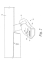
図2は、典型的な実施形態によるポッド126のハウジング124上の表示システム134を示している。図2に示されるように、表示システム134は、未準備光源238、待機光源240、および複数の燃料補給光源242を含む複数の光源236を有する。一例において、未準備光源238は、燃料補給システム120について受け側航空機112との結合の準備ができていないことを示すことができ、待機光源240は、受け側航空機112が燃料補給範囲132の外に位置し、燃料補給システム120は受け側航空機112と結合する準備ができていることを示すことができ、燃料補給光源242は、燃料補給システム120が燃料を供給しており、受け側航空機112の位置が燃料補給範囲132内にあることを示すことができる。
FIG. 2 shows a
図2に示されるように、燃料補給光源242は、少なくとも第1の燃料補給光源242Aと、第2の燃料補給光源242Bと、第3の燃料補給光源242Cとを含む。各燃料補給光源242A~242Cは、燃料補給範囲132内の異なる位置または位置範囲に対応することができる。複数の燃料補給光源242A~242Cを用意することによって、表示システム134は、受け側航空機112のパイロットが、受け側航空機112が燃料補給範囲132の第1の境界位置132Aおよび/または第2の境界位置132Bに近付いているかどうかを判断できるように、燃料補給範囲132における受け側航空機112の相対位置を知らせることができる。
As shown in FIG. 2, the refueling
各光源236は、作動時に可視光および赤外光を同時に発するように構成される。例えば、各光源236は、可視光スペクトル(すなわち、約380nm~約700nmの波長)および赤外光スペクトル(すなわち、約700nm~約1mmの波長)において電磁放射線を同時に生成する発光ダイオード(LED)を含むことができる。この種の光源は、「赤外線デュアル発光体」または「赤外線デュアルLED」と呼ばれることもある。
Each
可視光と赤外光とを同時に発することによって、各光源236は、昼光、低照度、および視界不良の状況において受け側航空機112が容易に受け取って判断することができる知らせをもたらすことができる。さらに、例えば、光源236が可視光および赤外光を同時に発するがゆえに、知らせを受け取るために受け側航空機112が暗視画像化システムを使用しているか否かを、空中給油機110に知らせる必要がない。したがって、受け側航空機112の暗視画像化システムに問題が生じた場合に、受け側航空機112のパイロットは、暗視画像化システムを取り除き、空中給油の作業を中断することなく可視スペクトルにて知らせを受け取り続けることができる。
By emitting visible and infrared light simultaneously, each
一例において、待機光源240は、第1の波長範囲の可視光を発するように動作可能であり、未準備光源238は、第2の波長範囲の可視光を発するように動作可能であり、燃料補給光源242の各々は、第3の波長範囲の可視光を発するように動作可能であり、第1の波長範囲、第2の波長範囲、および第3の波長範囲は、互いに異なる。異なる波長範囲で光源236を作動させることにより、光源236によって発せられる可視光を、互いに視覚的に区別することができる。例えば、一実施例において、第1の波長範囲は、琥珀色の光(例えば、約570nm~約620nm)をもたらし、第2の波長範囲は、赤色の光(例えば、約620nm~約700nm)をもたらし、第3の波長範囲は、緑色の光(例えば、約495nm~約570nm)をもたらす。各光源238、240、および242は、第1、第2、または第3の波長範囲の可視光と同時に、赤外の波長範囲の赤外光も発することができる。特定の実施形態において、少なくとも1つの光源238、240、および/または242は、可視光だけを発することができ、あるいは赤外光だけを発することができる。
In one example, the standby
各光源236は、暗設定および明設定で動作可能である。一例においては、各光源236について、明設定の光源236によって発せられる可視光および/または赤外光の強度は、暗設定の光源236によって発せられる可視光および/または赤外光の強度よりも、少なくとも2倍大きい。別の例においては、各光源236について、明設定の光源236によって発せられる可視光および/または赤外光の強度は、暗設定の光源236によって発せられる可視光および/または赤外光の強度よりも、約1.5倍~約10.0倍大きい。より一般的には、明設定の各光源236によって発せられる光の強度は、受け側航空機112(または、受け側航空機112のパイロット)が明設定で作動している光源236を暗設定で作動している光源236から視覚的に区別することができるように、暗設定の光源236によって発せられる光の強度から相違する。
Each
図3が、典型的な実施形態による空中給油機110および受け側航空機112のさらなる構成要素を含む簡略化したブロック図を示している。図3に示されるように、燃料補給システム120は、受け側航空機112へと供給される燃料を貯蔵する燃料タンク344を備える。燃料タンク344は、(例えば、図1に示されるように)受け側航空機112のプローブ128に結合することができるホース122に接続される。プローブ128は、受け側航空機112の燃料タンク346に接続される。このようにして、空中給油の作業において、プローブ128がドローグ130に挿入され、ホース122に結合すると、ホース122およびプローブ128は、空中給油機110の燃料タンク344から受け側航空機112の燃料タンク346へと燃料を流すための流路をもたらすことができる。
FIG. 3 shows a simplified block diagram containing additional components of
空中給油機110から受け側航空機112への燃料の流れを制御するために、燃料補給システム120は、流路に沿って1つ以上の弁348を備えることができる。例えば、図3においては、ホース122が弁348を備えるが、さらなる例または別の例では、弁348をホース122から分離させることができる。一実施例において、弁348は、燃料の流れを開始および停止させように動作でき、さらには/あるいはホース122を通る燃料の流れの圧力を上昇および低下させるように動作することができる。
To control the flow of fuel from the
やはり図3に示されるように、燃料補給システム120は、ホースアクチュエータ352を備える。ホースアクチュエータ352は、ホース122をハウジング124に対して移動させて、ホース122をハウジング124から延ばし、さらには/あるいはホース122をハウジング124へと引き込むことができる。一例として、ホースアクチュエータ352は、ホース122が巻き付けられるリール354と、ホース122を出し入れするためにリール354を回転させるように動作することができるモータ356とを備えることができる。リール354を、ポッド126のハウジング124内に取り付けることができ、さらには/あるいは後述されるように、空中給油機110の胴体114内のハウジング124内に取り付けることができる。より一般的には、ホースアクチュエータ352は、ハウジング124から延びるホース122の量を制御することによって、ハウジング124に対するホース122の位置を制御するように構成される。
As also shown in FIG. 3, the
さらに、燃料補給システム120は、ホース検出システム358を備える。ホース検出システム358は、(i)ホース122の状態を検出し、(ii)検出された状態に基づいて燃料補給データ360を生成するように構成される。状態を検出するために、ホース検出システム358は、1つ以上のセンサ362を備える。一例において、センサ362によって検出される状態は、(i)受け側航空機112のプローブ128が空中給油機110のホース122に結合しているか否か、(ii)ホース122が空中給油機110から受け側航空機112へと燃料を供給しているか否か、(iii)ホース122によって受け側航空機112へと供給される燃料の圧力、(iv)ハウジング124に対するホース122の位置、(v)受け側航空機112の位置の変化に応じたホース122の位置の変化、および/または(vi)ホース122が受け側航空機112のプローブ128に結合しているときのホース122の張力を含むことができる。
Further, the
ホース検出システム358によって生成される燃料補給データ360は、例えば、燃料補給システム120に対する受け側航空機112の位置を表す位置データ364を含むことができる。例えば、センサ362が、プローブ128がホース122に結合していることを検出すると、ホース122の位置が、受け側航空機112の位置を表す。したがって、ホース検出システム358は、センサ362によって検出されたハウジング124に対するホース122の位置に基づいて、位置データ364を決定することができる。
The
さらに、ホース検出システム358によって生成される燃料補給データ360は、燃料補給システム120において受け側航空機112との結合の準備ができているか、あるいは受け側航空機112との結合の準備ができていないかを表す準備状態データ366を含むことができる。一例において、準備状態データ366は、センサ362が(i)燃料補給システム120の1つ以上の構成要素について故障状態および/または機械的不具合が発生していることを検出し、さらには/あるいは(ii)(例えば、ホース122がハウジング124から最初に延ばされるときに)ホース122が燃料補給範囲132内の位置にないことを検出する場合に、燃料補給システム120において受け側航空機112との結合の準備ができていない旨を表すことができる。一方で、準備状態データ366は、センサ362がホース122が燃料補給範囲132内の位置にあることを検出し、かつセンサ362が燃料補給システム120の構成要素の故障状態または機械的不具合を検出しない場合に、燃料補給システム120において受け側航空機112との結合の準備ができている旨を表すことができる。典型的な実施例において、センサ362は、しきい値を上回り、しきい値を下回り、さらには/あるいは所定のしきい値の範囲の外にあるホース122内の燃料の圧力および/またはホース122への張力を検出することによって、故障状態および/または機械的不具合を検出することができる。
In addition, the
別の例において、準備状態データ366は、ホース検出システム358へとユーザ入力をもたらす空中給油機110の作業者に応答して燃料補給システム120において受け側航空機112との結合の準備ができていないことを表すことができる。他の例も可能である。
In another example, the
さらに、ホース検出システム358によって生成される燃料補給データ360は、燃料補給システム120が燃料を供給しているか、あるいは燃料を供給していないかを示す給油状態データ368を含むことができる。例えば、センサ362が、弁348の状態、ホース122内の燃料の圧力、および/またはホース122がプローブ128に結合しているか否かを検出して、給油状態データ368を生成することができる。
In addition, the
図3に示されるように、ホース検出システム358は、ホースアクチュエータ352に通信可能に接続される。一例においては、受け側航空機112のプローブ128が空中給油機110のホース122に結合したとき、ホースアクチュエータ352を、受け側航空機112の動きに応答してホース122の位置を調整するように構成することができる。例えば、受け側航空機112が燃料補給システム120に結合している間、センサ362がホース122への張力を検出することができ、ホースアクチュエータ352が、これに応答して、張力を所定の張力値の範囲内に維持するようにホース122を動かすことができる。
As shown in FIG. 3, the
また、図3に示されるように、燃料補給システム120のホース検出システム358は、さらに表示システム134にも通信可能に接続される。表示システム134は、複数の光源236に通信可能に接続された制御システム370を備える。一般に、制御システム370は、燃料補給システム120の動作を制御するように構成された演算装置である。したがって、制御システム370を、ハードウェア、ソフトウェア、および/またはファームウェアを使用して実現することができる。例えば、制御システム370は、1つ以上のプロセッサと、機械語命令または他の実行可能命令を記憶する非一時的なコンピュータ可読媒体(例えば、揮発性および/または不揮発性メモリ)とを備えることができる。これらの命令は、1つ以上のプロセッサによって実行されたとき、本明細書に記載の種々の動作を燃料補給システム120に実行させる。したがって、制御システム370は、データ(燃料補給データ360を含む)を受信し、データをメモリに格納することもできる。
Further, as shown in FIG. 3, the
より詳しくは、制御システム370は、燃料補給システム120から燃料補給データ360を受信し、受信した燃料補給データ360に応答して、(例えば、制御信号を光源236へと送信することによって)光源236のうちの少なくとも1つを明設定で作動させ、残りの光源236を暗設定で作動させる。例えば、制御システム370を、燃料補給データ360が燃料補給システム120において受け側航空機112との結合の準備ができていないことを示している場合に、未準備光源238を明設定で作動させ、待機光源240および複数の燃料補給光源242を暗設定で作動させるように構成することができる。さらに、例えば、制御システム370を、受け側航空機112の位置が燃料補給範囲132の外にあること、および燃料補給システム120において受け側航空機112との結合の準備ができていることを、燃料補給データ360が示している場合に、待機光源240を明設定で作動させ、未準備光源238および複数の燃料補給光源242を暗設定で作動させるように構成することができる。
More specifically, the
これに加え、あるいはこれに代えて、制御システム370を、受け側航空機112の位置が燃料補給範囲132内にあること、および燃料補給システム120が受け側航空機112へと燃料を供給していることを、燃料補給データ360が示している場合に、複数の燃料補給光源242のうちの少なくとも1つの燃料補給光源242A、242B、または242Cを明設定で作動させ、複数の燃料補給光源242のうちの残りの燃料補給光源、待機光源240、および未準備光源238を暗設定で作動させるように構成することができる。光源236のいずれかを作動させるために、制御システム370は、光源236へと信号を送信して、光源236をオンにすることができる。
In addition to, or in lieu of, the
一実施例においては、制御システム370を、位置データ364に基づいて複数の燃料補給光源242の中から少なくとも1つの燃料補給光源242A、242B、242Cを選択するように構成することができる。例えば、燃料補給範囲132は、複数の部分範囲を含むことができ、各燃料補給光源242は、複数の部分範囲のうちの該当の1つに対応することができる。この例においては、少なくとも1つの燃料補給光源242A、242B、242Cを選択するために、制御システム370を、(i)受け側航空機112が複数の部分範囲のうちの1つの部分範囲に位置していることを位置データ364が示していると決定し、(ii)決定された1つの部分範囲に対応する燃料補給光源242A、242B、242Cを、明設定で作動させる少なくとも1つの燃料補給光源242A、242B、242Cとして選択するように、構成することができる。したがって、明設定で作動する燃料補給光源242に基づいて、受け側航空機112は、第1の境界位置132Aおよび第2の境界位置132Bに対する燃料補給範囲132内の自身の位置を決定することができる。
In one embodiment, the
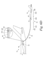
上述のように、図1および図2において、ホース122は、航空機の翼部118に結合したポッド126の形態のハウジング124から延びる。さらなる例または他の例において、ホース122を延ばすハウジング124は、胴体114の下部および/または翼部118に結合した1つ以上のポッド126を含むことができる。図4が、一例による空中給油機110の後面図を示している。図4に示されるように、空中給油機110は、各翼部118にポッド126を備える。さらに、空中給油機110は、各ポッド126および胴体114から延びるホース122を備える。したがって、図4において、燃料補給システム120のハウジング124は、ポッド126および/または胴体114を含む。複数のホース122を備えることによって、空中給油機110を、複数の受け側航空機112に同時に燃料を補給するように構成することができる。
As mentioned above, in FIGS. 1 and 2, the
一代案の例において、空中給油機110は、胴体114から延びるフライングブーム式燃料補給システムと、1つ以上のポッド126から延びる1つ以上のホース・アンド・ドローグ式システムとを備えることができる。この代案の例において、ポッド126は、空中給油機110のフライングブーム式システムまたはホース・アンド・ドローグ式システムのうちの一方のみに適合可能であってよい異なる種類の受け側航空機112に燃料を補給するための汎用性を、空中給油機110にもたらすことができる。
In an alternative example, the
図5A~図5Dは、典型的な実施形態による複数の光源236のさまざまな配置を示している。図5Aにおいて、光源236は、ポッド126のハウジング124上に水平方向の直線状のパターンにて配置されている。図5Bにおいて、光源236は、ポッド126のハウジング124上に鉛直方向の直線状のパターンにて配置されている。図5Cにおいて、光源236は、ポッド126のハウジング124の弧状の輪郭に対応する弧状の輪郭にて配置されている。図5Dにおいて、光源236は、ハウジング124の両側に弧状の輪郭にて配置されている。他の典型的な配置も可能である。
5A-5D show different arrangements of the plurality of
図2~図5Cに示した表示システム134は、5つの光源236を備えているが、表示システム134は、他の例では、より多数の光源236またはより少数の光源236を備えることができる。例えば、追加の例または代案の例においては、待機光源240が、複数の待機光源240を含むことができ、かつ/または未準備光源238が、複数の未準備光源238を含むことができる。さらに、追加の例または代案の例においては、燃料補給光源242が、N個の燃料補給光源242を含むことができ、ここでNは、2以上の整数値である(例えば、N=2,3,4,5,6,7,など)。燃料補給光源242の数が多なるにつれて、表示システム134は、受け側航空機112により高い精度で位置のフィードバックを提供することができる。
The
図6A~図6Eが、典型的な実施形態による空中給油の作業の種々の段階を示している。空中給油の作業は、空中給油機110が、受け側航空機112との結合に向けて燃料補給システム120を準備することによって始まる。例えば、図6Aにおいて、空中給油機110は、ハウジング124からホース122およびドローグ130を延ばすことによって燃料補給システム120を準備する。空気力学的な力ゆえに、ホース122およびドローグ130は、空中給油機110の後ろへと胴体114の下方かつ後方にたなびく。
6A-6E show the various stages of aerial refueling operations according to typical embodiments. The aerial refueling operation begins with the
ホース122を最初に延ばし、さらには/あるいは他のやり方で燃料補給システム120を準備しているときに、ホース検出システム358は、ホース122の状態を検出し、検出した状態に基づいて燃料補給データ360を生成し、燃料補給データ360を制御システム370へと伝える。図6Aにおいて、燃料補給データ360は、燃料補給システム120において受け側航空機112との結合の準備ができていないことを示す。したがって、図6Aに示されるとおり、燃料補給データ360が燃料補給システム120において受け側航空機112との結合の準備ができていないことを示しているとき、制御システム370は、未準備光源238を明設定で作動させ、待機光源240および燃料補給光源242を暗設定で作動させる。受け側航空機112は、光源238,240,242によってもたらされる知らせを受け取り、したがって空中給油機110との結合を試みない。
While the
図6Bにおいて、ホースアクチュエータ352は、燃料補給システム120を受け側航空機112へと結合させることができる位置へとホース122およびドローグ130を延ばし終え、受け側航空機112は、未だ燃料補給範囲132の外に位置し、受け側航空機112は、燃料補給システム120に結合していない。ホース検出システム358は、これらの状態を検出し、検出された状態に基づいて燃料補給データ360を生成し、燃料補給データ360を制御システム370へと伝える。
In FIG. 6B, the
図6Bにおいて、今や燃料補給データ360は、受け側航空機112が燃料補給範囲132の外に位置し、燃料補給システム120において受け側航空機112との結合の準備ができていることを示す。したがって、図6Bに示されるように、受け側航空機112の位置が燃料補給範囲132の外にあること、および燃料補給システム120において受け側航空機112との結合の準備ができていることを、燃料補給データ360が示しているとき、制御システム370は、待機光源240を明設定で作動させ、未準備光源238および複数の燃料補給光源242を暗設定で作動させる。
In FIG. 6B, refueling
光源238,240,242からのこの知らせに応答して、受け側航空機112は、プローブ128がドローグ130へと進入してホース122と結合するような位置へと移動する。ホース122との結合後に、受け側航空機112は、受け側航空機112が燃料補給範囲132に入るまで、燃料補給システム120に対して前方へとホース122およびドローグ130を押し続けることができる。受け側航空機112が前方へと移動するとき、ホースアクチュエータ352は、受け側航空機112の移動に応じてホース122を引き込み、ホース122のたるみを取り除くことができる。さらに、受け側航空機112がホース122を最初の接触後に所定の距離だけ前方に移動させた後に、燃料補給システム120は、受け側航空機112への燃料の供給を開始する。一例において、この所定の距離は、約5フィート~約10フィートであってよい。
In response to this news from
図6Cにおいては、受け側航空機112が燃料補給システム120に結合し、ホース122を所定の距離だけ前方に移動させることで、受け側航空機112が燃料補給範囲132内に位置している。したがって、図6Cにおいては、燃料補給システム120が受け側航空機112へと燃料を供給している。ホース検出システム358は、これらの状態を検出し、検出された状態に基づいて燃料補給データ360を生成し、燃料補給データ360を制御システム370へと伝える。図6Cに示されるように、受け側航空機112が燃料補給範囲132内に位置していること、および燃料補給システム120が受け側航空機112へと燃料を供給していることを、燃料補給データ360が示しているとき、制御システム370は、燃料補給光源のうちの1つの燃料補給光源242Aを明設定で作動させ、未準備光源238、待機光源240、および残りの燃料補給光源242B、242Cを暗設定で作動させる。
In FIG. 6C, the receiving
制御システム370は、燃料補給データ360の位置データ364に少なくとも部分的に基づいて、複数の燃料補給光源242の中から少なくとも1つの燃料補給光源242Aを選択する。例えば、図6A~図6Eにおいて、燃料補給範囲132は、複数の部分範囲632A、632B、632Cを含み、各燃料補給光源242A、242B、242Cは、複数の部分範囲632A、632B、632Cのうちの該当の1つに対応する。例えば、図6A~図6Eにおいては、第1の燃料補給光源242Aが、第1の部分範囲632Aに対応し、第2の燃料補給光源242Bが、第2の部分範囲632Bに対応し、第3の燃料補給光源242Cが、第3の部分範囲632Cに対応する。この例において、複数の燃料補給光源242A、242B、242Cは、燃料補給範囲132におけるそれぞれの部分範囲632A、632B、632Cの順番と同じ順番で、燃料補給システム120のハウジング124上に配置されている。
The
少なくとも1つの燃料補給光源242を選択するために、制御システム370は、受け側航空機112が複数の部分範囲632A、632B、632Cのうちの1つの部分範囲に位置していることを位置データ364が示していると判断し、この判断した1つの部分範囲に対応する燃料補給光源242を、明設定で作動させる少なくとも1つの燃料補給光源242として選択することができる。図6Cにおいては、受け側航空機112が第1の部分範囲632Aにあり、したがって制御システム370は、第1の燃料補給光源242Aを、明設定で作動させる少なくとも1つの燃料補給光源242として選択する。
In order to select at least one
図6Dにおいては、燃料補給システム120が受け側航空機112への燃料の供給を続けている一方で、受け側航空機112が、第1の部分範囲632Aから第2の部分範囲632Bへと移動している。したがって、図6Dにおいて、制御システム370は、第2の燃料補給光源242Bを、明設定で作動させる少なくとも1つの燃料補給光源242として選択する。図6Eにおいては、燃料補給システム120が受け側航空機112への燃料の供給を続けている一方で、受け側航空機112が、第2の部分範囲632Bから第3の部分範囲632Cへと移動している。したがって、図6Eにおいて、制御システム370は、第3の燃料補給光源242Cを、明設定で作動させる少なくとも1つの燃料補給光源242として選択する。
In FIG. 6D, the
一実施例において、受け側航空機112が、受け側航空機112が第1の部分範囲632Aまたは第3の部分範囲632Cに位置している旨の知らせを受け取るとき、受け側航空機112は、これに応答して、第2の部分範囲632B内の位置へと移動することができる。このようにして、受け側航空機112は、受け側航空機が燃料補給範囲132の外へと外れることによって燃料が遮断される恐れを、低減または排除することができる。
In one embodiment, when the receiving
図6A~図6Eは、燃料補給範囲132が3つの部分範囲632A、632B、632Cを含み、表示システム134が3つの対応する燃料補給光源242A、242B、242Cを含む例を示しているが、さらなる例または代案の例において、燃料補給範囲132は、4つ以上の部分範囲632A、632B、632Cを含むことができ、表示システムは、4つ以上の燃料補給光源242を含むことができる。さらに、第1の部分範囲632A、第2の部分範囲632B、および第3の部分範囲632Cの各々は、同じサイズであるが、別の例において、部分範囲632A、632B、632Cは、異なるサイズを有することができる。例えば、1つの代案の例において、第1の部分範囲632Aおよび第3の部分範囲632Bは、第2の部分範囲632Bよりも小さいサイズを有することができる。したがって、第2の部分範囲632Bは、燃料補給範囲132内の目標位置範囲をもたらす受け側航空機112の比較的広い範囲の位置に対応することができる。一方で、第1の部分範囲632Aおよび第3の部分範囲632Cは、燃料補給範囲132の境界から離れるように受け側航空機112に対して位置の調整を警告する比較的小さい範囲の位置に対応することができる。
6A-6E show an example where the
上述したように、制御システム370を、受け側航空機112の位置が燃料補給範囲132内にあること、および燃料補給システム120が受け側航空機112へと燃料を供給していることを、燃料補給データ360が示している場合に、複数の燃料補給光源242のうちの少なくとも1つの燃料補給光源242A、242B、または242Cを明設定で作動させ、複数の燃料補給光源242のうちの残りの燃料補給光源、待機光源240、および未準備光源238を暗設定で作動させるように構成することができる。図6A~図6Eに示した例では、受け側航空機112の位置が燃料補給範囲132内にあること、および燃料補給システム120が受け側航空機112へと燃料を供給していることを、燃料補給データ360が示している場合に、制御システム370は、燃料補給範囲132における受け側航空機112の相対位置に基づいて、単一の燃料補給光源242を明設定で作動させる。しかしながら、表示システム134は、さらなる例または代案の例においては、2つ以上の燃料補給光源242を明設定で作動させることができる。
As mentioned above, the refueling data indicates that the
一例として、図7A~図7Eは、5つの燃料補給光源242A~242Eを有する表示システム134を示し、5つの燃料補給光源242A~242Eの各々は、燃料補給システム120が受け側航空機112へと燃料を供給しているときに、燃料補給範囲132の種々の部分範囲732A~732Eにおける受け側航空機112の位置に基づいて明設定または暗設定で作動する。
As an example, FIGS. 7A-7E show a
図7Aに示されるように、受け側航空機112が第1の部分範囲732Aにあるとき、制御システム370は、第1の燃料補給光源242Aを明設定で作動させ、残りの燃料補給光源242B~242Eを暗設定で作動させる。図7Bに示されるように、受け側航空機112が第2の部分範囲732Bにあるとき、制御システム370は、第1の燃料補給光源242Aおよび第2の燃料補給光源242Bを明設定で作動させ、残りの燃料補給光源242C~242Eを暗設定で作動させる。図7Cに示されるように、受け側航空機112が第3の部分範囲732Cにあるとき、制御システム370は、第1の燃料補給光源242A、第2の燃料補給光源242B、および第3の燃料補給光源242Cを明設定で作動させ、残りの燃料補給光源242Dおよび242Eを暗設定で作動させる。図7Dに示されるように、受け側航空機112が第4の部分範囲732Dにあるとき、制御システム370は、第1の燃料補給光源242A、第2の燃料補給光源242B、第3の燃料補給光源242C、および第4の燃料補給光源242Dを明設定で作動させ、残りの燃料補給光源242Eを暗設定で作動させる。図7Eに示されるように、受け側航空機112が第5の部分範囲732Eにあるとき、制御システム370は、第1の燃料補給光源242A、第2の燃料補給光源242B、第3の燃料補給光源242C、第4の燃料補給光源242D、および第5の燃料補給光源242Eを明設定で作動させる。
As shown in FIG. 7A, when the receiving
ここで図1~図8を参照すると、典型的な実施形態による燃料補給システム120の表示システム134を使用して燃料補給の作業中に受け側航空機112へと表示を提供するプロセス800のフローチャートが示されている。上述したように、表示システム134は、空中給油機110のハウジング124上に複数の光源236を備える。複数の光源236は、未準備光源238、待機光源240、および複数の燃料補給光源242を含む。各光源236は、可視光および赤外光を同時に発するように構成される。各光源236は、明設定および暗設定で動作可能である。
Now referring to FIGS. 1-8, a flow chart of
図8に示されるように、ブロック810において、プロセス800は、燃料補給データ360を決定することによって開始する。燃料補給データ360は、燃料補給システム120に対する受け側航空機112の位置を示す位置データ364と、燃料補給システム120において受け側航空機112との結合の準備ができているか、あるいは受け側航空機112との結合の準備ができていないかを示す準備状態データ366と、燃料補給システム120が燃料を供給しているか、あるいは燃料を供給していないかを示す給油状態データ368とを含むことができる。
As shown in FIG. 8, at
ブロック812において、燃料補給データ360が燃料補給システム120において受け側航空機112との結合の準備ができていないことを示している場合に、プロセス800は、未準備光源238を明設定で作動させ、待機光源240および複数の燃料補給光源242を暗設定で作動させることを含むことができる。
At
ブロック814において、受け側航空機112の位置が燃料補給範囲132の外にあること、および燃料補給システム120において受け側航空機112との結合の準備ができていることを、燃料補給データ360が示している場合に、プロセス800は、待機光源240を明設定で作動させ、未準備光源238および複数の燃料補給光源242を暗設定で作動させることを含むことができる。
At
ブロック816において、受け側航空機112の位置が燃料補給範囲132内にあること、および燃料補給システム120が受け側航空機112へと燃料を供給していることを、燃料補給データ360が示している場合に、プロセス800は、複数の燃料補給光源242のうちの少なくとも1つの燃料補給光源242を明設定で作動させ、複数の燃料補給光源242のうちの残りの燃料補給光源を暗設定で作動させることを含むことができる。ブロック817において、受け側航空機112の位置が燃料補給範囲132内にあること、および燃料補給システム120が受け側航空機112へと燃料を供給していることを、燃料補給データ360が示している場合に、プロセス800は、待機光源240および未準備光源238を暗設定で動作させることをさらに含むことができる。
In
図9~図13は、図8に示したプロセス800に関連して実行することができる追加の動作または代替の動作を示している。図9に示されるように、プロセス800は、ブロック818において、燃料補給システム120のハウジング124に対するホース122の位置を決定することによって位置データ364を決定することをさらに含むことができる。図10に示されるように、プロセス800は、ブロック820において、位置データ364に基づいて、複数の燃料補給光源242の中から少なくとも1つの燃料補給光源242を選択することも含むことができる。
9 to 13 show additional or alternative actions that can be performed in connection with the
一例において、燃料補給範囲132は、複数の部分範囲632A~632Cを含み、各燃料補給光源242は、複数の部分範囲632A~632Cのうちの該当の1つに対応する。この例の一実施例においては、図11に示されるように、ブロック820において少なくとも1つの燃料補給光源242を選択することが、ブロック822において受け側航空機112が複数の部分範囲632A~632Cのうちの1つの部分範囲632A~632Cに位置していることを位置データ364が示していると判断し、ブロック824においてこの判断した1つの部分範囲632A~632Cに対応する燃料補給光源242を明設定で作動させる少なくとも1つの燃料補給光源242として選択することを、含むことができる。
In one example, the
図12に示されるように、プロセス800は、ブロック826において、燃料補給システム120から受け側航空機112へと供給されている燃料の圧力、燃料補給システム120のハウジング124に対する燃料補給システム120のホース122の位置、受け側航空機112の位置の変化に応答したホース122の位置の変化、およびホース122の張力で構成されるグループからの少なくとも1つの状態を決定することによって、準備状態データ366を決定することを含むことができる。ブロック828において、プロセス800は、燃料補給システム120において受け側航空機112との結合の準備ができているか、あるいは受け側航空機112との結合の準備ができていないかを判断するために、少なくとも1つの状態を少なくとも1つのしきい値と比較することを、さらに含むことができる。
As shown in FIG. 12,
図13に示されるように、プロセス800は、ブロック830において空中給油機110の翼部118に結合したポッド126から燃料補給システム120のホース122を延ばすことと、ブロック832においてホース122を使用して燃料補給システム120から受け側航空機112へと燃料を供給することを含む。
As shown in FIG. 13,
ここで図1~図7Eおよび図14を参照すると、典型的な実施形態による燃料補給システム120の表示システム134を使用して給油作業の最中に受け側航空機112へと表示を提供するプロセス1400のフロー図が示されている。表示システム134は、空中給油機110のハウジング124上に複数の光源236を備える。複数の光源236は、複数の燃料補給光源242を含む。各光源236は、可視光および赤外光を同時に発するように構成される。各光源236は、明設定および暗設定で動作可能である。各燃料補給光源242は、燃料補給システム120の燃料補給範囲132内の1つ以上の位置に対応する。
Now referring to FIGS. 1-7E and 14,
図14に示されるように、ブロック1410において、プロセス1400は、燃料補給システム120に対する受け側航空機112の位置を示す位置データ364を含む燃料補給データ360を決定することを含む。ブロック1412において、プロセス1400は、燃料補給データ360に基づいて、複数の燃料補給光源242のうちの少なくとも1つの燃料補給光源242を選択することを含む。ブロック1414において、プロセス1400は、少なくとも1つの燃料補給光源242を明設定で作動させ、複数の燃料補給光源242のうちの残りの燃料補給光源を暗設定で作動させることで、燃料補給範囲132における受け側航空機112の位置を示すことを含む。
As shown in FIG. 14, at
図8~図14に示したブロックはいずれも、プロセスにおける特定の論理機能または工程を実施するためにプロセッサによって実行することができる1つ以上の命令を含むモジュール、セグメント、またはプログラムコードの一部分を表すことができる。プログラムコードを、例えば、ディスクまたはハードドライブを含む記憶装置など、任意の種類のコンピュータ可読媒体またはデータ記憶装置に格納することができる。さらに、プログラムコードを、機械可読形式でコンピュータ可読記憶媒体上に符号化することができ、あるいは他の非一時的な媒体または製造物上に符号化することができる。コンピュータ可読媒体は、例えばレジスタメモリ、プロセッサキャッシュ、およびランダムアクセスメモリ(RAM)などのデータを短時間にわたって記憶するコンピュータ可読媒体など、非一時的なコンピュータ可読媒体またはメモリを含むことができる。また、コンピュータ可読媒体は、例えば読み出し専用メモリ(ROM)、光学ディスクまたは磁気ディスク、コンパクトディスク読み出し専用メモリ(CD-ROM)など、補助または永続的な長期記憶装置などの非一時的な媒体を含むことができる。コンピュータ可読媒体は、任意の他の揮発性または不揮発性のストレージシステムであってもよい。コンピュータ可読媒体を、例えば、有形のコンピュータ可読記憶媒体と考えることができる。 Each of the blocks shown in FIGS. 8-14 is a piece of module, segment, or program code that contains one or more instructions that can be executed by a processor to perform a particular logical function or process in a process. Can be represented. The program code can be stored in any kind of computer-readable medium or data storage device, for example, storage devices including disks or hard drives. In addition, the program code can be encoded on a computer-readable storage medium in a machine-readable format, or on other non-temporary media or products. Computer-readable media can include non-transitory computer-readable media or memory, such as computer-readable media that store data such as register memory, processor cache, and random access memory (RAM) over a short period of time. Computer-readable media also include non-temporary media such as auxiliary or permanent long-term storage devices such as read-only memory (ROM), optical or magnetic disks, compact disc read-only memory (CD-ROM). be able to. The computer readable medium may be any other volatile or non-volatile storage system. A computer-readable medium can be considered, for example, a tangible computer-readable storage medium.
いくつかの例においては、本明細書に記載した装置および/またはシステムの構成要素を、機能の実行を可能にするように(ハードウェアおよび/またはソフトウェアによって)実際に設定および構成されるように、機能を実行するように構成することができる。したがって、典型的な構成は、システムに機能を実行させる命令を実行する1つ以上のプロセッサを含む。同様に、装置および/またはシステムの構成要素を、特定のやり方で動作させられたときなどに、機能の実行に合わせて配置または調整され、機能の実行が可能であり、あるいは機能の実行に適するように構成することができる。 In some examples, the devices and / or system components described herein are actually configured and configured (by hardware and / or software) to enable performance of the function. , Can be configured to perform a function. Therefore, a typical configuration includes one or more processors that execute instructions that cause the system to perform a function. Similarly, equipment and / or system components can be arranged or tuned to perform a function, such as when operated in a particular manner, to be capable of performing the function, or suitable for performing the function. Can be configured as follows.
上述した図8~図14において、ブロックは、動作および/または動作の一部を表すことができ、種々のブロックを接続する線は、動作または動作の一部のいかなる特定の順序または依存性も意味しない。破線によって表されたブロックは、選択的な動作および/または動作の一部を示す。種々のブロックを接続する破線が存在する場合、そのような破線は、動作または動作の一部の選択的な依存関係を表す。開示された種々の動作の間の依存関係が、必ずしもすべて表されているわけではないことを、理解できるであろう。図8~図14および本明細書に記載の方法の動作を説明する付随の開示を、必ずしも動作の実行の順序を決定するものと解釈すべきではない。むしろ、1つの例示的な順序が示されているが、動作の順序は、適宜に変更されてもよいと理解されるべきである。したがって、特定の動作を、異なる順序で実行でき、あるいは同時に実行することができる。さらに、当業者であれば、必ずしも説明したすべての動作を実行する必要はないことを、理解できるであろう。 In FIGS. 8-14 described above, blocks can represent actions and / or parts of actions, and the lines connecting the various blocks can be any particular order or dependency of the actions or parts of the action. Doesn't mean. The blocks represented by the dashed lines indicate selective movements and / or some of the movements. If there is a dashed line connecting the various blocks, such a dashed line represents an action or a selective dependency of some of the actions. It will be appreciated that not all of the dependencies between the various disclosed behaviors are represented. The accompanying disclosures illustrating the operation of FIGS. 8-14 and the methods described herein should not necessarily be construed as determining the order in which the operations are performed. Rather, one exemplary order is shown, but it should be understood that the order of operations may be changed as appropriate. Therefore, specific actions can be performed in different orders or at the same time. Moreover, one of ordinary skill in the art will appreciate that it is not always necessary to perform all the actions described.
さらに、本開示は、以下の条項による実施形態を含む。 Further, the present disclosure includes embodiments according to the following provisions.
条項1.受け側航空機へと燃料を供給するためのホースを備えている燃料補給システムにおいて使用するための表示システムであって、表示システムが、未準備光源と、待機光源と、複数の燃料補給光源とを含む複数の光源であって、各光源は、可視光および赤外光を同時に発するように構成され、各光源は、暗設定および明設定で動作することができる、複数の光源と、複数の光源に通信可能に接続された制御システムであって、制御システムは、燃料補給システムから燃料補給データを受信するように構成され、燃料補給データは、燃料補給システムに対する受け側航空機の位置を表す位置データと、燃料補給システムにおいて受け側航空機との結合の準備ができているか、あるいは受け側航空機との結合の準備ができていないかを表す準備状態データと、燃料補給システムが燃料を供給しているか、あるいは燃料を供給していないかを示す給油状態データとを含む、制御システムと、を備え、制御システムは、燃料補給システムにおいて受け側航空機との結合の準備ができていないことを、燃料補給データが示している場合に、未準備光源を明設定で作動させ、待機光源および複数の燃料補給光源を暗設定で作動させ、受け側航空機の位置が燃料補給範囲の外にあること、および燃料補給システムにおいて受け側航空機との結合の準備ができていることを、燃料補給データが示している場合に、待機光源を明設定で作動させ、未準備光源および複数の燃料補給光源を暗設定で作動させ、受け側航空機の位置が燃料補給範囲内にあること、および燃料補給システムが受け側航空機へと燃料を供給していることを、燃料補給データが示している場合に、複数の燃料補給光源のうちの少なくとも1つの燃料補給光源を明設定で作動させ、複数の燃料補給光源のうちの残りの燃料補給光源、待機光源、および未準備光源を暗設定で動作させるように構成されている、表示システム。
条項2.制御システムは、位置データに基づいて複数の燃料補給光源の中から少なくとも1つの燃料補給光源を選択するようにさらに構成されている、条項1に記載の表示システム。
Clause 2. The display system according to
条項3.燃料補給範囲は、複数の部分範囲を含み、各燃料補給光源は、複数の部分範囲のうちの該当の1つに対応し、少なくとも1つの燃料補給光源を選択するために、制御システムは、位置データが、受け側航空機が複数の部分範囲のうちの1つの部分範囲にある旨を示していると決定し、決定した1つの部分範囲に対応する燃料補給光源を、明設定にて動作させる少なくとも1つの燃料補給光源として選択するように構成されている、条項2に記載の表示システム。 Clause 3. The refueling range includes multiple subranges, each refueling light source corresponds to one of the multiple subranges, and the control system is positioned to select at least one refueling light source. It is determined that the data indicates that the receiving aircraft is in one subrange of the plurality of subranges, and the refueling light source corresponding to the determined subrange is operated at least in the bright setting. The display system described in Clause 2, which is configured to be selected as one refueling light source.
条項4.複数の燃料補給光源は、燃料補給範囲における対応する部分範囲の順番と同じ順番で燃料補給システムのハウジング上に配置されている、条項3に記載の表示システム。 Clause 4. The display system according to clause 3, wherein the refueling light sources are located on the housing of the refueling system in the same order as the corresponding subranges in the refueling range.
条項5.各光源において、明設定のランプによって発せられる可視光の強度は、暗設定のランプによって発せられる可視光の強度の少なくとも2倍大きい、条項1から4のいずれかに記載の表示システム。
Clause 5. The display system according to any one of
条項6.少なくとも1つの待機光源は、第1の波長範囲の可視光を発するように動作可能であり、少なくとも1つの未準備光源は、第2の波長範囲の可視光を発するように動作可能であり、複数の燃料補給光源の各々は、第3の波長範囲の可視光を発するように動作可能であり、第1の波長範囲、第2の波長範囲、および第3の波長範囲は、互いに異なる、条項1から5のいずれかに記載の表示システム。
Clause 6. At least one standby light source can operate to emit visible light in the first wavelength range, and at least one unprepared light source can operate to emit visible light in the second wavelength range. Each of the refueling light sources in is capable of operating to emit visible light in a third wavelength range, the first wavelength range, the second wavelength range, and the third wavelength range are different from each other,
条項7.第1の波長範囲は、琥珀色の光をもたらし、第2の波長範囲は、赤色の光をもたらし、第3の波長範囲は、緑色の光をもたらす、条項6に記載の表示システム。 Clause 7. The display system according to Clause 6, wherein the first wavelength range results in amber light, the second wavelength range results in red light, and the third wavelength range results in green light.
条項8.待機光源が複数の待機光源を含むか、あるいは未準備光源が複数の未準備光源を含むか、の少なくとも一方である、条項1から7のいずれかに記載の表示システム。
Clause 8. The display system according to any one of
条項9.ポッドと、ポッドから延び、ポッドに対して移動可能であるホースであって、ホースが受け側航空機へと燃料を供給するように構成された、ホースと(a)ホースの状態を検出し、(b)該検出した状態に基づいて、燃料補給データを生成し、燃料補給データが、燃料補給システムに対する受け側航空機の位置を表す位置データと、燃料補給システムにおいて受け側航空機との結合の準備ができているか、あるいは受け側航空機との結合の準備ができていないかを表す準備状態データと、燃料補給システムが燃料を供給しているか、あるいは燃料を供給していないかを示す給油状態データとを含む、ホース検出システムと、未準備光源と、待機光源と、複数の燃料補給光源とを含む複数の光源を備える表示システムであって、各光源は、可視光および赤外光を同時に発するように構成され、各光源は、暗設定および明設定で動作することができる、表示システムと、複数の光源およびホース検出システムに通信可能に接続された制御システムとを備え、制御システムは、(i)燃料補給システムにおいて受け側航空機との結合の準備ができていないことを、燃料補給データが示している場合に、未準備光源を明設定で作動させ、待機光源および複数の燃料補給光源を暗設定で作動させ、(ii)受け側航空機の位置が燃料補給範囲の外にあること、および燃料補給システムにおいて受け側航空機との結合の準備ができていることを、燃料補給データが示している場合に、待機光源を明設定で作動させ、未準備光源および複数の燃料補給光源を暗設定で作動させ、(iii)受け側航空機の位置が燃料補給範囲内にあること、および燃料補給システムが受け側航空機へと燃料を供給していることを、燃料補給データが示している場合に、複数の燃料補給光源のうちの少なくとも1つの燃料補給光源を明設定で作動させ、複数の燃料補給光源のうちの残りの燃料補給光源、待機光源、および未準備光源を暗設定で動作させるように構成されている、燃料補給システム。 Clause 9. Detects the condition of the pod and (a) the hose, which is a hose that extends from the pod and is mobile to the pod and is configured to fuel the receiving aircraft. b) Based on the detected condition, refueling data is generated, and the refueling data is the position data indicating the position of the receiving aircraft with respect to the refueling system and the preparation for coupling with the receiving aircraft in the refueling system. Ready status data indicating whether it is ready or not ready to connect with the receiving aircraft, and refueling status data indicating whether the refueling system is refueling or not refueling. A display system comprising a hose detection system, an unprepared light source, a standby light source, and a plurality of light sources including a plurality of refueling light sources, wherein each light source emits visible light and infrared light simultaneously. Each light source can operate in dark and light settings, with a display system and a control system communicably connected to multiple light sources and hose detection systems, the control system is (i). ) When refueling data indicates that the refueling system is not ready to couple with the receiving aircraft, activate the unprepared light source at the bright setting and dim the standby light source and multiple refueling light sources. Refueling data indicates that it is activated in the settings and (ii) the position of the receiving aircraft is outside the refueling range and that the refueling system is ready to connect with the receiving aircraft. In some cases, the standby light source is activated in the bright setting, the unprepared light source and multiple refueling light sources are operated in the dark setting, (iii) the position of the receiving aircraft is within the refueling range, and the refueling system is When refueling data indicates that fuel is being supplied to the receiving aircraft, at least one of the refueling light sources may be activated at a bright setting to multiple refueling light sources. A refueling system that is configured to operate the remaining refueling, standby, and unprepared light sources in the dark settings.
条項10.ポッドは、航空機の翼部に結合するように構成されている、条項9に記載の燃料補給システム。 Clause 10. The refueling system described in Clause 9, wherein the pod is configured to be coupled to the wing of an aircraft.
条項11.状態は、ホースによって受け側航空機へと供給される燃料の圧力、ポッドに対するホースの位置、受け側航空機の位置の変化に応答したホースの位置の変化、およびホースが受け側航空機に結合しているときのホースへの張力で構成されるグループからの少なくとも1つを含む、条項9または10に記載の燃料補給システム。 Clause 11. The state is the pressure of the fuel supplied by the hose to the receiving aircraft, the position of the hose with respect to the pod, the change in the position of the hose in response to the change in the position of the receiving aircraft, and the hose coupled to the receiving aircraft. The refueling system according to clause 9 or 10, including at least one from the group consisting of tension on the hose when.
条項12.ホース検出システムは、ポッドに対するホースの位置に基づいて位置データを決定するように構成されている、条項9から11のいずれかに記載の燃料補給システム。 Clause 12. The refueling system according to any of clauses 9-11, wherein the hose detection system is configured to determine position data based on the position of the hose with respect to the pod.
条項13.複数の光源は、ポッド上に直線状のパターンにて配置されている、条項9から12のいずれかに記載の燃料補給システム。 Clause 13. The refueling system according to any of clauses 9-12, wherein the plurality of light sources are arranged in a linear pattern on the pod.
条項14.複数の光源は、ポッドの弧状の輪郭に対応する弧状の輪郭にて配置されている、条項9から12のいずれかに記載の燃料補給システム。 Clause 14. The refueling system according to any of clauses 9-12, wherein the plurality of light sources are arranged in an arcuate contour corresponding to the arcuate contour of the pod.
条項15.燃料補給システムの表示システムを使用して、燃料補給の作業の際に受け側航空機へと表示を提供するための方法であって、表示システムは空中給油機のハウジング上の複数の光源を備え、該複数の光源は、未準備光源、待機光源、および複数の燃料補給光源を含み、各光源は可視光および赤外光を同時に発するように構成され、各光源は明設定および暗設定で動作することができる、方法であって、方法が、燃料補給システムに対する受け側航空機の位置を表す位置データと、燃料補給システムにおいて受け側航空機との結合の準備ができているか、あるいは受け側航空機との結合の準備ができていないかを表す準備状態データと、燃料補給システムが燃料を供給しているか、あるいは燃料を供給していないかを示す給油状態データとを含む燃料補給データを決定するステップと、燃料補給システムにおいて受け側航空機との結合の準備ができていないことを、燃料補給データが示している場合に、未準備光源を明設定で作動させ、待機光源および複数の燃料補給光源を暗設定で作動させるステップと、受け側航空機の位置が燃料補給範囲の外にあること、および燃料補給システムにおいて受け側航空機との結合の準備ができていることを、燃料補給データが示している場合に、待機光源を明設定で作動させ、未準備光源および複数の燃料補給光源を暗設定で作動させるステップと、受け側航空機の位置が燃料補給範囲内にあること、および燃料補給システムが受け側航空機へと燃料を供給していることを、燃料補給データが示している場合に、複数の燃料補給光源のうちの少なくとも1つの燃料補給光源を明設定で作動させ、複数の燃料補給光源のうちの残りの燃料補給光源、待機光源、および未準備光源を暗設定で動作させるステップと、を含む方法。 Clause 15. A method for using the display system of the refueling system to provide a display to the receiving aircraft during refueling operations, where the display system is equipped with multiple light sources on the housing of the aerial refueling machine. The plurality of light sources include an unprepared light source, a standby light source, and a plurality of refueling light sources, each light source is configured to emit visible light and infrared light simultaneously, and each light source operates in a light setting and a dark setting. It is possible, and the method is that the position data representing the position of the receiving aircraft with respect to the refueling system is ready to be coupled to the receiving aircraft in the refueling system, or with the receiving aircraft. Steps to determine refueling data, including ready status data indicating whether the bond is ready and refueling status data indicating whether the refueling system is refueling or not refueling. When refueling data indicates that the refueling system is not ready to couple with the receiving aircraft, the unprepared light source is activated at the bright setting and the standby light source and multiple refueling light sources are dimmed. When refueling data indicates that the step to activate in the configuration, the position of the receiving aircraft is outside the refueling range, and the refueling system is ready to connect with the receiving aircraft. In addition, the step of operating the standby light source in the bright setting and the unprepared light source and multiple refueling light sources in the dark setting, the position of the receiving aircraft is within the refueling range, and the refueling system is on the receiving side. When refueling data indicates that fuel is being supplied to the aircraft, at least one of the multiple refueling light sources is activated at the bright setting, and among the multiple refueling light sources. A method that includes the steps of operating the remaining refueling light, standby light, and unprepared light in the dark setting.
条項16.燃料補給システムのハウジングに対するホースの位置を決定することによって位置データを決定するステップをさらに含む、条項15に記載の方法。 Clause 16. The method of clause 15, further comprising determining position data by determining the position of the hose with respect to the housing of the refueling system.
条項17.位置データに基づいて複数の燃料補給光源の中から少なくとも1つの燃料補給光源を選択するステップをさらに含む、条項15または16に記載の方法。 Clause 17. The method of clause 15 or 16, further comprising the step of selecting at least one refueling light source from among multiple refueling light sources based on location data.
条項18.燃料補給範囲は、複数の部分範囲を含み、各燃料補給光源は、複数の部分範囲のうちの該当の1つに対応し、少なくとも1つの燃料補給光源を選択するステップは、位置データが、受け側航空機が複数の部分範囲のうちの1つの部分範囲にある旨を示していると決定するステップと、決定した1つの部分範囲に対応する燃料補給光源を、明設定にて作動させる少なくとも1つの燃料補給光源として選択するステップとを含む、条項17に記載の方法。 Clause 18. The refueling range includes multiple subranges, each refueling light source corresponds to one of the plurality of subranges, and the step of selecting at least one refueling light source is received by the location data. At least one step to determine that the side aircraft indicates that it is in one of the multiple subranges, and at least one to operate the refueling light source corresponding to the determined subrange in the bright setting. The method described in Clause 17, including the step of selecting as a refueling light source.
条項19.燃料補給システムから受け側航空機へと供給されている燃料の圧力、燃料補給システムのハウジングに対する燃料補給システムのホースの位置、受け側航空機の位置の変化に応答したホースの位置の変化、およびホースへの張力で構成されるグループからの少なくとも1つの状態を判断することによって、準備状態データを決定するステップと、燃料補給システムにおいて受け側航空機との結合の準備ができているか、あるいは受け側航空機との結合の準備ができていないかを決定するために、少なくとも1つの状態を少なくとも1つのしきい値と比較するステップと、をさらに含む、条項15から18のいずれかに記載の方法。 Clause 19. The pressure of fuel being supplied from the refueling system to the receiving aircraft, the position of the refueling system hose relative to the housing of the refueling system, the change in the position of the hose in response to changes in the position of the receiving aircraft, and to the hose. The step of determining ready state data by determining at least one state from the group consisting of the tension of the refueling system is ready to connect with the receiving aircraft or with the receiving aircraft. The method according to any of clauses 15-18, further comprising a step of comparing at least one state to at least one threshold to determine if the union is ready.
条項20.空中給油機の翼部に結合したポッドから燃料補給システムのホースを延ばすステップと、該ホースを使用して燃料補給システムから受け側航空機へと燃料を供給するステップと、をさらに含む、条項15から19のいずれかに記載の方法。 Clause 20. From Clause 15, which further includes a step of extending a refueling system hose from a pod coupled to the aerial refueling aircraft wing, and a step of using the hose to fuel the receiving aircraft from the refueling system. The method described in any of 19.
条項21.受け側航空機へと燃料を供給するためのホースを備えている燃料補給システムにおいて使用するための表示システムであって、表示システムが、複数の燃料補給光源であって、各燃料補給光源が可視光および赤外光を同時に発するように構成され、各燃料補給光源が暗設定および明設定にて動作することができる、複数の燃料補給光源と、複数の燃料補給光源に通信可能に接続された制御システムであって、制御システムが燃料補給システムから燃料補給データを受信するように構成され、燃料補給データは、燃料補給システムに対する受け側航空機の位置を表す位置データと、燃料補給システムが燃料を供給しているか、あるいは燃料を供給していないかを示す給油状態データとを含む、制御システムとを備え制御システムは、受け側航空機の位置が燃料補給範囲内にあること、および燃料補給システムが受け側航空機へと燃料を供給していることを、燃料補給データが示している場合に、複数の燃料補給光源のうちの少なくとも1つの燃料補給光源を明設定で動作させ、複数の燃料補給光源のうちの残りの燃料補給光源を暗設定で動作させるように構成されている、表示システム。 Clause 21. A display system for use in a refueling system equipped with a hose to supply fuel to the receiving aircraft, the display system being multiple refueling light sources, each refueling light source being visible light. Multiple refueling light sources and controls communicably connected to multiple refueling light sources, configured to emit infrared light simultaneously and each refueling light source can operate in dark and light settings. In the system, the control system is configured to receive refueling data from the refueling system, which is the position data representing the position of the receiving aircraft with respect to the refueling system and the refueling system refueling. The control system is equipped with a control system, including refueling status data indicating whether fuel is being supplied or not, and the position of the receiving aircraft is within the refueling range, and the refueling system receives the fuel. When refueling data indicates that fuel is being supplied to the side aircraft, at least one of the multiple refueling light sources is operated at a bright setting, and the multiple refueling light sources are operated. A display system that is configured to operate the remaining refueling light sources in the dark setting.
条項22.制御システムは、位置データに基づいて複数の燃料補給光源の中から少なくとも1つの燃料補給光源を選択するようにさらに構成されている、条項21に記載の表示システム。 Clause 22. The display system according to clause 21, further configured the control system to select at least one refueling light source from among multiple refueling light sources based on location data.
条項23.燃料補給範囲は、複数の部分範囲を含み、各燃料補給光源は、複数の部分範囲のうちの該当の1つに対応し、少なくとも1つの燃料補給光源を選択するために、制御システムは、(i)位置データが、受け側航空機が複数の部分範囲のうちの1つの部分範囲にある旨を示していると決定し、(ii)決定した1つの部分範囲に対応する燃料補給光源を、明設定にて動作させる少なくとも1つの燃料補給光源として選択するように構成されている、条項22に記載の表示システム。 Clause 23. The refueling range includes multiple subranges, each refueling light source corresponds to one of the plurality of subranges, and the control system is capable of selecting at least one refueling light source. i) It is determined that the position data indicates that the receiving aircraft is in one of the multiple subranges, and (ii) the refueling light source corresponding to the determined subrange is specified. The display system according to clause 22, which is configured to be selected as at least one refueling light source to operate in the configuration.
条項24.複数の燃料補給光源は、燃料補給範囲における対応する部分範囲の順番と同じ順番で燃料補給システムのハウジング上に配置されている、条項23に記載の表示システム。 Clause 24. The display system according to clause 23, wherein the refueling light sources are located on the housing of the refueling system in the same order as the corresponding subranges in the refueling range.
条項25.各燃料補給光源において、明設定のランプによって発せられる可視光の強度は、暗設定のランプによって発せられる可視光の強度の少なくとも2倍大きい、条項21から24のいずれかに記載の表示システム。 Clause 25. The display system according to any of clauses 21-24, wherein for each refueling light source, the intensity of visible light emitted by the light setting lamp is at least twice as high as the intensity of visible light emitted by the dark setting lamp.
条項26.未準備光源および待機光源をさらに備え、未準備光源および待機光源の各々は、可視光および赤外光を同時に発するように構成され、未準備光源および待機光源の各々は、明設定および暗設定で動作可能であり、燃料補給データは、燃料補給システムにおいて受け側航空機との結合の準備ができているか、あるいは受け側航空機との結合の準備ができていないかを表す準備状態データをさらに含み、制御システムは、(i)燃料補給システムにおいて受け側航空機との結合の準備ができていないことを、燃料補給データが示している場合に、未準備光源を明設定で作動させ、待機光源および複数の燃料補給光源を暗設定で作動させ、(ii)受け側航空機の位置が燃料補給範囲の外にあること、および燃料補給システムにおいて受け側航空機との結合の準備ができていることを、燃料補給データが示している場合に、待機光源を明設定で作動させ、未準備光源および複数の燃料補給光源を暗設定で作動させるように構成されている、条項21から25のいずれかに記載の表示システム。 Clause 26. Further equipped with an unprepared light source and a standby light source, each of the unprepared light source and the standby light source is configured to emit visible light and infrared light simultaneously, and each of the unprepared light source and the standby light source is set to light and dark. It is operational and the refueling data further includes ready state data indicating whether the refueling system is ready to connect with the receiving aircraft or not. The control system (i) activates the unprepared light source in the bright setting, the standby light source and multiple, if the refueling data indicates that the refueling system is not ready for coupling with the receiving aircraft. Operate the refueling light source in the dark setting, and (ii) the position of the receiving aircraft is out of the refueling range, and the refueling system is ready to connect with the receiving aircraft. As set forth in any of clauses 21-25, which are configured to operate the standby light source in the bright setting and the unprepared light source and multiple refueling light sources in the dark setting, where replenishment data indicates. Display system.
条項27.少なくとも1つの待機光源は、第1の波長範囲の可視光を発するように動作可能であり、少なくとも1つの未準備光源は、第2の波長範囲の可視光を発するように動作可能であり、複数の燃料補給光源の各々は、第3の波長範囲の可視光を発するように動作可能であり、第1の波長範囲、第2の波長範囲、および第3の波長範囲は、互いに異なる、条項26に記載の表示システム。 Clause 27. At least one standby light source can operate to emit visible light in the first wavelength range, and at least one unprepared light source can operate to emit visible light in the second wavelength range. Each of the refueling light sources in is capable of operating to emit visible light in a third wavelength range, the first wavelength range, the second wavelength range, and the third wavelength range are different from each other, clause 26. The display system described in.
条項28.第1の波長範囲は、琥珀色の光をもたらし、第2の波長範囲は、赤色の光をもたらし、第3の波長範囲は、緑色の光をもたらす、条項27に記載の表示システム。 Clause 28. The display system according to clause 27, wherein the first wavelength range yields amber light, the second wavelength range yields red light, and the third wavelength range yields green light.
条項29.待機光源が複数の待機光源を含むか、あるいは未準備光源が複数の未準備光源を含むか、の少なくとも一方である、条項26から28のいずれかに記載の表示システム。 Clause 29. The display system according to any of clauses 26-28, wherein the standby light source contains more than one standby light source or the unprepared light source contains more than one unprepared light source.
条項30.条項21から29のいずれか一項に記載の表示システムと、ハウジングとハウジングから延び、ハウジングに対して移動可能であるホースであって、ホースは、受け側航空機へと燃料を供給するように構成されている、ホースと、(i)ホースの状態を検出し、(ii)検出した状態に基づいて燃料補給データを生成する、ホース検出システムを備える、燃料補給システム。 Clause 30. A display system as described in any one of paragraphs 21-29 and a hose extending from the housing and movable with respect to the housing, the hose being configured to fuel the receiving aircraft. A refueling system with a hose detection system that (i) detects the condition of the hose and (ii) generates refueling data based on the detected condition.
条項31.ハウジングは、航空機の翼部に結合するように構成されたポッドを備える、条項30に記載の燃料補給システム。 Clause 31. The refueling system according to clause 30, wherein the housing comprises a pod configured to be coupled to the wing of the aircraft.
条項32.状態は、ホースによって受け側航空機へと供給される燃料の圧力、ハウジングに対するホースの位置、受け側航空機の位置の変化に応答したホースの位置の変化、およびホースが受け側航空機に結合しているときのホースへの張力で構成されるグループからの少なくとも1つを含む、条項30または31に記載の燃料補給システム。 Clause 32. The state is the pressure of the fuel supplied by the hose to the receiving aircraft, the position of the hose with respect to the housing, the change in the position of the hose in response to the change in the position of the receiving aircraft, and the hose coupled to the receiving aircraft. The refueling system according to clause 30 or 31, including at least one from the group consisting of tension on the hose when.
条項33.ホース検出システムは、ハウジングに対するホースの位置に基づいて位置データを決定するように構成されている、条項30から32のいずれかに記載の燃料補給システム。 Clause 33. The refueling system according to any of clauses 30-32, wherein the hose detection system is configured to determine position data based on the position of the hose with respect to the housing.
条項34.複数の燃料補給光源は、ハウジング上に直線状のパターンにて配置されている、条項30から33のいずれかに記載の燃料補給システム。 Clause 34. Refueling system according to any of clauses 30-33, wherein the plurality of refueling light sources are arranged in a linear pattern on the housing.
条項35.複数の光源は、ハウジングの弧状の輪郭に対応する弧状の輪郭にて配置されている、条項30から33のいずれかに記載の燃料補給システム。 Clause 35. The refueling system according to any of clauses 30-33, wherein the plurality of light sources are arranged in an arcuate contour corresponding to the arcuate contour of the housing.
条項36.燃料補給システムの表示システムを使用して、燃料補給の作業の際に受け側航空機へと表示を提供するための方法であって、表示システムが空中給油機のハウジング上の複数の燃料補給光源を備え、各燃料補給光源は可視光および赤外光を同時に発するように構成され、各燃料補給光源は明設定および暗設定で動作することができ、各燃料補給光源は燃料補給システムの燃料補給範囲内の1つ以上の位置に対応している、方法であって、方法が、燃料補給システムに対する受け側航空機の位置を表す位置データを含む燃料補給データを決定するステップと、燃料補給データに基づいて複数の燃料補給光源のうちの少なくとも1つの燃料補給光源を選択するステップと、少なくとも1つの燃料補給光源を明設定で作動させる一方で、複数の燃料補給光源のうちの残りの燃料補給光源を暗設定で作動させることにより、燃料補給範囲における受け側航空機の位置を示すステップと、を含む方法。 Clause 36. A method for using the refueling system's display system to provide a display to the receiving aircraft during refueling operations, where the display system provides multiple refueling light sources on the aerial refueling machine housing. Each refueling light source is configured to emit visible and infrared light simultaneously, each refueling light source can operate in bright and dark settings, and each refueling light source is the refueling range of the refueling system. A method that corresponds to one or more of the locations within, based on the steps of determining refueling data, including position data representing the position of the receiving aircraft with respect to the refueling system, and the refueling data. And the step of selecting at least one refueling light source among multiple refueling light sources, and operating at least one refueling light source at the bright setting while the remaining refueling light source among multiple refueling light sources. A method comprising a step indicating the position of the receiving aircraft in the refueling range by operating in a dark setting.
条項37.燃料補給データを決定するステップは、燃料補給システムにおいて受け側航空機との結合の準備ができているか、あるいは受け側航空機との結合の準備ができていないかを表す準備状態データを決定するステップをさらに含み、方法は、燃料補給システムにおいて受け側航空機との結合の準備ができていないことを、燃料補給データが示している場合に、未準備光源を明設定で作動させ、待機光源および複数の燃料補給光源を暗設定で作動させるステップと、受け側航空機の位置が燃料補給範囲の外にあること、および燃料補給システムにおいて受け側航空機との結合の準備ができていることを、燃料補給データが示している場合に、待機光源を明設定で作動させ、未準備光源および複数の燃料補給光源を暗設定で作動させるステップと、をさらに含む、条項36に記載の方法。 Clause 37. The step of determining refueling data is the step of determining the readiness data that indicates whether the refueling system is ready to connect with the receiving aircraft or not. Further included, the method activates an unprepared light source in a bright setting, a standby light source and multiple, where refueling data indicates that the refueling system is not ready to couple with the receiving aircraft. Refueling data that the step of operating the refueling light source in the dark setting, that the receiving aircraft is out of range, and that the refueling system is ready to connect with the receiving aircraft. 36, wherein the standby light source is operated in the bright setting and the unprepared light source and multiple refueling light sources are operated in the dark setting, as indicated by.
条項38.燃料補給システムから受け側航空機へと供給されている燃料の圧力、燃料補給システムのハウジングに対する燃料補給システムのホースの位置、受け側航空機の位置の変化に応答したホースの位置の変化、およびホースへの張力で構成されるグループからの少なくとも1つの状態を判断することによって、準備状態データを決定するステップと、燃料補給システムにおいて受け側航空機との結合の準備ができているか、あるいは受け側航空機との結合の準備ができていないかを決定するために、少なくとも1つの状態を少なくとも1つのしきい値と比較するステップと、をさらに含む、条項37に記載の方法。 Clause 38. The pressure of fuel being supplied from the refueling system to the receiving aircraft, the position of the refueling system hose relative to the housing of the refueling system, the change in the position of the hose in response to changes in the position of the receiving aircraft, and to the hose. The step of determining ready state data by determining at least one state from the group consisting of the tension of the refueling system is ready to connect with the receiving aircraft or with the receiving aircraft. The method of clause 37, further comprising a step of comparing at least one state to at least one threshold to determine if the union is ready.
条項39.燃料補給データを決定するステップは、燃料補給システムが燃料を供給しているか、あるいは燃料を供給していないかを示す給油状態データを決定するステップをさらに含み、複数の燃料補給光源のうちの少なくとも1つの燃料補給光源を明設定で作動させ、複数の燃料補給光源のうちの残りの燃料補給光源を暗設定で作動させるステップは、受け側航空機の位置が燃料補給範囲内にあること、および燃料補給システムが受け側航空機へと燃料を供給していることを、燃料補給データが示していることに応答して行われる、条項36から38のいずれかに記載の方法。 Clause 39. The step of determining refueling data further includes the step of determining refueling status data indicating whether the refueling system is refueling or not refueling, and at least among a plurality of refueling light sources. The steps to operate one refueling light source in the bright setting and the remaining refueling light source of the multiple refueling light sources in the dark setting are that the receiving aircraft is within the refueling range and that the fuel is refueled. The method of any of clauses 36-38, which takes place in response to the refueling data indicating that the refueling system is supplying fuel to the receiving aircraft.
条項40.燃料補給システムのハウジングに対するホースの位置を決定することによって位置データを決定するステップをさらに含む、条項36から39のいずれかに記載の方法。 Clause 40. The method of any of clauses 36-39, further comprising determining position data by determining the position of the hose with respect to the housing of the refueling system.
条項41.燃料補給範囲は、複数の部分範囲を含み、各燃料補給光源は、複数の部分範囲のうちの該当の1つに対応し、少なくとも1つの燃料補給光源を選択するステップは、位置データが、受け側航空機が複数の部分範囲のうちの1つの部分範囲にある旨を示していると決定するステップと、決定した1つの部分範囲に対応する燃料補給光源を、明設定にて作動させる少なくとも1つの燃料補給光源として選択するステップとを含む、条項36から40のいずれかに記載の方法。 Clause 41. The refueling range includes multiple subranges, each refueling light source corresponds to one of the plurality of subranges, and the step of selecting at least one refueling light source is received by the location data. At least one step to determine that the side aircraft indicates that it is in one of the multiple subranges, and at least one to operate the refueling light source corresponding to the determined subrange in the bright setting. The method according to any of clauses 36-40, including the step of selecting as a refueling light source.
条項42.空中給油機の翼部に結合したポッドから燃料補給システムのホースを延ばすステップと、該ホースを使用して燃料補給システムから受け側航空機へと燃料を供給するステップと、をさらに含む、条項36から41のいずれかに記載の方法。 Clause 42. From Clause 36, further including the step of extending the hose of the refueling system from a pod coupled to the wing of the aerial refueling aircraft and the step of using the hose to fuel the receiving aircraft from the refueling system. The method according to any of 41.
条項43.条項21から29のいずれかに記載の表示システムと、ホースと、(i)ホースの状態を検出し、(ii)該検出された状態に基づいて燃料補給データを生成する、ホース検出システムと、を備えるポッド。 Clause 43. A display system according to any of clauses 21-29, a hose, and a hose detection system that (i) detects the condition of the hose and (ii) generates refueling data based on the detected condition. Pod with.
種々の好都合な構成の説明は、例示および説明の目的で提示され、すべてを述べ尽くそうとするものでも、開示された形式の実施形態への限定を意図するものでもない。多数の変更および変種が、当業者にとって明らかであろう。さらに、種々の好都合な実施形態は、他の好都合な実施形態と比較して異なる利点を説明することができる。選択された1つ以上の実施形態は、実施形態の原理および実際の応用を解説するとともに、種々の実施形態の開示を想定される個々の用途に適した種々の変更と併せて当業者にとって理解可能にするために、選択および説明されている。 Descriptions of the various convenient configurations are presented for purposes of illustration and illustration and are not intended to be exhaustive or intended to be limited to embodiments of the disclosed form. Numerous changes and variants will be apparent to those of skill in the art. In addition, the various convenient embodiments can explain different advantages as compared to other convenient embodiments. One or more embodiments selected will explain the principles and practical applications of the embodiments and will be understood by those of skill in the art along with various modifications suitable for the individual application in which the disclosure of the various embodiments is envisioned. Selected and described to enable.
110 空中給油機
112 受け側航空機
114 胴体
116 長手方向
118 翼部
120 燃料補給システム
122 ホース
122A 第1の端部
122B 第2の端部
124 ハウジング
126 ポッド
128 プローブ
130 ドローグ
132 燃料補給範囲
132A 第1の境界位置
132B 第2の境界位置
134 表示システム
236 光源
238 未準備光源
240 待機光源
242 燃料補給光源
242A 燃料補給光源
242B 燃料補給光源
242C 燃料補給光源
242D 燃料補給光源
242E 燃料補給光源
344 燃料タンク
346 燃料タンク
348 弁
352 ホースアクチュエータ
354 リール
356 モータ
358 ホース検出システム
360 燃料補給データ
362 センサ
364 位置データ
366 準備状態データ
368 給油状態データ
370 制御システム
632A 部分範囲
632B 部分範囲
632C 部分範囲
732A 部分範囲
732B 部分範囲
732C 部分範囲
732D 部分範囲
732E 部分範囲
110 aerial refueling aircraft
112 Recipient aircraft
114 torso
116 Longitudinal direction
118 Wings
120 refueling system
122 hose
122A 1st end
122B second end
124 Housing
126 pods
128 probe
130 Drogue
132 Refueling range
132A First boundary position
132B Second boundary position
134 Display system
236 Light source
238 Unprepared light source
240 Standby light source
242 Refueling light source
242A Refueling light source
242B Refueling light source
242C Refueling light source
242D Refueling light source
242E Refueling light source
344 fuel tank
346 fuel tank
348 valve
352 Hose actuator
354 reel
356 motor
358 Hose detection system
360 refueling data
362 sensor
364 Position data
366 Ready status data
368 Refueling status data
370 Control system
632A partial range
632B partial range
632C partial range
732A partial range
732B partial range
732C partial range
732D partial range
732E Partial range
Claims (11)
未準備光源(238)と、待機光源(240)と、複数の燃料補給光源(242)とを含む複数の光源(236)であって、各光源が可視光および赤外光を同時に発するように構成され、各光源が暗設定および明設定にて動作することができる、複数の光源(236)と、
前記複数の光源(236)に通信可能に接続された制御システム(370)であって、前記制御システム(370)が前記ホース検出システム(358)から燃料補給データ(360)を受信するように構成され、前記ホース検出システム(358)のセンサーは、前記燃料補給データ(360)を提供するために前記ホース(122)の状態を検出するように構成され、前記燃料補給データ(360)は、前記燃料補給システム(120)に対する前記受け側航空機(112)の位置を表す位置データ(364)と、前記燃料補給システム(120)において前記受け側航空機(112)との結合の準備ができているか、あるいは前記受け側航空機(112)との結合の準備ができていないかを表す準備状態データ(366)と、前記燃料補給システム(120)が燃料を供給しているか、あるいは燃料を供給していないかを示す給油状態データ(368)とを含む、制御システム(370)と
を備え、
前記制御システム(370)は、
前記燃料補給システム(120)において前記受け側航空機(112)との結合の準備ができていないことを表す前記燃料補給データ(360)に応じて、前記未準備光源(238)を前記明設定にて動作させ、且つ前記待機光源(240)及び前記複数の燃料補給光源(242)を前記暗設定にて動作させ、
前記受け側航空機(112)の位置が燃料補給範囲(132)の外であること及び前記燃料補給システム(120)において前記受け側航空機(112)との結合の準備ができていることを表す前記燃料補給データ(360)に応じて、前記待機光源(240)を前記明設定にて動作させ、且つ前記未準備光源(238)及び前記複数の燃料補給光源(242)を前記暗設定にて動作させ、
前記受け側航空機(112)の位置が燃料補給範囲(132)内にあること及び前記燃料補給システム(120)が前記受け側航空機(112)に燃料を供給していることを表す前記燃料補給データ(360)に応じて、前記複数の燃料補給光源(242)のうちの少なくとも1つの燃料補給光源を前記明設定にて動作させ、且つ前記複数の燃料補給光源(242)のうちの残りの燃料補給光源、前記未準備光源(238)及び前記待機光源(240)を前記暗設定にて動作させる
ように構成されている、
表示システム(134)。 A display system (134) for use with a refueling system (120) equipped with a hose detection system (358) for a hose (122) to supply fuel to the receiving aircraft (112). , The display system (134)
A plurality of light sources (236) including an unprepared light source (238), a standby light source (240), and a plurality of refueling light sources (242) so that each light source emits visible light and infrared light at the same time. Multiple light sources (236) that are configured and each light source can operate in dark and light settings,
A control system (370) communicably connected to the plurality of light sources (236) , configured such that the control system (370) receives refueling data (360) from the hose detection system (358) . The sensor of the hose detection system (358) is configured to detect the state of the hose (122) in order to provide the refueling data (360). Is the position data (364) representing the position of the receiving aircraft (112) with respect to the refueling system (120) ready to be coupled to the receiving aircraft (112) in the refueling system (120)? Alternatively, the ready state data (366) indicating whether or not the connection with the receiving aircraft (112) is ready, and the refueling system (120) is refueling or not refueling. Equipped with a control system (370), including refueling status data (368) to indicate
The control system (370)
The unprepared light source (238) is set to the bright setting according to the refueling data (360) indicating that the refueling system (120) is not ready for coupling with the receiving aircraft (112). And the standby light source (240) and the plurality of refueling light sources (242) are operated in the dark setting.
The above indicating that the position of the receiving aircraft (112) is outside the refueling range (132) and that the refueling system (120) is ready to be coupled with the receiving aircraft (112). The standby light source (240) is operated at the bright setting, and the unprepared light source (238) and the plurality of refueling light sources (242) are operated at the dark setting according to the refueling data (360). Let me
The refueling data indicating that the position of the receiving aircraft (112) is within the refueling range (132) and that the refueling system (120) is supplying fuel to the receiving aircraft (112). According to (360), at least one of the plurality of refueling light sources (242) is operated at the bright setting, and the remaining fuel of the plurality of refueling light sources (242) is operated. The refueling light source, the unprepared light source (238) and the standby light source (240) are operated in the dark setting.
Is configured as
Display system (134).
前記少なくとも1つの燃料補給光源(242)を選択するために、前記制御システム(370)は、
前記位置データ(364)が、前記受け側航空機(112)が前記複数の部分範囲(632A~632C、732A~732E)のうちの1つの部分範囲(632A~632C、732A~732E)にある旨を示していると決定し、
前記決定した1つの部分範囲(632A~632C、732A~732E)に対応する前記燃料補給光源を、前記明設定にて動作させる前記少なくとも1つの燃料補給光源(242)として選択する
ように構成されている、請求項2に記載の表示システム(134)。 The refueling range (132) includes a plurality of partial ranges (632A to 632C, 732A to 732E), and each refueling light source (242) is included in the plurality of partial ranges (632A to 632C, 732A to 732E). Corresponds to one of the applicable ones,
To select the at least one refueling light source (242), the control system (370)
The position data (364) indicates that the receiving aircraft (112) is in one partial range (632A to 632C, 732A to 732E) of the plurality of partial ranges (632A to 632C, 732A to 732E). Decided to show,
The refueling light source corresponding to the determined partial range (632A to 632C, 732A to 732E) is configured to be selected as the at least one refueling light source (242) operating in the bright setting. The display system according to claim 2 (134).
少なくとも1つの未準備光源(238)は、第2の波長範囲内の前記可視光を発するように動作することができ、
前記複数の燃料補給光源(242)の各々は、第3の波長範囲内の前記可視光を発するように動作することができ、
前記第1の波長範囲、前記第2の波長範囲、および前記第3の波長範囲は、互いに異なり、前記第1の波長範囲は、琥珀色の光をもたらし、前記第2の波長範囲は、赤色の光をもたらし、前記第3の波長範囲は、緑色の光をもたらす、請求項1から5のいずれか一項に記載の表示システム(134)。 At least one standby light source (240) can operate to emit said visible light within the first wavelength range.
At least one unprepared light source (238) can operate to emit said visible light within a second wavelength range.
Each of the plurality of refueling light sources (242) can operate to emit the visible light within a third wavelength range.
The first wavelength range, the second wavelength range, and the third wavelength range are different from each other, the first wavelength range results in amber light, and the second wavelength range is red. The display system according to any one of claims 1 to 5, wherein the third wavelength range provides green light.
ポッド(126)であって、前記ホース(122)は、前記ポッド(126)から延び、前記ポッド(126)に対して移動可能であり、前記ホース(122)は、受け側航空機(112)へと燃料を供給するように構成されている、ポッド(126)と、
(i)前記ホース(122)の状態を検出し、(ii)前記検出した状態に基づいて前記燃料補給データ(360)を生成する、ホース検出システム(358)と
を備える、燃料補給システム(120)。 The display system (134) according to any one of claims 1 to 7.
A pod (126), the hose (122) extending from the pod (126) and movable with respect to the pod (126), the hose (122) to the receiving aircraft (112). And the pod (126), which is configured to supply fuel,
A refueling system (120) comprising a hose detection system (358) that (i) detects the condition of the hose (122) and (ii) generates the refueling data (360) based on the detected condition. ).
前記ホース(122)によって前記受け側航空機(112)へと供給される前記燃料の圧力、
前記ポッド(126)に対する前記ホース(122)の位置、
前記受け側航空機(112)の位置の変化に応答した前記ホース(122)の位置の変化、および、
前記ホース(122)が前記受け側航空機(112)に結合しているとき、前記ホース(122)への張力で構成されるグループからの少なくとも1つを含む、請求項8に記載の燃料補給システム(120)。 The above state is
The pressure of the fuel supplied by the hose (122) to the receiving aircraft (112),
The position of the hose (122) with respect to the pod (126),
Changes in the position of the hose (122) in response to changes in the position of the receiving aircraft (112), and changes in the position of the hose (122).
The refueling system of claim 8, wherein when the hose (122) is coupled to the receiving aircraft (112), it comprises at least one from a group consisting of tension on the hose (122). (120).
Applications Claiming Priority (2)
| Application Number | Priority Date | Filing Date | Title |
|---|---|---|---|
| US15/476,156 US10351256B2 (en) | 2017-03-31 | 2017-03-31 | Systems and methods for aircraft refueling |
| US15/476,156 | 2017-03-31 |
Publications (3)
| Publication Number | Publication Date |
|---|---|
| JP2018177195A JP2018177195A (en) | 2018-11-15 |
| JP2018177195A5 JP2018177195A5 (en) | 2020-03-26 |
| JP7010705B2 true JP7010705B2 (en) | 2022-01-26 |
Family
ID=61569171
Family Applications (1)
| Application Number | Title | Priority Date | Filing Date |
|---|---|---|---|
| JP2018001775A Active JP7010705B2 (en) | 2017-03-31 | 2018-01-10 | Systems and methods for refueling aircraft |
Country Status (4)
| Country | Link |
|---|---|
| US (1) | US10351256B2 (en) |
| EP (1) | EP3381810B1 (en) |
| JP (1) | JP7010705B2 (en) |
| CN (1) | CN108688825B (en) |
Families Citing this family (2)
| Publication number | Priority date | Publication date | Assignee | Title |
|---|---|---|---|---|
| EP3812280B1 (en) * | 2019-10-23 | 2022-07-13 | Airbus Defence and Space, S.A.U. | Tanker aircraft comprising a referencing system |
| US11459116B2 (en) | 2020-06-24 | 2022-10-04 | The Boeing Company | Virtual laser pointer as a point of contact indicator for machine learning assisted aerial refueling or other targeting |
Citations (4)
| Publication number | Priority date | Publication date | Assignee | Title |
|---|---|---|---|---|
| US20090015436A1 (en) | 2007-07-11 | 2009-01-15 | Honeywell International Inc. | Dual mode pilot director light utilizing visible and infrared light emitting diodes (leds) |
| US20100072320A1 (en) | 2008-09-24 | 2010-03-25 | Asher Bartov | Programmable aerial refueling range |
| US20140346279A1 (en) | 2013-05-21 | 2014-11-27 | Singapore Technologies Aerospace Ltd. | System and method for transferring fuel in flight from a tanker aircraft to multiple receiver aircraft |
| US20140358335A1 (en) | 2013-05-31 | 2014-12-04 | Eads Construcciones Aeronauticas S.A. | Aerial refueling indication system and method |
Family Cites Families (11)
| Publication number | Priority date | Publication date | Assignee | Title |
|---|---|---|---|---|
| US4158885A (en) | 1977-11-09 | 1979-06-19 | The Boeing Company | Guidance-light display apparatus and method for in-flight link-up of two aircraft |
| US5904729A (en) * | 1997-03-04 | 1999-05-18 | The Boeing Company | Automated director light system for aerial refueling operations |
| US7093801B2 (en) * | 2004-05-28 | 2006-08-22 | The Boeing Company | Positioning system, device, and method for in-flight refueling |
| US7475852B2 (en) | 2004-06-04 | 2009-01-13 | The Boeing Company | Illuminating system, device, and method for in-flight refueling |
| US20100217526A1 (en) | 2009-02-26 | 2010-08-26 | Lockheed Martin Corporation | Method for simple optical autonomous refueling system |
| WO2012012442A1 (en) * | 2010-07-20 | 2012-01-26 | Cooper Technologies Company | Fuse link auxiliary tube improvement |
| EP2423109A1 (en) * | 2011-06-29 | 2012-02-29 | EADS Construcciones Aeronauticas, S.A. | Wing-mounted refueling pod in a tanker aircraft |
| US9061772B1 (en) * | 2012-06-11 | 2015-06-23 | The Boeing Company | Dual mode lights automatic intensity control |
| US9067689B2 (en) * | 2013-01-14 | 2015-06-30 | The Boeing Company | Aircraft refueling system and method of refueling an aircraft |
| US9278761B2 (en) | 2013-09-26 | 2016-03-08 | The Boeing Company | System and method for indicating pressure in aerial refueling assembly |
| CN104354871B (en) * | 2014-11-17 | 2016-06-01 | 河南师范大学 | A kind of aircraft air refuelling supplementary unit |
-
2017
- 2017-03-31 US US15/476,156 patent/US10351256B2/en active Active
-
2018
- 2018-01-10 JP JP2018001775A patent/JP7010705B2/en active Active
- 2018-01-23 CN CN201810067081.5A patent/CN108688825B/en active Active
- 2018-03-06 EP EP18160125.3A patent/EP3381810B1/en active Active
Patent Citations (4)
| Publication number | Priority date | Publication date | Assignee | Title |
|---|---|---|---|---|
| US20090015436A1 (en) | 2007-07-11 | 2009-01-15 | Honeywell International Inc. | Dual mode pilot director light utilizing visible and infrared light emitting diodes (leds) |
| US20100072320A1 (en) | 2008-09-24 | 2010-03-25 | Asher Bartov | Programmable aerial refueling range |
| US20140346279A1 (en) | 2013-05-21 | 2014-11-27 | Singapore Technologies Aerospace Ltd. | System and method for transferring fuel in flight from a tanker aircraft to multiple receiver aircraft |
| US20140358335A1 (en) | 2013-05-31 | 2014-12-04 | Eads Construcciones Aeronauticas S.A. | Aerial refueling indication system and method |
Also Published As
| Publication number | Publication date |
|---|---|
| CN108688825B (en) | 2022-09-06 |
| US20180281986A1 (en) | 2018-10-04 |
| US10351256B2 (en) | 2019-07-16 |
| EP3381810B1 (en) | 2020-07-01 |
| CN108688825A (en) | 2018-10-23 |
| EP3381810A1 (en) | 2018-10-03 |
| JP2018177195A (en) | 2018-11-15 |
Similar Documents
| Publication | Publication Date | Title |
|---|---|---|
| US11377228B2 (en) | Aerial refueling system, apparatus and methods | |
| JP7010705B2 (en) | Systems and methods for refueling aircraft | |
| US10850862B2 (en) | Systems and methods for signaling during aerial refueling operations | |
| US20190057528A1 (en) | Methods and Systems for Head Up Display (HUD) of Aerial Refueling Operation Status and Signaling | |
| US20080158012A1 (en) | Apparatus and method for preventing night blindness and/or vertigo among pilots caused by the reflection of an aircraft's anti-collision warning lights from clouds or other light reflecting conditions into the cockpit | |
| ES2681474T3 (en) | Method and indication system for refueling in flight | |
| CN105718230B (en) | Near-to-eye display system and method for verifying aircraft components | |
| EP3024730B1 (en) | System and method for indicating pressure in aerial refueling assembly | |
| RU2010122757A (en) | AUXILIARY AIR FILLING SYSTEM | |
| US20170152057A1 (en) | Self-illuminated coupling for automatic aerial refueling | |
| CN106482060A (en) | Airplane external illuminating device | |
| EP3626631B1 (en) | Aircraft light for a foldable wing tip, aircraft comprising and method of operating such aircraft light | |
| US20150251769A1 (en) | In-flight refueling method and system for contorlling motion of the hose and drogue | |
| US11591104B2 (en) | Tanker aircraft comprising a referencing system | |
| US20170276508A1 (en) | Image display | |
| US8047471B2 (en) | Indication system and method for refuelling operations | |
| JP2018177195A5 (en) | ||
| US20170287342A1 (en) | Image display | |
| US20170277199A1 (en) | Image display | |
| CN105366062A (en) | Air refueling hard tube control light guiding system | |
| US20230156890A1 (en) | Systems and methods for touchless passenger light control | |
| CN205203408U (en) | Light bootstrap system by control of air refuelling hard tube |
Legal Events
| Date | Code | Title | Description |
|---|---|---|---|
| A521 | Request for written amendment filed |
Free format text: JAPANESE INTERMEDIATE CODE: A523 Effective date: 20200214 |
|
| A621 | Written request for application examination |
Free format text: JAPANESE INTERMEDIATE CODE: A621 Effective date: 20201211 |
|
| A977 | Report on retrieval |
Free format text: JAPANESE INTERMEDIATE CODE: A971007 Effective date: 20210913 |
|
| A131 | Notification of reasons for refusal |
Free format text: JAPANESE INTERMEDIATE CODE: A131 Effective date: 20210921 |
|
| A521 | Request for written amendment filed |
Free format text: JAPANESE INTERMEDIATE CODE: A523 Effective date: 20211201 |
|
| TRDD | Decision of grant or rejection written | ||
| A01 | Written decision to grant a patent or to grant a registration (utility model) |
Free format text: JAPANESE INTERMEDIATE CODE: A01 Effective date: 20211220 |
|
| A61 | First payment of annual fees (during grant procedure) |
Free format text: JAPANESE INTERMEDIATE CODE: A61 Effective date: 20220113 |
|
| R150 | Certificate of patent or registration of utility model |
Ref document number: 7010705 Country of ref document: JP Free format text: JAPANESE INTERMEDIATE CODE: R150 |