EP3381810B1 - Systems and methods for aircraft refueling - Google Patents
Systems and methods for aircraft refueling Download PDFInfo
- Publication number
- EP3381810B1 EP3381810B1 EP18160125.3A EP18160125A EP3381810B1 EP 3381810 B1 EP3381810 B1 EP 3381810B1 EP 18160125 A EP18160125 A EP 18160125A EP 3381810 B1 EP3381810 B1 EP 3381810B1
- Authority
- EP
- European Patent Office
- Prior art keywords
- refueling
- light source
- receiver aircraft
- hose
- range
- Prior art date
- Legal status (The legal status is an assumption and is not a legal conclusion. Google has not performed a legal analysis and makes no representation as to the accuracy of the status listed.)
- Active
Links
- 238000000034 method Methods 0.000 title claims description 43
- 239000000446 fuel Substances 0.000 claims description 65
- 230000003213 activating effect Effects 0.000 claims description 21
- 230000008859 change Effects 0.000 claims description 6
- 230000008569 process Effects 0.000 description 29
- 239000000523 sample Substances 0.000 description 17
- 230000004297 night vision Effects 0.000 description 9
- 238000003384 imaging method Methods 0.000 description 7
- 239000002828 fuel tank Substances 0.000 description 6
- 230000008878 coupling Effects 0.000 description 5
- 238000010168 coupling process Methods 0.000 description 5
- 238000005859 coupling reaction Methods 0.000 description 5
- 230000006870 function Effects 0.000 description 5
- 238000001228 spectrum Methods 0.000 description 4
- 230000008901 benefit Effects 0.000 description 3
- 210000001015 abdomen Anatomy 0.000 description 2
- 238000010586 diagram Methods 0.000 description 2
- 230000009977 dual effect Effects 0.000 description 2
- 238000012986 modification Methods 0.000 description 2
- 230000004048 modification Effects 0.000 description 2
- 230000003287 optical effect Effects 0.000 description 2
- 230000000007 visual effect Effects 0.000 description 2
- 230000009286 beneficial effect Effects 0.000 description 1
- 238000013500 data storage Methods 0.000 description 1
- 230000005670 electromagnetic radiation Effects 0.000 description 1
- 239000012530 fluid Substances 0.000 description 1
- 230000007774 longterm Effects 0.000 description 1
- 238000004519 manufacturing process Methods 0.000 description 1
- 230000002085 persistent effect Effects 0.000 description 1
- 238000000926 separation method Methods 0.000 description 1
- 230000000087 stabilizing effect Effects 0.000 description 1
- 230000001052 transient effect Effects 0.000 description 1
- 238000001429 visible spectrum Methods 0.000 description 1
Images


Classifications
-
- B—PERFORMING OPERATIONS; TRANSPORTING
- B64—AIRCRAFT; AVIATION; COSMONAUTICS
- B64D—EQUIPMENT FOR FITTING IN OR TO AIRCRAFT; FLIGHT SUITS; PARACHUTES; ARRANGEMENTS OR MOUNTING OF POWER PLANTS OR PROPULSION TRANSMISSIONS IN AIRCRAFT
- B64D45/00—Aircraft indicators or protectors not otherwise provided for
-
- B—PERFORMING OPERATIONS; TRANSPORTING
- B64—AIRCRAFT; AVIATION; COSMONAUTICS
- B64D—EQUIPMENT FOR FITTING IN OR TO AIRCRAFT; FLIGHT SUITS; PARACHUTES; ARRANGEMENTS OR MOUNTING OF POWER PLANTS OR PROPULSION TRANSMISSIONS IN AIRCRAFT
- B64D39/00—Refuelling during flight
-
- B—PERFORMING OPERATIONS; TRANSPORTING
- B64—AIRCRAFT; AVIATION; COSMONAUTICS
- B64D—EQUIPMENT FOR FITTING IN OR TO AIRCRAFT; FLIGHT SUITS; PARACHUTES; ARRANGEMENTS OR MOUNTING OF POWER PLANTS OR PROPULSION TRANSMISSIONS IN AIRCRAFT
- B64D39/00—Refuelling during flight
- B64D39/06—Connecting hose to aircraft; Disconnecting hose therefrom
-
- B—PERFORMING OPERATIONS; TRANSPORTING
- B64—AIRCRAFT; AVIATION; COSMONAUTICS
- B64D—EQUIPMENT FOR FITTING IN OR TO AIRCRAFT; FLIGHT SUITS; PARACHUTES; ARRANGEMENTS OR MOUNTING OF POWER PLANTS OR PROPULSION TRANSMISSIONS IN AIRCRAFT
- B64D47/00—Equipment not otherwise provided for
- B64D47/02—Arrangements or adaptations of signal or lighting devices
-
- B—PERFORMING OPERATIONS; TRANSPORTING
- B64—AIRCRAFT; AVIATION; COSMONAUTICS
- B64D—EQUIPMENT FOR FITTING IN OR TO AIRCRAFT; FLIGHT SUITS; PARACHUTES; ARRANGEMENTS OR MOUNTING OF POWER PLANTS OR PROPULSION TRANSMISSIONS IN AIRCRAFT
- B64D2203/00—Aircraft or airfield lights using LEDs
Definitions
- the present disclosure generally relates to systems and methods for aircraft refueling, and more particularly to refueling systems and methods for providing indications to a receiver aircraft during aerial refueling operations.
- a tanker aircraft supplies fuel to a receiver aircraft while in-flight.
- One approach to aerial refueling is known as probe-and-drogue refueling.
- the tanker aircraft extends a flexible hose, which trails out behind and below the tanker aircraft.
- the receiver aircraft has a probe, which the receiver aircraft maneuvers into engagement with a drogue at a free end of the hose of the tanker aircraft. After the probe couples to the drogue and hose, the tanker aircraft supplies fuel to the receiver aircraft provided the receiver aircraft remains within a refueling range of the tanker aircraft.
- the receiver aircraft is generally responsible for maneuvering relative to the tanker aircraft to couple the probe on the receiver aircraft with the hose and drogue of the tanker aircraft. Once coupled, the receiver aircraft attempts to maintain a position within the refueling range of the tanker aircraft so that the receiver aircraft can receive fuel at a safe distance of separation from the tanker aircraft. To help the receiver aircraft accomplish these tasks, the tanker aircraft may provide to the receiver aircraft positional and/or operational feedback during the aerial refueling operation.
- the tanker aircraft includes an indication system for providing visual indications of the positional and/or operational feedback to the receiver aircraft.
- the indication system typically consists of a single not-ready light source for emitting a red light, a single waiting light source for emitting an amber light, and a single refueling light source for emitting a green light to provide indications in the visible light spectrum.
- the indication system activates the not-ready light source to indicate that the tanker aircraft is not ready to couple with the receiver aircraft, or the indication system activates the waiting light source to indicate that the tanker aircraft is ready to couple with the receiver aircraft.
- the indication system activates the refueling light source to indicate that the receiver aircraft is in the refueling range and receiving fuel from the tanker aircraft.
- the indication system may flash the waiting light source to indicate that the receiver aircraft exceeded a minimum distance from the tanker aircraft or steadily activate the waiting light source to indicate that the receiver aircraft exceeded a maximum distance from the tanker aircraft (i.e., to indicate that the receiver aircraft is outside of the refueling range).
- the tanker aircraft immediately ceases supplying fuel to the receiver aircraft until the receiver aircraft maneuvers back into the refueling range.
- the lights of the indication system provide no advanced warning to the receiver aircraft that it is approaching a boundary of the refueling range and should adjust its position to avoid an immediate shutoff of fuel supply.
- the tanker aircraft may include markings at various locations on the hose.
- the hose may include markings to indicate the boundaries of the refueling range.
- the pilot of the receiver aircraft can determine the position of the receiver aircraft relative to the refueling range by observing a position of the markings relative to a housing of the tanker aircraft from which the hose extends.
- One drawback is that the pilot may be required to focus on both the hose markings and the lights of the indication system to receive both positional and operational feedback indications. Because the lights and the markings are in different locations, the pilot may repeatedly shift his or her focus between the different locations on the tanker aircraft during the refueling operation. This may present difficulties for the pilot in some instances.
- the visible light signals emitted by the indication system and the markings on the hose may be challenging for the pilot to observe when operating under low-light conditions such as, for example, during night operations and/or during inclement weather.
- the tanker aircraft may include a separate set of infrared lights positioned immediately adjacent to the not-ready light source, the waiting light source, and the refueling light source.
- the receiver aircraft can use a night-vision imaging system (e.g., night-vision goggles) to observe when one of the infrared lights is activated.
- the pilot is required to identify other points of reference on the tanker aircraft to try to determine the relative position of the activated infrared light and ascertain the indication being communicated.
- it can be challenging to do so because it is often difficult for the pilot to accurately identify points of reference that can be used to determine the relative position of the activated light.
- US 4,158,885 describes that a display panel of selectively operated pilot guiding lights is mounted on the belly of a fuel tanker aircraft for guiding a piloted receiver aircraft into proper orientation for an in-flight refueling link-up in which a fuel dispensing boom that projects rearwardly and downwardly from the belly of the tanker aircraft is coupled to a complimentary, refueling receptacle mounted above the cockpit of the receiver aircraft.
- the guidance-lights are selectively and automatically operated by computer processed position signals developed by an optical position sensor system that continuously monitors the position of the receiver aircraft relative to the boom.
- a first set of guidance-lights are disposed lengthwise of the aircraft to form a fore-aft position indicating array, and a second set of lights are disposed in a cross-shaped array for providing a coordinated visual display of elevational and azimuthal position.
- the fore-aft array includes a series of longitudinally spaced lights which are sequentially strobed toward the nose or tail of the tanker aircraft to respectively indicate that the receiver aircraft is either closing on or falling behind the target refueling position and the frequency of such strobing is varied to indicate to the receiver pilot the rate at which he is closing on or falling behind such target position.
- US 2015/083864 describes an aerial refueling assembly that includes, for example, a pressure transducer, a processor, and one or more light sources.
- the processor is coupled to the pressure transducer.
- the one or more light sources are coupled to the processor.
- the pressure transducer is configured to sense a fuel pressure inside the aerial refueling assembly and to provide a signal that is indicative of the sensed fuel pressure inside the aerial refueling assembly.
- the processor is configured to receive the signal and to cause the one or more light sources to flash in a manner that relates to the sensed fuel pressure.
- an indication system as defined in claim 1.
- a refueling system as defined in claim 7.
- a method as defined in claim 11.
- an indication system for use with a refueling system includes a hose for supplying fuel to a receiver aircraft.
- the indication system includes a plurality of light sources including a not-ready light source, a waiting light source, and a plurality of refueling light sources. Each light source is configured to simultaneously emit visible light and infrared light. Each light source is operable at a dim setting and a bright setting.
- the indication system also includes a control system communicatively coupled with the plurality of light sources. The control system is configured to receive refueling data from the refueling system.
- the refueling data includes position data indicating a position of the receiver aircraft relative to the refueling system, ready-status data indicating whether the refueling system is ready to couple with the receiver aircraft or not ready to couple with the receiver aircraft, and fueling-status data indicating whether the refueling system is supplying fuel or not supplying fuel.
- the control system is configured to: (i) when the refueling data indicates that the refueling system is not ready to couple with the receiver aircraft, activate the not-ready light source at the bright setting and activate the waiting light source and the plurality of refueling light sources at the dim setting, (ii) when the refueling data indicates that the position of the receiver aircraft is outside of a refueling range and the refueling system is ready to couple with the receiver aircraft, activate the waiting light source at the bright setting and activate the not-ready light source and the plurality of refueling light sources at the dim setting, and (iii) when the refueling data indicates that the position of the receiver aircraft is in the refueling range and the refueling system is supplying fuel to the receiver aircraft, activate at least one refueling light source of the plurality of refueling light sources at the bright setting and activate a remainder of the plurality of refueling light sources, the waiting light source, and the not-ready light source at the dim setting.
- a refueling system in another example, includes a pod, and a hose extending from the pod and movable relative to the pod.
- the hose is configured to supply fuel to a receiver aircraft.
- the refueling system also includes a hose sensing system configured to (a) sense a condition of the hose and (b) generate, based on the sensed condition, refueling data.
- the refueling data includes position data indicating a position of the receiver aircraft relative to the refueling system, ready-status data indicating whether the refueling system is ready to couple with the receiver aircraft or not ready to couple with the receiver aircraft, and fueling-status data indicating whether the refueling system is supplying fuel or not supplying fuel.
- the refueling system further includes an indication system having a plurality of light sources including a not-ready light source, a waiting light source, and a plurality of refueling light sources.
- Each light source is configured to simultaneously emit visible light and infrared light.
- Each light source is operable at a dim setting and a bright setting.
- the refueling system also includes a control system communicatively coupled with the plurality of light sources and the hose sensing system.
- the control system is configured to: (i) when the refueling data indicates that the refueling system is not ready to couple with the receiver aircraft, activate the not-ready light source at the bright setting and activate the waiting light source and the plurality of refueling light sources at the dim setting, (ii) when the refueling data indicates that the position of the receiver aircraft is outside of a refueling range and the refueling system is ready to couple with the receiver aircraft, activate the waiting light source at the bright setting and activate the not-ready light source and the plurality of refueling light sources at the dim setting, and (iii) when the refueling data indicates that the position of the receiver aircraft is in the refueling range and the refueling system is supplying fuel to the receiver aircraft, activate at least one refueling light source of the plurality of refueling light sources at the bright setting and activate a
- the indication system includes a plurality of light sources on a housing of a tanker aircraft.
- the plurality of light sources includes a not-ready light source, a waiting light source, and a plurality of refueling light sources.
- Each light source is configured to simultaneously emit visible light and infrared light.
- Each light source is operable at a bright setting and a dim setting.
- the method includes determining refueling data including position data indicating a position of the receiver aircraft relative to the refueling system, ready-status data indicating whether the refueling system is ready to couple with the receiver aircraft or not ready to couple with the receiver aircraft, and fueling-status data indicating whether the refueling system is supplying fuel or not supplying fuel.
- the method further includes (i) when the refueling data indicates that the refueling system is not ready to couple with the receiver aircraft, activating the not-ready light source at the bright setting and activating the waiting light source and the plurality of refueling light sources at the dim setting, (ii) when the refueling data indicates that the position of the receiver aircraft is outside of a refueling range and the refueling system is ready to couple with the receiver aircraft, activating the waiting light source at the bright setting and activating the not-ready light source and the plurality of refueling light sources at the dim setting, and (iii) when the refueling data indicates that the position of the receiver aircraft is in the refueling range and the refueling system is supplying fuel to the receiver aircraft, activating at least one refueling light source of the plurality of refueling light sources at the bright setting and activating a remainder of the plurality of refueling light sources, the waiting light source, and the not-ready light source at the dim setting.
- a refueling system includes an indication system having a plurality of light sources. Each light source is configured to simultaneously emit visible light and infrared light. Additionally, each light source is operable in a bright setting and a dim setting.
- the refueling system determines one or more conditions relating to the refueling operation and, based on the determined condition(s), the indication system can selectively activate at least one of the light sources at the bright setting while activating the remaining light sources at the dim setting to provide indications of positional and operational feedback to the receiver aircraft.
- the light sources can include a not-ready light source, a waiting light source, and/or a plurality of refueling light sources.
- the indication system can activate the not-ready light source at the bright setting to indicate that the refueling system is not ready to couple with the receiver aircraft.
- the indication system can activate the waiting light source at the bright setting to indicate that the refueling system is ready to couple with the receiver aircraft.
- the indication system can activate at least one of the refueling light sources at the bright setting to indicate that the refueling system is supplying fuel to the receiver aircraft.
- each of the refueling light sources can correspond to a different position and/or sub-range of positions within the refueling range.
- the refueling light sources can indicate a specific position or position range of the receiver aircraft within the refueling range by selectively activating the refueling light source that corresponds to the specific position of the receiver aircraft. This may allow the receiver pilot to anticipate when the receiver aircraft is approaching a boundary of the refueling range and responsively make adjustments to avoid moving outside of the refueling range.
- the light sources provide both operational indications (e.g., ready, not ready, fuel being supplied, etc.) and positional indications (e.g., a position of the receiver aircraft within the refueling range), the pilot of the receiver aircraft can more easily ascertain the indications without having to repeatedly shift his or her focus between the hose and the light sources.
- operational indications e.g., ready, not ready, fuel being supplied, etc.
- positional indications e.g., a position of the receiver aircraft within the refueling range
- the receiver pilot can receive the indications in daylight and low-light conditions.
- a single set of light sources can facilitate refueling operations in both overt mode (i.e., for daylight conditions) and covert mode (i.e., for low-light conditions) of operation.
- This provides the indication system with operational versatility and also helps to reduce or avoid interruptions to the refueling operation.
- a pilot of the receiver aircraft can remove the night-vision imaging system to view the indications in the visible light spectrum without interruption to the refueling operation.
- the indication system provides each indication to the receiver aircraft by selectively activating each light source at either the bright setting or the dim setting
- the light sources activated at the dim setting provide reference points for ascertaining which of the light sources is activated at the bright setting for the indication.
- the light source activated at the bright setting can be readily identified by the pilot of the receiver aircraft. This may be particularly beneficial when the pilot of the receiver aircraft uses a night-vision imaging system, which causes the infrared light emitted by all of the light sources to appear to be the same color light (i.e., monochromatic such as, for example, a green color).
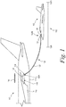
- FIG. 1 depicts a partial side view of a tanker aircraft 110 and a receiver aircraft 112 during an aerial refueling operation according to an example embodiment.
- the tanker aircraft 110 includes a fuselage 114 that extends in a longitudinal direction 116, and an aircraft wing 118 that extends from the fuselage 114 in a transverse direction relative to the longitudinal direction 116.
- the tanker aircraft 110 also includes a refueling system 120 that is operable to refuel the receiver aircraft 112 in-flight.
- the refueling system 120 includes a flexible hose 122 that extends from a housing 124 and is movable relative to the housing 124.
- the housing 124 is a pod 126, which is coupled to the aircraft wing 118.
- Figure 1 depicts a single pod 126 on the wing 118, the tanker aircraft 110 can include one or more pods 126 on the wing 118 and/or another wing on an opposite side of the fuselage 114 of the tanker aircraft 110 in additional or alternative examples.
- the tanker aircraft 110 can refuel multiple receiver aircraft 112 at the same time. Additionally or alternatively, as described below with reference to Figure 4 , the housing 124 from which the hose 122 extends can be provided by a lower portion of the fuselage 114 in other examples.
- the hose 122 is configured supply fuel to the receiver aircraft 112.
- the hose 122 can have (i) a first end 122A in the housing 124 for receiving the fuel from a fuel tank in the tanker aircraft 110 and (ii) a second end 122B trailing below and aft of the tanker aircraft 110 for coupling with a probe 128 of the receiver aircraft 112.
- the second end 122B of the hose 122 can include a drogue 130 to stabilize the hose 122 during flight and align the probe 128 to aid in coupling the probe 128 to the hose 122.
- the drogue 130 can have a conical shape to assist in stabilizing the hose 122 and coupling the hose 122 with the probe 128.
- the receiver aircraft 112 is in a position that is below and aft of a rear portion of the fuselage 114 of the tanker aircraft 110. This may mitigate or avoid potentially dangerous turbulence and disturbances in air flow created by, for instance, control surfaces and engines of the tanker aircraft 110. Additionally, in Figure 1 , the receiver aircraft 112 is shown within a refueling range 132 of the refueling system 120.
- the refueling range 132 can be a range of positions, between a first-boundary position 132A representing a minimum distance from the refueling system 120 and a second-boundary position 132B representing a maximum distance from the refueling system 120, at which the refueling system 120 can supply fuel to the receiver aircraft 112.
- the refueling system 120 may not supply fuel to the receiver aircraft 112 when the receiver aircraft 112 is outside of the refueling range 132.
- the refueling range 132 spans a distance of approximately 20 feet (ft) (6.1 meters (m)) between the first-boundary position 132A and the second-boundary position 132B.
- the refueling system 120 also includes an indication system 134 for providing indications to the receiver aircraft 112 relating to the aerial refueling operation.
- the indication system 134 is configured to indicate to the receiver aircraft 112 whether the refueling system 120 is ready to couple with the receiver aircraft 112 or not ready to couple with the receiver aircraft 112, whether the receiver aircraft 112 is positioned in the refueling range 132 or outside of the refueling range 132, a position of the receiver aircraft 112 in the refueling range 132 relative to the first-boundary position 132A and the second-boundary position 132B, and/or whether the refueling system 120 is supplying fuel to the receiver aircraft 112.
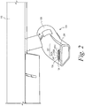
- Figure 2 depicts the indication system 134 on the housing 124 of the pod 126 according to an example embodiment.
- the indication system 134 has a plurality of light sources 236, including a not-ready light source 238, a waiting light source 240, and a plurality of refueling light sources 242.
- the not-ready light source 238 can indicate that the refueling system 120 is not ready to couple with the receiver aircraft 112
- the waiting light source 240 can indicate that the receiver aircraft 112 is positioned outside of the refueling range 132 and the refueling system 120 is ready to couple with the receiver aircraft 112
- the refueling light sources 242 can indicate that the refueling system 120 is supplying fuel and a position of the receiver aircraft 112 within the refueling range 132.
- the refueling light sources 242 include at least a first refueling light source 242A, a second refueling light source 242B, and a third refueling light source 242C.
- Each refueling light source 242A-242C can correspond to a different position or range of positions within the refueling range 132.
- the indication system 134 can indicate the relative position of the receiver aircraft 112 within the refueling range 132 so that the pilot of receiver aircraft 112 can determine when the receiver aircraft 112 is approaching the first-boundary position 132A and/or the second-boundary position 132B of the refueling range 132.
- Each light source 236 is configured to simultaneously emit visible light and infrared light when activated.
- each light source 236 can include a light-emitting diode (LED) that simultaneously generates electromagnetic radiation in the visible light spectrum (i.e., at a wavelength of about 380 nm to about 700 nm) and the infrared light spectrum (i.e., at a wavelength of about 700 nm to about 1 mm) when activated.
- LED light-emitting diode
- This type of light source may also be referred to as an "infrared dual emitter” or an "infrared dual LED".
- each light source 236 can provide indications that can be readily received and determined by the receiver aircraft 112 in daylight, low-light, and low-visibility conditions. Additionally, for example, because the light sources 236 simultaneously emit visible light and infrared light, there is no need for the tanker aircraft 110 to be informed as to whether the receiver aircraft 112 is using a night-vision imaging system to receive the indications. As such, if an issue arises with the night-vision imaging system of the receiver aircraft 112, the pilot of the receiver aircraft 112 can remove the night-vision imaging system and continue to receive indications in the visible spectrum without interrupting the aerial refueling operation.
- the waiting light source 240 is operable to emit the visible light in a first wavelength range
- the not-ready light source 238 is operable to emit the visible light in a second wavelength range
- each of the refueling light sources 242 is operable to emit the visible light in a third wavelength range, where the first wavelength range, the second wavelength range, and the third wavelength range are different than each other.
- the first wavelength range is provides amber light (e.g., approximately 570 nm to approximately 620 nm), the second wavelength range provides red light (e.g., approximately 620 nm to approximately 700 nm), and the third wavelength range provides green light (e.g., approximately 495 nm to approximately 570 nm).
- Each light source 238, 240, and 242 can also emit infrared light in an infrared wavelength range simultaneously with the visible light in the respective first, second, or third wavelength range.
- at least one light source 238, 240, and/or 242 can emit only visible light or emit only infrared light.
- Each light source 236 is operable at a dim setting and a bright setting.
- an intensity of the visible light and/or the infrared light emitted by the light source 236 at the bright setting is greater than an intensity of the visible light and/or the infrared light emitted by the light source 236 at the dim setting by at least factor of two.
- an intensity of the visible light and/or the infrared light emitted by the light source 236 at the bright setting is greater than an intensity of the visible light and/or the infrared light emitted by the light source 236 at the dim setting by a factor between approximately 1.5 and approximately 10.0.
- the intensity of the light emitted by each light source 236 at the bright setting differs from the intensity of the light emitted by the light source 236 at the dim setting such that the receiver aircraft 112 (or a pilot thereof) can visually distinguish the light source 236 activated at the bright setting from the light sources 236 activated at the dim setting.
- Figure 3 depicts a simplified block diagram including additional components of the tanker aircraft 110 and the receiver aircraft 112 according to an example embodiment.
- the refueling system 120 includes a fuel tank 344 that stores fuel to be supplied to the receiver aircraft 112.
- the fuel tank 344 is coupled to the hose 122, which can be coupled to the probe 128 of the receive aircraft 112 (e.g., as shown in Figure 1 ).
- the probe 128 is coupled to a fuel tank 346 of the receiver aircraft 112.
- the hose 122 and the probe 128 can provide a fluid path for the fuel to flow from the fuel tank 344 of the tanker aircraft 110 to the fuel tank 346 of the receiver aircraft 112.
- the refueling system 120 can include one or more valve(s) 348 along the flow path.
- the hose 122 includes the valve(s) 348; however, the valve(s) 348 can be separate from the hose 122 in additional or alternative examples.
- the valve(s) 348 are operable to start and stop the flow of fuel, and/or to increase and decrease a pressure of fuel flow through the hose 122.
- the refueling system 120 includes a hose actuator 352.
- the hose actuator 352 can move the hose 122 relative to the housing 124 to extend the hose 122 from the housing 124 and/or retract the hose 122 into the housing 124.
- the hose actuator 352 can include a reel 354 on which the hose 122 is wound, and a motor 356 operable to rotate the reel 354 to extend and retract the hose 122.
- the reel 354 can be mounted within the housing 124 of the pod 126 and/or, as described below, the housing 124 in the fuselage 114 of the tanker aircraft 110. More generally, the hose actuator 352 is configured to control a position of the hose 122 relative to the housing 124 by controlling an amount of the hose 122 that extends from the housing 124.
- the refueling system 120 further includes a hose sensing system 358.
- the hose sensing system 358 is configured to (i) sense a condition of the hose 122 and (ii) generate, based on the sensed condition, refueling data 360. To sense the condition, the hose sensing system 358 includes one or more sensors 362.
- the condition sensed by the sensor(s) 362 can include (i) whether the probe 128 of the receiver aircraft 112 is coupled to the hose 122 of the tanker aircraft 110, (ii) whether the hose 122 is supplying fuel from the tanker aircraft 110 to the receiver aircraft 112, (iii) a pressure of the fuel supplied by the hose 122 to the receiver aircraft 112, (iv) a position of the hose 122 relative to the housing 124, (v) a change in the position of the hose 122 responsive to a change in the position of the receiver aircraft 112, and/or (vi) a tension on the hose 122 when the hose 122 is coupled to the probe 128 of the receiver aircraft 112.
- the refueling data 360 generated by the hose sensing system 358 can include, for example, position data 364 indicating a position of the receiver aircraft 112 relative to the refueling system 120. For instance, when the sensor(s) 362 sense that the probe 128 is coupled to the hose 122, the position of the hose 122 is indicative of the position of the receiver aircraft 112. As such, the hose sensing system 358 can determine the position data 364 based on the position of the hose 122 relative to the housing 124 sensed by the sensor(s) 362.
- the refueling data 360 generated by the hose system 358 can also include ready-status data 366 indicating whether the refueling system 120 is ready to couple with the receiver aircraft 112 or not ready to couple with the receiver aircraft 112.
- the ready-status data 366 can indicate that the refueling system 120 is not ready to couple with the receiver aircraft 112 when the sensor(s) 362 sense (i) a fault condition and/or a mechanical failure of one or more components of the refueling system 120 has occurred, and/or (ii) the hose 122 is not in a position within the refueling range 132 (e.g., while the hose 122 is initially extended from the housing 124).
- the ready-status data 366 can indicate that the refueling system 120 is ready to couple with the receiver aircraft 112 when sensor(s) 362 sense that the hose 122 is in a position within the refueling range 132 and the sensor(s) 362 do not sense a fault condition or mechanical failure of the component(s) of the refueling system 120.
- the sensor(s) 362 can sense a fault condition and/or mechanical failure by sensing a fuel pressure in the hose 122 and/or a tension on the hose 122 that is above a threshold value, below a threshold value, and/or outside a predetermined range of threshold values.
- the ready-status data 366 can indicate that the refueling system 120 is not ready to couple with the receiver aircraft 112 responsive to an operator of the tanker aircraft 110 providing a user input to the hose sensing system 358.
- Other examples are also possible.
- the refueling data 360 generated by the hose system 358 can also include fueling-status data 368 indicating whether the refueling system 120 is supplying fuel or not supplying fuel.
- the sensor(s) 362 can sense a state of the valve(s) 348, a pressure of the fuel in the hose 122, and/or whether the hose 122 is coupled to the probe 128 to generate the fueling-status data 368.
- the hose sensing system 358 is communicatively coupled to the hose actuator 352.
- the hose actuator 352 can be configured to adjust the position of the hose 122 responsive to a movement of the receiver aircraft 112.
- the sensor(s) 362 can sense the tension on the hose 122 and the hose actuator 352 can responsively move the hose 122 to maintain the tension within a predetermined range of tension values while the receiver aircraft 112 is coupled to the refueling system 120.
- the hose sensing system 358 of the refueling system 120 is further communicatively coupled to the indication system 134.
- the indication system 134 includes a control system 370 communicatively coupled with the plurality of light sources 236.
- the control system 370 is a computing device that is configured to control operation of the refueling system 120.
- the control system 370 can be implemented using hardware, software, and/or firmware.
- the control system 370 can include one or more processors and a non-transitory computer readable medium (e.g., volatile and/or non-volatile memory) that stores machine language instructions or other executable instructions.
- the instructions when executed by the one or more processors, cause the refueling system 120 to carry out the various operations described herein.
- the control system 370 thus, can receive data (including the refueling data 360) and store the data in memory as well.
- control system 370 is configured to receive the refueling data 360 from the refueling system 120, and responsively activate at least one of the light sources 236 at the bright setting and the remaining light sources 236 at the dim setting (e.g., by transmitting control signals to the light sources 236).
- control system 370 can be configured to, when the refueling data 360 indicates that the refueling system 120 is not ready to couple with the receiver aircraft 112, activate the not-ready light source 238 at the bright setting and activate the waiting light source 240 and the plurality of refueling light sources 242 at the dim setting.
- control system 370 can be configured to, when the refueling data 360 indicates that the position of the receiver aircraft 112 is outside of the refueling range 132 and the refueling system 120 is ready to couple with the receiver aircraft 112, activate the waiting light source 240 at the bright setting and activate the not-ready light source 238 and the plurality of refueling light sources 242 at the dim setting.
- control system 370 can be configured to, when the refueling data 360 indicates that the position of the receiver aircraft 112 is in the refueling range 132 and the refueling system 120 is supplying fuel to the receiver aircraft 112, activate at least one refueling light source 242A, 242B, or 242C of the plurality of refueling light sources 242 at the bright setting and activate a remainder of the plurality of refueling light sources 242, the waiting light source 240, and the not-ready light source 238 at the dim setting. To activate any of the light sources 236, the control system 370 can send a signal to the light sources 236 to power on the light sources 236.
- control system 370 can be configured to select, based on the position data 364, the at least one refueling light source 242A, 242B, 242C from among the plurality of refueling light sources 242.
- the refueling range 132 can include a plurality of sub-ranges, and each refueling light source 242 can correspond to a respective one of the plurality of sub-ranges.
- the control system 370 can be configured to (i) determine that the position data 364 indicates that the receiver aircraft 112 is in one sub-range of the plurality of sub-ranges, and (ii) select the refueling light source 242A, 242B, 242C corresponding to the determined one sub-range as the at least one refueling light source 242A, 242B, 242C to activate at the bright setting.
- the receiver aircraft 112 can determine its position within the refueling range 132 relative to the first-boundary position 132A and the second-boundary position 132B.
- the hose 122 extends from the housing 124, which is in the form of the pod 126 coupled to the aircraft wing 118.
- the housing 124 from which the hose 122 extends can include a lower portion of the fuselage 114 and/or one or more pods 126 coupled to the wings 118.
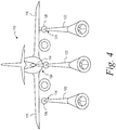
- Figure 4 depicts a rear view of the tanker aircraft 110 according to one example. As shown in Figure 4 , the tanker aircraft 110 includes a pod 126 on each wing 118. The tanker aircraft 110 further includes a hose 122 extending from each pod 126 and the fuselage 114.
- the housing 124 of the refueling system 120 thus includes the pods 126 and/or the fuselage 114.
- the tanker aircraft 110 can be configured to refuel multiple receiver aircraft 112 at the same time.
- the tanker aircraft 110 can include a flying-boom refueling system extending from the fuselage 114 and one or more hose-and-drogue systems extending from one or more pods 126.
- the pod(s) 126 can provide the tanker aircraft 110 with a versatility to refuel different types of receiver aircraft 112, which may be compatible with only one of the flying-boom system or the hose-and-drogue system of the tanker aircraft 110.
- Figures 5A-5D depict various arrangements of the plurality of light sources 236 according to example embodiments.
- the light sources 236 are arranged in a horizontal, linear pattern on the housing 124 of the pod 126.
- the light sources 236 are arranged in a vertical, linear pattern on the housing 124 of the pod 126.
- the light sources 236 are arranged in an arcing contour that corresponds to an arcing contour of the housing 124 of the pod 126.
- the light sources 236 are arranged with arcing contours on opposing sides of the housing 124. Other example arrangements are also possible.
- the indication system 134 depicted in Figures 2-5C includes five light sources 236, the indication system 134 can include a greater quantity of light sources 236 or a lesser quantity of light sources 236 in other examples.
- the waiting light source 240 can include a plurality of waiting light sources 240 and/or the not-ready light source 238 can include a plurality of not-ready light sources 238.
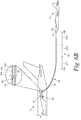
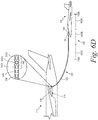
- FIGs 6A-6E depict various stages of an aerial refueling operation according to an example embodiment.
- the aerial refueling operation begins with the tanker aircraft 110 preparing the refueling system 120 for coupling with the receiver aircraft 112.
- the tanker aircraft 110 prepares the refueling system 120 by extending the hose 122 and the drogue 130 from the housing 124. Due to aerodynamic forces, the hose 122 and the drogue 130 trail behind the tanker aircraft 110 below and aft of the fuselage 114.
- the hose sensing system 358 can sense the condition(s) of the hose 122, generate the refueling data 360 based on the sense condition(s), and communicate the refueling data 360 to the control system 370.
- the refueling data 360 indicates that the refueling system 120 is not ready to couple with the receiver aircraft 112.
- the control system 370 activates the not-ready light source 238 at the bright setting and activates the waiting light source 240 and the refueling light sources 242 at the dim setting.
- the receiver aircraft 112 receives the indication provided by the light sources 238, 240, 242 and responsively does not attempt to couple with the tanker aircraft 110.
- the hose actuator 352 has completed extending the hose 122 and the drogue 130 to a position at which the refueling system 120 is ready to couple to the receiver aircraft 112, the receiver aircraft 112 remains outside of the refueling range 132, and the receiver aircraft 112 is not coupled to the refueling system 120.
- the hose sensing system 358 senses these conditions, generates the refueling data 360 based on the sensed conditions, and communicates the refueling data 360 to the control system 370.
- the refueling data 360 now indicates that the receiver aircraft 112 is at a position outside of the refueling range 132 and the refueling system 120 is ready to couple with the receiver aircraft 112. Accordingly, as shown in Figure 6B , when the refueling data 360 indicates that the position of the receiver aircraft 112 is outside of the refueling range 132 and the refueling system 120 is ready to couple with the receiver aircraft 112, the control system 370 activates the waiting light source 240 at the bright setting and activates the not-ready light source 238 and the refueling light sources 242 at the dim setting.
- the receiver aircraft 112 maneuvers into a position such that the probe 128 enters into the drogue 130 and couples with the hose 122. After coupling with the hose 122, the receiver aircraft 112 can continue to urge the hose 122 and the drogue 130 forward relative to the refueling system 120 until the receiver aircraft 112 is in the refueling range 132. As the receiver aircraft 112 moves forward, the hose actuator 352 can responsively retract the hose 122 to take up the slack in the hose 122. Additionally, after the receiver aircraft 112 moves the hose 122 forward by a predetermined distance after initial contact, the refueling system 120 starts supplying fuel to the receiver aircraft 112. In one example, the predetermined distance can be approximately five feet to approximately 10 feet.
- the receiver aircraft 112 has coupled to the refueling system 120 and moved the hose 122 forward by the predetermined distance such that that the receiver aircraft 112 is in the refueling range 132.
- the refueling system 120 is supplying fuel to the receiver aircraft 112.
- the hose sensing system 358 senses these conditions, generates the refueling data 360 based on the sensed conditions, and communicates the refueling data 360 to the control system 370.
- the control system 370 activates one of the refueling light sources 242A at the bright setting and activates the not-ready light source 238, the waiting light source 240, and the remaining refueling light sources 242B, 242C at the dim setting.
- the control system 370 select the at least one refueling light source 242A from among the plurality of refueling light sources 242 based, at least in part, on the position data 364 of the refueling data 360.
- the refueling range 132 includes a plurality of sub-ranges 632A, 632B, 632C, and each refueling light source 242A, 242B, 242C corresponds to a respective one of the plurality of sub-ranges 632A, 632B, 632C.
- the first refueling light source 242A corresponds to a first sub-range 632A
- the second refueling light source 242B corresponds to a second sub-range 632B
- the third refueling light source 242C corresponds to a third sub-range 632C.
- the plurality of refueling light sources 242A, 242B, 242C are positioned on the housing 124 of the refueling system 120 in an order that is the same as an order of the corresponding sub-ranges 632A, 632B, 632C in the refueling range 132.
- the control system 370 can determine that the position data 364 indicates that the receiver aircraft 112 is in one sub-range of the plurality of sub-ranges 632A, 632B, 632C, and select the refueling light source 242 corresponding to the determined one sub-range as the at least one refueling light source 242 to activate at the bright setting.
- the receiver aircraft 112 is in the first sub-range 632A and, thus, the control system 370 selects the first refueling light source 242A as the at least one refueling light source 242 to activate at the bright setting.
- the receiver aircraft 112 has moved from the first sub-range 632A to the second sub-range 632B while the refueling system 120 continues to supply fuel to the receiver aircraft 112. Accordingly, in Figure 6D , the control system 370 selects the second refueling light source 242B as the at least one refueling light source 242 to activate at the bright setting.
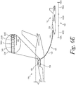
- the receiver aircraft 112 has moved from the second sub-range 632B to the third sub-range 632C while the refueling system 120 continues to supply fuel to the receiver aircraft 112. Accordingly, in Figure 6E , the control system 370 selects the third refueling light source 242C as the at least one refueling light source 242 to activate at the bright setting.
- the receiver aircraft 112 when the receiver aircraft 112 receives an indication that the receiver aircraft 112 is position in the first sub-range 632A or the third sub-range 632C, the receiver aircraft 112 can responsively move to a position in the second sub-range 632B. In this way, the receiver aircraft 112 can reduce or eliminate the risk that fuel is cutoff due to the receiver aircraft straying outside of the refueling range 132.
- Figures 6A-6E depict an example in which the refueling range 132 includes three sub-ranges 632A, 632B, 632C and the indication system 134 includes three corresponding refueling light sources 242A, 242B, 242C
- the refueling range 132 can include more than three sub-ranges 632A, 632B, 632C and the indication system can include more than three refueling light sources 242 in additional or alternative examples.
- each of the first sub-range 632A, the second sub-range 632B, and the third sub-range 632C are equal in size, the sub-ranges 632A, 632B, 632C can have different sizes in alternative examples.
- the first sub-range 632A and the third sub-range 632B can have a smaller size than the second sub-range 632B in one alternative example.
- the second sub-range 632B can thus correspond to a relatively greater range of positions for the receiver aircraft 112, which provides a target range of positions within the refueling range 132.
- the first sub-range 632A and the third sub-range 632C can correspond to a relatively smaller range of positions at which the receiver aircraft 112 is warned to adjust its position away from the boundaries of the refueling range 132.
- control system 370 can be configured to, when the refueling data 360 indicates that the position of the receiver aircraft 112 is in the refueling range 132 and the refueling system 120 is supplying fuel to the receiver aircraft 112, activate at least one refueling light source 242A, 242B, or 242C of the plurality of refueling light sources 242 at the bright setting and activate a remainder of the plurality of refueling light sources 242, the waiting light source 240, and the not-ready light source 238 at the dim setting.
- the control system 370 activates a single refueling light source 242 at the bright setting based on the relative position of the receiver aircraft 112 within the refueling range 132.
- the indication system 134 can activate more than one refueling light source 242 at the bright setting in additional or alternative examples.
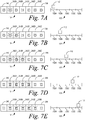
- Figures 7A-7E depict the indication system 134 having five refueling light sources 242A-242E, which are each activated at the bright setting or the dim setting based on a position of the receiver aircraft 112 in different sub-ranges 732A-732E of the refueling range 132 while the refueling system 120 is supplying fuel to the receiver aircraft 112.
- the control system 370 activates a first refueling light source 242A at the bright setting and activates a remainder of the refueling light sources 242B-242E at the dim setting.
- the control system 370 activates the first refueling light source 242A and a second refueling light source 242B at the bright setting, and activates the remainder of the refueling light sources 242C-242E at the dim setting.
- the control system 370 activates the first refueling light source 242A, the second refueling light source 242B and a third refueling light source 242C at the bright setting, and activates the remainder of the refueling light sources 242D-242E at the dim setting.
- the control system 370 activates the first refueling light source 242A, the second refueling light source 242B, the third refueling light source 242C, and a fourth refueling light source 242D at the bright setting, and activates the remainder of the refueling light sources 242E at the dim setting.
- the control system 370 activates the first refueling light source 242A, the second refueling light source 242B, the third refueling light source 242C, the fourth refueling light source 242D and the fifth refueling light source 242E at the bright setting.
- the indication system 134 includes a plurality of light sources 236 on a housing 124 of a tanker aircraft 110.
- the plurality of light sources 236 includes a not-ready light source 238, a waiting light source 240, and a plurality of refueling light sources 242.
- Each light source 236 is configured to simultaneously emit visible light and infrared light.
- Each light source 236 is operable at a bright setting and a dim setting.
- the process 800 begins by determining refueling data 360.
- the refueling data 360 can include position data 364 indicating a position of the receiver aircraft 112 relative to the refueling system 120, ready-status data 366 indicating whether the refueling system 120 is ready to couple with the receiver aircraft 112 or not ready to couple with the receiver aircraft 112, and fueling-status data 368 indicating whether the refueling system 120 is supplying fuel or not supplying fuel.
- the process 800 can include activating the not-ready light source 238 at the bright setting and activating the waiting light source 240 and the plurality of refueling light sources 242 at the dim setting.
- the process 800 can include activating the waiting light source 240 at the bright setting and activating the not-ready light source 238 and the plurality of refueling light sources 242 at the dim setting.
- the process 800 includes activating at least one refueling light source 242 of the plurality of refueling light sources 242 at the bright setting and activating a remainder of the plurality of refueling light sources 242 at the dim setting.
- the process 800 can also include activating the waiting light source 240 and the not-ready light source 238 at the dim setting.
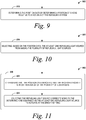
- Figures 9-13 depict additional or alternative operations that can be performed in connection with the process 800 shown in Figure 8 .
- the process 800 can further include determining the position data 364 by determining a position of a hose 122 relative to a housing 124 of the refueling system 120 at block 818.
- the process 800 can also include selecting, based on the position data 360, the at least one refueling light source 242 from among the plurality of refueling light sources 242 at block 820.
- the refueling range 132 includes a plurality of sub-ranges 632A-632C, and each refueling light source 242 corresponds to a respective one of the plurality of sub-ranges 632A-632A.
- selecting the at least one refueling light source 242 at block 820 can include: determining that the position data 364 indicates that the receiver aircraft 112 is in one sub-range 632A-632C of the plurality of sub-ranges 632A-632C at block 822, and selecting the refueling light source 242 corresponding to the determined one sub-range 632A-632C as the at least one refueling light source 242 to activate at the bright setting at block 824.
- the process 800 can include, at block 826, determining the ready-status data 366 by determining at least one condition from a group consisting of: a pressure of fuel being supplied from the refueling system 120 to the receiver aircraft 112, a position of a hose 122 of the refueling system 120 relative to a housing 124 of the refueling system 120, a change in the position of the hose 122 responsive to a change in the position of the receiver aircraft 112, and a tension on the hose 122.
- the process 800 can also include comparing the at least one condition to at least one threshold value to determine whether the refueling system 120 is ready to couple with the receiver aircraft 112 or not ready to couple with the receiver aircraft 112.
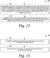
- the process 800 includes extending a hose 122 of the refueling system 120 from a pod 126 coupled to a wing 118 of a tanker aircraft 110 at block 830, and supplying, using the hose 122, fuel from the refueling system 120 to the receiver aircraft 112 at block 832.
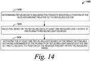
- the indication system 134 includes a plurality of light sources 236 on a housing 124 of a tanker aircraft 110.
- the plurality of light sources 236 includes a plurality of refueling light sources 242.
- Each light source 236 is configured to simultaneously emit visible light and infrared light.
- Each light source 236 is operable at a bright setting and a dim setting.
- Each refueling light source 236 corresponds to one or more positions within a refueling range 132 of the refueling system 120.
- the process 1400 includes determining refueling data 360 including position data 364 indicating a position of the receiver aircraft 112 relative to the refueling system 120.
- the process 1400 includes selecting, based on the refueling data 360, at least one refueling light source 242 of the plurality refueling light sources 242.
- the process 1400 includes activating the at least one refueling light source 242 at the bright setting and activating a remainder of the plurality of refueling light sources 242 at the dim setting to indicate the position of the receiver aircraft 112 within the refueling range 132.
- any of the blocks shown in Figures 8-14 may represent a module, a segment, or a portion of program code, which includes one or more instructions executable by a processor for implementing specific logical functions or steps in the process.
- the program code may be stored on any type of computer readable medium or data storage, for example, such as a storage device including a disk or hard drive. Further, the program code can be encoded on a computer-readable storage media in a machine-readable format, or on other non-transitory media or articles of manufacture.
- the computer readable medium may include non-transitory computer readable medium or memory, for example, such as computer-readable media that stores data for short periods of time like register memory, processor cache and Random Access Memory (RAM).
- the computer readable medium may also include non-transitory media, such as secondary or persistent long term storage, like read only memory (ROM), optical or magnetic disks, compact-disc read only memory (CD-ROM), for example.
- the computer readable media may also be any other volatile or non-volatile storage systems.
- the computer readable medium may be considered a tangible computer readable storage medium, for example.
- components of the devices and/or systems described herein may be configured to perform the functions such that the components are actually configured and structured (with hardware and/or software) to enable such performance.
- Example configurations then include one or more processors executing instructions to cause the system to perform the functions.
- components of the devices and/or systems may be configured so as to be arranged or adapted to, capable of, or suited for performing the functions, such as when operated in a specific manner.
- the blocks may represent operations and/or portions thereof and lines connecting the various blocks do not imply any particular order or dependency of the operations or portions thereof. Blocks represented by dashed lines indicate alternative operations and/or portions thereof. Dashed lines, if any, connecting the various blocks represent alternative dependencies of the operations or portions thereof. It will be understood that not all dependencies among the various disclosed operations are necessarily represented.
- Figures 8-14 and the accompanying disclosure describing the operations of the method(s) set forth herein should not be interpreted as necessarily determining a sequence in which the operations are to be performed. Rather, although one illustrative order is indicated, it is to be understood that the sequence of the operations may be modified when appropriate. Accordingly, certain operations may be performed in a different order or simultaneously. Additionally, those skilled in the art will appreciate that not all operations described need be performed.
Description
- The present disclosure generally relates to systems and methods for aircraft refueling, and more particularly to refueling systems and methods for providing indications to a receiver aircraft during aerial refueling operations.
- During aerial refueling operations, a tanker aircraft supplies fuel to a receiver aircraft while in-flight. One approach to aerial refueling is known as probe-and-drogue refueling. In a probe-and-drogue system, the tanker aircraft extends a flexible hose, which trails out behind and below the tanker aircraft. The receiver aircraft has a probe, which the receiver aircraft maneuvers into engagement with a drogue at a free end of the hose of the tanker aircraft. After the probe couples to the drogue and hose, the tanker aircraft supplies fuel to the receiver aircraft provided the receiver aircraft remains within a refueling range of the tanker aircraft.
- During an aerial refueling operation, the receiver aircraft is generally responsible for maneuvering relative to the tanker aircraft to couple the probe on the receiver aircraft with the hose and drogue of the tanker aircraft. Once coupled, the receiver aircraft attempts to maintain a position within the refueling range of the tanker aircraft so that the receiver aircraft can receive fuel at a safe distance of separation from the tanker aircraft. To help the receiver aircraft accomplish these tasks, the tanker aircraft may provide to the receiver aircraft positional and/or operational feedback during the aerial refueling operation.
- In one approach, the tanker aircraft includes an indication system for providing visual indications of the positional and/or operational feedback to the receiver aircraft. The indication system typically consists of a single not-ready light source for emitting a red light, a single waiting light source for emitting an amber light, and a single refueling light source for emitting a green light to provide indications in the visible light spectrum. Before the receiver aircraft couples to the tanker aircraft, the indication system activates the not-ready light source to indicate that the tanker aircraft is not ready to couple with the receiver aircraft, or the indication system activates the waiting light source to indicate that the tanker aircraft is ready to couple with the receiver aircraft.
- After the receiver aircraft couples to the tanker aircraft, the indication system activates the refueling light source to indicate that the receiver aircraft is in the refueling range and receiving fuel from the tanker aircraft. The indication system may flash the waiting light source to indicate that the receiver aircraft exceeded a minimum distance from the tanker aircraft or steadily activate the waiting light source to indicate that the receiver aircraft exceeded a maximum distance from the tanker aircraft (i.e., to indicate that the receiver aircraft is outside of the refueling range). In either scenario, the tanker aircraft immediately ceases supplying fuel to the receiver aircraft until the receiver aircraft maneuvers back into the refueling range. Also, in either scenario, the lights of the indication system provide no advanced warning to the receiver aircraft that it is approaching a boundary of the refueling range and should adjust its position to avoid an immediate shutoff of fuel supply.
- To provide additional positional feedback to the receiver aircraft, the tanker aircraft may include markings at various locations on the hose. For example, the hose may include markings to indicate the boundaries of the refueling range. As such, the pilot of the receiver aircraft can determine the position of the receiver aircraft relative to the refueling range by observing a position of the markings relative to a housing of the tanker aircraft from which the hose extends. One drawback is that the pilot may be required to focus on both the hose markings and the lights of the indication system to receive both positional and operational feedback indications. Because the lights and the markings are in different locations, the pilot may repeatedly shift his or her focus between the different locations on the tanker aircraft during the refueling operation. This may present difficulties for the pilot in some instances.
- Additionally, the visible light signals emitted by the indication system and the markings on the hose may be challenging for the pilot to observe when operating under low-light conditions such as, for example, during night operations and/or during inclement weather. To address low-light conditions, the tanker aircraft may include a separate set of infrared lights positioned immediately adjacent to the not-ready light source, the waiting light source, and the refueling light source. During low-light conditions, the receiver aircraft can use a night-vision imaging system (e.g., night-vision goggles) to observe when one of the infrared lights is activated. However, because the other infrared lights are not activated, the pilot is required to identify other points of reference on the tanker aircraft to try to determine the relative position of the activated infrared light and ascertain the indication being communicated. Under low-light conditions, it can be challenging to do so because it is often difficult for the pilot to accurately identify points of reference that can be used to determine the relative position of the activated light.
-
US 4,158,885 describes that a display panel of selectively operated pilot guiding lights is mounted on the belly of a fuel tanker aircraft for guiding a piloted receiver aircraft into proper orientation for an in-flight refueling link-up in which a fuel dispensing boom that projects rearwardly and downwardly from the belly of the tanker aircraft is coupled to a complimentary, refueling receptacle mounted above the cockpit of the receiver aircraft. The guidance-lights are selectively and automatically operated by computer processed position signals developed by an optical position sensor system that continuously monitors the position of the receiver aircraft relative to the boom. A first set of guidance-lights are disposed lengthwise of the aircraft to form a fore-aft position indicating array, and a second set of lights are disposed in a cross-shaped array for providing a coordinated visual display of elevational and azimuthal position. In addition to these position indicating lights, the fore-aft array includes a series of longitudinally spaced lights which are sequentially strobed toward the nose or tail of the tanker aircraft to respectively indicate that the receiver aircraft is either closing on or falling behind the target refueling position and the frequency of such strobing is varied to indicate to the receiver pilot the rate at which he is closing on or falling behind such target position. -
US 2015/083864 describes an aerial refueling assembly that includes, for example, a pressure transducer, a processor, and one or more light sources. The processor is coupled to the pressure transducer. The one or more light sources are coupled to the processor. The pressure transducer is configured to sense a fuel pressure inside the aerial refueling assembly and to provide a signal that is indicative of the sensed fuel pressure inside the aerial refueling assembly. The processor is configured to receive the signal and to cause the one or more light sources to flash in a manner that relates to the sensed fuel pressure. - In one aspect, there is provided an indication system as defined in claim 1. In another aspect, there is provided a refueling system as defined in
claim 7. In a further aspect, there is provided a method as defined in claim 11. - In an example, an indication system for use with a refueling system is described. The refueling system includes a hose for supplying fuel to a receiver aircraft. The indication system includes a plurality of light sources including a not-ready light source, a waiting light source, and a plurality of refueling light sources. Each light source is configured to simultaneously emit visible light and infrared light. Each light source is operable at a dim setting and a bright setting. The indication system also includes a control system communicatively coupled with the plurality of light sources. The control system is configured to receive refueling data from the refueling system. The refueling data includes position data indicating a position of the receiver aircraft relative to the refueling system, ready-status data indicating whether the refueling system is ready to couple with the receiver aircraft or not ready to couple with the receiver aircraft, and fueling-status data indicating whether the refueling system is supplying fuel or not supplying fuel.
- The control system is configured to: (i) when the refueling data indicates that the refueling system is not ready to couple with the receiver aircraft, activate the not-ready light source at the bright setting and activate the waiting light source and the plurality of refueling light sources at the dim setting, (ii) when the refueling data indicates that the position of the receiver aircraft is outside of a refueling range and the refueling system is ready to couple with the receiver aircraft, activate the waiting light source at the bright setting and activate the not-ready light source and the plurality of refueling light sources at the dim setting, and (iii) when the refueling data indicates that the position of the receiver aircraft is in the refueling range and the refueling system is supplying fuel to the receiver aircraft, activate at least one refueling light source of the plurality of refueling light sources at the bright setting and activate a remainder of the plurality of refueling light sources, the waiting light source, and the not-ready light source at the dim setting.
- In another example, a refueling system includes a pod, and a hose extending from the pod and movable relative to the pod. The hose is configured to supply fuel to a receiver aircraft. The refueling system also includes a hose sensing system configured to (a) sense a condition of the hose and (b) generate, based on the sensed condition, refueling data. The refueling data includes position data indicating a position of the receiver aircraft relative to the refueling system, ready-status data indicating whether the refueling system is ready to couple with the receiver aircraft or not ready to couple with the receiver aircraft, and fueling-status data indicating whether the refueling system is supplying fuel or not supplying fuel. The refueling system further includes an indication system having a plurality of light sources including a not-ready light source, a waiting light source, and a plurality of refueling light sources. Each light source is configured to simultaneously emit visible light and infrared light. Each light source is operable at a dim setting and a bright setting.
- The refueling system also includes a control system communicatively coupled with the plurality of light sources and the hose sensing system. The control system is configured to: (i) when the refueling data indicates that the refueling system is not ready to couple with the receiver aircraft, activate the not-ready light source at the bright setting and activate the waiting light source and the plurality of refueling light sources at the dim setting, (ii) when the refueling data indicates that the position of the receiver aircraft is outside of a refueling range and the refueling system is ready to couple with the receiver aircraft, activate the waiting light source at the bright setting and activate the not-ready light source and the plurality of refueling light sources at the dim setting, and (iii) when the refueling data indicates that the position of the receiver aircraft is in the refueling range and the refueling system is supplying fuel to the receiver aircraft, activate at least one refueling light source of the plurality of refueling light sources at the bright setting and activate a remainder of the plurality of refueling light sources, the waiting light source, and the not-ready light source at the dim setting.
- In another example, a method for providing indications to a receiver aircraft during a refueling operation using an indication system of a refueling system is described. The indication system includes a plurality of light sources on a housing of a tanker aircraft. The plurality of light sources includes a not-ready light source, a waiting light source, and a plurality of refueling light sources. Each light source is configured to simultaneously emit visible light and infrared light. Each light source is operable at a bright setting and a dim setting.
- The method includes determining refueling data including position data indicating a position of the receiver aircraft relative to the refueling system, ready-status data indicating whether the refueling system is ready to couple with the receiver aircraft or not ready to couple with the receiver aircraft, and fueling-status data indicating whether the refueling system is supplying fuel or not supplying fuel. The method further includes (i) when the refueling data indicates that the refueling system is not ready to couple with the receiver aircraft, activating the not-ready light source at the bright setting and activating the waiting light source and the plurality of refueling light sources at the dim setting, (ii) when the refueling data indicates that the position of the receiver aircraft is outside of a refueling range and the refueling system is ready to couple with the receiver aircraft, activating the waiting light source at the bright setting and activating the not-ready light source and the plurality of refueling light sources at the dim setting, and (iii) when the refueling data indicates that the position of the receiver aircraft is in the refueling range and the refueling system is supplying fuel to the receiver aircraft, activating at least one refueling light source of the plurality of refueling light sources at the bright setting and activating a remainder of the plurality of refueling light sources, the waiting light source, and the not-ready light source at the dim setting.
- The features, functions, and advantages that have been discussed can be achieved independently in various embodiments or may be combined in yet other embodiments further details of which can be seen with reference to the following description and drawings.
- The novel features believed characteristic of the illustrative embodiments are set forth in the appended claims. The illustrative embodiments, however, as well as a preferred mode of use, further objectives and descriptions thereof, will best be understood by reference to the following detailed description of an illustrative embodiment of the present disclosure when read in conjunction with the accompanying drawings, wherein:
-
Figure 1 illustrates a side view of a tanker aircraft and a receiver aircraft according to an example embodiment. -
Figure 2 illustrates an indication system according to an example embodiment. -
Figure 3 illustrates a simplified block diagram of a tanker aircraft and a receiver aircraft according to an example embodiment. -
Figure 4 illustrates a rear view of a tanker aircraft according to an example embodiment. -
Figure 5A illustrates an arrangement of light sources for an indication system according to an example embodiment. -
Figure 5B illustrates another arrangement of light sources for an indication system according to an example embodiment. -
Figure 5C illustrates another arrangement of light sources for an indication system according to an example embodiment. -
Figure 5D illustrates another arrangement of light sources for an indication system according to an example embodiment. -
Figure 6A illustrates a stage of a refueling operation according to an example embodiment. -
Figure 6B illustrates another stage of the refueling operation according to the example embodiment. -
Figure 6C illustrates another stage of the refueling operation according to the example embodiment. -
Figure 6D illustrates another stage of the refueling operation according to the example embodiment. -
Figure 6E illustrates another stage of the refueling operation according to the example embodiment. -
Figure 7A illustrates a state of an indication system when a receiver aircraft in a position within a refueling range according to an example embodiment. -
Figure 7B illustrates another state of the indication system when the receiver aircraft in another position within the refueling range according to the example embodiment. -
Figure 7C illustrates another state of the indication system when the receiver aircraft in another position within the refueling range according to the example embodiment. -
Figure 7D illustrates another state of the indication system when the receiver aircraft in another position within the refueling range according to the example embodiment. -
Figure 7E illustrates another state of the indication system when the receiver aircraft in another position within the refueling range according to the example embodiment. -
Figure 8 illustrates a flow chart of an example process for providing indications to a receiver aircraft during a refueling operation according to an example embodiment. -
Figure 9 illustrates a flow chart of an example process for providing indications to a receiver aircraft during a refueling operation that can be used with the process shown inFigure 8 . -
Figure 10 illustrates a flow chart of an example process for providing indications to a receiver aircraft during a refueling operation that can be used with the process shown inFigure 8 orFigure 9 . -
Figure 11 illustrates a flow chart of an example process for providing indications to a receiver aircraft during a refueling operation that can be used with the process shown inFigure 10 . -
Figure 12 illustrates a flow chart of an example process for providing indications to a receiver aircraft during a refueling operation that can be used with the process shown inFigures 8-11 . -
Figure 13 illustrates a flow chart of an example process for providing indications to a receiver aircraft during a refueling operation that can be used with the process shown inFigures 8-12 . -
Figure 14 illustrates a flow chart of an example process for providing indications to a receiver aircraft during a refueling operation according to an example embodiment. - Disclosed embodiments will now be described more fully hereinafter with reference to the accompanying drawings, in which some, but not all of the disclosed embodiments are shown. Indeed, several different embodiments may be described and should not be construed as limited to the embodiments set forth herein. Rather, these embodiments are described so that this disclosure will be thorough and complete and will fully convey the scope of the disclosure to those skilled in the art.
- Example systems and methods described herein can beneficially address at least some drawbacks of existing aerial refueling systems. Within the examples described herein, a refueling system includes an indication system having a plurality of light sources. Each light source is configured to simultaneously emit visible light and infrared light. Additionally, each light source is operable in a bright setting and a dim setting. During an aerial refueling operation, the refueling system determines one or more conditions relating to the refueling operation and, based on the determined condition(s), the indication system can selectively activate at least one of the light sources at the bright setting while activating the remaining light sources at the dim setting to provide indications of positional and operational feedback to the receiver aircraft.
- The light sources can include a not-ready light source, a waiting light source, and/or a plurality of refueling light sources. The indication system can activate the not-ready light source at the bright setting to indicate that the refueling system is not ready to couple with the receiver aircraft. The indication system can activate the waiting light source at the bright setting to indicate that the refueling system is ready to couple with the receiver aircraft. The indication system can activate at least one of the refueling light sources at the bright setting to indicate that the refueling system is supplying fuel to the receiver aircraft.
- Additionally, each of the refueling light sources can correspond to a different position and/or sub-range of positions within the refueling range. As such, the refueling light sources can indicate a specific position or position range of the receiver aircraft within the refueling range by selectively activating the refueling light source that corresponds to the specific position of the receiver aircraft. This may allow the receiver pilot to anticipate when the receiver aircraft is approaching a boundary of the refueling range and responsively make adjustments to avoid moving outside of the refueling range. Additionally, because the light sources provide both operational indications (e.g., ready, not ready, fuel being supplied, etc.) and positional indications (e.g., a position of the receiver aircraft within the refueling range), the pilot of the receiver aircraft can more easily ascertain the indications without having to repeatedly shift his or her focus between the hose and the light sources.
- Because the light sources simultaneously emit light in the visible and infrared wavelength ranges when activated, the receiver pilot can receive the indications in daylight and low-light conditions. As such, a single set of light sources can facilitate refueling operations in both overt mode (i.e., for daylight conditions) and covert mode (i.e., for low-light conditions) of operation. This provides the indication system with operational versatility and also helps to reduce or avoid interruptions to the refueling operation. For example, in a scenario in which a night-vision imaging system (e.g., night-vision goggles (NVGs)) has an operational transient, a pilot of the receiver aircraft can remove the night-vision imaging system to view the indications in the visible light spectrum without interruption to the refueling operation.
- Additionally, because the indication system provides each indication to the receiver aircraft by selectively activating each light source at either the bright setting or the dim setting, the light sources activated at the dim setting provide reference points for ascertaining which of the light sources is activated at the bright setting for the indication. As such, the light source activated at the bright setting can be readily identified by the pilot of the receiver aircraft. This may be particularly beneficial when the pilot of the receiver aircraft uses a night-vision imaging system, which causes the infrared light emitted by all of the light sources to appear to be the same color light (i.e., monochromatic such as, for example, a green color). These and other benefits are described in further detail below.
-
Figure 1 depicts a partial side view of atanker aircraft 110 and areceiver aircraft 112 during an aerial refueling operation according to an example embodiment. As shown inFigure 1 , thetanker aircraft 110 includes afuselage 114 that extends in alongitudinal direction 116, and anaircraft wing 118 that extends from thefuselage 114 in a transverse direction relative to thelongitudinal direction 116. - The
tanker aircraft 110 also includes arefueling system 120 that is operable to refuel thereceiver aircraft 112 in-flight. Therefueling system 120 includes aflexible hose 122 that extends from ahousing 124 and is movable relative to thehousing 124. InFigure 1 , thehousing 124 is apod 126, which is coupled to theaircraft wing 118. AlthoughFigure 1 depicts asingle pod 126 on thewing 118, thetanker aircraft 110 can include one ormore pods 126 on thewing 118 and/or another wing on an opposite side of thefuselage 114 of thetanker aircraft 110 in additional or alternative examples. By providing apod 126 on each of thewings 118, thetanker aircraft 110 can refuelmultiple receiver aircraft 112 at the same time. Additionally or alternatively, as described below with reference toFigure 4 , thehousing 124 from which thehose 122 extends can be provided by a lower portion of thefuselage 114 in other examples. - The
hose 122 is configured supply fuel to thereceiver aircraft 112. For example, thehose 122 can have (i) afirst end 122A in thehousing 124 for receiving the fuel from a fuel tank in thetanker aircraft 110 and (ii) asecond end 122B trailing below and aft of thetanker aircraft 110 for coupling with aprobe 128 of thereceiver aircraft 112. Thesecond end 122B of thehose 122 can include adrogue 130 to stabilize thehose 122 during flight and align theprobe 128 to aid in coupling theprobe 128 to thehose 122. For example, thedrogue 130 can have a conical shape to assist in stabilizing thehose 122 and coupling thehose 122 with theprobe 128. - In
Figure 1 , thereceiver aircraft 112 is in a position that is below and aft of a rear portion of thefuselage 114 of thetanker aircraft 110. This may mitigate or avoid potentially dangerous turbulence and disturbances in air flow created by, for instance, control surfaces and engines of thetanker aircraft 110. Additionally, inFigure 1 , thereceiver aircraft 112 is shown within arefueling range 132 of therefueling system 120. Therefueling range 132 can be a range of positions, between a first-boundary position 132A representing a minimum distance from therefueling system 120 and a second-boundary position 132B representing a maximum distance from therefueling system 120, at which therefueling system 120 can supply fuel to thereceiver aircraft 112. Therefueling system 120 may not supply fuel to thereceiver aircraft 112 when thereceiver aircraft 112 is outside of therefueling range 132. In one example, therefueling range 132 spans a distance of approximately 20 feet (ft) (6.1 meters (m)) between the first-boundary position 132A and the second-boundary position 132B. - The
refueling system 120 also includes anindication system 134 for providing indications to thereceiver aircraft 112 relating to the aerial refueling operation. For example, theindication system 134 is configured to indicate to thereceiver aircraft 112 whether therefueling system 120 is ready to couple with thereceiver aircraft 112 or not ready to couple with thereceiver aircraft 112, whether thereceiver aircraft 112 is positioned in therefueling range 132 or outside of therefueling range 132, a position of thereceiver aircraft 112 in therefueling range 132 relative to the first-boundary position 132A and the second-boundary position 132B, and/or whether therefueling system 120 is supplying fuel to thereceiver aircraft 112. -
Figure 2 depicts theindication system 134 on thehousing 124 of thepod 126 according to an example embodiment. As shown inFigure 2 , theindication system 134 has a plurality oflight sources 236, including a not-readylight source 238, a waitinglight source 240, and a plurality of refuelinglight sources 242. In an example, the not-readylight source 238 can indicate that therefueling system 120 is not ready to couple with thereceiver aircraft 112, the waitinglight source 240 can indicate that thereceiver aircraft 112 is positioned outside of therefueling range 132 and therefueling system 120 is ready to couple with thereceiver aircraft 112, and the refuelinglight sources 242 can indicate that therefueling system 120 is supplying fuel and a position of thereceiver aircraft 112 within therefueling range 132. - As shown in
Figure 2 , the refuelinglight sources 242 include at least a firstrefueling light source 242A, a secondrefueling light source 242B, and a thirdrefueling light source 242C. Each refuelinglight source 242A-242C can correspond to a different position or range of positions within therefueling range 132. By providing multiple refuelinglight sources 242A-242C, theindication system 134 can indicate the relative position of thereceiver aircraft 112 within therefueling range 132 so that the pilot ofreceiver aircraft 112 can determine when thereceiver aircraft 112 is approaching the first-boundary position 132A and/or the second-boundary position 132B of therefueling range 132. - Each
light source 236 is configured to simultaneously emit visible light and infrared light when activated. For example, eachlight source 236 can include a light-emitting diode (LED) that simultaneously generates electromagnetic radiation in the visible light spectrum (i.e., at a wavelength of about 380 nm to about 700 nm) and the infrared light spectrum (i.e., at a wavelength of about 700 nm to about 1 mm) when activated. This type of light source may also be referred to as an "infrared dual emitter" or an "infrared dual LED". - By simultaneously emitting visible light and infrared light, each
light source 236 can provide indications that can be readily received and determined by thereceiver aircraft 112 in daylight, low-light, and low-visibility conditions. Additionally, for example, because thelight sources 236 simultaneously emit visible light and infrared light, there is no need for thetanker aircraft 110 to be informed as to whether thereceiver aircraft 112 is using a night-vision imaging system to receive the indications. As such, if an issue arises with the night-vision imaging system of thereceiver aircraft 112, the pilot of thereceiver aircraft 112 can remove the night-vision imaging system and continue to receive indications in the visible spectrum without interrupting the aerial refueling operation. - In an example, the waiting
light source 240 is operable to emit the visible light in a first wavelength range, the not-readylight source 238 is operable to emit the visible light in a second wavelength range, and each of the refuelinglight sources 242 is operable to emit the visible light in a third wavelength range, where the first wavelength range, the second wavelength range, and the third wavelength range are different than each other. By activating thelight sources 236 at different wavelength ranges, the visible light emitted by thelight sources 236 can be visually distinguishable from each other. For instance, in one implementation, the first wavelength range is provides amber light (e.g., approximately 570 nm to approximately 620 nm), the second wavelength range provides red light (e.g., approximately 620 nm to approximately 700 nm), and the third wavelength range provides green light (e.g., approximately 495 nm to approximately 570 nm). Eachlight source light source - Each
light source 236 is operable at a dim setting and a bright setting. In one example, for eachlight source 236, an intensity of the visible light and/or the infrared light emitted by thelight source 236 at the bright setting is greater than an intensity of the visible light and/or the infrared light emitted by thelight source 236 at the dim setting by at least factor of two. In another example, for eachlight source 236, an intensity of the visible light and/or the infrared light emitted by thelight source 236 at the bright setting is greater than an intensity of the visible light and/or the infrared light emitted by thelight source 236 at the dim setting by a factor between approximately 1.5 and approximately 10.0. More generally, the intensity of the light emitted by eachlight source 236 at the bright setting differs from the intensity of the light emitted by thelight source 236 at the dim setting such that the receiver aircraft 112 (or a pilot thereof) can visually distinguish thelight source 236 activated at the bright setting from thelight sources 236 activated at the dim setting. -
Figure 3 depicts a simplified block diagram including additional components of thetanker aircraft 110 and thereceiver aircraft 112 according to an example embodiment. As shown inFigure 3 , therefueling system 120 includes afuel tank 344 that stores fuel to be supplied to thereceiver aircraft 112. Thefuel tank 344 is coupled to thehose 122, which can be coupled to theprobe 128 of the receive aircraft 112 (e.g., as shown inFigure 1 ). Theprobe 128 is coupled to afuel tank 346 of thereceiver aircraft 112. In this way, when theprobe 128 is inserted in thedrogue 130 and coupled to thehose 122 during an aerial refueling operation, thehose 122 and theprobe 128 can provide a fluid path for the fuel to flow from thefuel tank 344 of thetanker aircraft 110 to thefuel tank 346 of thereceiver aircraft 112. - To control the flow of fuel from the
tanker aircraft 110 to thereceiver aircraft 112, therefueling system 120 can include one or more valve(s) 348 along the flow path. For example, inFigure 3 , thehose 122 includes the valve(s) 348; however, the valve(s) 348 can be separate from thehose 122 in additional or alternative examples. In one implementation, the valve(s) 348 are operable to start and stop the flow of fuel, and/or to increase and decrease a pressure of fuel flow through thehose 122. - As also shown in
Figure 3 , therefueling system 120 includes ahose actuator 352. Thehose actuator 352 can move thehose 122 relative to thehousing 124 to extend thehose 122 from thehousing 124 and/or retract thehose 122 into thehousing 124. As one example, thehose actuator 352 can include areel 354 on which thehose 122 is wound, and amotor 356 operable to rotate thereel 354 to extend and retract thehose 122. Thereel 354 can be mounted within thehousing 124 of thepod 126 and/or, as described below, thehousing 124 in thefuselage 114 of thetanker aircraft 110. More generally, thehose actuator 352 is configured to control a position of thehose 122 relative to thehousing 124 by controlling an amount of thehose 122 that extends from thehousing 124. - The
refueling system 120 further includes ahose sensing system 358. Thehose sensing system 358 is configured to (i) sense a condition of thehose 122 and (ii) generate, based on the sensed condition,refueling data 360. To sense the condition, thehose sensing system 358 includes one ormore sensors 362. In an example, the condition sensed by the sensor(s) 362 can include (i) whether theprobe 128 of thereceiver aircraft 112 is coupled to thehose 122 of thetanker aircraft 110, (ii) whether thehose 122 is supplying fuel from thetanker aircraft 110 to thereceiver aircraft 112, (iii) a pressure of the fuel supplied by thehose 122 to thereceiver aircraft 112, (iv) a position of thehose 122 relative to thehousing 124, (v) a change in the position of thehose 122 responsive to a change in the position of thereceiver aircraft 112, and/or (vi) a tension on thehose 122 when thehose 122 is coupled to theprobe 128 of thereceiver aircraft 112. - The
refueling data 360 generated by thehose sensing system 358 can include, for example,position data 364 indicating a position of thereceiver aircraft 112 relative to therefueling system 120. For instance, when the sensor(s) 362 sense that theprobe 128 is coupled to thehose 122, the position of thehose 122 is indicative of the position of thereceiver aircraft 112. As such, thehose sensing system 358 can determine theposition data 364 based on the position of thehose 122 relative to thehousing 124 sensed by the sensor(s) 362. - The
refueling data 360 generated by thehose system 358 can also include ready-status data 366 indicating whether therefueling system 120 is ready to couple with thereceiver aircraft 112 or not ready to couple with thereceiver aircraft 112. In one example, the ready-status data 366 can indicate that therefueling system 120 is not ready to couple with thereceiver aircraft 112 when the sensor(s) 362 sense (i) a fault condition and/or a mechanical failure of one or more components of therefueling system 120 has occurred, and/or (ii) thehose 122 is not in a position within the refueling range 132 (e.g., while thehose 122 is initially extended from the housing 124). Whereas, the ready-status data 366 can indicate that therefueling system 120 is ready to couple with thereceiver aircraft 112 when sensor(s) 362 sense that thehose 122 is in a position within therefueling range 132 and the sensor(s) 362 do not sense a fault condition or mechanical failure of the component(s) of therefueling system 120. In an example implementation, the sensor(s) 362 can sense a fault condition and/or mechanical failure by sensing a fuel pressure in thehose 122 and/or a tension on thehose 122 that is above a threshold value, below a threshold value, and/or outside a predetermined range of threshold values. - In another example, the ready-status data 366 can indicate that the
refueling system 120 is not ready to couple with thereceiver aircraft 112 responsive to an operator of thetanker aircraft 110 providing a user input to thehose sensing system 358. Other examples are also possible. - The
refueling data 360 generated by thehose system 358 can also include fueling-status data 368 indicating whether therefueling system 120 is supplying fuel or not supplying fuel. For example, the sensor(s) 362 can sense a state of the valve(s) 348, a pressure of the fuel in thehose 122, and/or whether thehose 122 is coupled to theprobe 128 to generate the fueling-status data 368. - As shown in
Figure 3 , thehose sensing system 358 is communicatively coupled to thehose actuator 352. In an example, when theprobe 128 of thereceiver aircraft 112 is coupled with thehose 122 of thetanker aircraft 110, thehose actuator 352 can be configured to adjust the position of thehose 122 responsive to a movement of thereceiver aircraft 112. For instance, the sensor(s) 362 can sense the tension on thehose 122 and thehose actuator 352 can responsively move thehose 122 to maintain the tension within a predetermined range of tension values while thereceiver aircraft 112 is coupled to therefueling system 120. - Also, as shown in
Figure 3 , thehose sensing system 358 of therefueling system 120 is further communicatively coupled to theindication system 134. Theindication system 134 includes acontrol system 370 communicatively coupled with the plurality oflight sources 236. In general, thecontrol system 370 is a computing device that is configured to control operation of therefueling system 120. As such, thecontrol system 370 can be implemented using hardware, software, and/or firmware. For example, thecontrol system 370 can include one or more processors and a non-transitory computer readable medium (e.g., volatile and/or non-volatile memory) that stores machine language instructions or other executable instructions. The instructions, when executed by the one or more processors, cause therefueling system 120 to carry out the various operations described herein. Thecontrol system 370, thus, can receive data (including the refueling data 360) and store the data in memory as well. - More particularly, the
control system 370 is configured to receive therefueling data 360 from therefueling system 120, and responsively activate at least one of thelight sources 236 at the bright setting and the remaininglight sources 236 at the dim setting (e.g., by transmitting control signals to the light sources 236). For example, thecontrol system 370 can be configured to, when therefueling data 360 indicates that therefueling system 120 is not ready to couple with thereceiver aircraft 112, activate the not-readylight source 238 at the bright setting and activate the waitinglight source 240 and the plurality of refuelinglight sources 242 at the dim setting. Additionally, for example, thecontrol system 370 can be configured to, when therefueling data 360 indicates that the position of thereceiver aircraft 112 is outside of therefueling range 132 and therefueling system 120 is ready to couple with thereceiver aircraft 112, activate the waitinglight source 240 at the bright setting and activate the not-readylight source 238 and the plurality of refuelinglight sources 242 at the dim setting. - Additionally or alternatively, the
control system 370 can be configured to, when therefueling data 360 indicates that the position of thereceiver aircraft 112 is in therefueling range 132 and therefueling system 120 is supplying fuel to thereceiver aircraft 112, activate at least onerefueling light source light sources 242 at the bright setting and activate a remainder of the plurality of refuelinglight sources 242, the waitinglight source 240, and the not-readylight source 238 at the dim setting. To activate any of thelight sources 236, thecontrol system 370 can send a signal to thelight sources 236 to power on thelight sources 236. - In an implementation, the
control system 370 can be configured to select, based on theposition data 364, the at least onerefueling light source light sources 242. For example, therefueling range 132 can include a plurality of sub-ranges, and each refuelinglight source 242 can correspond to a respective one of the plurality of sub-ranges. In this example, to select the at least onerefueling light source control system 370 can be configured to (i) determine that theposition data 364 indicates that thereceiver aircraft 112 is in one sub-range of the plurality of sub-ranges, and (ii) select the refuelinglight source refueling light source light source 242 that is activated at the bright setting, thereceiver aircraft 112 can determine its position within therefueling range 132 relative to the first-boundary position 132A and the second-boundary position 132B. - As described above, in
Figures 1-2 , thehose 122 extends from thehousing 124, which is in the form of thepod 126 coupled to theaircraft wing 118. In additional or alternative examples, thehousing 124 from which thehose 122 extends can include a lower portion of thefuselage 114 and/or one ormore pods 126 coupled to thewings 118.Figure 4 depicts a rear view of thetanker aircraft 110 according to one example. As shown inFigure 4 , thetanker aircraft 110 includes apod 126 on eachwing 118. Thetanker aircraft 110 further includes ahose 122 extending from eachpod 126 and thefuselage 114. InFigure 4 , thehousing 124 of therefueling system 120 thus includes thepods 126 and/or thefuselage 114. By providingmultiple hoses 122, thetanker aircraft 110 can be configured to refuelmultiple receiver aircraft 112 at the same time. - In one alternative example, the
tanker aircraft 110 can include a flying-boom refueling system extending from thefuselage 114 and one or more hose-and-drogue systems extending from one ormore pods 126. In this alternative example, the pod(s) 126 can provide thetanker aircraft 110 with a versatility to refuel different types ofreceiver aircraft 112, which may be compatible with only one of the flying-boom system or the hose-and-drogue system of thetanker aircraft 110. -
Figures 5A-5D depict various arrangements of the plurality oflight sources 236 according to example embodiments. InFigure 5A , thelight sources 236 are arranged in a horizontal, linear pattern on thehousing 124 of thepod 126. InFigure 5B , thelight sources 236 are arranged in a vertical, linear pattern on thehousing 124 of thepod 126. InFigure 5C , thelight sources 236 are arranged in an arcing contour that corresponds to an arcing contour of thehousing 124 of thepod 126. InFigure 5D , thelight sources 236 are arranged with arcing contours on opposing sides of thehousing 124. Other example arrangements are also possible. - Although the
indication system 134 depicted inFigures 2-5C includes fivelight sources 236, theindication system 134 can include a greater quantity oflight sources 236 or a lesser quantity oflight sources 236 in other examples. For instance, in additional or alternative examples, the waitinglight source 240 can include a plurality of waitinglight sources 240 and/or the not-readylight source 238 can include a plurality of not-ready light sources 238. Further, in additional or alternative examples, the refuelinglight sources 242 can include N refuelinglight sources 242, where N is an integer value that is greater than or equal to two (e.g., N = 2, 3, 4, 5, 6, 7, etc.). As the quantity of refuelinglight sources 242 increases, theindication system 134 can provide positional feedback to thereceiver aircraft 112 with greater granularity. -
Figures 6A-6E depict various stages of an aerial refueling operation according to an example embodiment. The aerial refueling operation begins with thetanker aircraft 110 preparing therefueling system 120 for coupling with thereceiver aircraft 112. For example, inFigure 6A , thetanker aircraft 110 prepares therefueling system 120 by extending thehose 122 and thedrogue 130 from thehousing 124. Due to aerodynamic forces, thehose 122 and thedrogue 130 trail behind thetanker aircraft 110 below and aft of thefuselage 114. - While initially extending the
hose 122 and/or otherwise preparing therefueling system 120, thehose sensing system 358 can sense the condition(s) of thehose 122, generate therefueling data 360 based on the sense condition(s), and communicate therefueling data 360 to thecontrol system 370. InFigure 6A , therefueling data 360 indicates that therefueling system 120 is not ready to couple with thereceiver aircraft 112. Accordingly, as shown inFigure 6A , when therefueling data 360 indicates that therefueling system 120 is not ready to couple with thereceiver aircraft 112, thecontrol system 370 activates the not-readylight source 238 at the bright setting and activates the waitinglight source 240 and the refuelinglight sources 242 at the dim setting. Thereceiver aircraft 112 receives the indication provided by thelight sources tanker aircraft 110. - In
Figure 6B , thehose actuator 352 has completed extending thehose 122 and thedrogue 130 to a position at which therefueling system 120 is ready to couple to thereceiver aircraft 112, thereceiver aircraft 112 remains outside of therefueling range 132, and thereceiver aircraft 112 is not coupled to therefueling system 120. Thehose sensing system 358 senses these conditions, generates therefueling data 360 based on the sensed conditions, and communicates therefueling data 360 to thecontrol system 370. - In
Figure 6B , therefueling data 360 now indicates that thereceiver aircraft 112 is at a position outside of therefueling range 132 and therefueling system 120 is ready to couple with thereceiver aircraft 112. Accordingly, as shown inFigure 6B , when therefueling data 360 indicates that the position of thereceiver aircraft 112 is outside of therefueling range 132 and therefueling system 120 is ready to couple with thereceiver aircraft 112, thecontrol system 370 activates the waitinglight source 240 at the bright setting and activates the not-readylight source 238 and the refuelinglight sources 242 at the dim setting. - Responsive to this indication from the
light sources receiver aircraft 112 maneuvers into a position such that theprobe 128 enters into thedrogue 130 and couples with thehose 122. After coupling with thehose 122, thereceiver aircraft 112 can continue to urge thehose 122 and thedrogue 130 forward relative to therefueling system 120 until thereceiver aircraft 112 is in therefueling range 132. As thereceiver aircraft 112 moves forward, thehose actuator 352 can responsively retract thehose 122 to take up the slack in thehose 122. Additionally, after thereceiver aircraft 112 moves thehose 122 forward by a predetermined distance after initial contact, therefueling system 120 starts supplying fuel to thereceiver aircraft 112. In one example, the predetermined distance can be approximately five feet to approximately 10 feet. - In
Figure 6C , thereceiver aircraft 112 has coupled to therefueling system 120 and moved thehose 122 forward by the predetermined distance such that that thereceiver aircraft 112 is in therefueling range 132. As such, inFigure 6C , therefueling system 120 is supplying fuel to thereceiver aircraft 112. Thehose sensing system 358 senses these conditions, generates therefueling data 360 based on the sensed conditions, and communicates therefueling data 360 to thecontrol system 370. As shown inFigure 6C , when therefueling data 360 indicates that thereceiver aircraft 112 is in therefueling range 132 and therefueling system 120 is supplying fuel to thereceiver aircraft 112, thecontrol system 370 activates one of the refuelinglight sources 242A at the bright setting and activates the not-readylight source 238, the waitinglight source 240, and the remaining refuelinglight sources - The
control system 370 select the at least onerefueling light source 242A from among the plurality of refuelinglight sources 242 based, at least in part, on theposition data 364 of therefueling data 360. For example, inFigures 6A-6E , therefueling range 132 includes a plurality of sub-ranges 632A, 632B, 632C, and each refuelinglight source Figures 6A-6E , for example, the firstrefueling light source 242A corresponds to a first sub-range 632A, the secondrefueling light source 242B corresponds to a second sub-range 632B, and the thirdrefueling light source 242C corresponds to a third sub-range 632C. In this example, the plurality of refuelinglight sources housing 124 of therefueling system 120 in an order that is the same as an order of the corresponding sub-ranges 632A, 632B, 632C in therefueling range 132. - To select the at least one
refueling light source 242, thecontrol system 370 can determine that theposition data 364 indicates that thereceiver aircraft 112 is in one sub-range of the plurality of sub-ranges 632A, 632B, 632C, and select the refuelinglight source 242 corresponding to the determined one sub-range as the at least onerefueling light source 242 to activate at the bright setting. InFigure 6C , thereceiver aircraft 112 is in the first sub-range 632A and, thus, thecontrol system 370 selects the firstrefueling light source 242A as the at least onerefueling light source 242 to activate at the bright setting. - In
Figure 6D , thereceiver aircraft 112 has moved from the first sub-range 632A to the second sub-range 632B while therefueling system 120 continues to supply fuel to thereceiver aircraft 112. Accordingly, inFigure 6D , thecontrol system 370 selects the secondrefueling light source 242B as the at least onerefueling light source 242 to activate at the bright setting. InFigure 6E , thereceiver aircraft 112 has moved from the second sub-range 632B to the third sub-range 632C while therefueling system 120 continues to supply fuel to thereceiver aircraft 112. Accordingly, inFigure 6E , thecontrol system 370 selects the thirdrefueling light source 242C as the at least onerefueling light source 242 to activate at the bright setting. - In one implementation, when the
receiver aircraft 112 receives an indication that thereceiver aircraft 112 is position in the first sub-range 632A or the third sub-range 632C, thereceiver aircraft 112 can responsively move to a position in the second sub-range 632B. In this way, thereceiver aircraft 112 can reduce or eliminate the risk that fuel is cutoff due to the receiver aircraft straying outside of therefueling range 132. - Although
Figures 6A-6E depict an example in which therefueling range 132 includes threesub-ranges indication system 134 includes three corresponding refuelinglight sources refueling range 132 can include more than threesub-ranges light sources 242 in additional or alternative examples. Additionally, although each of the first sub-range 632A, the second sub-range 632B, and the third sub-range 632C are equal in size, the sub-ranges 632A, 632B, 632C can have different sizes in alternative examples. For instance, the first sub-range 632A and the third sub-range 632B can have a smaller size than the second sub-range 632B in one alternative example. The second sub-range 632B can thus correspond to a relatively greater range of positions for thereceiver aircraft 112, which provides a target range of positions within therefueling range 132. Whereas the first sub-range 632A and the third sub-range 632C can correspond to a relatively smaller range of positions at which thereceiver aircraft 112 is warned to adjust its position away from the boundaries of therefueling range 132. - As described above, the
control system 370 can be configured to, when therefueling data 360 indicates that the position of thereceiver aircraft 112 is in therefueling range 132 and therefueling system 120 is supplying fuel to thereceiver aircraft 112, activate at least onerefueling light source light sources 242 at the bright setting and activate a remainder of the plurality of refuelinglight sources 242, the waitinglight source 240, and the not-readylight source 238 at the dim setting. In the example shown inFigures 6A-6E , when therefueling data 360 indicates that thereceiver aircraft 112 is in therefueling range 132 and therefueling system 120 is supplying fuel to thereceiver aircraft 112, thecontrol system 370 activates a singlerefueling light source 242 at the bright setting based on the relative position of thereceiver aircraft 112 within therefueling range 132. However, theindication system 134 can activate more than onerefueling light source 242 at the bright setting in additional or alternative examples. - As one example,
Figures 7A-7E depict theindication system 134 having five refuelinglight sources 242A-242E, which are each activated at the bright setting or the dim setting based on a position of thereceiver aircraft 112 indifferent sub-ranges 732A-732E of therefueling range 132 while therefueling system 120 is supplying fuel to thereceiver aircraft 112. - As shown in
Figure 7A , when thereceiver aircraft 112 is in a first sub-range 732A, thecontrol system 370 activates a firstrefueling light source 242A at the bright setting and activates a remainder of the refuelinglight sources 242B-242E at the dim setting. As shown inFigure 7B , when thereceiver aircraft 112 is in a second sub-range 732B, thecontrol system 370 activates the firstrefueling light source 242A and a secondrefueling light source 242B at the bright setting, and activates the remainder of the refuelinglight sources 242C-242E at the dim setting. As shown inFigure 7C , when thereceiver aircraft 112 is in a third sub-range 732C, thecontrol system 370 activates the firstrefueling light source 242A, the secondrefueling light source 242B and a thirdrefueling light source 242C at the bright setting, and activates the remainder of the refueling light sources 242D-242E at the dim setting. As shown inFigure 7D , when thereceiver aircraft 112 is in a fourth sub-range 732D, thecontrol system 370 activates the firstrefueling light source 242A, the secondrefueling light source 242B, the thirdrefueling light source 242C, and a fourth refueling light source 242D at the bright setting, and activates the remainder of the refuelinglight sources 242E at the dim setting. As shown inFigure 7E , when thereceiver aircraft 112 is in a fifth sub-range 732E, thecontrol system 370 activates the firstrefueling light source 242A, the secondrefueling light source 242B, the thirdrefueling light source 242C, the fourth refueling light source 242D and the fifthrefueling light source 242E at the bright setting. - Referring now to
Figures 1-8 , a flowchart for aprocess 800 of providing indications to areceiver aircraft 112 during a refueling operation using anindication system 134 of arefueling system 120 is illustrated according to an example embodiment. As described above, theindication system 134 includes a plurality oflight sources 236 on ahousing 124 of atanker aircraft 110. The plurality oflight sources 236 includes a not-readylight source 238, a waitinglight source 240, and a plurality of refuelinglight sources 242. Eachlight source 236 is configured to simultaneously emit visible light and infrared light. Eachlight source 236 is operable at a bright setting and a dim setting. - As shown in
Figure 8 , atblock 810, theprocess 800 begins by determiningrefueling data 360. Therefueling data 360 can includeposition data 364 indicating a position of thereceiver aircraft 112 relative to therefueling system 120, ready-status data 366 indicating whether therefueling system 120 is ready to couple with thereceiver aircraft 112 or not ready to couple with thereceiver aircraft 112, and fueling-status data 368 indicating whether therefueling system 120 is supplying fuel or not supplying fuel. - At
block 812, when therefueling data 360 indicates that therefueling system 120 is not ready to couple with thereceiver aircraft 112, theprocess 800 can include activating the not-readylight source 238 at the bright setting and activating the waitinglight source 240 and the plurality of refuelinglight sources 242 at the dim setting. - At
block 814, when therefueling data 360 indicates that the position of thereceiver aircraft 112 is outside of arefueling range 132 and therefueling system 120 is ready to couple with thereceiver aircraft 112, theprocess 800 can include activating the waitinglight source 240 at the bright setting and activating the not-readylight source 238 and the plurality of refuelinglight sources 242 at the dim setting. - At
block 816, when therefueling data 360 indicates that the position of thereceiver aircraft 112 is in therefueling range 132 and therefueling system 120 is supplying fuel to thereceiver aircraft 112, theprocess 800 includes activating at least onerefueling light source 242 of the plurality of refuelinglight sources 242 at the bright setting and activating a remainder of the plurality of refuelinglight sources 242 at the dim setting. Atblock 817, when therefueling data 360 indicates that the position of thereceiver aircraft 112 is in therefueling range 132 and therefueling system 120 is supplying fuel to thereceiver aircraft 112, theprocess 800 can also include activating the waitinglight source 240 and the not-readylight source 238 at the dim setting. -
Figures 9-13 depict additional or alternative operations that can be performed in connection with theprocess 800 shown inFigure 8 . As shown inFigure 9 , theprocess 800 can further include determining theposition data 364 by determining a position of ahose 122 relative to ahousing 124 of therefueling system 120 atblock 818. As shown inFigure 10 , theprocess 800 can also include selecting, based on theposition data 360, the at least onerefueling light source 242 from among the plurality of refuelinglight sources 242 atblock 820. - In an example, the
refueling range 132 includes a plurality of sub-ranges 632A-632C, and each refuelinglight source 242 corresponds to a respective one of the plurality of sub-ranges 632A-632A. In an implementation of this example, as shown inFigure 11 , selecting the at least onerefueling light source 242 atblock 820 can include: determining that theposition data 364 indicates that thereceiver aircraft 112 is in one sub-range 632A-632C of the plurality of sub-ranges 632A-632C atblock 822, and selecting the refuelinglight source 242 corresponding to the determined one sub-range 632A-632C as the at least onerefueling light source 242 to activate at the bright setting atblock 824. - As shown in
Figure 12 , theprocess 800 can include, atblock 826, determining the ready-status data 366 by determining at least one condition from a group consisting of: a pressure of fuel being supplied from therefueling system 120 to thereceiver aircraft 112, a position of ahose 122 of therefueling system 120 relative to ahousing 124 of therefueling system 120, a change in the position of thehose 122 responsive to a change in the position of thereceiver aircraft 112, and a tension on thehose 122. Atblock 828, theprocess 800 can also include comparing the at least one condition to at least one threshold value to determine whether therefueling system 120 is ready to couple with thereceiver aircraft 112 or not ready to couple with thereceiver aircraft 112. - As shown in
Figure 13 , theprocess 800 includes extending ahose 122 of therefueling system 120 from apod 126 coupled to awing 118 of atanker aircraft 110 atblock 830, and supplying, using thehose 122, fuel from therefueling system 120 to thereceiver aircraft 112 atblock 832. - Referring now to
Figures 1-7E and14 , a flowchart for aprocess 1400 of providing indications to areceiver aircraft 112 during a refueling operation using anindication system 134 of arefueling system 120 is illustrated according to an example embodiment. Theindication system 134 includes a plurality oflight sources 236 on ahousing 124 of atanker aircraft 110. The plurality oflight sources 236 includes a plurality of refuelinglight sources 242. Eachlight source 236 is configured to simultaneously emit visible light and infrared light. Eachlight source 236 is operable at a bright setting and a dim setting. Each refuelinglight source 236 corresponds to one or more positions within arefueling range 132 of therefueling system 120. - As shown in
Figure 14 , atblock 1410, theprocess 1400 includes determiningrefueling data 360 includingposition data 364 indicating a position of thereceiver aircraft 112 relative to therefueling system 120. Atblock 1412, theprocess 1400 includes selecting, based on therefueling data 360, at least onerefueling light source 242 of the plurality refuelinglight sources 242. Atblock 1414, theprocess 1400 includes activating the at least onerefueling light source 242 at the bright setting and activating a remainder of the plurality of refuelinglight sources 242 at the dim setting to indicate the position of thereceiver aircraft 112 within therefueling range 132. - Any of the blocks shown in
Figures 8-14 may represent a module, a segment, or a portion of program code, which includes one or more instructions executable by a processor for implementing specific logical functions or steps in the process. The program code may be stored on any type of computer readable medium or data storage, for example, such as a storage device including a disk or hard drive. Further, the program code can be encoded on a computer-readable storage media in a machine-readable format, or on other non-transitory media or articles of manufacture. The computer readable medium may include non-transitory computer readable medium or memory, for example, such as computer-readable media that stores data for short periods of time like register memory, processor cache and Random Access Memory (RAM). The computer readable medium may also include non-transitory media, such as secondary or persistent long term storage, like read only memory (ROM), optical or magnetic disks, compact-disc read only memory (CD-ROM), for example. The computer readable media may also be any other volatile or non-volatile storage systems. The computer readable medium may be considered a tangible computer readable storage medium, for example. - In some instances, components of the devices and/or systems described herein may be configured to perform the functions such that the components are actually configured and structured (with hardware and/or software) to enable such performance. Example configurations then include one or more processors executing instructions to cause the system to perform the functions. Similarly, components of the devices and/or systems may be configured so as to be arranged or adapted to, capable of, or suited for performing the functions, such as when operated in a specific manner.
- In
Figures 8-14 , referred to above, the blocks may represent operations and/or portions thereof and lines connecting the various blocks do not imply any particular order or dependency of the operations or portions thereof. Blocks represented by dashed lines indicate alternative operations and/or portions thereof. Dashed lines, if any, connecting the various blocks represent alternative dependencies of the operations or portions thereof. It will be understood that not all dependencies among the various disclosed operations are necessarily represented.Figures 8-14 and the accompanying disclosure describing the operations of the method(s) set forth herein should not be interpreted as necessarily determining a sequence in which the operations are to be performed. Rather, although one illustrative order is indicated, it is to be understood that the sequence of the operations may be modified when appropriate. Accordingly, certain operations may be performed in a different order or simultaneously. Additionally, those skilled in the art will appreciate that not all operations described need be performed. - The description of the different advantageous arrangements has been presented for purposes of illustration and description, and is not intended to be exhaustive or limited to the embodiments in the form disclosed. Many modifications and variations will be apparent to those of ordinary skill in the art. Further, different advantageous embodiments may describe different advantages as compared to other advantageous embodiments. The embodiment or embodiments selected are chosen and described in order to explain the principles of the embodiments, the practical application, and to enable others of ordinary skill in the art to understand the disclosure for various embodiments with various modifications as are suited to the particular use contemplated.
Claims (14)
- An indication system (134) for use with a refueling system (120) including a hose (122) for supplying fuel to a receiver aircraft (112), the indication system (134) comprising:a plurality of refueling light sources (242), wherein each refueling light source (242) is configured to simultaneously emit visible light and infrared light, wherein each refueling light source (242) is operable at a dim setting and a bright setting; anda control system (370) communicatively coupled with the plurality of refueling light sources (242), wherein the control system (370) is configured to receive refueling data (360) from the refueling system (120), wherein the refueling data (360) includes position data (364) indicating a position of the receiver aircraft (112) relative to the refueling system (120) and fueling-status data (368) indicating whether the refueling system (120) is supplying fuel or not supplying fuel,wherein the control system (370) is configured to:
when the refueling data (360) indicates that the position of the receiver aircraft (112) is in the refueling range (132) and the refueling system (120) is supplying fuel to the receiver aircraft (112), activate at least one refueling light source (242) of the plurality of refueling light sources (242) at the bright setting and activate a remainder of the plurality of refueling light sources (242) at the dim setting. - The indication system (134) of claim 1, wherein the control system (370) is further configured to select, based on the position data (364), the at least one refueling light source (242) from among the plurality of refueling light sources (242).
- The indication system (134) of claim 2, wherein the refueling range (132) comprises a plurality of sub-ranges (632A-632C, 732A-732E), and each refueling light source (242) corresponds to a respective one of the plurality of sub-ranges (632A-632C, 732A-732E), and
wherein, to select the at least one refueling light source (242), the control system (370) is configured to:determine that the position data (364) indicates that the receiver aircraft (112) is in one sub-range (632A-632C, 732A-732E) of the plurality of sub-ranges (632A-632C, 732A-732E), andselect the refueling light source corresponding to the determined one sub-range (632A-632C, 732A-732E) as the at least one refueling light source (242) to activate at the bright setting. - The indication system (134) of any one of claims 1 to 3, wherein, for each refueling light source (242), an intensity of the visible light emitted by the refueling light source at the bright setting is greater than an intensity of the visible light emitted by the refueling light source at the dim setting by at least a factor of two.
- The indication system (134) of any one of claims 1 to 4, further comprising at least one waiting light source (240) that is operable to emit the visible light in a first wavelength range and at least one not-ready light source (238) that is operable to emit the visible light in a second wavelength range, wherein each of the plurality of refueling light sources (242) is operable to emit the visible light in a third wavelength range, and
wherein the first wavelength range, the second wavelength range, and the third wavelength range are different than each other,
preferably wherein the first wavelength range provides an amber light, the second wavelength range provides a red light, and the third wavelength range provides a green light. - The indication system (134) of claim 5, wherein at least one of: the waiting light source (240) comprises a plurality of waiting light sources (240) or the not-ready light source (238) comprises a plurality of not-ready light sources (238).
- A refueling system (120) comprising:the indication system (134) of any one of claims 1 to 6;a hose (122) for supplying fuel to a receiver aircraft (112);a pod (126), wherein the hose (122) extends from the pod (126) and is movable relative to the pod (126), wherein the hose (122) is configured to supply fuel to a receiver aircraft (112);a hose sensing system (358) configured to (i) sense a condition of the hose (122) and (ii) generate, based on the sensed condition, the refueling data (360).
- The refueling system (120) of claim 7, wherein the condition comprises at least one of the group consisting of: a pressure of the fuel supplied by the hose (122) to the receiver aircraft (112), a position of the hose (122) relative to the pod (126), a change in the position of the hose (122) responsive to a change in the position of the receiver aircraft (112), and a tension on the hose (122) when the hose (122) is coupled to the receiver aircraft (112).
- The refueling system (120) of claim 8, wherein the hose sensing system (358) is configured to determine the position data (364) based on the position of the hose (122) relative to the pod (126).
- The refueling system (120) of any one of claims 7 to 9, wherein the plurality of refueling light sources (242) are arranged in a linear pattern on the pod (126) or in an arcing contour that corresponds to an arcing contour of the pod (126).
- A method for providing indications to a receiver aircraft (112) during a refueling operation using an indication system (134) of a refueling system (120), wherein the indication system (134) includes a plurality of refueling light sources (242) on a housing (124) of a tanker aircraft (110), wherein each refueling light source (242) is configured to simultaneously emit visible light and infrared light and each refueling light source (242) is operable at a bright setting and a dim setting, and wherein each refueling light source (242) corresponds to one or more positions within a refueling range of the refueling system (120), the method comprising:determining refueling data (360) including position data (364) indicating a position of the receiver aircraft (112) relative to the refueling system (120);selecting, based on the position data (364), the at least one refueling light source (242) from among the plurality of refueling light sources (242); andactivating at least one refueling light source (242) of the plurality of refueling light sources (242) at the bright setting and activating a remainder of the plurality of refueling light sources (242) at the dim setting to indicate the position of the receiver aircraft within the refueling range.
- The method of claim 11, further comprising determining the position data (364) by determining a position of a hose (122) relative to a housing (124) of the refueling system (120).
- The method of claim 11 or 12, wherein the refueling range (132) comprises a plurality of sub-ranges (632A-632C, 732A-732E), each refueling light source (242) corresponds to a respective one of the plurality of sub-ranges (632A-632C, 732A-732E), and selecting the at least one refueling light source (242) comprises:determining that the position data (364) indicates that the receiver aircraft (112) is in one sub-range (632A-632C, 732A-732E) of the plurality of sub-ranges (632A-632C, 732A-732E); andselecting the refueling light source corresponding to the determined one sub-range (632A-632C, 732A-732E) as the at least one refueling light source (242) to activate at the bright setting.
- The method of any one of claims 11 to 13, further comprising:extending a hose (122) of the refueling system (120) from a pod (126) coupled to a wing (118) of a tanker aircraft (110); andsupplying, using the hose (122), fuel from the refueling system (120) to the receiver aircraft (112).
Applications Claiming Priority (1)
| Application Number | Priority Date | Filing Date | Title |
|---|---|---|---|
| US15/476,156 US10351256B2 (en) | 2017-03-31 | 2017-03-31 | Systems and methods for aircraft refueling |
Publications (2)
| Publication Number | Publication Date |
|---|---|
| EP3381810A1 EP3381810A1 (en) | 2018-10-03 |
| EP3381810B1 true EP3381810B1 (en) | 2020-07-01 |
Family
ID=61569171
Family Applications (1)
| Application Number | Title | Priority Date | Filing Date |
|---|---|---|---|
| EP18160125.3A Active EP3381810B1 (en) | 2017-03-31 | 2018-03-06 | Systems and methods for aircraft refueling |
Country Status (4)
| Country | Link |
|---|---|
| US (1) | US10351256B2 (en) |
| EP (1) | EP3381810B1 (en) |
| JP (1) | JP7010705B2 (en) |
| CN (1) | CN108688825B (en) |
Families Citing this family (2)
| Publication number | Priority date | Publication date | Assignee | Title |
|---|---|---|---|---|
| EP3812280B1 (en) * | 2019-10-23 | 2022-07-13 | Airbus Defence and Space, S.A.U. | Tanker aircraft comprising a referencing system |
| US11459116B2 (en) | 2020-06-24 | 2022-10-04 | The Boeing Company | Virtual laser pointer as a point of contact indicator for machine learning assisted aerial refueling or other targeting |
Family Cites Families (15)
| Publication number | Priority date | Publication date | Assignee | Title |
|---|---|---|---|---|
| US4158885A (en) | 1977-11-09 | 1979-06-19 | The Boeing Company | Guidance-light display apparatus and method for in-flight link-up of two aircraft |
| US5904729A (en) * | 1997-03-04 | 1999-05-18 | The Boeing Company | Automated director light system for aerial refueling operations |
| US7093801B2 (en) * | 2004-05-28 | 2006-08-22 | The Boeing Company | Positioning system, device, and method for in-flight refueling |
| US7475852B2 (en) | 2004-06-04 | 2009-01-13 | The Boeing Company | Illuminating system, device, and method for in-flight refueling |
| US7663506B2 (en) | 2007-07-11 | 2010-02-16 | Honeywell International Inc. | Dual mode pilot director light utilizing visible and infrared light emitting diodes (LEDS) |
| US20100072320A1 (en) | 2008-09-24 | 2010-03-25 | Asher Bartov | Programmable aerial refueling range |
| US20100217526A1 (en) | 2009-02-26 | 2010-08-26 | Lockheed Martin Corporation | Method for simple optical autonomous refueling system |
| US20120019347A1 (en) * | 2010-07-20 | 2012-01-26 | Cooper Technologies Company | Fuse Link Auxiliary Tube Improvement |
| EP2423109A1 (en) * | 2011-06-29 | 2012-02-29 | EADS Construcciones Aeronauticas, S.A. | Wing-mounted refueling pod in a tanker aircraft |
| US9061772B1 (en) * | 2012-06-11 | 2015-06-23 | The Boeing Company | Dual mode lights automatic intensity control |
| US9067689B2 (en) * | 2013-01-14 | 2015-06-30 | The Boeing Company | Aircraft refueling system and method of refueling an aircraft |
| SG2013039482A (en) | 2013-05-21 | 2014-12-30 | Singapore Tech Aerospace Ltd | A system and method for transferring fuel in flight from a tanker aircraft to multiple receiver aircraft |
| ES2681474T3 (en) | 2013-05-31 | 2018-09-13 | Airbus Defence And Space Sa | Method and indication system for refueling in flight |
| US9278761B2 (en) | 2013-09-26 | 2016-03-08 | The Boeing Company | System and method for indicating pressure in aerial refueling assembly |
| CN104354871B (en) * | 2014-11-17 | 2016-06-01 | 河南师范大学 | A kind of aircraft air refuelling supplementary unit |
-
2017
- 2017-03-31 US US15/476,156 patent/US10351256B2/en active Active
-
2018
- 2018-01-10 JP JP2018001775A patent/JP7010705B2/en active Active
- 2018-01-23 CN CN201810067081.5A patent/CN108688825B/en active Active
- 2018-03-06 EP EP18160125.3A patent/EP3381810B1/en active Active
Non-Patent Citations (1)
| Title |
|---|
| None * |
Also Published As
| Publication number | Publication date |
|---|---|
| US10351256B2 (en) | 2019-07-16 |
| CN108688825B (en) | 2022-09-06 |
| US20180281986A1 (en) | 2018-10-04 |
| EP3381810A1 (en) | 2018-10-03 |
| CN108688825A (en) | 2018-10-23 |
| JP7010705B2 (en) | 2022-01-26 |
| JP2018177195A (en) | 2018-11-15 |
Similar Documents
| Publication | Publication Date | Title |
|---|---|---|
| US10930041B2 (en) | Methods and systems for head up display (HUD) of aerial refueling operation status and signaling | |
| US7413144B2 (en) | Positioning system, device, and method for in-flight refueling | |
| US11377228B2 (en) | Aerial refueling system, apparatus and methods | |
| KR102429999B1 (en) | Aerial positioning systems and methods | |
| EP3381810B1 (en) | Systems and methods for aircraft refueling | |
| US9058743B2 (en) | Automatic landing method and device for an aircraft on a strong slope runway | |
| US10850862B2 (en) | Systems and methods for signaling during aerial refueling operations | |
| CN107031856B (en) | Method for autonomous operation of an aircraft lighting system and autonomous external aircraft light | |
| US8108086B2 (en) | System for guiding and piloting an aircraft in case of inability of the pilots | |
| JP2017047887A (en) | Aircraft stall protection system | |
| US9248916B2 (en) | Aerial refueling indication system and method | |
| US8478458B2 (en) | Method and device for activating an automatic piloting mode of an aircraft | |
| US9193473B2 (en) | Angle of attack display | |
| US9150310B1 (en) | Methods and systems for directing remote aerial refueling operations | |
| RU2010122757A (en) | AUXILIARY AIR FILLING SYSTEM | |
| US11136139B2 (en) | Aircraft light for a foldable wing tip of an aircraft, aircraft, and method of operating an aircraft light arranged on a foldable wing tip of an aircraft | |
| US8695921B2 (en) | Automatic method and device for aiding the piloting of an airplane | |
| US11591104B2 (en) | Tanker aircraft comprising a referencing system | |
| US10378920B2 (en) | Image display | |
| CN113391303A (en) | Automatic aircraft positioning system and method | |
| EP3112265B1 (en) | Dual-mode formation-light system | |
| CN105366062A (en) | Air refueling hard tube control light guiding system | |
| RU33554U1 (en) | Automated control system for an aircraft during landing on the deck of a ship | |
| CN205203408U (en) | Light bootstrap system by control of air refuelling hard tube |
Legal Events
| Date | Code | Title | Description |
|---|---|---|---|
| PUAI | Public reference made under article 153(3) epc to a published international application that has entered the european phase |
Free format text: ORIGINAL CODE: 0009012 |
|
| STAA | Information on the status of an ep patent application or granted ep patent |
Free format text: STATUS: REQUEST FOR EXAMINATION WAS MADE |
|
| 17P | Request for examination filed |
Effective date: 20180306 |
|
| AK | Designated contracting states |
Kind code of ref document: A1 Designated state(s): AL AT BE BG CH CY CZ DE DK EE ES FI FR GB GR HR HU IE IS IT LI LT LU LV MC MK MT NL NO PL PT RO RS SE SI SK SM TR |
|
| AX | Request for extension of the european patent |
Extension state: BA ME |
|
| GRAP | Despatch of communication of intention to grant a patent |
Free format text: ORIGINAL CODE: EPIDOSNIGR1 |
|
| STAA | Information on the status of an ep patent application or granted ep patent |
Free format text: STATUS: GRANT OF PATENT IS INTENDED |
|
| INTG | Intention to grant announced |
Effective date: 20200127 |
|
| RIN1 | Information on inventor provided before grant (corrected) |
Inventor name: WALSH, TIMOTHY J. Inventor name: CHANG, KEVIN JULIAN |
|
| GRAS | Grant fee paid |
Free format text: ORIGINAL CODE: EPIDOSNIGR3 |
|
| GRAA | (expected) grant |
Free format text: ORIGINAL CODE: 0009210 |
|
| STAA | Information on the status of an ep patent application or granted ep patent |
Free format text: STATUS: THE PATENT HAS BEEN GRANTED |
|
| AK | Designated contracting states |
Kind code of ref document: B1 Designated state(s): AL AT BE BG CH CY CZ DE DK EE ES FI FR GB GR HR HU IE IS IT LI LT LU LV MC MK MT NL NO PL PT RO RS SE SI SK SM TR |
|
| REG | Reference to a national code |
Ref country code: CH Ref legal event code: EP Ref country code: AT Ref legal event code: REF Ref document number: 1285962 Country of ref document: AT Kind code of ref document: T Effective date: 20200715 |
|
| REG | Reference to a national code |
Ref country code: IE Ref legal event code: FG4D |
|
| REG | Reference to a national code |
Ref country code: DE Ref legal event code: R096 Ref document number: 602018005611 Country of ref document: DE |
|
| REG | Reference to a national code |
Ref country code: LT Ref legal event code: MG4D |
|
| PG25 | Lapsed in a contracting state [announced via postgrant information from national office to epo] |
Ref country code: BG Free format text: LAPSE BECAUSE OF FAILURE TO SUBMIT A TRANSLATION OF THE DESCRIPTION OR TO PAY THE FEE WITHIN THE PRESCRIBED TIME-LIMIT Effective date: 20201001 |
|
| REG | Reference to a national code |
Ref country code: NL Ref legal event code: MP Effective date: 20200701 |
|
| REG | Reference to a national code |
Ref country code: AT Ref legal event code: MK05 Ref document number: 1285962 Country of ref document: AT Kind code of ref document: T Effective date: 20200701 |
|
| PG25 | Lapsed in a contracting state [announced via postgrant information from national office to epo] |
Ref country code: HR Free format text: LAPSE BECAUSE OF FAILURE TO SUBMIT A TRANSLATION OF THE DESCRIPTION OR TO PAY THE FEE WITHIN THE PRESCRIBED TIME-LIMIT Effective date: 20200701 Ref country code: PT Free format text: LAPSE BECAUSE OF FAILURE TO SUBMIT A TRANSLATION OF THE DESCRIPTION OR TO PAY THE FEE WITHIN THE PRESCRIBED TIME-LIMIT Effective date: 20201102 Ref country code: LT Free format text: LAPSE BECAUSE OF FAILURE TO SUBMIT A TRANSLATION OF THE DESCRIPTION OR TO PAY THE FEE WITHIN THE PRESCRIBED TIME-LIMIT Effective date: 20200701 Ref country code: AT Free format text: LAPSE BECAUSE OF FAILURE TO SUBMIT A TRANSLATION OF THE DESCRIPTION OR TO PAY THE FEE WITHIN THE PRESCRIBED TIME-LIMIT Effective date: 20200701 Ref country code: NO Free format text: LAPSE BECAUSE OF FAILURE TO SUBMIT A TRANSLATION OF THE DESCRIPTION OR TO PAY THE FEE WITHIN THE PRESCRIBED TIME-LIMIT Effective date: 20201001 Ref country code: ES Free format text: LAPSE BECAUSE OF FAILURE TO SUBMIT A TRANSLATION OF THE DESCRIPTION OR TO PAY THE FEE WITHIN THE PRESCRIBED TIME-LIMIT Effective date: 20200701 Ref country code: CZ Free format text: LAPSE BECAUSE OF FAILURE TO SUBMIT A TRANSLATION OF THE DESCRIPTION OR TO PAY THE FEE WITHIN THE PRESCRIBED TIME-LIMIT Effective date: 20200701 Ref country code: GR Free format text: LAPSE BECAUSE OF FAILURE TO SUBMIT A TRANSLATION OF THE DESCRIPTION OR TO PAY THE FEE WITHIN THE PRESCRIBED TIME-LIMIT Effective date: 20201002 Ref country code: FI Free format text: LAPSE BECAUSE OF FAILURE TO SUBMIT A TRANSLATION OF THE DESCRIPTION OR TO PAY THE FEE WITHIN THE PRESCRIBED TIME-LIMIT Effective date: 20200701 Ref country code: SE Free format text: LAPSE BECAUSE OF FAILURE TO SUBMIT A TRANSLATION OF THE DESCRIPTION OR TO PAY THE FEE WITHIN THE PRESCRIBED TIME-LIMIT Effective date: 20200701 |
|
| PG25 | Lapsed in a contracting state [announced via postgrant information from national office to epo] |
Ref country code: RS Free format text: LAPSE BECAUSE OF FAILURE TO SUBMIT A TRANSLATION OF THE DESCRIPTION OR TO PAY THE FEE WITHIN THE PRESCRIBED TIME-LIMIT Effective date: 20200701 Ref country code: LV Free format text: LAPSE BECAUSE OF FAILURE TO SUBMIT A TRANSLATION OF THE DESCRIPTION OR TO PAY THE FEE WITHIN THE PRESCRIBED TIME-LIMIT Effective date: 20200701 Ref country code: PL Free format text: LAPSE BECAUSE OF FAILURE TO SUBMIT A TRANSLATION OF THE DESCRIPTION OR TO PAY THE FEE WITHIN THE PRESCRIBED TIME-LIMIT Effective date: 20200701 Ref country code: IS Free format text: LAPSE BECAUSE OF FAILURE TO SUBMIT A TRANSLATION OF THE DESCRIPTION OR TO PAY THE FEE WITHIN THE PRESCRIBED TIME-LIMIT Effective date: 20201101 |
|
| PG25 | Lapsed in a contracting state [announced via postgrant information from national office to epo] |
Ref country code: NL Free format text: LAPSE BECAUSE OF FAILURE TO SUBMIT A TRANSLATION OF THE DESCRIPTION OR TO PAY THE FEE WITHIN THE PRESCRIBED TIME-LIMIT Effective date: 20200701 |
|
| REG | Reference to a national code |
Ref country code: DE Ref legal event code: R097 Ref document number: 602018005611 Country of ref document: DE |
|
| PG25 | Lapsed in a contracting state [announced via postgrant information from national office to epo] |
Ref country code: IT Free format text: LAPSE BECAUSE OF FAILURE TO SUBMIT A TRANSLATION OF THE DESCRIPTION OR TO PAY THE FEE WITHIN THE PRESCRIBED TIME-LIMIT Effective date: 20200701 Ref country code: SM Free format text: LAPSE BECAUSE OF FAILURE TO SUBMIT A TRANSLATION OF THE DESCRIPTION OR TO PAY THE FEE WITHIN THE PRESCRIBED TIME-LIMIT Effective date: 20200701 Ref country code: EE Free format text: LAPSE BECAUSE OF FAILURE TO SUBMIT A TRANSLATION OF THE DESCRIPTION OR TO PAY THE FEE WITHIN THE PRESCRIBED TIME-LIMIT Effective date: 20200701 Ref country code: RO Free format text: LAPSE BECAUSE OF FAILURE TO SUBMIT A TRANSLATION OF THE DESCRIPTION OR TO PAY THE FEE WITHIN THE PRESCRIBED TIME-LIMIT Effective date: 20200701 Ref country code: DK Free format text: LAPSE BECAUSE OF FAILURE TO SUBMIT A TRANSLATION OF THE DESCRIPTION OR TO PAY THE FEE WITHIN THE PRESCRIBED TIME-LIMIT Effective date: 20200701 |
|
| PLBE | No opposition filed within time limit |
Free format text: ORIGINAL CODE: 0009261 |
|
| STAA | Information on the status of an ep patent application or granted ep patent |
Free format text: STATUS: NO OPPOSITION FILED WITHIN TIME LIMIT |
|
| PG25 | Lapsed in a contracting state [announced via postgrant information from national office to epo] |
Ref country code: AL Free format text: LAPSE BECAUSE OF FAILURE TO SUBMIT A TRANSLATION OF THE DESCRIPTION OR TO PAY THE FEE WITHIN THE PRESCRIBED TIME-LIMIT Effective date: 20200701 |
|
| 26N | No opposition filed |
Effective date: 20210406 |
|
| PG25 | Lapsed in a contracting state [announced via postgrant information from national office to epo] |
Ref country code: SK Free format text: LAPSE BECAUSE OF FAILURE TO SUBMIT A TRANSLATION OF THE DESCRIPTION OR TO PAY THE FEE WITHIN THE PRESCRIBED TIME-LIMIT Effective date: 20200701 |
|
| PG25 | Lapsed in a contracting state [announced via postgrant information from national office to epo] |
Ref country code: SI Free format text: LAPSE BECAUSE OF FAILURE TO SUBMIT A TRANSLATION OF THE DESCRIPTION OR TO PAY THE FEE WITHIN THE PRESCRIBED TIME-LIMIT Effective date: 20200701 |
|
| PG25 | Lapsed in a contracting state [announced via postgrant information from national office to epo] |
Ref country code: MC Free format text: LAPSE BECAUSE OF FAILURE TO SUBMIT A TRANSLATION OF THE DESCRIPTION OR TO PAY THE FEE WITHIN THE PRESCRIBED TIME-LIMIT Effective date: 20200701 |
|
| REG | Reference to a national code |
Ref country code: CH Ref legal event code: PL |
|
| REG | Reference to a national code |
Ref country code: BE Ref legal event code: MM Effective date: 20210331 |
|
| PG25 | Lapsed in a contracting state [announced via postgrant information from national office to epo] |
Ref country code: IE Free format text: LAPSE BECAUSE OF NON-PAYMENT OF DUE FEES Effective date: 20210306 Ref country code: CH Free format text: LAPSE BECAUSE OF NON-PAYMENT OF DUE FEES Effective date: 20210331 Ref country code: LU Free format text: LAPSE BECAUSE OF NON-PAYMENT OF DUE FEES Effective date: 20210306 Ref country code: LI Free format text: LAPSE BECAUSE OF NON-PAYMENT OF DUE FEES Effective date: 20210331 |
|
| PG25 | Lapsed in a contracting state [announced via postgrant information from national office to epo] |
Ref country code: BE Free format text: LAPSE BECAUSE OF NON-PAYMENT OF DUE FEES Effective date: 20210331 |
|
| PGFP | Annual fee paid to national office [announced via postgrant information from national office to epo] |
Ref country code: FR Payment date: 20230327 Year of fee payment: 6 |
|
| P01 | Opt-out of the competence of the unified patent court (upc) registered |
Effective date: 20230516 |
|
| PG25 | Lapsed in a contracting state [announced via postgrant information from national office to epo] |
Ref country code: CY Free format text: LAPSE BECAUSE OF FAILURE TO SUBMIT A TRANSLATION OF THE DESCRIPTION OR TO PAY THE FEE WITHIN THE PRESCRIBED TIME-LIMIT Effective date: 20200701 |
|
| PG25 | Lapsed in a contracting state [announced via postgrant information from national office to epo] |
Ref country code: HU Free format text: LAPSE BECAUSE OF FAILURE TO SUBMIT A TRANSLATION OF THE DESCRIPTION OR TO PAY THE FEE WITHIN THE PRESCRIBED TIME-LIMIT; INVALID AB INITIO Effective date: 20180306 |
|
| PG25 | Lapsed in a contracting state [announced via postgrant information from national office to epo] |
Ref country code: MK Free format text: LAPSE BECAUSE OF FAILURE TO SUBMIT A TRANSLATION OF THE DESCRIPTION OR TO PAY THE FEE WITHIN THE PRESCRIBED TIME-LIMIT Effective date: 20200701 |
|
| PGFP | Annual fee paid to national office [announced via postgrant information from national office to epo] |
Ref country code: DE Payment date: 20240327 Year of fee payment: 7 Ref country code: GB Payment date: 20240327 Year of fee payment: 7 |