JP7009150B2 - Units, process cartridges and image forming equipment - Google Patents
Units, process cartridges and image forming equipment Download PDFInfo
- Publication number
- JP7009150B2 JP7009150B2 JP2017193639A JP2017193639A JP7009150B2 JP 7009150 B2 JP7009150 B2 JP 7009150B2 JP 2017193639 A JP2017193639 A JP 2017193639A JP 2017193639 A JP2017193639 A JP 2017193639A JP 7009150 B2 JP7009150 B2 JP 7009150B2
- Authority
- JP
- Japan
- Prior art keywords
- opening
- frame
- chamber
- developer
- unit
- Prior art date
- Legal status (The legal status is an assumption and is not a legal conclusion. Google has not performed a legal analysis and makes no representation as to the accuracy of the status listed.)
- Active
Links
Images


Classifications
-
- G—PHYSICS
- G03—PHOTOGRAPHY; CINEMATOGRAPHY; ANALOGOUS TECHNIQUES USING WAVES OTHER THAN OPTICAL WAVES; ELECTROGRAPHY; HOLOGRAPHY
- G03G—ELECTROGRAPHY; ELECTROPHOTOGRAPHY; MAGNETOGRAPHY
- G03G15/00—Apparatus for electrographic processes using a charge pattern
- G03G15/06—Apparatus for electrographic processes using a charge pattern for developing
- G03G15/08—Apparatus for electrographic processes using a charge pattern for developing using a solid developer, e.g. powder developer
- G03G15/0822—Arrangements for preparing, mixing, supplying or dispensing developer
- G03G15/0887—Arrangements for conveying and conditioning developer in the developing unit, e.g. agitating, removing impurities or humidity
- G03G15/0891—Arrangements for conveying and conditioning developer in the developing unit, e.g. agitating, removing impurities or humidity for conveying or circulating developer, e.g. augers
-
- G—PHYSICS
- G03—PHOTOGRAPHY; CINEMATOGRAPHY; ANALOGOUS TECHNIQUES USING WAVES OTHER THAN OPTICAL WAVES; ELECTROGRAPHY; HOLOGRAPHY
- G03G—ELECTROGRAPHY; ELECTROPHOTOGRAPHY; MAGNETOGRAPHY
- G03G15/00—Apparatus for electrographic processes using a charge pattern
- G03G15/06—Apparatus for electrographic processes using a charge pattern for developing
- G03G15/08—Apparatus for electrographic processes using a charge pattern for developing using a solid developer, e.g. powder developer
- G03G15/0896—Arrangements or disposition of the complete developer unit or parts thereof not provided for by groups G03G15/08 - G03G15/0894
- G03G15/0898—Arrangements or disposition of the complete developer unit or parts thereof not provided for by groups G03G15/08 - G03G15/0894 for preventing toner scattering during operation, e.g. seals
-
- G—PHYSICS
- G03—PHOTOGRAPHY; CINEMATOGRAPHY; ANALOGOUS TECHNIQUES USING WAVES OTHER THAN OPTICAL WAVES; ELECTROGRAPHY; HOLOGRAPHY
- G03G—ELECTROGRAPHY; ELECTROPHOTOGRAPHY; MAGNETOGRAPHY
- G03G21/00—Arrangements not provided for by groups G03G13/00 - G03G19/00, e.g. cleaning, elimination of residual charge
- G03G21/16—Mechanical means for facilitating the maintenance of the apparatus, e.g. modular arrangements
- G03G21/18—Mechanical means for facilitating the maintenance of the apparatus, e.g. modular arrangements using a processing cartridge, whereby the process cartridge comprises at least two image processing means in a single unit
- G03G21/1803—Arrangements or disposition of the complete process cartridge or parts thereof
- G03G21/1814—Details of parts of process cartridge, e.g. for charging, transfer, cleaning, developing
-
- G—PHYSICS
- G03—PHOTOGRAPHY; CINEMATOGRAPHY; ANALOGOUS TECHNIQUES USING WAVES OTHER THAN OPTICAL WAVES; ELECTROGRAPHY; HOLOGRAPHY
- G03G—ELECTROGRAPHY; ELECTROPHOTOGRAPHY; MAGNETOGRAPHY
- G03G21/00—Arrangements not provided for by groups G03G13/00 - G03G19/00, e.g. cleaning, elimination of residual charge
- G03G21/20—Humidity or temperature control also ozone evacuation; Internal apparatus environment control
- G03G21/206—Conducting air through the machine, e.g. for cooling, filtering, removing gases like ozone
-
- G—PHYSICS
- G03—PHOTOGRAPHY; CINEMATOGRAPHY; ANALOGOUS TECHNIQUES USING WAVES OTHER THAN OPTICAL WAVES; ELECTROGRAPHY; HOLOGRAPHY
- G03G—ELECTROGRAPHY; ELECTROPHOTOGRAPHY; MAGNETOGRAPHY
- G03G2221/00—Processes not provided for by group G03G2215/00, e.g. cleaning or residual charge elimination
- G03G2221/16—Mechanical means for facilitating the maintenance of the apparatus, e.g. modular arrangements and complete machine concepts
- G03G2221/18—Cartridge systems
- G03G2221/183—Process cartridge
- G03G2221/1853—Process cartridge having a submodular arrangement
- G03G2221/1869—Cartridge holders, e.g. intermediate frames for placing cartridge parts therein
Description
本発明は、電子写真画像形成装置に関する。 The present invention relates to an electrophotographic image forming apparatus.
プロセスカートリッジ方式の画像形成装置(複写機、プリンタ等)として、感光ドラムを有する感光体ユニット、現像手段を有する現像ユニット、トナー(現像剤)を供給するトナーユニット等の複数のユニットに分かれた構成が知られている。これらユニットにおいて画像形成装置における現像装置としての現像ユニットは、一般的に、現像容器と、現像容器の現像開口に配置される現像剤担持体としての現像ローラと、現像ローラに向かって伸び、トナーの層厚を規制する現像ブレードと、を備える。現像開口の長手方向の他方の縁部には、現像容器の内部のトナーが現像開口及び現像ローラの隙間から漏れることを防止するために、現像ローラに向かって伸びるシート部材が取り付けられる。さらに、現像開口の長手端部には、現像ローラ、現像ブレード、及びシート部材との隙間を埋めるシール部材が両端部に取り付けられる。 As a process cartridge type image forming apparatus (copier, printer, etc.), the configuration is divided into a plurality of units such as a photoconductor unit having a photosensitive drum, a developing unit having a developing means, and a toner unit for supplying toner (developer). It has been known. In these units, the developing unit as a developing device in an image forming apparatus generally extends toward a developing container, a developing roller as a developing agent carrier arranged in a developing opening of the developing container, and a developing roller, and a toner. It is equipped with a developing blade that regulates the layer thickness of. A sheet member extending toward the developing roller is attached to the other edge of the developing opening in the longitudinal direction in order to prevent the toner inside the developing container from leaking from the gap between the developing opening and the developing roller. Further, at the longitudinal end of the developing opening, a developing roller, a developing blade, and a sealing member that fills a gap between the developing blade and the sheet member are attached to both ends.
こうした現像ユニットでは、いくつかの要因によって内部の圧力が上昇することがある。その場合、現像ユニット内外の圧力差により、トナーをシールしているシート部材やシール部材などからトナーが漏出しやすくなる。そのため、従来より現像ユニット内の圧力を低減させ、トナーの漏出を防止するために、現像枠体に脱気開口とフィルタ部材とを設ける構成が提案されている(特許文献1、2参照)。 In such a developing unit, the internal pressure may increase due to several factors. In that case, due to the pressure difference between the inside and outside of the developing unit, the toner tends to leak from the sheet member or the sealing member that seals the toner. Therefore, conventionally, in order to reduce the pressure in the developing unit and prevent the leakage of toner, a configuration in which a degassing opening and a filter member are provided in the developing frame has been proposed (see Patent Documents 1 and 2).
上記現像ユニットにおいてFPOT(First-Print-Out-Time)を重視した構成の一例として、現像ローラが備えられる現像室をトナー収容室の上方に配置し、トナー収容室にシート状のトナー搬送部材を回転可能に取り付けた構成がある。そのような構成においては、トナー搬送部材がトナーと同時にトナー収容室内に存在する空気を搬送し、現像室内の内圧を大きく上昇させてしまうことがある。さらに近年、プリンタの高速化・長寿命化が進むことで多くのトナーを現像室に供給することが求められており、そのために、トナー搬送部材の回転速度を増加させたり、搬送部の厚みを増加させたりする必要がある。それらが原因となって現像室内の内圧がより高くなり、軽圧に接しているシート部材や、構成上隙間が生じやすい端部シール部材などから、トナーの漏出が起きやすくなる可能性がある。また、一定の姿勢で長期間使用されると、トナー供給時にフィルタ部材へ直接トナーが接触したり、現像ローラやトナー供給ローラの駆動によって巻き上げられたトナーがフィルタ部材に付着していき、フィルタ部材にトナーが目詰まりしてしまうことがある。すると、フィルタ部材の脱気能力が低下し、現像室の内圧抑制の効果が低下してしまうことがある。 As an example of the configuration in which FPOT (First-Print-Out-Time) is emphasized in the development unit, a developing chamber provided with a developing roller is arranged above the toner accommodating chamber, and a sheet-shaped toner transport member is provided in the toner accommodating chamber. There is a rotatably mounted configuration. In such a configuration, the toner transporting member may transport the air existing in the toner accommodating chamber at the same time as the toner, and the internal pressure in the developing chamber may be greatly increased. Furthermore, in recent years, as printers have become faster and have a longer life, it has been required to supply a large amount of toner to the developing room. Therefore, the rotation speed of the toner transport member is increased and the thickness of the transport portion is increased. It is necessary to increase it. As a result, the internal pressure in the developing chamber becomes higher, and there is a possibility that toner leaks easily from the sheet member that is in contact with the light pressure, the end seal member that tends to have a gap in the structure, and the like. Further, when the toner is used in a fixed posture for a long period of time, the toner comes into direct contact with the filter member when the toner is supplied, or the toner wound up by the drive of the developing roller or the toner supply roller adheres to the filter member, and the filter member. The toner may be clogged. Then, the degassing ability of the filter member is lowered, and the effect of suppressing the internal pressure in the developing chamber may be lowered.
本発明の目的は、現像剤が収容されるユニット内部の内圧上昇を抑制することができる技術を提供することである。 An object of the present invention is to provide a technique capable of suppressing an increase in internal pressure inside a unit in which a developer is housed.
上記目的を達成するため、本発明のユニットは、
画像形成装置の装置本体に着脱可能に構成されたユニットであって、
現像剤を搬送する搬送部材と、
現像剤を収納する枠体であって、
前記搬送部材を収納する第1室と、
第2室と、
前記第1室と前記第2室を連通し、前記第1室から前記第2室に搬送される現像剤を通過させるための第1開口と、
前記搬送部材の回転軸線の方向と直交する直交方向において、前記第2室の内部と前
記枠体の外部を連通する第2開口と、
が備えられた枠体と、
空気が通過することを許容し、現像剤が通過することを規制するフィルタであって、前記第2開口を覆うように前記枠体に対して固定されたフィルタと、
を有し、
前記搬送部材の変形が解放されることで、現像剤が前記第1開口を介して前記第1室から前記第2室に搬送されるように、前記搬送部材は変形可能であり、
前記枠体は、前記ユニットが前記装置本体に装着された状態において、前記フィルタが前記装置本体に対して変位するように第1の位置と第2の位置との間で前記装置本体に対して変位可能であり、
前記フィルタは、前記第2室の内部に露出された露出面を備え、かつ前記第1の位置における前記露出面と水平面の間の角度が、前記第2の位置における前記露出面と前記水平面の間の角度よりも小さくなるように配置されることを特徴とする。
また、上記目的を達成するため、本発明のユニットは、
画像形成装置の装置本体に着脱可能に構成されたユニットであって、
現像剤を搬送する搬送部材と、
現像剤を収納する枠体であって、
前記搬送部材を収納する第1室と、
第2室と、
前記第1室と前記第2室を連通し、前記第1室から前記第2室に搬送される現像剤を通過させるための第1開口と、
前記搬送部材の回転軸線の方向と直交する直交方向において、前記第2室の内部と前記枠体の外部を連通する第2開口と、
が備えられた枠体と、
空気が通過することを許容し、現像剤が通過することを規制するフィルタであって、前記第2開口を覆うように前記枠体に対して固定されたフィルタと、
を有し、
前記搬送部材の変形が解放されることで、現像剤が前記第1開口を介して前記第1室から前記第2室に搬送されるように、前記搬送部材は変形可能であり、
前記枠体は、前記ユニットが前記装置本体に装着された状態において、前記フィルタが前記装置本体に対して変位するように第1の位置と第2の位置との間で前記装置本体に対して変位可能であり、
前記搬送部材は、80rpm以上の速度で回転可能に構成されていることを特徴とする。
In order to achieve the above object, the unit of the present invention is
It is a unit that is detachably configured on the main body of the image forming device.
A transport member that transports the developer and
A frame that stores the developer
The first room for storing the transport member and
A first opening for communicating the first chamber and the second chamber and allowing a developing agent to be conveyed from the first chamber to the second chamber to pass through.
A second opening that communicates the inside of the second chamber with the outside of the frame in an orthogonal direction orthogonal to the direction of the rotation axis of the transport member.
With a frame equipped with
A filter that allows air to pass through and restricts the passage of the developer, and is fixed to the frame so as to cover the second opening.
Have,
By releasing the deformation of the transport member, the transport member is deformable so that the developer is transported from the first chamber to the second chamber through the first opening.
The frame body is provided with respect to the device body between the first position and the second position so that the filter is displaced with respect to the device body when the unit is mounted on the device body. Displaceable ,
The filter comprises an exposed surface exposed inside the second chamber, and the angle between the exposed surface and the horizontal plane at the first position is the angle between the exposed surface and the horizontal plane at the second position. It is characterized in that it is arranged so as to be smaller than the angle between them.
Further, in order to achieve the above object, the unit of the present invention is used.
It is a unit that is detachably configured on the main body of the image forming device.
A transport member that transports the developer and
A frame that stores the developer
The first room for storing the transport member and
A first opening for communicating the first chamber and the second chamber and allowing a developing agent to be conveyed from the first chamber to the second chamber to pass through.
A second opening that communicates the inside of the second chamber with the outside of the frame in an orthogonal direction orthogonal to the direction of the rotation axis of the transport member.
With a frame equipped with
A filter that allows air to pass through and restricts the passage of the developer, and is fixed to the frame so as to cover the second opening.
Have,
By releasing the deformation of the transport member, the transport member is deformable so that the developer is transported from the first chamber to the second chamber through the first opening.
The frame body is provided with respect to the device body between the first position and the second position so that the filter is displaced with respect to the device body when the unit is mounted on the device body. Displaceable,
The transport member is characterized in that it is configured to be rotatable at a speed of 80 rpm or more.
上記目的を達成するため、本発明のプロセスカートリッジは、
画像形成装置の装置本体に着脱可能なプロセスカートリッジであって、
現像剤を搬送する搬送部材と、
現像剤を収納する枠体であって、前記搬送部材を収納する第1室と、第2室と、前記第1室と前記第2室を連通し、前記第1室から前記第2室に搬送される現像剤を通過させるための第1開口と、前記搬送部材の回転軸線の方向と直交する直交方向において、前記第2室の内部と前記枠体の外部を連通する第2開口と、が備えられた枠体と、
空気が通過することを許容し、現像剤が通過することを規制するフィルタであって、前記第2開口を覆うように前記枠体に対して固定されたフィルタと、
前記枠体に回転可能に組み付けられた現像剤担持体と、
を有する第1のユニットと、
像担持体を有する第2のユニットと、
を備え、
前記搬送部材の変形が解放されることで、現像剤が前記第1開口を介して前記第1室から前記第2室に搬送されるように、前記搬送部材は変形可能であり、
前記枠体は、前記第1のユニットが前記装置本体に装着された状態において、前記フィルタが前記装置本体に対して変位するように第1の位置と第2の位置との間で前記装置本体に対して変位可能であり、
前記現像剤担持体と前記像担持体とが当接離間可能に、前記第1のユニットと前記第2のユニットとの相対位置を変化可能に構成されていることを特徴とする。
上記目的を達成するため、本発明の画像形成装置は、
上記ユニットまたは上記のプロセスカートリッジと、
前記フィルタが前記装置本体に対して変位するように、前記枠体を前記装置本体に対して変位させる加圧部と、
を備えることを特徴とする。
In order to achieve the above object, the process cartridge of the present invention is used.
A process cartridge that can be attached to and detached from the main body of the image forming device.
A transport member that transports the developer and
A frame body for storing a developing agent, which communicates with a first room and a second room for storing the transport member, the first room and the second room, and from the first room to the second room. A first opening for passing the developer to be conveyed, and a second opening for communicating the inside of the second chamber and the outside of the frame in a direction orthogonal to the direction of the rotation axis of the conveying member. With a frame equipped with
A filter that allows air to pass through and restricts the passage of the developer, and is fixed to the frame so as to cover the second opening.
A developer carrier rotatably attached to the frame and a developer carrier.
With the first unit having
A second unit with an image carrier and
Equipped with
By releasing the deformation of the transport member, the transport member is deformable so that the developer is transported from the first chamber to the second chamber through the first opening.
The frame body is the device body between the first position and the second position so that the filter is displaced with respect to the device body when the first unit is mounted on the device body. Can be displaced with respect to
It is characterized in that the developer carrier and the image carrier are configured so that the relative positions of the first unit and the second unit can be changed so that they can be brought into contact with each other and separated from each other.
In order to achieve the above object, the image forming apparatus of the present invention is used.
With the above unit or the above process cartridge ,
A pressurizing unit that displaces the frame with respect to the device body so that the filter displaces with respect to the device body .
It is characterized by having.
本発明によれば、現像剤が収容されるユニット内部の内圧上昇を抑制することができる。 According to the present invention, it is possible to suppress an increase in the internal pressure inside the unit in which the developer is housed.
以下に図面を参照して、この発明を実施するための形態を、実施例に基づいて例示的に詳しく説明する。ただし、この実施の形態に記載されている構成部品の寸法、材質、形状それらの相対配置などは、発明が適用される装置の構成や各種条件により適宜変更されるべきものである。すなわち、この発明の範囲を以下の実施の形態に限定する趣旨のものではない。 Hereinafter, embodiments for carrying out the present invention will be described in detail exemplary with reference to the drawings. However, the dimensions, materials, shapes, and relative arrangements of the components described in this embodiment should be appropriately changed depending on the configuration of the apparatus to which the invention is applied and various conditions. That is, it is not intended to limit the scope of the present invention to the following embodiments.
(実施例1)
本発明は、電子写真画像形成装置のうち、現像ユニット、感光体ユニット(クリーニングユニットと称される場合もある。)、プロセスカートリッジなどが装置本体に対して着脱可能な構成となっているものが対象となる。ここで、電子写真画像形成装置(以下、単に「画像形成装置」ともいう)とは、電子写真画像形成方式を用いて記録材(記録媒体)に画像を形成するものである。画像形成装置の例としては、例えば、複写機、プリンタ(レーザビームプリンタ、LEDプリンタ等)、ファクシミリ装置、ワードプロセッサ、及び、これらの複合機(マルチファンクションプリンタ)などが含まれる。また、装置本体とは、画像形成装置において上記ユニットやカートリッジなどを除いた構成部分のことを指す。
(Example 1)
In the present invention, among the electrophotographic image forming apparatus, a developing unit, a photoconductor unit (sometimes referred to as a cleaning unit), a process cartridge, and the like are configured to be detachable from the apparatus main body. Be the target. Here, the electrophotographic image forming apparatus (hereinafter, also simply referred to as “image forming apparatus”) is an apparatus that forms an image on a recording material (recording medium) by using an electrophotographic image forming method. Examples of the image forming apparatus include, for example, a copier, a printer (laser beam printer, LED printer, etc.), a facsimile apparatus, a word processor, and a multifunction printer thereof. Further, the apparatus main body refers to a component portion of the image forming apparatus excluding the above-mentioned unit and cartridge.
[電子写真画像形成装置]
図1~図3を参照して、本発明の実施例に係る電子写真画像形成装置(画像形成装置)について、本実施例の構成を説明する。図1は、プロセスカートリッジ7の概略断面図である。図2は、本実施例の画像形成装置100の概略断面図である。図3は、画像形成装置100の装置本体にプロセスカートリッジ7が装着されている様子を示す斜視図である。画像形成装置100は、複数の画像形成部として、それぞれイエロー(Y)、マゼンタ(M)、シアン(C)、ブラック(K)の各色の画像を形成するための第1、第2、第3、第4の画像形成部SY、SM、SC、SKを有する。本実施例では、第1~第4の画像形成部の構成及び動作は、形成する画像の色が異なることを除いて実質的に同じである。従って、以下、特に区別を要しない場合は、Y、M、C、Kは省略して、総括的に説明する。
[Electrophotograph image forming apparatus]
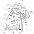
With reference to FIGS. 1 to 3, the configuration of the present embodiment will be described with respect to the electrophotographic image forming apparatus (image forming apparatus) according to the embodiment of the present invention. FIG. 1 is a schematic cross-sectional view of the
画像形成装置100は、4個の像担持体としての感光ドラム1(1Y、1M、1C、1K)を有する。感光ドラム1は、図示矢印A方向に回転する。感光ドラム1の周囲には帯電ローラ2及びスキャナユニット(露光装置)3が配置されている。ここで、帯電ローラ2は、感光ドラム1の表面を均一に帯電する帯電手段である。そして、スキャナユニット3は、画像情報に基づきレーザを照射して感光ドラム1上に静電像(静電潜像)を形成する露光手段である。又、感光ドラム1の周囲には、現像装置(以下、現像ユニット)4(4Y、4M、4C、4K)及びクリーニング手段としてのクリーニングブレード6(6Y、6M、6C、6K)が配置されている。また、4個の感光ドラム1に対向して、感光ドラム1上のトナー像(現像剤像)を記録材12に転写するための中間転写体としての中間転写ベルト5が配置されている。感光ドラム1、帯電ローラ2、クリーニングブレード6は、除去現像剤収容部(以下廃トナー収容部と称す)14a(14aY、14aM、14aC、14aK)を有する感光体ユニット13(13Y、13M、13C、13K)を形成している。廃トナー収容部14aには、記録材12へのトナー像の転写後に感光ドラム1上に残留し、クリーニングブレード6によって感光ドラム1から除去された転写残トナー(廃トナー)が収容される。
The
現像ユニット4は、トナー(現像剤)を担持する現像剤担持体としての現像ローラ22を感光ドラム1に対して接触させて接触現像を行うものとする。また、トナーとして非磁性一成分現像剤が収容されている。そして、現像ユニット4および感光体ユニット13を、一体的にカートリッジ化して、プロセスカートリッジ7を形成している。プロセスカートリッジ7は、画像形成装置100の装置本体に設けられた不図示の装着ガイド、位置決
め部材などの装着手段を介して、画像形成装置100の装置本体に着脱可能となっている。そして、本実施例では、プロセスカートリッジ7は、図3矢印Gで示すように、感光ドラム1の軸線方向に沿って、画像形成装置100の装置本体に対して着脱可能である。また、各色用のプロセスカートリッジ7は全て同一形状を有しており、各色用のプロセスカートリッジ7内には、それぞれイエロー(Y)、マゼンタ(M)、シアン(C)、ブラック(K)の各色のトナーT(TY、TM、TC、TK)が収納されている。
In the developing
中間転写ベルト5は、全ての感光ドラム1に当接し、図示矢印B方向に回転する。中間転写ベルト5は、複数の支持部材(駆動ローラ26、二次転写対向ローラ29、従動ローラ28)に掛け渡されている。中間転写ベルト5の内周面側には、各感光ドラム1に対向するように、一次転写手段としての、4個の一次転写ローラ8(8Y、8M、8C、8K)が並設されている。又、中間転写ベルト5の外周面側において二次転写対向ローラ29に対向する位置には、二次転写手段としての二次転写ローラ9が配置されている。
The intermediate transfer belt 5 abuts on all the photosensitive drums 1 and rotates in the direction of arrow B in the figure. The intermediate transfer belt 5 is hung on a plurality of support members (drive
[プロセスカートリッジ]
図1を用いて、本実施例のプロセスカートリッジ7の全体構成について説明する。現像ユニット4は、現像ユニット4内の各種要素を支持する現像枠体18を有する。現像ユニット4には、感光ドラム1と接触して図1の矢印D方向(反時計周りの方向)に回転する現像剤担持体としての現像ローラ22が設けられている。現像ローラ22は、その長手方向(回転軸線方向)の両端部において、軸受を介して回転可能に現像枠体18に支持されている。また、現像枠体18は、現像剤収容部として、現像剤収納室(以下、トナー収納室)(第1室)18aと、現像室(第2室)18bと、現像剤供給開口(第1開口)(以下、トナー供給開口)18cを有する。現像室18bには、現像ローラ22が配設されている。現像剤供給開口18cは、トナー収納室18aと現像室18bとを連通する。現像剤供給開口18cは、トナー収納室18aと現像室18bとを仕切る仕切部(図1の仕切部18m)に形成されている。本実施例では、現像室18bはトナー収納室18aの上方に位置する。現像室18bには、現像ローラ22に接触して矢印E方向に回転する供給部材としてのトナー供給ローラ20と現像ローラ22のトナー層を規制するための現像剤規制部材としての現像ブレード21が配置されている。ここで、図1に示すように、現像ブレード21は、現像ローラ22の表面に当接している。
図1に示すように、現像ローラ22とトナー供給ローラ20は、互いの接触部において、現像ローラ22の表面と、トナー供給ローラ20の表面が、同じ方向に向かうように回転する。言い換えると、現像ローラ22の回転軸線またはトナー供給ローラ20の回転軸線に沿った方向で見たときに、現像ローラ22の回転方向と、トナー供給ローラ20の回転方向は逆である。
また、現像枠体18のトナー収納室18aには、収納されたトナーTを撹拌するとともに、該トナーをトナー供給開口18cを介して現像室18bに流入させてトナー供給ローラ20へ搬送するための撹拌部材(搬送部材)23が設けられている。撹拌部材23は、現像ローラ22の回転軸線方向に平行な回転軸23aと、一端が回転軸23aに取り付けられ、トナーを撹拌搬送する、可撓性シート状部材である撹拌シート23bを有する。すなわち、撹拌部材23および撹拌シート23bの回転軸線の方向は、現像ローラ22の回転軸線の方向と平行であり、回転軸23aの中心が、撹拌部材23および撹拌シート23bの回転軸線である。
[Process cartridge]
The overall configuration of the
As shown in FIG. 1, the developing
Further, in the
感光体ユニット13は、感光体ユニット13内の各種要素を支持する枠体としてのクリーニング枠体14を有する。クリーニング枠体14には、軸受部材を介して感光ドラム1が図1の矢印A方向(時計回りの方向)に、回転可能に取り付けられている。また、クリーニング枠体14には、帯電ローラ軸受15が、帯電ローラ2の回転中心と感光ドラム1の回転中心とを通る線に沿って、取り付けられている。ここで、帯電ローラ軸受15は、図1の矢印C方向に移動可能に取り付けられている。帯電ローラ2は、帯電ローラ軸受1
5に回転可能に取り付けられている。帯電ローラ軸受15は、付勢手段としての帯電ローラ加圧バネ16により帯電ローラ2を感光ドラム1に向かって押し付けるように付勢される。クリーニングブレード6は、一次転写後に感光ドラム1の表面に残った転写残トナー(廃トナー)を除去するための弾性部材6aと、弾性部材を支持するための支持部材6bとが一体に形成されている。クリーニングブレード6によって感光ドラム1の表面から除去された廃トナーは、クリーニングブレード6とクリーニング枠体14により形成される空間を重力方向に落下し、廃トナー収容部14a内に収容される。
The
It is rotatably attached to 5. The charging
[現像室のシール構成]
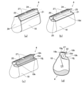
図1、図4を参照して、現像室18bの構成について説明する。図4(a)は、本実施例における現像ユニット4の模式的斜視図である。図4(b)は、図4(a)の状態から軸受ユニット26、現像ローラ22を取り外した状態における現像ユニット4の斜視図である。図4(c)は、図4(b)の状態から弾性シート24、現像ブレード21、端部シール部材25を取り外した状態における現像ユニット4の斜視図である。図4(d)は、図4(b)の状態における現像ユニット4の模式的断面図である。
[Seal configuration of developing room]
The configuration of the developing
図4(c)、図4(d)に示すように、現像室18bは、上縁部18h、下縁部18j、及び両側縁部18kで囲まれる現像開口18d(第3開口に相当する)を備える。現像開口18dにはトナーを担持する現像ローラ22が、軸受ユニット26を介して回転可能に設けられており、現像ローラ22の一部が現像開口18dを介して現像枠体18の外部に露出する構成となっている。図4(a)、図4(b)に示すように、この現像開口18dの下縁部18j側には、現像ローラ22の表面に向かって伸び、現像ローラ22上のトナー層厚を規制するための現像ブレード21が取り付けられる。一方で、現像開口18dの上縁部18j側には、弾性シート24(封止シートに相当する)が取り付けられている。すなわち、上縁部18hは、弾性シート24が固定される被固定部である。弾性シート24は、基端部が現像枠体18に取り付けられ、先端部は現像ローラ22に当接し、現像ユニット4から現像剤が漏出するのを防止する。
ここで、図4(c)に示すように、現像ローラ22の回転軸線方向の現像開口18dの長さは、現像ローラ22の回転軸線方向と直交する方向の現像開口18dの長さよりも長い。すなわち、現像開口18dの長手方向は、現像ローラ22の回転軸線方向と同じである。現像開口18dの短手方向は、現像ローラ22の回転軸線方向と直交する方向と同じである。また、上縁部18hと下縁部18jは、現像開口18dの長手方向に沿って延びる縁部である。両縁部18kは、現像開口18dの長手方向の端部に相当する。両縁部18kは、現像開口18dの短手方向に沿って伸びる縁部である。
As shown in FIGS. 4 (c) and 4 (d), the developing
Here, as shown in FIG. 4C, the length of the developing
現像開口18dの両側縁部18kには、現像枠体18、現像ローラ22、現像ブレード21、及び弾性シート24との隙間をシールするために、端部シール部材25がそれぞれ配置されている。端部シール部材25は可撓性の部材であり、現像ユニット4に取り付けられた際に、現像ローラ22の周面と、現像ブレード21の裏面と、弾性シート24の裏面に圧接する。これにより、現像ユニット4の、現像ローラ22の軸方向のシール性を保っている。すなわち、図4(a)から(d)に示すように、現像開口18dの長手方向において、一端側に設けられた端部シール部材25の内側端部と、他端側に設けられた端部シール25の内側端部の間で、弾性シート24は現像ローラ22に当接している。弾性シート24と端部シール部材25は、いずれも現像枠体18と現像ローラ22の間から現像が漏れることを抑制する封止部材としての機能を有する。
An
[トナー搬送の構成]
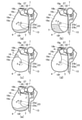
図1、図5を参照して、トナー収納室18a内のトナーを現像室18bへ搬送する構成について説明する。図5は、プロセスカートリッジ7の概略断面図である。
搬送部としての撹拌シート23bは、トナー収納室18aの内壁面に当接して、撹拌シ
ート23bが撓んだ状態で現像剤搬送部材としての撹拌部材23が100rpmで回転する。トナー収納室18aには、撹拌シート23bが撓み状態から解放される解放位置18eを有している。撹拌シート23bは解放位置18eを通過するときに、撹拌シート23bが撓み状態から解放される力によって撹拌シート23b上に乗ったトナーを跳ね上げ、トナー供給開口18cを介して現像室18b内のトナー供給ローラ20へ搬送する。すなわち、撹拌シート23bは変形可能であり、その変形が解放されることにより、トナーを搬送する。
[Toner transfer configuration]
A configuration for transporting the toner in the
The stirring
図1に示すように、撹拌シート23bの回転軸線に直交する直交方向において、撹拌シート23bの先端部、回転軸23a、トナー供給開口18cは、次のような関係を満たすように配置される。撹拌シート23bの長さは、トナー収納室18aの底部18fのトナーまで撹拌搬送できるように設定される。すなわち、図1に示すように、回転軸23aの中心から撹拌シート23b先端部までの長さW0が、回転軸23aの中心からトナー収納室18aの底部18fまでの長さW1に対して、W0>W1となるように設定される。さらに、安定的にトナーを現像室18bに搬送できるように、長さW0は、回転軸23aの中心からトナー供給開口18cの下端部までの長さW2に対して、W0>W2となるように設定される。すなわち、図1に示すように、変形していない状態の撹拌シート23bの先端と、撹拌シート23bの回転軸線との間の距離は、開口18cと撹拌シート23bの回転軸線との間の最短距離よりも大きい。
ここで、撹拌部材23が1周する間の撹拌シート23b及びトナーの状態を、図5を用いて説明する。
As shown in FIG. 1, in the orthogonal direction orthogonal to the rotation axis of the stirring
Here, the state of the stirring
図5(a)は、撹拌シート23bが、堆積したトナーの上面(界面)を押し始める位相で、そのときのトナーの状態を示している。その後、撹拌シート23bが図示矢印Fの方向に回転し、撹拌シート23bは、図5(b)の位相に到達して、トナーを上方に持ち上げて搬送する。さらに撹拌シート23bが矢印Fの方向に回転し、図5(c)に示すように、撹拌シート23bが解放位置18eの位相に到達する。撹拌シート23bには、搬送されたトナーが載っており、撹拌シート23bが解放位置18eを通過直後に、撹拌シート23bが撓んだ状態から解放され、トナーがトナー供給開口18cへ向けて跳ね上げられる。続いて、図5(d)のように、撹拌シート23bは、撓んだ状態から解放された状態に戻る力で、トナーをトナー供給開口18cに搬送するとともに、トナー供給開口18cに衝突して、トナーを現像室18bへ押し込む。その後、撹拌シート23bが矢印Fの方向に回転し、再び図5(a)の撹拌シート23b位相になる。このまま撹拌シート23bは矢印Fの方向に回転し続け、解放位置18eの位相を通過する度に、撹拌シート23b上のトナーを跳ね上げ、トナー供給開口18cを介して次々にトナーを現像室18bに搬送していく。すなわち、現像開口18cは、トナー収納室18aと現像室18bを連通し、トナー収納室18aから現像室18bに搬送されるトナーを通過させるための開口である。
FIG. 5A shows a phase in which the
このとき、図5(d)に示すように、トナー収容室18aから搬送されたトナーは、トナー供給開口18cを通過してトナー供給ローラ20の上方を通過し、現像開口18dへ向かって搬送される(図示矢印H方向)。さらに、現像開口18dへと搬送されたトナーは供給ローラ20と現像ローラ22の当接部に向かい、一部は現像ローラ22へと供給される。現像ローラ22に供給されなかったトナーは、現像ローラ22及びトナー供給ローラ20の回転によって、現像室18bにおいて現像ブレード21、現像ローラ22、トナー供給ローラ20、及びトナー供給開口18c下端で囲まれる領域Jへと搬送される。そして、図5(e)に示すようにトナーが十分に現像室18bに供給されると、領域Jはトナーで満たされ、余剰なトナーはトナー供給ローラ20の回転によって、トナー供給開口18cを通過してトナー収容室18aに戻る(図示矢印K方向)。
このとき、回転軸23aから撹拌シート23b先端部までの長さW0が、撹拌軸23a
からトナー供給開口18cの下端部までの長さW2に対して、W0>W2となるように設定される。そのため、撹拌シートは仕切り壁18mのうち、トナー供給開口18cが設けられる部分に衝突する。
At this time, as shown in FIG. 5D, the toner conveyed from the
At this time, the length W0 from the
W0> W2 is set with respect to the length W2 from the toner supply opening to the lower end of the
[脱気開口とフィルタ部材の構成]
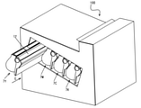
本実施例においては、脱気開口(第2開口)18gとフィルタ部材(以下フィルタ)27を設けることで、現像室18b内の圧力上昇によるトナーの漏出を効果的に抑制する。上述したように、本実施例では、攪拌部材23が100rpmで回転する(1分間に100回転する)構成としているが、これはプロセス速度の高速化の要請を受けてのものである(従来は約75rpm)。本実施例のように従来よりも攪拌速度が速い構成では、攪拌部材23の回転によって枠体18内の圧力が上昇しやすく、内圧が高いとトナーが飛散しやすくなり、上述したようなトナー漏れの発生等が懸念される。したがって、脱気開口18gとフィルタ27を設けて圧力上昇の抑制を図る必要がある。このような圧力上昇抑制のための機構は、攪拌部材23の回転数が80rpm以上の構成において必要になることが知見として得られている。脱気開口18gと、フィルタ27について、図1と図6を用いて説明する。図6(a)は、プロセスカートリッジ7の斜視図、図6(b)は、フィルタ27を取り外した状態におけるプロセスカートリッジ7の斜視図である。
[Structure of degassing opening and filter member]
In this embodiment, by providing the degassing opening (second opening) 18 g and the filter member (hereinafter, filter) 27, the leakage of toner due to the pressure increase in the developing
図1、図6に示すように、脱気開口18gは、現像室18bを構成する面であって、現像ユニット4の長手方向に伸びるように、現像ユニット4の外部と連通して設けられている。図1に示すように、撹拌シート23bの回転軸線に直交する断面方向(撹拌シート23bの回転軸線の方向に直交する直交方向)において、脱気開口18gは、現像室18bの内部と、現像枠体18の外部とを連通している。また、脱気開口18gは、現像ローラ22の一方の端部側から他方の端部側まで延在するように現像ユニット4の長手方向に長く、矩形型に広い領域に設けられている。すなわち、撹拌シート23bの回転軸線方向における脱気開口18gの長さは、撹拌シート23bの回転軸線方向と直交する方向(現像ユニット4の短手方向)における脱気開口18gの長さよりも長い。なお、例えば図1、図4(d)に示すように、撹拌部材23の回転軸線の直交方向において、脱気開口18gと開口18cは、単一の断面と交わるように構成されている(例えば、図1に示すように、攪拌部材23の回転軸線と直交する断面で見たときに、脱気開口18gと、開口18cと、両者の端部を結ぶ2本の仮想線(L1,L2)と、によって囲まれる矩形の仮想領域が形成されるように、脱気開口18gと開口18cが互いに対向する配置となっている。)。すなわち、脱気開口18gの開口縁を含む仮想の面領域と直交する方向、あるいは開口18cの開口縁を含む仮想の面領域と直交する方向から、脱気開口18gと開口18cを見たときに、脱気開口18gの少なくとも一部と、開口18cの少なくとも一部は重なっている。言い換えれば、回転軸23aの軸線方向(長手方向)において、脱気開口18gの範囲と、開口18cの範囲は、少なくとも一部が重なっている。前述したように、撹拌シート23bの回転軸線の方向と直交する直交方向において、脱気開口18gは、現像室18bの内部と、現像枠体18の外部とを連通している(図1)。脱気開口18gをこのような方向で配置することにより、撹拌シート23bによる現像室18b内の圧力変動を、効果的に低減できる。脱気開口18gは少なくとも一つ以上であればよく、その面積が広いほど圧力を逃がす効果を多く得ることができる。本実施例では、十分な枠体の剛性と脱気効果を得るために、脱気開口18gを2か所に分けて設けている。
ここで、図4及び図6(a)に示すように、本実施例では脱気開口18gが2か所に設けられている。このとき、現像開口18dの長手方向において、脱気開口18gは、現像開口18dの中央には配置されていない。すなわち、長手方向において、個々の脱気開口18gはそれぞれ現像開口18dの中心の位置に対して、ずれた位置に配置されている。言い換えると、現像開口18dの長手方向において、現像開口18dの中央の位置と、脱気開口18gの接続壁18nの位置が、重なっている。
現像開口18dに最も近い壁面である接続壁18nに脱気開口18gを設けることで、
現像開口18dの近傍で、圧力を効果的に下げることができる。さらに、長手方向の中央部において、現像枠体18(特に接続壁18n)の剛性を高くすることができる。
さらに、図4および図5に示すように、脱気開口18gの周囲には、凸部18pを設けている。これにより、脱気開口18gの周囲において、現像枠体18の剛性を高くすることができる。本実施例においては、凸部18pは、脱気開口18gの長手方向と短手方向に沿って延長されている。そして、それぞれの凸部18pは、脱気開口18gの両側に設けられている。なお、凸部18gは、開口18cの長手中央において、脱気開口18gの間を横切るように、短手方向に延長される部分を備えていてもよい。
さらに、図1に示すように、回転軸23cと直交する方向において、脱気開口18gの一端と、開口18cの一端を結ぶ線を第1線L1とする。さらに、脱気開口18gの他端と開口198cの他端を結ぶ線を第2線L2とする。このとき、第1線L1と第2線L2の間の領域は、開口18cを通過した空気が、脱気開口18gに到達する経路のうち、最も短い経路を含んだ領域と言える。図1に示した構成では、供給ローラ20の少なくとも一部が、第1線L1と第2線L2の間の領域の外に位置するように配置した。こうすることで、第1線L1と第2線L2の間の領域が、供給ローラ20によって狭められることを低減できる。なお、脱気開口18gが複数設けられる構成においては、すべての脱気開口18gが上記の配置である必要はない。すなわち、一部の脱気開口18gと供給ローラ20が、上記の配置関係となっていても良い。
As shown in FIGS. 1 and 6, the
Here, as shown in FIGS. 4 and 6 (a), degassing
By providing the
The pressure can be effectively reduced in the vicinity of the
Further, as shown in FIGS. 4 and 5, a
Further, as shown in FIG. 1, the line connecting one end of the
図1に示すように、被固定部(上縁部18h)には、接続壁18nが接続されている。接続壁18nは、直交方向(現像ローラ22の回転軸線、または撹拌シート23bの回転軸線の方向に直交する方向)において、弾性シート24が伸びる方向と交差する方向に延びている。接続壁18nは、被固定部を弾性シート24の厚み方向で、被固定部である上縁部18hを支持している壁面ともいえる。本実施例では、脱気開口18gは現像枠体18の天面(接続壁18n)に設けられている。このとき、現像室18b内の領域Jは基本的に常にトナーで満たされており、脱気開口18gは領域Jを構成しない面に設けるべきである。
さらに、脱気開口18gが設けられる壁面は、一方の面が現像室18bの内壁を形成し、他方の面が現像枠体18の外壁の一部を形成する壁面である。図1に示すように、このような壁面のうち、最も広い壁面に脱気開口18gを設けることで、脱気開口18gの大きさをより大きくできる。
As shown in FIG. 1, a
Further, the wall surface provided with the
脱気開口18gはトナー搬送経路(図示矢印H、図5(d)参照)において、現像開口18dより上流側に配置される。そのため、トナー収納室18aより搬送された空気が、トナーが漏出しやすい現像開口18dに到達する前に脱気開口18gから排出される。それにより、現像室18b内の圧力を効果的に下げることができ、トナー漏出を抑制することができる。さらに、脱気開口18gは現像室18bにおいて、両端部に近い領域まで設けられている。これにより、現像開口18d端部に配置される端部シール部材25への圧力上昇をより効果的に抑えることができ、トナーの漏出を抑えることができる。
The
また、図6(b)に示すように、フィルタ27は脱気開口18gを覆うように設けられ、現像ユニット4内からのトナーの漏出(脱気開口18gを通過すること)を防ぎ、内部の空気を通す材質から構成される。すなわち、フィルタ27は、脱気開口18gを空気が通過することを許容し、トナーが通過することを規制する。図6(a)、(b)に示すように、フィルタ27が固定される面の法線方向から見たときに、フィルタ27は、脱気開口18gよりも大きい。フィルタ27は、通気度が高い材質であることが望ましい。その通気度が高いほど、脱気効果が高くなり内圧低減効果が得られる。したがって、トナーの漏出に対して大きな効果を発揮する。
Further, as shown in FIG. 6B, the
フィルタ27は、本実施例では、現像枠体18壁面の外側から、現像枠体18に溶着し
て取り付けられる。フィルタ27の現像枠体18への固定方法は溶着に限らず、例えば両面テープや、接着剤などで固定してもよい。また、フィルタ27は、現像ユニット4内側から固定されてもよい。さらに、フィルタ27は現像ユニットにインサート成形されるなど、現像枠体18と一体になって構成されていてもよい。フィルタ27は、空気が通過でき、かつ脱気開口18gからのトナーの漏出を防ぐ固定方法であればよい。
In this embodiment, the
また、フィルタ27は一つ以上であればよく、その数は限定されない。本実施例では2つの脱気開口18gに対し、2枚のフィルタ27が覆うように配置されている。ここで、脱気開口18gとフィルタ27の数は一対でなくてもよく、例えば、複数の脱気開口18gを1つのフィルタ27で覆う構成であってもよい。すなわち、図8(a)から(c)に示すように、脱気開口18gと、フィルタ27を配置することもできる。図8は、本実施例における脱気開口18gとフィルタ27の配置の例を示す図である。図8は撹拌シート23bの回転軸線方向と直交する方向から、脱気開口18g、フィルタ27、開口18c、現像開口18dのそれぞれを見た概略図である。矢印Pは撹拌シート23bの回転軸線方向を表している。なお、図8では、脱気開口18g、フィルタ27、開口18c、現像開口18d以外の部分は、省略している。
図8(a)に示すように、現像開口18dの長手方向中央を境にした一方の領域と他方の領域のそれぞれの領域において、それぞれ単一の脱気開口18gを形成する(各脱気開口18gがそれぞれ各領域の略全域にわたって開口する)構成としてよい。なお、脱気開口18gの形状は、図示のような矩形に限られず、角の丸い形状や楕円形等の種々の形状を採用し得る。
また、図8(b)に示すように、上記一方の領域及び他方の領域のそれぞれにおいて、複数の脱気開口18gが長手方向に並んで開口する構成(図8(a)の各脱気開口18gを長手方向に分割した構成)としてもよい。各領域に形成される脱気開口18gの数は、図8(b)に図示した構成に限られず、例えば各2つでもよいし、各3つ以上でもよい。また、各脱気開口18gの形状・大きさも、図8(b)に図示したようにそれぞれ同じ形状・大きさとしてもよいし、個々に異なる形状・大きさとしてもよい。ここで、個々の脱気開口18gにおいて、長手方向(攪拌シート23bの回転軸線方向)における長さが、長手方向と直交する短手方向(現像ユニット4の短手方向)における長さよりも短くてもよい。すなわち、各領域における個々の脱気開口18gの長手方向の長さを足した全体の長さが、個々の脱気開口18gの短手方向の長さよりも長ければよい。
さらに、図8(c)に示すように、各領域において、現像開口18dの短手方向に複数の脱気開口18gが並んで開口する構成としてもよい。短手方向に並べる脱気開口18gの数は、図8(c)に図示した構成に限られず、3つ以上でもよい。また、短手方向における各行の脱気開口18gの数や形状・大きさ、配置も、図8(c)に図示したように、それぞれ異なる数、異なる形状・大きさ、互い違いの配置とする構成に限られない。すなわち、同じ数、同じ形状・大きさ、各行揃えた配置の、網の目のような配置構成としてもよい。
Further, the number of
As shown in FIG. 8A, a
Further, as shown in FIG. 8B, in each of the above-mentioned one region and the other region, a plurality of
Further, as shown in FIG. 8C, a plurality of
本実施例において、フィルタの素材は捕集性と通気性を確保するために平均口径5μmの不織布を用いている。 In this embodiment, the filter material is a non-woven fabric having an average diameter of 5 μm in order to ensure collectability and air permeability.
[画像形成プロセス]
画像形成時には、まず、感光ドラム1は、図示矢印A方向にφ30の真円形状で、300rpmで回転している。そして、感光ドラム1の表面が帯電ローラ2によって一様に帯電される。帯電ローラ2は、φ20の導電性ゴムローラで、ローラ部を感光ドラム1に加圧接触することで従動回転し、帯電ローラ2の芯金には、帯電工程として、感光ドラム1に対して所定の直流電圧が印加されている。これにより感光ドラム1の表面には、一様な暗部電位(Vd)が形成される。
[Image formation process]
At the time of image formation, first, the photosensitive drum 1 has a perfect circular shape of φ30 in the direction of arrow A in the figure and rotates at 300 rpm. Then, the surface of the photosensitive drum 1 is uniformly charged by the charging
そして、スキャナユニット3からのレーザ光によって画像データに対応して発光されるレーザ光のスポットパターンは、感光ドラム1を露光し、露光された部位は、キャリア発生層からのキャリアにより表面の電荷が消失し、電位が低下する。この結果、露光部位は所定の明部電位(Vl)、未露光部位は所定の暗部電位(Vd)の静電潜像が、感光ドラム1上に形成される。本実施例では、Vd=-500V、Vl=-100Vとした。
次に、感光ドラム1上に形成された静電潜像は、現像ユニット4によって現像ローラ22まで搬送供給されたトナーと接触現像し、トナー像となる。ここで、現像ローラ22に対してVdc=-300Vを印加することにより、明部電位との電位差ΔV=200Vを形成し、感光ドラムと従動方向に周速差150%で回転してトナー像を形成する。
Then, the spot pattern of the laser beam emitted corresponding to the image data by the laser beam from the scanner unit 3 exposes the photosensitive drum 1, and the exposed portion is charged with the surface charge due to the carriers from the carrier generation layer. It disappears and the potential drops. As a result, an electrostatic latent image having a predetermined bright area potential (Vl) in the exposed area and a predetermined dark area potential (Vd) in the unexposed area is formed on the photosensitive drum 1. In this embodiment, Vd = −500V and Vl = −100V.
Next, the electrostatic latent image formed on the photosensitive drum 1 is contact-developed with the toner conveyed and supplied to the developing
また、本実施例で使用しているトナーは初期状態で凝集度が5~40%の平均粒径が8μmである。寿命を通じてトナーの流動性を確保するために、このような凝集度を持つトナーを用いることが望ましい。また、トナーの凝集度については、以下のようにして測定を行った。 Further, the toner used in this example has an average particle size of 8 μm with a degree of cohesion of 5 to 40% in the initial state. In order to ensure the fluidity of the toner throughout its life, it is desirable to use a toner having such a degree of cohesion. The degree of toner aggregation was measured as follows.
測定装置としては、デジタル振動計(DEGITAL VIBLATIONMETERMODEL 1332 SHOWA SOKKI CORPORATION製)を有するパウダーテスター(細川ミクロン社製)を用いた。測定法としては、振動台に390メッシュ、200メッシュ、100メッシュのふるいを目開の狭い順に、すなわち100メッシュふるいが最上位にくるように390メッシュ、200メッシュ、100メッシュのふるい順に重ねてセットした。このセットした100メッシュふるい上に正確に秤量した試料(トナー)5gを加え、デジタル振動計の変位の値を0.60mm(peak-to-peak)になるように調整し、15秒間振動を加えた。その後、各ふるい上に残った試料の質量を測定して下式にもとづき凝集度を得た。
As a measuring device, a powder tester (manufactured by Hosokawa Micron Co., Ltd.) equipped with a digital vibrometer (manufactured by DEGITAL VIBRATIONMENTMODEL 1332 SHOWA SOKKI CORPORATION) was used. As a measurement method, 390 mesh, 200 mesh, and 100 mesh sieves are placed on the shaking table in the order of narrower opening, that is, the 390 mesh, 200 mesh, and 100 mesh sieves are stacked so that the 100 mesh sieve is at the top. did. Add 5 g of accurately weighed sample (toner) to this
その際の測定サンプルは、それぞれ事前に23℃、60%RH環境下において24時間放置したものであり、測定は23℃、60%RH環境下で行った。
凝集度(%)=(100メッシュふるい上の残試料質量/5g)×100+(200メッシュふるい上の残試料質量/5g)×60+(390メッシュふるい上の残試料質量/5g)×20
The measurement samples at that time were previously left in a 23 ° C. and 60% RH environment for 24 hours, respectively, and the measurement was performed in a 23 ° C. and 60% RH environment.
Cohesion degree (%) = (remaining sample mass on 100 mesh sieve / 5 g) × 100 + (remaining sample mass on 200 mesh sieve / 5 g) × 60 + (residual sample mass on 390 mesh sieve / 5 g) × 20
そして、感光ドラム1上に形成されたトナー像は、一次転写ローラ8の作用によって中間転写ベルト5上に転写(一次転写)される。ここで、一次転写ローラ8は、感光ドラム1から中間転写ベルト5上へ負極性に帯電したトナーを転写させるため、転写電圧Vtr=+1kVに設定されている。 Then, the toner image formed on the photosensitive drum 1 is transferred (primary transfer) onto the intermediate transfer belt 5 by the action of the primary transfer roller 8. Here, the primary transfer roller 8 is set to a transfer voltage Vtr = + 1 kV in order to transfer the negatively charged toner from the photosensitive drum 1 onto the intermediate transfer belt 5.
なお、フルカラー画像の形成時には、上述のプロセスが、第1~第4の画像形成部SY、SM、SC、SKにおいて順次に行われ、中間転写ベルト5上に各色のトナー像が順次に重ね合わせて一次転写される。その後、中間転写ベルト5の移動と同期して記録材12が二次転写部へと搬送される。そして、記録材12を介して中間転写ベルト5に当接している二次転写ローラ9の作用によって、中間転写ベルト5上の4色トナー像は、一括して記録材12上に二次転写される。トナー像が転写された記録材12は、定着手段としての定着装置10に搬送される。定着装置10において記録材12に熱及び圧力を加えられることで、記録材12にトナー像が定着され、およそ60ppmの速度で排出される。
At the time of forming a full-color image, the above-mentioned process is sequentially performed in the first to fourth image forming units SY, SM, SC, and SK, and the toner images of each color are sequentially superposed on the intermediate transfer belt 5. Is primary transferred. After that, the recording material 12 is transferred to the secondary transfer unit in synchronization with the movement of the intermediate transfer belt 5. Then, the four-color toner images on the intermediate transfer belt 5 are collectively secondarily transferred onto the recording material 12 by the action of the secondary transfer roller 9 that is in contact with the intermediate transfer belt 5 via the recording material 12. Toner. The recording material 12 to which the toner image is transferred is conveyed to the fixing
一次転写工程後に感光ドラム1上に残留した一次転写残トナーは、クリーニングブレード6によって除去される。また、二次転写工程後に中間転写ベルト5上に残留した二次転写残トナーは、中間転写ベルトクリーニング装置11によって除去される。除去された転写残トナー(廃トナー)は、画像形成装置100の廃トナーボックス(不図示)に排出される。画像形成装置100は、所望の単独又はいくつか(全てではない)の画像形成部の
みを用いて、単色又はマルチカラーの画像を形成することもできるようになっている。
The primary transfer residual toner remaining on the photosensitive drum 1 after the primary transfer step is removed by the
[本実施例の特徴]
図7を参照して、本実施例の特徴について具体的に説明する。図7(a)は、画像形成(現像当接)時のフィルタ位置の拡大模式図、図7(b)は非画像形成(現像離間)時のフィルタ位置の拡大模式図である。プロセスカートリッジ7は、現像ローラ22と感光ドラム1とが当接離間可能に、第1のユニットとしての現像ユニット4と第2のユニットとしての感光体ユニット13との相対位置を変化可能に構成されている。現像ユニット4(現像枠体18)は、画像形成装置100に設けられた現像当接離間機構の加圧部80による被加圧部18iに対する加圧の有無によって、現像当接離間支点17を支点として回転して位置(感光体ユニット13に対する角度)を変化させる。これにより、現像ユニット4が感光体ユニット13に対して、感光ドラム1と現像ローラ22とが当接する当接状態(当接位置および第2の位置に相当する)と、当接しない離間状態(離間位置および第1の位置に相当する)と、のいずれかを取る。これにより、感光ドラム1と現像ローラ22の現像離間が可能となっている。このように、現像ユニット4は当接位置と離間位置との間を移動可能(装置本体に対して変位可能)である。なお、現像枠体18の第2の位置は、現像ローラ22と感光ドラム1が隙間をあけて近接した位置でもよい。すなわち、本実施例の現像ユニット4は、現像枠体18の第1の位置における現像ローラ22と感光ドラム1の間の距離が、現像枠体18の第2の位置における現像ローラ22と感光ドラム1の間の距離よりも長いように構成される。
[Characteristics of this example]
The features of this embodiment will be specifically described with reference to FIG. 7. FIG. 7A is an enlarged schematic diagram of the filter position at the time of image formation (development contact), and FIG. 7B is an enlarged schematic diagram of the filter position at the time of non-image formation (development separation). The
被加圧部18iが加圧部80によって加圧(押圧)されると、所定の回転軸としての現像当接離間支点17を支点として、感光体ユニット13に対する現像ユニット4の位置が変化(回転)し、現像ローラ22が感光ドラム1に対して離間した状態となる。すなわち、本実施例では、現像枠体18cは、支点17を中心に、回転変位する。本実施例では、現像離間量を10mmとし、離間状態においてフィルタ27が配置されている天面(フィルタ取付面に相当する)は水平となるように構成されている。すなわち、フィルタ27において現像枠体18の内部(現像剤収容部)に露出された露出面(フィルタ27の現像剤収容部側の面)も水平もしくは水平に近い角度となっている。言い換えると、現像ローラ22が感光ドラム1に対して離間した状態において、水平面と露出面の間の角度(狭角側の角度)は、0°もしくは0°に近い角度である。
When the
一方、被加圧部18iに対する現像当接離間機構による加圧力が減圧または加圧状態が解かれると、付勢部材としての現像当接バネ18lの弾性力(付勢力)によって、現像ユニット4が感光体ユニット13に対して現像当接離間支点17を支点として回転する。これにより、現像ローラ22と感光ドラム1とが当接した状態となる。すなわち、現像ユニット4の現像枠体18は、クリーニング枠体14に対する現像枠体18の位置を離間位置から当接位置へ変化せしめるように作用する付勢力が、常に作用した状態となっている。この際、天面は水平方向に対して30°となるように構成されている。すなわち、フィルタ27の現像枠体18内部に露出する面も30°もしくは30°に近い角度となっている。言い換えると、現像ローラ22が感光ドラム1に対して当接した状態において、水平面と露出面の間の角度(狭角側の角度)は、30°もしくは30°に近い角度である。
上述したように、フィルタ27は、当接状態と離間状態で、水平面と露出面の間の角度が変化する。そして、本実施例では離間状態における水平面と露出面の間の角度は、当接状態における水平面と露出面の間の角度よりも小さい。
On the other hand, when the pressure applied by the developing contact separation mechanism to the
As described above, the
このように、現像当接離間機構によって現像ユニット4の位置を変えることで、同時に図7に示すようにフィルタ27の位置を変えることができる。具体的には、現像当接状態では図7(a)に示すような位置のままで、撹拌部材23からのトナー供給や、トナー供給ローラ20と現像ローラ22の回転によるトナー巻き上げによって、フィルタ27の表
面凹凸の凹みに徐々にトナーが溜まってしまう。すなわち、フィルタ27において現像枠体18の内部に露出された露出面にトナーが付着する。この際にフィルタ27に無数に空いているフィルタ穴27aを塞いでしまい、脱気能力が大幅に低下する。特に、現像当接状態では、撹拌部材23が矢印F方向に回転すると、撹拌シート23bの移動によって、壁面に脱気開口18g及びフィルタ27が配置されている現像室18bのトナー供給開口18cに向けて空気が送り込まれる構成である。このような構成のため、フィルタ27の表面凹凸へトナーが溜りやすい。一方、現像離間状態では図7(b)に示す位置となり、凹みに溜まっていたトナーが重力によって鉛直方向にトナーが落下しやすくなる。その結果、フィルタ穴27aまわりのトナーがいなくなることで、十分に脱気することができる。そうすることで、脱気能力の低下を抑制し、現像室18bの圧力上昇を抑えることができ、トナーの漏出を抑えることができる。
In this way, by changing the position of the developing
また、フィルタ27は、現像ローラ22やトナー供給ローラ20よりも現像ユニット4の回転支点17から遠い位置にあり、当接離間動作時における変位量が、現像ローラ22等よりも大きくなるように配置されている。言い換えると、フィルタ27は、フィルタ27と回転支点17(回転変位の中心)の距離(最短距離、例えば、図1の断面において、開口18gとオーバーラップする部分におけるフィルタ27の右側端部と回転支点17とを結んだときの距離)が、現像ローラ22と回転支点17の距離(最遠距離、例えば、図1の断面において、現像ローラ22の周面において回転支点17から最も遠い箇所と、回転支点17とを結んだときの距離)よりも長くなるように配置されている。これにより、当接離間動作によってフィルタ27に振動が生じやすくなり、付着したトナーが剥離することがより効果的に促される。
Further, the
本実施例における現像当接離間のタイミングは、画像形成前の前回転時に現像当接動作を行い、画像形成後の後回転時に現像離間動作を行っている。すなわち、現像ユニット4は、画像形成動作が行われる間は現像当接状態になる。そして、現像ユニット4は、画像形成動作が行われない間は現像離間状態になる。したがって、フィルタ取付面とフィルタ27の現像剤接触面は、画像形成動作が行われない間は水平もしくはそれに近い角度を維持した状態になる。また、連続プリント時など長時間現像当接をしたまま後回転動作が入らない場合は、500枚毎に強制的に中断し、後回転動作を一旦行う。その後、再度プリント動作を開始することとする。なお、本実施例においては、連続プリント時に500枚毎に中断し、後回転動作を実行することで現像当接離間動作を行っているが、これに限るものではない。現像装置の構成に合わせて中断する枚数を設定することが望ましい。また、本実施例では連続プリント時に一定枚数で強制的に中断し、後回転動作を実行することで現像当接離間動作を行っているが、これに限るものではない。例えば、現像装置への駆動指示を中断し、トナーの供給を停止した状態で現像当接離間動作を繰り返すなどでもより一層の効果を得られる。
As for the timing of the development contact separation in this embodiment, the development contact operation is performed during the front rotation before image formation, and the development separation operation is performed during the rear rotation after image formation. That is, the developing
[実験]
本実施例におけるトナー漏出抑制の効果を確認するために、以下の実験を行った。
1.現像離間量とフィルタの角度の適正値
<検証内容>
トナー漏出を抑制するために現像ユニットの位置、さらにはフィルタ部材の位置(鉛直方向に対する角度)について、現像離間量を変えながら、本実施例と比較例1~3を用いて検証した。具体的には、比較例1は現像離間なし、比較例2・比較例3・本実施例の順に現像離間量が5mmずつ大きくしていった。なお、比較例1・比較例2・比較例3について、上記以外のプロセスカートリッジの構成および画像形成装置の全体構成は、本実施例と同様である。
また、トナーの漏出を防止できるかどうかを評価するために、トナーの凝集度が小さくなり、フィルタに目詰まりしやすい高温高湿条件の環境下(温度30℃、湿度80%)に
て連続印字耐久試験を60K枚行った。この連続印字耐久では、画像比率1%の横線を記録画像に印字し、トナーを400g充填している。10K枚毎に現像剤規制部材上に溜まった漏出トナーの有無を目視にて確認した。
[experiment]
The following experiments were conducted to confirm the effect of suppressing toner leakage in this example.
1. 1. Appropriate value of development separation amount and filter angle <Verification content>
In order to suppress toner leakage, the position of the developing unit and the position of the filter member (angle with respect to the vertical direction) were verified using the present example and Comparative Examples 1 to 3 while changing the development separation amount. Specifically, in Comparative Example 1, there was no development separation, and the development separation amount was increased by 5 mm in the order of Comparative Example 2, Comparative Example 3, and this Example. Regarding Comparative Example 1, Comparative Example 2, and Comparative Example 3, the configuration of the process cartridge and the overall configuration of the image forming apparatus other than the above are the same as those of the present embodiment.
In addition, in order to evaluate whether or not toner leakage can be prevented, continuous printing is performed under high temperature and high humidity conditions (temperature 30 ° C,
<検証結果1>
表1に検証結果を示す。
[表1]

Table 1 shows the verification results.
[Table 1]
まず、比較例1について述べる。比較例1では感光ドラム1と現像ローラ22が常時当接している構成であるが、30K枚で少量のトナー漏出を確認し、40kにて激しくトナー漏出が発生してしまった。この際、フィルタにはトナーが目詰まりを起こしており、脱気性能が著しく低下していることが判明した。
次に、比較例2について述べる。比較例2では40K枚で少量のトナー漏出を確認し、50kにて激しくトナー漏出が発生してしまった。比較例1に対して10K分良化した。これは、現像離間時に現像離間量を5mmとしたことで、比較例1と比べフィルタ部材の角度が10°分水平に近くなることで、フィルタの凹みに溜まったトナーが落下し、脱気能力の低下を抑制したためと思われる。しかしながら、目標の60kには未達であった。
続いて、比較例3について述べる。比較例3では50K枚で少量のトナー漏出を確認し、60kにて激しくトナー漏出が発生してしまった。比較例2と同様に現像離間量が増えたことによって、フィルタ部材がよりフラットになり、フィルタの凹みに溜まったトナーが落下し、脱気能力の低下を抑制したためと思われる。しかしながらこの構成においても、目標の60kには未達であった。
そして、本実施例について述べる。本実施例では60K枚まで、トナーの漏出は発生しなかった。フィルタ部材が水平になり、フィルタの凹みに溜まったトナーが落下し、脱気能力の低下を抑制したためと思われる。
First, Comparative Example 1 will be described. In Comparative Example 1, the photosensitive drum 1 and the developing
Next, Comparative Example 2 will be described. In Comparative Example 2, a small amount of toner leakage was confirmed at 40K sheets, and toner leakage occurred violently at 50k. It was improved by 10K with respect to Comparative Example 1. This is because the development separation amount is set to 5 mm at the time of development separation, and the angle of the filter member is closer to horizontal by 10 ° as compared with Comparative Example 1, so that the toner accumulated in the dent of the filter drops and the degassing ability is achieved. It is thought that this is because the decrease in the amount of toner was suppressed. However, the target of 60k was not reached.
Subsequently, Comparative Example 3 will be described. In Comparative Example 3, a small amount of toner leakage was confirmed at 50K sheets, and toner leakage occurred violently at 60k. It is considered that this is because the filter member became flatter due to the increase in the development separation amount as in Comparative Example 2, the toner accumulated in the recess of the filter fell, and the deterioration of the degassing ability was suppressed. However, even in this configuration, the target of 60k was not reached.
Then, this embodiment will be described. In this example, toner leakage did not occur up to 60 K sheets. This is probably because the filter member became horizontal and the toner accumulated in the dent of the filter fell, suppressing the deterioration of the degassing ability.
2.現像離間のタイミング
<検証内容>
次に、現像離間を行うタイミングについて、トナー漏出が発生しないための実施枚数について確認した。比較例4では現像離間のタイミングを750枚毎、比較例5では現像離間のタイミングを1000枚毎に強制的に実行する。なお、比較例4および比較例5について、上記以外のプロセスカートリッジの構成および画像形成装置の全体構成は、本実施例と同様である。
2. 2. Timing of development separation <Verification content>
Next, regarding the timing of developing separation, the number of sheets to be carried out to prevent toner leakage was confirmed. In Comparative Example 4, the development separation timing is forcibly executed every 750 sheets, and in Comparative Example 5, the development separation timing is forcibly executed every 1000 sheets. Regarding Comparative Example 4 and Comparative Example 5, the configuration of the process cartridge and the overall configuration of the image forming apparatus other than the above are the same as those of the present embodiment.
<検証結果2>
表2に本実施例と比較例における、トナー漏出の有無を示す。
[表2]

Table 2 shows the presence or absence of toner leakage in this example and the comparative example.
[Table 2]
まず、比較例4について述べる。比較例4では現像離間のタイミングを1000枚毎に実行しているが、5K枚時点で激しくトナー漏出が発生していた。
次に、比較例5について述べる。比較例5では現像離間のタイミングを750枚毎に実行しているが、10K枚時点で少量のトナー漏出が発生した。そして20K時点では激しくトナー漏出が発生していた。750枚毎の現接離間でもトナーの目詰まりを抑制するには足りないことが分かった。
続いて、本実施例について述べる。本実施例では60K枚までトナー漏出は発生しなかった。この結果から、現像離間のタイミングは最低でも500枚に1度実行する必要があることがわかった。
First, Comparative Example 4 will be described. In Comparative Example 4, the timing of the development separation was executed every 1000 sheets, but toner leakage occurred violently at the time of 5K sheets.
Next, Comparative Example 5 will be described. In Comparative Example 5, the development separation timing was executed every 750 sheets, but a small amount of toner leaked at the time of 10K sheets. And at 20K, toner leakage occurred violently. It was found that even the current contact distance of every 750 sheets was not sufficient to suppress the clogging of the toner.
Subsequently, this embodiment will be described. In this example, toner leakage did not occur up to 60 K sheets. From this result, it was found that the timing of development separation needs to be executed at least once every 500 sheets.
以上説明したように、本実施例では、上記高速化・長寿命化カートリッジを備えた画像形成装置において、現像離間量を15mmにし、現像当接離間動作を500枚毎に行う構成とした。本実施例によれば、当接離間動作によってフィルタ部材(の第2室側の面)の角度がより水平方向に近づき、フィルタの凹みに溜まったトナーが落下しやすくなる。すなわち、長期間の使用によってフィルタ部材にトナーが目詰まりした場合に、現像当接離間動作によって現像装置ならびにフィルタ部材に衝撃を与えることによって、フィルタ部材からトナーの剥離を促すことができる。これにより、実験1・実験2で示したように、フィルタの目詰まりを抑制し、脱気性能の低下を防ぐことができた。その結果、現像室の内圧上昇を低減、抑制することができ、現像ユニットからのトナーの漏出を防止することができた。
As described above, in the present embodiment, in the image forming apparatus equipped with the high-speed and long-life cartridge, the development separation amount is set to 15 mm, and the development contact separation operation is performed every 500 sheets. According to this embodiment, the angle of the filter member (the surface on the second chamber side) of the filter member (the surface on the second chamber side) becomes closer to the horizontal direction due to the contact separation operation, and the toner accumulated in the recess of the filter is likely to fall. That is, when the filter member is clogged with toner due to long-term use, it is possible to promote the peeling of the toner from the filter member by giving an impact to the developing apparatus and the filter member by the developing contact separation operation. As a result, as shown in Experiment 1 and
4…現像ユニット、17…現像当接離間支点、18…現像枠体、18a…トナー収納室、18b…現像室、18c…トナー供給開口、18d…現像開口、18g…脱気開口、18i…被加圧部、18l…現像当接バネ、20…トナー供給ローラ、21…現像ブレード、22…現像ローラ、23…撹拌部材、23a…回転軸、23b…撹拌シート、24…弾性シート、25…端部シール部材、27…フィルタ、80…加圧部 4 ... Development unit, 17 ... Development contact separation fulcrum, 18 ... Development frame, 18a ... Toner storage chamber, 18b ... Development room, 18c ... Toner supply opening, 18d ... Development opening, 18g ... Degassing opening, 18i ... Covered Pressurizing part, 18l ... Development contact spring, 20 ... Toner supply roller, 21 ... Development blade, 22 ... Development roller, 23 ... Stirring member, 23a ... Rotating shaft, 23b ... Stirring sheet, 24 ... Elastic sheet, 25 ... End Part seal member, 27 ... filter, 80 ... pressurizing part
Claims (40)
現像剤を搬送する搬送部材と、
現像剤を収納する枠体であって、
前記搬送部材を収納する第1室と、
第2室と、
前記第1室と前記第2室を連通し、前記第1室から前記第2室に搬送される現像剤を通過させるための第1開口と、
前記搬送部材の回転軸線の方向と直交する直交方向において、前記第2室の内部と前記枠体の外部を連通する第2開口と、
が備えられた枠体と、
空気が通過することを許容し、現像剤が通過することを規制するフィルタであって、前記第2開口を覆うように前記枠体に対して固定されたフィルタと、
を有し、
前記搬送部材の変形が解放されることで、現像剤が前記第1開口を介して前記第1室から前記第2室に搬送されるように、前記搬送部材は変形可能であり、
前記枠体は、前記ユニットが前記装置本体に装着された状態において、前記フィルタが前記装置本体に対して変位するように第1の位置と第2の位置との間で前記装置本体に対して変位可能であり、
前記フィルタは、前記第2室の内部に露出された露出面を備え、かつ前記第1の位置における前記露出面と水平面の間の角度が、前記第2の位置における前記露出面と前記水平面の間の角度よりも小さくなるように配置されることを特徴とするユニット。 It is a unit that is detachably configured on the main body of the image forming device.
A transport member that transports the developer and
A frame that stores the developer
The first room for storing the transport member and
Room 2 and
A first opening for communicating the first chamber and the second chamber and allowing a developing agent to be conveyed from the first chamber to the second chamber to pass through.
A second opening that communicates the inside of the second chamber with the outside of the frame in an orthogonal direction orthogonal to the direction of the rotation axis of the transport member.
With a frame equipped with
A filter that allows air to pass through and restricts the passage of the developer, and is fixed to the frame so as to cover the second opening.
Have,
By releasing the deformation of the transport member, the transport member is deformable so that the developer is transported from the first chamber to the second chamber through the first opening.
The frame body is provided with respect to the device body between the first position and the second position so that the filter is displaced with respect to the device body when the unit is mounted on the device body. Displaceable ,
The filter comprises an exposed surface exposed inside the second chamber, and the angle between the exposed surface and the horizontal plane at the first position is the angle between the exposed surface and the horizontal plane at the second position. A unit characterized by being arranged so that it is smaller than the angle between them.
現像剤を搬送する搬送部材と、A transport member that transports the developer and
現像剤を収納する枠体であって、A frame that stores the developer
前記搬送部材を収納する第1室と、The first room for storing the transport member and
第2室と、Room 2 and
前記第1室と前記第2室を連通し、前記第1室から前記第2室に搬送される現像剤を通過させるための第1開口と、A first opening for communicating the first chamber and the second chamber and allowing a developing agent to be conveyed from the first chamber to the second chamber to pass through.
前記搬送部材の回転軸線の方向と直交する直交方向において、前記第2室の内部と前記枠体の外部を連通する第2開口と、A second opening that communicates the inside of the second chamber with the outside of the frame in an orthogonal direction orthogonal to the direction of the rotation axis of the transport member.
が備えられた枠体と、With a frame equipped with
空気が通過することを許容し、現像剤が通過することを規制するフィルタであって、前記第2開口を覆うように前記枠体に対して固定されたフィルタと、A filter that allows air to pass through and restricts the passage of the developer, and is fixed to the frame so as to cover the second opening.
を有し、Have,
前記搬送部材の変形が解放されることで、現像剤が前記第1開口を介して前記第1室から前記第2室に搬送されるように、前記搬送部材は変形可能であり、By releasing the deformation of the transport member, the transport member is deformable so that the developer is transported from the first chamber to the second chamber through the first opening.
前記枠体は、前記ユニットが前記装置本体に装着された状態において、前記フィルタが前記装置本体に対して変位するように第1の位置と第2の位置との間で前記装置本体に対して変位可能であり、The frame body is provided with respect to the device body between the first position and the second position so that the filter is displaced with respect to the device body when the unit is mounted on the device body. Displaceable,
前記搬送部材は、80rpm以上の速度で回転可能に構成されていることを特徴とするユニット。The transport member is a unit characterized in that it is configured to be rotatable at a speed of 80 rpm or more.
前記枠体の前記変位によって、前記現像剤担持体が像担持体に対して変位することを特徴とする請求項1~3のいずれか1項に記載のユニット。 It has a developer carrier rotatably assembled to the frame and has
The unit according to any one of claims 1 to 3 , wherein the developer carrier is displaced with respect to the image carrier due to the displacement of the frame.
前記フィルタは、前記フィルタと前記回転変位の中心との間の距離が、前記現像剤担持体と前記中心との間の距離よりも長くなるように配置されることを特徴とする請求項4~7のいずれか1項に記載のユニット。 The displacement of the frame is a rotational displacement.
4. The filter is characterized in that the distance between the filter and the center of the rotational displacement is longer than the distance between the developer carrier and the center. The unit according to any one of 7 .
記端部シールの間において、前記現像剤担持体に接触する封止シートと、を含むことを特徴とする請求項10または11に記載のユニット。 Includes end seals arranged on both longitudinal edges of the third opening and a sealing sheet fixed to the frame and in contact with the developer carrier between the end seals. The unit according to claim 10 or 11 .
前記第2開口は、前記接続壁に備えられることを特徴とする請求項12に記載のユニット。 The frame has a fixed portion to which the sealing sheet is fixed and a connecting wall connected to the fixed portion and extending in a direction intersecting the extending direction of the sealing sheet. Prepare,
12. The unit according to claim 12 , wherein the second opening is provided in the connecting wall.
前記長手方向において、前記第2開口は、前記第3開口の中心の位置に対して、ずれた位置に配置されることを特徴とする請求項13に記載のユニット。 The frame body is provided with a plurality of the second openings.
13. The unit according to claim 13 , wherein the second opening is arranged at a position deviated from the position of the center of the third opening in the longitudinal direction.
現像剤を搬送する搬送部材と、
現像剤を収納する枠体であって、前記搬送部材を収納する第1室と、第2室と、前記第1室と前記第2室を連通し、前記第1室から前記第2室に搬送される現像剤を通過させるための第1開口と、前記搬送部材の回転軸線の方向と直交する直交方向において、前記第2室の内部と前記枠体の外部を連通する第2開口と、が備えられた枠体と、
空気が通過することを許容し、現像剤が通過することを規制するフィルタであって、前記第2開口を覆うように前記枠体に対して固定されたフィルタと、
前記枠体に回転可能に組み付けられた現像剤担持体と、
を有する第1のユニットと、
像担持体を有する第2のユニットと、
を備え、
前記搬送部材の変形が解放されることで、現像剤が前記第1開口を介して前記第1室から前記第2室に搬送されるように、前記搬送部材は変形可能であり、
前記枠体は、前記第1のユニットが前記装置本体に装着された状態において、前記フィ
ルタが前記装置本体に対して変位するように第1の位置と第2の位置との間で前記装置本体に対して変位可能であり、
前記現像剤担持体と前記像担持体とが当接離間可能に、前記第1のユニットと前記第2のユニットとの相対位置を変化可能に構成されていることを特徴とするプロセスカートリッジ。 A process cartridge that can be attached to and detached from the main body of the image forming device.
A transport member that transports the developer and
A frame body for storing a developing agent, which communicates with a first room and a second room for storing the transport member, the first room and the second room, and from the first room to the second room. A first opening for passing the developer to be conveyed, and a second opening for communicating the inside of the second chamber and the outside of the frame in a direction orthogonal to the direction of the rotation axis of the conveying member. With a frame equipped with
A filter that allows air to pass through and restricts the passage of the developer, and is fixed to the frame so as to cover the second opening.
A developer carrier rotatably attached to the frame and a developer carrier.
With the first unit having
A second unit with an image carrier and
Equipped with
By releasing the deformation of the transport member, the transport member is deformable so that the developer is transported from the first chamber to the second chamber through the first opening.
The frame body has the frame body in a state where the first unit is attached to the apparatus main body.
It is possible to displace the device body between the first position and the second position so that the rut is displaced with respect to the device body.
A process cartridge characterized in that the relative positions of the first unit and the second unit can be changed so that the developer carrier and the image carrier can be brought into contact with each other and separated from each other.
前記フィルタは、前記フィルタと前記回転変位の中心との間の距離が、前記現像剤担持体と前記中心との間の距離よりも長くなるように配置されることを特徴とする請求項21~26のいずれか1項に記載のプロセスカートリッジ。21 to 21. The filter is arranged so that the distance between the filter and the center of the rotational displacement is longer than the distance between the developer carrier and the center. The process cartridge according to any one of 26.
前記第2開口は、前記接続壁に備えられることを特徴とする請求項31に記載のプロセス31. The process of claim 31, wherein the second opening is provided in the connecting wall.
カートリッジ。cartridge.
前記長手方向において、前記第2開口は、前記第3開口の中心の位置に対して、ずれた位置に配置されることを特徴とする請求項32に記載のプロセスカートリッジ。 32. The process cartridge according to claim 32, wherein the second opening is arranged at a position deviated from the position of the center of the third opening in the longitudinal direction.
前記フィルタが前記装置本体に対して変位するように、前記枠体を前記装置本体に対して変位させる加圧部と、
を備えることを特徴とする画像形成装置。 The unit according to any one of claims 1 to 20 or the process cartridge according to any one of claims 21 to 39 .
A pressurizing unit that displaces the frame with respect to the device body so that the filter displaces with respect to the device body .
An image forming apparatus comprising.
Priority Applications (5)
| Application Number | Priority Date | Filing Date | Title |
|---|---|---|---|
| KR1020170144483A KR102285652B1 (en) | 2016-11-09 | 2017-11-01 | Unit, process cartridge and image forming apparatus |
| US15/802,999 US10866539B2 (en) | 2016-11-09 | 2017-11-03 | Unit having a developer conveying member and a filter for a chamber |
| CN201711075983.5A CN108062014A (en) | 2016-11-09 | 2017-11-06 | Unit, handle box and imaging device |
| EP17200587.8A EP3349066B1 (en) | 2016-11-09 | 2017-11-08 | Unit, process cartridge and image forming apparatus |
| SG10201709190VA SG10201709190VA (en) | 2016-11-09 | 2017-11-08 | Unit, process cartridge and image forming apparatus |
Applications Claiming Priority (2)
| Application Number | Priority Date | Filing Date | Title |
|---|---|---|---|
| JP2016218761 | 2016-11-09 | ||
| JP2016218761 | 2016-11-09 |
Publications (3)
| Publication Number | Publication Date |
|---|---|
| JP2018081301A JP2018081301A (en) | 2018-05-24 |
| JP2018081301A5 JP2018081301A5 (en) | 2020-11-12 |
| JP7009150B2 true JP7009150B2 (en) | 2022-01-25 |
Family
ID=62198936
Family Applications (1)
| Application Number | Title | Priority Date | Filing Date |
|---|---|---|---|
| JP2017193639A Active JP7009150B2 (en) | 2016-11-09 | 2017-10-03 | Units, process cartridges and image forming equipment |
Country Status (4)
| Country | Link |
|---|---|
| EP (1) | EP3349066B1 (en) |
| JP (1) | JP7009150B2 (en) |
| KR (1) | KR102285652B1 (en) |
| SG (1) | SG10201709190VA (en) |
Families Citing this family (3)
| Publication number | Priority date | Publication date | Assignee | Title |
|---|---|---|---|---|
| JP7206614B2 (en) * | 2018-04-04 | 2023-01-18 | 富士フイルムビジネスイノベーション株式会社 | Developing device and image forming device |
| JP7200655B2 (en) * | 2018-12-19 | 2023-01-10 | 富士フイルムビジネスイノベーション株式会社 | Developing device, developing unit and image forming apparatus |
| CN114430812B (en) * | 2019-09-17 | 2024-03-12 | 佳能株式会社 | Cartridge and image forming apparatus |
Citations (7)
| Publication number | Priority date | Publication date | Assignee | Title |
|---|---|---|---|---|
| JP2003270939A (en) | 2002-03-18 | 2003-09-25 | Seiko Epson Corp | Developing device, image forming apparatus and computer system |
| JP2005346035A (en) | 2004-05-06 | 2005-12-15 | Ricoh Co Ltd | Development apparatus, process cartridge and image forming apparatus |
| JP2006309007A (en) | 2005-04-28 | 2006-11-09 | Ricoh Co Ltd | Image forming apparatus, development device and process cartridge |
| JP2009109863A (en) | 2007-10-31 | 2009-05-21 | Ricoh Co Ltd | Image developing unit, process unit, and image forming device |
| JP2009175419A (en) | 2008-01-24 | 2009-08-06 | Ricoh Co Ltd | Developing device, process cartridge, image forming apparatus and color image forming apparatus |
| JP2011112826A (en) | 2009-11-26 | 2011-06-09 | Canon Inc | Developing device and process cartridge |
| JP2016161627A (en) | 2015-02-27 | 2016-09-05 | キヤノン株式会社 | Cartridge, process cartridge, and image forming apparatus |
Family Cites Families (6)
| Publication number | Priority date | Publication date | Assignee | Title |
|---|---|---|---|---|
| JPS5419319A (en) | 1977-07-14 | 1979-02-14 | Fujitsu Ltd | Synchronous protection circuit |
| US4583112A (en) * | 1984-10-29 | 1986-04-15 | Xerox Corporation | Venting system for the developer housing of an electrostatic copying machine |
| JPH08146745A (en) * | 1994-11-21 | 1996-06-07 | Canon Inc | Developer storing container and process cartridge |
| JP4790676B2 (en) | 2007-08-02 | 2011-10-12 | 株式会社リコー | Developing device, process cartridge, and image forming apparatus |
| JP5111238B2 (en) * | 2008-05-27 | 2013-01-09 | キヤノン株式会社 | Process cartridge |
| JP5418895B2 (en) * | 2009-03-13 | 2014-02-19 | 株式会社リコー | Developing device, and image forming apparatus and process cartridge provided with the same |
-
2017
- 2017-10-03 JP JP2017193639A patent/JP7009150B2/en active Active
- 2017-11-01 KR KR1020170144483A patent/KR102285652B1/en active IP Right Grant
- 2017-11-08 EP EP17200587.8A patent/EP3349066B1/en active Active
- 2017-11-08 SG SG10201709190VA patent/SG10201709190VA/en unknown
Patent Citations (7)
| Publication number | Priority date | Publication date | Assignee | Title |
|---|---|---|---|---|
| JP2003270939A (en) | 2002-03-18 | 2003-09-25 | Seiko Epson Corp | Developing device, image forming apparatus and computer system |
| JP2005346035A (en) | 2004-05-06 | 2005-12-15 | Ricoh Co Ltd | Development apparatus, process cartridge and image forming apparatus |
| JP2006309007A (en) | 2005-04-28 | 2006-11-09 | Ricoh Co Ltd | Image forming apparatus, development device and process cartridge |
| JP2009109863A (en) | 2007-10-31 | 2009-05-21 | Ricoh Co Ltd | Image developing unit, process unit, and image forming device |
| JP2009175419A (en) | 2008-01-24 | 2009-08-06 | Ricoh Co Ltd | Developing device, process cartridge, image forming apparatus and color image forming apparatus |
| JP2011112826A (en) | 2009-11-26 | 2011-06-09 | Canon Inc | Developing device and process cartridge |
| JP2016161627A (en) | 2015-02-27 | 2016-09-05 | キヤノン株式会社 | Cartridge, process cartridge, and image forming apparatus |
Also Published As
| Publication number | Publication date |
|---|---|
| KR102285652B1 (en) | 2021-08-05 |
| SG10201709190VA (en) | 2018-06-28 |
| JP2018081301A (en) | 2018-05-24 |
| KR20180052092A (en) | 2018-05-17 |
| EP3349066A1 (en) | 2018-07-18 |
| EP3349066B1 (en) | 2021-03-31 |
Similar Documents
| Publication | Publication Date | Title |
|---|---|---|
| US10866539B2 (en) | Unit having a developer conveying member and a filter for a chamber | |
| JP5751779B2 (en) | Developing device, developing cartridge, process cartridge, and image forming apparatus | |
| US9098012B2 (en) | Electrophotographic image forming apparatus and process cartridge | |
| JP7009150B2 (en) | Units, process cartridges and image forming equipment | |
| US20220283526A1 (en) | Developing device, cartridge, image forming apparatus | |
| JP2017181803A (en) | Development apparatus, process cartridge and image formation apparatus | |
| US20170108822A1 (en) | Developing device process cartridge and image forming apparatus | |
| JP4631641B2 (en) | Image forming apparatus and developing cartridge | |
| JP6685979B2 (en) | Developing container, process cartridge and image forming apparatus | |
| JP6661332B2 (en) | Developing device, process cartridge and image forming device | |
| JP5683527B2 (en) | Developing device, process cartridge, and image forming apparatus | |
| JP6188840B2 (en) | Developing device, process cartridge, and image forming apparatus | |
| JP6833454B2 (en) | Develop equipment, process cartridges and image forming equipment | |
| JP5883167B2 (en) | Developing device, process cartridge, and image forming apparatus | |
| JP4739431B2 (en) | Developing device and image forming apparatus | |
| JP2020197699A (en) | Cleaning device | |
| JP5532846B2 (en) | How to handle the developing device | |
| JP2022156895A (en) | Process cartridge and image forming apparatus | |
| JP5310125B2 (en) | Developing device and image forming apparatus | |
| JP2014085568A (en) | Developing device and image forming apparatus | |
| JP2020134711A (en) | Cleaning device, image forming apparatus, and transfer device | |
| JP2012018217A (en) | Developing device, process cartridge and image forming apparatus |
Legal Events
| Date | Code | Title | Description |
|---|---|---|---|
| RD02 | Notification of acceptance of power of attorney |
Free format text: JAPANESE INTERMEDIATE CODE: A7422 Effective date: 20181116 |
|
| A521 | Written amendment |
Free format text: JAPANESE INTERMEDIATE CODE: A523 Effective date: 20201001 |
|
| A621 | Written request for application examination |
Free format text: JAPANESE INTERMEDIATE CODE: A621 Effective date: 20201001 |
|
| A977 | Report on retrieval |
Free format text: JAPANESE INTERMEDIATE CODE: A971007 Effective date: 20210727 |
|
| A131 | Notification of reasons for refusal |
Free format text: JAPANESE INTERMEDIATE CODE: A131 Effective date: 20210803 |
|
| A521 | Written amendment |
Free format text: JAPANESE INTERMEDIATE CODE: A523 Effective date: 20210924 |
|
| TRDD | Decision of grant or rejection written | ||
| A01 | Written decision to grant a patent or to grant a registration (utility model) |
Free format text: JAPANESE INTERMEDIATE CODE: A01 Effective date: 20211214 |
|
| A61 | First payment of annual fees (during grant procedure) |
Free format text: JAPANESE INTERMEDIATE CODE: A61 Effective date: 20220112 |