JP7008974B2 - Optical microscope and spectroscopic measurement method - Google Patents
Optical microscope and spectroscopic measurement method Download PDFInfo
- Publication number
- JP7008974B2 JP7008974B2 JP2017157778A JP2017157778A JP7008974B2 JP 7008974 B2 JP7008974 B2 JP 7008974B2 JP 2017157778 A JP2017157778 A JP 2017157778A JP 2017157778 A JP2017157778 A JP 2017157778A JP 7008974 B2 JP7008974 B2 JP 7008974B2
- Authority
- JP
- Japan
- Prior art keywords
- mirror
- light beam
- scanner
- light
- sample
- Prior art date
- Legal status (The legal status is an assumption and is not a legal conclusion. Google has not performed a legal analysis and makes no representation as to the accuracy of the status listed.)
- Active
Links
- 230000003287 optical effect Effects 0.000 title claims description 270
- 238000000691 measurement method Methods 0.000 title claims description 7
- 238000012937 correction Methods 0.000 claims description 50
- 238000005259 measurement Methods 0.000 claims description 34
- 238000012545 processing Methods 0.000 claims description 19
- 210000001747 pupil Anatomy 0.000 claims description 11
- 230000008859 change Effects 0.000 claims description 9
- 239000012141 concentrate Substances 0.000 claims description 5
- 230000004075 alteration Effects 0.000 description 40
- 238000001069 Raman spectroscopy Methods 0.000 description 34
- 238000001237 Raman spectrum Methods 0.000 description 10
- 201000009310 astigmatism Diseases 0.000 description 9
- 239000000463 material Substances 0.000 description 6
- 239000000126 substance Substances 0.000 description 6
- 238000010586 diagram Methods 0.000 description 5
- 238000001228 spectrum Methods 0.000 description 5
- VYPSYNLAJGMNEJ-UHFFFAOYSA-N Silicium dioxide Chemical compound O=[Si]=O VYPSYNLAJGMNEJ-UHFFFAOYSA-N 0.000 description 4
- 230000008901 benefit Effects 0.000 description 4
- 238000001514 detection method Methods 0.000 description 4
- 239000006185 dispersion Substances 0.000 description 4
- 206010010071 Coma Diseases 0.000 description 3
- WUKWITHWXAAZEY-UHFFFAOYSA-L calcium difluoride Chemical compound [F-].[F-].[Ca+2] WUKWITHWXAAZEY-UHFFFAOYSA-L 0.000 description 3
- 229910001634 calcium fluoride Inorganic materials 0.000 description 3
- 238000013461 design Methods 0.000 description 3
- 230000000694 effects Effects 0.000 description 3
- 238000005286 illumination Methods 0.000 description 3
- 230000003595 spectral effect Effects 0.000 description 3
- 230000015572 biosynthetic process Effects 0.000 description 2
- 238000000034 method Methods 0.000 description 2
- 230000004048 modification Effects 0.000 description 2
- 238000012986 modification Methods 0.000 description 2
- 229910000530 Gallium indium arsenide Inorganic materials 0.000 description 1
- 206010073261 Ovarian theca cell tumour Diseases 0.000 description 1
- 229910009372 YVO4 Inorganic materials 0.000 description 1
- 238000010521 absorption reaction Methods 0.000 description 1
- 238000001816 cooling Methods 0.000 description 1
- 230000005284 excitation Effects 0.000 description 1
- 238000003384 imaging method Methods 0.000 description 1
- 230000010365 information processing Effects 0.000 description 1
- 150000002632 lipids Chemical class 0.000 description 1
- 239000007788 liquid Substances 0.000 description 1
- 239000011159 matrix material Substances 0.000 description 1
- 150000007523 nucleic acids Chemical class 0.000 description 1
- 102000039446 nucleic acids Human genes 0.000 description 1
- 108020004707 nucleic acids Proteins 0.000 description 1
- 239000005304 optical glass Substances 0.000 description 1
- 230000008569 process Effects 0.000 description 1
- 230000009467 reduction Effects 0.000 description 1
- 230000035945 sensitivity Effects 0.000 description 1
- 238000000926 separation method Methods 0.000 description 1
- 208000001644 thecoma Diseases 0.000 description 1
Images


Classifications
-
- G—PHYSICS
- G02—OPTICS
- G02B—OPTICAL ELEMENTS, SYSTEMS OR APPARATUS
- G02B21/00—Microscopes
- G02B21/0004—Microscopes specially adapted for specific applications
- G02B21/002—Scanning microscopes
- G02B21/0024—Confocal scanning microscopes (CSOMs) or confocal "macroscopes"; Accessories which are not restricted to use with CSOMs, e.g. sample holders
- G02B21/0036—Scanning details, e.g. scanning stages
- G02B21/004—Scanning details, e.g. scanning stages fixed arrays, e.g. switchable aperture arrays
-
- G—PHYSICS
- G02—OPTICS
- G02B—OPTICAL ELEMENTS, SYSTEMS OR APPARATUS
- G02B21/00—Microscopes
- G02B21/0004—Microscopes specially adapted for specific applications
- G02B21/002—Scanning microscopes
- G02B21/0024—Confocal scanning microscopes (CSOMs) or confocal "macroscopes"; Accessories which are not restricted to use with CSOMs, e.g. sample holders
- G02B21/0036—Scanning details, e.g. scanning stages
- G02B21/0048—Scanning details, e.g. scanning stages scanning mirrors, e.g. rotating or galvanomirrors, MEMS mirrors
-
- G—PHYSICS
- G01—MEASURING; TESTING
- G01J—MEASUREMENT OF INTENSITY, VELOCITY, SPECTRAL CONTENT, POLARISATION, PHASE OR PULSE CHARACTERISTICS OF INFRARED, VISIBLE OR ULTRAVIOLET LIGHT; COLORIMETRY; RADIATION PYROMETRY
- G01J3/00—Spectrometry; Spectrophotometry; Monochromators; Measuring colours
- G01J3/02—Details
- G01J3/0205—Optical elements not provided otherwise, e.g. optical manifolds, diffusers, windows
- G01J3/0208—Optical elements not provided otherwise, e.g. optical manifolds, diffusers, windows using focussing or collimating elements, e.g. lenses or mirrors; performing aberration correction
-
- G—PHYSICS
- G01—MEASURING; TESTING
- G01J—MEASUREMENT OF INTENSITY, VELOCITY, SPECTRAL CONTENT, POLARISATION, PHASE OR PULSE CHARACTERISTICS OF INFRARED, VISIBLE OR ULTRAVIOLET LIGHT; COLORIMETRY; RADIATION PYROMETRY
- G01J3/00—Spectrometry; Spectrophotometry; Monochromators; Measuring colours
- G01J3/02—Details
- G01J3/0205—Optical elements not provided otherwise, e.g. optical manifolds, diffusers, windows
- G01J3/0229—Optical elements not provided otherwise, e.g. optical manifolds, diffusers, windows using masks, aperture plates, spatial light modulators or spatial filters, e.g. reflective filters
-
- G—PHYSICS
- G01—MEASURING; TESTING
- G01J—MEASUREMENT OF INTENSITY, VELOCITY, SPECTRAL CONTENT, POLARISATION, PHASE OR PULSE CHARACTERISTICS OF INFRARED, VISIBLE OR ULTRAVIOLET LIGHT; COLORIMETRY; RADIATION PYROMETRY
- G01J3/00—Spectrometry; Spectrophotometry; Monochromators; Measuring colours
- G01J3/02—Details
- G01J3/06—Scanning arrangements arrangements for order-selection
-
- G—PHYSICS
- G01—MEASURING; TESTING
- G01J—MEASUREMENT OF INTENSITY, VELOCITY, SPECTRAL CONTENT, POLARISATION, PHASE OR PULSE CHARACTERISTICS OF INFRARED, VISIBLE OR ULTRAVIOLET LIGHT; COLORIMETRY; RADIATION PYROMETRY
- G01J3/00—Spectrometry; Spectrophotometry; Monochromators; Measuring colours
- G01J3/02—Details
- G01J3/10—Arrangements of light sources specially adapted for spectrometry or colorimetry
-
- G—PHYSICS
- G01—MEASURING; TESTING
- G01J—MEASUREMENT OF INTENSITY, VELOCITY, SPECTRAL CONTENT, POLARISATION, PHASE OR PULSE CHARACTERISTICS OF INFRARED, VISIBLE OR ULTRAVIOLET LIGHT; COLORIMETRY; RADIATION PYROMETRY
- G01J3/00—Spectrometry; Spectrophotometry; Monochromators; Measuring colours
- G01J3/28—Investigating the spectrum
- G01J3/44—Raman spectrometry; Scattering spectrometry ; Fluorescence spectrometry
-
- G—PHYSICS
- G01—MEASURING; TESTING
- G01N—INVESTIGATING OR ANALYSING MATERIALS BY DETERMINING THEIR CHEMICAL OR PHYSICAL PROPERTIES
- G01N21/00—Investigating or analysing materials by the use of optical means, i.e. using sub-millimetre waves, infrared, visible or ultraviolet light
- G01N21/62—Systems in which the material investigated is excited whereby it emits light or causes a change in wavelength of the incident light
- G01N21/63—Systems in which the material investigated is excited whereby it emits light or causes a change in wavelength of the incident light optically excited
- G01N21/65—Raman scattering
-
- G—PHYSICS
- G02—OPTICS
- G02B—OPTICAL ELEMENTS, SYSTEMS OR APPARATUS
- G02B21/00—Microscopes
- G02B21/06—Means for illuminating specimens
-
- G—PHYSICS
- G02—OPTICS
- G02B—OPTICAL ELEMENTS, SYSTEMS OR APPARATUS
- G02B21/00—Microscopes
- G02B21/36—Microscopes arranged for photographic purposes or projection purposes or digital imaging or video purposes including associated control and data processing arrangements
- G02B21/361—Optical details, e.g. image relay to the camera or image sensor
-
- G—PHYSICS
- G01—MEASURING; TESTING
- G01J—MEASUREMENT OF INTENSITY, VELOCITY, SPECTRAL CONTENT, POLARISATION, PHASE OR PULSE CHARACTERISTICS OF INFRARED, VISIBLE OR ULTRAVIOLET LIGHT; COLORIMETRY; RADIATION PYROMETRY
- G01J3/00—Spectrometry; Spectrophotometry; Monochromators; Measuring colours
- G01J3/02—Details
- G01J3/06—Scanning arrangements arrangements for order-selection
- G01J2003/064—Use of other elements for scan, e.g. mirror, fixed grating
-
- G—PHYSICS
- G01—MEASURING; TESTING
- G01J—MEASUREMENT OF INTENSITY, VELOCITY, SPECTRAL CONTENT, POLARISATION, PHASE OR PULSE CHARACTERISTICS OF INFRARED, VISIBLE OR ULTRAVIOLET LIGHT; COLORIMETRY; RADIATION PYROMETRY
- G01J3/00—Spectrometry; Spectrophotometry; Monochromators; Measuring colours
- G01J3/02—Details
- G01J3/10—Arrangements of light sources specially adapted for spectrometry or colorimetry
- G01J2003/102—Plural sources
- G01J2003/104—Monochromatic plural sources
Description
本発明は、光学顕微鏡、及び分光測定方法に関する。 The present invention relates to an optical microscope and a spectroscopic measurement method.
ラマン分光測定は、試料が気体、液体、結晶、非晶質であることを問わず、温度は高温でも低温でも可能であり、測定において、真空などの特殊な測定雰囲気を必要としないという利点を持つ。さらに、試料の前処理を特に必要とせず、試料をそのままの状態で測定可能であるなどの長所があり、これらの長所を生かした測定が多くなされている。ラマン分光測定を利用することによって、物質の同定、濃度測定、結晶性、応力等が測定できる。 Raman spectroscopy has the advantage that the sample can be hot or cold, regardless of whether the sample is gas, liquid, crystalline or amorphous, and the measurement does not require a special measurement atmosphere such as vacuum. Have. Further, there is an advantage that the sample can be measured as it is without requiring special pretreatment of the sample, and many measurements are made by taking advantage of these advantages. By using Raman spectroscopy, substance identification, concentration measurement, crystallinity, stress, etc. can be measured.
このようなラマン分光測定を行うための光学顕微鏡が開示されている(特許文献1、2)。特許文献1の光学顕微鏡では、試料にレーザ光を集光して照射している。そして、試料からのラマン散乱光を分光器で分光することにより、ラマンスペクトルを測定する。さらに、この光学顕微鏡では、レーザ光を偏向させて、試料におけるビームスポットを走査させて測定することにより、試料の特定の領域内におけるスペクトルの分布を測定することができる。また、測定時間を短縮するためビームスポットを1方向に伸ばして走査し、試料をライン状に照明して、CCDカメラにより検出している。ライン状に照明しているため一度に広い領域を照射することができ、測定時間を短縮することができ、ビームスポットを伸ばすことで試料の損傷を防いでいる。 An optical microscope for performing such Raman spectroscopic measurement is disclosed (Patent Documents 1 and 2). In the optical microscope of Patent Document 1, a laser beam is focused and irradiated on a sample. Then, the Raman spectrum is measured by dispersing the Raman scattered light from the sample with a spectroscope. Further, in this optical microscope, the distribution of the spectrum in a specific region of the sample can be measured by deflecting the laser beam and scanning the beam spot in the sample for measurement. Further, in order to shorten the measurement time, the beam spot is extended in one direction and scanned, the sample is illuminated in a line shape, and the sample is detected by the CCD camera. Since it is illuminated in a line shape, it is possible to irradiate a wide area at once, the measurement time can be shortened, and the beam spot is extended to prevent damage to the sample.
しかしながら、特許文献1の光学顕微鏡では光ビームをレンズによって屈折させるために、色収差が生じ、広い波長帯域での測定が困難である問題があった。具体的には、特許文献1の図1に示す構成において、200nmの深紫外領域から2000nmの近赤外領域で共通の光学系を用いようとした場合、レンズを含む光学系において色収差が生じる。例えば、Y走査装置13で偏向された光ビームをX走査ミラー18に導くためのレンズ14、16(以下、リレー光学系Aと呼ぶ)、X走査ミラー18で反射された光ビームを対物レンズ21に導くためのレンズ19、20(以下、リレー光学系Bと呼ぶ)、試料22からの出射光を入射スリット30に集光させるレンズ24(以下、集光光学系と呼ぶ)において、色収差が生じる。
However, the optical microscope of Patent Document 1 has a problem that chromatic aberration occurs because the light beam is refracted by the lens, and it is difficult to measure in a wide wavelength band. Specifically, in the configuration shown in FIG. 1 of Patent Document 1, when a common optical system is used in the deep ultraviolet region of 200 nm to the near infrared region of 2000 nm, chromatic aberration occurs in the optical system including the lens. For example, the
特許文献1では、リレー光学系A、リレー光学系B、及び集光光学系で生じる色収差を回折限界近くまで補正することが困難である。これは、一般にレンズにおける色収差は、複数種類のレンズ材料を組み合わせることによって補正されるが、200nmからの深紫外領域を含めての色収差補正は、多くの光学ガラスが深紫外領域で不透明であるために使用できず、使用可能なレンズ材料が合成石英ガラスやフッ化カルシウムなど少ない種類に限定されるためである。 In Patent Document 1, it is difficult to correct the chromatic aberration generated in the relay optical system A, the relay optical system B, and the condensing optical system to near the diffraction limit. This is because chromatic aberration in a lens is generally corrected by combining a plurality of types of lens materials, but chromatic aberration correction including a deep ultraviolet region from 200 nm is opaque in many optical glasses in the deep ultraviolet region. This is because the lens material that can be used is limited to a small number such as synthetic quartz glass and calcium fluoride.
本発明は上述の問題点に鑑みてなされたものであり、収差を低減することができる光学顕微鏡、及び分光測定方法を提供することを目的とする。 The present invention has been made in view of the above-mentioned problems, and an object of the present invention is to provide an optical microscope capable of reducing aberrations and a spectroscopic measurement method.
本発明の一態様にかかる光学顕微鏡は、光ビームを発生する光源と、前記光ビームを偏向させて、試料上における前記光ビームのスポット位置を走査する第1のスキャナと、前記第1のスキャナで偏向された光ビームを集光して、試料に入射させる対物レンズと、前記試料の前記光ビームが照射された領域から出射した出射光が入射する入射側にスリットを有する分光器と、前記分光器からの出射光を検出する、アレイ状に配列された受光画素を有する2次元アレイ光検出器と、前記第1のスキャナから前記対物レンズまでの光路中に配置され、前記第1のスキャナで偏向された光ビームを反射する第1の非軸放物面鏡と、前記第1の非軸放物面鏡で反射された光ビームを反射する第2の非軸放物面鏡と、を備えた第1のリレー光学系と、を備えたものである。この構成により収差を低減することができる。 The optical microscope according to one aspect of the present invention includes a light source that generates a light beam, a first scanner that deflects the light beam to scan the spot position of the light beam on a sample, and the first scanner. An objective lens that condenses the light beam deflected by the above and makes it incident on the sample, a spectroscope having a slit on the incident side where the emitted light emitted from the region irradiated with the light beam of the sample is incident, and the above. A two-dimensional array light detector having light receiving pixels arranged in an array for detecting light emitted from the spectroscope, and the first scanner arranged in the optical path from the first scanner to the objective lens. A first non-axis parabolic mirror that reflects the light beam deflected by, and a second non-axis parabolic mirror that reflects the light beam reflected by the first non-axis parabolic mirror. It is provided with a first relay optical system provided with the above. Aberration can be reduced by this configuration.
上記の光学顕微鏡は、出射光を波長に応じて空間的に分散させる分光器をさらに有してもよい。 The above optical microscope may further have a spectroscope that spatially disperses the emitted light according to the wavelength.
上記の光学顕微鏡において、前記第1の非軸放物面鏡と前記第2の非軸放物面鏡との放物面の幾何学的な対称軸が平行で、かつ、前記放物面が互いに反対方向を向くように配置されていてもよい。 In the above optical microscope, the geometrical axes of symmetry of the parabolic surface of the first non-axis parabolic mirror and the second non-axis parabolic mirror are parallel, and the parabolic surface is They may be arranged so as to face each other in opposite directions.
上記の光学顕微鏡において、前記第1の非軸放物面鏡の焦点距離と前記第2の非軸放物面鏡の焦点距離が同じであってもよい。 In the above optical microscope, the focal length of the first non-axis parabolic mirror and the focal length of the second non-axis parabolic mirror may be the same.
上記の光学顕微鏡において、前記第1の非軸放物面鏡と前記第2の非軸放物面鏡との間における前記光ビームの焦点から前記第1の非軸放物面鏡までの距離をL2とし、前記焦点から前記第2の非軸放物面鏡までの距離をL3とすると、L2とL3との比が、前記第1の非軸放物面鏡の焦点距離と前記第2の非軸放物面鏡の焦点距離との比と等しくなっていてもよい In the above optical microscope, the distance from the focal point of the light beam between the first non-axis parabolic mirror and the second non-axis parabolic mirror to the first non-axis parabolic mirror. Is L2, and the distance from the focal point to the second non-axis parabolic mirror is L3, the ratio of L2 to L3 is the focal distance of the first non-axis parabolic mirror and the second. May be equal to the ratio to the focal distance of the non-axis parabolic mirror
上記の光学顕微鏡において、前記第1のスキャナから前記第1の非軸放物面鏡までの距離をL1とし、前記第2の非軸放物面鏡から前記対物レンズの入射瞳までの距離をL4とすると、L1=L2、かつ、L3=L4となっていてもよい。これにより、光ビームが、対物レンズの入射瞳のほぼ中心を通ることができるため、測定領域全体で、レーザ強度や空間分解能の変化を抑制することができる。 In the above optical microscope, the distance from the first scanner to the first non-axis parabolic mirror is L1, and the distance from the second non-axis parabolic mirror to the entrance pupil of the objective lens is defined as L1. Assuming L4, L1 = L2 and L3 = L4 may be set. As a result, the light beam can pass through substantially the center of the entrance pupil of the objective lens, so that changes in laser intensity and spatial resolution can be suppressed in the entire measurement region.
上記の光学顕微鏡において、前記第1のリレー光学系は、前記第1の非軸放物面鏡と前記光ビームの焦点との間に設けられた正のパワーを有する第1の補正レンズと、前記焦点と前記第2の非軸放物面鏡との間に設けられた正のパワーを有する第2の補正レンズと、をさらに備えていてもよい。これにより、収差を低減することができる。 In the above optical microscope, the first relay optical system includes a first correction lens having a positive power provided between the first non-axis parabolic mirror and the focal point of the light beam. A second correction lens having positive power provided between the focal point and the second non-axis parabolic mirror may be further provided. This makes it possible to reduce aberrations.
上記の光学顕微鏡において、前記第1の補正レンズから前記焦点までの距離をL5とし、前記焦点から前記第2の補正レンズまでの距離をL6とすると、L5=L6となっていることが好ましい。 In the above optical microscope, when the distance from the first correction lens to the focal point is L5 and the distance from the focal point to the second correction lens is L6, it is preferable that L5 = L6.
上記の光学顕微鏡は、前記第1のスキャナでデスキャンされた前記出射光を前記分光器のスリットに集光する集光光学系をさらに備え、前記集光光学系は、前記出射光を反射する第1の凹面鏡と、前記第1の凹面鏡で反射した出射光を反射する第1の凸面鏡と、を備えていてもよい。これにより、非点収差を補正することができる。 The optical microscope further includes a condensing optical system that collects the emitted light desscanned by the first scanner into a slit of the spectroscope, and the condensing optical system reflects the emitted light. A concave mirror of 1 and a first convex mirror that reflects the emitted light reflected by the first concave mirror may be provided. This makes it possible to correct astigmatism.
上記の光学顕微鏡において、前記第1の凹面鏡と前記第1の凸面鏡とは、曲率半径が実質的に等しい球面鏡であってもよい。これにより、ペッツバール和を小さくすることができ、像面湾曲を小さくすることができる。 In the above optical microscope, the first concave mirror and the first convex mirror may be spherical mirrors having substantially the same radius of curvature. As a result, the Petzval sum can be reduced, and the curvature of field can be reduced.
上記の光学顕微鏡において、前記集光光学系によって結像される前記試料の像面が、前記スリットの入射面に対して傾いていてもよい。これにより、ゴースト像の発生を抑制することができる。 In the above optical microscope, the image plane of the sample imaged by the condensing optical system may be tilted with respect to the incident plane of the slit. This makes it possible to suppress the generation of ghost images.
上記の光学顕微鏡において、前記第1の凹面鏡の曲率中心と前記第1の凸面鏡の曲率中心とを通る直線が、前記第1の凹面鏡に入射する前記出射光の基準軸から傾いていてもよい。 In the above optical microscope, the straight line passing through the center of curvature of the first concave mirror and the center of curvature of the first convex mirror may be tilted from the reference axis of the emitted light incident on the first concave mirror.
上記の光学顕微鏡は、前記光源から前記第1のスキャナまでの光路中に配置され、前記光ビームを偏向させて、前記試料上における前記光ビームの前記スポット位置を走査する第2のスキャナと、前記第1のスキャナと前記第2のスキャナとの間の光路中に配置され、前記第2のスキャナから前記第1のスキャナに向かう光ビームから、前記試料から前記分光器に向かう前記出射光を分離するビームスプリッタと、をさらに備え、前記第1のスキャナが前記分光器の前記スリットの長手方向と直交する方向に対応する第1の方向に前記スポット位置を走査し、前記第2のスキャナが前記スリットの長手方向に対応する第2の方向に前記スポット位置を走査するようにしてもよい。 The optical microscope is arranged in an optical path from the light source to the first scanner, and has a second scanner that deflects the light beam and scans the spot position of the light beam on the sample. The emitted light directed from the sample to the spectroscope from an optical beam arranged in an optical path between the first scanner and the second scanner and directed from the second scanner to the first scanner. Further comprising a beam splitter for separation, the first scanner scans the spot position in a first direction corresponding to a direction orthogonal to the longitudinal direction of the slit of the spectroscope, and the second scanner scans the spot position. The spot position may be scanned in a second direction corresponding to the longitudinal direction of the slit.
上記の光学顕微鏡は、前記第2のスキャナと前記第1のスキャナとの間の光路中に配置された第2のリレー光学系をさらに備え、前記第2のリレー光学系は、前記第2のスキャナからの光ビームを反射する第2の凹面鏡と、前記第2の凹面鏡で反射された光ビームを反射する第2の凸面鏡と、前記第2の凸面鏡で反射された光ビームを反射する第3の凸面鏡と、前記第3の凸面鏡で反射された光ビームを反射する第3の凹面鏡と、を備えており、前記第2の凸面鏡と前記第3の凸面鏡との間にある中間像面に対して、前記第2の凹面鏡と前記第2の凸面鏡が、前記第3の凹面鏡と前記第3の凸面鏡と対称に配置されていてもよい。これにより、コマ収差、歪曲収差、非点収差を補正することができる。 The optical microscope further includes a second relay optical system arranged in an optical path between the second scanner and the first scanner, and the second relay optical system is the second relay optical system. A second concave mirror that reflects the light beam from the scanner, a second convex mirror that reflects the light beam reflected by the second concave mirror, and a third that reflects the light beam reflected by the second convex mirror. The convex mirror and the third concave mirror that reflects the light beam reflected by the third convex mirror are provided with respect to the intermediate image plane between the second convex mirror and the third convex mirror. The second concave mirror and the second convex mirror may be arranged symmetrically with the third concave mirror and the third convex mirror. This makes it possible to correct coma aberration, distortion aberration, and astigmatism.
上記の光学顕微鏡において、前記第2の凹面鏡と前記第2の凸面鏡と前記第3の凹面鏡と前記第3の凸面鏡とが、曲率半径が実質的に等しい球面鏡であってもよい。像面湾曲を補正することができる。 In the above optical microscope, the second concave mirror, the second convex mirror, the third concave mirror, and the third convex mirror may be spherical mirrors having substantially the same radius of curvature. It is possible to correct curvature of field.
上記の光学顕微鏡において、前記第2の凹面鏡の曲率中心と前記第2の凸面鏡の曲率中心とを通る直線が、前記第2の凹面鏡に入射する前記光ビームの基準軸から傾いており、前記第3の凹面鏡の曲率中心と前記第3の凸面鏡の曲率中心とを通る直線が、前記第3の凹面鏡で反射された前記光ビームの基準軸から傾いていてもよい。 In the above optical microscope, a straight line passing through the center of curvature of the second concave mirror and the center of curvature of the second convex mirror is tilted from the reference axis of the light beam incident on the second concave mirror, and the first. The straight line passing through the center of curvature of the concave mirror 3 and the center of curvature of the third convex mirror may be tilted from the reference axis of the light beam reflected by the third concave mirror.
上記の光学顕微鏡は、前記第2のスキャナと前記第1のスキャナとの間の光路中に配置された第2のリレー光学系をさらに備え、前記光源は、異なるレーザ波長のレーザ光を切替えて使用可能であり、前記レーザ光の光路には、集光度合い又は発散度合いを調整するビームエキスパンダが設けられており、前記第2のリレー光学系は、前記第2のスキャナからの光ビームを屈折する第1のリレーレンズと、前記第1のリレーレンズからの光ビームを屈折して平行光とし、前記第1のスキャナに入射させる第2のリレーレンズと、前記第1のリレーレンズと第2のリレーレンズとの間に配置された絞りと、を備えていてもよい。これにより、色収差を補正することができる。 The optical microscope further comprises a second relay optical system arranged in an optical path between the second scanner and the first scanner, the light source switching between laser beams of different laser wavelengths. It can be used, and the optical path of the laser beam is provided with a beam expander for adjusting the degree of focusing or divergence, and the second relay optical system receives the light beam from the second scanner. The refracting first relay lens, the second relay lens that refrains the light beam from the first relay lens into parallel light, and causes the light beam to be incident on the first scanner, the first relay lens, and the first. It may be provided with an aperture arranged between the two relay lenses. This makes it possible to correct chromatic aberration.
上記の光学顕微鏡は、前記第1のスキャナの直前に配置され、試料上における前記光ビームの前記スポット位置を前記第2の方向に走査する第3のスキャナをさらに備え、前記第1のリレー光学系の歪曲収差により生じるスポット位置の変化を打ち消すように、前記第1のスキャナの角度に応じて、前記第3のスキャナが第2の方向に光ビームを走査するようにしてもよい。これにより、歪曲収差を補正することができる。 The optical microscope is arranged immediately in front of the first scanner and further includes a third scanner that scans the spot position of the light beam on the sample in the second direction, and the first relay optics. The third scanner may scan the light beam in the second direction according to the angle of the first scanner so as to cancel the change in the spot position caused by the distortion of the system. As a result, distortion can be corrected.
上記の光学顕微鏡は、前記第1のリレー光学系で生じる歪曲収差を補正する処理装置をさらに備え、前記試料上における前記光ビームのスポットが前記第2の方向に沿ってライン状に伸びており、前記2次元アレイ光検出器では、前記ライン状の領域からの出射光を検出する複数の画素が配列されており、前記複数の画素が検出した1次元の測定データを補間することで、歪曲収差を補正するようにしてもよい。これにより、簡便に歪曲収差を補正することができる。 The optical microscope further includes a processing device for correcting distortion caused by the first relay optical system, and spots of the light beam on the sample extend in a line along the second direction. In the two-dimensional array optical detector, a plurality of pixels for detecting emitted light from the line-shaped region are arranged, and distortion is caused by interpolating the one-dimensional measurement data detected by the plurality of pixels. The aberration may be corrected. This makes it possible to easily correct the distortion.
上記の光学顕微鏡は、前記第2のスキャナにおける光ビームのビーム断面形状を前記第2の方向に縮める光学部材をさらに備えていてもよい。これにより、試料の損傷を抑制ことができる。 The optical microscope may further include an optical member that shrinks the beam cross-sectional shape of the light beam in the second scanner in the second direction. As a result, damage to the sample can be suppressed.
上記の光学顕微鏡は、前記スリットの長手方向に対応する第2の方向が、前記第1の非軸放物面鏡の幾何学的な対称軸に対応する方向に沿っていてもよい。 In the above optical microscope, the second direction corresponding to the longitudinal direction of the slit may be along the direction corresponding to the geometric axis of symmetry of the first non-axis parabolic mirror.
本実施の形態にかかる分光測定装置は、光ビームを第1のスキャナによって偏向させ、第1のリレー光学系を介して、前記第1のスキャナからの前記光ビームを対物レンズに入射させ、前記光ビームを前記対物レンズで集光して試料に照射し、前記試料から出射した出射光を、前記対物レンズで集光し、前記対物レンズからの出射光を分光器で分光し、前記分光器で分光された出射光を検出することで分光測定する分光測定方法であって、前記第1のリレー光学系は、前記第1のスキャナから前記対物レンズまでの光路中に配置され、前記第1のスキャナで偏向された光ビームを反射する第1の非軸放物面鏡と、前記第1の非軸放物面鏡で反射された光ビームを反射する第2の非軸放物面鏡と、を備えているものである。これにより、収差を低減することができる。 In the spectroscopic measuring apparatus according to the present embodiment, the light beam is deflected by the first scanner, the light beam from the first scanner is incident on the objective lens via the first relay optical system, and the light beam is incident on the objective lens. The light beam is focused by the objective lens and irradiated to the sample, the emitted light emitted from the sample is focused by the objective lens, the emitted light from the objective lens is separated by a spectroscope, and the spectroscope is used. It is a spectroscopic measurement method of spectroscopically measuring by detecting the emitted light dispersed in, wherein the first relay optical system is arranged in an optical path from the first scanner to the objective lens, and the first relay optical system is arranged. A first non-axis spectroscopic mirror that reflects the light beam deflected by the scanner, and a second non-axis spectroscopic mirror that reflects the light beam reflected by the first non-axis parabolic mirror. And, it is equipped with. This makes it possible to reduce aberrations.
本発明によれば、収差を低減することができる光学顕微鏡、及び分光測定方法を提供することができる。 According to the present invention, it is possible to provide an optical microscope capable of reducing aberrations and a spectroscopic measurement method.
以下に、本発明を適用可能な実施の形態が説明される。以下の説明は、本発明の実施形態を説明するものであり、本発明が以下の実施形態に限定されるものではない。説明の明確化のため、以下の記載は、適宜、省略及び簡略化がなされている。又、当業者であれば、以下の実施形態の各要素を、本発明の範囲において容易に変更、追加、変換することが可能であろう。尚、各図において同一の符号を付されたものは同様の要素を示しており、適宜、説明が省略される。 Hereinafter, embodiments to which the present invention can be applied will be described. The following description describes embodiments of the present invention, and the present invention is not limited to the following embodiments. In order to clarify the explanation, the following description has been omitted or simplified as appropriate. Further, those skilled in the art will be able to easily change, add, or convert each element of the following embodiments within the scope of the present invention. In each figure, those having the same reference numerals indicate the same elements, and the description thereof will be omitted as appropriate.
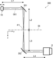
本発明の実施の形態にかかる光学顕微鏡について図1を用いて説明する。図1は本実施の形態にかかる光学顕微鏡100の光学系の全体構成を模式的に示す図である。光学顕微鏡100は、試料22を観察するための構成として、光源10と、ビームエキスパンダ11と、Y走査装置13と、第1のリレー光学系200と、ビームスプリッタ17と、X走査ミラー18と、第2のリレー光学系300、対物レンズ21と、ステージ23と、集光光学系400と、分光器31と、検出器32と、ステージ駆動装置40と、処理装置50とを備えている。また分光器31は入射側に入射スリット30を備えている。X走査ミラー18、及びY走査装置13による走査角度が変わる場合でも、基準軸(光軸)をZ軸として、光の進行方向を正、X軸とY軸を左手系にとる。X走査ミラー18、及びY走査装置13による走査角度が変わる場合でもZ軸は一定とする。
The optical microscope according to the embodiment of the present invention will be described with reference to FIG. FIG. 1 is a diagram schematically showing the overall configuration of the optical system of the
光学顕微鏡100はラマン顕微鏡であり、光源10からの光ビームを試料22に入射させ、試料22からのラマン散乱光を検出器32で検出する。さらに、ラマン散乱光を分光器31で分光するため、ラマンスペクトルを分光測定することができる。さらに、光学顕微鏡100では、XY方向(水平方向)及びZ方向(鉛直方向)に走査することができるため、3次元のラマンスペクトルイメージを測定することができる。
The
まず、光学顕微鏡100の全体構成について図1を参照して説明する。光源10は単色のレーザ光を出射するレーザ光源である。光源10には、例えば、スペクトラフィジックス社製Millenniaを用いることができる。この光源10はレーザ波長532nm、線幅0.24nm、最大出力が10WのNd/YVO4レーザである。光源10はこのレーザ波長を有するレーザ光を出射する。さらに、光源10として複数のレーザ光源を用いて、分光測定したい帯域に応じてレーザ波長を切り替えて用いることも可能である。すなわち、異なるレーザ波長のレーザ光を切替えて使用可能な光源10を用いることも可能である。
First, the overall configuration of the
光源10からの光ビームはビームエキスパンダ11によって拡大され、Y走査装置13に入射する。Y走査装置13は、例えば、音響光学素子や、ガルバノミラーであり、入射した光ビームの出射角を変化させて、光ビームを偏向させる。これにより、試料22上で光ビームの入射位置がY方向に沿って変化する。すなわち、Y走査装置13は、光ビームをY方向に走査する。なお、Y走査装置13での偏向角は、処理装置50からの電気信号によって制御される。Y走査装置13で偏向された光ビームは、リレー光学系200に入射する。リレー光学系200の詳細については後述する。
The light beam from the
リレー光学系200からの光ビームは、ビームスプリッタ17に入射する。ビームスプリッタ17は、例えば、ダイクロイックミラーであり、レーザ波長の光を試料22の方向に反射する。ダイクロイックミラーとしては、Semrock社製のエッジフィルタを用いることができる。ビームスプリッタ17により反射された光は、X走査ミラー18に入射する。X走査ミラー18は、例えば、ガルバノミラーであり、反射面の角度が変化することによって、光ビームを偏向させる。すなわち、光軸に対するX走査ミラー18の反射面の傾斜角度が変化するため、光ビームの出射角を変化させることができる。これにより、試料22上で光ビームの入射位置がX方向に沿って変化する。これにより、光ビームをX方向に走査することができる。なお、X走査ミラー18での偏向角は、処理装置50からの電気信号によって制御される。また、X方向とY方向とは互いに直交する方向であるため、X走査ミラー18及びY走査装置13によってXY方向に走査することにより、試料22上において2次元領域を走査することができる。
The light beam from the relay
X走査ミラー18によって走査された光ビームは、リレー光学系300に入射する。リレー光学系300の詳細については後述する。リレー光学系300からの光ビームは、対物レンズ21に入射する。対物レンズ21は、光ビームを集光して、試料22上に入射させる。すなわち、対物レンズ21は、試料22上に光ビームを集光して、試料22を照明する。これにより、試料22のスポット状の領域が照明される。対物レンズ21としては、後述するようにシュヴァルツシルト型の反射対物レンズを用いることができる。あるいは、レボルバなどに取り付けられた複数の対物レンズをレーザ波長に応じて、切替えるようにしてもよい。
The light beam scanned by the
試料22に入射した入射光の一部はラマン散乱される。試料22に入射した入射光のうち、ラマン散乱により対物レンズ21側に出射した光を出射光とする。すなわち、ラマン散乱光のうち、対物レンズ21に入射したものを出射光とする。ラマン散乱された出射光は入射光とは異なる波長となっている。すなわち、ラマンシフトによって出射光は入射光の振動数からずれて散乱される。この出射光のスペクトルがラマンスペクトルとなる。したがって、出射光のスペクトルを測定することにより、試料22中に含まれる物質の化学構造及び物理的状態を特定することができる。すなわち、ラマンスペクトルには、試料22を構成する物質の振動数の情報が含まれるため、出射光を分光器31で分光して検出することにより、試料22中の物質を特定することができる。
A part of the incident light incident on the
そして、入射光の焦点位置をXYZ方向にスキャンして試料22の全面又は一部の領域からの出射光のスペクトルを測定することにより、ラマンスペクトルの3次元測定を行うことができる。測定したラマンスペクトルのうち、特定の波長に注目することにより、特定の物質の3次元空間分布の測定も可能となる。具体的には、試料22を生体細胞とした場合、核酸や脂質の空間分布を測定することができる。
Then, by scanning the focal position of the incident light in the XYZ direction and measuring the spectrum of the emitted light from the entire surface or a part of the
なお、試料22はステージ23の上に載置されている。ステージ23は、例えば、XYZステージである。このステージ23はステージ駆動装置40によって、駆動される。ステージ駆動装置40がステージ23をXY方向に駆動することによって、試料22の任意の位置を照明することができる。また、ステージ駆動装置40がステージをZ方向に駆動することによって、対物レンズ21と試料22との距離を変化させることができる。従って、対物レンズ21の焦点位置を光軸方向に沿って変化させることができる。本発明にかかる光学顕微鏡100は、後述するようにレーザコンフォーカル顕微鏡を構成しているため、焦点位置を変化させることによって、Z方向の走査が可能となる。すなわち、Z方向にステージを移動させることによって、試料22の断層画像を撮像することができる。試料22の任意の高さからのラマン散乱光の検出することができ、3次元のラマンスペクトルイメージの測定が可能になる。処理装置50はステージ駆動装置40に対して制御信号を入力し、ステージ23の駆動を制御する。
The
ステージ23上に載置された試料22でラマン散乱され、対物レンズ21に入射した出射光は、入射光と同じ光路上を伝播していく。すなわち、対物レンズ21により屈折又は反射され、リレー光学系300を介して、X走査ミラー18に入射する。X走査ミラー18は、入射した出射光をビームスプリッタ17の方向に反射する。このとき、出射光は、X走査ミラー18によってデスキャンされる。すなわち、出射光は、X走査ミラー18で反射されることによって、出射光は、光源10からX走査ミラー18に入射した入射光の進行方向と反対方向に伝播する。また、試料22からのレーリー散乱光もラマン散乱光と同じ光路で伝播していく。
The emitted light that is Raman scattered by the
X走査ミラー18によって、反射された出射光は、ビームスプリッタ17に入射する。ビームスプリッタ17は、例えば、ダイクロイックミラーであり、試料22からの出射光と、光源10から試料22に入射する入射光とを波長に基づいて分岐する。すなわち、ビームスプリッタ17は、その反射面が入射光の光軸に対して傾いて設けられている。試料22からの出射光がビームスプリッタ17を透過することによって、試料22からの出射光の光軸が、光源10から試料22に入射する入射光の光軸と異なるものとなる。よって、試料22からの出射光を、光源10から試料22に入射する入射光から分離することができる。
The emitted light reflected by the
さらに、ダイクロイックミラーであるビームスプリッタ17は、レーザ波長の光を反射して、ラマン散乱光を透過するような、特性を有している。従って、試料22からのレーリー散乱光は、ビームスプリッタ17で反射され、ラマン散乱光は、ビームスプリッタ17を透過する。すなわち、ダイクロイックミラーをビームスプリッタ17として用いることによって、レーリー散乱光とラマン散乱光との波長に差に基づいてレーリー散乱光を除去することができる。さらに、光源10からのレーザ光のほとんどはビームスプリッタ17で反射され、試料22に向かう。これにより、レーザ光のロスを低減することができ、効率よくラマン散乱光のみを検出することができる。なお、ダイクロイックミラーの反射特性は、測定するスペクトルの範囲に応じて決定すればよい。ここで、ビームスプリッタ17は、試料22とY走査装置13との間に配置されている。従って、ビームスプリッタ17は、Y走査装置13によってデスキャンされる前の出射光と、光源10からの光ビームとを分離する。
Further, the
ビームスプリッタ17を透過した出射光は、集光光学系400を介して、分光器31の入射側に設けられた入射スリット30に入射する。このとき、集光光学系400は入射スリット30上に出射光を集光している。すなわち、集光光学系400は、入射スリット30上に試料22の照明された領域の拡大像を結像している。集光光学系400の詳細については後述する。入射スリット30には、ライン状の開口部が設けられている。この開口部は、Y方向に対応する方向に沿って設けられている。すなわち、入射スリット30の開口部は試料22上におけるY走査装置13の走査方向(Y方向)に対応する方向に沿って設けられている。したがって、Y走査装置13の走査方向は、入射スリット30の開口部の長手方向に対応している。
The emitted light transmitted through the
集光光学系400は出射光を、入射スリット30上に結像する。ここで、試料22面上において入射光はスポット状に結像されているため、入射スリット30上において出射光はスポット状に集光される。入射スリット30の開口部の長手方向とY走査装置13の走査方向とを一致させる。出射光は、Y走査装置13によってデスキャンされずに、ビームスプリッタ17に入射しているため、Y走査装置13で走査すると、入射スリット30上で光ビームのスポット位置が入射スリット30のライン状の開口部の方向に移動する。試料22上でY方向に走査された光が入射スリット30の開口部に結像するように配置する。換言すると入射スリット30と試料22の照明された領域とは互いに共役な関係となるよう配置される。したがって、ラマン顕微鏡はラインコンフォーカル(スリットコンフォーカル)光学系として構成される。
The condensing
そして、試料22から散乱して出射した出射光は入射スリット30上でスポット状に集光される。入射スリット30はY方向に沿った開口部を有しており、この開口部に入射した出射光のみを検出器32側に透過させる。光源10から試料22までの照明光学系及び試料22から検出器32まで観察光学系をこのような結像光学系とすることにより、共焦点ラマン顕微鏡とすることができる。これにより、Z方向の分解能の高い測定を行うことができる。そして、ステージ23をZ方向に移動することにより、試料22の任意の高さからのラマン散乱光を他の高さからのラマン散乱光から分離して検出することができる。
Then, the emitted light scattered and emitted from the
この入射スリット30を通過した出射光は、分光器31の本体に入射する。分光器31は、回折格子(グレーティング)やプリズムなどの分光素子を備えており、入射スリット30から入射した光をその波長に応じて空間的に分散させる。反射型回折格子を用いた分光器31の場合、さらに入射スリット30からの光を分光素子までに導く凹面ミラーと分光素子によって分光された光を検出器32まで導く凹面ミラーなどの光学系が設けられている。もちろん、上記以外の構成を有する分光器31を用いてもよい。出射光は分光器31によって入射スリット30の方向と垂直な方向に分散される。すなわち、分光器31は、入射スリット30のライン状の開口部と垂直な方向に出射光を波長分散する。分光器31により分光された出射光は検出器32に入射する。検出器32は受光素子がマトリクス状に配列されたエリアセンサである。具体的には、検出器32は画素がアレイ状に配置された2次元CCDカメラなどの2次元アレイ光検出器である。分光器31は、例えば、200nmの深紫外領域から2000nmの近赤外領域の広帯域のラマン散乱光を分光することができる。なお、分光器31は、フーリエ分光器であってもよい。この場合、出射光を波長に応じて空間的に分散させずに、検出器32が出射光を検出する。
The emitted light that has passed through the incident slit 30 is incident on the main body of the
検出器32には、例えば、200nmから1100nmの範囲の光の検出には、冷却CCDを用いることができる。具体的には、検出器32として、プリンストン・インスツルメンツ社製1024×256画素の電子冷却CCD(冷却温度-75℃)を用いることができる。また、検出器32にイメージインテンシファイアを取り付けることも可能である。1000nmから2000nmの光の検出には、InGaAsカメラを用いることができる。分光測定する帯域に応じて検出器32を切替えることで、広帯域のスペクトル測定に対応することができる。検出器32の画素は、入射スリット30に対応する方向に沿って配置されている。したがって、検出器32の画素の一方の配列方向は入射スリット30の方向と一致し、他方の配列方向は、分光器31の分散方向と一致する。検出器32の入射スリット30の方向に対応する方向がY方向(第2の方向)となり、入射スリット30と垂直な方向、すなわち、分光器31によって出射光が分散される方向がX方向(第1の方向)となる。
For the
上記のように、分光器は、200nmの深紫外領域から2000nmの近赤外領域の広帯域のラマン散乱光をX方向に分散する。そして、検出器32は、200nmの深紫外領域から2000nmの近赤外領域の光について感度を有する。検出器32は各画素で受光した出射光の光強度に応じた検出信号を処理装置50に出力する。処理装置50は、例えば、パーソナルコンピュータ(PC)などの情報処理装置であり、検出器32からの検出信号をメモリなどに記憶していく。そして、検出結果に所定の処理を行い、モニターに表示する。さらに、処理装置50は、Y走査装置13及びX走査ミラー18の走査や、ステージ23の駆動を制御している。ここで、検出器32のX方向は出射光の波長(振動数)に対応している。すなわち、X方向に配列されている画素列において、一端の画素は長波長(低振動数)の出射光を検出し、他端の画素は短波長(高振動数)の出射光を検出する。このように、検出器32のX方向における光強度の分布はラマンスペクトルの分布を示すことになる。
As described above, the spectroscope disperses the Raman scattered light in a wide band from the deep ultraviolet region of 200 nm to the near infrared region of 2000 nm in the X direction. Then, the
検出器32が1フレーム撮像する間に、Y走査装置13が光ビームをY方向に1回以上走査する。すなわち、Y走査装置13の走査周期を露光時間以下にして、検出器32の1フレームの露光時間内で、Y方向に1回以上走査する。これにより、検出器32の1フレームで、走査範囲に応じたライン状の領域のラマンスペクトルを測定することができる。すなわち、露光時間内に、Y走査装置13の走査領域の全体を走査させる。よって、測定時間を短縮することができる。例えば、3次元の広い領域に対してラマンスペクトルを測定する場合でも、測定時間が長時間となるのを防ぐことができ、実用性を向上することができる。さらに、Y走査装置13が光ビームを高速に走査しているため、試料の損傷を抑制することができる。
While the
本実施の形態では、光学顕微鏡100は、例えば、200nmの深紫外領域から2000nmの近赤外領域の広帯域のラマン散乱光を分光測定する。そのため、収差を低減するための光学系を用いている。例えば、リレー光学系200、リレー光学系300、集光光学系400が、後述するように反射鏡により構成されている。これにより、色収差を低減することができるため、広帯域で分光測定への適用が可能となる。以下、リレー光学系200、リレー光学系300、集光光学系400について、それぞれ説明する。
In the present embodiment, the
(リレー光学系300)
まず、リレー光学系300の構成について、図2を用いて説明する。図2は、リレー光学系300の構成を示す図である。なお、以下の説明では、非軸対称光学系について説明するが、対物レンズ21の瞳に入射角0度で入射する光、あるいは、対物レンズ21の瞳から0度で射出されるラマン散乱光(出射光)の主光線が通る直線を基準軸OX1とする。X走査ミラー18、及びY走査装置13による走査角度が変わる場合でも基準軸をZ軸として、光の進行方向を正、X軸とY軸を左手系にとる。また特に断りのない限り光学素子間の距離は、基準軸に沿った距離とする。
(Relay optical system 300)
First, the configuration of the relay
リレー光学系300は、第1の非軸放物面鏡301と第2の非軸放物面鏡302とを備えた反射光学系である。第1の非軸放物面鏡301と第2の非軸放物面鏡302とは、放物面を有する凹面鏡であり、放物面の幾何学的な焦点P1が一致するように配置されている。第1の非軸放物面鏡301と第2の非軸放物面鏡302とは、幾何学的な対称軸SXが互いに平行で、放物面が互いに反対の方向を向くように配置されている。例えば、図2において、第1の非軸放物面鏡301の放物面は左側を向いており、第2の非軸放物面鏡302の放物面は右側を向いている。なお、図2では第1の非軸放物面鏡301の幾何学的な対称軸SXと第2の非軸放物面鏡302の幾何学的な対称軸SXは一致している。また、第1の非軸放物面鏡301に入射する光ビームの基準軸と第2の非軸放物面鏡302で反射された光ビームの基準軸は、幾何学的な対称軸SXに平行である。Y軸は放物面の幾何学的な対称軸SXを含む平面内にある。具体的には、図2に示すY軸は、第1の非軸放物面鏡301と第2の非軸放物面鏡302の間において、対称軸SXと平行になっている。
The relay
X走査ミラー18で反射された平行光である光ビームが第1の非軸放物面鏡301に入射する。光ビームが基準軸OX1に沿って第1の非軸放物面鏡301に入射するとき(平行入射)、第1の非軸放物面鏡301で反射した反射光は、その放物面の幾何学的な焦点P1(中間焦点)に集光される。そして、第1の非軸放物面鏡301で反射した反射光は、第2の非軸放物面鏡302に入射する。第2の非軸放物面鏡302で反射された反射光は、基準軸に平行な平行光になって、対物レンズ21に入射する。対物レンズ21は対物レンズ21の光軸が第2の非軸放物面鏡302の幾何学的な軸に平行になるように配置される。
A light beam, which is parallel light reflected by the
リレー光学系300では、第1の非軸放物面鏡301と第2の非軸放物面鏡302の焦点距離を同じにすることが好ましい。これによって、試料22における走査範囲と、対物レンズ21に入射する光ビームのビーム径と、X走査ミラー18から対物レンズ22の瞳までの距離を一定にする条件下で、像面湾曲を最小化できる。基準軸に沿った第1の非軸放物面鏡301から焦点P1までの距離をL1とし、焦点P1から第2の非軸放物面鏡302までの距離をL2とし、X走査ミラー18から第1の非軸放物面鏡301までの距離をL3とし、第2の非軸放物面鏡302から対物レンズ21の入射瞳までの距離をL4とする。L1=L2=L3=L4とすることがより好ましい。
In the relay
例えば、第1の非軸放物面鏡301、第2の非軸放物面鏡302が焦点距離76.2mmの放物面を有しており、基準軸に平行に入射する光を90度の角度で反射させる場合、L1=L2=L3=L4=152.4mmとする。L1=L2=L3=L4とすることで、X走査ミラー18の角度を変えた場合にも光ビームが対物レンズ21の入射瞳のほぼ中心を通る。この結果、X走査ミラー18によって試料22を走査した場合にも、測定領域の全体でレーザ強度や空間分解能の変化を抑えることができる。なお多少の収差の増大を許容するのであれば、L1とL4とが等しくなく、かつ、L2=L3の条件としてもよい。このような条件下でも、X走査ミラー18の角度を変えた場合に光ビームが対物レンズの入射瞳のほぼ中心を通るようにできる。第1の非軸放物面鏡301と第2の非軸放物面鏡302の焦点距離は異なっていても良い。この場合、L2とL3との比を、第1の非軸放物面鏡301の焦点距離と第2の非軸放物面鏡302の焦点距離との比に等しくし、L1=L2、かつ、L3=L4とする。
For example, the first non-axis
非軸放物面鏡を単体で用いると、平行入射の場合を除いて収差が大きく発生する。しかしながら、リレー光学系300は中間焦点(焦点P1)に対して第1の非軸放物面鏡301と第2の非軸放物面鏡302とを互いに反対の方向を向くように置くことで収差を打ち消し、球面収差、コマ収差、非点収差を補正した光学系となっている。例えば、X走査ミラー18の角度を変えた場合、第1の非軸放物面鏡301への光ビームが平行入射でなくなる。このような場合には、中間焦点においては収差の影響でスポットの形状が広がるが、第2の非軸放物面鏡302で反射した後の光ビームは収差が打ち消されてほぼ完全な平行光となる。
When a non-axis parabolic mirror is used alone, large aberrations occur except in the case of parallel incident. However, in the relay
図2では第1の非軸放物面鏡301への入射光と反射光の主光線のなす角度(以下、第1の非軸放物面鏡301の反射角度とする)は90度であるが、第1の非軸放物面鏡301の反射角度が90度でない場合にも、以上で述べた性質をもった光学系となる。例えば第1の非軸放物面鏡301の反射角度は45度や60度など他の角度としても良い。しかしながら、この場合には対物レンズに光学部品および光路が近づいてしまうため、大きなサンプルの測定が難しくなる。大きなサンプルを測定する場合には、反射角度を90度程度にし、対物レンズから光学部品および光路を離すことが好ましい。反射角度を大きくした場合には歪曲収差が増大するため、望遠鏡等で類似のリレー光学系が用いられる場合には、反射角度がなるべく小さい角度となるように設計される。リレー光学系300においてはX走査ミラー18の角度の調整と、データ処理によって歪曲収差を補正できる(歪曲収差の補正については後述する)。したがって、反射角度を90度程度にできる。
In FIG. 2, the angle formed by the main light of the incident light and the reflected light on the first non-axis parabolic mirror 301 (hereinafter referred to as the reflection angle of the first non-axis parabolic mirror 301) is 90 degrees. However, even when the reflection angle of the first non-axis
以上では、X走査ミラー18から対物レンズ21に向かう光ビームについて説明したが、リレー光学系300は、対物レンズ21からX走査ミラー18に向かう出射光についても、同様の性質をもっている。図2では、レンズを用いない構成とすることができるため、色収差を無くすことができる。
Although the light beam from the
(リレー光学系300の変形例)
図3を用いて、リレー光学系300の変形例について説明する。図3では、図2の構成に対して、第1の補正レンズ303と、第2の補正レンズ303とが追加されている。すなわち、図3に示すリレーレンズ光学系300は、第1の非軸放物面鏡301と、第2の非軸放物面鏡302と、第1の補正レンズ303と第2の補正レンズ304とを備えた反射屈折光学系である。なお、図2と同様の構成については、適宜説明を省略する。なお、図3においても、第1の非軸放物面鏡301と第2の非軸放物面鏡302は、放物面の幾何学的な対称軸が互いに平行で、放物面が互いに反対の方向を向くように配置されている。そして、Y軸は対称軸を含む平面内にある。
(Modification example of relay optical system 300)
A modified example of the relay
第1の補正レンズ303、第2の補正レンズ304は、正のパワーを持つレンズである。第1の補正レンズ303は、第1の非軸放物面鏡301から焦点P1までの光路中に配置されている。第2の補正レンズ304は、焦点P1から第2の非軸放物面鏡302までの光路中に配置されている。すなわち、第1の非軸放物面鏡301で反射した光ビームは、第1の補正レンズ303に入射する。第1の補正レンズ303で屈折した光ビームは、第2の補正レンズ304に入射する。第2の補正レンズ304で屈折した光ビームは、第2の非軸放物面鏡302に入射する。第2の非軸放物面鏡302で反射した光ビームは、対物レンズ21に入射する。第1の非軸放物面鏡301、及び第1の補正レンズ303は、焦点P1に光ビームを集光する。
The
最適化された正のパワーを持つ第1の補正レンズ303及び第2の補正レンズ304を追加することで、図2の光学系の持つ像面湾曲を補正することができる。第1の補正レンズ303、及び第2の補正レンズ304は、なるべく焦点P1の近くに配置することが好ましい。このようにすることで、第1の補正レンズ303、及び第2の補正レンズ304によって生じる色収差を無視できる程度に小さくすることができる。また、第1の補正レンズ303、及び第2の補正レンズ304の材料は合成石英ガラスまたはフッ化カルシウムとすることが好ましい。このようにすることで、リレー光学系300が、深紫外領域を含んだ広い波長帯域において使用可能となる。
By adding the
第1の非軸放物面鏡301と第2の非軸放物面鏡302との間に、第1の補正レンズ303、及び第2の補正レンズ304が追加されている。このため、図2とは異なり、第1の非軸放物面鏡301と第2の非軸放物面鏡302の放物面の幾何学的な焦点と、光ビームの焦点P1とは一致しない。
A
第1の補正レンズ303から焦点P1までの距離をL5とし、焦点P1から第2の補正レンズ304までの距離をL6とする。第1の非軸放物面鏡301に平行光が平行入射した場合に、第2の非軸放物面鏡302の反射光が第2の非軸放物面鏡302の幾何学的な軸に平行な平行光となる条件下で、L5=L6、かつ、L2=L3とするのがよい。
The distance from the
焦点P1に対して、第1の非軸放物面鏡301、及び第1の補正レンズ303を、第1の補正レンズ303及び第2の補正レンズ304と対称に配置することで、コマ収差、非点収差を打ち消すことができる。図3のリレー光学系300においても、L1=L4の条件で、L1を、X走査ミラー18の角度を変えた場合にも光ビームが対物レンズ21の入射瞳のほぼ中心を通る、長さとすることが好ましい。このようなL1は、X走査ミラー18の位置から傾きを持った光線を光線追跡し、基準軸との交点を求めることを、L1を変えて繰り返すことで求めることができる。これにより、X走査ミラー18が試料22を走査した場合にも、測定領域の全体でレーザ強度や空間分解能の変化を抑えることができる。
By arranging the first astigmatism
例えば、焦点距離76.2mmの放物面をもった第1の非軸放物面鏡301、第2の非軸放物面鏡302を用い、基準軸OX1に平行に入射する光ビームを第1の非軸放物面鏡301で90度の方向に反射させるとする。さらに、第1の補正レンズ303、及第2の補正レンズ304に焦点距離1000mm、中心厚2.2mmの合成石英ガラス製平凸レンズを用いる。この場合に、L1=L4=128.7mm、L2=L3=152.7mm、L5=L6=20mmとすることで、以上の条件を満たすことができる。なお、L5、及びL6は、焦点P1から補正レンズの平面側までの距離である。
For example, using a first non-axis
また、多少の収差の増大を許容するのであれば、L1とL4とが等しくない条件としてもよい。このようにした場合でも、X走査ミラー18の角度を変えた場合に光ビームが対物レンズ21の入射瞳のほぼ中心を通るようにできる。
Further, if a slight increase in aberration is allowed, the condition may be such that L1 and L4 are not equal. Even in this case, the light beam can pass through substantially the center of the entrance pupil of the
像面湾曲は、焦点P1の位置に両凸レンズを置くことでも補正できる。焦点の位置に両凸レンズをおいた場合には、両凸レンズ中にレーザ光が集光されるため、レンズ材料からラマン散乱光等の発光が生じ、サンプルからのラマン散乱光の測定を妨げる場合がある。従って、図3のように、焦点P1を挟むように間隔を空けて、第1の補正レンズ303及び第2の補正レンズ304を配置することが好ましい。第1の補正レンズ303及び第2の補正レンズ304を用いる場合には、焦点位置にレンズ材料が無いため、レンズ材料からの発光がサンプルからのラマン散乱光の測定を妨げることがない。
The curvature of field can also be corrected by placing a biconvex lens at the position of the focal point P1. When a biconvex lens is placed at the focal position, the laser light is focused in the biconvex lens, so that the lens material emits light such as Raman scattered light, which may interfere with the measurement of Raman scattered light from the sample. be. Therefore, as shown in FIG. 3, it is preferable to arrange the
なお、図2,又は図3に示す構成を、リレー光学系200に用いることも可能である。すなわち、Y走査装置13からビームスプリッタ17までの光路中に図2,又は図3に示すリレー光学系を配置してもよい。この場合、Y走査装置13で走査された光ビームが第1の非軸放物面鏡301に入射する。
The configuration shown in FIGS. 2 or 3 can also be used for the relay
(集光光学系400)
次に、集光光学系400の構成について、図4を用いて説明する。図4は、集光光学系400の構成を示す図である。具体的には、図4は、X走査ミラー18から入射スリット30までの光学系を示している。図4では、ビームスプリッタ17が省略されている。図4において、Y軸は、紙面に垂直となっている。集光光学系400は、第1の凹面鏡401と第1の凸面鏡402と平面鏡403を備えた反射光学系となっている。
(Condensing optical system 400)
Next, the configuration of the condensing
試料22で発生した出射光はX走査ミラー18によってデスキャンされる。X走査ミラー18で反射された出射光は、第1の凹面鏡401で反射される。第1の凹面鏡401で反射された出射光は、第1の凸面鏡402で反射される。そして、第1の凸面鏡402で反射された出射光は、平面鏡403で反射される。平面鏡403で反射された出射光は、入射スリット30に入射する。第1の凹面鏡401と第1の凸面鏡402は、入射スリット30に出射光を集光する。第1の凹面鏡401、及び第1の凸面鏡402は球面鏡とすることができる。この場合、第1の凹面鏡401の曲率半径と第1の凸面鏡402の曲率半径が実質的に等しくなっていてもよい。なお、実質的に等しいとは、曲率半径の差が例えば、10%以内となっていることを示す。10%程度の違いであれば、十分な収差低減効果を得ることができる。図4では、第1の凹面鏡401の反射角度をθ1とし、第2の凸面鏡402の反射角度をθ2としている。
The emitted light generated in the
球面鏡である第1の凹面鏡401及び第1の凸面鏡402に対して光が垂直に入射しない場合は非点収差が生じる。しかしながら、集光光学系400においては、第1の凹面鏡401での反射角θ1と第1の凸面鏡402での反射角θ2とを最適化することで非点収差を補正できる。このようにして非点収差を補正した場合、第1の凹面鏡401の曲率中心と第1の凸面鏡402の曲率中心とを通る直線(対称軸)は、第1の凹面鏡401へ入射する光ビームの基準軸と平行にならない。すなわち、第1の凹面鏡401の曲率中心と第1の凸面鏡402の曲率中心を通る直線(対称軸)は、第1の凹面鏡401へ入射する光ビームの基準軸から傾いている。そして、Y軸に沿った狭い領域の外では、収差が増大する光学系となるが、入射スリット30の開口部分に沿っては良像が得られる。また、集光光学系400では第1の凹面鏡401と第2の凸面鏡402が使用されている。曲率の近い第1の凹面鏡401、及び第2の凸面鏡402を用いることでペッツバール和を小さくし、像面湾曲が小さくできる。なお、Y軸は、基準軸と対称軸を含む平面に垂直な向きとなっている。
Astigmatism occurs when light is not vertically incident on the first
特許文献1の集光光学系(レンズ24)では、試料の基準軸に垂直な面に対する像面(以下、単に像面という)と、分光器の入射スリットの入射面は一致しているため、光学系の調整が容易となっている。一方、図4に示す集光光学系400では、入射スリット30の位置で、試料の像面と入射スリット30とが平行とはなっていない。すなわち、集光光学系400によって結像される試料の像面が、入射スリットの入射面に対して傾いている。試料の像面は、入射スリットの入射面に対して、Y軸周りに回転している。換言すると、入射スリット30の位置において、基準軸OX1に対して垂直な平面と、試料の像面が平行となっていない。
In the condensing optical system (lens 24) of Patent Document 1, the image plane with respect to the plane perpendicular to the reference axis of the sample (hereinafter, simply referred to as the image plane) and the incident plane of the incident slit of the spectroscope are the same. The adjustment of the optical system is easy. On the other hand, in the condensing
これは分光器31(図4では不図示のため、図1参照)を、基準軸OX1に対して入射スリット30が垂直となるように設置しているためである。分光器31には入射スリット30への入射角が検出器32への入射角と等しくなるものを用いる。このようにすることで、光学系調整の手順は複雑になるものの、検出器32への入射角を0度とし、検出器32の窓と検出器32の受光面の反射によってゴースト像が生じるのを防ぐことができる。
This is because the spectroscope 31 (see FIG. 1 because it is not shown in FIG. 4) is installed so that the incident slit 30 is perpendicular to the reference axis OX1. A
入射スリット30の位置では、試料の像面と入射スリット30が平行にならないため、試料22のライン状の部分のみがスリットと合焦する。しかしながら、一度に測定するのは、入射スリット30に合焦する領域のみであるために問題は生じない。X走査ミラー18の角度に関わらず、レーザ光の照射される試料22上のライン状の領域が入射スリット30に合焦する。出射光の入射スリット30への入射角と、検出器32への入射角とが等しく無い場合には、検出器32への入射角が0度となるように入射スリット30に出射光を入射させる。
At the position of the incident slit 30, the image plane of the sample and the incident slit 30 are not parallel to each other, so that only the line-shaped portion of the
X走査ミラー18から第1の凹面鏡401までの距離は、試料22上のライン状に照明された各点からの出射光の主光線が、入射スリット30に対して垂直となる距離とすることが好ましい。言い換えるとX走査ミラー18から第1の凹面鏡401までの距離は、試料から入射スリット30への結像がテレセントリックとなる距離とするのが良い。テレセントリックとなる距離は、距離を変えて光線追跡を繰り返すことで求めることができる。分光器31には内部の光学系がテレセントリック光学系であるものを用いる。このようにすることで、ライン上の各点からの出射光は、検出器32に垂直に入射させることができる。よって、各点からの光の検出効率を一様にでき、またゴースト像の発生を抑えることができる。
The distance from the
設計例を以下に示す。第1の凹面鏡401及び第2の凸面鏡402の曲率半径を200mmで同じとする。基準軸OXに沿った第1の凹面鏡401から第2の凸面鏡402までの距離を55.11mm、第1の凸面鏡402からスリットまでの距離を81.42mmとする。さらに、θ1=11.52度、θ2=25.62度とすることで諸収差が良好に補正される。このとき、X走査ミラー18から第1の凹面鏡401までの距離を277.3mmにすることでテレセントリックとなる。
A design example is shown below. The radius of curvature of the first
集光光学系400では、基準軸OX1に沿って、試料22側から第1の凹面鏡401、第2の凸面鏡402の順番で光学素子が配置されている。この順番とすることで、試料22から入射スリット30への結像がテレセントリックとなる距離にした場合でも、X走査ミラー18から集光光学系400までの距離を離すことができる。よって、X走査ミラー18と集光光学系400との間に、ビームスプリッタ17や、フィルタ類を設置する空間を設けることができる。仮に、第2の凸面鏡402、第1の凹面鏡401の順に並べて、諸収差を補正した設計にすると、テレセントリックとなる距離ではX走査ミラー18と光学素子との間隔が小さくなる。よって、ビームスプリッタ17やフィルタ類を設置する空間を設けることが困難となる。本実施の形態のように、試料22から、第1の凹面鏡401、第2の凸面鏡402の順番で配置することが好ましい。
In the condensing
(リレー光学系200)
次に、図5を用いて、リレー光学系200の構成について説明する。図5は、リレー光学系200の構成を示す図である。具体的には、図5は、Y走査装置13からX走査ミラー18までの光学系を示している。なお、図5ではビームスプリッタ17は省略されている。図5では、Y方向は紙面と垂直な方向となっている。リレー光学系200は、第2の凹面鏡201、第2の凸面鏡202、第3の凸面鏡203、及び第3の凹面鏡204を備えた反射光学系である。
(Relay optical system 200)
Next, the configuration of the relay
Y走査装置13で走査された平行光の光ビームは、第2の凹面鏡201で反射される。第2の凹面鏡201で反射された光ビームは、第2の凸面鏡202で反射される。第2の凹面鏡201と第2の凸面鏡202は、光ビームを中間像面P2にスポット状に集光する。第2の凸面鏡202で反射された光ビームは、第3の凸面鏡203に入射する。第3の凸面鏡203は、光ビームを第3の凹面鏡204に向けて反射する。第3の凹面鏡204は、光ビームをX走査ミラー18に向けて反射する。第3の凸面鏡203と第3の凹面鏡204とで反射された光ビームは、平行光となる。よって、X走査ミラー18は、平行光の光ビームを走査する。
The light beam of the parallel light scanned by the
中間像面P2に絞り205を設けても良い。絞り205は例えば円状の開口を有し、外側の光ビームを遮光する。すなわち、開口から外れた光ビームの通過を制限する。Y走査装置13の走査速度が一定とならない領域を絞り205によって遮光することが好ましい。これにより、ライン状の領域の照明強度を均一にすることができる。
A
第2の凹面鏡201、第2の凸面鏡202、第3の凸面鏡203、及び第3の凹面鏡204は球面鏡である。中間像面P2に対して、第2の凹面鏡201、第2の凸面鏡202は、第3の凸面鏡203、及び第3の凹面鏡204に対称に配置されている。例えば、第2の凹面鏡201と第3の凹面鏡204の曲率半径は実質的に等しくする。第3の凸面鏡203と第2の凸面鏡202の曲率半径は実質的に等しくする。なお、実質的に等しくするとは、曲率半径の差が10%以内になっていることを示す。10%程度の違いであれば、十分な収差低減の効果を得ることができる。さらに、第2の凹面鏡201から第2の凸面鏡202までの距離を、第3の凸面鏡203から第3の凹面鏡204までの距離と同じとする。第2の凸面鏡202から中間像面P2までの距離を、中間像面P2から第3の凸面鏡203までの距離と同じとする。
The second
なお、第2の凹面鏡201の反射角度と、第3の凹面鏡204の反射角度とを同じ角度(以下、反射角度θ3)とし、第2の凸面鏡202の反射角度と第3の凸面鏡203の反射角度とを同じ角度(以下、反射角度θ4)とする。Y走査装置13から第2の凹面鏡201までの距離と、第3の凹面鏡204からX走査ミラー18までの距離を最適化することで、Y走査装置13が光ビームの角度を変えた場合にも、X走査ミラー18において主光線の通る位置がほとんど変化しないようにできる。
The reflection angle of the second
特許文献3には、直交する2個の走査ミラーの間に用いるリレー光学系が開示されている。特許文献3のリレー光学系は、凹面鏡を用いた反射光学系となっている。しかしながら、特許文献3に記載の光学系では収差の補正が不十分で、大きなビーム径では使用することができない。図5に示すリレー光学系200では、反射角度θ3、及び反射角度θ4を最適化することで非点収差を補正することできる。
Patent Document 3 discloses a relay optical system used between two orthogonal scanning mirrors. The relay optical system of Patent Document 3 is a catadioptric optical system using a concave mirror. However, the optical system described in Patent Document 3 is insufficient in correcting aberrations and cannot be used with a large beam diameter. In the relay
このとき、第2の凹面鏡201の曲率中心と、第2の凸面鏡202の曲率中心とを通る直線(対称軸)は、第2の凹面鏡201に入射する光ビームの基準軸と平行でない。すなわち、第2の凹面鏡201の曲率中心と第2の凸面鏡202の曲率中心を通る直線は、第2の凹面鏡201へ入射する光ビームの基準軸から傾いている。また、第3の凸面鏡203の曲率中心と第3の凹面鏡204の曲率中心とを通る直線(対称軸)は、第3の凹面鏡204で反射されX走査ミラー18に向かう光ビームの基準軸と平行でない。すなわち、第3の凹面鏡203の曲率中心と第3の凸面鏡204の曲率中心を通る直線は、第3の凹面鏡204で反射されX走査ミラー18に向かう光ビームの基準軸から傾いている。このようにすることで、非点収差を補正することができる。なお、Y軸は、基準軸と対称軸を含む平面に垂直な向きとなっている。
At this time, the straight line (axis of symmetry) passing through the center of curvature of the second
さらに、曲率の近い第2の凹面鏡201、第2の凸面鏡202、第3の凸面鏡203第3の凹面鏡204を使用することで像面湾曲を補正し、対称な配置とすることでコマ収差、歪曲収差を補正している。そのため、特許文献3の光学系よりも大きなビーム径でも使用できる。
Further, the curvature of field is corrected by using the second
リレー光学系200の設計例を示す。第2の凹面鏡201、第2の凸面鏡202、第3の凸面鏡203、第3の凹面鏡204の曲率半径を200mmで同じとする。基準軸OXに沿った第2の凹面鏡201から第2の凸面鏡202までの距離を55.11mm、第2の凸面鏡202から中間像面P2までの距離を81.42mm、中間像面P2から第3の凸面鏡203までの距離を81.42mm、第3の凸面鏡203から第3の凹面鏡204までの距離を55.11mmとする。さらに、θ3=11.52度、θ4=25.58度とする。このような構成とすることで、諸収差を良好に補正することが可能となる。このとき、Y走査装置13から第2の凹面鏡201までの距離と、第3の凹面鏡204からX走査ミラー18までの距離とをそれぞれ277.26mmにすることで、Y走査装置によってビームの角度を変えた場合にも、X走査ミラー18において主光線の通る位置をほとんど変化しないようにできる。
A design example of the relay
なお、波長の異なる複数のレーザ光源を用い、レーザ波長毎に光ビームの集光度合い、又は発散度合いを調整可能なビームエキスパンダをそれぞれ配置してもよい。波長に応じて光ビームの集光、発散の度合いを変化させるリレー光学系200の変形例を図6に示す。
It should be noted that a plurality of laser light sources having different wavelengths may be used, and beam expanders capable of adjusting the degree of focusing or the degree of divergence of the light beam for each laser wavelength may be arranged. FIG. 6 shows a modified example of the relay
光源10としては、レーザ波長の異なる3つの光源110、120、130が設けられている。光源110は、波長λ1のレーザ光を発生するレーザ光源である。光源120は、波長λ2のレーザ光を発生するレーザ光源である。光源130は、波長λ3のレーザ光を発生するレーザ光源である。
As the
光源110で発生した波長λ1の光ビームは、レンズ111、112からなるビームエキスパンダ11を介して、ダイクロイックミラー113に入射する。レンズ111、112の位置を調整することで、波長λ1の光ビームの集光度合い、又は発散度合いを調整することができる。光源120で発生した波長λ2の光ビームは、レンズ121、122からなるビームエキスパンダ11を介して、ダイクロイックミラー123に入射する。レンズ121、122の位置を調整することで、波長λ2の光ビームの集光度合い、又は発散度合いを調整することができる。光源130で発生した波長λ3の光ビームは、レンズ131、132からなるビームエキスパンダ11を介して、ダイクロイックミラー133に入射する。レンズ131、132の位置を調整することで、波長λ2の光ビームの集光度合い、又は発散度合いを調整することができる。
The light beam of wavelength λ1 generated by the light source 110 is incident on the
ダイクロイックミラー113は、波長λ1の光ビームを透過して、波長λ2、λ3の光ビームを反射する。ダイクロイックミラー123は、波長λ3の光ビームを透過して、波長λ2の光ビームを反射する。ダイクロイックミラー123は、波長λ3の光ビームを反射する。これにより、波長λ1、λ2,λ3の光ビームの光路が合成される。なお、ダイクロイックミラー113,123,133の代わりに、ビームスプリッタを用いて光ビームの光路を合成することも可能である。レンズ111、112、121、122,131、132の位置を調整することで、それぞれの光ビームの集光度合い、発散度合いを独立に変化させることができる。そして、ダイクロイックミラー111からの光ビームが、Y走査装置13に入射する。
The
図6では、リレー光学系200を特許文献1のように、2枚のレンズ14、レンズ16により構成することができる。Y走査装置13で偏向された光ビームはレンズ14で屈折され、絞り15に入射する。なお、レンズ14は絞り15の面上に光ビームを集光する。絞り15は、例えば円状の開口を有し、外側の光ビームを遮光する。すなわち、開口から外れた光ビームの通過を制限する。Y走査装置13の走査速度が一定とならない領域を絞り15によって遮光することが好ましい。これにより、ライン状の領域の照明強度を均一にすることができる。
In FIG. 6, the relay
絞り15を透過した光ビームは、レンズ16で屈折されて、平行光となる。なお、図6では省略されているが、レンズ16の後段には、図1に示すビームスプリッタ17が設けられている。レンズ14、レンズ16を、合成石英ガラスおよびフッ化カルシウムを材料とし、波長によって異なる集光、発散の度合いの光に対して最適化された設計のレンズとすることで、深紫外から近赤外の広い波長帯域で十分に色収差の補正された光学系とすることができる。
The light beam transmitted through the
(リレー光学系300で生じる歪曲収差の補正)
図2,又は図3のリレー光学系300では歪曲収差が生じる。図7は図3の光学系で生じる歪曲収差を説明するための図である。図7の正方格子は、歪曲収差の無い対物レンズに、基準軸に対してX方向およびY方向に角度を持った光を直接入射した場合の焦点位置を線で繋いだものである。図7のプロットされている点は、図3のX走査ミラー18の位置からリレー光学系300を通して、歪曲収差の無い対物レンズ21に、基準軸に対して角度を持った光を入射させたときの焦点の位置である。
(Correction of distortion caused by the relay optical system 300)
Distortion occurs in the relay
図7のプロットは設計データに対する光線追跡によって得ることができる。図7に示すように、Y方向の角度を固定してX方向の角度を変化させた場合には、スポット位置がX方向の角度に依存してY方向に変化する。一方、X方向の角度を固定して、Y方向の角度を変化させた場合には、スポット位置のX方向の変化はほとんど無い。言い換えるとY方向の角度変化に対してスポット位置はY方向のみに変化する。このため、試料22を照明するライン状の領域はY軸に沿って伸びた領域とするのが良い。言い換えるとY走査装置13で走査されるライン状の領域が第1の非軸放物面鏡301の幾何学的な対称軸に対応する方向に沿っていることが好ましい。つまり、図2の構成において、ライン状の領域は、Y軸に平行であり、かつ、第1の非軸放物面鏡301の幾何学的な対称軸がY軸と平行になっている。
The plot of FIG. 7 can be obtained by ray tracing against the design data. As shown in FIG. 7, when the angle in the Y direction is fixed and the angle in the X direction is changed, the spot position changes in the Y direction depending on the angle in the X direction. On the other hand, when the angle in the X direction is fixed and the angle in the Y direction is changed, there is almost no change in the spot position in the X direction. In other words, the spot position changes only in the Y direction with respect to the angle change in the Y direction. Therefore, the line-shaped region that illuminates the
このようにすることで、ライン状の領域の測定ごとのデータの計算によって、歪曲収差を補正することができる。すなわち、仮に図3のリレー光学系300において、X走査ミラー18と第1の非軸放物面鏡301との間で光学系をZ軸回りに90度回転させると、試料22を照明するライン状の領域は図7の横軸に沿って伸びる。このようにしてしまうと、例えば試料上のある直線に沿った領域のデータを取得しようとした場合に、歪曲収差によってカーブしたライン状の領域の測定を、測定領域を変えて複数回繰り返し、得たデータを補間して測定結果とする必要がある。このとき測定波長ごとに2次元データの補間が必要となる。ライン状の領域を図7の縦軸に沿った方向とした場合には、複数回のライン状の領域の測定データから補間する必要はなく、それぞれのライン状の領域の測定データに対して補間処理を行うことで歪曲収差を補正できる。また1次元の測定データの補間処理で結果が得られるため計算が容易である。
By doing so, the distortion can be corrected by calculating the data for each measurement of the line-shaped region. That is, in the relay
図7で、Y方向の角度を固定してX方向の角度を変化させた場合、スポット位置がX方向の角度に依存してY方向に変化する。この変化は上記のように補間処理による計算で補正することができる。例えば、処理装置50がこの補間処理を実施することで、歪曲収差を補正することができる。具体的には、光ビームが照射されたライン状の領域からの出射光を分光器31が分光する。検出器32は、分光された出射光を分散方向と直交する方向に配列された複数の画素を有している。なお、分散方向と直交する方向に沿って1列に配列された複数の画素は、ある特定の波長における出射光を検出する。そして、複数の画素で検出された1次元の測定データを分散方向と直交する方向に補間する。処理装置50は、ライン状の領域毎に、測定データに対して補間処理を行う。処理装置50は、歪曲収差を補正したラマン散乱光画像を取得する。
In FIG. 7, when the angle in the Y direction is fixed and the angle in the X direction is changed, the spot position changes in the Y direction depending on the angle in the X direction. This change can be corrected by calculation by interpolation processing as described above. For example, the
あるいは、図8のようにX走査ミラー18の直前にY走査ミラー41を追加することで歪曲収差を補正してもよい。第3のスキャナであるY走査ミラー41は、試料上において、光ビームのスポット位置をY方向に走査する。図8の構成において、X走査ミラー18の走査角度に応じてY走査ミラー41の走査角度を変化させることで、歪曲収差を補正できる。なお、図8のようにX走査ミラー18の直前にY走査ミラー41を配置した場合の光学顕微鏡の全体構成は、特許文献2の図1と同様となる。
Alternatively, distortion may be corrected by adding a
図9にX軸方向の入射角度と、歪曲収差によるY軸方向のスポット位置との関係を示す。そして、図9に示すスポット位置の変化を打ち消すように、Y走査ミラー41の角度を変えるようにすればよい。
FIG. 9 shows the relationship between the incident angle in the X-axis direction and the spot position in the Y-axis direction due to distortion. Then, the angle of the
図10は、図9に示した歪曲収差によるスポット位置の変化を打ち消すように、Y走査ミラー41の走査角度を変化させた場合の走査角度の関係を示すグラフである。図10において、横軸がX走査ミラー18の角度であり、縦軸がY走査ミラー41の角度となっている。歪曲収差によるスポット位置の変化を打ち消すように、X走査ミラー18とY走査ミラー41との走査角度を連動して変化させればよい。
FIG. 10 is a graph showing the relationship between the scanning angles when the scanning angle of the
(ビームスポットを1方向に伸ばす構成)
試料の損傷を防ぐためには、試料22におけるビームスポットを1方向に伸ばすことが好ましい。試料22におけるビームスポットは例えば図11の光学系を用いることで伸ばすことができる。図11ではY走査装置13の直前にシリンドリカルレンズ141が追加されている。シリンドリカルレンズ141は、Y走査装置13の位置に光ビームを集光している。
(Structure that extends the beam spot in one direction)
In order to prevent damage to the sample, it is preferable to extend the beam spot in the
集光された光ビームはY走査装置13の位置で、Y方向に縮められ、X方向に沿って伸びた断面形状となる。このとき試料22においてはY方向に沿って平行に伸びたビームスポットが形成される。すなわち、Y走査装置13による走査方向と同じ方向に伸びたビームスポットとなる。
The focused light beam is contracted in the Y direction at the position of the
異なる波長のレーザ光を用いるときには、Y走査装置13の位置に集光されるように、波長に応じてシリンドリカルレンズをZ方向に動かせばよい。あるいは円筒面の反射鏡を用いてY走査装置13の位置に集光すれば、このような調整を不要とできる。あるいは、特許文献1のようにY走査装置13の後に凹面のシリンドリカルレンズを配置してもよい。
When laser light having a different wavelength is used, the cylindrical lens may be moved in the Z direction according to the wavelength so as to be focused on the position of the
利用できるレーザ強度がそれほど大きくない場合には、試料22におけるビームスポットを伸ばす量が小さくても、試料の損傷を防ぐことができる。ビームスポットを伸ばす量が小さい場合には、図12に示す構成を用いることができる。図12では、Y走査装置13の直前にアナモルフィックプリズム151、152が追加されている。2個のアナモルフィックプリズム151、152によって、ビーム断面形状をY方向に縮め、楕円のビーム断面形状としてY走査装置13に入射させる。
If the available laser intensity is not very high, damage to the sample can be prevented even if the amount of beam spot extension in
あるいは光ビームを一方向に縮めるために、図13に示すように、2個のシリンドリカルレンズ161、162を用いても良い。シリンドリカルレンズ161、162は、Y走査装置13の直前に配置される。
Alternatively, in order to contract the light beam in one direction, two
シリンドリカルレンズ161、162等が、Y走査装置13の位置におけるビーム断面形状をY方向に縮める。すると、Y走査装置13の位置でビーム断面形状を縮めた量に応じて、試料22の位置のビームスポットがY方向に伸びる。例えば、シリンドリカルレンズ161、162等が、ビームを1/5や1/3に縮めるようにしてもよい。ビームを1/5に縮めた場合には、1/3に縮めた場合よりも、よりビームスポットが伸びる。このようにして試料22でのビームスポットを伸ばす量を調整することができる。
図11の光学系では、図12、図13の光学系よりも試料22におけるビームスポットを大きく伸ばすことができる。一方、ビームスポットを伸ばしすぎてしまうと、測定領域に照射されるレーザ強度が小さくなってしまう場合がある。図12、図13の光学系によって試料22を損傷させない程度に比較的小さくビームスポットを伸ばすことで、測定したい領域をより効率よくレーザ光を照射することができる。このとき測定したい領域に合わせてY走査装置13による走査範囲を調整するのが良い。
In the optical system of FIG. 11, the beam spot in the
以上の説明では、Y走査装置13の位置におけるビーム断面形状をY方向に縮める場合について述べたが、図12、図13の光学系を逆に用いて、一方向にビーム断面形状を広げることで、ビームの断面形状を変えてもよい。このとき、ビームエキスパンダ11でのビームの拡大率を調整する。
In the above description, the case where the beam cross-sectional shape at the position of the
図11~図13に示したように、Y走査装置13における光ビームの断面形状をY方向に縮めることで、試料22の損傷を防ぐことができる。図11~図13では、Y走査装置13における光ビームのビーム断面形状をY方向に縮める光学部材として、シリンドリカルレンズ又はアナモルフィックプリズムに限定されるものではなく、種々の光学部材を用いることが可能である。
As shown in FIGS. 11 to 13, damage to the
(対物レンズ21)
対物レンズ21は測定しようとする波長帯域ごとに切り替えて使用することができる。あるいは広い波長帯域を一度に測定しようとする場合には、例えばシュヴァルツシルト型の、反射対物レンズを用いれば良い。
(Objective lens 21)
The
上記の説明では、リレー光学系300、リレー光学系200、集光光学系400の構成について、それぞれ説明したが、全ての構成を用いなくてもよい。すなわち、図2~図13に示す構成の一部のみを図1に示す光学顕微鏡100に用いることが可能である。
In the above description, the configurations of the relay
例えば、リレー光学系300を図2、又は図3に示す構成とすれば、リレー光学系200、及び集光光学系400は、図4、図5、又は図6に示す構成に限られるものではない。また、リレー光学系200を、図2、又は図3に示す構成としてもよい。この場合、リレー光学系300は、図2、又は、図3の構成に限られるものではない。もちろん、リレー光学系300を図2又は図3の構成として、かつ、リレー光学系200を図5又は図6に示す構成とすることが好ましい。さらに、集光光学系400を図4に示す構成とすることが好ましい。図2~図6以外の光学系としては、例えば、特許文献1、2のようにレンズを用いた光学系とすることができる。
For example, if the relay
このように本実施の形態にかかる光学顕微鏡は、光源と、前記光源からの光ビームを偏向させて、試料上における前記光ビームのスポット位置を走査する第1のスキャナと、前記第1のスキャナで偏向された光ビームを集光して、試料に入射させる対物レンズと、前記試料の前記光ビームが照射された領域から出射した出射光を波長に応じて空間的に分散させる分光器と、アレイ状に配列された受光画素を有し、前記分光器で分散された出射光を検出する2次元アレイ光検出器と、前記第1のスキャナから前記対物レンズまでの光路中に配置され、前記第1のスキャナで偏向された光ビームを反射する第1の非軸放物面鏡と、前記第1の非軸放物面鏡で反射された光ビームを反射する第2の非軸放物面鏡と、を備えた第1のリレー光学系と、を備える光学顕微鏡。そして、第1のリレー光学系は、図1のリレー光学系200及びリレー光学系300の少なくとも一方とすることができる。
As described above, in the optical microscope according to the present embodiment, the light source, the first scanner that deflects the light beam from the light source and scans the spot position of the light beam on the sample, and the first scanner. An objective lens that collects the light beam deflected by the above and makes it incident on the sample, and a spectroscope that spatially disperses the emitted light emitted from the region irradiated with the light beam of the sample according to the wavelength. A two-dimensional array light detector having light receiving pixels arranged in an array and detecting emitted light dispersed by the spectroscope, and an optical path arranged in the optical path from the first scanner to the objective lens, said to be said. A first non-axis parabolic mirror that reflects the light beam deflected by the first scanner, and a second non-axis parabolic mirror that reflects the light beam reflected by the first non-axis parabolic mirror. An optical microscope comprising a surface mirror and a first relay optical system comprising. The first relay optical system can be at least one of the relay
上記の光学顕微鏡によって、ラマンスペクトルを測定することができる。なお、上述の説明では、ラマン散乱光を分光測定する光学顕微鏡100について説明したが、本発明はこれに限られるものでない。入射光のレーザ波長と異なる波長で試料から出射する出射光を検出する分光測定装置であればよい。例えば、励起光によって励起される蛍光を検出する分光測定装置や、赤外吸収を検出する分光測定装置であってもよい。これらの分光測定装置でも、収差を抑制することができる。
The Raman spectrum can be measured by the above optical microscope. In the above description, the
以上、本発明者によってなされた発明を実施の形態に基づき具体的に説明したが、本発明は既に述べた実施の形態に限定されるものではなく、その要旨を逸脱しない範囲において種々の変更が可能であることはいうまでもない。 Although the invention made by the present inventor has been specifically described above based on the embodiments, the present invention is not limited to the embodiments already described, and various changes can be made without departing from the gist thereof. It goes without saying that it is possible.
10 光源
11 ビームエキスパンダ
13 Y走査装置
17 ビームスプリッタ
18 X走査ミラー
21 対物レンズ
22 試料
23 ステージ
30 入射スリット
31 分光器
32 検出器
40 ステージ駆動装置
50 処理装置
100 顕微鏡
200 リレー光学系
201 第2の凹面鏡
202 第2の凸面鏡
203 第3の凸面鏡
204 第3の凹面鏡
300 リレー光学系
301 第1の非軸放物面鏡
302 第2の非軸放物面鏡
303 第1の補正レンズ
304 第2の補正レンズ
400 集光光学系
401 第1の凹面鏡
402 第2の凸面鏡
10
Claims (20)
前記光ビームを偏向させて、試料上における前記光ビームのスポット位置を走査する第1のスキャナと、
前記第1のスキャナで偏向された光ビームを集光して、試料に入射させる対物レンズと、
前記試料の前記光ビームが照射された領域から出射した出射光が入射する入射側にスリットを有する分光器と、
前記分光器からの出射光を検出する、アレイ状に配列された受光画素を有する2次元アレイ光検出器と、
前記第1のスキャナから前記対物レンズまでの光路中に配置され、前記第1のスキャナで偏向された光ビームを反射する第1の非軸放物面鏡と、前記第1の非軸放物面鏡で反射された光ビームを反射する第2の非軸放物面鏡と、を備えた第1のリレー光学系と、
を備え、
前記スリットの長手方向に対応する第2の方向が、前記第1の非軸放物面鏡の幾何学的な対称軸に対応する方向に沿っている光学顕微鏡。 A light source that generates a light beam and
A first scanner that deflects the light beam and scans the spot position of the light beam on the sample.
An objective lens that concentrates the light beam deflected by the first scanner and causes it to enter the sample.
A spectroscope having a slit on the incident side where the emitted light emitted from the region irradiated with the light beam of the sample is incident, and
A two-dimensional array photodetector having light-receiving pixels arranged in an array that detects the emitted light from the spectroscope, and
A first non-axis parabolic mirror arranged in the optical path from the first scanner to the objective lens and reflecting a light beam deflected by the first scanner, and the first non-axis parabolic mirror. A first relay optical system comprising a second non-axis parabolic mirror that reflects a light beam reflected by a surface mirror.
Equipped with
An optical microscope in which the second direction corresponding to the longitudinal direction of the slit is along the direction corresponding to the geometric axis of symmetry of the first non-axis parabolic mirror .
L2とL3との比が、前記第1の非軸放物面鏡の焦点距離と前記第2の非軸放物面鏡との比と等しい請求項1~3のいずれか1項に記載の光学顕微鏡。 The distance from the focal point of the light beam between the first non-axis parabolic mirror and the second non-axis parabolic mirror to the first non-axis parabolic mirror is L2, and the focal point is defined as the focal point. Assuming that the distance from the second non-axis parabolic mirror to the second non-axis parabolic mirror is L3,
The invention according to any one of claims 1 to 3, wherein the ratio of L2 to L3 is equal to the ratio of the focal length of the first non-axis parabolic mirror to the second non-axis parabolic mirror. Optical microscope.
L1=L2、かつ、L3=L4となっている請求項4に記載の光学顕微鏡。 Let L1 be the distance from the first scanner to the first non-axis parabolic mirror, and L4 be the distance from the second non-axis parabolic mirror to the entrance pupil of the objective lens.
The optical microscope according to claim 4, wherein L1 = L2 and L3 = L4.
前記光ビームを偏向させて、試料上における前記光ビームのスポット位置を走査する第1のスキャナと、
前記第1のスキャナで偏向された光ビームを集光して、試料に入射させる対物レンズと、
前記試料の前記光ビームが照射された領域から出射した出射光が入射する入射側にスリットを有する分光器と、
前記分光器からの出射光を検出する、アレイ状に配列された受光画素を有する2次元アレイ光検出器と、
前記第1のスキャナから前記対物レンズまでの光路中に配置され、前記第1のスキャナで偏向された光ビームを反射する第1の非軸放物面鏡と、前記第1の非軸放物面鏡で反射された光ビームを反射する第2の非軸放物面鏡と、を備えた第1のリレー光学系と、
を備え、
前記第1のリレー光学系は、
前記第1の非軸放物面鏡と前記光ビームの焦点との間に設けられた正のパワーを有する第1の補正レンズと、
前記焦点と前記第2の非軸放物面鏡との間に設けられた正のパワーを有する第2の補正レンズと、をさらに備えた光学顕微鏡。 A light source that generates a light beam and
A first scanner that deflects the light beam and scans the spot position of the light beam on the sample.
An objective lens that concentrates the light beam deflected by the first scanner and causes it to enter the sample.
A spectroscope having a slit on the incident side where the emitted light emitted from the region irradiated with the light beam of the sample is incident, and
A two-dimensional array photodetector having light-receiving pixels arranged in an array that detects the emitted light from the spectroscope, and
A first non-axis parabolic mirror arranged in the optical path from the first scanner to the objective lens and reflecting a light beam deflected by the first scanner, and the first non-axis parabolic mirror. A first relay optical system comprising a second non-axis parabolic mirror that reflects a light beam reflected by a surface mirror.
Equipped with
The first relay optical system is
A first correction lens having positive power provided between the first non-axis parabolic mirror and the focal point of the light beam, and
An optical microscope further comprising a second correction lens having positive power provided between the focal point and the second non-axis parabolic mirror.
L5=L6となっている請求項6に記載の光学顕微鏡。 Assuming that the distance from the first correction lens to the focal point is L5 and the distance from the focal point to the second correction lens is L6.
The optical microscope according to claim 6, wherein L5 = L6.
前記集光光学系は、
前記出射光を反射する第1の凹面鏡と、
前記第1の凹面鏡で反射した出射光を反射する第1の凸面鏡と、を備えた請求項1~7のいずれか1項に記載の光学顕微鏡。 Further comprising a condensing optical system for condensing the emitted light descanned by the first scanner into the slit of the spectroscope.
The condensing optical system is
The first concave mirror that reflects the emitted light, and
The optical microscope according to any one of claims 1 to 7, further comprising a first convex mirror that reflects the emitted light reflected by the first concave mirror.
前記第1のスキャナと前記第2のスキャナとの間の光路中に配置され、前記第2のスキャナから前記第1のスキャナに向かう光ビームから、前記試料から前記分光器に向かう前記出射光を分離するビームスプリッタと、をさらに備え、
前記第1のスキャナが前記分光器の前記スリットの長手方向と直交する方向に対応する第1の方向に前記スポット位置を走査し、
前記第2のスキャナが前記スリットの長手方向に対応する第2の方向に前記スポット位置を走査する請求項1~11のいずれか1項に記載の光学顕微鏡。 A second scanner, which is arranged in the optical path from the light source to the first scanner and deflects the light beam to scan the spot position of the light beam on the sample.
The emitted light directed from the sample to the spectroscope from the light beam directed from the second scanner to the first scanner, which is arranged in the optical path between the first scanner and the second scanner. Further equipped with a beam splitter to separate,
The first scanner scans the spot position in a first direction corresponding to a direction orthogonal to the longitudinal direction of the slit of the spectroscope.
The optical microscope according to any one of claims 1 to 11, wherein the second scanner scans the spot position in a second direction corresponding to the longitudinal direction of the slit.
前記光ビームを偏向させて、試料上における前記光ビームのスポット位置を走査する第1のスキャナと、
前記第1のスキャナで偏向された光ビームを集光して、試料に入射させる対物レンズと、
前記試料の前記光ビームが照射された領域から出射した出射光が入射する入射側にスリットを有する分光器と、
前記分光器からの出射光を検出する、アレイ状に配列された受光画素を有する2次元アレイ光検出器と、
前記第1のスキャナから前記対物レンズまでの光路中に配置され、前記第1のスキャナで偏向された光ビームを反射する第1の非軸放物面鏡と、前記第1の非軸放物面鏡で反射された光ビームを反射する第2の非軸放物面鏡と、を備えた第1のリレー光学系と、
前記光源から前記第1のスキャナまでの光路中に配置され、前記光ビームを偏向させて、前記試料上における前記光ビームの前記スポット位置を走査する第2のスキャナと、
前記第1のスキャナと前記第2のスキャナとの間の光路中に配置され、前記第2のスキャナから前記第1のスキャナに向かう光ビームから、前記試料から前記分光器に向かう前記出射光を分離するビームスプリッタと、
前記第2のスキャナと前記第1のスキャナとの間の光路中に配置された第2のリレー光学系とを、備え、
前記第1のスキャナが前記分光器の前記スリットの長手方向と直交する方向に対応する第1の方向に前記スポット位置を走査し、
前記第2のスキャナが前記スリットの長手方向に対応する第2の方向に前記スポット位置を走査し、
前記第2のリレー光学系は、
前記第2のスキャナからの光ビームを反射する第2の凹面鏡と、
前記第2の凹面鏡で反射された光ビームを反射する第2の凸面鏡と、
前記第2の凸面鏡で反射された光ビームを反射する第3の凸面鏡と、
前記第3の凸面鏡で反射された光ビームを反射する第3の凹面鏡と、を備えており、
前記第2の凸面鏡と前記第3の凸面鏡との間にある中間像面に対して、前記第2の凹面鏡と前記第2の凸面鏡が、前記第3の凹面鏡と前記第3の凸面鏡と対称に配置されている光学顕微鏡。 A light source that generates a light beam and
A first scanner that deflects the light beam and scans the spot position of the light beam on the sample.
An objective lens that concentrates the light beam deflected by the first scanner and causes it to enter the sample.
A spectroscope having a slit on the incident side where the emitted light emitted from the region irradiated with the light beam of the sample is incident, and
A two-dimensional array photodetector having light-receiving pixels arranged in an array that detects the emitted light from the spectroscope, and
A first non-axis parabolic mirror arranged in the optical path from the first scanner to the objective lens and reflecting a light beam deflected by the first scanner, and the first non-axis parabolic mirror. A first relay optical system comprising a second non-axis parabolic mirror that reflects a light beam reflected by a surface mirror.
A second scanner, which is arranged in the optical path from the light source to the first scanner and deflects the light beam to scan the spot position of the light beam on the sample.
The emitted light directed from the sample to the spectroscope from the light beam directed from the second scanner to the first scanner, which is arranged in the optical path between the first scanner and the second scanner. With a beam splitter to separate,
A second relay optical system arranged in an optical path between the second scanner and the first scanner is provided.
The first scanner scans the spot position in a first direction corresponding to a direction orthogonal to the longitudinal direction of the slit of the spectroscope.
The second scanner scans the spot position in a second direction corresponding to the longitudinal direction of the slit.
The second relay optical system is
A second concave mirror that reflects the light beam from the second scanner,
A second convex mirror that reflects the light beam reflected by the second concave mirror, and a second convex mirror.
A third convex mirror that reflects the light beam reflected by the second convex mirror,
A third concave mirror that reflects a light beam reflected by the third convex mirror is provided.
The second concave mirror and the second convex mirror are symmetrical with the third concave mirror and the third convex mirror with respect to the intermediate image plane between the second convex mirror and the third convex mirror. An optical microscope that is placed.
前記第3の凹面鏡の曲率中心と前記第3の凸面鏡の曲率中心とを通る直線が、前記第3の凹面鏡で反射された前記光ビームの基準軸から傾いている、請求項13、又は14に記載の光学顕微鏡。 A straight line passing through the center of curvature of the second concave mirror and the center of curvature of the second convex mirror is tilted from the reference axis of the light beam incident on the second concave mirror.
13. The optical microscope described.
前記光源は、異なるレーザ波長のレーザ光を切替えて使用可能であり、
前記レーザ光の光路には、集光度合い又は発散度合いを調整するビームエキスパンダが設けられており、
前記第2のリレー光学系は、
前記第2のスキャナからの光ビームを屈折する第1のリレーレンズと、
前記第1のリレーレンズからの光ビームを屈折して平行光とし、前記第1のスキャナに入射させる第2のリレーレンズと、
前記第1のリレーレンズと第2のリレーレンズとの間に配置された絞りと、を備えた請求項12に記載の光学顕微鏡。 Further comprising a second relay optical system located in the optical path between the second scanner and the first scanner.
The light source can be used by switching between laser beams having different laser wavelengths.
A beam expander for adjusting the degree of focusing or the degree of divergence is provided in the optical path of the laser beam.
The second relay optical system is
A first relay lens that refracts the light beam from the second scanner,
A second relay lens that refracts the light beam from the first relay lens into parallel light and causes it to enter the first scanner.
The optical microscope according to claim 12, further comprising a diaphragm arranged between the first relay lens and the second relay lens.
前記第1のリレー光学系の歪曲収差により生じるスポット位置の変化を打ち消すように、前記第1のスキャナの角度に応じて、前記第3のスキャナが第2の方向に光ビームを走査する請求項12~16のいずれか1項に記載の光学顕微鏡。 A third scanner, which is placed immediately in front of the first scanner and scans the spot position of the light beam on the sample in the second direction, is further provided.
The third scanner scans the light beam in the second direction according to the angle of the first scanner so as to cancel the change in the spot position caused by the distortion of the first relay optical system. Item 12. The optical microscope according to any one of 12 to 16.
前記試料上における前記光ビームのスポットが前記第2の方向に沿ってライン状に伸びており、
前記2次元アレイ光検出器では、前記ライン状の領域からの出射光を検出する複数の画素が配列されており、
前記複数の画素が検出した1次元の測定データを補間することで、歪曲収差を補正する請求項12~16のいずれか1項に記載の光学顕微鏡。 Further, a processing device for correcting the distortion caused by the first relay optical system is provided.
The spot of the light beam on the sample extends in a line along the second direction.
In the two-dimensional array photodetector, a plurality of pixels for detecting the emitted light from the line-shaped region are arranged.
The optical microscope according to any one of claims 12 to 16, wherein the distortion is corrected by interpolating the one-dimensional measurement data detected by the plurality of pixels.
第1のリレー光学系を介して、前記第1のスキャナからの前記光ビームを対物レンズに入射させ、
前記光ビームを前記対物レンズで集光して試料に照射し、
前記試料から出射した出射光を、前記対物レンズで集光し、
前記対物レンズからの出射光を分光器で分光し、
前記分光器で分光された出射光を検出することで分光測定する分光測定方法であって、
前記第1のリレー光学系は、前記第1のスキャナから前記対物レンズまでの光路中に配置され、前記第1のスキャナで偏向された光ビームを反射する第1の非軸放物面鏡と、前記第1の非軸放物面鏡で反射された光ビームを反射する第2の非軸放物面鏡と、を備え、
前記分光器のスリットの長手方向に対応する第2の方向が、前記第1の非軸放物面鏡の幾何学的な対称軸に対応する方向に沿っている分光測定方法。 The light beam from the light source is deflected by the first scanner and
The light beam from the first scanner is incident on the objective lens via the first relay optical system.
The light beam is focused by the objective lens and irradiated to the sample.
The emitted light emitted from the sample is collected by the objective lens, and is collected.
The emitted light from the objective lens is separated by a spectroscope and
It is a spectroscopic measurement method that spectroscopically measures by detecting the emitted light spectroscopically separated by the spectroscope.
The first relay optical system is arranged in an optical path from the first scanner to the objective lens, and has a first non-axis parabolic mirror that reflects a light beam deflected by the first scanner. A second non-axis parabolic mirror that reflects a light beam reflected by the first non-axis parabolic mirror.
A spectroscopic measurement method in which a second direction corresponding to the longitudinal direction of a slit of the spectroscope is along a direction corresponding to the geometric axis of symmetry of the first non-axis parabolic mirror .
Priority Applications (4)
| Application Number | Priority Date | Filing Date | Title |
|---|---|---|---|
| JP2017157778A JP7008974B2 (en) | 2017-08-18 | 2017-08-18 | Optical microscope and spectroscopic measurement method |
| EP18846177.6A EP3671307A4 (en) | 2017-08-18 | 2018-08-17 | Optical microscope and method of spectroscopic measurement |
| US16/640,012 US11442259B2 (en) | 2017-08-18 | 2018-08-17 | Optical microscope and spectroscopic measurement method |
| PCT/JP2018/030499 WO2019035483A1 (en) | 2017-08-18 | 2018-08-17 | Optical microscope and method of spectroscopic measurement |
Applications Claiming Priority (1)
| Application Number | Priority Date | Filing Date | Title |
|---|---|---|---|
| JP2017157778A JP7008974B2 (en) | 2017-08-18 | 2017-08-18 | Optical microscope and spectroscopic measurement method |
Publications (2)
| Publication Number | Publication Date |
|---|---|
| JP2019035882A JP2019035882A (en) | 2019-03-07 |
| JP7008974B2 true JP7008974B2 (en) | 2022-01-25 |
Family
ID=65362470
Family Applications (1)
| Application Number | Title | Priority Date | Filing Date |
|---|---|---|---|
| JP2017157778A Active JP7008974B2 (en) | 2017-08-18 | 2017-08-18 | Optical microscope and spectroscopic measurement method |
Country Status (4)
| Country | Link |
|---|---|
| US (1) | US11442259B2 (en) |
| EP (1) | EP3671307A4 (en) |
| JP (1) | JP7008974B2 (en) |
| WO (1) | WO2019035483A1 (en) |
Families Citing this family (4)
| Publication number | Priority date | Publication date | Assignee | Title |
|---|---|---|---|---|
| WO2020235142A1 (en) * | 2019-05-20 | 2020-11-26 | 日本電気株式会社 | Spectroscopic analysis device, spectroscopic analysis method, and computer-readable medium |
| TWI727869B (en) * | 2020-07-27 | 2021-05-11 | 聚威科技股份有限公司 | Dynamic energy adjustment method and spot size dynamic adjustment method for laser processing of optical microscope |
| WO2023204968A1 (en) * | 2022-04-19 | 2023-10-26 | Thermo Electron Scientific Instruments Llc | Optical extraction probe for electron microscope and other vacuum chambers |
| CN116679435B (en) * | 2023-08-03 | 2023-11-24 | 浙江荷湖科技有限公司 | Light field imaging system based on double-galvanometer scanning |
Citations (7)
| Publication number | Priority date | Publication date | Assignee | Title |
|---|---|---|---|---|
| JP2006047780A (en) | 2004-08-05 | 2006-02-16 | Shimadzu Corp | Infrared microscope |
| JP2007179002A (en) | 2005-12-02 | 2007-07-12 | Nano Photon Kk | Optical microscope and method of measuring spectrum |
| JP2009294159A (en) | 2008-06-09 | 2009-12-17 | Nikon Corp | In-vehicle observation apparatus |
| JP2011039542A (en) | 2010-09-27 | 2011-02-24 | Tohoku Univ | Projection optical device |
| JP2012229936A (en) | 2011-04-25 | 2012-11-22 | Yokogawa Electric Corp | Spectrometer |
| JP2016158708A (en) | 2015-02-27 | 2016-09-05 | 株式会社トプコン | Ophthalmologic apparatus |
| JP2016212197A (en) | 2015-05-01 | 2016-12-15 | キヤノン株式会社 | Catoptric system and astronomical observation device using the same |
Family Cites Families (5)
| Publication number | Priority date | Publication date | Assignee | Title |
|---|---|---|---|---|
| US4997242A (en) | 1988-03-07 | 1991-03-05 | Medical Research Council | Achromatic scanning system |
| US6243189B1 (en) | 1999-04-20 | 2001-06-05 | Alfonso Carlos Ribes | Inexpensive, high quality scanning system |
| JP5712342B2 (en) | 2008-11-27 | 2015-05-07 | ナノフォトン株式会社 | Optical microscope and spectrum measuring method |
| KR20150116999A (en) * | 2014-04-09 | 2015-10-19 | (주)다울아토닉스 | Micro Raman and photo-luminescence spectral analysis apparatus for multi-channel excitation laser source switching |
| JP2017157778A (en) | 2016-03-04 | 2017-09-07 | 東京エレクトロン株式会社 | Substrate processing device |
-
2017
- 2017-08-18 JP JP2017157778A patent/JP7008974B2/en active Active
-
2018
- 2018-08-17 US US16/640,012 patent/US11442259B2/en active Active
- 2018-08-17 WO PCT/JP2018/030499 patent/WO2019035483A1/en unknown
- 2018-08-17 EP EP18846177.6A patent/EP3671307A4/en active Pending
Patent Citations (7)
| Publication number | Priority date | Publication date | Assignee | Title |
|---|---|---|---|---|
| JP2006047780A (en) | 2004-08-05 | 2006-02-16 | Shimadzu Corp | Infrared microscope |
| JP2007179002A (en) | 2005-12-02 | 2007-07-12 | Nano Photon Kk | Optical microscope and method of measuring spectrum |
| JP2009294159A (en) | 2008-06-09 | 2009-12-17 | Nikon Corp | In-vehicle observation apparatus |
| JP2011039542A (en) | 2010-09-27 | 2011-02-24 | Tohoku Univ | Projection optical device |
| JP2012229936A (en) | 2011-04-25 | 2012-11-22 | Yokogawa Electric Corp | Spectrometer |
| JP2016158708A (en) | 2015-02-27 | 2016-09-05 | 株式会社トプコン | Ophthalmologic apparatus |
| JP2016212197A (en) | 2015-05-01 | 2016-12-15 | キヤノン株式会社 | Catoptric system and astronomical observation device using the same |
Also Published As
| Publication number | Publication date |
|---|---|
| EP3671307A4 (en) | 2021-04-28 |
| JP2019035882A (en) | 2019-03-07 |
| US20200249454A1 (en) | 2020-08-06 |
| WO2019035483A1 (en) | 2019-02-21 |
| US11442259B2 (en) | 2022-09-13 |
| EP3671307A1 (en) | 2020-06-24 |
Similar Documents
| Publication | Publication Date | Title |
|---|---|---|
| US7561265B2 (en) | Optical microscope and spectrum measuring method | |
| JP7008974B2 (en) | Optical microscope and spectroscopic measurement method | |
| JP5092104B2 (en) | Spectrometer and spectroscopic method | |
| CN106461925B (en) | System and method for Raman scattering optical microscope with adaptive optics system | |
| US11531193B2 (en) | Optical arrangement, multi-spot scanning microscope and method for operating a microscope | |
| EP2685303B1 (en) | Optical microscope, and spectroscopic measurement method | |
| US20160377546A1 (en) | Multi-foci multiphoton imaging systems and methods | |
| US20170045722A1 (en) | Apparatus and method for optical beam scanning microscopy | |
| US9804029B2 (en) | Microspectroscopy device | |
| EP2685304A1 (en) | Spectroscopic confocal microscope with aperture stop for increased spatial resolution and parallelized data acquisition | |
| US10514533B2 (en) | Method for creating a microscope image, microscopy device, and deflecting device | |
| US7385693B2 (en) | Microscope apparatus | |
| JP2007506955A (en) | Scanning microscope with evanescent wave illumination | |
| JP4818634B2 (en) | Scanning fluorescence observation system | |
| JP7449290B2 (en) | Apparatus and method for light beam scanning microspectroscopy | |
| EP3853651B1 (en) | Confocal laser scanning microscope configured for generating line foci | |
| KR100519266B1 (en) | Confocal microscope | |
| JP5454942B2 (en) | Spectrometer and microscope using the same | |
| WO2022168467A1 (en) | Spectrometry device and spectrometry method |
Legal Events
| Date | Code | Title | Description |
|---|---|---|---|
| A621 | Written request for application examination |
Free format text: JAPANESE INTERMEDIATE CODE: A621 Effective date: 20200803 |
|
| A131 | Notification of reasons for refusal |
Free format text: JAPANESE INTERMEDIATE CODE: A131 Effective date: 20210511 |
|
| A521 | Request for written amendment filed |
Free format text: JAPANESE INTERMEDIATE CODE: A523 Effective date: 20210707 |
|
| TRDD | Decision of grant or rejection written | ||
| A01 | Written decision to grant a patent or to grant a registration (utility model) |
Free format text: JAPANESE INTERMEDIATE CODE: A01 Effective date: 20211214 |
|
| A61 | First payment of annual fees (during grant procedure) |
Free format text: JAPANESE INTERMEDIATE CODE: A61 Effective date: 20220104 |
|
| R150 | Certificate of patent or registration of utility model |
Ref document number: 7008974 Country of ref document: JP Free format text: JAPANESE INTERMEDIATE CODE: R150 |