JP7007724B2 - connector - Google Patents

connector Download PDF

Info

Publication number
JP7007724B2
JP7007724B2 JP2018115225A JP2018115225A JP7007724B2 JP 7007724 B2 JP7007724 B2 JP 7007724B2 JP 2018115225 A JP2018115225 A JP 2018115225A JP 2018115225 A JP2018115225 A JP 2018115225A JP 7007724 B2 JP7007724 B2 JP 7007724B2
Authority
JP
Japan
Prior art keywords
connector
terminal
connector terminal
lance
box
Prior art date
Legal status (The legal status is an assumption and is not a legal conclusion. Google has not performed a legal analysis and makes no representation as to the accuracy of the status listed.)
Active
Application number
JP2018115225A
Other languages
Japanese (ja)
Other versions
JP2019220288A (en
Inventor
光司 和田
進也 正田
早紀 勝本
Current Assignee (The listed assignees may be inaccurate. Google has not performed a legal analysis and makes no representation or warranty as to the accuracy of the list.)
JST Mfg Co Ltd
Original Assignee
JST Mfg Co Ltd
Priority date (The priority date is an assumption and is not a legal conclusion. Google has not performed a legal analysis and makes no representation as to the accuracy of the date listed.)
Filing date
Publication date
Application filed by JST Mfg Co Ltd filed Critical JST Mfg Co Ltd
Priority to JP2018115225A priority Critical patent/JP7007724B2/en
Priority to CN201910480352.4A priority patent/CN110620306B/en
Publication of JP2019220288A publication Critical patent/JP2019220288A/en
Application granted granted Critical
Publication of JP7007724B2 publication Critical patent/JP7007724B2/en
Active legal-status Critical Current
Anticipated expiration legal-status Critical

Links

Images

Classifications

    • HELECTRICITY
    • H01ELECTRIC ELEMENTS
    • H01RELECTRICALLY-CONDUCTIVE CONNECTIONS; STRUCTURAL ASSOCIATIONS OF A PLURALITY OF MUTUALLY-INSULATED ELECTRICAL CONNECTING ELEMENTS; COUPLING DEVICES; CURRENT COLLECTORS
    • H01R13/00Details of coupling devices of the kinds covered by groups H01R12/70 or H01R24/00 - H01R33/00
    • H01R13/02Contact members
    • H01R13/10Sockets for co-operation with pins or blades
    • HELECTRICITY
    • H01ELECTRIC ELEMENTS
    • H01RELECTRICALLY-CONDUCTIVE CONNECTIONS; STRUCTURAL ASSOCIATIONS OF A PLURALITY OF MUTUALLY-INSULATED ELECTRICAL CONNECTING ELEMENTS; COUPLING DEVICES; CURRENT COLLECTORS
    • H01R13/00Details of coupling devices of the kinds covered by groups H01R12/70 or H01R24/00 - H01R33/00
    • H01R13/40Securing contact members in or to a base or case; Insulating of contact members
    • H01R13/42Securing in a demountable manner
    • H01R13/422Securing in resilient one-piece base or case, e.g. by friction; One-piece base or case formed with resilient locking means
    • H01R13/4223Securing in resilient one-piece base or case, e.g. by friction; One-piece base or case formed with resilient locking means comprising integral flexible contact retaining fingers

Description

本発明は、コネクタ、特に、コネクタハウジング内に挿入されたコネクタ端子を取り外し可能に係止し、かつコネクタ端子の解放を容易にするランスを備えたコネクタに関する。 The present invention relates to connectors, in particular connectors having a lance that detachably locks a connector terminal inserted into a connector housing and facilitates release of the connector terminal.

従来、コネクタハウジング内に挿入されたコネクタ端子を取り外し可能に係止するランスを備えたコネクタが知られている。例えば下記特許文献1には、コネクタハウジングにコネクタ端子を収容する収容穴とこの収容穴に近接した位置にあってコネクタ端子を係止する係止手段(ランス)とが形成されたコネクタが開示されている。ランスは所定肉厚および細幅の板状片とその表面に所定高さで形成された係止爪を含み、この係止爪がコネクタ端子に形成された係止部に係止され、コネクタ端子を抜け止めしている。係止爪を係止部から解除する場合には、ランスの先端とコネクタ端子との間に冶具を挿入し、ランスをコネクタ端子から離れる方向に移動させる。 Conventionally, a connector having a lance for detachably locking a connector terminal inserted in a connector housing is known. For example, Patent Document 1 below discloses a connector in which a housing hole for accommodating a connector terminal and a locking means (lance) for locking the connector terminal at a position close to the accommodating hole are formed in the connector housing. ing. The lance includes a plate-shaped piece having a predetermined thickness and a narrow width and a locking claw formed on the surface thereof at a predetermined height, and the locking claw is locked to a locking portion formed in the connector terminal to be engaged with the connector terminal. Is stuck. To release the locking claw from the locking portion, insert a jig between the tip of the lance and the connector terminal, and move the lance away from the connector terminal.

特開2006-260867号公報Japanese Unexamined Patent Publication No. 2006-260867

しかしながら、上記特許文献1記載のコネクタにおいては、コネクタ端子からランスを解除するために冶具が挿入される冶具当て部は、係止爪全体の上方あるいは下方に位置しており、結果としてランスの肉厚を大きくとらなければならなかった。また、ランスの肉厚を小さくすると、コネクタ端子が係止される係止爪の係止代が小さくなったり、ランスの強度が低下したりする恐れがある。 However, in the connector described in Patent Document 1, the jig contact portion into which the jig is inserted to release the lance from the connector terminal is located above or below the entire locking claw, and as a result, the meat of the lance is formed. I had to take a lot of thickness. Further, if the wall thickness of the lance is reduced, the locking allowance of the locking claw on which the connector terminal is locked may be reduced, or the strength of the lance may be reduced.

本発明の目的は、ランスにコネクタ端子を係止するための端子係止部および当該端子係止部のコネクタ端子への係止が冶具によって解除される冶具当て部が形成されたコネクタにおいて、ランスの強度またコネクタ端子に対する係止能力を損なうことなくランスを低背化することである。 An object of the present invention is to provide a lance in a connector having a terminal locking portion for locking a connector terminal to a lance and a jig contact portion in which the terminal locking portion is released from the connector terminal by a jig. It is to reduce the height of the lance without impairing the strength of the connector and the locking ability to the connector terminal.

本発明の第1の態様は、
長尺なコネクタ端子が一方向に挿入されて当該コネクタ端子を収容する収容穴と、前記収容穴を形成する壁面の一つに沿い、前記コネクタ端子の挿入方向に向かって片持ち状に前記収容穴内に突出するランスと、を備えたハウジングを含むコネクタであって、
前記ランスは、先端部に前記挿入方向に対して略垂直な当接面を有する端子係止部と、当該端子係止部の前記挿入方向に直交する幅方向一側から前記挿入方向に向けてさらに延出した冶具当て部とを備えるコネクタであることを特徴とする。
The first aspect of the present invention is
The accommodating hole in which a long connector terminal is inserted in one direction to accommodate the connector terminal and the accommodating hole cantilevered toward the insertion direction of the connector terminal along one of the wall surfaces forming the accommodating hole. A connector that includes a housing with a lance that protrudes into the hole.
The lance has a terminal locking portion having a contact surface at the tip portion substantially perpendicular to the insertion direction, and the terminal locking portion from one side in the width direction orthogonal to the insertion direction toward the insertion direction. Further, it is characterized in that it is a connector provided with an extended jig pad.

本発明の第2の態様は、上記態様において、前記冶具当て部の、前記挿入方向に対して垂直である高さ方向における前記コネクタ端子に近接する端面が、前記端子係止部の前記高さ方向における前記コネクタ端子に近接する端面より、前記コネクタ端子から遠い位置にある形状となっていることを特徴とする。 In the second aspect of the present invention, in the above aspect, the end surface of the jig rest portion in the height direction perpendicular to the insertion direction close to the connector terminal is the height of the terminal locking portion. The shape is characterized in that it is located at a position farther from the connector terminal than the end face close to the connector terminal in the direction.

本発明の第3の態様は、上記態様において、前記冶具当て部が、前記挿入方向における先端部から前記高さ方向における前記コネクタ端子に近接する端面に向けて所定角度のテーパ形状となっていることを特徴とする。 In the third aspect of the present invention, in the above aspect, the jig contact portion has a tapered shape having a predetermined angle from the tip portion in the insertion direction toward the end surface close to the connector terminal in the height direction. It is characterized by that.

本発明の第4の態様は、
挿入方向に沿って延在する少なくとも一つの平面と、当該平面に外側に向けて突出する係止突起とを有する長尺なコネクタ端子と、
前記コネクタ端子が一方向に挿入されて当該コネクタ端子を収容する収容穴と、前記収容穴を形成する壁面の一つであり、かつ前記コネクタ端子の前記平面に対向する壁面に沿い、前記コネクタ端子の挿入方向に向かって片持ち状に前記収容穴内に突出するランスと、を備えたハウジングと、を含むコネクタであって、
前記ランスは、先端部に前記挿入方向に対して略垂直な当接面を有する端子係止部と、当該端子係止部の前記挿入方向に直交する幅方向側から前記挿入方向に向けてさらに突出した冶具当て部とを備え、
前記端子係止部は、前記コネクタ端子が前記収容穴に収容された際に、前記係止突起を係止し、前記コネクタ端子の反挿入方向への移動を阻止し、
前記冶具当て部は、冶具により前記コネクタ端子の前記平面から離れる方向に押圧されることで、前記端子係止部の前記係止突起に対する係止を解除させるコネクタであることを特徴とする。
A fourth aspect of the present invention is
A long connector terminal having at least one plane extending along the insertion direction and a locking projection protruding outward from the plane.
The connector terminal is inserted in one direction to accommodate the connector terminal, and is one of the wall surfaces forming the accommodation hole, and is along the wall surface of the connector terminal facing the plane. A connector comprising a housing comprising a lance that cantilevers into the accommodating hole in the insertion direction of the connector.
The lance has a terminal locking portion having a contact surface substantially perpendicular to the insertion direction at the tip portion, and a terminal locking portion further extending from the width direction side orthogonal to the insertion direction toward the insertion direction. Equipped with a protruding jig pad
When the connector terminal is accommodated in the accommodating hole, the terminal locking portion engages the locking projection and prevents the connector terminal from moving in the anti-insertion direction.
The jig contact portion is characterized by being a connector that releases the locking of the terminal locking portion to the locking projection by being pressed by the jig in a direction away from the plane of the connector terminal.

上記本発明の第1の態様によれば、ランスの強度またコネクタ端子に対する係止能力を損なうことなく低背化することが可能となる。 According to the first aspect of the present invention, it is possible to reduce the height without impairing the strength of the lance and the locking ability with respect to the connector terminal.

上記本発明の第2の態様によれば、冶具当て部を冶具により操作しやすくなる。 According to the second aspect of the present invention, the jig contact portion can be easily operated by the jig.

上記本発明の第3の態様によれば、冶具当て部に冶具が挿入しやすくなる。 According to the third aspect of the present invention, the jig can be easily inserted into the jig pad.

上記本発明の第4の態様によれば、ランスの強度またコネクタ端子に対する係止能力を損なうことなく低背化することが可能となる。 According to the fourth aspect of the present invention, it is possible to reduce the height without impairing the strength of the lance and the locking ability with respect to the connector terminal.

本実施形態のコネクタ10の分解斜視図である。It is an exploded perspective view of the connector 10 of this embodiment. 図2(A)は、本実施形態におけるコネクタ10のコネクタ端子100の斜視図、図2(B)は図2(A)のコネクタ端子100の上面図、図2(C)は図2(A)のコネクタ端子100を左側からみた場合の左側面図、図2(D)は図2(A)のコネクタ端子100の底面図、図2(E)は図2(A)のコネクタ端子100の正面図、図2(F)は、図2(E)におけるIIF-IIF線断面図である。2A is a perspective view of the connector terminal 100 of the connector 10 in the present embodiment, FIG. 2B is a top view of the connector terminal 100 of FIG. 2A, and FIG. 2C is FIG. 2A. ) Is a left side view when the connector terminal 100 is viewed from the left side, FIG. 2 (D) is a bottom view of the connector terminal 100 of FIG. 2 (A), and FIG. 2 (E) is a view of the connector terminal 100 of FIG. 2 (A). The front view and FIG. 2 (F) are cross-sectional views taken along the line IIF-IIF in FIG. 2 (E). 図3(A)は、本実施形態のコネクタ10のハウジング200の斜視図であり、図3(B)は、図3(A)のハウジング200をX-Z平面において切断した場合の断面図であり、図3(C)は、図3(A)のハウジング200をX-Z平面において切断し、左側から見た場合の斜視図である。3A is a perspective view of the housing 200 of the connector 10 of the present embodiment, and FIG. 3B is a cross-sectional view of the housing 200 of FIG. 3A when the housing 200 is cut in an XX plane. 3 (C) is a perspective view of the housing 200 of FIG. 3 (A) cut in the XX plane and viewed from the left side. 図4(A)は、図3(B)のIVA部分の部分拡大図であり、図4(B)は、図3(C)のIVB部分の部分拡大図である。4 (A) is a partially enlarged view of the IVA portion of FIG. 3 (B), and FIG. 4 (B) is a partially enlarged view of the IVB portion of FIG. 3 (C). 図5(A)は、本実施形態のコネクタ10のリテーナ300の斜視図、図5(B)は、図5(A)のリテーナ300の正面図である。5 (A) is a perspective view of the retainer 300 of the connector 10 of the present embodiment, and FIG. 5 (B) is a front view of the retainer 300 of FIG. 5 (A). 図6は、本実施形態のコネクタ10の防水シール400の斜視図である。FIG. 6 is a perspective view of the waterproof seal 400 of the connector 10 of the present embodiment. 図7(A)は、コネクタ端子100のボックス部110がボックス部収容路221に部分的に挿入されたときの図3(C)に対応する断面斜視図、図7(B)は、図7(A)のVIIB部分の部分拡大図である。7 (A) is a cross-sectional perspective view corresponding to FIG. 3 (C) when the box portion 110 of the connector terminal 100 is partially inserted into the box portion accommodating path 221. FIG. 7 (B) is FIG. It is a partially enlarged view of the VIIB part of (A). 図8(A)は、コネクタ端子100のボックス部110がボックス部収容路221に完全に挿入されたときの図3(C)に対応する断面斜視図、図8(B)は、図8(A)のVIIIB部分の部分拡大図である。8 (A) is a cross-sectional perspective view corresponding to FIG. 3 (C) when the box portion 110 of the connector terminal 100 is completely inserted into the box portion accommodating path 221. FIG. 8 (B) is FIG. 8 (B). It is a partially enlarged view of the VIIIB part of A). 図9(A)は、専用冶具500を間隙Sに挿入した場合の図8(A)に対応する断面斜視図、図9(B)は、図9(A)のIXB部分の部分拡大図である。9 (A) is a cross-sectional perspective view corresponding to FIG. 8 (A) when the dedicated jig 500 is inserted into the gap S, and FIG. 9 (B) is a partially enlarged view of the IXB portion of FIG. 9 (A). be. 図10(A)は、工具600を間隙Sに挿入した状態の図8(A)に対応する断面斜視図、図10(B)は図10(A)のXB部分の部分拡大図である。10 (A) is a cross-sectional perspective view corresponding to FIG. 8 (A) in a state where the tool 600 is inserted into the gap S, and FIG. 10 (B) is a partially enlarged view of the XB portion of FIG. 10 (A). 図11は、上側ボックス部収容路221Uと下側ボックス部収容路221Lとの間に保護壁221Pが設けられた場合の、ハウジング200の拡大断面斜視図である。FIG. 11 is an enlarged cross-sectional perspective view of the housing 200 when the protective wall 221P is provided between the upper box portion accommodating path 221U and the lower box portion accommodating path 221L.

以下、本実施形態のコネクタ10を、図面を参照して説明する。なお、以下に説明する実施形態は、本発明のコネクタ10の一例を説明するものであって、本発明をこのコネクタに限定することを意図するものではなく、特許請求の範囲に記載された他の形態のコネクタにも等しく適用されるべきものである。 Hereinafter, the connector 10 of this embodiment will be described with reference to the drawings. It should be noted that the embodiments described below describe an example of the connector 10 of the present invention, and are not intended to limit the present invention to this connector, and are described in the scope of claims. It should apply equally to connectors in the form of.

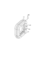
図1は、コネクタ10の分解斜視図である。図1に示すように、コネクタ10は、コネクタ端子100、ハウジング200、リテーナ300、防水シール400を備える。なお、以下の説明において、コネクタ端子100が延在する方向、つまり、コネクタ端子100をハウジング200に挿入する方向を挿入方向Xと呼び、挿入方向Xに直交し、図1において紙面奥に向かう方向を幅方向Yと呼び、挿入方向Xおよび幅方向Yの両方に直交する方向を高さ方向Zと呼んで説明することとする。また、以下の説明においては、挿入方向Xと反対の方向、つまりコネクタ端子100を引き抜く方向を抜去方向と呼ぶこととする。さらに、抜去方向に見た場合、つまり、コネクタ10と接続される相手方コネクタの挿入方向から見た場合に(図1において紙面右側から見た場合に)、上側を上方向、下側を下方向、左側を左方向(図1の紙面手前方向)、右側(図1の紙面奥方向)を右方向とみなして説明する。 FIG. 1 is an exploded perspective view of the connector 10. As shown in FIG. 1, the connector 10 includes a connector terminal 100, a housing 200, a retainer 300, and a waterproof seal 400. In the following description, the direction in which the connector terminal 100 extends, that is, the direction in which the connector terminal 100 is inserted into the housing 200 is referred to as an insertion direction X, which is orthogonal to the insertion direction X and toward the back of the paper in FIG. Is referred to as a width direction Y, and a direction orthogonal to both the insertion direction X and the width direction Y is referred to as a height direction Z. Further, in the following description, the direction opposite to the insertion direction X, that is, the direction in which the connector terminal 100 is pulled out is referred to as the pulling out direction. Further, when viewed in the removal direction, that is, when viewed from the insertion direction of the mating connector connected to the connector 10 (when viewed from the right side of the paper in FIG. 1), the upper side is upward and the lower side is downward. , The left side is regarded as the left direction (the direction toward the front of the paper in FIG. 1), and the right side (the direction toward the back of the paper in FIG. 1) is regarded as the right direction.

まず、コネクタ端子100について、図2を参照して説明する。なお、図2(A)は、本実施形態におけるコネクタ10のコネクタ端子100の斜視図、図2(B)は図2(A)のコネクタ端子100の上面図、図2(C)は図2(A)のコネクタ端子100を左側からみた場合の左側面図、図2(D)は図2(A)のコネクタ端子100の底面図、図2(E)は図2(A)のコネクタ端子100の正面図、図2(F)は、図2(E)におけるIIF-IIF線断面図である。 First, the connector terminal 100 will be described with reference to FIG. 2A is a perspective view of the connector terminal 100 of the connector 10 in the present embodiment, FIG. 2B is a top view of the connector terminal 100 of FIG. 2A, and FIG. 2C is FIG. 2; The left side view of the connector terminal 100 of (A) when viewed from the left side, FIG. 2 (D) is a bottom view of the connector terminal 100 of FIG. 2 (A), and FIG. 2 (E) is the connector terminal of FIG. 2 (A). A front view of 100, FIG. 2 (F) is a sectional view taken along line IIF-IIF in FIG. 2 (E).

コネクタ端子100は、一枚の金属平板を打ち抜いた後に折り曲げて形成される。コネクタ端子100は、相手方コネクタのコンタクト(図示せず)を内部に受容するための、断面外形状が少なくとも一部分において上下非対称形状のボックス部110と、導線180を把持する圧着部120と、ボックス部110と圧着部120とを接続し、断面形状がボックス部110の断面形状よりも小さな(あるいは低背な)移行部130と、を有する。なお、これら圧着部120および移行部130は、コネクタ端子100のボックス部110の挿入方向後部に形成される。 The connector terminal 100 is formed by punching a single metal flat plate and then bending it. The connector terminal 100 has a box portion 110 having a vertically asymmetrical shape at least in a part having an outer cross-sectional shape for internally receiving a contact (not shown) of the mating connector, a crimping portion 120 for gripping a conducting wire 180, and a box portion. The 110 is connected to the crimping portion 120, and has a transition portion 130 whose cross-sectional shape is smaller (or shorter) than the cross-sectional shape of the box portion 110. The crimping portion 120 and the transition portion 130 are formed at the rear portion of the box portion 110 of the connector terminal 100 in the insertion direction.

ボックス部110は、上板111、底板112、左側板113、右側板114を含み、これら上板111、底板112、左側板113、右側板114が、内部に相手方コネクタのコンタクトを収容するためのコンタクト挿入孔115を形成する筒状かつ箱型の形状をなしている。このボックス部110の、挿入方向Xまたは抜去方向に直交する平面における断面形状は、高さをHboxとする略長方形である。さらに、ボックス部110を構成する一つの面に外側に向けて突出する係止突起が設けられる。なお、本実施形態においては、上板111の上面に上方に向けて突出する係止突起116が形成されている。 The box portion 110 includes an upper plate 111, a bottom plate 112, a left side plate 113, and a right side plate 114, and the upper plate 111, the bottom plate 112, the left side plate 113, and the right side plate 114 are for accommodating the contact of the mating connector inside. It has a tubular and box-like shape that forms the contact insertion hole 115. The cross-sectional shape of the box portion 110 in a plane orthogonal to the insertion direction X or the removal direction is a substantially rectangular shape having a height of H box . Further, a locking projection that protrudes outward is provided on one surface constituting the box portion 110. In this embodiment, a locking projection 116 is formed on the upper surface of the upper plate 111 so as to project upward.

対照的に、係止突起116が設けられた面に対向する面、本実施形態においては底板112の下面112aは平坦な形状とされる。したがって、ボックス部110は、少なくとも係止突起116が形成された部位における断面外形状が、上下非対称形状となっている。ここで、底板112の下面112aから係止突起116の先端までの高さをHprotrusionとする。さらに、ボックス部110の上板111の、係止突起116の挿入方向Xにおける後方には、抜去方向に細長い上面開口119が形成される。上面開口119の幅方向Yの幅は、少なくとも、後述するランス229の端子係止部293の幅よりも大きくされる。 In contrast, the surface facing the surface on which the locking projection 116 is provided, that is, the lower surface 112a of the bottom plate 112 in the present embodiment, has a flat shape. Therefore, the box portion 110 has a vertically asymmetrical shape at least in the portion where the locking projection 116 is formed. Here, the height from the lower surface 112a of the bottom plate 112 to the tip of the locking projection 116 is defined as H protrusion . Further, behind the upper plate 111 of the box portion 110 in the insertion direction X of the locking projection 116, an elongated upper surface opening 119 is formed in the removal direction. The width of the upper surface opening 119 in the width direction Y is at least larger than the width of the terminal locking portion 293 of the lance 229 described later.

底板112の上面112bには、コンタクト挿入孔115内部において、後方かつ上方に向けて延びた接触片117が形成される。この接触片117は、相手方コネクタのコンタクトがコンタクト挿入孔115内に挿入された際に、相手方コネクタのコンタクトの下面に接触し、電気的な接続が可能となる。 On the upper surface 112b of the bottom plate 112, a contact piece 117 extending rearward and upward is formed inside the contact insertion hole 115. When the contact of the mating connector is inserted into the contact insertion hole 115, the contact piece 117 comes into contact with the lower surface of the contact of the mating connector, and electrical connection is possible.

圧着部120は、導線180の被覆部を把持する被覆把持部121と、導線180の導体部分を把持する導体把持部122を有する。なお、本実施形態においては、導線180の被覆の周囲には導線用防水シール190が取り付けられており、被覆把持部121はこの導線用防水シール190の周囲を包囲するように圧着されている。導体把持部122は、底板122aと、そこから左右両側において上方に延びた把持片122b、122cを備える。導線180の導体部分は、把持片122b、122cを底板122aに向けてかしめることにより、把持片122b、122cと底板122aとの間に圧着され、電気的な接続が形成される。 The crimping portion 120 has a covering grip portion 121 that grips the covering portion of the conductor 180, and a conductor grip portion 122 that grips the conductor portion of the conductor 180. In the present embodiment, the waterproof seal 190 for the conductor is attached around the coating of the conductor 180, and the coating grip portion 121 is crimped so as to surround the periphery of the waterproof seal 190 for the conductor. The conductor grip portion 122 includes a bottom plate 122a and grip pieces 122b and 122c extending upward on both left and right sides thereof. The conductor portion of the conductor 180 is crimped between the grip pieces 122b, 122c and the bottom plate 122a by caulking the grip pieces 122b, 122c toward the bottom plate 122a, and an electrical connection is formed.

移行部130は、ボックス部110と圧着部120とを接続する。移行部130は、底板112(ボックス部110の底板112と一続きになっている)、底板112の左側から上方に立設した左側面132、底板112の右側から立設した右側面133を備える。移行部130の底板112は、さらに圧着部120の導体把持部122の底板122aと一続きとなっている。また、移行部130の左側面132はボックス部110の左側板113と一続きであり、移行部130の右側面133はボックス部110の右側板114と一続きである。なお、移行部130の左側面132および右側面133の高さは、ボックス部110の左側板113および右側板114の高さよりも低くなるように形成される。これにより、移行部130の断面形状は、ボックス部110の断面形状よりも小さなもの(本実施形態においては、低背状)となる。また、ボックス部110の左側板113の、移行部130の左側面132と接続されていない後端部分、ボックス部110の右側板114の、移行部130の右側面133と接続されていない後端部分、およびボックス部110の上板111の後端部分は、後端面118を構成する。 The transition portion 130 connects the box portion 110 and the crimping portion 120. The transition portion 130 includes a bottom plate 112 (which is continuous with the bottom plate 112 of the box portion 110), a left side surface 132 erected upward from the left side of the bottom plate 112, and a right side surface 133 erected from the right side of the bottom plate 112. .. The bottom plate 112 of the transition portion 130 is further continuous with the bottom plate 122a of the conductor grip portion 122 of the crimping portion 120. Further, the left side surface 132 of the transition portion 130 is continuous with the left side plate 113 of the box portion 110, and the right side surface 133 of the transition portion 130 is continuous with the right side plate 114 of the box portion 110. The heights of the left side surface 132 and the right side surface 133 of the transition portion 130 are formed to be lower than the heights of the left side plate 113 and the right side plate 114 of the box portion 110. As a result, the cross-sectional shape of the transition portion 130 becomes smaller than the cross-sectional shape of the box portion 110 (in the present embodiment, it has a low profile). Further, the rear end portion of the left side plate 113 of the box portion 110 that is not connected to the left side surface 132 of the transition portion 130, and the rear end portion of the right side plate 114 of the box portion 110 that is not connected to the right side surface 133 of the transition portion 130. The portion and the rear end portion of the upper plate 111 of the box portion 110 constitute the rear end surface 118.

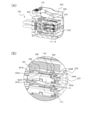
次にハウジング200について、図3、図4を参照して説明する。図3(A)は、本実施形態のコネクタ10のハウジング200の斜視図であり、図3(B)は、図3(A)のハウジング200をX-Z平面において切断した場合の断面図であり、図3(C)は、図3(A)のハウジング200をX-Z平面において切断し、左側から見た場合の斜視図である。また、図4(A)は、図3(B)のIVA部分の部分拡大図であり、図4(B)は、図3(C)のIVB部分の部分拡大図である。 Next, the housing 200 will be described with reference to FIGS. 3 and 4. 3A is a perspective view of the housing 200 of the connector 10 of the present embodiment, and FIG. 3B is a cross-sectional view of the housing 200 of FIG. 3A when the housing 200 is cut in an XX plane. 3 (C) is a perspective view of the housing 200 of FIG. 3 (A) cut in the XX plane and viewed from the left side. 4 (A) is a partially enlarged view of the IVA portion of FIG. 3 (B), and FIG. 4 (B) is a partially enlarged view of the IVB portion of FIG. 3 (C).

図3(A)~図3(C)に示すように、ハウジング200は、挿入方向Xに所定長さを有し、高さ方向Zおよび幅方向Yが比較的大きな直方体形状のベース210と、このベース210から挿入方向X前方に延びるコア220と、ベース210の外縁部分から挿入方向X前方に向かって、コア220の周囲を包囲するように延びる外殻230とを有する。外殻230は、外殻上面231、外殻底面232、外殻左側面233、外殻右側面234を含み、これらはベース210に直接接続されているのに対して、外殻230とコア220は、互いに直接は接続されておらず、ベース210を介して接続されている。また、外殻230とコア220の間には、コア220を包囲するように、相手方コネクタ(図示せず)のハウジングを受け入れる相手方コネクタ挿入スロット240がベース210に達するまで形成され、外殻230とコア220を隔てている。 As shown in FIGS. 3A to 3C, the housing 200 has a rectangular parallelepiped base 210 having a predetermined length in the insertion direction X and relatively large in the height direction Z and the width direction Y. It has a core 220 extending forward from the base 210 in the insertion direction X, and an outer shell 230 extending from the outer edge portion of the base 210 toward the front in the insertion direction X so as to surround the core 220. The outer shell 230 includes an outer shell upper surface 231 and an outer shell bottom surface 232, an outer shell left side surface 233, and an outer shell right side surface 234, which are directly connected to the base 210, whereas the outer shell 230 and the core 220 are connected. Are not directly connected to each other, but are connected via the base 210. Further, between the outer shell 230 and the core 220, a mating connector insertion slot 240 for receiving the housing of the mating connector (not shown) is formed so as to surround the core 220 until the mating connector insertion slot 240 reaches the base 210, and is formed with the outer shell 230. It separates the core 220.

ハウジング200のベース210、およびベース210に接続しているコア220の挿入方向Xにおける後部には、コネクタ端子100の圧着部120を収容するための圧着部収容路211が挿入方向Xに延在するように、後述するリテーナの挿入方向に複数形成される。この圧着部収容路211は、後述するボックス部収容路と同一直線状に形成される。なお、本実施形態においては、幅方向Yに3つ、高さ方向Zに2つ、合計6つの圧着部収容路211が形成されている。なお、これら圧着部収容路211の幅方向Yの数、高さ方向Zの数は、この例に限定されず、他の数であってもよい。それぞれの圧着部収容路211のY-Z平面に平行な面における断面形状は、コネクタ端子100の圧着部120およびここに取り付けられた導線用防水シール190を受容可能な形状および大きさであり、本実施形態においては導線用防水シール190の外径よりもわずかに小さな円形である。ベース210のX方向後面は後端面212をなしており、圧着部収容路211が後端面212に達する部位は、コネクタ端子100を圧着部収容路211に挿入するための端子挿入開口213となっている。 At the rear portion of the base 210 of the housing 200 and the core 220 connected to the base 210 in the insertion direction X, a crimp portion accommodating path 211 for accommodating the crimp portion 120 of the connector terminal 100 extends in the insertion direction X. As described above, a plurality of retainers are formed in the insertion direction of the retainer described later. The crimping portion accommodating path 211 is formed in the same linear shape as the box portion accommodating path described later. In this embodiment, a total of six crimping portion accommodating paths 211 are formed, three in the width direction Y and two in the height direction Z. The number of the crimping portion accommodating passages 211 in the width direction Y and the number in the height direction Z is not limited to this example, and may be other numbers. The cross-sectional shape of each crimping portion accommodating path 211 in a plane parallel to the YZ plane is a shape and size that can accept the crimping portion 120 of the connector terminal 100 and the conducting wire waterproof seal 190 attached thereto. In the present embodiment, the circular shape is slightly smaller than the outer diameter of the waterproof seal 190 for conducting wires. The rear surface of the base 210 in the X direction forms the rear end surface 212, and the portion where the crimping portion accommodating path 211 reaches the rear end surface 212 serves as a terminal insertion opening 213 for inserting the connector terminal 100 into the crimping portion accommodating path 211. There is.

コア220には、X方向における前部分において、圧着部収容路211と同一直線上に、コネクタ端子100のボックス部110を収容するための複数のボックス部収容路221が形成される。なお、本実施形態における以下の説明においては、高さ方向Z上側に位置するボックス部収容路221を、上側ボックス部収容路221U、高さ方向Z下側に位置するボックス部収容路221を、下側ボックス部収容路221Lと呼び、両方を総称する場合は単にボックス部収容路221と呼ぶこととする。それぞれのボックス部収容路221のY-Z平面に平行な面における断面形状は、コネクタ端子100のボックス部110を収容可能な形状であり、本実施形態においては、高さ方向Zの大きさが幅方向Yの大きさよりもわずかに大きい略長方形となっている。 In the front portion in the X direction, the core 220 is formed with a plurality of box portion accommodating paths 221 for accommodating the box portion 110 of the connector terminal 100 on the same straight line as the crimping portion accommodating path 211. In the following description of the present embodiment, the box portion accommodating path 221 located on the upper side in the height direction Z, the upper box portion accommodating path 221U, and the box portion accommodating path 221 located on the lower side in the height direction Z are referred to. It is referred to as a lower box portion accommodating path 221L, and when both are collectively referred to, it is simply referred to as a box portion accommodating path 221. The cross-sectional shape of each box portion accommodating path 221 in a plane parallel to the YZ plane is a shape capable of accommodating the box portion 110 of the connector terminal 100, and in the present embodiment, the size in the height direction Z is It is a substantially rectangular shape slightly larger than the size in the width direction Y.

コア220の挿入方向Xの前面は前端面222となっている。ボックス部収容路221は、前端面222に達し、オス端子挿入開口223を形成する。このオス端子挿入開口223は、コネクタ端子100のボックス部110の、上板111、底板112、左側板113、右側板114によって囲まれる内部空間の大きさに略同一の大きさまた形状である。それぞれのオス端子挿入開口223の上側には、工具挿入開口226が形成される。さらに、それぞれのボックス部収容路221には、ボックス部収容路221を形成する壁面の一つ、つまり上板221Aおよび/あるいは側板221Bから当該上板221Aあるいは側板221Bに沿い、前方に向かって片持ち状にボックス部収容路221内に斜めに突出したランス229が設けられる。 The front surface of the core 220 in the insertion direction X is the front end surface 222. The box portion accommodating path 221 reaches the front end surface 222 and forms a male terminal insertion opening 223. The male terminal insertion opening 223 has substantially the same size and shape as the size of the internal space surrounded by the upper plate 111, the bottom plate 112, the left side plate 113, and the right side plate 114 of the box portion 110 of the connector terminal 100. A tool insertion opening 226 is formed above each male terminal insertion opening 223. Further, in each box portion accommodating path 221, one of the wall surfaces forming the box portion accommodating path 221, that is, from the upper plate 221A and / or the side plate 221B along the upper plate 221A or the side plate 221B toward the front. A lance 229 that protrudes diagonally is provided in the box portion accommodating path 221 in a holding shape.

上側ボックス部収容路221Uに設けられたランス229は、ボックス部収容路221Uの上板221Aに接続され、下側ボックス部収容路221Lに設けられたランス229はボックス部収容路221Lの側板221Bに接続されている。それぞれのランス229は、上板221Aおよび/あるいは側板221Bに接続されたランス基部291、ランス基部291から挿入方向に向かってボックス部収容路221内に延設されたカンチレバー状部292、およびカンチレバー状部292の先端部に形成された、抜去方向に対して略垂直な当接面293Aを有する端子係止部293と、当該端子係止部293の前記挿入方向に直交する幅方向Yの一側から当接面293Aを超えて挿入方向Xに向けてさらに延出した冶具当て部294と、を備える。 The lance 229 provided in the upper box accommodation path 221U is connected to the upper plate 221A of the box accommodation path 221U, and the lance 229 provided in the lower box accommodation path 221L is connected to the side plate 221B of the box accommodation path 221L. It is connected. Each lance 229 has a lance base 291 connected to the upper plate 221A and / or a side plate 221B, a cantilever-shaped portion 292 extending from the lance base 291 into the box portion accommodating path 221 in the insertion direction, and a cantilever-shaped portion. A terminal locking portion 293 formed at the tip of the portion 292 having a contact surface 293A substantially perpendicular to the removal direction, and one side of the terminal locking portion 293 in the width direction Y orthogonal to the insertion direction. A jig contact portion 294 extending further from the contact surface 293A toward the insertion direction X is provided.

ランス基部291は高さ方向Zに所定の厚みを有している。本実施形態では高さ方向Zに2つのボックス部収容路221が設けられているが、上側ボックス部収容路221U内に形成されるランス229のランス基部291の基部下面291Aは、下側ボックス部収容路221L内に形成されるランス229のランス基部291の基部上面291Bと対向しており、それらの間に、コネクタ端子100のボックス部110の底板112の下面112aから係止突起116の先端までの高さHprotrusionを受け入れることが可能である。一方、下側ボックス部収容路221L内に形成されるランス229のランス基部291の基部下面291Aは、ボックス部収容路221の底面221Cと対向し、その間に、コネクタ端子100のボックス部110の底板112の下面112aから係止突起116の先端までの高さHprotrusionを受け入れることが可能である。 The lance base 291 has a predetermined thickness in the height direction Z. In the present embodiment, two box portion accommodating paths 221 are provided in the height direction Z, but the lower bottom surface 291A of the base portion of the lance base 291 of the lance 229 formed in the upper box portion accommodating path 221U is the lower box portion. It faces the upper surface 291B of the base of the lance base 291 of the lance 229 formed in the accommodation path 221L, and between them, from the lower surface 112a of the bottom plate 112 of the box portion 110 of the connector terminal 100 to the tip of the locking projection 116. It is possible to accept the height H protrusion . On the other hand, the lower surface surface 291A of the base portion of the lance base portion 291 of the lance 229 formed in the lower box portion accommodating path 221L faces the bottom surface 221C of the box portion accommodating path 221, and the bottom plate of the box portion 110 of the connector terminal 100 is in between. It is possible to accept a height H protrusion from the lower surface 112a of the 112 to the tip of the locking projection 116.

ランス229のカンチレバー状部292にはランス基部291の基部下面291Aの先端部から挿入方向Xに向かって斜め下方に傾斜した第1テーパ面292Aと、当該第1テーパ面292Aの先端部から水平方向に挿入方向Xに向けて延びるレバー下面292Bが設けられる。上側ボックス部収容路221Uにおいて、下側に位置するランス229のランス基部291の基部上面291Bから上側に位置するランス229のレバー下面292Bまでの高さ方向Zの高さ、および下側ボックス部収容路221Lにおいて、底面221Cから下側ボックス部収容路221L内にあるランス229のレバー下面292Bまでの高さ方向Zの高さは、コネクタ端子100のボックス部110の高さHboxより大きく、ボックス部110の底板112の下面112aから係止突起116の先端までの高さHprotrusionよりも小さくなるようにされる。 The cantilever-shaped portion 292 of the lance 229 has a first tapered surface 292A inclined diagonally downward from the tip of the base lower surface 291A of the lance base 291 toward the insertion direction X, and a horizontal direction from the tip of the first tapered surface 292A. Is provided with a lever lower surface 292B extending in the insertion direction X. In the upper box portion accommodating path 221U, the height in the height direction Z from the base upper surface 291B of the lance base 291 of the lance 229 located on the lower side to the lever lower surface 292B of the lance 229 located on the upper side, and the lower box portion accommodating. In the road 221L, the height in the height direction Z from the bottom surface 221C to the lever lower surface 292B of the lance 229 in the lower box portion accommodating path 221L is larger than the height H box of the box portion 110 of the connector terminal 100, and is a box. The height from the lower surface 112a of the bottom plate 112 of the portion 110 to the tip of the locking projection 116 is made smaller than the height H protrusion .

さらに、ランス229の端子係止部293には、上述した当接面293Aに加えて、カンチレバー状部292のレバー下面292Bの先端部から挿入方向Xに向かって斜め下方に傾斜した第2テーパ面293Bと、当該第2テーパ面293Bの先端部から水平方向に挿入方向Xに向けて延びる係止部下面293Cが設けられる。上側ボックス部収容路221Uにおいて、下側のランス229のランス基部291の基部上面291Bから上側のランス229の係止部下面293Cまでの高さ方向Zの高さ、および、下側のボックス部収容路221Lにおいて、底面221Cから下側のランス229の係止部下面293Cまでの高さ方向Zの高さは、コネクタ端子100のボックス部110の高さHboxと略等しくなるようにされる。 Further, in addition to the contact surface 293A described above, the terminal locking portion 293 of the lance 229 has a second tapered surface inclined diagonally downward from the tip end portion of the lever lower surface 292B of the cantilever-shaped portion 292 toward the insertion direction X. A 293B and a lower surface 293C of a locking portion extending horizontally from the tip end portion of the second tapered surface 293B in the insertion direction X are provided. In the upper box portion accommodating path 221U, the height in the height direction Z from the base upper surface 291B of the lance base 291 of the lower lance 229 to the lower surface 293C of the locking portion of the upper lance 229, and the lower box portion accommodating. In the road 221L, the height in the height direction Z from the bottom surface 221C to the lower surface surface 293C of the locking portion of the lower lance 229 is set to be substantially equal to the height H box of the box portion 110 of the connector terminal 100.

端子係止部293の当接面293Aは抜去方向に対して略垂直であるが、ボックス部110の係止突起116の抜去方向への移動を阻止できる角度であればいずれの角度を採用してもよい。当接面293Aの高さは、ボックス部110の係止突起116の高さと略同じかそれよりも大きくされる。 The contact surface 293A of the terminal locking portion 293 is substantially perpendicular to the removal direction, but any angle can be adopted as long as the angle can prevent the locking projection 116 of the box portion 110 from moving in the removal direction. May be good. The height of the contact surface 293A is substantially the same as or larger than the height of the locking projection 116 of the box portion 110.

治具当て部294は、上述したように、端子係止部293の幅方向Yの一側から当接面293Aを超えて挿入方向Xに向けてさらに延出している。治具当て部294には、冶具当て部下面294Aと、挿入方向Xの先端部から治具当て部下面294Aの先端部に向かって斜め下方に所定角度で傾斜した第3テーパ面294Bが設けられる。治具当て部下面294Aは、コネクタ端子100のボックス部110の上板111に近接する端面であるが、上述した係止部下面293Cより、コネクタ端子100のボックス部110の上板111から遠い位置となるように形成されている。 As described above, the jig contact portion 294 extends further from one side of the terminal locking portion 293 in the width direction Y beyond the contact surface 293A toward the insertion direction X. The jig contact portion 294 is provided with a jig contact portion lower surface 294A and a third tapered surface 294B inclined diagonally downward from the tip end portion in the insertion direction X toward the tip end portion of the jig contact portion lower surface 294A. .. The lower surface of the jig contact portion 294A is an end surface close to the upper plate 111 of the box portion 110 of the connector terminal 100, but is located farther from the upper plate 111 of the box portion 110 of the connector terminal 100 than the above-mentioned lower surface 293C of the locking portion. It is formed so as to be.

リテーナ挿入スロット250は、ハウジング200の外殻230の外殻左側面233の挿入方向Xの略中央部分に、高さ方向Zに長尺に形成される。リテーナ挿入スロット250は、圧着部収容路211およびボックス部収容路221の延在方向に対して垂直な方向、すなわち、本実施形態においては幅方向Yに向かって延び、外殻左側面233側の相手方コネクタ挿入スロット240を貫通し、コア左面、コア220内部の圧着部収容路211およびボックス部収容路221、およびコア右面を貫通し、外殻右側面234側の相手方コネクタ挿入スロット240に達し、上述のボックス部収容路221と圧着部収容路211とを隔てるように、ボックス部収容路221および圧着部収容路211の延在方向に対して直交するように形成されている。なお、コア220のコア左面とコア右面はリテーナ挿入スロット250によって貫通されるのに対し、コア220のコア上面224とコア下面225はリテーナ挿入スロット250によって貫通されずベース210に達するまで一続きとなっている。なお、コア220において、内部の圧着部収容路211およびボックス部収容路221がリテーナ挿入スロット250によって貫通された部分は、後述するリテーナ300の本体部を収容する本体受容部228を形成している。 The retainer insertion slot 250 is formed elongated in the height direction Z at a substantially central portion of the outer shell left side surface 233 of the outer shell 230 of the housing 200 in the insertion direction X. The retainer insertion slot 250 extends in a direction perpendicular to the extending direction of the crimping portion accommodating path 211 and the box portion accommodating path 221, that is, in the width direction Y in the present embodiment, and is on the left side surface 233 side of the outer shell. It penetrates the mating connector insertion slot 240, penetrates the core left side, the crimping portion accommodating path 211 and the box portion accommodating path 221 inside the core 220, and the core right surface, and reaches the mating connector insertion slot 240 on the outer shell right side surface 234 side. The box portion accommodating path 221 and the crimping portion accommodating path 211 are formed so as to be orthogonal to the extending direction of the box portion accommodating path 221 and the crimping portion accommodating path 211 so as to separate the box portion accommodating path 221 and the crimping portion accommodating path 211. The left side of the core and the right side of the core of the core 220 are penetrated by the retainer insertion slot 250, whereas the core upper surface 224 and the core lower surface 225 of the core 220 are not penetrated by the retainer insertion slot 250 and continue until they reach the base 210. It has become. In the core 220, the portion through which the internal crimping portion accommodating path 211 and the box portion accommodating path 221 are penetrated by the retainer insertion slot 250 forms a main body receiving portion 228 for accommodating the main body portion of the retainer 300 described later. ..

さらに、コア上面224には、第1係止溝224a、第2係止溝224bが形成される。同様に、コア下面225には、第1係止溝225a、第2係止溝225bが形成される。第1係止溝224a、225aは、本実施形態においては、リテーナ挿入スロット250が形成されている外殻左側面233に近い側、つまりコア左面に近い側に形成され、第2係止溝224b、225bは、外殻左側面233から遠い側、つまりコア右面に近い側に形成される。 Further, a first locking groove 224a and a second locking groove 224b are formed on the core upper surface 224. Similarly, the first locking groove 225a and the second locking groove 225b are formed on the lower surface surface 225 of the core. In the present embodiment, the first locking grooves 224a and 225a are formed on the side close to the outer shell left side surface 233 on which the retainer insertion slot 250 is formed, that is, on the side close to the core left side, and the second locking groove 224b. 225b is formed on the side far from the left side surface 233 of the outer shell, that is, the side close to the right side surface of the core.

次に、図5を参照してリテーナ300について説明する。図5(A)は、本実施形態のコネクタ10のリテーナ300の斜視図、図5(B)は、図5(A)のリテーナ300の正面図である。リテーナ300は、上述のリテーナ挿入スロット250に挿入されて、後述する仮係止位置と本係止位置とをとる。リテーナ300は、幅方向Yに長尺な本体部310、本体部310の幅方向Yの左側端部311の上端から上方に延び次いで幅方向Y(右方向)に向けて延びる上部アーム320、および本体部310の幅方向Yの左側端部311の下端から下方に延び、次いで幅方向Y(右方向)に向けて延びる下部アーム330を備える。 Next, the retainer 300 will be described with reference to FIG. 5 (A) is a perspective view of the retainer 300 of the connector 10 of the present embodiment, and FIG. 5 (B) is a front view of the retainer 300 of FIG. 5 (A). The retainer 300 is inserted into the retainer insertion slot 250 described above, and takes a temporary locking position and a main locking position, which will be described later. The retainer 300 has a main body 310 that is long in the width direction Y, an upper arm 320 that extends upward from the upper end of the left end 311 in the width direction Y of the main body 310, and then extends in the width direction Y (right direction). A lower arm 330 extending downward from the lower end of the left end portion 311 in the width direction Y of the main body 310 and then extending in the width direction Y (right direction) is provided.

上部アーム320はリテーナ300がハウジング200のリテーナ挿入スロット250に挿入され、本体部310がコア220の本体受容部228に挿入された際に、コア220のコア上面224と外殻230の外殻上面231の下面231aとの間に位置する。また、このとき、下部アーム330は、コア220のコア下面225と外殻230の外殻底面232の上面232aとの間に位置する。 When the retainer 300 is inserted into the retainer insertion slot 250 of the housing 200 and the main body 310 is inserted into the main body receiving portion 228 of the core 220, the upper arm 320 has the core upper surface 224 of the core 220 and the outer shell upper surface of the outer shell 230. It is located between the lower surface 231a of 231 and the lower surface 231a. At this time, the lower arm 330 is located between the core lower surface 225 of the core 220 and the upper surface 232a of the outer shell bottom surface 232 of the outer shell 230.

リテーナ300の上部アーム320の上部アーム下面321には高さ方向Zの下方に向けて突出する上部係止突起322が設けられる。また、下部アーム330の下部アーム上面331には高さ方向Zの上方に向けて突出する下部係止突起332が設けられる。上部係止突起322は、コア上面224の第1係止溝224aまたは第2係止溝224bのいずれかに係止される。一方、下部係止突起332は、コア下面225の第1係止溝225aまたは第2係止溝225bのいずれかに係止される。 The lower surface 321 of the upper arm of the upper arm 320 of the retainer 300 is provided with an upper locking projection 322 that projects downward in the height direction Z. Further, the lower arm upper surface 331 of the lower arm 330 is provided with a lower locking projection 332 that protrudes upward in the height direction Z. The upper locking projection 322 is locked to either the first locking groove 224a or the second locking groove 224b of the core upper surface 224. On the other hand, the lower locking projection 332 is locked to either the first locking groove 225a or the second locking groove 225b of the core lower surface 225.

本体部310の幅方向Yの長さ(幅)は、本体部310がリテーナ挿入スロット250からハウジング200のコア220の本体受容部228に挿入され、上部アーム320の上部係止突起322がコア上面224の第1係止溝224aに係止され、下部アーム330の下部係止突起332がコア下面225の第1係止溝225aに係止された「仮係止位置」のときに、本体部310の右側端部312とコア右面とが略同一平面上に揃う長さとなるように形成される。 Regarding the length (width) of the main body 310 in the width direction Y, the main body 310 is inserted from the retainer insertion slot 250 into the main body receiving portion 228 of the core 220 of the housing 200, and the upper locking projection 322 of the upper arm 320 is the upper surface of the core. When the lower locking projection 332 of the lower arm 330 is locked to the first locking groove 225a of the core lower surface 225 at the "temporary locking position" of being locked to the first locking groove 224a of the 224, the main body portion. The right end portion 312 of the 310 and the right surface of the core are formed so as to have a length that is substantially aligned on the same plane.

本体部310の高さ方向Zの高さは、コア下面225の上面225cからコア上面224の本体受容部228における下面224cまで間の高さよりも、コネクタ端子100の移行部130の高さ分だけ小さな高さとされる。 The height of the main body 310 in the height direction Z is the height of the transition portion 130 of the connector terminal 100 rather than the height between the upper surface 225c of the core lower surface 225 and the lower surface 224c of the main body receiving portion 228 of the core upper surface 224. It is said to be a small height.

本体部310には、リテーナ300がリテーナ挿入スロット250内の予め定められた位置(仮係止位置)にある場合に、コネクタ端子100のボックス部110の挿通を可能とするボックス部用開口313と、ボックス部用開口313に幅方向に連通した移行部用開口314がそれぞれ複数形成される。本実施形態においては、リテーナ300の本体部310には、リテーナの挿入方向(幅方向Y)に向かって、ボックス部用開口313と移行部用開口314が、上述したハウジング200のベース210およびコア220に形成された、リテーナの挿入方向(幅方向Y)におけるボックス部収容路221および圧着部収容路211の数と同数形成されており、それぞれのボックス部用開口313は隣接する他のコネクタ端子100の移行部130を受け入れるための移行部用開口と連通している。 The main body 310 has a box opening 313 that allows the box portion 110 of the connector terminal 100 to be inserted when the retainer 300 is in a predetermined position (temporary locking position) in the retainer insertion slot 250. , A plurality of transition portion openings 314 communicating with the box portion opening 313 in the width direction are formed. In the present embodiment, the main body 310 of the retainer 300 has the opening 313 for the box portion and the opening 314 for the transition portion in the insertion direction (width direction Y) of the retainer, and the base 210 and the core of the housing 200 described above. The number of the box portion accommodating paths 221 and the crimping portion accommodating paths 211 formed in the 220 in the insertion direction (width direction Y) of the retainer is the same as the number of the box portion accommodating paths 221 and each box portion opening 313 is adjacent to another connector terminal. It communicates with the transition opening for receiving the transition 130 of 100.

具体的には、コネクタ10に組み込まれるコネクタ端子100の、幅方向Yの数と同数、つまり3つのボックス部用開口313(313a、313b、313c)と3つの移行部用開口314(314a、314b、314c)が幅方向Yに沿って同一直線上に形成される。なお、それぞれのボックス部用開口313は、リテーナ300の本体部310がリテーナ挿入スロット250からコア220の本体受容部228に挿入され、リテーナ300が仮係止位置にあるとき、コア220のボックス部収容路221と挿入方向Xにおいて同一直線状となる位置に形成される。 Specifically, the number of connector terminals 100 incorporated in the connector 10 is the same as the number in the width direction Y, that is, three box opening openings 313 (313a, 313b, 313c) and three transitional opening 314 (314a, 314b). 314c) are formed on the same straight line along the width direction Y. Each box portion opening 313 has a box portion of the core 220 when the main body portion 310 of the retainer 300 is inserted from the retainer insertion slot 250 into the main body receiving portion 228 of the core 220 and the retainer 300 is in the temporary locking position. It is formed at a position that is in the same linear shape as the accommodation path 221 in the insertion direction X.

一つのコネクタ端子100を受け入れるボックス部用開口313および移行部用開口314は、幅方向Yに隣接する別のコネクタ端子100を受入れるボックス部用開口313および移行部用開口314に連通している。したがって、本実施形態においては、ボックス部用開口313aは、この開口が受け入れるのと同じ端子のための移行部用開口314aと連通しており、移行部用開口314aは、隣接する別のコネクタ端子100を受入れるボックス部用開口313bに連通しており、ボックス部用開口313bはこれと同じコネクタ端子100を受け入れる移行部用開口314bに連通し、この移行部用開口314bは、隣接するさらに別のコネクタ端子100を受入れるボックス部用開口313cに連通しており、このボックス部用開口313cはこれと同じコネクタ端子100を受け入れる移行部用開口314cに連通している。 The box portion opening 313 and the transition portion opening 314 that receive one connector terminal 100 communicate with the box portion opening 313 and the transition portion opening 314 that receive another connector terminal 100 adjacent to each other in the width direction Y. Therefore, in this embodiment, the box opening 313a communicates with the transition opening 314a for the same terminals that this opening accepts, and the transition opening 314a is another adjacent connector terminal. It communicates with the box opening 313b that receives 100, the box opening 313b communicates with the transition opening 314b that accepts the same connector terminal 100, and this transition opening 314b is adjacent to yet another. It communicates with the opening 313c for the box portion that receives the connector terminal 100, and the opening 313c for the box portion communicates with the opening 314c for the transition portion that receives the same connector terminal 100.

それぞれのボックス部用開口313は、コネクタ端子100をリテーナ300のボックス部用開口313からハウジング200のボックス部収容路221に挿通しようとした際に、コネクタ端子100が適正な位置からコネクタ端子100の挿入軸(挿入方向X)を中心として回転した状態のときに当該挿通を阻止する形状となっている。例えば、ボックス部用開口313の形状は、上下非対称形状のボックス部110の断面外形状に対応した形状(または左右非対称形状のボックスの断面外形状に対応した形状)となっている。すなわち本実施形態においては、ボックス部用開口313の高さは、コネクタ端子100のボックス部110の高さHboxと同じかわずかに大きい高さである略長方形であって、その底辺が平坦形状であるのに対し、上辺がその中央部に上方に向かって凹んだくぼみを有する形状となっている。 Each box portion opening 313 has a connector terminal 100 from an appropriate position when the connector terminal 100 is inserted from the box portion opening 313 of the retainer 300 into the box portion accommodating path 221 of the housing 200. The shape is such that the insertion is blocked when the connector is rotated about the insertion axis (insertion direction X). For example, the shape of the opening 313 for the box portion is a shape corresponding to the shape outside the cross section of the box portion 110 having a vertically asymmetric shape (or a shape corresponding to the shape outside the cross section of the box having a left-right asymmetric shape). That is, in the present embodiment, the height of the opening 313 for the box portion is substantially rectangular, which is the same as or slightly larger than the height H box of the box portion 110 of the connector terminal 100, and the base thereof has a flat shape. On the other hand, the upper side has a shape with an upwardly dented recess in the central part thereof.

また、それぞれの移行部用開口314の、リテーナ300の挿入方向(幅方向Y)に直交する方向の大きさ(高さ方向Zの大きさ)が、ボックス部用開口313の大きさよりも小さく形成されている。具体的には、移行部用開口314の高さは、コネクタ端子100のボックス部110の高さHboxよりも小さく、コネクタ端子100の移行部130の高さより大きな高さとされる。 Further, the size (size of the height direction Z) of each transition portion opening 314 in the direction orthogonal to the insertion direction (width direction Y) of the retainer 300 is formed to be smaller than the size of the box portion opening 313. Has been done. Specifically, the height of the transition portion opening 314 is smaller than the height H box of the box portion 110 of the connector terminal 100, and is larger than the height of the transition portion 130 of the connector terminal 100.

さらに、リテーナ300の本体部310の下面316には、上述したボックス部用開口313a~313cと、幅方向Yにおいて同一位置となる位置に、ボックス部用凹部317a~317c(以下、まとめてボックス部用凹部317という)が形成される。それぞれのボックス部用凹部317は、上述したボックス部用開口313の上側部分と略同一の形状であり、ボックス部用開口313の上辺に対応した上辺と、その上辺がその中央部において上方に向かって凹んだくぼみを有する形状となっている。 Further, on the lower surface 316 of the main body 310 of the retainer 300, the recesses 317a to 317c for the box portion (hereinafter collectively referred to as the box portion) are located at the same positions as the above-mentioned openings 313a to 313c for the box portion in the width direction Y. A recess 317) is formed. Each box portion recess 317 has substantially the same shape as the upper portion of the box portion opening 313 described above, and the upper side corresponding to the upper side of the box portion opening 313 and the upper side thereof face upward in the central portion thereof. It has a shape with a dented dent.

ここで、リテーナ300の本体部310がリテーナ挿入スロット250からコア220の本体受容部228に挿入され、リテーナ300が仮係止位置にあるとき、リテーナの下部アーム330はコア220のコア下面225と外殻230の外殻底面232の上面232aとの間に位置しているため、本体部310の下面316は、コア下面225の上面225cに対向した状態となる。このとき、コア下面225の上面225cからボックス部用凹部317の上辺までの高さは、上述したボックス部用開口313の高さと略等しく、また、コア下面225の上面225cからボックス部用凹部317のくぼみまでの高さは、上述したボックス部用開口313の底辺からくぼみ313Xまでの高さと略等しくなる。また、上記仮係止位置において、コア下面225の上面225cからリテーナ300の本体部310の下面316までの高さは上述した移行部用開口314の高さと略等しくなる。 Here, when the main body 310 of the retainer 300 is inserted from the retainer insertion slot 250 into the main body receiving portion 228 of the core 220 and the retainer 300 is in the temporary locking position, the lower arm 330 of the retainer becomes the core lower surface 225 of the core 220. Since the outer shell 230 is located between the upper surface 232a and the upper surface 232a of the outer shell bottom surface 232, the lower surface 316 of the main body 310 faces the upper surface 225c of the core lower surface 225. At this time, the height from the upper surface 225c of the core lower surface 225 to the upper side of the box portion recess 317 is substantially equal to the height of the box portion opening 313 described above, and the height from the upper surface 225c of the core lower surface 225 to the box portion recess 317. The height of the recess is substantially equal to the height from the bottom of the box opening 313 to the recess 313X described above. Further, at the temporary locking position, the height from the upper surface 225c of the core lower surface 225 to the lower surface 316 of the main body 310 of the retainer 300 is substantially equal to the height of the transition portion opening 314 described above.

次に、図6を参照して、防水シール400について説明する。なお、図6は、本実施形態のコネクタ10の防水シール400の斜視図である。防水シール400は、外形がハウジング200の外殻230を構成する外殻上面231、外殻底面232、外殻左側面233、外殻右側面234の内壁に接触し防水可能となる形状をしており、内部にハウジング200のコア220が挿通される開口405を有する。防水シール400は、弾性を有する材料で形成される。さらに、防水シール400の外面410には、挿入方向Xと直交する方向(つまり幅方向Yおよび高さ方向Z)に沿って複数の凸状部411が形成される。また、防水シール400の内面420には、挿入方向Xと直交する方向(つまり幅方向Yおよび高さ方向Z)に沿って複数の溝状部421が形成される。防水シール400は、コネクタ10の組立時にハウジング200の相手方コネクタ挿入スロット240のスロット最奥部241に挿入される。 Next, the waterproof seal 400 will be described with reference to FIG. Note that FIG. 6 is a perspective view of the waterproof seal 400 of the connector 10 of the present embodiment. The waterproof seal 400 has a shape capable of being waterproof by contacting the inner walls of the outer shell upper surface 231, the outer shell bottom surface 232, the outer shell left side surface 233, and the outer shell right side surface 234 whose outer shape constitutes the outer shell 230 of the housing 200. It has an opening 405 inside which the core 220 of the housing 200 is inserted. The waterproof seal 400 is made of an elastic material. Further, on the outer surface 410 of the waterproof seal 400, a plurality of convex portions 411 are formed along the directions orthogonal to the insertion direction X (that is, the width direction Y and the height direction Z). Further, a plurality of groove-shaped portions 421 are formed on the inner surface 420 of the waterproof seal 400 along the directions orthogonal to the insertion direction X (that is, the width direction Y and the height direction Z). The waterproof seal 400 is inserted into the innermost portion 241 of the mating connector insertion slot 240 of the housing 200 when the connector 10 is assembled.

次に、コネクタ10の組み立て方法について説明する。図1に示すように、まず、防水シール400を、相手方コネクタ挿入スロット240に、挿入方向Xと反対の向き、つまり抜去方向に挿入し、防水シール400をスロット最奥部241に配置する。このとき、防水シール400の内面420に形成された複数の溝状部421により、防水シール400はコア220の周囲に密着する。 Next, a method of assembling the connector 10 will be described. As shown in FIG. 1, first, the waterproof seal 400 is inserted into the mating connector insertion slot 240 in the direction opposite to the insertion direction X, that is, in the removal direction, and the waterproof seal 400 is arranged in the innermost portion 241 of the slot. At this time, the waterproof seal 400 is in close contact with the periphery of the core 220 due to the plurality of groove-shaped portions 421 formed on the inner surface 420 of the waterproof seal 400.

次いで、リテーナ300を、ハウジング200のリテーナ挿入スロット250に挿入する。すると、リテーナ300の本体部310はコア220の本体受容部228に進入する。また、リテーナ300の上部アーム320は、ハウジング200の外殻上面231の下面231aとコア220のコア上面224との間に挿入される。さらに、リテーナ300の下部アーム330は、ハウジング200の外殻底面232の上面232aとコア220のコア下面225の間に挿入される。リテーナ300をリテーナ挿入スロット250に挿入し、幅方向Yに移動させてゆくと、リテーナ300の上部アーム320の上部係止突起322がコア220のコア上面224に形成された第1係止溝224aに係止され、リテーナ300の下部アーム330の下部係止突起332がコア220のコア下面225に形成された第1係止溝225aに係止される。このとき、リテーナ300は仮係止位置にある。 The retainer 300 is then inserted into the retainer insertion slot 250 of the housing 200. Then, the main body 310 of the retainer 300 enters the main body receiving portion 228 of the core 220. Further, the upper arm 320 of the retainer 300 is inserted between the lower surface 231a of the outer shell upper surface 231 of the housing 200 and the core upper surface 224 of the core 220. Further, the lower arm 330 of the retainer 300 is inserted between the upper surface 232a of the outer shell bottom surface 232 of the housing 200 and the core lower surface 225 of the core 220. When the retainer 300 is inserted into the retainer insertion slot 250 and moved in the width direction Y, the upper locking projection 322 of the upper arm 320 of the retainer 300 is formed on the core upper surface 224 of the core 220. The lower locking projection 332 of the lower arm 330 of the retainer 300 is locked to the first locking groove 225a formed on the core lower surface 225 of the core 220. At this time, the retainer 300 is in the temporary locking position.

この仮係止位置のとき、リテーナ300の本体部310に形成されたボックス部用開口313およびボックス部用凹部317は、ハウジング200の圧着部収容路211およびボックス部収容路221と挿入方向Xにおいて一直線上に位置が揃う。 At this temporary locking position, the box portion opening 313 and the box portion recess 317 formed in the main body portion 310 of the retainer 300 are formed in the crimping portion accommodating path 211 and the box portion accommodating path 221 of the housing 200 and the insertion direction X. The positions are aligned on a straight line.

この仮係止位置のときに、圧着部120に導線180を圧着接続したコネクタ端子100を、ハウジング200のベース210の端子挿入開口213から圧着部収容路211に挿入する。圧着部収容路211の形状がコネクタ端子100のボックス部110の外形よりも大きい円形であるため、コネクタ端子100のボックス部110は、妨げられることなく圧着部収容路211を通過し、リテーナ300の本体部310のボックス部用開口313またはボックス部用凹部317に達し、リテーナ300のボックス部用開口313は、ボックス部110の挿入方向Xへの進入を許容する。コネクタ端子100をさらに挿入方向Xに移動させると、ボックス部110は、コア220のボックス部収容路221に挿入される。つまり、コネクタ端子100は、圧着部収容路211からボックス部用開口313またはボックス部用凹部317を経てボックス部収容路221に挿入される。 At this temporary locking position, the connector terminal 100 to which the conducting wire 180 is crimp-connected to the crimping portion 120 is inserted into the crimping portion accommodating path 211 from the terminal insertion opening 213 of the base 210 of the housing 200. Since the shape of the crimping portion accommodating path 211 is a circle larger than the outer shape of the box portion 110 of the connector terminal 100, the box portion 110 of the connector terminal 100 passes through the crimping portion accommodating path 211 without being hindered, and the retainer 300 The opening 313 for the box portion or the recess 317 for the box portion of the main body 310 is reached, and the opening 313 for the box portion of the retainer 300 allows the box portion 110 to enter the insertion direction X. When the connector terminal 100 is further moved in the insertion direction X, the box portion 110 is inserted into the box portion accommodating path 221 of the core 220. That is, the connector terminal 100 is inserted into the box portion accommodating path 221 from the crimping portion accommodating path 211 through the box portion opening 313 or the box portion recess 317.

ここで、コネクタ端子100がボックス部収容路221に部分的に挿入された状態を、図7を参照して説明する。図7(A)は、コネクタ端子100のボックス部110がボックス部収容路221に部分的に挿入されたときの図3(C)に対応する断面斜視図、図7(B)は、図7(A)のVIIB部分の部分拡大図である。 Here, a state in which the connector terminal 100 is partially inserted into the box portion accommodating path 221 will be described with reference to FIG. 7. 7 (A) is a cross-sectional perspective view corresponding to FIG. 3 (C) when the box portion 110 of the connector terminal 100 is partially inserted into the box portion accommodating path 221. FIG. 7 (B) is FIG. It is a partially enlarged view of the VIIB part of (A).

図7(A)、図7(B)において、上側に位置するコネクタ端子100のボックス部110は、上側ボックス部収容路221Uに形成されたランス229のランス基部291の基部下面291Aと、下側ボックス部収容路221Lに形成されたランス229のランス基部291の基部上面291Bの間に挿入されている。このとき、ボックス部110の上板111と基部下面291Aの間には係止突起116の高さよりわずかに大きい空間があり、ボックス部110は挿入方向Xに移動可能である。 In FIGS. 7A and 7B, the box portion 110 of the connector terminal 100 located on the upper side is the lower side of the lower surface 291A of the base portion of the lance base 291 of the lance 229 formed in the upper box portion accommodating path 221U. It is inserted between the upper surface surface 291B of the base portion of the lance base 291 of the lance 229 formed in the box portion accommodating path 221L. At this time, there is a space slightly larger than the height of the locking projection 116 between the upper plate 111 of the box portion 110 and the lower surface 291A of the base portion, and the box portion 110 can move in the insertion direction X.

コネクタ端子100の挿入方向Xへの移動に伴ってボックス部110が挿入方向Xにさらに移動すると、ボックス部110の係止突起116が、ランス229のカンチレバー状部292の第1テーパ面292Aに摺接しつつランス229のカンチレバー状部292を高さ方向Z上方に押し上げる。このとき、ランス229のカンチレバー状部292はランス基部291を支点として上方に旋回する。ボックス部110をさらに挿入方向Xへ移動させると、ボックス部110の係止突起116はカンチレバー状部292のレバー下面292B、端子係止部293の第2テーパ面293B、係止部下面293Cの順に摺接してゆき、その間にランス229は全体としてランス基部291を支点として上方に持ち上げられた状態を維持する。 When the box portion 110 further moves in the insertion direction X as the connector terminal 100 moves in the insertion direction X, the locking projection 116 of the box portion 110 slides on the first tapered surface 292A of the cantilever-shaped portion 292 of the lance 229. While touching, the cantilever-shaped portion 292 of the lance 229 is pushed up Z upward in the height direction. At this time, the cantilever-shaped portion 292 of the lance 229 swivels upward with the lance base 291 as a fulcrum. When the box portion 110 is further moved in the insertion direction X, the locking projection 116 of the box portion 110 is in the order of the lever lower surface 292B of the cantilever-shaped portion 292, the second tapered surface 293B of the terminal locking portion 293, and the locking portion lower surface 293C. During the sliding contact, the lance 229 maintains a state of being lifted upward with the lance base 291 as a fulcrum as a whole.

次いで、ボックス部110の係止突起116が端子係止部293の係止部下面293Cを摺接しながら挿入方向Xに移動し、端子係止部293の当接面293Aまで到達すると、係止突起116と係止部下面293Cとの接触がなくなり、図8に示すように、ランス229はランス基部291を支点として下方に旋回し、当初の形状に復帰する。なお、図8(A)は、コネクタ端子100のボックス部110がボックス部収容路221に完全に挿入されたときの図3(C)に対応する断面斜視図、図8(B)は、図8(A)のVIIIB部分の部分拡大図である。 Next, when the locking projection 116 of the box portion 110 moves in the insertion direction X while sliding in contact with the lower surface 293C of the locking portion of the terminal locking portion 293 and reaches the contact surface 293A of the terminal locking portion 293, the locking projection The contact between the 116 and the lower surface 293C of the locking portion is lost, and as shown in FIG. 8, the lance 229 swivels downward with the lance base 291 as a fulcrum and returns to the original shape. 8 (A) is a cross-sectional perspective view corresponding to FIG. 3 (C) when the box portion 110 of the connector terminal 100 is completely inserted into the box portion accommodating path 221. FIG. 8 (B) is a view. 8 (A) is a partially enlarged view of a VIIIB portion.

図8(A)、図8(B)に示すように、コネクタ端子100のボックス部110がボックス部収容路221に完全に挿入された際に、コネクタ端子100のボックス部110のコンタクト挿入孔115は、コア220のオス端子挿入開口223の、挿入方向Xのすぐ後方側に位置する。さらに、係止突起116は、挿入方向Xにおける後面側が端子係止部293の当接面293Aと係止されており、ボックス部110の抜去方向への移動が阻止される。また、ランス229の端子係止部293は、その下側の一部がボックス部110の上板111の上面開口119に挿入され、結果としてボックス部110の抜去方向への移動が確実に阻止される。 As shown in FIGS. 8A and 8B, when the box portion 110 of the connector terminal 100 is completely inserted into the box portion accommodation path 221, the contact insertion hole 115 of the box portion 110 of the connector terminal 100 is inserted. Is located just behind the insertion direction X of the male terminal insertion opening 223 of the core 220. Further, the locking projection 116 is locked to the contact surface 293A of the terminal locking portion 293 on the rear surface side in the insertion direction X, and the movement of the box portion 110 in the removal direction is prevented. Further, a part of the lower side of the terminal locking portion 293 of the lance 229 is inserted into the upper surface opening 119 of the upper plate 111 of the box portion 110, and as a result, the movement of the box portion 110 in the removal direction is surely prevented. To.

また、このとき、冶具当て部294は、係止突起116の幅方向Yの一側において係止突起116を超えて挿入方向Xに延在している。冶具当て部294の冶具当て部下面294A下には所定の間隙Sが形成される。 Further, at this time, the jig contact portion 294 extends beyond the locking projection 116 in the insertion direction X on one side of the locking projection 116 in the width direction Y. A predetermined gap S is formed under the lower surface 294A of the jig rest portion of the jig rest portion 294.

コネクタ端子100のボックス部110が、図8(A)、図8(B)のように、ボックス部収容路221に完全に挿入されると、コネクタ端子100の移行部130がリテーナ300のボックス部用開口313の下部およびボックス部用凹部317の下方部分に位置する。これにより、リテーナ300を幅方向Yにさらに移動させることが可能となる。一方、ボックス部110がボックス部収容路221に完全に収容されていない場合、ボックス部110の左側板113がボックス部用開口313およびボックス部用凹部317内に存在しており、このときにリテーナ300を幅方向Yに移動させようとしても、ボックス部110の左側板113により幅方向Yへの移動が阻まれる。これにより、コネクタ端子100の半挿入の検知、つまり、コネクタ端子100が完全にボックス部収容路221に収容されていないことを検知することが可能となる。 When the box portion 110 of the connector terminal 100 is completely inserted into the box portion accommodating path 221 as shown in FIGS. 8A and 8B, the transition portion 130 of the connector terminal 100 becomes the box portion of the retainer 300. It is located at the lower part of the opening 313 and the lower part of the box recess 317. This makes it possible to further move the retainer 300 in the width direction Y. On the other hand, when the box portion 110 is not completely accommodated in the box portion accommodating path 221, the left side plate 113 of the box portion 110 exists in the box portion opening 313 and the box portion recess 317, and at this time, the retainer Even if the 300 is to be moved in the width direction Y, the left plate 113 of the box portion 110 prevents the 300 from moving in the width direction Y. This makes it possible to detect that the connector terminal 100 is half-inserted, that is, that the connector terminal 100 is not completely accommodated in the box portion accommodating path 221.

上述のように、コネクタ端子100のボックス部110をボックス部収容路221に完全に挿入すると、リテーナ300の幅方向Yへの移動が可能となる。リテーナ300を幅方向Yへさらに移動させると、リテーナ300の上部アーム320の上部係止突起322がコア220のコア上面224に形成された第1係止溝224aから外れて幅方向Yへ移動し、第2係止溝224bに係止される。同様に、リテーナ300の下部アーム330の下部係止突起332がコア220のコア下面225に形成された第1係止溝225aから外れて幅方向Yへ移動し、第2係止溝225bに係止される。このときリテーナ300は、本係止位置となる。 As described above, when the box portion 110 of the connector terminal 100 is completely inserted into the box portion accommodating path 221, the retainer 300 can be moved in the width direction Y. When the retainer 300 is further moved in the width direction Y, the upper locking projection 322 of the upper arm 320 of the retainer 300 disengages from the first locking groove 224a formed on the core upper surface 224 of the core 220 and moves in the width direction Y. , Locked in the second locking groove 224b. Similarly, the lower locking projection 332 of the lower arm 330 of the retainer 300 disengages from the first locking groove 225a formed on the core lower surface 225 of the core 220 and moves in the width direction Y, and engages with the second locking groove 225b. It will be stopped. At this time, the retainer 300 is in the main locking position.

このとき、移行部用開口314の高さは、コネクタ端子100のボックス部110の高さHboxよりも小さいため、リテーナ300の本体部310の前面319がコネクタ端子100のボックス部110の後端面118と接触する。また、コア下面225の上面225cからリテーナ300の、ボックス部用凹部317に隣接した本体部310の下面316までの高さは、コネクタ端子100のボックス部110の高さHboxよりも小さいため、リテーナ300の本体部310の前面319がコネクタ端子100のボックス部110の後端面118と接触する。すなわち、リテーナ300が本係止位置にあるとき、コネクタ端子100の移行部130がリテーナ300の移行部用開口314に収容されているため、この状態でコネクタ端子100を抜去方向に引き抜こうとしても、リテーナ300の本体部310の前面319にボックス部110の後端面118が当接することにより、ボックス部110の後方への移動が阻止され、当該ボックス部110を抜去することができない状態となる。これによりコネクタ端子100のハウジング200からの脱落が防止される。 At this time, since the height of the opening 314 for the transition portion is smaller than the height H box of the box portion 110 of the connector terminal 100, the front end surface 319 of the main body portion 310 of the retainer 300 is the rear end surface of the box portion 110 of the connector terminal 100. Contact with 118. Further, since the height from the upper surface 225c of the core lower surface 225 to the lower surface 316 of the main body 310 adjacent to the box portion recess 317 of the retainer 300 is smaller than the height H box of the box portion 110 of the connector terminal 100. The front surface 319 of the main body 310 of the retainer 300 comes into contact with the rear end surface 118 of the box 110 of the connector terminal 100. That is, when the retainer 300 is in the main locking position, the transition portion 130 of the connector terminal 100 is housed in the transition portion opening 314 of the retainer 300, so that even if the connector terminal 100 is to be pulled out in the removal direction in this state. When the rear end surface 118 of the box portion 110 abuts on the front surface 319 of the main body portion 310 of the retainer 300, the box portion 110 is prevented from moving backward, and the box portion 110 cannot be removed. This prevents the connector terminal 100 from falling off from the housing 200.

次に、コネクタ端子100をハウジング200から取り外す方法について説明する。まず、リテーナ300を本係止位置から仮係止位置に移動する。すると、リテーナ300の本体部310のボックス部用開口313およびボックス部用凹部317が、ハウジング200の圧着部収容路211およびボックス部収容路221と挿入方向Xにおいて一直線上に位置が揃う。しかしながら、この時点では、まだコネクタ端子100のボックス部110の係止突起116がランス229の端子係止部293の当接面293Aに係止されているため、コネクタ端子100を抜去方向に引き抜くことはできない。 Next, a method of removing the connector terminal 100 from the housing 200 will be described. First, the retainer 300 is moved from the main locking position to the temporary locking position. Then, the box portion opening 313 and the box portion recess 317 of the main body portion 310 of the retainer 300 are aligned with the crimping portion accommodating path 211 and the box portion accommodating path 221 of the housing 200 in the insertion direction X. However, at this point, since the locking projection 116 of the box portion 110 of the connector terminal 100 is still locked to the contact surface 293A of the terminal locking portion 293 of the lance 229, the connector terminal 100 is pulled out in the extraction direction. Can't.

そこで、図9、図10に示すように、冶具または工具を用いてランス229を上方に持ち上げ、係止突起116と端子係止部293の当接面293Aとの係止を解除する。なお、図9(A)は、専用冶具500を間隙Sに挿入した場合の図8(A)に対応する断面斜視図、図9(B)は、図9(A)のIXB部分の拡大斜視図であり、図10(A)は、一般的な工具600を間隙Sに挿入した状態の図8(A)に対応する断面斜視図、図10(B)は図10(A)のXB部分の拡大斜視図である。 Therefore, as shown in FIGS. 9 and 10, the lance 229 is lifted upward by using a jig or a tool to release the locking between the locking projection 116 and the contact surface 293A of the terminal locking portion 293. 9 (A) is a cross-sectional perspective view corresponding to FIG. 8 (A) when the dedicated jig 500 is inserted into the gap S, and FIG. 9 (B) is an enlarged perspective view of the IXB portion of FIG. 9 (A). 10 (A) is a cross-sectional perspective view corresponding to FIG. 8 (A) in a state where a general tool 600 is inserted into the gap S, and FIG. 10 (B) is an XB portion of FIG. 10 (A). It is an enlarged perspective view of.

図9(A)に示すように、専用冶具500は、長尺な握り部510、握り部の先端から突出した中間部520、中間部520の先端から突出した作動部530を備える。中間部520は断面形状が正方形または長方形の矩形状であり、高さあるいは幅のすくなくとも一方が上述したハウジング200の工具挿入開口226の高さまたは幅よりも大きくされ、この中間部520が工具挿入開口226に挿入できない大きさに形成される。作動部530は、高さおよび幅が上述の工具挿入開口226に挿入可能な大きさに形成される。作動部530の長さは、工具挿入開口226からランス229の冶具当て部294までの長さよりも長くされる。作動部530の先端には、作動部530の底面531に対して鋭角になるように傾斜した冶具テーパ面532が形成される。 As shown in FIG. 9A, the dedicated jig 500 includes a long grip portion 510, an intermediate portion 520 protruding from the tip of the grip portion, and an operating portion 530 protruding from the tip of the intermediate portion 520. The intermediate portion 520 has a square or rectangular cross-sectional shape, and at least one of the heights or widths is made larger than the height or width of the tool insertion opening 226 of the housing 200 described above, and the intermediate portion 520 is used for inserting tools. It is formed in a size that cannot be inserted into the opening 226. The actuating portion 530 is formed in a height and width sized to be inserted into the tool insertion opening 226 described above. The length of the actuating portion 530 is longer than the length from the tool insertion opening 226 to the jig contact portion 294 of the lance 229. At the tip of the actuating portion 530, a jig tapered surface 532 inclined so as to have an acute angle with respect to the bottom surface 531 of the actuating portion 530 is formed.

この専用冶具500の作動部530をハウジング200の工具挿入開口226に挿入し、抜去方向に移動させる。すると、作動部530の冶具テーパ面532がランス229の冶具当て部294の第3テーパ面294Bに当接する。この状態で専用冶具500をさらに抜去方向に移動させると、冶具テーパ面532の抜去方向への移動により、冶具当て部294の第3テーパ面294Bは冶具テーパ面532に沿って上方に押し動かされ、結果としてランス229はランス基部291を支点として高さ方向Zにおける上方に旋回する。 The operating portion 530 of the special jig 500 is inserted into the tool insertion opening 226 of the housing 200 and moved in the removal direction. Then, the jig tapered surface 532 of the operating portion 530 comes into contact with the third tapered surface 294B of the jig contact portion 294 of the lance 229. When the special jig 500 is further moved in the removal direction in this state, the third tapered surface 294B of the jig contact portion 294 is pushed upward along the jig tapered surface 532 by the movement of the jig tapered surface 532 in the removal direction. As a result, the lance 229 swivels upward in the height direction Z with the lance base 291 as a fulcrum.

そして、係止部下面293Cが、コネクタ端子100のボックス部110の上面開口119から解放され、さらに、高さ方向Zにおいて係止突起116よりも相対的に高い位置まで上方に持ち上げられる。これにより、端子係止部293の当接面293Aのコネクタ端子100のボックス部110の係止突起116に対する係止が解除され、コネクタ端子100を抜去方向に引き抜くことが可能な状態となる。 Then, the lower surface 293C of the locking portion is released from the upper surface opening 119 of the box portion 110 of the connector terminal 100, and is further lifted upward to a position relatively higher than the locking projection 116 in the height direction Z. As a result, the connector terminal 100 on the contact surface 293A of the terminal locking portion 293 is unlocked from the locking projection 116 of the box portion 110, and the connector terminal 100 can be pulled out in the removal direction.

なお、本発明のコネクタ10は、専用冶具500を使用せずとも、図10(A)、図10(B)に示すように、マイナスドライバーなどの一般的な工具600を使用しても、ランス229の端子係止部293の当接面293Aの、コネクタ端子100の係止突起116に対する係止を解除することができる。工具600は、握り部610、握り部610の先端から突出した軸部620、軸部620の先端に形成された、肉厚の薄い平板状の刃先630を備える。 The connector 10 of the present invention is a lance even if a general tool 600 such as a flat-blade screwdriver is used as shown in FIGS. 10 (A) and 10 (B) without using the dedicated jig 500. The contact surface 293A of the terminal locking portion 293 of the 229 can be released from the locking projection 116 of the connector terminal 100. The tool 600 includes a grip portion 610, a shaft portion 620 protruding from the tip of the grip portion 610, and a thin flat plate-shaped cutting edge 630 formed at the tip of the shaft portion 620.

図9(A)、図9(B)の専用冶具の場合と同様に、工具600の刃先630をハウジング200の工具挿入開口226からボックス部収容路221に挿入する。その後、刃先630を抜去方向に移動させ、コネクタ端子100のボックス部110の上板111とランス229の冶具当て部294の冶具当て部下面294Aとの間の間隙Sに刃先630を挿入し、刃先630を上方に移動させる。すると、ランス229の冶具当て部294が上方に持ち上げられ、ランス229全体がランス基部291を支点として高さ方向Zにおける上方に旋回する。結果として、係止部下面293Cが、コネクタ端子100のボックス部110の上面開口119から解放され、さらに、係止突起116よりも高さ方向Zにおいて相対的に高い位置まで上方に持ち上げられる。これにより、端子係止部293の当接面293Aのコネクタ端子100のボックス部110の係止突起116に対する係止が解除され、コネクタ端子100を抜去方向に引き抜くことが可能な状態となる。 Similar to the case of the dedicated jig of FIGS. 9A and 9B, the cutting edge 630 of the tool 600 is inserted into the box portion accommodating path 221 from the tool insertion opening 226 of the housing 200. After that, the cutting edge 630 is moved in the removal direction, and the cutting edge 630 is inserted into the gap S between the upper plate 111 of the box portion 110 of the connector terminal 100 and the lower surface 294A of the jig contact portion 294 of the jig contact portion 294 of the lance 229. Move the 630 upwards. Then, the jig contact portion 294 of the lance 229 is lifted upward, and the entire lance 229 swivels upward in the height direction Z with the lance base 291 as a fulcrum. As a result, the lower surface 293C of the locking portion is released from the upper surface opening 119 of the box portion 110 of the connector terminal 100, and is further lifted upward to a position relatively higher in the height direction Z than the locking projection 116. As a result, the connector terminal 100 on the contact surface 293A of the terminal locking portion 293 is unlocked from the locking projection 116 of the box portion 110, and the connector terminal 100 can be pulled out in the removal direction.

上述のコネクタ10によれば、ランス229の冶具当て部294が、コネクタ端子100のボックス部110に形成された係止突起116を係止するための端子係止部293よりも、工具や冶具の挿入方向からみて手前側にあるので、冶具当て部294に工具や冶具を到達させることが容易になり、操作性が向上する。 According to the connector 10 described above, the jig contact portion 294 of the lance 229 is more of a tool or jig than the terminal locking portion 293 for locking the locking projection 116 formed on the box portion 110 of the connector terminal 100. Since it is on the front side when viewed from the insertion direction, it becomes easy for the tool or jig to reach the jig contact portion 294, and the operability is improved.

なお、上記の実施形態においては、ハウジング200上側のボックス部収容路221Uと下側ボックス部収容路221Lとの間を仕切る壁面がなく、側板221Bから下側ボックス部収容路221Lに突出するランス229のみが上下のボックス部収容路221の間に存在する例について説明した。しかしながら、本発明においては、上記の構成に限定されず、図11に示すように、上側ボックス部収容路221Uと下側ボックス部収容路221Lとの間において、側板221Bから幅方向Yに向けて突出した保護壁221Pが存在するような構成としてもよい。なお、図11は、上側ボックス部収容路221Uと下側ボックス部収容路221Lとの間に保護壁221Pが設けられた場合の、ハウジング200の拡大断面斜視図である。 In the above embodiment, there is no wall surface partitioning between the box portion accommodating path 221U on the upper side of the housing 200 and the lower box portion accommodating path 221L, and the lance 229 projecting from the side plate 221B to the lower box portion accommodating path 221L. An example was described in which only the upper and lower box portion accommodation paths 221 exist. However, the present invention is not limited to the above configuration, and as shown in FIG. 11, between the upper box portion accommodating path 221U and the lower box portion accommodating path 221L, from the side plate 221B toward the width direction Y. The configuration may be such that a protruding protective wall 221P is present. FIG. 11 is an enlarged cross-sectional perspective view of the housing 200 when the protective wall 221P is provided between the upper box portion accommodating path 221U and the lower box portion accommodating path 221L.

保護壁221Pは、上側ボックス収容路Uの、オス端子挿入開口223の直下から、下側ボックス収容路L内に設けられたランス229のランス基部291にかけて上側ボックス部収容路221Uと下側ボックス部収容路221Lとを部分的に隔てるように形成されている。なお、保護壁221Pは、上側ボックス部収容路221Uと下側ボックス部収容路221Lとを完全に隔てるように側板221B間を完全に接続してもよいが、本実施形態ではランス229の冶具当て部294が形成される側の側板221Bから所定幅のみ突出する構成となっている。 The protective wall 221P has an upper box portion accommodating path 221U and a lower box portion from directly below the male terminal insertion opening 223 of the upper box accommodating path U to the lance base 291 of the lance 229 provided in the lower box accommodating path L. It is formed so as to be partially separated from the accommodation path 221L. The protective wall 221P may completely connect the side plates 221B so as to completely separate the upper box portion accommodating path 221U and the lower box portion accommodating path 221L, but in the present embodiment, the jig contact of the lance 229 The structure is such that only a predetermined width protrudes from the side plate 221B on the side on which the portion 294 is formed.

図11に示す構成により、図10(A)、図10(B)に示すような工具600が工具挿入開口226からランス229の冶具当て部294の冶具当て部下面294Aとボックス部110の上板111の間に挿入され、ランス229が上方に押し上げられた際に、冶具当て部294の上面が当該保護壁221Pの下面に接触し、ランス229が過度に上方に撓んで、応力集中やランス229の破損を防ぐことができる。 According to the configuration shown in FIG. 11, the tool 600 as shown in FIGS. 10A and 10B has a tool insertion opening 226 through the tool insertion opening 226 to the lower surface of the jig contact portion 294 of the lance 229 and the upper plate of the box portion 110. When inserted between 111 and the lance 229 is pushed upward, the upper surface of the jig contact portion 294 comes into contact with the lower surface of the protective wall 221P, and the lance 229 bends excessively upward, resulting in stress concentration and lance 229. Can be prevented from being damaged.

10 コネクタ
100 コネクタ端子
110 ボックス部
111 上板
112 底板
112a 下面
112b 上面
113 左側板
114 右側板
115 コンタクト挿入孔
116 係止突起
117 接触片
118 後端面
119 上面開口
120 圧着部
121 被覆把持部
122 導体把持部
122a 底板
122b 把持片
130 移行部
132 左側面
133 右側面
180 導線
190 導線用防水シール
200 ハウジング
210 ベース
211 圧着部収容路
212 後端面
213 端子挿入開口
220 コア
221 ボックス部収容路
221A 上板
221B 側板
221C 底面
221L 下側ボックス部収容路
221P 保護壁
221U 上側ボックス部収容路
222 前端面
223 オス端子挿入開口
224 コア上面
224a 係止溝
224b 係止溝
224c 下面
225 コア下面
225a 係止溝
225b 係止溝
225c 上面
226 工具挿入開口
228 本体受容部
229 ランス
230 外殻
231 外殻上面
231a 下面
232 外殻底面
232a 上面
233 外殻左側面
234 外殻右側面
240 相手方コネクタ挿入スロット
241 スロット最奥部
250 リテーナ挿入スロット
291 ランス基部
291A 基部下面
291B 基部上面
292 カンチレバー状部
292A テーパ面
292B レバー下面
293 端子係止部
293A 当接面
293B テーパ面
293C 係止部下面
294 冶具当て部
294A 冶具当て部下面
294B テーパ面
300 リテーナ
310 本体部
311 左側端部
312 右側端部
313 ボックス部用開口
313a、313b、313c ボックス部用開口
314 移行部用開口
314a、314b、314c 移行部用開口
316 下面
317 ボックス部用凹部
319 前面
320 上部アーム
321 上部アーム下面
322 上部係止突起
330 下部アーム
331 下部アーム上面
332 下部係止突起
400 防水シール
405 開口
410 外面
411 凸状部
420 内面
421 溝状部
500 専用冶具
510 握り部
520 中間部
530 作動部
531 底面
532 冶具テーパ面
600 工具
610 握り部
620 軸部
630 刃先
10 Connector 100 Connector terminal 110 Box part 111 Top plate 112 Bottom plate 112a Bottom plate 112b Top surface 113 Left side plate 114 Right side plate 115 Contact insertion hole 116 Locking protrusion 117 Contact piece 118 Rear end surface 119 Top surface opening 120 Crimping part 121 Cover grip part 122 Conductor grip Part 122a Bottom plate 122b Grip piece 130 Transition part 132 Left side 133 Right side 180 Conductor 190 Conductive wire waterproof seal 200 Housing 210 Base 211 Crimping part Storage path 212 Rear end surface 213 Terminal insertion opening 220 Core 221 Box section Storage path 221A Top plate 221B Side plate 221C Bottom 221L Lower box accommodation path 221P Protective wall 221U Upper box accommodation path 222 Front end surface 223 Male terminal insertion opening 224 Core top surface 224a Locking groove 224b Locking groove 224c Bottom surface 225 Core bottom surface 225a Locking groove 225b Locking groove 225c Top surface 226 Tool insertion opening 228 Main body receiving part 229 Lance 230 Outer shell 231 Outer shell upper surface 231a Lower surface 232 Outer shell bottom surface 232a Upper surface 233 Outer shell left side surface 234 Outer shell right side 240 Opposite connector insertion slot 241 Slot innermost 250 retainer insertion Slot 291 Lance base 291A Base bottom surface 291B Base top surface 292 Cantilever lever-shaped part 292A Tapered surface 292B Lever bottom surface 293 Terminal locking part 293A Contact surface 293B Tapered surface 293C Locking part bottom surface 294 Metallurgical contact part 294A Retainer 310 Main body 311 Left end 312 Right end 313 Box opening 313a, 313b, 313c Box opening 314 Transition opening 314a, 314b, 314c Transition opening 316 Bottom surface 317 Box recess 319 Front surface 320 Upper arm 321 Upper arm lower surface 322 Upper arm locking protrusion 330 Lower arm 331 Lower arm upper surface 332 Lower locking protrusion 400 Waterproof seal 405 Opening 410 Outer surface 411 Convex part 420 Inner surface 421 Groove-shaped part 500 Dedicated jig 510 Grip part 520 Middle part 530 Acting part 531 Bottom bottom 532 Metal fittings connector Surface 600 Tool 610 Grip part 620 Shaft part 630 Cutting edge

Claims (4)

長尺なコネクタ端子が一方向に挿入されて当該コネクタ端子を収容する収容穴と、前記収容穴を形成する壁面の一つに沿い、前記コネクタ端子の挿入方向に向かって片持ち状に前記収容穴内に突出するランスと、を備えたハウジングを含むコネクタであって、
前記ランスは、先端部に前記挿入方向に対して略垂直な当接面を有する端子係止部と、当該端子係止部の前記挿入方向に直交する幅方向一側から前記挿入方向に向けてさらに延出した冶具当て部とを備えるコネクタ。
The accommodating hole in which a long connector terminal is inserted in one direction to accommodate the connector terminal and the accommodating hole cantilevered toward the insertion direction of the connector terminal along one of the wall surfaces forming the accommodating hole. A connector that includes a housing with a lance that protrudes into the hole.
The lance has a terminal locking portion having a contact surface at the tip portion substantially perpendicular to the insertion direction, and the terminal locking portion from one side in the width direction orthogonal to the insertion direction toward the insertion direction. A connector with a further extended jig pad.
前記冶具当て部の、前記挿入方向に対して垂直である高さ方向における前記コネクタ端子に近接する端面が、前記端子係止部の前記高さ方向における前記コネクタ端子に近接する端面より、前記コネクタ端子から遠い位置にある形状となっている請求項1記載のコネクタ。 The end face of the jig rest portion close to the connector terminal in the height direction perpendicular to the insertion direction is closer to the connector terminal in the height direction of the terminal locking portion, and the connector is closer to the connector terminal. The connector according to claim 1, which has a shape far from the terminal. 前記冶具当て部が、前記挿入方向における先端部から前記高さ方向における前記コネクタ端子に近接する端面に向けて所定角度のテーパ形状となっている請求項2記載のコネクタ。 The connector according to claim 2, wherein the jig contact portion has a tapered shape having a predetermined angle from a tip portion in the insertion direction toward an end surface close to the connector terminal in the height direction. 挿入方向に沿って延在する少なくとも一つの平面と、当該平面に外側に向けて突出する係止突起とを有する長尺なコネクタ端子と、
前記コネクタ端子が一方向に挿入されて当該コネクタ端子を収容する収容穴と、前記収容穴を形成する壁面の一つであり、かつ前記コネクタ端子の前記平面に対向する壁面に沿い、前記コネクタ端子の挿入方向に向かって片持ち状に前記収容穴内に突出するランスと、を備えたハウジングと、を含むコネクタであって、
前記ランスは、先端部に前記挿入方向に対して略垂直な当接面を有する端子係止部と、当該端子係止部の前記挿入方向に直交する幅方向側から前記挿入方向に向けてさらに突出した冶具当て部とを備え、
前記端子係止部は、前記コネクタ端子が前記収容穴に収容された際に、前記係止突起を係止し、前記コネクタ端子の反挿入方向への移動を阻止し、
前記冶具当て部は、冶具により前記コネクタ端子の前記平面から離れる方向に押圧されることで、前記端子係止部の前記係止突起に対する係止を解除させるコネクタ。
A long connector terminal having at least one plane extending along the insertion direction and a locking projection protruding outward from the plane.
The connector terminal is inserted in one direction to accommodate the connector terminal, and is one of the wall surfaces forming the accommodation hole, and is along the wall surface of the connector terminal facing the plane. A connector comprising a housing comprising a lance that cantilevers into the accommodating hole in the insertion direction of the connector.
The lance has a terminal locking portion having a contact surface substantially perpendicular to the insertion direction at the tip portion, and a terminal locking portion further extending from the width direction side orthogonal to the insertion direction toward the insertion direction. Equipped with a protruding jig pad
When the connector terminal is accommodated in the accommodating hole, the terminal locking portion engages the locking projection and prevents the connector terminal from moving in the anti-insertion direction.
The jig contact portion is a connector that releases the lock of the terminal locking portion to the locking projection by being pressed by the jig in a direction away from the plane of the connector terminal.
JP2018115225A 2018-06-18 2018-06-18 connector Active JP7007724B2 (en)

Priority Applications (2)

Application Number Priority Date Filing Date Title
JP2018115225A JP7007724B2 (en) 2018-06-18 2018-06-18 connector
CN201910480352.4A CN110620306B (en) 2018-06-18 2019-06-04 Connector with a locking member

Applications Claiming Priority (1)

Application Number Priority Date Filing Date Title
JP2018115225A JP7007724B2 (en) 2018-06-18 2018-06-18 connector

Publications (2)

Publication Number Publication Date
JP2019220288A JP2019220288A (en) 2019-12-26
JP7007724B2 true JP7007724B2 (en) 2022-01-25

Family

ID=68921346

Family Applications (1)

Application Number Title Priority Date Filing Date
JP2018115225A Active JP7007724B2 (en) 2018-06-18 2018-06-18 connector

Country Status (2)

Country Link
JP (1) JP7007724B2 (en)
CN (1) CN110620306B (en)

Citations (5)

* Cited by examiner, † Cited by third party
Publication number Priority date Publication date Assignee Title
JP2002313472A (en) 2001-04-16 2002-10-25 Yazaki Corp Connector
JP2003243078A (en) 2002-02-15 2003-08-29 Sumitomo Wiring Syst Ltd Connector
JP2011054535A (en) 2009-09-04 2011-03-17 Yazaki Corp Terminal engagement/releasing tool and connector housing
JP2015035395A (en) 2013-08-09 2015-02-19 住友電装株式会社 Connector
US20170062987A1 (en) 2015-08-31 2017-03-02 Delphi International Operations Luxembourg S.A.R.L. Connector for motor vehicles

Family Cites Families (15)

* Cited by examiner, † Cited by third party
Publication number Priority date Publication date Assignee Title
JPS5917093Y2 (en) * 1980-12-27 1984-05-18 矢崎総業株式会社 connector
JPH11214062A (en) * 1998-01-21 1999-08-06 Yazaki Corp Double-lock connector
JP2001155810A (en) * 1999-11-29 2001-06-08 Yazaki Corp Connector
JP2008287898A (en) * 2007-05-15 2008-11-27 Mitsubishi Cable Ind Ltd Connector
KR20090022964A (en) * 2007-08-31 2009-03-04 한국단자공업 주식회사 Connector
JP5095446B2 (en) * 2008-03-05 2012-12-12 矢崎総業株式会社 connector
JP2011076974A (en) * 2009-10-01 2011-04-14 Yazaki Corp Connector
JP5552951B2 (en) * 2010-08-06 2014-07-16 住友電装株式会社 connector
JP5775342B2 (en) * 2011-03-30 2015-09-09 矢崎総業株式会社 Connector housing with both-end support lance and its removal jig
JP5985797B2 (en) * 2011-05-13 2016-09-06 日本航空電子工業株式会社 Electrical connector and harness
WO2013013967A1 (en) * 2011-07-08 2013-01-31 Fci Automotive Holding Connector and connector assembly
JP5754412B2 (en) * 2012-04-26 2015-07-29 住友電装株式会社 connector
JP5747866B2 (en) * 2012-05-25 2015-07-15 住友電装株式会社 jig
US9054430B2 (en) * 2012-07-02 2015-06-09 Yazaki Corporation Connection terminal
KR20140011817A (en) * 2012-07-20 2014-01-29 한국단자공업 주식회사 Connector

Patent Citations (5)

* Cited by examiner, † Cited by third party
Publication number Priority date Publication date Assignee Title
JP2002313472A (en) 2001-04-16 2002-10-25 Yazaki Corp Connector
JP2003243078A (en) 2002-02-15 2003-08-29 Sumitomo Wiring Syst Ltd Connector
JP2011054535A (en) 2009-09-04 2011-03-17 Yazaki Corp Terminal engagement/releasing tool and connector housing
JP2015035395A (en) 2013-08-09 2015-02-19 住友電装株式会社 Connector
US20170062987A1 (en) 2015-08-31 2017-03-02 Delphi International Operations Luxembourg S.A.R.L. Connector for motor vehicles

Also Published As

Publication number Publication date
CN110620306B (en) 2022-04-12
CN110620306A (en) 2019-12-27
JP2019220288A (en) 2019-12-26

Similar Documents

Publication Publication Date Title
JP4972174B2 (en) Electrical connector assembly
US6644992B2 (en) Lever-type connector
US7922504B2 (en) Lever-type connector
JP4186866B2 (en) connector
US7114998B2 (en) Divided connector and connector assembly
US20110034049A1 (en) Lever-Type Connector
JP3755429B2 (en) connector
EP1863134B1 (en) A connector
US7946874B2 (en) Waterproof structure having a sealing member pressed against an inner housing by an outer housing having through-holes with a projection
US6655993B1 (en) Terminal-retainment cancellation structure of connector
US20080096397A1 (en) Lever type connector
CN110176684B (en) Connector assembly
WO2017119395A1 (en) Terminal locking structure and connector
EP1134847B1 (en) Connector
JP7007724B2 (en) connector
JP6050420B2 (en) Electrical connector assembly
EP0940886A1 (en) Connector structure
JP2000294334A (en) Play preventing structure for connector wire
JP3246894B2 (en) connector
JP7248443B2 (en) Terminal extraction jig
WO2023218946A1 (en) Connector
JP7144293B2 (en) connector
JP2023118239A (en) connector
JP3800314B2 (en) connector
JP2015072871A (en) Lever type connector

Legal Events

Date Code Title Description
RD03 Notification of appointment of power of attorney

Free format text: JAPANESE INTERMEDIATE CODE: A7423

Effective date: 20201029

RD04 Notification of resignation of power of attorney

Free format text: JAPANESE INTERMEDIATE CODE: A7424

Effective date: 20201030

A521 Request for written amendment filed

Free format text: JAPANESE INTERMEDIATE CODE: A523

Effective date: 20201203

A621 Written request for application examination

Free format text: JAPANESE INTERMEDIATE CODE: A621

Effective date: 20210310

TRDD Decision of grant or rejection written
A977 Report on retrieval

Free format text: JAPANESE INTERMEDIATE CODE: A971007

Effective date: 20211217

A01 Written decision to grant a patent or to grant a registration (utility model)

Free format text: JAPANESE INTERMEDIATE CODE: A01

Effective date: 20211222

A61 First payment of annual fees (during grant procedure)

Free format text: JAPANESE INTERMEDIATE CODE: A61

Effective date: 20211227

R150 Certificate of patent or registration of utility model

Ref document number: 7007724

Country of ref document: JP

Free format text: JAPANESE INTERMEDIATE CODE: R150