JP2015072871A - Lever type connector - Google Patents

Lever type connector Download PDF

Info

Publication number
JP2015072871A
JP2015072871A JP2013209104A JP2013209104A JP2015072871A JP 2015072871 A JP2015072871 A JP 2015072871A JP 2013209104 A JP2013209104 A JP 2013209104A JP 2013209104 A JP2013209104 A JP 2013209104A JP 2015072871 A JP2015072871 A JP 2015072871A
Authority
JP
Japan
Prior art keywords
lever
fitting
connector
housing
terminal
Prior art date
Legal status (The legal status is an assumption and is not a legal conclusion. Google has not performed a legal analysis and makes no representation as to the accuracy of the status listed.)
Abandoned
Application number
JP2013209104A
Other languages
Japanese (ja)
Inventor
圭佑 寺本
Keisuke Teramoto
圭佑 寺本
翔平 三井
Shohei Mitsui
翔平 三井
Current Assignee (The listed assignees may be inaccurate. Google has not performed a legal analysis and makes no representation or warranty as to the accuracy of the list.)
Sumitomo Wiring Systems Ltd
Original Assignee
Sumitomo Wiring Systems Ltd
Priority date (The priority date is an assumption and is not a legal conclusion. Google has not performed a legal analysis and makes no representation as to the accuracy of the date listed.)
Filing date
Publication date
Application filed by Sumitomo Wiring Systems Ltd filed Critical Sumitomo Wiring Systems Ltd
Priority to JP2013209104A priority Critical patent/JP2015072871A/en
Priority to IN2627DE2014 priority patent/IN2014DE02627A/en
Publication of JP2015072871A publication Critical patent/JP2015072871A/en
Abandoned legal-status Critical Current

Links

Images

Abstract

PROBLEM TO BE SOLVED: To reduce the number of components while improving workability for storing a terminal metal fitting.SOLUTION: A lever type connector 30 comprises: a terminal metal fitting 32; a lever 33 that has a cam groove 33c receiving a cam pin 13a provided in a male connector 10 and draws the male connector 10 into a fitting condition in accompanying turning thereof from a waiting position allowing the cam pin 13a to enter the cam groove 33c to a fitting position; and a housing 31, which has a terminal storing portion 34 for storing the terminal metal fitting 32 and a lever storing portion 35 for storing the lever 33, whose rear end face 31a is arranged at a position becoming flush with a rear end face 33g of the lever 33, set as the fitting position, or at a position protruding further rearward than the rear end face 33g of the lever 33 as the fitting position.

Description

本発明は、レバー式コネクタに関する。   The present invention relates to a lever-type connector.

レバー式コネクタは、相手コネクタに対して嵌合されるハウジングに相手コネクタとの嵌合を助勢するためのレバーを取り付けたものである。レバー式コネクタを相手コネクタに嵌合するに際しては、まずレバーを待機位置として相手側コネクタに突設されたカムピンをレバーのカム溝に係合させ、次いでレバーを嵌合位置へと回動操作することで、カムピンとカム溝とのカム作用によって両コネクタが引き寄せられ嵌合状態となる。このようなレバー式コネクタの一例として下記特許文献1に記載されたものが知られている。   The lever-type connector is obtained by attaching a lever for assisting fitting with a mating connector to a housing fitted with the mating connector. When fitting the lever-type connector to the mating connector, first the cam pin projecting from the mating connector is engaged with the cam groove of the lever with the lever in the standby position, and then the lever is rotated to the mating position. As a result, both the connectors are drawn together by the cam action of the cam pin and the cam groove, and are brought into a fitted state. As an example of such a lever-type connector, one described in Patent Document 1 below is known.

特開2003−249304号公報JP 2003-249304 A

上記した特許文献1に記載されたレバー式コネクタは、レバーと、端子金具と、端子金具を収容するサブコネクタと、レバー及び複数のサブコネクタをそれぞれ収容するホルダと、を備えている。このような構成によれば、先にサブコネクタに端子金具を収容してから、端子金具を収容した状態のサブコネクタをホルダに収容する、といった手順でレバー式コネクタを組み付けることが可能となるので、レバーが待機位置及び嵌合位置の双方においてホルダの後端面から後側に突き出した形で配されていても、サブコネクタに対する端子金具の収容作業を行う際に、レバーが収容作業を妨げる要因となることがないものとされる。
しかしながら、このレバー式コネクタでは、複数のサブコネクタと、ホルダとを要するため、部品点数が多くなるとともに組付工数も多くなる、といった問題が生じていた。
The lever-type connector described in Patent Document 1 includes a lever, a terminal fitting, a sub-connector that accommodates the terminal fitting, and a holder that accommodates the lever and the plurality of sub-connectors. According to such a configuration, the lever-type connector can be assembled in such a procedure that the terminal fitting is first accommodated in the sub-connector and then the sub-connector in the state where the terminal fitting is accommodated is accommodated in the holder. Even if the lever is arranged to protrude rearward from the rear end surface of the holder in both the standby position and the mating position, the factor that hinders the housing operation when housing the terminal fitting in the sub-connector It is not supposed to be.
However, since this lever type connector requires a plurality of sub-connectors and a holder, there has been a problem that the number of parts is increased and the number of assembling steps is also increased.

本発明は上記のような事情に基づいて完成されたものであって、端子金具の収容作業性を良好なものとしつつ部品点数の削減を図ることを目的とする。   The present invention has been completed based on the above-described circumstances, and an object thereof is to reduce the number of parts while improving the workability of accommodating the terminal fitting.

本発明のレバー式コネクタは、端子金具と、相手コネクタに設けられたカムピンを受け入れるカム溝を有するとともに、前記カム溝に対する前記カムピンの進入を許容する待機位置から嵌合位置へと回動されるのに伴って前記相手コネクタを嵌合状態に引き込むレバーと、前記相手コネクタに嵌合可能とされるとともに、前記端子金具を収容する端子収容部と、前記レバーを収容するレバー収容部とを有するコネクタハウジングであって、その後端面が前記嵌合位置とされた前記レバーの後端面と面一状をなす位置、または前記嵌合位置とされた前記レバーの後端面よりも後側に突き出した位置に配されるコネクタハウジングと、を備える。   The lever-type connector of the present invention has a terminal fitting and a cam groove for receiving a cam pin provided in the mating connector, and is rotated from a standby position allowing the cam pin to enter the cam groove to a fitting position. Accordingly, the lever includes a lever that pulls the mating connector into a mating state, a terminal accommodating portion that accommodates the terminal fitting, and a lever accommodating portion that accommodates the lever. A connector housing, the rear end surface of which is flush with the rear end surface of the lever at the fitting position, or the position protruding rearward from the rear end surface of the lever at the fitting position And a connector housing.

上記した構成によれば、相手コネクタをコネクタハウジングに嵌合するには、まずレバーを待機位置とした状態で相手コネクタのカムピンをレバーのカム溝に進入させる。そして、レバーを待機位置から嵌合位置へと回動させると、カムピン及びカム溝のカム作用によって相手コネクタが引き込まれて嵌合状態に至る。   According to the configuration described above, in order to fit the mating connector into the connector housing, first, the cam pin of the mating connector is inserted into the cam groove of the lever with the lever in the standby position. Then, when the lever is rotated from the standby position to the mating position, the mating connector is pulled in by the cam action of the cam pin and the cam groove to reach the mating state.

一方、コネクタハウジングの端子収容部に端子金具を収容する作業を行う際には、コネクタハウジングのレバー収容部に収容されたレバーを嵌合位置とすることで、嵌合位置とされたレバーの後端面に対してコネクタハウジングの後端面が面一状をなす位置、またはコネクタハウジングの後端面が後方に突き出した位置に配されるので、レバーによって端子金具を端子収容部に収容する作業が妨げられる事態が生じ難くなっている。このように、従来のようにホルダにレバー及びサブコネクタをそれぞれ収容する構成を採らずとも端子金具の収容作業性を改善することができるので、部品点数の削減及び組付工数の削減を図ることができる。   On the other hand, when the terminal fitting is received in the terminal housing part of the connector housing, the lever housed in the lever housing part of the connector housing is set to the mating position so that the rear of the lever in the mating position is Since the rear end surface of the connector housing is flush with the end surface, or the rear end surface of the connector housing protrudes rearward, the lever prevents the terminal fitting from being accommodated in the terminal accommodating portion. Things are hard to happen. Thus, since it is possible to improve the workability of housing the terminal fittings without adopting a structure for housing the lever and the sub-connector in the holder as in the prior art, the number of parts and the number of assembly steps can be reduced. Can do.

本発明のレバー式コネクタの実施態様として、次の構成が好ましい。
(1)前記レバーは、前記待機位置では前記コネクタハウジングの後端面よりも後方に突き出しているものの、前記嵌合位置では後端面が前記コネクタハウジングの後端面と面一状をなす位置に配されるよう前記レバー収容部に収容されている。このようにすれば、相手コネクタをコネクタハウジングに嵌合するに際して、レバーが待機位置から嵌合位置へと回動されると、レバーは、コネクタハウジングの後端面から後方に突き出した状態から、コネクタハウジングの後端面と面一状をなす状態に至る。従って、レバーの回動作業を行う際に、レバーがコネクタハウジングの後端面よりも後方に突き出していれば、レバーが嵌合位置に達しておらず、嵌合状態には至っていないことになるので、半嵌合状態を検知することができる。
The following configuration is preferable as an embodiment of the lever-type connector of the present invention.
(1) Although the lever protrudes rearward from the rear end surface of the connector housing in the standby position, the rear end surface is arranged at a position where the rear end surface is flush with the rear end surface of the connector housing in the fitting position. The lever is accommodated in the lever accommodating portion. In this manner, when the mating connector is fitted into the connector housing, when the lever is rotated from the standby position to the mating position, the lever projects from the rear end surface of the connector housing to the connector housing. It reaches a state of being flush with the rear end surface of the housing. Therefore, when the lever is rotated, if the lever protrudes rearward from the rear end surface of the connector housing, the lever has not reached the fitting position, and the fitting state has not been reached. The half-fitted state can be detected.

(2)前記レバー収容部は、前記端子収容部の側面に対して前記レバーを収容可能な間隔を空けつつ対向状に配される対向壁部を有しているのに対し、前記レバーは、前記端子収容部と前記対向壁部との間に収容されるレバー本体と、前記レバー本体に対して前記端子収容部の前記側面の法線方向について少なくとも前記対向壁部側に突き出す形で設けられる回動操作部と、を少なくとも有しており、前記対向壁部には、前記嵌合位置とされた前記レバーの前記回動操作部に当接することで前記レバーが前記嵌合位置からさらに回動するのを規制する過度回動規制凹部が切り欠き形成されている。このようにすれば、レバーには、レバー本体に対して端子収容部の側面の法線方向について対向壁部側に突き出す形で回動操作部が設けられているので、レバーが小型であっても回動操作部を容易に回動操作することができ、もって当該レバー式コネクタの小型化を図る上で好適とされる。そして、対向壁部には、レバーが嵌合位置にまで回動されると、回動操作部に当接する過度回動規制凹部が切り欠き形成されているので、レバーが嵌合位置からさらに回動するのを規制することができる。つまり、互いに端子収容部の側面の法線方向について重なり合う回動操作部及び対向壁部を利用してレバーにおける嵌合位置からの過度回動を規制することができるから、仮に別途専用の過度回動規制構造を設けた場合に比べると、構造の簡素化を図ることができるとともに、小型化を図る上でも一層有用とされる。 (2) The lever housing portion has an opposing wall portion that is arranged in an opposing manner with a space capable of housing the lever with respect to a side surface of the terminal housing portion, whereas the lever is A lever main body accommodated between the terminal accommodating portion and the opposing wall portion, and provided so as to protrude at least toward the opposing wall portion in the normal direction of the side surface of the terminal accommodating portion with respect to the lever main body. A rotation operation portion, and the lever is further rotated from the fitting position by abutting against the rotation operation portion of the lever at the fitting position on the opposing wall portion. An excessive rotation restricting recess for restricting movement is formed in a notch. In this case, the lever is provided with the rotation operation portion so as to protrude toward the opposing wall portion with respect to the normal direction of the side surface of the terminal housing portion with respect to the lever main body. In addition, the rotation operation portion can be easily rotated, which is suitable for reducing the size of the lever-type connector. Then, the counter wall is formed with a notch for the excessive rotation restricting concave portion that contacts the rotation operation portion when the lever is rotated to the fitting position, so that the lever is further rotated from the fitting position. Can be controlled. That is, excessive rotation from the fitting position of the lever can be regulated by using the rotation operation unit and the opposing wall unit that overlap each other in the normal direction of the side surface of the terminal accommodating unit. Compared with the case where a movement restricting structure is provided, the structure can be simplified and more useful in reducing the size.

(3)前記レバー収容部は、前記端子収容部の側面に対して前記レバーを収容可能な間隔を空けつつ対向状に配される対向壁部を有しているのに対し、前記レバーは、前記端子収容部と前記対向壁部との間に収容されるレバー本体と、前記レバー本体に対して前記端子収容部の前記側面の法線方向について少なくとも前記対向壁部側に突き出す形で設けられる回動操作部と、を少なくとも有しており、前記対向壁部には、前記待機位置とされた前記レバーの前記回動操作部に当接することで前記待機位置から前記嵌合位置側とは反対側に回動するのを規制する逆回動規制凹部が切り欠き形成されている。このようにすれば、レバーには、レバー本体に対して端子収容部の側面の法線方向について対向壁部側に突き出す形で回動操作部が設けられているので、レバーが小型であっても回動操作部を容易に回動操作することができ、もって当該レバー式コネクタの小型化を図る上で好適とされる。そして、対向壁部には、待機位置とされたレバーに当接する逆回動規制凹部が切り欠き形成されているので、レバーが待機位置から嵌合位置側とは反対側に回動するのを規制することができる。つまり、互いに端子収容部の側面の法線方向について重なり合う回動操作部及び対向壁部を利用してレバーにおける待機位置からの逆回動を規制することができるから、仮に別途専用の逆回動規制構造を設けた場合に比べると、構造の簡素化を図ることができるとともに、小型化を図る上でも一層有用とされる。 (3) Whereas the lever housing portion has an opposing wall portion arranged in an opposing manner with a space capable of housing the lever with respect to a side surface of the terminal housing portion, A lever main body accommodated between the terminal accommodating portion and the opposing wall portion, and provided so as to protrude at least toward the opposing wall portion in the normal direction of the side surface of the terminal accommodating portion with respect to the lever main body. A rotation operation part, and the opposite wall part comes into contact with the rotation operation part of the lever at the standby position so that the engagement position side is separated from the standby position. A reverse rotation restricting recess for restricting the rotation to the opposite side is formed in a notch. In this case, the lever is provided with the rotation operation portion so as to protrude toward the opposing wall portion with respect to the normal direction of the side surface of the terminal housing portion with respect to the lever main body. In addition, the rotation operation portion can be easily rotated, which is suitable for reducing the size of the lever-type connector. Since the counter wall is formed with a notch for the reverse rotation restricting recess that comes into contact with the lever at the standby position, the lever can be rotated from the standby position to the side opposite to the fitting position side. Can be regulated. In other words, since the reverse rotation from the standby position of the lever can be regulated by using the rotation operation unit and the opposing wall portion that overlap each other in the normal direction of the side surface of the terminal accommodating portion, a special reverse rotation is provided. Compared with the case where a restricting structure is provided, the structure can be simplified and further useful in reducing the size.

本発明によれば、端子金具の収容作業性を良好なものとしつつ部品点数の削減を図ることができる。   ADVANTAGE OF THE INVENTION According to this invention, reduction of a number of parts can be aimed at, making the accommodation work | operativity of a terminal metal fitting favorable.

本発明の実施形態1に係る各雌コネクタを嵌合した雄コネクタにレバー式コネクタを嵌合する前の状態を示す平面図The top view which shows the state before fitting a lever-type connector to the male connector which fitted each female connector which concerns on Embodiment 1 of this invention. 雄コネクタの正面図Front view of male connector レバーを待機位置としたレバー式コネクタの平面図Top view of a lever-type connector with the lever in the standby position レバーを嵌合位置としたレバー式コネクタの平面図Top view of the lever connector with the lever in the mating position レバーを嵌合位置としたレバー式コネクタの正面図Front view of lever-type connector with lever in mating position レバーを嵌合位置としたレバー式コネクタの背面図Rear view of lever-type connector with lever in mating position レバーを嵌合位置としたレバー式コネクタに端子金具を挿入する前の状態を示す斜視図The perspective view which shows the state before inserting a terminal metal fitting in the lever-type connector which made the lever a fitting position レバーを嵌合位置としたレバー式コネクタに端子金具を挿入する途中の状態を示す斜視図The perspective view which shows the state in the middle of inserting a terminal metal fitting into the lever type connector which made the lever into the fitting position レバーを嵌合位置としたレバー式コネクタに端子金具を挿入した状態を示す斜視図The perspective view which shows the state which inserted the terminal metal fitting in the lever type connector which made the lever into the fitting position 雄コネクタにレバー式コネクタを嵌合する途中において、解除部が待機位置用ロックアームに当接した状態を示す一部切欠平面図Partially cutaway plan view showing a state in which the release portion is in contact with the lock arm for the standby position during the fitting of the lever-type connector to the male connector 雄コネクタにレバー式コネクタを嵌合する途中において、カムピンがカム溝の入り口部に進入するとともに解除部により待機位置用ロックアームが撓まされた状態を示す一部切欠平面図Partially cutaway plan view showing a state in which the cam pin enters the entrance portion of the cam groove and the standby position lock arm is bent by the release portion while the lever-type connector is being fitted to the male connector. レバーが嵌合位置まで回動されて雄コネクタに対してレバー式コネクタが嵌合された状態を示す一部切欠平面図Partially cutaway plan view showing a state where the lever is rotated to the mating position and the lever-type connector is mated with the male connector. 雄コネクタに各雌コネクタ及びレバー式コネクタを嵌合した状態を示す平面図The top view which shows the state which fitted each female connector and lever type connector to the male connector 各雌コネクタ及びレバー式コネクタを嵌合した雄コネクタの正面図Front view of male connector fitted with each female connector and lever type connector 本発明の実施形態2に係るレバーを嵌合位置としたレバー式コネクタの平面図The top view of the lever-type connector which made the lever which concerns on Embodiment 2 of this invention a fitting position

<実施形態1>
本発明の実施形態1を図1から図14によって説明する。本実施形態1では、雄コネクタ(相手コネクタ)10と、雄コネクタ10に対して嵌合される複数の雌コネクタ(非レバー式コネクタ)20と、雄コネクタ10に対して嵌合されるレバー式コネクタ30と、を備えたコネクタCについて例示する。なお、各図面の一部にはX軸、Y軸及びZ軸を示しており、各軸方向が各図面で示した方向となるように描かれている。また、前後方向については、両コネクタ10,20の嵌合方向を前方とし、逆の離脱方向を後方としている。また、上下方向については、図2及び図5などを基準としている。
<Embodiment 1>
A first embodiment of the present invention will be described with reference to FIGS. In the first embodiment, a male connector (mating connector) 10, a plurality of female connectors (non-lever type connectors) 20 fitted to the male connector 10, and a lever type fitted to the male connector 10 are used. The connector C provided with the connector 30 is illustrated. In addition, a part of each drawing shows an X axis, a Y axis, and a Z axis, and each axis direction is drawn to be a direction shown in each drawing. Moreover, about the front-back direction, the fitting direction of both the connectors 10 and 20 is made into the front, and the reverse removal direction is made into the back. The vertical direction is based on FIGS. 2 and 5.

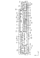
先に雄コネクタ10について説明する。雄コネクタ10は、図1及び図2に示すように、合成樹脂製の雄ハウジング(相手コネクタハウジング)11と、導電性に優れた金属製とされて雄ハウジング11に収容される複数の雄端子金具(相手端子金具)12と、を備えており、その底面が図示しない基板に接する形で基板上に取り付けられている。なお、図1は、雄コネクタ10に対して各雌コネクタ20をそれぞれ嵌合しているものの、レバー式コネクタ30については嵌合する前の状態を表している。雄ハウジング11は、雄端子金具12を保持する端子保持部11aと、端子保持部11aから前方に向けて突出する筒状のフード部11bとを有している。雄端子金具12は、前側部分が端子保持部11aを前後に貫通するとともにフード部11bにより取り囲まれているのに対し、端子保持部11aから後方へ突出した部分が一旦下方へほぼ直角に屈曲された後、その後端部が再び後方へ向けてほぼ直角に屈曲された形状とされている。この雄端子金具12のうち、フード部11b内に突き出す前端部が雌コネクタ20やレバー式コネクタ30の各端子金具32と導通接触可能なコネクタ側接続部12aとされるのに対し、後端部が基板上にプリントされた導電路(図示せず)に対して半田付けにより導通接続される基板側接続部12bとなっている。   First, the male connector 10 will be described. As shown in FIGS. 1 and 2, the male connector 10 includes a synthetic resin male housing (mating connector housing) 11 and a plurality of male terminals which are made of metal having excellent conductivity and are accommodated in the male housing 11. A metal fitting (mating terminal metal fitting) 12 is provided, and the bottom surface of the metal fitting 12 is attached to the substrate so as to be in contact with a substrate (not shown). FIG. 1 shows a state before the female connector 20 is fitted to the male connector 10 but before the lever-type connector 30 is fitted. The male housing 11 includes a terminal holding portion 11a that holds the male terminal fitting 12, and a cylindrical hood portion 11b that protrudes forward from the terminal holding portion 11a. The male terminal fitting 12 has a front portion penetrating the terminal holding portion 11a back and forth and surrounded by the hood portion 11b, whereas a portion protruding rearward from the terminal holding portion 11a is once bent substantially at a right angle downward. After that, the rear end portion is bent back at a substantially right angle toward the rear again. Among the male terminal fittings 12, the front end protruding into the hood portion 11 b is a connector-side connecting portion 12 a capable of conducting contact with each terminal fitting 32 of the female connector 20 or the lever connector 30, whereas the rear end portion Is a board side connection portion 12b that is conductively connected by soldering to a conductive path (not shown) printed on the board.

雄ハウジング11のフード部11bには、図2に示すように、その内部空間を複数に仕切る仕切り壁11b1が設けられており、それにより雌コネクタ20及びレバー式コネクタ30を個別に嵌合可能な複数の嵌合部13,14が設けられている。このうち、レバー式コネクタ30を嵌合可能なレバー式コネクタ用嵌合部(レバー式コネクタ用嵌合部)13は、雌コネクタ20を嵌合可能な雌コネクタ用嵌合部(非レバー式コネクタ用嵌合部)14によりY軸方向(幅方向)について両側から挟み込まれた配置とされる。つまり、レバー式コネクタ用嵌合部13と雌コネクタ用嵌合部14とは、互いに隣り合う形で配されるとともにその並び方向はY軸方向と一致している。このレバー式コネクタ用嵌合部13は、その幅寸法及び高さ寸法がいずれの雌コネクタ用嵌合部14の各同寸法よりも大きなものとされている。レバー式コネクタ用嵌合部13には、フード部11bの天井面から内向きに突出する形でレバー33に係合可能なカムピン13aが設けられている。カムピン13aは、略円柱状をなしており、レバー式コネクタ用嵌合部13の天井面におけるY軸方向(幅方向)についてほぼ中央位置で且つX軸方向(嵌合方向)について前端位置からやや後側に引っ込んだ位置に配されている。レバー式コネクタ用嵌合部13におけるフード部11bの天井面には、カムピン13aからY軸方向について所定の間隔を空けた位置にレバー33のロック状態を解除するための解除部13bと、嵌合動作をガイドするためのガイドリブ13cと、がY軸方向について並ぶとともにそれぞれ内向きに突出する形で設けられている。また、レバー式コネクタ用嵌合部13におけるフード部11bの底面にも、上記と同様のガイドリブ13cが内向きに突出する形で設けられている。さらには、レバー式コネクタ用嵌合部13における端子保持部11aの前端面からは、前方に突出する形で配されるとともに、レバー式コネクタ30以外の雌コネクタ20が誤って嵌合するのを規制するための誤嵌合規制部13dが設けられている。誤嵌合規制部13dは、Y軸方向に沿って延びる、正面から視て横長な板状をなしており、Y軸方向についてカムピン13aを挟んだ両側に一対が所定の間隔を空けて配されている。誤嵌合規制部13dは、その前端が雄端子金具12の前端よりも前方に位置している。一方、雌コネクタ用嵌合部14は、Y軸方向についてレバー式コネクタ用嵌合部13を挟んだ両側に一対配されるとともに、図2に示す左端位置にもう1つが配されることで、合計3つ備えられている。これら3つの雌コネクタ用嵌合部14は、Y軸方向についての幅が互いに異なっている。各雌コネクタ用嵌合部14におけるフード部11bの天井面には、雌コネクタ20のロックアーム21bが係止可能とされるロック部14aが設けられている。   As shown in FIG. 2, the hood portion 11 b of the male housing 11 is provided with a partition wall 11 b 1 that divides the internal space into a plurality of parts, so that the female connector 20 and the lever-type connector 30 can be individually fitted. A plurality of fitting portions 13 and 14 are provided. Among them, a lever connector fitting portion (lever connector fitting portion) 13 into which the lever connector 30 can be fitted is a female connector fitting portion (non-lever connector) into which the female connector 20 can be fitted. For the Y-axis direction (width direction) by the fitting portion 14). That is, the lever-type connector fitting portion 13 and the female connector fitting portion 14 are arranged adjacent to each other and the arrangement direction thereof coincides with the Y-axis direction. The lever-type connector fitting portion 13 has a width dimension and a height dimension larger than the same dimensions of any female connector fitting section 14. The lever-type connector fitting portion 13 is provided with a cam pin 13a that can be engaged with the lever 33 so as to protrude inward from the ceiling surface of the hood portion 11b. The cam pin 13a has a substantially cylindrical shape, and is slightly at the center position in the Y-axis direction (width direction) on the ceiling surface of the lever-type connector fitting portion 13 and slightly from the front end position in the X-axis direction (fitting direction). It is arranged at the position retracted to the rear side. On the ceiling surface of the hood portion 11b in the lever-type connector fitting portion 13, a release portion 13b for releasing the locked state of the lever 33 at a position spaced from the cam pin 13a in the Y-axis direction is fitted. Guide ribs 13c for guiding the operation are provided so as to line up in the Y-axis direction and protrude inward. Further, a guide rib 13c similar to the above is also provided on the bottom surface of the hood portion 11b in the lever-type connector fitting portion 13 so as to protrude inward. Further, the lever-type connector fitting portion 13 is arranged so as to protrude forward from the front end surface of the terminal holding portion 11a, and the female connector 20 other than the lever-type connector 30 is erroneously fitted. An erroneous fitting restricting portion 13d for restricting is provided. The erroneous fitting restricting portion 13d has a plate shape that extends in the Y-axis direction and is horizontally long when viewed from the front, and a pair is arranged on both sides of the cam pin 13a with a predetermined interval in the Y-axis direction. ing. The front end of the erroneous fitting restricting portion 13 d is located in front of the front end of the male terminal fitting 12. On the other hand, the female connector fitting portion 14 is arranged in a pair on both sides of the lever-type connector fitting portion 13 in the Y-axis direction, and another one is arranged at the left end position shown in FIG. A total of three are provided. These three female connector fitting portions 14 have different widths in the Y-axis direction. On the ceiling surface of the hood portion 11 b in each female connector fitting portion 14, a lock portion 14 a that can lock the lock arm 21 b of the female connector 20 is provided.

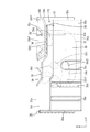
このコネクタCには、図1及び図14に示すように、雄コネクタ10に備えられる3つの雌コネクタ用嵌合部14に対して個別に嵌合可能な形で雌コネクタ20が3つ備えられている。3つの雌コネクタ20のうち、雄コネクタ10におけるY軸方向についての両端に位置する2つの雌コネクタ用嵌合部14に嵌合される2つの雌コネクタ20については、高さ寸法及び幅寸法が近似している。これに対し、図2に示す左端の雌コネクタ用嵌合部14に対して右側に隣り合う雌コネクタ用嵌合部14に嵌合される雌コネクタ20については、高さ寸法が左隣の雌コネクタ20とほぼ等しいものの、幅寸法が左隣の雌コネクタ20に比べて相対的に大きなものとされる。そして、3つの雌コネクタ20は、以下のような共通構造を有している。すなわち、雌コネクタ20は、合成樹脂製の雌ハウジング(非レバー式コネクタ用ハウジング)21と、雌ハウジング21内に収容される複数の雌端子金具(図示せず)と、を備えている。雌ハウジング21は、略ブロック状をなすとともに雌端子金具を後方から個別に収容可能な雌端子金具収容室21aが設けられている(図14参照)。雌ハウジング21の外周面のうち、図14に示す上側の側面には、雄コネクタ10の雌コネクタ用嵌合部14に設けられたロック部14a(図2)に係止されることで、雄コネクタ10に対して雌コネクタ20を嵌合状態に保持可能なロックアーム21bが設けられている(図1)。   As shown in FIGS. 1 and 14, the connector C includes three female connectors 20 that can be individually fitted into the three female connector fitting portions 14 provided in the male connector 10. ing. Of the three female connectors 20, the two female connectors 20 fitted to the two female connector fitting portions 14 located at both ends in the Y-axis direction of the male connector 10 have height and width dimensions. Approximate. On the other hand, for the female connector 20 fitted to the female connector fitting portion 14 adjacent to the right side with respect to the female connector fitting portion 14 at the left end shown in FIG. Although it is substantially equal to the connector 20, the width dimension is relatively larger than that of the female connector 20 on the left side. The three female connectors 20 have the following common structure. That is, the female connector 20 includes a female housing (non-lever connector housing) 21 made of synthetic resin and a plurality of female terminal fittings (not shown) housed in the female housing 21. The female housing 21 has a substantially block shape and is provided with a female terminal fitting accommodation chamber 21a capable of individually accommodating female terminal fittings from the rear (see FIG. 14). Of the outer peripheral surface of the female housing 21, the upper side surface shown in FIG. 14 is engaged with a lock portion 14 a (FIG. 2) provided in the female connector fitting portion 14 of the male connector 10. A lock arm 21b capable of holding the female connector 20 in a fitted state with respect to the connector 10 is provided (FIG. 1).

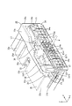
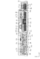
レバー式コネクタ30は、図1及び図14に示すように、上記した雌コネクタ20と同様に雄コネクタ10に対して嵌合可能な雌型のコネクタであり、雌コネクタ20とは主にレバー33の有無で相違するとともに、幅寸法及び高さ寸法がいずれの雌コネクタ20の各同寸法よりも大きなものとされている。レバー式コネクタ30は、図3及び図7に示すように、合成樹脂製のハウジング(コネクタハウジング)31と、ハウジング31に収容される複数の端子金具32と、ハウジング31に収容されるレバー33と、を備えている。ハウジング31は、全体として横長な略ブロック状をなすとともに端子金具32を収容する端子収容部34と、端子収容部34の外周面のうち横長な側面(底面とは反対側の天面)34eとの間にレバー33を収容するレバー収容空間LSを保有するレバー収容部35と、を有してなる(図6)。端子収容部34には、図5及び図6に示すように、端子金具32を後方から挿入可能な端子金具収容室34aが複数、前後に開口する形で設けられている。端子金具収容室34aに個別に収容される端子金具32は、導電性に優れた金属製で、雌コネクタ20の雌端子金具と同様に、雄端子金具12に対して導通接続可能な雌型とされており、電線Wの端末に圧着接続されている。端子金具収容室34aは、端子収容部34の幅方向における両端側部分では上下2段、幅方向(Y軸方向)に5室ずつそれぞれ並んで配されているのに対し、端子収容部34の幅方向における中央側部分では上下3段、幅方向に5室または6室並んで配されている。なお、端子収容部34における底面(上記側面34eとは反対側の横長な側面)には、上記中央側部分に配された一部の端子金具収容室34aを切り欠く形で、雄コネクタ10のレバー式コネクタ用嵌合部13における底面側に設けられたガイドリブ13cを受け入れるガイドリブ受け入れ凹部34bが設けられている。これにより、端子金具収容室34aは、最上段では、幅方向に6室並ぶのに対し、下側の2段では、幅方向に4室と1室とに分かれた配置で合計5室ずつ並んでいる。端子収容部34における前端面には、図5に示すように、雄コネクタ10のレバー式コネクタ用嵌合部13に設けられた一対の誤嵌合規制部13dを受け入れる規制部受け入れ凹部34cが前方に向けて開口する形で一対設けられている。   As shown in FIGS. 1 and 14, the lever connector 30 is a female connector that can be fitted to the male connector 10 in the same manner as the female connector 20 described above. The width dimension and the height dimension are larger than the same dimension of any female connector 20. As shown in FIGS. 3 and 7, the lever-type connector 30 includes a synthetic resin housing (connector housing) 31, a plurality of terminal fittings 32 accommodated in the housing 31, and a lever 33 accommodated in the housing 31. It is equipped with. The housing 31 has a generally horizontally long and substantially block shape, and a terminal accommodating portion 34 that accommodates the terminal fitting 32, and a laterally long side surface (a top surface opposite to the bottom surface) 34e of the outer peripheral surface of the terminal accommodating portion 34; And a lever accommodating portion 35 having a lever accommodating space LS for accommodating the lever 33 (FIG. 6). As shown in FIGS. 5 and 6, the terminal housing portion 34 is provided with a plurality of terminal fitting housing chambers 34 a into which the terminal fittings 32 can be inserted from the rear, and are opened in the front-rear direction. The terminal fittings 32 individually accommodated in the terminal fitting receiving chambers 34a are made of metal having excellent conductivity, and, like the female terminal fittings of the female connector 20, are female types that can be conductively connected to the male terminal fittings 12. It is crimped and connected to the end of the electric wire W. The terminal fitting accommodating chamber 34a is arranged in two upper and lower stages at the both ends in the width direction of the terminal accommodating portion 34, and five chambers are arranged side by side in the width direction (Y-axis direction). In the central side portion in the width direction, the upper and lower three stages are arranged side by side with five or six rooms in the width direction. The male connector 10 has a bottom surface (a lateral side surface opposite to the side surface 34e) of the terminal housing portion 34, in which a part of the terminal fitting housing chamber 34a arranged in the center side portion is cut out. A guide rib receiving recess 34b for receiving a guide rib 13c provided on the bottom surface side of the lever connector fitting portion 13 is provided. As a result, the terminal fitting housing chambers 34a are arranged in six rooms in the width direction in the uppermost stage, whereas in the lower two stages, a total of five rooms are arranged in four rooms and one room in the width direction. It is out. On the front end surface of the terminal accommodating portion 34, as shown in FIG. 5, a restricting portion receiving recess 34c for receiving a pair of erroneous fitting restricting portions 13d provided in the lever-type connector fitting portion 13 of the male connector 10 is forward. A pair is provided so as to open toward.

レバー収容部35は、図3,図5及び図7に示すように、ハウジング31の前縁部及び両側縁部からそれぞれ立ち上がる立ち上がり壁部35aと、各立ち上がり壁部35aの立ち上がり先端部に連なるとともにハウジング31の側面34eに対して間隔を空けつつ対向状に配される対向壁部35bと、を有してなる。このうち、前側の立ち上がり壁部35a及び対向壁部35bには、雄コネクタ10のカムピン13aを受け入れるカムピン受け入れ溝部35cが切り欠き形成されているのに加え、解除部13bを受け入れる解除部受け入れ凹部35dと、ガイドリブ13cを受け入れるガイドリブ受け入れ凹部35eと、がそれぞれ凹み形成されている。カムピン受け入れ溝部35cは、レバー収容部35における幅方向(Y軸方向)のほぼ中央位置に配されているのに対し、解除部受け入れ凹部35d及びガイドリブ受け入れ凹部35eは、カムピン受け入れ溝部35cに対して幅方向について離間した位置にそれぞれ配されている。このうちの解除部受け入れ凹部35dは、レバー33に近い側の側壁が切り欠かれることでレバー収容空間LSに連通されているので、解除部受け入れ凹部35d内にレバー33の一部が進入可能とされている。そして、解除部受け入れ凹部35dにおけるレバー33側とは反対側の側壁には、レバー33に設けられた待機位置用ロックアーム33dに係止する待機位置用ロック部35fがレバー33側に突出する形で設けられている。この待機位置用ロック部35fは、雄コネクタ10の解除部13bとはY軸方向について重なり合うもののZ軸方向については重なり合わない配置とされる。さらには、対向壁部35bにおける内側(レバー33と対向する側)の板面には、レバー33に設けられた嵌合位置用ロックアーム33eに係止する嵌合位置用ロック部35gが内側に突出する形で設けられている。端子収容部34のうち対向壁部35bと対向する側面34eには、レバー33を回動可能に軸支するための円柱状をなす軸部34dがZ軸方向(対向壁部35bの板面の法線方向)に沿ってレバー収容空間LS内に突き出す形で設けられている。また、対向壁部35bのうち、上記したカムピン受け入れ溝部35c、解除部受け入れ凹部35d及びガイドリブ受け入れ凹部35eが非形成とされた後端側部分には、Z軸方向について外側に段付き状に突き出す形で部分的に肉厚な肉厚部35hが設けられている。   As shown in FIGS. 3, 5, and 7, the lever accommodating portion 35 is connected to a rising wall portion 35 a that rises from the front edge portion and both side edge portions of the housing 31, and a rising tip portion of each rising wall portion 35 a. And an opposing wall portion 35b arranged to face the side surface 34e of the housing 31 while being spaced from each other. Of these, the front rising wall portion 35a and the opposing wall portion 35b are notched with cam pin receiving grooves 35c for receiving the cam pins 13a of the male connector 10, but also release portion receiving recesses 35d for receiving the release portions 13b. And a guide rib receiving recess 35e for receiving the guide rib 13c, respectively, is formed as a recess. The cam pin receiving groove portion 35c is disposed at a substantially central position in the width direction (Y-axis direction) of the lever accommodating portion 35, whereas the release portion receiving recess portion 35d and the guide rib receiving recess portion 35e are located with respect to the cam pin receiving groove portion 35c. They are arranged at positions separated from each other in the width direction. Of these, the release portion receiving recess 35d communicates with the lever receiving space LS by cutting out the side wall close to the lever 33, so that a part of the lever 33 can enter the release portion receiving recess 35d. Has been. A standby position lock portion 35f that engages with a standby position lock arm 33d provided on the lever 33 protrudes toward the lever 33 on the side wall of the release portion receiving recess 35d opposite to the lever 33 side. Is provided. The standby position locking portion 35f is arranged so as to overlap the release portion 13b of the male connector 10 in the Y-axis direction but not in the Z-axis direction. Furthermore, a fitting position lock portion 35g that engages with a fitting position lock arm 33e provided on the lever 33 is provided on the inner side (side facing the lever 33) of the facing wall portion 35b. It is provided in a protruding form. A cylindrical portion 34d for pivotally supporting the lever 33 in a pivotable manner on the side surface 34e of the terminal accommodating portion 34 that faces the opposing wall portion 35b has a Z-axis direction (on the plate surface of the opposing wall portion 35b). It is provided in a form protruding in the lever housing space LS along the (normal direction). Further, in the opposing wall portion 35b, the rear end side portion in which the cam pin receiving groove portion 35c, the release portion receiving recess portion 35d, and the guide rib receiving recess portion 35e are not formed projects outwardly in a stepped manner in the Z-axis direction. A thick portion 35h that is partially thick is provided.

レバー33は、合成樹脂製とされ、図3に示すように、レバー収容部35の対向壁部35bの板面(X軸方向及びY軸方向)に並行する板面を有する板状をなすレバー本体33aを備えている。レバー本体33aは、ハウジング31(レバー収容部35)と同様に横長な平面形状を有するとともにその板面がレバー収容部35の対向壁部35bの壁面及びそれと対向する端子収容部34の側面34eに並行しており、対向壁部35bと端子収容部34との間に収容されるようになっている。。レバー本体33aには、ハウジング31の軸部34dを嵌合可能な軸受け孔部33bが板面を貫通する形で形成されるとともに、雄コネクタ10のカムピン13aを受け入れるカム溝33cが切り欠き形成されている。そして、レバー33は、レバー本体33aが上記したレバー収容部35のレバー収容空間LS内に収容されると、軸部34dが軸受け孔部33bに嵌合されることで軸支されるとともに、カム溝33cに対する雄コネクタ10のカムピン13aの進入を許容する待機位置(図3)から嵌合位置(図4)に至るまで時計回り方向に回動されるのに伴って相対的に雄コネクタ10を嵌合状態に引き込むことが可能とされる。カム溝33cは、入り口部33c1から奥端部33c2にかけて次第に回動軸である軸受け孔部33bに接近するような略弧状(略渦巻き状)をなしており、待機位置では入り口部33c1がレバー収容部35のカムピン受け入れ溝部35c内に配されるとともに前方に向けて開口している。   The lever 33 is made of synthetic resin, and as shown in FIG. 3, a lever having a plate shape parallel to the plate surface (X-axis direction and Y-axis direction) of the opposing wall portion 35b of the lever housing portion 35. A main body 33a is provided. The lever main body 33a has a horizontally long planar shape like the housing 31 (lever accommodating portion 35), and its plate surface is provided on the wall surface of the opposing wall portion 35b of the lever accommodating portion 35 and the side surface 34e of the terminal accommodating portion 34 facing the same. It is parallel and is accommodated between the opposing wall part 35b and the terminal accommodating part 34. FIG. . The lever main body 33a is formed with a bearing hole 33b into which the shaft portion 34d of the housing 31 can be fitted so as to penetrate the plate surface, and a cam groove 33c for receiving the cam pin 13a of the male connector 10 is formed in a cutout manner. ing. When the lever body 33a is accommodated in the lever accommodating space LS of the lever accommodating portion 35 described above, the lever 33 is pivotally supported by fitting the shaft portion 34d into the bearing hole portion 33b, and the cam 33 As the male connector 10 is rotated clockwise from the standby position (FIG. 3) allowing the cam pin 13a of the male connector 10 to enter the groove 33c to the fitting position (FIG. 4), the male connector 10 is relatively moved. It can be pulled into the fitted state. The cam groove 33c has a substantially arc shape (substantially spiral) so as to gradually approach the bearing hole 33b, which is a rotation shaft, from the entrance portion 33c1 to the back end portion 33c2. It is arranged in the cam pin receiving groove 35c of the portion 35 and opens forward.

レバー本体33aには、図3及び図4に示すように、レバー33を待機位置に保持するための待機位置用ロックアーム33dと、レバー33を嵌合位置に保持するための嵌合位置用ロックアーム33eと、がそれぞれ設けられている。待機位置用ロックアーム33dは、図3に示すように、カム溝33cの入り口部33c1の近くから片持ち状に延在するとともに、基端部を支点としてレバー本体33aの板面に沿う方向に弾性的に撓むことが可能とされる。待機位置用ロックアーム33dは、レバー33が待機位置に配された状態では、その先端部が解除部受け入れ凹部35d内に進入するとともに待機位置用ロック部35fに係止されることで、レバー33を待機位置から嵌合位置側に回動するのを規制した状態に保持することが可能とされる。嵌合位置用ロックアーム33eは、レバー本体33aのうちカム溝33cに対して待機位置用ロックアーム33d側とは反対側の部分に一対のスリットを入れることで片持ち状に延在する形で設けられており、基端部を支点としてレバー本体33aの板面と直交する方向(Z軸方向)に弾性的に撓むことが可能とされる。嵌合位置用ロックアーム33eは、その自由端部がロック解除操作を行うことが可能なロック解除操作部33e1とされるとともに、ロック解除操作部33e1の前側位置には嵌合位置用ロック部35gに係止可能な係止部33e2が凹み形成されている。嵌合位置用ロックアーム33eは、レバー33が待機位置に配された状態ではその全体がレバー収容部35の外部に露出しているものの、図4に示すように、レバー33が嵌合位置に配された状態ではX軸方向(嵌合方向)に沿って真っ直ぐに延在するとともに、係止部33e2が嵌合位置用ロック部35gに係止されている。   As shown in FIGS. 3 and 4, the lever main body 33 a includes a standby position lock arm 33 d for holding the lever 33 in the standby position, and a fitting position lock for holding the lever 33 in the fitting position. Arms 33e are provided respectively. As shown in FIG. 3, the standby position lock arm 33d extends in a cantilevered manner from the vicinity of the entrance 33c1 of the cam groove 33c, and extends in the direction along the plate surface of the lever main body 33a with the base end as a fulcrum. It is possible to bend elastically. In the state where the lever 33 is arranged at the standby position, the standby position lock arm 33d enters the release portion receiving recess 35d and is engaged with the standby position lock portion 35f, so that the lever 33 Can be held in a state where the rotation from the standby position to the fitting position side is restricted. The fitting position lock arm 33e extends in a cantilever manner by inserting a pair of slits into a portion of the lever body 33a opposite to the standby position lock arm 33d side with respect to the cam groove 33c. It is provided and can be elastically bent in a direction (Z-axis direction) orthogonal to the plate surface of the lever main body 33a with the base end portion as a fulcrum. The engagement position lock arm 33e is an unlock operation portion 33e1 whose free end can perform an unlock operation, and the engagement position lock portion 35g is located at the front side of the unlock operation portion 33e1. A locking portion 33e2 that can be locked to is recessed. The engagement position lock arm 33e is entirely exposed to the outside of the lever housing portion 35 when the lever 33 is disposed at the standby position, but as shown in FIG. 4, the lever 33 is at the engagement position. In the arranged state, it extends straight along the X-axis direction (fitting direction), and the locking portion 33e2 is locked to the fitting position locking portion 35g.

レバー本体33aのうち、嵌合位置用ロックアーム33eのロック解除操作部33e1側の端部には、図3及び図6に示すように、レバー33を回動操作するための回動操作部33fが設けられている。詳しくは、回動操作部33fは、レバー本体33aのうち嵌合位置用ロックアーム33eを挟んだ両側部分にそれぞれ連なる部分と、当該部分間を架橋する一対の架橋部分33f1とを有しており、これらが嵌合位置用ロックアーム33eを取り囲む形で環状をなしている。回動操作部33fは、レバー本体33aに対してZ軸方向(レバー本体33aの板面、対向壁部35bの壁面、及び端子収容部34の側面34eの法線方向)について上下両側、つまり対向壁部35b側と、端子収容部34側とにそれぞれ突き出す形で設けられている。しかも、回動操作部33fは、そのZ軸方向について上側(対向壁部35b側)の外面が、対向壁部35bに設けられた肉厚部35hの外面よりも外側に突き出すような厚み(高さ)を有している。これにより、作業者がレバー33を回動操作する際に回動操作部33fにおける被操作範囲(被押圧面積)が広く確保されるので、レバー33及びレバー式コネクタ30が小型であっても回動操作を容易に行うことが可能とされている。回動操作部33fには、嵌合位置用ロックアーム33e側とは反対側に向けて突出することで、嵌合位置とされたレバー33を待機位置に向けて回動操作(解除操作)を行う際に作業者が指を掛けることが可能な指掛け部33f2が設けられている。   As shown in FIGS. 3 and 6, a rotation operation portion 33f for rotating the lever 33 is provided at the end portion of the lever main body 33a on the lock release operation portion 33e1 side of the fitting position lock arm 33e. Is provided. Specifically, the rotation operation portion 33f includes a portion that is connected to both sides of the lever main body 33a with the fitting position lock arm 33e interposed therebetween, and a pair of bridging portions 33f1 that bridge the portions. These have an annular shape surrounding the fitting position lock arm 33e. The rotation operation portion 33f is opposite to the lever main body 33a in the Z-axis direction (the normal direction of the plate surface of the lever main body 33a, the wall surface of the opposing wall portion 35b, and the side surface 34e of the terminal accommodating portion 34). They are provided so as to protrude from the wall 35b side and the terminal accommodating portion 34 side, respectively. In addition, the rotation operation portion 33f has a thickness (high) such that the outer surface on the upper side (opposing wall portion 35b side) in the Z-axis direction protrudes outside the outer surface of the thick portion 35h provided on the facing wall portion 35b. A). Accordingly, when the operator rotates the lever 33, the operated range (pressed area) in the rotating operation portion 33f is secured widely, so that the lever 33 and the lever-type connector 30 can be rotated even if they are small. It is possible to easily perform a moving operation. The rotation operation portion 33f projects a rotation operation (release operation) toward the standby position by moving the lever 33 set to the engagement position by projecting toward the opposite side to the engagement position lock arm 33e side. A finger hook 33f2 is provided so that an operator can hook his / her finger when performing the operation.

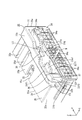
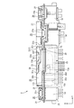
そして、本実施形態1に係るレバー式コネクタ30は、図4に示すように、嵌合位置とされたレバー33の後端面33gと、ハウジング31の後端面31aと、が面一状をなす構成とされている。詳しくは、レバー33は、待機位置においては、図3に示すように、その一部(回動操作部33fの大部分を含む)がハウジング31の後端面31aよりも後方に突き出す形で配されているのに対し、嵌合位置においては、図4に示すように、その全域がハウジング31と平面に視て重畳する形で配されるとともに、レバー33の後端面33gがハウジング31の後端面31aと面一状をなしている。このような構成とすれば、ハウジング31の端子収容部34に端子金具32を収容する作業を行う際には、図7に示すように、レバー33を嵌合位置にしておけば、レバー33の後端面33gがハウジング31の後端面31aと面一状をなす配置とされるので、レバー33がハウジング31の後端面31aから後方に突き出すことが避けられ、もってレバー33によって端子金具32を端子収容部34に収容する作業が妨げられる事態が生じ難くなっている。このように、従来の特許文献1のようにホルダにレバー及びサブコネクタをそれぞれ収容する構成を採らずとも端子金具32の収容作業性を改善することができるので、部品点数の削減及び組付工数の削減を図ることができる。さらには、レバー33を待機位置から嵌合位置へと回動する作業を行う際には、レバー33の後端面33gがハウジング31の後端面31aよりも後方に突き出していれば、レバー33が嵌合位置に達しておらず、嵌合状態には至っていないことになるので、レバー33の回動操作を途中で止めてしまい、半嵌合状態が生じた場合にはそれを検知することができる。   And the lever type connector 30 which concerns on this Embodiment 1 is the structure where the rear end surface 33g of the lever 33 made into the fitting position and the rear end surface 31a of the housing 31 make the same shape, as shown in FIG. It is said that. Specifically, as shown in FIG. 3, the lever 33 is arranged such that a part (including most of the rotation operation portion 33 f) protrudes rearward from the rear end surface 31 a of the housing 31 at the standby position. On the other hand, in the fitting position, as shown in FIG. 4, the entire region is arranged so as to overlap with the housing 31 in a plan view, and the rear end surface 33 g of the lever 33 is arranged at the rear end surface of the housing 31. It is flush with 31a. With such a configuration, when the operation of accommodating the terminal fitting 32 in the terminal accommodating portion 34 of the housing 31 is performed, as shown in FIG. Since the rear end surface 33g is arranged so as to be flush with the rear end surface 31a of the housing 31, the lever 33 can be prevented from protruding rearward from the rear end surface 31a of the housing 31, so that the terminal fitting 32 is accommodated in the terminal by the lever 33. It is difficult for a situation in which the work accommodated in the portion 34 is hindered. Thus, since the workability of housing the terminal fitting 32 can be improved without adopting a configuration in which the lever and the sub-connector are housed in the holder as in the conventional patent document 1, the number of parts can be reduced and the number of assembly steps can be reduced. Can be reduced. Furthermore, when the lever 33 is rotated from the standby position to the fitting position, if the rear end surface 33g of the lever 33 projects rearward from the rear end surface 31a of the housing 31, the lever 33 is fitted. Since the fitting position has not been reached and the fitting state has not been reached, the turning operation of the lever 33 is stopped halfway, and when a half-fitting state occurs, it can be detected. .

ここで、上記したようにレバー33の回動操作部33fは、図6及び図7に示すように、レバー本体33aに対してZ軸方向について上下両側に突き出す形で設けられており、その上下両側に突き出した部分がレバー収容部35の対向壁部35bとハウジング31の一部とに対してそれぞれZ軸方向(対向壁部35bの板面及びそれと対向する端子収容部34の側面34eにおける法線方向)について重なり合う配置とされる。その一方、上記したようにレバー33は、嵌合位置においてはその後端面33gがハウジング31の後端面31aと面一状をなしていることから、回動操作部33fの全域がハウジング31と平面に視て(Z軸方向から視て)重畳する配置とされる。これに対し、レバー収容部35の対向壁部35bには、嵌合位置に配されたレバー33の回動操作部33fのうちのZ軸方向についての上側の架橋部分33f1を受け入れるための第1操作部受け入れ凹部(過度回動規制凹部)36が切り欠き形成されている。さらには、ハウジング31の後端部には、嵌合位置に配されたレバー33の回動操作部33fのうちのZ軸方向についての下側の架橋部分33f1を受け入れるための第2操作部受け入れ凹部37が切り欠き形成されている。そして、これら第1操作部受け入れ凹部36及び第2操作部受け入れ凹部37は、レバー33が嵌合位置に達するまで回動されると、回動操作部33fの上下各架橋部分33f1における前端面のほぼ全域にわたって当接することで、レバー33が嵌合位置から待機位置側とは反対側(順方向)にさらに回動されるのを規制することが可能とされている。このように、互いにZ軸方向について重なり合う回動操作部33f及び対向壁部35bを利用してレバー33における嵌合位置からの過度回動を規制することができるから、仮に別途専用の過度回動規制構造を設けた場合に比べると、構造の簡素化を図ることができるとともに、小型化を図る上でも一層有用とされる。   Here, as described above, the rotation operation portion 33f of the lever 33 is provided so as to protrude from the lever main body 33a to both the upper and lower sides in the Z-axis direction, as shown in FIGS. The protruding portions on both sides are in the Z-axis direction with respect to the opposing wall portion 35b of the lever accommodating portion 35 and a part of the housing 31 (the method on the plate surface of the opposing wall portion 35b and the side surface 34e of the terminal accommodating portion 34 opposed thereto). (Line direction) is an overlapping arrangement. On the other hand, since the rear end surface 33g of the lever 33 is flush with the rear end surface 31a of the housing 31 at the fitting position as described above, the entire area of the rotation operation portion 33f is flat with the housing 31. It is arranged so as to overlap when viewed (viewed from the Z-axis direction). On the other hand, the opposing wall portion 35b of the lever housing portion 35 receives the first bridge portion 33f1 in the Z-axis direction of the rotation operation portion 33f of the lever 33 disposed at the fitting position. An operation portion receiving recessed portion (excessive rotation restricting recessed portion) 36 is notched. Furthermore, the rear end portion of the housing 31 receives a second operation portion for receiving the lower bridging portion 33f1 in the Z-axis direction of the rotation operation portion 33f of the lever 33 disposed at the fitting position. A recess 37 is formed in the cutout. When the lever 33 is rotated until the lever 33 reaches the fitting position, the first operation portion receiving recess 36 and the second operation portion receiving recess 37 are formed on the front end surfaces of the upper and lower bridge portions 33f1 of the rotation operation portion 33f. By abutting over almost the entire region, it is possible to restrict the lever 33 from being further rotated from the fitting position to the side opposite to the standby position side (forward direction). In this way, since the excessive rotation from the fitting position in the lever 33 can be restricted by using the rotation operation portion 33f and the opposing wall portion 35b that overlap each other in the Z-axis direction, a special dedicated excessive rotation is temporarily provided. Compared with the case where a restricting structure is provided, the structure can be simplified and further useful in reducing the size.

レバー収容部35をなす対向壁部35bには、図3に示すように、第1操作部受け入れ凹部36に加えて、待機位置に配されたレバー33の回動操作部33fのうちのZ軸方向についての上側の架橋部分33f1を受け入れるための第3操作部受け入れ凹部(逆回動規制凹部)38が切り欠き形成されている。第3操作部受け入れ凹部38は、対向壁部35bにおいて第1操作部受け入れ凹部36に対してY軸方向について軸部34d側(後述する指入れ用凹部39側とは反対側)に隣り合う形で配されている。第3操作部受け入れ凹部38は、その前端位置(レバー33に対する当接位置)が第1操作部受け入れ凹部36の前端位置(レバー33に対する当接位置)よりも後方に配されており、対向壁部35bに対するX軸方向についての切り欠き範囲が、対向壁部35bに対する第1操作部受け入れ凹部36の同切り欠き範囲よりも狭くなっている。そして、レバー33の回動操作部33fをなすZ軸方向についての上側の架橋部分33f1のうち、指掛け部33f2側とは反対側の端部は、レバー33が待機位置とされた状態では、第3操作部受け入れ凹部38に当接することで、レバー33が待機位置から嵌合位置側とは反対側(逆方向)に回動する、逆回動を規制することが可能とされる。このように、互いにZ軸方向について重なり合う回動操作部33f及び対向壁部35bを利用してレバー33における待機位置からの逆回動を規制することができるから、仮に別途専用の過度回動規制構造を設けた場合に比べると、構造の簡素化を図ることができるとともに、小型化を図る上でも一層有用とされる。   As shown in FIG. 3, in addition to the first operation portion receiving recess 36, the opposing wall portion 35b forming the lever housing portion 35 has a Z-axis of the rotation operation portion 33f of the lever 33 arranged at the standby position. A third operating portion receiving recess (reverse rotation restricting recess) 38 for receiving the upper bridging portion 33f1 in the direction is cut out. The third operation portion receiving recess 38 is adjacent to the shaft portion 34d side (opposite to the finger insertion recess 39 side described later) in the Y-axis direction with respect to the first operation portion receiving recess 36 in the opposing wall portion 35b. It is arranged with. The front end position (contact position with respect to the lever 33) of the third operation portion receiving recess 38 is disposed rearward of the front end position (contact position with respect to the lever 33) of the first operation portion receiving recess 36. The cutout range in the X-axis direction with respect to the portion 35b is narrower than the cutout range of the first operation portion receiving recess 36 with respect to the opposing wall portion 35b. Then, of the upper bridging portion 33f1 in the Z-axis direction that forms the rotation operation portion 33f of the lever 33, the end portion on the side opposite to the finger hooking portion 33f2 side is in the state where the lever 33 is in the standby position. 3 By abutting on the operation portion receiving recess 38, it is possible to restrict reverse rotation in which the lever 33 rotates from the standby position to the opposite side (reverse direction) from the fitting position side. As described above, the reverse rotation from the standby position in the lever 33 can be restricted by using the rotation operation part 33f and the opposing wall part 35b that overlap each other in the Z-axis direction. Compared with the case where a structure is provided, the structure can be simplified and more useful in reducing the size.

さらには、本実施形態1に係るレバー式コネクタ30は、図4に示すように、嵌合位置とされたレバー33の側面33hと、ハウジング31の外側面31bとが面一状をなす構成とされている。詳しくは、嵌合位置とされたレバー33のうち、回動操作部33fの端部に配された指掛け部33f2における側面33hは、ハウジング31の外側面31bと面一状をなしていて、同外側面31bからY軸方向について側方外部に突き出すことがないものとされる。従って、雄コネクタ10に対して各雌コネクタ20及びレバー式コネクタ30を嵌合した状態では、図13及び図14に示すように、レバー式コネクタ30のレバー33がハウジング31の外側面31bからY軸方向について隣り合う雌コネクタ20側に突き出すことがない配置とされている。このような構成によれば、雄コネクタ10に対して先行してレバー式コネクタ30を嵌合し、その次に隣り合う雌コネクタ20を嵌合する作業手順を採った場合、雌コネクタ20を嵌合する際に、雌コネクタ20がレバー式コネクタ30のレバー33に対して干渉し難くなるので、雌コネクタ20の嵌合作業を円滑に行うことができ、作業性に優れる。   Furthermore, as shown in FIG. 4, the lever-type connector 30 according to the first embodiment has a configuration in which the side surface 33 h of the lever 33 in the fitting position and the outer side surface 31 b of the housing 31 are flush with each other. Has been. Specifically, among the levers 33 in the fitting position, the side surface 33h of the finger hook portion 33f2 disposed at the end of the rotation operation portion 33f is flush with the outer surface 31b of the housing 31, and the same. The outer side surface 31b does not protrude outward in the Y-axis direction. Therefore, in a state where each female connector 20 and the lever type connector 30 are fitted to the male connector 10, the lever 33 of the lever type connector 30 is moved from the outer surface 31b of the housing 31 to the Y position as shown in FIGS. It is the arrangement | positioning which does not protrude to the adjacent female connector 20 side about an axial direction. According to such a configuration, when the work procedure for fitting the lever-type connector 30 to the male connector 10 and then fitting the adjacent female connector 20 is adopted, the female connector 20 is fitted. When mating, the female connector 20 is less likely to interfere with the lever 33 of the lever-type connector 30, so that the female connector 20 can be smoothly fitted and the workability is excellent.

上記したように嵌合位置とされたレバー33の側面33hが、ハウジング31の外側面31bに対して面一状をなす構成とすれば、隣り合う雌コネクタ20の嵌合作業性に優れる反面、レバー式コネクタ30を雄コネクタ10から取り外す場合に、レバー33の回動操作部33fにおける指掛け部33f2に作業者が指を掛け難くなり、レバー式コネクタ30の離脱作業性が悪化することが懸念される。そこで、本実施形態1では、回動操作部33fに対してZ軸方向について重なり合う配置とされるハウジング31の側端部には、回動操作部33fの指掛け部33f2に指を掛ける際に指を入れ易くするための指入れ用凹部39が切り欠き形成されている。指入れ用凹部39は、ハウジング31の側端部を切り欠くことで、X軸方向について後方に、Y軸方向について右側方に、Z軸方向について上方にそれぞれ開口しており、レバー33を嵌合位置に配した状態では、指掛け部33f2との間に指を入れることが可能な指入れ空間FSを有している。指入れ空間FSは、Z軸方向について上方に、Y軸方向について側方にそれぞれ開口しており、これらの開口部分を通して指を入れることが可能とされている。指入れ用凹部39は、ハウジング31の側端部を、Z軸方向について回動操作部33fの指掛け部33f2と重なり合う範囲を全域にわたって切り欠くことで形成されており、それにより指掛け部33f2の全域を受け入れることができる。指入れ用凹部39は、レバー収容部35の対向壁部35bに設けられた第1操作部受け入れ凹部36に対してY軸方向について第3操作部受け入れ凹部38側とは反対側に隣り合う形で配されている。指入れ用凹部39は、その前端位置が第1操作部受け入れ凹部36の前端位置よりも前方に配されており、ハウジング31の側端部に対するX軸方向についての切り欠き範囲が、対向壁部35bに対する第1操作部受け入れ凹部36の同切り欠き範囲よりも広くなっている。このような構成によれば、レバー式コネクタ30及びそれに隣り合う雌コネクタ20を雄コネクタ10に対して嵌合した状態において、例えばレバー式コネクタ30を取り外す場合には、指入れ用凹部39と、嵌合位置とされたレバー33の指掛け部33f2との間に有される指入れ空間FS内に作業者は指を入れることができるので(図13)、その指を指掛け部33f2に掛けることで回動操作部33fを容易に回動操作することができる。これにより、嵌合位置とされたレバー33の側面33hを、ハウジング31の外側面31bに対して面一状とし、隣り合う雌コネクタ20の嵌合作業性を良好なものに担保しつつも、レバー式コネクタ30の取り外し作業性に関しても良好なものとすることができる。   If the side surface 33h of the lever 33 in the fitting position as described above is flush with the outer side surface 31b of the housing 31, the fitting workability of the adjacent female connectors 20 is excellent. When the lever connector 30 is detached from the male connector 10, it is difficult for an operator to put a finger on the finger hook portion 33f2 in the rotation operation portion 33f of the lever 33, and there is a concern that the detachability of the lever connector 30 may be deteriorated. The Therefore, in the first embodiment, a finger is placed on the side end portion of the housing 31 that is disposed so as to overlap the rotation operation portion 33f in the Z-axis direction when a finger is placed on the finger hook portion 33f2 of the rotation operation portion 33f. A finger insertion recess 39 for facilitating insertion of the finger is formed in the cutout. The finger insertion recess 39 is opened rearwardly in the X-axis direction, rightward in the Y-axis direction, and upward in the Z-axis direction by cutting out the side end portion of the housing 31. In the state of being arranged at the joint position, it has a finger insertion space FS in which a finger can be inserted between the finger hooking portion 33f2. The finger insertion space FS is opened upward in the Z-axis direction and laterally in the Y-axis direction, and a finger can be inserted through these opening portions. The finger insertion recess 39 is formed by notching the side end portion of the housing 31 over the entire area overlapping with the finger hook portion 33f2 of the rotation operation portion 33f in the Z-axis direction. Can accept. The finger insertion recess 39 is adjacent to the first operation portion receiving recess 36 provided on the opposing wall portion 35b of the lever accommodating portion 35 on the opposite side to the third operation portion receiving recess 38 side in the Y-axis direction. It is arranged with. The front end position of the finger insertion recess 39 is disposed in front of the front end position of the first operation portion receiving recess 36, and the notch range in the X-axis direction with respect to the side end portion of the housing 31 has an opposing wall portion. It is wider than the notch range of the first operating portion receiving recess 36 with respect to 35b. According to such a configuration, in the state where the lever connector 30 and the female connector 20 adjacent thereto are fitted to the male connector 10, for example, when removing the lever connector 30, the finger insertion recess 39, Since the operator can put his finger into the finger putting space FS between the finger holding portion 33f2 of the lever 33 in the fitting position (FIG. 13), the operator can put the finger on the finger holding portion 33f2. The rotation operation portion 33f can be easily rotated. Thereby, the side surface 33h of the lever 33 in the fitting position is flush with the outer side surface 31b of the housing 31, while ensuring good fitting workability between the adjacent female connectors 20, The removal workability of the lever-type connector 30 can be improved.

本実施形態1は以上のような構造であり、続いてその作用を説明する。まず、レバー式コネクタ30の組み付けに際しては、先行してハウジング31に対してレバー33を組み付ける作業を行う。レバー33は、ハウジング31のレバー収容部35に備えられるレバー収容空間LS内に後方から挿入され(図6)、その内部に配された軸部34dに対して軸受け孔部33bを嵌合させることで、回動可能な形で軸支される。レバー収容部35内に収容したレバー33を嵌合位置に配すると、嵌合位置用ロックアーム33eが嵌合位置用ロック部35gに係止されるとともに、回動操作部33fの両架橋部分33f1が第1操作部受け入れ凹部36に当接されることで、レバー33が嵌合位置から回動不能な状態に保持される。   The first embodiment has the structure as described above, and its operation will be described next. First, when the lever connector 30 is assembled, the lever 33 is assembled to the housing 31 in advance. The lever 33 is inserted from the rear into the lever accommodating space LS provided in the lever accommodating portion 35 of the housing 31 (FIG. 6), and the bearing hole portion 33b is fitted to the shaft portion 34d disposed therein. And is pivotally supported. When the lever 33 accommodated in the lever accommodating portion 35 is arranged at the fitting position, the fitting position lock arm 33e is locked to the fitting position lock portion 35g, and the both bridging portions 33f1 of the rotation operation portion 33f are provided. Is brought into contact with the first operating portion receiving recess 36, whereby the lever 33 is held in a state in which it cannot rotate from the fitting position.

続いて、上記したようにレバー33を嵌合位置に保持した状態で組み付けたハウジング31に対して端子金具32を収容する作業を行う。電線Wの端末に接続された端子金具32は、図7に示す状態からハウジング31の端子収容部34に備えられる端子金具収容室34aに対して後方から挿入される。ここで、ハウジング31に組み付けられたレバー33は、嵌合位置に保持されるとともに、その後端面33gがハウジング31の後端面31aと面一状をなしており、ハウジング31の後端面31aから後方に突き出すことが避けられる。言い換えると、レバー33がZ軸方向について端子収容部34の上側において庇状に突き出す配置とされることが避けられている。つまり、レバー33は、端子収容部34の後方の空間に対して平面視で影を形成することが殆どないものとされる。従って、作業者は、端子金具32の挿入先である端子金具収容室34aの位置を目視により確認し易くなっているので、図8及び図9に示すように、端子金具32を目的の端子金具収容室34aに対してスムーズに挿入することができる。もって端子金具32の挿入作業性に優れる。なお、図7から図9では、紙面の都合上、複数ある端子金具32の中から1本のみを代表して図示している。   Then, the operation | work which accommodates the terminal metal fitting 32 with respect to the housing 31 assembled | attached in the state which hold | maintained the lever 33 in the fitting position as mentioned above is performed. The terminal fitting 32 connected to the terminal of the electric wire W is inserted from the rear side into the terminal fitting accommodating chamber 34a provided in the terminal accommodating portion 34 of the housing 31 from the state shown in FIG. Here, the lever 33 assembled to the housing 31 is held in the fitting position, and the rear end surface 33g thereof is flush with the rear end surface 31a of the housing 31, and is rearward from the rear end surface 31a of the housing 31. Protruding is avoided. In other words, it is avoided that the lever 33 is disposed so as to protrude like a bowl on the upper side of the terminal accommodating portion 34 in the Z-axis direction. In other words, the lever 33 hardly forms a shadow in a plan view with respect to the space behind the terminal accommodating portion 34. Accordingly, it is easy for the operator to visually confirm the position of the terminal fitting housing chamber 34a into which the terminal fitting 32 is to be inserted, so that the terminal fitting 32 is the target terminal fitting as shown in FIGS. It can be smoothly inserted into the storage chamber 34a. Therefore, the insertion workability of the terminal fitting 32 is excellent. In FIGS. 7 to 9, only one of the plurality of terminal fittings 32 is shown as a representative for convenience of space.

全ての端子金具32をハウジング31内に収容したら、続いてレバー式コネクタ30を雄コネクタ10に対して嵌合する作業を行う。嵌合作業を行うのに先立って、嵌合位置用ロックアーム33eをZ軸方向の下側に押してロック解除して、レバー33を嵌合位置から待機位置へと回動させておく。レバー33が待機位置に配されると、待機位置用ロックアーム33dが待機位置用ロック部35fに係止されるとともに、回動操作部33fの両架橋部分33f1が第3操作部受け入れ凹部38に当接されることで、レバー33が待機位置からの回動が不能な状態に保持される。図1に示す状態からレバー式コネクタ30を雄コネクタ10のレバー式コネクタ用嵌合部13内に嵌め入れる。レバー式コネクタ30がレバー式コネクタ用嵌合部13内に所定深さまで嵌め込まれると、図10に示すように、カムピン13aがカムピン受け入れ溝部35c内に、解除部13bが解除部受け入れ凹部35d内に、各ガイドリブ13cが各ガイドリブ受け入れ凹部34b,35e内に、各誤嵌合規制部13dが各規制部受け入れ凹部34c内に、それぞれ進入する。そして、解除部13bが解除部受け入れ凹部35d内において待機位置用ロックアーム33dの先端部に対して当接した状態からさらに嵌合が進行すると、図11に示すように、解除部13bによって待機位置用ロックアーム33dが撓まされることで、待機位置用ロック部35fに対する係止状態が解除される。これにより、レバー33を待機位置から嵌合位置側へ回動させるのが許容される。この係止解除時には、カムピン13aは、レバー33のカム溝33cにおける入り口部33c1内に進入している。   When all the terminal fittings 32 are accommodated in the housing 31, the operation of fitting the lever connector 30 to the male connector 10 is subsequently performed. Prior to performing the fitting operation, the lock arm 33e for fitting position is pushed downward in the Z-axis direction to release the lock, and the lever 33 is rotated from the fitting position to the standby position. When the lever 33 is arranged at the standby position, the standby position lock arm 33d is locked to the standby position lock portion 35f, and both bridging portions 33f1 of the rotation operation portion 33f are formed in the third operation portion receiving recess 38. By abutting, the lever 33 is held in a state in which the lever 33 cannot be rotated from the standby position. The lever connector 30 is fitted into the lever connector fitting portion 13 of the male connector 10 from the state shown in FIG. When the lever-type connector 30 is fitted into the lever-type connector fitting portion 13 to a predetermined depth, as shown in FIG. 10, the cam pin 13a is in the cam pin receiving groove portion 35c, and the release portion 13b is in the release portion receiving recess 35d. Each guide rib 13c enters each guide rib receiving recess 34b, 35e, and each erroneous fitting restricting portion 13d enters each restricting portion receiving recess 34c. When the fitting further proceeds from the state in which the release portion 13b is in contact with the distal end portion of the standby position lock arm 33d in the release portion receiving recess 35d, as shown in FIG. When the lock arm 33d is bent, the locked state with respect to the standby position lock portion 35f is released. This allows the lever 33 to be rotated from the standby position to the fitting position. At the time of releasing the lock, the cam pin 13 a enters the entrance 33 c 1 in the cam groove 33 c of the lever 33.

ロック状態が解除されたレバー33を待機位置から時計回り方向に回動させると、カムピン13aがカム溝33cの周縁に沿って入り口部33c1から奥端部33c2側(軸部34d側)へと移動することで、ハウジング31が雄ハウジング11側へ相対的に引き込まれて嵌合が進行する。このとき、カムピン13aがカム溝33cの周縁に係合することで、カム作用が発揮されるので、低い操作力でもって嵌合作業を行うことができる。このレバー33の回動操作を行うに際しては、回動操作部33fがレバー本体33aよりもZ軸方向について上下に拡張されているので、レバー33が小型であっても回動操作を行い易くなっており、もってレバー式コネクタ30の小型化に好適とされる。レバー33が嵌合位置にまで回動されると、図12に示すように、両ハウジング11,31が正規の嵌合深さに達して両端子金具12,32が正規に導通接続されるとともに、カムピン13aがカム溝33cの奥端部33c2に配される。このとき、嵌合位置用ロックアーム33eが嵌合位置用ロック部35gに対して係止されるとともに、回動操作部33fの両架橋部分33f1が第1操作部受け入れ凹部36に当接されることで、レバー33が嵌合位置からの回動が不能な状態に保持される。以上により両ハウジング11,31が正規の嵌合状態に保持される。   When the unlocked lever 33 is rotated clockwise from the standby position, the cam pin 13a moves from the entrance 33c1 to the back end 33c2 side (shaft 34d side) along the periphery of the cam groove 33c. By doing so, the housing 31 is relatively drawn toward the male housing 11 side, and the fitting proceeds. At this time, the cam action is exhibited by the cam pin 13a engaging with the peripheral edge of the cam groove 33c, so that the fitting operation can be performed with a low operation force. When performing the rotation operation of the lever 33, the rotation operation portion 33f is extended vertically in the Z-axis direction relative to the lever main body 33a, so that the rotation operation is easy even if the lever 33 is small. Therefore, the lever-type connector 30 is suitable for miniaturization. When the lever 33 is rotated to the mating position, as shown in FIG. 12, both the housings 11 and 31 reach the proper mating depth, and both the terminal fittings 12 and 32 are normally conductively connected. The cam pin 13a is disposed on the inner end 33c2 of the cam groove 33c. At this time, the engagement position lock arm 33e is engaged with the engagement position lock portion 35g, and both bridging portions 33f1 of the rotation operation portion 33f are brought into contact with the first operation portion receiving recess 36. Thus, the lever 33 is held in a state in which the lever 33 cannot be rotated from the fitting position. As described above, both the housings 11 and 31 are held in a properly fitted state.

ところで、上記のようにレバー33の回動作業を行うに際して、作業者はレバー33が嵌合位置に至る手前の状態で回動操作を取り止める場合が生じ得るものとされる。その場合には、図12の二点鎖線に示すように、レバー33の一部がハウジング31の後端面31aから後方に突き出す形で配されることになる。一方、レバー33が嵌合位置に達していれば、レバー33がハウジング31の後端面31aから後方に突き出すことがなく、レバー33の後端面33gがハウジング31の後端面31aと面一状をなす形で配される。従って、レバー33がハウジング31の後端面31aよりも後方に突き出していれば、レバー33が嵌合位置に達しておらず、嵌合状態には至っていない、半嵌合状態(不完全嵌合状態)であることが作業者に知られることになるので、半嵌合状態を容易に検知することができる。半嵌合状態が検知されたら、作業者はレバー33の後端面33gがハウジング31の後端面31aと面一状になるまでレバー33の回動操作を行うようにすればよい。   By the way, when performing the rotation operation of the lever 33 as described above, the operator may stop the rotation operation in a state before the lever 33 reaches the fitting position. In that case, as shown by a two-dot chain line in FIG. 12, a part of the lever 33 protrudes rearward from the rear end surface 31 a of the housing 31. On the other hand, if the lever 33 has reached the fitting position, the lever 33 does not protrude rearward from the rear end surface 31a of the housing 31, and the rear end surface 33g of the lever 33 is flush with the rear end surface 31a of the housing 31. Arranged in the form. Therefore, if the lever 33 protrudes rearward from the rear end surface 31a of the housing 31, the lever 33 has not reached the fitting position, and has not reached the fitting state. ) Is known to the operator, so that the half-fitted state can be easily detected. When the half-fitted state is detected, the operator may perform the turning operation of the lever 33 until the rear end surface 33g of the lever 33 is flush with the rear end surface 31a of the housing 31.

メンテナンスなどの事情により雄コネクタ10からレバー式コネクタ30を取り外す場合には、図13及び図14に示す状態から嵌合位置用ロックアーム33eのロック解除操作部33e1を押圧して嵌合位置用ロックアーム33eを撓ませることで、嵌合位置用ロック部35gに対する係止部33e2の係止状態を解除しつつ、回動操作部33fを操作することで嵌合位置から反時計回り方向に回動させる。この回動操作部33fの操作を行うに際しては、回動操作部33fの側面33hがハウジング31の外側面31bと面一状をなしているため、指掛け部33f2に指を掛け難くなっているものの、ハウジング31の側端部を切り欠くことで指掛け部33f2との間に指入れ空間FSを有するよう指入れ用凹部39が設けられているので、作業者は上記指入れ空間FSに指を入れることで、指掛け部33f2に容易に指を掛けることができる。これにより、レバー33を嵌合位置から待機位置へ向けて回動させる作業を容易に行うことができ、レバー式コネクタ30の離脱作業性に優れる。なお、レバー33が嵌合位置から待機位置へと回動されるのに伴い、カムピン13aがカム溝33cの奥端部33c2から入り口部33c1へと移動することで、ハウジング31が雄ハウジング11から相対的に引き離される形で離脱が進行するようになっている。   When the lever-type connector 30 is removed from the male connector 10 due to maintenance or the like, the lock position operating portion 33e1 of the lock arm 33e for fitting position is pressed from the state shown in FIGS. 13 and 14 to lock the fitting position. The arm 33e is bent to rotate counterclockwise from the fitting position by operating the turning operation portion 33f while releasing the locking state of the locking portion 33e2 with respect to the fitting position lock portion 35g. Let When the rotation operation unit 33f is operated, the side surface 33h of the rotation operation unit 33f is flush with the outer surface 31b of the housing 31, so that it is difficult to put a finger on the finger hooking unit 33f2. Since the finger insertion recess 39 is provided so as to have the finger insertion space FS between the finger hooking portion 33f2 by cutting out the side end portion of the housing 31, the operator puts his finger into the finger insertion space FS. Thus, it is possible to easily hook the finger on the finger hook portion 33f2. Thereby, the operation | work which rotates the lever 33 toward a standby position from a fitting position can be performed easily, and it is excellent in the isolation | separation workability | operativity of the lever-type connector 30. FIG. As the lever 33 is rotated from the fitting position to the standby position, the cam pin 13a moves from the rear end portion 33c2 of the cam groove 33c to the entrance portion 33c1, so that the housing 31 is removed from the male housing 11. The withdrawal proceeds in a relatively separated manner.

以上説明したように本実施形態1のレバー式コネクタ30は、端子金具32と、雄コネクタ(相手コネクタ)10に設けられたカムピン13aを受け入れるカム溝33cを有するとともに、カム溝33cに対するカムピン13aの進入を許容する待機位置から嵌合位置へと回動されるのに伴って雄コネクタ10を嵌合状態に引き込むレバー33と、雄コネクタ10に嵌合可能とされるとともに、端子金具32を収容する端子収容部34と、レバー33を収容するレバー収容部35とを有するハウジング(コネクタハウジング)31であって、その後端面31aが嵌合位置とされたレバー33の後端面33gと面一状をなす位置に配されるハウジング31と、を備える。   As described above, the lever-type connector 30 of the first embodiment has the terminal fitting 32 and the cam groove 33c for receiving the cam pin 13a provided in the male connector (mating connector) 10, and the cam pin 13a with respect to the cam groove 33c. A lever 33 that pulls the male connector 10 into the mating state as it is rotated from the standby position allowing entry into the mating position, and the male connector 10 can be mated, and the terminal fitting 32 is accommodated. A housing (connector housing) 31 having a terminal housing portion 34 for receiving the lever 33 and a lever housing portion 35 for housing the lever 33. A housing 31 disposed at a position to be formed.

上記した構成によれば、雄コネクタ10をハウジング31に嵌合するには、まずレバー33を待機位置とした状態で雄コネクタ10のカムピン13aをレバー33のカム溝33cに進入させる。そして、レバー33を待機位置から嵌合位置へと回動させると、カムピン13a及びカム溝33cのカム作用によって雄コネクタ10が引き込まれて嵌合状態に至る。   According to the above configuration, in order to fit the male connector 10 into the housing 31, first, the cam pin 13 a of the male connector 10 is caused to enter the cam groove 33 c of the lever 33 with the lever 33 in the standby position. Then, when the lever 33 is rotated from the standby position to the fitting position, the male connector 10 is drawn by the cam action of the cam pin 13a and the cam groove 33c to reach the fitting state.

一方、ハウジング31の端子収容部34に端子金具32を収容する作業を行う際には、ハウジング31のレバー収容部35に収容されたレバー33を嵌合位置とすることで、嵌合位置とされたレバー33の後端面33gに対してハウジング31の後端面31aが面一状をなす位置に配されるので、レバー33によって端子金具32を端子収容部34に収容する作業が妨げられる事態が生じ難くなっている。このように、従来の特許文献1のようにホルダにレバー及びサブコネクタをそれぞれ収容する構成を採らずとも端子金具32の収容作業性を改善することができるので、部品点数の削減及び組付工数の削減を図ることができる。   On the other hand, when the operation of accommodating the terminal fitting 32 in the terminal accommodating portion 34 of the housing 31 is performed, the lever 33 accommodated in the lever accommodating portion 35 of the housing 31 is set to the mating position, thereby setting the mating position. Since the rear end surface 31a of the housing 31 is flush with the rear end surface 33g of the lever 33, there is a situation in which the operation of housing the terminal fitting 32 in the terminal accommodating portion 34 is hindered by the lever 33. It has become difficult. Thus, since the workability of housing the terminal fitting 32 can be improved without adopting a configuration in which the lever and the sub-connector are housed in the holder as in the conventional patent document 1, the number of parts can be reduced and the number of assembly steps can be reduced. Can be reduced.

また、レバー33は、待機位置ではハウジング31の後端面31aよりも後方に突き出しているものの、嵌合位置では後端面33gがハウジング31の後端面31aと面一状をなす位置に配されるようレバー収容部35に収容されている。このようにすれば、雄コネクタ10をハウジング31に嵌合するに際して、レバー33が待機位置から嵌合位置へと回動されると、レバー33は、ハウジング31の後端面31aから後方に突き出した状態から、ハウジング31の後端面31aと面一状をなす状態に至る。従って、レバー33の回動作業を行う際に、レバー33がハウジング31の後端面31aよりも後方に突き出していれば、レバー33が嵌合位置に達しておらず、嵌合状態には至っていないことになるので、半嵌合状態を検知することができる。   The lever 33 protrudes rearward from the rear end surface 31a of the housing 31 at the standby position, but the rear end surface 33g is arranged at a position where the rear end surface 33g is flush with the rear end surface 31a of the housing 31 at the fitting position. It is accommodated in the lever accommodating portion 35. In this way, when the male connector 10 is fitted into the housing 31, when the lever 33 is rotated from the standby position to the fitting position, the lever 33 protrudes rearward from the rear end surface 31a of the housing 31. From the state, it reaches a state that is flush with the rear end surface 31a of the housing 31. Therefore, when the lever 33 is rotated, if the lever 33 protrudes rearward from the rear end surface 31a of the housing 31, the lever 33 has not reached the fitting position and has not reached the fitting state. As a result, the half-fitted state can be detected.

また、レバー収容部35は、端子収容部34の側面34eに対してレバー33を収容可能な間隔を空けつつ対向状に配される対向壁部35bを有しているのに対し、レバー33は、端子収容部34と対向壁部35bとの間に収容されるレバー本体33aと、レバー本体33aに対して端子収容部34の側面34eの法線方向について少なくとも対向壁部35b側に突き出す形で設けられる回動操作部33fと、を少なくとも有しており、対向壁部35bには、嵌合位置とされたレバー33の回動操作部33fに当接することでレバー33が嵌合位置からさらに回動するのを規制する第1操作部受け入れ凹部(過度回動規制凹部)36が切り欠き形成されている。このようにすれば、レバー33には、レバー本体33aに対して端子収容部34の側面34eの法線方向について対向壁部35b側に突き出す形で回動操作部33fが設けられているので、レバー33が小型であっても回動操作部33fを容易に回動操作することができ、もって当該レバー式コネクタ30の小型化を図る上で好適とされる。そして、対向壁部35bには、レバー33が嵌合位置にまで回動されると、回動操作部33fに第1操作部受け入れ凹部36が当接する第1操作部受け入れ凹部36が切り欠き形成されているので、レバー33が嵌合位置からさらに回動するのを規制することができる。つまり、互いに端子収容部34の側面34eの法線方向について重なり合う回動操作部33f及び対向壁部35bを利用してレバー33における嵌合位置からの過度回動を規制することができるから、仮に別途専用の過度回動規制構造を設けた場合に比べると、構造の簡素化を図ることができるとともに、小型化を図る上でも一層有用とされる。   In addition, the lever housing portion 35 has an opposing wall portion 35b arranged in an opposing manner with a space that can accommodate the lever 33 with respect to the side surface 34e of the terminal housing portion 34, whereas the lever 33 is The lever main body 33a accommodated between the terminal accommodating portion 34 and the opposing wall portion 35b, and the lever main body 33a protrudes at least toward the opposing wall portion 35b in the normal direction of the side surface 34e of the terminal accommodating portion 34. A rotation operation portion 33f provided, and the lever 33 further moves from the fitting position by abutting the rotation operation portion 33f of the lever 33 at the fitting position on the opposing wall portion 35b. A first operating portion receiving recess (excessive rotation restricting recess) 36 that restricts rotation is formed in a notch. In this way, the lever 33 is provided with the rotation operation portion 33f so as to protrude toward the opposing wall portion 35b in the normal direction of the side surface 34e of the terminal accommodating portion 34 with respect to the lever main body 33a. Even if the lever 33 is small, the rotation operation portion 33f can be easily rotated, which is preferable in reducing the size of the lever connector 30. Then, when the lever 33 is rotated to the fitting position, the first operation portion receiving recess 36 is formed in the opposing wall portion 35b so that the first operation portion receiving recess 36 comes into contact with the rotating operation portion 33f. Therefore, it is possible to restrict the lever 33 from further rotating from the fitting position. That is, excessive rotation of the lever 33 from the fitting position can be restricted using the rotation operation portion 33f and the opposing wall portion 35b that overlap each other in the normal direction of the side surface 34e of the terminal accommodating portion 34. Compared to a case where a separate dedicated excessive rotation restricting structure is provided, the structure can be simplified and further useful in reducing the size.

また、レバー収容部35は、端子収容部34の側面34eに対してレバー33を収容可能な間隔を空けつつ対向状に配される対向壁部35bを有しているのに対し、レバー33は、端子収容部34と対向壁部35bとの間に収容されるレバー本体33aと、レバー本体33aに対して端子収容部34の側面34eの法線方向について少なくとも対向壁部35b側に突き出す形で設けられる回動操作部33fと、を少なくとも有しており、対向壁部35bには、待機位置とされたレバー33の回動操作部33fに当接することで待機位置から嵌合位置側とは反対側に回動するのを規制する第3操作部受け入れ凹部(逆回動規制凹部)38が切り欠き形成されている。このようにすれば、レバー33には、レバー本体33aに対して端子収容部34の側面34eの法線方向について対向壁部35b側に突き出す形で回動操作部33fが設けられているので、レバー33が小型であっても回動操作部33fを容易に回動操作することができ、もって当該レバー式コネクタ30の小型化を図る上で好適とされる。そして、対向壁部35bには、待機位置とされたレバー33に当接する第3操作部受け入れ凹部38が切り欠き形成されているので、レバー33が待機位置から嵌合位置側とは反対側に回動するのを規制することができる。つまり、互いに端子収容部34の側面34eの法線方向について重なり合う回動操作部33f及び対向壁部35bを利用してレバー33における待機位置からの逆回動を規制することができるから、仮に別途専用の逆回動規制構造を設けた場合に比べると、構造の簡素化を図ることができるとともに、小型化を図る上でも一層有用とされる。   In addition, the lever housing portion 35 has an opposing wall portion 35b arranged in an opposing manner with a space that can accommodate the lever 33 with respect to the side surface 34e of the terminal housing portion 34, whereas the lever 33 is The lever main body 33a accommodated between the terminal accommodating portion 34 and the opposing wall portion 35b, and the lever main body 33a protrudes at least toward the opposing wall portion 35b in the normal direction of the side surface 34e of the terminal accommodating portion 34. A rotation operation portion 33f provided, and the opposing wall portion 35b is in contact with the rotation operation portion 33f of the lever 33 at the standby position, so that the engagement position side from the standby position is A third operating portion receiving recess (reverse rotation restricting recess) 38 that restricts the rotation to the opposite side is cut out. In this way, the lever 33 is provided with the rotation operation portion 33f so as to protrude toward the opposing wall portion 35b in the normal direction of the side surface 34e of the terminal accommodating portion 34 with respect to the lever main body 33a. Even if the lever 33 is small, the rotation operation portion 33f can be easily rotated, which is preferable in reducing the size of the lever connector 30. Further, since the third operation portion receiving recess 38 that is in contact with the lever 33 in the standby position is cut out in the opposing wall portion 35b, the lever 33 is moved from the standby position to the side opposite to the fitting position side. The rotation can be restricted. That is, reverse rotation of the lever 33 from the standby position can be restricted using the rotation operation portion 33f and the opposing wall portion 35b that overlap each other in the normal direction of the side surface 34e of the terminal accommodating portion 34. Compared with the case where a dedicated reverse rotation restricting structure is provided, the structure can be simplified and more useful in miniaturization.

<実施形態2>
本発明の実施形態2を図15によって説明する。この実施形態2では、嵌合位置とされたレバー133の後端面133gと、ハウジング131の後端面131aとの位置関係を変更したものを示す。なお、上記した実施形態1と同様の構造、作用及び効果について重複する説明は省略する。
<Embodiment 2>
A second embodiment of the present invention will be described with reference to FIG. In the second embodiment, the rear end surface 133g of the lever 133 in the fitting position and the rear end surface 131a of the housing 131 are changed. In addition, the overlapping description about the same structure, an effect | action, and effect as above-mentioned Embodiment 1 is abbreviate | omitted.

本実施形態2に係るレバー式コネクタ130は、図15に示すように、嵌合位置とされたレバー133の後端面133gに対してハウジング131の後端面131aが後方に突き出した配置とされている。言い換えると、嵌合位置とされたレバー133は、その後端面133gがハウジング131の後端面131aよりも前方に引っ込んだ形で配されている。このような構成であっても、ハウジング131の端子収容部134に端子金具(図示せず)を収容する作業を行う際に、レバー133を嵌合位置としておけば、レバー133がハウジング131の後端面131aから後方に突き出すことが避けられているので、レバー133によって端子金具を端子収容部134に収容する作業が妨げられる事態が生じ難くなる。   As shown in FIG. 15, the lever-type connector 130 according to the second embodiment is configured such that the rear end surface 131a of the housing 131 protrudes rearward from the rear end surface 133g of the lever 133 in the fitting position. . In other words, the lever 133 in the fitting position is arranged such that its rear end surface 133g is retracted forward of the rear end surface 131a of the housing 131. Even in such a configuration, if the lever 133 is set to the fitting position when the terminal fitting 134 (not shown) is accommodated in the terminal accommodating portion 134 of the housing 131, the lever 133 can be moved to the rear of the housing 131. Since it is avoided to protrude rearward from the end surface 131a, it is difficult for the lever 133 to interfere with the operation of housing the terminal fitting in the terminal housing portion 134.

以上説明したように本実施形態のレバー式コネクタ130は、端子金具と、雄コネクタ(相手コネクタ)に設けられたカムピンを受け入れるカム溝133cを有するとともに、カム溝133cに対するカムピンの進入を許容する待機位置から嵌合位置へと回動されるのに伴って雄コネクタを嵌合状態に引き込むレバー133と、雄コネクタに嵌合可能とされるとともに、端子金具を収容する端子収容部134と、レバー133を収容するレバー収容部135とを有するハウジング(コネクタハウジング)131であって、その後端面131aが嵌合位置とされたレバー133の後端面133gよりも後側に突き出した位置に配されるハウジング131と、を備える。   As described above, the lever-type connector 130 of the present embodiment has the terminal fitting and the cam groove 133c that receives the cam pin provided in the male connector (mating connector), and waits to allow the cam pin to enter the cam groove 133c. A lever 133 that pulls the male connector into the mating state as it is rotated from the position to the mating position, a terminal accommodating portion 134 that is capable of mating with the male connector and that accommodates the terminal fitting, and a lever A housing (connector housing) 131 having a lever accommodating portion 135 for accommodating 133, the housing being arranged at a position where the rear end surface 131a protrudes rearward from the rear end surface 133g of the lever 133 in the fitting position. 131.

このようにすれば、ハウジング131の端子収容部134に端子金具を収容する作業を行う際には、ハウジング131のレバー収容部135に収容されたレバー133を嵌合位置とすることで、嵌合位置とされたレバー133の後端面133gに対してハウジング131の後端面131aが後方に突き出した位置に配されるので、レバー133によって端子金具を端子収容部134に収容する作業が妨げられる事態が生じ難くなっている。このように、従来の特許文献1のようにホルダにレバー及びサブコネクタをそれぞれ収容する構成を採らずとも端子金具の収容作業性を改善することができるので、部品点数の削減及び組付工数の削減を図ることができる。   In this way, when performing the operation of accommodating the terminal fitting in the terminal accommodating portion 134 of the housing 131, the lever 133 accommodated in the lever accommodating portion 135 of the housing 131 is set to the mating position. Since the rear end surface 131a of the housing 131 protrudes rearward with respect to the rear end surface 133g of the lever 133 that is positioned, there is a situation in which the operation of housing the terminal fitting in the terminal accommodating portion 134 is hindered by the lever 133. It is hard to occur. As described above, since the housing workability of the terminal fitting can be improved without adopting a configuration in which the lever and the sub-connector are respectively housed in the holder as in the conventional patent document 1, the number of parts can be reduced and the assembly man-hour can be reduced. Reduction can be achieved.

<他の実施形態>
本発明は上記記述及び図面によって説明した実施形態1,2に限定されるものではなく、例えば次のような実施形態も本発明の技術的範囲に含まれる。
(1)上記した各実施形態以外にも、レバーの回動操作部の具体的な形状や大きさは適宜に変更可能であり、それに伴って回動操作部を受け入れる第1操作部受け入れ凹部、第2操作部受け入れ凹部、及び第3操作部受け入れ凹部の具体的な形状や形成範囲は適宜に変更可能である。
<Other embodiments>
The present invention is not limited to the first and second embodiments described with reference to the above description and drawings. For example, the following embodiments are also included in the technical scope of the present invention.
(1) In addition to the above-described embodiments, the specific shape and size of the turning operation portion of the lever can be changed as appropriate, and accordingly, a first operation portion receiving recess for receiving the turning operation portion, The specific shapes and formation ranges of the second operation portion receiving recess and the third operation portion receiving recess can be appropriately changed.

(2)上記した各実施形態では、レバー式コネクタのハウジングに、嵌合位置としたレバーの回動操作部を受け入れる第1操作部受け入れ凹部と第2操作部受け入れ凹部とをそれぞれ設けたものを示したが、回動操作部におけるZ軸方向についての大きさによっては、第1操作部受け入れ凹部と第2操作部受け入れ凹部とのいずれか一方を省略することも可能である。具体的には、回動操作部がレバー本体に対してZ軸方向(端子収容部の側面の法線方向)について対向壁部側に突き出すことがない構成であれば、第1操作部受け入れ凹部を省略することができ、逆に回動操作部がレバー本体に対してZ軸方向について端子収容部側に突き出すことがない構成であれば、第2操作部受け入れ凹部を省略することができる。また、回動操作部がレバー本体に対してZ軸方向について対向壁部側及び端子収容部側のいずれにも突き出すことがない構成であれば、第1操作部受け入れ凹部と第2操作部受け入れ凹部とを両方とも省略することも可能である。   (2) In each of the above-described embodiments, the lever-type connector housing is provided with the first operation portion receiving recess and the second operation portion receiving recess for receiving the turning operation portion of the lever as the fitting position. Although shown, depending on the size of the rotation operation unit in the Z-axis direction, one of the first operation unit receiving recess and the second operation unit receiving recess may be omitted. Specifically, if the rotation operation unit does not protrude toward the opposing wall in the Z-axis direction (the normal direction of the side surface of the terminal housing unit) with respect to the lever body, the first operation unit receiving recess On the contrary, if the rotation operation part does not protrude toward the terminal accommodating part in the Z-axis direction with respect to the lever body, the second operation part receiving recessed part can be omitted. In addition, if the rotation operation unit does not protrude from the opposing wall side or the terminal housing side in the Z-axis direction with respect to the lever body, the first operation unit receiving recess and the second operation unit receiving It is also possible to omit both the recesses.

(3)上記した各実施形態では、レバー式コネクタのハウジングに、待機位置としたレバーの回動操作部を受け入れる第3操作部受け入れ凹部を設けたものを示したが、回動操作部におけるZ軸方向についての大きさによっては、第3操作部受け入れ凹部を省略することも可能である。具体的には、回動操作部がレバー本体に対してZ軸方向(端子収容部の側面の法線方向)について対向壁部側に突き出すことがない構成であれば、第3操作部受け入れ凹部を省略することができる。   (3) In each of the above-described embodiments, the lever-type connector housing is provided with the third operation portion receiving recess for receiving the rotation operation portion of the lever in the standby position. Depending on the size in the axial direction, the third operating portion receiving recess may be omitted. Specifically, if the rotation operation unit is configured not to protrude toward the opposing wall in the Z-axis direction (normal direction of the side surface of the terminal accommodating unit) with respect to the lever body, the third operation unit receiving recess Can be omitted.

(4)上記した各実施形態では、レバー式コネクタにおいて、嵌合位置とされたレバーの側面がハウジングの外側面と面一状をなす配置としたものを示したが、嵌合位置とされたレバーの側面がハウジングの外側面よりも内側に引っ込んだ配置とされたものも本発明に含まれる。   (4) In each of the above-described embodiments, in the lever type connector, the side surface of the lever that is in the fitting position is arranged so as to be flush with the outer side surface of the housing. A structure in which the side surface of the lever is disposed inwardly of the outer surface of the housing is also included in the present invention.

(5)上記した(4)以外にも、嵌合位置とされたレバーの側面がハウジングの外側面よりも外側に突き出した配置とされたものも本発明に含まれる。   (5) In addition to the above (4), the present invention includes an arrangement in which the side surface of the lever in the fitting position protrudes outward from the outer surface of the housing.

(6)上記した各実施形態以外にも、端子収容部における端子金具収容室の数や配置は適宜に変更可能である。   (6) In addition to the above-described embodiments, the number and arrangement of the terminal fitting accommodation chambers in the terminal accommodation portion can be changed as appropriate.

(7)上記した各実施形態では、レバー式コネクタが相手コネクタである雄コネクタに対して嵌合される雌型とされたものを示したが、相手コネクタを雌コネクタとし、その雌コネクタに対して嵌合される雄型のレバー式コネクタについても本発明は適用可能である。   (7) In each of the above-described embodiments, the lever type connector is shown as a female type that is fitted to the male connector that is the mating connector. However, the mating connector is a female connector, and the female connector The present invention can also be applied to a male lever-type connector that is fitted together.

(8)上記した各実施形態以外にも、雄コネクタにおける雌コネクタ用嵌合部の設置数(嵌合される雌コネクタの数)及び配置については適宜に変更可能である。   (8) In addition to the above-described embodiments, the number of female connector fitting portions (number of female connectors to be fitted) and the arrangement of male connectors can be changed as appropriate.

(9)上記した各実施形態では、雄コネクタが雌コネクタ用嵌合部とレバー式コネクタ用嵌合部とを併有する構成のものを示したが、雄コネクタがレバー式コネクタ用嵌合部のみを有していて、雌コネクタが嵌合されることがない構成であっても構わない。   (9) In each of the above-described embodiments, the male connector has a female connector fitting portion and a lever connector fitting portion. However, the male connector has only the lever connector fitting portion. The female connector may not be fitted.

(10)上記した各実施形態では、雄コネクタに備えられる雄端子金具が基板に接続されるタイプのものを例示したが、雄端子金具が電線に接続されるタイプの雄コネクタに対して嵌合されるレバー式コネクタについても本発明は適用可能である。   (10) In each of the embodiments described above, the male terminal fitting provided in the male connector is exemplified as a type that is connected to the substrate, but the male terminal fitting is fitted to the male connector of the type that is connected to the electric wire. The present invention can also be applied to a lever-type connector.

(11)上記した各実施形態では、レバー収容部の対向壁部に、第1操作部受け入れ凹部及び第3操作部受け入れ凹部が切り欠き形成されるとともに、肉厚部が設けられたものを示したが、このうちの肉厚部のみを省略することも可能である。また、第1操作部受け入れ凹部と第3操作部受け入れ凹部とのいずれか一方または両方と、肉厚部とを省略することも可能である。   (11) In each of the above-described embodiments, the first operating portion receiving recess and the third operating portion receiving recess are notched and formed in the opposing wall portion of the lever accommodating portion, and a thick portion is provided. However, it is also possible to omit only the thick part. Moreover, it is also possible to abbreviate | omit any one or both of a 1st operation part receiving recessed part and a 3rd operating part receiving recessed part, and a thick part.

(12)上記した各実施形態では、レバーに設けられた回動操作部がレバー本体に対してZ軸方向(端子収容部の側面の法線方向)について対向壁部側に突き出して、肉厚部の外面よりも外側に突き出す形態のものを示したが、例えば回動操作部が肉厚部の外面と面一状をなす位置まで突き出す構成としたものや、回動操作部が肉厚部の外面よりは内側で且つ対向壁部の内面(端子収容部の側面に対する対向面)よりも外側となる位置まで突き出す構成としたものも本発明に含まれる。また、それ以外にも、対向壁部及び肉厚部に対する回動操作部の外面のZ軸方向についての位置関係は適宜に変更可能である。   (12) In each of the above-described embodiments, the turning operation portion provided on the lever protrudes toward the opposing wall in the Z-axis direction (the normal direction of the side surface of the terminal accommodating portion) with respect to the lever body, and is thick. However, for example, the rotation operation part protrudes to a position that is flush with the outer surface of the thick part, or the rotation operation part is a thick part. The present invention also includes a structure that protrudes to a position that is inside the outer surface and outside the inner surface of the opposing wall portion (the opposing surface to the side surface of the terminal accommodating portion). In addition, the positional relationship in the Z-axis direction of the outer surface of the rotation operation portion with respect to the opposing wall portion and the thick portion can be changed as appropriate.

10…雄コネクタ(相手コネクタ)、13a…カムピン、30,130…レバー式コネクタ、31,131…ハウジング(コネクタハウジング)、31a,131a…ハウジング31(131)の後端面、32…端子金具、33,133…レバー、33c,133c…カム溝、33a…レバー本体、33f…回動操作部、33g,133g…レバー33(133)の後端面、34,134…端子収容部、34e…端子収容部34の側面、35,135…レバー収容部、35b…対向壁部、36…第1操作部受け入れ凹部(過度回動規制凹部)、38…第3操作部受け入れ凹部(逆回動規制凹部)   DESCRIPTION OF SYMBOLS 10 ... Male connector (mating connector), 13a ... Cam pin, 30, 130 ... Lever type connector, 31, 131 ... Housing (connector housing), 31a, 131a ... Rear end surface of housing 31 (131), 32 ... Terminal metal fitting, 33 133 ... lever, 33c, 133c ... cam groove, 33a ... lever body, 33f ... rotating operation part, 33g, 133g ... rear end surface of lever 33 (133), 34, 134 ... terminal accommodating part, 34e ... terminal accommodating part 34, 35, 135 ... lever housing part, 35b ... opposing wall part, 36 ... first operation part receiving recessed part (excessive rotation restricting recessed part), 38 ... third operation part receiving recessed part (reverse turning restricting recessed part)

Claims (4)

端子金具と、
相手コネクタに設けられたカムピンを受け入れるカム溝を有するとともに、前記カム溝に対する前記カムピンの進入を許容する待機位置から嵌合位置へと回動されるのに伴って前記相手コネクタを嵌合状態に引き込むレバーと、
前記相手コネクタに嵌合可能とされるとともに、前記端子金具を収容する端子収容部と、前記レバーを収容するレバー収容部とを有するコネクタハウジングであって、その後端面が前記嵌合位置とされた前記レバーの後端面と面一状をなす位置、または前記嵌合位置とされた前記レバーの後端面よりも後側に突き出した位置に配されるコネクタハウジングと、を備えるレバー式コネクタ。
Terminal fittings,
The mating connector has a cam groove for receiving the cam pin provided in the mating connector, and the mating connector is brought into the mating state as the cam pin is rotated from the standby position allowing the cam pin to enter the cam groove to the mating position. A lever to pull in,
A connector housing that can be fitted to the mating connector and that has a terminal accommodating portion that accommodates the terminal fitting and a lever accommodating portion that accommodates the lever, the rear end surface of which is the fitting position. A lever-type connector comprising: a connector housing disposed at a position that is flush with a rear end surface of the lever, or at a position protruding rearward from the rear end surface of the lever that is the fitting position.
前記レバーは、前記待機位置では前記コネクタハウジングの後端面よりも後方に突き出しているものの、前記嵌合位置では後端面が前記コネクタハウジングの後端面と面一状をなす位置に配されるよう前記レバー収容部に収容されている請求項1記載のレバー式コネクタ。   The lever protrudes rearward from the rear end surface of the connector housing at the standby position, but the rear end surface is arranged at a position flush with the rear end surface of the connector housing at the fitting position. The lever-type connector according to claim 1, wherein the lever-type connector is accommodated in the lever accommodating portion. 前記レバー収容部は、前記端子収容部の側面に対して前記レバーを収容可能な間隔を空けつつ対向状に配される対向壁部を有しているのに対し、前記レバーは、前記端子収容部と前記対向壁部との間に収容されるレバー本体と、前記レバー本体に対して前記端子収容部の前記側面の法線方向について少なくとも前記対向壁部側に突き出す形で設けられる回動操作部と、を少なくとも有しており、
前記対向壁部には、前記嵌合位置とされた前記レバーの前記回動操作部に当接することで前記レバーが前記嵌合位置からさらに回動するのを規制する過度回動規制凹部が切り欠き形成されている請求項1または請求項2記載のレバー式コネクタ。
The lever housing portion has an opposing wall portion that is arranged to face the side surface of the terminal housing portion while being spaced from each other so that the lever can be housed. A lever main body accommodated between a portion and the opposing wall portion, and a rotation operation provided so as to protrude at least toward the opposing wall portion with respect to the normal direction of the side surface of the terminal accommodating portion with respect to the lever main body And at least
The opposed wall portion is cut with an excessive rotation restricting recess that restricts the lever from further rotating from the fitting position by contacting the turning operation portion of the lever at the fitting position. The lever-type connector according to claim 1 or 2, wherein the connector is notched.
前記レバー収容部は、前記端子収容部の側面に対して前記レバーを収容可能な間隔を空けつつ対向状に配される対向壁部を有しているのに対し、前記レバーは、前記端子収容部と前記対向壁部との間に収容されるレバー本体と、前記レバー本体に対して前記端子収容部の前記側面の法線方向について少なくとも前記対向壁部側に突き出す形で設けられる回動操作部と、を少なくとも有しており、
前記対向壁部には、前記待機位置とされた前記レバーの前記回動操作部に当接することで前記待機位置から前記嵌合位置側とは反対側に回動するのを規制する逆回動規制凹部が切り欠き形成されている請求項1から請求項3のいずれか1項に記載のレバー式コネクタ。
The lever housing portion has an opposing wall portion that is arranged to face the side surface of the terminal housing portion while being spaced from each other so that the lever can be housed. A lever main body accommodated between a portion and the opposing wall portion, and a rotation operation provided so as to protrude at least toward the opposing wall portion with respect to the normal direction of the side surface of the terminal accommodating portion with respect to the lever main body And at least
The opposite wall portion is reversely rotated so as to be restricted from rotating from the standby position to the opposite side of the fitting position side by contacting the rotation operation portion of the lever at the standby position. The lever-type connector according to any one of claims 1 to 3, wherein the restriction recess is formed by notching.
JP2013209104A 2013-10-04 2013-10-04 Lever type connector Abandoned JP2015072871A (en)

Priority Applications (2)

Application Number Priority Date Filing Date Title
JP2013209104A JP2015072871A (en) 2013-10-04 2013-10-04 Lever type connector
IN2627DE2014 IN2014DE02627A (en) 2013-10-04 2014-09-12

Applications Claiming Priority (1)

Application Number Priority Date Filing Date Title
JP2013209104A JP2015072871A (en) 2013-10-04 2013-10-04 Lever type connector

Publications (1)

Publication Number Publication Date
JP2015072871A true JP2015072871A (en) 2015-04-16

Family

ID=53015101

Family Applications (1)

Application Number Title Priority Date Filing Date
JP2013209104A Abandoned JP2015072871A (en) 2013-10-04 2013-10-04 Lever type connector

Country Status (2)

Country Link
JP (1) JP2015072871A (en)
IN (1) IN2014DE02627A (en)

Cited By (1)

* Cited by examiner, † Cited by third party
Publication number Priority date Publication date Assignee Title
JP2017045670A (en) * 2015-08-28 2017-03-02 住友電装株式会社 connector

Citations (5)

* Cited by examiner, † Cited by third party
Publication number Priority date Publication date Assignee Title
JP2003346973A (en) * 2002-05-29 2003-12-05 Yazaki Corp Small insertion force lever connector
JP2006120535A (en) * 2004-10-22 2006-05-11 Sumitomo Wiring Syst Ltd Lever type connector
JP2008071527A (en) * 2006-09-12 2008-03-27 Japan Aviation Electronics Industry Ltd Connector
JP2008153102A (en) * 2006-12-19 2008-07-03 Sumitomo Wiring Syst Ltd Lever type connector
JP2012146520A (en) * 2011-01-12 2012-08-02 Sumitomo Wiring Syst Ltd Connector with lever

Patent Citations (5)

* Cited by examiner, † Cited by third party
Publication number Priority date Publication date Assignee Title
JP2003346973A (en) * 2002-05-29 2003-12-05 Yazaki Corp Small insertion force lever connector
JP2006120535A (en) * 2004-10-22 2006-05-11 Sumitomo Wiring Syst Ltd Lever type connector
JP2008071527A (en) * 2006-09-12 2008-03-27 Japan Aviation Electronics Industry Ltd Connector
JP2008153102A (en) * 2006-12-19 2008-07-03 Sumitomo Wiring Syst Ltd Lever type connector
JP2012146520A (en) * 2011-01-12 2012-08-02 Sumitomo Wiring Syst Ltd Connector with lever

Cited By (1)

* Cited by examiner, † Cited by third party
Publication number Priority date Publication date Assignee Title
JP2017045670A (en) * 2015-08-28 2017-03-02 住友電装株式会社 connector

Also Published As

Publication number Publication date
IN2014DE02627A (en) 2015-06-26

Similar Documents

Publication Publication Date Title
JP4267935B2 (en) Electrical connector assembly and electrical connector
JP5811429B2 (en) Lever type connector
JP4926836B2 (en) connector
EP2284960A1 (en) Lever-type connector
US8215970B2 (en) Connector
JP3987737B2 (en) Lever type connector
JP3987736B2 (en) Lever type connector
JP5347936B2 (en) Lever type connector
JP2019003939A (en) Connector system with low profile connector position assurance device
JP2015060628A (en) Connector
JP2008153102A (en) Lever type connector
JP2008027787A (en) Lever-type connector
US10367290B2 (en) Connector device and male connector
JP2007188783A (en) Connector
US20180248310A1 (en) Lever-type connector
JP2010092888A (en) Lever-type connector
JP3494285B2 (en) connector
JP4544065B2 (en) connector
JP2015072871A (en) Lever type connector
JP6056727B2 (en) connector
JP5362931B2 (en) Electrical connector assembly
JP2010108872A (en) Lever-type connector
JP2019110015A (en) Lever type connector
JP6315346B2 (en) connector
JP5767870B2 (en) Lever type connector

Legal Events

Date Code Title Description
A621 Written request for application examination

Free format text: JAPANESE INTERMEDIATE CODE: A621

Effective date: 20151224

A131 Notification of reasons for refusal

Free format text: JAPANESE INTERMEDIATE CODE: A131

Effective date: 20160825

A977 Report on retrieval

Free format text: JAPANESE INTERMEDIATE CODE: A971007

Effective date: 20160831

A762 Written abandonment of application

Free format text: JAPANESE INTERMEDIATE CODE: A762

Effective date: 20160928