以下、一実施形態を、図面を参照して説明する。
Hereinafter, one embodiment will be described with reference to the drawings.
図1に示すように、照明器具10は、例えば施設等の天井が高い空間の照明に用いられる高天井用照明器具である。
As shown in FIG. 1, the lighting fixture 10 is a high ceiling lighting fixture used for lighting a space having a high ceiling such as a facility.
図3および図4に示すように、照明器具10は、発光モジュール11、この発光モジュール11を配設する放熱器12、発光モジュール11に対向配置されて配光を制御する反射体13、発光モジュール11および反射体13を覆う透光カバー(下面カバー)14、放熱器12を支持するアーム15、および発光モジュール11に電源を供給する電源部16等を備えている。
As shown in FIGS. 3 and 4, the lighting fixture 10 includes a light emitting module 11, a radiator 12 in which the light emitting module 11 is arranged, a reflector 13 which is arranged to face the light emitting module 11 and controls light distribution, and a light emitting module. It includes a translucent cover (bottom cover) 14 that covers 11 and the reflector 13, an arm 15 that supports the radiator 12, and a power supply unit 16 that supplies power to the light emitting module 11.
そして、発光モジュール11は、基板20、およびこの基板20の一面に実装された複数の発光素子21を備えている。
The light emitting module 11 includes a substrate 20 and a plurality of light emitting elements 21 mounted on one surface of the substrate 20.
基板20は、図3に示すように四隅や各辺の中心付近または全体の中央付近が切り取られたような略四角形(例えば略正方形でもよい)に形成されている。基板20の一面に、発光素子21を実装するパターンが設けられている。基板20は、基板20の他面が放熱器12の下面に絶縁性を有する放熱シート22を介して密着するように取り付けられている。基板20の取り付けには、基板20を押える絶縁性を有する複数の基板押え23、およびこれら基板押え23を介して放熱器12に基板20を締め付け固定する図示しない複数のねじが用いられている。基板20の中央には配線孔20aが形成されている。基板20の四隅および配線孔22aの周囲に基板押え23が嵌合する嵌合部20b,20cが形成されている。基板20の四隅の嵌合部20bは溝状に形成され、配線孔22aの周囲の嵌合部20cは孔状に形成されている。基板20の各辺の中央には、放熱器12への反射体13の取り付けを可能とするための半円状の溝部20dが形成されている。また、放熱シート22の中央にも配線孔22aが形成されている。なお、基板20の一面のパターン上には図示しない光源側コネクタが実装されている。
As shown in FIG. 3, the substrate 20 is formed in a substantially quadrangle (for example, a substantially square) in which the four corners, the vicinity of the center of each side, or the vicinity of the center of the whole is cut off. A pattern for mounting the light emitting element 21 is provided on one surface of the substrate 20. The substrate 20 is attached so that the other surface of the substrate 20 is in close contact with the lower surface of the radiator 12 via a heat radiating sheet 22 having an insulating property. A plurality of board retainers 23 having an insulating property for pressing the substrate 20 and a plurality of screws (not shown) for tightening and fixing the substrate 20 to the radiator 12 via the substrate retainers 23 are used for mounting the substrate 20. A wiring hole 20a is formed in the center of the substrate 20. Fitting portions 20b and 20c into which the substrate retainer 23 is fitted are formed around the four corners of the substrate 20 and the wiring holes 22a. The fitting portions 20b at the four corners of the substrate 20 are formed in a groove shape, and the fitting portions 20c around the wiring hole 22a are formed in a hole shape. A semicircular groove 20d is formed in the center of each side of the substrate 20 to enable the reflector 13 to be attached to the radiator 12. Further, a wiring hole 22a is also formed in the center of the heat radiating sheet 22. A light source side connector (not shown) is mounted on the pattern on one surface of the substrate 20.
樹脂等の絶縁部材からなる基板押え23は、反射体13とは別体として設けられる。これにより、長期使用においても発光素子21からの熱影響による寸法変化等が抑制される。
The substrate retainer 23 made of an insulating member such as resin is provided separately from the reflector 13. As a result, dimensional changes and the like due to the thermal influence from the light emitting element 21 are suppressed even in long-term use.
また、嵌合部20b,20cおよび溝部20dの形状は任意であり、基板20を切り欠くように形成される嵌合部20b,20cおよび溝部20dの面積を増やすことで基板20の軽量化を図ってもよいし、嵌合部20b,20cおよび溝部20dの面積を小さくすることで基板20の形状を簡略化し、製造および組立が容易な構成にしてもよい。
Further, the shapes of the fitting portions 20b and 20c and the groove portion 20d are arbitrary, and the weight of the substrate 20 is reduced by increasing the areas of the fitting portions 20b and 20c and the groove portion 20d formed so as to cut out the substrate 20. Alternatively, the shape of the substrate 20 may be simplified by reducing the areas of the fitting portions 20b and 20c and the groove portions 20d, and the configuration may be easy to manufacture and assemble.
発光素子21は、例えば表面実装形LEDが用いられている。発光素子21は、基板20の一面のパターン上に所定の配列で実装されている。発光素子21は基板20の複数箇所の実装領域に分かれて実装され、複数の発光部24が構成されている。本実施形態では、基板20の四隅に対応した4箇所の実装領域に分かれて実装され、4つの発光部24が構成されている。発光部24は、例えば複数の発光素子21が略円形に配列されて設けられた領域である。なお、発光素子21は、LEDに限らず、有機ELなどの他の発光素子を用いてもよい。
As the light emitting element 21, for example, a surface mount type LED is used. The light emitting elements 21 are mounted in a predetermined arrangement on a pattern on one surface of the substrate 20. The light emitting element 21 is divided into a plurality of mounting areas of the substrate 20 and mounted, and a plurality of light emitting units 24 are configured. In the present embodiment, the board 20 is divided into four mounting areas corresponding to the four corners of the board 20 and mounted, and four light emitting units 24 are configured. The light emitting unit 24 is, for example, a region in which a plurality of light emitting elements 21 are arranged in a substantially circular shape. The light emitting element 21 is not limited to the LED, and other light emitting elements such as an organic EL may be used.
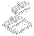
また、図1ないし図6に示すように、放熱器12は、例えばアルミニウムなどの金属材料によって形成されている。放熱器12は、ベース26、このベース26の上面側から突出する複数のフィン27を備えている。なお、本実施形態ではベース26と各放熱フィン27とは別体としているが、ベース26およびフィン27を例えば押出成形や3Dプリンタによって一体に形成してもよい。
Further, as shown in FIGS. 1 to 6, the radiator 12 is made of a metal material such as aluminum. The radiator 12 includes a base 26 and a plurality of fins 27 protruding from the upper surface side of the base 26. In the present embodiment, the base 26 and each heat radiation fin 27 are separate bodies, but the base 26 and the fins 27 may be integrally formed by, for example, extrusion molding or a 3D printer.
ベース26は、四角形状(例えば正方形)でかつ平板状のベース板部28、ベース板部28の一方の対向する両側縁から上方に折曲された一方の側板部29、およびベース板部28の他方の対向する両側縁から上方に折曲された他方の側板部30を備えている。なお、一方の側板部29および他方の側板部30がベース板部28から上方に折曲される曲面部分の曲率半径は異なっていてもよい。例えば、一方の側板部29がベース板部28から上方に折曲される曲面部分の曲率半径は、他方の側板部30がベース板部28から上方に折曲される曲面部分の曲率半径よりも大きく形成されてもよい。そして、ベース板部28の下面に、発光モジュール11の基板20が放熱シート22を介して取り付けられている。
The base 26 is a square (for example, square) and flat plate-shaped base plate portion 28, one side plate portion 29 bent upward from one of the opposite side edges of the base plate portion 28, and the base plate portion 28. It comprises the other side plate portion 30, which is bent upward from the other opposite side edges. The radius of curvature of the curved surface portion where one side plate portion 29 and the other side plate portion 30 are bent upward from the base plate portion 28 may be different. For example, the radius of curvature of the curved surface portion where one side plate portion 29 is bent upward from the base plate portion 28 is larger than the radius of curvature of the curved surface portion where the other side plate portion 30 is bent upward from the base plate portion 28. It may be formed large. Then, the substrate 20 of the light emitting module 11 is attached to the lower surface of the base plate portion 28 via the heat radiating sheet 22.
ベース板部28の中央には配線孔26aが形成されている。一方の側板部29には、設置時の振れ防止用のワイヤや落下防止用のワイヤ等を連結するための連結孔29aが形成されている。
A wiring hole 26a is formed in the center of the base plate portion 28. One side plate portion 29 is formed with a connecting hole 29a for connecting a wire for preventing runout at the time of installation, a wire for preventing falling, and the like.
ベース26の上面には、各フィン27の固定位置に対応してかしめ用の複数の突起31が突設されている。各フィン27の固定位置は、両側の一方の側板部29の間で、ベース26の中央の配線孔26aを挟んだ両側域となっている。
On the upper surface of the base 26, a plurality of caulking protrusions 31 are provided so as to correspond to the fixed positions of the fins 27. The fixed position of each fin 27 is between the side plate portions 29 on both sides, and is a region on both sides of the central wiring hole 26a of the base 26.
フィン27は、ベース26の上面で、両側の一方の側板部29間に平行に並んで設けられている。フィン27は、図6および図7に示すように、ベース26の上面に固定される固定部32、およびこの固定部32から互いに対向するように折曲された一対のフィン部33を有する断面略U字形に形成されている。
The fins 27 are provided side by side on the upper surface of the base 26 in parallel between the side plate portions 29 on both sides. As shown in FIGS. 6 and 7, the fin 27 has a fixed portion 32 fixed to the upper surface of the base 26 and a pair of fin portions 33 bent so as to face each other from the fixed portion 32. It is formed in a U shape.
固定部32には、ベース26の上面から突出する複数の突起31が貫通する複数の貫通孔32aが設けられている。そして、貫通孔32aを貫通した突起31を上方から固定部32の上面に押し付けるようにしてかしめることにより、フィン27がベース26に固定されている。
The fixing portion 32 is provided with a plurality of through holes 32a through which a plurality of protrusions 31 protruding from the upper surface of the base 26 penetrate. Then, the fin 27 is fixed to the base 26 by crimping the protrusion 31 penetrating the through hole 32a against the upper surface of the fixing portion 32 from above.
固定部32から両フィン部33のベース26と接触する下縁に亘って、ベース26の上面側に突出する図示しない突出物との干渉を避けるための開口部34が形成されている。開口部34は、例えば長方形や半円形および多角形等の形状に形成される。突出物としては、ベース26の下面側に発光モジュール11、反射体13および透光カバー14をそれぞれ固定するためのねじ等がある。また、突出物は、放熱器12に他の構成部品を取り付ける取付位置となる図示しない構成部材や、フィン部33とは異なる図示しない別の放熱部材等であってもよい。さらに、各フィン部33の下側には、複数の開口部35が形成されている。開口部35は、例えばフィン部33の下縁に沿った方向に長い長方形や長円形等の形状に形成されている。そして、開口部34と開口部35とはフィン部33の下縁に沿った方向に位置をずらして配設されている。すなわち、フィン27の幅方向全体域に点在して開口部34および開口部35が配設されている。そして、これら開口部34,35は、空気が流通する通気開口としての機能を有する。
An opening 34 is formed from the fixed portion 32 to the lower edge of both fin portions 33 in contact with the base 26 to avoid interference with a protrusion (not shown) protruding toward the upper surface side of the base 26. The opening 34 is formed in a shape such as a rectangle, a semicircle, or a polygon. The protrusions include screws for fixing the light emitting module 11, the reflector 13, and the translucent cover 14 on the lower surface side of the base 26. Further, the protrusion may be a component (not shown) that is a mounting position for attaching another component to the radiator 12, or another heat-dissipating member (not shown) different from the fin portion 33. Further, a plurality of openings 35 are formed on the lower side of each fin portion 33. The opening 35 is formed in a shape such as a long rectangle or an oval shape along the lower edge of the fin portion 33, for example. The opening 34 and the opening 35 are arranged so as to be displaced in the direction along the lower edge of the fin portion 33. That is, the openings 34 and the openings 35 are arranged scattered over the entire width direction of the fins 27. The openings 34 and 35 have a function as a ventilation opening through which air flows.
例えば開口部34は、熱の発生する発光素子21が配置されたベース26と接触する部位に設けられるため、ベース26からの熱を直接外気に発散させることができ、高い放熱効果が期待できる。また、開口部35は、フィン部33に囲まれるように形成されるため、ベース26から熱を伝導したフィン部33が外気と触れる表面積を増やすことができ、効率のよい放熱が期待できる。また、他の実施例として、開口部34および35は、フィン部33の下縁に沿った方向である幅方向に一部以上重なるよう並べて配設されてもよい。また、開口部34は、例えばフィン部33の立ち上がり方向に長い長方形や長円形に形成されてもよい。開口部35は、フィン部33の下側だけでなく中心側や上側にあってもよいし、フィン部33の立ち上がり方向に向かって二列以上に並べて配設されてもよい。
For example, since the opening 34 is provided at a portion in contact with the base 26 in which the light emitting element 21 that generates heat is arranged, the heat from the base 26 can be directly dissipated to the outside air, and a high heat dissipation effect can be expected. Further, since the opening 35 is formed so as to be surrounded by the fin portion 33, the surface area where the fin portion 33 that conducts heat from the base 26 comes into contact with the outside air can be increased, and efficient heat dissipation can be expected. Further, as another embodiment, the openings 34 and 35 may be arranged side by side so as to partially overlap each other in the width direction, which is the direction along the lower edge of the fin portion 33. Further, the opening 34 may be formed, for example, in a rectangular shape or an oval shape long in the rising direction of the fin portion 33. The openings 35 may be located not only on the lower side of the fin portion 33 but also on the center side or the upper side, or may be arranged in two or more rows toward the rising direction of the fin portion 33.
フィン部33の上縁中央には、凹部38が形成されている。この凹部38は、例えば発光モジュール11と電源部16とを電気的に接続する配線36の中間部を保持部材37によって保持可能なように設けられている。例えば、凹部38は、中央付近から上方に突出する凸部39、およびこの凸部39の両側に設けられた切欠き部40を備えている。このとき、凸部39の先端側には幅広となる抜止め部が設けられている。保持部材37としては結束バンドが用いられている。そして、保持部材37は、両側の切欠き部40を通じて凸部39に引っ掛けられるとともに、配線36を凸部39に対して締め付けて保持する。保持部材37は、凸部39の先端側の抜止め部によって凸部39の先端側から脱落することなく配線36を保持する。
A recess 38 is formed in the center of the upper edge of the fin portion 33. The recess 38 is provided so that, for example, the intermediate portion of the wiring 36 that electrically connects the light emitting module 11 and the power supply unit 16 can be held by the holding member 37. For example, the concave portion 38 includes a convex portion 39 protruding upward from the vicinity of the center, and notches 40 provided on both sides of the convex portion 39. At this time, a wide retaining portion is provided on the tip end side of the convex portion 39. A binding band is used as the holding member 37. Then, the holding member 37 is hooked on the convex portion 39 through the notches 40 on both sides, and the wiring 36 is tightened and held with respect to the convex portion 39. The holding member 37 holds the wiring 36 without falling off from the tip end side of the convex portion 39 by the retaining portion on the tip end side of the convex portion 39.
また、凹部38は、例えばフィン部33の上縁からの切欠きではなく、フィン部33の上側に口形状の孔を切欠き部40としてフィン部33の上縁方向に二箇所並べて設け、その2つの切欠き部40間に形成される部分を凸部39として、保持部材37によって配線36を保持可能な構成としてもよい。
Further, the recess 38 is not a notch from the upper edge of the fin portion 33, for example, but a mouth-shaped hole is provided on the upper side of the fin portion 33 as a notch portion 40 in two places arranged side by side in the direction of the upper edge of the fin portion 33. The portion formed between the two notch portions 40 may be a convex portion 39, and the wiring 36 may be held by the holding member 37.
また、凹部38は、フィン部33の上方に設けられるためフィン部33の上方の表面積を広げる役割を果たし、フィン部33に沿って上方へ伝導されるベース26からの熱を効率よく発散できるという効果が期待できる。また、凹部38は、フィン部33の上方中心付近に外気を効率よく通気できるという効果も望める。
Further, since the recess 38 is provided above the fin portion 33, it plays a role of increasing the surface area above the fin portion 33, and can efficiently dissipate heat from the base 26 conducted upward along the fin portion 33. The effect can be expected. Further, the recess 38 can be expected to have the effect of efficiently ventilating the outside air near the upper center of the fin portion 33.
複数のフィン27は、共通の部品が用いられている。すなわち、全てのフィン27は、固定部32および一対のフィン部33を備えるとともに、開口部34,35および凹部38を備えている。
Common parts are used for the plurality of fins 27. That is, all fins 27 include a fixing portion 32 and a pair of fin portions 33, as well as openings 34, 35 and recesses 38.
そのため、複数のフィン27は、フィン部33の平面側から見て最奥のフィン部33まで貫通するように形成される複数の開口部34、複数の開口部35および複数の凹部38を有する。これら複数の開口部34、複数の開口部35および複数の凹部38を有することにより、複数のフィン27は、フィン27中を通り抜けるように外気の流れを取り入れられるため、高い放熱効果が期待できる。
Therefore, the plurality of fins 27 have a plurality of openings 34, a plurality of openings 35, and a plurality of recesses 38 formed so as to penetrate to the innermost fin portion 33 when viewed from the plane side of the fin portion 33. By having the plurality of openings 34, the plurality of openings 35, and the plurality of recesses 38, the plurality of fins 27 can take in the flow of outside air so as to pass through the fins 27, so that a high heat dissipation effect can be expected.
そして、フィン27は、ベース26の両側の一方の側板部29間で、ベース26の配線孔26aが設けられた中央域を除いた両側域に配設されている。すなわち、ベース26の中央域には、フィン27は設けられず、ベース26の配線孔26aが開口されている。
The fins 27 are arranged between the side plate portions 29 on both sides of the base 26 in both side regions excluding the central region where the wiring hole 26a of the base 26 is provided. That is, the fin 27 is not provided in the central region of the base 26, and the wiring hole 26a of the base 26 is opened.
なお、フィン27は、断面略U字形に限らず、固定部32と一方のフィン部33を有する断面略L字形でもよく、あるいは、フィン部33のみを有する平板状でもよい。平板状の場合には、ベース26の上面に複数のスリットを設け、各スリットに各フィン27を差し込んで固定するようにしてもよい。
The fin 27 is not limited to a substantially U-shaped cross section, and may have a substantially L-shaped cross section having a fixed portion 32 and one fin portion 33, or may have a flat plate shape having only the fin portion 33. In the case of a flat plate, a plurality of slits may be provided on the upper surface of the base 26, and each fin 27 may be inserted into each slit to fix the base 26.
また、図3、図4および図8に示すように、反射体13は、発光モジュール11の各発光部24に対向配置される複数の反射筒部43、およびベース26に取り付けられる複数の取付部44を備えている。本実施形態では、複数の反射筒部43および複数の取付部44が一体に形成されているが、複数の反射筒部43を別体とし、各反射筒部43毎に取付部44を設けてもよい。
Further, as shown in FIGS. 3, 4, and 8, the reflector 13 has a plurality of reflectors 43 arranged to face each other of the light emitting portions 24 of the light emitting module 11, and a plurality of mounting portions attached to the base 26. It has 44. In the present embodiment, the plurality of reflecting cylinder portions 43 and the plurality of mounting portions 44 are integrally formed, but the plurality of reflecting cylinder portions 43 are separated from each other, and the mounting portions 44 are provided for each reflecting cylinder portion 43. May be good.
反射筒部43は、上下方向に開口するとともに、下方へ向けて拡開する円筒状に形成されている。反射筒部43の内面には、例えば鏡面等の高反射率の反射面43aが形成されている。各反射筒部43は発光モジュール11の各発光部24に対応する位置に配置されるとともに隣り合う反射筒部43の下部側が一体に設けられている。反射筒部43の外側に位置する下端周辺部から上方に向けて縁部43bが突設されているとともに、縁部43bが反射体13の外周を一周するように一体に設けられている。さらに、各反射筒部43の外面と縁部43bの内側との間に複数のリブ43cが設けられている。このような構造により、反射体13の強度が確保されている。そして、反射筒部43は、上面開口から発光モジュール11の発光部24の光を入射し、下面開口から出射する光の配光を制御する。
The reflecting cylinder portion 43 is formed in a cylindrical shape that opens in the vertical direction and expands downward. A reflecting surface 43a having a high reflectance, such as a mirror surface, is formed on the inner surface of the reflecting cylinder portion 43. Each reflecting cylinder portion 43 is arranged at a position corresponding to each light emitting portion 24 of the light emitting module 11, and the lower side of the adjacent reflecting cylinder portions 43 is integrally provided. The edge portion 43b projects upward from the lower end peripheral portion located on the outside of the reflector portion 43, and the edge portion 43b is integrally provided so as to go around the outer periphery of the reflector 13. Further, a plurality of ribs 43c are provided between the outer surface of each reflector 43 and the inside of the edge 43b. With such a structure, the strength of the reflector 13 is ensured. Then, the reflector portion 43 incidents the light of the light emitting portion 24 of the light emitting module 11 from the upper surface opening, and controls the light distribution of the light emitted from the lower surface opening.
また、例えば反射筒部43は配設されなくともよく、その場合はより簡易な構成となるため、軽量化や製造コストの低減、組立の簡易化が望めるという効果を奏する。
Further, for example, the reflector portion 43 does not have to be arranged, and in that case, the structure is simpler, so that it is possible to obtain the effects of weight reduction, reduction of manufacturing cost, and simplification of assembly.
また、反射筒部43の代わりに発光素子21を覆うように設けられる不図示のレンズ部材が設けられてもよい。その場合は、軽量化や小型化、配光性の向上等の効果が期待できる。
Further, instead of the reflecting cylinder portion 43, a lens member (not shown) provided so as to cover the light emitting element 21 may be provided. In that case, effects such as weight reduction, miniaturization, and improvement of light distribution can be expected.
取付部44は、隣り合う反射筒部43間から立ち上げられたボス部45の上端に設けられており、基板20の溝部20dを通じて放熱器12(放熱シート22)の下面側に配置され、図示しないねじによってベース26の下面に固定されている。
The mounting portion 44 is provided at the upper end of the boss portion 45 raised from between the adjacent reflector portions 43, and is arranged on the lower surface side of the radiator 12 (heat dissipation sheet 22) through the groove portion 20d of the substrate 20 and is shown in the figure. It is fixed to the underside of the base 26 with no screws.
取付部44は、隣り合う反射筒部43間から立ち上げられたボス部45の上端に設けられている。取付部44は、反射筒部43よりも基板20の厚み分だけ上方に突出されており、基板20の溝部20dを通じて放熱器12のベース26の下面側に放熱シート22を介して配置され、図示しないねじによってベース26の下面側に固定されている。
The mounting portion 44 is provided at the upper end of the boss portion 45 raised from between the adjacent reflecting cylinder portions 43. The mounting portion 44 is projected above the reflecting cylinder portion 43 by the thickness of the substrate 20, and is arranged via the heat radiating sheet 22 on the lower surface side of the base 26 of the radiator 12 through the groove portion 20d of the substrate 20. It is fixed to the underside of the base 26 by a screw that does not.
また、透光カバー14は、発光モジュール11および反射体13を覆って放熱器12の下面側に取り付けられる透光カバー本体48、および放熱器12の側部に係合して透光カバー本体48を位置決めする係合部49a,49bを備えている。この透光カバー14は、一体に形成されている。
Further, the translucent cover 14 engages with the translucent cover main body 48, which covers the light emitting module 11 and the reflector 13 and is attached to the lower surface side of the radiator 12, and the side portion of the radiator 12, and the translucent cover main body 48. It is equipped with engaging parts 49a and 49b for positioning. The translucent cover 14 is integrally formed.
透光カバー本体48は、発光モジュール11および反射体13の下面側を覆う下面部50、発光モジュール11および反射体13の側面側を覆う側面部51、および側面部51の上縁に設けられベース26の下面側に取り付けられる枠状の取付縁部52を備えている。下面部50は平面状に形成され、側面部51は反射体13の側面の形状に沿った形状に形成されている。側面部51の形状は、反射体13の各反射筒部43の側面に沿った複数の曲面部51aと、隣り合う反射筒部43間の側面(ボス部45)に沿った平面部(窪み部)51bとを含んでいる。曲面部51aは側面部51の四隅位置に配置され、平面部51bは隣り合う曲面部51aの間で窪んだ位置に配置されている。また、取付縁部52は、放熱器12のベース26の下面形状に対応した四角形枠状に形成されている。取付縁部52は、この取付縁部52の四隅部分が側面部51の各曲面部51aよりも側方に突出されているとともに、取付縁部52の各辺の中央部分が側面部51の平面部51bよりも側方に突出されている。取付縁部52の突出部分が図示しないねじで放熱器12のベース26の下面に固定されている。
The translucent cover main body 48 is provided on the lower surface portion 50 covering the lower surface side of the light emitting module 11 and the reflector 13, the side surface portion 51 covering the side surface side of the light emitting module 11 and the reflector 13, and the base provided on the upper edge of the side surface portion 51. It is provided with a frame-shaped mounting edge 52 that is mounted on the lower surface side of 26. The lower surface portion 50 is formed in a planar shape, and the side surface portion 51 is formed in a shape that follows the shape of the side surface of the reflector 13. The shape of the side surface portion 51 is a plurality of curved surface portions 51a along the side surface of each reflector portion 43 of the reflector 13, and a flat surface portion (recessed portion) along the side surface (boss portion 45) between the adjacent reflector portions 43. ) 51b and included. The curved surface portion 51a is arranged at the four corners of the side surface portion 51, and the flat surface portion 51b is arranged at a recessed position between the adjacent curved surface portions 51a. Further, the mounting edge portion 52 is formed in a rectangular frame shape corresponding to the shape of the lower surface of the base 26 of the radiator 12. In the mounting edge portion 52, the four corner portions of the mounting edge portion 52 project laterally from the curved surface portions 51a of the side surface portion 51, and the central portion of each side of the mounting edge portion 52 is the flat surface of the side surface portion 51. It protrudes laterally from the part 51b. The protruding portion of the mounting edge 52 is fixed to the lower surface of the base 26 of the radiator 12 with a screw (not shown).
係合部49a,49bは、透光カバー本体48の取付縁部52の4辺から上方に突設されている。係合部49aは、放熱器12の一対の一方の側板部29の位置に対応して配設され、また、係合部49bは、放熱器12の一対の他方の側板部30の位置に対応して配設されている。係合部49a,49bは、放熱器12の一対の一方の側板部29と一対の他方の側板部30の外側に弾性的に係合し、放熱器12に対して透光カバー本体48を位置決め保持する。係合部49a,49bは、透光カバー本体48の取付縁部52の各辺で各曲面部51aの位置に対応した2箇所に離間して設けられている。
The engaging portions 49a and 49b project upward from the four sides of the mounting edge portion 52 of the translucent cover main body 48. The engaging portion 49a is disposed corresponding to the position of the pair of one side plate portions 29 of the radiator 12, and the engaging portion 49b corresponds to the position of the pair of the other side plate portions 30 of the radiator 12. Is arranged. The engaging portions 49a and 49b elastically engage with the outside of the pair of side plate portions 29 of the radiator 12 and the pair of other side plate portions 30, and position the translucent cover main body 48 with respect to the radiator 12. Hold. The engaging portions 49a and 49b are provided at two locations corresponding to the positions of the curved surface portions 51a on each side of the mounting edge portion 52 of the translucent cover main body 48.
取付縁部52から上方に突設される係合部49a,49bの曲面部分は、放熱器12のベース26から上方に突設される一対の一方の側板部29および一対の他方の側板部30の曲面部分に係合してもよい。この場合、一対の一方の側板部29の曲面部分と一対の他方の側板部30の曲面部分との曲率半径が異なるのに対応して、一対の一方の側板部29の曲面部分に係合する係合部49aと一対の他方の側板部30の曲面部分に係合する係合部49bの曲面部分との曲率半径が異なるよう形成されてもよい。例えば、一対の一方の側板部29に係合する係合部49aの曲率半径は、一対の他方の側板部30に係合する係合部49bの曲率半径よりも大きくなるように形成されてもよい。この構成によれば、同一の曲率半径の係合部49a,49bのみで放熱器12に係合させるよりも、透光カバー本体48の係合強度が強くなるという効果が期待できる。また、透光カバー本体48を放熱器12に対して取り付ける場合、透光カバー本体48を90°回転させると、放熱器12の一方の側板部29および他方の側板部30に対して曲率半径が異なる係合部49a,49bが係合位置にくるため、正しい透光カバー本体48の取り付け方向を容易に認識できる。
The curved surface portions of the engaging portions 49a and 49b projecting upward from the mounting edge portion 52 are a pair of one side plate portions 29 and a pair of other side plate portions 30 projecting upward from the base 26 of the radiator 12. You may engage with the curved surface portion of. In this case, it engages with the curved surface portion of the pair of one side plate portions 29 corresponding to the difference in the radius of curvature between the curved surface portion of the pair of one side plate portions 29 and the curved surface portion of the pair of the other side plate portions 30. It may be formed so that the radius of curvature of the engaging portion 49a and the curved surface portion of the engaging portion 49b that engages with the curved surface portion of the pair of other side plate portions 30 are different. For example, even if the radius of curvature of the engaging portion 49a that engages with the pair of one side plate portions 29 is formed to be larger than the radius of curvature of the engaging portion 49b that engages with the pair of other side plate portions 30. good. According to this configuration, it can be expected that the engagement strength of the translucent cover main body 48 is stronger than that of engaging the radiator 12 with only the engaging portions 49a and 49b having the same radius of curvature. Further, when the translucent cover main body 48 is attached to the radiator 12, when the translucent cover main body 48 is rotated by 90 °, the radius of curvature is increased with respect to one side plate portion 29 and the other side plate portion 30 of the radiator 12. Since the different engaging portions 49a and 49b come to the engaging position, the correct mounting direction of the translucent cover body 48 can be easily recognized.
なお、係合部49a,49bは、例えばアーム15が取り付けられる放熱器12の取付側の両側部(一方の側板部29)とこれら取付側の両側部に直交する非取付側の両側部(他方の側板部30)とのうち、取付側の両側部(一方の側板部29)のみに設けられてもよいし、非取付側の両側部(他方の側板部30)のみに設けられてもよい。
The engaging portions 49a and 49b are, for example, both side portions on the mounting side (one side plate portion 29) of the radiator 12 to which the arm 15 is mounted and both side portions on the non-mounting side orthogonal to both side portions on the mounting side (the other). The side plate portion 30) may be provided only on both side portions on the mounting side (one side plate portion 29), or may be provided only on both side portions on the non-mounting side (the other side plate portion 30). ..
また、係合部49a,49bは、透光カバー14の重力方向への落下を防止できる構成であれば、取付側の両側部(一方の側板部29)および(または)非取付側の両側部(側板部30)に係合しなくともよいし、曲面に弾性的に係合するものでなくともよい。
Further, if the engaging portions 49a and 49b are configured to prevent the translucent cover 14 from falling in the direction of gravity, both side portions on the mounting side (one side plate portion 29) and / or both side portions on the non-mounting side are provided. It does not have to be engaged with (side plate portion 30), and it does not have to be elastically engaged with a curved surface.
例えば、一対の係合部49a(または49b)は、透光カバー本体48の取付縁部52から上方に突出した後、照明器具10の内部に向かって延びる爪部(不図示)を有するように形成され、ベース26の縁に爪部をスライドさせるようにして透光カバー14を放熱器12に係合させてもよい。または、一対の係合部49a(または49b)は、透光カバー本体48の取付縁部52から上方に突出するとともに、その突出した先端に下方に向けた返しを有するように形成され、ベース26に形成された不図示の孔等に貫通することにより、返しによって落下防止可能な構成であってもよい。
For example, the pair of engaging portions 49a (or 49b) may have claws (not shown) that project upward from the mounting edge 52 of the translucent cover body 48 and then extend toward the interior of the luminaire 10. The translucent cover 14 may be formed and engaged with the radiator 12 by sliding the claws around the edge of the base 26. Alternatively, the pair of engaging portions 49a (or 49b) are formed so as to project upward from the mounting edge 52 of the translucent cover body 48 and have a downward barb at the protruding tip of the base 26. The structure may be such that the fall can be prevented by turning back by penetrating through a hole (not shown) formed in the above.
透光カバー14は、光透過性の良いクリアカバーでもよいし、光を拡散する拡散カバーでもよい。透光カバー14は、本実施形態では全体が透光性を有しているが、少なくとも下面部50が透光性を有していればよく、側面部51、取付縁部52および係合部49等は非透過性であってもよい。また、透光カバー14は発光素子21から照射される光を光学制御可能なレンズ等と一体に形成されてもよい。
The light-transmitting cover 14 may be a clear cover having good light transmission, or may be a diffusion cover that diffuses light. The translucent cover 14 has translucency as a whole in the present embodiment, but it is sufficient that at least the lower surface portion 50 has translucency, and the side surface portion 51, the mounting edge portion 52, and the engaging portion 49 etc. may be opaque. Further, the translucent cover 14 may be integrally formed with a lens or the like capable of optically controlling the light emitted from the light emitting element 21.
透光カバー14の下面部50の外周縁には、脚部53が突設されている。脚部53が突設されていることにより、照明器具10を床面等に置いた際、脚部53が床面等に接触し、下面部50の面が床面等に接触して傷付くのを防止する。
A leg portion 53 is projected from the outer peripheral edge of the lower surface portion 50 of the translucent cover 14. Since the leg portion 53 is projected, when the lighting fixture 10 is placed on the floor surface or the like, the leg portion 53 comes into contact with the floor surface or the like, and the surface of the lower surface portion 50 comes into contact with the floor surface or the like and is damaged. To prevent.
そして、透光カバー14は、発光モジュール11および反射体13が取り付けられた放熱器12の下面側を閉塞し、虫や埃等が侵入するのを防止する。
The translucent cover 14 closes the lower surface side of the radiator 12 to which the light emitting module 11 and the reflector 13 are attached, and prevents insects, dust, and the like from invading.
なお、ベース26には配線36を通す配線孔26aが開口されているため、透光カバー14内への虫や埃等が侵入するのを防止するには、配線孔26aも閉塞する必要がある。配線孔26aを閉塞するために、配線36が貫通するパッキン56、およびこのパッキン56をベース26に取り付けるパッキン押え57が用いられている。パッキン56およびパッキン押え57はベース26の下面側から取り付けられている。パッキン押え57は、図示しないねじにより、パッキン56を介してベース26に固定されている。
Since the base 26 has a wiring hole 26a through which the wiring 36 passes, it is necessary to close the wiring hole 26a in order to prevent insects, dust, etc. from entering the translucent cover 14. .. In order to close the wiring hole 26a, a packing 56 through which the wiring 36 penetrates and a packing retainer 57 for attaching the packing 56 to the base 26 are used. The packing 56 and the packing retainer 57 are attached from the lower surface side of the base 26. The packing retainer 57 is fixed to the base 26 via the packing 56 by a screw (not shown).
また、図1ないし図5に示すように、アーム15は、放熱器12の両側部に取り付けられる一対のアーム部60、およびこれらアーム部60の上端間に角度調整可能に連結されたアーム設置部61を備えている。なお、アーム15は、上方に立ち上がる両側部ではなく、直接ベース26に取り付けられてもよい。
Further, as shown in FIGS. 1 to 5, the arm 15 is a pair of arm portions 60 attached to both side portions of the radiator 12, and an arm mounting portion connected so as to be angle-adjustable between the upper ends of these arm portions 60. It has 61. The arm 15 may be directly attached to the base 26 instead of both sides rising upward.
アーム部60は、例えばアルミニウム等の金属板によって形成されている。アーム部60の下端側には、複数の挿通孔62が設けられている。そして、アーム部60の下端側は、放熱器12の両側部つまり一方の側板部29の外側部に配置され、挿通孔62を挿通する図示しない複数のねじやボルト等を含む締結手段によって放熱器12の両側部つまり一方の側板部29に固定されている。
The arm portion 60 is formed of, for example, a metal plate such as aluminum. A plurality of insertion holes 62 are provided on the lower end side of the arm portion 60. The lower end side of the arm portion 60 is arranged on both sides of the radiator 12, that is, on the outer side of one side plate portion 29, and the radiator is provided by a fastening means including a plurality of screws and bolts (not shown) through which the insertion hole 62 is inserted. It is fixed to both sides of 12, that is, one side plate part 29.
アーム部60の上端側には、アーム設置部61と連結するための支点孔63および調整孔64が上下に離間して設けられている。アーム部60の下端側には、透光カバー14(取付縁部52)の下面側に配置される落下防止部65が折曲形成されている。落下防止部65は、透光カバー14の隣り合う曲面部51a間の窪み部分に進入して平面部51bに対向され、平面部51bの上端から外側に突出する取付縁部52の下面側に配置されている。
A fulcrum hole 63 and an adjustment hole 64 for connecting to the arm installation portion 61 are provided on the upper end side of the arm portion 60 so as to be vertically separated from each other. On the lower end side of the arm portion 60, a fall prevention portion 65 arranged on the lower surface side of the translucent cover 14 (mounting edge portion 52) is bent and formed. The fall prevention portion 65 is arranged on the lower surface side of the mounting edge portion 52 that enters the recessed portion between the adjacent curved surface portions 51a of the translucent cover 14 and faces the flat surface portion 51b and protrudes outward from the upper end of the flat surface portion 51b. Has been done.
一対のアーム部60の上下方向中間位置には、一対のアーム部60間の所定の取付位置Aに電源部16を位置決めする一対の位置決め部66が対向して設けられているとともに、所定の取付位置Aに電源部16を複数のねじボルト等の締結部材S(図1参照)で水平方向から支持して取り付けるための複数の挿通孔67が設けられている。
At the vertical intermediate position of the pair of arm portions 60, a pair of positioning portions 66 for positioning the power supply portion 16 are provided facing each other at a predetermined mounting position A between the pair of arm portions 60, and a predetermined mounting is performed. A plurality of insertion holes 67 for horizontally supporting and mounting the power supply unit 16 with fastening members S (see FIG. 1) such as a plurality of screw bolts are provided at the position A.
位置決め部66は、アーム部60の両側縁から切り起こされた切起片68を有している。そして、一対のアーム部60の4箇所の切起片68上に電源部16を載せることにより、電源部16を所定の取付位置Aの高さに位置決めするとともに支えることができる。
The positioning portion 66 has a cut piece 68 cut up from both side edges of the arm portion 60. Then, by mounting the power supply unit 16 on the four cut-and-raise pieces 68 of the pair of arm units 60, the power supply unit 16 can be positioned and supported at a predetermined height of the mounting position A.
位置決め部66が設けられることにより、挿通孔67に締結部材Sを用いて電源部16を固定する水平方向の固定と、電源部16が切起片68に載せられることによる重力方向の固定がなされる。このように電源部16が複数方向から固定されることにより、従来のような本体シャーシを必要とせず、照明器具10の大幅な軽量化および簡素化を実現できる。
By providing the positioning portion 66, the power supply portion 16 is fixed to the insertion hole 67 in the horizontal direction by using the fastening member S, and the power supply portion 16 is fixed in the gravity direction by being placed on the cut-out piece 68. To. By fixing the power supply unit 16 from a plurality of directions in this way, it is possible to realize a significant weight reduction and simplification of the luminaire 10 without the need for the conventional main body chassis.
なお、位置決め部66は、切起片68に限らず、アーム部60の内面側から突出する複数の山形の突起部や、アーム部60を屈曲させた段差部等でもよい。また、位置決め部66は、突出する部位でなく切欠きとしてアーム部60に設けられてもよい。その場合、電源部16は、位置決め部66の切欠きに係合するような突起を有していてもよい。あるいは、一対のアーム部60の内、一方のアーム部60に設けられる位置決め部66と他方のアーム部60に設けられる位置決め部60が異なる形状の構成であってもよい。また、位置決め部66は、アーム部60の長手方向に複数並べて設けられるものでもよい。この場合、複数の方向から電源部16の位置が定められるため、電源部16を配設しやすくなるとともに、電源部16の固定がより安定した強固なものとなる。
The positioning portion 66 is not limited to the cut-and-raised piece 68, but may be a plurality of chevron-shaped protrusions protruding from the inner surface side of the arm portion 60, a stepped portion in which the arm portion 60 is bent, or the like. Further, the positioning portion 66 may be provided in the arm portion 60 as a notch instead of a protruding portion. In that case, the power supply unit 16 may have a protrusion that engages with the notch of the positioning unit 66. Alternatively, of the pair of arm portions 60, the positioning portion 66 provided on one arm portion 60 and the positioning portion 60 provided on the other arm portion 60 may have different shapes. Further, a plurality of positioning portions 66 may be provided side by side in the longitudinal direction of the arm portion 60. In this case, since the positions of the power supply unit 16 are determined from a plurality of directions, the power supply unit 16 can be easily arranged and the power supply unit 16 can be fixed more stably and firmly.
例えば、一対のアーム部60の内、一方のアーム部60に設けられる位置決め部66は、アーム部60の長手方向において上下段に分かれて設けられ、上段の位置決め部66は電源部16に設けられた突起と係合するような切欠きとして形成され、下段の位置決め部66は上面が電源部16の底面と接触するような切起片68として形成される。他方のアーム部60に設けられるとともに一方のアーム部60の位置決め部66と対応する上段の位置決め部66は、下面が電源部16の上面に接触するような切起片68として形成され、他方のアーム部60に設けられるとともに一方のアーム部60の位置決め部66と対応する下段の位置決め部66は、電源部16に設けられた突起と係合するような切欠きとして形成されてもよい。
For example, of the pair of arm portions 60, the positioning portion 66 provided in one arm portion 60 is provided separately in the upper and lower stages in the longitudinal direction of the arm portion 60, and the upper positioning portion 66 is provided in the power supply unit 16. It is formed as a notch that engages with the protrusion, and the lower positioning portion 66 is formed as a cut-out piece 68 such that the upper surface contacts the bottom surface of the power supply portion 16. The upper positioning portion 66 provided on the other arm portion 60 and corresponding to the positioning portion 66 of one arm portion 60 is formed as a cut-out piece 68 such that the lower surface contacts the upper surface of the power supply portion 16. The lower positioning portion 66 provided on the arm portion 60 and corresponding to the positioning portion 66 of one arm portion 60 may be formed as a notch that engages with a protrusion provided on the power supply portion 16.
また、位置決め部66は、電源部16以外の部材の位置を定めるために形成されてもよい。例えば、無線通信などを行うセンサや、他の部材を積載するような天板などが同様に位置決め部66によって位置決めされる構成であってもよい。
Further, the positioning unit 66 may be formed to determine the position of a member other than the power supply unit 16. For example, a sensor that performs wireless communication or the like, a top plate on which other members are loaded, or the like may be similarly positioned by the positioning unit 66.
アーム設置部61は、金属板によって形成されている。アーム設置部61は、設置部69、およびこの設置部69の両端から下方へ折曲された支持部70を有している。設置部69には、電源部16に電源供給する電源線が挿通される配線孔71a、および天井等の被設置部に設置するための複数の設置孔71bが設けられている。支持部70には、アーム部60と連結するための支点孔72および調整溝73が設けられている。調整溝73は、支点孔72を中心とした円弧状に設けられている。
The arm mounting portion 61 is formed of a metal plate. The arm installation portion 61 has an installation portion 69 and a support portion 70 bent downward from both ends of the installation portion 69. The installation unit 69 is provided with a wiring hole 71a through which a power supply line for supplying power to the power supply unit 16 is inserted, and a plurality of installation holes 71b for installation in an installed portion such as a ceiling. The support portion 70 is provided with a fulcrum hole 72 and an adjusting groove 73 for connecting to the arm portion 60. The adjusting groove 73 is provided in an arc shape centered on the fulcrum hole 72.
そして、アーム設置部61の両側の支持部70は、アーム部60の外側に配置され、アーム設置部61の支点孔72およびアーム部60の支点孔63を挿通する図示しない支軸手段(例えばボルトおよびナット)によって回動可能に連結されているとともに、アーム設置部61の調整溝73およびアーム部60の調整孔64を挿通する図示しない締結手段(例えばボルトおよびナット)によって締め付け固定されている。そして、締結手段が緩められた状態で、天井等の被設置部に設置されるアーム設置部61に対してアーム部60を角度調整可能とするものであって、照明器具10の光照射方向を例えば直下方向等の任意の方向となるように角度調整可能とする。すなわち、アーム15は、照射角度の角度調整を行う角度調整部70aを有している。
The support portions 70 on both sides of the arm installation portion 61 are arranged outside the arm portion 60, and the fulcrum holes 72 of the arm installation portion 61 and the fulcrum holes 63 of the arm portion 60 are inserted into the support shaft means (for example, bolts) (not shown). And nuts) are rotatably connected, and are fastened and fixed by fastening means (for example, bolts and nuts) (not shown) through which the adjusting groove 73 of the arm mounting portion 61 and the adjusting hole 64 of the arm portion 60 are inserted. Then, with the fastening means loosened, the angle of the arm portion 60 can be adjusted with respect to the arm installation portion 61 installed on the installed portion such as the ceiling, and the light irradiation direction of the lighting fixture 10 can be adjusted. For example, the angle can be adjusted so as to be in an arbitrary direction such as a direct downward direction. That is, the arm 15 has an angle adjusting unit 70a that adjusts the irradiation angle.
支持部70は、例えばアーム部60の長手方向よりも短く形成される。すなわち、アーム部60、照明器具10および発光モジュール11の照射角度の角度調整を行う角度調整部70aである支点孔72および調整溝73は、電源部16よりも上方に設けられる。この場合、位置決め部66が設けられていることにより、角度調整を行っても電源部16をアーム設置部61および支持部70と干渉しない位置に手早く配設できるという効果を有する。
The support portion 70 is formed, for example, shorter than the longitudinal direction of the arm portion 60. That is, the fulcrum hole 72 and the adjustment groove 73, which are the angle adjusting portions 70a for adjusting the angle of the irradiation angle of the arm portion 60, the lighting fixture 10, and the light emitting module 11, are provided above the power supply portion 16. In this case, since the positioning unit 66 is provided, there is an effect that the power supply unit 16 can be quickly arranged at a position that does not interfere with the arm installation unit 61 and the support unit 70 even if the angle is adjusted.
また、例えば他の実施形態として、支持部70がアーム部60の長手方向よりも長く形成され、角度調整を行う支点孔72および調整溝73が電源部16よりも下方に設けられてもよい。この場合、挿通孔67および位置決め部66は、支持部70におけるアーム設置部61と支点孔72の間に設けられる。その時、アーム設置部61および支持部70を照明器具10に対して角度調整すると、支持部70に固定され電源部16も共に動いてしまう。この様な場合であっても、適切な位置に位置決め部66が設けられていることにより、電源部16がフィン27と干渉することを防ぐことができるという効果を有する。
Further, for example, as another embodiment, the support portion 70 may be formed longer than the longitudinal direction of the arm portion 60, and the fulcrum hole 72 and the adjustment groove 73 for adjusting the angle may be provided below the power supply portion 16. In this case, the insertion hole 67 and the positioning portion 66 are provided between the arm mounting portion 61 and the fulcrum hole 72 in the support portion 70. At that time, if the angle of the arm installation portion 61 and the support portion 70 is adjusted with respect to the lighting fixture 10, the arm installation portion 61 is fixed to the support portion 70 and the power supply portion 16 also moves. Even in such a case, the provision of the positioning unit 66 at an appropriate position has the effect of preventing the power supply unit 16 from interfering with the fins 27.
また、電源部16は、アーム15の一対のアーム部60間の所定の取付位置Aに取り付けられている。電源部16は、放熱器12とアーム15のアーム設置部61(設置部69)との間で、放熱器12およびアーム設置部61(設置部69)に対してそれぞれ空間をあけて配設されている。電源部16は、放熱器12と電源部16との間の距離が、アーム15のアーム設置部61(設置部69)と電源部16との間の距離よりも狭くなる位置関係に配設されている。
Further, the power supply unit 16 is attached to a predetermined attachment position A between the pair of arm units 60 of the arm 15. The power supply unit 16 is arranged between the radiator 12 and the arm installation unit 61 (installation unit 69) of the arm 15 with a space between the radiator 12 and the arm installation unit 61 (installation unit 69), respectively. ing. The power supply unit 16 is arranged in a positional relationship in which the distance between the radiator 12 and the power supply unit 16 is narrower than the distance between the arm installation unit 61 (installation unit 69) of the arm 15 and the power supply unit 16. ing.
電源部16は、電源ボックス76、この電源ボックス76に配置される複数の端子台77、および電源ボックス76内に収容される電源回路78を備えている。
The power supply unit 16 includes a power supply box 76, a plurality of terminal blocks 77 arranged in the power supply box 76, and a power supply circuit 78 housed in the power supply box 76.
電源ボックス76は、上下方向の高さ(厚み)が薄い扁平状のボックス形状に形成されている。電源ボックス76は、上面を開口した電源ケース79、およびこの電源ケース79の上面側を覆う電源カバー80を備えている。
The power supply box 76 is formed in a flat box shape having a thin vertical height (thickness). The power supply box 76 includes a power supply case 79 having an open top surface and a power supply cover 80 covering the upper surface side of the power supply case 79.
電源ボックス76の一方の対向する側面は、一対のアーム部60の内面側に取り付けられる取付面81として構成されている。取付面81には、アーム部60の各挿通孔62を挿通した締結部材S(図1参照)が螺着される複数の取付孔82が設けられている。また、電源ボックス76の取付面81と直交する一方の側面の一部が開口され、この開口に臨む電源ボックス76の内側に端子台77が配置されている。また、電源ボックス76の下面中央に配線孔76aが設けられている。
One opposite side surface of the power supply box 76 is configured as a mounting surface 81 attached to the inner surface side of the pair of arm portions 60. The mounting surface 81 is provided with a plurality of mounting holes 82 into which the fastening member S (see FIG. 1) into which the insertion holes 62 of the arm portion 60 are inserted is screwed. Further, a part of one side surface orthogonal to the mounting surface 81 of the power supply box 76 is opened, and the terminal block 77 is arranged inside the power supply box 76 facing this opening. Further, a wiring hole 76a is provided in the center of the lower surface of the power supply box 76.
電源回路78は、電源基板83、およびこの電源基板83に実装された複数の電子部品84を備えている。そして、電源回路78は、一方の端子台77を通じて交流電源を入力し、この交流電源を所定の直流電源に変換して発光モジュール11に供給し、発光素子21を点灯させる。また、電源回路78は、他方の端子台77を通じて外部の制御部や調光器から調光信号を入力し、この調光信号に応じて発光素子21を調光制御する。
The power supply circuit 78 includes a power supply board 83 and a plurality of electronic components 84 mounted on the power supply board 83. Then, the power supply circuit 78 inputs an AC power supply through one of the terminal blocks 77, converts the AC power supply into a predetermined DC power supply, supplies the AC power supply to the light emitting module 11, and lights the light emitting element 21. Further, the power supply circuit 78 inputs a dimming signal from an external control unit or a dimmer through the other terminal block 77, and dimming controls the light emitting element 21 according to the dimming signal.
電源部16と発光モジュール11とは、配線36によって電気的に接続されている。配線36の一端は発光モジュール11に実装された光源側コネクタに電気的に接続され、他端は電源回路78が有する電源側コネクタ85に接続されている。配線36の一端と他端との間は、基板20の配線孔20a、放熱シート22の配線孔22a、パッキン56、放熱器12の配線孔26a、中央側の隣り合うフィン27間、電源ボックス76の配線孔76aを挿通されている。そして、配線36は、放熱器12と電源部16との間において、結束バンド等の保持部材37により1つのフィン27の凹部38に保持されている。
The power supply unit 16 and the light emitting module 11 are electrically connected by wiring 36. One end of the wiring 36 is electrically connected to the light source side connector mounted on the light emitting module 11, and the other end is connected to the power supply side connector 85 of the power supply circuit 78. Between one end and the other end of the wiring 36, the wiring hole 20a of the board 20, the wiring hole 22a of the heat sink 22, the packing 56, the wiring hole 26a of the radiator 12, the adjacent fins 27 on the center side, and the power supply box 76. Wiring hole 76a is inserted. The wiring 36 is held between the radiator 12 and the power supply unit 16 by a holding member 37 such as a binding band in a recess 38 of one fin 27.
なお、電源ボックス76に、所定の取付位置Aでアーム部60の位置決め部66によって位置決めされる被位置決め部を設けてもよく、この場合には、アーム部60の挿通孔62と電源ボックス76の取付孔82とを位置決めすることができる。被位置決め部は、アーム部60の切起片68に嵌り込む溝部や凹部あるいは一対の突起部等がある。
The power supply box 76 may be provided with a positioned portion to be positioned by the positioning portion 66 of the arm portion 60 at a predetermined mounting position A. In this case, the insertion hole 62 of the arm portion 60 and the power supply box 76 may be provided. It can be positioned with the mounting hole 82. The positioned portion includes a groove portion, a recess, a pair of protrusions, and the like that are fitted into the cut-and-raised piece 68 of the arm portion 60.
そして、照明器具10を組み立てるには、放熱器12の下面側に、パッキン56を介してパッキン押え57をねじ止めするとともに、放熱シート22および発光モジュール11を複数の基板押え23を介してねじ止めする。
Then, in order to assemble the lighting fixture 10, the packing retainer 57 is screwed to the lower surface side of the radiator 12 via the packing 56, and the heat dissipation sheet 22 and the light emitting module 11 are screwed via the plurality of substrate retainers 23. do.
放熱器12の下面側に、反射体13を配置してねじ止めするとともに、この反射体13を覆うように透光カバー14を配置してねじ止めする。透光カバー14は、取付縁部52から突出する四方の係合部49a,49bを放熱器12の周囲側面に係合することにより、放熱器12に位置決めされ、取付縁部52を放熱器12の下面側に容易にねじ止めすることができる。
A reflector 13 is arranged and screwed on the lower surface side of the radiator 12, and a translucent cover 14 is arranged and screwed so as to cover the reflector 13. The translucent cover 14 is positioned on the radiator 12 by engaging the four engaging portions 49a and 49b protruding from the mounting edge 52 with the peripheral side surfaces of the radiator 12, and the mounting edge 52 is positioned on the radiator 12. Can be easily screwed to the lower surface side of the.
アーム15の一対のアーム部60を放熱器12の両側部に配置して締結手段で固定する。なお、アーム15の一対のアーム部60とアーム設置部61とは予め組み立てられていてもよし、分離状態の一対のアーム部60を放熱器12の両側部に配置して締結手段で固定した後にその一対のアーム部60にアーム設置部61を取り付けるようにしてもよい。
A pair of arm portions 60 of the arms 15 are arranged on both side portions of the radiator 12 and fixed by fastening means. The pair of arm portions 60 and the arm mounting portion 61 of the arm 15 may be preassembled, or after the pair of arm portions 60 in the separated state are arranged on both sides of the radiator 12 and fixed by the fastening means. The arm mounting portion 61 may be attached to the pair of arm portions 60.
電源部16を一対のアーム部60間に挿入するとともにアーム部60の内面側に突出する複数の切起片68上に載せる。これにより、一対のアーム部60間の所定の取付位置A(少なくとも取付位置Aの高さ位置)に電源部16を位置決めして支えることができる。このとき、電源部16の取付孔82の位置がアーム部60の挿通孔67からずれていても、電源部16を複数の切起片68上でスライドさせることによって容易に一致させることができる。締結部材S(図1参照)をアーム部60の挿通孔67を通じて電源部16の取付孔82に螺着し、一対のアーム部60間に電源部16を取り付ける。
The power supply unit 16 is inserted between the pair of arm units 60 and placed on a plurality of cut-and-raise pieces 68 protruding toward the inner surface side of the arm units 60. As a result, the power supply unit 16 can be positioned and supported at a predetermined mounting position A (at least the height position of the mounting position A) between the pair of arm units 60. At this time, even if the position of the mounting hole 82 of the power supply unit 16 is deviated from the insertion hole 67 of the arm unit 60, the power supply unit 16 can be easily matched by sliding the power supply unit 16 on the plurality of cutting pieces 68. The fastening member S (see FIG. 1) is screwed into the mounting hole 82 of the power supply unit 16 through the insertion hole 67 of the arm unit 60, and the power supply unit 16 is mounted between the pair of arm units 60.
また、配線36は、組立途中において、パッキン56に通し、一端側を発光モジュール11に接続し、他端側を電源回路78に接続する。なお、放熱器12の配線孔26aから上方に引き出された配線36と電源部16の配線孔76aから下方に引き出された配線36とをコネクタ接続するようにしてもよい。そして、放熱器12と電源部16との間の配線36の中間部は、保持部材37によって1つのフィン27に設けられている凹部38に保持する。
Further, the wiring 36 is passed through the packing 56 during assembly, one end side is connected to the light emitting module 11, and the other end side is connected to the power supply circuit 78. The wiring 36 drawn upward from the wiring hole 26a of the radiator 12 and the wiring 36 drawn downward from the wiring hole 76a of the power supply unit 16 may be connected by a connector. Then, the intermediate portion of the wiring 36 between the radiator 12 and the power supply unit 16 is held by the holding member 37 in the recess 38 provided in one fin 27.
そして、照明器具10を設置するには、アーム15のアーム設置部61を天井等の被設置部に取り付ける。例えば被設置部が傾斜しているような場合には、アーム15のアーム設置部61も傾斜するが、アーム設置部61に対してアーム部60の角度を調整することにより、照明器具10からの光照射方向を例えば直下方向に設定することができる。
Then, in order to install the lighting fixture 10, the arm mounting portion 61 of the arm 15 is attached to a mounted portion such as a ceiling. For example, when the mounted portion is tilted, the arm mounting portion 61 of the arm 15 is also tilted, but by adjusting the angle of the arm portion 60 with respect to the arm mounting portion 61, the lighting fixture 10 can be used. The light irradiation direction can be set, for example, directly below.
必要に応じて、一方の側板部29の連結孔29aに、被設置部からの振れ防止用のワイヤや落下防止用のワイヤ等を連結する。
If necessary, a wire for preventing runout from the installed portion, a wire for preventing fall, etc. are connected to the connecting hole 29a of one side plate portion 29.
また、照明器具10の点灯時には、電源部16によって交流電源を所定の直流電源に変換して発光モジュール11に供給し、発光モジュール11の発光素子21が点灯する。点灯する発光素子21からの光は、反射体13および透光カバー14を通過して照明空間に照射される。透光カバー14は、下面部50が明るく光るが、透光カバー14に入射した光の一部が側面部51に導光されたり反射体13と下面部50の内面との隙間から漏れる光が側面部51に入射して側面部51も光る。
Further, when the lighting fixture 10 is lit, the power supply unit 16 converts an AC power source into a predetermined DC power source and supplies it to the light emitting module 11, and the light emitting element 21 of the light emitting module 11 is turned on. The light from the light emitting element 21 to be lit passes through the reflector 13 and the translucent cover 14 and is applied to the illumination space. The lower surface portion 50 of the translucent cover 14 shines brightly, but a part of the light incident on the translucent cover 14 is guided to the side surface portion 51 or the light leaking from the gap between the reflector 13 and the inner surface of the lower surface portion 50. It is incident on the side surface portion 51 and the side surface portion 51 also shines.
点灯時に発光素子21が発生する熱は、主として、基板20から放熱器12に伝わり、放熱器12の複数のフィン27から空気中に放熱される。フィン27には、開口部34,35が設けられているため、複数のフィン27が並列に配列されている状態でも、外側の相対的に温度の低い空気が外側のフィン27から内側のフィン27まで流通しやすくなり、複数のフィン27によって効率よく放熱される。
The heat generated by the light emitting element 21 at the time of lighting is mainly transmitted from the substrate 20 to the radiator 12, and is dissipated into the air from the plurality of fins 27 of the radiator 12. Since the fins 27 are provided with openings 34 and 35, even when a plurality of fins 27 are arranged in parallel, the air having a relatively low temperature on the outside can flow from the outer fins 27 to the inner fins 27. It becomes easy to distribute to, and heat is efficiently dissipated by a plurality of fins 27.
また、透光カバー14が発光モジュール11および反射体13が取り付けられた放熱器12の下面側を閉塞し、かつ、配線36が挿通する放熱器12の配線孔26aをパッキン56で閉塞し、透光カバー14の内側に虫や埃等が侵入するのを防止する。
Further, the translucent cover 14 closes the lower surface side of the radiator 12 to which the light emitting module 11 and the reflector 13 are attached, and the wiring hole 26a of the radiator 12 through which the wiring 36 is inserted is closed by the packing 56 to transmit through. Prevents insects, dust, etc. from entering the inside of the optical cover 14.
そして、本実施形態の照明器具10では、放熱器12にアーム15の一対のアーム部60を取り付け、これら一対のアーム部60間に電源部16を取り付ける構成であるため、本体シャーシ等が不要となり、簡素化および軽量化することができる。
Further, in the lighting fixture 10 of the present embodiment, since the pair of arm portions 60 of the arms 15 are attached to the radiator 12 and the power supply portion 16 is attached between the pair of arm portions 60, the main body chassis and the like are not required. , Simplified and lightweight.
このように簡素化および軽量化された照明器具10は、設置時の施工を行いやすく、施工にかかる時間を短縮でき、さらに、照明器具10を設置する天井側等の被設置部に加わる負荷を軽減できる。
The luminaire 10 that has been simplified and reduced in weight in this way facilitates the construction at the time of installation, can shorten the time required for the construction, and further, the load applied to the installed portion such as the ceiling side on which the luminaire 10 is installed is applied. Can be reduced.
また、電源部16は、アーム15に取り付けられるため、放熱器12からの熱影響を軽減できる。
Further, since the power supply unit 16 is attached to the arm 15, the heat influence from the radiator 12 can be reduced.
しかも、アーム15は、アーム部60間の所定の取付位置Aに電源部16を位置決めする位置決め部66を有しているため、アーム部60間の所定の取付位置Aに電源部16を容易に取り付けることができ、組立性を向上できる。
Moreover, since the arm 15 has a positioning unit 66 for positioning the power supply unit 16 at a predetermined mounting position A between the arm units 60, the power supply unit 16 can be easily placed at a predetermined mounting position A between the arm units 60. It can be attached and the assemblability can be improved.
位置決め部66として、アーム部60から切り起こした切起片68を用いることにより、簡単に構成できる。さらに、各アーム部60の幅方向の両側縁に切起片68を設けることにより、これら切起片68上に載る電源部16の状態が安定し、作業しやすくできる。
It can be easily configured by using the cutting piece 68 cut up from the arm part 60 as the positioning part 66. Further, by providing the cutting pieces 68 on both side edges in the width direction of each arm part 60, the state of the power supply unit 16 resting on these cutting pieces 68 is stable, and the work can be facilitated.
また、一対のアーム部60は、透光カバー14の下面側に配置される落下防止部65を有するため、仮に、透光カバー14に加わる発光モジュール11等からの熱の影響や振動の影響等で、透光カバー14が放熱器12から外れても、落下防止部65に透光カバー14の下面側が支えられるため、透光カバー14の落下を防止できる。しかも、アーム部60に落下防止部65を一体に設けることにより、簡単な構成で落下防止できる。
Further, since the pair of arm portions 60 have the fall prevention portion 65 arranged on the lower surface side of the translucent cover 14, the influence of heat and the influence of vibration from the light emitting module 11 and the like applied to the translucent cover 14 are assumed. Therefore, even if the translucent cover 14 comes off from the radiator 12, the lower surface side of the translucent cover 14 is supported by the fall prevention portion 65, so that the translucent cover 14 can be prevented from falling. Moreover, by integrally providing the fall prevention portion 65 with the arm portion 60, it is possible to prevent the fall with a simple configuration.
さらに、透光カバー14には放熱器12の側面部に係合する係合部49a,49bが設けられているため、透光カバー14が放熱器12から外れて落下防止部65で支えられた状態で、この落下防止部65から透光カバー14がずれて外れるのを防止することができる。
Further, since the translucent cover 14 is provided with engaging portions 49a and 49b that engage with the side surface portions of the radiator 12, the translucent cover 14 is disengaged from the radiator 12 and supported by the fall prevention portion 65. In this state, it is possible to prevent the translucent cover 14 from slipping off from the fall prevention portion 65.
また、放熱器12に取り付けられるとともに電源部16が取り付けられる一対のアーム部60に対して、アーム設置部61を角度調整可能に連結しているため、天井等の被設置部が傾斜していても、照明器具10からの光照射方向を適切に調整することができる。
Further, since the arm mounting portion 61 is connected to the pair of arm portions 60 to which the radiator 12 is attached and the power supply portion 16 is attached so that the angle can be adjusted, the installed portion such as the ceiling is inclined. Also, the direction of light irradiation from the luminaire 10 can be adjusted appropriately.
さらに、電源部16は、放熱器12に固定されるアーム部60に取り付けられることにより、角度調整可能でありながら、放熱器12と電源部16との位置関係を一定に保つことができるため、角度調整しても放熱器12と電源部16とが当たることがなく、しかも、電源部16で放熱器12の上方域を覆い、埃等が放熱器12に付着するのを低減できる。
Further, since the power supply unit 16 is attached to the arm unit 60 fixed to the radiator unit 12, the positional relationship between the radiator unit 12 and the power supply unit 16 can be kept constant while the angle can be adjusted. Even if the angle is adjusted, the radiator 12 and the power supply unit 16 do not come into contact with each other, and the power supply unit 16 covers the upper area of the radiator 12 to reduce dust and the like from adhering to the radiator 12.
また、放熱器12のベース26の周辺部から一方の側板部29および側面部30を折曲して設けているため、ベース26のベース板部28に複数のフィン27をかしめる構造であっても、ベース26の強度を向上し、ベース部26の変形を防止することができる。
Further, since one side plate portion 29 and the side surface portion 30 are bent from the peripheral portion of the base 26 of the radiator 12, the structure is such that a plurality of fins 27 are crimped to the base plate portion 28 of the base 26. However, the strength of the base 26 can be improved and the deformation of the base portion 26 can be prevented.
本発明のいくつかの実施形態を説明したが、これらの実施形態は、例として提示したものであり、発明の範囲を限定することは意図していない。これら新規な実施形態は、その他の様々な形態で実施されることが可能であり、発明の要旨を逸脱しない範囲で、種々の省略、置き換え、変更を行うことができる。これら実施形態やその変形は、発明の範囲や要旨に含まれるとともに、特許請求の範囲に記載された発明とその均等の範囲に含まれる。
Although some embodiments of the present invention have been described, these embodiments are presented as examples and are not intended to limit the scope of the invention. These novel embodiments can be implemented in various other embodiments, and various omissions, replacements, and changes can be made without departing from the gist of the invention. These embodiments and variations thereof are included in the scope and gist of the invention, and are also included in the scope of the invention described in the claims and the equivalent scope thereof.