JP7007573B2 - Ice making system - Google Patents
Ice making system Download PDFInfo
- Publication number
- JP7007573B2 JP7007573B2 JP2018003975A JP2018003975A JP7007573B2 JP 7007573 B2 JP7007573 B2 JP 7007573B2 JP 2018003975 A JP2018003975 A JP 2018003975A JP 2018003975 A JP2018003975 A JP 2018003975A JP 7007573 B2 JP7007573 B2 JP 7007573B2
- Authority
- JP
- Japan
- Prior art keywords
- cooled
- ice
- storage tank
- pipe
- making system
- Prior art date
- Legal status (The legal status is an assumption and is not a legal conclusion. Google has not performed a legal analysis and makes no representation as to the accuracy of the status listed.)
- Active
Links
Images


Description
本開示は製氷システムに関する。さらに詳しくは、シャーベット状の氷スラリーを製造する製氷システムに関する。 This disclosure relates to an ice making system. More specifically, the present invention relates to an ice making system for producing a sherbet-like ice slurry.
魚等を冷蔵するためにシャーベット状の氷スラリーを用いる場合がある。かかる氷スラリーを製造する装置として、冷媒により海水等の被冷却物を冷却しシャーベット状の氷スラリーを生成する製氷機がある。かかる製氷機は、被冷却物を貯留しておく貯留タンクを備えている。 A sherbet-like ice slurry may be used to refrigerate fish and the like. As an apparatus for producing such an ice slurry, there is an ice maker that cools an object to be cooled such as seawater with a refrigerant to generate a sherbet-like ice slurry. Such an ice maker is equipped with a storage tank for storing the object to be cooled.
図5は、従来の貯留タンク50を示している。この貯留タンク50は密閉式のタンクであり、内部に収容された被冷却物51はポンプ52により製氷機(図示せず)に送られ、当該製氷機で生成された氷を含んだ状態で貯留タンク50に戻される。生成された氷は凝集ないし固まって氷塊53となる。氷塊53は浮力により貯留タンク50の上部に浮き上がるので、浮いた氷塊53の上面を当該貯留タンク50内の上部に設けた回転式の掻取装置54で掻き取ってシャーベット状の氷スラリーを得ていた。
FIG. 5 shows a
製造する氷の量が増えてくると貯留タンク50内の氷塊53も大きくなる。貯留タンク50内に氷塊53がある状態で製氷機の運転を長期間停止すると、図6に示されるように、氷結現象により、貯留タンク50の側部50aの内壁面55に接触している氷塊53の部分が当該内壁面55に吸着することがある。この状態で製氷機の運転を再開しても、氷塊53は内壁面55に吸着して浮き上がらないので、その上面の氷を掻き取ることができなくなるという問題が生じる。
As the amount of ice produced increases, so does the
かかる問題を解消するために、従来、貯留タンク50の側部の周囲に電気ヒータを巻き付けて当該貯留タンク50を加熱し、貯留タンク50の側部50aの内壁面55に氷塊53が接触しても当該内壁面55に吸着しないようにしていた。
しかし、この方法では、常時電気ヒータに通電しておく必要があり、電気代(ランニングコスト)がかかるという問題がある。
Conventionally, in order to solve such a problem, an electric heater is wound around the side portion of the
However, in this method, it is necessary to keep the electric heater energized at all times, and there is a problem that an electric cost (running cost) is required.
本開示は、ランニングコストを抑えることができる製氷システムを提供することを目的としている。 The present disclosure is intended to provide an ice making system capable of reducing running costs.
本開示の第1の観点に係る製氷システムは、
(1)冷媒により被冷却物を冷却し氷を生成する製氷機と、前記被冷却物を貯留する貯留タンクと、前記被冷却物を前記製氷機に供給するポンプとが配管で接続された製氷システムであって、
前記製氷システムは冷房運転及び暖房運転が可能な冷凍装置を備えており、
前記製氷機から貯留タンクに戻る配管から、暖房運転時に前記被冷却物を前記貯留タンクの上部に供給する加熱配管が分岐して設けられ、
前記貯留タンクに、前記加熱配管から供給される被冷却物を当該貯留タンク内に放出する放出部が設けられている。
The ice making system according to the first aspect of the present disclosure is
(1) Ice making in which an ice maker that cools an object to be cooled by a refrigerant to generate ice, a storage tank that stores the object to be cooled, and a pump that supplies the object to be cooled to the ice maker are connected by a pipe. It ’s a system,
The ice making system is equipped with a refrigerating device capable of cooling operation and heating operation.
A heating pipe that supplies the object to be cooled to the upper part of the storage tank during the heating operation is branched from the pipe that returns from the ice maker to the storage tank.
The storage tank is provided with a discharge unit that discharges the object to be cooled supplied from the heating pipe into the storage tank.
本開示の第1の観点に係る製氷システムでは、冷凍装置を暖房運転することで被冷却物を温めることができ、この温められた被冷却物を加熱配管を経由して貯留タンクの上部から当該貯留タンク内に放出することで、貯留タンクの内壁面に吸着した氷を溶かすことができる。 In the ice making system according to the first aspect of the present disclosure, the object to be cooled can be heated by heating the refrigerating device, and the heated object to be cooled can be heated from the upper part of the storage tank via the heating pipe. By releasing it into the storage tank, the ice adsorbed on the inner wall surface of the storage tank can be melted.
(2)前記(1)の製氷システムにおいて、前記製氷機は、内管と、この内管の径方向外側において当該内管と同軸に設けられた外管とを備えており、前記内管内に被冷却物を流し、前記内管と外管との間のスペースに冷媒を流す二重管式製氷機とすることができる。この場合、内管内で温められた被冷却物を加熱配管を経由して貯留タンクの上部から当該貯留タンク内に放出することで、貯留タンクの内壁面に吸着した氷を溶かすことができる。 (2) In the ice making system of the above (1), the ice making machine includes an inner pipe and an outer pipe provided coaxially with the inner pipe on the radial outer side of the inner pipe, and the inside of the inner pipe is provided. It can be a double-tube ice maker in which an object to be cooled flows and a refrigerant flows in the space between the inner pipe and the outer pipe. In this case, the ice adsorbed on the inner wall surface of the storage tank can be melted by discharging the cooled object warmed in the inner pipe from the upper part of the storage tank into the storage tank via the heating pipe.
本開示の第2の観点に係る製氷システムは、
(3)冷媒により被冷却物を冷却し氷を生成する製氷機と、前記被冷却物を貯留する貯留タンクと、前記被冷却物を前記製氷機に供給するポンプとが配管で接続された製氷システムであって、
前記貯留タンクに被冷却物を供給する補給タンクを備えており、
前記貯留タンクの側部外面に加熱用配管が設けられており、
前記貯留タンク又は前記加熱用配管に選択的に被冷却物を供給する切換部を有する。
The ice making system according to the second aspect of the present disclosure is
(3) Ice making in which an ice maker that cools an object to be cooled by a refrigerant to generate ice, a storage tank that stores the object to be cooled, and a pump that supplies the object to be cooled to the ice maker are connected by a pipe. It ’s a system,
It is equipped with a supply tank that supplies the object to be cooled to the storage tank.
A heating pipe is provided on the outer surface of the side of the storage tank.
It has a switching unit that selectively supplies the object to be cooled to the storage tank or the heating pipe.
本開示の第2の観点に係る製氷システムでは、切換部を操作することで、貯留タンクの側部外面に設けられた加熱用配管に補給タンクから被冷却物を供給することができる。補給タンク内の被冷却物の温度は、例えば当該被冷却物が海水である場合、10~25℃の範囲内であり、かかる被冷却物を加熱用配管に供給することで貯留タンクの側部内面を加熱することができる。これにより、貯留タンクの内壁面に吸着した氷を溶かすことができる。 In the ice making system according to the second aspect of the present disclosure, by operating the switching unit, the object to be cooled can be supplied from the replenishment tank to the heating pipe provided on the outer surface of the side portion of the storage tank. The temperature of the object to be cooled in the replenishment tank is, for example, in the range of 10 to 25 ° C. when the object to be cooled is seawater, and the side portion of the storage tank is supplied by supplying the object to be cooled to the heating pipe. The inner surface can be heated. This makes it possible to melt the ice adsorbed on the inner wall surface of the storage tank.
(4)前記(3)の製氷システムにおいて、前記製氷機は、内管と、この内管の径方向外側において当該内管と同軸に設けられた外管とを備えており、前記内管内に被冷却物を流し、前記内管と外管との間のスペースに冷媒を流す二重管式製氷機とすることができる。 (4) In the ice making system of the above (3), the ice making machine includes an inner pipe and an outer pipe provided coaxially with the inner pipe on the radial outer side of the inner pipe. It can be a double-tube ice maker in which an object to be cooled flows and a refrigerant flows in the space between the inner pipe and the outer pipe.
以下、添付図面を参照しつつ、本開示の製氷システムを詳細に説明する。なお、本開示はこれらの例示に限定されるものではなく、特許請求の範囲によって示され、特許請求の範囲と均等の意味及び範囲内でのすべての変更が含まれることが意図される。 Hereinafter, the ice making system of the present disclosure will be described in detail with reference to the attached drawings. It should be noted that the present disclosure is not limited to these examples, and is indicated by the scope of claims, and is intended to include all modifications within the meaning and scope equivalent to the scope of claims.
〔第1実施形態〕
図1は、本開示の一実施形態(第1実施形態)に係る製氷システムAの概略構成図である。
製氷システムAは海水を被冷却物としており、利用側熱交換器を構成する二重管式製氷機1以外に、圧縮機2、熱源側熱交換器3、四路切換弁4、膨張弁5、25、過熱器6、レシーバ7、海水タンク(貯留タンク)8、及びポンプ9を備えている。二重管式製氷機1、圧縮機2、熱源側熱交換器3、四路切換弁4、膨張弁5、25、過熱器6、及びレシーバ7により冷凍装置が構成され、これらの機器又は部材は配管により接続されて冷媒回路を構成している。また、二重管式製氷機1、海水タンク8、及びポンプ9も同じく配管により接続されて海水循環路を構成している。本実施形態における冷凍装置は、後述するように、四路切換弁4を切り換えることで冷房運転及び暖房運転が可能な装置である。
[First Embodiment]
FIG. 1 is a schematic configuration diagram of an ice making system A according to an embodiment (first embodiment) of the present disclosure.
The ice making system A uses seawater as a object to be cooled, and in addition to the double-tube ice making machine 1 constituting the heat exchanger on the user side, the
通常の製氷運転(冷房運転)時には、四路切換弁4が、図1において実線で示される状態に保持される。圧縮機2から吐出された高温高圧のガス状冷媒は四路切換弁4を経て凝縮器として機能する熱源側熱交換器3に流入し、送風ファン10の作動により空気と熱交換して凝縮・液化する。液化した冷媒は、レシーバ7、過熱器6を経て膨張弁5に流入する。冷媒は、膨張弁5により所定の低圧に減圧され、二重管式製氷機1のノズル(図示せず)の噴出口から当該二重管式製氷機1を構成する内管12と外管13との間の環状スペース14内に噴出される。
During the normal ice making operation (cooling operation), the four-way switching valve 4 is held in the state shown by the solid line in FIG. The high-temperature and high-pressure gaseous refrigerant discharged from the
環状スペース14内に噴出された冷媒は、ポンプ9により内管12内に流入された海水と熱交換して蒸発する。冷媒の蒸発により冷却された海水は、内管12から流出して海水タンク8に戻る。二重管式製氷機1で蒸発して気化した冷媒は圧縮機2に吸い込まれる。その際、二重管式製氷機1で蒸発しきれずに液体を含んだ状態の冷媒が圧縮機2に入ると、急激な圧縮機シリンダー内部圧力上昇(液圧縮)や冷凍機油の粘度低下により圧縮機2が故障する原因となることから、当該圧縮機2を保護するために二重管式製氷機1を出た冷媒は、過熱器6により過熱して圧縮機2に戻すようにしている。過熱器6は二重管式であり、二重管式製氷機1を出た冷媒は、過熱器6の内管と外管との間のスペースを通る間に過熱され、圧縮機2に戻る。
The refrigerant ejected into the annular space 14 exchanges heat with the seawater flowing into the
また、二重管式製氷機1の内管12内の海水の流れが滞り、内管12内に氷が蓄積される(アイスアキュームレーション)と、当該二重管式製氷機1が運転できなくなる。この場合、内管12内の氷を溶かすためにデフロスト運転(暖房運転)が行われる。このとき、四路切換弁4は、図1において破線で示される状態に保持される。圧縮機2から吐出された高温高圧のガス状冷媒は四路切換弁4、過熱器6を経て二重管式製氷機1を構成する内管12と外管13との間の環状スペース14内に流入し、内管12内の氷を含む海水と熱交換して凝縮・液化する。液化した冷媒は、過熱器6、レシーバ7を経て膨張弁25に流入し、当該膨張弁25により所定の低圧に減圧され、蒸発器として機能する熱源側熱交換器3に流入する。デフロスト運転時には蒸発器として機能する熱源側熱交換器3に流入した冷媒は送風ファン10の作動により空気と熱交換して気化し、圧縮機2に吸い込まれる。
Further, if the flow of seawater in the
図2は、図1に示される、本開示の一実施形態に係る製氷システムAにおける二重管式製氷機1の側面説明図である。二重管式製氷機1は、内管12と、外管13とを備えた横置き型の二重管式製氷機である。
FIG. 2 is a side view of the double-tube ice making machine 1 in the ice making system A according to the embodiment of the present disclosure, which is shown in FIG. The double-tube ice maker 1 is a horizontal double-tube ice maker provided with an
内管12は、内部を被冷却物である海水が通過する要素であり、ステンレスや鉄等の金属材料で作製されている。内管12の両端は閉止されており、その内部には当該内管12の内周面に生成されたシャーベット状の氷スラリーを掻き上げて内管12内に分散させるブレード機構15が配設されている。内管12の軸方向一端側(図2において右側)に海水が当該内管12内に供給される海水入口管16が設けられており、内管12の軸方向他端側(図2において左側)に内管12から海水が排出される海水出口管17が設けられている。
The
外管13は、内管12の径方向外側において当該内管12と同軸に設けられ、ステンレスや鉄等の金属材料で作製されている。外管13の下部には複数の(本実施形態では3つ)冷媒入口管18が設けられており、外管13の上部には複数の(本実施形態では2つ)の冷媒出口管19が設けられている。外管13の壁13aには、外管13と内管12との間の環状スペース14に内管12内の海水を冷却するための冷媒を噴出するノズルが設けられている。ノズルは、冷媒入口管18と連通するように設けられている。
The
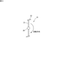
ブレード機構15は、図3に示されるように、回転軸20と、支持バー21と、ブレード22とを備えている。回転軸20の軸方向の他端は内管12の軸方向一端に設けられたフランジ23から外部に延びて設けられ、ブレード機構15を駆動させる駆動部を構成するモータ24に接続されている。回転軸20の周面には所定間隔で支持バー21が立設されており、この支持バー21の先端にブレード22が取り付けられている。ブレード22は、例えば樹脂で作製された帯板状の部材からなり、回転方向の前方側の側縁は先細形状とされている。
As shown in FIG. 3, the
貯留タンク8はステンレスや鉄等の金属材料で作製された密閉型のタンクである。貯留タンク8の内部の上方には、当該貯留タンク8内に貯留される海水に浮かぶ氷塊の上面を掻き取ってシャーベット状の氷スラリーを得るための回転式の掻取装置26が設けられている。掻取装置26は図示しないモータ等の駆動装置により回転させられる。
The
二重管式製氷機1から貯留タンク8に戻る配管P1から加熱配管27が分岐しており、この加熱配管27は貯留タンク8の天板28の開口(図示せず)に接続されている。通常の製氷時(冷房運転)には、加熱配管27に設けられた開閉弁29は「閉」の状態であり、二重管式製氷機1で生成された氷を含む海水は、「開」の状態である開閉弁30を通って貯留タンク8に戻される。貯留タンク8の内壁面31に氷塊が吸着するのを防止するか、又は、すでに吸着した氷塊部分を溶かすために、二重管式製氷機1を暖房運転する場合は、開閉弁30を「閉」にするとともに開閉弁29を「開」にして、当該二重管式製氷機1で温められた海水を加熱配管27から貯留タンク8に供給する。
A
天板28の開口には、加熱配管から供給される温められた海水を貯留タンク8の内部に放出(放水)するための放出部であるノズル32が設けられている。ノズル32は、貯留タンク8の内壁面31に吸着した氷塊部分を効率よく溶かすという点より、当該内壁面31に向けて海水を放出する噴出口(図示せず)を有することが望ましい。
The opening of the
温められた海水の温度は、氷塊を効果的に溶かすという点より、ある程度の温度以上、例えば5℃以上であることが望ましいが、冷凍装置の加熱能力が不足する場合は、ポンプ9の回転数を少なくするか、又は、ポンプ9が定速ポンプである場合は間欠運転をすることで、所望の海水温度を得ることができる。
The temperature of the warmed seawater is preferably a certain temperature or higher, for example, 5 ° C. or higher from the viewpoint of effectively melting the ice block, but if the heating capacity of the refrigerating device is insufficient, the rotation speed of the
〔第2実施形態〕
図4は、本開示の他の実施形態に係る製氷システムBの概略構成図である。本実施形態に係る製氷システムBは、図1~3に示される製氷システムAにおける加熱配管27に代えて、貯留タンク8とは別の補給タンク33を設け、貯留タンク8の側部外周に加熱用配管34を設けている。したがって、製氷システムAと共通する要素又は機器には同じ参照符号を付し、簡単のため、それらについての説明は省略する。
[Second Embodiment]
FIG. 4 is a schematic configuration diagram of an ice making system B according to another embodiment of the present disclosure. In the ice making system B according to the present embodiment, instead of the
補給タンク33には、貯留タンク8に供給される海水が収容されている。この補給タンク33には、海中に設けられたフィルタ付きの取水口(図示せず)から取得した海水が収容される。貯留タンク8の側部外面には、当該貯留タンク8を温めるための加熱用配管34がらせん状に設けられている。また、加熱用配管34の外方ないし外側には加熱効率を高めるための断熱材35が巻き付けられている。
The
補給タンク33の出口36の下流には循環ポンプ37が設けられ、この循環ポンプの下流には補給タンク33からの海水を貯留タンク8内に供給する経路と加熱用配管34に供給する経路とを切り換えることができる切換部である三方弁38が設けられている。
海水の温度は、前述したように、通常10~25℃の範囲内である。循環ポンプ37を作動させ、前記三方弁38を加熱用配管34に海水を供給する経路に切り換えることで、当該加熱用配管34に海水を供給して貯留タンク8の内壁面31を温めることができる。これにより、内壁面31に吸着した氷塊の部分を溶かすことができ、又、氷塊が内壁面31に吸着することを防止することができる。
A
As mentioned above, the temperature of seawater is usually in the range of 10 to 25 ° C. By operating the
本実施形態では、補給タンク33内の海水を貯留タンク8の加熱するために循環させることで、当該海水を予冷することができる。したがって、この予冷した海水を貯留タンク8に供給することで、製氷に要する電気代(ランニングコスト)を抑えることができる。
In the present embodiment, the seawater in the
〔その他の変形例〕
本開示は前述した実施形態に限定されるものではなく、特許請求の範囲内において種々の変更が可能である。
例えば、前述した実施形態では、被冷却物を冷却して氷を生成する製氷機として、内管と外管とを備えた、いわゆるかき取り方式の二重管式製氷機を例示しているが、本開示は、かかる二重管式製氷機以外に、例えば過冷却方式の二重管式製氷機や、ハーベスト方式の製氷機にも適用することができる。
[Other variants]
The present disclosure is not limited to the above-described embodiment, and various modifications can be made within the scope of the claims.
For example, in the above-described embodiment, as an ice maker that cools an object to be cooled to generate ice, a so-called scraping type double-tube ice maker provided with an inner tube and an outer tube is exemplified. The present disclosure can be applied not only to such a double-tube ice maker, but also to, for example, a supercooling double-tube ice maker and a harvest type ice maker.
また、前述した実施形態では、加熱用配管としてらせん状の配管を用いているが、貯留タンクを加熱することができるかぎり、例えば一端が入口ヘッダに連結され他端が出口ヘッダに連結された複数のC字状の管からなる加熱用配管を用いることもできる。この場合、入口ヘッダに供給された海水は複数のC字状の管に分配され、C字状の管を通過後に出口ヘッダに集められ、ついで補給タンクに戻される。 Further, in the above-described embodiment, a spiral pipe is used as the heating pipe, but as long as the storage tank can be heated, for example, one end is connected to the inlet header and the other end is connected to the outlet header. It is also possible to use a heating pipe composed of a C-shaped pipe. In this case, the seawater supplied to the inlet header is distributed to a plurality of C-shaped pipes, collected in the outlet header after passing through the C-shaped pipes, and then returned to the supply tank.
また、前述した実施形態では、製氷システム内に1台の二重管式製氷機が用いられているが、2台以上の二重管式製氷機を直列又は並列に配置して用いることもできる。
また、前述した実施形態では、横型の二重管式製氷機を例として説明しているが、縦型の二重管式製氷機に本開示を適用することもできる。
Further, in the above-described embodiment, one double-tube ice maker is used in the ice-making system, but two or more double-tube ice makers can be arranged in series or in parallel for use. ..
Further, in the above-described embodiment, the horizontal double-tube ice maker is described as an example, but the present disclosure can also be applied to the vertical double-tube ice maker.
1 : 二重管式製氷機(製氷機)
2 : 圧縮機
3 : 熱源側熱交換器
4 : 四路切換弁
5 : 膨張弁
6 : 過熱器
7 : レシーバ
8 : 海水タンク
9 : ポンプ
10 : 送風ファン
12 : 内管
13 : 外管
13a: 壁
14 : 環状スペース
15 : ブレード機構
16 : 海水入口管
17 : 海水出口管
18 : 冷媒入口管
19 : 冷媒出口管
20 : 回転軸
21 : 支持バー
22 : ブレード
23 : フランジ
24 : モータ
25 : 膨張弁
26 : 掻取装置
27 : 加熱配管
28 : 天板
29 : 開閉弁
30 : 開閉弁
31 : 内壁面
32 : ノズル
33 : 補給タンク
34 : 加熱用配管
35 : 断熱材
36 : 出口
37 : 循環ポンプ
38 : 三方弁
A : 製氷システム
B : 製氷システム
1: Double tube ice maker (ice maker)
2: Compressor 3: Heat source side heat exchanger 4: Four-way switching valve 5: Expansion valve 6: Overheater 7: Receiver 8: Seawater tank 9: Pump 10: Blower fan 12: Inner pipe 13: Outer pipe 13a: Wall 14: Ring space 15: Blade mechanism 16: Seawater inlet pipe 17: Seawater outlet pipe 18: Refrigerator inlet pipe 19: Refrigerator outlet pipe 20: Rotating shaft 21: Support bar 22: Blade 23: Flange 24: Motor 25: Expansion valve 26 : Scraping device 27: Heating pipe 28: Top plate 29: On-off valve 30: On-off valve 31: Inner wall surface 32: Nozzle 33: Supply tank 34: Heating pipe 35: Insulation material 36: Outlet 37: Circulation pump 38: Three-way Valve A: Ice making system B: Ice making system
Claims (7)
前記冷凍装置は、冷媒により前記製氷機(1)内の前記被冷却物を冷却し氷を生成する冷房運転と、冷媒により前記製氷機(1)内の前記被冷却物を加熱する暖房運転と、を行うことが可能であり、
前記製氷機(1)から前記貯留タンク(8)に戻る配管(P1)から、前記暖房運転時に加熱された前記被冷却物を前記貯留タンク(8)の上部に供給する加熱配管(27)が分岐して設けられ、
前記貯留タンク(8)に、前記加熱配管(27)から供給される加熱された前記被冷却物を当該貯留タンク(8)内に放出する放出部(32)が設けられている、製氷システム(A)。 A refrigerating device including an ice maker (1) that cools the object to be cooled to generate ice, a storage tank (8) that stores the object to be cooled, and a pump that supplies the object to be cooled to the ice maker (1). (9) is an ice making system (A) connected by piping.
The refrigerating apparatus includes a cooling operation in which the object to be cooled in the ice maker (1) is cooled by a refrigerant to generate ice, and a heating operation in which the object to be cooled in the ice maker (1) is heated by a refrigerant. , It is possible to do,
From the pipe (P1) returning from the ice maker (1) to the storage tank (8), the heating pipe (27) that supplies the cooled object heated during the heating operation to the upper part of the storage tank (8) is provided. Branched and provided
An ice making system (32) provided in the storage tank (8) with a discharge unit (32) for discharging the heated object to be cooled supplied from the heating pipe (27) into the storage tank (8). A).
前記貯留タンク(8)に前記被冷却物を供給する補給タンク(33)を備えており、
前記貯留タンク(8)の側部外面に加熱用配管(34)が設けられており、
前記貯留タンク(8)又は前記加熱用配管(34)に選択的に前記補給タンク(33)から前記被冷却物を供給する切換部を有する、製氷システム(B)。 An ice maker (1) that cools the object to be cooled with a refrigerant to generate ice, a storage tank (8) that stores the object to be cooled, and a pump (9) that supplies the object to be cooled to the ice maker (1). ) Is an ice making system (B) connected by piping.
The storage tank (8) is provided with a supply tank (33) for supplying the object to be cooled.
A heating pipe (34) is provided on the outer surface of the side of the storage tank (8).
An ice making system (B) having a switching unit for selectively supplying the object to be cooled from the replenishment tank (33) to the storage tank (8) or the heating pipe (34).
Priority Applications (1)
| Application Number | Priority Date | Filing Date | Title |
|---|---|---|---|
| JP2018003975A JP7007573B2 (en) | 2018-01-15 | 2018-01-15 | Ice making system |
Applications Claiming Priority (1)
| Application Number | Priority Date | Filing Date | Title |
|---|---|---|---|
| JP2018003975A JP7007573B2 (en) | 2018-01-15 | 2018-01-15 | Ice making system |
Publications (2)
| Publication Number | Publication Date |
|---|---|
| JP2019124385A JP2019124385A (en) | 2019-07-25 |
| JP7007573B2 true JP7007573B2 (en) | 2022-01-24 |
Family
ID=67399420
Family Applications (1)
| Application Number | Title | Priority Date | Filing Date |
|---|---|---|---|
| JP2018003975A Active JP7007573B2 (en) | 2018-01-15 | 2018-01-15 | Ice making system |
Country Status (1)
| Country | Link |
|---|---|
| JP (1) | JP7007573B2 (en) |
Families Citing this family (2)
| Publication number | Priority date | Publication date | Assignee | Title |
|---|---|---|---|---|
| CN111207541A (en) * | 2020-01-19 | 2020-05-29 | 中国科学院广州能源研究所 | Energy storage type online emergency cold source system |
| CN115132050B (en) * | 2022-07-05 | 2023-03-21 | 浙江大学 | Observation experiment teaching device for simulating marine environment |
Citations (4)
| Publication number | Priority date | Publication date | Assignee | Title |
|---|---|---|---|---|
| JP2010071484A (en) | 2008-09-16 | 2010-04-02 | Nichimo Co Ltd | Method of making sherbet ice, machine for making sherbet ice, and ice generator used for the same |
| JP2014070823A (en) | 2012-09-28 | 2014-04-21 | Daikin Ind Ltd | Ice making machine |
| JP2014219151A (en) | 2013-05-08 | 2014-11-20 | 株式会社大気社 | Ice and water tank |
| CN205641706U (en) | 2016-04-19 | 2016-10-12 | 湖南工程学院 | Utilize recovery waste heat to prevent cold process production ice thick liquid stifled device of ice to appear |
Family Cites Families (1)
| Publication number | Priority date | Publication date | Assignee | Title |
|---|---|---|---|---|
| JPH0634165A (en) * | 1992-07-20 | 1994-02-08 | Ohbayashi Corp | Ice lump melting device for dynamic type ice heat storage tank |
-
2018
- 2018-01-15 JP JP2018003975A patent/JP7007573B2/en active Active
Patent Citations (4)
| Publication number | Priority date | Publication date | Assignee | Title |
|---|---|---|---|---|
| JP2010071484A (en) | 2008-09-16 | 2010-04-02 | Nichimo Co Ltd | Method of making sherbet ice, machine for making sherbet ice, and ice generator used for the same |
| JP2014070823A (en) | 2012-09-28 | 2014-04-21 | Daikin Ind Ltd | Ice making machine |
| JP2014219151A (en) | 2013-05-08 | 2014-11-20 | 株式会社大気社 | Ice and water tank |
| CN205641706U (en) | 2016-04-19 | 2016-10-12 | 湖南工程学院 | Utilize recovery waste heat to prevent cold process production ice thick liquid stifled device of ice to appear |
Also Published As
| Publication number | Publication date |
|---|---|
| JP2019124385A (en) | 2019-07-25 |
Similar Documents
| Publication | Publication Date | Title |
|---|---|---|
| JP6575669B2 (en) | Ice making system | |
| JP7007573B2 (en) | Ice making system | |
| JP6760361B2 (en) | Operation control method of ice machine | |
| JPH05296503A (en) | Ice heat storage device | |
| JP2017003239A (en) | Ice-making machine | |
| KR102396593B1 (en) | Ice maker | |
| KR101545508B1 (en) | Machine for ice and snow with capillary outside and easy-assembling and -disassembling and -replacing | |
| JP6614250B2 (en) | Ice making system | |
| JP6954137B2 (en) | Double tube ice machine | |
| KR101891634B1 (en) | Sea water sherbet ice manufacturing apparatus having a function of preventing scraper sticking and removing using high-temperature cooling water | |
| KR101862579B1 (en) | Sea water sherbet ice manufacturing apparatus having a function of preventing and removing scraper sticking using hot gas | |
| WO2019138765A1 (en) | Ice making system | |
| KR101470958B1 (en) | An ice machine with an integrated water-air cooling system | |
| JP2009222379A (en) | Automatic ice maker | |
| KR101591510B1 (en) | Ice making device for dispersing powder ice | |
| JP6590092B2 (en) | Double tube ice machine | |
| JP2019124445A (en) | Ice making system | |
| KR102603516B1 (en) | Apparatus of generating ice, and control method thereof | |
| JP6864702B2 (en) | Double tube ice machine | |
| JP2020026924A (en) | Operation control method for ice maker | |
| JP7089153B2 (en) | Ice making system | |
| KR101075059B1 (en) | Cooling unit controllering method of water purifier having ice-maker | |
| KR101888397B1 (en) | Sea Water Sherbet type Ice Generator With Scraper Forming Water Path | |
| US11976877B2 (en) | Method for controlling water purifier | |
| US20210131724A1 (en) | Method for controlling water purifier |
Legal Events
| Date | Code | Title | Description |
|---|---|---|---|
| A621 | Written request for application examination |
Free format text: JAPANESE INTERMEDIATE CODE: A621 Effective date: 20201102 |
|
| A977 | Report on retrieval |
Free format text: JAPANESE INTERMEDIATE CODE: A971007 Effective date: 20210921 |
|
| A131 | Notification of reasons for refusal |
Free format text: JAPANESE INTERMEDIATE CODE: A131 Effective date: 20211005 |
|
| A521 | Written amendment |
Free format text: JAPANESE INTERMEDIATE CODE: A523 Effective date: 20211116 |
|
| TRDD | Decision of grant or rejection written | ||
| A01 | Written decision to grant a patent or to grant a registration (utility model) |
Free format text: JAPANESE INTERMEDIATE CODE: A01 Effective date: 20211207 |
|
| A61 | First payment of annual fees (during grant procedure) |
Free format text: JAPANESE INTERMEDIATE CODE: A61 Effective date: 20211220 |