[1.パチンコ機の全体構造]
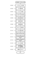
本発明の一実施形態であるパチンコ機1の全体構成について、図1乃至図3を参照して説明する。図1は、本発明の一実施形態であるパチンコ機の正面図である。図2は、パチンコ機の斜視図である。図3は、パチンコ機を扉枠、遊技盤、本体枠、及び外枠に分解して前から見た分解斜視図である。
[1. Overall structure of pachinko machine]
The overall configuration of the pachinko machine 1 according to the embodiment of the present invention will be described with reference to FIGS. 1 to 3. FIG. 1 is a front view of a pachinko machine according to an embodiment of the present invention. FIG. 2 is a perspective view of the pachinko machine. FIG. 3 is an exploded perspective view of the pachinko machine disassembled into a door frame, a game board, a main body frame, and an outer frame and viewed from the front.
本実施形態のパチンコ機1は、遊技ホールの島設備(図示しない)に設置される枠状の外枠2と、外枠2の前面を開閉可能に閉鎖する扉枠3と、扉枠3を開閉可能に支持していると共に外枠2に開閉可能に取付けられている本体枠4と、本体枠4に前側から着脱可能に取付けられると共に扉枠3を通して遊技者側から視認可能とされ遊技者によって遊技球Bが打込まれる遊技領域5aを有した遊技盤5と、を備えている。
The pachinko machine 1 of the present embodiment includes a frame-shaped outer frame 2 installed in an island facility (not shown) of a game hall, a door frame 3 for opening and closing the front surface of the outer frame 2, and a door frame 3. The main body frame 4 which is openable and closable and is attached to the outer frame 2 so as to be openable and closable, and the main body frame 4 which is detachably attached from the front side and is visible from the player side through the door frame 3. It is provided with a game board 5 having a game area 5a into which the game ball B is hit.
外枠2は、図3に示すように、正面視の形状が上下に延びた四角形の枠に形成されている。外枠2は、左右に離間しており上下に延びている外枠左部10及び外枠右部20と、外枠左部10及び外枠右部20の上端同士を連結している外枠上部30と、外枠左部10及び外枠右部20の下端同士を連結している外枠下部40と、外枠上部30の上面左端に取付けられている外枠上ヒンジ部50と、外枠左部10の右側面下部と外枠下部40の上面左端に取付けられている外枠下ヒンジ部60と、を備えている。
As shown in FIG. 3, the outer frame 2 is formed in a quadrangular frame having a front view extending vertically. The outer frame 2 is an outer frame that connects the left portion 10 and the right portion 20 of the outer frame, which are separated from each other to the left and right and extend vertically, and the upper ends of the left portion 10 and the right portion 20 of the outer frame. The upper portion 30, the outer frame lower portion 40 connecting the lower ends of the outer frame left portion 10 and the outer frame right portion 20, the outer frame upper hinge portion 50 attached to the upper left end of the outer frame upper portion 30, and the outer frame. It includes a lower right side surface of the left side portion 10 of the frame and a lower hinge portion 60 of the outer frame attached to the left end of the upper surface of the lower portion 40 of the outer frame.
外枠2は、パチンコ機1が設置される遊技ホールの島設備に取付けられ、外枠上ヒンジ部50と外枠下ヒンジ部60とによって、本体枠4の本体枠上ヒンジ部310と本体枠下ヒンジ部320とを同軸上で回転可能に支持して、本体枠4を正面視左側を中心にして前方へ開閉可能に取付けるためのものである。
The outer frame 2 is attached to the island equipment of the game hall where the pachinko machine 1 is installed, and the upper hinge portion 50 of the outer frame and the lower hinge portion 60 of the outer frame make up the hinge portion 310 on the main body frame and the main body frame of the main body frame 4. The purpose is to support the lower hinge portion 320 coaxially and rotatably, and to attach the main body frame 4 so as to be openable and closable forward with the left side of the front view as the center.
扉枠3は、遊技球Bが打込まれる遊技盤5の遊技領域5aを前側から視認可能に閉鎖する遊技窓201と、遊技領域5a内に打込むための遊技球Bを貯留する上皿130及び下皿140と、上皿130に貯留されている遊技球Bを遊技領域5a内へ打込むために遊技者が操作するハンドル111と、を備えているものである。また、扉枠3は、パチンコ機1の前面全体を装飾している。扉枠3は、本体枠4の本体枠上ヒンジ部310と本体枠下ヒンジ部320とにより、本体枠4の前面を開閉可能に取付けられる。
The door frame 3 has a game window 201 that visually closes the game area 5a of the game board 5 into which the game ball B is driven from the front side, and an upper plate 130 that stores the game ball B for driving into the game area 5a. The lower plate 140 and the handle 111 operated by the player to drive the game ball B stored in the upper plate 130 into the game area 5a are provided. Further, the door frame 3 decorates the entire front surface of the pachinko machine 1. The door frame 3 is attached so that the front surface of the main body frame 4 can be opened and closed by the hinge portion 310 on the main body frame and the hinge portion 320 below the main body frame of the main body frame 4.
本体枠4は、前方へ開放された箱状に形成されている。本体枠4は、遊技盤5を前方から脱着可能に保持する遊技盤取付部301と、正面視左側の上端に設けられている本体枠上ヒンジ部310と、左側の下端に設けられている本体枠下ヒンジ部320と、遊技盤取付部301の下方で右側に設けられており遊技盤5の遊技領域5a内に遊技球Bを打込むための球発射装置330と、上皿130や下皿140へ遊技球Bを払出すための払出装置350と、外枠2と本体枠4、及び扉枠3と本体枠4の間を施錠する施錠ユニット360と、を備えている。
The main body frame 4 is formed in a box shape that is open forward. The main body frame 4 has a game board mounting portion 301 that holds the game board 5 detachably from the front, a hinge portion 310 on the main body frame provided at the upper end on the left side when viewed from the front, and a main body provided at the lower end on the left side. A hinge portion 320 under the frame, a ball launching device 330 provided on the right side below the game board mounting portion 301 and for driving the game ball B into the game area 5a of the game board 5, and an upper plate 130 and a lower plate. It is provided with a payout device 350 for paying out the game ball B to 140, and a locking unit 360 for locking between the outer frame 2 and the main body frame 4, and between the door frame 3 and the main body frame 4.
本体枠4は、本体枠上ヒンジ部310及び本体枠下ヒンジ部320が、外枠上ヒンジ部50及び外枠下ヒンジ部60により外枠2に対して開閉可能に取付けられると共に、図示しない扉枠上ヒンジ部及び扉枠下ヒンジ部を介して扉枠3を本体枠4に対して開閉可能に取付けている。
In the main body frame 4, the main body frame upper hinge portion 310 and the main body frame lower hinge portion 320 are attached to the outer frame 2 by the outer frame upper hinge portion 50 and the outer frame lower hinge portion 60 so as to be openable and closable, and a door (not shown). The door frame 3 is attached to the main body frame 4 so as to be openable and closable via the hinge portion above the frame and the hinge portion below the door frame.
遊技盤5は、本体枠4の遊技盤取付部301に着脱可能に取付けられる。遊技盤5は、図示は省略するが、遊技球Bの受入れ又は通過により遊技者に対して所定の特典(例えば、所定数の遊技球Bの払出し)を付与する一般入賞口、第一始動口、ゲート部、第二始動口、及び大入賞口と、演出画像を表示可能な演出表示装置1600と、を備えている。
The game board 5 is detachably attached to the game board mounting portion 301 of the main body frame 4. Although not shown, the game board 5 is a general winning opening and a first starting opening that give a predetermined privilege (for example, payout of a predetermined number of game balls B) to a player by accepting or passing the game ball B. , A gate portion, a second starting port, a large winning opening, and an effect display device 1600 capable of displaying an effect image.
[2.外枠]
パチンコ機1の外枠について、主に図3等を参照して詳細に説明する。外枠2は、遊技ホール等のパチンコ機1が設置される島設備(図示は省略)に取付けられるものである。外枠2は、正面視の形状が上下に延びた四角形の枠に形成されている。
[2. Outer frame]
The outer frame of the pachinko machine 1 will be described in detail mainly with reference to FIG. 3 and the like. The outer frame 2 is attached to an island facility (not shown) in which a pachinko machine 1 such as a game hall is installed. The outer frame 2 is formed in a quadrangular frame having a front view extending vertically.
外枠2は、図示するように、左右に離間しており上下に延びている外枠左部10及び外枠右部20と、外枠左部10及び外枠右部20の上端同士を連結している外枠上部30と、外枠左部10及び外枠右部20の下端同士を連結している外枠下部40と、外枠上部30の上面左端に取付けられている外枠上ヒンジ部50と、外枠左部10の右側面下部と外枠下部40の上面左端に取付けられている外枠下ヒンジ部60と、を備えている。
As shown in the figure, the outer frame 2 connects the outer frame left portion 10 and the outer frame right portion 20 which are separated from each other to the left and right and extend vertically, and the upper ends of the outer frame left portion 10 and the outer frame right portion 20. The upper part 30 of the outer frame, the lower part 40 of the outer frame connecting the lower ends of the left part 10 and the right part 20 of the outer frame, and the hinge on the outer frame attached to the left end of the upper surface of the upper part 30 of the outer frame. A portion 50 and an outer frame lower hinge portion 60 attached to the lower right surface of the outer frame left portion 10 and the upper left end of the outer frame lower portion 40 are provided.
外枠2は、外枠上ヒンジ部50が、本体枠4の本体枠上ヒンジ部310を着脱可能に支持することができる。外枠2は、外枠上ヒンジ部50と外枠下ヒンジ部60とによって、本体枠4の本体枠上ヒンジ部310と本体枠下ヒンジ部320とを同軸上で回転可能に支持することができ、本体枠4を正面視左側を中心にして前方へ開閉可能に取付けることができる。
In the outer frame 2, the hinge portion 50 on the outer frame can detachably support the hinge portion 310 on the main body frame of the main body frame 4. The outer frame 2 may rotatably support the main body frame upper hinge portion 310 and the main body frame lower hinge portion 320 of the main body frame 4 by the outer frame upper hinge portion 50 and the outer frame lower hinge portion 60. The main body frame 4 can be attached so as to be openable and closable forward with the left side of the front view as the center.
[3.扉枠]
パチンコ機1における扉枠3について、主に図4乃至図9を参照して詳細に説明する。図4は、パチンコ機における扉枠の正面図である。図5は扉枠の左側面図であり、図6は扉枠の右側面図である。図7は扉枠を右前から見た斜視図であり、図8は扉枠を左前から見た斜視図である。図9は、扉枠を上下方向中央で切断して上から見た断面図である。
[3. Door frame]
The door frame 3 in the pachinko machine 1 will be described in detail mainly with reference to FIGS. 4 to 9. FIG. 4 is a front view of the door frame of the pachinko machine. FIG. 5 is a left side view of the door frame, and FIG. 6 is a right side view of the door frame. FIG. 7 is a perspective view of the door frame viewed from the front right, and FIG. 8 is a perspective view of the door frame viewed from the front left. FIG. 9 is a cross-sectional view of the door frame cut at the center in the vertical direction and viewed from above.
扉枠3は、外枠2の枠内と略同じ大きさで正面視において上下に延びた四角形に形成されており、本体枠4を介して外枠2の枠内を前側から開閉可能に取付けられている。扉枠3は、遊技球Bが打込まれる遊技盤5の遊技領域5aを前側から視認可能に閉鎖している遊技窓201と、遊技領域5a内に打込むための遊技球Bを貯留する上皿130と、上皿130内の遊技球Bを遊技領域5a内へ打込むために遊技者が操作するハンドル111と、を備えている。また、扉枠3は、パチンコ機1の前面全体を装飾するものである。
The door frame 3 has substantially the same size as the inside of the outer frame 2 and is formed in a quadrangle extending vertically in front view, and the inside of the outer frame 2 can be opened and closed from the front side via the main body frame 4. Has been done. The door frame 3 stores a game window 201 that closes the game area 5a of the game board 5 into which the game ball B is driven so as to be visible from the front side, and a game ball B for driving into the game area 5a. It includes a plate 130 and a handle 111 operated by a player to drive the game ball B in the upper plate 130 into the game area 5a. Further, the door frame 3 decorates the entire front surface of the pachinko machine 1.
扉枠3は、下端から全高の約1/4の高さまでの部位に設けられている扉枠下部ユニット100と、扉枠下部ユニット100の上側に設けられている扉枠上部ユニット200と、本体枠4の本体枠上ヒンジ部310及び本体枠下ヒンジ部320に回転可能、且つ、脱着可能に支持される扉枠上ヒンジ部及び扉枠下ヒンジ部(図示は省略)と、を備えている。
The door frame 3 includes a door frame lower unit 100 provided at a portion from the lower end to a height of about 1/4 of the total height, a door frame upper unit 200 provided above the door frame lower unit 100, and a main body. The frame 4 is provided with a door frame upper hinge portion 310 and a door frame lower hinge portion 320 that are rotatable and detachably supported by the main body frame upper hinge portion 310 and the main body frame lower hinge portion 320 (not shown). ..
扉枠3の扉枠下部ユニット100は、遊技領域5a内に遊技球Bを打込むために遊技者が操作可能なハンドル111と、前方へ膨出している膨出部120と、膨出部120の上面に設けられており遊技領域5a内に打込むための遊技球Bを貯留する上皿130と、上皿130の下方に設けられており遊技球Bを貯留するための下皿140と、膨出部の上面に設けられており遊技者に所定の演出を提示するための扉枠演出装置150と、膨出部120の上面に設けられており上皿130内の遊技球Bを下皿へ放出する上皿球抜ボタン124と、膨出部120の上面に設けられている球貸ボタン125及び返却ボタン126と、球貸ボタン125及び返却ボタン126の後方に設けられている扉枠サブ表示部185と、膨出部120の前面に設けられている下部前面スピーカ191と、を備えている。
The door frame lower unit 100 of the door frame 3 has a handle 111 that can be operated by the player to drive the game ball B into the game area 5a, a bulging portion 120 that bulges forward, and a bulging portion 120. An upper plate 130 provided on the upper surface of the above plate for storing the game ball B for driving into the game area 5a, and a lower plate 140 provided below the upper plate 130 for storing the game ball B. The door frame effecting device 150 provided on the upper surface of the bulging portion to present a predetermined effect to the player, and the game ball B in the upper plate 130 provided on the upper surface of the bulging portion 120 are used as the lower plate. The upper plate ball pulling button 124, the ball lending button 125 and the return button 126 provided on the upper surface of the bulging portion 120, and the door frame sub provided behind the ball lending button 125 and the return button 126. It includes a display unit 185 and a lower front speaker 191 provided on the front surface of the bulging unit 120.
扉枠3の扉枠上部ユニット200は、遊技盤5の遊技領域5a内を前方から視認可能としている内周が逆U字形の遊技窓201と、遊技窓201を閉鎖している透明な閉鎖ガラス205と、遊技窓201の内周に沿って設けられている扉枠上部内装飾ユニット210と、扉枠上部内装飾ユニット210の外側に設けられている扉枠上部外装飾ユニット220と、扉枠上部内装飾ユニット210、及び扉枠上部外装飾ユニット220を覆っている扉枠上部外縁装飾ユニット230と、扉枠上部外縁装飾ユニット230の上部前面に設けられている上部スピーカユニット240と、を備えている。
The door frame upper unit 200 of the door frame 3 has a game window 201 having an inverted U-shaped inner circumference that makes the inside of the game area 5a of the game board 5 visible from the front, and a transparent closed glass that closes the game window 201. 205, a door frame upper inner decoration unit 210 provided along the inner circumference of the game window 201, a door frame upper outer decoration unit 220 provided outside the door frame upper inner decoration unit 210, and a door frame. The door frame upper outer edge decoration unit 230 covering the upper inner decoration unit 210 and the door frame upper outer edge decoration unit 220, and the upper speaker unit 240 provided on the upper front surface of the door frame upper outer edge decoration unit 230 are provided. ing.
また、扉枠3は、上皿130に貯留されている遊技球Bを一つずつ本体枠4の球発射装置330へ送るための球送給ユニット(図示は省略)を備えている。球送給ユニットは、払出制御基板370の発射制御部372により制御される球送給ソレノイド105(図17を参照)を備えている。
Further, the door frame 3 includes a ball feeding unit (not shown) for sending the game balls B stored in the upper plate 130 one by one to the ball launching device 330 of the main body frame 4. The ball feeding unit includes a ball feeding solenoid 105 (see FIG. 17) controlled by a launch control unit 372 of the payout control board 370.
[3-1.扉枠下部ユニット]
次に、扉枠3の扉枠下部ユニット100について、主に図4乃至図12等を参照して詳細に説明する。図10は、扉枠下部ユニットを左右方向中央で切断して右から見た断面図である。図11(a)は扉枠演出装置の第一可動部を上昇端へ移動させた状態を示す斜視図であり、(b)は(a)の状態から演出操作部を上昇端へ移動させた状態を示す斜視図である。図12(a)は下部前面スピーカユニット付近の拡大正面図であり、(b)は(a)において下部前面スピーカグリル、グリル装飾枠、及び格子装飾部を取外した状態で示す拡大正面図である。
[3-1. Door frame lower unit]
Next, the door frame lower unit 100 of the door frame 3 will be described in detail with reference mainly to FIGS. 4 to 12 and the like. FIG. 10 is a cross-sectional view of the door frame lower unit cut at the center in the left-right direction and viewed from the right. FIG. 11 (a) is a perspective view showing a state in which the first movable portion of the door frame effect device is moved to the ascending end, and FIG. 11 (b) is a perspective view showing a state in which the effect operating unit is moved from the state of (a) to the ascending end. It is a perspective view which shows the state. 12 (a) is an enlarged front view of the vicinity of the lower front speaker unit, and FIG. 12 (b) is an enlarged front view showing the lower front speaker grill, the grill decorative frame, and the lattice decorative portion in (a). ..
扉枠3の扉枠下部ユニット100は、本体枠4に保持された遊技盤5の遊技領域5aを前方から視認可能に閉鎖している遊技窓201によりも下方に配置されている。扉枠下部ユニット100は、正面視において右下隅に設けられており遊技領域5a内に遊技球Bを打込むために遊技者が操作可能なハンドルユニット110と、ハンドルユニット110の上方及び左方において本体枠4の前面を閉鎖する面に対して前方へ膨出している膨出部120と、を備えている。
The door frame lower unit 100 of the door frame 3 is arranged below by the game window 201 which closes the game area 5a of the game board 5 held by the main body frame 4 so as to be visible from the front. The door frame lower unit 100 is provided in the lower right corner in the front view, and is a handle unit 110 that can be operated by the player to drive the game ball B into the game area 5a, and above and to the left of the handle unit 110. It is provided with a bulging portion 120 that bulges forward with respect to a surface that closes the front surface of the main body frame 4.
また、扉枠下部ユニット100は、膨出部120の上面で装置配置部123を囲むように設けられており遊技球Bを貯留するための上皿130と、上皿130の下方で左右方向中央より左側に設けられており遊技球Bを貯留するための下皿140と、膨出部120の上面における装置配置部123に設けられており遊技者に所定の演出を提示可能な扉枠演出装置150と、正面視において右上隅設けられている扉枠サブ表示部185と、膨出部120の前面に設けられている下部前面スピーカユニット190と、を備えている。
Further, the door frame lower unit 100 is provided so as to surround the device arrangement portion 123 on the upper surface of the bulging portion 120, and has an upper plate 130 for storing the game ball B and a center in the left-right direction below the upper plate 130. A door frame effect device provided on the left side of the lower plate 140 for storing the game ball B and a device arrangement unit 123 on the upper surface of the bulge portion 120 and capable of presenting a predetermined effect to the player. It includes a door frame sub-display unit 185 provided in the upper right corner in front view, and a lower front speaker unit 190 provided in front of the bulging portion 120.
[3-1a.ハンドルユニット]
扉枠下部ユニット100のハンドルユニット110は、遊技者が掴んで回転操作することのできるハンドル111と、ハンドル111の前側に設けられているハンドルカバー112と、ハンドル111を回動可能に支持しているハンドルベース113と、を備えている。また、ハンドルユニット110は、ハンドルベース113内に設けられており、ハンドル111の回動角度を検知するハンドル回転検知センサ114(図17を参照)と、遊技者がハンドル111に触れていることを検知するハンドルタッチセンサ115と、ハンドル111を反時計回りの方向へ付勢しているハンドル復帰バネ(図示は省略)と、遊技者が押圧可能な単発ボタン116と、を備えている。
[3-1a. Handle unit]
The handle unit 110 of the door frame lower unit 100 rotatably supports the handle 111 that the player can grasp and rotate, the handle cover 112 provided on the front side of the handle 111, and the handle 111. It is equipped with a handle base 113 and. Further, the handle unit 110 is provided in the handle base 113, and the handle rotation detection sensor 114 (see FIG. 17) that detects the rotation angle of the handle 111 and the player touching the handle 111. It includes a handle touch sensor 115 for detecting, a handle return spring (not shown) that urges the handle 111 in a counterclockwise direction, and a single-shot button 116 that can be pressed by a player.
ハンドルユニット110は、ハンドル111の回転軸が、前方へ向かうに従って右方へ移動するように傾斜している。これにより、遊技者がハンドルユニット110のハンドル111が握り易く、違和感がなく回動操作を行わせることができる。また、ハンドルユニット110は、ハンドルベース113が、ハンドル111の回転軸の延びている方向へ伸縮可能に構成されていると共に、所望の伸縮位置で保持することができる。これにより、ハンドル111の前後方向の位置を調整することができるため、遊技者の操作し易い位置でハンドル111を操作することができる。
The handle unit 110 is inclined so that the rotation axis of the handle 111 moves to the right as it moves forward. As a result, the player can easily grip the handle 111 of the handle unit 110 and perform the rotation operation without any discomfort. Further, the handle unit 110 is configured such that the handle base 113 can be expanded and contracted in the direction in which the rotation axis of the handle 111 extends, and can be held at a desired expansion and contraction position. As a result, the position of the handle 111 in the front-rear direction can be adjusted, so that the handle 111 can be operated at a position that is easy for the player to operate.
ハンドル111は、所定角度範囲内でのみ回動可能にハンドルベース113に支持されている。ハンドル111は、周方向へ離隔し外周面から突出している複数(ここでは四つ)の突起を有している。ハンドルカバー112は、透光性を有しており、後方に配置されている複数のフルカラーLEDにより、様々な色で発光装飾することができる。
The handle 111 is rotatably supported by the handle base 113 only within a predetermined angle range. The handle 111 has a plurality of (here, four) protrusions that are separated in the circumferential direction and protrude from the outer peripheral surface. The handle cover 112 is translucent and can be luminescently decorated in various colors by a plurality of full-color LEDs arranged at the rear.
ハンドルユニット110のハンドル回転検知センサ114は、ハンドル111の回転角度に応じて内部抵抗が変化する可変抵抗器とされている。ハンドル111の回転操作により変化するハンドル回転検知センサ114の内部抵抗に応じて、後述する球発射装置330における発射ソレノイド331の駆動力が変化し、ハンドル111の回転角度に応じた強さで遊技球Bを遊技領域5a内へ打込むことができる。
The handle rotation detection sensor 114 of the handle unit 110 is a variable resistor whose internal resistance changes according to the rotation angle of the handle 111. The driving force of the firing solenoid 331 in the ball launching device 330, which will be described later, changes according to the internal resistance of the handle rotation detection sensor 114 that changes due to the rotation operation of the handle 111, and the game ball has a strength corresponding to the rotation angle of the handle 111. B can be driven into the game area 5a.
ハンドルユニット110のハンドルタッチセンサは、ハンドル111等の静電気容量を検知するものである。遊技者がハンドル111等に接触すると、ハンドル111等の静電気容量が変化することから、ハンドルタッチセンサによりハンドル111等の静電気容量を検知することで、遊技者がハンドル111に触れているか否かを検知する。本実施形態では、ハンドルタッチセンサ115が遊技者の接触を検出している時に、ハンドル111を回動させると、ハンドル回転検知センサ114の検知が受付けられ、ハンドル111の回転角度に応じた強さで発射ソレノイド331の駆動が制御されて、遊技球Bを打込むことができる。
The handle touch sensor of the handle unit 110 detects the electrostatic capacity of the handle 111 and the like. When the player touches the handle 111 or the like, the electrostatic capacity of the handle 111 or the like changes. Therefore, by detecting the electrostatic capacity of the handle 111 or the like with the handle touch sensor, whether or not the player is touching the handle 111 or not is determined. Detect. In the present embodiment, when the handle 111 is rotated while the handle touch sensor 115 is detecting the contact of the player, the detection of the handle rotation detection sensor 114 is received, and the strength according to the rotation angle of the handle 111 is received. The drive of the firing solenoid 331 is controlled by, and the game ball B can be driven.
つまり、遊技者がハンドル111に触れずに、何らかの方法でハンドル111を回転させて遊技球Bを遊技領域5a内に打込もうとしても、ハンドルタッチセンサ115が遊技者の接触を検知していないことから、発射ソレノイド331は駆動されず、遊技球Bを打込むことができないようになっている。これにより、遊技者が本来とは異なる方法でハンドル111を回転させて遊技が行われるのを防止することができ、パチンコ機1を設置する遊技ホールに係る負荷(負担)を軽減させることができる。
That is, even if the player tries to drive the game ball B into the game area 5a by rotating the handle 111 in some way without touching the handle 111, the handle touch sensor 115 does not detect the player's contact. Therefore, the firing solenoid 331 is not driven, and the game ball B cannot be driven. As a result, it is possible to prevent the player from rotating the handle 111 in a manner different from the original method to play the game, and it is possible to reduce the load (burden) on the game hall in which the pachinko machine 1 is installed. ..
ハンドルユニット110の単発ボタン116は、遊技者がハンドル111を回転操作中に、を押圧すると、払出制御基板370の発射制御部372によって発射ソレノイド331の駆動が停止させられる。これにより、ハンドル111の回転操作を戻さなくても、遊技球Bの発射を一時的に停止させることができる。そして、単発ボタン116の押圧操作を解除することで、単発ボタン116を操作する前の打込み強さで再び遊技球Bを遊技領域5a内に打込むことができる。
When the player presses the single-shot button 116 of the handle unit 110 while the player is rotating the handle 111, the launch control unit 372 of the payout control board 370 stops the drive of the launch solenoid 331. As a result, the firing of the game ball B can be temporarily stopped without returning the rotation operation of the handle 111. Then, by releasing the pressing operation of the single-shot button 116, the game ball B can be driven into the game area 5a again with the driving strength before the single-shot button 116 is operated.
[3-1b.膨出部]
扉枠3の膨出部120は、正面視の形状が、上下に延びている軸の短いT字状に形成されていると共に、平面視の形状が、後端側が扉枠3の左右方向の全幅の長さで前方へ向かうに従って幅が狭くなるような等脚台形状に形成されている(図9等を参照)。膨出部120は、左右方向の全幅の半分の長さよりも若干長く前方へ膨出している。膨出部120の上面は、水平面に対して、前方へ向かうに従って下方へ位置するように、僅かに傾斜している。
[3-1b. Swelling part]
The bulging portion 120 of the door frame 3 has a front view shape formed in a T-shape having a short axis extending vertically, and a plan view shape in which the rear end side is in the left-right direction of the door frame 3. It is formed in an isosceles trapezoidal shape with the entire width and the width narrowing toward the front (see FIG. 9 and the like). The bulging portion 120 bulges forward slightly longer than half the total width in the left-right direction. The upper surface of the bulging portion 120 is slightly inclined so as to be located downward with respect to the horizontal plane toward the front.
膨出部120は、左右方向において、扉枠3の全幅を三等分した中央部が、扉枠3の下端から上面までの全高に亘って前方へ膨出しており、残りの部位(左右両側の部位)が、扉枠3の下端から上面までの全高に対して上から約1/3の部位までが前方へ膨出している。これにより、膨出部120の正面視の形状が、T字状となっている。膨出部120は、前面中央の下部に四角く開口しているスピーカ取付口120aを有している。このスピーカ取付口120aに下部前面スピーカユニット190が取付けられる。
In the left-right direction, the bulging portion 120 has a central portion that divides the entire width of the door frame 3 into three equal parts and bulges forward over the entire height from the lower end to the upper surface of the door frame 3, and the remaining portions (both left and right sides). The part) bulges forward from the top to about 1/3 of the total height from the lower end to the upper surface of the door frame 3. As a result, the shape of the bulging portion 120 when viewed from the front is T-shaped. The bulging portion 120 has a speaker mounting port 120a having a square opening at the lower part in the center of the front surface. The lower front speaker unit 190 is attached to the speaker attachment port 120a.
また、膨出部120は、正面視T字状における上下に延びている部位(スピーカ取付口120aが開口している部位)の左右両側面に、上下に延びている放音スリット120bと放熱スリット120cとが設けられている。放音スリット120bは、後述する下部前面スピーカ191からの音を外部へ放出させるためのものである。また、放熱スリット120cは、後述する扉枠演出装置150内の第一昇降駆動モータ175bや第二昇降駆動モータ182、下部前面スピーカ191等からの熱を外部へ放出させるためのものである。
Further, the bulging portion 120 has a sound emitting slit 120b and a heat radiating slit extending vertically on both the left and right sides of the vertically extending portion (the portion where the speaker mounting port 120a is opened) in the front view T-shape. 120c is provided. The sound emitting slit 120b is for emitting the sound from the lower front speaker 191, which will be described later, to the outside. Further, the heat dissipation slit 120c is for releasing heat from the first elevating drive motor 175b, the second elevating drive motor 182, the lower front speaker 191 and the like in the door frame effecting device 150, which will be described later, to the outside.
膨出部120は、前面における上端縁に設けられている膨出部上装飾部121と、前面における下端縁に設けられている膨出部下装飾部122と、上面において左右方向中央部で後端側から前方へ突出するように設けられている装置配置部123と、上面に設けられており上皿130内の遊技球Bを下皿140へ放出する上皿球抜ボタン124と、上皿球抜ボタン124の後方に設けられている球貸ボタン125及び返却ボタン126と、を備えている。
The bulging portion 120 includes a bulging portion upper decorative portion 121 provided on the upper end edge on the front surface, a bulging portion lower decorative portion 122 provided on the lower end edge on the front surface, and a rear end at the center portion in the left-right direction on the upper surface. A device arrangement unit 123 provided so as to project from the side to the front, an upper plate ball pulling button 124 provided on the upper surface and discharging the game ball B in the upper plate 130 to the lower plate 140, and an upper plate ball. It includes a ball lending button 125 and a return button 126 provided behind the pull-out button 124.
膨出部上装飾部121及び膨出部下装飾部122は、透光性を有した乳白色で、半円柱状に形成されている。膨出部上装飾部121は、膨出部120の前面における上端縁に沿って延びており、述する上皿130の前側の上縁を装飾するように設けられている。膨出部上装飾部121は、内部に複数のLED121aを有している(図15を参照)。複数のLED121aは、膨出部上装飾部121の延びている方向へ一列に並べられている。これら複数のLED121aは、フルカラーLEDである。
The bulging portion upper decorative portion 121 and the bulging portion lower decorative portion 122 are milky white having translucency and are formed in a semi-cylindrical shape. The bulging portion upper decorative portion 121 extends along the upper end edge of the front surface of the bulging portion 120, and is provided so as to decorate the upper edge on the front side of the above-mentioned upper plate 130. The bulging portion upper decorative portion 121 has a plurality of LEDs 121a inside (see FIG. 15). The plurality of LEDs 121a are arranged in a row in the extending direction of the decorative portion 121 on the bulging portion. These plurality of LEDs 121a are full-color LEDs.
膨出部上装飾部121は、左右方向へ離隔している二つの後端同士の間隔が、後述する扉枠上部ユニット200の扉枠上部内装飾ユニット210における左右方向へ離隔している上部内装飾部212の下端同士の間隔と一致している。この膨出部上装飾部121は、扉枠3に組立てた状態で、上部内装飾部212と一致するように形成されており、上部内装飾部212とで一つの連続した装飾を形成している。この膨出部上装飾部121は、上部内装飾部212とで、遊技窓201の周りを発光装飾する第一周光領域LA1を構成している。
In the bulging portion upper decorative portion 121, the distance between the two rear ends separated in the left-right direction is in the upper portion of the door frame upper inner decorative unit 210 of the door frame upper unit 200 described later, which is separated in the left-right direction. It coincides with the distance between the lower ends of the decorative portion 212. The bulging portion upper decorative portion 121 is formed so as to coincide with the upper inner decorative portion 212 in a state of being assembled to the door frame 3, and forms one continuous decoration with the upper inner decorative portion 212. There is. The bulging portion upper decorative portion 121 together with the upper inner decorative portion 212 constitutes a first peripheral light region LA1 that emits light and decorates the periphery of the game window 201.
また、膨出部上装飾部121は、上皿130の前周壁134の上端よりも上側を装飾していると共に、上皿130の前側の壁(前周壁134)を嵩上げしている。この膨出部上装飾部121は、LED121aからの光の一部が、上皿130内(貯留領域131内)へ照射されるように構成されており、貯留領域131内に貯留されている遊技球Bに光を照射して発光装飾させることができる。
Further, the bulging portion upper decorative portion 121 decorates the upper side of the upper plate 130 with respect to the upper end of the front peripheral wall 134, and raises the front wall (front peripheral wall 134) of the upper plate 130. The bulging portion upper decorative portion 121 is configured so that a part of the light from the LED 121a is irradiated into the upper plate 130 (inside the storage region 131), and the game is stored in the storage region 131. The sphere B can be illuminated with light to decorate it with light emission.
膨出部下装飾部122は、膨出部120の前面における下端縁に沿うように延びている。膨出部下装飾部122は、内部に複数のLED122aを有している(図15を参照)。複数のLED122aは、膨出部下装飾部122の延びている方向へ一列に並べられている。これら複数のLED122aは、フルカラーLEDである。
The bulging lower decorative portion 122 extends along the lower edge of the front surface of the bulging portion 120. The bulging lower decorative portion 122 has a plurality of LEDs 122a inside (see FIG. 15). The plurality of LEDs 122a are arranged in a row in the extending direction of the bulging portion lower decorative portion 122. These plurality of LEDs 122a are full-color LEDs.
装置配置部123は、平面視の形状が、左右に長い長方形と、その長方形の前辺を底辺とした等脚台形とを組み合わせたような形状に形成されている。装置配置部123は、後端側の左右方向の幅が、扉枠3の全幅の約1/2の長さである。装置配置部123は、膨出部120の上面において上方が開放されており、上方から膨出部120の内部へ延びた容器状に形成されている。
The device arrangement unit 123 is formed so that the shape in a plan view is a combination of a rectangle long to the left and right and an isosceles trapezoid having the front side of the rectangle as the base. The width of the device arrangement unit 123 in the left-right direction on the rear end side is about ½ of the total width of the door frame 3. The device arranging portion 123 has an open upper portion on the upper surface of the bulging portion 120, and is formed in a container shape extending from above to the inside of the bulging portion 120.
上皿球抜ボタン124は、上皿130よりも右側で膨出部120の上面の右隅に設けられている。上皿球抜ボタン124は、下方へ押圧することにより、上皿130に貯留されている遊技球Bを、送出口136から下皿140へ放出することができる。この上皿球抜ボタン124は、押圧している間だけ、上皿130内の遊技球Bを下皿140へ放出させ、押圧を解除すると、上方へ移動して元の状態に復帰すると共に、下皿140への放出を停止する。
The upper plate ball removal button 124 is provided in the right corner of the upper surface of the bulging portion 120 on the right side of the upper plate 130. By pressing the upper plate ball removal button 124 downward, the game ball B stored in the upper plate 130 can be discharged from the delivery port 136 to the lower plate 140. The upper plate ball removal button 124 releases the game ball B in the upper plate 130 to the lower plate 140 only while it is being pressed, and when the pressing is released, the upper plate ball removal button 124 moves upward and returns to the original state. Stop the release to the lower plate 140.
上皿球抜ボタン124は、外形が正方形に形成されている。上皿球抜ボタン124は、下方に配置されたLEDにより発光する発光装飾部124aを有している。発光装飾部124aは、上皿球抜ボタン124の外周を囲むように配置されている。発光装飾部124aを発光させることで、上皿球抜ボタン124を発光装飾させることができる。
The upper plate ball removal button 124 has a square outer shape. The upper plate ball removal button 124 has a light emitting decorative portion 124a that emits light by an LED arranged below. The light emitting decoration portion 124a is arranged so as to surround the outer periphery of the upper plate ball removal button 124. By making the light emitting decoration unit 124a emit light, the upper plate ball removal button 124 can be made to emit light.
球貸ボタン125は、膨出部120の上面における上皿球抜ボタン124の後方に配置されている。球貸ボタン125は、外形が円形に形成されている。返却ボタン126は、膨出部120の上面における球貸ボタン125の右方に配置されている。返却ボタン126は、外形が正三角形に形成されている。
The ball lending button 125 is arranged behind the upper plate ball pulling button 124 on the upper surface of the bulging portion 120. The ball lending button 125 has a circular outer shape. The return button 126 is arranged to the right of the ball lending button 125 on the upper surface of the bulge 120. The return button 126 is formed in an equilateral triangle in outer shape.
球貸ボタン125は、パチンコ機1に隣接して設けられた球貸機(図示は省略)に対して現金やプリペイドカードを投入した上で、押すことにより、所定数の遊技球Bを、上皿130内へ供給して、遊技球Bを遊技者に貸出すものである。返却ボタン126は、押すことにより、球貸機に投入された現金やプリペイドカードを貸出された遊技球Bの分を差し引いて返却するものである。なお、球貸機に投入された現金やプリペイドカードの残量は、扉枠サブ表示部185に表示される。
The ball lending button 125 raises a predetermined number of game balls B by inserting cash or a prepaid card into a ball lending machine (not shown) provided adjacent to the pachinko machine 1 and then pressing the ball lending button 125. The game ball B is lent to the player by supplying it into the plate 130. When the return button 126 is pressed, the cash or prepaid card inserted in the ball lending machine is returned after deducting the amount of the rented game ball B. The remaining amount of cash or prepaid card inserted into the ball lending machine is displayed on the door frame sub-display unit 185.
[3-1c.上皿]
扉枠3の上皿130は、膨出部120の上面において下方へ窪んでおり、遊技球Bが貯留される貯留領域131を有している。貯留領域131は、装置配置部123の前方側のフロント領域131a(図14において一点鎖線で囲まれている部位)と、フロント領域131aにより互いに繋がれ装置配置部123の左右両外側のサイド領域131b(図14において二点鎖線で囲まれている部位)と、から構成されている。
[3-1c. Upper plate]
The upper plate 130 of the door frame 3 is recessed downward on the upper surface of the bulging portion 120, and has a storage area 131 in which the game ball B is stored. The storage area 131 is connected to each other by the front area 131a (the portion surrounded by the alternate long and short dash line in FIG. 14) on the front side of the device arrangement unit 123, and the side areas 131b on both the left and right sides of the device arrangement unit 123. It is composed of (a portion surrounded by a two-dot chain line in FIG. 14).
フロント領域131aは、前後方向の幅が略一定で、左右方向へ延びている。左側のサイド領域131bは、後端側から前方のフロント領域131a側へ向かうに従って左右方向の幅が狭くなるように前後方向へ延びている。右側のサイド領域131bは、前端側のフロント領域131a側から途中まで後方へ向かうに従って左右方向の幅が広くなるように延びた後に、後端側へ向かって幅が狭くなるように、前後方向へ延びている。上皿130(貯留領域131)は、装置配置部123の前方側と左右両外側とを囲むように形成されている。
The front region 131a has a substantially constant width in the front-rear direction and extends in the left-right direction. The left side region 131b extends in the front-rear direction so that the width in the left-right direction becomes narrower from the rear end side toward the front front region 131a. The right side region 131b extends in the left-right direction from the front region 131a side on the front end side halfway toward the rear, and then extends in the front-rear direction so as to narrow toward the rear end side. It is extended. The upper plate 130 (storage area 131) is formed so as to surround the front side and the left and right outer sides of the device arrangement portion 123.
上皿130は、底面を形成している底壁132と、底壁132の後端から上方へ立上っている後周壁133と、底壁132の前端から上方へ立上っている前周壁134と、左側のサイド領域131bの後端において前方へ向かって開口している供給口135と、右側のサイド領域131bの後端において前方へ向かって開口している送出口136と、送出口136の近傍に設けられており送出口136へ向かって遊技球Bを整列させる整列部137と、を備えている。
The upper plate 130 has a bottom wall 132 forming a bottom surface, a rear peripheral wall 133 rising upward from the rear end of the bottom wall 132, and a front peripheral wall rising upward from the front end of the bottom wall 132. 134, a supply port 135 that opens forward at the rear end of the left side region 131b, an outlet 136 that opens forward at the rear end of the right side region 131b, and an outlet 136. It is provided in the vicinity of the above and includes an alignment portion 137 for aligning the game balls B toward the delivery port 136.
上皿130の底壁132は、供給口135側から送出口136へ向かって低くなるように傾斜している。前周壁134及び後周壁133は、略垂直に立上っている。底壁132、後周壁133、及び前周壁134の表面は、鏡面状に形成されている。上皿130は、底壁132、後周壁133、及び前周壁134によって貯留領域131を形成している。上皿130の深さ(底壁132から後周壁133及び前周壁134の上端までの高さ)は、最も浅い部位(供給口135付近)でも、遊技球Bの直径より深く形成されている。
The bottom wall 132 of the upper plate 130 is inclined so as to be lowered from the supply port 135 side toward the delivery port 136. The front peripheral wall 134 and the rear peripheral wall 133 stand up substantially vertically. The surfaces of the bottom wall 132, the rear peripheral wall 133, and the front peripheral wall 134 are formed in a mirror shape. The upper plate 130 forms a storage area 131 by the bottom wall 132, the rear peripheral wall 133, and the front peripheral wall 134. The depth of the upper plate 130 (height from the bottom wall 132 to the upper ends of the rear peripheral wall 133 and the front peripheral wall 134) is formed deeper than the diameter of the game ball B even at the shallowest portion (near the supply port 135).
供給口135は、本体枠4の払出装置350から払出された遊技球Bを、貯留領域131内へ供給するためのものである。送出口136は、貯留領域131内に貯留された遊技球Bを貯留領域131から球発射装置330や下皿140へ送出するためのものである。整列部137は、平面視において長方形と等脚台形とを組み合わせた装置配置部123における長方形と等脚台形との境界付近で、底壁132が送出口136へ向かって低くなるように下方へ折れ曲がっている。
The supply port 135 is for supplying the game ball B paid out from the payout device 350 of the main body frame 4 into the storage area 131. The delivery port 136 is for sending the game ball B stored in the storage area 131 from the storage area 131 to the ball launcher 330 or the lower plate 140. The alignment portion 137 is bent downward so that the bottom wall 132 is lowered toward the delivery port 136 near the boundary between the rectangle and the isosceles trapezoid in the device arrangement portion 123 in which the rectangle and the isosceles trapezoid are combined in a plan view. ing.
また、上皿130は、貯留領域131内へ向かって光を照射可能な複数のLED138aを有した貯留発光装飾部138を、備えている。貯留発光装飾部138の複数のLED138aは、後周壁133に設けられており、底壁132から遊技球Bの外径の半分よりも上方で、後周壁133の上端と略平行となる高さに設けられている。これらLED138aは、フルカラーLEDである。貯留発光装飾部138のLED138aを発光させることで、貯留領域131内や、貯留領域131内に貯留されている遊技球Bを発光装飾させることができる。
Further, the upper plate 130 includes a storage light emitting decoration unit 138 having a plurality of LEDs 138a capable of irradiating light toward the inside of the storage area 131. The plurality of LEDs 138a of the storage light emitting decoration portion 138 are provided on the rear peripheral wall 133, and are above the bottom wall 132 to a height higher than half of the outer diameter of the game ball B and substantially parallel to the upper end of the rear peripheral wall 133. It is provided. These LEDs 138a are full-color LEDs. By emitting light from the LED 138a of the storage light emitting decoration unit 138, the game ball B stored in the storage area 131 or in the storage area 131 can be light-emitting and decorated.
上皿130は、前周壁134の上端に膨出部120の膨出部上装飾部121が設けられており、膨出部上装飾部121により貯留領域131の前端側が嵩上げされて、より多くの遊技球Bを貯留させることができる。また、上皿130は、膨出部上装飾部121のLED121aからの光の一部が、貯留領域131内へ照射されるようになっており、膨出部上装飾部121からの光によっても貯留領域131内の遊技球Bが発光装飾される。
The upper plate 130 is provided with the bulging portion upper decorative portion 121 of the bulging portion 120 at the upper end of the front peripheral wall 134, and the bulging portion upper decorative portion 121 raises the front end side of the storage area 131 to increase the number. The game ball B can be stored. Further, in the upper plate 130, a part of the light from the LED 121a of the bulging portion upper decorative portion 121 is irradiated into the storage area 131, and the light from the bulging portion upper decorative portion 121 also causes the upper plate 130. The game ball B in the storage area 131 is light-emittingly decorated.
上皿130は、扉枠演出装置150が配置される装置配置部123の前方側のフロント領域131aと、左右両外側のサイド領域131bとを有しており、フロント領域131aにより扉枠演出装置150よりも前方側に遊技球Bを貯留させることができるため、上皿130内に貯留されている遊技球Bを遊技者から見え易くすることができる。また、上皿130において、フロント領域131aにより繋がれる二つのサイド領域131bは、前後に延びたような領域となるため、フロント領域131aに加えて、サイド領域131bに貯留されている遊技球Bも、遊技者側から視認し易くすることができる。
The upper plate 130 has a front area 131a on the front side of the device arrangement unit 123 in which the door frame effect device 150 is arranged, and side areas 131b on both the left and right outer sides. The front area 131a provides the door frame effect device 150. Since the game ball B can be stored on the front side of the plate 130, the game ball B stored in the upper plate 130 can be easily seen by the player. Further, in the upper plate 130, since the two side regions 131b connected by the front region 131a are regions that extend back and forth, in addition to the front region 131a, the game ball B stored in the side region 131b is also included. , It can be easily seen from the player side.
従って、上皿130内の遊技球Bが見え易くなることで、遊技者に対して遊技球Bの貯留量に対する意識を喚起させることができることから、遊技の進行により上皿130内の遊技球Bを消費して貯留量が少なくなっても、遊技者に対して貯留量の低下を認識させ易くして、上皿130内へ遊技球Bを補充させることができるため、遊技者が気付かないうちに遊技球Bが上皿130から無くなることを回避させて、突然の遊技の中断を阻止することができ、遊技の中断による遊技者の落胆を防止して、遊技者の遊技に対する興趣の低下を抑制させることができる。
Therefore, since the game ball B in the upper plate 130 can be easily seen, the player can be made aware of the stored amount of the game ball B. Therefore, as the game progresses, the game ball B in the upper plate 130 can be easily seen. Even if the storage amount is reduced by consuming, the player can be made to easily recognize the decrease in the storage amount, and the game ball B can be replenished in the upper plate 130, so that the player does not notice. It is possible to prevent the game ball B from disappearing from the upper plate 130 and prevent a sudden interruption of the game, prevent the player's disappointment due to the interruption of the game, and reduce the interest of the player in the game. It can be suppressed.
また、上皿130では、フロント領域131a内や二つのサイド領域131b内の遊技球Bを遊技者側から見え易くすることができるため、遊技者が視線を、遊技領域5aから下方の扉枠演出装置150へ落とすだけで、フロント領域131a内に遊技球Bが有るか無いかを即座に認識させることができ、上皿130内における遊技球Bの有無を、遊技者が注意深く確認する必要はなく、遊技者を遊技に専念させ易くすることが可能となり、遊技を楽しませて興趣の低下を抑制させることができる。
Further, in the upper plate 130, the game ball B in the front area 131a and the two side areas 131b can be easily seen from the player side, so that the player can easily see the line of sight from the game area 5a to the lower door frame. By simply dropping it on the device 150, it is possible to immediately recognize whether or not the game ball B is present in the front area 131a, and it is not necessary for the player to carefully check the presence or absence of the game ball B in the upper plate 130. , It becomes possible to make it easier for the player to concentrate on the game, and it is possible to entertain the game and suppress the deterioration of the interest.
更に、上皿130では、供給口135から貯留領域131内へ供給された遊技球Bが、フロント領域131aを通って送出口136から貯留領域131外へ送出されるため、遊技を行うことで上皿130内の遊技球Bを消費すると、遊技球Bが目の前(フロント領域131a)を流れることとなり、遊技者に対して遊技球Bの消費速度や消費量等を認識させ易くすることができ、上述した作用効果を奏し易いものとすることができる。
Further, in the upper plate 130, the game ball B supplied from the supply port 135 into the storage area 131 is sent out from the delivery port 136 through the front area 131a to the outside of the storage area 131. When the game ball B in the plate 130 is consumed, the game ball B flows in front of the eyes (front area 131a), which makes it easier for the player to recognize the consumption speed, consumption amount, etc. of the game ball B. It can be made easy to exert the above-mentioned action and effect.
また、上皿130では、貯留領域131内へ光を照射する貯留発光装飾部138を設けており、貯留発光装飾部138(LED138a)からの光が遊技球Bにより上方へ反射されるため、貯留発光装飾部138からの光により上皿130に貯留されている遊技球Bをキラキラと輝かせて発光装飾させることができ、遊技者に対して遊技球Bの発光装飾を楽しませることができると共に、遊技者の関心を上皿130に貯留されている遊技球Bに強く引付けさせることができ、上皿130における遊技球Bの貯留量を確認させて上記と同様の作用効果を奏することができる。
Further, the upper plate 130 is provided with a storage light emitting decoration unit 138 that irradiates light into the storage area 131, and the light from the storage light emitting decoration unit 138 (LED 138a) is reflected upward by the game ball B, so that the storage is stored. The game ball B stored in the upper plate 130 can be shined and decorated by the light from the light emitting decoration unit 138, and the player can enjoy the light emitting decoration of the game ball B. , The player's interest can be strongly attracted to the game ball B stored in the upper plate 130, and the amount of the game ball B stored in the upper plate 130 can be confirmed to exert the same action and effect as described above. can.
また、上皿130では、底壁132、後周壁133、及び前周壁134等の内面を、鏡面状に形成していることから、上皿130内に貯留されている遊技球Bが、上皿130の周壁にうつるため、遊技者に対して周壁の向こうにも遊技球Bが貯留されているように錯覚させることができ、上皿130に多くの遊技球Bが貯留されているように見せることができる。
Further, in the upper plate 130, since the inner surfaces of the bottom wall 132, the rear peripheral wall 133, the front peripheral wall 134, and the like are formed in a mirror shape, the game ball B stored in the upper plate 130 is the upper plate. Since it is transferred to the peripheral wall of 130, it is possible to give the player the illusion that the game ball B is also stored on the other side of the peripheral wall, and it is made to appear that many game balls B are stored in the upper plate 130. be able to.
更に、上皿130では、送出口136の近傍に整列部137を設けて遊技球Bを整列させるようにしているため、送出口136の近傍において遊技球Bの詰りを防止することができ、上皿130に貯留されている遊技球Bを、送出口136からスムーズに球発射装置330や下皿140へ送出させることができる。従って、遊技球Bが詰まることによる遊技の中断を回避させることができ、遊技者に遊技を楽しませて興趣の低下を抑制させることができる。
Further, in the upper plate 130, since the alignment portion 137 is provided in the vicinity of the delivery port 136 to align the game balls B, it is possible to prevent the game balls B from being clogged in the vicinity of the delivery port 136. The game ball B stored in the plate 130 can be smoothly sent to the ball launcher 330 or the lower plate 140 from the delivery port 136. Therefore, it is possible to avoid interruption of the game due to the jam of the game ball B, and it is possible to entertain the player and suppress the deterioration of the interest.
また、上皿130では、右側のサイド領域131bに配置されている送出口136を、前方から視認可能としているため、これまでのパチンコ機では見ることができなかった送出口136から遊技球Bが送出される様子を見ることができ、遊技者を驚かせることができると共に、遊技者の関心を強く引付けさせることができ、上述と同様の作用効果を奏することができる。
Further, in the upper plate 130, since the delivery port 136 arranged in the right side area 131b is visible from the front, the game ball B can be seen from the delivery port 136, which cannot be seen with the conventional pachinko machines. The state of being sent can be seen, the player can be surprised, and the player's interest can be strongly attracted, and the same action and effect as described above can be achieved.
[3-1d.下皿]
下皿140は、上皿130の下方で、膨出部120における前方へ膨出している中央部分よりも左側に設けられており、上方へ開放された浅い皿状に形成されている。下皿140と上皿130(膨出部120における左側の部位の下面)との間には、遊技者の手を挿入できる間隔があけられている。下皿140は、前面が、平面視において膨出部120の前面と略同じ形状に形成されている。
[3-1d. Lower plate]
The lower plate 140 is provided below the upper plate 130 and on the left side of the central portion of the bulging portion 120 that bulges forward, and is formed in the shape of a shallow plate that is open upward. There is a gap between the lower plate 140 and the upper plate 130 (the lower surface of the left side portion of the bulging portion 120) so that the player's hand can be inserted. The front surface of the lower plate 140 is formed to have substantially the same shape as the front surface of the bulging portion 120 in a plan view.
下皿140は、底壁の最も低くなっている部位に形成されており、開閉可能な下皿球抜孔141(図8を参照)と、下皿球抜孔141を開閉させて下皿140内の遊技球Bを下方へ排出するための下皿球抜ボタン142と、下皿140が遊技球Bで一杯になっていることを検知する満タン検知センサ143(図17を参照)と、を有している。
The lower plate 140 is formed in the lowest portion of the bottom wall, and the lower plate ball extraction hole 141 (see FIG. 8) that can be opened and closed and the lower plate ball extraction hole 141 are opened and closed in the lower plate 140. It has a lower plate ball removal button 142 for discharging the game ball B downward, and a full tank detection sensor 143 (see FIG. 17) for detecting that the lower plate 140 is full of the game ball B. is doing.
下皿140は、上皿球抜ボタン124の操作により上皿130内の遊技球Bが供給される。また、下皿140は、上皿130内において遊技球Bが一杯になった状態で、払出装置350から払出された遊技球Bが供給される。なお、下皿140内が遊技球Bで一杯になると、下皿140の満タンを満タン検知センサ143が検知し、下皿140の満タンが検知されると、払出装置350による遊技球Bの払出しが一時的に停止される。その後、下皿140内の満タンが解消される(満タン検知センサ143が非検知となる)と、払出しの一時停止が解除される。
The lower plate 140 is supplied with the game ball B in the upper plate 130 by operating the upper plate ball removal button 124. Further, the lower plate 140 is supplied with the game balls B paid out from the payout device 350 in a state where the game balls B are full in the upper plate 130. When the lower plate 140 is filled with the game ball B, the full tank detection sensor 143 detects the full tank of the lower plate 140, and when the full tank of the lower plate 140 is detected, the game ball B by the payout device 350 is detected. Withdrawal is temporarily suspended. After that, when the full tank in the lower plate 140 is cleared (the full tank detection sensor 143 is not detected), the suspension of payout is released.
下皿球抜ボタン142は、下皿140の前面に設けられており、外形が四角形に形成されている。下皿球抜ボタン142を、後方へ押圧すると、下皿球抜孔141が開くと共に、下皿球抜ボタン142が押圧されたままの状態で保持される。この状態で下皿球抜ボタン142を更に後方へ押圧すると、下皿球抜孔141が閉じると共に、下皿球抜ボタン142が前方へ移動して元の状態に復帰する。
The lower plate ball removal button 142 is provided on the front surface of the lower plate 140, and has a rectangular outer shape. When the lower plate ball removal button 142 is pressed backward, the lower plate ball removal hole 141 is opened and the lower plate ball removal button 142 is held in the pressed state. When the lower plate ball removal button 142 is further pressed backward in this state, the lower plate ball removal hole 141 is closed, and the lower plate ball removal button 142 moves forward to return to the original state.
下皿球抜ボタン142は、図示しないLEDにより発光する発光装飾部142aを有している。発光装飾部142aは、下皿球抜ボタン142の左右両側及び上側を囲むように配置されている。発光装飾部142aを発光させることで、下皿球抜ボタン142を発光装飾させることができる。例えば、多くの遊技球Bが払出される「大当り」遊技の時に、発光装飾部142aにより下皿球抜ボタン142を発光装飾させることで、遊技者の関心を下皿140に向けさせることができ、下皿球抜ボタン142を操作させて下皿140内の遊技球Bを下方のドル箱等に排出させることができ、下皿140が満タンとなって遊技球Bの払出しが一時停止されることを回避させることができる。
The lower plate ball removal button 142 has a light emitting decorative portion 142a that emits light by an LED (not shown). The light emitting decoration portion 142a is arranged so as to surround the left and right sides and the upper side of the lower plate ball removal button 142. By making the light emitting decoration portion 142a emit light, the lower plate ball removal button 142 can be made to emit light. For example, at the time of a "big hit" game in which many game balls B are paid out, the player's attention can be directed to the lower plate 140 by illuminating the lower plate ball removal button 142 by the light emitting decoration unit 142a. , The lower plate ball removal button 142 can be operated to eject the game ball B in the lower plate 140 to the lower dollar box or the like, and the lower plate 140 becomes full and the payout of the game ball B is suspended. It can be avoided.
[3-1e.扉枠演出装置の全体構成]
扉枠演出装置150は、膨出部120の上面に設けられている装置配置部123に配置されている。扉枠演出装置150は、上方へ開放されている装置配置部123を閉鎖している透明な装置カバー151と、装置カバー151を通して前方から視認可能に設けられている扉枠演出表示装置152と、扉枠演出表示装置152の前方に設けられている下部スピーカユニット153と、下部スピーカユニット153の前方で上面が装置カバー151よりも上方へ昇降可能に設けられている第一可動部155と、第一可動部155に昇降可能に設けられており遊技者が押圧操作可能な演出操作部160と、第一可動部155を昇降させる第一昇降機構170と、演出操作部160を昇降させる第二昇降機構180と、を備えている。
[3-1e. Overall configuration of door frame production device]
The door frame effecting device 150 is arranged in the device arranging portion 123 provided on the upper surface of the bulging portion 120. The door frame effect device 150 includes a transparent device cover 151 that closes the device arrangement unit 123 that is open upward, a door frame effect display device 152 that is visibly provided from the front through the device cover 151, and the door frame effect display device 152. The lower speaker unit 153 provided in front of the door frame effect display device 152, the first movable portion 155 provided in front of the lower speaker unit 153 so that the upper surface can be raised and lowered above the device cover 151, and the first One movable part 155 is provided so as to be able to move up and down, and the player can press and operate the effect operation unit 160, the first elevating mechanism 170 for raising and lowering the first movable part 155, and the second elevating and lowering mechanism 170 for raising and lowering the effect operation unit 160. It is equipped with a mechanism 180.
[3-1e-1.装置カバー]
装置カバー151は、平面視の形状が、装置配置部123と同じ、左右に長い四角形と、その四角形の前辺を底辺とした等脚台形と、を組み合わせた形状に形成されている。装置カバー151は、等脚台形の部位において等脚台形状に大きく開口した開口部151aと、四角形の部位において前後方向の中央付近で後端側が上方となるように屈曲して傾斜している傾斜面部151bと、四角形の部位の前端付近において六角形状に貫通している複数のグリル孔151cと、を有している。装置カバー151は、前端側が低くなるように全体が傾斜している。装置カバー151の開口部151aには、第一可動部155が挿通される。
[3-1e-1. Equipment cover]
The device cover 151 is formed in a shape in which the shape in a plan view is the same as that of the device arrangement portion 123, which is a combination of a long quadrangle on the left and right and an isosceles trapezoid with the front side of the quadrangle as the base. The device cover 151 has an opening 151a having a large opening in an isosceles trapezoidal shape in an isosceles trapezoidal part, and an inclination in which the rear end side is bent upward near the center in the front-rear direction in a quadrangular part. It has a face portion 151b and a plurality of grill holes 151c penetrating in a hexagonal shape in the vicinity of the front end of the quadrangular portion. The entire device cover 151 is inclined so that the front end side is lowered. The first movable portion 155 is inserted through the opening 151 a of the device cover 151.
装置カバー151は、傾斜面部151bの上端が、扉枠上部ユニット200の扉枠上部カバー232の下端と一致している。また、装置カバー151は、傾斜面部151bよりも前側が、前方へ向かって低くなるように傾斜している。これにより、装置カバー151の上面に遊技球Bが載っても、前方へ転動して上皿130内へ放出させることができる。
The upper end of the inclined surface portion 151b of the device cover 151 coincides with the lower end of the door frame upper cover 232 of the door frame upper unit 200. Further, the device cover 151 is inclined so that the front side of the inclined surface portion 151b is lowered toward the front. As a result, even if the game ball B is placed on the upper surface of the device cover 151, it can be rolled forward and discharged into the upper plate 130.
[3-1e-2.扉枠演出表示装置]
扉枠演出表示装置152は、演出画像を表示する表示画面が、左右に長い四角形に形成されており、左右方向の長さが、扉枠3の全幅の1/2よりも若干短い。扉枠演出表示装置152は、上辺に対して下辺が前方に位置するように、傾斜させた状態で設けられている。つまり、扉枠演出表示装置152は、本パチンコ機1の前方に着座した遊技者の頭部付近に向けられている。扉枠演出表示装置152は、上辺が扉枠下部ユニット100の上端付近の高さに位置しており、下辺が上皿130におけるフロント領域131aの底面よりも下方の高さに位置している。また、扉枠演出表示装置152は、上辺が扉枠下部ユニット100(装置カバー151)の後端付近に位置しており、下辺が装置カバー151における傾斜面部151bの前端付近に位置している。扉枠演出表示装置152は、画面比率が16:9の液晶表示装置である。
[3-1e-2. Door frame production display device]
In the door frame effect display device 152, the display screen for displaying the effect image is formed in a long quadrangle on the left and right, and the length in the left and right direction is slightly shorter than 1/2 of the total width of the door frame 3. The door frame effect display device 152 is provided in an inclined state so that the lower side is located forward with respect to the upper side. That is, the door frame effect display device 152 is directed to the vicinity of the head of the player seated in front of the pachinko machine 1. The upper side of the door frame effect display device 152 is located at a height near the upper end of the door frame lower unit 100, and the lower side is located at a height below the bottom surface of the front region 131a in the upper plate 130. Further, the upper side of the door frame effect display device 152 is located near the rear end of the door frame lower unit 100 (device cover 151), and the lower side is located near the front end of the inclined surface portion 151b of the device cover 151. The door frame effect display device 152 is a liquid crystal display device having a screen ratio of 16: 9.
[3-1e-3.下部スピーカユニット]
下部スピーカユニット153は、左右に離隔して配置されている一対の下部スピーカ153aと、一対の下部スピーカ153aを取付けている下部スピーカベース153bと、下部スピーカベース153bに取付けられており下部スピーカ153aの外周や下部スピーカ153a同士の間を装飾する下部スピーカ装飾部153cと、を有している。一対の下部スピーカ153aは、高音域のサウンドを出力するツイータである。
[3-1e-3. Lower speaker unit]
The lower speaker unit 153 includes a pair of lower speakers 153a arranged apart from each other on the left and right, a lower speaker base 153b to which a pair of lower speakers 153a are attached, and a lower speaker base 153b attached to the lower speaker base 153b. It has a lower speaker decoration portion 153c that decorates the outer periphery and the space between the lower speakers 153a. The pair of lower speakers 153a are tweeters that output high-pitched sound.
下部スピーカベース153bは、前辺に対して後辺が上方に位置するように傾斜している前面と、前面の後辺から前面に対して垂直に下方へ延びている後面とを有し、下方へ開放された左右に長い容器状に形成されている。また、下部スピーカベース153bは、前面に円形の取付孔が左右に離隔して形成されている。下部スピーカベース153bの前面は、水平からの傾斜角度が、扉枠演出表示装置152の水平からの傾斜角度よりも小さい角度で傾斜している(図10等を参照)。
The lower speaker base 153b has a front surface that is inclined so that the rear side is located upward with respect to the front side, and a rear surface that extends downward from the rear side of the front surface perpendicularly to the front surface. It is formed in the shape of a long container on the left and right that is open to the left and right. Further, the lower speaker base 153b is formed with circular mounting holes on the front surface separated from the left and right. The front surface of the lower speaker base 153b is inclined so that the inclination angle from the horizontal is smaller than the inclination angle from the horizontal of the door frame effect display device 152 (see FIG. 10 and the like).
下部スピーカ装飾部153cは、下部スピーカベース153bの前面に取付けられており、下部スピーカ153aの外周に配置されている円環状の部位と、一対の下部スピーカ153a同士の間に配置されている複数の円弧状の部位と、で構成されている。下部スピーカ装飾部153cは、透光性を有しており、図示しない、下部スピーカ装飾基板に実装されているLEDを発光させることで、発光装飾することができる。
The lower speaker decorative portion 153c is attached to the front surface of the lower speaker base 153b, and has a plurality of annular portions arranged on the outer circumference of the lower speaker 153a and a plurality of portions arranged between the pair of lower speakers 153a. It is composed of an arc-shaped part. The lower speaker decoration portion 153c has translucency, and can be decorated by emitting light by emitting an LED mounted on the lower speaker decoration substrate (not shown).
下部スピーカユニット153は、一対の下部スピーカ153aが、下部スピーカベース153bの取付孔から前方へ臨むように、下部スピーカベース153bの内部に取付けられている。これにより、一対の下部スピーカ153aが、本パチンコ機1の前方に着座した遊技者の頭部付近に向けられている。下部スピーカユニット153は、上端が扉枠演出表示装置152の上下方向中央よりも若干低い高さに位置しており、下端が扉枠演出表示装置152の下端よりも若干低い高さに位置している。
The lower speaker unit 153 is mounted inside the lower speaker base 153b so that the pair of lower speakers 153a face forward from the mounting holes of the lower speaker base 153b. As a result, the pair of lower speakers 153a are directed toward the vicinity of the head of the player seated in front of the pachinko machine 1. The upper end of the lower speaker unit 153 is located at a height slightly lower than the vertical center of the door frame effect display device 152, and the lower end is located at a height slightly lower than the lower end of the door frame effect display device 152. There is.
また、下部スピーカユニット153は、前端が装置カバー151の開口部151aの後端から前方寄り(演出操作部160から若干後方)に位置しており、後端が装置カバー151の傾斜面部151bの前端付近に位置している。下部スピーカユニット153は、透明な装置カバー151を通して視認することができる。また、一対の下部スピーカ153aから出力されたサウンドは、装置カバー151のグリル孔151c及び第一可動部本体156のグリル孔156bを通して、外部(パチンコ機1外)へ良好に放射させることができる。
Further, the front end of the lower speaker unit 153 is located closer to the front (slightly rearward from the effect operation unit 160) from the rear end of the opening 151a of the device cover 151, and the rear end is the front end of the inclined surface portion 151b of the device cover 151. It is located in the vicinity. The lower speaker unit 153 can be visually recognized through the transparent device cover 151. Further, the sound output from the pair of lower speakers 153a can be satisfactorily radiated to the outside (outside the pachinko machine 1) through the grill hole 151c of the device cover 151 and the grill hole 156b of the first movable portion main body 156.
また、下部スピーカユニット153は、図示しない、下部スピーカ装飾基板のLEDにより下部スピーカ装飾部153cを発光装飾させることで、下部スピーカ153aと下部スピーカ153aのスピーカグリル(装置カバー151及び第一可動部本体156の上壁)との間を発光装飾させることができ、これまでのパチンコ機では見られなかったスピーカ内部の発光装飾を遊技者に見せることができる。
Further, the lower speaker unit 153 emits and decorates the lower speaker decorative portion 153c with an LED of the lower speaker decorative substrate (not shown), so that the speaker grills of the lower speaker 153a and the lower speaker 153a (device cover 151 and the first movable portion main body) are used. The space between the speaker and the upper wall of the speaker can be lit up, and the luminescent decoration inside the speaker, which has not been seen in conventional pachinko machines, can be shown to the player.
[3-1e-4.第一可動部]
第一可動部155は、後方及び下方が開放された容器状で透明な第一可動部本体156と、第一可動部本体156の下側に取付けられている第一可動部ベース157と、第一可動部本体156の上面に取付けられている第一可動部カバー158と、第一可動部本体156の側面内側に取付けられている第一可動部装飾基板159と、を備えている(図10及び図11を参照)。第一可動部155は、装置カバー151の開口部151aに配置されている。第一可動部155は、第一昇降機構170により昇降可能に支持されていると共に、第一昇降機構170によって昇降させられる。
[3-1e-4. First moving part]
The first movable portion 155 includes a container-shaped and transparent first movable portion main body 156 whose rear and lower portions are open, a first movable portion base 157 attached to the lower side of the first movable portion main body 156, and a first movable portion base 157. It includes a first movable portion cover 158 attached to the upper surface of the movable portion main body 156, and a first movable portion decorative substrate 159 attached to the inside of the side surface of the first movable portion main body 156 (FIG. 10). And see FIG. 11). The first movable portion 155 is arranged in the opening portion 151a of the device cover 151. The first movable portion 155 is supported by the first elevating mechanism 170 so as to be able to move up and down, and is moved up and down by the first elevating mechanism 170.
第一可動部本体156は、平面視の形状が、装置カバー151の開口部151aの形状と相似し、左右に長い四角形と、四角形の前辺を底辺とした等脚台形とを組み合わせたように形状に形成されている。第一可動部本体156は、四角形と等脚台形とを組み合わせたような形状の上壁と、上壁における後辺を除いた側辺から下方へ延びている側壁と、で後方及び下方が開放された容器状に形成されている。第一可動部本体156の上壁(上面)は、前側が低くなるように傾斜していると共に、左右方向中央が高くなるように湾曲している。
The shape of the first movable portion main body 156 is similar to the shape of the opening 151a of the device cover 151, as if a long quadrangle on the left and right and an isosceles trapezoid with the front side of the quadrangle as the base are combined. It is formed in a shape. The first movable portion main body 156 has an upper wall shaped like a combination of a quadrangle and an isosceles trapezoid, and a side wall extending downward from the side surface excluding the rear side of the upper wall, and the rear and lower sides are open. It is formed in the shape of a container. The upper wall (upper surface) of the first movable portion main body 156 is inclined so that the front side is low, and is curved so that the center in the left-right direction is high.
第一可動部本体156は、上壁における前端付近で左右に長い四角形状に貫通している開口部156aと、上壁の開口部156aを除いた部位において六角形状で貫通している複数のグリル孔156bと、側壁において周方向へ列設されており四角形状で貫通している複数の貫通孔156cと、を有している。開口部156aは、第一可動部カバー158の開口枠部158aの下端が挿入される。貫通孔156cは、第一可動部装飾基板159に実装されているLED159aが外側へ臨む大きさに形成されている。
The first movable portion main body 156 has a plurality of grills penetrating in a hexagonal shape at a portion excluding the opening 156a penetrating in a long square shape to the left and right near the front end of the upper wall and the opening 156a of the upper wall. It has holes 156b and a plurality of through holes 156c which are arranged in a row in the circumferential direction on the side wall and penetrate in a rectangular shape. The lower end of the opening frame portion 158a of the first movable portion cover 158 is inserted into the opening portion 156a. The through hole 156c is formed in such a size that the LED 159a mounted on the first movable portion decorative substrate 159 faces outward.
第一可動部ベース157は、左右に長い平板状に形成されている。第一可動部ベース157は、前後方向の幅が、第一可動部本体156の開口部156aにおける前後方向の幅よりも短く形成されている。第一可動部ベース157は、前端が第一可動部本体156の開口部156aの前端と前後方向が略同じ位置となるように、第一可動部本体156に取付けられている。第一可動部ベース157は、水平な状態で第一可動部本体156に取付けられている。この第一可動部ベース157は、下面に、第一昇降機構170の一対の昇降スライダ172が取付けられと共に、上面に、第二昇降機構180の第二昇降ベース181が取付けられる。
The first movable portion base 157 is formed in the shape of a long flat plate on the left and right. The width of the first movable portion base 157 in the front-rear direction is formed to be shorter than the width in the front-rear direction of the opening 156a of the first movable portion main body 156. The first movable portion base 157 is attached to the first movable portion main body 156 so that the front end is substantially the same as the front end of the opening 156a of the first movable portion main body 156 in the front-rear direction. The first movable portion base 157 is attached to the first movable portion main body 156 in a horizontal state. A pair of elevating sliders 172 of the first elevating mechanism 170 are attached to the lower surface of the first movable portion base 157, and a second elevating base 181 of the second elevating mechanism 180 is attached to the upper surface of the first movable portion base 157.
第一可動部カバー158は、外形が、第一可動部本体156の上壁と同じ形状で、同じ大きさに形成されている。第一可動部カバー158は、第一可動部本体156の開口部156aと対応している横長四角形の開口枠部158aと、左右に延びており前後方向へ離隔している複数のルーバー部158bと、を有している。第一可動部カバー158は、表面に銀色の金属光沢を有したメッキ層が設けられている。第一可動部カバー158の開口枠部158aは、下端が、ルーバー部158bの下端よりも下方へ突出しており、第一可動部本体156の開口部156a内に挿入される。開口枠部158aの枠内には、演出操作部160が挿入される。
The outer shape of the first movable portion cover 158 is the same as that of the upper wall of the first movable portion main body 156, and is formed to have the same size. The first movable portion cover 158 includes a horizontally long rectangular opening frame portion 158a corresponding to the opening portion 156a of the first movable portion main body 156, and a plurality of louver portions 158b extending to the left and right and separated in the front-rear direction. ,have. The first movable portion cover 158 is provided with a plating layer having a silver metallic luster on the surface thereof. The lower end of the opening frame portion 158a of the first movable portion cover 158 projects downward from the lower end of the louver portion 158b, and is inserted into the opening portion 156a of the first movable portion main body 156. The effect operation unit 160 is inserted into the frame of the opening frame portion 158a.
第一可動部カバー158のルーバー部158bは、左右方向の両端部を除いた部位が一定の幅で延びており、左右方向の両端部が前方へ斜めに広がるような三角形状に形成されている。複数(ここでは五つ)のルーバー部158bは、前後方向へ遊技球Bの外径よりも若干大きい間隔をあけて設けられている。これにより、ルーバー部158b同士の間に、遊技球Bを貯留させることができる。因みに、前から一つ目のルーバー部158b同士の間には遊技球Bを一つ、二つ目のルーバー部158b同士の間には遊技球Bを二つ、三つ目のルーバー部158b同士の間には遊技球Bを三つ、夫々貯留することができる(図14を参照)。
The louver portion 158b of the first movable portion cover 158 extends in a certain width except for both ends in the left-right direction, and is formed in a triangular shape so that both ends in the left-right direction spread diagonally forward. .. A plurality of (here, five) louver portions 158b are provided at intervals slightly larger than the outer diameter of the game ball B in the front-rear direction. As a result, the game ball B can be stored between the louver portions 158b. By the way, one game ball B is between the first louver parts 158b from the front, two game balls B are between the second louver parts 158b, and the third louver part 158b is between them. Three game balls B can be stored between them (see FIG. 14).
第一可動部装飾基板159は、前面に複数のLED159aが実装されている。複数のLED159aは、第一可動部本体156の貫通孔156cと対応した位置に配置されている。第一可動部装飾基板159は、第一可動部本体156の側壁の内側に取付けられることで、実装されている複数のLED159aが、側壁の貫通孔156cから外側へ臨む。第一可動部装飾基板159のLED159aは、フルカラーLEDである。
A plurality of LEDs 159a are mounted on the front surface of the first movable portion decorative substrate 159. The plurality of LEDs 159a are arranged at positions corresponding to the through holes 156c of the first movable portion main body 156. The first movable portion decorative substrate 159 is attached to the inside of the side wall of the first movable portion main body 156, so that a plurality of mounted LEDs 159a face outward from the through hole 156c of the side wall. The LED 159a of the first movable portion decorative substrate 159 is a full-color LED.
この第一可動部装飾基板159は、第一可動部155を下降させた状態(通常の状態)でLED159aを発光させると、上皿130の後周壁133と第一可動部本体156の側壁との間を通して、上皿130の後周壁133の上部を発光装飾させることができ。また、第一可動部装飾基板159は、第一可動部155を上昇させた状態でLED159aを発光させると、第一可動部本体156の側壁を発光装飾させることができると共に、貯留領域131内や前方(遊技者側)へ光を照射させることができる。
When the LED 159a is made to emit light in a state where the first movable portion 155 is lowered (normal state), the first movable portion decorative substrate 159 has a rear peripheral wall 133 of the upper plate 130 and a side wall of the first movable portion main body 156. Through the space, the upper part of the rear peripheral wall 133 of the upper plate 130 can be luminescently decorated. Further, when the LED 159a is emitted from the first movable portion decorative substrate 159 in a state where the first movable portion 155 is raised, the side wall of the first movable portion main body 156 can be illuminated and decorated, and the inside of the storage area 131 or the like. It is possible to irradiate the front (player side) with light.
[3-1e-5.演出操作部]
演出操作部160は、第一可動部155に対して昇降可能に設けられており、遊技者が押圧操作可能とされた、所謂、プッシュボタンである。演出操作部160は、第二昇降機構180により昇降可能に支持されていると共に、第二昇降機構180により昇降させられる(図10及び図11を参照)。
[3-1e-5. Production operation unit]
The effect operation unit 160 is a so-called push button that is provided so as to be able to move up and down with respect to the first movable unit 155 and can be pressed by the player. The effect operation unit 160 is supported by the second elevating mechanism 180 so as to be able to move up and down, and is moved up and down by the second elevating mechanism 180 (see FIGS. 10 and 11).
演出操作部160は、上面に「PUSH」の文字が形成された透光性を有する押圧操作部161と、押圧操作部161の下方に配置されており上面に複数のLEDが実装されている操作部装飾基板162と、上面に押圧操作部161及び操作部装飾基板162が取付けられている操作部可動ベース163と、操作部可動ベース163を昇降可能に支持しており下面が第二昇降機構180(第二昇降ベース181)を介して第一可動部155に取付けられている操作部ベース164と、操作部可動ベース163を上方へ付勢している操作部バネと、操作部バネの付勢力に抗した下方へ移動した押圧操作部161を検知する押圧検知センサ165(図17を参照)と、を備えている。
The effect operation unit 160 is an operation in which a translucent pressing operation unit 161 in which the characters "PUSH" are formed on the upper surface and a plurality of LEDs are mounted on the upper surface and are arranged below the pressing operation unit 161. The part decorative board 162, the operation part movable base 163 to which the pressing operation part 161 and the operation part decorative board 162 are mounted on the upper surface, and the operation part movable base 163 are supported so as to be able to move up and down, and the lower surface is the second raising and lowering mechanism 180. The operation unit base 164 attached to the first movable unit 155 via (second elevating base 181), the operation unit spring urging the operation unit movable base 163 upward, and the urging force of the operation unit spring. It is equipped with a pressing detection sensor 165 (see FIG. 17) that detects a pressing operation unit 161 that has moved downward against the above.
押圧操作部161は、左右に長い四角形で、上面に「PUSH」の文字がレリーフ状に形成されている。押圧操作部161は、外周形状が、第一可動部カバー158における開口枠部158aの枠内よりも若干小さく形成されている。
The pressing operation unit 161 is a long quadrangle on the left and right, and the characters "PUSH" are formed in a relief shape on the upper surface. The outer peripheral shape of the pressing operation portion 161 is formed to be slightly smaller than the inside of the opening frame portion 158a in the first movable portion cover 158.
操作部装飾基板162の上面に実装されている複数のLEDは、フルカラーLEDである。操作部装飾基板162は、上方へ光を照射する第一LEDと、操作部装飾基板162の上面に沿った外方へ光を照射する第二LEDと、が上面に実装されている。操作部装飾基板162は、第一LEDを発光させることで、押圧操作部161(「PUSH」の文字)を発光装飾させることができる。また、第二LEDを発光させることで、操作部可動ベース163の周壁を発光装飾させることができると共に、演出操作部160が下降端の状態では、第一可動部カバー158の開口枠部158aを発光装飾させることができる。
The plurality of LEDs mounted on the upper surface of the operation unit decorative board 162 are full-color LEDs. The operation unit decorative substrate 162 has a first LED that irradiates light upward and a second LED that irradiates light outward along the upper surface of the operation unit decorative substrate 162 on the upper surface thereof. The operation unit decoration substrate 162 can make the pressing operation unit 161 (characters of "PUSH") emit light by emitting light from the first LED. Further, by emitting light from the second LED, the peripheral wall of the operation unit movable base 163 can be light-emittingly decorated, and when the effect operation unit 160 is at the descending end, the opening frame portion 158a of the first movable unit cover 158 is opened. It can be decorated with light emission.
操作部可動ベース163は、下方が開放された左右に長い箱状に形成されている。操作部可動ベース163は、押圧操作部161の外周よりも若干小さく形成されている。操作部可動ベース163の上面に、操作部装飾基板162を挟むように、押圧操作部161が取付けられている。操作部可動ベース163は、内部に下方から操作部ベース164が挿入される。
The operation unit movable base 163 is formed in a long box shape on the left and right with the lower side open. The operation unit movable base 163 is formed to be slightly smaller than the outer circumference of the pressing operation unit 161. A pressing operation unit 161 is attached to the upper surface of the operation unit movable base 163 so as to sandwich the operation unit decorative substrate 162. The operation unit base 164 is inserted into the operation unit movable base 163 from below.
操作部ベース164は、操作部可動ベース163の内部に挿入可能な大きさで上方が開放された左右に長い箱状の部位と、箱状の部位から操作部可動ベース163の外周と同じ位置まで外方へ突出しているフランジ状の部位とで構成されている。操作部ベース164は、操作部可動ベース163を、所定の範囲内で昇降可能に支持している。この操作部ベース164の下面には、第二昇降機構180が取付けられる。
The operation unit base 164 has a box-shaped portion that is large enough to be inserted inside the operation unit movable base 163 and has a long left and right opening, and from the box-shaped portion to the same position as the outer periphery of the operation unit movable base 163. It is composed of a flange-shaped part protruding outward. The operation unit base 164 supports the operation unit movable base 163 so as to be able to move up and down within a predetermined range. A second elevating mechanism 180 is attached to the lower surface of the operation unit base 164.
操作バネは、上端が操作部可動ベース163の上壁の下面に当接していると共に、下端が操作部ベース164の下壁の上面に当接している。押圧検知センサ165は、操作部ベース164の内部に取付けられており、操作部可動ベース163の図示しない検知片を検知することで、操作部可動ベース163を介して押圧操作部161の押圧操作を検知する。
The upper end of the operation spring is in contact with the lower surface of the upper wall of the operation unit movable base 163, and the lower end is in contact with the upper surface of the lower wall of the operation unit base 164. The press detection sensor 165 is mounted inside the operation unit base 164, and by detecting a detection piece (not shown) of the operation unit movable base 163, the pressing operation of the pressing operation unit 161 is performed via the operation unit movable base 163. Detect.
[3-1e-6.第一昇降機構]
第一昇降機構170は、図10に示すように、膨出部120の内部に取付けられており、第一可動部155を昇降させるためのものである。第一昇降機構170は、膨出部120の内部に左右に離隔して取付けられ上下に延びている一対の昇降レール171と、一対の昇降レール171により夫々が上下方向へ案内される一対の昇降スライダ172と、一対の昇降スライダ172同士を連結している連結部173と、一端が昇降スライダ172に回転可能に取付けられており、他端が膨出部120に回転可能に取付けられている棹状の一対の昇降アーム174と、一対の昇降アーム174を夫々回転させる第一昇降駆動機構175と、昇降スライダ172(第一可動部155)の昇降位置を検知する第一昇降検知センサ176と、を備えている。
[3-1e-6. First elevating mechanism]
As shown in FIG. 10, the first elevating mechanism 170 is attached to the inside of the bulging portion 120 and is for raising and lowering the first movable portion 155. The first elevating mechanism 170 includes a pair of elevating rails 171 that are separately attached to the inside of the bulging portion 120 and extend vertically, and a pair of elevating rails 171 that are guided in the vertical direction. A rail 172, a connecting portion 173 connecting the pair of elevating sliders 172 to each other, and a rail rotatably attached to the elevating slider 172 at one end and rotatably attached to the bulging portion 120 at the other end. A pair of elevating arms 174, a first elevating drive mechanism 175 that rotates the pair of elevating arms 174, and a first elevating detection sensor 176 that detects the elevating position of the elevating slider 172 (first movable portion 155). It is equipped with.
一対の昇降レール171は、演出操作部160(押圧操作部161)の左右方向の長さよりも長い間隔で、左右に離隔している。一対の昇降レール171は、垂直に延びるように膨出部120の内部に取付けられている。一対の昇降スライダ172は、夫々の上端が第一可動部155の第一可動部ベース157の下面に取付けられており、夫々の下端が連結部173に取付けられている。
The pair of elevating rails 171 are separated from each other to the left and right at intervals longer than the length of the effect operation unit 160 (pressing operation unit 161) in the left-right direction. The pair of elevating rails 171 are mounted inside the bulge 120 so as to extend vertically. The upper end of each of the pair of elevating sliders 172 is attached to the lower surface of the first movable portion base 157 of the first movable portion 155, and the lower ends of each are attached to the connecting portion 173.
一対の昇降アーム174は、対応する昇降スライダ172に対して、夫々の前端側が、左右方向へ延びた軸周り回転可能に取付けられていると共に昇降アーム174の長手方向へスライド可能に取付けられている。また、一対の昇降アーム174は、後端側が、膨出部120に対して、左右方向へ延びた軸周りに回転可能に取付けられている。一対の昇降アーム174は、長手方向の中央に対して前端寄りの位置に、長手方向へ延びているスリット174aを夫々有している。
The pair of elevating arms 174 are attached to the corresponding elevating slider 172 so that their front ends are rotatable around an axis extending in the left-right direction and slidably in the longitudinal direction of the elevating arm 174. .. Further, the pair of elevating arms 174 are rotatably attached to the rear end side around an axis extending in the left-right direction with respect to the bulging portion 120. The pair of elevating arms 174 each have a slit 174a extending in the longitudinal direction at a position closer to the front end with respect to the center in the longitudinal direction.
第一昇降駆動機構175は、一対の昇降アーム174に対して、夫々設けられている。つまり、第一昇降駆動機構175は、一対設けられている。第一昇降機構170は、第一昇降駆動機構175により、一対の昇降アーム174の前端側が夫々上方へ移動する方向に、一対の昇降アーム174を夫々回転させることで、一対の昇降アーム174の先端が夫々取付けられている一対の昇降スライダ172を介して第一可動部155(演出操作部160)を昇降させることができる。
The first elevating drive mechanism 175 is provided for each of the pair of elevating arms 174. That is, a pair of first elevating drive mechanisms 175 are provided. The first elevating mechanism 170 rotates the pair of elevating arms 174 in the direction in which the front end side of the pair of elevating arms 174 moves upward by the first elevating drive mechanism 175, whereby the tip of the pair of elevating arms 174 The first movable portion 155 (effect operation unit 160) can be moved up and down via a pair of raising and lowering sliders 172 attached to each of them.
第一昇降駆動機構175について詳述すると、第一昇降駆動機構175は、昇降アーム174のスリット174a内にスライド可能に挿入されると共に、左右方向の延びた軸周りに対して公転する第一昇降ピン175aと、第一昇降ピン175aを公転させる第一昇降駆動モータ175bと、を有している。更に詳述すると、第一昇降駆動機構175は、膨出部120の内部に取付けられており前後方向及び上下方向に延びている平板状の駆動ベース175cと、駆動ベース175cに左右方向へ延びた軸周りに対して回転可能に取付けられていると共に、回転軸に対して偏芯した位置に第一昇降ピン175aが取付けられている平歯車状の昇降ギア175dと、昇降ギア175dと噛合し第一昇降駆動モータ175bの回転軸に取付けられている駆動ギア175eと、を有している。
The first elevating drive mechanism 175 will be described in detail. The first elevating drive mechanism 175 is slidably inserted into the slit 174a of the elevating arm 174 and revolves around an extended axis in the left-right direction. It has a pin 175a and a first elevating drive motor 175b that revolves the first elevating pin 175a. More specifically, the first elevating drive mechanism 175 extends in the left-right direction to the flat plate-shaped drive base 175c which is attached to the inside of the bulging portion 120 and extends in the front-rear direction and the up-down direction, and the drive base 175c. A spur gear-shaped elevating gear 175d and a spur gear-shaped elevating gear 175d, which are rotatably attached around the shaft and have a first elevating pin 175a attached at a position eccentric with respect to the rotating shaft, mesh with the elevating gear 175d. It has a drive gear 175e attached to the rotating shaft of the elevating drive motor 175b.
本実施形態では、駆動ベース175cには、二つの第一昇降駆動モータ175bが取付けられており、夫々の第一昇降駆動モータ175bの回転軸に取付けられている駆動ギア175eが、昇降ギア175dに対して夫々噛合している。つまり、一つの昇降ギア175dを、二つの第一昇降駆動モータ175bにより回転させるようにしている。
In the present embodiment, two first elevating drive motors 175b are attached to the drive base 175c, and the drive gear 175e attached to the rotating shaft of each of the first elevating drive motors 175b is attached to the elevating gear 175d. On the other hand, they are in mesh with each other. That is, one elevating gear 175d is rotated by two first elevating drive motors 175b.
この第一昇降駆動機構175は、二つの第一昇降駆動モータ175bの夫々の回転軸に取付けられている駆動ギア175eを同じ方向へ回転させると、夫々の駆動ギア175eが噛合している昇降ギア175dが回転すると共に、昇降ギア175dの軸芯を中心として第一昇降ピン175aが公転する。この第一昇降ピン175aが公転することで、第一昇降ピン175aが、昇降アーム174のスリット174a内を摺動すると共に、スリット174aの内部を上下方向へ押圧し、昇降アーム174が後端側を中心として回転(回動)することとなる。これにより、昇降アーム174の前端側が上下方向へ移動するため、昇降アーム174の前端側が取付けられている昇降スライダ172を介して第一可動部155を昇降させることができる。
In this first elevating drive mechanism 175, when the drive gears 175e attached to the respective rotation shafts of the two first elevating drive motors 175b are rotated in the same direction, the elevating gears in which the respective drive gears 175e are meshed are engaged. As the 175d rotates, the first elevating pin 175a revolves around the axis of the elevating gear 175d. When the first elevating pin 175a revolves, the first elevating pin 175a slides in the slit 174a of the elevating arm 174 and presses the inside of the slit 174a in the vertical direction, so that the elevating arm 174 is on the rear end side. Will rotate (rotate) around. As a result, the front end side of the elevating arm 174 moves in the vertical direction, so that the first movable portion 155 can be moved up and down via the elevating slider 172 to which the front end side of the elevating arm 174 is attached.
第一昇降検知センサ176は、一対の昇降スライダ172が下方への移動端(下降端)に位置している時に、検知状態となる。つまり、第一昇降検知センサ176は、昇降スライダ172を介して、第一可動部155が下降端に位置していることを検知するものである。
The first elevating detection sensor 176 is in the detection state when the pair of elevating sliders 172 are located at the downward moving end (descending end). That is, the first elevating detection sensor 176 detects that the first movable portion 155 is located at the descending end via the elevating slider 172.
[3-1e-7.第二昇降機構]
第二昇降機構180は、第一可動部155における第一可動部ベース157の上面に取付けられると共に、演出操作部160の操作部ベース164を昇降可能に支持している第二昇降ベース181と、第二昇降ベース181に取付けられている第二昇降駆動モータ182と、第二昇降駆動モータ182の回転軸に取付けられており回転軸に対して偏芯した位置で公転する第二昇降ピン183と、第二昇降ピン183が摺動可能に挿入される前後方向へ延びたスリット184aを有し上部が操作部ベース164に取付けられる昇降伝達片184と、第二昇降ベース181(演出操作部160)の昇降を検知する第二昇降検知センサ180aと、を備えている。
[3-1e-7. Second elevating mechanism]
The second elevating mechanism 180 is attached to the upper surface of the first movable portion base 157 in the first movable portion 155, and also has a second elevating base 181 that supports the operation unit base 164 of the effect operation unit 160 so as to be able to move up and down. A second elevating drive motor 182 attached to the second elevating base 181 and a second elevating pin 183 attached to the rotating shaft of the second elevating drive motor 182 and revolving at a position eccentric with respect to the rotating shaft. , The elevating transmission piece 184 having a slit 184a extending in the front-rear direction into which the second elevating pin 183 is slidably inserted and the upper part of which is attached to the operation unit base 164, and the second elevating base 181 (effect operation unit 160). It is equipped with a second elevating detection sensor 180a for detecting the elevating of the vehicle.
第二昇降機構180の第二昇降ベース181は、操作部ベース164を、押圧操作部161の上面に対して垂直な方向(上方へ向かうに従って前方へ位置するような傾斜した軸線の延びている方向)へ昇降可能に支持している。
The second elevating base 181 of the second elevating mechanism 180 has the operation unit base 164 in a direction perpendicular to the upper surface of the pressing operation unit 161 (direction in which an inclined axis line extends forward so as to be positioned forward as it goes upward). ) Is supported so that it can be raised and lowered.
第二昇降機構180は、第二昇降駆動モータ182により第二昇降ピン183を公転させると、第二昇降ピン183が昇降伝達片184のスリット184a内を摺動すると共に、スリット184aの内面を上下方向へ押圧し、昇降伝達片184が上下方向へ移動する。この昇降伝達片184には、演出操作部160の操作部ベース164が取付けられているため、昇降伝達片184を介して演出操作部160を昇降させることができる。
When the second elevating pin 183 is revolved by the second elevating drive motor 182, the second elevating mechanism 180 slides the second elevating pin 183 in the slit 184a of the elevating transmission piece 184 and moves up and down the inner surface of the slit 184a. Pressing in the direction, the elevating transmission piece 184 moves in the vertical direction. Since the operation unit base 164 of the effect operation unit 160 is attached to the elevating transmission piece 184, the effect operation unit 160 can be moved up and down via the elevating transmission piece 184.
第二昇降機構180は、昇降伝達片184(演出操作部160)を下降端へ位置させている状態では、前後方向へ延びているスリット184aの後端付近に第二昇降ピン183が位置している。つまり、第二昇降ピン183が下死点に位置している。この状態から昇降伝達片184を上昇させる場合は、第二昇降駆動モータ182により第二昇降ピン183を、前方への移動ベクトルを有するように公転させる。これにより、第二昇降ピン183がスリット184a内を前方へ向かって摺動すると共に、第二昇降ピン183がスリット184aの内面を上方へ押圧して、昇降伝達片184が上方へ移動することとなる。
In the second elevating mechanism 180, when the elevating transmission piece 184 (effect operation unit 160) is positioned at the descending end, the second elevating pin 183 is located near the rear end of the slit 184a extending in the front-rear direction. There is. That is, the second elevating pin 183 is located at the bottom dead center. When raising the elevating transmission piece 184 from this state, the second elevating drive motor 182 revolves the second elevating pin 183 so as to have a forward movement vector. As a result, the second elevating pin 183 slides forward in the slit 184a, and the second elevating pin 183 presses the inner surface of the slit 184a upward, so that the elevating transmission piece 184 moves upward. Become.
第二昇降ピン183が更に公転することで、第二昇降ピン183の中心と公転中心とを結んだ線がスリット184aの中心軸線を過ぎると、第二昇降ピン183が、スリット184aの内面を上方へ押圧しつつ、スリット184a内を後方へ向かって摺動する。そして、第二昇降ピン183が、スリット184aの後端付近に到達すると、第二昇降駆動モータ182の駆動が停止して、第二昇降ピン183の公転が停止する。この状態では、第二昇降ピン183が上死点に位置しており、昇降伝達片184が上昇端に位置している。
When the second elevating pin 183 revolves further and the line connecting the center of the second elevating pin 183 and the center of revolution passes the central axis of the slit 184a, the second elevating pin 183 moves upward on the inner surface of the slit 184a. While pressing to, it slides backward in the slit 184a. Then, when the second elevating pin 183 reaches the vicinity of the rear end of the slit 184a, the driving of the second elevating drive motor 182 is stopped, and the revolution of the second elevating pin 183 is stopped. In this state, the second elevating pin 183 is located at the top dead center, and the elevating transmission piece 184 is located at the ascending end.
昇降伝達片184(演出操作部160)を上昇端に位置させた状態で、演出操作部160を押圧操作すること等により、昇降伝達片184を下方へ移動させようとする力が作用した場合、第二昇降ピン183が上死点に位置しているため、第二昇降ピン183に前後方向の力が作用することはない。従って、第二昇降ピン183が公転することはないため、昇降伝達片184が下方へ移動することはない。
When a force for moving the elevating transmission piece 184 downward acts by pressing the effect operation unit 160 or the like while the elevating transmission piece 184 (effect operation unit 160) is positioned at the ascending end. Since the second elevating pin 183 is located at the top dead center, no force in the front-rear direction acts on the second elevating pin 183. Therefore, since the second elevating pin 183 does not revolve, the elevating transmission piece 184 does not move downward.
また、昇降伝達片184を上昇端に位置させた状態で、演出操作部160が押圧操作されると、演出操作部160の前方に位置している遊技者が操作することから、演出操作部160に対して、下方への移動ベクトルに加えて、後方への移動ベクトルが作用することとなる。これに対して、上昇端の状態では、第二昇降ピン183がスリット184aの後端に位置していため、スリット184aを介して第二昇降ピン183に後方への移動ベクトルが作用しても、第二昇降ピン183がスリット184aの後方端に当接して、第二昇降ピン183の公転が阻止され、昇降伝達片184が下方へ移動することはなく、演出操作部160を上昇端の位置に維持させることができる。
Further, when the effect operation unit 160 is pressed while the elevating transmission piece 184 is positioned at the ascending end, the player who is located in front of the effect operation unit 160 operates the effect operation unit 160. On the other hand, in addition to the downward movement vector, the backward movement vector acts. On the other hand, in the ascending end state, the second elevating pin 183 is located at the rear end of the slit 184a, so that even if the backward movement vector acts on the second elevating pin 183 via the slit 184a, The second elevating pin 183 abuts on the rear end of the slit 184a, the revolution of the second elevating pin 183 is prevented, the elevating transmission piece 184 does not move downward, and the effect operation unit 160 is moved to the position of the ascending end. Can be maintained.
第二昇降検知センサ180aは、第二昇降ベース181が下方への移動端(下降端)に位置している時に、検知状態となる。つまり、第二昇降検知センサ180aは、第二昇降ベース181を介して、演出操作部160が下降端に位置していることを検知するものである。
The second elevating detection sensor 180a is in the detection state when the second elevating base 181 is located at the downward moving end (descending end). That is, the second elevating detection sensor 180a detects that the effect operation unit 160 is located at the descending end via the second elevating base 181.
[3-1f.扉枠サブ表示部]
扉枠サブ表示部185は、扉枠演出装置150における扉枠演出表示装置152の右方で、上皿球抜ボタン124、球貸ボタン125及び返却ボタン126の後方に配置されている。扉枠サブ表示部185は、左右に並んだ三つの7セグメントLEDによって構成されている。扉枠サブ表示部185は、上端側に対して下端側が前方に位置するように、傾斜した状態で設けられている。扉枠サブ表示部185は、下端が、上皿球抜ボタン124、球貸ボタン125及び返却ボタン126が突出している膨出部120の上面と同じ高さに配置されている。
[3-1f. Door frame sub-display section]
The door frame sub-display unit 185 is arranged on the right side of the door frame effect display device 152 in the door frame effect device 150, behind the upper plate ball removal button 124, the ball lending button 125, and the return button 126. The door frame sub-display unit 185 is composed of three 7-segment LEDs arranged side by side. The door frame sub display unit 185 is provided in an inclined state so that the lower end side is located forward with respect to the upper end side. The lower end of the door frame sub-display unit 185 is arranged at the same height as the upper surface of the bulging portion 120 from which the upper plate ball pulling button 124, the ball lending button 125, and the return button 126 project.
扉枠サブ表示部185は、三つの四角い7セグメントLEDの外周を発光装飾させる枠状のサブ表示部装飾枠186と、三つの7セグメントLED及びサブ表示部装飾枠186を覆い扉枠演出装置150における装置カバー151の傾斜面部151bと同じ角度で傾斜している透明なサブ表示部カバー187と、を備えている。
The door frame sub-display unit 185 covers the frame-shaped sub-display unit decorative frame 186 that emits and decorates the outer periphery of the three square 7-segment LEDs, the three 7-segment LEDs and the sub-display unit decorative frame 186, and the door frame effect device 150. Includes a transparent sub-display portion cover 187 that is tilted at the same angle as the tilted surface portion 151b of the device cover 151.
[3-1g.下部前面スピーカユニット]
下部前面スピーカユニット190は、図10及び図12に示すように、膨出部120のスピーカ取付口120aの後方に取付けられる下部前面スピーカ191と、複数のグリル孔が貫通しておりスピーカ取付口120aを閉鎖する下部前面スピーカグリル192と、下部前面スピーカグリル192の前方に配置されており膨出部120の前面に取付けられている横格子状のグリル装飾枠193と、グリル装飾枠193における各格子部の後側に夫々配置されている棒状の格子装飾部194と、各格子装飾部194の両端に設けられており格子装飾部194を発光装飾させる格子装飾LED195と、を備えている。
[3-1 g. Lower front speaker unit]
As shown in FIGS. 10 and 12, the lower front speaker unit 190 has a lower front speaker 191 mounted behind the speaker mounting port 120a of the bulging portion 120 and a plurality of grill holes penetrating the speaker mounting port 120a. The lower front speaker grill 192 that closes the lower front speaker grill 192, the horizontal grid-like grill decorative frame 193 that is arranged in front of the lower front speaker grill 192 and attached to the front of the bulging portion 120, and each grid in the grill decorative frame 193. It is provided with a bar-shaped lattice decoration portion 194 arranged on the rear side of each portion, and a grid decoration LED 195 provided at both ends of each grid decoration portion 194 to emit light and decorate the grid decoration portion 194.
下部前面スピーカ191は、低音域のサウンドを出力するウーファーである。下部前面スピーカグリル192は、膨出部120の内側に取付けられている。下部前面スピーカグリル192は、パンチングメタルである。
The lower front speaker 191 is a woofer that outputs a low-pitched sound. The lower front speaker grill 192 is mounted inside the bulge 120. The lower front speaker grill 192 is punching metal.
グリル装飾枠193は、表面に銀色の金属光沢を有したメッキ層が設けられている。グリル装飾枠193は、膨出部120のスピーカ取付口120aの内周に沿った四角形の枠部と、枠部の上下に延びている二辺同士を結び上下に離隔して配置されている複数の格子部と、から構成されている。グリル装飾枠193の左右に延びている格子部は、左右方向の両端部を除いた部位(一般部位)が一定の幅で延びており、左右方向の両端部が端部へ向かって下方へ斜めに広がった後に一定の幅で延びた台形状に形成されている。
The grill decorative frame 193 is provided with a plating layer having a silver metallic luster on the surface thereof. A plurality of grill decorative frames 193 are arranged so as to connect a rectangular frame portion along the inner circumference of the speaker mounting port 120a of the bulging portion 120 and two sides extending above and below the frame portion and to be separated from each other at the top and bottom. It is composed of the grid part of. In the lattice portion extending to the left and right of the grill decorative frame 193, the portion (general portion) excluding both ends in the left-right direction extends with a certain width, and both ends in the left-right direction are slanted downward toward the ends. It is formed in a trapezoidal shape that extends with a certain width after spreading to.
格子装飾部194は、透光性を有しており、左右に長い円柱状に形成されている。格子装飾部194は、左右方向の両端がグリル装飾枠193における格子部の台形状の部位の後側に位置し、残りの部位が格子部の一般部位よりも下方に位置している。これにより、格子装飾部194は、両端を除いた部位を、前方から視認することができる。複数の格子装飾部194は、下部前面スピーカグリル192の前方に設けられている。格子装飾LED195は、フルカラーLEDである。
The lattice decoration portion 194 has translucency and is formed in a long columnar shape on the left and right. Both ends of the lattice decoration portion 194 in the left-right direction are located behind the trapezoidal portion of the grid portion in the grill decoration frame 193, and the remaining portions are located below the general portion of the grid portion. As a result, the lattice decoration portion 194 can visually recognize the portion excluding both ends from the front. A plurality of lattice decoration portions 194 are provided in front of the lower front speaker grill 192. The lattice decoration LED 195 is a full-color LED.
下部前面スピーカユニット190は、下部前面スピーカ191により、出力するサウンドのうち低音域(低周波数)のサウンドを出力することができる。この下部前面スピーカユニット190は、前方へ膨出している膨出部120の前面から前方へ臨んでいることから、本パチンコ機1の前面に着座している遊技者に対して、音圧を付与させることができる。また、下部前面スピーカユニット190は、複数の格子装飾LED195を適宜発光させることで、格子装飾部194を発光装飾させることができると共に、格子装飾部194を介してグリル装飾枠193内(下部前面スピーカグリル192の前面側)を発光装飾させることができる。
The lower front speaker unit 190 can output low-pitched sound (low frequency) among the sounds to be output by the lower front speaker unit 191. Since the lower front speaker unit 190 faces forward from the front of the bulging portion 120 that bulges forward, sound pressure is applied to the player sitting on the front of the pachinko machine 1. Can be made to. Further, the lower front speaker unit 190 can make the grid decoration portion 194 emit light and decorate by appropriately causing the plurality of grid decoration LEDs 195 to emit light, and the inside of the grill decoration frame 193 (lower front speaker) via the grid decoration portion 194. The front side of the grill 192) can be luminescently decorated.
[3-2.扉枠上部ユニット]
続いて、扉枠3の扉枠上部ユニット200について、主に図4乃至図9、及び図13を参照して詳細に説明する。図13(a)は扉枠の上部の拡大正面図であり、(b)は(a)においてグリル装飾枠、及び格子装飾部を取外した状態で示す拡大正面図である。扉枠3の扉枠上部ユニット200は、扉枠3を本体枠4に対して閉じた時に本体枠4に保持されている遊技盤5の遊技領域5a内を前方から視認可能としている遊技窓201と、正面視において外周が上下に長い四角形で遊技窓201となる内周が下方へ開放された逆U字形に形成されている扉枠上部ユニットベース202と、扉枠上部ユニットベース202に設けられており扉枠上部ユニットベース202の逆U字形の内周(遊技窓201)を閉鎖している透明な閉鎖ガラス205と、を備えている。
[3-2. Door frame upper unit]
Subsequently, the door frame upper unit 200 of the door frame 3 will be described in detail mainly with reference to FIGS. 4 to 9 and 13. 13 (a) is an enlarged front view of the upper part of the door frame, and FIG. 13 (b) is an enlarged front view showing the state where the grill decorative frame and the lattice decorative portion are removed in (a). The door frame upper unit 200 of the door frame 3 has a game window 201 that makes it possible to visually recognize the inside of the game area 5a of the game board 5 held by the main body frame 4 when the door frame 3 is closed with respect to the main body frame 4. The door frame upper unit base 202 is provided in the door frame upper unit base 202 and the door frame upper unit base 202, which are formed in an inverted U shape in which the inner circumference serving as the game window 201 is formed in an inverted U shape with a square whose outer circumference is long vertically when viewed from the front. It is equipped with a transparent closed glass 205 that closes the inverted U-shaped inner circumference (game window 201) of the door frame upper unit base 202.
また、扉枠上部ユニット200は、扉枠上部ユニットベース202の前面において遊技窓201の逆U字形の内周に沿って帯状に設けられている扉枠上部内装飾ユニット210と、扉枠上部ユニットベース202の前面で扉枠上部内装飾ユニット210の外側に設けられている扉枠上部外装飾ユニット220と、扉枠上部内装飾ユニット210、及び扉枠上部外装飾ユニット220を覆っている扉枠上部外縁装飾ユニット230と、扉枠上部ユニットベース202の上部前面に設けられている上部スピーカユニット240と、を備えている。
Further, the door frame upper unit 200 includes a door frame upper inner decoration unit 210 provided in a band shape along the inner circumference of the inverted U shape of the game window 201 on the front surface of the door frame upper unit base 202, and a door frame upper unit. The door frame covering the door frame upper outer decoration unit 220 provided on the front side of the base 202 and outside the door frame upper inner decoration unit 210, the door frame upper inner decoration unit 210, and the door frame upper outer decoration unit 220. It includes an upper outer edge decorative unit 230 and an upper speaker unit 240 provided on the upper front surface of the door frame upper unit base 202.
[3-2a.扉枠上部ユニットベース]
扉枠上部ユニットベース202は、扉枠上部ユニット200の後面を形成している(図9を参照)。扉枠上部ユニットベース202は、平板状で、下方に開放された門型に形成されている。扉枠上部ユニットベース202は、正面視において外周が上下に長い四角形に形成されており、内周が下方へ開放された逆U字形に形成されている。扉枠上部ユニットベース202の内周の大きさは、後方に配置される遊技盤5の遊技領域5aよりも大きく形成されている。
[3-2a. Door frame upper unit base]
The door frame upper unit base 202 forms the rear surface of the door frame upper unit 200 (see FIG. 9). The door frame upper unit base 202 has a flat plate shape and is formed in a gate shape that is open downward. The door frame upper unit base 202 is formed in a quadrangle whose outer periphery is long in the vertical direction when viewed from the front, and is formed in an inverted U shape whose inner circumference is open downward. The size of the inner circumference of the door frame upper unit base 202 is formed to be larger than the game area 5a of the game board 5 arranged behind.
[3-2b.閉鎖ガラス]
閉鎖ガラス205は、扉枠上部ユニットベース202の内周内(遊技窓201)を閉鎖するように、扉枠上部ユニットベース202の後端に、脱着可能に設けられている(図9を参照)。この閉鎖ガラス205は、扉枠3を本体枠4対して閉じた時に、本体枠4に保持されている遊技盤5の遊技領域5a内から遊技球Bが前方へ脱落しないように、遊技領域5aの前側を閉鎖するためのものである。閉鎖ガラス205は、透明な強化ガラスである。
[3-2b. Closed glass]
The closing glass 205 is detachably provided at the rear end of the door frame upper unit base 202 so as to close the inner circumference (game window 201) of the door frame upper unit base 202 (see FIG. 9). .. The closed glass 205 is provided in the game area 5a so that the game ball B does not fall forward from the game area 5a of the game board 5 held by the main body frame 4 when the door frame 3 is closed with respect to the main body frame 4. It is for closing the front side of the door. The closed glass 205 is a transparent tempered glass.
[3-2c.扉枠上部内装飾ユニット]
扉枠上部内装飾ユニット210は、一定の幅で扉枠上部ユニットベース202の内周に沿って延びていると共に前方へ突出している壁状の上部内ベース211と、上部内ベース211に沿って延びていると共に上部内ベース211の前端に設けられている半円柱状の上部内装飾部212と、上部内装飾部212の後方に設けられており前面に複数のLED213aが実装されている上部内装飾基板213と、を備えている。
[3-2c. Decorative unit inside the upper part of the door frame]
The door frame upper inner decoration unit 210 extends along the inner circumference of the door frame upper unit base 202 with a certain width and extends forward along the wall-shaped upper inner base 211 and the upper inner base 211. A semi-cylindrical upper inner decorative portion 212 that is extended and provided at the front end of the upper inner base 211, and an upper portion that is provided behind the upper inner decorative portion 212 and has a plurality of LEDs 213a mounted on the front surface. It is provided with a decorative substrate 213.
上部内ベース211は、正面視の形状が逆U字形に形成されている。上部内ベース211の前端は、逆U字形における直線状に延びている一対の部分が、上下方向へ垂直に延びており、逆U字形における半円弧状に延びている部位が、上方へ向かうに従って前方へ突出するように湾曲している。この上部内ベース211は、不透光性に形成されている。上部内ベース211の下端における左右方向の間隔は、扉枠下部ユニット100の膨出部120における膨出部上装飾部121の左右に離隔している後端同士の間隔と一致している。
The upper inner base 211 is formed in an inverted U shape when viewed from the front. At the front end of the upper inner base 211, a pair of linearly extending portions in an inverted U shape extend vertically in the vertical direction, and a semicircular extending portion in the inverted U shape extends upward. It is curved so as to protrude forward. The upper inner base 211 is formed to be translucent. The distance in the left-right direction at the lower end of the upper inner base 211 coincides with the distance between the rear ends separated to the left and right of the bulging portion upper decorative portion 121 in the bulging portion 120 of the door frame lower unit 100.
上部内装飾部212は、透光性を有した乳白色で、半円柱状に形成されている。上部内装飾基板213は、上部内ベース211に取付けられており、前面に実装されている複数のLED213aが、上部内装飾部212に沿うように列設されている。上部内装飾基板213の複数のLED213aは、フルカラーLEDである。上部内装飾基板213の複数のLED213aを適宜発光させることで、上部内装飾部212を発光装飾させることができる。
The upper inner decorative portion 212 is milky white with translucency and is formed in a semi-cylindrical shape. The upper inner decorative substrate 213 is attached to the upper inner base 211, and a plurality of LEDs 213a mounted on the front surface are arranged in a row along the upper inner decorative portion 212. The plurality of LEDs 213a of the upper inner decorative substrate 213 are full-color LEDs. By appropriately causing the plurality of LEDs 213a of the upper inner decorative substrate 213 to emit light, the upper inner decorative portion 212 can be made to emit light.
扉枠上部内装飾ユニット210は、扉枠3に組立てた状態で、上部内装飾部212の下端が、膨出部120の膨出部上装飾部121の後端と一致するように形成されており、上部内装飾部212と膨出部上装飾部121とが一つの連続した装飾を形成する。
The door frame upper inner decoration unit 210 is formed so that the lower end of the upper inner decoration portion 212 coincides with the rear end of the bulge portion upper decoration portion 121 of the bulge portion 120 in a state of being assembled to the door frame 3. The upper inner decoration portion 212 and the bulging portion upper decoration portion 121 form one continuous decoration.
この扉枠上部内装飾ユニット210の上部内装飾部212は、膨出部上装飾部121とで、遊技窓201の周りを発光装飾する第一周光領域LA1(図15において一点鎖線で囲まれている部位)を構成している。また、上部内装飾部212は、乳白色に形成されていることから、複数のLED213aからの光を低減させて外方へ放射させることができるため、上部内装飾部212により囲まれている遊技窓201内が眩しさで見え難くなることを防止することができ、遊技窓201を通して前方から遊技領域5aを良好な状態で視認させることができる。
The upper inner decoration portion 212 of the upper inner decoration unit 210 of the door frame is surrounded by the first circumferential light region LA1 (enclosed by a dotted chain line in FIG. 15) that emits light and decorates the periphery of the game window 201 with the bulging portion upper decoration portion 121. Part). Further, since the upper inner decoration portion 212 is formed in a milky white color, the light from the plurality of LEDs 213a can be reduced and radiated to the outside, so that the game window surrounded by the upper inner decoration portion 212. It is possible to prevent the inside of 201 from becoming difficult to see due to glare, and the game area 5a can be visually recognized from the front through the game window 201 in a good state.
[3-2d.扉枠上部外装飾ユニット]
扉枠上部外装飾ユニット220は、後端が扉枠上部ユニットベース202の前面に取付けられており、前方へ突出していると共に、上下方向へ間隔をあけて配置されている複数の突出ベース221と、突出ベース221の前端に設けられている上部外頂装飾部222と、突出ベース221同士の間に夫々配置されている上部外谷装飾部223と、上部外頂装飾部222の後方に夫々配置されている上部外頂LED224と、上部外谷装飾部223の後方に配置されている上部外谷LED225と、を備えている。
[3-2d. Door frame upper exterior decoration unit]
The door frame upper outer decoration unit 220 has a rear end attached to the front surface of the door frame upper unit base 202, and has a plurality of projecting bases 221 that project forward and are arranged at intervals in the vertical direction. , The upper outer valley decorative portion 222 provided at the front end of the protruding base 221 and the upper outer valley decorative portion 223 arranged between the protruding bases 221 and the rear of the upper outer valley decorative portion 222, respectively. It is provided with an upper outer valley LED 224 and an upper outer valley LED 225 arranged behind the upper outer valley decoration portion 223.
突出ベース221は、側面視の形状が二等辺三角形に形成されている。突出ベース221は、上部内ベース211の外周面から扉枠上部ユニットベース202の左右の側片付近まで左右方向へ延びており、上部内ベース211から外方へ延び出すように形成されている。突出ベース221は、前端が、上部内ベース211の接している部位の前端と略同じ位置まで前方へ突出している。
The protruding base 221 is formed in an isosceles triangle shape in a side view. The protruding base 221 extends in the left-right direction from the outer peripheral surface of the upper inner base 211 to the vicinity of the left and right side pieces of the door frame upper unit base 202, and is formed so as to extend outward from the upper inner base 211. The front end of the protruding base 221 protrudes forward to substantially the same position as the front end of the portion in contact with the upper inner base 211.
複数の上部外頂装飾部222は、左右方向へ延びた円柱状に形成されており、左右両端が半球状に形成されている。上部外頂装飾部222は、円柱の外径が、上部内装飾部212の外径の約1/3に形成されている。上部外頂装飾部222は、設けられている突出ベース221の左右方向の長さと対応した長さに夫々が形成されている。これら上部外頂装飾部222は、透光性を有している。
The plurality of upper outer apex decorative portions 222 are formed in a columnar shape extending in the left-right direction, and both left and right ends are formed in a hemispherical shape. The outer diameter of the cylinder of the upper outer top decorative portion 222 is formed to be about 1/3 of the outer diameter of the upper inner decorative portion 212. The upper outer top decorative portion 222 is formed to have a length corresponding to the length of the protruding base 221 provided in the left-right direction. These upper outer top decorative portions 222 have translucency.
上部外谷装飾部223は、突出ベース221同士の間で扉枠上部ユニットベース202の前面と平行に延びている部位(垂直面部)と、当該部位の上辺や下辺から突出ベース221の下面や上面に沿って突出ベース221の前端付近まで斜めに延びている部位(斜面部)と、で構成されている。上部外谷装飾部223は、表面(前面)に鏡面状のメッキ層を有している。また、上部外谷装飾部223は、扉枠上部ユニットベース202の前面と平行に延びている部位に、後方に配置されている上部外谷LED225が前方へ臨むように、四角い開口部が形成されている。
The upper outer valley decorative portion 223 includes a portion (vertical surface portion) extending parallel to the front surface of the door frame upper unit base 202 between the protruding bases 221 and the lower surface or the upper surface of the protruding base 221 from the upper side or the lower side of the portion. It is composed of a portion (slope portion) extending diagonally to the vicinity of the front end of the projecting base 221 along the above. The upper outer valley decorative portion 223 has a mirror-shaped plating layer on the surface (front surface). Further, in the upper outer valley decoration portion 223, a square opening is formed in a portion extending parallel to the front surface of the door frame upper unit base 202 so that the upper outer valley LED 225 arranged at the rear faces forward. ing.
上部外頂LED224は、フルカラーLEDである。上部外谷LED225は、高輝度のフルカラーLEDである。
The upper outer top LED 224 is a full color LED. The upper outer valley LED 225 is a high-brightness full-color LED.
扉枠上部外装飾ユニット220は、上部外頂LED224を適宜発光させることで、上部外頂装飾部222を発光装飾させることができる。また、扉枠上部外装飾ユニット220は、上部外谷LED225を適宜発光させることで、上部外谷装飾部223を発光装飾させることができると共に、上下方向に離隔している上部外頂装飾部222同士の間を明るく輝かせることができる。
The door frame upper outer decoration unit 220 can illuminate and decorate the upper outer top decorative portion 222 by appropriately emitting light from the upper outer top LED 224. Further, the door frame upper outer valley decoration unit 220 can make the upper outer valley decoration portion 223 emit light and decorate by appropriately causing the upper outer valley LED 225 to emit light, and the upper outer valley decoration portion 222 separated in the vertical direction. You can make the space between each other shine brightly.
扉枠上部外装飾ユニット220の上部外頂装飾部222及び上部外谷装飾部223は、遊技窓201の周りで第一周光領域LA1の外側を発光装飾する第二周光領域LA2(図15において二点鎖線で囲まれている部位)を構成している。また、扉枠上部外装飾ユニット220の上部外頂装飾部222及び上部外谷装飾部223は、前端が、扉枠上部内装飾ユニット210の上部内装飾部212の前端よりも後方に位置していることから、上部外頂LED224や上部外谷LED225から遊技窓201側へ照射された光が、上部内ベース211や上部内装飾部212によって遮られることとなり、上部外頂装飾部222及び上部外谷装飾部223を発光装飾させても遊技窓201内が眩しさで見え難くなることを防止され、遊技窓201を通して前方から遊技領域5aを良好な状態で視認させることができる。
The upper outer top decoration portion 222 and the upper outer valley decoration portion 223 of the door frame upper outer decoration unit 220 emit light and decorate the outside of the first peripheral light region LA1 around the game window 201 (FIG. 15). The part surrounded by the alternate long and short dash line). Further, the front end of the upper outer top decoration unit 222 and the upper outer valley decoration unit 223 of the door frame upper outer decoration unit 220 is located behind the front end of the upper inner decoration unit 212 of the door frame upper inner decoration unit 210. Therefore, the light radiated from the upper outer top LED 224 and the upper outer valley LED 225 to the game window 201 side is blocked by the upper inner base 211 and the upper inner decorative portion 212, and the upper outer top decorative portion 222 and the upper outer Even if the valley decoration portion 223 is light-emittingly decorated, it is possible to prevent the inside of the game window 201 from becoming difficult to see due to glare, and the game area 5a can be visually recognized from the front through the game window 201 in a good state.
[3-2e.扉枠上部外縁装飾ユニット]
扉枠上部外縁装飾ユニット230は、扉枠上部ユニットベース202の外周辺縁(左右両辺、及び上辺)に沿って列設されている複数の上部外縁LED231と、扉枠上部ユニットベース202の外周辺縁に取付けられ扉枠上部内装飾ユニット210及び扉枠上部外装飾ユニット220を覆う扉枠上部カバー232と、扉枠上部カバー232の左右両側壁に設けられている不透明装飾部233と、を備えている。複数の上部外縁LED231は、フルカラーLEDである。
[3-2e. Door frame upper outer edge decoration unit]
The door frame upper outer edge decorative unit 230 includes a plurality of upper outer edge LEDs 231 arranged along the outer peripheral edge (left and right sides and upper side) of the door frame upper unit base 202, and the outer periphery of the door frame upper unit base 202. It is provided with a door frame upper cover 232 that is attached to the edge and covers the door frame upper inner decoration unit 210 and the door frame upper outer decoration unit 220, and an opaque decorative portion 233 provided on the left and right side walls of the door frame upper cover 232. ing. The plurality of upper outer edge LEDs 231 are full-color LEDs.
扉枠上部カバー232は、扉枠上部ユニットベース202の左右両端付近の部位から前方へ延出している一対の側壁と、一対の側壁の上辺同士を連結し扉枠上部ユニットベース202の上端付近の部位から前方へ延出している上壁と、一対の側壁の前辺及び上壁の前辺を連結している前壁と、から構成されており、後方及び下方が開放された箱状に形成されている。扉枠上部カバー232は、全体が透明に形成されている。
The door frame upper cover 232 connects a pair of side walls extending forward from the portions near the left and right ends of the door frame upper unit base 202 and the upper sides of the pair of side walls to each other, and is near the upper end of the door frame upper unit base 202. It is composed of an upper wall extending forward from the site and a front wall connecting the front side of the pair of side walls and the front side of the upper wall, and is formed in a box shape with the rear and lower sides open. Has been done. The door frame upper cover 232 is entirely transparently formed.
扉枠上部カバー232は、側壁の前端が、上部内装飾部212の前端よりも僅かに前方に位置するように、上部内装飾部212の前端形状に沿った形状に形成されている。詳しくは、扉枠上部カバー232の側壁の前端が、下端から遊技窓201における逆U字形の直線状に延びている部位の上端付近の高さまで垂直に延び、そこから扉枠上部ユニットベース202の状態と略同じ高さまで上方へ向かうに従って前方へ位置するように円弧状に湾曲して延びている。また、扉枠上部カバー232の左右の側壁の前端は、上方へ向かって円弧状に湾曲している部位が、上方へ向かうに従って互いに接近する方向へ湾曲している。
The door frame upper cover 232 is formed in a shape along the front end shape of the upper inner decorative portion 212 so that the front end of the side wall is located slightly forward of the front end of the upper inner decorative portion 212. Specifically, the front end of the side wall of the door frame upper cover 232 extends vertically from the lower end to a height near the upper end of the portion extending linearly in the inverted U shape in the game window 201, from which the door frame upper unit base 202 It curves and extends in an arc shape so that it is located forward as it goes upward to approximately the same height as the state. Further, the front ends of the left and right side walls of the door frame upper cover 232 are curved in an arcuate shape upward, and are curved in a direction closer to each other as the upper cover 232 is moved upward.
扉枠上部カバー232は、前壁の上部の左右両隅に、上部スピーカユニット240のグリル装飾枠243等が取付けられる一対のスピーカ取付口232aが、形成されている。
The door frame upper cover 232 is formed with a pair of speaker mounting openings 232a to which the grill decorative frame 243 and the like of the upper speaker unit 240 are mounted at both left and right corners of the upper part of the front wall.
不透明装飾部233は、扉枠上部カバー232の左右の側壁の外側面に設けられている。不透明装飾部233は、扉枠上部外装飾ユニット220における突出ベース221と同じ高さの位置に、前後に延びたスリット233aが形成されている。不透明装飾部233のスリット233aを通して、扉枠上部カバー232の透明な側壁の一部が外方へ臨んでいる。
The opaque decorative portion 233 is provided on the outer surface of the left and right side walls of the door frame upper cover 232. The opaque decorative portion 233 has a slit 233a extending back and forth formed at a position at the same height as the protruding base 221 in the door frame upper outer decorative unit 220. A part of the transparent side wall of the door frame upper cover 232 faces outward through the slit 233a of the opaque decorative portion 233.
扉枠上部外縁装飾ユニット230は、扉枠上部カバー232により、扉枠上部内装飾ユニット210及び扉枠上部外装飾ユニット220を前方から視認可能に被覆している。また、扉枠上部外縁装飾ユニット230は、複数の上部外縁LED231を適宜発光させることで、扉枠上部ユニットベース202の外縁と、扉枠上部カバー232の前壁の外縁(側壁及び上壁の夫々の前端)とを発光装飾させることができる。
The door frame upper outer edge decoration unit 230 covers the door frame upper inner decoration unit 210 and the door frame upper outer decoration unit 220 so as to be visible from the front by the door frame upper cover 232. Further, the door frame upper outer edge decorative unit 230 appropriately emits light of a plurality of upper outer edge LEDs 231 so that the outer edge of the door frame upper unit base 202 and the outer edge of the front wall of the door frame upper cover 232 (the side wall and the upper wall, respectively). The front end of the door can be decorated with light emission.
また、扉枠上部外縁装飾ユニット230は、左右両外側に不透明装飾部233を有しているため、扉枠上部外装飾ユニット220の上部外頂LED224や上部外谷LED225からの光が、本パチンコ機1と隣接して配置された他のパチンコ機の前方に着座している他の遊技者に照射されることを防止することができる。
Further, since the door frame upper outer edge decoration unit 230 has opaque decoration portions 233 on both the left and right outer sides, the light from the upper outer top LED 224 and the upper outer valley LED 225 of the door frame upper outer decoration unit 220 is the pachinko machine. It is possible to prevent another player sitting in front of another pachinko machine arranged adjacent to the machine 1 from being irradiated.
扉枠上部外縁装飾ユニット230の複数の上部外縁LED231(扉枠上部カバー232の前端外縁)は、遊技窓201の周りで第二周光領域LA2の外側を発光装飾する第三周光領域LA3(図15において破線で囲まれている部位)を構成している。また、扉枠上部外縁装飾ユニット230の複数の上部外縁LED231は、扉枠上部ユニットベース202の前面、つまり、扉枠上部内装飾ユニット210の上部内装飾部212の前端よりも後方に配置されていることから、上部外縁LED231から遊技窓201側へ照射された光が、上部内ベース211や上部内装飾部212によって遮られることとなり、複数の上部外縁LED231を発光させても遊技窓201内が眩しさで見え難くなることを防止され、遊技窓201を通して前方から遊技領域5aを良好な状態で視認させることができる。
The plurality of upper outer edge LEDs 231 (front end outer edge of the door frame upper cover 232) of the door frame upper outer edge decoration unit 230 emit light and decorate the outside of the second peripheral light region LA2 around the game window 201 (third peripheral light region LA3 (). A portion surrounded by a broken line in FIG. 15) is configured. Further, the plurality of upper outer edge LEDs 231 of the door frame upper outer edge decoration unit 230 are arranged on the front surface of the door frame upper unit base 202, that is, behind the front end of the upper inner decoration portion 212 of the door frame upper inner decoration unit 210. Therefore, the light radiated from the upper outer edge LED 231 to the game window 201 side is blocked by the upper inner base 211 and the upper inner decorative portion 212, and even if the plurality of upper outer edge LEDs 231 are made to emit light, the inside of the game window 201 is emitted. It is possible to prevent the game area 5a from being difficult to see due to glare, and to visually recognize the game area 5a from the front through the game window 201 in a good state.
[3-2f.上部スピーカユニット]
上部スピーカユニット240は、扉枠上部ユニットベース202の前面上部における左右両隅付近に夫々取付けられる上部スピーカ241と、夫々の上部スピーカ241の前方で扉枠上部カバー232のスピーカ取付口232aを閉鎖する上部スピーカグリル(図示は省略)と、上部スピーカグリルの前方に配置され扉枠上部カバー232の前壁に取付けられる横格子状のグリル装飾枠243と、グリル装飾枠243における各格子部と略同じ間隔で上部スピーカグリルの後方に配置されている棒状の格子装飾部244と、各格子装飾部244の左右方向の外側端に設けられており格子装飾部を発光装飾させる格子装飾LED245と、(図13を参照)を備えている。
[3-2f. Upper speaker unit]
The upper speaker unit 240 closes the upper speaker 241 attached to each of the left and right corners in the upper front surface of the door frame upper unit base 202, and the speaker attachment port 232a of the door frame upper cover 232 in front of each upper speaker 241. The upper speaker grill (not shown), the horizontal grid-shaped grill decorative frame 243 arranged in front of the upper speaker grill and attached to the front wall of the door frame upper cover 232, and substantially the same as each grid portion in the grill decorative frame 243. A bar-shaped grid decoration portion 244 arranged behind the upper speaker grill at intervals, and a grid decoration LED 245 provided at the outer end of each grid decoration portion 244 in the left-right direction to emit light and decorate the grid decoration portion (Fig.). 13).
上部スピーカ241は、夫々が、扉枠上部ユニット200の左右方向中央で、やや下方へ向くように斜めに取付けられている。上部スピーカ241は、扉枠上部外装飾ユニット220における隣接している上部外頂装飾部222よりも後方に取付けられている。上部スピーカ241は、低音から高音までの全音域のサウンドを出力するフルレンジスピーカである。上部スピーカグリルは、扉枠上部カバー232の内側(前壁の後面)に取付けられている。上部スピーカグリルは、パンチングメタルである。
The upper speakers 241 are attached obliquely at the center of the door frame upper unit 200 in the left-right direction so as to face slightly downward. The upper speaker 241 is attached behind the adjacent upper outer top decoration portion 222 in the door frame upper outer decoration unit 220. The upper speaker 241 is a full-range speaker that outputs sound in the entire range from bass to treble. The upper speaker grill is attached to the inside (rear surface of the front wall) of the door frame upper cover 232. The upper speaker grill is punching metal.
グリル装飾枠243は、表面に銀色の金属光沢を有したメッキ層が設けられている。グリル装飾枠243は、扉枠上部カバー232のスピーカ取付口232aの内周に沿った形状の枠部と、枠部の上下に延びている二辺同士を結び上下に離隔して配置されている複数の格子部と、から構成されている。グリル装飾枠243の左右に延びている格子部は、扉枠3の左右方向外側となる端部を除いた部位(一般部位)が一定の幅で延びており、左右方向の外側となる端部が端部へ向かって下方へ斜めに広がった後に一定の幅で延びた台形状に形成されている。
The grill decorative frame 243 is provided with a plating layer having a silver metallic luster on the surface thereof. The grill decorative frame 243 is arranged so as to connect the frame portion having a shape along the inner circumference of the speaker mounting port 232a of the door frame upper cover 232 and the two sides extending above and below the frame portion and to separate them from each other. It is composed of a plurality of grid parts. In the lattice portion extending to the left and right of the grill decorative frame 243, the portion (general portion) excluding the end portion on the outside in the left-right direction of the door frame 3 extends with a certain width, and the end portion on the outside in the left-right direction. Is formed in a trapezoidal shape that extends diagonally downward toward the end and then extends with a certain width.
格子装飾部244は、透光性を有しており、左右に長い円柱状に形成されている。格子装飾部244は、上部スピーカグリルを通して前方から視認することができる。格子装飾LED245は、フルカラーLEDである。
The lattice decoration portion 244 has translucency and is formed in a long columnar shape on the left and right. The lattice decoration portion 244 can be visually recognized from the front through the upper speaker grill. The grid decoration LED 245 is a full-color LED.
上部スピーカユニット240は、本パチンコ機1の前方に着座した遊技者の頭部に近く、遊技者に対して良質なステレオサウンドを出力することができる。また、上部スピーカユニット240は、複数の格子装飾LED245を適宜発光させることで、格子装飾部244を発光装飾させることができると共に、格子装飾部244を介してグリル装飾枠243内(上部スピーカグリルの後面側)を発光装飾させることができる。
The upper speaker unit 240 is close to the head of the player seated in front of the pachinko machine 1, and can output high-quality stereo sound to the player. Further, the upper speaker unit 240 can make the lattice decoration portion 244 emit light and decorate by appropriately causing the plurality of lattice decoration LEDs 245 to emit light, and the inside of the grill decoration frame 243 (of the upper speaker grill) via the lattice decoration portion 244. The rear side) can be decorated with light emission.
また、上部スピーカユニット240は、正面視において、上部スピーカグリル(グリル装飾枠243)内に配置されている上部外頂装飾部222が、上部スピーカ241よりも前方に位置している。つまり、上部スピーカ241と上部スピーカグリルとの間に、発光装飾可能な格子装飾部244、上部外頂装飾部222が配置されている。これにより、当該上部外頂装飾部222や格子装飾部244を発光装飾させると、これまでのパチンコ機では見られなかった、スピーカグリルの内側が発光装飾される演出を遊技者に見せることができる。
Further, in the upper speaker unit 240, the upper outer top decorative portion 222 arranged in the upper speaker grill (grill decoration frame 243) is located in front of the upper speaker 241 in the front view. That is, between the upper speaker 241 and the upper speaker grill, a lattice decoration portion 244 capable of luminescent decoration and an upper outer top decoration portion 222 are arranged. As a result, when the upper outer top decoration portion 222 and the lattice decoration portion 244 are light-emitting decorated, it is possible to show the player an effect that the inside of the speaker grill is light-emitting decorated, which has not been seen in conventional pachinko machines. ..
[3-3.扉枠の全体構成]
続いて、扉枠3の全体構成について、図4乃至図15を参照して詳細に説明する。図14は、扉枠の上皿に遊技球が貯留されている状態を示す扉枠下部ユニットの平面図である。図15は、扉枠における周光領域を示す説明図である。扉枠3は、本体枠4の前面を閉鎖している状態で、遊技窓201を通して、本体枠4に保持されている遊技盤5の遊技領域5aを含む前面の殆どを前方から視認可能とすることができる。また、遊技窓201の閉鎖ガラス205により、遊技盤5(遊技領域5a)の前側を閉鎖することができる。
[3-3. Overall configuration of door frame]
Subsequently, the overall configuration of the door frame 3 will be described in detail with reference to FIGS. 4 to 15. FIG. 14 is a plan view of a door frame lower unit showing a state in which game balls are stored in the upper plate of the door frame. FIG. 15 is an explanatory diagram showing a peripheral light region in the door frame. With the front surface of the main body frame 4 closed, the door frame 3 makes most of the front surface including the game area 5a of the game board 5 held by the main body frame 4 visible from the front through the game window 201. be able to. Further, the front side of the game board 5 (game area 5a) can be closed by the closing glass 205 of the game window 201.
扉枠3は、図15等に示すように、膨出部上装飾部121と上部内装飾部212とが、環状に繋がっており、その環内に上皿130、扉枠演出装置150、及び遊技窓201等が配置されている。換言すると、上皿130、扉枠演出装置150、及び遊技窓201等が、膨出部上装飾部121と上部内装飾部212と(第一周光領域LA1)で、囲まれている。更に、上部内装飾部212の外側が、上部外頂装飾部222及び上部外谷装飾部223(第二周光領域LA2)と、上部外縁LED231(第三周光領域LA3)とで囲まれている。つまり、遊技窓201が、第一周光領域LA1、第二周光領域LA2、及び第三周光領域LA3、の三つの周光領域により三重に囲まれている。
In the door frame 3, as shown in FIG. 15 and the like, the bulging portion upper decorative portion 121 and the upper inner decorative portion 212 are connected in a ring shape, and the upper plate 130, the door frame effecting device 150, and the door frame effecting device 150 are connected in the ring. The game window 201 and the like are arranged. In other words, the upper plate 130, the door frame effecting device 150, the game window 201, and the like are surrounded by the bulging portion upper decorative portion 121, the upper inner decorative portion 212, and (first peripheral light region LA1). Further, the outside of the upper inner decoration portion 212 is surrounded by the upper outer top decoration portion 222, the upper outer valley decoration portion 223 (second peripheral light region LA2), and the upper outer edge LED 231 (third peripheral light region LA3). There is. That is, the game window 201 is triple-enclosed by three peripheral light regions, that is, the first peripheral light region LA1, the second peripheral light region LA2, and the third peripheral light region LA3.
扉枠3は、上皿130の貯留領域131が、扉枠演出装置150の前側及び左右両側を囲むように形成されており、供給口135から供給された遊技球Bが、膨出部120の前端縁に沿うように流通して送出口136から外部(下皿140又は球発射装置330)へ送出される。
In the door frame 3, the storage area 131 of the upper plate 130 is formed so as to surround the front side and the left and right sides of the door frame effect device 150, and the game ball B supplied from the supply port 135 is formed in the bulging portion 120. It circulates along the front edge and is sent out from the delivery port 136 to the outside (lower plate 140 or ball launcher 330).
扉枠3は、通常の状態では、扉枠演出装置150の第一可動部155と演出操作部160が下方への移動端(下降端)に夫々位置している。この状態では、第一可動部155(第一可動部本体156)の上面が、装置カバー151の開口部151aを通して、装置カバー151の上面よりも僅かに上方に位置している。また、演出操作部160は、押圧操作部161が、第一可動部本体156の開口部156aを通して、第一可動部本体156の上面よりも僅かに上方に位置している。
In the door frame 3, in a normal state, the first movable portion 155 and the effect operation unit 160 of the door frame effect device 150 are located at the downward moving end (descending end), respectively. In this state, the upper surface of the first movable portion 155 (first movable portion main body 156) is located slightly above the upper surface of the device cover 151 through the opening 151 a of the device cover 151. Further, in the effect operation unit 160, the pressing operation unit 161 is located slightly above the upper surface of the first movable portion main body 156 through the opening portion 156a of the first movable portion main body 156.
扉枠3は、上皿130の前周壁134の上端に、全長に亘って膨出部上装飾部121が設けられている。この膨出部上装飾部121によって上皿130における遊技球Bを貯留する壁の上端が嵩上げされている。膨出部上装飾部121の前側(フロント領域131a側)の上端は、通常の状態の扉枠演出装置150(第一可動部155)の上面の前端よりも高くなっている。これにより、上皿130内が遊技球Bで一杯になった時に、遊技球Bが扉枠演出装置150側へ溢れることとなり、遊技者に対して上皿130が遊技球Bで満杯であることを認識させ易くすることができると共に、上皿130から遊技球Bが前方へこぼれてしまうことを抑制させることができる。
The door frame 3 is provided with a bulging upper decorative portion 121 over the entire length at the upper end of the front peripheral wall 134 of the upper plate 130. The upper end of the wall for storing the game ball B in the upper plate 130 is raised by the bulging portion upper decorative portion 121. The upper end of the front side (front region 131a side) of the bulging portion upper decorative portion 121 is higher than the front end of the upper surface of the door frame effecting device 150 (first movable portion 155) in the normal state. As a result, when the inside of the upper plate 130 is filled with the game ball B, the game ball B overflows to the door frame effect device 150 side, and the upper plate 130 is full with the game ball B for the player. Can be easily recognized, and the game ball B can be prevented from spilling forward from the upper plate 130.
扉枠3は、膨出部120の上面における上皿130よりも右側の右隅において、上皿球抜ボタン124、球貸ボタン125、及び返却ボタン126が、集約されている。上皿球抜ボタン124、球貸ボタン125、及び返却ボタン126が設けられている面は、上皿130よりも高く膨出部上装飾部121よりも低い位置に設けられていると共に、前方へ向かって低くなるように傾斜している。これにより、上皿球抜ボタン124、球貸ボタン125、及び返却ボタン126が設けられている面上に遊技球Bが載った場合、当該面と膨出部上装飾部121とにより遊技球Bが上皿130側へ転動して、上皿130内に放出させることができる。
In the door frame 3, the upper plate ball pulling button 124, the ball lending button 125, and the return button 126 are integrated in the right corner on the upper surface of the bulging portion 120 on the right side of the upper plate 130. The surface on which the upper plate ball pulling button 124, the ball lending button 125, and the return button 126 are provided is provided at a position higher than the upper plate 130 and lower than the bulging portion upper decorative portion 121, and is provided forward. It is inclined so that it becomes lower toward it. As a result, when the game ball B is placed on the surface provided with the upper plate ball removal button 124, the ball lending button 125, and the return button 126, the game ball B is formed by the surface and the bulging portion upper decorative portion 121. Can be rolled toward the upper plate 130 and discharged into the upper plate 130.
また、扉枠3は、上皿130を構成している底壁132、後周壁133、及び前周壁134の表面(つまり、上皿130の内面)が、鏡面状に形成されていることから、上皿130に貯留されている遊技球Bが、上皿130の内面にうつるため、写った遊技球Bが見えることで、上皿130に多くの遊技球Bが貯留されているように錯覚させることができると共に、上皿130の容積が大きいように見せることができる。
Further, in the door frame 3, the bottom wall 132, the rear peripheral wall 133, and the front peripheral wall 134 (that is, the inner surface of the upper plate 130) constituting the upper plate 130 are formed in a mirror shape. Since the game ball B stored in the upper plate 130 moves to the inner surface of the upper plate 130, the photographed game ball B can be seen, which gives the illusion that many game balls B are stored in the upper plate 130. At the same time, the volume of the upper plate 130 can be made to appear large.
扉枠3は、上皿130において、供給口135から供給された遊技球Bが、まず、左側のサイド領域131b内で前方へ向かって転動した後に、フロント領域131aへ進入してフロント領域131a内を右方へ転動する。そして、フロント領域131aの右端から右側のサイド領域131bへ進入し、右側のサイド領域131b内で後方へ転動した後に、送出口136から外部へ送出されるような遊技球Bの流れを遊技者に見せることができる(図14を参照)。この際に、扉枠演出装置150よりも前側の遊技者に近いフロント領域131aを遊技球Bが流通するため、フロント領域131a内の遊技球Bを良好に視認することができ、上皿130内での遊技球Bの貯留量を容易に確認することができる。
In the door frame 3, the game ball B supplied from the supply port 135 in the upper plate 130 first rolls forward in the left side region 131b, then enters the front region 131a and enters the front region 131a. Roll to the right inside. Then, the player enters the right side region 131b from the right end of the front region 131a, rolls backward in the right side region 131b, and then sends the game ball B to the outside from the delivery port 136. Can be shown to (see FIG. 14). At this time, since the game ball B circulates in the front area 131a closer to the player on the front side of the door frame effect device 150, the game ball B in the front area 131a can be satisfactorily visually recognized, and the inside of the upper plate 130. The amount of the game ball B stored in the game ball B can be easily confirmed.
また、扉枠3では、上皿130において遊技球Bが後方へ転動する右側のサイド領域131bの後端に送出口136を設けているため、遊技者側から送出口136を視認することができる。これにより、これまでのパチンコ機で見ることのできなかった、送出口136(上皿130)から遊技球Bが球発射装置330へ送られる様子を遊技者に見せることができる。
Further, in the door frame 3, since the delivery port 136 is provided at the rear end of the side region 131b on the right side where the game ball B rolls backward in the upper plate 130, the delivery port 136 can be visually recognized from the player side. can. As a result, it is possible to show the player how the game ball B is sent to the ball launcher 330 from the delivery port 136 (upper plate 130), which has not been seen with conventional pachinko machines.
扉枠3は、透明な装置カバー151及び第一可動部本体156の上壁を通して、一対の下部スピーカ153aを視認することができると共に、下部スピーカ153aの後方に扉枠演出表示装置152を視認することができる。扉枠3は、扉枠演出表示装置152の上端が、扉枠下部ユニット100の上端、つまり、遊技窓201の下端に接近している。これにより、扉枠演出表示装置152と遊技盤5の演出表示装置1600とが接近した状態となるため、扉枠演出表示装置152と演出表示装置1600とで一つの画面を構成するような演出画像を表示させることができる。
The door frame 3 can visually recognize the pair of lower speakers 153a through the transparent device cover 151 and the upper wall of the first movable portion main body 156, and also visually recognizes the door frame effect display device 152 behind the lower speakers 153a. be able to. In the door frame 3, the upper end of the door frame effect display device 152 is close to the upper end of the door frame lower unit 100, that is, the lower end of the game window 201. As a result, the door frame effect display device 152 and the effect display device 1600 of the game board 5 are in close proximity to each other. Can be displayed.
扉枠3は、演出操作部160の後方に配置されている扉枠演出表示装置152において、下辺を演出操作部160の上部前端よりも下方へ位置させると共に、上辺を演出操作部160の上部前端よりも上方に位置させており、扉枠演出表示装置152の上部を演出操作部160よりも高くしている。これにより、扉枠演出表示装置152全体を演出操作部160よりも低くした場合と比較して、扉枠演出表示装置152を演出操作部160に接近させても遊技者側から扉枠演出表示装置152を見え易くすることができる。また、扉枠演出表示装置152にかかる前後方向の奥行を小さくすることができることから、膨出部120の前方への膨出量を抑制することができるため、膨出部120によって遊技者に圧迫感を与えてしまうことを回避させることができ、遊技者に対して快適な状態で遊技を楽しませて興趣の低下を抑制させることができる。
In the door frame effect display device 152 arranged behind the effect operation unit 160, the door frame 3 positions the lower side below the upper front end of the effect operation unit 160 and the upper side at the upper front end of the effect operation unit 160. It is positioned above the door frame, and the upper part of the door frame effect display device 152 is higher than the effect operation unit 160. As a result, compared to the case where the entire door frame effect display device 152 is lower than the effect operation unit 160, even if the door frame effect display device 152 is brought closer to the effect operation unit 160, the door frame effect display device is displayed from the player side. The 152 can be made easy to see. Further, since the depth of the door frame effect display device 152 in the front-rear direction can be reduced, the amount of bulging forward of the bulging portion 120 can be suppressed, so that the bulging portion 120 presses the player. It is possible to avoid giving a feeling, and it is possible to entertain the game in a comfortable state for the player and suppress the deterioration of the interest.
また、扉枠3は、演出操作部160の後方に表示画面の垂直投影範囲VP(図10において二つの一点鎖線の間の範囲)が演出操作部160の近傍となるように斜めに配置した扉枠演出表示装置152を、設けていることから、遊技者側から扉枠演出表示装置152を見ると、扉枠演出表示装置152の下側の外縁付近に演出操作部160が見えることとなるため、扉枠演出表示装置152に演出操作部160を装飾するような演出画像を表示させることで、演出画像により演出操作部160を装飾することができると共に、演出画像を変化させることで演出操作部160の装飾を様々に変化させることができ、遊技者を飽きさせ難くすることができる。
Further, the door frame 3 is a door diagonally arranged behind the effect operation unit 160 so that the vertical projection range VP of the display screen (the range between the two alternate long and short dash lines in FIG. 10) is in the vicinity of the effect operation unit 160. Since the frame effect display device 152 is provided, when the door frame effect display device 152 is viewed from the player side, the effect operation unit 160 can be seen near the lower outer edge of the door frame effect display device 152. By displaying the effect image that decorates the effect operation unit 160 on the door frame effect display device 152, the effect operation unit 160 can be decorated with the effect image, and the effect operation unit can be changed by changing the effect image. The decoration of the 160 can be changed in various ways, and the player can be less likely to get bored.
更に、扉枠3は、演出操作部160の近傍に扉枠演出表示装置152の表示画面が見えるため、扉枠演出表示装置152に演出操作部160の画像を表示しなくても、演出操作部160へ向けた矢印や手等の画像を表示して、遊技者に対して演出操作部160の操作を促すことができるため、遊技者の視線を直ちに演出操作部160に向けさせることが可能となり、演出操作部160の操作タイミングを遅れ難くすることができ、遊技者に演出操作部160を操作する遊技者参加型演出を楽しませて興趣の低下を抑制させることができる。
Further, since the display screen of the door frame effect display device 152 can be seen in the vicinity of the effect operation unit 160 in the door frame 3, the effect operation unit does not need to display the image of the effect operation unit 160 on the door frame effect display device 152. Since it is possible to display an image such as an arrow or a hand toward the 160 to urge the player to operate the effect operation unit 160, it is possible to immediately direct the player's line of sight to the effect operation unit 160. The operation timing of the effect operation unit 160 can be made difficult to be delayed, and the player can enjoy the player participation type effect of operating the effect operation unit 160 and suppress the deterioration of the interest.
また、扉枠3は、下部前面スピーカユニット190の下部前面スピーカグリル192と、上部スピーカユニット240の上部スピーカグリルとにより、通常の状態では、下部前面スピーカ191及び上部スピーカ241が前方(遊技者側)から見え難くなっている。
Further, in the door frame 3, the lower front speaker grill 192 of the lower front speaker unit 190 and the upper speaker grill of the upper speaker unit 240 cause the lower front speaker 191 and the upper speaker 241 to move forward (player side) under normal conditions. ) Makes it difficult to see.
[3-4.扉枠の発光演出]
次に、扉枠3による発光演出について説明する。扉枠3は、上皿130、扉枠演出装置150、及び遊技窓201等を、乳白色で円柱状に形成されている膨出部上装飾部121と上部内装飾部212と(第一周光領域LA1)で囲んでいる。膨出部上装飾部121の複数のLED121aと、上部内装飾部212の複数のLED213aは、夫々が延びている方向へ一列に配置されている。これにより、複数のLED121a及びLED213aを適宜発光させることで、遊技窓201等の周りを発光装飾させることができる。この際に、複数のLED121a及びLED213aを、順番に発光させると、遊技窓201の周りを光が回るような発光演出を遊技者に見せることができる。
[3-4. Light emission effect of the door frame]
Next, the light emitting effect by the door frame 3 will be described. The door frame 3 has an upper plate 130, a door frame effecting device 150, a game window 201, etc., and is formed in a milky white columnar shape with a bulging upper decorative portion 121 and an upper inner decorative portion 212 (first peripheral light). It is surrounded by the area LA1). The plurality of LEDs 121a of the bulging portion upper decorative portion 121 and the plurality of LEDs 213a of the upper inner decorative portion 212 are arranged in a row in the extending direction. As a result, by appropriately causing the plurality of LEDs 121a and 213a to emit light, the surroundings of the game window 201 and the like can be illuminated and decorated. At this time, if the plurality of LEDs 121a and LEDs 213a are made to emit light in order, it is possible to show the player a light emitting effect such that the light rotates around the game window 201.
また、扉枠3は、上部内装飾部212の外側に配置されている上部外頂装飾部222及び上部外谷装飾部223(第二周光領域LA2)を備えているため、上部外頂LED224及び上部外谷LED225により上部外頂装飾部222及び上部外谷装飾部223を発光装飾させることで、第一周光領域LA1の外側を発光装飾させることができ、遊技窓201の外側を二重に発光装飾させる発光演出を遊技者に見せることができる。
Further, since the door frame 3 includes the upper outer top decoration portion 222 and the upper outer valley decoration portion 223 (second peripheral light region LA2) arranged outside the upper inner decoration portion 212, the upper outer top LED 224 is provided. By illuminating the upper outer valley decoration portion 222 and the upper outer valley decoration portion 223 by the upper outer valley LED 225, the outside of the first peripheral light region LA1 can be luminescently decorated, and the outside of the game window 201 is doubled. It is possible to show the player a light emission effect that makes the light emission decoration.
上部外頂装飾部222は、上下方向へ間隔をあけて複数配置されていることから、上下方向の一方側から順次発光させることで、レベルメータのような発光演出を遊技者に見せることができる。例えば、チャンスの到来等の際に、遊技に対する期待値をレベルメータとして遊技者に見せたり、出力される音楽に合わせたサウンドメータとして遊技者に見せたりすることができる。
Since a plurality of upper outer top decorative portions 222 are arranged at intervals in the vertical direction, it is possible to show the player a light emission effect like a level meter by sequentially emitting light from one side in the vertical direction. .. For example, when a chance comes, the expected value for the game can be shown to the player as a level meter, or can be shown to the player as a sound meter according to the output music.
また、上部外谷装飾部223は、鏡面状に形成されていることから、上部外谷LED225を発光させることで、上部外頂装飾部222同士の間を上部内装飾部212よりも強く輝かせることができ、遊技者の関心を強く引付けさせることが可能な発光演出を遊技者に見せることができる。
Further, since the upper outer valley decoration portion 223 is formed in a mirror surface shape, the upper outer valley LED 225 emits light to make the space between the upper outer valley decoration portions 222 shine stronger than the upper inner decoration portion 212. It is possible to show the player a light emitting effect that can strongly attract the player's interest.
この扉枠3は、扉枠上部ユニットベース202の外縁列設された複数の上部外縁LED231を備えているため、これら上部外縁LED231を発光させることで、これまでのパチンコ機1では見ることのできなかった扉枠3の外縁(第三周光領域LA3)が発光する発光演出を遊技者に見せることができる。
Since the door frame 3 includes a plurality of upper outer edge LEDs 231 arranged in rows on the outer edge of the door frame upper unit base 202, the upper outer edge LEDs 231 can be made to emit light, which can be seen in the conventional pachinko machine 1. It is possible to show the player the light emission effect that the outer edge (third peripheral light region LA3) of the door frame 3 that was not emitted emits light.
そして、扉枠3では、遊技窓201の外側に、第一周光領域LA1、第二周光領域LA2、及び第三周光領域LA3、の三重の周光領域を有しているため、夫々の周光領域を適宜発光させることで、遊技窓201の周りを回るような発光演出、外側から遊技窓201へ向かうような発光演出、遊技窓201から外側へ向かうような発光演出、等の様々な発光演出を遊技者に見せることができる。
The door frame 3 has a triple peripheral light region of the first peripheral light region LA1, the second peripheral light region LA2, and the third peripheral light region LA3 on the outside of the game window 201, respectively. By appropriately emitting light in the peripheral light region of the above, various light emitting effects such as rotating around the game window 201, light emitting effect toward the game window 201 from the outside, light emitting effect toward the outside from the game window 201, and the like. It is possible to show the player a bright light effect.
また、扉枠3では、下部前面スピーカユニット190の格子装飾LED195や、上部スピーカユニット240の格子装飾LED245、を適宜発光させることで、グリル装飾枠193の格子部(格子装飾部194)や、グリル装飾枠243の格子部(格子装飾部244)、を発光装飾させることができ、下部前面スピーカユニット190のグリル装飾枠193や、上部スピーカユニット240のグリル装飾枠243を目立たせる発光演出を遊技者に見せることができる。
Further, in the door frame 3, the grid decoration LED 195 of the lower front speaker unit 190 and the grid decoration LED 245 of the upper speaker unit 240 are appropriately emitted to emit light, so that the grid portion (lattice decoration portion 194) of the grill decoration frame 193 and the grill can be emitted. The lattice portion (lattice decoration portion 244) of the decorative frame 243 can be light-emitting decorated, and the player can produce a light-emitting effect that makes the grill decorative frame 193 of the lower front speaker unit 190 and the grill decorative frame 243 of the upper speaker unit 240 stand out. Can be shown to.
更に、扉枠3では、下部スピーカユニット153の下部スピーカ装飾部153c、上部スピーカユニット240の格子装飾部244、複数の上部外頂LED224及び上部外谷LED225における上部スピーカユニット240のグリル装飾枠243(上部スピーカグリル)の後方に位置している上部外頂LED224及び上部外谷LED225、を発光させることで、一対の下部スピーカ153aと第一可動部本体156の上壁との間、上部スピーカ241と上部スピーカグリルとの間、を発光装飾させることができ、スピーカとスピーカグリルとの間が発光装飾するこれまでのパチンコ機では見ることのできなかった発光演出を遊技者に見せることができる。
Further, in the door frame 3, the lower speaker decorative portion 153c of the lower speaker unit 153, the lattice decorative portion 244 of the upper speaker unit 240, the plurality of upper outer top LEDs 224, and the grill decorative frame 243 of the upper speaker unit 240 in the upper outer valley LED 225 ( By emitting the upper outer peak LED 224 and the upper outer valley LED 225 located behind the upper speaker grill), between the pair of lower speakers 153a and the upper wall of the first movable part main body 156, the upper speaker 241 and the upper speaker 241. The space between the upper speaker grill and the speaker grill can be decorated with light emission, and the player can be shown a light emission effect that cannot be seen with conventional pachinko machines.
また、扉枠3では、上皿130の後周壁133に貯留発光装飾部138の複数のLED138aを備えているため、複数のLED138aを発光させることで、上皿130や、上皿130内に貯留されている遊技球Bを発光装飾させることができる。例えば、上皿130内に遊技球Bが貯留されていない状態で、複数のLED138aを発光させること、上皿130の内面が鏡面状に形成されていることから、上皿130内の全体が眩しく発光装飾される発光演出を遊技者に見せることができ、遊技するパチンコ機を選択中の遊技者に対して、本パチンコ機1の上皿130が眩しく輝くことで、本パチンコ機1への関心を強く引付けさせることができる。
Further, since the door frame 3 is provided with a plurality of LEDs 138a of the storage light emitting decoration portion 138 on the rear peripheral wall 133 of the upper plate 130, the plurality of LEDs 138a are caused to emit light to be stored in the upper plate 130 and the upper plate 130. The game ball B that has been played can be decorated with light emission. For example, since the plurality of LEDs 138a are made to emit light in a state where the gaming ball B is not stored in the upper plate 130, and the inner surface of the upper plate 130 is formed in a mirror shape, the entire inside of the upper plate 130 is dazzling. It is possible to show the player the light emission effect that is decorated with light emission, and the player who is selecting the pachinko machine to play is interested in the pachinko machine 1 because the upper plate 130 of the pachinko machine 1 shines brightly. Can be strongly attracted.
この貯留発光装飾部138は、上皿130の底壁132から遊技球Bの外径の半分よりも上方に設けられているため、上皿130内に遊技球Bが貯留されている状態で複数のLED138aを発光させること、その光が、遊技球Bの上半分側に照射されて、上方側へ反射することとなり、上皿130の貯留されている遊技球Bがキラキラと輝く発光演出を遊技者に見せることができる。
Since the storage light emitting decoration portion 138 is provided above half of the outer diameter of the game ball B from the bottom wall 132 of the upper plate 130, a plurality of the storage light emitting decoration portions 138 are stored in the upper plate 130. The LED 138a of the above is made to emit light, and the light is irradiated to the upper half side of the game ball B and reflected upward, so that the game ball B stored in the upper plate 130 shines brilliantly. Can be shown to others.
なお、膨出部上装飾部121を発光装飾させると、その光の一部が上皿130内へも照射されるため、膨出部上装飾部121によっても上皿130内や上皿130に貯留されている遊技球Bが発光装飾する発光演出を遊技者に見せることができる。
When the bulging portion upper decoration portion 121 is light-emittingly decorated, a part of the light is also emitted into the upper plate 130, so that the bulging portion upper decoration portion 121 also causes the inside of the upper plate 130 and the upper plate 130 to be decorated. It is possible to show the player the light emission effect that the stored game ball B emits and decorates.
また、扉枠3では、上皿球抜ボタン124の周囲を囲んでいる発光装飾部124aと、下皿球抜ボタン142の周囲を囲んでいる発光装飾部142aと、を備えているため、上皿球抜ボタン124の発光装飾部124aや、下皿球抜ボタン142の発光装飾部142aを発光させることで、上皿球抜ボタン124や下皿球抜ボタン142を発光装飾させることができる。従って、「大当り」遊技中等、多くの遊技球Bが払出される時に、上皿球抜ボタン124や下皿球抜ボタン142を発光装飾させることで、上皿130や下皿140が遊技球Bで満タンになることを回避させるように、遊技者に対して上皿球抜ボタン124や下皿球抜ボタン142の操作を促す発光演出を見せることができる。
Further, since the door frame 3 is provided with a light emitting decorative portion 124a surrounding the upper plate ball removing button 124 and a light emitting decorative portion 142a surrounding the lower plate ball removing button 142, the upper portion 3 is provided. By causing the light emitting decoration portion 124a of the plate ball removing button 124 and the light emitting decorative portion 142a of the lower plate ball removing button 142 to emit light, the upper plate ball removing button 124 and the lower plate ball removing button 142 can be light-emitting decorated. Therefore, when a large number of game balls B are paid out, such as during a "big hit" game, the upper plate 130 and the lower plate 140 are decorated with light emission by the upper plate ball removal button 124 and the lower plate ball removal button 142. It is possible to show a light emitting effect that urges the player to operate the upper plate ball removal button 124 and the lower plate ball removal button 142 so as to prevent the tank from becoming full.
このように、本実施形態の扉枠3は、様々な発光演出を遊技者に見せることができ、それらを適宜組合せることで、より多彩に演出を遊技者に提示することができ、遊技者を楽しませることができると共に、遊技者を飽きさせ難くすることができる。
As described above, the door frame 3 of the present embodiment can show the player various light emission effects, and by appropriately combining them, the player can present more various effects to the player. It is possible to entertain and make it difficult for the player to get bored.
[3-5.扉枠演出装置の演出]
次に、扉枠3の扉枠演出装置150による演出について、主に図16等を参照して説明する。図16(a)は扉枠演出装置における扉枠演出表示装置と演出操作部との関係を模式的に示す説明図であり、(b)は扉枠演出表示装置の演出画像による演出操作部の装飾の一例を示す説明図であり、(c)は扉枠演出表示装置の演出画像と演出操作部の可動演出とによるコラボレーション演出の一例を示す説明図である。
[3-5. Door frame production device production]
Next, the effect of the door frame 3 by the door frame effect device 150 will be described mainly with reference to FIG. 16 and the like. FIG. 16A is an explanatory diagram schematically showing the relationship between the door frame effect display device and the effect operation unit in the door frame effect display device, and FIG. 16B is an effect operation unit based on the effect image of the door frame effect display device. It is explanatory drawing which shows an example of a decoration, and (c) is an explanatory diagram which shows an example of the collaboration effect by the effect image of a door frame effect display device, and the movable effect of an effect operation unit.
扉枠演出装置150は、通常の状態では、第一可動部155と演出操作部160とが、夫々下方の移動端(下降端)に位置している。この状態では、第一可動部155(第一可動部本体156)の上面が、装置カバー151の開口部151aを通して、装置カバー151の上面よりも僅かに上方に位置している。また、演出操作部160は、押圧操作部161が、第一可動部本体156の開口部156aを通して、第一可動部本体156の上面よりも僅かに上方に位置している。この通常の状態でも、演出操作部160における押圧操作部161を押圧操作することができる。
In the door frame effect device 150, in a normal state, the first movable portion 155 and the effect operation unit 160 are respectively located at the lower moving end (descending end). In this state, the upper surface of the first movable portion 155 (first movable portion main body 156) is located slightly above the upper surface of the device cover 151 through the opening 151 a of the device cover 151. Further, in the effect operation unit 160, the pressing operation unit 161 is located slightly above the upper surface of the first movable portion main body 156 through the opening portion 156a of the first movable portion main body 156. Even in this normal state, the pressing operation unit 161 in the effect operation unit 160 can be pressed.
通常の状態で、操作部装飾基板162の第一LEDを発光させると、押圧操作部161の上面が発光装飾する発光演出を遊技者に見せることができる。また、通常の状態で、操作部装飾基板162の第二LEDを発光させると、押圧操作部161の外側を囲んでいる第一可動部カバー158の開口枠部158aが発光装飾する発光演出を遊技者に見せることができる。これらの発光演出により、遊技者の関心を押圧操作部161へ向けさせることができ、遊技者に対して押圧操作部161の押圧操作を促して、押圧操作部161を操作する遊技者参加型演出に参加させ易くすることができる。
When the first LED of the operation unit decorative substrate 162 is made to emit light in a normal state, it is possible to show the player a light emission effect in which the upper surface of the pressing operation unit 161 emits light. Further, when the second LED of the operation unit decorative substrate 162 is made to emit light in a normal state, the opening frame portion 158a of the first movable portion cover 158 surrounding the outside of the pressing operation unit 161 emits light to decorate the game. Can be shown to others. With these light emission effects, the player's attention can be directed to the pressing operation unit 161 and the player is urged to perform the pressing operation of the pressing operation unit 161 to operate the pressing operation unit 161. Can be made easier to participate in.
また、通常の状態で、第一可動部装飾基板159の複数のLED159aを発光させると、第一可動部本体156の側壁を介して、上皿130の後周壁133と第一可動部本体156との間を発光装飾させることができる。つまり、上皿130の後周壁133の上端付近が発光装飾する発光演出を遊技者に見せることができる。
Further, when a plurality of LEDs 159a of the first movable portion decorative substrate 159 are made to emit light in a normal state, the rear peripheral wall 133 of the upper plate 130 and the first movable portion main body 156 pass through the side wall of the first movable portion main body 156. The space can be decorated with light emission. That is, it is possible to show the player a light emission effect in which the vicinity of the upper end of the rear peripheral wall 133 of the upper plate 130 is light-emitting and decorated.
この通常の状態で、一対の下部スピーカ153aから所定のサウンドを出力させると、そのサウンドが、装置カバー151のグリル孔151cと第一可動部本体156のグリル孔156bとを通して遊技者側へ放射され、演出操作部160(押圧操作部161)の方向からサウンドが聞える音響演出を遊技者に聴かせることができる。これにより、下部スピーカ153aからのサウンドにより、遊技者の関心を押圧操作部161へ引付けさせることができ、遊技者に対して押圧操作部161の押圧操作を促して、押圧操作部161を操作する遊技者参加型演出に参加させ易くすることができる。
When a predetermined sound is output from the pair of lower speakers 153a in this normal state, the sound is radiated to the player side through the grill hole 151c of the device cover 151 and the grill hole 156b of the first movable portion main body 156. , The player can hear the sound effect that the sound can be heard from the direction of the effect operation unit 160 (pressing operation unit 161). As a result, the player's interest can be attracted to the pressing operation unit 161 by the sound from the lower speaker 153a, and the player is urged to perform the pressing operation of the pressing operation unit 161 to operate the pressing operation unit 161. It is possible to make it easier to participate in the player participation type production.
また、扉枠演出装置150は、通常の状態では、装置カバー151を通して扉枠演出表示装置152を遊技者側から良好な状態で視認することができ、扉枠演出表示装置152に表示されている演出画像によって遊技者を楽しませることができる(図16(a)等を参照)。
Further, in the normal state, the door frame effect display device 150 can visually recognize the door frame effect display device 152 in good condition from the player side through the device cover 151, and is displayed on the door frame effect display device 152. The effect image can entertain the player (see FIG. 16A and the like).
扉枠演出装置150は、通常の状態で、第一昇降機構170の四つの第一昇降駆動モータ175bにより第一昇降ピン175aを公転させることで、一対の昇降アーム174及び昇降スライダ172を介して、演出操作部160と一緒に第一可動部155が上方への移動端(上昇端)へ移動する可動演出を遊技者に見せることができる。これにより、演出操作部160と一緒に第一可動部155が上方へ飛び出してくるため、遊技者を驚かせることができ、遊技者に対して押圧操作部161の押圧操作を強く促すことができると共に、第一可動部155が上昇することで、遊技者に対して何か良いことがあるのではないかと思わせることができ、遊技者の遊技に対する期待感を高めさせることができる。
In the normal state, the door frame effecting device 150 revolves the first elevating pin 175a by the four first elevating drive motors 175b of the first elevating mechanism 170, thereby passing through the pair of elevating arms 174 and the elevating slider 172. It is possible to show the player a movable effect in which the first movable unit 155 moves upward together with the effect operation unit 160 to the upward moving end (rising end). As a result, the first movable portion 155 pops out upward together with the effect operation unit 160, so that the player can be surprised and the player can be strongly urged to perform the pressing operation of the pressing operation unit 161. At the same time, by raising the first movable portion 155, it is possible to make the player think that there is something good, and it is possible to raise the player's expectation for the game.
この第一可動部155を上昇端へ移動させた状態では、図11(a)に示すように、第一可動部本体156の側壁が、遊技者側から視認可能となる。この状態で、第一可動部装飾基板159の複数のLED159aを発光させると、第一可動部本体156の側壁が発光装飾する発光演出を遊技者に見せることができる。従って、第一可動部本体156の側壁を発光装飾させながら第一可動部155を下降端から上昇端へ移動させると、第一可動部155が光の中から上昇してくるような演出を遊技者に見せることができ、遊技者に強いインパクトを与えることができる。
In the state where the first movable portion 155 is moved to the ascending end, the side wall of the first movable portion main body 156 becomes visible from the player side as shown in FIG. 11A. In this state, when the plurality of LEDs 159a of the first movable portion decorative substrate 159 are made to emit light, the player can be shown the light emitting effect that the side wall of the first movable portion main body 156 emits light and decorates. Therefore, when the first movable portion 155 is moved from the descending end to the ascending end while the side wall of the first movable portion main body 156 is light-emittingly decorated, the effect that the first movable portion 155 rises from the light is played. It can be shown to the player and can have a strong impact on the player.
また、第一可動部155を上昇端へ移動させた状態で第一可動部装飾基板159の複数のLED159aを発光させると、その光の一部が上皿130に貯留されている遊技球Bに照射されるため、複数のLED159aによっても上皿130に貯留されている遊技球Bをキラキラ輝かせる発光演出を遊技者に見せることができ、上記と同様の作用効果を奏することができる。
Further, when the plurality of LEDs 159a of the first movable portion decorative substrate 159 are made to emit light in a state where the first movable portion 155 is moved to the ascending end, a part of the light is stored in the game ball B stored in the upper plate 130. Since it is irradiated, it is possible to show the player a light emitting effect that makes the game ball B stored in the upper plate 130 shine even by the plurality of LEDs 159a, and the same effect as described above can be obtained.
また、四つの第一昇降駆動モータ175bにより第一可動部155を昇降させることができるため、第一昇降駆動モータ175bを小刻みに正転・逆転を繰り返させることで、第一可動部155を振動させることができる。これにより、第一可動部155が振動している時に遊技者が第一可動部155や演出操作部160に触れると、その振動によって遊技者を驚かせることができる。また、演出操作部160(押圧操作部161)を押圧操作するタイミングで第一可動部155を振動させると、押圧操作の操作感を重くしたり軽くしたりして変化させることができ、遊技者を楽しませることができる。
Further, since the first movable portion 155 can be moved up and down by the four first elevating drive motors 175b, the first elevating drive motor 175b is repeatedly rotated forward and backward in small steps to vibrate the first movable portion 155. Can be made to. As a result, when the player touches the first movable portion 155 or the effect operation unit 160 while the first movable portion 155 is vibrating, the vibration can surprise the player. Further, by vibrating the first movable portion 155 at the timing of pressing the effect operation unit 160 (pressing operation unit 161), the operation feeling of the pressing operation can be changed by making it heavier or lighter, and the player can change it. Can be entertained.
更に、第一可動部155を下降端から上昇端側へ移動させると、第一可動部本体156の上壁に形成されている複数のグリル孔156bが上方へ移動するため、複数のグリル孔156bと一対の下部スピーカ153aとの間の空間の容積が増加することとなる。これにより、下部スピーカ153aとグリル孔156bとの間の容積が変化することで、当該部位の固有振動が変化し、下部スピーカ153aから出力されるサウンドの共振周波数が変化することとなるため、複数のグリル孔156bを通して遊技者側へ放射されるサウンドの音色が変化する音響演出を遊技者に聴かせることができる。
Further, when the first movable portion 155 is moved from the descending end to the ascending end side, the plurality of grill holes 156b formed on the upper wall of the first movable portion main body 156 move upward, so that the plurality of grill holes 156b And the volume of the space between the pair of lower speakers 153a will increase. As a result, the volume between the lower speaker 153a and the grill hole 156b changes, so that the natural vibration of the portion changes and the resonance frequency of the sound output from the lower speaker 153a changes. It is possible to let the player hear the acoustic effect of changing the tone of the sound radiated to the player side through the grill hole 156b of the above.
また、本パチンコ機1の前方に着座している遊技者からは、第一可動部155を下降端から上昇端へ移動させると、第一可動部155の上部が、扉枠演出表示装置152の表示画面の下部を覆うように見える。これにより、第一可動部155を上昇端へ移動させると、扉枠演出表示装置152に表示されている演出画像の一部が第一可動部155により遮られるため、遊技者に対して第一可動部155の上昇に気付かせることができ、上記と同様の作用効果を奏することができる。
Further, when the player sitting in front of the pachinko machine 1 moves the first movable portion 155 from the descending end to the ascending end, the upper part of the first movable portion 155 becomes the door frame effect display device 152. It seems to cover the bottom of the display screen. As a result, when the first movable portion 155 is moved to the ascending end, a part of the effect image displayed on the door frame effect display device 152 is blocked by the first movable portion 155. The rise of the movable portion 155 can be noticed, and the same action and effect as described above can be obtained.
この際に、扉枠演出表示装置152に、例えば、所定のキャラクタにより第一可動部155を持ち上げるような演出画像、第一可動部155の上昇により所定のキャラクタが持上げられるような演出画像、等を表示させることで、第一可動部155の可動演出と演出画像とによるコラボレーション演出を遊技者に見せることができ、遊技者をおおいに楽しませることができる。
At this time, on the door frame effect display device 152, for example, an effect image in which the first movable portion 155 is lifted by a predetermined character, an effect image in which the predetermined character is lifted by raising the first movable portion 155, and the like. By displaying, the collaborative effect of the movable effect of the first movable portion 155 and the effect image can be shown to the player, and the player can be greatly entertained.
また、扉枠演出装置150は、通常の状態で、第二昇降機構180の第二昇降駆動モータ182により第二昇降ピン183を公転させると、昇降伝達片184を介して演出操作部160が上方の移動端(上昇端)へ移動する可動演出を遊技者に見せることができる。これにより、演出操作部160の押圧操作部161の上面が、第一可動部155の上面よりも大きく上方へ突出した状態となるため、遊技者の関心を押圧操作部161へ強く引付けさせることができ、遊技者に対して押圧操作部161の押圧操作を強く促すことができると共に、押圧操作部161が上昇することで、遊技者に対して何か良いことがあるのではないかと思わせることができ、遊技者の遊技に対する期待感を高めさせることができる。
Further, in the door frame effecting device 150, when the second elevating pin 183 is revolved by the second elevating drive motor 182 of the second elevating mechanism 180 in a normal state, the effect operation unit 160 is moved upward via the elevating transmission piece 184. It is possible to show the player a movable effect of moving to the moving end (rising end) of. As a result, the upper surface of the pressing operation unit 161 of the effect operating unit 160 is in a state of protruding upward more than the upper surface of the first movable unit 155, so that the player's interest is strongly attracted to the pressing operation unit 161. It is possible to strongly urge the player to perform the pressing operation of the pressing operation unit 161 and to raise the pressing operation unit 161 to make the player think that there is something good. This can increase the player's expectation for the game.
演出操作部160を上昇端へ移動させた状態では、図11(b)に示すように、押圧操作部161の下側の操作部可動ベース163の周壁が、外部に露出した状態となる。この状態で、操作部装飾基板162の第二LEDを発光させると、操作部可動ベース163の周壁が発光装飾する発光演出を遊技者に見せることができる。従って、演出操作部160の操作部可動ベース163の周壁を発光装飾させながら演出操作部160を下降端から上昇端へ移動させると、演出操作部160が光の中から上昇してくるような演出を遊技者に見せることができ、遊技者に強いインパクトを与えることができる。
In the state where the effect operation unit 160 is moved to the ascending end, as shown in FIG. 11B, the peripheral wall of the operation unit movable base 163 on the lower side of the pressing operation unit 161 is exposed to the outside. In this state, when the second LED of the operation unit decorative substrate 162 is made to emit light, the player can be shown the light emission effect that the peripheral wall of the operation unit movable base 163 emits light and decorates. Therefore, when the effect operation unit 160 is moved from the descending end to the ascending end while the peripheral wall of the operation unit movable base 163 of the effect operation unit 160 is light-emittingly decorated, the effect is such that the effect operation unit 160 rises from the light. Can be shown to the player and can give a strong impact to the player.
また、第二昇降駆動モータ182により演出操作部160を昇降させることができるため、第二昇降駆動モータ182を小刻みに正転・逆転を繰り返させることで、演出操作部160を振動させることができる。これにより、演出操作部160が振動している時に遊技者が演出操作部160に触れると、その振動によって遊技者を驚かせることができる。また、演出操作部160(押圧操作部161)を押圧操作するタイミングで演出操作部160を振動させると、押圧操作の操作感を重くしたり軽くしたりして変化させることができ、遊技者を楽しませることができる。
Further, since the effect operation unit 160 can be raised and lowered by the second elevating drive motor 182, the effect operation unit 160 can be vibrated by repeating the forward and reverse rotation of the second elevating drive motor 182 in small steps. .. As a result, when the player touches the effect operation unit 160 while the effect operation unit 160 is vibrating, the vibration can surprise the player. Further, by vibrating the effect operation unit 160 at the timing of pressing the effect operation unit 160 (pressing operation unit 161), the operation feeling of the pressing operation can be changed by making it heavier or lighter, and the player can be affected. Can be entertained.
また、本パチンコ機1の前方に着座している遊技者からは、演出操作部160を下降端から上昇端へ移動させると、演出操作部160の上部が、扉枠演出表示装置152の表示画面の下部を覆うように見える。これにより、演出操作部160を上昇端へ移動させると、扉枠演出表示装置152に表示されている演出画像の一部が演出操作部160により遮られるため、遊技者に対して演出操作部160の上昇に気付かせることができ、上記と同様の作用効果を奏することができる。
Further, when the player sitting in front of the pachinko machine 1 moves the effect operation unit 160 from the descending end to the ascending end, the upper part of the effect operation unit 160 is displayed on the display screen of the door frame effect display device 152. It seems to cover the bottom of the door. As a result, when the effect operation unit 160 is moved to the ascending end, a part of the effect image displayed on the door frame effect display device 152 is blocked by the effect operation unit 160, so that the effect operation unit 160 is directed to the player. It is possible to notice the increase in the amount of the door, and it is possible to exert the same action and effect as described above.
この際に、扉枠演出表示装置152に、例えば、演出操作部160の周りを装飾するような演出画像(図16(b)を参照)、所定のキャラクタにより演出操作部160を持ち上げるような演出画像、演出操作部160の上昇により所定のキャラクタが持上げられるような演出画像(図16(c)を参照)、等を表示させることで、演出操作部160の可動演出と演出画像とによるコラボレーション演出を遊技者に見せることができ、遊技者をおおいに楽しませることができる。
At this time, on the door frame effect display device 152, for example, an effect image (see FIG. 16B) that decorates the surroundings of the effect operation unit 160, and an effect that lifts the effect operation unit 160 by a predetermined character. By displaying an image, an effect image (see FIG. 16 (c)) in which a predetermined character is lifted by raising the effect operation unit 160, etc., a collaborative effect between the movable effect of the effect operation unit 160 and the effect image is displayed. Can be shown to the player, and the player can be greatly entertained.
この演出操作部160は、第一可動部155が下降端の状態で上昇端へ移動させることができると共に、第一可動部155が上昇端の状態で上昇させることもできる(図11(b)の状態)。例えば、第一可動部155を下降端から上昇端へ移動させた後に、演出操作部160を下降端から上昇端へ移動させることで、演出操作部160が二段階に上昇する可動演出を遊技者に見せることができる。これにより、演出操作部160が二段階で上昇するため、遊技者に対して演出操作部160を操作すると、「大当り」遊技が開始される(特別抽選結果が「大当り」)と強く思わせることができ、遊技者の遊技に対する期待感を高めさせることができると共に、遊技者に演出操作部160を操作させて遊技者参加型演出を楽しませることができる。
The effect operation unit 160 can be moved to the ascending end with the first movable portion 155 in the descending end state, and can also be raised with the first movable portion 155 in the ascending end state (FIG. 11B). State). For example, by moving the first movable portion 155 from the descending end to the ascending end and then moving the effect operating unit 160 from the descending end to the ascending end, the player can perform a movable effect in which the effect operating unit 160 rises in two stages. Can be shown to. As a result, the effect operation unit 160 rises in two stages, so that when the player operates the effect operation unit 160, the "big hit" game is started (the special lottery result is "big hit"). This makes it possible to raise the player's expectation for the game, and at the same time, the player can be made to operate the production operation unit 160 to enjoy the player participation type production.
このように、扉枠演出装置150は、上述したような、発光演出、可動演出、画像演出、遊技者参加型演出、音響演出、等の様々な演出を遊技者に提示することができるため、それらを適宜組合せることで、より多彩に演出を遊技者に提示することができ、遊技者を飽きさせ難くすることができると共に、遊技者を楽しませることができる。
As described above, the door frame effect device 150 can present various effects such as light emission effect, movable effect, image effect, player participation type effect, sound effect, etc. to the player as described above. By appropriately combining them, it is possible to present a more diverse effect to the player, it is possible to make the player less likely to get bored, and it is possible to entertain the player.
[3-6.本実施形態の特徴的な作用効果]
このように、本実施形態のパチンコ機1によると、遊技が行われる遊技領域5aの前方且つ下方に設けられている扉枠3の膨出部120の上面に、扉枠演出装置150が配置される装置配置部123の前方側のフロント領域131aと、左右両外側のサイド領域131bとにより、装置配置部123を囲む遊技球Bの貯留領域131を有した上皿130を設けているため、フロント領域131aにより扉枠演出装置150よりも前方側に遊技球Bが貯留されることとなり、上皿130内に貯留されている遊技球Bを遊技者から見え易くすることができる。また、フロント領域131aにより繋がれる二つのサイド領域131bは、前後に延びたような領域となるため、フロント領域131aに加えて、サイド領域131bに貯留されている遊技球Bも、遊技者側から視認し易くすることができる。
[3-6. Characteristic effects of this embodiment]
As described above, according to the pachinko machine 1 of the present embodiment, the door frame effect device 150 is arranged on the upper surface of the bulging portion 120 of the door frame 3 provided in front of and below the game area 5a where the game is played. The front plate 130 having the storage area 131 of the game ball B surrounding the device arrangement unit 123 is provided by the front area 131a on the front side of the device arrangement unit 123 and the side areas 131b on both the left and right outer sides. The area 131a allows the game ball B to be stored in front of the door frame effecting device 150, so that the game ball B stored in the upper plate 130 can be easily seen by the player. Further, since the two side regions 131b connected by the front region 131a are regions that extend back and forth, in addition to the front region 131a, the game ball B stored in the side region 131b is also from the player side. It can be made easier to see.
従って、上皿130内の遊技球Bが見え易くなることで、遊技者に対して遊技球Bの貯留量に対する意識を喚起させることができることから、遊技の進行により上皿130内の遊技球Bを消費して貯留量が少なくなっても、遊技者に対して貯留量の低下を認識させ易くして、上皿130内へ遊技球Bを補充させることができるため、遊技者が気付かないうちに遊技球Bが上皿130から無くなることを回避させて、突然の遊技の中断を阻止することができ、遊技の中断による遊技者の落胆を防止して、遊技者の遊技に対する興趣の低下を抑制させることができる。
Therefore, since the game ball B in the upper plate 130 can be easily seen, the player can be made aware of the stored amount of the game ball B. Therefore, as the game progresses, the game ball B in the upper plate 130 can be easily seen. Even if the storage amount is reduced by consuming, the player can be made to easily recognize the decrease in the storage amount, and the game ball B can be replenished in the upper plate 130, so that the player does not notice. It is possible to prevent the game ball B from disappearing from the upper plate 130 and prevent a sudden interruption of the game, prevent the player's disappointment due to the interruption of the game, and reduce the interest of the player in the game. It can be suppressed.
また、上記のように、フロント領域131a内や二つのサイド領域131b内の遊技球Bを遊技者側から見え易くすることができるため、遊技者が視線を、遊技領域5aから下方の扉枠演出装置150へ落とすだけで、フロント領域131a内に遊技球Bが有るか無いかを即座に認識させることができ、上皿130内における遊技球Bの有無を、遊技者が注意深く確認する必要はなく、遊技者を遊技に専念させ易くすることが可能となり、遊技を楽しませて興趣の低下を抑制させることができる。
Further, as described above, since the game ball B in the front area 131a and the two side areas 131b can be easily seen from the player side, the player can direct the line of sight to the door frame below the game area 5a. By simply dropping it on the device 150, it is possible to immediately recognize whether or not the game ball B is present in the front area 131a, and the player does not need to carefully check the presence or absence of the game ball B in the upper plate 130. , It becomes possible to make it easier for the player to concentrate on the game, and it is possible to entertain the game and suppress the deterioration of the interest.
また、フロント領域131aにより繋がれている二つのサイド領域131bの左側に供給口135を配置し、反対の右側に送出口136を配置していることから、フロント領域131aが、供給口135から送出口136までの途中に設けられることとなり、供給口135から貯留領域131内へ供給された遊技球Bが、フロント領域131aを通って送出口136から貯留領域131外へ送出されることとなるため、遊技を行うことで上皿130内の遊技球Bを消費すると、遊技球Bが目の前(フロント領域131a)を流れることとなり、遊技者に対して遊技球Bの消費速度や消費量等を認識させ易くすることができ、上述した作用効果を奏し易いものとすることができる。
Further, since the supply port 135 is arranged on the left side of the two side areas 131b connected by the front area 131a and the delivery port 136 is arranged on the opposite right side, the front area 131a feeds from the supply port 135. This is to be provided on the way to the outlet 136, and the game ball B supplied from the supply port 135 into the storage area 131 is sent out from the delivery port 136 to the outside of the storage area 131 through the front area 131a. When the game ball B in the upper plate 130 is consumed by playing a game, the game ball B flows in front of the eyes (front area 131a), and the consumption speed and amount of the game ball B are consumed for the player. Can be easily recognized, and the above-mentioned action and effect can be easily exerted.
更に、装置配置部123の左右両外側のサイド領域131bの左側に供給口135を配置し、右側に送出口136を配置していることから、供給口135と送出口136との左右方向の間を大きくすることができるため、蓋然的に、貯留領域131の左右方向も大きくなることから、上皿130における遊技球Bの貯留量をより多くすることができる。従って、上皿130に多くの遊技球Bを貯留させることができるため、遊技者に対して遊技球Bの貯留量を気にせずに遊技を行わせることができ、遊技者を遊技に専念させて遊技をより楽しませることができると共に、遊技者が視線を、遊技領域5aから下方の扉枠演出装置150へ落とすだけで、フロント領域131a内に遊技球Bが有るか無いかを即座に認識させることができ、上皿130内における遊技球Bの有無を、遊技者が注意深く確認する必要はなく、遊技者を遊技に専念させ易くすることが可能となり、遊技を楽しませて興趣の低下を抑制させることができる。
Further, since the supply port 135 is arranged on the left side of the side regions 131b on both the left and right sides of the device arrangement unit 123 and the delivery port 136 is arranged on the right side, the space between the supply port 135 and the delivery port 136 in the left-right direction is provided. Since the storage area 131 can be increased in the left-right direction, the storage amount of the game ball B in the upper plate 130 can be increased. Therefore, since a large number of game balls B can be stored in the upper plate 130, the player can play the game without worrying about the stored amount of the game balls B, and the player can concentrate on the game. The game can be further enjoyed, and the player can immediately recognize whether or not the game ball B is present in the front area 131a simply by dropping the line of sight from the game area 5a to the lower door frame effect device 150. It is possible to make it easier for the player to concentrate on the game without having to carefully check the presence or absence of the game ball B in the upper plate 130, which makes the game entertaining and reduces the interest. It can be suppressed.
また、上皿130の底面(底壁132)から遊技球Bの外径の半分よりも上方に上皿130の貯留領域131内へ光を照射する貯留発光装飾部138を設けており、貯留領域131内に貯留されている遊技球Bの半分よりも上側の部位に、貯留発光装飾部138のLED138aからの光が照射されることとなるため、遊技球Bにより貯留発光装飾部138からの光を上方へ反射させることができる。従って、貯留発光装飾部138からの光により上皿130に貯留されている遊技球Bをキラキラと輝かせて発光装飾させることができ、遊技者に対して遊技球Bの発光装飾を楽しませることができると共に、遊技者の関心を上皿130に貯留されている遊技球Bに強く引付けさせることができ、上皿130における遊技球Bの貯留量を確認させて上記と同様の作用効果を奏することができる。
Further, a storage light emitting decoration portion 138 that irradiates light into the storage area 131 of the upper plate 130 is provided above half of the outer diameter of the game ball B from the bottom surface (bottom wall 132) of the upper plate 130. Since the light from the LED 138a of the stored light emitting decoration unit 138 is irradiated to the portion above the half of the game ball B stored in the 131, the light from the stored light emitting decoration unit 138 is emitted by the game ball B. Can be reflected upwards. Therefore, the game ball B stored in the upper plate 130 can be shined and decorated by the light from the stored light emitting decoration unit 138, and the player can enjoy the light emitting decoration of the game ball B. At the same time, the player's interest can be strongly attracted to the game ball B stored in the upper plate 130, and the amount of the game ball B stored in the upper plate 130 can be confirmed to achieve the same effect as described above. Can play.
また、上皿130の後周壁133に貯留発光装飾部138を設けるようにしているため、貯留発光装飾部138のLED138aを発光させることで、上皿130の前方を向いた後周壁133が発光するこれまでのパチンコ機では見られない発光装飾を遊技者に見せることができ、遊技者を驚かせることができると共に、遊技者の関心を上皿130(貯留領域131)へ向けさせることができ、遊技者に遊技球Bの貯留量を確認させて、上述した作用効果を確実に奏するものとすることができる。この際に、上皿130の内面を鏡面状に形成しているため、貯留発光装飾部138からの光、或いは、遊技球Bにおいて反射した貯留発光装飾部138からの光が、上皿130の内面において反射することにより、貯留発光装飾部138による貯留領域131内のキラキラ感を更に増させることができ、遊技者を楽しませて興趣の低下を抑制させることができる。
Further, since the storage light emitting decoration portion 138 is provided on the rear peripheral wall 133 of the upper plate 130, the rear peripheral wall 133 facing the front of the upper plate 130 emits light by causing the LED 138a of the storage light emitting decoration portion 138 to emit light. It is possible to show the player a luminescent decoration that cannot be seen in conventional pachinko machines, to surprise the player, and to direct the player's attention to the upper plate 130 (storage area 131). It is possible to have the player confirm the stored amount of the game ball B so that the above-mentioned action and effect can be surely achieved. At this time, since the inner surface of the upper plate 130 is formed in a mirror shape, the light from the stored light emitting decoration portion 138 or the light reflected by the game ball B from the stored light emitting decoration portion 138 is emitted from the upper plate 130. By reflecting on the inner surface, it is possible to further increase the glittering feeling in the storage area 131 by the storage light emitting decoration unit 138, and it is possible to entertain the player and suppress the deterioration of the interest.
また、送出口136の近傍に整列部137を設けて遊技球Bを整列させるようにしているため、送出口136の近傍において遊技球Bの詰りを防止することができ、上皿130に貯留されている遊技球Bを、送出口136からスムーズに球発射装置330や下皿140へ送出させることができる。従って、遊技球Bが詰まることによる遊技の中断を回避させることができ、遊技者に遊技を楽しませて興趣の低下を抑制させることができる。
Further, since the alignment portion 137 is provided in the vicinity of the delivery port 136 to align the game balls B, it is possible to prevent the game balls B from being clogged in the vicinity of the delivery port 136, and the game balls B are stored in the upper plate 130. The game ball B can be smoothly sent from the delivery port 136 to the ball launcher 330 or the lower plate 140. Therefore, it is possible to avoid interruption of the game due to the jam of the game ball B, and it is possible to entertain the player and suppress the deterioration of the interest.
更に、上皿130のサイド領域131bに配置されている送出口136を、前方から視認可能としているため、これまでのパチンコ機では見ることができなかった送出口136から遊技球Bが送出される様子を見ることができ、遊技者を驚かせることができると共に、遊技者の関心を強く引付けさせることができ、上述と同様の作用効果を奏することができる。
Further, since the delivery port 136 arranged in the side area 131b of the upper plate 130 is visible from the front, the game ball B is delivered from the delivery port 136, which has not been seen by conventional pachinko machines. The situation can be seen, the player can be surprised, and the player's interest can be strongly attracted, and the same action and effect as described above can be achieved.
また、装置配置部123の前方側に、遊技球Bが貯留される貯留領域131におけるフロント領域131aが設けられているため、装置配置部123に設けられた扉枠演出装置150上に遊技球Bが載って前方へ向かって転動しても、フロント領域131a内へ落下することとなり、膨出部120から前方へ遊技球Bが落下することを防止することができる。
Further, since the front area 131a in the storage area 131 in which the game ball B is stored is provided on the front side of the device arrangement unit 123, the game ball B is provided on the door frame effect device 150 provided in the device arrangement unit 123. Even if the door is placed and rolled forward, it will fall into the front area 131a, and it is possible to prevent the game ball B from falling forward from the bulging portion 120.
また、上皿130の底壁132、後周壁133、及び前周壁134等の内面を、鏡面状に形成していることから、上皿130内に貯留されている遊技球Bが、上皿130の周壁にうつるため、遊技者に対して周壁の向こうにも遊技球Bが貯留されているように錯覚させることができ、上皿130に多くの遊技球Bが貯留されているように見せることができる。
Further, since the inner surfaces of the bottom wall 132, the rear peripheral wall 133, the front peripheral wall 134, and the like of the upper plate 130 are formed in a mirror shape, the game ball B stored in the upper plate 130 is the upper plate 130. Because it moves to the peripheral wall of the wall, it is possible to make the player think that the game ball B is also stored on the other side of the peripheral wall, and to make it appear that many game balls B are stored in the upper plate 130. Can be done.
また、貯留領域131内へ光を照射する貯留発光装飾部138を備えているため、貯留発光装飾部138からの光、或いは、遊技球Bにおいて反射した貯留発光装飾部138からの光が、上皿130の内面において反射することにより、貯留発光装飾部138による貯留領域131内のキラキラ感を更に増させることができ、遊技者を楽しませて興趣の低下を抑制させることができる。
Further, since the storage light emitting decoration unit 138 that irradiates the storage area 131 with light is provided, the light from the storage light emitting decoration unit 138 or the light from the storage light emitting decoration unit 138 reflected by the game ball B is above. By reflecting on the inner surface of the dish 130, it is possible to further increase the glittering feeling in the storage area 131 by the storage light emitting decoration unit 138, and it is possible to entertain the player and suppress the deterioration of the interest.
また、膨出部120の装置配置部123に扉枠演出装置150が配置されるため、扉枠演出装置150による演出によって遊技者を楽しませることができ、遊技者の遊技に対する興趣の低下を抑制させることができる。
Further, since the door frame effecting device 150 is arranged in the device arranging portion 123 of the bulging portion 120, the player can be entertained by the effect of the door frame effecting device 150, and the deterioration of the player's interest in the game is suppressed. Can be made to.
なお、上記の実施形態では、上皿130における遊技球Bが貯留される貯留領域131として、装置配置部123(扉枠演出装置150)の前方のフロント領域131aと、装置配置部123の左右両側の二つのサイド領域131bとで構成されているものを示したが、これに限定するものではなく、装置配置部123の前方のフロント領域と、装置配置部123の左方の一つのサイド領域、装置配置部123の後方のバック領域とで構成されたものとしても良い。或いは、装置配置部123の前方のフロント領域131aと、装置配置部123の左右両側の二つのサイド領域131bと、装置配置部123の後方のバック領域とで構成されたもの(装置配置部123が上皿130内に島状に設けられているもの)としても良い。なお、貯留領域131のバック領域は、遊技者側から遊技球Bが視認不能なトンネル状としても良い。また、貯留領域131のバック領域は、扉枠演出装置150における扉枠演出表示装置152と演出操作部160との間を通るようにしても良い。
In the above embodiment, as the storage area 131 in which the game ball B in the upper plate 130 is stored, the front area 131a in front of the device arrangement unit 123 (door frame effect device 150) and the left and right sides of the device arrangement unit 123. Although the one composed of the two side regions 131b of the above is shown, the present invention is not limited to this, and the front region in front of the device arrangement unit 123 and one side area on the left side of the device arrangement unit 123. It may be composed of a back area behind the device arrangement unit 123. Alternatively, it is composed of a front area 131a in front of the device arrangement unit 123, two side areas 131b on the left and right sides of the device arrangement unit 123, and a back area behind the device arrangement unit 123 (the device arrangement unit 123 is). It may be provided in an island shape in the upper plate 130). The back area of the storage area 131 may be in the shape of a tunnel in which the game ball B cannot be visually recognized from the player side. Further, the back area of the storage area 131 may pass between the door frame effect display device 152 and the effect operation unit 160 in the door frame effect device 150.
また、上記の実施形態では、上皿130を、内面が鏡面状のものを示したが、これに限定するものではなく、上皿130の内面を、非鏡面状としても良い。
Further, in the above embodiment, the upper plate 130 is shown to have a mirror-like inner surface, but the present invention is not limited to this, and the inner surface of the upper plate 130 may be non-mirror-like.
更に、上記の実施形態では、貯留発光装飾部138を上皿130の後周壁133に設けたものを示したが、これに限定するものではなく、貯留発光装飾部138を前周壁134に設けるようにしても良い。
Further, in the above embodiment, the storage light emitting decoration portion 138 is provided on the rear peripheral wall 133 of the upper plate 130, but the present invention is not limited to this, and the storage light emitting decoration portion 138 is provided on the front peripheral wall 134. You can do it.
また、上記の実施形態では、扉枠演出装置150の第一可動部155において、第一可動部カバー158の複数のルーバー部158bにより第一可動部155の上面に、ある程度の数の遊技球Bを貯留させることができるものを示したが、これに限定するものではなく、扉枠演出装置150の上面を上皿130へ向かって低くなるように傾斜した状態とし、扉枠演出装置150の上面に載った遊技球Bを上皿130へ転動させて、扉枠演出装置150の上面に遊技球Bが貯留されない(載り続けない)ようにしても良い。
Further, in the above embodiment, in the first movable portion 155 of the door frame effecting device 150, a certain number of game balls B are placed on the upper surface of the first movable portion 155 by the plurality of louver portions 158b of the first movable portion cover 158. However, the present invention is not limited to this, and the upper surface of the door frame effecting device 150 is set to be inclined so as to be lowered toward the upper plate 130, and the upper surface of the door frame producing device 150 is shown. The game ball B placed on the door frame effect device B may be rolled onto the upper plate 130 so that the game ball B is not stored (continues to be placed) on the upper surface of the door frame effect device 150.
[4.本体枠]
パチンコ機1における本体枠4について、主に図3を参照して説明する。本体枠4は、遊技球Bを打込むことで遊技が行われる遊技領域5aを有した遊技盤5を保持すると共に、遊技球Bを遊技者側(扉枠3の上皿130)へ払出したり、遊技に使用された遊技球Bをパチンコ機1の後方(遊技ホールの島設備側)へ排出したり、するためのものである。本体枠4は、図示するように、前方が開放された箱状に形成されており、内部に前方から遊技盤5が着脱可能に収容される。本体枠4は、正面左辺側前端の上下において、遊技ホールの島設備に取付けられる枠状の外枠2に開閉可能に取付けられると共に、開放された前面側が閉鎖されるように扉枠3が開閉可能に取付けられる。
[4. Body frame]
The main body frame 4 of the pachinko machine 1 will be mainly described with reference to FIG. The main body frame 4 holds the game board 5 having the game area 5a in which the game is played by hitting the game ball B, and the game ball B is paid out to the player side (upper plate 130 of the door frame 3). , The game ball B used for the game is to be discharged to the rear of the pachinko machine 1 (on the island equipment side of the game hall). As shown in the figure, the main body frame 4 is formed in a box shape with an open front, and the game board 5 is detachably housed inside from the front. The main body frame 4 is vertically attached to the frame-shaped outer frame 2 attached to the island equipment of the game hall at the top and bottom of the front end on the left side of the front, and the door frame 3 is opened and closed so that the opened front side is closed. Can be installed.
本体枠4は、後部が外枠2の枠内に挿入可能とされると共に遊技盤5の外周を支持可能とされた枠状の本体枠ベースユニット300と、本体枠ベースユニット300の正面視左側の上端に取付けられ外枠2の外枠上ヒンジ部50に回転可能に取付けられると共に扉枠3の扉枠上ヒンジ部が回転可能に取付けられる本体枠上ヒンジ部310と、本体枠ベースユニット300の正面視左側の下端に取付けられ外枠2の外枠下ヒンジ部60に回転可能に取付けられると共に扉枠3の扉枠下ヒンジ部が回転可能に取付けられる本体枠下ヒンジ部320と、を備えている。
The main body frame 4 has a frame-shaped main body frame base unit 300 whose rear portion can be inserted into the frame of the outer frame 2 and which can support the outer periphery of the game board 5, and the left side of the main body frame base unit 300 when viewed from the front. The main body frame upper hinge portion 310 and the main body frame base unit 300, which are attached to the upper end of the outer frame 2 and rotatably attached to the outer frame upper hinge portion 50 of the outer frame 2 and rotatably attached to the door frame upper hinge portion of the door frame 3. The main body frame lower hinge portion 320, which is attached to the lower end on the left side of the front view and is rotatably attached to the outer frame lower hinge portion 60 of the outer frame 2 and to which the door frame lower hinge portion of the door frame 3 is rotatably attached. I have.
また、本体枠4は、本体枠ベースユニット300の前面下部に取付けられており遊技盤5の遊技領域5a内に遊技球Bを打込むための球発射装置330と、本体枠ベースユニット300の後側における正面視上辺及び左辺に沿って取付けられている逆L字状の払出ベースユニット340と、払出ベースユニット340の後側に取付けられており遊技者側(上皿130や下皿140)へ遊技球Bを払出すための払出装置350と、本体枠ベースユニット300の正面視右側面に取付けられており外枠2と本体枠4、及び扉枠3と本体枠4の間を施錠する施錠ユニット360と、を備えている。
Further, the main body frame 4 is attached to the lower part of the front surface of the main body frame base unit 300, and is after the ball launching device 330 for driving the game ball B into the game area 5a of the game board 5 and the main body frame base unit 300. To the player side (upper plate 130 and lower plate 140) attached to the inverted L-shaped payout base unit 340 mounted along the upper side and the left side of the front view on the side and the rear side of the payout base unit 340. A payout device 350 for paying out the game ball B and a lock that is attached to the right side surface of the main body frame base unit 300 and locks between the outer frame 2 and the main body frame 4, and the door frame 3 and the main body frame 4. It is equipped with a unit 360.
本体枠4の本体枠ベースユニット300は、正面視において上端から下方へ全高の約3/4の高さの範囲で後方へ窪んでおり、遊技盤5が前側から着脱可能に挿入される遊技盤取付部301を有している。球発射装置330は、本体枠ベースユニット300の前面における遊技盤取付部301よりも下方の位置に取付けられている。
The main body frame base unit 300 of the main body frame 4 is recessed rearward from the upper end to the lower side within a height range of about 3/4 of the total height, and the game board 5 is detachably inserted from the front side. It has a mounting portion 301. The ball launcher 330 is mounted at a position below the game board mounting portion 301 on the front surface of the main body frame base unit 300.
また、本体枠4の本体枠ベースユニット300は、施錠ユニット360の伝達シリンダが挿通されるシリンダ挿通口の下方の位置に、本体枠4に対する扉枠3の開放を検出するための扉枠開放スイッチ4aが取り付けられている。扉枠開放スイッチ4aは、本体枠4に対して扉枠3が開かれる(開放される)と、その押圧が解除されて扉枠3の開放を検出することができるようになっている。扉枠開放スイッチ4aからの検出信号は、払出制御基板633を介して、主制御基板1310へ入力されている。また、本体枠4の本体枠ベースユニット300は、扉枠開放スイッチ4aが取り付けられた位置よりも下方の後面において、外枠2に対する本体枠4の開放を検出するための本体枠開放スイッチ4bが取り付けられている。本体枠開放スイッチ4bは、外枠2に対して本体枠4が開かれる(開放される)と、その押圧が解除されて本体枠4の開放を検出することができるようになっている。本体枠開放スイッチ4bからの検出信号は、払出制御基板633を介して、主制御基板1310へ入力されている。
Further, the main body frame base unit 300 of the main body frame 4 is a door frame opening switch for detecting the opening of the door frame 3 with respect to the main body frame 4 at a position below the cylinder insertion port through which the transmission cylinder of the locking unit 360 is inserted. 4a is attached. When the door frame 3 is opened (opened) with respect to the main body frame 4, the door frame opening switch 4a is released from the pressure and can detect the opening of the door frame 3. The detection signal from the door frame opening switch 4a is input to the main control board 1310 via the payout control board 633. Further, in the main body frame base unit 300 of the main body frame 4, the main body frame opening switch 4b for detecting the opening of the main body frame 4 with respect to the outer frame 2 is provided on the rear surface below the position where the door frame opening switch 4a is attached. It is attached. When the main body frame 4 is opened (opened) with respect to the outer frame 2, the main body frame opening switch 4b releases the pressing force and can detect the opening of the main body frame 4. The detection signal from the main body frame opening switch 4b is input to the main control board 1310 via the payout control board 633.
[5.遊技盤の全体構成]
パチンコ機1における遊技盤5の全体構成について、主に図17乃至図24を参照して詳細に説明する。図17は、パチンコ機において遊技パネル等を不透明にした遊技盤の正面図である。図18は図17の遊技盤を右前から見た斜視図であり、図19は図17の遊技盤を左前から見た斜視図であり、図20は遊技盤を右後ろから見た斜視図であり、図21は遊技盤を左後ろから見た斜視図である。図22は遊技盤を主な部材毎に分解して前から見た分解斜視図であり、図23は遊技盤を主な部材毎に分解して後ろから見た分解斜視図である。図24は、遊技パネル等を透明にした状態の遊技盤の正面図である。
[5. Overall configuration of the game board]
The overall configuration of the game board 5 in the pachinko machine 1 will be described in detail mainly with reference to FIGS. 17 to 24. FIG. 17 is a front view of a gaming board in which a gaming panel or the like is made opaque in a pachinko machine. 18 is a perspective view of the game board of FIG. 17 from the front right, FIG. 19 is a perspective view of the game board of FIG. 17 from the front left, and FIG. 20 is a perspective view of the game board from the back right. Yes, FIG. 21 is a perspective view of the game board as viewed from the left rear. FIG. 22 is an exploded perspective view of the game board disassembled for each main member and viewed from the front, and FIG. 23 is an exploded perspective view of the game board disassembled for each main member and viewed from the rear. FIG. 24 is a front view of the game board in a state where the game panel and the like are transparent.
パチンコ機1の遊技盤5は、遊技者がハンドルユニット180のハンドル111を操作することで遊技球Bが打込まれる遊技領域5aを有している。遊技領域5aには、遊技球Bの受入れ又は通過により遊技者に対して所定の特典(例えば、所定数の遊技球Bの払出し)を付与する一般入賞口2001、第一始動口2002、ゲート部2003、第二始動口2004、及び大入賞口2005が備えられている。従って、遊技盤5は、遊技球Bが、遊技領域5a内の一般入賞口2001、第一始動口2002、ゲート部2003、第二始動口2004、及び大入賞口2005等に、受入れられたり通過したりするように、ハンドル111の打込操作と遊技領域5a内での遊技球Bの流通とを楽しませる遊技を行うためのものである。
The game board 5 of the pachinko machine 1 has a game area 5a in which the game ball B is driven by the player operating the handle 111 of the handle unit 180. In the game area 5a, a general winning opening 2001, a first starting port 2002, and a gate portion that grant a predetermined privilege (for example, payout of a predetermined number of game balls B) to a player by accepting or passing the game ball B. It is provided with 2003, a second starting port 2004, and a large winning opening 2005. Therefore, in the game board 5, the game ball B is accepted or passed through the general winning opening 2001, the first starting opening 2002, the gate portion 2003, the second starting opening 2004, the large winning opening 2005, etc. in the game area 5a. The purpose is to perform a game that enjoys the driving operation of the handle 111 and the distribution of the game ball B in the game area 5a.
遊技盤5は、遊技領域5aの外周を区画し外形が正面視略四角形状とされた前構成部材1000と、前構成部材1000の後側に取付けられており遊技領域5aの後端を区画する板状の遊技パネル1100と、を備えている。遊技パネル1100の前面における遊技領域5a内となる部位には、遊技球Bと当接する複数の障害釘N(図27等を参照)が所定のゲージ配列で植設されている。また、遊技盤5は、遊技パネル1100の後側下部に取付けられている基板ホルダ1200と、基板ホルダ1200の後面に取付けられており遊技球Bを遊技領域5a内へ打込むことで行われる遊技内容を制御する主制御基板1310(図100及び図61等を参照)を有している主制御ユニット1300と、を備えている。
The game board 5 is attached to the rear side of the front component 1000, which divides the outer periphery of the game area 5a and has a substantially square shape in front view, and divides the rear end of the game area 5a. It is equipped with a plate-shaped game panel 1100. A plurality of obstacle nails N (see FIG. 27 and the like) that come into contact with the game ball B are planted in a predetermined gauge arrangement in a portion within the game area 5a on the front surface of the game panel 1100. Further, the game board 5 is a game played by driving the game ball B into the game area 5a, which is attached to the rear surface of the board holder 1200 attached to the lower rear side of the game panel 1100 and the board holder 1200. It includes a main control unit 1300 having a main control board 1310 (see FIGS. 100 and 61, etc.) for controlling the contents.
また、遊技盤5は、主制御基板1310からの制御信号に基づいて遊技状況を表示し前構成部材1000の左上隅に遊技者側へ視認可能に取付けられている機能表示ユニット1400と、遊技パネル1100の後側に配置されている周辺制御ユニット1500と、正面視において遊技領域5aの中央に配置されており所定の演出画像を表示可能な演出表示装置1600と、遊技パネル1100の後側に配置されている駆動基板ユニット1700と、遊技パネル1100の前面に取付けられる表ユニット2000と、遊技パネル1100の後面に取付けられる裏ユニット3000と、を更に備えている。
Further, the game board 5 displays a game status based on a control signal from the main control board 1310, and has a function display unit 1400 and a game panel visibly attached to the player side in the upper left corner of the front component 1000. The peripheral control unit 1500 arranged on the rear side of the 1100, the effect display device 1600 arranged in the center of the game area 5a in front view and capable of displaying a predetermined effect image, and the effect display device 1600 arranged on the rear side of the game panel 1100. It further includes a drive board unit 1700, a front unit 2000 attached to the front surface of the game panel 1100, and a back unit 3000 attached to the rear surface of the game panel 1100.
裏ユニット3000の後面に演出表示装置1600が取付けられていると共に、演出表示装置1600の後面に周辺制御ユニット1500が取付けられている。また、演出表示装置1600の後方で裏ユニット3000の後面に、駆動基板ユニット1700が取付けられている。
The effect display device 1600 is attached to the rear surface of the back unit 3000, and the peripheral control unit 1500 is attached to the rear surface of the effect display device 1600. Further, a drive board unit 1700 is attached to the rear surface of the back unit 3000 behind the effect display device 1600.
遊技パネル1100は、外周が枠状の前構成部材1000の内周よりもやや大きく形成されていると共に透明な平板状のパネル板1110と、パネル板1110の外周を保持しており前構成部材1000の後側に取付けられると共に後面に裏ユニット3000が取付けられる枠状のパネルホルダ1120(図25等を参照)と、を備えている。
The game panel 1100 holds a transparent flat plate-shaped panel plate 1110 and a transparent flat plate-shaped panel plate 1110 having an outer periphery slightly larger than the inner circumference of the frame-shaped front constituent member 1000, and holds the outer periphery of the panel plate 1110. It is equipped with a frame-shaped panel holder 1120 (see FIG. 25 and the like) which is attached to the rear side and to which the back unit 3000 is attached to the rear surface.
駆動基板ユニット1700は、主制御基板1310と周辺制御基板1510との接続を中継しているパネル中継基板1710と、周辺制御基板1510からのコマンドに応じて表ユニット2000や裏ユニットに備えられている装飾基板及び駆動モータを駆動させる演出駆動基板1720と、パネル中継基板1710と演出駆動基板1720とを収容している駆動基板ボックス1730と、を備えている。駆動基板ボックス1730は、背面視左辺側が裏ユニット3000における裏箱3010の後面にヒンジ回転可能に取付けられていると共に、背面視右辺側が演出表示装置1600の後面に着脱可能に取付けられている。
The drive board unit 1700 is provided in the panel relay board 1710 that relays the connection between the main control board 1310 and the peripheral control board 1510, and in the front unit 2000 and the back unit in response to a command from the peripheral control board 1510. It includes a production drive board 1720 for driving a decorative board and a drive motor, and a drive board box 1730 for accommodating a panel relay board 1710 and a production drive board 1720. The drive board box 1730 is rotatably attached to the rear surface of the back box 3010 in the back unit 3000 on the left side in the rear view, and is detachably attached to the rear surface in the effect display device 1600 on the right side in the rear view.
表ユニット2000は、遊技領域5a内に打込まれた遊技球Bを受入可能に常時開口している複数(ここでは四つ)の一般入賞口2001と、複数の一般入賞口2001とは遊技領域5a内の異なる位置で遊技球Bを受入可能に常時開口している第一始動口2002と、遊技領域5a内の所定位置に取付けられており遊技球Bの通過を検知するゲート部2003と、遊技球Bがゲート部2003を通過することにより抽選される普通抽選結果に応じて遊技球Bの受入れが可能となる第二始動口2004と、第一始動口2002又は第二始動口2004への遊技球Bの受入れにより抽選される第一特別抽選結果又は第二特別抽選結果に応じて遊技球Bの受入れが可能となる大入賞口2005と、を備えている。
The table unit 2000 has a plurality of (here, four) general winning openings 2001 that are always open so that the game ball B driven into the game area 5a can be received, and the plurality of general winning openings 2001 are game areas. The first start port 2002, which is always open so that the game ball B can be received at different positions in 5a, and the gate portion 2003, which is attached to a predetermined position in the game area 5a and detects the passage of the game ball B, To the second starting port 2004 and the first starting port 2002 or the second starting port 2004, in which the game ball B can be accepted according to the normal lottery result drawn by passing the game ball B through the gate portion 2003. It is provided with a large winning opening 2005 in which the game ball B can be accepted according to the first special lottery result or the second special lottery result drawn by the acceptance of the game ball B.
また、表ユニット2000は、遊技領域5a内の左右方向中央で遊技領域5aの下端の直上に取付けられており第一始動口2002及び一つの一般入賞口2001を有している始動口ユニット2100と、始動口ユニット2100の正面視左方で内レール1002に沿うように取付けられており二つの一般入賞口2001を有しているサイドユニット2200と、遊技領域5a内の正面視右下隅となる始動口ユニット2100の正面視右方に取付けられており一つの一般入賞口2001、第二始動口2004、及び大入賞口2005を有しているアタッカユニット2400と、始動口ユニット2100及びサイドユニット2200よりも上方で、遊技領域5a内の正面視略中央やや上寄りに取付けられておりゲート部2003を有している枠状のセンター役物2500と、を備えている。
Further, the table unit 2000 is attached to the center of the game area 5a in the left-right direction and directly above the lower end of the game area 5a, and has a first start port 2002 and a start port unit 2100 having one general winning opening 2001. , The side unit 2200, which is mounted along the inner rail 1002 on the left side of the front view of the start port unit 2100 and has two general winning openings 2001, and the start which is the lower right corner of the front view in the game area 5a. From the attacker unit 2400, which is attached to the right side of the front view of the mouth unit 2100 and has one general winning opening 2001, the second starting opening 2004, and the large winning opening 2005, and the starting opening unit 2100 and the side unit 2200. Also above, a frame-shaped center accessory 2500, which is attached slightly upward in the center of the front view in the game area 5a and has a gate portion 2003, is provided.
始動口ユニット2100は、第一始動口2002に受入れられた遊技球Bを検知する第一始動口センサ2101を備えている。アタッカユニット2400には、自身に備えられている一般入賞口2001に受入れられた遊技球Bを検知する一般入賞口センサ2401と、第二始動口2004に受入れられた遊技球Bを検知する第二始動口センサ2402と、大入賞口2005に受入れられた遊技球Bを検知する大入賞口センサ2403と、を備えている。また、センター役物2500は、ゲート部2003を通過した遊技球Bを検知するゲートセンサ2506と、不正に作用する磁気を検知する磁気センサ2470と、を備えている。
The start port unit 2100 includes a first start port sensor 2101 that detects a game ball B received by the first start port 2002. The attacker unit 2400 has a general winning opening sensor 2401 that detects the game ball B received in the general winning opening 2001 provided therein, and a second that detects the game ball B received in the second starting port 2004. It includes a start opening sensor 2402 and a large winning opening sensor 2403 that detects a game ball B received in the large winning opening 2005. Further, the center accessory 2500 includes a gate sensor 2506 that detects the game ball B that has passed through the gate portion 2003, and a magnetic sensor 2470 that detects magnetism that acts illegally.
裏ユニット3000は、パネルホルダ1120の後面に取付けられ前方が開放されている箱状で後壁に四角い開口部3010aを有している裏箱3010と、裏箱3010の後面に取付けられており演出表示装置1600を着脱可能に取付けるためのロック機構3020と、を備えている。また、裏ユニット3000は、表ユニット2000の始動口ユニット2100及びサイドユニット2200に設けられている一般入賞口2001に受入れられた遊技球Bを検知する一般入賞口センサ3001を備えている(図61を参照)。
The back unit 3000 is attached to the rear surface of the panel holder 1120 and is attached to the rear surface of the back box 3010 which is box-shaped and has a square opening 3010a on the rear wall and is attached to the rear surface of the back box 3010. It is provided with a lock mechanism 3020 for detachably attaching the display device 1600. Further, the back unit 3000 includes a general winning opening sensor 3001 that detects a game ball B received in the general winning opening 2001 provided in the starting port unit 2100 and the side unit 2200 of the front unit 2000 (FIG. 61). See).
また、裏ユニット3000は、裏箱3010の前端に取付けられている裏第一演出ユニット3100と、裏第一演出ユニット3100の後方で裏箱3010内に取付けられている裏第二演出ユニット3200と、裏第二演出ユニット3200の後方で裏箱3010内に取付けられている裏第三演出ユニット3300と、裏第二演出ユニット3200の前面に取付けられており始動口ユニット2100及びサイドユニット2200の一般入賞口2001に受入れられた遊技球Bを受取って下方へ放出させる裏左球排出ユニット3030と、アタッカユニット2400の一般入賞口2001、第二始動口2004、及び大入賞口2005に受入れられた遊技球Bを受取って下方へ放出させる裏右球排出ユニット3040と、を備えている。
Further, the back unit 3000 includes a back first effect unit 3100 attached to the front end of the back box 3010 and a back second effect unit 3200 installed in the back box 3010 behind the back first effect unit 3100. , The back third effect unit 3300 installed in the back box 3010 behind the back second effect unit 3200, and the start port unit 2100 and the side unit 2200 installed on the front of the back second effect unit 3200. The game received in the back left ball discharge unit 3030 that receives the game ball B received in the winning opening 2001 and discharges it downward, the general winning opening 2001, the second starting opening 2004, and the large winning opening 2005 of the attacker unit 2400. It is equipped with a back right ball discharge unit 3040 that receives the ball B and discharges it downward.
[5-1.前構成部材]
遊技盤5における前構成部材1000について、主に図25を参照して詳細に説明する。図25(a)は遊技盤における前構成部材及び遊技パネルを前から見た斜視図であり、(b)は前構成部材及び遊技パネルを後ろから見た斜視図である。
[5-1. Front component]
The front component 1000 in the game board 5 will be described in detail mainly with reference to FIG. 25. FIG. 25 (a) is a perspective view of the front component and the game panel of the game board as viewed from the front, and FIG. 25 (b) is a perspective view of the front component and the game panel as viewed from the back.
前構成部材1000は、全体が透明に形成されている。前構成部材1000は、正面視の外形が略正方形とされ、内形が略円形状に前後方向へ貫通しており、内形の内周によって遊技領域5aの外周を区画している。この前構成部材1000は、正面視で左右方向中央から左寄りの下端から時計回りの周方向へ沿って円弧状に延び正面視左右方向中央上端を通り過ぎて右斜め上部まで延びた外レール1001と、外レール1001に略沿って前構成部材1000の内側に配置され正面視左右方向中央下部から正面視左斜め上部まで円弧状に延びた内レール1002と、内レール1002の下端の正面視右側で遊技領域5aの最も低くなった位置に形成されており後方へ向かって低くなるように傾斜しているアウト誘導部1003と、を備えている。
The front component 1000 is entirely transparently formed. The front component 1000 has a substantially square outer shape in front view, and has a substantially circular inner shape penetrating in the front-rear direction, and the inner circumference of the inner shape divides the outer periphery of the game area 5a. The front component 1000 includes an outer rail 1001 extending in an arc shape from the lower end on the left side from the center in the left-right direction in a front view along the clockwise circumferential direction, passing through the upper end in the center in the left-right direction in the front view, and extending to the upper right diagonally. A game is played on the inner rail 1002, which is arranged inside the front component 1000 substantially along the outer rail 1001 and extends in an arc shape from the lower center in the left-right direction in the front view to the diagonally upper left in the front view, and the right side in the front view of the lower end of the inner rail 1002. It includes an out-guide portion 1003, which is formed at the lowest position of the region 5a and is inclined so as to be lowered toward the rear.
また、前構成部材1000は、アウト誘導部1003の正面視右端から前構成部材1000の右辺付近まで右端側が僅かに高くなるように直線状に傾斜している右下レール1004と、右下レール1004の右端から前構成部材1000の右辺に沿って外レール1001の上端の下側まで延びており上部が前構成部材1000の内側へ湾曲している右レール1005と、右レール1005の上端と外レール1001の上端とを繋いでおり外レール1001に沿って転動して来た遊技球Bが当接する衝止部1006と、を備えている。
Further, the front component 1000 has a lower right rail 1004 and a lower right rail 1004 that are linearly inclined so that the right end side is slightly higher from the right end of the front view of the out guide portion 1003 to the vicinity of the right side of the front component 1000. Right rail 1005 extending from the right end of the front component 1000 to the lower side of the upper end of the outer rail 1001 along the right side of the front component 1000, and the upper end curved inward of the front component 1000, and the upper end and outer rail of the right rail 1005. It is provided with an abutting portion 1006 that is connected to the upper end of the 1001 and is in contact with the game ball B that has rolled along the outer rail 1001.
また、前構成部材1000は、内レール1002の上端に回動可能に軸支され、外レール1001との間を閉鎖するように内レール1002の上端から上方へ延出した閉鎖位置と正面視時計回りの方向へ回動して外レール1001との間を開放した開放位置との間でのみ回動可能とされると共に閉鎖位置側へ復帰するように図示しないバネによって付勢された逆流防止部材1007を、備えている。
Further, the front component 1000 is rotatably supported by the upper end of the inner rail 1002, and has a closing position and a front view clock extending upward from the upper end of the inner rail 1002 so as to close between the front constituent member 1000 and the outer rail 1001. Backflow prevention member urged by a spring (not shown) so that it can rotate only with the open position that rotates in the circumferential direction and opens between the outer rail 1001 and returns to the closed position side. It is equipped with 1007.
更に、前構成部材1000は、枠内における正面視左右方向中央下部で、アウト誘導部1003の後端において前後に貫通しているアウト口1008を備えている。アウト誘導部1003によって後方へ誘導された遊技球Bは、アウト口1008を通って前構成部材1000(遊技パネル1100)の後方へ排出される。
Further, the front component 1000 includes an out port 1008 that penetrates back and forth at the rear end of the out guide portion 1003 at the lower center in the left-right direction in the front view in the frame. The game ball B guided rearward by the out guide unit 1003 is discharged to the rear of the front component 1000 (game panel 1100) through the out port 1008.
また、前構成部材1000は、外レール1001及び内レール1002における下端から略垂直に延びた付近の部位の外側、アウト誘導部1003及び右下レール1004の下側、及び右レール1005の外側、の夫々の部位において、前端から後方へ窪んだ防犯凹部1009を備えている。この防犯凹部1009は、遊技盤5を本体枠4に取付けて、本体枠4に対して扉枠3を閉じた状態とすると、扉枠3における防犯カバー170の後方へ突出した後方突片172が挿入された状態となる。これにより、防犯カバー170と遊技盤5(前構成部材1000)との間が、防犯カバー170の後方突片172と前構成部材1000の防犯凹部1009とによって複雑に屈曲した状態となるため、遊技盤5の前面下方より防犯カバー170と前構成部材1000との間を通してピアノ線等の不正な工具を遊技領域5a内に侵入させようとしても、後方突片172や防犯凹部1009に阻まれることとなり、遊技領域5a内への不正な工具の侵入を阻止することができる。
Further, the front component 1000 is formed on the outside of a portion of the outer rail 1001 and the inner rail 1002 that extends substantially vertically from the lower end, the lower side of the out guide portion 1003 and the lower right rail 1004, and the outer side of the right rail 1005. Each part is provided with a security recess 1009 recessed from the front end to the rear. When the game board 5 is attached to the main body frame 4 and the door frame 3 is closed with respect to the main body frame 4, the security recess 1009 has a rear projection piece 172 protruding rearward of the security cover 170 in the door frame 3. It will be in the inserted state. As a result, the space between the security cover 170 and the game board 5 (front component 1000) is complicatedly bent by the rear projecting piece 172 of the security cover 170 and the security recess 1009 of the front component 1000. Even if an unauthorized tool such as a piano wire is attempted to enter the game area 5a from below the front surface of the board 5 through between the security cover 170 and the front component 1000, it will be blocked by the rear projecting piece 172 and the security recess 1009. , It is possible to prevent an unauthorized tool from entering the game area 5a.
また、前構成部材1000は、正面視左下隅において下端から上方へ切欠かれている切欠部1010を備えている。この切欠部1010は、遊技パネル1100におけるパネルホルダ1120の切欠部1122と一致しており、遊技盤5を本体枠4に取付けた時に、切欠部1010及び切欠部を貫通して下部満タン球経路ユニット610の下部通常払出通路610a及び下部満タン払出通路610bの前端開口が前方へ臨むようになっている。
Further, the front component 1000 includes a notch portion 1010 notched upward from the lower end in the lower left corner of the front view. This notch 1010 coincides with the notch 1122 of the panel holder 1120 in the game panel 1100, and when the game board 5 is attached to the main body frame 4, the lower full ball path penetrates the notch 1010 and the notch. The front end openings of the lower normal payout passage 610a and the lower full tank payout passage 610b of the unit 610 face forward.
更に、前構成部材1000は、正面視において左上隅に形成されており、機能表示ユニット1400が取付けられる機能表示ユニット取付部1011と、左下隅に形成されている証紙貼付部1012と、を備えている。
Further, the front component 1000 is formed in the upper left corner in the front view, and includes a function display unit mounting portion 1011 to which the function display unit 1400 is mounted, and a certificate stamp attaching portion 1012 formed in the lower left corner. There is.
また、前構成部材1000は、略全体が透明に形成されており、後側に配置されている遊技パネル1100のパネル板1110等を前方から視認することができる。
Further, the front component 1000 is formed substantially entirely transparently, and the panel plate 1110 and the like of the game panel 1100 arranged on the rear side can be visually recognized from the front.
[5-2.遊技パネル]
遊技盤5における遊技パネル1100について、主に図25等を参照して詳細に説明する。遊技パネル1100は、前構成部材1000の後面に取付けられており、表ユニット2000及び裏ユニット3000が取付けられるものである。遊技パネル1100は、外周が枠状の前構成部材1000の内周よりもやや大きく形成されていると共に透明な合成樹脂で形成されている平板状のパネル板1110と、パネル板1110の外周を保持しており前構成部材1000の後側に取付けられると共に後面に裏ユニット3000が取付けられる枠状のパネルホルダ1120と、を備えている。
[5-2. Game panel]
The game panel 1100 in the game board 5 will be described in detail mainly with reference to FIG. 25 and the like. The game panel 1100 is attached to the rear surface of the front component 1000, and the front unit 2000 and the back unit 3000 are attached to the game panel 1100. The game panel 1100 holds a flat plate-shaped panel plate 1110 whose outer circumference is slightly larger than the inner circumference of the frame-shaped front component 1000 and is made of a transparent synthetic resin, and the outer circumference of the panel plate 1110. It is provided with a frame-shaped panel holder 1120 which is attached to the rear side of the front component 1000 and to which the back unit 3000 is attached to the rear surface.
遊技パネル1100のパネル板1110は、アクリル樹脂、ポリカーボネイト樹脂、ポリアリレート樹脂、メタクリル樹脂等の合成樹脂板や、ガラスや金属等の無機質板により形成されている。このパネル板1110の板厚は、パネルホルダよりも薄く、障害釘Nを前面に植設したり表ユニット2000を取付けたりしても十分に保持可能な必要最低限の厚さ(8~10mm)とされている。なお、本実施形態では、透明な合成樹脂板によってパネル板1110が形成されている。
The panel plate 1110 of the game panel 1100 is formed of a synthetic resin plate such as acrylic resin, polycarbonate resin, polyarylate resin, and methacrylic resin, or an inorganic plate such as glass or metal. The plate thickness of this panel plate 1110 is thinner than the panel holder, and is the minimum necessary thickness (8 to 10 mm) that can be sufficiently held even if the obstacle nail N is planted on the front surface or the front unit 2000 is attached. It is said that. In this embodiment, the panel plate 1110 is formed of a transparent synthetic resin plate.
パネル板1110は、遊技領域5a内において最も低い位置となり前構成部材1000のアウト口1008と対応した位置に下端から上方へ窪んだアウト凹部1111が形成されている。また、パネル板1110には、前後に貫通しており表ユニット2000を取付けるための開口部1112が複数形成されている。
The panel plate 1110 is at the lowest position in the game area 5a, and an out recess 1111 recessed upward from the lower end is formed at a position corresponding to the out port 1008 of the front component 1000. Further, the panel plate 1110 is formed with a plurality of openings 1112 that penetrate the panel plate 1110 in the front-rear direction and for mounting the table unit 2000.
また、図示は省略するが、パネル板1110は、前後に貫通した丸孔及び短い長孔に形成されている複数の位置決孔と、上縁と下縁とにおいて夫々左右方向へ離隔しており板厚が薄く形成されている複数の係合段部と、を備えている。位置決孔は、パネルホルダ1120の突出ピン(図示は省略)が挿入されることで、パネルホルダ1120との位置決めをするためのものである。係合段部は、パネルホルダ1120の係合爪(図示は省略)や係合片(図示は省略)に係合されることで、パネルホルダ1120に対して着脱可能に取付けられるためのものである。
Further, although not shown, the panel plate 1110 is separated from each other in the left-right direction at the upper edge and the lower edge by a plurality of positioning holes formed in a round hole penetrating the front and rear and a short elongated hole. It is provided with a plurality of engaging step portions, which are formed to have a thin plate thickness. The positioning hole is for positioning with the panel holder 1120 by inserting a protruding pin (not shown) of the panel holder 1120. The engaging step portion is for being detachably attached to the panel holder 1120 by being engaged with the engaging claw (not shown) or the engaging piece (not shown) of the panel holder 1120. be.
パネル板1110は、図25に示すように、センター役物2500を取付けるための大きな開口部1112が、正面視において中央よりも右上にオフセットしている。これにより、パネル板1110が枠状となっており、正面視において、遊技球Bの流通方向(枠状の周方向)に対して直交している幅が、中央より左側と下側が複数の遊技球Bが並ぶことが可能な広い幅となっており、上側と右側が複数の遊技球Bが並ぶことが不能な狭い幅となっている。
As shown in FIG. 25, the panel plate 1110 has a large opening 1112 for mounting the center accessory 2500 offset to the upper right of the center in the front view. As a result, the panel plate 1110 has a frame shape, and the width orthogonal to the distribution direction (circumferential direction of the frame shape) of the game ball B in the front view is a plurality of games on the left side and the lower side from the center. The width is wide so that the balls B can be lined up, and the upper side and the right side have a narrow width where a plurality of game balls B cannot be lined up.
遊技パネル1100のパネルホルダ1120は、パネル板1110を包含する大きさで外形が略四角形状とされ、パネル板1110よりも厚く(本例では、約20mm)形成されている。パネルホルダ1120は、透明な合成樹脂(例えば、熱可塑性合成樹脂)により形成されている。このパネルホルダ1120は、パネル板1110と略同じ大きさで前面側から後方側に向かって凹んでいる保持段部(図示は省略)と、保持段部を略遊技領域5aと同等の大きさで前後方向に貫通している貫通口1121を備えている。
The panel holder 1120 of the game panel 1100 has a size including the panel plate 1110 and has a substantially square outer shape, and is formed to be thicker than the panel plate 1110 (about 20 mm in this example). The panel holder 1120 is made of a transparent synthetic resin (for example, a thermoplastic synthetic resin). The panel holder 1120 has a holding step portion (not shown) that is substantially the same size as the panel plate 1110 and is recessed from the front side to the rear side, and the holding step portion is substantially the same size as the game area 5a. It is provided with a through port 1121 that penetrates in the front-rear direction.
また、パネルホルダ1120は、正面視左下隅において下端から上方へ切欠かれている切欠部1122を備えている。この切欠部1122は、前構成部材1000の切欠部1010と一致するように形成されており、遊技盤5を本体枠4に取付けた時に、切欠部1010及び切欠部を貫通して貫通して下部満タン球経路ユニット610の下部通常払出通路610a及び下部満タン払出通路610bの前端開口が前方へ臨むようになっている。
Further, the panel holder 1120 includes a cutout portion 1122 that is cut out upward from the lower end in the lower left corner of the front view. The notch 1122 is formed so as to coincide with the notch 1010 of the front component 1000, and when the game board 5 is attached to the main body frame 4, it penetrates the notch 1010 and the notch and lowers. The front end openings of the lower normal payout passage 610a and the lower full tank payout passage 610b of the full tank path unit 610 face forward.
また、パネルホルダ1120は、図示は省略するが、保持段部から前方へ突出しておりパネル板1110の複数の位置決孔に夫々が挿入される複数の突出ピンと、保持段部よりも外側に配置されておりパネル板1110の上側と左下の傾斜している部位の係合段部に対して弾性係合する三つの係合爪と、保持段部の下外側から上方へ突出しておりパネル板1110の下辺の二つの係合段部と夫々係合する一対の係合片と、を備えている。パネルホルダ1120は、前方斜め上からパネル板1110の下辺の係合段部を、係合片に係合させた上で、パネル板1110の上部を後方へ移動させて、上側と左下の傾斜している部位の係合段部を係合爪に弾性係合させることで、パネル板1110を保持段部に収容した状態で着脱可能に取付けることができる。この際に、パネル板1110の位置決孔に、パネルホルダ1120の突出ピンが挿入され、パネル板1110がパネルホルダ1120に対して所定の位置に位置決めされる。
Further, although not shown, the panel holder 1120 is arranged outside the holding step portion and a plurality of protruding pins each projecting forward from the holding step portion and being inserted into a plurality of positioning holes of the panel plate 1110. Three engaging claws that elastically engage with the engaging step portion of the inclined portion on the upper side and the lower left of the panel plate 1110, and the panel plate 1110 protruding upward from the lower outside of the holding step portion. It comprises two engaging steps on the lower side and a pair of engaging pieces that engage with each other. The panel holder 1120 tilts the upper side and the lower left by moving the upper part of the panel plate 1110 backward after engaging the engaging step portion of the lower side of the panel plate 1110 with the engaging piece from diagonally above the front. By elastically engaging the engaging step portion of the portion to be engaged with the engaging claw, the panel plate 1110 can be detachably attached while being housed in the holding step portion. At this time, the protruding pin of the panel holder 1120 is inserted into the positioning hole of the panel plate 1110, and the panel plate 1110 is positioned at a predetermined position with respect to the panel holder 1120.
[5-3.基板ホルダ]
遊技盤5における基板ホルダ1200について、主に図22及び図23等を参照して詳細に説明する。基板ホルダ1200は、上方及び前方が開放された横長の箱状に形成されており、底面が左右方向中央へ向かって低くなるように傾斜している。基板ホルダ1200は、底面における左右方向中央において、前端から後方へ向かって切欠かれている排出部1201を有している。この基板ホルダ1200は、遊技盤5に組立てた状態で、遊技パネル1100の後側に取付けられている裏ユニット3000の下部を下側及び後側から覆っていると共に、後面に主制御ユニット1300の主制御基板ボックス1320が取付けられている。
[5-3. Board holder]
The substrate holder 1200 in the game board 5 will be described in detail mainly with reference to FIGS. 22 and 23. The substrate holder 1200 is formed in a horizontally long box shape with the upper side and the front side open, and the bottom surface is inclined so as to be lowered toward the center in the left-right direction. The substrate holder 1200 has a discharge portion 1201 notched from the front end to the rear at the center in the left-right direction on the bottom surface. The board holder 1200 covers the lower part of the back unit 3000 attached to the rear side of the game panel 1100 from the lower side and the rear side in a state of being assembled on the game board 5, and the main control unit 1300 is on the rear surface. The main control board box 1320 is attached.
基板ホルダ1200は、パチンコ機1に組立てた状態で、排出部1201が、本体枠4の基板ユニット620におけるベースユニット620bの排出球受部628の直上に位置している。これにより、アウト口1008を通って遊技パネル1100の後側へ排出された遊技球B、及び、表ユニット2000及び裏ユニット3000から下方へ排出された遊技球B、を全て受けることができ、底面に形成された排出部1201から下方の排出球受部628へ排出させることができる。
When the board holder 1200 is assembled in the pachinko machine 1, the discharge unit 1201 is located directly above the discharge ball receiving unit 628 of the base unit 620b in the board unit 620 of the main body frame 4. As a result, the game ball B discharged to the rear side of the game panel 1100 through the out port 1008 and the game ball B discharged downward from the front unit 2000 and the back unit 3000 can all be received, and the bottom surface can be received. It can be discharged from the discharge unit 1201 formed in the above to the discharge ball receiving unit 628 below.
[5-4.主制御基板ユニット]
遊技盤5における主制御ユニット1300について、主に図22乃至図23等を参照して詳細に説明する。主制御ユニット1300は、基板ホルダ1200の後面に着脱可能に取付けられている。主制御ユニット1300は、遊技内容及び遊技球Bの払出し等を制御する主制御基板1310(図61を参照)と、遊技性能を設定することができる設定変更基板1311と、主制御基板1310と設定変更基板1311とを収容しており基板ホルダ1200に取付けられる主制御基板ボックス1320と、を備えている。
[5-4. Main control board unit]
The main control unit 1300 in the game board 5 will be described in detail mainly with reference to FIGS. 22 to 23 and the like. The main control unit 1300 is detachably attached to the rear surface of the board holder 1200. The main control unit 1300 is set as a main control board 1310 (see FIG. 61) that controls the game content and payout of the game ball B, a setting change board 1311 that can set the game performance, and a main control board 1310. It includes a main control board box 1320 that houses the modified board 1311 and is attached to the board holder 1200.
主制御基板ボックス1320は、カバー体とベース体とから構成されている。カバー体とベース体とは、ポリカーボネートの樹脂製であり、透明に成型されている。カバー体とベース体とにより形成される内部空間には、主制御基板1310及び設定変更基板1311を収容することができるようになっている。カバー体とベース体とがポリカーボネートの樹脂製により透明に成型されていることにより、主制御基板1310及び設定変更基板1311の表面側や裏面側の状態(不正な改変が行われているか否か、又は不正ICが実装されているか否か)を、主制御基板ボックス1320の外側から確認することができるようになっている。また、主制御基板ボックス1320は、カバー体とベース体とにそれぞれ対応するように複数の封印機構を備えており、一つの封印機構を用いて主制御基板ボックス1320を閉じると、次に、主制御基板ボックス1320を開けるためにはその封印機構を破壊する必要があり、主制御基板ボックス1320の開閉の痕跡を残すことができる。したがって、開閉の痕跡を見ることで、主制御基板ボックス1320の不正な開閉を発見することができ、主制御基板1310への不正行為に対する抑止力が高められている。
The main control board box 1320 is composed of a cover body and a base body. The cover body and the base body are made of polycarbonate resin and are transparently molded. The main control board 1310 and the setting change board 1311 can be accommodated in the internal space formed by the cover body and the base body. Since the cover body and the base body are transparently molded of polycarbonate resin, the state of the front surface side and the back surface side of the main control board 1310 and the setting change board 1311 (whether or not unauthorized modification has been performed). Or whether or not an unauthorized IC is mounted) can be confirmed from the outside of the main control board box 1320. Further, the main control board box 1320 is provided with a plurality of sealing mechanisms so as to correspond to the cover body and the base body, respectively. When the main control board box 1320 is closed by using one sealing mechanism, the main control board box 1320 is then closed. In order to open the control board box 1320, it is necessary to destroy the sealing mechanism, and it is possible to leave a trace of opening and closing of the main control board box 1320. Therefore, by looking at the traces of opening and closing, it is possible to detect unauthorized opening and closing of the main control board box 1320, and the deterrence against illegal acts on the main control board 1310 is enhanced.
主制御ユニット1300の主制御基板1310は、インターフェイス基板635、周辺制御基板1510、設定変更基板1311と、接続されている。また、主制御基板1310は、機能表示ユニット1400、第一始動口センサ2101、ゲートセンサ2506、第二始動口センサ2402、大入賞口センサ2403、始動口ソレノイド2412、アタッカソレノイド2414、一般入賞口センサ2401、一般入賞口センサ3001、磁気センサ2470、振動センサ3005、アウト口センサ3032、と接続されている。
The main control board 1310 of the main control unit 1300 is connected to the interface board 635, the peripheral control board 1510, and the setting change board 1311. Further, the main control board 1310 includes a function display unit 1400, a first start port sensor 2101, a gate sensor 2506, a second start port sensor 2402, a large winning opening sensor 2403, a starting opening solenoid 2412, an attacker solenoid 2414, and a general winning opening sensor. It is connected to 2401, a general winning opening sensor 3001, a magnetic sensor 2470, a vibration sensor 3005, and an out opening sensor 3032.
主制御ユニット1300の設定変更基板1311は、パチンコ機1の設定値の切り替えと設定値の確認とを行うことができる設定キースイッチ1311a、設定値を選択して切り替えることができる設定切替ボタン1311b、パチンコ機1の設定値の切り替えが許可されている状態を示す設定変更許可ランプ1311cと、を備えている。設定変更基板1311のコネクタSMCNは、主制御基板1310のコネクタMSCNとコネクタ接続(基板間接続)されている(設定変更基板1311のコネクタSMCNと主制御基板1310のコネクタMSCNとのコネクタ間を、ハーネスを介して、電気的に接続してもよい)。このコネクタ接続(基板間接続)されることにより、設定キースイッチ1311aからの信号、設定切替ボタン1311bからの信号は、主制御基板1310と電気的に接続される。設定変更基板1311は、その右辺及び左辺の上下方向の距離寸法が主制御基板1310の右辺及び左辺の上下方向の距離寸法とほぼ同一であり、その左右方向の距離寸法が主制御基板1310の左右方向の距離寸法と比べて短く、主制御基板1310の右辺と左辺とのそれぞれの中点を通る中心線と、設定変更基板1311の右辺と左辺とのそれぞれの中点を通る中心線と、が合致している。
The setting change board 1311 of the main control unit 1300 has a setting key switch 1311a capable of switching the setting value of the pachinko machine 1 and confirming the setting value, and a setting switching button 1311b capable of selecting and switching the setting value. It is equipped with a setting change permission lamp 1311c indicating a state in which switching of the setting value of the pachinko machine 1 is permitted. The connector SMCN of the setting change board 1311 is connected to the connector MSCN of the main control board 1310 (connection between boards) (the harness between the connector SMCN of the setting change board 1311 and the connector MSCN of the main control board 1310). May be electrically connected via). By this connector connection (connection between boards), the signal from the setting key switch 1311a and the signal from the setting switching button 1311b are electrically connected to the main control board 1310. The vertical distance dimension of the right side and the left side of the setting change board 1311 is almost the same as the vertical distance dimension of the right side and the left side of the main control board 1310, and the vertical distance dimension thereof is the left and right of the main control board 1310. It is shorter than the distance dimension in the direction, and the center line passing through the midpoints of the right side and the left side of the main control board 1310 and the center line passing through the midpoints of the right side and the left side of the setting change board 1311 are It matches.
設定変更基板1311のコネクタSMCNは、設定変更基板1311の右辺に沿って、その上下方向の距離寸法の中心となる位置が中心線上に配置されているとともに、主制御基板1310のコネクタMSCNは、主制御基板1310の左辺に沿って、その上下方向の距離寸法の中心となる位置が中心線上に配置されている。設定変更基板1311の中心線より下方に設定キーが挿入されて回動操作される設定キーシリンダを有する設定キースイッチ1311aが配置され、設定変更基板1311の中心線より上方に押圧操作部を有する設定切替ボタン1311bが配置され、設定変更基板1311の中心線上であって設定キースイッチ1311aの左上方(設定切替ボタン1311bの左下方)に単色(例えば、赤色)に発光することができる設定変更許可ランプ1311cが配置されている。主制御基板1310の中心線より上方であってコネクタMSCNの近傍に小数点付き(いわゆる、ドット付き)7セグメントLED表示器単体で構成される設定表示器1310gが配置され、主制御基板1310の中心線より下方であって中央から右辺へ向かって小数点付き(いわゆる、ドット付き)7セグメントLED表示器が6つ一列に連なって構成されるベースモニタ1310hが配置され、主制御基板1310の下辺の中央寄りに押圧操作部を有するRAMクリアスイッチ1310fが配置されている。
The connector SMCN of the setting change board 1311 is arranged along the right side of the setting change board 1311 at the center of the vertical distance dimension on the center line, and the connector MSCN of the main control board 1310 is the main. Along the left side of the control board 1310, a position at the center of the vertical distance dimension is arranged on the center line. A setting in which a setting key switch 1311a having a setting key cylinder to be rotated by inserting a setting key below the center line of the setting change board 1311 is arranged, and a pressing operation unit is provided above the center line of the setting change board 1311. A setting change permission lamp on which the changeover button 1311b is arranged and capable of emitting a single color (for example, red) on the center line of the setting change board 1311 and on the upper left side of the setting key switch 1311a (lower left side of the setting changeover button 1311b). 1311c is arranged. A setting display 1310 g consisting of a single 7-segment LED display with a decimal point (so-called dot) is placed above the center line of the main control board 1310 and near the connector MSCN, and the center line of the main control board 1310. The base monitor 1310h, which is lower and is composed of six 7-segment LED displays with a decimal point (so-called dots) connected in a row from the center to the right side, is arranged near the center of the lower side of the main control board 1310. A RAM clear switch 1310f having a pressing operation unit is arranged therein.
本実施形態では、設定キースイッチ1311aの設定キーシリンダに形成される差し込み口に設定キーが差し込まれる準備が整っている位置(例えば、矩形状を有する差し込み口の長手方向が上下方向へ沿う位置)において、初期位置として設定キースイッチ1311aをOFFとする状態となっている。設定キーシリンダが初期位置にあるときにおいて、差し込み口に設定キーを差し込むことができるとともに、差し込み口から設定キーを抜き取ることができるようになっている。なお、本実施形態では、差し込み口に設定キーが差し込まれた状態のまま、外枠2に対して本体枠4を閉鎖したとしても、遊技ホールの島設備に背向かいで列設される他のパチンコ機の部材(又は遊技ホールの島設備の部材)と設定キーとが互いに干渉せずに損傷しないように設定キースイッチ1311aの奥行き方向の距離寸法を採用している。
In the present embodiment, a position where the setting key is ready to be inserted into the insertion port formed in the setting key cylinder of the setting key switch 1311a (for example, a position where the longitudinal direction of the insertion port having a rectangular shape is along the vertical direction). In the initial position, the setting key switch 1311a is turned off. When the setting key cylinder is in the initial position, the setting key can be inserted into the insertion slot and the setting key can be removed from the insertion slot. In addition, in this embodiment, even if the main body frame 4 is closed with respect to the outer frame 2 with the setting key inserted in the insertion slot, the other equipment is arranged in a row facing the island equipment of the game hall. The distance dimension of the setting key switch 1311a in the depth direction is adopted so that the member of the pachinko machine (or the member of the island equipment of the game hall) and the setting key do not interfere with each other and are not damaged.
設定キーシリンダが初期位置から時計方向へ向かって60度回動操作されてON操作されることにより設定キースイッチ1311aを設定キーONとすることができ、この設定キーONの信号が設定変更基板1311から主制御基板1310の主制御MPU1310aへ入力される。また、設定キースイッチ1311aを設定キーONした設定キーシリンダの回転位置から元の位置である初期位置(つまり、設定キースイッチ1311aをOFFする設定キーシリンダの回転位置)へ戻すように設定キーシリンダが反時計方向へ向かって60度回転操作されてOFF操作されることにより設定キースイッチ1311aをOFFとすることができる。このOFFの信号が設定変更基板1311から主制御基板1310の主制御MPU1310aへ入力される。
The setting key switch 1311a can be turned on by turning the setting key cylinder 60 degrees clockwise from the initial position and turning it on, and the setting key ON signal is the setting change board 1311. Is input to the main control MPU 1310a of the main control board 1310. Further, the setting key cylinder is set to return the setting key switch 1311a from the rotation position of the setting key cylinder in which the setting key is turned on to the initial position (that is, the rotation position of the setting key cylinder for turning off the setting key switch 1311a). The setting key switch 1311a can be turned off by rotating it 60 degrees in the counterclockwise direction and turning it off. This OFF signal is input from the setting change board 1311 to the main control MPU 1310a of the main control board 1310.
設定キースイッチ1311aの設定キーシリンダの前面、設定切替ボタン1311bの押圧操作部、及びRAMクリアスイッチ1310fの押圧操作部は、それぞれ対応する主制御基板ボックス1320のカバー体に形成される開口部を介して露出されているものの、設定キースイッチ1311aの設定キーシリンダの前面、設定切替ボタン1311bの押圧操作部、及びRAMクリアスイッチ1310fの押圧操作部とそれぞれ対応する開口部とに形成される「すき間」から針金などを侵入して設定変更基板1311及び主制御基板1310を改変することができないように、これらの開口部に対して針金侵入防止部がカバー体にそれぞれ成型されている構造となっている。設定表示器1310g、及びベースモニタ1310hは、カバー体とベース体とにより形成される内部空間に収容されて全く触れることができないものの、カバー体が、上述したように、透明に成型されているため、カバー体を通して、設定表示器1310gが表示する設定値と、ベースモニタ1310hが表示する球数と、を視認することができるようになっている。
The front surface of the setting key cylinder of the setting key switch 1311a, the pressing operation unit of the setting switching button 1311b, and the pressing operation unit of the RAM clear switch 1310f are via openings formed in the cover body of the corresponding main control board box 1320. A "gap" formed in the front surface of the setting key cylinder of the setting key switch 1311a, the pressing operation portion of the setting switching button 1311b, and the pressing operation portion of the RAM clear switch 1310f and the corresponding openings, respectively. The structure is such that the wire intrusion prevention portion is molded into the cover body for each of these openings so that the setting change board 1311 and the main control board 1310 cannot be modified by invading the wire or the like. .. Although the setting display 1310g and the base monitor 1310h are housed in the internal space formed by the cover body and the base body and cannot be touched at all, the cover body is transparently molded as described above. Through the cover body, the set value displayed by the setting display 1310g and the number of balls displayed by the base monitor 1310h can be visually recognized.
なお、不正な改変を防止するために、設定キースイッチ1311aの設定キーONの信号が伝送される配線パターンと、設定キースイッチ1311aのOFFの信号が伝送される配線パターンと、設定切替ボタン1311bからの信号が伝送される配線パターンと、の引き回しとして、設定変更基板1311において相互に近づけないように(相互に離間して)形成されるとともに、設定変更基板1311のコネクタSMCNの端子(主制御基板1310のコネクタMSCNの端子)への接続も離間して形成され、主制御基板1310においても、設定キースイッチ1311aからの各種信号が伝送される配線パターン(つまり、設定キースイッチ1311aの設定キーONの信号が伝送される配線パターン、及び設定キースイッチ1311aのOFFの信号が伝送される配線パターン)と設定切替ボタン1311bからの信号が伝送される配線パターンとの引き回しも相互に近づけないように(相互に離間して)形成されているとともに、RAMクリアスイッチ1310fからの信号が伝送される配線パターンとの引き回しも相互に近づけないように(相互に離間して)形成されている。
In order to prevent unauthorized modification, the wiring pattern in which the setting key ON signal of the setting key switch 1311a is transmitted, the wiring pattern in which the setting key switch 1311a OFF signal is transmitted, and the setting switching button 1311b As a wiring pattern to which the signal of the above is transmitted, the setting change board 1311 is formed so as not to be close to each other (separate from each other), and the terminal of the connector SMCN of the setting change board 1311 (main control board). The connection to the connector MSCN terminal of the 1310 is also formed separately, and the wiring pattern (that is, the setting key ON of the setting key switch 1311a) in which various signals from the setting key switch 1311a are transmitted is also formed on the main control board 1310. The wiring pattern in which the signal is transmitted and the wiring pattern in which the OFF signal of the setting key switch 1311a is transmitted) and the wiring pattern in which the signal from the setting switching button 1311b is transmitted are also kept away from each other (mutually). In addition to being formed (separated from each other), the wiring pattern with which the signal from the RAM clear switch 1310f is transmitted is also formed so as not to be close to each other (separated from each other).
設定キースイッチ1311a、設定切替ボタン1311b、及び設定表示器1310gについて簡単に説明する。ここで、まず設定値の設定変更を行う場合について簡単に説明し、現在の設定値の確認表示を行う場合について簡単に説明する。なお、設定キーは、設定値の変更のほかに、設定されている現状の設定値の確認等を行うことができる重要なキーであるため、遊技ホールの店長を含め限られた者のみ所持が許可され、2~3人に限定されている。
The setting key switch 1311a, the setting switching button 1311b, and the setting display 1310g will be briefly described. Here, first, the case of changing the setting of the setting value will be briefly described, and then the case of confirming and displaying the current setting value will be briefly described. In addition to changing the set value, the setting key is an important key that allows you to check the current set value, so only a limited number of people, including the manager of the game hall, can own it. Allowed and limited to 2-3 people.
設定値の設定変更を行う場合には、パチンコ機1の電源投入時や停電(瞬間的に停電が発生する瞬停)後の電力回復時における復電時において、外枠2に対して本体枠4が開放され、設定キースイッチ1311aの設定キーシリンダの差し込み口に設定キーが差し込まれ、設定キーシリンダが時計方向へ向かって60度回動操作されてON操作されることで設定キースイッチ1311aが設定キーONされ、かつRAMクリアスイッチ1310fの押圧操作部が操作されているという「予め定めた設定値変更許可条件」が成立する必要がある。つまり、実際に設定値の設定変更を行う者は、まずパチンコ機1が電源投入されていない状態(パチンコ機1の電源が遮断されている状態)を確認してから、外枠2に対して本体枠4を開放する作業を行い、続いて設定キースイッチ1311aの設定キーシリンダの差し込み口に設定キーを差し込んで時計方向へ向かって60度回動操作してON操作することにより設定キースイッチ1311aを設定キーONし、続いてRAMクリアスイッチ1310fの押圧操作部を操作しながら、パチンコ機1の電源投入を行うこととなる。
When changing the setting of the set value, the main body frame with respect to the outer frame 2 when the power of the pachinko machine 1 is turned on or when the power is restored when the power is restored after a power failure (a momentary power failure occurs). 4 is released, the setting key is inserted into the insertion port of the setting key cylinder of the setting key switch 1311a, and the setting key switch 1311a is turned ON by rotating the setting key cylinder 60 degrees clockwise to turn the setting key switch 1311a. It is necessary to satisfy the "predetermined setting value change permission condition" that the setting key is turned on and the pressing operation unit of the RAM clear switch 1310f is operated. That is, the person who actually changes the setting of the set value first confirms the state in which the pachinko machine 1 is not turned on (the state in which the power of the pachinko machine 1 is turned off), and then the outer frame 2 is used. The work of opening the main body frame 4 is performed, and then the setting key switch 1311a is operated by inserting the setting key into the insertion port of the setting key cylinder of the setting key switch 1311a and rotating it 60 degrees clockwise to turn it on. The setting key is turned on, and then the power of the pachinko machine 1 is turned on while operating the pressing operation unit of the RAM clear switch 1310f.
設定値の設定変更を行う者は、まずパチンコ機1が電源投入されていない状態(パチンコ機1の電源が遮断されている状態)を確認してから、外枠2に対して本体枠4を開放する作業を行い、続いて設定キースイッチ1311aの設定キーシリンダの差し込み口に設定キーを差し込み、設定キーシリンダを時計方向へ向かって60度回動操作してON操作することにより設定キースイッチ1311aを設定キーONとする。続いて図21のRAMクリアスイッチ1310fの押圧操作部を操作しながら、電源スイッチ630aを操作してパチンコ機1の電源投入を行う。これにより、設定キーONの信号が設定変更基板1311から主制御基板1310の主制御MPU1310aへ入力される。主制御MPU1310aは、その内蔵されているRAMの特定領域に格納されている現状の設定値(設定キースイッチ1311aの設定キーシリンダがON操作された時点における設定値1~設定値6のうち設定されている値)を設定表示器1310gに表示し、設定変更許可ランプ1311cを消灯した状態から点灯する状態へと切り替える。
A person who changes the setting of the set value first confirms that the pachinko machine 1 is not turned on (the power of the pachinko machine 1 is turned off), and then sets the main body frame 4 to the outer frame 2. After opening the setting key switch 1311a, insert the setting key into the insertion port of the setting key cylinder of the setting key switch 1311a, and rotate the setting key cylinder 60 degrees clockwise to turn it on. Is set to ON. Subsequently, while operating the pressing operation unit of the RAM clear switch 1310f of FIG. 21, the power switch 630a is operated to turn on the power of the pachinko machine 1. As a result, the setting key ON signal is input from the setting change board 1311 to the main control MPU 1310a of the main control board 1310. The main control MPU 1310a is set among the current set values (set values 1 to 6 at the time when the setting key cylinder of the setting key switch 1311a is turned on) stored in the specific area of the built-in RAM. The value) is displayed on the setting display 1310g, and the setting change permission lamp 1311c is switched from the off state to the on state.
設定値の設定変更を行う者は、設定切替ボタン1311bの押圧操作部を押圧操作すると、設定変更基板1311の設定切替ボタン1311bからの検出信号が設定変更基板1311から主制御基板1310の主制御MPU1310aへ入力される。設定値の設定変更を行う者が設定切替ボタン1311bの押圧操作部を押圧操作するごとに、主制御MPU1310aは、設定変更基板1311の設定切替ボタン1311bからの検出信号に基づいて、現状の設定値から値1ずつ増加し、最大値である設定値6に達すると、初期値である設定値1へ戻り、再び値1ずつ増加し、設定値を設定表示器1310gに表示する制御を行う。
When a person who changes the setting of the set value presses the pressing operation unit of the setting switching button 1311b, the detection signal from the setting switching button 1311b of the setting changing board 1311 is sent from the setting changing board 1311 to the main control MPU 1310a of the main control board 1310. Is entered in. Each time the person who changes the setting of the set value presses the pressing operation unit of the setting switching button 1311b, the main control MPU 1310a sets the current setting value based on the detection signal from the setting switching button 1311b of the setting change board 1311. When the value increases by 1 from the value of 1 and reaches the maximum value of the set value of 6, the value returns to the initial value of the set value of 1, the value is increased by 1 again, and the set value is displayed on the setting display 1310 g.
設定値の設定変更を行う者は、設定値を決定する場合には、設定キースイッチ1311aを設定キーONした設定キーシリンダの回転位置から元の位置である初期位置(つまり、設定キースイッチ1311aをOFFする設定キーシリンダの回転位置)へ戻すように反時計方向へ向かって60度回転操作してOFF操作する。この設定キーOFFの信号が設定変更基板1311から主制御基板1310の主制御MPU1310aへ入力される。これにより、主制御MPU1310aは、設定変更して決定した設定値を主制御MPU1310aに内蔵されているRAMの特定領域に格納し、設定表示器1310gに対して設定値を表示する状態から非表示する状態へ切り替え、設定変更許可ランプ1311cを点灯する状態から消灯する状態へ切り替える。
When determining the set value, the person who changes the setting of the set value sets the setting key switch 1311a to the initial position (that is, the setting key switch 1311a) which is the original position from the rotation position of the setting key cylinder in which the setting key is turned on. Set to turn off Turn the key cylinder 60 degrees counterclockwise so that it returns to the rotation position of the key cylinder. This setting key OFF signal is input from the setting change board 1311 to the main control MPU 1310a of the main control board 1310. As a result, the main control MPU 1310a stores the set value determined by changing the setting in the specific area of the RAM built in the main control MPU 1310a, and hides the set value from the state of displaying the set value on the setting display 1310 g. It switches to the state and switches from the state where the setting change permission lamp 1311c is turned on to the state where it is turned off.
設定値の設定変更を行う者は、設定キースイッチ1311aの設定キーシリンダの差し込み口から設定キーを抜き取り、外枠2に対して本体枠4を閉鎖する作業を行い、設定値の設定変更の作業を完了する。
A person who changes the setting of the set value pulls out the setting key from the insertion port of the setting key cylinder of the setting key switch 1311a, closes the main body frame 4 with respect to the outer frame 2, and changes the setting of the setting value. To complete.
現在設定されている設定値の確認表示を行う場合には、パチンコ機1の電源投入時や停電(瞬間的に停電が発生する瞬停)後の電力回復された復電時において、外枠2に対して本体枠4が開放され、設定キースイッチ1311aの設定キーシリンダの差し込み口に設定キーが差し込まれ、設定キーシリンダが時計方向へ向かって60度回動操作されてON操作されることで設定キースイッチ1311aが設定キーONされ、かつRAMクリアスイッチ1310fの押圧操作部が操作されていないという「予め定めた設定値表示許可条件」が成立する必要がある。つまり、実際に現在設定されている設定値の確認表示を行う者は、まずパチンコ機1が電源投入されていない状態(パチンコ機1の電源が遮断されている状態)を確認してから、外枠2に対して本体枠4を開放する作業を行い、続いて設定キースイッチ1311aの設定キーシリンダの差し込み口に設定キーを差し込んで時計方向へ向かって60度回動操作してON操作することにより設定キースイッチ1311aを設定キーONし、続いてRAMクリアスイッチ1310fの押圧操作部を操作することなく、パチンコ機1の電源投入を行うこととなる。
When confirming the currently set value, the outer frame 2 is used when the power of the pachinko machine 1 is turned on or when the power is restored after a power failure (a momentary power failure that causes a momentary power failure). The main body frame 4 is opened, the setting key is inserted into the insertion port of the setting key cylinder of the setting key switch 1311a, and the setting key cylinder is rotated 60 degrees clockwise to be turned ON. It is necessary to satisfy the "predetermined setting value display permission condition" that the setting key switch 1311a is turned on and the pressing operation unit of the RAM clear switch 1310f is not operated. That is, the person who actually confirms and displays the currently set value first confirms that the pachinko machine 1 is not turned on (the state in which the pachinko machine 1 is turned off) and then outside. Work to open the main body frame 4 with respect to the frame 2, and then insert the setting key into the insertion port of the setting key cylinder of the setting key switch 1311a and rotate it 60 degrees clockwise to turn it on. The setting key switch 1311a is turned on, and then the power of the pachinko machine 1 is turned on without operating the pressing operation unit of the RAM clear switch 1310f.
現在設定されている設定値の確認表示を行う者は、まずパチンコ機1が電源投入されていない状態(パチンコ機1の電源が遮断されている状態)を確認してから、外枠2に対して本体枠4を開放する作業を行い、続いて設定キースイッチ1311aの設定キーシリンダの差し込み口に設定キーを差し込み、設定キーシリンダを時計方向へ向かって60度回動操作してON操作することにより設定キースイッチ1311aを設定キーONとする。続いてRAMクリアスイッチ1310fの押圧操作部を操作することなく、電源スイッチ630aを操作してパチンコ機1の電源投入を行う。これにより、設定キーONの信号が設定変更基板1311から主制御基板1310の主制御MPU1310aへ入力される。主制御MPU1310aは、その内蔵されているRAMの特定領域に格納されている現状の設定値(設定キースイッチ1311aの設定キーシリンダがON操作された時点における設定値1~設定値6のうち設定されている値)を設定表示器1310gに表示する。このとき、設定変更許可ランプ1311cを消灯した状態が維持され、また現在設定されている設定値の確認表示を行う者が設定切替ボタン1311bの押圧操作部を押圧操作しても、この押圧操作に対応して設定値が全く変更されないし、設定表示器1310gに表示された内容も変更されない。
The person who confirms and displays the currently set value first confirms that the pachinko machine 1 is not turned on (the power of the pachinko machine 1 is turned off), and then checks the outer frame 2. Then, insert the setting key into the insertion port of the setting key cylinder of the setting key switch 1311a, and rotate the setting key cylinder 60 degrees clockwise to turn it on. The setting key switch 1311a is turned on by the setting key switch 1311a. Subsequently, the power switch 630a is operated to turn on the power of the pachinko machine 1 without operating the pressing operation unit of the RAM clear switch 1310f. As a result, the setting key ON signal is input from the setting change board 1311 to the main control MPU 1310a of the main control board 1310. The main control MPU 1310a is set among the current set values (set values 1 to 6 at the time when the setting key cylinder of the setting key switch 1311a is turned on) stored in the specific area of the built-in RAM. The value) is displayed on the setting display 1310 g. At this time, the state in which the setting change permission lamp 1311c is turned off is maintained, and even if a person who confirms and displays the currently set setting value presses the pressing operation unit of the setting switching button 1311b, this pressing operation is performed. Correspondingly, the set value is not changed at all, and the content displayed on the setting display 1310 g is not changed either.
現在設定されている設定値の確認表示を行う者は、現在設定されている設定値の確認を完了すると、設定キースイッチ1311aを設定キーONした設定キーシリンダの回転位置から元の位置である初期位置(つまり、設定キースイッチ1311aをOFFする設定キーシリンダの回転位置)へ戻すように反時計方向へ向かって60度回転操作してOFF操作する。この設定キーOFFの信号が設定変更基板1311から主制御基板1310の主制御MPU1310aへ入力される。これにより、主制御MPU1310aは、設定表示器1310gに対して設定値を表示する状態から非表示する状態へ切り替える。
When the person who performs the confirmation display of the currently set setting value completes the confirmation of the currently set setting value, the initial position is the original position from the rotation position of the setting key cylinder in which the setting key switch 1311a is turned on. The OFF operation is performed by rotating 60 degrees counterclockwise so as to return to the position (that is, the rotation position of the setting key cylinder for turning off the setting key switch 1311a). This setting key OFF signal is input from the setting change board 1311 to the main control MPU 1310a of the main control board 1310. As a result, the main control MPU 1310a switches from the state of displaying the set value to the state of not displaying the set value to the setting display 1310g.
現在設定されている設定値の確認表示を行う者は、設定キースイッチ1311aの設定キーシリンダの差し込み口から設定キーを抜き取り、外枠2に対して本体枠4を閉鎖する作業を行い、現在設定されている設定値の確認表示の作業を完了する。
The person who confirms and displays the currently set setting value pulls out the setting key from the insertion port of the setting key cylinder of the setting key switch 1311a, closes the main body frame 4 with respect to the outer frame 2, and currently sets the setting. Complete the work of confirming and displaying the set values.
なお、予め定めた設定値変更許可条件は、上述したように、パチンコ機1の電源投入時や停電(瞬間的に停電が発生する瞬停)後の電力回復時における復電時において、外枠2に対して本体枠4が開放され、設定キースイッチ1311aの設定キーシリンダの差し込み口に設定キーが差し込まれ、設定キーシリンダが時計方向へ向かって60度回動操作されてON操作されることで設定キーON操作され、かつRAMクリアスイッチ1310fの押圧操作部が操作されていることが必要であるのに対して、予め定めた設定値表示許可条件は、上述したように、パチンコ機1の電源投入時や停電(瞬間的に停電が発生する瞬停)後の電力回復された復電時において、外枠2に対して本体枠4が開放され、かつ、設定キースイッチ1311aの設定キーシリンダの差し込み口に設定キーが差し込まれ、設定キーシリンダが時計方向へ向かって60度回動操作されてON操作されることで設定キーON操作され、かつRAMクリアスイッチ1310fの押圧操作部が操作されていないことが必要である。このように、予め定めた設定値変更許可条件と予め定めた設定値表示許可条件とは、パチンコ機1の電源投入時や停電(瞬間的に停電が発生する瞬停)後の電力回復時における復電時において、外枠2に対して本体枠4が開放され、かつ、設定キースイッチ1311aの設定キーシリンダの差し込み口に設定キーが差し込まれ、設定キーシリンダが時計方向へ向かって60度回動操作されてON操作されることで設定キーON操作されているという点で共通する要件があり、予め定めた設定値変更許可条件には「パチンコ機1の電源投入時や停電(瞬間的に停電が発生する瞬停)後の電力回復時における復電時に、RAMクリアスイッチ1310fの押圧操作部が操作されていること」を要件とするのに対して、予め定めた設定値表示許可条件には「パチンコ機1の電源投入時や停電(瞬間的に停電が発生する瞬停)後の電力回復時における復電時に、RAMクリアスイッチ1310fの押圧操作部が操作されていること」を要件とする点で相違する。
As described above, the predetermined setting value change permission condition is the outer frame when the power of the pachinko machine 1 is turned on or when the power is restored when the power is restored after a power failure (a momentary power failure occurs). The main body frame 4 is opened with respect to 2, the setting key is inserted into the insertion port of the setting key cylinder of the setting key switch 1311a, and the setting key cylinder is rotated 60 degrees clockwise to be turned ON. It is necessary that the setting key is turned on and the pressing operation unit of the RAM clear switch 1310f is operated, whereas the predetermined set value display permission condition is that of the pachinko machine 1 as described above. When the power is turned on or when the power is restored after a power failure (a momentary power failure occurs), the main body frame 4 is opened with respect to the outer frame 2, and the setting key cylinder of the setting key switch 1311a is opened. The setting key is inserted into the insertion port, and the setting key cylinder is rotated 60 degrees clockwise to turn it on, so that the setting key is turned on and the pressing operation unit of the RAM clear switch 1310f is operated. It is necessary not to. In this way, the predetermined setting value change permission condition and the predetermined setting value display permission condition are when the power of the pachinko machine 1 is turned on or when the power is restored after a power failure (a momentary power failure in which a power failure occurs). At the time of power recovery, the main body frame 4 is opened with respect to the outer frame 2, the setting key is inserted into the insertion port of the setting key cylinder of the setting key switch 1311a, and the setting key cylinder is rotated 60 degrees clockwise. There is a common requirement that the setting key is turned on by being manually operated and turned on, and the predetermined setting value change permission condition is "when the power of the pachinko machine 1 is turned on or a power failure (instantaneously). The requirement is that the pressing operation unit of the RAM clear switch 1310f is operated when the power is restored when the power is restored after a momentary power failure (a momentary power failure occurs). Requires that "the pressing operation unit of the RAM clear switch 1310f is operated when the power of the pachinko machine 1 is turned on or when the power is restored when the power is restored after a power failure (a momentary power failure occurs)". It differs in that it does.
ここで、設定値について簡単に説明すると、「設定値」とは、大当りか否かを抽選判定するための確率や小当りか否かを抽選判定するための確率のほかに、確変時から通常時へ移行する際に抽選判定するための確率、遊技者にとって有利となる領域への振り分け率等を変更することができるものであり、遊技者にとって有利となる(つまり、遊技者が獲得することができる遊技球の球数を増やすことができる)確率(有利度合い)が予め設定されているものである。本実施形態では、設定値として、設定値1、設定値2、設定値3、設定値4、設定値5、及び設定値6が予め用意されており、設定値1から設定値6へ向かって遊技者にとって有利となる確率(有利度合い)が予め設定されている。主制御基板1310の主制御MPU1310aは、設定値と対応付けた各種抽選判定で用いられる各種テーブル(例えば、大当りに当選したことを示す大当り判定値の割合が規定される大当り判定テーブル、大当り図柄の決定の判定値の割合が規定される大当り図柄決定テーブル、小当りに当選したことを示す小当り判定値の割合が規定される小当り判定テーブル、小当り図柄の決定の判定値の割合が規定される小当り図柄決定テーブル、確変時から通常時への移行決定の判定値の割合が規定される通常時移行判定テーブル等)を選択したり、設定値と対応付けた各種振り分け率で用いられる各種テーブル(例えば、振り分ける時間が規定される振り分けテーブル、モータやソレノイド等の電気的駆動源の駆動を管理するブロック等)を選択したりする。設定値と対応付けた各種抽選判定で用いられる各種テーブルには、各種判定値には所定の割合で割り振られている。なお、各種抽選判定で用いられる各種テーブルは、相互に少なくとも一部の値が異なるように設定され、各種振り分け率で用いられる各種テーブルは、相互に少なくとも一部の値が異なるように設定されているものもあれば、一の電気的駆動源の駆動を管理するブロックに対応するテーブルと他の電気的駆動源の駆動を管理するブロックに対応するテーブルとの関係性に基づいて値が異なるように設定されているものもある。また、上述した設定値としては、設定値1から設定値6までに亘る範囲の6つの設定値(整数)としていたが、これと比べて少ない範囲のものでもあってもよいし、多い範囲のものであってもよい。例えば、設定値1~設定値4までに亘る範囲の4つの設定値(整数)としてもよいし、設定値1~設定値8までに亘る範囲の8つの設定値(整数)としてもよい。
Here, to briefly explain the set value, the "set value" is a probability for determining whether or not it is a big hit by lottery, a probability for determining whether or not it is a small hit by lottery, and a normal probability from the time of change. It is possible to change the probability for determining the lottery when shifting to time, the distribution rate to areas that are advantageous to the player, etc., which is advantageous to the player (that is, to be acquired by the player). The probability (degree of advantage) that can increase the number of game balls that can be played is preset. In the present embodiment, a setting value 1, a setting value 2, a setting value 3, a setting value 4, a setting value 5, and a setting value 6 are prepared in advance as setting values, and the setting value 1 to the setting value 6 are prepared in advance. The probability (degree of advantage) that is advantageous to the player is preset. The main control MPU 1310a of the main control board 1310 is of various tables used in various lottery determinations associated with set values (for example, a jackpot determination table in which the ratio of jackpot determination values indicating that a jackpot has been won is defined, a jackpot symbol). The big hit symbol determination table that defines the ratio of the judgment value of the decision, the small hit judgment table that specifies the ratio of the small hit judgment value that indicates that the small hit was won, and the ratio of the judgment value of the determination of the small hit symbol are specified. It is used to select the small hit symbol determination table, the normal time transition judgment table that defines the ratio of the judgment value of the transition decision from the probability change time to the normal time, etc.), or to use various distribution rates associated with the set value. Various tables (for example, a distribution table in which the distribution time is specified, a block that manages the drive of an electric drive source such as a motor or a solenoid, etc.) are selected. The various tables used in the various lottery determinations associated with the set values are assigned to the various determination values at a predetermined ratio. The various tables used in the various lottery determinations are set so that at least a part of the values are different from each other, and the various tables used in the various distribution rates are set so that at least a part of the values are different from each other. Some have different values based on the relationship between the table corresponding to the block that manages the drive of one electrical drive source and the table that corresponds to the block that manages the drive of another electrical drive source. Some are set to. Further, the above-mentioned setting values are six setting values (integers) in the range from the setting value 1 to the setting value 6, but the setting values may be smaller than this and may be in the larger range. It may be a thing. For example, it may be four setting values (integers) in the range from the setting value 1 to the setting value 4, or eight setting values (integers) in the range from the setting value 1 to the setting value 8.
設定表示器1310gは、上述したように、設定値の表示を行うほかに、主制御MPU1310aが復電時に自身に内蔵されているRAMの内容をチェックして異常があるか否かを判定して異常があると判定した場合、電源遮断時に主制御側電源断時処理が正常に終了していない場合には、自身に内蔵されているRAMに格納されている内容に異常がある(又は信用することができないものである)として、その旨を伝えるエラー表示を行う。本実施形態では、主制御MPU1310aがエラー表示として英字Eを設定表示器1310gに表示するようになっている。
As described above, the setting display 1310g not only displays the setting value, but also checks the contents of the RAM built in the main control MPU 1310a at the time of power recovery to determine whether or not there is an abnormality. If it is determined that there is an error, and if the main control side power off processing is not completed normally when the power is turned off, there is an error (or trust) in the contents stored in the RAM built in the unit. It is not possible to do this), and an error message is displayed to that effect. In the present embodiment, the main control MPU 1310a displays the alphabet E as an error display on the setting display 1310g.
次に、ベースモニタ1310hについて簡単に説明すると、ベースモニタ1310hは、遊技領域5aに発射された遊技球のうち、遊技盤5に区画形成される遊技領域5aに設けられるアウト口1008により回収された遊技球の球数が表示されるものである。遊技領域5aに発射された遊技球のうち、アウト口1008により回収された遊技球は、アウト口センサ3032で検出され、この検出信号がパネル中継基板1710を介して主制御MPU1310aへ入力される。
Next, the base monitor 1310h will be briefly described. The base monitor 1310h is collected by the out port 1008 provided in the game area 5a partitioned on the game board 5 among the game balls launched in the game area 5a. The number of game balls is displayed. Of the game balls launched into the game area 5a, the game balls collected by the out port 1008 are detected by the out port sensor 3032, and this detection signal is input to the main control MPU 1310a via the panel relay board 1710.
主制御MPU1310aは、アウト口1008により回収された遊技球の球数を計数し、計数結果(総数)を、その内蔵されているRAMの特定領域に格納するとともに、ベースモニタ1310hに表示するようになっている。
The main control MPU 1310a counts the number of game balls collected by the out port 1008, stores the counting result (total number) in a specific area of its built-in RAM, and displays it on the base monitor 1310h. It has become.
なお、上述した実施形態では、設定キーシリンダが初期位置から時計方向へ向かって60度回動操作されてON操作されることにより設定キースイッチ1311aを設定キーONとすることができ、この設定キーONの信号が設定変更基板1311から主制御基板1310の主制御MPU1310aへ入力され、また、設定キースイッチ1311aを設定キーONした設定キーシリンダの回転位置から元の位置である初期位置(つまり、設定キースイッチ1311aをOFFする設定キーシリンダの回転位置)へ戻すように設定キーシリンダが反時計方向へ向かって60度回転操作されてOFF操作されることにより設定キースイッチ1311aをOFFとすることができ、このOFFの信号が設定変更基板1311から主制御基板1310の主制御MPU1310aへ入力されるようになっていたが、設定キーON、及びOFFを伝える情報を、シリアル情報として、外部へシリアル出力することができるシリアル出力回路を、設定キースイッチ1311aに設けてもよい。これにより、設定キースイッチ1311aからの信号に対してセキュリティーを向上することができる。このシリアル出力回路が設けられる設定キースイッチ1311aは、設定変更基板1311に備えていたが、これに代えて、主制御基板1310に備えていてもよいし、払出制御基板633に備えていてもよい。このシリアル出力回路からシリアル出力されるシリアル情報が設定変更基板1311から主制御基板1310の主制御MPU1310aへ入力されると、主制御MPU1310aは、受信したシリアル情報から設定キーON、及びOFFのうち、いずれを伝えるものであるかを判別することができる(シリアル回路を有する設定キースイッチ1311aの態様を「設定キーの変形例(1)」と記載する場合がある)。
In the above-described embodiment, the setting key switch 1311a can be turned on by turning the setting key cylinder 60 degrees clockwise from the initial position and turning it ON, and the setting key can be turned ON. The ON signal is input from the setting change board 1311 to the main control MPU 1310a of the main control board 1310, and the initial position (that is, the setting) which is the original position from the rotation position of the setting key cylinder in which the setting key switch 1311a is turned ON is set. The setting key switch 1311a can be turned off by turning the key cylinder 60 degrees counterclockwise and turning it off to return it to the setting key cylinder rotation position). , This OFF signal was input from the setting change board 1311 to the main control MPU 1310a of the main control board 1310, but the information for transmitting the setting key ON and OFF is serially output to the outside as serial information. A capable serial output circuit may be provided in the setting key switch 1311a. This makes it possible to improve security for the signal from the setting key switch 1311a. The setting key switch 1311a provided with this serial output circuit is provided on the setting change board 1311, but may be provided on the main control board 1310 or the payout control board 633 instead of the setting change board 1311. .. When the serial information serially output from this serial output circuit is input from the setting change board 1311 to the main control MPU 1310a of the main control board 1310, the main control MPU 1310a has the setting key ON and OFF from the received serial information. It is possible to determine which one is to be transmitted (the mode of the setting key switch 1311a having a serial circuit may be described as "a modification of the setting key (1)").
また、上述した実施形態では、設定キーシリンダが初期位置から時計方向へ向かって60度回動操作されてON操作されることにより設定キースイッチ1311aを設定キーONとすることができ、この設定キーONの信号が設定変更基板1311から主制御基板1310の主制御MPU1310aへ入力され、また、設定キースイッチ1311aを設定キーONした設定キーシリンダの回転位置から元の位置である初期位置(つまり、設定キースイッチ1311aをOFFする設定キーシリンダの回転位置)へ戻すように設定キーシリンダが反時計方向へ向かって60度回転操作されてOFF操作されることにより設定キースイッチ1311aをOFFとすることができ、このOFFの信号が設定変更基板1311から主制御基板1310の主制御MPU1310aへ入力されるようになっていたが、設定キーON、及びOFFを伝える情報を、パルス信号として、外部へ出力することができるパルス出力回路を、設定キースイッチ1311aに設けてもよい。これにより、設定キースイッチ1311aからの信号に対してセキュリティーを向上することができる。このパルス出力回路が設けられる設定キースイッチ1311aは、設定変更基板1311に備えていたが、これに代えて、主制御基板1310に備えていてもよいし、払出制御基板633に備えていてもよい。このパルス出力回路から出力されるパルス信号は、例えば、設定キーONを伝える情報である場合にはパルス幅が1msに設定され、OFFを伝える情報である場合にはパルス幅が5msに設定される。このパルス出力回路から出力されるパルス信号は、設定変更基板1311から主制御基板1310の主制御MPU1310aへ入力されると、主制御MPU1310aは、入力されたパルス信号から設定キーON、及びOFFのうち、いずれを伝える情報であるかを判別することができる(パルス出力回路を有する設定キースイッチ1311aの態様を「設定キーの変形例(2)」と記載する場合がある)。
Further, in the above-described embodiment, the setting key switch 1311a can be turned on by turning the setting key cylinder 60 degrees clockwise from the initial position and turning it ON, and the setting key can be turned ON. The ON signal is input from the setting change board 1311 to the main control MPU 1310a of the main control board 1310, and the initial position (that is, the setting) which is the original position from the rotation position of the setting key cylinder in which the setting key switch 1311a is turned ON is set. The setting key switch 1311a can be turned off by turning the key cylinder 60 degrees counterclockwise and turning it off to return it to the setting key cylinder rotation position). , This OFF signal was input from the setting change board 1311 to the main control MPU 1310a of the main control board 1310, but the information for transmitting the setting key ON and OFF is output as a pulse signal to the outside. A pulse output circuit capable of the above may be provided in the setting key switch 1311a. This makes it possible to improve security for the signal from the setting key switch 1311a. The setting key switch 1311a provided with this pulse output circuit is provided in the setting change board 1311, but may be provided in the main control board 1310 or in the payout control board 633 instead of the setting change board 1311. .. For the pulse signal output from this pulse output circuit, for example, the pulse width is set to 1 ms when the information conveys the setting key ON, and the pulse width is set to 5 ms when the information conveys OFF. .. When the pulse signal output from this pulse output circuit is input from the setting change board 1311 to the main control MPU 1310a of the main control board 1310, the main control MPU 1310a has the setting key ON and OFF from the input pulse signal. (The mode of the setting key switch 1311a having a pulse output circuit may be described as "variation example (2) of the setting key").
また、上述した実施形態では、設定キーシリンダが初期位置から時計方向へ向かって60度回動操作されてON操作されることにより設定キースイッチ1311aを設定キーONとすることができ、この設定キーONの信号が設定変更基板1311から主制御基板1310の主制御MPU1310aへ入力され、また、設定キースイッチ1311aを設定キーONした設定キーシリンダの回転位置から元の位置である初期位置(つまり、設定キースイッチ1311aをOFFする設定キーシリンダの回転位置)へ戻すように設定キーシリンダが反時計方向へ向かって60度回転操作されてOFF操作されることにより設定キースイッチ1311aをOFFとすることができ、このOFFの信号が設定変更基板1311から主制御基板1310の主制御MPU1310aへ入力されるようになっていたが、設定キーONの信号の電圧レベル、及びOFFの信号の電圧レベルを、設定変更基板1311から主制御基板1310までに亘る基板間において、中間電位(例えば、ゼロVから5Vまでのうち、2Vから3Vまでの電位)を用い、主制御基板1310においてコンパレータ回路を設けて、コンパレータ回路による比較結果が主制御MPU1310aへ入力されることで、主制御MPU1310aが設定キーONの信号のON/OFF、及びOFFの信号のON/OFFを判定してもよい。これにより、設定キースイッチ1311aからの信号に対してセキュリティーを向上することができる(中間電位を用いる設定キースイッチの態様を「設定キーの変形例(3)」と記載する場合がある)。
Further, in the above-described embodiment, the setting key switch 1311a can be turned on by turning the setting key cylinder 60 degrees clockwise from the initial position and turning it ON, and the setting key can be turned ON. The ON signal is input from the setting change board 1311 to the main control MPU 1310a of the main control board 1310, and the initial position (that is, the setting) which is the original position from the rotation position of the setting key cylinder in which the setting key switch 1311a is turned ON is set. The setting key switch 1311a can be turned off by turning the key cylinder 60 degrees counterclockwise and turning it off to return it to the setting key cylinder rotation position) that turns off the key switch 1311a. , This OFF signal was input from the setting change board 1311 to the main control MPU 1310a of the main control board 1310, but the voltage level of the setting key ON signal and the voltage level of the OFF signal were changed. An intermediate potential (for example, a potential of 2V to 3V from zero V to 5V) is used between the boards extending from the board 1311 to the main control board 1310, and a comparator circuit is provided on the main control board 1310 to provide a comparator circuit. By inputting the comparison result by the main control MPU 1310a to the main control MPU 1310a, the main control MPU 1310a may determine ON / OFF of the setting key ON signal and ON / OFF of the OFF signal. Thereby, the security for the signal from the setting key switch 1311a can be improved (the mode of the setting key switch using the intermediate potential may be described as "variation example (3) of the setting key").
また、上述した実施形態では、設定変更基板1311に備える設定キースイッチ1311aを設定キーONした設定キーシリンダの回転位置から元の位置である初期位置(つまり、設定キースイッチ1311aをOFFする設定キーシリンダの回転位置)へ戻すように反時計方向へ向かって60度回転操作してOFF操作することにより設定キースイッチ1311aをOFFとすることができ、このOFFの信号が設定変更基板1311から主制御基板1310の主制御MPU1310aへ入力されるようになっていたが、この設定キースイッチ1311aを主制御基板1310に備えるようにしてもよい(設定キースイッチの態様を「設定キーの変形例(4)」と記載する場合がある)。
Further, in the above-described embodiment, the initial position (that is, the setting key cylinder for turning off the setting key switch 1311a) which is the original position from the rotation position of the setting key cylinder in which the setting key switch 1311a provided on the setting change board 1311 is turned on is turned on. The setting key switch 1311a can be turned off by rotating it 60 degrees counterclockwise to return it to the rotation position), and this OFF signal is sent from the setting change board 1311 to the main control board. Although it was supposed to be input to the main control MPU 1310a of the 1310, the setting key switch 1311a may be provided on the main control board 1310 (the mode of the setting key switch is "a modification of the setting key (4)". May be described as).
また、上述した実施形態では、カバー体とベース体とから構成されている主制御基板ボックス1320の内部空間に主制御基板1310及び設定変更基板1311が収容されていたが、設定変更基板1311を別体の設定変更基板ボックスに収容して主制御基板ボックス1320の周囲又は隣接して配置してもよい。主制御基板ボックス1320は、カバー体とベース体とがカシメ部のワンウェイネジ等によりカシメられている。このカシメ部は、封印機構であり、複数備えている。一つの封印機構を用いてカバー体とベース体とがカシメ部のワンウェイネジ等によりカシメられることで主制御基板ボックス1320を閉じることができ、次に、主制御基板ボックス1320を開けるためにはその封印機構を破壊する必要がある。つまり、その封印機構を破壊しない限り、カバー体をベース体から取り外すことができない。このような主制御基板ボックス1320の構造は、設定変更基板ボックスの構造においても、適用することができる。この場合、設定キースイッチ1311aの設定キーシリンダの前面、及び決定キーボタンの押圧操作部は、それぞれと対応する主制御基板ボックス1320のカバー体に形成される開口部を介して露出されているものの、設定キースイッチ1311aの設定キーシリンダの前面、及び決定キーボタンの押圧操作部とそれぞれ対応する開口部とに形成される「すき間」から針金などを侵入して設定変更基板1311を改変することができないように、開口部に対して針金侵入防止部がカバー体に成型される構造となる。なお、設定変更基板ボックスの構造として、上述した主制御基板ボックス1320の構造と異なり、カバー体をベース体から開放又は閉鎖することができるように構成されている場合には、ベース体に対してカバー体の開放を検出することができる設定変更基板カバー体用開閉スイッチを設けてもよい。この場合、設定変更基板カバー体用開閉スイッチからの検出信号を主制御基板1310へ直接入力されるように構成してもよいし、設定変更基板1311を介して主制御基板1310へ(間接)入力されるように構成してもよい。設定変更基板カバー体用開閉スイッチからの検出信号に基づいて、カバー体をベース体から開放されている場合を、上述した予め定めた設定値変更許可条件に含むことができる(設定変更基板ボックスの態様を「設定キーの変形例(5)」と記載する場合がある)。
Further, in the above-described embodiment, the main control board 1310 and the setting change board 1311 are housed in the internal space of the main control board box 1320 composed of the cover body and the base body, but the setting change board 1311 is different. It may be housed in a body setting change board box and placed around or adjacent to the main control board box 1320. In the main control board box 1320, the cover body and the base body are crimped by a one-way screw or the like in the crimped portion. This caulking part is a sealing mechanism and is provided with a plurality of parts. The main control board box 1320 can be closed by caulking the cover body and the base body with a one-way screw or the like in the caulking portion using one sealing mechanism, and then, in order to open the main control board box 1320, the main control board box 1320 can be closed. The sealing mechanism needs to be destroyed. That is, the cover body cannot be removed from the base body unless the sealing mechanism is destroyed. Such a structure of the main control board box 1320 can also be applied to the structure of the setting change board box. In this case, although the front surface of the setting key cylinder of the setting key switch 1311a and the pressing operation portion of the enter key button are exposed through the openings formed in the cover body of the corresponding main control board box 1320. , The setting change board 1311 can be modified by intruding a wire or the like from the "gap" formed in the front surface of the setting key cylinder of the setting key switch 1311a and the opening corresponding to the pressing operation portion of the enter key button. The structure is such that the wire intrusion prevention portion is molded into the cover body with respect to the opening so as not to be possible. Note that, unlike the structure of the main control board box 1320 described above, the structure of the setting change board box is different from the structure of the main control board box 1320 described above, and when the cover body is configured to be open or closed from the base body, the structure of the base body is relative to the base body. A setting change board cover body open / close switch capable of detecting the opening of the cover body may be provided. In this case, the detection signal from the open / close switch for the setting change board cover may be configured to be directly input to the main control board 1310, or may be (indirectly) input to the main control board 1310 via the setting change board 1311. It may be configured to be. The case where the cover body is released from the base body based on the detection signal from the open / close switch for the setting change board cover body can be included in the above-mentioned predetermined setting value change permission condition (setting change board box). The embodiment may be described as "variation example of setting key (5)").
また、上述した設定キーの変形例(1)~(5)のうち、適宜選択して組み合わせた態様を採用してもよい(変形例の選択組み合わせの態様を「設定キーの変形例(6)」と記載する場合がある)。
Further, from the above-mentioned modified examples (1) to (5) of the setting key, an embodiment selected and combined as appropriate may be adopted. May be described).
また、上述した設定値では、大当りか否かを抽選判定するための確率や小当りか否かを抽選判定するための確率のほかに、確変時から通常時へ移行する際に抽選判定するための確率、遊技者にとって有利となる領域への振り分け率等を変更することができるものであり、遊技者にとって有利となる(つまり、遊技者が獲得することができる遊技球の球数を増やすことができる)確率(有利度合い)が予め設定されている。本実施形態では、設定値として、設定値1、設定値2、設定値3、設定値4、設定値5、及び設定値6が予め用意されており、設定値1から設定値6へ向かって遊技者にとって有利となる確率(有利度合い)が予め設定されていた。ところで、本実施形態のパチンコ機1には、設定値1~設定値6までに亘って複数の設定値が存在するものの、他のパチンコ機には遊技者にとって有利となる確率(有利度合い)が予め設定される単一の設定値が存在するものもある。つまり、本実施形態のパチンコ機1のように遊技者にとって有利となる確率(有利度合い)が予め複数の設定値として存在して設定変更が必要な遊技仕様のものと、遊技者にとって有利となる確率(有利度合い)が予め単一の設定値のみが存在して設定変更が全く必要ない遊技仕様のものと、がある。ところが、このような遊技仕様に応じて主制御基板1310のハードウェア構成を設計変更するとともに、設定変更基板1311のハードウェア構成を設計変更又は不使用とすると、主制御基板1310及び設定変更基板1311が遊技仕様に依存されることとなるため、遊技仕様に応じてハードウェア構成が類似する又は異なる主制御基板1310及び設定変更基板1311を有することとなる。そこで、主制御基板1310及び設定変更基板1311を、遊技仕様に依存されない、つまりハードウェア構成の設計変更を伴わずに共通して使用することができるものが求められる。
Further, in the above-mentioned set values, in addition to the probability for determining whether or not a big hit is a lottery and the probability for determining whether or not a small hit is a lottery, the lottery is determined when shifting from the probability change time to the normal time. It is possible to change the probability of The probability (degree of advantage) is preset. In the present embodiment, a setting value 1, a setting value 2, a setting value 3, a setting value 4, a setting value 5, and a setting value 6 are prepared in advance as setting values, and the setting value 1 to the setting value 6 are prepared in advance. The probability (degree of advantage) that is advantageous to the player is preset. By the way, although the pachinko machine 1 of the present embodiment has a plurality of set values from the set value 1 to the set value 6, the other pachinko machines have a probability (degree of advantage) that is advantageous to the player. Some have a single preset value. That is, a game specification such as the pachinko machine 1 of the present embodiment, in which a probability (advantage) that is advantageous to the player exists as a plurality of setting values in advance and the setting needs to be changed, is advantageous to the player. There is a game specification in which the probability (degree of advantage) exists only in a single setting value in advance and the setting does not need to be changed at all. However, if the hardware configuration of the main control board 1310 is changed according to such game specifications and the hardware configuration of the setting change board 1311 is changed or not used, the main control board 1310 and the setting change board 1311 are used. Will depend on the game specifications, and therefore will have a main control board 1310 and a setting change board 1311 having similar or different hardware configurations depending on the game specifications. Therefore, it is required that the main control board 1310 and the setting change board 1311 can be used in common without depending on the game specifications, that is, without changing the design of the hardware configuration.
例えば、遊技者にとって有利となる確率(有利度合い)が予め単一の設定値のみが存在して設定変更が全く必要ない遊技仕様においては、設定値を遊技者にとって有利となる確率(有利度合い)として使用する必要が全くなくなるため、設定値1、設定値2、設定値3、設定値4、設定値5、及び設定値6を、次のような内容として割り当てるソフトウェアによる設計変更により対応することができる。
For example, in a game specification in which only a single set value exists in advance and the setting change is not necessary at all, the probability that the set value is advantageous to the player (degree of advantage) is the probability that the set value is advantageous to the player (degree of advantage). Since it is not necessary to use it at all, the setting value 1, the setting value 2, the setting value 3, the setting value 4, the setting value 5, and the setting value 6 should be assigned as the following contents by design change by the software. Can be done.
例えば、主制御MPU1310aが自身に内蔵されているRAMの所定領域(RAMの全領域のうち特定領域を除く領域。)をクリアした後に実機確認動作パターンを複数設定することができる(RAMクリア後におけるパチンコ機1の起動方法にバリエーションを持たせることができる)設定値として使用することができる。この場合には、主制御MPU1310aが制御する対象となっている可動体(役物)の動作、ランプやLED等の発光体の点灯に対して、設定値1として「全動作(可動体(役物)の動作、発光体の点灯)」を指定する実機確認動作パターン1が割り当てられ、設定値2として「可動体(役物)の動作」を指定する実機確認動作パターン2が割り当てられ、設定値3として「発光体の点灯」を指定する実機確認動作パターン3が割り当てられ、設定値4として「可動体(役物)の詳細動作(移動速度の可変、作動領域全体に亘る移動、他の構造体や他の可動体(役物)との干渉チェック、他の可動体(役物)との作動順番などの動作)」を指定する実機確認動作パターン4が割り当てられ、設定値5として「発光体1ポート単位(主制御MPU1310aの所定の出力ポート単位(つまり、1つの出力ポートごと)による発光体の点灯)の点灯」を指定する実機確認動作パターン5が割り当てられ、設定値6として「動作なし」を指定する実機確認動作パターン6が割り当てられる(RAMクリア後の実機確認動作の変更設定の態様を「共通ハードウェア構成による変形例(1)」と記載する場合がある)。なお、主制御MPU1310aは、RAMクリア後の実機確認動作を、後述する主制御側タイマ割り込み処理を繰り返し行うことにより可動体(役物)の動作、ランプやLED等の発光体の点灯を行う。主制御MPU1310aからの設定変更コマンド(図65には設定変更完了コマンドと記載)を受信する周辺制御基板1510は、設定変更コマンドに含まれる設定値に応じた内容(実機確認動作パターン)で周辺制御基板1510が制御する対象となっている可動体(役物)の動作、発光体の点灯を行うことができる。このRAMクリア後の実機確認動作の変更設定の態様により、RAMクリア後におけるパチンコ機1の起動方法にバリエーションを持たせることができる。
For example, after the main control MPU 1310a clears a predetermined area of the RAM built in the main control MPU 1310a (an area excluding a specific area among all the areas of the RAM), a plurality of actual machine confirmation operation patterns can be set (after the RAM is cleared). It can be used as a set value (which can give variation to the starting method of the pachinko machine 1). In this case, for the operation of the movable body (accessory) controlled by the main control MPU1310a and the lighting of the light emitting body such as a lamp or LED, the setting value 1 is set to "all operations (movable body (role)). The actual machine confirmation operation pattern 1 that specifies "operation of the object), lighting of the light emitter)" is assigned, and the actual machine confirmation operation pattern 2 that specifies "operation of the movable body (role)" is assigned and set as the setting value 2. The actual machine confirmation operation pattern 3 that specifies "lighting of the light emitting body" is assigned as the value 3, and the "detailed operation of the movable body (role) (variable movement speed, movement over the entire operating area, etc.) is assigned as the setting value 4. The actual machine confirmation operation pattern 4 that specifies "check for interference with the structure and other movable bodies (roles), operation order with other movable bodies (roles), etc.)" is assigned, and the setting value 5 is " An actual machine confirmation operation pattern 5 for specifying "lighting of the light emitter in units of one light emitter (lighting of the light emitter in units of predetermined output ports of the main control MPU 1310a (that is, for each output port)") is assigned, and "lighting of the light emitter" is assigned as the setting value 6. The actual machine confirmation operation pattern 6 that specifies "no operation" is assigned (the mode of the change setting of the actual machine confirmation operation after clearing the RAM may be described as "variation example (1) by common hardware configuration"). The main control MPU 1310a operates a movable body (accessory) and lights a light emitting body such as a lamp or an LED by repeatedly performing an actual machine confirmation operation after clearing the RAM and a timer interrupt process on the main control side, which will be described later. The peripheral control board 1510 that receives the setting change command from the main control MPU 1310a (described as the setting change completion command in FIG. 65) controls the peripheral by the contents (actual machine confirmation operation pattern) according to the setting value included in the setting change command. It is possible to operate the movable body (accessory) controlled by the substrate 1510 and to light the light emitting body. Depending on the mode of the change setting of the actual machine confirmation operation after the RAM is cleared, the starting method of the pachinko machine 1 after the RAM is cleared can be varied.
また、例えば、図柄の変動終了後からデモンストレーション(遊技者待ち状態となって行われるデモ演出)となるまでの時間を複数設定することができる設定値として使用することができる。この場合には、設定値1として「10秒」を指定する時間設定パターン1が割り当てられ、設定値2として「15秒」を指定する時間設定パターン2が割り当てられ、設定値3として「20秒」を指定する時間設定パターン3が割り当てられ、設定値4として「25秒」を指定する時間設定パターン4が割り当てられ、設定値5として「30秒」を指定する時間設定パターン5が割り当てられ、設定値6として「35秒」を指定する時間設定パターン6が割り当てられる(図柄の変動終了後から遊技者待ち状態となるでの時間の変更設定の態様を「共通ハードウェア構成による変形例(2)」と記載する場合がある)。なお、主制御MPU1310aからの設定変更コマンドを受信する周辺制御基板1510は、設定変更コマンドに含まれる設定値に応じた時間(時間設定パターン)でデモンストレーションを開始することができる。この図柄の変動終了後から遊技者待ち状態となるでの時間の変更設定の態様により、図柄の変動終了後からデモンストレーションとなるまでの時間にバリエーションを持たせることができる。
Further, for example, it can be used as a setting value capable of setting a plurality of times from the end of the change of the symbol to the demonstration (demo effect performed in the player waiting state). In this case, the time setting pattern 1 that specifies "10 seconds" is assigned as the setting value 1, the time setting pattern 2 that specifies "15 seconds" is assigned as the setting value 2, and "20 seconds" is assigned as the setting value 3. The time setting pattern 3 that specifies "" is assigned, the time setting pattern 4 that specifies "25 seconds" is assigned as the setting value 4, and the time setting pattern 5 that specifies "30 seconds" is assigned as the setting value 5. A time setting pattern 6 that specifies "35 seconds" as the setting value 6 is assigned (a modification of the time change setting mode in which the player waits after the end of the symbol change is set to "Modification example by common hardware configuration (2)". ) ”). The peripheral control board 1510 that receives the setting change command from the main control MPU 1310a can start the demonstration at a time (time setting pattern) corresponding to the setting value included in the setting change command. Depending on the mode of setting the change of the time from the end of the change of the symbol to the state of waiting for the player, it is possible to give a variation to the time from the end of the change of the symbol to the demonstration.
また、例えば、図柄の変動終了後に行われるデモンストレーション(遊技者待ち状態となって行われるデモ演出)の内容を複数設定することができる設定値として使用することができる。この場合には、設定値1として「コミカル演出」を指定するデモ演出設定パターン1が割り当てられ、設定値2として「コミカル演出、可動体(役物)の動作演出」を指定するデモ演出設定パターン2が割り当てられ、設定値3として「シリアス演出」を指定するデモ演出設定パターン3が割り当てられ、設定値4として「シリアル演出、可動体(役物)の動作演出」を指定するデモ演出設定パターン4が割り当てられ、設定値5として「時代劇風演出」を指定するデモ演出設定パターン5が割り当てられ、設定値6として「時代劇風演出、可動体(役物)」を指定するデモ演出設定パターン6が割り当てられる(デモ演出の内容の変更設定の態様を「共通ハードウェア構成による変形例(3)」と記載する場合がある)。なお、主制御MPU1310aからの設定変更コマンドを受信する周辺制御基板1510は、設定変更コマンドに含まれる設定値に応じたデモ演出(デモ演出設定パターン)でデモンストレーションを行うことができる。このデモ演出の内容の変更設定の態様により、図柄の変動終了後に行われるデモ演出の内容にバリエーションを持たせることができる。
Further, for example, it can be used as a setting value capable of setting a plurality of contents of a demonstration (demo effect performed in a player waiting state) performed after the end of the change of the symbol. In this case, the demo effect setting pattern 1 that specifies "comical effect" is assigned as the setting value 1, and the demo effect setting pattern 1 that specifies "comical effect, motion effect of the movable body (role)" is assigned as the setting value 2. 2 is assigned, and a demo effect setting pattern 3 that specifies "serious effect" as a setting value 3 is assigned, and a demo effect setting pattern that specifies "serial effect, motion effect of a movable body (character)" as a setting value 4. 4 is assigned, and the demo effect setting pattern 5 that specifies "historical drama style effect" is assigned as the setting value 5, and the demo effect setting that specifies "historical drama style effect, movable body (character)" as the setting value 6. Pattern 6 is assigned (the mode of setting the change of the content of the demo effect may be described as "modification example (3) by common hardware configuration"). The peripheral control board 1510 that receives the setting change command from the main control MPU 1310a can perform a demonstration with a demo effect (demo effect setting pattern) according to the setting value included in the setting change command. Depending on the mode of changing the content of the demo effect, it is possible to give variation to the content of the demo effect performed after the end of the change of the symbol.
また、例えば、周辺制御基板1510に備える音量調整スイッチにより調整されるデフォルト音量を複数設定することができる設定値として使用することができる。音量調整スイッチが回転操作されることでデフォルト音量から音量を大きくしたり、小さくしたりすることができる。この場合には、設定値1として「音量1」を指定する音量設定パターン1が割り当てられ、設定値2として「音量2」を指定する音量設定パターン2が割り当てられ、設定値3として「音量3」を指定する音量設定パターン3が割り当てられ、設定値4として「音量4」を指定する音量設定パターン4が割り当てられ、設定値5として「音量5」を指定する音量設定パターン5が割り当てられ、設定値6として「音量6」を指定する音量設定パターン6が割り当てられる(デフォルト音量の変更設定の態様を「共通ハードウェア構成による変形例(4)」と記載する場合がある)。なお、設定値1から設定値6へ向かって音量が大きくなるように設定されている。主制御MPU1310aからの設定変更コマンドを受信する周辺制御基板1510は、設定変更コマンドに含まれる設定値に応じた音量(音量設定パターン)でデフォルト音量が設定される。また、設定値1に割り当てられる「音量1」のデフォルト音量は、音量調整スイッチが音量を小さくする方向へ移動され(音量を大きくする方向と反対方向へ移動され)、音量最小側末端へ移動完了されて最小側音量に調整されたときには、消音となるようにしてもよいし、パチンコ機の前面で立ち止まると、音を認識することができる音量としてもよい。また、設定値6に割り当てられる「音量6」のデフォルト音量は、音量調整スイッチが音量を大きくする方向へ移動され(音量を小さくする方向と反対方向へ移動され)、音量最大側末端へ移動完了されて最大側音量に調整されたときには、最大音量としてもよいし、最大音量の所定割合(例えば、85%)の音量としてもよい。このデフォルト音量の変更設定の態様により、周辺制御基板1510に備える音量調整スイッチにより調整されるデフォルト音量にバリエーションを持たせることができる。
Further, for example, it can be used as a setting value capable of setting a plurality of default volumes adjusted by the volume adjustment switch provided on the peripheral control board 1510. By rotating the volume control switch, the volume can be increased or decreased from the default volume. In this case, the volume setting pattern 1 that specifies "volume 1" is assigned as the setting value 1, the volume setting pattern 2 that specifies "volume 2" is assigned as the setting value 2, and the "volume 3" is assigned as the setting value 3. The volume setting pattern 3 for specifying "volume 4" is assigned, the volume setting pattern 4 for specifying "volume 4" is assigned as the setting value 4, and the volume setting pattern 5 for specifying "volume 5" is assigned as the setting value 5. A volume setting pattern 6 that specifies "volume 6" is assigned as the setting value 6 (the mode of setting the change of the default volume may be described as "variation example (4) by common hardware configuration"). The volume is set to increase from the set value 1 to the set value 6. The peripheral control board 1510 that receives the setting change command from the main control MPU 1310a is set to the default volume with a volume (volume setting pattern) corresponding to the setting value included in the setting change command. In addition, the default volume of "Volume 1" assigned to the setting value 1 is moved in the direction in which the volume adjustment switch is turned down (moved in the direction opposite to the direction in which the volume is turned up), and the movement to the minimum volume side end is completed. When the volume is adjusted to the minimum side volume, the sound may be muted, or the volume may be such that the sound can be recognized when the machine stops in front of the pachinko machine. In addition, the default volume of "Volume 6" assigned to the set value 6 is moved in the direction in which the volume adjustment switch is increased (moved in the direction opposite to the direction in which the volume is decreased), and the movement to the maximum volume side end is completed. When the volume is adjusted to the maximum volume, the volume may be the maximum volume or the volume may be a predetermined ratio (for example, 85%) of the maximum volume. Depending on the mode of changing the default volume, the default volume adjusted by the volume adjustment switch provided on the peripheral control board 1510 can be varied.
また、例えば、各種の不具合、ゴト、及びエラー等のエラー報知におけるエラー報知音の音量を複数設定することができる設定値として使用することができる。各種エラー報知音は、周辺制御基板1510に備える音量調整スイッチの操作により調整することができないもの(つまり、依存されないもの)であり、最大音量とすることでエラー報知音が発するパチンコ機を遊技ホールの店員等の係員が気付きやすいものの、他のパチンコ機で遊技を行っている遊技者に対して、耳障りに感じる場合もある。そこで、各種エラー報知音の音量を調整することができるものも求められる。この場合には、設定値1として「エラー報知音量1」を指定するエラー報知音量設定パターン1が割り当てられ、設定値2として「エラー報知音量2」を指定するエラー報知音量設定パターン2が割り当てられ、設定値3として「エラー報知音量3」を指定するエラー報知音量設定パターン3が割り当てられ、設定値4として「音量4」を指定するエラー報知音量設定パターン4が割り当てられ、設定値5として「エラー報知音量5」を指定するエラー報知音量設定パターン5が割り当てられ、設定値6として「エラー報知音量6(最大音量)」を指定するエラー報知音量設定パターン6が割り当てられる(エラー報知音の音量の変更設定の態様を「共通ハードウェア構成による変形例(5)」と記載する場合がある)。なお、設定値1(消音とならない音量であって、エラー報知音を発するパチンコ機の前面で立ち止まると、そのエラー報知音を認識することができる音量)から設定値6(最大音量であって、エラー報知音を発するパチンコ機から数メートル離れてもそのエラー報知音を十分に認識することができる音量)へ向かってエラー報知音の音量が大きくなるように設定されている。主制御MPU1310aからの設定変更コマンドを受信する周辺制御基板1510は、設定変更コマンドに含まれる設定値に応じたエラー報知音の音量(エラー報知音量設定パターン)でエラー報知音を発する制御を行う。このエラー報知音の音量の変更設定の態様により、エラー報知におけるエラー報知音の音量にバリエーションを持たせることができる。
Further, for example, it can be used as a setting value capable of setting a plurality of volume of the error notification sound in error notification such as various defects, gotos, and errors. Various error notification sounds cannot be adjusted by operating the volume adjustment switch provided on the peripheral control board 1510 (that is, those that do not depend on it), and a pachinko machine that emits error notification sounds by setting the maximum volume is used in the game hall. Although it is easy for a staff member such as a clerk to notice, it may be jarring to a player who is playing a game with another pachinko machine. Therefore, a device capable of adjusting the volume of various error notification sounds is also required. In this case, the error notification volume setting pattern 1 that specifies "error notification volume 1" is assigned as the setting value 1, and the error notification volume setting pattern 2 that specifies "error notification volume 2" is assigned as the setting value 2. , The error notification volume setting pattern 3 that specifies "error notification volume 3" is assigned as the setting value 3, the error notification volume setting pattern 4 that specifies "volume 4" is assigned as the setting value 4, and "error notification volume setting pattern 4" is assigned as the setting value 5. The error notification volume setting pattern 5 that specifies "error notification volume 5" is assigned, and the error notification volume setting pattern 6 that specifies "error notification volume 6 (maximum volume)" is assigned as the setting value 6 (error notification volume volume). The mode of the change setting may be described as "variation example (5) by common hardware configuration"). It should be noted that the set value 1 (the volume that does not mute and the volume at which the error notification sound can be recognized when stopped in front of the pachinko machine that emits the error notification sound) to the setting value 6 (the maximum volume and the maximum volume). The volume of the error notification sound is set to increase toward (the volume at which the error notification sound can be sufficiently recognized even if the distance from the pachinko machine that emits the error notification sound is several meters). The peripheral control board 1510 that receives the setting change command from the main control MPU 1310a controls to emit an error notification sound at the volume of the error notification sound (error notification volume setting pattern) according to the setting value included in the setting change command. Depending on the mode of changing the volume of the error notification sound, the volume of the error notification sound in the error notification can be varied.
また、例えば、ランプやLED等の発光体のデフォルト輝度を複数設定することができる設定値として使用することができる。主制御MPU1310aが制御する対象となっている発光体に対して、デフォルト輝度から輝度を高くしたり、低くしたりすることができる。この場合には、設定値1として「輝度1」を指定するデフォルト輝度設定パターン1が割り当てられ、設定値2として「輝度2」を指定するデフォルト輝度設定パターン2が割り当てられ、設定値3として「輝度3」を指定するデフォルト輝度設定パターン3が割り当てられ、設定値4として「輝度4」を指定するデフォルト輝度設定パターン4が割り当てられ、設定値5として「輝度5」を指定するデフォルト輝度設定パターン5が割り当てられ、設定値6として「輝度6」を指定するデフォルト輝度設定パターン6が割り当てられる(デフォルト輝度の変更設定の態様を「共通ハードウェア構成による変形例(6)」と記載する場合がある)。なお、主制御MPU1310aは、デフォルト輝度の変更設定を、後述する主制御側タイマ割り込み処理を繰り返し行うことにより発光体の輝度を調整して発光体の点灯、点滅、階調点等を行う。主制御MPU1310aからの設定変更コマンドを受信する周辺制御基板1510は、設定変更コマンドに含まれる設定値に応じたデフォルト輝度(デフォルト輝度設定パターン)に基づいて周辺制御基板1510が制御する対象となっている発光体の輝度を調整して発光体の点灯、点滅、階調点等を行うことができる。このデフォルト輝度の内容の変更設定の態様により、ランプやLED等の発光体のデフォルト輝度にバリエーションを持たせることができる。
Further, for example, it can be used as a setting value at which a plurality of default brightness of a light emitter such as a lamp or an LED can be set. The brightness can be increased or decreased from the default brightness for the light emitter to be controlled by the main control MPU 1310a. In this case, the default brightness setting pattern 1 that specifies "brightness 1" is assigned as the setting value 1, the default brightness setting pattern 2 that specifies "brightness 2" is assigned as the setting value 2, and "brightness 1" is assigned as the setting value 3. A default brightness setting pattern 3 that specifies "brightness 3" is assigned, a default brightness setting pattern 4 that specifies "brightness 4" is assigned as a setting value 4, and a default brightness setting pattern that specifies "brightness 5" as a setting value 5. 5 is assigned, and the default brightness setting pattern 6 that specifies "brightness 6" as the setting value 6 is assigned (the mode of setting the change of the default brightness may be described as "variation example (6) by common hardware configuration". be). The main control MPU 1310a adjusts the brightness of the light emitter by repeatedly performing the main control side timer interrupt process described later for changing the default brightness, and turns on, blinks, gradation points, etc. of the light emitter. The peripheral control board 1510 that receives the setting change command from the main control MPU 1310a is the target to be controlled by the peripheral control board 1510 based on the default brightness (default brightness setting pattern) according to the setting value included in the setting change command. It is possible to adjust the brightness of the light emitting body to turn on, blink, and set the gradation point of the light emitting body. Depending on the mode of changing the content of the default brightness, the default brightness of a light emitter such as a lamp or an LED can be varied.
また、例えば、各種の不具合、ゴト、及びエラー等のエラー報知におけるランプやLED等の発光体の輝度を複数設定することができる設定値として使用することができる。主制御MPU1310aが制御する対象となっているランプに対して、設定値1として「エラー報知輝度1」を指定するエラー報知輝度設定パターン1が割り当てられ、設定値2として「エラー報知輝度2」を指定するエラー報知輝度設定パターン2が割り当てられ、設定値3として「エラー報知輝度3」を指定するエラー報知輝度設定パターン3が割り当てられ、設定値4として「エラー報知輝度4」を指定するエラー報知輝度設定パターン4が割り当てられ、設定値5として「エラー報知輝度5」を指定するエラー報知輝度設定パターン5が割り当てられ、設定値6として「エラー報知輝度6(最大輝度)」を指定するエラー報知輝度設定パターン6が割り当てられる(エラー報知における発光体の輝度の変更設定の態様を「共通ハードウェア構成による変形例(7)」と記載する場合がある)。なお、設定値1(消灯とならないものの、ランプの輝度が低く、パチンコ機の前面で立ち止まると、エラー報知を認識することができるランプの輝度)から設定値6(最大輝度)へ向かってランプの輝度が高くなるように設定されている。主制御MPU1310aは、エラー報知における発光体の輝度の変更設定を、後述する主制御側タイマ割り込み処理を繰り返し行うことにより発光体の輝度を調整して発光体の点灯、点滅、階調点等を行う。主制御MPU1310aからの設定変更コマンドを受信する周辺制御基板1510は、設定変更コマンドに含まれる設定値に応じたエラー報知輝度(エラー報知輝度設定パターン)に基づいて周辺制御基板1510が制御する対象となっている発光体の輝度を調整して発光体の点灯、点滅、階調点等を行うことができる。このエラー報知における発光体の輝度の変更設定の態様により、エラー報知におけるランプやLED等の発光体の輝度にバリエーションを持たせることができる。
Further, for example, it can be used as a setting value capable of setting a plurality of brightness of a light emitter such as a lamp or an LED in error notification such as various defects, gotos, and errors. An error notification brightness setting pattern 1 that specifies "error notification brightness 1" is assigned as the setting value 1 to the lamp controlled by the main control MPU 1310a, and "error notification brightness 2" is assigned as the setting value 2. The specified error notification brightness setting pattern 2 is assigned, the error notification brightness setting pattern 3 that specifies "error notification brightness 3" is assigned as the setting value 3, and the error notification that specifies "error notification brightness 4" as the setting value 4 is assigned. The brightness setting pattern 4 is assigned, and the error notification brightness setting pattern 5 that specifies "error notification brightness 5" is assigned as the setting value 5. The error notification that specifies "error notification brightness 6 (maximum brightness)" as the setting value 6 is assigned. The brightness setting pattern 6 is assigned (the mode of setting the change of the brightness of the light emitter in the error notification may be described as "variation example (7) by common hardware configuration"). It should be noted that the lamp changes from the set value 1 (the brightness of the lamp is not turned off, but the brightness of the lamp is low and the lamp can recognize the error notification when stopped in front of the pachinko machine) to the set value 6 (maximum brightness). The brightness is set to be high. The main control MPU 1310a adjusts the brightness of the light emitter by repeatedly performing the main control side timer interrupt process described later for setting the change of the brightness of the light emitter in the error notification, and turns on, blinks, gradation points, etc. of the light emitter. conduct. The peripheral control board 1510 that receives the setting change command from the main control MPU 1310a is the target to be controlled by the peripheral control board 1510 based on the error notification brightness (error notification brightness setting pattern) according to the setting value included in the setting change command. It is possible to adjust the brightness of the light emitting body to turn on, blink, and make a gradation point of the light emitting body. Depending on the mode of changing the brightness of the light emitting body in the error notification, the brightness of the light emitting body such as a lamp or an LED in the error notification can be varied.
また、上述した共通ハードウェア構成による変形例(1)~(7)に割り当てられる各種設定値は、主制御MPU1310aが行う後述する設定値確認表示処理において予め定めた設定値表示許可条件が成立したときに設定表示器1310gに表示されるようになっているが、パチンコ機1の電源投入後から電源遮断時までに亘って常に設定表示器1310gに表示されるようにしてもよい(設定値表示の態様を「共通ハードウェア構成による変形例(8)」と記載する場合がある)。
Further, for the various setting values assigned to the above-mentioned modification examples (1) to (7) due to the common hardware configuration, the setting value display permission condition predetermined in the setting value confirmation display processing described later performed by the main control MPU 1310a is satisfied. Occasionally, it is displayed on the setting display 1310g, but it may always be displayed on the setting display 1310g from the time when the power of the pachinko machine 1 is turned on to the time when the power is turned off (setting value display). The embodiment may be described as "modification example (8) due to common hardware configuration").
また、上述した共通ハードウェア構成による変形例(1)~(8)のうち、いずれか1つを適宜選択して、上述した設定キーの変形例(6)に採用してもよい。
Further, any one of the above-mentioned modification examples (1) to (8) based on the common hardware configuration may be appropriately selected and adopted in the above-mentioned modification example (6) of the setting key.
また、上述した実施形態では、パチンコ機1の電源投入時や停電(瞬間的に停電が発生する瞬停)後の電力回復時における復電時において、外枠2に対して本体枠4が開放され、設定キースイッチ1311aの設定キーシリンダの差し込み口に設定キーが差し込まれ、設定キーシリンダが時計方向へ向かって60度回動操作されてON操作されることで設定キーON操作されていることを前提として、RAMクリアスイッチ1310fの押圧操作部が押圧操作されているときには、主制御MPU1310aは、後述する主制御側電源投入時処理において設定変更処理を行って主制御内蔵RAMの全領域のうち特定領域を除いてクリアし、その後、割り込み許可設定などを行うことで遊技を進行するのに対して、RAMクリアスイッチ1310fの押圧操作部が押圧操作されていないときには、主制御MPU1310aは、後述する主制御側電源投入時処理において設定値確認表示処理を行い、その後、割り込み許可設定などを行うことで遊技を進行する。この態様を採用することにより、主制御MPU1310aは、遊技の進行を開始すると、設定値確認表示処理が一度も行われない。つまり、主制御MPU1310aは、割り込み許可設定などを行うことで遊技の進行を開始すると、設定されている現状の設定値を設定表示器1310gに表示することが一度もない。主制御MPU1310aは、後述する主制御側電源投入時処理の球数計数処理において遊技盤5に区画形成される遊技領域5aに設けられるアウト口1008により回収された遊技球の球数を計数して後述する主制御側電源投入時処理のポート出力処理においてベースモニタ1310hに出力してアウト口1008により回収された遊技球の球数をベースモニタ1310hに表示する。そこで、設定表示器1310gが表示する設定されている現状の設定値を、上述したベースモニタ1310hに表示するようにしてもよい。これにより、主制御MPU1310aは、ベースモニタ1310hを用いて、復電してから割り込み許可設定などを行うことで遊技の進行を開始するまでの期間において、設定されている現状の設定値を表示することができるとともに、復電してから割り込み許可設定などを行うことで遊技の進行を開始すると、アウト口1008により回収された遊技球の球数を表示することができるため、設定表示器1310gを設ける必要がなくなりコスト削減に寄与することができる。
Further, in the above-described embodiment, the main body frame 4 is opened with respect to the outer frame 2 when the power of the pachinko machine 1 is turned on or when the power is restored when the power is restored after a power failure (a momentary power failure occurs). Then, the setting key is inserted into the insertion port of the setting key cylinder of the setting key switch 1311a, and the setting key cylinder is rotated 60 degrees clockwise and turned ON to operate the setting key ON. When the pressing operation unit of the RAM clear switch 1310f is being pressed, the main control MPU 1310a performs a setting change process in the main control side power-on processing described later to be included in the entire area of the main control built-in RAM. The main control MPU 1310a will be described later when the pressing operation unit of the RAM clear switch 1310f is not pressed, while the game proceeds by clearing except for a specific area and then setting the interrupt permission or the like. The game proceeds by performing the set value confirmation display process in the process when the power is turned on on the main control side, and then setting the interrupt permission and the like. By adopting this aspect, the main control MPU 1310a does not perform the set value confirmation display process even once when the progress of the game is started. That is, when the main control MPU 1310a starts the progress of the game by setting the interrupt permission or the like, the current set value set is never displayed on the setting display 1310g. The main control MPU 1310a counts the number of balls of the game balls collected by the out port 1008 provided in the game area 5a partitioned on the game board 5 in the ball number counting process of the main control side power-on processing described later. The number of game balls that are output to the base monitor 1310h and collected by the out port 1008 in the port output processing of the main control side power-on processing described later is displayed on the base monitor 1310h. Therefore, the current set value displayed by the setting display 1310g may be displayed on the above-mentioned base monitor 1310h. As a result, the main control MPU 1310a displays the current set value set in the period from when the power is restored to when the progress of the game is started by setting the interrupt permission or the like using the base monitor 1310h. At the same time, when the progress of the game is started by setting the interrupt permission after the power is restored, the number of the game balls collected by the out port 1008 can be displayed. Therefore, the setting display 1310 g is used. It is not necessary to provide it, which can contribute to cost reduction.
[5-5.機能表示ユニット]
遊技盤5における機能表示ユニット1400について、主に図17等を参照して詳細に説明する。機能表示ユニット1400は、遊技領域5aの外側で前構成部材1000の左上隅に取付けられている。機能表示ユニット1400は、パチンコ機1に組立てた状態で、扉枠3の扉窓101aを通して前方(遊技者側)から視認することができる。この機能表示ユニット1400は、主制御基板1310からの制御信号に基づき複数のLEDを用いて、遊技状態(遊技状況)や、普通抽選結果や特別抽選結果等を表示するものである。
[5-5. Function display unit]
The function display unit 1400 in the game board 5 will be described in detail mainly with reference to FIG. 17 and the like. The function display unit 1400 is attached to the upper left corner of the front component 1000 on the outside of the game area 5a. The function display unit 1400 can be visually recognized from the front (player side) through the door window 101a of the door frame 3 in a state of being assembled in the pachinko machine 1. The function display unit 1400 uses a plurality of LEDs based on control signals from the main control board 1310 to display a game state (game status), a normal lottery result, a special lottery result, and the like.
機能表示ユニット1400は、詳細な図示は省略脛が、遊技状態を表示する三つのLEDからなる状態表示器と、ゲート部2003に対する遊技球Bの通過により抽選される普通抽選結果を表示する二つのLEDからなる普通図柄表示器と、ゲート部2003に対する遊技球Bの通過に係る保留数を表示する二つのLEDからなる普通保留表示器と、を備えている。
The function display unit 1400 has a status display consisting of three LEDs for displaying the game status, and two normal lottery results drawn by the passage of the game ball B to the gate portion 2003. It includes a normal symbol display made of LEDs and a normal hold display made of two LEDs that display the number of holds related to the passage of the game ball B to the gate portion 2003.
また、機能表示ユニット1400は、第一始動口2002への遊技球Bの受入れにより抽選された第一特別抽選結果を表示する八つのLEDからなる第一特別図柄表示器と、第一始動口2002への遊技球Bの受入れに係る保留数を表示する二つのLEDからなる第一特別保留数表示器と、第二始動口2004への遊技球Bの受入れにより抽選された第二特別抽選結果を表示する八つのLEDからなる第二特別図柄表示器と、第二始動口2004への遊技球Bの受入れに係る保留数を表示する二つのLEDからなる第二特別保留数表示器と、を備えている。
Further, the function display unit 1400 has a first special symbol display consisting of eight LEDs for displaying the result of the first special lottery drawn by accepting the game ball B into the first starting port 2002, and the first starting port 2002. The first special hold number indicator consisting of two LEDs indicating the number of holds related to the acceptance of the game ball B to the second start port 2004, and the second special lottery result drawn by the acceptance of the game ball B to the second start port 2004. It is equipped with a second special symbol display consisting of eight LEDs to display, and a second special holding number display consisting of two LEDs displaying the number of holdings related to the acceptance of the game ball B into the second starting port 2004. ing.
更に、機能表示ユニット1400は、第一特別抽選結果又は第二特別抽選結果が「大当り」等の時に、大入賞口2005の開閉パターンの繰返し回数(ラウンド数)を表示する五つのLEDからなるラウンド表示器、を備えている。
Further, the function display unit 1400 is a round composed of five LEDs that displays the number of repetitions (number of rounds) of the opening / closing pattern of the big winning opening 2005 when the first special lottery result or the second special lottery result is "big hit" or the like. It is equipped with a display.
この機能表示ユニット1400では、備えられているLEDを、適宜、点灯、消灯、及び、点滅、等させることにより、保留数や図柄等を表示することができる。
In this function display unit 1400, the number of holds, the design, etc. can be displayed by appropriately turning on, turning off, blinking, and the like the LED provided.
[5-6.周辺制御ユニット]
遊技盤5における周辺制御ユニット1500について、主に図20及び図21等を参照して説明する。周辺制御ユニット1500は、裏ユニット3000の裏箱3010の後面に取付けられている演出表示装置1600の後側に取付けられている。周辺制御ユニット1500は、主制御基板1310からの制御信号に基づいて遊技者に提示する演出を制御する周辺制御基板1510(図61を参照)と、周辺制御基板1510を収容している周辺制御基板ボックス1520と、を備えている。周辺制御基板1510は、発光演出、サウンド演出、及び可動演出、等を制御するための周辺制御部1511と、演出画像を制御するための演出表示制御部1512と、を備えている。
[5-6. Peripheral control unit]
The peripheral control unit 1500 in the game board 5 will be described mainly with reference to FIGS. 20 and 21 and the like. The peripheral control unit 1500 is attached to the rear side of the effect display device 1600 attached to the rear surface of the back box 3010 of the back unit 3000. The peripheral control unit 1500 includes a peripheral control board 1510 (see FIG. 61) that controls an effect presented to the player based on a control signal from the main control board 1310, and a peripheral control board that houses the peripheral control board 1510. It is equipped with a box 1520. The peripheral control board 1510 includes a peripheral control unit 1511 for controlling light emission effect, sound effect, movable effect, and the like, and an effect display control unit 1512 for controlling an effect image.
周辺制御ユニット1500の周辺制御基板1510は、主制御基板1310、演出操作ユニット300、扉枠3側の各種装飾基板、演出表示装置1600、等と接続されている。
The peripheral control board 1510 of the peripheral control unit 1500 is connected to the main control board 1310, the effect operation unit 300, various decorative boards on the door frame 3 side, the effect display device 1600, and the like.
[5-7.演出表示装置]
遊技盤5における演出表示装置1600について、主に図22及び図23等を参照して説明する。演出表示装置1600は、正面視において遊技領域5aの中央に配置されており、遊技パネル1100の後側に、裏ユニット3000の裏箱3010を介して取付けられている。演出表示装置1600は、裏箱3010の後壁の略中央の後面に対して、着脱可能に取付けられている。演出表示装置1600は、遊技盤5を組立てた状態で、枠状のセンター役物2500の枠内を通して、前側(遊技者側)から視認することができる。演出表示装置1600は、白色LEDをバックライトとした19inchのフルカラーの液晶表示装置である。演出表示装置は、周辺制御基板1510に接続されており、所定の静止画像や動画を表示することができる。
[5-7. Production display device]
The effect display device 1600 in the game board 5 will be described mainly with reference to FIGS. 22 and 23. The effect display device 1600 is arranged in the center of the game area 5a in the front view, and is attached to the rear side of the game panel 1100 via the back box 3010 of the back unit 3000. The effect display device 1600 is detachably attached to the rear surface at the substantially center of the rear wall of the back box 3010. The effect display device 1600 can be visually recognized from the front side (player side) through the frame of the frame-shaped center accessory 2500 in a state where the game board 5 is assembled. The effect display device 1600 is a 19-inch full-color liquid crystal display device backed by a white LED. The effect display device is connected to the peripheral control board 1510, and can display a predetermined still image or moving image.
演出表示装置1600は、上面から外方へ突出している二つの上固定片1601と、下面から外方へ突出している下固定片1602と、を備えている。この演出表示装置1600は、液晶画面を前方へ向けた状態で、後述する裏箱3010の枠状の液晶取付部3010b内の上内周面に開口している二つの固定溝3010cに、裏箱3010の斜め後方から二つの上固定片1601を挿入した上で、下固定片1602側を前方へ移動させて、下固定片1602をロック機構3020の開口部内に挿入し、ロック機構3020を背面視において右方へスライドさせることにより、裏箱3010に取付けられる。
The effect display device 1600 includes two upper fixing pieces 1601 protruding outward from the upper surface and a lower fixing piece 1602 protruding outward from the lower surface. The effect display device 1600 has a back box in two fixing grooves 3010c opened on the upper inner peripheral surface in the frame-shaped liquid crystal mounting portion 3010b of the back box 3010, which will be described later, with the liquid crystal screen facing forward. After inserting the two upper fixing pieces 1601 diagonally from the rear of the 3010, the lower fixing piece 1602 side is moved forward, the lower fixing piece 1602 is inserted into the opening of the lock mechanism 3020, and the lock mechanism 3020 is viewed from the rear. It is attached to the back box 3010 by sliding it to the right.
[5-8.表ユニットの全体構成]
遊技盤5における表ユニット2000について、主に図26乃至図29等を参照して詳細に説明する。図26(a)は遊技盤における表ユニットを前から見た斜視図であり、(b)は遊技盤における表ユニットを後ろから見た斜視図である。図27は、遊技パネルを不透明にすると共に遊技パネルの面と平行に表ユニットを切断して遊技球が流通する遊技領域内と障害釘とを現した状態で示す遊技盤の正面図である。図28は図27における右上隅の流通通路群の拡大正面図であり、図29は図27における右下隅のアタッカユニットの拡大正面図である。
[5-8. Overall configuration of table unit]
The table unit 2000 in the game board 5 will be described in detail mainly with reference to FIGS. 26 to 29 and the like. FIG. 26A is a perspective view of the front unit of the game board as viewed from the front, and FIG. 26B is a perspective view of the front unit of the game board as viewed from the back. FIG. 27 is a front view of the game board showing a state in which the game panel is made opaque and the front unit is cut in parallel with the surface of the game panel to show the inside of the game area where the game balls are distributed and the obstacle nails. 28 is an enlarged front view of the distribution passage group in the upper right corner in FIG. 27, and FIG. 29 is an enlarged front view of the attacker unit in the lower right corner in FIG. 27.
表ユニット2000は、遊技パネル1100のパネル板1110に、前方から取付けられており、前端がパネル板1110の前面よりも前方へ突出していると共に、後端の一部がパネル板1110の開口部1112を貫通してパネル板1110の後面よりも後方へ突出している。
The table unit 2000 is attached to the panel plate 1110 of the game panel 1100 from the front, the front end protrudes forward from the front surface of the panel plate 1110, and a part of the rear end is an opening 1112 of the panel plate 1110. It penetrates through and protrudes rearward from the rear surface of the panel plate 1110.
表ユニット2000は、遊技領域5a内に打込まれた遊技球Bを受入可能としており常時開口している複数(ここでは四つ)の一般入賞口2001と、複数の一般入賞口2001とは遊技領域5a内の異なる位置で遊技球Bを受入可能に常時開口している第一始動口2002と、遊技領域5a内の所定位置に取付けられており遊技球Bの通過を検知するゲート部2003と、遊技球Bがゲート部2003を通過することにより抽選される普通抽選結果に応じて遊技球Bの受入れが可能となる第二始動口2004と、第一始動口2002又は第二始動口2004への遊技球Bの受入れにより抽選される第一特別抽選結果又は第二特別抽選結果に応じて遊技球Bの受入れが可能となる大入賞口2005と、を備えている。
The table unit 2000 is capable of accepting the game ball B driven into the game area 5a, and the plurality of (here, four) general winning openings 2001 that are always open, and the plurality of general winning openings 2001 are games. A first start port 2002 that is always open so that the game ball B can be received at different positions in the area 5a, and a gate portion 2003 that is attached to a predetermined position in the game area 5a and detects the passage of the game ball B. , To the second starting port 2004 and the first starting port 2002 or the second starting port 2004, which can accept the game ball B according to the normal lottery result drawn by the game ball B passing through the gate portion 2003. It is provided with a large winning opening 2005 in which the game ball B can be accepted according to the first special lottery result or the second special lottery result drawn by the acceptance of the game ball B.
複数(ここでは四つ)の一般入賞口2001は、遊技領域5a内の上下方向中央よりも下側に配置されており、左右方向中央に対して左側に三つ、右側に一つ夫々配置されている。左側の一般入賞口2001は、遊技領域5a内の下部に配置されており、右側の一般入賞口2001は、遊技領域5a内の右端付近で、上下方向中央よりも下寄りに配置されている。第一始動口2002は、遊技領域5a内の左右方向中央で最下端にあるアウト口1008の直上に配置されている。ゲート部2003は、右側の一般入賞口2001の上方で上下方向の略中央に配置されている。第二始動口2004は、右側の一般入賞口2001の下方で第一始動口2002よりも高い位置に配置されている。大入賞口2005は、第二始動口2004の左側で、第一始動口2002よりも若干低い高さに配置されている。
A plurality of (here, four) general winning openings 2001 are arranged below the center in the vertical direction in the game area 5a, three on the left side and one on the right side with respect to the center in the left-right direction. ing. The general winning opening 2001 on the left side is arranged at the lower part in the game area 5a, and the general winning opening 2001 on the right side is arranged near the right end in the game area 5a and lower than the center in the vertical direction. The first starting port 2002 is arranged directly above the out port 1008 at the lowermost end in the center in the left-right direction in the game area 5a. The gate portion 2003 is arranged above the general winning opening 2001 on the right side and substantially in the center in the vertical direction. The second starting port 2004 is located below the general winning opening 2001 on the right side and higher than the first starting port 2002. The big winning opening 2005 is located on the left side of the second starting opening 2004 and at a height slightly lower than that of the first starting opening 2002.
表ユニット2000は、遊技領域5a内の左右方向中央で遊技領域5aの下端の直上に取付けられており第一始動口2002及び一つの一般入賞口2001を有している始動口ユニット2100と、始動口ユニット2100の正面視左方で内レール1002に沿うように取付けられており二つの一般入賞口2001を有しているサイドユニット2200と、遊技領域5a内の正面視右下隅となる始動口ユニット2100の正面視右方に取付けられており一つの一般入賞口2001、第二始動口2004、及び大入賞口2005を有しているアタッカユニット2400と、始動口ユニット2100及びサイドユニット2200よりも上方で、遊技領域5a内の正面視略中央やや上寄りに取付けられておりゲート部2003を有している枠状のセンター役物2500と、を備えている。
The table unit 2000 is attached to the center of the game area 5a in the left-right direction and directly above the lower end of the game area 5a, and has a first start port 2002 and a start port unit 2100 having one general winning opening 2001, and a start port unit 2100. The side unit 2200, which is mounted along the inner rail 1002 on the left side of the front view of the mouth unit 2100 and has two general winning openings 2001, and the starting port unit which is the lower right corner of the front view in the game area 5a. The attacker unit 2400, which is attached to the right side of the front view of the 2100 and has one general winning opening 2001, a second starting opening 2004, and a large winning opening 2005, and above the starting opening unit 2100 and the side unit 2200. The frame-shaped center accessory 2500, which is attached slightly upward in the center of the front view in the game area 5a and has a gate portion 2003, is provided.
[5-8a.始動口ユニット]
表ユニット2000の始動口ユニット2100は、遊技領域5a内において、左右方向中央の下端部付近でアウト口1008の直上に配置されており、パネル板1110に前方から取付けられている。始動口ユニット2100は、遊技球Bが一つのみ受入可能な幅で上方へ向かって常時開口している第一始動口2002と、第一始動口2002の左下で遊技球Bが一つのみ受入可能な幅で上方へ向かって常時開口している一つの一般入賞口2001と、を有している。始動口ユニット2100は、全体が透明に形成されており、後側(裏ユニット3000)を視認することができる(図24等を参照)。
[5-8a. Starting port unit]
The start port unit 2100 of the table unit 2000 is arranged in the game area 5a near the lower end portion in the center in the left-right direction and directly above the out port 1008, and is attached to the panel plate 1110 from the front. The starting port unit 2100 receives only one game ball B at the lower left of the first starting port 2002 and the first starting port 2002, which are always open upward with a width that allows only one game ball B to be received. It has one general winning opening 2001, which is always open upward with a possible width. The starting port unit 2100 is formed to be transparent as a whole, and the rear side (back unit 3000) can be visually recognized (see FIG. 24 and the like).
始動口ユニット2100は、第一始動口2002に受入れられた遊技球Bを検知する第一始動口センサ2101(図27等を参照)と、第一始動口2002に受入れられた遊技球Bをパネル板1110の後方に誘導した上で、下方(基板ホルダ1200上)へ排出する誘導路2102(図26を参照)と、を備えている。
The start port unit 2100 has a panel of a first start port sensor 2101 (see FIG. 27 and the like) for detecting the game ball B received in the first start port 2002 and a game ball B received in the first start port 2002. It is provided with a taxiway 2102 (see FIG. 26) that is guided to the rear of the plate 1110 and then discharged downward (above the substrate holder 1200).
始動口ユニット2100は、パネル板1110に取付けることで、一般入賞口2001がパネル板1110の前面よりも前方に突出した上で、上方へ開放された状態となり、第一始動口2002が後述するセンター役物2500のステージ2503の中央の直下に位置する。従って、ステージ2503の中央から下方へ遊技球Bが放出されると、極めて高い確率で第一始動口2002に受入れられる。
By attaching the starting port unit 2100 to the panel plate 1110, the general winning opening 2001 protrudes forward from the front surface of the panel plate 1110 and is opened upward, and the first starting port 2002 is the center described later. It is located just below the center of the stage 2503 of the accessory 2500. Therefore, when the game ball B is released downward from the center of the stage 2503, it is received by the first starting port 2002 with an extremely high probability.
始動口ユニット2100は、遊技盤5に組立てた状態で、第一始動口2002が、後述するセンター役物2500におけるステージ2503の中央放出部2503aの直下に位置しており、ステージ2503の中央放出部2503aから放出された遊技球Bが第一始動口2002に極めて高い確率で受入れられるように構成されている。
In the state where the start port unit 2100 is assembled on the game board 5, the first start port 2002 is located directly below the central discharge portion 2503a of the stage 2503 in the center accessory 2500 described later, and the central discharge portion of the stage 2503 is located. The game ball B released from the 2503a is configured to be received by the first starting port 2002 with an extremely high probability.
[5-8b.サイドユニット]
表ユニット2000のサイドユニット2200は、遊技領域5a内において、始動口ユニット2100の左方で内レール1002に沿うように延びており、パネル板1110に前方から取付けられている。サイドユニット2200は、遊技球Bを常時受入可能に開口している二つの一般入賞口2001と、二つの一般入賞口2001の左上で右端が低くなるように傾斜している第一棚部2201と、二つの一般入賞口2001の上部において右端が低くなるように傾斜している第二棚部2202と、を備えている。サイドユニット2200の三つの一般入賞口2001は、内レール1002に沿うように円弧状に列設されている。
[5-8b. Side unit]
The side unit 2200 of the table unit 2000 extends along the inner rail 1002 on the left side of the starting port unit 2100 in the game area 5a, and is attached to the panel plate 1110 from the front. The side unit 2200 has two general winning openings 2001 that are open so that the game ball B can be accepted at all times, and a first shelf portion 2201 that is inclined so that the right end is lowered at the upper left of the two general winning openings 2001. , A second shelf 2202, which is inclined so that the right end is lowered at the upper part of the two general winning openings 2001. The three general winning openings 2001 of the side unit 2200 are arranged in an arc shape along the inner rail 1002.
サイドユニット2200は、二つの一般入賞口2001が、第一始動口2002と始動口ユニット2100の一般入賞口2001との間の高さの位置に設けられている。二つの一般入賞口2001は、左右に並ぶように、互いに背向して設けられている。左側の一般入賞口2001は、左上方に向かって開口しており、右側の一般入賞口2001は、右方に向かって開口している。
The side unit 2200 is provided with two general winning openings 2001 at a height between the first starting opening 2002 and the general winning opening 2001 of the starting opening unit 2100. The two general winning openings 2001 are provided facing each other so as to be arranged side by side. The general winning opening 2001 on the left side opens toward the upper left, and the general winning opening 2001 on the right side opens toward the right.
サイドユニット2200は、遊技盤5に組立てた状態で、第一棚部2201の左端が、遊技領域5aの周縁付近に位置しており、センター役物2500の左側の領域を流下してきた遊技球Bを、右方へ誘導させることができる。この第一棚部2201は、上面の延長線が、第一始動口2002とステージ2503との間を通るように傾斜している。第二棚部2202は、上面の延長線が、始動口ユニット2100の一般入賞口2001の開口している部位を通るように傾斜している。
In the state where the side unit 2200 is assembled on the game board 5, the left end of the first shelf portion 2201 is located near the peripheral edge of the game area 5a, and the game ball B has flowed down the area on the left side of the center accessory 2500. Can be guided to the right. The first shelf portion 2201 is inclined so that an extension line on the upper surface passes between the first starting port 2002 and the stage 2503. The second shelf portion 2202 is inclined so that the extension line on the upper surface passes through the open portion of the general winning opening 2001 of the starting port unit 2100.
サイドユニット2200は、全体が透明に形成されており、後側(裏ユニット3000)を視認することができる(図24等を参照)。サイドユニット2200は、パネル板1110の前面に取付けることで、二つの一般入賞口2001、第一棚部2201、及び第二棚部2202が、パネル板1110の前面よりも前方へ突出した状態となる。このサイドユニット2200は、一般入賞口2001に受入れられた遊技球を、パネル板1110の後方に誘導し、裏ユニット3000の誘導路に受け渡すことができる。一般入賞口2001に受入れられた遊技球は、裏ユニット3000に備えられている一般入賞口センサ3001に検知される(図61を参照)。
The side unit 2200 is formed to be transparent as a whole, and the rear side (back unit 3000) can be visually recognized (see FIG. 24 and the like). By attaching the side unit 2200 to the front surface of the panel plate 1110, the two general winning openings 2001, the first shelf portion 2201, and the second shelf portion 2202 are in a state of protruding forward from the front surface of the panel plate 1110. .. The side unit 2200 can guide the game ball received in the general winning opening 2001 to the rear of the panel plate 1110 and deliver it to the taxiway of the back unit 3000. The game ball received in the general winning opening 2001 is detected by the general winning opening sensor 3001 provided in the back unit 3000 (see FIG. 61).
[5-8c.アタッカユニット]
表ユニット2000のアタッカユニット2400は、遊技領域5a内において、正面視右下隅となる始動口ユニット2100の正面視右方に配置されており、パネル板1110の前面に前方から取付けられている。アタッカユニット2400は、略全体が透明に形成されており、後側(裏ユニット3000)を視認することができる(図24等を参照)。このアタッカユニット2400は、四つの一般入賞口2001のうちの一つの一般入賞口2001、第二始動口2004、及び大入賞口2005を備えている(図29等を参照)。
[5-8c. Attacker unit]
The attacker unit 2400 of the front unit 2000 is arranged in the game area 5a on the right side of the front view of the start port unit 2100, which is the lower right corner of the front view, and is attached to the front surface of the panel plate 1110 from the front. The attacker unit 2400 is formed substantially entirely transparently, and the rear side (back unit 3000) can be visually recognized (see FIG. 24 and the like). The attacker unit 2400 includes one of the four general winning openings 2001, the general winning opening 2001, the second starting opening 2004, and the large winning opening 2005 (see FIG. 29 and the like).
アタッカユニット2400は、正面視における外形形状が、左右方向の略中央から右側の上端が上方へ延びたL字状に形成されている。このアタッカユニット2400では、一般入賞口2001が右上隅において上方へ向かって常時開口しており、第二始動口2004が一般入賞口2001の左下で上方へ向かって開口可能としており、大入賞口2005が第二始動口2004の左下で上方へ向かって開口可能としている。
The attacker unit 2400 is formed in an L-shape in which the outer shape in the front view extends upward from substantially the center in the left-right direction to the upper end on the right side. In this attacker unit 2400, the general winning opening 2001 is always open upward in the upper right corner, and the second starting opening 2004 can be opened upward at the lower left of the general winning opening 2001, and the large winning opening 2005 Can be opened upward at the lower left of the second starting port 2004.
アタッカユニット2400は、一般入賞口2001が遊技球Bよりも若干大きい大きさで開口している。また、アタッカユニット2400は、第二始動口2004が遊技球よりも若干大きい大きさで上方へ向かって開口していると共に、大入賞口2005が左右方向へ遊技球の外径の約3倍~5倍の幅で上方へ向かって開口している。
In the attacker unit 2400, the general winning opening 2001 is opened with a size slightly larger than that of the game ball B. Further, in the attacker unit 2400, the second starting port 2004 is slightly larger than the game ball and opens upward, and the large winning opening 2005 is about three times the outer diameter of the game ball in the left-right direction. It is 5 times wider and opens upward.
アタッカユニット2400は、一般入賞口2001に受入れられた遊技球Bを検知する一般入賞口センサ2401と、第二始動口2004に受入れられた遊技球Bを検知する第二始動口センサ2402と、大入賞口2005に受入れられた遊技球Bを検知する大入賞口センサ2403と、を備えている(図61等を参照)。
The attacker unit 2400 has a large general winning opening sensor 2401 that detects the game ball B received in the general winning opening 2001, and a second starting opening sensor 2402 that detects the game ball B received in the second starting opening 2004. It is equipped with a large winning opening sensor 2403 that detects the game ball B received in the winning opening 2005 (see FIG. 61 and the like).
アタッカユニット2400は、第二始動口2004を開閉可能な第二始動口扉2411と、第二始動口扉2411をゲート部2003の遊技球Bの通過により抽選される普通抽選結果に応じて開閉させる始動口ソレノイド2412と、大入賞口2005を開閉可能な大入賞口扉2413と、大入賞口扉2413を第一始動口2002又は第二始動口2004への遊技球Bの受入れにより抽選される第一特別抽選結果又は第二特別抽選結果に応じて開閉させるアタッカソレノイド2414と、を備えている。
The attacker unit 2400 opens and closes the second start opening door 2411 capable of opening and closing the second starting opening 2004 and the second starting opening door 2411 according to the normal lottery result drawn by passing the game ball B of the gate portion 2003. The starting port solenoid 2412, the large winning opening door 2413 that can open and close the large winning opening 2005, and the large winning opening door 2413 are drawn by accepting the game ball B into the first starting opening 2002 or the second starting opening 2004. It is provided with an attacker solenoid 2414 that opens and closes according to a special lottery result or a second special lottery result.
アタッカユニット2400は、図29等に示すように、右上に配置されている一般入賞口2001の左右両側に遊技球Bが下方へ流通可能なアタッカ左通路2421及びアタッカ右通路2422と、アタッカ左通路2421の直下から左方へ向かって低くなるように傾斜しており途中に第二始動口2004が開口している第二始動口誘導棚2423と、第二始動口誘導棚2423の下方で第二始動口誘導棚2423の左端から左方へ間隔をあけた位置から左方へ向かって低くなるように傾斜しており途中に大入賞口2005が開口している大入賞口誘導棚2424と、を備えている。
As shown in FIG. 29 and the like, the attacker unit 2400 has an attacker left passage 2421 and an attacker right passage 2422, and an attacker left passage, on which the game balls B can flow downward on both the left and right sides of the general winning opening 2001 arranged in the upper right. The second start port guide shelf 2423, which is inclined so as to be lowered from directly below 2421 to the left and the second start port 2004 is opened in the middle, and the second below the second start port guide shelf 2423. The large winning opening guide shelf 2424, which is inclined so as to be lowered toward the left from a position spaced from the left end of the starting opening guiding shelf 2423 to the left, and the large winning opening 2005 is open in the middle. I have.
また、アタッカユニット2400は、第二始動口誘導棚2423の右端側でアタッカ右通路2422と連通している連通口2425と、第二始動口誘導棚2423の右端側から大入賞口2005よりも下方へ延びた後に左方へ向かって低くなるように大入賞口誘導棚2424の左端まで延びているアタッカ右下通路2426と、第二始動口誘導棚2423と大入賞口誘導棚2424との間から大入賞口2005よりも下方へ延びてアタッカ右下通路2426と連通している中間通路2427と、を備えている。
Further, the attacker unit 2400 has a communication port 2425 communicating with the attacker right passage 2422 on the right end side of the second start port guide shelf 2423 and a lower side than the large winning opening 2005 from the right end side of the second start port guide shelf 2423. From between the attacker lower right passage 2426 extending to the left end of the large winning opening guide shelf 2424 so as to be lowered to the left after extending to the second starting opening guiding shelf 2423 and the large winning opening guiding shelf 2424. It is equipped with an intermediate passage 2427 that extends downward from the grand prize opening 2005 and communicates with the attacker lower right passage 2426.
更に、アタッカユニット2400は、一般入賞口2001の下端から下方へ延びておりアタッカ左通路2421とアタッカ右通路2422とを仕切ると共に、下端と第二始動口誘導棚2423との間で連通口2425を形成する仕切部2428と、仕切部2428の下端から上方へ向かうに従って左方へ位置するように傾斜している傾斜部2429と、を備えている。
Further, the attacker unit 2400 extends downward from the lower end of the general winning opening 2001 to partition the attacker left passage 2421 and the attacker right passage 2422, and also provides a communication port 2425 between the lower end and the second starting port guide shelf 2423. It includes a partition portion 2428 to be formed, and an inclined portion 2429 that is inclined so as to be located to the left as it goes upward from the lower end of the partition portion 2428.
第二始動口誘導棚2423において開口している第二始動口2004を開閉可能としている第二始動口扉2411は、前後に延びていると共に、左端が低くなるように左右に延びた板状に形成されており、左端側が前後に延びた軸周りに対して回転可能に設けられている。この第二始動口扉2411は、右端側を、水平に対して上方で、第二始動口2004の開口の右端よりも若干低い位置の状態とすることで、第二始動口2004への遊技球Bの受入れを不能として、第二始動口2004を閉鎖することができる。第二始動口扉2411は、第二始動口2004を閉鎖している状態では、上流側(右方側)から第二始動口誘導棚2423を流通してきた遊技球Bを、左方へ誘導することができる。
The second starting port door 2411 that can open and close the second starting port 2004 that is open in the second starting port guide shelf 2423 extends in the front-rear direction and extends to the left and right so that the left end is lowered. It is formed, and the left end side is rotatably provided around an axis extending back and forth. The second starting port door 2411 is positioned so that the right end side is above the horizontal position and slightly lower than the right end of the opening of the second starting port 2004, so that the game ball to the second starting port 2004 can be reached. The second starting port 2004 can be closed by disabling the acceptance of B. When the second starting port 2004 is closed, the second starting port door 2411 guides the game ball B circulating through the second starting port guiding shelf 2423 from the upstream side (right side) to the left. be able to.
第二始動口扉2411は、第二始動口2004を閉鎖している状態から、左端側を中心として右端側が上方へ移動するように反時計回りの方向へ回動させた状態とすることで、第二始動口2004への遊技球Bの受入れを可能として、第二始動口2004を開放(開く)することができる。第二始動口扉2411は、右端側を上昇するように立上げて第二始動口2004を開状態にすると、第二始動口扉2411が、第二始動口誘導棚2423から立上った状態となり、第二始動口誘導棚2423上を転動している遊技球Bの進路を阻害して、当該遊技球Bを第二始動口2004へ受入れさせることができる。第二始動口扉2411は、始動口ソレノイド2412がOFF(非通電時)の時は第二始動口2004を閉鎖し、始動口ソレノイド2412がON(通電時)の時は第二始動口2004を開放させる。
The second starting port door 2411 is rotated in the counterclockwise direction so that the right end side moves upward with the left end side as the center from the state where the second starting port 2004 is closed. The second starting port 2004 can be opened (opened) by allowing the game ball B to be accepted into the second starting port 2004. When the second starting port door 2411 is raised so as to rise on the right end side to open the second starting port 2004, the second starting port door 2411 is raised from the second starting port guide shelf 2423. Therefore, the path of the game ball B rolling on the second start port guide shelf 2423 can be obstructed, and the game ball B can be accepted into the second start port 2004. The second starting port door 2411 closes the second starting port 2004 when the starting port solenoid 2412 is OFF (when not energized), and closes the second starting port 2004 when the starting port solenoid 2412 is ON (when energized). Let it open.
大入賞口誘導棚2424において開口している大入賞口2005を開閉可能としている大入賞口扉2413は、前後に延びていると共に、左端が低くなるように左右に延びた板状に形成されており、前後に進退することで上方へ開口している大入賞口2005を開閉可能としている。大入賞口扉2413は、前進することで大入賞口2005を閉鎖することができ、大入賞口2005を閉鎖している状態では、大入賞口誘導棚2424を上流側(右方側)から流通してきた遊技球Bを、左方へ誘導することができる。また、大入賞口扉2413は、アタッカソレノイド2414の駆動によって後退することで大入賞口2005を開放して、センター役物2500の第二始動口誘導棚2423及び大入賞口誘導棚2424を流通してきた遊技球Bを、大入賞口2005に受入れさせることができる。この大入賞口扉2413は、アタッカソレノイド2414がOFF(非通電時)の時は大入賞口2005を閉鎖し、アタッカソレノイド2414がON(通電時)の時は大入賞口2005を開放させる。
The large prize opening door 2413, which is openable and closable in the large prize opening guide shelf 2424, extends back and forth and is formed in a plate shape extending left and right so that the left end is lowered. The large winning opening 2005, which opens upward, can be opened and closed by moving forward and backward. The large winning opening door 2413 can close the large winning opening 2005 by moving forward, and when the large winning opening 2005 is closed, the large winning opening guide shelf 2424 is distributed from the upstream side (right side). The game ball B that has been played can be guided to the left. Further, the large winning opening door 2413 is retracted by the drive of the attacker solenoid 2414 to open the large winning opening 2005, and the second starting opening guide shelf 2423 and the large winning opening guide shelf 2424 of the center accessory 2500 have been distributed. The game ball B can be accepted into the large winning opening 2005. The large winning opening door 2413 closes the large winning opening 2005 when the attacker solenoid 2414 is OFF (when not energized), and opens the large winning opening 2005 when the attacker solenoid 2414 is ON (when energized).
なお、アタッカユニット2400は、図示しないが、大入賞口2005の内部において、上方へ向かって開口可能な第一受入口2007が配置されていると共に、第一受入口2007の右側で上方へ向かって常時開口している第二受入口2008が配置されている。また、アタッカユニット2400は、第一受入口2007に受入れられた遊技球Bを検知する第一受入口センサ2404と、第二受入口2008に受入れられた遊技球Bを検知する第二受入口センサ2405と、第一受入口2007を開閉する(大入賞口2005に受入れられて内部を流通する遊技球Bを第一受入口2007又は第二受入口2008の何れかに振分ける)振分片2415と、振分片2415を第一始動口2002又は第二始動口2004への遊技球Bの受入れにより抽選される第一特別抽選結果又は第二特別抽選結果に応じて開閉させる振分ソレノイド2416と、を備えている。振分片2415は、大入賞口2005の内部において、前後に延びていると共に、右端が低くなるように左右に延びている板状に形成されており、前後に進退することで上方へ開口している第一受入口2007(V入賞口)を開閉可能としている。振分片2415は、前進することで第一受入口2007を閉鎖し、大入賞口2005に受入れられた遊技球Bを右方へ誘導して常時上方へ向かって開口している第二受入口2008へ受入れさせることができる。また、振分片2415は、振分ソレノイド2416の駆動によって、後退することで第一受入口2007を開放し、大入賞口2005に受入れられた遊技球Bを、高い確率で第一受入口2007に受入れさせることができる。この振分片2415は、振分ソレノイド2416がOFF(非通電時)の時は第一受入口2007を閉鎖し、振分ソレノイド2416がON(通電時)の時は第一受入口2007を開放させる。換言すると、振分片2415は、大入賞口2005に受入れられた遊技球Bを、第一受入口2007又は第二受入口2008の何れかに受入れられるように振分けることができる。
Although not shown, the attacker unit 2400 has a first entrance 2007 that can be opened upward inside the large winning opening 2005, and is located upward on the right side of the first entrance 2007. A second inlet 2008, which is always open, is arranged. Further, the attacker unit 2400 has a first inlet sensor 2404 that detects the game ball B received in the first inlet 2007 and a second inlet sensor that detects the game ball B received in the second inlet 2008. 2405 and the first receiving port 2007 are opened and closed (the game ball B received in the large winning opening 2005 and circulating inside is distributed to either the first receiving port 2007 or the second receiving port 2008). And the distribution solenoid 2416 that opens and closes the distribution piece 2415 according to the first special lottery result or the second special lottery result drawn by accepting the game ball B to the first start port 2002 or the second start port 2004. , Is equipped. The distribution piece 2415 is formed in the inside of the large winning opening 2005 in a plate shape extending back and forth and extending left and right so that the right end is lowered, and opens upward by moving back and forth. The first entrance 2007 (V winning opening) can be opened and closed. The distribution piece 2415 closes the first entrance 2007 by moving forward, guides the game ball B received in the grand prize opening 2005 to the right, and always opens upward at the second entrance. It can be accepted in 2008. Further, the distribution piece 2415 opens the first reception port 2007 by retreating by driving the distribution solenoid 2416, and the game ball B received in the large winning opening 2005 is highly likely to be the first reception port 2007. Can be accepted by. The distribution piece 2415 closes the first inlet / outlet 2007 when the distribution solenoid 2416 is OFF (when not energized), and opens the first inlet / outlet 2007 when the distribution solenoid 2416 is ON (when energized). Let me. In other words, the distribution piece 2415 can distribute the game ball B received in the large winning opening 2005 so that it can be received in either the first entrance 2007 or the second entrance 2008.
このアタッカユニット2400は、パネル板1110の前面に取付けた状態で、一般入賞口2001が、後述するセンター役物2500における流通通路群2520及びゲート部2003の下流側でゲート部2003の下方(直下よりもやや右寄り)に位置しており、第二始動口2004がセンター役物2500のステージ2503と始動口ユニット2100の第一始動口2002との間の高さに位置していると共に、大入賞口2005が始動口ユニット2100の第一始動口2002よりも下方に位置している。また、パネル板1110に取付けた状態では、センター役物2500の流通通路群2520の下端と、上端(一般入賞口2001)との間には、複数の障害釘Nが、存在している。
In the state where the attacker unit 2400 is attached to the front surface of the panel plate 1110, the general winning opening 2001 is below the gate portion 2003 (from directly below) on the downstream side of the distribution passage group 2520 and the gate portion 2003 in the center accessory 2500 described later. It is located slightly to the right), and the second starting port 2004 is located at the height between the stage 2503 of the center accessory 2500 and the first starting port 2002 of the starting port unit 2100. 2005 is located below the first start port 2002 of the start port unit 2100. Further, in the state of being attached to the panel plate 1110, a plurality of obstacle nails N exist between the lower end of the distribution passage group 2520 of the center accessory 2500 and the upper end (general winning opening 2001).
続いて、アタッカユニット2400における遊技球Bの流れについて説明する。遊技盤5に組立てた状態で、アタッカユニット2400の一般入賞口2001や第二始動口2004が、センター役物2500のステージ2503よりも上方に位置していることから、ステージ2503から遊技球Bが放出されてもアタッカユニット2400の一般入賞口2001や第二始動口2004に受入れられることはない。従って、センター役物2500の右側(流通通路群2520)を流下した遊技球Bのみ、アタッカユニット2400の一般入賞口2001や第二始動口2004に受入れられる可能がある。センター役物2500の流通通路群2520の下流には、アタッカ左通路2421、一般入賞口2001、及びアタッカ右通路2422が左から並んで開口しており、センター役物2500の右側を流下した遊技球Bは、それらの何れかに進入することとなる。
Subsequently, the flow of the game ball B in the attacker unit 2400 will be described. Since the general winning opening 2001 and the second starting opening 2004 of the attacker unit 2400 are located above the stage 2503 of the center accessory 2500 in the state of being assembled on the game board 5, the game ball B is located from the stage 2503. Even if it is released, it will not be accepted by the general winning opening 2001 or the second starting opening 2004 of the attacker unit 2400. Therefore, only the game ball B that has flowed down the right side of the center accessory 2500 (distribution passage group 2520) may be accepted by the general winning opening 2001 or the second starting opening 2004 of the attacker unit 2400. At the downstream of the distribution passage group 2520 of the center accessory 2500, the attacker left passage 2421, the general winning opening 2001, and the attacker right passage 2422 are opened side by side from the left, and the game ball flowing down the right side of the center accessory 2500. B will enter any of them.
センター役物2500の流通通路群2520を通ってアタッカユニット2400の一般入賞口2001の上方に供給された遊技球Bが、一般入賞口2001に受入れられると、一般入賞口センサ2401により検知された後に、遊技パネル1100の後側において下方(基板ホルダ1200上)へ排出される。遊技球Bが、一般入賞口2001に受入れられずに、一般入賞口2001の左側のアタッカ左通路2421に進入すると、第二始動口誘導棚2423上に落下し、第二始動口誘導棚2423の傾斜に従って、第二始動口2004側(左側)へ流通する。第二始動口2004が第二始動口扉2411により閉鎖されている状態では、第二始動口扉2411上を左方へ流通し、第二始動口誘導棚2423の左端から左方へ放出される。遊技球Bが第二始動口誘導棚2423を通る際に、第二始動口2004が開放されていれば、遊技球Bが第二始動口2004へ極めて高い確率で受入れられる。
When the game ball B supplied above the general winning opening 2001 of the attacker unit 2400 through the distribution passage group 2520 of the center accessory 2500 is received by the general winning opening 2001, after being detected by the general winning opening sensor 2401. , Is discharged downward (above the substrate holder 1200) on the rear side of the game panel 1100. When the game ball B enters the attacker left passage 2421 on the left side of the general winning opening 2001 without being accepted by the general winning opening 2001, it falls on the second starting port guiding shelf 2423 and falls on the second starting opening guiding shelf 2423. It circulates to the second starting port 2004 side (left side) according to the inclination. When the second starting port 2004 is closed by the second starting port door 2411, it circulates to the left on the second starting port door 2411 and is discharged from the left end of the second starting port guide shelf 2423 to the left. .. If the second starting port 2004 is opened when the game ball B passes through the second starting port guide shelf 2423, the game ball B is accepted into the second starting port 2004 with an extremely high probability.
第二始動口2004に受入れられた遊技球Bは、第二始動口センサ2402により検知された後、遊技パネル1100の後側において下方(基板ホルダ1200上)へ排出される。センター役物2500の右側を流下した遊技球Bが、第二始動口2004に受入れられなかった場合、第二始動口誘導棚2423を介して左方の大入賞口2005側へ放出される。
The game ball B received in the second start port 2004 is discharged downward (above the substrate holder 1200) on the rear side of the game panel 1100 after being detected by the second start port sensor 2402. If the game ball B that has flowed down the right side of the center accessory 2500 is not received by the second starting port 2004, it is discharged to the left large winning opening 2005 side via the second starting port guide shelf 2423.
第二始動口誘導棚2423の左方には複数の障害釘Nが植設されているため、第二始動口誘導棚2423から左方へ放出された遊技球Bは、大入賞口2005側、又は中間通路2427側の何れかに流下することとなる。大入賞口2005側へ流下した際に、大入賞口2005が大入賞口扉2413により閉鎖されている場合は、大入賞口扉2413により左方へ誘導され、大入賞口誘導棚2424の左端から左方へ放出される。大入賞口2005を閉鎖している大入賞口扉2413が後退して大入賞口2005が開いている場合は、第二始動口誘導棚2423から大入賞口2005側へ流下した遊技球Bが、大入賞口2005に受入れられる。大入賞口2005に受入れられた遊技球Bは、大入賞口センサ2403に検知された後、遊技パネル1100の後側において下方(基板ホルダ1200上)へ排出される。
Since a plurality of obstacle nails N are planted on the left side of the second starting port guide shelf 2423, the game ball B released to the left from the second starting port guide shelf 2423 is on the large winning opening 2005 side. Alternatively, it will flow down to either side of the intermediate passage 2427. If the big winning opening 2005 is closed by the big winning opening door 2413 when flowing down to the big winning opening 2005 side, it is guided to the left by the big winning opening door 2413 and from the left end of the big winning opening guide shelf 2424. It is released to the left. When the big winning opening door 2413 that closes the big winning opening 2005 is retracted and the big winning opening 2005 is open, the game ball B that has flowed down from the second starting opening guide shelf 2423 to the big winning opening 2005 side is It will be accepted in the big prize opening 2005. The game ball B received in the large winning opening 2005 is discharged downward (above the substrate holder 1200) on the rear side of the game panel 1100 after being detected by the large winning opening sensor 2403.
第二始動口誘導棚2423から中間通路2427へ進入した遊技球B、及び、大入賞口誘導棚2424から左方へ放出された遊技球Bは、アウト口1008を通って遊技パネル1100の後側で下方(基板ホルダ1200上)へ排出される。
The game ball B that has entered the intermediate passage 2427 from the second starting port guide shelf 2423 and the game ball B that has been released to the left from the large winning opening guide shelf 2424 are on the rear side of the game panel 1100 through the out port 1008. Is discharged downward (above the substrate holder 1200).
一方、センター役物2500の流通通路群2520を通ってアタッカユニット2400の一般入賞口2001の上方に供給された遊技球Bが、一般入賞口2001に受入れられずに、一般入賞口2001の右側のアタッカ右通路2422に進入すると、右レール1005の段部1005aに当接して、左方へ跳ね返る。本実施形態では、第二始動口誘導棚2423の延長線が、右レール1005の段部1005aと一致するように、第二始動口誘導棚2423が設けられているため、アタッカ右通路2422に進入して右レール1005の段部1005aで跳ね返った遊技球Bが、高い確率で連通口2425を通って第二始動口誘導棚2423上へ落下(流通)することとなる。
On the other hand, the game ball B supplied above the general winning opening 2001 of the attacker unit 2400 through the distribution passage group 2520 of the center accessory 2500 is not accepted by the general winning opening 2001, and is on the right side of the general winning opening 2001. When entering the attacker right passage 2422, it abuts on the step portion 1005a of the right rail 1005 and bounces to the left. In the present embodiment, since the second start port guide shelf 2423 is provided so that the extension line of the second start port guide shelf 2423 coincides with the step portion 1005a of the right rail 1005, the attacker enters the right passage 2422. Then, the game ball B bounced off at the step portion 1005a of the right rail 1005 will drop (distribute) onto the second starting port guide shelf 2423 through the communication port 2425 with a high probability.
アタッカ右通路2422に進入して右レール1005の段部1005aに当接した遊技球Bが、連通口2425よりも上方へ跳ね返った場合、連通口2425の上端側を形成している仕切部2428の下端に傾斜部2429が設けられているため、遊技球Bが傾斜部2429に当接することとなる。この傾斜部2429は、下端に対して上端が右方に位置するように傾斜しているため、傾斜部2429に当接した遊技球Bは、下方へのアタッカ右下通路2426側へ反射し、アタッカ右下通路2426に進入することとなる。また、右レール1005の段部1005aに当接した遊技球Bが、連通口2425よりも下方へ跳ね返った場合は、アタッカ右下通路2426に進入することとなる。
When the game ball B that has entered the attacker right passage 2422 and abuts on the step portion 1005a of the right rail 1005 bounces above the communication port 2425, the partition portion 2428 forming the upper end side of the communication port 2425 Since the inclined portion 2429 is provided at the lower end, the game ball B comes into contact with the inclined portion 2429. Since the inclined portion 2429 is inclined so that the upper end is located to the right with respect to the lower end, the game ball B in contact with the inclined portion 2429 is reflected downward to the lower right passage 2426 side of the attacker. You will enter the lower right passage 2426 of the attacker. Further, when the game ball B in contact with the step portion 1005a of the right rail 1005 bounces below the communication port 2425, it enters the attacker lower right passage 2426.
アタッカ右下通路2426に進入した遊技球Bは、第二始動口2004、及び、大入賞口2005に受入られる機会もなく、アウト口1008から遊技領域5a外へ排出される。
The game ball B that has entered the lower right passage 2426 of the attacker is discharged from the out port 1008 to the outside of the game area 5a without having a chance to be accepted by the second starting port 2004 and the large winning opening 2005.
また、アタッカユニット2400は、第二始動口2004の上方にサブ機能表示部2450を、備えている。サブ機能表示部2450は、複数(ここでは六つ)のフルカラーLEDを有している。サブ機能表示部2450は、機能表示ユニット1400の普通図柄表示器、第一特別図柄表示器、及び第二特別図柄表示器と連動しており、LEDの点灯・点滅、発光色等により、ゲート部2003に対する遊技球Bの通過により抽選された普通抽選結果、第一始動口2002や第二始動口2004への遊技球Bの受入れにより抽選された第一特別抽選結果や第二特別抽選結果を表示するものである。
Further, the attacker unit 2400 is provided with a sub-function display unit 2450 above the second starting port 2004. The sub-function display unit 2450 has a plurality of (here, six) full-color LEDs. The sub-function display unit 2450 is interlocked with the normal symbol display, the first special symbol display, and the second special symbol display of the function display unit 1400, and the gate unit is determined by LED lighting / blinking, emission color, and the like. The normal lottery result drawn by the passage of the game ball B for 2003, the first special lottery result and the second special lottery result drawn by the acceptance of the game ball B to the first starting port 2002 and the second starting port 2004 are displayed. It is something to do.
更に、アタッカユニット2400は、磁気を検知する磁気センサ2470を備えている(図61を参照)。この磁気センサ2470は、磁石を用いた不正行為を検知するためのものである。
Further, the attacker unit 2400 includes a magnetic sensor 2470 that detects magnetism (see FIG. 61). The magnetic sensor 2470 is for detecting fraudulent activity using a magnet.
[5-8d.センター役物]
表ユニット2000のセンター役物2500は、遊技領域5a内において、始動口ユニット2100よりも上方で、正面視略中央やや上寄りに配置されており、遊技パネル1100のパネル板1110の前面に取付けられている。センター役物2500は、枠状に形成されており、枠内を通して遊技パネル1100の後方に配置された演出表示装置1600や裏ユニット3000に備えられている各種演出ユニット等を前方から視認することができる。また、センター役物2500は、略全体が透明に形成されており、後側(裏ユニット3000)を視認することができる。
[5-8d. Center role]
The center accessory 2500 of the table unit 2000 is arranged in the game area 5a above the start port unit 2100 and slightly above the center of the front view, and is attached to the front surface of the panel plate 1110 of the game panel 1100. ing. The center accessory 2500 is formed in a frame shape, and various effect units provided in the effect display device 1600 and the back unit 3000 arranged behind the game panel 1100 can be visually recognized from the front through the frame. can. Further, the center accessory 2500 is formed substantially entirely transparently, and the rear side (back unit 3000) can be visually recognized.
枠状のセンター役物2500は、下辺を除いた全周が、遊技パネル1100のパネル板1110の前面よりも前方へ突出しており、遊技領域5a内に打込まれた遊技球Bが、枠内に侵入できないようになっている。
In the frame-shaped center accessory 2500, the entire circumference excluding the lower side protrudes forward from the front surface of the panel plate 1110 of the game panel 1100, and the game ball B driven into the game area 5a is inside the frame. It is not possible to invade.
センター役物2500は、正面視左側の外周面に、遊技領域5a内の遊技球Bが進入可能に開口しているワープ入口2501と、ワープ入口2501に進入した遊技球Bを放出可能とされ枠内に開口しているワープ出口2502と、ワープ出口2502から放出された遊技球Bを左右方向に転動させた後に遊技領域5a内へ放出可能なステージ2503と、を備えている。
The center accessory 2500 has a frame on the outer peripheral surface on the left side of the front view so that the warp entrance 2501 in which the game ball B in the game area 5a can enter and the game ball B that has entered the warp entrance 2501 can be released. It includes a warp outlet 2502 that is open inside, and a stage 2503 that can roll the game ball B discharged from the warp outlet 2502 in the left-right direction and then discharge it into the game area 5a.
センター役物2500のステージ2503は、左右方向の中央側が窪んだ湾曲状で、始動口ユニット2100の第一始動口2002の直上と対応した位置、つまり、センター役物2500を遊技パネル1100(パネル板1110)に取付けた状態で左右方向の略中央の位置が、その左右両側よりも若干高くなるような波状(W字状)に形成されている。このステージ2503は、左右方向中央の左右両側よりも若干高くなっている部位(中央放出部2503a)と、その左右両側の最も低くなっている部位(サイド放出部2503b)とが、前方へ向かって低くなるように傾斜しており、それらの部位から遊技球Bを遊技領域5a内へ放出させることができる。
The stage 2503 of the center accessory 2500 has a curved shape with a concave center side in the left-right direction, and the position corresponding to directly above the first start port 2002 of the start port unit 2100, that is, the center accessory 2500 is placed on the game panel 1100 (panel plate). When attached to 1110), it is formed in a wavy shape (W-shape) so that the position at the substantially center in the left-right direction is slightly higher than that on both the left and right sides. In this stage 2503, the portion slightly higher than the left and right sides in the center in the left-right direction (central emission portion 2503a) and the lowest portion on both the left and right sides (side emission portion 2503b) are directed forward. It is inclined so as to be low, and the game ball B can be discharged into the game area 5a from those parts.
センター役物2500は、遊技盤5に組立てた状態で、ステージ2503の左右方向中央の高くなっている部位(中央放出部2503a)が、始動口ユニット2100の第一始動口2002の直上に位置している。これにより、ステージ2503の中央の中央放出部2503aから遊技球Bが放出されると、極めて高い確率で第一始動口2002に受入れられる。
When the center accessory 2500 is assembled on the game board 5, the raised portion (central discharge portion 2503a) in the center of the stage 2503 in the left-right direction is located directly above the first start port 2002 of the start port unit 2100. ing. As a result, when the game ball B is discharged from the central discharge portion 2503a in the center of the stage 2503, it is received by the first starting port 2002 with an extremely high probability.
センター役物2500は、上下方向の中央よりも下寄りで、右側の外周面よりも右方の位置に設けられているゲート部2003を備えている。ゲート部2003は、遊技球Bが一つのみ通過可能な大きさで上下に貫通しており、遊技球の通過を検知するゲートセンサ2506が設けられている。ゲート部2003は、センター役物2500の枠状の外周面との間に、遊技球Bが一つのみ通過可能な間隔をあけて設けられている。
The center accessory 2500 includes a gate portion 2003 provided at a position lower than the center in the vertical direction and at a position to the right of the outer peripheral surface on the right side. The gate portion 2003 is vertically penetrated with a size that allows only one game ball B to pass through, and is provided with a gate sensor 2506 that detects the passage of the game ball. The gate portion 2003 is provided with a space between the gate portion 2003 and the frame-shaped outer peripheral surface of the center accessory 2500 so that only one game ball B can pass through.
また、センター役物2500は、上側の外周面の一部を構成しており、左右方向の中央よりも左寄りの位置から右方へ向かって低くなるように傾斜している上右周壁部2510と、右上隅に設けられており遊技球Bが流通可能な複数の通路からなる流通通路群2520と、を備えている。流通通路群2520は、上右周壁部2510の右端付近からゲート部2003の上方まで上下に延びている。
Further, the center accessory 2500 constitutes a part of the upper outer peripheral surface, and has an upper right peripheral wall portion 2510 that is inclined so as to be lower from a position on the left side of the center in the left-right direction toward the right. The distribution passage group 2520, which is provided in the upper right corner and is composed of a plurality of passages through which the game ball B can be distributed, is provided. The distribution passage group 2520 extends vertically from the vicinity of the right end of the upper right peripheral wall portion 2510 to the upper side of the gate portion 2003.
流通通路群2520は、図27及び図28等に示すように、センター役物2500の枠外に設けられており、第一流通通路2521と、第一流通通路2521の左側に隣接して設けられている第二流通通路2522と、から構成されている。第一流通通路2521は、上端の入口側から下方へ遊技領域5aの周縁(右レール1005)に沿って円弧状に延びており、下端付近が左方へクランク状に屈曲して、出口が下方へ向かって開口している。第一流通通路2521の下端の出口は、ゲート部2003の直上に対してやや右寄りに位置している。
As shown in FIGS. 27 and 28, the distribution passage group 2520 is provided outside the frame of the center accessory 2500, and is provided adjacent to the first distribution passage 2521 and the left side of the first distribution passage 2521. It is composed of the second distribution passage 2522 and the second distribution passage. The first distribution passage 2521 extends downward from the entrance side of the upper end along the peripheral edge of the game area 5a (right rail 1005) in an arc shape, the lower end portion bends to the left in a crank shape, and the exit is downward. It opens toward. The exit at the lower end of the first distribution passage 2521 is located slightly to the right of the gate portion 2003.
第二流通通路2522は、上端の入口が、第一流通通路2521の入口に対して左方へ間隔をあけて開口しており、上端付近で右方へクランク状に屈曲した上で、第一流通通路2521に隣接して下方へ円弧状に延び、下端付近において左方へクランク状に屈曲した後に右方へクランク状に屈曲して、出口が第一流通通路2521の出口と隣接して下方へ向かって開口している。これにより、第二流通通路2522は、第一流通通路2521よりも遊技球Bの流通速度を減衰させることができる。なお、第一流通通路2521及び第二流通通路2522には、夫々遊技球Bの流通方向へ間隔をあけて複数の突条2523が設けられており、遊技球Bが突条2523に当接することで、その流通速度を抑制させることができる。
In the second distribution passage 2522, the entrance at the upper end is opened with an interval to the left with respect to the entrance of the first distribution passage 2521, and the first distribution passage 2522 is bent to the right in a crank shape near the upper end. It extends downward in an arc shape adjacent to the distribution passage 2521, bends in a crank shape to the left near the lower end, and then bends in a crank shape to the right, and the outlet is adjacent to the exit of the first distribution passage 2521 and downward. It opens toward. As a result, the second distribution passage 2522 can reduce the distribution speed of the game ball B more than the first distribution passage 2521. The first distribution passage 2521 and the second distribution passage 2522 are provided with a plurality of ridges 2523 at intervals in the distribution direction of the game ball B, respectively, and the game ball B abuts on the ridge 2523. Therefore, the distribution speed can be suppressed.
このセンター役物2500は、遊技盤5に組立てた状態で、上右周壁部2510と前構成部材1000の外レール1001(遊技領域5aの周縁)との間に、流通通路群2520の上流側となり、遊技球Bが流通可能な上流空間部2511が形成される。また、遊技盤5に組立てた状態では、流通通路群2520の第一流通通路2521の上端の入口が衝止部1006の直下に位置していると共に、第一流通通路2521が右レール1005(遊技領域5aの周縁)に沿って延びている。更に、センター役物2500のゲート部2003と右レール1005(遊技領域5aの周縁)との間には、遊技球Bが通過可能な隙間が形成されている。
This center accessory 2500 is on the upstream side of the distribution passage group 2520 between the upper right peripheral wall portion 2510 and the outer rail 1001 (periphery of the game region 5a) of the front component 1000 in a state of being assembled on the game board 5. , An upstream space portion 2511 through which the game ball B can be distributed is formed. Further, in the state of being assembled on the game board 5, the entrance of the upper end of the first distribution passage 2521 of the distribution passage group 2520 is located directly under the abutment portion 1006, and the first distribution passage 2521 is the right rail 1005 (game). It extends along the periphery of the region 5a). Further, a gap through which the game ball B can pass is formed between the gate portion 2003 of the center accessory 2500 and the right rail 1005 (periphery of the game area 5a).
[5-8e.センター役物の流通通路群による遊技球の流れ]
次に、遊技領域5a内におけるセンター役物2500の流通通路群2520による遊技球Bの流れについて、図27乃至図29等を参照して詳細に説明する。遊技盤5に組立てた状態では、センター役物2500の流通通路群2520とゲート部2003との間、及び、ゲート部2003とアタッカユニット2400の一般入賞口2001との間に、複数の障害釘Nが植設されている。流通通路群2520とゲート部2003との間に植設されている複数の障害釘Nは、第一流通通路2521を流通した遊技球Bが、ゲート部2003の右側(ゲート部2003と右レール1005との間)を、高い確率で流通するように調整されている。また、流通通路群2520とゲート部2003との間に植設されている複数の障害釘Nは、第二流通通路2522を流通した遊技球Bが、ゲート部2003を高い確率で通過するように調整されている。更に、流通通路群2520とゲート部2003との間に植設されている複数の障害釘Nは、第二流通通路2522を流通した遊技球Bが、ゲート部2003の次に高い確率でゲート部2003の左側を流通するように調節されている。
[5-8e. Flow of game balls by distribution passages of center characters]
Next, the flow of the game ball B by the distribution passage group 2520 of the center accessory 2500 in the game area 5a will be described in detail with reference to FIGS. 27 to 29 and the like. In the state of being assembled on the game board 5, a plurality of obstacle nails N are provided between the distribution passage group 2520 of the center accessory 2500 and the gate portion 2003, and between the gate portion 2003 and the general winning opening 2001 of the attacker unit 2400. Has been planted. In the plurality of obstacle nails N planted between the distribution passage group 2520 and the gate portion 2003, the game ball B circulating through the first distribution passage 2521 is on the right side of the gate portion 2003 (gate portion 2003 and right rail 1005). Is adjusted to be distributed with a high probability. Further, the plurality of obstacle nails N planted between the distribution passage group 2520 and the gate portion 2003 are such that the game ball B circulating through the second distribution passage 2522 passes through the gate portion 2003 with a high probability. It has been adjusted. Further, in the plurality of obstacle nails N planted between the distribution passage group 2520 and the gate portion 2003, the game ball B circulating through the second distribution passage 2522 has the highest probability of being the gate portion next to the gate portion 2003. It is adjusted to circulate on the left side of 2003.
一方、ゲート部2003とアタッカユニット2400の一般入賞口2001との間に植設されている複数の障害釘Nは、ゲート部2003の右側を流通した遊技球Bが、高い確率でアタッカユニット2400のアタッカ右通路2422に進入するように調整されている。また、ゲート部2003とアタッカユニット2400の一般入賞口2001との間に植設されている複数の障害釘Nは、ゲート部2003又はゲート部2003の左側を流通した遊技球Bが、高い確率でアタッカユニット2400の一般入賞口2001の左側のアタッカ左通路2421に進入するように調整されており、アタッカ左通路2421の次に高い確率で一般入賞口2001に受入れられるように調整されている。
On the other hand, in the plurality of obstacle nails N planted between the gate portion 2003 and the general winning opening 2001 of the attacker unit 2400, the game ball B circulating on the right side of the gate portion 2003 has a high probability of the attacker unit 2400. It is adjusted to enter the attacker right passage 2422. Further, as for the plurality of obstacle nails N planted between the gate portion 2003 and the general winning opening 2001 of the attacker unit 2400, the game ball B circulating on the left side of the gate portion 2003 or the gate portion 2003 has a high probability. It is adjusted to enter the attacker left passage 2421 on the left side of the general winning opening 2001 of the attacker unit 2400, and is adjusted to be accepted into the general winning opening 2001 with the next highest probability after the attacker left passage 2421.
本実施形態の遊技盤5では、センター役物2500の上右周壁部2510の上方(上流空間部2511)に遊技球Bが進入する強さで遊技球Bを打込むと、流通通路群2520の第一流通通路2521又は第二流通通路2522の何れかを遊技球Bが流通する。具体的に詳述すると、遊技球Bを、遊技領域5aの周縁の一部を構成する外レール1001から内方へ突出している衝止部1006に当接する強さで打込む(所謂、右打ちする)と、衝止部1006に当接した遊技球Bが第一流通通路2521に進入する。この第一流通通路2521に進入した遊技球Bは、第一流通通路2521の下流端とゲート部2003との間に植設されている複数の障害釘Nにより、高い確率でゲート部2003の右側を通過する。そして、ゲート部2003の右側を通過した遊技球Bは、ゲート部2003とアタッカユニット2400との間に植設されている複数の障害釘Nにより、高い確率でアタッカ右通路2422に進入する。アタッカ右通路2422に進入した遊技球Bは、第二始動口誘導棚2423又はアタッカ右下通路2426の何れかを流通することとなる。
In the game board 5 of the present embodiment, when the game ball B is driven with the strength that the game ball B enters above the upper right peripheral wall portion 2510 (upstream space portion 2511) of the center accessory 2500, the distribution passage group 2520 The game ball B circulates in either the first distribution passage 2521 or the second distribution passage 2522. More specifically, the game ball B is driven with a strength that abuts on the abutment portion 1006 protruding inward from the outer rail 1001 forming a part of the peripheral edge of the game area 5a (so-called right-handed striking). Then, the game ball B in contact with the abutment portion 1006 enters the first distribution passage 2521. The game ball B that has entered the first distribution passage 2521 has a high probability of being on the right side of the gate portion 2003 due to a plurality of obstacle nails N planted between the downstream end of the first distribution passage 2521 and the gate portion 2003. Pass through. Then, the game ball B that has passed the right side of the gate portion 2003 enters the attacker right passage 2422 with a high probability by the plurality of obstacle nails N planted between the gate portion 2003 and the attacker unit 2400. The game ball B that has entered the attacker right passage 2422 will circulate in either the second starting port guide shelf 2423 or the attacker right lower passage 2426.
上記のように、第一流通通路2521を流通した遊技球Bは、ゲート部2003をあまり通過しないため、遊技球Bのゲート部2003の通過により実施される普通抽選結果の抽選があまり行われず、第二始動口2004が開状態となる普通抽選結果が抽選される可能性が低い。従って、第一流通通路2521を流通した遊技球Bが、アタッカ右通路2422を介して第二始動口誘導棚2423を流通しても、第二始動口2004が閉じていることが多く第二始動口2004にあまり受入れられないため、第二始動口2004に遊技球Bが受入れられることで第二特別抽選結果の抽選や遊技球Bの払出し等の特典が付与される機会が少ない。従って、遊技球Bが第一流通通路2521を流通した場合、遊技者に付与される特典が相対的に少ないものとなる。
As described above, since the game ball B circulating through the first distribution passage 2521 does not pass through the gate portion 2003 so much, the lottery of the normal lottery result carried out by passing through the gate portion 2003 of the game ball B is not often performed. It is unlikely that a normal lottery result in which the second starting port 2004 will be open will be drawn. Therefore, even if the game ball B that has circulated through the first distribution passage 2521 passes through the second start port guide shelf 2423 via the attacker right passage 2422, the second start port 2004 is often closed and the second start. Since the opening 2004 is not so much accepted, there are few chances that the second special lottery result lottery and the payout of the game ball B will be given by the gaming ball B being accepted in the second starting opening 2004. Therefore, when the game ball B circulates in the first distribution passage 2521, the privilege given to the player is relatively small.
なお、上記では、右打ちした場合を説明したが、上右周壁部2510の右端付近で開口している第二流通通路2522の入口を飛び越えるような強さで打込まれた遊技球Bも、第一流通通路2521に進入することとなり、上記と同様の結果となる。
Although the case of hitting right is described above, the game ball B hit with a strength that jumps over the entrance of the second distribution passage 2522 that is open near the right end of the upper right peripheral wall portion 2510 is also used. It will enter the first distribution passage 2521, and the result will be the same as above.
一方、上流空間部2511に打込まれた遊技球Bが第二流通通路2522に進入して、第二流通通路2522を流通すると、第二流通通路2522の下流端とゲート部2003との間に植設されている複数の障害釘Nにより、高い確率でゲート部2003を通過して、普通抽選結果の抽選が行われる。ゲート部2003を通過した遊技球Bは、ゲート部2003とアタッカユニット2400との間に植設されている複数の障害釘Nにより、高い確率でアタッカ左通路2421に進入し、アタッカ左通路2421から第二始動口誘導棚2423を流通する。
On the other hand, when the game ball B driven into the upstream space portion 2511 enters the second distribution passage 2522 and circulates through the second distribution passage 2522, it is between the downstream end of the second distribution passage 2522 and the gate portion 2003. The plurality of obstacle nails N that have been planted pass through the gate portion 2003 with a high probability, and the lottery of the normal lottery result is performed. The game ball B that has passed through the gate portion 2003 has a high probability of entering the attacker left passage 2421 due to a plurality of obstacle nails N planted between the gate portion 2003 and the attacker unit 2400, and from the attacker left passage 2421. The second start port guide shelf 2423 is distributed.
この際に、ゲート部2003を遊技球Bが通過して普通抽選結果が抽選されていることから、抽選された普通抽選結果が「普通当り」であれば、第二始動口2004が所定のパターンで開状態となるため、遊技球Bが第二始動口2004に受入れられる可能性がある。そして、遊技球Bが第二始動口2004に受入れられると、第二特別抽選結果の抽選が行われると共に所定数の遊技球Bが払出される等の特典が付与される。従って、遊技球Bが第二流通通路2522を流通した場合、遊技者に付与される特典が相対的に高い(多い)ものとなる。
At this time, since the game ball B passes through the gate portion 2003 and the normal lottery result is drawn, if the lottery normal lottery result is "normal hit", the second starting port 2004 has a predetermined pattern. Since the game ball B is opened at, there is a possibility that the game ball B will be received in the second starting port 2004. Then, when the game ball B is accepted into the second starting port 2004, a lottery of the second special lottery result is performed and a predetermined number of game balls B are paid out. Therefore, when the game ball B circulates in the second distribution passage 2522, the privilege given to the player is relatively high (many).
このようなことから、遊技者は、第二流通通路2522の方が、特典が付与される可能性が高いため、上流空間部2511に遊技球Bが進入する打込強さで、且つ、遊技球Bが第二流通通路2522に進入する打込強さで、遊技球Bが遊技領域5a内に打込まれるように、遊技球Bの打込強さを調整することとなり、遊技球Bの打込操作に対して変化を付与させることができ、遊技者を飽きさせ難くすることができると共に、遊技者に対して第二流通通路2522の入口を狙った遊技球Bの打込操作を楽しませることができ、遊技者の遊技に対する興趣の低下を抑制させることができる。
For this reason, the player is more likely to be given the privilege in the second distribution passage 2522, so that the player has the strength to drive the game ball B into the upstream space portion 2511 and the game. With the driving strength at which the ball B enters the second distribution passage 2522, the driving strength of the game ball B is adjusted so that the game ball B is driven into the game area 5a, and the driving strength of the game ball B is adjusted. It is possible to give a change to the driving operation, it is possible to make it difficult for the player to get bored, and at the same time, the player can enjoy the driving operation of the game ball B aiming at the entrance of the second distribution passage 2522. It is possible to prevent the player from losing interest in the game.
なお、第一始動口2002又は第二始動口2004への遊技球Bの受入れにより抽選された第一特別抽選結果又は第二特別抽選結果が、有利遊技状態を発生させる「大当り」等の場合、大入賞口2005が所定の開閉パターンで遊技球Bの受入れが可能な状態となると共に、大入賞口2005に遊技球Bが受入れられると多くの遊技球Bが払出されることとなる。このような有利遊技状態(「大当り遊技状態」)の時に、遊技者に対して遊技球Bの打込強さの調整が要求されると、遊技者によっては焦りや苛立ちを感じてしまい、遊技に対する興趣を低下させてしまう恐れがある。しかしながら、本実施形態では、遊技球Bを右打ちして第一流通通路2521を流通させると、ゲート部2003の右側、及びアタッカ右通路2422を流通した後に、右レール1005の段部1005aで連通口2425へ向かって跳ね返り、連通口2425を通って第二始動口誘導棚2423に落下することにより、遊技球Bを大入賞口誘導棚2424側(大入賞口2005側)へ流通させることができるため、微妙な打込操作の調整をしなくても楽な打込操作で遊技球Bを大入賞口2005へ受入れさせることができ、有利遊技状態での遊技を遊技者に楽しませることができると共に、遊技状態に応じて遊技球Bの打込操作にメリハリを付けることができ、遊技者の興趣の低下を抑制させることができる。
If the result of the first special lottery or the result of the second special lottery drawn by accepting the game ball B to the first starting port 2002 or the second starting port 2004 is a "big hit" or the like that causes an advantageous gaming state. The large winning opening 2005 is in a state where the game ball B can be accepted in a predetermined opening / closing pattern, and when the game ball B is accepted in the large winning opening 2005, a large number of the game balls B are paid out. In such an advantageous gaming state (“big hit gaming state”), if the player is required to adjust the driving strength of the game ball B, some players may feel impatient or frustrated, and the game may be played. There is a risk of diminishing the interest in. However, in the present embodiment, when the game ball B is hit to the right and the first distribution passage 2521 is circulated, the right side of the gate portion 2003 and the attacker right passage 2422 are circulated, and then the game ball B is communicated with the step portion 1005a of the right rail 1005. The game ball B can be distributed to the large winning opening guide shelf 2424 side (large winning opening 2005 side) by bouncing toward the opening 2425 and falling to the second starting opening guiding shelf 2423 through the communication opening 2425. Therefore, the game ball B can be accepted into the large winning opening 2005 with an easy driving operation without finely adjusting the driving operation, and the player can enjoy the game in the advantageous gaming state. At the same time, the driving operation of the game ball B can be sharpened according to the game state, and the deterioration of the player's interest can be suppressed.
[5-8f.センター役物の流通通路群の別の実施形態]
続いて、上記とは異なる実施形態のセンター役物2500の流通通路群2520について、主に図30乃至図32を参照して詳細に説明する。図30(a)は図28等とは異なるセンター役物の流通通路群の実施形態を示す要部拡大図であり、(b)は(a)とは更に異なるセンター役物の流通通路群の実施形態を示す要部拡大図である。図31(a)は図30とは更に異なるセンター役物の流通通路群の実施形態を示す要部拡大図であり、(b)は更に異なるセンター役物の流通通路群の実施形態を示す要部拡大図である。図32は、図30及び図31とは更に異なるセンター役物の流通通路群の実施形態を示す要部拡大図である。なお、図30及び図31では、上記と同様の構成部分については、同一の符号を付している。
[5-8f. Another embodiment of the distribution passage group of the center accessory]
Subsequently, the distribution passage group 2520 of the center accessory 2500 of the embodiment different from the above will be described in detail mainly with reference to FIGS. 30 to 32. FIG. 30 (a) is an enlarged view of a main part showing an embodiment of a distribution passage group of a center accessory different from FIG. 28 and the like, and FIG. 30 (b) is a distribution passage group of a center accessory different from (a). It is an enlarged view of the main part which shows the embodiment. FIG. 31 (a) is an enlarged view of a main part showing an embodiment of a distribution passage group of a center accessory further different from FIG. 30, and FIG. 31 (b) is a key showing an embodiment of a distribution passage group of a further different center accessory. It is a part enlarged view. FIG. 32 is an enlarged view of a main part showing an embodiment of a distribution passage group of a center accessory, which is further different from FIGS. 30 and 31. In addition, in FIGS. 30 and 31, the same reference numerals are given to the same components as described above.
図30(a)に示す実施形態は、図28と比較して、第二流通通路2522の上端の入口を、第一流通通路2521の入口に対して左方への離隔している距離を流したものである。この流通通路群2520によっても上記と同様の作用効果を奏することができる。
In the embodiment shown in FIG. 30 (a), as compared with FIG. 28, the entrance of the upper end of the second distribution passage 2522 flows at a distance to the left with respect to the entrance of the first distribution passage 2521. It was done. The same effect as described above can be obtained by the distribution passage group 2520.
図30(b)に示す実施形態は、前構成部材1000における衝止部1006を、当接した遊技球Bが第二流通通路2522の入口側へ跳ね返り易くなるように、衝止部1006の角度を変更していると共に、上右周壁部2510における第一流通通路2521の入口と第二流通通路2522の入口との間の部位を、第二流通通路2522側(左側)が低くなるように傾斜させたものである。これにより、第二流通通路2522側へ遊技球Bが進入し易くなることから、第二流通通路2522に遊技球Bが進入する遊技球Bの打込強さの調整範囲が広くなるため、第二流通通路2522の入口を狙った遊技球Bの打込操作を行い易いものとすることができる。
In the embodiment shown in FIG. 30B, the angle of the abutting portion 1006 of the front component 1000 is such that the abutting portion 1006 can easily bounce off the abutting game ball B toward the entrance side of the second distribution passage 2522. The portion between the entrance of the first distribution passage 2521 and the entrance of the second distribution passage 2522 in the upper right peripheral wall portion 2510 is inclined so that the second distribution passage 2522 side (left side) is lower. It was made to. As a result, the game ball B easily enters the second distribution passage 2522 side, and the adjustment range of the driving strength of the game ball B into which the game ball B enters the second distribution passage 2522 becomes wider. (Ii) It is possible to facilitate the driving operation of the game ball B aiming at the entrance of the distribution passage 2522.
図31(a)に示す実施形態は、図28や図30の流通通路群2520では、第一流通通路2521や第二流通通路2522の夫々の入口を上方へ向けて開口させているのに対して、第一流通通路2521及び第二流通通路2522の上流側を、センター役物2500の上方の左右方向中央付近まで延び出させて、夫々の入口を上下に並んだ状態で左方へ向けて開口させるようにしたものである。
In the embodiment shown in FIG. 31 (a), in the distribution passage group 2520 of FIGS. 28 and 30, the entrances of the first distribution passage 2521 and the second distribution passage 2522 are opened upward. Then, the upstream side of the first distribution passage 2521 and the second distribution passage 2522 is extended to the vicinity of the center in the left-right direction above the center accessory 2500, and the respective entrances are arranged vertically and directed to the left. It is designed to be opened.
この実施形態では、外レール1001(遊技領域5aの周縁)の一部が第一流通通路2521の一部を構成していると共に、上右周壁部2510の一部が第二流通通路2522の一部を構成している。また、この実施形態では、上右周壁部2510と外レール1001(遊技領域5aの周縁)との間の上流空間部2511の左右方向の長さが、上右周壁部2510の左端から第一流通通路2521及び第二流通通路2522の夫々の入口までの長さとなり、図28や図30に示す上流空間部2511よりも狭くなっている。
In this embodiment, a part of the outer rail 1001 (periphery of the game area 5a) constitutes a part of the first distribution passage 2521, and a part of the upper right peripheral wall portion 2510 is one of the second distribution passages 2522. It constitutes a part. Further, in this embodiment, the left-right length of the upstream space portion 2511 between the upper right peripheral wall portion 2510 and the outer rail 1001 (periphery of the game area 5a) is first distributed from the left end of the upper right peripheral wall portion 2510. It is the length to the entrance of each of the passage 2521 and the second distribution passage 2522, and is narrower than the upstream space portion 2511 shown in FIGS. 28 and 30.
この実施形態では、遊技球Bを第二流通通路2522の入口に進入させるためには、上右周壁部2510における第二流通通路2522の入口よりも左側の狭い部位に当接する打込強さか、左方へ向かって開口している第二流通通路2522の入口に直接進入する打込強さで、遊技球Bを打込む必要があるため、図28や図30の実施形態と比較して、遊技球Bの打込強さの調整範囲が狭くなる。また、第一流通通路2521の入口と第二流通通路2522の入口の左方の上流空間部2511に打込まれた遊技球Bが、第一流通通路2521と第二流通通路2522とを仕切っている壁部の左端(二つの入口の間の部位)に当接した場合、跳ね返った遊技球Bの左方への勢いや角度によっては上流空間部2511から逸脱する可能性がある。つまり、上流空間部2511へ進入する強さで遊技球Bを打込んでも、上流空間部2511から左方へ逸脱して第一流通通路2521及び第二流通通路2522の何れにも進入することなくセンター役物2500の左側を流通してしまう可能性がある。このようなことから、遊技球Bの打込操作に対する難易度が高くなるため、遊技者の遊技球Bの打込操作に対する意欲を高めさせることができ、遊技者に対して遊技媒体の打込操作を楽しませて興趣の低下を抑制させることができる。
In this embodiment, in order to allow the game ball B to enter the entrance of the second distribution passage 2522, is it the driving strength that abuts on a narrow portion on the left side of the entrance of the second distribution passage 2522 in the upper right peripheral wall portion 2510? Since it is necessary to drive the game ball B with a driving strength that directly enters the entrance of the second distribution passage 2522 that opens to the left, as compared with the embodiment of FIGS. 28 and 30 The adjustment range of the driving strength of the game ball B is narrowed. Further, the game ball B driven into the upstream space portion 2511 on the left side of the entrance of the first distribution passage 2521 and the entrance of the second distribution passage 2522 separates the first distribution passage 2521 and the second distribution passage 2522. When it comes into contact with the left end of the wall portion (the portion between the two entrances), it may deviate from the upstream space portion 2511 depending on the momentum and angle of the bouncing game ball B to the left. That is, even if the game ball B is driven with the strength to enter the upstream space portion 2511, it does not deviate to the left from the upstream space portion 2511 and enter either the first distribution passage 2521 or the second distribution passage 2522. There is a possibility that the left side of the center accessory 2500 will be distributed. For this reason, the difficulty level of the driving operation of the game ball B becomes high, so that the player's motivation for the driving operation of the game ball B can be increased, and the player can drive the game medium. It is possible to entertain the operation and suppress the decline in interest.
図31(b)に示す実施形態は、図31(a)の実施形態において、第一流通通路2521の途中に、第二流通通路2522と一方通行で連通している分岐部2524を設けたものである。分岐部2524は、第二流通通路2522における左右に延びている部位(上右周壁部2510)の右端から下方へ折れ曲がっている部位の直上に設けられている。この実施形態では、第一流通通路2521へ進入する強さで遊技球Bを打込んでも、その打込強さによっては(打込強さが弱いと)分岐部2524において遊技球Bが第二流通通路2522側へ分岐するため、第二流通通路2522に対する遊技球Bの流通の難易度を、図31(a)の実施形態よりも低くすることができる。
In the embodiment shown in FIG. 31 (b), in the embodiment of FIG. 31 (a), a branch portion 2524 that communicates with the second distribution passage 2522 in one way is provided in the middle of the first distribution passage 2521. Is. The branch portion 2524 is provided directly above the portion of the second distribution passage 2522 that is bent downward from the right end of the portion extending to the left and right (upper right peripheral wall portion 2510). In this embodiment, even if the game ball B is driven with the strength of entering the first distribution passage 2521, the game ball B is second at the branch portion 2524 (when the driving strength is weak) depending on the driving strength. Since the branch is made to the distribution passage 2522 side, the difficulty level of distribution of the game ball B to the second distribution passage 2522 can be made lower than that of the embodiment of FIG. 31 (a).
なお、第二流通通路2522に遊技球Bを進入させるためには、第一流通通路2521へ進入される遊技球Bの打込強さよりも弱く打込む必要があると共に、第一流通通路2521と連通している分岐部2524が、第二流通通路2522における下方へ折れ曲がっている部位の上方に設けられているため、第二流通通路2522に進入した遊技球Bが、下方へ折れ曲がっている部位で上方(分岐部2524側)へ跳ねることはなく、分岐部2524を通って第一流通通路2521側へ進入することはない。つまり、分岐部2524は、第一流通通路2521から第二流通通路2522へ一方通行で連通している。
In addition, in order to allow the game ball B to enter the second distribution passage 2522, it is necessary to drive the game ball B weaker than the driving strength of the game ball B entering the first distribution passage 2521, and the first distribution passage 2521. Since the communicating branch portion 2524 is provided above the portion of the second distribution passage 2522 that is bent downward, the game ball B that has entered the second distribution passage 2522 is located at the portion that is bent downward. It does not bounce upward (branch portion 2524 side) and does not enter the first distribution passage 2521 side through the branch portion 2524. That is, the branch portion 2524 communicates from the first distribution passage 2521 to the second distribution passage 2522 in one way.
また、この実施形態では、途中に分岐部2524を有している第一流通通路2521の入口に進入して第一流通通路2521を流通すると、分岐部2524の部位において、第一流通通路2521側又は第二流通通路2522側の何れかに分岐することとなるため、分岐部2524において遊技球Bが何れの側へ分岐するか否かにより遊技者をハラハラ・ドキドキさせることができ、第一流通通路2521内での遊技球Bの流れを楽しませて興趣の低下を抑制させることができる。
Further, in this embodiment, when the first distribution passage 2521 is circulated by entering the entrance of the first distribution passage 2521 having the branch portion 2524 in the middle, the first distribution passage 2521 side is formed at the portion of the branch portion 2524. Or, since the branch is made to either side of the second distribution passage 2522, the player can be thrilled depending on which side the game ball B branches to at the branch portion 2524, and the first distribution can be performed. It is possible to entertain the flow of the game ball B in the passage 2521 and suppress the deterioration of the interest.
更に、この実施形態では、遊技者が、第二流通通路2522を狙って遊技球Bを打込んだのにも関わらず、第一流通通路2521の入口に遊技球Bが進入してしまっても、第一流通通路2521の分岐部2524において、第二流通通路2522側へ分岐する可能性があるため、分岐部2524において第二流通通路2522側へ分岐するか否かで、遊技者をハラハラ・ドキドキさせることができ、遊技者を楽しませることができると共に、分岐部2524において第二流通通路2522側へ分岐すると、遊技者の打込操作のミスがカバーされて所望の第二流通通路2522を遊技球Bが流通することとなり、遊技者に対して得した気分にさせることができ、遊技者の遊技に対する興趣の低下を抑制させることができる。
Further, in this embodiment, even if the game ball B enters the entrance of the first distribution passage 2521 even though the player hits the game ball B aiming at the second distribution passage 2522. , At the branch portion 2524 of the first distribution passage 2521, there is a possibility of branching to the second distribution passage 2522 side. It is possible to excite and entertain the player, and when the branch portion 2524 branches to the second distribution passage 2522 side, the mistake of the player's driving operation is covered and the desired second distribution passage 2522 is formed. Since the game ball B will be distributed, it is possible to make the player feel as if he / she has gained, and it is possible to suppress the deterioration of the player's interest in the game.
図32に示す実施形態は、第二流通通路2522に、センター役物2500の枠内を横断するバイパス部2525を有するようにしたものである。この実施形態では、第二流通通路2522の入口が、上右周壁部2510の左端よりも左方の位置で、上方へ向かって開口している。従って、上右周壁部2510の上方の上流空間部2511に打込まれた遊技球Bは全て第一流通通路2521を流通することとなる。この実施形態によれば、遊技球Bが第二流通通路2522の入口に進入してバイパス部2525を流通すると、その遊技球Bがセンター役物2500の枠内を横断することから、遊技者側から遊技球Bの流通を目立たせることができるため、遊技者に対して遊技球Bがバイパス部2525を流通すると、その後に何か良いことがあるのではないかと思わせることが可能となり、遊技者にバイパス部2525を有した第二流通通路2522の入口を狙った遊技球Bの打込操作を行わせることができ、遊技球Bの打込操作を楽しませて興趣の低下を抑制させることができる。
In the embodiment shown in FIG. 32, the second distribution passage 2522 is provided with a bypass portion 2525 that crosses the frame of the center accessory 2500. In this embodiment, the entrance of the second distribution passage 2522 opens upward at a position to the left of the left end of the upper right peripheral wall portion 2510. Therefore, all the game balls B driven into the upstream space portion 2511 above the upper right peripheral wall portion 2510 circulate in the first distribution passage 2521. According to this embodiment, when the game ball B enters the entrance of the second distribution passage 2522 and circulates through the bypass portion 2525, the game ball B crosses the frame of the center accessory 2500, so that the player side. Since the distribution of the game ball B can be made conspicuous, it becomes possible to make the player think that there is something good after the game ball B distributes the bypass portion 2525. It is possible to have a person perform a driving operation of the game ball B aiming at the entrance of the second distribution passage 2522 having the bypass portion 2525, and entertain the driving operation of the game ball B and suppress the deterioration of the interest. Can be done.
[5-9.裏ユニット]
遊技盤5における裏ユニット3000について、主に図33乃至図36等を参照して説明する。図33は遊技盤の裏ユニットを前から見た斜視図であり、図34は遊技盤の裏ユニットを後ろから見た斜視図である。図35は裏ユニットを主な構成毎に分解して前から見た分解斜視図であり、図36は裏ユニットを主な構成毎に分解して後ろから見た分解斜視図である。裏ユニット3000は、遊技パネル1100におけるパネルホルダ1120の後面に取付けられており、後側に周辺制御ユニット1500、演出表示装置1600、及び駆動基板ユニット1700が取付けられている。
[5-9. Back unit]
The back unit 3000 in the game board 5 will be described mainly with reference to FIGS. 33 to 36 and the like. FIG. 33 is a perspective view of the back unit of the game board as viewed from the front, and FIG. 34 is a perspective view of the back unit of the game board as viewed from the back. FIG. 35 is an exploded perspective view of the back unit disassembled for each main configuration and viewed from the front, and FIG. 36 is an exploded perspective view of the back unit disassembled for each main configuration and viewed from the rear. The back unit 3000 is attached to the rear surface of the panel holder 1120 in the game panel 1100, and the peripheral control unit 1500, the effect display device 1600, and the drive board unit 1700 are attached to the rear side.
裏ユニット3000は、パネルホルダ1120の後面に取付けられ前方が開放されている箱状で後壁に四角い開口部3010aを有している裏箱3010と、裏箱3010の後面に取付けられており演出表示装置1600を着脱可能に取付けるためのロック機構3020と、を備えている。また、裏ユニット3000は、表ユニット2000の始動口ユニット2100及びサイドユニット2200に設けられている一般入賞口2001に受入れられた遊技球Bを検知する一般入賞口センサ3001を備えている(図61を参照)。
The back unit 3000 is attached to the rear surface of the panel holder 1120 and is attached to the rear surface of the back box 3010 which is box-shaped and has a square opening 3010a on the rear wall and is attached to the rear surface of the back box 3010. It is provided with a lock mechanism 3020 for detachably attaching the display device 1600. Further, the back unit 3000 includes a general winning opening sensor 3001 that detects a game ball B received in the general winning opening 2001 provided in the starting port unit 2100 and the side unit 2200 of the front unit 2000 (FIG. 61). See).
また、裏ユニット3000は、裏箱3010の前端に取付けられている裏第一演出ユニット3100と、裏第一演出ユニット3100の後方で裏箱3010内に取付けられている裏第二演出ユニット3200と、裏第二演出ユニット3200の後方で裏箱3010内に取付けられている裏第三演出ユニット3300と、裏第二演出ユニット3200の前面に取付けられており始動口ユニット2100及びサイドユニット2200の一般入賞口2001に受入れられた遊技球Bを受取って下方へ放出させる裏左球排出ユニット3030と、アタッカユニット2400の一般入賞口2001、第二始動口2004、及び大入賞口2005に受入れられた遊技球Bを受取って下方へ放出させる裏右球排出ユニット3040と、を備えている。
Further, the back unit 3000 includes a back first effect unit 3100 attached to the front end of the back box 3010 and a back second effect unit 3200 installed in the back box 3010 behind the back first effect unit 3100. , The back third effect unit 3300 installed in the back box 3010 behind the back second effect unit 3200, and the start port unit 2100 and the side unit 2200 installed on the front of the back second effect unit 3200. The game received in the back left ball discharge unit 3030 that receives the game ball B received in the winning opening 2001 and discharges it downward, the general winning opening 2001, the second starting opening 2004, and the large winning opening 2005 of the attacker unit 2400. It is equipped with a back right ball discharge unit 3040 that receives the ball B and discharges it downward.
裏ユニット3000の裏箱3010は、前方が開放されている箱状で後壁に四角く貫通している開口部3010aと、開口部3010aの周縁から間隔を開けて後方へ突出している平板枠状の液晶取付部3010bと、液晶取付部3010bにおける上辺において枠内の内側から上方へ向かって窪んでおり演出表示装置1600の上固定片1601が挿入される二つの固定溝3010cと、液晶取付部3010bの下辺の左右方向中央付近において後端から裏箱3010の後壁まで切欠かれロック機構3020が取付けられる切欠部3010dと、を備えている(図35及び図36等を参照)。
The back box 3010 of the back unit 3000 has a box-shaped opening 3010a having an open front and a square penetrating the rear wall, and a flat plate frame-shaped projecting rearward at a distance from the peripheral edge of the opening 3010a. The liquid crystal mounting portion 3010b, the two fixing grooves 3010c which are recessed upward from the inside of the frame on the upper side of the liquid crystal mounting portion 3010b and into which the upper fixing piece 1601 of the effect display device 1600 is inserted, and the liquid crystal mounting portion 3010b. It is provided with a notch 3010d, which is cut from the rear end to the rear wall of the back box 3010 and to which the lock mechanism 3020 is attached, near the center in the left-right direction of the lower side (see FIGS. 35 and 36, etc.).
裏箱3010の開口部3010aは、演出表示装置1600の表示画面と略同じ大きさに形成されている。また、液晶取付部3010bは、枠内に演出表示装置1600を嵌め込むことが可能な大きさに形成されている。裏箱3010は、後面における切欠部3010dの背面視左側にロック機構3020が左右にスライド可能に取付けられる。
The opening 3010a of the back box 3010 is formed to have substantially the same size as the display screen of the effect display device 1600. Further, the liquid crystal mounting portion 3010b is formed in a size capable of fitting the effect display device 1600 into the frame. In the back box 3010, the lock mechanism 3020 is slidably attached to the left side of the notch 3010d on the rear surface when viewed from the rear.
また、裏箱3010は、前端から外方へ延出している平板状の固定片部3010eを備えている。この固定片部3010eは、前面が遊技パネル1100のパネルホルダ1120の後面に当接した状態で、パネルホルダ1120に取付けられる。裏箱3010は、各可動演出ユニット等を取付けるためのボスや取付孔等が適宜位置に形成されている。
Further, the back box 3010 includes a flat plate-shaped fixed piece portion 3010e extending outward from the front end. The fixed piece portion 3010e is attached to the panel holder 1120 with the front surface in contact with the rear surface of the panel holder 1120 of the game panel 1100. The back box 3010 is formed with bosses, mounting holes, and the like for mounting the movable effect units and the like at appropriate positions.
更に、裏箱3010は、左右両側面における上下方向の中央付近で、前端から後方へ凹むように切欠かれている挿通口3011を有している。挿通口3011は、遊技盤5に組立てた状態で、後述する裏第一演出ユニット3100における導光板3110よりも後方の空間と、裏箱3010の外部とを連通するように構成されている。この挿通口3011は、遊技盤5を輸送する際に、裏箱3010の側面側から回転装飾体3210同士の間に詰め物を挿入することで、輸送等よる振動によって、裏第二演出ユニット3200の回転装飾体3210が動かないようにすることができる。或いは、裏第二演出ユニット3200の回転装飾体3210の動きに不具合が生じた際に、挿通口3011を通して指や工具等を挿入して、不具合を解消させることができる。
Further, the back box 3010 has an insertion port 3011 notched so as to be recessed from the front end to the rear near the center in the vertical direction on both the left and right sides. The insertion port 3011 is configured to communicate with the space behind the light guide plate 3110 in the back first effect unit 3100, which will be described later, and the outside of the back box 3010 in a state of being assembled on the game board 5. When the game board 5 is transported, the insertion port 3011 inserts a padding between the rotating decorative bodies 3210 from the side surface side of the back box 3010, and the back second effect unit 3200 is vibrated by vibration due to transportation or the like. The rotating decoration 3210 can be prevented from moving. Alternatively, when a problem occurs in the movement of the rotating decorative body 3210 of the back second effect unit 3200, a finger, a tool, or the like can be inserted through the insertion port 3011 to solve the problem.
[5-9a.裏第一演出ユニット]
次に、裏ユニットにおける裏第一演出ユニット3100について、主に図37及び図38等を参照して詳細に説明する。図37(a)は裏ユニットの裏第一演出ユニットを前から見た斜視図であり、(b)は裏ユニットの裏第一演出ユニットを後ろから見た斜視図である。図38は、裏第一演出ユニットにおける導光板と装飾基板との関係を示す正面図である。裏ユニット3000の裏第一演出ユニット3100は、裏箱3010の前端で、前方へ開放されている開口を閉鎖するように取付けられている。
[5-9a. Back first production unit]
Next, the back first effect unit 3100 in the back unit will be described in detail mainly with reference to FIGS. 37 and 38. FIG. 37 (a) is a perspective view of the back first effect unit of the back unit as viewed from the front, and FIG. 37 (b) is a perspective view of the back first effect unit of the back unit as viewed from the back. FIG. 38 is a front view showing the relationship between the light guide plate and the decorative substrate in the back first effect unit. The back first effect unit 3100 of the back unit 3000 is attached at the front end of the back box 3010 so as to close the opening opened to the front.
裏第一演出ユニット3100は、裏箱3010の前端開口を閉鎖する透明平板状の導光板3110と、導光板3110の上方に配置されており導光板3110の上面へ向かって光を照射する複数のLED3121が実装されている裏第一上装飾基板3120と、導光板3110の左方に配置されており導光板3110の左面へ向かって光を照射する複数のLED3131が実装されている裏第一左装飾基板3130と、裏第一左装飾基板3130の複数のLED3131と導光板3110の左面との間に設けられており、LED3131からの光を拡散させて導光板3110の左面に照射させる拡散レンズ3140と、を備えている。
The back first effect unit 3100 has a transparent flat plate-shaped light guide plate 3110 that closes the front end opening of the back box 3010, and a plurality of light guide plates 3110 that are arranged above the light guide plate 3110 and irradiate light toward the upper surface of the light guide plate 3110. The back first upper decorative substrate 3120 on which the LED 3121 is mounted, and the back first left on which a plurality of LEDs 3131 arranged on the left side of the light guide plate 3110 and irradiating light toward the left surface of the light guide plate 3110 are mounted. A diffuser lens 3140 is provided between the decorative substrate 3130, the plurality of LEDs 3131 of the back first left decorative substrate 3130, and the left surface of the light guide plate 3110, and diffuses the light from the LED 3131 to irradiate the left surface of the light guide plate 3110. And have.
また、裏第一演出ユニット3100は、導光板3110の前面上縁に取付けられている透明平板状の上部ベース3151と、上部ベース3151後側に取付けられて導光板3110を挟持していると共に裏第一上装飾基板3120が取付けられている透明な上部後カバー3152と、導光板3110の前面左縁に取付けられている透明平板状の左部ベース3153と、左部ベース3153の後側に取付けられて導光板3110を挟持していると共に裏第一左装飾基板3130及び拡散レンズ3140が取付けられている透明な左部後カバー3154と、導光板3110の前面右縁に取付けられている透明平板状の右部ベース3155と、右部ベース3155の後側に取付けられて導光板3110を挟持している透明な右部後カバー3156と、を備えている。
Further, the back first effect unit 3100 sandwiches the transparent flat plate-shaped upper base 3151 attached to the front upper edge of the light guide plate 3110 and the light guide plate 3110 attached to the rear side of the upper base 3151, and also back. The transparent upper rear cover 3152 to which the first upper decorative substrate 3120 is attached, the transparent flat plate-shaped left base 3153 attached to the front left edge of the light guide plate 3110, and the rear side of the left base 3153. The transparent left rear cover 3154 on which the light guide plate 3110 is sandwiched and the back first left decorative substrate 3130 and the diffuser lens 3140 are attached, and the transparent flat plate attached to the front right edge of the light guide plate 3110. It is provided with a shaped right base 3155 and a transparent right rear cover 3156 attached to the rear side of the right base 3155 and sandwiching the light guide plate 3110.
また、裏第一演出ユニット3100は、上部ベース3151の前面に取付けられており、レリーフ状の装飾が形成されている裏第一上装飾体3161と、左部ベース3153の前面に取付けられており、レリーフ状の装飾が形成されている裏第一左装飾体3162と、右部ベース3155の前面に取付けられており、レリーフ状の装飾が形成されている裏第一右装飾体3163と、導光板3110の前面下縁の左右方向中央に取付けられており、レリーフ状の装飾が形成されている裏第一下装飾体3164と、裏第一下装飾体3164の後側に取付けられており前方へ向かって光を照射可能な複数のLED3171が実装されている裏第一下装飾基板3170と、を備えている。
Further, the back first effect unit 3100 is attached to the front surface of the upper base 3151, and is attached to the front surface of the back first upper decorative body 3161 in which the relief-like decoration is formed and the left base 3153. , The back first left decorative body 3162 on which the relief-shaped decoration is formed, and the back first right decorative body 3163 which is attached to the front surface of the right base 3155 and has the relief-shaped decoration formed. It is attached to the center of the lower front edge of the light plate 3110 in the left-right direction, and is attached to the rear side of the back first lower decorative body 3164 in which a relief-like decoration is formed and the back first lower decorative body 3164, and is attached to the front. It includes a back first lower decorative substrate 3170 on which a plurality of LEDs 3171 capable of irradiating light toward the back first are mounted.
裏第一演出ユニット3100の導光板3110は、正面視の形状が略四角形で、下縁における左右方向の中央に、半円弧状に上方へ切欠かれた切欠部3111を有している。この導光板3110は、図示は省略するが、上面から照射された光により発光する第一絵柄と、左面から照射された光により発光する第二絵柄と、を備えている。第一絵柄と第二絵柄とは、互いに異なる絵柄である。また、図示は省略するは、第一絵柄は、裏第一上装飾基板3120の複数のLED3121のうち、発光させたLED3121によって発光態様が異なるように形成されている。
The light guide plate 3110 of the back first effect unit 3100 has a substantially quadrangular shape when viewed from the front, and has a notch 3111 notched upward in a semicircular shape at the center of the lower edge in the left-right direction. Although not shown, the light guide plate 3110 includes a first pattern that emits light by light emitted from the upper surface and a second pattern that emits light by light emitted from the left surface. The first pattern and the second pattern are different patterns from each other. Further, although not shown, the first pattern is formed so that the light emitting mode differs depending on the emitted LED 3121 among the plurality of LEDs 3121 of the back first upper decorative substrate 3120.
裏第一上装飾基板3120及び裏第一左装飾基板3130は、夫々に実装されているLED3121及びLED3131が、フルカラーLEDである。また、裏第一左装飾基板3130は、上下方向へ三つに分割されている。この裏第一左装飾基板3130が三つに分割されていることで、拡散レンズ3140も対応するように上下方向へ三つに分割されている。裏第一上装飾基板3120のLED3121を発光させることで、導光板3110の第一絵柄を発光させることができ、裏第一左装飾基板3130のLED3131を発光させることで、導光板3110の第二絵柄を発光させることができる。
In the back first upper decorative substrate 3120 and the back first left decorative substrate 3130, the LEDs 3121 and LED 3131 mounted respectively are full-color LEDs. Further, the back first left decorative substrate 3130 is divided into three in the vertical direction. Since the back first left decorative substrate 3130 is divided into three, the diffuser lens 3140 is also divided into three in the vertical direction so as to correspond to the three. By making the LED 3121 of the back first upper decorative substrate 3120 emit light, the first pattern of the light guide plate 3110 can be made to emit light, and by making the LED 3131 of the back first left decorative substrate 3130 emit light, the second of the light guide plate 3110. The pattern can be made to emit light.
裏第一上装飾体3161、裏第一左装飾体3162、及び、裏第一右装飾体3163は、金属光沢を有するメッキ層を備えている。裏第一上装飾体3161、裏第一左装飾体3162、及び、裏第一右装飾体3163は、導光板3110の上辺、左辺、及び、右辺に沿うように、帯板状に形成されている。
The back first upper decorative body 3161, the back first left decorative body 3162, and the back first right decorative body 3163 have a plating layer having a metallic luster. The back first upper decorative body 3161, the back first left decorative body 3162, and the back first right decorative body 3163 are formed in a strip shape along the upper side, the left side, and the right side of the light guide plate 3110. There is.
裏第一下装飾体3164は、導光板3110の下縁中央の切欠部3111の円弧と同心円で上下方向へ円弧状に延びている一対の部位を有しており、上方及び下方が開放された略円環状に形成されている。裏第一下装飾体3164は、前面に複数の三つ巴の装飾が円弧状に列設されている。また、裏第一下装飾体3164は、夫々の三つ巴の装飾の部位を通るように放射状に延びている突起を有している。これら放射状に延びている突起は、三つ巴の装飾から外方へは長く、中心側へは短く延びている。この裏第一下装飾体3164は、透明な部材に、所定の色の金属光沢を有すると共に透光性を有している蒸着層を施したものである。裏第一下装飾体3164は、裏第一下装飾基板3170のLED3171を発光させていない状態では、金属光沢の蒸着層により、表側の装飾を遊技者側から良好な状態で視認することができる。
The back first lower decorative body 3164 has a pair of portions extending in an arc shape in the vertical direction concentrically with the arc of the notch 3111 in the center of the lower edge of the light guide plate 3110, and the upper and lower portions are opened. It is formed in a substantially annular shape. In the back first lower decorative body 3164, a plurality of three-way decorations are arranged in an arc shape on the front surface. Further, the back first lower decorative body 3164 has protrusions extending radially so as to pass through each of the three-way decorative parts. These radial protrusions extend outwardly from the three-way decoration and short toward the center. The back first lower decorative body 3164 is a transparent member provided with a thin-film vapor deposition layer having a metallic luster of a predetermined color and having translucency. In the state where the LED 3171 of the back first lower decorative substrate 3170 is not emitted from the back first lower decorative body 3164, the decoration on the front side can be visually recognized from the player side in good condition by the metallic luster vapor deposition layer. ..
裏第一下装飾基板3170は、裏第一下装飾体3164における三つ巴の装飾の部位の後方となる位置にLED3171が実装されている。裏第一下装飾基板3170の複数のLED3171を発光させると、裏第一下装飾体3164の全体を発光装飾させることができると共に、三つ巴の装飾の部位をより明るく発光装飾させることができる。裏第一下装飾基板3170の複数のLED3171は、フルカラーLEDである。
In the back first lower decorative substrate 3170, the LED 3171 is mounted at a position behind the three-way decoration portion in the back first lower decorative body 3164. When the plurality of LEDs 3171 of the back first lower decorative substrate 3170 are made to emit light, the entire back first lower decorative body 3164 can be luminescently decorated, and the three-way decorative portion can be lit and decorated more brightly. The plurality of LEDs 3171 of the back first lower decorative substrate 3170 are full-color LEDs.
裏第一演出ユニット3100は、遊技盤5に組立てた状態で、導光板3110が、透明なパネル板1110の後方で、センター役物2500のステージ2503の上方の略前面に及んで、第一絵柄や第二絵柄を発光表示させることができる。また、裏第一演出ユニット3100は、遊技盤5に組立てた状態で、図24等に示すように、裏第一上装飾体3161、裏第一左装飾体3162、裏第一右装飾体3163が、夫々遊技領域5a内の、上縁、左縁、右縁、付近に位置している。
In the state where the back first production unit 3100 is assembled on the game board 5, the light guide plate 3110 extends behind the transparent panel plate 1110 and substantially in front of the stage 2503 of the center accessory 2500, and has the first pattern. And the second pattern can be displayed by light emission. Further, as shown in FIG. 24 and the like, the back first effect unit 3100 is assembled on the game board 5, and the back first upper decorative body 3161, the back first left decorative body 3162, and the back first right decorative body 3163 are shown. However, they are located near the upper edge, the left edge, and the right edge in the game area 5a, respectively.
また、裏第一下装飾体3164は、アウト口1008の直上に位置しており、略円環状の裏第一下装飾体3164の中心が、第一始動口2002の位置と略一致している。この裏第一下装飾体3164は、裏第二演出ユニット3200の複数の回転装飾体3210のうち、最も下方となる特定位置に位置している回転装飾体3210の外側を装飾することができる。従って、裏第一下装飾体3164により、特定位置の回転装飾体3210に対して、スペシャル感(或いは、プレミアム感)を付与することができる。
Further, the back first lower decorative body 3164 is located directly above the out opening 1008, and the center of the substantially annular back first lower decorative body 3164 substantially coincides with the position of the first starting port 2002. .. The back first lower decorative body 3164 can decorate the outside of the rotating decorative body 3210 located at the lowermost specific position among the plurality of rotating decorative bodies 3210 of the back second effect unit 3200. Therefore, the back first lower decorative body 3164 can give a special feeling (or a premium feeling) to the rotating decorative body 3210 at a specific position.
[5-9b.裏第二演出ユニット]
次に、裏ユニット3000の裏第二演出ユニット3200について、主に図39乃至図46等を参照して詳細に説明する。図39は裏ユニットの裏第二演出ユニットを前から見た斜視図であり、図40は裏ユニットの裏第二演出ユニットを後ろから見た斜視図である。図41は裏第二演出ユニットを主に構成毎に分解して前から見た分解斜視図であり、図42は裏第二演出ユニットを主に構成毎に分解して後ろから見た分解斜視図である。図43は裏第二演出ユニットにおける駆動の機構を示す正面図である。図44(a)~(d)は裏第二演出ユニットにおける複数の回転装飾体の動きを示す説明図であり、図45(e)~(g)は図44から続く裏第二演出ユニットにおける複数の回転装飾体の動きを示す説明図である。図46は、裏第二演出ユニットにおけるLEDの配置を示す正面図である。
[5-9b. Back second production unit]
Next, the back second effect unit 3200 of the back unit 3000 will be described in detail mainly with reference to FIGS. 39 to 46 and the like. FIG. 39 is a perspective view of the back second effect unit of the back unit as viewed from the front, and FIG. 40 is a perspective view of the back second effect unit of the back unit as viewed from the back. FIG. 41 is an exploded perspective view of the back second effect unit mainly disassembled for each configuration and viewed from the front, and FIG. 42 is an exploded perspective view of the back second effect unit mainly disassembled for each configuration and viewed from behind. It is a figure. FIG. 43 is a front view showing the drive mechanism in the back second effect unit. 44 (a) to (d) are explanatory views showing the movement of a plurality of rotating decorative bodies in the back second effect unit, and FIGS. 45 (e) to 45 (g) show the back second effect unit continuing from FIG. 44. It is explanatory drawing which shows the movement of a plurality of rotating ornaments. FIG. 46 is a front view showing the arrangement of LEDs in the back second effect unit.
裏ユニット3000の裏第二演出ユニット3200は、裏第一演出ユニット3100と裏第三演出ユニット3300との間で、裏箱3010内に取付けられている。裏第二演出ユニット3200は、所定の円周上に列設されており、自転しながら公転する円盤状の複数(ここでは12個)の回転装飾体3210を備えている。複数の回転装飾体3210は、後面の中央から後方へ円柱状に突出している軸部3210aを、夫々有している。複数の回転装飾体3210は、透光性を有している。複数の回転装飾体3210は、後述する裏第二外側装飾体3228及び裏第二内側装飾体3229の前方に設けられている。
The back second effect unit 3200 of the back unit 3000 is mounted in the back box 3010 between the back first effect unit 3100 and the back third effect unit 3300. The back second effect unit 3200 is arranged in a row on a predetermined circumference, and includes a plurality of disk-shaped (here, 12) rotating decorative bodies 3210 that revolve while rotating. Each of the plurality of rotating decorative bodies 3210 has a shaft portion 3210a projecting from the center of the rear surface to the rear in a columnar shape. The plurality of rotating ornaments 3210 have translucency. The plurality of rotating decorative bodies 3210 are provided in front of the back second outer decorative body 3228 and the back second inner decorative body 3229, which will be described later.
複数の回転装飾体3210は、複数(ここでは四個)の特別回転装飾体3211と、残り(ここでは8個)の普通回転装飾体3212と、で構成されている。特別回転装飾体3211は、一定数(ここでは二個)の普通回転装飾体3212を間にして周方向へ等間隔に配置されている。本実施形態において、特別回転装飾体3211は、三つ巴の装飾が施されている。特別回転装飾体3211は、巴の部位が赤色で、その他の部位が金属光沢を有した金色に形成されており、全体が透光性を有している。普通回転装飾体3212は、花弁の装飾が施されている。普通回転装飾体3212は、花弁の部位が金属光沢を有した桃色に形成されていると共に、その他の縁取りの部位が白色に形成されており、全体が透光性を有している。
The plurality of rotating decorations 3210 are composed of a plurality of (here, four) special rotating decorations 3211 and the remaining (here, eight) ordinary rotating decorations 3212. The special rotating decorations 3211 are arranged at equal intervals in the circumferential direction with a fixed number (here, two) of the normal rotating decorations 3212 in between. In the present embodiment, the special rotating decorative body 3211 is decorated with a three-way decoration. The special rotating ornament 3211 is formed in a red color in the tomoe portion and a golden color having a metallic luster in the other portions, and has translucency as a whole. The ordinary rotating ornament 3212 is decorated with petals. In the ordinary rotating ornament 3212, the petal portion is formed in pink with metallic luster, and the other edging portion is formed in white, and the whole is translucent.
裏第二演出ユニット3200は、外形が四角形で中央に多角形の貫通孔3220a、及び貫通孔3220aよりも大きい直径で円環状の固定ギア部3220b、を有しているユニットベース3220と、ユニットベース3220の前面に回転可能に取付けられ、ユニットベース3220の固定ギア部3220bよりも大きい同一円周上において周方向へ一定の間隔で前後に貫通しており回転装飾体3210の軸部3210aが回転可能に挿入される複数の軸孔3221a、複数の軸孔3221aよりも外側に設けられている円環状のリングギア部3221b、を有している円環状の駆動リング3221と、を備えている。
The back second effect unit 3200 has a unit base 3220 having a square outer shape and a polygonal through hole 3220a in the center, and an annular fixed gear portion 3220b having a diameter larger than that of the through hole 3220a, and a unit base. It is rotatably attached to the front surface of the 3220, and penetrates back and forth at regular intervals in the circumferential direction on the same circumference, which is larger than the fixed gear portion 3220b of the unit base 3220, and the shaft portion 3210a of the rotary decorative body 3210 can rotate. It is provided with an annular drive ring 3221 having a plurality of shaft holes 3221a inserted into the shaft hole 3221a and an annular ring gear portion 3221b provided outside the plurality of shaft holes 3221a.
また、裏第二演出ユニット3200は、ユニットベース3220における右上隅の後面に取付けられており、回転軸がユニットベース3220を貫通して前方へ突出している裏第二駆動モータ3222と、裏第二駆動モータ3222の回転軸に取付けられている平歯車状の駆動ギア3223と、駆動ギア3223と噛合していると共に、駆動リング3221のリングギア部3221bと噛合しており、ユニットベース3220に回転可能に取付けられている平歯車状の伝達ギア3224と、複数の回転装飾体3210の軸部3210aの後端に夫々固定されており、ユニットベース3220の固定ギア部3220bと噛合する回転体ギア3225と、を備えている。
Further, the back second effect unit 3200 is attached to the rear surface of the upper right corner of the unit base 3220, and the back second drive motor 3222 and the back second drive motor 3222 whose rotating shaft penetrates the unit base 3220 and protrudes forward. The spur gear-shaped drive gear 3223 attached to the rotating shaft of the drive motor 3222 meshes with the drive gear 3223 and also meshes with the ring gear portion 3221b of the drive ring 3221, and can rotate to the unit base 3220. A spur gear-shaped transmission gear 3224 attached to the above, and a rotary body gear 3225 that is fixed to the rear end of each of the shaft portions 3210a of the plurality of rotary decorative bodies 3210 and meshes with the fixed gear portion 3220b of the unit base 3220. , Is equipped.
また、裏第二演出ユニット3200は、駆動リング3221の前方に設けられていると共にユニットベース3220に取付けられており、外形が四角形で駆動リング3221の外径よりも若干小さい直径の貫通孔3226aを有している外側ベース3226と、外側ベース3226の貫通孔3226a内において駆動リング3221の前方に設けられていると共にユニットベース3220に取付けられており、外形が駆動リング3221の内径よりも若干大きい円形で中央に多角形の貫通孔3227aを有している内側ベース3227と、外側ベース3226の前面に取付けられており、外形が外側ベース3226の外形と略同じ四角形で外側ベース3226の貫通孔3226aよりも小さい直径の貫通孔3228aを有している裏第二外側装飾体3228と、裏第二外側装飾体3228の貫通孔3228a内において内側ベース3227の前面に取付けられており、外形が内側ベース3227の外径よりも大きい円形で中央に多角形の貫通孔3229aを有している裏第二内側装飾体3229と、裏第二内側装飾体3229の貫通孔3229aに挿入されていると共にユニットベース3220に取付けられている環状の裏第二内周装飾体3230と、を備えている。
Further, the back second effect unit 3200 is provided in front of the drive ring 3221 and is attached to the unit base 3220, and has a through hole 3226a having a rectangular outer shape and a diameter slightly smaller than the outer diameter of the drive ring 3221. A circular shape having an outer base 3226 and a circular shape provided in front of the drive ring 3221 in the through hole 3226a of the outer base 3226 and attached to the unit base 3220, the outer diameter of which is slightly larger than the inner diameter of the drive ring 3221. The inner base 3227 having a polygonal through hole 3227a in the center and the outer base 3226 are attached to the front surface of the outer base 3226. It is attached to the front surface of the inner base 3227 in the through hole 3228a of the back second outer decorative body 3228 and the back second outer decorative body 3228 having a small diameter through hole 3228a, and the outer shape is the inner base 3227. The unit base 3220 is inserted into the through hole 3229a of the back second inner decorative body 3229 and the back second inner decorative body 3229 which is circular and has a polygonal through hole 3229a in the center, which is larger than the outer diameter of the back second inner decorative body 3229. It is provided with an annular back second inner peripheral decorative body 3230, which is attached to.
更に、裏第二演出ユニット3200は、自転しながら公転する回転装飾体3210が最も下方となる特定位置に位置していることを検知するための回転位置検知センサ3231と、自転しながら公転する特別回転装飾体3211が最も下方となる特定位置に位置していることを検知するための特別回転位置検知センサ3232と、を備えている。
Further, the back second effect unit 3200 has a rotation position detection sensor 3231 for detecting that the rotation decoration body 3210 that revolves while rotating is located at the lowermost specific position, and a special rotation position detection sensor 3231 that revolves while rotating. It is provided with a special rotation position detection sensor 3232 for detecting that the rotation decoration body 3211 is located at the lowermost specific position.
また、裏第二演出ユニット3200は、外側ベース3226及び内側ベース3227と、裏第二外側装飾体3228及び裏第二内側装飾体3229との間で、外側ベース3226及び内側ベース3227に取付けられており、前面に複数のLED3241が実装されている裏第二装飾基板3240を備えている。裏第二装飾基板3240のLED3241を適宜発光させることで、回転装飾体3210、裏第二外側装飾体3228及び裏第二内側装飾体3229を発光装飾させることができる。
Further, the back second effect unit 3200 is attached to the outer base 3226 and the inner base 3227 between the outer base 3226 and the inner base 3227 and the back second outer decorative body 3228 and the back second inner decorative body 3229. It is provided with a back second decorative board 3240 on which a plurality of LEDs 3241 are mounted on the front surface. By appropriately emitting light from the LED 3241 of the back second decorative substrate 3240, the rotating decorative body 3210, the back second outer decorative body 3228, and the back second inner decorative body 3229 can be light-emitting decorated.
ユニットベース3220は、透明で平板状に形成されている。駆動リング3221は、複数の軸孔3221aが、複数の回転装飾体3210と同じ数だけ形成されている。ユニットベース3220の貫通孔3220aの内周形状は、中心側へ突出した台形の部位が、周方向へ一定の間隔で並んだ形状である。この台形に突出した部位は、回転装飾体3210と同じ数(ここでは12個)が設けられている。本実施形態では、12個の台形に突出した部位が、円周の上端の位置から時計回りの方向へ30度の角度ずつ設けられている。
The unit base 3220 is transparent and formed in a flat plate shape. In the drive ring 3221, a plurality of shaft holes 3221a are formed in the same number as the plurality of rotary decoration bodies 3210. The inner peripheral shape of the through hole 3220a of the unit base 3220 is a shape in which trapezoidal portions protruding toward the center are arranged at regular intervals in the circumferential direction. The number of the trapezoidal protruding portions is the same as that of the rotating decorative body 3210 (12 in this case). In the present embodiment, twelve trapezoidal protruding portions are provided at an angle of 30 degrees in the clockwise direction from the position of the upper end of the circumference.
駆動リング3221は、複数の軸孔3221aと対応する部位の内周から中心へ向かって突出している複数の検知片3221cを有している。また、駆動リング3221は、複数の検知片3221cにおいて、一定数(ここでは二つ)の検知片3221cを間にして周方向へ等間隔に配置されている検知片3221cから更に中心側へ延出している複数(ここでは四つ)の特別検知片3221dを有している。つまり、本実施形態の駆動リング3221は、回転装飾体3210と同じ数(12個)の検知片3221cを有していると共に、特別回転装飾体3211と同じ数(4個)の特別検知片3221dを有している。この駆動リング3221は、図示は省略するが、ユニットベース3220に設けられている複数のローラにより回転可能に支持されている。
The drive ring 3221 has a plurality of detection pieces 3221c protruding from the inner circumference of the portion corresponding to the plurality of shaft holes 3221a toward the center. Further, the drive ring 3221 extends further toward the center from the detection pieces 3221c arranged at equal intervals in the circumferential direction with a certain number (here, two) of detection pieces 3221c in between the plurality of detection pieces 3221c. It has a plurality of (here, four) special detection pieces 3221d. That is, the drive ring 3221 of the present embodiment has the same number (12 pieces) of detection pieces 3221c as the rotary decoration body 3210, and also has the same number (4 pieces) of special detection pieces 3221d as the special rotation decoration body 3211. have. Although not shown, the drive ring 3221 is rotatably supported by a plurality of rollers provided on the unit base 3220.
外側ベース3226の外形は、ユニットベース3220の外形と同じ大きさに形成されている。外側ベース3226は、透明で平板状に形成されている。この外側ベース3226は、貫通孔3226aの中心を通る垂直線と水平線とを境にして、四つに分割されており、夫々がユニットベース3220に取付けられている。
The outer shape of the outer base 3226 is formed to have the same size as the outer shape of the unit base 3220. The outer base 3226 is transparent and formed in a flat plate shape. The outer base 3226 is divided into four parts with a vertical line and a horizontal line passing through the center of the through hole 3226a as boundaries, and each is attached to the unit base 3220.
内側ベース3227は、多角形の貫通孔3227aの内周形状が、ユニットベース3220の貫通孔3220aの内周形状と同じ形状で同じ大きさに形成されている。内側ベース3227は、透明で平板状に形成されている。この内側ベース3227は、中心を通る垂直線と水平線を、時計回りの方向へ約20度回転させた十字線を境にして、四つに分割されており、夫々がユニットベース3220に取付けられている。本実施形態では、四つに分割されている内側ベース3227の分割部位を、外側ベース3226の分割部位と異ならせているため、夫々の分割部位を同じとした場合と比較して、ユニットベース3220に外側ベース3226と内側ベース3227とを取付けた時の強度・剛性を向上させることができる。
In the inner base 3227, the inner peripheral shape of the polygonal through hole 3227a is the same as the inner peripheral shape of the through hole 3220a of the unit base 3220, and is formed to have the same size. The inner base 3227 is transparent and formed in a flat plate shape. The inner base 3227 is divided into four parts, each of which is divided into four by a crosshair obtained by rotating a vertical line and a horizontal line passing through the center by about 20 degrees in a clockwise direction, and each of them is attached to the unit base 3220. There is. In the present embodiment, since the divided portion of the inner base 3227 divided into four is different from the divided portion of the outer base 3226, the unit base 3220 is compared with the case where each divided portion is the same. It is possible to improve the strength and rigidity when the outer base 3226 and the inner base 3227 are attached to the surface.
裏第二外側装飾体3228は、外形が外側ベース3226の外形と同じ形状で同じ大きさに形成されている。裏第二外側装飾体3228は、貫通孔3228aの内径が、駆動リング3221における複数の軸孔3221aが列設されている同一円周よりも若干大きい径に形成されている。裏第二外側装飾体3228は、貫通孔3227aから外側へ一定の幅で円環状に設けられている赤色の環状装飾部3228bと、環状装飾部3228bの外側で四隅のうちの上側の二つの隅に設けられている隅装飾部3228cと、を有している。環状装飾部3228bは、図案化された植物の葉を一定のパターンで周方向に配列した装飾が施されている。隅装飾部3228cは、唐破風を模した装飾が施されている。裏第二外側装飾体3228は、表面にレリーフ状の装飾が形成されている。この裏第二外側装飾体3228は、金属光沢を有すると共に透光性を有している蒸着層を備えている。裏第二外側装飾体3228は、外側ベース3226と同様に四つに分割されている。
The back second outer decorative body 3228 is formed to have the same outer shape as the outer shape of the outer base 3226 and the same size. The back second outer decorative body 3228 is formed so that the inner diameter of the through hole 3228a is slightly larger than the same circumference in which the plurality of shaft holes 3221a in the drive ring 3221 are arranged in a row. The back second outer decorative body 3228 has a red annular decorative portion 3228b provided in an annular shape with a certain width outward from the through hole 3227a, and two upper corners of the four corners on the outer side of the annular decorative portion 3228b. It has a corner decoration portion 3228c provided in the. The annular decoration portion 3228b is decorated with stylized plant leaves arranged in a certain pattern in the circumferential direction. The corner decoration portion 3228c is decorated to imitate Karahafu. The back second outer decorative body 3228 has a relief-like decoration formed on the surface thereof. The back second outer decorative body 3228 has a vapor-filmed layer having a metallic luster and a translucent property. The back second outer decorative body 3228 is divided into four parts like the outer base 3226.
裏第二内側装飾体3229は、円形の外径が、駆動リング3221における複数の軸孔3221aが列設されている同一円周よりも若干小さい径に形成されている。裏第二内側装飾体3229は、貫通孔3229aの内周形状が内側ベース3227の貫通孔3227aの内周形状と略同じ形状で同じ大きさに形成されている。裏第二内側装飾体3229は、裏第二外側装飾体3228の環状装飾部3228bに対して組となるように、図案化された植物の葉を一定のパターンで周方向に配列した赤色の装飾が施されている。裏第二内側装飾体3229は、表面にレリーフ状の装飾が形成されている。この裏第二内側装飾体3229は、金属光沢を有すると共に透光性を有している蒸着層を備えている。裏第二内側装飾体3229は、内側ベース3227と同様に四つに分割されている。
The back second inner decorative body 3229 has a circular outer diameter slightly smaller than the same circumference in which a plurality of shaft holes 3221a in the drive ring 3221 are arranged in a row. The back second inner decorative body 3229 is formed so that the inner peripheral shape of the through hole 3229a is substantially the same as the inner peripheral shape of the through hole 3227a of the inner base 3227 and has the same size. The back second inner decorative body 3229 is a red decoration in which the leaves of the stylized plants are arranged in a certain pattern in the circumferential direction so as to be paired with the annular decorative portion 3228b of the back second outer decorative body 3228. Is given. The back second inner decorative body 3229 has a relief-like decoration formed on the surface thereof. The back second inner decorative body 3229 has a vapor-filmed layer having a metallic luster and a translucent property. The back second inner decorative body 3229 is divided into four like the inner base 3227.
裏第二内周装飾体3230は、前後方向が、ユニットベース3220の貫通孔3220aの周縁と、裏第二内側装飾体3229の貫通孔3229aの周縁とを結ぶ長さに形成されており、ユニットベース3220と裏第二内側装飾体3229との間の内周側を閉鎖している。この裏第二内周装飾体3230は、金属光沢を有すると共に透光性を有している蒸着層を備えている。
The back second inner peripheral decorative body 3230 is formed in the front-rear direction so as to have a length connecting the peripheral edge of the through hole 3220a of the unit base 3220 and the peripheral edge of the through hole 3229a of the back second inner decorative body 3229. The inner peripheral side between the base 3220 and the back second inner decorative body 3229 is closed. The back second inner peripheral decorative body 3230 includes a thin-film deposition layer having a metallic luster and a translucent property.
回転位置検知センサ3231は、裏第二装飾基板3240の後面に取付けられている。この回転位置検知センサ3231は、駆動リング3221の複数の検知片3221cのうち、最も下方に位置している検知片3221cを検知するものである(図43を参照)。
The rotation position detection sensor 3231 is attached to the rear surface of the back second decorative substrate 3240. The rotation position detection sensor 3231 detects the detection piece 3221c located at the lowermost position among the plurality of detection pieces 3221c of the drive ring 3221 (see FIG. 43).
特別回転位置検知センサ3232は、ユニットベース3220と内側ベース3227との間に取付けられており、駆動リング3221の特別検知片3221dを検知するためのものである。更に詳述すると、特別回転位置検知センサ3232は、ユニットベース3220の貫通孔3220aにおける複数の台形に突出している部位のうち、最も下端の部位から時計回りの方向へ一つ移動した(30度回転した)位置で突出している台形の部位に取付けられている(図43を参照)。
The special rotation position detection sensor 3232 is attached between the unit base 3220 and the inner base 3227, and is for detecting the special detection piece 3221d of the drive ring 3221. More specifically, the special rotation position detection sensor 3232 has moved one in the clockwise direction from the lowermost portion of the plurality of trapezoidal protruding portions in the through hole 3220a of the unit base 3220 (rotation by 30 degrees). It is attached to a trapezoidal part that protrudes at the position (see FIG. 43).
裏第二装飾基板3240は、前面に実装されている複数のLED3241が、フルカラーLEDである。裏第二装飾基板3240は、外形が四角形で、中央に多角形の貫通孔3240aが形成されている。また、裏第二装飾基板3240は、貫通孔3240aよりも外周側に円環状に貫通している挿通孔3240bが形成されている。この裏第二装飾基板3240は、挿通孔3240bよりも外側の部位が外側ベース3226に取付けられており、挿通孔3240bよりも内側の部位が内側ベース3227に取付けられている。裏第二装飾基板3240は、夫々四つに分割されている外側ベース3226及び内側ベース3227の夫々の分割体と対応するように、八つに分割されている。
In the back second decorative board 3240, a plurality of LEDs 3241 mounted on the front surface are full-color LEDs. The back second decorative substrate 3240 has a quadrangular outer shape, and a polygonal through hole 3240a is formed in the center. Further, the back second decorative substrate 3240 is formed with an insertion hole 3240b penetrating in an annular shape on the outer peripheral side of the through hole 3240a. In the back second decorative substrate 3240, a portion outside the insertion hole 3240b is attached to the outer base 3226, and a portion inside the insertion hole 3240b is attached to the inner base 3227. The back second decorative substrate 3240 is divided into eight parts so as to correspond to the divided bodies of the outer base 3226 and the inner base 3227, which are each divided into four parts.
続いて、裏第二演出ユニット3200における複数の回転装飾体3210の動きについて説明する。まず、裏第二演出ユニット3200は、複数の回転装飾体3210の夫々から後方へ突出している軸部3210aが、前方から、裏第二外側装飾体3228の内周と裏第二内側装飾体3229の外周との間、裏第二装飾基板3240の挿通孔3240b、及び、外側ベース3226の内周と内側ベース3227の外周との間、を通って、駆動リング3221の軸孔3221aに回転可能に挿入されていると共に、後端が軸孔3221aを貫通して駆動リング3221から後方へ突出している。そして、回転装飾体3210の軸部3210aの後端には、ユニットベース3220の固定ギア部3220bと噛合している回転体ギア3225が固定されている。
Subsequently, the movements of the plurality of rotating decorative bodies 3210 in the back second effect unit 3200 will be described. First, in the back second effect unit 3200, the shaft portion 3210a projecting rearward from each of the plurality of rotating decorative bodies 3210 has the inner circumference of the back second outer decorative body 3228 and the back second inner decorative body 3229 from the front. Rotatably into the shaft hole 3221a of the drive ring 3221 through the insertion hole 3240b of the back second decorative substrate 3240 and between the inner circumference of the outer base 3226 and the outer circumference of the inner base 3227. At the same time as being inserted, the rear end penetrates the shaft hole 3221a and protrudes rearward from the drive ring 3221. A rotating body gear 3225 meshing with the fixed gear portion 3220b of the unit base 3220 is fixed to the rear end of the shaft portion 3210a of the rotating decorative body 3210.
複数の回転装飾体3210のうち、4個の特別回転装飾体3211は、正面視において、駆動リング3221における特別検知片3221dと対応している軸孔3221aから、反時計回りの方向へ一つ移動した軸孔3221aに、特別回転装飾体3211の軸部3210aが挿通されている。残りの8個の普通回転装飾体3212は、特別回転装飾体3211の軸部3210aが挿入されていない残りの軸孔に、夫々の軸部3210aが挿入されている。
Of the plurality of rotating decorative bodies 3210, the four special rotating decorative bodies 3211 move one in the counterclockwise direction from the shaft hole 3221a corresponding to the special detection piece 3221d in the drive ring 3221 in the front view. The shaft portion 3210a of the special rotating decorative body 3211 is inserted into the shaft hole 3221a. In the remaining eight ordinary rotating decoration bodies 3212, the shaft portions 3210a are inserted into the remaining shaft holes into which the shaft portion 3210a of the special rotating decoration body 3211 is not inserted.
本実施形態の裏第二演出ユニット3200は、通常の状態では、図24及び図43等に示すように、12個の回転装飾体3210のうち4個の特別回転装飾体3211が、公転軌道の円周上における上下方向の両端と、左右方向の両端とに位置している。換言すると、4個の特別回転装飾体3211は、時計において、3時、6時、9時、及び、12時、の部位に位置しており、残りの8個の普通回転装飾体3212は、1時、2時、4時、5時、7時、8時、10時、11時、の部位に位置している。本実施形態では、6時の部位の位置を、回転装飾体3210の特定位置としている。
In the back second effect unit 3200 of the present embodiment, as shown in FIGS. 24 and 43, in a normal state, four special rotating decorations 3211 out of twelve rotating decorations 3210 are in a revolution orbit. It is located at both ends in the vertical direction and both ends in the horizontal direction on the circumference. In other words, the four special rotating ornaments 3211 are located at 3 o'clock, 6 o'clock, 9 o'clock, and 12 o'clock on the clock, and the remaining 8 ordinary rotating ornaments 3212 are It is located at 1 o'clock, 2 o'clock, 4 o'clock, 5 o'clock, 7 o'clock, 8 o'clock, 10 o'clock and 11 o'clock. In the present embodiment, the position of the 6 o'clock portion is set as the specific position of the rotating decorative body 3210.
この通常の状態では、回転位置検知センサ3231が、駆動リング3221の検知片3221cを検知していると共に、特別回転位置検知センサ3232が、駆動リング3221の特別検知片3221dを検知している(図43を参照)。
In this normal state, the rotation position detection sensor 3231 detects the detection piece 3221c of the drive ring 3221, and the special rotation position detection sensor 3232 detects the special detection piece 3221d of the drive ring 3221 (FIG. FIG. See 43).
裏第二演出ユニット3200は、遊技盤5に組立てた状態では、図24等に示すように、複数の回転装飾体3210が、遊技領域5aの周縁に沿って円形に並んでおり、左右両端側を除いて、全ての回転装飾体3210を前方から良好な状態で視認することができる。また、遊技盤5に組立てた状態では、裏第二内側装飾体3229の貫通孔3229a(裏第二内周装飾体3230)を通して、後方に配置されている演出表示装置1600の表示画面を前方から良好な状態で視認することができる。
In the state where the back second effect unit 3200 is assembled on the game board 5, as shown in FIG. 24 and the like, a plurality of rotary decorative bodies 3210 are arranged in a circle along the peripheral edge of the game area 5a, and both left and right ends are sideways. Except for, all the rotating ornaments 3210 can be visually recognized from the front in good condition. Further, in the state of being assembled on the game board 5, the display screen of the effect display device 1600 arranged behind is viewed from the front through the through hole 3229a (back second inner peripheral decorative body 3230) of the back second inner decorative body 3229. It can be visually recognized in good condition.
そして、通常の状態では、最も下端となった6時の部位の特定位置に位置している回転装飾体3210が、裏第一演出ユニット3100における略円環状の裏第一下装飾体3164の中央に位置しており、外側が裏第一下装飾体3164により装飾された状態となっている。また、特定位置の回転装飾体3210は、第一始動口2002の後方に位置しており、第一始動口2002の後方を装飾することができる。
Then, in the normal state, the rotating decorative body 3210 located at the specific position of the 6 o'clock portion at the lowermost end is the center of the substantially annular back first lower decorative body 3164 in the back first effect unit 3100. The outside is decorated with the back first lower decorative body 3164. Further, the rotary decorative body 3210 at a specific position is located behind the first starting port 2002, and can decorate the rear of the first starting port 2002.
この通常の状態で、裏第二駆動モータ3222により駆動ギア3223を時計回りの方向へ回転させると、駆動ギア3223と噛合している伝達ギア3224、伝達ギア3224と噛合しているリングギア部3221bを介して、駆動リング3221が時計回りの方向へ回転することとなる。この駆動リング3221が回転すると、駆動リング3221の軸孔3221aも周方向へ移動することとなり、軸孔3221aに挿入されている軸部3210aを介して回転装飾体3210も周方向へ移動することとなる。
In this normal state, when the drive gear 3223 is rotated in the clockwise direction by the back second drive motor 3222, the transmission gear 3224 meshing with the drive gear 3223 and the ring gear portion 3221b meshing with the transmission gear 3224b. The drive ring 3221 will rotate in the clockwise direction via the above. When the drive ring 3221 rotates, the shaft hole 3221a of the drive ring 3221 also moves in the circumferential direction, and the rotary decoration 3210 also moves in the circumferential direction via the shaft portion 3210a inserted in the shaft hole 3221a. Become.
この際に、回転装飾体3210の軸部3210aに固定されている回転体ギア3225が、ユニットベース3220の固定ギア部3220bに噛合しているため、軸部3210aの周方向への移動に伴って回転体ギア3225が、軸部3210aを中心として駆動リング3221の回転方向と同じ方向(ここでは時計回りの方向)へ回転することとなる。これにより、裏第二駆動モータ3222により駆動リング3221を時計回りの方向へ回転させると、複数の回転装飾体3210が、夫々時計回りの方向へ自転しながら、時計回りの方向へ公転することとなる。
At this time, since the rotating body gear 3225 fixed to the shaft portion 3210a of the rotating decorative body 3210 meshes with the fixed gear portion 3220b of the unit base 3220, the shaft portion 3210a moves in the circumferential direction. The rotating body gear 3225 rotates about the shaft portion 3210a in the same direction as the rotation direction of the drive ring 3221 (here, in the clockwise direction). As a result, when the drive ring 3221 is rotated in the clockwise direction by the back second drive motor 3222, the plurality of rotating ornaments 3210 revolve in the clockwise direction while rotating in the clockwise direction respectively. Become.
本実施形態では、ユニットベース3220の固定ギア部3220bと、回転体ギア3225とのギア比が、駆動リング3221が30度回転すると、各回転装飾体3210が1回転自転するように構成されている。
In the present embodiment, the gear ratio between the fixed gear portion 3220b of the unit base 3220 and the rotating body gear 3225 is configured so that each rotating decorative body 3210 rotates once when the drive ring 3221 rotates 30 degrees. ..
上記のように、駆動リング3221が時計回りの方向へ回転することで、複数の回転装飾体3210が自転しながら公転し、特定位置に普通回転装飾体3212が位置している状態では、回転位置検知センサ3231が駆動リング3221の検知片3221cを検知していると共に、特別回転位置検知センサ3232が駆動リング3221の特別検知片3221dを検知していない(図44(a)を参照)。
As described above, when the drive ring 3221 rotates in the clockwise direction, the plurality of rotating decorative bodies 3210 rotate while revolving, and in a state where the normal rotating decorative body 3212 is located at a specific position, the rotation position. The detection sensor 3231 has detected the detection piece 3221c of the drive ring 3221, and the special rotation position detection sensor 3232 has not detected the special detection piece 3221d of the drive ring 3221 (see FIG. 44 (a)).
そして、駆動リング3221が更に時計回りの方向へ回転して、特別回転装飾体3211が特定位置に接近すると、駆動リング3221の回転方向に対して特別回転装飾体3211の一つ前の普通回転装飾体3212の軸部3210aが挿入されている軸孔3221aと対応した特別検知片3221dが、特別回転位置検知センサ3232に接近することとなる(図44(b)~(d)及び図45(e),(f)を参照)。
Then, when the drive ring 3221 further rotates in the clockwise direction and the special rotation decoration 3211 approaches a specific position, the normal rotation decoration immediately before the special rotation decoration 3211 with respect to the rotation direction of the drive ring 3221. The special detection piece 3221d corresponding to the shaft hole 3221a into which the shaft portion 3210a of the body 3212 is inserted approaches the special rotation position detection sensor 3232 (FIGS. 44 (b) to (d) and 45 (e). ), (F).
駆動リング3221が更に時計回りの方向へ回転して、特別回転装飾体3211が特定位置に到達すると、当該特別回転装飾体3211の軸部3210aが挿入されている駆動リング3221の軸孔3221aと対応している検知片3221cが、回転位置検知センサ3231に検知されると共に、当該特別回転装飾体3211の回転方向の一つ前の普通回転装飾体3212の軸部3210aが挿入されている軸孔3221aと対応している検知片3221cから突出している特別検知片3221dが、特別回転位置検知センサ3232に検知される(図45(g)を参照)。つまり、特別回転位置検知センサ3232により特別検知片3221dが検知されることで、特別回転装飾体3211が特定位置に位置していることが検知される。
When the drive ring 3221 further rotates in the clockwise direction and the special rotation decoration 3211 reaches a specific position, it corresponds to the shaft hole 3221a of the drive ring 3221 into which the shaft portion 3210a of the special rotation decoration 3211 is inserted. The detection piece 3221c is detected by the rotation position detection sensor 3231, and the shaft hole 3221a into which the shaft portion 3210a of the normal rotation decoration body 3212 immediately before the rotation direction of the special rotation decoration body 3211 is inserted is inserted. The special detection piece 3221d protruding from the detection piece 3221c corresponding to the above is detected by the special rotation position detection sensor 3232 (see FIG. 45 (g)). That is, when the special detection piece 3221d is detected by the special rotation position detection sensor 3232, it is detected that the special rotation decoration body 3211 is located at a specific position.
この裏第二演出ユニット3200は、裏第二駆動モータ3222を、上記とは逆方向へ回転駆動させることで、複数の回転装飾体3210を、上記とは反対に、反時計回りの方向へ自転しながら反時計回りの方向へ公転させることもできる。
The back second effect unit 3200 rotates the back second drive motor 3222 in the direction opposite to the above, so that the plurality of rotary decorations 3210 rotate in the counterclockwise direction in the opposite direction to the above. It can also be revolved in the counterclockwise direction.
続いて、裏第二演出ユニット3200における裏第二装飾基板3240の複数のLED3241による発光演出について、主に図46等を参照して説明する。裏第二装飾基板3240に実装されている複数のLED3241は、夫々が高輝度のフルカラーLEDである。これらLED3241は、前側に配置されている回転装飾体3210、裏第二外側装飾体3228及び裏第二内側装飾体3229の装飾色に関係なく、発光させた色を遊技者側へ照射させることができる。つまり、LED3241の発光色によって、回転装飾体3210、裏第二外側装飾体3228及び裏第二内側装飾体3229を、適宜の色で発光装飾させることができる。
Subsequently, the light emitting effect by the plurality of LEDs 3241 of the back second decorative substrate 3240 in the back second effect unit 3200 will be described mainly with reference to FIG. 46 and the like. The plurality of LEDs 3241 mounted on the back second decorative substrate 3240 are high-brightness full-color LEDs, respectively. These LEDs 3241 can irradiate the player side with the emitted color regardless of the decorative colors of the rotating decorative body 3210, the back second outer decorative body 3228, and the back second inner decorative body 3229 arranged on the front side. can. That is, the rotating decoration body 3210, the back second outer decoration body 3228, and the back second inner decoration body 3229 can be light-emitting decorated with an appropriate color depending on the emission color of the LED 3241.
裏第二装飾基板3240の複数のLED3241は、特定位置に回転装飾体3210が停止している状態(通常の状態)で、夫々の回転装飾体3210の後方となる部位に設けられている12個の回転装飾体LED群3250と、各回転装飾体LED群3250同士の間に夫々設けられている12個の中間LED群3255と、裏第二外側装飾体3228の隅装飾部3228cの後方との位置となる部位に設けられている左上隅LED群3256及び右上隅LED群3257と、サイドユニット2200の後方となり左下隅の部位に設けられている左下隅LED群3258と、始動口ユニット2100及びサイドユニット2200の夫々の一般入賞口2001の後方となる部位に設けられている入賞口LED群3259と、から構成されている。
The plurality of LEDs 3241 of the back second decorative substrate 3240 are 12 provided in a portion behind each of the rotating decorative bodies 3210 in a state where the rotating decorative body 3210 is stopped at a specific position (normal state). The rotating decorative body LED group 3250, the 12 intermediate LED groups 3255 provided between the rotating decorative body LED groups 3250, and the rear of the corner decorative portion 3228c of the back second outer decorative body 3228. The upper left corner LED group 3256 and the upper right corner LED group 3257 provided at the position, the lower left corner LED group 3258 provided behind the side unit 2200 and at the lower left corner, the starting port unit 2100 and the side. It is composed of a winning opening LED group 3259 provided in a portion behind each general winning opening 2001 of the unit 2200.
12個の回転装飾体LED群3250は、最も下方の特定位置の後方となる部位を第一回転装飾体LED群3250aとして、時計回りの方向へ、第二回転装飾体LED群3250b、第三回転装飾体LED群3250c、第四回転装飾体LED群3250d、第五回転装飾体LED群3250e、第六回転装飾体LED群3250f、第七回転装飾体LED群3250g、第八回転装飾体LED群3250h、第九回転装飾体LED群3250i、第十回転装飾体LED群3250j、第十一回転装飾体LED群3250k、第十二回転装飾体LED群3250lまで設けられている。12個の回転装飾体LED群3250は、夫々に設けられているLED3241が、独立して発光可能とされている
In the 12 rotating decorative body LED group 3250, the second rotating decorative body LED group 3250b and the third rotating decorative body LED group 3250b are set in the clockwise direction with the portion behind the specific position at the lowermost position as the first rotating decorative body LED group 3250a. Decorative LED group 3250c, 4th rotating decorative LED group 3250d, 5th rotating decorative LED group 3250e, 6th rotating decorative LED group 3250f, 7th rotating decorative LED group 3250g, 8th rotating decorative LED group 3250h , Ninth rotation decoration LED group 3250i, tenth rotation decoration LED group 3250j, eleventh rotation decoration LED group 3250k, and twelfth rotation decoration LED group 3250l. In the 12 rotating decorative LED groups 3250, the LEDs 3241 provided in each of the 12 rotating decorative LED groups 3250 are capable of independently emitting light.
12個の回転装飾体LED群3250は、夫々において、回転装飾体3210の公転中心から回転装飾体3210自転中心を通る放射線と、回転装飾体3210の公転中心を中心として回転装飾体3210の自転中心を通る円弧線と、第一LED群3251、第二LED群3252、第三LED群3253、及び第四LED群3254の四つに分割されている。一つの回転装飾体LED群3250を構成している四つの第一LED群3251、第二LED群3252、第三LED群3253、及び第四LED群3254は、夫々に設けられているLED3241が、独立して発光可能とされている
In each of the 12 rotating decoration LED groups 3250, radiation passing from the rotation center of the rotating decoration 3210 to the rotation center of the rotating decoration 3210 and the rotation center of the rotating decoration 3210 centered on the rotation center of the rotating decoration 3210. It is divided into four parts: a first LED group 3251, a second LED group 3252, a third LED group 3253, and a fourth LED group 3254. The four first LED groups 3251, the second LED group 3252, the third LED group 3253, and the fourth LED group 3254 constituting one rotating decorative LED group 3250 have LEDs 3241 provided respectively. It is said that it can emit light independently
回転装飾体LED群3250の第一LED群3251は、回転装飾体3210の自転中心よりも公転中心側(内側)で、回転装飾体3210の自転中心を通る放射線の反時計回りの公転方向側に位置している。第二LED群3252は、第一LED群3251に対して、回転装飾体3210の自転中心よりも公転中心側とは反対側(外側)に位置している。第三LED群3253は、第一LED群3251に対して、回転装飾体3210の自転中心を通る放射線の反対側(時計回りの方向の側)に位置している。第四LED群3254は、第三LED群3253に対して回転装飾体3210の自転中心よりも公転中心側とは反対側(外側)に位置している。
The first LED group 3251 of the rotating decoration body LED group 3250 is on the revolution center side (inside) of the rotation center of the rotation decoration body 3210, and on the counterclockwise rotation direction side of the radiation passing through the rotation center of the rotation decoration body 3210. positioned. The second LED group 3252 is located on the opposite side (outside) of the rotation center of the rotating decoration body 3210 from the rotation center side with respect to the first LED group 3251. The third LED group 3253 is located on the opposite side (clockwise direction side) of the radiation passing through the rotation center of the rotating decoration body 3210 with respect to the first LED group 3251. The fourth LED group 3254 is located on the opposite side (outside) of the rotation center of the rotating decoration body 3210 from the rotation center side with respect to the third LED group 3253.
12個の中間LED群3255は、最も下方の特定位置に対して時計回りの方向に隣接している部位を、第一中間LED群3255aとして、時計回りの方向へ、第二中間LED群3255b、第三中間LED群3255c、第四中間LED群3255d、第五中間LED群3255e、第六中間LED群3255f、第七中間LED群3255g、第八中間LED群3255h、第九中間LED群3255i、第十中間LED群3255j、第十一中間LED群3255k、第十二中間LED群3255l、まで設けられている。
The 12 intermediate LED groups 3255 have the portion adjacent to the lowermost specific position in the clockwise direction as the first intermediate LED group 3255a, and the second intermediate LED group 3255b in the clockwise direction. 3rd intermediate LED group 3255c, 4th intermediate LED group 3255d, 5th intermediate LED group 3255e, 6th intermediate LED group 3255f, 7th intermediate LED group 3255g, 8th intermediate LED group 3255h, 9th intermediate LED group 3255i, The ten intermediate LED group 3255j, the eleventh intermediate LED group 3255k, and the twelfth intermediate LED group 3255l are provided.
本実施形態の裏第二演出ユニット3200は、通常の状態において、裏第二装飾基板3240に実装されている複数のLED3241のうち、回転装飾体LED群3250のLED3241を発光させることで、複数の回転装飾体3210を発光装飾させることができる。つまり、円周上に並んだ12個の円形の発光装飾を遊技者に見せることができる。この際に、回転装飾体3210毎に異なる色で発光装飾させたり、普通回転装飾体3212に対して特別回転装飾体3211を異なる色で発光装飾させたりすることができる。
In the normal state, the back second effect unit 3200 of the present embodiment emits a plurality of LEDs 3241 of the rotating decorative body LED group 3250 among the plurality of LEDs 3241 mounted on the back second decorative substrate 3240. The rotating decoration body 3210 can be light-emitting decorated. That is, it is possible to show the player 12 circular luminous decorations arranged on the circumference. At this time, the rotating decoration body 3210 can be light-emitting decorated with a different color, or the special rotating decoration body 3211 can be light-emitting decorated with a different color from the normal rotating decoration body 3212.
また、12個の回転装飾体LED群3250を、周方向へ順番に発光させることで、周方向へ光が回転する発光演出を遊技者に見せることができる。この際に、次の回転装飾体LED群3250を発光させる前に、その回転装飾体LED群3250との間に位置している中間LED群3255を発光させるようにしても良い。これにより、回転装飾体LED群3250同士の間の発光が、中間LED群3255の発光によって補われることとなり、よりスムーズに旋回する発光演出を遊技者に見せることができる。
Further, by causing the 12 rotating decorative LED groups 3250 to emit light in order in the circumferential direction, it is possible to show the player a light emitting effect in which the light rotates in the circumferential direction. At this time, before the next rotating decorative LED group 3250 is made to emit light, the intermediate LED group 3255 located between the rotating decorative LED group 3250 and the rotating decorative LED group 3250 may be made to emit light. As a result, the light emission between the rotating decorative LED groups 3250 is supplemented by the light emission of the intermediate LED group 3255, and the light emitting effect of turning more smoothly can be shown to the player.
また、夫々の回転装飾体LED群3250では、第一LED群3251、第二LED群3252、第三LED群3253、及び第四LED群3254の四つに分割されているため、例えば、第一LED群3251及び第二LED群3252を発光させた後に、第三LED群3253及び第四LED群3254を発光させ、続いて、その第三LED群3253及び第四LED群3254に隣接している中間LED群3255を発光させるようにした場合、よりスムーズに旋回する発光演出や、小刻みに旋回する発光演出を、遊技者に見せることができる。そして、複数の回転装飾体3210を自転させながら公転させている時に、上記のような発光演出を、回転装飾体3210の公転速度に合わせて行うと、恰も回転装飾体3210自身にLEDが設けられているかの如く、回転装飾体3210が発光しながら公転しているような演出を遊技者に見せることができる。
Further, in each of the rotating decorative LED groups 3250, the first LED group 3251, the second LED group 3252, the third LED group 3253, and the fourth LED group 3254 are divided into four, for example, the first. After the LED group 3251 and the second LED group 3252 are made to emit light, the third LED group 3253 and the fourth LED group 3254 are made to emit light, and then the third LED group 3253 and the fourth LED group 3254 are adjacent to each other. When the intermediate LED group 3255 is made to emit light, the player can be shown a light emitting effect that turns more smoothly and a light emitting effect that turns in small steps. Then, when the plurality of rotating decorative bodies 3210 are revolved while rotating, if the above-mentioned light emitting effect is performed according to the revolution speed of the rotating decorative body 3210, the LED is provided on the rotating decorative body 3210 itself. It is possible to show the player the effect that the rotating decorative body 3210 revolves while emitting light as if it were.
更に、夫々の回転装飾体LED群3250において、例えば、第一LED群3251、第二LED群3252、第三LED群3253、第四LED群3254、第一LED群3251、・・・、のような順番で発光させることで、一ヶ所の回転装飾体LED群3250において光が回転しているような発光演出を遊技者に見せることができる。これにより、回転装飾体3210を通常の状態で、停止させている時に、第一LED群3251、第二LED群3252、第三LED群3253、及び第四LED群3254を順番に発光させると、遊技者に対して、回転装飾体3210が公転していない状態で回転(自転)しているように錯覚させることができる。
Further, in each of the rotating decorative LED groups 3250, for example, the first LED group 3251, the second LED group 3252, the third LED group 3253, the fourth LED group 3254, the first LED group 3251, and so on. By emitting light in any order, it is possible to show the player a light emitting effect as if the light is rotating in one rotating decorative LED group 3250. As a result, when the rotating decoration body 3210 is stopped in the normal state, the first LED group 3251, the second LED group 3252, the third LED group 3253, and the fourth LED group 3254 are made to emit light in order. It is possible to give the player the illusion that the rotating decorative body 3210 is rotating (rotating) in a state where it is not revolving.
また、夫々の回転装飾体LED群3250において、例えば、第一LED群3251及び第三LED群3253を発光させた後に、第二LED群3252及び第四LED群3254を発光させると、中心から外側へ移動して広がるような発光演出を遊技者に見せることができる。或いは、第二LED群3252及び第四LED群3254を発光させた後に、第一LED群3251及び第三LED群3253を発光させると、外側から中心へ収束するような発光演出を遊技者に見せることができる。
Further, in each of the rotating decorative LED groups 3250, for example, when the first LED group 3251 and the third LED group 3253 are made to emit light and then the second LED group 3252 and the fourth LED group 3254 are made to emit light, the outside from the center. It is possible to show the player a light emitting effect that moves to and spreads. Alternatively, when the first LED group 3251 and the third LED group 3253 are made to emit light after the second LED group 3252 and the fourth LED group 3254 are made to emit light, the player is shown a light emitting effect that converges from the outside to the center. be able to.
また、回転装飾体LED群3250と中間LED群3255との夫々のLED3241を同時に発光させると、円環状の発光装飾を遊技者に見せることができる。この際に、発光装飾の輝度を高くすることで、回転装飾体3210等の形状を遊技者に認識させ難くする(見え難くする)ことができる。これにより、例えば、輝度を高くすることで回転装飾体3210を見え難くして環状に発光させた状態で、回転装飾体3210を自転させながら公転させて特別回転装飾体3211の位置を変更し、その後、輝度を低くする、或いは、消灯することで、回転装飾体3210を見え易くすることで、回転装飾体3210がいつの間にか移動しているような演出を遊技者に見せることができる。
Further, by simultaneously emitting the LEDs 3241 of the rotating decorative body LED group 3250 and the intermediate LED group 3255, the annular light emitting decoration can be shown to the player. At this time, by increasing the brightness of the light emitting decoration, it is possible to make it difficult for the player to recognize (make it difficult to see) the shape of the rotating decoration body 3210 or the like. Thereby, for example, in a state where the rotating decoration body 3210 is made difficult to see by increasing the brightness and the rotating decoration body 3210 is made to emit light in a ring shape, the rotating decoration body 3210 is rotated and revolved to change the position of the special rotating decoration body 3211. After that, by lowering the brightness or turning off the light, the rotating decoration body 3210 can be easily seen, so that the player can see the effect that the rotating decoration body 3210 is moving unknowingly.
このように、本実施形態の裏第二演出ユニット3200によれば、複数の回転装飾体3210により様々な可動演出を行うことができると共に、裏第二装飾基板3240の複数のLED3241により様々な発光演出を行うことができる。また、それら可動演出と発光演出とを適宜組合せることで、多彩な演出を遊技者に見せることができ、遊技者を飽きさせ難くすることができる。
As described above, according to the back second effect unit 3200 of the present embodiment, various movable effects can be performed by the plurality of rotating decorative bodies 3210, and various light emission is performed by the plurality of LEDs 3241 of the back second decorative substrate 3240. You can produce. Further, by appropriately combining the movable effect and the light emission effect, it is possible to show the player a variety of effects, and it is possible to prevent the player from getting bored.
[5-9c.裏第三演出ユニット]
次に、裏ユニット3000の裏第三演出ユニット3300について、主に図47乃至図51等を参照して詳細に説明する。図47は裏ユニットの裏第三演出ユニットを前から見た斜視図であり、図48は裏ユニットの裏第三演出ユニットを後ろから見た斜視図である。図49は裏第三演出ユニットを主な部材毎に分解して前から見た分解斜視図であり、図50は裏第三演出ユニットを主な部材毎に分解して後ろから見た分解斜視図である。図51は、左横リング装飾体及び右横リング装飾体を出現位置へ移動させた状態で裏第三演出ユニットにおける駆動の機構と装飾基板を示す正面図である。裏ユニット3000の裏第三演出ユニット3300は、裏第二演出ユニット3200の後方で裏箱3010内に取付けられているものである。
[5-9c. Back third production unit]
Next, the back third effect unit 3300 of the back unit 3000 will be described in detail mainly with reference to FIGS. 47 to 51 and the like. FIG. 47 is a perspective view of the back third effect unit of the back unit as viewed from the front, and FIG. 48 is a perspective view of the back third effect unit of the back unit as viewed from the back. FIG. 49 is an exploded perspective view of the back third effect unit disassembled for each main member and viewed from the front, and FIG. 50 is an exploded perspective view of the back third effect unit disassembled for each main member and viewed from behind. It is a figure. FIG. 51 is a front view showing a drive mechanism and a decorative substrate in the back third effect unit with the left horizontal ring decoration and the right horizontal ring decoration moved to the appearance position. The back third effect unit 3300 of the back unit 3000 is installed in the back box 3010 behind the back second effect unit 3200.
裏ユニット3000の裏第三演出ユニット3300は、裏箱3010内に取付けられ、四角形で枠状のユニットベース3301と、ユニットベース3301の前面の上部に設けられている上部ユニット3310と、ユニットベース3301の前面の下部に設けられている下部ユニット3330と、ユニットベース3301の前面の左部に設けられている左部ユニット3350と、ユニットベース3301の前面の右部に設けられている右部ユニット3370と、を備えている。
The back third effect unit 3300 of the back unit 3000 is mounted in the back box 3010, and has a rectangular frame-shaped unit base 3301, an upper unit 3310 provided on the upper part of the front surface of the unit base 3301, and a unit base 3301. The lower unit 3330 provided at the lower part of the front surface of the unit, the left unit 3350 provided at the left portion of the front surface of the unit base 3301, and the right portion unit 3370 provided at the right portion of the front surface of the unit base 3301. And have.
裏第三演出ユニット3300の上部ユニット3310は、ユニットベース3301の上部における左右方向中央付近において開閉可能に取付けられている上縦リング装飾体3311と、上縦リング装飾体3311の後側に取付けられている上縦リング装飾基板3315と、ユニットベース3301の前面における右上隅に取付けられており、回転軸がユニットベース3301の後方に突出している裏第三上駆動モータ3320と、裏第三上駆動モータ3320の回転軸に取付けられている平歯車状の駆動ギア3321と、駆動ギア3321の回転により回転しユニットベース3301に回転可能に取付けられている回転リンク部材3322と、回転リンク部材3322の回転により左右方向へスライドして上縦リング装飾体3311を開閉させるスライドリンク部材3323と、を備えている。
The upper unit 3310 of the back third effect unit 3300 is attached to the rear side of the upper vertical ring decoration 3311 which is attached so as to be openable and closable near the center in the left-right direction in the upper part of the unit base 3301 and the upper vertical ring decoration 3311. The upper vertical ring decorative substrate 3315, the back third upper drive motor 3320, which is attached to the upper right corner of the front surface of the unit base 3301, and the rotating shaft protrudes to the rear of the unit base 3301, and the back third upper drive. Rotation of spur gear-shaped drive gear 3321 attached to the rotation shaft of the motor 3320, rotary link member 3322 that is rotated by the rotation of the drive gear 3321 and rotatably attached to the unit base 3301, and rotary link member 3322. It is provided with a slide link member 3323 that slides in the left-right direction to open and close the upper vertical ring decorative body 3311.
また、上部ユニット3310は、上縦リング装飾体3311の開閉位置を検知する上検知センサ3324と、上縦リング装飾体3311の一部を前側から覆うようにユニットベース3301の前面に取付けられている前カバー3325と、駆動ギア3321を後方から覆うようにユニットベース3301の後面に取付けられているギアカバー3326と、上縦リング装飾体3311が閉鎖する方向へスライドリンク部材3323を付勢している上部用バネ3327と、を備えている。
Further, the upper unit 3310 is attached to the front surface of the unit base 3301 so as to cover the upper detection sensor 3324 for detecting the opening / closing position of the upper vertical ring decoration body 3311 and a part of the upper vertical ring decoration body 3311 from the front side. The front cover 3325, the gear cover 3326 attached to the rear surface of the unit base 3301 so as to cover the drive gear 3321 from the rear, and the slide link member 3323 are urged in the direction in which the upper vertical ring decoration 3311 is closed. It is provided with a spring 3327 for the upper part.
上縦リング装飾体3311は、基端側が前後に延びた軸周りに対して回動可能にユニットベース3301に取付けられている第一装飾体3312と、第一装飾体3312の基端側の右側で基端側が前後に延びた軸周りに対して回動可能にユニットベース3301に取付けられている第二装飾体3313と、から構成されている。第一装飾体3312と第二装飾体3313は、一部を除いて、垂直線に対して左右対称に形成されている。第一装飾体3312及び第二装飾体3313は、基端側から直線状に短く延びた上で、その先端から直線状の部位の延長線が弦の腹の内側を向くように略半円状に基端側から遠ざかる方向へ延びた後に、更に弦の腹を同じ方向へ向けて約1/2半円弧状に基端側から遠ざかる方向へ延びた波状に形成されている。
The upper vertical ring decorative body 3311 has a first decorative body 3312 attached to the unit base 3301 so as to be rotatable around an axis whose base end side extends back and forth, and a right side of the base end side of the first decorative body 3312. It is composed of a second decorative body 3313 which is rotatably attached to the unit base 3301 with respect to the axis whose base end side extends back and forth. The first decorative body 3312 and the second decorative body 3313 are formed symmetrically with respect to the vertical line except for a part. The first decorative body 3312 and the second decorative body 3313 extend linearly and shortly from the base end side, and then have a substantially semicircular shape so that the extension line of the linear portion from the tip end faces the inside of the belly of the string. After extending in the direction away from the base end side, the belly of the chord is further formed in a wavy shape extending in the direction away from the base end side in a semicircular shape of about 1/2 toward the same direction.
第一装飾体3312及び第二装飾体3313は、基端側から先端側まで略一定の幅で延びている。第一装飾体3312及び第二装飾体3313は、延びている方向に沿って、三つの直径の大きな大径装飾部3311aと、六つの直径の小さな小径装飾部3311bと、を有している。
The first decorative body 3312 and the second decorative body 3313 extend from the proximal end side to the distal end side with a substantially constant width. The first decorative body 3312 and the second decorative body 3313 have three large-diameter large-diameter decorative portions 3311a and six small-diameter small-diameter decorative portions 3311b along the extending direction.
第一装飾体3312は、基端側においてユニットベース3301に回動可能に支持される軸孔3312aと、軸孔3312aを中心として第二装飾体3313側を向くように円弧状に設けられている第一ギア部3312bと、基端側から先端側とは反対側へ突出しているリンク片3312cと、リンク片3312cを貫通しており軸孔3312aへ向かって延びている長孔状のリンクスリット3312dと、を有している。リンクスリット3312dは、内部に、後述するスライドリンク部材3323の伝達ピン3323bが、摺動可能に挿入される。
The first decorative body 3312 is provided in an arc shape so as to face the second decorative body 3313 side with the shaft hole 3312a rotatably supported by the unit base 3301 on the base end side and the shaft hole 3312a as the center. The first gear portion 3312b, the link piece 3312c protruding from the base end side to the opposite side to the tip end side, and the long hole-shaped link slit 3312d penetrating the link piece 3312c and extending toward the shaft hole 3312a. And have. A transmission pin 3323b of a slide link member 3323, which will be described later, is slidably inserted into the link slit 3312d.
第二装飾体3313は、基端側においてユニットベース3301に回動可能に支持される軸孔3313aと、軸孔3313aを中心として第一装飾体3312側を向くように円弧状に設けられていると共に第一ギア部3312bと噛合する第二ギア部3313bと、を有している。第二装飾体3313は、第一装飾体3312を回動させると、第一ギア部3312bと第二ギア部3313bとの噛合により、第一装飾体3312とは反対方向へ回動する。これにより、上縦リング装飾体3311は、第一装飾体3312と第二装飾体3313とが、基端側を中心として先端側が開閉するように可動する。
The second decorative body 3313 is provided in an arc shape so as to face the first decorative body 3312 side with the shaft hole 3313a rotatably supported by the unit base 3301 on the base end side and the shaft hole 3313a as the center. It also has a second gear portion 3313b that meshes with the first gear portion 3312b. When the first decorative body 3312 is rotated, the second decorative body 3313 rotates in the direction opposite to that of the first decorative body 3312 due to the engagement between the first gear portion 3312b and the second gear portion 3313b. As a result, the upper vertical ring decorative body 3311 is movable so that the first decorative body 3312 and the second decorative body 3313 open and close with the base end side as the center.
上縦リング装飾基板3315は、第一装飾体3312及び第二装飾体3313の夫々の後面に取付けられており、大径装飾部3311aの後方となる第一LED3316と、小径装飾部3311bの後方となる第二LED3317と、が実装されている。本実施形態では、第一LED3316がフルカラーLEDであり、第二LED3317が単色LEDである。
The upper vertical ring decorative substrate 3315 is attached to the rear surfaces of the first decorative body 3312 and the second decorative body 3313, respectively, and has the first LED 3316 behind the large-diameter decorative portion 3311a and the rear of the small-diameter decorative portion 3311b. The second LED 3317 and the like are mounted. In this embodiment, the first LED 3316 is a full-color LED and the second LED 3317 is a monochromatic LED.
裏第三上駆動モータ3320は、駆動トルクの高いモータを用いている。回転リンク部材3322は、裏第三上駆動モータ3320の左方における裏第三上駆動モータ3320の回転軸と同じ高さの位置において、ユニットベース3301に回転可能に取付けられている。回転リンク部材3322は、駆動ギア3321と噛合する平歯車状の伝達ギア部3322aと、偏芯した位置から前方へ円柱状に突出しているクランクピン3322bと、を備えている。回転リンク部材3322のクランクピン3322bは、後述するスライドリンク部材3323の伝達スリット3323a内に摺動可能に挿入される。
The back third upper drive motor 3320 uses a motor having a high drive torque. The rotary link member 3322 is rotatably attached to the unit base 3301 at a position at the same height as the rotation axis of the back third upper drive motor 3320 on the left side of the back third upper drive motor 3320. The rotary link member 3322 includes a spur gear-shaped transmission gear portion 3322a that meshes with the drive gear 3321, and a crankpin 3322b that projects forward in a columnar shape from an eccentric position. The crankpin 3322b of the rotary link member 3322 is slidably inserted into the transmission slit 3323a of the slide link member 3323 described later.
スライドリンク部材3323は、基端側が裏第三上駆動モータ3320付近に位置していると共に、先端側がユニットベース3301の左右方向中央(上縦リング装飾体3311の回動可能に支持されている部位)付近まで、左右方向へ延びていると共に、ユニットベース3301に対して左右方向へスライド可能に取付けられている。スライドリンク部材3323は、回転リンク部材3322の回転中心よりも上方に設けられている。スライドリンク部材3323は、基端側において上下に延びていると共に回転リンク部材3322のクランクピン3322bが摺動可能に挿入される伝達スリット3323aと、先端側において前方へ円柱状に突出しており第一装飾体3312のリンクスリット3312d内に摺動可能に挿入される伝達ピン3323bと、基端側において上検知センサ3324により検知される検知片3323cと、を有している。
The base end side of the slide link member 3323 is located near the back third upper drive motor 3320, and the tip end side is the center of the unit base 3301 in the left-right direction (a portion rotatably supported by the upper vertical ring decoration body 3311). ), And it is slidably attached to the unit base 3301 in the left-right direction. The slide link member 3323 is provided above the rotation center of the rotation link member 3322. The slide link member 3323 extends vertically on the proximal end side and has a transmission slit 3323a into which the crankpin 3322b of the rotary link member 3322 is slidably inserted, and the slide link member 3323 projects forward in a columnar shape on the distal end side. It has a transmission pin 3323b slidably inserted into the link slit 3312d of the decorative body 3312, and a detection piece 3323c detected by the upper detection sensor 3324 on the proximal end side.
スライドリンク部材3323の伝達スリット3323aは、回転リンク部材3322の回転中心よりも右方に位置しており、下端が回転リンク部材3322の回転中心よりも下方に位置していると共に、先端側へ向かうように屈曲している。また、スライドリンク部材3323は、上部用バネ3327の一端側(左端側)が掛止される鉤部3323dを有している。スライドリンク部材3323は、鉤部3323dに掛止された上部用バネ3327により、常時、右方へ付勢されている。
The transmission slit 3323a of the slide link member 3323 is located to the right of the rotation center of the rotation link member 3322, and the lower end thereof is located below the rotation center of the rotation link member 3322 and faces the tip side. It is bent like. Further, the slide link member 3323 has a hook portion 3323d on which one end side (left end side) of the upper spring 3327 is hooked. The slide link member 3323 is always urged to the right by the upper spring 3327 hooked on the hook portion 3323d.
上部ユニット3310は、通常の状態では、スライドリンク部材3323が右方への移動端に位置しており、第一装飾体3312と第二装飾体3313の互いの先端同士が最も離れて上縦リング装飾体3311が最も開いた待機位置の状態にしていている。上縦リング装飾体3311が待機位置の状態では、第一装飾体3312と第二装飾体3313とが、枠状のユニットベース3301における枠内の上縁付近に夫々が位置している。また、通常の状態では、回転リンク部材3322のクランクピン3322bが、スライドリンク部材3323における伝達スリット3323aの下端の屈曲している部位に位置している。更に、通常の状態では、スライドリンク部材3323の検知片3323cが、上検知センサ3324により検知されている。
In the upper unit 3310, under normal conditions, the slide link member 3323 is located at the moving end to the right, and the tips of the first decorative body 3312 and the second decorative body 3313 are farthest from each other and are the upper vertical ring. The decoration 3311 is in the most open standby position. When the upper vertical ring decorative body 3311 is in the standby position, the first decorative body 3312 and the second decorative body 3313 are respectively located near the upper edge in the frame of the frame-shaped unit base 3301. Further, in a normal state, the crankpin 3322b of the rotary link member 3322 is located at the bent portion of the lower end of the transmission slit 3323a in the slide link member 3323. Further, in a normal state, the detection piece 3323c of the slide link member 3323 is detected by the upper detection sensor 3324.
この通常の状態では、上縦リング装飾体3311の第一装飾体3312及び第二装飾体3313における夫々の先端側が、夫々の回動中心を通る垂直線から遠ざかっているため、夫々にかかる重力によって夫々の先端側が互いに接近しようとする回転モーメントが作用しており、その回転モーメントにより、第一装飾体3312のリンクスリット3312d及びスライドリンク部材3323の伝達ピン3323bを介して、スライドリンク部材3323を左方へ移動させようとする力が作用している。このスライドリンク部材3323を左方へ移動させようとする力により、スライドリンク部材3323の伝達スリット3323a介してクランクピン3322bに左方へ移動させようとする力が作用することとなる。
In this normal state, the tip side of each of the first decorative body 3312 and the second decorative body 3313 of the upper vertical ring decorative body 3311 is away from the vertical line passing through the respective rotation centers, so that the gravity applied to each of them causes. A rotational moment is acting on the tip sides of each to approach each other, and the rotational moment causes the slide link member 3323 to move to the left via the link slit 3312d of the first decorative body 3312 and the transmission pin 3323b of the slide link member 3323. The force to move it toward you is acting. The force for moving the slide link member 3323 to the left causes a force for moving the crankpin 3322b to move to the left through the transmission slit 3323a of the slide link member 3323.
そして、通常の状態では、クランクピン3322bが公転中心(回転リンク部材3322の回転中心)に対して下方に位置していることから、クランクピン3322bが下方且つ左方へ移動するように時計回りの方向へ公転しようとするが、クランクピン3322bが伝達スリット3323aの下端に位置しているため、クランクピン3322bがこれ以上、時計回りの方向へ公転することができず、クランクピン3322bが公転することはない。つまり、通常の状態では、上縦リング装飾体3311側からの力が作用しても、上縦リング装飾体3311が閉じる(出現位置側へ移動する)ことはなく、開いたままの待機位置の状態でロックされており、上縦リング装飾体3311側から裏第三上駆動モータ3320への負荷が遮断されている。
Since the crankpin 3322b is located below the center of rotation (the center of rotation of the rotation link member 3322) in the normal state, the crankpin 3322b is clockwise so as to move downward and to the left. It tries to revolve in the direction, but since the crankpin 3322b is located at the lower end of the transmission slit 3323a, the crankpin 3322b cannot revolve in the clockwise direction any more, and the crankpin 3322b revolves. There is no. That is, in the normal state, even if a force from the upper vertical ring decoration 3311 side acts, the upper vertical ring decoration 3311 does not close (move to the appearance position side), and the standby position remains open. It is locked in the state, and the load from the upper vertical ring decorative body 3311 side to the back third upper drive motor 3320 is cut off.
この通常の状態で、裏第三上駆動モータ3320により駆動ギア3321を介して回転リンク部材3322を反時計回りの方向へ回転させると、回転リンク部材3322のクランクピン3322bが伝達スリット3323a内を上昇する方向へ摺動するように公転し、スライドリンク部材3323が上部用バネ3327の付勢力に抗して左方へスライドする。このスライドリンク部材3323が左方へ移動すると、先端の伝達ピン3323bによりリンクスリット3312dを介して第一装飾体3312が、その先端側が下方へ移動するように軸孔3312aを中心として反時計周りの方向へ回動すると共に、第一ギア部3312bと噛合している第二ギア部3313bにより、第二装飾体3313が軸孔3313aを中心として時計回りの方向へ回動することとなる。つまり、第一装飾体3312の先端と第二装飾体3313の先端とが、互いに接近する(上縦リング装飾体3311が閉じるように)ように夫々が回動する。
In this normal state, when the rotary link member 3322 is rotated in the counterclockwise direction by the back third upper drive motor 3320 via the drive gear 3321, the crank pin 3322b of the rotary link member 3322 rises in the transmission slit 3323a. The slide link member 3323 slides to the left against the urging force of the upper spring 3327. When the slide link member 3323 moves to the left, the first decorative body 3312 moves downward through the link slit 3312d by the transmission pin 3323b at the tip, and counterclockwise around the shaft hole 3312a so that the tip side thereof moves downward. In addition to rotating in the direction, the second gear portion 3313b meshing with the first gear portion 3312b causes the second decorative body 3313 to rotate in the clockwise direction about the shaft hole 3313a. That is, the tip of the first decorative body 3312 and the tip of the second decorative body 3313 rotate so as to be close to each other (so that the upper vertical ring decorative body 3311 is closed).
また、スライドリンク部材3323が左方へスライドすることで、検知片3323cも左方へ一緒に移動するため、上検知センサ3324が非検知の状態となる。
Further, as the slide link member 3323 slides to the left, the detection piece 3323c also moves to the left, so that the upper detection sensor 3324 is in a non-detection state.
そして、回転リンク部材3322のクランクピン3322bが、反時計回りの方向へ公転することで、クランクピン3322bが伝達スリット3323a内を上方へ摺動した後に下方へ摺動し、クランクピン3322bが通常の状態から180度以上公転して、伝達スリット3323aの下端付近(公転中心よりも下方)に位置すると、裏第三上駆動モータ3320の駆動が停止する。この状態では、上縦リング装飾体3311が閉じるように、第一装飾体3312と第二装飾体3313の夫々の先端同士が接近した出現位置の状態となっている。この出現位置の状態は、待機位置の状態から、第一装飾体3312及び第二装飾体3313が夫々50度回動した状態である。
Then, the crankpin 3322b of the rotary link member 3322 revolves in the counterclockwise direction, so that the crankpin 3322b slides upward in the transmission slit 3323a and then slides downward, and the crankpin 3322b is normal. When it revolves 180 degrees or more from the state and is located near the lower end of the transmission slit 3323a (below the center of revolution), the drive of the back third upper drive motor 3320 is stopped. In this state, the tips of the first decorative body 3312 and the second decorative body 3313 are close to each other so that the upper vertical ring decorative body 3311 is closed. The state of the appearance position is a state in which the first decorative body 3312 and the second decorative body 3313 are each rotated by 50 degrees from the state of the standby position.
この出現位置の状態では、上部用バネ3327の付勢力により、スライドリンク部材3323を右方へ移動させようする力が作用しているため、スライドリンク部材3323の伝達スリット3323a介してクランクピン3322bに右方へ移動させようとする力が作用している。この出現位置の状態では、クランクピン3322bが公転中心(回転リンク部材3322の回転中心)に対して下方に位置していることから、クランクピン3322bが下方且つ右方へ移動するように反時計回りの方向へ公転しようとするが、クランクピン3322bが伝達スリット3323aの下端に位置しているため、クランクピン3322bがこれ以上、反時計回りの方向へ公転することができず、クランクピン3322bが公転することはない。つまり、出現位置の状態では、上部用バネ3327等からの力が作用しても、上縦リング装飾体3311が開く(待機位置側へ移動する)ことはなく、閉じたままの出現位置の状態でロックされており、上縦リング装飾体3311側から裏第三上駆動モータ3320への負荷が遮断されている。
In the state of this appearance position, the urging force of the upper spring 3327 exerts a force for moving the slide link member 3323 to the right, so that the crankpin 3322b is subjected to the transmission slit 3323a of the slide link member 3323. A force trying to move it to the right is acting. In the state of this appearance position, since the crankpin 3322b is located below the rotation center (rotation center of the rotation link member 3322), the crankpin 3322b moves counterclockwise so as to move downward and to the right. However, since the crankpin 3322b is located at the lower end of the transmission slit 3323a, the crankpin 3322b cannot revolve in the counterclockwise direction any more, and the crankpin 3322b revolves. There is nothing to do. That is, in the state of the appearance position, the upper vertical ring decoration 3311 does not open (move to the standby position side) even if a force from the upper spring 3327 or the like acts, and the state of the appearance position remains closed. The load is cut off from the upper vertical ring decoration 3311 side to the back third upper drive motor 3320.
本実施形態では、第一装飾体3312及び第二装飾体3313は、夫々の先端同士が接するまで回動することはなく、通常の状態(待機位置)の状態から、夫々50度回動した位置(出現位置)で停止する。上縦リング装飾体3311を、待機位置から出現位置側へ移動させると、上縦リング装飾体3311(第一装飾体3312及び第二装飾体3313)が、枠状のユニットベース3301の枠内に位置した状態となる。なお、上縦リング装飾体3311を、出現位置から待機位置へ移動させる場合は、スライドリンク部材3323の検知片3323cが上検知センサ3324により検知されるまで、裏第三上駆動モータ3320を上記とは逆方向に駆動させることで、待機位置の状態に復帰させることができる。
In the present embodiment, the first decorative body 3312 and the second decorative body 3313 do not rotate until their tips are in contact with each other, and are rotated by 50 degrees from the normal state (standby position). Stop at (appearance position). When the upper vertical ring decoration 3311 is moved from the standby position to the appearance position side, the upper vertical ring decoration 3311 (first decoration 3312 and second decoration 3313) is placed in the frame of the frame-shaped unit base 3301. It will be in a positioned state. When moving the upper vertical ring decorative body 3311 from the appearance position to the standby position, the back third upper drive motor 3320 is used as described above until the detection piece 3323c of the slide link member 3323 is detected by the upper detection sensor 3324. Can be returned to the standby position by driving in the opposite direction.
このように、上部ユニット3310では、裏第三上駆動モータ3320により上縦リング装飾体3311を、開いた待機位置の状態と、閉じた出現位置の状態との間で開閉させることができる。
In this way, in the upper unit 3310, the upper vertical ring decoration 3311 can be opened and closed between the open standby position state and the closed appearance position state by the back third upper drive motor 3320.
また、本実施形態では、裏第三上駆動モータ3320を定電流駆動方式にて駆動させることで、高トルクで駆動ギア3321を回転させており、上縦リング装飾体3311を待機位置と出現位置との間で、650msと言う極めて短い時間で移動(開閉)させることができる。
Further, in the present embodiment, the drive gear 3321 is rotated with high torque by driving the back third upper drive motor 3320 by a constant current drive method, and the upper vertical ring decoration 3311 is placed in the standby position and the appearance position. It can be moved (opened and closed) in an extremely short time of 650 ms.
裏第三演出ユニット3300の下部ユニット3330は、ユニットベース3301の下部における左右方向中央付近において開閉可能に取付けられている下縦リング装飾体3331と、下縦リング装飾体3331の後側に取付けられている下縦リング装飾基板3335と、ユニットベース3301の前面における左下隅に取付けられており、回転軸がユニットベース3301の後方に突出している裏第三下駆動モータ3340と、裏第三下駆動モータ3340の回転軸に取付けられている平歯車状の駆動ギア3341と、駆動ギア3341の回転により回転しユニットベース3301に回転可能に取付けられている回転リンク部材3342と、回転リンク部材3342の回転により左右方向へスライドして下縦リング装飾体3331を開閉させるスライドリンク部材3343と、を備えている。
The lower unit 3330 of the back third effect unit 3300 is attached to the rear side of the lower vertical ring decoration 3331 which is attached so as to be openable and closable near the center in the left-right direction in the lower part of the unit base 3301 and the lower vertical ring decoration 3331. The lower vertical ring decorative substrate 3335, the back third lower drive motor 3340, which is attached to the lower left corner on the front surface of the unit base 3301, and the rotating shaft protrudes to the rear of the unit base 3301, and the back third lower drive. Rotation of spur gear-shaped drive gear 3341 attached to the rotation shaft of the motor 3340, a rotary link member 3342 rotated by the rotation of the drive gear 3341 and rotatably attached to the unit base 3301, and a rotary link member 3342. It is provided with a slide link member 3343 that slides in the left-right direction to open and close the lower vertical ring decorative body 3331.
また、下部ユニット3330は、下縦リング装飾体3331の開閉位置を検知する下検知センサ3344と、下縦リング装飾体3331の一部を前側から覆うようにユニットベース3301の前面に取付けられている前カバー3345と、駆動ギア3341を後方から覆うようにユニットベース3301の後面に取付けられているギアカバー3346と、下縦リング装飾体3331が閉鎖する方向へスライドリンク部材3343を付勢している下部用バネ3347と、を備えている。
Further, the lower unit 3330 is attached to the front surface of the unit base 3301 so as to cover the lower detection sensor 3344 for detecting the opening / closing position of the lower vertical ring decoration 3331 and a part of the lower vertical ring decoration 3331 from the front side. The front cover 3345, the gear cover 3346 attached to the rear surface of the unit base 3301 so as to cover the drive gear 3341 from the rear, and the slide link member 3343 are urged in the direction in which the lower vertical ring decoration 3331 is closed. It is equipped with a lower spring 3347.
下縦リング装飾体3331は、基端側が前後に延びた軸周りに対して回動可能にユニットベース3301に取付けられている第一装飾体3332と、第一装飾体3332の基端側の左側で基端側が前後に延びた軸周りに対して回動可能にユニットベース3301に取付けられている第二装飾体3333と、から構成されている。第一装飾体3332と第二装飾体3333は、一部を除いて、垂直線に対して左右対称に形成されている。第一装飾体3332及び第二装飾体3333は、基端側から直線状に短く延びた上で、その先端から直線状の部位の延長線が弦の腹の内側を向くように略半円状に基端側から遠ざかる方向へ延びた後に、更に弦の腹を同じ方向へ向けて約1/2半円弧状に基端側から遠ざかる方向へ延びた波状に形成されている。
The lower vertical ring decorative body 3331 has a first decorative body 3332 attached to the unit base 3301 so as to be rotatable around an axis whose base end side extends back and forth, and a left side of the base end side of the first decorative body 3332. It is composed of a second decorative body 3333 whose base end side is rotatably attached to the unit base 3301 with respect to the axis extending back and forth. The first decorative body 3332 and the second decorative body 3333 are formed symmetrically with respect to the vertical line except for a part. The first decorative body 3332 and the second decorative body 3333 extend linearly and shortly from the base end side, and then have a substantially semicircular shape so that the extension line of the linear portion from the tip end faces the inside of the belly of the string. After extending in the direction away from the base end side, the belly of the chord is further formed in a wavy shape extending in the direction away from the base end side in a semicircular shape of about 1/2 toward the same direction.
第一装飾体3332及び第二装飾体3333は、基端側から先端側まで略一定の幅で延びている。第一装飾体3332及び第二装飾体3333は、延びている方向に沿って、三つの直径の大きな大径装飾部3331aと、六つの直径の小さな小径装飾部3331bと、を有している。
The first decorative body 3332 and the second decorative body 3333 extend from the proximal end side to the distal end side with a substantially constant width. The first decorative body 3332 and the second decorative body 3333 have three large-diameter large-diameter decorative portions 3331a and six small-diameter small-diameter decorative portions 3331b along the extending direction.
第一装飾体3332は、基端側においてユニットベース3301に回動可能に支持される軸孔3332aと、軸孔3332aを中心として第二装飾体3333側を向くように円弧状に設けられている第一ギア部3332bと、基端側から先端側とは反対側へ突出しているリンク片3332cと、リンク片3332cを貫通しており軸孔3312aへ向かって延びている長孔状のリンクスリット3332dと、を有している。リンクスリット3332dは、内部に、後述するスライドリンク部材3343の伝達ピン3343bが、摺動可能に挿入される。
The first decorative body 3332 is provided in an arc shape so as to face the second decorative body 3333 side with the shaft hole 3332a rotatably supported by the unit base 3301 on the base end side and the shaft hole 3332a as the center. The first gear portion 3332b, the link piece 3332c protruding from the base end side to the opposite side to the tip end side, and the long hole-shaped link slit 3332d penetrating the link piece 3332c and extending toward the shaft hole 3312a. And have. A transmission pin 3343b of a slide link member 3343, which will be described later, is slidably inserted into the link slit 3332d.
第二装飾体3333は、基端側においてユニットベース3301に回動可能に支持される軸孔3333aと、軸孔3333aを中心として第一装飾体3332側を向くように円弧状に設けられていると共に第一ギア部3332bと噛合する第二ギア部3333bと、を有している。第二装飾体3333は、第一装飾体3332を回動させると、第一ギア部3332bと第二ギア部3333bとの噛合により、第一装飾体3332とは反対方向へ回動する。これにより、下縦リング装飾体3331は、第一装飾体3332と第二装飾体3333とが、基端側を中心として先端側が開閉するように可動する。
The second decorative body 3333 is provided in an arc shape so as to face the first decorative body 3332 side with the shaft hole 3333a rotatably supported by the unit base 3301 on the base end side and the shaft hole 3333a as the center. It also has a second gear portion 3333b that meshes with the first gear portion 3332b. When the first decorative body 3332 is rotated, the second decorative body 3333 rotates in the direction opposite to that of the first decorative body 3332 due to the engagement between the first gear portion 3332b and the second gear portion 3333b. As a result, the lower vertical ring decorative body 3331 is movable so that the first decorative body 3332 and the second decorative body 3333 open and close with the base end side as the center.
下縦リング装飾基板3335は、第一装飾体3332及び第二装飾体3333の夫々の後面に取付けられており、大径装飾部3331aの後方となる第一LED3336と、小径装飾部3331bの後方となる第二LED3337と、が実装されている。本実施形態では、第一LED3336がフルカラーLEDであり、第二LED3337が単色LEDである。
The lower vertical ring decorative substrate 3335 is attached to the rear surfaces of the first decorative body 3332 and the second decorative body 3333, respectively, and has a first LED 3336 behind the large-diameter decorative portion 3331a and a rear surface of the small-diameter decorative portion 3331b. The second LED 3337 and the like are mounted. In this embodiment, the first LED 3336 is a full-color LED and the second LED 3337 is a monochromatic LED.
裏第三下駆動モータ3340は、駆動トルクの高いモータを用いている。回転リンク部材3342は、裏第三下駆動モータ3340の右方における裏第三下駆動モータ3340の回転軸と同じ高さの位置において、ユニットベース3301に回転可能に取付けられている。回転リンク部材3342は、駆動ギア3341と噛合する平歯車状の伝達ギア部3342aと、偏芯した位置から前方へ円柱状に突出しているクランクピン3342bと、を備えている。回転リンク部材3342のクランクピン3342bは、後述するスライドリンク部材3343の伝達スリット3343a内に摺動可能に挿入される。
The back third lower drive motor 3340 uses a motor having a high drive torque. The rotary link member 3342 is rotatably attached to the unit base 3301 at a position at the same height as the rotation axis of the back third lower drive motor 3340 on the right side of the back third lower drive motor 3340. The rotary link member 3342 includes a spur gear-shaped transmission gear portion 3342a that meshes with the drive gear 3341, and a crankpin 3342b that projects forward in a columnar shape from an eccentric position. The crankpin 3342b of the rotary link member 3342 is slidably inserted into the transmission slit 3343a of the slide link member 3343, which will be described later.
スライドリンク部材3343は、基端側が裏第三下駆動モータ3340付近に位置していると共に、先端側がユニットベース3301の左右方向中央(下縦リング装飾体3331の回動可能に支持されている部位)付近まで、左右方向へ延びていると共に、ユニットベース3301に対して左右方向へスライド可能に取付けられている。スライドリンク部材3343は、回転リンク部材3342の回転中心よりも下方に設けられている。スライドリンク部材3343は、基端側において上下に延びていると共に回転リンク部材3342のクランクピン3342bが摺動可能に挿入される伝達スリット3343aと、先端側において前方へ円柱状に突出しており第一装飾体3332のリンクスリット3332d内に摺動可能に挿入される伝達ピン3343bと、基端側において下検知センサ3344により検知される検知片3343cと、を有している。
The base end side of the slide link member 3343 is located near the back third lower drive motor 3340, and the tip end side is a portion rotatably supported by the center of the unit base 3301 in the left-right direction (lower vertical ring decoration 3331). ), And it is slidably attached to the unit base 3301 in the left-right direction. The slide link member 3343 is provided below the rotation center of the rotation link member 3342. The slide link member 3343 extends vertically on the proximal end side and has a transmission slit 3343a into which the crankpin 3342b of the rotary link member 3342 is slidably inserted, and the slide link member 3343 projects forward in a columnar shape on the distal end side. It has a transmission pin 3343b that is slidably inserted into the link slit 3332d of the decorative body 3332, and a detection piece 3343c that is detected by the lower detection sensor 3344 on the proximal end side.
スライドリンク部材3343の伝達スリット3343aは、回転リンク部材3342の回転中心よりも左方に位置しており、上端が回転リンク部材3342の回転中心よりも上方に位置していると共に、先端側へ向かうように屈曲している。また、スライドリンク部材3343は、下部用バネ3347の一端側(左端側)が掛止される鉤部3343dを有している。スライドリンク部材3343は、鉤部3343dに掛止された下部用バネ3347により、常時、左方へ付勢されている。
The transmission slit 3343a of the slide link member 3343 is located to the left of the rotation center of the rotation link member 3342, the upper end thereof is located above the rotation center of the rotation link member 3342, and is directed toward the tip side. It is bent like. Further, the slide link member 3343 has a hook portion 3343d on which one end side (left end side) of the lower spring 3347 is hooked. The slide link member 3343 is always urged to the left by the lower spring 3347 hooked on the hook portion 3343d.
下部ユニット3330は、通常の状態では、スライドリンク部材3343が左方への移動端に位置しており、第一装飾体3332と第二装飾体3333の互いの先端同士が最も離れて下縦リング装飾体3331が最も開いた待機位置の状態にしていている。下縦リング装飾体3331が待機位置の状態では、第一装飾体3332と第二装飾体3333とが、枠状のユニットベース3301における枠内の下縁付近に夫々が位置している。また、通常の状態では、回転リンク部材3342のクランクピン3342bが、スライドリンク部材3343における伝達スリット3343aの上端の屈曲している部位に位置している。更に、通常の状態では、スライドリンク部材3343の検知片3343cが、下検知センサ3344により検知されている。
In the lower unit 3330, under normal conditions, the slide link member 3343 is located at the moving end to the left, and the tips of the first decorative body 3332 and the second decorative body 3333 are farthest from each other and are the lower vertical ring. The decoration 3331 is in the most open standby position. When the lower vertical ring decorative body 3331 is in the standby position, the first decorative body 3332 and the second decorative body 3333 are respectively located near the lower edge in the frame of the frame-shaped unit base 3301. Further, in a normal state, the crankpin 3342b of the rotary link member 3342 is located at the bent portion of the upper end of the transmission slit 3343a in the slide link member 3343. Further, in a normal state, the detection piece 3343c of the slide link member 3343 is detected by the lower detection sensor 3344.
この通常の状態では、下縦リング装飾体3331の第一装飾体3332及び第二装飾体3333における夫々の先端側が、夫々の回動中心を通る垂直線から遠ざかっているため、夫々にかかる重力によって夫々の先端側が互いに接近しようとする回転モーメントが作用しており、その回転モーメントにより、第一装飾体3332のリンクスリット3332d及びスライドリンク部材3343の伝達ピン3343bを介して、スライドリンク部材3343を右方へ移動させようとする力が作用している。このスライドリンク部材3343を右方へ移動させようとする力により、スライドリンク部材3343の伝達スリット3343a介してクランクピン3342bに右方へ移動させようとする力が作用することとなる。
In this normal state, the tip side of each of the first decorative body 3332 and the second decorative body 3333 of the lower vertical ring decorative body 3331 is away from the vertical line passing through the respective rotation centers, and therefore, due to the gravity applied to each. A rotational moment is acting on the tip sides of each to approach each other, and the rotational moment causes the slide link member 3343 to move to the right via the link slit 3332d of the first decorative body 3332 and the transmission pin 3343b of the slide link member 3343. The force to move it toward you is acting. The force for moving the slide link member 3343 to the right causes a force for moving the crankpin 3342b to move to the right through the transmission slit 3343a of the slide link member 3343.
そして、通常の状態では、クランクピン3342bが公転中心(回転リンク部材3342の回転中心)に対して上方に位置していることから、クランクピン3342bが上方且つ右方へ移動するように時計回りの方向へ公転しようとするが、クランクピン3342bが伝達スリット3343aの上端に位置しているため、クランクピン3342bがこれ以上、時計回りの方向へ公転することができず、クランクピン3342bが公転することはない。つまり、通常の状態では、下縦リング装飾体3331側からの力が作用しても、下縦リング装飾体3331が更に開くことはなく、待機位置のままの状態でロックされており、下縦リング装飾体3331側から裏第三下駆動モータ3340への負荷が遮断されている。
Since the crankpin 3342b is located above the center of rotation (center of rotation of the rotation link member 3342) in the normal state, the crankpin 3342b is clockwise so as to move upward and to the right. It tries to revolve in the direction, but since the crank pin 3342b is located at the upper end of the transmission slit 3343a, the crank pin 3342b cannot revolve in the clockwise direction any more, and the crank pin 3342b revolves. There is no. That is, in the normal state, even if a force from the lower vertical ring decoration 3331 side is applied, the lower vertical ring decoration 3331 does not open further and is locked in the standby position. The load from the ring decoration 3331 side to the back third lower drive motor 3340 is cut off.
この通常の状態で、裏第三下駆動モータ3340により駆動ギア3341を介して回転リンク部材3342を反時計回りの方向へ回転させると、回転リンク部材3342のクランクピン3342bが伝達スリット3343a内を下降する方向へ摺動するように公転し、スライドリンク部材3343が下部用バネ3347の付勢力に抗して右方へスライドする。このスライドリンク部材3343が右方へ移動すると、先端の伝達ピン3343bによりリンクスリット3332dを介して第一装飾体3332が、その先端側が上方へ移動するように軸孔3332aを中心として反時計周りの方向へ回動すると共に、第一ギア部3332bと噛合している第二ギア部3333bにより、第二装飾体3333が軸孔3333aを中心として時計回りの方向へ回動することとなる。つまり、第一装飾体3332の先端と第二装飾体3333の先端とが、互いに接近する(下縦リング装飾体3331が閉じるように)ように夫々が回動する。
In this normal state, when the rotary link member 3342 is rotated in the counterclockwise direction by the back third lower drive motor 3340 via the drive gear 3341, the crank pin 3342b of the rotary link member 3342 descends in the transmission slit 3343a. The slide link member 3343 slides to the right against the urging force of the lower spring 3347. When the slide link member 3343 moves to the right, the first decorative body 3332 moves upward through the link slit 3332d by the transmission pin 3343b at the tip, and counterclockwise around the shaft hole 3332a so that the tip side thereof moves upward. In addition to rotating in the direction, the second gear portion 3333b meshing with the first gear portion 3332b causes the second decorative body 3333 to rotate in the clockwise direction about the shaft hole 3333a. That is, the tip of the first decorative body 3332 and the tip of the second decorative body 3333 rotate so as to be close to each other (so that the lower vertical ring decorative body 3331 is closed).
また、スライドリンク部材3343が右方へスライドすることで、検知片3343cも右方へ一緒に移動するため、下検知センサ3344が非検知の状態となる。
Further, when the slide link member 3343 slides to the right, the detection piece 3343c also moves to the right, so that the lower detection sensor 3344 is in a non-detection state.
そして、回転リンク部材3342のクランクピン3342bが、反時計回りの方向へ公転することで、クランクピン3342bが伝達スリット3343a内を下方へ摺動した後に上方へ摺動し、クランクピン3342bが通常の状態から180度以上公転して、伝達スリット3343aの上端付近(公転中心よりも上方)に位置すると、裏第三下駆動モータ3340の駆動が停止する。この状態では、下縦リング装飾体3331が閉じるように、第一装飾体3332と第二装飾体3333の夫々の先端同士が接近した出現位置の状態となっている。この出現位置の状態は、待機位置の状態から、第一装飾体3332及び第二装飾体3333が夫々50度回動した状態である。
Then, the crankpin 3342b of the rotary link member 3342 revolves in the counterclockwise direction, so that the crankpin 3342b slides downward in the transmission slit 3343a and then slides upward, and the crankpin 3342b is normal. When it revolves 180 degrees or more from the state and is located near the upper end of the transmission slit 3343a (above the center of revolution), the drive of the back third lower drive motor 3340 is stopped. In this state, the tips of the first decorative body 3332 and the second decorative body 3333 are close to each other so that the lower vertical ring decorative body 3331 is closed. The state of the appearance position is a state in which the first decorative body 3332 and the second decorative body 3333 are each rotated by 50 degrees from the state of the standby position.
この出現位置の状態では、下部用バネ3347の付勢力により、スライドリンク部材3343を左方へ移動させようする力が作用しているため、スライドリンク部材3343の伝達スリット3343a介してクランクピン3342bに左方へ移動させようとする力が作用している。この出現位置の状態では、クランクピン3342bが公転中心(回転リンク部材3342の回転中心)に対して上方に位置していることから、クランクピン3342bが上方且つ左方へ移動するように反時計回りの方向へ公転しようとするが、クランクピン3342bが伝達スリット3343aの上端に位置しているため、クランクピン3342bがこれ以上、反時計回りの方向へ公転することができず、クランクピン3342bが公転することはない。つまり、出現位置の状態では、下部用バネ3347等からの力が作用しても、下縦リング装飾体3331が開く(待機位置側へ移動する)ことはなく、閉じたままの出現位置の状態でロックされており、下縦リング装飾体3331側から裏第三下駆動モータ3340への負荷が遮断されている。
In the state of this appearance position, the urging force of the lower spring 3347 exerts a force for moving the slide link member 3343 to the left, so that the crankpin 3342b is subjected to the transmission slit 3343a of the slide link member 3343. A force that tries to move it to the left is acting. In the state of this appearance position, since the crankpin 3342b is located above the center of rotation (the center of rotation of the rotation link member 3342), the crankpin 3342b moves counterclockwise so as to move upward and to the left. However, since the crank pin 3342b is located at the upper end of the transmission slit 3343a, the crank pin 3342b cannot revolve in the counterclockwise direction any more, and the crank pin 3342b revolves. There is nothing to do. That is, in the state of the appearance position, the lower vertical ring decoration 3331 does not open (move to the standby position side) even if a force from the lower spring 3347 or the like acts, and the state of the appearance position remains closed. The load is cut off from the lower vertical ring decorative body 3331 side to the back third lower drive motor 3340.
本実施形態では、第一装飾体3332及び第二装飾体3333は、夫々の先端同士が接するまで回動することはなく、通常の状態(待機位置)の状態から、夫々50度回動した位置(出現位置)で停止する。下縦リング装飾体3331を、待機位置から出現位置側へ移動させると、下縦リング装飾体3331(第一装飾体3332及び第二装飾体3333)が、枠状のユニットベース3301の枠内に位置した状態となる。なお、下縦リング装飾体3331を、出現位置から待機位置へ移動させる場合は、スライドリンク部材3343の検知片3343cが下検知センサ3344により検知されるまで、裏第三下駆動モータ3340を上記とは逆方向に駆動させることで、待機位置の状態に復帰させることができる。
In the present embodiment, the first decorative body 3332 and the second decorative body 3333 do not rotate until their tips are in contact with each other, and are rotated by 50 degrees from the normal state (standby position). Stop at (appearance position). When the lower vertical ring decoration 3331 is moved from the standby position to the appearance position side, the lower vertical ring decoration 3331 (first decoration 3332 and second decoration 3333) is placed in the frame of the frame-shaped unit base 3301. It will be in a positioned state. When moving the lower vertical ring decoration 3331 from the appearance position to the standby position, the back third lower drive motor 3340 is used as described above until the detection piece 3343c of the slide link member 3343 is detected by the lower detection sensor 3344. Can be returned to the standby position by driving in the opposite direction.
このように、下部ユニット3330では、裏第三下駆動モータ3340により下縦リング装飾体3331を、開いた待機位置の状態と、閉じた出現位置の状態との間で開閉させることができる。
In this way, in the lower unit 3330, the lower vertical ring decoration 3331 can be opened and closed between the open standby position state and the closed appearance position state by the back third lower drive motor 3340.
また、本実施形態では、裏第三下駆動モータ3340を定電流駆動方式にて駆動させることで、高トルクで駆動ギア3341を回転させており、下縦リング装飾体3331を待機位置と出現位置との間で、650msと言う極めて短い時間で移動(開閉)させることができる。
Further, in the present embodiment, the drive gear 3341 is rotated with high torque by driving the back third lower drive motor 3340 by a constant current drive method, and the lower vertical ring decoration 3331 is placed in the standby position and the appearance position. It can be moved (opened and closed) in an extremely short time of 650 ms.
裏第三演出ユニット3300の左部ユニット3350は、ユニットベース3301の左部における上下方向中央付近において開閉可能に取付けられている左横リング装飾体3351と、左横リング装飾体3351の後側に取付けられている左横リング装飾基板3355と、ユニットベース3301の前面における左上隅に取付けられており、回転軸がユニットベース3301の後方に突出している裏第三左駆動モータ3360と、裏第三左駆動モータ3360の回転軸に取付けられている平歯車状の駆動ギア3361と、駆動ギア3361の回転により回転しユニットベース3301に回転可能に取付けられている回転リンク部材3362と、回転リンク部材3362の回転により上下方向へスライドして左横リング装飾体3351を開閉させるスライドリンク部材3363と、を備えている。
The left unit 3350 of the back third effect unit 3300 is located on the rear side of the left horizontal ring decoration 3351 and the left horizontal ring decoration 3351 which are attached so as to be openable and closable near the center in the vertical direction in the left part of the unit base 3301. The left horizontal ring decorative board 3355 attached, the back third left drive motor 3360 mounted in the upper left corner on the front surface of the unit base 3301, and the rotating shaft protruding rearward of the unit base 3301, and the back third. A spur gear-shaped drive gear 3361 attached to the rotary shaft of the left drive motor 3360, a rotary link member 3362 rotated by the rotation of the drive gear 3361 and rotatably attached to the unit base 3301, and a rotary link member 3362. It is provided with a slide link member 3363 that slides up and down in the vertical direction to open and close the left lateral ring decorative body 3351.
また、左部ユニット3350は、左横リング装飾体3351の開閉位置を検知する左検知センサ3364と、左横リング装飾体3351の一部を前側から覆うようにユニットベース3301の前面に取付けられている前カバー3365と、駆動ギア3361を後方から覆うようにユニットベース3301の後面に取付けられているギアカバー3366と、を備えている。
Further, the left unit 3350 is attached to the front surface of the unit base 3301 so as to cover the left detection sensor 3364 that detects the opening / closing position of the left horizontal ring decoration 3351 and a part of the left horizontal ring decoration 3351 from the front side. It includes a front cover 3365 and a gear cover 3366 attached to the rear surface of the unit base 3301 so as to cover the drive gear 3361 from the rear.
左横リング装飾体3351は、基端側が前後に延びた軸周りに対して回動可能にユニットベース3301に取付けられている第一装飾体3352と、第一装飾体3352の基端側の上側で基端側が前後に延びた軸周りに対して回動可能にユニットベース3301に取付けられている第二装飾体3353と、から構成されている。第一装飾体3352と第二装飾体3353は、一部を除いて、水平線に対して上下対称に形成されている。第一装飾体3352及び第二装飾体3353は、基端側から直線状に短く延びた上で、その先端から直線状の部位の延長線が弦の腹の内側を向くように略半円状に基端側から遠ざかる方向へ延びた後に、更に弦の腹を同じ方向へ向けて約1/2半円弧状に基端側から遠ざかる方向へ延びた波状に形成されている。
The left lateral ring decorative body 3351 has a first decorative body 3352 attached to the unit base 3301 so as to be rotatable around an axis whose base end side extends back and forth, and an upper side of the base end side of the first decorative body 3352. It is composed of a second decorative body 3353 attached to the unit base 3301 so as to be rotatable around an axis whose base end side extends in the front-rear direction. The first decorative body 3352 and the second decorative body 3353 are formed vertically symmetrically with respect to the horizon, except for a part. The first decorative body 3352 and the second decorative body 3353 extend linearly and shortly from the base end side, and then have a substantially semicircular shape so that the extension line of the linear portion from the tip end faces the inside of the belly of the string. After extending in the direction away from the base end side, the belly of the chord is further formed in a wavy shape extending in a direction away from the base end side in a semicircular shape of about 1/2 toward the same direction.
第一装飾体3352及び第二装飾体3353は、基端側から先端側まで略一定の幅で延びている。第一装飾体3352及び第二装飾体3353は、延びている方向に沿って、三つの直径の大きな大径装飾部3351aと、六つの直径の小さな小径装飾部3351bと、を有している。
The first decorative body 3352 and the second decorative body 3353 extend from the proximal end side to the distal end side with a substantially constant width. The first decorative body 3352 and the second decorative body 3353 have three large-diameter large-diameter decorative portions 3351a and six small-diameter small-diameter decorative portions 3351b along the extending direction.
第一装飾体3352は、基端側においてユニットベース3301に回動可能に支持される軸孔3352aと、軸孔3352aを中心として第二装飾体3353側を向くように円弧状に設けられている第一ギア部3352bと、基端側から先端側とは反対側へ突出しているリンク片3352cと、リンク片3352cを貫通しており軸孔3352aへ向かって延びている長孔状のリンクスリット3352dと、を有している。リンクスリット3352dは、内部に、後述するスライドリンク部材3363の伝達ピン3363bが、摺動可能に挿入される。
The first decorative body 3352 is provided in an arc shape so as to face the second decorative body 3353 side with the shaft hole 3352a rotatably supported by the unit base 3301 on the base end side and the shaft hole 3352a as the center. The first gear portion 3352b, the link piece 3352c protruding from the proximal end side to the opposite side to the distal end side, and the elongated link slit 3352d penetrating the link piece 3352c and extending toward the shaft hole 3352a. And have. A transmission pin 3363b of a slide link member 3363, which will be described later, is slidably inserted into the link slit 3352d.
第二装飾体3353は、基端側においてユニットベース3301に回動可能に支持される軸孔3353aと、軸孔3353aを中心として第一装飾体3352側を向くように円弧状に設けられていると共に第一ギア部3352bと噛合する第二ギア部3353bと、を有している。第二装飾体3353は、第一装飾体3352を回動させると、第一ギア部3352bと第二ギア部3353bとの噛合により、第一装飾体3352とは反対方向へ回動する。これにより、左横リング装飾体3351は、第一装飾体3352と第二装飾体3353とが、基端側を中心として先端側が開閉するように可動する。
The second decorative body 3353 is provided in an arc shape so as to face the first decorative body 3352 side with the shaft hole 3353a rotatably supported by the unit base 3301 on the base end side and the shaft hole 3353a as the center. It also has a second gear portion 3353b that meshes with the first gear portion 3352b. When the first decorative body 3352 is rotated, the second decorative body 3353 rotates in the direction opposite to that of the first decorative body 3352 due to the engagement between the first gear portion 3352b and the second gear portion 3353b. As a result, the left lateral ring decorative body 3351 is movable so that the first decorative body 3352 and the second decorative body 3353 open and close with the base end side as the center.
左横リング装飾基板3355は、第一装飾体3352及び第二装飾体3353の夫々の後面に取付けられており、大径装飾部3351aの後方となる第一LED3356と、小径装飾部3351bの後方となる第二LED3357と、が実装されている。本実施形態では、第一LED3356がフルカラーLEDであり、第二LED3357が単色LEDである。
The left horizontal ring decorative substrate 3355 is attached to the rear surfaces of the first decorative body 3352 and the second decorative body 3353, respectively, and has the first LED 3356 behind the large-diameter decorative portion 3351a and the rear of the small-diameter decorative portion 3351b. The second LED 3357 and the like are mounted. In this embodiment, the first LED 3356 is a full-color LED and the second LED 3357 is a monochromatic LED.
裏第三左駆動モータ3360は、駆動トルクの高いモータを用いている。回転リンク部材3362は、裏第三左駆動モータ3360の下方における裏第三左駆動モータ3360の回転軸を通る垂直線上の位置において、ユニットベース3301に回転可能に取付けられている。回転リンク部材3362は、駆動ギア3361と噛合する平歯車状の伝達ギア部3362aと、偏芯した位置から前方へ円柱状に突出しているクランクピン3362bと、を備えている。回転リンク部材3362のクランクピン3362bは、後述するスライドリンク部材3363の伝達スリット3363a内に摺動可能に挿入される。
The back third left drive motor 3360 uses a motor having a high drive torque. The rotary link member 3362 is rotatably attached to the unit base 3301 at a position on a vertical line passing through the rotation axis of the back third left drive motor 3360 below the back third left drive motor 3360. The rotary link member 3362 includes a spur gear-shaped transmission gear portion 3362a that meshes with the drive gear 3361, and a crankpin 3362b that projects forward in a columnar shape from an eccentric position. The crankpin 3362b of the rotary link member 3362 is slidably inserted into the transmission slit 3363a of the slide link member 3363, which will be described later.
スライドリンク部材3363は、基端側が裏第三左駆動モータ3360付近に位置していると共に、先端側がユニットベース3301の上下方向中央(左横リング装飾体3351の回動可能に支持されている部位)付近まで、上下方向へ延びていると共に、ユニットベース3301に対して上下方向へスライド可能に取付けられている。スライドリンク部材3363は、回転リンク部材3362の回転中心よりも左方に設けられている。スライドリンク部材3363は、基端側において左右に延びていると共に回転リンク部材3362のクランクピン3362bが摺動可能に挿入される伝達スリット3363aと、先端側において前方へ円柱状に突出しており第一装飾体3352のリンクスリット3352d内に摺動可能に挿入される伝達ピン3363bと、基端側において左検知センサ3364により検知される検知片3363cと、を有している。
The base end side of the slide link member 3363 is located near the back third left drive motor 3360, and the tip end side is a portion rotatably supported by the center of the unit base 3301 in the vertical direction (left lateral ring decoration 3351). ), And it is slidably attached to the unit base 3301 in the vertical direction. The slide link member 3363 is provided on the left side of the rotation center of the rotation link member 3362. The slide link member 3363 extends to the left and right on the proximal end side and has a transmission slit 3363a into which the crankpin 3362b of the rotary link member 3362 is slidably inserted, and the slide link member 3363 projects forward in a columnar shape on the distal end side. It has a transmission pin 3363b that is slidably inserted into the link slit 3352d of the decorative body 3352, and a detection piece 3363c that is detected by the left detection sensor 3364 on the proximal end side.
スライドリンク部材3363の伝達スリット3363aは、回転リンク部材3362の回転中心よりも下方に位置しており、右端が回転リンク部材3362の回転中心よりも右方に位置していると共に、先端側へ向かうように屈曲している。
The transmission slit 3363a of the slide link member 3363 is located below the rotation center of the rotation link member 3362, and the right end is located to the right of the rotation center of the rotation link member 3362 and faces the tip side. It is bent like.
左部ユニット3350は、通常の状態では、スライドリンク部材3363が上方への移動端に位置しており、第一装飾体3352と第二装飾体3353の互いの先端同士が最も離れて左横リング装飾体3351が最も開いた待機位置の状態にしていている。左横リング装飾体3351が待機位置の状態では、第一装飾体3352と第二装飾体3353とが、枠状のユニットベース3301における枠内の左縁付近に夫々が位置している。また、通常の状態では、回転リンク部材3362のクランクピン3362bが、スライドリンク部材3363における伝達スリット3363aの右端に位置している。更に、通常の状態では、スライドリンク部材3363の検知片3363cが、左検知センサ3364により検知されている。
In the left unit 3350, under normal conditions, the slide link member 3363 is located at the upward moving end, and the tips of the first decorative body 3352 and the second decorative body 3353 are farthest from each other and are left lateral rings. The decoration 3351 is in the most open standby position. In the state where the left horizontal ring decorative body 3351 is in the standby position, the first decorative body 3352 and the second decorative body 3353 are respectively located near the left edge in the frame of the frame-shaped unit base 3301. Further, in a normal state, the crankpin 3362b of the rotary link member 3362 is located at the right end of the transmission slit 3363a in the slide link member 3363. Further, in a normal state, the detection piece 3363c of the slide link member 3363 is detected by the left detection sensor 3364.
この通常の状態では、左横リング装飾体3351の第一装飾体3352及び第二装飾体3353における夫々の先端側が、夫々の回動中心を通る垂直線に接近して重心が回動中心よりも右方に位置している。そのため、第一装飾体3352及び第二装飾体3353では、時計回りの方向へ回動しようとする回転モーメントが夫々に作用することとなるが、第一装飾体3352の第一ギア部3352bと第二装飾体3353の第二ギア部3353bとが噛合していることから、夫々にかかる回転モーメントが相殺され、待機位置の状態で維持される。これにより、左横リング装飾体3351側からは、リンクスリット3352d及び伝達ピン3363bを介して、スライドリンク部材3323を上下方向へスライドさせようとする力が殆ど作用することはなく、左横リング装飾体3351側から裏第三左駆動モータ3360へ負荷がかかることは殆どない。
In this normal state, the tips of the first decorative body 3352 and the second decorative body 3353 of the left lateral ring decorative body 3351 approach the vertical line passing through the respective rotation centers, and the center of gravity is closer to the rotation center. It is located on the right side. Therefore, in the first decorative body 3352 and the second decorative body 3353, a rotational moment that tends to rotate in the clockwise direction acts on each of the first decorative body 3352 and the first gear portion 3352b of the first decorative body 3352. Since the second gear portion 3353b of the second decorative body 3353 is meshed with the second gear portion 3353b, the rotational moments applied to each of the two decorative bodies 3353 are offset and maintained in the standby position. As a result, from the left lateral ring decoration body 3351 side, a force for sliding the slide link member 3323 in the vertical direction via the link slit 3352d and the transmission pin 3363b hardly acts, and the left lateral ring decoration There is almost no load applied to the back third left drive motor 3360 from the body 3351 side.
この通常の状態で、裏第三左駆動モータ3360により駆動ギア3361を介して回転リンク部材3362を反時計回りの方向へ回転させると、回転リンク部材3362のクランクピン3362bが伝達スリット3363a内を左方向へ摺動するように公転し、スライドリンク部材3363が下方へスライドする。このスライドリンク部材3363が下方へ移動すると、先端の伝達ピン3363bによりリンクスリット3352dを介して第一装飾体3352が、その先端側が上方へ移動するように軸孔3352aを中心として反時計周りの方向へ回動すると共に、第一ギア部3352bと噛合している第二ギア部3353bにより、第二装飾体3353が軸孔3353aを中心として時計回りの方向へ回動することとなる。つまり、第一装飾体3352の先端と第二装飾体3353の先端とが、互いに接近する(左横リング装飾体3351が閉じるように)ように夫々が回動する。
In this normal state, when the rotary link member 3362 is rotated in the counterclockwise direction by the back third left drive motor 3360 via the drive gear 3361, the crank pin 3362b of the rotary link member 3362 left in the transmission slit 3363a. It revolves so as to slide in the direction, and the slide link member 3363 slides downward. When the slide link member 3363 moves downward, the transmission pin 3363b at the tip causes the first decorative body 3352 to move upward through the link slit 3352d in a counterclockwise direction about the shaft hole 3352a. The second gear portion 3353b meshing with the first gear portion 3352b causes the second decorative body 3353 to rotate in the clockwise direction about the shaft hole 3353a. That is, the tip of the first decorative body 3352 and the tip of the second decorative body 3353 rotate so as to approach each other (so that the left lateral ring decorative body 3351 is closed).
また、スライドリンク部材3363が下方へスライドすることで、検知片3363cも下方へ一緒に移動するため、左検知センサ3364が非検知の状態となる。
Further, as the slide link member 3363 slides downward, the detection piece 3363c also moves downward together, so that the left detection sensor 3364 is in a non-detection state.
そして、回転リンク部材3362のクランクピン3362bが、反時計回りの方向へ公転することで、クランクピン3362bが伝達スリット3363a内を左方へ摺動した後に右方へ摺動し、クランクピン3362bが通常の状態から180度以上公転して、伝達スリット3363aの右端付近(公転中心よりも右方)に位置すると、裏第三左駆動モータ3360の駆動が停止する。この状態では、左横リング装飾体3351が閉じるように、第一装飾体3352と第二装飾体3353の夫々の先端同士が接近した出現位置の状態となっている。この出現位置の状態は、待機位置の状態から、第一装飾体3352及び第二装飾体3353が夫々50度回動した状態である。
Then, the crankpin 3362b of the rotary link member 3362 revolves in the counterclockwise direction, so that the crankpin 3362b slides to the left in the transmission slit 3363a and then to the right, and the crankpin 3362b When it revolves 180 degrees or more from the normal state and is located near the right end of the transmission slit 3363a (to the right of the center of revolution), the drive of the back third left drive motor 3360 is stopped. In this state, the tips of the first decorative body 3352 and the second decorative body 3353 are close to each other so that the left horizontal ring decorative body 3351 is closed. The state of the appearance position is a state in which the first decorative body 3352 and the second decorative body 3353 are each rotated by 50 degrees from the state of the standby position.
この出現位置の状態では、左横リング装飾体3351の第一装飾体3352及び第二装飾体3353が、夫々の回動中心から右方へ延びた状態となっているため、第一装飾体3352及び第二装飾体3353に対して、時計回りの方向へ回動しようとする回転モーメントが夫々に作用することとなるが、第一装飾体3352の第一ギア部3352bと第二装飾体3353の第二ギア部3353bとが噛合していることから、夫々にかかる回転モーメントが相殺され、出現位置の状態で維持される。これにより、左横リング装飾体3351側からは、リンクスリット3352d及び伝達ピン3363bを介して、スライドリンク部材3323を上下方向へスライドさせようとする力が殆ど作用することはなく、左横リング装飾体3351側から裏第三左駆動モータ3360へ負荷がかかることは殆どない。
In the state of this appearance position, the first decorative body 3352 and the second decorative body 3353 of the left horizontal ring decorative body 3351 are in a state of extending to the right from the respective rotation centers, so that the first decorative body 3352 The rotational moments that try to rotate in the clockwise direction act on the second decorative body 3353, respectively, but the first gear portion 3352b and the second decorative body 3353 of the first decorative body 3352 Since the second gear portion 3353b is meshed with each other, the rotational moments applied to each of them cancel each other out and are maintained in the state of the appearance position. As a result, from the left lateral ring decoration body 3351 side, a force for sliding the slide link member 3323 in the vertical direction via the link slit 3352d and the transmission pin 3363b hardly acts, and the left lateral ring decoration There is almost no load applied to the back third left drive motor 3360 from the body 3351 side.
本実施形態では、第一装飾体3352及び第二装飾体3353は、夫々の先端同士が接するまで回動することはなく、通常の状態(待機位置)の状態から、夫々50度回動した位置(出現位置)で停止する。左横リング装飾体3351を、待機位置から出現位置側へ移動させると、左横リング装飾体3351(第一装飾体3352及び第二装飾体3353)が、枠状のユニットベース3301の枠内に位置した状態となる。なお、左横リング装飾体3351を、出現位置から待機位置へ移動させる場合は、スライドリンク部材3363の検知片3363cが左検知センサ3364により検知されるまで、裏第三左駆動モータ3360を上記とは逆方向に駆動させることで、待機位置の状態に復帰させることができる。
In the present embodiment, the first decorative body 3352 and the second decorative body 3353 do not rotate until their tips are in contact with each other, and are rotated by 50 degrees from the normal state (standby position). Stop at (appearance position). When the left horizontal ring decoration 3351 is moved from the standby position to the appearance position side, the left horizontal ring decoration 3351 (first decoration 3352 and second decoration 3353) is placed in the frame of the frame-shaped unit base 3301. It will be in a positioned state. When moving the left lateral ring decorative body 3351 from the appearance position to the standby position, the back third left drive motor 3360 is used as described above until the detection piece 3363c of the slide link member 3363 is detected by the left detection sensor 3364. Can be returned to the standby position by driving in the opposite direction.
このように、左部ユニット3350では、裏第三上駆動モータ3320により左横リング装飾体3351を、開いた待機位置の状態と、閉じた出現位置の状態との間で開閉させることができる。
In this way, in the left unit 3350, the left lateral ring decoration 3351 can be opened and closed between the open standby position state and the closed appearance position state by the back third upper drive motor 3320.
また、本実施形態では、裏第三左駆動モータ3360を定電流駆動方式にて駆動させることで、高トルクで駆動ギア3361を回転させており、左横リング装飾体3351を待機位置と出現位置との間で、650msと言う極めて短い時間で移動(開閉)させることができる。
Further, in the present embodiment, the drive gear 3361 is rotated with high torque by driving the back third left drive motor 3360 by a constant current drive method, and the left lateral ring decoration 3351 is placed in the standby position and the appearance position. It can be moved (opened and closed) in an extremely short time of 650 ms.
裏第三演出ユニット3300の右部ユニット3370は、ユニットベース3301の右部における上下方向中央付近において開閉可能に取付けられている右横リング装飾体3371と、右横リング装飾体3371の後側に取付けられている右横リング装飾基板3375と、ユニットベース3301の前面における右下隅に取付けられており、回転軸がユニットベース3301の後方に突出している裏第三右駆動モータ3380と、裏第三右駆動モータ3380の回転軸に取付けられている平歯車状の駆動ギア3381と、駆動ギア3381の回転により回転しユニットベース3301に回転可能に取付けられている回転リンク部材3382と、回転リンク部材3382の回転により上下方向へスライドして右横リング装飾体3371を開閉させるスライドリンク部材3383と、を備えている。
The right side unit 3370 of the back third effect unit 3300 is located behind the right side ring decoration 3371 and the right side ring decoration 3371 that are openably and closably attached near the center in the vertical direction in the right part of the unit base 3301. The right lateral ring decorative board 3375 attached, the back third right drive motor 3380 mounted in the lower right corner on the front surface of the unit base 3301, and the rotating shaft protruding rearward of the unit base 3301, and the back third. A spur gear-shaped drive gear 3381 attached to the rotating shaft of the right drive motor 3380, a rotary link member 3382 rotated by the rotation of the drive gear 3381 and rotatably attached to the unit base 3301, and a rotary link member 3382. It is provided with a slide link member 3383 that slides up and down in the vertical direction to open and close the right lateral ring decorative body 3371.
また、右部ユニット3370は、右横リング装飾体3371の開閉位置を検知する右検知センサ3384と、右横リング装飾体3371の一部を前側から覆うようにユニットベース3301の前面に取付けられている前カバー3385と、駆動ギア3381を後方から覆うようにユニットベース3301の後面に取付けられているギアカバー3386と、を備えている。
Further, the right unit 3370 is attached to the front surface of the unit base 3301 so as to cover the right detection sensor 3384 that detects the opening / closing position of the right horizontal ring decoration 3371 and a part of the right horizontal ring decoration 3371 from the front side. It includes a front cover 3385 and a gear cover 3386 attached to the rear surface of the unit base 3301 so as to cover the drive gear 3381 from the rear.
右横リング装飾体3371は、基端側が前後に延びた軸周りに対して回動可能にユニットベース3301に取付けられている第一装飾体3372と、第一装飾体3372の基端側の上側で基端側が前後に延びた軸周りに対して回動可能にユニットベース3301に取付けられている第二装飾体3373と、から構成されている。第一装飾体3372と第二装飾体3373は、一部を除いて、水平線に対して上下対称に形成されている。第一装飾体3372及び第二装飾体3373は、基端側から直線状に短く延びた上で、その先端から直線状の部位の延長線が弦の腹の内側を向くように略半円状に基端側から遠ざかる方向へ延びた後に、更に弦の腹を同じ方向へ向けて約1/2半円弧状に基端側から遠ざかる方向へ延びた波状に形成されている。
The right lateral ring decorative body 3371 has a first decorative body 3372 attached to the unit base 3301 so as to be rotatable around an axis whose base end side extends back and forth, and an upper side of the base end side of the first decorative body 3372. It is composed of a second decorative body 3373, which is rotatably attached to the unit base 3301 with respect to the axis whose base end side extends in the front-rear direction. The first decorative body 3372 and the second decorative body 3373 are formed vertically symmetrically with respect to the horizon, except for a part. The first decorative body 3372 and the second decorative body 3373 extend linearly and shortly from the base end side, and then have a substantially semicircular shape so that the extension line of the linear portion from the tip end faces the inside of the belly of the string. After extending in the direction away from the base end side, the belly of the chord is further formed in a wavy shape extending in a direction away from the base end side in a semicircular shape of about 1/2 toward the same direction.
第一装飾体3372及び第二装飾体3373は、基端側から先端側まで略一定の幅で延びている。第一装飾体3372及び第二装飾体3373は、延びている方向に沿って、三つの直径の大きな大径装飾部3371aと、六つの直径の小さな小径装飾部3371bと、を有している。
The first decorative body 3372 and the second decorative body 3373 extend from the proximal end side to the distal end side with a substantially constant width. The first decorative body 3372 and the second decorative body 3373 have three large-diameter large-diameter decorative portions 3371a and six small-diameter small-diameter decorative portions 3371b along the extending direction.
第一装飾体3372は、基端側においてユニットベース3301に回動可能に支持される軸孔3372aと、軸孔3372aを中心として第二装飾体3373側を向くように円弧状に設けられている第一ギア部3372bと、基端側から先端側とは反対側へ突出しているリンク片3372cと、リンク片3372cを貫通しており軸孔3372aへ向かって延びている長孔状のリンクスリット3372dと、を有している。リンクスリット3372dは、内部に、後述するスライドリンク部材3383の伝達ピン3383bが、摺動可能に挿入される。
The first decorative body 3372 is provided in an arc shape so as to have a shaft hole 3372a rotatably supported by the unit base 3301 on the base end side and facing the second decorative body 3373 side with the shaft hole 3372a as the center. The first gear portion 3372b, the link piece 3372c protruding from the proximal end side to the opposite side to the distal end side, and the elongated link slit 3372d penetrating the link piece 3372c and extending toward the shaft hole 3372a. And have. A transmission pin 3383b of a slide link member 3383, which will be described later, is slidably inserted into the link slit 3372d.
第二装飾体3373は、基端側においてユニットベース3301に回動可能に支持される軸孔3373aと、軸孔3373aを中心として第一装飾体3372側を向くように円弧状に設けられていると共に第一ギア部3372bと噛合する第二ギア部3373bと、を有している。第二装飾体3373は、第一装飾体3372を回動させると、第一ギア部3372bと第二ギア部3373bとの噛合により、第一装飾体3372とは反対方向へ回動する。これにより、右横リング装飾体3371は、第一装飾体3372と第二装飾体3373とが、基端側を中心として先端側が開閉するように可動する。
The second decorative body 3373 is provided with a shaft hole 3373a rotatably supported by the unit base 3301 on the base end side and an arc shape so as to face the first decorative body 3372 side with the shaft hole 3373a as the center. It also has a second gear portion 3373b that meshes with the first gear portion 3372b. When the first decorative body 3372 is rotated, the second decorative body 3373 rotates in the direction opposite to that of the first decorative body 3372 due to the engagement between the first gear portion 3372b and the second gear portion 3373b. As a result, the right lateral ring decorative body 3371 is movable so that the first decorative body 3372 and the second decorative body 3373 open and close with the base end side as the center.
右横リング装飾基板3375は、第一装飾体3372及び第二装飾体3373の夫々の後面に取付けられており、大径装飾部3371aの後方となる第一LED3376と、小径装飾部3371bの後方となる第二LED3377と、が実装されている。本実施形態では、第一LED3376がフルカラーLEDであり、第二LED3377が単色LEDである。
The right horizontal ring decorative substrate 3375 is attached to the rear surfaces of the first decorative body 3372 and the second decorative body 3373, respectively, and has the first LED 3376 behind the large-diameter decorative portion 3371a and the rear of the small-diameter decorative portion 3371b. The second LED 3377 and the like are mounted. In this embodiment, the first LED 3376 is a full-color LED and the second LED 3377 is a monochromatic LED.
裏第三右駆動モータ3380は、駆動トルクの高いモータを用いている。回転リンク部材3382は、裏第三右駆動モータ3380の上方における裏第三右駆動モータ3380の回転軸を通る垂直線上の位置において、ユニットベース3301に回転可能に取付けられている。回転リンク部材3382は、駆動ギア3381と噛合する平歯車状の伝達ギア部3382aと、偏芯した位置から前方へ円柱状に突出しているクランクピン3382bと、を備えている。回転リンク部材3382のクランクピン3382bは、後述するスライドリンク部材3383の伝達スリット3383a内に摺動可能に挿入される。
The back third right drive motor 3380 uses a motor having a high drive torque. The rotary link member 3382 is rotatably attached to the unit base 3301 at a position on a vertical line passing through the rotation axis of the back third right drive motor 3380 above the back third right drive motor 3380. The rotary link member 3382 includes a spur gear-shaped transmission gear portion 3382a that meshes with the drive gear 3381, and a crankpin 3382b that projects forward in a columnar shape from an eccentric position. The crankpin 3382b of the rotary link member 3382 is slidably inserted into the transmission slit 3383a of the slide link member 3383, which will be described later.
スライドリンク部材3383は、基端側が裏第三右駆動モータ3380付近に位置していると共に、先端側がユニットベース3301の上下方向中央(右横リング装飾体3371の回動可能に支持されている部位)付近まで、上下方向へ延びていると共に、ユニットベース3301に対して上下方向へスライド可能に取付けられている。スライドリンク部材3383は、回転リンク部材3382の回転中心よりも右方に設けられている。スライドリンク部材3383は、基端側において左右に延びていると共に回転リンク部材3382のクランクピン3382bが摺動可能に挿入される伝達スリット3383aと、先端側において前方へ円柱状に突出しており第一装飾体3372のリンクスリット3372d内に摺動可能に挿入される伝達ピン3383bと、基端側において右検知センサ3384により検知される検知片3383cと、を有している。
The base end side of the slide link member 3383 is located near the back third right drive motor 3380, and the tip end side is a portion rotatably supported by the center of the unit base 3301 in the vertical direction (right horizontal ring decoration 3371). ), And it is slidably attached to the unit base 3301 in the vertical direction. The slide link member 3383 is provided to the right of the rotation center of the rotation link member 3382. The slide link member 3383 extends to the left and right on the proximal end side, and has a transmission slit 3383a into which the crankpin 3382b of the rotary link member 3382 is slidably inserted, and the slide link member 3383 projects forward in a columnar shape on the distal end side. It has a transmission pin 3383b that is slidably inserted into the link slit 3372d of the decorative body 3372, and a detection piece 3383c that is detected by the right detection sensor 3384 on the proximal end side.
スライドリンク部材3383の伝達スリット3383aは、回転リンク部材3382の回転中心よりも上方に位置しており、左端が回転リンク部材3382の回転中心よりも左方に位置していると共に、先端側とは反対側へ向かうように屈曲している。
The transmission slit 3383a of the slide link member 3383 is located above the rotation center of the rotation link member 3382, the left end is located to the left of the rotation center of the rotation link member 3382, and the tip side is It bends toward the other side.
右部ユニット3370は、通常の状態では、スライドリンク部材3383が上方への移動端に位置しており、第一装飾体3372と第二装飾体3373の互いの先端同士が最も離れて右横リング装飾体3371が最も開いた待機位置の状態にしていている。右横リング装飾体3371が待機位置の状態では、第一装飾体3372と第二装飾体3373とが、枠状のユニットベース3301における枠内の右縁付近に夫々が位置している。また、通常の状態では、回転リンク部材3382のクランクピン3382bが、スライドリンク部材3383における伝達スリット3383aの左端に位置している。更に、通常の状態では、スライドリンク部材3383の検知片3383cが、右検知センサ3384により検知されている。
In the right side unit 3370, under normal conditions, the slide link member 3383 is located at the upward moving end, and the tips of the first decorative body 3372 and the second decorative body 3373 are farthest from each other to the right lateral ring. The decorative body 3371 is in the most open standby position. When the right horizontal ring decoration 3371 is in the standby position, the first decoration 3372 and the second decoration 3373 are respectively located near the right edge in the frame of the frame-shaped unit base 3301. Further, in a normal state, the crankpin 3382b of the rotary link member 3382 is located at the left end of the transmission slit 3383a in the slide link member 3383. Further, under normal conditions, the detection piece 3383c of the slide link member 3383 is detected by the right detection sensor 3384.
この通常の状態では、右横リング装飾体3371の第一装飾体3372及び第二装飾体3373における夫々の先端側が、夫々の回動中心を通る垂直線に接近して重心が回動中心よりも左方に位置している。そのため、第一装飾体3372及び第二装飾体3373では、反時計回りの方向へ回動しようとする回転モーメントが夫々に作用することとなるが、第一装飾体3372の第一ギア部3372bと第二装飾体3373の第二ギア部3373bとが噛合していることから、夫々にかかる回転モーメントが相殺され、待機位置の状態で維持される。これにより、右横リング装飾体3371側からは、リンクスリット3382d及び伝達ピン3383bを介して、スライドリンク部材3383を上下方向へスライドさせようとする力が殆ど作用することはなく、右横リング装飾体3371側から裏第三右駆動モータ3380へ負荷がかかることは殆どない。
In this normal state, the tips of the first decorative body 3372 and the second decorative body 3373 of the right lateral ring decorative body 3371 approach the vertical line passing through the respective rotation centers, and the center of gravity is closer to the rotation center. It is located on the left. Therefore, in the first decorative body 3372 and the second decorative body 3373, a rotational moment that tries to rotate in the counterclockwise direction acts on each of the first decorative body 3372 and the first gear portion 3372b of the first decorative body 3372. Since the second gear portion 3373b of the second decorative body 3373 is meshed with the second gear portion 3373b, the rotational moments applied to each of the second decorative bodies 3373 are offset and maintained in the standby position. As a result, the force for sliding the slide link member 3383 in the vertical direction hardly acts from the right lateral ring decoration body 3371 side via the link slit 3382d and the transmission pin 3383b, and the right lateral ring decoration There is almost no load applied to the back third right drive motor 3380 from the body 3371 side.
この通常の状態で、裏第三右駆動モータ3380により駆動ギア3381を介して回転リンク部材3382を時計回りの方向へ回転させると、回転リンク部材3382のクランクピン3382bが伝達スリット3383a内を右方向へ摺動するように公転し、スライドリンク部材3383が下方へスライドする。このスライドリンク部材3383が下方へ移動すると、先端の伝達ピン3383bによりリンクスリット3372dを介して第一装飾体3372が、その先端側が上方へ移動するように軸孔3372aを中心として時計周りの方向へ回動すると共に、第一ギア部3372bと噛合している第二ギア部3373bにより、第二装飾体3373が軸孔3373aを中心として反時計回りの方向へ回動することとなる。つまり、第一装飾体3372の先端と第二装飾体3373の先端とが、互いに接近する(右横リング装飾体3371が閉じるように)ように夫々が回動する。
In this normal state, when the rotary link member 3382 is rotated clockwise by the back third right drive motor 3380 via the drive gear 3381, the crank pin 3382b of the rotary link member 3382 moves to the right in the transmission slit 3383a. The slide link member 3383 slides downward as it revolves so as to slide toward. When the slide link member 3383 moves downward, the transmission pin 3383b at the tip causes the first decorative body 3372 to move upward through the link slit 3372d in the clockwise direction around the shaft hole 3372a. Along with the rotation, the second gear portion 3373b meshing with the first gear portion 3372b causes the second decorative body 3373 to rotate in the counterclockwise direction about the shaft hole 3373a. That is, the tip of the first decorative body 3372 and the tip of the second decorative body 3373 rotate so as to approach each other (so that the right lateral ring decorative body 3371 is closed).
また、スライドリンク部材3383が下方へスライドすることで、検知片3383cも下方へ一緒に移動するため、右検知センサ3384が非検知の状態となる。
Further, as the slide link member 3383 slides downward, the detection piece 3383c also moves downward together, so that the right detection sensor 3384 is in a non-detection state.
そして、回転リンク部材3382のクランクピン3382bが、時計回りの方向へ公転することで、クランクピン3382bが伝達スリット3383a内を右方へ摺動した後に左方へ摺動し、クランクピン3382bが通常の状態から180度以上公転して、伝達スリット3383aの左端付近(公転中心よりも左方)に位置すると、裏第三右駆動モータ3380の駆動が停止する。この状態では、右横リング装飾体3371が閉じるように、第一装飾体3372と第二装飾体3373の夫々の先端同士が接近した出現位置の状態となっている。この出現位置の状態は、待機位置の状態から、第一装飾体3372及び第二装飾体3373が夫々50度回動した状態である。
Then, the crankpin 3382b of the rotary link member 3382 revolves in the clockwise direction, so that the crankpin 3382b slides to the right and then to the left in the transmission slit 3383a, and the crankpin 3382b normally slides to the left. When it revolves 180 degrees or more from the above state and is located near the left end of the transmission slit 3383a (to the left of the center of revolution), the drive of the back third right drive motor 3380 is stopped. In this state, the tips of the first decorative body 3372 and the second decorative body 3373 are in close proximity to each other so that the right lateral ring decorative body 3371 is closed. The state of the appearance position is a state in which the first decorative body 3372 and the second decorative body 3373 are each rotated by 50 degrees from the state of the standby position.
この出現位置の状態では、右横リング装飾体3371の第一装飾体3372及び第二装飾体3373が、夫々の回動中心から左方へ延びた状態となっているため、第一装飾体3372及び第二装飾体3373に対して、反時計回りの方向へ回動しようとする回転モーメントが夫々に作用することとなるが、第一装飾体3372の第一ギア部3372bと第二装飾体3373の第二ギア部3373bとが噛合していることから、夫々にかかる回転モーメントが相殺され、出現位置の状態で維持される。これにより、右横リング装飾体3371側からは、リンクスリット3372d及び伝達ピン3383bを介して、スライドリンク部材3383を上下方向へスライドさせようとする力が殆ど作用することはなく、右横リング装飾体3371側から裏第三右駆動モータ3380へ負荷がかかることは殆どない。
In the state of this appearance position, the first decorative body 3372 and the second decorative body 3373 of the right lateral ring decorative body 3371 are in a state of extending to the left from the respective rotation centers, so that the first decorative body 3372 And the second decorative body 3373, the rotational moments that try to rotate in the counterclockwise direction act on each of the first decorative body 3372, the first gear portion 3372b, and the second decorative body 3373. Since the second gear portion 3373b of the above is meshed with each other, the rotational moments applied to each of them are canceled out and maintained in the state of the appearance position. As a result, the force for sliding the slide link member 3383 in the vertical direction hardly acts from the right lateral ring decoration body 3371 side via the link slit 3372d and the transmission pin 3383b, and the right lateral ring decoration There is almost no load applied to the back third right drive motor 3380 from the body 3371 side.
本実施形態では、第一装飾体3372及び第二装飾体3373は、夫々の先端同士が接するまで回動することはなく、通常の状態(待機位置)の状態から、夫々50度回動した位置(出現位置)で停止する。右横リング装飾体3371を、待機位置から出現位置側へ移動させると、右横リング装飾体3371(第一装飾体3372及び第二装飾体3373)が、枠状のユニットベース3301の枠内に位置した状態となる。なお、右横リング装飾体3371を、出現位置から待機位置へ移動させる場合は、スライドリンク部材3383の検知片3383cが右検知センサ3384により検知されるまで、裏第三右駆動モータ3380を上記とは逆方向に駆動させることで、待機位置の状態に復帰させることができる。
In the present embodiment, the first decorative body 3372 and the second decorative body 3373 do not rotate until their tips are in contact with each other, and are rotated by 50 degrees from the normal state (standby position). Stop at (appearance position). When the right horizontal ring decoration 3371 is moved from the standby position to the appearance position side, the right horizontal ring decoration 3371 (first decoration 3372 and second decoration 3373) is placed in the frame of the frame-shaped unit base 3301. It will be in a positioned state. When moving the right lateral ring decoration 3371 from the appearance position to the standby position, the back third right drive motor 3380 is used as described above until the detection piece 3383c of the slide link member 3383 is detected by the right detection sensor 3384. Can be returned to the standby position by driving in the opposite direction.
このように、右部ユニット3370では、裏第三右駆動モータ3380により右横リング装飾体3371を、開いた待機位置の状態と、閉じた出現位置の状態との間で開閉させることができる。
In this way, in the right unit 3370, the right lateral ring decoration 3371 can be opened and closed between the open standby position state and the closed appearance position state by the back third right drive motor 3380.
また、本実施形態では、裏第三右駆動モータ3380を定電流駆動方式にて駆動させることで、高トルクで駆動ギア3381を回転させており、右横リング装飾体3371を待機位置と出現位置との間で、650msと言う極めて短い時間で移動(開閉)させることができる。
Further, in the present embodiment, the drive gear 3381 is rotated with high torque by driving the back third right drive motor 3380 by a constant current drive method, and the right lateral ring decoration 3371 is placed in the standby position and the appearance position. It can be moved (opened and closed) in an extremely short time of 650 ms.
本実施形態の裏第三演出ユニット3300は、上縦リング装飾体3311、下縦リング装飾体3331、左横リング装飾体3351、及び右横リング装飾体3371が、同じ形状に形成されている。裏第三演出ユニット3300の上縦リング装飾体3311と下縦リング装飾体3331とは、前後方向が同じ位置に設けられている。また、左横リング装飾体3351と右横リング装飾体3371とは、前後方向が同じ位置に設けられている。また、裏第三演出ユニット3300では、左横リング装飾体3351及び右横リング装飾体3371が、上縦リング装飾体3311及び下縦リング装飾体3331によりも後方に設けられている。
In the back third effect unit 3300 of the present embodiment, the upper vertical ring decoration 3311, the lower vertical ring decoration 3331, the left horizontal ring decoration 3351, and the right horizontal ring decoration 3371 are formed in the same shape. The upper vertical ring decoration body 3311 and the lower vertical ring decoration body 3331 of the back third effect unit 3300 are provided at the same positions in the front-rear direction. Further, the left horizontal ring decorative body 3351 and the right horizontal ring decorative body 3371 are provided at the same positions in the front-rear direction. Further, in the back third effect unit 3300, the left horizontal ring decorative body 3351 and the right horizontal ring decorative body 3371 are provided behind by the upper vertical ring decorative body 3311 and the lower vertical ring decorative body 3331.
なお、本実施形態では、裏第三上駆動モータ3320、裏第三下駆動モータ3340、裏第三左駆動モータ3360、及び裏第三右駆動モータ3380として、2相のステッピングモータを用いている。
In this embodiment, a two-phase stepping motor is used as the back third upper drive motor 3320, the back third lower drive motor 3340, the back third left drive motor 3360, and the back third right drive motor 3380. ..
また、本実施形態では、上縦リング装飾体3311、下縦リング装飾体3331、左横リング装飾体3351、及び右横リング装飾体3371を装着した状態で、200pps(1パルスの幅は5ms)で駆動することになっており、さらに停止状態から、スローアップ処理なしで200ppsのパルスで励磁しても自起動可能である。
Further, in the present embodiment, 200 pps (width of 1 pulse is 5 ms) with the upper vertical ring decoration 3311, the lower vertical ring decoration 3331, the left horizontal ring decoration 3351, and the right horizontal ring decoration 3371 attached. It is supposed to be driven by, and it can be self-started even if it is excited by a pulse of 200 pps without slow-up processing from the stopped state.
また、上縦リング装飾体3311、下縦リング装飾体3331、左横リング装飾体3351、及び右横リング装飾体3371の待機位置から出現位置まで、130stepで移動を完了するので、[130step×5ms=650ms]となり、650msで出現させたり退避させたり(出現/退避)することが可能である。
Further, since the movement of the upper vertical ring decoration 3311, the lower vertical ring decoration 3331, the left horizontal ring decoration 3351, and the right horizontal ring decoration 3371 from the standby position to the appearance position is completed at 130 steps, [130 steps × 5 ms. = 650 ms], and it is possible to make it appear or evacuate (appear / evacuate) at 650 ms.
続いて、裏第三演出ユニット3300における上縦リング装飾体3311、下縦リング装飾体3331、左横リング装飾体3351、及び右横リング装飾体3371を用いた可動演出について説明する。裏第三演出ユニット3300の上縦リング装飾体3311、下縦リング装飾体3331、左横リング装飾体3351、及び右横リング装飾体3371は、通常の状態では、夫々が待機位置の状態となっている。上縦リング装飾体3311、下縦リング装飾体3331、左横リング装飾体3351、及び右横リング装飾体3371が待機位置の状態では、前方に配置されている裏第二演出ユニット3200の裏第二内側装飾体3229の貫通孔3229aよりも外側に位置しており、前方(遊技者側)から視認不能な状態となっている。
Subsequently, a movable effect using the upper vertical ring decorative body 3311, the lower vertical ring decorative body 3331, the left horizontal ring decorative body 3351, and the right horizontal ring decorative body 3371 in the back third effect unit 3300 will be described. Under normal conditions, the upper vertical ring decoration 3311, the lower vertical ring decoration 3331, the left horizontal ring decoration 3351, and the right horizontal ring decoration 3371 of the back third production unit 3300 are in the standby position. ing. When the upper vertical ring decoration 3311, the lower vertical ring decoration 3331, the left horizontal ring decoration 3351, and the right horizontal ring decoration 3371 are in the standby position, the back second effect unit 3200 arranged in front is the back. (Ii) It is located outside the through hole 3229a of the inner decorative body 3229, and is invisible from the front (player side).
この通常の状態で、裏第三上駆動モータ3320及び裏第三下駆動モータ3340を駆動させて、上縦リング装飾体3311及び下縦リング装飾体3331を待機位置から出現位置へ移動させると、正面視においてユニットベース3301の枠内の中央で、上縦リング装飾体3311の先端と下縦リング装飾体3331の先端とが接近した状態となり、三つのリングが縦(上下)に並んだ装飾を遊技者に見せることができる(図54を参照)。
In this normal state, when the back third upper drive motor 3320 and the back third lower drive motor 3340 are driven to move the upper vertical ring decoration 3311 and the lower vertical ring decoration 3331 from the standby position to the appearance position, In front view, the tip of the upper vertical ring decoration 3311 and the tip of the lower vertical ring decoration 3331 are close to each other in the center of the frame of the unit base 3301, and the decoration in which the three rings are lined up vertically (upper and lower) is displayed. It can be shown to the player (see FIG. 54).
また、通常の状態で、裏第三左駆動モータ3360及び裏第三右駆動モータ3380を駆動させて、左横リング装飾体3351及び右横リング装飾体3371を待機位置から出現位置へ移動させると、正面視においてユニットベース3301の枠内の中央で、左横リング装飾体3351の先端と右横リング装飾体3371の先端とが接近した状態となり、三つのリングが横(左右)に並んだ装飾を遊技者に見せることができる(図55を参照)。
Further, in a normal state, when the back third left drive motor 3360 and the back third right drive motor 3380 are driven to move the left horizontal ring decoration 3351 and the right horizontal ring decoration 3371 from the standby position to the appearance position. In front view, the tip of the left horizontal ring decoration 3351 and the tip of the right horizontal ring decoration 3371 are close to each other in the center of the frame of the unit base 3301, and the three rings are arranged side by side (left and right). Can be shown to the player (see Figure 55).
更に、通常の状態で、裏第三上駆動モータ3320、裏第三下駆動モータ3340、裏第三左駆動モータ3360、及び裏第三右駆動モータ3380を駆動させて、上縦リング装飾体3311、下縦リング装飾体3331、左横リング装飾体3351、及び右横リング装飾体3371を、夫々待機位置から出現位置へ移動させると、正面視においてユニットベース3301の枠内の中央で、上縦リング装飾体3311の先端と下縦リング装飾体3331の先端とが接近した状態となると共に、左横リング装飾体3351の先端と右横リング装飾体3371の先端とが接近した状態となり、五つのリングが縦横の十字に並んだ装飾を遊技者に見せることができる(図56を参照)。
Further, under normal conditions, the back third upper drive motor 3320, the back third lower drive motor 3340, the back third left drive motor 3360, and the back third right drive motor 3380 are driven to drive the upper vertical ring decoration 3311. When the lower vertical ring decoration 3331, the left horizontal ring decoration 3351, and the right horizontal ring decoration 3371 are moved from the standby position to the appearance position, respectively, the upper vertical is at the center of the frame of the unit base 3301 in the front view. The tip of the ring decoration 3311 and the tip of the lower vertical ring decoration 3331 are in close contact with each other, and the tip of the left horizontal ring decoration 3351 and the tip of the right horizontal ring decoration 3371 are in close contact with each other. The decoration in which the rings are arranged in vertical and horizontal crosses can be shown to the player (see FIG. 56).
また、裏第三演出ユニット3300では、通常の状態で、例えば、裏第三上駆動モータ3320及び裏第三右駆動モータ3380を駆動させて、上縦リング装飾体3311及び右横リング装飾体3371を、待機位置から出現位置への途中の位置まで移動させると、上縦リング装飾体3311(第一装飾体3312及び第二装飾体3313)の先端部分と、右横リング装飾体3371(第一装飾体3372及び第二装飾体3373)の先端部分とが、正面視において裏第二演出ユニット3200における裏第二内側装飾体3229の貫通孔3229aの内側に位置して、部分的に遊技者側から視認できる(図57を参照)。この状態では、上縦リング装飾体3311の二つの先端が、裏第二内側装飾体3229の貫通孔3229a内における四隅のうち上側の左右の隅に出現すると共に、右横リング装飾体3371の二つの先端が、裏第二内側装飾体3229の貫通孔3229a内における四隅のうち右側の上下の隅に出現するため、裏第二内側装飾体3229の貫通孔3229aの内周形状を変化させることができる。
Further, in the back third effect unit 3300, in a normal state, for example, the back third upper drive motor 3320 and the back third right drive motor 3380 are driven to drive the upper vertical ring decorative body 3311 and the right horizontal ring decorative body 3371. Is moved from the standby position to a position in the middle of the appearance position, the tip portion of the upper vertical ring decoration 3311 (first decoration 3312 and second decoration 3313) and the right horizontal ring decoration 3371 (first). The tip portion of the decorative body 3372 and the second decorative body 3373) is located inside the through hole 3229a of the back second inner decorative body 3229 in the back second effect unit 3200 in the front view, and is partially on the player side. Visible from (see FIG. 57). In this state, the two tips of the upper vertical ring decoration 3311 appear in the upper left and right corners of the four corners in the through hole 3229a of the back second inner decoration 3229, and the right horizontal ring decoration 3371-2. Since one tip appears in the upper and lower right corners of the four corners in the through hole 3229a of the back second inner decorative body 3229, the inner peripheral shape of the through hole 3229a of the back second inner decorative body 3229 can be changed. can.
このように、本実施形態の裏第三演出ユニット3300によれば、上縦リング装飾体3311、下縦リング装飾体3331、左横リング装飾体3351、及び右横リング装飾体3371を適宜の組合せで出現位置へ移動させることで、縦、横、或いは、十字、に並んだリングの装飾を出現させることができ、多彩な可動演出を遊技者に見せることができる。
As described above, according to the back third effect unit 3300 of the present embodiment, the upper vertical ring decoration 3311, the lower vertical ring decoration 3331, the left horizontal ring decoration 3351, and the right horizontal ring decoration 3371 are appropriately combined. By moving to the appearance position with, the decoration of the ring arranged vertically, horizontally, or in a cross can be made to appear, and various movable effects can be shown to the player.
また、上縦リング装飾基板3315の第一LED3316及び第二LED3317、下縦リング装飾基板3335の第一LED3336及び第二LED3337、左横リング装飾基板3355の第一LED3356及び第二LED3357、右横リング装飾基板3375の第一LED3376及び第二LED3377を、適宜発光させることで、上縦リング装飾体3311、下縦リング装飾体3331、左横リング装飾体3351、及び右横リング装飾体3371を発光装飾させることができるため、様々な発光演出を遊技者に見せることができる。
Further, the first LED 3316 and the second LED 3317 of the upper vertical ring decorative substrate 3315, the first LED 3336 and the second LED 3337 of the lower vertical ring decorative substrate 3335, the first LED 3356 and the second LED 3357 of the left horizontal ring decorative substrate 3355, and the right horizontal ring. By appropriately causing the first LED 3376 and the second LED 3377 of the decorative substrate 3375 to emit light, the upper vertical ring decoration body 3311, the lower vertical ring decoration body 3331, the left horizontal ring decoration body 3351, and the right horizontal ring decoration body 3371 are luminescently decorated. Therefore, it is possible to show the player various light emission effects.
[5-10.遊技盤における演出]
次に、遊技盤5における主な演出について、主に図52乃至図60等を参照して詳細に説明する。図52は、裏第二演出ユニットにおける複数の回転装飾体を通常の状態から時計回りの方向へ自転させながら15度公転させた状態で示す遊技盤の正面図である。図53は、裏第二演出ユニットにおける特別回転装飾体を特定位置に移動させた状態で遊技盤の下部を拡大して示す正面図である。図54は、裏第三演出ユニットにおける上縦リング装飾体と下縦リング装飾体とを出現位置に移動させた状態で示す遊技盤の正面図である。図55は、裏第三演出ユニットにおける左横リング装飾体と右横リング装飾体とを出現位置に移動させた状態で示す遊技盤の正面図である。図56は、裏第三演出ユニットにおける上縦リング装飾体、下縦リング装飾体、左横リング装飾体、及び右横リング装飾体を出現位置に移動させた状態で示す遊技盤の正面図である。図57は、裏第三演出ユニットにおける上縦リング装飾体と右横リング装飾体とを出現位置の途中まで移動させた状態で示す遊技盤の正面図である。
[5-10. Production on the game board]
Next, the main effects on the game board 5 will be described in detail mainly with reference to FIGS. 52 to 60 and the like. FIG. 52 is a front view of a game board showing a state in which a plurality of rotating decorative bodies in the back second effect unit are revolved 15 degrees while rotating in a clockwise direction from a normal state. FIG. 53 is a front view showing an enlarged lower portion of the game board in a state where the special rotating decorative body in the back second effect unit is moved to a specific position. FIG. 54 is a front view of the game board showing the upper vertical ring decoration body and the lower vertical ring decoration body in the back third effect unit in a state of being moved to the appearance position. FIG. 55 is a front view of the game board showing the left horizontal ring decoration and the right horizontal ring decoration in the back third effect unit in a state of being moved to the appearance position. FIG. 56 is a front view of the game board showing the upper vertical ring decoration, the lower vertical ring decoration, the left horizontal ring decoration, and the right horizontal ring decoration in the back third effect unit in a state of being moved to the appearance position. be. FIG. 57 is a front view of a game board showing a state in which the upper vertical ring decoration body and the right horizontal ring decoration body in the back third effect unit are moved to the middle of the appearance position.
また、図58は、裏上第三演出ユニットにおいて不具合が発生した時における演出表示装置での演出画像の一例を示す遊技盤の正面図である。図59は、裏ユニットにおける発光演出中に実行される影演出の一例を示す遊技盤の正面図である。図60は、扉枠の遊技窓から遊技盤が臨んでいる状態で示すパチンコ機の正面図である。
Further, FIG. 58 is a front view of a game board showing an example of an effect image on the effect display device when a problem occurs in the back-up third effect unit. FIG. 59 is a front view of a game board showing an example of a shadow effect executed during a light emission effect in the back unit. FIG. 60 is a front view of the pachinko machine shown in a state where the game board is facing from the game window of the door frame.
遊技盤5は、遊技領域5aの後端を区画している遊技パネル1100のパネル板1110、始動口ユニット2100、サイドユニット、2200、アタッカユニット2400、及びセンター役物2500等が、略全体的に透明に形成されていることから、通常の状態では、図24等に示すように、それらを通して、遊技パネル1100の後方に配置されている演出表示装置1600に表示されている演出画像、裏ユニット3000における裏第一演出ユニット3100の裏第一上装飾体3161、裏第一左装飾体3162、裏第一右装飾体3163、裏第一下装飾体3164、裏第二演出ユニット3200における複数の回転装飾体3210(特別回転装飾体3211及び普通回転装飾体3212)、裏第二外側装飾体3228、裏第二内側装飾体3229、及び裏第二内周装飾体3230、等を良好に視認することができる。
In the game board 5, the panel plate 1110 of the game panel 1100, the start port unit 2100, the side unit 2200, the attacker unit 2400, the center accessory 2500, etc., which divide the rear end of the game area 5a, are substantially as a whole. Since it is transparently formed, under normal conditions, as shown in FIG. 24 and the like, the effect image displayed on the effect display device 1600 arranged behind the game panel 1100, the back unit 3000, through them. The back first upper decorative body 3161, the back first left decorative body 3162, the back first right decorative body 3163, the back first lower decorative body 3164, and the back second directing unit 3200 in the back first effect unit 3100. Good visibility of the decorative body 3210 (special rotating decorative body 3211 and the normal rotating decorative body 3212), the back second outer decorative body 3228, the back second inner decorative body 3229, the back second inner peripheral decorative body 3230, and the like. Can be done.
通常の状態では、図24等の示すように、裏第二演出ユニット3200における複数の回転装飾体3210のうち4個の特別回転装飾体3211が、公転軌道の円周上における上下方向の両端と、左右方向の両端とに位置している。つまり、1個の特別回転装飾体3211が、公転軌道上における最も下方となる特定位置(時計における6時の部位)に位置している。この特定位置に位置している特別回転装飾体3211は、裏第一演出ユニット3100における略円環状の裏第一下装飾体3164の中央に位置しており、外側が裏第一下装飾体3164により装飾された状態となっている。また、特定位置の特別回転装飾体3211(回転装飾体3210)は、第一始動口2002の後方に位置しており、第一始動口2002の後方を装飾している(図53を参照)。
In a normal state, as shown in FIG. 24 and the like, four special rotating decorations 3211 out of a plurality of rotating decorations 3210 in the back second effect unit 3200 are arranged at both ends in the vertical direction on the circumference of the revolution orbit. , Located at both ends in the left-right direction. That is, one special rotating ornament 3211 is located at the lowermost specific position (6 o'clock portion in the clock) on the revolution orbit. The special rotating decorative body 3211 located at this specific position is located in the center of the back first lower decorative body 3164 in the back first effect unit 3100, and the outside is the back first lower decorative body 3164. It is in a state of being decorated by. Further, the special rotating decorative body 3211 (rotating decorative body 3210) at a specific position is located behind the first starting port 2002 and decorates the rear of the first starting port 2002 (see FIG. 53).
また、通常の状態では、裏第三演出ユニット3300の上縦リング装飾体3311、下縦リング装飾体3331、左横リング装飾体3351、及び右横リング装飾体3371が、夫々待機位置の状態となっており、正面視において裏第二演出ユニット3200における裏第二内周装飾体3230よりも外側に位置していることで、前方が複数の回転装飾体3210、駆動リング3221、裏第二外側装飾体3228、裏第二内側装飾体3229等で覆われて、遊技者側から視認不能な状態となっている。
Further, in the normal state, the upper vertical ring decoration 3311, the lower vertical ring decoration 3331, the left horizontal ring decoration 3351, and the right horizontal ring decoration 3371 of the back third effect unit 3300 are in the standby position, respectively. In front view, it is located outside the back second inner peripheral decorative body 3230 in the back second effect unit 3200, so that the front is a plurality of rotating decorative bodies 3210, a drive ring 3221, and a back second outer side. It is covered with the decorative body 3228, the back second inner decorative body 3229, etc., and is invisible from the player side.
この通常の状態では、裏第二演出ユニット3200における裏第二内周装飾体3230の内側を通して、後方に配置されている演出表示装置1600に表示されている演出画像を、遊技者側(前方)から良好な状態で視認することができる。
In this normal state, the effect image displayed on the effect display device 1600 arranged behind the inside of the back second inner peripheral decorative body 3230 in the back second effect unit 3200 is displayed on the player side (front). It can be visually recognized in good condition.
遊技盤5は、第一始動口2002や第二始動口2004に遊技球Bが受入れられることで抽選される第一特別抽選結果や第二特別抽選結果に応じて、裏ユニット3000の裏第一演出ユニット3100、裏第二演出ユニット3200、及び裏第三演出ユニット3300が、所定の可動演出を行う。
The game board 5 has the back first of the back unit 3000 according to the first special lottery result and the second special lottery result drawn by receiving the game ball B in the first start port 2002 and the second start port 2004. The effect unit 3100, the back second effect unit 3200, and the back third effect unit 3300 perform a predetermined movable effect.
まず、裏第二演出ユニット3200を用いた演出について、主に図52及び図53等を参照して説明する。裏第二演出ユニット3200の複数の回転装飾体3210を用いた演出としては、例えば、図52に示すように、裏第二駆動モータ3222の駆動により駆動リング3221を時計回りの方向へ回転させると、複数(12個)の回転装飾体3210が時計回りの方向へ自転しながら、時計回りの方向へ公転する可動演出を行うことができる。これにより、複数の回転装飾体3210が、自転しながら裏第二内周装飾体3230の内側を通して見える演出画像の周りを公転(周回)するため、グルグル回る複数の回転装飾体3210により、遊技領域5aを賑やかな感じにすることができ、遊技者を楽しませることができる。
First, the effect using the back second effect unit 3200 will be described mainly with reference to FIGS. 52 and 53. As an effect using a plurality of rotating decorative bodies 3210 of the back second effect unit 3200, for example, as shown in FIG. 52, when the drive ring 3221 is rotated in the clockwise direction by driving the back second drive motor 3222. , A plurality of (12 pieces) rotating decorative bodies 3210 can perform a movable effect of revolving in the clockwise direction while rotating in the clockwise direction. As a result, the plurality of rotating decorative bodies 3210 revolve (orbit) around the effect image that can be seen through the inside of the back second inner peripheral decorative body 3230 while rotating. 5a can be made lively and the player can be entertained.
上記のように、複数の回転装飾体3210を自転させながら公転させている状態で、例えば、裏第一演出ユニット3100における裏第一下装飾基板3170のLED3171を発光させると、後方を回転装飾体3210が周回している略円環状の裏第一下装飾体3164が発光するため、遊技者の関心を裏第一下装飾体3164へ向けさせることができる。また、裏第一下装飾体3164が目立つことから、遊技者に対して裏第一下装飾体3164の円環内(特定位置)に、所望の回転装飾体3210(特別回転装飾体3211)が公転停止するか否かによって、遊技者をハラハラ・ドキドキさせることができ、遊技者を楽しませることができる。
As described above, in a state where a plurality of rotating decorative bodies 3210 are revolving while rotating, for example, when the LED 3171 of the back first lower decorative substrate 3170 in the back first effect unit 3100 is made to emit light, the rear is rotated decorative body. Since the substantially annular back first lower decorative body 3164 around the 3210 emits light, the player's attention can be directed to the back first lower decorative body 3164. Further, since the back first lower decorative body 3164 is conspicuous, the desired rotating decorative body 3210 (special rotating decorative body 3211) is placed in the ring (specific position) of the back first lower decorative body 3164 for the player. Depending on whether or not the revolution is stopped, the player can be thrilled and excited, and the player can be entertained.
この際に、回転装飾体LED群3250のうち特定位置に対応している第一回転装飾体LED群3250aのみを点灯させた状態としても良い。これにより、裏第一下装飾体3164の円環内の後側を通る回転装飾体3210のみが良好に視認でき、その他の回転装飾体3210が視認し難くなるため、裏第一下装飾体3164の円環内を窓とした、ルーレット、或いは、スロット、のような演出を遊技者に見せることができ、特定位置に所望の回転装飾体3210が停止するか否かのドキドキ感をより高めることができる。
At this time, of the rotating decorative body LED group 3250, only the first rotating decorative body LED group 3250a corresponding to the specific position may be turned on. As a result, only the rotating decorative body 3210 passing through the rear side in the annulus of the back first lower decorative body 3164 can be clearly seen, and the other rotating decorative bodies 3210 are difficult to see. Therefore, the back first lower decorative body 3164 It is possible to show the player an effect such as a roulette or a slot with the inside of the annulus as a window, and further enhance the feeling of excitement as to whether or not the desired rotating decoration 3210 stops at a specific position. Can be done.
そして、裏第一下装飾体3164の円環内(特定位置)で所望の回転装飾体3210(特別回転装飾体3211)が停止すると、図53に示すように、その前方には始動口ユニット2100の第一始動口2002が設けられているため、遊技者に対して第一始動口2002に遊技球Bを受入れさせると、「大当り」が抽選される可能性が極めて高いのではないかと思わせることができ、遊技者に対して第一始動口2002を狙った遊技球Bの打込操作を促すことができると共に、遊技球Bの打込操作を楽しませることができる。
Then, when the desired rotating decorative body 3210 (special rotating decorative body 3211) stops in the ring (specific position) of the back first lower decorative body 3164, as shown in FIG. 53, the starting port unit 2100 is in front of the rotating decorative body 3210. Since the first starting port 2002 of the above is provided, if the player is made to accept the game ball B at the first starting port 2002, it makes us think that there is an extremely high possibility that a "big hit" will be drawn. It is possible to urge the player to drive the game ball B aiming at the first starting port 2002, and to enjoy the driving operation of the game ball B.
また、複数の回転装飾体3210を裏第二駆動モータ3222の駆動により自転させながら公転させる際に、各回転装飾体3210の移動位置に合わせて、裏第二装飾基板3240の複数のLED3241を適宜発光させるようにしても良い。例えば、一つの回転装飾体3210が特定位置に位置している時には、各回転装飾体LED群3250の第一LED群3251、第二LED群3252、第三LED群3253、第四LED群3254を点灯させると共に、各中間LED群3255を消灯させる。続いて、回転装飾体3210が時計回りの方向へ約7度公転すると、回転装飾体LED群3250の第三LED群3253と第四LED群3254を点灯させたままで、第一LED群3251と第二LED群3252を消灯させると共に、中間LED群3255を点灯させる。更に、回転装飾体3210が初めの位置から15度公転すると、第三LED群3253と第四LED群3254も消灯させて回転装飾体LED群3250を消灯させると共に、中間LED群3255のみを点灯させたままとする。
Further, when the plurality of rotating decorative bodies 3210 are revolved while rotating by being driven by the back second decorative body 3222, a plurality of LEDs 3241 of the back second decorative board 3240 are appropriately used according to the moving position of each rotating decorative body 3210. It may be made to emit light. For example, when one rotating decoration body 3210 is located at a specific position, the first LED group 3251, the second LED group 3252, the third LED group 3253, and the fourth LED group 3254 of each rotating decoration body LED group 3250 are combined. At the same time as turning on, each intermediate LED group 3255 is turned off. Subsequently, when the rotating decoration body 3210 revolves about 7 degrees in the clockwise direction, the first LED group 3251 and the first LED group 3251 while keeping the third LED group 3253 and the fourth LED group 3254 of the rotating decoration body LED group 3250 lit. (2) The LED group 3252 is turned off and the intermediate LED group 3255 is turned on. Further, when the rotating decoration body 3210 revolves 15 degrees from the initial position, the third LED group 3253 and the fourth LED group 3254 are also turned off to turn off the rotating decoration body LED group 3250, and only the intermediate LED group 3255 is turned on. Leave it as it is.
続いて、回転装飾体3210が最初の位置から約22度公転すると、回転装飾体LED群3250の第一LED群3251と第二LED群3252を点灯させて第三LED群3253と第四LED群3254を消灯させたままとすると共に、中間LED群3255を点灯させたままとする。そして、回転装飾体3210が最初の位置から30度公転する(次の回転装飾体3210が特定位置に位置する)と、第三LED群3253と第四LED群3254を点灯させて回転装飾体LED群3250を点灯させると共に、中間LED群3255を消灯させる。これにより、前方に回転装飾体3210が位置しているLED3241を点灯させるようにしていると共に、前方に回転装飾体3210が位置していないLED3241を消灯させるようにしているため、恰も回転装飾体3210自身にLEDが設けられているかの如く、回転装飾体3210が発光しながら公転しているような演出を遊技者に見せることができ、遊技者を楽しませて興趣の低下を抑制させることができる。
Subsequently, when the rotating decoration body 3210 revolves about 22 degrees from the initial position, the first LED group 3251 and the second LED group 3252 of the rotating decoration body LED group 3250 are turned on to light the third LED group 3253 and the fourth LED group. The 3254 is left off and the intermediate LED group 3255 is left on. Then, when the rotating decoration body 3210 revolves 30 degrees from the first position (the next rotating decoration body 3210 is located at a specific position), the third LED group 3253 and the fourth LED group 3254 are turned on to turn on the rotating decoration body LED. The group 3250 is turned on and the intermediate LED group 3255 is turned off. As a result, the LED 3241 in which the rotating decoration body 3210 is located in front is turned on, and the LED 3241 in which the rotating decoration body 3210 is not located in front is turned off. As if an LED is provided on its own, it is possible to show the player the effect that the rotating decorative body 3210 is revolving while emitting light, and it is possible to entertain the player and suppress the deterioration of the interest. ..
また、裏第二演出ユニット3200では、通常の状態で、全ての回転装飾体LED群3250及び中間LED群3255を、高輝度で発光させた上で、裏第二駆動モータ3222により複数の回転装飾体3210を自転&公転させ、通常の状態とは異なる状態で複数の回転装飾体3210の自転&公転を停止させて、回転装飾体LED群3250及び中間LED群3255を消灯又は減光させるようにしても良い。これにより、全ての回転装飾体LED群3250及び中間LED群3255が高輝度で発光することにより、遊技者から複数の回転装飾体3210を視認し難くすることができるため、その状態で回転装飾体3210の位置を変えることで、遊技者が知らないうちに回転装飾体3210が移動する演出を遊技者に見せることができ、遊技者を驚かせて楽しませることができる。
Further, in the back second effect unit 3200, under the normal state, all the rotary decoration LED group 3250 and the intermediate LED group 3255 are made to emit light with high brightness, and then a plurality of rotary decorations are performed by the back second drive motor 3222. The body 3210 is rotated and revolved, and the rotation and revolution of a plurality of rotating decorative bodies 3210 are stopped in a state different from the normal state, so that the rotating decorative body LED group 3250 and the intermediate LED group 3255 are turned off or dimmed. May be. As a result, all the rotating decorative body LED group 3250 and the intermediate LED group 3255 emit light with high brightness, so that it is difficult for the player to visually recognize the plurality of rotating decorative bodies 3210. Therefore, the rotating decorative body is in that state. By changing the position of the 3210, it is possible to show the player the effect that the rotating decorative body 3210 moves without the player's knowledge, and the player can be surprised and entertained.
また、裏第二演出ユニット3200では、裏第二装飾基板3240に実装されている複数のLED3241を適宜発光させることができるため、回転装飾体LED群3250を、第一回転装飾体LED群3250aから、第二回転装飾体LED群3250b、第三回転装飾体LED群3250c、第四回転装飾体LED群3250d、第五回転装飾体LED群3250e、第六回転装飾体LED群3250f、第七回転装飾体LED群3250g、第八回転装飾体LED群3250h、第九回転装飾体LED群3250i、第十回転装飾体LED群3250j、第十一回転装飾体LED群3250k、第十二回転装飾体LED群3250l、のように順番に発光(点灯)させることで、光が所定方向へ回転しているような発光演出を遊技者に見せることができ、遊技者を楽しませることができる。この光の回転を停止させる際に、どの位置で光の回転が停止するか否かによって、遊技者の期待感を高めさせることができ、遊技者を楽しませることができる。
Further, in the back second effect unit 3200, since the plurality of LEDs 3241 mounted on the back second decorative substrate 3240 can appropriately emit light, the rotating decorative body LED group 3250 is generated from the first rotating decorative body LED group 3250a. , 2nd rotation decoration LED group 3250b, 3rd rotation decoration LED group 3250c, 4th rotation decoration LED group 3250d, 5th rotation decoration LED group 3250e, 6th rotation decoration LED group 3250f, 7th rotation decoration Body LED group 3250g, 8th rotation decoration body LED group 3250h, 9th rotation decoration body LED group 3250i, 10th rotation decoration body LED group 3250j, 11th rotation decoration body LED group 3250k, 12th rotation decoration body LED group By emitting (lighting) the light in order such as 3250l, it is possible to show the player a light emitting effect as if the light is rotating in a predetermined direction, and the player can be entertained. When the rotation of the light is stopped, the player's expectation can be raised and the player can be entertained depending on the position at which the rotation of the light is stopped.
なお、光りの回転を停止させる際に、光の回転速度を徐々に低下させると共に、回転装飾体LED群3250において、第一LED群3251と第二LED群3252、第三LED群3253と第四LED群3254、更には、中間LED群3255、と順番に点灯させて、回転方向へ小刻みに光が移動してゆっくり停止するようにしても良い。これにより、光が停止する位置が細かくなるため、遊技者に対して、どの位置で光の回転が停止するのかを予測し難くすることができ、遊技者をハラハラさせて楽しませることができる。
When the rotation of the light is stopped, the rotation speed of the light is gradually reduced, and in the rotating decorative LED group 3250, the first LED group 3251 and the second LED group 3252, the third LED group 3253 and the fourth LED group 3250. The LED group 3254 and further, the intermediate LED group 3255 may be turned on in order so that the light moves in small steps in the rotation direction and stops slowly. As a result, the position where the light stops becomes finer, so that it is difficult for the player to predict at which position the rotation of the light stops, and the player can be annoyed and entertained.
また、上記のように、光を回転(周回)させることができるため、周方向へ順番に点灯させたり、消灯させたりすることで、時計のように時間を計測する発光演出や、残り時間を示唆する発光演出等も行うことができ、遊技者を楽しませて興趣の低下を抑制させることができる。
In addition, as described above, the light can be rotated (circulated), so by turning it on and off in order in the circumferential direction, a light emission effect that measures the time like a clock and the remaining time can be obtained. It is also possible to perform a light emission effect that suggests, and it is possible to entertain the player and suppress the deterioration of the interest.
更に、夫々の回転装飾体LED群3250において、例えば、第一LED群3251、第二LED群3252、第三LED群3253、第四LED群3254、第一LED群3251、・・・、のような順番で発光させるようにしても良い。これにより、一ヶ所の回転装飾体LED群3250において光が回転しているような発光演出を遊技者に見せることができると共に、遊技者に対して、回転装飾体3210が公転していない状態で回転(自転)しているように錯覚させることができ、遊技者を楽しませることができる。
Further, in each of the rotating decorative LED groups 3250, for example, the first LED group 3251, the second LED group 3252, the third LED group 3253, the fourth LED group 3254, the first LED group 3251, and so on. The light may be emitted in any order. As a result, it is possible to show the player a light emitting effect as if the light is rotating in the rotating decorative body LED group 3250 in one place, and the rotating decorative body 3210 is not revolving to the player. It is possible to make the player feel as if he / she is rotating (rotating), and the player can be entertained.
また、夫々の回転装飾体LED群3250において、例えば、第一LED群3251及び第三LED群3253を発光させた後に、第二LED群3252及び第四LED群3254を発光させると、中心から外側へ移動して広がるような発光演出を遊技者に見せることができる。或いは、第二LED群3252及び第四LED群3254を発光させた後に、第一LED群3251及び第三LED群3253を発光させると、外側から中心へ収束するような発光演出を遊技者に見せることができる。
Further, in each of the rotating decorative LED groups 3250, for example, when the first LED group 3251 and the third LED group 3253 are made to emit light and then the second LED group 3252 and the fourth LED group 3254 are made to emit light, the outside from the center. It is possible to show the player a light emitting effect that moves to and spreads. Alternatively, when the first LED group 3251 and the third LED group 3253 are made to emit light after the second LED group 3252 and the fourth LED group 3254 are made to emit light, the player is shown a light emitting effect that converges from the outside to the center. be able to.
続いて、裏第三演出ユニット3300を用いた演出について、主に図54乃至図58を参照して説明する。まず、例えば、図54に示すように、通常の状態から、裏第三上駆動モータ3320及び裏第三下駆動モータ3340を駆動させて、上縦リング装飾体3311及び下縦リング装飾体3331を待機位置から出現位置へ移動させる。これにより、正面視において裏第二内周装飾体3230の内側の中央で、上縦リング装飾体3311の先端と下縦リング装飾体3331の先端とが接近した状態となり、三つのリングが縦(上下)に並んだ装飾を遊技者に見せることができる。
Subsequently, the effect using the back third effect unit 3300 will be described mainly with reference to FIGS. 54 to 58. First, for example, as shown in FIG. 54, the upper vertical ring decoration body 3311 and the lower vertical ring decoration body 3331 are driven by driving the back third upper drive motor 3320 and the back third lower drive motor 3340 from a normal state. Move from the standby position to the appearance position. As a result, in the front view, the tip of the upper vertical ring decoration 3311 and the tip of the lower vertical ring decoration 3331 are in close contact with each other at the center inside the back second inner peripheral decoration 3230, and the three rings are vertically (3 rings). The decorations lined up (upper and lower) can be shown to the player.
また、裏第三演出ユニット3300を用いた演出として、図55に示すように、通常の状態から、裏第三左駆動モータ3360及び裏第三右駆動モータ3380を駆動させて、左横リング装飾体3351及び右横リング装飾体3371を待機位置から出現位置へ移動させる。これにより、正面視において裏第二内周装飾体3230の内側の中央で、左横リング装飾体3351の先端と右横リング装飾体3371の先端とが接近した状態となり、三つのリングが横(左右)に並んだ装飾を遊技者に見せることができる。
Further, as an effect using the back third effect unit 3300, as shown in FIG. 55, the back third left drive motor 3360 and the back third right drive motor 3380 are driven from a normal state to decorate the left lateral ring. The body 3351 and the right lateral ring decorative body 3371 are moved from the standby position to the appearance position. As a result, in the front view, the tip of the left lateral ring decorative body 3351 and the tip of the right lateral ring decorative body 3371 are in close contact with each other at the center inside the back second inner peripheral decorative body 3230, and the three rings are lateral (three rings). The decorations lined up on the left and right) can be shown to the player.
本実施形態では、裏第三演出ユニット3300の左横リング装飾体3351及び右横リング装飾体3371を出現位置に移動させて、三つのリングが横に並んだ装飾を形成させた状態で、演出表示装置1600において三つのリングの夫々の中となる部位に、第一始動口2002や第二始動口2004への遊技球Bの受入れにより抽選された第一特別抽選結果や第二特別抽選結果を示唆するための、三つの図柄列の変動表示を行うことができる。これにより、左横リング装飾体3351及び右横リング装飾体3371を出現位置へ移動させていない状態で、三つの図柄列を変動表示された場合と比較して、三つの図柄列の上下が、出現位置の左横リング装飾体3351及び右横リング装飾体3371により物理的に装飾されている状態となるため、遊技者に対して、変動表示されている図柄列が、「大当り」等の遊技者が有利となる図柄の組合せで停止表示される可能性が高いと思わせることができ、遊技者の遊技に対する期待感を高めさせることができる。
In the present embodiment, the left horizontal ring decoration 3351 and the right horizontal ring decoration 3371 of the back third effect unit 3300 are moved to the appearance positions to form a decoration in which three rings are arranged side by side. The first special lottery result and the second special lottery result drawn by accepting the game ball B to the first starting port 2002 and the second starting port 2004 are displayed in the part of the display device 1600 which is inside each of the three rings. It is possible to make a variable display of three symbol rows for suggestion. As a result, the top and bottom of the three symbol rows are increased as compared with the case where the three symbol rows are displayed in a variable manner without moving the left horizontal ring decoration 3351 and the right horizontal ring decoration 3371 to the appearance position. Since it is physically decorated by the left horizontal ring decoration 3351 and the right horizontal ring decoration 3371 at the appearance position, the symbol row that is variablely displayed to the player is a game such as "big hit". It is possible to make the player think that there is a high possibility that the stop display is made with a combination of symbols that is advantageous to the player, and it is possible to raise the player's expectation for the game.
更に、裏第三演出ユニット3300を用いた演出として、図56に示すように、通常の状態から、裏第三上駆動モータ3320、裏第三下駆動モータ3340、裏第三左駆動モータ3360、及び裏第三右駆動モータ3380を駆動させて、上縦リング装飾体3311、下縦リング装飾体3331、左横リング装飾体3351、及び右横リング装飾体3371を、夫々待機位置から出現位置へ移動させる。これにより、裏第二内周装飾体3230の内側の中央で、上縦リング装飾体3311の先端と下縦リング装飾体3331の先端とが接近した状態となると共に、左横リング装飾体3351の先端と右横リング装飾体3371の先端とが接近した状態となり、五つのリングが縦横の十字に並んだ装飾を遊技者に見せることができる。
Further, as an effect using the back third effect unit 3300, as shown in FIG. 56, from the normal state, the back third upper drive motor 3320, the back third lower drive motor 3340, the back third left drive motor 3360, And the back third right drive motor 3380 is driven to move the upper vertical ring decoration 3311, the lower vertical ring decoration 3331, the left horizontal ring decoration 3351, and the right horizontal ring decoration 3371 from the standby position to the appearance position, respectively. Move it. As a result, at the center inside the inner second inner peripheral decorative body 3230, the tip of the upper vertical ring decorative body 3311 and the tip of the lower vertical ring decorative body 3331 are in close contact with each other, and the left horizontal ring decorative body 3351 is in a state of being close to each other. The tip and the tip of the right horizontal ring decoration 3371 are in close contact with each other, and the player can see the decoration in which the five rings are arranged in a vertical and horizontal cross.
また、図56に示すように、上縦リング装飾体3311、下縦リング装飾体3331、左横リング装飾体3351、及び右横リング装飾体3371を、全て待機位置から出現位置へ移動させると、演出表示装置1600の表示画面の前方に、五つのリングが十字に並んだ装飾が形成されるため、遊技者に対して、「大当り」等の遊技者が有利となる有利遊技状態が発生すると思わせることができ、「大当り」遊技に対する期待感を高めさせて興趣の低下を抑制させることができる。
Further, as shown in FIG. 56, when the upper vertical ring decoration 3311, the lower vertical ring decoration 3331, the left horizontal ring decoration 3351, and the right horizontal ring decoration 3371 are all moved from the standby position to the appearance position, Since a decoration in which five rings are lined up in a cross is formed in front of the display screen of the effect display device 1600, it is considered that an advantageous gaming state such as "big hit" will occur in which the player is advantageous to the player. It is possible to raise expectations for the "big hit" game and suppress the decline in interest.
また、裏第三演出ユニット3300では、下縦リング装飾体3331、左横リング装飾体3351、及び右横リング装飾体3371を、適宜の順番や組合せ順に、待機位置から出現位置へ移動させるようにしても良い。例えば、上縦リング装飾体3311、右横リング装飾体3371、下縦リング装飾体3331、左横リング装飾体3351、の順番に出現位置へ移動させたり、上縦リング装飾体3311及び下縦リング装飾体3331、左横リング装飾体3351及び右横リング装飾体3371、の順番に出現位置へ移動させたりしても良い。これにより、多段階を経て、五つのリングが十字に並んだ状態となるため、夫々の段階において、次の段階に移行するか否かによって遊技者をドキドキ・ワクワクさせることができ、遊技者を楽しませることができる。
Further, in the back third effect unit 3300, the lower vertical ring decoration 3331, the left horizontal ring decoration 3351, and the right horizontal ring decoration 3371 are moved from the standby position to the appearance position in an appropriate order or combination order. May be. For example, the upper vertical ring decoration 3311, the right horizontal ring decoration 3371, the lower vertical ring decoration 3331, and the left horizontal ring decoration 3351 can be moved to the appearance positions in this order, or the upper vertical ring decoration 3311 and the lower vertical ring can be moved. The decorative body 3331, the left horizontal ring decorative body 3351, and the right horizontal ring decorative body 3371 may be moved to the appearance positions in this order. As a result, the five rings are arranged in a cross shape through multiple stages, so that the player can be thrilled and excited depending on whether or not to move to the next stage at each stage. Can be entertained.
ところで、裏第三演出ユニット3300では、裏第三上駆動モータ3320、裏第三下駆動モータ3340、裏第三左駆動モータ3360、及び裏第三右駆動モータ3380を、定電流駆動方式により高トルクで駆動させているため、上縦リング装飾体3311、下縦リング装飾体3331、左横リング装飾体3351、及び右横リング装飾体3371を、一秒以下の極めて短い時間(ここでは、650ms)で、待機位置から出現位置まで、或いは、出現位置から待機位置まで、移動させることができる。これにより、上縦リング装飾体3311、下縦リング装飾体3331、左横リング装飾体3351、及び右横リング装飾体3371が、一瞬で出現したり消えたりするため、遊技者に強いインパクトを与えることができ、遊技者を楽しませることができる。
By the way, in the back third effect unit 3300, the back third upper drive motor 3320, the back third lower drive motor 3340, the back third left drive motor 3360, and the back third right drive motor 3380 are increased by a constant current drive method. Since it is driven by torque, the upper vertical ring decoration 3311, the lower vertical ring decoration 3331, the left horizontal ring decoration 3351, and the right horizontal ring decoration 3371 are operated for an extremely short time of one second or less (here, 650 ms). ), It is possible to move from the standby position to the appearance position or from the appearance position to the standby position. As a result, the upper vertical ring decoration 3311, the lower vertical ring decoration 3331, the left horizontal ring decoration 3351, and the right horizontal ring decoration 3371 appear and disappear in an instant, which gives a strong impact to the player. Can be entertained by the player.
更に、裏第三演出ユニット3300では、例えば、図57に示すように、通常の状態から、裏第三上駆動モータ3320及び裏第三右駆動モータ3380を駆動させて、上縦リング装飾体3311及び右横リング装飾体3371を、待機位置から出現位置への途中の位置まで移動させる。これにより、上縦リング装飾体3311(第一装飾体3312及び第二装飾体3313)の先端部分と、右横リング装飾体3371(第一装飾体3372及び第二装飾体3373)の先端部分とが、正面視において裏第二内周装飾体3230の内側に位置して、部分的に遊技者側から視認することができる。
Further, in the back third effect unit 3300, for example, as shown in FIG. 57, the back third upper drive motor 3320 and the back third right drive motor 3380 are driven from a normal state to drive the upper vertical ring decoration 3311. And the right lateral ring decoration 3371 is moved from the standby position to the position on the way to the appearance position. As a result, the tip portion of the upper vertical ring decoration body 3311 (first decoration body 3312 and second decoration body 3313) and the tip portion of the right horizontal ring decoration body 3371 (first decoration body 3372 and second decoration body 3373) However, it is located inside the back second inner peripheral decorative body 3230 in the front view, and can be partially visually recognized from the player side.
詳述すると、図57の状態では、上縦リング装飾体3311の二つの先端が、裏第二内側装飾体3229の貫通孔3229a内における四隅のうち上側の左右の隅に出現していると共に、右横リング装飾体3371の二つの先端が、裏第二内側装飾体3229の貫通孔3229a内における四隅のうち右側の上下の隅に出現している。これにより、後方に演出表示装置1600の表示画面が臨んでいる裏第二内周装飾体3230の内側の形状が変化するため、遊技者に対して上縦リング装飾体3311及び右横リング装飾体3371の移動に気付かせ易くすることができ、遊技者に対して何か起きるのではないかと予感させて遊技に対する期待感を高めさせることができる。
More specifically, in the state of FIG. 57, the two tips of the upper vertical ring decoration 3311 appear in the upper left and right corners of the four corners in the through hole 3229a of the back second inner decoration 3229. The two tips of the right lateral ring decoration 3371 appear in the upper and lower right corners of the four corners in the through hole 3229a of the back second inner decoration 3229. As a result, the shape of the inside of the back second inner peripheral decorative body 3230 facing the display screen of the effect display device 1600 to the rear changes, so that the player can see the upper vertical ring decorative body 3311 and the right horizontal ring decorative body. It is possible to make the movement of 3371 easier to notice, and it is possible to make the player feel that something will happen and raise the expectation for the game.
なお、上縦リング装飾体3311、下縦リング装飾体3331、左横リング装飾体3351、及び右横リング装飾体3371を待機位置から出現位置へ移動させる際に、まず、先端部分のみが視認できるように途中まで移動させ、次の段階として出現位置まで移動させるようにしても良い。これにより、完全に出現位置まで移動するか否かによって遊技者をドキドキさせることができ、遊技者を楽しませることができる。この出現位置の途中まで移動させる際に、待機位置との間で小刻みに往復移動させるようにしても良く、裏第二内周装飾体3230の内側の形状が小刻みに変化することで、遊技者に対してより気付かせ易くすることができる。
When moving the upper vertical ring decoration 3311, the lower vertical ring decoration 3331, the left horizontal ring decoration 3351, and the right horizontal ring decoration 3371 from the standby position to the appearance position, only the tip portion can be visually recognized. It may be moved halfway and moved to the appearance position as the next step. As a result, the player can be thrilled depending on whether or not the player completely moves to the appearance position, and the player can be entertained. When moving to the middle of this appearance position, it may be reciprocated in small steps to and from the standby position, and the inner shape of the back second inner peripheral decorative body 3230 changes in small steps, so that the player Can be made easier to notice.
裏第三演出ユニット3300では、上縦リング装飾基板3315の第一LED3316及び第二LED3317、下縦リング装飾基板3335の第一LED3336及び第二LED3337、左横リング装飾基板3355の第一LED3356及び第二LED3357、右横リング装飾基板3375の第一LED3376及び第二LED3377を、適宜発光させること、上縦リング装飾体3311、下縦リング装飾体3331、左横リング装飾体3351、及び右横リング装飾体3371を適宜発光装飾させることができる。これにより、出現位置側へ移動した上縦リング装飾体3311、下縦リング装飾体3331、左横リング装飾体3351、及び右横リング装飾体3371を、様々な発光態様で発光装飾させることができ、遊技者を楽しませることができる。
In the back third effect unit 3300, the first LED 3316 and the second LED 3317 of the upper vertical ring decorative board 3315, the first LED 3336 and the second LED 3337 of the lower vertical ring decorative board 3335, and the first LED 3356 and the second LED 3356 of the left horizontal ring decorative board 3355. (2) LED3357, the first LED3376 and the second LED3377 of the right horizontal ring decorative substrate 3375 are appropriately made to emit light, the upper vertical ring decoration 3311, the lower vertical ring decoration 3331, the left horizontal ring decoration 3351, and the right horizontal ring decoration. The body 3371 can be appropriately luminescent and decorated. As a result, the upper vertical ring decoration 3311, the lower vertical ring decoration 3331, the left horizontal ring decoration 3351, and the right horizontal ring decoration 3371 that have moved to the appearance position side can be luminescently decorated in various light emitting modes. , Can entertain the player.
ところで、本実施形態では、裏第三演出ユニット3300において、上縦リング装飾体3311、下縦リング装飾体3331、左横リング装飾体3351、及び右横リング装飾体3371を出現位置へ移動させた時に、演出表示装置1600に表示される演出画像として、上縦リング装飾体3311、下縦リング装飾体3331、左横リング装飾体3351、及び右横リング装飾体3371の真後ろとなる部位に、それらと同じような装飾画像3390を表示させるようにしている(図58を参照)。
By the way, in the present embodiment, in the back third effect unit 3300, the upper vertical ring decoration 3311, the lower vertical ring decoration 3331, the left horizontal ring decoration 3351, and the right horizontal ring decoration 3371 are moved to the appearance positions. Occasionally, as the effect images displayed on the effect display device 1600, they are placed directly behind the upper vertical ring decorative body 3311, the lower vertical ring decorative body 3331, the left horizontal ring decorative body 3351, and the right horizontal ring decorative body 3371. The decorative image 3390 similar to the above is displayed (see FIG. 58).
また、本実施形態では、何らかの原因により、裏第三演出ユニット3300の上縦リング装飾体3311、下縦リング装飾体3331、左横リング装飾体3351、及び右横リング装飾体3371の少なくとも一つが、出現位置へ移動することができなくなった場合、上縦リング装飾体3311、下縦リング装飾体3331、左横リング装飾体3351、及び右横リング装飾体3371を移動させる演出が実行されても、それらを待機位置のままとして出現位置側へ移動させないようにしていると共に、演出表示装置1600には装飾画像3390を表示させるようにしている(図58を参照)。これにより、裏第三演出ユニット3300において不具合が発生しても、装飾画像3390が見えることで、遊技者に対して不具合の発生を認識させ難くすることができるため、遊技者が不具合の発生を認識することで、遊技を中断させなければならなくなって不快感を覚えてしまうことを回避させることができ、遊技者に対して引き続き遊技を楽しませて興趣の低下を抑制させることができる。
Further, in the present embodiment, for some reason, at least one of the upper vertical ring decoration 3311, the lower vertical ring decoration 3331, the left horizontal ring decoration 3351, and the right horizontal ring decoration 3371 of the back third effect unit 3300 is , Even if the effect of moving the upper vertical ring decoration 3311, the lower vertical ring decoration 3331, the left horizontal ring decoration 3351, and the right horizontal ring decoration 3371 is executed when it becomes impossible to move to the appearance position. , They are kept in the standby position so as not to be moved to the appearance position side, and the decorative image 3390 is displayed on the effect display device 1600 (see FIG. 58). As a result, even if a defect occurs in the back third effect unit 3300, it is possible to make it difficult for the player to recognize the occurrence of the defect by seeing the decorative image 3390. By recognizing it, it is possible to prevent the player from having to interrupt the game and feeling uncomfortable, and it is possible to continue to entertain the player and suppress the decline in interest.
更に、裏ユニット3000を用いた演出としては、裏第二演出ユニット3200による演出と、裏第三演出ユニット3300による演出とを、適宜組合せた演出も行うことができる。これにより、より多彩な演出を遊技者に見せることができ、遊技者を飽きさせ難くすることができる。また、より多段階の演出を遊技者に見せることが可能となるため、各段階において遊技者をハラハラ・ドキドキさせることができ、遊技者の期待感を高めさせて興趣の低下を抑制させることができる。
Further, as the effect using the back unit 3000, an effect in which the effect by the back second effect unit 3200 and the effect by the back third effect unit 3300 can be appropriately combined can be performed. As a result, it is possible to show the player a wider variety of effects, and it is possible to make the player less likely to get bored. In addition, since it is possible to show the player a more multi-stage production, it is possible to make the player feel excited at each stage, raise the expectation of the player, and suppress the decline in the interest. can.
また、裏ユニット3000を用いた演出として、例えば、裏第一演出ユニット3100、裏第二演出ユニット3200、及び裏第三演出ユニット3300を用いて適宜の発光演出を実行している時に、特定のライン上に位置しているLEDを消灯させると共に、当該ラインを、所定方向の一方側から他方側へ遊技領域5aを横切るように短時間(一秒以下)で移動させる影演出を行うことができる(図59を参照)。これにより、特定のライン上のLEDを消灯させることで、遊技領域5a内にライン上に暗い部分(影部3050)が表れると共に、その影部3050が短時間で遊技領域5a内を横切るこことなるため、遊技者に対して「ハッ」とさせることができ、何かが起こるのではないかと予感させて遊技に集中させることができる。なお、影部3050は、上下方向の他に、左右方向や斜め方向へも移動させることができる。
Further, as an effect using the back unit 3000, for example, when an appropriate light emitting effect is executed using the back first effect unit 3100, the back second effect unit 3200, and the back third effect unit 3300, a specific light emitting effect is performed. While turning off the LED located on the line, it is possible to perform a shadow effect in which the line is moved from one side to the other side in a predetermined direction in a short time (1 second or less) so as to cross the game area 5a. (See FIG. 59). As a result, by turning off the LED on the specific line, a dark part (shadow part 3050) appears on the line in the game area 5a, and the shadow part 3050 crosses the game area 5a in a short time. Therefore, it is possible to make the player feel "haha", and to make them feel that something will happen and concentrate on the game. The shadow portion 3050 can be moved not only in the vertical direction but also in the horizontal direction and the diagonal direction.
また、上記の影演出は、回転装飾体3210、上縦リング装飾体3311、下縦リング装飾体3331、左横リング装飾体3351、及び右横リング装飾体3371、等による可動演出の時や、演出表示装置1600に表示されている演出画像の切換わりの時、等の際に実行することもできる。これにより、影演出を区切りとして、次の可動演出や演出画像等に対して遊技者の関心を強く引付けさせることができ、遊技者を楽しませて興趣の低下を抑制させることができる。
Further, the above shadow effect is a movable effect by the rotating decorative body 3210, the upper vertical ring decorative body 3311, the lower vertical ring decorative body 3331, the left horizontal ring decorative body 3351, the right horizontal ring decorative body 3371, and the like. It can also be executed at the time of switching the effect image displayed on the effect display device 1600, or the like. As a result, the player's interest can be strongly attracted to the next movable effect, the effect image, and the like with the shadow effect as a delimiter, and the player can be entertained and the deterioration of the interest can be suppressed.
更に、本実施形態の遊技盤5は、パチンコ機1に組立てた状態では、図60に示すように、扉枠3の扉窓101aを通して遊技領域5a内を遊技者側から視認することができる。そして、扉枠3では、扉窓101aの外周を、半チューブ状の皿左上装飾体271、皿右上装飾体276、皿中央上装飾体312a、扉枠左サイド装飾体404、扉枠右サイド装飾体419、及び扉枠トップ装飾体453により囲んでいる。また、扉枠3では、皿左上装飾体271、皿右上装飾体276、皿中央上装飾体312a、扉枠左サイド装飾体404、扉枠右サイド装飾体419、及び扉枠トップ装飾体453の後方に、皿左上装飾基板273、皿右上装飾基板278、皿中央上装飾基板314、扉枠左サイド装飾基板402、扉枠右サイド装飾基板418、扉枠トップ中央装飾基板455、扉枠トップ左装飾基板456、及び扉枠トップ右装飾基板457が配置されているため、それら装飾基板のLEDを適宜発光させることで、扉窓101a(遊技領域5a)の外周全体を発光装飾させることができると共に、扉窓101aの外周に沿って光を移動させることができる。
Further, when the gaming board 5 of the present embodiment is assembled on the pachinko machine 1, as shown in FIG. 60, the inside of the gaming area 5a can be visually recognized from the player side through the door window 101a of the door frame 3. Then, in the door frame 3, the outer periphery of the door window 101a is covered with a semi-tube-shaped dish upper left decorative body 271, a dish upper right decorative body 276, a dish center upper decorative body 312a, a door frame left side decorative body 404, and a door frame right side decoration. It is surrounded by a body 419 and a door frame top decorative body 453. Further, in the door frame 3, the dish upper left decorative body 271, the dish upper right decorative body 276, the dish center upper decorative body 312a, the door frame left side decorative body 404, the door frame right side decorative body 419, and the door frame top decorative body 453. Behind, dish upper left decorative board 273, dish upper right decorative board 278, dish center upper decorative board 314, door frame left side decorative board 402, door frame right side decorative board 418, door frame top center decorative board 455, door frame top left Since the decorative substrate 456 and the decorative substrate 457 on the right side of the door frame top are arranged, the entire outer periphery of the door window 101a (game area 5a) can be illuminated and decorated by appropriately emitting the LEDs of the decorative substrate. , Light can be moved along the outer circumference of the door window 101a.
そして、上述したように、本実施形態の遊技盤5では、様々な発光演出を行うことができるため、例えば、裏第二演出ユニット3200の第一LED群3251及び第三LED群3253、第二LED群3252及び第四LED群3254、扉枠3の各装飾基板のLED、の順番に発光させると、中心から外側へ移動して広がるような発光演出を遊技者に見せることができ、遊技者の関心を遊技領域5aの外側へ向けさせることができる。或いは、扉枠3の各装飾基板のLED、裏第二演出ユニット3200の第二LED群3252及び第四LED群3254、第一LED群3251及び第三LED群3253、の順番で発光させると、外側から中心へ収束するような発光演出を遊技者に見せることができ、遊技者の関心を遊技領域5aの中央に向けさせることができる。
As described above, since the game board 5 of the present embodiment can perform various light emitting effects, for example, the first LED group 3251 and the third LED group 3253 of the back second effect unit 3200, the second. By emitting light in the order of the LED group 3252, the fourth LED group 3254, and the LED of each decorative substrate of the door frame 3, it is possible to show the player a light emitting effect that moves from the center to the outside and spreads. Can be directed to the outside of the gaming area 5a. Alternatively, when the LED of each decorative substrate of the door frame 3, the second LED group 3252 and the fourth LED group 3254 of the back second effect unit 3200, the first LED group 3251 and the third LED group 3253 are emitted in this order, the light is emitted. It is possible to show the player a light emitting effect that converges from the outside to the center, and it is possible to direct the player's attention to the center of the game area 5a.
また、裏第二演出ユニット3200において、上述したように、複数の回転装飾体LED群3250や中間LED群3255による周方向へ光が回転(旋回)する発光演出の際に、扉枠3側においても、扉窓101aの周方向へ光が回転する発光演出を実行するようにしても良い。これにより、遊技領域5aの中央を中心としてパチンコ機1の全体で光がグルグル回るような発光演出を遊技者に見せることができ、遊技者に強いインパクトを与えることができると共に、遊技者を楽しませることができ、興趣の低下を抑制せることができる。
Further, in the back second effect unit 3200, as described above, when the light is rotated (swirl) in the circumferential direction by the plurality of rotating decorative LED groups 3250 and the intermediate LED group 3255, the door frame 3 side. Also, a light emitting effect in which the light rotates in the circumferential direction of the door window 101a may be executed. As a result, it is possible to show the player a light emission effect in which the light rotates around the entire pachinko machine 1 centering on the center of the game area 5a, which can give a strong impact to the player and entertain the player. It is possible to avoid it, and it is possible to suppress the decline in interest.
なお、本実施形態の遊技盤5では、上記したような可動演出と発光演出とを適宜組合せることができる共に、演出表示装置1600の表示画面に表示される演出画像(表示演出)とも組合せることができる。これにより、発光演出、可動演出、表示演出、等を適宜組合せることで多彩なパターンの演出を遊技者に提示することができ、遊技者を飽きさせ難くすることができると共に、各種の演出によって遊技者を楽しませることができ、遊技者の遊技に対する興趣が低下するのを抑制することができる。
In the game board 5 of the present embodiment, the movable effect and the light emission effect as described above can be appropriately combined, and also combined with the effect image (display effect) displayed on the display screen of the effect display device 1600. be able to. As a result, various patterns of effects can be presented to the player by appropriately combining light emission effects, movable effects, display effects, etc., and the players can be less likely to get bored, and various effects can be used. It is possible to entertain the player and suppress the decrease in the player's interest in the game.
[5-11.本実施形態の特徴的な作用効果]
このように、本実施形態のパチンコ機1によると、通常の状態では、裏ユニット3000における裏第三演出ユニット3300の上部ユニット3310の上縦リング装飾体3311、下部ユニット3330の下縦リング装飾体3331、左部ユニット3350の左横リング装飾体3351、及び右部ユニット3370の右横リング装飾体3371を、遊技領域5aの中央部(ここでは、裏第二演出ユニット3200の裏第二内周装飾体3230の内周)よりも外側に回動させて退避位置の状態とすることで、上縦リング装飾体3311、下縦リング装飾体3331、左横リング装飾体3351、及び右横リング装飾体3371が、裏第二演出ユニット3200の回転装飾体3210、裏第二外側装飾体3228、裏第二内側装飾体3229、及び裏第二内周装飾体3230の後方に位置することとなり、回転装飾体3210、裏第二外側装飾体3228、裏第二内側装飾体3229、及び裏第二内周装飾体3230により上縦リング装飾体3311、下縦リング装飾体3331、左横リング装飾体3351、及び右横リング装飾体3371を遊技者側(前方)から視認不能とすることができ、遊技者に対して上縦リング装飾体3311、下縦リング装飾体3331、左横リング装飾体3351、及び右横リング装飾体3371の存在に気付かせ難くすることができると共に、遊技領域5aの中央に臨んでいる演出表示装置1600に表示されている演出画像を、遊技者側(前方)から良好に視認させることができ、遊技者に演出画像を楽しませることができる。
[5-11. Characteristic effects of this embodiment]
As described above, according to the pachinko machine 1 of the present embodiment, under normal conditions, the upper vertical ring decoration body 3311 of the upper unit 3310 of the back third effect unit 3300 and the lower vertical ring decoration body of the lower unit 3330 in the back unit 3000. 3331, the left horizontal ring decoration 3351 of the left unit 3350, and the right horizontal ring decoration 3371 of the right unit 3370 are placed in the central portion of the game area 5a (here, the back second inner circumference of the back second production unit 3200). By rotating it outward from the inner circumference of the decorative body 3230) to bring it into the retracted position, the upper vertical ring decoration body 3311, the lower vertical ring decoration body 3331, the left horizontal ring decoration body 3351, and the right horizontal ring decoration body are decorated. The body 3371 will be located behind the rotating decorative body 3210, the back second outer decorative body 3228, the back second inner decorative body 3229, and the back second inner peripheral decorative body 3230 of the back second effect unit 3200, and will rotate. The upper vertical ring decoration 3311, the lower vertical ring decoration 3331, and the left horizontal ring decoration 3351 by the decoration 3210, the back second outer decoration 3228, the back second inner decoration 3229, and the back second inner peripheral decoration 3230. , And the right horizontal ring decoration 3371 can be made invisible from the player side (front), and the upper vertical ring decoration 3311, the lower vertical ring decoration 3331, and the left horizontal ring decoration 3351 can be made invisible to the player. In addition to making it difficult to notice the presence of the right lateral ring decorative body 3371, the effect image displayed on the effect display device 1600 facing the center of the game area 5a can be satisfactorily displayed from the player side (front). It can be visually recognized, and the player can entertain the directed image.
この通常の状態で、上縦リング装飾体3311、下縦リング装飾体3331、左横リング装飾体3351、及び右横リング装飾体3371が0.5秒~1.0秒の範囲内(本実施形態では650ms(0.65秒))で退避位置から出現位置まで回動(移動)するように、周辺制御基板1510により、裏第三上駆動モータ3320、裏第三下駆動モータ3340、裏第三左駆動モータ3360、及び裏第三右駆動モータ3380を、定電流駆動方式にて駆動して上縦リング装飾体3311、下縦リング装飾体3331、左横リング装飾体3351、及び右横リング装飾体3371を回動させると、上縦リング装飾体3311、下縦リング装飾体3331、左横リング装飾体3351、及び右横リング装飾体3371が高いトルクで回動させられることとなり、トルクが高いことで停止していた上縦リング装飾体3311、下縦リング装飾体3331、左横リング装飾体3351、及び右横リング装飾体3371に大きな回転モーメントが作用し、上縦リング装飾体3311、下縦リング装飾体3331、左横リング装飾体3351、及び右横リング装飾体3371を極めて速いスピードで出現位置へ回動させることができるため、遊技者が認識していなかった上縦リング装飾体3311、下縦リング装飾体3331、左横リング装飾体3351、及び右横リング装飾体3371が、遊技領域5aの中央部に、突然出現したような演出を遊技者に見せることができ、遊技者に強いインパクトを与えることができると共に、上縦リング装飾体3311、下縦リング装飾体3331、左横リング装飾体3351、及び右横リング装飾体3371が突然瞬時に出現することで遊技者に対して何か良いことがあるのではないかと強く思わせることができ、遊技に対する期待感を高めさせて興趣の低下を抑制させることができる。
In this normal state, the upper vertical ring decoration 3311, the lower vertical ring decoration 3331, the left horizontal ring decoration 3351, and the right horizontal ring decoration 3371 are within the range of 0.5 seconds to 1.0 seconds (this implementation). In the embodiment, the peripheral control board 1510 rotates (moves) from the retracted position to the appearance position in 650 ms (0.65 seconds)), so that the back third upper drive motor 3320, the back third lower drive motor 3340, and the back third The three left drive motor 3360 and the back third right drive motor 3380 are driven by a constant current drive method to drive the upper vertical ring decoration 3311, the lower vertical ring decoration 3331, the left horizontal ring decoration 3351, and the right horizontal ring. When the decorative body 3371 is rotated, the upper vertical ring decoration body 3311, the lower vertical ring decoration body 3331, the left horizontal ring decoration body 3351, and the right horizontal ring decoration body 3371 are rotated with a high torque, and the torque is increased. A large rotational moment acts on the upper vertical ring decoration 3311, the lower vertical ring decoration 3331, the left horizontal ring decoration 3351, and the right horizontal ring decoration 3371 that have stopped due to the height, and the upper vertical ring decoration 3311, Since the lower vertical ring decoration 3331, the left horizontal ring decoration 3351, and the right horizontal ring decoration 3371 can be rotated to the appearance position at an extremely high speed, the upper vertical ring decoration that the player did not recognize. The 3311, the lower vertical ring decoration 3331, the left horizontal ring decoration 3351, and the right horizontal ring decoration 3371 can show the player an effect as if they suddenly appeared in the central part of the game area 5a. The upper vertical ring decoration 3311, the lower vertical ring decoration 3331, the left horizontal ring decoration 3351, and the right horizontal ring decoration 3371 suddenly and instantly appear to the player. It makes me strongly think that there is something good, and it can raise expectations for the game and suppress the decline in interest.
また、周辺制御基板1510によって裏第三上駆動モータ3320、裏第三下駆動モータ3340、裏第三左駆動モータ3360、及び裏第三右駆動モータ3380を定電流駆動方式にて駆動することにより高いトルクで上縦リング装飾体3311、下縦リング装飾体3331、左横リング装飾体3351、及び右横リング装飾体3371を回動させると、退避位置から出現位置へ素早く回動(移動)した上縦リング装飾体3311、下縦リング装飾体3331、左横リング装飾体3351、及び右横リング装飾体3371により演出表示装置1600に表示されている演出画像の一部が遮られることとなるため、遊技者に対して出現位置への上縦リング装飾体3311、下縦リング装飾体3331、左横リング装飾体3351、及び右横リング装飾体3371の移動を即座に認識させることができ、上縦リング装飾体3311、下縦リング装飾体3331、左横リング装飾体3351、及び右横リング装飾体3371の移動により遊技者を大いに驚かせることができる。
Further, by driving the back third upper drive motor 3320, the back third lower drive motor 3340, the back third left drive motor 3360, and the back third right drive motor 3380 by the peripheral control board 1510 by a constant current drive method. When the upper vertical ring decoration 3311, the lower vertical ring decoration 3331, the left horizontal ring decoration 3351, and the right horizontal ring decoration 3371 were rotated with high torque, they quickly rotated (moved) from the retracted position to the appearance position. This is because the upper vertical ring decoration 3311, the lower vertical ring decoration 3331, the left horizontal ring decoration 3351, and the right horizontal ring decoration 3371 block a part of the effect image displayed on the effect display device 1600. , The player can immediately recognize the movement of the upper vertical ring decoration 3311, the lower vertical ring decoration 3331, the left horizontal ring decoration 3351, and the right horizontal ring decoration 3371 to the appearance position. The movement of the vertical ring decoration 3311, the lower vertical ring decoration 3331, the left horizontal ring decoration 3351, and the right horizontal ring decoration 3371 can greatly surprise the player.
更に、上縦リング装飾体3311、下縦リング装飾体3331、左横リング装飾体3351、及び右横リング装飾体3371における基端側と先端側との間の部位を、退避位置から出現位置へ回動する時における基端側と先端側とを結んだ直線の後側に位置するようにしていることから、基端側と先端側との間を非直線状に延びた形状(ここでは円弧形状)としているため、上縦リング装飾体3311、下縦リング装飾体3331、左横リング装飾体3351、及び右横リング装飾体3371を退避位置から出現位置へ回動(移動)させると、初めに上縦リング装飾体3311、下縦リング装飾体3331、左横リング装飾体3351、及び右横リング装飾体3371の先端側が視認可能となる。この際に、上縦リング装飾体3311、下縦リング装飾体3331、左横リング装飾体3351、及び右横リング装飾体3371における前方から視認可能となっている部位(先端側)は、基端側と先端側との間が非直線形状であるため、裏第二内周装飾体3230から内側に突出している方向が、上縦リング装飾体3311、下縦リング装飾体3331、左横リング装飾体3351、及び右横リング装飾体3371の基端側の方向とは異なる方向となる。従って、上縦リング装飾体3311、下縦リング装飾体3331、左横リング装飾体3351、及び右横リング装飾体3371を、出現位置側への途中で回動を停止させて先端側のみが視認可能となる演出を実行すると(図57を参照)、遊技者に対して上縦リング装飾体3311、下縦リング装飾体3331、左横リング装飾体3351、及び右横リング装飾体3371とは異なる別の装飾体が出現しているように錯覚させることができるため、より多彩な演出を遊技者に見せることができ、遊技者を飽きさせ難くして興趣の低下を抑制させることができる。
Further, the portions of the upper vertical ring decoration 3311, the lower vertical ring decoration 3331, the left horizontal ring decoration 3351, and the right horizontal ring decoration 3371 between the base end side and the tip end side are moved from the retracted position to the appearance position. Since it is located on the rear side of the straight line connecting the proximal end side and the distal end side at the time of rotation, a shape extending non-linearly between the proximal end side and the distal end side (here, an arc). Therefore, when the upper vertical ring decoration 3311, the lower vertical ring decoration 3331, the left horizontal ring decoration 3351, and the right horizontal ring decoration 3371 are rotated (moved) from the retracted position to the appearance position, the first The tip side of the upper vertical ring decoration 3311, the lower vertical ring decoration 3331, the left horizontal ring decoration 3351, and the right horizontal ring decoration 3371 becomes visible. At this time, the portions (tip side) that are visible from the front in the upper vertical ring decoration 3311, the lower vertical ring decoration 3331, the left horizontal ring decoration 3351, and the right horizontal ring decoration 3371 are the base ends. Since there is a non-linear shape between the side and the tip side, the directions protruding inward from the back second inner peripheral decorative body 3230 are the upper vertical ring decoration body 3311, the lower vertical ring decoration body 3331, and the left horizontal ring decoration. The direction is different from the direction of the base end side of the body 3351 and the right lateral ring decorative body 3371. Therefore, the upper vertical ring decoration 3311, the lower vertical ring decoration 3331, the left horizontal ring decoration 3351, and the right horizontal ring decoration 3371 are stopped rotating on the way to the appearance position side, and only the tip side can be visually recognized. When the possible effects are performed (see FIG. 57), the player is different from the upper vertical ring decoration 3311, the lower vertical ring decoration 3331, the left horizontal ring decoration 3351, and the right horizontal ring decoration 3371. Since it is possible to make the illusion that another decorative body is appearing, it is possible to show the player a wider variety of effects, and it is possible to prevent the player from getting bored and to suppress the deterioration of the interest.
また、上縦リング装飾体3311、下縦リング装飾体3331、左横リング装飾体3351、及び右横リング装飾体3371を、基端側を遊技領域5aの中央部(裏第二内周装飾体3230)よりも外側で回動可能に支持し、出現位置の時に先端側を遊技領域5aの中央部まで延出するような細長いフレーム状としていることから、上縦リング装飾体3311、下縦リング装飾体3331、左横リング装飾体3351、及び右横リング装飾体3371を出現位置へ回動させると、上縦リング装飾体3311、下縦リング装飾体3331、左横リング装飾体3351、及び右横リング装飾体3371の先端側が遊技領域5aの中央部に位置するため、出現位置の上縦リング装飾体3311、下縦リング装飾体3331、左横リング装飾体3351、及び右横リング装飾体3371を目立たせることができ、遊技者の関心を上縦リング装飾体3311、下縦リング装飾体3331、左横リング装飾体3351、及び右横リング装飾体3371に強く引付けさせることができる。
Further, the upper vertical ring decoration 3311, the lower vertical ring decoration 3331, the left horizontal ring decoration 3351, and the right horizontal ring decoration 3371 are placed on the base end side in the central portion of the game area 5a (the back second inner peripheral decoration). Since it is rotatably supported on the outside of 3230) and has an elongated frame shape that extends to the center of the game area 5a at the time of appearance, the upper vertical ring decoration 3311 and the lower vertical ring When the decoration 3331, the left horizontal ring decoration 3351, and the right horizontal ring decoration 3371 are rotated to the appearance positions, the upper vertical ring decoration 3311, the lower vertical ring decoration 3331, the left horizontal ring decoration 3351, and the right Since the tip side of the horizontal ring decoration 3371 is located in the center of the game area 5a, the upper vertical ring decoration 3311, the lower vertical ring decoration 3331, the left horizontal ring decoration 3351, and the right horizontal ring decoration 3371 at the appearance positions are located. Can be made to stand out, and the player's interest can be strongly attracted to the upper vertical ring decoration 3311, the lower vertical ring decoration 3331, the left horizontal ring decoration 3351, and the right horizontal ring decoration 3371.
また、周辺制御基板1510により裏第三上駆動モータ3320、裏第三下駆動モータ3340、裏第三左駆動モータ3360、及び裏第三右駆動モータ3380を定電流駆動方式にて駆動することによって、高いトルクにより上縦リング装飾体3311、下縦リング装飾体3331、左横リング装飾体3351、及び右横リング装飾体3371を退避位置から出現位置まで回動させた時の時間を、0.5秒~1.0秒の範囲内としているため、必要以上にトルクの高い大型の駆動モータを用いる必要が無く、裏第三上駆動モータ3320、裏第三下駆動モータ3340、裏第三左駆動モータ3360、及び裏第三右駆動モータ3380に必要なスペースの増加を抑制させることができ、相対的に、上縦リング装飾体3311、下縦リング装飾体3331、左横リング装飾体3351、及び右横リング装飾体3371や他の部材を配置するためのスペースを確保し易くすることができると共に、確保したスペースにより上縦リング装飾体3311、下縦リング装飾体3331、左横リング装飾体3351、及び右横リング装飾体3371等をより大きくすることができ、大型の上縦リング装飾体3311、下縦リング装飾体3331、左横リング装飾体3351、及び右横リング装飾体3371等により遊技者をより楽しませられるパチンコ機1とすることができる。また、必要以上にトルクの高い大型の駆動モータを用いたり、高いトルクを出力させるための複雑な制御回路を用いたりする必要がないため、パチンコ機1にかかるコストの増加を抑制させることができる。
Further, by driving the back third upper drive motor 3320, the back third lower drive motor 3340, the back third left drive motor 3360, and the back third right drive motor 3380 by the peripheral control board 1510 by a constant current drive method. The time when the upper vertical ring decoration 3311, the lower vertical ring decoration 3331, the left horizontal ring decoration 3351, and the right horizontal ring decoration 3371 are rotated from the retracted position to the appearance position by a high torque is set to 0. Since it is within the range of 5 seconds to 1.0 seconds, it is not necessary to use a large drive motor with a higher torque than necessary, and the back third upper drive motor 3320, the back third lower drive motor 3340, and the back third left The increase in space required for the drive motor 3360 and the back third right drive motor 3380 can be suppressed, and the upper vertical ring decoration 3311, the lower vertical ring decoration 3331, and the left horizontal ring decoration 3351 can be relatively suppressed. It is possible to easily secure a space for arranging the right horizontal ring decoration 3371 and other members, and the secured space allows the upper vertical ring decoration 3311, the lower vertical ring decoration 3331, and the left horizontal ring decoration. The 3351, the right horizontal ring decoration 3371, etc. can be made larger, and the large upper vertical ring decoration 3311, the lower vertical ring decoration 3331, the left horizontal ring decoration 3351, the right horizontal ring decoration 3371, etc. can be used. It can be a pachinko machine 1 that can entertain the player more. Further, since it is not necessary to use a large drive motor having a higher torque than necessary or a complicated control circuit for outputting a high torque, it is possible to suppress an increase in the cost of the pachinko machine 1. ..
また、遊技領域5aの中央に演出画像を表示可能な演出表示装置1600を設けるようにしており、上縦リング装飾体3311、下縦リング装飾体3331、左横リング装飾体3351、及び右横リング装飾体3371を退避位置から出現位置、或いは、出現位置から退避位置、に回動(移動)させる際に、表示画面を一時的に暗くすることで、遊技者に対して上縦リング装飾体3311、下縦リング装飾体3331、左横リング装飾体3351、及び右横リング装飾体3371の移動を見辛くすることができるため、その後に表示画面を明るくすることで、上縦リング装飾体3311、下縦リング装飾体3331、左横リング装飾体3351、及び右横リング装飾体3371が突然、中央部に出現したり中央部からいなくなったりするような演出を遊技者に見せることができ、遊技者を驚かせることができると共に、上縦リング装飾体3311、下縦リング装飾体3331、左横リング装飾体3351、及び右横リング装飾体3371により遊技者を楽しませることができ、遊技に対する興趣の低下を抑制させることができる。
Further, an effect display device 1600 capable of displaying an effect image is provided in the center of the game area 5a, and the upper vertical ring decoration 3311, the lower vertical ring decoration 3331, the left horizontal ring decoration 3351, and the right horizontal ring are provided. When the decorative body 3371 is rotated (moved) from the retracted position to the appearance position or from the appearance position to the retracted position, the display screen is temporarily darkened so that the player can see the upper vertical ring decorative body 3311. Since it is possible to make it difficult to see the movement of the lower vertical ring decoration 3331, the left horizontal ring decoration 3351, and the right horizontal ring decoration 3371, by brightening the display screen thereafter, the upper vertical ring decoration 3311, It is possible to show the player the effect that the lower vertical ring decoration 3331, the left horizontal ring decoration 3351, and the right horizontal ring decoration 3371 suddenly appear in the center or disappear from the center. The upper vertical ring decoration 3311, the lower vertical ring decoration 3331, the left horizontal ring decoration 3351, and the right horizontal ring decoration 3371 can entertain the player, and the player can be entertained. Can be suppressed from decreasing.
ところで、裏第三上駆動モータ3320、裏第三下駆動モータ3340、裏第三左駆動モータ3360、及び裏第三右駆動モータ3380を定電流駆動方式にて駆動することにより、上縦リング装飾体3311、下縦リング装飾体3331、左横リング装飾体3351、及び右横リング装飾体3371を高いトルクで回動させていることから、裏第三上駆動モータ3320、裏第三下駆動モータ3340、裏第三左駆動モータ3360、及び裏第三右駆動モータ3380や、上縦リング装飾体3311、下縦リング装飾体3331、左横リング装飾体3351、及び右横リング装飾体3371等が早期に疲労することで不具合が発生し易くなる恐れがあるが、上縦リング装飾体3311、下縦リング装飾体3331、左横リング装飾体3351、及び右横リング装飾体3371を出現位置へ移動させる演出の実行により、演出表示装置1600に装飾画像3390を表示させるようにしているため、それらに不具合が発生して、上縦リング装飾体3311、下縦リング装飾体3331、左横リング装飾体3351、及び右横リング装飾体3371が出現位置へ移動(回動)することができなくても、装飾画像3390により、遊技者に対して恰も上縦リング装飾体3311、下縦リング装飾体3331、左横リング装飾体3351、及び右横リング装飾体3371が出現位置へ移動したかのように錯覚させることができ、装飾画像3390により上縦リング装飾体3311、下縦リング装飾体3331、左横リング装飾体3351、及び右横リング装飾体3371による演出と同じ演出を遊技者に見せて興趣の低下を抑制させることができる。
By the way, by driving the back third upper drive motor 3320, the back third lower drive motor 3340, the back third left drive motor 3360, and the back third right drive motor 3380 by a constant current drive method, the upper vertical ring is decorated. Since the body 3311, the lower vertical ring decoration 3331, the left horizontal ring decoration 3351, and the right horizontal ring decoration 3371 are rotated with high torque, the back third upper drive motor 3320 and the back third lower drive motor 3340, back third left drive motor 3360, back third right drive motor 3380, upper vertical ring decoration 3311, lower vertical ring decoration 3331, left horizontal ring decoration 3351, right horizontal ring decoration 3371, etc. Although problems may easily occur due to early fatigue, the upper vertical ring decoration 3311, the lower vertical ring decoration 3331, the left horizontal ring decoration 3351, and the right horizontal ring decoration 3371 are moved to the appearance positions. Since the decorative image 3390 is displayed on the effect display device 1600 by executing the effect, a problem occurs in them, and the upper vertical ring decoration 3311, the lower vertical ring decoration 3331, and the left horizontal ring decoration occur. Even if the 3351 and the right horizontal ring decoration 3371 cannot be moved (rotated) to the appearance position, the decorative image 3390 allows the player to use the upper vertical ring decoration 3311 and the lower vertical ring decoration 3331. , Left horizontal ring decoration 3351, and right horizontal ring decoration 3371 can be made to appear as if they have moved to the appearance position. It is possible to show the player the same effect as that of the horizontal ring decorative body 3351 and the right horizontal ring decorative body 3371 to suppress the deterioration of the interest.
更に、本実施形態のパチンコ機1によると、通常の状態では、周辺制御基板1510(周辺制御部1511及び演出表示制御部1512)により、裏ユニット3000における裏第三演出ユニット3300の上部ユニット3310の上縦リング装飾体3311、下部ユニット3330の下縦リング装飾体3331、左部ユニット3350の左横リング装飾体3351、及び右部ユニット3370の右横リング装飾体3371が、遊技者側から視認不能な退避位置に移動しているため、演出表示装置1600に表示されている演出画像を良好に視認することができ、遊技者に演出画像を楽しませることができる。そして、周辺制御基板1510により上縦リング装飾体3311、下縦リング装飾体3331、左横リング装飾体3351、及び右横リング装飾体3371を出現位置へ移動させる演出が実行されると、適宜の数の上縦リング装飾体3311、下縦リング装飾体3331、左横リング装飾体3351、及び右横リング装飾体3371が、退避位置から出現位置へ移動するタイミングで、演出表示装置1600において、出現位置の上縦リング装飾体3311、下縦リング装飾体3331、左横リング装飾体3351、及び右横リング装飾体3371の後方となる部位に装飾画像3390が表示されると共に、フレーム状の上縦リング装飾体3311、下縦リング装飾体3331、左横リング装飾体3351、及び右横リング装飾体3371により区画される部位に特定演出画像(例えば、抽選された特別抽選結果を示唆するための複数の図柄列)が表示されるため、上縦リング装飾体3311、下縦リング装飾体3331、左横リング装飾体3351、及び右横リング装飾体3371により特定演出画像が明確に区画され、特定演出画像を目立たせることができ、特定演出画像による演出を楽しませて興趣の低下を抑制させることができる。
Further, according to the pachinko machine 1 of the present embodiment, in a normal state, the peripheral control board 1510 (peripheral control unit 1511 and effect display control unit 1512) causes the upper unit 3310 of the back third effect unit 3300 in the back unit 3000. The upper vertical ring decoration 3311, the lower vertical ring decoration 3331 of the lower unit 3330, the left horizontal ring decoration 3351 of the left unit 3350, and the right horizontal ring decoration 3371 of the right unit 3370 are invisible from the player side. Since the player has moved to the retracted position, the effect image displayed on the effect display device 1600 can be satisfactorily visually recognized, and the effect image can be entertained by the player. Then, when the peripheral control board 1510 executes an effect of moving the upper vertical ring decoration 3311, the lower vertical ring decoration 3331, the left horizontal ring decoration 3351, and the right horizontal ring decoration 3371 to the appearance position, it is appropriate. The number of upper vertical ring decorations 3311, lower vertical ring decorations 3331, left horizontal ring decorations 3351, and right horizontal ring decorations 3371 appear in the effect display device 1600 at the timing of moving from the retracted position to the appearance position. A decorative image 3390 is displayed at a position behind the upper vertical ring decoration body 3311, the lower vertical ring decoration body 3331, the left horizontal ring decoration body 3351, and the right horizontal ring decoration body 3371, and the frame-shaped upper vertical ring decoration body 3390 is displayed. A plurality of specific effect images (for example, a plurality for suggesting a special lottery result drawn) in a portion partitioned by a ring decoration 3311, a lower vertical ring decoration 3331, a left horizontal ring decoration 3351, and a right horizontal ring decoration 3371. The specific effect image is clearly divided by the upper vertical ring decoration body 3311, the lower vertical ring decoration body 3331, the left horizontal ring decoration body 3351, and the right horizontal ring decoration body 3371, and the specific effect is displayed. The image can be made to stand out, and the production by the specific production image can be enjoyed and the deterioration of the interest can be suppressed.
そして、何らかの理由により上縦リング装飾体3311、下縦リング装飾体3331、左横リング装飾体3351、及び右横リング装飾体3371のうちの一つでも出現位置へ移動することができない不具合を上検知センサ3324、下検知センサ3344、左検知センサ3364、及び右検知センサ3384の何れかにより検知すると、周辺制御基板1510により全ての上縦リング装飾体3311、下縦リング装飾体3331、左横リング装飾体3351、及び右横リング装飾体3371の移動制御のみを休止させるようにしているため、上縦リング装飾体3311、下縦リング装飾体3331、左横リング装飾体3351、及び右横リング装飾体3371を出現位置へ移動させる演出が実行されると、上縦リング装飾体3311、下縦リング装飾体3331、左横リング装飾体3351、及び右横リング装飾体3371が退避位置から移動せずに、演出表示装置1600に、出現位置の上縦リング装飾体3311、下縦リング装飾体3331、左横リング装飾体3351、及び右横リング装飾体3371の後方となる部位に装飾画像3390が表示されると共に、出現位置の上縦リング装飾体3311、下縦リング装飾体3331、左横リング装飾体3351、及び右横リング装飾体3371(装飾画像3390)により区画される部位に特定演出画像が表示されるため、遊技者に対して恰も上縦リング装飾体3311、下縦リング装飾体3331、左横リング装飾体3351、及び右横リング装飾体3371が出現位置へ移動したかのように錯覚させることができ、上縦リング装飾体3311、下縦リング装飾体3331、左横リング装飾体3351、及び右横リング装飾体3371に類似した装飾画像3390により上縦リング装飾体3311、下縦リング装飾体3331、左横リング装飾体3351、及び右横リング装飾体3371による演出と同じ演出を遊技者に見せることができる。従って、上縦リング装飾体3311、下縦リング装飾体3331、左横リング装飾体3351、及び右横リング装飾体3371に不具合が生じて出現位置へ移動することができなくても、上縦リング装飾体3311、下縦リング装飾体3331、左横リング装飾体3351、及び右横リング装飾体3371に類似した装飾画像3390を遊技者に見せることができ、上縦リング装飾体3311、下縦リング装飾体3331、左横リング装飾体3351、及び右横リング装飾体3371による演出と同等の演出を装飾画像3390によって遊技者に見せることができると共に、装飾画像3390により特定演出画像を目立たせることができ、遊技者に特定演出画像による演出を楽しませて興趣の低下を抑制させることができる。
Then, for some reason, even one of the upper vertical ring decoration 3311, the lower vertical ring decoration 3331, the left horizontal ring decoration 3351, and the right horizontal ring decoration 3371 cannot be moved to the appearance position. When detected by any of the detection sensor 3324, the lower detection sensor 3344, the left detection sensor 3364, and the right detection sensor 3384, all the upper vertical ring decorations 3311, the lower vertical ring decorations 3331, and the left horizontal ring are detected by the peripheral control board 1510. Since only the movement control of the decorative body 3351 and the right horizontal ring decorative body 3371 is suspended, the upper vertical ring decorative body 3311, the lower vertical ring decorative body 3331, the left horizontal ring decorative body 3351, and the right horizontal ring decorative body 3351 are suspended. When the effect of moving the body 3371 to the appearance position is executed, the upper vertical ring decoration 3311, the lower vertical ring decoration 3331, the left horizontal ring decoration 3351, and the right horizontal ring decoration 3371 do not move from the retracted position. In addition, the effect display device 1600 displays a decorative image 3390 at a position behind the upper vertical ring decoration 3311, the lower vertical ring decoration 3331, the left horizontal ring decoration 3351, and the right horizontal ring decoration 3371 at the appearance position. At the same time, the specific effect image is displayed in the portion partitioned by the upper vertical ring decoration body 3311, the lower vertical ring decoration body 3331, the left horizontal ring decoration body 3351, and the right horizontal ring decoration body 3371 (decorative image 3390) at the appearance position. Since it is displayed, it is an illusion to the player that the upper vertical ring decoration 3311, the lower vertical ring decoration 3331, the left horizontal ring decoration 3351, and the right horizontal ring decoration 3371 have moved to the appearance position. The upper vertical ring decoration 3311 and the lower vertical ring can be made by the decorative image 3390 similar to the upper vertical ring decoration 3311, the lower vertical ring decoration 3331, the left horizontal ring decoration 3351, and the right horizontal ring decoration 3371. The same effect as that produced by the decorative body 3331, the left horizontal ring decorative body 3351, and the right horizontal ring decorative body 3371 can be shown to the player. Therefore, even if the upper vertical ring decoration 3311, the lower vertical ring decoration 3331, the left horizontal ring decoration 3351, and the right horizontal ring decoration 3371 have a problem and cannot be moved to the appearance position, the upper vertical ring A decorative image 3390 similar to the decorative body 3311, the lower vertical ring decorative body 3331, the left horizontal ring decorative body 3351, and the right horizontal ring decorative body 3371 can be shown to the player, and the upper vertical ring decorative body 3311 and the lower vertical ring The decorative image 3390 can show the player the same effect as the effect of the decorative body 3331, the left horizontal ring decorative body 3351, and the right horizontal ring decorative body 3371, and the decorative image 3390 can make the specific effect image stand out. It is possible to entertain the player with the production by the specific production image and suppress the deterioration of the interest.
また、上縦リング装飾体3311、下縦リング装飾体3331、左横リング装飾体3351、及び右横リング装飾体3371のうち、一つでも出現位置へ移動することができない不具合が発生した場合、全ての上縦リング装飾体3311、下縦リング装飾体3331、左横リング装飾体3351、及び右横リング装飾体3371の移動制御を休止させて、上縦リング装飾体3311、下縦リング装飾体3331、左横リング装飾体3351、及び右横リング装飾体3371を出現位置へ移動させないようにしているため、上縦リング装飾体3311、下縦リング装飾体3331、左横リング装飾体3351、及び右横リング装飾体3371を出現位置へ同時に移動させる演出を行った時に、出現位置へ移動した上縦リング装飾体3311、下縦リング装飾体3331、左横リング装飾体3351、及び右横リング装飾体3371の何れかと不具合により出現位置へ移動しないことで視認可能となる装飾画像3390とが、混在して見える演出が行われることを回避させることができ、遊技者に違和感を与えてしまうことを防止して遊技に対する興趣の低下を抑制させることができる。
In addition, if any one of the upper vertical ring decoration 3311, the lower vertical ring decoration 3331, the left horizontal ring decoration 3351, and the right horizontal ring decoration 3371 cannot be moved to the appearance position occurs. The movement control of all the upper vertical ring decoration 3311, the lower vertical ring decoration 3331, the left horizontal ring decoration 3351, and the right horizontal ring decoration 3371 is suspended, and the upper vertical ring decoration 3311 and the lower vertical ring decoration are suspended. Since the 3331, the left horizontal ring decoration 3351, and the right horizontal ring decoration 3371 are not moved to the appearance position, the upper vertical ring decoration 3311, the lower vertical ring decoration 3331, the left horizontal ring decoration 3351, and When the effect of moving the right horizontal ring decoration 3371 to the appearance position at the same time is performed, the upper vertical ring decoration 3311, the lower vertical ring decoration 3331, the left horizontal ring decoration 3351, and the right horizontal ring decoration that have moved to the appearance position are performed. It is possible to prevent the appearance of the decorative image 3390, which can be visually recognized by not moving to the appearance position due to a defect with any of the body 3371, from being performed, which may give the player a sense of discomfort. It can be prevented and the deterioration of the interest in the game can be suppressed.
また、上縦リング装飾体3311、下縦リング装飾体3331、左横リング装飾体3351、及び右横リング装飾体3371を出現位置へ移動させる演出を実行すると、演出表示装置1600に装飾画像3390を表示させるようにしており、上縦リング装飾体3311、下縦リング装飾体3331、左横リング装飾体3351、及び右横リング装飾体3371が出現位置へ移動しない不具合の有無に関わらず、装飾画像3390を表示させるようにしているため、上縦リング装飾体3311、下縦リング装飾体3331、左横リング装飾体3351、及び右横リング装飾体3371に不具合が発生した時用の画像を別途設ける必要が無く、装飾画像3390を含む演出画像の表示にかかる負荷を軽減させることができる。
Further, when the effect of moving the upper vertical ring decorative body 3311, the lower vertical ring decorative body 3331, the left horizontal ring decorative body 3351, and the right horizontal ring decorative body 3371 to the appearance position is executed, the decorative image 3390 is displayed on the effect display device 1600. The decorative image is displayed regardless of whether or not the upper vertical ring decoration 3311, the lower vertical ring decoration 3331, the left horizontal ring decoration 3351, and the right horizontal ring decoration 3371 do not move to the appearance position. Since the 3390 is displayed, an image for when a problem occurs in the upper vertical ring decoration 3311, the lower vertical ring decoration 3331, the left horizontal ring decoration 3351, and the right horizontal ring decoration 3371 is separately provided. It is not necessary, and the load on the display of the effect image including the decorative image 3390 can be reduced.
また、周辺制御基板1510において、上検知センサ3324、下検知センサ3344、左検知センサ3364、及び右検知センサ3384により上縦リング装飾体3311、下縦リング装飾体3331、左横リング装飾体3351、及び右横リング装飾体3371が移動しない不具合が検知されると、上縦リング装飾体3311、下縦リング装飾体3331、左横リング装飾体3351、及び右横リング装飾体3371の移動制御を休止させるようにしているため、不具合により上縦リング装飾体3311、下縦リング装飾体3331、左横リング装飾体3351、及び右横リング装飾体3371が中途半端な位置で停止する等して不完全な演出となることを回避させることができ、遊技者に対して不快感を与えてしまうことを防止することができると共に、移動制御のみを休止しており、演出表示装置1600には装飾画像3390が表示されるため、装飾画像3390により遊技者を楽しませることができ、遊技者の興趣の低下を抑制させることができる。
Further, in the peripheral control board 1510, the upper vertical ring decoration 3311, the lower vertical ring decoration 3331, and the left horizontal ring decoration 3351 are provided by the upper detection sensor 3324, the lower detection sensor 3344, the left detection sensor 3364, and the right detection sensor 3384. And when the problem that the right horizontal ring decoration 3371 does not move is detected, the movement control of the upper vertical ring decoration 3311, the lower vertical ring decoration 3331, the left horizontal ring decoration 3351, and the right horizontal ring decoration 3371 is suspended. Due to a defect, the upper vertical ring decoration 3311, the lower vertical ring decoration 3331, the left horizontal ring decoration 3351, and the right horizontal ring decoration 3371 stop at a halfway position and are incomplete. It is possible to prevent the effect from becoming unpleasant, prevent the player from being uncomfortable, and suspend only the movement control. The effect display device 1600 has a decorative image 3390. Is displayed, the decorative image 3390 can entertain the player, and the deterioration of the player's interest can be suppressed.
更に、不具合の検知により上縦リング装飾体3311、下縦リング装飾体3331、左横リング装飾体3351、及び右横リング装飾体3371の移動制御を休止させるようにしているため、上縦リング装飾体3311、下縦リング装飾体3331、左横リング装飾体3351、及び右横リング装飾体3371を移動させるための裏第三上駆動モータ3320、裏第三下駆動モータ3340、裏第三左駆動モータ3360、及び裏第三右駆動モータ3380に過負荷が作用することはなく、上縦リング装飾体3311、下縦リング装飾体3331、左横リング装飾体3351、及び右横リング装飾体3371や他の部材が破損してしまうことを防止することができ、不具合が拡大してしまうことを回避させることができる。
Further, since the movement control of the upper vertical ring decoration 3311, the lower vertical ring decoration 3331, the left horizontal ring decoration 3351, and the right horizontal ring decoration 3371 is suspended due to the detection of the defect, the upper vertical ring decoration is suspended. Back third upper drive motor 3320, back third lower drive motor 3340, back third left drive for moving body 3311, lower vertical ring decoration 3331, left horizontal ring decoration 3351, and right horizontal ring decoration 3371. No overload acts on the motor 3360 and the back third right drive motor 3380, and the upper vertical ring decoration 3311, the lower vertical ring decoration 3331, the left horizontal ring decoration 3351, and the right horizontal ring decoration 3371 It is possible to prevent the other members from being damaged, and it is possible to prevent the defect from spreading.
また、退避位置の状態では上縦リング装飾体3311、下縦リング装飾体3331、左横リング装飾体3351、及び右横リング装飾体3371を視認不能としているため、何らかの理由により上縦リング装飾体3311、下縦リング装飾体3331、左横リング装飾体3351、及び右横リング装飾体3371が出現位置へ移動することができない不具合が生じていても、上述したように、演出表示装置1600に装飾画像3390が表示されるため、装飾画像3390による演出を楽しませることができると共に、退避位置の上縦リング装飾体3311、下縦リング装飾体3331、左横リング装飾体3351、及び右横リング装飾体3371が見えないことから上縦リング装飾体3311、下縦リング装飾体3331、左横リング装飾体3351、及び右横リング装飾体3371が移動しない不具合が発生していることを遊技者に気付かせ難くすることができ、遊技者に不安感を与えてしまうことを防止して興趣の低下を抑制させることができる。
Further, in the retracted position, the upper vertical ring decoration 3311, the lower vertical ring decoration 3331, the left horizontal ring decoration 3351, and the right horizontal ring decoration 3371 are invisible. Therefore, for some reason, the upper vertical ring decoration is invisible. Even if there is a problem that the 3311, the lower vertical ring decoration 3331, the left horizontal ring decoration 3351, and the right horizontal ring decoration 3371 cannot be moved to the appearance position, the effect display device 1600 is decorated as described above. Since the image 3390 is displayed, the effect of the decorative image 3390 can be enjoyed, and the upper vertical ring decoration 3311, the lower vertical ring decoration 3331, the left horizontal ring decoration 3351, and the right horizontal ring decoration at the retracted position can be enjoyed. Since the body 3371 cannot be seen, the player notices that the upper vertical ring decoration 3311, the lower vertical ring decoration 3331, the left horizontal ring decoration 3351, and the right horizontal ring decoration 3371 do not move. It can be made difficult, and it is possible to prevent the player from giving anxiety and suppress the deterioration of the interest.
また、上縦リング装飾体3311、下縦リング装飾体3331、左横リング装飾体3351、及び右横リング装飾体3371を退避位置へ移動させた状態(通常の状態)では、遊技者側から上縦リング装飾体3311、下縦リング装飾体3331、左横リング装飾体3351、及び右横リング装飾体3371を視認することができないことから、退避位置の状態では遊技者に上縦リング装飾体3311、下縦リング装飾体3331、左横リング装飾体3351、及び右横リング装飾体3371の存在を気付かせ難くすることができるため、上縦リング装飾体3311、下縦リング装飾体3331、左横リング装飾体3351、及び右横リング装飾体3371を出現位置へ移動させると、見えていなかった上縦リング装飾体3311、下縦リング装飾体3331、左横リング装飾体3351、及び右横リング装飾体3371が出現することで遊技者を大いに驚かせることができ、遊技者を楽しませることができると共に、遊技者に対して何か良いことがあるのではないかと思わせることができ、遊技に対する期待感を高めさせて興趣の低下を抑制させることができる。
Further, in a state where the upper vertical ring decoration 3311, the lower vertical ring decoration 3331, the left horizontal ring decoration 3351, and the right horizontal ring decoration 3371 are moved to the evacuation position (normal state), the player is upward from the player side. Since the vertical ring decoration 3311, the lower vertical ring decoration 3331, the left horizontal ring decoration 3351, and the right horizontal ring decoration 3371 cannot be visually recognized, the player can see the upper vertical ring decoration 3311 in the retracted position. , Lower vertical ring decoration 3331, left horizontal ring decoration 3351, and right horizontal ring decoration 3371 can be made difficult to notice, so that upper vertical ring decoration 3311, lower vertical ring decoration 3331, left horizontal When the ring decoration 3351 and the right horizontal ring decoration 3371 are moved to the appearance position, the upper vertical ring decoration 3311, the lower vertical ring decoration 3331, the left horizontal ring decoration 3351, and the right horizontal ring decoration that were not visible are displayed. The appearance of the body 3371 can greatly surprise the player, entertain the player, and make the player think that there is something good for the game. It is possible to raise expectations and suppress the decline in interest.
また、上検知センサ3324、下検知センサ3344、左検知センサ3364、及び右検知センサ3384により上縦リング装飾体3311、下縦リング装飾体3331、左横リング装飾体3351、及び右横リング装飾体3371が出現位置へ移動しない不具合を検知させるようにしており、退避位置の上縦リング装飾体3311、下縦リング装飾体3331、左横リング装飾体3351、及び右横リング装飾体3371を、上検知センサ3324、下検知センサ3344、左検知センサ3364、及び右検知センサ3384により検知させるようにしているため、周辺制御基板1510によって上縦リング装飾体3311、下縦リング装飾体3331、左横リング装飾体3351、及び右横リング装飾体3371を出現位置へ移動制御させた際に、上検知センサ3324、下検知センサ3344、左検知センサ3364、及び右検知センサ3384が、上縦リング装飾体3311、下縦リング装飾体3331、左横リング装飾体3351、及び右横リング装飾体3371を検知したままであれば、上縦リング装飾体3311、下縦リング装飾体3331、左横リング装飾体3351、及び右横リング装飾体3371が移動していないこととなり、上縦リング装飾体3311、下縦リング装飾体3331、左横リング装飾体3351、及び右横リング装飾体3371が出現位置へ移動しない不具合を検知することができ、上述した作用効果を奏する遊技機を具現化することができる。
Further, the upper vertical ring decoration 3311, the lower vertical ring decoration 3331, the left horizontal ring decoration 3351, and the right horizontal ring decoration are provided by the upper detection sensor 3324, the lower detection sensor 3344, the left detection sensor 3364, and the right detection sensor 3384. The problem that the 3371 does not move to the appearance position is detected, and the upper vertical ring decoration 3311, the lower vertical ring decoration 3331, the left horizontal ring decoration 3351, and the right horizontal ring decoration 3371 at the retracted position are placed above. Since the detection sensor 3324, the lower detection sensor 3344, the left detection sensor 3364, and the right detection sensor 3384 are used for detection, the peripheral control board 1510 is used to detect the upper vertical ring decoration body 3311, the lower vertical ring decoration body 3331, and the left horizontal ring. When the decorative body 3351 and the right horizontal ring decorative body 3371 are moved and controlled to the appearance position, the upper detection sensor 3324, the lower detection sensor 3344, the left detection sensor 3364, and the right detection sensor 3384 form the upper vertical ring decoration body 3311. If the lower vertical ring decoration 3331, the left horizontal ring decoration 3351, and the right horizontal ring decoration 3371 are still detected, the upper vertical ring decoration 3311, the lower vertical ring decoration 3331, and the left horizontal ring decoration 3351 are still detected. , And the right horizontal ring decoration 3371 has not moved, and the upper vertical ring decoration 3311, the lower vertical ring decoration 3331, the left horizontal ring decoration 3351, and the right horizontal ring decoration 3371 do not move to the appearance position. It is possible to detect a defect and embody a game machine that exhibits the above-mentioned effects.
なお、上縦リング装飾体3311、下縦リング装飾体3331、左横リング装飾体3351、及び右横リング装飾体3371と類似した装飾画像3390は、上縦リング装飾体3311、下縦リング装飾体3331、左横リング装飾体3351、及び右横リング装飾体3371の大きさよりも、大きくても良いし、小さくても良い。装飾画像3390を上縦リング装飾体3311、下縦リング装飾体3331、左横リング装飾体3351、及び右横リング装飾体3371よりも大きくした場合は、演出表示装置1600に表示されている装飾画像3390により、上縦リング装飾体3311、下縦リング装飾体3331、左横リング装飾体3351、及び右横リング装飾体3371を更に装飾することができると言う利点がある。一方、装飾画像3390を上縦リング装飾体3311、下縦リング装飾体3331、左横リング装飾体3351、及び右横リング装飾体3371よりも小さくした場合は、上縦リング装飾体3311、下縦リング装飾体3331、左横リング装飾体3351、及び右横リング装飾体3371を出現位置へ移動させる演出を実行した時に、不具合の発生により上縦リング装飾体3311、下縦リング装飾体3331、左横リング装飾体3351、及び右横リング装飾体3371の移動制御を休止させない限り、遊技者に装飾画像3390を認識されないと言う利点がある。
The decorative image 3390 similar to the upper vertical ring decoration 3311, the lower vertical ring decoration 3331, the left horizontal ring decoration 3351, and the right horizontal ring decoration 3371 is the upper vertical ring decoration 3311 and the lower vertical ring decoration. It may be larger or smaller than the size of 3331, the left horizontal ring decoration 3351, and the right horizontal ring decoration 3371. When the decorative image 3390 is larger than the upper vertical ring decoration 3311, the lower vertical ring decoration 3331, the left horizontal ring decoration 3351, and the right horizontal ring decoration 3371, the decorative image displayed on the effect display device 1600. The 3390 has the advantage that the upper vertical ring decoration 3311, the lower vertical ring decoration 3331, the left horizontal ring decoration 3351, and the right horizontal ring decoration 3371 can be further decorated. On the other hand, when the decorative image 3390 is made smaller than the upper vertical ring decoration 3311, the lower vertical ring decoration 3331, the left horizontal ring decoration 3351, and the right horizontal ring decoration 3371, the upper vertical ring decoration 3311 and the lower vertical ring decoration 3371. When the effect of moving the ring decoration 3331, the left horizontal ring decoration 3351, and the right horizontal ring decoration 3371 to the appearance position is executed, the upper vertical ring decoration 3311, the lower vertical ring decoration 3331, and the left occur due to a defect. There is an advantage that the decorative image 3390 is not recognized by the player unless the movement control of the horizontal ring decorative body 3351 and the right horizontal ring decorative body 3371 is suspended.
更に、本実施形態のパチンコ機1によると、遊技盤5の裏ユニット3000の裏第二演出ユニット3200において、裏第二外側装飾体3228及び前後に貫通している貫通孔3329aを有している裏第二内側装飾体3229の前方において、通常の状態では、特別な装飾が施されている4個の特別回転装飾体3211と、特別回転装飾体3211とは異なる装飾が施されている残り6個の普通回転装飾体3212とで構成されている平板状で透光性を有する12個の回転装飾体3210が、貫通孔3229aの外周を装飾するように、前後に延びた軸線を中心とした公転円周上に並んでいると共に、貫通孔3229aから後方に設けられている演出表示装置1600の表示画面が臨んでいる。この状態で、裏第二駆動モータ3222により駆動リング3221を回転させると、各回転装飾体3210から後方に延びている軸部3210aが、駆動リング3221の軸孔3221aに挿入されていることから、軸部3210aと共に回転装飾体3210と軸部3210aの後端に設けられている回転体ギア3225とが、駆動リング3221の回転中心から軸孔3221aまでの距離を半径とした円周上(公転円周上)を移動(公転)する。この際に、軸部3210aの後端に設けられている回転体ギア3225は、ユニットベース3220における公転円よりも公転中心側に設けられている固定ギア部3220bと噛合していることから、回転体ギア3225が公転すると、回転体ギア3225が固定ギア部3220bを転動して回転体ギア3225の公転方向と同じ方向に回転することとなり、回転体ギア3225が軸部3210a及び回転装飾体3210と一緒に、軸部3210aの前後に延びた軸周りに回転(自転)することとなる。従って、裏第二駆動モータ3222により駆動リング3221を回転させることで、複数(12個)の回転装飾体3210が自転しながら同じ方向へ公転するため、遊技者に対して強いインパクトを与えることができ、遊技者の関心を強く引付けさせることができると共に、遊技者に対して何か良いことがあるのではないかと思わせることができ、遊技に対する期待感を高めさせて興趣の低下を抑制させることができる。
Further, according to the pachinko machine 1 of the present embodiment, the back second effect unit 3200 of the back unit 3000 of the game board 5 has a back second outer decorative body 3228 and a through hole 3329a penetrating the front and back. In front of the back second inner decorative body 3229, under normal conditions, four special rotating decorative bodies 3211 with special decorations and the remaining 6 with decorations different from the special rotating decorative bodies 3211. Twelve flat and translucent rotating ornaments 3210 composed of the ordinary rotating ornaments 3212 are centered on an axis extending back and forth so as to decorate the outer periphery of the through hole 3229a. Along with being lined up on the circumference of the revolution, the display screen of the effect display device 1600 provided behind the through hole 3229a faces. In this state, when the drive ring 3221 is rotated by the back second drive motor 3222, the shaft portion 3210a extending rearward from each rotating decorative body 3210 is inserted into the shaft hole 3221a of the drive ring 3221. Along with the shaft portion 3210a, the rotating decorative body 3210 and the rotating body gear 3225 provided at the rear end of the shaft portion 3210a are on a circumference (revolving circle) whose radius is the distance from the rotation center of the drive ring 3221 to the shaft hole 3221a. Move (revolve) on the circumference. At this time, since the rotating body gear 3225 provided at the rear end of the shaft portion 3210a meshes with the fixed gear portion 3220b provided on the revolving center side of the revolving circle in the unit base 3220, it rotates. When the body gear 3225 revolves, the rotating body gear 3225 rolls on the fixed gear portion 3220b and rotates in the same direction as the revolving direction of the rotating body gear 3225, and the rotating body gear 3225 rotates on the shaft portion 3210a and the rotating decorative body 3210. Together with this, it will rotate (rotate) around the axis extending back and forth of the shaft portion 3210a. Therefore, by rotating the drive ring 3221 by the back second drive motor 3222, a plurality of (12) rotating decorative bodies 3210 revolve in the same direction while rotating, which may give a strong impact to the player. It can attract the player's interest strongly, and at the same time, it can make the player think that there is something good, raise the expectation for the game, and suppress the decline in the interest. Can be made to.
また、前後に延びた軸周りに自転しながら公転する複数の回転装飾体3210を平板状としていることから、回転装飾体3210の面を前方へ向けており、回転装飾体3210の全体が遊技者側から見え易くなっているため、これら回転装飾体3210が自転しながら公転すると、複数の回転装飾体3210がグルグルと回転する様子を遊技者に見せることができ、賑やかな感じの演出を遊技者に見せることができると共に、遊技者に強いインパクトを与えて大いに楽しませることができ、遊技者の興趣の低下を抑制させることができる。
Further, since the plurality of rotating decorative bodies 3210 that revolve while rotating around the axis extending back and forth are formed into a flat plate shape, the surface of the rotating decorative body 3210 is directed forward, and the entire rotating decorative body 3210 is a player. Since it is easy to see from the side, when these rotating decorative bodies 3210 revolve while rotating, it is possible to show the player how the plurality of rotating decorative bodies 3210 rotate around, creating a lively feeling. In addition to being able to make the player look like this, it is possible to give a strong impact to the player and greatly entertain him, and it is possible to suppress a decline in the player's interest.
また、複数の回転装飾体3210、裏第二外側装飾体3228及び裏第二内側装飾体3229の後方で、回転装飾体3210の公転軌跡の範囲内に、公転円周上の停止位置(一つの回転装飾体3210が特定位置で公転停止する位置)で公転停止している複数の回転装飾体3210の後方となり公転方向に分割されている複数(12個)の回転装飾体LED群3250と、各回転装飾体LED群3250同士の間に位置している中間LED群3255と、で構成された裏第二装飾基板3240の複数のLED3241を備えていることから、複数の回転装飾体3210が停止位置の状態で、回転装飾体LED群3250のLED3241を発光させると、回転装飾体3210を発光装飾させることができ、複数の回転装飾体3210が停止位置同士の間の状態で、中間LED群3255のLED3241を発光させると、回転装飾体3210を発光装飾させることができる。従って、複数の回転装飾体3210を自転させながら公転させている時に、回転装飾体3210の公転に合わせて回転装飾体LED群3250のLED3241や中間LED群3255のLED3241を適宜発光させると、発光しているLED3241が、回転装飾体3210の公転と一緒に移動することとなるため、LED3241からの光が透光性を有した裏第二外側装飾体3228及び裏第二内側装飾体3229と回転装飾体3210とを通して前方(遊技者側)へ照射されることで、恰も回転装飾体3210にLED3241が設けられているように回転装飾体3210を発光装飾させることができ、発光装飾されている複数の回転装飾体3210が自転しながら公転する演出を遊技者に見せることで、遊技者を大いに楽しませて興趣の低下を抑制させることができる。
Further, behind the plurality of rotating decorative bodies 3210, the back second outer decorative body 3228, and the back second inner decorative body 3229, within the range of the revolution trajectory of the rotating decorative body 3210, the stop position (one) on the revolution circumference. A plurality of (12) rotating decoration LED groups 3250, which are behind the plurality of rotating decorations 3210 that have stopped revolving at a position (position where the rotating decoration 3210 stops revolving at a specific position) and are divided in the revolution direction, and each of them. Since the intermediate LED group 3255 located between the rotating decorative body LED groups 3250 and the plurality of LEDs 3241 of the back second decorative substrate 3240 composed of the rotating decorative body LED group 3250 are provided, the plurality of rotating decorative bodies 3210 are in the stop position. When the LED 3241 of the rotating decoration body LED group 3250 is made to emit light in the state of, the rotating decoration body 3210 can be made to emit light decoration, and the intermediate LED group 3255 is in a state where the plurality of rotating decoration bodies 3210 are between the stop positions. When the LED 3241 emits light, the rotating decoration body 3210 can be made to emit light. Therefore, when the plurality of rotating decorative bodies 3210 are revolved while rotating, if the LED 3241 of the rotating decorative body LED group 3250 and the LED 3241 of the intermediate LED group 3255 are appropriately emitted in accordance with the revolving rotation of the rotating decorative body 3210, the light is emitted. Since the LED 3241 moves together with the rotation of the rotating decoration body 3210, the light from the LED 3241 has a translucent back second outer decoration body 3228 and the back second inner decoration body 3229 and the rotation decoration. By irradiating the front (player side) through the body 3210, the rotating decoration 3210 can be light-emitting-decorated as if the rotating decoration 3210 is provided with the LED 3241, and a plurality of light-emitting decorations can be made. By showing the player the effect that the rotating decorative body 3210 revolves while rotating, the player can be greatly entertained and the deterioration of the interest can be suppressed.
この際に、回転装飾体LED群3250を構成している複数のLED3241を、回転装飾体3210の公転方向に第一LED群3251及び第二LED群3252と第三LED群3253及び第四LED群3254とに分割していることから、回転装飾体3210の公転に合わせてきめ細かく回転装飾体LED群3250のLED3241を発光させることができるようになるため、回転装飾体3210の後方に位置するLED3241のみを発光させ易くすることができ、自転しながら公転する回転装飾体3210にLED3241が設けられていると遊技者に対して強く錯覚させることができると共に、発光装飾された回転装飾体3210の動きをより楽しませることができ、遊技者の遊技に対する興趣の低下を抑制させることができる。
At this time, a plurality of LEDs 3241 constituting the rotating decorative body LED group 3250 are arranged in the revolution direction of the rotating decorative body 3210 with the first LED group 3251 and the second LED group 3252 and the third LED group 3253 and the fourth LED group. Since it is divided into 3254, the LED 3241 of the rotating decoration LED group 3250 can be made to emit light finely according to the revolution of the rotating decoration 3210, so that only the LED 3241 located behind the rotating decoration 3210 can emit light. If the LED 3241 is provided on the rotating decorative body 3210 that revolves while rotating, it is possible to give a strong illusion to the player, and at the same time, the movement of the rotating decorative body 3210 decorated with light emission can be seen. It can be more entertaining, and it is possible to suppress a decrease in the player's interest in the game.
更に、回転装飾体3210の公転軌跡の範囲内に回転装飾体LED群3250と中間LED群3255とで構成された複数のLED3241を備えていることから、複数のLED3241が円環状に配置されており、左上隅LED群3256、右上隅LED群3257、左下隅LED群3258、及び入賞口LED群3259に含まれるLED3241を除いた全てのLED3241を発光させると、円環状の発光演出を遊技者に見せることができる。また、回転装飾体LED群3250と中間LED群3255とが、回転装飾体3210の公転方向(周方向)へ交互に設けられていため、回転装飾体LED群3250と中間LED群3255をと円周方向へ交互に順番に発光させると、光が円周上を回転する発光装飾を遊技者に見せることができる。更に、回転装飾体3210の公転軌跡の範囲内に複数のLED3241を備えていることから、複数のLED3241が所定の幅で円環状に配置されることとなるため、複数のLED3241を円環の内側から外側へ順番に発光させることで、光の輪が外側へ広がるような発光演出を遊技者に見せたり、複数のLED3241を円環の外側から内側へ順番に発光させることで、光の輪が内側へ収束するような発光演出を遊技者に見せたり、することができる。このように、様々な発光演出を遊技者に見せることができるため、多彩な演出により遊技者を飽きさせ難くすることができ、遊技者の遊技に対する興趣の低下を抑制させることができる。
Further, since the plurality of LEDs 3241 composed of the rotating decorative body LED group 3250 and the intermediate LED group 3255 are provided within the range of the revolving locus of the rotating decorative body 3210, the plurality of LEDs 3241 are arranged in an annular shape. When all the LEDs 3241 except the LED 3241 included in the upper left corner LED group 3257, the upper right corner LED group 3257, the lower left corner LED group 3258, and the winning opening LED group 3259 are made to emit light, a ring-shaped light emitting effect is shown to the player. be able to. Further, since the rotating decorative body LED group 3250 and the intermediate LED group 3255 are alternately provided in the revolution direction (circumferential direction) of the rotating decorative body 3210, the rotating decorative body LED group 3250 and the intermediate LED group 3255 are circumferentially provided. When the light is emitted alternately in the direction, the player can see the light emitting decoration in which the light rotates on the circumference. Further, since the plurality of LEDs 3241 are provided within the range of the revolution trajectory of the rotating decoration body 3210, the plurality of LEDs 3241 are arranged in an annular shape with a predetermined width, so that the plurality of LEDs 3241 are arranged inside the annular ring. By emitting light in order from the outside to the outside, the player can see the light emission effect that the ring of light spreads to the outside, or by making multiple LEDs 3241 emit light in order from the outside to the inside of the annulus, the ring of light can be emitted. It is possible to show the player a light emission effect that converges inward. In this way, since various light emission effects can be shown to the player, it is possible to make the player less likely to get bored with various effects, and it is possible to suppress a decrease in the player's interest in the game.
また、回転装飾体3210の公転方向へ光が回転するような発光演出を行う際に、各回転装飾体LED群3250が回転装飾体3210の公転方向へ第一LED群3251及び第二LED群3252と第三LED群3253及び第四LED群3254と分割されていることから、公転方向への光の移動をより細かくすることが可能となるため、光がより滑らかに回転する発光演出を遊技者に見せることができる。また、回転装飾体3210の公転方向への光の移動が細かくなるため、周方向へ回転する光の回転速度をより遅くすることができ、多彩な発光演出により遊技者を飽きさせ難くして興趣の低下を抑制させることができる。
Further, when performing a light emitting effect such that the light rotates in the revolution direction of the rotating decoration body 3210, each rotating decoration body LED group 3250 has the first LED group 3251 and the second LED group 3252 in the revolution direction of the rotating decoration body 3210. Since it is divided into the third LED group 3253 and the fourth LED group 3254, it is possible to make the movement of light in the revolution direction finer, so that the player can produce a light emitting effect in which the light rotates more smoothly. Can be shown to. In addition, since the movement of light in the revolution direction of the rotating decoration body 3210 becomes finer, the rotation speed of the light rotating in the circumferential direction can be slowed down, and various light emission effects make it difficult for the player to get bored. It is possible to suppress the decrease in the amount of light.
また、上述したような複数のLED3241による発光演出と、回転装飾体3210を自転させながら公転させる可動演出とを適宜組合せることで、これまでのパチンコ機では見ることのできなかった演出を遊技者に見せることができ、遊技者に強いインパクトを与えることができると共に、遊技者の関心を強く引付けさせることができ、遊技者を楽しませて興趣の低下を抑制させることができる。
In addition, by appropriately combining the light emitting effect by the plurality of LEDs 3241 as described above and the movable effect of revolving the rotating decorative body 3210 while rotating, the player can produce an effect that could not be seen with the conventional pachinko machines. It is possible to give a strong impact to the player, and at the same time, it is possible to strongly attract the player's interest, entertain the player, and suppress the deterioration of the interest.
また、複数のLED3241を、複数の回転装飾体LED群3250と複数の中間LED群3255とに纏めているため、各回転装飾体LED群3250や中間LED群3255毎に制御して発光させるようにすることで、複数のLED3241を一つずつ制御して発光させるようにした場合と比較して、制御にかかる負荷を軽減させることができ、過負荷の発生により不具合が発生して遊技者の興趣を低下させてしまうことを回避させることができると共に、周辺制御基板1510等での制御回路をシンプルにすることができ、コストダウンをすることができる。
Further, since the plurality of LEDs 3241 are grouped into the plurality of rotating decorative body LED groups 3250 and the plurality of intermediate LED groups 3255, the rotating decorative body LED group 3250 and the intermediate LED group 3255 are controlled to emit light. By doing so, it is possible to reduce the load applied to the control as compared with the case where a plurality of LEDs 3241 are controlled one by one to emit light, and a problem occurs due to the occurrence of an overload, which is a pleasure for the player. It is possible to prevent the LED from being lowered, and the control circuit on the peripheral control board 1510 or the like can be simplified, so that the cost can be reduced.
更に、回転装飾体LED群3250と中間LED群3255とを、回転装飾体3210の公転方向(周方向)へ交互に設けているため、例えば、一定の時間間隔で回転装飾体LED群3250のみを周方向へ順番に発光させた場合と、同じ時間間隔で回転装飾体LED群3250と中間LED群3255とを周方向へ交互に発光させた場合とでは、周方向へ回転する光りの速度を異ならせることができ、発光演出の制御にかかる負荷を軽減させることができる共に、光が異なる速度で回転する発光演出を遊技者に楽しませることができ、遊技者の興趣の低下を抑制させることができる。
Further, since the rotating decoration LED group 3250 and the intermediate LED group 3255 are alternately provided in the revolution direction (circumferential direction) of the rotating decoration body 3210, for example, only the rotating decoration LED group 3250 is provided at regular time intervals. If the speed of the light rotating in the circumferential direction is different between the case where the light is emitted in order in the circumferential direction and the case where the rotating decorative LED group 3250 and the intermediate LED group 3255 are alternately emitted in the circumferential direction at the same time interval. It is possible to reduce the load on the control of the light emitting effect, and at the same time, it is possible to entertain the player with the light emitting effect in which the light rotates at different speeds, and it is possible to suppress the deterioration of the player's interest. can.
また、複数の回転装飾体3210と複数のLED3241との間に透光性を有する裏第二外側装飾体3228及び裏第二内側装飾体3229を設けていることから、裏第二外側装飾体3228及び裏第二内側装飾体3229により前方から裏第二装飾基板3240のLED3241が視認し難くなることから、遊技者に対して回転装飾体3210とは別に設けられているLED3241の存在に気付かせ難くすることができるため、回転装飾体3210にLED3241が設けられているように錯覚させ易くすることができ、自転しながら公転する回転装飾体3210の発光装飾によるインパクトをより高めることができると共に、回転装飾体3210による演出をより楽しませることができ、遊技者の遊技に対する興趣の低下を抑制させることができる。
Further, since the back second outer decorative body 3228 and the back second inner decorative body 3229 having translucency are provided between the plurality of rotating decorative bodies 3210 and the plurality of LEDs 3241, the back second outer decorative body 3228 is provided. And since the LED 3241 of the back second decorative substrate 3240 is difficult to see from the front due to the back second inner decorative body 3229, it is difficult for the player to notice the existence of the LED 3241 provided separately from the rotating decorative body 3210. Therefore, it is possible to make it easy to make an illusion that the rotating decoration body 3210 is provided with the LED 3241, and it is possible to further enhance the impact of the light emitting decoration of the rotating decoration body 3210 that revolves while rotating, and also to rotate. The effect of the decorative body 3210 can be further enjoyed, and the deterioration of the player's interest in the game can be suppressed.
また、複数の回転装飾体3210の中に、特別な装飾(三つ巴の装飾)が施されている特別回転装飾体3211を有するようにしているため、複数の回転装飾体3210を自転させながら公転させた時に、特別回転装飾体3211が、特定位置で公転停止するか否かによって、遊技者をハラハラ・ドキドキさせることができ、遊技者に複数の回転装飾体3210による可動演出を楽しませて興趣の低下を抑制させることができる。
Further, since the special rotating decoration 3211 having a special decoration (three-way decoration) is provided in the plurality of rotating decorations 3210, the plurality of rotating decorations 3210 are revolved while rotating. At that time, depending on whether or not the special rotating decorative body 3211 revolves at a specific position, the player can be thrilled, and the player can enjoy the movable production by the plurality of rotating decorative bodies 3210. The decrease can be suppressed.
更に、一つの回転装飾体3210が停止位置を含む公転円周上の特定位置に位置していることを検知する回転位置検知センサ3231と、一つの特別回転装飾体3211が特定位置に位置していることを検知する特別回転位置検知センサ3232と、を備えていることから、複数の回転装飾体3210のうち、普通回転装飾体3212が特定位置に位置している時には、回転位置検知センサ3231のみが検知し、特別回転装飾体3211が特定位置に位置している時には、回転位置検知センサ3231と特別回転位置検知センサ3232とが検知することとなるため、回転位置検知センサ3231による検知と特別回転位置検知センサ3232による検知の組合せにより、特定位置に普通回転装飾体3212又は特別回転装飾体3211の何れが位置しているのかを検知することができる。従って、複数の回転装飾体3210の一つのを特定位置で公転停止させる際に、回転位置検知センサ3231と特別回転位置検知センサ3232とを用いることで、自転しながら公転している普通回転装飾体3212及び特別回転装飾体3211の何れかを、特定位置において公転停止させることができるため、特定位置において特別回転装飾体3211が公転停止するか否かという演出を遊技者に見せることが可能となり、遊技者をハラハラ・ドキドキさせて楽しませることができ、遊技者の遊技に対する興趣の低下を抑制させることができる。
Further, the rotation position detection sensor 3231 that detects that one rotation decoration body 3210 is located at a specific position on the revolutionary circumference including the stop position, and one special rotation decoration body 3211 are located at a specific position. Since it is equipped with a special rotation position detection sensor 3232 that detects the presence of the rotation position, only the rotation position detection sensor 3231 is provided when the normal rotation decoration body 3212 is located at a specific position among the plurality of rotation decoration bodies 3210. When the special rotation decoration body 3211 is located at a specific position, the rotation position detection sensor 3231 and the special rotation position detection sensor 3232 detect the rotation position detection sensor 3231 and the special rotation. By combining the detection by the position detection sensor 3232, it is possible to detect whether the normal rotation decoration body 3212 or the special rotation decoration body 3211 is located at a specific position. Therefore, when one of the plurality of rotating decorative bodies 3210 is revolved and stopped at a specific position, the normal rotating decorative body that revolves while rotating by using the rotation position detection sensor 3231 and the special rotation position detection sensor 3232. Since either the 3212 or the special rotating decorative body 3211 can be stopped revolving at a specific position, it is possible to show the player whether or not the special rotating decorative body 3211 revolves at a specific position. It is possible to make the player feel excited and entertained, and it is possible to suppress the deterioration of the player's interest in the game.
また、特定位置に位置している普通回転装飾体3212及び特別回転装飾体3211を検知するための検知片3221cと、特定位置に位置している特別回転装飾体3211を検知するための特別検知片3221dとを、駆動リング3221に設けているため、回転装飾体3210に検知片や特別検知片を設けるようにした場合と比較して、検知片3221cや特別検知片3221dが自転することはないため、検知片3221cや特別検知片3221dの構成を簡単にものとすることができ、上述した作用効果を奏するパチンコ機1を具現化し易くすることができる。
Further, a detection piece 3221c for detecting the normal rotation decoration body 3212 and the special rotation decoration body 3211 located at a specific position, and a special detection piece for detecting the special rotation decoration body 3211 located at the specific position. Since the 3221d is provided on the drive ring 3221, the detection piece 3221c and the special detection piece 3221d do not rotate as compared with the case where the detection piece and the special detection piece are provided on the rotating decoration body 3210. , The configuration of the detection piece 3221c and the special detection piece 3221d can be easily made, and the pachinko machine 1 having the above-mentioned action and effect can be easily realized.
また、一つの裏第二駆動モータ3222により複数の回転装飾体3210を、自転させながら公転させることができるため、回転装飾体3210の自転と公転とを別々の駆動モータで駆動させるようにした場合比較して、複数の回転装飾体3210にかかる駆動機構の構成を簡単なものとすることができ、当該駆動機構を小さくすることができると共に、複数の回転装飾体3210の可動演出にかかる制御の負荷を軽減させることができる。また、上述したように、複数の回転装飾体3210にかかる駆動機構を小さくすることができることから、相対的に複数の回転装飾体3210を配置するためのスペースを広くすることが可能となるため、回転装飾体3210をより大きくして遊技者側から目立たせることができ、複数の回転装飾体3210に遊技者の関心を強く引付けさせることができる。
Further, since a plurality of rotary decorations 3210 can be revolved while rotating by one back second drive motor 3222, when the rotation and revolution of the rotary decoration 3210 are driven by different drive motors. In comparison, the configuration of the drive mechanism for the plurality of rotary decorations 3210 can be simplified, the drive mechanism can be made smaller, and the control for the movable effect of the plurality of rotary decorations 3210 can be controlled. The load can be reduced. Further, as described above, since the drive mechanism applied to the plurality of rotating decorative bodies 3210 can be reduced, it is possible to relatively widen the space for arranging the plurality of rotating decorative bodies 3210. The rotary decorative body 3210 can be made larger to stand out from the player side, and the plurality of rotary decorative bodies 3210 can strongly attract the interest of the player.
更に、軸部3210aをLED3241よりも後方へ突出させていることから、後端に設けられる回転体ギア3225がLED3241よりも後方となり、自ずと固定ギア部3220bや駆動リング3221もLED3241の後方となるため、回転体ギア3225、固定ギア部3220b、及び駆動リング3221等が、LED3241から前方へ照射される光を遮ることはなく、複数の回転装飾体3210を確実に発光装飾させることができる。
Further, since the shaft portion 3210a is projected to the rear of the LED 3241, the rotating body gear 3225 provided at the rear end is behind the LED 3241, and the fixed gear portion 3220b and the drive ring 3221 are naturally behind the LED 3241. , The rotating body gear 3225, the fixed gear portion 3220b, the drive ring 3221, and the like do not block the light radiated forward from the LED 3241, and the plurality of rotating decorative bodies 3210 can be reliably emitted and decorated.
また、駆動リング3221を回転させる裏第二駆動モータ3222を、駆動リング3221の外側に設けており、固定ギア部3220bの内側(貫通孔3229aの内側)を広く取ることができるため、内側に臨む演出表示装置1600の表示画面をより見え易くすることができ、演出画像による演出効果をより発揮させ易くすることができる。
Further, since the back second drive motor 3222 for rotating the drive ring 3221 is provided on the outside of the drive ring 3221 and the inside of the fixed gear portion 3220b (inside of the through hole 3229a) can be widened, it faces the inside. The display screen of the effect display device 1600 can be made easier to see, and the effect of the effect image can be more easily exhibited.
また、固定ギア部3220bの外側に駆動リング3221を設けると共に、駆動リング3221の外側に裏第二駆動モータ3222を設けていることから、駆動リング3221の前後方向の位置と略同じ位置に裏第二駆動モータ3222を設けることができるため、複数の回転装飾体3210にかかる駆動機構の厚さの増加を抑制させることができる。また、複数の回転装飾体3210を平板状としており、複数の回転装飾体3210にかかる前後方向の厚さを薄くすることができる。これらのことから、前後方向の厚さを薄くすることができるため、相対的に複数の回転装飾体3210を配置するためのスペースを広くすることで、回転装飾体3210の直径をより大きくして遊技者側から目立たせることができ、複数の回転装飾体3210に遊技者の関心を強く引付けさせることができると共に、複数の回転装飾体3210の前方や後方に他の部材を設けることが可能となり、設けた他の部材を用いて演出を行うようにすることで、より多彩な演出を遊技者に見せることができ、遊技者を飽きさせ難くして興趣の低下を抑制させることができる。
Further, since the drive ring 3221 is provided on the outside of the fixed gear portion 3220b and the back second drive motor 3222 is provided on the outside of the drive ring 3221, the back second drive motor 3222 is provided at substantially the same position as the position in the front-rear direction of the drive ring 3221. Since the two drive motors 3222 can be provided, it is possible to suppress an increase in the thickness of the drive mechanism applied to the plurality of rotary decorative bodies 3210. Further, the plurality of rotating decorative bodies 3210 are formed in a flat plate shape, and the thickness of the plurality of rotating decorative bodies 3210 in the front-rear direction can be reduced. From these facts, since the thickness in the front-rear direction can be reduced, the diameter of the rotating decoration body 3210 can be made larger by relatively widening the space for arranging the plurality of rotating decoration bodies 3210. It can be made to stand out from the player side, the player's interest can be strongly attracted to the plurality of rotating decorations 3210, and other members can be provided in front of or behind the plurality of rotating decorations 3210. Therefore, by performing the production using other provided members, it is possible to show the player a wider variety of productions, make it difficult for the player to get bored, and suppress the deterioration of the interest.
更に、本実施形態のパチンコ機1によると、左方側から周縁に沿って遊技領域5a内の上部に打込まれた遊技球Bが、遊技領域5aに設けられている特典付与部としてのゲート部2003を通過する又は特典付与部としてのアタッカユニット2400の一般入賞口2001、第二始動口2004、及び大入賞口2005に受入れられると、所定の特典(例えば、遊技者が有利となる普通抽選結果や特別抽選結果の抽選、所定数の遊技球Bの払出し、等)が付与されるため、遊技者に対してゲート部2003等の特典付与部を狙った遊技球Bの打込操作をさせる遊技を行うことができる。
Further, according to the pachinko machine 1 of the present embodiment, the game ball B driven into the upper part of the game area 5a from the left side along the peripheral edge is a gate as a privilege granting portion provided in the game area 5a. When the attacker unit 2400 passes through the section 2003 or is accepted into the general winning opening 2001, the second starting opening 2004, and the large winning opening 2005, a predetermined privilege (for example, a normal lottery in which the player has an advantage). Since the result, the lottery of the special lottery result, the payout of a predetermined number of game balls B, etc.) are given, the player is made to drive the game ball B aiming at the privilege granting part such as the gate part 2003. You can play games.
この遊技領域5a内には、枠状のセンター役物2500の上方の左右方向の右側の上右周壁部2510の上方に上流空間部2511が設けられていると共に、上流空間部2511の下流側に打込強さに応じて異なるルートで遊技球Bが流通しゲート部2003の上流側に設けられている流通通路群2520が設けられているため、流通通路群2520を構成している第一流通通路2521及び第二流通通路2522毎に、遊技球Bが下流側のゲート部2003を通過する確率が異なることとなる。従って、遊技者が、上流空間部2511に遊技球Bが進入する打込強さで、且つ、遊技球Bがゲート部2003を通過する確率の高い第二流通通路2522の入口に、遊技球Bが進入する打込強さで、遊技球Bが遊技領域5a内に打込まれるように、遊技球Bの打込強さを調整しなければならず、遊技球Bの打込操作に対して変化を付与させることができ、遊技者を飽きさせ難くすることができると共に、遊技者に対して所望の第二流通通路2522の入口を狙った遊技球Bの打込操作を楽しませることができ、遊技者の遊技に対する興趣の低下を抑制させることができる。
In the game area 5a, an upstream space portion 2511 is provided above the upper right peripheral wall portion 2510 on the right side in the left-right direction above the frame-shaped center accessory 2500, and is provided on the downstream side of the upstream space portion 2511. Since the game ball B is distributed by different routes according to the driving strength and the distribution passage group 2520 provided on the upstream side of the gate portion 2003 is provided, the first distribution constituting the distribution passage group 2520 is provided. The probability that the game ball B passes through the gate portion 2003 on the downstream side differs for each of the passage 2521 and the second distribution passage 2522. Therefore, the game ball B is at the entrance of the second distribution passage 2522, which has a driving strength at which the game ball B enters the upstream space portion 2511 and has a high probability that the game ball B passes through the gate portion 2003. The driving strength of the game ball B must be adjusted so that the game ball B is driven into the game area 5a by the driving strength of the game ball B. It is possible to give a change, it is possible to make it difficult for the player to get bored, and it is possible to entertain the player with the operation of driving the game ball B aiming at the desired entrance of the second distribution passage 2522. , It is possible to suppress the deterioration of the player's interest in the game.
また、上流空間部2511の右方側の端部付近に遊技領域5aの周縁から衝止部1006が内方へ突出していると共に、衝止部1006の近傍に第一流通通路2521の入口が設けられているため、衝止部1006に当接する強さ(例えば、遊技領域5aの周縁に沿って遊技球Bが流通(転動)する特定以上の打込強さ)で遊技球Bを打込むと、衝止部1006に当接した遊技球Bが、流通通路群2520のうち衝止部1006の近傍の第一流通通路2521の入口に高い確率で進入することとなる。従って、当該第一流通通路2521を狙う場合は、衝止部1006に当接する強さで遊技球Bを打込み、その他の第二流通通路2522を狙う場合、衝止部1006に当接しない強さで遊技球Bを打込めば良く、遊技球Bの打込操作にメリハリを付けることができ、遊技者を楽しませて興趣の低下を抑制させることができる。
Further, the abutment portion 1006 protrudes inward from the peripheral edge of the game area 5a near the right end of the upstream space portion 2511, and the entrance of the first flow passage 2521 is provided in the vicinity of the abutment portion 1006. Therefore, the game ball B is driven with a strength of contacting the abutment portion 1006 (for example, a hitting strength higher than a specific value at which the game ball B is distributed (rolled) along the peripheral edge of the game area 5a). Then, the game ball B in contact with the abutment portion 1006 will enter the entrance of the first circulation passage 2521 in the vicinity of the abutment portion 1006 in the circulation passage group 2520 with a high probability. Therefore, when aiming at the first distribution passage 2521, the game ball B is driven with a strength that abuts on the abutment portion 1006, and when aiming at another second distribution passage 2522, a strength that does not abut on the abutment portion 1006. It suffices to hit the game ball B with, and the driving operation of the game ball B can be sharpened, and the player can be entertained and the deterioration of the interest can be suppressed.
そして、衝止部1006の近傍に入口が設けられている第一流通通路2521を流通した遊技球Bが、下流側のゲート部2003を通過する確率を低くして、特典が付与される機会もなく遊技領域5a外へ排出されるようにしているため、遊技者に対して、当該第一流通通路2521の入口に遊技球Bが進入しないように、遊技球Bの打込強さを調整させて、遊技球Bの打込操作に対して変化を付与させることができ、遊技者を飽きさせ難くすることができると共に、遊技者に対して残りの第二流通通路2522の入口を狙った遊技球Bの打込操作を楽しませることができ、遊技者の遊技に対する興趣の低下を抑制させることができる。
There is also an opportunity to reduce the probability that the game ball B that has circulated through the first distribution passage 2521 having an entrance provided in the vicinity of the stop portion 1006 will pass through the gate portion 2003 on the downstream side, and the privilege will be given. Since the ball is discharged to the outside of the game area 5a, the player is made to adjust the driving strength of the game ball B so that the game ball B does not enter the entrance of the first distribution passage 2521. Therefore, it is possible to give a change to the driving operation of the game ball B, so that the player is less likely to get bored, and at the same time, the game aimed at the entrance of the remaining second distribution passage 2522 for the player. It is possible to entertain the driving operation of the ball B, and it is possible to suppress a decrease in the player's interest in the game.
また、遊技球Bが打込まれる方向に流通通路群2520を設けているため、遊技球Bの打込強さに応じて異なるルートで流通する流通通路群2520(第一流通通路2521及び第二流通通路2522)を、確実に具現化することができ、上述した作用効果を奏するパチンコ機1とすることができる。
Further, since the distribution passage group 2520 is provided in the direction in which the game ball B is driven, the distribution passage group 2520 (first distribution passage 2521 and the second distribution passage 2521) are distributed by different routes according to the driving strength of the game ball B. The distribution passage 2522) can be reliably embodied, and the pachinko machine 1 can be a pachinko machine 1 that exhibits the above-mentioned effects.
また、流通通路群2520の上流側に上流空間部2511を設けているため、遊技者が所望の第一流通通路2521又は第二流通通路2522の入口に遊技球Bを進入させるためには、上流空間部2511に進入する打込強さで、なお且つ、所望の第一流通通路2521又は第二流通通路2522に進入する打込強さで、遊技球Bを遊技領域5a内へ打込む必要があり、遊技球Bの打込操作の難易度を更に高めることができ、遊技者に遊技球Bの打込操作を楽しませて興趣の低下を抑制させることができる。
Further, since the upstream space portion 2511 is provided on the upstream side of the distribution passage group 2520, in order for the player to enter the game ball B into the entrance of the desired first distribution passage 2521 or the second distribution passage 2522, it is upstream. It is necessary to drive the game ball B into the game area 5a with a driving strength that enters the space portion 2511 and with a driving strength that enters the desired first distribution passage 2521 or the second distribution passage 2522. Therefore, the difficulty level of the driving operation of the game ball B can be further increased, and the player can enjoy the driving operation of the game ball B and suppress the deterioration of the interest.
更に、第一流通通路2521と第二流通通路2522とを隣接させていることから、それらの入口が隣接することとなるため、遊技球Bの打込強さの僅かな違いにより、遊技球Bが進入する流通通路の入口が異なり易くなるため、遊技者による遊技球Bの打込操作の難易度を高めることができ、遊技者に遊技球Bの打込操作を楽しませて興趣の低下を抑制させることができる。
Further, since the first distribution passage 2521 and the second distribution passage 2522 are adjacent to each other, their entrances are adjacent to each other. Therefore, due to a slight difference in the driving strength of the game ball B, the game ball B Since the entrance of the distribution passage into which the player enters is likely to be different, the difficulty level of the player's driving operation of the game ball B can be increased, and the player can enjoy the driving operation of the game ball B to reduce the interest. It can be suppressed.
また、第一流通通路2521と第二流通通路2522とを隣接させていることから、第一流通通路2521と第二流通通路2522とがある程度集約されることとなるため、遊技領域5a内やセンター役物2500の枠内を相対的に広くすることができ、遊技領域5a内での遊技や、センター役物2500の枠内での演出を遊技者に楽しませて興趣の低下を抑制させることができる。
Further, since the first distribution passage 2521 and the second distribution passage 2522 are adjacent to each other, the first distribution passage 2521 and the second distribution passage 2522 are integrated to some extent, so that the inside of the game area 5a or the center The frame of the character 2500 can be made relatively wide, and the player can enjoy the game in the game area 5a and the production within the frame of the center character 2500 to suppress the deterioration of the interest. can.
なお、上記の実施形態では、流通通路群2520として、第一流通通路2521及び第二流通通路2522の二つの流通通路により構成されているものを示したが、これに限定するものではなく、三つの流通通路により構成されているものとしても良い。
In the above embodiment, the distribution passage group 2520 is shown to be composed of two distribution passages, the first distribution passage 2521 and the second distribution passage 2522, but the present invention is not limited to this. It may be composed of two distribution passages.
また、上記の実施形態では、アタッカユニット2400のアタッカ右通路2422に進入した遊技球Bが、右レール1005の段部1005aへの当接により高い確率で第二始動口誘導棚2423上へ誘導されるものを示したが、これに限定するものではなく、アタッカ右通路2422に進入した遊技球Bが、高い確率でアタッカ右下通路2426へ誘導されるようにしても良い。
Further, in the above embodiment, the game ball B that has entered the attacker right passage 2422 of the attacker unit 2400 is guided onto the second starting port guide shelf 2423 with a high probability by abutting on the step portion 1005a of the right rail 1005. However, the present invention is not limited to this, and the game ball B that has entered the attacker right passage 2422 may be guided to the attacker right lower passage 2426 with a high probability.
また、上記の実施形態では、裏ユニット3000の裏第二演出ユニット3200において、複数の回転装飾体3210が自転する方向と同じ方向へ公転するものを示したが、これに限定するものではなく、自転する方向と反対方向へ公転するものとしても良い。
Further, in the above embodiment, in the back second effect unit 3200 of the back unit 3000, a plurality of rotating decorative bodies 3210 revolve in the same direction as the rotation direction, but the present invention is not limited to this. It may revolve in the direction opposite to the direction of rotation.
更に、上記の実施形態では、上縦リング装飾体3311、下縦リング装飾体3331、左横リング装飾体3351、及び右横リング装飾体3371が出現位置へ移動しない不具合の有無に関わらず、それらを用いた演出を実行させる際に、装飾画像3390を表示させるものを示したが、これに限定するものではなく、それらに不具合が発生していない状態では、装飾画像3390のない演出画像を表示、それらに不具合が発生した時のみ、装飾画像3390を表示させるようにしても良い。
Further, in the above embodiment, the upper vertical ring decoration 3311, the lower vertical ring decoration 3331, the left horizontal ring decoration 3351, and the right horizontal ring decoration 3371 do not move to the appearance position. Although the display of the decorative image 3390 is shown when the effect using the above is executed, the present invention is not limited to this, and the effect image without the decorative image 3390 is displayed when there is no problem in them. , The decorative image 3390 may be displayed only when a problem occurs in them.
また、上記の実施形態では、裏第三上駆動モータ3320、裏第三下駆動モータ3340、裏第三左駆動モータ3360、及び裏第三右駆動モータ3380を定電流駆動方式にて駆動させるものを示したが、これに限定するものではなく、それらがステッピングモータであることから、2-2相励磁方式にて駆動させるようにしても良く、高いトルクを発生させることができる。
Further, in the above embodiment, the back third upper drive motor 3320, the back third lower drive motor 3340, the back third left drive motor 3360, and the back third right drive motor 3380 are driven by a constant current drive method. However, the present invention is not limited to this, and since they are stepping motors, they may be driven by a 2-2 phase excitation method, and high torque can be generated.
更に、上記の実施形態では、裏第三上駆動モータ3320、裏第三下駆動モータ3340、裏第三左駆動モータ3360、及び裏第三右駆動モータ3380を、ステッピングモータとしたものを示したが、これに限定するものではなく、起動トルクの大きなDCモータとしても良い。
Further, in the above embodiment, the back third upper drive motor 3320, the back third lower drive motor 3340, the back third left drive motor 3360, and the back third right drive motor 3380 are shown as stepping motors. However, the present invention is not limited to this, and a DC motor having a large starting torque may be used.
また、上記の実施形態では、上縦リング装飾体3311、下縦リング装飾体3331、左横リング装飾体3351、及び右横リング装飾体3371を回動させるものとして、裏第三上駆動モータ3320、裏第三下駆動モータ3340、裏第三左駆動モータ3360、及び裏第三右駆動モータ3380等の駆動モータを示したが、これに限定するものではなく、ソレノイドやロータリーソレノイド等としても良い。
Further, in the above embodiment, the upper vertical ring decorative body 3311, the lower vertical ring decorative body 3331, the left horizontal ring decorative body 3351, and the right horizontal ring decorative body 3371 are rotated, and the back third upper drive motor 3320 is used. , Back third lower drive motor 3340, back third left drive motor 3360, back third right drive motor 3380, and other drive motors are shown, but the present invention is not limited to this, and solenoids, rotary solenoids, and the like may be used. ..
[6.制御構成]
次に、パチンコ機1の各種制御を行う制御構成について、図61を参照して説明する。図61は、パチンコ機の制御構成を概略で示すブロック図である。パチンコ機1の主な制御構成は、図示するように、遊技盤5に取付けられる主制御基板1310及び周辺制御基板1510と、本体枠4に取付けられる払出制御基板633と、から構成されており、夫々の制御が分担されている。主制御基板1310は、遊技動作(遊技の進行)を制御する。周辺制御基板1510は、主制御基板1310からのコマンドに基づいて遊技中の各種演出を制御する周辺制御部1511と、周辺制御部1511からのコマンドに基づいて扉枠演出表示装置152、扉枠サブ表示部185、及び演出表示装置1600での演出画像の表示を制御する演出表示制御部1512と、を備えている。払出制御基板633は、遊技球Bの払出し等を制御する払出制御部633aと、ハンドル111の回転操作による遊技球Bの発射を制御する発射制御部633bと、を備えている。
[6. Control configuration]
Next, a control configuration for performing various controls of the pachinko machine 1 will be described with reference to FIG. 61. FIG. 61 is a block diagram schematically showing a control configuration of a pachinko machine. As shown in the figure, the main control configuration of the pachinko machine 1 is composed of a main control board 1310 and a peripheral control board 1510 attached to the game board 5, and a payout control board 633 attached to the main body frame 4. Each control is shared. The main control board 1310 controls the game operation (progress of the game). The peripheral control board 1510 includes a peripheral control unit 1511 that controls various effects during a game based on commands from the main control board 1310, a door frame effect display device 152, and a door frame sub based on commands from the peripheral control unit 1511. It includes a display unit 185 and an effect display control unit 1512 that controls the display of the effect image on the effect display device 1600. The payout control board 633 includes a payout control unit 633a that controls payout and the like of the game ball B, and a launch control unit 633b that controls the launch of the game ball B by the rotation operation of the handle 111.
[6-1.主制御基板]
遊技の進行を制御する主制御基板1310は、詳細な図示は省略するが、各種処理プログラムや各種コマンドを記憶するROMや一時的にデータを記憶するRAM等が内蔵されるマイクロプロセッサである主制御MPUと、入出力デバイス(I/Oデバイス)としての主制御I/Oポートと、各種検出スイッチからの検出信号が入力される主制御入力回路と、各種ソレノイドを駆動するための主制御ソレノイド駆動回路と、主制御MPUに内蔵されているRAMに記憶された情報を完全に消去するためのRAMクリアスイッチ1310fと、設定値の表示やエラー表示を行うための設定表示器1310g、遊技盤5に区画形成される遊技領域5aに設けられるアウト口1008により回収された遊技球の球数を表示するためのベースモニタ1310hと、を備えている。主制御MPUは、その内蔵されたROMやRAMのほかに、その動作(システム)を監視するウォッチドックタイマや不正を防止するための機能等も内蔵されている。
[6-1. Main control board]
Although detailed illustration is omitted, the main control board 1310 that controls the progress of the game is a main control that is a microprocessor having a built-in ROM for storing various processing programs and various commands, a RAM for temporarily storing data, and the like. MPU, main control I / O port as input / output device (I / O device), main control input circuit to which detection signals from various detection switches are input, and main control solenoid drive to drive various solenoids. On the circuit, the RAM clear switch 1310f for completely erasing the information stored in the RAM built in the main control MPU, the setting display 1310g for displaying the set value and the error display, and the game board 5. It is provided with a base monitor 1310h for displaying the number of game balls collected by the out port 1008 provided in the game area 5a where the section is formed. In addition to the built-in ROM and RAM, the main control MPU also has a built-in watchdog timer for monitoring its operation (system) and a function for preventing fraud.
主制御MPUには、その内蔵されているRAM(以下、「主制御内蔵RAM」と記載する。)や、その内蔵されているROM(以下、「主制御内蔵ROM」と記載する。)のほかに、その動作(システム)を監視するウォッチドックタイマ(以下、「主制御内蔵WDT」と記載する。)や不正を防止するための機能等も内蔵されている。
The main control MPU includes a built-in RAM (hereinafter referred to as "main control built-in RAM"), a built-in ROM thereof (hereinafter referred to as "main control built-in ROM"), and the like. It also has a built-in watchdog timer (hereinafter referred to as "main control built-in WDT") for monitoring its operation (system) and a function for preventing fraud.
また、主制御MPUは、不揮発性のRAMが内蔵されている。この不揮発性のRAMには、主制御MPUを製造したメーカによって個体を識別するためのユニークな符号(世界で1つしか存在しない符号)が付された固有のIDコードが予め記憶されている。この一度付されたIDコードは、不揮発性のRAMに記憶されるため、外部装置を用いても書き換えることができない。主制御MPUは、不揮発性のRAMからIDコードを取り出して参照することができるようになっている。
Further, the main control MPU has a built-in non-volatile RAM. In this non-volatile RAM, a unique ID code with a unique code (a code that exists only one in the world) for identifying an individual by the manufacturer of the main control MPU is stored in advance. Since the ID code once attached is stored in the non-volatile RAM, it cannot be rewritten even by using an external device. The main control MPU can take out the ID code from the non-volatile RAM and refer to it.
また、主制御MPUは、電気的なノイズの影響を受けると、ハードウェアによって強制的にリセットがかかる回路も内蔵されている(以下、「内蔵リセット回路」と記載する)。内蔵リセット回路は、主制御MPUの所定のレジスタの内容を監視して、つじつまの合わない内容にレジスタが変化した場合に、電気的なノイズの影響を受けたとして、主制御MPUを強制的にリセットする回路である。このような内蔵リセット回路による強制リセットは、ユーザプログラムによって制御して無効化することができない仕組みとなっている。このため、主制御MPUは、内蔵リセット回路による強制リセットがかかると、後述する主制御側電源断時処理を実行することなく、リセットがかかり、再び、後述する主制御側電源投入時処理を実行することとなる。この場合、主制御側電源断時処理が実行されていないため、後述するように、必ず主制御内蔵RAMのチェックサム(サム値)エラーとなるため、主制御内蔵RAMの内容が完全に消去(クリア)されることとなる。なお、主制御MPUが内蔵リセット回路により強制リセットがかかったとしても、主制御MPUの内蔵リセット回路から払出制御基板633に対してリセット信号を出力することがないため、主制御基板1310(主制御MPU)のみが再起動することとなり、払出制御基板633は起動した状態が維持されている。
The main control MPU also has a built-in circuit that is forcibly reset by hardware when affected by electrical noise (hereinafter referred to as "built-in reset circuit"). The built-in reset circuit monitors the contents of a predetermined register of the main control MPU, and if the register changes to a content that does not make sense, it forces the main control MPU to be affected by electrical noise. It is a circuit to reset. Such a forced reset by the built-in reset circuit cannot be invalidated by being controlled by a user program. Therefore, when the main control MPU is forcibly reset by the built-in reset circuit, the reset is performed without executing the main control side power off processing described later, and the main control side power on processing described later is executed again. Will be to be done. In this case, since the main control side power off processing is not executed, a checksum (sum value) error of the main control built-in RAM always occurs, and the contents of the main control built-in RAM are completely erased (as described later). Will be cleared). Even if the main control MPU is forcibly reset by the built-in reset circuit, the main control board 1310 (main control) does not output a reset signal to the payout control board 633 from the built-in reset circuit of the main control MPU. Only the MPU) will be restarted, and the payout control board 633 is maintained in the started state.
また、主制御MPUは、遊技に関する各種乱数のうち、大当り遊技状態を発生させるか否かの決定に用いるための大当り判定用乱数をハードウェアにより更新するハード乱数回路(以下、「主制御内蔵ハード乱数回路」と記載する。)が内蔵されている。この主制御内蔵ハード乱数回路は、予め定めた数値範囲(本実施形態では、最小値として値0~最大値として値65535という数値範囲が予め設定されている。)内において乱数を生成し、初期値として予め定めた値が固定されず(つまり、初期値が固定されず)、主制御MPUがリセットされるごとに異なる値がセットされるように回路構成されている。具体的には、主制御内蔵ハード乱数回路は、主制御MPUがリセットされると、まず、予め定めた数値範囲内における一の値を初期値として、主制御MPUに入力されるクロック信号(主制御MPUと別体に設けた図示しない水晶発振器から出力されるクロック信号)に基づいて高速に予め定めた数値範囲内における他の値を重複することなく次々に抽出し、予め定めた数値範囲内におけるすべての値を抽出し終えると、再び、予め定めた数値範囲内における一の値を抽出して、主制御MPUに入力されるクロック信号に基づいて高速に予め定めた数値範囲内における他の値を重複することなく次々に抽出する。このような高速な抽選を主制御内蔵ハード乱数回路が繰り返し行い、主制御MPUは、主制御内蔵ハード乱数回路から値を取得する時点における主制御内蔵ハード乱数回路が抽出した値を大当り判定用乱数としてセットするようになっている。
Further, the main control MPU is a hardware random number circuit that updates the big hit determination random number to be used for determining whether or not to generate a big hit game state among various random numbers related to the game by hardware (hereinafter, "hardware with built-in main control". It is described as "random number circuit".) Is built-in. This main control built-in hard random number circuit generates a random number within a predetermined numerical range (in the present embodiment, a numerical range of a value 0 to a maximum value of 65535 is preset), and an initial value is generated. The circuit is configured so that a predetermined value is not fixed as a value (that is, the initial value is not fixed), and a different value is set each time the main control MPU is reset. Specifically, in the main control built-in hard random number circuit, when the main control MPU is reset, first, a clock signal (main) input to the main control MPU with one value within a predetermined numerical range as an initial value. Based on (a clock signal output from a crystal oscillator (not shown) provided separately from the control MPU), other values within a predetermined numerical range are extracted one after another at high speed without duplication, and within the predetermined numerical range. After extracting all the values in, one value in the predetermined numerical range is extracted again, and the other values in the predetermined numerical range are extracted at high speed based on the clock signal input to the main control MPU. Extract values one after another without duplication. The main control built-in hard random number circuit repeatedly performs such a high-speed lottery, and the main control MPU uses the value extracted by the main control built-in hard random number circuit at the time of acquiring the value from the main control built-in hard random number circuit as a random number for jackpot determination. It is designed to be set as.
主制御入力回路は、その各種入力端子に各種センサからの検出信号がそれぞれ入力された情報を強制的にリセットするためのリセット端子が設けられず、リセット機能を有していない。このため、主制御入力回路は、図示しない主制御システムリセットからのシステムリセット信号が入力されない回路として構成されている。つまり、主制御入力回路は、その各種入力端子に入力されている各種センサからの検出信号に基づく情報が主制御システムリセットによりリセットされないことによって、その情報に基づく各種信号がその各種出力端子から出力される回路として構成されている。
The main control input circuit is not provided with a reset terminal for forcibly resetting the information input by the detection signals from the various sensors to the various input terminals, and does not have a reset function. Therefore, the main control input circuit is configured as a circuit in which a system reset signal from a main control system reset (not shown) is not input. That is, the main control input circuit does not reset the information based on the detection signals from the various sensors input to the various input terminals by the main control system reset, so that various signals based on the information are output from the various output terminals. It is configured as a circuit to be used.
主制御基板1310の主制御MPUは、第一始動口2002に受入れられた遊技球Bを検出する第一始動口センサ2101、第二始動口2004に受入れられた遊技球Bを検出する第二始動口センサ2402、一般入賞口2001に受入れられた遊技球Bを検出する一般入賞口センサ2401や一般入賞口センサ3001、ゲート部2003を通過した遊技球Bを検知するゲートセンサ2506、大入賞口2005に受入れられた遊技球Bを検知する大入賞口センサ2403、大入賞口センサ2403に検知された後に第一受入口2007に受入れられた遊技球Bを検知する第一受入口センサ2404、大入賞口センサ2403に検知された後に第二受入口2008に受入れられた遊技球Bを検知する第二受入口センサ2405、遊技領域5a内における不正な磁気を検知する磁気センサ2470、遊技領域5a内における不正な振動を検知する振動センサ3005、及び遊技盤5に区画形成される遊技領域5aに設けられるアウト口1008により回収される遊技球Bを検出するアウト口センサ3032、等からの検出信号が夫々主制御I/Oポートを介して入力される。
The main control MPU of the main control board 1310 has a first start port sensor 2101 that detects the game ball B received in the first start port 2002, and a second start that detects the game ball B received in the second start port 2004. The mouth sensor 2402, the general winning opening sensor 2401 for detecting the game ball B received in the general winning opening 2001, the general winning opening sensor 3001, the gate sensor 2506 for detecting the game ball B passing through the gate portion 2003, and the large winning opening 2005. Large winning opening sensor 2403 that detects the game ball B received in, the first receiving entrance sensor 2404 that detects the game ball B received in the first entrance 2007 after being detected by the large winning opening sensor 2403, and the large winning prize. The second inlet sensor 2405 that detects the game ball B received in the second inlet 2008 after being detected by the mouth sensor 2403, the magnetic sensor 2470 that detects illegal magnetism in the game area 5a, and the game area 5a. Detection signals from the vibration sensor 3005 for detecting illegal vibration, the out port sensor 3032 for detecting the game ball B collected by the out port 1008 provided in the game area 5a partitioned on the game board 5, etc. are each. It is input via the main control I / O port.
また、設定変更基板1311に備える設定キー1311a、設定切替ボタン1311bからのそれぞれの検出信号は、主制御入力回路を介して主制御I/Oポートの入力端子に入力されている。
Further, the respective detection signals from the setting key 1311a and the setting switching button 1311b provided on the setting change board 1311 are input to the input terminal of the main control I / O port via the main control input circuit.
また、扉枠開放スイッチ4aからの検出信号と本体枠開放スイッチ4bからの検出信号とは、払出制御基板633を介して(経由して、つまり、後述する、払出制御入力回路、そして払出制御出力回路を介すことなく、そのまま)、主制御基板1310へそれぞれ入力されると、主制御入力回路を介して、主制御I/Oポートの入力端子にそれぞれ入力されている。
Further, the detection signal from the door frame opening switch 4a and the detection signal from the main body frame opening switch 4b are transmitted via the payout control board 633 (via, that is, the payout control input circuit and the payout control output described later). When they are input to the main control board 1310 as they are without going through the circuit), they are input to the input terminals of the main control I / O port via the main control input circuit.
なお、第一始動口センサ2101、及び第二始動口センサ2402からのそれぞれの検出信号は、他の基板を介すことなく、つまり直接、主制御基板1310に入力され、主制御入力回路を介して主制御I/Oポートの入力端子に入力されている。これに対して、一般入賞口センサ3001、一般入賞口センサ2401、大入賞口センサ2403、第一受入口センサ2404、第二受入口センサ2405、磁気センサ2470、振動センサ3005、及びアウト口センサ3032からのそれぞれの検出信号は、パネル中継基板1710を介して、つまり間接的に、主制御基板1310に入力され、主制御入力回路を介して主制御I/Oポートの入力端子に入力されている。
The detection signals from the first start port sensor 2101 and the second start port sensor 2402 are directly input to the main control board 1310 without passing through another board, and are directly input to the main control board 1310 via the main control input circuit. It is input to the input terminal of the main control I / O port. On the other hand, the general winning opening sensor 3001, the general winning opening sensor 2401, the large winning opening sensor 2403, the first inlet / outlet sensor 2404, the second inlet / outlet sensor 2405, the magnetic sensor 2470, the vibration sensor 3005, and the out opening sensor 3032. Each detection signal from is input to the main control board 1310 via the panel relay board 1710, that is, indirectly to the input terminal of the main control I / O port via the main control input circuit. ..
主制御MPUは、これらの検出信号に基づいて、主制御I/Oポートの出力端子から主制御ソレノイド駆動回路に制御信号を出力することにより、主制御ソレノイド駆動回路から始動口ソレノイド2412、及びアタッカソレノイド2414、へそれぞれの駆動信号を、パネル中継基板1710を介して、つまり間接的に、出力したり、主制御I/Oポートの出力端子から機能表示ユニット1400の状態表示器、普通図柄表示器、普通保留表示器、第一特別図柄表示器、第一特別保留数表示器、第二特別図柄表示器、第二特別保留数表示器、ラウンド表示器、等へそれぞれの駆動信号を、他の基板を介すことなく、つまり直接、出力したりする。また、主制御MPUは、これらの検出信号に基づいて、主制御I/Oポートの出力端子から駆動信号を出力することにより、設定変更基板1311の設定変更許可ランプ1311cへ駆動信号を出力する。
Based on these detection signals, the main control MPU outputs a control signal from the output terminal of the main control I / O port to the main control solenoid drive circuit, whereby the start port solenoid 2412 and the attacker are output from the main control solenoid drive circuit. Each drive signal to the solenoid 2414 can be output via the panel relay board 1710, that is, indirectly, or from the output terminal of the main control I / O port. , Ordinary hold indicator, 1st special hold indicator, 1st special hold indicator, 2nd special symbol indicator, 2nd special hold indicator, round indicator, etc. Output without going through the board, that is, directly. Further, the main control MPU outputs a drive signal to the setting change permission lamp 1311c of the setting change board 1311 by outputting the drive signal from the output terminal of the main control I / O port based on these detection signals.
また、主制御MPUは、主制御I/Oポートの出力端子から遊技に関する各種情報(遊技情報)を出力することにより、払出制御基板633に対して遊技に関する各種情報(遊技情報)を出力したり、主制御I/Oポートの出力端子から信号(停電クリア信号)を出力することにより、停電監視回路に対して信号(停電クリア信号)を出力したり、主制御I/Oポートの出力端子から遊技球Bの発射を許可する旨を伝える発射許可信号を出力することにより、払出制御基板633に対して遊技球Bの発射を許可する旨を伝える発射許可信号を出力したりする。この発射を許可する旨を伝える発射許可信号の論理は、発射を許可するときには発射許可論理に設定される一方、発射を許可しないときには発射許可論理を反転させた発射停止論理(発射非許可論理)に設定される。なお、発射許可信号の論理は、初期値(デフォルト)として、発射許可論理を反転させた発射停止論理(発射非許可論理)に設定されるようにリセット機能付き主制御出力回路を含むハードウェアにより構成されているが、パチンコ機1が電源投入された後(復電した後)には、発射許可論理に設定されるようにしている。
Further, the main control MPU outputs various information (game information) related to the game to the payout control board 633 by outputting various information (game information) related to the game from the output terminal of the main control I / O port. By outputting a signal (power failure clear signal) from the output terminal of the main control I / O port, a signal (power failure clear signal) can be output to the power failure monitoring circuit, or from the output terminal of the main control I / O port. By outputting a launch permission signal for permitting the launch of the game ball B, a launch permission signal for permitting the launch of the game ball B is output to the payout control board 633. The logic of the launch permission signal that tells that this launch is permitted is set to the launch permission logic when launching is permitted, while the launch stop logic (launch non-permission logic) that reverses the launch permission logic when firing is not permitted. Is set to. In addition, the logic of the launch permission signal is set by the hardware including the main control output circuit with a reset function so that it is set to the launch stop logic (launch non-permission logic) which is the reverse of the launch permission logic as the initial value (default). Although it is configured, it is set to the launch permission logic after the power of the pachinko machine 1 is turned on (after the power is restored).
なお、本実施形態おいて、第一始動口センサ2101、第二始動口センサ2402、ゲートセンサ2506、及び大入賞口センサ2403には、非接触タイプの電磁式の近接スイッチを用いているのに対して、一般入賞口センサ2401、及び一般入賞口センサ3001には、接触タイプのON/OFF動作式のメカニカルスイッチを用いている。これは、遊技球Bが、第一始動口2002や第二始動口2004に頻繁に入球すると共に、ゲート部2003を頻繁に通過するため、第一始動口センサ2101、第二始動口センサ2402、及びゲートセンサ2506による遊技球Bの検出も頻繁に発生する。このため、第一始動口センサ2101、第二始動口センサ2402、及びゲートセンサ2506には、耐久性が高く寿命の長い近接スイッチを用いている。
In this embodiment, a non-contact type electromagnetic proximity switch is used for the first start port sensor 2101, the second start port sensor 2402, the gate sensor 2506, and the grand prize opening sensor 2403. On the other hand, a contact type ON / OFF operation type mechanical switch is used for the general winning opening sensor 2401 and the general winning opening sensor 3001. This is because the game ball B frequently enters the first start port 2002 and the second start port 2004 and frequently passes through the gate portion 2003, so that the first start port sensor 2101 and the second start port sensor 2402 , And the detection of the game ball B by the gate sensor 2506 also frequently occurs. Therefore, the proximity switch having high durability and long life is used for the first start port sensor 2101, the second start port sensor 2402, and the gate sensor 2506.
また、遊技者にとって有利となる有利遊技状態(「大当り」遊技、等)が発生すると、大入賞口2005が開放されて遊技球Bが頻繁に入球するため、大入賞口センサ2403による遊技球Bの検出も頻繁に発生する。このため、大入賞口センサ2403にも、耐久性が高く寿命の長い近接スイッチを用いている。また、遊技領域5aに発射された遊技球Bは、遊技盤5に区画形成される遊技領域5aに設けられるアウト口1008により多量に回収されるため、アウト口センサ3032による遊技球Bの検出も頻繁に発生する。このため、アウト口センサ3032に対しても、耐久性が高く寿命の長い近接スイッチを用いている。これに対して、遊技球Bが頻繁に入球しない一般入賞口2001には、一般入賞口センサ2401及び一般入賞口センサ3001による検出も頻繁に発生しない。このため、一般入賞口センサ2401及び一般入賞口センサ3001には、近接スイッチより寿命が短いメカニカルスイッチを用いている。なお、一般入賞口2001に遊技球Bが頻繁に入球するしないに関係なく、耐久性が高く寿命の長い近接スイッチを用いてもよい。
In addition, when an advantageous gaming state (“big hit” game, etc.) that is advantageous to the player occurs, the big winning opening 2005 is opened and the game ball B frequently enters, so that the game ball by the big winning opening sensor 2403 is used. B detection also occurs frequently. For this reason, a proximity switch with high durability and long life is also used for the large winning opening sensor 2403. Further, since the game ball B launched in the game area 5a is collected in a large amount by the out port 1008 provided in the game area 5a partitioned on the game board 5, the game ball B can be detected by the out port sensor 3032. Occurs frequently. For this reason, a proximity switch having high durability and a long life is used for the out port sensor 3032. On the other hand, in the general winning opening 2001 in which the game ball B does not enter frequently, the detection by the general winning opening sensor 2401 and the general winning opening sensor 3001 does not occur frequently. Therefore, a mechanical switch having a shorter life than the proximity switch is used for the general winning opening sensor 2401 and the general winning opening sensor 3001. Regardless of whether the game ball B frequently enters the general winning opening 2001, a proximity switch having high durability and a long life may be used.
また、主制御MPUは、遊技に関する各種情報(遊技情報)及び払出しに関する各種コマンド等を払出制御基板633に送信したり、この払出制御基板633からのパチンコ機1の状態に関する各種コマンド等を受信したりする。更に、主制御MPUは、遊技演出の制御に関する各種コマンド及びパチンコ機1の状態に関する各種コマンドを、主制御I/Oポートを介して周辺制御基板1510の周辺制御部1511に送信したりする。なお、主制御MPUは、その詳細な説明は後述するが、払出制御基板633からパチンコ機1の状態に関する各種コマンドを受信すると、これらの各種コマンドを整形して周辺制御部1511に送信する。
Further, the main control MPU transmits various information related to the game (game information) and various commands related to payout to the payout control board 633, and receives various commands related to the state of the pachinko machine 1 from the payout control board 633. Or something. Further, the main control MPU transmits various commands related to the control of the game effect and various commands related to the state of the pachinko machine 1 to the peripheral control unit 1511 of the peripheral control board 1510 via the main control I / O port. Although the details of the main control MPU will be described later, when the main control MPU receives various commands related to the state of the pachinko machine 1 from the payout control board 633, these various commands are shaped and transmitted to the peripheral control unit 1511.
主制御基板1310には、詳細な説明は後述するが、基板ユニット620の電源基板630から各種電圧が供給されている。この主制御基板1310に各種電圧を供給する電源基板630は、パチンコ機1の電源投入を行うことができる電源スイッチ630aのほかに、電源遮断時にでも所定時間、主制御基板1310に電力を供給するためのバックアップ電源としての電気二重層キャパシタ(以下、単に「キャパシタ」と記載する。)を備えている。このキャパシタにより主制御MPUは、電源遮断時にでも電源断時処理において各種情報をRAMに記憶することができる。この記憶した各種情報は、電源投入時に主制御基板1310のRAMクリアスイッチ1310fが操作されると、RAMから完全に消去(クリア)される。このRAMクリアスイッチ1310fの操作信号(検出信号)は、払出制御基板633にも出力される。
Although detailed description will be described later, various voltages are supplied to the main control board 1310 from the power supply board 630 of the board unit 620. The power supply board 630 that supplies various voltages to the main control board 1310 supplies power to the main control board 1310 for a predetermined time even when the power is cut off, in addition to the power switch 630a that can turn on the power of the pachinko machine 1. It is equipped with an electric double layer capacitor (hereinafter, simply referred to as "capacitor") as a backup power source for the purpose. With this capacitor, the main control MPU can store various information in the RAM in the power off processing even when the power is cut off. When the RAM clear switch 1310f of the main control board 1310 is operated when the power is turned on, the various stored information is completely erased (cleared) from the RAM. The operation signal (detection signal) of the RAM clear switch 1310f is also output to the payout control board 633.
また、主制御基板1310には、停電監視回路が設けられている。この停電監視回路は、電源基板630から供給される各種電圧の低下を監視しており、それらの電圧が停電予告電圧以下となると、停電予告として停電予告信号を出力する。この停電予告信号は、主制御I/Oポートを介して主制御MPUに入力される他に、払出制御基板633等にも出力されている。
Further, the main control board 1310 is provided with a power failure monitoring circuit. This power failure monitoring circuit monitors a decrease in various voltages supplied from the power supply board 630, and outputs a power failure warning signal as a power failure warning when those voltages are equal to or lower than the power failure warning voltage. This power failure warning signal is input to the main control MPU via the main control I / O port, and is also output to the payout control board 633 and the like.
[6-2.払出制御基板]
遊技球Bの払出し等を制御する払出制御基板633は、払出しに関する各種制御を行う払出制御部633aと、発射ソレノイド542による発射制御を行うとともに、球送給ソレノイド145による球送給制御を行う発射制御部633bと、パチンコ機1の状態を表示するエラーLED表示器と、エラーLED表示器に表示されているエラーを解除するためのエラー解除スイッチと、メンテナンスの際に、球タンク552、タンクレール553、球誘導ユニット570、及び払出装置580内の遊技球Bを、パチンコ機1の外部(上皿130)に排出して、球抜き動作を開始するための球抜スイッチと、を備えている。
[6-2. Payout control board]
The payout control board 633 that controls the payout of the game ball B is a payout control unit 633a that controls various payouts, a launch control by the launch solenoid 542, and a launch control by the ball feed solenoid 145. The control unit 633b, the error LED display that displays the status of the pachinko machine 1, the error release switch for canceling the error displayed on the error LED display, the ball tank 552, and the tank rail during maintenance. It is provided with a ball pulling switch for discharging the game ball B in the 553, the ball guiding unit 570, and the payout device 580 to the outside (upper plate 130) of the pachinko machine 1 and starting the ball pulling operation. ..
[6-2a.払出制御部]
払出制御基板633における払出しに関する各種制御を行う払出制御部633aは、詳細な図示は省略するが、各種処理プログラムや各種コマンドを記憶するROMや一時的にデータを記憶するRAM等が内蔵されるマイクロプロセッサである払出制御MPUと、I/Oデバイスとしての払出制御I/Oポートと、払出制御MPUが正常に動作しているか否かを監視するための外部WDT(外部ウォッチドックタイマ)と、払出装置580の払出モータ584に駆動信号を出力するための払出モータ駆動回路と、払出しに関する各種検出スイッチからの検出信号が入力される払出制御入力回路と、を備えている。払出制御MPUには、その内蔵されたROMやRAMのほかに、不正を防止するため機能等も内蔵されている。
[6-2a. Payout control unit]
Although detailed illustration is omitted, the payout control unit 633a that performs various controls related to payout on the payout control board 633 is a micro having a built-in ROM for storing various processing programs and various commands, a RAM for temporarily storing data, and the like. A payout control MPU that is a processor, a payout control I / O port as an I / O device, an external WDT (external watchdog timer) for monitoring whether the payout control MPU is operating normally, and a payout. It includes a payout motor drive circuit for outputting a drive signal to the payout motor 584 of the device 580, and a payout control input circuit for inputting detection signals from various detection switches related to payout. In addition to the built-in ROM and RAM, the payout control MPU also has a built-in function to prevent fraud.
払出制御部633aの払出制御MPUは、主制御基板1310からの遊技に関する各種情報(遊技情報)及び払い出しに関する各種コマンドを払出制御I/Oポートを介してシリアル方式で受信したり、主制御基板1310からのRAMクリアスイッチ1310fの操作信号(検出信号)が払出制御I/Oポートを介して入力されたりする他に、満タン検知センサ154からの検出信号が入力されたり、球切検知センサ574、払出検知センサ591、及び羽根回転検知センサ590からの検出信号が入力される。
The payout control MPU of the payout control unit 633a receives various information (game information) related to the game from the main control board 1310 and various commands related to the payout serially via the payout control I / O port, or the main control board 1310. The operation signal (detection signal) of the RAM clear switch 1310f from is input via the payout control I / O port, the detection signal from the full tank detection sensor 154 is input, and the ball cut detection sensor 574, The detection signals from the payout detection sensor 591 and the blade rotation detection sensor 590 are input.
球誘導ユニット570の球切検知センサ574、払出装置580の払出検知センサ591及び羽根回転検知センサ590からの検出信号は、払出制御入力回路に入力され、払出制御I/Oポートを介して払出制御MPUに入力される。
The detection signals from the ball cut detection sensor 574 of the ball guidance unit 570, the payout detection sensor 591 of the payout device 580, and the blade rotation detection sensor 590 are input to the payout control input circuit, and the payout control is performed via the payout control I / O port. It is input to the MPU.
また、本体枠4に対する扉枠3の開放を検出する扉枠開放スイッチ、及び外枠2に対する本体枠4の開放を検出する本体枠開放スイッチからの検出信号は、払出制御入力回路に入力され、払出制御I/Oポートを介して払出制御MPUに入力される。
Further, the detection signals from the door frame opening switch for detecting the opening of the door frame 3 with respect to the main body frame 4 and the main body frame opening switch for detecting the opening of the main body frame 4 with respect to the outer frame 2 are input to the payout control input circuit. It is input to the payout control MPU via the payout control I / O port.
また、ファールカバーユニット150の満タン検知センサ154からの検出信号、主制御基板1310の停電監視回路からの停電予告信号、エラー解除スイッチからのエラー解除信号は、払出制御入力回路に入力され、払出制御I/Oポートを介して払出制御MPUに入力される。
Further, the detection signal from the full tank detection sensor 154 of the foul cover unit 150, the power failure warning signal from the power failure monitoring circuit of the main control board 1310, and the error release signal from the error release switch are input to the payout control input circuit and dispensed. It is input to the payout control MPU via the control I / O port.
払出制御MPUは、払出モータ584を駆動するための駆動信号を、払出制御I/Oを介して払出モータ584に出力したり、パチンコ機1の状態をエラーLED表示器に表示するための信号を、払出制御I/Oポートを介してエラーLED表示器に出力したり、パチンコ機1の状態を示すためのコマンドを、払出制御I/Oポートを介して主制御基板1310にシリアル方式で送信したり、実際に払出した遊技球Bの球数を払出制御I/Oポートを介して外部端子板558に出力したりする。この外部端子板558は、遊技ホール側に設置されたホールコンピュータに接続されている。このホールコンピュータは、パチンコ機1が払出した遊技球Bの球数やパチンコ機1の遊技情報等を把握することにより遊技者の遊技を監視している。
The payout control MPU outputs a drive signal for driving the payout motor 584 to the payout motor 584 via the payout control I / O, and outputs a signal for displaying the status of the pachinko machine 1 on the error LED display. , Output to the error LED display via the payout control I / O port, or send a command to indicate the status of the pachinko machine 1 to the main control board 1310 via the payout control I / O port in a serial manner. Alternatively, the number of balls of the game ball B actually paid out is output to the external terminal board 558 via the payout control I / O port. The external terminal board 558 is connected to a hall computer installed on the game hall side. This hall computer monitors the game of the player by grasping the number of balls of the game ball B paid out by the pachinko machine 1 and the game information of the pachinko machine 1.
エラーLED表示器(図示は省略)は、セグメント表示器であり、英数字や図形等を表示してパチンコ機1の状態を表示している。エラーLED表示器が表示して報知する内容としては、次のようなものがある。例えば、図形「-」が表示されているときには「正常」である旨を報知し、数字「0」が表示されているときには「接続異常」である旨(具体的には、主制御基板1310と払出制御基板633との基板間の電気的な接続に異常が生じている旨)を報知し、数字「1」が表示されているときには「球切れ」である旨(具体的には、球切検知センサ574からの検出信号に基づいて払出装置580内に遊技球Bがない旨)を報知し、数字「2」が表示されているときには「球がみ」である旨(具体的には、羽根回転検知センサ590からの検出信号に基づいて払出装置580の払出通路580aと払出羽根589との間に遊技球Bがかみ込んで払出羽根589が回転困難となっている旨)を報知し、数字「3」が表示されているときには「計数スイッチエラー」である旨(具体的には、払出検知センサ591からの検出信号に基づいて払出検知センサ591に不具合が生じている旨)を報知し、数字「5」が表示されているときには「リトライエラー」である旨(具体的には、払出し動作のリトライ回数が予め設定された上限値に達した旨)を報知し、数字「6」が表示されているときには「満タン」である旨(具体的には、満タン検知センサ154からの検出信号に基づいてファールカバーユニット150内に貯留された遊技球Bで満タンである旨)を報知し、数字「7」が表示されているときには「CR未接続」である旨(払出制御基板633からCRユニットまでに亘るいずれかにおいて電気的な接続が切断されている旨)を報知し、数字「9」が表示されているときには「ストック中」である旨(具体的には、まだ払出していない遊技球Bの球数が予め定めた球数に達している旨)を報知している。
The error LED display (not shown) is a segment display, which displays alphanumericals, figures, and the like to indicate the status of the pachinko machine 1. The contents displayed and notified by the error LED display include the following. For example, when the figure "-" is displayed, it is notified that it is "normal", and when the number "0" is displayed, it means that it is "connection abnormality" (specifically, with the main control board 1310). Notifies that there is an abnormality in the electrical connection between the payout control board 633 and the board, and when the number "1" is displayed, it means that the ball is out (specifically, the ball is out). Based on the detection signal from the detection sensor 574, it notifies that there is no game ball B in the payout device 580), and when the number "2" is displayed, it means that it is a "ball" (specifically, it is a ball. Based on the detection signal from the blade rotation detection sensor 590, the game ball B is caught between the payout passage 580a of the payout device 580 and the payout blade 589, and the payout blade 589 is difficult to rotate). When the number "3" is displayed, it is notified that a "count switch error" has occurred (specifically, a defect has occurred in the payout detection sensor 591 based on the detection signal from the payout detection sensor 591). , When the number "5" is displayed, a "retry error" is notified (specifically, the number of retries of the payout operation has reached a preset upper limit), and the number "6" is displayed. When it is displayed, it means that it is "full" (specifically, it means that the game ball B stored in the foul cover unit 150 is full based on the detection signal from the full tank detection sensor 154). When the number "7" is displayed, it is notified that "CR is not connected" (meaning that the electrical connection is disconnected in any of the areas from the payout control board 633 to the CR unit). When the number "9" is displayed, it is informed that it is "in stock" (specifically, the number of balls of the game ball B that has not been paid out has reached a predetermined number). ..
球貸ボタン224からの遊技球Bの球貸要求信号、及び返却ボタン225からのプリペイドカードの返却要求信号は、CRユニットに入力される。CRユニットは、球貸要求信号に従って貸し出す遊技球Bの球数を指定した信号を、払出制御基板633にシリアル方式で送信し、この信号が払出制御I/Oポートで受信されて払出制御MPUに入力される。またCRユニットは、貸出した遊技球Bの球数に応じて挿入されたプリペイドカードの残度を更新するとともに、その残度の表示信号を球貸操作ユニット220へ出力し、この信号が球貸操作ユニット220の球貸表示部に入力されて表示される。
The ball lending request signal of the game ball B from the ball lending button 224 and the return request signal of the prepaid card from the return button 225 are input to the CR unit. The CR unit serially transmits a signal specifying the number of balls of the game ball B to be rented according to the ball lending request signal to the payout control board 633, and this signal is received by the payout control I / O port to the payout control MPU. Entered. Further, the CR unit updates the remaining amount of the inserted prepaid card according to the number of balls of the rented game ball B, and outputs a display signal of the remaining amount to the ball lending operation unit 220, and this signal is used for ball lending. It is input to and displayed on the ball rental display unit of the operation unit 220.
[6-2b.発射制御部]
発射制御部633bは、発射ソレノイド542による発射制御と、球送給ソレノイド145による球送給制御と、を行う。発射制御部633bは、詳細に図示は省略するが、発射に関する各種検出スイッチからの検出信号が入力される発射制御入力回路と、定時間毎にクロック信号を出力する発振回路と、このクロック信号に基づいて遊技球Bを遊技領域5aに向かって打ち出すための発射基準パルスを出力する発射タイミング制御回路と、この発射基準パルスに基づいて発射ソレノイド542に駆動信号を出力する発射ソレノイド駆動回路と、発射基準パルスに基づいて球送給ソレノイド145に駆動信号を出力する球送給ソレノイド駆動回路と、を備えている。発射タイミング制御回路は、発振回路からのクロック信号に基づいて、1分当たり100個の遊技球Bが遊技領域5aに向かって打ち出されるよう発射基準パルスを生成して発射ソレノイド駆動回路に出力するとともに、発射基準パルスを所定数倍した球送基準パルスを生成して球送給ソレノイド駆動回路に出力する。
[6-2b. Launch control unit]
The launch control unit 633b performs launch control by the launch solenoid 542 and ball feed control by the ball feed solenoid 145. Although not shown in detail, the launch control unit 633b has a launch control input circuit for inputting detection signals from various detection switches related to launch, an oscillation circuit for outputting a clock signal at regular time intervals, and the clock signal. Based on this, a launch timing control circuit that outputs a launch reference pulse for launching the game ball B toward the game region 5a, a launch solenoid drive circuit that outputs a drive signal to the launch solenoid 542 based on this launch reference pulse, and a launch It is provided with a ball feed solenoid drive circuit that outputs a drive signal to the ball feed solenoid 145 based on a reference pulse. The firing timing control circuit generates a firing reference pulse so that 100 game balls B are launched toward the game region 5a per minute based on the clock signal from the oscillation circuit, and outputs the firing reference pulse to the firing solenoid drive circuit. , Generates a ball feed reference pulse obtained by multiplying the launch reference pulse by a predetermined number and outputs it to the ball feed solenoid drive circuit.
ハンドルユニット110の関係では、ハンドル111に手のひらや指が触れているか否かを検出するハンドルタッチセンサ192、及び遊技者の意志によって遊技球Bの打ち出しを強制的に停止するか否かを検出する単発ボタン操作センサ194からの検出信号は、発射制御入力回路に入力された後に、発射タイミング制御回路に入力される。またCRユニットとCRユニット接続端子板とが電気的に接続されると、CR接続信号として発射制御入力回路に入力され、発射タイミング制御回路に入力される。遊技球Bの発射を許可する旨を伝える主制御基板1310からの発射許可信号は、発射制御入力回路に入力された後に、発射タイミング制御回路に入力される。ハンドル111の回転位置に応じて遊技球Bを遊技領域5aに向かって打ち出す強度を電気的に調節するハンドル回転検知センサ189からの信号は、発射ソレノイド駆動回路に入力され。
In relation to the handle unit 110, the handle touch sensor 192 that detects whether or not the palm or finger is touching the handle 111, and whether or not the launch of the game ball B is forcibly stopped by the player's will is detected. The detection signal from the single-shot button operation sensor 194 is input to the firing control input circuit and then to the firing timing control circuit. When the CR unit and the CR unit connection terminal board are electrically connected, they are input to the firing control input circuit as a CR connection signal and input to the firing timing control circuit. The launch permission signal from the main control board 1310 that conveys that the launch of the game ball B is permitted is input to the launch control input circuit and then input to the launch timing control circuit. A signal from the handle rotation detection sensor 189, which electrically adjusts the strength of launching the game ball B toward the game area 5a according to the rotation position of the handle 111, is input to the firing solenoid drive circuit.
発射タイミング制御回路は、ハンドルタッチセンサ192からの検出信号に基づいてハンドル111に手のひらや指が触れているという発射条件1が成立し、CR接続信号に基づいてCRユニットとCRユニット接続端子板とが電気的に接続されるという発射条件2が成立し、主制御基板1310からの発射許可信号に基づいて遊技球Bの発射が許可されているという発射条件3が成立しなければ、遊技球Bを遊技領域5aに向かって打ち出すための発射基準パルスを出力しないため、例えば、発射ソレノイド駆動回路が発射ソレノイド542に駆動信号を出力せず遊技球Bを発射することができない。
In the firing timing control circuit, the firing condition 1 that the palm or finger is touching the handle 111 based on the detection signal from the handle touch sensor 192 is satisfied, and the CR unit and the CR unit connection terminal board are formed based on the CR connection signal. If the launch condition 2 that is electrically connected is satisfied and the launch condition 3 that the launch of the game ball B is permitted based on the launch permission signal from the main control board 1310 is not satisfied, the game ball B is not satisfied. Since the firing reference pulse for launching is not output toward the game area 5a, for example, the firing solenoid drive circuit does not output a drive signal to the firing solenoid 542 and the game ball B cannot be launched.
この発射ソレノイド駆動回路は、ハンドル回転検知センサ189からの信号に基づいて、ハンドル111の回転位置に見合う打ち出し強度で遊技球Bを遊技領域5aに向かって打ち出すための駆動電流を、発射基準パルスが入力されたことを契機として、発射ソレノイド542に出力する。一方、球送給ソレノイド駆動回路は、球送基準パルスが入力されたことを契機として、球送給ソレノイド145に一定電流を出力することにより、扉枠3の上皿130に貯留された遊技球Bを球送給ユニット140内に1球受入れ、その球送基準パルスの入力が終了したことを契機として、その一定電流の出力を停止することにより受入れた遊技球Bを球発射装置540側へ送る。このように、発射ソレノイド駆動回路から発射ソレノイド542に出力される駆動電流は可変に制御されるのに対して、球送給ソレノイド駆動回路から球送給ソレノイド145に出力される駆動電流は一定に制御されている。
In this firing solenoid drive circuit, based on the signal from the handle rotation detection sensor 189, the firing reference pulse generates a driving current for launching the game ball B toward the game region 5a with a launch strength commensurate with the rotation position of the handle 111. When it is input, it is output to the firing solenoid 542. On the other hand, the ball feeding solenoid drive circuit outputs a constant current to the ball feeding solenoid 145 when the ball feeding reference pulse is input, so that the game ball stored in the upper plate 130 of the door frame 3 is stored. One ball B is received in the ball feeding unit 140, and when the input of the ball feeding reference pulse is completed, the output of the constant current is stopped to move the received game ball B to the ball launching device 540 side. send. In this way, the drive current output from the launch solenoid drive circuit to the launch solenoid 542 is variably controlled, while the drive current output from the ball feed solenoid drive circuit to the ball feed solenoid 145 is constant. It is controlled.
なお、払出制御基板633に各種電圧を供給する電源基板630は、電源遮断時にでも所定時間、主制御基板1310に電力を供給するためのバックアップ電源としてのキャパシタを備えている。このキャパシタにより払出制御MPUは、電源遮断時にでも電源断時処理において各種情報を払出制御基板633のRAMに記憶することができる。この記憶した各種情報は、電源投入時に主制御基板1310のRAMクリアスイッチ1310fが操作されると、払出制御基板633のRAMから完全に消去(クリア)される。
The power supply board 630 that supplies various voltages to the payout control board 633 includes a capacitor as a backup power source for supplying power to the main control board 1310 for a predetermined time even when the power supply is cut off. With this capacitor, the payout control MPU can store various information in the RAM of the payout control board 633 in the power cutoff process even when the power supply is cut off. When the RAM clear switch 1310f of the main control board 1310 is operated when the power is turned on, the various stored information is completely erased (cleared) from the RAM of the payout control board 633.
また、本実施形態では、発射ソレノイド542による発射制御を行うと共に球送給ソレノイド145による球送給制御を行う発射制御部633bを、払出制御基板633に備えたが、電源基板630に備えるように構成してもよい。この場合、主制御基板1310からの発射許可信号は、電源基板630に直接入力されるように構成してもよいし、払出制御基板633を介して電源基板630へ入力されてもよいし、図示しない中継基板を介して電源基板630へ入力されてもよい。
Further, in the present embodiment, the payout control board 633 is provided with the launch control unit 633b, which controls the launch by the launch solenoid 542 and also controls the ball feed by the ball feed solenoid 145, but the power supply board 630 is provided. It may be configured. In this case, the emission permission signal from the main control board 1310 may be configured to be directly input to the power supply board 630, may be input to the power supply board 630 via the payout control board 633, or is shown in the figure. It may be input to the power supply board 630 via a relay board that does not.
[6-3.周辺制御基板]
周辺制御基板1510は、図61に示すように、主制御基板1310からのコマンドに基づいて演出制御を行う周辺制御部1511と、この周辺制御部1511からの制御データに基づいて、扉枠演出表示装置152や演出表示装置1600の描画制御を行う演出表示制御部1512と、を備えている。
[6-3. Peripheral control board]
As shown in FIG. 61, the peripheral control board 1510 displays the door frame effect based on the peripheral control unit 1511 that performs effect control based on the command from the main control board 1310 and the control data from the peripheral control unit 1511. It includes an effect display control unit 1512 that controls drawing of the device 152 and the effect display device 1600.
[6-3a.周辺制御部]
周辺制御基板1510における演出制御を行う周辺制御部1511は、詳細な図示は省略するが、マイクロプロセッサとしての周辺制御MPUと、各種処理プログラムや各種コマンドを記憶する周辺制御ROMと、高音質の演奏を行う音源ICと、この音源ICが参照する音楽、音声、及び効果音等の音情報が記憶されている音ROMと、を備えている。
[6-3a. Peripheral control unit]
Although detailed illustration is omitted, the peripheral control unit 1511 that controls the effect on the peripheral control board 1510 has a peripheral control MPU as a microprocessor, a peripheral control ROM that stores various processing programs and various commands, and high-quality sound performance. It is provided with a sound source IC for performing the above, and a sound ROM in which sound information such as music, sound, and sound effects referred to by the sound source IC is stored.
周辺制御MPUは、パラレルI/Oポート、シリアルI/Oポート等を複数内蔵しており、主制御基板1310から各種コマンドを受信すると、この各種コマンドに基づいて、遊技盤5の各装飾基板に設けられたカラーLED等への点灯信号、点滅信号又は階調点灯信号を出力するための遊技盤側発光データをランプ駆動基板用シリアルI/Oポートから遊技盤5の各装飾基板に送信したり、遊技盤5に設けられた各種演出ユニットを作動させる駆動モータへの駆動信号を出力するための遊技盤側駆動データを遊技盤装飾駆動基板用シリアルI/Oポートから遊技盤5の駆動モータ或いは駆動ソレノイドに送信したり、扉枠3に設けられた第一昇降駆動モータ175b、第二昇降駆動モータ182等への駆動信号を出力するための扉側駆動データと、扉枠3の各装飾基板に設けられたカラーLED等への点灯信号、点滅信号又は階調点灯信号を出力するための扉側発光データと、から構成される扉側駆動発光データを枠装飾駆動基板用シリアルI/Oポートから扉枠3側に送信したり、扉枠演出表示装置152や演出表示装置1600に表示させる画面を示す制御データ(表示コマンド)を表示制御部用シリアルI/Oポートから演出表示制御部1512に送信したり、するほかに、音ROMから音情報を抽出するための制御信号(音コマンド)を音源ICに出力したりする。
The peripheral control MPU has a plurality of parallel I / O ports, serial I / O ports, etc. built-in, and when various commands are received from the main control board 1310, each decorative board of the game board 5 is based on these various commands. The game board side light emission data for outputting a lighting signal, blinking signal, or gradation lighting signal to the provided color LED or the like is transmitted from the serial I / O port for the lamp drive board to each decorative board of the game board 5. , The drive motor of the game board 5 or the drive motor of the game board 5 from the serial I / O port for the game board decorative drive board to output the drive data on the game board side for outputting the drive signal to the drive motor for operating various production units provided on the game board 5. Door-side drive data for transmitting to the drive solenoid and outputting drive signals to the first elevating drive motor 175b, the second elevating drive motor 182, etc. provided in the door frame 3, and each decorative substrate of the door frame 3. The door-side drive light emission data composed of the door-side light emission data for outputting the lighting signal, blinking signal, or gradation lighting signal to the color LED or the like provided in the frame decoration drive board serial I / O port. Control data (display command) indicating a screen to be transmitted from to the door frame 3 side or displayed on the door frame effect display device 152 or effect display device 1600 is transmitted from the serial I / O port for the display control unit to the effect display control unit 1512. In addition to transmitting, it also outputs a control signal (sound command) for extracting sound information from the sound ROM to the sound source IC.
遊技盤5に設けられた裏ユニット3000における裏第二演出ユニット3200の複数の回転装飾体3210、裏第三演出ユニット3300の上縦リング装飾体3311、下縦リング装飾体3331、左横リング装飾体3351、及び右横リング装飾体3371、等の回転位置や移動位置等を検知するための各種検知センサからの検知信号は、周辺制御MPUに入力されている。
Multiple rotating decorations 3210 of the back second effect unit 3200 in the back unit 3000 provided on the game board 5, upper vertical ring decoration 3311, lower vertical ring decoration 3331, left horizontal ring decoration of the back third effect unit 3300. Detection signals from various detection sensors for detecting the rotation position, movement position, etc. of the body 3351, the right lateral ring decoration body 3371, and the like are input to the peripheral control MPU.
また、扉枠3に設けられた扉枠演出装置150における演出操作部160の押圧検知センサ165からの検知信号は、周辺制御MPUに入力されている。また周辺制御MPUは、演出表示制御部1512が正常に動作している旨を伝える信号(動作信号)が演出表示制御部1512から入力されており、この動作信号に基づいて演出表示制御部1512の動作を監視している。
Further, the detection signal from the press detection sensor 165 of the effect operation unit 160 in the door frame effect device 150 provided on the door frame 3 is input to the peripheral control MPU. Further, in the peripheral control MPU, a signal (operation signal) indicating that the effect display control unit 1512 is operating normally is input from the effect display control unit 1512, and the effect display control unit 1512 is based on this operation signal. The operation is being monitored.
音源ICは、周辺制御MPUからの制御データ(音コマンド)に基づいて音ROMから音情報を抽出し、扉枠3に設けられた下部スピーカ153a、下部前面スピーカ191、及び上部スピーカ241等から各種演出に合せた音楽及び効果音等のサウンドが出力されるように制御を行う。なお、周辺制御基板1510が収容された周辺制御基板ボックスから後方へ突出しているボリュームを回転操作することで、音量を調整することができるようになっている。本実施形態では、扉枠3の下部スピーカ153a、下部前面スピーカ191、及び上部スピーカ241に、音情報としての音響信号(例えば、2chステレオ信号、4chステレオ信号、2.1chサラウンド信号、或いは、4.1chサラウンド信号、等)を送ることで、従来よりも臨場感のある音響効果(音響演出)を提示することができる。
The sound source IC extracts sound information from the sound ROM based on the control data (sound command) from the peripheral control MPU, and variously from the lower speaker 153a, the lower front speaker 191 and the upper speaker 241 provided on the door frame 3. Control is performed so that sounds such as music and sound effects that match the production are output. The volume can be adjusted by rotating the volume protruding rearward from the peripheral control board box in which the peripheral control board 1510 is housed. In the present embodiment, the lower speaker 153a, the lower front speaker 191 and the upper speaker 241 of the door frame 3 have acoustic signals as sound information (for example, 2ch stereo signal, 4ch stereo signal, 2.1ch surround signal, or 4). By sending 1ch surround signal, etc.), it is possible to present a more realistic sound effect (sound effect) than before.
なお、周辺制御部1511は、周辺制御MPUに内蔵された内蔵WDT(ウォッチドックタイマ)のほかに、図示しない、外部WDT(ウォッチドックタイマ)も備えており、周辺制御MPUは、内蔵WDTと外部WDTとを併用して自身のシステムが暴走しているか否かを診断している。
In addition to the built-in WDT (watchdog timer) built into the peripheral control MPU, the peripheral control unit 1511 also includes an external WDT (watchdog timer) (not shown), and the peripheral control MPU has a built-in WDT and an external device. In combination with WDT, he diagnoses whether his system is out of control.
この周辺制御MPUから演出表示制御部1512に出力される表示コマンドはシリアル入出力ポートにより行われ、本実施形態では、ビットレート(単位時間あたりに送信できるデータの大きさ)として19.2キロ(k)ビーピーエス(bits per second、以下、「bps」と記載する)が設定されている。一方、周辺制御MPUから遊技盤5の演出駆動基板1720に出力される、初期データ、扉枠側点灯点滅コマンド、遊技盤側点灯点滅コマンド、可動体駆動コマンド等は、表示コマンドと異なる複数のシリアル入出力ポートにより行われ、本実施形態では、ビットレートとして250kbpsが設定されている。
The display command output from the peripheral control MPU to the effect display control unit 1512 is performed by the serial input / output port, and in the present embodiment, the bit rate (the size of data that can be transmitted per unit time) is 19.2 km (19.2 km). k) BPS (bits per second, hereinafter referred to as "bps") is set. On the other hand, the initial data, the door frame side lighting / blinking command, the game board side lighting / blinking command, the movable body drive command, etc. output from the peripheral control MPU to the effect drive board 1720 of the game board 5 are a plurality of serials different from the display commands. It is performed by the input / output port, and in this embodiment, 250 kbps is set as the bit rate.
演出駆動基板1720は、受信した扉枠側点灯点滅コマンドに基づいた点灯信号又は点滅信号を、扉枠3に備えられた各装飾基板のLED(LED121a、LED122a、LED138a、LED153c、LED159a、格子装飾LED195、LED213a、上部外頂LED224、上部外谷LED225、上部外縁LED231、格子装飾LED245等)に出力したり、受信した遊技盤側点灯点滅コマンドに基づいた点灯信号又は点滅信号を遊技盤5に備えられた各装飾基板のLEDに出力したりする。
The effect drive board 1720 transmits a lighting signal or a blinking signal based on the received door frame side lighting / blinking command to the LEDs (LED121a, LED122a, LED138a, LED153c, LED159a, lattice decoration LED195) of each decorative board provided in the door frame 3. , LED 213a, upper outer top LED 224, upper outer valley LED 225, upper outer edge LED 231, grid decoration LED 245, etc.) It is output to the LED of each decorative board.
また、演出駆動基板1720は、受信した駆動コマンドに基づいた駆動信号を、扉枠3に備えられた第一昇降駆動モータ175b及び第二昇降駆動モータ182や、遊技盤5に備えられた各駆動モータ等に出力したりする。
Further, the effect drive board 1720 transmits a drive signal based on the received drive command to the first elevating drive motor 175b and the second elevating drive motor 182 provided in the door frame 3, and each drive provided in the game board 5. Output to a motor, etc.
[6-3b.演出表示制御部]
演出表示制御部1512は、扉枠演出表示装置152や演出表示装置1600の描画制御を行うものである。演出表示制御部1512は、詳細な図示は省略するが、マイクロプロセッサとしての表示制御MPUと、各種処理プログラム、各種コマンド及び各種データを記憶する表示制御ROMと、扉枠演出表示装置152や演出表示装置1600を表示制御するVDP(Video Display Processorの略)と、扉枠演出表示装置152や演出表示装置1600に表示される画面の各種データを記憶する画像ROMと、この画像ROMに記憶されている各種データが転送されてコピーされる画像RAMと、を備えている。
[6-3b. Production display control unit]
The effect display control unit 1512 controls drawing of the door frame effect display device 152 and the effect display device 1600. Although detailed illustration is omitted, the effect display control unit 1512 has a display control MPU as a microprocessor, a display control ROM for storing various processing programs, various commands, and various data, a door frame effect display device 152, and an effect display. A VDP (abbreviation for Video Display Processor) that controls the display of the device 1600, an image ROM that stores various data of the screen displayed on the door frame effect display device 152 and the effect display device 1600, and an image ROM that stores various data are stored in this image ROM. It is equipped with an image RAM in which various data are transferred and copied.
この表示制御MPUは、パラレルI/Oポート、シリアルI/Oポート等を内蔵しており、周辺制御部1511からの制御データ(表示コマンド)に基づいてVDPを制御して扉枠演出表示装置152や演出表示装置1600の描画制御を行っている。なお、表示制御MPUは、正常に動作していると、その旨を伝える動作信号を周辺制御部1511に出力する。また表示制御MPUは、VDPから実行中信号が入力されており、この実行中信号の出力が16msごとに停止されたことを契機として、割り込み処理を行っている。
This display control MPU has a built-in parallel I / O port, serial I / O port, etc., and controls VDP based on control data (display command) from the peripheral control unit 1511 to control the door frame effect display device 152. And the drawing control of the effect display device 1600. If the display control MPU is operating normally, the display control MPU outputs an operation signal to that effect to the peripheral control unit 1511. Further, the display control MPU performs interrupt processing when an executing signal is input from VDP and the output of the executing signal is stopped every 16 ms.
表示制御ROMは、扉枠演出表示装置152や演出表示装置1600に描画する画面を生成するための各種プログラムのほかに、周辺制御部1511からの制御データ(表示コマンド)と対応するスケジュールデータ、その制御データ(表示コマンド)と対応する非常駐領域転送スケジュールデータ等を複数記憶している。スケジュールデータは、画面の構成を規定する画面データが時系列に配列されて構成されており、扉枠演出表示装置152や演出表示装置1600に描画する画面の順序が規定されている。非常駐領域転送スケジュールデータは、画像ROMに記憶されている各種データを画像RAMの非常駐領域に転送する際に、その順序を規定する非常駐領域転送データが時系列に配列されて構成されている。この非常駐領域転送データは、スケジュールデータの進行に従って、扉枠演出表示装置152や演出表示装置1600に描画される画面データを、前もって、画像ROMから画像RAMの非常駐領域に各種データを転送する順序が規定されている。
The display control ROM includes various programs for generating a screen to be drawn on the door frame effect display device 152 and the effect display device 1600, as well as control data (display commands) from the peripheral control unit 1511 and corresponding schedule data. Multiple control data (display commands) and corresponding non-resident area transfer schedule data are stored. The schedule data is configured by arranging screen data that defines the screen configuration in chronological order, and defines the order of screens to be drawn on the door frame effect display device 152 and the effect display device 1600. The non-resident area transfer schedule data is configured by arranging the non-resident area transfer data that defines the order of various data stored in the image ROM to the non-resident area of the image RAM in chronological order. The non-resident area transfer data is the order in which the screen data drawn on the door frame effect display device 152 and the effect display device 1600 are transferred from the image ROM to the non-resident area of the image RAM in advance according to the progress of the schedule data. It is stipulated.
表示制御MPUは、周辺制御部1511からの制御データ(表示コマンド)と対応するスケジュールデータの先頭の画面データを表示制御ROMから抽出してVDPに出力した後に、先頭の画面データに続く画面データを表示制御ROMから抽出してVDPに出力する。このように、表示制御MPUは、スケジュールデータに時系列に配列された画面データを、先頭の画面データから1つずつ表示制御ROMから抽出してVDPに出力する。
The display control MPU extracts the first screen data of the schedule data corresponding to the control data (display command) from the peripheral control unit 1511 from the display control ROM and outputs it to the VDP, and then outputs the screen data following the first screen data. It is extracted from the display control ROM and output to VDP. In this way, the display control MPU extracts the screen data arranged in time series in the schedule data from the display control ROM one by one from the first screen data and outputs the screen data to the VDP.
VDPは、表示制御MPUから出力された画面データが入力されると、この入力された画面データに基づいて画像RAMからスプライトデータを抽出して扉枠演出表示装置152や演出表示装置1600に表示する描画データを生成し、この生成した描画データを、扉枠演出表示装置152や演出表示装置1600に出力する。またVDPは、扉枠演出表示装置152や演出表示装置1600が、表示制御MPUからの画面データを受入れないときに、その旨を伝える実行中信号を表示制御MPUに出力する。なお、VDPは、ラインバッファ方式が採用されている。この「ラインバッファ方式」とは、扉枠演出表示装置152や演出表示装置1600の左右方向を描画する1ライン分の描画データをラインバッファに保持し、このラインバッファに保持した1ライン分の描画データを、扉枠演出表示装置152や演出表示装置1600に出力する方式である。
When the screen data output from the display control MPU is input, the VDP extracts sprite data from the image RAM based on the input screen data and displays it on the door frame effect display device 152 or the effect display device 1600. Drawing data is generated, and the generated drawing data is output to the door frame effect display device 152 and the effect display device 1600. Further, when the door frame effect display device 152 or the effect display device 1600 does not accept the screen data from the display control MPU, the VDP outputs an executing signal to that effect to the display control MPU. The line buffer method is adopted for VDP. This "line buffer method" is a line buffer that holds drawing data for one line that draws the left-right direction of the door frame effect display device 152 and the effect display device 1600, and draws one line that is held in this line buffer. This is a method of outputting data to the door frame effect display device 152 and the effect display device 1600.
画像ROMには、極めて多くのスプライトデータが記憶されており、その容量が大きくなっている。画像ROMの容量が大きくなると、つまり、扉枠演出表示装置152や演出表示装置1600に描画するスプライトの数が多くなると、画像ROMのアクセス速度が無視できなくなり、扉枠演出表示装置152や演出表示装置1600に描画する速度に影響することとなる。そこで、本実施形態では、アクセス速度の速い画像RAMに、画像ROMに記憶されているスプライトデータを転送してコピーし、この画像RAMからスプライトデータを抽出している。なお、スプライトデータは、スプライトをビットマップ形式に展開する前のデータである基データであり、圧縮された状態で画像ROMに記憶されている。
An extremely large amount of sprite data is stored in the image ROM, and its capacity is large. When the capacity of the image ROM becomes large, that is, when the number of sprites drawn on the door frame effect display device 152 or the effect display device 1600 increases, the access speed of the image ROM cannot be ignored, and the door frame effect display device 152 or the effect display This will affect the speed of drawing on the device 1600. Therefore, in the present embodiment, the sprite data stored in the image ROM is transferred and copied to the image RAM having a high access speed, and the sprite data is extracted from the image RAM. The sprite data is basic data that is data before the sprite is expanded into a bitmap format, and is stored in the image ROM in a compressed state.
ここで、「スプライト」について説明すると、「スプライト」とは、扉枠演出表示装置152や演出表示装置1600に、纏まった単位として表示されるイメージである。例えば、扉枠演出表示装置152や演出表示装置1600に、種々の人物(キャラクタ)を表示させる場合には、夫々の人物を描くためのデータを「スプライト」と呼ぶ。これにより、扉枠演出表示装置152や演出表示装置1600に複数人の人物を表示させる場合には、複数のスプライトを用いることとなる。また人物のほかに、背景を構成する家、山、道路等もスプライトであり、背景全体を1つのスプライトとすることもできる。これらのスプライトは、画面に配置される位置やスプライト同士が重なる場合の上下関係(以下、「スプライトの重ね合わせの順序」と記載する。)が設定されて扉枠演出表示装置152や演出表示装置1600に描画される。
Here, to explain the "sprite", the "sprite" is an image displayed as a unit grouped on the door frame effect display device 152 and the effect display device 1600. For example, when displaying various characters on the door frame effect display device 152 and the effect display device 1600, the data for drawing each person is called a "sprite". As a result, when displaying a plurality of people on the door frame effect display device 152 and the effect display device 1600, a plurality of sprites are used. In addition to people, houses, mountains, roads, etc. that make up the background are also sprites, and the entire background can be a single sprite. These sprites are set to the position where they are arranged on the screen and the vertical relationship when the sprites overlap each other (hereinafter, referred to as "the order of superimposing the sprites"), and the door frame effect display device 152 and the effect display device are set. It is drawn at 1600.
なお、スプライトは縦横それぞれ64画素の矩形領域を複数張り合わせて構成されている。この矩形領域を描くためのデータを「スプライトキャラクタ」と呼ぶ。小さなスプライトの場合には1つのスプライトキャラクタを用いて表現することができるし、人物など比較的大きいスプライトの場合には、例えば横2×縦3などで配置した合計6個のスプライトキャラクタを用いて表現することができる。背景のように更に大きいスプライトの場合には更に多数のスプライトキャラクタを用いて表現することができる。このように、スプライトキャラクタの数及び配置は、スプライトごとに任意に指定することができるようになっている。
It should be noted that the sprite is configured by laminating a plurality of rectangular areas of 64 pixels in each of the vertical and horizontal directions. The data for drawing this rectangular area is called a "sprite character". In the case of a small sprite, it can be expressed using one sprite character, and in the case of a relatively large sprite such as a person, for example, a total of 6 sprite characters arranged in a width of 2 x a height of 3 can be used. Can be expressed. In the case of a larger sprite such as a background, it can be expressed by using a larger number of sprite characters. In this way, the number and arrangement of sprite characters can be arbitrarily specified for each sprite.
扉枠演出表示装置152や演出表示装置1600は、その正面から見て左から右に向かって順次、画素に沿った一方向に画素ごとの表示状態を設定する主走査と、その一方向と交差する方向に主走査を繰り返し行う副走査と、によって駆動される。扉枠演出表示装置152や演出表示装置1600は、演出表示制御部1512から出力された1ライン分の描画データが入力されると、主走査として扉枠演出表示装置152や演出表示装置1600の正面から見て左から右に向かって順次、1ライン分の画素にそれぞれ出力する。そして1ライン分の出力が完了すると、扉枠演出表示装置152や演出表示装置1600は、副走査として直下のラインに移行し、同様に次ライン分の描画データが入力されると、この次ライン分の描画データに基づいて主走査として扉枠演出表示装置152や演出表示装置1600の正面から見て左から右に向かって順次、1ライン分の画素にそれぞれ出力する。
The door frame effect display device 152 and the effect display device 1600 intersect with the main scan for setting the display state for each pixel in one direction along the pixel in order from left to right when viewed from the front. It is driven by a sub-scan that repeats the main scan in the direction of the main scan. When the drawing data for one line output from the effect display control unit 1512 is input to the door frame effect display device 152 and the effect display device 1600, the front of the door frame effect display device 152 and the effect display device 1600 is used as the main scan. When viewed from the left, the data is sequentially output to one line of pixels from left to right. Then, when the output for one line is completed, the door frame effect display device 152 and the effect display device 1600 shift to the line directly below as a sub-scan, and similarly, when the drawing data for the next line is input, this next line Based on the drawing data of the minute, the main scan is sequentially output to the pixels of one line from the left to the right when viewed from the front of the door frame effect display device 152 and the effect display device 1600.
[7.遊技内容]
本実施形態のパチンコ機1による遊技内容について、図27乃至図29等を参照して説明する。本実施形態のパチンコ機1は、扉枠3の前面右下隅に配置されたハンドルユニット180のハンドル111を遊技者が回転操作することで、扉枠3の上皿130に貯留された遊技球Bが、遊技盤5における外レール1001と内レール1002との間を通って遊技領域5a内の上部へと打ち込まれて、遊技球Bによる遊技が開始される。遊技領域5a内の上部へ打ち込まれた遊技球Bは、その打込強さによってセンター役物2500の左側、或いは、右側の何れかを流下する。なお、遊技球Bの打込強さは、ハンドル111の回転量によって調整することができ、時計回りの方向へ回転させるほど強く打込むことができ、連続で一分間に最大100個の遊技球B、つまり、0.6秒間隔で遊技球Bを打込むことができる。
[7. Game content]
The content of the game by the pachinko machine 1 of the present embodiment will be described with reference to FIGS. 27 to 29 and the like. In the pachinko machine 1 of the present embodiment, the player rotates the handle 111 of the handle unit 180 arranged in the lower right corner of the front surface of the door frame 3, and the game ball B stored in the upper plate 130 of the door frame 3 is operated. However, the game board 5 is driven into the upper part of the game area 5a through the space between the outer rail 1001 and the inner rail 1002, and the game by the game ball B is started. The game ball B driven into the upper part of the game area 5a flows down either the left side or the right side of the center accessory 2500 depending on the driving strength. The striking strength of the game ball B can be adjusted by the amount of rotation of the handle 111, and the more the handle 111 is rotated, the stronger the striking can be. B, that is, the game ball B can be hit at intervals of 0.6 seconds.
また、遊技領域5a内には、適宜位置に所定のゲージ配列で複数の障害釘Nが遊技パネル1100(パネル板1110)の前面に植設されており、遊技球Bが障害釘Nに当接することで、遊技球Bの流下速度が抑制されると共に、遊技球Bに様々な動きが付与されて、その動きを楽しませられるようになっている。また、遊技領域5a内には、障害釘Nの他に、遊技球Bの当接により回転する風車がサイドユニット2200の第一棚部2201とワープ入口2501との間の位置に設けられている。
Further, in the game area 5a, a plurality of obstacle nails N are planted in front of the game panel 1100 (panel plate 1110) in a predetermined gauge arrangement at appropriate positions, and the game ball B abuts on the obstacle nails N. As a result, the flow speed of the game ball B is suppressed, and various movements are given to the game ball B so that the movements can be enjoyed. Further, in the game area 5a, in addition to the obstacle nail N, a wind turbine that rotates due to the contact of the game ball B is provided at a position between the first shelf portion 2201 of the side unit 2200 and the warp inlet 2501. ..
センター役物2500の上部へ打込まれた遊技球Bは、センター役物2500の外周面のうち、最も高くなった部位よりも正面視左側(上右周壁部2510よりも左側)へ進入すると、複数の障害釘Nに当接しながら、センター役物2500よりも左側の領域を流下することとなる。そして、センター役物2500の左側の領域を流下する遊技球Bが、センター役物2500の外周面に開口しているワープ入口2501に進入すると、ワープ出口2502からステージ2503に供給される。
When the game ball B driven into the upper part of the center accessory 2500 enters the left side of the front view (left side of the upper right peripheral wall portion 2510) from the highest portion of the outer peripheral surface of the center accessory 2500, While abutting on a plurality of obstacle nails N, the area on the left side of the center accessory 2500 will flow down. Then, when the game ball B flowing down the area on the left side of the center accessory 2500 enters the warp inlet 2501 opened on the outer peripheral surface of the center accessory 2500, it is supplied from the warp outlet 2502 to the stage 2503.
ステージ2503に供給された遊技球Bは、ステージ2503上を転動して左右に行ったり来たりして、左右方向中央部分から前方へ放出される。ステージ2503の中央の中央放出部2503aから遊技球Bが遊技領域5a内に放出されると、その中央放出部2503aが第一始動口2002の直上に位置していることから、高い確率で第一始動口2002に受入れられる。この第一始動口2002に遊技球Bが受入れられると、主制御基板1310及び払出制御基板633を介して払出装置580から所定数(例えば、3個)の遊技球Bが、上皿130に払出される。
The game ball B supplied to the stage 2503 rolls on the stage 2503 and moves back and forth from side to side, and is discharged forward from the central portion in the left-right direction. When the game ball B is discharged into the game area 5a from the central discharge portion 2503a in the center of the stage 2503, the central discharge portion 2503a is located directly above the first starting port 2002, so that there is a high probability that the first Accepted at the start port 2002. When the game balls B are received in the first starting port 2002, a predetermined number (for example, three) of the game balls B are discharged from the payout device 580 to the upper plate 130 via the main control board 1310 and the payout control board 633. Will be done.
センター役物2500のステージ2503から遊技領域5a内に放出された遊技球Bは、始動口ユニット2100の第一始動口2002や一般入賞口2001に受入れられる可能性がある。
The game ball B released from the stage 2503 of the center accessory 2500 into the game area 5a may be accepted by the first start port 2002 or the general winning opening 2001 of the start port unit 2100.
ところで、センター役物2500の左側へ流下した遊技球Bが、ワープ入口2501に進入しなかった場合、サイドユニット2200の第一棚部2201や障害釘Nにより左右方向中央側へ寄せられ、サイドユニット2200の一般入賞口2001、或いは、始動口ユニット2100の第一始動口2002や一般入賞口2001等、に受入れられる可能性がある。そして、一般入賞口2001に遊技球Bが受入れられると、主制御基板1310及び払出制御基板633を介して払出装置580から所定数(例えば、10個)の遊技球Bが、上皿130に払出される。
By the way, when the game ball B that has flowed down to the left side of the center accessory 2500 does not enter the warp entrance 2501, it is moved to the center side in the left-right direction by the first shelf 2201 of the side unit 2200 and the obstacle nail N, and the side unit. It may be accepted by the general winning opening 2001 of the 2200, the first starting opening 2002 of the starting opening unit 2100, the general winning opening 2001, or the like. Then, when the game balls B are received in the general winning opening 2001, a predetermined number (for example, 10) of the game balls B are paid out to the upper plate 130 from the payout device 580 via the main control board 1310 and the payout control board 633. Will be done.
一方、遊技領域5a内においてセンター役物2500の上部に打込まれた遊技球Bが、センター役物2500の外周面の最も高くなった部位よりも右側(上右周壁部2510の上方の上流空間部2511)に進入すると、センター役物2500の流通通路群2520の第一流通通路2521又は第二流通通路2522の何れかを通って、センター役物2500のゲート部2003の上方に放出され、ゲート部2003の上方に植設されている複数の障害釘Nに当接した上で、ある程度の確率でゲート部2003を通過する。
On the other hand, in the game area 5a, the game ball B driven into the upper part of the center accessory 2500 is on the right side of the highest portion of the outer peripheral surface of the center accessory 2500 (upstream space above the upper right peripheral wall portion 2510). Upon entering the part 2511), it is discharged above the gate part 2003 of the center accessory 2500 through either the first distribution passage 2521 or the second distribution passage 2522 of the distribution passage group 2520 of the center accessory 2500 and is gated. After contacting a plurality of obstacle nails N planted above the portion 2003, the passage through the gate portion 2003 with a certain probability.
センター役物2500の流通通路群2520は、衝止部1006の近傍に入口が開口している第一流通通路2521と、第一流通通路2521の入口から左方へ間隔をあけて入口が開口している第二流通通路2522と、から構成されている。これにより、衝止部1006に当接する強さで遊技球Bを打込む(所謂、右打ちする)と、第一流通通路2521に進入し、上流空間部2511に進入し衝止部1006に当接しない強さ(右打ちよりもある程度弱い強さ)で遊技球Bを打込むと、高い確率で第二流通通路2522に進入する。つまり、上流空間部2511内に打込まれた遊技球Bは、その打込強さに応じて、第一流通通路2521又は第二流通通路2522の何れかを流通する。
In the distribution passage group 2520 of the center accessory 2500, the first distribution passage 2521 having an entrance opened in the vicinity of the abutment portion 1006 and the entrance opening at a distance to the left from the entrance of the first distribution passage 2521. It is composed of a second distribution passage 2522 and the like. As a result, when the game ball B is driven (so-called right-handed) with the strength of contacting the abutment portion 1006, the game ball B enters the first distribution passage 2521, enters the upstream space portion 2511, and hits the abutment portion 1006. If the game ball B is hit with a strength that does not touch (a strength that is weaker than right-handed hitting), it will enter the second distribution passage 2522 with a high probability. That is, the game ball B driven into the upstream space portion 2511 circulates in either the first distribution passage 2521 or the second distribution passage 2522 according to the driving strength.
一方、第一流通通路2521を流通した遊技球Bは、ゲート部2003の上方に植設されている複数の障害釘Nにより、高い確率でゲート部2003の右側へ誘導され、ゲート部2003をあまり通過することはなく、ゲート部2003の右側を流通する。一方、第二流通通路2522を流通した遊技球Bは、ゲート部2003の上方に植設されている複数の障害釘Nにより、高い確率でゲート部2003の右側よりも左方へ誘導され、高い確率でゲート部2003を通過する。
On the other hand, the game ball B that has circulated through the first distribution passage 2521 is guided to the right side of the gate portion 2003 with a high probability by a plurality of obstacle nails N planted above the gate portion 2003, and the gate portion 2003 is not so much. It does not pass through and circulates on the right side of the gate portion 2003. On the other hand, the game ball B circulated through the second distribution passage 2522 is likely to be guided to the left side of the right side of the gate portion 2003 by a plurality of obstacle nails N planted above the gate portion 2003, and is high. There is a probability that it will pass through the gate section 2003.
このゲート部2003を遊技球Bが通過してゲートセンサ2506により検知されると、主制御基板1310において普通抽選が行われ、抽選された普通抽選結果が「普通当り」の場合、アタッカユニット2400における閉鎖されている第二始動口2004が所定時間(例えば、0.3~10秒)の間、開状態となり、第二始動口2004への遊技球Bの受入れが可能となる。
When the game ball B passes through the gate portion 2003 and is detected by the gate sensor 2506, a normal lottery is performed on the main control board 1310, and when the lottery normal lottery result is "normal hit", the attacker unit 2400. The closed second starting port 2004 is opened for a predetermined time (for example, 0.3 to 10 seconds), and the game ball B can be accepted into the second starting port 2004.
本実施形態では、ゲート部2003を遊技球Bが通過することで行われる普通抽選において、普通抽選を開始してから普通抽選結果を示唆するまでにある程度の時間を設定している(例えば、0.01~60秒、普通変動時間とも称す)。この普通抽選結果の示唆は、遊技盤5の機能表示ユニット1400やサブ機能表示部2450に表示される。第二始動口2004では、普通変動時間の経過後に開状態となる。
In the present embodiment, in the ordinary lottery performed by the game ball B passing through the gate portion 2003, a certain amount of time is set from the start of the ordinary lottery until the result of the ordinary lottery is suggested (for example, 0). 0.01 to 60 seconds, also referred to as normal fluctuation time). The suggestion of the normal lottery result is displayed on the function display unit 1400 and the sub-function display unit 2450 of the game board 5. The second starting port 2004 is normally opened after the lapse of the fluctuation time.
なお、遊技球Bがゲート部2003を通過してから普通抽選結果が示唆されるまでの間に、遊技球Bがゲート部2003を通過すると、普通抽選結果の示唆を開始することができないため、普通抽選結果の示唆の開始を、先の普通抽選結果の示唆が終了するまで保留するようにしている。また、普通抽選結果の保留数は、4つまでを上限とし、それ以上については、ゲート部2003を遊技球Bが通過しても、保留せずに破棄している。これにより、保留が貯まることで遊技ホール側の負担の増加を抑制している。
If the game ball B passes through the gate portion 2003 between the time when the game ball B passes through the gate portion 2003 and the time when the normal lottery result is suggested, the suggestion of the normal lottery result cannot be started. The start of the suggestion of the normal lottery result is suspended until the suggestion of the previous normal lottery result is completed. In addition, the maximum number of pending lottery results is four, and even if the game ball B passes through the gate portion 2003, the number of pending results is discarded without being reserved. As a result, the increase in the burden on the game hall side is suppressed by accumulating the hold.
ゲート部2003の右側を通過した遊技球Bは、ゲート部2003とアタッカユニット2400との間に植設されている複数の障害釘Nにより、極めて高い確率でアタッカユニット2400の一般入賞口2001の右側のアタッカ右通路2422に進入する。一方、ゲート部2003を通過した遊技球B、又は、ゲート部2003の左側を通過した遊技球Bは、ゲート部2003とアタッカユニット2400との間に植設されている複数の障害釘Nにより、極めて高い確率でアタッカ右通路2422よりも左方へ誘導されて、高い確率でアタッカ左通路2421に進入する。
The game ball B that has passed the right side of the gate portion 2003 has an extremely high probability of being on the right side of the general winning opening 2001 of the attacker unit 2400 due to a plurality of obstacle nails N planted between the gate portion 2003 and the attacker unit 2400. Enter the attacker right passage 2422. On the other hand, the game ball B that has passed through the gate portion 2003 or the game ball B that has passed through the left side of the gate portion 2003 is provided by a plurality of obstacle nails N planted between the gate portion 2003 and the attacker unit 2400. It is very likely that it will be guided to the left of the attacker right passage 2422 and will enter the attacker left passage 2421 with a high probability.
なお、アタッカ右通路2422の左方には、アタッカユニット2400の一般入賞口2001が配置されており、この一般入賞口2001に遊技球Bが受入れられて一般入賞口センサ2401に検知されると、主制御基板1310及び払出制御基板633を介して払出装置580から所定数(例えば、10個)の遊技球Bが、上皿130に払出される。
The general winning opening 2001 of the attacker unit 2400 is arranged on the left side of the attacker right passage 2422, and when the game ball B is received by the general winning opening 2001 and detected by the general winning opening sensor 2401. A predetermined number (for example, 10) of game balls B are dispensed from the payout device 580 to the upper plate 130 via the main control board 1310 and the payout control board 633.
アタッカ右通路2422に進入した遊技球Bは、右レール1005の段部1005aに当接することで、高い確率で連通口2425を通って第二始動口誘導棚2423上に進入して、閉状態の第二始動口扉2411上を流通する。アタッカ右通路2422に進入した遊技球Bが、第二始動口誘導棚2423上に進入しなかった場合は、アタッカ右下通路2426に進入し、第二始動口2004や大入賞口2005に関わることなくアウト口1008から遊技領域5a外に排出される。また、アタッカ左通路2421に進入した遊技球Bは、第二始動口誘導棚2423上に進入して、閉状態の第二始動口扉2411上を流通する。
The game ball B that has entered the attacker right passage 2422 enters the second starting port guide shelf 2423 through the communication port 2425 with a high probability by abutting on the step portion 1005a of the right rail 1005, and is in a closed state. It circulates on the second starting door 2411. If the game ball B that has entered the attacker right passage 2422 does not enter the second starting port guide shelf 2423, it enters the attacker right lower passage 2426 and is involved in the second starting port 2004 and the large winning opening 2005. It is discharged from the out port 1008 to the outside of the game area 5a. Further, the game ball B that has entered the attacker left passage 2421 enters the second start opening guide shelf 2423 and circulates on the second start opening door 2411 in the closed state.
そして、遊技球Bが第二始動口誘導棚2423上に進入した時に、ゲート部2003での遊技球Bの通過により抽選された普通抽選結果が「普通当り」で、第二始動口扉2411が開状態となっていると、第二始動口2004に遊技球Bが受入れられる。この第二始動口2004に遊技球Bが受入れられると、主制御基板1310及び払出制御基板633を介して払出装置580から所定数(例えば、4個)の遊技球Bが、上皿130に払出される。
Then, when the game ball B enters the second start opening guide shelf 2423, the normal lottery result drawn by the passage of the game ball B at the gate portion 2003 is "normal hit", and the second start opening door 2411 is When the game ball B is in the open state, the game ball B is received in the second starting port 2004. When the game balls B are received in the second starting port 2004, a predetermined number (for example, four) of the game balls B are discharged from the payout device 580 to the upper plate 130 via the main control board 1310 and the payout control board 633. Will be done.
第二始動口誘導棚2423上に進入し第二始動口2004に受入れられなかった遊技球Bは、大入賞口誘導棚2424側へ放出され、閉状態の大入賞口扉2413上を転動した後に、遊技領域5a内に放出され、アウト口1008から遊技領域5a外へ排出される。なお、第二始動口誘導棚2423と大入賞口誘導棚2424との間には、複数の障害釘Nが植設されていると共に、中間通路2427が開口しているため、第二始動口誘導棚2423から大入賞口誘導棚2424側へ放出された遊技球Bが、低い確率で中間通路2427に進入する。この中間通路2427に進入した遊技球Bは、大入賞口2005に関わることなくアウト口1008から遊技領域5a外に排出される。
The game ball B that entered the second starting port guide shelf 2423 and was not accepted by the second starting port 2004 was released to the large winning opening guide shelf 2424 side and rolled on the closed large winning opening door 2413. Later, it is discharged into the game area 5a and discharged from the out port 1008 to the outside of the game area 5a. Since a plurality of obstacle nails N are planted between the second start port guide shelf 2423 and the large winning opening guide shelf 2424, and the intermediate passage 2427 is open, the second start port guide is provided. The game ball B released from the shelf 2423 to the large winning opening guide shelf 2424 side enters the intermediate passage 2427 with a low probability. The game ball B that has entered the intermediate passage 2427 is discharged from the out port 1008 to the outside of the game area 5a without being involved in the big winning opening 2005.
上記のようなことから、第一流通通路2521を流通した遊技球Bは、ゲート部2003をあまり通過することはないため、遊技球Bのゲート部2003の通過により第二始動口2004が開状態となる普通抽選結果が抽選されることはあまりないと共に、第二始動口2004に遊技球Bがあまり受入れられない。一方、第二流通通路2522を流通した遊技球Bは、高い確率でゲート部2003を通過するため、遊技球Bのゲート部2003の通過により第二始動口2004が開状態となる普通抽選結果(「普通当り」)が抽選される可能性が高いと共に、第二始動口2004に遊技球Bが受入れられる可能性が高い。
From the above, since the game ball B circulating through the first distribution passage 2521 does not pass through the gate portion 2003 so much, the second starting port 2004 is opened by passing through the gate portion 2003 of the game ball B. The result of the ordinary lottery is rarely drawn, and the game ball B is not accepted so much at the second starting port 2004. On the other hand, since the game ball B circulating in the second distribution passage 2522 passes through the gate portion 2003 with a high probability, the second starting port 2004 is opened by the passage of the gate portion 2003 of the game ball B (normal lottery result). There is a high possibility that a "normal hit") will be drawn, and there is a high possibility that the game ball B will be accepted at the second starting port 2004.
このようなことから、遊技者が、第二流通通路2522の入口を狙った遊技球Bの打込操作を行うようになることから、上流空間部2511に遊技球Bが進入する打込強さで、且つ、遊技球Bが第二流通通路2522に進入する打込強さで、遊技球Bが遊技領域5a内に打込まれるように、遊技球Bの打込強さを調整しなければならないため、遊技球Bの打込操作に対して変化を付与させて遊技者を飽きさせ難くすることができ、遊技者に対して遊技球Bの打込操作を楽しませて興趣の低下を抑制させることができる。
For this reason, the player will perform a driving operation of the game ball B aiming at the entrance of the second distribution passage 2522, so that the driving strength at which the game ball B enters the upstream space portion 2511. In addition, the driving strength of the game ball B must be adjusted so that the game ball B is driven into the game area 5a by the driving strength at which the game ball B enters the second distribution passage 2522. Therefore, it is possible to give a change to the driving operation of the game ball B so that the player is less likely to get bored, and to entertain the player with the driving operation of the game ball B and suppress the deterioration of the interest. Can be made to.
ところで、本実施形態のパチンコ機1は、第一始動口2002及び第二始動口2004に遊技球Bが受入れられると、主制御基板1310において、遊技者に有利な有利遊技状態(例えば、「大当り」)を発生させる特別抽選結果の抽選が行われる。そして、抽選された特別抽選結果を、所定時間(例えば、0.1~360秒、特別変動時間とも称す)かけて遊技者に示唆する。なお、第一始動口2002及び第二始動口2004に遊技球Bが受入れられることで抽選される特別抽選結果には、「ハズレ」、「15R大当りA」、「15R大当りB」、等がある。
By the way, in the pachinko machine 1 of the present embodiment, when the game ball B is received in the first start port 2002 and the second start port 2004, the main control board 1310 is in an advantageous gaming state (for example, "big hit". A lottery of the special lottery result that generates ") is performed. Then, the lottery special lottery result is suggested to the player over a predetermined time (for example, 0.1 to 360 seconds, also referred to as a special fluctuation time). The special lottery results drawn by accepting the game ball B in the first starting port 2002 and the second starting port 2004 include "loss", "15R jackpot A", "15R jackpot B", and the like. ..
第一始動口2002及び第二始動口2004への遊技球Bの受入れにより抽選された特別抽選結果(第一特別抽選結果及び第二特別抽選結果)が、有利遊技状態を発生させる特別抽選結果の場合、特別変動時間の経過後に、大入賞口2005が所定の開閉パターンで遊技球Bの受入れが可能な状態となる。大入賞口2005が開状態の時に、大入賞口2005に遊技球Bが受入れられると、主制御基板1310及び払出制御基板633によって払出装置580から所定数(例えば、10個、又は、13個)の遊技球Bが、上皿130に払出される。従って、大入賞口2005が遊技球Bを受入可能としている時に、大入賞口2005に遊技球Bを受入れさせることで、多くの遊技球Bを払出させることができ、遊技者を楽しませることができる。
The special lottery results (first special lottery result and second special lottery result) drawn by accepting the game ball B to the first starting port 2002 and the second starting port 2004 are the special lottery results that generate an advantageous gaming state. In this case, after the special fluctuation time has elapsed, the large winning opening 2005 is in a state where the game ball B can be accepted in a predetermined opening / closing pattern. When the game ball B is received in the large winning opening 2005 when the large winning opening 2005 is open, a predetermined number (for example, 10 or 13) is received from the payout device 580 by the main control board 1310 and the payout control board 633. The game ball B is paid out to the upper plate 130. Therefore, when the large winning opening 2005 allows the game ball B to be accepted, by accepting the game ball B in the large winning opening 2005, a large number of game balls B can be paid out, and the player can be entertained. can.
特別抽選結果が「大当り」の場合、大入賞口2005が、遊技球Bを受入可能な開状態となった後に、所定時間(例えば、約30秒)経過、或いは、大入賞口2005への所定個数(例えば、10個)の遊技球Bの受入れ、の何れかの条件が充足すると、遊技球Bを受入不能な閉状態とする開閉パターン(一回の開閉パターンを1ラウンドと称す)を、所定回数(所定ラウンド数)繰返す。例えば、「15R大当り」であれば15ラウンド繰返して、遊技者に有利な有利遊技状態を発生させる。
When the special lottery result is "big hit", a predetermined time (for example, about 30 seconds) has elapsed after the big winning opening 2005 is in an open state where the game ball B can be accepted, or a predetermined time to the big winning opening 2005. An opening / closing pattern (one opening / closing pattern is referred to as one round) in which the game ball B is in an unacceptable closed state when any of the conditions of accepting the number (for example, 10) of the game balls B is satisfied. Repeat a predetermined number of times (predetermined number of rounds). For example, in the case of "15R jackpot", 15 rounds are repeated to generate an advantageous gaming state advantageous to the player.
なお、「大当り」では、大当り遊技状態によって大入賞口2005が開状態の時に、大入賞口2005に受入れられた遊技球が、振分片2415によって第二受入口2008に振り分けられると、大当り遊技状態の終了後に、有利遊技状態としてST(スペシャル・タイム)を発生させる。このSTとは、予め決められた特定の変動回数の間、「大当り」等の特別抽選結果が抽選される確率を変更する確変や、特別抽選結果を示唆する演出画像の表示時間を変更する時短の状態を維持するものである。
In the "big hit", when the big winning opening 2005 is open due to the big hit game state, the game ball received in the big winning opening 2005 is distributed to the second entrance 2008 by the distribution piece 2415, and the big hit game is played. After the end of the state, ST (special time) is generated as an advantageous gaming state. This ST is a probability change that changes the probability that a special lottery result such as "big hit" will be drawn during a predetermined specific number of fluctuations, and a time saving that changes the display time of a production image that suggests a special lottery result. It maintains the state of.
本実施形態では、第一始動口2002及び第二始動口2004への遊技球Bの受入れにより特別抽選の開始から抽選された特別抽選結果が示唆されるまでの間に、第一始動口2002及び第二始動口2004に遊技球Bが受入れられると、特別抽選結果の示唆を開始することができないため、先に抽選された特別抽選結果の示唆が完了するまで、特別抽選結果の示唆の開始が保留される。この保留される特別抽選結果の保留数は、第一始動口2002及び第二始動口2004に対して、夫々4つまでを上限とし、それ以上については、第一始動口2002及び第二始動口2004に遊技球Bが受入れられても特別抽選結果を保留せずに、破棄している。これにより、保留が貯まることで遊技ホール側の負担の増加を抑制している。
In the present embodiment, the first starting port 2002 and the first starting port 2002 and the period from the start of the special lottery to the suggestion of the lottery special lottery result due to the acceptance of the game ball B into the first starting port 2002 and the second starting port 2004. When the game ball B is accepted in the second starting port 2004, the suggestion of the special lottery result cannot be started. Therefore, the suggestion of the special lottery result is started until the suggestion of the special lottery result previously drawn is completed. It is put on hold. The number of reserved special lottery results is limited to four for each of the first starting port 2002 and the second starting port 2004, and for more than that, the first starting port 2002 and the second starting port 2004. Even if the game ball B is accepted in 2004, the special lottery result is not reserved and is discarded. As a result, the increase in the burden on the game hall side is suppressed by accumulating the hold.
なお、上記のように、第一始動口2002及び第二始動口2004への遊技球Bの受入れにより抽選された特別抽選結果によって、大入賞口2005が開状態となった時に、第二流通通路2522の入口を狙った遊技球Bの打込操作を行うと、打込操作を微妙に調整しなければならないことから、せっかくのチャンスの到来に対して、遊技者によっては焦りや苛立ちを感じてしまい、遊技に対する興趣を低下させてしまう恐れがある。しかしながら、本実施形態では、遊技球Bを右打ちして第一流通通路2521を流通させると、ゲート部2003の右側、アタッカ右通路2422、右レール1005の段部1005a、連通口2425、及び第二始動口誘導棚2423を介して、遊技球Bを大入賞口誘導棚2424側(大入賞口2005側)へ流通させることができるため、微妙な打込操作の調整をしなくても楽な打込操作で遊技球Bを大入賞口2005へ受入れさせることができ、有利遊技状態での遊技を遊技者に楽しませることができると共に、遊技状態に応じて遊技球Bの打込操作にメリハリを付けることができ、遊技者の興趣の低下を抑制させることができる。
As described above, when the large winning opening 2005 is opened due to the special lottery result drawn by accepting the game ball B to the first starting port 2002 and the second starting port 2004, the second distribution passage When the driving operation of the game ball B aimed at the entrance of 2522 is performed, the driving operation must be finely adjusted, so some players may feel impatient or frustrated by the arrival of the chance. This may reduce the interest in the game. However, in the present embodiment, when the game ball B is hit to the right to circulate the first distribution passage 2521, the right side of the gate portion 2003, the attacker right passage 2422, the step portion 1005a of the right rail 1005, the communication port 2425, and the first passage. (2) Since the game ball B can be distributed to the large winning opening guide shelf 2424 side (large winning opening 2005 side) via the starting port guiding shelf 2423, it is easy without making delicate adjustments to the driving operation. The game ball B can be accepted into the large winning opening 2005 by the driving operation, and the player can enjoy the game in the advantageous game state, and the driving operation of the game ball B is sharp according to the game state. It is possible to suppress the deterioration of the player's interest.
ところで、第一始動口2002及び第二始動口2004への遊技球Bの受入れにより抽選された特別抽選結果の示唆は、機能表示ユニット1400と演出表示装置1600とで行われる。機能表示ユニット1400やサブ機能表示部2450では、主制御基板1310によって直接制御されて特別抽選結果の示唆が行われる。機能表示ユニット1400での特別抽選結果の示唆は、複数のLEDを、点灯・消灯を繰返して所定時間点滅させ、その後に、点灯しているLEDの組合せによって特別抽選結果を示唆する。
By the way, the suggestion of the special lottery result drawn by the acceptance of the game ball B into the first starting port 2002 and the second starting port 2004 is performed by the function display unit 1400 and the effect display device 1600. The function display unit 1400 and the sub-function display unit 2450 are directly controlled by the main control board 1310 to suggest the special lottery result. The suggestion of the special lottery result in the function display unit 1400 suggests the special lottery result by repeatedly turning on and off a plurality of LEDs to blink for a predetermined time and then by combining the lighting LEDs.
一方、演出表示装置1600では、主制御基板1310からの制御信号に基づいて、周辺制御基板1510によって間接的に制御され演出画像として特別抽選結果の示唆が行われる。演出表示装置1600での特別抽選結果を示唆する演出画像は、複数の絵柄からなる絵柄列を、左右方向へ三つ並べて表示した状態で、各絵柄列を変動させ、変動表示されている絵柄列を順次停止表示させ、停止表示される三つの絵柄列の絵柄が、特別抽選結果と対応した組合せとなるように夫々の絵柄列が停止表示される。特別抽選結果が「ハズレ」以外の場合は、三つの絵柄列が停止して各絵柄が停止表示された後に、特別抽選結果を示唆する確定画像が演出表示装置1600に表示されて、抽選された特別抽選結果に応じた有利遊技状態(例えば、15R大当り遊技A、15R大当り遊技B、等)が発生する。
On the other hand, in the effect display device 1600, based on the control signal from the main control board 1310, it is indirectly controlled by the peripheral control board 1510, and the suggestion of the special lottery result is performed as the effect image. The effect image suggesting the result of the special lottery on the effect display device 1600 is a pattern sequence in which three pattern rows consisting of a plurality of patterns are displayed side by side in the left-right direction, and each pattern sequence is varied to display the pattern. Are stopped and displayed in sequence, and each of the three picture rows is stopped and displayed so that the patterns of the three picture rows that are stopped and displayed are in a combination corresponding to the special lottery result. When the special lottery result is other than "missing", after the three pattern rows are stopped and each pattern is stopped and displayed, a definite image suggesting the special lottery result is displayed on the effect display device 1600 and the lottery is performed. An advantageous gaming state (for example, 15R jackpot game A, 15R jackpot game B, etc.) is generated according to the special lottery result.
なお、機能表示ユニット1400での特別抽選結果を示唆する時間(LEDの点滅時間(変動時間))と、演出表示装置1600での特別抽選結果を示唆する時間(絵柄列が変動して確定画像が表示されるまでの時間)とは、異なっており、機能表示ユニット1400やサブ機能表示部2450の方が長い時間に設定されている。
The time for suggesting the special lottery result in the function display unit 1400 (LED blinking time (variable time)) and the time for suggesting the special lottery result in the effect display device 1600 (the pattern row fluctuates and the confirmed image is displayed). It is different from the time until it is displayed), and the function display unit 1400 and the sub-function display unit 2450 are set to a longer time.
また、周辺制御基板1510では、演出表示装置1600による特別抽選結果を示唆するための演出画像の表示の他に、抽選された特別抽選結果に応じて、扉枠3における演出操作部160の押圧操作部161を操作させる遊技者参加型演出を行うことができる。遊技者参加型演出では、第一昇降駆動モータ180a及び第二昇降駆動モータ182により押圧操作部161を上昇させて目立たせることができ、演出操作部160の操作により遊技者参加型演出を楽しませることができる。
Further, in the peripheral control board 1510, in addition to the display of the effect image for suggesting the special lottery result by the effect display device 1600, the pressing operation of the effect operation unit 160 on the door frame 3 according to the lottery special lottery result. It is possible to perform a player participation type production in which the unit 161 is operated. In the player participation type production, the pressing operation unit 161 can be raised to stand out by the first elevating drive motor 180a and the second elevating drive motor 182, and the player participation type production can be enjoyed by operating the effect operation unit 160. be able to.
また、周辺制御基板1510では、扉枠3に備えられている各装飾基板や、遊技盤5に備えられている各装飾基板及び裏ユニット3000の裏第一演出ユニット3100、裏第二演出ユニット3200、及び裏第三演出ユニット3300等を適宜用いて、発光演出や可動演出等を行うことが可能であり、各種の演出によっても遊技者を楽しませることができ、遊技者の遊技に対する興趣が低下するのを抑制することができる。
Further, in the peripheral control board 1510, each decorative board provided in the door frame 3, each decorative board provided in the game board 5, and the back first effect unit 3100 and the back second effect unit 3200 of the back unit 3000 are provided. , And the back third production unit 3300, etc. can be used as appropriate to perform light emission production, movable production, etc., and the player can be entertained by various productions, and the player's interest in the game is reduced. Can be suppressed.
また、周辺制御基板1510では、演出表示装置1600による特別抽選結果を示唆するための演出画像の表示の他に、抽選された特別抽選結果に応じて、遊技盤5における裏ユニット3000の裏第一演出ユニット3100、裏第二演出ユニット3200、及び裏第三演出ユニット3300等を適宜用いて、発光演出、可動演出、表示演出、等を行うことが可能であり、各種の演出によっても遊技者を楽しませることができ、遊技者の遊技に対する興趣が低下するのを抑制することができる。
Further, in the peripheral control board 1510, in addition to displaying the effect image for suggesting the special lottery result by the effect display device 1600, the back first of the back unit 3000 in the game board 5 according to the lottery special lottery result. It is possible to perform light emission effect, movable effect, display effect, etc. by appropriately using the effect unit 3100, the back second effect unit 3200, the back third effect unit 3300, etc. It can be entertained, and it is possible to suppress a decrease in the player's interest in the game.
[8.主制御基板の各種制御処理]
次に、パチンコ機1の遊技の進行に応じて、図61に示した主制御基板1310が行う各種制御処理について、図62~図67を参照して説明する。図62は主制御側電源投入時処理の一例を示すフローチャートであり、図63は図62の主制御側電源投入時処理のつづきを示すフローチャートであり、図64は主制御側タイマ割り込み処理の一例を示すフローチャートであり、図65は設定変更処理の一例を示すフローチャートであり、図66は設定値確認表示処理の一例を示すフローチャートであり、図67はエラー表示処理の一例を示すフローチャートである。まず、遊技制御に用いられる各種乱数について説明し、続いて初期値更新型のカウンタの動き、主制御側電源投入時処理、主制御側タイマ割り込み処理、設定変更処理、エラー表示処理、設定値確認表示処理について説明する。
[8. Various control processes on the main control board]
Next, various control processes performed by the main control board 1310 shown in FIG. 61 according to the progress of the game of the pachinko machine 1 will be described with reference to FIGS. 62 to 67. FIG. 62 is a flowchart showing an example of the main control side power-on processing, FIG. 63 is a flowchart showing the continuation of the main control-side power-on processing of FIG. 62, and FIG. 64 is an example of the main control side timer interrupt processing. 65 is a flowchart showing an example of setting change processing, FIG. 66 is a flowchart showing an example of setting value confirmation display processing, and FIG. 67 is a flowchart showing an example of error display processing. First, various random numbers used for game control will be explained, followed by the operation of the initial value update type counter, main control side power-on processing, main control side timer interrupt processing, setting change processing, error display processing, and setting value confirmation. The display process will be described.
[8-1.各種乱数]
遊技制御に用いられる各種乱数として、大当り遊技状態や小当り遊技状態を発生させるか否かの決定に用いるための特別乱数と、この特別乱数の初期値の決定に用いるための当り判定用初期値決定乱数と、大当り遊技状態を発生させないときにリーチ(リーチはずれ)を発生させるか否かの決定に用いるためのリーチ判定用乱数と、機能表示ユニット1400の第一特別図柄表示器及び第二特別図柄表示器で変動表示される特別図柄の変動表示パターンの決定に用いるための変動表示パターン用乱数と、大当り遊技状態を発生させるときに機能表示ユニット1400の第一特別図柄表示器及び第二特別図柄表示器で導出表示される大当り図柄や小当り図柄の決定(当り種別の決定)に用いるための図柄乱数と、この図柄乱数の初期値の決定に用いるための大当り図柄用初期値決定用乱数等が用意されている。またこれらの乱数に加えて、第二始動口2004の遊技球の受け入れが可能とする可動片を開閉動作させるか否かの決定に用いるための普通図柄当り判定用乱数と、この普通図柄当り判定用乱数の初期値の決定に用いるための普通図柄当り判定用初期値決定乱数と、機能表示ユニット1400の普通図柄表示器で変動表示される普通図柄の変動表示パターンの決定に用いるための普通図柄変動表示パターン用乱数等が用意されている。
[8-1. Various random numbers]
As various random numbers used for game control, a special random number for determining whether to generate a big hit game state or a small hit game state, and an initial value for hit determination to be used for determining the initial value of this special random number. A determined random number, a reach determination random number used to determine whether to generate reach (reach loss) when the jackpot game state is not generated, and a first special symbol display and a second special of the function display unit 1400. A random number for a variable display pattern used to determine a variable display pattern of a special symbol that is variablely displayed on the symbol display, and a first special symbol display and a second special of the function display unit 1400 when a big hit game state is generated. A symbol random number to be used for determining the big hit symbol and the small hit symbol (determination of the hit type) derived and displayed by the symbol display, and a random number for determining the initial value for the big hit symbol to be used for determining the initial value of this symbol random number. Etc. are prepared. In addition to these random numbers, a random number for determining whether or not to open and close the movable piece that can accept the game ball of the second starting port 2004, and a random number for determining whether or not the normal symbol hit is determined. The initial value determination random number for determining the normal symbol hit to be used for determining the initial value of the random number for normal use, and the normal symbol for determining the variable display pattern of the normal symbol that is variablely displayed on the normal symbol display of the function display unit 1400. Random numbers for variable display patterns are available.
このような遊技制御に用いられる各種乱数のうち、特別乱数はハードウェアにより更新されるのに対して、他の各種乱数はソフトウェアにより更新されるようになっている。
Of the various random numbers used for such game control, the special random numbers are updated by the hardware, while the other various random numbers are updated by the software.
例えば、特別乱数は、主制御MPUに内蔵される主制御内蔵ハード乱数回路によりハードウェアにより直接更新されるようになっている。この主制御内蔵ハード乱数回路は、主制御MPUがリセットされると、まず、予め定めた数値範囲内における一の値を初期値として、主制御MPUに入力されるクロック信号に基づいて高速に予め定めた数値範囲内における他の値を次々に抽出し、予め定めた数値範囲内におけるすべての値を抽出し終えると、再び、予め定めた数値範囲内における一の値を抽出して、主制御MPUに入力されるクロック信号に基づいて高速に予め定めた数値範囲内における他の値を次々に抽出する。このような高速な抽選を主制御内蔵ハード乱数回路が繰り返し行い、主制御MPUは、主制御内蔵ハード乱数回路から値を取得する時点における主制御内蔵ハード乱数回路が抽出した値を特別乱数としてセットするようになっている。
For example, the special random number is updated directly by the hardware by the main control built-in hard random number circuit built in the main control MPU. When the main control MPU is reset, this main control built-in hard random number circuit first sets a value within a predetermined numerical range as an initial value and preliminarily at high speed based on the clock signal input to the main control MPU. When other values in the predetermined numerical range are extracted one after another and all the values in the predetermined numerical range are extracted, one value in the predetermined numerical range is extracted again and the main control is performed. Other values within a predetermined numerical range are extracted one after another at high speed based on the clock signal input to the MPU. The main control built-in hard random number circuit repeatedly performs such a high-speed lottery, and the main control MPU sets the value extracted by the main control built-in hard random number circuit at the time of acquiring the value from the main control built-in hard random number circuit as a special random number. It is designed to do.
これに対して、普通図柄当り判定用乱数を更新するカウンタは、最小値から最大値までに亘る予め定めた固定数値範囲内において更新され、この最小値から最大値までに亘る範囲を、後述する主制御側タイマ割り込み処理が行われるごとに値1ずつ加算されることでカウントアップする。このカウンタは、普通図柄当り判定用初期値決定乱数から最大値に向かってカウントアップし、続いて最小値から普通図柄当り判定用初期値決定乱数に向かってカウントアップする。普通図柄当り判定用乱数の最小値から最大値までに亘る範囲をカウンタがカウントアップし終えると、普通図柄当り判定用初期値決定乱数は更新される。このようなカウンタの更新方法を「初期値更新型のカウンタ」という。普通図柄当り判定用初期値決定乱数は、普通図柄当り判定用乱数を更新するカウンタの固定数値範囲から一の値を抽選する初期値抽選処理を実行して得ることができるようになっている。
On the other hand, the counter for updating the random number for normal symbol hit determination is updated within a predetermined fixed numerical value range from the minimum value to the maximum value, and the range from the minimum value to the maximum value will be described later. Each time the main control side timer interrupt process is performed, the value is incremented by 1 to count up. This counter counts up from the normal symbol hit determination initial value determination random number toward the maximum value, and then counts up from the minimum value toward the normal symbol hit determination initial value determination random number. When the counter finishes counting up the range from the minimum value to the maximum value of the normal symbol hit determination random number, the normal symbol hit determination initial value determination random number is updated. Such a counter update method is called an "initial value update type counter". The normal symbol hit determination initial value determination random number can be obtained by executing an initial value lottery process in which one value is drawn from a fixed numerical value range of a counter that updates the normal symbol hit determination random number.
なお、本実施形態では、主制御基板1310のRAMクリアスイッチ1310fが電源投入時に操作された場合や、後述する、主制御側電源投入時処理において主制御MPUの主制御内蔵RAMに記憶されている各種情報を数値とみなしてその合計を算出して得たチェックサムの値(サム値)が主制御側電源断時処理(電源断時)において記憶されているチェックサムの値(サム値)と一致していない場合など、主制御内蔵RAMの全領域のうち特定領域を除いてをクリアする場合には、普通図柄当り判定用初期値決定乱数は、主制御MPUがその内蔵する不揮発性のRAMからIDコードを取り出し、この取り出したIDコードに基づいて普通図柄当り判定用乱数を更新するカウンタの固定数値範囲から常に同一の固定値を導出する初期値導出処理を実行し、この導出した固定値がセットされる仕組みとなっている。つまり、普通図柄当り判定用初期値決定乱数は、初期値導出処理の実行によりIDコードに基づいて導出された同一の固定値が常に上書き更新されるようになっている。このように、普通図柄当り判定用初期値決定乱数にセットされる値は、IDコードを利用して導出されており、主制御MPUを製造したメーカによって主制御MPUに内蔵する不揮発性のRAMにIDコードを記憶させるとIDコードが外部装置を用いても書き換えられないという第1のセキュリティー対策と、主制御内蔵RAMの全領域のうち特定領域を除いてをクリアする場合に初期値導出処理を実行することによってIDコードに基づいて同一の固定値を導出するという第2のセキュリティー対策と、による2段階のセキュリティー対策が講じられることよって解析されるのを防止している。
In this embodiment, the RAM clear switch 1310f of the main control board 1310 is stored in the main control built-in RAM of the main control MPU when it is operated when the power is turned on or in the process when the main control side power is turned on, which will be described later. The checksum value (sum value) obtained by treating various information as numerical values and calculating the total is the checksum value (sum value) stored in the main control side power off processing (power off). When clearing all areas of the main control built-in RAM except for a specific area, such as when they do not match, the initial value determination random number for normal symbol hit determination is the non-volatile RAM built in the main control MPU. The ID code is taken out from, and the initial value derivation process that always derives the same fixed value from the fixed numerical range of the counter that updates the random number for normal symbol hit judgment based on the taken out ID code is executed, and this derived fixed value is executed. Is set. That is, the same fixed value derived based on the ID code is always overwritten and updated in the initial value determination random number for normal symbol hit determination by executing the initial value derivation process. In this way, the value set in the initial value determination random number for normal symbol hit determination is derived using the ID code, and is stored in the non-volatile RAM built in the main control MPU by the manufacturer of the main control MPU. The first security measure that the ID code cannot be rewritten even if an external device is used when the ID code is stored, and the initial value derivation process when clearing all areas of the main control built-in RAM except for a specific area. It is prevented from being analyzed by taking a second security measure of deriving the same fixed value based on the ID code and a two-step security measure by the execution.
ここで、主制御MPUに内蔵する不揮発性のRAMからIDコードを取り出し、この取り出したIDコードを普通図柄当り判定用初期値決定乱数として用いる利点について説明する。例えば、賞球として払い出される遊技球を不正に獲得しようとする者が何らかの方法で遊技盤5を入手して分解し、主制御MPUに内蔵する不揮発性のRAMに予め記憶されているIDコードを不正に取得し、普通図柄当り判定用乱数を更新するカウンタの値と普通図柄当り判定値とが一致するタイミングを把握することができたとしても、そのIDコードが個体を識別するためのユニークな符号が付されたものであるため、他の遊技盤5’に備える主制御MPU’に内蔵する不揮発性のRAMに予め記憶されているIDコードとまったく異なるものとなる。つまり他の遊技盤5’においては、普通図柄当り判定用乱数を更新するカウンタの値と普通図柄当り判定値とが一致するタイミングも、入手した遊技盤5のものとまったく異なる。換言すると、入手した遊技盤5を分解して解析して得たIDコードは、他の遊技盤5’、つまり他のパチンコ機1’において、まったく役に立たないものであるため、分解して解析した得た所定間隔ごとに瞬停を発生させ、その所定間隔ごとに、ゲート部2003に遊技球を通過させたとしても、可動片を開閉動作させて第二始動口2004へ遊技球が受入可能となる遊技状態を発生させることができない。
Here, an advantage of extracting an ID code from the non-volatile RAM built in the main control MPU and using the extracted ID code as an initial value determination random number for normal symbol hit determination will be described. For example, a person who illegally obtains a game ball to be paid out as a prize ball obtains the game board 5 by some method, disassembles it, and inputs an ID code stored in advance in the non-volatile RAM built in the main control MPU. Even if it is possible to grasp the timing at which the value of the counter that illegally acquires and updates the random value for normal symbol hit judgment and the normal symbol hit judgment value match, the ID code is unique for identifying the individual. Since the code is attached, the ID code is completely different from the ID code stored in advance in the non-volatile RAM built in the main control MPU'provided in the other game board 5'. That is, in the other game board 5', the timing at which the value of the counter for updating the random number for normal symbol hit determination and the normal symbol hit determination value match is also completely different from that of the obtained game board 5. In other words, the ID code obtained by disassembling and analyzing the obtained game board 5 is completely useless in another game board 5', that is, another pachinko machine 1', so it was disassembled and analyzed. Even if a momentary power failure is generated at each predetermined interval obtained and the game ball is passed through the gate portion 2003 at each predetermined interval, the movable piece can be opened and closed to accept the game ball into the second starting port 2004. Cannot generate a gaming state.
[8-2.主制御側電源投入時処理]
まず、パチンコ機1に電源が投入されると、デフォルトとして予め定めたアドレスにスタックポインタが設定されるように主制御MPUが回路構成されている。このスタックポインタは、例えば、使用中の記憶素子(レジスタ)の内容を一時記憶するためにスタックに積んだアドレスを示したり、サブルーチンを終了して本ルーチンに復帰するときの本ルーチンの復帰アドレスを一時記憶するためにスタックに積んだアドレスを示したりするものであり、スタックが積まれるごとにスタックポインタが進む。
[8-2. Main control side power-on processing]
First, when the power is turned on to the pachinko machine 1, the main control MPU is configured so that the stack pointer is set at a predetermined address as a default. This stack pointer indicates, for example, the address stacked on the stack for temporarily storing the contents of the storage element (register) in use, or the return address of this routine when the subroutine is terminated and returned to this routine. It indicates the address stacked on the stack for temporary storage, and the stack pointer advances each time the stack is stacked.
主制御MPUによる制御の下、図62及び図63に示すように、主制御側電源投入時処理を行う。この主制御側電源投入時処理が開始されると、主制御MPUは、RAMアクセス許可の設定を行う(ステップS10)。このRAMアクセス許可の設定により主制御内蔵RAMに対する更新を行うことができる。
Under the control of the main control MPU, as shown in FIGS. 62 and 63, the main control side power-on processing is performed. When the main control side power-on processing is started, the main control MPU sets the RAM access permission (step S10). By setting this RAM access permission, the main control built-in RAM can be updated.
ステップS10に続いて、主制御MPUは、停電クリア処理を行う(ステップS12)。この停電クリア処理では、ウェイトタイマ処理を行い、停電監視回路1310eからの停電予告信号が入力されているか否かを判定する。電源投入時から所定電圧となるまでの間では電圧がすぐに上がらない。一方、停電又は瞬停(電力の供給が一時停止する現象)となるときでは電圧が下がり、停電予告電圧より小さくなると、停電監視回路1310eから停電予告として停電予告信号が入力される。電源投入時から所定電圧に上がるまでの間では同様に電圧が停電予告電圧より小さくなると、停電監視回路1310eから停電予告信号が入力される。そこで、ウェイトタイマ処理では、電源投入後、電圧が停電予告電圧より大きくなって安定するまで待つための処理であり、本実施形態では、待ち時間(ウェイトタイマ)として200ミリ秒(ms)が設定されている。
Following step S10, the main control MPU performs a power failure clearing process (step S12). In this power failure clearing process, a wait timer process is performed to determine whether or not a power failure warning signal from the power failure monitoring circuit 1310e is input. The voltage does not rise immediately from the time the power is turned on until the specified voltage is reached. On the other hand, when a power failure or a momentary power failure (a phenomenon in which the power supply is temporarily stopped) occurs, the voltage drops, and when the voltage becomes smaller than the power failure warning voltage, a power failure warning signal is input from the power failure monitoring circuit 1310e as a power failure warning signal. Similarly, when the voltage becomes smaller than the power failure warning voltage between the time when the power is turned on and the voltage rises to the predetermined voltage, the power failure warning signal is input from the power failure monitoring circuit 1310e. Therefore, the wait timer process is a process for waiting until the voltage becomes larger than the power failure warning voltage and stabilizes after the power is turned on. In the present embodiment, 200 milliseconds (ms) is set as the waiting time (wait timer). Has been done.
ステップS12に続いて、主制御MPUは、RAMクリアスイッチ1310fが操作されているか否かを判定する(ステップS14)。この判定では、主制御MPUは、RAMクリアスイッチ1310fからの操作信号(RAMクリア信号)の論理がHIであるときにはRAMクリアを行うと判断してRAMクリアスイッチ1310fが操作されていないと判定する一方、RAMクリアスイッチ1310fからの操作信号(RAMクリア信号)の論理がLOWであるときにはRAMクリアを行うと判断してRAMクリアスイッチ1310fが操作されていると判定する。なお、本ルーチンである主制御側電源投入時処理が開始されてからステップS14の判定までに亘る期間内において、極めて短時間であるため、実際には、RAMクリアスイッチ1310fの押圧操作部を押圧操作する者は、RAMクリアスイッチ1310fの押圧操作部を押圧操作しながらパチンコ機1の電源投入を行うこととなる。
Following step S12, the main control MPU determines whether or not the RAM clear switch 1310f is being operated (step S14). In this determination, the main control MPU determines that the RAM is cleared when the logic of the operation signal (RAM clear signal) from the RAM clear switch 1310f is HI, and determines that the RAM clear switch 1310f is not operated. When the logic of the operation signal (RAM clear signal) from the RAM clear switch 1310f is LOW, it is determined that the RAM is cleared, and it is determined that the RAM clear switch 1310f is operated. Since the time is extremely short within the period from the start of the main control side power-on processing, which is this routine, to the determination in step S14, the pressing operation unit of the RAM clear switch 1310f is actually pressed. The operator turns on the power of the pachinko machine 1 while pressing the pressing operation unit of the RAM clear switch 1310f.
ステップS14の判定において、主制御MPUは、RAMクリアスイッチ1310fが操作されていると判定したときには、RAMクリア報知フラグRCL-FLGに値1をセットする(ステップS16A)。一方、ステップS14の判定において、主制御MPUは、RAMクリアスイッチ1310fが操作されていないと判定したときには、RAMクリア報知フラグRCL-FLGに値0をセットする(ステップS16B)。つまり、主制御MPUは、電源投入時から所定時間に亘って、主制御MPUに内蔵されたRAM(つまり、主制御内蔵RAM)の初期化を行うRAMクリア処理を実行可能な状態とする。上述したRAMクリア報知フラグRCL-FLGは、主制御MPUの主制御内蔵RAMに記憶されている、確率変動、未払い出し賞球等の遊技に関する遊技情報、及びその他の情報(例えば、メイン賞球数情報出力判定用カウンタの値を示す情報等)を含む各種情報を消去するか否かを示すフラグであり、各種情報を消去するとき値1、各種情報を消去しないとき値0にそれぞれ設定される。なお、ステップS16A及びステップS16BでセットされたRAMクリア報知フラグRCL-FLGの値は、主制御MPUの汎用記憶素子(汎用レジスタ)に記憶される。
In the determination in step S14, when the main control MPU determines that the RAM clear switch 1310f is being operated, the main control MPU sets the value 1 in the RAM clear notification flag RCL-FLG (step S16A). On the other hand, in the determination in step S14, when the main control MPU determines that the RAM clear switch 1310f is not operated, the value 0 is set in the RAM clear notification flag RCL-FLG (step S16B). That is, the main control MPU is in a state in which the RAM clear process for initializing the RAM (that is, the main control built-in RAM) built in the main control MPU can be executed for a predetermined time from the time when the power is turned on. The RAM clear notification flag RCL-FLG described above is stored in the main control built-in RAM of the main control MPU, and is stored in the game information related to the game such as probability fluctuation and unpaid prize balls, and other information (for example, the number of main prize balls). It is a flag indicating whether to delete various information including information indicating the value of the information output judgment counter), and is set to a value of 1 when deleting various information and a value of 0 when various information is not deleted. .. The value of the RAM clear notification flag RCL-FLG set in steps S16A and S16B is stored in the general-purpose storage element (general-purpose register) of the main control MPU.
ステップS16A又はステップS16Bに続いて、本体枠4の開放及び設定キーのON操作があるか否かを判定する(ステップS18)。この判定では、主制御MPUは、外枠2に対する本体枠4の開放を検出するための本体枠開放スイッチ4bからの検出信号と、設定キースイッチ1311aの設定キーシリンダの差し込み口に設定キーが差し込まれ、設定キーシリンダが初期位置(つまり、設定キースイッチ1311aをOFFする設定キーシリンダの回転位置)から時計方向へ向かって60度回動操作されてON操作されることで設定キースイッチ1311aが設定キーONされ、設定キースイッチ1311aからの設定キーONの信号と、に基づいて行う。なお、本ルーチンである主制御側電源投入時処理が開始されてからステップS18の判定までに亘る期間内において、極めて短時間であるため、実際には、設定キースイッチ1311aをON操作する者は、設定キースイッチ1311aをON操作したのちにパチンコ機1の電源投入を行うこととなる。
Following step S16A or step S16B, it is determined whether or not there is an operation of opening the main body frame 4 and turning on the setting key (step S18). In this determination, in the main control MPU, the detection signal from the main body frame opening switch 4b for detecting the opening of the main body frame 4 with respect to the outer frame 2 and the setting key are inserted into the insertion port of the setting key cylinder of the setting key switch 1311a. The setting key switch 1311a is set by turning the setting key cylinder 60 degrees clockwise from the initial position (that is, the rotation position of the setting key cylinder that turns off the setting key switch 1311a) and turning it ON. The key is turned on, and the setting key is turned on from the setting key switch 1311a, and the setting key is turned on. Since the time is extremely short within the period from the start of the main control side power-on processing, which is this routine, to the determination in step S18, the person who actually turns on the setting key switch 1311a After turning on the setting key switch 1311a, the power of the pachinko machine 1 is turned on.
ステップS18の判定において、主制御MPUは、本体枠開放スイッチ4bからの検出信号により外枠2に対して本体枠4が開放されていると判定し、かつ、設定キーONの信号により設定キースイッチ1311aが設定キーONされていると判定したときには、設定キーONフラグCS-FLGに値1をセットする(ステップS20A)。一方、ステップS18の判定において、主制御MPUは、本体枠開放スイッチ4bからの検出信号により外枠2に対して本体枠4が開放されていないと判定し、及び/又は、設定キーONの信号により設定キースイッチ1311aが設定キーONされていないと判定したときには、設定キーONフラグCS-FLGに値0をセットする(ステップS20B)。設定キーONフラグCS-FLGは、主制御MPUの主制御内蔵RAMの所定領域(後述する、特定領域における設定値専用領域)に格納されている現状の設定値(設定キースイッチ1311aの設定キーシリンダがON操作された時点における設定値1~設定値6のうち設定されている値)の設定変更や確認表示を行うことを許可するか否かを示すフラグであり、設定値の設定変更や確認表示を行うことを許可するとき値1、設定値の設定変更や確認表示を行うことを許可しないとき値0にそれぞれ設定される。なお、ステップS20A及びステップS20Bでセットされた設定キーONフラグCS-FLGの値は、主制御MPUの汎用記憶素子(汎用レジスタ)に記憶される。
In the determination of step S18, the main control MPU determines that the main body frame 4 is open to the outer frame 2 by the detection signal from the main body frame release switch 4b, and the setting key switch is determined by the setting key ON signal. When it is determined that the setting key 1311a is ON, the value 1 is set in the setting key ON flag CS-FLG (step S20A). On the other hand, in the determination in step S18, the main control MPU determines that the main body frame 4 is not open to the outer frame 2 by the detection signal from the main body frame release switch 4b, and / or the signal of the setting key ON. When it is determined that the setting key switch 1311a is not turned on, the value 0 is set in the setting key ON flag CS-FLG (step S20B). The setting key ON flag CS-FLG is the current setting value (setting key cylinder of the setting key switch 1311a) stored in a predetermined area (described later, a setting value dedicated area in a specific area) of the main control built-in RAM of the main control MPU. Is a flag indicating whether or not to allow the setting change or confirmation display of the setting value 1 to the setting value 6 at the time when is turned ON, and the setting change or confirmation of the setting value. The value is set to 1 when the display is permitted, and the value is set to 0 when the setting change of the set value or the confirmation display is not permitted. The value of the setting key ON flag CS-FLG set in steps S20A and S20B is stored in the general-purpose storage element (general-purpose register) of the main control MPU.
ステップS20A又はステップS20Bに続いて、主制御MPUは、ウェイト時間待機処理を行う(ステップS22)。このウェイト時間待機処理では、周辺制御基板1510の描画制御を行うシステムが起動する(ブートする)まで待っている。本実施形態では、ブートするまでの待機時間(ブートタイマ)として10秒(s)が設定されている。周辺制御基板1510は、主制御MPUがウェイト時間待機処理を完了する時点において、主制御基板1310(主制御MPU)からの各種コマンドを受信することができる状態となっている。なお、主制御MPUがウェイト時間待機処理を完了する時点において、払出制御基板633が周辺制御基板1510と比べて短時間でブート完了するため、払出制御基板633は、主制御基板1310(主制御MPU)からの各種コマンドを受信することができる状態となっている。
Following step S20A or step S20B, the main control MPU performs a wait time wait process (step S22). In this wait time standby process, the system that controls drawing of the peripheral control board 1510 is waiting until it starts (boots). In the present embodiment, 10 seconds (s) is set as the waiting time (boot timer) until booting. The peripheral control board 1510 is in a state where various commands from the main control board 1310 (main control MPU) can be received at the time when the main control MPU completes the wait time standby process. When the main control MPU completes the wait time standby process, the payout control board 633 boots in a shorter time than the peripheral control board 1510. Therefore, the payout control board 633 is the main control board 1310 (main control MPU). ) Is ready to receive various commands.
ステップS22に続いて、主制御MPUは、停電予告信号が入力されているか否かを判定する(ステップS24)。上述したように、パチンコ機1の電源を遮断したり、停電又は瞬停したりするときには、電圧が停電予告電圧以下となると、停電予告として停電予告信号が停電監視回路1310eから入力される。ステップS24の判定は、この停電予告信号に基づいて行う。ステップS24の判定において、主制御MPUは、停電予告信号の入力があると判定したときには、ステップS24の判定に再び戻り、停電予告信号の入力があり続ける限り、ステップS24の判定を繰り返し行う。なお、ステップS24の判定がステップS22のウェイト時間待機処理に続いて行われる点についての詳細な説明を後述する。
Following step S22, the main control MPU determines whether or not a power failure warning signal has been input (step S24). As described above, when the power of the pachinko machine 1 is cut off, a power failure or a momentary power failure occurs, when the voltage becomes equal to or lower than the power failure warning voltage, a power failure warning signal is input from the power failure monitoring circuit 1310e as a power failure warning. The determination in step S24 is performed based on this power failure warning signal. In the determination of step S24, when it is determined that the power failure warning signal is input, the main control MPU returns to the determination of step S24 again, and repeats the determination of step S24 as long as the power failure warning signal is continuously input. A detailed description of the point that the determination in step S24 is performed following the wait time waiting process in step S22 will be described later.
ステップS24の判定において、主制御MPUは、停電予告信号の入力がないと判定したときには、RAMクリア報知フラグRCL-FLGが値1、且つ、設定キーONフラグCS-FLGが値1であるか否かを判定する(ステップS25)。主制御MPUは、RAMクリア報知フラグRCL-FLGが値1、且つ、設定キーONフラグCS-FLGが値1であると判定したことによって、予め定めた設定値変更許可条件が成立していると判定する。
In the determination in step S24, when the main control MPU determines that there is no input of the power failure warning signal, whether or not the RAM clear notification flag RCL-FLG has a value of 1 and the setting key ON flag CS-FLG has a value of 1. (Step S25). When the main control MPU determines that the RAM clear notification flag RCL-FLG has a value of 1 and the setting key ON flag CS-FLG has a value of 1, a predetermined setting value change permission condition is satisfied. judge.
ステップS25の判定において、主制御MPUは、RAMクリア報知フラグRCL-FLGが値1、且つ、設定キーONフラグCS-FLGが値1でないと判定したときには、RAMクリア報知フラグRCL-FLGが値1、且つ、設定キーONフラグCS-FLGが値0であるか否かを判定する(ステップS26)。主制御MPUは、RAMクリア報知フラグRCL-FLGが値1、且つ、設定キーONフラグCS-FLGが値0であると判定したことによって、予め定めた設定値変更許可条件が成立していないが、予め定めた設定値変更許可条件が成立した場合と同様に各種情報を消去すると判定する。
In the determination of step S25, when the main control MPU determines that the RAM clear notification flag RCL-FLG is not a value 1 and the setting key ON flag CS-FLG is not a value 1, the RAM clear notification flag RCL-FLG is a value 1. In addition, it is determined whether or not the setting key ON flag CS-FLG has a value of 0 (step S26). The main control MPU determines that the RAM clear notification flag RCL-FLG has a value of 1 and the setting key ON flag CS-FLG has a value of 0, so that the predetermined setting value change permission condition is not satisfied. , It is determined that various information will be deleted in the same manner as when the predetermined setting value change permission condition is satisfied.
ステップS26の判定において、主制御MPUは、RAMクリア報知フラグRCL-FLGが値1、且つ、設定キーONフラグCS-FLGが値0でないと判定したときには、RAMクリア報知フラグRCL-FLGが値0、且つ、設定キーONフラグCS-FLGが値1であるか否かを判定する(ステップS27)。主制御MPUは、RAMクリア報知フラグRCL-FLGが値0、且つ、設定キーONフラグCS-FLGが値1であると判定したことによって、予め定めた設定値表示許可条件が成立していると判定する。
In the determination in step S26, when the main control MPU determines that the RAM clear notification flag RCL-FLG has a value of 1 and the setting key ON flag CS-FLG is not a value 0, the RAM clear notification flag RCL-FLG has a value of 0. In addition, it is determined whether or not the setting key ON flag CS-FLG has a value of 1 (step S27). When the main control MPU determines that the RAM clear notification flag RCL-FLG has a value of 0 and the setting key ON flag CS-FLG has a value of 1, a predetermined setting value display permission condition is satisfied. judge.
ステップS27の判定において、主制御MPUは、RAMクリア報知フラグRCL-FLGが値0、且つ、設定キーONフラグCS-FLGが値1であるとして、予め定めた設定値表示許可条件が成立していると判定したときには、設定値確認表示処理を行う(ステップS28)。この設定値確認表示処理では、その詳細な説明を後述するが、主制御内蔵RAMの特定領域における設定値専用領域に格納されている設定値を設定表示器1310gに表示する。
In the determination in step S27, the main control MPU assumes that the RAM clear notification flag RCL-FLG has a value of 0 and the setting key ON flag CS-FLG has a value of 1, and the predetermined set value display permission condition is satisfied. When it is determined that the value is present, the set value confirmation display process is performed (step S28). In this set value confirmation display process, a detailed description thereof will be described later, but the set value stored in the set value dedicated area in the specific area of the main control built-in RAM is displayed on the setting display 1310 g.
ステップS28に続いて、又はステップS27の判定において、主制御MPUは、RAMクリア報知フラグRCL-FLGが値0、且つ、設定キーONフラグCS-FLGが値1でない(RAMクリア報知フラグRCL-FLGが値0、且つ、設定キーONフラグCS-FLGが値0である)と判定したときには、チェックサムの算出を行う(ステップS29)。このチェックサムは、主制御内蔵RAMに記憶されている各種情報を数値とみなしてその合計を算出するものである。
Following step S28 or in the determination of step S27, the main control MPU has the RAM clear notification flag RCL-FLG having a value of 0 and the setting key ON flag CS-FLG not having a value of 1 (RAM clear notification flag RCL-FLG). When it is determined that the value is 0 and the setting key ON flag CS-FLG is the value 0), the checksum is calculated (step S29). This checksum considers various information stored in the main control built-in RAM as numerical values and calculates the total.
ステップS29に続いて、主制御MPUは、算出したチェックサムの値(サム値)が後述する主制御側電源断時処理(電源断時)において記憶されているチェックサムの値(サム値)と一致しているか否かを判定する(ステップS30)。ステップS30において、主制御MPUは、一致していると判定したときには、バックアップフラグBK-FLGが値1であるか否かを判定する(ステップS32)。このバックアップフラグBK-FLGは、各種情報、チェックサムの値(サム値)及びバックアップフラグBK-FLGの値等の遊技バックアップ情報を後述する主制御側電源断時処理において主制御内蔵RAMに記憶保持したか否かを示すフラグであり、主制御側電源断時処理を正常に終了したとき値1、主制御側電源断時処理を正常に終了していないとき値0にそれぞれ設定される。なお、主制御基板1310の製造ラインの検査工程において、検査のために製造してから最初に主制御基板1310が電源投入される際における、ステップS29のチェックサムの算出と、ステップS30の判定と、についての詳細な説明を後述する。
Following step S29, in the main control MPU, the calculated checksum value (sum value) is the checksum value (sum value) stored in the main control side power off time processing (power off) described later. It is determined whether or not they match (step S30). In step S30, when the main control MPU determines that they match, it determines whether or not the backup flag BK-FLG has a value of 1 (step S32). The backup flag BK-FLG stores various information, checksum value (sum value), game backup information such as the backup flag BK-FLG value, etc. in the main control built-in RAM in the main control side power cutoff process described later. It is a flag indicating whether or not the power is turned off, and is set to a value of 1 when the main control side power cutoff process is normally completed and a value of 0 when the main control side power cutoff process is not normally completed. In the inspection process of the production line of the main control board 1310, the checksum of step S29 is calculated and the determination of step S30 is performed when the main control board 1310 is first turned on after being manufactured for inspection. , Will be described in detail later.
ステップS30の判定において、主制御MPUは、チェックサムの値(サム値)が一致していないと判定したときには、又はステップS32の判定において、主制御MPUは、バックアップフラグBK-FLGが値1でない(値0である)とき、つまり主制御側電源断時処理を正常に終了していないと判定したときには、エラー表示処理を行い(ステップS33)、無限ループに入る。この無限ループにより、エラー表示処理が終了した状態を維持することとなり、遊技を進行することが全くできない状態となり、パチンコ機1の電源を遮断して、再び電源を投入することとなる。このエラー表示処理では、その詳細な説明を後述するが、主制御内蔵RAMの内容に異常があると判定した場合、又は、電源遮断時に主制御側電源断時処理が正常に終了していないと判定した場合には、主制御内蔵RAMに格納されている内容に異常がある(又は信用することができないものである)として、その旨を伝えるエラー表示を行う。本実施形態では、主制御MPUがエラー表示として英字Eを設定表示器1310gに表示するようになっている。
In the determination in step S30, when the main control MPU determines that the checksum values (sum values) do not match, or in the determination in step S32, the main control MPU has a backup flag BK-FLG that is not a value 1. When (value is 0), that is, when it is determined that the processing for power off on the main control side has not been normally completed, an error display processing is performed (step S33), and an infinite loop is entered. Due to this infinite loop, the state in which the error display process is completed is maintained, the game cannot proceed at all, the power of the pachinko machine 1 is cut off, and the power is turned on again. A detailed explanation of this error display processing will be described later, but if it is determined that there is an abnormality in the contents of the main control built-in RAM, or if the main control side power off processing has not been completed normally when the power is turned off. If it is determined, the content stored in the main control built-in RAM is regarded as abnormal (or unreliable), and an error message is displayed to that effect. In the present embodiment, the main control MPU displays the alphabet E as an error display on the setting display 1310 g.
なお、パチンコ機1の電源遮断を行い、外枠2に対して本体枠4が開放し、かつ、設定キーシリンダが初期位置(つまり、設定キースイッチ1311aをOFFする設定キーシリンダの回転位置)から時計方向へ向かって60度回動操作してON操作したのちに、RAMクリアスイッチ1310fの押圧操作部を操作しながらパチンコ機1の電源投入を行うことにより、再び本ルーチンである主制御側電源投入時処理が開始される。主制御MPUは、上述したステップS14の判定において、RAMクリアスイッチ1310fが操作されていると判定して、上述したステップS16Aにおいて、RAMクリア報知フラグRCL-FLGに値1をセットするとともに、上述したステップS18の判定において、本体枠開放スイッチ4bからの検出信号により外枠2に対して本体枠4が開放されていると判定し、かつ、設定キーONの信号により設定キースイッチ1311aが設定キーONされていると判定して、上述したステップS20Aにおいて、設定キーONフラグCS-FLGに値1をセットするため、上述したステップS25の判定において、RAMクリア報知フラグRCL-FLGが値1、且つ、設定キーONフラグCS-FLGが値1であるとして、予め定めた設定値変更許可条件が成立していると判定して、後述するステップS37の設定変更処理に続いて、後述するステップS38の処理において、主制御内蔵RAMの全領域のうち特定領域を除いてクリアすることによりRAMエラーを解除して遊技を進行することができるようになっている(以下、「第1のRAMエラー解除方法」と記載する)。
The power of the pachinko machine 1 is cut off, the main body frame 4 is opened with respect to the outer frame 2, and the setting key cylinder is set from the initial position (that is, the rotation position of the setting key cylinder that turns off the setting key switch 1311a). After turning it 60 degrees clockwise to turn it on, the pachinko machine 1 is turned on while operating the pressing operation unit of the RAM clear switch 1310f. Processing at the time of input is started. The main control MPU determines that the RAM clear switch 1310f is being operated in the determination in step S14 described above, sets the value 1 in the RAM clear notification flag RCL-FLG in step S16A described above, and described above. In the determination of step S18, it is determined that the main body frame 4 is open to the outer frame 2 by the detection signal from the main body frame release switch 4b, and the setting key switch 1311a is turned on by the setting key ON signal. In step S20A described above, the value 1 is set in the setting key ON flag CS-FLG. Therefore, in the determination of step S25 described above, the RAM clear notification flag RCL-FLG has a value of 1 and Assuming that the setting key ON flag CS-FLG has a value of 1, it is determined that the predetermined setting value change permission condition is satisfied, and the process of step S38 described later is followed by the setting change process of step S37 described later. In the above, the RAM error can be canceled and the game can be advanced by clearing all the areas of the main control built-in RAM except for a specific area (hereinafter, "first RAM error canceling method"). To be described).
この第1のRAMエラー解除方法とは別の方法として、パチンコ機1の電源遮断を行い、設定キーシリンダが初期位置(つまり、設定キースイッチ1311aをOFFする設定キーシリンダの回転位置)のままで、RAMクリアスイッチ1310fの押圧操作部を押圧操作しながらパチンコ機1の電源投入を行うことにより、再び本ルーチンである主制御側電源投入時処理が開始される。主制御MPUは、上述したステップS14の判定において、RAMクリアスイッチ1310fが操作されていると判定して、上述したステップS16Aにおいて、RAMクリア報知フラグRCL-FLGに値1をセットするのに対し、上述したステップS18において、本体枠開放スイッチ4bからの検出信号により外枠2に対して本体枠4が開放されていないと判定し、及び/又は、設定キーONの信号により設定キースイッチ1311aが設定キーONされていないと判定して、上述したステップS20Bにおいて、設定キーONフラグCS-FLGに値0をセットするため、上述したステップS26の判定において、RAMクリア報知フラグRCL-FLGが値1、且つ、設定キーONフラグCS-FLGが値0であるとして、つまり予め定めた設定値変更許可条件が成立していないが、予め定めた設定値変更許可条件が成立した場合と同様に各種情報を消去すると判定して、後述するステップS38の処理において、主制御内蔵RAMの全領域のうち特定領域を除いてクリアすることによりRAMエラーを解除して遊技を進行することができるようになっている(以下、「第2のRAMエラー解除方法」と記載する)。
As a method different from this first RAM error clearing method, the power of the pachinko machine 1 is cut off, and the setting key cylinder remains in the initial position (that is, the rotation position of the setting key cylinder that turns off the setting key switch 1311a). By turning on the power of the pachinko machine 1 while pressing the pressing operation unit of the RAM clear switch 1310f, the main control side power-on processing of this routine is started again. The main control MPU determines that the RAM clear switch 1310f is operated in the determination in step S14 described above, and sets the value 1 in the RAM clear notification flag RCL-FLG in step S16A described above. In step S18 described above, it is determined that the main body frame 4 is not opened with respect to the outer frame 2 by the detection signal from the main body frame opening switch 4b, and / or the setting key switch 1311a is set by the setting key ON signal. In step S20B described above, it is determined that the key is not turned on, and the value 0 is set in the setting key ON flag CS-FLG. Therefore, in the determination of step S26 described above, the RAM clear notification flag RCL-FLG has a value of 1. Moreover, assuming that the setting key ON flag CS-FLG has a value of 0, that is, the predetermined setting value change permission condition is not satisfied, but various information is input in the same manner as when the predetermined setting value change permission condition is satisfied. By determining that the game is to be erased and clearing the entire area of the main control built-in RAM except for a specific area in the process of step S38 described later, the RAM error can be cleared and the game can proceed. (Hereinafter, it will be described as "second RAM error canceling method").
このように、本実施形態では、ステップS30の判定において、主制御MPUは、チェックサムの値(サム値)が一致していないと判定したときには、又はステップS32の判定において、主制御MPUは、バックアップフラグBK-FLGが値1でない(値0である)とき、つまり主制御側電源断時処理を正常に終了していないと判定したときには、ステップS33のエラー表示を行って、主制御内蔵RAMに格納されている内容に異常がある(又は信用することができないものである)の旨を伝える場合には、第1のRAMエラー解除方法と第2のRAMエラー解除方法との2つの解除方法により行うことができるようになっている。これにより、設定値の設定変更を全く行う必要がない場合には、RAMクリアスイッチ1310fによる第2のRAMエラー解除方法を行うことによりRAMエラーを解除することができるようになっている。
As described above, in the present embodiment, when the main control MPU determines that the checksum values (sum values) do not match in the determination in step S30, or in the determination in step S32, the main control MPU determines. When the backup flag BK-FLG is not a value 1 (value is 0), that is, when it is determined that the main control side power off processing has not been normally completed, the error display in step S33 is performed and the main control built-in RAM is displayed. When telling that the content stored in is abnormal (or unreliable), there are two cancellation methods, the first RAM error cancellation method and the second RAM error cancellation method. Can be done by. As a result, when it is not necessary to change the setting of the set value at all, the RAM error can be canceled by performing the second RAM error canceling method by the RAM clear switch 1310f.
一方、ステップS32の判定において、主制御MPUは、バックアップフラグBK-FLGが値1であるとき、つまり主制御側電源断時処理を正常に終了したと判定したときには、復電時として主制御内蔵RAMの作業領域を設定する(ステップS34)。この設定は、主制御MPUに内蔵されたROM(つまり、主制御内蔵ROM)から復電時情報を読み出し、この復電時情報を主制御内蔵RAMの作業領域にセットする。これにより、遊技バックアップ情報から各種情報を読み出してこの各種情報に応じた各種コマンドを主制御内蔵RAMの所定記憶領域に記憶する。また、主制御MPUは、主制御内蔵RAMの特定領域における設定値専用領域に格納されている設定値に基づいて遊技を進行することとなる。なお、「復電」とは、電源を遮断した状態から電源を投入した状態のほかに、停電又は瞬停からその後の電力の復旧した状態、不正手段(例えば、不正行為者が腕の裾に隠した高周波出力装置)からの高周波が主制御基板1310に照射されて主制御MPU自体がリセットし、その後に復帰した状態も含める。
On the other hand, in the determination in step S32, when the backup flag BK-FLG has a value of 1, that is, when it is determined that the main control side power cutoff process has been normally completed, the main control MPU has a built-in main control as a power recovery time. The work area of the RAM is set (step S34). This setting reads the power recovery information from the ROM (that is, the main control built-in ROM) built in the main control MPU, and sets the power recovery information in the work area of the main control built-in RAM. As a result, various information is read from the game backup information, and various commands corresponding to the various information are stored in a predetermined storage area of the main control built-in RAM. Further, the main control MPU advances the game based on the set value stored in the set value dedicated area in the specific area of the main control built-in RAM. In addition to the state where the power is turned on from the state where the power is cut off, the "reset power" is the state where the power is restored after the power failure or momentary power failure, and the fraudulent means (for example, the cheating person is on the hem of the arm). The state in which the main control board 1310 is irradiated with the high frequency from the hidden high frequency output device), the main control MPU itself is reset, and then the main control MPU itself is restored is also included.
ステップS34に続いて、主制御MPUは、バックアップフラグBK-FLGに値0をセットする(ステップS36)。これにより、これ以後の各種処理が行われることにより各種情報、チェックサムの値(サム値)等が変更されるため、後述する主制御側電源断時処理を正常に終了してバックアップフラグBK-FLGに値1がセットされないと、後述するように、主制御内蔵RAMの全領域のうち特定領域を除いてがクリアされることとなる。
Following step S34, the main control MPU sets the backup flag BK-FLG to a value of 0 (step S36). As a result, various information, checksum value (sum value), etc. are changed by performing various subsequent processes. Therefore, the backup flag BK-is normally terminated when the main control side power is turned off, which will be described later. If the value 1 is not set in FLG, as will be described later, all areas of the main control built-in RAM except for a specific area will be cleared.
一方、ステップS25の判定において、主制御MPUは、RAMクリア報知フラグRCL-FLGが値1、且つ、設定キーONフラグCS-FLGが値1であると判定したとき、つまり予め定めた設定値変更許可条件が成立していると判定したときには、設定変更処理を行う(ステップS37)。この設定変更処理では、その詳細な説明を後述するが、設定変更基板1311の設定切替ボタン1311bからの検出信号に基づいて、設定変更基板1311の設定切替ボタン1311bの押圧操作部が押圧操作されるごとに、設定値を変更して設定表示器1310gに表示し、設定キースイッチ1311aの設定キーシリンダがON操作からOFF操作されたことで設定キースイッチ1311aからのOFFの信号に基づいて、変更した設定値を決定し、主制御MPUに内蔵されているRAMの所定領域に格納する。
On the other hand, in the determination in step S25, when the main control MPU determines that the RAM clear notification flag RCL-FLG has a value 1 and the setting key ON flag CS-FLG has a value 1, that is, a predetermined setting value change. When it is determined that the permission condition is satisfied, the setting change process is performed (step S37). In this setting change process, a detailed description thereof will be described later, but the pressing operation unit of the setting switching button 1311b of the setting changing board 1311 is pressed based on the detection signal from the setting switching button 1311b of the setting changing board 1311. Each time, the set value was changed and displayed on the setting display 1310g, and the setting key cylinder of the setting key switch 1311a was changed from the ON operation to the OFF operation based on the OFF signal from the setting key switch 1311a. The set value is determined and stored in a predetermined area of the RAM built in the main control MPU.
ステップS37の処理、又はステップS26の判定において、主制御MPUは、RAMクリア報知フラグRCL-FLGが値1、且つ、設定キーONフラグCS-FLGが値0であると判定したとき、つまり予め定めた設定値変更許可条件が成立していないが、予め定めた設定値変更許可条件が成立した場合と同様に各種情報を消去すると判定したときには、主制御内蔵RAMの全領域のうち特定領域を除いてクリアする(ステップS38)。ここでは、主制御MPUは、値0を主制御内蔵RAMの所定領域(主制御内蔵RAMの全領域のうち特定領域を除く領域。)に書き込むことよって行う。本実施形態では、RAMクリア報知フラグRCL-FLGが値0でない(値1である)とき、つまり各種情報を消去すると判定したときに加えて、設定変更処理を終了すると、必ず、主制御内蔵RAMの全領域のうち特定領域を除いて(主制御内蔵RAMの所定領域(主制御内蔵RAMの全領域のうち特定領域を除く領域。)を)クリアするようになっている。ここで、「特定領域」とは、設定値が格納される設定値専用領域と、遊技盤5に区画形成される遊技領域5aに設けられるアウト口1008により回収された遊技球の球数の計数結果(総数)が格納されるアウト球計数専用領域と、から構成されている。設定値専用領域は、後述する設定変更処理において設定変更される設定値が格納され、アウト球計数専用領域は、後述する球数計数処理において計数されるアウト口1008により回収された遊技球の球数の計数結果(総数)が格納される。
In the process of step S37 or the determination of step S26, when the main control MPU determines that the RAM clear notification flag RCL-FLG has a value of 1 and the setting key ON flag CS-FLG has a value of 0, that is, it is predetermined. When it is determined that various information will be deleted in the same way as when the preset setting value change permission condition is satisfied, the specified area is excluded from the entire area of the main control built-in RAM. And clear (step S38). Here, the main control MPU is performed by writing a value 0 to a predetermined area of the main control built-in RAM (an area excluding a specific area among all the areas of the main control built-in RAM). In the present embodiment, when the RAM clear notification flag RCL-FLG is not a value 0 (value 1), that is, when it is determined that various information is to be erased, and when the setting change process is completed, the main control built-in RAM is always used. Except for a specific area among all the areas of the main control built-in RAM (a predetermined area of the main control built-in RAM (an area excluding the specific area of the total area of the main control built-in RAM)) is cleared. Here, the "specific area" is a count of the number of balls of the game ball collected by the set value dedicated area in which the set value is stored and the out port 1008 provided in the game area 5a partitioned on the game board 5. It consists of an out-ball counting area where the results (total number) are stored. The set value dedicated area stores the set value whose setting is changed in the setting change process described later, and the out ball counting area is the ball of the game ball collected by the out port 1008 counted in the ball number counting process described later. The counting result (total number) of the number is stored.
なお、主制御MPUは、初期値として主制御内蔵ROMから所定値を読み出して、セットしてもよい。また、主制御MPUは、RAMクリアスイッチ1310fからの操作信号(RAMクリア信号)の論理がRAMクリアを指示するもので各種情報を消去するとき、サム値が一致していないとき、又は主制御側電源断時処理を正常に終了していないときには、主制御MPUの不揮発性のRAMに予め記憶された固有のIDコードを取り出し、この取り出したIDコードに基づいて普通図柄当り判定用乱数を更新するカウンタの固定数値範囲から常に同一の固定値を導出する初期値導出処理を行い、この固定値を、上述した普通図柄当り判定用乱数の初期値の決定に用いるための普通図柄当り判定用初期値決定乱数にセットする。
The main control MPU may read a predetermined value from the main control built-in ROM as an initial value and set it. Further, in the main control MPU, the logic of the operation signal (RAM clear signal) from the RAM clear switch 1310f indicates RAM clear, and when various information is erased, when the sum values do not match, or on the main control side. When the power off processing is not completed normally, the unique ID code stored in advance in the non-volatile RAM of the main control MPU is taken out, and the random number for normal symbol hit determination is updated based on the taken out ID code. An initial value derivation process that always derives the same fixed value from the fixed numerical value range of the counter is performed, and this fixed value is used to determine the initial value of the above-mentioned normal symbol hit judgment random number. Set to a fixed random number.
ステップS38に続いて、主制御MPUは、初期設定として主制御内蔵RAMの作業領域を設定する(ステップS40)。この設定は、主制御内蔵ROMから初期情報を読み出してこの初期情報を主制御内蔵RAMの作業領域にセットされることにより実施される。これにより、遊技バックアップ情報が初期化され、例えばメイン賞球数情報出力判定用カウンタの値は、初期値である値0に設定(セット)される。また、主制御MPUは、主制御内蔵RAMの特定領域における設定値専用領域に格納されている設定値に基づいて遊技を進行することとなる。
Following step S38, the main control MPU sets the work area of the main control built-in RAM as an initial setting (step S40). This setting is performed by reading the initial information from the main control built-in ROM and setting this initial information in the work area of the main control built-in RAM. As a result, the game backup information is initialized, and for example, the value of the main prize ball number information output determination counter is set (set) to the initial value 0. Further, the main control MPU advances the game based on the set value stored in the set value dedicated area in the specific area of the main control built-in RAM.
ステップS36又はステップS40に続いて、主制御MPUは、主制御内蔵WDTの初期値設定及び起動設定を行う(ステップS41)。ここでは、主制御MPUの動作(システム)が正常動作しているか否かを監視する主制御内蔵WDTに初期値を設定するために主制御MPUに内蔵されるウォッチドックタイマコントロールレジスタ(以下、「WDTコントロールレジスタ」と記載する。)にタイマ設定値を設定して主制御内蔵WDTを起動させて主制御MPUをリセットするまでの計時を開始する。主制御内蔵WDTが起動すると、主制御内蔵WDTによる計時が開始され、この計時された時間がタイマ設定値で設定された時間に達するまでに、主制御MPUに内蔵されるウォッチドックタイマクリアレジスタ(以下、「WDTクリアレジスタ」と記載する。)にタイマクリア設定値をセットしないと、主制御内蔵WDTにより主制御MPUが強制的にリセットされるようになっている。これに対して、主制御内蔵WDTが起動して計時が開始されると、この計時された時間がタイマ設定値で設定された時間に達するまでにWDTクリアレジスタにタイマクリア設定値をセットすると、主制御内蔵WDTによる計時がクリアされて、再び計時が開始されるようになっている。このように、主制御内蔵WDTによる計時をタイマ設定値で設定された時間に達するまでにクリアして再び計時を開始するという処理を繰り返し行うことにより主制御MPUの動作(システム)が正常動作しているか否かを監視することができる。
Following step S36 or step S40, the main control MPU sets the initial value and the start setting of the main control built-in WDT (step S41). Here, the watchdog timer control register built in the main control MPU to set the initial value in the main control built-in WDT that monitors whether the operation (system) of the main control MPU is operating normally (hereinafter, "" It is described as "WDT control register"), the timer setting value is set, the main control built-in WDT is started, and the time counting until the main control MPU is reset is started. When the main control built-in WDT is started, the time measurement by the main control built-in WDT is started, and the watchdog timer clear register built in the main control MPU (by the time when the time measured reaches the time set by the timer set value) ( Hereinafter, if the timer clear setting value is not set in the “WDT clear register”), the main control MPU is forcibly reset by the main control built-in WDT. On the other hand, when the WDT with built-in main control is started and the time is started, if the timer clear setting value is set in the WDT clear register before the time is reached by the time set by the timer setting value, the timer clear setting value is set. The timekeeping by the main control built-in WDT is cleared, and the timekeeping is started again. In this way, the operation (system) of the main control MPU operates normally by repeating the process of clearing the time by the WDT with built-in main control by the time set by the timer set value and starting the time again. It is possible to monitor whether or not it is.
ステップS41に続いて、主制御MPUは、割り込み初期設定を行う(ステップS42)。この設定は、後述する主制御側タイマ割り込み処理が行われるときの割り込み周期を設定するものである。本実施形態では、4ミリ秒(ms)に設定されている。
Following step S41, the main control MPU performs interrupt initial setting (step S42). This setting sets the interrupt cycle when the main control side timer interrupt process, which will be described later, is performed. In this embodiment, it is set to 4 milliseconds (ms).
ステップS42に続いて、主制御MPUは、シリアル通信初期設定を行う(ステップS44)。ここでは、主制御MPUに内蔵される各種シリアル入出力ポート(例えば、払出制御基板633に対するシリアル入出力ポート(受信チャンネル及び送信チャンネル)、周辺制御基板1510に対するシリアル入出力ポート(受信チャンネル及び送信チャンネル)に対応する、送信シリアルポートプリスケーラに通信速度の設定やパリティ有無の設定等を行うとともに、送信シリアルポートコントロールレジスタに送信回路の初期化の設定や送信許可の設定等を行う。
Following step S42, the main control MPU performs serial communication initial setting (step S44). Here, various serial input / output ports built in the main control MPU (for example, serial input / output ports (reception channel and transmission channel) for the payout control board 633, serial input / output ports (reception channel and transmission channel) for the peripheral control board 1510). ), The communication speed is set and the presence / absence of parity is set in the transmission serial port prescaler, and the initialization of the transmission circuit and the transmission permission are set in the transmission serial port control register.
ステップS44に続いて、主制御MPUは、試験信号出力ポート初期化設定を行う(ステップS46)。ここでは、遊技機の試験機関において、各種検査情報を出力するための図示しない試験信号出力ポートを、電源投入時に初期化設定(OFFデータ出力に設定)等を行う。
Following step S44, the main control MPU sets the test signal output port initialization (step S46). Here, in a gaming machine test institution, a test signal output port (not shown) for outputting various inspection information is initialized (set to OFF data output) when the power is turned on.
ステップS46に続いて、主制御MPUは、主制御内蔵ハード乱数回路の起動設定を行う(ステップS48)。ここでは、遊技に関する各種乱数のうち、大当り遊技状態を発生させるか否かの決定に用いるための特別乱数を、ハードウェアにより更新するために主制御MPUに内蔵されるハード乱数コントロールレジスタに乱数をラッチして取得するという設定等を行うとともに、ハード乱数設定レジスタに主制御内蔵ハード乱数回路の起動等を設定する。これらの設定により主制御内蔵ハード乱数回路が起動すると、主制御MPUに入力されるクロック信号に基づいて高速に予め定めた数値範囲内における他の値を重複することなく次々に抽出し、予め定めた数値範囲内におけるすべての値を抽出し終えると、再び、予め定めた数値範囲内における一の値を抽出して、主制御MPUに入力されるクロック信号に基づいて高速に予め定めた数値範囲内における他の値を重複することなく次々に抽出する。なお、主制御MPUは、主制御内蔵ハード乱数回路から乱数(乱数値)を取得するときには、主制御内蔵ハード乱数回路にラッチ信号を出力し、このラッチ信号が入力された際における主制御内蔵ハード乱数回路が抽出した乱数(乱数値)を、主制御MPUに内蔵されるハード乱数ラッチレジスタから取得するようになっている。主制御MPUは、この取得した乱数値を特別乱数としてセットする。
Following step S46, the main control MPU sets the activation of the main control built-in hard random number circuit (step S48). Here, among various random numbers related to the game, a special random number used for determining whether or not to generate a big hit game state is input to the hard random number control register built in the main control MPU in order to be updated by the hardware. In addition to making settings such as latching and acquiring, the startup of the main control built-in hard random number circuit is set in the hard random number setting register. When the main control built-in hard random number circuit is activated by these settings, other values within the predetermined numerical range are extracted one after another at high speed based on the clock signal input to the main control MPU without duplication, and are predetermined. When all the values in the numerical range have been extracted, one value in the predetermined numerical range is extracted again, and the numerical range predetermined at high speed based on the clock signal input to the main control MPU. Extract other values in one after another without duplication. When the main control MPU acquires a random number (random number value) from the main control built-in hard random number circuit, it outputs a latch signal to the main control built-in hard random number circuit, and the main control built-in hardware when this latch signal is input. The random number (random number value) extracted by the random number circuit is acquired from the hard random number latch register built in the main control MPU. The main control MPU sets the acquired random number value as a special random number.
ステップS48に続いて、主制御MPUは、電源投入時に送信するコマンドの予約設定を行う(ステップS50)。ここでは、ステップS34の主制御内蔵RAMの作業領域の設定において主制御内蔵RAMの作業領域にセットされた復電時情報に基づいて、電源投入(復電)した旨を伝えるために、電源投入に区分される電源投入時状態コマンド、電源投入時主制御復帰先コマンド、そして電源投入時メイン賞球数情報出力判定用カウンタ通知コマンドを作成して送信情報として主制御内蔵RAMの送信情報記憶領域に記憶する。主制御内蔵RAMの送信情報記憶領域には、ステップS34の主制御内蔵RAMの作業領域の設定において、遊技バックアップ情報から各種情報を読み出してこの各種情報に応じた各種コマンドが記憶されている場合もある。このような場合には、まず各種情報のうち遊技情報に応じた各種コマンドの送信完了後に、続いて電源投入時状態コマンド、電源投入時主制御復帰先コマンド、そして電源投入時メイン賞球数情報出力判定用カウンタ通知コマンドが送信されることとなる。これらのコマンドは、後述する主制御側タイマ割り込み処理において送信されるようになっている。なお、ステップS50において電源投入時に送信するコマンドの予約設定が行われる点についての詳細な説明を後述する。
Following step S48, the main control MPU sets a reservation for a command to be transmitted when the power is turned on (step S50). Here, in order to convey that the power has been turned on (recovered) based on the power recovery information set in the work area of the main control built-in RAM in the setting of the work area of the main control built-in RAM in step S34, the power is turned on. The transmission information storage area of the main control built-in RAM is created as the transmission information by creating the power-on state command, the power-on main control return destination command, and the power-on main prize ball count information output judgment counter notification command. Remember in. In the transmission information storage area of the main control built-in RAM, in the setting of the work area of the main control built-in RAM in step S34, various information may be read from the game backup information and various commands corresponding to the various information may be stored. be. In such a case, first of all the various information, after the transmission of various commands according to the game information is completed, the power-on state command, the power-on main control return destination command, and the power-on main prize ball number information The output judgment counter notification command will be sent. These commands are transmitted in the timer interrupt process on the main control side, which will be described later. A detailed description of the fact that the reservation setting of the command to be transmitted when the power is turned on is set in step S50 will be described later.
ステップS50に続いて、主制御MPUは、割り込み許可設定を行う(ステップS52)。この設定によりステップS42で設定した割り込み周期、つまり4msごとに後述する主制御側タイマ割り込み処理が繰り返し行われる。
Following step S50, the main control MPU sets interrupt enable (step S52). With this setting, the interrupt cycle set in step S42, that is, the main control side timer interrupt process described later is repeatedly performed every 4 ms.
ステップS52に続いて、主制御MPUは、停電予告信号が入力されているか否かを判定する(ステップS54)。パチンコ機1の電源を遮断したり、停電又は瞬停したりするときには、上述したように、電圧が停電予告電圧以下となると、停電予告として停電予告信号が停電監視回路から主制御MPUに入力される。ステップS54の判定は、この停電予告信号に基づいて行う。
Following step S52, the main control MPU determines whether or not a power failure warning signal has been input (step S54). When the power of the pachinko machine 1 is cut off, a power failure or a momentary power failure occurs, as described above, when the voltage falls below the power failure warning voltage, a power failure warning signal is input from the power failure monitoring circuit to the main control MPU as a power failure warning. To. The determination in step S54 is performed based on this power failure warning signal.
ステップS54の判定において、主制御MPUは、停電予告信号の入力がないと判定したときには、非当落乱数更新処理を行う(ステップS56)。この非当落乱数更新処理では、上述した、リーチ判定用乱数、変動表示パターン用乱数、大当り図柄用初期値決定用乱数、及び小当り図柄用初期値決定用乱数等を更新する。このように、非当落乱数更新処理では、当落判定(大当り判定)にかかわらない乱数をソフトウェアにより更新する。なお、上述した、普通図柄当り判定用乱数、普通図柄当り判定用初期値決定乱数及び普通図柄変動表示パターン用乱数等もこの非当落乱数更新処理により更新される。
In the determination in step S54, when it is determined that there is no input of the power failure warning signal, the main control MPU performs the non-winning random number update process (step S56). In this non-winning random number update process, the above-mentioned random number for reach determination, random number for variable display pattern, random number for determining initial value for big hit symbol, random number for determining initial value for small hit symbol, and the like are updated. In this way, in the non-winning random number update process, the random numbers that are not related to the winning determination (big hit determination) are updated by the software. The above-mentioned random number for determining normal symbol hit, random number for determining initial value for determining normal symbol, random number for normal symbol variation display pattern, and the like are also updated by this non-winning random number update process.
ステップS56に続いて、再びステップS54に戻り、主制御MPUは、停電予告信号の入力があるか否かを判定し、この停電予告信号の入力がなければ、ステップS56で非当落乱数更新処理を行い、ステップS54~ステップS56を繰り返し行う。なお、このステップS54~ステップS56の処理を「主制御側メイン処理」という。
Following step S56, the process returns to step S54 again, and the main control MPU determines whether or not there is a power failure warning signal input. If this power failure warning signal is not input, the non-winning random number update process is performed in step S56. Then, steps S54 to S56 are repeated. The processes of steps S54 to S56 are referred to as "main control side main process".
一方、ステップS54の判定において、主制御MPUは、停電予告信号の入力があったと判定したときには、割り込み禁止設定を行う(ステップS58)。この設定により後述する主制御側タイマ割り込み処理が行われなくなり、主制御内蔵RAMへの書き込みを防ぎ、上述した、遊技情報、及びその他の情報を含む各種情報の書き換えを保護している。
On the other hand, in the determination in step S54, when it is determined that the power failure warning signal has been input, the main control MPU sets the interrupt prohibition setting (step S58). With this setting, the timer interrupt process on the main control side, which will be described later, is not performed, writing to the main control built-in RAM is prevented, and the above-mentioned rewriting of various information including game information and other information is protected.
ステップS58に続いて、主制御MPUは、停電クリア信号を出力開始する(ステップS60)。ここでは、ステップS12の停電クリア処理において停電クリア信号を出力開始した処理と同一の処理を行う。
Following step S58, the main control MPU starts outputting a power failure clear signal (step S60). Here, the same process as the process in which the output of the power failure clear signal is started is performed in the power failure clear process in step S12.
ステップS60に続いて、主制御MPUは、例えば、機能表示ユニット1400の各種表示器、始動口ソレノイド2404、アタッカソレノイド2405、ベースモニタ1310h等に出力している駆動信号を停止する(ステップS62)。
Following step S60, the main control MPU stops the drive signal output to, for example, various indicators of the function display unit 1400, the start port solenoid 2404, the attacker solenoid 2405, the base monitor 1310h, and the like (step S62).
ステップS62に続いて、主制御MPUは、チェックサムの算出を行ってこの算出した値を記憶する(ステップS64)。このチェックサムは、上述したチェックサムの値(サム値)及びバックアップフラグBK-FLGの値の記憶領域を除く、主制御内蔵RAMの作業領域の遊技情報を数値とみなしてその合計を算出する。
Following step S62, the main control MPU calculates the checksum and stores the calculated value (step S64). This checksum calculates the total of the game information in the work area of the main control built-in RAM, excluding the storage area of the checksum value (sum value) and the backup flag BK-FLG value described above, as numerical values.
ステップS64に続いて、主制御MPUは、バックアップフラグBK-FLGに値1をセットする(ステップS66)。これにより、遊技バックアップ情報の記憶が完了する。
Following step S64, the main control MPU sets the backup flag BK-FLG to a value of 1 (step S66). This completes the storage of the game backup information.
ステップS66に続いて、主制御MPUは、RAMアクセス禁止の設定を行う(ステップS68)。このRAMアクセス禁止の設定により主制御内蔵RAMに対するアクセスが行うことができなくなることよって主制御内蔵RAMの内容の更新を防止することができる。
Following step S66, the main control MPU sets RAM access prohibition (step S68). This RAM access prohibition setting makes it impossible to access the main control built-in RAM, so that it is possible to prevent the contents of the main control built-in RAM from being updated.
ステップS68に続いて、無限ループに入る。この無限ループでは、ステップS41において起動した主制御内蔵WDTに対して主制御MPUに内蔵されるWDTクリアレジスタにタイマクリア設定値をセットし、主制御内蔵WDTによる計時をクリアして再び計時を開始させることができなくなることによって、主制御内蔵WDTにより主制御MPUが強制的にリセットされることとなる。その後、主制御MPUは、この主制御側電源投入時処理を再び行う。なお、ステップS58~ステップS68の処理及び無限ループを「主制御側電源断時処理」という。
Following step S68, an infinite loop is entered. In this infinite loop, the timer clear setting value is set in the WDT clear register built in the main control MPU for the main control built-in WDT started in step S41, the time measurement by the main control built-in WDT is cleared, and the time measurement is started again. The main control MPU is forcibly reset by the main control built-in WDT. After that, the main control MPU performs this main control side power-on processing again. The process of steps S58 to S68 and the infinite loop are referred to as "main control side power cutoff process".
主制御MPUは、上述したように、電気的なノイズの影響を受けると、内蔵リセット回路による強制リセットがかかる。この場合、主制御MPUは、ステップS54の判定を行うことができず、主制御側電源断時処理を行うことができない。このため、主制御MPUは、内蔵リセット回路による強制リセットがかかると、主制御側電源断時処理を実行することなく、リセットがかかり、再び、主制御側電源投入時処理を実行することとなる。つまり、主制御側電源断時処理が実行されないことにより、内蔵リセット回路による強制リセットがかかる直前に基づく主制御側電源断時処理におけるチェックサムの値(サム値)が記憶されていないため、前回電源遮断時において主制御側電源断時処理が実行されて記憶されたチェックサムの値(サム値)と、内蔵リセット回路による強制リセットがかかって再起動するときにステップS29で算出したチェックサムの値(サム値)と、が一致するはずがなく、必ず主制御内蔵RAMのチェックサム(サム値)エラーとなって、ステップS38の処理において主制御内蔵RAMの全領域のうち特定領域を除いて完全に消去(クリア)されることとなる。
As described above, the main control MPU is forcibly reset by the built-in reset circuit when it is affected by electrical noise. In this case, the main control MPU cannot perform the determination in step S54, and cannot perform the main control side power cutoff process. Therefore, when the main control MPU is forcibly reset by the built-in reset circuit, it is reset without executing the main control side power off processing, and the main control side power on processing is executed again. .. In other words, the checksum value (sum value) in the main control side power off processing based immediately before the forced reset by the built-in reset circuit is not executed because the main control side power off processing is not executed, so the previous time. The checksum value (sum value) stored by executing the power cutoff process on the main control side when the power is turned off, and the checksum calculated in step S29 when the system is restarted after being forcibly reset by the built-in reset circuit. The value (sum value) cannot match, and a checksum (sum value) error of the main control built-in RAM always occurs, and in the process of step S38, all areas of the main control built-in RAM except for a specific area are excluded. It will be completely erased (cleared).
パチンコ機1(主制御MPU)は、停電したとき又は瞬停したときにはリセットがかかり、その後の電力の復旧により、この主制御側電源投入時処理を行う。
The pachinko machine 1 (main control MPU) is reset when there is a power failure or when there is a momentary power failure, and when the power is restored thereafter, the main control side power-on processing is performed.
なお、ステップS30では主制御内蔵RAMに記憶されている遊技バックアップ情報が正常なものであるか否かを検査し、続いてステップS32では主制御側電源断時処理が正常に終了された否かを検査している。このように、主制御内蔵RAMに記憶されている遊技バックアップ情報を2重にチェックすることにより遊技バックアップ情報が不正行為により記憶されたものであるか否かを検査している。
In step S30, it is inspected whether or not the game backup information stored in the main control built-in RAM is normal, and then in step S32, whether or not the main control side power cutoff process is normally completed. Is inspecting. In this way, by double-checking the game backup information stored in the main control built-in RAM, it is inspected whether or not the game backup information is stored by fraudulent activity.
また、ステップS25の判定において、RAMクリア報知フラグRCL-FLGが値1、且つ、設定キーONフラグCS-FLGが値1であるとして、予め定めた設定値変更許可条件が成立していると判定したときには、ステップS37の設定変更処理を行い、ステップS38の処理において主制御内蔵RAMの全領域のうち特定領域を除いて完全に消去(クリア)し、ステップS26の判定において、RAMクリア報知フラグRCL-FLGが値1、且つ、設定キーONフラグCS-FLGが値0であるとして、つまり予め定めた設定値変更許可条件が成立していないが、予め定めた設定値変更許可条件が成立した場合と同様に各種情報を消去すると判定したときには、ステップS38の処理において主制御内蔵RAMの全領域のうち特定領域を除いて完全に消去(クリア)する。このように、復電時に押圧操作部が操作されている場合(正確には、RAMクリアスイッチ1310fの押圧操作部を押圧操作しながらパチンコ機1の電源投入を行う場合)には、設定値を変更決定することができる設定変更を行う場合(主制御MPUが設定変更処理を行った場合)でなくても、主制御MPUが主制御内蔵RAMの所定領域を必ずクリアする。これは、RAMクリアスイッチ1310fの押圧操作部が押圧操作される場合には、例えば、遊技ホールの営業が終了した際に、パチンコ機1が遊技者にとって有利な状態(例えば、確率変動(確変)当りとなっている状態等)である場合には、次の営業開始までに、上述した遊技バックアップ情報を消去(クリア)する必要があるため、遊技ホールの店員等の係員は、RAMクリアスイッチ1310fの押圧操作部を押圧操作しながらパチンコ機1の電源投入する必要がある。また、設定値を変更決定する場合には、設定変更処理が行われると、結果的に現状の設定値が維持される場合であっても、設定変更処理が行われる前の設定値により得た遊技情報等の各種情報を含む遊技バックアップ情報を主制御内蔵RAMから消去(クリア)する必要がある。設定キーは、上述したように、設定値の変更のほかに、設定されている現状の設定値の確認等を行うことができる重要なキーであるため、遊技ホールの店長を含め限られた者のみ所持が許可され、2~3人に限定されている。本実施形態では、設定値が変更決定されなくても、つまり限定された特定の者だけが所持する設定キーがなくても、遊技ホールの店員等の係員は、遊技バックアップ情報を消去(クリア)する必要があるときにRAMクリアスイッチ1310fの押圧操作部を押圧操作しながらパチンコ機1の電源投入を行うことにより、遊技バックアップ情報を主制御内蔵RAMから消去(クリア)することができるようになっている。
Further, in the determination in step S25, it is determined that the predetermined setting value change permission condition is satisfied, assuming that the RAM clear notification flag RCL-FLG has a value of 1 and the setting key ON flag CS-FLG has a value of 1. When this is done, the setting change process of step S37 is performed, and in the process of step S38, all the areas of the main control built-in RAM except the specific area are completely erased (cleared), and in the determination of step S26, the RAM clear notification flag RCL is performed. -When the FLG is a value 1 and the setting key ON flag CS-FLG is a value 0, that is, the predetermined setting value change permission condition is not satisfied, but the predetermined setting value change permission condition is satisfied. Similarly, when it is determined to erase various information, in the process of step S38, all the areas of the main control built-in RAM except the specific area are completely erased (cleared). In this way, when the pressing operation unit is operated at the time of power recovery (to be exact, when the power of the pachinko machine 1 is turned on while pressing the pressing operation unit of the RAM clear switch 1310f), the set value is set. The main control MPU always clears the predetermined area of the main control built-in RAM even if the setting change that can be changed is not performed (when the main control MPU performs the setting change process). This means that when the pressing operation unit of the RAM clear switch 1310f is pressed, for example, when the game hall is closed, the pachinko machine 1 is in an advantageous state for the player (for example, probability fluctuation (probability change)). In the case of a hit state, etc.), it is necessary to erase (clear) the above-mentioned game backup information before the next business start, so the staff such as the clerk of the game hall should use the RAM clear switch 1310f. It is necessary to turn on the power of the pachinko machine 1 while pressing the pressing operation unit of. Further, when deciding to change the setting value, if the setting change processing is performed, even if the current setting value is maintained as a result, the setting value before the setting change processing is performed is obtained. It is necessary to erase (clear) the game backup information including various information such as the game information from the main control built-in RAM. As mentioned above, the setting key is an important key that can check the current setting value that is set in addition to changing the setting value, so a limited number of people including the manager of the game hall Only possession is permitted and is limited to 2 to 3 people. In the present embodiment, even if the set value is not decided to be changed, that is, even if there is no setting key possessed only by a limited specific person, the staff such as the clerk of the game hall deletes (clears) the game backup information. By turning on the power of the pachinko machine 1 while pressing the pressing operation unit of the RAM clear switch 1310f when it is necessary to perform the game backup information, the game backup information can be erased (cleared) from the main control built-in RAM. ing.
ここで、ステップS24の停電予告信号の有無の判定をステップS22のウェイト時間待機処理に続いて行う点について説明する。まず、ステップS24の停電予告信号の有無の判定がない場合における問題点について、つまりステップS22のウェイト時間待機処理の後に、ステップS26以降の処理をすすめる場合における問題点について説明する。
Here, it will be described that the presence / absence of the power failure warning signal in step S24 is determined following the wait time standby process in step S22. First, a problem in the case where the presence / absence of the power failure warning signal in step S24 is not determined, that is, a problem in the case where the process after the wait time standby process in step S22 is performed and the process after step S26 will be performed will be described.
主制御MPUの電源端子であるVDD端子には、上述したように、停電又は瞬停が発生して遊技ホールの島設備からの電源が遮断された場合に、電解コンデンサMC2に充電された電荷が停電又は瞬停が発生してから約7ミリ秒(ms)という期間に亘って直流+5Vとして印加されるようになっている。つまり、瞬停や停電により遊技ホールの島設備からの電源が遮断された状態であっても、電解コンデンサMC2というハードウェアに充電された電荷が直流+5Vとして印加されることにより、遊技ホールの島設備からの電源が遮断されてから約7msという時間が経過するまでの期間内に、主制御側電源断時処理を完了することができるようになっている。これは、遊技者が遊技を行っている際に、つまり、主制御側メイン処理又は後述する主制御側タイマ割り込み処理を行っている際に、停電又は瞬停が発生して遊技ホールの島設備からの電源が遮断された場合において、主制御側電源断時処理を確実に完了することができるようになっている。
As described above, the photoelectric terminal MC2, which is the power supply terminal of the main control MPU, receives the electric charge charged in the electrolytic capacitor MC2 when the power supply from the island facility of the game hall is cut off due to a power failure or a momentary power failure. It is applied as DC + 5V for a period of about 7 milliseconds (ms) after a power failure or a momentary power failure occurs. That is, even if the power supply from the island equipment of the game hall is cut off due to a momentary power failure or a power failure, the electric charge charged to the hardware called the electrolytic capacitor MC2 is applied as DC + 5V, so that the island of the game hall is island. It is possible to complete the power cutoff process on the main control side within a period of about 7 ms after the power supply from the equipment is cut off. This is because a power failure or a momentary power failure occurs when the player is playing a game, that is, when the main control side main process or the main control side timer interrupt process described later is performed, and the island equipment of the game hall When the power supply from the main control side is cut off, the main control side power supply cutoff process can be reliably completed.
ところが、極めて稀な現象として、復電時にステップS22のウェイト時間待機処理において、周辺制御基板1510の描画制御を行うシステムが起動する(ブートする)までの待機時間(ブートタイマ:本実施形態では、2.5秒が設定されている。)を計時開始し、その待機時間に達する直前で、仮に瞬停又は停電が発生すると、主制御MPUの電源端子であるVDD端子に電解コンデンサMC2というハードウェアに充電された電荷が直流+5Vとして印加されるものの、約7msという期間内に、ステップS42で割り込み初期設定が行われ、その後、ステップS52で割り込み許可設定が行われることにより、後述する主制御側タイマ割り込み処理が行われて、主制御内蔵RAMの内容が更新されても、主制御側電源投入時処理における主制御側電源断時処理を完了することができなくなる場合がある。このため、主制御内蔵RAMの内容に基づく、チェックサムを算出した値が記憶されることなく再び復電時に主制御側電源投入時処理を開始することとなる。
However, as an extremely rare phenomenon, in the wait time standby process of step S22 at the time of power recovery, the waiting time until the system that controls the drawing of the peripheral control board 1510 starts (boots) (boot timer: in this embodiment). 2.5 seconds is set.) If a momentary power failure or power failure occurs just before the standby time is reached, a hardware called electrolytic capacitor MC2 is connected to the VDD terminal, which is the power supply terminal of the main control MPU. Although the charged charge is applied as DC + 5V, the interrupt initial setting is performed in step S42 within a period of about 7 ms, and then the interrupt permission setting is performed in step S52. Even if the timer interrupt processing is performed and the contents of the main control built-in RAM are updated, the main control side power off processing in the main control side power on processing may not be completed. Therefore, the value obtained by calculating the checksum based on the contents of the main control built-in RAM is not stored, and the main control side power-on processing is started again at the time of power recovery.
そうすると、今回の復電時において主制御側電源投入時処理を開始して、瞬停や停電が発生することなく、ステップS22のウェイト時間待機処理を完了し、その後、ステップS29で主制御内蔵RAMの内容に基づくチェックサムを算出した値と、瞬停又は停電が発生した直前における主制御内蔵RAMに記憶されている値と、をステップS30で比較判定すると、チェックサムの値が一致するはずがなく、ステップS38で主制御内蔵RAMの全領域のうち特定領域を除いてクリアすることなる。換言すると、復電時にRAMクリアスイッチ1310fが遊技ホールの店員等の係員により操作されてRAMクリアという遊技ホールの店員等の係員による意思表示がなくても、強制的に主制御内蔵RAMに記憶されている上述した遊技バックアップ情報を消去(クリア)することとなるという問題がある。
Then, at the time of this power recovery, the main control side power-on processing is started, the wait time standby processing in step S22 is completed without the occurrence of a momentary power failure or a power failure, and then the main control built-in RAM is completed in step S29. When the value calculated based on the contents of the above and the value stored in the main control built-in RAM immediately before the momentary power failure or power failure occurs are compared and judged in step S30, the checksum values should match. Instead, in step S38, the entire area of the main control built-in RAM is cleared except for a specific area. In other words, the RAM clear switch 1310f is forcibly stored in the main control built-in RAM even if the RAM clear switch 1310f is operated by a staff member such as a game hall clerk at the time of power recovery and there is no intention display by the game hall clerk staff member such as RAM clear. There is a problem that the above-mentioned game backup information is deleted (cleared).
そこで、本実施形態では、ステップS22のウェイト時間待機処理の直後に、停電予告信号が入力されているか否かの判定を行う処理をステップS24として設けて、停電予告信号が入力されているときには、ステップS24の判定に再び戻り、停電予告信号の入力があり続ける限り、ステップS24の判定を繰り返し行うようになっている。これにより、遊技の進行を行うことができないようになっている。ステップS22のウェイト時間待機処理を行う前に、ステップS16A又はステップS16BにおいてRAMクリア報知フラグRCL-FLGに値が設定されるものの、RAMクリア報知フラグRCL-FLGの値は、上述したように、主制御MPUの汎用記憶素子(汎用レジスタ)に記憶されるため、ステップS10でRAMアクセス許可の設定が行われていても、主制御内蔵RAMの内容(遊技情報)が全く変更されない。
Therefore, in the present embodiment, immediately after the wait time standby process in step S22, a process for determining whether or not a power failure warning signal is input is provided as step S24, and when the power failure warning signal is input, the process is provided. The determination in step S24 is returned again, and the determination in step S24 is repeated as long as the power failure warning signal is continuously input. This makes it impossible to proceed with the game. Although the value of the RAM clear notification flag RCL-FLG is set in step S16A or step S16B before the wait time standby process of step S22 is performed, the value of the RAM clear notification flag RCL-FLG is mainly set as described above. Since it is stored in the general-purpose storage element (general-purpose register) of the control MPU, the contents (game information) of the main control built-in RAM are not changed at all even if the RAM access permission is set in step S10.
このように、ステップS22のウェイト時間待機処理の直後に、停電予告信号が入力されているか否かの判定を行う処理をステップS24として設けて、停電予告信号が入力されているときには(つまり、ステップS22のウェイト時間待機処理で待機した後にパチンコ機1への電源が遮断されるとステップS24の判定により判定されたときには)、ステップS24の判定に再び戻り、停電予告信号の入力があり続ける限り、ステップS24の判定を繰り返し行うことにより、遊技の進行を行うことができず、遊技情報、及びその他の情報(例えば、メイン賞球数情報出力判定用カウンタの値を示す情報等)を含む各種情報が更新されることを防止することができ、チェックサムの算出結果に変動が生ずることがないようになっている。これにより、主制御基板1310の主制御MPUは、再起動した際に、ステップS28のチェックサムの算出結果と、ステップS64のチェックサムの算出記憶した値と、が一致していると判定することとなるため、主制御内蔵RAMに記憶保持される瞬停や停電が発生する直前の遊技情報を初期化することがない。したがって、復電時において、瞬停や停電が発生する直前の遊技情報が初期化されることを防止することができる。
In this way, immediately after the wait time standby process in step S22, a process for determining whether or not a power failure warning signal is input is provided as step S24, and when the power failure warning signal is input (that is, step). When it is determined by the determination in step S24 that the power to the pachinko machine 1 is cut off after waiting in the wait time standby process in S22), the determination in step S24 is returned again and as long as the power failure warning signal continues to be input. By repeating the determination in step S24, the game cannot be progressed, and various information including game information and other information (for example, information indicating the value of the main prize ball number information output determination counter). Can be prevented from being updated, and the checksum calculation result does not fluctuate. As a result, when the main control MPU of the main control board 1310 is restarted, it is determined that the calculation result of the checksum in step S28 and the calculated and stored value of the checksum in step S64 match. Therefore, there is no need to initialize the game information immediately before the momentary power failure or power failure that is stored and held in the main control built-in RAM. Therefore, it is possible to prevent the game information immediately before the occurrence of a momentary power failure or a power failure from being initialized at the time of power recovery.
また、ステップS22のウェイト時間待機処理の直後に、停電予告信号が入力されているか否かの判定を行う処理をステップS24として設けて、停電予告信号が入力されていないときには(つまり、ステップS22のウェイト時間待機処理で待機した後にパチンコ機1への電源が遮断されないとステップS24の判定により判別されたときには)、主制御基板1310の主制御MPUが遊技の進行を行っている際に、パチンコ機1への電源が遮断されても、主制御MPUの電源端子であるVDD端子に、電解コンデンサMC2による電源の供給により、この遊技の進行による遊技情報、及びその他の情報(例えば、メイン賞球数情報出力判定用カウンタの値を示す情報等)を含む各種情報を記憶するためのバックアップ処理であるステップS58~ステップS68の処理及び無限ループにより構成される主制御側電源断時処理を主制御基板1310の主制御MPUが完了することができるようになっているため、主制御MPUの主制御MPUは、再起動した際に、ステップS28のチェックサムの算出結果と、バックアップ処理においてチェックサムの算出結果(つまり、ステップS64のチェックサムの算出記憶した値)と、が一致していると判定することとなるため、主制御内蔵RAMに記憶保持される瞬停や停電が発生する直前の遊技情報を初期化することがない。つまり、瞬停や停電が発生する直前の遊技情報に復元されて主制御基板1310を起動することができるようになっている。
Further, immediately after the wait time standby process in step S22, a process for determining whether or not a power failure warning signal is input is provided as step S24, and when the power failure warning signal is not input (that is, in step S22). When it is determined by the determination in step S24 that the power supply to the pachinko machine 1 is not cut off after waiting in the wait time standby process), the pachinko machine is being played while the main control MPU of the main control board 1310 is proceeding with the game. Even if the power supply to 1 is cut off, the game information and other information (for example, the number of main prize balls) due to the progress of this game can be obtained by supplying power to the VDD terminal, which is the power supply terminal of the main control MPU, by the electrolytic capacitor MC2. The main control board performs the processing of steps S58 to S68, which is the backup processing for storing various information including information indicating the value of the information output determination counter, and the main control side power cutoff processing composed of an infinite loop. Since the main control MPU of 1310 can be completed, when the main control MPU of the main control MPU is restarted, the checksum calculation result in step S28 and the checksum calculation in the backup process are performed. Since it is determined that the result (that is, the value calculated and stored in the checksum of step S64) matches, the game information immediately before the momentary power failure or power failure that is stored in the main control built-in RAM is stored. Never initializes. That is, the main control board 1310 can be started by being restored to the game information immediately before the momentary power failure or the power failure occurs.
更に、ステップS22のウェイト時間待機処理の直後に、ステップS24で停電予告信号が入力されていると判定したときには主制御内蔵WDTにより主制御MPUが強制的にリセットさせることで主制御内蔵RAMの内容を全く更新することなく再び主制御側電源断時処理を開始することができる一方、ステップS22のウェイト時間待機処理の直後に、ステップS24で停電予告信号が入力されていないと判定したときにはこれまで通りハードウェアによる約7msという「瞬停又は停電時電源確保期間」以内に主制御側電源断時処理を確実に完了することができるようになっている。つまり、本実施形態では、復電時に主制御側電源投入時処理を行っている際に瞬停や停電が発生して遊技ホールの島設備からの電源が遮断された場合であって、主制御MPUの電源端子であるVDD端子に、電解コンデンサMC2に充電された電荷が停電又は瞬停が発生してから約7ミリ秒(ms)という期間に亘って直流+5Vとして印加されるようになっているため、電解コンデンサMC2というハードウェアによる約7msという「瞬停又は電源確保期間」内において主制御側電源断時処理を完了することができない場合においては、ステップS22のウェイト時間待機処理の直後におけるステップS24で停電予告信号が入力されているか否かの判定を行い、停電予告信号が入力されているときには、ステップS24の判定に再び戻り、停電予告信号の入力があり続ける限り、ステップS24の判定を繰り返し行うことにより、遊技の進行を行うことができないようになっている。
Further, immediately after the wait time standby process in step S22, when it is determined in step S24 that the power failure warning signal is input, the main control built-in WDT forcibly resets the main control MPU to contents the main control built-in RAM. While the main control side power cutoff process can be started again without updating at all, when it is determined in step S24 that the power failure warning signal has not been input immediately after the wait time standby process in step S22, so far. As you can see, it is possible to reliably complete the power cutoff process on the main control side within the "power supply securing period in the event of a momentary power failure or power failure" of about 7 ms by the hardware. That is, in the present embodiment, the power supply from the island facility of the game hall is cut off due to a momentary power failure or a power failure while the main control side power-on processing is being performed at the time of power recovery, and the main control is performed. The charge charged in the electrolytic capacitor MC2 is applied to the VDD terminal, which is the power supply terminal of the MPU, as DC + 5V for a period of about 7 milliseconds (ms) after a power failure or momentary power failure occurs. Therefore, if the main control side power cutoff process cannot be completed within the "instantaneous power failure or power supply securing period" of about 7 ms by the hardware of the electrolytic capacitor MC2, immediately after the wait time standby process in step S22. It is determined in step S24 whether or not the power failure warning signal is input, and when the power failure warning signal is input, the determination returns to the determination in step S24 again, and as long as the power failure warning signal continues to be input, the determination in step S24. By repeating the above steps, the game cannot be advanced.
このようなソフトウェアにより遊技の進行が行うことができないようにされることでステップS24より後のステップ(具体的には、ステップS42で割り込み初期設定を行って、その後に、ステップS52で割り込み許可を設定して後述する主制御側タイマ割り込み処理を開始するという制御フロー)への進行を阻止することで主制御内蔵RAMの内容(遊技情報、及びその他の情報(例えば、メイン賞球数情報出力判定用カウンタの値を示す情報等)を含む各種情報)が更新されることを回避することができるという仕組みを採用した。このように停電又は瞬停が発生して遊技ホールの島設備からの電源が遮断された際に、主制御内蔵RAMの内容(遊技情報、及びその他の情報(例えば、メイン賞球数情報出力判定用カウンタの値を示す情報等)を含む各種情報)が全く変更されないようにソフトウェアで賄う部分と、主制御側電源断時処理を確実に完了して主制御内蔵RAMの内容(遊技情報、及びその他の情報(例えば、メイン賞球数情報出力判定用カウンタの値を示す情報等)を含む各種情報)が全く変更されないようにハードウェアで賄う部分と、に2つに分けて構成することにより、主制御内蔵RAMの内容(遊技情報、及びその他の情報(例えば、メイン賞球数情報出力判定用カウンタの値を示す情報等)を含む各種情報)が変更されることを確実に防止することができるようになっている。
By preventing the progress of the game by such software, the steps after step S24 (specifically, the interrupt initial setting is performed in step S42, and then the interrupt enable is enabled in step S52. By blocking the progress to the main control side timer interrupt process that is set and described later, the contents of the main control built-in RAM (game information and other information (for example, main prize ball number information output determination)) We have adopted a mechanism that can prevent various information) including information indicating the value of the counter (such as information) from being updated. When the power supply from the island facility of the game hall is cut off due to a power failure or momentary power failure in this way, the contents of the main control built-in RAM (game information and other information (for example, main prize ball number information output determination)) Various information including information indicating the value of the counter) is covered by software so that it will not be changed at all, and the contents of the main control built-in RAM (game information and game information) by surely completing the main control side power outage processing. By configuring it in two parts, a part covered by hardware so that other information (for example, various information including information indicating the value of the main prize ball number information output determination counter) is not changed at all). , The contents of the main control built-in RAM (game information, and various information including other information (for example, information indicating the value of the main prize ball number information output determination counter)) are surely prevented from being changed. Can be done.
次に、ステップS50において電源投入時に送信するコマンドの予約設定が行われる点について説明する。ステップS50では、上述したように、ステップS34の主制御内蔵RAMの作業領域の設定において主制御内蔵RAMの作業領域にセットされた復電時情報に基づいて、電源投入(復電)した旨を伝えるために、電源投入に区分される電源投入時状態コマンド、電源投入時主制御復帰先コマンド、そして電源投入時メイン賞球数情報出力判定用カウンタ通知コマンドを作成して送信情報として主制御内蔵RAMの送信情報記憶領域に記憶する。この電源投入時主制御復帰先コマンドは、始動口ソレノイド2404の駆動状態を指示する情報と、アタッカソレノイド2405の駆動状態を指示する情報と、から主として構成されている。ここでは、まず電源投入時主制御復帰先コマンドに、始動口ソレノイド2404の駆動状態を指示する情報と、アタッカソレノイド2405の駆動状態を指示する情報と、が含まれていない場合における問題点、つまり、ステップS50において電源投入時主制御復帰先コマンドが電源投入時に送信するコマンドの予約設定が行われない場合における問題点について説明する。
Next, the point that the reservation setting of the command to be transmitted when the power is turned on is set in step S50 will be described. In step S50, as described above, in the setting of the work area of the main control built-in RAM in step S34, the power is turned on (recovery) based on the power recovery information set in the work area of the main control built-in RAM. In order to convey, the power-on state command, the power-on main control return destination command, and the power-on main prize ball number information output determination counter notification command are created and the main control is built-in as transmission information. Stored in the transmission information storage area of the RAM. This power-on main control return destination command is mainly composed of information indicating the drive state of the start port solenoid 2404 and information indicating the drive state of the attacker solenoid 2405. Here, first, the problem when the main control return destination command at power-on does not include the information indicating the drive state of the start port solenoid 2404 and the information indicating the drive state of the attacker solenoid 2405, that is, the problem. , The problem in the case where the reservation setting of the command to be transmitted at the time of turning on the power of the main control return destination command at the time of turning on the power is not performed in step S50 will be described.
例えば、周辺制御基板1510が大当り遊技状態の画面(例えば、大当り遊技演出の画面)を演出表示装置1600の表示領域に表示制御している際に、主制御基板1310がアタッカソレノイド2405を駆動して大入賞口2005が開閉部材により開放されているときに瞬停や停電が発生して、その後に復電すると、主制御基板1310は、ステップS34の主制御内蔵RAMの作業領域の設定において主制御内蔵RAMの作業領域にセットされた復電時情報に基づいて、瞬停又は停電が発生する直前の遊技状態に復元されることにより、アタッカソレノイド2405の駆動を開始して大入賞口2005が開閉部材により閉鎖されている状態から開放されている状態へ移行することとなる。
For example, when the peripheral control board 1510 controls the display of the big hit game state screen (for example, the big hit game effect screen) in the display area of the effect display device 1600, the main control board 1310 drives the attacker solenoid 2405. When a momentary power failure or a power failure occurs when the large winning opening 2005 is opened by the opening / closing member, and then the power is restored, the main control board 1310 is mainly controlled in the setting of the work area of the main control built-in RAM in step S34. Based on the power recovery information set in the work area of the built-in RAM, the attacker solenoid 2405 is started to be driven and the grand prize opening 2005 is opened and closed by restoring the game state immediately before the momentary power failure or power failure occurs. It will shift from the closed state to the open state by the member.
ところが、瞬停や停電が発生すると、周辺制御基板1510は、復電時において、主制御基板1310からの各種コマンドを受信して復帰するようになっているため、瞬停や停電が発生して、その後に復電すると、周辺制御基板1510は、復電時において主制御基板1310から受信した電源投入時状態コマンドが指示する確率及び時短状態に基づいて復帰することができる。しかし、主制御基板1310が遊技状態として大当り遊技状態を発生させているときに、瞬停や停電が発生して、その後に復電すると、周辺制御基板1510は、復電時において主制御基板1310から受信した電源投入時状態コマンドが指示する確率及び時短状態に基づいて、確率及び時短状態に応じて画面を演出表示装置1600の表示領域に表示して復帰することができても、大当り遊技状態のどのラウンドであるか全く表示することができない。つまり、例えば大入賞口2005に遊技球が入球して大入賞口センサ2403によって検出され、大入賞口2005に入球した遊技球の球数を伝える大入賞口1カウント表示コマンドを主制御基板1310が周辺制御基板1510に送信して周辺制御基板1510が受信したとしても、周辺制御基板1510は、確率及び時短状態に応じて画面に大入賞口2005に入球した遊技球の球数が演出表示装置1600の表示領域に表示することができても、大当り遊技状態のどのラウンド(つまり、何回目のラウンド)であるか全く表示することができない。
However, when a momentary power failure or power failure occurs, the peripheral control board 1510 receives various commands from the main control board 1310 and recovers at the time of power recovery, so that a momentary power failure or power failure occurs. After that, when the power is restored, the peripheral control board 1510 can be restored based on the probability and the time saving state indicated by the power-on state command received from the main control board 1310 at the time of power restoration. However, when a momentary power failure or a power failure occurs while the main control board 1310 is generating a big hit gaming state as a gaming state, and then power is restored, the peripheral control board 1510 will be subjected to the main control board 1310 at the time of power recovery. Even if the screen can be displayed in the display area of the effect display device 1600 and returned according to the probability and the time saving state based on the probability and the time saving state instructed by the power-on state command received from, the jackpot game state. It is not possible to display at all which round of the throat. That is, for example, a game ball enters the large winning opening 2005 and is detected by the large winning opening sensor 2403, and a large winning opening 1 count display command that conveys the number of game balls entered in the large winning opening 2005 is used as the main control board. Even if the peripheral control board 1510 transmits to the peripheral control board 1510 and receives the peripheral control board 1510, the peripheral control board 1510 produces the number of game balls that have entered the large winning opening 2005 on the screen according to the probability and the time saving state. Even if it can be displayed in the display area of the display device 1600, it is not possible to display at all which round (that is, the number of rounds) of the jackpot game state.
このような状況において、主制御基板1310は、例えば大当り遊技状態の4ラウンド(4回目のラウンド)を終了するときには、アタッカソレノイド2405の駆動を停止して大入賞口2005が開閉部材により開放されている状態から閉鎖されている状態へ移行する旨(つまり、アタッカユニット2100の大入賞口2005のラウンド間の閉鎖開始)を指示する大入賞口1閉鎖表示コマンドを主制御基板1310から周辺制御基板1510に送信し、主制御基板1310が大当り遊技状態の5ラウンド(5回目のラウンド)を開始するときには、アタッカソレノイド2405の駆動を開始して大入賞口2005が開閉部材により閉鎖されている状態から開放されている状態へ移行する旨(つまり、大入賞口2005の5回目のラウンドの開放開始)を指示する大入賞口開放5回目表示コマンドを主制御基板1310から周辺制御基板1510へ送信する。これにより、周辺制御基板1510は、大当り遊技状態の5ラウンドの開始という画面を、上述した確率及び時短状態に応じた画面からようやく切り替えて演出表示装置1600の表示領域に表示することとなる。
In such a situation, for example, when the main control board 1310 finishes the fourth round (fourth round) in the big hit game state, the drive of the attacker solenoid 2405 is stopped and the big winning opening 2005 is opened by the opening / closing member. A large winning opening 1 closure display command is issued from the main control board 1310 to the peripheral control board 1510 to instruct the transition from the present state to the closed state (that is, the closing start between the rounds of the large winning opening 2005 of the attacker unit 2100). When the main control board 1310 starts the 5th round (fifth round) of the big hit game state, the attacker solenoid 2405 is started to be driven and the big winning opening 2005 is released from the state of being closed by the opening / closing member. A command for displaying the fifth round of opening the special winning opening 2005 is transmitted from the main control board 1310 to the peripheral control board 1510 instructing that the state is changed to the above state (that is, the opening of the fifth round of the large winning opening 2005 is started). As a result, the peripheral control board 1510 finally switches the screen of starting 5 rounds of the big hit game state from the screen corresponding to the above-mentioned probability and time saving state and displays it in the display area of the effect display device 1600.
また、例えば、第二始動口2004へ遊技球が受入可能となる遊技状態となって遊技者に有利な遊技状態となっている旨を伝える画面(例えば、可動片が開いている旨を遊技者に伝える画面)を周辺制御基板1510が演出表示装置1600の表示領域に表示制御している際に、主制御基板1310が始動口ソレノイド2404を駆動して可動片を開動作させて第二始動口2004を開放する状態となっているときに瞬停や停電が発生して、その後に復電すると、主制御基板1310は、ステップS34の主制御内蔵RAMの作業領域の設定において主制御内蔵RAMの作業領域にセットされた復電時情報に基づいて、瞬停又は停電が発生する直前の遊技状態に復元されることにより、始動口ソレノイド2404の駆動を開始して可動片を閉動作させて第二始動口2004を閉鎖する状態へ移行することとなる。
Further, for example, a screen telling the player that the game ball is in a game state in which the game ball can be accepted to the second start port 2004 and that the game state is advantageous to the player (for example, the player indicates that the movable piece is open). When the peripheral control board 1510 controls the display in the display area of the effect display device 1600, the main control board 1310 drives the start port solenoid 2404 to open the movable piece to open the second start port. When a momentary power failure or a power failure occurs while the 2004 is open, and then the power is restored, the main control board 1310 uses the main control built-in RAM in the setting of the work area of the main control built-in RAM in step S34. Based on the power recovery information set in the work area, the starting port solenoid 2404 is started to be driven and the movable piece is closed by restoring the gaming state immediately before the momentary power failure or power failure occurs. (Ii) The start port 2004 will be closed.
ところが、瞬停や停電が発生すると、周辺制御基板1510は、復電時において、主制御基板1310からの各種コマンドを受信して復帰するようになっているため、瞬停や停電が発生して、その後に復電すると、周辺制御基板1510は、復電時において主制御基板1310から受信した電源投入時状態コマンドに基づいて復帰することができる。しかし、主制御基板1310が遊技状態として第二始動口2004へ遊技球が受入可能となる遊技状態となって遊技者に有利な遊技状態を発生させているときに、瞬停や停電が発生して、その後に復電すると、周辺制御基板1510は、復電時において主制御基板1310から受信した電源投入時状態コマンドが指示する確率及び時短状態に基づいて、確率及び時短状態に応じて画面を演出表示装置1600の表示領域に表示して復帰することができても、第二始動口2004へ遊技球が受入可能となる遊技状態となって遊技者に有利な遊技状態となっている旨を伝える画面を周辺制御基板1510が演出表示装置1600の表示領域に全く表示することができない。このため、パチンコ機の前面に着座する遊技者は、瞬停や停電が発生したことに驚いて、復電時において、瞬停や停電が発生する直前における第二始動口2004へ遊技球が受入可能となる遊技状態であることを忘れている場合もあり、このような場合には、復電時における遊技状態として第二始動口2004へ遊技球が受入可能となる遊技状態に復帰されているにもかかわらず、復電時に演出表示装置1600の表示領域に遊技を指示する画面(つまり、第二始動口2004へ遊技球を入球させるという遊技を指示する画面)が表示されないことにより、遊技者がどのような遊技を行えば分からなくなるという問題もあった。
However, when a momentary power failure or power failure occurs, the peripheral control board 1510 receives various commands from the main control board 1310 and recovers at the time of power recovery, so that a momentary power failure or power failure occurs. After that, when the power is restored, the peripheral control board 1510 can be restored based on the power-on state command received from the main control board 1310 at the time of power restoration. However, when the main control board 1310 is in a gaming state in which the gaming ball can be accepted into the second starting port 2004 as a gaming state and a gaming state advantageous to the player is generated, a momentary power failure or a power failure occurs. After that, when the power is restored, the peripheral control board 1510 displays a screen according to the probability and the time saving state based on the probability and the time saving state indicated by the power-on state command received from the main control board 1310 at the time of power recovery. Even if it can be displayed in the display area of the effect display device 1600 and returned, the game state is such that the game ball can be accepted to the second starting port 2004, and the game state is advantageous to the player. The peripheral control board 1510 cannot display the screen to be transmitted in the display area of the effect display device 1600 at all. For this reason, the player sitting in front of the pachinko machine is surprised that a momentary power failure or power failure has occurred, and the game ball is received at the second starting port 2004 immediately before the momentary power failure or power failure occurs at the time of power restoration. In some cases, it may be forgotten that the game state is possible, and in such a case, the game state is returned to the game state in which the game ball can be accepted to the second starting port 2004 as the game state at the time of power recovery. Nevertheless, the game is not displayed in the display area of the effect display device 1600 at the time of power recovery (that is, the screen instructing the game to enter the game ball into the second starting port 2004). There was also the problem of not knowing what kind of game a person would play.
このように、上述した2つの例においては、瞬停又は停電直前における遊技状態に、復電後、速やかに復帰することができないという問題があった。換言すると、パチンコ機の前面に着座する遊技者は、瞬停や停電が発生して、その後に復電すると、パチンコ機のシステムがかたまった状態、いわゆるフリーズした状態に見えて故障したと勘違いするという問題があった。
As described above, in the above-mentioned two examples, there is a problem that the gaming state immediately before a momentary power failure or a power failure cannot be quickly restored after the power is restored. In other words, a player sitting in front of a pachinko machine misunderstands that the pachinko machine's system seems to be in a frozen state and has failed when a momentary power failure or power outage occurs and then the power is restored. There was a problem.
そこで、本実施形態では、主制御基板1310が電源投入時(電源投入する場合のほかに、停電や瞬停が発生して電力が回復する復電時も含む。)において、電源投入時状態コマンドと電源投入時主制御復帰先コマンドとを周辺制御基板1510に送信するために、ステップS50において、電源投入に区分される電源投入時状態コマンド、電源投入時主制御復帰先コマンド、そして電源投入時メイン賞球数情報出力判定用カウンタ通知コマンドを作成して送信情報として主制御内蔵RAMの送信情報記憶領域に記憶するようになっている。そして、これらのコマンドは、後述する主制御側タイマ割り込み処理において送信されるようになっている。
Therefore, in the present embodiment, when the main control board 1310 is turned on (including not only when the power is turned on but also when the power is restored due to a power failure or a momentary power failure), a power-on state command is used. And the power-on main control return destination command to the peripheral control board 1510, in step S50, the power-on state command classified into power-on, the power-on main control return destination command, and the power-on time. A counter notification command for determining the output of the main prize ball number information is created and stored as transmission information in the transmission information storage area of the main control built-in RAM. Then, these commands are transmitted in the timer interrupt process on the main control side, which will be described later.
これにより、周辺制御基板1510は、主制御基板1310から受信した電源投入時状態コマンドと電源投入時主制御復帰先コマンドとに基づいて、例えば、上述した例では、大当り遊技状態の4ラウンドにおいて、瞬停や停電が発して、その後に復電すると、主制御基板1310の復帰先として、アタッカソレノイド2405の駆動を開始して大入賞口2005が開閉部材により閉鎖されている状態から開放されている状態へ移行する旨を周辺制御基板1510に伝えることができるため、周辺制御基板1510は、大当り遊技状態の4ラウンドである旨を特定した画面(つまり、何回目のラウンドであるかを示す画面)を演出表示装置1600の表示領域に表示することができないものの、大当り遊技状態であってアタッカソレノイド2405の駆動を開始して大入賞口2005が開閉部材により開放されている状態である旨を伝える画面(例えば、「大当りです。大入賞口が開放されています。大入賞口に遊技球を入球させるように遊技を行ってください。」というメッセージを遊技者に伝える画面)を演出表示装置1600の表示領域に表示してパチンコ機の前面に着座する遊技者に復電後において大入賞口2005に遊技球を入球させるという遊技を指示することができるし、また例えば、上述した例では、第二始動口2004へ遊技球が受入可能となる遊技状態となって遊技者に有利な遊技状態となっている状態において、瞬停や停電が発して、その後に復電すると、主制御基板1310の復帰先として、始動口ソレノイド2404の駆動を開始して可動片を開動作させて第二始動口2004を開放させた状態となっている旨を伝える画面(例えば、「可動片が開いています。第二始動口に遊技球を入球させるように遊技を行ってください。」というメッセージを遊技者に伝える画面)を周辺制御基板1510が演出表示装置1600の表示領域に表示してパチンコ機の前面に着座する遊技者に復電後において第二始動口2004へ遊技球を入球させるという遊技を指示することができる。
As a result, the peripheral control board 1510 is based on the power-on state command and the power-on main control return destination command received from the main control board 1310, for example, in the above-mentioned example, in the four rounds of the jackpot gaming state. When a momentary power failure or power failure occurs and then the power is restored, the attacker solenoid 2405 is started to be driven as the return destination of the main control board 1310, and the large winning opening 2005 is released from the state of being closed by the opening / closing member. Since it is possible to inform the peripheral control board 1510 that the state is to be changed, the peripheral control board 1510 is a screen that specifies that it is the 4th round of the jackpot game state (that is, a screen showing how many rounds it is). Can not be displayed in the display area of the effect display device 1600, but a screen telling that the attacker solenoid 2405 is started to be driven in the big hit game state and the big winning opening 2005 is opened by the opening / closing member. (For example, a screen that conveys to the player the message "It's a big hit. The big winning opening is open. Please play the game so that the game ball enters the big winning opening.") It is possible to instruct a player who is displayed in the display area and sits on the front of the pachinko machine to enter the game ball into the large winning opening 2005 after the power is restored. (Ii) In a state where the game ball can be accepted into the starting port 2004 and the game state is favorable to the player, when a momentary power failure or a power failure occurs and then the power is restored, the main control board 1310 As a return destination, a screen telling that the drive of the start port solenoid 2404 is started to open the movable piece and the second start port 2004 is open (for example, "the movable piece is open." The peripheral control board 1510 displays the message "Please play the game so that the game ball enters the second starting port" to the player in the display area of the effect display device 1600, and the front of the pachinko machine. It is possible to instruct the player who is seated in the game to enter the game ball into the second starting port 2004 after the power is restored.
これにより、瞬停や停電が発して、その後に復電する際に、周辺制御基板1510の復帰先を主制御基板1310側で細かく指示することができる。したがって、瞬停又は停電直前における遊技状態に、復電後、速やかに復帰することができる。換言すると、パチンコ機の前面に着座する遊技者は、瞬停や停電が発生して、その後に復電すると、パチンコ機のシステムがかたまった状態、いわゆるフリーズした状態に見えて故障したと勘違いすることを防止することができる。
As a result, when a momentary power failure or a power failure occurs and the power is restored thereafter, the return destination of the peripheral control board 1510 can be finely instructed on the main control board 1310 side. Therefore, it is possible to quickly return to the gaming state immediately before the momentary power failure or power failure after the power is restored. In other words, a player sitting in front of a pachinko machine misunderstands that the pachinko machine's system seems to be in a frozen state and has failed when a momentary power failure or power outage occurs and then the power is restored. It can be prevented.
次に、主制御基板1310の製造ラインの検査工程である主制御基板検査工程において、検査のために製造してから最初に主制御基板1310が電源投入される際における、ステップS29のチェックサムの算出と、ステップS30の判定と、について説明する。主制御基板検査工程において、検査のために製造してから最初に主制御基板1310が電源投入されると、上述した、バックアップ処理であるステップS58~ステップS68の処理及び無限ループにより構成される主制御側電源断時処理を主制御基板1310の主制御MPUは、一度も実行していない状態であるため、ステップS29で主制御内蔵RAMの内容に基づくチェックサムを算出しても、ステップS30で比較判定において、チェックサムの値が一致するはずがなく、ステップS38で主制御内蔵RAMの全領域のうち特定領域を除いて必ずクリアすることなる。
Next, in the main control board inspection process, which is the inspection process of the production line of the main control board 1310, the checksum of step S29 when the main control board 1310 is first turned on after being manufactured for inspection. The calculation and the determination in step S30 will be described. In the main control board inspection process, when the main control board 1310 is turned on for the first time after being manufactured for inspection, the main control board is composed of the above-mentioned backup processes, steps S58 to S68, and an infinite loop. Since the main control MPU of the main control board 1310 has never executed the control side power cutoff process, even if the checksum based on the contents of the main control built-in RAM is calculated in step S29, it is performed in step S30. In the comparison determination, the checksum values cannot match, and in step S38, all the areas of the main control built-in RAM except the specific area are always cleared.
これにより、ステップS50において電源投入時に送信するコマンドの予約設定が行われると、電源投入に区分される電源投入時状態コマンド、電源投入時主制御復帰先コマンド、そして電源投入時メイン賞球数情報出力判定用カウンタ通知コマンドを作成して送信情報として主制御内蔵RAMの送信情報記憶領域に記憶することにより、電源投入時状態コマンド、電源投入時主制御復帰先コマンド、そして電源投入時メイン賞球数情報出力判定用カウンタ通知コマンドという3つのコマンドのみが送信情報として主制御内蔵RAMの送信情報記憶領域に記憶される状態となる。そして、これらのコマンドは、後述する主制御側タイマ割り込み処理において、まず電源投入時状態コマンドが送信され、続いて電源投入時主制御復帰先コマンドが送信され、続いて電源投入時メイン賞球数情報出力判定用カウンタ通知コマンドが送信されるようになっている。これを利用して、主制御基板検査工程においては、検査のために製造してから最初に主制御基板1310が電源投入されると、主制御基板1310から最初のコマンドとして電源投入時状態コマンドが主制御基板検査工程の検査装置へ送信されることとなる。
As a result, when the reservation setting of the command to be transmitted at power-on is made in step S50, the power-on state command classified into power-on, the power-on main control return destination command, and the power-on main prize ball number information By creating an output judgment counter notification command and storing it as transmission information in the transmission information storage area of the main control built-in RAM, a power-on state command, a power-on main control return destination command, and a power-on main prize ball Only three commands, the counter notification command for determining the number information output, are stored in the transmission information storage area of the main control built-in RAM as transmission information. Then, in these commands, in the timer interrupt process on the main control side, which will be described later, the power-on state command is first transmitted, then the power-on main control return destination command is transmitted, and then the number of main prize balls at power-on. The information output judgment counter notification command is sent. Utilizing this, in the main control board inspection process, when the main control board 1310 is turned on for the first time after being manufactured for inspection, the power-on state command is issued as the first command from the main control board 1310. It will be transmitted to the inspection device in the main control board inspection process.
ところで、電源投入時状態コマンドは、電源投入時(電源投入する場合のほかに、停電や瞬停が発生して電力が回復する復電時も含む。)に、RAMクリアスイッチ1310fが操作されてRAMクリアを行う場合にその旨を指示する情報と、電源投入時(電源投入する場合のほかに、停電や瞬停が発生して電力が回復する復電時も含む。)に、上述した、低確率時短状態、高確率時短状態、低確率非時短状態、及び高確率非時短状態のうち、いずれの状態(確率及び時短状態)で復帰するかを指示する情報と、パチンコ機の機種コードを示す情報と、から構成されている。ここでは、電源投入時状態コマンドにパチンコ機の機種コードを示す情報が含まれていない場合における問題点について説明する。
By the way, when the power is turned on, the RAM clear switch 1310f is operated when the power is turned on (including not only when the power is turned on but also when the power is restored due to a power failure or a momentary power failure). Information to indicate that when clearing the RAM, and when the power is turned on (including not only when the power is turned on, but also when the power is restored due to a power failure or momentary power failure). Information indicating which of the low-probability time-saving state, high-probability time-saving state, low-probability non-time-saving state, and high-probability non-time-saving state (probability and time-saving state) is to be restored, and the model code of the pachinko machine. It consists of the information shown and. Here, a problem will be described when the power-on state command does not include information indicating the model code of the pachinko machine.
パチンコ機の機種コードは、パチンコ機1(正確には、主制御基板1310)として、いわゆる、マックスタイプ、ミドルタイプ、甘デジタイプをそれぞれ作成するときに、どの作品の版権に対するものであるのか、どのような遊技仕様(例えば、確率変動が生ずると、次回大当り遊技状態が発生するまでその状態が継続されるという遊技仕様のほかに、特別図柄の変動回数が限定(例えば、30回や70回)された状態で確率変動が生ずるという遊技仕様(いわゆる、ST機)など))であるのか、を特定することができるものである。
The model code of the pachinko machine is the copyright of which work when creating the so-called max type, middle type, and amadeji type as the pachinko machine 1 (to be exact, the main control board 1310). In addition to the game specifications (for example, when a probability change occurs, the state is continued until the next big hit game state occurs), the number of times the special symbol changes is limited (for example, 30 times or 70 times). It is possible to specify whether or not the game specification (so-called ST machine), etc., in which the probability fluctuation occurs in the state of)).
パチンコ機1を製造するメーカの製造ラインにおいては、主制御基板1310を製造する際に、複数種類の作品の版権に対する主制御基板1310が混在する場合がある。そうすると、製造ラインの作業者は、複数種類の作品の版権(例えば、映画A、映画B、ドラマC、映画D、漫画E、及び漫画Fという作品の版権)のうち、どの作品の版権に対する主制御基板1310を製造するために主制御基板1310が製造ラインに流れているのか分からなくなったり、複数種類の作品の版権のうち、一の版権(例えば、映画Dという作品の版権)に対する主制御基板1310を製造するために主制御基板1310が製造ラインに流れているにもかかわらず、他の版権(例えば、漫画Fという作品の版権)に対する主制御基板1310を製造するために主制御基板1310が製造ラインに流れているという思い込みや勘違いもある。
In the production line of the manufacturer that manufactures the pachinko machine 1, when the main control board 1310 is manufactured, the main control board 1310 for the copyright of a plurality of types of works may coexist. Then, the worker of the production line is responsible for the copyright of any of the copyrights of the multiple types of works (for example, the copyrights of the works A, Movie B, Drama C, Movie D, Manga E, and Manga F). It is difficult to know whether the main control board 1310 is flowing to the production line in order to manufacture the control board 1310, or the main control board for one copyright (for example, the copyright of the work called movie D) among the copyrights of multiple types of works. Although the main control board 1310 is flowing to the production line to manufacture the 1310, the main control board 1310 is used to manufacture the main control board 1310 for other copyrights (for example, the copyright of the work called Manga F). There are also beliefs and misunderstandings that it is flowing to the production line.
このため、パチンコ機1を製造するメーカの製造ラインにおいて、主制御基板1310を製造する際に、複数種類の作品の版権に対する主制御基板1310が混在すると、製造ラインの作業者は、製造ラインで製造した主制御基板1310がどの作品の版権に対するものなのかを確認することができないし、同一作品の版権に対しても、どの機種タイプ(マックスタイプ、ミドルタイプ、甘デジタイプのうち、いずれのタイプ)であるのか、そしてどのような遊技仕様(確率変動が生ずると、次回大当り遊技状態が発生するまでその状態が継続されるという遊技仕様やST機)であるのかを確認することもできない。
For this reason, when the main control board 1310 is manufactured in the manufacturing line of the manufacturer that manufactures the pachinko machine 1, if the main control board 1310 for the copyrights of a plurality of types of works is mixed, the worker of the manufacturing line is on the manufacturing line. It is not possible to confirm which work the manufactured main control board 1310 is for the copyright of which work, and for the copyright of the same work, any model type (max type, middle type, or Amadeji type). It is also not possible to confirm whether it is a type) and what kind of game specification (a game specification or ST machine that, when a probability fluctuation occurs, the state is continued until the next big hit game state occurs).
これにより、パチンコ機1を製造するメーカの製造ラインにおいて、主制御基板1310を製造する際に、複数種類の作品の版権に対する主制御基板1310が混在すると、複数種類の作品の版権に対する主制御基板1310が混在したまま、遊技盤5に主制御基板1310を取り付けるための遊技盤組立ラインへ送られることとなる。このため、遊技盤組立ラインの作業者は、作品の版権に対する遊技盤5と対応しない主制御基板1310を遊技盤5に取り付ける場合もあった。これにより、結果として、遊技盤5の生産効率が低下するという問題があった。
As a result, when the main control board 1310 is manufactured on the production line of the manufacturer that manufactures the pachinko machine 1, if the main control board 1310 for the copyrights of a plurality of types of works is mixed, the main control board for the copyrights of a plurality of types of works is mixed. The 1310 will be sent to the game board assembly line for mounting the main control board 1310 on the game board 5 with the 1310 mixed. Therefore, the worker of the game board assembly line may attach the main control board 1310, which does not correspond to the game board 5 for the copyright of the work, to the game board 5. As a result, there is a problem that the production efficiency of the game board 5 is lowered.
そこで、本実施形態では、主制御基板1310が電源投入時(電源投入する場合のほかに、停電や瞬停が発生して電力が回復する復電時も含む。)において、パチンコ機の機種コードを示す情報を含む電源投入時状態コマンドを周辺制御基板1510に送信するために、ステップS50において、電源投入に区分される電源投入時状態コマンド、電源投入時主制御復帰先コマンド、そして電源投入時メイン賞球数情報出力判定用カウンタ通知コマンドを作成して送信情報として主制御内蔵RAMの送信情報記憶領域に記憶するようになっている。そして、これらのコマンドは、後述する主制御側タイマ割り込み処理において送信されるようになっている。
Therefore, in the present embodiment, the model code of the pachinko machine is used when the main control board 1310 is turned on (including not only when the power is turned on but also when the power is restored due to a power failure or a momentary power failure). In order to transmit the power-on state command including the information indicating the power-on to the peripheral control board 1510, in step S50, the power-on state command classified into power-on, the power-on main control return destination command, and the power-on A counter notification command for determining the output of the main prize ball number information is created and stored as transmission information in the transmission information storage area of the main control built-in RAM. Then, these commands are transmitted in the timer interrupt process on the main control side, which will be described later.
これにより、パチンコ機1を製造するメーカの製造ラインの作業者は、製造ラインの検査工程である主制御基板検査工程において、主制御基板1310を電源投入することにより、検査装置が主制御基板1310から受信した電源投入時状態コマンドに含まれるパチンコ機の機種コードを示す情報に基づいて、つまり、パチンコ機の機種コードを示す情報を構成する、上述した、機種タイプを示すマックスタイプ、ミドルタイプ、及び甘デジタイプのうち、いずれのタイプであるかを特定するためのシリーズコードと、作品の版権を特定するための版権コードと、遊技仕様(例えば、確率変動が生ずると、次回大当り遊技状態が発生するまでその状態が継続されるという遊技仕様のほかに、特別図柄の変動回数が限定された状態で確率変動が生ずるという遊技仕様(ST機)など)を特定するための遊技仕様コードと、に基づいて、検査モニタに表示する詳細な機種情報を目視することにより、主制御基板1310がどの作品の版権に対するものなのかを判別することができるとともに、同一作品の版権に対しても、どの機種タイプ(マックスタイプ、ミドルタイプ、及び甘デジタイプのうち、いずれのタイプ)であるのか、そしてどのような遊技仕様(確率変動が生ずると、次回大当り遊技状態が発生するまでその状態が継続されるという遊技仕様やST機)であるのかを判別することもできるようになっている。
As a result, the operator of the production line of the manufacturer that manufactures the pachinko machine 1 turns on the main control board 1310 in the main control board inspection process, which is the inspection process of the production line, so that the inspection device becomes the main control board 1310. Based on the information indicating the model code of the pachinko machine included in the power-on state command received from, that is, the above-mentioned max type, middle type, indicating the model type, which constitutes the information indicating the model code of the pachinko machine. And a series code for specifying which type of Amadeji type, a copyright code for specifying the copyright of the work, and a game specification (for example, when a probability fluctuation occurs, the next big hit game state will be In addition to the game specification that the state is continued until it occurs, the game specification code for specifying the game specification (ST machine) that the probability fluctuation occurs when the number of fluctuations of the special symbol is limited, and the game specification code. By visually observing the detailed model information displayed on the inspection monitor based on the above, it is possible to determine which work the main control board 1310 is for the copyright of which work, and which of the same work is for the copyright. What type of machine (max type, middle type, and Amadeji type), and what kind of game specifications (when probability fluctuations occur, that state will continue until the next big hit game state occurs. It is also possible to determine whether it is a game specification or ST machine).
これにより、パチンコ機1を製造するメーカの製造ラインにおいて、主制御基板1310を製造する際に、複数種類の作品の版権に対する主制御基板1310が混在しても、製造ラインの主制御基板検査工程の作業者は、検査モニタを目視して主制御基板1310の機種タイプ、作品の版権、及び遊技仕様を正確に判別することができることによって、作品の版権に対する主制御基板1310ごとに分別して後続の遊技盤組立ラインへ送ることができる。そして、遊技盤組立ラインの作業者は、作品の版権に対する遊技盤5と対応する主制御基板1310を遊技盤5に確実に取り付けることができ、作品の版権に対する遊技盤5と対応しない主制御基板1310を遊技盤5に取り付けるという作業によって生ずる遊技盤5の生産効率の低下を防止することができる。したがって、遊技盤5の生産効率の向上に寄与することができる。
As a result, when the main control board 1310 is manufactured in the manufacturing line of the manufacturer that manufactures the pachinko machine 1, even if the main control board 1310 for the copyright of a plurality of types of works is mixed, the main control board inspection process of the manufacturing line is performed. By visually observing the inspection monitor and accurately determining the model type of the main control board 1310, the copyright of the work, and the game specifications, the worker can sort each of the main control boards 1310 for the copyright of the work and succeed. It can be sent to the game board assembly line. Then, the worker of the game board assembly line can surely attach the main control board 1310 corresponding to the game board 5 to the copyright of the work to the game board 5, and the main control board not corresponding to the game board 5 to the copyright of the work. It is possible to prevent a decrease in the production efficiency of the game board 5 caused by the work of attaching the 1310 to the game board 5. Therefore, it can contribute to the improvement of the production efficiency of the game board 5.
[8-3.主制御側タイマ割り込み処理]
次に、主制御側タイマ割り込み処理について説明する。この主制御側タイマ割り込み処理は、図62及び図63に示した主制御側電源投入時処理において設定された割り込み周期(本実施形態では、4ms)ごとに繰り返し行われる。
[8-3. Main control side timer interrupt processing]
Next, the timer interrupt processing on the main control side will be described. This main control side timer interrupt process is repeatedly performed every interrupt cycle (4 ms in this embodiment) set in the main control side power-on time process shown in FIGS. 62 and 63.
主制御側タイマ割り込み処理が開始されると、主制御MPUは、図64に示すように、レジスタバンクの切替を行う(ステップS100)。主制御MPUの汎用記憶素子(汎用レジスタ)には、第1のレジスタバンクと第2のレジスタバンクとから構成される2つのレジスタバンクがある。第1のレジスタバンクは上述した主制御側電源投入時処理における主制御メイン処理において使用される一方、第2のレジスタバンクは本ルーチンである主制御側タイマ割り込み処理において使用される。ステップS100では、本ルーチンである主制御側タイマ割り込み処理において第2のレジスタバンクを使用するため、主制御側電源投入時処理における主制御メイン処理において使用されている第1のレジスタバンクから第2のレジスタタンクへのレジスタバンクの切り替えを行う。なお、本実施形態では、本ルーチンである主制御側タイマ割り込み処理が開始されるときに、各レジスタをスタックに退避する処理は必要ないようになっている。
When the main control side timer interrupt process is started, the main control MPU switches the register bank as shown in FIG. 64 (step S100). The general-purpose storage element (general-purpose register) of the main control MPU has two register banks composed of a first register bank and a second register bank. The first register bank is used in the main control main processing in the main control side power-on processing described above, while the second register bank is used in the main control side timer interrupt processing which is this routine. In step S100, since the second register bank is used in the timer interrupt process on the main control side, which is the routine, the second register bank from the first register bank used in the main control main process in the power-on process on the main control side is used. Switch the register bank to the register tank of. In this embodiment, it is not necessary to save each register on the stack when the main control side timer interrupt process, which is the routine, is started.
ステップS100に続いて、主制御MPUは、タイマ減算処理を行う(ステップS102)。このタイマ減算処理では、例えば、後述する特別図柄及び特別電動役物制御処理で決定される変動表示パターンに従って機能表示ユニット1400の第一特別図柄表示器及び第二特別図柄表示器が点灯する時間、後述する普通図柄及び普通電動役物制御処理で決定される普通図柄変動表示パターンに従って機能表示ユニット1400の普通図柄表示器が点灯する時間のほかに、主制御基板1310(主制御MPU)が送信した各種コマンドを払出制御基板633が正常に受信した旨を伝える払主ACK信号が入力されているか否かを判定する際にその判定条件として設定されているACK信号入力判定時間等の時間管理を行う。具体的には、変動表示パターン又は普通図柄変動表示パターンの変動時間が5秒間であるときには、タイマ割り込み周期が4msに設定されているので、このタイマ減算処理を行うごとに変動時間を4msずつ減算し、その減算結果が値0になることで変動表示パターン又は普通図柄変動表示パターンの変動時間を正確に計っている。
Following step S100, the main control MPU performs timer subtraction processing (step S102). In this timer subtraction process, for example, the time during which the first special symbol display and the second special symbol display of the function display unit 1400 are lit according to the fluctuation display pattern determined by the special symbol and the special electric accessory control process described later. In addition to the time when the normal symbol display of the function display unit 1400 is lit according to the normal symbol variation display pattern determined by the normal symbol and the normal electric accessory control process described later, the main control board 1310 (main control MPU) transmits. When determining whether or not a payer ACK signal indicating that the payout control board 633 has normally received various commands is input, time management such as the ACK signal input determination time set as the determination condition is performed. .. Specifically, when the fluctuation time of the fluctuation display pattern or the normal symbol fluctuation display pattern is 5 seconds, the timer interrupt cycle is set to 4 ms, so that the fluctuation time is subtracted by 4 ms each time the timer subtraction process is performed. Then, when the subtraction result becomes a value of 0, the fluctuation time of the fluctuation display pattern or the normal symbol fluctuation display pattern is accurately measured.
本実施形態では、ACK信号入力判定時間が100msに設定されている。このタイマ減算処理を行うごとにACK信号入力判定時間が4msずつ減算し、その減算結果が値0になることでACK信号入力判定時間を正確に計っている。なお、これらの各種時間及びACK信号入力判定時間は、時間管理情報として主制御内蔵RAMの時間管理情報記憶領域に記憶される。
In this embodiment, the ACK signal input determination time is set to 100 ms. Each time this timer subtraction process is performed, the ACK signal input determination time is subtracted by 4 ms, and the subtraction result becomes a value of 0, so that the ACK signal input determination time is accurately measured. These various times and the ACK signal input determination time are stored in the time management information storage area of the main control built-in RAM as time management information.
ステップS102に続いて、主制御MPUは、スイッチ入力処理を行う(ステップS104)。このスイッチ入力処理では、主制御MPUの各種入力ポートの入力端子に入力されている各種信号を読み取り、入力情報として主制御内蔵RAMの入力情報記憶領域に記憶する。具体的には、主制御MPUは、例えば、一般入賞口センサ2401からの検出信号、一般入賞口センサ3001からの検出信号、第一始動口センサ2101からの検出信号、第二始動口センサ2402からの検出信号、大入賞口センサ2403からの検出信号、アウト口センサ3032からの検出信号、磁気センサ2470からの検出信号、振動センサ3005からの検出信号、RAMクリアスイッチ1310fからの操作信号(RAMクリア信号)、扉枠開放スイッチ4aからの検出信号、本体枠開放スイッチ4bからの検出信号、設定キースイッチ1311aからの信号、設定切替ボタン1311bからの信号、後述する賞球制御処理で送信した賞球コマンドを払出制御基板633が正常に受信した旨を伝える払出制御基板633からの払主ACK信号、をそれぞれ読み取り、入力情報として主制御内蔵RAMの入力情報記憶領域に記憶する。また、第一始動口センサ2101からの検出信号、第二始動口センサ2402からの検出信号をそれぞれ読み取ると、これと対応するその他に区分される始動口入賞コマンドを送信情報として主制御内蔵RAMの送信情報記憶領域に記憶する。つまり、第一始動口センサ2101からの検出信号があると、これと対応する始動口入賞コマンドが送信情報として主制御内蔵RAMの送信情報記憶領域に記憶されるし、第二始動口センサ2402からの検出信号があると、これと対応する始動口入賞コマンドが送信情報として主制御内蔵RAMの送信情報記憶領域に記憶されるようになっている。
Following step S102, the main control MPU performs a switch input process (step S104). In this switch input process, various signals input to the input terminals of the various input ports of the main control MPU are read and stored as input information in the input information storage area of the main control built-in RAM. Specifically, the main control MPU is, for example, a detection signal from the general winning opening sensor 2401, a detection signal from the general winning opening sensor 3001, a detection signal from the first starting opening sensor 2101, and a second starting opening sensor 2402. Detection signal, detection signal from the winning opening sensor 2403, detection signal from the out opening sensor 3032, detection signal from the magnetic sensor 2470, detection signal from the vibration sensor 3005, operation signal from the RAM clear switch 1310f (RAM clear) Signal), detection signal from door frame opening switch 4a, detection signal from main body frame opening switch 4b, signal from setting key switch 1311a, signal from setting switching button 1311b, prize ball transmitted by prize ball control processing described later. The payer ACK signal from the payout control board 633, which conveys that the payout control board 633 has normally received the command, is read and stored as input information in the input information storage area of the main control built-in RAM. Further, when the detection signal from the first start port sensor 2101 and the detection signal from the second start port sensor 2402 are read, the start port winning command corresponding to the other is used as transmission information in the main control built-in RAM. Stored in the transmission information storage area. That is, when there is a detection signal from the first start port sensor 2101, the corresponding start port winning command is stored as transmission information in the transmission information storage area of the main control built-in RAM, and is stored from the second start port sensor 2402. When there is a detection signal of, the corresponding start opening winning command is stored in the transmission information storage area of the main control built-in RAM as transmission information.
なお、本実施形態では、主制御MPUの各種入力ポートのすべての入力端子に入力されている状態(空き端子処理が施されているものも含める。)は、このスイッチ入力処理が開始されると、まず1回目としてそれぞれ読み取られ、所定時間(例えば、10μs)経過した後、2回目としてそれぞれ再び読み取られる。そして、この2回目に読み取られた結果と、1回目に読み取られた結果と、を比較する。この比較結果のうち、同結果となっているものがあるか否かを判定する。同結果でないものについては、さらに、3回目として再び読み取られ、この3回目に読み取られた結果と、2回目に読み取られた結果と、を比較する。この比較結果のうち、同結果となっているものがあるか否かを再び判定する。同結果でないものについては、さらに、4回目として再び読み取られ、この4回目に読み取られた結果と、3回目に読み取られた結果と、を比較する。この比較結果のうち、同結果となっているものがあるか否かを再び判定する。同結果とならいものについては、遊技球の入球がないものとして、又は入力を無視するものとして扱う。
In this embodiment, when all the input terminals of the various input ports of the main control MPU are input (including those that have been subjected to empty terminal processing), this switch input processing is started. First, each is read as the first time, and after a predetermined time (for example, 10 μs) has elapsed, each is read again as the second time. Then, the result read for the second time and the result read for the first time are compared. It is determined whether or not any of the comparison results has the same result. If the result is not the same, it is read again as the third time, and the result read in the third time is compared with the result read in the second time. It is determined again whether or not any of the comparison results has the same result. If the result is not the same, it is read again as the fourth time, and the result read in the fourth time is compared with the result read in the third time. It is determined again whether or not any of the comparison results has the same result. If the result is the same, it is treated as if there is no entry of the game ball or if the input is ignored.
このように、スイッチ入力処理では、主制御MPUの各種入力ポートのすべての入力端子に入力されている状態(空き端子処理が施されているものも含める。)を、1回目~3回目に亘って比較する2度読み取りと、2回目~4回目に亘って比較する2度読み込みと、による計2回の2度読み取りを行うことによって、チャタリングやノイズ等の影響による誤検出を回避することができるようになっているため、一般入賞口センサ2401からの検出信号、一般入賞口センサ3001からの検出信号、第一始動口センサ2101からの検出信号、第二始動口センサ2402からの検出信号、大入賞口センサ2403からの検出信号、アウト口センサ3032からの検出信号、磁気センサ3005からの検出信号、振動センサ3005からの検出信号、RAMクリアスイッチ1310fからの操作信号(RAMクリア信号)、扉枠開放スイッチ4aからの検出信号、本体枠開放スイッチ4bからの検出信号、設定キースイッチ1311aからの信号、設定切替ボタン1311bからの信号、後述する賞球制御処理で送信した賞球コマンドを払出制御基板633が正常に受信した旨を伝える払出制御基板633からの払主ACK信号の信頼性を高めることができる。
In this way, in the switch input processing, the state of being input to all the input terminals of the various input ports of the main control MPU (including the one to which the empty terminal processing is performed) is set for the first to third times. It is possible to avoid erroneous detection due to the influence of chattering, noise, etc. by performing a total of two readings, a double reading for comparison and a double reading for comparison over the second to fourth times. Therefore, the detection signal from the general winning port sensor 2401, the detection signal from the general winning port sensor 3001, the detection signal from the first starting port sensor 2101, the detection signal from the second starting port sensor 2402, Detection signal from the winning port sensor 2403, detection signal from the out port sensor 3032, detection signal from the magnetic sensor 3005, detection signal from the vibration sensor 3005, operation signal (RAM clear signal) from the RAM clear switch 1310f, door The detection signal from the frame opening switch 4a, the detection signal from the main body frame opening switch 4b, the signal from the setting key switch 1311a, the signal from the setting switching button 1311b, and the prize ball command transmitted by the prize ball control process described later are paid out. It is possible to improve the reliability of the payer ACK signal from the payout control board 633 that conveys that the board 633 has been normally received.
ステップS104に続いて、主制御MPUは、入力端子不具合監視処理を行う(ステップS105)。この入力端子不具合監視処理では、主制御MPUの各種入力ポートの入力端子のうち、空き端子処理が施されているものの状態を、ステップS104のスイッチ入力処理において取得した情報に基づいて行う。具体的には、例えば、主制御MPUの入力ポートPAの入力端子PA7は、空き端子処理としてグランド(GND)に接地されているため、常に論理状態がLOWとなっている。そこで、入力端子不具合監視処理では、各種入力ポートの入力端子のうち、空き端子処理が施されている入力端子の論理状態がLOWとなっているか否かをステップS104のスイッチ入力処理において取得した情報に基づいて行う。主制御MPUは、空き端子処理が施されている入力端子の論理状態がLOWとなっていないと判定したときには、主制御MPUの周辺回路に不具合が発生している旨を伝える報知表示に区分される不具合コマンドを送信情報として主制御内蔵RAMの送信情報記憶領域に記憶する。
Following step S104, the main control MPU performs an input terminal defect monitoring process (step S105). In this input terminal defect monitoring process, among the input terminals of the various input ports of the main control MPU, the state of which the empty terminal process is performed is performed based on the information acquired in the switch input process of step S104. Specifically, for example, since the input terminal PA7 of the input port PA of the main control MPU is grounded to the ground (GND) as an empty terminal process, the logical state is always LOW. Therefore, in the input terminal defect monitoring process, information acquired in the switch input process in step S104 is performed to determine whether or not the logical state of the input terminal to which the empty terminal process is performed is LOW among the input terminals of various input ports. Do based on. When it is determined that the logical state of the input terminal to which the empty terminal processing is performed is not LOW, the main control MPU is classified into a notification display indicating that a problem has occurred in the peripheral circuit of the main control MPU. The malfunction command is stored as transmission information in the transmission information storage area of the main control built-in RAM.
ステップS105に続いて、主制御MPUは、当落乱数更新処理を行う(ステップS106)。この当落乱数更新処理では、上述した、図柄乱数を更新する。またこれらの乱数に加えて、図63に示した主制御側電源投入時処理(主制御側メイン処理)におけるステップS56の非当落乱数更新処理で更新される、大当り図柄用初期値決定用乱数、及び小当り図柄用初期値決定用乱数も更新する。これらの大当り図柄用初期値決定用乱数、及び小当り図柄用初期値決定用乱数は、主制御側メイン処理及びこの主制御側タイマ割り込み処理においてそれぞれ更新されることでランダム性をより高めている。これに対して、図柄乱数は、当落判定(当り判定)にかかわる乱数であるためこの当落乱数更新処理が行われるごとにのみ、それぞれのカウンタがカウントアップする。なお、上述した、普通図柄当り判定用乱数、普通図柄当り判定用初期値決定乱数もこの当落乱数更新処理により更新される。
Following step S105, the main control MPU performs a winning random number update process (step S106). In this winning random number update process, the symbol random number described above is updated. Further, in addition to these random numbers, a random number for determining an initial value for a jackpot symbol, which is updated by the non-winning random number update process in step S56 in the main control side power-on processing (main control side main process) shown in FIG. And the random number for determining the initial value for the small hit symbol is also updated. These random numbers for determining the initial value for the big hit symbol and the random numbers for determining the initial value for the small hit symbol are updated in the main control side main process and the main control side timer interrupt process, respectively, to further enhance the randomness. .. On the other hand, since the symbol random number is a random number related to the winning determination (winning determination), each counter counts up only every time the winning random number update process is performed. The above-mentioned random number for determining the normal symbol hit and the initial value determination random number for determining the normal symbol hit are also updated by this winning random number update process.
例えば、普通図柄当り判定用乱数を更新するカウンタは、上述したように、初期値更新型のカウンタであり、最小値から最大値までに亘る予め定めた固定数値範囲内において更新され、この最小値から最大値までに亘る範囲を、この主制御側タイマ割り込み処理が行われるごとに値1ずつ加算されることでカウントアップする。普通図柄当り判定用初期値決定乱数から最大値に向かってカウントアップし、続いて最小値から普通図柄当り判定用初期値決定乱数に向かってカウントアップする。普通図柄当り判定用乱数の最小値から最大値までに亘る範囲をカウンタがカウントアップし終えると、この当落乱数更新処理により当り判定用初期値決定乱数は更新される。普通図柄当り判定用初期値決定乱数は、普通図柄当り判定用乱数を更新するカウンタの固定数値範囲から一の値を抽選する初期値抽選処理を実行して得ることができるようになっている。
For example, as described above, the counter that updates the random number for normal symbol hit determination is an initial value update type counter, which is updated within a predetermined fixed numerical value range from the minimum value to the maximum value, and this minimum value. The range from to the maximum value is counted up by adding a value of 1 each time the main control side timer interrupt process is performed. The initial value determination random number for normal symbol hit determination is counted up toward the maximum value, and then the minimum value is counted up toward the initial value determination random number for normal symbol hit determination. When the counter finishes counting up the range from the minimum value to the maximum value of the normal symbol hit determination random number, the winning random number update process updates the initial value determination random number for hit determination. The normal symbol hit determination initial value determination random number can be obtained by executing an initial value lottery process in which one value is drawn from a fixed numerical value range of a counter that updates the normal symbol hit determination random number.
本実施形態では、大当り図柄用初期値決定用乱数、及び小当り図柄用初期値決定用乱数を、図63に示した主制御側電源投入時処理(主制御側メイン処理)におけるステップS56の非当落乱数更新処理、及び本ルーチンである主制御側タイマ割り込み処理におけるステップS106の当落乱数更新処理でそれぞれ更新しているが、割り込みタイマが発生するごとに本ルーチンの処理時間にムラが生じて次の割り込みタイマが発生するまでの残り時間内において主制御側メイン処理を繰り返し実行することによりステップS56の非当落乱数更新処理の実行回数がランダムとなる場合には、大当り図柄用初期値決定用乱数、及び小当り図柄用初期値決定用乱数をステップS56の非当落乱数更新処理においてのみ更新する仕組みとしてもよい。
In the present embodiment, the random number for determining the initial value for the big hit symbol and the random number for determining the initial value for the small hit symbol are not used in step S56 in the main control side power-on processing (main control side main process) shown in FIG. The random number is updated in the random number update process and the random number update process in step S106 in the main control side timer interrupt process, which is the routine, but the processing time of this routine becomes uneven each time the interrupt timer occurs. If the number of executions of the non-winning random number update process in step S56 becomes random by repeatedly executing the main control side main process within the remaining time until the interrupt timer is generated, the random number for determining the initial value for the jackpot symbol , And the random number for determining the initial value for the small hit symbol may be updated only in the non-winning random number update process in step S56.
ステップS106に続いて、主制御MPUは、球数計数処理を行う(ステップS107)。この球数計数処理では、上述した入力情報記憶領域から入力情報を読み出してこの入力情報に基づいて、アウト口センサ3032からの検出信号が入力されて遊技盤5に区画形成される遊技領域5aに設けられるアウト口1008により回収された遊技球をアウト口センサ3032が検出した場合にはアウト口1008により回収された遊技球の球数の計数をカウントする回収球カウンタの値に値1を加算する(インクリメントする)演算を行う。主制御MPUは、演算結果である回収球カウンタの値を、アウト口1008により回収された遊技球の球数の計数結果(総数)として、主制御内蔵RAMの特定領域におけるアウト球計数専用領域に格納するとともに、ベースモニタ1310hに表示する点灯信号の出力を設定し、出力情報として出力情報記憶領域に記憶する。また、主制御MPUは、回収球カウンタの値が値10で割り切れる場合、つまり、アウト口1008で回収される遊技球の球数が10球に達するごとに、その旨を伝える球回収コマンドを作成し、送信情報として出力情報記憶領域に記憶する。なお、主制御MPUは、演算結果である回収球カウンタの値が最大値(本実施形態では、値65535)に達して、さらに回収球カウンタの値に値1だけ加算(インクリメント)すると、回収球カウンタの値がオーバーフローして値0となり、この値0から加算する演算を行う。
Following step S106, the main control MPU performs a ball count counting process (step S107). In this ball count processing, input information is read from the above-mentioned input information storage area, and a detection signal from the out port sensor 3032 is input based on this input information to the game area 5a which is partitioned on the game board 5. When the out port sensor 3032 detects a game ball collected by the provided out port 1008, the value 1 is added to the value of the collection ball counter that counts the number of game balls collected by the out port 1008. Perform an operation (increment). The main control MPU uses the value of the collected ball counter, which is the calculation result, as the counting result (total number) of the number of game balls collected by the out port 1008 in the out ball counting dedicated area in the specific area of the main control built-in RAM. At the same time as storing, the output of the lighting signal to be displayed on the base monitor 1310h is set and stored in the output information storage area as output information. Further, the main control MPU creates a ball collection command to notify when the value of the collection ball counter is divisible by the value 10, that is, every time the number of game balls collected at the out port 1008 reaches 10. Then, it is stored in the output information storage area as transmission information. In the main control MPU, when the value of the collection ball counter, which is the calculation result, reaches the maximum value (value 65535 in this embodiment) and further adds (increments) the value by 1 to the value of the collection ball counter, the collection ball The value of the counter overflows and becomes a value 0, and the operation of adding from this value 0 is performed.
ステップS107に続いて、主制御MPUは、賞球制御処理を行う(ステップS108)。この賞球制御処理では、上述した入力情報記憶領域から入力情報を読み出してこの入力情報に基づいて遊技球を払い出すための賞球コマンドを作成したり、主制御基板1310と払出制御基板633との基板間の接続状態を確認するためのセルフチェックコマンドを作成したりする。そして作成した賞球コマンドやセルフチェックコマンドを主払シリアルデータとして払出制御基板633に送信する。例えば、大入賞口2005に遊技球が1球、入球すると、賞球として15球を払い出す賞球コマンドを作成するとともに、賞球として払い出す予定の遊技球の球数が10球に達しているため、その旨を伝えるためにメイン賞球数情報出力信号の出力を設定し、出力情報として出力情報記憶領域に記憶し、賞球コマンドを払出制御基板633に送信したり、この賞球コマンドを払出制御基板633が正常に受信完了した旨を伝える払主ACK信号が所定時間内に入力されないときには主制御基板1310と払出制御基板633との基板間の接続状態を確認するセルフチェックコマンドを作成して払出制御基板633に送信したりする。
Following step S107, the main control MPU performs a prize ball control process (step S108). In this prize ball control process, input information is read from the above-mentioned input information storage area, and a prize ball command for paying out a game ball is created based on this input information, or a main control board 1310 and a payout control board 633 are used. Create a self-check command to check the connection status between the boards. Then, the created prize ball command and self-check command are transmitted to the payout control board 633 as the main payment serial data. For example, when one game ball enters the large prize opening 2005, a prize ball command is created to pay out 15 balls as a prize ball, and the number of game balls to be paid out as a prize ball reaches 10 balls. Therefore, in order to convey that fact, the output of the main prize ball number information output signal is set, stored in the output information storage area as output information, and the prize ball command is transmitted to the payout control board 633, or this prize ball. When the payer ACK signal indicating that the payout control board 633 has normally received the command is not input within the specified time, a self-check command for checking the connection status between the main control board 1310 and the payout control board 633 is issued. It is created and transmitted to the payout control board 633.
また、ステップS108の賞球制御処理では、上述した入力情報記憶領域から入力情報を読み出してこの入力情報に基づいて、賞球として払い出す予定の遊技球の球数が10球に達している場合には、その旨を伝えるためにその他に区分されるメイン賞球数情報出力コマンドを作成し、送信情報として送信情報記憶領域に記憶する。メイン賞球数情報出力コマンドは、メイン賞球数情報出力判定用カウンタの値に基づいて作成されるようになっている。このメイン賞球数情報出力判定用カウンタの値は、上述した入力情報記憶領域から入力情報を読み出してこの入力情報に基づいて、つまり遊技盤5に設けられる一般入賞口2001、第一始動口2002、第二始動口2004、及び大入賞口2005等の各種入賞口(以下、「遊技盤5に設けられる各種入賞口」と記載する。)に入球した遊技球に基づいて、賞球として払い出す予定の遊技球の球数をカウントするものであり、ステップS108の賞球制御処理において、主制御内蔵RAMの賞球予定情報記憶領域に記憶更新されるようになっている。ステップS108の賞球制御処理では、主制御内蔵RAMの賞球予定情報記憶領域に記憶されるメイン賞球数情報出力判定用カウンタの値を読み出し、この読み出したメイン賞球数情報出力判定用カウンタの値に、上述した入力情報記憶領域から入力情報を読み出してこの入力情報に基づいて、賞球として払い出す予定の遊技球の球数を加算し、この加算した球数を示す値が値10を超えているときには(つまり、賞球として払い出す予定の遊技球の球数が10球に達しているときには)、その旨を伝えるためにメイン賞球数情報出力コマンドを作成し、送信情報として出力情報記憶領域に記憶するとともに、その超えた球数を示す値を、メイン賞球数情報出力判定用カウンタの値として、上述した主制御内蔵RAMの賞球予定情報記憶領域に記憶更新するようになっている。
Further, in the prize ball control process in step S108, when the number of game balls to be paid out as prize balls has reached 10 based on the input information read from the above-mentioned input information storage area. In order to convey that fact, a main prize ball number information output command, which is classified into other categories, is created and stored in the transmission information storage area as transmission information. The main prize ball number information output command is created based on the value of the main prize ball number information output determination counter. The value of the main prize ball number information output determination counter is based on the input information read from the above-mentioned input information storage area, that is, the general winning opening 2001 and the first starting opening 2002 provided in the game board 5. , The second starting port 2004, and various winning openings such as the large winning opening 2005 (hereinafter referred to as "various winning openings provided in the game board 5") are paid as prize balls based on the game balls entered. It counts the number of game balls to be released, and is stored and updated in the prize ball schedule information storage area of the main control built-in RAM in the prize ball control process in step S108. In the prize ball control process of step S108, the value of the main prize ball number information output determination counter stored in the prize ball schedule information storage area of the main control built-in RAM is read, and the read main prize ball number information output determination counter is read. The input information is read from the above-mentioned input information storage area, and the number of game balls to be paid out as a prize ball is added to the value of, and the value indicating the added number of balls is the value 10. When the number exceeds (that is, when the number of game balls to be paid out as prize balls has reached 10), a main prize ball number information output command is created to inform that fact, and as transmission information. It is stored in the output information storage area, and the value indicating the excess number of balls is stored and updated in the prize ball schedule information storage area of the above-mentioned main control built-in RAM as the value of the counter for determining the number of main prize balls. It has become.
ステップS108に続いて、主制御MPUは、枠コマンド受信処理を行う(ステップS110)。払出制御基板633は、状態表示に区分される1バイト(8ビット)の各種コマンド(例えば、枠状態1コマンド、エラー解除ナビコマンド、及び枠状態2コマンド)を送信する。枠コマンド受信処理では、各種コマンドを払主シリアルデータとして正常に受信すると、その旨を払出制御基板633に伝える情報を、出力情報として主制御内蔵RAMの出力情報記憶領域に記憶する。また、主制御MPUは、その正常に払主シリアルデータとして受信したコマンドを2バイト(16ビット)のコマンドに整形し(状態表示に区分される各種コマンド(枠状態1コマンド、エラー解除ナビコマンド、及び枠状態2コマンド))、送信情報として上述した送信情報記憶領域に記憶する。
Following step S108, the main control MPU performs frame command reception processing (step S110). The payout control board 633 transmits various 1-byte (8-bit) commands (for example, a frame state 1 command, an error release navigation command, and a frame state 2 command) classified into status displays. In the frame command reception process, when various commands are normally received as payer serial data, information to convey that fact to the payout control board 633 is stored as output information in the output information storage area of the main control built-in RAM. In addition, the main control MPU formats the command normally received as the payer serial data into a 2-byte (16-bit) command (various commands classified into status display (frame status 1 command, error cancellation navigation command, etc.). And frame state 2 command)), it is stored in the transmission information storage area described above as transmission information.
ステップS110に続いて、主制御MPUは、不正行為検出処理を行う(ステップS112)。この不正行為検出処理では、第二始動口扉2411が開放状態でないにもかかわらず第二始動口2004に遊技球Bへの入球があったり、大入賞口扉2413が開放状態でないにもかかわらず大入賞口2005への遊技球Bの入球があったり等、賞球に関する異常状態の有無を確認する。また、本実施形態では、不正行為検出処理において賞球に関する異常状態が発生していると判断されたときには、パチンコ機1の外部端子板558を介して遊技ホール側に設置されたホールコンピュータに対して、主制御MPUがセキュリティ信号を出力することにより、遊技ホールの店員等の係員が賞球に関する異常状態を早い段階で発見することができることに寄与することができるようになっている。なお、賞球に関する異常状態が発生していると判断されたときに出力されるセキュリティ信号は、後述する磁石ゴトが行われていると判断されたときに出力されるセキュリティ信号や、後述する振動ゴトが行われていると判断されたときに出力されるセキュリティ信号と同じ信号である。また、セキュリティ信号は、主制御MPUが払出制御基板633及びその払出制御基板633に接続されている外部端子板558を介して、遊技ホール側に設置されたホールコンピュータに対して出力するようにしているが、主制御MPUがセキュリティ信号の出力を指示するコマンドを払出制御基板633に送信した後、払出制御MPUによって、その払出制御基板633に接続されている外部端子板558を介して遊技ホール側に設置されたホールコンピュータに対して、セキュリティ信号を出力するようにしてもよい。
Following step S110, the main control MPU performs fraud detection processing (step S112). In this fraud detection process, even though the second start door 2411 is not in the open state, the second start door 2004 has entered the game ball B, or the big prize door 2413 is not in the open state. Check if there is any abnormal condition related to the prize ball, such as the entry of the game ball B into the large prize opening 2005. Further, in the present embodiment, when it is determined that an abnormal state related to the prize ball has occurred in the fraud detection process, the hall computer installed on the game hall side via the external terminal board 558 of the pachinko machine 1 is used. By outputting a security signal to the main control MPU, it is possible to contribute to the ability of a staff member such as a clerk of a game hall to detect an abnormal state related to a prize ball at an early stage. The security signal output when it is determined that an abnormal state related to the prize ball has occurred includes the security signal output when it is determined that the magnet goto described later is being performed, and the vibration described later. It is the same signal as the security signal that is output when it is determined that a goto is being performed. Further, the security signal is output by the main control MPU to the hall computer installed on the game hall side via the payout control board 633 and the external terminal board 558 connected to the payout control board 633. However, after the main control MPU sends a command instructing the output of the security signal to the payout control board 633, the payout control MPU uses the game hall side via the external terminal board 558 connected to the payout control board 633. A security signal may be output to the hall computer installed in the.
また、ステップS112の不正行為検出処理では、上述した入力情報記憶領域から入力情報を読み出し、磁気センサ2470からの検出信号が入力されているときには、磁石を用いた不正行為(以下、「磁石ゴト」と記載する。)が行われていると判断し、磁石ゴトカウンタの値を値1だけ加算(インクリメント)する。この磁石ゴトカウンタの値は、不正行為検出処理において磁石ゴトが行われると判断されるごとに、インクリメントされるものであり、遊技バックアップ情報に含まれるものであり、RAMクリアされると、初期値として値0(ゼロ)がセットされるようになっている。磁石ゴトカウンタの値が上限値に達すると(本実施形態では、不正行為検出処理が主制御側タイマ割り込み処理が行われる割り込み周期である4msに基づいて、上限値として値250が設定されている。)、磁石ゴトが行われている旨を伝える報知表示に区分される磁石ゴト報知コマンドを作成し、送信情報として上述した送信情報記憶領域に記憶する。また、本実施形態では、不正行為検出処理において磁石ゴトが行われていると判断されたときには、パチンコ機1の外部端子板558を介して遊技ホール側に設置されたホールコンピュータに対して、主制御MPUがセキュリティ信号を出力することにより、遊技ホールの店員等の係員が磁石ゴトを早い段階で発見することができることに寄与することができるようになっている。
Further, in the fraudulent act detection process of step S112, the input information is read from the above-mentioned input information storage area, and when the detection signal from the magnetic sensor 2470 is input, the fraudulent act using a magnet (hereinafter, “magnet goto””. It is determined that the above is performed, and the value of the magnet goto counter is added (incremented) by the value 1. The value of this magnet goto counter is incremented each time it is determined that magnet goto is performed in the fraud detection process, is included in the game backup information, and is an initial value when the RAM is cleared. The value 0 (zero) is set as. When the value of the magnet goto counter reaches the upper limit value (in this embodiment, the value 250 is set as the upper limit value based on 4 ms, which is the interrupt cycle in which the fraud detection process is performed by the timer interrupt process on the main control side. ), Create a magnet goto notification command classified into a notification display indicating that magnet goto is being performed, and store it in the above-mentioned transmission information storage area as transmission information. Further, in the present embodiment, when it is determined that the magnet goto is performed in the fraud detection process, the hall computer installed on the game hall side via the external terminal board 558 of the pachinko machine 1 is mainly used. By outputting the security signal from the control MPU, it is possible to contribute to the ability of the staff such as the clerk of the game hall to find the magnet goto at an early stage.
また、ステップS112の不正行為検出処理では、上述した入力情報記憶領域から入力情報を読み出し、振動センサ3005からの検出信号が入力されているときには、振動による不正行為(以下、「振動ゴト」と記載する。)が行われていると判断し、振動ゴトカウンタの値を値1だけ加算(インクリメント)する。この振動ゴトカウンタの値は、不正行為検出処理において振動ゴトが行われると判断されるごとに、インクリメントされるものであり、遊技バックアップ情報に含まれるものであり、RAMクリアされると、初期値として値0(ゼロ)がセットされるようになっている。振動ゴトカウンタの値が上限値に達すると(本実施形態では、不正行為検出処理が主制御側タイマ割り込み処理が行われる割り込み周期である4msに基づいて、上限値として値250が設定されている。)、振動ゴトが行われている旨を伝える報知表示に区分される振動ゴト報知コマンドを作成し、送信情報として上述した送信情報記憶領域に記憶する。また、本実施形態では、不正行為検出処理において振動ゴトが行われていると判断されたときには、パチンコ機1の外部端子板558を介して遊技ホール側に設置されたホールコンピュータに対して、主制御MPUがセキュリティ信号を出力することにより、遊技ホールの店員等の係員が振動ゴトを早い段階で発見することができることに寄与することができるようになっている。
Further, in the fraud detection process of step S112, the input information is read from the above-mentioned input information storage area, and when the detection signal from the vibration sensor 3005 is input, the fraud due to vibration (hereinafter referred to as “vibration goto”) is described. ) Is performed, and the value of the vibration goto counter is added (incremented) by the value 1. The value of this vibration goto counter is incremented each time it is determined that vibration goto is performed in the fraud detection process, is included in the game backup information, and is an initial value when the RAM is cleared. The value 0 (zero) is set as. When the value of the vibration goto counter reaches the upper limit value (in this embodiment, the value 250 is set as the upper limit value based on 4 ms, which is the interrupt cycle in which the fraud detection process is performed by the timer interrupt process on the main control side. ), Create a vibration goto notification command classified as a notification display indicating that vibration goto is being performed, and store it in the above-mentioned transmission information storage area as transmission information. Further, in the present embodiment, when it is determined that the vibration goto is performed in the fraud detection process, the hall computer installed on the game hall side via the external terminal board 558 of the pachinko machine 1 is mainly used. By outputting the security signal from the control MPU, it is possible to contribute to the ability of the staff such as the clerk of the game hall to detect the vibrating goto at an early stage.
また、ステップS112の不正行為検出処理では、例えば、上述した入力情報記憶領域から入力情報を読み出し、大当り遊技状態でない場合に大入賞口センサ2403からの検出信号が入力されているとき(大入賞口2005に遊技球が入球するとき)等の大入賞口異常入賞発生には、異常状態として報知表示に区分される入賞異常表示コマンドを作成し、送信情報として上述した送信情報記憶領域に記憶する。
Further, in the fraud detection process in step S112, for example, when the input information is read from the above-mentioned input information storage area and the detection signal from the big winning opening sensor 2403 is input when the game is not in the big hit game state (big winning opening). When a large winning opening abnormality winning is generated (when a game ball enters in 2005), a winning abnormality display command classified into a notification display as an abnormal state is created and stored in the above-mentioned transmission information storage area as transmission information. ..
なお、ステップS112の不正行為検出処理では、磁石ゴト及び/又は、振動ゴトを検出したときには、不正行為の検出として不正行為検出フラグFD-FLGに値1をセットする一方、磁石ゴト及び振動ゴトを検出していないときには、不正行為の未検出として不正行為検出フラグFD-FLGに値0をセットする。この不正行為検出フラグFD-FLGは、遊技バックアップ情報に含まれるものであり、RAMクリアされると、初期値として値0(ゼロ)がセットされるようになっている。また、大入賞口異常入賞発生を検出したときにも、不正行為の検出として、不正行為検出フラグFD-FLGに値1をセットするようにしてもよい。
In the fraud detection process of step S112, when the magnet goto and / or the vibration goto is detected, the fraud detection flag FD-FLG is set to a value of 1 as the fraud detection, while the magnet goto and the vibration goto are set. When not detected, the value 0 is set in the fraud detection flag FD-FLG as undetected fraud. This fraud detection flag FD-FLG is included in the game backup information, and when the RAM is cleared, the value 0 (zero) is set as the initial value. Further, even when the occurrence of the abnormal winning of the large winning opening is detected, the value 1 may be set to the fraudulent activity detection flag FD-FLG as the detection of the fraudulent activity.
ステップS112に続いて、主制御MPUは、発射許可信号設定処理を行う(ステップS113)。この発射許可信号設定処理では、遊技球Bの発射を払出制御基板633の発射制御部633bに対して許可する旨を伝える発射許可信号の論理を設定する。具体的には、主制御MPUは、上述した不正行為検出フラグFD-FLGの値に基づいて、不正行為検出フラグFD-FLGが値0であるとき、つまり不正行為の未検出であると判定したときには発射許可信号の論理として発射許可論理に設定し、出力情報として上述した出力情報記憶領域に記憶する一方、不正行為検出フラグFD-FLGが値0でない(値1である)とき、つまり不正行為の検出であると判定したときには発射許可信号の論理として発射許可論理を反転させた発射停止論理(発射非許可論理)に設定し、出力情報として上述した出力情報記憶領域に記憶する。なお、発射許可信号の論理は、初期値(デフォルト)として、発射許可論理を反転させた発射停止論理(発射非許可論理)に設定されるようにリセット機能付き主制御出力回路を含むハードウェアにより構成されているが、パチンコ機1が電源投入された後(復電した後)には、発射許可論理に設定されるようにしている。
Following step S112, the main control MPU performs a firing permission signal setting process (step S113). In this launch permission signal setting process, the logic of the launch permission signal for notifying the launch control unit 633b of the payout control board 633 to permit the launch of the game ball B is set. Specifically, the main control MPU determines that the fraud detection flag FD-FLG has a value of 0, that is, the fraud has not been detected, based on the value of the fraud detection flag FD-FLG described above. Occasionally, it is set in the launch permission logic as the logic of the launch permission signal and stored in the output information storage area described above as output information, while the fraud detection flag FD-FLG is not a value 0 (value 1), that is, fraudulent activity. When it is determined that the detection is, the logic of the launch permission signal is set to the launch stop logic (launch non-permission logic) in which the launch permission logic is inverted, and the output information is stored in the above-mentioned output information storage area. In addition, the logic of the launch permission signal is set by the hardware including the main control output circuit with a reset function so that it is set to the launch stop logic (launch non-permission logic) which is the reverse of the launch permission logic as the initial value (default). Although it is configured, it is set to the launch permission logic after the power of the pachinko machine 1 is turned on (after the power is restored).
ステップS113に続いて、主制御MPUは、特別図柄及び特別電動役物制御処理を行う(ステップS114)。この特別図柄及び特別電動役物制御処理では、主制御内蔵ハード乱数回路にラッチ信号を出力し、ラッチ信号が入力された際における主制御内蔵ハード乱数回路が抽出した乱数(乱数値)を、主制御MPUに内蔵されるハード乱数ラッチレジスタから取得し、この取得した乱数値を特別乱数としてセットする。そして特別乱数(つまり、主制御MPUに内蔵されるハード乱数ラッチレジスタから取得した乱数値)と、主制御内蔵ROMに予め記憶されている大当り判定値と、が一致するか否かを判定(大当り遊技状態を発生させるか否かを判定(「特別抽選」という。))したり、図柄乱数を更新するカウンタの値を取り出して主制御内蔵ROMに大当り種別や小当り種別に応じて予め記憶されている当り種別判定値のいずれと一致するか否かを判定(当り種別を決定)したりする。
Following step S113, the main control MPU performs special symbol and special electric accessory control processing (step S114). In this special symbol and special electric accessory control process, a latch signal is output to the main control built-in hard random number circuit, and the random number (random number value) extracted by the main control built-in hard random number circuit when the latch signal is input is mainly used. It is acquired from the hard random number latch register built in the control MPU, and the acquired random number value is set as a special random number. Then, it is determined whether or not the special random number (that is, the random number value acquired from the hard random number latch register built in the main control MPU) and the big hit judgment value stored in advance in the main control built-in ROM match (big hit). It is determined whether or not to generate a game state (referred to as "special lottery"), and the value of the counter that updates the symbol random number is taken out and stored in advance in the main control built-in ROM according to the big hit type and small hit type. Judgment (determines the hit type) whether or not it matches any of the hit type judgment values.
これらの判定結果(抽選結果)が第一始動口センサ2101によるものである場合には特図1同調演出関連の各種コマンドを作成する一方、その判定結果(抽選結果)が第二始動口センサ2402によるものである場合には特図2同調演出関連の各種コマンドを作成し、送信情報として送信情報記憶領域に記憶するとともに、特別図柄の変動表示パターンを上述した変動表示パターン用乱数に基づいて決定し、その決定した特別図柄の変動表示パターンに従って機能表示ユニット1400の第一特別図柄表示器又は第二特別図柄表示器を点灯させるよう機能表示ユニット1400の第一特別図柄表示器又は第二特別図柄表示器への点灯信号の出力を設定し、出力情報として上述した出力情報記憶領域に記憶する。また、発生させる遊技状態に応じて、例えば大当り遊技状態となるときには、大当り関連に区分される各種コマンド(大当りオープニングコマンド、大入賞口1開放N回目表示コマンド、大入賞口1閉鎖表示コマンド、大入賞口1カウント表示コマンド、大当りエンディングコマンド、及び大当り図柄表示コマンド)を作成し、送信情報として送信情報記憶領域に記憶したり、例えば、開閉部材を開閉動作させるようアタッカソレノイド2414への駆動信号の出力を設定し、出力情報として出力情報記憶領域に記憶したり、大入賞口2005が閉鎖状態から開放状態となる回数(ラウンド)が2回であるときには、機能表示ユニット1400のラウンド表示器の2ラウンド表示ランプを点灯させるよう2ラウンド表示ランプへの点灯信号の出力を設定し、出力情報として出力情報記憶領域に記憶したり、ラウンドが15回であるときには、機能表示ユニット1400のラウンド表示器の15ラウンド表示ランプを点灯させるよう15ラウンド表示ランプへの点灯信号の出力を設定し、出力情報として出力情報記憶領域に記憶したり、時短発生の有無を所定の色で点灯させるよう機能表示ユニット1400の状態表示器への点灯信号の出力を設定し、出力情報として出力情報記憶領域に記憶したりする。
When these determination results (lottery results) are based on the first start port sensor 2101, various commands related to the special figure 1 tuning effect are created, while the determination results (lottery results) are the second start port sensor 2402. In the case of, various commands related to the special figure 2 synchronization effect are created and stored in the transmission information storage area as transmission information, and the variation display pattern of the special symbol is determined based on the above-mentioned random number for the variation display pattern. Then, the first special symbol display or the second special symbol of the function display unit 1400 is turned on so as to light the first special symbol display or the second special symbol display of the function display unit 1400 according to the determined variation display pattern of the special symbol. The output of the lighting signal to the display is set and stored in the output information storage area described above as output information. In addition, depending on the game state to be generated, for example, when a big hit game state is reached, various commands classified as big hit related commands (big hit opening command, big winning opening 1 open Nth display command, big winning opening 1 closed display command, big hit opening command, big winning opening 1 closed display command, big winning opening 1 closed display command A winning opening 1 count display command, a jackpot ending command, and a jackpot symbol display command) are created and stored in the transmission information storage area as transmission information. When the output is set and stored as output information in the output information storage area, or when the number of times (round) that the big prize opening 2005 is changed from the closed state to the open state is 2 times, 2 of the round display of the function display unit 1400. Set the output of the lighting signal to the 2-round indicator lamp so that the round indicator lamp is lit, and store it in the output information storage area as output information. When the round is 15 times, the round indicator of the function display unit 1400 Function display unit 1400 that sets the output of the lighting signal to the 15-round display lamp so that the 15-round display lamp is lit, stores it in the output information storage area as output information, and lights the presence or absence of time reduction in a predetermined color. Set the output of the lighting signal to the status display of, and store it in the output information storage area as output information.
ステップS114に続いて、主制御MPUは、普通図柄及び普通電動役物制御処理を行う(ステップS116)。この普通図柄及び普通電動役物制御処理では、上述した入力情報記憶領域から入力情報を読み出してこの入力情報に基づいて普通入賞口入賞処理を行う。この普通入賞口入賞処理では、入力情報からゲートセンサ2506からの検出信号が入力ポートの入力端子に入力されていたか否かを判定する。この判定結果に基づいて、検出信号が入力ポートの入力端子に入力されていたときには、上述した普通図柄当り判定用乱数を更新するカウンタの値等を抽出して普通入賞口入賞情報として主制御内蔵RAMの普通入賞口入賞情報記憶領域に記憶する。
Following step S114, the main control MPU performs a normal symbol and a normal electric accessory control process (step S116). In this ordinary symbol and ordinary electric accessory control process, input information is read from the above-mentioned input information storage area, and the ordinary winning opening winning process is performed based on this input information. In this normal winning opening winning process, it is determined from the input information whether or not the detection signal from the gate sensor 2506 has been input to the input terminal of the input port. Based on this judgment result, when the detection signal is input to the input terminal of the input port, the value of the counter that updates the above-mentioned normal symbol hit judgment random number is extracted and the main control is built in as the normal winning opening winning information. It is stored in the normal winning opening winning information storage area of the RAM.
この普通入賞口入賞情報記憶領域には、第0区画~第3区画(4つの区画)が設けられており、第0区画、第1区画、第2区画、そして第3区画の順に普通入賞口入賞情報が格納されるようになっている。例えば普通入賞口入賞情報が普通入賞口入賞情報記憶の第0区画~第2区画に格納されている場合、ゲートセンサ2506からの検出信号が入力ポートの入力端子に入力されていたときには普通入賞口入賞情報を普通入賞口入賞情報記憶の第3区画に格納する。
The normal winning opening winning information storage area is provided with a 0th to 3rd section (4 sections), and a normal winning opening is provided in the order of the 0th section, the 1st section, the 2nd section, and the 3rd section. Winning information is stored. For example, when the normal winning slot winning information is stored in the 0th to 2nd sections of the normal winning slot winning information storage, when the detection signal from the gate sensor 2506 is input to the input terminal of the input port, the normal winning slot The winning information is stored in the third section of the normal winning opening winning information storage.
普通入賞口入賞情報は普通入賞口入賞情報記憶の第0区画に格納されているものが主制御内蔵RAMの作業領域にセットされる。この普通入賞口入賞情報がセットされると、普通入賞口入賞情報記憶の第1区画の普通入賞口入賞情報が普通入賞口入賞情報記憶の第0区画に、普通入賞口入賞情報記憶の第2区画の普通入賞口入賞情報が普通入賞口入賞情報記憶の第1区画に、普通入賞口入賞情報記憶の第3区画の普通入賞口入賞情報が普通入賞口入賞情報記憶の第2区画に、それぞれシフトされて普通入賞口入賞情報記憶の第3区画が空き領域となる。例えば、普通入賞口入賞情報記憶の第1区画~第2区画に普通入賞口入賞情報が記憶されている場合には、普通入賞口入賞情報記憶の第1区画の普通入賞口入賞情報が普通入賞口入賞情報記憶の第0区画に、普通入賞口入賞情報記憶の第2区画の普通入賞口入賞情報が普通入賞口入賞情報記憶の第1区画にそれぞれシフトされて普通入賞口入賞情報記憶の第2区画及び普通入賞口入賞情報記憶の第3区画が空き領域となる。ここで、普通入賞口入賞情報記憶の第1区画~第3区画に普通入賞口入賞情報が格納されていると、格納された普通入賞口入賞情報の総数を保留球として機能表示ユニット1400の普通保留表示器を点灯させるよう、上述した普通入賞口入賞情報に基づいて機能表示ユニット1400の普通保留表示器の点灯信号の出力を設定し、出力情報として上述した出力情報記憶領域に記憶する。
The normal winning opening winning information stored in the 0th section of the normal winning opening winning information storage is set in the work area of the main control built-in RAM. When this ordinary winning opening winning information is set, the ordinary winning opening winning information in the first section of the ordinary winning opening winning information memory is placed in the 0th section of the ordinary winning opening winning information storage, and the second section of the ordinary winning opening winning information storage. The ordinary winning opening winning information of the section is in the first section of the normal winning opening winning information storage, and the ordinary winning opening winning information in the third section of the ordinary winning opening winning information storage is in the second section of the ordinary winning opening winning information storage, respectively. It is shifted and the third section of the normal winning opening winning information storage becomes an empty area. For example, when the normal winning opening winning information is stored in the first and second sections of the normal winning opening winning information storage, the ordinary winning opening winning information in the first section of the ordinary winning opening winning information storage is the normal winning opening. The normal winning mouth winning information in the second section of the ordinary winning opening information storage is shifted to the first section of the ordinary winning opening information storage in the 0th section of the ordinary winning opening information storage, and the normal winning opening winning information storage is the first. The 2nd section and the 3rd section of the normal winning opening winning information storage will be empty areas. Here, if the normal winning opening winning information is stored in the first to third sections of the normal winning opening winning information storage, the total number of the stored normal winning opening winning information is used as a reserved ball and the normal winning opening unit 1400 is used. The output of the lighting signal of the normal hold display of the function display unit 1400 is set based on the above-mentioned normal winning opening winning information so as to light the hold display, and is stored in the above-mentioned output information storage area as output information.
普通入賞口入賞処理に続いて、主制御内蔵RAMの作業領域にセットされた普通入賞口入賞情報を読み出し、この読み出した普通入賞口入賞情報から普通図柄当り判定用乱数の値を取り出して主制御内蔵ROMに予め記憶されている普通図柄当り判定値と一致するか否かを判定する(「普通抽選」という)。この判定結果(普通抽選による抽選結果)により可動片を開閉動作させるか否かが決定する。この決定で開閉動作をさせる場合には、可動片が開動作した状態となることで第二始動口2004へ遊技球が受入可能となる遊技状態となって遊技者に有利な遊技状態なる。この決定と対応する普通図柄の変動表示パターンを上述した普通図柄変動表示パターン用乱数に基づいて決定し、普図同調演出関連に区分される各種コマンドを作成し、送信情報として上述した送信情報記憶領域に記憶するとともに、その決定した普通図柄の変動表示パターンに従って機能表示ユニット1400の普通図柄表示器を点灯させるよう機能表示ユニット1400の普通図柄表示器への点灯信号の出力を設定し、出力情報として上述した出力情報記憶領域に記憶する。
Following the normal winning opening winning process, the normal winning opening winning information set in the work area of the main control built-in RAM is read, and the value of the random number for determining the normal symbol hit is extracted from the read normal winning opening winning information and the main control is performed. It is determined whether or not it matches the normal symbol hit judgment value stored in advance in the built-in ROM (referred to as "normal lottery"). Whether or not to open and close the movable piece is determined based on this determination result (lottery result by ordinary lottery). When the opening / closing operation is performed by this determination, the movable piece is in the open operation state, so that the game ball can be accepted into the second starting port 2004, which is advantageous to the player. The variation display pattern of the normal symbol corresponding to this determination is determined based on the above-mentioned random number for the normal symbol variation display pattern, various commands classified to be related to the normal symbol tuning effect are created, and the transmission information storage described above is performed as transmission information. While storing in the area, the output of the lighting signal to the normal symbol display of the function display unit 1400 is set so as to light the normal symbol display of the function display unit 1400 according to the determined fluctuation display pattern of the normal symbol, and the output information. Is stored in the output information storage area described above.
また、例えばその取り出した普通図柄当り判定用乱数の値が主制御内蔵ROMに予め記憶されている普通図柄当り判定値と一致しているときには、普通電役演出関連の各種コマンドを作成し、送信情報として送信情報記憶領域に記憶するとともに、可動片を開閉動作させるよう始動口ソレノイド2412への駆動信号の出力を設定し、出力情報として上述した出力情報記憶領域に記憶する一方、その取り出した普通図柄当り判定用乱数の値が主制御内蔵ROMに予め記憶されている普通図柄当り判定値と一致していないときには、上述した普通図柄変動表示パターン用乱数に基づいて普通図柄変動表示パターンを決定し、普図同調演出関連に区分される各種コマンドを作成し、送信情報として上述した送信情報記憶領域に記憶するとともに、その決定した普通図柄変動表示パターンに従って機能表示ユニット1400の普通図柄表示器を点灯させるよう機能表示ユニット1400の普通図柄表示器への点灯信号の出力を設定し、出力情報として上述した出力情報記憶領域に記憶する。なお、本例では普通抽選の当選確率(普通当りとなる確率)は2分の1となっている。
Further, for example, when the value of the extracted normal symbol hit judgment random number matches the normal symbol hit judgment value stored in advance in the main control built-in ROM, various commands related to the normal electric service effect are created and transmitted. While storing as information in the transmission information storage area, the output of the drive signal to the start port solenoid 2412 is set so as to open and close the movable piece, and the output information is stored in the output information storage area described above, while being taken out normally. When the value of the symbol hit determination random number does not match the normal symbol hit judgment value stored in advance in the main control built-in ROM, the normal symbol variation display pattern is determined based on the above-mentioned normal symbol variation display pattern random number. , Create various commands classified in relation to the normal symbol synchronization effect, store them in the above-mentioned transmission information storage area as transmission information, and turn on the normal symbol display of the function display unit 1400 according to the determined normal symbol variation display pattern. The output of the lighting signal to the normal symbol display of the function display unit 1400 is set so as to be stored in the output information storage area described above as output information. In this example, the winning probability of the normal lottery (probability of winning the normal lottery) is halved.
ステップS116に続いて、主制御MPUは、ポート出力処理を行う(ステップS118)。このポート出力処理では、主制御MPUの各種出力ポートの出力端子から、上述した出力情報記憶領域から出力情報を読み出してこの出力情報に基づいて各種信号を出力する。この主制御MPUは、例えば、出力情報に基づいて主制御MPUの所定の出力ポートの出力端子から、払出制御基板633からの各種コマンドを正常に受信完了したときには主払ACK信号を払出制御基板633に出力したり、大当り遊技状態であるときには大入賞口2005の開閉部材の開閉動作を行うアタッカソレノイド2414に駆動信号を出力したり、可動片の開閉動作を行う始動口ソレノイド2412に駆動信号を出力したりするほかに、15ラウンド大当り情報出力信号、2ラウンド大当り情報出力信号、小当り情報出力信号、特別図柄表示情報出力信号、普通図柄表示情報出力信号、時短中情報出力信号、始動口入賞情報出力信号等の遊技に関する各種情報(遊技情報)信号を払出制御基板633に出力したり、発射許可論理又は発射停止論理(発射非許可論理)に設定された発射許可信号を払出制御基板633に出力したり、アウト口1008により回収された遊技球の球数の計数結果(総数)を表示するベースモニタ1310hに表示信号を出力したり、主制御内蔵RAMの特定領域における設定値専用領域に格納されている設定値を設定表示器1310gに表示するための点灯信号を出力したりする。
Following step S116, the main control MPU performs port output processing (step S118). In this port output process, output information is read from the output information storage area described above from the output terminals of various output ports of the main control MPU, and various signals are output based on this output information. This main control MPU, for example, outputs a main payment ACK signal when various commands from the payout control board 633 are normally received from the output terminal of a predetermined output port of the main control MPU based on the output information. Outputs a drive signal to the attacker solenoid 2414 that opens and closes the opening and closing member of the big winning opening 2005, and outputs a drive signal to the starting port solenoid 2412 that opens and closes the movable piece when it is in the big hit game state. In addition to doing, 15 round big hit information output signal, 2 round big hit information output signal, small hit information output signal, special symbol display information output signal, normal symbol display information output signal, time saving medium information output signal, start opening winning information Various information (game information) signals related to the game such as output signals are output to the payout control board 633, and the launch permission signal set in the launch permission logic or the launch stop logic (launch non-permission logic) is output to the payout control board 633. A display signal can be output to the base monitor 1310h that displays the counting result (total number) of the number of game balls collected by the out port 1008, or stored in a set value dedicated area in a specific area of the main control built-in RAM. A lighting signal for displaying the set value on the setting display 1310g is output.
ステップS118に続いて、主制御MPUは、周辺制御基板コマンド送信処理を行う(ステップS120)。この周辺制御基板コマンド送信処理では、上述した送信情報記憶領域から送信情報を読み出してこの送信情報を主周シリアルデータとして周辺制御基板1510に送信する。この送信情報には、本ルーチンである主制御側タイマ割り込み処理で作成した、特図1同調演出関連に区分される各種コマンド、特図2同調演出関連に区分される各種コマンド、大当り関連に区分される各種コマンド(例えば、大入賞口2005に入球した遊技球を検出した際に大入賞口センサ2403からの検出信号に基づいて大入賞口カウントコマンドに相当する大入賞口1カウント表示コマンド)、電源投入に区分される各種コマンド、普図同調演出関連に区分される各種コマンド、普通電役演出関連に区分される各種コマンド、報知表示に区分される各種コマンド、状態表示に区分される各種コマンド、テスト関連に区分される各種コマンド及びその他に区分される各種コマンド(例えば、主制御基板1310が遊技盤5に設けられる各種入賞口に入球した遊技球に基づいて賞球として払い出す予定の遊技球の球数が10球に達するごとにその旨をメイン賞球数情報としてメイン賞球数情報出力信号を、外部端子板558を介して、ホールコンピュータへ伝えることを指示するメイン賞球数情報出力コマンドなど)、及び特定履歴に区分される各種コマンド(例えば、アウト口1008で回収される遊技球の球数が10球に達するごとにその旨を伝える球回収コマンド、設定値が設定変更された旨を伝える設定変更コマンド、主制御内蔵RAMに格納されている内容に異常がある(又は信用することができないものである)旨を伝えるエラー表示コマンド、主制御内蔵RAMの特定領域における後述する設定値専用領域に格納されている設定値を確認する旨を伝える設定値確認表示コマンド等)が記憶されている。主周シリアルデータは、1パケットが3バイトに構成されている。具体的には、主周シリアルデータは、1バイト(8ビット)の記憶容量を有するコマンドの種類を示すステータスと、1バイト(8ビット)の記憶容量を有する演出のバリエーションを示すモードと、ステータス及びモードを数値とみなしてその合計を算出したサム値と、から構成されており、このサム値は、送信時に作成されている。
Following step S118, the main control MPU performs peripheral control board command transmission processing (step S120). In this peripheral control board command transmission process, transmission information is read from the transmission information storage area described above, and this transmission information is transmitted to the peripheral control board 1510 as main peripheral serial data. This transmission information is classified into various commands classified in the special figure 1 tuning effect-related, various commands classified in the special figure 2 tuning effect-related, and jackpot-related, which are created by the main control side timer interrupt processing of this routine. Various commands (for example, a large winning opening 1 count display command corresponding to a large winning opening count command based on a detection signal from the large winning opening sensor 2403 when a game ball entered in the large winning opening 2005 is detected) , Various commands classified as power-on, various commands classified as related to normal electric power production, various commands classified as normal electric service production, various commands classified as notification display, various commands classified as status display Various commands classified into commands, test-related commands, and various other commands (for example, the main control board 1310 is scheduled to be paid out as a prize ball based on the game ball entered into the various winning openings provided in the game board 5. Every time the number of game balls reaches 10, the main prize ball number information output signal is transmitted to the hall computer via the external terminal board 558 as the main prize ball number information. Numerical information output command, etc.), various commands classified into specific history (for example, ball collection command to notify every time the number of game balls collected at the out port 1008 reaches 10 balls, set value is set. A setting change command that tells that the change has been made, an error display command that tells that the contents stored in the main control built-in RAM are abnormal (or unreliable), and a specific area of the main control built-in RAM The setting value confirmation display command, etc. that tells to confirm the setting value stored in the setting value dedicated area, which will be described later, is stored. One packet of the main peripheral serial data is composed of 3 bytes. Specifically, the main peripheral serial data has a status indicating the type of a command having a storage capacity of 1 byte (8 bits), a mode indicating a variation of an effect having a storage capacity of 1 byte (8 bits), and a status. And the sum value calculated by regarding the mode as a numerical value and the sum, and this sum value is created at the time of transmission.
この周辺制御基板コマンド送信処理では、主周シリアルデータとして各種コマンドを構成する、ステータス、モード、そしてサム値という順番で周辺制御基板1510に送信する。主制御MPUの電源端子であるVDD端子には、上述したように、停電又は瞬停が発生した場合に、電解コンデンサMC2に充電された電荷が直流+5Vとして印加されるようになっているため、主制御MPUに内蔵される主周シリアル送信ポートは、少なくとも、その送信バッファレジスタにセットされたコマンドをシリアル管理部により送信シフトレジスタに転送して送信シフトレジスタから主周シリアルデータとして送信完了することができるようになっている。パチンコ機1への電源投入するときや、電源投入後に停電又は瞬停が発生して電力が回復する復電時には、図63に示した主制御側電源投入時処理におけるステップS50の電源投入時に送信するコマンドの予約設定において、復電した旨を伝えるために、電源投入に区分される電源投入時状態コマンド、電源投入時主制御復帰先コマンド、そして電源投入時メイン賞球数情報出力判定用カウンタ通知コマンドを作成して送信情報として主制御内蔵RAMの送信情報記憶領域に記憶しているため、主周シリアルデータとして、電源投入時状態コマンドを構成する、ステータス、モード、そしてサム値という順番で周辺制御基板1510に送信し、続いて電源投入時主制御復帰先コマンドを構成する、ステータス、モード、そしてサム値という順番で周辺制御基板1510に送信し、続いて電源投入時メイン賞球数情報出力判定用カウンタ通知コマンドを構成する、ステータス、モード、そしてサム値という順番で周辺制御基板1510に送信する。なお、主制御内蔵RAMの送信情報記憶領域には、主制御側電源投入時処理におけるステップS34の主制御内蔵RAMの作業領域の設定において、遊技バックアップ情報から各種情報を読み出してこの各種情報に応じた各種コマンドが記憶されている場合もある。このような場合には、まず各種情報のうち遊技情報に応じた各種コマンドの送信完了後に、続いて電源投入時状態コマンド、電源投入時主制御復帰先コマンド、そして電源投入時メイン賞球数情報出力判定用カウンタ通知コマンドが送信されることとなる。
In this peripheral control board command transmission process, various commands are transmitted to the peripheral control board 1510 in the order of status, mode, and sum value, which configure various commands as main peripheral serial data. As described above, the charge charged in the electrolytic capacitor MC2 is applied as DC + 5V to the VDD terminal, which is the power supply terminal of the main control MPU, in the event of a power failure or momentary power failure. The main-circle serial transmission port built into the main control MPU at least transfers the command set in the transmission buffer register to the transmission shift register by the serial management unit, and completes transmission from the transmission shift register as main-circle serial data. Can be done. When the power is turned on to the pachinko machine 1, or when the power is restored due to a power failure or momentary power failure after the power is turned on, transmission is performed when the power is turned on in step S50 in the main control side power-on processing shown in FIG. In the reservation setting of the command to be executed, in order to notify that the power has been restored, the power-on state command, the power-on main control return destination command, and the power-on main prize ball count information output determination counter are used. Since the notification command is created and stored as transmission information in the transmission information storage area of the main control built-in RAM, the status, mode, and sum value that configure the power-on state command are stored as main peripheral serial data in that order. It is transmitted to the peripheral control board 1510, then to the peripheral control board 1510 in the order of status, mode, and sum value that configures the main control return destination command when the power is turned on, and then the main prize ball number information when the power is turned on. The output determination counter notification command is transmitted to the peripheral control board 1510 in the order of status, mode, and sum value. In the transmission information storage area of the main control built-in RAM, various information is read from the game backup information in the setting of the work area of the main control built-in RAM in step S34 in the main control side power-on processing, and the various information is accommodated. Various commands may be stored. In such a case, first of all the various information, after the transmission of various commands according to the game information is completed, the power-on state command, the power-on main control return destination command, and the power-on main prize ball number information The output judgment counter notification command will be sent.
なお、アウト口1008で回収される遊技球の球数が10球に達するごとにその旨を伝える球回収コマンドを周辺制御基板1510へ送信すると、周辺制御基板1510における周辺制御MPUは、受信した球回収コマンドごとに、アウト口1008で回収される遊技球の球数を計数して、図示しないリアルタイムクロックICの内蔵RAMに記憶保持される球回収情報(計数した値(つまりアウト口1008で回収される遊技球の球数の総数)と更新した日時とを対応付けた情報)を更新する。なお、球回収コマンドを受信できずに、遊技ホールの営業時間が終了してパチンコ機1が電源遮断されると、結果的に、最後に計数した値(つまりアウト口1008で回収される遊技球の球数の総数)と更新した日時とを対応付けた球回収情報が図示しないリアルタイムクロックICの内蔵RAMに記憶保持される。遊技ホールの営業を開始するときにパチンコ機1が電源投入されると、周辺制御基板1510における周辺制御MPUは、図示しないリアルタイムクロックICの内蔵RAMに記憶保持される球回収情報を、営業開始した日から再び球回収情報を作成するようになっており、図示しないリアルタイムクロックICの内蔵RAMに球回収情報が球回収履歴情報として記憶保持されるようになっている。なお、図示しないリアルタイムクロックICの内蔵RAMに球回収情報として記憶保持される計数した値は、その日に値0(ゼロ)から計数した値を用いてもよいし、その日に値0(ゼロ)から計数した値とこれまでの計数した値の総和との両方を用いてもよい。
When a ball recovery command is transmitted to the peripheral control board 1510 every time the number of game balls collected at the out port 1008 reaches 10, the peripheral control MPU in the peripheral control board 1510 receives the received ball. For each collection command, the number of balls of the game ball collected at the out port 1008 is counted, and the ball collection information stored and stored in the built-in RAM of the real-time clock IC (not shown) (counted value (that is, collected at the out port 1008). Information that associates the total number of game balls) with the updated date and time) is updated. If the pachinko machine 1 is turned off after the business hours of the game hall are closed without receiving the ball collection command, as a result, the last counted value (that is, the game ball collected at the out port 1008) is used. The ball collection information associated with the total number of balls) and the updated date and time is stored and held in the built-in RAM of the real-time clock IC (not shown). When the power of the pachinko machine 1 was turned on when the game hall was opened, the peripheral control MPU on the peripheral control board 1510 started operating the ball collection information stored in the built-in RAM of the real-time clock IC (not shown). The ball recovery information is created again from the day, and the ball recovery information is stored and held as the ball recovery history information in the built-in RAM of the real-time clock IC (not shown). As the counted value stored and stored as the ball recovery information in the built-in RAM of the real-time clock IC (not shown), the value counted from the value 0 (zero) on that day may be used, or the value counted from the value 0 (zero) on that day may be used. Both the counted value and the sum of the counted values so far may be used.
ステップS120に続いて、主制御MPUは、主制御内蔵WDTのクリアを行い(ステップS122)、このルーチンを終了する。ステップS122の主制御内蔵WDTのクリアは、主制御MPUに内蔵されるWDTクリアレジスタにタイマクリア設定値をセットすることにより行う。これにより、主制御内蔵WDTによる計時がクリアされる。そして、主制御内蔵WDTによる計時が再び開始されることによって、主制御内蔵WDTにより主制御MPUが強制的にリセットされずに済む。
Following step S120, the main control MPU clears the main control built-in WDT (step S122) and ends this routine. The main control built-in WDT in step S122 is cleared by setting the timer clear set value in the WDT clear register built in the main control MPU. As a result, the timekeeping by the main control built-in WDT is cleared. Then, by restarting the time counting by the main control built-in WDT, the main control MPU does not have to be forcibly reset by the main control built-in WDT.
なお、主制御基板1310は、上述したように、遊技の進行を行っている際に、パチンコ機1への電源が遮断される前に、遊技の進行による遊技情報を記憶するための上述したバックアップ処理を実行して完了することができるとともに、復電時において、主制御基板1310による遊技の進行の復帰先として、バックアップ処理を実行した遊技情報に基づいて、パチンコ機1への電源が遮断される際における、本ルーチンにおけるステップS118のポート出力処理による電気的駆動源である始動口ソレノイド2412やアタッカソレノイド2414の駆動状態を指示する電源投入時主制御復帰先コマンドを周辺制御基板1510へ出力することができるようになっている。つまり、主制御基板1310は、図63に示した主制御側電源投入時処理におけるステップS50の電源投入時に送信するコマンドの予約設定において、図62に示した同処理におけるステップS34の主制御内蔵RAMの作業領域の設定において主制御内蔵RAMの作業領域にセットされた復電時情報に基づいて、電源投入(復電)した旨を伝えるために、電源投入に区分される電源投入時状態コマンド、電源投入時主制御復帰先コマンド、そして電源投入時メイン賞球数情報出力判定用カウンタ通知コマンドを作成して送信情報として主制御内蔵RAMの送信情報記憶領域に記憶し、本ルーチンにおけるステップS120の周辺制御基板コマンド送信処理において、主周シリアルデータとして、電源投入時状態コマンドを構成する、ステータス、モード、そしてサム値という順番で周辺制御基板1510に送信し、続いて電源投入時主制御復帰先コマンドを構成する、ステータス、モード、そしてサム値という順番で周辺制御基板1510に送信し、続いて電源投入時メイン賞球数情報出力判定用カウンタ通知コマンドを構成する、ステータス、モード、そしてサム値という順番で周辺制御基板1510に送信する。
As described above, the main control board 1310 is a backup for storing the game information due to the progress of the game before the power to the pachinko machine 1 is cut off during the progress of the game. The process can be executed and completed, and at the time of power recovery, the power to the pachinko machine 1 is cut off based on the game information in which the backup process is executed as the return destination of the game progress by the main control board 1310. When the power is turned on, the main control return destination command at power-on, which indicates the drive state of the start port solenoid 2412 and the attacker solenoid 2414, which are the electric drive sources by the port output process of step S118 in this routine, is output to the peripheral control board 1510. You can do it. That is, the main control board 1310 has the main control built-in RAM in step S34 in the same process shown in FIG. 62 in the reservation setting of the command to be transmitted when the power is turned on in step S50 in the main control side power-on process shown in FIG. Power-on status command, which is classified as power-on, to notify that the power has been turned on (restored) based on the power-on information set in the work area of the main control built-in RAM in the work area setting of. A command to return to the main control when the power is turned on and a counter notification command for determining the number of main prize balls when the power is turned on are created and stored as transmission information in the transmission information storage area of the main control built-in RAM. In the peripheral control board command transmission process, the main peripheral serial data is transmitted to the peripheral control board 1510 in the order of status, mode, and sum value that configure the power-on state command, and then the main control return destination when the power is turned on. The command is sent to the peripheral control board 1510 in the order of status, mode, and sum value, and then the status, mode, and sum value that configures the counter notification command for determining the main prize ball number information output when the power is turned on. It is transmitted to the peripheral control board 1510 in this order.
このため、周辺制御基板1510は、主制御基板1310からの電源投入時主制御復帰先コマンドに基づいて、復電時における主制御基板1310による遊技の進行の復帰先を演出表示装置1600の表示領域において演出表示することができる。これにより、遊技者が遊技を行っている際に、瞬停や停電が発生して、その後に復電するときに、瞬停又は停電直前における遊技状態に、復電後、速やかに復帰することができるとともに、主制御基板1310による遊技の進行の復帰先を演出表示装置1600の表示領域において演出表示して報知することができるため、パチンコ機1のシステムがかたまった状態、いわゆるフリーズした状態に遊技者に見えて故障したと勘違いされることを防止することができる。したがって、瞬停又は停電直前における遊技状態に、復電後、速やかに復帰することにより、遊技者に故障したと勘違いされることを防止することができる。
Therefore, the peripheral control board 1510 displays the return destination of the progress of the game by the main control board 1310 at the time of power restoration in the display area of the effect display device 1600 based on the main control return destination command when the power is turned on from the main control board 1310. Can be displayed in the production. As a result, when a momentary power failure or power failure occurs while the player is playing a game, and then the power is restored, the game state immediately before the momentary power failure or power failure is restored immediately after the power is restored. In addition, the return destination of the progress of the game by the main control board 1310 can be displayed and notified in the display area of the effect display device 1600, so that the system of the pachinko machine 1 is in a solid state, that is, a so-called frozen state. It is possible to prevent the player from being mistaken for a failure. Therefore, it is possible to prevent the player from being mistaken for a failure by promptly returning to the gaming state immediately before the momentary power failure or power failure after the power is restored.
また、主制御基板1310の製造ラインの検査工程である主制御基板検査工程において、検査のために製造してから最初に主制御基板1310が電源投入されると、上述したように、図62に示した主制御側電源投入時処理におけるステップS38で主制御内蔵RAMの全領域のうち特定領域を除いて必ずクリアすることなる。これにより、図63に示した同処理におけるステップS50の電源投入時に送信するコマンドの予約設定において、電源投入時に送信するコマンドの予約設定が行われると、電源投入に区分される電源投入時状態コマンド、電源投入時主制御復帰先コマンド、そして電源投入時メイン賞球数情報出力判定用カウンタ通知コマンドを作成して送信情報として主制御内蔵RAMの送信情報記憶領域に記憶することにより、電源投入時状態コマンド、電源投入時主制御復帰先コマンド、そして電源投入時メイン賞球数情報出力判定用カウンタ通知コマンドという3つのコマンドのみが送信情報として主制御内蔵RAMの送信情報記憶領域に記憶される状態となり、本ルーチンにおけるステップS120の周辺制御基板コマンド送信処理において、主周シリアルデータとして、電源投入時状態コマンドを構成する、ステータス、モード、そしてサム値という順番で主制御基板検査工程の検査装置に送信し、続いて電源投入時主制御復帰先コマンドを構成する、ステータス、モード、そしてサム値という順番で主制御基板検査工程の検査装置に送信し、続いて電源投入時メイン賞球数情報出力判定用カウンタ通知コマンドを構成する、ステータス、モード、そしてサム値という順番で主制御基板検査工程の検査装置に送信する。主制御基板検査工程の検査装置は、主制御基板1310から受信した電源投入時状態コマンドに含まれるパチンコ機の機種コードを示す情報に基づいて、つまり、パチンコ機の機種コードを示す情報を構成する、上述した、機種タイプを示すマックスタイプ、ミドルタイプ、及び甘デジタイプのうち、いずれのタイプであるかを特定するためのシリーズコードと、作品の版権を特定するための版権コードと、遊技仕様(例えば、確率変動が生ずると、次回大当り遊技状態が発生するまでその状態が継続されるという遊技仕様のほかに、特別図柄の変動回数が限定された状態で確率変動が生ずるという遊技仕様(ST機)など)を特定するための遊技仕様コードと、に基づいて、主制御基板検査工程の検査モニタに詳細な機種情報を表示するようになっている。
Further, in the main control board inspection process, which is the inspection process of the production line of the main control board 1310, when the main control board 1310 is turned on for the first time after being manufactured for inspection, as described above, FIG. 62 shows. In step S38 in the main control side power-on processing shown, the entire area of the main control built-in RAM is always cleared except for a specific area. As a result, in the reservation setting of the command to be transmitted at power-on in step S50 in the same process shown in FIG. 63, when the reservation setting of the command to be transmitted at power-on is performed, the power-on state command classified as power-on is performed. , When the power is turned on, the main control return destination command when the power is turned on and the counter notification command for determining the main prize ball number information output when the power is turned on are created and stored as transmission information in the transmission information storage area of the main control built-in RAM. Only three commands, the status command, the main control return destination command when the power is turned on, and the counter notification command for determining the main prize ball number information output when the power is turned on, are stored in the transmission information storage area of the main control built-in RAM as transmission information. In the peripheral control board command transmission process in step S120 in this routine, the main control board inspection device is used as the main control board inspection process in the order of status, mode, and sum value that configure the power-on state command as main peripheral serial data. It sends, then sends to the inspection device of the main control board inspection process in the order of status, mode, and sum value that configures the main control return destination command when the power is turned on, and then outputs the main prize ball number information when the power is turned on. Judgment counter Sends to the inspection device in the main control board inspection process in the order of status, mode, and sum value that configure the notification command. The inspection device in the main control board inspection process constitutes information indicating the model code of the pachinko machine, that is, based on the information indicating the model code of the pachinko machine included in the power-on state command received from the main control board 1310. , The series code for specifying which of the above-mentioned max type, middle type, and Amadeji type indicating the model type, the copyright code for specifying the copyright of the work, and the game specifications. (For example, when a probability fluctuation occurs, in addition to the game specification that the state is continued until the next big hit game state occurs, the game specification that the probability fluctuation occurs in a state where the number of fluctuations of the special symbol is limited (ST). Based on the game specification code for specifying the machine), etc.), detailed model information is displayed on the inspection monitor of the main control board inspection process.
[8-4.設定変更処理]
次に、設定変更処理について説明する。この設定変更処理は、図62に示した主制御側電源投入時処理におけるステップS37において行われる処理である。
[8-4. Setting change process]
Next, the setting change process will be described. This setting change process is a process performed in step S37 in the main control side power-on time process shown in FIG. 62.
設定変更処理が開始されると、主制御MPUは、図65に示すように、現状の設置値を取得する(ステップS200)。ここでは、主制御MPUは、主制御内蔵RAMの特定領域における設定値専用領域に格納されている設定値を取得する。この設定値を取得するときには、読み出してもよいし、取り出してもよいが、設定値を取り出す場合には、取り出した設定値を所定領域にセットする。
When the setting change process is started, the main control MPU acquires the current installation value as shown in FIG. 65 (step S200). Here, the main control MPU acquires the set value stored in the set value dedicated area in the specific area of the main control built-in RAM. When acquiring this set value, it may be read out or taken out, but when the set value is taken out, the taken out set value is set in a predetermined area.
ステップS200に続いて、主制御MPUは、チェックサムの算出を行う(ステップS202)。このチェックサムは、主制御内蔵RAMに記憶されている各種情報を数値とみなしてその合計を算出するものであり、図62に示した主制御側電源投入時処理におけるステップS28において行われるチェックサムの算出と同一の処理である。
Following step S200, the main control MPU calculates the checksum (step S202). This checksum calculates the total of various information stored in the main control built-in RAM as numerical values, and is a checksum performed in step S28 in the main control side power-on processing shown in FIG. 62. It is the same process as the calculation of.
ステップS202に続いて、主制御MPUは、算出したチェックサムの値(サム値)が図63に示した主制御側電源投入時処理における主制御側電源断時処理(電源断時)において記憶されているチェックサムの値(サム値)と一致しているか否かを判定する(ステップS204)。ステップS204において、主制御MPUは、一致していると判定したときには、バックアップフラグBK-FLGが値1であるか否かを判定する(ステップS206)。ステップS204の判定、及びステップS206の判定は、図62に示した主制御側電源投入時処理におけるステップS30の判定、及びステップS32の判定とそれぞれ同一の判定である。バックアップフラグBK-FLGは、上述したように、各種情報、チェックサムの値(サム値)及びバックアップフラグBK-FLGの値等の遊技バックアップ情報を後述する主制御側電源断時処理において主制御内蔵RAMに記憶保持したか否かを示すフラグであり、主制御側電源断時処理を正常に終了したとき値1、主制御側電源断時処理を正常に終了していないとき値0にそれぞれ設定される。
Following step S202, the calculated checksum value (sum value) is stored in the main control MPU in the main control side power off processing (power off) in the main control side power on processing shown in FIG. It is determined whether or not the checksum value (sum value) matches the checksum value (step S204). In step S204, when the main control MPU determines that they match, it determines whether or not the backup flag BK-FLG has a value of 1 (step S206). The determination in step S204 and the determination in step S206 are the same as the determination in step S30 and the determination in step S32 in the main control side power-on processing shown in FIG. 62. As described above, the backup flag BK-FLG has a built-in main control in the main control side power cutoff process, which will be described later, for game backup information such as various information, checksum value (sum value), and backup flag BK-FLG value. It is a flag indicating whether or not the memory is stored in the RAM, and is set to a value of 1 when the main control side power off processing is normally completed and a value of 0 when the main control side power off processing is not normally completed. Will be done.
ステップS204の判定において、主制御MPUは、チェックサムの値(サム値)が一致していないと判定したときには、又はステップS206の判定において、主制御MPUは、バックアップフラグBK-FLGが値1でない(値0である)とき、つまり主制御側電源断時処理を正常に終了していないと判定したときには、ステップS200で取得した設定値が正常範囲であるか否かを判定する(ステップS208)。ここで、「正常範囲」とは、設定値が設定変更することができる値であり、本実施形態では、設定値1、設定値2、設定値3、設定値4、設定値5、及び設定値6までの値に予め設定されている。ステップS208の判定へフローチャートがすすむことにより、主制御内蔵RAMの内容に異常があると判定した場合、又は、電源遮断時に主制御側電源断時処理が正常に終了していないと判定した場合となっているため、主制御内蔵RAMに格納されている内容に異常がある(又は信用することができないものである)。そこで、ステップS208の判定において、主制御MPUは、ステップS200で取得した、主制御内蔵RAMの特定領域における設定値専用領域に格納されている設定値が正常範囲である設定値1~設定値6のうちいずれかの値となっているか否かを判定し、正常範囲であると判定したときにはその設定値をそのまま使用する。
In the determination of step S204, when the main control MPU determines that the checksum values (sum values) do not match, or in the determination of step S206, the main control MPU has a backup flag BK-FLG that is not a value 1. When (value is 0), that is, when it is determined that the processing for power off on the main control side has not been normally completed, it is determined whether or not the set value acquired in step S200 is within the normal range (step S208). .. Here, the "normal range" is a value whose setting can be changed, and in the present embodiment, the setting value 1, the setting value 2, the setting value 3, the setting value 4, the setting value 5, and the setting. It is preset to a value up to the value 6. When it is determined that there is an abnormality in the contents of the main control built-in RAM by proceeding to the determination in step S208, or when it is determined that the main control side power cutoff process is not normally completed when the power is cut off. Therefore, there is something wrong with the contents stored in the main control built-in RAM (or it cannot be trusted). Therefore, in the determination in step S208, the main control MPU has set values 1 to 6 in which the set values stored in the set value dedicated area in the specific area of the main control built-in RAM acquired in step S200 are in the normal range. It is determined whether or not the value is one of the values, and when it is determined that the value is within the normal range, the set value is used as it is.
一方、ステップS208の判定において、主制御MPUは、正常範囲でないと判定したときにはステップS200で取得した設定値に対して初期値である設定値1を設定する(ステップS210)。なお、ステップS208の判定では、ステップS200で取得した、主制御内蔵RAMの特定領域における設定値専用領域に格納されている設定値が正常範囲である設定値1~設定値6のうちいずれかの値となっているか否かを判定しているが、このステップS208の判定を行わずに、ステップS204の判定において、主制御MPUは、チェックサムの値(サム値)が一致していないと判定したときには、又はステップS206の判定において、主制御MPUは、バックアップフラグBK-FLGが値1でない(値0である)とき、つまり主制御側電源断時処理を正常に終了していないと判定したときには、ステップS210の処理にすすみ、ステップS200で取得した設定値に対して初期値である設定値1を設定するようにしてもよい。
On the other hand, in the determination in step S208, when it is determined that the main control MPU is not in the normal range, the set value 1 which is an initial value is set with respect to the set value acquired in step S200 (step S210). In the determination of step S208, any one of the set value 1 to the set value 6 in which the set value stored in the set value dedicated area in the specific area of the main control built-in RAM acquired in step S200 is in the normal range. Although it is determined whether or not it is a value, the main control MPU determines that the checksum values (sum values) do not match in the determination in step S204 without performing the determination in step S208. When, or in the determination in step S206, the main control MPU determines that the backup flag BK-FLG is not a value 1 (value is 0), that is, the main control side power cutoff process is not normally completed. Occasionally, the process of step S210 may be proceeded, and the set value 1 which is the initial value may be set with respect to the set value acquired in step S200.
ステップS206の判定において、主制御MPUは、バックアップフラグBK-FLGが値1であるとき、つまり主制御側電源断時処理を正常に終了したと判定したときには、又はステップS208の判定において、主制御MPUは、正常範囲であると判定したときには、又はステップS210に続いて、主制御MPUは、設定変更許可ランプ1311cに点灯信号を出力して設定変更許可ランプ1311cを点灯する(ステップS212)。
In the determination of step S206, the main control MPU determines when the backup flag BK-FLG has a value of 1, that is, when it is determined that the main control side power cutoff process is normally completed, or in the determination of step S208, the main control When the MPU determines that the range is normal, or following step S210, the main control MPU outputs a lighting signal to the setting change permission lamp 1311c to light the setting change permission lamp 1311c (step S212).
ステップS212に続いて、主制御MPUは、設定値を設定表示器1310gに表示するための点灯信号を設定表示器1310gに出力して設定表示器1310gに対して設定値を表示する(ステップS214)。
Following step S212, the main control MPU outputs a lighting signal for displaying the set value on the setting display 1310g to the setting display 1310g, and displays the setting value on the setting display 1310g (step S214). ..
ステップS214に続いて、主制御MPUは、設定切替ボタン1311bが操作されているか否かを判定する(ステップS216)。この判定は、設定切替ボタン1311bからの検出信号を読み取り、設定切替ボタン1311bからの検出信号が入力されているか否かを判定する。主制御MPUは、設定切替ボタン1311bからの検出信号が入力されているときには設定切替ボタン1311bが操作されていると判定する一方、設定切替ボタン1311bからの検出信号が入力されていないときには設定切替ボタン1311bが操作されていないと判定する。
Following step S214, the main control MPU determines whether or not the setting switching button 1311b is being operated (step S216). This determination reads the detection signal from the setting switching button 1311b and determines whether or not the detection signal from the setting switching button 1311b is input. The main control MPU determines that the setting switching button 1311b is operated when the detection signal from the setting switching button 1311b is input, while the setting switching button when the detection signal from the setting switching button 1311b is not input. It is determined that 1311b is not operated.
ステップS216の判定において、主制御MPUは、設定切替ボタン1311bが操作されていると判定したときには、設定値に値1を加算する(インクリメントする)演算を行って更新する(ステップS218)。このとき、ステップS200で設定値を取得するときにおいて、主制御内蔵RAMの特定領域における設定値専用領域に格納されている設定値を取り出して所定領域にセットしている場合には、この所定領域にセットした設定値に値1を加算する(インクリメントする)こととなる。
In the determination of step S216, when it is determined that the setting switching button 1311b is being operated, the main control MPU performs an operation of adding (incrementing) the value 1 to the set value to update it (step S218). At this time, when the set value is acquired in step S200, if the set value stored in the set value dedicated area in the specific area of the main control built-in RAM is taken out and set in the predetermined area, this predetermined area is set. The value 1 is added (incremented) to the set value set in.
ステップS218に続いて、主制御MPUは、ステップS216で更新した設定値を設定表示器1310gに表示するための点灯信号を設定表示器1310gに出力して設定表示器1310gに対して更新した設定値を表示する(ステップS220)。
Following step S218, the main control MPU outputs a lighting signal for displaying the setting value updated in step S216 to the setting display 1310g to the setting display 1310g, and updates the setting value for the setting display 1310g. Is displayed (step S220).
ステップS220に続いて、又はステップS216の判定において、主制御MPUは、設定切替ボタン1311bが操作されていないと判定したときには、主制御MPUは、設定キーのOFF操作があるか否かを判定する(ステップS222)。この判定では、主制御MPUは、設定キースイッチ1311aの設定キーシリンダの差し込み口に設定キーが差し込まれ、設定キースイッチ1311aを設定キーONした設定キーシリンダの回転位置から初期位置(つまり、設定キースイッチ1311aをOFFする設定キーシリンダの回転位置)へ戻すように反時計方向へ向かって60度回転操作されてOFF操作することで設定キースイッチ1311aがOFFされ、設定キースイッチ1311aからのOFFの信号に基づいて行い、設定キースイッチ1311aからのOFFの信号が入力されているときには設定キーがOFF操作されたと判定する一方、設定キースイッチ1311aからのOFFの信号が入力されていないときには設定キーがOFF操作されていないと判定する。
Following step S220 or in the determination of step S216, when the main control MPU determines that the setting switching button 1311b has not been operated, the main control MPU determines whether or not there is an OFF operation of the setting key. (Step S222). In this determination, the main control MPU has an initial position (that is, a setting key) from the rotation position of the setting key cylinder in which the setting key is inserted into the insertion port of the setting key cylinder of the setting key switch 1311a and the setting key switch 1311a is turned on. The setting key switch 1311a is turned off by turning it 60 degrees counterclockwise so as to return it to the setting key cylinder rotation position to turn off the switch 1311a, and the setting key switch 1311a is turned off and the OFF signal from the setting key switch 1311a is turned off. When the OFF signal from the setting key switch 1311a is input, it is determined that the setting key has been turned off, while when the OFF signal from the setting key switch 1311a is not input, the setting key is OFF. Judge that it has not been operated.
ステップS222の判定において、主制御MPUは、設定キーがOFF操作されていないと判定したときには、ステップS216の判定に再び戻り、設定切替ボタン1311bが操作されているか否かを判定する。ステップS216の判定において、主制御MPUは、設定切替ボタン1311bが操作されていると判定したときには、ステップS218、そしてステップS220の処理を再び行い、ステップS222の判定を行い、設定キーがOFF操作されていないと判定したときには、ステップS216の判定に再び戻り、設定キーがOFF操作されるまで、設定切替ボタン1311bが操作されると、操作されるごとに設定値が値1ずつ加算され更新されて設定表示器1310gに表示され、設定切替ボタン1311bが操作されないと、直前に設定切替ボタン1311bが操作され更新された設定値が設定表示器1310gに表示される。なお、ステップS222の判定で設定キーがOFF操作されたと判定されるまでに、仮に停電や瞬停が発生して復電しても、停電や瞬停が発生する直前に更新した設定値が主制御内蔵RAMの特定領域における設定値専用領域に格納されないため、破棄され、主制御内蔵RAMの特定領域における設定値専用領域に格納される設定値が変更されない。
In the determination of step S222, when the main control MPU determines that the setting key has not been turned off, it returns to the determination of step S216 again and determines whether or not the setting switching button 1311b is operated. In the determination of step S216, when the main control MPU determines that the setting switching button 1311b is being operated, the processing of steps S218 and S220 is performed again, the determination of step S222 is performed, and the setting key is turned off. When it is determined that the setting is not performed, the determination is returned to step S216 again, and when the setting switching button 1311b is operated until the setting key is turned OFF, the setting value is added and updated by 1 each time the operation is performed. It is displayed on the setting display 1310g, and if the setting switching button 1311b is not operated, the setting switching button 1311b is operated immediately before and the updated setting value is displayed on the setting display 1310g. Even if a power failure or momentary power failure occurs and the power is restored by the time it is determined in step S222 that the setting key has been turned off, the setting value updated immediately before the power failure or momentary power failure occurs is the main setting value. Since it is not stored in the set value dedicated area in the specific area of the control built-in RAM, it is discarded and the set value stored in the set value dedicated area in the specific area of the main control built-in RAM is not changed.
一方、ステップS222の判定において、主制御MPUは、設定キーがOFF操作されたと判定したときには、主制御内蔵RAMの特定領域における設定値専用領域に更新した設定値を格納する(ステップS224)。このとき、ステップS200で設定値を取得するときにおいて、主制御内蔵RAMの特定領域における設定値専用領域に格納されている設定値を取り出して所定領域にセットしている場合には、この所定領域にセットした設定値に対して更新されるため、この更新された設定値を、主制御内蔵RAMの特定領域における設定値専用領域へ戻すこととなる。このステップS224の処理完了の後に、仮に停電や瞬停が発生して復電しても、停電や瞬停が発生する前に決定キーが操作されたときにおける更新した設定値が主制御内蔵RAMの特定領域における設定値専用領域に格納されている。
On the other hand, in the determination in step S222, when it is determined that the setting key has been turned off, the main control MPU stores the updated setting value in the setting value dedicated area in the specific area of the main control built-in RAM (step S224). At this time, when the set value is acquired in step S200, if the set value stored in the set value dedicated area in the specific area of the main control built-in RAM is taken out and set in the predetermined area, this predetermined area is set. Since the updated setting value is updated with respect to the setting value set in, the updated setting value is returned to the setting value dedicated area in the specific area of the main control built-in RAM. Even if a power failure or momentary power failure occurs after the processing in step S224 is completed and the power is restored, the updated setting value when the enter key is operated before the power failure or momentary power failure occurs is the main control built-in RAM. It is stored in the area dedicated to the setting value in the specific area of.
ステップS224に続いて、主制御MPUは、更新した設定値を設定表示器1310gに表示するための点灯信号の設定表示器1310gへの出力を停止して設定表示器1310gに対して更新した設定値を非表示とする(ステップS228)。
Following step S224, the main control MPU stops the output of the lighting signal for displaying the updated setting value on the setting display 1310g to the setting display 1310g, and updates the setting value for the setting display 1310g. Is hidden (step S228).
ステップS228に続いて、主制御MPUは、設定変更許可ランプ1311cへの点灯信号を停止して設定変更許可ランプ1311cを消灯する(ステップS230)。
Following step S228, the main control MPU stops the lighting signal to the setting change permission lamp 1311c and turns off the setting change permission lamp 1311c (step S230).
ステップS230に続いて、主制御MPUは、設定キーONフラグCS-FLGに値0をセットする(ステップS232)。この設定キーONフラグCS-FLGは、上述したように、主制御内蔵RAMの特定領域における設定値専用領域に格納されている現状の設定値(設定キースイッチ1311aの設定キーシリンダがON操作された時点における設定値1~設定値6のうち設定されている値)の設定変更や確認表示を行うことを許可するか否かを示すフラグであり、設定値の設定変更や確認表示を行うことを許可するとき値1、設定値の設定変更や確認表示を行うことを許可しないとき値0にそれぞれ設定される。ステップS232の処理では、設定キーONフラグCS-FLGに値0をセットすることにより、これより以後、設定値の設定変更や確認表示を行うことを許可しない。
Following step S230, the main control MPU sets the value 0 in the setting key ON flag CS-FLG (step S232). As described above, the setting key ON flag CS-FLG is set to the current setting value (the setting key cylinder of the setting key switch 1311a is turned ON) stored in the setting value dedicated area in the specific area of the main control built-in RAM. It is a flag indicating whether or not to allow the setting change and confirmation display of the setting value 1 to the setting value 6 at the present time), and the setting change and confirmation display of the setting value can be performed. The value is set to 1 when permitted, and the value is set to 0 when the setting change or confirmation display of the set value is not permitted. In the process of step S232, by setting the value 0 in the setting key ON flag CS-FLG, it is not permitted to change the setting of the set value or display the confirmation after that.
ステップS232に続いて、主制御MPUは、ステップS224で格納した設定値が正常範囲であるか否かを判定する(ステップS233)。「正常範囲」とは、ステップS208の判定のものと同一であり、上述したように、本実施形態では、設定値1、設定値2、設定値3、設定値4、設定値5、及び設定値6までの値に予め設定されている。ステップS233の判定において、主制御MPUは、設定値が異常な値となっていないか再確認するために、ステップS224で主制御内蔵RAMの特定領域における設定値専用領域に格納した設定値が正常範囲である設定値1~設定値6のうちいずれかの値となっているか否かを判定し、正常範囲であると判定したときにはその設定値をそのまま使用する。
Following step S232, the main control MPU determines whether or not the set value stored in step S224 is within the normal range (step S233). The "normal range" is the same as that of the determination in step S208, and as described above, in the present embodiment, the setting value 1, the setting value 2, the setting value 3, the setting value 4, the setting value 5, and the setting. It is preset to a value up to a value of 6. In the determination of step S233, the main control MPU reconfirms whether the set value is an abnormal value, so that the set value stored in the set value dedicated area in the specific area of the main control built-in RAM in step S224 is normal. It is determined whether or not the value is one of the set value 1 to the set value 6 which is the range, and when it is determined that the value is within the normal range, the set value is used as it is.
ステップS233の判定において、主制御MPUは、正常範囲であると判定したときにはシリアル通信初期設定を行い(ステップS234)、続いて、設定変更コマンドを作成して送信情報を設定し(ステップS236)、続いて、ステップS236で設定した送信情報(設定変更コマンド)を主周シリアルデータとして周辺制御基板1510に送信する周辺制御基板送信コマンド送信処理を行い(ステップS238)、本ルーチンを終了する。ステップS234のシリアル通信初期設定は、図63に示した主制御側電源投入時処理におけるステップS44のシリアル通信初期設定と同一の処理であり、ステップS238の周辺制御基板送信コマンド送信処理は、図64に示した主制御側タイマ割り込み処理におけるステップS120の周辺制御基板送信コマンド送信処理と同一の処理である。ここで、ステップS234のシリアル通信初期設では、ステップS44のシリアル通信初期設より先に行って、ステップS238の周辺制御基板送信コマンド送信処理においてステップS236で設定した送信情報(設定変更コマンド)を主周シリアルデータとして周辺制御基板1510に送信しているが、これは、図63に示した主制御側電源投入時処理におけるステップS50において電源投入時に送信するコマンドの予約設定される前に、優先して、設定値が設定変更された旨を設定変更コマンドにより周辺制御基板1510へ伝えるためである。なお、設定変更コマンドは、設定変更された設定値と設定値格納完了とを伝えるコマンドである。周辺制御基板1510における周辺制御MPUは、設定変更コマンドを受信すると、図示しないリアルタイムクロックICの内蔵RAMに記憶保持される設定値履歴情報(設定値と日時とを対応付けた情報)を更新する。
In the determination of step S233, when the main control MPU determines that the range is normal, the serial communication initial setting is performed (step S234), and then a setting change command is created to set transmission information (step S236). Subsequently, the peripheral control board transmission command transmission process for transmitting the transmission information (setting change command) set in step S236 to the peripheral control board 1510 as the main peripheral serial data is performed (step S238), and this routine is terminated. The serial communication initial setting in step S234 is the same process as the serial communication initial setting in step S44 in the main control side power-on processing shown in FIG. 63, and the peripheral control board transmission command transmission process in step S238 is FIG. 64. This is the same process as the peripheral control board transmission command transmission process in step S120 in the main control side timer interrupt process shown in 1. Here, in the serial communication initial setting in step S234, the transmission information (setting change command) set in step S236 in the peripheral control board transmission command transmission process in step S238 is mainly performed prior to the serial communication initial setting in step S44. Although it is transmitted to the peripheral control board 1510 as peripheral serial data, this is prioritized before the reservation of the command to be transmitted at power-on is set in step S50 in the main control side power-on processing shown in FIG. This is to notify the peripheral control board 1510 that the setting value has been changed by the setting change command. The setting change command is a command for notifying the setting value whose setting has been changed and the setting value storage completion. Upon receiving the setting change command, the peripheral control MPU in the peripheral control board 1510 updates the set value history information (information in which the set value is associated with the date and time) stored and held in the built-in RAM of the real-time clock IC (not shown).
一方、ステップS233の判定において、主制御MPUは、正常範囲でないと判定したときにはエラー表示処理を行い(ステップS240)、無限ループに入る。この無限ループにより、エラー表示処理が終了した状態を維持することとなり、遊技を進行することが全くできない状態となり、パチンコ機1の電源を遮断して、再び電源を投入することとなる。このエラー表示処理では、その詳細な説明を後述するが、主制御内蔵RAMの内容に異常があると判定した場合、又は、電源遮断時に主制御側電源断時処理が正常に終了していないと判定した場合には、主制御内蔵RAMに格納されている内容に異常がある(又は信用することができないものである)として、その旨を伝えるエラー表示を行う。本実施形態では、主制御MPUがエラー表示として英字Eを設定表示器1310gに表示するようになっている。
On the other hand, in the determination of step S233, when it is determined that the main control MPU is not in the normal range, an error display process is performed (step S240), and the main control MPU enters an infinite loop. Due to this infinite loop, the state in which the error display process is completed is maintained, the game cannot proceed at all, the power of the pachinko machine 1 is cut off, and the power is turned on again. A detailed explanation of this error display processing will be described later, but if it is determined that there is an abnormality in the contents of the main control built-in RAM, or if the main control side power off processing has not been completed normally when the power is turned off. If it is determined, the content stored in the main control built-in RAM is regarded as abnormal (or unreliable), and an error message is displayed to that effect. In the present embodiment, the main control MPU displays the alphabet E as an error display on the setting display 1310 g.
[8-5.設定値確認表示処理]
次に、設定値確認表示処理について説明する。この設定値確認表示処理は、図62に示した主制御側電源投入時処理におけるステップS28において行われる処理である。
[8-5. Setting value confirmation display processing]
Next, the setting value confirmation display process will be described. This set value confirmation display process is a process performed in step S28 in the process at the time of turning on the power on the main control side shown in FIG. 62.
設定値確認表示処理が開始されると、主制御MPUは、図66に示すように、現状の設置値を取得する(ステップS350)。ここでは、主制御MPUは、主制御内蔵RAMの特定領域における設定値専用領域に格納されている設定値を取得する。
When the set value confirmation display process is started, the main control MPU acquires the current installed value as shown in FIG. 66 (step S350). Here, the main control MPU acquires the set value stored in the set value dedicated area in the specific area of the main control built-in RAM.
ステップS350に続いて、主制御MPUは、ステップS350で取得した設定値が正常範囲であるか否かを判定する(ステップS352)。「正常範囲」とは、図81の設定変更処理におけるステップS208の判定、及びステップS233の判定のものと同一であり、上述したように、本実施形態では、設定値1、設定値2、設定値3、設定値4、設定値5、及び設定値6までの値に予め設定されている。ステップS357の判定において、主制御MPUは、設定値が異常な値となっていないか再確認するために、ステップS350で取得した設定値(つまり、主制御内蔵RAMの特定領域における設定値専用領域に格納されている設定値)が正常範囲である設定値1~設定値6のうちいずれかの値となっているか否かを判定し、正常範囲であると判定したときにはその設定値をそのまま使用する。
Following step S350, the main control MPU determines whether or not the set value acquired in step S350 is within the normal range (step S352). The "normal range" is the same as that of the determination in step S208 and the determination in step S233 in the setting change process of FIG. 81. As described above, in the present embodiment, the setting value 1, the setting value 2, and the setting The values up to 3, the set value 4, the set value 5, and the set value 6 are preset. In the determination of step S357, the main control MPU reconfirms whether the set value is an abnormal value, the set value acquired in step S350 (that is, the set value dedicated area in the specific area of the main control built-in RAM). It is determined whether or not the set value (set value stored in) is within the normal range from the set value 1 to the set value 6, and when it is determined that the set value is within the normal range, the set value is used as it is. do.
ステップS352の判定において、主制御MPUは、正常範囲であると判定したときにはステップS350で取得した設定値を設定表示器1310gに表示するための点灯信号を設定表示器1310gに出力して設定表示器1310gに対して設定値を表示する(ステップS354)。
In the determination of step S352, when the main control MPU determines that the range is normal, the main control MPU outputs a lighting signal for displaying the setting value acquired in step S350 on the setting display 1310g to the setting display 1310g, and outputs the setting display to the setting display 1310g. The set value is displayed for 1310 g (step S354).
一方、ステップS352の判定において、主制御MPUは、正常範囲でないと判定したときにはエラー表示処理を行い(ステップS356)、無限ループに入る。この無限ループにより、エラー表示処理が終了した状態を維持することとなり、遊技を進行することが全くできない状態となり、パチンコ機1の電源を遮断して、再び電源を投入することとなる。このエラー表示処理では、その詳細な説明を後述するが、主制御内蔵RAMの内容に異常があると判定した場合、又は、電源遮断時に主制御側電源断時処理が正常に終了していないと判定した場合には、主制御内蔵RAMに格納されている内容に異常がある(又は信用することができないものである)として、その旨を伝えるエラー表示を行う。本実施形態では、主制御MPUがエラー表示として英字Eを設定表示器1310gに表示するようになっている。
On the other hand, in the determination of step S352, when it is determined that the main control MPU is not in the normal range, an error display process is performed (step S356), and the main control MPU enters an infinite loop. Due to this infinite loop, the state in which the error display process is completed is maintained, the game cannot proceed at all, the power of the pachinko machine 1 is cut off, and the power is turned on again. A detailed explanation of this error display processing will be described later, but if it is determined that there is an abnormality in the contents of the main control built-in RAM, or if the main control side power off processing has not been completed normally when the power is turned off. If it is determined, the content stored in the main control built-in RAM is regarded as abnormal (or unreliable), and an error message is displayed to that effect. In the present embodiment, the main control MPU displays the alphabet E as an error display on the setting display 1310 g.
ステップS354に続いて、主制御MPUは、設定キーのOFF操作があるか否かを判定する(ステップS358)。この判定では、主制御MPUは、設定キースイッチ1311aの設定キーシリンダの差し込み口に設定キーが差し込まれ、設定キースイッチ1311aを設定キーONした設定キーシリンダの回転位置から初期位置(つまり、設定キースイッチ1311aをOFFする設定キーシリンダの回転位置)へ戻すように設定キーシリンダが反時計方向へ向かって60度回転操作されてしてOFF操作することで設定キースイッチ1311aがOFFされ、設定キースイッチ1311aからのOFFの信号に基づいて行い、設定キースイッチ1311aからのOFFの信号が入力されているときには設定キーがOFF操作されたと判定する一方、設定キースイッチ1311aからのOFFの信号が入力されていないときには設定キーがOFF操作されていないと判定する。
Following step S354, the main control MPU determines whether or not there is an OFF operation of the setting key (step S358). In this determination, the main control MPU has an initial position (that is, a setting key) from the rotation position of the setting key cylinder in which the setting key is inserted into the insertion port of the setting key cylinder of the setting key switch 1311a and the setting key switch 1311a is turned on. The setting key switch 1311a is turned off by turning the switch 1311a 60 degrees counterclockwise to return it to the setting key cylinder rotation position), and then turning it off to turn off the setting key switch 1311a. It is performed based on the OFF signal from 1311a, and when the OFF signal from the setting key switch 1311a is input, it is determined that the setting key has been turned OFF, while the OFF signal from the setting key switch 1311a is input. If not, it is determined that the setting key has not been turned off.
ステップS358の判定において、主制御MPUは、設定キーがOFF操作されていないと判定したときには、ステップS358の判定に再び戻り、設定キーがOFF操作されるまで、ステップS358の判定を繰り返し行う。
In the determination of step S358, when the main control MPU determines that the setting key has not been turned off, it returns to the determination of step S358 and repeats the determination of step S358 until the setting key is turned off.
一方、ステップS358の判定において、主制御MPUは、設定キーがOFF操作されたと判定したときには、ステップS350で取得した設定値を設定表示器1310gに表示するための点灯信号の設定表示器1310gへの出力を停止して設定表示器1310gに対してその取得した設定値を非表示とする(ステップS360)。
On the other hand, in the determination of step S358, when the main control MPU determines that the setting key has been turned off, the lighting signal for displaying the setting value acquired in step S350 on the setting display 1310g is displayed on the setting display 1310g. The output is stopped and the acquired setting value is hidden from the setting display 1310g (step S360).
ステップS360に続いて、主制御MPUは、設定キーONフラグCS-FLGに値0をセットする(ステップS361)。この設定キーONフラグCS-FLGは、上述したように、主制御内蔵RAMの特定領域における設定値専用領域に格納されている現状の設定値(設定キースイッチ1311aの設定キーシリンダがON操作された時点における設定値1~設定値6のうち設定されている値)の設定変更や確認表示を行うことを許可するか否かを示すフラグであり、設定値の設定変更や確認表示を行うことを許可するとき値1、設定値の設定変更や確認表示を行うことを許可しないとき値0にそれぞれ設定される。ステップS232の処理では、設定キーONフラグCS-FLGに値0をセットすることにより、これより以後、設定値の設定変更や確認表示を行うことを許可しない。
Following step S360, the main control MPU sets the value 0 in the setting key ON flag CS-FLG (step S361). As described above, the setting key ON flag CS-FLG is set to the current setting value (the setting key cylinder of the setting key switch 1311a is turned ON) stored in the setting value dedicated area in the specific area of the main control built-in RAM. It is a flag indicating whether or not to allow the setting change and confirmation display of the setting value 1 to the setting value 6 at the present time), and the setting change and confirmation display of the setting value can be performed. The value is set to 1 when permitted, and the value is set to 0 when the setting change or confirmation display of the set value is not permitted. In the process of step S232, by setting the value 0 in the setting key ON flag CS-FLG, it is not permitted to change the setting of the set value or display the confirmation after that.
ステップS361に続いて、主制御MPUは、シリアル通信初期設定を行い(ステップS362)、続いて、設定値確認表示コマンドを作成して送信情報を設定し(ステップS364)、続いて、ステップS364で設定した送信情報(設定値確認表示コマンド)を主周シリアルデータとして周辺制御基板1510に送信する周辺制御基板送信コマンド送信処理を行い(ステップS366)、本ルーチンを終了する。ステップS362のシリアル通信初期設定は、図63に示した主制御側電源投入時処理におけるステップS44のシリアル通信初期設定と同一の処理であり、ステップS366の周辺制御基板送信コマンド送信処理は、図64に示した主制御側タイマ割り込み処理におけるステップS120の周辺制御基板送信コマンド送信処理と同一の処理である。ここで、ステップS362のシリアル通信初期設では、ステップS44のシリアル通信初期設より先に行って、ステップS366の周辺制御基板送信コマンド送信処理においてステップS364で設定した送信情報(設定値確認表示コマンド)を主周シリアルデータとして周辺制御基板1510に送信しているが、これは、図63に示した主制御側電源投入時処理におけるステップS50において電源投入時に送信するコマンドの予約設定される前に、優先して、設定値を確認完了した旨を設定値確認表示コマンドにより周辺制御基板1510へ伝えるためである。なお、設定値確認表示コマンドは、本ルーチンである設定値確認表示処理が終了された旨(つまり、主制御内蔵RAMの特定領域における設定値専用領域に格納されている設定値を確認完了した旨)を伝えるコマンドである。
Following step S361, the main control MPU performs serial communication initial setting (step S362), then creates a setting value confirmation display command to set transmission information (step S364), and then in step S364. Peripheral control board transmission command transmission processing for transmitting the set transmission information (set value confirmation display command) to the peripheral control board 1510 as main peripheral serial data is performed (step S366), and this routine is terminated. The serial communication initial setting in step S362 is the same process as the serial communication initial setting in step S44 in the main control side power-on processing shown in FIG. 63, and the peripheral control board transmission command transmission process in step S366 is FIG. 64. This is the same process as the peripheral control board transmission command transmission process in step S120 in the main control side timer interrupt process shown in 1. Here, in the serial communication initial setting in step S362, the transmission information (set value confirmation display command) set in step S364 in the peripheral control board transmission command transmission process in step S366 is performed prior to the serial communication initial setting in step S44. Is transmitted to the peripheral control board 1510 as the main peripheral serial data, but this is before the reservation of the command to be transmitted at the time of power-on is set in step S50 in the process at the time of power-on on the main control side shown in FIG. This is because, with priority, the peripheral control board 1510 is notified by the set value confirmation display command that the confirmation of the set value has been completed. The setting value confirmation display command indicates that the setting value confirmation display process, which is the routine, has been completed (that is, the setting value stored in the setting value dedicated area in the specific area of the main control built-in RAM has been confirmed. ) Is a command to convey.
[8-6.エラー表示処理]
次に、エラー表示処理について説明する。このエラー表示処理は、図62に示した主制御側電源投入時処理におけるステップS33において行われる処理であり、図62に示した主制御側電源投入時処理におけるステップS37において行われる処理(図65に示した設定変更処理におけるステップS240において行われる処理)であり、図62に示した主制御側電源投入時処理におけるステップS28において行われる処理(図66に示した設定値確認表示処理におけるステップS356において行われる処理である。
[8-6. Error display processing]
Next, the error display process will be described. This error display process is a process performed in step S33 in the main control side power-on process shown in FIG. 62, and is a process performed in step S37 in the main control-side power-on process shown in FIG. 62 (FIG. 65). The process performed in step S240 in the setting change process shown in FIG. 62, and the process performed in step S28 in the main control side power-on process shown in FIG. 62 (step S356 in the set value confirmation display process shown in FIG. 66). It is a process performed in.
エラー表示処理が開始されると、主制御MPUは、図67に示すように、発射許可信号の停止を行う(ステップS400)。発射許可信号は、上述したように、遊技球Bの発射を払出制御基板633の発射制御部633bに対して許可する旨を伝えるものであり、その論理が発射許可論理に設定されると、発射を許可する旨を伝えることができる一方、その論理が発射許可論理を反転させた発射停止論理(発射非許可論理)に設定されると、発射を停止(非許可)する旨を伝えることができる。
When the error display process is started, the main control MPU stops the firing permission signal as shown in FIG. 67 (step S400). As described above, the launch permission signal conveys that the launch of the game ball B is permitted to the launch control unit 633b of the payout control board 633, and when the logic is set to the launch permission logic, the launch is performed. While it is possible to tell that the launch is permitted, if the logic is set to the launch stop logic (launch non-permitted logic) that is the reverse of the launch permission logic, it is possible to convey that the launch is stopped (not permitted). ..
本ルーチンであるエラー表示処理が図62に示した主制御側電源投入時処理におけるステップS33において行われる処理、図62に示した主制御側電源投入時処理におけるステップS37において行われる処理の一処理(具体的には、図65に示した設定変更処理におけるステップS240において行われる処理)又は図62に示した主制御側電源投入時処理におけるステップS28において行われる処理(具体的には、図66に示した設定値確認表示処理におけるステップS356において行われる処理)として開始されると、主制御MPUは、図63に示した主制御側電源投入時処理におけるステップS52の割り込み許可設定を行うことができないため、図64に示した主制御側タイマ割り込み処理を行うことができず、同処理におけるステップS113の発射許可信号設定処理を行うことができない。発射許可信号は、主制御MPUの所定の出力ポートの出力端子からリセット機能付き主制御出力回路を介して払出制御基板633の発射制御部633bに出力されるため、復電時において、リセット機能付き主制御出力回路がリセットされ、その論理は、発射許可論理を反転させた発射停止論理(発射非許可論理)となっている。
The error display process of this routine is one of the processes performed in step S33 in the main control side power-on process shown in FIG. 62 and the process performed in step S37 in the main control-side power-on process shown in FIG. 62. (Specifically, the process performed in step S240 in the setting change process shown in FIG. 65) or the process performed in step S28 in the main control side power-on time process shown in FIG. 62 (specifically, FIG. 66). When started as the process performed in step S356 in the set value confirmation display process shown in FIG. 63, the main control MPU can set the interrupt enable setting in step S52 in the main control side power-on process shown in FIG. Therefore, the main control side timer interrupt process shown in FIG. 64 cannot be performed, and the firing permission signal setting process in step S113 in the same process cannot be performed. Since the emission permission signal is output from the output terminal of the predetermined output port of the main control MPU to the emission control unit 633b of the payout control board 633 via the main control output circuit with a reset function, it has a reset function at the time of power recovery. The main control output circuit has been reset, and its logic is the launch stop logic (launch non-permission logic), which is the reverse of the launch permission logic.
そこで、本ルーチンであるエラー表示処理が図62に示した主制御側電源投入時処理におけるステップS33において行われる処理、図62に示した主制御側電源投入時処理におけるステップS37において行われる処理の一処理(具体的には、図65に示した設定変更処理におけるステップS240において行われる処理)又は図62に示した主制御側電源投入時処理におけるステップS28において行われる処理(具体的には、図66に示した設定値確認表示処理におけるステップS356において行われる処理)として開始されると、主制御MPUは、ステップS400において、復電してから本ルーチンであるエラー表示処理が開始された後においても、遊技球Bが発射されることを確実に防止するために、発射許可信号の論理を発射停止論理(発射非許可論理)に設定して、その所定の出力ポートの出力端子からリセット機能付き主制御出力回路を介して払出制御基板633の発射制御部633bに出力する。
Therefore, the error display process of this routine is the process performed in step S33 in the main control side power-on process shown in FIG. 62, and the process performed in step S37 in the main control-side power-on process shown in FIG. 62. One process (specifically, the process performed in step S240 in the setting change process shown in FIG. 65) or the process performed in step S28 in the main control side power-on time process shown in FIG. 62 (specifically, the process performed in step S28). When started as a process performed in step S356 in the set value confirmation display process shown in FIG. 66, the main control MPU recovers power in step S400 after the error display process, which is the present routine, is started. Also, in order to surely prevent the game ball B from being fired, the logic of the firing permission signal is set to the firing stop logic (launch non-permitted logic), and the reset function is performed from the output terminal of the predetermined output port. It is output to the launch control unit 633b of the payout control board 633 via the main control output circuit.
ステップS400に続いて、エラー表示として英字Eを設定表示器1310gに表示するための点灯信号を設定表示器1310gに出力して設定表示器1310gに対してエラー表示する(ステップS402)。
Following step S400, a lighting signal for displaying the alphabet E as an error display on the setting display 1310g is output to the setting display 1310g, and an error is displayed on the setting display 1310g (step S402).
ステップS402に続いて、主制御MPUは、機能表示ユニット1400に対してエラー表示を行う(ステップS404)。このステップS404では、機能表示ユニット1400の各種表示器をすべて点灯するための点灯信号を機能表示ユニット1400に出力して、機能表示ユニット1400に対してエラー表示する。
Following step S402, the main control MPU displays an error to the function display unit 1400 (step S404). In this step S404, a lighting signal for lighting all the various indicators of the function display unit 1400 is output to the function display unit 1400, and an error is displayed to the function display unit 1400.
ステップS404に続いて、主制御MPUは、シリアル通信初期設定を行い(ステップS406)、続いて、エラー表示コマンドを作成して送信情報を設定し(ステップS408)、続いて、ステップS406で設定した送信情報(エラー表示コマンド)を主周シリアルデータとして周辺制御基板1510に送信する周辺制御基板送信コマンド送信処理を行い(ステップS410)、本ルーチンを終了する。
Following step S404, the main control MPU performs serial communication initial setting (step S406), then creates an error display command to set transmission information (step S408), and then sets in step S406. Peripheral control board transmission command transmission processing for transmitting transmission information (error display command) as main peripheral serial data to peripheral control board 1510 is performed (step S410), and this routine is terminated.
ステップS406のシリアル通信初期設定は、図65に示した設定変更処理におけるステップS234のシリアル通信初期設定と、図66に示した設定値確認表示処理におけるステップS362のシリアル通信初期設定と、図63に示した主制御側電源投入時処理におけるステップS44のシリアル通信初期設定と、同一の処理であり、ステップS410の周辺制御基板送信コマンド送信処理は、図65に示した設定変更処理におけるステップS238の周辺制御基板送信コマンド送信処理と、図66に示した設定値確認表示処理におけるステップS366の周辺制御基板送信コマンド送信処理と、図64に示した主制御側タイマ割り込み処理におけるステップS120の周辺制御基板送信コマンド送信処理と同一の処理である。本ルーチンであるエラー表示処理が図62に示した主制御側電源投入時処理におけるステップS33において行われる処理、図62に示した主制御側電源投入時処理におけるステップS37において行われる処理(図65に示した設定変更処理におけるステップS240において行われる処理)、及び図66に示した設定値確認表示処理におけるステップS356において行われる処理としてそれぞれ開始されて終了すると、上述したように、無限ループに入り、この無限ループにより、エラー表示処理が終了した状態を維持することとなり、遊技を進行することが全くできない状態となる。
The serial communication initial setting in step S406 includes the serial communication initial setting in step S234 in the setting change process shown in FIG. 65, the serial communication initial setting in step S362 in the setting value confirmation display process shown in FIG. 66, and FIG. 63. The process is the same as the serial communication initial setting in step S44 in the main control side power-on process, and the peripheral control board transmission command transmission process in step S410 is the periphery of step S238 in the setting change process shown in FIG. The peripheral control board transmission command transmission process in step S366 in the control board transmission command transmission process and the set value confirmation display process shown in FIG. 66, and the peripheral control board transmission in step S120 in the main control side timer interrupt process shown in FIG. This is the same process as the command transmission process. The error display process of this routine is performed in step S33 in the main control side power-on process shown in FIG. 62, and is performed in step S37 in the main control-side power-on process shown in FIG. 62 (FIG. 65). The process performed in step S240 in the setting change process shown in FIG. 66) and the process performed in step S356 in the setting value confirmation display process shown in FIG. Due to this infinite loop, the state in which the error display processing is completed is maintained, and the game cannot proceed at all.
そこで、本実施形態では、ステップS406のシリアル通信初期設を行って、ステップS410の周辺制御基板送信コマンド送信処理においてステップS408で設定した送信情報(エラー表示コマンド)を主周シリアルデータとして周辺制御基板1510に送信している。
Therefore, in the present embodiment, the serial communication initial setting in step S406 is performed, and the transmission information (error display command) set in step S408 in the peripheral control board transmission command transmission process in step S410 is used as the main peripheral serial data for the peripheral control board. It is being sent to 1510.
なお、エラー表示コマンドは、主制御内蔵RAMに格納されている内容に異常がある(又は信用することができないものである)旨を伝えるコマンドである。周辺制御基板1510における周辺制御MPUは、エラー表示コマンドを受信すると、図示しないリアルタイムクロックICの内蔵RAMに記憶保持されるエラー表示履歴情報(エラー表示コマンドと受信した日時とを対応付けた情報)を更新する。
The error display command is a command for notifying that the content stored in the main control built-in RAM is abnormal (or cannot be trusted). When the peripheral control MPU in the peripheral control board 1510 receives an error display command, it stores and holds error display history information (information corresponding to the error display command and the received date and time) in the built-in RAM of the real-time clock IC (not shown). Update.
また、周辺制御基板1510における周辺制御MPUは、エラー表示コマンドを受信すると、演出表示装置1600の表示領域に、青色の背景画像に「RAMエラーが発生しました。係員をお呼びください。」という白色の文字のメッセージ画像を表示する制御を行うとともに、「RAMエラーが発生しました。係員をお呼びください。」というアナウンスを、周辺制御基板1510に備える音量調整スイッチが回転操作されることにより調整された音量に依存されず、最大音量となるように強制的に設定して各種スピーカ(振動スピーカ354、トップ中央スピーカ462、トップサイドスピーカ464、本体枠スピーカ622等)から流す制御を行う。エラー表示コマンドによるRAMエラー報知を行う処理は、優先順位が最も高い処理であり、周辺制御基板1510における周辺制御MPUが他のエラーを伝えるコマンドを受信した後にエラー表示コマンドを受信すると、RAMエラー報知を最優先で行う。
In addition, when the peripheral control MPU on the peripheral control board 1510 receives an error display command, the white background image "RAM error has occurred. Please call the staff." Is displayed in the display area of the effect display device 1600. In addition to controlling the display of text message images, the volume adjusted by rotating the volume control switch on the peripheral control board 1510 to announce "A RAM error has occurred. Please call a staff member." It is controlled to flow from various speakers (vibration speaker 354, top center speaker 462, top side speaker 464, main body frame speaker 622, etc.) by forcibly setting the maximum volume without depending on the above. The process of notifying a RAM error by an error display command is the process having the highest priority, and when the peripheral control MPU on the peripheral control board 1510 receives a command for transmitting another error and then receives an error display command, the RAM error is notified. Is the highest priority.
[9.払出制御基板の各種制御処理]
次に、図137に示した払出制御基板633が行う各種制御処理について、図68~図71を参照して説明する。図68は払出制御部電源投入時処理の一例を示すフローチャートであり、図69は図68の払出制御部電源投入時処理のつづきを示すフローチャートであり、図70は図69に続いて払出制御部電源投入時処理のつづきを示すフローチャートであり、図71は払出制御部タイマ割り込み処理の一例を示すフローチャートである。まず、払出制御部電源投入時処理について説明し、続いて払出制御部タイマ割り込み処理について説明する。
[9. Various control processes for payout control boards]
Next, various control processes performed by the payout control board 633 shown in FIG. 137 will be described with reference to FIGS. 68 to 71. FIG. 68 is a flowchart showing an example of the power-on processing of the payout control unit, FIG. 69 is a flowchart showing the continuation of the power-on processing of the payout control unit, and FIG. 70 is a payout control unit following FIG. It is a flowchart which shows the continuation of the power-on processing, and FIG. 71 is a flowchart which shows an example of the payout control unit timer interrupt processing. First, the payout control unit power-on processing will be described, and then the payout control unit timer interrupt processing will be described.
[9-1.払出制御部電源投入時処理]
まず、パチンコ機1に電源が投入されると、払出制御基板633における払出制御部633aの払出制御MPUによる制御の下、図68~図70に示すように、払出制御部電源投入時処理を行う。この払出制御部電源投入時処理が開始されると、払出制御MPUは、割り込みモードの設定を行う(ステップS500)。この割り込みモードは、払出制御MPUの割り込みの優先順位を設定するものである。本実施形態では、後述する払出制御部タイマ割り込み処理が優先順位として最も高く設定されており、この払出制御部タイマ割り込み処理の割り込みが発生すると、優先的にその処理を行う。
[9-1. Dispensing control unit power-on processing]
First, when the power is turned on to the pachinko machine 1, the payout control unit power-on processing is performed as shown in FIGS. 68 to 70 under the control of the payout control unit 633a on the payout control board 633. .. When the payout control unit power-on processing is started, the payout control MPU sets the interrupt mode (step S500). This interrupt mode sets the priority of interrupts of the payout control MPU. In the present embodiment, the payout control unit timer interrupt process, which will be described later, is set to have the highest priority, and when an interrupt of the payout control unit timer interrupt process occurs, the process is preferentially performed.
ステップS500に続いて、払出制御MPUは、入出力設定(I/Oの入出力設定)を行う(ステップS502)。このI/Oの入出力設定では、払出制御MPUの各種入力ポート及び各種出力ポートの設定等を行う。
Following step S500, the payout control MPU performs input / output settings (I / O input / output settings) (step S502). In this I / O input / output setting, various input ports and various output ports of the payout control MPU are set.
ステップS502に続いて、払出制御MPUは、ウェイトタイマ処理1を行い(ステップS506)、停電予告信号が入力されているか否かを判定する(ステップS508)。電源投入時から所定電圧となるまでの間では電圧がすぐに上がらない。一方、停電又は瞬停(電力の供給が一時停止する現象)となるときでは電圧が下がり、停電予告電圧より小さくなると、主制御基板1310の停電監視回路から停電予告として停電予告信号が入力される。電源投入時から所定電圧に上がるまでの間では同様に電圧が停電予告電圧より小さくなると主制御基板1310の停電監視回路から停電予告信号が入力される。そこで、ステップS506のウェイトタイマ処理1は、電源投入後、電圧が停電予告電圧より大きくなって安定するまで待つための処理であり、本実施形態では、待ち時間(ウェイトタイマ)として200ミリ秒(ms)が設定されている。ステップS508の判定では、主制御基板1310の停電監視回路からの停電予告信号に基づいて行う。
Following step S502, the payout control MPU performs wait timer processing 1 (step S506) and determines whether or not a power failure warning signal has been input (step S508). The voltage does not rise immediately from the time the power is turned on until the specified voltage is reached. On the other hand, in the event of a power failure or momentary power failure (a phenomenon in which the power supply is temporarily stopped), the voltage drops, and when the voltage becomes smaller than the power failure warning voltage, a power failure warning signal is input from the power failure monitoring circuit of the main control board 1310 as a power failure warning. .. Similarly, when the voltage becomes smaller than the power failure warning voltage between the time when the power is turned on and the voltage rises to a predetermined voltage, a power failure warning signal is input from the power failure monitoring circuit of the main control board 1310. Therefore, the wait timer process 1 in step S506 is a process for waiting until the voltage becomes larger than the power failure warning voltage and stabilizes after the power is turned on. In the present embodiment, the waiting time (wait timer) is 200 milliseconds (waiting timer). ms) is set. The determination in step S508 is performed based on the power failure warning signal from the power failure monitoring circuit of the main control board 1310.
ステップS508に続いて、払出制御MPUは、主制御基板1310のRAMクリアスイッチ1310fが操作されているか否かを判定する(ステップS512)。この判定は、RAMクリアスイッチ1310fからの操作信号の論理に基づいて、RAMクリアスイッチ1310fからの操作信号(RAMクリア信号)の論理がHIであるときにはRAMクリアを行うことを指示するものではないと判断してRAMクリアスイッチ1310fが操作されていないと判定する一方、RAMクリアスイッチ1310fからの操作信号(RAMクリア信号)の論理がLOWであるときにはRAMクリアを行うことを指示するものであると判断してRAMクリアスイッチ1310fが操作されていると判定する。
Following step S508, the payout control MPU determines whether or not the RAM clear switch 1310f of the main control board 1310 is operated (step S512). This determination is based on the logic of the operation signal from the RAM clear switch 1310f, and does not indicate that the RAM is cleared when the logic of the operation signal (RAM clear signal) from the RAM clear switch 1310f is HI. It is determined that the RAM clear switch 1310f is not operated, while it is determined that the RAM clear is instructed when the logic of the operation signal (RAM clear signal) from the RAM clear switch 1310f is LOW. Then, it is determined that the RAM clear switch 1310f is operated.
ステップS512の判定において、払出制御MPUは、RAMクリアスイッチ1310fが操作されていると判定したときには、払出RAMクリア報知フラグHRCL-FLGに値1をセットする(ステップS514)。つまり、払出制御MPUは、電源投入時から所定時間に亘って、払出制御MPUに内蔵されたRAM(つまり、払出制御内蔵RAM)の初期化を行うRAMクリア処理を実行可能な状態とする。
In the determination of step S512, when it is determined that the RAM clear switch 1310f is operated, the payout control MPU sets the value 1 in the payout RAM clear notification flag HRCL-FLG (step S514). That is, the payout control MPU is in a state in which the RAM clear process for initializing the RAM (that is, the payout control built-in RAM) built in the payout control MPU can be executed for a predetermined time from the time when the power is turned on.
一方、ステップS512の判定において、払出制御MPUは、RAMクリアスイッチ1310fが操作されていないと判定したときには、払出RAMクリア報知フラグHRCL-FLGに値0をセットする(ステップS516)。この払出RAMクリア報知フラグHRCL-FLGは、払出制御MPUの払出制御内蔵RAMに記憶されている、例えば、各種フラグ、各種情報記憶領域に記憶されている各種情報等(例えば、賞球情報記憶領域に記憶されている、賞球ストック数PBS、実球計数PB、駆動指令数DRV、不整合カウンタINCC等や、CR通信情報記憶領域に記憶されている、PRDY信号の論理の状態が設定されているPRDY信号出力設定情報等)の払い出しに関する払出情報を消去するか否かを示すフラグであり、払出情報を消去するとき値1、払出情報を消去しないとき値0にそれぞれ設定される。なお、ステップS514及びステップS516でセットされた払出RAMクリア報知フラグHRCL-FLGは、払出制御MPUの汎用記憶素子(汎用レジスタ)に記憶される。
On the other hand, in the determination in step S512, when the payout control MPU determines that the RAM clear switch 1310f is not operated, the payout RAM clear notification flag HRCL-FLG is set to a value 0 (step S516). The payout RAM clear notification flag HRCL-FLG is stored in the payout control built-in RAM of the payout control MPU, for example, various flags, various information stored in various information storage areas, and the like (for example, a prize ball information storage area). The logical state of the PRDY signal stored in the prize ball stock number PBS, actual ball count PB, drive command number DRV, mismatch counter INCC, etc. stored in the CR communication information storage area is set. It is a flag indicating whether or not to delete the payout information related to the payout information (such as the PRDY signal output setting information), and is set to a value 1 when the payout information is erased and a value 0 when the payout information is not erased. The payout RAM clear notification flag HRCL-FLG set in steps S514 and S516 is stored in the general-purpose storage element (general-purpose register) of the payout control MPU.
ステップS514又はステップS516に続いて、払出制御MPUは、払出制御内蔵RAMへのアクセスを許可する設定を行う(ステップS518)。この設定により払出制御内蔵RAMへのアクセスができ、例えば払出情報の書き込み(記憶)又は読み出しを行うことができる。
Following step S514 or step S516, the payout control MPU is set to allow access to the payout control built-in RAM (step S518). With this setting, the RAM with built-in payout control can be accessed, and for example, payout information can be written (stored) or read out.
ステップS518に続いて、払出制御MPUは、スタックポインタの設定を行う(ステップS520)。スタックポインタは、例えば、使用中の記憶素子(レジスタ)の内容を一時記憶するためにスタックに積んだアドレスを示したり、サブルーチンを終了して本ルーチンに復帰するときの本ルーチンの復帰アドレスを一時記憶するためにスタックに積んだアドレスを示したりするものであり、スタックが積まれるごとにスタックポインタが進む。ステップS520では、スタックポインタに初期アドレスをセットし、この初期アドレスから、レジスタの内容、復帰アドレス等をスタックに積んで行く。そして最後に積まれたスタックから最初に積まれたスタックまで、順に読み出すことによりスタックポインタが初期アドレスに戻る。
Following step S518, the payout control MPU sets the stack pointer (step S520). The stack pointer indicates, for example, the address stacked on the stack for temporarily storing the contents of the storage element (register) in use, or temporarily returns the return address of this routine when the subroutine is terminated and returned to this routine. It indicates the address stacked on the stack for storage, and the stack pointer advances each time the stack is stacked. In step S520, the initial address is set in the stack pointer, and the contents of the register, the return address, and the like are pushed onto the stack from this initial address. Then, the stack pointer returns to the initial address by reading in order from the last stacked stack to the first stacked stack.
ステップS520に続いて、払出制御MPUは、払出RAMクリア報知フラグHRCL-FLGが値0である否かを判定する(ステップS522)。払出RAMクリア報知フラグHRCL-FLGは、上述したように、払出情報を消去するとき値1、払出情報を消去しないとき値0にそれぞれ設定される。
Following step S520, the payout control MPU determines whether or not the payout RAM clear notification flag HRCL-FLG has a value of 0 (step S522). As described above, the payout RAM clear notification flag HRCL-FLG is set to a value 1 when the payout information is erased and a value 0 when the payout information is not erased.
ステップS522の判定において、払出制御MPUは、払出RAMクリア報知フラグHRCL-FLGが値0であるとき、つまり払出情報を消去しないと判定したときには、チェックサムの算出を行う(ステップS524)。このチェックサムは、払出制御内蔵RAMに記憶されている払出情報を数値とみなしてその合計を算出するものである。
In the determination of step S522, the payout control MPU calculates the checksum when the payout RAM clear notification flag HRCL-FLG has a value of 0, that is, when it is determined that the payout information is not erased (step S524). This checksum regards the payout information stored in the payout control built-in RAM as a numerical value and calculates the total.
ステップS524に続いて、払出制御MPUは、算出したチェックサムの値が後述する払出制御部電源断時処理(電源断時)において記憶されているチェックサムの値と一致しているか否かを判定する(ステップS526)。ステップS526において、払出制御MPUは、一致していると判定したときには、払出バックアップフラグHBK-FLGが値1であるか否かを判定する(ステップS528)。この払出バックアップフラグHBK-FLGは、払出情報、チェックサムの値等の払出バックアップ情報を後述する払出制御部電源断時処理において払出制御内蔵RAMに記憶保持したか否かを示すフラグであり、払出制御部電源断時処理を正常に終了したとき値1、払出制御部電源断時処理を正常に終了していないとき値0にそれぞれ設定される。
Following step S524, the payout control MPU determines whether or not the calculated checksum value matches the checksum value stored in the payout control unit power cutoff process (when the power is turned off), which will be described later. (Step S526). In step S526, when the payout control MPU determines that they match, it determines whether or not the payout backup flag HBK-FLG has a value of 1 (step S528). The payout backup flag HBK-FLG is a flag indicating whether or not the payout backup information such as the payout information and the checksum value is stored and held in the payout control built-in RAM in the payout control unit power cutoff process described later, and is paid out. The value is set to 1 when the power cutoff process of the control unit is normally completed, and to 0 when the power cutoff process of the payout control unit is not normally completed.
ステップS528の判定において、払出制御MPUは、払出バックアップフラグHBK-FLGが値1であるとき、つまり払出制御部電源断時処理を正常に終了したと判定したときには、復電時として払出制御内蔵RAMの作業領域を設定する(ステップS530)。この設定では、払出バックアップフラグHBK-FLGに値0がセットされるほかに、払出制御MPUに内蔵されたROM(つまり、払出制御内蔵ROM)から復電時情報が読み出され、この復電時情報が払出制御内蔵RAMの作業領域にセットされる。これにより、払出制御内蔵RAMに記憶されている上述した払出バックアップ情報である、各種フラグ、各種情報記憶領域に記憶されている各種情報等(例えば、賞球情報記憶領域に記憶されている、賞球ストック数PBS、実球計数PB、駆動指令数DRV、不整合カウンタINCC等や、CR通信情報記憶領域に記憶されている、PRDY信号の論理の状態が設定されているPRDY信号出力設定情報、時間管理情報記憶領域に記憶されている不整合カウンタリセット判定時間等)の払い出しに関する払出情報に基づいて各種処理に使用する情報が設定される。なお、「復電」とは、電源を遮断した状態から電源を投入した状態のほかに、停電又は瞬停からその後の電力の復旧した状態も含める。
In the determination of step S528, when the payout backup flag HBK-FLG has a value of 1, that is, when it is determined that the payout control unit power cutoff process has been normally completed, the payout control built-in RAM is used as the time of power recovery. The work area of (step S530) is set. In this setting, the value 0 is set in the payout backup flag HBK-FLG, and the power recovery information is read from the ROM built in the payout control MPU (that is, the payout control built-in ROM). The information is set in the work area of the payout control built-in RAM. As a result, various flags, various information stored in various information storage areas, etc. (for example, prizes stored in the prize ball information storage area), which are the above-mentioned payout backup information stored in the payout control built-in RAM. Ball stock number PBS, actual ball count PB, drive command number DRV, inconsistency counter INCC, etc., PRDY signal output setting information in which the logical state of the PRDY signal is set, stored in the CR communication information storage area, Information used for various processes is set based on the payout information related to the payout of the inconsistency counter reset determination time stored in the time management information storage area. The term "recovery" includes not only the state in which the power is turned on from the state in which the power is cut off, but also the state in which the power is restored after the power failure or momentary power failure.
一方、ステップS522の判定において、払出制御MPUは、払出RAMクリア報知フラグHRCL-FLGが値0でない(値1である)とき、つまり払出情報を消去すると判定したときには、又はステップS526の判定において、払出制御MPUは、チェックサムの値が一致していないと判定したときには、又はステップS528の判定において、払出制御MPUは、払出バックアップフラグHBK-FLGが値1でない(値0である)とき、つまり払出制御部電源断時処理を正常に終了していないと判定したときには、払出制御内蔵RAMの全領域をクリアする(ステップS532)。これにより、払出制御内蔵RAMに記憶されている払出バックアップ情報がクリアされる。
On the other hand, in the determination in step S522, the payout control MPU determines when the payout RAM clear notification flag HRCL-FLG is not a value 0 (value 1), that is, when it is determined to erase the payout information, or in the determination in step S526. When the payout control MPU determines that the checksum values do not match, or in the determination of step S528, the payout control MPU determines that the payout backup flag HBK-FLG is not a value 1 (value 0), that is. When it is determined that the payout control unit power cutoff process has not been normally completed, the entire area of the payout control built-in RAM is cleared (step S532). As a result, the payout backup information stored in the payout control built-in RAM is cleared.
ステップS532に続いて、払出制御MPUは、初期設定として払出制御内蔵RAMの作業領域を設定する(ステップS534)。この設定は、払出制御内蔵ROMから初期情報を読み出してこの初期情報を払出制御内蔵RAMの作業領域にセットする。
Following step S532, the payout control MPU sets the work area of the payout control built-in RAM as an initial setting (step S534). This setting reads the initial information from the payout control built-in ROM and sets this initial information in the work area of the payout control built-in RAM.
ステップS530又はステップS534に続いて、払出制御MPUは、割り込み初期設定を行う(ステップS536)。この設定は、後述する払出制御部タイマ割り込み処理が行われるときの割り込み周期を設定するものである。本実施形態では、2msに設定されている。
Following step S530 or step S534, the payout control MPU performs interrupt initial setting (step S536). This setting sets the interrupt cycle when the payout control unit timer interrupt process, which will be described later, is performed. In this embodiment, it is set to 2 ms.
ステップS536に続いて、払出制御MPUは、割り込み許可設定を行う(ステップS538)。この設定によりステップS536で設定した割り込み周期、つまり2msごとに払出制御部タイマ割り込み処理が繰り返し行われる。
Following step S536, the payout control MPU sets the interrupt enable setting (step S538). With this setting, the payout control unit timer interrupt process is repeatedly performed every 2 ms, that is, the interrupt cycle set in step S536.
ステップS538に続いて、払出制御MPUは、ウォッチドックタイマクリアレジスタHWCLに値Aをセットする(ステップS539)。このウォッチドックタイマクリアレジスタHWCLに、値A、値Bそして値Cを順にセットすることによりウォッチドックタイマがクリア設定される。
Following step S538, the payout control MPU sets the value A in the watchdog timer clear register HWCL (step S539). The watchdog timer is set to clear by setting the value A, the value B, and the value C in order in the watchdog timer clear register HWCL.
ステップS539に続いて、払出制御MPUは、停電予告信号が入力されているか否かを判定する(ステップS540)。パチンコ機1の電源を遮断したり、停電又は瞬停したりするときには、上述したように、電圧が停電予告電圧以下となると、停電予告として停電予告信号が主制御基板1310の停電監視回路から入力される。ステップS540の判定は、この停電予告信号に基づいて行う。
Following step S539, the payout control MPU determines whether or not a power failure warning signal has been input (step S540). When the power of the pachinko machine 1 is cut off, a power failure or a momentary power failure occurs, as described above, when the voltage falls below the power failure warning voltage, a power failure warning signal is input from the power failure monitoring circuit of the main control board 1310 as a power failure warning. Will be done. The determination in step S540 is performed based on this power failure warning signal.
ステップS540の判定において、払出制御MPUは、停電予告信号の入力がないと判定したときには、2ms経過フラグHT-FLGが値1であるか否かを判定する(ステップS542)。この2ms経過フラグHT-FLGは、後述する、2msごとに処理される払出制御部タイマ割り込み処理で2msを計時するフラグであり、2ms経過したとき値1、2ms経過していないとき値0にそれぞれ設定される。
In the determination of step S540, the payout control MPU determines whether or not the 2 ms elapsed flag HT-FLG has a value of 1 when it is determined that there is no input of the power failure warning signal (step S542). This 2 ms elapsed flag HT-FLG is a flag for timing 2 ms by the timer interrupt process of the payout control unit, which is processed every 2 ms, which will be described later. Set.
ステップS542の判定において、払出制御MPUは、2ms経過フラグHT-FLGが値0であるとき、つまり2ms経過していないと判定したときには、ステップS540に戻り、払出制御MPUは、停電予告信号が入力されているか否かを判定する。
In the determination of step S542, when the 2 ms elapsed flag HT-FLG has a value of 0, that is, when it is determined that 2 ms has not elapsed, the payout control MPU returns to step S540, and the payout control MPU inputs a power failure warning signal. It is determined whether or not it has been done.
一方、ステップS542の判定において、払出制御MPUは、2ms経過フラグHT-FLGが値1であるとき、つまり2ms経過したと判定したときには、2ms経過フラグHT-FLGに値0をセットする(ステップS544)。
On the other hand, in the determination in step S542, the payout control MPU sets the value 0 in the 2 ms elapsed flag HT-FLG when the 2 ms elapsed flag HT-FLG has a value of 1, that is, when it is determined that 2 ms has elapsed (step S544). ).
ステップS544に続いて、払出制御MPUは、ウォッチドックタイマクリアレジスタHWCLに値Bをセットする(ステップS546)。このとき、ウォッチドックタイマクリアレジスタHWCLには、ステップS539においてセットされた値Aに続いて値Bがセットされる。
Following step S544, the payout control MPU sets the value B in the watchdog timer clear register HWCL (step S546). At this time, the value B is set in the watchdog timer clear register HWCL following the value A set in step S539.
ステップS546に続いて、払出制御MPUは、ポート出力処理を行う(ステップS548)。このポート出力処理では、払出制御内蔵RAMの出力情報記憶領域から各種情報を読み出してこの各種情報に基づいて各種信号を払出制御MPUの各種出力ポートの出力端子から出力する。出力情報記憶領域には、例えば、主制御基板1310からの払い出しに関する各種コマンド(賞球コマンドやセルフチェックコマンド)を正常に受信した旨を伝える払主ACK情報、払出モータ584への駆動制御を行う駆動情報、払出モータ584が実際に遊技球を払い出した球数の賞球数情報、エラーLED表示器に表示するLED表示情報等の各種情報が記憶されており、この出力情報に基づいて払出制御MPUの所定の出力ポートの出力端子から、主制御基板1310からの払い出しに関する各種コマンドを正常に受信したときには払主ACK信号を主制御基板1310に出力したり、払出モータ584に駆動信号を出力したり、払出モータ584が実際に遊技球を払い出した球数を賞球数情報出力信号として外部端子板558に出力したり(本実施形態では、払出モータ584が実際に10個の遊技球を払い出すごとに外部端子板558に賞球数情報出力信号を出力している。
Following step S546, the payout control MPU performs port output processing (step S548). In this port output process, various information is read from the output information storage area of the payout control built-in RAM, and various signals are output from the output terminals of various output ports of the payout control MPU based on the various information. In the output information storage area, for example, payer ACK information indicating that various commands (prize ball command and self-check command) related to payout from the main control board 1310 have been normally received, and drive control to the payout motor 584 are performed. Various information such as drive information, prize ball number information of the number of balls actually paid out by the payout motor 584, and LED display information displayed on the error LED display is stored, and payout control is performed based on this output information. When various commands related to payout from the main control board 1310 are normally received from the output terminal of the predetermined output port of the MPU, the payer ACK signal is output to the main control board 1310 or the drive signal is output to the payout motor 584. Or, the number of balls actually paid out by the payout motor 584 is output to the external terminal board 558 as a prize ball number information output signal (in the present embodiment, the payout motor 584 actually pays 10 game balls). The prize ball number information output signal is output to the external terminal board 558 each time it is output.
具体的には、賞球数情報を出力するか否かを判定するための賞球数情報出力判定用カウンタが設けられており、この賞球数情報出力判定用カウンタは、払出モータ584が実際に払い出した遊技球の球数を、後述するステップS550のポート入力処理で払出検知センサ591からの検出信号に基づいて、カウントするものであり、払出モータ584が実際に払い出した遊技球の球数を監視するための図示しない処理(プログラム)により払出制御内蔵RAMの賞球情報記憶領域に記憶更新されるようになっている。
Specifically, a counter for determining the number of prize balls information for determining whether or not to output the number of prize balls information is provided, and the payout motor 584 actually uses the counter for determining the number of prize balls information. The number of game balls paid out to is counted based on the detection signal from the payout detection sensor 591 in the port input process of step S550 described later, and the number of game balls actually paid out by the payout motor 584. Is stored and updated in the prize ball information storage area of the payout control built-in RAM by a process (program) (not shown) for monitoring.
この払出モータ584が実際に払い出した遊技球の球数を監視するための図示しない処理(プログラム)では、払出制御内蔵RAMの賞球情報記憶領域に記憶される賞球数情報出力判定用カウンタの値に、後述するステップS550のポート入力処理で払出検知センサ591からの検出信号に基づいて、払出モータ584が実際に払い出した遊技球の球数を加算して記憶更新する。
In a process (program) (not shown) for monitoring the number of game balls actually paid out by the payout motor 584, the prize ball number information output determination counter stored in the prize ball information storage area of the payout control built-in RAM Based on the detection signal from the payout detection sensor 591 in the port input process of step S550 described later, the number of game balls actually paid out by the payout motor 584 is added to the value and stored and updated.
ステップS548のポート出力処理では、この賞球情報記憶領域から賞球数情報出力判定用カウンタの値を読み出し、この読み出した賞球数情報出力判定用カウンタの値が値10を超えているときには(つまり、払出モータ584が実際に払い出した遊技球の球数が10球に達しているときには)外部端子板558に賞球数情報出力信号を出力するとともに(このとき、その超えた球数を示す値を、賞球数情報出力判定用カウンタの値として上述した払出制御内蔵RAMの賞球情報記憶領域に記憶更新する。)、エラーLED表示器に表示信号を出力する。
In the port output process of step S548, the value of the prize ball number information output determination counter is read from the prize ball information storage area, and when the value of the read prize ball number information output determination counter exceeds the value 10 ( That is, when the number of game balls actually paid out by the payout motor 584 reaches 10, the prize ball number information output signal is output to the external terminal plate 558 (at this time, the number of balls exceeded is shown. The value is stored and updated in the prize ball information storage area of the above-mentioned payout control built-in RAM as the value of the prize ball number information output determination counter), and the display signal is output to the error LED display.
ステップS548に続いて、払出制御MPUは、ポート入力処理を行う(ステップS550)。このポート入力処理では、払出制御MPUの各種入力ポートの入力端子に入力されている各種信号を読み取り、入力情報として払出制御内蔵RAMの入力情報記憶領域に記憶する。例えば、RAMクリアスイッチ1310fの操作信号(RAMクリア信号)、羽根回転検知センサ590からの検出信号、払出検知センサ591からの検出信号、満タン検知センサ154からの検出信号、CRユニットからのBRQ信号、BRDY信号及びCR接続信号、後述するコマンド送信処理で送信した各種コマンドを主制御基板1310が正常に受信した旨を伝える主制御基板1310からの主払ACK信号等、をそれぞれ読み取り、入力情報として入力情報記憶領域に記憶する。
Following step S548, the payout control MPU performs port input processing (step S550). In this port input process, various signals input to the input terminals of the various input ports of the payout control MPU are read and stored as input information in the input information storage area of the payout control built-in RAM. For example, the operation signal (RAM clear signal) of the RAM clear switch 1310f, the detection signal from the blade rotation detection sensor 590, the detection signal from the payout detection sensor 591, the detection signal from the full tank detection sensor 154, and the BRQ signal from the CR unit. , BRDY signal and CR connection signal, main payment ACK signal from the main control board 1310 that conveys that the main control board 1310 has normally received various commands transmitted in the command transmission process described later, etc., as input information. Stored in the input information storage area.
ステップS550に続いて、払出制御MPUは、タイマ更新処理を行う(ステップS552)。このタイマ更新処理では、払出モータ584の回転軸の回転が伝達される払出羽根589による球ガミ状態が生じているか否かの判定を行う際にその判定条件として設定されている球ガミ判定時間、払出羽根589の定位置判定を行わない際に設定されているスキップ判定時間、下皿202が貯留された遊技球で満タンであるか否かの判定を行う際にその判定条件として設定されている満タン判定時間、球切検知センサ574からの検出信号により球誘導ユニット570の誘導通路570a内に取り込まれた遊技球の球数が所定数以上となっているか否かの判定を行う際にその判定条件として設定されている球切れ判定時間等の時間管理を行うほかに、払出羽根589の球収容部589bに受け止められて払い出された遊技球の球数と、実際に払出検知センサ591で検出された球数と、の不一致によるつじつまの合わない遊技球の払い出しを、繰り返し行っているか否かを監視するための不整合カウンタINCCをリセットするか否かの判定を行う際にその判定条件と設定されている不整合カウンタリセット判定時間の時間管理を行う。例えば、球ガミ判定時間が5005msに設定されているときには、タイマ割り込み周期が2msに設定されているので、このタイマ更新処理を行うごとに球ガミ判定時間を2msずつ減算し、その減算結果が値0になることで球ガミ判定時間を正確に計っている。なお、これらの各種判定時間は、時間管理情報として払出制御内蔵RAMの時間管理情報記憶領域に記憶される。
Following step S550, the payout control MPU performs a timer update process (step S552). In this timer update process, the ball gummy determination time set as a determination condition when determining whether or not a ball gummy state is generated by the payout blade 589 to which the rotation of the rotation shaft of the payout motor 584 is transmitted is determined. The skip determination time set when the fixed position determination of the payout blade 589 is not performed is set as the determination condition when determining whether or not the game ball in which the lower plate 202 is stored is full. When determining whether or not the number of game balls taken into the guidance passage 570a of the ball guidance unit 570 is equal to or greater than a predetermined number by the detection signal from the ball cut detection sensor 574 during the full tank determination time. In addition to managing the time such as the ball out judgment time set as the judgment condition, the number of game balls received and paid out by the ball accommodating portion 589b of the payout blade 589 and the actual payout detection sensor 591. Judgment when determining whether to reset the inconsistency counter INCC for monitoring whether or not the game balls that do not match due to the mismatch with the number of balls detected in Inconsistency counter that is set as a condition Time management of reset judgment time is performed. For example, when the ball gadget determination time is set to 5005 ms, the timer interrupt cycle is set to 2 ms. Therefore, the ball gummy determination time is subtracted by 2 ms each time the timer update process is performed, and the subtraction result is a value. When it becomes 0, the ball gadget judgment time is accurately measured. These various determination times are stored in the time management information storage area of the payout control built-in RAM as time management information.
ステップS552に続いて、払出制御MPUは、CR通信処理を行う(ステップS554)。このCR通信処理では、上述した入力情報記憶領域から入力情報を読み出してこの入力情報に基づいて、CRユニットからの各種信号(BRQ信号、BRDY信号及びCR接続信号)が入力されているか否かを判定する。CRユニットからの各種信号に基づいて、払出制御MPUは、CRユニットと各種信号のやり取りを行う。ステップS530の払出制御内蔵RAMの作業領域を設定する処理において、上述したように、払出制御内蔵RAMに記憶されている払出バックアップ情報である、各種フラグ、各種情報記憶領域に記憶されている各種情報等(例えば、賞球情報記憶領域に記憶されている、賞球ストック数PBS、実球計数PB、駆動指令数DRV、不整合カウンタINCC等や、CR通信情報記憶領域に記憶されている、PRDY信号の論理の状態が設定されているPRDY信号出力設定情報等)の払い出しに関する払出情報に基づいて各種処理に使用する情報が設定される。
Following step S552, the payout control MPU performs CR communication processing (step S554). In this CR communication process, input information is read from the above-mentioned input information storage area, and based on this input information, whether or not various signals (BRQ signal, BRDY signal, CR connection signal) from the CR unit are input is determined. judge. The payout control MPU exchanges various signals with the CR unit based on various signals from the CR unit. In the process of setting the work area of the payout control built-in RAM in step S530, as described above, various flags and various information stored in the payout control built-in RAM, which are payout backup information stored in the payout control built-in RAM. Etc. (For example, prize ball stock number PBS, actual ball count PB, drive command number DRV, mismatch counter INCC, etc. stored in the prize ball information storage area, PRDY stored in the CR communication information storage area, etc. Information used for various processes is set based on the payout information related to the payout (PRDY signal output setting information, etc. in which the logical state of the signal is set).
この処理によって、例えば、瞬停又は停電しても、復電時における、賞球ストック数PBS、実球計数PB、駆動指令数DRV、不整合カウンタINCC等の値を、払出バックアップ情報として記憶した、瞬停又は停電する直前における、賞球ストック数PBS、実球計数PB、駆動指令数DRV、不整合カウンタINCC等の値に復元することができる。これにより、払出装置580による遊技球の払出動作を実行している際に、瞬停又は停電して払出動作を続行することができなくなっても、復電時に、その払出動作を続行することができるため、過不足なく遊技球を上皿201や下皿202に払い出すことができる。換言すれば、払出制御MPUは、CR通信処理において、CRユニットと各種信号のやり取りを行いながら、遊技球を上皿201や下皿202に払い出している際に、瞬停又は停電してCRユニットと各種信号のやり取りが遮断され、遊技球の払い出しを続行することができなくなっても、復電時における、賞球ストック数PBS、実球計数PB、駆動指令数DRV、不整合カウンタINCC等の値が、払出バックアップ情報として記憶された、瞬停又は停電する直前における、賞球ストック数PBS、実球計数PB、駆動指令数DRV、不整合カウンタINCC等の値に復元されることによって、瞬停又は停電する直前における、パチンコ機1(払出制御MPU)とCRユニットとによる各種信号のやり取りを、復電時から継続することができるとともに、遊技球の払い出しを引き続き行うことができるようになっている。
By this processing, for example, even if there is a momentary power failure or a power failure, the values of the prize ball stock number PBS, the actual ball count PB, the drive command number DRV, the mismatch counter INCC, etc. at the time of power recovery are stored as payout backup information. It can be restored to the values of the prize ball stock number PBS, the actual ball count PB, the drive command number DRV, the mismatch counter INCC, etc. immediately before the momentary power failure or power failure. As a result, even if the payout operation cannot be continued due to a momentary power failure or a power failure while the payout operation of the game ball is being executed by the payout device 580, the payout operation can be continued at the time of power recovery. Therefore, the game ball can be paid out to the upper plate 201 and the lower plate 202 without excess or deficiency. In other words, the payout control MPU momentarily stops or loses power when paying out the game ball to the upper plate 201 or the lower plate 202 while exchanging various signals with the CR unit in the CR communication process. Even if the exchange of various signals is cut off and it becomes impossible to continue paying out the game balls, the prize ball stock number PBS, actual ball count PB, drive command number DRV, mismatch counter INCC, etc. at the time of power recovery The value is restored to the value stored as the payout backup information, such as the prize ball stock number PBS, the actual ball count PB, the drive command number DRV, and the inconsistency counter INCC, immediately before the momentary power failure or power failure. The exchange of various signals between the pachinko machine 1 (payout control MPU) and the CR unit immediately before the stoppage or power failure can be continued from the time of power recovery, and the game balls can be continuously paid out. ing.
このように、パチンコ機1(払出制御MPU)とCRユニットとによる各種信号のやり取りは、瞬停又は停止しても、復電時に、瞬停又は停止する直前の状態に復元されるようになっており、瞬停又は停止による影響によってパチンコ機1(払出制御MPU)とCRユニットとによる各種信号が変化しないようになっている。したがって、パチンコ機1(払出制御MPU)とCRユニットとによる各種信号のやり取りの信頼性を高めることができる。
In this way, the exchange of various signals between the pachinko machine 1 (pain control MPU) and the CR unit is restored to the state immediately before the momentary stop or stop at the time of power recovery, even if the momentary power failure or stop occurs. Therefore, various signals by the pachinko machine 1 (payout control MPU) and the CR unit do not change due to the influence of the momentary power failure or stoppage. Therefore, it is possible to improve the reliability of the exchange of various signals between the pachinko machine 1 (payout control MPU) and the CR unit.
また、CR通信情報記憶領域に記憶される各種情報は、払出バックアップ情報に含まれている。CR通信処理では、復電時に、ステップS530の払出制御内蔵RAMの作業領域を設定する処理において設定された、払出制御内蔵RAMに記憶されているCR通信情報記憶領域からPRDY信号出力設定情報を読み出してこの読み出したPRDY信号出力設定情報が、例えば貸球を払い出すための払出動作が不可能である旨を伝えるPRDY信号の論理の状態に設定されている場合には、そのPRDY信号を払出制御MPUの所定の出力ポートの出力端子からCRユニットへ出力する。そして、主要動作設定処理の一処理として行われる、例えばリトライ動作監視処理において、払出バックアップ情報に含まれている、払出制御内蔵RAMに記憶されている賞球情報記憶領域の不整合カウンタINCCの値に基づいて、この不整合カウンタINCCの値が不整合しきい値INCTHより小さいか否かを判定し、不整合カウンタINCCの値が不整合しきい値INCTHより小さくないときには、リトライ動作が異常動作していると判断して、つまり払出装置580による遊技球の払出動作が異常状態であると判断して、リトライエラーフラグRTERR-FLGに値1をセットし、払出球ガミ動作判定設定処理において、CRユニットへのエラー状態の出力の設定として、例えばCRユニットと通信中でないときには貸球を払い出すための払出動作が不可能である旨を伝えるPRDY信号の論理の状態(LOW)をPRDY信号出力設定情報に設定してCR通信情報記憶領域に記憶する。
Further, various information stored in the CR communication information storage area is included in the payout backup information. In the CR communication process, the PRDY signal output setting information is read from the CR communication information storage area stored in the payout control built-in RAM set in the process of setting the work area of the payout control built-in RAM in step S530 at the time of power recovery. When the read PRDY signal output setting information is set to the logical state of the PRDY signal that conveys, for example, that the payout operation for paying out the rental ball is impossible, the PRDY signal is paid out. Output to the CR unit from the output terminal of the specified output port of the MPU. Then, in the retry operation monitoring process performed as one of the main operation setting processes, for example, the value of the mismatch counter INCC of the prize ball information storage area stored in the payout control built-in RAM included in the payout backup information. Based on, it is determined whether or not the value of the inconsistency counter INCC is smaller than the inconsistency threshold value INCTH, and when the value of the inconsistency counter INCC is not smaller than the inconsistency threshold value INCTH, the retry operation is abnormal operation. In other words, it is determined that the payout operation of the game ball by the payout device 580 is in an abnormal state, a value 1 is set in the retry error flag RTERR-FLG, and the payout ball Gami movement determination setting process is performed. As a setting of the output of the error state to the CR unit, for example, the logical state (LOW) of the PRDY signal indicating that the payout operation for paying out the rental ball is impossible when not communicating with the CR unit is output as the PRDY signal. It is set in the setting information and stored in the CR communication information storage area.
これにより、CR通信処理では、復電時から次のタイマ割り込みで、このPRDY信号の論理の状態を、CR通信情報記憶領域から読み出してそのPRDY信号を払出制御MPUの所定の出力ポートの出力端子からCRユニットへ出力する。このように、例えば、瞬停する直前において、払出装置580による遊技球の払出動作が異常状態であった場合には、復電時に、その状態が復元されるため、復電してから極めて早い段階で、貸球を払い出すための払出動作が不可能である旨を伝えるPRDY信号を払出制御MPUの所定の出力ポートの出力端子からCRユニットへ出力することができ、CRユニットに払出装置580による遊技球の払出動作が異常状態である旨を伝えることができる。これにより、復電時から極めて早い段階で、CRユニットからの無駄な貸球要求信号であるBRDYが出力されるのを防止することができる。
As a result, in the CR communication processing, the logical state of this PRDY signal is read from the CR communication information storage area by the next timer interrupt from the time of power recovery, and the PRDY signal is output from the output terminal of the predetermined output port of the payout control MPU. Outputs to the CR unit. In this way, for example, if the payout operation of the game ball by the payout device 580 is in an abnormal state immediately before the momentary power failure, that state is restored when the power is restored, so that it is extremely early after the power is restored. At the stage, a PRDY signal indicating that the payout operation for paying out the rental ball is impossible can be output to the CR unit from the output terminal of the predetermined output port of the payout control MPU, and the payout device 580 can be output to the CR unit. It is possible to convey that the payout operation of the game ball is in an abnormal state. As a result, it is possible to prevent BRDY, which is a useless ball rental request signal, from being output from the CR unit at an extremely early stage after the power is restored.
また、CR通信処理では、ステップS550のポート入力処理で、払出制御内蔵RAMの入力情報記憶領域からCR接続信号を読み出してこのCR接続信号に基づいて、その論理がHIであるとき、つまりパチンコ機1が電源投入されているときであって、払出制御基板633とCRユニットとが電気的に接続されているときには、貸球を払い出すための払出動作が可能である旨を伝えるために、PRDY信号の論理の状態をHIとして払出制御MPUの所定の出力ポートの出力端子からCRユニットへ出力する一方、その論理がLOWであるとき、つまりパチンコ機1が電源投入されているときであって、払出制御基板633とCRユニットとが電気的に接続されていないときには、貸球を払い出すための払出動作が不可能である旨を伝えるために、PRDY信号の論理の状態をLOWとして払出制御MPUの所定の出力ポートの出力端子からCRユニットへ出力する。なお、1回の払出動作を開始した旨又は終了した旨を伝えるEXS信号の論理の状態は、EXS信号出力設定情報として払出制御内蔵RAMのCR通信情報記憶領域に記憶され、払出制御基板633とCRユニットとが電気的に接続されているか否かを伝えるCR接続信号は、CR接続情報として状態情報記憶領域に記憶されるようになっている。
Further, in the CR communication process, in the port input process of step S550, the CR connection signal is read from the input information storage area of the payout control built-in RAM, and based on this CR connection signal, the logic is HI, that is, the pachinko machine. When 1 is turned on and the payout control board 633 and the CR unit are electrically connected, PRDY is used to convey that the payout operation for paying out the rental ball is possible. While the logic state of the signal is output as HI from the output terminal of the predetermined output port of the payout control MPU to the CR unit, when the logic is LOW, that is, when the pachinko machine 1 is turned on. When the payout control board 633 and the CR unit are not electrically connected, the payout control MPU is set to the logical state of the PRDY signal as LOW in order to convey that the payout operation for paying out the rental ball is impossible. Output to the CR unit from the output terminal of the specified output port of. The logical state of the EXS signal for notifying that one payout operation has started or ended is stored in the CR communication information storage area of the payout control built-in RAM as EXS signal output setting information, and is stored with the payout control board 633. The CR connection signal that conveys whether or not the CR unit is electrically connected is stored in the state information storage area as CR connection information.
ステップS554に続いて、払出制御MPUは、満タン及び球切れチェック処理を行う(ステップS556)。この満タン及び球切れチェック処理では、上述した入力情報記憶領域から入力情報を読み出してこの入力情報に基づいて、満タン検知センサ154からの検出信号により上述した下皿202が貯留された遊技球で満タンとなっているか否かを判定したり、球切検知センサ574からの検出信号により上述した球誘導ユニット570の誘導通路570a内に取り込まれた遊技球の球数が所定数以上となっているか否かを判定したりする。例えば、下皿202が貯留された遊技球で満タンとなっているか否かの判定は、タイマ割り込み周期2msを利用して、今回の満タン及び球切れチェック処理で満タン検知センサ154からの検出信号がON、前回(2ms前)の満タン及び球切れチェック処理で満タン検知センサ154からの検出信号がOFFとなったとき、つまり満タン検知センサ154からの検出信号がOFFからONに遷移したときには、ステップS552のタイマ更新処理で上述した満タン判定時間の計時を開始する。そしてタイマ更新処理で満タン判定時間が値0となったとき、つまり満タン判定時間となったときには、この満タン及び球切れチェック処理で満タン検知センサ154からの検出信号がONであるか否かを判定する。この判定では、満タン検知センサ154からの検出信号がONであるときには、下皿202が貯留された遊技球で満タンであるとしてその旨を伝える満タン情報を上述した状態情報記憶領域に記憶する。一方、満タン検知センサ154からの検出信号がOFFであるときには、下皿202が貯留された遊技球で満タンでないとしてその旨を伝える満タン情報を状態情報記憶領域域に記憶する。
Following step S554, the payout control MPU performs a full tank and out-of-ball check process (step S556). In this full tank and out of ball check process, the input information is read from the above-mentioned input information storage area, and based on this input information, the game ball in which the above-mentioned lower plate 202 is stored by the detection signal from the full tank detection sensor 154. The number of balls of the game ball taken into the guidance passage 570a of the ball guidance unit 570 described above by the detection signal from the ball cut detection sensor 574 becomes a predetermined number or more. It is judged whether or not it is. For example, it is determined from the full tank detection sensor 154 in the current full tank and out of ball check process by using the timer interrupt cycle 2 ms to determine whether or not the lower plate 202 is full in the stored game ball. When the detection signal is ON and the detection signal from the full tank detection sensor 154 is OFF in the previous (2 ms before) full tank and ball out check process, that is, the detection signal from the full tank detection sensor 154 is changed from OFF to ON. When the transition occurs, the time counting of the full tank determination time described above is started in the timer update process of step S552. Then, when the full tank determination time becomes 0 in the timer update process, that is, when the full tank determination time is reached, is the detection signal from the full tank detection sensor 154 ON in this full tank and out-of-ball check process? Judge whether or not. In this determination, when the detection signal from the full tank detection sensor 154 is ON, the full tank information indicating that the lower plate 202 is full in the stored game ball is stored in the above-mentioned state information storage area. do. On the other hand, when the detection signal from the full tank detection sensor 154 is OFF, the full tank information indicating that the lower plate 202 is not full in the stored game ball is stored in the state information storage area.
球誘導ユニット570の誘導通路570a内に取り込まれた遊技球の球数が所定数以上となっているか否かの判定も、タイマ割り込み周期2msを利用して、今回の満タン及び球切れチェック処理で球切れスイッチからの検出信号がON、前回(2ms前)の満タン及び球切れチェック処理で球切れスイッチからの検出信号がOFFとなったとき、つまり球切検知センサ574からの検出信号がOFFからONに遷移したときには、ステップS552のタイマ更新処理で上述した球切れ判定時間の計時を開始する。そしてタイマ更新処理で球切れ判定時間が値0となったとき、つまり球切れ判定時間となったときには、この満タン及び球切れチェック処理で球切検知センサ574からの検出信号がONであるか否かを判定する。この判定では、球切検知センサ574からの検出信号がONであるときには、球誘導ユニット570の誘導通路570a内に取り込まれた遊技球の球数が所定数以上であるとしてその旨を伝える球切れ情報を状態情報記憶領域に記憶する一方、球切検知センサ574からの検出信号がOFFであるときには、球誘導ユニット570の誘導通路570a内に取り込まれた遊技球の球数が所定数以上でないとしてその旨を伝える球切れ情報を状態情報記憶領域に記憶する。
Whether or not the number of balls of the game ball taken into the guidance passage 570a of the ball guidance unit 570 is equal to or more than a predetermined number is also determined by using the timer interrupt cycle of 2 ms to check for full tank and out of balls this time. When the detection signal from the out-of-ball switch is turned on, and the detection signal from the out-of-ball switch is turned off in the previous (2 ms before) full tank and out-of-ball check processing, that is, the detection signal from the out-of-ball detection sensor 574 is When the transition from OFF to ON is performed, the timer update process in step S552 starts the time counting of the ball-out determination time described above. Then, when the ball-out determination time becomes 0 in the timer update process, that is, when the ball-out determination time is reached, is the detection signal from the ball-out detection sensor 574 ON in this full tank and ball-out check process? Judge whether or not. In this determination, when the detection signal from the ball cut detection sensor 574 is ON, it is assumed that the number of game balls taken into the guidance passage 570a of the ball guidance unit 570 is equal to or more than a predetermined number, and the ball breaks to that effect. While the information is stored in the state information storage area, when the detection signal from the ball cut detection sensor 574 is OFF, it is assumed that the number of balls of the game ball taken into the guidance passage 570a of the ball guidance unit 570 is not more than a predetermined number. The ball-out information that conveys that fact is stored in the state information storage area.
ステップS556に続いて、払出制御MPUは、コマンド受信処理を行う(ステップS558)。このコマンド受信処理では、主制御基板1310からの払い出しに関する各種コマンド(賞球コマンドやセルフチェックコマンド)を受信する。この各種コマンドを正常に受信したときには、その旨を伝える払主ACK情報を上述した出力情報記憶領域に記憶する。一方、各種コマンドを正常に受信できなかったときには、主制御基板1310と払出制御基板633との基板間の接続に異常が生じている(各種コマンド信号に異常が生じている)旨を伝える接続異常情報を上述した状態情報記憶領域に記憶する。
Following step S556, the payout control MPU performs command reception processing (step S558). In this command reception process, various commands (prize ball command and self-check command) related to payout from the main control board 1310 are received. When these various commands are normally received, the payer ACK information to that effect is stored in the above-mentioned output information storage area. On the other hand, when various commands cannot be received normally, a connection abnormality is transmitted to indicate that an abnormality has occurred in the connection between the main control board 1310 and the payout control board 633 (an abnormality has occurred in various command signals). Information is stored in the state information storage area described above.
ステップS558に続いて、払出制御MPUは、コマンド解析処理を行う(ステップS560)。このコマンド解析処理では、ステップS558で受信したコマンドの解析を行い、その解析したコマンドを受信コマンド情報として払出制御内蔵RAMの受信コマンド情報記憶領域に記憶する。
Following step S558, the payout control MPU performs command analysis processing (step S560). In this command analysis process, the command received in step S558 is analyzed, and the analyzed command is stored in the received command information storage area of the payout control built-in RAM as received command information.
ステップS560に続いて、払出制御MPUは、主要動作設定処理を行う(ステップS562)。この主要動作設定処理では、賞球、貸球、球抜き及び球ガミ等の動作設定を行ったり、リトライ動作の判定を行ったり、未払い出しの球数(賞球ストック数)を監視したりする。
Following step S560, the payout control MPU performs the main operation setting process (step S562). In this main motion setting process, motion settings such as prize balls, lending balls, ball removal and ball shavings are set, retry motions are determined, and the number of unpaid balls (prize ball stock number) is monitored. ..
ステップS562に続いて、払出制御MPUは、LED表示データ作成処理を行う(ステップS564)。このLED表示データ作成処理では、上述した状態情報記憶領域から各種情報を読み出し、払出制御基板633のエラーLED表示器に表示する表示データを作成してLED表示情報として上述した出力情報記憶領域に記憶する。例えば、状態情報記憶領域から上述した球切れ情報を読み出し、この球切れ情報に基づいて、球誘導ユニット570の誘導通路570a内に取り込まれた遊技球の球数が所定数以上でないときには、対応する表示データ(本実施形態では、表示値1(数字「1」))を作成してLED表示情報を出力情報記憶領域に記憶する。
Following step S562, the payout control MPU performs LED display data creation processing (step S564). In this LED display data creation process, various information is read from the above-mentioned state information storage area, display data to be displayed on the error LED display of the payout control board 633 is created, and the display data is stored in the above-mentioned output information storage area as LED display information. do. For example, when the above-mentioned ball-out information is read from the state information storage area and the number of balls of the game ball taken into the guidance passage 570a of the ball guidance unit 570 is not more than a predetermined number based on this ball-out information, it corresponds. Display data (in the present embodiment, display value 1 (number "1")) is created and LED display information is stored in the output information storage area.
ステップS564に続いて、払出制御MPUは、コマンド送信処理を行う(ステップS566)。このコマンド送信処理では、上述した状態情報記憶領域から各種情報を読み出し、この各種情報に基づいて状態表示に区分される各種コマンド(枠状態1コマンド、エラー解除ナビコマンド及び枠状態2コマンド)を作成して主制御基板1310に送信する。例えば、状態情報記憶領域から球切れ情報を読み出すと、この球切れ情報に基づいて、球誘導ユニット570の誘導通路570a内に取り込まれた遊技球の球数が所定数以上でないときには、枠状態1コマンドを作成して主制御基板1310に送信したりする。
Following step S564, the payout control MPU performs a command transmission process (step S566). In this command transmission process, various information is read from the above-mentioned state information storage area, and various commands (frame state 1 command, error release navigation command, and frame state 2 command) classified into status displays are created based on the various information. Then, it is transmitted to the main control board 1310. For example, when the ball-out information is read from the state information storage area, the frame state 1 is obtained when the number of game balls taken into the guidance passage 570a of the ball guidance unit 570 is not equal to or more than a predetermined number based on the ball-out information. A command is created and sent to the main control board 1310.
ステップS566に続いて、払出制御MPUは、ウォッチドックタイマクリアレジスタHWCLに値Cをセットする(ステップS568)。ステップS568でウォッチドックタイマクリアレジスタHWCLに値Cがセットされることにより、ウォッチドックタイマクリアレジスタHWCLには、ステップS546においてセットされた値Bに続いて値Cがセットされる。これにより、ウォッチドックタイマクリアレジスタHWCLには、値A、値Bそして値Cが順にセットされ、ウォッチドックタイマがクリア設定される。
Following step S566, the payout control MPU sets the value C in the watchdog timer clear register HWCL (step S568). By setting the value C in the watchdog timer clear register HWCL in step S568, the value C is set in the watchdog timer clear register HWCL following the value B set in step S546. As a result, the value A, the value B, and the value C are set in order in the watchdog timer clear register HWCL, and the watchdog timer is set to clear.
ステップS568に続いて、再びステップS539に戻り、払出制御MPUは、ウォッチドックタイマクリアレジスタHWCLに値Aをセットし、ステップS540で停電予告信号が入力されているか否かを判定し、この停電予告信号の入力がなければ、ステップS542で2ms経過フラグHT-FLGが値1であるか否かを判定し、この2ms経過フラグHT-FLGが値1であるとき、つまり2ms経過したときには、ステップS544で2ms経過フラグHT-FLGに値0をセットし、ステップS546でウォッチドックタイマクリアレジスタHWCLに値Bをセットし、ステップS548でポート出力処理を行い、ステップS550でポート入力処理を行い、ステップS552でタイマ更新処理を行い、ステップS554でCR通信処理を行い、ステップS556で満タン及び球切れチェック処理を行い、ステップS558でコマンド受信処理を行い、ステップS560でコマンド解析処理を行い、ステップS562で主要動作設定処理を行い、ステップS564でLED表示データ作成処理を行い、ステップS566でコマンド送信処理を行い、ステップS568でウォッチドックタイマクリアレジスタHWCLに値Cをセットし、ステップS539~ステップS568を繰り返し行う。なお、このステップS539~ステップS568の処理を「払出制御部メイン処理」という。
Following step S568, returning to step S539 again, the payout control MPU sets a value A in the watchdog timer clear register HWCL, determines whether or not a power failure warning signal has been input in step S540, and determines whether or not a power failure warning signal has been input, and this power failure warning. If there is no signal input, it is determined in step S542 whether or not the 2 ms elapsed flag HT-FLG has a value of 1, and when the 2 ms elapsed flag HT-FLG has a value of 1, that is, when 2 ms has elapsed, step S544 Set the value 0 in the 2 ms elapsed flag HT-FLG, set the value B in the watchdog timer clear register HWCL in step S546, perform port output processing in step S548, perform port input processing in step S550, and step S552. Performs timer update processing in step S554, CR communication processing in step S554, full tank and ball out check processing in step S556, command reception processing in step S558, command analysis processing in step S560, and step S562. The main operation setting process is performed, the LED display data creation process is performed in step S564, the command transmission process is performed in step S566, the value C is set in the watchdog timer clear register HWCL in step S568, and steps S539 to S568 are repeated. conduct. The processing of steps S539 to S568 is referred to as "payout control unit main processing".
主制御基板1310による遊技の進行に応じて払出制御部メイン処理の処理内容が異なってくる。このため、払出制御MPUの処理に要する時間が変動することとなる。そこで、払出制御MPUは、ステップS548のポート出力処理において、主制御基板1310からの払い出しに関する各種コマンドを正常に受信した旨を伝える払主ACK信号を、優先して主制御基板1310に出力している。これにより、払出制御MPUは、変動する他の処理を十分に行えるよう、その処理時間を確保している。
The processing content of the payout control unit main processing differs depending on the progress of the game by the main control board 1310. Therefore, the time required for processing the payout control MPU varies. Therefore, in the port output process of step S548, the payout control MPU preferentially outputs a payer ACK signal indicating that various commands related to payout from the main control board 1310 have been normally received to the main control board 1310. There is. As a result, the payout control MPU secures the processing time so that other variable processing can be sufficiently performed.
一方、ステップS540の判定において、払出制御MPUは、停電予告信号の入力があったと判定したときには、割り込み禁止設定を行う(ステップS570)。この設定により後述する払出制御部タイマ割り込み処理が行われなくなり、払出制御内蔵RAMへの書き込みを防ぎ、上述した払出情報の書き換えを保護している。
On the other hand, in the determination of step S540, when it is determined that the power failure warning signal has been input, the payout control MPU sets the interrupt prohibition setting (step S570). By this setting, the timer interrupt process of the payout control unit, which will be described later, is not performed, the writing to the payout control built-in RAM is prevented, and the above-mentioned rewriting of the payout information is protected.
ステップS570に続いて、払出制御MPUは、払出モータ584への駆動信号の出力を停止する(ステップS574)。これにより、遊技球の払い出しを停止する。
Following step S570, the payout control MPU stops the output of the drive signal to the payout motor 584 (step S574). As a result, the payout of the game ball is stopped.
ステップS574に続いて、払出制御MPUは、ウォッチドックタイマのクリア設定を行う(ステップS576)。このクリア設定は、上述したように、ウォッチドックタイマクリアレジスタHWCLに値A、値Bそして値Cを順にセットすることにより行われる。
Following step S574, the payout control MPU sets the watchdog timer to clear (step S576). As described above, this clear setting is performed by setting the value A, the value B, and the value C in order in the watchdog timer clear register HWCL.
ステップS576に続いて、払出制御MPUは、チェックサムの算出を行ってこの算出した値を記憶する(ステップS578)。このチェックサムは、ステップS524で算出したチェックサムの値及び払出バックアップフラグHBK-FLGの値の記憶領域を除く、払出制御内蔵RAMの作業領域の払出情報を数値とみなしてその合計を算出する。
Following step S576, the payout control MPU calculates the checksum and stores the calculated value (step S578). For this checksum, the payout information of the work area of the payout control built-in RAM excluding the storage area of the checksum value calculated in step S524 and the value of the payout backup flag HBK-FLG is regarded as a numerical value, and the total is calculated.
ステップS578に続いて、払出制御MPUは、払出バックアップフラグHBK-FLGに値1をセットする(ステップS580)。これにより、払出バックアップ情報の記憶が完了する。
Following step S578, the payout control MPU sets the payout backup flag HBK-FLG to a value of 1 (step S580). This completes the storage of the payout backup information.
ステップS580に続いて、払出制御MPUは、払出制御内蔵RAMへのアクセスの禁止設定を行う(ステップS582)。この設定により払出制御内蔵RAMへのアクセスが禁止され書き込み及び読み出しができなくなり、払出制御内蔵RAMに記憶されている払出バックアップ情報が保護される。
Following step S580, the payout control MPU sets the prohibition of access to the payout control built-in RAM (step S582). By this setting, access to the payout control built-in RAM is prohibited, writing and reading become impossible, and the payout backup information stored in the payout control built-in RAM is protected.
ステップS582に続いて、払出制御MPUは、無限ループに入る。この無限ループでは、ウォッチドックタイマクリアレジスタHWCLに値A、値Bそして値Cを順にセットしないためウォッチドックタイマがクリア設定されなくなる。このため、払出制御MPUにリセットがかかり、その後、この払出制御部電源投入時処理を再び行う。なお、ステップS570~ステップS582の処理及び無限ループを「払出制御部電源断時処理」という。
Following step S582, the payout control MPU enters an infinite loop. In this infinite loop, the watchdog timer is not set to clear because the value A, the value B, and the value C are not set in order in the watchdog timer clear register HWCL. Therefore, the payout control MPU is reset, and then the payout control unit power-on processing is performed again. The process of steps S570 to S582 and the infinite loop are referred to as "payout control unit power cutoff process".
パチンコ機1(払出制御MPU)は、停電したとき又は瞬停したときにはリセットがかかり、その後の電力の復旧により払出制御部電源投入時処理を行う。
The pachinko machine 1 (payout control MPU) is reset when there is a power failure or when there is a momentary power failure, and when the power is restored thereafter, the payout control unit power-on processing is performed.
なお、ステップS526では払出制御内蔵RAMに記憶されている払出バックアップ情報が正常なものであるか否かを検査し、続いてステップS528では払出制御部電源断時処理が正常に終了されたか否かを検査している。このように、払出制御内蔵RAMに記憶されている払出バックアップ情報を2重にチェックすることにより払出バックアップ情報が不正行為により記憶されたものであるか否かを検査している。
In step S526, it is inspected whether or not the payout backup information stored in the payout control built-in RAM is normal, and then in step S528, whether or not the payout control unit power cutoff process is normally completed. Is inspecting. In this way, by double-checking the payout backup information stored in the payout control built-in RAM, it is inspected whether or not the payout backup information is stored by fraudulent activity.
[9-2.払出制御部タイマ割り込み処理]
次に、払出制御部タイマ割り込み処理について説明する。この払出制御部タイマ割り込み処理は、図68~図70に示した払出制御部電源投入時処理において設定された割り込み周期(本実施形態では、2ms)ごとに繰り返し行われる。
[9-2. Payout control unit timer interrupt processing]
Next, the payout control unit timer interrupt processing will be described. This payout control unit timer interrupt process is repeatedly performed every interrupt cycle (2 ms in this embodiment) set in the payout control unit power-on time process shown in FIGS. 68 to 70.
払出制御部タイマ割り込み処理が開始されると、払出制御MPUは、図71に示すように、タイマ割り込みを禁止に設定してレジスタの切替(退避)を行う(ステップS590)。ここでは、上述した払出制御部メイン処理で使用していた汎用記憶素子(汎用レジスタ)から補助レジスタに切り替える。この補助レジスタを払出制御部タイマ割り込み処理で使用することにより汎用レジスタの値が上書きされなくなる。これにより、払出制御部メイン処理で使用していた汎用レジスタの内容の破壊を防いでいる。
When the payout control unit timer interrupt process is started, the payout control MPU sets the timer interrupt to disabled and switches (saves) the register as shown in FIG. 71 (step S590). Here, the general-purpose storage element (general-purpose register) used in the above-mentioned payout control unit main processing is switched to the auxiliary register. By using this auxiliary register in the payout control unit timer interrupt processing, the value of the general-purpose register is not overwritten. This prevents the contents of the general-purpose register used in the main processing of the payout control unit from being destroyed.
ステップS590に続いて、払出制御MPUは、2ms経過フラグHT-FLGに値1をセットする(ステップS592)。この2ms経過フラグHT-FLGは、この払出制御部タイマ割り込み処理が行われるごとに、つまり2msごとに2msを計時するフラグであり、2ms経過したとき値1、2ms経過していないとき値0にそれぞれ設定される。
Following step S590, the payout control MPU sets the value 1 in the 2 ms elapsed flag HT-FLG (step S592). This 2 ms elapsed flag HT-FLG is a flag that clocks 2 ms every time the payout control unit timer interrupt process is performed, that is, every 2 ms, and becomes a value of 1 when 2 ms has elapsed and a value of 0 when 2 ms has not elapsed. Each is set.
ステップS592に続いて、払出制御MPUは、レジスタの切替(復帰)を行う(ステップS594)。この復帰は、払出制御部タイマ割り込み処理で使用していた補助レジスタから汎用記憶素子(汎用レジスタ)に切り替える。この汎用レジスタを払出制御部メイン処理で使用することにより補助レジスタの値が上書きされなくなる。これにより、払出制御部タイマ割り込み処理で使用していた補助レジスタの内容の破壊を防いでいる。
Following step S592, the payout control MPU switches (returns) the register (step S594). This return switches from the auxiliary register used in the payout control unit timer interrupt processing to the general-purpose storage element (general-purpose register). By using this general-purpose register in the payout control unit main processing, the value of the auxiliary register is not overwritten. This prevents the contents of the auxiliary register used in the payout control unit timer interrupt processing from being destroyed.
ステップS594に続いて、払出制御MPUは、割り込み許可の設定を行い(ステップS596)、このルーチンを終了する。
Following step S594, the payout control MPU sets interrupt enable (step S596) and ends this routine.
[10.周辺制御基板の各種制御処理]
次に、図137に示した、主制御基板1310(主制御MPU)から各種コマンドを受信する周辺制御基板1510の各種処理について、図72~図76を参照して説明する。図72は周辺制御部電源投入時処理の一例を示すフローチャートであり、図73は周辺制御部Vブランク割り込み処理の一例を示すフローチャートであり、図74は周辺制御部1msタイマ割り込み処理の一例を示すフローチャートであり、図75は周辺制御部コマンド受信割り込み処理の一例を示すフローチャートであり、図76は周辺制御部停電予告信号割り込み処理の一例を示すフローチャートである。まず、周辺制御部電源投入時処理について説明し、続いて周辺制御部Vブランク割り込み処理、周辺制御部1msタイマ割り込み処理、周辺制御部コマンド受信割り込み処理、周辺制御部停電予告信号割り込み処理について説明する。なお、本実施形態では、割り込み処理の優先順位として、周辺制御部停電予告信号割り込み処理が最も高く設定され、続いて周辺制御部1msタイマ割り込み処理、周辺制御部コマンド受信割り込み処理、そして周辺制御部Vブランク割り込み処理という順番に設定されている。
[10. Various control processes for peripheral control boards]
Next, various processes of the peripheral control board 1510 for receiving various commands from the main control board 1310 (main control MPU) shown in FIG. 137 will be described with reference to FIGS. 72 to 76. FIG. 72 is a flowchart showing an example of peripheral control unit power-on processing, FIG. 73 is a flowchart showing an example of peripheral control unit V blank interrupt processing, and FIG. 74 shows an example of peripheral control unit 1ms timer interrupt processing. FIG. 75 is a flowchart showing an example of peripheral control unit command reception interrupt processing, and FIG. 76 is a flowchart showing an example of peripheral control unit power failure warning signal interrupt processing. First, the peripheral control unit power-on processing will be described, and then the peripheral control unit V blank interrupt processing, the peripheral control unit 1ms timer interrupt processing, the peripheral control unit command reception interrupt processing, and the peripheral control unit power failure warning signal interrupt processing will be described. .. In the present embodiment, the peripheral control unit power failure warning signal interrupt processing is set to the highest priority as the interrupt processing, followed by the peripheral control unit 1ms timer interrupt processing, the peripheral control unit command reception interrupt processing, and the peripheral control unit. It is set in the order of V blank interrupt processing.
周辺制御基板1510の周辺制御MPUは、上述したように、CPU、RAM、VDP、VRAM、音源、SATAコントローラ、そして各種I/Oインターフェイス等が1つの半導体チップ上に集積されている。
As described above, the peripheral control MPU of the peripheral control board 1510 has a CPU, RAM, VDP, VRAM, a sound source, a SATA controller, various I / O interfaces, and the like integrated on one semiconductor chip.
[10-1.周辺制御部電源投入時処理]
まず、周辺制御部電源投入時処理について、図72を参照して説明する。パチンコ機1に電源が投入されると、周辺制御基板1510の周辺制御MPUによる制御の下、図72に示すように、周辺制御部電源投入時処理を行う。この周辺制御部電源投入時処理が開始されると、周辺制御MPUは、初期設定処理を行う(ステップS1000)。この初期設定処理では、周辺制御MPU自身を初期化する処理と、ホットスタート/コールドスタートの判定処理と、リセット後のウェイトタイマを設定する処理、各種の制御情報(周辺データ)を転送する処理等を行う。周辺制御MPUは、まず周辺制御MPU自身を初期化する処理を行うが、周辺制御MPUを初期化する処理にかかる時間は、マイクロ秒(μs)オーダーであり、極めて短い時間で周辺制御MPUを初期化することができる。これにより、周辺制御MPUは、割り込み許可が設定された状態となることによって、例えば、後述する周辺制御部コマンド受信割り込み処理において、主制御基板1310から出力される、遊技演出の制御に関するコマンドやパチンコ機1の状態に関するコマンド等の各種コマンドを受信することができる状態となる。
[10-1. Peripheral control unit power-on processing]
First, the peripheral control unit power-on processing will be described with reference to FIG. 72. When the power is turned on to the pachinko machine 1, the peripheral control unit power-on processing is performed as shown in FIG. 72 under the control of the peripheral control MPU of the peripheral control board 1510. When the peripheral control unit power-on processing is started, the peripheral control MPU performs initial setting processing (step S1000). In this initial setting process, a process of initializing the peripheral control MPU itself, a process of determining hot start / cold start, a process of setting a wait timer after reset, a process of transferring various control information (peripheral data), etc. I do. The peripheral control MPU first performs a process of initializing the peripheral control MPU itself, but the time required for the process of initializing the peripheral control MPU is on the order of microseconds (μs), and the peripheral control MPU is initially initialized in an extremely short time. Can be transformed into. As a result, the peripheral control MPU is in a state in which interrupt permission is set, so that, for example, in the peripheral control unit command reception interrupt processing described later, commands and pachinko related to control of game effects output from the main control board 1310. It is in a state where it can receive various commands such as commands related to the state of the machine 1.
ステップS1000に続いて、周辺制御MPUは、現在時刻情報取得処理を行う(ステップS1002)。この現在時刻情報取得処理では、図示しないリアルタイムクロックICの内蔵RAMから、年月日を特定するカレンダー情報と時分秒を特定する時刻情報とを取得して、周辺制御MPUのRAMに、現在のカレンダー情報、現在の時刻情報をセットする。
Following step S1000, the peripheral control MPU performs the current time information acquisition process (step S1002). In this current time information acquisition process, calendar information for specifying the date and time information for specifying the hour, minute, and second are acquired from the built-in RAM of the real-time clock IC (not shown), and the current time information is stored in the RAM of the peripheral control MPU. Set calendar information and current time information.
本実施形態では、周辺制御MPUがリアルタイムクロックICの内蔵RAMからカレンダー情報と時刻情報とを取得するのは、電源投入時の1回のみとなっている。また周辺制御MPUは、この現在時刻情報取得処理を行った後に、図示しない外部WDTにクリア信号を出力して周辺制御MPUにリセットがかからないようにしている。
In the present embodiment, the peripheral control MPU acquires the calendar information and the time information from the built-in RAM of the real-time clock IC only once when the power is turned on. Further, the peripheral control MPU outputs a clear signal to an external WDT (not shown) after the current time information acquisition process is performed so that the peripheral control MPU is not reset.
ステップS1002に続いて、周辺制御MPUは、Vブランク信号検出フラグVB-FLGに値0をセットする(ステップS1004)。このVブランク信号検出フラグVB-FLGは、後述する周辺制御部定常処理を実行するか否かを決定するためのフラグであり、周辺制御部定常処理を実行するとき値1、周辺制御部定常処理を実行しないとき値0にそれぞれ設定される。Vブランク信号検出フラグVB-FLGは、周辺制御MPUからの画面データ(画面の構成を規定する情報)を受け入れることができる状態である旨を伝えるVブランク信号が周辺制御MPUのVDPから入力されたことを契機として実行される後述する周辺制御部Vブランク信号割り込み処理において値1がセットされるようになっている。このステップS1004では、Vブランク信号検出フラグVB-FLGに値0をセットすることによりVブランク信号検出フラグVB-FLGを一度初期化している。また周辺制御MPUは、このVブランク信号検出フラグVB-FLGに値0をセットした後に、外部WDTにクリア信号を出力して周辺制御MPUにリセットがかからないようにしている。
Following step S1002, the peripheral control MPU sets the value 0 in the V blank signal detection flag VB-FLG (step S1004). This V blank signal detection flag VB-FLG is a flag for determining whether or not to execute the peripheral control unit steady processing described later, and has a value of 1 when the peripheral control unit steady processing is executed, and the peripheral control unit steady processing. Is set to a value of 0 when is not executed. The V blank signal detection flag VB-FLG is input from the VDP of the peripheral control MPU to the effect that the screen data (information defining the screen configuration) from the peripheral control MPU can be accepted. The value 1 is set in the peripheral control unit V blank signal interrupt processing, which will be described later, which is executed with this as an opportunity. In this step S1004, the V blank signal detection flag VB-FLG is initialized once by setting the value 0 to the V blank signal detection flag VB-FLG. Further, the peripheral control MPU outputs a clear signal to the external WDT after setting the value 0 in the V blank signal detection flag VB-FLG so that the peripheral control MPU is not reset.
ステップS1004に続いて、周辺制御MPUは、Vブランク信号検出フラグVB-FLGが値1であるか否かを判定する(ステップS1006)。周辺制御MPUは、Vブランク信号検出フラグVB-FLGが値1でない(値0である)と判定したときには、再びステップS1006に戻ってVブランク信号検出フラグVB-FLGが値1であるか否かを繰り返し判定する。このような判定を繰り返すことにより、周辺制御部定常処理を実行するまで待機する状態となる。また周辺制御MPUは、このVブランク信号検出フラグVB-FLGが値1であるか否かを判定した後に、外部WDTにクリア信号を出力して周辺制御MPUにリセットがかからないようにしている。
Following step S1004, the peripheral control MPU determines whether or not the V blank signal detection flag VB-FLG has a value of 1 (step S1006). When the peripheral control MPU determines that the V blank signal detection flag VB-FLG is not a value 1 (value is 0), the peripheral control MPU returns to step S1006 again to determine whether or not the V blank signal detection flag VB-FLG has a value 1. Is repeatedly determined. By repeating such a determination, it becomes a state of waiting until the peripheral control unit steady processing is executed. Further, the peripheral control MPU outputs a clear signal to the external WDT after determining whether or not the V blank signal detection flag VB-FLG has a value of 1, so that the peripheral control MPU is not reset.
ステップS1006の判定において、周辺制御MPUは、Vブランク信号検出フラグVB-FLGが値1であるとき、つまり周辺制御部定常処理を実行すると判定したときには、まず定常処理中フラグSP-FLGに値1をセットする(ステップS1008)。この定常処理中フラグSP-FLGは、周辺制御部定常処理を実行中であるとき値1、周辺制御部定常処理を実行完了したとき値0にそれぞれセットされる。
In the determination of step S1006, when the peripheral control MPU determines that the V blank signal detection flag VB-FLG has a value of 1, that is, when it is determined to execute the peripheral control unit steady processing, the peripheral control MPU first sets the value 1 to the steady processing flag SP-FLG. Is set (step S1008). The steady-state processing flag SP-FLG is set to a value of 1 when the peripheral control unit steady-state processing is being executed, and to a value of 0 when the peripheral control unit steady-state processing is completed.
ステップS1008に続いて、周辺制御MPUは、1ms割り込みタイマ起動処理を行う(ステップS1010)。この1ms割り込みタイマ起動処理では、後述する周辺制御部1msタイマ割り込み処理を実行するための1ms割り込みタイマを起動するとともに、この1ms割り込みタイマが起動して周辺制御部1msタイマ割り込み処理が実行された回数をカウントするための1msタイマ割り込み実行回数STNに値1をセットして1msタイマ割り込み実行回数STNの初期化も行う。この1msタイマ割り込み実行回数STNは周辺制御部1msタイマ割り込み処理で更新される。
Following step S1008, the peripheral control MPU performs 1 ms interrupt timer activation processing (step S1010). In this 1 ms interrupt timer activation process, the 1 ms interrupt timer for executing the peripheral control unit 1 ms timer interrupt process, which will be described later, is activated, and the number of times the 1 ms interrupt timer is activated and the peripheral control unit 1 ms timer interrupt process is executed. The 1ms timer interrupt execution count STN for counting is set to a value of 1, and the 1ms timer interrupt execution count STN is also initialized. The 1ms timer interrupt execution count STN is updated by the peripheral control unit 1ms timer interrupt processing.
ステップS1010に続いて、周辺制御MPUは、演出操作ユニット監視処理を行う(ステップS1014)。この演出操作ユニット監視処理では、後述する周辺制御部1msタイマ割り込み処理における演出操作ユニット情報取得処理において、演出操作ユニット300に設けられた第一回転検知センサ347、第二回転検知センサ348、押圧検知センサ381、昇降検知センサ382等の各種検知センサ(以下、「演出操作ユニット300に設けられた各種センサ」と記載する。)からの検出信号に基づいて回転操作部302の回転(回転方向)及び押圧操作部303の操作等を取得した各種情報(例えば、演出操作ユニット300に設けられた各種センサからの検出信号に基づいて作成する回転操作部302の回転(回転方向)履歴情報、及び押圧操作部303の操作履歴情報など。)がセットされる周辺制御MPUのRAMに基づいて、回転操作部302の回転方向や押圧操作部303の操作有無を監視し、回転操作部302の回転方向や押圧操作部303の操作の状態を遊技演出に反映するか否かを適宜決定する。具体的には、演出操作ユニット情報取得処理で音量が調節されていれば調節後の音量に応じて音生成用スケジュールデータを書き換え、輝度が調節されていれば調節後の輝度に応じて発光態様生成用スケジュールデータを書き換る。これにより、音量や輝度の調節がリアルタイムに反映されて調節後の音量や輝度で演出が進行するようになる。
Following step S1010, the peripheral control MPU performs the effect operation unit monitoring process (step S1014). In this effect operation unit monitoring process, the first rotation detection sensor 347, the second rotation detection sensor 348, and the press detection provided in the effect operation unit 300 in the effect operation unit information acquisition process in the peripheral control unit 1 ms timer interrupt process described later. The rotation (rotation direction) of the rotation operation unit 302 and the rotation (rotation direction) of the rotation operation unit 302 based on the detection signals from various detection sensors such as the sensor 381 and the elevating detection sensor 382 (hereinafter, referred to as "various sensors provided in the effect operation unit 300"). Various information acquired from the operation of the pressing operation unit 303 (for example, rotation (rotation direction) history information of the rotation operation unit 302 created based on detection signals from various sensors provided in the effect operation unit 300, and pressing operation. Based on the RAM of the peripheral control MPU in which the operation history information of the unit 303 is set, the rotation direction of the rotation operation unit 302 and the presence / absence of operation of the pressing operation unit 303 are monitored, and the rotation direction and pressing of the rotation operation unit 302 are monitored. It is appropriately determined whether or not the operation state of the operation unit 303 is reflected in the game effect. Specifically, if the volume is adjusted by the effect operation unit information acquisition process, the schedule data for sound generation is rewritten according to the adjusted volume, and if the brightness is adjusted, the light emission mode is adjusted according to the adjusted brightness. Rewrite the schedule data for generation. As a result, the adjustment of the volume and the brightness is reflected in real time, and the production proceeds with the adjusted volume and the brightness.
なお、周辺制御MPUは、演出操作ユニット監視処理の一処理としてランプパレット設定処理も行う。ランプパレット設定処理では、輝度指定値、通常パレット値、及び特殊パレット値から構成されるランプパレット設定テーブルに基づいて、直接光として用いられるLEDの輝度と、間接光として用いられるLEDの輝度と、をそれぞれ設定する。演出の進行中において、ランプパレット設定処理を実行して、遊技者(又は遊技ホールの店員等の係員)が演出操作部301(回転操作部302、押圧操作部303)を操作して、第1輝度指定値から最大輝度となる第31輝度指定値までに亘る一の輝度指定値を設定した場合には、その設定した輝度指定値となるように、周辺制御MPUのRAMにセットした上述した階調情報を更新することができるようになっている。
The peripheral control MPU also performs a lamp pallet setting process as one of the effects operation unit monitoring processes. In the lamp pallet setting process, the brightness of the LED used as direct light and the brightness of the LED used as indirect light are determined based on the lamp pallet setting table composed of the specified brightness value, the normal pallet value, and the special pallet value. Are set respectively. While the production is in progress, the lamp pallet setting process is executed, and the player (or a staff member such as a clerk in the game hall) operates the production operation unit 301 (rotation operation unit 302, pressing operation unit 303) to perform the first operation. When one brightness specified value from the brightness specified value to the 31st brightness specified value which is the maximum brightness is set, the above-mentioned floor set in the RAM of the peripheral control MPU so as to be the set brightness specified value. The key information can be updated.
ここで、ランプパレット設定テーブルを構成する輝度指定値、通常パレット値、及び特殊パレット値について簡単に説明する。輝度指定値は、最小輝度(消灯)となる第0(ゼロ)輝度指定値から最大輝度となる第31輝度指定値までに亘る32段階の範囲のうち、一の輝度指定値を設定することができる値であり、第0(ゼロ)輝度指定値~第31輝度指定値と対応して後述する通常パレット値、及び特殊パレット値がそれぞれ予め設定されている。遊技者(又は遊技ホールの店員等の係員)は、操作可能な演出操作部301(回転操作部302、押圧操作部303)を操作して、第1輝度指定値から最大輝度となる第31輝度指定値までに亘る一の輝度指定値を設定することができる。
Here, the luminance specified value, the normal pallet value, and the special pallet value constituting the lamp pallet setting table will be briefly described. As the brightness designation value, one brightness designation value can be set in a range of 32 steps from the 0th (zero) brightness designation value which is the minimum brightness (off) to the 31st brightness designation value which is the maximum brightness. It is a value that can be set, and the normal palette value and the special palette value, which will be described later, are set in advance corresponding to the 0th (zero) luminance designated value to the 31st luminance designated value. The player (or a staff member such as a store clerk in the game hall) operates the operable effect operation unit 301 (rotation operation unit 302, pressing operation unit 303) to obtain the 31st luminance which is the maximum luminance from the 1st luminance designated value. It is possible to set one brightness specified value up to the specified value.
例えば、遊技者(又は遊技ホールの店員等の係員)は、回転操作部302を時計回りに回転操作する場合であって現状の輝度が仮に最小輝度(消灯)となる第0(ゼロ)輝度指定値の次に輝度が高い段階となる第1輝度指定値に設定されているときには、第1輝度指定値から最大輝度である第31輝度指定値へ向かって予め定めた数式(例えば、直線的なトーンカーブ、又はスプライン曲線的なトーンカーブ)に沿って、間接光として用いられるLEDの輝度と、直接光として用いられるLEDの輝度と、を高くするように変化する一方、回転操作部302を反時計回りに回転操作する場合であって現状の輝度が最大輝度に設定されているときには、最大輝度である第31輝度指定値から第1輝度指定値へ向かって予め定めた数式(例えば、直線的なトーンカーブ、又はスプライン曲線的なトーンカーブ)に沿って、間接光として用いられるLEDの輝度と、直接光として用いられるLEDの輝度と、を低くするように変化する。遊技者(又は遊技ホールの店員等の係員)が回転操作部302を回転操作して所望の輝度を選択して押圧操作部303を押圧操作すると、選択した所望の輝度が確定する。なお、本実施形態では、演出の進行中において、遊技者(又は遊技ホールの店員等の係員)が輝度を設定できる場合が予め用意されており、このときに、遊技者(又は遊技ホールの店員等の係員)が回転操作部302、及び押圧操作部303の操作により所望の輝度に設定することができるようになっている。また、演出の進行中における演出表示装置1600の表示領域の所定位置には、遊技者(又は遊技ホールの店員等の係員)が回転操作部302を操作すると、第1輝度指定値~第31輝度指定値までの位置を示す棒状のインジケータが表示されることで、遊技者(又は遊技ホールの店員等の係員)の所望の輝度がどの程度のものであるかを画像として視覚的に示すことができるようになっている。また、本実施形態では、初期値(デフォルト)として第14輝度指定値が設定されるようになっている。
For example, a player (or a staff member such as a clerk in a game hall) specifies a 0th (zero) brightness in which the current brightness is tentatively the minimum brightness (turns off) when the rotation operation unit 302 is rotated clockwise. When it is set to the first luminance specified value, which is the next highest brightness level after the value, a predetermined formula (for example, linear) from the first luminance specified value to the 31st luminance designated value which is the maximum luminance. Along the tone curve (or spline curve tone curve), the brightness of the LED used as indirect light and the brightness of the LED used as direct light are changed so as to increase, while the rotation operation unit 302 is counteracted. When the current brightness is set to the maximum brightness in the case of rotating clockwise, a predetermined formula (for example, linear) from the 31st brightness specified value, which is the maximum brightness, to the first brightness specified value. The brightness of the LED used as indirect light and the brightness of the LED used as direct light are changed to be low along the tone curve (or a spline curve-like tone curve). When the player (or a staff member such as a store clerk in the game hall) rotates the rotation operation unit 302 to select a desired brightness and presses the pressing operation unit 303, the selected desired brightness is determined. In this embodiment, a case where the player (or a clerk of a game hall clerk or the like) can set the brightness while the production is in progress is prepared in advance, and at this time, the player (or the clerk of the game hall) can set the brightness. Etc.) can set the desired brightness by operating the rotation operation unit 302 and the pressing operation unit 303. Further, when a player (or a staff member such as a clerk in a game hall) operates the rotation operation unit 302 at a predetermined position in the display area of the effect display device 1600 while the effect is in progress, the first brightness specified value to the 31st brightness are obtained. By displaying a rod-shaped indicator indicating the position up to the specified value, it is possible to visually show as an image how much the desired brightness of the player (or a clerk such as a clerk in the game hall) is. You can do it. Further, in the present embodiment, the 14th luminance designated value is set as the initial value (default).
通常パレット値は、直接光として照射される遊技盤側に設けられる各種装飾基板や扉枠側に設けられる各種装飾基板に実装される各種LEDの輝度が上述した階調情報として設定されるものである。通常パレット値は、最小値である最小パレット値(20%)から最大値である最大パレット値(100%)へ向かって5%刻みで17段階のうち、一の段階が選択され、上述した輝度指定値である第0(ゼロ)輝度指定値~第31輝度指定値までに亘る32段階の範囲のうち、一の輝度指定と対応するパレット値が予め定めた数式(例えば、直線的なトーンカーブ、又はスプライン曲線的なトーンカーブ)に沿ってそれぞれ設定されている。
The normal palette value is set as the above-mentioned gradation information by the brightness of various LEDs mounted on various decorative boards provided on the game board side and various decorative boards provided on the door frame side, which are directly irradiated with light. be. As the normal pallet value, one of 17 steps is selected in 5% increments from the minimum pallet value (20%), which is the minimum value, to the maximum pallet value (100%), which is the maximum value. A mathematical formula (for example, a linear tone curve) in which one brightness designation and the corresponding palette value are predetermined in a range of 32 steps from the specified value of the 0th (zero) brightness designation to the 31st brightness designation value. , Or a spline curve tone curve).
最小パレット値(20%)は、上述した輝度指定値である第0(ゼロ)輝度指定値~第31輝度指定値までに亘る32段階の範囲のうち、一の輝度指定と対応する最大パレット値(100%)に対して20%の値であり、他のパレット値も同様に、括弧書きに記載される値(%)が、上述した輝度指定値である第0(ゼロ)輝度指定値~第31輝度指定値までに亘る32段階の範囲のうち、一の輝度指定と対応する最大パレット値(100%)に対しての値となる。
The minimum pallet value (20%) is the maximum pallet value corresponding to one luminance designation in the range of 32 steps from the 0th (zero) luminance designation value to the 31st luminance designation value which is the above-mentioned luminance designation value. It is a value of 20% with respect to (100%), and similarly, the value (%) described in parentheses is the 0th (zero) luminance designation value which is the above-mentioned luminance designation value in the other palette values. It is a value for the maximum palette value (100%) corresponding to one luminance designation in the range of 32 steps up to the 31st luminance designation value.
本実施形態では、通常パレット値は、直接光として照射される遊技盤側に設けられる各種装飾基板や扉枠側に設けられる各種装飾基板に対して、最大パレット値(100%)が予め選択され上述した階調情報として設定されていると共に、直接光として照射される遊技盤側に設けられる各種装飾基板のうち、図示しない特定の装飾基板(遊技者に眩しく感じられるLED)に対して、パレット値(50%)が予め選択され上述した階調情報として設定されている。
In the present embodiment, the maximum pallet value (100%) is selected in advance for the normal pallet value with respect to various decorative substrates provided on the game board side and various decorative substrates provided on the door frame side, which are irradiated with direct light. Of the various decorative boards provided on the game board side that are set as the gradation information described above and are directly irradiated as light, the palette is applied to a specific decorative board (LED that is dazzling to the player) that is not shown. A value (50%) is selected in advance and set as the gradation information described above.
特殊パレット値は、間接光として照射される導光板に利用される各種装飾基板に実装される各種LEDの輝度が上述した階調情報として設定されるものである。特殊パレット値は、通常パレット値と異なり、1段階のみ存在し、上述した輝度指定値である第0(ゼロ)輝度指定値~第31輝度指定値までに亘る32段階の範囲のうち、一の輝度指定と対応するパレット値が予め定めた数式(例えば、直線的なトーンカーブ、又はスプライン曲線的なトーンカーブ)に沿って上述した階調情報として設定されている。
The special pallet value is set as the above-mentioned gradation information of the brightness of various LEDs mounted on various decorative substrates used for the light guide plate irradiated as indirect light. Unlike the normal palette value, the special palette value has only one step, and is one of the 32 steps in the range from the 0th (zero) luminance designation value to the 31st luminance designation value, which is the above-mentioned luminance designation value. The luminance designation and the corresponding palette value are set as the above-mentioned gradation information according to a predetermined mathematical formula (for example, a linear tone curve or a spline curve tone curve).
間接光として用いられるLEDの輝度は、上述したように、直接光として用いられるLEDの輝度と同一のものとすると、導光板による間接光が直接光と比べて暗くなる。そこで、本実施形態では、間接光として用いられるLEDの輝度は、直接光として用いられるLEDの輝度に対して設定される通常パレット値を用いず、特殊パレット値を用いて設定されるようになっており、最小輝度(消灯)となる第0(ゼロ)輝度指定値の次に輝度が高い段階となる第1輝度指定値を、導光板が間接光により発光している状態を視認することができる最低の輝度として、通常パレット値が最大パレット値(100%)に設定された場合における第18輝度指定値とほぼ等しい値に設定され、第1輝度指定値から第31輝度指定値までの範囲のうち、一の輝度指定値と対応するパレット値が予め定めた数式(例えば、直線的なトーンカーブ、又はスプライン曲線的なトーンカーブ)に沿って設定されるようになっている。
As described above, if the brightness of the LED used as indirect light is the same as the brightness of the LED used as direct light, the indirect light from the light guide plate becomes darker than the direct light. Therefore, in the present embodiment, the brightness of the LED used as indirect light is set by using a special palette value instead of using the normal palette value set for the brightness of the LED used as direct light. The state in which the light guide plate emits light by indirect light can be visually recognized as the first luminance specified value, which is the next highest luminance level after the 0th (zero) luminance specified value, which is the minimum luminance (off). As the lowest possible brightness, the normal palette value is set to a value almost equal to the 18th brightness specified value when the maximum palette value (100%) is set, and the range from the 1st brightness specified value to the 31st brightness specified value. Of these, one luminance designated value and a corresponding palette value are set according to a predetermined mathematical formula (for example, a linear tone curve or a spline curved tone curve).
このように、ランプパレット設定処理では、輝度指定値、通常パレット値、及び特殊パレット値から構成されるランプパレット設定テーブルに基づいて、直接光として用いられるLEDの輝度と、間接光として用いられるLEDの輝度と、をそれぞれ設定する際に、直接光として用いられるLEDの輝度に対して、遊技者(又は遊技ホールの店員等の係員)が回転操作部302、及び押圧操作部303の操作による輝度指定値と対応する通常パレット値に沿って設定される一方、間接光として用いられるLEDの輝度に対して、遊技者(又は遊技ホールの店員等の係員)が回転操作部302、及び押圧操作部303の操作による輝度指定値と対応する特殊パレット値に沿って設定されるようになっている。これにより、直接光として用いられるLEDの輝度が眩しいと感じて、その輝度を小さくするために、遊技者が回転操作部302、及び押圧操作部303を操作して設定する場合において、直接光として用いられるLEDの輝度を最も小さい輝度(つまり、最小輝度(消灯)となる第0(ゼロ)輝度指定値の次に輝度が高い段階となる第1輝度指定値)に設定し、これに連動して、間接光として用いられるLEDの輝度も最も小さい輝度(つまり、最小輝度(消灯)となる第0(ゼロ)輝度指定値の次に輝度が高い段階となる第1輝度指定値)に設定したとしても、間接光として用いられるLEDの輝度は、通常パレット値が最大パレット値(100%)に設定された場合における第18輝度指定値とほぼ等しい値に設定されるようになっているため、導光板が間接光により発光している状態を視認することができる最低の輝度が設定される。
As described above, in the lamp pallet setting process, the brightness of the LED used as direct light and the LED used as indirect light are based on the lamp pallet setting table composed of the specified brightness value, the normal pallet value, and the special pallet value. With respect to the brightness of the LED used as direct light when setting the brightness of While it is set according to the normal palette value corresponding to the specified value, the player (or a staff member such as a clerk in the game hall) determines the rotation operation unit 302 and the pressing operation unit with respect to the brightness of the LED used as indirect light. It is set according to the special palette value corresponding to the luminance specified value by the operation of 303. As a result, when the player feels that the brightness of the LED used as direct light is dazzling and the player operates and sets the rotation operation unit 302 and the pressing operation unit 303 in order to reduce the brightness, the direct light is used. The brightness of the LED used is set to the minimum brightness (that is, the first brightness specified value that is the next highest brightness level after the 0th (zero) brightness specified value that is the minimum brightness (lights out)), and is linked to this. Therefore, the brightness of the LED used as indirect light is also set to the lowest brightness (that is, the first brightness specified value at which the brightness is the next highest after the 0th (zero) brightness specified value which is the minimum brightness (turning off)). Even so, the brightness of the LED used as indirect light is set to a value substantially equal to the 18th brightness specified value when the normal palette value is set to the maximum palette value (100%). The minimum brightness is set so that the state in which the light guide plate is emitting light by indirect light can be visually recognized.
また、発光態様を設計するプログラマーは、直接光として用いられるLEDに対して、遊技盤側に設けられる各種装飾基板や扉枠側に設けられる各種装飾基板に実装される各種LEDの輝度を個別に設定しなくても、演出の流れに伴う発光態様を設定して、遊技盤側に設けられる各種装飾基板や扉枠側に設けられる各種装飾基板に実装される各種LEDの発光態様による演出の流れを見てから、眩しすぎる(又は、少し暗い輝度の方が演出効果をより発揮できる)特定の装飾基板に対して通常パレット値を小さいパレット値(例えば、50%)に設定するとともに、他の装飾基板に対して通常パレット値を最大パレット値(100%)に設定することで、全体の発光態様のバランスを極めて簡単に変更することができる。つまり、遊技者(又は遊技ホールの店員等の係員)は、操作可能な演出操作部301(回転操作部302、押圧操作部303)を操作して第1輝度指定値から最大輝度となる第31輝度指定値までに亘る一の輝度指定値を設定したとしても、特定の装飾基板に対しては一の輝度指定値と対応する小さいパレット値(例えば、50%)が設定されるのに対して、他の装飾基板に対しては一の輝度指定値と対応する最大パレット値(100%)がそれぞれ設定されるようになっているため、相互に設定された発光態様の関係(明るい、又は暗いという関係)を崩すことなく、極めて簡単に輝度調整を行うことができる。
In addition, the programmer who designs the light emission mode individually determines the brightness of the various LEDs mounted on the various decorative boards provided on the game board side and the various decorative boards provided on the door frame side with respect to the LEDs used as direct light. Even if you do not set it, you can set the light emission mode according to the flow of the effect, and the flow of the effect by the light emission mode of various LEDs mounted on the various decorative boards provided on the game board side and the various decorative boards provided on the door frame side. After seeing, set the normal palette value to a small palette value (for example, 50%) for a specific decorative substrate that is too dazzling (or a slightly darker brightness is more effective), and other By setting the normal pallet value to the maximum pallet value (100%) for the decorative substrate, the balance of the overall light emission mode can be changed extremely easily. That is, the player (or a staff member such as a store clerk in the game hall) operates the operable effect operation unit 301 (rotation operation unit 302, pressing operation unit 303) to obtain the maximum brightness from the first brightness specified value. Even if one luminance specified value is set up to the luminance specified value, a small palette value (for example, 50%) corresponding to the one luminance specified value is set for a specific decorative substrate. Since one brightness specified value and the corresponding maximum palette value (100%) are set for each of the other decorative substrates, the relationship between the light emission modes set mutually (bright or dark). It is possible to adjust the brightness extremely easily without breaking the relationship).
更に、導光板による間接光は、直接光と比べて輝度の調整が難しいものの、間接光として用いられるLEDに対しては、通常パレット値と異なる(つまり、通常パレット値と独立した)特殊パレット値により輝度を設定することができるようになっている。これにより、間接光として用いられるLEDの輝度は特殊パレット値により管理されるとともに、直接光として用いられるLEDの輝度は通常パレット値により管理されるようになっているため、間接光として用いられるLEDの輝度と、直接光として用いられるLEDの輝度と、を容易にそれぞれ調整することができる。
Further, although it is difficult to adjust the brightness of the indirect light by the light guide plate as compared with the direct light, the special palette value different from the normal palette value (that is, independent of the normal palette value) for the LED used as the indirect light. The brightness can be set by. As a result, the brightness of the LED used as indirect light is controlled by the special palette value, and the brightness of the LED used as direct light is controlled by the normal palette value. Therefore, the LED used as indirect light. The brightness of the LED and the brightness of the LED used as direct light can be easily adjusted.
ステップS1014に続いて、周辺制御MPUは、表示データ出力処理を行う(ステップS1016)。この表示データ出力処理では、後述する表示データ作成処理において、周辺制御MPUのVDPが周辺制御MPUからの指示に基づいてSDRAMから画像データを読み出して周辺制御MPUのVRAM上に生成した1画面分(1フレーム分)の描画データを液晶出力基板1530に出力する。これにより、演出表示装置1600にさまざまな画面(画像)が描画(表示)される。なお、表示データ出力処理では、周辺制御MPUのVDPの描画能力を超える描画を行った場合には、生成した1画面分(1フレーム分)の描画データを出力することをキャンセルするようになっている。これにより、処理時間の遅れを防止することができるが、いわゆるコマ落ちが発生することとなるものの、後述する音データ出力処理による、振動スピーカ354、トップ中央スピーカ462、トップサイドスピーカ464、本体枠スピーカ622等の各種スピーカ(以下、「各種スピーカ」と記載する。)から各種演出に合わせた音楽や効果音等の演出音による演出を優先することができる仕組みとなっている。
Following step S1014, the peripheral control MPU performs display data output processing (step S1016). In this display data output process, in the display data creation process described later, the VDP of the peripheral control MPU reads the image data from the SDRAM based on the instruction from the peripheral control MPU and generates one screen on the VRAM of the peripheral control MPU ( The drawing data for one frame) is output to the liquid crystal output board 1530. As a result, various screens (images) are drawn (displayed) on the effect display device 1600. In the display data output process, when drawing that exceeds the drawing capacity of the VDP of the peripheral control MPU is performed, the output of the generated drawing data for one screen (one frame) is canceled. There is. As a result, it is possible to prevent a delay in the processing time, but although so-called frame dropping occurs, the vibration speaker 354, the top center speaker 462, the top side speaker 464, and the main body frame by the sound data output processing described later will occur. From various speakers such as the speaker 622 (hereinafter, referred to as "various speakers"), it is possible to give priority to the production by the production sound such as music or sound effect according to the various production.
ステップS1016に続いて、周辺制御MPUは、音データ出力処理を行う(ステップS1018)。この音データ出力処理では、後述する音データ作成処理において、周辺制御MPUの音源が周辺制御MPUからの指示に基づいてSDRAMから音データを読み出し、設定される出力チャンネルから各種スピーカに出力する。これにより、各種スピーカから各種演出に合せた音楽及び効果音等のサウンドが流れる。
Following step S1016, the peripheral control MPU performs sound data output processing (step S1018). In this sound data output process, in the sound data creation process described later, the sound source of the peripheral control MPU reads the sound data from the SDRAM based on the instruction from the peripheral control MPU and outputs it to various speakers from the set output channel. As a result, sounds such as music and sound effects that match various effects are played from various speakers.
ステップS1018に続いて、周辺制御MPUは、スケジューラ更新処理を行う(ステップS1020)。このスケジューラ更新処理では、周辺制御MPUのRAMにセットされた各種スケジュールデータを更新する。例えば、スケジューラ更新処理では、画面生成用スケジュールデータを構成する時系列に配列された画面データのうち、先頭の画面データから何番目の画面データを周辺制御MPUのVDPに出力するのかを指示するために、ポインタを更新する。
Following step S1018, the peripheral control MPU performs a scheduler update process (step S1020). In this scheduler update process, various schedule data set in the RAM of the peripheral control MPU are updated. For example, in the scheduler update process, in order to instruct which screen data from the first screen data among the screen data arranged in the time series constituting the screen generation schedule data is to be output to the VDP of the peripheral control MPU. Update the pointer to.
またスケジューラ更新処理では、発光態様生成用スケジュールデータを構成する時系列に配列された発光データのうち、先頭の発光データから何番目の発光データを出力対象とするのかを指示するために、ポインタを更新する。
Further, in the scheduler update process, a pointer is set to indicate which light emission data is to be output from the first light emission data among the light emission data arranged in the time series constituting the light emission mode generation schedule data. Update.
またスケジューラ更新処理では、音生成用スケジュールデータを構成する時系列に配列された、音楽や効果音等の演出音の音データ、報知音や告知音の音データを指示する音指令データのうち、先頭の音指令データから何番目の音指令データを周辺制御MPUの音源に出力するのかを指示するために、ポインタを更新する。
In the scheduler update process, among the sound data of the production sounds such as music and sound effects, and the sound command data for instructing the sound data of the notification sound and the notification sound, which are arranged in the time series constituting the schedule data for sound generation. The pointer is updated to indicate which sound command data is output to the sound source of the peripheral control MPU from the first sound command data.
またスケジューラ更新処理では、電気的駆動源スケジュールデータを構成する時系列に配列されたモータやソレノイド等の電気的駆動源の駆動データのうち、先頭の駆動データから何番目の駆動データを出力対象とするのかを指示するために、ポインタを更新する。電気的駆動源スケジュールデータを構成する時系列に配列されたモータやソレノイド等の電気的駆動源の駆動データは、後述する、1msタイマ割り込みが発生するごとに繰り返し実行される周辺制御部1msタイマ割り込み処理におけるモータ及びソレノイド駆動処理で更新される。この1msタイマ割り込みが発生するごとに繰り返し実行されるモータ及びソレノイド駆動処理では、ポインタが指示する駆動データに従ってモータやソレノイド等の電気的駆動源を駆動するとともに、時系列に規定された次の駆動データにポインタを更新し、自身の処理を実行するごとに、ポインタを更新する。つまり、モータ及びソレノイド駆動処理において更新したポインタの指示する駆動データは、スケジューラ更新処理において強制的に更新される仕組みとなっているため、仮に、モータ及びソレノイド駆動処理においてポインタが何らかの原因で本来指示するはずの駆動データから他の駆動データを指示することとなっても、スケジューラ更新処理において本来指示するはずの駆動データに指示するように強制的に更新されるようになっている。
In the scheduler update process, the output target is the drive data from the first drive data among the drive data of the electric drive sources such as motors and solenoids arranged in the time series constituting the electrical drive source schedule data. Update the pointer to indicate if you want to. Electrical drive source The drive data of an electric drive source such as a motor or solenoid that constitutes the schedule data is the peripheral control unit 1ms timer interrupt that is repeatedly executed every time a 1ms timer interrupt occurs, which will be described later. Updated with motor and solenoid drive processing in the processing. In the motor and solenoid drive processing that is repeatedly executed each time this 1 ms timer interrupt occurs, the electric drive source such as the motor or solenoid is driven according to the drive data indicated by the pointer, and the next drive specified in time series is performed. It updates the pointer to the data and updates the pointer each time it executes its own processing. That is, since the drive data instructed by the pointer updated in the motor and solenoid drive processing is forcibly updated in the scheduler update processing, the pointer is originally instructed in the motor and solenoid drive processing for some reason. Even if another drive data is instructed from the drive data that should be instructed, the drive data that should be originally instructed in the scheduler update process is forcibly updated.
ステップS1020に続いて、周辺制御MPUは、受信コマンド解析処理を行う(ステップS1022)。この受信コマンド解析処理では、主制御基板1310から送信された各種コマンドを、後述する周辺制御部コマンド受信割り込み処理において受信してその受信した各種コマンドの解析を行うとともに、演出の各種設定に用いられる乱数(例えば保留先読み関連の演出に用いられる乱数)の更新を行う。主制御基板1310からの各種コマンドは、周辺制御部コマンド受信割り込み処理で受信されて周辺制御MPUのRAMに記憶されるようになっており、この受信コマンド解析処理では、周辺制御MPUのRAMに記憶された各種コマンドの解析を行う。周辺制御MPUは、解析した各種コマンドに基づいて、画面生成用スケジュールデータ、発光態様生成用スケジュールデータ、音生成用スケジュールデータ、及び電気的駆動源スケジュールデータ等を、周辺制御ROMから読み出して(抽出して)周辺制御MPUのRAMにセットする。
Following step S1020, the peripheral control MPU performs a received command analysis process (step S1022). In this received command analysis process, various commands transmitted from the main control board 1310 are received in the peripheral control unit command reception interrupt process described later, and the received commands are analyzed and used for various settings of the effect. Update random numbers (for example, random numbers used for hold look-ahead related effects). Various commands from the main control board 1310 are received by the peripheral control unit command reception interrupt processing and stored in the RAM of the peripheral control MPU. In this reception command analysis processing, they are stored in the RAM of the peripheral control MPU. Analyze the various commands that have been issued. The peripheral control MPU reads (extracts) screen generation schedule data, light emission mode generation schedule data, sound generation schedule data, electrical drive source schedule data, etc. from the peripheral control ROM based on various analyzed commands. Then) set it in the RAM of the peripheral control MPU.
なお、周辺制御MPUは、受信コマンド解析処理の一処理としてランプパレット設定処理も行う。ランプパレット設定処理では、上述した輝度指定値、通常パレット値、及び特殊パレット値から構成されるランプパレット設定テーブルに基づいて、直接光として用いられるLEDの輝度と、間接光として用いられるLEDの輝度と、をそれぞれ設定する。周辺制御MPUは、主制御基板1310からの各種コマンドを解析し、この解析した各種コマンドに基づいて、発光態様生成用スケジュールデータを周辺制御ROMから読み出して(抽出して)、ランプパレット設定処理を実行して、遊技者(又は遊技ホールの店員等の係員)が演出操作部301(回転操作部302、押圧操作部303)を操作して、上述した、第1輝度指定値から最大輝度となる第31輝度指定値までに亘る一の輝度指定値を設定した場合には、その設定した輝度指定値となるように、上述した階調情報を更新して周辺制御MPUのRAMにセットすることができるようになっている。
The peripheral control MPU also performs a lamp pallet setting process as one of the received command analysis processes. In the lamp pallet setting process, the brightness of the LED used as direct light and the brightness of the LED used as indirect light are based on the lamp pallet setting table composed of the above-mentioned brightness designation value, normal pallet value, and special pallet value. And, respectively, are set. The peripheral control MPU analyzes various commands from the main control board 1310, reads (extracts) the schedule data for generating the light emission mode from the peripheral control ROM based on the analyzed various commands, and performs the lamp pallet setting process. By executing this, the player (or a staff member such as a clerk in the game hall) operates the effect operation unit 301 (rotation operation unit 302, pressing operation unit 303) to obtain the maximum brightness from the first brightness specified value described above. When one brightness specified value up to the 31st brightness specified value is set, the above-mentioned gradation information may be updated and set in the RAM of the peripheral control MPU so as to be the set brightness specified value. You can do it.
また、周辺制御MPUは、この周辺制御部コマンド割り込み処理で受信された主制御基板1310からのコマンドが、例えば、始動口入賞演出の開始を指示するための始動口入賞コマンド、普通図柄の保留数(0~4個)を識別するための普通図柄記憶コマンド、特別図柄の変動表示に同期して演出表示装置1600において装飾図柄の変動表示等の変動演出の開始を指示するための変動パターンコマンド、始動保留数が変化すると出力される図柄記憶コマンド、大入賞口2005に遊技球が受け入れられる度に出力された大入賞口1カウント表示コマンドであるか否かを解析し、現在、どの遊技状態であるかを認識する。
Further, in the peripheral control MPU, the command from the main control board 1310 received in the peripheral control unit command interrupt process is, for example, a start opening winning command for instructing the start of the starting opening winning effect, and the number of reserved symbols. A normal symbol storage command for identifying (0 to 4), a variable pattern command for instructing the start of a variable effect such as a variable display of a decorative symbol on the effect display device 1600 in synchronization with the variable display of a special symbol, It analyzes whether it is a symbol memory command that is output when the number of start hold changes, and a command that displays 1 count of the big prize opening that is output every time a game ball is accepted in the big winning opening 2005. Recognize if there is.
主制御基板1310からの各種コマンドは、周辺制御部コマンド受信割り込み処理で受信されて周辺制御MPUのRAMに記憶されるようになっており、受信コマンド解析処理では、周辺制御MPUのRAMに記憶された各種コマンドの解析を行う。各種コマンドには、特図1同調演出関連に区分される各種コマンド、特図2同調演出関連に区分される各種コマンド、大当り関連に区分される各種コマンド、電源投入に区分される各種コマンド、普図同調演出関連に区分される各種コマンド、普通電役演出関連に区分される各種コマンド、報知表示に区分される各種コマンド、状態表示に区分される各種コマンド、テスト関連に区分される各種コマンド及びその他に区分される各種コマンドがある。また、周辺制御基板1510は受信したコマンドに基づいて予告等に関する抽選処理を実行し、該抽選結果に基づいて画面生成用スケジュールデータ、発光態様生成用スケジュールデータ、音生成用スケジュールデータ、及び電気的駆動源スケジュールデータ等を、周辺制御ROMから読み出して(抽出して)周辺制御MPUのRAMにセットする。これにより周辺制御基板1510の抽選結果に応じた演出が実行されるようになる。
Various commands from the main control board 1310 are received by the peripheral control unit command reception interrupt processing and stored in the RAM of the peripheral control MPU, and are stored in the RAM of the peripheral control MPU in the reception command analysis processing. Analyze various commands. Various commands include various commands classified as related to special figure 1 synchronization effect, various commands classified as related to special figure 2 synchronization effect, various commands classified as jackpot related, various commands classified as power-on, and general. Various commands classified as related to the synchronization effect, various commands classified as related to the normal electric function effect, various commands classified as the notification display, various commands classified as the status display, various commands classified as related to the test, and so on. There are various other commands that are classified. Further, the peripheral control board 1510 executes a lottery process related to a notice or the like based on a received command, and based on the lottery result, screen generation schedule data, light emission mode generation schedule data, sound generation schedule data, and electrical The drive source schedule data and the like are read (extracted) from the peripheral control ROM and set in the RAM of the peripheral control MPU. As a result, the effect according to the lottery result of the peripheral control board 1510 is executed.
なお、周辺制御ROMには、周辺制御部1511、演出表示制御部1511等を制御する各種制御プログラム、各種データ、各種制御データ、及び各種スケジュールデータが予め記憶されている。各種スケジュールデータには、演出表示装置1600に描画する画面を生成する画面生成用スケジュールデータ、各種LEDの発光態様を生成する発光態様生成用スケジュールデータ、音楽や効果音等の演出音を生成する音生成用スケジュールデータ、及びモータやソレノイド等の電気的駆動源の駆動態様を生成する電気的駆動源スケジュールデータ等がある。画面生成用スケジュールデータは、画面の構成を規定する画面データが時系列に配列されて構成されており、演出表示装置1600に描画する画面の順序が規定されている。発光態様生成用スケジュールデータは、各種LEDの発光態様を規定する発光態様データが時系列に配列されて構成されている。音生成用スケジュールデータは、音指令データが時系列に配列されて構成されており、音楽や効果音が流れる順番が規定されている。この音指令データには、周辺制御MPUの内蔵音源における複数の出力チャンネルのうち、どの出力チャンネルを使用するのかを指示するための出力チャンネル番号と、周辺制御MPUの内蔵音源における複数のトラックのうち、どのトラックに音楽及び効果音等の音データを組み込むのかを指示するためのトラック番号と、が規定されている。電気的駆動源スケジュールデータは、モータやソレノイド等の電気的駆動源の駆動データが時系列に配列されて構成されており、モータやソレノイド等の電気的駆動源の動作が規定されている。
The peripheral control ROM stores in advance various control programs, various data, various control data, and various schedule data for controlling the peripheral control unit 1511, the effect display control unit 1511, and the like. The various schedule data include screen generation schedule data for generating a screen to be drawn on the effect display device 1600, light emission mode generation schedule data for generating light emission modes of various LEDs, and sounds for generating effect sounds such as music and sound effects. There are schedule data for generation, electrical drive source schedule data for generating drive modes of electric drive sources such as motors and solenoids, and the like. The screen generation schedule data is configured by arranging screen data that defines the screen configuration in chronological order, and defines the order of the screens to be drawn on the effect display device 1600. The light emission mode generation schedule data is configured by arranging light emission mode data defining the light emission modes of various LEDs in time series. The sound generation schedule data is composed of sound command data arranged in chronological order, and the order in which music and sound effects are played is defined. This sound command data includes an output channel number for instructing which output channel to use among a plurality of output channels in the built-in sound source of the peripheral control MPU, and a plurality of tracks in the built-in sound source of the peripheral control MPU. , A track number for instructing which track to incorporate sound data such as music and sound effects, is specified. The electric drive source schedule data is configured by arranging the drive data of the electric drive source such as a motor or a solenoid in a time series, and defines the operation of the electric drive source such as a motor or a solenoid.
ステップS1022に続いて、周辺制御MPUは、警告処理を行う(ステップS1024)。この警告処理では、ステップS1022の受信コマンド解析処理で解析したコマンドに、報知表示に区分される各種コマンドが含まれているときには、各種異常報知を実行するための異常表示態様に設定されている、画面生成用スケジュールデータ、発光態様生成用スケジュールデータ、音生成用スケジュールデータ、及び電気的駆動源スケジュールデータ等を、周辺制御ROMから読み出して(抽出して)周辺制御MPUのRAMにセットする。なお、警告処理では、複数の異常が同時に発生した場合には、予め登録した優先度の高い順から異常報知から行われ、その異常が解決して残っている他の異常報知に自動的に遷移するようになっている。これにより、一の異常が発生した後であってその異常を解決する前に他の異常が発生して一の異常が発生しているという情報を失うことなく、複数の異常を同時に監視することができる。
Following step S1022, the peripheral control MPU performs warning processing (step S1024). In this warning process, when the command analyzed in the received command analysis process in step S1022 includes various commands classified into the notification display, the abnormality display mode for executing various abnormality notifications is set. The screen generation schedule data, the light emission mode generation schedule data, the sound generation schedule data, the electrical drive source schedule data, and the like are read (extracted) from the peripheral control ROM and set in the RAM of the peripheral control MPU. In the warning process, when multiple abnormalities occur at the same time, the abnormality notification is performed from the order of the highest priority registered in advance, and the abnormality is automatically resolved and the remaining abnormality notification is automatically transferred. It is designed to do. This allows multiple anomalies to be monitored simultaneously without losing information that another anomaly has occurred and that one anomaly has occurred after one anomaly has occurred but before the anomaly has been resolved. Can be done.
ステップS1024に続いて、周辺制御MPUは、RCT取得情報更新処理を行う(ステップS1026)。このRTC取得情報更新処理では、ステップS1002の現在時刻情報取得処理で取得して周辺制御MPUのRAMに記憶されたカレンダー情報と時刻情報とを更新する。このRCT取得情報更新処理により、周辺制御MPUのRAMに記憶される時刻情報である時分秒が更新され、この更新される時刻情報に基づいて周辺制御MPUのRAMに記憶されるカレンダー情報である年月日が更新される。
Following step S1024, the peripheral control MPU performs RCT acquisition information update processing (step S1026). In this RTC acquisition information update process, the calendar information and the time information acquired in the current time information acquisition process of step S1002 and stored in the RAM of the peripheral control MPU are updated. By this RCT acquisition information update process, the hour, minute, and second, which is the time information stored in the RAM of the peripheral control MPU, is updated, and the calendar information is stored in the RAM of the peripheral control MPU based on the updated time information. The date is updated.
ステップS1026に続いて、周辺制御MPUは、表示データ作成処理を行う(ステップS1030)。この表示データ作成処理では、ステップS1020のスケジューラ更新処理においてポインタが更新されて、画面生成用スケジュールデータを構成する時系列に配列された画面データのうち、そのポインタが示す画面データを、周辺制御ROMから読み出して(抽出して)周辺制御MPUのVDPに出力する。
Following step S1026, the peripheral control MPU performs display data creation processing (step S1030). In this display data creation process, the pointer is updated in the scheduler update process of step S1020, and among the screen data arranged in time series constituting the screen generation schedule data, the screen data indicated by the pointer is stored in the peripheral control ROM. Read from (extract) and output to the VDP of the peripheral control MPU.
周辺制御MPUのVDPは、周辺制御MPUから画面データが入力されると、この入力された画面データに基づいて、SDRAMから画像データを読み出して演出表示装置1600に描画(表示)する1画面分(1フレーム分)の描画データを内蔵VRAMに生成する。
When screen data is input from the peripheral control MPU, the VDP of the peripheral control MPU reads image data from the SDRAM based on the input screen data and draws (displays) it on the effect display device 1600 (for one screen). The drawing data for one frame) is generated in the built-in VRAM.
ステップS1030に続いて、周辺制御MPUは、音データ作成処理を行う(ステップS1032)。この音データ作成処理では、ステップS1020のスケジューラ更新処理においてポインタが更新されて、音生成用スケジュールデータを構成する時系列に配列された音指令データのうち、そのポインタが指示する音指令データを、周辺制御ROMから読み出して(抽出して)周辺制御MPUのRAMにセットする。周辺制御MPUの音源は、周辺制御MPUから音指令データが入力されると、SDRAMから音データを読み出して音指令データに規定されたトラック番号に従って音楽及び効果音等の音データを組み込むとともに、出力チャンネル番号に従って使用する出力チャンネルを設定する。
Following step S1030, the peripheral control MPU performs sound data creation processing (step S1032). In this sound data creation process, the pointer is updated in the scheduler update process of step S1020, and among the sound command data arranged in time series constituting the sound generation schedule data, the sound command data instructed by the pointer is selected. Read (extract) from the peripheral control ROM and set it in the RAM of the peripheral control MPU. When the sound command data is input from the peripheral control MPU, the sound source of the peripheral control MPU reads the sound data from the SDRAM, incorporates the sound data such as music and sound effects according to the track number specified in the sound command data, and outputs the sound data. Set the output channel to be used according to the channel number.
なお、音データ作成処理では、この音データ作成処理を行うごとに(つまり、周辺制御部定常処理を行うごとに)、音量調整スイッチからの音量調整操作信号に基づいて、音量調整スイッチの回転位置を特定している。周辺制御MPUは、音量調整スイッチの回転位置と対応する音量となるように、周辺制御MPUの音源を制御して、ステップS1018の音データ出力処理において、この音データ作成処理で設定した出力チャンネルから音データを各種スピーカに出力する。これにより、各種スピーカから各種演出に合せた音楽及び効果音等のサウンドが流れるようになっている。
In the sound data creation process, each time this sound data creation process is performed (that is, each time the peripheral control unit performs steady processing), the rotation position of the volume adjustment switch is based on the volume adjustment operation signal from the volume adjustment switch. Is specified. The peripheral control MPU controls the sound source of the peripheral control MPU so that the volume corresponds to the rotation position of the volume adjustment switch, and in the sound data output process of step S1018, from the output channel set in this sound data creation process. Sound data is output to various speakers. As a result, sounds such as music and sound effects that match various effects are played from various speakers.
具体的には、音量調整スイッチを回動操作することにより抵抗値が可変し、音量スイッチの回転位置における抵抗値により分圧された電圧を、アナログ値からデジタル値に変換して、値0~値1023までの1024段階の値に変換している。本実施形態では、1024段階の値を7つに分割して基板ボリューム0~6として管理している。基板ボリューム0では消音、基板ボリューム6では最大音量に設定されており、基板ボリューム0から基板ボリューム6に向かって音量が大きくなるようにそれぞれ設定されている。基板ボリューム0~6に設定された音量となるように周辺制御MPUの音源を制御して扉枠3側のトップ中央スピーカ462、トップサイドスピーカ464と、本体枠4の低音用の本体枠スピーカ622から音楽や効果音が流れるようになっている。このように、音量調整スイッチの回動操作に基づく音量調整により扉枠3側のトップ中央スピーカ462、トップサイドスピーカ464と、本体枠4の低音用の本体枠スピーカ622から音楽や効果音が流れるようになっている。
Specifically, the resistance value is variable by rotating the volume control switch, and the voltage divided by the resistance value at the rotation position of the volume switch is converted from an analog value to a digital value, and the value is 0 to 0. It is converted into a value of 1024 steps up to the value 1023. In this embodiment, the value of 1024 steps is divided into seven and managed as a substrate volume 0 to 6. The board volume 0 is set to mute, the board volume 6 is set to the maximum volume, and the volume is set so as to increase from the board volume 0 to the board volume 6. The sound source of the peripheral control MPU is controlled so that the volume is set to the board volume 0 to 6, the top center speaker 462 and the top side speaker 464 on the door frame 3 side, and the main body frame speaker 622 for the bass of the main body frame 4. Music and sound effects are played from the door. In this way, music and sound effects flow from the top center speaker 462 and the top side speaker 464 on the door frame 3 side and the main body frame speaker 622 for bass of the main body frame 4 by adjusting the volume based on the rotation operation of the volume adjustment switch. It has become like.
なお、音指令データには、音データを組み込むトラックの音量を調節するためのサブボリューム値も含まれており、周辺制御MPUの内蔵音源における複数のトラックには、音楽や効果音等の演出音の音データとその音量を調節するサブボリューム値のほかに、パチンコ機1の不具合の発生やパチンコ機1に対する不正行為をホールの店員等に報知するための報知音の音データとその音量を調節するサブボリューム値が組み込まれる。
The sound command data also includes a sub-volume value for adjusting the volume of the track that incorporates the sound data, and multiple tracks in the built-in sound source of the peripheral control MPU include directing sounds such as music and sound effects. In addition to the sound data of the sound data and the sub-volume value that adjusts the volume, the sound data of the notification sound and its volume are adjusted to notify the clerk of the hall of the occurrence of a malfunction of the pachinko machine 1 or an illegal act against the pachinko machine 1. Subvolume value to be included.
具体的には、演出音に対しては、上述した、音量調整スイッチが回動操作されて調節された基板ボリュームがサブボリューム値として設定され、報知音に対しては、音量調整スイッチの回動操作に基づく音量調整に全く依存されず最大音量がサブボリューム値として設定されるようになっている。演出音のサブボリューム値は、電源投入後の所定期間(具体的には周辺制御部が初期設定処理(ステップS1000)及び現在時刻設定処理(ステップS1002)を終了するまでの期間)や特別図柄表示器(第一特別図柄表示器、第二特別図柄表示器)において特別図柄(第一特別図柄、第二特別図柄)の変動表示を開始又は停止するときの一定期間(この例では周辺制御部にて変動パターンコマンドを受信してから装飾図柄の変動表示開始後に0.5秒経過するまでや、周辺制御部にて停止表示コマンドを受信してから装飾図柄の確定表示後に0.5秒経過するまで)を除き、演出操作ユニット300の回転操作部302や押圧操作部303を操作することで調節することができるようになっている。
Specifically, the substrate volume adjusted by rotating the volume adjustment switch described above is set as the sub-volume value for the effect sound, and the volume adjustment switch is rotated for the notification sound. The maximum volume is set as the sub-volume value without depending on the volume adjustment based on the operation. The sub-volume value of the effect sound is a predetermined period after the power is turned on (specifically, a period until the peripheral control unit finishes the initial setting process (step S1000) and the current time setting process (step S1002)) or a special symbol display. A certain period of time (in this example, the peripheral control unit) when the variable display of the special symbol (first special symbol, second special symbol) is started or stopped in the device (first special symbol display, second special symbol display). 0.5 seconds have passed since the change pattern command was received until 0.5 seconds have passed since the start of the change display of the decorative symbol, and 0.5 seconds have passed since the stop display command was received by the peripheral control unit. Except for (up to)), it can be adjusted by operating the rotation operation unit 302 and the pressing operation unit 303 of the effect operation unit 300.
このように、本例のパチンコ機1では電源投入後の所定期間(具体的には周辺制御部が初期設定処理(ステップS1000)及び現在時刻設定処理(ステップS1002)を終了するまでの期間)や特別図柄表示器(第一特別図柄表示器、第二特別図柄表示器)において特別図柄(第一特別図柄、第二特別図柄)の変動表示を開始又は停止するときの一定期間(この例では周辺制御部にて変動パターンコマンドを受信してから装飾図柄の変動表示開始後に0.5秒経過するまでや、周辺制御部にて停止表示コマンドを受信してから装飾図柄の確定表示後に0.5秒経過するまで)を除き、演出操作ユニット300の回転操作部302や押圧操作部303を操作することで、音データ作成処理において音量調整スイッチの回転位置における抵抗値により分圧された電圧を基板ボリューム0~6の7段階の値に変換し、さらに音量調整スイッチの回転位置における抵抗値により分圧された電圧に対して、演出操作ユニット300の回転操作部302や押圧操作部303の操作に応じて所定値を加算又は減算することによって、基板ボリュームの値を増やしたり、又は減らしたりして基板ボリュームを設定することで演出音のサブボリューム値を調節できるようになっている。
As described above, in the pachinko machine 1 of this example, a predetermined period after the power is turned on (specifically, a period until the peripheral control unit finishes the initial setting process (step S1000) and the current time setting process (step S1002)). A certain period of time (in this example, the periphery) when the variable display of the special symbol (first special symbol, second special symbol) is started or stopped on the special symbol display (first special symbol display, second special symbol display). 0.5 seconds after the variable pattern command is received by the control unit until 0.5 seconds have passed since the start of the variable display of the decorative symbol, or after the stop display command is received by the peripheral control unit and the decorative symbol is confirmed and displayed. By operating the rotation operation unit 302 and the pressing operation unit 303 of the effect operation unit 300, the voltage divided by the resistance value at the rotation position of the volume control switch in the sound data creation process is applied to the substrate except for (until the elapse of seconds). It is converted into 7 levels of volume 0 to 6, and further, the voltage divided by the resistance value at the rotation position of the volume adjustment switch is used to operate the rotation operation unit 302 and the pressing operation unit 303 of the effect operation unit 300. The sub-volume value of the effect sound can be adjusted by setting the board volume by increasing or decreasing the value of the board volume by adding or subtracting a predetermined value accordingly.
また、音指定データには、出力するチャンネルの音量を調節するためのマスターボリューム値も含まれており、周辺制御MPUの内蔵音源における複数の出力チャンネルには、周辺制御MPUの内蔵音源における複数のトラックうち、使用するトラックに組み込まれた演出音の音データと、使用するトラックに組み込まれた演出音の音量を調節するサブボリューム値と、を合成して、この合成した演出音の音量を、実際に、扉枠3側のトップ中央スピーカ462、トップサイドスピーカ464と、本体枠4の低音用の本体枠スピーカ622から流れる音量となるマスターボリューム値まで増幅し、この増幅した演出音をシリアル化してオーディオデータとして出力するようになっている。
In addition, the sound designation data also includes a master volume value for adjusting the volume of the output channel, and the plurality of output channels in the built-in sound source of the peripheral control MPU include a plurality of multiple output channels in the built-in sound source of the peripheral control MPU. Of the tracks, the sound data of the effect sound incorporated in the track to be used and the sub-volume value for adjusting the volume of the effect sound incorporated in the track to be used are combined, and the volume of the combined effect sound is calculated. Actually, the top center speaker 462 and the top side speaker 464 on the door frame 3 side and the main body frame speaker 622 for bass of the main body frame 4 are amplified to the master volume value which is the volume to flow, and the amplified production sound is serialized. It is designed to be output as audio data.
本実施形態では、マスターボリューム値は一定値に設定されており、合成した演出音の音量が最大音量であるときに、マスターボリューム値まで増幅されることにより、扉枠3側のトップ中央スピーカ462、トップサイドスピーカ464と、本体枠4の低音用の本体枠スピーカ622から流れる音量が許容最大音量となるように設定されている。具体的には、演出音に対しては、周辺制御MPUの内蔵音源における複数のトラックのうち、使用するトラックに組み込まれた演出音の音データと、使用するトラックに組み込まれた演出音の音量を調節するサブボリューム値として設定された音量調整スイッチが回動操作されて調節された基板ボリュームと、を合成して、この合成した演出音の音量を、実際に、扉枠3側のトップ中央スピーカ462、トップサイドスピーカ464と、本体枠4の低音用の本体枠スピーカ622から流れる音量となるマスターボリューム値まで増幅し、この増幅した演出音をシリアル化してオーディオデータとして出力し、報知音に対しては、使用するトラックに組み込まれた報知音の音データと、使用するトラックに組み込まれた報知音の音量を調節するサブボリューム値として設定された音量調整スイッチの回動操作に基づく音量調整に全く依存されず最大音量と、を合成して、この合成した報知音の音量を、実際に、扉枠3側のトップ中央スピーカ462、トップサイドスピーカ464と、本体枠4の低音用の本体枠スピーカ622から流れる音量となるマスターボリューム値まで増幅し、この増幅した報知音をシリアル化してオーディオデータとして出力する。
In the present embodiment, the master volume value is set to a constant value, and when the volume of the combined effect sound is the maximum volume, it is amplified to the master volume value, so that the top center speaker 462 on the door frame 3 side is used. , The volume flowing from the top side speaker 464 and the main body frame speaker 622 for bass of the main body frame 4 is set to be the allowable maximum volume. Specifically, for the effect sound, the sound data of the effect sound incorporated in the track to be used and the volume of the effect sound incorporated in the track to be used among a plurality of tracks in the built-in sound source of the peripheral control MPU. The volume adjustment switch set as the sub-volume value to adjust is combined with the board volume adjusted by rotation operation, and the volume of this combined production sound is actually the top center on the door frame 3 side. The speaker 462, the top side speaker 464, and the main body frame speaker 622 for low-pitched sound of the main body frame 4 are amplified to the master volume value which is the volume to flow, and this amplified production sound is serialized and output as audio data to be used as a notification sound. On the other hand, the sound data of the notification sound incorporated in the track to be used and the volume adjustment based on the rotation operation of the volume adjustment switch set as the sub-volume value for adjusting the volume of the notification sound incorporated in the track to be used. The maximum volume, which is completely independent of It is amplified to the master volume value which is the volume flowing from the frame speaker 622, and the amplified notification sound is serialized and output as audio data.
ここで、演出音が扉枠3側のトップ中央スピーカ462、トップサイドスピーカ464と、本体枠4の低音用の本体枠スピーカ622から流れている場合に、パチンコ機1の不具合の発生やパチンコ機1に対する不正行為をホールの店員等に報知するため報知音を流す制御について簡単に説明すると、まず演出音が組み込まれているトラックのサブボリューム値を強制的に消音に設定し、この演出音が組み込まれたトラックの音データと、その消音に設定したサブボリューム値と、報知音が組み込まれたトラックの音データと、報知音の音量が最大音量に設定されたサブボリューム値と、を合成し、この合成した演出音の音量と報知音の音量とを、実際に、扉枠3側のトップ中央スピーカ462、トップサイドスピーカ464と、本体枠4の低音用の本体枠スピーカ622から流れる音量となるマスターボリューム値まで増幅し、この増幅した演出音及び報知音をシリアル化してオーディオデータとして出力する。つまり、実際に、扉枠3側のトップ中央スピーカ462、トップサイドスピーカ464と、本体枠4の低音用の本体枠スピーカ622から流れる音は、最大音量の報知音だけが流れることとなる。このとき、演出音は消音となっているため、扉枠3側のトップ中央スピーカ462、トップサイドスピーカ464と、本体枠4の低音用の本体枠スピーカ622から流れないものの、演出音は、上述した音生成用スケジュールデータに従って進行している。
Here, when the production sound is flowing from the top center speaker 462 and the top side speaker 464 on the door frame 3 side and the main body frame speaker 622 for the bass of the main body frame 4, a malfunction of the pachinko machine 1 occurs or the pachinko machine To briefly explain the control to play the notification sound in order to notify the clerk of the hall of the fraudulent act against 1, first, the sub-volume value of the track in which the production sound is incorporated is forcibly set to mute, and this production sound is set to mute. The sound data of the built-in track, the sub-volume value set to mute the sound, the sound data of the track with the built-in notification sound, and the sub-volume value set to the maximum volume of the notification sound are combined. , The volume of the combined production sound and the volume of the notification sound are actually the volume flowing from the top center speaker 462 and the top side speaker 464 on the door frame 3 side and the main body frame speaker 622 for the bass of the main body frame 4. The master volume value is amplified, and the amplified production sound and notification sound are serialized and output as audio data. That is, as for the sound actually flowing from the top center speaker 462 and the top side speaker 464 on the door frame 3 side and the main body frame speaker 622 for bass of the main body frame 4, only the maximum volume notification sound flows. At this time, since the production sound is muted, the production sound does not flow from the top center speaker 462 and the top side speaker 464 on the door frame 3 side and the main body frame speaker 622 for bass of the main body frame 4, but the production sound is described above. It is proceeding according to the schedule data for sound generation.
本実施形態では、報知音は所定期間(例えば、90秒)だけ扉枠3側のトップ中央スピーカ462、トップサイドスピーカ464と、本体枠4の低音用の本体枠スピーカ622から流れるようになっており、この所定期間経過すると、これまで消音に強制的に設定された音生成用スケジュールデータに従って進行している演出音の音量が、音量調整スイッチが回動操作されて調節された基板ボリュームがサブボリューム値として再び設定され(このとき、演出操作ユニット300の回転操作部302や押圧操作部303を操作することで演出音の音量が調節されている場合には、その調節された演出音のサブボリューム値に設定され)、扉枠3側のトップ中央スピーカ462、トップサイドスピーカ464と、本体枠4の低音用の本体枠スピーカ622から流れるようになっている。
In the present embodiment, the notification sound flows from the top center speaker 462 and the top side speaker 464 on the door frame 3 side and the main body frame speaker 622 for bass of the main body frame 4 for a predetermined period (for example, 90 seconds). After this predetermined period has elapsed, the volume of the effect sound that has been progressing according to the sound generation schedule data forcibly set to mute is subordinated to the board volume adjusted by rotating the volume adjustment switch. It is set again as a volume value (at this time, if the volume of the effect sound is adjusted by operating the rotation operation unit 302 or the pressing operation unit 303 of the effect operation unit 300, the sub of the adjusted effect sound. (Set to the volume value), the sound flows from the top center speaker 462 and the top side speaker 464 on the door frame 3 side, and the main body frame speaker 622 for bass of the main body frame 4.
このように、演出音が扉枠3側のトップ中央スピーカ462、トップサイドスピーカ464と、本体枠4の低音用の本体枠スピーカ622から流れている場合に、パチンコ機1の不具合の発生やパチンコ機1に対する不正行為をホールの店員等に報知するため報知音が流れるときには、演出音の音量が消音になって報知音が扉枠3側のトップ中央スピーカ462、トップサイドスピーカ464と、本体枠4の低音用の本体枠スピーカ622から流れるものの、この消音となった演出音は、音生成用スケジュールデータに従って進行しているため、報知音が所定期間経過して扉枠3側のトップ中央スピーカ462、トップサイドスピーカ464と、本体枠4の低音用の本体枠スピーカ622から流れなくなると、演出音は、報知音が流れ始めたところから再び流れ始めるのではなく、報知音が流れ始めて所定期間経過した時点まで音生成用スケジュールデータに従って進行したところから再び流れ始めるようになっている。
In this way, when the production sound is flowing from the top center speaker 462 and the top side speaker 464 on the door frame 3 side and the main body frame speaker 622 for the bass of the main body frame 4, a malfunction occurs in the pachinko machine 1 or pachinko. When the notification sound is played to notify the clerk of the hall of the fraudulent act against the machine 1, the volume of the production sound is muted and the notification sound is the top center speaker 462 and the top side speaker 464 on the door frame 3 side, and the main body frame. Although it flows from the main body frame speaker 622 for bass of 4, this muted production sound is proceeding according to the schedule data for sound generation, so that the notification sound has passed a predetermined period and the top center speaker on the door frame 3 side. When 462, the top side speaker 464, and the main body frame speaker 622 for bass of the main body frame 4 stop flowing, the production sound does not start to flow again from the place where the notification sound starts to flow, but the notification sound starts to flow for a predetermined period. It starts to flow again from the point where it progresses according to the schedule data for sound generation until the time has passed.
また、報知音や告知音は、音量調整スイッチの回転操作に基づく音量調整に全く依存されずに流れる仕組みとなっており、消音から最大音量までの音量をプログラムにより周辺制御MPUが周辺制御MPUの音源を制御して調整することができるようになっている。このプログラムにより調整される音量は、消音から最大音量までを滑らかに変化させることができるようになっている。例えば、遊技ホールの店員等の係員が音量調整スイッチを回転操作して音量を小さく設定した場合であっても、各種スピーカから流れる音楽や効果音等の演出音が小さくなるものの、パチンコ機1に不具合が発生しているときや遊技者が不正行為を行っているときには大音量(本実施形態では、最大音量)に設定した報知音を流すことができる。したがって、演出音の音量を小さくしても、報知音により遊技ホールの店員等の係員が不具合の発生や遊技者の不正行為を気付き難くなることを防止することができる。
In addition, the notification sound and notification sound flow without depending on the volume adjustment based on the rotation operation of the volume adjustment switch, and the peripheral control MPU is the peripheral control MPU by programming the volume from mute to the maximum volume. The sound source can be controlled and adjusted. The volume adjusted by this program can be smoothly changed from mute to maximum volume. For example, even when a staff member such as a clerk in a game hall rotates the volume control switch to set the volume to a low level, the production sounds such as music and sound effects played from various speakers are reduced, but the pachinko machine 1 is used. When a problem has occurred or when the player is cheating, a notification sound set to a loud volume (maximum volume in this embodiment) can be played. Therefore, even if the volume of the effect sound is reduced, it is possible to prevent a staff member such as a store clerk of the game hall from becoming less likely to notice the occurrence of a problem or the player's fraudulent activity due to the notification sound.
ステップS1032に続いて、周辺制御MPUは、バックアップ処理を行う(ステップS1034)。このバックアップ処理では、周辺制御MPUのRAMに記憶されている内容を周辺制御MPUのRAMに設けられる定常処理用バックアップ領域にコピーしてバックアップするとともに、SDRAMに記憶されている内容をSDRAMに設けられる定常処理用バックアップ領域にコピーしてバックアップする。
Following step S1032, the peripheral control MPU performs a backup process (step S1034). In this backup process, the contents stored in the RAM of the peripheral control MPU are copied to the backup area for steady processing provided in the RAM of the peripheral control MPU and backed up, and the contents stored in the SDRAM are provided in the SDRAM. Copy to the backup area for routine processing and back up.
ステップS1034に続いて、周辺制御MPUは、WDTクリア処理を行う(ステップS1036)。このWDTクリア処理では、外部WDTにクリア信号を出力して周辺制御MPUにリセットがかからないようにしている。
Following step S1034, the peripheral control MPU performs the WDT clear process (step S1036). In this WDT clear process, a clear signal is output to the external WDT so that the peripheral control MPU is not reset.
ステップS1036に続いて、周辺制御MPUは、周辺制御部定常処理の実行完了として定常処理中フラグSP-FLGに値0をセットし(ステップS1038)、再びステップS1004に戻り、Vブランク信号検出フラグVB-FLGに値0をセットして初期化し、後述する周辺制御部Vブランク信号割り込み処理においてVブランク信号検出フラグVB-FLGに値1がセットされるまで、ステップS1006の判定を繰り返し行う。つまりステップS1006では、Vブランク信号検出フラグVB-FLGに値1がセットされるまで待機し、ステップS1006でVブランク信号検出フラグVB-FLGが値1であると判定されると、ステップS1008~ステップS1038の処理を行い、再びステップS1004に戻る。このように、ステップS1006でVブランク信号検出フラグVB-FLGが値1であると判定されると、ステップS1008~ステップS1038の処理を行うようになっている。ステップS1008~ステップS1038の処理を「周辺制御部定常処理」という。
Following step S1036, the peripheral control MPU sets the value 0 in the steady processing flag SP-FLG as the execution of the peripheral control unit steady processing is completed (step S1038), returns to step S1004 again, and returns to the V blank signal detection flag VB. -The value 0 is set in FLG and initialized, and the determination in step S1006 is repeated until the value 1 is set in the V blank signal detection flag VB-FLG in the peripheral control unit V blank signal interrupt processing described later. That is, in step S1006, the process waits until the value 1 is set in the V blank signal detection flag VB-FLG, and when it is determined in step S1006 that the V blank signal detection flag VB-FLG has a value 1, steps S1008 to step S1006. The process of S1038 is performed, and the process returns to step S1004 again. As described above, when it is determined in step S1006 that the V blank signal detection flag VB-FLG has a value of 1, the processes of steps S1008 to S1038 are performed. The processing of steps S1008 to S1038 is referred to as "peripheral control unit steady processing".
この周辺制御部定常処理では、まずステップS1008で周辺制御部定常処理を実行中であるとして定常処理中フラグSP-FLGに値1をセットすることから開始し、ステップS1010で1ms割り込みタイマ起動処理を行い、ステップS1014、・・・、そしてステップS1036の各処理を行って最後にステップS1038において周辺制御部定常処理の実行完了として定常処理中フラグSP-FLGに値0をセットすると、完了することとなる。周辺制御部定常処理は、ステップS1006でVブランク信号検出フラグVB-FLGが値1であるときに実行される。このVブランク信号検出フラグVB-FLGは、上述したように、周辺制御MPUからの画面データを受け入れることができる状態である旨を伝えるVブランク信号が周辺制御MPUのVDPから周辺制御MPUに入力されたことを契機として実行される後述する周辺制御部Vブランク信号割り込み処理において値1がセットされるようになっている。本実施形態では、演出表示装置1600のフレーム周波数(1秒間あたりの画面更新回数)として、上述したように、概ね秒間30fpsに設定しているため、Vブランク信号が入力される間隔は、約33.3ms(=1000ms÷30fps)となっている。つまり、周辺制御部定常処理は、約33.3msごとに繰り返し実行されるようになっている。
In this peripheral control unit steady processing, first, it is assumed that the peripheral control unit steady processing is being executed in step S1008, and a value 1 is set in the steady processing flag SP-FLG. Then, each process of step S1014, ..., And step S1036 is performed, and finally, when the value 0 is set in the steady processing flag SP-FLG as the execution completion of the peripheral control unit steady processing in step S1038, the process is completed. Become. Peripheral control unit steady processing is executed when the V blank signal detection flag VB-FLG has a value of 1 in step S1006. As described above, the V blank signal detection flag VB-FLG is input to the peripheral control MPU from the VDP of the peripheral control MPU with a V blank signal indicating that the screen data from the peripheral control MPU can be accepted. The value 1 is set in the peripheral control unit V blank signal interrupt processing, which will be described later, which is executed with this as an opportunity. In the present embodiment, as described above, the frame frequency (number of screen updates per second) of the effect display device 1600 is set to approximately 30 fps per second, so that the interval at which the V blank signal is input is approximately 33. It is .3 ms (= 1000 ms ÷ 30 fps). That is, the peripheral control unit steady processing is repeatedly executed approximately every 33.3 ms.
[10-2.周辺制御部Vブランク信号割り込み処理]
次に、周辺制御MPUからの画面データを受け入れることができる状態である旨を伝えるVブランク信号が周辺制御MPUのVDPから入力されたことを契機として実行する周辺制御部Vブランク信号割り込み処理について説明する。この周辺制御部Vブランク信号割り込み処理が開始されると、周辺制御MPUは、図73に示すように、定常処理中フラグSP-FLGが値0であるかを判定する(ステップS1045)。この定常処理中フラグSP-FLGは、上述したように、図72の周辺制御部電源投入時処理におけるステップS1008~ステップS1038の周辺制御部定常処理を実行中であるとき値1、周辺制御部定常処理を実行完了したとき値0にそれぞれセットされる。
[10-2. Peripheral control unit V blank signal interrupt processing]
Next, the peripheral control unit V blank signal interrupt processing executed when the V blank signal indicating that the screen data from the peripheral control MPU can be accepted is input from the VDP of the peripheral control MPU will be described. do. When the peripheral control unit V blank signal interrupt processing is started, the peripheral control MPU determines whether the steady-state processing flag SP-FLG has a value of 0, as shown in FIG. 73 (step S1045). As described above, the steady processing flag SP-FLG has a value of 1 when the peripheral control unit steady processing in steps S1008 to S1038 in the peripheral control unit power-on processing in FIG. 72 is being executed, and the peripheral control unit steady state. When the execution of the process is completed, the value is set to 0.
ステップS1045の判定において、周辺制御MPUは、定常処理中フラグSP-FLGが値0でない(値1である)とき、つまり周辺制御部定常処理を実行中であると判定したときには、そのままこのルーチンを終了する。一方、ステップS1045の判定において、周辺制御MPUは、定常処理中フラグSP-FLGが値0であるとき、つまり周辺制御部定常処理を実行完了したと判定したときには、Vブランク信号検出フラグVB-FLGに値1をセットし(ステップS1050)、このルーチンを終了する。このVブランク信号検出フラグVB-FLGは、上述したように、周辺制御部定常処理を実行するか否かを決定するためのフラグであり、周辺制御部定常処理を実行するとき値1、周辺制御部定常処理を実行しないとき値0にそれぞれ設定される。
In the determination of step S1045, when the peripheral control MPU determines that the steady processing flag SP-FLG is not a value 0 (value 1), that is, when it is determined that the peripheral control unit steady processing is being executed, this routine is used as it is. finish. On the other hand, in the determination of step S1045, when the peripheral control MPU determines that the steady processing flag SP-FLG has a value of 0, that is, when it is determined that the peripheral control unit steady processing has been executed, the V blank signal detection flag VB-FLG. Is set to the value 1 (step S1050), and this routine ends. As described above, this V blank signal detection flag VB-FLG is a flag for determining whether or not to execute the peripheral control unit steady processing, and has a value of 1 when the peripheral control unit steady processing is executed. The value is set to 0 when the steady processing is not executed.
本実施形態では、ステップS1045の判定で定常処理中フラグSP-FLGが値0であるか否か、つまり周辺制御部定常処理を実行完了したか否かを判定し、周辺制御部定常処理を実行完了したときにはステップS1050でVブランク信号検出フラグVB-FLGに値1をセットするようになっているが、これは、周辺制御部定常処理を実行中であるときに、Vブランク信号が入力されてVブランク信号検出フラグVB-FLGに値1をセットすると、図72の周辺制御部電源投入時処理におけるステップS1006の判定で周辺制御部定常処理を実行するものとして、現在実行中の周辺制御部定常処理を途中で強制的にキャンセルして周辺制御部定常処理を最初から実行開始するため、これを防止する目的で、図72の周辺制御部電源投入時処理(周辺制御部定常処理)におけるステップS1008で定常処理中フラグSP-FLGに値1をセットすることで周辺制御部定常処理を実行中である旨を、本ルーチンである周辺制御部Vブランク信号割り込み処理に伝えるとともに、図72の周辺制御部電源投入時処理(周辺制御部定常処理)におけるステップS1038で定常処理中フラグSP-FLGに値0をセットすることで周辺制御部定常処理を実行完了した旨を、本ルーチンである周辺制御部Vブランク信号割り込み処理に伝えることにより、本ルーチンである周辺制御部Vブランク信号割り込み処理におけるステップS1045の判定で定常処理中フラグSP-FLGが値0であるか否か、つまり周辺制御部定常処理を実行完了したか否かを判定するようになっている。換言すると、Vブランク信号が入力されて次のVブランク信号が入力されるまでに周辺制御部定常処理を実行完了することができず、いわゆる処理落ちした場合の処置である。
In the present embodiment, in the determination of step S1045, it is determined whether or not the constant processing flag SP-FLG has a value of 0, that is, whether or not the peripheral control unit stationary processing has been executed, and the peripheral control unit stationary processing is executed. When completed, the value 1 is set in the V blank signal detection flag VB-FLG in step S1050, but this is because the V blank signal is input while the peripheral control unit steady processing is being executed. When the value 1 is set in the V blank signal detection flag VB-FLG, the peripheral control unit steady processing currently being executed is assumed to be executed in the determination of step S1006 in the peripheral control unit power-on processing in FIG. 72. Since the processing is forcibly canceled in the middle and the peripheral control unit steady processing is started from the beginning, in order to prevent this, step S1008 in the peripheral control unit power-on processing (peripheral control unit steady processing) in FIG. 72. By setting the value 1 to the flag SP-FLG during steady processing in, the peripheral control unit stationary processing is being executed, which is notified to the peripheral control unit V blank signal interrupt processing, which is this routine, and the peripheral control in FIG. 72. Peripheral control unit, which is this routine, indicates that the peripheral control unit steady processing has been executed by setting the value 0 to the flag SP-FLG during steady processing in step S1038 in the unit power-on processing (peripheral control unit steady processing). By transmitting to the V-blank signal interrupt processing, whether or not the flag SP-FLG during steady processing in the determination of step S1045 in the peripheral control unit V-blank signal interrupt processing, which is this routine, has a value of 0, that is, the peripheral control unit steady processing. Is designed to determine whether or not the execution has been completed. In other words, it is a measure when the peripheral control unit steady processing cannot be completed by the time the V blank signal is input and the next V blank signal is input, so that the processing fails.
これにより、今回の周辺制御部定常処理においては、約33.3msという時間でその処理を完了できず処理落ちした場合には、図72の周辺制御部電源投入時処理におけるステップS1006の判定で次回のVブランク信号が入力されるまで待機する状態となる。つまり、処理落ちした今回の周辺制御部定常処理を実行するための時間が約66.6msとなる。通常、図72の周辺制御部電源投入時処理(周辺制御部定常処理)におけるステップS1010で1ms割り込みタイマの起動により1ms割り込みタイマが発生するごとに繰り返し実行する、後述する周辺制御部1msタイマ割り込み処理は1回の周辺制御部定常処理に対して32回だけ実行されるものの、上述した処理落ちした今回の周辺制御部定常処理が存在する場合には、周辺制御部1msタイマ割り込み処理が64回ではなく、32回だけ実行されるようになっている。つまり、周辺制御部定常処理が処理落ちした場合であっても、周辺制御部定常処理による演出の進行状態とタイマ割り込み制御である周辺制御部1msタイマ割り込み処理による演出の進行状態との整合性が崩れないようになっている。したがって、周辺制御部定常処理が処理落ちした場合であっても演出の進行状態を確実に整合させることができる。
As a result, in the peripheral control unit steady processing this time, if the processing cannot be completed in about 33.3 ms and the processing fails, the next time the determination in step S1006 in the peripheral control unit power-on processing in FIG. 72 is performed. It will be in a state of waiting until the V blank signal of is input. That is, the time for executing the current peripheral control unit steady processing that has failed the processing is about 66.6 ms. Normally, the peripheral control unit 1ms timer interrupt processing, which will be described later, is repeatedly executed every time the 1ms interrupt timer is activated by starting the 1ms interrupt timer in step S1010 in the peripheral control unit power-on processing (peripheral control unit steady processing) of FIG. 72. Is executed only 32 times for one peripheral control unit steady processing, but if the peripheral control unit steady processing of this time that the above-mentioned processing failed exists, the peripheral control unit 1ms timer interrupt processing is 64 times. It is designed to be executed only 32 times. That is, even if the peripheral control unit steady processing fails, the consistency between the progress state of the effect by the peripheral control unit steady processing and the progress state of the effect by the peripheral control unit 1ms timer interrupt processing, which is the timer interrupt control, is consistent. It is designed not to collapse. Therefore, even if the peripheral control unit steady processing fails, the progress state of the effect can be reliably matched.
[10-3.周辺制御部1msタイマ割り込み処理]
次に、図72の周辺制御部電源投入時処理の周辺制御部定常処理におけるステップS1010で1ms割り込みタイマの起動により1ms割り込みタイマが発生するごとに繰り返し実行する周辺制御部1msタイマ割り込み処理について説明する。この周辺制御部1msタイマ割り込み処理が開始されると、周辺制御MPUは、図74に示すように、1msタイマ割り込み実行回数STNが33回より小さいか否かを判定する(ステップS1100)。この1msタイマ割り込み実行回数STNは、上述したように、図72の周辺制御部電源投入時処理の周辺制御部定常処理におけるステップS1010の1ms割り込みタイマ起動処理で1ms割り込みタイマが起動して本ルーチンである周辺制御部1msタイマ割り込み処理が実行された回数をカウントするカウンタである。本実施形態では、演出表示装置1600のフレーム周波数(1秒間あたりの画面更新回数)として、上述したように、概ね秒間30fpsに設定しているため、Vブランク信号が入力される間隔は、約33.3ms(=1000ms÷30fps)となっている。つまり、周辺制御部定常処理は、約33.3msごとに繰り返し実行されるようになっているため、周辺制御部定常処理におけるステップS1010で1ms割り込みタイマを起動した後、次の周辺制御部定常処理が実行されるまでに、周辺制御部1msタイマ割り込み処理が32回だけ実行されるようになっている。具体的には、周辺制御部定常処理におけるステップS1010で1ms割り込みタイマが起動されると、まず1回目の1msタイマ割り込みが発生し、2回目、・・・、そして32回目の1msタイマ割り込みが順次発生することとなる。
[10-3. Peripheral control unit 1ms timer interrupt processing]
Next, the peripheral control unit 1ms timer interrupt processing that is repeatedly executed every time the 1ms interrupt timer is generated by the activation of the 1ms interrupt timer in step S1010 in the peripheral control unit steady processing of the peripheral control unit power-on processing of FIG. 72 will be described. .. When the peripheral control unit 1ms timer interrupt processing is started, the peripheral control MPU determines whether or not the 1ms timer interrupt execution count STN is smaller than 33 times as shown in FIG. 74 (step S1100). As described above, the 1ms timer interrupt execution count STN is determined by the 1ms interrupt timer activation processing in step S1010 in the peripheral control unit steady processing of the peripheral control unit power-on processing in FIG. 72, in which the 1ms interrupt timer is activated in this routine. A peripheral control unit 1ms timer A counter that counts the number of times interrupt processing is executed. In the present embodiment, as described above, the frame frequency (number of screen updates per second) of the effect display device 1600 is set to approximately 30 fps per second, so that the interval at which the V blank signal is input is approximately 33. It is .3 ms (= 1000 ms ÷ 30 fps). That is, since the peripheral control unit steady processing is repeatedly executed approximately every 33.3 ms, after the 1 ms interrupt timer is started in step S1010 in the peripheral control unit steady process, the next peripheral control unit steady process is performed. Is executed, the peripheral control unit 1 ms timer interrupt process is executed only 32 times. Specifically, when the 1 ms timer interrupt is activated in step S1010 in the peripheral control unit steady processing, the first 1 ms timer interrupt is generated first, the second, ..., And the 32nd 1 ms timer interrupt is sequentially performed. It will occur.
ステップS1100の判定において、周辺制御MPUは、1msタイマ割り込み実行回数STNが33回より小さくないとき、つまり33回目の1msタイマ割り込みが発生してこの周辺制御部1msタイマ割り込み処理が開始されたと判定したときには、そのままこのルーチンを終了する。33回目の1msタイマ割り込みの発生が次回のVブランク信号の発生よりたまたま先行した場合には、本実施形態では、割り込み処理の優先順位として、周辺制御部1msタイマ割り込み処理の方が周辺制御部Vブランク割り込み処理と比べて高く設定されているものの、この33回目の1msタイマ割り込みによる周辺制御部1msタイマ割り込み処理の開始を強制的にキャンセルするようになっている。換言すると、本実施形態では、Vブランク信号が周辺制御基板1510のシステム全体を支配する信号であるため、33回目の1msタイマ割り込みの発生が次回のVブランク信号の発生よりたまたま先行した場合には、周辺制御部Vブランク割り込み処理を実行するために33回目の1msタイマ割り込みによる周辺制御部1msタイマ割り込み処理の開始が強制的にキャンセルさせられている。そして、Vブランク信号の発生により周辺制御部定常処理におけるステップS1010で1ms割り込みタイマを再び起動した後、新たに1回目の1msタイマ割り込みの発生による周辺制御部1msタイマ割り込み処理を開始するようになっている。
In the determination of step S1100, the peripheral control MPU determines that the 1ms timer interrupt execution count STN is not smaller than 33 times, that is, the 33rd 1ms timer interrupt has occurred and the peripheral control unit 1ms timer interrupt processing has started. Occasionally, just exit this routine. When the occurrence of the 33rd 1ms timer interrupt happens to precede the generation of the next V blank signal, in the present embodiment, the peripheral control unit 1ms timer interrupt processing is the peripheral control unit V as the priority of the interrupt processing. Although it is set higher than the blank interrupt processing, the start of the peripheral control unit 1ms timer interrupt processing by the 33rd 1ms timer interrupt is forcibly canceled. In other words, in the present embodiment, since the V blank signal is the signal that controls the entire system of the peripheral control board 1510, when the occurrence of the 33rd 1 ms timer interrupt happens to precede the generation of the next V blank signal. , The start of the peripheral control unit 1ms timer interrupt processing by the 33rd 1ms timer interrupt is forcibly canceled in order to execute the peripheral control unit V blank interrupt processing. Then, after the 1ms interrupt timer is restarted in step S1010 in the peripheral control unit steady processing due to the generation of the V blank signal, the peripheral control unit 1ms timer interrupt processing due to the generation of the first 1ms timer interrupt is newly started. ing.
一方、ステップS1100の判定において、周辺制御MPUは、1msタイマ割り込み実行回数STNが33回より小さいと判定したときには、1msタイマ割り込み実行回数STNに値1だけ足す(インクリメントする、ステップS1102)。この1msタイマ割り込み実行回数STNに値1が足されることにより、図72の周辺制御部電源投入時処理の周辺制御部定常処理におけるステップS1010の1ms割り込みタイマ起動処理で1ms割り込みタイマが起動して本ルーチンである周辺制御部1msタイマ割り込み処理が実行された回数が1回分だけ増えることとなる。
On the other hand, in the determination of step S1100, when the peripheral control MPU determines that the 1 ms timer interrupt execution count STN is smaller than 33, the peripheral control MPU adds a value 1 to the 1 ms timer interrupt execution count STN (increment, step S1102). By adding the value 1 to the 1ms timer interrupt execution count STN, the 1ms interrupt timer is activated by the 1ms interrupt timer activation processing in step S1010 in the peripheral control unit steady processing of the peripheral control unit power-on processing in FIG. 72. The number of times the peripheral control unit 1ms timer interrupt processing, which is this routine, is executed is increased by one time.
ステップS1102に続いて、モータ及びソレノイド駆動処理を行う(ステップS1104)。このモータ及びソレノイド駆動処理では、周辺制御MPUのRAMにセットされた電気的駆動源スケジュールデータを構成する時系列に配列されたモータやソレノイド等の電気的駆動源の駆動データのうち、ポインタが指示する駆動データに従って、モータやソレノイド等の電気的駆動源を駆動するとともに、時系列に規定された次の駆動データにポインタを更新し、このモータ及びソレノイド駆動処理を実行するごとに、ポインタを更新する。これにより、周辺制御MPUが管理するモータやソレノイド等の電気的駆動源(例えば、扉枠3に設けられる電気的駆動源や遊技盤5に設けられる各種演出ユニットに備える電気的駆動源等)は、電気的駆動源スケジュールデータに従って駆動される。
Following step S1102, motor and solenoid drive processing is performed (step S1104). In this motor and solenoid drive processing, the pointer indicates among the drive data of the electric drive sources such as the motor and the solenoid arranged in time series constituting the electric drive source schedule data set in the RAM of the peripheral control MPU. According to the drive data to be driven, an electric drive source such as a motor or a solenoid is driven, the pointer is updated to the next drive data specified in time series, and the pointer is updated each time the motor or solenoid drive process is executed. do. As a result, the electric drive sources such as motors and solenoids managed by the peripheral control MPU (for example, the electric drive sources provided in the door frame 3 and the electric drive sources provided in various production units provided in the game board 5) become available. , Electrical drive source Driven according to schedule data.
ステップS1104に続いて、周辺制御MPUは、可動体情報取得処理を行う(ステップS1106)。この可動体情報取得処理では、遊技盤5に設けられる各種演出ユニットに備える各種センサからの検出信号が入力されているか否かを判定することにより各種センサからの検出信号の履歴情報(例えば、原位置履歴情報、可動位置履歴情報など。)を作成し、周辺制御MPUのRAMにセットする。周辺制御MPUは、周辺制御MPUのRAMにセットされる各種センサからの検出信号の履歴情報に基づいて、遊技盤5に設けられる各種演出ユニットに備える各種可動体の原位置(待機位置)を設定したり、可動位置を取得したりすることにより、可動位置を把握する。
Following step S1104, the peripheral control MPU performs a movable body information acquisition process (step S1106). In this movable body information acquisition process, the history information of the detection signals from the various sensors (for example, the original) is determined by determining whether or not the detection signals from the various sensors provided in the various production units provided in the game board 5 are input. (Position history information, movable position history information, etc.) are created and set in the RAM of the peripheral control MPU. The peripheral control MPU sets the original position (standby position) of various movable bodies provided in the various production units provided on the game board 5 based on the history information of the detection signals from the various sensors set in the RAM of the peripheral control MPU. The movable position is grasped by performing or acquiring the movable position.
ステップS1106に続いて、周辺制御MPUは、演出操作ユニット情報取得処理を行う(ステップS1108)。この演出操作ユニット情報取得処理では、演出操作ユニット300に設けられた各種センサからの検出信号が入力されているか否かを判定することにより各種センサからの検出信号の履歴情報(例えば、回転操作部302の回転(回転方向)履歴情報、及び押圧操作部303の操作履歴情報など。)を作成し、周辺制御MPUのRAMにセットする。周辺制御MPUのRAMにセットされる各種センサからの検出信号の履歴情報から回転操作部302の回転方向や押圧操作部303の操作有無を取得することができる。本実施形態のパチンコ機1では、演出操作部301を操作することにより、振動スピーカ354、トップ中央スピーカ462、トップサイドスピーカ464や、本体枠4の本体枠スピーカ622から出力される演出音の音量を調節したり、扉枠3や遊技盤5に備える各種装飾基板に複数実装される各種LEDの輝度を調節したりすることができるようになっている。
Following step S1106, the peripheral control MPU performs the effect operation unit information acquisition process (step S1108). In this effect operation unit information acquisition process, the history information of the detection signals from the various sensors (for example, the rotation operation unit) is determined by determining whether or not the detection signals from the various sensors provided in the effect operation unit 300 are input. The rotation (rotation direction) history information of 302, the operation history information of the pressing operation unit 303, etc.) are created and set in the RAM of the peripheral control MPU. From the history information of the detection signals from various sensors set in the RAM of the peripheral control MPU, the rotation direction of the rotation operation unit 302 and the operation presence / absence of the pressing operation unit 303 can be acquired. In the pachinko machine 1 of the present embodiment, the volume of the effect sound output from the vibration speaker 354, the top center speaker 462, the top side speaker 464, and the main body frame speaker 622 of the main body frame 4 by operating the effect operation unit 301. It is possible to adjust the brightness of various LEDs mounted on various decorative boards provided in the door frame 3 and the game board 5.
ステップS1108に続いて、周辺制御MPUは、バックアップ処理を行い(ステップS1110)、このルーチンを終了する。このバックアップ処理では、周辺制御MPUのRAMに記憶されている内容を周辺制御MPUのRAMに設けられる1msタイマ割り込み処理用バックアップ領域にコピーしてバックアップするとともに、SDRAMに記憶されている内容をSDRAMに設けられる1msタイマ割り込み処理用バックアップ領域にコピーしてバックアップする。なお、本実施形態では、周辺制御MPUのRAMに設けられる1msタイマ割り込み処理用バックアップ領域と、周辺制御MPUのRAMに設けられる定常処理用バックアップ領域と、は異なる領域に設定されているとともに、SDRAMに設けられる1msタイマ割り込み処理用バックアップ領域と、SDRAMに設けられる定常処理用バックアップ領域と、は異なる領域に設定されている。
Following step S1108, the peripheral control MPU performs backup processing (step S1110) and ends this routine. In this backup process, the contents stored in the RAM of the peripheral control MPU are copied to the backup area for 1 ms timer interrupt processing provided in the RAM of the peripheral control MPU and backed up, and the contents stored in the SDRAM are stored in the SDRAM. Copy to the backup area for 1ms timer interrupt processing provided and back up. In this embodiment, the backup area for 1 ms timer interrupt processing provided in the RAM of the peripheral control MPU and the backup area for steady processing provided in the RAM of the peripheral control MPU are set in different areas and are set to different areas, and are set to SDRAM. The backup area for 1ms timer interrupt processing provided in the DRAM and the backup area for steady processing provided in the SDRAM are set in different areas.
このように、周辺制御部1msタイマ割り込み処理では、1msという期間内において、演出の進行としてステップS1104~ステップS1108の演出に関する各種処理を実行している。これに対して、図72の周辺制御部電源投入時処理における周辺制御部定常処理では、約33.3msという期間内において、演出の進行としてステップS1014~ステップS1032の演出に関する各種処理を実行している。周辺制御部1msタイマ割り込み処理では、ステップS1100で1msタイマ割り込み実行回数STNが値33より小さくないとき、つまり33回目の1msタイマ割り込みが発生してこの周辺制御部1msタイマ割り込み処理が開始されたときには、そのままこのルーチンを終了するようになっているため、仮に、33回目の1msタイマ割り込みの発生が次回のVブランク信号の発生よりたまたま先行した場合でも、この33回目の1msタイマ割り込みによる周辺制御部1msタイマ割り込み処理の開始を強制的にキャンセルし、Vブランク信号の発生により周辺制御部定常処理におけるステップS1010で1ms割り込みタイマを再び起動した後、新たに1回目の1msタイマ割り込みの発生による周辺制御部1msタイマ割り込み処理を開始するようになっている。つまり、周辺制御部定常処理による演出の進行状態とタイマ割り込み制御である周辺制御部1msタイマ割り込み処理による演出の進行状態との整合性が崩れないようになっている。したがって、演出の進行状態を確実に整合させることができる。
As described above, in the peripheral control unit 1 ms timer interrupt process, various processes related to the effect of steps S1104 to S1108 are executed as the progress of the effect within the period of 1 ms. On the other hand, in the peripheral control unit steady processing in the peripheral control unit power-on processing of FIG. 72, various processes related to the production of steps S1014 to S1032 are executed as the progress of the production within a period of about 33.3 ms. There is. In the peripheral control unit 1ms timer interrupt processing, when the 1ms timer interrupt execution count STN is not smaller than the value 33 in step S1100, that is, when the 33rd 1ms timer interrupt occurs and the peripheral control unit 1ms timer interrupt processing is started. Since this routine is terminated as it is, even if the occurrence of the 33rd 1ms timer interrupt happens to precede the generation of the next V blank signal, the peripheral control unit due to this 33rd 1ms timer interrupt Peripheral control by forcibly canceling the start of the 1ms timer interrupt processing, restarting the 1ms interrupt timer in step S1010 in the peripheral control unit steady processing due to the generation of the V blank signal, and then newly generating the 1ms timer interrupt. Part 1ms Timer interrupt processing is started. That is, the consistency between the progress state of the effect by the peripheral control unit steady processing and the progress state of the effect by the peripheral control unit 1 ms timer interrupt process, which is the timer interrupt control, is not broken. Therefore, it is possible to surely match the progress state of the production.
また、上述したように、Vブランク信号が出力される間隔は、演出表示装置1600の液晶サイズによって多少変化するし、周辺制御MPUが実装された周辺制御基板1510の製造ロットにおいてもVブランク信号が出力される間隔が多少変化する場合もある。本実施形態では、Vブランク信号が周辺制御基板1510のシステム全体を支配する信号であるため、33回目の1msタイマ割り込みの発生が次回のVブランク信号の発生よりたまたま先行した場合には、周辺制御部Vブランク割り込み処理を実行するために33回目の1msタイマ割り込みによる周辺制御部1msタイマ割り込み処理の開始が強制的にキャンセルさせられている。つまり本実施形態では、Vブランク信号が出力される間隔が多少変化する場合であっても、33回目の1msタイマ割り込みによる周辺制御部1msタイマ割り込み処理の開始を強制的にキャンセルすることによって、このVブランク信号が出力される間隔が多少変化することによる時間ズレを吸収することができるようになっている。
Further, as described above, the interval at which the V blank signal is output varies slightly depending on the liquid crystal size of the effect display device 1600, and the V blank signal is also generated in the manufacturing lot of the peripheral control board 1510 on which the peripheral control MPU is mounted. The output interval may change slightly. In the present embodiment, since the V blank signal is a signal that controls the entire system of the peripheral control board 1510, if the occurrence of the 33rd 1 ms timer interrupt happens to precede the generation of the next V blank signal, peripheral control is performed. The start of the peripheral control unit 1ms timer interrupt processing by the 33rd 1ms timer interrupt is forcibly canceled in order to execute the unit V blank interrupt processing. That is, in the present embodiment, even if the interval at which the V blank signal is output changes slightly, the start of the peripheral control unit 1ms timer interrupt processing by the 33rd 1ms timer interrupt is forcibly canceled. It is possible to absorb the time lag due to a slight change in the interval at which the V-blank signal is output.
[10-4.周辺制御部コマンド受信割り込み処理]
次に、主制御基板1310からの各種コマンドを受信する周辺制御部コマンド受信割り込み処理について説明する。周辺制御MPUは、主制御基板1310からの各種コマンドがシリアルデータとして送信開始されると、これを契機として、主周シリアルデータを周辺制御MPUのシリアルI/Oポートで1バイト(8ビット)の情報を受信バッファに取り込み、この取り込みが完了すると、これを契機として割り込みが発生し、周辺制御部コマンド受信割り込み処理を行う。主周シリアルデータは、1パケットが3バイトに構成されており、1バイト目としてステータスが割り振られ、2バイト目としてモードが割り振られ、3バイト目としてステータスとモードとを数値とみなしてその合計を算出したサム値が割り振られている。
[10-4. Peripheral control unit command reception interrupt processing]
Next, peripheral control unit command reception interrupt processing for receiving various commands from the main control board 1310 will be described. When various commands from the main control board 1310 are started to be transmitted as serial data, the peripheral control MPU uses this as an opportunity to transmit the main peripheral serial data to 1 byte (8 bits) at the serial I / O port of the peripheral control MPU. Information is fetched into the receive buffer, and when this fetch is completed, an interrupt is generated as a trigger, and peripheral control unit command reception interrupt processing is performed. In the main peripheral serial data, one packet is composed of 3 bytes, the status is assigned as the 1st byte, the mode is assigned as the 2nd byte, and the status and mode are regarded as numerical values as the 3rd byte, and the total thereof. The calculated sum value is assigned.
周辺制御部コマンド受信割り込み処理が開始されると、周辺制御MPUは、図75に示すように、1バイト受信期間タイマがタイムアウトしたか否かを判定する(ステップS1200)。この1バイト受信期間タイマは、主制御基板1310から送信される主周シリアルデータのうち、1バイト(8ビット)の情報を受信し得る期間を設定するものである。
When the peripheral control unit command reception interrupt process is started, the peripheral control MPU determines whether or not the 1-byte reception period timer has timed out, as shown in FIG. 75 (step S1200). This 1-byte reception period timer sets a period during which 1-byte (8-bit) information of the main peripheral serial data transmitted from the main control board 1310 can be received.
ステップS1200の判定において、周辺制御MPUは、1バイト受信期間タイマがタイムアウトしていないとき、つまり主制御基板1310から送信される主周シリアルデータのうち、1バイト(8ビット)の情報を受信し得る期間内であると判定したときには、周辺制御MPUのシリアルI/Oポートの受信バッファから受信した1バイトの情報を取り込み(ステップS1202)、受信カウンタSRXCに値1を加える(インクリメントする、ステップS1204)。この受信カウンタSRXCは、受信バッファから取り出した回数を示すカウンタであり、主周シリアルデータの1バイト目であるステータスを受信バッファから取り出すと値1、主周シリアルデータの2バイト目であるモードを受信バッファから取り出すと値2、主周シリアルデータの3バイト目であるサム値を受信バッファから取り出すと値3となる。なお、受信カウンタSRXCは、電源投入時等に初期値0がセットされる。
In the determination of step S1200, the peripheral control MPU receives 1 byte (8 bits) of information in the main peripheral serial data transmitted from the main control board 1310 when the 1-byte reception period timer has not timed out. When it is determined that it is within the acquisition period, 1 byte of information received from the receive buffer of the serial I / O port of the peripheral control MPU is taken in (step S1202), and a value 1 is added to the reception counter SRXC (increment, step S1204). ). This reception counter SRXC is a counter indicating the number of times the data is fetched from the receive buffer, and when the status which is the first byte of the main cycle serial data is fetched from the receive buffer, the value is 1, and the mode which is the second byte of the main cycle serial data is set. When it is taken out from the receive buffer, it becomes a value 2, and when the sum value which is the third byte of the main peripheral serial data is taken out from the receive buffer, it becomes a value 3. The initial value 0 of the reception counter SRXC is set when the power is turned on or the like.
ステップS1204に続いて、受信カウンタSRXCが値3であるか否か、つまり主周シリアルデータの3バイト目であるサム値を受信バッファから取り出したか否かを判定する(ステップS1206)。この判定では、主周シリアルデータの1バイト目であるステータスに続いて、主周シリアルデータの2バイト目であるモード、そして主周シリアルデータの3バイト目であるサム値を、順に受信バッファから取り出したか否かを判定している。
Following step S1204, it is determined whether or not the reception counter SRXC has a value of 3, that is, whether or not the sum value, which is the third byte of the main peripheral serial data, has been fetched from the receive buffer (step S1206). In this determination, following the status that is the first byte of the main cycle serial data, the mode that is the second byte of the main cycle serial data, and the sum value that is the third byte of the main cycle serial data are sequentially input from the receive buffer. It is determined whether or not it has been taken out.
ステップS1206の判定において、周辺制御MPUは、受信カウンタSRXCが値3でないとき、つまり主周シリアルデータの1バイト目であるステータスに続いて、まだ主周シリアルデータの2バイト目であるモード、そして主周シリアルデータの3バイト目であるサム値を、順に受信バッファから取り出していないと判定したときには、1バイト受信期間タイマのセットを行い(ステップS1208)、このルーチンを終了する。ステップS1208で1バイト受信期間タイマがセットされることで、主周シリアルデータの2バイト目であるモード又は主周シリアルデータの3バイト目であるサム値を受信し得る期間が設定される。
In the determination of step S1206, the peripheral control MPU is in a mode in which the reception counter SRXC is not a value 3, that is, a status in which the status is the first byte of the main circuit serial data, and the mode is still the second byte of the main circuit serial data. When it is determined that the sum value, which is the third byte of the main peripheral serial data, has not been sequentially fetched from the receive buffer, the 1-byte reception period timer is set (step S1208), and this routine is terminated. By setting the 1-byte reception period timer in step S1208, the mode in which the second byte of the main cycle serial data or the sum value which is the third byte of the main cycle serial data can be received is set.
一方、ステップS1206の判定において、周辺制御MPUは、受信カウンタSRXCが値3であるとき、つまり主周シリアルデータの1バイト目であるステータスに続いて、主周シリアルデータの2バイト目であるモード、そして主周シリアルデータの3バイト目であるサム値を、順に受信バッファから取り出したと判定したときには、受信カウンタSRXCに初期値0をセットし(ステップS1210)、サム値を算出する(ステップS1212)。この算出は、ステップS1202で受信バッファからすでに取り出した、主周シリアルデータの1バイト目であるステータスと、主周シリアルデータの2バイト目であるモードと、を数値とみなしてその合計(サム値)を算出する。
On the other hand, in the determination in step S1206, the peripheral control MPU is a mode in which the reception counter SRXC has a value of 3, that is, the status which is the first byte of the main circumference serial data and the second byte of the main circumference serial data. When it is determined that the sum value, which is the third byte of the main peripheral serial data, is sequentially taken out from the receive buffer, the initial value 0 is set in the reception counter SRXC (step S1210), and the sum value is calculated (step S1212). .. In this calculation, the status which is the first byte of the main peripheral serial data and the mode which is the second byte of the main peripheral serial data already taken out from the receive buffer in step S1202 are regarded as numerical values and the total (sum value). ) Is calculated.
ステップS1212に続いて、ステップS1202で受信バッファからすでに取り出した主周シリアルデータの3バイト目であるサム値と、ステップS1212で算出したサム値と、が一致しているか否かを判定する(ステップS1214)。ステップS1202で受信バッファからすでに取り出した主周シリアルデータの3バイト目であるサム値は、主制御基板1310からの主周シリアルデータのうち、主周シリアルデータの3バイト目として割り振られたサム値であるため、ステップS1212で算出したサム値と一致しているはずである。ところが、パチンコ機1は、遊技ホールの島設備から遊技球が供給されており、遊技球は、互いにこすれ合って帯電すると、静電放電してノイズを発生するため、パチンコ機1はノイズの影響を受けやすり環境下にある。
Following step S1212, it is determined whether or not the sum value, which is the third byte of the main peripheral serial data already fetched from the receive buffer in step S1202, and the sum value calculated in step S1212 match (step). S1214). The thumb value, which is the third byte of the main peripheral serial data already taken out from the receive buffer in step S1202, is the sum value allocated as the third byte of the main peripheral serial data among the main peripheral serial data from the main control board 1310. Therefore, it should match the sum value calculated in step S1212. However, in the pachinko machine 1, game balls are supplied from the island equipment of the game hall, and when the game balls rub against each other and become charged, electrostatic discharge is performed to generate noise, so that the pachinko machine 1 is affected by noise. It is in a vulnerable environment.
そこで、本実施形態では、周辺制御基板1510側において、受信した主周シリアルデータの1バイト目として割り振られたステータスと、主周シリアルデータの2バイト目として割り振られたモードと、を数値とみなしてその合計(サム値)を算出し、この算出したサム値が、主制御基板1310からの主周シリアルデータのうち、主周シリアルデータの3バイト目として割り振られたサム値と一致しているか否かを判定している。これにより、周辺制御MPUは、主制御基板1310と周辺制御基板1510との基板間において、主周シリアルデータがノイズの影響を受けて正規と異なる主周シリアルデータに変化したか否かを判定することができる。
Therefore, in the present embodiment, on the peripheral control board 1510 side, the status allocated as the first byte of the received main peripheral serial data and the mode allocated as the second byte of the main peripheral serial data are regarded as numerical values. The total (sum value) is calculated, and whether the calculated sum value matches the sum value allocated as the third byte of the main circumference serial data in the main circumference serial data from the main control board 1310. It is judged whether or not. As a result, the peripheral control MPU determines whether or not the main peripheral serial data has changed to the main peripheral serial data different from the normal one due to the influence of noise between the substrates of the main control board 1310 and the peripheral control board 1510. be able to.
ステップS1214の判定において、周辺制御MPUは、ステップS1202で受信バッファからすでに取り出した主周シリアルデータの3バイト目であるサム値と、ステップS1212で算出したサム値と、が一致していると判定したときには、受信した、主周シリアルデータの1バイト目として割り振られたステータスと、主周シリアルデータの2バイト目として割り振られたモードとを、周辺制御MPUのRAMに記憶し(ステップS1216)、このルーチンを終了する。
In the determination in step S1214, the peripheral control MPU determines that the sum value, which is the third byte of the main peripheral serial data already taken out from the receive buffer in step S1202, and the sum value calculated in step S1212 match. When this is done, the received status allocated as the first byte of the main peripheral serial data and the mode allocated as the second byte of the main peripheral serial data are stored in the RAM of the peripheral control MPU (step S1216). End this routine.
一方、ステップS1200の判定において、周辺制御MPUは、1バイト受信期間タイマがタイムアウトしていないとき、つまり主制御基板1310から送信される主周シリアルデータのうち、1バイト(8ビット)の情報を受信し得る期間を超えていると判定したときには、又はステップS1214の判定において、周辺制御MPUは、ステップS1202で受信バッファからすでに取り出した主周シリアルデータの3バイト目であるサム値と、ステップS1212で算出したサム値と、が一致していないと判定したときには、そのままこのルーチンを終了する。
On the other hand, in the determination in step S1200, the peripheral control MPU selects 1 byte (8 bits) of information in the main peripheral serial data transmitted from the main control board 1310 when the 1-byte reception period timer has not timed out. When it is determined that the receivable period has been exceeded, or in the determination of step S1214, the peripheral control MPU has a sum value which is the third byte of the main peripheral serial data already fetched from the receive buffer in step S1202, and step S1212. When it is determined that the sum value calculated in step 1 does not match, this routine is terminated as it is.
[10-5.周辺制御部停電予告信号割り込み処理]
次に、主制御基板1310の停電監視回路からの停電予告信号が主制御基板1310から入力されたことを契機として実行する周辺制御部停電予告信号割り込み処理について説明する。この周辺制御部停電予告信号割り込み処理が開始されると周辺制御MPUは、図76に示すように、まず2マイクロ秒タイマを起動し(ステップS1300)、停電予告信号が入力されているか否かを判定する(ステップS1302)。ステップS1302の判定において、周辺制御MPUは、停電予告信号が入力されていないと判定したときには、そのままこのルーチンを終了する。
[10-5. Peripheral control unit power failure warning signal interrupt processing]
Next, the peripheral control unit power failure warning signal interrupt process executed when the power failure warning signal from the power failure monitoring circuit of the main control board 1310 is input from the main control board 1310 will be described. When the peripheral control unit power failure warning signal interrupt process is started, the peripheral control MPU first activates a 2-microsecond timer (step S1300) as shown in FIG. 76, and determines whether or not the power failure warning signal is input. Determination (step S1302). In the determination of step S1302, when the peripheral control MPU determines that the power failure warning signal has not been input, the peripheral control MPU ends this routine as it is.
一方、ステップS1302の判定において、周辺制御MPUは、停電予告信号が入力されていると判定したときには、2マイクロ秒経過したか否かを判定する(ステップS1304)。この判定では、ステップS1300で起動したタイマが2マイクロ秒経過した否かを判定している。ステップS1304の判定において、周辺制御MPUは、2マクロ秒経過していないときには、ステップS1302に戻り、停電予告信号が入力されているか否かを判定し、停電予告信号が入力されていないと判定したときにはそのままこのルーチンを終了する一方、停電予告信号が入力されていると判定したときには、再びステップS1304で2マイクロ秒経過したか否かを判定する。つまりステップS1304の判定では、本ルーチンである周辺制御部停電予告信号割り込み処理が開始されて2マイクロ秒間、停電予告信号が入力され続けているか否かを判定している。
On the other hand, in the determination in step S1302, when it is determined that the power failure warning signal is input, the peripheral control MPU determines whether or not 2 microseconds have elapsed (step S1304). In this determination, it is determined whether or not the timer started in step S1300 has elapsed 2 microseconds. In the determination of step S1304, when 2 macroseconds have not elapsed, the peripheral control MPU returns to step S1302, determines whether or not the power failure warning signal has been input, and determines that the power failure warning signal has not been input. Occasionally, this routine is terminated as it is, but when it is determined that the power failure warning signal is input, it is determined again in step S1304 whether or not 2 microseconds have elapsed. That is, in the determination in step S1304, it is determined whether or not the power failure warning signal is continuously input for 2 microseconds after the peripheral control unit power failure warning signal interrupt processing, which is the routine, is started.
ステップS1304の判定において、周辺制御MPUは、本ルーチンである周辺制御部停電予告信号割り込み処理が開始されて2マイクロ秒間、停電予告信号が入力され続けていると判定したときには、節電処理を行う(ステップS1306)。この節電処理では、演出表示装置1600のバックライトの消灯、遊技盤5に設けられるモータやソレノイドへの励磁OFF、各種LEDの消灯等を順次実行することによりパチンコ機1のシステム全体の消費電力を抑えることによって、パチンコ機1の電力が遮断されても周辺制御MPUが動作可能な時間である20ミリ秒の期間だけ安定動作を確保している。
In the determination in step S1304, the peripheral control MPU performs power saving processing when it is determined that the power failure warning signal has been continuously input for 2 microseconds after the peripheral control unit power failure warning signal interrupt processing, which is the routine, is started. Step S1306). In this power saving process, the power consumption of the entire system of the pachinko machine 1 is reduced by sequentially turning off the backlight of the effect display device 1600, turning off the excitation to the motor and solenoid provided in the game board 5, turning off various LEDs, and the like. By suppressing it, stable operation is ensured for a period of 20 milliseconds, which is the time during which the peripheral control MPU can operate even if the power of the pachinko machine 1 is cut off.
ステップS1306に続いて、周辺制御MPUは、コマンド受信待機処理を行う(ステップS1308)。このコマンド受信待機処理では、主制御基板1310が送信中の各種コマンドがある場合を想定して、送信中のコマンドを周辺制御MPUが受信することができるように、少なくとも、17ミリ秒の期間だけ待機するようになっている。コマンドを受信すると、上述した、周辺制御部コマンド受信割り込み処理が開始されて周辺制御MPUのRAMに受信したコマンドが記憶される。
Following step S1306, the peripheral control MPU performs command reception standby processing (step S1308). In this command reception standby process, assuming that there are various commands being transmitted by the main control board 1310, the command being transmitted can be received by the peripheral control MPU for a period of at least 17 milliseconds. It is supposed to wait. When the command is received, the above-mentioned peripheral control unit command reception interrupt processing is started, and the received command is stored in the RAM of the peripheral control MPU.
ステップS1308に続いて、周辺制御MPUは、コマンドのバックアップ処理を行う(ステップS1310)。このコマンドのバックアップ処理では、周辺制御MPUのRAMに記憶されているコマンドを周辺制御MPUのRAMに設けられる定常処理用バックアップ領域にコピーしてバックアップする。
Following step S1308, the peripheral control MPU performs command backup processing (step S1310). In the backup process of this command, the command stored in the RAM of the peripheral control MPU is copied to the backup area for steady processing provided in the RAM of the peripheral control MPU and backed up.
ステップS1310に続いて、周辺制御MPUは、停電予告信号が入力されているか否かを判定する(ステップS1312)。ステップS1312の判定において、周辺制御MPUは、停電予告信号が入力されていると判定したときには、WDTクリア処理を行う(ステップS1314)。このWDTクリア処理では、外部WDTにクリア信号を出力して周辺制御MPUにリセットがかからないようにする。
Following step S1310, the peripheral control MPU determines whether or not a power failure warning signal has been input (step S1312). In the determination of step S1312, when it is determined that the power failure warning signal is input, the peripheral control MPU performs the WDT clear process (step S1314). In this WDT clear process, a clear signal is output to the external WDT so that the peripheral control MPU is not reset.
一方、ステップS1312の判定において、周辺制御MPUは、停電予告信号が入力されていないと判定したとき、又はステップS1314に続いて、再びステップS1312に戻り、停電予告信号が入力されているか否かを判定する。つまり、停電予告信号が入力されているか否かを無限に判定し続けることとなる。このように無限に判定し続けることにより、ステップS1312の判定において、周辺制御MPUは、停電予告信号が入力されていないと判定したときには、外部WDTにクリア信号を出力することができなくなり、周辺制御MPUにリセットがかかる一方、ステップS1312の判定において、周辺制御MPUは、停電予告信号が入力されていると判定したときには、ステップS1314でWDTクリア処理を行い、周辺制御MPUにリセットがかからない。なお、周辺制御MPUにリセットがかかると、図72に示した周辺制御部電源投入時処理が再び開始されることとなる。
On the other hand, in the determination of step S1312, when the peripheral control MPU determines that the power failure warning signal has not been input, or after step S1314, the peripheral control MPU returns to step S1312 again to determine whether or not the power failure warning signal has been input. judge. That is, it is infinitely determined whether or not the power failure warning signal is input. By continuing the determination indefinitely in this way, in the determination of step S1312, when the peripheral control MPU determines that the power failure warning signal has not been input, the peripheral control MPU cannot output the clear signal to the external WDT, and the peripheral control While the MPU is reset, when it is determined in the determination of step S1312 that the power failure warning signal is input, the peripheral control MPU performs the WDT clear process in step S1314, and the peripheral control MPU is not reset. When the peripheral control MPU is reset, the peripheral control unit power-on processing shown in FIG. 72 is restarted.
このように、ステップS1312による判定で無限ループにおいて停電予告信号の入力が継続する場合には、ステップS1314でWDTクリア処理が実行されることによって停電状態になる直前で周辺制御MPUにリセットがかからないようになっている。これに対して、ステップS1312による判定で無限ループにおいて停電予告信号の入力が継続されず解除された場合には、WDTクリア処理が実行されないため、外部WDTにクリア信号を出力が中断されるようになっている。これにより、ノイズなどで本ルーチンである周辺制御部停電予告信号割り込み処理が誤って開始され、そのノイズが2マイクロ秒の期間を超えて発生することでステップS1302の判定を通過したとしても、ステップS1312による判定で無限ループにおいて停電予告信号の入力が継続されず解除された場合には、ステップS1314のWDTクリア処理が実行されないことにより周辺制御MPUにリセットがかかるようになっているため、そのようなノイズに対して自動的にリセット復帰することで対応することができるようになっている。
In this way, when the input of the power failure warning signal continues in the infinite loop according to the determination in step S1312, the peripheral control MPU is not reset immediately before the power failure state due to the WDT clear processing being executed in step S1314. It has become. On the other hand, if the input of the power failure warning signal is not continued and is canceled in the infinite loop by the determination in step S1312, the WDT clear processing is not executed, so that the output of the clear signal to the external WDT is interrupted. It has become. As a result, even if the peripheral control unit power failure warning signal interrupt process, which is the routine, is erroneously started due to noise or the like, and the noise occurs for more than a period of 2 microseconds, the determination in step S1302 is passed. If the input of the power failure warning signal is not continued and is canceled in the infinite loop by the determination by S1312, the peripheral control MPU is reset because the WDT clear process in step S1314 is not executed. It is possible to deal with such noise by automatically resetting and returning.
[11.主制御基板の制御処理]
次に、主制御基板1310(特に主制御MPU)で実行される制御処理の例について説明する。図77は、上記特別図柄及び特別電動役物制御処理(ステップS114)についてその手順を示すフローチャートである。
[11. Main control board control process]
Next, an example of the control process executed by the main control board 1310 (particularly the main control MPU) will be described. FIG. 77 is a flowchart showing the procedure for the special symbol and the special electric accessory control process (step S114).
いま、各種の抽選処理に供される乱数が更新されたとすると(ステップS13)、同図77に示されるように、この主制御基板1310の主制御MPUはまず、上記第一始動口センサ2101による検出信号がオン状態(第一始動口2002への入球あり)にあることを条件に(ステップS2031)、第一特別図柄の第一特別乱数を上記乱数カウンタから取得してこれをRAMの第一特別図柄保留記憶領域に格納するなどの第一始動口通過処理を実行する(ステップS2032)。また、上記第二始動口センサ2402による検出信号がオン状態(第二始動口2004への入球あり)にあることを条件に(ステップS2033)、第二特別図柄の第二特別乱数を上記乱数カウンタから取得してこれをRAMの第二特別図柄保留記憶領域に格納するなどの第二始動口通過処理を実行する(ステップS2034)。
Assuming that the random numbers used for various lottery processes have been updated (step S13), as shown in FIG. 77, the main control MPU of the main control board 1310 is first driven by the first start port sensor 2101. On condition that the detection signal is in the ON state (the ball has entered the first start port 2002) (step S2031), the first special random number of the first special symbol is acquired from the above random number counter and this is the first of the RAM. (I) Execute a first start port passage process such as storing in a special symbol hold storage area (step S2032). Further, on condition that the detection signal by the second start port sensor 2402 is in the ON state (there is a ball entering the second start port 2004) (step S2033), the second special random number of the second special symbol is the above random number. A second start port passage process such as acquiring from a counter and storing it in the second special symbol hold storage area of the RAM is executed (step S2034).
次いで、大当り遊技状態に制御している旨を示す大当り実行中フラグがセットされているか否かを判別し(ステップS2035)、大当り実行中フラグがセットされていれば、大当り遊技状態の制御を行う大当り制御処理(ステップS2039)を実行する。なお、大当り制御処理では、特別図柄(第一特別図柄、第二特別図柄)の変動表示停止時における表示態様についての抽選処理の結果が「15R大当りA」を示唆する態様となったときに、15R大当り遊技状態Aに応じて大入賞口2005を開閉制御し、大入賞口2005に受け入れられた遊技球Bを第一受入口2007または第二受入口2008のいずれかに振り分ける振分片2415を駆動制御し、第二受入口2008に遊技球Bを振り分けることが可能な15ラウンド目に有効状態に設定する処理を実行する。また、「15R大当りB」を示唆する態様となったときに、15R大当り遊技状態Bに応じて大入賞口2005を開閉制御し、大入賞口2005に受け入れられた遊技球Bを第一受入口2007または第二受入口2008のいずれかに振り分ける振分片2415を駆動制御し、第二受入口2008に遊技球Bを振り分けることが可能な15ラウンド目に有効状態に設定する処理を実行する。
Next, it is determined whether or not the jackpot executing flag indicating that the jackpot gaming state is controlled is set (step S2035), and if the jackpot executing flag is set, the jackpot gaming state is controlled. The jackpot control process (step S2039) is executed. In the jackpot control process, when the result of the lottery process for the display mode when the variable display of the special symbol (first special symbol, second special symbol) is stopped is a mode suggesting "15R jackpot A". 15R A distribution piece 2415 that controls the opening and closing of the big winning opening 2005 according to the big hit game state A and distributes the game ball B accepted in the big winning opening 2005 to either the first entrance 2007 or the second entrance 2008. Drive control is performed, and a process of setting the game ball B to the effective state in the 15th round in which the game ball B can be distributed to the second entrance 2008 is executed. Further, when the mode suggesting "15R jackpot B", the opening and closing control of the big winning opening 2005 is performed according to the 15R jackpot gaming state B, and the game ball B accepted by the big winning opening 2005 is the first entrance. The distribution piece 2415 to be distributed to either 2007 or the second reception 2008 is driven and controlled, and a process of setting the game ball B to the valid state in the 15th round in which the game ball B can be distributed to the second reception 2008 is executed.
ここで、「有効状態」及び「無効状態」について説明する。先ず、本実施形態では、第二受入口2008に遊技球Bが受け入れられるときの状態として、「有効状態」を有している。ここで、「有効状態」は、第二受入口2008に遊技球Bを振り分けることが可能な15ラウンド目において、第二受入口2008に遊技球Bが受け入れられることにより大当り遊技状態の終了後に高確率状態に制御することが許容される(有効化される)状態である。よって、「有効状態」で第二受入口2008に遊技球Bが受け入れられることによって、大当り遊技状態の終了後に高確率状態に制御されることととなる。また、本実施形態では、第二受入口2008に遊技球Bが受け入れられることがない状態として、「有効状態」とは異なる「無効状態」を有している。ここで、「無効状態」は、第一受入口2007に遊技球Bを振り分ける1~14ラウンド目など、原則として第二受入口2008に遊技球Bが受け入れられることがない状態であり、仮に第二受入口2008に遊技球Bが受け入れられたとしても大当り遊技状態の終了後に高確率状態に制御することが許容されない(無効化される)状態である。よって、「無効状態」で第二受入口2008に遊技球Bが受け入れられても、大当り遊技状態の終了後に高確率状態に制御されることはない。また、「無効状態」は、不正行為などの異常が発生することにより第二受入口2008に遊技球Bが受け入れられた場合において、そのような異常発生に関する情報をホール管理側に通知可能とするため、第二受入口2008に遊技球Bが受け入れられたか否かについて監視される期間とされている。なお、本実施形態では、第二受入口2008に遊技球Bを振り分けることを可能とする所定のラウンド(15ラウンド目)には「有効状態」に設定するようにし、第二受入口2008に遊技球Bが受け入れられたときには必ず、大当り遊技状態の終了後に高確率状態に制御するようにしている。また、第二受入口2008に遊技球Bを振り分けることがない所定のラウンド(1~14ラウンド目)には「無効状態」に設定しているが、「有効状態」に設定してもよい。このように大当り遊技状態中の全てのラウンドで「有効状態」に設定したとしても、1~14ラウンド目には原則として第二受入口2008に遊技球Bが受け入れられることがないため、1~14ラウンド目に「無効状態」に設定する場合と同じく、「有効状態」に設定した15ラウンド目に第二受入口2008に遊技球Bが受け入れられるか否かが重要となっている。
Here, the "valid state" and the "invalid state" will be described. First, in the present embodiment, the game ball B has an "effective state" as a state when the game ball B is received in the second entrance 2008. Here, the "valid state" is high after the end of the jackpot gaming state due to the acceptance of the game ball B in the second reception 2008 in the 15th round in which the game ball B can be distributed to the second reception 2008. It is a state that is allowed (enabled) to be controlled to a stochastic state. Therefore, by accepting the game ball B at the second entrance 2008 in the "valid state", the game ball B is controlled to the high probability state after the end of the big hit game state. Further, in the present embodiment, the game ball B has an "invalid state" different from the "valid state" as a state in which the game ball B is not accepted in the second entrance 2008. Here, the "invalid state" is a state in which the game ball B is not accepted in the second reception 2008 in principle, such as in the 1st to 14th rounds in which the game ball B is distributed to the first reception 2007. (Ii) Even if the game ball B is accepted at the reception entrance 2008, it is not allowed (invalidated) to control the game ball B to a high probability state after the end of the big hit game state. Therefore, even if the game ball B is accepted at the second entrance 2008 in the "invalid state", it is not controlled to the high probability state after the end of the big hit game state. In addition, the "invalid state" makes it possible to notify the hall management side of information regarding the occurrence of such an abnormality when the game ball B is accepted at the second entrance 2008 due to an abnormality such as fraudulent activity. Therefore, it is set as a period during which it is monitored whether or not the game ball B is accepted at the second entrance 2008. In this embodiment, the game ball B is set to the "valid state" in a predetermined round (15th round) that enables the game ball B to be distributed to the second entrance 2008, and the game is played in the second entrance 2008. Whenever the ball B is accepted, it is controlled to a high probability state after the end of the big hit game state. Further, although the "invalid state" is set for a predetermined round (1st to 14th rounds) in which the game ball B is not distributed to the second entrance 2008, it may be set to the "valid state". In this way, even if the "valid state" is set in all rounds during the jackpot game state, the game ball B is not accepted in the second entrance 2008 in principle in the 1st to 14th rounds, so 1 to 1 to As in the case of setting the "invalid state" in the 14th round, it is important whether or not the game ball B is accepted in the second entrance 2008 in the 15th round set in the "valid state".
また、大当り制御処理(ステップS2041)では、大入賞口2005の開放制御を行った後、高確率フラグ、時短フラグ、及び時短回数カウンタの各セット処理を実行する。高確率フラグは、高確率状態であることを示すフラグである。大当り(15R大当りA、15R大当りB)に基づいた大当り遊技状態の実行中において、大入賞口2005を開放する1~15ラウンド目のうち第二受入口2008に遊技球Bを振り分けることが可能な15ラウンド目での有効状態中に第二受入口2008に遊技球Bが受け入れられた場合には、大当り遊技状態の終了後に高確率状態(高確率時短状態)に制御することから高確率フラグがセットされるが、その15ラウンド目での有効状態中に第二受入口2008に遊技球Bが受け入れられなかった場合には、大当り遊技状態の終了後に高確率状態(高確率時短状態)に制御しないことから高確率フラグがセットされない。そして、高確率フラグがセットされた場合には、次に大当りとなったとき、又は時短回数カウンタのカウンタ値が「0」になったときに後述する図126に示す第一特別図柄停止処理又は図示しない第二特別図柄停止処理で高確率フラグがリセットされる。
Further, in the big hit control process (step S2041), after the opening control of the big winning opening 2005 is performed, each set process of the high probability flag, the time saving flag, and the time saving number counter is executed. The high probability flag is a flag indicating that the state is in a high probability state. During the execution of the jackpot game state based on the jackpot (15R jackpot A, 15R jackpot B), it is possible to distribute the game ball B to the second entrance 2008 in the 1st to 15th rounds in which the jackpot 2005 is opened. If the game ball B is accepted at the second entrance 2008 during the valid state in the 15th round, the high probability flag is set because it is controlled to the high probability state (high probability time saving state) after the end of the big hit game state. Although it is set, if the game ball B is not accepted at the second entrance 2008 during the valid state in the 15th round, it is controlled to a high probability state (high probability time saving state) after the end of the big hit game state. Since it does not, the high probability flag is not set. Then, when the high probability flag is set, the first special symbol stop processing or the first special symbol stop processing shown in FIG. The high probability flag is reset by the second special symbol stop processing (not shown).
また、時短フラグは、時短状態であることを示すフラグであり、大当り遊技状態の終了後に時短状態(高確率時短状態、低確率時短状態)に制御する大当り(15R大当りA、15R大当りB)に基づいた大当り遊技状態を終了するときにセットされる。そして、時短フラグは、次に大当りとなったとき、又は時短回数カウンタのカウンタ値が「0」になったときに後述する図126に示す第一特別図柄停止処理又は図示しない第二特別図柄停止処理でリセットされる。
Further, the time saving flag is a flag indicating that the time saving state is reached, and is a big hit (15R big hit A, 15R big hit B) that controls the time saving state (high probability time saving state, low probability time saving state) after the end of the big hit gaming state. Set at the end of the based jackpot game state. Then, when the time saving flag becomes a big hit next time, or when the counter value of the time saving number counter becomes "0", the first special symbol stop processing shown in FIG. 126 described later or the second special symbol stop not shown is shown. It is reset by the process.
また、時短回数カウンタは、時短状態の継続回数としての特別図柄(第一特別図柄及び第二特別図柄)の変動表示の残り回数を示すカウンタであり、大当り遊技状態の終了後に時短状態(高確率時短状態、低確率時短状態)に制御する大当り(15R大当りA、15R大当りB)に基づいた大当り遊技状態を終了するときに、その時短状態の継続回数がセットされる、そして、時短回数カウンタは、そのカウンタ値が「0」になるまで特別図柄の変動表示を実行するごとにカウントダウンされるが、カウンタ値が「0」になるよりも前に次の大当りとなったときには、後述する図126に示す第一特別図柄停止処理又は図示しない第二特別図柄停止処理でリセットされる(カウンタ値を「0」に戻す)。
Further, the time reduction counter is a counter that indicates the remaining number of times of variation display of special symbols (first special symbol and second special symbol) as the number of continuations of the time reduction state, and is a time reduction state (high probability) after the end of the jackpot game state. When the jackpot game state based on the jackpot (15R jackpot A, 15R jackpot B) controlled to the time saving state (low probability time saving state) is ended, the number of continuations of the time saving state is set, and the time saving number counter is set. , The counter value is counted down every time the fluctuation display of the special symbol is executed until the counter value becomes "0", but when the next big hit occurs before the counter value becomes "0", FIG. 126 described later. It is reset by the first special symbol stop processing shown in (1) or the second special symbol stop processing (not shown) (counter value is returned to "0").
また、大当り実行中フラグがセットされていなければ、第二特別図柄保留記憶領域に記憶される第二特別乱数の個数を示す第二特別保留数カウンタの値が「0」であることを条件に(ステップS2036)、第一特別図柄の変動表示停止時における表示態様にかかる抽選処理を含む第一特別図柄プロセス処理を実行し(ステップS2037)、第二特別図柄保留記憶領域に記憶される第二特別乱数の個数を示す第二特別保留数カウンタの値が「0」でないことを条件に(ステップS2036)、第二特別図柄の変動表示停止時における表示態様にかかる抽選処理を含む第二特別図柄プロセス処理を実行する(ステップS2038)。このようにこの例では、第二特別保留数カウンタの値が「0」でないときには第二特別図柄の変動表示を優先的に実行するように構成されている。
If the jackpot executing flag is not set, the value of the second special hold number counter indicating the number of second special random numbers stored in the second special symbol hold storage area is "0". (Step S2036), the first special symbol process process including the lottery process relating to the display mode when the variable display of the first special symbol is stopped is executed (step S2037), and the second special symbol is stored in the reserved storage area. On condition that the value of the second special hold number counter indicating the number of special random numbers is not "0" (step S2036), the second special symbol including the lottery process relating to the display mode when the variation display of the second special symbol is stopped. The process process is executed (step S2038). As described above, in this example, when the value of the second special hold number counter is not "0", the variation display of the second special symbol is preferentially executed.
図78は、上記第一始動口通過処理(ステップS2032)についてその手順を示すフローチャートである。
FIG. 78 is a flowchart showing the procedure for the first starting port passing process (step S2032).
いま、上記ステップS2031の処理において、上記第一始動口センサ2101がオン状態にあり、上記第一始動口2002への遊技球Bの入球があったと判断されたとすると、同図78に示されるように、上記主制御基板1310の主制御MPUは、ステップS2041の処理として、まず、上記第一特別乱数、上記リーチ乱数、上記第一図柄乱数、上記変動乱数を上記乱数カウンタから取得する。
If it is determined in the process of step S2031 that the first start port sensor 2101 is in the ON state and the game ball B has entered the first start port 2002, it is shown in FIG. 78. As described above, the main control MPU of the main control board 1310 first acquires the first special random number, the reach random number, the first symbol random number, and the variable random number from the random number counter as the process of step S2041.
次いで上記主制御基板1310の主制御MPUは、第一特別図柄保留記憶領域に記憶される第一特別乱数の個数を示す第一特別保留数カウンタによるカウンタ値を主制御内蔵RAMから取得し、このカウンタ値に基づいて上記第一保留記憶数がその最大値(上限値)である「4」であるか否かの判断を行う(ステップS2042)。このステップS2042の処理において、上記第一保留記憶数がその最大値でないと判断された場合には、上記第一特別図柄の変動表示制御を新たに保留の状態とすべく、以下のステップS2043~S2045の処理を行うこととなる。すなわち、まず、上記ステップS2043の処理として、上記第一特別保留数カウンタをカウントアップ(1加算)する。次いで、ステップS2044の処理として、上記ステップS2041で取得された各乱数を、上記主制御内蔵RAMの記憶領域のうちの上記第一特別保留数カウンタによるカウンタ値に対応する第一特別図柄保留記憶領域に格納する。
Next, the main control MPU of the main control board 1310 acquires a counter value by the first special hold number counter indicating the number of first special random numbers stored in the first special symbol hold storage area from the main control built-in RAM. Based on the counter value, it is determined whether or not the first reserved storage number is "4", which is the maximum value (upper limit value) (step S2042). In the process of step S2042, when it is determined that the first reserved storage number is not the maximum value, the following steps S2043 to S2043 to newly put the variable display control of the first special symbol into the pending state. The processing of S2045 will be performed. That is, first, as the process of step S2043, the first special hold number counter is counted up (added by 1). Next, as the process of step S2044, each random number acquired in step S2041 is stored in the first special symbol hold storage area corresponding to the counter value by the first special hold number counter in the storage area of the main control built-in RAM. Store in.
また、主制御基板1310の主制御MPUは、ステップS2041で取得した上記第一特別乱数、上記リーチ乱数、上記第一図柄乱数、上記変動乱数に基づいて、第一特別図柄の変動表示の表示結果を大当りとするか否か、大当りとなる場合には大当りの種類、大当りとならない場合には演出表示装置1600で実行される遊技演出としてリーチ演出を実行するか、実行する遊技演出の態様種別(変動パターンの種別)などの事前判定情報を、当該始動入賞に応じた変動表示を開始する以前に判定する演出事前判定処理を実行した後(ステップS2045)、処理を終了する。
Further, the main control MPU of the main control board 1310 is a display result of the variation display of the first special symbol based on the first special random number, the reach random number, the first symbol random number, and the variation random number acquired in step S2041. Whether or not to make a big hit, if it is a big hit, the type of the big hit, if it is not a big hit, the reach effect is executed as the game effect executed by the effect display device 1600, or the mode type of the game effect to be executed ( After executing the effect pre-determination process for determining the pre-determination information (type of variation pattern) before starting the variation display according to the start winning prize (step S2045), the process ends.
一方、上記ステップS2042の処理において、上記第一保留記憶数がその最大値であると判断された場合には、上記第一特別図柄の変動表示制御は新たに保留されない。すなわち、ステップS2043~ステップS2045の処理を実行することなく処理を終了することで、上記第一特別図柄の変動表示制御を新たに保留の状態としない。
On the other hand, in the process of step S2042, when it is determined that the first reserved storage number is the maximum value, the variation display control of the first special symbol is not newly suspended. That is, by terminating the processing without executing the processing of steps S2043 to S2045, the fluctuation display control of the first special symbol is not newly put on hold.
また、第一始動口2002へ遊技球Bが入球したことに基づいて第一保留記憶数が変化すると機能表示ユニット1400における第一特別保留数表示器の二つのLEDの点灯状態を第一保留記憶数に対応するように更新するとともに、上記記憶処理(ステップS20)にて第一保留記憶数を指示するコマンド(第一保留数指定コマンド0~4)をセットして周辺制御基板1510に送信するようになっている。なお、周辺制御基板1510の周辺制御MPUは第一保留数指定コマンド0~4を受信したことに基づいて第一保留記憶数を演出表示装置1600に表示するようになっている。
Further, when the first hold storage number changes based on the game ball B entering the first start port 2002, the lighting state of the two LEDs of the first special hold number indicator in the function display unit 1400 is first held. In addition to updating to correspond to the number of stored items, a command (first reserved number designation command 0 to 4) for instructing the number of first reserved stored items is set in the above-mentioned storage process (step S20) and transmitted to the peripheral control board 1510. It is designed to do. The peripheral control MPU of the peripheral control board 1510 displays the first reserved storage number on the effect display device 1600 based on the reception of the first reserved number designation commands 0 to 4.
図79は、上記演出事前判定処理(ステップS2045)についてその手順を示すフローチャートである。主制御基板1310の主制御MPUは、演出事前判定処理を開始すると、図示しない事前判定テーブルと上記ステップS2041で取得した乱数、具体的には第一特別乱数、第一図柄乱数、リーチ乱数、変動乱数とを比較することにより大当りとなるか否か、大当りとなる場合には大当りの種類、大当りとならない場合には演出表示装置1600で実行される遊技演出としてリーチ演出を実行するか、実行する遊技演出の態様種別、を特定する(ステップS2061)。
FIG. 79 is a flowchart showing the procedure for the effect pre-determination process (step S2045). When the main control MPU of the main control board 1310 starts the effect pre-determination process, it has a pre-determination table (not shown) and a random number acquired in step S2041, specifically, a first special random number, a first symbol random number, a reach random number, and a variation. Whether or not a big hit is achieved by comparing with a random number, if it is a big hit, the type of the big hit, and if it is not a big hit, the reach effect is executed or executed as a game effect executed by the effect display device 1600. The mode type of the game effect is specified (step S2061).
そして、特定した事前判定情報(大当りとなるか否か、大当りとなる場合には大当りの種類、大当りとならない場合には演出表示装置1600で実行される遊技演出としてリーチ演出を実行するか、実行する遊技演出の態様種別など)と、取得した特別乱数の種別(第一特別乱数)と、取得した特別乱数に対応して記憶される保留記憶数(保留数カウンタの値)と、に応じた事前判定コマンドをセットする。例えば、第一始動口通過処理のステップS2045で実行される第一特別図柄に関する演出事前判定処理では、特定した事前判定情報と、第一特別乱数を取得したことと、第一保留記憶数(第一特別保留数カウンタの値)と、に応じた第一特別図柄事前判定コマンドをセットする(ステップS2062)。
Then, the specified pre-judgment information (whether or not it is a big hit, the type of the big hit if it is a big hit, and if it is not a big hit, the reach effect is executed or executed as a game effect executed by the effect display device 1600. Depending on the type of game effect to be played (such as the type of game effect to be played), the type of the acquired special random number (first special random number), and the number of reserved storages (value of the pending number counter) stored corresponding to the acquired special random number. Set the pre-judgment command. For example, in the effect pre-determination process relating to the first special symbol executed in step S2045 of the first start port passage process, the specified pre-determination information, the acquisition of the first special random number, and the first reserved storage number (first hold storage number). (1) The value of the special hold number counter) and the first special symbol pre-determination command according to (step S2062).
そして、上記特別図柄コマンド制御処理(ステップS16)で主制御基板1310から周辺制御基板1510に事前判定コマンドが送信されることにより、始動入賞が発生した第一始動口2002に対応して記憶される保留記憶数に加え、発生した始動入賞に基づく特別図柄の変動表示の表示結果を大当りとするか否か、大当りとなる場合には大当りの種類、大当りとならない場合には演出表示装置1600で実行される遊技演出としてリーチ演出を実行するか、実行する遊技演出の態様種別などの事前判定情報を、当該始動入賞に応じた変動表示を開始する以前に周辺制御基板1510に搭載される周辺制御MPUが把握できるようになる。
Then, in the special symbol command control process (step S16), the pre-determination command is transmitted from the main control board 1310 to the peripheral control board 1510, and is stored corresponding to the first start port 2002 in which the start winning is generated. In addition to the number of reserved memories, whether or not the display result of the variable display of the special symbol based on the generated start prize is a big hit, if it is a big hit, the type of big hit, if it is not a big hit, it is executed by the effect display device 1600. Peripheral control MPU mounted on the peripheral control board 1510 before starting the variable display according to the start winning prize, such as whether to execute the reach effect as the game effect to be performed or the mode type of the game effect to be executed. Will be able to grasp.
なお、周辺制御基板1510に搭載される周辺制御MPUは主制御基板1310から事前判定コマンドを受信すると、受信した事前判定コマンドによって示される事前判定情報を記憶するようになっている。具体的には、周辺制御MPUのRAMには、第一特別図柄の変動表示に関する事前判定情報を記憶する第一保留記憶領域が設けられている。
When the peripheral control MPU mounted on the peripheral control board 1510 receives the pre-determination command from the main control board 1310, the peripheral control MPU stores the pre-determination information indicated by the received pre-determination command. Specifically, the RAM of the peripheral control MPU is provided with a first reserved storage area for storing prior determination information regarding the variation display of the first special symbol.
また、第一保留記憶領域は保留記憶数に対応する1~4の記憶領域を有しており、周辺制御MPUは受信した事前判定コマンドによって示される事前判定情報を1番目(最先)の記憶領域から順に格納する。そして、n番目(n=1~3)の記憶領域に事前判定情報が格納されている場合に事前判定コマンドを受信するとn+1番目(n=1~3)の記憶領域に通知された事前判定情報を格納し、第一特別図柄の変動表示開始を通知する第一変動パターンコマンドを受信すると受信した第一変動パターンコマンドに応じて第一保留記憶領域の1番目の記憶領域に格納されている事前判定情報を破棄してN番目(N=2~4)の記憶領域に格納されている事前判定情報をN-1番目(N=2~4)番目の記憶領域に移動させる(保留記憶領域に格納されている事前判定情報をシフトする)。これにより、上記第一特別図柄の事前判定情報が、変動表示開始の保留が発生した順序を特定可能に記憶されるとともに最先の事前判定情報から順に破棄されるようになる。
Further, the first reserved storage area has 1 to 4 storage areas corresponding to the number of reserved storage areas, and the peripheral control MPU stores the first (earliest) pre-determination information indicated by the received pre-determination command. Store in order from the area. Then, when the pre-judgment command is received when the pre-judgment information is stored in the n-th (n = 1 to 3) storage area, the pre-judgment information notified to the n + 1-th (n = 1 to 3) storage area is received. Is stored and is stored in the first storage area of the first reserved storage area according to the received first variation pattern command when the first variation pattern command for notifying the start of variation display of the first special symbol is received. The determination information is discarded and the pre-judgment information stored in the Nth (N = 2 to 4) storage area is moved to the N-1st (N = 2 to 4) storage area (to the reserved storage area). Shift the stored pre-judgment information). As a result, the pre-judgment information of the first special symbol is stored so as to be able to specify the order in which the hold for starting the variable display occurs, and is discarded in order from the earliest pre-judgment information.
このように変動表示制御が保留の状態とされた時点では、その変動表示制御を未実行の状態(保留状態)にて維持するにもかかわらず、その変動表示制御の大当り期待度(疑似当選確率)についてはこれを先行して、例えば、その保留表示の新規出力時や保留消化に応じた保留表示のシフト表示時などの予め定められたタイミングにて報知することが可能とされるようになる。
At the time when the fluctuation display control is put on hold in this way, the jackpot expectation degree (pseudo-winning probability) of the fluctuation display control is maintained even though the fluctuation display control is maintained in the unexecuted state (holding state). ) Will be notified in advance at a predetermined timing, for example, at the time of new output of the hold display or at the time of shift display of the hold display according to the hold digestion. ..
図80は、上記第二始動口通過処理(ステップS2034)についてその手順を示すフローチャートである。
FIG. 80 is a flowchart showing the procedure for the second starting port passing process (step S2034).
いま、上記ステップS2033の処理において、上記第二始動口センサ2402がオン状態にあり、上記第二始動口2004への遊技球Bの入球があったと判断されたとすると、同図80に示されるように、上記主制御基板1310の主制御MPUは、ステップS2051の処理として、まず、上記第二特別乱数、上記リーチ乱数、上記第二図柄乱数、上記変動乱数を上記乱数カウンタから取得する。
Now, assuming that the second start port sensor 2402 is in the ON state and it is determined that the game ball B has entered the second start port 2004 in the process of step S2033, it is shown in FIG. 80. As described above, the main control MPU of the main control board 1310 first acquires the second special random number, the reach random number, the second symbol random number, and the variable random number from the random number counter as the process of step S2051.
次いで上記主制御基板1310の主制御MPUは、上記第二特別保留数カウンタによるカウンタ値を主制御内蔵RAMから取得し、このカウンタ値に基づいて上記第二保留記憶数がその最大値(上限値)である「4」であるか否かの判断を行う(ステップS2052)。このステップS2052の処理において、上記第二保留記憶数がその最大値でないと判断された場合には、上記第二特別図柄の変動表示制御を新たに保留の状態とすべく、以下のステップS2053~S2054の処理を行うこととなる。すなわち、まず、上記ステップS2053の処理として、上記第二特別保留数カウンタをカウントアップ(1加算)する。次いで、ステップS2054の処理として、上記ステップS2051で取得された各乱数を、上記主制御内蔵RAMの記憶領域のうちの上記第二特別保留数カウンタによるカウンタ値に対応する第二特別図柄保留記憶領域に格納する。
Next, the main control MPU of the main control board 1310 acquires the counter value by the second special hold number counter from the main control built-in RAM, and the second hold storage number is the maximum value (upper limit value) based on this counter value. ) Is determined to be "4" (step S2052). In the process of step S2052, when it is determined that the second reserved storage number is not the maximum value, the following steps S2053 to the following steps S2053 to newly put the variable display control of the second special symbol into the pending state. The processing of S2054 will be performed. That is, first, as the process of step S2053, the second special hold number counter is counted up (added by 1). Next, as the process of step S2054, each random number acquired in step S2051 is stored in the second special symbol hold storage area corresponding to the counter value by the second special hold number counter in the storage area of the main control built-in RAM. Store in.
一方、上記ステップS2052の処理において、上記第二保留記憶数がその最大値であると判断された場合には、上記第二特別図柄の変動表示制御は新たに保留されない。すなわち、ステップS2053~ステップS2054の処理を実行することなく処理を終了することで、上記第二特別図柄の変動表示制御を新たに保留の状態としない。
On the other hand, in the process of step S2052, when it is determined that the second reserved storage number is the maximum value, the variation display control of the second special symbol is not newly reserved. That is, by terminating the processing without executing the processing of steps S2053 to S2054, the fluctuation display control of the second special symbol is not newly put on hold.
また、第二始動口2004へ遊技球Bが入球したことに基づいて第二保留記憶数が変化すると機能表示ユニット1400における第二特別保留数表示器の二つのLEDの点灯状態を第二保留記憶数に対応するように更新するとともに、上記記憶処理(ステップS20)にて第二保留記憶数を指示するコマンド(第二保留数指定コマンド0~1)をセットして周辺制御基板1510に送信するようになっている。なお、周辺制御基板1510の周辺制御MPUは第二保留数指定コマンド0~4を受信したことに基づいて第二保留記憶数を演出表示装置1600に表示するようになっている。
Further, when the second reserved storage number changes based on the game ball B entering the second starting port 2004, the lighting state of the two LEDs of the second special reserved number indicator in the function display unit 1400 is second-held. In addition to updating to correspond to the number of storages, a command (second hold number designation command 0 to 1) for instructing the second number of reserved storages is set in the above storage process (step S20) and transmitted to the peripheral control board 1510. It is designed to do. The peripheral control MPU of the peripheral control board 1510 displays the second reserved storage number on the effect display device 1600 based on the reception of the second reserved number designation commands 0 to 4.
図81は、第一特別図柄プロセス処理(ステップS2037)についてその手順を示すフローチャートである。なお、特別図柄及び特別電動役物制御処理のステップS2037で実行される第一特別図柄プロセス処理と特別図柄及び特別電動役物制御処理のステップS2038で実行される第二特別図柄プロセス処理とは同様のプログラムモジュールであり、判定に用いる乱数やテーブルが異なるだけであるため、ここでは特別図柄及び特別電動役物制御処理のステップS2037で実行される第一特別図柄プロセス処理についてのみ説明する。第一特別図柄プロセス処理では、上述の第一特別図柄プロセスフラグに応じて、以下の5つのプロセス処理の1つを選択的に実行することとなる。
FIG. 81 is a flowchart showing the procedure for the first special symbol process process (step S2037). The first special symbol process process executed in step S2037 of the special symbol and special electric accessory control process and the second special symbol process process executed in step S2038 of the special symbol and special electric accessory control process are the same. Since it is a program module of the above and only the random numbers and tables used for the determination are different, only the first special symbol process process executed in step S2037 of the special symbol and special electric accessory control process will be described here. In the first special symbol process process, one of the following five process processes is selectively executed according to the above-mentioned first special symbol process flag.
1.主制御MPUのRAMに格納されている第一特別乱数を読み出し、読み出した第一特別乱数に基づいて上記第一特別図柄の変動制御停止時における表示態様についての抽選処理などが行われる第一特別図柄通常処理(ステップS2080)
2.第一特別図柄の変動制御停止時における表示態様についての抽選処理の結果に基づいて第一特別図柄の変動制御停止時の態様の決定処理などが行われる第一特別図柄停止図柄設定処理(ステップS2081)
3.変動乱数に基づいて上記機能表示ユニット1400の第一特別図柄表示器に表示される第一特別図柄の変動態様や、上記演出表示装置1600に特別図柄に対応して実行される演出表示の変動態様についての抽選処理などが行われる第一変動パターン設定処理(ステップS2082)
4.機能表示ユニット1400の第一特別図柄表示器における上記第一特別図柄の変動表示が停止されるまで待機する第一特別図柄変動処理(ステップS2083)
5.第一特別図柄の変動制御停止時における表示態様についての抽選処理の結果に基づいて決定された第一特別図柄の変動制御停止時の態様が上記機能表示ユニット1400の第一特別図柄表示器に表示されるように上記第一特別図柄の変動表示を停止させる第一特別図柄停止処理(ステップS2084)
1. 1. The first special random number stored in the RAM of the main control MPU is read, and based on the read first special random number, a lottery process for displaying the display mode when the fluctuation control of the first special symbol is stopped is performed. Design normal processing (step S2080)
2. 2. First special symbol stop symbol setting process (step S2081) in which the process of determining the mode when the variation control of the first special symbol is stopped is performed based on the result of the lottery process regarding the display mode when the variation control of the first special symbol is stopped. )
3. 3. The variation mode of the first special symbol displayed on the first special symbol display of the function display unit 1400 based on the variable random number, and the variation mode of the effect display executed in the effect display device 1600 corresponding to the special symbol. First fluctuation pattern setting process (step S2082) in which a lottery process or the like is performed.
4. First special symbol variation processing (step S2083) that waits until the variation display of the first special symbol on the first special symbol display of the function display unit 1400 is stopped.
5. The mode when the fluctuation control of the first special symbol is stopped, which is determined based on the result of the lottery process for the display mode when the fluctuation control of the first special symbol is stopped, is displayed on the first special symbol display of the function display unit 1400. First special symbol stop processing (step S2084) to stop the variable display of the first special symbol so as to be performed.
なお、上記第一特別図柄プロセスフラグは、上述のステップS1の処理(図173参照)において、上記第一特別図柄通常処理(ステップS2080)を行うべき旨を示すよう操作されている。
The first special symbol process flag is operated to indicate that the first special symbol normal process (step S2080) should be performed in the process of step S1 (see FIG. 173).
図82は、上記第一特別図柄通常処理(ステップS2080)についてその手順を示すフローチャートである。
FIG. 82 is a flowchart showing the procedure for the first special symbol normal processing (step S2080).
上記第一特別図柄プロセスフラグが当該第一特別図柄通常処理を行うべき旨を示しているときは、同図82に示されるように、上記主制御基板1310の主制御MPUは、まず、ステップS2101の処理として、上記第一特別保留数カウンタによるカウンタ値に基づいて保留の状態にある第一特別図柄の変動表示制御があるか否かの判断を行う。この結果、保留の状態にある第一特別図柄の変動表示制御があると判断された場合には、次にステップS2102の処理として、上記主制御MPUのRAMの第一特別図柄保留記憶領域に格納されている第一特別図柄の表示態様に関わる乱数(例えば、第一特別乱数、第一図柄乱数、リーチ乱数、変動乱数)のうちの最先の記憶領域に格納された乱数を同RAMから読み出す。そして次に、ステップS2103及びS2104の処理として、上記第一特別保留数カウンタをカウントダウンするとともに、上記主制御MPUのRAMの第一特別図柄保留記憶領域の各記憶領域に格納されている上記第一特別図柄の変動表示停止時における表示態様に関わる乱数(第一特別乱数、第一図柄乱数、リーチ乱数、変動乱数)を先入れ先出し(First-In First-Out)の態様にてシフト操作する。
When the first special symbol process flag indicates that the first special symbol normal processing should be performed, the main control MPU of the main control board 1310 first, as shown in FIG. 82, first steps S2101. As the process of, it is determined whether or not there is variable display control of the first special symbol in the hold state based on the counter value by the first special hold number counter. As a result, if it is determined that there is variable display control of the first special symbol in the hold state, it is then stored in the first special symbol hold storage area of the RAM of the main control MPU as the process of step S2102. The random number stored in the earliest storage area of the random numbers related to the display mode of the first special symbol (for example, the first special random number, the first symbol random number, the reach random number, the variable random number) is read from the RAM. .. Next, as the processing of steps S2103 and S2104, the first special hold number counter is counted down, and the first special symbol hold storage area of the RAM of the main control MPU is stored in each storage area. Random numbers (first special random number, first symbol random number, reach random number, variable random number) related to the display mode when the variable display of the special symbol is stopped are shifted by the first-in first-out (First-In First-Out) mode.
具体的には、第一特別図柄保留記憶領域は1~4の4つの記憶領域を有し、始動入賞の発生に応じて抽出した乱数を1番目(最先)の領域から順に記憶する。そして、n番目(n=1~3)の記憶領域に乱数が記憶されている場合に始動入賞が発生するとn+1番目(n=1~3)の記憶領域に抽出した乱数を記憶し、1番目の記憶領域に格納された乱数に基づく変動表示の開始条件が成立すると1番目の記憶領域に記憶されている各種乱数を読み出すとともにN番目(N=2~4)の記憶領域に記憶されている各種乱数をN-1番目(N=2~4)番目の記憶領域に移動させる。これにより、上記第一特別図柄の変動表示制御の保留が発生した順序を特定可能に記憶されるとともに最先の保留(最も先に発生した保留)から順に変動表示制御の保留が解除されるようになる。
Specifically, the first special symbol reservation storage area has four storage areas 1 to 4, and the random numbers extracted according to the occurrence of the start winning prize are stored in order from the first (first) area. Then, when a start winning is generated when a random number is stored in the nth (n = 1 to 3) storage area, the extracted random number is stored in the n + 1th (n = 1 to 3) storage area, and the first one is stored. When the start condition of the variation display based on the random number stored in the storage area of is satisfied, various random numbers stored in the first storage area are read out and stored in the Nth (N = 2 to 4) storage area. Various random numbers are moved to the N-1st (N = 2-4) th storage area. As a result, the order in which the variable display control hold of the first special symbol occurs is identifiable and stored, and the hold of the variable display control is released in order from the earliest hold (the earliest hold). become.
そしてその後、ステップS2105の処理として、上記読み出された第一特別図柄の第一特別乱数に基づいて上記大当りの当落についての抽選処理である大当り判定処理を行う。その後、上記第一特別図柄停止図柄設定処理(ステップS2081)にプロセス移行されるよう上述の第一特別図柄プロセスフラグが更新された時点で(ステップS2106)、この処理を終了する。
Then, as the process of step S2105, a jackpot determination process, which is a lottery process for winning the jackpot, is performed based on the first special random number of the first special symbol read out. After that, when the first special symbol process flag is updated so that the process is transferred to the first special symbol stop symbol setting process (step S2081) (step S2106), this process is terminated.
図83は、上記大当り判定処理(ステップS2105)についてその手順を示すフローチャートである。
FIG. 83 is a flowchart showing the procedure for the jackpot determination process (step S2105).
上記主制御基板1310の主制御MPUは、現在の遊技状態が高確率状態(高確率時短状態、高確率非時短状態)であれば(ステップS2111)、図84(A)に示す高確率時の大当り判定テーブルを選択し(ステップS2112)、現在の遊技状態が低確率状態であれば(ステップS2111)、図84(A)に示す低確率時の大当り判定テーブルを選択し(ステップS2113)、選択した大当り判定テーブルと第一特別図柄通常処理のステップS2102で読み出した第一特別乱数とを比較する(ステップS2114)。
If the current gaming state is a high-probability state (high-probability time-saving state, high-probability non-time-saving state) (step S2111), the main control MPU of the main control board 1310 may be in the high-probability time shown in FIG. 84 (A). If the jackpot determination table is selected (step S2112) and the current gaming state is a low probability state (step S2111), the jackpot determination table at the time of low probability shown in FIG. 84 (A) is selected (step S2113) and selected. The big hit determination table is compared with the first special random number read in step S2102 of the first special symbol normal processing (step S2114).
図84(A)に示す大当り判定テーブルは、上記主制御MPUのROMに記憶され、遊技状態が低確率時(通常状態(低確率非時短状態)及び時短状態(低確率時短状態))の場合に使用する低確率時の大当り判定テーブルと、遊技状態が高確率時(高確率時短状態)の場合に使用する高確率時の大当り判定テーブルと、を備えている。そして、低確率時の大当り判定テーブルでは、設定値1である場合に1/319、設定値2である場合に1/309、設定値3である場合に1/299、設定値4である場合に1/289、設定値5である場合に1/279、設定値6である場合に1/269の大当り確率で第一特別乱数が大当りに当選したことを示す大当り判定値と一致し、それ以外の第一特別乱数が上記はずれであることを示すはずれ判定値と一致するように上記第一特別乱数がそれぞれ関連付けされている。なお、特別図柄及び特別電動役物制御処理のステップS2038で実行される第二特別図柄プロセス処理内において、第二特別乱数と比較するために参照される低確率時の大当り判定テーブルでは、第一特別乱数と比較するために参照される低確率時の大当り判定テーブルと同様に、設定値1である場合に1/319、設定値2である場合に1/309、設定値3である場合に1/299、設定値4である場合に1/289、設定値5である場合に1/279、設定値6である場合に1/269の大当り確率で第二特別乱数が大当りに当選したことを示す大当り判定値と一致し、それ以外の第二特別乱数が上記はずれであることを示すはずれ判定値と一致するように上記第二特別乱数がそれぞれ関連付けされている。
The jackpot determination table shown in FIG. 84 (A) is stored in the ROM of the main control MPU, and when the gaming state is a low probability state (normal state (low probability non-time saving state) and time saving state (low probability time saving state)). It is provided with a jackpot determination table at the time of low probability used for, and a jackpot determination table at the time of high probability used when the gaming state is a high probability time (high probability time saving state). Then, in the jackpot determination table at the time of low probability, when the set value is 1, 1/319, when the set value is 2, 1/309, when the set value is 3, 1/299, and when the set value is 4. 1/289, 1/279 when the set value is 5, and 1/269 when the set value is 6, which matches the jackpot judgment value indicating that the first special random number has won the jackpot. The first special random numbers other than the above are associated with each other so as to match the deviation determination value indicating that the first special random numbers are out of the above. In the second special symbol process process executed in step S2038 of the special symbol and special electric accessory control process, the first is in the jackpot determination table at the time of low probability referred to for comparison with the second special random number. Similar to the low-probability jackpot determination table referred to for comparison with special random numbers, 1/319 when the set value is 1, 1/309 when the set value is 2, and 3 when the set value is 3. The second special random number was won with a jackpot probability of 1/299, 1/289 when the set value is 4, 1/279 when the set value is 5, and 1/269 when the set value is 6. The second special random numbers are associated with each other so as to match the jackpot determination value indicating that the second special random number is the same as the deviation determination value indicating that the other second special random numbers are out of the above.
また、高確率時の大当り判定テーブルでは、設定値1である場合に1/31.9、設定値2である場合に1/30.9、設定値3である場合に1/29.9、設定値4である場合に1/28.9、設定値5である場合に1/27.9、設定値6である場合に1/26.9の大当り確率で第一特別乱数(低確率時の大当り判定テーブルに設定される第一特別乱数と同一の第一特別乱数を含む。)が大当り判定値と一致し、それ以外の第一特別乱数がはずれ判定値と一致するように上記第一特別乱数がそれぞれ関連付けされている。このように、この実施の形態では、高確率状態(高確率時短状態)では、設定値ごとに、大当りに当選したことを示す大当り判定値が低確率時(通常状態(低確率非時短状態)及び時短状態(低確率時短状態))の10倍に高められる。なお、特別図柄及び特別電動役物制御処理のステップS2038で実行される第二特別図柄プロセス処理内において、第二特別乱数と比較するために参照される高確率時の大当り判定テーブルでは、第一特別乱数と比較するために参照される高確率時の大当り判定テーブルと同様に、設定値1である場合に1/31.9、設定値2である場合に1/30.9、設定値3である場合に1/29.9、設定値4である場合に1/28.9、設定値5である場合に1/27.9、設定値6である場合に1/26.9の大当り確率で第二特別乱数(低確率時の大当り判定テーブルに設定される第二特別乱数と同一の第二特別乱数を含む。)が大当り判定値と一致し、それ以外の第二特別乱数がはずれ判定値と一致するように上記第二特別乱数がそれぞれ関連付けされている。
Further, in the jackpot determination table at the time of high probability, 1 / 31.9 when the set value is 1, 1 / 30.9 when the set value is 2, and 1 / 29.9 when the set value is 3. The first special random number (at low probability) with a jackpot probability of 1 / 28.9 when the set value is 4, 1 / 27.9 when the set value is 5, and 1 / 26.9 when the set value is 6. (Includes the same first special random number as the first special random number set in the jackpot judgment table) matches the jackpot judgment value, and the other first special random numbers match the loss judgment value. Special random numbers are associated with each. As described above, in this embodiment, in the high-probability state (high-probability time-saving state), the jackpot determination value indicating that the jackpot has been won is low-probability time (normal state (low-probability non-time-saving state)) for each set value. And the time saving state (low probability time saving state)) is increased to 10 times. In the second special symbol process process executed in step S2038 of the special symbol and special electric accessory control process, the first is in the jackpot determination table at the time of high probability referred to for comparison with the second special random number. Similar to the high-probability jackpot judgment table referred to for comparison with special random numbers, 1 / 31.9 when the setting value is 1, 1 / 30.9 when the setting value is 2, and the setting value 3 1 / 29.9 when the set value is 4, 1 / 28.9 when the set value is 4, 1 / 27.9 when the set value is 5, and 1 / 26.9 when the set value is 6. The second special random number (including the same second special random number as the second special random number set in the jackpot judgment table at the time of low probability) matches the jackpot judgment value with probability, and the other second special random numbers are missed. The second special random numbers are associated with each other so as to match the determination value.
上記主制御基板1310の主制御MPUは、選択した大当り判定テーブルと第一特別図柄通常処理のステップS2102で読み出した第一特別乱数との比較の結果、大当りとすると判定した場合には(ステップS2115)、当該変動が大当りに当選していることを示す大当りフラグをセットして処理を終了し(ステップS2116)、選択した大当り判定テーブルと第一特別図柄通常処理のステップS2102で読み出した第一特別乱数との比較の結果、はずれとすると判定した場合には、図示しないリーチ判定テーブルとステップS2102で読み出したリーチ乱数とを比較する(ステップS2117)。そして、リーチ判定テーブルとステップS2102で読み出したリーチ乱数との比較の結果、リーチはずれとすると判定した場合には(ステップS2118)、当該変動がリーチとなることを示すリーチフラグをセットして処理を終了する(ステップS2119)。
When the main control MPU of the main control board 1310 is determined to be a big hit as a result of comparison between the selected jackpot determination table and the first special random number read in step S2102 of the first special symbol normal processing (step S2115). ), The jackpot flag indicating that the fluctuation has won the jackpot is set, the process is terminated (step S2116), and the selected jackpot determination table and the first special read in step S2102 of the first special symbol normal process are performed. If it is determined that the result is out of alignment as a result of comparison with the random number, the reach determination table (not shown) is compared with the reach random number read in step S2102 (step S2117). Then, as a result of comparison between the reach determination table and the reach random number read in step S2102, if it is determined that the reach is out of reach (step S2118), a reach flag indicating that the fluctuation is reach is set and processing is performed. It ends (step S2119).
図85は、上記第一特別図柄停止図柄設定処理(ステップS2081)についてその手順を示すフローチャートである。
FIG. 85 is a flowchart showing the procedure for the first special symbol stop symbol setting process (step S2081).
上記第一特別図柄プロセスフラグが当該第一特別図柄停止図柄設定処理を行うべき旨を示しているときは、同図85に示されるように、上記主制御基板1310の主制御MPUは、まず、第一特別図柄の変動表示停止時における表示態様の抽選処理の結果、すなわち上記大当り判定処理(ステップS2105)の結果を判別する。抽選処理結果の判別は、大当りフラグがセットされているか否か(ステップS2121)を判別することにより行う。
When the first special symbol process flag indicates that the first special symbol stop symbol setting process should be performed, the main control MPU of the main control board 1310 first, as shown in FIG. 85, first. The result of the lottery process of the display mode when the variation display of the first special symbol is stopped, that is, the result of the jackpot determination process (step S2105) is determined. The lottery processing result is determined by determining whether or not the jackpot flag is set (step S2121).
主制御MPUは、ステップS2121で大当りフラグがセットされていれば、第一特別図柄通常処理のステップS2102で読み出した第一図柄乱数と図84(B)に示す図柄決定テーブルとを比較することにより(ステップS2122)、大当りの種類を決定し、該決定した大当りの種類に対応する第一特別図柄の変動制御停止時の態様(第一特別図柄の停止図柄)を決定する(ステップS2123)。一方、ステップS2121で大当りフラグがセットされていなければ、第一特別図柄の変動停止時の態様としてはずれ図柄に決定する(ステップS2124)。
If the jackpot flag is set in step S2121, the main control MPU compares the first symbol random number read in step S2102 of the first special symbol normal processing with the symbol determination table shown in FIG. 84 (B). (Step S2122), the type of jackpot is determined, and the mode (stop symbol of the first special symbol) at the time of stopping the fluctuation control of the first special symbol corresponding to the determined type of jackpot is determined (step S2123). On the other hand, if the jackpot flag is not set in step S2121, the first special symbol is determined to be an out-of-order symbol as the mode when the fluctuation is stopped (step S2124).
図84(B)に示すように、図柄決定テーブルには、判定結果毎(15R大当りA、15R大当りB)に図柄乱数(第一図柄乱数、第二図柄乱数)が関連付けされるかたちで記憶されている。主制御基板1310の主制御MPUでは、取得した図柄乱数に対応して関連付けされている判定結果を特定することにより、大当りの種類を決定する。なお、本例の図柄決定テーブルでは、第一図柄乱数に基づいて決定される大当りの種類の決定確率と第二図柄乱数に基づいて決定される大当りの種類の決定確率とが異なるように設定している。
As shown in FIG. 84 (B), the symbol random number (first symbol random number, second symbol random number) is stored in the symbol determination table in a form associated with each determination result (15R jackpot A, 15R jackpot B). ing. In the main control MPU of the main control board 1310, the type of jackpot is determined by specifying the determination result associated with the acquired symbol random number. In the symbol determination table of this example, the probability of determining the type of jackpot determined based on the first symbol random number and the probability of determining the type of jackpot determined based on the second symbol random number are set to be different. ing.
具体的には、
1.15R大当り遊技状態Aに応じて大入賞口2005を開閉制御するものであって、15ラウンド目で大入賞口2005を短時間開放(遊技球Bが入球困難な開放。例えば、0.5秒)及び長時間開放(遊技球Bが入球可能(容易)な開放。例えば、20秒)するときに有効状態(第二受入口2008に遊技球Bが受け入れられることにより大当り遊技状態の終了後に高確率状態に制御することとなる状態)に設定し、15ラウンド目での有効状態中に第二受入口2008に遊技球Bが受け入れられた場合には、大当り遊技状態の終了後に特別図柄(第一特別図柄及び第二特別図柄)の変動表示が100回実行されるまで高確率時短状態に制御する一方、15ラウンド目での有効状態中に第二受入口2008に遊技球Bが受け入れられなかった場合には、大当り遊技状態の終了後に特別図柄(第一特別図柄及び第二特別図柄)の変動表示が100回実行されるまで低確率時短状態に制御する15R大当りA
2.15R大当り遊技状態Bに応じて大入賞口2005を開閉制御するものであって、15ラウンド目で大入賞口2005を短時間開放(遊技球Bが入球困難な開放。例えば、0.5秒)するときに有効状態(第二受入口2008に遊技球Bが受け入れられることにより大当り遊技状態の終了後に高確率状態に制御することとなる状態)に設定し、15ラウンド目での有効状態中に第二受入口2008に遊技球Bが受け入れられた場合には、大当り遊技状態の終了後に特別図柄(第一特別図柄及び第二特別図柄)の変動表示が100回実行されるまで高確率時短状態に制御する一方、15ラウンド目での有効状態中に第二受入口2008に遊技球Bが受け入れられなかった場合には、大当り遊技状態の終了後に特別図柄(第一特別図柄及び第二特別図柄)の変動表示が100回実行されるまで低確率時短状態に制御する15R大当りB、の2種類の大当りの中からいずれかの大当りに決定する。
In particular,
1.15R The big winning opening 2005 is controlled to open and close according to the big hit game state A, and the big winning opening 2005 is opened for a short time in the 15th round (opening where the game ball B is difficult to enter. For example, 0. 5 seconds) and open for a long time (opening that allows the game ball B to enter (easily). For example, 20 seconds). If the game ball B is accepted at the second entrance 2008 during the valid state in the 15th round, it is special after the end of the big hit game state. While the variable display of the symbols (first special symbol and second special symbol) is controlled to a high probability time saving state until it is executed 100 times, the game ball B is placed at the second entrance 2008 during the valid state in the 15th round. If it is not accepted, the 15R jackpot A that controls the variable display of the special symbols (first special symbol and second special symbol) to a low probability time saving state until the variable display is executed 100 times after the end of the jackpot game state.
2.15R The big winning opening 2005 is controlled to open and close according to the big hit game state B, and the big winning opening 2005 is opened for a short time in the 15th round (opening where the game ball B is difficult to enter. For example, 0. It is set to the effective state (a state in which the game ball B is accepted at the second entrance 2008 and is controlled to a high probability state after the end of the big hit game state) at the time of 5 seconds), and is effective in the 15th round. If the game ball B is accepted at the second entrance 2008 during the state, it is high until the variable display of the special symbols (first special symbol and second special symbol) is executed 100 times after the end of the jackpot game state. While controlling to the probability time reduction state, if the game ball B is not accepted at the second entrance 2008 during the valid state in the 15th round, the special symbols (first special symbol and first special symbol and first) after the end of the jackpot game state. (2) One of the two types of jackpots, 15R jackpot B, which controls the variable display of the special symbol) to a low probability time saving state until it is executed 100 times, is determined.
本例の15R大当り遊技状態Aでは、15ラウンド目における大入賞口2005の動作スケジュールとして、大入賞口2005を短時間開放(0.5秒)し、ラウンド内インターバル時間として所定時間(4.5秒)が経過した後に大入賞口2005を長時間開放(20秒)するように設定されている。また、15ラウンド目における振分片2415の動作スケジュールとして、大入賞口2005の短時間開放(0.5秒)を開始するときには、振分片2415の短時間作動(0.2秒)を開始し、大入賞口2005の長時間開放(20秒)を開始するときには、振分片2415の長時間作動(10秒)を開始し、それら振分片2415の作動期間中に第二受入口2008に遊技球Bが受け入れ可能となるように設定されている。また、15ラウンド目における第二受入口2008の状態設定スケジュールとして、有効状態(第二受入口2008に遊技球Bが受け入れられることにより大当り遊技状態の終了後に高確率状態に制御することとなる状態)に設定されている。
In the 15R big hit game state A of this example, the big winning opening 2005 is opened for a short time (0.5 seconds) as the operation schedule of the big winning opening 2005 in the 15th round, and the predetermined time (4.5 seconds) is set as the interval time in the round. It is set to open the big prize opening 2005 for a long time (20 seconds) after the lapse of seconds). In addition, as the operation schedule of the distribution piece 2415 in the 15th round, when the short-time opening (0.5 seconds) of the large winning opening 2005 is started, the short-time operation (0.2 seconds) of the distribution piece 2415 is started. Then, when the long-time opening (20 seconds) of the large winning opening 2005 is started, the long-time operation (10 seconds) of the distribution pieces 2415 is started, and the second inlet 2008 is started during the operation period of the distribution pieces 2415. The game ball B is set to be acceptable. In addition, as a state setting schedule for the second entrance 2008 in the 15th round, an effective state (a state in which the game ball B is accepted in the second entrance 2008 and is controlled to a high probability state after the end of the big hit game state). ) Is set.
一方、本例の15R大当り遊技状態Bでは、15ラウンド目における大入賞口2005の動作スケジュールとして、大入賞口2005を短時間開放(0.5秒)するように設定されている。また、15ラウンド目における振分片2415の動作スケジュールとして、大入賞口2005の短時間開放(0.5秒)を開始するときには、振分片2415の短時間作動(0.2秒)を開始し、その振分片2415の作動期間中に第二受入口2008に遊技球Bが受け入れ可能となるように設定されている。また、15ラウンド目における第二受入口2008の状態設定スケジュールとして、有効状態(第二受入口2008に遊技球Bが受け入れられることにより大当り遊技状態の終了後に高確率状態に制御することとなる状態)に設定されている。
On the other hand, in the 15R big hit game state B of this example, the big winning opening 2005 is set to open for a short time (0.5 seconds) as the operation schedule of the big winning opening 2005 in the 15th round. In addition, as the operation schedule of the distribution piece 2415 in the 15th round, when the short-time opening (0.5 seconds) of the large winning opening 2005 is started, the short-time operation (0.2 seconds) of the distribution piece 2415 is started. However, the game ball B is set to be acceptable at the second reception port 2008 during the operation period of the distribution piece 2415. In addition, as a state setting schedule for the second entrance 2008 in the 15th round, an effective state (a state in which the game ball B is accepted in the second entrance 2008 and is controlled to a high probability state after the end of the big hit game state). ) Is set.
上記したように、15R大当り遊技状態A及び15R大当り遊技状態Bのいずれも15ラウンド目に有効状態(第二受入口2008に遊技球Bが受け入れられることにより大当り遊技状態の終了後に高確率状態に制御することとなる状態)に設定されているが、15R大当り遊技状態Aでは、15ラウンド目における大入賞口2005の2回目の開放時に長時間開放(20秒)するため、大入賞口2005に遊技球Bが受け入れられることが極めて容易であり、さらに大入賞口2005を長時間開放(20秒)する期間中に振分片2415を長時間作動(10秒)するため、大入賞口2005に受け入れられた遊技球Bが第二受入口2008に振り分けられる(受け入れられる)ことが極めて容易となっている。このように、15R大当り遊技状態Aでは、有効状態に設定された15ラウンド目で第二受入口2008に遊技球Bが受け入れられる確率が極めて高いため、大当り遊技状態の終了後に高確率状態に制御する確率も極めて高くなっている。一方、15R大当り遊技状態Bでは、15ラウンド目に大入賞口2005を短時間開放(0.5秒)しかしないため、大入賞口2005に遊技球Bが受け入れられることが極めて困難であり、さらに大入賞口2005を短時間開放(0.5秒)する期間中に振分片2415を短時間作動(0.2秒)しかしないため、大入賞口2005に受け入れられた遊技球Bが第二受入口2008に振り分けられる(受け入れられる)ことが極めて困難となっている。このように、15R大当り遊技状態Bでは、有効状態に設定された15ラウンド目で第二受入口2008に遊技球Bが受け入れられる確率が極めて低いため、大当り遊技状態の終了後に高確率状態に制御する確率も極めて低くなっている。
As described above, both the 15R jackpot gaming state A and the 15R jackpot gaming state B are in the valid state in the 15th round (the game ball B is accepted in the second entrance 2008, so that the high probability state is reached after the end of the jackpot gaming state. Although it is set to the state to be controlled), in the 15R big hit game state A, the big winning opening 2005 is opened for a long time (20 seconds) when the big winning opening 2005 is opened for the second time in the 15th round. It is extremely easy for the game ball B to be accepted, and since the distribution piece 2415 is operated for a long time (10 seconds) during the period when the large winning opening 2005 is opened for a long time (20 seconds), the large winning opening 2005 is used. It is extremely easy for the accepted game ball B to be distributed (accepted) to the second entrance 2008. In this way, in the 15R jackpot game state A, the probability that the game ball B will be accepted by the second entrance 2008 in the 15th round set to the valid state is extremely high, so that the high probability state is controlled after the end of the jackpot gaming state. The probability of doing so is also extremely high. On the other hand, in the 15R big hit game state B, since the big winning opening 2005 is only opened for a short time (0.5 seconds) in the 15th round, it is extremely difficult for the game ball B to be accepted in the big winning opening 2005, and further. Since the distribution piece 2415 is operated only for a short time (0.2 seconds) during the period when the big winning opening 2005 is opened for a short time (0.5 seconds), the game ball B accepted by the big winning opening 2005 is the second. It is extremely difficult to distribute (accept) to the entrance 2008. In this way, in the 15R jackpot game state B, the probability that the game ball B will be accepted by the second entrance 2008 in the 15th round set to the valid state is extremely low, so that the high probability state is controlled after the end of the jackpot gaming state. The probability of doing so is also extremely low.
また、振分片2415の動作スケジュールとしては、振分片2415を短時間作動(0.2秒)し、所定時間(4.8秒)が経過した後に振分片2415を長時間開放(10秒)するように設定されている単一の動作スケジュールを有しており、15R大当り遊技状態A及び15R大当り遊技状態Bにおける15ラウンド目を開始するときに、そのような振分片2415の動作スケジュールを開始するようにしている。このように、振分片2415の動作スケジュールを単一の動作スケジュールとすることで、振分片2415の動作スケジュールに関するデータ量を極力増加させないようにしている。
As for the operation schedule of the distribution piece 2415, the distribution piece 2415 is operated for a short time (0.2 seconds), and after a predetermined time (4.8 seconds) has elapsed, the distribution piece 2415 is opened for a long time (10). It has a single motion schedule set to (seconds), and the motion of such a distribution piece 2415 when starting the 15th round in the 15R jackpot gaming state A and the 15R jackpot gaming state B. I try to start the schedule. In this way, by setting the operation schedule of the distribution piece 2415 as a single operation schedule, the amount of data related to the operation schedule of the distribution piece 2415 is not increased as much as possible.
なお、本例の15R大当り遊技状態A及び15R大当り遊技状態Bでは、1~14ラウンド目の各々のラウンドにおける大入賞口2005の動作スケジュールとして、大入賞口2005を長時間開放(20秒)するように設定されている。また、1~14ラウンド目の各々のラウンドにおける振分片2415の動作スケジュールとして、振分片2415を作動させず、その期間中に第二受入口2008ではなく第一受入口2007に遊技球Bが受け入れられるように設定されている。また、1~14ラウンド目の各々のラウンドにおける第二受入口2008の状態設定スケジュールとして、無効状態(原則として第二受入口2008に遊技球Bが受け入れられることがなく、大当り遊技状態の終了後に高確率状態に制御しないこととなる状態)に設定されている。このように、15R大当り遊技状態A及び15R大当り遊技状態Bのいずれも1~14ラウンド目では、15ラウンド目のような大入賞口2005の開放時に第二受入口2008に遊技球Bが振り分けられる(受け入れられる)かどうかの遊技を行うことがなく、単純に、大入賞口2005の開放時に遊技球Bが受け入れられるかどうかの遊技を行うようになっている。
In the 15R jackpot gaming state A and the 15R jackpot gaming state B of this example, the big winning opening 2005 is opened for a long time (20 seconds) as the operation schedule of the big winning opening 2005 in each round of the 1st to 14th rounds. Is set to. Further, as the operation schedule of the distribution piece 2415 in each of the 1st to 14th rounds, the distribution piece 2415 is not operated, and the game ball B is not operated at the second reception 2008 but at the first reception 2007 during that period. Is set to be accepted. In addition, as a state setting schedule for the second entrance 2008 in each of the 1st to 14th rounds, an invalid state (in principle, the game ball B is not accepted in the second entrance 2008, and after the end of the big hit game state). It is set to a state that will not be controlled to a high probability state). In this way, in both the 15R jackpot gaming state A and the 15R jackpot gaming state B, the game ball B is distributed to the second entrance 2008 when the big winning opening 2005 is opened as in the 15th round. It does not play a game of whether or not it is (accepted), but simply plays a game of whether or not the game ball B is accepted when the big winning opening 2005 is opened.
本例では、第一特別図柄に対応する図柄決定テーブルと、第二特別図柄に対応する図柄決定テーブルとを備えている。そして、第二特別図柄に対応する図柄決定テーブルでは、第一特別図柄に対応する図柄決定テーブルと比べて判定値の振分けが異なるように設定されており、各々の大当りの決定割合が異なるようにしている。具体的には、図84(B)に示すように、第一特別図柄に対応する図柄決定テーブルにおいて、15R大当りA及び15R大当りBのうち、遊技者に比較的有利な15R大当りA(15ラウンド目での有効状態中に第二受入口2008に遊技球Bが受け入れられる確率が高く、大当り遊技状態の終了後に高確率状態に制御する確率が高い大当り)に対して50個の判定値の振分けが設定されているのに対し、遊技者に比較的不利な15R大当りB(15ラウンド目での有効状態中に第二受入口2008に遊技球Bが受け入れられる確率が低く、大当り遊技状態の終了後に高確率状態に制御する確率が低い大当り)に対して50個の判定値の振分けが設定されている。一方、第二特別図柄に対応する図柄決定テーブルにおいては、15R大当りA及び15R大当りBのうち、遊技者に比較的有利な15R大当りAに対して65個の判定値の振分けが設定されているのに対し、遊技者に比較的不利な15R大当りBに対して35個の判定値の振分けが設定されている。このように、第一特別図柄側の大当り時には、遊技者の有利度合いが異なる15R大当りA又は15R大当りBのいずれかを決定することから、初大当り時にどのような大当りの種類が決定されるかに注目させることができる。また、大当り遊技状態の終了後に制御される時短状態では、第二特別図柄側の遊技(第二始動口2004への遊技球Bの入球を可能とする遊技)が行われるが、第二特別図柄側の大当り時には、第一特別図柄側の大当り時よりも高い確率で15R大当り遊技Aに決定することから、連荘時にどの程度の賞球量を獲得することができるかに注目させることができる。したがって、初大当り時と連荘時とでゲーム性が変化するため、遊技が単調とはならない。
In this example, a symbol determination table corresponding to the first special symbol and a symbol determination table corresponding to the second special symbol are provided. Then, in the symbol determination table corresponding to the second special symbol, the distribution of the determination values is set to be different from that of the symbol determination table corresponding to the first special symbol, so that the determination ratio of each jackpot is different. ing. Specifically, as shown in FIG. 84 (B), in the symbol determination table corresponding to the first special symbol, among the 15R jackpot A and the 15R jackpot B, the 15R jackpot A (15 rounds) which is relatively advantageous to the player. Distribution of 50 judgment values to the jackpot (big hit) where the probability that the game ball B is accepted at the second entrance 2008 during the valid state by the eye and the probability of controlling to the high probability state after the end of the jackpot game state is high). Is set, but 15R jackpot B, which is relatively disadvantageous to the player (the probability that the game ball B will be accepted at the second entrance 2008 during the valid state in the 15th round is low, and the jackpot game state ends. Distribution of 50 determination values is set for a jackpot with a low probability of controlling to a high probability state later). On the other hand, in the symbol determination table corresponding to the second special symbol, 65 determination values are set for the 15R jackpot A, which is relatively advantageous to the player, among the 15R jackpot A and the 15R jackpot B. On the other hand, 35 determination values are set for the 15R jackpot B, which is relatively disadvantageous to the player. In this way, at the time of the big hit on the first special symbol side, since either the 15R big hit A or the 15R big hit B having different degrees of advantage of the player is determined, what kind of big hit is determined at the time of the first big hit? Can be noticed. Further, in the time saving state controlled after the end of the big hit game state, the game on the second special symbol side (the game that allows the game ball B to enter the second starting port 2004) is performed, but the second special. At the time of the big hit on the symbol side, the 15R big hit game A is decided with a higher probability than at the time of the big hit on the first special symbol side, so it is important to pay attention to how much prize ball amount can be obtained at the time of consecutive villas. can. Therefore, the game is not monotonous because the game characteristics change between the first big hit and the consecutive villas.
また、大当りの種類を決定すると大当りの種類に応じた停止図柄を第一特別図柄の停止時の態様として決定する。具体的には、15R大当りAに決定した場合には大当り図柄として15R大当りA図柄に決定し、15R大当りBに決定した場合には大当り図柄として15R大当りB図柄に決定する。なお、図示しない第二特別図柄停止図柄設定処理において、15R大当りAに決定した場合には大当り図柄として15R大当りA図柄に決定する。
Further, when the type of the jackpot is determined, the stop symbol corresponding to the type of the jackpot is determined as the mode when the first special symbol is stopped. Specifically, when the 15R jackpot A is determined, the 15R jackpot A symbol is determined as the jackpot symbol, and when the 15R jackpot B is determined, the 15R jackpot B symbol is determined as the jackpot symbol. In the second special symbol stop symbol setting process (not shown), when the 15R jackpot A is determined, the 15R jackpot A symbol is determined as the jackpot symbol.
そして、こうして停止図柄についての決定処理が行われた後は、ステップS2125の処理として、これら抽選結果(大当りの種類、リーチはずれ、はずれのいずれかを指示(第一特別図柄の停止図柄の態様を指示するものであってもよい))が上記周辺制御基板1510に送信されるよう抽選結果それぞれに応じた判定結果通知コマンドをセットする。そしてその後は、ステップS2126の処理として、上記第一変動パターン設定処理(ステップS2082)にプロセス移行されるよう上述の第一特別図柄プロセスフラグを更新した時点で、この処理を終了する。周辺制御MPUは、受信した判定結果通知コマンド及び変動パターンコマンドに基づいて左・中・右の装飾図柄の変動表示を開始し、左装飾図柄→右装飾図柄→中装飾図柄の順序で停止表示するように演出表示装置1600を表示制御する。
Then, after the determination process for the stop symbol is performed in this way, as the process of step S2125, any of these lottery results (type of jackpot, missed reach, or missed) is instructed (the mode of the stop symbol of the first special symbol is specified). A determination result notification command corresponding to each of the lottery results is set so that the instruction)) is transmitted to the peripheral control board 1510. After that, as the process of step S2126, this process ends when the above-mentioned first special symbol process flag is updated so that the process is transferred to the first variation pattern setting process (step S2082). The peripheral control MPU starts variable display of the left, middle, and right decorative symbols based on the received determination result notification command and variation pattern command, and stops and displays in the order of left decorative symbol → right decorative symbol → middle decorative symbol. The display control of the effect display device 1600 is performed.
具体的には、周辺制御MPUは、演出表示装置1600に表示される装飾図柄の変動停止時の態様(停止図柄)として、受信した判定結果通知コマンドから第一特別図柄に関連した大当りのうち15R大当りAを特定した場合には15R大当りA図柄(同一の装飾図柄の組合せ)に決定し、15R大当りBを特定した場合には15R大当りB図柄(15R大当りA図柄と共通)に決定し、変動パターンコマンドから特定される変動時間の経過時(リーチ演出の終了時)においてその決定された停止図柄を演出表示装置1600に表示制御する。このように、演出表示装置1600に表示される装飾図柄が15R大当りA図柄または15R大当りB図柄のいずれかで変動停止されたときには、その装飾図柄の停止図柄から大当りであることを判別することができるが、15R大当りA図柄及び15R大当りB図柄として共通の図柄を用いているため、15R大当りAまたは15R大当りBのいずれかを判別することができない。
Specifically, the peripheral control MPU is 15R out of the jackpots related to the first special symbol from the received determination result notification command as the mode (stop symbol) when the fluctuation of the decorative symbol displayed on the effect display device 1600 is stopped. When the jackpot A is specified, it is determined to be the 15R jackpot A symbol (combination of the same decorative symbols), and when the 15R jackpot B is specified, it is determined to be the 15R jackpot B symbol (common to the 15R jackpot A symbol) and varies. When the variation time specified from the pattern command elapses (at the end of the reach effect), the determined stop symbol is displayed and controlled on the effect display device 1600. In this way, when the decorative symbol displayed on the effect display device 1600 is variable-stopped by either the 15R jackpot A symbol or the 15R jackpot B symbol, it can be determined from the stop symbol of the decorative symbol that it is a jackpot. However, since a common symbol is used as the 15R jackpot A symbol and the 15R jackpot B symbol, it is not possible to discriminate between the 15R jackpot A and the 15R jackpot B.
また、周辺制御MPUは、演出表示装置1600に表示される装飾図柄の変動停止時の態様(停止図柄)として、受信した判定結果通知コマンドからリーチはずれを特定した場合にはリーチを伴ったはずれ図柄(同一とはならない装飾図柄の組合せ。ただし左右の装飾図柄が同一)に決定し、はずれを特定した場合にはリーチを伴わないはずれ図柄(同一とはならない装飾図柄の組合せ。ただし左右の装飾図柄が非同一)に決定し、変動パターンコマンドから特定される変動時間の経過時(遊技演出の終了時)においてその決定された停止図柄を演出表示装置1600に表示制御する。
Further, the peripheral control MPU is a mode (stop symbol) at the time of stopping the fluctuation of the decorative symbol displayed on the effect display device 1600. When the reach loss is specified from the received determination result notification command, the peripheral control MPU is accompanied by a reach. (Combination of decorative symbols that are not the same. However, the left and right decorative symbols are the same), and if the deviation is specified, the missing symbol without reach (combination of decorative symbols that are not the same. However, the left and right decorative symbols are the same). Is not the same), and the determined stop symbol is displayed and controlled on the effect display device 1600 when the variation time specified from the variation pattern command has elapsed (at the end of the game effect).
図86は、上記第一変動パターン設定処理(ステップS2082)についてその手順を示すフローチャートである。
FIG. 86 is a flowchart showing the procedure for the first fluctuation pattern setting process (step S2082).
上記第一特別図柄プロセスフラグが当該第一変動パターン設定処理を行うべき旨を示しているときは、同図86に示されるように、上記主制御基板1310の主制御MPUは、大当りフラグがセットされていれば(ステップS2141)、第一特別図柄停止図柄設定処理のステップS2123で決定した大当りの種類、及び現在の遊技状態に応じた大当り時の変動パターンテーブル(図示しない)を選択し(ステップS2142)、リーチフラグがセットされていれば(ステップS2143)、現在の遊技状態に応じたリーチ時の変動パターンテーブル(図示しない)を選択し(ステップS2144)、大当りフラグとリーチフラグとのいずれもセットされていない場合、すなわち通常のはずれ(リーチ演出を実行しないはずれ)となる場合には、はずれ時の変動パターンテーブル(図示しない)を選択する(ステップS2145)。
When the first special symbol process flag indicates that the first fluctuation pattern setting process should be performed, the jackpot flag is set in the main control MPU of the main control board 1310 as shown in FIG. 86. If so (step S2141), the type of jackpot determined in step S2123 of the first special symbol stop symbol setting process and the variation pattern table (not shown) at the time of jackpot according to the current gaming state are selected (step). S2142), if the reach flag is set (step S2143), a variation pattern table (not shown) at the time of reach according to the current gaming state is selected (step S2144), and both the jackpot flag and the reach flag are selected. If it is not set, that is, if it is a normal deviation (a deviation that does not execute the reach effect), a variation pattern table (not shown) at the time of the deviation is selected (step S2145).
そして、選択した変動パターンテーブルと第一特別図柄通常処理のステップS2102で読み出した変動乱数とを比較することにより実行する変動パターンを決定し(ステップS2146)、決定した変動パターンを開始することを周辺制御基板1510に通知する変動パターンコマンドをセットして機能表示ユニット1400の第一特別図柄表示器に表示される第一特別図柄の変動表示を開始する(ステップS2147)。また、主制御MPUは、変動パターンを決定すると決定した変動パターンに対応して設定されている変動時間を変動タイマに設定する(ステップS2148)。これにより、こうして決定された変動時間だけ機能表示ユニット1400の第一特別図柄表示器及び上記演出表示装置1600にて演出制御が行われるようになる。
Then, the variation pattern to be executed is determined by comparing the selected variation pattern table with the variation random number read in step S2102 of the first special symbol normal processing (step S2146), and the determination variation pattern is started. A variation pattern command to be notified to the control board 1510 is set, and variation display of the first special symbol displayed on the first special symbol display of the function display unit 1400 is started (step S2147). Further, the main control MPU sets the fluctuation time set corresponding to the fluctuation pattern determined to determine the fluctuation pattern in the fluctuation timer (step S2148). As a result, the effect control is performed by the first special symbol display of the function display unit 1400 and the effect display device 1600 for the fluctuation time determined in this way.
なお、本例の変動パターンテーブルは、特別乱数(第一特別乱数、第二特別乱数)及び図柄乱数(第一図柄乱数、第二図柄乱数)に基づく判定結果毎に複数種類設けられている。また、各変動パターンテーブルに設定される変動パターンには上記特別図柄(第一特別図柄、第二特別図柄)の変動表示制御に要する所定の時間(変動時間)を示す複数の変動時間情報が上記変動乱数にそれぞれ対応して関連付けされるかたちで記憶されている。しかして、主制御MPUは、特別乱数及び図柄乱数に基づく判定結果に応じた複数種類の変動パターンテーブルのうち、選択した変動パターンテーブルと第一特別図柄通常処理のステップS2102で読み出した変動乱数とを比較し、上記読み出した変動乱数に関連付けされている変動時間情報をこのテーブルから取得することで、上記特別図柄(第一特別図柄、第二特別図柄)の変動パターンを決定する。これにより、上記特別図柄(第一特別図柄、第二特別図柄)の変動パターンについての抽選処理が行われるようになる。なお、上記変動パターンテーブルは、上記主制御MPUのROMに記憶されている。
The fluctuation pattern table of this example is provided with a plurality of types for each determination result based on a special random number (first special random number, second special random number) and a symbol random number (first symbol random number, second symbol random number). Further, in the fluctuation pattern set in each fluctuation pattern table, a plurality of fluctuation time information indicating a predetermined time (variation time) required for the fluctuation display control of the special symbol (first special symbol, second special symbol) is described above. It is stored in a form associated with each variable random number. Then, the main control MPU includes the selected variation pattern table from the plurality of types of variation pattern tables according to the determination result based on the special random number and the symbol random number, and the variation random number read in step S2102 of the first special symbol normal processing. By comparing the above and acquiring the fluctuation time information associated with the read fluctuation random number from this table, the fluctuation pattern of the special symbol (first special symbol, second special symbol) is determined. As a result, the lottery process for the variation pattern of the above special symbols (first special symbol, second special symbol) is performed. The fluctuation pattern table is stored in the ROM of the main control MPU.
また、本例のリーチ時の変動パターンテーブルでは、いずれのリーチ演出を実行するかを示す判定値と変動乱数とを比較することにより実行するリーチ演出の態様種別を決定するように設定されている。例えば、リーチ演出のうちスーパーリーチ演出は、ノーマルリーチ演出よりも大当り期待度が高く、スーパーリーチ演出が実行されたときには、大当り遊技状態に対する遊技者の期待度が高まるようになっている。
Further, in the variation pattern table at the time of reach of this example, it is set to determine the mode type of the reach effect to be executed by comparing the determination value indicating which reach effect is to be executed with the variable random number. .. For example, among the reach effects, the super reach effect has a higher expectation of a big hit than the normal reach effect, and when the super reach effect is executed, the player's expectation for the big hit gaming state is increased.
また、第一特別図柄の変動表示制御が開始されると、次にステップS2149の処理として、上記第一特別図柄変動処理(ステップS2083)にプロセス移行されるよう上述の第一特別図柄プロセスフラグを更新した時点で、この処理を終了する。
Further, when the variation display control of the first special symbol is started, the above-mentioned first special symbol process flag is set so that the process is transferred to the first special symbol variation process (step S2083) as the process of step S2149. This process ends when the update is made.
本例では、はずれ時の変動パターンテーブルにおいて、時短時には1秒程度に設定された特別図柄の変動時間情報が上記特別図柄乱数(第一特別図柄、第二特別図柄)に関連付けされる一方、非時短時には12秒程度に設定された特別図柄の変動時間情報が上記特別図柄乱数(第一特別図柄、第二特別図柄)に関連付けされるかたちで、特別図柄の変動パターンが設定されている。すなわち、時短時に選択されるはずれ時の変動パターンには、非時短時に選択されるはずれ時の変動パターンと比べると、上記特別図柄の変動表示制御に要する時間が極めて短時間となるよう、上記特別図柄の変動時間情報が設定されている。
In this example, in the fluctuation pattern table at the time of off, the fluctuation time information of the special symbol set to about 1 second at the time of shortening is associated with the above special symbol random numbers (first special symbol, second special symbol), but not. The variation pattern of the special symbol is set in such a form that the variation time information of the special symbol set to about 12 seconds at the time reduction is associated with the above-mentioned special symbol random numbers (first special symbol, second special symbol). That is, the above-mentioned special pattern is selected so that the time required for the variation display control of the special symbol is extremely short as compared with the variation pattern at the time of deviation selected at the non-time reduction. The fluctuation time information of the symbol is set.
図87は、上記第一特別図柄変動処理(ステップS2083)についてその手順を示すフローチャートである。
FIG. 87 is a flowchart showing the procedure for the first special symbol variation processing (step S2083).
上記第一特別図柄プロセスフラグが当該第一特別図柄変動処理を行うべき旨を示しているときは、同図87に示されるように、上記主制御基板1310の主制御MPUは、まず、ステップS2171の処理として、上記変動パターンについての抽選処理(ステップS2082)で決定した変動パターンに応じた変動時間が設定される変動タイマを1減算する。そして、変動時間タイマが0、すなわち、上記抽選された変動時間が経過したと判断されると(ステップS2172)、次にステップS2173の処理に移行する。すなわち、このステップS2173の処理において、上記第一特別図柄停止処理(ステップS2084)にプロセス移行されるよう上述の第一特別図柄プロセスフラグを更新した時点で、この処理を終了する。
When the first special symbol process flag indicates that the first special symbol variation process should be performed, the main control MPU of the main control board 1310 first, as shown in FIG. 87, first steps S2171. As the process of, the variation timer in which the variation time according to the variation pattern determined in the lottery process for the variation pattern (step S2082) is set is subtracted by 1. Then, when it is determined that the fluctuation time timer is 0, that is, the lottery fluctuation time has elapsed (step S2172), the process proceeds to step S2173. That is, in the process of this step S2173, this process ends when the above-mentioned first special symbol process flag is updated so that the process is transferred to the first special symbol stop process (step S2084).
図88は、上記第一特別図柄停止処理(ステップS2084)についてその手順を示すフローチャートである。
FIG. 88 is a flowchart showing the procedure for the first special symbol stop process (step S2084).
上記第一特別図柄プロセスフラグが当該第一特別図柄停止処理を行うべき旨を示しているときは、同図88に示されるように、上記主制御基板1310の主制御MPUは、まず、ステップS2181の処理として、上記第一特別図柄停止図柄設定処理にて決定された停止図柄を上記機能表示ユニット1400の第一特別図柄表示器に表示させるための表示制御を行うとともに、上記演出表示装置1600に第一特別図柄の停止図柄に応じた装飾図柄の表示結果の導出表示を指示する停止表示コマンドを上記周辺制御基板1510へのコマンドとしてセットする(ステップS2182)。
When the first special symbol process flag indicates that the first special symbol stop process should be performed, the main control MPU of the main control board 1310 first, as shown in FIG. 88, first steps S2181. As the process of, display control for displaying the stop symbol determined in the first special symbol stop symbol setting process on the first special symbol display of the function display unit 1400 is performed, and the effect display device 1600 is used. A stop display command for instructing the derivation display of the display result of the decorative symbol corresponding to the stop symbol of the first special symbol is set as a command to the peripheral control board 1510 (step S2182).
次いで、上記主制御基板1310の主制御MPUは、上記時短フラグがセットされているとともに、時短状態の継続回数がセットされる時短回数カウンタのカウンタ値が「0」であるか否かを判断する(ステップS2183)。そして、このカウンタ値が「0」でなければ、該時短回数カウンタをカウントダウンした後(ステップS2184)、同時短回数カウンタのカウンタ値が「0」であるか否かをさらに判断する(ステップS2185)。そしてこの結果、同カウンタ値が「0」であれば、上記時短フラグをリセットし、さらに上記高確率フラグがセットされている場合には該高確率フラグをリセットする(ステップS2186)。なお、上記ステップS2183の処理にて時短回数カウンタのカウンタ値が「0」であると判断された場合や、上記ステップS2185の処理にて時短回数カウンタが「0」でないと判断された場合には、その時点でステップS2187の処理に移行する。
Next, the main control MPU of the main control board 1310 determines whether or not the counter value of the time reduction counter for which the time reduction flag is set and the number of continuations of the time reduction state is set is "0". (Step S2183). Then, if this counter value is not "0", after counting down the time reduction counter (step S2184), it is further determined whether or not the counter value of the simultaneous reduction counter is "0" (step S2185). .. As a result, if the counter value is "0", the time saving flag is reset, and if the high probability flag is set, the high probability flag is reset (step S2186). If it is determined in the process of step S2183 that the counter value of the time reduction counter is "0", or if it is determined in the process of step S2185 that the time reduction counter is not "0". At that point, the process proceeds to step S2187.
また、上記大当りフラグがセットされているときは(ステップS2187)、大当り遊技状態を開始することを示す大当り開始コマンドをセットし(ステップS2189)、大当り遊技状態を開始(大当りラウンド開始コマンドをセット)するまでの待機時間(大当り遊技状態を開始する旨の表示等を行う期間)をインターバルタイマにセットする(ステップS2190)。そして次に、上記高確率フラグがセットされている場合には該高確率フラグをリセットし、上記時短フラグがセットされている場合には該時短フラグをリセットし、さらに時短回数カウンタのカウンタ値が「0」でない場合には同カウンタ値をリセット(「0」に戻す)した後、大当り遊技状態の実行中であることを示す大当り実行中フラグをセットし(ステップS2191)、第一特別図柄プロセスフラグを初期値である第一特別図柄通常処理にプロセス移行されるように更新した時点で(ステップS2192)、この処理を終了する。
When the jackpot flag is set (step S2187), a jackpot start command indicating to start the jackpot gaming state is set (step S2189), and the jackpot game state is started (big hit round start command is set). The waiting time (the period for displaying the start of the big hit game state, etc.) is set in the interval timer (step S2190). Then, when the high probability flag is set, the high probability flag is reset, when the time saving flag is set, the time saving flag is reset, and the counter value of the time saving count counter is set. If it is not "0", the counter value is reset (returned to "0"), and then the jackpot executing flag indicating that the jackpot gaming state is being executed is set (step S2191), and the first special symbol process is performed. This process ends when the flag is updated so that the process shifts to the first special symbol normal process, which is the initial value (step S2192).
なお、大当り開始コマンドは、周辺制御基板1510に送信されるコマンドであり、大当りの種類(15R大当りA、15R大当りB)に応じて個々に用意されている。ステップS2189では、大当りの種類に応じた大当り開始コマンド(15R大当りA開始コマンド、15R大当りB開始コマンド)をセットする。これにより、大当り開始コマンドによって指示された大当りの種類に応じた演出が演出表示装置1600、ランプ・LED及びスピーカ等により実行される。
The jackpot start command is a command transmitted to the peripheral control board 1510, and is individually prepared according to the type of jackpot (15R jackpot A, 15R jackpot B). In step S2189, a jackpot start command (15R jackpot A start command, 15R jackpot B start command) corresponding to the type of jackpot is set. As a result, the effect corresponding to the type of the jackpot instructed by the jackpot start command is executed by the effect display device 1600, the lamp / LED, the speaker, and the like.
図89は、上記大当り制御処理(ステップS2039)についてその手順を示すフローチャートである。
FIG. 89 is a flowchart showing the procedure for the jackpot control process (step S2039).
上記ステップS2189では、大当り遊技状態を開始するまでの待機時間をインターバルタイマにセットしているが、ステップS2401の処理において、このインターバルタイマにセットされた待機時間を経過した後には、同図89に示されるように、上記主制御基板1310の主制御MPUは、大入賞口2005を開閉制御するとともに、15ラウンド目に有効状態(第二受入口2008に遊技球Bが受け入れられることにより大当り遊技状態の終了後に高確率状態に制御することとなる状態)に設定する大入賞口開閉処理(ステップS2402)と、15ラウンド目に大入賞口2005に受け入れられた遊技球Bを第二受入口2008に振り分けることが可能となるように振分片2415を駆動制御するとともに、15ラウンド目での有効状態中に第二受入口2008に遊技球Bが受け入れられたか否かを監視する第二受入口開閉処理(ステップS2403)と、を順に実行する。
In step S2189, the waiting time until the start of the big hit game state is set in the interval timer. However, in the process of step S2401, after the waiting time set in the interval timer has elapsed, FIG. 89 shows. As shown, the main control MPU of the main control board 1310 controls the opening and closing of the big winning opening 2005, and is in an effective state in the 15th round (a big hit game state by receiving the game ball B in the second entrance 2008). The large winning opening opening / closing process (step S2402) set to the high probability state after the end of the game, and the game ball B accepted in the large winning opening 2005 in the 15th round are set to the second entrance 2008. The distribution piece 2415 is driven and controlled so that it can be distributed, and the opening / closing of the second entrance is monitored to monitor whether or not the game ball B is accepted by the second entrance 2008 during the effective state in the 15th round. The process (step S2403) and the process (step S2403) are executed in order.
図90は、上記大入賞口開閉処理(ステップS2402)についてその手順を示すフローチャートである。
FIG. 90 is a flowchart showing the procedure for the above-mentioned large winning opening opening / closing process (step S2402).
いま、ステップS2411の処理において、上記大入賞口2005が開放状態にあると判断されるとすると、同図90に示されるように、上記主制御基板1310の主制御MPUは、上記大入賞口2005の動作スケジュールに従って、上記大入賞口2005の開放状態から所定時間(例えば、長時間開放のときに20秒、短時間開放のときに0.5秒)が経過したとき(ステップS2412)、あるいは、開放状態の上記大入賞口2005に遊技球Bが最大入賞数(例えば、9個)入賞したときには(ステップS2413)、開放状態の上記大入賞口2005を閉鎖状態に制御する(ステップS2414)。そして、上記大入賞口2005を閉鎖状態に制御することにより現在のラウンドを終了すると判断された場合には(ステップS2415)、周辺制御基板1510に送信されるコマンドとして大当りの種類及び現在のラウンド数に応じた大当りラウンド終了コマンドをセットし(ステップS2416)、ステップS2428に移行する。
Now, assuming that the large winning opening 2005 is determined to be in the open state in the process of step S2411, as shown in FIG. 90, the main control MPU of the main control board 1310 is the large winning opening 2005. When a predetermined time (for example, 20 seconds when opening for a long time and 0.5 seconds when opening for a short time) has elapsed from the open state of the large winning opening 2005 (step S2412), or according to the operation schedule of When the game ball B wins the maximum number of winnings (for example, nine) in the open winning opening 2005 (step S2413), the open winning opening 2005 is controlled to be closed (step S2414). Then, when it is determined that the current round is ended by controlling the big winning opening 2005 in the closed state (step S2415), the type of big hit and the current number of rounds are sent as commands to the peripheral control board 1510. The jackpot round end command corresponding to is set (step S2416), and the process proceeds to step S2428.
また、ステップS2411の処理において、上記大入賞口2005が閉鎖状態にあると判断されるとすると、同図90に示されるように、上記主制御基板1310の主制御MPUは、上記大入賞口2005の動作スケジュールに従って、上記大入賞口2005を開放状態とするタイミングになったときに(ステップS2417)、上記大入賞口2005を開放状態に制御することにより新たなラウンドを開始すると判断された場合には(ステップS2418)、周辺制御基板1510に送信されるコマンドとして大当りの種類及び新たなラウンド数に応じた大当りラウンド開始コマンドをセットする(ステップS2419)。そして、上記第二受入口2008の状態設定スケジュールに従って、有効状態フラグをセットするタイミングであると判断された場合、すなわち、上記大入賞口2005を開放する1~15ラウンド目のうち15ラウンド目の開始時である場合には(ステップS2420)、有効状態フラグをセットする(ステップS2421)。なお、ステップS2420で15ラウンド目の開始時に有効状態フラグがセットされた場合には、15ラウンド目の終了時において、その有効状態フラグをリセットする必要がある。そして、閉鎖状態の上記大入賞口2005又は上記大入賞口2005を開放状態に制御し(ステップS2422)、ステップS2428に移行する。なお、上記大入賞口2005を開放状態に制御することにより新たなラウンドを開始することにならない(同じラウンド内における2回目の開放など)と判断された場合(ステップS2418)、あるいは、有効状態フラグをセットするタイミングではないと判断された場合(15ラウンド目の開始時ではない場合)には(ステップS2420)、閉鎖状態の上記大入賞口2005を開放状態に制御し(ステップS2422)、ステップS2428に移行する。これにより、大当りラウンド開始コマンド及び大当りラウンド終了コマンドによって指示された大当りの種類及び現在のラウンド数に応じた演出を演出表示装置1600、ランプ・LED及びスピーカ等により実行することができる。
Further, assuming that the large winning opening 2005 is determined to be in the closed state in the process of step S2411, as shown in FIG. 90, the main control MPU of the main control board 1310 is the large winning opening 2005. When it is time to open the big winning opening 2005 according to the operation schedule of (step S2417), when it is determined that a new round is started by controlling the big winning opening 2005 to the open state. (Step S2418) sets a jackpot round start command according to the type of jackpot and the number of new rounds as a command transmitted to the peripheral control board 1510 (step S2419). Then, when it is determined that it is time to set the valid state flag according to the state setting schedule of the second entrance 2008, that is, the 15th round out of the 1st to 15th rounds in which the large winning opening 2005 is opened. If it is the start time (step S2420), the valid state flag is set (step S2421). If the valid state flag is set at the start of the 15th round in step S2420, it is necessary to reset the valid state flag at the end of the 15th round. Then, the closed state of the large winning opening 2005 or the large winning opening 2005 is controlled to be open (step S2422), and the process proceeds to step S2428. In addition, when it is determined that a new round will not be started by controlling the above-mentioned big winning opening 2005 to the open state (second opening in the same round, etc.) (step S2418), or the valid state flag. If it is determined that it is not the timing to set (step S2420), the above-mentioned grand prize opening 2005 in the closed state is controlled to the open state (step S2422), and step S2428 is performed. Move to. Thereby, the effect according to the type of the jackpot and the current number of rounds instructed by the jackpot round start command and the jackpot round end command can be executed by the effect display device 1600, the lamp / LED, the speaker, and the like.
なお、有効状態フラグは、有効状態(第二受入口2008に遊技球Bが受け入れられることにより大当り遊技状態の終了後に高確率状態に制御することとなる状態)に設定された状態であることを示すフラグである。上記大入賞口2005を開放する1~15ラウンド目のうち15ラウンド目では、後述する第二受入口開閉処理(ステップS2403)で大入賞口2005に受け入れられた遊技球Bを第一受入口2007または第二受入口2008のいずれかに振り分ける振分片2415を駆動制御することにより第二受入口2008に遊技球Bを受け入れ可能にするとともに、有効状態に設定するようにしている。
It should be noted that the valid state flag is set to the valid state (a state in which the game ball B is accepted in the second entrance 2008 and is controlled to a high probability state after the end of the big hit game state). It is a flag to indicate. In the 15th round of the 1st to 15th rounds in which the large winning opening 2005 is opened, the game ball B accepted by the large winning opening 2005 in the second entrance opening / closing process (step S2403) described later is used as the first entrance 2007. Alternatively, by driving and controlling the distribution piece 2415 to be distributed to any of the second inlets 2008, the game ball B can be accepted by the second acceptor 2008 and is set to the effective state.
また、ステップS2428の処理において、上記大入賞口2005に遊技球Bが受け入れられたと判断されるとすると、同図90に示されるように、上記主制御基板1310の主制御MPUは、周辺制御基板1510に送信されるコマンドとして大入賞口入球コマンドをセットし(ステップS2429)、この処理を終了する。これにより、大入賞口入球コマンドが周辺制御基板1510側に送信されたときに、上記大入賞口2005への遊技球Bの受け入れに応じた演出を演出表示装置1600、ランプ・LED及びスピーカ等により実行することができる。
Further, if it is determined in the process of step S2428 that the game ball B has been accepted in the large winning opening 2005, as shown in FIG. 90, the main control MPU of the main control board 1310 is a peripheral control board. A large winning opening ball entry command is set as a command to be transmitted to 1510 (step S2429), and this process is terminated. As a result, when the big winning opening command is transmitted to the peripheral control board 1510 side, the effect corresponding to the acceptance of the game ball B to the big winning opening 2005 is produced by the effect display device 1600, the lamp / LED, the speaker, etc. Can be executed by.
また、ステップS2417の処理において、上記大入賞口2005を開放状態とするタイミングではないと判断されるとすると、同図90に示されるように、上記主制御基板1310の主制御MPUは、上記大入賞口2005の開放状態と閉鎖状態とを繰り返すことにより全てのラウンド数を終了したときに(ステップS2423)、大当り実行中フラグをリセットする(ステップS2424)。そして、後述する第二受入口通過フラグがセットされていると判断された場合には(ステップS2425)、高確率フラグをセットし(ステップS2426)、時短フラグをセットするとともに時短回数カウンタのカウンタ値に時短状態の継続回数として初期値(例えば、100回)をセットした時点で(ステップS2427)、この処理を終了する。なお、第二受入口通過フラグがセットされていないと判断された場合には(ステップS2425)、高確率フラグをセットすることがなく、時短フラグをセットするとともに時短回数カウンタのカウンタ値に時短状態の継続回数として初期値(例えば、100回)をセットした時点で(ステップS2427)、この処理を終了する。このように、第二受入口通過フラグがセットされている(15ラウンド目での有効状態中に第二受入口2008に遊技球Bが受け入れられた)と判断された場合には、高確率フラグ及び時短フラグをセットし、高確率時短状態に制御するが、第二受入口通過フラグがセットされていない(15ラウンド目での有効状態中に第二受入口2008に遊技球Bが受け入れられなかった)と判断された場合には、時短フラグのみをセットし、低確率時短状態に制御するようになる。
Further, if it is determined in the process of step S2417 that it is not the timing to open the large winning opening 2005, as shown in FIG. 90, the main control MPU of the main control board 1310 is the large. When the total number of rounds is completed by repeating the open state and the closed state of the winning opening 2005 (step S2423), the jackpot executing flag is reset (step S2424). Then, when it is determined that the second entrance passage flag, which will be described later, is set (step S2425), the high probability flag is set (step S2426), the time reduction flag is set, and the counter value of the time reduction count counter is set. This process ends when the initial value (for example, 100 times) is set as the number of continuations of the time saving state (step S2427). If it is determined that the second entrance passage flag is not set (step S2425), the high probability flag is not set, the time reduction flag is set, and the time reduction counter value is set to the time reduction state. This process ends when the initial value (for example, 100 times) is set as the number of continuations of (step S2427). In this way, when it is determined that the second entrance passage flag is set (the game ball B is accepted in the second entrance 2008 during the valid state in the 15th round), the high probability flag is set. And the time saving flag is set to control the time saving state with high probability, but the second entrance passage flag is not set (the game ball B is not accepted in the second entrance 2008 during the valid state in the 15th round). If it is determined that the time is reduced, only the time saving flag is set and the time saving state is controlled with a low probability.
図91は、上記第二受入口開閉処理(ステップS2403)についてその手順を示すフローチャートである。
FIG. 91 is a flowchart showing the procedure for the second entrance opening / closing process (step S2403).
いま、ステップS2431の処理において、上記第二受入口2008が開放状態(振分片2415により第二受入口2008側に遊技球Bが振り分けられる状態)にあると判断されるとすると、同図91に示されるように、上記主制御基板1310の主制御MPUは、上記振分片2415の動作スケジュールに従って、上記第二受入口2008の開放状態から所定時間(例えば、長時間開放のときに10秒、短時間開放のときに0.2秒)が経過したとき(ステップS2432)、あるいは、上記大入賞口2005を閉鎖状態に制御することにより現在のラウンド(15ラウンド目)を終了するときには(ステップS2433)、開放状態の上記第二受入口2008を閉鎖状態(振分片2415により第一受入口2007側に遊技球Bが振り分けられる状態)に制御する(ステップS2434)。
Now, if it is determined in the process of step S2431 that the second receiving port 2008 is in an open state (a state in which the game ball B is distributed to the second receiving port 2008 side by the distribution piece 2415), FIG. 91. As shown in the above, the main control MPU of the main control board 1310 has a predetermined time (for example, 10 seconds when the second inlet 2008 is open) from the open state of the second inlet 2008 according to the operation schedule of the distribution piece 2415. , 0.2 seconds when the game is opened for a short time) (step S2432), or when the current round (15th round) is completed by controlling the large winning opening 2005 to be closed (step). S2433), the open second receiving port 2008 is controlled to be closed (a state in which the game ball B is distributed to the first receiving port 2007 side by the distribution piece 2415) (step S2434).
また、ステップS2431の処理において、上記第二受入口2008が閉鎖状態にあると判断されるとすると、同図91に示されるように、上記主制御基板1310の主制御MPUは、上記振分片2415の動作スケジュールに従って、上記第二受入口2008を開放状態とするタイミングになったときには(ステップS2435)、閉鎖状態の上記第二受入口2008を開放状態に制御する(ステップS2436)。
Further, if it is determined in the process of step S2431 that the second receiving port 2008 is in the closed state, as shown in FIG. 91, the main control MPU of the main control board 1310 is the distribution piece. According to the operation schedule of 2415, when it is time to open the second inlet 2008 (step S2435), the closed second inlet 2008 is controlled to be open (step S2436).
次に、ステップS2437の処理において、開放状態の上記第二受入口2008に遊技球Bが受け入れられたと判断されるとすると、同図91に示されるように、上記主制御基板1310の主制御MPUは、有効状態フラグのセット中で、15ラウンド目での有効状態中に上記第二受入口2008に遊技球Bが受け入れられたか否かを判断する(ステップS2438)。そして、15ラウンド目での有効状態中に上記第二受入口2008に遊技球Bが受け入れられたと判断された場合には(ステップS2438)、その15ラウンド目での有効状態中に上記第二受入口2008に遊技球Bが受け入れられたことを示す第二受入口通過フラグがセットされていない場合に(ステップS2439)該第二受入口通過フラグをセットし(ステップS2440)、周辺制御基板1510に送信されるコマンドとして第二受入口通過コマンドをセットした時点で(ステップS2441)、この処理を終了する。このように、15ラウンド目での有効状態中に上記第二受入口2008に遊技球Bが受け入れられない限りは、第二受入口通過フラグがセットされることがなく、ステップS2426で高確率フラグがセットされないため、大当り遊技状態の終了後に高確率状態に制御することがない。また、第二受入口通過コマンドが周辺制御基板1510側に送信されたときに、上記第二受入口2008への遊技球Bの受け入れに応じた演出を演出表示装置1600、ランプ・LED及びスピーカ等により実行することができる。
Next, in the process of step S2437, if it is determined that the game ball B has been accepted by the second entrance 2008 in the open state, as shown in FIG. 91, the main control MPU of the main control board 1310 is determined. Determines whether or not the game ball B has been accepted by the second entrance 2008 during the valid state in the 15th round in the setting of the valid state flag (step S2438). If it is determined that the game ball B has been accepted at the second receiving port 2008 during the valid state in the 15th round (step S2438), the second receiving is received during the valid state in the 15th round. When the second inlet / outlet passage flag indicating that the game ball B has been accepted is not set at the entrance 2008 (step S2439), the second inlet / outlet passage flag is set (step S2440), and the peripheral control board 1510 is set. This process ends when the second entrance passage command is set as the command to be transmitted (step S2441). As described above, unless the game ball B is accepted in the second entrance 2008 during the valid state in the 15th round, the second entrance passage flag is not set and the high probability flag is set in step S2426. Is not set, so it is not controlled to a high probability state after the end of the big hit game state. Further, when the second inlet / exit passage command is transmitted to the peripheral control board 1510 side, the effect corresponding to the acceptance of the game ball B into the second inlet / outlet 2008 is produced by the effect display device 1600, the lamp / LED, the speaker, etc. Can be executed by.
図92は、上記普通図柄及び普通電動役物制御処理(ステップS116)についてその手順を示すフローチャートである。
FIG. 92 is a flowchart showing the procedure for the ordinary symbol and the ordinary electric accessory control process (step S116).
いま、ステップS2801の処理において、上記ゲートセンサ2506による検出信号がオン状態にあり、上記ゲート部2003への遊技球Bの通過があったと判断されたとすると、同図92に示されるように、上記主制御基板1310の主制御MPUは、ステップS2802の処理として、まず、普通図柄の普通乱数を上記乱数カウンタから取得してこれをRAMの普通図柄保留記憶領域に格納するなどのゲート部通過処理を実行する。
Now, assuming that the detection signal by the gate sensor 2506 is in the ON state in the process of step S2801 and it is determined that the game ball B has passed through the gate portion 2003, as shown in FIG. 92, the above As the process of step S2802, the main control MPU of the main control board 1310 first performs a gate portion passing process such as acquiring a normal random number of a normal symbol from the random number counter and storing it in the normal symbol hold storage area of the RAM. Execute.
次いで、普通図柄及び普通電動役物制御処理では、普通図柄プロセスフラグに応じて、以下の5つのプロセス処理の1つを選択的に実行する。
Next, in the normal symbol and the normal electric accessory control process, one of the following five process processes is selectively executed according to the normal symbol process flag.
1.主制御MPUのRAMに格納されている普通乱数を読み出し、読み出した普通乱数に基づいて上記普通図柄の変動制御停止時における表示態様についての抽選処理などが行われる普通図柄通常処理(ステップS2803)
2.普図変動乱数に基づいて上記機能表示ユニット1400の普通図柄表示器に表示される普通図柄の変動態様(変動時間)についての抽選処理などが行われる普通図柄変動時間決定処理(ステップS2804)
3.機能表示ユニット1400の普通図柄表示器における上記普通図柄の変動表示が停止されるまで待機する普通図柄変動処理(ステップS2805)
4.普通図柄の変動制御停止時における表示態様についての抽選処理の結果に基づいて決定された普通図柄の変動制御停止時の態様が上記機能表示ユニット1400の普通図柄表示器に表示されるように上記普通図柄の変動表示を停止させる普通図柄停止処理(ステップS2806)
5.普通図柄の変動制御停止時の態様についての抽選処理の結果が「普図当り」を示唆する態様となったとき、上記第二始動口扉2411が回動して第二始動口2004への遊技球Bの受入れを可能に制御する処理を実行する普通電動役物開放処理(ステップS2807)
1. 1. A normal symbol normal process (step S2803) in which a normal random number stored in the RAM of the main control MPU is read, and a lottery process for displaying the display mode when the fluctuation control of the normal symbol is stopped is performed based on the read normal random number.
2. 2. Normal symbol fluctuation time determination process (step S2804) in which a lottery process is performed for the fluctuation mode (variation time) of the normal symbol displayed on the normal symbol display of the function display unit 1400 based on the normal symbol fluctuation random number.
3. 3. Normal symbol fluctuation processing (step S2805) that waits until the fluctuation display of the normal symbol on the normal symbol display of the function display unit 1400 is stopped.
4. The mode when the fluctuation control of the normal symbol is stopped, which is determined based on the result of the lottery process for the display mode when the fluctuation control of the normal symbol is stopped, is displayed on the normal symbol display of the function display unit 1400. Normal symbol stop processing (step S2806) to stop the variable display of the symbol
5. When the result of the lottery process for the mode when the fluctuation control of the normal symbol is stopped is a mode suggesting "hit the normal figure", the second starting door 2411 rotates to play the game to the second starting port 2004. Ordinary electric accessory opening process (step S2807) for executing a process for controlling the acceptance of the ball B.
なお、上記普通図柄プロセスフラグは、上述のステップS1の処理(図173参照)において、上記普通図柄通常処理(ステップS2803)を行うべき旨を示すよう操作されている。
The normal symbol process flag is operated to indicate that the normal symbol normal process (step S2803) should be performed in the process of step S1 (see FIG. 173).
図93は、上記ゲート部通過処理(ステップS2802)についてその手順を示すフローチャートである。
FIG. 93 is a flowchart showing the procedure for the gate portion passing process (step S2802).
いま、上記ステップS2801の処理において、上記ゲートセンサ2506による検出信号がオン状態にあり、上記ゲート部2003への遊技球Bの通過があったと判断されたとすると、同図93に示されるように、上記主制御基板1310の主制御MPUは、ステップS2811の処理として、まず、上記普通乱数、上記普図変動乱数を上記乱数カウンタから取得する。
Now, assuming that the detection signal by the gate sensor 2506 is in the ON state in the process of step S2801 and it is determined that the game ball B has passed through the gate portion 2003, as shown in FIG. 93. As the process of step S2811, the main control MPU of the main control board 1310 first acquires the normal random number and the normal random number from the random number counter.
次いで上記主制御基板1310の主制御MPUは、上記普通保留数カウンタによるカウンタ値を主制御MPUのRAMから取得し、このカウンタ値に基づいて普通図柄の保留数がその最大値である「4」であるか否かの判断を行う(ステップS2812)。このステップS2812の処理において、上記普通図柄の保留数がその最大値でないと判断された場合には、上記普通図柄の変動表示制御を新たに保留の状態とすべく、以下のステップS2813~S2814の処理を行うこととなる。すなわち、まず、上記ステップS2813の処理として、上記普通保留数カウンタをカウントアップ(1加算)する。次いで、ステップS2814の処理として、上記ステップS2811で取得された各乱数を、上記主制御MPUのRAMの記憶領域のうちの上記普通保留数カウンタによるカウンタ値に対応する普通図柄保留記憶領域に格納する。
Next, the main control MPU of the main control board 1310 acquires the counter value by the normal hold number counter from the RAM of the main control MPU, and based on this counter value, the hold number of the normal symbol is the maximum value "4". (Step S2812). If it is determined in the process of step S2812 that the number of reserved symbols is not the maximum value, the following steps S2813 to S2814 are performed in order to put the fluctuation display control of the ordinary symbols into a new pending state. Processing will be performed. That is, first, as the process of step S2813, the normal hold number counter is counted up (added by 1). Next, as the process of step S2814, each random number acquired in step S2811 is stored in the normal symbol hold storage area corresponding to the counter value by the normal hold number counter in the RAM storage area of the main control MPU. ..
ただし、上記ステップS2812の処理において、上記普通図柄の保留数がその最大値であると判断された場合には、上記普通図柄の変動表示制御は新たに保留されない。すなわち、ステップS2813~ステップS2814の処理を実行しないことで、上記普通図柄の変動表示制御を新たに保留の状態としない。
However, in the process of step S2812, when it is determined that the reserved number of the ordinary symbols is the maximum value, the variation display control of the ordinary symbols is not newly suspended. That is, by not executing the processes of steps S2813 to S2814, the fluctuation display control of the normal symbol is not newly put on hold.
図94は、上記普通図柄通常処理(ステップS2803)についてその手順を示すフローチャートである。
FIG. 94 is a flowchart showing the procedure for the normal symbol normal processing (step S2803).
上記普通図柄プロセスフラグが当該普通図柄通常処理を行うべき旨を示しているときは、同図94に示されるように、上記主制御基板1310の主制御MPUは、まず、ステップS2821の処理として、上記普通保留数カウンタによるカウンタ値に基づいて保留の状態にある普通図柄の変動表示制御があるか否かの判断を行う。この結果、保留の状態にある普通図柄の変動表示制御があると判断された場合には、次にステップS2822の処理として、上記主制御MPUのRAMの普通図柄保留記憶領域に格納されている普通図柄の表示態様に関わる乱数(例えば、普通乱数、普図変動乱数)のうちの最先の記憶領域に格納された乱数を同RAMから読み出す。そして次に、ステップS2823及びS2824の処理として、上記普通保留数カウンタをカウントダウンするとともに、上記主制御MPUのRAMの普通保留記憶領域の各記憶領域に格納されている上記普通図柄の変動表示停止時における表示態様に関わる乱数(普通乱数、普図変動乱数)を先入れ先出し(First-In First-Out)の態様にてシフト操作する。
When the normal symbol process flag indicates that the normal symbol normal processing should be performed, as shown in FIG. 94, the main control MPU of the main control board 1310 first performs the processing of step S2821. Based on the counter value of the normal hold number counter, it is determined whether or not there is a fluctuation display control of the normal symbol in the hold state. As a result, if it is determined that there is a variable display control of the normal symbol in the hold state, then, as the process of step S2822, the normal symbol stored in the normal symbol hold storage area of the RAM of the main control MPU is normal. Random numbers stored in the earliest storage area among random numbers related to the display mode of the symbol (for example, ordinary random numbers and random numbers with variable figures) are read from the same RAM. Next, as the processing of steps S2823 and S2824, when the normal hold number counter is counted down and the fluctuation display of the normal symbol stored in each storage area of the RAM of the main control MPU is stopped. The random numbers (ordinary random numbers, variable random numbers in the normal figure) related to the display mode in the above are shifted in the first-in first-out (First-In First-Out) mode.
具体的には、普通図柄保留記憶領域は1~4の4つの記憶領域を有し、上記ゲート部2003への遊技球Bの通過に応じて抽出した乱数を1番目(最先)の領域から順に記憶する。そして、n番目(n=1~3)の記憶領域に乱数が記憶されている場合に上記ゲート部2003に遊技球Bが通過するとn+1番目(n=1~3)の記憶領域に抽出した乱数を記憶し、1番目の記憶領域に格納された乱数に基づく変動表示の開始条件が成立すると1番目の記憶領域に記憶されている各種乱数を読み出すとともにN番目(N=2~4)の記憶領域に記憶されている各種乱数をN-1番目(N=2~4)番目の記憶領域に移動させる。これにより、上記普通図柄の変動表示制御の保留が発生した順序を特定可能に記憶されるとともに最先の保留(最も先に発生した保留)から順に変動表示制御の保留が解除されるようになる。
Specifically, the normal symbol reservation storage area has four storage areas 1 to 4, and random numbers extracted according to the passage of the game ball B to the gate portion 2003 are extracted from the first (first) area. Memorize in order. Then, when the game ball B passes through the gate portion 2003 when the random number is stored in the nth (n = 1 to 3) storage area, the random number extracted in the n + 1th (n = 1 to 3) storage area. Is stored, and when the start condition of the variation display based on the random number stored in the first storage area is satisfied, various random numbers stored in the first storage area are read out and the Nth (N = 2 to 4) storage is performed. Various random numbers stored in the area are moved to the N-1st (N = 2 to 4) th storage area. As a result, the order in which the fluctuation display control hold of the normal symbol occurs is identifiable and stored, and the hold of the fluctuation display control is released in order from the earliest hold (hold that occurred first). ..
次いで、上記主制御基板1310の主制御MPUは、現在の遊技状態が時短状態(低確率時短状態、高確率時短状態)であれば(ステップS2826)、時短時の普図当り判定テーブル(図示しない)を選択し(ステップS2826)、現在の遊技状態が非時短状態(低確率非時短状態)であれば(ステップS2825)、非時短時の普図当り判定テーブル(図示しない)を選択し(ステップS2827)、選択した普図当り判定テーブルと普通図柄通常処理のステップS2822で読み出した普通乱数とを比較する(ステップS2828)。
Next, if the current gaming state is a time saving state (low probability time saving state, high probability time saving state) (step S2826), the main control MPU of the main control board 1310 is a normal drawing hit determination table (not shown). ) Is selected (step S2826), and if the current gaming state is a non-time saving state (low probability non-time saving state) (step S2825), a non-time saving hit determination table (not shown) is selected (step). S2827), the selected normal figure hit determination table is compared with the normal random number read in step S2822 of the normal symbol normal processing (step S2828).
なお、普図当り判定テーブルは、上記主制御MPUのROMに記憶され、遊技状態が時短時(低確率時短状態、高確率時短状態)の場合に使用する時短時の普図当り判定テーブルと、遊技状態が非時短時(低確率非時短状態)の場合に使用する非時短時の普図当り判定テーブルと、を備えている。そして、普通乱数と比較するために参照される時短時の普図当り判定テーブルでは、251種類の全ての普通乱数が普図当りに当選したことを示す普図当り判定値と一致し、普図はずれであることを示す普図はずれ判定値と一致することがないように上記普通乱数がそれぞれ関連付けされている。このように、時短時では、上記ゲート部2003への遊技球Bの通過があったとき、普図当りに必ず当選し、上記第二始動口扉2411が回動して第二始動口2004への遊技球Bの受入れを可能に制御している。
The normal figure hit determination table is stored in the ROM of the main control MPU, and is used when the game state is the time saving time (low probability time saving state, high probability time saving state). It is equipped with a non-time saving time hit determination table used when the game state is non-time saving time (low probability non-time saving state). Then, in the time-saving normal figure hit judgment table referred to for comparison with the normal random number, all 251 kinds of normal random numbers match the normal figure hit judgment value indicating that the normal random number was won, and the normal figure is used. The above-mentioned ordinary random numbers are associated with each other so as not to match the deviation determination value in the normal figure indicating the deviation. In this way, in the short time, when the game ball B passes through the gate portion 2003, the player always wins the game, and the second start door 2411 rotates to the second start 2004. It controls the acceptance of the game ball B of.
また、普通乱数と比較するために参照される非時短時の普図当り判定テーブルでは、251種類の全ての普通乱数が普図当りに当選したことを示す普図当り判定値と一致することがなく、普図はずれであることを示す普図はずれ判定値と一致するように上記普通乱数がそれぞれ関連付けされている。このように、非時短時では、上記ゲート部2003への遊技球Bの通過があったとしても、普図当りに当選することがないため、上記第二始動口扉2411が回動して第二始動口2004への遊技球Bの受入れを可能に制御することがない。
In addition, in the non-time saving normal figure hit determination table referred to for comparison with ordinary random numbers, it is possible that all 251 types of ordinary random numbers match the normal figure hit judgment value indicating that the normal random numbers have been won. The above-mentioned ordinary random numbers are associated with each other so as to match the deviation determination value of the normal map, which indicates that the normal figure is out of order. As described above, in the non-time saving time, even if the game ball B passes through the gate portion 2003, the game ball B is not won in the normal drawing, so that the second starting door 2411 rotates to the second position. (Ii) It is not possible to control the acceptance of the game ball B into the starting port 2004.
上記主制御基板1310の主制御MPUは、選択した普図当り判定テーブルと普通図柄通常処理のステップS2822で読み出した普通乱数との比較の結果、普図当りとすると判定した場合には(ステップS2829)、当該変動が普図当りに当選していることを示す普図当りフラグをセットした後(ステップS2830)、普通図柄の変動制御停止時の態様(普通図柄の停止図柄)としての普図当り図柄を決定する(ステップS2831)、一方、選択した普図当り判定テーブルと普通図柄通常処理のステップS2822で読み出した普通乱数との比較の結果、はずれとすると判定した場合には、普通図柄の変動制御停止時の態様(普通図柄の停止図柄)としての普図はずれ図柄を決定する(ステップS2832)。そしてその後、上記普通図柄変動時間決定処理(ステップS2804)にプロセス移行されるよう上述の普通図柄プロセスフラグが更新された時点で(ステップS2833)、この処理を終了する。
When the main control MPU of the main control board 1310 is determined to be a normal figure hit as a result of comparison between the selected normal figure hit determination table and the normal random number read in step S2822 of the normal symbol normal processing (step S2829). ), After setting the normal symbol hit flag indicating that the fluctuation is won per normal symbol (step S2830), the normal symbol hit as a mode (normal symbol stop symbol) when the fluctuation control of the normal symbol is stopped. The symbol is determined (step S2831), while the normal symbol changes when it is determined to be out of order as a result of comparison between the selected ordinary symbol hit determination table and the ordinary random number read in step S2822 of the ordinary symbol normal processing. The out-of-normal symbol as the mode (stop symbol of the normal symbol) at the time of control stop is determined (step S2832). Then, when the above-mentioned ordinary symbol process flag is updated so that the process is transferred to the above-mentioned ordinary symbol fluctuation time determination process (step S2804) (step S2833), this process is terminated.
本例では、上記時短状態の制御において、上記普通図柄の当選確率を251/251に設定し、上記普通図柄の抽選結果が常に当りとなるとともに、上記普通図柄の変動表示制御に要する時間を極端に短い所定時間(例えば、0.3秒)に短縮している。そして、上記普通図柄の抽選結果が当りとなったときには、上記第二始動口2004を極端に長い所定時間(例えば、5.5秒)の間、開状態として閉鎖する開閉パターンで制御している。つまり、上記時短状態の制御中には、上記普通図柄の抽選結果が当りとなる確率が極めて高く、上記普通図柄の変動表示制御に要する時間が一定で短く、上記第二始動口2004の開状態の時間が長いこと等により、上記第二始動口2004へ遊技球Bを入賞させることを格段に容易とし、上記第一始動口2002よりも上記第二始動口2004を狙ったほうが効率良く遊技球Bを入賞させることができる。なお、上記非時短状態の制御においては、上記普通図柄の当選確率を0/251に設定し、上記普通図柄の抽選結果が常に当りとなることがなく、上記第二始動口2004を狙ったとしても上記第二始動口2004に遊技球Bを入賞させることができない。
In this example, in the control of the time saving state, the winning probability of the normal symbol is set to 251/251, the lottery result of the normal symbol is always a hit, and the time required for the fluctuation display control of the normal symbol is extreme. It is shortened to a short predetermined time (for example, 0.3 seconds). Then, when the lottery result of the normal symbol is a hit, the second starting port 2004 is controlled by an opening / closing pattern in which the second starting port 2004 is closed in an open state for an extremely long predetermined time (for example, 5.5 seconds). .. That is, during the control of the time saving state, the probability that the lottery result of the normal symbol will be a hit is extremely high, the time required for the fluctuation display control of the normal symbol is constant and short, and the second starting port 2004 is in the open state. It is much easier to win the game ball B to the second starting port 2004 due to the long time, etc., and it is more efficient to aim at the second starting port 2004 than the first starting port 2002. B can be awarded. In the control of the non-time saving state, the winning probability of the normal symbol is set to 0/251, and the lottery result of the normal symbol is not always a hit, and the second starting port 2004 is aimed at. Also, the game ball B cannot be won in the second starting port 2004.
上記したように、上記非時短状態の制御中には、上記第二始動口2004を狙ったとしても上記第二始動口2004に遊技球Bを入賞させることができないため、上記第一始動口2002に遊技球Bが入賞するように、上記センター役物2500の左側を狙って遊技球Bを発射(いわゆる「左打ち」)しなければならない。また、上記センター役物2500の左側の遊技領域5a内には、適宜位置に所定のゲージ配列で複数の障害釘Nが遊技パネル1100の前面に植設されており、遊技球Bがその障害釘Nに当接することで、遊技球Bに様々な動きが付与されて流下するようになっている。このため、上記第一始動口2002を狙って上記センター役物2500の左側に遊技球Bを打ち込んだとしても、上記第一始動口2002に入賞するとは限らず、上記第一始動口2002に入賞しなかった遊技球Bは、遊技領域5aの左右方向中央下端に設けられたアウト口1008から外部に排出される。
As described above, during the control of the non-time saving state, even if the second starting port 2004 is aimed at, the game ball B cannot be won by the second starting port 2004, so that the first starting port 2002 The game ball B must be launched (so-called "left-handed") aiming at the left side of the center accessory 2500 so that the game ball B wins the prize. Further, in the game area 5a on the left side of the center accessory 2500, a plurality of obstacle nails N are planted in front of the game panel 1100 in a predetermined gauge arrangement at appropriate positions, and the game ball B is the obstacle nails. By abutting on N, various movements are given to the game ball B so that the game ball B flows down. Therefore, even if the game ball B is driven into the left side of the center accessory 2500 aiming at the first starting port 2002, the first starting port 2002 is not always won, and the first starting port 2002 is won. The game ball B that has not been played is discharged to the outside from the out port 1008 provided at the lower center in the left-right direction of the game area 5a.
一方、上記時短状態の制御中には、上記第一始動口2002よりも上記第二始動口2004を狙ったほうが効率良く遊技球Bを入賞させることができるため、上記第二始動口2004に遊技球Bが入賞するように、上記センター役物2500の右側を狙って遊技球Bを発射(いわゆる「右打ち」)しなければならない。また、遊技盤5の構造上、上記第二始動口2004を開放したときに、上記第二始動口2004を狙って上記センター役物2500の右側に遊技球Bを打ち込むと、上記ゲート部2003を通過した遊技球Bが、上記第二始動口2004に極めて高い確率で入賞するようになっている。このため、上記時短状態の制御中では、上記センター役物2500の右側に打ち込んだ遊技球Bが無駄となる(アウト口1008から外部に排出される)ことが殆どなく、上記非時短状態の制御中における上記第一始動口2002と比べて、遊技球Bが極めて効率良く上記第二始動口2004に入賞するようになる。
On the other hand, during the control of the time saving state, it is possible to win the game ball B more efficiently by aiming at the second starting port 2004 than at the first starting port 2002. The game ball B must be launched (so-called "right-handed") aiming at the right side of the center accessory 2500 so that the ball B wins a prize. Further, due to the structure of the game board 5, when the second starting port 2004 is opened, when the game ball B is driven into the right side of the center accessory 2500 aiming at the second starting port 2004, the gate portion 2003 is opened. The passing game ball B is designed to win a prize in the second starting port 2004 with an extremely high probability. Therefore, during the control of the time saving state, the game ball B driven into the right side of the center accessory 2500 is hardly wasted (is discharged to the outside from the out port 1008), and the control of the non-time saving state is controlled. Compared to the first starting port 2002 in the game ball B, the game ball B wins the second starting port 2004 extremely efficiently.
また、上記時短状態の制御中には、遊技盤5の構造に加え、上記ゲート部2003を通過したときに、上記普通図柄の抽選結果が当りとなる確率が極めて高く、上記普通図柄の変動表示制御に要する時間が一定で短く、上記第二始動口2004の開放状態の時間が長いこと等により、上記第二始動口2004へ遊技球Bが入賞しやすく、さらに、上記第二始動口2004へ遊技球Bが入賞したときに、上記特別図柄の変動表示制御に要する時間を1秒程度とし、上記非時短状態の制御中における10~120秒の範囲と比べて極めて短くなるため、短時間で上記特別図柄の変動表示制御(上記特別図柄の変動表示制御の保留)を消化することができる。すなわち、大当り遊技状態の終了後に上記時短状態に制御した場合には、上記第二始動口2004を狙って上記センター役物2500の右側に遊技球Bを打ち込むことで、短時間で再び大当りとなって大当り遊技状態に制御し、多くの遊技球Bの獲得を期待することができる。なお、上記したように本実施形態では、上記第二始動口2004への遊技球Bの入賞により払出される遊技球Bの数を、1個としているので、上記第二始動口2004への遊技球Bの入賞が頻繁に起きたとしても、遊技者の興趣を高めつつ遊技ホール側の負担を軽減させることができる。
Further, during the control of the time saving state, in addition to the structure of the game board 5, there is an extremely high probability that the lottery result of the normal symbol will be a hit when passing through the gate portion 2003, and the variation display of the normal symbol is performed. The time required for control is constant and short, and the open state of the second starting port 2004 is long, so that the game ball B can easily win a prize in the second starting port 2004, and further to the second starting port 2004. When the game ball B wins a prize, the time required for controlling the fluctuation display of the special symbol is set to about 1 second, which is extremely shorter than the range of 10 to 120 seconds during the control of the non-time saving state, so that the time is short. The variable display control of the special symbol (holding of the variable display control of the special symbol) can be digested. That is, when the time reduction state is controlled after the end of the big hit game state, the game ball B is driven into the right side of the center accessory 2500 aiming at the second start port 2004, and the big hit is made again in a short time. It is possible to control the game state to a big hit and expect to acquire many game balls B. As described above, in the present embodiment, the number of game balls B paid out by winning the game ball B to the second start port 2004 is one, so that the game to the second start port 2004 is performed. Even if the winning of the ball B occurs frequently, it is possible to reduce the burden on the game hall side while enhancing the interest of the player.
[12.電源投入時におけるパチンコ機の挙動]
本実施形態では、パチンコ機1の機能として、設定値の設定変更を行う機能や、設定値の確認表示を行う機能が搭載されている。具体的には、上述したステップS37の設定変更処理の実行によって、設定値の設定変更が行われることを可能とし、上述したステップS28の設定値確認表示処理の実行によって、設定値の確認表示が行われることを可能にしている。このような設定値の設定変更を行う場合には、パチンコ機1の電源投入時において、電源スイッチ630aを操作する他に、RAMクリアスイッチ1310f及び設定キースイッチ1311aを操作する必要があり、設定値の確認表示を行う場合には、パチンコ機1の電源投入時において、電源スイッチ630aを操作する他に、RAMクリアスイッチ1310fを操作することなく設定キースイッチ1311aを操作する必要がある。
[12. Behavior of pachinko machines when the power is turned on]
In the present embodiment, as the functions of the pachinko machine 1, a function for changing the setting of the set value and a function for confirming and displaying the set value are installed. Specifically, the setting change of the set value can be changed by executing the setting change process of step S37 described above, and the confirmation display of the set value can be displayed by executing the setting value confirmation display process of step S28 described above. Allows it to be done. When changing the setting of such a set value, it is necessary to operate the RAM clear switch 1310f and the setting key switch 1311a in addition to operating the power switch 630a when the power of the pachinko machine 1 is turned on. In order to display the confirmation, it is necessary to operate the setting key switch 1311a without operating the RAM clear switch 1310f in addition to operating the power switch 630a when the power of the pachinko machine 1 is turned on.
まず、パチンコ機1の電源投入時におけるパチンコ機1の挙動について、図95を参照して説明する。図95(A)は、パチンコ機1の電源投入時に主制御内蔵RAMの初期化を行う場合におけるパチンコ機1の挙動を示すタイムチャートであり、図95(B)は、パチンコ機1の電源投入時に設定値の設定変更を行う場合におけるパチンコ機1の挙動を示すタイムチャートであり、図95(C)は、パチンコ機1の電源投入時に設定値の確認表示を行う場合におけるパチンコ機1の挙動を示すタイムチャートである。
First, the behavior of the pachinko machine 1 when the power of the pachinko machine 1 is turned on will be described with reference to FIG. 95. FIG. 95 (A) is a time chart showing the behavior of the pachinko machine 1 when the main control built-in RAM is initialized when the power of the pachinko machine 1 is turned on, and FIG. 95 (B) is a time chart showing the behavior of the pachinko machine 1 when the power of the pachinko machine 1 is turned on. It is a time chart showing the behavior of the pachinko machine 1 when the setting of the set value is changed at times, and FIG. 95 (C) shows the behavior of the pachinko machine 1 when the confirmation display of the set value is performed when the power of the pachinko machine 1 is turned on. It is a time chart showing.
図95に示すように、タイミングt3でパチンコ機1が電源投入されると、主制御MPUは、図62に示した主制御側電源投入時処理を開始する。つまり、タイミングt3でパチンコ機1が電源投入されると、主制御MPUは、RAMアクセス許可の設定を行い(ステップS10)、続いて停電クリア処理を行う(ステップS12)。この停電クリア処理では、ウェイトタイマ処理を行い、停電監視回路1310eからの停電予告信号が入力されているか否かを判定する。上述したように、ウェイトタイマ処理では、電源投入後、電圧が停電予告電圧より大きくなって安定するまで待つための処理であり、本実施形態では、待ち時間(ウェイトタイマ)として200ミリ秒(ms)が設定されている。
As shown in FIG. 95, when the pachinko machine 1 is powered on at the timing t3, the main control MPU starts the main control side power-on processing shown in FIG. 62. That is, when the pachinko machine 1 is turned on at the timing t3, the main control MPU sets the RAM access permission (step S10), and then performs the power failure clearing process (step S12). In this power failure clearing process, a wait timer process is performed to determine whether or not a power failure warning signal from the power failure monitoring circuit 1310e is input. As described above, the wait timer process is a process for waiting until the voltage becomes larger than the power failure warning voltage and stabilizes after the power is turned on. In the present embodiment, the waiting time (wait timer) is 200 milliseconds (ms). ) Is set.
タイミングt3でパチンコ機1が電源投入された後のタイミングtxの時点では、ステップS12に続いて、主制御MPUは、RAMクリアスイッチ1310fが操作されているか否かを判定する(ステップS14)。ステップS14の判定において、主制御MPUは、RAMクリアスイッチ1310fが操作されていると判定したときには、RAMクリア報知フラグRCL-FLGに値1をセットする(ステップS16A)。一方、ステップS14の判定において、主制御MPUは、RAMクリアスイッチ1310fが操作されていないと判定したときには、RAMクリア報知フラグRCL-FLGに値0をセットする(ステップS16B)。そして、ステップS16A又はステップS16Bに続いて、本体枠4の開放及び設定キーのON操作があるか否かを判定する(ステップS18)。ステップS18の判定において、主制御MPUは、本体枠開放スイッチ4bからの検出信号により外枠2に対して本体枠4が開放されていると判定し、かつ、設定キーONの信号により設定キースイッチ1311aが設定キーONされていると判定したときには、設定キーONフラグCS-FLGに値1をセットする(ステップS20A)。一方、ステップS18の判定において、主制御MPUは、本体枠開放スイッチ4bからの検出信号により外枠2に対して本体枠4が開放されていないと判定し、及び/又は、設定キーONの信号により設定キースイッチ1311aが設定キーONされていないと判定したときには、設定キーONフラグCS-FLGに値0をセットする(ステップS20B)。つまり、タイミングtxの時点では、RAMクリアスイッチ1310fが操作されているか否かを判定するとともに、本体枠4の開放及び設定キーのON操作があるか否かを判定し、それらの判定結果を操作情報として主制御MPUの汎用記憶素子(汎用レジスタ)に記憶している。なお、タイミングt3からタイミングtxまでの期間については、極めて短時間であるため、RAMクリアスイッチ1310fの押圧操作部を押圧操作する者は、RAMクリアスイッチ1310fの押圧操作部を押圧操作しながらパチンコ機1の電源投入を行う必要があり、設定キースイッチ1311aをON操作する者は、設定キースイッチ1311aをON操作したのちにパチンコ機1の電源投入を行う必要がある。
At the time of timing tx after the pachinko machine 1 is turned on at timing t3, following step S12, the main control MPU determines whether or not the RAM clear switch 1310f is operated (step S14). In the determination in step S14, when the main control MPU determines that the RAM clear switch 1310f is being operated, the main control MPU sets the value 1 in the RAM clear notification flag RCL-FLG (step S16A). On the other hand, in the determination in step S14, when the main control MPU determines that the RAM clear switch 1310f is not operated, the value 0 is set in the RAM clear notification flag RCL-FLG (step S16B). Then, following step S16A or step S16B, it is determined whether or not there is an opening operation of the main body frame 4 and an ON operation of the setting key (step S18). In the determination of step S18, the main control MPU determines that the main body frame 4 is open to the outer frame 2 by the detection signal from the main body frame release switch 4b, and the setting key switch is determined by the setting key ON signal. When it is determined that the setting key 1311a is ON, the value 1 is set in the setting key ON flag CS-FLG (step S20A). On the other hand, in the determination in step S18, the main control MPU determines that the main body frame 4 is not open to the outer frame 2 by the detection signal from the main body frame release switch 4b, and / or the signal of the setting key ON. When it is determined that the setting key switch 1311a is not turned on, the value 0 is set in the setting key ON flag CS-FLG (step S20B). That is, at the time of timing tx, it is determined whether or not the RAM clear switch 1310f is operated, and whether or not the main body frame 4 is opened and the setting key is turned on, and the determination results are operated. Information is stored in the general-purpose storage element (general-purpose register) of the main control MPU. Since the period from timing t3 to timing tx is extremely short, a person who presses the pressing operation unit of the RAM clear switch 1310f presses the pressing operation unit of the RAM clear switch 1310f while pressing the pachinko machine. It is necessary to turn on the power of the pachinko machine 1, and a person who turns on the setting key switch 1311a needs to turn on the power of the pachinko machine 1 after turning on the setting key switch 1311a.
タイミングtxで操作情報が記憶された後には、ステップS20A又はステップS20Bに続いて、主制御MPUは、ウェイト時間待機処理を行う(ステップS22)。このウェイト時間待機処理では、周辺制御基板1510の描画制御を行うシステムが起動する(ブートする)まで待っている。本実施形態では、ブートするまでの待機時間(ブートタイマ)として10秒(s)が設定されている。周辺制御基板1510(周辺制御MPU)は、主制御MPUがウェイト時間待機処理を完了する時点であるタイミングtyよりも前に、周辺制御基板1510の描画制御を行うシステムが起動する(ブートする)ための初期化処理を完了し、主制御基板1310(主制御MPU)からの各種コマンドを受信することができる状態としている。
After the operation information is stored at the timing tx, the main control MPU performs the wait time standby process following step S20A or step S20B (step S22). In this wait time standby process, the system that controls drawing of the peripheral control board 1510 is waiting until it starts (boots). In the present embodiment, 10 seconds (s) is set as the waiting time (boot timer) until booting. The peripheral control board 1510 (peripheral control MPU) starts (boots) the system that controls drawing of the peripheral control board 1510 before the timing ty when the main control MPU completes the wait time standby process. The initialization process of the above is completed, and various commands from the main control board 1310 (main control MPU) can be received.
主制御MPUがウェイト時間待機処理を完了するタイミングtyの時点では、ステップS22に続いて、主制御MPUは、停電予告信号が入力されているか否かを判定し(ステップS24)、停電予告信号の入力がないと判定したときには、RAMクリア報知フラグRCL-FLGの値、及び、設定キーONフラグCS-FLGの値がいずれの組み合わせであるのかを判定する(ステップS25~S27)。ステップS25の判定において、主制御MPUは、RAMクリア報知フラグRCL-FLGが値1、且つ、設定キーONフラグCS-FLGが値1であると判定したときには、予め定めた設定値変更許可条件が成立することによって、設定変更処理(ステップS37)を行う。また、ステップS26の判定において、主制御MPUは、RAMクリア報知フラグRCL-FLGが値1、且つ、設定キーONフラグCS-FLGが値0であると判定したときには、主制御内蔵RAMの初期化(ステップS38)を行う。また、ステップS27の判定において、主制御MPUは、RAMクリア報知フラグRCL-FLGが値0、且つ、設定キーONフラグCS-FLGが値1であると判定したときには、予め定めた設定値表示許可条件が成立することによって、設定値確認表示処理(ステップS28)を行う。つまり、タイミングtxの時点では、RAMクリアスイッチ1310fが操作されているか否かを判定するとともに、本体枠4の開放及び設定キーのON操作があるか否かを判定し、それらの判定結果を操作情報として主制御MPUの汎用記憶素子(汎用レジスタ)に記憶しているが、その後に主制御MPUがウェイト時間待機処理を完了する時点であるタイミングtyが到来するまでの間、操作情報の記憶を維持することとしている。そして、タイミングtyの時点では、その操作情報の記憶に基づいて、主制御内蔵RAMの初期化(ステップS38)を行うか、設定変更処理(ステップS37)を行うか、設定値確認表示処理(ステップS28)を行うか、を決定することとしている。
At the time of the timing ty when the main control MPU completes the wait time standby process, following step S22, the main control MPU determines whether or not a power failure warning signal has been input (step S24), and the power failure warning signal is displayed. When it is determined that there is no input, it is determined which combination the value of the RAM clear notification flag RCL-FLG and the value of the setting key ON flag CS-FLG are (steps S25 to S27). In the determination of step S25, when the main control MPU determines that the RAM clear notification flag RCL-FLG has a value of 1 and the setting key ON flag CS-FLG has a value of 1, a predetermined setting value change permission condition is set. If it is satisfied, the setting change process (step S37) is performed. Further, in the determination in step S26, when the main control MPU determines that the RAM clear notification flag RCL-FLG has a value of 1 and the setting key ON flag CS-FLG has a value of 0, the main control built-in RAM is initialized. (Step S38) is performed. Further, in the determination in step S27, when the main control MPU determines that the RAM clear notification flag RCL-FLG has a value of 0 and the setting key ON flag CS-FLG has a value of 1, a predetermined setting value display permission is permitted. When the condition is satisfied, the set value confirmation display process (step S28) is performed. That is, at the time of timing tx, it is determined whether or not the RAM clear switch 1310f is operated, and whether or not the main body frame 4 is opened and the setting key is turned on, and the determination results are operated. The information is stored in the general-purpose storage element (general-purpose register) of the main control MPU, but the operation information is stored until the timing ty, which is the time when the main control MPU completes the wait time standby process, arrives. It is supposed to be maintained. Then, at the time of the timing ty, whether to initialize the main control built-in RAM (step S38), perform the setting change process (step S37), or perform the setting value confirmation display process (step S37) based on the storage of the operation information. It is decided whether to perform S28).
図95(A)に示すように、主制御内蔵RAMの初期化を行う場合には、タイミングt3でパチンコ機1が電源投入された後のタイミングtxの時点で、RAMクリアスイッチ1310fの押圧操作部が操作されている必要がある一方、設定キースイッチ1311aがON操作されている必要がない。このように、タイミングtxの時点で、RAMクリアスイッチ1310fの押圧操作部が操作されている場合には、第1操作情報としてRAMクリア報知フラグRCL-FLGに値1をセットし、設定キースイッチ1311aがON操作されていない場合には、第2操作情報として設定キーONフラグCS-FLGに値0をセットし、それらの操作情報を主制御MPUの汎用記憶素子(汎用レジスタ)に記憶する。そして、タイミングtyの時点では、それらの操作情報の記憶に基づいて、主制御内蔵RAMの初期化(ステップS38)を行うことを決定し、タイミングtyの時点から、主制御内蔵RAMの初期化(ステップS38)を行うこととしている。
As shown in FIG. 95 (A), when the main control built-in RAM is initialized, the pressing operation unit of the RAM clear switch 1310f is at the timing tx after the pachinko machine 1 is turned on at the timing t3. Needs to be operated, while the setting key switch 1311a does not need to be turned on. In this way, when the pressing operation unit of the RAM clear switch 1310f is operated at the time of the timing tx, the value 1 is set in the RAM clear notification flag RCL-FLG as the first operation information, and the setting key switch 1311a If is not turned on, the setting key ON flag CS-FLG is set to a value of 0 as the second operation information, and the operation information is stored in the general-purpose storage element (general-purpose register) of the main control MPU. Then, at the time of timing ty, it is determined to initialize the main control built-in RAM (step S38) based on the storage of those operation information, and from the time of timing ty, the main control built-in RAM is initialized (step S38). Step S38) is to be performed.
なお、主制御内蔵RAMの初期化を行う場合には、タイミングtxの時点で、RAMクリアスイッチ1310fの押圧操作部が操作されている必要があるが、タイミングtyの時点では、RAMクリアスイッチ1310fの押圧操作部が操作されている必要がない。つまり、タイミングtxで操作情報が記憶された後には、タイミングtyが到来するまでの間、タイミングtxで記憶された操作情報が維持されるため、タイミングtyが到来する前であっても、RAMクリアスイッチ1310fの押圧操作部が操作されている状態から、操作していない状態にすることが可能になっている。
When initializing the RAM with the built-in main control, the pressing operation unit of the RAM clear switch 1310f needs to be operated at the time of timing tx, but at the time of timing ty, the RAM clear switch 1310f of the RAM clear switch 1310f needs to be operated. The pressing operation unit does not need to be operated. That is, after the operation information is stored in the timing tx, the operation information stored in the timing tx is maintained until the timing ty arrives, so that the RAM is cleared even before the timing ty arrives. It is possible to change from the state in which the pressing operation unit of the switch 1310f is operated to the state in which it is not operated.
また、本例では、タイミングtxの時点で、第1操作情報としてRAMクリア報知フラグRCL-FLGに値1をセットし、タイミングtyの時点で、そのRAMクリア報知フラグRCL-FLGを値0にリセットしているが、RAMクリア報知フラグRCL-FLGの値は、タイミングtyから主制御内蔵RAMの初期化(ステップS38)が完了するまでの間に、値0にリセットするものであればよい。
Further, in this example, the value 1 is set in the RAM clear notification flag RCL-FLG as the first operation information at the time of timing tx, and the RAM clear notification flag RCL-FLG is reset to the value 0 at the time of timing ty. However, the value of the RAM clear notification flag RCL-FLG may be reset to a value 0 between the timing ty and the completion of the initialization of the main control built-in RAM (step S38).
図95(B)に示すように、設定値の設定変更を行う場合には、タイミングt3でパチンコ機1が電源投入された後のタイミングtxの時点で、RAMクリアスイッチ1310fの押圧操作部が操作されている必要があり、且つ、設定キースイッチ1311aがON操作されている必要がある。このように、タイミングtxの時点で、RAMクリアスイッチ1310fの押圧操作部が操作されている場合には、第1操作情報としてRAMクリア報知フラグRCL-FLGに値1をセットし、設定キースイッチ1311aがON操作されている場合には、第2操作情報として設定キーONフラグCS-FLGに値1をセットし、それらの操作情報を主制御MPUの汎用記憶素子(汎用レジスタ)に記憶する。そして、タイミングtyの時点では、それらの操作情報の記憶に基づいて、設定変更処理(ステップS37)を行うことを決定し、タイミングtyの時点から、設定変更処理(ステップS37)を行うこととしている。また、タイミングtyで設定変更処理(ステップS37)を開始した後、設定キースイッチ1311aがON操作されている状態から、OFF操作されている状態にした場合には、設定変更処理(ステップS37)を完了することとしている(タイミングt4)。
As shown in FIG. 95 (B), when the setting of the set value is changed, the pressing operation unit of the RAM clear switch 1310f operates at the timing tx after the pachinko machine 1 is turned on at the timing t3. It is necessary that the setting key switch 1311a is turned on. In this way, when the pressing operation unit of the RAM clear switch 1310f is operated at the time of the timing tx, the value 1 is set in the RAM clear notification flag RCL-FLG as the first operation information, and the setting key switch 1311a When is ON-operated, a value 1 is set in the setting key ON flag CS-FLG as the second operation information, and the operation information is stored in the general-purpose storage element (general-purpose register) of the main control MPU. Then, at the time of timing ty, it is decided to perform the setting change process (step S37) based on the storage of those operation information, and from the time of timing ty, the setting change process (step S37) is to be performed. .. Further, after starting the setting change process (step S37) at the timing ty, if the setting key switch 1311a is changed from the ON operation state to the OFF operation state, the setting change process (step S37) is performed. It is supposed to be completed (timing t4).
なお、設定値の設定変更を行う場合には、タイミングtxの時点で、RAMクリアスイッチ1310fの押圧操作部が操作されている必要があり、且つ、設定キースイッチ1311aがON操作されている必要があるが、タイミングtyの時点では、RAMクリアスイッチ1310fの押圧操作部が操作されている必要がなく、同様に、設定キースイッチ1311aがON操作されている必要がない。つまり、タイミングtxで操作情報が記憶された後には、タイミングtyが到来するまでの間、タイミングtxで記憶された操作情報が維持されるため、タイミングtyが到来する前であっても、RAMクリアスイッチ1310fの押圧操作部が操作されている状態から、操作していない状態にすることが可能であり、同様に、設定キースイッチ1311aがON操作されている状態から、OFF操作されている状態にすることが可能になっている。ただし、タイミングtyが到来する前に、設定キースイッチ1311aがON操作されている状態から、OFF操作されている状態にした場合には、タイミングtyで設定変更処理(ステップS37)を開始した後に、再び設定キースイッチ1311aがON操作されている状態から、OFF操作されている状態にし、さらに設定キースイッチ1311aがON操作されている状態から、OFF操作されている状態にする必要がある。これは、設定変更処理のステップS222の判定において、主制御MPUは、設定キーのOFF操作があるか否かを判定しているが、この判定では、設定キースイッチ1311aがON操作されている状態から、OFF操作されている状態にしたときに、設定キースイッチ1311aからOFFの信号を入力するようになっているためである。
When changing the setting of the set value, the pressing operation unit of the RAM clear switch 1310f needs to be operated and the setting key switch 1311a needs to be turned ON at the time of timing tx. However, at the time of timing ty, the pressing operation unit of the RAM clear switch 1310f does not need to be operated, and similarly, the setting key switch 1311a does not need to be turned ON. That is, after the operation information is stored in the timing tx, the operation information stored in the timing tx is maintained until the timing ty arrives, so that the RAM is cleared even before the timing ty arrives. It is possible to change from the state in which the pressing operation unit of the switch 1310f is operated to the state in which it is not operated. Similarly, the state in which the setting key switch 1311a is turned on is changed to the state in which the setting key switch 1311a is turned off. It is possible to do. However, if the setting key switch 1311a is changed from the ON operation state to the OFF operation state before the timing ty arrives, after the setting change process (step S37) is started at the timing ty, the setting change process is started. It is necessary to switch from the state in which the setting key switch 1311a is turned on to the state in which the setting key switch 1311a is turned off again, and from the state in which the setting key switch 1311a is turned on to the state in which the setting key switch 1311a is turned off. This is because, in the determination of step S222 of the setting change process, the main control MPU determines whether or not there is an OFF operation of the setting key. In this determination, the setting key switch 1311a is turned ON. This is because the OFF signal is input from the setting key switch 1311a when the OFF operation is performed.
また、本例では、タイミングtxの時点で、第1操作情報としてRAMクリア報知フラグRCL-FLGに値1をセットし、タイミングtyの時点で、そのRAMクリア報知フラグRCL-FLGを値0にリセットしているが、RAMクリア報知フラグRCL-FLGの値は、タイミングtyから設定変更処理(ステップS37)後に主制御内蔵RAMの初期化(ステップS38)が完了するまでの間に、値0にリセットするものであればよい。また、本例では、タイミングtxの時点で、第2操作情報として設定キーONフラグCS-FLGに値1をセットし、設定変更処理(ステップS37)が完了するタイミングt4の時点で、その設定キーONフラグCS-FLGを値0にリセットしているが、設定キーONフラグCS-FLGの値は、タイミングtyから設定変更処理(ステップS37)後に主制御内蔵RAMの初期化(ステップS38)が完了するまでの間に、値0にリセットするものであればよい。
Further, in this example, the value 1 is set in the RAM clear notification flag RCL-FLG as the first operation information at the time of timing tx, and the RAM clear notification flag RCL-FLG is reset to the value 0 at the time of timing ty. However, the value of the RAM clear notification flag RCL-FLG is reset to the value 0 from the timing ty until the initialization of the main control built-in RAM (step S38) is completed after the setting change process (step S37). Anything that does. Further, in this example, the value 1 is set in the setting key ON flag CS-FLG as the second operation information at the time of timing tx, and the setting key is set at the time of timing t4 when the setting change process (step S37) is completed. The ON flag CS-FLG has been reset to a value of 0, but the value of the setting key ON flag CS-FLG has been initialized from the main control built-in RAM (step S38) after the setting change process (step S37) from the timing ty. Anything that resets to the value 0 may be used until the value is set to 0.
図95(C)に示すように、設定値の確認表示を行う場合には、タイミングt3でパチンコ機1が電源投入された後のタイミングtxの時点で、RAMクリアスイッチ1310fの押圧操作部が操作されている必要がない一方、設定キースイッチ1311aがON操作されている必要がある。このように、タイミングtxの時点で、RAMクリアスイッチ1310fの押圧操作部が操作されていない場合には、第1操作情報としてRAMクリア報知フラグRCL-FLGに値0をセットし、設定キースイッチ1311aがON操作されている場合には、第2操作情報として設定キーONフラグCS-FLGに値1をセットし、それらの操作情報を主制御MPUの汎用記憶素子(汎用レジスタ)に記憶する。そして、タイミングtyの時点では、それらの操作情報の記憶に基づいて、設定値確認表示処理(ステップS28)を行うことを決定し、タイミングtyの時点から、設定値確認表示処理(ステップS28)を行うこととしている。また、タイミングtyで設定値確認表示処理(ステップS28)を開始した後、設定キースイッチ1311aがON操作されている状態から、OFF操作されている状態にした場合には、設定値確認表示処理(ステップS28)を完了することとしている(タイミングt4)。
As shown in FIG. 95 (C), when the setting value is confirmed and displayed, the pressing operation unit of the RAM clear switch 1310f is operated at the timing tx after the pachinko machine 1 is turned on at the timing t3. On the other hand, it is necessary that the setting key switch 1311a is turned on. As described above, when the pressing operation unit of the RAM clear switch 1310f is not operated at the timing tx, the value 0 is set in the RAM clear notification flag RCL-FLG as the first operation information, and the setting key switch 1311a is set. When is ON-operated, a value 1 is set in the setting key ON flag CS-FLG as the second operation information, and the operation information is stored in the general-purpose storage element (general-purpose register) of the main control MPU. Then, at the time of timing ty, it is determined to perform the set value confirmation display process (step S28) based on the storage of those operation information, and from the time of timing ty, the set value confirmation display process (step S28) is performed. I'm supposed to do it. Further, when the setting value confirmation display process (step S28) is started at the timing ty and then the setting key switch 1311a is changed from the ON operation state to the OFF operation state, the setting value confirmation display process (step S28) is performed. Step S28) is to be completed (timing t4).
なお、設定値の確認表示を行う場合には、タイミングtxの時点で、設定キースイッチ1311aがON操作されている必要があるが、タイミングtyの時点では、設定キースイッチ1311aがON操作されている必要がない。つまり、タイミングtxで操作情報が記憶された後には、タイミングtyが到来するまでの間、タイミングtxで記憶された操作情報が維持されるため、タイミングtyが到来する前であっても、設定キースイッチ1311aがON操作されている状態から、OFF操作されている状態にすることが可能になっている。ただし、タイミングtyが到来する前に、設定キースイッチ1311aがON操作されている状態から、OFF操作されている状態にした場合には、タイミングtyで設定値確認表示処理(ステップS28)を開始した後に、再び設定キースイッチ1311aがON操作されている状態から、OFF操作されている状態にし、さらに設定キースイッチ1311aがON操作されている状態から、OFF操作されている状態にする必要がある。これは、設定値確認表示処理のステップS358の判定において、主制御MPUは、設定キーのOFF操作があるか否かを判定しているが、この判定では、設定キースイッチ1311aがON操作されている状態から、OFF操作されている状態にしたときに、設定キースイッチ1311aからOFFの信号を入力するようになっているためである。
When confirming the set value, the setting key switch 1311a needs to be turned on at the time of timing tx, but the setting key switch 1311a is turned on at the time of timing ty. There is no need. That is, after the operation information is stored in the timing tx, the operation information stored in the timing tx is maintained until the timing ty arrives. Therefore, even before the timing ty arrives, the setting key is used. It is possible to change from the state in which the switch 1311a is turned on to the state in which the switch 1311a is turned off. However, if the setting key switch 1311a is changed from the ON operation state to the OFF operation state before the timing ty arrives, the setting value confirmation display process (step S28) is started at the timing ty. Later, it is necessary to change the state in which the setting key switch 1311a is turned on to the state in which the setting key switch 1311a is turned off, and then from the state in which the setting key switch 1311a is turned on to the state in which the setting key switch 1311a is turned off. This is because, in the determination of step S358 of the setting value confirmation display process, the main control MPU determines whether or not there is an OFF operation of the setting key. In this determination, the setting key switch 1311a is turned ON. This is because the OFF signal is input from the setting key switch 1311a when the OFF operation is performed from the state of being on.
また、本例では、タイミングtxの時点で、第2操作情報として設定キーONフラグCS-FLGに値1をセットし、設定値確認表示処理(ステップS28)が完了するタイミングt4の時点で、その設定キーONフラグCS-FLGを値0にリセットしているが、設定キーONフラグCS-FLGの値は、タイミングtyから設定値確認表示処理(ステップS28)が完了するタイミングt4までの間に、値0にリセットするものであればよい。
Further, in this example, at the time of timing tx, the value 1 is set in the setting key ON flag CS-FLG as the second operation information, and at the time of timing t4 when the setting value confirmation display process (step S28) is completed, the value 1 is set. The setting key ON flag CS-FLG is reset to a value 0, but the value of the setting key ON flag CS-FLG is set between the timing ty and the timing t4 when the setting value confirmation display process (step S28) is completed. Anything that resets to a value of 0 will do.
また、本例では、主制御側電源投入時処理のステップS18に記載したように、外枠2に対して本体枠4が開放されているなかで設定キースイッチ1311aがON操作されていることを条件に、第2操作情報として設定キーONフラグCS-FLGに値1をセットすることとしており、図95(B),(C)は、外枠2に対して本体枠4が開放されている状況が継続していることを前提としたものである。この点、タイミングtxが到来するまでの間に外枠2に対して本体枠4が一度も開放されていない状況や、タイミングt3からタイミングtxまでの間に外枠2に対して本体枠4が閉鎖された状況では、設定キースイッチ1311aがON操作されていても、第2操作情報として設定キーONフラグCS-FLGに値1をセットしないように(値0をセットするように)制限している。これは、遊技ホールの営業時間内等に、外枠2に対して本体枠4が閉鎖された状況下(遊技ホールの管理者が気付き難い状況下)で不正に設定変更されたり、不正に設定確認されることを防止するためである。一方で、本例では、主制御側電源投入時処理のステップS14にて、RAMクリア報知フラグRCL-FLGに値1をセットする条件として、外枠2に対して本体枠4が開放されていることを問わないようにしており、タイミングtxが到来するまでの間に外枠2に対して本体枠4が一度も開放されていない状況や、タイミングt3からタイミングtxまでの間に外枠2に対して本体枠4が閉鎖された状況であっても、RAMクリアスイッチ1310fが操作されていると判定したときには、RAMクリア報知フラグRCL-FLGに値1をセットすることとしている。これによれば、仮に本体枠開放スイッチ4bに何らかの異常や不具合が生じ、外枠2に対して本体枠4が開放しているかどうかが認識できなくなってしまっている場合であっても、RAMクリア報知フラグRCL-FLGへの値1のセットを可能にして、主制御内蔵RAMの初期化(ステップS38)が実行不能になることを防止することができる。そして、本体枠開放スイッチ4bに何らかの異常や不具合が生じても、遊技開始そのものに支障が生じることを最低限防止することができる。
Further, in this example, as described in step S18 of the main control side power-on processing, it is determined that the setting key switch 1311a is turned ON while the main body frame 4 is open to the outer frame 2. As a condition, a value 1 is set in the setting key ON flag CS-FLG as the second operation information, and in FIGS. 95 (B) and 95 (C), the main body frame 4 is opened with respect to the outer frame 2. It is assumed that the situation is continuing. In this respect, the main body frame 4 has never been opened to the outer frame 2 until the timing tx arrives, and the main body frame 4 has never been opened to the outer frame 2 from the timing t3 to the timing tx. In the closed situation, even if the setting key switch 1311a is turned ON, the setting key ON flag CS-FLG is restricted from setting the value 1 (to set the value 0) as the second operation information. There is. This can be illegally changed or illegally set under the condition that the main body frame 4 is closed with respect to the outer frame 2 during the business hours of the game hall (under the situation where the manager of the game hall is difficult to notice). This is to prevent confirmation. On the other hand, in this example, the main body frame 4 is opened with respect to the outer frame 2 as a condition for setting the value 1 in the RAM clear notification flag RCL-FLG in step S14 of the main control side power-on processing. It does not matter, and the main body frame 4 has never been opened with respect to the outer frame 2 until the timing tx arrives, or the outer frame 2 is used between the timing t3 and the timing tx. On the other hand, even when the main body frame 4 is closed, when it is determined that the RAM clear switch 1310f is being operated, the value 1 is set in the RAM clear notification flag RCL-FLG. According to this, even if some abnormality or malfunction occurs in the main body frame opening switch 4b and it becomes impossible to recognize whether or not the main body frame 4 is open to the outer frame 2, the RAM is cleared. It is possible to set the value 1 to the notification flag RCL-FLG and prevent the initialization of the main control built-in RAM (step S38) from becoming infeasible. Then, even if some abnormality or malfunction occurs in the main body frame opening switch 4b, it is possible to at least prevent the game start itself from being hindered.
本実施形態では、タイミングt3でパチンコ機1が電源投入された後のタイミングtxの時点で、第1操作情報としてRAMクリア報知フラグRCL-FLGの値、及び、第2操作情報として設定キーONフラグCS-FLGの値をセットし、それらの操作情報を主制御MPUの汎用記憶素子(汎用レジスタ)に記憶している。そして、タイミングtxで操作情報が記憶された後には、タイミングtyが到来するまでの間、タイミングtxで記憶された操作情報を維持するようにし、タイミングtyの時点では、それらの操作情報の記憶に基づいて、主制御内蔵RAMの初期化(ステップS38)を行うか、設定変更処理(ステップS37)を行うか、設定値確認表示処理(ステップS28)を行うか、を決定し、その決定した処理を行うようにしている。つまり、タイミングtxで操作情報が記憶された後、タイミングtyが到来するまでの間には、RAMクリアスイッチ1310fの操作態様、及び、設定キースイッチ1311aの操作態様を変更した場合であっても、タイミングtxで記憶された操作情報を変更することがなく維持するようにしている。これにより、タイミングt3でパチンコ機1が電源投入された後のタイミングtxで操作情報が記憶された後には、ホール管理者が誤ってRAMクリアスイッチ1310fの操作態様や設定キースイッチ1311aの操作態様を変更した場合であっても、タイミングtxで記憶された操作情報を変更することがないように維持することで、新たにパチンコ機1の電源投入をし直す必要がなく、パチンコ機1の電源投入後にホール管理者が意図する処理(主制御内蔵RAMの初期化(ステップS38)、設定変更処理(ステップS37)、設定値確認表示処理(ステップS28)のいずれか)を速やかに実行することができる。
In the present embodiment, the value of the RAM clear notification flag RCL-FLG as the first operation information and the setting key ON flag as the second operation information at the time of the timing tx after the pachinko machine 1 is turned on at the timing t3. The values of CS-FLG are set, and their operation information is stored in the general-purpose storage element (general-purpose register) of the main control MPU. Then, after the operation information is stored in the timing tx, the operation information stored in the timing ty is maintained until the timing ty arrives, and at the time of the timing ty, the operation information is stored in the storage of the operation information. Based on this, it is determined whether to perform the initialization of the main control built-in RAM (step S38), the setting change process (step S37), or the set value confirmation display process (step S28), and the determined process. I try to do. That is, even if the operation mode of the RAM clear switch 1310f and the operation mode of the setting key switch 1311a are changed between the time when the operation information is stored in the timing tx and the time when the timing ty arrives, the operation mode is changed. The operation information stored in the timing tx is maintained without being changed. As a result, after the operation information is stored at the timing tx after the pachinko machine 1 is turned on at the timing t3, the hall administrator mistakenly sets the operation mode of the RAM clear switch 1310f and the operation mode of the setting key switch 1311a. Even if it is changed, by keeping the operation information stored in the timing tx unchanged, it is not necessary to turn on the power of the pachinko machine 1 again, and the power of the pachinko machine 1 is turned on. Later, the process intended by the hall administrator (any of the initialization of the main control built-in RAM (step S38), the setting change process (step S37), and the set value confirmation display process (step S28)) can be promptly executed. ..
また、パチンコ機1の電源投入時において、主制御内蔵RAMの初期化を行う場合には、電源スイッチ630aを操作する他に、設定キースイッチ1311aを操作することなくRAMクリアスイッチ1310fを操作する必要があり、設定値の設定変更を行う場合には、電源スイッチ630aを操作する他に、RAMクリアスイッチ1310f及び設定キースイッチ1311aを操作する必要があり、設定値の確認表示を行う場合には、電源スイッチ630aを操作する他に、RAMクリアスイッチ1310fを操作することなく設定キースイッチ1311aを操作する必要がある。そして、タイミングt3でパチンコ機1が電源投入された後のタイミングtxの時点では、第1操作情報としてRAMクリア報知フラグRCL-FLGの値、及び、第2操作情報として設定キーONフラグCS-FLGの値をセットし、それらの操作情報を主制御MPUの汎用記憶素子(汎用レジスタ)に記憶するようにし、タイミングtyの時点で、それらの操作情報の組み合わせがいずれであるかによって、ホール管理者が意図する処理(主制御内蔵RAMの初期化(ステップS38)、設定変更処理(ステップS37)、設定値確認表示処理(ステップS28)のいずれか)を実行するようにしている。例えば、主制御内蔵RAMの初期化を行う場合、設定値の設定変更を行う場合、設定値の確認表示を行う場合のそれぞれに対応して操作部を設けた場合には、電源スイッチ630aの他に3つの操作部を設けることが必要となるが、操作情報の組み合わせによってパチンコ機1の電源投入後に実行される処理を異ならせることで、電源スイッチ630aの他にRAMクリアスイッチ1310f及び設定キースイッチ1311aの2つの操作部を設ければよく、操作部にかかる部品点数を節約することができる。
Further, when the main control built-in RAM is initialized when the power of the pachinko machine 1 is turned on, it is necessary to operate the RAM clear switch 1310f without operating the setting key switch 1311a in addition to operating the power switch 630a. In addition to operating the power switch 630a, it is necessary to operate the RAM clear switch 1310f and the setting key switch 1311a when changing the setting of the set value. In addition to operating the power switch 630a, it is necessary to operate the setting key switch 1311a without operating the RAM clear switch 1310f. Then, at the time of the timing tx after the pachinko machine 1 is turned on at the timing t3, the value of the RAM clear notification flag RCL-FLG is used as the first operation information, and the setting key ON flag CS-FLG is used as the second operation information. The value of is set, and those operation information is stored in the general-purpose storage element (general-purpose register) of the main control MPU. Is intended to execute (one of the initialization of the main control built-in RAM (step S38), the setting change processing (step S37), and the setting value confirmation display processing (step S28)). For example, when the operation unit is provided corresponding to each of the case of initializing the main control built-in RAM, changing the setting of the set value, and displaying the confirmation of the set value, the power switch 630a and others It is necessary to provide three operation units, but by different processing executed after the power of the pachinko machine 1 is turned on depending on the combination of operation information, the RAM clear switch 1310f and the setting key switch are used in addition to the power switch 630a. The two operation units of 1311a may be provided, and the number of parts required for the operation unit can be saved.
また、本例では、主制御側電源投入時処理のステップS18に記載したように、外枠2に対して本体枠4が開放されているなかで設定キースイッチ1311aがON操作されていることを条件に、第2操作情報として設定キーONフラグCS-FLGに値1をセットすることとしており、図95(B),(C)に示すように、タイミングtxからタイミングtyまでの期間については、第2操作情報として設定キーONフラグCS-FLGのセット状態を保持することとし、外枠2に対して本体枠4が開放されていることを問わないようにしている。つまり、タイミングtxからタイミングtyまでの期間については、外枠2に対して本体枠4の開閉を何度でも繰り返すことが可能になっている。これに対し、タイミングtxで第2操作情報として設定キーONフラグCS-FLGに値1をセットした後であって、タイミングtyが到来するまでの期間内に外枠2に対して本体枠4が閉鎖された場合に、タイミングtxでセットした第2操作情報としての設定キーONフラグCS-FLGの値をリセットして、タイミングtyの時点で、設定変更処理(ステップS37)や設定値確認表示処理(ステップS28)を行わないようにしたり、タイミングtxでセットした第2操作情報としての設定キーONフラグCS-FLGの値をリセットすることなく、タイミングtyの時点で、設定変更処理(ステップS37)や設定値確認表示処理(ステップS28)を行うと判定しないようにしてもよい。つまり、タイミングtxで外枠2に対して本体枠4が開放されている状況であっても、タイミングtyが到来するまでの期間内に外枠2に対して本体枠4が閉鎖された場合には、設定値の設定変更や設定値の確認表示を行いえないように制限してもよい。これによれば、上述したとおり、遊技ホールの営業時間内等に、外枠2に対して本体枠4が閉鎖された状況下(遊技ホールの管理者が気付き難い状況下)で不正に設定変更されたり、不正に設定確認されることを防止することができる。
Further, in this example, as described in step S18 of the main control side power-on processing, it is determined that the setting key switch 1311a is turned ON while the main body frame 4 is open to the outer frame 2. As a condition, a value 1 is set in the setting key ON flag CS-FLG as the second operation information, and as shown in FIGS. 95 (B) and 95 (C), the period from timing tx to timing ty is set. As the second operation information, the set state of the setting key ON flag CS-FLG is held, and it does not matter whether the main body frame 4 is open with respect to the outer frame 2. That is, during the period from the timing tx to the timing ty, the main body frame 4 can be repeatedly opened and closed with respect to the outer frame 2. On the other hand, after the value 1 is set in the setting key ON flag CS-FLG as the second operation information at the timing tx, the main body frame 4 is set with respect to the outer frame 2 within the period until the timing ty arrives. When it is closed, the value of the setting key ON flag CS-FLG as the second operation information set by the timing tx is reset, and at the time of the timing ty, the setting change process (step S37) and the set value confirmation display process. At the time of timing ty, the setting change process (step S37) is performed without performing (step S28) or resetting the value of the setting key ON flag CS-FLG as the second operation information set at the timing tx. Or may not be determined to perform the set value confirmation display process (step S28). That is, even if the main body frame 4 is open to the outer frame 2 at the timing tx, when the main body frame 4 is closed to the outer frame 2 within the period until the timing ty arrives. May be restricted so that the setting of the setting value cannot be changed or the confirmation display of the setting value cannot be performed. According to this, as described above, the setting is illegally changed under the condition that the main body frame 4 is closed with respect to the outer frame 2 during the business hours of the game hall (under the situation where the manager of the game hall is difficult to notice). It is possible to prevent the settings from being checked illegally.
また、本例では、主制御側電源投入時処理のステップS14にて、一時的にでもRAMクリアスイッチ1310fが操作されていることを条件として、第1操作情報としてRAMクリア報知フラグRCL-FLGに値1をセットしているが、所定時間(例えば2~3秒)にわたってRAMクリアスイッチ1310fが操作されている、すなわちRAMクリアスイッチ1310fが長押しされていることを条件としてもよい。同様に、主制御側電源投入時処理のステップS18にて、一時的にでも設定キースイッチ1311aがON操作されていることを条件として、第2操作情報として設定キーONフラグCS-FLGに値1をセットしているが、所定時間(例えば2~3秒)にわたって設定キースイッチ1311aがON操作されていることを条件としてもよい。これにより、パチンコ機1の電源投入時において、ホール管理者が誤ってRAMクリアスイッチ1310fや設定キースイッチ1311aに一時的に触れてしまったとしても、ホール管理者が意図しない処理が実行されることを防止することができる。
Further, in this example, the RAM clear notification flag RCL-FLG is set as the first operation information on condition that the RAM clear switch 1310f is operated even temporarily in step S14 of the main control side power-on processing. Although the value 1 is set, it may be a condition that the RAM clear switch 1310f is operated for a predetermined time (for example, 2 to 3 seconds), that is, the RAM clear switch 1310f is held down. Similarly, in step S18 of the main control side power-on processing, the setting key ON flag CS-FLG has a value of 1 as the second operation information, provided that the setting key switch 1311a is turned ON even temporarily. However, it may be a condition that the setting key switch 1311a is turned on for a predetermined time (for example, 2 to 3 seconds). As a result, even if the hall manager accidentally touches the RAM clear switch 1310f or the setting key switch 1311a when the power of the pachinko machine 1 is turned on, the hall manager does not intend to execute the process. Can be prevented.
また、詳しくは後述するが、タイミングt3からタイミングt4までの期間には、磁気センサ3003を用いての不正行為の監視や、振動センサ2005を用いての不正監視を実行しないように制限している。つまり、タイミングt3からタイミングtyまでの期間には、ホール管理者が、RAMクリアスイッチ1310fが操作されている状態から操作されていない状態にしたり、設定キースイッチ1311aがON操作されている状態からOFF操作されている状態にしたりすることが可能であるが、磁気センサ3003を用いての不正行為の監視や、振動センサ2005を用いての不正監視を実行しないように制限している。これにより、RAMクリアスイッチ1310fや設定キースイッチ1311aを操作する際に、ホール管理者が磁気を発生しうるものを有していたり振動を加えてしまったとしても、不正行為として検出されてることを防止し、正規の作業の阻害を抑制することができる。
Further, as will be described in detail later, during the period from the timing t3 to the timing t4, the monitoring of fraudulent activity using the magnetic sensor 3003 and the fraudulent monitoring using the vibration sensor 2005 are restricted. .. That is, during the period from the timing t3 to the timing ty, the hall administrator may change the RAM clear switch 1310f from the operated state to the non-operated state, or change the setting key switch 1311a from the ON operation state to the OFF state. It is possible to put it in an operated state, but it is restricted so that fraud monitoring using the magnetic sensor 3003 and fraud monitoring using the vibration sensor 2005 are not performed. As a result, even if the hall manager has something that can generate magnetism or vibrates when operating the RAM clear switch 1310f or the setting key switch 1311a, it is detected as a fraudulent act. It can be prevented and the obstruction of regular work can be suppressed.
[12-1.電源投入時におけるパチンコ機の挙動の変形例]
上記した実施形態では、主制御内蔵RAMの初期化を行う場合、設定値の設定変更を行う場合、設定値の確認表示を行う場合のそれぞれで、RAMクリアスイッチ1310fが操作されているか否かを判定するタイミングと、本体枠4の開放及び設定キーのON操作があるか否かを判定するタイミングと、を同じにしているが、本体枠4の開放及び設定キーのON操作があるか否かを判定するタイミングについては、RAMクリアスイッチ1310fが操作されているか否かを判定するタイミングと異なるようにしてもよい。このようなパチンコ機1の電源投入時におけるパチンコ機1の挙動の変形例について、図96及び図97を参照して説明する。図96は、主制御側電源投入時処理の変形例を示すフローチャートである。また、図97(A)は、パチンコ機1の電源投入時に主制御内蔵RAMの初期化を行う場合におけるパチンコ機1の挙動の変形例を示すタイムチャートであり、図97(B)は、パチンコ機1の電源投入時に設定値の設定変更を行う場合におけるパチンコ機1の挙動の変形例を示すタイムチャートであり、図97(C)は、パチンコ機1の電源投入時に設定値の確認表示を行う場合におけるパチンコ機1の挙動の変形例を示すタイムチャートである。
[12-1. Modification example of the behavior of pachinko machines when the power is turned on]
In the above-described embodiment, whether or not the RAM clear switch 1310f is operated is determined in each of the cases of initializing the main control built-in RAM, changing the setting of the set value, and displaying the confirmation of the set value. The timing of determination and the timing of determining whether or not the main body frame 4 is opened and the setting key is turned on are the same, but whether or not the main body frame 4 is opened and the setting key is turned on. The timing for determining whether or not the RAM clear switch 1310f may be determined may be different from the timing for determining whether or not the RAM clear switch 1310f is operated. An example of modification of the behavior of the pachinko machine 1 when the power of the pachinko machine 1 is turned on will be described with reference to FIGS. 96 and 97. FIG. 96 is a flowchart showing a modified example of the main control side power-on processing. Further, FIG. 97 (A) is a time chart showing a modified example of the behavior of the pachinko machine 1 when the main control built-in RAM is initialized when the power of the pachinko machine 1 is turned on, and FIG. 97 (B) is a pachinko machine. FIG. 97 (C) is a time chart showing a modified example of the behavior of the pachinko machine 1 when the setting of the set value is changed when the power of the machine 1 is turned on. FIG. 97 (C) shows a confirmation display of the set value when the power of the pachinko machine 1 is turned on. It is a time chart which shows the modification of the behavior of the pachinko machine 1 in the case of performing.
図97に示すように、タイミングt3でパチンコ機1が電源投入されると、主制御MPUは、図96に示した主制御側電源投入時処理を開始する。つまり、タイミングt3でパチンコ機1が電源投入されると、主制御MPUは、RAMアクセス許可の設定を行い(ステップS10)、続いて停電クリア処理を行う(ステップS12)。この停電クリア処理では、ウェイトタイマ処理を行い、停電監視回路1310eからの停電予告信号が入力されているか否かを判定する。上述したように、ウェイトタイマ処理では、電源投入後、電圧が停電予告電圧より大きくなって安定するまで待つための処理であり、本実施形態では、待ち時間(ウェイトタイマ)として200ミリ秒(ms)が設定されている。
As shown in FIG. 97, when the pachinko machine 1 is powered on at the timing t3, the main control MPU starts the main control side power-on processing shown in FIG. 96. That is, when the pachinko machine 1 is turned on at the timing t3, the main control MPU sets the RAM access permission (step S10), and then performs the power failure clearing process (step S12). In this power failure clearing process, a wait timer process is performed to determine whether or not a power failure warning signal from the power failure monitoring circuit 1310e is input. As described above, the wait timer process is a process for waiting until the voltage becomes larger than the power failure warning voltage and stabilizes after the power is turned on. In the present embodiment, the waiting time (wait timer) is 200 milliseconds (ms). ) Is set.
タイミングt3でパチンコ機1が電源投入された後のタイミングtxの時点では、ステップS12に続いて、主制御MPUは、RAMクリアスイッチ1310fが操作されているか否かを判定する(ステップS14)。ステップS14の判定において、主制御MPUは、RAMクリアスイッチ1310fが操作されていると判定したときには、RAMクリア報知フラグRCL-FLGに値1をセットする(ステップS16A)。一方、ステップS14の判定において、主制御MPUは、RAMクリアスイッチ1310fが操作されていないと判定したときには、RAMクリア報知フラグRCL-FLGに値0をセットする(ステップS16B)。つまり、タイミングtxの時点では、RAMクリアスイッチ1310fが操作されているか否かを判定し、その判定結果を第1操作情報として主制御MPUの汎用記憶素子(汎用レジスタ)に記憶している。なお、タイミングt3からタイミングtxまでの期間については、極めて短時間であるため、RAMクリアスイッチ1310fの押圧操作部を押圧操作する者は、RAMクリアスイッチ1310fの押圧操作部を押圧操作しながらパチンコ機1の電源投入を行う必要がある。
At the time of timing tx after the pachinko machine 1 is turned on at timing t3, following step S12, the main control MPU determines whether or not the RAM clear switch 1310f is operated (step S14). In the determination in step S14, when the main control MPU determines that the RAM clear switch 1310f is being operated, the main control MPU sets the value 1 in the RAM clear notification flag RCL-FLG (step S16A). On the other hand, in the determination in step S14, when the main control MPU determines that the RAM clear switch 1310f is not operated, the value 0 is set in the RAM clear notification flag RCL-FLG (step S16B). That is, at the time of the timing tx, it is determined whether or not the RAM clear switch 1310f is operated, and the determination result is stored in the general-purpose storage element (general-purpose register) of the main control MPU as the first operation information. Since the period from timing t3 to timing tx is extremely short, a person who presses the pressing operation unit of the RAM clear switch 1310f presses the pressing operation unit of the RAM clear switch 1310f while pressing the pachinko machine. It is necessary to turn on the power of 1.
タイミングtxで第1操作情報が記憶された後には、ステップS16A又はステップS16Bに続いて、主制御MPUは、ウェイト時間待機処理を行う(ステップS22)。このウェイト時間待機処理では、周辺制御基板1510の描画制御を行うシステムが起動する(ブートする)まで待っている。本実施形態では、ブートするまでの待機時間(ブートタイマ)として10秒(s)が設定されている。周辺制御基板1510(周辺制御MPU)は、主制御MPUがウェイト時間待機処理を完了する時点であるタイミングtyよりも前に、周辺制御基板1510の描画制御を行うシステムが起動する(ブートする)ための初期化処理を完了し、主制御基板1310(主制御MPU)からの各種コマンドを受信することができる状態としている。
After the first operation information is stored at the timing tx, the main control MPU performs the wait time waiting process following step S16A or step S16B (step S22). In this wait time standby process, the system that controls drawing of the peripheral control board 1510 is waiting until it starts (boots). In the present embodiment, 10 seconds (s) is set as the waiting time (boot timer) until booting. The peripheral control board 1510 (peripheral control MPU) starts (boots) the system that controls drawing of the peripheral control board 1510 before the timing ty when the main control MPU completes the wait time standby process. The initialization process of the above is completed, and various commands from the main control board 1310 (main control MPU) can be received.
主制御MPUがウェイト時間待機処理を完了するタイミングty1の時点では、ステップS22に続いて、主制御MPUは、停電予告信号が入力されているか否かを判定し(ステップS24)、停電予告信号の入力がないと判定したときには、本体枠4の開放及び設定キーのON操作があるか否かを判定する(ステップS18)。ステップS18の判定において、主制御MPUは、本体枠開放スイッチ4bからの検出信号により外枠2に対して本体枠4が開放されていると判定し、かつ、設定キーONの信号により設定キースイッチ1311aが設定キーONされていると判定したときには、設定キーONフラグCS-FLGに値1をセットする(ステップS20A)。一方、ステップS18の判定において、主制御MPUは、本体枠開放スイッチ4bからの検出信号により外枠2に対して本体枠4が開放されていないと判定し、及び/又は、設定キーONの信号により設定キースイッチ1311aが設定キーONされていないと判定したときには、設定キーONフラグCS-FLGに値0をセットする(ステップS20B)。つまり、タイミングty1の時点では、本体枠4の開放及び設定キーのON操作があるか否かを判定し、その判定結果を第2操作情報として主制御MPUの汎用記憶素子(汎用レジスタ)に記憶している。このように変形例では、主制御MPUがウェイト時間待機処理を開始する前のタイミングtxで第1操作情報が記憶されるのに対し、主制御MPUがウェイト時間待機処理を完了するタイミングty1の時点で第2操作情報が記憶されている。なお、タイミングt3からタイミングty1までの期間として、少なくともウェイト時間待機処理(ステップS22)におけるブートするまでの待機時間(ブートタイマ)である10秒(s)が設定されているため、設定キースイッチ1311aをON操作する者は、タイミングt3でパチンコ機1の電源投入を行うよりも前から設定キースイッチ1311aをON操作してもよいが、タイミングt3でパチンコ機1の電源投入を行った後、主制御MPUがウェイト時間待機処理を完了するタイミングty1が到来するまでの間に、設定キースイッチ1311aをON操作してもよい。
At the time of timing ty1 when the main control MPU completes the wait time standby process, following step S22, the main control MPU determines whether or not a power failure warning signal has been input (step S24), and the power failure warning signal is displayed. When it is determined that there is no input, it is determined whether or not there is an operation of opening the main body frame 4 and turning on the setting key (step S18). In the determination of step S18, the main control MPU determines that the main body frame 4 is open to the outer frame 2 by the detection signal from the main body frame release switch 4b, and the setting key switch is determined by the setting key ON signal. When it is determined that the setting key 1311a is ON, the value 1 is set in the setting key ON flag CS-FLG (step S20A). On the other hand, in the determination in step S18, the main control MPU determines that the main body frame 4 is not open to the outer frame 2 by the detection signal from the main body frame release switch 4b, and / or the signal of the setting key ON. When it is determined that the setting key switch 1311a is not turned on, the value 0 is set in the setting key ON flag CS-FLG (step S20B). That is, at the time of timing ty1, it is determined whether or not the main body frame 4 is opened and the setting key is turned ON, and the determination result is stored in the general-purpose storage element (general-purpose register) of the main control MPU as the second operation information. is doing. As described above, in the modified example, the first operation information is stored at the timing tx before the main control MPU starts the wait time wait process, whereas the time point of the timing ty1 when the main control MPU completes the wait time wait process. The second operation information is stored in. Since at least 10 seconds (s), which is the waiting time (boot timer) until booting in the wait time waiting process (step S22), is set as the period from the timing t3 to the timing ty1, the setting key switch 1311a The person who turns on the setting key switch 1311a may turn on the setting key switch 1311a before turning on the power of the pachinko machine 1 at the timing t3, but after turning on the power of the pachinko machine 1 at the timing t3, the main operation is performed. The setting key switch 1311a may be turned on until the timing ty1 for the control MPU to complete the wait time standby process arrives.
タイミングty1で第2操作情報が記憶された後のタイミングty2の時点では、ステップS20A又はステップS20Bに続いて、主制御MPUは、RAMクリア報知フラグRCL-FLGの値、及び、設定キーONフラグCS-FLGの値がいずれの組み合わせであるのかを判定する(ステップS25~S27)。ステップS25の判定において、主制御MPUは、RAMクリア報知フラグRCL-FLGが値1、且つ、設定キーONフラグCS-FLGが値1であると判定したときには、予め定めた設定値変更許可条件が成立することによって、設定変更処理(ステップS37)を行う。また、ステップS26の判定において、主制御MPUは、RAMクリア報知フラグRCL-FLGが値1、且つ、設定キーONフラグCS-FLGが値0であると判定したときには、主制御内蔵RAMの初期化(ステップS38)を行う。また、ステップS27の判定において、主制御MPUは、RAMクリア報知フラグRCL-FLGが値0、且つ、設定キーONフラグCS-FLGが値1であると判定したときには、予め定めた設定値表示許可条件が成立することによって、設定値確認表示処理(ステップS28)を行う。つまり、タイミングtxの時点では、RAMクリアスイッチ1310fが操作されているか否かを判定し、その判定結果を第1操作情報として主制御MPUの汎用記憶素子(汎用レジスタ)に記憶しているが、その後に主制御MPUがウェイト時間待機処理を完了する時点であるタイミングty2が到来するまでの間、第1操作情報の記憶を維持することとしている。一方、タイミングty1の時点では、本体枠4の開放及び設定キーのON操作があるか否かを判定し、その判定結果を第2操作情報として主制御MPUの汎用記憶素子(汎用レジスタ)に記憶しているが、その後に主制御MPUがウェイト時間待機処理を完了する時点であるタイミングty2が到来するまでの間、第2操作情報の記憶を維持することとしている。そして、タイミングty2の時点では、それらの操作情報の記憶に基づいて、主制御内蔵RAMの初期化(ステップS38)を行うか、設定変更処理(ステップS37)を行うか、設定値確認表示処理(ステップS28)を行うか、を決定することとしている。
At the time of timing ty2 after the second operation information is stored in timing ty1, following step S20A or step S20B, the main control MPU uses the value of the RAM clear notification flag RCL-FLG and the setting key ON flag CS. -It is determined which combination the FLG value is (steps S25 to S27). In the determination of step S25, when the main control MPU determines that the RAM clear notification flag RCL-FLG has a value of 1 and the setting key ON flag CS-FLG has a value of 1, a predetermined setting value change permission condition is set. If it is satisfied, the setting change process (step S37) is performed. Further, in the determination in step S26, when the main control MPU determines that the RAM clear notification flag RCL-FLG has a value of 1 and the setting key ON flag CS-FLG has a value of 0, the main control built-in RAM is initialized. (Step S38) is performed. Further, in the determination in step S27, when the main control MPU determines that the RAM clear notification flag RCL-FLG has a value of 0 and the setting key ON flag CS-FLG has a value of 1, a predetermined setting value display permission is permitted. When the condition is satisfied, the set value confirmation display process (step S28) is performed. That is, at the time of timing tx, it is determined whether or not the RAM clear switch 1310f is operated, and the determination result is stored in the general-purpose storage element (general-purpose register) of the main control MPU as the first operation information. After that, the storage of the first operation information is maintained until the timing ty2, which is the time when the main control MPU completes the wait time standby process, arrives. On the other hand, at the time of timing ty1, it is determined whether or not the main body frame 4 is opened and the setting key is turned ON, and the determination result is stored in the general-purpose storage element (general-purpose register) of the main control MPU as the second operation information. However, the storage of the second operation information is maintained until the timing ty2, which is the time when the main control MPU completes the wait time waiting process, arrives thereafter. Then, at the time of timing ty2, whether to initialize the main control built-in RAM (step S38), perform the setting change process (step S37), or perform the setting value confirmation display process (step S37) based on the storage of those operation information. It is decided whether to perform step S28).
図97(A)に示すように、主制御内蔵RAMの初期化を行う場合には、タイミングt3でパチンコ機1が電源投入された後のタイミングtxの時点で、RAMクリアスイッチ1310fの押圧操作部が操作されている必要がある。このように、タイミングtxの時点で、RAMクリアスイッチ1310fの押圧操作部が操作されている場合には、第1操作情報としてRAMクリア報知フラグRCL-FLGに値1をセットし、その第1操作情報を主制御MPUの汎用記憶素子(汎用レジスタ)に記憶する。一方、主制御内蔵RAMの初期化を行う場合には、タイミングtxの後に主制御MPUがウェイト時間待機処理を完了するタイミングty1の時点で、設定キースイッチ1311aがON操作されていない必要がある。このように、タイミングty1の時点で、設定キースイッチ1311aがON操作されていない場合には、第2操作情報として設定キーONフラグCS-FLGに値0をセットし、その第2操作情報を主制御MPUの汎用記憶素子(汎用レジスタ)に記憶する。そして、タイミングty2の時点では、それらの操作情報の記憶に基づいて、主制御内蔵RAMの初期化(ステップS38)を行うことを決定し、タイミングty2の時点から、主制御内蔵RAMの初期化(ステップS38)を行うこととしている。
As shown in FIG. 97 (A), when the main control built-in RAM is initialized, the pressing operation unit of the RAM clear switch 1310f is at the timing tx after the pachinko machine 1 is turned on at the timing t3. Must be operated. In this way, when the pressing operation unit of the RAM clear switch 1310f is operated at the time of the timing tx, the value 1 is set in the RAM clear notification flag RCL-FLG as the first operation information, and the first operation thereof. Information is stored in the general-purpose storage element (general-purpose register) of the main control MPU. On the other hand, when the main control built-in RAM is initialized, it is necessary that the setting key switch 1311a is not turned on at the timing ty1 when the main control MPU completes the wait time standby process after the timing tx. In this way, when the setting key switch 1311a is not turned ON at the time of timing ty1, the value 0 is set in the setting key ON flag CS-FLG as the second operation information, and the second operation information is mainly used. It is stored in the general-purpose storage element (general-purpose register) of the control MPU. Then, at the time of timing ty2, it is determined to initialize the main control built-in RAM (step S38) based on the storage of those operation information, and from the time of timing ty2, the main control built-in RAM is initialized (step S38). Step S38) is to be performed.
なお、主制御内蔵RAMの初期化を行う場合には、タイミングtxの時点で、RAMクリアスイッチ1310fの押圧操作部が操作されている必要があるが、タイミングty1やタイミングty2の時点では、RAMクリアスイッチ1310fの押圧操作部が操作されている必要がない。つまり、タイミングtxで第1操作情報が記憶された後には、タイミングty2が到来するまでの間、タイミングtxで記憶された第1操作情報が維持されるため、タイミングty2が到来する前であっても、RAMクリアスイッチ1310fの押圧操作部が操作されている状態から、操作していない状態にすることが可能になっている。
When initializing the RAM with built-in main control, the pressing operation unit of the RAM clear switch 1310f needs to be operated at the time of timing tx, but at the time of timing ty1 or timing ty2, the RAM is cleared. It is not necessary that the pressing operation unit of the switch 1310f is operated. That is, after the first operation information is stored at the timing tx, the first operation information stored at the timing tx is maintained until the timing ty2 arrives, so that the first operation information is maintained before the timing ty2 arrives. Also, it is possible to change from the state in which the pressing operation unit of the RAM clear switch 1310f is operated to the state in which it is not being operated.
また、主制御内蔵RAMの初期化を行う場合には、タイミングty1の時点で、設定キースイッチ1311aがON操作されていない必要があるが、タイミングtxやタイミングty2の時点では、設定キースイッチ1311aがON操作されていてもよい。つまり、タイミングty1で第2操作情報が記憶された後には、タイミングty2が到来するまでの間、タイミングty1で記憶された第2操作情報が維持されるが、タイミングty1の時点で、第2操作情報が記憶されるため、タイミングtxからタイミングty1までの期間には、設定キースイッチ1311aがON操作されている状態と、OFF操作されている状態と、を自由に変更することが可能になっている。
Further, when initializing the main control built-in RAM, it is necessary that the setting key switch 1311a is not turned on at the time of timing ty1, but at the time of timing tx or timing ty2, the setting key switch 1311a is set. It may be turned on. That is, after the second operation information is stored in the timing ty1, the second operation information stored in the timing ty1 is maintained until the timing ty2 arrives, but at the time of the timing ty1, the second operation is performed. Since the information is stored, it is possible to freely change between the state in which the setting key switch 1311a is operated and the state in which the setting key switch 1311a is operated during the period from the timing tx to the timing ty1. There is.
また、本例では、タイミングtxの時点で、第1操作情報としてRAMクリア報知フラグRCL-FLGに値1をセットし、タイミングty2の時点で、そのRAMクリア報知フラグRCL-FLGを値0にリセットしているが、RAMクリア報知フラグRCL-FLGの値は、タイミングty2から主制御内蔵RAMの初期化(ステップS38)が完了するまでの間に、値0にリセットするものであればよい。
Further, in this example, the value 1 is set in the RAM clear notification flag RCL-FLG as the first operation information at the time of timing tx, and the RAM clear notification flag RCL-FLG is reset to the value 0 at the time of timing ty2. However, the value of the RAM clear notification flag RCL-FLG may be reset to a value 0 between the timing ty2 and the completion of the initialization of the main control built-in RAM (step S38).
図97(B)に示すように、設定値の設定変更を行う場合には、タイミングt3でパチンコ機1が電源投入された後のタイミングtxの時点で、RAMクリアスイッチ1310fの押圧操作部が操作されている必要がある。このように、タイミングtxの時点で、RAMクリアスイッチ1310fの押圧操作部が操作されている場合には、第1操作情報としてRAMクリア報知フラグRCL-FLGに値1をセットし、その第1操作情報を主制御MPUの汎用記憶素子(汎用レジスタ)に記憶する。一方、設定値の設定変更を行う場合には、タイミングtxの後に主制御MPUがウェイト時間待機処理を完了するタイミングty1の時点で、設定キースイッチ1311aがON操作されている必要がある。このように、タイミングty1の時点で、設定キースイッチ1311aがON操作されている場合には、第2操作情報として設定キーONフラグCS-FLGに値1をセットし、その第2操作情報を主制御MPUの汎用記憶素子(汎用レジスタ)に記憶する。そして、タイミングty2の時点では、それらの操作情報の記憶に基づいて、設定変更処理(ステップS37)を行うことを決定し、タイミングty2の時点から、設定変更処理(ステップS37)を行うこととしている。また、タイミングty2で設定変更処理(ステップS37)を開始した後、設定キースイッチ1311aがON操作されている状態から、OFF操作されている状態にした場合には、設定変更処理(ステップS37)を完了することとしている(タイミングt4)。
As shown in FIG. 97 (B), when the setting of the set value is changed, the pressing operation unit of the RAM clear switch 1310f is operated at the timing tx after the pachinko machine 1 is turned on at the timing t3. Must have been. In this way, when the pressing operation unit of the RAM clear switch 1310f is operated at the time of the timing tx, the value 1 is set in the RAM clear notification flag RCL-FLG as the first operation information, and the first operation thereof. Information is stored in the general-purpose storage element (general-purpose register) of the main control MPU. On the other hand, when changing the setting of the set value, it is necessary that the setting key switch 1311a is turned on at the time of the timing ty1 in which the main control MPU completes the wait time standby process after the timing tx. In this way, when the setting key switch 1311a is turned ON at the time of timing ty1, the value 1 is set in the setting key ON flag CS-FLG as the second operation information, and the second operation information is mainly used. It is stored in the general-purpose storage element (general-purpose register) of the control MPU. Then, at the time of timing ty2, it is decided to perform the setting change process (step S37) based on the storage of those operation information, and from the time of timing ty2, the setting change process (step S37) is to be performed. .. Further, after starting the setting change process (step S37) at the timing ty2, if the setting key switch 1311a is changed from the ON operation state to the OFF operation state, the setting change process (step S37) is performed. It is supposed to be completed (timing t4).
なお、設定値の設定変更を行う場合には、タイミングtxの時点で、RAMクリアスイッチ1310fの押圧操作部が操作されている必要があるが、タイミングty1やタイミングty2の時点では、RAMクリアスイッチ1310fの押圧操作部が操作されている必要がない。つまり、タイミングtxで第1操作情報が記憶された後には、タイミングty2が到来するまでの間、タイミングtxで記憶された第1操作情報が維持されるため、タイミングty2が到来する前であっても、RAMクリアスイッチ1310fの押圧操作部が操作されている状態から、操作していない状態にすることが可能になっている。
When changing the setting of the set value, it is necessary that the pressing operation unit of the RAM clear switch 1310f is operated at the time of timing tx, but at the time of timing ty1 or timing ty2, the RAM clear switch 1310f is required. It is not necessary that the pressing operation unit of is operated. That is, after the first operation information is stored at the timing tx, the first operation information stored at the timing tx is maintained until the timing ty2 arrives, so that the first operation information is maintained before the timing ty2 arrives. Also, it is possible to change from the state in which the pressing operation unit of the RAM clear switch 1310f is operated to the state in which it is not being operated.
また、設定値の設定変更を行う場合には、タイミングty1の時点で、設定キースイッチ1311aがON操作されている必要があるが、タイミングtxやタイミングty2の時点では、設定キースイッチ1311aがON操作されていなくてもよい。つまり、タイミングty1で第2操作情報が記憶された後には、タイミングty2が到来するまでの間、タイミングty1で記憶された第2操作情報が維持されるが、タイミングty1の時点で、第2操作情報が記憶されるため、タイミングtxからタイミングty1までの期間には、設定キースイッチ1311aがON操作されている状態と、OFF操作されている状態と、を自由に変更することが可能になっている。
Further, when changing the setting of the set value, the setting key switch 1311a needs to be turned on at the time of timing ty1, but at the time of timing tx or timing ty2, the setting key switch 1311a is turned on. It does not have to be. That is, after the second operation information is stored in the timing ty1, the second operation information stored in the timing ty1 is maintained until the timing ty2 arrives, but at the time of the timing ty1, the second operation is performed. Since the information is stored, it is possible to freely change between the state in which the setting key switch 1311a is operated and the state in which the setting key switch 1311a is operated during the period from the timing tx to the timing ty1. There is.
また、本例では、タイミングtxの時点で、第1操作情報としてRAMクリア報知フラグRCL-FLGに値1をセットし、タイミングty2の時点で、そのRAMクリア報知フラグRCL-FLGを値0にリセットしているが、RAMクリア報知フラグRCL-FLGの値は、タイミングty2から主制御内蔵RAMの初期化(ステップS38)が完了するまでの間に、値0にリセットするものであればよい。また、本例では、タイミングty1の時点で、第2操作情報として設定キーONフラグCS-FLGに値1をセットし、設定変更処理(ステップS37)が完了するタイミングt4の時点で、その設定キーONフラグCS-FLGを値0にリセットしているが、設定キーONフラグCS-FLGの値は、タイミングty2から設定変更処理(ステップS37)後に主制御内蔵RAMの初期化(ステップS38)が完了するまでの間に、値0にリセットするものであればよい。
Further, in this example, the value 1 is set in the RAM clear notification flag RCL-FLG as the first operation information at the time of timing tx, and the RAM clear notification flag RCL-FLG is reset to the value 0 at the time of timing ty2. However, the value of the RAM clear notification flag RCL-FLG may be reset to a value 0 between the timing ty2 and the completion of the initialization of the main control built-in RAM (step S38). Further, in this example, the value 1 is set in the setting key ON flag CS-FLG as the second operation information at the time of timing ty1, and the setting key is set at the time of timing t4 when the setting change process (step S37) is completed. The ON flag CS-FLG has been reset to a value of 0, but the value of the setting key ON flag CS-FLG has been initialized from the main control built-in RAM (step S38) after the setting change process (step S37) from the timing ty2. Anything that resets to the value 0 may be used until the value is set to 0.
図97(C)に示すように、設定値の確認表示を行う場合には、タイミングt3でパチンコ機1が電源投入された後のタイミングtxの時点で、RAMクリアスイッチ1310fの押圧操作部が操作されていない必要がある。このように、タイミングtxの時点で、RAMクリアスイッチ1310fの押圧操作部が操作されていない場合には、第1操作情報としてRAMクリア報知フラグRCL-FLGに値0をセットし、その第1操作情報を主制御MPUの汎用記憶素子(汎用レジスタ)に記憶する。一方、設定値の確認表示を行う場合には、タイミングtxの後に主制御MPUがウェイト時間待機処理を完了するタイミングty1の時点で、設定キースイッチ1311aがON操作されている必要がある。このように、タイミングty1の時点で、設定キースイッチ1311aがON操作されている場合には、第2操作情報として設定キーONフラグCS-FLGに値1をセットし、その第2操作情報を主制御MPUの汎用記憶素子(汎用レジスタ)に記憶する。そして、タイミングty2の時点では、それらの操作情報の記憶に基づいて、設定値確認表示処理(ステップS28)を行うことを決定し、タイミングty2の時点から、設定値確認表示処理(ステップS28)を行うこととしている。また、タイミングty2で設定値確認表示処理(ステップS28)を開始した後、設定キースイッチ1311aがON操作されている状態から、OFF操作されている状態にした場合には、設定値確認表示処理(ステップS28)を完了することとしている(タイミングt4)。
As shown in FIG. 97 (C), when the setting value is confirmed and displayed, the pressing operation unit of the RAM clear switch 1310f is operated at the timing tx after the pachinko machine 1 is turned on at the timing t3. Must not have been. As described above, when the pressing operation unit of the RAM clear switch 1310f is not operated at the time of the timing tx, the value 0 is set in the RAM clear notification flag RCL-FLG as the first operation information, and the first operation thereof. Information is stored in the general-purpose storage element (general-purpose register) of the main control MPU. On the other hand, when the confirmation display of the set value is performed, the setting key switch 1311a needs to be turned ON at the time of the timing ty1 in which the main control MPU completes the wait time standby process after the timing tx. In this way, when the setting key switch 1311a is turned ON at the time of timing ty1, the value 1 is set in the setting key ON flag CS-FLG as the second operation information, and the second operation information is mainly used. It is stored in the general-purpose storage element (general-purpose register) of the control MPU. Then, at the time of timing ty2, it is determined to perform the set value confirmation display process (step S28) based on the storage of those operation information, and from the time of timing ty2, the set value confirmation display process (step S28) is performed. I'm supposed to do it. Further, when the setting value confirmation display process (step S28) is started at the timing ty2 and then the setting key switch 1311a is changed from the ON operation state to the OFF operation state, the setting value confirmation display process (step S28) is performed. Step S28) is to be completed (timing t4).
なお、設定値の確認表示を行う場合には、タイミングty1の時点で、設定キースイッチ1311aがON操作されている必要があるが、タイミングtxやタイミングty2の時点では、設定キースイッチ1311aがON操作されていなくてもよい。つまり、タイミングty1で第2操作情報が記憶された後には、タイミングty2が到来するまでの間、タイミングty1で記憶された第2操作情報が維持されるが、タイミングty1の時点で、第2操作情報が記憶されるため、タイミングtxからタイミングty1までの期間には、設定キースイッチ1311aがON操作されている状態と、OFF操作されている状態と、を自由に変更することが可能になっている。
When confirming the set value, the setting key switch 1311a needs to be turned on at the time of timing ty1, but at the time of timing tx or timing ty2, the setting key switch 1311a is turned on. It does not have to be. That is, after the second operation information is stored in the timing ty1, the second operation information stored in the timing ty1 is maintained until the timing ty2 arrives, but at the time of the timing ty1, the second operation is performed. Since the information is stored, it is possible to freely change between the state in which the setting key switch 1311a is operated and the state in which the setting key switch 1311a is operated during the period from the timing tx to the timing ty1. There is.
また、本例では、タイミングty1の時点で、第2操作情報として設定キーONフラグCS-FLGに値1をセットし、設定値確認表示処理(ステップS28)が完了するタイミングt4の時点で、その設定キーONフラグCS-FLGを値0にリセットしているが、設定キーONフラグCS-FLGの値は、タイミングty2から設定値確認表示処理(ステップS28)が完了するまでの間に、値0にリセットするものであればよい。
Further, in this example, at the time of timing ty1, the value 1 is set in the setting key ON flag CS-FLG as the second operation information, and at the time of timing t4 when the setting value confirmation display process (step S28) is completed, the value 1 is set. The setting key ON flag CS-FLG is reset to the value 0, but the value of the setting key ON flag CS-FLG is 0 from the timing ty2 until the setting value confirmation display process (step S28) is completed. Anything that resets to
また、本例では、主制御側電源投入時処理のステップS18に記載したように、外枠2に対して本体枠4が開放されているなかで設定キースイッチ1311aがON操作されていることを条件に、第2操作情報として設定キーONフラグCS-FLGに値1をセットすることとしており、図97(B),(C)は、外枠2に対して本体枠4が開放されている状況が継続していることを前提としたものである。この点、タイミングty1が到来するまでの間に外枠2に対して本体枠4が一度も開放されていない状況や、タイミングt3からタイミングty1までの間に外枠2に対して本体枠4が閉鎖された状況では、設定キースイッチ1311aがON操作されていても、第2操作情報として設定キーONフラグCS-FLGに値1をセットしないように(値0をセットするように)制限している。これは、遊技ホールの営業時間内等に、外枠2に対して本体枠4が閉鎖された状況下(遊技ホールの管理者が気付き難い状況下)で不正に設定変更されたり、不正に設定確認されることを防止するためである。一方で、本例では、主制御側電源投入時処理のステップS14にて、RAMクリア報知フラグRCL-FLGに値1をセットする条件として、外枠2に対して本体枠4が開放されていることを問わないようにしており、タイミングtxが到来するまでの間に外枠2に対して本体枠4が一度も開放されていない状況や、タイミングt3からタイミングtxまでの間に外枠2に対して本体枠4が閉鎖された状況であっても、RAMクリアスイッチ1310fが操作されていると判定したときには、RAMクリア報知フラグRCL-FLGに値1をセットすることとしている。これによれば、仮に本体枠開放スイッチ4bに何らかの異常や不具合が生じ、外枠2に対して本体枠4が開放しているかどうかが認識できなくなってしまっている場合であっても、RAMクリア報知フラグRCL-FLGへの値1のセットを可能にして、主制御内蔵RAMの初期化(ステップS38)が実行不能になることを防止することができる。そして、本体枠開放スイッチ4bに何らかの異常や不具合が生じても、遊技開始そのものに支障が生じることを最低限防止することができる。
Further, in this example, as described in step S18 of the main control side power-on processing, it is determined that the setting key switch 1311a is turned ON while the main body frame 4 is open to the outer frame 2. As a condition, a value 1 is set in the setting key ON flag CS-FLG as the second operation information, and in FIGS. 97 (B) and 97 (C), the main body frame 4 is opened with respect to the outer frame 2. It is assumed that the situation is continuing. In this respect, the main body frame 4 has never been opened to the outer frame 2 until the timing ty1 arrives, and the main body frame 4 has never been opened to the outer frame 2 from the timing t3 to the timing ty1. In the closed situation, even if the setting key switch 1311a is turned ON, the setting key ON flag CS-FLG is restricted from setting the value 1 (to set the value 0) as the second operation information. There is. This can be illegally changed or illegally set under the condition that the main body frame 4 is closed with respect to the outer frame 2 during the business hours of the game hall (under the situation where the manager of the game hall is difficult to notice). This is to prevent confirmation. On the other hand, in this example, the main body frame 4 is opened with respect to the outer frame 2 as a condition for setting the value 1 in the RAM clear notification flag RCL-FLG in step S14 of the main control side power-on processing. It does not matter, and the main body frame 4 has never been opened to the outer frame 2 until the timing tx arrives, or the outer frame 2 is used between the timing t3 and the timing tx. On the other hand, even when the main body frame 4 is closed, when it is determined that the RAM clear switch 1310f is being operated, the value 1 is set in the RAM clear notification flag RCL-FLG. According to this, even if some abnormality or malfunction occurs in the main body frame opening switch 4b and it becomes impossible to recognize whether or not the main body frame 4 is open to the outer frame 2, the RAM is cleared. It is possible to set the value 1 to the notification flag RCL-FLG and prevent the initialization of the main control built-in RAM (step S38) from becoming infeasible. Then, even if some abnormality or malfunction occurs in the main body frame opening switch 4b, it is possible to at least prevent the game start itself from being hindered.
本実施形態では、タイミングt3でパチンコ機1が電源投入された後のタイミングtxの時点で、第1操作情報としてRAMクリア報知フラグRCL-FLGの値をセットし、その第1操作情報を主制御MPUの汎用記憶素子(汎用レジスタ)に記憶し、タイミングty2が到来するまでの間、タイミングtxで記憶された第1操作情報を維持するようにしている。また、タイミングtxの後に主制御MPUがウェイト時間待機処理を完了するタイミングty1の時点では、第2操作情報として設定キーONフラグCS-FLGの値をセットし、その第2操作情報を主制御MPUの汎用記憶素子(汎用レジスタ)に記憶し、タイミングty2が到来するまでの間、タイミングty1で記憶された第2操作情報を維持するようにしている。そして、タイミングty2の時点では、それらの操作情報の記憶に基づいて、主制御内蔵RAMの初期化(ステップS38)を行うか、設定変更処理(ステップS37)を行うか、設定値確認表示処理(ステップS28)を行うか、を決定し、その決定した処理を行うようにしている。つまり、タイミングtxで第1操作情報が記憶された後、第2操作情報が記憶されるタイミングty1が到来するまでの期間には、設定キースイッチ1311aがON操作されている状態と、OFF操作されている状態と、を自由に変更することが可能になっている。そして、タイミングty1の時点では、タイミングtxからタイミングty1までの期間に変更された設定キースイッチ1311aの操作状態を反映するように、第2操作情報を主制御MPUの汎用記憶素子(汎用レジスタ)に記憶し、その後のタイミングty2の時点で、それらの操作情報の記憶に基づいて、主制御内蔵RAMの初期化(ステップS38)を行うか、設定変更処理(ステップS37)を行うか、設定値確認表示処理(ステップS28)を行うか、を決定し、その決定した処理を行うようにしている。これにより、設定値の設定変更や設定値の確認表示を行う場合において、タイミングt3でパチンコ機1が電源投入された後のタイミングtxの時点で、ホール管理者が誤って設定キースイッチ1311aをON操作するのを忘れていたとしても、第2操作情報が記憶されるタイミングty1が到来するまでの期間に、設定キースイッチ1311aがON操作されている状態に変更することで、新たにパチンコ機1の電源投入をし直す必要がなく、パチンコ機1の電源投入後にホール管理者が意図する処理(主制御内蔵RAMの初期化(ステップS38)、設定変更処理(ステップS37)、設定値確認表示処理(ステップS28)のいずれか)を速やかに実行することができる。また、主制御内蔵RAMの初期化を行う場合において、タイミングt3でパチンコ機1が電源投入された後のタイミングtxの時点で、ホール管理者が誤って設定キースイッチ1311aをON操作したとしても、第2操作情報が記憶されるタイミングty1が到来するまでの期間に、設定キースイッチ1311aがOFF操作されている状態に変更することで、設定値の設定変更をし直す必要がなく、パチンコ機1の電源投入後にホール管理者が意図する処理(主制御内蔵RAMの初期化(ステップS38)、設定変更処理(ステップS37)、設定値確認表示処理(ステップS28)のいずれか)を速やかに実行することができる。
In the present embodiment, the value of the RAM clear notification flag RCL-FLG is set as the first operation information at the timing tx after the pachinko machine 1 is turned on at the timing t3, and the first operation information is mainly controlled. It is stored in a general-purpose storage element (general-purpose register) of the MPU, and the first operation information stored in the timing tx is maintained until the timing ty2 arrives. Further, at the time of timing ty1 in which the main control MPU completes the wait time wait process after the timing tx, the value of the setting key ON flag CS-FLG is set as the second operation information, and the second operation information is set as the main control MPU. The second operation information stored in the general-purpose storage element (general-purpose register) is maintained until the timing ty2 arrives. Then, at the time of timing ty2, whether to initialize the main control built-in RAM (step S38), perform the setting change process (step S37), or perform the setting value confirmation display process (step S37) based on the storage of those operation information. It is determined whether to perform step S28), and the determined process is performed. That is, during the period from when the first operation information is stored at the timing tx until the timing ty1 where the second operation information is stored arrives, the setting key switch 1311a is turned on and turned off. It is possible to freely change between the state and the state. Then, at the time of timing ty1, the second operation information is sent to the general-purpose storage element (general-purpose register) of the main control MPU so as to reflect the operation state of the setting key switch 1311a changed during the period from timing tx to timing ty1. It is stored, and at the time of the subsequent timing ty2, whether to initialize the main control built-in RAM (step S38) or perform the setting change process (step S37) based on the storage of those operation information, or to confirm the set value. It is determined whether to perform the display process (step S28), and the determined process is performed. As a result, when changing the setting of the set value or displaying the confirmation of the set value, the hall administrator mistakenly turns on the setting key switch 1311a at the timing tx after the pachinko machine 1 is turned on at the timing t3. Even if you forget to operate the pachinko machine 1, you can change the setting key switch 1311a to the ON operation state until the timing ty1 where the second operation information is stored arrives. There is no need to turn on the power of the pachinko machine 1 again, and the processing intended by the hall administrator after the power of the pachinko machine 1 is turned on (initialization of the main control built-in RAM (step S38), setting change processing (step S37), setting value confirmation display processing). Any one of (step S28)) can be executed promptly. Further, in the case of initializing the main control built-in RAM, even if the hall administrator mistakenly turns on the setting key switch 1311a at the timing tx after the pachinko machine 1 is turned on at the timing t3. By changing the setting key switch 1311a to the state in which the setting key switch 1311a is turned off during the period until the timing ty1 in which the second operation information is stored arrives, it is not necessary to change the setting of the set value again, and the pachinko machine 1 After the power is turned on, the hall administrator immediately executes the process intended by the hall administrator (one of the initialization of the main control built-in RAM (step S38), the setting change process (step S37), and the set value confirmation display process (step S28)). be able to.
上記したように、タイミングt3でパチンコ機1が電源投入された後、第2操作情報が記憶されるタイミングty1が到来するまでの期間については、タイミングt3でパチンコ機1が電源投入された後、第1操作情報が記憶されるタイミングtxが到来するまでの期間よりも長くなるように構成されている。これにより、パチンコ機1の電源投入時において、RAMクリアスイッチ1310f及び設定キースイッチ1311aを同時に操作する必要がなく、RAMクリアスイッチ1310fを操作した後に設定キースイッチ1311aをON操作することが可能であり、複数の操作部に対するホール管理者の操作を容易にすることができる。
As described above, for the period from when the pachinko machine 1 is turned on at the timing t3 until the timing ty1 where the second operation information is stored arrives, after the pachinko machine 1 is turned on at the timing t3, the power is turned on. It is configured to be longer than the period until the timing tx at which the first operation information is stored arrives. As a result, when the power of the pachinko machine 1 is turned on, it is not necessary to operate the RAM clear switch 1310f and the setting key switch 1311a at the same time, and it is possible to turn on the setting key switch 1311a after operating the RAM clear switch 1310f. , It is possible to facilitate the operation of the hall manager for a plurality of operation units.
なお、パチンコ機1の電源投入時において、主制御内蔵RAMの初期化や設定値の設定変更を行う場合には、RAMクリアスイッチ1310fを操作する必要があるが、そのRAMクリアスイッチ1310fを操作するタイミングについては、パチンコ機1が電源投入された直後のタイミングtxの時点とし、主制御MPUがウェイト時間待機処理を完了するタイミングty1の時点としていない。これは、RAMクリアスイッチ1310fについては、操作状態が維持されない押下式のスイッチで構成されており、タイミングt3でパチンコ機1が電源投入された後、タイミングty1が到来するまでの間、RAMクリアスイッチ1310fを操作し続けようとしても、タイミングty1が到来したか否かが不明確であることもあって、ホール管理者がRAMクリアスイッチ1310fの操作を止めてしまう可能性がある。このため、RAMクリアスイッチ1310fを操作するタイミングについては、パチンコ機1が電源投入された直後のタイミングtxの時点とすることで、RAMクリアスイッチ1310fを長期間にわたって操作し続ける必要がなくなり、ホール管理者が意図するように、主制御内蔵RAMの初期化(ステップS38)や設定変更処理(ステップS37)を確実に実行することができる。
When the main control built-in RAM is initialized or the setting value is changed when the power of the pachinko machine 1 is turned on, it is necessary to operate the RAM clear switch 1310f, but the RAM clear switch 1310f is operated. The timing is the time point of the timing tx immediately after the pachinko machine 1 is turned on, and is not the time point of the timing ty1 in which the main control MPU completes the wait time standby process. This is because the RAM clear switch 1310f is composed of a push-type switch whose operating state is not maintained, and is a RAM clear switch after the power of the pachinko machine 1 is turned on at the timing t3 until the timing ty1 arrives. Even if an attempt is made to continue operating the 1310f, it may be unclear whether or not the timing ty1 has arrived, and the hall manager may stop the operation of the RAM clear switch 1310f. Therefore, by setting the timing for operating the RAM clear switch 1310f at the timing tx immediately after the pachinko machine 1 is turned on, it is not necessary to continue operating the RAM clear switch 1310f for a long period of time, and the hall management It is possible to reliably execute the initialization (step S38) and the setting change process (step S37) of the main control built-in RAM as intended by the person.
また、上記したように、。周辺制御基板1510(周辺制御MPU)は、主制御MPUがウェイト時間待機処理を完了する時点であるタイミングtyよりも前に、周辺制御基板1510の描画制御を行うシステムが起動する(ブートする)ための初期化処理を完了し、主制御基板1310(主制御MPU)からの各種コマンドを受信することができる状態としている。このような周辺制御基板1510の初期化処理を完了する時点で、タイミングty1での設定キーのON操作があるか否かの判定待ちであることを特定するコマンドを主制御基板1310(主制御MPU)から受信することによって、周辺制御基板1510の初期化処理を完了した後、タイミングty1が到来するまでの期間には、演出表示装置1600の画像やランプ、スピーカからの出力によって、設定キースイッチ1311aがON操作されている状態に変更可能であることを通知する設定キー操作可能報知を実行している。この設定キー操作可能報知としては、「設定キー操作可能中です」を繰り返す音声と、「設定キー操作可能中!」というメッセージ表示、選択操作過程における1~6の設定値設定キースイッチ1311aがON操作されている状態であるか否かに対応した色でのランプ発光を実行することとしている。
Also, as mentioned above. The peripheral control board 1510 (peripheral control MPU) starts (boots) the system that controls drawing of the peripheral control board 1510 before the timing ty when the main control MPU completes the wait time standby process. The initialization process of the above is completed, and various commands from the main control board 1310 (main control MPU) can be received. At the time of completing the initialization process of the peripheral control board 1510, a command for specifying that the command is waiting for determination of whether or not there is an ON operation of the setting key at the timing ty1 is issued to the main control board 1310 (main control MPU). ), After the initialization process of the peripheral control board 1510 is completed, until the timing ty1 arrives, the setting key switch 1311a is output from the image, the lamp, and the speaker of the effect display device 1600. The setting key that notifies that the state can be changed to the ON-operated state is being executed. As the notification that the setting key can be operated, the voice that repeats "the setting key can be operated", the message "the setting key can be operated!" Is displayed, and the setting value setting key switch 1311a of 1 to 6 in the selection operation process is turned on. It is decided to execute the lamp emission in the color corresponding to whether or not it is in the operated state.
また、詳しくは後述するが、タイミングt3からタイミングt4までの期間には、磁気センサ3003を用いての不正行為の監視や、振動センサ2005を用いての不正監視を実行しないように制限している。つまり、タイミングt3からタイミングty2までの期間には、ホール管理者が、RAMクリアスイッチ1310fが操作されている状態から操作されていない状態にしたり、設定キースイッチ1311aがON操作されている状態からOFF操作されている状態や、OFF操作されている状態からON操作されている状態にしたりすることが可能であるが、磁気センサ3003を用いての不正行為の監視や、振動センサ2005を用いての不正監視を実行しないように制限している。これにより、RAMクリアスイッチ1310fや設定キースイッチ1311aを操作する際に、ホール管理者が磁気を発生しうるものを有していたり振動を加えてしまったとしても、不正行為として検出されてることを防止し、正規の作業の阻害を抑制することができる。
Further, as will be described in detail later, during the period from the timing t3 to the timing t4, the monitoring of fraudulent activity using the magnetic sensor 3003 and the fraudulent monitoring using the vibration sensor 2005 are restricted. .. That is, during the period from the timing t3 to the timing ty2, the hall administrator changes the RAM clear switch 1310f from the operated state to the non-operated state, or turns the setting key switch 1311a from the ON operation to the OFF state. It is possible to change from the state of being operated or the state of being turned off to the state of being turned on, but monitoring of fraudulent activity using the magnetic sensor 3003 and using the vibration sensor 2005 can be used. It is restricted not to execute fraud monitoring. As a result, even if the hall manager has something that can generate magnetism or vibrates when operating the RAM clear switch 1310f or the setting key switch 1311a, it is detected as a fraudulent act. It can be prevented and the obstruction of regular work can be suppressed.
[13.変更許可状態や確認表示状態におけるパチンコ機の挙動]
次に、設定値の変更許可や設定値の確認表示が行われている状態におけるパチンコ機1の挙動について、図98乃至図100を参照して説明する。図98は、設定値の設定変更中におけるパチンコ機1の挙動を示すタイムチャートであり、図99及び図100は、設定値の確認表示中におけるパチンコ機1の挙動を示すタイムチャートである。このような設定値の設定変更や設定値の確認表示が行われている状態では、設定値の設定変更や設定値の確認表示が行われていない状態と比べて、パチンコ機1の挙動が異なるものとなっている。また、設定値の確認表示中におけるパチンコ機1の挙動については、設定値の設定変更中におけるパチンコ機1の挙動と略同じであるが、パチンコ機1の電源投入を行う際にRAMクリアスイッチ1310fの押圧操作部を操作していないため、パチンコ機1の電源投入後にも、電源を遮断する時点での各種情報を保持している点で異なるものとなっている。
[13. Behavior of pachinko machines in the change permission state and confirmation display state]
Next, the behavior of the pachinko machine 1 in a state where the setting value change permission and the setting value confirmation display are performed will be described with reference to FIGS. 98 to 100. FIG. 98 is a time chart showing the behavior of the pachinko machine 1 while the setting of the set value is being changed, and FIGS. 99 and 100 are time charts showing the behavior of the pachinko machine 1 during the confirmation display of the set value. In the state where the setting change of the setting value and the confirmation display of the setting value are performed, the behavior of the pachinko machine 1 is different from the state where the setting change of the setting value and the confirmation display of the setting value are not performed. It has become a thing. The behavior of the pachinko machine 1 during the confirmation display of the set value is substantially the same as the behavior of the pachinko machine 1 while the setting of the set value is being changed, but the RAM clear switch 1310f is used when the power of the pachinko machine 1 is turned on. Since the pressing operation unit of the pachinko machine 1 is not operated, it is different in that various information at the time when the power is turned off is retained even after the power of the pachinko machine 1 is turned on.
図98に示すように、設定値の設定変更を行う場合には、まず、パチンコ機1が電源投入されている状態であるか否かを確認し、パチンコ機1が電源投入されている状態である場合には、そのパチンコ機1の電源を遮断する必要がある(タイミングt0)。そして、パチンコ機1が電源投入されていない状態(パチンコ機1の電源が遮断されている状態)において、外枠2に対して本体枠4が閉鎖している状態である場合には、外枠2に対して本体枠4を開放する作業を行い(タイミングt1)、続いて設定キースイッチ1311aの設定キーシリンダの差し込み口に設定キーを差し込み、設定キーシリンダを時計方向へ向かって60度回動操作してON操作することにより設定キースイッチ1311aを設定キーONとする(タイミングt2)。そして、RAMクリアスイッチ1310fの押圧操作部を操作しながら電源スイッチ630aを操作してパチンコ機1の電源投入を行うことで(タイミングt3)、設定値の設定変更を行うことが可能な状態(変更許可状態)となる。このような変更許可状態では、設定切替ボタン1311bの押圧操作部を押圧操作するごとに、設定値(設定値1~6)を変更することが可能であり、その後に設定キースイッチ1311aを設定キーONした設定キーシリンダの回転位置から元の位置へ戻すように設定キーシリンダを反時計方向へ向かって60度回転操作してOFF操作することにより設定キースイッチ1311aをOFFとする(タイミングt4)。つまり、タイミングt3からタイミングt4までの期間については、設定値の設定変更を行うことが可能な状態(変更許可状態)であり、設定キースイッチ1311aをOFFとしたタイミングt4の後には、設定値の設定変更を行うことが不能な状態(変更不能状態)となる。そして、設定キースイッチ1311aの設定キーシリンダの差し込み口から設定キーを抜き取り、外枠2に対して本体枠4を閉鎖する作業を行うことで(タイミングt5)、遊技者が遊技を行うことが可能な状態となる。
As shown in FIG. 98, when changing the setting of the set value, first, it is confirmed whether or not the pachinko machine 1 is in the power-on state, and then the pachinko machine 1 is in the power-on state. In some cases, it is necessary to shut off the power supply of the pachinko machine 1 (timing t0). When the pachinko machine 1 is not turned on (the power of the pachinko machine 1 is cut off) and the main body frame 4 is closed with respect to the outer frame 2, the outer frame is closed. Work to open the main body frame 4 with respect to 2 (timing t1), then insert the setting key into the insertion port of the setting key cylinder of the setting key switch 1311a, and rotate the setting key cylinder 60 degrees clockwise. By operating and turning on, the setting key switch 1311a is turned on (timing t2). Then, by operating the power switch 630a while operating the pressing operation unit of the RAM clear switch 1310f to turn on the power of the pachinko machine 1 (timing t3), it is possible to change the setting of the set value (change). It becomes the permission state). In such a change permission state, it is possible to change the set value (set value 1 to 6) each time the pressing operation unit of the setting switching button 1311b is pressed, and then the setting key switch 1311a is set to the setting key. The setting key switch 1311a is turned OFF by rotating the setting key cylinder 60 degrees counterclockwise so as to return it from the rotation position of the ON setting key cylinder to the original position and operating the OFF operation (timing t4). That is, the period from the timing t3 to the timing t4 is a state in which the setting of the set value can be changed (change permission state), and after the timing t4 when the setting key switch 1311a is turned off, the set value is set. It becomes impossible to change the settings (unchangeable state). Then, the player can play the game by pulling out the setting key from the insertion port of the setting key cylinder of the setting key switch 1311a and closing the main body frame 4 with respect to the outer frame 2 (timing t5). It becomes a state.
なお、設定値の設定変更を行う場合には、タイミングt3でのパチンコ機1の電源投入時において、主制御MPUが主制御電源投入時処理を開始するが、タイミングt4で設定キースイッチ1311aをOFFとするまでは、ステップS37の設定変更処理を終了しないようにし(設定変更処理のステップS222で設定キースイッチ1311aのOFF操作があったと判断しない)、タイミングt3からタイミングt4までの期間には、その後のステップS52の割り込み許可設定が行われないように禁則し、通常の電源投入に比べてステップS52の割り込み許可設定の実行タイミングを遅延させている。そして、ステップS52の割り込み許可設定が行われるまでは、主制御側タイマ割り込み処理を開始しないため、主制御側タイマ割り込み処理におけるステップS104のスイッチ入力処理、ステップS114の特別図柄及び特別電動役物制御処理、ステップS116の普通図柄及び普通電動役物制御処理などが未実行とされて待機された状態となる。つまり、タイミングt3からタイミングt4までの期間については、設定値の設定変更を行うことが可能な状態(変更許可状態)であるが、第一始動口2002、第二始動口2004、大入賞口2005などの各種入賞口やゲート部2003に遊技球Bが入球した際に検出信号の入力を有効なものとしないようにし、また、特別図柄の変動表示、普通図柄の変動表示、第二始動口扉2411の開放動作、大入賞口扉2413の開放動作、振分片2415の振分動作などを行わない特殊な期間としている。
When changing the setting of the set value, the main control MPU starts the processing when the main control power is turned on when the power of the pachinko machine 1 is turned on at the timing t3, but the setting key switch 1311a is turned off at the timing t4. Until, the setting change process of step S37 is not completed (it is not determined that the setting key switch 1311a has been turned off in step S222 of the setting change process), and after that, during the period from timing t3 to timing t4. It is forbidden to prevent the interrupt permission setting in step S52 from being performed, and the execution timing of the interrupt permission setting in step S52 is delayed as compared with the normal power-on. Since the main control side timer interrupt process is not started until the interrupt enable setting in step S52 is performed, the switch input process in step S104 in the main control side timer interrupt process, the special symbol in step S114, and the special electric accessory control. The process, the normal symbol in step S116, the normal electric accessory control process, and the like are not executed and are in a standby state. That is, for the period from the timing t3 to the timing t4, the setting of the set value can be changed (change permission state), but the first starting port 2002, the second starting port 2004, and the big winning opening 2005 The input of the detection signal is not valid when the game ball B enters the various winning openings and gates 2003, and the special symbol variation display, normal symbol variation display, and second start opening. It is a special period in which the opening operation of the door 2411, the opening operation of the large winning opening door 2413, the distribution operation of the distribution piece 2415, etc. are not performed.
図99に示すように、現在設定されている設定値の確認表示を行う場合には、まず、パチンコ機1が電源投入されている状態であるか否かを確認し、パチンコ機1が電源投入されている状態である場合には、そのパチンコ機1の電源を遮断する必要がある(タイミングt0)。そして、パチンコ機1が電源投入されていない状態(パチンコ機1の電源が遮断されている状態)において、外枠2に対して本体枠4が閉鎖している状態である場合には、外枠2に対して本体枠4を開放する作業を行い(タイミングt1)、続いて設定キースイッチ1311aの設定キーシリンダの差し込み口に設定キーを差し込み、設定キーシリンダを時計方向へ向かって60度回動操作してON操作することにより設定キースイッチ1311aを設定キーONとする(タイミングt2)。そして、RAMクリアスイッチ1310fの押圧操作部を操作することなく電源スイッチ630aを操作してパチンコ機1の電源投入を行うことで(タイミングt3)、設定値の確認表示を行うことが可能な状態(確認表示状態)となる。このような確認表示状態では、設定表示器1310gにおいて、現状の設定値(設定キースイッチ1311aの設定キーシリンダがON操作された時点における設定値1~設定値6のうち設定されている値)を表示するようにし、その後に設定キースイッチ1311aを設定キーONした設定キーシリンダの回転位置から元の位置へ戻すように反時計方向へ向かって60度回転操作してOFF操作することで(タイミングt4)、設定表示器1310gに対して設定値を表示する状態から非表示する状態へ切り替える。つまり、タイミングt3からタイミングt4までの期間については、設定値の確認表示を行うことが可能な状態(確認表示状態)であり、設定キースイッチ1311aをOFFとしたタイミングt4の後には、設定値の確認表示を行うことが不能な状態(確認不能状態)となる。そして、設定キースイッチ1311aの設定キーシリンダの差し込み口から設定キーを抜き取り、外枠2に対して本体枠4を閉鎖する作業を行うことで(タイミングt5)、遊技者が遊技を行うことが可能な状態となる。
As shown in FIG. 99, when confirming and displaying the currently set value, first, it is confirmed whether or not the pachinko machine 1 is in the power-on state, and then the pachinko machine 1 is turned on. If this is the case, it is necessary to shut off the power supply of the pachinko machine 1 (timing t0). When the pachinko machine 1 is not turned on (the power of the pachinko machine 1 is cut off) and the main body frame 4 is closed with respect to the outer frame 2, the outer frame is closed. Work to open the main body frame 4 with respect to 2 (timing t1), then insert the setting key into the insertion port of the setting key cylinder of the setting key switch 1311a, and rotate the setting key cylinder 60 degrees clockwise. By operating and turning on, the setting key switch 1311a is turned on (timing t2). Then, by operating the power switch 630a to turn on the power of the pachinko machine 1 without operating the pressing operation unit of the RAM clear switch 1310f (timing t3), it is possible to confirm and display the set value (timing t3). Confirmation display state). In such a confirmation display state, the current setting value (the value set among the setting value 1 to the setting value 6 at the time when the setting key cylinder of the setting key switch 1311a is turned on) is displayed on the setting display 1310g. After that, the setting key switch 1311a is rotated 60 degrees counterclockwise so as to return from the rotation position of the setting key cylinder with the setting key turned on to the original position, and the setting key switch 1311a is turned OFF (timing t4). ), Switch from the state where the set value is displayed to the state where the set value is not displayed for the setting display 1310 g. That is, the period from the timing t3 to the timing t4 is a state in which the confirmation display of the set value can be performed (confirmation display state), and after the timing t4 when the setting key switch 1311a is turned off, the set value is set. It becomes impossible to display the confirmation (unconfirmable state). Then, the player can play the game by pulling out the setting key from the insertion port of the setting key cylinder of the setting key switch 1311a and closing the main body frame 4 with respect to the outer frame 2 (timing t5). It becomes a state.
なお、現在設定されている設定値の確認表示を行う場合には、タイミングt3でのパチンコ機1の電源投入時において、主制御MPUが主制御電源投入時処理を開始するが、タイミングt4で設定キースイッチ1311aをOFFとするまでは、ステップS28の設定値確認表示処理を終了しないようにし(設定値確認表示処理のステップS358で設定キースイッチ1311aのOFF操作があったと判断しない)、タイミングt3からタイミングt4までの期間には、その後のステップS52の割り込み許可設定が行われないように禁則し、通常の電源投入に比べてステップS52の割り込み許可設定の実行タイミングを遅延させている。そして、ステップS52の割り込み許可設定が行われるまでは、主制御側タイマ割り込み処理を開始しないため、主制御側タイマ割り込み処理におけるステップS104のスイッチ入力処理、ステップS114の特別図柄及び特別電動役物制御処理、ステップS116の普通図柄及び普通電動役物制御処理などが未実行とされて待機された状態となる。つまり、タイミングt3からタイミングt4までの期間については、設定値の確認表示を行うことが可能な状態(確認表示状態)であるが、第一始動口2002、第二始動口2004、大入賞口2005などの各種入賞口やゲート部2003に遊技球Bが入球した際に検出信号の入力を有効なものとしないようにし、また、特別図柄の変動表示、普通図柄の変動表示、第二始動口扉2411の開放動作、大入賞口扉2413の開放動作、振分片2415の振分動作などを行わない特殊な期間としている。
When confirming and displaying the currently set value, the main control MPU starts the processing when the main control power is turned on when the pachinko machine 1 is turned on at the timing t3, but the setting is made at the timing t4. Until the key switch 1311a is turned off, the setting value confirmation display process in step S28 is not terminated (it is not determined that the setting key switch 1311a has been turned off in step S358 of the setting value confirmation display process), and from timing t3. During the period up to the timing t4, it is prohibited not to set the interrupt permission in step S52 after that, and the execution timing of the interrupt permission setting in step S52 is delayed as compared with the normal power-on. Since the main control side timer interrupt process is not started until the interrupt enable setting in step S52 is performed, the switch input process in step S104 in the main control side timer interrupt process, the special symbol in step S114, and the special electric accessory control. The process, the normal symbol in step S116, the normal electric accessory control process, and the like are not executed and are in a standby state. That is, for the period from the timing t3 to the timing t4, the set value can be confirmed and displayed (confirmation display state), but the first starting port 2002, the second starting port 2004, and the large winning opening 2005 The input of the detection signal is not valid when the game ball B enters the various winning openings and gates 2003, and the special symbol variation display, normal symbol variation display, and second start opening. It is a special period in which the opening operation of the door 2411, the opening operation of the large winning opening door 2413, the distribution operation of the distribution piece 2415, etc. are not performed.
[13-1.特別図柄、各種入球検知、払出装置について]
図98に示すように、タイミングt3からタイミングt4までの期間である変更許可状態には、主制御側タイマ割り込み処理(ステップS114の特別図柄及び特別電動役物制御処理)を開始していないため、機能表示ユニット1400の特別図柄表示器(第一特別図柄表示器、第二特別図柄表示器)における特別図柄(第一特別図柄、第二特別図柄)の変動表示を行うことが不能な状態(変動不能状態A)となる。そして、タイミングt4で設定キースイッチ1311aをOFFとした時点で、ステップS52の割り込み許可設定の実行によって主制御側タイマ割り込み処理(ステップS114の特別図柄及び特別電動役物制御処理)を開始するようにし、機能表示ユニット1400の特別図柄表示器における特別図柄の変動表示を行うことが可能な状態(変動可能状態)となる。
[13-1. About special symbols, various ball entry detection, and payout devices]
As shown in FIG. 98, since the main control side timer interrupt process (special symbol and special electric accessory control process in step S114) is not started in the change permission state during the period from timing t3 to timing t4. The state (variation) in which it is impossible to display the variation of the special symbol (first special symbol, second special symbol) in the special symbol display (first special symbol display, second special symbol display) of the function display unit 1400. It becomes an impossible state A). Then, when the setting key switch 1311a is turned off at the timing t4, the main control side timer interrupt process (special symbol and special electric accessory control process in step S114) is started by executing the interrupt enable setting in step S52. , It becomes a state (variable state) in which it is possible to perform variable display of the special symbol in the special symbol display of the function display unit 1400.
なお、タイミングt4で設定キースイッチ1311aをOFFとした後、タイミングt6で大当り遊技を開始する場合には、第一始動口2002や第二始動口2004に遊技球Bが入賞した際に検出信号の入力を有効なものとしながらも、機能表示ユニット1400の特別図柄表示器における特別図柄の変動表示を行うことが不能な状態(変動不能状態B)となる。このように、変動不能状態Aと変動不能状態Bとでは、機能表示ユニット1400の特別図柄表示器における特別図柄の変動表示を行うことが不能な状態である点で同じであるが、変動不能状態Aでは、第一始動口2002や第二始動口2004に遊技球Bが入賞した際に検出信号の入力を有効なものとしないのに対し、変動不能状態Bでは、第一始動口2002や第二始動口2004に遊技球Bが入賞した際に検出信号の入力を有効なものとする点で異なっている。
When the big hit game is started at the timing t6 after the setting key switch 1311a is turned off at the timing t4, the detection signal is displayed when the game ball B wins a prize at the first start port 2002 or the second start port 2004. Even though the input is valid, it becomes impossible to display the variation of the special symbol on the special symbol display of the function display unit 1400 (non-variable state B). As described above, the non-variable state A and the non-variable state B are the same in that the variable display of the special symbol on the special symbol display of the function display unit 1400 is impossible, but the non-variable state. In A, the input of the detection signal is not valid when the game ball B wins a prize in the first start port 2002 or the second start port 2004, whereas in the non-variable state B, the first start port 2002 or the first start port 2002 or the first (2) The difference is that the input of the detection signal is valid when the game ball B wins a prize in the starting port 2004.
また、タイミングt0で電源を遮断する時点で、機能表示ユニット1400の特別図柄表示器における特別図柄の変動表示が行われている場合や、特別図柄の変動表示が保留として記憶されている場合には、タイミングt4で設定キースイッチ1311aをOFFとした時点で、主制御電源投入時処理のステップS37の設定変更処理を終了するようにし、続いてステップS38で主制御内蔵RAMの全領域のうち特定領域を除いてクリアすることから、特別図柄の変動表示に関する情報が失われることとなる。このため、タイミングt3からタイミングt4までの期間である変更許可状態の終了後には、変動可能状態になるものの、電源を遮断した時点で中断されている特別図柄の変動表示を再開することがなく、また、電源を遮断した時点で保留として記憶されている特別図柄の変動表示を行うことがないようになっている。
Further, when the change display of the special symbol is performed on the special symbol display of the function display unit 1400 at the time when the power is cut off at the timing t0, or when the change display of the special symbol is stored as a hold. When the setting key switch 1311a is turned off at the timing t4, the setting change processing in step S37 of the main control power-on processing is terminated, and then in step S38, a specific area of the entire area of the main control built-in RAM is specified. Since it is cleared except for, the information about the variable display of the special symbol will be lost. Therefore, after the end of the change permission state, which is the period from the timing t3 to the timing t4, the changeable state is established, but the change display of the special symbol that was interrupted when the power was cut off is not restarted. In addition, when the power is turned off, the special symbol stored as a hold is not displayed in a variable manner.
また、変動可能状態において、何らかの不正行為が行われて特別図柄の変動表示などの遊技を行うことが不能となる不正関連エラー(例えば、磁気検出時や振動検出時における重度のエラー)が発生した場合には、周辺制御MPUによって、所定の表示器(例えば、演出表示装置1600)に対して、その旨を通知する不正関連エラー情報の表示処理を行ったり、所定の発光装置(例えば、複数のLED121aや複数のLED213aなど)に対して、その旨を通知する不正関連エラー態様の発光処理を行ったり、所定の音出力装置(例えば、下部スピーカ153aなど)に対して、その旨を通知する不正関連エラー音の出力処理を行う不正関連エラー出力処理を行うようにしているが、タイミングt3からタイミングt4までの期間である変更許可状態には、特別図柄の変動表示を行うことが不能な状態(変動不能状態A)であるものの、上述した不正関連エラー出力処理を行わないようにしている。これは、タイミングt3からタイミングt4までの期間である変更許可状態には、ホール店員が外枠2に対して本体枠4を開放して設定値の設定変更を行っていることが想定され、周囲への示唆を意図する不正関連エラー出力処理の必要性よりも、ホール店員の作業効率を重視し、その作業を阻害するような事象の発生を抑制するためである。なお、不正関連エラー出力処理の行わないようにする点については、上述した不正関連エラー情報の表示処理、不正関連エラー態様の発光処理、不正関連エラー音の出力処理の全てを行わないようにしてもよいが、ホール店員の作業を阻害するような事象の発生を抑制することを鑑みれば、不正関連エラー出力処理のうちの少なくとも一部の処理だけを行わないようにしてもよい。例えば、大音量で作業者の作業効率を低下させうる不正関連エラー音の出力処理については行わないようにしつつ、他の処理については通常通りに行うようにすること等が例示できる。
In addition, in the variable state, a fraud-related error (for example, a severe error during magnetic detection or vibration detection) that makes it impossible to perform a game such as a variable display of a special symbol due to some fraudulent activity has occurred. In this case, the peripheral control MPU may perform display processing of fraud-related error information notifying a predetermined display (for example, the effect display device 1600), or a predetermined light emitting device (for example, a plurality of light emitting devices). Fraud to notify the LED121a, a plurality of LEDs 213a, etc.) Fraud related error mode of light emission processing, or to notify a predetermined sound output device (for example, lower speaker 153a, etc.) to that effect. Illegal related error output processing is performed. However, in the change permission state during the period from timing t3 to timing t4, it is impossible to display the variation of the special symbol ( Although it is in an immutable state A), the above-mentioned fraud-related error output processing is not performed. This is because it is assumed that the hall clerk opens the main body frame 4 to the outer frame 2 and changes the setting of the set value in the change permission state during the period from the timing t3 to the timing t4. This is because the work efficiency of the hall clerk is emphasized rather than the necessity of fraud-related error output processing intended to suggest to, and the occurrence of an event that hinders the work is suppressed. Regarding the point of not performing fraud-related error output processing, do not perform all of the above-mentioned fraud-related error information display processing, fraud-related error mode light emission processing, and fraud-related error sound output processing. However, in view of suppressing the occurrence of an event that hinders the work of the hall clerk, at least a part of the fraud-related error output processing may not be performed. For example, it is possible to exemplify that the output processing of fraud-related error sounds that can reduce the work efficiency of the operator at a loud volume is not performed, while the other processing is performed as usual.
また、タイミングt3からタイミングt4までの期間である変更許可状態には、主制御側タイマ割り込み処理(ステップS104のスイッチ入力処理)を開始していないため、第一始動口2002、第二始動口2004、大入賞口2005、第一受入口2007、第二受入口2008などの各種入賞口やゲート部2003に遊技球Bが入球した際に、各々に対応する検出センサからの検出信号を主制御MPUが入力することがなく、遊技球Bの検出を無効なものとして扱うようにしている。なお、検出センサによる遊技球Bの検出自体を行わないようにしたり、検出センサからの検出信号を入力しながらも無効なものとして扱うようにしたりしてもよい。このように、遊技球Bの検出を無効とする場合には、例えば、第一始動口2002や第二始動口2004に遊技球Bが入球したとしても、抽選、図柄変動(特別図柄の変動表示)、遊技球Bの払出しの何れについても行われることがなくなり、これにより、設定値の設定変更を行う正規の作業中に何らかの事情で遊技球Bが第一始動口2002や第二始動口2004に入球したとしても、それによる遊技進行を抑制することができる。同様に、遊技球Bの検出を無効とする場合には、例えば、大入賞口2005、第一受入口2007、第二受入口2008に遊技球Bが入球したとしても、遊技球Bの払出し、高確率状態の付与の何れについても行われることがなくなり、これにより、設定値の確認表示を行う正規の作業中に何らかの事情で遊技球Bが大入賞口2005、第一受入口2007、第二受入口2008に入球したとしても、それによる遊技進行を抑制することができる。
Further, since the main control side timer interrupt process (switch input process in step S104) is not started in the change permission state during the period from the timing t3 to the timing t4, the first start port 2002 and the second start port 2004 When the game ball B enters various winning openings such as the large winning opening 2005, the first entrance 2007, the second entrance 2008, and the gate portion 2003, the detection signal from the detection sensor corresponding to each is mainly controlled. The MPU does not input, and the detection of the game ball B is treated as invalid. It should be noted that the detection sensor itself may not detect the game ball B, or the detection signal from the detection sensor may be input but treated as invalid. In this way, when the detection of the game ball B is invalidated, for example, even if the game ball B enters the first start port 2002 or the second start port 2004, the lottery and the symbol change (change of the special symbol). (Display) and the payout of the game ball B will no longer be performed, so that the game ball B will be used as the first start port 2002 or the second start port for some reason during the regular work of changing the setting of the set value. Even if the ball enters 2004, the progress of the game due to it can be suppressed. Similarly, when the detection of the game ball B is invalidated, for example, even if the game ball B enters the large winning opening 2005, the first entrance 2007, and the second reception 2008, the game ball B is paid out. , The high probability state is no longer given, and as a result, the game ball B has a big winning opening 2005, the first entrance 2007, and the first entrance during the regular work of confirming and displaying the set value. (Ii) Even if the ball enters the entrance 2008, it is possible to suppress the progress of the game.
なお、タイミングt3からタイミングt4までの期間である変更許可状態には、各種入賞口やゲート部(ゲート)などの各々に対応する検出センサからの検出信号を主制御MPUが入力することがないのと同時に、アウト口1008に対応する検出センサからの検出信号も主制御MPUが入力することがないようにして、遊技球Bの検出を無効なものとして扱うようにしている。このように、アウト口1008から排出される遊技球Bの検出を無効とする場合には、例えば、変更許可状態にて遊技領域5aから排出された遊技球Bについて、上記したベースモニタ1310hによる計測対象(アウト数カウンタへの加算対象)から除外することが可能になり、遊技領域5a内に玉掛かり(球詰まり)等で残存していた遊技球Bが変更許可状態で検出されてベースモニタ1310hに計測(アウト数カウンタに加算)されてしまう、といった事態を回避することができる。
It should be noted that the main control MPU does not input the detection signal from the detection sensor corresponding to each of the various winning openings and the gate portion (gate) in the change permission state during the period from the timing t3 to the timing t4. At the same time, the detection signal from the detection sensor corresponding to the out port 1008 is also prevented from being input by the main control MPU, so that the detection of the game ball B is treated as invalid. In this way, when the detection of the game ball B discharged from the out port 1008 is invalidated, for example, the game ball B discharged from the game area 5a in the change permission state is measured by the above-mentioned base monitor 1310h. It becomes possible to exclude from the target (target to be added to the out number counter), and the game ball B remaining in the game area 5a due to a sling (ball jam) or the like is detected in the change permission state and the base monitor 1310h. It is possible to avoid the situation where the measurement (added to the out number counter) is performed.
一方、タイミングt4で設定キースイッチ1311aをOFFとした時点で、ステップS52の割り込み許可設定の実行によって主制御側タイマ割り込み処理(ステップS104のスイッチ入力処理)を開始するようにし、第一始動口2002、第二始動口2004、大入賞口2005、第一受入口2007、第二受入口2008などの各種入賞口やゲート部2003に遊技球Bが入球した際に、各々に対応する検出センサからの検出信号を主制御MPUが入力し、遊技球Bの検出を有効なものとして扱うようにしている。このように、遊技球Bの検出を有効とする場合には、第一始動口2002や第二始動口2004に遊技球Bが入球したときに、抽選、図柄変動(特別図柄の変動表示)、遊技球Bの払出しが行われることを可能としている。同様に、遊技球Bの検出を有効とする場合には、大入賞口2005、第一受入口2007、第二受入口2008に遊技球Bが入球したときに、遊技球Bの払出し、高確率状態の付与(上述したように第二受入口2008に遊技球Bが受け入れられるときの状態として「有効状態」に設定されている場合)が行われることを可能としている。
On the other hand, when the setting key switch 1311a is turned off at the timing t4, the main control side timer interrupt process (switch input process in step S104) is started by executing the interrupt enable setting in step S52, and the first start port 2002. When the game ball B enters various winning openings such as the second starting port 2004, the large winning opening 2005, the first receiving port 2007, the second receiving port 2008, and the gate portion 2003, from the detection sensors corresponding to each. The detection signal of the game ball B is input by the main control MPU so that the detection of the game ball B is treated as valid. In this way, when the detection of the game ball B is enabled, when the game ball B enters the first start port 2002 or the second start port 2004, the lottery and the symbol change (variation display of the special symbol). , It is possible to pay out the game ball B. Similarly, when the detection of the game ball B is enabled, when the game ball B enters the large winning opening 2005, the first entrance 2007, and the second reception 2008, the game ball B is paid out and high. It is possible to give a probabilistic state (when the game ball B is set to the "valid state" as the state when the game ball B is accepted in the second entrance 2008 as described above).
なお、本例では、タイミングt4で設定キースイッチ1311aをOFFとした時点、つまり変更許可状態の終了時点から、第一始動口2002、第二始動口2004、大入賞口2005、第一受入口2007、第二受入口2008などの各種入賞口やゲート部2003に遊技球Bが入球した際に、遊技球Bの検出を有効なものとして扱うようにしているが、タイミングt5で外枠2に対して本体枠4を閉鎖した時点や、タイミングt4で設定キースイッチ1311aをOFFとしてから所定時間が経過した時点で、遊技球Bの検出を有効なものとして扱うようにしてもよい。これは、タイミングt5で外枠2に対して本体枠4を閉鎖する前には、ハンドル182を操作して遊技球Bを発射することが困難で、実質的に遊技を開始することが困難であるためである。
In this example, from the time when the setting key switch 1311a is turned off at the timing t4, that is, from the end of the change permission state, the first start port 2002, the second start port 2004, the large winning opening 2005, and the first entrance 2007 , When the game ball B enters various winning openings such as the second entrance 2008 and the gate portion 2003, the detection of the game ball B is treated as effective, but at the timing t5, the outer frame 2 is used. On the other hand, the detection of the game ball B may be treated as valid when the main body frame 4 is closed or when a predetermined time has elapsed since the setting key switch 1311a was turned off at the timing t4. This is because it is difficult to operate the handle 182 to launch the game ball B before closing the main body frame 4 with respect to the outer frame 2 at the timing t5, and it is practically difficult to start the game. Because there is.
また、本例では、タイミングt3でパチンコ機1が電源投入された時点で、払出制御MPUが払出制御電源投入時処理を開始するようにし、払出装置580の払出モータ584に駆動信号を出力することを可能とし、払出装置580から遊技球Bの払出しが行われることを可能としている。つまり、タイミングt3からタイミングt4までの期間である変更許可状態には、払出装置580から遊技球Bの払出しが行われることを可能としている。ただし、タイミングt3からタイミングt4までの期間である変更許可状態には、上述したように各種入賞口やゲート部(ゲート)などの各々に対応する検出センサからの検出信号を主制御MPUが入力することがないため、例えば、変更許可状態にて第一始動口2002や第二始動口2004、大入賞口2005に遊技球Bが入球したとしても、遊技球Bの払出しが行われることがない。
Further, in this example, when the pachinko machine 1 is turned on at the timing t3, the payout control MPU is set to start the payout control power-on time process, and a drive signal is output to the payout motor 584 of the payout device 580. It is possible to pay out the game ball B from the payout device 580. That is, it is possible to pay out the game ball B from the payout device 580 in the change permission state which is the period from the timing t3 to the timing t4. However, as described above, the main control MPU inputs the detection signals from the detection sensors corresponding to each of the various winning openings and gates (gates) in the change permission state during the period from timing t3 to timing t4. Therefore, for example, even if the game ball B enters the first start port 2002, the second start port 2004, or the large winning opening 2005 in the change permission state, the game ball B is not paid out. ..
なお、タイミングt0で電源を遮断する時点で、各種入賞口に遊技球Bが入球して払出装置580から遊技球Bの払出しが行われている場合には、RAMクリアスイッチ1310fの押圧操作部を操作しながらタイミングt3でパチンコ機1が電源投入された時点で、主制御基板1310から払出制御基板633にRAMクリアスイッチ1310fの操作信号(検出信号)を入力するようにし、払出制御内蔵RAMの全領域をクリアすることから、遊技球Bの払出しに関する情報が失われることとなる。このため、タイミングt3でのパチンコ機1の電源投入後には、払出装置580から遊技球Bの払出しを行うことが可能になるものの、電源を遮断した時点で未払出しである遊技球Bの払出しを再開することがないようになっている。
If the game ball B enters the various winning openings and the game ball B is paid out from the payout device 580 at the time when the power is cut off at the timing t0, the pressing operation unit of the RAM clear switch 1310f. When the pachinko machine 1 is turned on at the timing t3 while operating, the operation signal (detection signal) of the RAM clear switch 1310f is input from the main control board 1310 to the payout control board 633, and the payout control built-in RAM Since all areas are cleared, information regarding the payout of the game ball B will be lost. Therefore, after the power of the pachinko machine 1 is turned on at the timing t3, the game ball B can be paid out from the payout device 580, but the game ball B that has not been paid out is paid out when the power is cut off. It is designed so that it will not be restarted.
図99に示すように、タイミングt3からタイミングt4までの期間である確認表示状態には、変更許可状態と同様に、主制御側タイマ割り込み処理(ステップS114の特別図柄及び特別電動役物制御処理)を開始していないため、機能表示ユニット1400の特別図柄表示器(第一特別図柄表示器、第二特別図柄表示器)における特別図柄(第一特別図柄、第二特別図柄)の変動表示を行うことが不能な状態(変動不能状態A)となる。そして、タイミングt4で設定キースイッチ1311aをOFFとした時点で、ステップS52の割り込み許可設定の実行によって主制御側タイマ割り込み処理(ステップS114の特別図柄及び特別電動役物制御処理)を開始するようにし、機能表示ユニット1400の特別図柄表示器における特別図柄の変動表示を行うことが可能な状態(変動可能状態)となる。
As shown in FIG. 99, in the confirmation display state during the period from the timing t3 to the timing t4, the timer interrupt process on the main control side (special symbol and special electric accessory control process in step S114) is the same as in the change permission state. Is not started, so the special symbol (first special symbol, second special symbol) in the special symbol display (first special symbol display, second special symbol display) of the function display unit 1400 is displayed in a variable manner. It becomes an impossible state (unchangeable state A). Then, when the setting key switch 1311a is turned off at the timing t4, the main control side timer interrupt process (special symbol and special electric accessory control process in step S114) is started by executing the interrupt enable setting in step S52. , It becomes a state (variable state) in which it is possible to perform variable display of the special symbol in the special symbol display of the function display unit 1400.
なお、タイミングt4で設定キースイッチ1311aをOFFとした後、タイミングt6で大当り遊技を開始する場合には、第一始動口2002や第二始動口2004に遊技球Bが入賞した際に検出信号の入力を有効なものとしながらも、機能表示ユニット1400の特別図柄表示器における特別図柄の変動表示を行うことが不能な状態(変動不能状態B)となる。このように、変動不能状態Aと変動不能状態Bとでは、機能表示ユニット1400の特別図柄表示器における特別図柄の変動表示を行うことが不能な状態である点で同じであるが、変動不能状態Aでは、第一始動口2002や第二始動口2004に遊技球Bが入賞した際に検出信号の入力を有効なものとしないのに対し、変動不能状態Bでは、第一始動口2002や第二始動口2004に遊技球Bが入賞した際に検出信号の入力を有効なものとする点で異なっている。
When the big hit game is started at the timing t6 after the setting key switch 1311a is turned off at the timing t4, the detection signal is displayed when the game ball B wins a prize at the first start port 2002 or the second start port 2004. Even though the input is valid, it becomes impossible to display the variation of the special symbol on the special symbol display of the function display unit 1400 (non-variable state B). As described above, the non-variable state A and the non-variable state B are the same in that the variable display of the special symbol on the special symbol display of the function display unit 1400 is impossible, but the non-variable state. In A, the input of the detection signal is not valid when the game ball B wins a prize in the first start port 2002 or the second start port 2004, whereas in the non-variable state B, the first start port 2002 or the first start port 2002 or the first (2) The difference is that the input of the detection signal is valid when the game ball B wins a prize in the starting port 2004.
また、タイミングt0で電源を遮断する時点で、機能表示ユニット1400の特別図柄表示器における特別図柄の変動表示が行われている場合や、特別図柄の変動表示が保留として記憶されている場合には、RAMクリアスイッチ1310fの押圧操作部を操作しながらタイミングt3でパチンコ機1が電源投入された場合(設定値の設定変更を行う場合)であると、タイミングt4で設定キースイッチ1311aをOFFとした時点で、主制御電源投入時処理のステップS37の設定変更処理を終了するようにし、続いてステップS38で主制御内蔵RAMの全領域のうち特定領域を除いてクリアすることから、特別図柄の変動表示に関する情報が失われるのに対し、RAMクリアスイッチ1310fの押圧操作部を操作することなくタイミングt3でパチンコ機1が電源投入された場合(設定値の確認表示を行う場合)であると、タイミングt4で設定キースイッチ1311aをOFFとした時点で、主制御電源投入時処理のステップS28の設定値確認表示処理を終了するが、ステップS37の設定変更処理後のように主制御内蔵RAMの全領域のうち特定領域を除いてクリアするステップS38の処理を実行しないことから、特別図柄の変動表示に関する情報が保持されることとなる。このため、タイミングt3からタイミングt4までの期間である確認表示状態の終了後には、変動可能状態になることを契機として、電源を遮断した時点で中断されている特別図柄の変動表示を再開するようにし、また、電源を遮断した時点で保留として記憶されている特別図柄の変動表示を行うようになっている。
Further, when the change display of the special symbol is performed on the special symbol display of the function display unit 1400 at the time when the power is cut off at the timing t0, or when the change display of the special symbol is stored as a hold. When the power of the pachinko machine 1 is turned on at the timing t3 (when the setting of the set value is changed) while operating the pressing operation unit of the RAM clear switch 1310f, the setting key switch 1311a is turned off at the timing t4. At this point, the setting change process in step S37 of the main control power-on process is terminated, and then in step S38, all areas of the main control built-in RAM are cleared except for a specific area. While the information related to the display is lost, when the power of the pachinko machine 1 is turned on at the timing t3 without operating the pressing operation unit of the RAM clear switch 1310f (when the setting value is confirmed and displayed), the timing is set. When the setting key switch 1311a is turned off at t4, the setting value confirmation display processing in step S28 of the main control power-on processing is terminated, but the entire area of the main control built-in RAM is as in the setting change processing in step S37. Since the process of step S38 for clearing the area is not executed except for the specific area, the information regarding the variable display of the special symbol is retained. Therefore, after the end of the confirmation display state, which is the period from the timing t3 to the timing t4, the variable display of the special symbol, which is interrupted when the power is turned off, is restarted when the variable state is reached. Also, when the power is turned off, the special symbol stored as a hold is displayed in a variable manner.
また、上述したように、変動可能状態において、何らかの不正行為が行われて特別図柄の変動表示などの遊技を行うことが不能となる不正関連エラー(例えば、磁気検出時や振動検出時における重度のエラー)が発生した場合には、周辺制御MPUによって、所定の表示器(例えば、演出表示装置1600)に対して、その旨を通知する不正関連エラー情報の表示処理を行ったり、所定の発光装置(例えば、複数のLED121aや複数のLED213aなど)に対して、その旨を通知する不正関連エラー態様の発光処理を行ったり、所定の音出力装置(例えば、下部スピーカ153aなど)に対して、その旨を通知する不正関連エラー音の出力処理を行う不正関連エラー出力処理を行うようにしているが、タイミングt3からタイミングt4までの期間である確認表示状態には、変更許可状態のときと同様に、特別図柄の変動表示を行うことが不能な状態(変動不能状態A)であるものの、上述した不正関連エラー出力処理を行わないようにしている。これは、タイミングt3からタイミングt4までの期間である確認表示状態には、ホール店員が外枠2に対して本体枠4を開放して設定値の確認表示を行っていることが想定され、周囲への示唆を意図する不正関連エラー出力処理の必要性よりも、ホール店員の作業効率を重視し、その作業を阻害するような事象の発生を抑制するためである。なお、不正関連エラー出力処理の行わないようにする点については、上述した不正関連エラー情報の表示処理、不正関連エラー態様の発光処理、不正関連エラー音の出力処理の全てを行わないようにしてもよいが、ホール店員の作業を阻害するような事象の発生を抑制することを鑑みれば、不正関連エラー出力処理のうちの少なくとも一部の処理だけを行わないようにしてもよい。例えば、大音量で作業者の作業効率を低下させうる不正関連エラー音の出力処理については行わないようにしつつ、他の処理については通常通りに行うようにすること等が例示できる。また、不正関連エラー出力処理を行わないようにするにあたっては、前述した変更許可状態のときに行う制御との間で、ホール店員の作業を阻害するような事象の違いに応じて、禁則する処理の種類や数等を相違させるようにしてもよい。例えば、変更許可状態では、何らかの不正関連エラーが発生した場合に不正関連エラー出力処理の全てを行わないようにする一方で、確認表示状態では、何らかの不正関連エラーが発生した場合に不正関連エラー出力処理の一部のみを行わないようにしたり、あるいは、変更許可状態では、何らかの不正関連のエラーが発生した場合に全ての不正関連エラー出力処理の全てを行わないようにする一方で、確認表示状態では、何らかの不正関連のエラーが発生した場合に不正関連エラー出力処理の一部を行わないようにすること等が例示できる。
In addition, as described above, in the variable state, some fraudulent activity is performed and it becomes impossible to perform a game such as a variable display of a special symbol (for example, a severe fraud-related error at the time of magnetic detection or vibration detection). When an error occurs), the peripheral control MPU performs display processing of fraud-related error information to notify a predetermined display (for example, effect display device 1600) to that effect, or a predetermined light emitting device. (For example, a plurality of LEDs 121a, a plurality of LEDs 213a, etc.) may be subjected to light emission processing in an improper-related error mode for notifying that fact, or a predetermined sound output device (for example, a lower speaker 153a, etc.) may be subjected to light emission processing. Although the fraud-related error output processing is performed to output the fraud-related error sound that notifies the fact, the confirmation display state, which is the period from the timing t3 to the timing t4, is the same as in the change permission state. Although it is in a state where it is impossible to display the fluctuation of the special symbol (non-variable state A), the above-mentioned fraud-related error output processing is not performed. This is because it is assumed that the hall clerk opens the main body frame 4 to the outer frame 2 to confirm and display the set value in the confirmation display state during the period from the timing t3 to the timing t4. This is because the work efficiency of the hall clerk is emphasized rather than the necessity of fraud-related error output processing intended to suggest to, and the occurrence of an event that hinders the work is suppressed. Regarding the point of not performing fraud-related error output processing, do not perform all of the above-mentioned fraud-related error information display processing, fraud-related error mode light emission processing, and fraud-related error sound output processing. However, in view of suppressing the occurrence of an event that hinders the work of the hall clerk, at least a part of the fraud-related error output processing may not be performed. For example, it is possible to exemplify that the output processing of fraud-related error sounds that can reduce the work efficiency of the operator at a loud volume is not performed, while the other processing is performed as usual. In addition, in order to prevent fraud-related error output processing, processing that is prohibited according to the difference in events that hinder the work of hall clerk between the control performed in the above-mentioned change permission state. The types and numbers of these may be different. For example, in the change permission state, all fraud-related error output processing is not performed when some fraud-related error occurs, while in the confirmation display state, fraud-related error output is performed when some fraud-related error occurs. While not performing only a part of the processing, or in the change permission state, all the fraud-related error output processing is not performed when some fraud-related error occurs, while the confirmation display state. Then, it can be exemplified that a part of the fraud-related error output processing is not performed when some fraud-related error occurs.
また、タイミングt3からタイミングt4までの期間である確認表示状態には、変更許可状態と同様に、主制御側タイマ割り込み処理(ステップS104のスイッチ入力処理)を開始していないため、第一始動口2002、第二始動口2004、大入賞口2005、第一受入口2007、第二受入口2008などの各種入賞口やゲート部2003に遊技球Bが入球した際に、各々に対応する検出センサからの検出信号を主制御MPUが入力することがなく、遊技球Bの検出を無効なものとして扱うようにしている。なお、検出センサによる遊技球Bの検出自体を行わないようにしたり、検出センサからの検出信号を入力しながらも無効なものとして扱うようにしたりしてもよい。このように、遊技球Bの検出を無効とする場合には、例えば、第一始動口2002や第二始動口2004に遊技球Bが入球したとしても、抽選、図柄変動(特別図柄の変動表示)、遊技球Bの払出しの何れについても行われることがなくなり、これにより、設定値の確認表示を行う正規の作業中に何らかの事情で遊技球Bが第一始動口2002や第二始動口2004に入球したとしても、それによる遊技進行を抑制することができる。同様に、遊技球Bの検出を無効とする場合には、例えば、大入賞口2005、第一受入口2007、第二受入口2008に遊技球Bが入球したとしても、遊技球Bの払出し、高確率状態の付与の何れについても行われることがなくなり、これにより、設定値の確認表示を行う正規の作業中に何らかの事情で遊技球Bが大入賞口2005、第一受入口2007、第二受入口2008に入球したとしても、それによる遊技進行を抑制することができる。
Further, in the confirmation display state during the period from the timing t3 to the timing t4, the main control side timer interrupt process (switch input process in step S104) is not started as in the change permission state, so that the first start port Detection sensors corresponding to each when the game ball B enters various winning openings such as 2002, the second starting opening 2004, the large winning opening 2005, the first entrance 2007, the second entrance 2008, and the gate portion 2003. The main control MPU does not input the detection signal from the game ball B, and the detection of the game ball B is treated as invalid. It should be noted that the detection sensor itself may not detect the game ball B, or the detection signal from the detection sensor may be input but treated as invalid. In this way, when the detection of the game ball B is invalidated, for example, even if the game ball B enters the first start port 2002 or the second start port 2004, the lottery and the symbol change (change of the special symbol). (Display) and the payout of the game ball B are no longer performed, so that the game ball B can be used for the first start port 2002 or the second start port for some reason during the regular work of confirming and displaying the set value. Even if the ball enters 2004, the progress of the game due to it can be suppressed. Similarly, when the detection of the game ball B is invalidated, for example, even if the game ball B enters the large winning opening 2005, the first entrance 2007, and the second reception 2008, the game ball B is paid out. , The high probability state is no longer given, and as a result, the game ball B has a big winning opening 2005, the first entrance 2007, and the first entrance during the regular work of confirming and displaying the set value. (Ii) Even if the ball enters the entrance 2008, it is possible to suppress the progress of the game.
なお、タイミングt3からタイミングt4までの期間である確認表示状態には、各種入賞口やゲート部(ゲート)などの各々に対応する検出センサからの検出信号を主制御MPUが入力することがないのと同時に、アウト口1008に対応する検出センサからの検出信号も主制御MPUが入力することがないようにして、遊技球Bの検出を無効なものとして扱うようにしている。このように、アウト口1008から排出される遊技球Bの検出を無効とする場合には、例えば、確認表示状態にて遊技領域5aから排出された遊技球Bについて、上記したベースモニタ1310hによる計測対象(アウト数カウンタへの加算対象)から除外することが可能になり、遊技領域5a内に玉掛かり(球詰まり)等で残存していた遊技球Bが確認表示状態で検出されてベースモニタ1310hに計測(アウト数カウンタに加算)されてしまう、といった事態を回避することができる。
In the confirmation display state during the period from the timing t3 to the timing t4, the main control MPU does not input the detection signal from the detection sensor corresponding to each of the various winning openings and the gate portion (gate). At the same time, the detection signal from the detection sensor corresponding to the out port 1008 is also prevented from being input by the main control MPU, so that the detection of the game ball B is treated as invalid. In this way, when the detection of the game ball B discharged from the out port 1008 is invalidated, for example, the game ball B discharged from the game area 5a in the confirmation display state is measured by the above-mentioned base monitor 1310h. It becomes possible to exclude from the target (target to be added to the out number counter), and the game ball B remaining in the game area 5a due to a sling (ball jam) or the like is detected in the confirmation display state and the base monitor 1310h. It is possible to avoid the situation where the measurement (added to the out number counter) is performed.
一方、タイミングt4で設定キースイッチ1311aをOFFとした時点で、ステップS52の割り込み許可設定の実行によって主制御側タイマ割り込み処理(ステップS104のスイッチ入力処理)を開始するようにし、第一始動口2002、第二始動口2004、大入賞口2005、第一受入口2007、第二受入口2008などの各種入賞口やゲート部2003に遊技球Bが入球した際に、各々に対応する検出センサからの検出信号を主制御MPUが入力し、遊技球Bの検出を有効なものとして扱うようにしている。このように、遊技球Bの検出を有効とする場合には、第一始動口2002や第二始動口2004に遊技球Bが入球したときに、抽選、図柄変動(特別図柄の変動表示)、遊技球Bの払出しが行われることを可能としている。同様に、遊技球Bの検出を有効とする場合には、大入賞口2005、第一受入口2007、第二受入口2008に遊技球Bが入球したときに、遊技球Bの払出し、高確率状態の付与(上述したように第二受入口2008に遊技球Bが受け入れられるときの状態として「有効状態」に設定されている場合)が行われることを可能としている。
On the other hand, when the setting key switch 1311a is turned off at the timing t4, the main control side timer interrupt process (switch input process in step S104) is started by executing the interrupt enable setting in step S52, and the first start port 2002. When the game ball B enters various winning openings such as the second starting port 2004, the large winning opening 2005, the first receiving port 2007, the second receiving port 2008, and the gate portion 2003, from the detection sensors corresponding to each. The detection signal of the game ball B is input by the main control MPU so that the detection of the game ball B is treated as valid. In this way, when the detection of the game ball B is enabled, when the game ball B enters the first start port 2002 or the second start port 2004, the lottery and the symbol change (variation display of the special symbol). , It is possible to pay out the game ball B. Similarly, when the detection of the game ball B is enabled, when the game ball B enters the large winning opening 2005, the first entrance 2007, and the second reception 2008, the game ball B is paid out and high. It is possible to give a probabilistic state (when the game ball B is set to the "valid state" as the state when the game ball B is accepted in the second entrance 2008 as described above).
なお、本例では、タイミングt4で設定キースイッチ1311aをOFFとした時点、つまり確認表示状態の終了時点から、第一始動口2002、第二始動口2004、大入賞口2005、第一受入口2007、第二受入口2008などの各種入賞口やゲート部2003に遊技球Bが入球した際に、遊技球Bの検出を有効なものとして扱うようにしているが、タイミングt5で外枠2に対して本体枠4を閉鎖した時点や、タイミングt4で設定キースイッチ1311aをOFFとしてから所定時間が経過した時点で、遊技球Bの検出を有効なものとして扱うようにしてもよい。これは、タイミングt5で外枠2に対して本体枠4を閉鎖する前には、ハンドル182を操作して遊技球Bを発射することが困難で、実質的に遊技を開始することが困難であるためである。
In this example, from the time when the setting key switch 1311a is turned off at the timing t4, that is, from the end of the confirmation display state, the first starting port 2002, the second starting port 2004, the large winning opening 2005, and the first receiving port 2007 , When the game ball B enters various winning openings such as the second entrance 2008 and the gate portion 2003, the detection of the game ball B is treated as effective, but at the timing t5, the outer frame 2 is used. On the other hand, the detection of the game ball B may be treated as valid when the main body frame 4 is closed or when a predetermined time has elapsed since the setting key switch 1311a was turned off at the timing t4. This is because it is difficult to operate the handle 182 to launch the game ball B before closing the main body frame 4 with respect to the outer frame 2 at the timing t5, and it is practically difficult to start the game. Because there is.
また、本例では、タイミングt3でパチンコ機1が電源投入された時点で、払出制御MPUが払出制御電源投入時処理を開始するようにし、払出装置580の払出モータ584に駆動信号を出力することを可能とし、払出装置580から遊技球Bの払出しが行われることを可能としている。つまり、タイミングt3からタイミングt4までの期間である確認表示状態には、変更許可状態と同様に、払出装置580から遊技球Bの払出しが行われることを可能としている。ただし、タイミングt3からタイミングt4までの期間である確認表示状態には、上述したように各種入賞口やゲート部(ゲート)などの各々に対応する検出センサからの検出信号を主制御MPUが入力することがないため、例えば、確認表示状態にて第一始動口2002や第二始動口2004、大入賞口2005に遊技球Bが入球したとしても、遊技球Bの払出しが行われることがない。
Further, in this example, when the pachinko machine 1 is turned on at the timing t3, the payout control MPU is set to start the payout control power-on time process, and a drive signal is output to the payout motor 584 of the payout device 580. It is possible to pay out the game ball B from the payout device 580. That is, in the confirmation display state during the period from the timing t3 to the timing t4, it is possible to pay out the game ball B from the payout device 580 in the same manner as in the change permission state. However, as described above, the main control MPU inputs the detection signals from the detection sensors corresponding to each of the various winning openings and gates (gates) in the confirmation display state during the period from timing t3 to timing t4. Therefore, for example, even if the game ball B enters the first start port 2002, the second start port 2004, or the large winning opening 2005 in the confirmation display state, the game ball B is not paid out. ..
なお、タイミングt0で電源を遮断する時点で、各種入賞口に遊技球Bが入球して払出装置580から遊技球Bの払出しが行われている場合には、RAMクリアスイッチ1310fの押圧操作部を操作しながらタイミングt3でパチンコ機1が電源投入された場合(設定値の設定変更を行う場合)であると、その時点で、主制御基板1310から払出制御基板633にRAMクリアスイッチ1310fの操作信号(検出信号)を入力するようにし、払出制御内蔵RAMの全領域をクリアすることから、遊技球Bの払出しに関する情報が失われるのに対し、RAMクリアスイッチ1310fの押圧操作部を操作することなくタイミングt3でパチンコ機1が電源投入された場合(設定値の確認表示を行う場合)であると、その時点で、払出制御内蔵RAMの全領域をクリアする処理を実行しないことから、遊技球Bの払出しに関する情報が保持されることとなる。このため、タイミングt3でのパチンコ機1の電源投入後には、払出装置580から遊技球Bの払出しを行うことが可能になることを契機として、電源を遮断した時点で未払出しである遊技球Bの払出しを再開するようになっている。
If the game ball B enters the various winning openings and the game ball B is paid out from the payout device 580 at the time when the power is cut off at the timing t0, the pressing operation unit of the RAM clear switch 1310f. When the power of the pachinko machine 1 is turned on at the timing t3 (when the setting of the set value is changed), the RAM clear switch 1310f is operated from the main control board 1310 to the payout control board 633 at that time. Since the signal (detection signal) is input and the entire area of the RAM with built-in payout control is cleared, the information regarding the payout of the game ball B is lost, whereas the pressing operation unit of the RAM clear switch 1310f is operated. If the pachinko machine 1 is turned on at the timing t3 (when the setting value is confirmed and displayed), the process of clearing the entire area of the payout control built-in RAM is not executed at that time. Information about B's payout will be retained. Therefore, after the power of the pachinko machine 1 is turned on at the timing t3, the game ball B that has not been paid out when the power is cut off is triggered by the fact that the game ball B can be paid out from the payout device 580. It is designed to resume the payout of.
また、タイミングt3からタイミングt4までの期間である確認表示状態には、設定表示器1310gにおいて、現状の設定値(設定キースイッチ1311aの設定キーシリンダがON操作された時点における設定値1~設定値6のうち設定されている値)を表示しているが、上記したように電源を遮断した時点で未払出しである遊技球Bの払出しが行われている確認表示状態において、球切れなどの払出関連エラーが発生した場合には、払出制御MPUによって、設定表示器1310gとは別の表示器(例えば、払出制御基板633に設けられた7セグメントLED)に対して、その旨を通知する払出関連エラー情報の表示処理を行ったり、所定の発光装置(例えば、複数のLED121aや複数のLED213aなど)に対して、その旨を通知する払出関連エラー態様の発光処理を行う払出関連エラー出力処理を行うようにしている。これにより、確認表示状態において、電源を遮断した時点で未払出しである遊技球Bの払出しが完了しているのか、球切れなどの払出関連エラーが発生して遊技球Bの払出しが行われていないのか、を判別することができ、遊技者に損失が発生することを防止することができる。なお、払出関連エラー処理については、後に遊技を円滑に行う上で重要な事象であることから、ホール店員の作業効率を問わずに払出メンテナンスを重視することとし、前述した不正関連エラー処理のような禁則を設けず、一切の抑制を行わずに通常時と同様の処理を行うようにしている。
Further, in the confirmation display state during the period from the timing t3 to the timing t4, the current set value (the set value 1 to the set value at the time when the setting key cylinder of the setting key switch 1311a is turned on) is displayed on the setting display 1310g. The value set out of 6) is displayed, but in the confirmation display state in which the game ball B, which has not been paid out when the power is turned off, is being paid out as described above, the payout such as out of balls is displayed. When a related error occurs, the payout control MPU notifies a display other than the setting display 1310 g (for example, a 7-segment LED provided on the payout control board 633) to that effect. Performs payout-related error output processing that performs error information display processing, or performs light-emitting processing of a payout-related error mode that notifies a predetermined light emitting device (for example, a plurality of LEDs 121a or a plurality of LEDs 213a) to that effect. I am doing it. As a result, in the confirmation display state, whether the payout of the game ball B that has not been paid out at the time when the power is cut off is completed, or a payout-related error such as a ball out occurs and the game ball B is paid out. It is possible to determine whether or not there is an error, and it is possible to prevent the player from suffering a loss. Since payout-related error handling is an important event for smooth game play later, we decided to emphasize payout maintenance regardless of the work efficiency of hall clerk, and like the above-mentioned fraud-related error handling. No special prohibition is set, and the same processing as in normal times is performed without any suppression.
上記したように、タイミングt0で電源を遮断する時点で、各種入賞口に遊技球Bが入球して払出装置580から遊技球Bの払出しが行われている場合には、RAMクリアスイッチ1310fの押圧操作部を操作することなくタイミングt3でパチンコ機1が電源投入された場合(設定値の確認表示を行う場合)であると、その時点で、電源を遮断した時点で未払出しである遊技球Bの払出しを再開することができる。一方、タイミングt3からタイミングt4までの期間である確認表示状態には、機能表示ユニット1400の特別図柄表示器(第一特別図柄表示器、第二特別図柄表示器)における特別図柄(第一特別図柄、第二特別図柄)の変動表示を行うことが不能な状態(変動不能状態A)であるため、タイミングt0で電源を遮断する時点で、機能表示ユニット1400の特別図柄表示器における特別図柄の変動表示が行われている場合や、特別図柄の変動表示が保留として記憶されている場合には、RAMクリアスイッチ1310fの押圧操作部を操作することなくタイミングt3でパチンコ機1が電源投入された場合(設定値の確認表示を行う場合)であると、その時点で、電源を遮断した時点で中断されている特別図柄の変動表示を再開したり、電源を遮断した時点で保留として記憶されている特別図柄の変動表示を行ったりすることがない。つまり、タイミングt3からタイミングt4までの期間である確認表示状態には、電源を遮断した時点で中断されている特別図柄の変動表示を再開したり、電源を遮断した時点で保留として記憶されている特別図柄の変動表示を行ったりすることがなく、それによる遊技進行を阻止しながらも、電源を遮断した時点で未払出しである遊技球Bの払出しのみを行うことが可能な期間となっている。例えば、ホールの閉店時において、各種入賞口に遊技球Bが入球して払出装置580から遊技球Bの払出しが行われている状態でありながらも、電源を遮断すると、電源を遮断した時点で未払出しである遊技球Bの分だけ遊技者に損失が発生してしまうが、その後にパチンコ機1を電源投入して確認表示状態にすることで、電源を遮断した以降の遊技進行を阻止しつつ、電源を遮断した時点で未払出しである遊技球Bの払出しのみを行うことができ、遊技者に損失が発生することを防止することができる。
As described above, when the game ball B enters the various winning openings and the game ball B is paid out from the payout device 580 at the time when the power is cut off at the timing t0, the RAM clear switch 1310f is used. If the pachinko machine 1 is turned on at timing t3 without operating the pressing operation unit (when confirming the set value is displayed), the game ball that has not been paid out when the power is turned off at that time. The payout of B can be resumed. On the other hand, in the confirmation display state during the period from timing t3 to timing t4, the special symbol (first special symbol) in the special symbol display (first special symbol display, second special symbol display) of the function display unit 1400 is displayed. , The second special symbol) is in a state where it is impossible to display the fluctuation (non-variable state A), so when the power is cut off at the timing t0, the fluctuation of the special symbol in the special symbol display of the function display unit 1400 When the pachinko machine 1 is turned on at the timing t3 without operating the pressing operation unit of the RAM clear switch 1310f when the display is performed or when the variable display of the special symbol is stored as a hold. If it is (when confirming the set value), the fluctuation display of the special symbol that was interrupted when the power was turned off is resumed at that time, or it is stored as a hold when the power is turned off. There is no variable display of special symbols. That is, in the confirmation display state during the period from timing t3 to timing t4, the variable display of the special symbol that was interrupted when the power was turned off is restarted, or it is stored as a hold when the power is turned off. It is a period in which it is possible to pay out only the game ball B, which is unpaid when the power is cut off, while preventing the game progress due to the change display of the special symbol. .. For example, when the hall is closed, the game ball B enters various winning openings and the game ball B is paid out from the payout device 580, but when the power is cut off, the power is turned off. A loss will occur to the player by the amount of the game ball B that has not been paid out, but after that, by turning on the power of the pachinko machine 1 and putting it in the confirmation display state, the game progress after the power is cut off is prevented. However, it is possible to pay out only the game ball B that has not been paid out when the power is cut off, and it is possible to prevent the player from suffering a loss.
なお、上記の変形例として、設定キースイッチ1311aを設定キーONとし、且つ、RAMクリアスイッチ1310fの押圧操作部を操作することなくパチンコ機1が電源投入された場合には、設定キースイッチ1311aを設定キーOFFとするまでの間、特別図柄の変動表示を行うことが不能な状態とし、電源を遮断した以降の遊技進行を阻止しつつ、電源を遮断した時点で未払出しである遊技球Bの払出しのみを行うことが可能な期間とする一方、設定値の確認表示を行わないようにしてもよい。また、設定キースイッチ1311aやRAMクリアスイッチ1310f、電源スイッチ630aとは別の操作部を設けるようにし、その別の操作部をホール店員が操作ONとした場合には、操作OFFとするまでの間、特別図柄の変動表示を行うことが不能な状態とし、ホール店員が操作ONとした以降の遊技進行を阻止しつつ、ホール店員が操作ONとした時点で未払出しである遊技球Bの払出しのみを行うことが可能な期間としてもよい。このような場合にも、例えば、ホールの閉店時においては、ホール店員が操作ONとした期間の遊技進行を阻止しつつ、ホール店員が操作ONとした時点で未払出しである遊技球Bの払出しのみを行うことができ、遊技者に損失が発生することを防止することができる。
As a modification of the above, when the setting key switch 1311a is turned on and the pachinko machine 1 is turned on without operating the pressing operation unit of the RAM clear switch 1310f, the setting key switch 1311a is turned on. Until the setting key is turned off, it is impossible to display the fluctuation of the special symbol, and while blocking the progress of the game after the power is turned off, the game ball B that has not been paid out when the power is turned off While the period is set so that only payout can be performed, the confirmation display of the set value may not be performed. Further, an operation unit different from the setting key switch 1311a, the RAM clear switch 1310f, and the power switch 630a is provided, and when the hall clerk turns on the operation of the other operation units, until the operation is turned off. , It is impossible to display the fluctuation of the special symbol, and while blocking the progress of the game after the hall clerk turns on the operation, only the payout of the game ball B that has not been paid out when the hall clerk turns on the operation It may be a period during which the above can be performed. Even in such a case, for example, when the hall is closed, the game ball B that has not been paid out when the hall clerk turns on the operation is paid out while blocking the progress of the game during the period when the hall clerk turns on the operation. Only can be done, and it is possible to prevent the player from incurring a loss.
[13-2.大当り遊技や発射装置について]
図98に示すように、タイミングt3からタイミングt4までの期間である変更許可状態には、主制御側タイマ割り込み処理(ステップS114の特別図柄及び特別電動役物制御処理)を開始していないため、大入賞口2005を開閉可能な大入賞口扉2413や、大入賞口2005に受け入れられた遊技球Bを第一受入口2007又は第二受入口2008の何れかに振り分ける振分片2415を動作することが不能な状態となる。そして、タイミングt4で設定キースイッチ1311aをOFFとした時点で、ステップS52の割り込み許可設定の実行によって主制御側タイマ割り込み処理(ステップS114の特別図柄及び特別電動役物制御処理)を開始するようにし、大入賞口扉2413や振分片2415を動作することが可能な状態となる。これにより、タイミングt4で設定キースイッチ1311aをOFFとした後、タイミングt6で大当り遊技を開始する場合には、その大当り遊技として大入賞口扉2413や振分片2415を動作することが可能であり、大入賞口2005に遊技球Bを入球させたり、大入賞口2005に受け入れられた遊技球Bを第二受入口2008に振り分けたりすることができる。
[13-2. About jackpot games and launchers]
As shown in FIG. 98, since the main control side timer interrupt process (special symbol and special electric accessory control process in step S114) is not started in the change permission state during the period from timing t3 to timing t4. It operates a large winning opening door 2413 that can open and close the large winning opening 2005, and a distribution piece 2415 that distributes the game ball B accepted in the large winning opening 2005 to either the first entrance 2007 or the second entrance 2008. It becomes impossible. Then, when the setting key switch 1311a is turned off at the timing t4, the main control side timer interrupt process (special symbol and special electric accessory control process in step S114) is started by executing the interrupt enable setting in step S52. , The large winning door 2413 and the distribution piece 2415 can be operated. As a result, when the big hit game is started at the timing t6 after the setting key switch 1311a is turned off at the timing t4, the big winning door 2413 and the distribution piece 2415 can be operated as the big hit game. , The game ball B can be inserted into the large winning opening 2005, or the game ball B accepted by the large winning opening 2005 can be distributed to the second entrance 2008.
なお、タイミングt0で電源を遮断する時点で、大当り遊技の実行中で大入賞口扉2413や振分片2415が動作している場合には、タイミングt4で設定キースイッチ1311aをOFFとした時点で、主制御電源投入時処理のステップS37の設定変更処理を終了するようにし、続いてステップS38で主制御内蔵RAMの全領域のうち特定領域を除いてクリアすることから、大当り遊技の実行中(大入賞口扉2413や振分片2415の動作中)に関する情報が失われることとなる。このため、タイミングt3からタイミングt4までの期間である変更許可状態の終了後には、大入賞口扉2413や振分片2415を動作することが可能な状態になるものの、電源を遮断した時点で中断されている大当り遊技を再開することがなく、大入賞口扉2413や振分片2415を動作しないようになっている。
At the time when the power is cut off at the timing t0, if the big winning door 2413 or the distribution piece 2415 is operating during the execution of the big hit game, the setting key switch 1311a is turned off at the timing t4. , The setting change process of step S37 of the main control power-on process is terminated, and then in step S38, all the areas of the main control built-in RAM are cleared except for a specific area, so that the jackpot game is being executed ( Information about the winning door 2413 and the distribution piece 2415) will be lost. Therefore, after the end of the change permission state, which is the period from timing t3 to timing t4, the large winning door 2413 and the distribution piece 2415 can be operated, but the power is interrupted when the power is cut off. The big hit game that has been played is not restarted, and the big winning door 2413 and the distribution piece 2415 are not operated.
上記したように、タイミングt3からタイミングt4までの期間である変更許可状態には、主制御側タイマ割り込み処理(ステップS104のスイッチ入力処理)を開始していないため、第一始動口2002、第二始動口2004、大入賞口2005、第一受入口2007、第二受入口2008などの各種入賞口やゲート部2003に遊技球Bが入球した際に、各々に対応する検出センサからの検出信号を主制御MPUが入力することがなく、遊技球Bの検出を無効なものとして扱うようにしている。このように、遊技球Bの検出を無効とする場合には、例えば、大入賞口2005、第一受入口2007、第二受入口2008に遊技球Bが入球したとしても、遊技球Bの払出し、高確率状態の付与の何れについても行われることがなくなり、これにより、設定値の設定変更を行う正規の作業中に何らかの事情で遊技球Bが大入賞口2005、第一受入口2007、第二受入口2008に入球したとしても、それによる遊技進行を抑制することができる。
As described above, since the timer interrupt processing on the main control side (switch input processing in step S104) has not been started in the change permission state during the period from timing t3 to timing t4, the first start port 2002 and the second When the game ball B enters various winning openings such as the start opening 2004, the large winning opening 2005, the first entrance 2007, the second entrance 2008, and the gate portion 2003, the detection signals from the detection sensors corresponding to each of them. Is not input by the main control MPU, and the detection of the game ball B is treated as invalid. In this way, when the detection of the game ball B is invalidated, for example, even if the game ball B enters the large winning opening 2005, the first entrance 2007, and the second reception 2008, the game ball B Neither payout nor granting a high probability state will be performed, and as a result, the game ball B will be able to win the big prize opening 2005, the first entrance 2007, for some reason during the regular work of changing the setting of the set value. Even if the ball enters the second entrance 2008, the progress of the game due to the ball can be suppressed.
また、本例では、タイミングt4で設定キースイッチ1311aをOFFとした時点、つまり変更許可状態の終了時点から、大入賞口扉2413や振分片2415を動作することが可能な状態としているが、タイミングt5で外枠2に対して本体枠4を閉鎖した時点や、タイミングt4で設定キースイッチ1311aをOFFとしてから所定時間が経過した時点で、大入賞口扉2413や振分片2415を動作することが可能な状態としてもよい。これは、タイミングt5で外枠2に対して本体枠4を閉鎖する前には、ハンドル182を操作して遊技球Bを発射することが困難で、実質的に遊技を開始することが困難であるためである。
Further, in this example, the large winning opening door 2413 and the distribution piece 2415 can be operated from the time when the setting key switch 1311a is turned off at the timing t4, that is, the end time of the change permission state. When the main body frame 4 is closed with respect to the outer frame 2 at the timing t5, or when a predetermined time has elapsed since the setting key switch 1311a was turned off at the timing t4, the large winning opening door 2413 and the distribution piece 2415 are operated. It may be possible to do so. This is because it is difficult to operate the handle 182 to launch the game ball B before closing the main body frame 4 with respect to the outer frame 2 at the timing t5, and it is practically difficult to start the game. Because there is.
また、タイミングt3からタイミングt4までの期間である変更許可状態には、主制御側タイマ割り込み処理(ステップS113の発射許可信号設定処理)を開始していないが、変更許可状態にてハンドル182による発射操作の点検等を行うことを考慮して、その期間で、遊技球Bの発射を払出制御基板633の発射制御部633bに対して許可する旨を伝える発射許可信号の論理を設定するようにし、ハンドル182を操作したときに遊技球Bの発射を可能としている。また、タイミングt4で設定キースイッチ1311aをOFFとした時点で、ステップS52の割り込み許可設定の実行によって主制御側タイマ割り込み処理(ステップS113の発射許可信号設定処理)を開始するようにし、変更許可状態の終了後にも、ハンドル182を操作したときに遊技球Bの発射が可能な状態を継続するようにしている。このように、タイミングt5で外枠2に対して本体枠4を閉鎖する前からハンドル182を操作して遊技球Bの発射を準備することも可能であり、外枠2に対して本体枠4を閉鎖した直後から遊技を開始することができる。
Further, in the change permission state during the period from the timing t3 to the timing t4, the main control side timer interrupt process (the firing permission signal setting process in step S113) has not been started, but the handle 182 fires in the change permission state. In consideration of checking the operation, etc., the logic of the launch permission signal for notifying the launch control unit 633b of the payout control board 633 to permit the launch of the game ball B during that period is set. The game ball B can be launched when the handle 182 is operated. Further, when the setting key switch 1311a is turned off at the timing t4, the timer interrupt processing on the main control side (the firing permission signal setting processing in step S113) is started by executing the interrupt permission setting in step S52, and the change permission state is set. Even after the end of the game ball B, the game ball B can be continuously fired when the handle 182 is operated. In this way, it is also possible to prepare for launching the game ball B by operating the handle 182 before closing the main body frame 4 with respect to the outer frame 2 at the timing t5, and the main body frame 4 with respect to the outer frame 2 can be prepared. You can start the game immediately after closing.
図99に示すように、タイミングt3からタイミングt4までの期間である確認表示状態には、変更許可状態と同様に、主制御側タイマ割り込み処理(ステップS114の特別図柄及び特別電動役物制御処理)を開始していないため、大入賞口2005を開閉可能な大入賞口扉2413や、大入賞口2005に受け入れられた遊技球Bを第一受入口2007又は第二受入口2008の何れかに振り分ける振分片2415を動作することが不能な状態となる。そして、タイミングt4で設定キースイッチ1311aをOFFとした時点で、ステップS52の割り込み許可設定の実行によって主制御側タイマ割り込み処理(ステップS114の特別図柄及び特別電動役物制御処理)を開始するようにし、大入賞口扉2413や振分片2415を動作することが可能な状態となる。これにより、タイミングt4で設定キースイッチ1311aをOFFとした後、タイミングt6で大当り遊技を開始する場合には、その大当り遊技として大入賞口扉2413や振分片2415を動作することが可能であり、大入賞口2005に遊技球Bを入球させたり、大入賞口2005に受け入れられた遊技球Bを第二受入口2008に振り分けたりすることができる。
As shown in FIG. 99, in the confirmation display state during the period from timing t3 to timing t4, the timer interrupt process on the main control side (special symbol and special electric accessory control process in step S114) is the same as in the change permission state. The game ball B accepted in the large winning opening door 2413 that can open and close the large winning opening 2005 and the large winning opening 2005 is distributed to either the first entrance 2007 or the second entrance 2008. The distribution piece 2415 becomes inoperable. Then, when the setting key switch 1311a is turned off at the timing t4, the main control side timer interrupt process (special symbol and special electric accessory control process in step S114) is started by executing the interrupt enable setting in step S52. , The large winning door 2413 and the distribution piece 2415 can be operated. As a result, when the big hit game is started at the timing t6 after the setting key switch 1311a is turned off at the timing t4, the big winning door 2413 and the distribution piece 2415 can be operated as the big hit game. , The game ball B can be inserted into the large winning opening 2005, or the game ball B accepted by the large winning opening 2005 can be distributed to the second entrance 2008.
なお、タイミングt0で電源を遮断する時点で、大当り遊技の実行中で大入賞口扉2413や振分片2415が動作している場合には、RAMクリアスイッチ1310fの押圧操作部を操作しながらタイミングt3でパチンコ機1が電源投入された場合(設定値の設定変更を行う場合)であると、タイミングt4で設定キースイッチ1311aをOFFとした時点で、主制御電源投入時処理のステップS37の設定変更処理を終了するようにし、続いてステップS38で主制御内蔵RAMの全領域のうち特定領域を除いてクリアすることから、大当り遊技の実行中(大入賞口扉2413や振分片2415の動作中)に関する情報が失われるのに対し、RAMクリアスイッチ1310fの押圧操作部を操作することなくタイミングt3でパチンコ機1が電源投入された場合(設定値の確認表示を行う場合)であると、タイミングt4で設定キースイッチ1311aをOFFとした時点で、主制御電源投入時処理のステップS28の設定値確認表示処理を終了するが、ステップS37の設定変更処理後のように主制御内蔵RAMの全領域のうち特定領域を除いてクリアするステップS38の処理を実行しないことから、大当り遊技の実行中(大入賞口扉2413や振分片2415の動作中)に関する情報が保持されることとなる。このため、図100に示すように、タイミングt3からタイミングt4までの期間である確認表示状態の終了後には、大入賞口扉2413や振分片2415を動作することが可能な状態になることを契機として、電源を遮断した時点で中断されている大当り遊技を再開し、大入賞口扉2413や振分片2415を動作するようになっている。また、後述するように、タイミングt5で電源を遮断した時点で中断されている大当り遊技を再開するよりも前にハンドル182を操作して遊技球Bの発射を準備することが可能であり、大当り遊技を再開した直後から効率よく大入賞口2007や第二受入口2008に遊技球Bを入球させることができる。
If the big winning opening door 2413 or the distribution piece 2415 is operating during the execution of the big hit game at the time when the power is cut off at the timing t0, the timing is performed while operating the pressing operation unit of the RAM clear switch 1310f. When the power of the pachinko machine 1 is turned on at t3 (when the setting of the set value is changed), the setting of step S37 of the main control power-on processing is performed when the setting key switch 1311a is turned off at the timing t4. Since the change process is terminated and then cleared in step S38 except for a specific area of the entire area of the main control built-in RAM, the jackpot game is being executed (operation of the jackpot door 2413 and the distribution piece 2415). When the power of the pachinko machine 1 is turned on at the timing t3 without operating the pressing operation unit of the RAM clear switch 1310f (when the setting value is confirmed and displayed), the information regarding (middle) is lost. When the setting key switch 1311a is turned off at the timing t4, the setting value confirmation display processing in step S28 of the main control power-on processing is terminated, but all of the main control built-in RAM is as in the setting change processing in step S37. Since the process of step S38 for clearing the area except for the specific area is not executed, the information regarding the execution of the big hit game (during the operation of the big winning door 2413 and the distribution piece 2415) is retained. Therefore, as shown in FIG. 100, after the confirmation display state, which is the period from the timing t3 to the timing t4, is completed, the large winning door 2413 and the distribution piece 2415 can be operated. As an opportunity, the big hit game that was interrupted when the power was cut off is restarted, and the big winning door 2413 and the distribution piece 2415 are operated. Further, as will be described later, it is possible to prepare for the launch of the game ball B by operating the handle 182 before restarting the big hit game that was interrupted when the power was cut off at the timing t5. Immediately after resuming the game, the game ball B can be efficiently entered into the large winning opening 2007 or the second entrance 2008.
上記したように、タイミングt3からタイミングt4までの期間である確認表示状態には、主制御側タイマ割り込み処理(ステップS104のスイッチ入力処理)を開始していないため、第一始動口2002、第二始動口2004、大入賞口2005、第一受入口2007、第二受入口2008などの各種入賞口やゲート部2003に遊技球Bが入球した際に、各々に対応する検出センサからの検出信号を主制御MPUが入力することがなく、遊技球Bの検出を無効なものとして扱うようにしている。このように、遊技球Bの検出を無効とする場合には、例えば、大入賞口2005、第一受入口2007、第二受入口2008に遊技球Bが入球したとしても、遊技球Bの払出し、高確率状態の付与の何れについても行われることがなくなり、これにより、設定値の確認表示を行う正規の作業中に何らかの事情で遊技球Bが大入賞口2005、第一受入口2007、第二受入口2008に入球したとしても、それによる遊技進行を抑制することができる。
As described above, since the main control side timer interrupt process (switch input process in step S104) has not been started in the confirmation display state during the period from timing t3 to timing t4, the first start port 2002 and the second When the game ball B enters various winning openings such as the start opening 2004, the large winning opening 2005, the first entrance 2007, the second entrance 2008, and the gate portion 2003, the detection signals from the detection sensors corresponding to each of them. Is not input by the main control MPU, and the detection of the game ball B is treated as invalid. In this way, when the detection of the game ball B is invalidated, for example, even if the game ball B enters the large winning opening 2005, the first entrance 2007, and the second reception 2008, the game ball B Neither payout nor granting of a high probability state will be performed, and as a result, the game ball B will be able to win the big prize opening 2005, the first entrance 2007, for some reason during the regular work of confirming and displaying the set value. Even if the ball enters the second entrance 2008, the progress of the game due to the ball can be suppressed.
また、本例では、タイミングt4で設定キースイッチ1311aをOFFとした時点、つまり確認表示状態の終了時点から、大入賞口扉2413や振分片2415を動作することが可能な状態としているが、タイミングt5で外枠2に対して本体枠4を閉鎖した時点や、タイミングt4で設定キースイッチ1311aをOFFとしてから所定時間が経過した時点で、大入賞口扉2413や振分片2415を動作することが可能な状態としてもよい。これは、タイミングt5で外枠2に対して本体枠4を閉鎖する前には、ハンドル182を操作して遊技球Bを発射することが困難で、実質的に遊技を開始することが困難であるためである。また、タイミングt4で設定キースイッチ1311aをOFFとした時点、つまり確認表示状態の終了時点から、電源を遮断した時点で中断されている大当り遊技を再開すると、その大当り遊技を再開するよりも前にハンドル182を操作して遊技球Bの発射を準備することが困難であるが、電源を遮断した時点で中断されている大当り遊技の再開を遅延させることで、その大当り遊技を再開するよりも前にハンドル182を操作して遊技球Bの発射を準備することが容易となり、大当り遊技を再開した直後から効率よく大入賞口2007や第二受入口2008に遊技球Bを入球させることができる。
Further, in this example, the large winning opening door 2413 and the distribution piece 2415 can be operated from the time when the setting key switch 1311a is turned off at the timing t4, that is, the end time of the confirmation display state. The big winning door 2413 and the distribution piece 2415 are operated when the main body frame 4 is closed with respect to the outer frame 2 at the timing t5, or when a predetermined time has elapsed since the setting key switch 1311a was turned off at the timing t4. It may be possible to do so. This is because it is difficult to operate the handle 182 to launch the game ball B before closing the main body frame 4 with respect to the outer frame 2 at the timing t5, and it is practically difficult to start the game. Because there is. Further, if the jackpot game suspended at the time when the power is cut off from the time when the setting key switch 1311a is turned off at the timing t4, that is, the end of the confirmation display state, the jackpot game is restarted before the jackpot game is restarted. It is difficult to operate the handle 182 to prepare for the launch of the game ball B, but by delaying the restart of the jackpot game that was interrupted when the power was cut off, before restarting the jackpot game. It becomes easy to prepare for launching the game ball B by operating the handle 182, and the game ball B can be efficiently entered into the big winning opening 2007 or the second entrance 2008 immediately after restarting the big hit game. ..
また、タイミングt3からタイミングt4までの期間である確認表示状態には、変更許可状態と同様に、主制御側タイマ割り込み処理(ステップS113の発射許可信号設定処理)を開始していないが、確認表示状態にてハンドル182による発射操作の点検等を行うことを考慮して、その期間で、遊技球Bの発射を払出制御基板633の発射制御部633bに対して許可する旨を伝える発射許可信号の論理を設定するようにし、ハンドル182を操作したときに遊技球Bの発射を可能としている。また、タイミングt4で設定キースイッチ1311aをOFFとした時点で、ステップS52の割り込み許可設定の実行によって主制御側タイマ割り込み処理(ステップS113の発射許可信号設定処理)を開始するようにし、変更許可状態の終了後にも、ハンドル182を操作したときに遊技球Bの発射が可能な状態を継続するようにしている。このように、タイミングt5で外枠2に対して本体枠4を閉鎖する前からハンドル182を操作して遊技球Bの発射を準備することが可能であり、外枠2に対して本体枠4を閉鎖した直後から遊技を開始することができる。
Further, in the confirmation display state during the period from the timing t3 to the timing t4, the main control side timer interrupt process (the emission permission signal setting process in step S113) is not started as in the change permission state, but the confirmation display is displayed. In consideration of checking the firing operation by the handle 182 in the state, the firing permission signal indicating that the firing of the game ball B is permitted to the firing control unit 633b of the payout control board 633 during that period. The logic is set so that the game ball B can be launched when the handle 182 is operated. Further, when the setting key switch 1311a is turned off at the timing t4, the timer interrupt processing on the main control side (the firing permission signal setting processing in step S113) is started by executing the interrupt permission setting in step S52, and the change permission state is set. Even after the end of the game ball B, the game ball B can be continuously fired when the handle 182 is operated. In this way, it is possible to prepare for launching the game ball B by operating the handle 182 before closing the main body frame 4 with respect to the outer frame 2 at the timing t5, and it is possible to prepare the main body frame 4 with respect to the outer frame 2. You can start the game immediately after closing.
[13-3.演出装置や演出部材について]
図98に示すように、本例では、タイミングt3でパチンコ機1が電源投入された時点で、周辺制御MPUが周辺制御電源投入時処理を開始するようにし、演出表示装置1600の画面に所定の画像を表示することを可能としている。そして、タイミングt3からタイミングt4までの期間である変更許可状態には、演出表示装置1600の画面における図柄表示(装飾図柄表示)を消去し、演出表示装置1600の画像やランプ、スピーカからの出力によって、設定値の設定変更中であることを通知する設定変更中報知を実行している。この設定変更中報知としては、「設定変更中です」を繰り返す音声と、「設定変更中!」というメッセージ表示、選択操作過程における1~6の設定値に対応した色でのランプ発光を実行することとしている。また、設定変更中報知は、変更許可状態でのみ行われる報知(演出)であり、外枠2に対して本体枠4が開放した状態で行われる本体枠開放報知よりも優先して実行される。すなわち、外枠2に対して本体枠4が開放した状態では、通常では本体枠開放報知(「枠が開いています」の表示や音声など)を行うものの、変更許可状態では、本体枠開放報知を行うことなく設定変更中報知を最優先に実行することとしている。なお、本体枠開放報知と設定変更中報知とを並行して実行するようにし、設定変更中報知を本体枠開放報知よりも優先して、設定変更中報知が終了した後に本体枠開放報知を行う形態も例示できる。そして、タイミングt4での変更許可状態の終了後には、所定期間(例えば、20秒程度)が経過するまでの間、演出表示装置1600の画像やランプ、スピーカからの出力によって、図柄変動や大当り遊技などの遊技を開始することが可能になったことを通知する遊技開始報知を実行している。
[13-3. About production equipment and production materials]
As shown in FIG. 98, in this example, when the power of the pachinko machine 1 is turned on at the timing t3, the peripheral control MPU starts the peripheral control power-on processing, and the screen of the effect display device 1600 is predetermined. It is possible to display an image. Then, in the change permission state during the period from the timing t3 to the timing t4, the symbol display (decorative symbol display) on the screen of the effect display device 1600 is erased, and the image of the effect display device 1600, the lamp, or the output from the speaker is used. , Notifying that the setting of the set value is being changed The notification during setting change is being executed. As this setting changing notification, a voice that repeats "setting is being changed", a message "setting is being changed!" Is displayed, and a lamp is emitted in a color corresponding to the setting values 1 to 6 in the selection operation process. It is supposed to be. Further, the notification during setting change is a notification (effect) performed only in the change permission state, and is executed with priority over the main body frame opening notification performed in the state where the main body frame 4 is open with respect to the outer frame 2. .. That is, in the state where the main body frame 4 is open with respect to the outer frame 2, the main body frame opening notification (display of "frame is open", voice, etc.) is normally performed, but in the change permission state, the main body frame opening notification is performed. It is decided that the notification during setting change is executed with the highest priority without performing. In addition, the main body frame opening notification and the setting changing notification are executed in parallel, the setting changing notification is prioritized over the main body frame opening notification, and the main body frame opening notification is performed after the setting changing notification is completed. The morphology can also be exemplified. Then, after the end of the change permission state at the timing t4, until a predetermined period (for example, about 20 seconds) elapses, the image of the effect display device 1600, the lamp, and the output from the speaker cause a symbol change and a big hit game. The game start notification is executed to notify that it is possible to start the game such as.
なお、タイミングt3からタイミングt4までの期間である変更許可状態には、上記した設定変更中報知として、演出表示装置1600の画像やランプ、スピーカからの出力に加えて、機能表示ユニット1400による通知も実行している。具体的には、機能表示ユニット1400には、図示は省略するが、状態表示器、普通図柄表示器、普通保留表示器、第一特別図柄表示器、第一特別保留数表示器、第二特別図柄表示器、第二特別保留数表示器、ラウンド表示器に加えて、設定値の設定変更中(変更許可状態)であることを表示する1つのLEDからなる設定変更中表示器、設定値の確認表示中(確認表示状態)であることを表示する1つのLEDからなる確認表示中表示器が備えられている。そして、変更許可状態には、機能表示ユニット1400における設定変更中表示器のLEDのみを点灯させ、それ以外の表示器のLEDを全て消灯させるようになっている。これにより、変更許可状態では、機能表示ユニット1400による通知によって、遊技が進行しないことを把握することができる。
In the change permission state during the period from timing t3 to timing t4, in addition to the image of the effect display device 1600, the output from the lamp, and the speaker, the function display unit 1400 also notifies as the above-mentioned setting changing notification. Running. Specifically, although not shown, the function display unit 1400 has a status display, a normal symbol display, a normal hold display, a first special symbol display, a first special hold number display, and a second special. In addition to the symbol display, the second special hold number display, and the round display, the setting changing display consisting of one LED that indicates that the setting of the set value is being changed (change permission state), the setting value A confirmation display displaying indicator including one LED indicating that the confirmation display is in progress (confirmation display state) is provided. Then, in the change permission state, only the LED of the display being changed in the function display unit 1400 is turned on, and all the LEDs of the other indicators are turned off. Thereby, in the change permission state, it is possible to grasp that the game does not proceed by the notification by the function display unit 1400.
また、タイミングt3からタイミングt4までの期間である変更許可状態には、第一始動口2002、第二始動口2004、大入賞口2005、第一受入口2007、第二受入口2008などの各種入賞口やゲート部2003に遊技球Bが入球した際に、各々に対応する検出センサからの検出信号を主制御MPUが入力したとしても、遊技球Bの検出を無効なものとして扱うようにしているが、そのような検出信号を入力した場合には、演出表示装置1600の画像やランプ、スピーカからの出力によって、変更許可状態で遊技を行うべき期間でないにもかかわらず、各種入賞口やゲート部に遊技球Bが入球していることを通知する警告演出Aを実行している。この警告演出Aは、設定変更中報知や本体枠開放報知よりも優先して実行される。すなわち、警告演出Aの実行時には、設定変更中報知や本体枠開放報知を行うことなく警告演出Aを最優先に実行することとしている。
Further, in the change permission state during the period from timing t3 to timing t4, various prizes such as the first starting port 2002, the second starting port 2004, the large winning opening 2005, the first receiving port 2007, and the second receiving port 2008 are awarded. Even if the main control MPU inputs the detection signal from the detection sensor corresponding to each when the game ball B enters the mouth or the gate portion 2003, the detection of the game ball B is treated as invalid. However, when such a detection signal is input, various winning openings and gates are used even though it is not a period during which the game should be played in the change permission state due to the output from the image, lamp, and speaker of the effect display device 1600. A warning effect A for notifying the part that the game ball B has entered is being executed. This warning effect A is executed with priority over the setting change notification and the main body frame opening notification. That is, when the warning effect A is executed, the warning effect A is executed with the highest priority without performing the setting changing notification or the main body frame opening notification.
また、外枠2に対して本体枠4を閉鎖している通常時については、設定キースイッチ1311aを設定キーONとする状態にならない期間であるが、そのような設定キーONとする状態になった場合には、演出表示装置1600の画像やランプ、スピーカからの出力によって、不正に設定キーONとする状態になったことを通知する警告演出B,Cを実行している。具体的には、通常時に図柄変動が行われている状態で、設定キースイッチ1311aを設定キーONとする状態になった場合には、その設定キースイッチ1311aが設定キーOFFに戻るまでの間、警告演出Bを実行している。同様に、通常時に図柄変動が行われていない状態で、設定キースイッチ1311aを設定キーONとする状態になった場合には、その設定キースイッチ1311aが設定キーOFFに戻るまでの間、警告演出Cを実行している。また、この警告演出B,Cは、実行中の演出よりも優先して実行される。すなわち、警告演出B,Cの実行時には、図柄変動が行われているか否かにかかわらず実行中の演出を停止して警告演出B,Cを最優先に実行することとしている。なお、警告演出B,Cは、同じ態様で演出を実行しているが、図柄変動が行われている状態であるか否かを判別しうるように異なる態様で演出を実行してもよい。
Further, in the normal time when the main body frame 4 is closed with respect to the outer frame 2, the setting key switch 1311a is not in the state of turning on the setting key, but the setting key is turned on. In this case, warning effects B and C are executed to notify that the setting key is illegally turned on by the image of the effect display device 1600, the lamp, and the output from the speaker. Specifically, when the setting key switch 1311a is turned on while the symbol is being changed during normal operation, until the setting key switch 1311a returns to the setting key OFF. Warning effect B is being executed. Similarly, if the setting key switch 1311a is turned on when the design is not changed during normal operation, a warning effect is produced until the setting key switch 1311a returns to the setting key OFF. C is running. Further, the warning effects B and C are executed with priority over the effect being executed. That is, when the warning effects B and C are executed, the effects being executed are stopped regardless of whether or not the symbol is changed, and the warning effects B and C are executed with the highest priority. Although the warning effects B and C are performing the effects in the same manner, the effects may be executed in different modes so that it can be determined whether or not the symbol is in a state of being changed.
また 本例では、タイミングt3でパチンコ機1が電源投入された時点で、周辺制御MPUが周辺制御電源投入時処理を開始するようにし、スピーカから出力される音量や、ランプや演出表示装置1600の画面などの発光部材から出力される光量を調整することを可能としている。つまり、タイミングt3からタイミングt4までの期間である変更許可状態には、スピーカから出力される音量や、ランプや演出表示装置1600の画面などの発光部材から出力される光量を調整することを可能としている。具体的には、演出操作部160(押圧操作部161)を操作することで演出表示装置1600に調整用の画像を表示した後、さらに演出操作部160(押圧操作部161)を回転操作することで音量や光量を調整することを可能としている。ただし、図柄変動中における演出操作部160を用いた演出が実行されている期間には、その演出に対して演出操作部160が操作されることを待機した状態であるため、演出操作部160を操作したとしても、音量や光量を調整することができない禁止期間としている。
Further, in this example, when the pachinko machine 1 is turned on at the timing t3, the peripheral control MPU starts the processing when the peripheral control power is turned on, and the volume output from the speaker, the lamp, and the effect display device 1600 are used. It is possible to adjust the amount of light output from a light emitting member such as a screen. That is, it is possible to adjust the volume output from the speaker and the amount of light output from the light emitting member such as the screen of the lamp or the effect display device 1600 in the change permission state during the period from the timing t3 to the timing t4. There is. Specifically, after displaying an image for adjustment on the effect display device 1600 by operating the effect operation unit 160 (pressing operation unit 161), the effect operation unit 160 (pressing operation unit 161) is further rotated. It is possible to adjust the volume and the amount of light with. However, during the period when the effect using the effect operation unit 160 is being executed during the symbol change, the effect operation unit 160 is in a state of waiting for the effect operation unit 160 to be operated for the effect. Even if it is operated, it is a prohibited period in which the volume and the amount of light cannot be adjusted.
また、本例では、タイミングt3でパチンコ機1が電源投入された時点で、周辺制御MPUが周辺制御電源投入時処理を開始するようにし、本体枠4や遊技盤5に搭載されている演出部材(例えば、演出操作部160や複数の回転装飾体3210)の初期動作が行われている。つまり、タイミングt3からタイミングt4までの期間である変更許可状態には、機能表示ユニット1400の特別図柄表示器における特別図柄の変動表示を行うことが不能な状態(変動不能状態A)としつつ、本体枠4や遊技盤5に搭載されている演出部材(例えば、演出操作部160や複数の回転装飾体3210)の初期動作が行われている。このような演出部材は、各々が初期位置と動作位置との間で動作することが可能な部材であり、演出部材の初期動作では、演出部材が初期位置から動作位置に向けて正常に動作するかの確認や、演出部材が初期位置で待機するように正確な位置合わせなどを行うこととしている。そして、タイミングt4での変更許可状態の終了後には、演出部材を用いた演出が実行されることを可能としている。例えば、主制御基板1310から周辺制御基板1510に送信される変動パターン(変動パターンコマンド)として、図柄変動中に演出部材を用いた演出が設定された変動パターンが送信されている場合には、図柄変動中の所定のタイミングで、演出部材を初期位置から動作位置に動作するようにしている。
Further, in this example, when the pachinko machine 1 is powered on at the timing t3, the peripheral control MPU starts the peripheral control power-on processing, and the effect member mounted on the main body frame 4 and the game board 5 is mounted. (For example, the effect operation unit 160 and the plurality of rotating decorative bodies 3210) are initially operated. That is, in the change permission state during the period from the timing t3 to the timing t4, the main body is in a state in which it is impossible to display the change of the special symbol in the special symbol display of the function display unit 1400 (unchangeable state A). The initial operation of the effect member (for example, the effect operation unit 160 and the plurality of rotary decorative bodies 3210) mounted on the frame 4 and the game board 5 is performed. Each of such effect members is a member capable of operating between the initial position and the operation position, and in the initial operation of the effect member, the effect member normally operates from the initial position to the operation position. It is decided to confirm whether or not, and to perform accurate alignment so that the effect member stands by at the initial position. Then, after the end of the change permission state at the timing t4, it is possible to execute the effect using the effect member. For example, as a fluctuation pattern (variation pattern command) transmitted from the main control board 1310 to the peripheral control board 1510, when a fluctuation pattern in which an effect using an effect member is set during symbol variation is transmitted, the symbol is transmitted. The effect member is moved from the initial position to the operating position at a predetermined timing during the fluctuation.
なお、パチンコ機1の電源投入を行う際に設定キースイッチ1311aを設定キーONとすることなく、設定値の設定変更や設定値の確認表示を行わない場合には、変動許可状態や確認表示状態のようにステップS52の割り込み許可設定の実行タイミングを遅延させることがなく、その割り込み許可設定の実行によって主制御側タイマ割り込み処理を開始することから、パチンコ機1の電源投入後に直ぐに、機能表示ユニット1400の特別図柄表示器における特別図柄の変動表示を行うことが可能な状態(変動可能状態)となる。しかしながら、このような場合、本体枠4や遊技盤5に搭載されている演出部材の初期動作の完了を待つことなく変動可能状態に移行しているため、例えば、パチンコ機1の電源投入後の演出部材の初期動作中において、図柄変動中に演出部材を用いた演出が設定された変動パターンが送信されている場合には、その変動パターンに基づいて演出部材を初期位置から動作位置に動作することができず、演出部材の動作機会が失われてしまうことがある。これに対し、本例では、タイミングt3からタイミングt4までの期間である変更許可状態において、機能表示ユニット1400の特別図柄表示器における特別図柄の変動表示を行うことが不能な状態(変動不能状態A)としつつ、本体枠4や遊技盤5に搭載されている演出部材の初期動作が行われているため、変更許可状態の終了後に変動可能状態に移行したときには、演出部材の初期動作を完了している可能性が高くなっている。これにより、変更許可状態を終了した後、図柄変動中に演出部材を用いた演出が設定された変動パターンが送信されている場合であっても、演出部材の初期動作に影響されることなく、その変動パターンに基づいて演出部材を初期位置から動作位置に動作することができ、その演出内容から得られる情報を逃すことがないようになっている。
If the setting key switch 1311a is not turned on when the power of the pachinko machine 1 is turned on and the setting value setting change or the setting value confirmation display is not performed, the fluctuation permission state or the confirmation display state is performed. Since the execution timing of the interrupt enable setting in step S52 is not delayed and the timer interrupt process on the main control side is started by executing the interrupt enable setting as in step S52, the function display unit is immediately after the power of the pachinko machine 1 is turned on. It becomes a state (variable state) in which it is possible to perform variable display of the special symbol on the 1400 special symbol display. However, in such a case, since the state shifts to the variable state without waiting for the completion of the initial operation of the effect members mounted on the main body frame 4 and the game board 5, for example, after the power of the pachinko machine 1 is turned on. During the initial operation of the effect member, if a variation pattern in which an effect using the effect member is set is transmitted during the symbol variation, the effect member is operated from the initial position to the operation position based on the variation pattern. This may not be possible and the opportunity for the production member to operate may be lost. On the other hand, in this example, in the change permission state during the period from the timing t3 to the timing t4, it is impossible to display the fluctuation of the special symbol on the special symbol display of the function display unit 1400 (non-variable state A). ), Since the initial operation of the effect member mounted on the main body frame 4 and the game board 5 is performed, the initial operation of the effect member is completed when the variable state is entered after the change permission state ends. There is a high possibility that it is. As a result, even when the variation pattern in which the effect using the effect member is set is transmitted after the change permission state is terminated, the initial operation of the effect member is not affected. The effect member can be operated from the initial position to the operation position based on the fluctuation pattern, and the information obtained from the effect content is not missed.
ただし、本体枠4や遊技盤5に搭載されている演出部材の初期動作については、完了するまでに所定の時間(例えば、30秒)が必要となる。このため、タイミングt3からタイミングt4までの期間である変更許可状態において、演出部材の初期動作が完了するよりも前に、タイミングt4で設定キースイッチ1311aをOFFとした場合には、演出部材の初期動作の完了を待って、演出部材を用いた演出の実行を可能にすることとなる。つまり、タイミングt4で設定キースイッチ1311aをOFFとする時期については、演出部材の初期動作の完了前であっても、完了後であってもよく、いずれの場合にも、タイミングt4で設定キースイッチ1311aをOFFとした時点で、図柄変動を行うことが可能となっている。
However, it takes a predetermined time (for example, 30 seconds) to complete the initial operation of the effect member mounted on the main body frame 4 and the game board 5. Therefore, in the change permission state during the period from the timing t3 to the timing t4, if the setting key switch 1311a is turned off at the timing t4 before the initial operation of the effect member is completed, the initial operation of the effect member is started. Waiting for the completion of the operation, it is possible to execute the effect using the effect member. That is, the timing for turning off the setting key switch 1311a at the timing t4 may be before or after the completion of the initial operation of the effect member, and in either case, the setting key switch at the timing t4. When 1311a is turned off, it is possible to change the symbol.
図99に示すように 本例では、タイミングt3でパチンコ機1が電源投入された時点で、周辺制御MPUが周辺制御電源投入時処理を開始するようにし、演出表示装置1600の画面に所定の画像を表示することを可能としている。そして、タイミングt3からタイミングt4までの期間である確認表示状態には、変更許可状態と同様に、演出表示装置1600の画面における図柄表示(装飾図柄表示)を消去し、演出表示装置1600の画像やランプ、スピーカからの出力によって、設定値の確認表示中であることを通知する確認表示中報知を実行している。この確認表示中報知としては、「確認表示中です」を繰り返す音声と、「確認表示中!」というメッセージ表示、設定されている1~6の設定値に対応した色でのランプ発光を実行することとしている。また、確認表示中報知は、確認表示状態でのみ行われる報知(演出)であり、外枠2に対して本体枠4が開放した状態で行われる本体枠開放報知よりも優先して実行される。すなわち、外枠2に対して本体枠4が開放した状態では、通常では本体枠開放報知(「枠が開いています」の表示や音声など)を行うものの、確認表示状態では、本体枠開放報知を行うことなく確認表示中報知を最優先に実行することとしている。なお、本体枠開放報知と確認表示中報知とを並行して実行するようにし、確認表示中報知を本体枠開放報知よりも優先して、確認表示中報知が終了した後に本体枠開放報知を行う形態も例示できる。そして、タイミングt4での確認表示状態の終了後には、所定期間(例えば、20秒程度)が経過するまでの間、演出表示装置1600の画像やランプ、スピーカからの出力によって、図柄変動や大当り遊技などの遊技を開始することが可能になったことを通知する遊技開始報知を実行している。
As shown in FIG. 99, in this example, when the pachinko machine 1 is turned on at the timing t3, the peripheral control MPU starts the peripheral control power-on processing, and a predetermined image is displayed on the screen of the effect display device 1600. It is possible to display. Then, in the confirmation display state during the period from the timing t3 to the timing t4, the symbol display (decorative symbol display) on the screen of the effect display device 1600 is erased, and the image of the effect display device 1600 and the image of the effect display device 1600 are displayed, as in the change permission state. By the output from the lamp and the speaker, the confirmation display notification is executed to notify that the confirmation display of the set value is in progress. As this confirmation display notification, a voice that repeats "confirmation display is in progress", a message display "confirmation display in progress!", And a lamp emission in a color corresponding to the set values 1 to 6 are executed. It is supposed to be. Further, the confirmation display notification is a notification (effect) performed only in the confirmation display state, and is executed with priority over the main body frame opening notification performed when the main body frame 4 is open with respect to the outer frame 2. .. That is, in the state where the main body frame 4 is open with respect to the outer frame 2, the main body frame opening notification (display of "frame is open", voice, etc.) is normally performed, but in the confirmation display state, the main body frame opening notification is performed. It is decided that the notification during confirmation display is executed with the highest priority without performing. In addition, the main body frame opening notification and the confirmation display notification are executed in parallel, the confirmation display notification is prioritized over the main body frame opening notification, and the main body frame opening notification is performed after the confirmation display notification is completed. The morphology can also be exemplified. Then, after the end of the confirmation display state at the timing t4, until a predetermined period (for example, about 20 seconds) elapses, the image of the effect display device 1600, the lamp, and the output from the speaker cause a symbol change and a big hit game. The game start notification is executed to notify that it is possible to start the game such as.
また、タイミングt4での確認表示状態の終了後には、大入賞口扉2413や振分片2415を動作することが可能な状態になることを契機として、電源を遮断した時点で中断されている大当り遊技を再開し、大入賞口扉2413や振分片2415を動作することを可能としているが、図100に示すように、このような大当り遊技の再開時には、演出表示装置1600の画像やランプ、スピーカからの出力によって、電源を遮断した時点で中断されている大当り遊技を再開して大入賞口扉2413や振分片2415を動作することを通知する大当り遊技再開報知を実行している。なお、大当り遊技の再開前には、演出表示装置1600の画像やランプ、スピーカからの出力によって、電源を遮断した時点で中断されている大当り遊技の実行待機中、つまり大入賞口扉2413や振分片2415の動作待機中であることを通知する大当り遊技待機報知を実行してもよい。これにより、大当り遊技の再開前からハンドル182を操作して遊技球Bの発射を準備することが可能であり、大当り遊技を再開した直後から効率よく大入賞口2007や第二受入口2008に遊技球Bを入球させることができる。
Further, after the confirmation display state at the timing t4 ends, the big hit that is interrupted when the power is turned off, triggered by the state in which the big winning door 2413 and the distribution piece 2415 can be operated. It is possible to restart the game and operate the big winning door 2413 and the distribution piece 2415, but as shown in FIG. 100, when such a big hit game is restarted, the image and the lamp of the effect display device 1600, The output from the speaker restarts the jackpot game that was interrupted when the power is cut off, and executes the jackpot game restart notification that notifies that the jackpot door 2413 and the distribution piece 2415 are operated. Before resuming the big hit game, the big hit game is waiting to be executed when the power is cut off due to the image of the effect display device 1600, the lamp, and the output from the speaker, that is, the big winning door 2413 and the shaking. The jackpot game standby notification may be executed to notify that the fragment 2415 is waiting for operation. As a result, it is possible to prepare for the launch of the game ball B by operating the handle 182 even before the big hit game is restarted, and the game is efficiently sent to the big winning opening 2007 and the second entrance 2008 immediately after the big hit game is restarted. Ball B can be inserted.
なお、タイミングt3からタイミングt4までの期間である確認表示状態には、変更許可状態と同様に、上記した確認表示中報知として、演出表示装置1600の画像やランプ、スピーカからの出力に加えて、機能表示ユニット1400による通知も実行している。具体的には、機能表示ユニット1400には、図示は省略するが、状態表示器、普通図柄表示器、普通保留表示器、第一特別図柄表示器、第一特別保留数表示器、第二特別図柄表示器、第二特別保留数表示器、ラウンド表示器に加えて、設定値の設定変更中(変更許可状態)であることを表示する1つのLEDからなる設定変更中表示器、設定値の確認表示中(確認表示状態)であることを表示する1つのLEDからなる確認表示中表示器が備えられている。そして、確認表示状態には、機能表示ユニット1400における確認表示中表示器のLEDのみを点灯させ、それ以外の表示器のLEDを全て消灯させるようになっている。これにより、確認表示状態では、機能表示ユニット1400による通知によって、遊技が進行しないことを把握することができる。
In the confirmation display state during the period from the timing t3 to the timing t4, as in the change permission state, as the above-mentioned confirmation display notification, in addition to the image of the effect display device 1600, the output from the lamp, and the speaker, Notification by the function display unit 1400 is also executed. Specifically, although not shown, the function display unit 1400 has a status display, a normal symbol display, a normal hold display, a first special symbol display, a first special hold number display, and a second special. In addition to the symbol display, the second special hold number display, and the round display, the setting changing display consisting of one LED that indicates that the setting of the set value is being changed (change permission state), the setting value A confirmation display displaying indicator including one LED indicating that the confirmation display is in progress (confirmation display state) is provided. Then, in the confirmation display state, only the LED of the display during confirmation display in the function display unit 1400 is turned on, and all the LEDs of the other indicators are turned off. Thereby, in the confirmation display state, it is possible to grasp that the game does not proceed by the notification by the function display unit 1400.
また、タイミングt3からタイミングt4までの期間である確認表示状態には、第一始動口2002、第二始動口2004、大入賞口2005、第一受入口2007、第二受入口2008などの各種入賞口やゲート部2003に遊技球Bが入球した際に、各々に対応する検出センサからの検出信号を主制御MPUが入力したとしても、遊技球Bの検出を無効なものとして扱うようにしているが、そのような検出信号を入力した場合には、演出表示装置1600の画像やランプ、スピーカからの出力によって、確認表示状態で遊技を行うべき期間でないにもかかわらず、各種入賞口やゲート部に遊技球Bが入球していることを通知する警告演出Aを実行している。この警告演出Aは、確認表示中報知や本体枠開放報知よりも優先して実行される。すなわち、警告演出Aの実行時には、確認表示中報知や本体枠開放報知を行うことなく警告演出Aを最優先に実行することとしている。
Further, in the confirmation display state during the period from timing t3 to timing t4, various prizes such as the first starting port 2002, the second starting port 2004, the large winning opening 2005, the first receiving port 2007, and the second receiving port 2008 are awarded. Even if the main control MPU inputs the detection signal from the detection sensor corresponding to each when the game ball B enters the mouth or the gate portion 2003, the detection of the game ball B is treated as invalid. However, when such a detection signal is input, various winning openings and gates are used even though it is not a period during which the game should be played in the confirmation display state due to the image of the effect display device 1600, the lamp, and the output from the speaker. A warning effect A for notifying the part that the game ball B has entered is being executed. This warning effect A is executed with priority over the confirmation display notification and the main body frame opening notification. That is, when the warning effect A is executed, the warning effect A is executed with the highest priority without performing the confirmation display notification or the main body frame opening notification.
また、外枠2に対して本体枠4を閉鎖している通常時については、設定キースイッチ1311aを設定キーONとする状態にならない期間であるが、そのような設定キーONとする状態になった場合には、演出表示装置1600の画像やランプ、スピーカからの出力によって、不正に設定キーONとする状態になったことを通知する警告演出B,Cを実行している。具体的には、通常時に図柄変動が行われている状態で、設定キースイッチ1311aを設定キーONとする状態になった場合には、その設定キースイッチ1311aが設定キーOFFに戻るまでの間、警告演出Bを実行している。同様に、通常時に図柄変動が行われていない状態で、設定キースイッチ1311aを設定キーONとする状態になった場合には、その設定キースイッチ1311aが設定キーOFFに戻るまでの間、警告演出Cを実行している。また、この警告演出B,Cは、実行中の演出よりも優先して実行される。すなわち、警告演出B,Cの実行時には、図柄変動が行われているか否かにかかわらず実行中の演出を停止して警告演出B,Cを最優先に実行することとしている。なお、警告演出B,Cは、同じ態様で演出を実行しているが、図柄変動が行われている状態であるか否かを判別しうるように異なる態様で演出を実行してもよい。
Further, in the normal time when the main body frame 4 is closed with respect to the outer frame 2, the setting key switch 1311a is not in the state of turning on the setting key, but the setting key is turned on. In this case, warning effects B and C are executed to notify that the setting key is illegally turned on by the image of the effect display device 1600, the lamp, and the output from the speaker. Specifically, when the setting key switch 1311a is turned on while the symbol is being changed during normal operation, until the setting key switch 1311a returns to the setting key OFF. Warning effect B is being executed. Similarly, if the setting key switch 1311a is turned on when the design is not changed during normal operation, a warning effect is produced until the setting key switch 1311a returns to the setting key OFF. C is running. Further, the warning effects B and C are executed with priority over the effect being executed. That is, when the warning effects B and C are executed, the effects being executed are stopped regardless of whether or not the symbol is changed, and the warning effects B and C are executed with the highest priority. Although the warning effects B and C are performing the effects in the same manner, the effects may be executed in different modes so that it can be determined whether or not the symbol is in a state of being changed.
また、本例では、タイミングt3でパチンコ機1が電源投入された時点で、周辺制御MPUが周辺制御電源投入時処理を開始するようにし、スピーカから出力される音量や、ランプや演出表示装置1600の画面などの発光部材から出力される光量を調整することを可能としている。つまり、タイミングt3からタイミングt4までの期間である確認表示状態には、変更許可状態と同様に、スピーカから出力される音量や、ランプや演出表示装置1600の画面などの発光部材から出力される光量を調整することを可能としている。具体的には、演出操作部160(押圧操作部161)を操作することで演出表示装置1600に調整用の画像を表示した後、さらに演出操作部160(押圧操作部161)を回転操作することで音量や光量を調整することを可能としている。ただし、図柄変動中における演出操作部160を用いた演出が実行されている期間には、その演出に対して演出操作部160が操作されることを待機した状態であるため、演出操作部160を操作したとしても、音量や光量を調整することができない禁止期間としている。
Further, in this example, when the pachinko machine 1 is turned on at the timing t3, the peripheral control MPU starts the peripheral control power-on processing, and the volume output from the speaker, the lamp, and the effect display device 1600 are started. It is possible to adjust the amount of light output from a light emitting member such as a screen of. That is, in the confirmation display state during the period from the timing t3 to the timing t4, the volume output from the speaker and the amount of light output from the light emitting member such as the lamp or the screen of the effect display device 1600 are the same as in the change permission state. It is possible to adjust. Specifically, after displaying an image for adjustment on the effect display device 1600 by operating the effect operation unit 160 (pressing operation unit 161), the effect operation unit 160 (pressing operation unit 161) is further rotated. It is possible to adjust the volume and the amount of light with. However, during the period when the effect using the effect operation unit 160 is being executed during the symbol change, the effect operation unit 160 is in a state of waiting for the effect operation unit 160 to be operated for the effect. Even if it is operated, it is a prohibited period in which the volume and the amount of light cannot be adjusted.
また、本例では、タイミングt3でパチンコ機1が電源投入された時点で、周辺制御MPUが周辺制御電源投入時処理を開始するようにし、本体枠4や遊技盤5に搭載されている演出部材(例えば、演出操作部160や複数の回転装飾体3210)の初期動作が行われている。つまり、タイミングt3からタイミングt4までの期間である確認表示状態には、変更許可状態と同様に、機能表示ユニット1400の特別図柄表示器における特別図柄の変動表示を行うことが不能な状態(変動不能状態A)としつつ、本体枠4や遊技盤5に搭載されている演出部材(例えば、演出操作部160や複数の回転装飾体3210)の初期動作が行われている。このような演出部材は、各々が初期位置と動作位置との間で動作することが可能な部材であり、演出部材の初期動作では、予め定められた動作パターンで演出部材の各々を順次あるいは同時に動作させることで、演出部材が初期位置から動作位置に向けて正常に動作するかの確認や、演出部材が初期位置で待機するように正確な位置合わせなどを行うこととしている。そして、タイミングt4での確認表示状態の終了後には、演出部材を用いた演出が実行されることを可能としている。例えば、主制御基板1310から周辺制御基板1510に送信される変動パターン(変動パターンコマンド)として、図柄変動中に演出部材を用いた演出が設定された変動パターンが送信されている場合には、図柄変動中の所定のタイミングで、演出部材を初期位置から動作位置に動作するようにしている。
Further, in this example, when the power of the pachinko machine 1 is turned on at the timing t3, the peripheral control MPU starts the processing at the time of turning on the peripheral control power, and the effect member mounted on the main body frame 4 and the game board 5. (For example, the effect operation unit 160 and the plurality of rotating decorative bodies 3210) are initially operated. That is, in the confirmation display state during the period from the timing t3 to the timing t4, it is impossible to display the change of the special symbol on the special symbol display of the function display unit 1400 (unchangeable) as in the change permission state. In the state A), the initial operation of the effect member (for example, the effect operation unit 160 and the plurality of rotary decorative bodies 3210) mounted on the main body frame 4 and the game board 5 is performed. Each of such effect members is a member capable of operating between the initial position and the operation position, and in the initial operation of the effect member, each of the effect members is sequentially or simultaneously operated in a predetermined operation pattern. By operating the effect member, it is confirmed whether the effect member operates normally from the initial position to the operation position, and accurate alignment is performed so that the effect member stands by at the initial position. Then, after the confirmation display state at the timing t4 ends, it is possible to execute the effect using the effect member. For example, as a fluctuation pattern (variation pattern command) transmitted from the main control board 1310 to the peripheral control board 1510, when a fluctuation pattern in which an effect using an effect member is set during symbol variation is transmitted, the symbol is transmitted. The effect member is moved from the initial position to the operating position at a predetermined timing during the fluctuation.
なお、パチンコ機1の電源投入を行う際に設定キースイッチ1311aを設定キーONとすることなく、設定値の設定変更や設定値の確認表示を行わない場合には、変動許可状態や確認表示状態のようにステップS52の割り込み許可設定の実行タイミングを遅延させることがなく、その割り込み許可設定の実行によって主制御側タイマ割り込み処理を開始することから、パチンコ機1の電源投入後に直ぐに、機能表示ユニット1400の特別図柄表示器における特別図柄の変動表示を行うことが可能な状態(変動可能状態)となる。しかしながら、このような場合、本体枠4や遊技盤5に搭載されている演出部材の初期動作の完了を待つことなく変動可能状態に移行しているため、例えば、パチンコ機1の電源投入後の演出部材の初期動作中において、図柄変動中に演出部材を用いた演出が設定された変動パターンが送信されている場合には、その変動パターンに基づいて演出部材を初期位置から動作位置に動作することができず、演出部材の動作機会が失われてしまうことがある。これに対し、本例では、タイミングt3からタイミングt4までの期間である確認表示状態において、機能表示ユニット1400の特別図柄表示器における特別図柄の変動表示を行うことが不能な状態(変動不能状態A)としつつ、本体枠4や遊技盤5に搭載されている演出部材の初期動作が行われているため、確認表示状態の終了後に変動可能状態に移行したときには、演出部材の初期動作を完了している可能性が高くなっている。これにより、確認表示状態を終了した後、図柄変動中に演出部材を用いた演出が設定された変動パターンが送信されている場合であっても、演出部材の初期動作に影響されることなく、その変動パターンに基づいて演出部材を初期位置から動作位置に動作することができ、その演出内容から得られる情報を逃すことがないようになっている。
If the setting key switch 1311a is not turned on when the power of the pachinko machine 1 is turned on and the setting value setting change or the setting value confirmation display is not performed, the fluctuation permission state or the confirmation display state is performed. Since the execution timing of the interrupt enable setting in step S52 is not delayed and the timer interrupt process on the main control side is started by executing the interrupt enable setting as in step S52, the function display unit is immediately after the power of the pachinko machine 1 is turned on. It becomes a state (variable state) in which it is possible to perform variable display of the special symbol on the 1400 special symbol display. However, in such a case, since the state shifts to the variable state without waiting for the completion of the initial operation of the effect members mounted on the main body frame 4 and the game board 5, for example, after the power of the pachinko machine 1 is turned on. During the initial operation of the effect member, if a variation pattern in which an effect using the effect member is set is transmitted during the symbol variation, the effect member is operated from the initial position to the operation position based on the variation pattern. This may not be possible and the opportunity for the production member to operate may be lost. On the other hand, in this example, in the confirmation display state during the period from the timing t3 to the timing t4, it is impossible to display the fluctuation of the special symbol on the special symbol display of the function display unit 1400 (non-variable state A). ), Since the initial operation of the effect member mounted on the main body frame 4 and the game board 5 is performed, the initial operation of the effect member is completed when the variable state is entered after the confirmation display state ends. There is a high possibility that it is. As a result, even when the variation pattern in which the effect using the effect member is set is transmitted during the symbol variation after the confirmation display state is finished, the initial operation of the effect member is not affected. The effect member can be operated from the initial position to the operation position based on the fluctuation pattern, and the information obtained from the effect content is not missed.
ただし、本体枠4や遊技盤5に搭載されている演出部材の初期動作については、完了するまでに所定の時間(例えば、30秒)が必要となる。このため、タイミングt3からタイミングt4までの期間である確認表示状態において、演出部材の初期動作が完了するよりも前に、タイミングt4で設定キースイッチ1311aをOFFとした場合には、演出部材の初期動作の完了を待って、演出部材を用いた演出の実行を可能にすることとなる。つまり、タイミングt4で設定キースイッチ1311aをOFFとする時期については、演出部材の初期動作の完了前であっても、完了後であってもよく、いずれの場合にも、タイミングt4で設定キースイッチ1311aをOFFとした時点で、図柄変動を行うことが可能となっている。
However, it takes a predetermined time (for example, 30 seconds) to complete the initial operation of the effect member mounted on the main body frame 4 and the game board 5. Therefore, in the confirmation display state during the period from the timing t3 to the timing t4, when the setting key switch 1311a is turned off at the timing t4 before the initial operation of the effect member is completed, the initial operation of the effect member is started. Waiting for the completion of the operation, it becomes possible to execute the effect using the effect member. That is, the timing for turning off the setting key switch 1311a at the timing t4 may be before or after the completion of the initial operation of the effect member, and in either case, the setting key switch at the timing t4. When 1311a is turned off, it is possible to change the symbol.
また、本体枠4と遊技盤5に各々演出部材が搭載されている場合には、少なくとも遊技盤5に搭載されている演出部材の初期動作を先行して実行するようにし、本体枠4に搭載されている演出部材の初期動作を「タイミングt5での本体枠4の閉鎖後」まで遅延させるようにしてもよい。これは、設定値の設定変更中や設定値の確認表示中には本体枠4が開放状態とされ、設定値の設定変更や設定値の確認表示の終了後における本体枠4の閉鎖動作によって本体枠4に衝撃が発生することとなる。このため、本体枠4の閉鎖動作時には、本体枠4に搭載されている演出部材が正常に動作しなくなったり、初期位置に位置ズレが生じたりする等の事態が発生する可能性があるが、本体枠4に搭載されている演出部材の初期動作については、本体枠4の閉鎖後に開始することで、そのような事態が発生した場合にも対処できるようになる。
Further, when the effect member is mounted on the main body frame 4 and the game board 5, at least the initial operation of the effect member mounted on the game board 5 is executed in advance, and the effect member is mounted on the main body frame 4. The initial operation of the effect member may be delayed until "after the main body frame 4 is closed at the timing t5". This is because the main body frame 4 is opened during the setting change of the setting value or the confirmation display of the setting value, and the main body is closed by the closing operation of the main body frame 4 after the setting change of the setting value or the confirmation display of the setting value is completed. An impact will be generated on the frame 4. Therefore, when the main body frame 4 is closed, the effect member mounted on the main body frame 4 may not operate normally, or the position may be displaced at the initial position. By starting the initial operation of the effect member mounted on the main body frame 4 after the main body frame 4 is closed, it becomes possible to deal with such a situation.
なお、本体枠4や遊技盤5に搭載されている演出部材の各々を順次に、あるいは同時に初期動作させた後に、演出部材の各々の初期動作が正常に完了しなかった場合(各々の演出部材の初期位置を検出する原点検出センサによって、所定時期に初期位置で検出されていない演出部材がある場合、あるいは、所定時期に初期位置で検出されていない演出部材がある場合に行われる再度の初期動作やリトライ動作を行った後の所定時期にも、初期位置で検出されていない演出部材がある場合など)には、その正常に完了しなかった演出部材を用いた演出を図柄変動中に実行しないように制限することとしている。ここで、前述したように、パチンコ機1の電源投入を行う際に設定キースイッチ1311aを設定キーONとすることなく、設定値の設定変更や設定値の確認表示を行わない場合には、パチンコ機1の電源投入後に直ぐに、機能表示ユニット1400の特別図柄表示器における特別図柄の変動表示を行うことが可能な状態(変動可能状態)となり、且つ、演出部材の初期動作が行われる状態となる。本例では、こうした状況下での演出部材の初期動作が正常に完了しなかった場合には、特別図柄の変動表示中に演出部材が初期位置と異なる位置で停止したままとなる違和感を遊技者に与えてしまうといった興趣低下を招きかねないことから、パチンコ機1の電源投入を行う際に設定キースイッチ1311aを設定キーONとすることなく、設定値の設定変更や設定値の確認表示を行わない場合には、パチンコ機1の電源投入後の所定時期(各々の演出部材の初期動作が終了して初期位置に位置すると想定される時期)において、いずれかの演出部材が初期位置で検出されていないときに、演出表示装置1600の画像やランプ、スピーカからの出力によって、外部への初期位置エラー報知を行うこととしている。
In addition, when each of the effect members mounted on the main body frame 4 and the game board 5 is sequentially or simultaneously initially operated, the initial operation of each of the effect members is not normally completed (each effect member). If there is an effect member that is not detected at the initial position at a predetermined time by the origin detection sensor that detects the initial position of, or if there is an effect member that is not detected at the initial position at a predetermined time, the initial stage is performed again. If there is an effect member that is not detected at the initial position even at a predetermined time after performing the operation or retry operation), an effect using the effect member that was not completed normally is executed during the symbol change. It is decided to limit it so that it will not be done. Here, as described above, when the setting key switch 1311a is not turned on when the power of the pachinko machine 1 is turned on, the setting value of the setting value is not changed or the confirmation display of the setting value is not performed. Immediately after the power of the machine 1 is turned on, the special symbol display on the special symbol display of the function display unit 1400 is in a state where it is possible to display the variation of the special symbol (variable state), and the initial operation of the effect member is performed. .. In this example, if the initial operation of the effect member is not completed normally under such a situation, the player feels a sense of discomfort that the effect member remains stopped at a position different from the initial position during the variable display of the special symbol. Since there is a possibility that the pachinko machine 1 will be given to the user, the setting value will be changed and the setting value will be confirmed without turning on the setting key switch 1311a when the pachinko machine 1 is turned on. If not, one of the effect members is detected at the initial position at a predetermined time after the power of the pachinko machine 1 is turned on (the time when the initial operation of each effect member is expected to be completed and is assumed to be located at the initial position). When not, the initial position error is notified to the outside by the image of the effect display device 1600, the lamp, and the output from the speaker.
一方、設定値の設定変更中(変更許可状態)や設定値の確認表示中(確認表示状態)に初期動作により演出部材が初期位置で検出されていない場合には、正規の設定変更や確認表示の作業の阻害を避けるべく、演出部材が初期位置と異なる位置で停止したままの状態になっても、初期位置エラー報知を行わないように抑制することとしている。そして、変更許可状態や確認表示状態の終了後には、演出表示装置1600の画像やランプ、スピーカからの出力によって、外部への初期位置エラー報知を行うようにしている。なお、初期位置エラー報知については、変更許可状態や確認表示状態の終了後に開始するようにしているが、初期動作により演出部材が初期位置で検出されていない時点から予め開始させておく仕様であってもよい。また、初期動作により演出部材が初期位置で検出されていない時点では、演出表示装置1600の画像やランプ、スピーカからの出力のうち、正規の設定変更や確認表示の作業を阻害しない態様の報知(例えば、ランプ)のみ先行して実行する仕様であってもよい。
On the other hand, if the effect member is not detected at the initial position by the initial operation during the setting change of the set value (change permission state) or the confirmation display of the set value (confirmation display state), the regular setting change or confirmation display is performed. In order to avoid obstruction of the work, even if the effect member remains stopped at a position different from the initial position, it is suppressed so that the initial position error notification is not performed. Then, after the change permission state or the confirmation display state is completed, the initial position error is notified to the outside by the output from the image, the lamp, and the speaker of the effect display device 1600. The initial position error notification is set to start after the change permission state or confirmation display state ends, but it is a specification to start in advance from the time when the effect member is not detected at the initial position by the initial operation. You may. Further, at the time when the effect member is not detected at the initial position due to the initial operation, the notification of the mode that does not interfere with the regular setting change or confirmation display work among the images, lamps, and speakers of the effect display device 1600 ( For example, the specification may be such that only the lamp) is executed in advance.
なお、上記の変形例として、設定キースイッチ1311aを設定キーONとし、且つ、RAMクリアスイッチ1310fの押圧操作部を操作するか否かにかかわらずパチンコ機1が電源投入された場合には、特別図柄の変動表示を行うことが不能な状態とし、遊技進行を阻止しつつ、本体枠4や遊技盤5に搭載されている演出部材(例えば、演出操作部160や複数の回転装飾体3210)の初期動作が行われる期間とする一方、設定値の設定変更や設定値の確認表示を行わないようにしてもよい。また、設定キースイッチ1311aやRAMクリアスイッチ1310f、電源スイッチ630aとは別の操作部を設けるようにし、その別の操作部をホール店員が操作ONとした場合には、操作OFFとするまでの間、特別図柄の変動表示を行うことが不能な状態とし、ホール店員が操作ONとした以降の遊技進行を阻止しつつ、本体枠4や遊技盤5に搭載されている演出部材の初期動作が行われる期間としてもよい。このような場合にも、ホール店員が操作OFFとした後、図柄変動中に演出部材を用いた演出が設定された変動パターンが送信されている場合であっても、演出部材の初期動作に影響されることなく、その変動パターンに基づいて演出部材を初期位置から動作位置に動作することができ、その演出内容から得られる情報を逃さないようにすることがきる。
As an example of the above modification, when the setting key switch 1311a is turned on and the pachinko machine 1 is turned on regardless of whether or not the pressing operation unit of the RAM clear switch 1310f is operated, it is special. The effect member (for example, the effect operation unit 160 and the plurality of rotating decorative bodies 3210) mounted on the main body frame 4 and the game board 5 while making it impossible to display the variation of the symbol and preventing the game from progressing. While the initial operation is performed, the setting of the set value may not be changed or the confirmation of the set value may not be displayed. Further, an operation unit different from the setting key switch 1311a, the RAM clear switch 1310f, and the power switch 630a is provided, and when the hall clerk turns on the operation of the other operation units, until the operation is turned off. , It is impossible to display the fluctuation of the special symbol, and the initial operation of the effect member mounted on the main body frame 4 and the game board 5 is performed while preventing the game progress after the hall clerk turns on the operation. It may be a period of time. Even in such a case, even if the hall clerk turns off the operation and then the fluctuation pattern in which the effect using the effect member is set is transmitted during the symbol variation, the initial operation of the effect member is affected. The effect member can be operated from the initial position to the operation position based on the fluctuation pattern, and the information obtained from the effect content can be not missed.
[13-4.不正監視について]
本実施形態では、上述したステップS112の不正行為検出処理において、各種の不正行為が監視されている。具体的には、パチンコ機1に磁石を近づけて遊技盤5に区画形成される遊技領域5aを流下する遊技球Bの進路を変更して遊技盤5に設けられる各種入賞口やゲート部(ゲート)に入球させるなどの不正行為を検知する磁気センサ3003が設けられており、主制御MPUが磁気センサ3003からの検出信号に基づいて不正行為の有無を判定し、磁石による不正行為を監視し、周辺制御MPUに対してその監視結果を送信し、周辺制御MPUに不正関連エラー処理を行わせるようにしている。加えて、パチンコ機1をゆすったり、叩いたりすることでパチンコ機1に振動を加えて遊技盤5に区画形成される遊技領域5aを流下する遊技球Bの進路を変更して遊技盤5に設けられる各種入賞口やゲート部(ゲート)に入球させるなどの不正行為を検知する振動センサを設けることで、主制御MPUが振動センサからの検出信号に基づいて不正行為の有無を判定し、振動による不正行為を監視し、周辺制御MPUに対してその監視結果を送信し、周辺制御MPUに不正関連エラー処理を行わせるようにしている。これらの不正行為の監視については、通常時(設定値の設定変更や設定値の確認表示が行われていない状態)と、設定値の設定変更や設定値の確認表示が行われている状態とで、監視する態様を異ならせている。
[13-4. Fraud monitoring]
In the present embodiment, various fraudulent acts are monitored in the fraudulent act detection process of step S112 described above. Specifically, various winning openings and gates (gates) provided in the game board 5 by changing the course of the game ball B flowing down the game area 5a partitioned by the game board 5 by bringing a magnet close to the pachinko machine 1 ) Is provided with a magnetic sensor 3003 that detects fraudulent activity such as entering a ball, and the main control MPU determines the presence or absence of fraudulent activity based on the detection signal from the magnetic sensor 3003 and monitors the fraudulent activity by the magnet. , The monitoring result is transmitted to the peripheral control MPU, and the peripheral control MPU is made to perform fraud-related error processing. In addition, by shaking or hitting the pachinko machine 1, the pachinko machine 1 is vibrated to change the course of the game ball B flowing down the game area 5a partitioned on the game board 5 to become the game board 5. By providing a vibration sensor that detects fraudulent activities such as entering a ball into various winning openings and gates (gates) provided, the main control MPU determines the presence or absence of fraudulent activities based on the detection signal from the vibration sensor. The fraudulent activity due to vibration is monitored, the monitoring result is transmitted to the peripheral control MPU, and the peripheral control MPU is made to perform fraud-related error processing. Regarding the monitoring of these fraudulent activities, there are normal times (setting value setting change and setting value confirmation display are not performed) and setting value setting change and setting value confirmation display. So, the mode of monitoring is different.
本例では、磁石による不正行為を検知する磁気センサ3003として、磁気の発生した箇所(遊技盤5の後側に位置する設定変更基板1311や設定キースイッチ1311aの周辺であるのか、遊技盤5の前側に位置する遊技領域5aの前方であるのか)を特定することが可能な1つの磁気センサが設けられている。そして、通常時には、磁気センサ3003によって、パチンコ機1の裏面側における設定変更基板1311や設定キースイッチ1311aが設けられた領域に対して、本来発生するはずのない磁気(不正なアクセスによる磁気)が発生したか(磁石が近づいたか)を監視し、設定値の設定変更や確認表示を行う者以外がその設定変更や確認表示しようとするなどの不正行為を監視するとともに、遊技領域5aの前方の領域に対して、本来発生するはずのない磁気(不正なアクセスによる磁気)が発生したか(磁石が近づいたか)を監視し、遊技領域5aを流下する遊技球Bの進路を変更して遊技盤5に設けられる各種入賞口やゲート部(ゲート)に入球させるなどの不正行為を監視している。なお、磁石を用いたパチンコ機1の裏面側に対する不正行為としては、例えば、パチンコ機1が設置される島設備内(パチンコ機1の裏面側が露呈される空間内)に金属製の不正器具と、その金属製の不正器具を間接的に操作する磁石とを仕込んでおき、パチンコ機1と島設備内との僅かな隙間やパチンコ機1の一部を破壊した開口を通じて磁石および金属製の不正器具を操作し、パチンコ機1の裏面側における設定変更基板1311や設定キースイッチ1311aに不正にアクセスする行為が考えられる。
In this example, as the magnetic sensor 3003 for detecting fraudulent activity by a magnet, whether it is around a place where magnetism is generated (a setting change board 1311 located behind the game board 5 or a setting key switch 1311a, or a game board 5). One magnetic sensor capable of identifying (whether it is in front of the game area 5a located on the front side) is provided. Then, in normal times, the magnetic sensor 3003 causes magnetism (magnetism due to unauthorized access) that should not originally occur in the area provided with the setting change board 1311 and the setting key switch 1311a on the back surface side of the pachinko machine 1. It monitors whether it has occurred (whether the magnet is approaching), monitors fraudulent activities such as trying to change the setting or display confirmation by someone other than the person who changes the setting of the set value or displays confirmation, and also monitors the front of the game area 5a. It monitors whether magnetism (magnetism due to unauthorized access) that should not be generated originally (magnetism approaches) is generated in the area, and the course of the game ball B flowing down the game area 5a is changed to the game board. It monitors fraudulent activities such as entering balls into various winning openings and gates provided in 5. As a fraudulent act against the back side of the pachinko machine 1 using a magnet, for example, a metal fraudulent device is used in the island facility where the pachinko machine 1 is installed (in the space where the back side of the pachinko machine 1 is exposed). , A magnet that indirectly operates the metal fraudulent instrument is installed, and the magnet and metal fraud through the slight gap between the pachinko machine 1 and the island equipment and the opening that destroyed a part of the pachinko machine 1. It is conceivable that the device is operated to illegally access the setting change board 1311 and the setting key switch 1311a on the back side of the pachinko machine 1.
なお、ステップS112の不正行為検出処理において、磁気センサ3003からの検出信号が入力されたときには、磁石を用いた不正行為が行われていると判断している。そして、磁石を用いた不正行為が行われていると判断した場合には、パチンコ機1の外部端子板558を介して遊技ホール側に設置されたホールコンピュータに対して、主制御MPUがセキュリティ信号を出力し、その不正行為が行われていることをホール店員が把握しうるようにしている。
In the fraud detection process in step S112, when the detection signal from the magnetic sensor 3003 is input, it is determined that the fraudulent activity using the magnet is performed. Then, when it is determined that a fraudulent act using a magnet is being performed, the main control MPU sends a security signal to the hall computer installed on the game hall side via the external terminal board 558 of the pachinko machine 1. Is output so that the hall clerk can grasp that the fraudulent activity is being carried out.
また、本例の磁気センサ3003は、図示は省略するが、矩形箱状のセンサ体で構成されており、一方側の側面に対して垂直方向に感度が強い指向性を有する第1の磁気検出領域内での磁気検出と、その反対側である他方側の側面に対して垂直方向に感度が強い指向性を有する第2の磁気検出領域内での磁気検出とを行うことができるようになっている。なお、「垂直方向に感度が強い」とは、各側面に対して水平方向と比べて垂直方向に感度が強いという意味であって、水平方向に感度が全くないという意味ではない。換言すると、各側面から発せられる磁気検出領域は、それぞれ球体状に囲まれた広域な領域となっている。そして、磁気センサ3003は、こうしたセンサ体の側面から発する第1の磁気検出領域と第2の磁気検出領域とがパチンコ機1の正面視で前後方向に広がるように配置され、一方の磁気検出領域がパチンコ機1の表面側を包含し、磁気検出領域がパチンコ機1の表面側における第一始動口2002、第二始動口2004、普通入賞口2003、大入賞口2005などの入賞口や、その他球流路の主要部位などのうちの複数箇所を監視できるようにし、他方の磁気検出領域がパチンコ機1の裏面側を包含し、パチンコ機1の裏面側における設定変更基板1311や設定キースイッチ1311aが設けられた領域を監視できるようにしている。このような構成によって、設定変更基板1311や設定キースイッチ1311aが設けられた領域に対して磁石が近づいたかや、遊技領域5aの前方の領域に対して磁石が近づいたかをそれぞれ監視することができる。
Further, although not shown, the magnetic sensor 3003 of this example is composed of a rectangular box-shaped sensor body, and has a first magnetic detection having high sensitivity in the direction perpendicular to one side surface. It has become possible to perform magnetic detection within a region and magnetic detection within a second magnetic detection region having a directionality that is highly sensitive in the direction perpendicular to the opposite side surface. ing. Note that "strong sensitivity in the vertical direction" means that the sensitivity is stronger in the vertical direction than in the horizontal direction with respect to each side surface, and does not mean that there is no sensitivity in the horizontal direction. In other words, the magnetic detection area emitted from each side surface is a wide area surrounded by a sphere. The magnetic sensor 3003 is arranged so that the first magnetic detection region and the second magnetic detection region emanating from the side surface of the sensor body expand in the front-rear direction in the front view of the pachinko machine 1, and one of the magnetic detection regions. Including the front surface side of the pachinko machine 1, and the magnetic detection region is the winning openings such as the first starting port 2002, the second starting port 2004, the normal winning opening 2003, and the large winning opening 2005 on the front surface side of the pachinko machine 1, and others. It is possible to monitor multiple points among the main parts of the ball flow path, the other magnetic detection area includes the back side of the pachinko machine 1, and the setting change board 1311 and the setting key switch 1311a on the back side of the pachinko machine 1. It is possible to monitor the area where is provided. With such a configuration, it is possible to monitor whether the magnet has approached the area where the setting change board 1311 or the setting key switch 1311a is provided, or whether the magnet has approached the area in front of the game area 5a. ..
また、本例では、振動による不正行為を検知する振動センサ3005として、遊技盤5に設けられた大入賞口2005の内部の振分片2415の周辺における振動の発生を検知することが可能な振動センサ3004が設けられている。そして、通常時のうち大当り遊技中のみ、振動センサ3005を用いて不正行為を監視し、大当り遊技以外では、振動センサ3005を用いての不正行為の監視を行っていない。これは、大当り遊技では、振分片2415により大入賞口2005に受入れられて内部を流通する遊技球Bを第一受入口2007又は第二受入口2008の何れかに振分けるようにしているが、振分片2415に対して振動が加えられると、大入賞口2005の内部における遊技球Bの進路を変更して第二受入口2008に遊技球Bを入球させることが可能になってしまい、そのような不正行為を防止するためである。つまり、通常時のうち大当り遊技中には、振動センサ3005によって、大入賞口2005の内部の振分片2415の周辺に対して、本来発生するはずのない振動(不正なアクセスによる振動)が加えられたかを監視し、大入賞口2005の内部における遊技球Bの進路を変更して第二受入口2008に遊技球Bを入球させるなどの不正行為を監視している。
Further, in this example, as a vibration sensor 3005 for detecting fraudulent activity due to vibration, vibration capable of detecting the occurrence of vibration around the distribution piece 2415 inside the large winning opening 2005 provided in the game board 5 is possible. A sensor 3004 is provided. Then, during the normal time, the vibration sensor 3005 is used to monitor the fraudulent activity only during the jackpot game, and the vibration sensor 3005 is not used to monitor the fraudulent activity other than the jackpot game. This is because in the big hit game, the game ball B that is received in the big winning opening 2005 by the distribution piece 2415 and circulates inside is distributed to either the first entrance 2007 or the second entrance 2008. When vibration is applied to the distribution piece 2415, it becomes possible to change the course of the game ball B inside the large winning opening 2005 and allow the game ball B to enter the second entrance 2008. , To prevent such fraudulent activity. That is, during the big hit game during normal times, the vibration sensor 3005 adds vibration (vibration due to unauthorized access) that should not occur to the periphery of the distribution piece 2415 inside the big winning opening 2005. It monitors whether or not it has been done, and monitors fraudulent acts such as changing the course of the game ball B inside the big winning opening 2005 and letting the game ball B enter the second entrance 2008.
なお、ステップS112の不正行為検出処理において、振動センサ3005からの検出信号が入力されたときには、大入賞口2005の内部の振分片2415の周辺に対して振動による不正行為が行われていると判断している。そして、大入賞口2005の内部の振分片2415の周辺に対して振動による不正行為が行われていると判断した場合には、パチンコ機1の外部端子板558を介して遊技ホール側に設置されたホールコンピュータに対して、主制御MPUがセキュリティ信号を出力し、その不正行為が行われていることをホール店員が把握しうるようにしている。
In the fraud detection process of step S112, when the detection signal from the vibration sensor 3005 is input, it is said that the fraudulent activity due to vibration is performed around the distribution piece 2415 inside the large winning opening 2005. Deciding. Then, when it is determined that a fraudulent act due to vibration is performed around the distribution piece 2415 inside the large winning opening 2005, it is installed on the game hall side via the external terminal board 558 of the pachinko machine 1. The main control MPU outputs a security signal to the hall computer, so that the hall clerk can know that the fraudulent activity is being performed.
また、振動による不正行為が行われていると判断した場合に出力されるセキュリティ信号は、磁石を用いた不正行為が行われていると判断した場合に出力されるセキュリティ信号と同一の信号である。しかしながら、振動による不正行為が行われていると判断してセキュリティ信号が出力される場合と、磁石を用いた不正行為が行われていると判断してセキュリティ信号が出力される場合とでは、周辺制御MPUによって制御される不正関連エラー処理にて外部報知が行われる際の報知態様が相違している。すなわち、振動による不正行為が行われていると判断してセキュリティ信号が出力される場合には、振動による不正行為であることに対応する態様で、演出表示装置1600の画像やランプ、スピーカからの出力による報知が行われるのに対し、磁石を用いた不正行為が行われていると判断してセキュリティ信号が出力される場合には、磁石による不正行為であることに対応する態様で、演出表示装置1600の画像やランプ、スピーカからの出力による報知が行われることにより、いずれの不正行為が行われているのかを区別できるようになっている。
Further, the security signal output when it is determined that fraudulent activity due to vibration is performed is the same signal as the security signal output when it is determined that fraudulent activity using a magnet is performed. .. However, there are cases where it is determined that fraudulent activity due to vibration is being performed and a security signal is output, and cases where it is determined that fraudulent activity using a magnet is being performed and a security signal is output. The notification mode when external notification is performed in the fraud-related error processing controlled by the control MPU is different. That is, when it is determined that a fraudulent act due to vibration is performed and a security signal is output, the image, lamp, or speaker of the effect display device 1600 is used in a manner corresponding to the fraudulent act due to vibration. When it is determined that a fraudulent act using a magnet is being performed and a security signal is output while the notification is performed by the output, the effect is displayed in a manner corresponding to the fraudulent act by the magnet. By notifying by the image of the device 1600, the lamp, and the output from the speaker, it is possible to distinguish which fraudulent act is being performed.
次に、設定値の設定変更中や設定値の確認表示中における不正行為の監視について、図101及び図102を参照して説明する。図101は、設定値の設定変更中における不正行為の監視状態を示すタイムチャートであり、図102は、設定値の確認表示中における不正行為の監視状態を示すタイムチャートである。
Next, monitoring of fraudulent activity during the setting change of the set value and the confirmation display of the set value will be described with reference to FIGS. 101 and 102. FIG. 101 is a time chart showing a fraudulent activity monitoring state while the setting value is being changed, and FIG. 102 is a time chart showing a fraudulent activity monitoring state during the confirmation display of the set value.
図101に示すように、タイミングt3からタイミングt4までの期間である変更許可状態には、磁気センサ3003を用いての不正行為の監視を実行しないようにしている。これは、変更許可状態では、設定値の設定変更を行う正規の作業者が設定キースイッチ1311aや設定切替ボタン1311bを操作しており、設定値の設定変更を行う正規の作業者以外が、磁石を用いた不正行為を行う余地がないためである。また、設定値の設定変更を行う際に、その設定変更を行う正規の作業者が磁気を発生しうるものを有していたとしても、磁石を用いた不正行為として検出されることを防止し、正規の設定変更作業の阻害を抑制することができる。
As shown in FIG. 101, in the change permission state during the period from the timing t3 to the timing t4, the magnetic sensor 3003 is used to prevent the monitoring of fraudulent activity. This is because, in the change permission state, a regular worker who changes the setting of the set value operates the setting key switch 1311a and the setting switching button 1311b, and a magnet other than the regular worker who changes the setting of the set value is a magnet. This is because there is no room for cheating using. In addition, when changing the setting of the set value, even if the legitimate worker who changes the setting has something that can generate magnetism, it is prevented from being detected as a fraudulent act using a magnet. , It is possible to suppress the obstruction of the regular setting change work.
また、タイミングt3からタイミングt4までの期間である変更許可状態には、振動センサ3005を用いての不正行為の監視を実行しないようにしている。これは、変更許可状態では、設定値の設定変更を行う正規の作業者が設定キースイッチ1311aや設定切替ボタン1311bを操作しており、その設定変更を行う正規の作業者以外が、振動による不正行為を行う余地がないためである。また、設定値の設定変更を行う際に、その設定変更を行う正規の作業者が振動を加えてしまったとしても、振動による不正行為として検出されることを防止し、正規の設定変更作業の阻害を抑制することができる。
Further, in the change permission state during the period from the timing t3 to the timing t4, the vibration sensor 3005 is used to prevent the monitoring of fraudulent activity. This is because, in the change permission state, a legitimate worker who changes the setting value is operating the setting key switch 1311a and the setting switching button 1311b, and a person other than the legitimate worker who changes the setting is illegal due to vibration. This is because there is no room for action. In addition, when changing the setting of the set value, even if the legitimate worker who changes the setting vibrates, it is prevented from being detected as a fraudulent act due to the vibration, and the legitimate setting change work is performed. Inhibition can be suppressed.
また、本例では、設定キースイッチ1311aを設定キーONとし、RAMクリアスイッチ1310fの押圧操作部を操作しながら電源スイッチ630aを操作してパチンコ機1の電源投入を行うことで、設定値の設定変更を行うことが可能な状態(変更許可状態)となるが、タイミングt3でパチンコ機1が電源投入された時点、つまり変更許可状態を開始する時点で、パチンコ機1の外部端子板558を介して遊技ホール側に設置されたホールコンピュータに対して、主制御MPUがセキュリティ信号を出力している。これに加え、タイミングt4で設定キースイッチ1311aを設定キーOFFとした時点、つまり変更許可状態を終了する時点でも、パチンコ機1の外部端子板558を介して遊技ホール側に設置されたホールコンピュータに対して、主制御MPUがセキュリティ信号を出力している。つまり、設定値の設定変更を行う場合には、パチンコ機1の電源投入が行われた後にホールコンピュータに対してセキュリティ信号を2回、出力することとなる。このセキュリティ信号は、磁気センサ3003を用いて磁石による不正行為を監視している状態において、磁気センサ3003からの検出信号が入力されて、振動による不正行為が行われていると判断した場合や、振動センサ3005を用いて振動による不正行為を監視している状態において、振動センサ3005からの検出信号が入力されて、振動による不正行為が行われていると判断した場合において、ホールコンピュータに対して出力される信号と同じ信号である。しかしながら、タイミングt3からタイミングt4までの期間である変更許可状態には、磁気センサ3003を用いての不正行為の監視や、振動センサ3005を用いての不正行為の監視を実行していない状態であり、そのような不正行為の監視を実行していない状態でありながらも、ホールコンピュータに対してセキュリティ信号を出力することで、ホールコンピュータを通じて当該パチンコ機1への監視を警告し、正規に設定値の設定変更が行われていることをホールコンピュータを通じてホール店員に把握させることできる。つまり、ホール店員は、ホールコンピュータを通じて不正行為を行う者により設定値の設定変更が行われていないことをホールコンピュータを通じて監視することができる。また、タイミングt4で設定キースイッチ1311aを設定キーOFFとした時点で、主制御MPUが2回目のセキュリティ信号を出力しており、この2回目のセキュリティ信号により、設定値の設定変更が完了したことをホールコンピュータを通じてホール店員に把握させることができる。
Further, in this example, the setting value is set by turning on the setting key 1311a and operating the power switch 630a while operating the pressing operation unit of the RAM clear switch 1310f to turn on the power of the pachinko machine 1. It becomes a state where the change can be made (change permission state), but when the power of the pachinko machine 1 is turned on at the timing t3, that is, when the change permission state is started, the pachinko machine 1 is passed through the external terminal board 558. The main control MPU outputs a security signal to the hall computer installed on the game hall side. In addition to this, even when the setting key switch 1311a is turned off at the timing t4, that is, when the change permission state is terminated, the hall computer installed on the game hall side via the external terminal board 558 of the pachinko machine 1 On the other hand, the main control MPU outputs a security signal. That is, when the setting of the set value is changed, the security signal is output to the hall computer twice after the power of the pachinko machine 1 is turned on. This security signal is used when it is determined that a detection signal from the magnetic sensor 3003 is input and the fraudulent activity due to vibration is performed while the magnetic sensor 3003 is used to monitor the fraudulent activity by the magnet. When the detection signal from the vibration sensor 3005 is input while the vibration sensor 3005 is used to monitor the fraudulent activity due to vibration, and it is determined that the fraudulent activity due to vibration is being performed, the hall computer is subjected to the detection signal. It is the same signal as the output signal. However, in the change permission state during the period from timing t3 to timing t4, the monitoring of fraudulent activity using the magnetic sensor 3003 and the monitoring of fraudulent activity using the vibration sensor 3005 are not executed. By outputting a security signal to the hall computer, the pachinko machine 1 is warned of monitoring through the hall computer even though the monitoring of such fraudulent activity is not executed, and the set value is properly set. It is possible to let the hall clerk know through the hall computer that the setting of is being changed. That is, the hall clerk can monitor through the hall computer that the setting of the set value has not been changed by the person who commits the fraudulent act through the hall computer. Further, when the setting key switch 1311a is turned off at the timing t4, the main control MPU outputs the second security signal, and the setting change of the set value is completed by this second security signal. Can be grasped by the hall clerk through the hall computer.
なお、セキュリティ信号については、ホールコンピュータが認識しうる時間だけそのホールコンピュータに対して出力されるものであればよく、タイミングt3からタイミングt3’までの時間が短時間(例えば、1秒以下)であってもよいし、長時間(例えば、10秒以上)であってもよい。しかしながら、セキュリティ信号の出力時間が長時間である場合には、タイミングt3でパチンコ機1が電源投入された時点、つまり変更許可状態を開始する時点で出力された1回目のセキュリティ信号が、その後にタイミングt4で設定キースイッチ1311aを設定キーOFFとした時点、つまり変更許可状態を終了する時点で終了していない可能性がある。つまり、1回目のセキュリティ信号の出力が終了するタイミングt3’が到来するよりも前に、タイミングt4で設定キースイッチ1311aを設定キーOFFとする可能性がある。このように、タイミングt4で設定キースイッチ1311aを設定キーOFFとした時点、つまり変更許可状態を終了する時点で、1回目のセキュリティ信号の出力が終了していない場合には、その1回目のセキュリティ信号の出力が終了した後、所定のインターバル時間(例えば、1秒)を経て、2回目のセキュリティ信号を出力するようにしている。つまり、1回目のセキュリティ信号の出力が終了するまでの間、2回目のセキュリティ信号の出力が遅延されることとなる。これにより、タイミングt4で設定キースイッチ1311aを設定キーOFFとした時点、つまり変更許可状態を終了する時点で、1回目のセキュリティ信号の出力が終了していない場合であっても、ホールコンピュータに対してセキュリティ信号を2回、確実に出力することができる。
The security signal may be output to the hall computer for a time that can be recognized by the hall computer, and the time from timing t3 to timing t3'is short (for example, 1 second or less). It may be present or it may be for a long time (for example, 10 seconds or more). However, when the output time of the security signal is long, the first security signal output when the pachinko machine 1 is turned on at the timing t3, that is, when the change permission state is started, is subsequently output. There is a possibility that the setting key switch 1311a is not terminated at the timing t4 when the setting key is turned off, that is, when the change permission state is terminated. That is, there is a possibility that the setting key switch 1311a is turned off at the timing t4 before the timing t3'when the output of the first security signal ends arrives. In this way, if the output of the first security signal is not completed at the time when the setting key switch 1311a is turned off at the timing t4, that is, at the time when the change permission state is terminated, the first security After the signal output is completed, a second security signal is output after a predetermined interval time (for example, 1 second). That is, the output of the second security signal is delayed until the output of the first security signal is completed. As a result, even if the output of the first security signal is not completed at the time when the setting key switch 1311a is turned off at the timing t4, that is, at the time when the change permission state is terminated, the whole computer is notified. The security signal can be reliably output twice.
なお、上記した所定のインターバル期間を設けない場合の別例として、次のようにしてもよい。すなわち、タイミングt4で設定キースイッチ1311aを設定キーOFFとした時点、つまり変更許可状態を終了する時点で、1回目のセキュリティ信号の出力が終了していない場合には、その時点から新たにセキュリティ信号の計時を開始する(信号出力時間をカウントするタイマを再度セットする)とともに、1回目のセキュリティ信号と2回目のセキュリティ信号とを継続させるかたちで出力するようにしてもよい。この場合、予め定められた最大出力時間(1回目のセキュリティ信号の出力時間)を越える長期に亘ってセキュリティ信号が出力されることとなり、2回目のセキュリティ信号を出力するときと同様に、設定値の設定変更が完了したことを長期に亘るセキュリティ信号の出力を通じてホール店員に把握させることができる。なお、遊技ホールの環境等によって、セキュリティ信号の出力態様を用いて設定変更が完了したことをホールコンピュータを通じてホール店員に把握させる必要がない場合には、所定の切換スイッチ等の操作に基づいて、2回目のセキュリティ信号自体を出力しないでキャンセルできるようにしてもよい。
As another example in the case where the above-mentioned predetermined interval period is not provided, the following may be used. That is, if the output of the first security signal is not completed at the time when the setting key switch 1311a is turned off at the timing t4, that is, at the time when the change permission state is terminated, a new security signal is newly output from that point. (The timer for counting the signal output time is set again), and the first security signal and the second security signal may be continuously output. In this case, the security signal is output for a long period of time exceeding the predetermined maximum output time (output time of the first security signal), and the set value is the same as when the second security signal is output. It is possible to let the hall clerk know that the setting change of is completed through the output of the security signal for a long period of time. If it is not necessary for the hall clerk to know through the hall computer that the setting change has been completed using the security signal output mode due to the environment of the game hall, etc., based on the operation of the predetermined changeover switch or the like, The second security signal itself may be canceled without being output.
図102に示すように、タイミングt3からタイミングt4までの期間である確認表示状態には、変更許可状態と同様に、磁気センサ3003を用いての不正行為の監視を実行しないようにしている。これは、確認表示状態では、設定値の確認表示を行う正規の作業者が設定キースイッチ1311aを操作しており、設定値の確認表示を行う正規の作業者以外が、磁石を用いた不正行為を行う余地がないためである。また、設定値の確認表示を行う際に、その確認表示を行う正規の作業者が磁気を発生しうるものを有していたとしても、磁石を用いた不正行為として検出されることを防止し、正規の確認表示作業の阻害を抑制することができる。
As shown in FIG. 102, in the confirmation display state during the period from the timing t3 to the timing t4, the magnetic sensor 3003 is used to prevent the monitoring of fraudulent activity, as in the change permission state. In the confirmation display state, a legitimate worker who confirms and displays the set value operates the setting key switch 1311a, and a person other than the legitimate worker who confirms and displays the set value is an illegal act using a magnet. This is because there is no room to do. In addition, when confirming and displaying the set value, even if the legitimate worker who displays the confirmation has something that can generate magnetism, it is prevented from being detected as a fraudulent act using a magnet. , It is possible to suppress the obstruction of the regular confirmation display work.
また、タイミングt3からタイミングt4までの期間である確認表示状態には、変更許可状態と同様に、振動センサ3005を用いての不正行為の監視を実行しないようにしている。これは、確認表示状態では、設定値の確認表示を行う正規の作業者が設定キースイッチ1311aを操作しており、その確認表示を行う正規の作業者以外が、振動による不正行為を行う余地がないためである。また、設定値の確認表示を行う際に、その確認表示を行う正規の作業者が振動を加えてしまったとしても、振動による不正行為として検出されることを防止し、正規の確認表示作業の阻害を抑制することができる。
Further, in the confirmation display state during the period from the timing t3 to the timing t4, the vibration sensor 3005 is used to prevent the monitoring of fraudulent activity, as in the change permission state. This is because, in the confirmation display state, a legitimate worker who confirms and displays the set value operates the setting key switch 1311a, and there is room for a person other than the legitimate worker who displays the confirmation to perform fraudulent acts due to vibration. Because there is no such thing. In addition, even if a legitimate worker who performs the confirmation display vibrates when confirming the set value, it is prevented from being detected as a fraudulent act due to the vibration, and the legitimate confirmation display work is performed. Inhibition can be suppressed.
また、本例では、設定キースイッチ1311aを設定キーONとし、RAMクリアスイッチ1310fの押圧操作部を操作することなく電源スイッチ630aを操作してパチンコ機1の電源投入を行うことで、設定値の確認表示を行うことが可能な状態(確認表示状態)となるが、タイミングt3でパチンコ機1が電源投入された時点、つまり確認表示状態を開始する時点で、パチンコ機1の外部端子板558を介して遊技ホール側に設置されたホールコンピュータに対して、主制御MPUがセキュリティ信号を出力している。一方、変更許可状態の終了時には、タイミングt4で設定キースイッチ1311aを設定キーOFFとした時点で、パチンコ機1の外部端子板558を介して遊技ホール側に設置されたホールコンピュータに対して、主制御MPUがセキュリティ信号を出力するのに対し、確認表示状態の終了時には、タイミングt4で設定キースイッチ1311aを設定キーOFFとした時点で、パチンコ機1の外部端子板558を介して遊技ホール側に設置されたホールコンピュータに対して、主制御MPUがセキュリティ信号を出力していない。つまり、設定値の設定変更を行う場合には、ホールコンピュータに対してセキュリティ信号を2回、出力するのに対し、設定値の確認表示を行う場合には、ホールコンピュータに対してセキュリティ信号を1回のみ、出力することとなる。これにより、タイミングt3からタイミングt4までの期間である確認表示状態には、磁気センサ3003を用いての不正行為の監視や、振動センサ3005を用いての不正行為の監視を実行していない状態であり、そのような不正行為の監視を実行していない状態でありながらも、ホールコンピュータに対してセキュリティ信号を出力することで、ホールコンピュータを通じて当該パチンコ機1への監視を警告し、正規に設定値の確認表示が行われていることをホールコンピュータを通じてホール店員に把握させることできる。つまり、ホール店員は、ホールコンピュータを通じて不正行為を行う者により設定値の確認表示が行われていないことをホールコンピュータを通じて監視することができる。なお、タイミングt4で設定キースイッチ1311aを設定キーOFFとした時点では、変更許可状態のように主制御MPUが2回目のセキュリティ信号を出力することがないことにより、設定値の設定変更と設定値の確認表示とのいずれが行われていたのかを区別できるようになっている。
Further, in this example, the setting value is set by turning on the setting key 1311a and operating the power switch 630a without operating the pressing operation unit of the RAM clear switch 1310f to turn on the power of the pachinko machine 1. The confirmation display is possible (confirmation display state), but when the power of the pachinko machine 1 is turned on at the timing t3, that is, when the confirmation display state is started, the external terminal board 558 of the pachinko machine 1 is pressed. The main control MPU outputs a security signal to the hall computer installed on the game hall side via the main control MPU. On the other hand, at the end of the change permission state, when the setting key switch 1311a is turned off at the timing t4, the main is for the hall computer installed on the game hall side via the external terminal board 558 of the pachinko machine 1. While the control MPU outputs a security signal, at the end of the confirmation display state, when the setting key switch 1311a is turned off at the timing t4, it is sent to the game hall side via the external terminal board 558 of the pachinko machine 1. The main control MPU does not output a security signal to the installed hall computer. That is, when the setting of the set value is changed, the security signal is output to the hall computer twice, whereas when the confirmation display of the set value is performed, the security signal is output to the hall computer by 1. It will be output only once. As a result, in the confirmation display state during the period from the timing t3 to the timing t4, the fraudulent activity is not monitored by using the magnetic sensor 3003 or the vibration sensor 3005. Yes, even though the monitoring of such fraudulent activity is not executed, by outputting a security signal to the hall computer, the monitoring of the pachinko machine 1 is warned through the hall computer and set properly. It is possible to let the hall clerk know that the value is confirmed and displayed through the hall computer. That is, the hall clerk can monitor through the hall computer that the confirmation display of the set value is not performed by the person who commits the fraudulent act through the hall computer. When the setting key switch 1311a is turned off at the timing t4, the main control MPU does not output the security signal for the second time as in the change permission state, so that the setting value is changed and the setting value is set. It is possible to distinguish which was performed from the confirmation display of.
また、磁石や振動による不正行為が行われていると判断してホールコンピュータに対してセキュリティ信号が出力される場合には、主制御MPUから周辺制御MPUへの監視結果の送信に基づき、周辺制御MPUによって制御されるエラー関連処理での外部報知として演出表示装置1600の画像やランプ、スピーカからの出力による報知が行われるのに対し、設定値の設定変更時(変更許可状態)や設定値の設定確認時(確認表示状態)にホールコンピュータに対してセキュリティ信号が出力される場合には、周辺制御MPUへの監視結果に関する何らの情報も送信しないようにし、周辺制御MPUによって制御されるエラー関連処理での外部報知として演出表示装置1600の画像やランプ、スピーカからの出力による一切の報知が行われないようにしている。これによっても、正規の設定変更や確認表示の作業を阻害しないようにできる。
In addition, when it is determined that fraudulent activity by magnets or vibration is performed and a security signal is output to the hall computer, peripheral control is performed based on the transmission of the monitoring result from the main control MPU to the peripheral control MPU. While notification is performed by the output from the image, lamp, and speaker of the effect display device 1600 as external notification in the error-related processing controlled by the MPU, when the setting of the set value is changed (change permission state) or the set value is set. When a security signal is output to the hall computer at the time of setting confirmation (confirmation display state), do not send any information about the monitoring result to the peripheral control MPU, and error-related controlled by the peripheral control MPU. As an external notification in the processing, no notification is performed by the image of the effect display device 1600, the lamp, or the output from the speaker. This also prevents the work of changing regular settings and displaying confirmations from being hindered.
なお、上記の変形例として、設定キースイッチ1311aを設定キーONとし、且つ、RAMクリアスイッチ1310fの押圧操作部を操作するか否かにかかわらずパチンコ機1が電源投入された場合には、設定キースイッチ1311aを設定キーOFFとするまでの間、磁気センサ3003や振動センサ3005を用いての不正行為の監視を実行しない期間とする一方、設定値の設定変更や設定値の確認表示を行わないようにしてもよい。また、設定キースイッチ1311aやRAMクリアスイッチ1310f、電源スイッチ630aとは別の操作部を設けるようにし、その別の操作部をホール店員が操作ONとした場合には、磁気センサ3003や振動センサ3005を用いての不正行為の監視を実行しない期間としてもよい。このような場合にも、パチンコ機1の点検作業を行う際に、その点検作業を行う正規の作業者が磁石を近づけたり振動を加えたりしたとしても、磁石や振動による不正行為として検出されることを防止し、正規の点検作業の阻害を抑制することができる。また、磁気センサ3003や振動センサ3005を用いての不正行為の監視を実行しない期間についての少なくとも開始時には、変更許可状態や確認表示状態の開始時と同じく、ホールコンピュータに対してセキュリティ信号を出力することで、ホールコンピュータを通じて当該パチンコ機1への監視を警告し、正規に点検作業が行われていることをホールコンピュータを通じてホール店員に把握させることできる。
As an example of the above modification, when the setting key switch 1311a is turned on and the pachinko machine 1 is turned on regardless of whether or not the pressing operation unit of the RAM clear switch 1310f is operated, the setting is made. Until the key switch 1311a is turned off, the period is set during which fraudulent activity monitoring using the magnetic sensor 3003 and vibration sensor 3005 is not performed, while the setting value setting is not changed or the setting value confirmation display is not performed. You may do so. Further, when an operation unit different from the setting key switch 1311a, the RAM clear switch 1310f, and the power switch 630a is provided and the hall clerk turns on the operation of the other operation unit, the magnetic sensor 3003 or the vibration sensor 3005 is provided. It may be a period during which monitoring of fraudulent activity using is not performed. Even in such a case, when the inspection work of the pachinko machine 1 is performed, even if a legitimate worker who performs the inspection work brings the magnet close to the machine or applies vibration, it is detected as a fraudulent act due to the magnet or vibration. This can be prevented and the obstruction of regular inspection work can be suppressed. Further, at least at the start of the period during which the monitoring of fraudulent activity using the magnetic sensor 3003 and the vibration sensor 3005 is not performed, a security signal is output to the hall computer in the same manner as at the start of the change permission state and the confirmation display state. As a result, it is possible to warn the pachinko machine 1 to be monitored through the hall computer and to let the hall clerk know that the inspection work is being performed regularly.
なお、本例では、磁石による不正行為を検知する磁気センサ3003として、磁気の発生した箇所(遊技盤5の後側に位置する設定変更基板1311や設定キースイッチ1311aの周辺であるのか、遊技盤5の前側に位置する遊技領域5aの前方であるのか)を特定することが可能な1つの磁気センサが設けられているが、複数の磁気センサを設けるようにし、例えば、遊技盤5の前側に位置する遊技領域5aの前方や、遊技盤5の後側に位置する設定変更基板1311や設定キースイッチ1311aの周辺において、それぞれの磁気センサが磁気の発生を検知可能としてもよい。このような構成では、上記した1つの磁気センサ3003である構成と同様に、通常時において、複数の磁気センサを用いての不正行為の監視を実行するのに対し、変更許可状態や確認表示状態において、複数の磁気センサを用いての不正行為の監視を実行しないようにしてもよいが、変更許可状態や確認表示状態においては、複数の磁気センサのうち一部の磁気センサ(例えば、設定変更基板1311や設定キースイッチ1311aの周辺に設けられた磁気センサ)のみ用いての不正行為の監視を実行するようにしてもよい。
In this example, as the magnetic sensor 3003 for detecting fraudulent activity by the magnet, is it around the place where magnetism is generated (the setting change board 1311 located behind the game board 5 or the setting key switch 1311a)? Although one magnetic sensor capable of specifying (whether it is in front of the game area 5a located on the front side of 5) is provided, a plurality of magnetic sensors may be provided, for example, on the front side of the game board 5. Each magnetic sensor may be able to detect the generation of magnetism in the front of the game area 5a where it is located, or around the setting change board 1311 and the setting key switch 1311a located behind the game board 5. In such a configuration, similar to the configuration of one magnetic sensor 3003 described above, in the normal state, fraudulent activity is monitored using a plurality of magnetic sensors, whereas a change permission state and a confirmation display state are performed. In, it is possible not to monitor fraudulent activity using a plurality of magnetic sensors, but in the change permission state or confirmation display state, some of the magnetic sensors (for example, setting change) among the plurality of magnetic sensors are changed. The monitoring of fraudulent activity may be performed using only the magnetic sensor provided around the board 1311 and the setting key switch 1311a).
同様に、本例では、振動による不正行為を検知する振動センサ3005として、遊技盤5に設けられた大入賞口2005の内部の振分片2415の周辺における振動の発生を検知することが可能な1つの振動センサが設けられているが、複数の振動センサを設けるようにし、例えば、大入賞口2005の内部の振分片2415の周辺に加えて、遊技盤5の前側に位置する大入賞口2005以外の入球口の周辺や、遊技盤5の後側に位置する設定変更基板13111や設定キースイッチ1311aの周辺においても、それぞれの振動センサが振動の発生を検知可能としてもよい。このような構成では、通常時において、複数の振動センサを用いての不正行為の監視を実行する(ただし、大入賞口2005の内部の振分片2415の周辺に設けられた振動センサについては、大当り遊技中のみ)のに対し、変更許可状態や確認表示状態において、複数の振動センサを用いての不正行為の監視を実行しないようにしてもよいが、変更許可状態や確認表示状態においては、複数の振動センサのうち一部の振動センサ(例えば、設定変更基板1311や設定キースイッチ1311aの周辺に設けられた振動センサ)のみ用いての不正行為の監視を実行するようにしてもよい。
Similarly, in this example, as the vibration sensor 3005 for detecting fraudulent activity due to vibration, it is possible to detect the occurrence of vibration around the distribution piece 2415 inside the large winning opening 2005 provided in the game board 5. Although one vibration sensor is provided, a plurality of vibration sensors are provided. For example, in addition to the periphery of the distribution piece 2415 inside the large winning opening 2005, the large winning opening located on the front side of the game board 5 is provided. Each vibration sensor may be able to detect the occurrence of vibration in the vicinity of the entry port other than 2005, or in the vicinity of the setting change board 13111 and the setting key switch 1311a located on the rear side of the game board 5. In such a configuration, in normal times, monitoring of fraudulent activity is performed using a plurality of vibration sensors (however, for the vibration sensors provided around the distribution piece 2415 inside the grand prize opening 2005, the vibration sensors are used. (Only during the big hit game), it is possible not to monitor fraudulent activity using multiple vibration sensors in the change permission state or confirmation display state, but in the change permission state or confirmation display state, it may not be performed. Of the plurality of vibration sensors, only some of the vibration sensors (for example, the vibration sensors provided around the setting change board 1311 and the setting key switch 1311a) may be used to monitor fraudulent activity.
また、変更許可状態や確認表示状態が終了した直後(不正行為の監視を開始した直後)のセキュリティ信号送信中に磁石や振動による不正行為を検知することもあり、そのような場合には、不正行為の検知に基づく重要なセキュリティ信号が出力できずに、不正監視体制が弱体化してしまうような事態の発生が懸念される。こうした事態を防ぐために、以下のようにしてもよい。すなわち、変更許可状態における2回目のセキュリティ信号の出力期間や、確認表示状態における1回目のセキュリティ信号の出力期間が経過するまで遅延させるように、不正行為の検知に基づくセキュリティ信号の出力時期を遅延させ、不正行為の検知に基づくセキュリティ信号の出力時期が重ならないようにしておくことが例示できる。具体的には、変更許可状態や確認表示状態が終了した後に、不正行為の監視を直ちに開始するものの、変更許可状態における2回目のセキュリティ信号の出力期間や、確認表示状態における1回目のセキュリティ信号の出力期間内に新たなセキュリティ信号が出力される契機(不正行為の検知)が発生した場合には、新たなセキュリティ信号の出力を破棄せずに、先行して出力されているセキュリティ信号の出力が完了するまで新たなセキュリティ信号の出力情報を記憶保持し、本来の出力時期よりも遅延させるかたちで新たなセキュリティ信号を出力するようにしてもよい。このような実施形態によれば、本来の不正行為の検知に基づくセキュリティ信号の出力が破棄されず、不正監視体制が弱体化してしまうような事態の発生を抑制することができる。また、別例として、不正監視の開始時期そのものを変更許可状態における2回目のセキュリティ信号の出力期間や、確認表示状態における1回目のセキュリティ信号の出力期間が終了するまで延長するようにしておくこととしてもよい。このような実施形態によっても、本来の不正行為の検知に基づくセキュリティ信号の出力が破棄されてしまうことがなく、不正監視体制が弱体化してしまうような事態の発生を抑制することができる。
In addition, fraudulent activity due to magnets or vibration may be detected during security signal transmission immediately after the change permission status or confirmation display status is completed (immediately after the monitoring of fraudulent activity is started). There is concern that the fraud monitoring system may be weakened because important security signals based on the detection of actions cannot be output. In order to prevent such a situation, the following may be done. That is, the output timing of the security signal based on the detection of fraudulent activity is delayed so as to delay until the output period of the second security signal in the change permission state or the output period of the first security signal in the confirmation display state elapses. It can be exemplified that the output timings of security signals based on the detection of fraudulent activity do not overlap. Specifically, although the monitoring of fraudulent activity is started immediately after the change permission state and confirmation display state are completed, the output period of the second security signal in the change permission state and the first security signal in the confirmation display state are started. If a new security signal is output (detection of fraudulent activity) within the output period of, the security signal output in advance is output without discarding the output of the new security signal. The output information of the new security signal may be stored and retained until the completion of the operation, and the new security signal may be output in a form delayed from the original output time. According to such an embodiment, it is possible to suppress the occurrence of a situation in which the output of the security signal based on the detection of the original fraudulent activity is not discarded and the fraud monitoring system is weakened. As another example, the start time of fraud monitoring itself should be extended until the output period of the second security signal in the change permission state or the output period of the first security signal in the confirmation display state ends. May be. Even with such an embodiment, the output of the security signal based on the detection of the original fraudulent activity is not discarded, and the occurrence of a situation in which the fraud monitoring system is weakened can be suppressed.
[14.コマンド送信処理について]
上述したように、パチンコ機1の主な制御構成は、遊技盤5に取付けられる主制御基板1310及び周辺制御基板1510と、本体枠4に取付けられる払出制御基板633と、から構成されており、夫々の制御が分担されている。このうち、主制御基板1310は、遊技動作(遊技の進行)を制御するのに対し、周辺制御基板1510は、主制御基板1310からのコマンドに基づいて遊技中の各種演出を制御している。具体的には、主制御基板1310の主制御MPUは、所定のタイミングで、遊技演出の制御に関する情報やパチンコ機1の状態に関する情報を各種コマンドとして主制御内蔵RAMの所定記憶領域(コマンドを記憶する専有領域、コマンドバッファ)にセットし、それらのセットしたコマンドを周辺制御基板1510に順次送信することで、周辺制御基板1510側でも、遊技演出の制御に関する情報やパチンコ機1の状態に関する情報を把握することができる。ただし、パチンコ機1の電源投入時において、設定値の設定変更や設置値の確認表示を行う際には、遊技演出の制御に関する情報やパチンコ機1の状態に関する情報を各種コマンドとして主制御内蔵RAMの所定記憶領域にセットしながらも、変更許可状態や確認表示状態の実行中に一部のコマンドだけを周辺制御基板1510に直ちに送信し、残りのコマンドについては、変更許可状態や確認表示状態の終了後に周辺制御基板1510に送信するようにしている。
[14. About command transmission processing]
As described above, the main control configuration of the pachinko machine 1 is composed of a main control board 1310 and a peripheral control board 1510 attached to the game board 5, and a payout control board 633 attached to the main body frame 4. Each control is shared. Of these, the main control board 1310 controls the game operation (progress of the game), while the peripheral control board 1510 controls various effects during the game based on commands from the main control board 1310. Specifically, the main control MPU of the main control board 1310 uses information about the control of the game effect and information about the state of the pachinko machine 1 as various commands at a predetermined timing, and stores a predetermined storage area (commands) of the main control built-in RAM. By setting it in the exclusive area (command buffer) to be used and sequentially transmitting the set commands to the peripheral control board 1510, the peripheral control board 1510 can also send information on the control of the game effect and information on the state of the pachinko machine 1. Can be grasped. However, when the setting value is changed or the installation value is confirmed and displayed when the power of the pachinko machine 1 is turned on, the information on the control of the game effect and the information on the state of the pachinko machine 1 are used as various commands in the main control built-in RAM. While the change permission status and confirmation display status are being executed, only some commands are immediately sent to the peripheral control board 1510, and the remaining commands are in the change permission status and confirmation display status. After the end, it is transmitted to the peripheral control board 1510.
まず、パチンコ機1の電源投入時におけるコマンドの送信タイミングについて、図103を参照して説明する。図103(A)は、パチンコ機1の通常の電源投入時(設定値の設定変更や設定値の確認表示を行わない場合)におけるコマンドの送信タイミングを示すタイムチャートであり、図103(B)は、パチンコ機1の電源投入時に設定値の設定変更や設定値の確認表示を行う場合におけるコマンドの送信タイミングを示すタイムチャートである。なお、本例では、変更許可状態や確認表示状態の開始時において、少なくとも主制御側タイマ割り込み処理におけるステップS104のスイッチ入力処理を開始するようにし、各種入賞口やゲート部2003に遊技球Bが入球した際に、各々に対応する検出センサからの検出信号を主制御MPUが入力するものとして記載している。
First, the command transmission timing when the power of the pachinko machine 1 is turned on will be described with reference to FIG. 103. FIG. 103 (A) is a time chart showing a command transmission timing when the pachinko machine 1 is normally turned on (when the setting value is not changed or the setting value is not confirmed and displayed), and FIG. 103 (B) is shown in FIG. Is a time chart showing the command transmission timing when the setting value of the pachinko machine 1 is changed and the confirmation display of the setting value is performed when the power of the pachinko machine 1 is turned on. In this example, at least the switch input process of step S104 in the main control side timer interrupt process is started at the start of the change permission state or the confirmation display state, and the game ball B is placed in various winning openings and gates 2003. It is described that the main control MPU inputs the detection signal from the detection sensor corresponding to each when the ball enters.
図103に示すように、タイミングt3でパチンコ機1が電源投入されると、主制御MPUは、図62に示した主制御側電源投入時処理を開始する。そして、タイミングt3からタイミングtyまでの期間には、上述した[電源投入時におけるパチンコ機の挙動]で説明したように、主制御側電源投入時処理のステップS10~S24の処理を実行し、タイミングtyが到来した時点で、RAMクリア報知フラグRCL-FLGの値、及び、設定キーONフラグCS-FLGの値がいずれの組み合わせであるのかを判定する(ステップS25~S27)。ステップS25の判定において、主制御MPUは、RAMクリア報知フラグRCL-FLGが値1、且つ、設定キーONフラグCS-FLGが値1であると判定したときには、予め定めた設定値変更許可条件が成立することによって、ステップS37の設定変更処理に移行して設定許可状態にする。また、ステップS26の判定において、主制御MPUは、RAMクリア報知フラグRCL-FLGが値1、且つ、設定キーONフラグCS-FLGが値0であると判定したときには、ステップS38の主制御内蔵RAMの初期化を行った後に変動可能状態にする。また、ステップS27の判定において、主制御MPUは、RAMクリア報知フラグRCL-FLGが値0、且つ、設定キーONフラグCS-FLGが値1であると判定したときには、予め定めた設定値表示許可条件が成立することによって、ステップS28の設定値確認表示処理に移行して確認表示状態にする。また、ステップS27の判定において、主制御MPUは、RAMクリア報知フラグRCL-FLGが値0、且つ、設定キーONフラグCS-FLGが値0であると判定したときには、ステップS38の主制御内蔵RAMの初期化を行うことなく変動可能状態にする。なお、変動可能状態とは、上述したように、ステップS52の割り込み許可設定の実行によって主制御側タイマ割り込み処理(ステップS114の特別図柄及び特別電動役物制御処理)を開始することで、機能表示ユニット1400の特別図柄表示器における特別図柄の変動表示を行うことが可能となる状態である。
As shown in FIG. 103, when the pachinko machine 1 is powered on at the timing t3, the main control MPU starts the main control side power-on processing shown in FIG. 62. Then, during the period from the timing t3 to the timing ty, as described in the above-mentioned [Behavior of the pachinko machine at the time of turning on the power], the processing of steps S10 to S24 of the processing at the time of turning on the power of the main control side is executed, and the timing When ty arrives, it is determined which combination the value of the RAM clear notification flag RCL-FLG and the value of the setting key ON flag CS-FLG are (steps S25 to S27). In the determination of step S25, when the main control MPU determines that the RAM clear notification flag RCL-FLG has a value of 1 and the setting key ON flag CS-FLG has a value of 1, a predetermined setting value change permission condition is set. If it is satisfied, the process proceeds to the setting change process in step S37, and the setting permission state is set. Further, in the determination in step S26, when the main control MPU determines that the RAM clear notification flag RCL-FLG has a value of 1 and the setting key ON flag CS-FLG has a value of 0, the main control built-in RAM in step S38. After initializing, make it variable. Further, in the determination in step S27, when the main control MPU determines that the RAM clear notification flag RCL-FLG has a value of 0 and the setting key ON flag CS-FLG has a value of 1, a predetermined setting value display permission is permitted. When the condition is satisfied, the process proceeds to the set value confirmation display process in step S28, and the confirmation display state is set. Further, in the determination in step S27, when the main control MPU determines that the RAM clear notification flag RCL-FLG has a value of 0 and the setting key ON flag CS-FLG has a value of 0, the main control built-in RAM in step S38. Make it variable without initializing. As described above, the variable state is a function display by starting the main control side timer interrupt process (special symbol and special electric accessory control process in step S114) by executing the interrupt enable setting in step S52. It is a state in which it is possible to perform variable display of the special symbol on the special symbol display of the unit 1400.
なお、上述したが、周辺制御基板1510(周辺制御MPU)は、主制御MPUがウェイト時間待機処理を完了する時点であるタイミングtyよりも前に、周辺制御基板1510の描画制御を行うシステムが起動する(ブートする)ための初期化処理を完了しているため、タイミングtyの時点以降には、主制御基板1310(主制御MPU)からの各種コマンドを受信することができる状態となっている。
As described above, the peripheral control board 1510 (peripheral control MPU) starts a system that controls drawing of the peripheral control board 1510 before the timing ty, which is the time when the main control MPU completes the wait time standby process. Since the initialization process for booting is completed, various commands from the main control board 1310 (main control MPU) can be received after the timing ty.
図103(A)に示すように、タイミングt3の時点で設定キースイッチ1311aがON操作されておらず、通常の電源投入時であるとして、設定値の設定変更や設定値の確認表示を行わない場合には、同じくタイミングt3の時点でRAMクリアスイッチ1310fの押圧操作部が操作されていると、タイミングtyの時点から、ステップS38の主制御内蔵RAMの初期化を行った後に変動可能状態にする一方、タイミングt3の時点でRAMクリアスイッチ1310fの押圧操作部が操作されていないと、タイミングtyの時点から、ステップS38の主制御内蔵RAMの初期化を行うことなく変動可能状態にする。このような変動可能状態では、主制御MPUは、遊技演出の制御に関する情報やパチンコ機1の状態に関する情報を各種コマンドとして主制御内蔵RAMのコマンドバッファにセットすることが可能であり、それらのコマンドをセットすると直ちに周辺制御基板1510に送信することとなる。
As shown in FIG. 103 (A), the setting key switch 1311a is not turned on at the time of timing t3, and the setting value is not changed or the setting value is confirmed and displayed, assuming that the power is normally turned on. In this case, if the pressing operation unit of the RAM clear switch 1310f is also operated at the time of timing t3, the variable state is set after the main control built-in RAM of step S38 is initialized from the time of timing ty. On the other hand, if the pressing operation unit of the RAM clear switch 1310f is not operated at the time of timing t3, the variable state is set from the time of timing ty without initializing the main control built-in RAM in step S38. In such a variable state, the main control MPU can set information on the control of the game effect and information on the state of the pachinko machine 1 as various commands in the command buffer of the main control built-in RAM, and these commands. Is set and immediately transmitted to the peripheral control board 1510.
例えば、タイミングtyの時点で本体枠4が開放している場合には、主制御MPUは、本体枠4が開放していることを特定するドア開放時コマンドをコマンドバッファにセットし、そのドア開放時コマンドをセットすると直ちに周辺制御基板1510に送信する。そして、周辺制御MPUは、主制御基板1310(主制御MPU)からドア開放時コマンドを受信することによって、本体枠4を閉鎖する時点であるタイミングt5が到来するまでの期間には、演出表示装置1600の画像やランプ、スピーカからの出力によって、本体枠4が開放していることを通知するドア開放時報知を実行している。このドア開放時報知としては、「ドア開放中です」を繰り返す音声と、「ドア開放中!」というメッセージ表示、通常時よりも高い輝度でのランプ発光を実行することとしている。このように、本体枠4の開放中には、外部に向けてドア開放時報知を実行することで、本体枠4が開放していることをホール管理者が直ぐに把握することができ、本体枠4の開放中において、ホール管理者以外が不正行為を行うことがないように監視体制を強めることができる。
For example, when the main body frame 4 is open at the time of timing ty, the main control MPU sets a door opening command specifying that the main body frame 4 is open in the command buffer, and the door is opened. As soon as the hour command is set, it is sent to the peripheral control board 1510. Then, the peripheral control MPU receives the door opening command from the main control board 1310 (main control MPU), and during the period until the timing t5, which is the time when the main body frame 4 is closed, arrives, the effect display device. The door opening notification for notifying that the main body frame 4 is open is executed by the output from the image, the lamp, and the speaker of the 1600. As the notification when the door is opened, the voice that repeats "the door is being opened", the message "the door is being opened!" Is displayed, and the lamp is emitted with a higher brightness than usual. In this way, while the main body frame 4 is open, the hall manager can immediately grasp that the main body frame 4 is open by executing the door opening notification to the outside, and the main body frame 4 can be opened. During the opening of 4, the monitoring system can be strengthened so that only the hall manager can cheat.
図103(B)に示すように、タイミングt3の時点で設定キースイッチ1311aがON操作されており、設定値の設定変更や設定値の確認表示を行う場合には、同じくタイミングt3の時点でRAMクリアスイッチ1310fの押圧操作部が操作されていると、タイミングtyの時点から、設定値の設定変更を行うことが可能な変更許可状態にする一方、タイミングt3の時点でRAMクリアスイッチ1310fの押圧操作部が操作されていないと、タイミングtyの時点から、設定値の確認表示を行うことが可能な確認表示状態にする。そして、変更許可状態では、設定キースイッチ1311aをOFF操作したタイミングt4の時点で、変更許可状態を終了し、そのタイミングt4の時点から、ステップS38の主制御内蔵RAMの初期化を行った後に変動可能状態にする。一方、確認表示状態では、設定キースイッチ1311aをOFF操作したタイミングt4の時点で、確認表示状態を終了し、そのタイミングt4の時点から、ステップS38の主制御内蔵RAMの初期化を行うことなく変動可能状態にする。
As shown in FIG. 103 (B), the setting key switch 1311a is turned on at the time of timing t3, and when the setting of the set value is changed or the setting value is confirmed and displayed, the RAM is also operated at the time of timing t3. When the pressing operation unit of the clear switch 1310f is operated, the setting of the set value can be changed from the time of timing ty, while the change permission state is set, while the pressing operation of the RAM clear switch 1310f is performed at the time of timing t3. If the unit is not operated, the confirmation display state is set so that the confirmation display of the set value can be performed from the time of the timing ty. Then, in the change permission state, the change permission state is terminated at the timing t4 when the setting key switch 1311a is turned off, and the change is changed after the main control built-in RAM is initialized in step S38 from the timing t4. Make it possible. On the other hand, in the confirmation display state, the confirmation display state ends at the timing t4 when the setting key switch 1311a is turned off, and changes from the timing t4 without initializing the main control built-in RAM in step S38. Make it possible.
上記した変更許可状態や確認表示状態では、主制御MPUは、遊技演出の制御に関する情報やパチンコ機1の状態に関する情報を各種コマンドとして主制御内蔵RAMの所定記憶領域(コマンドバッファ)にセットするものの、そのコマンドの種類によって、セットする主制御内蔵RAMの記憶領域を異ならせている。具体的には、少なくとも変更許可状態や確認表示状態には、主制御内蔵RAMの記憶領域(コマンドバッファ)として、第1記憶領域(第1コマンドバッファ)と第2記憶領域(第2コマンドバッファ)とを設けるようにし、第1コマンドバッファにコマンドをセットした場合には、そのコマンドを直ちに周辺制御基板1510に送信する一方、第2コマンドバッファにコマンドをセットした場合には、そのセットしたコマンドを直ちに周辺制御基板1510に送信することなく、設定キースイッチ1311aをOFF操作したタイミングt4が到来するまでの間、第2コマンドバッファにセットしたコマンドを保持し、タイミングt4の時点で、第2コマンドバッファにセットしたコマンドを周辺制御基板1510に送信するようにしている。つまり、少なくとも変更許可状態や確認表示状態において、第1コマンドバッファには、直ちに周辺制御基板1510に送信することを要するコマンドをセットする一方、第2コマンドバッファには、タイミングt4で変更許可状態や確認表示状態を終了した後に周辺制御基板1510に送信することを要するコマンドをセットするようにしている。
In the above-mentioned change permission state and confirmation display state, the main control MPU sets information on the control of the game effect and information on the state of the pachinko machine 1 as various commands in the predetermined storage area (command buffer) of the main control built-in RAM. , The storage area of the main control built-in RAM to be set differs depending on the type of the command. Specifically, at least in the change permission state and the confirmation display state, the first storage area (first command buffer) and the second storage area (second command buffer) are stored as the storage area (command buffer) of the main control built-in RAM. When a command is set in the first command buffer, the command is immediately sent to the peripheral control board 1510, while when a command is set in the second command buffer, the set command is sent. The command set in the second command buffer is held until the timing t4 when the setting key switch 1311a is turned off arrives without immediately transmitting to the peripheral control board 1510, and at the time of the timing t4, the second command buffer is held. The command set in is sent to the peripheral control board 1510. That is, at least in the change permission state or the confirmation display state, the command that needs to be immediately transmitted to the peripheral control board 1510 is set in the first command buffer, while the change permission state or the change permission state is set in the second command buffer at the timing t4. A command that needs to be transmitted to the peripheral control board 1510 is set after the confirmation display state is finished.
なお、変更許可状態や確認表示状態を除いては、主制御MPUは、遊技演出の制御に関する情報やパチンコ機1の状態に関する情報を各種コマンドとして第1コマンドバッファにセットし、第1コマンドバッファにコマンドをセットした場合には、そのコマンドを直ちに周辺制御基板1510に送信するようにしている。つまり、変更許可状態や確認表示状態においては、第1コマンドバッファと第2コマンドバッファとのいずれかにコマンドをセットしているが、変更許可状態や確認表示状態を除いては、全てのコマンドを直ちに周辺制御基板1510に送信するように、第1コマンドバッファのみにコマンドをセットしている。ただし、変更許可状態や確認表示状態を除いては、第1コマンドバッファと第2コマンドバッファとを区分しないようにし、その区分していないコマンドバッファにコマンドをセットした場合には、そのコマンドを直ちに周辺制御基板1510に送信するようにしてもよい。
Except for the change permission state and the confirmation display state, the main control MPU sets the information related to the control of the game effect and the state related to the pachinko machine 1 as various commands in the first command buffer and sets them in the first command buffer. When a command is set, the command is immediately sent to the peripheral control board 1510. That is, in the change permission state and the confirmation display state, the command is set in either the first command buffer or the second command buffer, but all the commands are set except for the change permission state and the confirmation display state. The command is set only in the first command buffer so that it is immediately transmitted to the peripheral control board 1510. However, except for the change permission status and confirmation display status, the first command buffer and the second command buffer should not be separated, and if a command is set in the command buffer that is not divided, the command is immediately issued. It may be transmitted to the peripheral control board 1510.
まず、変更許可状態や確認表示状態において、第2コマンドバッファにセットされるコマンドとしては、不正監視に関するコマンドとして、本体枠4が開放していることを特定するドア開放時コマンドや、各種入賞口(第一始動口2002、第二始動口2004、大入賞口2005など)やゲート部2003に遊技球Bが入球した際に検出信号の入力を無効な期間としながらも検出自体(異常入球)があったことを特定する異常入球時コマンドなどが挙げられる。具体的には、ドア開放時コマンドは、変更許可状態や確認表示状態の開始時であるタイミングtyの時点で、本体枠4が開放している場合に第2コマンドバッファにセットし、第2コマンドバッファにドア開放時コマンドをセットした場合には、設定キースイッチ1311aをOFF操作したタイミングt4が到来するまでの間、第2コマンドバッファにセットしたドア開放時コマンドを保持し、タイミングt4の時点で、第2コマンドバッファにセットしたドア開放時コマンドを周辺制御基板1510に送信する。また、異常入球時コマンドは、タイミングtyからタイミングt4までの期間である変更許可状態や確認表示状態において遊技球Bの検出(異常入球)があった時点で、第2コマンドバッファにセットし、第2コマンドバッファに異常入球時コマンドをセットした場合には、設定キースイッチ1311aをOFF操作したタイミングt4が到来するまでの間、第2コマンドバッファにセットした異常入球時コマンドを保持し、タイミングt4の時点で、第2コマンドバッファにセットした異常入球時コマンドを周辺制御基板1510に送信する。
First, as the command set in the second command buffer in the change permission state or the confirmation display state, as a command related to fraud monitoring, a command at the time of opening the door that specifies that the main body frame 4 is open, and various winning openings. When the game ball B enters the (first start port 2002, second start port 2004, large winning opening 2005, etc.) or the gate portion 2003, the detection itself (abnormal entry) is performed even though the input of the detection signal is invalid. ) Is mentioned, such as a command at the time of abnormal entry to specify that there was. Specifically, the door open command is set in the second command buffer when the main body frame 4 is open at the timing ty at the start of the change permission state or the confirmation display state, and the second command is set. When the door open command is set in the buffer, the door open command set in the second command buffer is held until the timing t4 when the setting key switch 1311a is turned off arrives, and at the time of timing t4. , The door opening command set in the second command buffer is transmitted to the peripheral control board 1510. Further, the command at the time of abnormal entry is set in the second command buffer when the game ball B is detected (abnormal entry) in the change permission state or the confirmation display state, which is the period from the timing ty to the timing t4. , When the command for abnormal ball entry is set in the second command buffer, the command for abnormal ball entry set in the second command buffer is held until the timing t4 when the setting key switch 1311a is turned off arrives. At the time of timing t4, the command at the time of abnormal ball entry set in the second command buffer is transmitted to the peripheral control board 1510.
そして、周辺制御MPUは、タイミングt4の時点で主制御基板1310(主制御MPU)からドア開放時コマンドを受信することによって、本体枠4を閉鎖する時点であるタイミングt5が到来するまでの期間には、演出表示装置1600の画像やランプ、スピーカからの出力によって、本体枠4が開放していることを通知するドア開放時報知を実行している。このドア開放時報知としては、「ドア開放中です」を繰り返す音声と、「ドア開放中!」というメッセージ表示、通常時よりも高い輝度でのランプ発光を実行することとしている。また、周辺制御MPUは、タイミングt4の時点で主制御基板1310(主制御MPU)から異常入球時コマンドを受信することによって、タイミングt4から所定期間にわたって、演出表示装置1600の画像やランプ、スピーカからの出力によって、各種入賞口やゲート部2003に異常入球があったことを通知する異常入球時報知を実行している。この異常入球時報知としては、「異常入球」を繰り返す音声と、「異常入球あり!」というメッセージ表示、通常時よりも高い輝度でのランプ発光を実行することとしている。このように、変更許可状態や確認表示状態においては、本体枠4が開放しているか否かや、各種入賞口やゲート部2003に異常入球があったか否かを監視し、変更許可状態や確認表示状態の終了後には、外部に向けてドア開放時報知や異常入球時報知を実行することで、本体枠4が開放していることや、各種入賞口やゲート部2003に異常入球があったことをホール管理者が把握することができる。なお、変更許可状態や確認表示状態の終了後においては、ドア開放時報知や異常入球時報知を同時に実行することも可能であるが、重度の不正が疑われる報知(例えば、異常入球時報知)を優先して実行するようにしてもよい。
Then, the peripheral control MPU receives a door opening command from the main control board 1310 (main control MPU) at the time of timing t4, so that the period until the timing t5, which is the time when the main body frame 4 is closed, arrives. Is executing the door opening notification notifying that the main body frame 4 is open by the image of the effect display device 1600, the lamp, and the output from the speaker. As the notification when the door is opened, the voice that repeats "the door is being opened", the message "the door is being opened!" Is displayed, and the lamp is emitted with a higher brightness than usual. Further, the peripheral control MPU receives an abnormal ball entry command from the main control board 1310 (main control MPU) at the time of timing t4, so that the image, lamp, and speaker of the effect display device 1600 are displayed from the timing t4 for a predetermined period. By the output from, the notification at the time of abnormal ball entry is executed to notify that there was an abnormal ball entry in various winning openings and the gate portion 2003. As the notification at the time of abnormal ball entry, a voice that repeats "abnormal ball entry", a message display "There is an abnormal ball entry!", And a lamp emission with a higher brightness than usual are executed. In this way, in the change permission state and confirmation display state, it is monitored whether or not the main body frame 4 is open and whether or not there is an abnormal entry in various winning openings and gates 2003, and the change permission state and confirmation. After the end of the display state, by executing the door opening notification and the abnormal ball entry notification to the outside, the main body frame 4 is open, and abnormal ball entry occurs in various winning openings and gates 2003. The hall manager can know what happened. It is possible to simultaneously execute the notification when the door is opened and the notification when the ball is abnormally entered after the change permission state or the confirmation display state is completed, but the notification when a serious fraud is suspected (for example, when the ball is abnormally entered). Notification) may be prioritized for execution.
上記したように、ドア開放時コマンドや異常入賞時コマンドなどの不正監視に関するコマンドについては、変更許可状態や確認表示状態において第2コマンドバッファにセットし、そのセットしたコマンドを直ちに周辺制御基板1510に送信することなく、設定キースイッチ1311aをOFF操作したタイミングt4が到来するまでの間、第2コマンドバッファにセットしたコマンドを保持し、タイミングt4の時点で、第2コマンドバッファにセットしたコマンドを周辺制御基板1510に送信するようにしている。これにより、設定値の設定変更や設定値の確認表示を行う際に、ホール管理者が意図しない不正検知によりドア開放時報知や異常入球時報知が実行されることを防止し、正規の作業の阻害を抑制することができる。
As described above, commands related to fraud monitoring such as door open command and abnormal winning command are set in the second command buffer in the change permission state and confirmation display state, and the set command is immediately sent to the peripheral control board 1510. The command set in the second command buffer is held until the timing t4 when the setting key switch 1311a is turned off arrives without transmission, and at the time of timing t4, the command set in the second command buffer is around. It is designed to be transmitted to the control board 1510. As a result, when changing the setting of the set value or confirming the set value, it is possible to prevent the hall manager from executing the notification when the door is opened or the notification when the ball is abnormally entered due to an unintended fraud detection. Can suppress the inhibition of.
一方、変更許可状態や確認表示状態において、第1コマンドバッファにセットされるコマンドとしては、設定に関するコマンドとして、変更許可状態の開始時であることを特定する設定変更コマンドや、確認表示状態の開始時であることを特定する設定確認コマンド、変更許可状態の終了時であることを特定する設定変更完了コマンド、確認表示状態の終了時であることを特定する設定値確認表示完了コマンドなどが挙げられる。具体的には、設定変更コマンドは、変更許可状態の開始時であるタイミングtyの時点で、第1コマンドバッファにセットし、設定確認コマンドは、確認表示状態の開始時であるタイミングtyの時点で、第1コマンドバッファにセットし、いずれのコマンドも、セットすると直ちに周辺制御基板1510に送信する。同様に、設定変更完了コマンドは、変更許可状態の終了時であるタイミングt4の時点で、第1コマンドバッファにセットし、設定値確認表示完了コマンドは、確認表示状態の終了時であるタイミングt4の時点で、第1コマンドバッファにセットし、いずれのコマンドも、セットすると直ちに周辺制御基板1510に送信する。
On the other hand, in the change permission state and the confirmation display state, the command set in the first command buffer includes a setting change command that specifies that it is the start time of the change permission state and a start of the confirmation display state as a command related to the setting. Examples include a setting confirmation command that specifies that it is time, a setting change completion command that specifies that it is the end of the change permission state, and a setting value confirmation display completion command that specifies that it is the end of the confirmation display state. .. Specifically, the setting change command is set in the first command buffer at the timing ty when the change permission state starts, and the setting confirmation command is set at the timing ty when the confirmation display state starts. , Set in the first command buffer, and any command is sent to the peripheral control board 1510 as soon as it is set. Similarly, the setting change completion command is set in the first command buffer at the timing t4 when the change permission state ends, and the setting value confirmation display completion command is set at the timing t4 when the confirmation display state ends. At this point, it is set in the first command buffer, and any command is transmitted to the peripheral control board 1510 as soon as it is set.
そして、周辺制御MPUは、タイミングtyの時点で主制御基板1310(主制御MPU)から設定変更コマンドや設定確認コマンドを受信することによって、設定キースイッチ1311aをOFF操作したタイミングt4が到来するまでの期間には、演出表示装置1600の画像やランプ、スピーカからの出力によって、コマンドの種類に対応した警戒報知を実行している。つまり、タイミングtyからタイミングt4までの期間である変更許可状態や確認表示状態には、演出表示装置1600の画像やランプ、スピーカからの出力によって、コマンドの種類に対応した警戒報知を実行している。設定変更コマンドに対応した警戒報知としては、「設定変更中です」を繰り返す音声と、「設定変更中!」というメッセージ表示、設定値の設定変更中に対応した色でのランプ発光を実行することとしている。また、設定確認コマンドに対応した警戒報知としては、「設定確認中です」という音声と、「設定確認中!」というメッセージ表示、設定値の設定確認中に対応した色でのランプ発光(設定値の設定変更中に対応した色でのランプ発光とは異なる発光態様)を実行することとしている。このように、変更許可状態や確認表示状態においては、外部に向けて警戒報知を実行することで、設定値の設定変更や設定値の確認表示を行うことが可能であることをホール管理者が直ぐに把握することができ、変更許可状態や確認表示状態において、ホール管理者以外が不正行為を行うことがないように監視体制を強めることができる。
Then, the peripheral control MPU receives a setting change command and a setting confirmation command from the main control board 1310 (main control MPU) at the time of the timing ty, until the timing t4 when the setting key switch 1311a is turned off arrives. During the period, the warning notification corresponding to the type of command is executed by the image of the effect display device 1600, the lamp, and the output from the speaker. That is, in the change permission state and the confirmation display state, which is the period from the timing ty to the timing t4, the warning notification corresponding to the command type is executed by the output from the image, the lamp, and the speaker of the effect display device 1600. .. As a warning notification corresponding to the setting change command, the voice that repeats "setting is being changed", the message "setting is being changed!" Is displayed, and the lamp is emitted in the corresponding color while the setting value is being changed. It is supposed to be. In addition, as warning notifications corresponding to the setting confirmation command, the voice "Setting is being confirmed", the message "Setting is being confirmed!" Is displayed, and the lamp is emitted in the corresponding color while the setting value is being confirmed (setting value). While changing the setting of, the light emission mode different from that of the lamp light emission in the corresponding color) is to be executed. In this way, in the change permission state and confirmation display state, the hall manager can perform the setting change of the set value and the confirmation display of the set value by executing the warning notification to the outside. It can be grasped immediately, and the monitoring system can be strengthened so that only the hall manager does not cheat in the change permission state or the confirmation display state.
上記したように、設定変更コマンドや設定確認コマンドなどの設定に関するコマンドについては、変更許可状態や確認表示状態の開始時であるタイミングtyの時点で第1コマンドバッファにセットし、そのセットしたコマンドを直ちに周辺制御基板1510に送信している。変更許可状態や確認表示状態においては、本体枠4が開放していたり各種入賞口やゲート部2003に異常入球があったとしても、変更許可状態や確認表示状態の終了後までドア開放時報知や異常入球時報知が実行されることを遅延させているため、通常の不正監視体制でない状況であるが、第2コマンドバッファにセットしたコマンドに先行して、設定変更コマンドや設定確認コマンドなどの設定に関するコマンド(警戒用の特定コマンド)を周辺制御基板1510に送信することで、変更許可状態や確認表示状態においても、ホール管理者以外が不正行為を行うことがないように監視体制を強めることができる。
As described above, the command related to the setting such as the setting change command and the setting confirmation command is set in the first command buffer at the timing ty when the change permission state and the confirmation display state are started, and the set command is set. It is immediately transmitted to the peripheral control board 1510. In the change permission state or confirmation display state, even if the main body frame 4 is open or there is an abnormal entry in various winning openings or gates 2003, notification when the door is opened until after the change permission state or confirmation display state ends. Although it is not a normal fraud monitoring system because it delays the execution of notification when an abnormal ball enters, a setting change command, a setting confirmation command, etc. precede the command set in the second command buffer. By sending a command related to the setting of (a specific command for caution) to the peripheral control board 1510, the monitoring system is strengthened so that only the hall manager does not cheat even in the change permission state and the confirmation display state. be able to.
また、周辺制御MPUは、タイミングtyの時点で主制御基板1310(主制御MPU)から設定変更コマンドや設定確認コマンドを受信した際に、コマンドの種類に対応した警戒報知を実行している。変更許可状態においては、設定値の設定変更を行うことが可能な状態であり、確認表示状態と比べて、ホール管理者以外が不正に設定値の設定変更を行うことがないように特に監視体制を強くする必要があるが、コマンドの種類に対応した警戒報知を実行することで、監視体制を強くする必要があるか否かをホール管理者が的確に判断することができる。
Further, when the peripheral control MPU receives a setting change command or a setting confirmation command from the main control board 1310 (main control MPU) at the time of timing ty, the peripheral control MPU executes warning notification corresponding to the command type. In the change permission state, it is possible to change the setting of the set value, and compared to the confirmation display state, a monitoring system is especially required to prevent anyone other than the hall administrator from illegally changing the setting of the set value. However, by executing the warning notification corresponding to the type of command, the hall manager can accurately determine whether or not the monitoring system needs to be strengthened.
また、周辺制御MPUは、タイミングt4の時点で主制御基板1310(主制御MPU)からドア開放時コマンドや異常入球時コマンドを受信した際に、ドア開放時報知や異常入球時報知を実行しているが、これらの報知では、演出表示装置1600の画像やランプ、スピーカからの出力によって所定のメッセージ内容を報知するだけでなく、スピーカから「ビービービー」などの警告音を音声に加えて出力し(「ドアが開いています、ビービービー、ドアが開いています、・・・」など)、「メッセージ+警告音」の組み合わせで実行するようにしている。これに対し、タイミングtyの時点で主制御基板1310(主制御MPU)から設定変更コマンドや設定確認コマンドを受信した際には、コマンドの種類に対応した警戒報知を実行しているが、これらの報知では、演出表示装置1600の画像やランプ、スピーカからの出力によって所定のメッセージ内容を報知しているが、スピーカから出力する音については、警告音を出力せずに音声のみで実行するようにしている。これにより、設定値の設定変更や設定値の確認表示を行う際に、コマンドの種類に対応した警戒演出を実行したとしても、ドア開放時報知や異常入球時報知と比べて外部に向けたアピールを抑制することができ、正規の作業の阻害を抑制することができる。
Further, when the peripheral control MPU receives a door opening command or an abnormal ball entry command from the main control board 1310 (main control MPU) at the timing t4, the peripheral control MPU executes a door opening notification or an abnormal ball entry notification. However, in these notifications, not only the predetermined message content is notified by the image of the effect display device 1600, the lamp, and the output from the speaker, but also a warning sound such as "BBB" is added to the voice from the speaker. It outputs ("door is open, BB, door is open, ...", etc.) and is executed with a combination of "message + warning sound". On the other hand, when a setting change command or a setting confirmation command is received from the main control board 1310 (main control MPU) at the time of timing ty, warning notification corresponding to the command type is executed. In the notification, the predetermined message content is notified by the image of the effect display device 1600, the lamp, and the output from the speaker, but the sound output from the speaker is executed only by voice without outputting the warning sound. ing. As a result, even if a warning effect corresponding to the type of command is executed when changing the setting of the set value or confirming the set value, it is directed to the outside compared to the notification when the door is opened or the notification when an abnormal ball enters. Appeal can be suppressed, and obstruction of regular work can be suppressed.
[14-1.遊技情報コマンドの送信タイミングについて]
上記した実施形態では、パチンコ機1の電源投入時において、設定値の確認表示を行う場合には、ステップS28の設定値確認表示処理を行った後に、ステップS29~S36の処理を行っている。つまり、確認表示状態の終了時点(設定キースイッチ1311aをOFF操作したタイミングt4の時点)で、ステップS34において、遊技バックアップ情報から各種情報を読み出してこの各種情報に応じた遊技情報コマンドを主制御内蔵RAMの所定記憶領域(コマンドバッファ)にセットし、そのセットした遊技情報コマンドを周辺制御基板1510に順次送信することで、周辺制御基板1510側でも、電源を遮断する前の遊技に関する情報を把握することができる。これにより、確認表示状態の終了後には、現在の遊技状態、電源を遮断した時点で中断されている特別図柄の変動表示、電源を遮断した時点で記憶されている保留数などを周辺制御基板1510の周辺制御MPUが把握することによって、周辺制御MPUは、演出表示装置1600の画像やランプ、スピーカからの出力による演出を復帰させ、例えば、電源を遮断した時点で中断されている装飾図柄の変動表示を再開したり、電源を遮断した時点で記憶されている保留数の表示を再開したりできるようになっている。
[14-1. About transmission timing of game information commands]
In the above-described embodiment, when the pachinko machine 1 is turned on, when the set value is confirmed and displayed, the set value confirmation and display process of step S28 is performed, and then the processes of steps S29 to S36 are performed. That is, at the end of the confirmation display state (at the time of timing t4 when the setting key switch 1311a is turned off), in step S34, various information is read from the game backup information and the game information command corresponding to the various information is built in the main control. By setting it in a predetermined storage area (command buffer) of the RAM and sequentially transmitting the set game information commands to the peripheral control board 1510, the peripheral control board 1510 also grasps the information about the game before the power is cut off. be able to. As a result, after the confirmation display state ends, the current game state, the variable display of the special symbol interrupted when the power is turned off, the number of holdings stored when the power is turned off, etc. are displayed on the peripheral control board 1510. By grasping the peripheral control MPU of the peripheral control MPU, the peripheral control MPU restores the effect by the image of the effect display device 1600, the lamp, and the output from the speaker. The display can be resumed, and the display of the number of holds stored when the power is turned off can be resumed.
この点、遊技情報コマンドについては、確認表示状態の終了時点(設定キースイッチ1311aをOFF操作したタイミングt4の時点)ではなく、確認表示状態の開始時点(タイミングtyの時点)で、第2コマンドバッファにセットするようにし、第2コマンドバッファに遊技情報コマンドをセットした場合には、設定キースイッチ1311aをOFF操作したタイミングt4が到来するまでの間、第2コマンドバッファにセットした遊技情報コマンドを保持し、タイミングt4の時点で、第2コマンドバッファにセットした遊技情報コマンドを周辺制御基板1510に送信するようにしてもよい。このような遊技バックアップ情報を遊技情報コマンドとして送信する場合における遊技情報コマンドのセットタイミング及び送信タイミングについて、図104及び図105を参照して説明する。図104は、主制御側電源投入時処理の変形例を示すフローチャートである。また、図105(A)は、パチンコ機1の通常の電源投入時(RAMクリアスイッチ1310f及び設定キースイッチ1311aを操作しない場合)における遊技情報コマンドの送信タイミングを示すタイムチャートであり、図105(B)は、パチンコ機1の電源投入時に設定値の確認表示を行う場合における遊技情報コマンドの送信タイミングを示すタイムチャートである。
In this regard, regarding the game information command, the second command buffer is not at the end of the confirmation display state (at the time of timing t4 when the setting key switch 1311a is turned off) but at the start of the confirmation display state (at the time of timing ty). When the game information command is set in the second command buffer, the game information command set in the second command buffer is retained until the timing t4 when the setting key switch 1311a is turned off arrives. Then, at the time of timing t4, the game information command set in the second command buffer may be transmitted to the peripheral control board 1510. The set timing and transmission timing of the game information command when such game backup information is transmitted as the game information command will be described with reference to FIGS. 104 and 105. FIG. 104 is a flowchart showing a modified example of the main control side power-on processing. Further, FIG. 105 (A) is a time chart showing the transmission timing of the game information command when the pachinko machine 1 is normally turned on (when the RAM clear switch 1310f and the setting key switch 1311a are not operated), and is a time chart of FIG. 105 (A). B) is a time chart showing the transmission timing of the game information command when the confirmation display of the set value is performed when the power of the pachinko machine 1 is turned on.
なお、本例では、パチンコ機1の電源投入時にRAMクリアスイッチ1310fを操作しておらず、遊技バックアップ情報を遊技情報コマンドとして送信する場合について説明しているが、パチンコ機1の電源投入時にRAMクリアスイッチ1310fを操作し、主制御内蔵RAMの初期化を行う場合や設定値の設定変更を行う場合には、ステップS38で主制御内蔵RAMの全領域のうち特定領域を除いてクリアすることから、遊技バックアップ情報が失われることとなり、遊技バックアップ情報を遊技情報コマンドとして送信することがない。
In this example, the case where the RAM clear switch 1310f is not operated when the power of the pachinko machine 1 is turned on and the game backup information is transmitted as a game information command is described. However, the RAM is described when the power of the pachinko machine 1 is turned on. When the clear switch 1310f is operated to initialize the main control built-in RAM or change the setting of the set value, the entire area of the main control built-in RAM is cleared except for a specific area in step S38. , The game backup information will be lost, and the game backup information will not be transmitted as a game information command.
図104に示すように、本例の主制御電源投入時処理では、ステップS26の判定において、主制御MPUは、RAMクリア報知フラグRCL-FLGが値1、且つ、設定キーONフラグCS-FLGが値0でないと判定したときには、まず、ステップS29~S36の処理を行う。このステップS29~S36の処理のうち、ステップ32においては、遊技バックアップ情報から各種情報を読み出してこの各種情報に応じた遊技情報コマンドを主制御内蔵RAMの所定記憶領域(コマンドバッファ)にセットしている。そして、ステップS29~S36の処理に続いて、RAMクリア報知フラグRCL-FLGが値0、且つ、設定キーONフラグCS-FLGが値1であるか否かを判定する(ステップS27)。ステップS27の判定において、主制御MPUは、RAMクリア報知フラグRCL-FLGが値0、且つ、設定キーONフラグCS-FLGが値1であるとして、予め定めた設定値表示許可条件が成立していると判定したときには、設定値確認表示処理を行う(ステップS28)。つまり、ステップS28の設定値確認表示処理を行うよりも前にステップS32の処理を行い、遊技バックアップ情報から各種情報を読み出してこの各種情報に応じた遊技情報コマンドを主制御内蔵RAMの所定記憶領域(コマンドバッファ)にセットしている。また、ステップS28の設定値確認表示処理を行った後にステップS29~S36の処理を行う場合には、ステップS29でチェックサムの算出を行う時間や、ステップS30でチェックサムの値(サム値)が主制御側電源断時処理(電源断時)において記憶されているチェックサムの値(サム値)と一致しているか否かを判定する時間の分だけ、遊技の再開が遅延することとなるが、ステップS28の設定値確認表示処理を行うよりも前にステップS29~S36の処理を行うことで、ステップS28の設定値確認表示処理を行った後に遊技が再開されるまでの時間を短縮することができるようになる。
As shown in FIG. 104, in the main control power-on processing of this example, in the determination in step S26, the RAM clear notification flag RCL-FLG has a value of 1 and the setting key ON flag CS-FLG has a value of 1 in the main control MPU. When it is determined that the value is not 0, first, the processes of steps S29 to S36 are performed. Of the processes of steps S29 to S36, in step 32, various information is read from the game backup information and a game information command corresponding to the various information is set in a predetermined storage area (command buffer) of the main control built-in RAM. There is. Then, following the processing of steps S29 to S36, it is determined whether or not the RAM clear notification flag RCL-FLG has a value of 0 and the setting key ON flag CS-FLG has a value of 1 (step S27). In the determination in step S27, the main control MPU assumes that the RAM clear notification flag RCL-FLG has a value of 0 and the setting key ON flag CS-FLG has a value of 1, and the predetermined set value display permission condition is satisfied. When it is determined that the value is present, the set value confirmation display process is performed (step S28). That is, the processing of step S32 is performed before the setting value confirmation display processing of step S28 is performed, various information is read from the game backup information, and the game information command corresponding to the various information is issued to the predetermined storage area of the main control built-in RAM. It is set in (command buffer). Further, when the processing of steps S29 to S36 is performed after the setting value confirmation display processing of step S28 is performed, the time for calculating the checksum in step S29 and the checksum value (sum value) in step S30 are set. The restart of the game will be delayed by the amount of time it takes to determine whether or not the checksum value (sum value) stored in the main control side power off processing (power off) matches. By performing the processes of steps S29 to S36 before performing the set value confirmation display process of step S28, the time until the game is restarted after the set value confirmation display process of step S28 is performed is shortened. Will be able to.
図105(A)に示すように、通常の電源投入時である場合、つまりタイミングt3の時点でRAMクリアスイッチ1310f及び設定キースイッチ1311aが操作されていない場合には、タイミングtyの時点から、ステップS38の主制御内蔵RAMの初期化を行うことなく変動可能状態にする。このような変動可能状態の開始時であるタイミングtyの時点で、主制御MPUは、遊技バックアップ情報を遊技情報コマンドとして主制御内蔵RAMの所定記憶領域にセットし、その遊技情報コマンドをセットすると直ちに周辺制御基板1510に送信することとなる。これにより、周辺制御MPUは、変動可能状態の開始時であるタイミングtyの時点で、電源を遮断した時点での演出(演出表示装置1600の画像やランプ、スピーカからの出力)を迅速に復帰させることができる。
As shown in FIG. 105 (A), when the power is turned on normally, that is, when the RAM clear switch 1310f and the setting key switch 1311a are not operated at the time of timing t3, the step is started from the time of timing ty. The main control built-in RAM of S38 is made variable without being initialized. At the timing ty, which is the start of such a variable state, the main control MPU sets the game backup information as a game information command in a predetermined storage area of the main control built-in RAM, and immediately after setting the game information command. It will be transmitted to the peripheral control board 1510. As a result, the peripheral control MPU quickly restores the effect (image, lamp, speaker output of the effect display device 1600) at the time when the power is cut off at the timing ty, which is the start of the variable state. be able to.
なお、周辺制御MPUは、タイミングtyの時点で主制御基板1310(主制御MPU)から遊技情報コマンドを受信した際に、本体枠4や遊技盤5に搭載されている演出部材(例えば、演出操作部160や複数の回転装飾体3210)の初期動作が行われている。つまり、変動可能状態の開始時であるタイミングtyの時点からは、本体枠4や遊技盤5に搭載されている演出部材(例えば、演出操作部160や複数の回転装飾体3210)の初期動作が行われている。このような演出部材は、各々が初期位置と動作位置との間で動作することが可能な部材であり、演出部材の初期動作では、演出部材が初期位置から動作位置に向けて正常に動作するかの確認や、演出部材が初期位置で待機するように正確な位置合わせなどを行うこととしている。これにより、変動可能状態の開始時であるタイミングtyの時点で、演出部材が初期位置からずれた位置にあったとしても、初期動作を行うことで、演出部材を初期位置に戻すことができ、1回の初期動作で演出部材が初期位置に戻らなかった場合には、演出部材が初期位置に戻るための制御を幾度か繰り返すことで、演出部材が初期位置からずれた位置で待機することを防止することができる。そして、演出部材の初期動作の終了後には、演出部材を用いた演出が実行されることを可能としている。例えば、主制御基板1310から周辺制御基板1510に送信される変動パターンコマンドとして、図柄変動中に演出部材を用いた演出が設定された変動パターンが送信されている場合には、図柄変動中の所定のタイミングで、演出部材を初期位置から動作位置に動作するようにしている。
When the peripheral control MPU receives the game information command from the main control board 1310 (main control MPU) at the time of timing ty, the peripheral control MPU is mounted on the main body frame 4 or the game board 5 (for example, the effect operation). The initial operation of the portion 160 and the plurality of rotating decorative bodies 3210) is performed. That is, from the time of the timing ty, which is the start of the variable state, the initial operation of the effect member (for example, the effect operation unit 160 and the plurality of rotary decorative bodies 3210) mounted on the main body frame 4 and the game board 5 is started. It is done. Each of such effect members is a member capable of operating between the initial position and the operation position, and in the initial operation of the effect member, the effect member normally operates from the initial position to the operation position. It is decided to confirm whether or not, and to perform accurate alignment so that the effect member stands by at the initial position. As a result, even if the effect member is in a position deviated from the initial position at the timing ty, which is the start of the variable state, the effect member can be returned to the initial position by performing the initial operation. If the effect member does not return to the initial position in one initial operation, the effect member waits at a position deviated from the initial position by repeating the control for returning the effect member to the initial position several times. Can be prevented. Then, after the initial operation of the effect member is completed, it is possible to execute the effect using the effect member. For example, when a variation pattern in which an effect using an effect member is set during a symbol variation is transmitted as a variation pattern command transmitted from the main control board 1310 to the peripheral control board 1510, a predetermined variation during the symbol variation is transmitted. At the timing of, the effect member is operated from the initial position to the operation position.
図105(B)に示すように、設定値の確認表示を行う場合、つまりタイミングt3の時点で設定キースイッチ1311aがON操作されており、且つ、RAMクリアスイッチ1310fの押圧操作部が操作されていない場合には、タイミングtyの時点から、設定値の確認表示を行うことが可能な確認表示状態にする。そして、確認表示状態では、設定キースイッチ1311aをOFF操作したタイミングt4の時点で、確認表示状態を終了し、そのタイミングt4の時点から、ステップS38の主制御内蔵RAMの初期化を行うことなく変動可能状態にする。このような場合には、確認表示状態の開始時であるタイミングtyの時点で、主制御MPUは、遊技バックアップ情報を遊技情報コマンドとして第2コマンドバッファにセットし、第2コマンドバッファに遊技情報コマンドをセットした場合には、そのセットした遊技情報コマンドを直ちに周辺制御基板1510に送信することなく、設定キースイッチ1311aをOFF操作したタイミングt4が到来するまでの間、第2コマンドバッファにセットした遊技情報コマンドを保持し、タイミングt4の時点で、第2コマンドバッファにセットした遊技情報コマンドを周辺制御基板1510に送信する。これにより、周辺制御MPUは、変動可能状態の開始時であるタイミングtyの時点で、電源を遮断した時点での演出(演出表示装置1600の画像やランプ、スピーカからの出力)を復帰させることができる。
As shown in FIG. 105 (B), when the setting value is confirmed and displayed, that is, the setting key switch 1311a is turned on at the timing t3, and the pressing operation unit of the RAM clear switch 1310f is operated. If not, the confirmation display state is set so that the confirmation display of the set value can be performed from the time of the timing ty. Then, in the confirmation display state, the confirmation display state is terminated at the timing t4 when the setting key switch 1311a is turned off, and the confirmation display state is changed from the timing t4 without initializing the main control built-in RAM in step S38. Make it possible. In such a case, the main control MPU sets the game backup information as the game information command in the second command buffer at the timing ty, which is the start of the confirmation display state, and the game information command is set in the second command buffer. When is set, the game set in the second command buffer until the timing t4 when the setting key switch 1311a is turned off arrives without immediately transmitting the set game information command to the peripheral control board 1510. The information command is held, and at the time of timing t4, the game information command set in the second command buffer is transmitted to the peripheral control board 1510. As a result, the peripheral control MPU can restore the effect (image, lamp, speaker output of the effect display device 1600) at the time when the power is cut off at the timing ty, which is the start of the variable state. can.
上記したように、遊技情報コマンドについては、確認表示状態の開始時であるタイミングtyの時点で第2コマンドバッファにセットし、そのセットした遊技情報コマンドを直ちに周辺制御基板1510に送信することなく、設定キースイッチ1311aをOFF操作したタイミングt4が到来するまでの間、第2コマンドバッファにセットした遊技情報コマンドを保持し、タイミングt4の時点で、第2コマンドバッファにセットした遊技情報コマンドを周辺制御基板1510に送信するようにしている。これにより、設定値の確認表示を行う際に、電源を遮断した時点での演出(演出表示装置1600の画像やランプ、スピーカからの出力)が復帰することを防止し、正規の作業の阻害を抑制することができる。また、確認表示状態の開始時であるタイミングtyの時点で、既に遊技バックアップ情報を遊技情報コマンドとして第2コマンドバッファにセットしているため、タイミングtyからタイミングt4までの期間である確認表示状態においてノイズが発生して遊技バックアップ情報が破壊されたとしても、遊技情報コマンドを周辺制御基板1510に確実に送信することができる。
As described above, the game information command is set in the second command buffer at the timing ty at the start of the confirmation display state, and the set game information command is not immediately transmitted to the peripheral control board 1510. Until the timing t4 when the setting key switch 1311a is turned off arrives, the game information command set in the second command buffer is held, and at the time of timing t4, the game information command set in the second command buffer is peripherally controlled. It is designed to be transmitted to the board 1510. This prevents the effect (images and lamps of the effect display device 1600, output from the speaker) at the time when the power is turned off when the setting value is confirmed and displayed, and hinders regular work. It can be suppressed. Further, since the game backup information is already set in the second command buffer as the game information command at the time of the timing ty which is the start of the confirmation display state, in the confirmation display state which is the period from the timing ty to the timing t4. Even if noise occurs and the game backup information is destroyed, the game information command can be reliably transmitted to the peripheral control board 1510.
また、設定確認コマンドについては、確認表示状態の開始時であるタイミングtyの時点で第1コマンドバッファにセットし、そのセットした設定確認コマンドを直ちに周辺制御基板1510に送信している。そして、周辺制御MPUは、タイミングtyの時点で主制御基板1310(主制御MPU)から設定確認コマンドを受信した際に、本体枠4や遊技盤5に搭載されている演出部材(例えば、演出操作部160や複数の回転装飾体3210)の初期動作が行われている。つまり、タイミングt3からタイミングt4までの期間である確認表示状態には、本体枠4や遊技盤5に搭載されている演出部材(例えば、演出操作部160や複数の回転装飾体3210)の初期動作が行われている。このような演出部材は、各々が初期位置と動作位置との間で動作することが可能な部材であり、演出部材の初期動作では、演出部材が初期位置から動作位置に向けて正常に動作するかの確認や、演出部材が初期位置で待機するように正確な位置合わせなどを行うこととしている。これにより、確認表示状態の開始時であるタイミングtyの時点で、演出部材が初期位置からずれた位置にあったとしても、初期動作を行うことで、演出部材を初期位置に戻すことができ、1回の初期動作で演出部材が初期位置に戻らなかった場合には、演出部材が初期位置に戻るための制御を幾度か繰り返すことで、演出部材が初期位置からずれた位置で待機することを防止することができる。そして、タイミングt4での確認表示状態の終了後には、演出部材を用いた演出が実行されることを可能としている。例えば、主制御基板1310から周辺制御基板1510に送信される変動パターンコマンドとして、図柄変動中に演出部材を用いた演出が設定された変動パターンが送信されている場合には、図柄変動中の所定のタイミングで、演出部材を初期位置から動作位置に動作するようにしている。
The setting confirmation command is set in the first command buffer at the timing ty at the start of the confirmation display state, and the set setting confirmation command is immediately transmitted to the peripheral control board 1510. Then, when the peripheral control MPU receives the setting confirmation command from the main control board 1310 (main control MPU) at the time of timing ty, the effect member mounted on the main body frame 4 or the game board 5 (for example, the effect operation). The initial operation of the portion 160 and the plurality of rotating decorative bodies 3210) is performed. That is, in the confirmation display state during the period from the timing t3 to the timing t4, the initial operation of the effect member (for example, the effect operation unit 160 or the plurality of rotary decorative bodies 3210) mounted on the main body frame 4 or the game board 5 is performed. Is being done. Each of such effect members is a member capable of operating between the initial position and the operation position, and in the initial operation of the effect member, the effect member normally operates from the initial position to the operation position. It is decided to confirm whether or not, and to perform accurate alignment so that the effect member stands by at the initial position. As a result, even if the effect member is at a position deviated from the initial position at the timing ty, which is the start of the confirmation display state, the effect member can be returned to the initial position by performing the initial operation. If the effect member does not return to the initial position in one initial operation, the effect member waits at a position deviated from the initial position by repeating the control for returning the effect member to the initial position several times. Can be prevented. Then, after the confirmation display state at the timing t4 ends, it is possible to execute the effect using the effect member. For example, when a variation pattern in which an effect using an effect member is set during a symbol variation is transmitted as a variation pattern command transmitted from the main control board 1310 to the peripheral control board 1510, a predetermined variation during the symbol variation is transmitted. At the timing of, the effect member is operated from the initial position to the operation position.
上記したように、タイミングt4での確認表示状態の終了後には、主制御基板1310から周辺制御基板1510に変動パターンコマンドを送信することが可能である一方、タイミングtyからタイミングt4までの期間である確認表示状態には、その変動パターンを送信することがない。このため、タイミングtyからタイミングt4までの期間である確認表示状態には、図柄変動中に演出部材を用いた演出が設定された変動パターンが送信されることによって演出部材が動作することがなく、演出部材の故障によって動作していないのか否かを判別することができない。この点、タイミングtyからタイミングt4までの期間である確認表示状態には、本体枠4や遊技盤5に搭載されている演出部材(例えば、演出操作部160や複数の回転装飾体3210)の初期動作が行われることで、「演出部材は正常であるが遊技に伴していない状況であること」を外部に向けて知らせることができ、演出部材の故障ではないと判別することができる。なお、本例では、タイミングtyからタイミングt4までの期間である確認表示状態において、演出部材の初期動作が行われているが、演出部材が故障ではないことを知らせるために動作が行われるものであればよく、例えば、タイミングtyからタイミングt4までの期間である確認表示状態には、初期動作とは別に演出部材の仮動作が行われるのみであって、タイミングt4での確認表示状態の終了後に、演出部材の初期動作が行われるものであってもよい。なお、演出部材の仮動作は、初期動作とは異なる動作であっても良いし、初期動作と同じ動作であっても良い。
As described above, after the confirmation display state at the timing t4 ends, the fluctuation pattern command can be transmitted from the main control board 1310 to the peripheral control board 1510, while the period from the timing ty to the timing t4. The fluctuation pattern is not transmitted to the confirmation display state. Therefore, in the confirmation display state during the period from the timing ty to the timing t4, the effect member does not operate due to the transmission of the variation pattern in which the effect using the effect member is set during the symbol variation. It is not possible to determine whether or not the product is not operating due to a failure of the effect member. In this respect, in the confirmation display state during the period from the timing ty to the timing t4, the initial stage of the effect member (for example, the effect operation unit 160 and the plurality of rotating decorative bodies 3210) mounted on the main body frame 4 and the game board 5 is set. By performing the operation, it is possible to notify the outside that "the effect member is normal but not accompanied by the game", and it can be determined that the effect member is not a failure. In this example, the initial operation of the effect member is performed in the confirmation display state during the period from the timing ty to the timing t4, but the operation is performed to notify that the effect member is not a failure. For example, in the confirmation display state during the period from the timing ty to the timing t4, only the temporary operation of the effect member is performed separately from the initial operation, and after the confirmation display state at the timing t4 ends. , The initial operation of the effect member may be performed. The temporary operation of the effect member may be an operation different from the initial operation, or may be the same operation as the initial operation.
なお、設定値の設定変更を行う場合には、変更許可状態の開始時であるタイミングtyの時点で第1コマンドバッファに設定変更コマンドをセットし、そのセットした設定変更コマンドを直ちに周辺制御基板1510に送信している。そして、周辺制御MPUは、タイミングtyの時点で主制御基板1310(主制御MPU)から設定変更コマンドを受信した際に、設定確認コマンドを受信した際と同じく、本体枠4や遊技盤5に搭載されている演出部材(例えば、演出操作部160や複数の回転装飾体3210)の初期動作が行われている。このように、タイミングtyからタイミングt4までの期間である変更許可状態においても、確認表示状態と同じく、本体枠4や遊技盤5に搭載されている演出部材(例えば、演出操作部160や複数の回転装飾体3210)の初期動作が行われることで、「演出部材は正常であるが遊技に伴していない状況であること」を外部に向けて知らせることができ、演出部材の故障ではないと判別することができる。
When changing the setting of the set value, a setting change command is set in the first command buffer at the timing ty at the start of the change permission state, and the set setting change command is immediately applied to the peripheral control board 1510. Is sending to. Then, the peripheral control MPU is mounted on the main body frame 4 or the game board 5 in the same manner as when the setting confirmation command is received when the setting change command is received from the main control board 1310 (main control MPU) at the time of timing ty. The initial operation of the effect member (for example, the effect operation unit 160 and the plurality of rotating decorative bodies 3210) is performed. In this way, even in the change permission state during the period from the timing ty to the timing t4, the effect member (for example, the effect operation unit 160 or a plurality of effect members) mounted on the main body frame 4 or the game board 5 is the same as in the confirmation display state. By performing the initial operation of the rotating decorative body 3210), it is possible to notify the outside that "the effect member is normal but the situation is not accompanied by the game", and it is not a failure of the effect member. It can be determined.
[14-2.変更許可状態や確認表示状態の終了後における警戒報知の延長について]
上記した実施形態では、タイミングtyからタイミングt4までの期間である変更許可状態や確認表示状態には、演出表示装置1600の画像やランプ、スピーカからの出力によって、コマンドの種類に対応した警戒報知を実行しているが、変更許可状態や確認表示状態の終了後にも、その警戒報知を延長して実行するようにしてもよい。このような変更許可状態や確認表示状態の終了後に警戒報知を延長して実行する場合について、図106を参照して説明する。図106は、変更許可状態や確認表示状態の終了後に警戒報知を延長して実行する場合を示すタイムチャートである。
[14-2. About extension of warning notification after the end of change permission status and confirmation display status]
In the above-described embodiment, in the change permission state and the confirmation display state, which is the period from the timing ty to the timing t4, the warning notification corresponding to the type of command is sent by the image of the effect display device 1600, the lamp, and the output from the speaker. Although it is executed, the warning notification may be extended and executed even after the change permission state or the confirmation display state ends. A case where the warning notification is extended and executed after the end of the change permission state or the confirmation display state will be described with reference to FIG. 106. FIG. 106 is a time chart showing a case where the warning notification is extended and executed after the change permission state or the confirmation display state ends.
図106に示すように、詳細は上述したが、タイミングtyでの変更許可状態の開始時には、第1コマンドバッファに設定変更コマンドをセットし、タイミングtyでの確認表示状態の開始時には、第1コマンドバッファに設定確認コマンドをセットし、いずれのコマンドも、セットすると直ちに周辺制御基板1510に送信する。そして、周辺制御MPUは、タイミングtyの時点で主制御基板1310(主制御MPU)から設定変更コマンドや設定確認コマンドを受信することによって、設定キースイッチ1311aをOFF操作したタイミングt4が到来するまでの期間には、演出表示装置1600の画像やランプ、スピーカからの出力によって、コマンドの種類に対応した警戒報知を実行している。
As shown in FIG. 106, although the details have been described above, the setting change command is set in the first command buffer at the start of the change permission state at the timing ty, and the first command is set at the start of the confirmation display state at the timing ty. A setting confirmation command is set in the buffer, and any command is sent to the peripheral control board 1510 as soon as it is set. Then, the peripheral control MPU receives a setting change command and a setting confirmation command from the main control board 1310 (main control MPU) at the time of the timing ty, until the timing t4 when the setting key switch 1311a is turned off arrives. During the period, the warning notification corresponding to the type of command is executed by the image of the effect display device 1600, the lamp, and the output from the speaker.
また、タイミングt4での変更許可状態の終了時には、第1コマンドバッファに設定変更完了コマンドをセットし、タイミングt4での確認表示状態の開始時には、第1コマンドバッファに設定値確認表示完了コマンドをセットし、いずれのコマンドも、セットすると直ちに周辺制御基板1510に送信する。このとき、周辺制御MPUは、タイミングt4の時点で主制御基板1310(主制御MPU)から設定変更完了コマンドや設定値確認表示完了コマンドを受信することによって、タイミングt4の時点から所定時間(例えば、30秒間)が経過したタイミングt4’が到来するまでの期間には、演出表示装置1600の画像やランプ、スピーカからの出力によって、タイミングtyの時点から実行中の警戒報知を継続して実行している。つまり、タイミングtyからタイミングt4までの期間である変更許可状態や確認表示状態には、コマンドの種類に対応した警戒報知を実行しているが、変更許可状態や確認表示状態の終了後にも、タイミングt4からタイミングt4’までの期間である所定時間(例えば、30秒間)の分だけ、その警戒報知を延長して実行している。この警戒報知の延長は、警戒報知の延長終了条件を設定し、その設定した延長終了条件が満たされることで終了するものである。具体的には、警戒報知の延長期間として所定時間(例えば、30秒間)で終了する場合は、その所定時間(例えば30秒間)を特定のタイマ部に設定し、そのタイマ部が所定時間の計時を開始して時間満了になることで終了するものである。また、別例としては、警戒報知の延長期間として所定回数の音声の報知(例えば、5回のメッセージ音声のループ)で終了する場合は、その所定回数を特定のカウント部に設定し、そのカウント部が所定回数の計数を開始して回数満了になることで終了するようにしてもよい。
At the end of the change permission state at timing t4, the setting change completion command is set in the first command buffer, and at the start of the confirmation display state at timing t4, the setting value confirmation display completion command is set in the first command buffer. However, any command is transmitted to the peripheral control board 1510 as soon as it is set. At this time, the peripheral control MPU receives the setting change completion command and the setting value confirmation display completion command from the main control board 1310 (main control MPU) at the time of timing t4, so that the peripheral control MPU receives a predetermined time (for example, for example) from the time of timing t4. During the period until the timing t4'after 30 seconds) has passed, the warning notification being executed from the time of the timing ty is continuously executed by the output from the image, the lamp, and the speaker of the effect display device 1600. There is. That is, the warning notification corresponding to the command type is executed in the change permission state and the confirmation display state during the period from the timing ty to the timing t4, but the timing is also executed after the change permission state and the confirmation display state are terminated. The warning notification is extended and executed for a predetermined time (for example, 30 seconds), which is the period from t4 to the timing t4'. This extension of the warning notification is terminated when the extension ending condition of the warning notification is set and the set extension ending condition is satisfied. Specifically, when the warning notification ends in a predetermined time (for example, 30 seconds) as an extension period, the predetermined time (for example, 30 seconds) is set in a specific timer unit, and the timer unit clocks the predetermined time. It starts and ends when the time expires. As another example, when the warning is terminated with a predetermined number of voice notifications (for example, a loop of five message voices) as an extension period of the warning notification, the predetermined number of times is set in a specific counting unit and the count is set. The unit may start counting a predetermined number of times and end when the number of times expires.
上記したように、変更許可状態や確認表示状態の実行時には、タイミングtyからタイミングt4までの期間だけでなく、タイミングt4の時点から所定時間(例えば、30秒間)が経過したタイミングt4’が到来するまでの期間、警戒報知を延長して実行している。例えば、変更許可状態や確認表示状態の実行時のみ警戒報知を実行する場合には、変更許可状態や確認表示状態の開始時であるタイミングtyの時点から短時間(例えば、1~2秒)で設定キースイッチ1311aをOFF操作すると、タイミングtyからタイミングt4までの期間である警戒報知を実行する時間が短くなることから、ホール管理者以外が短時間で不正に設定値の設定変更や設定値の確認表示を行った場合には、ホール管理者が気付かない可能性がある。特に、設定値の確認表示を行う場合については、設定値を設定変更する必要がないことから、ホール管理者以外が短時間で不正に設定値の確認表示を行うことが可能であり、ホール管理者が気付かない可能性がある。これに対し、変更許可状態や確認表示状態の終了後にも警戒報知を延長して実行する場合には、変更許可状態や確認表示状態の開始時であるタイミングtyの時点から短時間(例えば、1~2秒)で設定キースイッチ1311aをOFF操作したとしても、警戒報知を実行する時間として、タイミングt4からタイミングt4’までの期間が確保されることとなる。このため、ホール管理者以外が短時間で不正に設定値の設定変更や設定値の確認表示を行った場合であっても、ホール管理者が気付きやすく、ホール管理者以外が不正行為を行うことがないように監視体制を強めることができる。
As described above, when the change permission state or the confirmation display state is executed, not only the period from the timing ty to the timing t4 but also the timing t4'that a predetermined time (for example, 30 seconds) has elapsed from the time of the timing t4 arrives. Until then, the warning alert has been extended. For example, when the warning notification is executed only when the change permission state or the confirmation display state is executed, it takes a short time (for example, 1 to 2 seconds) from the time of the timing ty which is the start time of the change permission state or the confirmation display state. When the setting key switch 1311a is turned off, the time for executing the warning notification during the period from the timing ty to the timing t4 is shortened. If a confirmation is displayed, the hall manager may not notice it. In particular, when confirming and displaying the set value, it is not necessary to change the setting, so it is possible for anyone other than the hall administrator to illegally confirm and display the set value in a short time. May not be noticed by a person. On the other hand, when the warning notification is extended and executed even after the change permission state or the confirmation display state ends, a short time (for example, 1) from the timing ty at the start of the change permission state or the confirmation display state. Even if the setting key switch 1311a is turned off in (2 seconds), the period from the timing t4 to the timing t4'is secured as the time for executing the warning notification. For this reason, even if a person other than the hall manager illegally changes the setting value or confirms the setting value in a short time, the hall manager can easily notice it, and a person other than the hall manager can perform fraudulent acts. The monitoring system can be strengthened so that there is no such thing.
また、詳しくは上述したが、タイミングtyからタイミングt4までの期間である変更許可状態や確認表示状態には、演出表示装置1600の画像やランプ、スピーカからの出力によって、コマンドの種類に対応した警戒報知を実行している。設定変更コマンドに対応した警戒報知としては、「設定変更中です」を繰り返す音声と、「設定変更中!」というメッセージ表示、設定値の設定変更中に対応した色でのランプ発光を実行することとしている。また、設定確認コマンドに対応した警戒報知としては、「設定確認中です」という音声と、「設定確認中!」というメッセージ表示、設定値の設定確認中に対応した色でのランプ発光を実行することとしている。そして、変更許可状態や確認表示状態の終了後に警戒報知を延長して実行する場合には、変更許可状態や確認表示状態中における警戒報知のメッセージ内容を維持するようにしてもよいが、変更許可状態や確認表示状態とは別のメッセージ内容としてもよい。例えば、変更許可状態や確認表示状態の終了後の警戒報知では、変更許可状態や確認表示状態中におけるメッセージ内容とは別のメッセージ内容である「設定変更が完了しました」や「設定確認が完了しました」といったメッセージをループさせて出力する構成にしてもよい。これにより、上述した不正行為の対策だけでなく、正規に変更許可状態や確認表示状態が終了した場合にもホール管理者にその旨を気付き易くすることができる。また、変更許可状態や確認表示状態中における警戒報知のメッセージ内容を維持する場合には、警戒報知の延長時との切り換わりタイミングであるt4にて一時的な報知の分断が起きないようにしてもよい。例えば、変更許可状態や確認表示状態にてコマンドの種類に対応して実行される警戒報知のうちの少なくともスピーカから出力される音声については、その音声が中途で終了しないように完結するまで継続出力するように制御し、延長される警戒報知における音声については、継続出力された警戒報知の音声の完了後に、音声の先頭から改めて実行するようにすることが例示できる。
Further, as described in detail above, in the change permission state and the confirmation display state during the period from the timing ty to the timing t4, the warning corresponding to the command type is obtained by the image of the effect display device 1600, the lamp, and the output from the speaker. Notification is being executed. As a warning notification corresponding to the setting change command, the voice that repeats "setting is being changed", the message "setting is being changed!" Is displayed, and the lamp is emitted in the corresponding color while the setting value is being changed. It is supposed to be. In addition, as a warning notification corresponding to the setting confirmation command, the voice "Setting is being confirmed", the message "Setting is being confirmed!" Is displayed, and the lamp is emitted in the corresponding color while the setting value is being confirmed. It is supposed to be. Then, when the warning notification is extended and executed after the change permission state or the confirmation display state ends, the message content of the warning notification in the change permission state or the confirmation display state may be maintained, but the change permission may be maintained. The message content may be different from the status or confirmation display status. For example, in the warning notification after the change permission status or confirmation display status is completed, the message content is different from the message content in the change permission status or confirmation display status, such as "setting change completed" or "setting confirmation completed". It may be configured to output a message such as "I did it" in a loop. As a result, it is possible to make it easier for the hall manager to notice not only the above-mentioned countermeasures against fraudulent activities but also when the change permission state or the confirmation display state is normally terminated. In addition, when maintaining the message content of the warning notification in the change permission state or the confirmation display state, make sure that the temporary notification is not divided at t4, which is the switching timing with the extension of the warning notification. May be good. For example, at least the voice output from the speaker among the warning notifications executed according to the command type in the change permission state or confirmation display state is continuously output until the voice is completed so as not to end halfway. As for the voice in the extended warning notification, it can be exemplified that the voice is executed again from the beginning of the voice after the voice of the continuously output warning notification is completed.
また、警戒報知については、演出表示装置1600の画像やランプ、スピーカからの出力によって所定のメッセージ内容を報知しているが、スピーカから出力する音については、ドア開放時報知や異常入球時報知として出力される「ビービービー」などの警告音については出力しておらず、音声のみで実行するようにしている。また、タイミングtyからタイミングt4までの期間である変更許可状態や確認表示状態には、機能表示ユニット1400の特別図柄表示器における特別図柄の変動表示を行うことが不能な変動不能状態であるのに対し、タイミングtyからタイミングt4までの期間である変更許可状態や確認表示状態の終了後には、機能表示ユニット1400の特別図柄表示器における特別図柄の変動表示を行うことが可能な変動可能状態となり、例えば、主制御基板1310から周辺制御基板1510に変動パターンコマンドが送信されることによって、各種の演出音がスピーカから出力されることとなる。この点、変更許可状態や確認表示状態の終了後に警戒報知を延長して実行する場合であっても、警告報知としてスピーカから警告音の出力がないことで、音声を出力するために有限に設けられたチャンネルに余裕をもたせることができ、各種の演出音を出力するために有限に設けられたチャンネルに対する割り当てを行う際に、その有限に設けられたチャンネルに空き(未使用チャンネル)がない状況を極力回避することができる。
Further, regarding the warning notification, the predetermined message content is notified by the image of the effect display device 1600, the lamp, and the output from the speaker, but the sound output from the speaker is notified when the door is opened or when an abnormal ball enters. The warning sound such as "Bee-Bee" that is output as "Bee-Bee" is not output, and it is executed only by voice. Further, in the change permission state and the confirmation display state during the period from the timing ty to the timing t4, it is impossible to display the change of the special symbol on the special symbol display of the function display unit 1400. On the other hand, after the end of the change permission state or the confirmation display state, which is the period from the timing ty to the timing t4, the special symbol display on the function display unit 1400 becomes a variable state capable of displaying the variation of the special symbol. For example, by transmitting a variation pattern command from the main control board 1310 to the peripheral control board 1510, various production sounds are output from the speaker. In this regard, even when the warning notification is extended and executed after the change permission state or confirmation display state is completed, the warning sound is not output from the speaker as the warning notification, so that the warning sound is finitely provided to be output. A situation in which there is no vacancy (unused channel) in the finitely provided channels when allocating to the finitely provided channels in order to give a margin to the provided channels and output various production sounds. Can be avoided as much as possible.
また、変更許可状態や確認表示状態の終了後に警戒報知を延長して実行する場合、周辺制御MPUは、タイミングt4の時点で主制御基板1310(主制御MPU)からドア開放時コマンドや異常入球時コマンドを受信しているが、タイミングt4の時点でドア開放時報知や異常入球時報知を実行することなく、延長して実行した警戒報知の終了時であるタイミングt4’の時点からドア開放時報知や異常入球時報知を実行している。つまり、変更許可状態や確認表示状態の終了後に警戒報知を延長して実行する場合には、ドア開放時報知や異常入球時報知よりも優先して、延長した警告報知を実行している。これにより、ホール管理者以外が短時間で不正に設定値の設定変更や設定値の確認表示を行った場合であっても、延長した警告報知を優先して実行することで、ホール管理者が気付きやすく、ホール管理者以外が不正行為を行うことがないように監視体制を強めることができる。なお、重度の不正が疑われる報知(例えば、異常入球時報知)については、延長して実行した警戒報知の終了時であるタイミングt4’の時点ではなく、延長した警告報知の実行中ではあるが、タイミングt4の時点で実行するようにしてもよい。
Further, when the warning notification is extended and executed after the change permission state or the confirmation display state ends, the peripheral control MPU receives a command at the time of opening the door or an abnormal entry from the main control board 1310 (main control MPU) at the timing t4. Although the hour command is received, the door is opened from the time of timing t4', which is the end of the extended warning notification, without executing the door opening notification or the abnormal ball entry notification at the timing t4. Time notification and abnormal ball entry notification are executed. That is, when the warning notification is extended and executed after the change permission state or the confirmation display state ends, the extended warning notification is executed in preference to the door opening notification and the abnormal entry notification. As a result, even if a person other than the hall manager illegally changes the setting value or confirms the setting value in a short time, the hall manager can give priority to the extended warning notification. It is easy to notice, and the monitoring system can be strengthened so that only the hall manager can cheat. Regarding the notification suspected of being severely fraudulent (for example, the notification at the time of abnormal ball entry), the extended warning notification is being executed, not at the timing t4', which is the end time of the extended warning notification. However, it may be executed at the time of timing t4.
また、ドア開放時報知や異常入球時報知については、演出表示装置1600の画像やランプ、スピーカからの出力によって所定のメッセージ内容を報知するだけでなく、スピーカから「ビービービー」などの警告音を出力し、「メッセージ+警告音」の組み合わせで実行するようにしている。このドア開放時報知や異常入球時報知については、ドア開放時報知や異常入球時報知の実行中に継続して出力するものであるが、所定時間(例えば、10秒間)だけ出力する構成としてもよい。しかしながら、本例では、延長して実行した警戒報知の終了時であるタイミングt4’の時点からドア開放時報知や異常入球時報知を実行しているため、例えば、警戒報知の延長時間(タイミングt4からタイミングt4’までの期間)のほうがドア開放時報知や異常入球時報知の出力時間(例えば、10秒間)よりも長い、あるいは同じとされる場合には、そのドア開放時報知や異常入球時報知が出力されないようになってしまう。この報知頻度の低下による問題を鑑みて、警戒報知の延長時間(タイミングt4からタイミングt4’までの期間)のほうが警告音の出力時間(例えば、10秒間)よりも長い、あるいは同じとされる場合には、ドア開放時報知や異常入球時報知の出力時間のうち警戒報知の延長時間後の残り時間だけ、そのドア開放時報知や異常入球時報知を出力するように構成してもよい。また、警戒報知の延長時間後に新たにドア開放時報知や異常入球時報知を開始するように構成してもよい。
As for the notification when the door is opened and the notification when the ball is abnormally entered, not only the predetermined message content is notified by the image of the effect display device 1600, the lamp, and the output from the speaker, but also the warning sound such as "BB" is emitted from the speaker. Is output, and it is executed by the combination of "message + warning sound". The door open notification and the abnormal entry notification are continuously output during the execution of the door opening notification and the abnormal entry notification, but are output only for a predetermined time (for example, 10 seconds). May be. However, in this example, since the door opening notification and the abnormal ball entry notification are executed from the time of the timing t4', which is the end time of the extended warning notification, for example, the extension time (timing) of the warning notification is executed. If the period from t4 to the timing t4'is longer than or the same as the output time of the door opening notification or abnormal ball entry notification (for example, 10 seconds), the door opening notification or abnormality The notification at the time of entering the ball will not be output. In view of the problem caused by the decrease in the frequency of notification, the extension time of the warning notification (the period from timing t4 to timing t4') is longer than or the same as the output time of the warning sound (for example, 10 seconds). May be configured to output the door open notification and the abnormal entry notification only for the remaining time after the extension time of the warning notification among the output times of the door opening notification and the abnormal entry notification. .. Further, it may be configured to newly start the notification when the door is opened and the notification when the ball enters abnormally after the extension time of the warning notification.
また、変更許可状態や確認表示状態の終了後に警戒報知を延長して実行する場合、延長して実行した警戒報知の終了時であるタイミングt4’の時点からドア開放時報知を実行しているが、本体枠4を閉鎖したタイミングt5がタイミングt4’よりも前に到来したときには、ドア開放時報知を実行しないようにしている。つまり、延長した警戒報知の実行中に本体枠4を閉鎖した場合には、ドア開放時報知を実行しないようにしている。ただし、延長した警戒報知の実行中に本体枠4を閉鎖し、タイミングt4’よりも前に再び本体枠4を開放した場合には、その延長した警告報知を終了して、ドア開放時報知を実行している。これは、通常であれば、設定値の設定変更や設定値の確認表示を行った後には、本体枠4を閉鎖するのみであって、再び本体枠4を開放することがないが、設定値の設定変更や設定値の確認表示を行った直後に再び本体枠4を開放するという不可解な状況が生じた場合には、「メッセージ+警告音」の組み合わせからなるドア開放時報知を警戒報知に優先して実行することで、不正等の疑いがある不可解な状況が生じて本体枠4が開放していることにホール管理者が気付きやすく、本体枠4が開放している状況が継続することがないように監視体制を強めることができる。
Further, when the warning notification is extended and executed after the change permission state or the confirmation display state ends, the door opening notification is executed from the timing t4', which is the end of the extended warning notification. When the timing t5 when the main body frame 4 is closed arrives before the timing t4', the notification when the door is opened is not executed. That is, if the main body frame 4 is closed during the execution of the extended warning notification, the notification when the door is opened is not executed. However, if the main body frame 4 is closed during the execution of the extended warning notification and the main body frame 4 is opened again before the timing t4', the extended warning notification is terminated and the door opening notification is sent. Running. Normally, after changing the setting value or confirming the setting value, the main body frame 4 is only closed and the main body frame 4 is not opened again, but the setting value is set. If a mysterious situation occurs in which the main body frame 4 is opened again immediately after changing the setting or confirming the set value, the door opening notification consisting of the combination of "message + warning sound" becomes a warning notification. By giving priority to execution, it is easy for the hall manager to notice that the main body frame 4 is open due to a mysterious situation suspected of being fraudulent, and the situation where the main body frame 4 is open continues. The monitoring system can be strengthened so that there is no such thing.
また、詳しくは上述したが、タイミングtyからタイミングt4までの期間である変更許可状態や確認表示状態には、磁気センサ3003や振動センサ3005を用いての不正行為の監視を実行していないのに対し、変更許可状態や確認表示状態の終了後には、磁気センサ3003や振動センサ3005を用いての不正行為の監視を実行している(ただし、振動センサ3005を用いての不正行為の監視については、大当り遊技中のみ)。そして、磁石や振動による不正行為が行われていると判断した場合には、外部報知として演出表示装置1600の画像やランプ、スピーカからの出力による不正報知を実行している。このとき、変更許可状態や確認表示状態の終了後に警戒報知を延長して実行する場合であっても、その延長した警戒報知よりも優先して、不正報知を実行している。このように、磁石や振動のように重度の不正が疑われる不正報知については、延長した警戒報知よりも優先することで、ホール管理者が気付きやすく、ホール管理者以外が不正行為を行うことがないように監視体制を強めることができる。
Further, as described in detail above, in the change permission state and the confirmation display state during the period from the timing ty to the timing t4, the magnetic sensor 3003 and the vibration sensor 3005 are not used to monitor the fraudulent activity. On the other hand, after the change permission state and the confirmation display state are completed, the magnetic sensor 3003 and the vibration sensor 3005 are used to monitor the fraudulent activity (however, the vibration sensor 3005 is used to monitor the fraudulent activity. , Only during big hit games). When it is determined that a fraudulent act is performed by a magnet or vibration, the fraudulent notification is executed by the image of the effect display device 1600, the lamp, or the output from the speaker as an external notification. At this time, even when the warning notification is extended and executed after the change permission state or the confirmation display state ends, the unauthorized notification is executed with priority over the extended warning notification. In this way, for fraudulent notifications that are suspected of being serious fraud such as magnets and vibrations, by prioritizing extended warning notifications, it is easier for hall managers to notice, and non-hall managers can commit fraudulent activities. The monitoring system can be strengthened so that there is no such thing.
また、警戒報知では、演出表示装置1600の画像やランプ、スピーカからの出力によって所定のメッセージ内容を報知しているが、例えば、ランプ、スピーカからの出力によって所定のメッセージ内容を報知し、演出表示装置1600の画像については出力しない構成としてもよい。このように複数の報知部材(演出表示装置1600、ランプ、スピーカ)のうちの一部を用いて警戒報知を行う構成において、変更許可状態や確認表示状態の終了後に警戒報知を延長して実行する場合には、延長中の警戒報知として演出表示装置1600の画像から出力していないが、磁石や振動による不正行為が行われていると判断した場合には、延長中の警戒報知として出力していない演出表示装置1600の画像のみによって(複数の報知部材のうちの使用していない報知部材のみを用いた報知によって)、不正報知を実行するようにしてもよい。これにより、変更許可状態や確認表示状態の終了後に警戒報知を延長して実行する場合において、その延長した警戒報知を中止することなく、不正が疑われる不正報知をホール管理者に気付かせることができる。なお、ドア開放時報知や異常入賞時報知についても同様に、延長中の警戒報知として出力していない演出表示装置1600の画像のみによって(複数の報知部材のうちの使用していない報知部材のみを用いた報知によって)、そのドア開放時報知や異常入賞時報知を実行するようにしてもよい。
Further, in the warning notification, the predetermined message content is notified by the image of the effect display device 1600, the lamp, and the output from the speaker. For example, the predetermined message content is notified by the output from the lamp and the speaker, and the effect display is performed. The image of the device 1600 may not be output. In the configuration in which the warning notification is performed by using a part of the plurality of notification members (effect display device 1600, lamp, speaker) in this way, the warning notification is extended and executed after the change permission state or the confirmation display state ends. In this case, it is not output from the image of the effect display device 1600 as a warning notification during extension, but when it is determined that fraudulent activity by magnets or vibration is being performed, it is output as a warning notification during extension. The fraudulent notification may be executed only by the image of the effect display device 1600 (by notification using only the unused notification member among the plurality of notification members). As a result, when the warning notification is extended and executed after the change permission status or confirmation display status is completed, the hall manager can be made aware of the fraudulent notification suspected of being fraudulent without stopping the extended warning notification. can. Similarly, for the notification when the door is opened and the notification when an abnormal prize is won, only the image of the effect display device 1600 which is not output as the warning notification during extension (only the unused notification member among the plurality of notification members is used). (Depending on the notification used), the notification when the door is opened or the notification when an abnormal prize is won may be executed.
また、本例では、変更許可状態や確認表示状態の終了後のいずれであっても、警戒報知を延長して実行しているが、確認表示状態の終了後のみ、警戒報知を延長して実行する構成としてもよい。例えば、設定値の設定変更を行う場合には、変更許可状態の終了後に主制御内蔵RAMの初期化を行う(ステップS38で主制御内蔵RAMの全領域のうち特定領域を除いてクリアする)こととなるが、周辺制御MPUは、タイミングt4の時点で主制御基板1310(主制御MPU)から設定変更完了コマンドを受信することによって、タイミングt4の時点から所定時間(例えば、30秒間)が経過したタイミングt4’が到来するまでの期間には、演出表示装置1600の画像やランプ、スピーカからの出力によって、警戒演出の延長ではなく、RAMクリアがあったことを通知するRAMクリア報知を実行する構成としてもよい。これにより、変更許可状態の終了後においては、RAMクリアがあったことをホール管理者が把握することができる。
Further, in this example, the warning notification is extended and executed regardless of whether the change permission state or the confirmation display state ends, but the warning notification is extended and executed only after the confirmation display state ends. It may be configured to be used. For example, when changing the setting of the set value, the main control built-in RAM is initialized after the change permission state ends (cleared in step S38 except for a specific area of the main control built-in RAM). However, the peripheral control MPU receives a setting change completion command from the main control board 1310 (main control MPU) at the time of timing t4, so that a predetermined time (for example, 30 seconds) has elapsed from the time of timing t4. During the period until the timing t4'appears, the image of the effect display device 1600, the lamp, and the output from the speaker are configured to execute the RAM clear notification not to extend the warning effect but to notify that the RAM has been cleared. May be. As a result, the hall manager can know that the RAM has been cleared after the change permission state ends.
以上、本発明について好適な実施形態を挙げて説明したが、本発明はこれらの実施形態に限定されるものではなく、以下に示すように、本発明の要旨を逸脱しない範囲において、種々の改良及び設計の変更が可能である。
Although the present invention has been described above with reference to suitable embodiments, the present invention is not limited to these embodiments, and as shown below, various improvements are made without departing from the gist of the present invention. And the design can be changed.
すなわち、上記の実施形態では、遊技機としてパチンコ機1に適用したものを示したが、これに限定するものではなく、パチンコ機とパチスロ機とを融合させてなる遊技機(パロット機)に、適用しても良く、この場合でも、上記と同様の作用効果を奏することができる。
That is, in the above embodiment, the one applied to the pachinko machine 1 as a gaming machine is shown, but the present invention is not limited to this, and the gaming machine (parrot machine) formed by fusing the pachinko machine and the pachislot machine can be used. It may be applied, and even in this case, the same action and effect as described above can be obtained.